Finite-Element simulations of Ribs subjected to dynamic three ...
16
HAL Id: hal-02568199 https://hal.archives-ouvertes.fr/hal-02568199 Submitted on 8 May 2020 HAL is a multi-disciplinary open access archive for the deposit and dissemination of sci- entific research documents, whether they are pub- lished or not. The documents may come from teaching and research institutions in France or abroad, or from public or private research centers. L’archive ouverte pluridisciplinaire HAL, est destinée au dépôt et à la diffusion de documents scientifiques de niveau recherche, publiés ou non, émanant des établissements d’enseignement et de recherche français ou étrangers, des laboratoires publics ou privés. Finite-Element simulations of Ribs subjected to dynamic three point bending loads Aravind Ayagara, André Langlet, Ridha Hambli To cite this version: Aravind Ayagara, André Langlet, Ridha Hambli. Finite-Element simulations of Ribs subjected to dynamic three point bending loads. 24e Congrès Français de Mécanique, Aug 2019, Brest, France. hal-02568199
-
Upload
khangminh22 -
Category
Documents
-
view
4 -
download
0
Transcript of Finite-Element simulations of Ribs subjected to dynamic three ...

HAL Id: hal-02568199https://hal.archives-ouvertes.fr/hal-02568199
Submitted on 8 May 2020
HAL is a multi-disciplinary open accessarchive for the deposit and dissemination of sci-entific research documents, whether they are pub-lished or not. The documents may come fromteaching and research institutions in France orabroad, or from public or private research centers.
L’archive ouverte pluridisciplinaire HAL, estdestinée au dépôt et à la diffusion de documentsscientifiques de niveau recherche, publiés ou non,émanant des établissements d’enseignement et derecherche français ou étrangers, des laboratoirespublics ou privés.
Finite-Element simulations of Ribs subjected to dynamicthree point bending loads
Aravind Ayagara, André Langlet, Ridha Hambli
To cite this version:Aravind Ayagara, André Langlet, Ridha Hambli. Finite-Element simulations of Ribs subjected todynamic three point bending loads. 24e Congrès Français de Mécanique, Aug 2019, Brest, France.�hal-02568199�

24ème Congrès Français de Mécanique Brest, 26 au 30 Août 2019
Finite-Element simulations of Ribs subjected to
dynamic three point bending loads
Aravind Rajan Ayagaraa, André Langletb,Ridha Hamblic
a. Laboratoire de Mécanique Gabiel Lamé, Université d’Orléans :[email protected]
b. Laboratoire de Mécanique Gabiel Lamé, Université d’Orléans : [email protected]. Laboratoire de Mécanique Gabiel Lamé, Université d’Orléans : [email protected]
Résumé :
Nous proposons un modèle éléments-finis avec comportement élastique viscoplastique couplé à une loid’endommagement incrémentale, dépendante de l’état de contrainte . La géométrie tridimensionnelle dela côte a été reconstruite à partir des contours des images DICOM obtenu par la tomographie quantita-tive (HR-pQCT). La masse volumique apparente est corrélée aux intensités de niveaux de gris par unerelation linéaire. Les résultats des simulations ont été validés par les données expérimentales obtenueslors d’essais de flexion avec le système des barres de Hopkinson. Le modèle de EF proposé permet deprédire de manière satisfaisante l’occurrence de la fracture et sa propagation.
Abstract :
Rib fractures due to a blunt impact to the chest pose a huge risk today. In order to mitigate these effects, itis necessary to understand the mechanical behavior of ribs under similar mechanical environments. Wepropose a Finite Element with elasticviscoplastic constitutive coupled to an external damage law. Thethree-dimensional rib geometry was generated from the contours of DICOM images of High-Resolutionperipheral Quantitative Computed Tomography (HR-pQCT) scans. Apparent dry density was correlatedto grey scale intensities through a linear relationship. The mechanical properties for bone constituentsbased on apparent density, gave the best results. The FE results were validated by experimental data ob-tained from Split Hopkinson Pressure bar tests. The proposed FE model was able to predict satisfactoryforce-displacement response and fracture pattern.
Mots clefs : Blunt impact, Porcine ribs, HR-pQCT, Dynamic response, SplitHopkinson Pressure Bar, Finite Element simulations, LS-Dyna.

24ème Congrès Français de Mécanique Brest, 26 au 30 Août 2019
1 IntroductionThe bone fragments originating from a blunt thoracic impact pose a risk of penetration thereby causingcomplex medical conditions, for example, pneumothorax, hemothorax or sometimes even a fail chestleading to eventual death. Therefore, trauma to the chest is one of the main contributors to the develop-ment of medical complexity and even mortality among polytrauma patients [1]. A recent study on chesttrauma proposed by [2] states that a chest trauma can be caused either by a blunt impact or a penetratingimpact. As the projectile does not penetrate into the body, an blunt impact cannot be identified as easilyas a penetrating impact. Therefore, the blunt trauma (a trauma to the chest by blunt impact) needs moreattention and time for recovery [2],[3]. Another aspect of blunt trauma is that the injury mechanism doesplay an important role [4],[5]. Among which road traffic accidents are the most commonly encounteredinjury mechanisms, which are important to be known prior to a radiological examination. Therefore, weare interested to understand the behavior of rib under blunt impact environment.
The advantages of FE simulations over expensive and time staking experimental procedures (e.g. humandummies) have drawn attention for years now. Several numerical human thorax models are have beendeveloped : Isolated thorax models [6], H-model [7], RADIOSS [8], THUMS [9], and HUMOS [10].Despite their efficiency and frequent use, these FE models still have some constraints, such as : geo-metrical representation, use elements, constitutive law, and damage law. To understand the behavior ofribs under such environment, the mechanical properties, the geometrical representation, the constitutivebehavior and progressive nature of damage must be given equal importance.
Quite a lot of researches can be found on the mechanical properties of bones and the properties influen-cing them through regressions. We can notice that some authors consider both cortical and trabecularbone are formed by same morphological tissue i.e. the tissue density of both bones is the same and thedifference in mechanical behavior is due to the architectural arrangements. While other authors state thatthey both are of different morphological tissue. Therefore, leading to the use of different independentvariables. These studies can be categorized in terms of the independent variable used. For example, theapparent density ρapp was considered by [11],[12] and [13]. In contrast to ρapp, mineralization basedparameters such as ash fraction α or apparent ash density ρα were also considered as independent va-riables. Some researches regarding the later are [14],[15]. One of the recent studies on the parametersinfluencing bone properties put forth by [16] had considered both volume fraction Vf and ash fractionα. They had stated the bone tissue density ρtissue is influenced by its mineralization and had proposedregression formulae.
Apart from the aforementioned variables, there are variables that influence the mechanical behavior ofbones. One of themost important variables influencing themechanical behavior of bones is the strain rateε̇ i.e. bone behaves differently under different mechanical loading conditions. An increase in Young’smodulus E and an increase in ultimate strength σult was reported by [17],[18],[19],[20] and [21]. Amore interesting fact is that the strain at fracture εf decreases with an increase in strain rate [17],[22].
Similar to the mechanical properties, bone had also been studied through FE simulations for years now.The most commonly implemented constitutive law for cortical bone is elastic-plastic [23],[24]. We can

24ème Congrès Français de Mécanique Brest, 26 au 30 Août 2019
see the use of elastic-plastic consitutitve law for trabecular bone in [27],[28]. Yet in contrast, there isevidence of using foam like constitutive laws for trabecular bone [12],[25],[26]
In this study, we propose an elasticviscoplastic constitutive lawwith isotropic hardening for cortical boneand an elasticviscoplastic constitutive lawwith kinematic hardening for trabecular bone. The constitutivelaw is coupled to an external path dependent damage law that is capable of considering non linear damageaccumulation, reduction in rigidity through continuum damage mechanics, and strain rate effects onfracture strain.
2 Material and Methods
2.1 Experimental ProcedureThe experimental tests were carried using a modified Split Hopkinson Pressure Bar (SHPB) setup forstudying the behavior of material under dynamic three point bending. The principle of SHPB tests is togenerate a compressive stress pulse through an impact of a striker (preferably of same material as bars)launched at the input bar. This compressive waves propagates (εinc(t′)) along the length of input bar.Once the wave arrives at input bar sample interface, a part of it is reflected and a part of it is transmittedto the output bar(s) through the sample. The amount of wave reflected (εref (t′)) and transmitted (εtr1(t′)and εtr2(t′)), depends on the difference in themechanical impedance of bar and sample. Since the signalsare acquired at a known distance form the interfaces, a time and space shifting procedure is required todifferentiate these three waves. This includes the definition of arrival time for the incident wave pulseat the input bar-sample interface and then expressing all strain signals to the relative time (see Eq. 1) assuch they were measured at the interface.
t = t′ − t′0 (1)
If the stress magnitudes in the bar are below yield limit of the bar material, then the plane wave formulais applicable. This formula leads to the dynamic variables used for describing the response of the samplei.e. Force at interfaces (Finp, Fout1, and Fout2), velocity at interfaces (vinp, vout1, and vout2), displa-cements at interface (uinp, uout1, and uout2) expressed from Eq. 2 to Eq. 10
The porcine rib samples were brought from a local butcher and the surrounding muscles and tissueswere removed prior to experiments. The experimental setup consists of a striker, an input bar (3 m long)and two output bars (1.75 m long). The bars of SHPB setup were made of nylon in order to adapt for theimpedance difference between bars and rib sample. The anterior and posterior extremities of rib weresanded to establish a planar contact at the output bar-sample interface.
24ème Congrès Français de Mécanique Brest, 26 au 30 Août 2019
Finp = AbEb [εinc(t) + εref (t)] (2)
Fout1 = AbEbεtr1(t) (3)
Fout2 = AbEbεtr2(t) (4)
vinp = −cb [εinc(t) − εref (t)] (5)
vout1 = −cbεtr1(t) (6)
vout2 = −cbεtr2(t) (7)
uinp =
ˆ t
0vinpdt (8)
uout1 =
ˆ t
0vout1dt (9)
uout2 =
ˆ t
0vout2dt (10)
2.2 Numerical Rib GeometryThe numerical porcine rib sample was generated from the contours of DICOM images obtained throughHigh Resolution-peripheral Quantitative Computed Tomography (HR-pQCT) scans. The porcine ribsamples brought from a local butcher were soaked in saline solution, stored in a refrigerator at and,carefully defatted prior to CT scans. The raw DICOM image data were the imported to ScanIP moduleof Simpleware (Synopsys) for image processing, visualization and geometry generation of rib segments.A Five-sample calibration phantom with K2HPO4 and H2O densities was placed below the ribs in thecourse of scan. The raw linear attenuation data µ were converted to normalized data GS, expressed inHounsfield Units using the following relation
GS [HU] = 1000
(µb − µwµw − µa
); µw = 0;µa = −1000; (11)
here, µb, µw, and µa are µ values of bone, water, and air respectively.
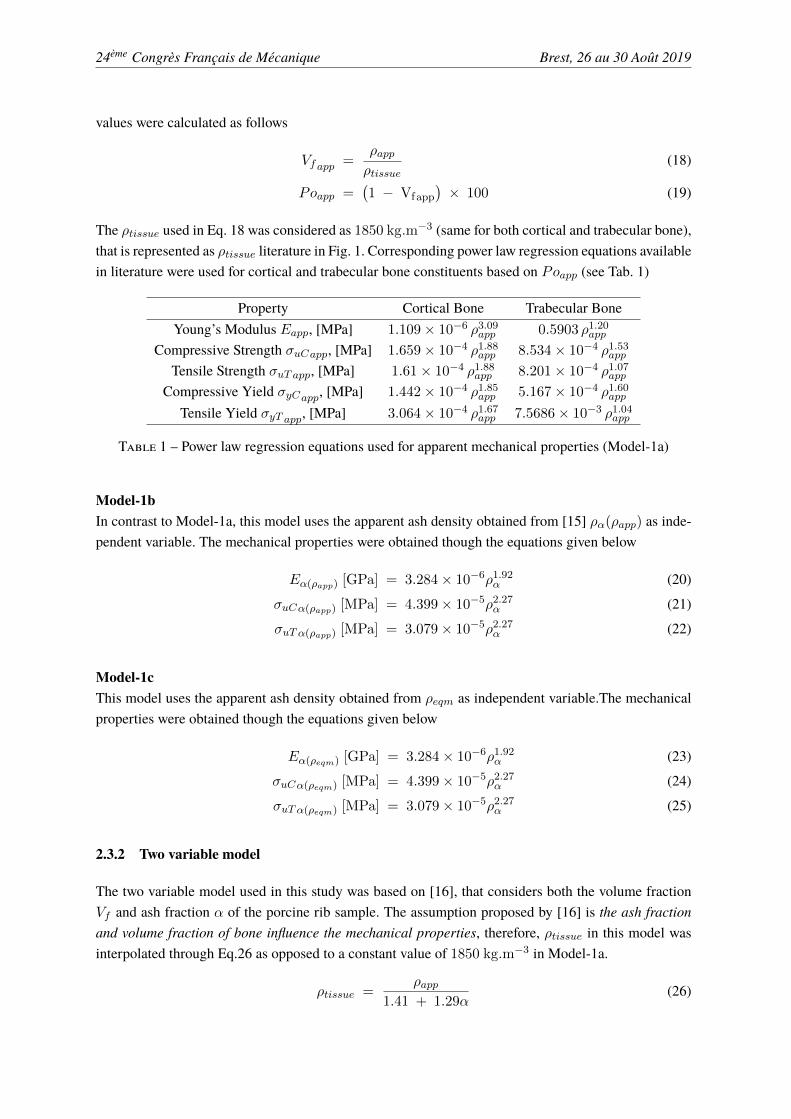
In order to test the influence of different independent variables on the mechanical properties of bone,three different densities were calibrated :
1. Apparent Dry Density ρapp, determined from the hypothesis presented by [29]. Firstly, the ef-fective density ρeff (Eq. 12) 1. Once ρeff is obtained, the ρapp was interpolated to GS througha linear relation as in Eq. 13
ρeff [kg.m−3] = 0.523GS + 1000 (12)
ρapp [kg.m−3] = 1.207GS (13)
2. Equivalent Mineral Density ρeqm. The ρeqm was found from GS values through the followingequation
ρeqm [kg.m−3] = 0.6452GS + 0.487 (14)1. density of the sample including the bone marrow and fluids
24ème Congrès Français de Mécanique Brest, 26 au 30 Août 2019
3. Apparent Ash Density ρα. Two methods were followed obtain ρα of porcine rib
(a) form ρeqm, through Eq.
ρα(ρeqm) [kg.m−3] = 1.27ρeqm + 0.0452 (15)
(b) based on the relation of ρα with ρapp, proposed by [15] as expressed as in Eq. 16 and Eq. 17
ρα(ρapp) [kg.m−3] = 0.522ρapp + 0.007; for ρapp < 1000 kg.m−3 (16)
ρα(ρapp) [kg.m−3] = 0.779ρapp − 0.250; for ρapp ≥ 1000 kg.m−3 (17)
0 500 1000 15000
500
1000
1500
2000
2500
Figure 1 – Different density measures for porcine rib
2.3 Mechanical properties of boneAs said in introduction, the mechanical properties of rib constituents were determined using either singlevariable power law regression (Model 1a, 1b and 1c) or two variable power law regression (Model 2).These models predict mechanical properties such as Young modulus (E), Yield strength in compressionand tension (σyC) and (σyT ), Ultimate strength in compression and tension (σuC) and (σuT ) respectively.
2.3.1 Single variable models
These models consider only one independent variable either ρapp (model-1a) or ρα (model-1b andmodel-1c).
Model-1aThe Model-1a is based on the hypothesis that ρapp is the only variable influencing the mechanical pro-perties of bone. Since the porcine rib has both cortical and trabecular bone, corresponding porosity Po
24ème Congrès Français de Mécanique Brest, 26 au 30 Août 2019
values were calculated as follows
Vf app =ρappρtissue
(18)
Poapp =(1 − Vf app
)× 100 (19)
The ρtissue used in Eq. 18 was considered as 1850 kg.m−3 (same for both cortical and trabecular bone),that is represented as ρtissue literature in Fig. 1. Corresponding power law regression equations availablein literature were used for cortical and trabecular bone constituents based on Poapp (see Tab. 1)
Property Cortical Bone Trabecular BoneYoung’s Modulus Eapp, [MPa] 1.109 × 10⁻⁶ ρ3.09app 0.5903 ρ1.20app
Compressive Strength σuCapp, [MPa] 1.659 × 10⁻⁴ ρ1.88app 8.534 × 10⁻⁴ ρ1.53app
Tensile Strength σuT app, [MPa] 1.61 × 10⁻⁴ ρ1.88app 8.201 × 10⁻⁴ ρ1.07app
Compressive Yield σyCapp, [MPa] 1.442 × 10⁻⁴ ρ1.85app 5.167 × 10⁻⁴ ρ1.60app
Tensile Yield σyT app, [MPa] 3.064 × 10⁻⁴ ρ1.67app 7.5686 × 10⁻³ ρ1.04app
Table 1 – Power law regression equations used for apparent mechanical properties (Model-1a)
Model-1bIn contrast to Model-1a, this model uses the apparent ash density obtained from [15] ρα(ρapp) as inde-pendent variable. The mechanical properties were obtained though the equations given below
Eα(ρapp) [GPa] = 3.284 × 10⁻⁶ρ1.92α (20)
σuCα(ρapp) [MPa] = 4.399 × 10⁻⁵ρ2.27α (21)
σuT α(ρapp) [MPa] = 3.079 × 10⁻⁵ρ2.27α (22)
Model-1cThis model uses the apparent ash density obtained from ρeqm as independent variable.The mechanicalproperties were obtained though the equations given below
Eα(ρeqm) [GPa] = 3.284 × 10⁻⁶ρ1.92α (23)
σuCα(ρeqm) [MPa] = 4.399 × 10⁻⁵ρ2.27α (24)
σuT α(ρeqm) [MPa] = 3.079 × 10⁻⁵ρ2.27α (25)
2.3.2 Two variable model
The two variable model used in this study was based on [16], that considers both the volume fractionVf and ash fraction α of the porcine rib sample. The assumption proposed by [16] is the ash fractionand volume fraction of bone influence the mechanical properties, therefore, ρtissue in this model wasinterpolated through Eq.26 as opposed to a constant value of 1850 kg.m−3 in Model-1a.
ρtissue =ρapp
1.41 + 1.29α(26)

24ème Congrès Français de Mécanique Brest, 26 au 30 Août 2019
Since ρtissue is not constant, the Vf does not have the same evolution for differentGS values as ofModel-1a, thereby changing the Po values. The mechanical properties in this model were obtained through thefollowing equations
Eα,Vf [GPa] = 84.37 V 2.58f α2.74 (27)
σuCα,Vf [MPa] = 794.33 V 1.92f α2.79 (28)
σuT α,Vf [MPa] = 556.00 V 1.92f α2.79 (29)
2.3.3 Comparison of regression models
In order to make sure which hypothesis shall be considered for the material properties of bone, the re-sults of single variable model and two variable model were compared and verified with the elementdistribution in the numerical rib sample.
First of all, the different density measures obtained through all these models were compared. The ashdensity of model-1b ρα(ρapp) is greater than that of model-1c ρα(ρeqm). This is due to the sample ori-gin used for correlation i.e. the data presented by [15] was obtained from pooling data of human femurand human vertebrae, whereas, ρα(ρeqm) of Model-1c was specific to porcine ribs. This shows the ashfraction varies for different species, thereby explaining the overestimation of density data.
Secondly, the volume fractions and porosity from Model-1a and Model-2 Vf app,Poapp and Vf (α),Po(α) were compared. This again proved that the ash fraction had a tendency of over estimating thevalues.
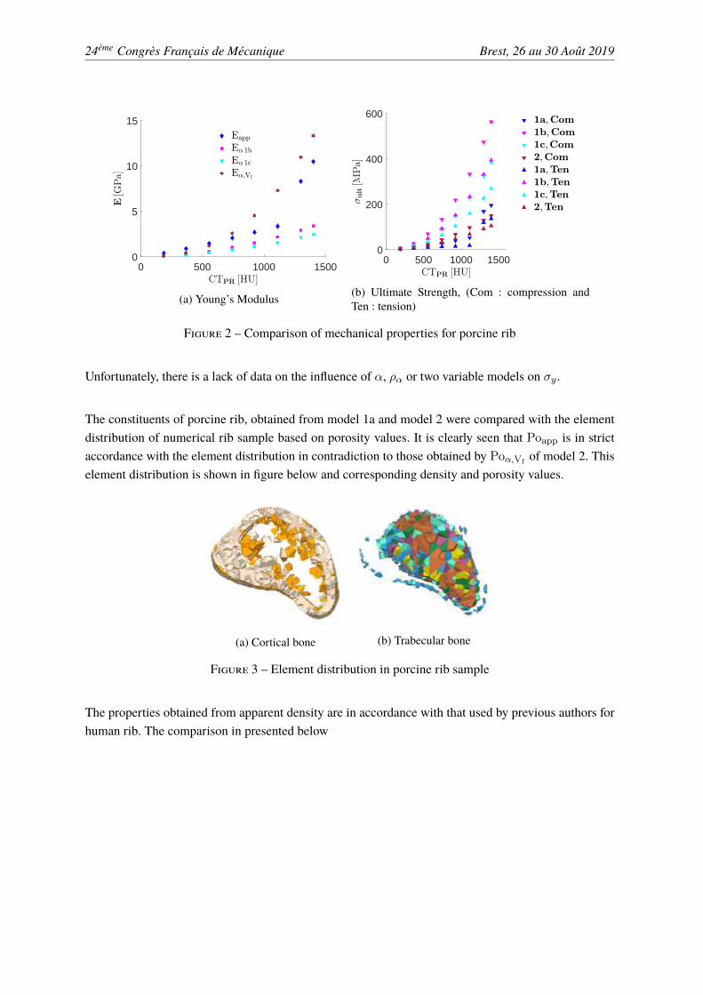
Lastly, estimated mechanical properties common to all 4 power law regression models (Young modulus,ultimate strength in compression and tension) were compared. Regarding the mechanical properties,following conclusions can be drawn
• The young’s modulus obtained thorough apparent density and two variable model are of similarrange and are largely high to those obtained from apparent ash density based models (see Fig.2a).
• The ultimate properties are highly influenced by α or ρα as it can be seen in Fig. 2b. Even thoughthe model 2 considers α, it does produce results similar to those obtained from apparent density.
We can conclude that the ash content in bone has a strong positive correlation on strength of bone anda negative correlation on the initial elastic behavior of bone. The reason for this influence in particularfor human ribs or its biological surrogates is yet to be explained.
24ème Congrès Français de Mécanique Brest, 26 au 30 Août 2019
0 500 1000 15000
5
10
15
(a) Young’s Modulus
0 500 1000 15000
200
400
600
(b) Ultimate Strength, (Com : compression andTen : tension)
Figure 2 – Comparison of mechanical properties for porcine rib
Unfortunately, there is a lack of data on the influence of α, ρα or two variable models on σy.
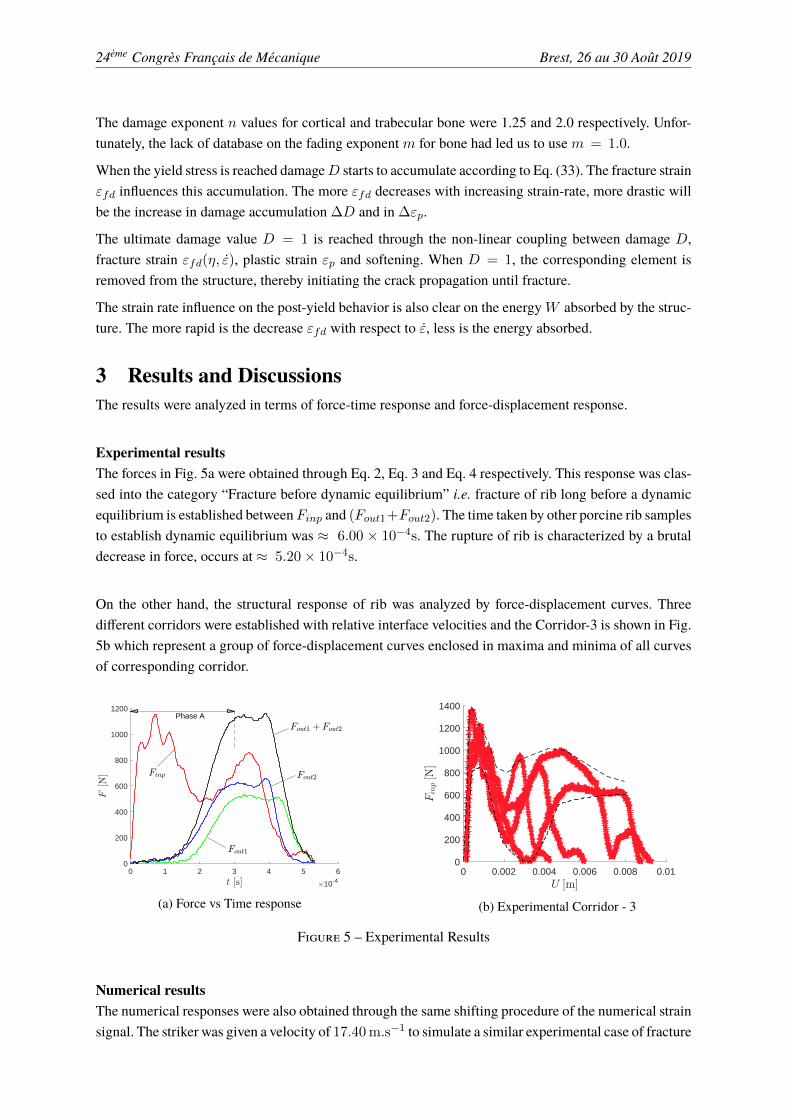
The constituents of porcine rib, obtained from model 1a and model 2 were compared with the elementdistribution of numerical rib sample based on porosity values. It is clearly seen that Poapp is in strictaccordance with the element distribution in contradiction to those obtained by Poα,Vf
of model 2. Thiselement distribution is shown in figure below and corresponding density and porosity values.
(a) Cortical bone (b) Trabecular bone
Figure 3 – Element distribution in porcine rib sample
The properties obtained from apparent density are in accordance with that used by previous authors forhuman rib. The comparison in presented below

24ème Congrès Français de Mécanique Brest, 26 au 30 Août 2019
Author Origin Bone ρ, kg.m−3 E,GPa σy,MPa
[30]Human Cortical 2000 13 150Human Trabecular 1000 2.4 2
[27]Human Cortical 2000 11.5 88Human Trabecular 1000 0.04 2.2
[28] aHuman Cortical 2000 11.03 98.98Human Trabecular 1000 0.04 1.8
[28] bHuman Cortical 2000 12.38 82.36Human Trabecular 1000 0.04 1.8
This studyPorcine Cortical 1630.00 9.37 70.876Porcine Trabecular 779.92 1.80 24.48
Table 2 – Comparison of average porcine rib apparent properties with human rib
These data prove that either Vf or ρapp based regression models are efficient and reliable for having adecent insight on mechanical properties given that it is correctly correlated to GS.
2.4 FE SimulationsThe FE simulations presented in this study were carried out at experimental scale. An elastic constitutivemodel was chosen for bars. The striker was given an initial velocity of 17.40 [m.s−1].
A good constitutive law for bone material must consider the strain rate effects. As proven by [31] thatat higher strain rates, the strain rate has more effects on the post yield regime and the use of elastic-viscoplastic constitutive law by [27] proves that the elastoviscoplastic constitutive law is adaptable forbone material. Therefore, a classic elastic plastic constitutive law was modified to consider the strainrate effects on post yield behavior through the cowper-symmonds model, that can be expressed as
σydσy0
= 1 +
(ε̇
C
)1/P
(30)
here, σyd is the strain sensitive yield stress, σy0 is the initial yield stress, ε̇ is the strain rate, C and Pare cowper-symmonds parameters. The σy0 is identified as the tensile yield stress presented in Tab. 2.The cowper-symmonds parameters are adapted from [27] and are specified here for the sake of clarityC = 2.5 GPa and P = 7.0. The cortical and trabecular bone were supposed to obey isotropic andkinematic hardening respectively as found in previous studies.
In order to simulate the progressive nature of fracture propagation and damage accumulation, an externaldamage law was coupled to the constitutive law. This law is incremental and stress-state dependent andis capable of considering the reduction in load carrying capacity and effects of strain rate. This modelis based on the works of [32] and [33]. The dependency on stress state is considered through stresstriaxiality as follows
η = −13tr ¯̄σ
σeq(31)
where : 13tr ¯̄σ is the hydrostatic pressure (average of the ¯̄σ stress tensor trace) and σeq is the equivalent
stress.
The relation between the fracture strain εfd and triaxiality η – Eq. (31) – is given in the form of an input

24ème Congrès Français de Mécanique Brest, 26 au 30 Août 2019
curve plotted in Fig. 4a.
In this study, the static fracture strain εfs value is 2 × 10⁻² m/m for cortical and 3 × 10⁻² m/m fortrabecular bone. To approach the realistic fracture and propagation behavior using our damage model,the influence of strain rate ε̇ on the fracture strain εfd was implemented by an equation from [22] asfollows :
εfdεfs
= A − B Lnε̇ (32)
where A = 0.63. Five different values of B = 1.25 × 10⁻². The corresponding εfd/εfs vs ε̇ inputcurve is plotted in Fig. 4b.
-1 -0.5 0 0.5 1
100
1010
1020
(a) Threshold curve of fracture strain for positivetriaxiality
0 500 1000 15000
0.2
0.4
0.6
0.8
1
(b) εfd/εfs vs ε̇
Figure 4 – Input curves of damage law
Note that the static fracture strain provided by [22] is 0.86 × 10⁻² m/m, which corresponds to a quasi-static strain-rate of 3.18×10⁻³ s−1. Similarly, in the present study Eq. (32) is not applicable for ε̇ lowerthan 3.00 × 10⁻³ s−1, which are quasi static. For all values 0 s−1 ≤ ε̇ ≤ 3.00 × 10⁻³ s−1, a linearapproximation is applied so that εfd/εfs = 1 at ε̇ = 0 s−1.
The increments in damage ∆D is expressed in terms of plastic strain ∆εp and triaxility η as follows :
∆D =n
εfd (η, ε̇)D(1−1/n)∆εp (33)
The damage exponent n is to differentiate between linear and non-linear damage accumulation.
The reduction in load carrying capacity due to an increase in damage is taken into account through amodified equation of Lemaitre’s effective stress principle :
σ = σ̃ (1 −Dm ) (34)
When the damage D reaches 1.0, fracture occurs and the Gaussian integral point of the correspondingelement no longer exists in the calculation.
24ème Congrès Français de Mécanique Brest, 26 au 30 Août 2019
The damage exponent n values for cortical and trabecular bone were 1.25 and 2.0 respectively. Unfor-tunately, the lack of database on the fading exponentm for bone had led us to usem = 1.0.
When the yield stress is reached damageD starts to accumulate according to Eq. (33). The fracture strainεfd influences this accumulation. The more εfd decreases with increasing strain-rate, more drastic willbe the increase in damage accumulation ∆D and in ∆εp.
The ultimate damage value D = 1 is reached through the non-linear coupling between damage D,fracture strain εfd(η, ε̇), plastic strain εp and softening. When D = 1, the corresponding element isremoved from the structure, thereby initiating the crack propagation until fracture.
The strain rate influence on the post-yield behavior is also clear on the energyW absorbed by the struc-ture. The more rapid is the decrease εfd with respect to ε̇, less is the energy absorbed.
3 Results and DiscussionsThe results were analyzed in terms of force-time response and force-displacement response.
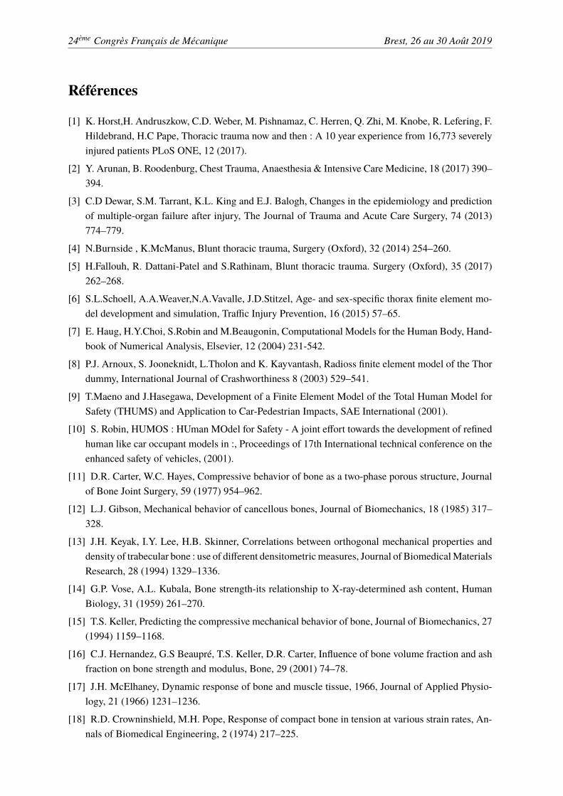
Experimental resultsThe forces in Fig. 5a were obtained through Eq. 2, Eq. 3 and Eq. 4 respectively. This response was clas-sed into the category “Fracture before dynamic equilibrium” i.e. fracture of rib long before a dynamicequilibrium is established betweenFinp and (Fout1+Fout2). The time taken by other porcine rib samplesto establish dynamic equilibrium was ≈ 6.00 × 10⁻⁴s. The rupture of rib is characterized by a brutaldecrease in force, occurs at ≈ 5.20 × 10⁻⁴s.
On the other hand, the structural response of rib was analyzed by force-displacement curves. Threedifferent corridors were established with relative interface velocities and the Corridor-3 is shown in Fig.5b which represent a group of force-displacement curves enclosed in maxima and minima of all curvesof corresponding corridor.
0 1 2 3 4 5 6
10-4
0
200
400
600
800
1000
1200Phase A
(a) Force vs Time response
0 0.002 0.004 0.006 0.008 0.010
200
400
600
800
1000
1200
1400
(b) Experimental Corridor - 3
Figure 5 – Experimental Results
Numerical resultsThe numerical responses were also obtained through the same shifting procedure of the numerical strainsignal. The striker was given a velocity of 17.40 m.s−1 to simulate a similar experimental case of fracture

24ème Congrès Français de Mécanique Brest, 26 au 30 Août 2019
before equilibrium. The numerical responses are shown in figure below compared to the correspondingexperimental results. Following deductions can be drawn,
1. A keen observation to the εinc and εref , reveals that there is a slight difference between numericaland experimental signals. On the other hand, the difference in the transmitted strain signals can beexplained by the difference in geometry. Yet, the numerical interface velocities and displacementsare almost similar to that of experimental.
2. The numerical displacement of output interface 2 shows a peculiar response. It is clear thatit superposes with experimental signal till t ≈ 500 × 10−4s. Beyond this point of time themagnitude of uout2 Num is greater than uout1 Exp, that can be explained by the loss of contactbetween the sample and output bar interface 2. The increase in displacement beyond this timerepresents the rigid displacement of output bar.
0 2 4 6
10-4
-5
-2.5
0
2.5
510-3
(a) incident and reflected waves
0 2 4 6
10-4
-1
-0.8
-0.6
-0.4
-0.2
010-3
(b) transmitted waves
0 2 4 6
10-4
0
5
10
15
(c) interface velocities
0 2 4 6 8
10-4
0
2
4
6
810-3
0
2
4
610-4
(d) interface displacements
Figure 6 – Experimental and Numerical strain, interface velocities and displacements
The numerical force-displacement response is shown in figure below. Initially, the structure behaves asan elastic material (till t ≈ 0.75×10⁻⁴ s). During this period of time, the response depends on materialproperties and the stiffness distribution. Beyond this time, the force starts to increase till it reaches themaximum value and decreases till t ≈ 2.05 × 10⁻⁴ s. This is followed by an increase in force, whichrepresents the reflection of waves from output interface. The second decrease in force starts to occurwhen a crack appears in macro scale thereby proving the reduction in force carrying capacity of the ribuntil rupture at t ≈ 5.00 × 10⁻⁴ s or U ≈ 5.00 × 10⁻³ m.

24ème Congrès Français de Mécanique Brest, 26 au 30 Août 2019
0 1 2 3 4 5
10-3
0
200
400
600
800
1000
1200
1400
Figure 7 – Comparison of Numerical response to experimental response
4 ConclusionsDynamic three point bending tests using the split hopkinson pressure bar on rib was successfully imple-mented to have insights on fracture of ribs.
Different power law regression models were tested. The apparent density was the one that gave reliableresults. The power law regression models with apparent ash density or ash fraction had a tendency toover estimate the ultimate properties of porcine rib. Moreover, the average apparent properties of porcinerib constituents are in good accordance with those of human ribs. This proves that the choice of porcinerib as human surrogates is biologically reliable.
The numerical results in this study prove that the FEmodel presented in this study is pertinent. The strainrate effects in behavior and damage till rupture were successfully taken into account. Even though theFE model results are coherent with that of experiments, optimization of damage law parameters throughuni axial tensile test data could further improve the predicting capability of the model.
24ème Congrès Français de Mécanique Brest, 26 au 30 Août 2019
Références
[1] K. Horst,H. Andruszkow, C.D. Weber, M. Pishnamaz, C. Herren, Q. Zhi, M. Knobe, R. Lefering, F.Hildebrand, H.C Pape, Thoracic trauma now and then : A 10 year experience from 16,773 severelyinjured patients PLoS ONE, 12 (2017).
[2] Y. Arunan, B. Roodenburg, Chest Trauma, Anaesthesia & Intensive Care Medicine, 18 (2017) 390–394.
[3] C.D Dewar, S.M. Tarrant, K.L. King and E.J. Balogh, Changes in the epidemiology and predictionof multiple-organ failure after injury, The Journal of Trauma and Acute Care Surgery, 74 (2013)774–779.
[4] N.Burnside , K.McManus, Blunt thoracic trauma, Surgery (Oxford), 32 (2014) 254–260.
[5] H.Fallouh, R. Dattani-Patel and S.Rathinam, Blunt thoracic trauma. Surgery (Oxford), 35 (2017)262–268.
[6] S.L.Schoell, A.A.Weaver,N.A.Vavalle, J.D.Stitzel, Age- and sex-specific thorax finite element mo-del development and simulation, Traffic Injury Prevention, 16 (2015) 57–65.
[7] E. Haug, H.Y.Choi, S.Robin and M.Beaugonin, Computational Models for the Human Body, Hand-book of Numerical Analysis, Elsevier, 12 (2004) 231-542.
[8] P.J. Arnoux, S. Jooneknidt, L.Tholon and K. Kayvantash, Radioss finite element model of the Thordummy, International Journal of Crashworthiness 8 (2003) 529–541.
[9] T.Maeno and J.Hasegawa, Development of a Finite Element Model of the Total Human Model forSafety (THUMS) and Application to Car-Pedestrian Impacts, SAE International (2001).
[10] S. Robin, HUMOS : HUman MOdel for Safety - A joint effort towards the development of refinedhuman like car occupant models in :, Proceedings of 17th International technical conference on theenhanced safety of vehicles, (2001).
[11] D.R. Carter, W.C. Hayes, Compressive behavior of bone as a two-phase porous structure, Journalof Bone Joint Surgery, 59 (1977) 954–962.
[12] L.J. Gibson, Mechanical behavior of cancellous bones, Journal of Biomechanics, 18 (1985) 317–328.
[13] J.H. Keyak, I.Y. Lee, H.B. Skinner, Correlations between orthogonal mechanical properties anddensity of trabecular bone : use of different densitometricmeasures, Journal of BiomedicalMaterialsResearch, 28 (1994) 1329–1336.
[14] G.P. Vose, A.L. Kubala, Bone strength-its relationship to X-ray-determined ash content, HumanBiology, 31 (1959) 261–270.
[15] T.S. Keller, Predicting the compressive mechanical behavior of bone, Journal of Biomechanics, 27(1994) 1159–1168.
[16] C.J. Hernandez, G.S Beaupré, T.S. Keller, D.R. Carter, Influence of bone volume fraction and ashfraction on bone strength and modulus, Bone, 29 (2001) 74–78.
[17] J.H. McElhaney, Dynamic response of bone and muscle tissue, 1966, Journal of Applied Physio-logy, 21 (1966) 1231–1236.
[18] R.D. Crowninshield, M.H. Pope, Response of compact bone in tension at various strain rates, An-nals of Biomedical Engineering, 2 (1974) 217–225.
24ème Congrès Français de Mécanique Brest, 26 au 30 Août 2019
[19] J.D. Currey, The effects of strain rate, reconstruction and mineral content on some mechanicalproperties of bovine bone, Journal of Biomechanics, 8 (1975) 81–86.
[20] T.M. Wright, W.C. Hayes, Tensile testing of bone over a wide range of strain rates : effects of strainrate, microstructure and density, Medical & Biological Engineering, 14 (1976) 671–680.
[21] U. Hansen, P. Zioupos, R. Simpson, J.D Currey, D. Hynd, Effects of strain rate on mechanicalproperties of human cortical bone, Journal of Biomedical Engineering, 130 (2008).
[22] J.L. Wood, Dynamic response of human cranial bone, Journal of Biomechanics, 4 (1971) 1–12.
[23] D. Garcia, Elastic-plastic damage laws for cortical bone, PhD. Thesis, Ecole Polytecnique Fédéralede Laussane, 2006.
[24] J. Pavier, Contribution à la compréhension des phénomènes physiques lors de l’impact d’un corpssur un modèle de structure biologique. Thèse, Université d’Orléans, 2013.
[25] N. Kelly, J.P. McGarry, Experimental and numerical characterization of the elastic-plastic proper-ties of bovine trabecular bone and a trabecular bone analogue, Journal of Mechanical Behavior ofBiomedical Behavior, 9 (2012) 184–197.
[26] M. Karkar, Personnalisation morpho-mécanique de la voûte crânienne humaine à différentes vi-tesses de sollicitations, Thèse, Université de Valenciennes, 2017.
[27] Z. Li, M.W. Kindig, J.R. Kerrigan, C.D. Untaroiu, D. Subit, J.R. Crandall, R.W. Kent, Rib frac-tures under anterior-posterior dynamic loads : Experimental study and Finite Element Simulations,Journal of Biomechanics, 24 (2010) 228–234.
[28] K. Yates, C. Untaroiu, Subject specific modeling of human ribs : Finite Element simulations of ribbending tests, mesh sensitivity, model testing with data from coupon tests, In : Proceedings of 15thinternational LS-Dyna User’s Conference, 2018 ;
[29] W.R. Taylor, E. Roland, H. Ploeg, D. Hertig, R. Klabunde, M.D. Warner, M.C. Hobatho, L. Ra-kotomanana, S.E. Clift, Determination of orhtotropic bone elastic constants using FEA and modalanalysis, Journal of Biomechanics, 35 (2002) 767–773,
[30] E. Charpail, Analyse du comportement mécanique des côtes humaines en dynamique, Thèse, ÉcoleNational de Supérieur d’Arts et Métiers , 2006,
[31] P. Zioupos, U. Hansen, J.D. Currey, Microcracking damage and the fracture process in relation tostrain rate in human cortical bone tensile fracture, Journal of Biomechanics, 41 (2008) 2932–2939,
[32] N. Frieder, F. Markus, H. André, Considering damage history in crash-worthiness simulations, In :Proceedings of 7th international LS-Dyna User’s Conference, 2009 ;
[33] A. Fillipe, F.Markus, H. André, On the prediction of damage and failure in LS-Dyna : a comparisonof GISSMO and DIEM, In : Proceedings of 13th international LS-Dyna User’s Conference, 2014 ;