Final thesis chapters 1-4 + appendices - University of Glasgow
157
Glasgow Theses Service http://theses.gla.ac.uk/ [email protected] Paul, Pauline Elizabeth (2010) The validation of a new articulator system for orthognathic model surgery. MSc(R) thesis. http://theses.gla.ac.uk/2256/ Copyright and moral rights for this thesis are retained by the author A copy can be downloaded for personal non-commercial research or study, without prior permission or charge This thesis cannot be reproduced or quoted extensively from without first obtaining permission in writing from the Author The content must not be changed in any way or sold commercially in any format or medium without the formal permission of the Author When referring to this work, full bibliographic details including the author, title, awarding institution and date of the thesis must be given
-
Upload
khangminh22 -
Category
Documents
-
view
0 -
download
0
Transcript of Final thesis chapters 1-4 + appendices - University of Glasgow

Glasgow Theses Service http://theses.gla.ac.uk/
Paul, Pauline Elizabeth (2010) The validation of a new articulator system for orthognathic model surgery. MSc(R) thesis. http://theses.gla.ac.uk/2256/ Copyright and moral rights for this thesis are retained by the author A copy can be downloaded for personal non-commercial research or study, without prior permission or charge This thesis cannot be reproduced or quoted extensively from without first obtaining permission in writing from the Author The content must not be changed in any way or sold commercially in any format or medium without the formal permission of the Author When referring to this work, full bibliographic details including the author, title, awarding institution and date of the thesis must be given

The Validation of a New Articulator System for
Orthognathic Model Surgery
By
Pauline E. Paul.
Thesis submitted in fulfilment for the Degree of Master of Medical Science (M.Sc.) in the Faculty of Medicine,
University of Glasgow
Glasgow Dental Hospital and School
University of Glasgow June 2010
© P.E.Paul

I
Acknowledgements
I would like to take this opportunity to thank the following people:
To Professor A.F. Ayoub, I will always be forever indebted to you for giving me the
opportunity and support to undertake this study. It would not have possible without
your belief and faith in me to see this project through.
To Professor J.C. Barbenel, I would like to express my most sincere thanks for all
your guidance and endless support throughout this study. You were forever the
calming influence to me. I could have not have done this without your constant
encouragement and help.
To Professor K.F. Moos O.B.E. for all your valuable time and support you gave me
with my study. Offering me your endless knowledge and guidance throughout, it is
so very much appreciated.
To Mr F.S. Walker my friend and colleague who had faith in me to fulfil my goals.
Thank you for all your constant support throughout the years and with this project.
To Dr B. Khambay for being part of my supervisory committee and providing helpful
input and support throughout.

II
To Mr J. Eyland for all your help with the photography required during this study.
For your willingness to always help and your patents with me throughout my study, I
thank you. Without your valuable input this project would not have been possible.
To Mrs M. Craig for all your help with the photography in the initial stages of my
study and your support throughout, it was very much appreciated.
To Mrs A. Hanlon-Bucher my most sincere thanks for all your help with the graphics
and photo analysis required for the first part of my study.
To Mrs A. Sherriff thank you for all your help with the statistical analysis of this
study.
I would like to thank Ms A McCormack for all your help throughout the last few
years.
I would like to express my sincere thanks to my friends and colleagues within the
Maxillofacial laboratory at the Southern General Hospital for all your support and
encouragement throughout my study.
To my extended family and friends thank you for all your support and
encouragement throughout the last few years.

III
My most sincere thanks to Steven Murray, who has always had faith in me to achieve
my goals. You have encouraged me with words of support and helped me
throughout. Most of all you have helped me to believe in what I do.
I would like to express my most sincere thanks and gratitude to my parents and
sister who have encouraged and constantly supported me throughout all my
endeavours, especially throughout the last couple of years. It has been a
rollercoaster but you were always there to help pick up the pieces, I love you and
thank you from the bottom of my heart.
Last but not least to my soul mate and husband Robert, stepdaughter Chloe,
daughter Téa and son Harley, my most sincere thanks for your support, enduring all
the ups and downs during my study and supporting me throughout. Thank you, I
love you and it is to you I dedicate this thesis.
Téa my homework is finished now. It’s time to play.

IV
DECLARATION.
This thesis represents the original work of the author.
……………………………….
Pauline E. Paul.
June 2010

V
Contents
Acknowledgements I-III
Declaration IV List of contents V-VI List of figures VII-X List of tables XI List of graphs XII-XIII List of publications XIV Definitions/abbreviations XV-XVI Preface XVII Abstract XVIII Chapter 1 Introduction 1-14 Chapter 2 Articulators and face bows 15-48 Chapter 3 Aims and objectives 49-51

VI
Chapter 4 Errors produced by cast misalignment
52-66 Chapter 5 Evaluation of a new orthognathic articulator system
67-94
Chapter 6
Discussion and conclusions 95-116 Chapter 7 References 117-121 Appendices Errors produced by cast misalignment study Evaluation of a new orthognathic articulator system results
I-VII
VIII-XV

VII
Figures Content: Chapter 1. Fig.1.1 Master cast with localizing grooves cut into the base of the
model with plaster wafer in place.
5. Fig.1.2. Master cast with wafer removed. 5. Fig.1.3. Master cast with localizing key in position. 6. Fig.1.4. Segmental cast reposition with plaster wafer removed. 6. Fig.1.5. Articulated models showing reference lines and the
measurements.
7. Fig.1.6. Models showing vertical reference lines VC,VB,VM. 7. Fig.1.7. Occlusal view of post-operative dental casts showing medial-
lateral measurements.
7. Fig.1.8. Models showing measurement of the antero-posterior
movement (V.F).
7. Fig.1.9. Vertical repositioning lines scribed on mandibular and
maxillary casts.
9. Fig.1.10. Posterior maxilla rotation lines scribed on the cast. 9.
Chapter 2. Fig.2.1. Fig.2.2. Fig.2.3. Fig 2.4.
Image illustrating Campers’ plane. Image illustrating the Frankfort plane. Image illustrating Beyron point. Articulator with Fox plane modified for angle measurements.
18.
19.
21.
24. Fig.2.5. Diagram to show the effect of altering the steepness of the
occlusal plane on mandibular rotation.
27. Fig.2.6. A compass used to scribe the distance on a cephalometric
tracing.
29.

VIII
Fig.2.7. A Prototype orthognathic articulator. 36. Fig.2.8. Head position study photograph. 39. Fig.2.9. Dentatus average value face bow with orbital pointer. 40. Fig.2.10. Dentatus average value face bow with attached circular
spirit level.
40. Fig.2.11. Measurement method to determine the maxillary occlusal
plane.
41. Fig.2.12. Cast mounted on an average value Dentatus face bow. 42. Fig.2.13. Cast mounted using spirit level face bow. 43. Fig.2.14. Protractor on a slide fit stand to measure the maxillary
occlusal plane angle.
43. Fig.2.15. Frontal view of the casts mounted on the Orthognathic
articulator.
45. Fig.2.16. Lateral view of the maxillary and mandibular casts. 46.
Chapter 4. Fig.4.1. Difference between the axes based on the articulator cross
member and the natural head position.
54. Fig.4.2. Qualitative illustration, movement of a model relative to
articulator and natural head position.
55. Fig.4.3. Maxillary model in initial position showing plumb line. 59. Fig.4.4. Cast in start position. 61. Fig.4.5. Cast in downgrafted position. 61. Fig.4.6. Cast in impacted position. 62. Fig.4.7. Superimposed images of model in initial and displaced
positions.
63.

IX
Chapter 5. Fig.5.1. Mounting plate attached to the base of the skull. 69. Fig.5.2. Brass plates with cortical titanium screws fixing the maxilla. 70. Fig.5.3. Custom measuring device base. 70. Fig.5.4. Spirit levels attached to measuring device base. 71. Fig.5.5a. Aluminium rod with tripod attachment in place. 71. Fig.5.5b. Aluminium rod with tripod attachment in place. 71. Fig.5.6. Frankfort horizontal plane being leveled to the true
horizontal.
72. Fig.5.7. Angle finder (protractor) placed on the remaining part of
skull.
73. Fig.5.8. Adjusting the skull to achieve the angle required. 73. Fig.5.9a. Circular spirit level secured to top of skull. 74. Fig.5.9b. Circular spirit level secured to top of skull. 74. Fig.5.10. Skull with fixed mandible. 74. Fig.5.11. Face bow recording using Orthognathic articulator face bow.
75. Fig.5.12. Face bow recording using Standard articulator face bow.
75. Fig.5.13. Maxillary cast mounted using aluminium disc. 76. Fig.5.14. Perioperative with maxilla and mandible occluding. 77. Fig.5.15a.
Standard articulator with predicted movements carried out. 77.
Fig.5.15b.
Orthognathic articulator with predicted movements carried out.
77.
Fig.5.16. Maxilla repositioned using the perioperative wafer held in
place with sticky wax.
78. Fig.5.17. Reference points used to quantify the movements of the
maxilla after simulated surgery.
79.

X
Fig.5.18. Aluminium rod attached horizontally by a clamp. 80. Fig.5.19. Plastic skull set in a predetermined angle with the vertical
caliper for measurements.
81.
Fig.5.20. Protractor with a sliding fit on a stand measuring the maxillary occlusal plane angle.
81.
Chapter 6. Fig.6.1. Variations of the cant of the Frankfort horizontal plane. 99.

XI
Tables Content: Chapter 4. Table 4.1. Comparison of theoretical predictions and experimental
measurements.
64.
Chapter 5. Table 5.1. Vertical error, mm, measured at 4 reference points. 91. Table 5.2. Wilcoxon comparison of vertical errors measured at 4
reference points.
92.
Chapter 6. Table 6.1. Antero-posterior errors, mm. Difference between fixed and
autorotated mandible.
110. Table 6.2. Absolute antero-posterior errors, mm. Difference between
fixed and autorotated mandible.
110.

XII
Graphs Content: Chapter 4. Graph 4.1. The dependence of the vertical and horizontal errors on
the vertical movment.
57. Graph 4.2. The dependence of the vertical and horizontal errors on
the vertical and horizontal movement.
57. Graph 4.3. A statistical representation of the correction between the
predicted theoretical values of displacement and experimental values.
65.
Chapter 5. Graph 5.1a. Antero-posterior errors in mm of Standard articulator. 84. Graph 5.1b. Antero-posterior errors in mm of Orthognathic articulator. 84. Graph 5.2a. Antero-posterior absolute errors in mm of Standard
articulator.
85. Graph 5.2b. Antero-posterior absolute errors in mm of Orthognathic
articulator.
85. Graph 5.3a. Bland Altman plot showing antero-posterior errors (vertical
axis) of Standard and articulator.
86. Graph 5.3b. Bland Altman plot showing antero-posterior absolute errors
(vertical axis) of Standard and Orthognathic articulator.
86. Graph 5.4a. Vertical errors in mm, central incisor of Standard
articulator.
87. Graph 5.4b. Vertical errors in mm, central incisor of Orthognathic
articulator.
87. Graph 5.5a. Vertical absolute errors in mm, central incisor of Standard
articulator.
88. Graph 5.5b. Vertical absolute errors in mm, central incisor of
Orthognathic articulator.
88. Graph 5.6a. Bland Altman plot showing vertical errors of Standard and
Orthognathic articulators.
89.

XIII
Graph 5.6b. Bland Altman plot showing absolute vertical errors of
Standard and Orthognathic articulators.
89. Graph 5.7a. Maxillary occlusal plane angle errors in degrees of Standard
articulator.
92. Graph 5.7b. Maxillary occlusal plane angle errors in degrees of
Orthognathic articulator.
92. Graph 5.8a. Maxillary occlusal plane angle absolute errors in degrees of
Orthognathic articulator.
93. Graph 5.8b. Maxillary occlusal plane angle absolute errors in degrees of
Orthognathic articulator. 93.
Graph 5.9a. Bland Altman plot showing maxillary occlusal plane angle
errors in degrees of Standard and Orthognathic articulators.
94.
Graph 5.9b. Bland Altman plot showing maxillary occlusal errors in
degrees of Standard and Orthognathic articulator.
94.
Chapter 6. Graph 6.1. Error of antero-posterior movement as a function of skull
angle. 105.
Graph 6.2. Error of antero-posterior movement as a function of skull
angle for each movement advance, advance down and up.
106. Graph 6.3. Error of vertical movement measured at central incisor as
a function of skull angle. Compare with chapter 5 graph 5.9a.
107. Graph 6.4. Error of vertical movement measured at central incisors as
a function of skull angle.
108. Graph 6.5. Difference between pre-operative maxillary occlusal plane
angle of the skull and of the mounted casts.
111.

XIV
Publications:
Barbenel, J.C., Paul, P.E., Ayoub, A.F., Walker, F.S., Khambay, B.S., Moos, K.F.
(2010), Errors in orthognathic surgery planning; The effect of inaccurate study
model orientation.
Accepted by the International Journal of Oral and Maxillofacial Surgery 2010.

XV
DEFINITIONS/ABBREVIATIONS:
Articulator. A mechanical device to which models of the upper and
lower arches are attached and which reproduces
recorded positions of the mandible in relation to the
maxilla.
Axis orbital plane An imaginary line joining orbitale and the axis of the
mandibular rotation (the most prominent palpable area
of the condylar head)
Campers plane. Imaginary line running from the inferior border of the ala
of the nose to the superior border of the tragus of the
ear.
Dentatus. Manufacturer of semi-adjustable articulators and face
bows.
Natural head position The position of the head when an individual is sitting or
standing erect with the head level and eyes fixed on the
horizon.
Face bow. An instrument used to record the transverse horizontal
axis (hinge axis) of the mandible and relating this
recording to the maxilla to facilitate anatomical
mounting of the maxillary cast to an articulator.

XVI
Frankfort horizontal
plane A plane passing through the lowest point of the floor of
the left orbit (orbitale) and the highest point of each
external auditory meatus (porion).
Kinematic face bow. Used in conjunction with an articulator. The ends can be
adjusted to permit location of the axis of rotation of the
mandible.
Maxillary occlusal plane A plane passing through the occlusal or biting surfaces of
the maxillary teeth. It represents the mean of the
curvature of the occlusal surface.
Semi-adjustable
Articulator. A mechanical device, which can be adjusted to replicate
the many movements of the mandible relative to the
maxilla.

XVII
PREFACE:
This study was carried out at the University of Glasgow Dental Hospital and School,
with the practical part of the study carried out at the West of Scotland Regional
Maxillofacial Prosthetics Laboratory at the Glasgow Southern General Hospital
under the supervision of Professor A. Ayoub, Dr B. Khambay, Mr F.S.Walker,
Professor J.C.Barbenel, and Professor K.F. Moos O.B.E.
The study represents the original work carried out by the author, and has not been
submitted in any form to any other university.

XVIII
ABSTRACT:
A review of the literature showed that the outcome of orthognathic surgery may
differ from the planned outcome, that casts mounted on semi-adjustable
articulators show systematic errors of orientation and that there may be a causal
connection between them.
It was demonstrated that the movements of casts mounted on, and moved relative
to, a standard articulator produced movements of different magnitudes relative to
the natural head position. A mathematical model was developed to quantify the
difference and the predictions of the resulting equations were confirmed in a
photographic study using image analysis.
The second stage of the study compared a standard and the orthognathic
articulator. Plastic model skulls were mounted at different angulations to represent
different natural head positions. Casts of the maxillary teeth of the skulls mounted
on the orthognathic articulator accurately reproduced the occlusal plane angles of
the skulls, but those mounted on the standard articulator showed systematic errors
of up to 28º. Surgical movements of the maxilla were reproduced using
perioperative wafers constructed on casts mounted on the standard and
orthognathic articulators. The accuracy of the maxillary repositioning was assessed
at five anatomical reference points on the skulls. The results indicated that the
orthognathic articulator was significantly more accurate than the standard
articulator.

XIX

1
1 INTRODUCTION

2
1.1.Introduction.
1.1.1.Orthognathic Surgery.
Orthognathic surgery or the surgery for the correction of jaw deformity has been
routinely carried out in most Maxillofacial units over many years. This form of
surgery has commonly involved either a single jaw or both upper and lower jaws.
The procedure normally requires the collaboration of a multidisciplinary team
including the surgeon, an orthodontist and a Maxillofacial technologist to plan the
surgical procedure.
The surgeon:
Assesses the patient by clinical examination and appropriate radiographs and
prescribes the jaw movements required to correct the aesthetic and functional
orthognathic abnormalities. These can be vertical, horizontal as well as both
antero-posterior and lateral movements, and less commonly rotational movements
of the patient’s jaws based on an assessment of the patient in the natural head
position. This is carried out by sectioning and repositioning the jaws into a
prescribed optimum position, using templates in the form of perioperative wafers.
There are several systems that assist the surgeon in predicting the movements
required to correct the skeletal abnormalities of the patient. One of the original
prediction planning techniques utilizes a lateral cephalogram and scaled lateral
photograph. This is used in conjunction with a profile analysis such as Ricketts to
diagnose the required movements for correction of a deformity. Although this is an
older technique it still finds favour with many Maxillofacial surgeons today. There
are in addition several computer surgical prediction packages for example Opal,

3
Dolphin and CASSOS. The latter of the two are useful tools that can produce a print
out of the patients’ hard and soft tissue profile, however there are limitations with
these programmes as they do not always accurately predict soft tissue movements.
Technology is now moving more towards 3D analysis using photogramitry and it
hoped eventually this will provide a superior method of pre-surgical prediction
planning.
The orthodontist:
� Re-aligns the dental arches and de-compensates the dentition prior to
surgery and carries out any occlusal adjustments to the dentition post
surgery .
To ensure that the jaws have been positioned into the prescribed relationship at
the time of surgery a technique known as orthognathic model surgery has been
employed to make certain that this surgery will be achieved through the optimal
desired safe movements of the jaws.
The technologist:
� Simulates the prescribed movements on dental casts mounted on an
articulator and then proceeds to produce perioperative wafers for the
surgeon to use and to guide the placement of one or both jaws at this time of
orthognathic surgery, into the preplanned position.
An articulator is a mechanical device that represents as closely as possible the
relevant anatomical landmarks of the upper and lower jaws upon which dental casts
are mounted to reproduce a recorded occlusal position, usually the position of
centric occlusion or the rest position which would have been recorded with a wax
registration. The upper arm of the articulator hinges (normally rotates) to allow the

4
separation of the mandibular and maxillary teeth and simulates the opening of the
mandible for planning purposes.
Even when an accurate wafer has been constructed this cannot guarantee an
accurate surgical outcome in relation to the prediction plan. The following are the
errors that are frequently associated with this procedure:
� Surgical errors, the surgeon may not follow the prediction plan accurately,
due to difficulties in theatre when trying to achieve the movements
required, or may accept a compromise of the occlusion or change the
planned movement to achieve an acceptable occlusion.
� Systematic errors in the laboratory preparation of the wafer may occur due
to the face bow recording, its transfer and the casting and mounting of the
dental casts.
� For the majority of articulators it is well recognized that they do not
reproduce jaw movements precisely and therefore accurately, reposition the
occlusion and they may not place the jaws themselves into an optimal or
stable position.
An accurate surgical outcome could not be achieved with inaccurately recorded
occlusal records, which were transferred to a reliable articulator, without some
form of surgical compromise.
1.1.2. Model surgery and wafer construction.
The first stage of model surgery is simply that of recording the current occlusion
followed by the taking of a face bow registration, the purpose of which is to
orientate the dental casts relative to the articulator cross member and, it is

5
assumed, relative to an anatomical plane such as the Frankfort plane, and to
register the anteroposterior position of the maxillary cast relative to the hinge axis
of the mandible. The upper cast is then mounted onto the articulator using the face
bow recording. This is followed by the mandibular cast being mounted on the
articulator using an appropriate wax registration of the maxillary jaw relationship.
Reference lines, both vertical and horizontal, which will be used for the
repositioning of the jaws, are drawn on the side of the upper and lower casts and
the mounting plaster. The casts are then individually separated from the mounting
plaster and moved to reproduce the movements prescribed by the surgeon. Acrylic
wafers are then constructed to reposition each jaw to their new position in the
agreed final occlusion to be obtained at the time of surgery
It should be highlighted that the articulators which are in current use, were
designed as mechanical devices that represented the temporomandibular joints and
the bones of the jaws. They have been used in dentistry for many years to obtain
the correct articulation for dentures compatible with the anatomical dentition.
Several types of articulators have been used for the purpose of orthognathic model
surgery, usually without modification. These types include simple hinge
articulators, full anatomical articulators and semi-adjustable articulators. The
design of these will be discussed further in chapter 2.
Orthognathic model surgery planning has generally been carried out using one of
two techniques but each Maxillofacial unit has tended to have their own
modifications of one of the following planning methods.

6
The Lockwood key spacer technique (Lockwood, 1974) has used plaster wafers to
reposition the dental casts for the correction of dento-facial deformity using a
simple hinge articulator. This technique used a plaster wafer between the master
cast and the mounting plaster to re-position the cast (Fig.1.1. & Fig.1.2.). The
space created between the mounting plaster and the dental cast in its new position
was filled with plaster (Fig.1.3. & Fig.1.4.). This then became the plaster wafer.
This in turn was measured to produce the measured movement required. The
Lockwood Key Spacer technique has been used for the planning of bi-maxillary and
segmental osteotomies.
Fig.1.1: Master cast with localising Fig.1.2: Master cast with wafer
grooves cut into the base of the removed.
model with plaster wafer in place.
Mounting plaster
Plaster wafer
Master cast
Plaster wafer removed

7
Fig.1.3: Master cast with localising Fig.1.4: Segmental cast reposition
key in position. with plaster wafer removed
Another technique developed was the Eastman Dental Hospital anatomically
orientated model surgery technique [Anwar, Bamber and Harris, (1990)]. This
advocated the use of a semi-adjustable articulator with a face bow recording with
the patient in a supine position. The casts were mounted, then horizontal and
vertical reference lines were drawn on the mounting plaster to register the pre-
operative position of the maxillary and mandibular segments. Vertical movements
were measured between the A line and the cusp reference point (Fig.1.5.), VM =
mesial buccal cusp of the last molar tooth, VB = the buccal cusp of a premolar, VC =
the canine cusp (Fig.1.6.) and VF = the inter-incisor midline at the crown tip if the
teeth or the maxilla were asymmetrically rotated (Fig.1.7.). The most anterior
point at the incisor edge was used for VF. Antero-posterior movements were
measured between VF and the articulator pin (Fig.1.8.).
Localising key
Re-positioned cast Plaster wafer
removed

8
Fig.1.5: Articulated dental models Fig.1.6: Models showing vertical
showing reference lines and the reference lines VC,VB,VM.
measurements.
Fig.1.8. Models showing measurement
of the antero-posterior movement (VF)
Fig.1.7: Occlusal view of post-operative dental
Casts showing medial-lateral measurements

9
The transverse relationship had to be checked visually using the vertically inscribed
lines on the models. The casts had to be detached from the articulator and the
planned movements were then carried out, trimming the model’s mounting plaster
when necessary, and the segments were then reassembled into the pre-planned
post-operative position using sticky wax. The wax could be softened and the
maxillary and mandibular segments were then repositioned, and when necessary
minor late adjustments could be made.
The Glasgow Model Surgery Technique has been evolved over several years with
help of various visiting orthognathic surgeons from around the world, this was
originally similar to the Eastman Model Surgery Technique. The technique employed
the use of a face bow and a registration taken in the upright position. After the
casts were articulated in the centric position (or when necessary the rest position)
the casts were marked out with two horizontal and several vertical lines. The
horizontal lines were adequately separated to allow sufficient trimming when a
maxillary impaction was required. The vertical lines were colour coded. Those lines
were used to re-orientate the casts back to their original position should a change
in planning be necessary. Centric occlusion i.e. the start position had to be marked
out at a tooth level with a drawn pencil line on the posterior teeth. This line had to
be coincident with both maxillary and mandibular teeth (Fig.1.9.). Two vertical
lines positioned in the molar region were drawn on the posterior wall of the
maxillary cast. These lines were used to ensure the maxilla did not inadvertently
rotate at the centre of the palate when the anterior midline needed to be shifted
(Fig.1.10.).
10
Fig.1.9: Vertical repositioning lines on mandibular and maxillary casts.
Fig.1.10: Posterior maxilla rotation lines scribed on the cast.
Once model surgery had been carried out to incorporate the prescribed movements
a final interocclusal wafer was constructed to guide the jaws into their new pre-
determined position in theatre. This wafer was constructed in a self-curing clear
acrylic. The mandibular cast was then separated from the articulated mounting
base and repositioned into its pre-surgical position. This would then be the
intermediate position if bimaxillary surgery was being undertaken. An acrylic wafer
11
was then constructed in an ivory self-curing acrylic to eliminate confusion with the
final wafer in the operating theatre.
1.1.3. Outcome of surgery
The outcome of surgery can differ significantly from the prediction plan provided
prior to surgery as has been shown by Anwar & Harris (1990), Bryan & Hunt
(1993), Donatsky et al (1997), Donatsky et al (1992), Friede et al (1987).
Jacobson & Sarver (2002), McCance et al (1992), Sharifi et al (2008), Van Sickels
et al (1986) and Wolford (1999). They provided some numerical data, generally as
mean values of the errors, due to the discrepancy between the planned surgical
movements and the actual outcomes. The errors, however, incorporated the
direction e.g. over-advancement was reported as a positive number and under-
advancement as a negative number. Their results had to be interpreted with care as
in calculating the sum of the positive and negative values they could to some extent
eliminate each other, which would result in a small mean error, but a large
standard deviation. As a result statistical tests have led to the misleading
conclusion that the mean error was not significantly different from zero. Bamber
and Harris (2001) reported a mean vertical error of 0.0mm (Standard Deviation,
1.0mm), but a range of error between -2.3 and 2.4 mm.
Van Sickels (1986) had reported a significant mean horizontal error of 3.6 mm.
Sharifi et al (2008) reported that 50% of surgical outcomes showed inaccuracies,
defined as values greater than one standard deviation from the mean. McCance et
al (1992) described individual orthognathic surgical movements compared to the
predicted outcomes as “disappointing”, with errors of up to 6 mm being reported.

12
Pospisil (1987) reported that 60% of their outcomes showed “significant
inaccuracies” defined as errors greater than 20% of the planned movement. Polido
et al (1991) reported that 48% of vertical movements and 29% of horizontal
movements had an error of 2 mm or greater; the equivalent values reported by
Jacobson & Sarver (2002) were 20 – 30%.
Although there was strong evidence of inaccuracies of surgical outcomes, the
causes were then unclear, as few papers Donatsky et al (1997) & (1992) provided
details of prediction and planning procedures. Pospisil (1987) reported that 33% of
inaccurate outcomes were due to surgery deviating from the prediction plan, in 17%
the surgery was satisfactory but the treatment plan was inaccurate and in 50% the
surgery was satisfactory, but the outcome was unsatisfactory for undetermined
reasons. Although Pospisils’ study was comparing the accuracy of computerised
surgical prediction planning to the post-operative cephalograms it is necessary to
mention the inaccuracies that occur. Pospisil has evidenced his findings in his
results section however Eales et al (1994) and Eales et al (1995) have disputed
these findings in their own published scientific evaluations.
Errors in cephalometric technique, inaccurate prediction of the autorotation of the
mandible, face bow recording errors, the difference in mandibular position in
upright and supine patient and inaccurate surgery were all suggested as possible
causes for the inaccuracies and unreliability of orthognathic surgery Bryan & Hunt
(1993), Friede et al (1987), Pospisil (1987), Olszewski & Reychar (2004), Sharifi
et al (2008). However, no clear evidence was presented that these errors actually
occurred, nor was there any discussion of the magnitude of the outcome errors that
each might produce. Only Sharifi et al (2008) identified clearly the now well-

13
established discrepancy in the orientation of models mounted on articulators using
conventional face bows as a possible source of error in surgical outcome.
1.1.4. Summary
The literature has stressed that the actual outcome of surgery did not replicate the
prediction plan in many cases. This could have been for the following reasons as
mentioned previously:
1. Inaccurate face bow recording and transfer
2. Unreliable casting and mounting of dental models on the articulator
especially the failure to appreciate the horizontal changes which occur with
vertical repositioning and autorotation of the mandible
3. Lack of care with the construction of the inter-occlusal wafer
4. Surgical error (usually related to the surgeon deviating from the original
plan)
Orthognathic model surgery has been used to assist the surgeon with the
repositioning of the upper and lower jaws into a predicted position. This should be
achievable when the articulated models replicate the relationship of the patient’s
jaws and teeth to the base of the skull prior to model surgery. The literature had
identified and stated that the orientation of the dental models mounted on
articulators using conventional face bows did not necessarily replicate the
orientation of the patient’s teeth and jaws, Sharifi et al (2008), Walker et al
(2008), introduced the principle of the development of a systematic error. These
errors usually will have been incorporated into the inter-occlusal wafer, prepared
for the surgeon by the technologist and by using that template for major

14
repositioning of the maxilla and mandible there was a significant risk of serious
adverse effects on the surgical outcome (details of which will be explained in
chapter 4.

15
2
ARTICULATORS AND FACE BOWS

16
2.1. Background
The articulator is a mechanical device that supports, and relates, the upper and
lower dental casts. There have been several types of articulators used for the
purpose of orthognathic model surgery.
The simple hinge articulator was suitable for certain single jaw procedures such as
mandibular advancement or setback and maxillary procedures without any change
of vertical height. This device allowed the upper cross-member, which includes a
maxillary cast to rotate about a fixed axis.
Fully anatomical articulators and semi-adjustable articulators allow not only the
rotation of the simple hinge articulator but also reproduce additional interdental
positions, but for this they require the additional use of a face bow. The semi-
adjustable articulator reproduces three interdental positions, protrusive and right
and left lateral excursions obtained by wax interdental records of their three
positions. Fully anatomical articulators record and are able to reproduce additional
interdental positions. A gothic arch tracing is used with a kinematic face bow to
record the true centre of rotation of the mandible. This is a functional record
obtained by recording the patient’s mandibular excursions in right, left and
protrusive positions, and is a useful tool for jaw registration used for the diagnosis
of functional anomalies associated with the jaws and the construction of dental
prostheses. Although a useful diagnostic tool, it is of little relevance in the
orthognathic model surgery field.

17
According to the literature the semi-adjustable articulator is the most commonly
used articulator system for orthognathic model surgery. O’Malley and Milosevic
(1999). Semi-adjustable articulators fall into two types, arcon or non-arcon. Arcon
articulators have the condylar head component situated on the lower cross member
of the articulator replicating the anatomy of the lower jaw. The non-arcon
articulator has the condylar component attached to the upper articulating arm. The
non-arcon type does not follow the anatomy of the mandible.
Maxillary and mandibular casts are attached to the semi adjustable articulator using
a face bow and bite fork, the function of which is to relate the position of the
maxillary teeth to anatomical landmarks relative to the position of the maxilla.
Face-bow recordings use three points of reference, which are recorded in relation
to the articulator with this instrument. These points are anatomically positioned.
All face bow registrations require the maxillary occlusal plane to be registered in an
occlusal wax bite supported by a bite fork, which is attached to the face bow. This
provides the first reference point; additionally two others are employed, either the
two condylar heads or the auditory meati. Consequently this includes the occlusal
plane inclination, orbitale (lowest point of the infra-orbital margin), nasion (most
retruded point on the bridge of the nose) or Campers plane (an imaginary line from
the inferior border of the ala of the nose to the superior border of the tragus
F.J.Harty (1994) (Fig 2.1). The position of the maxillary teeth is recorded using a
bite fork attached to the face bow.

18
Fig 2.1. Image illustrating Campers plane.
There are two types of face bows, the arbitrary face bow (average value face bow)
and the kinematic face bow. The kinematic face bow recordes the true axis of
mandibular rotation with the use of adjustable condylar location components. This
is most commonly used in the construction of dental prostheses Walker (2006).
The Dentatus is an arbitrary condylar face bow, which uses the position of the
condylar heads and orbitale to define the axis orbital plane. Another type of face
bow is the Denar face bow, which uses the external auditory meati and Camper’s
plane to define the anatomical plane Walker (2006). The Kavo face bow uses the
external auditory meati, nasion or left orbitale and also has pointers to indicate the
position of the condyles (KaVo Dental GmbH, Germany); the SAM system uses also
the external auditory meati and nasion (SAM PRÄZISIONSTECHNIK GmbH,
Germany).

19
The face-bow itself is then transferred to the articulator with the maxillary cast
mounted using the bite fork record, the mandibular cast is mounted on the
articulator in the patient’s centric or rest position with the aid of a wax bite
registration taken previously.
Face-bows and articulator systems have been developed for dental rehabilitation
and not for orthognathic model surgery and have significant limitations if used for
the latter purpose. The most important problem is the orientation of the mounted
casts. For prosthodontics the casts are generally orientated relative to Camper’s
plane or a nominal Frankfort plane (Fig. 2.2.) and there is no need to relate the
casts to the position of the skull or the anatomically defined Frankfort plane, which
is essential for accurate orthognathic model surgery.
Fig. 2.2. Image illustrating the Frankfort plane.
The data sheets and information supplied by articulator manufacturers do not
generally specify the mechanics by which the mounted casts are related to the

20
nominal Frankfort plane. Dentatus, for example, claims that mounting the upper
cast using the orbital pointer and the orbital-axis plane indicator relates the upper
cast to the Frankfort plane (personal communication, J. Roosaar, Product manager,
Dentatus), but gives no reason why this should be so and no evidence that it was so.
It appeared that in the design of many articulator systems it was assumed that the
Frankfort and orbital-axis plane were parallel Pitchford (1991) or at a fixed angle
to each other.
There was doubt about the actual orientation of casts when mounted on semi-
adjustable articulators and this has been the subject of research, which is to be
reviewed in the next section.
2.2. Accuracy of mounting maxillary casts using face bow registration.
Gonzalez and Kingery (1968) investigated 21 edentulous patients with complete
dentures to determine which, was the least variable reference plane that had been
used to mount dental casts. The relationships between the Frankfort plane and the
axis-orbital, residual ridge and denture occlusal planes were analysed using lateral
cephalograms. Metal markers were used to identify the planes from the
cephalogram. A metal bead 1.5mm in diameter had been fixed over the left Beyron
point (Arbitrary condylar head position 13mm anterior to the most posterior part of
the tragus of the ear on a line to the outer canthus of the eye) (Fig 2.3.) to allow
the axis-orbital plane to be identified; tin foil strips were placed on the incisal edge

21
of the left maxillary central incisor, on the mesiobuccal cusp of the left maxillary
first molar on the subject’s upper denture in order to identify the occlusal plane
and foil on the crest of the left maxillary ridge. The results showed that none of the
3 planes was parallel to the Frankfort plane, but that angle between Frankfort and
the axis-orbital plane was the most consistent finding. The angle varied between 3º
and 12.2 º, mean 5.9 º and standard error 0.6 º.
Gonzales and Kingery (1968) devised an arbitrary adjustment to align the axis-
orbital plane with the Frankfort plane when using a face bow. The orbital pointer
could be placed 7mm below orbitale on the patient or the orbital pin of the face
bow could be raised 7mm. The magnitude of the correction was based on the
average value of 5.9 º, but the range of difference was so great that many of the
mounted casts would have a significant error.
Fig 2.3. Image illustrating Beyron line. Beyron point is highlighted in red.

22
Stade et al (1982) attempted to identify and quantify the possible aesthetic errors
in the use of a conventional face-bow by investigating ten subjects, all of whom
were with complete natural dentitions and no obvious facial asymmetries.
The articulator system used in the study was the Hanau 130-28 articulator and the
Hanau model 132-2SM face-bow. This articulator system was selected as a
preference of the author, no reason was offered for this choice of instrument. The
face bow was modified by attaching 2 pivoting bubble gauges, the angles of which
could be adjusted to record an antero-posterior and medio-lateral plane. The
articulator was supported on a flat, triangular plastic board 20mm thick; three
threaded bolts, one at each corner of the triangle, allowed the angle of the board
and the articulator to be tilted.
Each patient was placed in the aesthetic reference position (natural head position),
defined by Stade et al as “standing erect with eyes fixed in the horizontal plane”.
The face bow recording was taken and the bubble gauges were centered, thus
recording the relationship of the face bow to the aesthetic reference plane. The
face-bow was then attached to the articulator using the manufacturer’s
specifications. The bolts supporting the triangular platform were adjusted to centre
the bubble gauges and duplicate the aesthetic reference position. The amount the
board was raised at each corner was recorded. The platform was raised anteriorly
by 14mm to 53mm, mean 34.65mm and standard deviation 11.4mm. The left rear
elevations ranged from 2mm to 17.5mm, mean 6mm and standard deviation
6.86mm. The mean right posterior elevation was 1.15mm and standard deviation

23
2.29mm. Student’s t-test showed that all the changes except the right posterior
measurement point were significantly different from zero at the P=.01 level.
The results indicated that casts mounted using the conventional face bow technique
were misaligned by an average of 10º relative to the horizontal plane, defined by
the aesthetic reference position or natural head position, although the authors
referred to the incisor rather than the cast angulation. The results were further
analysed to show that the misalignment ranged from 3.9 º to 14.6º (JCBarbenel,
personal communication).
It was suggested that the misalignment could be corrected and the casts mounted
relative to the aesthetic reference position by raising the height of the articulator
cross member by 16.4mm; this was an average value correction, but the range of
errors was so large that many of the mounted casts would still have a significant
error. The suggested correction was considerably more than the 7mm elevation
suggested by Gonzalez and Kingery (1968), but that related to mounting the casts
relative to the Frankfort plane.
Bailey and Nowlin (1984) investigated the accuracy with which maxillary casts
could be mounted using a conventional face bow by comparing the angle between
the occlusal and Frankfort planes measured from cephalometric radiographs with
the angle between the upper cross member of a Hanau articulator and the occlusal
plane of the mounted cast.

24
Ten patients with a full maxillary dentition were selected for the study. All
subjects had a lateral cephalometric radiograph taken by the same radiographer.
The radiograph was marked to show the Frankfort plane (porion to orbitale) and the
maxillary occlusal plane (lowest point of the central incisor and the mesiobuccal
cusp on a first molar tooth). The angle between the 2 lines was measured with a
protractor to the nearest 1º.
An upper maxillary impression and a face-bow registration using the Hanau 132-25m
face-bow was taken for each subject. The face-bow used recorded three points of
reference, the right and left Beyron points and the right orbitale. Using the face
bow the maxillary casts were mounted on a Hanau model 130-28 articulator
following the manufacturer’s specification.
A customised Fox plane (Dentsply International Inc., York, Pa.) was used to define
the maxillary occlusal plane of the mounted cast and this was extended posteriorly
to the upper cross member of the articulator. The angle between these two planes
was measured with a protractor to the nearest 1o (Fig.2.4).
Fig.2.4. Articulator with Fox Plane modified for angle measurements.

25
The angles recorded on the articulator were all greater than those determined from
the radiograph, indicating that the occlusal plane of casts mounted using the
conventional face bow technique were misaligned by an average of 7.5º (standard
error 1º) compared to the Frankfort plane. There was also considerable variability,
with the discrepancy ranging from +4º to +12º.
The authors showed that the inaccuracy could be largely eliminated by aligning the
face bow with a notch on the incisal pin, which reduced the misalignment to an
average value of -2º.
O’Malley and Milosevic (2000) investigated the maxillary occlusal plane angle of
casts mounted using three different semi-adjustable articulator systems. Twenty
patients were selected for the study, 10 symmetrical skeletal Class II and 10
symmetrical skeletal Class III. The angle between the Frankfort and maxillary plane
angle was measured for each patient from a cephalogram, which was remeasured to
assess the accuracy of the measurement.
The Dentatus Type ARL, Denar MKII, and the Whipmix Quickmount 8800 articulator
systems were investigated. The base and upper arm of the articulators were set
horizontal with spirit levels and the maxillary casts were mounted using the
appropriate face bow. After mounting the cast the face bow was left in place and
its angle relative to the horizontal was measured using a Rabone angle setter. It
was assumed that this was the angle between the occlusal plane and the articulator

26
upper arm. The authors assumed that the horizontal upper arm of the articulator
was parallel to the Frankfort plane.
The casts of five patients were remounted and remeasured to confirm the
reproducibility.
The angle between the maxillary occlusal plane and the horizontal articulator upper
arm measured from the bite fork extension to the upper articulator arm was
compared with the Frankfort - maxillary occlusal plane angle measured from the
cephalographs; the ‘gold standard’ was the cephalogram angle. The Whipmix was
closest to the ‘gold standard’ showing a mean difference of –1.9º, which was
significant (P<0.05). The Denar and the Dentatus flattened the occlusal plane more
severely on the articulator by 5.2º (P<0.001) and 6.5º (P<0.001). The difference
may relate to the Whipmix using nasion as a third point of reference unlike the
Dentatus and the Denar which use orbitale. Whether the angles were greater or
less than the actual maxillary occlusal plane angle this would still have an effect on
the accuracy of the position of the upper incisor edges resulting in inaccurate
model surgery movements. The effect of altering the steepness of the occlusal
plane was investigated diagrammatically (Fig 2.5)(their Figure 3).
27
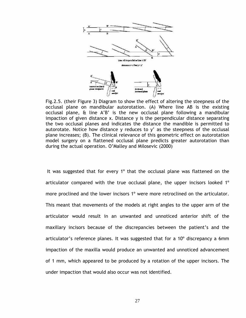
Fig.2.5. (their Figure 3) Diagram to show the effect of altering the steepness of the occlusal plane on mandibular autorotation. (A) Where line AB is the existing occlusal plane, & line A’B’ is the new occlusal plane following a mandibular impaction of given distance x. Distance y is the perpendicular distance separating the two occlusal planes and indicates the distance the mandible is permitted to autorotate. Notice how distance y reduces to y’ as the steepness of the occlusal plane increases; (B). The clinical relevance of this geometric effect on autorotation model surgery on a flattened occlusal plane predicts greater autorotation than during the actual operation. O’Malley and Milosevic (2000)
It was suggested that for every 1º that the occlusal plane was flattened on the
articulator compared with the true occlusal plane, the upper incisors looked 1º
more proclined and the lower incisors 1º were more retroclined on the articulator.
This meant that movements of the models at right angles to the upper arm of the
articulator would result in an unwanted and unnoticed anterior shift of the
maxillary incisors because of the discrepancies between the patient’s and the
articulator’s reference planes. It was suggested that for a 10º discrepancy a 6mm
impaction of the maxilla would produce an unwanted and unnoticed advancement
of 1 mm, which appeared to be produced by a rotation of the upper incisors. The
under impaction that would also occur was not identified.

28
Ellis et al (1992) undertook a study to assess the accuracy of face bow transfer of
maxillary dental casts to the corresponding articulator for the purpose of
orthognathic model surgery. Twenty-five subjects who were undergoing
orthognathic surgery were recruited for this study. The patients required
orthognathic model surgery on models mounted on an anatomical articulator prior
to their operation. The articulator system used for this study was the Hanau Model
H2 semi-adjustable articulator. The face bow for this system used the external
auditory meati for the posterior reference points, a bite fork for the maxillary
position and right orbitale as the anterior reference point. This system came with a
removable mounting jig, which according to the manufacturer properly located the
maxillary cast. The author commented that using this type of face bow only gave an
estimation of the location of the mid-point of the mandibular condyles, but by using
this method it was thought to locate the intercondylar hinge axis within a 5mm
radius of the true hinge axis.
The accuracy of the face bow transfer was assessed by comparing the angle
between the occlusal plane and the Frankfort plane obtained from lateral
cephalograms with the angle between the occlusal plane and articulator upper
cross member of the mounted maxillary models.
A lateral cephalogram was taken for each subject. A protocol was devised for taking
measurements from this allowing for the magnification that generally arose when
taking these radiographs. Four reference points were traced on each lateral
cephalogram, porion and orbitale, which were used to define the Frankfort plane,
and the most anterior incisor and the most posterior molar points, which were used

29
to define the occlusal plane. A line was drawn along the Frankfort horizontal plane
and a measurement using a compass was recorded between the orthodontic bracket
on the maxillary incisor and the bottom of the articulator cross member. This was
then transferred to the lateral cephalogram and an arc was drawn with the compass
when using the central incisor bracket; the same technique was employed for
drawing an arc using the molar reference point (Fig. 2.6). A line was then drawn
tangential to the two arcs recorded. The angle between this line and the Frankfort
plane was calculated by digitising both lines on the tracings. The angle between the
lines should have been 0º if the transfer had been accurate. The mean angle was,
however, 6.8º with a standard deviation of 3.5º. The mean value was significantly
different from 0º (paired t test, P<0.001).
Fig.2.6. The compass is used to scribe the distance on a cephalometric tracing, which included porion, orbitale (Frankfort horizontal), the incisor and the terminal molar. Ellis et al (1992)
All of the twenty-five cases showed a transfer and mounting error. Twenty-three
cases recorded an increase in the maxillary occlusal plane angle and two a

30
decrease. The differences in the occlusal plane angles with the cephalograms and
articulators were presented as histogram and appeared to show that the differences
were between -3 º and 13.5º.
This study proved that the mounting of the maxillary cast was inaccurate. Ellis et al
noted that when carrying out bi-maxillary surgery the maxilla moved into the
author’s new position predetermined by model surgery. The authors reached the
qualitative conclusion that if the maxillary-occlusal plane angle relative to the
Frankfort plane was under estimated on the articulator impacting the maxillary cast
vertically during model surgery, this would produce a wafer that would alter
inappropriately both vertical and horizontal movements during surgery.
Ellis et al devised a method to improve the accuracy of mounting, suggesting that
the mounting error could be corrected by measuring the angle between the occlusal
plane and the Frankfort plane from a lateral cephalogram and rotating the face bow
attached to the articulator to reproduce this angle. This was suggested to be the
only reliable way of measuring the angle between the occlusal plane and Frankfort
plane so as to allow the relevant corrections to be achieved. However, it is unsafe
to consider the articulator to be capable of representing the anatomical points
required in Ellis’ study. This is due to anomalies incorporated in articulator design.
Pitchford (1991) investigated three aspects of the accuracy of face bow transfers.
The first investigation of nine subjects was to determine the ability of the face-bow
to record and transfer the vertical position of the maxillary occlusal plane when the
patient’s Frankfort plane was parallel to the reference horizontal, using the

31
distance between the subject’s orbitale and upper central incisor to quantify the
accuracy of the transfer.
The position of the subject’s orbitale was located and marked. The position of the
subject’s head was adjusted to make the Frankfort plane horizontal as determined
by using a builder’s level. A Boley Gauge (a measuring caliper) was then used to
measure the distance between orbitale and the edge of an acrylic resin bar
attached to the central incisors. Allowing for the thickness of the bar gave the
distance between orbitale and the incisors. A Hanau 159-4 face-bow was placed in
the conventional manner; the subject’s head position was checked to ensure that
the Frankfort plane was horizontal and the face bow indexed to the Frankfort plane
and the horizontal using two bubble gauges mounted on the face bow. The face
bow was transferred to a Hanau 158-H2. The tip of the orbital pointer was put in
contact with the orbital indicator of the articulator and the distance between the
orbital indicator indentation in the wax record representing the central incisor was
measured. The face bow was then adjusted to render it parallel with the Frankfort
horizontal plane and the measurement was repeated. The mean difference between
orbitale and the central incisor measured from the patient and the articulator with
the orbital pointer in contact with the orbital plane which was 0.17 mm showing a
high degree of accuracy. With the face bow indexed to the horizontal Frankfort the
mean difference was 3.34mm; Pitchford suggested that this indicated that the
transfer with the Frankfort plane horizontal was “reasonably accurate”.
The second part of Pitchford’s study tested the ability of the face bow to transfer
the aesthetic reference position to the articulator. The procedure used in the first

32
part of the study was repeated, but an additional set of measurements were made
with the subject placed in the aesthetic reference position, “sitting erect, head
level and eyes gazing at the horizon”. The face bow was indexed to this position
using a second pair of bubble gauges. The mean orbitale -incisor distance measured
from the articulator using the aesthetic reference position was 13.45 mm less than
the value obtained with the orbital pointer in contact with the orbital plane, which
would increase the maxillary occlusal plane angle on the mounted casts.
The third part of the study was to determine the vertical distance between the
porion and orbitale. A steel rod bearing a spirit level was attached to an earpiece
from a Hanau face bow. Each of twenty subjects assumed a patient selected
aesthetic reference position, “standing erect with head level and eyes staring
straight ahead into a wall mirror”. The rod was levelled using the spirit level and
the vertical distance between the rod and subject’s orbitale measured. The mean
distance was 11.4 mm, with a standard deviation of 5.24 mm implying that casts
mounted using the orbitale or the aesthetic reference position would have very
different angular orientations.
Pitchford concluded that the face bow could transfer distances fairly accurately
from the patient to the articulator, but that neither the Frankfort nor the axis –
orbital plane was parallel to the reference horizontal in the aesthetic reference
position. His results indicated that the axis – orbital plane was at 13º and the
Frankfort plane 8º to the reference horizontal.

33
Although this study was carried out for the purpose of dental prostheses, the
findings were very much applicable to orthognathic model surgery. This study did
not use cephalograms, which would have determined the position of porion for
measuring the Frankfort Horizontal Plane.
Gateno et al (2001) undertook a study that compared the occlusal plane
inclination of models mounted using three different systems for the face bow
recording transfer for use with the S.A.M.2 articulator. The three different face
bows used in this study were The S.A.M. Anatomical Face bow, the Erickson Surgical
Face-bow and a new technique developed by Gateno et al that considered the
individual anatomical variations among subjects.
Twenty-two subjects were investigated and three alginate impressions were taken
for each subject and the angle between the maxillary occlusal plane and the
Frankfort plane were measured on a cephalometric radiograph.
Each patient then had a face bow recording taken according to the manufacturers’
specification. The first technique used the SAM Anatomical face bow, and the
second the Erickson Surgical face bow, which was a modified SAM Anatomical face
bow, which used nasion as well as left orbitale as an anterior reference point. The
third technique was that of Gateno et al. The vertical separation between the face
bow and bite fork was adjusted to match the value obtained from an additional
cephalographic radiograph.

34
The maxillary casts were mounted on the articulator using the different face bows,
and were then detached from the articulator and measured using an Erickson Model
Block and Platform. The vertical height of the incisal edge of the right central
incisor and the tip of mesiobuccal cusp of the right first molar and the horizontal
distance between them were measured and the angle of the occlusal plane was
calculated.
The mean occlusal plane angle of the mounted models using the conventional
S.A.M. face bow was 7.8º greater than the angle measured on the radiograph and
the Erickson Surgical Face-bow was 4.4 º greater; both these differences were
statistically significant (P<0.05). The angle produced by the method of Gateno et al
was not significantly different from that on the cephalogram. The authors
concluded that the articulator upper member was not parallel to the Frankfort
plane, confirming previous results. The method described by Gateno et al was
accurate, but required an additional radiograph, making it unsuitable for routine
use.
The effect of the occlusal plane misalignment on the surgical outcome was
investigated diagrammatically for the case when the axis-orbital plane was 12º
steeper than the patient’s value. The diagram suggested that a 10mm maxillary
advancement relative to the articulator would result in a surgical under
advancement of 1.5mm. The diagram also showed a vertical error that was
overlooked by the authors.

35
2.3. Articulators for orthognathic model surgery planning.
Various articulators and techniques have been designed specifically for orthognathic
model surgery. The aims were to simplify the movements of casts to the prescribed
positions before wafer production or allow maxillary casts to be mounted to
replicate the orientation of the occlusal plane seen in the patient. Simplified
methods of cast movement were described by Angelillo et al (1977), Schwestka et
al (1991) and Junger et al (2003).
Angelillo et al (1977) produced a device that located the upper and lower casts on
spring loaded mounting plates that held the models in place without using plaster.
The casts could be remounted at any time using the marking holes located in the
mounting posts. The upper and lower casts could be moved independently in a
lateral, vertical and antero-posterior direction and the upper cast could be rotated
to correct anterior and posterior open bites. The device was mounted on a semi-
adjustable articulator and a Whip Mix auricular face bow was used to locate the
upper cast on the articulator. The mounted casts, therefore, incorporated the error
of orientation discussed above. (Fig. 2.7.)

36
Fig.2.7. A & A provide vertical movement. B & B allow lateral movement. C & C allow anterior- posterior movement and D & D allow the casts to be rotated. Angelillo et al (1977).
The use of the S.A.M. cast positioning device (S.A.M. PrazisionstechNik GMBH:
www.sam-dental.de) was reported by Schwestka et al (1991). The positioning
device allowed 3 dimensional repositioning of either the upper or lower mounted
dental casts without sectioning the mounting plaster. The device was used in
conjunction with a S.A.M. semi-adjustable articulator and face bow. Once again the
mounted casts incorporated the error of orientation discussed previously.

37
Junger at al (2003) described the use of the three-dimensional orthognathic
surgery simulator (3-d-oss, Girrbach Co, Pforzheim, Germany) developed by
Krenkel, which allowed the independent movement of the mandibular and maxillary
casts in 3 dimensions. The paper and illustrations were rather unclear, but there
were no details of how the casts were orientated for mounting in the system. The
means for mounting casts to replicate the orientation of the occlusal plane seen in
the patent have been considered in several publications, some of which have been
reviewed above.
Gonzalez and Kingery (1968) suggested a standard way of correcting face bow
records by rotating the face bow around the intercondylar axis 5.9 º by raising the
orbital pin of the face bow by 7mm. The values were derived from their
experimental results. However, this average value correction will only be
appropriate for a few individual patients, notably those undergoing orthognathic
surgery, who may be anatomically very variable i.e. asymmetric patients.
Ellis et al (1992) and Gateno et al (2001) described correction techniques of
mounting dental casts on articulators appropriate for individual patients based on
the use of lateral cephalograms. Ellis et al (1992) suggested that the angle between
the occlusal plane and the Frankfort plane be measured from a lateral cephalogram
and the face bow attached to the articulator rotated to reproduce this angle.
Gateno et al (2001) adjusted the vertical separation between the face bow and bite
fork to match the value obtained from an additional cephalographic radiograph.
Neither method has been widely applied because of their complexity and, in the
case of Gateno et al (2001), the need for an additional unacceptable radiograph.

38
Walker et al (2008a; 2008b) stated that accurate positioning of casts was essential
for reliable orthognathic treatment planning, but that mounting dental casts on a
semi-adjustable articulator using a conventional face bow was inaccurate and
unreliable, and went on to describe the development of an articulator and face bow
system specifically for orthognathic surgery planning.
Walker et al (2008a) described the development and evaluation of a novel face
bow that could accurately transfer the relationship between the natural head
position and the absolute horizontal plane to an articulator. The reproducibility of
the natural head position was evaluated in ten normal volunteers. A mark was
placed in the right condylar region and right side near the tip of the nose, although
no reason was given for the choice of this landmark. Each subject assumed the
natural head position; the subjects sat upright on a chair, which was positioned two
meters from a full-length mirror with a vertical line on it. The subjects looked into
their own eyes reflected in the mirror, with the vertical line centralled on their
reflected image. Each subject was photographed laterally under studio conditions
on three separate occasions at intervals of an hour apart; the facial marks and the
height of the chair remained constant. A horizontal line was placed across the
image and the angle between this horizontal and a line joining the facial marks was
measured to 0.5º using a protractor (Fig. 2.8.). There was considerable difference
in angle between the subjects, but the measurements of each subject made on
different occasions were similar, showing non-significant differences (Freidmann’s
test; P >0.05). The median difference of the replicate measurements was 1.75º and

39
the 95% confidence interval of the median using a Hodges-Lehmann estimate was
1.25º.
Having established the reproducibility of the natural head position relative to the
absolute horizontal, the next stage was to construct a face bow to transfer this
relationship to a Dentatus ARH semi-adjustable articulator. The orbital pointer of a
Dentatus average value face-bow was replaced by a circular spirit level, which
could be levelled and locked in place, recording the horizontal plane. (Fig.2.9,
2.10).
Fig.2.8. Natural head position showing the head position angle. Walker et al (2008).
Six patients requiring orthognathic surgery, without serious facial asymmetry were
selected. Each patient had a lateral cephalogram taken with the head in the natural
head position. Two face bow recordings were taken for each patient, one with the

40
conventional orbital pointer and the other with the spirit level on the modified face
bow. Two sets of dental models were prepared for each subject.
A horizontal line was drawn on each subject’s lateral cephalogram parallel to the
horizontal edge of the nasion rest and the occlusal plane was drawn on the
radiograph from the central incisor tip to the lowest tip of the maxillary molar
tooth, usually the mesio-buccal cusp of the first molar.
Fig.2.9. Dentatus average value face bow with orbital pointer. Walker et al (2008a). Fig. 2.10. Dentatus average value face bow with attached circular spirit level. Walker et al (2008a).

41
Both of these lines were extended posteriorly and the angle between them
measured using a protractor (Fig.2.11.).
The angle was measured twice; the median difference between the first and second
measurement was 0.5°, and the Hodges- Lehmann 95% confidence interval of the
median was 0.5º
Following this, both the replicate casts were mounted on an articulator. One cast
was mounted using the conventional technique with the orbital pointer in contact
with the underside of the orbital plane indicator (Fig. 2.12). The second cast was
mounted using the spirit level face bow, which was positioned on the articulator
and rotated about the condylar rods by raising or lowering the anterior rod of the
face bow to centre the spirit level (Fig. 2.13).
Fig.2.11. Measurement method to determine the maxillary occlusal plane. Walker et al (2008aa).

42
Fig.2.12. Cast mounted on an average value Dentatus face bow using the orbital pin and orbital plane guide. Walker et al (2008a).
Fig.2.13. Cast mounted using spirit level face bow. Walker (2008a)
A flat plane was placed across the occlusal plane of each mounted cast and the
angle between articulator cross member and the maxillary occlusal plane was
measured (Fig. 2.14). The values of the horizontal-occlusal plane angle for each
method of mounting were compared with the mean value of the angle measured
from the cephalograms.

43
Fig.2.14. Protractor on a slide fit stand to measure the maxillary occlusal plane angle. Walker (2008a).
The differences between the measurements taken on the cephalogram and the
model mounted using the conventional face bow were found to be large. The
difference between the mean values of the angles measured from the cephalogram
and the cast mounted using the spirit level was 1.0º with a Hodges-Lehmann 95%
confidence interval of 1.25°. The equivalent values for the casts mounted using the
orbital pointer were -10.75° and 11.5°.
The differences between the three methods of obtaining the horizontal-occlusal
plane angle were highly significant (Friedmann’s test, p<0.001). There was a
significant difference between the cephalographic values and those for the model
mounted using the orbital pointer (Nemenyi’s test, p<0.005) but not for the models
mounted using the spirit level (p>0.05).
The photographic study proved that the subjects could repeatedly assume the same
head position under the same conditions. The sample size used in the second part
of the study was considered to be small, although statistically significant results

44
were obtained. This study confirmed that there were significant systematic
differences between the occlusal angle measured from the cephalogram and the
models mounted using the orbital pointer, confirming the previous criticisms
reviewed in the previous paragraphs. Models mounted using the spirit level face
bow accurately replicated the values obtained from the cephalogram and Walker et
al suggested that the novel spirit level face bow should be accepted as a new
method for mounting models on an articulator and for planning orthognathic
operations. Walker et al (2008) indicated it was possible to record the lateral angle
between the horizontal and occlusal planes (cant) using the spirit level face bow,
reflecting the asymmetry often seen in craniofacial deformity cases. It was,
however, impossible to mount casts to replicate this angle on currently available
articulators and an orthognathic articulator was required to realise the potential of
the spirit level face bow.
Walker et al (2008b) reported the design, construction and initial evaluation of an
articulator for orthognathic surgery planning. A primary design consideration was
that the articulator could adjust to fit the spirit level face-bow recording of the
patient so that no error would be built in when transferring the face-bow to the
articulator, and it would be able to incorporate the asymmetries often present in
patients undergoing orthognathic surgery. These aims were achieved by making it
possible to adjust the position of each of the condylar components of the
articulator in three directions, vertically, antero-posteriorly and laterally as well as
rotate about a vertical axis. The condylar head elements were adjustable for major
and fine adjustment of the vertical position of the condylar head. Antero-posterior
45
and lateral positions were achieved by mounting the condylar components on
curved horizontal arms with a slot cut in an arc to allow horizontal movements.
Walker et al also felt that it would be advantageous to have more space between
the lower and upper cross-members and that the movement of the mandible be
replicated by rotation of the lower cast instead of the upper cast. These
requirements were incorporated into the new orthognathic articulator. The
articulator body was made of aluminium (Fig.2.15.). The articulator consisted of a
triangular shaped base with supporting feet, a long square central pillar and a
maxillary cross member (Fig.2.16). This gave plenty of room for mounting the
maxillary and mandibular casts. The maxillary cast was mounted using a mounting
plate attached to the central pillar. The mandibular cast was positioned using a
support on the condylar component and two curved ramus frames. A spring was
used on each side of the casts to keep the casts in occlusion.
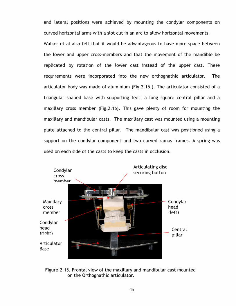
Figure.2.15. Frontal view of the maxillary and mandibular cast mounted on the Orthognathic articulator.
Articulator Base
Central pillar
Maxillary cross member
Condylar head (left)
Condylar cross member
Articulating disc securing button
Condylar head (right)

46
Figure.2.16. Lateral view of the maxillary and mandibular cast
The face bow and articulator system were evaluated on twelve patients, six with
severe facial asymmetry and six patients with no asymmetry. Lateral cephalograms
were taken for each patient and postero-anterior cephalograms taken for patients
with facial asymmetry; the nasion rest was visible in each radiograph and was used
as a horizontal reference. The postero-anterior horizontal-occlusal plane angles
were measured from each lateral cephalogram using the technique employed for
cephalograms taken in the face bow study; the lateral-occlusal plane angles,
(cants) were measured from the postero-anterior cephalograms. The distance
between the most lateral point of each condyle was identified and measured.
Face bow recordings were taken for each patient with the spirit level face bow and
used to mount upper and lower dental casts of the patient on the orthognathic
articulator. The horizontal-occlusal plane angles were measured on the maxillary
Central pillar
Spring to hold mandibular model in occlusion
Articulating disc securing button
Lock nuts for condylar posts
Condylar rotation indicators

47
casts usIng a flat Plane placed across the dentition and a protractor adapted to
allow vertical adjustment. The inter-condylar width on the cast was measured using
the vernier gauge as on the cephalograms.
The values of the occlusal plane angles obtained from the radiographs were
compared to the values obtained from the mounted casts. The results showed
considerable variation between patients, but less variation in individual patients;
the measurements obtained from the radiographs and mounted casts did not differ
significantly (Wilcoxon signed rank test, p>0.05). The paper did not report the
comparison of the inter-condylar widths, but Walker (2006) reported that there
was no significant difference between the measurements obtained from the
postero-anterior radiograph and the mounted casts (Wilcoxon signed rank test,
p>0.05).
It was suggested that in addition to the high accuracy of mounting casts, a great
advantage of the face bow and articulator system was that it was possible to mount
casts of asymmetrical faces to reproduce the cant shown clinically, unlike any other
articulator. In discussing the use of the system, the need to simplify the coupling
between the articulator and face bow was identified. Walker et al concluded that
the accurate mounting of occlusal models on the new orthognathic articulator
would improve orthognathic planning and prediction, but that the assumption
needed to be verified.
This system is unique in that it was designed specifically for orthognathic surgery
planning. It would be presumed that using this new articulator system would enable

48
the production of more accurate surgical wafers, which in turn would aid accurate
orthognathic surgery to be carried out. A further evaluation of the practical
application of the system is required.
2.2.Summary.
Although a few attempts have been made to construct orthognathic articulators
using available semi-adjustable articulators for the purpose of orthognathic model
surgery, there are none commercially available that take into consideration the
inaccuracies that arise when the corresponding face bow is transferred to the
articulator. Walker et al (2008a), (2008b) has taken into consideration and
highlighted all the shortfalls and limitations of the systems available and developed
a system that overcomes these problems. Walker’s system was designed especially
for planning craniofacial deformity patients where the position of the condyles
could be asymmetric.

49
3
AIMS AND OBJECTIVES

50
Aims and Objectives.
Hypothesis:
The null hypothesis of the study proposes that the new orthognathic articulator
system is not more accurate than the standard articulator system presently used.
The literature reviewed in the preceding chapters suggested that there was
evidence that:
• The final outcome of surgery using perioperative wafers prepared on
commercially available semi-adjustable articulators may differ from the
prediction plan.
• Casts mounted that have been articulated on semi-adjustable articulators
using the corresponding face bows following the manufacturers guidelines
have systematic errors of cast orientation.
• There were suggestions that there is a connection between misalignment of
the casts used for model surgery and inaccurate surgical outcomes but there
has been no reliable objective evidence to support these suggestions, only
from individual case histories.
This gave the motivation to undertake this study, the first aim of which was to
investigate the errors produced by cast misalignment.
The specific objectives were to:
• Demonstrate whether the misorientation of casts mounted on conventional
semi-adjustable articulators produced errors in the maxillary cast movements
at the time of model surgery.

51
• Develop a mathematical model to quantify the magnitude of the errors
occurring during movement of the casts.
• To experimentally validate the mathematical analysis.
There appeared to be only one face bow and articulator system specifically
designed for orthognathic model surgery planning. The natural head position was
used to reproduce on the articulator the maxillary occlusal plane angle seen in the
patient. Although the accuracy of the cast orientation had been established, the
accuracy of the perioperative wafers constructed on the orthognathic articulator
remained unknown. This fuelled motivation to undertake a study to evaluate the
Orthognathic Articulator system, the aim of which was to compare the accuracy of
the Orthognathic articulator system with a Standard semi-adjustable articulator
system.
The specific objectives were to:
• Mount plastic skulls and adjust their angulations to represent subjects with
differing natural head positions.
• Mount dental casts taken from the plastic skull on both a Standard Dentatus
semi-adjustable articulator and on the Orthognathic articulator.
• Compare the accuracy of outcome of simulated orthognathic surgery using
inter-occlusal wafers prepared on each articulator.

52
4
ERRORS PRODUCED BY CAST MISALIGNMENT

53
The vertical and horizontal displacements prescribed by the surgeon are relative to
a set of reference axes, the horizontal axis being parallel to a horizontal plane with
the head in its natural position and the vertical axis at right angles to the horizontal
axis; these axes will be called the reference horizontal and vertical axes.
Conventional articulators and face bows have been designed to replicate a few
interdental occlusal relations, not to reproduce the position of important
anatomical features relating to the maxilla and skull O’Malley & Milosevic(2000),
Walker (2008a). The maxillary cast was mounted relative to the horizontal axis
defined by the upper cross member of the articulator, which often differed
significantly from the reference horizontal axis and anatomical planes such as the
Frankfort plane which was assumed to be horizontal, Bamber & Harris (2001),
Downs (1956), Ferrario, et al (2002), O’Malley & Milosevic (2000), Pitchford
(1991), Walker (2008).
The difference between the axes based on the articulator cross member and on the
natural head position is shown in Fig.4.1, in which a maxillary model has been
mounted on an articulator cross member that is horizontal. The axis Ha is parallel
with the articulator cross member and Va at right angles to Ha. The reference
horizontal and vertical axes, Hr and Vr, are also shown. Ideally both sets of axes
should coincide, but mounting models using a conventional face bow produces the
discrepancy of orientation discussed above and there is an angle θ between the two
sets of axes.
In the laboratory the prescribed displacements of models have been made relative
to the axes based on the cross member of the articulator, not in relation to the

54
reference horizontal and vertical axes that were used by the surgeon to define the
displacements required.
Va Vr Hr θ Ha Fig.4.1.The axes based on the articulator cross member are at an angle θ to the reference axes based on the natural head position.
This would produce erroneous and inaccurate occlusal wafers, which are used
routinely to reposition the maxillary segment perioperatively. The magnitude of the
inaccuracies depended on the discrepancy between the orientation of the reference
horizontal axis, and the horizontal axis based on the articulator cross member;
differences of up to 20º have been reported, Walker (2008b). Out of six cases
Walker carried out, the results of the maxillary occlusal plane angle study were
found to overestimate the maxillary occlusal plane angle and two of the cases
showed errors of -20º and –20.5º.

55
4.1 Qualitative illustration.
Movement of a model relative to axes (Ha and Va) based on the articulator on which
it is mounted also produces movements of the model relative to the reference axes
(Hr and Vr ) based on the patient’s natural head position, but the magnitude of the
movements will be different. This is shown in (Fig.4.2), in which the reference axes
are at an angle θ to the articulator axes.
Fig.4.2. Model displaced by a distance AB parallel to the axis Ha parallel to the articulator cross bar produces displacements relative to the reference axes Hr and Vr.
The horizontal axis Ha was parallel to the articulator cross bar. A horizontal
movement of the maxillary model by a distance ha (shown as the line AB in Fig.4.2.)
produce two movements of the model relative to the rotated reference axes Hr and
Vr, a movement AC (distance hr) parallel to Hr and a movement CB (distance v r)
parallel to Vr ; these were horizontal and vertical movements relative to the
reference axes. ABC is a right angle triangle with AB as the hypotenuse and hence hr
was smaller than ha; vr was greater than va, which was equal to zero for a horizontal
movement relative to the articulator axis.
Thus relative to the reference axes the model is under-advanced and down-grafted.

56
4.2. Mathematical analysis.
Mathematical analysis of the general case of model movements both parallel and at
right angles to the articulator axes (Appendix 1) showed that movements relative to
the articulator and to reference axes at an angle θ to each other are related by the
equations
hr = ha cos θ + va sin θ Eqn 1a
and vr = va cos θ - ha sin θ. Eqn 1b
The magnitude of the vertical and horizontal errors depended on the magnitude of
the movements made relative to the articulator and to the angle between the
articulator and reference axes.
Graph 4.1. showed how the vertical and horizontal errors, ∆ vr and ∆ hr depend on
the magnitude of the vertical movement of the cast relative to the articulator for
an advancement of 10 mm. The graphs were linear because both the advancement,
ha, and the angle, θ, between the articulator and reference axes were constant.
The greatest error was 4 mm in a movement of 10 mm.

57
-5
-4
-3
-2
-1
0
1
2
3
4
-10 0 10
Vertical movement, mm.
Err
or,
mm
-5
-4
-3
-2
-1
0
1
2
3
4
5
-30 -20 -10 0 10 20 30
Angle, degrees
Err
or,
mm
∆hr
∆vr
Graph 4.1. The dependence of the vertical and horizontal errors, ∆vr and ∆hr, on the vertical movement, va. The horizontal movement, ha, was an advancement of 10mm. θ is 20º.
The dependence of the error on the angle θ was more complicated because it
depends on trigonometric functions of the angle. Graph 4.2. showed a typical result
and over the restricted range of θ of clinical relevance, the relationship was only
approximately linear.
∆vr
∆hr
∆vr
∆hr
Graph 4.2. The dependence of the vertical and horizontal errors, ∆vr and ∆hr, on θ. The horizontal movement, ha, was an advancement of 10 mm and the vertical movement, va, was a downgraft of 10 mm.

58
4.3 Experimental Photographic study to confirm mathematical analysis.
The validity of the equations derived theoretically were evaluated by an
experimental photographic study in which dental casts were moved parallel and
normal to a horizontal articulator axis and the resulting movement relative to a
reference axis at 20º to the articulator axis was determined by image analysis.
4.3.1 Materials and Methods:
The Orthognathic Articulator was reproducibly located on a drilled wooden board
placed upon a chair which was firmly secured and parallel to the wall; the feet of
the articulator were located and secured in holes pre-drilled in the board. This was
done in order to prevent any lateral, posterior or anterior movement. The base and
top arm of the articulator were then levelled using a spirit level.
A maxillary cast had been previously mounted on the Orthognathic Articulator using
a metal cast mounting plate and a threaded rod. The upper arm of the articulator
had been set horizontal using a spirit level. The sides of the plaster block were
trimmed at right angles using a set-square to ensure uniformity. Spacers were used
to produce defined, accurate and reproducible vertical movements. Two aluminium
spacers were constructed, one 10mm thick and the other 20mm. Slots were made in
the spacers to ensure their easy positioning whilst the images were being taken. A
10mm spacer was used to represent the start position of the maxilla so that the
spacer could be removed, producing a 10mm impaction. Replacing the 10 mm
spacer with the 20mm spacer produced a 10mm downgraft.

59
Horizontal movements were standardized by drilling three holes 10 mm apart
through the cross bar. The model was initially mounted using the central hole, but
could be moved 10 mm forwards or backwards by remounting the model using one
of the additional holes.
In order to eliminate parallax errors when viewing and photographing the model, a
red reference point was marked on the model and two plumb line threads hung
vertically in front of a red reference mark and aligned so that they superimposed
when viewed at right angles to the model (Fig.4.3.).
A second black reference point was used to define the position of the models.
.
Fig.4.3. Maxillary model in initial position. Each of the two red threads supports a
brass bob.

60
A matrix was constructed using lab putty that would cover the posterior side of the
mounting plaster. The maxillary cast, the top arm and vertical post of the
articulator were then incorporated in this matrix. This would ensure that no
rotational movement was incorporated when the cast was moved into the different
positions. A ruler was placed vertically within the picture frame so that the image
could be sized, and to ensure that the scale was demonstrated to be one to one.
The photographs were taken using a Nikon D1x digital camera, with a 105mm macro
lens. A qualified photographer positioned the camera using a tripod stand thus
ensuring it was parallel to the wooden base that located the articulator. The
camera was leveled using a spirit level. The camera was set at right angles to the
model by moving it laterally until the plumb lines superimposed and ran through the
centre of the red reference point. A white background was used during the taking
of the images to ensure a clear representation of the specimen being photographed.
Two Broncolor miniplus C80 flash heads were placed at 450 angles to ensure even
lighting of the subject. To ensure the highest quality, photographs were taken using
NEF files.
A photograph was taken of the model in its initial position. The model was then
moved relative to the articulator cross bar by defined distances and re-
photographed.
The first image was taken in the start position using the 10mm spacer (Fig.4.4.).
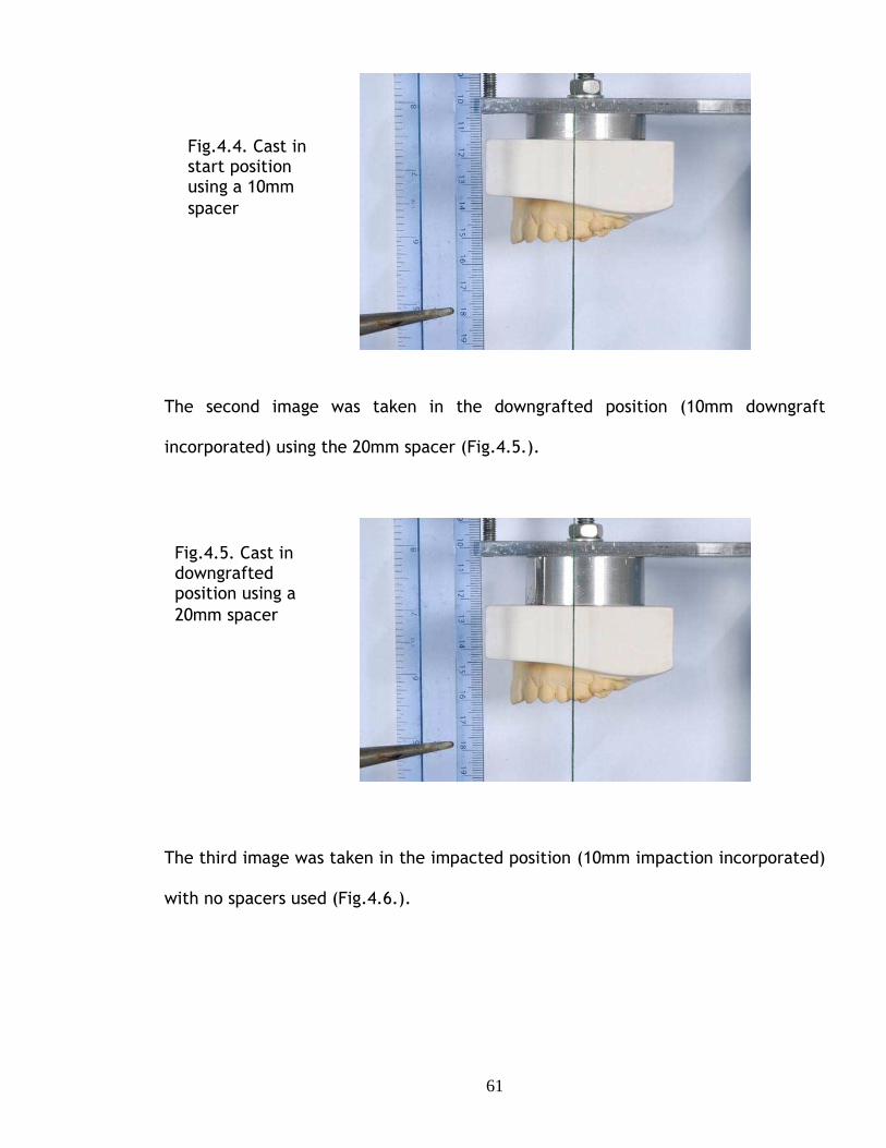
61
The second image was taken in the downgrafted position (10mm downgraft
incorporated) using the 20mm spacer (Fig.4.5.).
The third image was taken in the impacted position (10mm impaction incorporated)
with no spacers used (Fig.4.6.).
Fig.4.4. Cast in start position using a 10mm spacer
Fig.4.5. Cast in downgrafted position using a 20mm spacer

62
The digital images were transferred to a computer and sized one to one using the
image of the reference ruler. The digital images were then analyzed by a graphic
designer using Adobe Photoshop CS3 Illustrator computer package.
An image of the model in the displaced position was super-imposed over the image
of the model in the initial position. The opacity of the superimposed image was
reduced to 60% so that the black reference marks on both models were visible.
A line was superimposed on the threads to produce a vertical articulator axis. A line
was drawn at 70º to this vertical axis to produce a reference axis at 20º to the
articulator horizontal axis (Fig.4.7.).
Fig.4.6. Cast in impacted position no spacers incorporated

63
Fig.4.7. Superimposed images of model in initial and displaced positions. Vertical and parallel lines pass through the black reference mark on the model in the displaced (A) and initial (B) position.
Vertical and parallel lines pass through the black reference mark on the model in
the displaced (A) and initial (B) positions (Fig.4.7.).
The co-ordinates of the black reference points were recorded and lines parallel and
at right angles to the reference axis were drawn through each of the reference
points.
The lengths of the sides of the resulting rectangles, which were equal to the
horizontal and vertical displacement of the models relative to the reference axis,
were calculated from the coordinates of the corners of the rectangle. Two
estimates of the displacements were obtained from each rectangle and the analysis
was repeated to produce four values.
Lines at right angle to 20º reference axis. Lines parallel to reference 20º axis.
A
B

64
4.3.2 Results.
The values of the displacements of the models relative to both the articulator and
reference axes are shown in Table 4.1. Each of the values of the measured
displacements relative to the reference axis was the mean of the four values
mentioned above.
Direction and distance, mm, of movement relative to articulator axis.
Direction and distance, mm, of movement relative to reference axis.
Up Movement Measurement Theory ha = 0.0 h20 3.40 3.42 va = 10.0 v20 9.43 9.40 Down ha = 0.0 h20 -3.62 -3.42 va = -10.0 v20 -9.34 -9.40 Forward ha = 10.0 h20 9.46 9.40 va = 0.0 v20 -3.30 -3.42 Forward +Up ha = 10.0 h20 12.84 12.82 va = 10.0 v20 5.83 6.00 Forward+down ha = 10.0 h20 6.25 6.00 va = -10.0 v20 -12.84 -12.82
Table 4.1. Comparison of theoretical predictions and experimental measurements.
Horizontal and vertical movements, ha and va, relative to articulator axes produced
displacements, v20 and h20, parallel, and at right angles to, reference axes at 20º to
articulator axes. Forward (advancement) and up grafting movements were positive.
hA = Movement parallel to articulator cross bar (horizontal).
vA = Movement normal to articulator cross bar (vertical).
h20 = Movement parallel to 20º axis.
v20 = Movement normal to 20º axis.

65
The results were also shown graphically in the Graph 4.1., together with statistical
parameters. The R2 value of 0.998 indicated that the there was a strong and highly
significant linear correlation between the predicted theoretical values of the
displacement and the experimental values obtained by image analysis of the
photographs.
Calculation of the 90% confidence limits of the values of the intercept and gradient
of the line of best fit in the Graph 4.3. show that the values of 0.0069 for the
intercept was not significantly different from 0 and the value of 1.0069 for the
gradient was not significantly different from 1 ie the best straight line was not
significantly different from the line of identity Measured value = Theoretical value.
Chart Title y = 1.0023x + 0.0069
R2 = 0.9998
-15
-10
-5
0
5
10
15
-15 -10 -5 0 5 10 15
Theory,mm
Mea
sure
men
t, m
m
Graph 4.3: A statistical representation of the correction between the predicted
theoretical values of the displacement and experimental values obtained. Data
from table 4.1.
4.4 Conclusion:
The mathematical analysis presented above quantifies the errors produced by
discrepancies between the reference and articulator axes. The experimental study
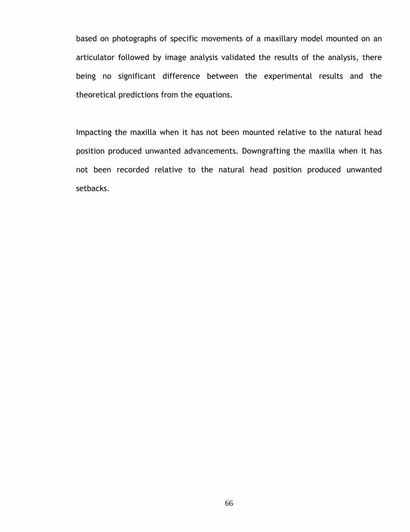
66
based on photographs of specific movements of a maxillary model mounted on an
articulator followed by image analysis validated the results of the analysis, there
being no significant difference between the experimental results and the
theoretical predictions from the equations.
Impacting the maxilla when it has not been mounted relative to the natural head
position produced unwanted advancements. Downgrafting the maxilla when it has
not been recorded relative to the natural head position produced unwanted
setbacks.

67
5
EVALUATION OF AN NEW ORTHOGNATHIC ARTICULATOR SYSTEM

68
The results reported in the previous chapter implied that the occlusal wafers
produced on casts mounted on a semi-adjustable articulator would be inaccurate.
Walker et al (2008a,b) described an orthognathic articulator and face bow system
for orthognathic model surgery based on the reproduction of the patient’s natural
head position, that would eliminate the systematic errors of cast orientation that
occur with the use of semi-adjustable articulators, and they suggested that wafers
prepared on the orthognathic articulator would be more accurate, leading to an
improved surgical outcome.
No direct validated evidence was presented to support this claim. This has now
been evaluated in order to determine whether the orthognathic articulator did,
indeed, produce more accurate results.
5.1 MATERIALS AND METHODS.
The accuracy of perioperative wafers constructed on a Standard semi-adjustable
and an Orthognathic articulator were compared by carrying out simulated surgery
on five plastic model skulls where the “natural head position” could be predictably
altered.
5.1.1. Plastic Model skulls.
The plastic model skulls (K_Med Uk) used for this study were similar but not
identical. A mounting plate was incorporated into the underside of the skull using
cold cure acrylic resin. (Fig. 5.1).

69
Fig.5.1. Mounting plate attached to the base of the skull.
Duplicate impressions were taken of the maxillary and mandibular dentition using
silicone-duplicating material (Metrosil, Metrodent Ltd); Bone screws were screwed
through the condylar head of the mandible and the fossa to ensure a fixed path into
centric occlusion.
A line was drawn on the maxilla to replicate the position of a Le Fort I osteotomy
cut. Holes were drilled above and below this line at the zygomatic buttress and the
pyriform aperture, on the left and right sides, anterior-posteriorly. Sufficient room
was left for a 5mm impaction. 0.5 mm lengths of 0.7mm stainless steel wire were
fed into the drilled holes and were glued into place. These wires were used as
reference points for measurements. Four brass plates representing bone plates
were adapted to the pyriform aperture and zygomatic areas of the maxilla, bridging
where the Le Fort I cut would be. Two screw holes were drilled at each end of the
vertical plate for 2mm diameter cortical titanium screws to be inserted to fix the
bone plates to the maxilla (Fig. 5.2).
Mounting plate fixed using cold cure acrylic
Attachment to fix skull to measuring device

70
Fig. 5.2. Brass plates with cortical titanium screws fixing the maxilla in place.
A centric registration of the bite of the upper and lower dental arches was taken in
rubber base impression material. The lower portion of the maxilla was then
detached from the plastic skull by carrying out the Le Fort I osteotomy cut and re-
attached it to the skull using the pre-fixed bone plates in the centric bite position.
The skulls were then attached to a custom made measuring device made from a
44.5cm x 28cm x 0.635mm rectangle aluminium base plate. Adjustable feet made
of 7mm threaded stainless steel bolts with 1.3mm nuts to secure them in place,
each with rubber attachments were attached at each corner of the plate.
(Fig.5.3.).
Fig. 5.3. Custom measuring device base.

71
Spirit levels were attached to the plate to ensure accurate levelling. (Fig. 5.4.).
Fig.5.4. Spirit levels attached to measuring device base.
An aluminium rod 4cm in diameter and 14.5cm long was fixed in the centre of the
base plate of the measuring device. The upper end of the rod carried a plate that
had been taken from a tripod stand used previously for supporting a camera, which
incorporated a ball joint that could be rotated and locked into position. (Fig.5.5b.).
(a) (b)
Fig.5.5a&b. Aluminium rod with tripod attachment in place.
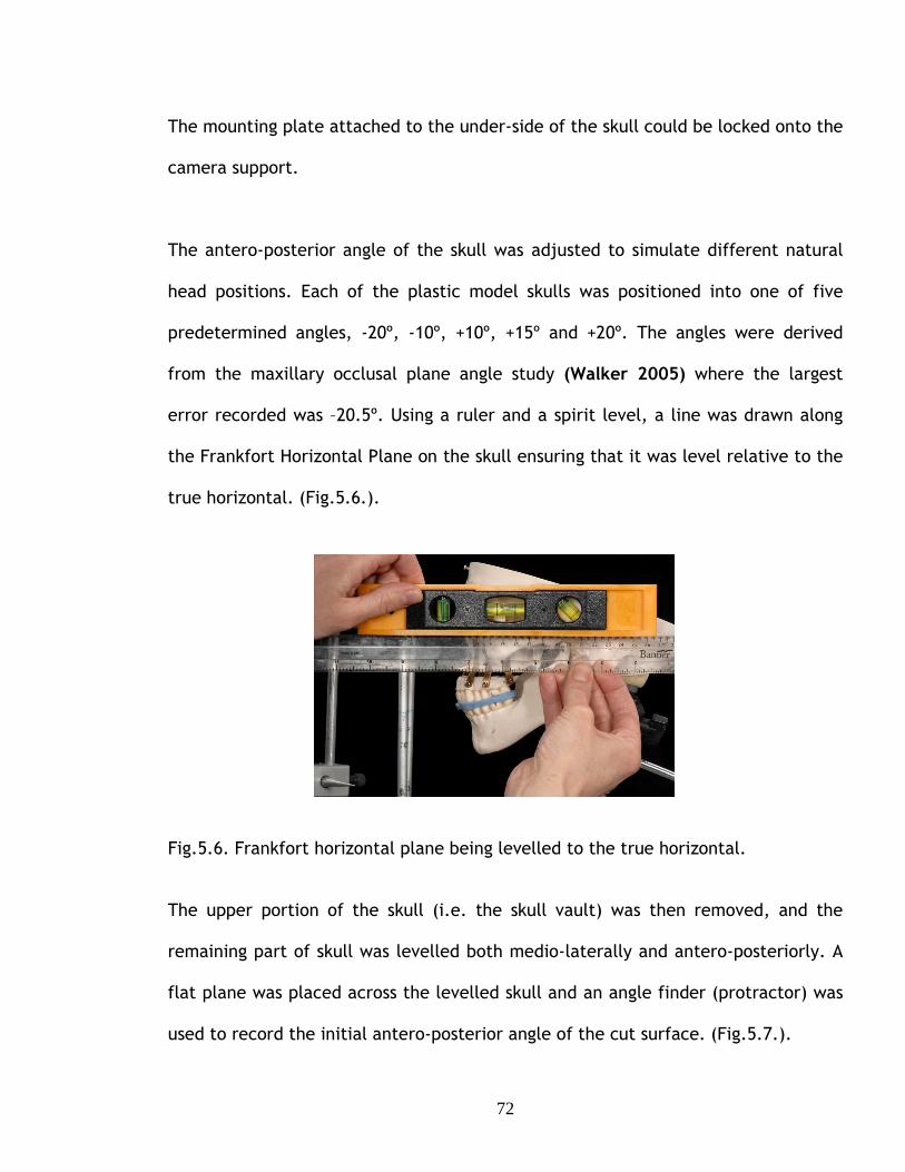
72
The mounting plate attached to the under-side of the skull could be locked onto the
camera support.
The antero-posterior angle of the skull was adjusted to simulate different natural
head positions. Each of the plastic model skulls was positioned into one of five
predetermined angles, -20º, -10º, +10º, +15º and +20º. The angles were derived
from the maxillary occlusal plane angle study (Walker 2005) where the largest
error recorded was –20.5º. Using a ruler and a spirit level, a line was drawn along
the Frankfort Horizontal Plane on the skull ensuring that it was level relative to the
true horizontal. (Fig.5.6.).
Fig.5.6. Frankfort horizontal plane being levelled to the true horizontal.
The upper portion of the skull (i.e. the skull vault) was then removed, and the
remaining part of skull was levelled both medio-laterally and antero-posteriorly. A
flat plane was placed across the levelled skull and an angle finder (protractor) was
used to record the initial antero-posterior angle of the cut surface. (Fig.5.7.).

73
Fig.5.7. Angle finder (protractor) placed on the remaining part of skull. The antero-posterior orientation of the skull was then adjusted until the desired
angle plus the initial angle was achieved. (Fig.5.8.).
Fig.5.8. Adjusting the skull to achieve the angle required.
Once the skull was fixed in the angular position required a circular spirit level was
fixed using cold cure acrylic to the top of the skull. (Fig.5.9a&b). The spirit level
was positioned so that it was level. This would ensure the correct position of the
skull and that it remained so throughout the study.

74
Fig.5.9.a&b. Circular spirit level secured to top of skull.
The mandible was fixed in centric occlusion using a lab putty matrix supported by a
face bow bite fork attached to an anterior vertical rod. (Fig.5.10.).
Fig 5.10. Skull with fixed mandible.
Adjustable anterior attachment

75
5.1.2. Wafer construction and simulated surgery.
Duplicate impressions were taken of the maxillary and mandibular dentition using
silicone-duplicating material (Metrosil, Metrodent Ltd), which were then cast in a
hard stone according to the manufacturer’s specification. A face bow recording was
taken of the skull in the start position using the Orthognathic face bow, (Fig.5.11.)
which used spirit levels and the Standard face bow, which used an orbital pointer.
(Fig.5.12.).
Fig.5.11. Face bow recording using the face bow appropriate to the Orthognathic articulator.
Fig.5.12. Face bow recording using the face bow appropriate to the Standard articulator.

76
A maxillary cast was then mounted on both the Orthognathic and the Standard
articulators using the appropriate face bow.
Three maxillary movements were carried out for each skull:
1. Forward 10 mm
2. Forward 10mm & up (impaction) 5mm
3. Forward 10mm & down (downgraft) 5mm
When carrying out the articulating procedure a 5mm aluminum disc was positioned
between the underside of the articulator’s upper cross member and the articulating
disc, this would be known as the “start position” (Fig.5.13.). Removal of the disc
impacted the cast by 5mm. Replacing the 5mm disc with one 10mm thick produced
a 5mm downgraft.
Fig.5.13. Maxillary cast mounted using aluminium disc. The mandibular cast was articulated using a centric rubber based registration bite.
The mandible was fixed in centric occlusion using a lab putty matrix. Horizontal
advancement of the cast to simulate model surgery was made using a hole in the
upper cross members of each articulator, 10mm in front of the hole used to mount
the cast in the start position.
Aluminium Articulating
disc

77
Two thin surgical acrylic wafers had been constructed previously in cold cure clear
acrylic on duplicated upper and lower casts. These were then placed on the
articulated casts that had undergone the necessary displacements. The wafers were
trimmed occlusally until there was tooth-to-tooth contact between the upper and
lower dentition also ensuring that the incisal pin was touching the anterior table.
The wafers were then sealed together with sticky wax. This was now the final
perioperative wafer. (Fig.5.14.).
Fig.5.14. Perioperative wafer with maxilla and mandible occluding.
Standard (a) Orthognathic (b) Fig.5.15a&b. Standard and Orthognathic articulators with predicted movements carried out on the upper model and surgical wafer in place.

78
The maxilla of the model skull was detached by removing the custom-made bone
plates from the pyriform aperture and zygomatic buttress. The maxilla was
repositioned using the perioperative wafer constructed firstly on the Standard
articulator, simulating surgery. The mandible was in a fixed position, the wafer was
fitted to the mandibular teeth and then the detached maxilla was positioned with
the dentition occluding the wafer and mandibular teeth. Dental sticky wax was
used to seal the maxilla in place and re-attach it to the skull. (Fig.5.16.).
The procedure was repeated using a wafer constructed using the orthognathic
articulator.
Fig.5.16. Maxilla repositioned using the perioperative wafer held in place with sticky wax.
The process was carried out twice for each of the five angles i.e. for ten plastic
skulls. The mandible was in a fixed position so there would always be a fixed point
of reference as the simulated surgery was carried out only on the maxilla. The
mandible was also de-rotated when there was a downgrafted displacement, but this
was calculated accordingly to allow for this displacement.

79
5.1.3 Measurements and measuring frame.
The displacement of six reference points and the maxillary occlusal plane angle
were used to quantify the movements of the maxilla after simulated surgery.
The simultaneous displacements carried out were:
1. Antero-Posterior movement, using a reference point on the upper left central
incisor. (Fig.5.17.).
2. Anterior vertical movement measured between a reference point at the
nasion to the left central incisor tip.
3. Posterior vertical height right side measured between two reference points
previously placed above and below the Le Fort I cut line on the plastic skull.
(Fig.5.17.).
4. Posterior vertical height left side measured between two reference points.
(Fig.5.17.).
5. Anterior vertical height right side measured between two reference points.
(Fig.5.17.).
6. Anterior vertical height left side measured between two reference points.
(Fig.5.17.).
Fig.5.17. Reference points used to quantify the movements of the maxilla after simulated surgery.
Antero-posterior reference point
Anterior reference points
Posterior reference points

80
Measurements were made with the skull supported in the measuring frame. A 8mm
aluminium measuring rod was attached vertically to the base plate of the device
opposite the frontal position (Fig.5.18).
Fig. 5.18. Aluminium rod attached horizontally by a clamp.
A 8mm rod with a pointer at one end was attached horizontally using a clamp that
allowed the rod to be moved antero-posteriorly and vertically.
The antero-posterior measurement was taken by bringing the pointed tip of the
horizontal rod into contact with the reference point on the upper left central
incisor and measuring the length of rod protruding from the clamp using a
electronic digital calliper with a resolution of a hundredth of a mm.
Vertical measurements were made using a vertical height calliper (Chesterman,
Sheffield) with an analogue vernier scale with a resolution of 0.5mm. (Fig.5.19.).
The maxillary occlusal plane angle was measured relative to the true horizontal
using a flat plane and a protractor adapted with a sliding fit on a right-angled stand
Walker et al (2005). This allowed the measure of the anterior-posterior angle and
the medio-lateral angles.
Clamp
Vertical rod with adjustable clamp
Horizontal aluminium rod

81
Fig.5.19. Plastic skull set in a predetermined angle with the vertical calliper for measurements.
Measurements were made on the skull in the start position prior to and after
simulated surgery and the changes in the position of the maxilla were calculated.
The full process was duplicated to reduce any error in the method.
Fig.5.20. Protractor on a sliding fit stand measuring the maxillary occlusal plane angle.
Vertical calliper Aluminium
central pointer
Lab putty matrix to fix mandible
Measuring pin
Protractor
Sliding fit stand

82
5.2. Results.
The results were displayed as histograms and Bland – Altman plots and analysed
using a non-parametric test; each value was the mean of two measurements. The
errors analysed were the difference between actual and predicted movements
calculated for both the Standard articulator and the Orthognathic articulator;
where the actual movement was greater than the predicted movement the
difference was written as positive and as negative when it was less.
Using a sign to denote the direction of movement was useful for displaying the
nature of the errors, but produced statistical problems. The effect on the
calculation of the mean value has been outlined in Chapter 1, but using positive and
negative values also produced a problem in the non-parametric statistics, which is
best illustrated by an example. An error of 3mm is obviously greater than an error
of 0mm, but if there is under-advancement the 3mm error will be recorded as -
3mm; 0 is larger than -3 and hence the 0mm will be classified as the greater error
when ranking the results for statistical comparison.
To eliminate the statistical problems the absolute values of the errors, without a
sign, were used. Both the errors with signs and the absolute errors without signs
were displayed.
The errors that occurred for the Standard and the Orthognathic articulator were
displayed as histograms, with summary statistics. The histograms immediately
showed the distribution of the grouped data and the errors of the axes for both
articulators and the same scale was used to further simplify the comparisons. The
x-axis showed the magnitude of error; the y-axis showed the frequency of the error.
Each of the 30 results was the mean of two measurements.

83
The errors produced by the two articulators were compared visually as Bland
Altman graphs. (Bland and Altman, 1986). The y-axis of the Bland Altman plot
showed graphically the individual errors of the Standard articulator (shown in red)
and of the Orthognathic articulator (shown in blue). The x-axis was arbitrary and
was the distance between a fixed datum point and the tooth used to measure the
movement of the maxillary cast, which was identified for each comparison; the x-
value shown for each error value was the mean measurement for each articulator.
Ideally points should cluster close to 0, which represented no difference between
the predicted movement plan and the actual movement. The spread of the error
values indicated the variability of the error, with a narrow spread indicating
consistency of a limited error. The magnitude and variability of the errors were
characterized by the mean value (m) and standard deviation (s) of the errors. The
graphs showed the mean error for each articulator (solid line) and the 95%
confidence limits, defined as m ± 2s (dotted line). Finally, the differences
between the absolute errors of the Standard and the Orthognathic articulators
were compared statistically using the non-parametric Wilcoxon signed rank test.
The test was a non-parametric analogue of a paired sample t-test. (Zar, 2010).
The comparison of the analysis of both the signed and absolute errors will be
treated in Chapter 6 Discussion and Conclusions.
The study produced a large amount of data. The results and analysis of the
vertical and horizontal errors measured at the central incisors are presented in
full in this Chapter. The other vertical errors are shown in full in Appendices 1a-
4d and in a summary presented in this chapter.

84
5.2.1 Antero-posterior errors -central incisor.
Predicted movement - Standard articulator4.002.000.00-2.00-4.00-6.00
Fre
quen
cy10
8
6
4
2
0
(a) (b)
Graph 5.1a&b. Antero-posterior errors in mm Standard and Orthognathic
articulators.
The histograms showed that the errors for the Standard articulator (Graph 5.1a.)
ranged from –6mm to +2.5mm, mean = -1.03mm and the standard deviation =
1.621mm; the errors for the Orthognathic articulator (Graph 5.1b.) ranged from –
0.75mm to +1.50mm, mean = 0.11mm and the standard deviation = 0.569mm.
The histograms showed that the errors for the Standard articulator were mostly
negative errors, (an under-advancement of the maxilla) whereas the Orthognathic
articulator errors were mostly positive, (over-advancement of the maxilla). This
exacerbated the problem of ranking the results for statistical analysis mentioned
above. The Standard deviation for both articulators showed that the Orthognathic
articulator was more consistent and the errors there were smaller than the
Standard articulator. The histograms also showed a lack of symmetry of the errors
of both articulators.
Predicted movement - Improved articulator4.002.000.00-2.00-4.00-6.00
Fre
quen
cy
10
8
6
4
2
0
- Orthognathic articulator

85
Abs Predicted movement - Standard articulator5.004.003.002.001.000.00
Fre
quen
cy
10
8
6
4
2
0
Abs Predicted movement - Improved articulator5.004.003.002.001.000.00
Fre
quen
cy
10
8
6
4
2
0
(a) (b)
Graph 5.2a&b. Antero-posterior absolute errors in mm Standard and Orthognathic
articulators.
Graph 5.2a. showed that the absolute errors for the Standard articulator ranged
from 0mm to 5mm, mean = 1.53mm, with a standard deviation = 1.136mm; the
errors for the Orthognathic articulator (Graph 5.2b) ranged from 0mm to 1.50mm,
mean = 0.47mm, with a standard deviation = 0.324mm.
There was still a marked difference between the mean error for the Standard
articulator and the Orthognathic articulator, which was in favour of the
Orthognathic articulator.
Using absolute errors increased the mean error for both articulators, because
positive and negative errors no longer cancelled each other, but the effect was
greater for the Standard articulator, which had a predominance of negative errors.
Using either the signed or absolute errors showed the Orthognathic articulator had
a smaller mean error than the Standard articulator.
- Orthognathic articulator

86
125.00 120.00 115.00 110.00 105.00 100.00 95.00
4.00
2.00
0.00
-2.00
Abs mean of predicted movement and articulator
Signed errors (a) Absolute errors (b)
Graph 5.3a&B. Bland Altman plot showing antero-posterior errors (vertical axis) of Standard and Orthognathic articulators.
Bland Altman plot of the signed errors (Graph 5.3a.) confirmed the results shown
in the histograms. The Orthognathic articulator (Graph 5.3b.) showed smaller
errors, the mean being closer to zero than for the Standard articulator, which also
displayed a much greater variability, as shown by the separation of the 95%
confidence limits. This was difficult to interpret and it was compounded by the
fact that the lower 95% limit of agreement for the orthognathic articulator (blue
dashed) sat exactly on the solid line for the standard articulator.
The data in Graph 5.3a appeared to fall into five separate groups, which were
found to relate to the angulations of the skull. The boxed numbers in Graph
5.3a.e.g. 20 deg + or - represented the chosen angle the plastic skull was set at.
It can also be noted that the magnitude of errors increased with extreme change
of the maxillary plane angle at -20º and +20º. This was readily detected with the
standard articulator but not apparent with the Orthognathic articulator.
125.00120.00115.00110.00105.00100.0095.00
4.00
2.00
0.00
-2.00
-4.00
-6.00
15 deg +
20 deg +
10 deg +
10 deg -
20 deg -
Mean of predicted movement and articulator
hognathic articulator

87
The Bland Altman plot of the absolute errors (Graph 5.3b) confirmed the results
shown in the histograms. The Orthognathic articulator showed smaller errors, the
mean being closer to zero than the Standard articulator. There were, however, a
band of errors of c. 0.5mm for the Standard articulator
The Wilcoxon comparison of the absolute measures showed that the Orthognathic
articulator showed larger error in 6 of the 30 paired comparisons. The value of the
Wilcoxon parameter, z, was –3.877. The difference in the errors of the two
articulators was highly significant, P<0.000.
5.2.1 Vertical errors -central incisor. N.3 Results. Anterior Vertical Height – (central in cisor).
abs Predicted movement - Standard articulator8.006.004.002.000.00-2.00
Fre
quen
cy
20
15
10
5
0
(a) (b) Graph 5.4a&b. Vertical errors in mm, Central incisor. Standard and Orthognathic
articulators.
The Histograms showed that the errors for the Standard articulator (Graph 5.4a.)
ranged from –4mm to 7mm, mean = 0.45mm and the standard deviation = 2.647mm;
Predicted movement - Improved articulator7.505.002.500.00-2.50
Freq
uenc
y
15
10
5
0
- Orthognathic articulator

88
the errors for the Orthognathic articulator (Graph 5.4b.) ranged from –2mm to
4mm, mean = 0.33mm and the standard deviation = 1.003mm.
The Standard articulator showed the larger error of the two articulators although
the Orthognathic articulator still had a considerable error, resulting from
systematic errors in the production of the wafers and of measurements.
The standard deviation showed that the errors of the Orthognathic articulator were
smaller and more consistent.
The histograms again showed a lack of symmetry of the errors for both articulators.
abs Predicted movement - Standard articulator8.006.004.002.000.00-2.00
Fre
quen
cy
20
15
10
5
0
Abs Predicted movement - Improved articulator8.006.004.002.000.00-2.00
Fre
quen
cy20
15
10
5
0
(a) (b)
Graph 5.5a&b. Vertical absolute errors in mm, Central incisor. Standard and
Orthognathic articulators.
The Histograms showed that the absolute errors for the Standard articulator (Graph
5.5a) ranged from 0mm to 7mm, mean = 1.78mm, with a standard deviation =
1.981mm; the errors for the Orthognathic articulator (Graph 5.5b) ranged from
0mm to 4mm, mean = 0.53mm, with a standard deviation = 0.909mm.
- Orthognathic articulator

89
There was still a marked difference between the mean error of the Standard
articulator and the Orthognathic articulator, which was in favour of the
Orthognathic articulator.
Using the absolute errors again as in the Antero-posterior measurements, increased
the mean error for both articulators, because positive and negative errors no longer
cancel each other, but the effect was greater for the Standard articulator, which
had a predominance of negative errors. Using either the signed or absolute errors
showed the Orthognathic articulator had a less mean error than the Standard
articulator.
90.0085.0080.0075.0070.0065.0060.00
7.50
5.00
2.50
0.00
-2.50
-5.00
Mean of predicted movement and articulator
Bland Altman Plot of Anterior vertical height
90.00 85.00 80.00 75.00 70.00 65.00 60.00
8.00
6.00
4.00
2.00
0.00
-2.00
-4.00
Abs Mean of predicted movement and
Signed Errors (a) Absolute errors (b) Graph 5.6a&b. Bland Altman plot showing Vertical errors (vertical axis) of Standard and Orthognathic articulators.
The Bland Altman plot (Graph 5.6a&b) confirmed the results shown in the
histograms. The Orthognathic articulator showed (Graph 5.6b.) smaller errors, the
mean being closer to zero than for the Standard articulator (Graph 5.6a.), which

90
also displayed a much greater variability, as shown by the separation of the 95%
confidence limits. It was not clear from the plots that the points fell into the five
separate groups related to the angulations of the plastic skull.
The plot of the absolute errors (Graph 5.6b.) confirmed the results shown in the
histograms. The Orthognathic articulator showed smaller errors, the mean being
closer to zero than the Standard articulator. There was, however a plotted error for
the Orthognathic articulator, which was 4mm, which would be certainly clinically
be significant.
The Wilcoxon comparison of the absolute measures indicated that the
Orthognathic articulator showed a larger error in 2 of the 30 paired comparisons,
the Standard articulator showed larger errors in 20 comparisons, with 8 showing no
difference. The value of the Wilcoxon parameter, z, was –3.963. The difference in
the errors of the two articulators was highly significant, P<0.000.

91
5.2.1. Other vertical errors.
The statistics descriptive of the other vertical errors are given in Table 5.1.
Standard (mm) Range Mean (SD)
Orthognathic (mm) Range Mean (SD)
Abs. Standard (mm) Range Mean (SD)
Abs. Orthognathic(mm) Range Mean (SD)
Anterior
Right
-4.0 → 6.0
0.07 (2.79)
-2.0 → 3.5
0.17 (1.00)
0 → 6.0
2.1 (1.79)
0 → 3.5
0.73 (0.69)
Anterior
Left
-2.5 → 7.0
0.52 (2.46)
-1.0 → 2.75
0.47 (0.85)
0 → 7.0
1.72 (1.82)
0 → 3.0
0.63 (0.73)
Posterior
Right
-5.0 → 5.0
-0.08 (2.85)
-2.5 → 1.75
0.03 (0.82)
0 → 5.75
2.28 (1.66)
0 → 2.75
0.53 (0.62)
Posterior
Left
-3.0 → 6.0
0.5 (2.45)
-1.75 → 3.0
0.55 (0.94)
0 → 5.75
1.93 (1.54)
0 → 3.0
0.82 (0.71)
Table 5.1. Vertical errors, mm, measured at 4 reference points.
The values of the parameters in Table 5.1 were consistent with the vertical errors
measured at the central incisor. The range of errors for the Standard articulator is
consistently wider than for the Orthognathic articulator and this difference is also
apparent in the value of the standard deviation. The value of the mean error was,
with one exception, smaller for the Orthognathic articulator than the Standard
articulator.
The Wilcoxon comparisons using the absolute errors are shown in Table 5.2. At all
sites the comparisons showed that the Orthognathic articulator was consistently
better than the standard articulator, the differences being statistically highly
significant.

92
Site Orthognathic Artic better
Standard Artic better
No difference
z P<
Ant. Right 22 2 6 -4.028 0.000
Ant.Left 20 2 8 -3.827 0.000
Post.
Right
24 1 5 -4.315 0.000
Post. left 22 4 4 -3.700 0.000
Table 5.2. Wilcoxon comparison of vertical errors measured at 4 reference points.
5.2.4. Maxillary occlusal plane angle.
Predicted angle - Standard articulator 30.00 20.00 10.00 0.00 -10.00 -20.00
Fre
quen
cy
15
10
5
0 Predicted angle - Improved articulator
30.00 20.00 10.00 0.00 -10.00 -20.00
Fre
quen
cy
15
10
5
0
Maxillary Occlusal Plane Angle (start) (mean measu rement)
(a) (b)
Graph 5.7a&b. Maxillary Occlusal Plane Angle errors, in degrees. Standard and
Orthognathic articulators.
The histograms showed that the errors for the Standard articulator (Graph 5.7a)
ranged from -19º to 28º, mean = -5.62º and the standard deviation = 16.37º; the
errors for the Orthognathic articulator (Graph 5.7b) ranged from -0.75º to 0º, mean
= -0.15º and the standard deviation = -0.51º.
- Orthognathic articulator
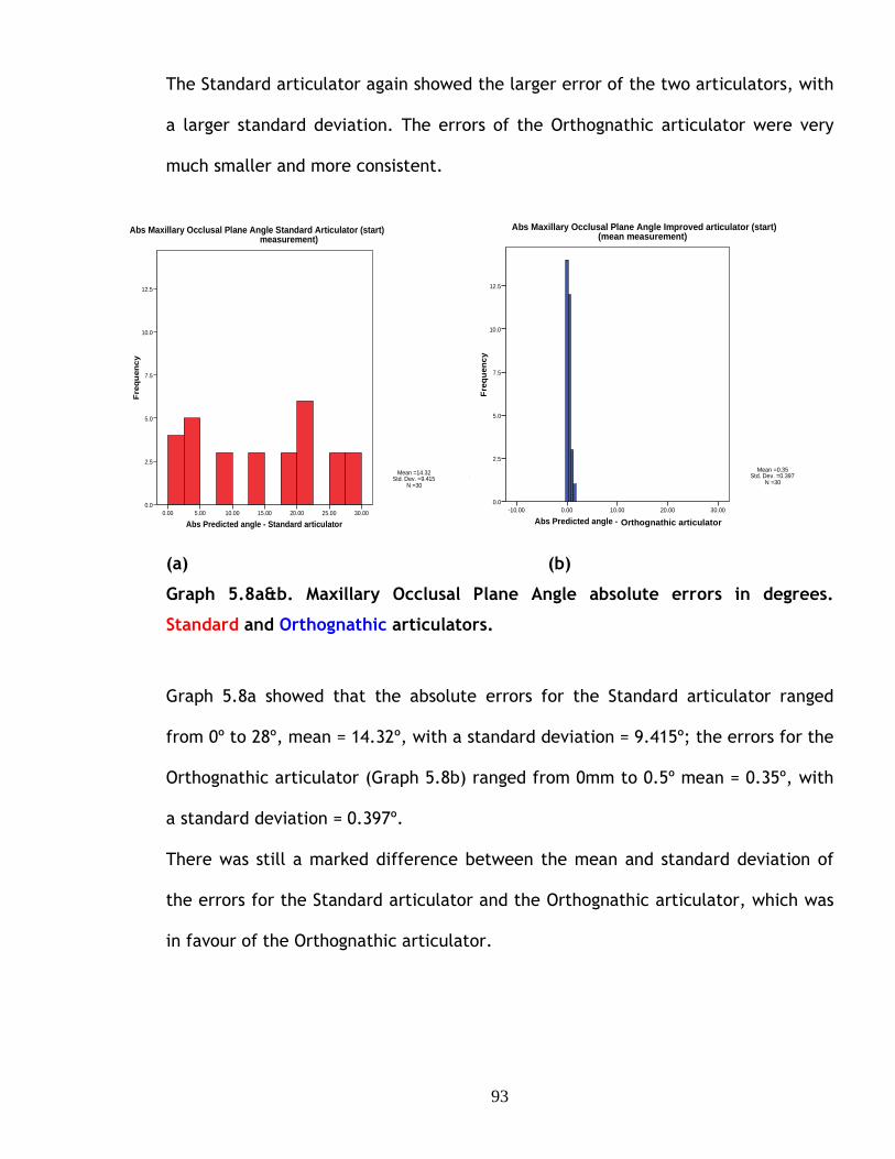
93
The Standard articulator again showed the larger error of the two articulators, with
a larger standard deviation. The errors of the Orthognathic articulator were very
much smaller and more consistent.
(a) Graph 5.8a&b. Maxillary Occlusal Plane Angle absolute errors in degrees. Standard and Orthognathic articulators.
(a) (b)
Graph 5.8a&b. Maxillary Occlusal Plane Angle absolute errors in degrees.
Standard and Orthognathic articulators.
Graph 5.8a showed that the absolute errors for the Standard articulator ranged
from 0º to 28º, mean = 14.32º, with a standard deviation = 9.415º; the errors for the
Orthognathic articulator (Graph 5.8b) ranged from 0mm to 0.5º mean = 0.35º, with
a standard deviation = 0.397º.
There was still a marked difference between the mean and standard deviation of
the errors for the Standard articulator and the Orthognathic articulator, which was
in favour of the Orthognathic articulator.
Abs Predicted angle - Standard articulator30.0025.0020.0015.0010.005.000.00
Fre
qu
ency
12.5
10.0
7.5
5.0
2.5
0.0
Mean =14.32Std. Dev. =9.415
N =30
Abs Maxillary Occlusal Plane Angle Standard Articul ator (start) mean measurement)
Abs Predicted angle - Improved articulator30.0020.0010.000.00-10.00
Fre
quen
cy
12.5
10.0
7.5
5.0
2.5
0.0
Mean =0.35Std. Dev. =0.397
N =30
Abs Maxillary Occlusal Plane Angle Improved articul ator (start) (mean measurement)
Orthognathic articulator

94
110.00 100.00 90.00 80.00 70.00 60.00 50.00
40.00
20.00
0.00
-20.00
Mean of predicted angle and articulator angle
110.00 100.00 90.00 80.00 70.00 60.00 50.00
30.00
20.00
10.00
0.00
Abs Mean of predicted angle and articulator
Signed Errors (a) Absolute errors (b) Graph 5.9a&b. Bland Altman plot showing Maxillary Occlusal Plane Angle errors, in degrees. Standard and Orthognathic articulators.
The Bland Altman plot of the signed and absolute errors (Graph 5.9a&b) confirmed
the results shown in the histograms. The Orthognathic articulator showed
significantly smaller errors, the mean being closer to zero than the Standard
articulator. The Standard articulator also had very large errors occurring. This
would certainly be clinically significant.
The Wilcoxon comparison of the absolute measures (See Appendices) showed that
the Orthognathic articulator showed smaller error in all of the 30 paired
comparisons and that the difference was highly significant, P<0.000.

95
6
DISCUSSION AND CONCLUSIONS

96
6.1. Discussion.
Commercially available semi-adjustable articulators manufactured for prosthetic
and occlusal analysis purposes have been used worldwide for orthognathic planning,
but the literature identifies inaccuracies that arise from using these systems.
There has been compelling evidence that casts mounted on semi-adjustable
articulators using the conventional face bow technique have systematic errors of
cast orientation. The angle between the maxillary occlusal plane angle of the cast
and the articulator cross member replicates neither the angle between the occlusal
plane and the Frankfort horizontal plane nor horizontal plane with the patient in
the natural head position. The discrepancy may be as much as 20º (Walker et al
(2008a).
There is also been strong evidence that the final surgical outcome may differ from
the prediction plan using commercially available articulators. These issues were
reviewed and discussed in chapter 1 and 2.
Within the literature there have been suggestions that there is a causal connection
between misalignment of the casts used for model surgery and inaccurate surgical
outcomes. Ellis (2001) suggested that errors of surgical outcome were both more
common and more severe than the literature suggested and that surgeons
evaluating the accuracy of the outcome of orthognathic surgery “will often face a
surprise, if not be shocked”. He was explicit about the cause of errors-“accurate
mounting of the casts on an articulator is an essential (sic) component of planning

97
surgery”. By accurate mounting he meant “orientating the casts on the articulator
in the same spatial relationship as the teeth are oriented to the facial bones”. He
offered no evidence, other than clinical experience, for his statements.
Sharifi et al (2008) identified the well-established discrepancy in the orientation
of models mounted on articulators using conventional face bows as a possible
source of error in surgical outcome. There was, once again, no objective evidence
to support this suggestion.
Gateno et al (2001) investigated the effect of the occlusal plane misalignment on
the surgical outcome for a single case in which the axis-orbital plane was 12º
steeper than the patient’s value. Analysis of tracings suggested that a 10mm
maxillary advancement relative to the articulator would result in a surgical under
advancement of 1.5mm. The findings in this study also show a vertical error that
was overlooked by the authors.
Natterstad and Vedtofte (1994) presented a mathematical analysis of the surgery
effect of an angular error in the mounted casts, which was equivalent to a
discrepancy in the orientation of the reference and articulator axes. Only the
vertical position was analysed, but the equations used were incorrect and contained
only the tangent of the angle. This resulted in the vertical discrepancy depending
only on the horizontal displacement and an underestimate of the magnitude of the
errors.

98
There was clearly a need for convincing evidence of the effect of incorrect cast
orientation on surgical outcome compared with the prediction plan. This gave the
motivation to undertake this study. Firstly to demonstrate the effect of incorrect
cast orientation on the maxillary cast movements in model surgery, to
mathematically quantify the errors and to experimentally validate the
mathematical analysis, all of which have been presented in this thesis.
Methods of improving the mounting of casts on semi-adjustable articulators using
conventional face bows have been suggested, despite the lack of evidence of the
connection between cast misorientation and surgical outcomes. It is necessary to
decide whether the mounted cast should reproduce the angle between the occlusal
plane and either the Frankfort plane or the horizontal plane in the natural head
position.
The Frankfort horizontal plane is a widely recognised anatomical reference plane. It
is relatively easy to identify on the patient and from lateral radiographs. Downs
(1956), however, showed that the Frankfort horizontal plane is commonly not
horizontal. (Fig. 6.1).

99
Fig.6.1. Variations of the cant of the Frankfort horizontal plane. (Illustration from Downs WB. Angle Orthod.1956;26:)
Thus casts mounted with the articulator’s cross member representing the Frankfort
plane may give a false impression of the clinical orientation of the maxillary
occlusal plane.
Patients can repeatedly and accurately assume their natural head position
(Moorrees and Kean,1958 ; Walker et al 2008 A) and the horizontal plane is easily
and repeatably identified. Apart from being easily reproducible the natural head
position can be seen by a trained eye and adjusted accordingly if the patient has
postured. Casts mounted relative to the horizontal natural head position reproduce
the natural appearance of the teeth relative to the head.
The angular difference between the two planes is variable. Allport (2002)
presented data from 10 patients that showed that the mean angle between the
planes was 7.65º but varied between -1.5º and + 18.5º. Pitchford (1991) reported
an average discrepancy of 8º between the natural head position and the Frankfort
horizontal plane, but gave no details of the range of values.

100
Various methods of correcting the inaccurate orientation of casts mounted using
conventional face bow have been suggested. Gonzalez & Kingery (1968) devised an
arbitrary adjustment to align the articulator cross member with the Frankfort plane
that consisted of either placing the orbital pointer 7mm lower than the orbital
border of the patient or raising the orbital pin of the face bow by 7mm once
transferred to the articulator. The correction was equivalent to a 5.9º realignment
of the cast. Stade et al (1982) suggested a correction of 16.4mm, equivalent to a
10º realignment, to align the cross member with the horizontal of the natural head
position. Such mean value corrections are unlikely to suit all patients, particularly
candidates for orthognathic surgery, who may be particularly variable.
Ellis et al (1992) suggested individual corrections could be made by rotating the
face bow attached to the articulator to reproduce the angle between the maxillary
occlusal plane and Frankfort plane measured on a lateral cephalograms. The
corrections were time consuming and depended on the operator measuring the
lateral cephalogram accurately. A similar method was suggested by Gateno et al
(2001), but required an additional lateral cephalograms. This made this method
unsuitable for routine use because it would not be ethical to subject patients to an
additional lateral cephalogram.
There appears to be only one articulator system specifically designed for
orthognathic model surgery planning. Walker et al (2008 A and B) took into
consideration all the limitations of commercially available articulator systems and
devised a system that addressed these shortcomings. The natural head position was
used to reproduce the maxillary occlusal plane angle seen in the patient on the

101
articulator. Although the accuracy of the orientation of mounted casts was
established, the accuracy of the perioperative wafers constructed on the
orthognathic articulator was not investigated. This fuelled the motivation to
undertake this study to evaluate Walker’s orthognathic articulator.
6.1.1. Errors produced by cast misalignment.
The qualitative example showed that a horizontal movement of a model relative to
axes based on the articulator on which it is mounted also produced movements of
the model relative to the reference axes based on the patient’s natural head
position. Relative to the reference axis the model was under-advanced and
displaced inferiorly.
In this study the mathematical analysis is presented, it quantified the errors
produced by discrepancies between the reference and articulator axes. The
mathematical analysis produced equations, which showed that movements of a
maxillary model relative to the articulator axes produced errors in the movements
of the model relative to the reference axes. The magnitude of the resulting errors
depended on three variables these were: the magnitudes of the horizontal and
vertical movements made relative to the articulator and the angle between the
upper cross member of the articulator and the reference horizontal. This
dependence was not surprising, but quantification of the errors produces
surprisingly large values. When the angular discrepancy was 20º a 10 mm
advancement and down graft produced a 4mm horizontal error and the equations
showed that even a 5 mm movement would produce an error of more than 3 mm
horizontally. A smaller angular discrepancy reduced the errors, but a 10º

102
difference produced an error of more than 2 mm in a 10 mm displacement (See
Chapter 4, Table 4.1).
The practical study based on photographs of specific movements of a maxillary
model mounted on an articulator followed by image analysis validated the results of
the analysis, there being no significant difference between the practical results and
the theoretical predictions from the equations.
The movement of the casts for the photographic study used aluminium spacers for
vertical displacements and pre-drilled holes in the articulator’s cross bar for
forward displacements. The choice of a disc of a standard size and standard hole
positions produced accurate and reproducible movements without the need for
measurement. The method was simple and convenient and eliminated the need to
detach the casts from the mounting disc before the casts were measured and
marked, trimmed and remounted.
6.1.2. Evaluation of a new orthognathic articulator.
The errors identified above would be incorporated into the inter-occlusal wafer
prepared for the surgeon and used as a template for positioning the maxilla, and
would have a seriously deleterious effect on the surgical outcome.
The second stage of the study was to take this concept further by simulating
orthognathic surgery using plastic model skulls to validate the analysis and clarify
the clinical significance relative to the first stage of the study.

103
The study was run as a parallel study with a Standard articulator and an
Orthognathic articulator where appropriate face bow recordings were taken and
dental casts were mounted on each articulator. Orthognathic model surgery on the
maxilla was carried out and surgical wafers constructed. Measurements from
anatomical reference points were recorded before and after orthognathic surgery
was simulated on the plastic model skulls in five predetermined head positions
using a custom made measuring device. This process was documented in the
materials and methods (chapter 5). It may have been more advantageous to use
natural skulls, as they would have given more variety of maxillary and mandibular
relationship, as all the plastic skulls, were in a class I occlusion before simulated
surgery was carried out. Thus, carrying out a Le Fort I osteotomy and autorotating
or de-rotating the mandible into occlusion would be more realistic approach.
However, this is irrelevant as it was only maxillary surgery that was carried out in
this study and the mandible remained in a fixed position. It proved to be necessary
to have a fixed reference point using the mandible to achieve the required
measurements on the maxilla. When carrying out a Le Fort I osteotomy, any height
change of the maxilla is measured from a pin placed into the bone at nasion. This
was not applied in this study.
The measurements were carried out using a digital vernier gauge for the antero-
posterior movements, which was accurate to a hundredth of a mm. Vertical
measurements were recorded using a vertical height calliper (Chesterman,
Sheffield) with an analogue vernier scale with a resolution of 0.5mm accuracy. The
measurements could have been carried out using 3D imaging, which would have
given more accurate recordings. However this would have been of little benefit as

104
the surgeon is only able to perform orthognathic surgery to 0.5 mm, this is because
of the saw blades that they use being 0.5mm or more in width. The measurements
produced were as accurate as required for this type of study.
With the method devised, the maxilla had to be detached and replaced back into its
original position on the skull before surgery was carried out. The most simple and
practical method was by using custom made bone plates (documented in chapter
5). After the surgery was carried out the maxilla was located and fixed in place
using sticky wax. The wax could have expanded or contracted, this was eliminated
by using the fixed mandible and a bite registration to ensure no unwanted height
changes occurred.
The Bland Altman plot of the errors of antero-posterior movement (Chapter 5
Fig.5.3a) showed grouping of the data that appeared to be related to the different
skull angles. The x-axis of the Bland Altman plot in (Fig.5.3a.), was arbitrary and
the grouping was investigated by plotting the error against the skull angle
(Fig.6.1.), which showed that the grouping is clearly a function of skull angle. The
errors produced by the Standard articulator were systematically dependent on the
angles. The errors for -20º and -10º being both negative and positive, but for the
positive angle the errors were only positive. No such asymmetry or systematic
variations were shown for the results of the Orthognathic articulator and the errors
appeared to be random.

105
Graph 6.1. Error of antero-posterior movement as a function of skull angle.
The best straight line fitting the Standard articulator data was calculated and
added to Graph 6.1., showing that the asymmetry of the results was caused by the
skewed distribution of the data; the line did not pass through the origin of the
graph, but cut the error axis at a skull angle of -12º. This implied that mounting the
casts using the conventional face bow technique introduced an added misalignment
of 12º, a value similar to the 10.75º discrepancy reported for similarly mounted
casts by Walker et al (2008a).
The mathematical analysis predicted that the error produced by cast misalignment
would depend on angle and the magnitude of the movements of the cast. The
dependence on angle was confirmed by Graph 6.1. The dependence on movement
was more difficult to demonstrate, because the movements were combined.
Replotting Graph 6.1. for each of the movements, Graph 6.2. showed that the
results for each movement displayed a consistent pattern, suggesting a dependence
of error on cast movement. Each of the best straight lines showed a positive
Antero-posterior movement, mean error
-3
-2
-1
0
1
2
3
4
5
6
-30 -20 -10 0 10 20 30
Skull angle, degrees.
Err
or,
mm
.Inproved
Standard
Linear (Standard)
Orthognathic

106
gradient which, when combined gave the clear dependence on angle shown in
Graph 6.1.
Graph 6.2. Error of antero-posterior movement as a function of skull angle for each movement advance, advance down and advance up.
The Bland Altman plots for the vertical errors did not show the grouping shown by
the antero-posterior errors. The vertical errors measured from the central incisor
were plotted against the skull angle, Fig.6.3, which showed the grouping of the
data. Neither the gradient nor the intercept of the best straight line shown on the
graph were significantly different from zero, reflecting the variability of the data,
and this may account for the lack of grouping in the Bland Altman plots of the
vertical errors.
Antero-posterior error, Standard articulator.
-3
-2
-1
0
1
2
3
4
5
6
-30 -20 -10 0 10 20 30
Skull angle, degrees.
Err
or,
mm
.
Adv
Adv+down
Adv+up
Linear (Adv)
Linear (Adv+down)
Linear (Adv+up)

107
Graph 6.3. Error of vertical movement measured at central incisor as a function of skull angle. Compare with Chapter 5 Graph 5.9a.
Replotting Graph 6.3. for each of the movements, Graph 6.4., showed that the
results for each movement displayed a consistent pattern, suggesting a
dependence of error on cast movement. One of the best straight lines showed a
zero gradient, one a positive gradient the third a negative gradient; the two latter
lines were widely spaced at -20º, which accounted for the wide range of points
shown for -20º in Graph 6.3.
Vertical error;central incisor; Standard articulato r.
y = 0.0077x - 0.0731
-8
-6
-4
-2
0
2
4
6
8
-30 -20 -10 0 10 20 30
Skull angle, degrees.
Err
or,
mm
.

108
Vertical errors, central incisor. Standard articulator.
-8
-6
-4
-2
0
2
4
6
8
-30 -20 -10 0 10 20 30
Skull angle, degrees.
Err
or,
mm
.Advance
Adv + Down
Adv + Up
Linear (Advance)
Linear (Adv + Down)
Linear (Adv + Up)
Graph 6.4. Error of vertical movement measured at central incisor as a function of skull angle.
The difference between the results of the Wilcoxon tests on signed and absolute
data was very striking. The tests were initially carried out on the signed data. The
histograms and Bland Altman plots showed that the errors of the Orthognathic
articulator were consistently smaller than the Standard articulator; it came as no
surprise the Wilcoxon test showed the difference to be statistically significant at P<
0.001. Although the vertical errors using the orthognathic articulator were also
consistently smaller than the Standard articulator, none of the Wilcoxon
comparisons were statistically significant, with P value ranging from 0.534 to 0.963.
The reason was outlined in chapter 5.2. Using the Wilcoxon test to compare the
absolute values of the errors showed that the errors of the Orthognathic articulator
were consistently highly significantly smaller than the errors of the Standard
articulator.

109
Casts repositioned using the Standard articulator showed significant antero-
posterior and vertical errors. It is common surgical practice to check the post-
operative vertical position of the maxilla with dividers and move the maxilla
vertically to achieve the prescribed vertical position. An initial assessment of this
adjustment was carried out on casts repositioned on the standard articulator. Five
casts that had undergone a 10mm advancement and a 5mm impaction were
investigated, one at each skull angle. After the measurements with the mandible in
the fixed position were completed, the maxilla was detached from the skull and
relocated in the wafer supported on the mandibular teeth. The mandible and the
supported maxilla were raised by autorotation while measuring the vertical position
of the reference point on the central incisor until the vertical error was eliminated.
The maxilla was then fixed using sticky wax and the displacements of the other
reference points determined.
The results (Table 6.1) showed that correcting the vertical error made the
horizontal error worse. The consistency of the increase in error made the results
statistically significant although there are only five paired results (Binomial test, P<
0.005).(Zar 2010).

110
Angleº Fixed, mm Autorotated, mm Difference, mm
-20 -2.00 -2.66 0.66
-10 -1.39 -2.17 0.82
10 0.43 1.51 -1.08
15 0.51 1.58 -1.07
20 2.55 6.19 -3.54
Table 6.1. Antero posterior errors, mm. Difference between fixed and autorotated mandible.
The Wilcoxon test of the absolute values (Table 6.2) was also significant at P<0.005.
Angleº Fixed,mm Autorotated,mm Difference, mm
-20 2.00 2.66 -0.66
-10 1.39 2.17 -0.82
10 0.43 1.51 -1.08
15 0.51 1.58 -1.07
20 2.55 6.19 -3.54
Table 6.2. Absolute antero posterior errors, mm. Difference between fixed and autorotated mandible.
It was suggested that one of the advantages of using the natural head position was
that the mounted cast more accurately replicated the appearance of the natural
relationship between the teeth and skull. Graph 6.5. showed the angle between the
pre-operative maxillary occlusal plane angle for the skulls and the mounted casts
for both the Standard and Orthognathic articulator.

111
Graph 6.5. Difference between the pre-operative maxillary occlusal plane angle of the skull and of the mounted casts.
Casts mounted on the Standard articulator showed a large systematic difference
from the skull angle, whereas the casts mounted on the Orthognathic articulator
consistently and accurately replicated the natural skull angle. The difference
between the articulators was shown to be statistically significantly at P< 0.05.
6.1.3. Development of the orthognathic articulator system and suggestions for
further work.
The orthognathic articulator system has proved without a doubt a more accurate
way to plan orthognathic surgery, but there are problems that arise when using the
device. The face bow and articulator can be difficult to apply, because the
adjustable components are rather difficult to set. This could be easily overcome
Maxillary occlusal plane angle.
-30
-20
-10
0
10
20
30
40
-30 -20 -10 0 10 20 30
Angle, degrees.
Err
or,
degr
ees. Standard
Improved
Linear (Standard)
Linear (Improved)
Orthognathic

112
with commercially machined adjustable components, so that adjustments can be
made to the devices with ease. It is possible to adjust the lateral position of each
condyle independently and this is necessary to relate the position of the jaws and
teeth to each condyle. It is also possible to independently adjust the antero-
posterior and vertical position of each condyle. This adjustment would seem to be
redundant because the related position of the condyles would be sufficient. Making
only one condyle adjustable in the lateral plane would be sufficiently accurate and
simplify the setting up of the articulator for orthognathic surgery but not for
asymmetric cases. Fully adjustable condylar components would be required for such
cases.
Once the mandibular cast is mounted on the articulator, removing it and fixing it in
the correct predetermined position can be difficult in some cases i.e. mandibular
set-backs. The development of an additional adjustable mandibular mounting base
for these cases would be the way forward. Using the disc and hole system simplified
the movement of the maxillary casts eliminating the need to mark up the cast,
detach, trim and then replace and fix it in position. This saved time and was also
likely to be more accurate.
Adjustable predetermined vertical movements could be achieved by providing a set
of discs with thickness of 1 to 10mm or by build up sets of thinner discs covering
the same range. Further development of the hole system could be used for
horizontal movement. The incorporation of rotation into the adjustable positioning
system to allow for lateral rotations where occlusal canting is present and
horizontal rotation is required to correct the maxillary and mandibular midlines

113
would be slightly more difficult, but entirely possible. The adjustable system could
be used with some effect on semi-adjustable articulators as well as the
orthognathic articulator. The use of magnetic articulating discs would allow easier
fixation and removal of casts from the articulator.
Five plastic model skulls were used and the process duplicated, but the whole
process took a considerable amount of time to execute for each articulator system
allowing time only for the ten cases to be undertaken. It would have been
advantageous to undertake this study, particularly the effect of autorotation, on a
larger number of skulls. This would have produced more robust conclusions.
The ultimate test of the Orthognathic articulator system would be a clinical study
carried out on patients undergoing orthognathic surgery using pre and post-
operative cephalograms to compare the predicted movement and the actual
outcome of treatment. This has been undertaken in a previous study where the
post-operative results using the two articulator systems were compared and
evaluated (Walker at al 2008b). A more robust clinical study would be the logical
conclusion to the evaluation of the orthognathic model surgery system.
6.1.5. The future of orthognathic surgery planning, the use of 3D models.
Using cone beam computed tomographic scans as the input to 3D rapid prototyping
systems is a useful means for the production of 3D models of the human skull.
There is considerable interest in using such models for orthognathic surgery
planning. However, there are problems of producing the dentition from CT data due
114
to magnification and streak artifacts produced by the presence of metal, such as
fillings or orthodontic brackets in or on the teeth. An accurate perioperative wafer
could not be constructed on the present generation rapid prototyped skull models.
Studies have been undertaken to replace the distorted dentition of 3D model skulls.
Replacement of the model teeth with an accurate plaster dentition from dental
impressions has been successfully achieved with an accuracy of 0.5mm [O’Neil et al
(2010)]. Swennen et al (2009) replaced the inaccurate occlusal detail of models
with the accurate dentition using a double cone-beam CT scan. Cone-beam scans
deliver less radiation than the original CT scans, but it would still be unethical to
subject patients to the extra radiation of a double scan. Other studies are
underway to replace the distorted model dentition using an intra-oral technique.
The findings on these have yet to be published.
Technology is moving forward all the time and the use of plaster dental casts
mounted on an articulator when planning orthognathic surgery will slowly become
obsolete. This will not happen overnight and it could take some years. For the
meantime the Orthognathic articulator will facilitate more accurate model surgery.
Even when the use of models for orthognathic treatment becomes established,
some form of articulator to simplify accurate positioning of dental segments,
perhaps using the disc and hole system pioneered in this thesis, will still be needed.

115
6.2. Conclusions.
6.2.1. Errors produced by cast misalignment.
1. The literature provides convincing evidence that the outcome of
orthognathic surgery may differ from the planned outcome, although
inappropriate statistical testing confuses the situation.
2. The misalignment of casts mounted on semi-adjustable articulators may
cause or contribute to the errors of surgical outcomes.
3. An illustrative example showed that movements of casts parallel to the
articulator cross member produced erroneous movements relative to axes
representing the patient’s natural head position (reference axes).
4. A detailed mathematical analysis confirmed the errors in the example. The
relationship of movements relative to the articulator and reference axes
showed that the latter, and hence the errors, depended on the magnitude
of the movements made relative to the articulator and the angle between
the cross member and reference axes.
5. The accuracy of the theoretical analysis was confirmed by an experimental
study using image analysis.

116
6.2.2. Evaluation of a new orthognathic articulator.
1. The maxillary occlusal plane angles of the skulls were accurately reproduced
by casts mounted using the Orthognathic articulator system, but casts
mounted using the Standard articulator showed systematic errors of up to
28º.
2. The post-operative position of the maxilla after simulated orthognathic
surgery demonstrated that the Orthognathic articulator system produced
more accurate model surgery. The differences between the actual and
predicted movements were significantly smaller for the Orthognathic
articulator system than for the standard articulator system.
3. The results justify further research, development and evaluation of the
Orthognathic articulator system.

117
7
REFERENCES

118
References:
ALLPORT, D.M., 2002. Evaluation of two reference planes to the horizon in the natural head position. MSc thesis. University of West Virginia.
ANGELILLO, J.C., GEORGINADE, N.G., RABE, W.C., 1997. A prototype articulator for planning orthognathic and craniofacial surgery. Journal of Oral Surgery, 35, 847-49.
ANWAR, M. and HARRIS, M., 1990. Model surgery for orthognathic planning. The British Journal of Oral & Maxillofacial Surgery, 28(6), 393-397.
BAILEY, J.O., and NOWLIN, T.P., 1984. Evaluation of the third point of reference for mounting maxillary casts on the Hanau articulator. Journal of Prosthetic Dentistry, 51(2), 199-201.
BAMBER, M.A., HARRIS, M. and NACHER, C., 2001. A validation of two orthognathic model surgery techniques. Journal of Orthodontics, 28(2), 135-142.
BLAND, M.J., ALTMAN, D.G., 1986. Statistical method for assessing agreement between two methods of clinical measurement. Lancet, I, 307-310.
BRYAN, D.C. and HUNT, N.P., 1993. Surgical accuracy in orthognathic surgery. British Journal of Oral & Maxillofacial Surgery, 31(6), 343-349.
DENTATUS AB. Bromstensvägen 172, Box 8093, SE-163 08 Spånga, Sweden. Web site available at : www.dentatus.se.
DONATSKY, O., BJORN-JORGENSEN, J., HOLMQVIST-LARSEN, M. and HILLERUP, S., 1997. Computerized cephalometric evaluation of orthognathic surgical precision and stability in relation to maxillary superior repositioning combined with mandibular advancement or setback. Journal of Oral & Maxillofacial Surgery, 55(10), 1071-1079.
DONATSKY, O., HILLERUP, S., BJORN-JORGENSEN, J. and JACOBSEN, P.U., 1992. Computerized cephalometric orthognathic surgical simulation, prediction and postoperative evaluation of precision. International Journal of Oral & Maxillofacial Surgery, 21(4), 199-203.
DOWNS, W.B.,1956. Analysis of the dentofacial profile. Angle Orthod, 26,192-212.
EALES, E.A, NEWTON C, JONES M.L, SUGAR A.W., 1994. The accuracy of computerized prediction of the soft tissue profile: a study of 25 patients treated by means of the Le Fort I osteotomy. International Journal of Adult Orthodontic &Orthognathic Surgery, 9, 141-152.

119
EALES, E.A, JONES, M.L, NEWTON, C, SUGAR, A.W., 1995.A study of the accuracy of predicted soft tissue changes produced by a computer software package (COG 3.4) in a series of patients treated by the Le Fort I osteotomy. British Journal of Oral & Maxillofacial Surgery, 33, 362-369.
ELLIS, E.,3RD, 1990. Accuracy of model surgery: evaluation of an old technique and introduction of a new one. Journal of Oral & Maxillofacial Surgery, 48(11), 1161-1167.
Ellis,E.,3RD, 2001. Discussion of Gateno’s, A comparison of 3 methods of face-bow transfer recording: implications for orthognathic surgery. Journal of Oral & Maxillofacial Surgery, 59(6), 635-640. Journal of American Association of Oral and Maxillofacial Surgeons, 640-641.
ELLIS, E.,3RD, THARANON, W. and GAMBRELL, K., 1992. Accuracy of face-bow transfer: effect on surgical prediction and postsurgical result. Journal of Oral & Maxillofacial Surgery, 50(6), 562-567.
FERRARIO, V.F., SFORZA, C., SERRAO, G. and SCHMITZ, J.H., 2002. Three-dimensional assessment of the reliability of a postural face-bow transfer. Journal of Prosthetic Dentistry, 87(2), 210-215.
FRIEDE, H., KAHNBERG, K.E., ADELL, R. and RIDELL, A., 1987. Accuracy of cephalometric prediction in orthognathic surgery. Journal of Oral & Maxillofacial Surgery, 45(9), 754-760.
GATENO, J., FORREST, K.K. and CAMP, B., 2001. A comparison of 3 methods of face-bow transfer recording: implications for orthognathic surgery. Journal of Oral & Maxillofacial Surgery, 59(6), 635-640.
GONZALEZ, J.B., KINGERY, R.H. 1968. Evaluation of planes of reference for orientating maxillary casts on articulators. Journal American Dental Association, 76, 329-36.
HARTY, F.J. 1994. Concise illustrated dental dictionary. 2nd edn. IOP Publishing Ltd (1987).
JACOBSON, R. and SARVER, D.M., 2002. The predictability of maxillary repositioning in LeFort I orthognathic surgery. American Journal of Orthodontics & Dentofacial Orthopedics, 122(2), 142-154.
JUNGER, T.H., KRENKEL, C. and HOWALDT, H.P., 2003. Le Fort I sliding osteotomy--a procedure for stable inferior repositioning of the maxilla. Journal of Cranio-Maxillo-Facial Surgery, 31(2), 92-96.
KaVo DENTAL GMBH (Head office), Bismarckring 39, D-88400 Birerach/RiB, Germany. Web site available at: www.kavo.com or www.kavo.co.uk.
120
LOCKWOOD, H., 1974. A planning technique for segmental osteotomies. British Journal of Oral Surgery, 12(1), 102-105.
MCCANCE, A.M., MOSS, J.P. and JAMES, D.R., 1992. Le Fort I maxillary osteotomy: is it possible to accurately produce planned pre-operative movements?. British Journal of Oral & Maxillofacial Surgery, 30(6), 369-376.
MOORREES, C.F.A. and KEAN, M.R., 1958. Natural head position: a basic consideration in the interpretation of cephalometric radiographs. American Journal of Phys and Anthropology, 16, 213-234.
NATTESTAD, A. and VEDTOFTE, P., 1994. Pitfalls in orthognathic model surgery. The significance of using different reference lines and points during model surgery and operation. International Journal of Oral & Maxillofacial Surgery, 23(1), 11-15.
OLSZEWSKI, R. and REYCHLER, H., 2004. [Limitations of orthognathic model surgery: theoretical and practical implications]. Revue de stomatologie et de chirurgie maxillo-faciale, 105(3), 165-169.
O'MALLEY, A.M. and MILOSEVIC, A., 1999. Use of articulators in the United Kingdom by consultant orthodontists in planning orthognathic surgery. International Journal of Adult Orthodontics and Orthognathic Surgery, 14 (8), 236-242
O'MALLEY, A.M. and MILOSEVIC, A., 2000. Comparison of three facebow/semi-adjustable articulator systems for planning orthognathic surgery. British Journal of Oral & Maxillofacial Surgery, 38(3), 185-190.
O’NEIL, M, AYOUB, A.F., KHAMBAY, B, MOOS, K.F., BARBENEL, J.C. A novel method of building a 3D physical model of the skull and dentition. (sent to British Journal of Oral & Maxillofacial Surgery, awaiting instructions for publication)
PITCHFORD, J.H., 1991. A reevaluation of the axis-orbital plane and the use of orbitale in a face bow transfer record. Journal of Prosthetic Dentistry, 66(3), 349-355.
POLIDO, W.D., ELLIS, E.,3RD and SINN, D.P., 1991. An assessment of the predictability of maxillary repositioning. International Journal of Oral & Maxillofacial Surgery, 20(6), 349-352.
POSPISIL, O.A., 1987. Reliability and feasibility of prediction tracing in orthognathic surgery. Journal of Cranio-Maxillo-Facial Surgery, 15(2), 79-83.
S.A.M. PRÄZISIONSTECHNIK GMBH, Fussbergstrasse 1, 82131 Gauting, Germany. Web site available at: www.sam-dental.de.
SCHWESTKA, R., ENGELKE, D., ZIMMER, B. and KUBEIN-MEESENBURG, D., 1991. Positioning control of the upper incisors in orthognathic surgery. Pre-operative planning with the Model Positioning Device and intra-operative application of the Sandwich Splint. European Journal of Orthodontics, 13(5), 367-371.

121
SHARIFI, A., JONES, R., AYOUB, A., MOOS, K., WALKER, F., KHAMBAY, B. and MCHUGH, S., 2008. How accurate is model planning for orthognathic surgery?. International Journal of Oral and Maxillofacial Surgery, 37(12), 1089-1093.
STADE, E.H., HANSON, J.G. and BAKER, C.L., 1982. Esthetic considerations in the use of face-bows. Journal of Prosthetic Dentistry, 48(3), 253-256.
SWENNEN, G.R.J., MOMMAERTS, M.Y., ABELOOS, J., DE CLERCQ, C., LAMORAL, P., NEYT, N., CASSELMAN, J., SCHUTYSER, F., 2009. A cone-beam CT based technique to augment the 3D virtual skull model with a detailed dental surface. International Journal of Oral and Maxillofacial Surgery, 38, 48-57.
VAN SICKELS JE, LARSEN AJ, TRIPLETT RG, 1986. Predictability of maxillary surgery: A comparison of internal and external reference marks. Oral Surg Oral Med Oral Path, 61, 542-545.
WALKER F.S., 2005. A new orthognathic articulator for surgical planning. University of Glasgow.
WALKER, F., AYOUB, A.F., MOOS, K.F. and BARBENEL, J., 2008. Face bow and articulator for planning orthognathic surgery: 1 face bow. British Journal of Oral & Maxillofacial Surgery, 46(7), 567-572.
WALKER, F., AYOUB, A.F., MOOS, K.F. and BARBENEL, J., 2008. Face bow and articulator for planning orthognathic surgery: 2 articulator. British Journal of Oral and Maxillofacial Surgery, 46(7), 573-578.
WOLFORD, L.M., 1999. Surgical planning in orthognathic surgery. Maxillofacial surgery. 2nd edn. St Louis: Churchhill Livingstone Elsevier, pp. 1135-1210.
ZAR, 2010. Biostatistical analysis, Pearson Education International, New Jersey. pp. 183-188. (Wilcoxon test); 519-524) binomial distribution.

I
Appendices

II
ERRORS PRODUCED BY CAST MISALIGNMENT STUDY (Mathematical study was
carried out by Professor J.C.Barbenel (University of Strathclyde).
A model is displaced from its initial position O relative to orthogonal axes based on
the articulator, with horizontal axis Ha and vertical axis Va . The model is moved by
the horizontal and vertical distances ha and va, which can be represented in Figure
A1 by the line r at an angle θ to the Ha axis and:
ha = r cos ε and va= r sin ε Eqn A.1
The displacements relative to the orthogonal reference axes Hr and Vr at an angle ε
to the articulator axes Ha and Va are hr and vr with r being at an angle α to the Hr
axis. And:
hr = r cos α and vr = r sin α Eqn A.2
From Fig A.1
hr = r cos (ε-θ) and vr = r sin (ε-θ) Eqn A.3
But
cos (ε-θ) = cos θ cos ε + sin θ sin ε Eqn. A.4

III
and sin (ε-θ) = sin θ cos ε - cos θ sin ε Eqn. A.5
Substituting Eqn A.4 into Eqn A.3 and Eqn A.5 andEqn. A.1 into Eqn. A.3 yields:
hr = r (cos θ cos ε + sin θ sin ε )
= r cos θ cos ε + r sin θ sin ε Eqn A.6
and
vr = r (sin θ cos ε - cos θ sin ε )
= r sin θ cos ε - r cos θ sin ε Eqn A.7
Eliminating r cos ε and r sin ε in Eqn A.6 and A.7 using Eqn A.1 yields:
hr = ha cos θ + va sin θ
and vr = vr cos θ - ha sin θ.

IV
Figure A1. Displacement of model referred to articulator and reference axes.
O
P
α θ
ε
Ha
r
Va
va
Vr
vr
Hr
hr
ha

V
-5
-4
-3
-2
-1
0
1
2
3
4
-10 0 10
Vertical movement, mm.
Err
or,
mm
-5
-4
-3
-2
-1
0
1
2
3
4
5
-30 -20 -10 0 10 20 30
Angle, degrees
Err
or,
mm
Graph 4.1. The dependence of the vertical and horizontal errors, ∆vr and ∆hr, on the vertical movement, va. The horizontal movement, ha, is an advancement of 10mm. θ is 20º.
Graph 4.2. The dependence of the vertical and horizontal errors, ∆vr and
∆hr, on θ. The horizontal movement, ha, is an advancement of 10 mm and the vertical movement, va, is a downgraft of 10 mm.
hr
hr
vr
vr
hr

VI
Qualitative illustration.
Figure 2. Model displaced by a distance AB parallel to the axis Ha parallel
to the articulator cross bar produces displacements relative to
the reference axes Hr and Vr.

VII
Direction and distance, mm, of movement relative to articulator axis.
Direction and distance, mm, of movement relative to reference axis.
Up Movement Measurement Theory ha = 0.0 h20 3.40 3.42 va = 10.0 v20 9.43 9.40 Down ha = 0.0 h20 -3.62 -3.42 va = -10.0 v20 -9.34 -9.40 Forward ha = 10.0 h20 9.46 9.40 va = 0.0 v20 -3.30 -3.42 Forward +Up ha = 10.0 h20 12.84 12.82 va = 10.0 v20 5.83 6.00 Forward+down ha = 10.0 h20 6.25 6.00 va = -10.0 v20 -12.84 -12.82
Table 4.1. Comparison of theoretical predictions and experimental measurements.
Chart Title y = 1.0023x + 0.0069
R2 = 0.9998
-15
-10
-5
0
5
10
15
-15 -10 -5 0 5 10 15
Theory,mm
Mea
sure
men
t, m
m
Graph 4.3: A statistical representation of the correction between the predicted
theoretical values of the displacement and experimental values obtained. Data
from table 4.1.

VIII
Evaluation of an Improved orthognathic articulator system results
relating to chapter 5:
1a. Anterior vertical height – right side:
1b. Anterior vertical height – right side absolute measure:
Predicted Movement - Standard articulator6.004.002.000.00-2.00-4.00
Fre
quen
cy
10
8
6
4
2
0
Mean =0.07Std. Dev. =2.791
N =30
Anterior height - right side
Predicted Movement - Improved articulator6.004.002.000.00-2.00-4.00
Fre
quen
cy
10
8
6
4
2
0
Mean =0.17Std. Dev. =1.003
N =30
Anterior height - right side
Abs predicted movement - Standard articulator8.006.004.002.000.00-2.00
Fre
quen
cy
20
15
10
5
0
Mean =2.10Std. Dev. =1.798
N =30
Abs Anterior vertical height (right side)
Abs Predicted movement - Improved articulator8.006.004.002.000.00-2.00
Fre
quen
cy
20
15
10
5
0
Mean =0.73Std. Dev. =0.691
N =30
Abs Anterior Vertical Height (right side)
- Orthognathic articulator
Orthognathic articulator

IX
40.0035.0030.0025.0020.0015.0010.00
6.00
4.00
2.00
0.00
-2.00
-4.00
Abs Improved articulatorAbs Standard articulator
Abs Mean of predicted movement and articulator
Abs Bland Altman Plot of Anterior Vertical Height ( right side)
Abs Orthognathic articulator
40.0035.0030.0025.0020.0015.0010.00
5.00
2.50
0.00
-2.50
-5.00
Improved articulatorStandard articulator
Mean of predicted movement and articulator
Bland Altman Plot of Anterior height - right side
Orthognathic articulator
1c&d. Anterior vertical height – right side measure: Real and absolute 2a.

X
Predicted movement - Standard articulator7.505.002.500.00-2.50
Fre
quen
cy
12
10
8
6
4
2
0
Mean =0.52Std. Dev. =2.465
N =30
Anterior height - left side
Predicted movement - Improved articulator7.505.002.500.00-2.50
Fre
quen
cy
12
10
8
6
4
2
0
Mean =0.47Std. Dev. =0.85
N =30
Anterior height - left side
Anterior vertical height – left side:
2b. Anterior vertical height – left side absolute measure:
Abs Predicted movement - Standard articulator8.006.004.002.000.00-2.00
Fre
quen
cy
12
10
8
6
4
2
0
Mean =1.72Std. Dev. =1.818
N =30
Abs Anterior Vertical Height (left side)
Abs Predicted movement - Improved articulator8.006.004.002.000.00-2.00
Fre
quen
cy
12
10
8
6
4
2
0
Mean =0.63Std. Dev. =0.73
N =30
Abs Anterior Vertical Height (left side)
Orthognathic articulator
Orthognathic articulator

XI
2c&d. Anterior vertical height – left side: real and absolute 35.0030.0025.0020.0015.0010.00
8.00
6.00
4.00
2.00
0.00
-2.00
Abs Improved articulator
Abs Standard articulator
Abs Mean of predicted movement and articulator
Abs Bland Altman Plot of Anterior Vertical Height ( left side)
35.0030.0025.0020.0015.0010.00
8.00
6.00
4.00
2.00
0.00
-2.00
-4.00
Improved articulatorStandard articulator
Mean of predicted movement and articulator
Bland Altman Plot of Anterior height - left side
Orthognathic articulator
Abs Orthognathic articulator

XII
Abs Predicted movement - Standard articulator6.004.002.000.00
Fre
quen
cy
12
10
8
6
4
2
0
Mean =2.28Std. Dev. =1.659
N =30
Abs Posterior Vertical Height (right side)
Abs Predicted movement - Improved articulator6.004.002.000.00
Fre
quen
cy
12
10
8
6
4
2
0
Mean =0.53Std. Dev. =0.615
N =30
Abs Posterior Vertical Height (right side)
Orthognathic articulator
3a. Posterior vertical height – right side:
3b. Posterior vertical height – right side absolute measure:
Predicted movement - Standard articulator5.002.500.00-2.50-5.00
Fre
quen
cy12
10
8
6
4
2
0
Mean =-0.08Std. Dev. =2.853
N =30
Posterior height - right side
Predicted movement - Improved articulator5.002.500.00-2.50-5.00
Fre
quen
cy
12
10
8
6
4
2
0
Mean =0.03Std. Dev. =0.819
N =30
Posterior height - right side
Orthognathic articulator

XIII
3c&d. Posterior vertical height – right side: real and absolute
30.0025.0020.0015.0010.005.00
6.00
4.00
2.00
0.00
-2.00
Abs Improved articulatorAbs Standard articulator
Abs Mean of predicted movement and articulator
Abs Bland Altman Plot of Posterior Vertical Height (right side)
Abs Orthognathic articulator
30.0025.0020.0015.0010.005.00
5.00
2.50
0.00
-2.50
-5.00
Improved articulatorStandard articulator
Mean of predicted movement and articulator
Bland Altman Plot of Posterior height-right side
Orthognathic articul ator

XIV
Predicted movement - Standard articulator6.004.002.000.00-2.00-4.00
Fre
quen
cy
8
6
4
2
0
Mean =0.50Std. Dev. =2.446
N =30
Posterior height - left side
Predicted movement - Improved articulator6.004.002.000.00-2.00-4.00
Fre
quen
cy
8
6
4
2
0
Mean =0.55Std. Dev. =0.941
N =30
Posterior height - left side
Orthognathic articulator
Abs Predicted movement - Standard articulator6.004.002.000.00
Fre
quen
cy
10
8
6
4
2
0
Mean =1.93Std. Dev. =1.541
N =30
Abs Posterior Vertical Height (left side)
Abs Predicted movement - Improved articulator6.004.002.000.00
Fre
quen
cy
10
8
6
4
2
0
Mean =0.82Std. Dev. =0.713
N =30
Abs Posterior Vertical Height (left side)
Orthognathic articulator
4a. Posterior vertical height – left side:
4b. Posterior vertical height – left side absolute measure:

XV
4c&d. Posterior vertical height – left side: real and absolute measure
30.0025.0020.0015.0010.005.00
6.00
4.00
2.00
0.00
-2.00
Abs improved articulatorAbs Standard articulator
Abs Mean of predicted movement and articulator
Abs Bland Altman of Posterior vertical Height (left side)
35.0030.0025.0020.0015.0010.00
8.00
6.00
4.00
2.00
0.00
-2.00
-4.00
Improved articulatorStandard articulator
Mean of predicted movement and articulator
Bland Altman Plot of Anterior height - left side
Orthognathic articulator
Abs Orthognathic articulator