FINAL REPORT - Pipeline Risk Management Information ...
196
FINAL REPORT R2269-01R PIPELINE RESEARCH COUNCIL INTERNATIONAL, INC. ARLINGTON, VIRGINIA UPDATED PIPELINE REPAIR MANUAL
-
Upload
khangminh22 -
Category
Documents
-
view
4 -
download
0
Transcript of FINAL REPORT - Pipeline Risk Management Information ...
FINAL REPORT R2269-01R
PIPELINE RESEARCH COUNCIL INTERNATIONAL, INC.
ARLINGTON, VIRGINIA
UPDATED PIPELINE REPAIR MANUAL
FINAL REPORT Project Number R 2269-01R
UPDATED PIPELINE REPAIR MANUAL REVISION 6
PREPARED FOR PIPELINE RESEARCH COUNCIL INTERNATIONAL, INC.
ARLINGTON, VIRGINIA CONTRACT NO. PR-186-0324
PREPARED BY CC TECHNOLOGIES, INC.
CARL E. JASKE AND BRIAN O. HART
EDISON WELDING INSTITUTE WILLIAM A. BRUCEa
AUGUST 28, 2006
a Now with CC Technologies, Inc.
CC Technologies5777 FRANTZ ROAD
DUBLIN, OHIO 43017 614.761.1214 • 614.761.1633 fax
www.cctechnologies.com
Edison Welding Institute1250 ARTHUR E. ADAMS DRIVE
COLUMBUS, OHIO 43221 614.688.5000 • 614.688.5001 fax
www.ewi.org

ii
This report is furnished to Pipeline Research Council International, Inc. (PRCI) under the terms of PRCI Contract No. PR-186-0324 between PRCI and CC Technologies, Inc. (CCT).
The contents of this report are published as received from CCT. The opinions, findings, and conclusions expressed in the report are those of the authors and not necessarily those of PRCI, its member companies, or their representatives. Publication and dissemination of this report by PRCI should not be considered an endorsement by PRCI or CCT, or the accuracy or validity of any opinions, findings, or conclusions expressed herein.
In publishing this report, PRCI makes no warranty or representation, expressed or implied, with respect to the accuracy, completeness, usefulness, or fitness for purpose of the information contained herein, or that the use of any information, method, process, or apparatus disclosed in this report may not infringe on privately owned rights. PRCI assumes no liability with respect to the use of, or for damages resulting from the use of, any information, method, process, or apparatus disclosed in this report.
The text of this publication, or any part thereof, may not be reproduced or transmitted in any form by any means, electronic or mechanical, including photocopying, recording, storage in an information retrieval system, or otherwise, without the prior, written approval of PRCI.
Pipeline Research Council International Catalog No. _____ Price: _____
Copyright 2006
All Rights Reserved by Pipeline Research Council International, Inc.
PRCI Reports are published by Technical Toolboxes, Inc.
3801 Kirby Drive, Suite 340 Houston, TX 77098 Tel: 713-630-0505 Fax: 713-630-0560 Email: [email protected]

iii
PRCI Board of Directors Lee Stewart, Southern California Gas Company, a Sempra Energy Utility (Chairman) A. M. Al-Ghamdi, Saudi Aramco Eric Amundsen, Panhandle Energy Jean-Pierre Beringuier, Gaz de France - R&D Division Klaas Beukema, N.V. Nederlandse Gasunie Marty Bowin, Chevron Pipe Line Company Thomas Scott Collier, Columbia Gas Trasmission Corporation Cesar J. M. Del Vecchio, Petrobras/Research & Development Center R. Alan Englehart, Texas Gas Transmission LLC Walter L. Ferguson, CenterPoint Energy Gas Transmission Company/Mississippi River Transmission Corporation R.E.(Dick) Graham, TransGas Eric Gustafson, Buckeye Partners, L.P. & AOPL Representative Gary M. Houston, TOTAL S.A. Robert T. Howard, Pacific Gas and Electric Company Mike Jablonske, Northern Plains Natural Gas Co. Craig M. Linn, Williams Gas Pipeline Paul MacGregor, TransCanada Leonard W. Mallett, TEPPCO Art Meyer, Enbridge Pipelines and Enbridge Energy Partners Les Owen, BP Exploration & Production John R. Pustulka, National Fuel Gas Supply Corporation Peter J. Roberts, National Grid Transco Alan Rodecker, Gulf South Pipeline Company, LP Peyton Ross, Shell Pipeline Company LP Paul Ruppert, Dominion Transmission Linus Schmitz, ConocoPhillips Pipe Line Company Jeff Schulze, Duke Energy Gas Transmission Dennis Sprick, ExxonMobil Pipeline Company Richard Stewart, Colonial Pipeline Company Per Alte Stromme, Gassco A.S. Richard D. Turley, Marathon Pipe Line LLC Juha Vainikka, Gasum Oy Jeff Wenzell, Explorer Pipeline Company

iv
Pipeline Materials Technical Committee David Dorling, TransCanada PipeLines Limited (Chairman) John Godfrey, Colonial Pipeline Company (Vice Chairman) Mohammend Al-Anezi, Saudi Aramco Bill Amend, Southern California Gas Company Remi Batisse, Gas de France – R&D Division Michael Crump, Enron Corporation John Currey, Dominion Transmission, Inc. Wayne DeVries, Consumers Energy Donald Drake, ExxonMobil Corporation Steve Foh, Gas Technology Institute Scott Ironside, Enbridge Pipelines Inc. George B. Kohut, ChevronTexaco Energy Technology Company (Representing AOPL) Jim Lawrence, Gulf South Pipeline Company, LP David Moore, BP p.l.c. Thomas R. Odom, Texas Gas Transmission LLC Robert Owen, Transco Damodaran Raghu, Shell Pipeline Company LP Stephen Rapp, Duke Energy Gas Transmission Ron Scrivner, Williams Gas Pipeline Wytze Sloterdijk, Gastransport Services (Gasunie) Jim Swatzel, Columbia Gas Transmission Corporation Iikka Taka-Aho, Gasum Oy Brian Torgunrud, TransGas Gary Vervake, El Paso Corporation David M. Williams, Buckeye Pipe Line Company Alternate Members Adnan Al-Awwami, Saudi Aramco Bennie Barnes, El Paso Pipeline Group Doug Barnes, Panhandle Pipeline Company Jack Beattie, Foothills Pipe Lines Ltd. Raymond E. Belcher, El Paso Corporation Robert Bood, National Grid Transco Raymond Fessler, BIZTEK Consulting, Inc. (Consultant Member) Steven Gauthier, Gas Technology Institute John Hammond, BP Exploration Dave Hodgkinson, TransCanada Transmission Pipelines Limited David Horsley, TransCanada PipeLines Limited Marvin Hovis, Panhandle Energy Company Mark G. Hudson, BP Exploration Larry Hunt, Duke Energy – BC Pipeline Field Services Dave Katz, Williams Gas Pipeline Danny Keck, Saudi Aramco
v
Chad Lensing, BP America Mark Mateer, Shell Pipeline Company LP Scott Miller, Saudi Aramco Sam Mishael, ChevronTexaco Energy Engineering Technology Company Larry Moskowitz, BP Brian Rothwell, TransCanada PipeLines Limited Steve Schock, TransCanada PipeLines Limited Brian C. Sheppard, Dominion Transmission, Inc. David Shindo, ExxonMobil Pipeline Company Bob Sutherby, TransCanada PipeLines Limited Mures Zarea, Gas de France – R&D Division Other Invited Participants Robert Eiber, Robert J. Eiber Consultant, Inc. Ali Quraishi, American Gas Association

vi
EXECUTIVE SUMMARY
This Pipeline Repair Manual is an updated version of the PRCI Pipeline Repair Manual, PR-218-9307 (AGA L51716), which was published 1994. The updated manual discusses response to anomaly or defect discovery, reviews repair methods, identifies appropriate repairs for various types of defects, and provides generic guidelines for use of various repair methods. CC Technologies has reviewed existing and emerging pipeline repair technologies and evaluated them in comparison with those in the current repair manual. The review was based on published literature, vendor literature, and a survey of industry experience. A large number of documents were obtained from the published literature and vendors, but only six pipeline operators responded to the survey of industry experience. Four operators provided written responses, while two provided verbal response to our interview.
The revised Pipeline Repair Manual contains added and updated information on repair technologies gleaned from the literature, vendor publications, and survey of industry experience. The section on weld deposition repair and Appendix A on welding on an in-service pipeline has been revised based on the results of extensive research conducted by the Edison Welding Institute. No response was received to our inquiry regarding potential use of information from repair guidelines developed by Europeans, so the section on European repair methods contains minimal revisions. The generic repair procedure has been updated and is included in a separate file for easy use by pipeline operators. In addition to the printed copy of the manual, an Adobe Acrobat (PDF) version has been produced. It can be searched for rapid location of information on a specific topic.
This manual does not identify or prescribe all repair methods for all defects or anomalies. Instead, the manual concentrates on commonly encountered defects and commonly used methodologies. Other repair techniques may be equally valid depending on the specific conditions encountered.
This revised manual does not provide guidance on current regulations or on code interpretation. National and international codes and regulations change rapidly, and code interpretation is best left to individual companies. Footnotes identify specific sections of selected U. S. regulations.

vii
CONTENTS
1.0 – INTRODUCTION.................................................................................................... 1
2.0 – RESPONSE TO DISCOVERY OF AN ANOMALY OR DEFECT ........................... 2 2.1 – Key Definitions .................................................................................................. 3 2.2 – Pressure Reduction .......................................................................................... 4
2.2.1 – Responses to Leak Surveys ..................................................................... 4 2.2.2 – Responses to In-Line Inspection Results.................................................. 5 2.2.3 – Responses to Hydrostatic Pressure Test Failures.................................... 5 2.2.4 – Other Pressure Reduction Considerations ............................................... 6
2.3 – Excavation Safety ............................................................................................. 6 2.4 – Critical Information for Repair Decisions........................................................... 7
2.4.1 – Pipe Material............................................................................................. 7 2.4.2 – Pipeline Operating Characteristics ........................................................... 7 2.4.3 – Pipeline Configuration............................................................................... 8 2.4.4 – Pipeline Location ...................................................................................... 8 2.4.5 – Nature and Extent of Anomaly.................................................................. 8 2.4.6 – Available Repair Materials and Personnel ................................................ 9 2.4.7 – Inherent Risk in Performing Repair........................................................... 9
3.0 – PIPELINE REPAIR METHODS.............................................................................. 9 3.1 – Removal and Replacement of a Defective Segment....................................... 10
3.1.1 – Isolation by Freeze Plug ......................................................................... 10 3.1.2 – Hot Tie-In or Hot Repair.......................................................................... 11
3.2 – Grinding .......................................................................................................... 12 3.3 – Full-Encirclement Steel Sleeves ..................................................................... 15
3.3.1 – Type A Sleeves (Reinforcing) ................................................................. 16 3.3.2 – Assuring Effective Reinforcement........................................................... 18
3.3.2.1 – Pressure Reduction........................................................................ 18 3.3.2.2 – Mechanical Loading ....................................................................... 21 3.3.2.3 – Hardenable Fillers .......................................................................... 22 3.3.2.4 – Fit-Up on Submerged-Arc-Welded and Flash-Welded
Line Pipe ........................................................................................ 23 3.3.2.5 – Epoxy-Filled Shells......................................................................... 23 3.3.2.6 – Steel Compression Sleeves ........................................................... 24
3.3.3 – Type B Sleeves: Pressure Containing or Capable of Containing Pressure ............................................................................... 26
3.3.3.1 – Design ............................................................................................ 27 3.3.3.2 – The Importance of Quality Fabrication ........................................... 28 3.3.3.3 – Sleeve Length ................................................................................ 28 3.3.3.4 – Leaking Defects.............................................................................. 29 3.3.3.5 – Nonleaking Defects ........................................................................ 29 3.3.3.6 – Inspection Requirements................................................................ 30
3.3.4 – Special Sleeve Configurations................................................................ 30 3.3.4.1 – Sleeves to Repair Girth Welds ....................................................... 30
viii
3.3.4.2 – Sleeves to Repair Couplings .......................................................... 31 3.3.4.3 – Sleeve-On-Sleeve Repair............................................................... 32 3.3.4.4 – Sleeve Configurations for Curved (Field-Bent) Pipe....................... 32
3.4 – Defect Repair Using Composite Reinforcement Sleeves................................ 34 3.4.1 – Design of Repair Using Composite Reinforcements............................... 38 3.4.2 – Requirements for Using Composite Sleeves .......................................... 38
3.5 –Weld Deposition Repair ................................................................................... 39 3.5.1 – Background ............................................................................................ 40 3.5.2 – Burnthrough............................................................................................ 40 3.5.3 – Hydrogen Cracking................................................................................. 40 3.5.4 – Deposition of Repairs ............................................................................. 41 3.5.5 – Static Strength and Resistance to Pressure Cycles ............................... 46 3.5.6 – External Repair for Internal Wall Loss .................................................... 46 3.5.7 – Detailed Guidelines for Weld Deposition Repair..................................... 46 3.5.8 – Industry Experience and Regulatory Activities........................................ 46 3.5.9 – Limitations on the Use of Weld Deposition Repair.................................. 48
3.6 – Mechanical Clamps......................................................................................... 48 3.6.1 – Bolt-On Clamps ...................................................................................... 48 3.6.2 – Leak Clamps........................................................................................... 49
3.7 – Hot Tapping .................................................................................................... 49 3.8 – Patches and Half Soles................................................................................... 50
4.0 – APPROPRIATE REPAIRS FOR VARIOUS TYPES OF DEFECTS ..................... 51 4.1 – Overview of Repair Applications ..................................................................... 52 4.2 – Detailed Selection Criteria .............................................................................. 60
4.2.1 – External Corrosion.................................................................................. 60 4.2.2 – Internal Corrosion ................................................................................... 72 4.2.3 – Plain Dents or Dents with Stress Concentrators..................................... 73 4.2.4 – Longitudinal Cracks and Arc Burns ........................................................ 74 4.2.5 – Girth-Weld Defects ................................................................................. 75 4.2.6 – Wrinkle Bends/Buckles ........................................................................... 75 4.2.7 – Hard Spots.............................................................................................. 75 4.2.8 – Blisters and Hydrogen-Induced Cracking ............................................... 76 4.2.9 – Couplings................................................................................................ 76 4.2.10 – Defective Prior Repairs......................................................................... 76
5.0 – REPAIR METHODS IN EUROPE ........................................................................ 76
6.0 – GUIDELINES FOR A REPAIR PROCEDURE...................................................... 77
7.0 – REFERENCES..................................................................................................... 78

ix
APPENDICES APPENDIX A – Welding On a Live Pipeline APPENDIX B – Survey of Pipeline Operators APPENDIX C – Guidelines for a Repair Procedure

x
TABLES
Table 1. Summary of repair options for various types of defects. .......................... 53
Table 2. Summary of qualifying factors for various repair options. ........................ 54

xi
FIGURES
Figure 1. Illustration of Type A (reinforcing) sleeve................................................. 17
Figure 2. Weld details for Type A sleeve. ............................................................... 17
Figure 3. Theoretical relationships between carrier pipe stress, repair pressure, and wall thickness.................................................................... 20
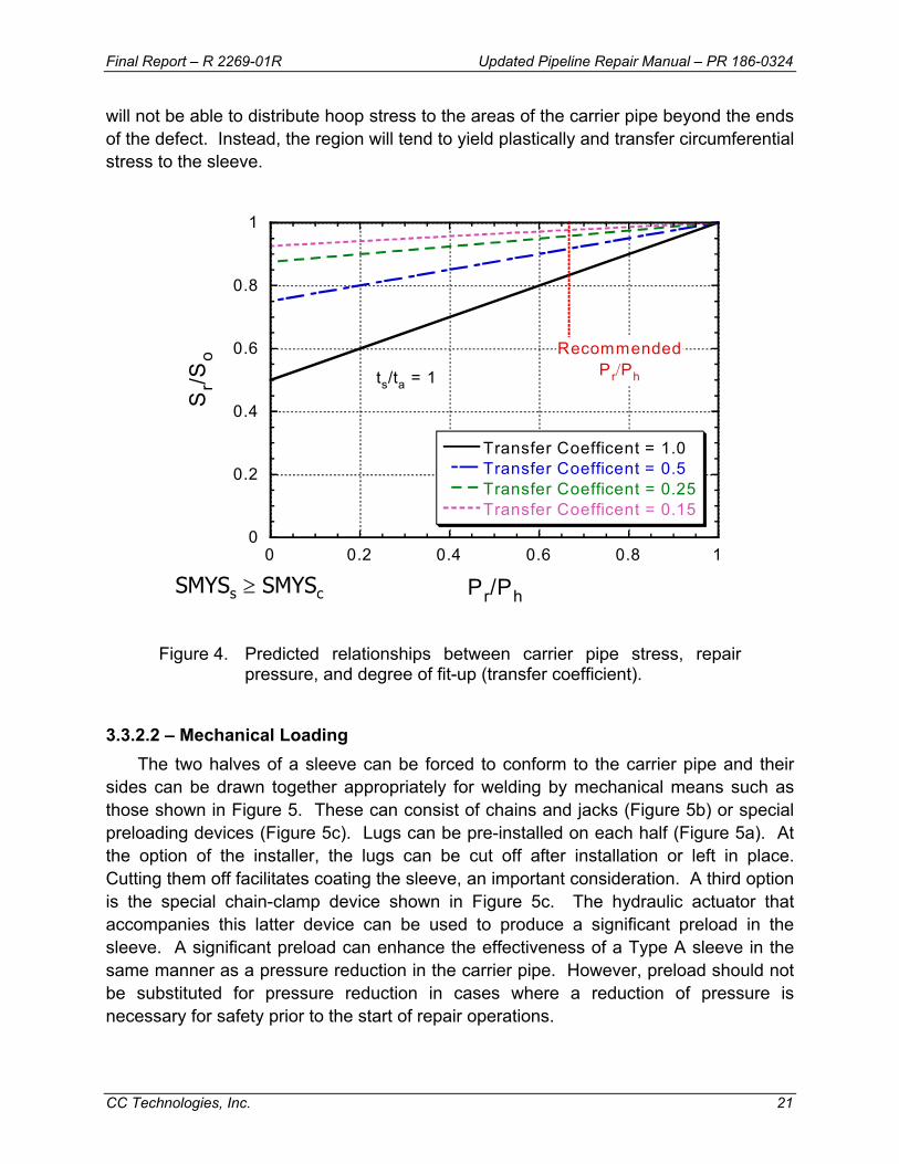
Figure 4. Predicted relationships between carrier pipe stress, repair pressure, and degree of fit-up (transfer coefficient). ................................ 21
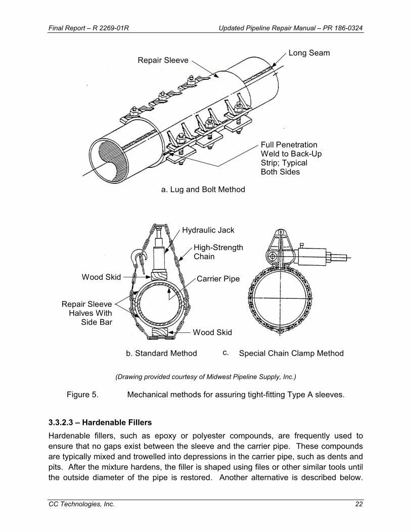
Figure 5. Mechanical methods for assuring tight-fitting Type A sleeves. ................ 22
Figure 6. Installation steps for the steel compression sleeve: (A) place half-sleeves on carrier pipe, (B) heat sleeve to expand sleeve, and (C) place field welds and cool assembly to achieve compression (drawing Courtesy of Petro-Line, Inc.). ............................... 25
Figure 7. Example of installed and sandblasted steel compression sleeve (photograph Courtesy of Petro-Line, Inc.)................................................ 25
Figure 8. Installation of a Type B repair sleeve. ...................................................... 26
Figure 9. Illustration of a Type B sleeve.................................................................. 27
Figure 10. Typical sleeve configuration for repair of girth welds (drawing courtesy of Allan Edwards Companies) ................................................... 31
Figure 11. Typical sleeve configuration for repair of couplings (drawing courtesy of Allan Edwards Companies). .................................................. 32
Figure 12. Sleeve-on-sleeve repair. .......................................................................... 33
Figure 13. Armadillo sleeve repair. ........................................................................... 34
Figure 14. Illustration of the Clock Spring® repair system (courtesy of Clock Spring Company, L.P.)................................................................... 36
Figure 15. Components of the Clock Spring® repair system: (1) composite wrap, (2) polymer adhesive, and (3) filler compound (courtesy of Clock Spring Company, L.P.)............................................................... 36
Figure 16. Completed Armor Plate™ repair at a branch connection (courtesy of Armor Plate, Inc.). ................................................................ 37

xii
FIGURES (continued)
Figure 17. Completed PermaWrap™ repair at a pipe bend (courtesy of WrapMaster, Inc.). ................................................................................... 37
Figure 18. Illustration of typical weld deposition sequence. ...................................... 42
Figure 19. Deposition of perimeter pass and several first layer passes. Initial attention was given to filling deeper areas in this example, simplifying filling of the remaining area..................................... 44
Figure 20. Grinding applied to perimeter pass and first layer. Separation between weld toe and ground surface should be about 1-2 mm (1/16 inch)................................................................................................ 44
Figure 21. Deposition of second perimeter pass and several second layer passes. Separation of the first and second perimeter pass weld toes should be approximately 1-2 mm (1/16 inch). .................................. 45
Figure 22. Completed repair. In this example, a portion of the wall loss was to be left un-repaired. ....................................................................... 45
Figure 23. Illustration of weld deposition sequence adapted to external repair of internal wall loss. ....................................................................... 47
Figure 24. Typical mechanical bolt-on clamp (courtesy of T. D. Williamson, Inc.).......................................................................................................... 49
Figure 25. Typical leak clamp (courtesy of T. D. Williamson, Inc.)............................ 50
Figure 26. Repairs for external corrosion.................................................................. 62
Figure 27. Repairs for internal corrosion................................................................... 63
Figure 28. Repairs for plain dents or dents with stress concentrators....................... 64
Figure 29. Repairs for longitudinal cracks and arc burns. ......................................... 65
Figure 30. Repairs for girth-weld defects. ................................................................. 66
Figure 31. Repairs for wrinkle bends/buckles. .......................................................... 67
Figure 32. Repairs for hard spots.............................................................................. 68
Figure 33. Repairs for blisters and HIC..................................................................... 69
Figure 34. Repairs for couplings. .............................................................................. 70
xiii
FIGURES (continued)
Figure 35. Repairs for defective prior repairs. ........................................................... 71
Figure 36. Acceptance criterion for circumferential extent of metal-loss defect. ...................................................................................................... 72

Final Report – R 2269-01R Updated Pipeline Repair Manual – PR 186-0324
CC Technologies, Inc. 1
1.0 – INTRODUCTION This manual is an updated version of the one produced in 1994.(1) As with the
original version, the manual provides guidance to pipeline operators for:
• Choosing an appropriate repair technique for a specific type of defect or combination of defects in an operating pipeline.
• Developing or improving their pipeline repair procedures and repair manuals. • Training or qualifying engineering and maintenance personnel.
This manual outlines and describes known and commonly accepted techniques for pipeline repairs, with major emphasis on methods that can be applied to in-service pipelines. The various repair methods and types of defects are summarized in a spreadsheet table where the applicability of each type of repair to a given type of defect is indicated. Defect assessment methods and safety considerations for making pipeline repairs are presented and reviewed.
Following the format of the earlier version,(1) the updated manual is divided into the following six sections and three appendices:
• Response to Discovery of an Anomaly or Defect. This section discusses how a pipeline operator should respond following the discovery of an anomaly or defect, including safety issues that should be addressed and information that is required to make an appropriate repair response.
• Pipeline Repair Methods. This section presents and describes the known and commonly accepted methods for repairing in-service pipelines.
• Appropriate Repairs for Various Types of Defects. This section points out and describes the types of in-service pipeline repair methods that are applicable to various types of defects found in operating pipelines.
• Repair Methods in Europe. This section reviews pipeline repair methods used in Europe. Information in the original version of the manual was obtained from the Groupe Européen de Recherches Gazières (GERG), whereas recent information was obtained from the European Pipeline Research Group (EPRG).
• Guidelines for a Repair Procedure. This section introduces a model procedure that can be used by a pipeline operator to create its own new repair procedure, enhance or update its existing procedure, or evaluate its existing repair procedure. In addition to the written version included in this manual (Appendix C), an electronic version is provided with this manual. The electronic version facilitates use of the generic repair procedures by pipeline operators.
• References. This section lists the references that are cited throughout the manual.

Final Report – R 2269-01R Updated Pipeline Repair Manual – PR 186-0324
CC Technologies, Inc. 2
• Appendix A. This appendix discusses the issues related to welding on an in-service pipeline. It includes information from the research that Edison Welding Institute has performed for PRCI.(2)
• Appendix B. This appendix summarizes various repair methods being used by pipeline operators based on a survey of PRCI member companies, other select operators, and providers of repair equipment and services. The authors and CC Technologies thank those who participated in the survey for taking time to respond to our queries and sharing information with us.
• Appendix C. This appendix contains the written version of a model pipeline repair procedure that can be used by a pipeline operator.
This manual does not identify or prescribe all repair methods for all defects or anomalies – no repair manual can serve this purpose. This manual concentrates on commonly encountered defects and commonly used methodologies. Other repair techniques may be equally valid depending on the specific conditions encountered.
This manual does not give requirements for evaluations or repair. It uses the word “should” to describe the actions commonly taken when evaluating or repairing an anomaly. Individual companies may choose to require some actions, making others advisory or replacing them with other actions.
Finally, this manual does not provide guidance on specific regulations or on code interpretation. National and international codes and regulations change rapidly, and code interpretation is best left to individual companies. On occasion, the manual may identify or comment on items commonly found in regulations, provided those items influence an analysis or repair. Also, footnotes identify specific sections of selected U. S. regulations.
2.0 – RESPONSE TO DISCOVERYb OF AN ANOMALY OR DEFECT When an operator discovers that a segment of its pipeline contains an anomaly or
defect, one extreme option is to shut down the pipeline, remove or release its contents, cut out the segment, and replace the cut-out segment with new pipe. This approach is usually very costly in terms of both lost revenue and disruption of service. For this reason, pipeline operators typically utilize in-service repair methods to restore the integrity of the operating pipeline without removing it from service. In some cases, though, it is both possible and desirable to remove a defective segment of pipe instead of repairing it. In the remainder of this manual, removal and replacement is referred to as repair by removal.
b The word ‘discovery’ is used as it is defined in Section 2.1 throughout this document. The U.S. Department of
Transportation (DOT) definition of the word ‘discovery’ includes the completion of an evaluation that determines whether an anomaly is a defect or an imperfection.

Final Report – R 2269-01R Updated Pipeline Repair Manual – PR 186-0324
CC Technologies, Inc. 3
Well-planned procedures and skilled, trained personnel are key factors in minimizing risk when in-service repair is chosen as the response to discovery of an anomaly or defect. Following the discovery of an anomaly or defect in an operating pipeline, a prudent operator considers the issues related to safety before undertaking an in-service repair. These issues include (1) evaluation of the necessity and the degree of pressure reduction before excavation, (2) consideration of personnel and public safety during excavation, (3) collection of critical information on the pipeline, and (4) characterization of the anomalies and location by direct inspection and testing during the excavation. The above issues are discussed in the remainder of this section of the manual.
2.1 – Key Definitions In addressing the need to investigate, analyze, and repair anomalies, some terms
are needed to describe specific actions. Key terms used in this manual include:
Term Definition
Anomaly A deviation from the norm. All engineering materials contain anomalies, which may or may not be detrimental to material performance.
Defect An anomaly with dimensions or characteristics that exceed acceptable limits.
Discovery The act of identifying or locating a previously unknown anomaly or condition in an operating pipeline.
Imperfection An anomaly with dimensions or characteristics that do not exceed acceptable limits.
Indication or Feature
A signal from an in-line inspection system that has been interpreted as an anomaly. An indication could be an imperfection, defect, or some other condition.
MAOP Maximum Allowable Operating Pressure
MOP Maximum Operating Pressure
Remediation An activity that transforms a defect or unacceptable condition to an acceptable one. Remediation could include repairs, pressure reductions, or other actions intended to preclude a defect from failing.
Repair The act of restoring a pipeline to sound condition after damage or injury
SMYS Specified Minimum Yield Strength
Unacceptable Condition A condition that requires action, such as a repair, as defined by an operator.
Final Report – R 2269-01R Updated Pipeline Repair Manual – PR 186-0324
CC Technologies, Inc. 4
2.2 – Pressure Reduction When a condition that could impair pipeline integrity is discovered, an operator may
need to reduce the operating pressure until remediation can be implemented. The purpose of a pressure reduction is to provide a margin of safety beyond that present when the condition was first discovered. Pressure reduction is usually a temporary measure that is implemented until remediation is completed. It is generally a short term approach, and the operator should consult local codes for guidance.
Conditions that could impair pipeline integrity include reported indications following an in-line inspection, a leak reported by an outside party, damage from outside sources, and anomalies observed during excavation. After learning that such a condition exists, an operator may begin lowering pressure and continue doing so until the condition is shown to be no immediate threat to pipeline integrity or the pressure has reached a safe level. Typically, the pressure is reduced to no more than 80% of what was first reported at the location. Alternatively, consideration can be given to factors such as a recent high pressure or the highest pressure experienced by the carrier pipe after the defect was present. Recent is typically considered to be no more than 1 year for a gas pipeline and no more than 60 days for a liquids pipeline. An anomaly is considered to be of no immediate threat to pipeline integrity if it can be established by an accepted remaining strength evaluation procedure and/or by lowering the pressure such that the pipeline’s failure pressure at the defect location is safely above (usually at least 20% above) the current pressure at that location.
ASME B31G(3) or RSTRENG(4) provides an accepted procedure for evaluating the remaining strength of a pipeline at the location of a local thin area in the pipe wall, such as that caused by localized corrosion. Engineering fracture mechanics is used to evaluate the remaining strength of pipelines with cracks or crack-like flaws. BS7910(5) and API RP 579(6) provide accepted procedures for evaluating the remaining strength of welded steel structures and piping with crack-like flaws. The same procedures can be applied to pipelines. The Log-Secant model,(7) CorLAS™,(8) and PAFFC(9) provide accepted fracture mechanics procedures specifically for assessing crack-like flaws in pipelines. CSA Z662(10) includes a recommended practice for determining the acceptability of cracks in fusion welds by using engineering critical assessment (analytical procedure based on fracture mechanics).
2.2.1 – Responses to Leak Surveys When a pipeline operator conducts a leak survey, it is possible that one or more
leaks will be discovered. The usual response is to reduce the operating pressure to no more than 80% of the level at the time of the survey and to maintain that reduced level as the maximum level until all leaks are examined and evaluated. The pressure reduction should be implemented at all leak locations along the pipeline.
Final Report – R 2269-01R Updated Pipeline Repair Manual – PR 186-0324
CC Technologies, Inc. 5
The pressure reduction should consider the local conditions at the leak site or sites. If the pipeline is shut-in, the shut-in level should be at least 20% below the lowest level at any leak at the time of its discovery. Once the pressure level is properly reduced and controlled at the reduced level, the operator may proceed to excavate, examine, and evaluate leaks.
2.2.2 – Responses to In-Line Inspection Results In-line inspection (ILI) results typically include a list of indications identified, their
locations, their types, and some measure of their severities. The degree of confidence in the last two factors depends on the inspection tool technology, the quality of the ILI run, the skill and experience of the interpreter of the ILI logs, and the pipeline operator’s level of experience with ILI. When the operator’s confidence in the ILI results is high, the potential impact of each indication on pipeline integrity is ranked in order of severity to establish a prioritized response list. In addition, the need for pressure reduction is established prior to excavation by using the predicted failure pressure based on the ILI results. For example, when an area of local metal loss is indicated, the failure pressure at this location is predicted using B31G,(3) RSTRENG,(4) or some other accepted procedure. Then, the predicted failure pressure is compared with the current maximum operating pressure at the same location to make sure that it is higher than the current maximum operating pressure by a safe margin.
When confidence in the ILI results is not high, it is possible that severe anomalies may exist without being identified as being severe. In this case, the operator may decide to reduce the operating pressure to a safe percentage (often 80%) of the highest level that was present around the period when the ILI was performed or of a recently documented high pressure (see Section 4.2.1). The reduced level of operating pressure would be maintained until either all indications have been examined and repaired as necessary or until the operator is confident that the remaining unexamined anomalies are no immediate potential threat to the pipeline’s integrity. The period of reduced operating pressure could be relatively long, such as in cases with numerous indications identified by a crack-detection tool. In such situations, it may be necessary to make additional periodic pressure reductions. The decision to do this is typically based on an engineering assessment of the potential for crack growth during future operations.
2.2.3 – Responses to Hydrostatic Pressure Test Failures Hydrostatic pressure testing may be used as a pipeline integrity assessment
method. If a failure occurs during such testing of a pipeline segment, a “removal” repair should be performed. Then, the pipeline segment is re-tested. This process is repeated until no additional test failures occur.
Final Report – R 2269-01R Updated Pipeline Repair Manual – PR 186-0324
CC Technologies, Inc. 6
2.2.4 – Other Pressure Reduction Considerations As indicated in the previous discussion, a pressure reduction is often considered
when an anomaly is discovered. The rationale for pressure reduction is that the pipeline may be on the verge of failure at the anomaly location. Pressure reduction to a safe percentage of that existing at the time of discovery provides a minimum level of assurance that the pipeline will not fail during examination and possible repair of the anomaly. Other conditions may necessitate additional pressure reductions. For example, as is discussed later, the effectiveness of a certain type of repair sleeve may depend on the amount of pressure reduction during installation and, thus, increase the desired amount of pressure reduction. Also, soil movement, settlement, and/or pipeline support conditions may impose unknown or difficult to predict stresses on pipeline in the region of the defect. In such cases, it is usually considered prudent to increase the amount of pressure reduction.
Cosham and Hopkins(11) have reviewed industry guidelines for pressure reductions prior to working near or on a damaged pipeline. The earlier version of this manual(1) recommended a minimum pressure reduction to 80% based on the rationale that lowering the operating pressure to 80% of the current value creates a safety margin of 1.25, which is the same as that of a hydrostatic pressure test to 1.25 times the operating pressure. Experimental studies of dents and gouges suggest failures do not occur unless the test pressure is above 85% of that at the time the damage was induced. Reduction to 80% of the pressure at the time of damage thus also provides some additional margin compared with the experimental results.
EPRG and National Grid Transco (formerly British Gas)(11) recommend pressure reduction to at least 85% of that at the time of the damage. When visual examination during excavation reveals the damage to be more than superficial or when ILI results categorize the damage as severe or extreme, National Grid Transco additionally recommends that the pressure be reduced to the lesser of 85% of that at the time of damage or to a value corresponding to a hoop stress of 30% SMYS. The 30% SMYS guideline is reportedly based on full-scale test results that show a rupture failure of part-wall or through-wall defect is unlikely at this stress level. Thus, the 30% SMYS guideline is based on considering the consequences of a failure.
2.3 – Excavation Safety Potential hazards accompany the excavation of an in-service pipeline. These
include damage from outside sources, such as that caused by the use of heavy excavating equipment, and the potential for cave-ins of the sides of the ditch. It is not within the scope of this manual to provide specific guidelines for excavation safety. However, users are urged to consider these hazards and to see that prudent procedures are followed so that adequate safety is assured and compliance with
Final Report – R 2269-01R Updated Pipeline Repair Manual – PR 186-0324
CC Technologies, Inc. 7
applicable legal requirements and safety regulations is satisfied. Users should also consider the pressure reduction guidelines discussed in Section 2.2 above.
2.4 – Critical Information for Repair Decisions A pipeline operator should have information on a number of important parameters
or factors to make an appropriate repair decision. These parameters and factors fit into the following five categories: (1) pipe material, (2) pipeline product and operating characteristics, (3) pipeline configuration, (4) pipeline location, and (5) nature and extent of the anomaly. The operator should also have information pertaining to the availability of repair materials and personnel, and be aware of the inherent risk involved in performing a repair. Knowledge of leak history, past defects found, and past repairs to the pipeline can also be useful. The more of these parameters that are known, the greater the confidence the operator can have in selecting a pipeline repair method.
2.4.1 – Pipe Material The operator should know the nominal diameter, nominal wall thickness, and
material grade for the pipeline to be repaired. It also is desirable to know the type of seam weld, pipe manufacturer, date of manufacture, coating type, chemical composition, and Charpy V-notch impact energy versus temperature (full curve) of the material. In some cases, additional information on fatigue and fracture toughness properties of the material is also desirable.
2.4.2 – Pipeline Operating Characteristics In order to undertake a pipeline repair, an operator should know the maximum
allowable operating pressure (MAOP) or the maximum operating pressure (MOP) of the pipeline. In addition, the operator should know the discrete point pressure at the location of the repair. Other characteristics that could affect a repair decision include the pressure fluctuations, operating temperatures, the type of product in the pipeline, and its flow velocity. If these characteristics are well known, then the operator can have a high degree of confidence in choosing a repair procedure.
The operator also should consider the influence of a repair on maintaining integrity during future operation of the pipeline. It should be determined whether the repair is permanent or temporary for anticipated future operating conditions. For a temporary repair, the convenience of performing a future repair, including removal, should be evaluated. The operator also should determine whether the repair will adversely affect future inspection or testing of the pipeline. In locations where flexibility is important or where loads other than internal pressure may affect the pipeline, the effect of possibly changing the pipeline’s local stiffness should be evaluated.

Final Report – R 2269-01R Updated Pipeline Repair Manual – PR 186-0324
CC Technologies, Inc. 8
2.4.3 – Pipeline Configuration The configuration of the pipeline at the point of repair should be known. If the
pipeline is not straight, it is essential to know the bend radius and the degree of pipe ovalization in order to plan a proper repair. It is also essential to know what appurtenances are present, if any, and the amount of seam and/or girth weld reinforcement in the area of the repair. The operator also should find out if any feature such as a mechanical coupling or an oxy-acetylene girth weld is present in the repair region. These often require special precautions regarding the amount of pipe that is excavated or the amount of pipe movement that can be tolerated.
2.4.4 – Pipeline Location Location attributes that may affect the choice of repair procedure include, but are
not limited to, offshore versus onshore, aboveground versus belowground, terrain, accessibility, and proximity to populated or environmentally sensitive areas.
2.4.5 – Nature and Extent of Anomaly Important factors that should be known regarding the nature of the anomaly include
answers to the questions listed below. The operator can use these questions as a checklist when planning an analysis or repair.
• Is the pipeline leaking? • Is the anomaly crack-like? • Is the pipeline indented? • Is the pipeline gouged? • Does the pipeline have corrosion-caused metal loss? • If corrosion has occurred, is it internal, external, or both? • Has some type of metal loss other than corrosion occurred? • Is the anomaly located near or on a weld? • If the anomaly is located on or near a weld, is it a girth or a seam weld?
At a minimum, the axial extent, circumferential extent, and depth of the anomaly should be known or measured. If the anomaly is a dent, the depth and extent of the dent should be measured. Likewise, if the defect is a bulge, the height and extent of the bulge should be known. If the defect is a wrinkle, its depth, height, length, and extent should be known. When any of these parameters is unknown or cannot be readily determined, the pipeline operator may have to make worst-case, conservative assumptions in choosing a repair method.
The potential effect on pipeline integrity of many types of anomalies, such as general wall thinning, local wall thinning, pitting corrosion, laminations, blisters, weld

Final Report – R 2269-01R Updated Pipeline Repair Manual – PR 186-0324
CC Technologies, Inc. 9
misalignment, cracks, grooves, gouges, and shell distortions, can be evaluated by performing a fitness-for-service (FFS) assessment(6) or an engineering critical assessment (ECA)(10). These types of assessments can be performed to show that an anomaly does not seriously degrade the serviceability and safety of the pipeline. If the nature and extent of the anomaly are such that it does not adversely affect pipeline integrity, it is usually preferable to make no repair except possibly to restore the protective coating if it is degraded or damaged.
2.4.6 – Available Repair Materials and Personnel The operator should know what materials and qualified personnel are available for
making a repair. This includes repair materials that the operator may stock or have to obtain from suppliers as well as the capabilities of both the operator’s and contractor’s personnel. Timelines for implementing various types of repairs at typical locations within the operator’s system should be established. These should include considerations for seasonal variations and typical variations in weather conditions. Knowledge of materials and personnel is especially important when repairs need to be made quickly.
2.4.7 – Inherent Risk in Performing Repair The operator should consider the inherent risk involved in performing a repair
procedure. This includes both the likelihood and consequence of a problem occurring during the repair process. Typically, the likelihood of a problem occurring increases as the complexity of the repair procedure increases. For example, applying a steel reinforcement (see Section 3.3.1) or composite sleeve (see Section 3.4) is usually less complex than applying a pressure-containment sleeve (see Section 3.3.4) because neither of the former requires welding to the pipeline whereas the latter does. The immediate consequence of making a mistake in the repair procedure is also important. For example, excessive grinding (see Section 3.2) or improper welding (see Section 3.5) on a pipeline could have a higher consequence than improper application of a steel reinforcement or composite sleeve.
3.0 – PIPELINE REPAIR METHODS Defects in pipelines may be repaired by a variety of methods. Those that have
been commonly used by pipeline operators include:
• Removal of a section of pipe and replacement with new pipe • Grinding an anomaly to significantly reduce its effect as stress concentrator or
site for crack initiation • Reinforcing a defective piece of pipe with an encircling sleeve

Final Report – R 2269-01R Updated Pipeline Repair Manual – PR 186-0324
CC Technologies, Inc. 10
• Placing a sealed pressure containment device (clamp or sleeve) over a defect, including one that is leaking
• Applying a composite wrap over corrosion and blunt wall-loss defects • Applying deposited weld metal in a defect to fill it with new material • Placing a patch or sole (partial encirclement reinforcement device) over a defect • Hot tapping to remove a defect
Descriptions of these methods are provided in this manual for the benefit of those who may not be familiar with one or more of them. Throughout this manual, we refer to temporary repairs. For our purposes, a temporary repair is a repair that will be re-evaluated within a period specified by the pipeline operator’s written procedures. Any repair that is left in service for a period greater than five years, without being re-examined, should be considered to be permanent.
3.1 – Removal and Replacement of a Defective Segment Sometimes it is both possible and desirable to remove a defective section of pipe
and replace it with new pipe rather than to attempt some other type of repair. Removal necessitates shutdown or isolation and depressurization of the affected pipeline segment. The defective section within the segment is then cut out as a cylinder. This removed section is in turn normally replaced with a pre-tested section of sound pipe, the tie-in welds are inspected, and the pipeline is returned to normal service. When pre-tested pipe is not used, the pipeline must be hydrostatically tested, as required by code, before the line is returned to service. In the remainder of this manual a removal and replacement repair is referred to simply as a removal repair.
3.1.1 – Isolation by Freeze Plug One option is to temporarily isolate the area to be repaired using a freeze plug.(12)(13)
A freeze plug is a pipeline freezing procedure that uses liquid nitrogen to freeze the product, or hydrostatic test water, and isolate the section to be repaired. The method involves applying a freeze jacket upstream and downstream to the area of interest. Liquid nitrogen is pumped into the jacket, which is equipped with several temperature probes that monitor the plug’s growth. The areas of pipe outside the cutout region are typically inspected for defects, which may initiate a brittle fracture in the pipe under the very cold conditions.
When a freeze plug is fully formed, the temperature at the outside edge of the jacket should be well below the temperature at which the product can exist as anything other than a solid. This system has been designed to withstand pressures up to 55.16 MPa (8000 psi) without failure. The process allows for isolating sections shorter than valve-to-valve on the pipe; however, the freeze time for a plug to fully develop can range from two to five hours. Standard freeze plugs range in size from 13 mm (0.5-inch) to 1.22 m

Final Report – R 2269-01R Updated Pipeline Repair Manual – PR 186-0324
CC Technologies, Inc. 11
(48-inch) outside diameter (OD). Pipeline products that are suitable for freeze plug application include water and treated water, brine, glycols, chemicals, sewage, oils and petroleum products, heavier hydrocarbons, and slurries.(12)
3.1.2 – Hot Tie-In or Hot Repair Hot tie-in or hot repair, which is described in detail elsewhere,(14) refers to the
method of repairing a gas pipeline by removal under controlled conditions with a burning gaseous atmosphere present. Rather than purging the pipeline with an inert gas, the repair or cutting operation is carried out with the product still in line. This is achieved by performing welding and cutting operations with a low positive pressure of gaseous product in the pipeline. The pressure is high enough to prevent ingress of air in to the pipeline, which would result in the creation of an explosive mixture, but it is low enough to ensure that the resulting ignition of escaping product does not produce excessively large flames that would place the personnel and equipment involved in the repair in danger.
Appropriate weld procedures need to be established, as there will be arc interference and metallurgical changes in the weld metal. Because this technique involves the release of gas, properly trained personnel together with well planned procedures are necessary. Some safety considerations for a hot tie-in or hot repair procedure include the following:
• All personnel involved have appropriate training and clear instructions of the task.
• The potential for an explosive atmosphere, due to air ingress requires detailed investigation and planning prior to undertaking the repair.
• Monitoring for explosive mixture is recommended. Particular attention should be given to elevation differences along the repair section as this could have a bearing on the ability to control air ingress.
• In order to carry out this procedure on pipelines containing liquids, i.e. gathering lines, condensate and oil may be present. The line should be pigged prior to the hot cut to remove the liquid.
• Effective communications via 2-way radio is essential at the work-site, mainline valves and the communication centre.
• This repair method relies on the presence of a flame during the cutting and welding operations, therefore, suitable flame retardant safety wear should be adopted.
The gas purge required for a hot tie-in or hot repair procedure must maintain a positive pressure throughout the operation. This may be achieved by a regulator system or via the bypass on the mainline valves. Caution must be exercised if gas is regulated through a ball valve, as a high differential pressure exists.
Final Report – R 2269-01R Updated Pipeline Repair Manual – PR 186-0324
CC Technologies, Inc. 12
3.2 – Grinding Hand filing or power disk grinding can be used to repair a defect or imperfection in a
pipeline if the following criteria are satisfied:
1. The stress concentrating effect of the defect or imperfection is eliminated. 2. All damaged or excessively hard or soft metal (metal with an altered
microstructure) is removed. 3. The amount and distribution of removed metal does not significantly reduce the
pressure-carrying capacity of the pipeline.
Historical precedents for using grinding as a repair technique are discussed in this section. Then, guidelines for its application to pipelines are presented.
API Specification 5L for line pipe(15) permits manufacturers to remove a defect from new pipe by grinding so that the ground area blends in smoothly with the pipe contour, provided that it can be eliminated without reducing the remaining pipe wall thickness to a value less than a specified limit. For welded pipe greater than or equal to 508 mm (20 inches) in diameter and of Grade X42 or higher, the minimum allowable thickness after repair grinding is 8% less than the nominal thickness. For seamless pipe greater than or equal to 508 mm (20 inches) in diameter and of Grade X42 or higher, the minimum allowable thickness after repair grinding is 10% less than the nominal thickness. For all Grade B or lower pipe and for Grade X42 or higher pipe less than 508 mm (20 inches) in diameter, the minimum allowable thickness after repair grinding is 12.5% less than the nominal thickness.
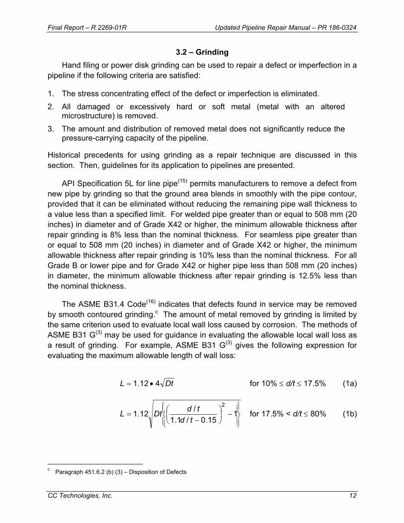
The ASME B31.4 Code(16) indicates that defects found in service may be removed by smooth contoured grinding.c The amount of metal removed by grinding is limited by the same criterion used to evaluate local wall loss caused by corrosion. The methods of ASME B31 G(3) may be used for guidance in evaluating the allowable local wall loss as a result of grinding. For example, ASME B31 G(3) gives the following expression for evaluating the maximum allowable length of wall loss:
DtL 412.1 •= for 10% ≤ d/t ≤ 17.5% (1a)
−
−= 1
15.0/1.1/12.1
2
tdtdDtL for 17.5% < d/t ≤ 80% (1b)
c Paragraph 451.6.2 (b) (3) – Disposition of Defects

Final Report – R 2269-01R Updated Pipeline Repair Manual – PR 186-0324
CC Technologies, Inc. 13
Where
D = nominal outside diameter of the pipe L = maximum allowable longitudinal extent of the ground area d = measured maximum depth of the ground area t = nominal wall thickness of the pipe
ASME B31.8(17) permits the field repair of gouges and groovesd and mechanical damage, including cracks, where any associated indentation of the pipe is not greater 4% of the nominal diametere by smooth contoured grinding. For gouges and grooves, at least 90% of the nominal wall thickness should remain after grinding.f
Grinding removal of mechanical damage, including cracks, is allowed by ASME B31.8 to depths up to a maximum of 40% of the nominal wall thickness if the length of the ground area does not exceed the value given by the following equation:
−
−= 1
11.0/1.1/12.1
2
tdtdDtL (2)
For depths of 10% or less, there is no limit on the grinding length. Values computed using Equation (2) are less (more conservative) than comparable ones computed using Equation (1b). After grinding, the surface should be inspected to make sure that no detectable cracks are present and examined after etching to make sure that metallurgically altered material has been removed.
CSA Z662(10) also permits grinding as a permanent repair method. For arc burns, examination after etching is required to ensure the removal of metallurgically altered material. For gouges, grooves, and cracks, liquid-penetrant or magnetic-particle inspection should be performed to confirm complete removal of the defect. The length of grinding is not limited for depths up to 10% of the nominal wall thickness. Grinding is permitted up to a maximum depth of 40% of the nominal wall thickness, provided that the length of the ground area is no more than that allowed by ASME B31G(3), by the RSTRENG 0.85 dL method,(4) or by the RSTRENG effective area method.(4)
Areas of metal loss resulting from grinding beyond the length or depth limits discussed above, should be considered to be grind defects. Pipe containing grind defects should be repaired using one or more of the other acceptable repair methods described in this manual. This approach typically is used to remove cracks that are deeper or longer than would acceptable to remove by grinding alone. The grind defect
d Paragraph 841.242 – Field Repair of Gouges and Grooves e Paragraph 851.42 (c) (3) – Permanent Field Repairs of Injurious Dents and Mechanical Damage f Paragraph 841.113 (b)] – Additional Requirements for Nominal Wall Thickness t in Paragraph 841.11
Final Report – R 2269-01R Updated Pipeline Repair Manual – PR 186-0324
CC Technologies, Inc. 14
then is typically repaired using a steel reinforcement sleeve (see Section 3.3.1) or a composite (see Section 3.4).
Researchers at British Gas studied the use of grinding for repair of pipelines.(18) They showed that grinding can be done safely at a reduced stress level (85% of the level that the defect can be proven to have experienced) and that grinding does not introduce cracks below the surface of the ground area. They recommend leaving a remaining wall thickness of at least 4.1 mm (0.16 inch). They also suggest use of a grinder with less than 460 watts of power (0.62 hp), that the ground area be smoothly contoured, and that the grinding wheel not be oriented at an angle of more than 45 degrees to the surface to avoid creating grooves. They found no adverse effects, such as unfavorable metallurgical transformations, from heat generated during grinding, probably because of the low power grinder that they used.
The grinding procedure should avoid excessive heat input into the pipe while removing defects. Grinding with a rigid sanding disk, when not performed properly, typically tends to introduce heat into the material more rapidly than grinding with a flap wheel. The grinding disk should be angled into the material just under 180° to the plane of its surface using a back and forth sweeping motion with moderate pressure. Using an angle near 90° to the plane of surface causes grooving, and applying too much pressure on the grinder causes excessive heating of the material. Excessive heating might be indicated by molten red metal particles being thrown away by the wheel and a tinting or “bluing” of the steel in the area of grinding. The ground area should be warm to the touch, not excessively hot.
Extra caution should be taken when doing grinding repairs on electric-resistance welded (ERW) pipe, especially pre-1970 vintage ERW pipe. The concern with old ERW pipe is that the seam weld is difficult to locate, may have low toughness, and may contain imperfections. Modern ERW pipe manufactured using the high-frequency welding process can be of high quality and toughness. Unless the operator is certain that the ERW seam has high quality and toughness, grinding of the seam area should not be performed unless special precautions are taken, such as reducing the pressure to a very low level until a through nondestructive examination is completed.
With appropriate limitations, one can see from the preceding discussions that grinding is a widely accepted permanent repair technique for pipelines. It is therefore reasonable to permit grinding as a means of defect repair under the following conditions:
• Operating pressure should be reduced to a safe level, as discussed previously in Section 2.2. When grinding beyond the allowable limits produces a grind defect for subsequent repair by another acceptable method, additional pressure reduction may be necessary. The amount of additional pressure reduction is
Final Report – R 2269-01R Updated Pipeline Repair Manual – PR 186-0324
CC Technologies, Inc. 15
determined by an engineering assessment using the maximum depth and length allowed for the grind defect.
• Limits on metal removal of non-indented defects should be the same as those allowed by an accepted criterion for metal loss, such as ASME B31.8, (17) ASME B31G or RSTRENG. The ASME B31.8 criterion for acceptable length of metal removal is more conservative than the ASME B31G criterion. When grinding exceeds acceptable limits, another acceptable method of repair should be used in addition to grinding.
• Grinding of defects in a dented region should be permitted with additional restrictions to those given above. One source of guidelines is ASME B31.8.(17) The depth of the dented region and the extent of grinding allowed should be carefully evaluated to ensure a safe repair.
• Grinding should be permitted for the removal of defects that are to be subsequently repaired by the application of a sleeve, provided that an engineering assessment is performed to establish a maximum allowable length and depth for grinding and a corresponding safe level of reduced operating pressure during grinding.
• The removal of cracks and stress concentrators should be verified by means of liquid-penetrant or magnetic-particle inspection. Furthermore, if the defect is an arc burn, removal of metallurgically altered material should be confirmed by examination after applying an etching solution. CSA Z662 requires etching with a 10% solution of ammonium persulphate or a 5% solution of nital (nitric acid in methanol).
• If the anomaly is a crack, stress concentrator, metallurgically damaged material, or other defect that cannot be entirely removed by grinding to the limits indicated above, the attempt to repair by grinding should be abandoned and another, more suitable repair method should be employed. A more suitable repair method could include additional grinding followed by an acceptable repair of the resulting grind defect.
3.3 – Full-Encirclement Steel Sleeves Full-encirclement steel sleeves have historically been a widely used method for
general repair of defects in onshore pipelines. Because they involve welding, they are generally not applicable to the repair of defects in offshore pipelines. In the early 1970s, the American Gas Association funded a major project(19-22) on the effectiveness of various repair methods with emphasis on full-encirclement sleeves. The results of this work showed that a properly fabricated steel sleeve restores the strength of a defective piece of pipe to at least 100% of SMYS. The keys to properly fabricating a sleeve are the use of a proven procedure and skilled personnel.
Most of the previous research on steel repair sleeves has addressed only their response to static pressures and lateral loads. Their response to repeated pressure cycles has not been studied in depth. Pressure-cycle fatigue tests were performed as
Final Report – R 2269-01R Updated Pipeline Repair Manual – PR 186-0324
CC Technologies, Inc. 16
part of an in-depth evaluation of steel compression sleeves.(23) (24) When they are used to repair defects in pipelines subjected to significant cyclic pressurization, steel sleeves are likely to have a finite time to failure. In the case of a reinforcing sleeve, the useful life might be controlled by the repaired defect, whereas in the case of a pressure-containing sleeve, the sleeve itself would be the critical component. Whenever a steel sleeve is to be used in cyclic service, its fatigue resistance should be evaluated. The results of the fatigue evaluation should be used to establish a suitable limit on the allowed service life before replacement is required.
3.3.1 – Type A Sleeves (Reinforcing) The Type A sleeve is particularly attractive because it can be installed on a pipeline
without welding it to the carrier pipe. Such a sleeve provides reinforcement for the defective area. It cannot contain pressure and is used only for nonleaking defects. It should be installed at a pressure level below that at which the area of the line pipe with the defect might be expected to fail.
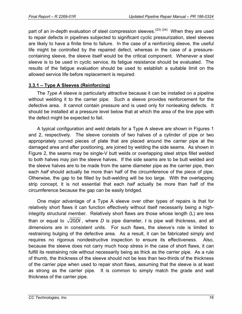
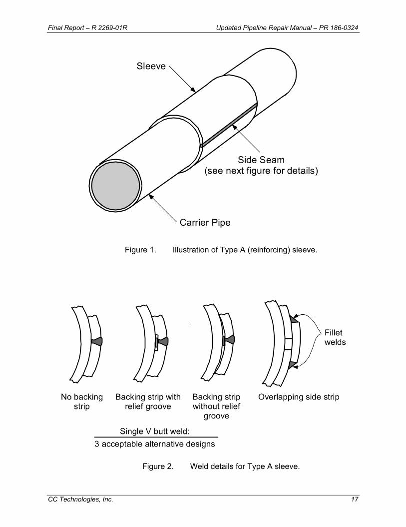
A typical configuration and weld details for a Type A sleeve are shown in Figures 1 and 2, respectively. The sleeve consists of two halves of a cylinder of pipe or two appropriately curved pieces of plate that are placed around the carrier pipe at the damaged area and after positioning, are joined by welding the side seams. As shown in Figure 2, the seams may be single-V butt welds or overlapping steel strips fillet welded to both halves may join the sleeve halves. If the side seams are to be butt welded and the sleeve halves are to be made from the same diameter pipe as the carrier pipe, then each half should actually be more than half of the circumference of the piece of pipe. Otherwise, the gap to be filled by butt-welding will be too large. With the overlapping strip concept, it is not essential that each half actually be more than half of the circumference because the gap can be easily bridged.
One major advantage of a Type A sleeve over other types of repairs is that for relatively short flaws it can function effectively without itself necessarily being a high-integrity structural member. Relatively short flaws are those whose length (L) are less than or equal to Dt20 , where D is pipe diameter, t is pipe wall thickness, and all dimensions are in consistent units. For such flaws, the sleeve’s role is limited to restraining bulging of the defective area. As a result, it can be fabricated simply and requires no rigorous nondestructive inspection to ensure its effectiveness. Also, because the sleeve does not carry much hoop stress in the case of short flaws, it can fulfill its restraining role without necessarily being as thick as the carrier pipe. As a rule of thumb, the thickness of the sleeve should not be less than two-thirds of the thickness of the carrier pipe when used to repair short flaws, assuming that the sleeve is at least as strong as the carrier pipe. It is common to simply match the grade and wall thickness of the carrier pipe.
Final Report – R 2269-01R Updated Pipeline Repair Manual – PR 186-0324
CC Technologies, Inc. 17
Side Seam(see next figure for details)
Sleeve
Carrier Pipe
Figure 1. Illustration of Type A (reinforcing) sleeve.
Filletwelds
Overlapping side strip
Single V butt weld:3 acceptable alternative designs
No backingstrip
Backing strip withrelief groove
Backing stripwithout relief
groove
Figure 2. Weld details for Type A sleeve.
Final Report – R 2269-01R Updated Pipeline Repair Manual – PR 186-0324
CC Technologies, Inc. 18
With flaws longer than Dt20 , the sleeve thickness should be at least as great as that of the carrier pipe, again assuming that the sleeve is at least as strong as the carrier pipe. It is permissible to use sleeves thinner than the carrier pipe if their strength is increased by an amount sufficient to compensate for their thickness being less than that of the carrier pipe. In a similar fashion, the sleeve could be of an acceptable material with lower strength than that of the carrier pipe if its thickness is increased to compensate for the difference is strength. To assure that adequate restraint exists and that the sleeve will indeed prevent a rupture, the sleeve should be extended onto sound, full-thickness pipe at least 50 mm (2 inches) beyond the ends of the defect. The operator should design the repair to carry anticipated loads.
The Type A sleeve has some minor disadvantages. It is not useful for circumferentially oriented defects because it has no effect on the longitudinal stress in the carrier pipe. Secondly, it cannot be used to repair leaking defects. Thirdly, it creates a potential crevice in the form of an annular space between it and the carrier pipe that may be difficult to protect from corrosion. However, there have been no reported service failures caused by this potential problem. Because of this potential problem, however, some companies use full-encirclement sleeves as Type A sleeves, but weld the ends to the pipe to prevent further corrosion, thus making them essentially Type B sleeves.
3.3.2 – Assuring Effective Reinforcement To be effective, the Type A sleeve should reinforce the defective area, restraining it
from bulging radially as much as possible. First and foremost, the sleeve should be installed with a minimal gap between the sleeve and the carrier pipe in the area of the anomaly. Forming and/or positioning the sleeve so that it firmly contacts the carrier pipe, especially at the area of the defect, can assure that the gap is minimized. One or more of the following actions (discussed separately in this sub-section) can further enhance the effectiveness of a Type A sleeve:
• Reduce pressure in the carrier pipe during sleeve installation. • Externally load the sleeve to force it to fit tightly against the carrier pipe. • Use a semi-liquid material that will fill and harden in any gaps in the annular
space between the sleeve and the carrier pipe. • Apply special fit-up procedures for seam welds. • Use special epoxy-filled shells.
3.3.2.1 – Pressure Reduction Pressure reduction is essential if the defect being repaired is at or near its predicted
failure pressure at the start of the repair operation. If the pressure is not reduced in such a case, the repaired defect could begin leaking after the sleeve is installed. In
Final Report – R 2269-01R Updated Pipeline Repair Manual – PR 186-0324
CC Technologies, Inc. 19
contrast, when the pressure is reduced, the radial bulging at the defect location is reduced and can be prevented from recurring during re-pressurization by using a tightly fitting sleeve. Research results(19)(20) indicate that a pressure reduction of 33-1/3% from the predicted failure pressure was adequate for the application of Type A sleeves.
Typically, a pressure reduction is not necessary if it can be shown that the defect is not at or near its predicted failure pressure. For example, if calculations based on the size of the defect show that its predicted failure pressure is 33-1/3% or more above the current pressure, a Type A sleeve can effectively repair it without a reduction in pressure.
Reinforcing sleeves usually do not share much of the hoop stress that is acting on the carrier pipe unless special application techniques are used. Even if the sleeve fits perfectly and has 100%-efficient side seams, it will at most carry one-half of the hoop stress recovered after a pressure reduction if its wall thickness is that same as that of the carrier pipe. The optimum amounts of stress sharing produced by a snugly fitting sleeve for various amounts of pressure reduction are illustrated in Figure 3. The notation used in Figure 3 is as follows:
ta = actual wall thickness of carrier pipe
ts = wall thickness of steel sleeve
So = initial hoop stress in carrier pipe
Sr = reduced hoop stress in carrier pipe after installation of steel sleeve
Pr = reduced pressure at time sleeve is applied
Ph = highest pressure previously experienced by the carrier pipe after defect was present.
SMYSc = specified minimum yield strength of carrier pipe.
SMYSS = specified minimum yield strength of sleeve.
The actual amount of hoop stress supported by the sleeves is usually much less than indicated on the graph due to variations in fit and efficiency of side seams. In spite of this, a properly fabricated sleeve can restore the strength of a defective piece of pipe to at least 100% of SMYS.

Final Report – R 2269-01R Updated Pipeline Repair Manual – PR 186-0324
CC Technologies, Inc. 20
0
0.2
0.4
0.6
0.8
1
0 0.2 0.4 0.6 0.8 1
ts/ta = 0.5ts/ta = 1.0ts/ta = 2.0ts/ta = 4.0
Sr/S
o
Pr/Ph
RecommendedPr/Ph
Optimum Fit
SMYSs x ts/ta ≥ SMYSc
Figure 3. Theoretical relationships between carrier pipe stress, repair pressure, and wall thickness.
Figure 4 shows predicted amounts of stress sharing for various degrees of less than optimum fit-up with a sleeve of the same wall thickness as the carrier pipe. The degree of fit-up was modeled using a load transfer coefficient as follows:
• 1.0 for ideal case of perfect fit-up, which is never approached in practice without mechanical loading
• 0.50 for a strong highly compressed epoxy filler, such as that used in tight-fitting compression sleeves (see Section 3.3.2.6)
• 0.25 for typical tight-fitting sleeve with epoxy filler • 0.15 for typical tight-fitting sleeve with epoxy filler only in the defect area
One can see that there is much less transfer of hoop stress to the sleeve in the realistic cases than in the ideal case. Since the main function of sleeves is to prevent radial bulging at the defect, it is not necessary for them to carry much stress. However, they should fit snugly to restrain bulging.
Sleeves used to repair long defects (i.e., L ≥ Dt20 ) should be capable of sustaining a significant amount of hoop stress and are expected to absorb an appreciable amount of hoop stress. The reason is that a long defect-weakened region
Final Report – R 2269-01R Updated Pipeline Repair Manual – PR 186-0324
CC Technologies, Inc. 21
will not be able to distribute hoop stress to the areas of the carrier pipe beyond the ends of the defect. Instead, the region will tend to yield plastically and transfer circumferential stress to the sleeve.
0
0.2
0.4
0.6
0.8
1
0 0.2 0.4 0.6 0.8 1
Transfer Coefficent = 1.0Transfer Coefficent = 0.5Transfer Coefficent = 0.25Transfer Coefficent = 0.15
Sr/S
o
Pr/Ph
RecommendedPr/Phts/ta = 1
SMYSs ≥ SMYSc
Figure 4. Predicted relationships between carrier pipe stress, repair pressure, and degree of fit-up (transfer coefficient).
3.3.2.2 – Mechanical Loading
The two halves of a sleeve can be forced to conform to the carrier pipe and their sides can be drawn together appropriately for welding by mechanical means such as those shown in Figure 5. These can consist of chains and jacks (Figure 5b) or special preloading devices (Figure 5c). Lugs can be pre-installed on each half (Figure 5a). At the option of the installer, the lugs can be cut off after installation or left in place. Cutting them off facilitates coating the sleeve, an important consideration. A third option is the special chain-clamp device shown in Figure 5c. The hydraulic actuator that accompanies this latter device can be used to produce a significant preload in the sleeve. A significant preload can enhance the effectiveness of a Type A sleeve in the same manner as a pressure reduction in the carrier pipe. However, preload should not be substituted for pressure reduction in cases where a reduction of pressure is necessary for safety prior to the start of repair operations.
Final Report – R 2269-01R Updated Pipeline Repair Manual – PR 186-0324
CC Technologies, Inc. 22
a. Lug and Bolt Method
Repair SleeveLong Seam
Full PenetrationWeld to Back-UpStrip; TypicalBoth Sides
(Drawing provided courtesy of Midwest Pipeline Supply, Inc.)
Figure 5. Mechanical methods for assuring tight-fitting Type A sleeves.
3.3.2.3 – Hardenable Fillers Hardenable fillers, such as epoxy or polyester compounds, are frequently used to ensure that no gaps exist between the sleeve and the carrier pipe. These compounds are typically mixed and trowelled into depressions in the carrier pipe, such as dents and pits. After the mixture hardens, the filler is shaped using files or other similar tools until the outside diameter of the pipe is restored. Another alternative is described below.
b. Standard Method b. Special Chain Clamp Method
Repair SleeveHalves With
Side Bar
Wood Skid
Wood Skid
Hydraulic Jack
High-StrengthChain
Carrier Pipe
c.
Final Report – R 2269-01R Updated Pipeline Repair Manual – PR 186-0324
CC Technologies, Inc. 23
Before the mixture hardens, the sleeve halves are placed around the pipe, and mechanical means, such as those described above, are used to squeeze the excess filler material. By the time the side seams of the sleeve have been welded, the filler mixture has usually solidified and load transfer between the sleeve and the carrier pipe is assured at all defect locations. Tests performed on pipe sections with filled gouges and dents(19)(20) showed that such fillers are very effective.
3.3.2.4 – Fit-Up on Submerged-Arc-Welded and Flash-Welded Line Pipe One concern with respect to applying Type A sleeves is the presence of a crown or
reinforcement on the seam weld of submerged-arc-welded (SAW) carrier pipe or the flash on flash-welded carrier pipe. To assure a tight-fitting sleeve, three options are available. The first option is to remove the weld crown or flash by grinding it flush to the surface of the carrier pipe. This option is acceptable if the pressure has been reduced as suggested in Section 3.3.2.1. The second option is to grind a compensating groove in one of the sleeve halves. If this second option is selected, it may be desirable or necessary (in the case of long defects) to use a sleeve that is thicker than the carrier pipe by an amount that compensates for the thickness of material removed, including any compensation needed for differences in material strength. The third option is to force the unmodified sleeve over the weld reinforcement after sufficient filler material has been deposited to fill the expected gaps. This third option is acceptable if the resulting fit-up of the sleeve halves is adequate for side-seam fabrication. With the standard method of application shown in Figure 5b, there is no risk of damaging the weld. This third option should not be used with relatively high-force methods, such as lug and bolt (Figure 5a) or chain clamp (Figure 5c), as local bending adjacent to the seam weld reinforcement may result.
3.3.2.5 – Epoxy-Filled Shells British Gas developed a variation of the filled-sleeve concept in the form of their
epoxy-filled shell repair method.(25) In this case, the shell is a sleeve with a standoff distance of several millimeters from the carrier pipe. The shell is placed on the defective pipe, and bolts are used to center it. The side seams are then welded, and the gaps at the ends are sealed with trowelled filler. After these seals have hardened, epoxy is pumped into the annular space until it comes out an overflow hole at the top of the sleeve.
Once the epoxy filler has hardened, the radial bulging tendency of the defect is restrained by the epoxy in the same manner as a conventional Type A sleeve would have if it were directly in contact with the sleeve. Data have been presented(26) that show that the epoxy-filled shell also can be used to repair weakened, but not leaking, girth welds. Bonding between the epoxy and the sleeve and the epoxy and the pipe
Final Report – R 2269-01R Updated Pipeline Repair Manual – PR 186-0324
CC Technologies, Inc. 24
permits the transfer of longitudinal stress. If the sleeves are used for an under-water repair, an epoxy that cures properly in water should be used.
3.3.2.6 – Steel Compression Sleeves Steel compression sleeves are a special class of Type A sleeves. They are
designed, fabricated, and applied so that the repaired section of the carrier pipe is maintained under compressive hoop stress during subsequent operation. This approach is attractive for repairing longitudinally oriented crack-like defects because without a tensile hoop stress there is no driving force for crack growth. This type of sleeve is not suitable for the repair of circumferential cracks or for defects in field bends. CSA Z662(10) addresses the use of steel compression sleeves.g
Steel compression sleeves involve installing two sleeve halves over the defect area and drawing them together using clamps, jacks and chains, or lugs and bolts. The sleeve halves are then welded together using conventional welding techniques. Pressure reduction during installation is normally used to induce compression in the carrier pipe. Thermal contraction of the longitudinal seam welds also promotes compression in the carrier pipe. Epoxy filler is used between the carrier pipe and sleeve to achieve the transfer of stresses. As pointed out previously, pressure reduction alone will only transfer a portion of the hoop stress from the carrier pipe to the sleeve.
PetroSleeve™ is a commercial product that was developed to combine pressure reduction with thermal shrinkage of the sleeve for achieving full compression in the carrier pipe. Figure 6 illustrates the installation process for PetroSleeve™. Two steel sleeve halves with sidebars are installed over the defect, the sleeve halves are heated, and are initially held in place with chain clamps or hydraulic jacks. The halves are then welded together using two longitudinal sidebars. During installation, an epoxy layer is applied between the sleeve and the carrier pipe. The epoxy is used as a lubricant when the halves are placed on the carrier pipe and later acts as a filler to evenly transfer the load between the sleeve and the pipe. As with other versions of Type A sleeves, no welds are made to the carrier pipe. Thermal shrinkage of the sleeve upon cooling helps induce a compressive stress into the carrier pipe.(23) A completed PetroSleeve installation is shown in Figure 7.
Several factors influence the degree of stress reduction in the carrier pipe. These include the fit of the sleeve, the pipe wall thickness and diameter, the sleeve wall thickness, the internal pressure during installation, and the installation temperature. Specially developed software can be used to determine the target sleeve installation temperature and to help confirm that the desired amount of sleeve compression has been achieved.(27)
g Paragraph 10.8.5.4.4 – Steel Compression Reinforcement Sleeve Repair

Final Report – R 2269-01R Updated Pipeline Repair Manual – PR 186-0324
CC Technologies, Inc. 25
Quality control procedures for PetroSleeve™ involve monitoring sleeve temperature during the heating process and verification of the achieved carrier pipe compression by measuring how far the two sleeve halves advance towards each other using caliper measurements. Three sets of measurements on each side of the sleeve are typically made. Nondestructive inspection of the completed welds is conducted after cooling.
Figure 6. Installation steps for the steel compression sleeve: (A) place half-sleeves on
carrier pipe, (B) heat sleeve to expand sleeve, and (C) place field welds and cool assembly to achieve compression (drawing Courtesy of Petro-Line, Inc.).
Figure 7. Example of installed and sandblasted steel compression sleeve
(photograph Courtesy of Petro-Line, Inc.).

Final Report – R 2269-01R Updated Pipeline Repair Manual – PR 186-0324
CC Technologies, Inc. 26
PetroSleeve has been commercially available since 1994 and has been installed primarily as a means to repair stress corrosion cracking, corrosion, and dents. It also has been used as a permanent field repair method on long-seam indications and arc burns.(28) PetroSleeve uses a fillet welded overlapping side strip for the longitudinal seams. Since the installation of a PetroSleeve induces a compressive stress into the carrier pipe sleeve, the PetroSleeve itself must be in a high state of tension. Fillet welds are not ideal when loaded in tension because of the bending moment that results. Operators may want to consider whether fillet welded overlapping side strips are appropriate, particularly for pipelines subjected to significant cyclic pressurization.
3.3.3 – Type B Sleeves: Pressure Containing or Capable of Containing Pressure The other type of steel sleeve used to make pipeline repairs is known as a Type B
sleeve. The ends of a Type B sleeve are fillet welded to the carrier pipe. The installation of a Type B sleeve is shown in Figures 8. Detailed discussions of the issues related to welding on an in-service pipeline are presented in Appendix A. Since its ends are attached to the carrier pipe, a Type B sleeve can be used to repair leaks and to strengthen circumferentially oriented defects. In fact, a Type B sleeve has been used in place of a girth weld to make a tie-in on a pipeline. Because a Type B sleeve may contain pressure and/or carry a substantial longitudinal stress imposed on the pipeline by lateral loads, it should be designed to carry the full pressure of the carrier pipe. Additionally, it should be carefully fabricated and inspected to ensure its integrity.
Figure 8. Installation of a Type B repair sleeve.

Final Report – R 2269-01R Updated Pipeline Repair Manual – PR 186-0324
CC Technologies, Inc. 27
3.3.3.1 – Design The typical configuration of a Type B sleeve is illustrated in Figure 9. It consists of
two halves of a cylinder or pipe or two appropriately curved plates fabricated and positioned in the same manner as those of a Type A sleeve. Since the Type B sleeve is designed to contain full operating pressure, the ends are welded to the carrier pipe, and butt-welded seams are recommended. For a sleeve that will be pressurized, the overlapping strip concept of Figure 2 is not recommended because it is inherently weaker than a sound full-thickness butt weld and because it would be vulnerable to the stresses induced by direct internal pressurization. A Type B sleeve should be designed to the same standard as the carrier pipe. This usually means that the wall thickness of the sleeve will be equal to that of the carrier pipe and that the grade of the sleeve material also will be equal to that of the carrier pipe. It is acceptable to use a sleeve that is thicker or thinner than the carrier pipe and is of lesser or greater yield strength than the carrier pipe as long as the pressure-carrying capacity of the sleeve is at least equal to that of the carrier pipe. Many companies simply match the wall thickness and grade of the pipe material.
Side Seam(butt weld only; overlappingside strip not recommended)
Sleeve
Carrier Pipe
End Fillet Weld
End Fillet Weld
Figure 9. Illustration of a Type B sleeve.
The diameter of the sleeve is slightly greater than that of the carrier pipe so it fits
over the carrier pipe. Usually, this point is ignored in the sleeve design even though it causes the sleeve to be slightly under-designed when it’s made from the same material as the carrier pipe. If material is removed from the sleeve for a groove to accommodate the carrier pipe seam weld or a backing strip for the sleeve side seam welds, the
Final Report – R 2269-01R Updated Pipeline Repair Manual – PR 186-0324
CC Technologies, Inc. 28
thickness of the sleeve should be greater than that of carrier pipe by an amount that compensates for the material that is to be removed. If the sleeve thickness exceeds that of the carrier pipe by more than 2.4 mm (3/32 inch), it is recommended that the ends be tapered to the carrier pipe thickness on a 4 to 1 slope (four units along the sleeve for one unit of thickness). It is also recommended that the leg lengths of the fillet welds be equal to the thickness of the carrier pipe. Additional discussion pertaining to fillet weld size is provided in Appendix A.
3.3.3.2 – The Importance of Quality Fabrication Type B sleeves are more likely to pose fabrication problems than Type A sleeves.
Poor fit may lead to inadequate quality side seams, which in turn will degrade the pressure-carrying capacity of the sleeve. The end fillet welds are also possible sources of problems. A Type B sleeve installed over a leak that develops a leak itself is potentially as severe a problem as the defect that it was intended to repair.
Implementation of Type B sleeves requires (1) the development of adequate and appropriate welding procedures and (2) the training and qualification of personnel specifically for the purpose of fabricating such sleeves. The objectives of the procedures, training, and qualification should be to assure full-penetration side-seam butt welds and crack-free end fillet welds. Low-hydrogen consumables should be employed, and the recommended practices outline in Appendix B of API STD 1104(29) or some other recognized industry standard should be followed.
There are two primary concerns with welding onto an in-service pipeline. The first is for maintenance crew safety during repair welding, since there is a possibility of the welding causing the pipe wall to be penetrated and allowing the contents of the pipe to escape. The second concern is for the integrity of the system following repair welding, because welds made in service typically cool at an accelerated rate as a result of the ability of the flowing contents to remove heat from the pipe wall. These welds, therefore, may have hard heat-affected zone (HAZ) microstructures and may be susceptible to hydrogen cracking. Detailed discussion of the issues related to welding onto an in-service pipeline is provided in Appendix A.
3.3.3.3 – Sleeve Length While it should be long enough to extend beyond both ends of the defect by at least
50 mm (2 inches), there is no inherent upper limit to the length of a Type B sleeve. However, practical considerations are likely to impose some limits on sleeve length. If the sleeve length is limited, two requirements should be satisfied. First, as mentioned previously, the sleeve should extend at least 50 mm (2 inches) beyond both ends of the defect. Second, the fillet-welded end of one sleeve should not be any closer than one-half of the carrier pipe diameter to the corresponding end of another sleeve. This latter requirement is needed to avoid a notch-like condition between the two sleeves. If two

Final Report – R 2269-01R Updated Pipeline Repair Manual – PR 186-0324
CC Technologies, Inc. 29
sleeves should be placed closer than one-half pipe diameter apart, the inboard ends of the sleeves should not be welded to the carrier pipe. Instead, a bridging sleeve-on-sleeve should be used (see Section 3.3.4.3).
Another important factor that should be considered when installing long sleeves is the weight that is being added to the pipeline in conjunction with how it is being supported during the sleeve installation process. When the sleeve length exceeds four pipe diameters or when two or more sleeves whose total length exceeds four pipe diameters are to be installed within a single excavation, the pipeline operator’s written procedures should contain guidelines for support spacing, methods of temporary support (e.g., air bags, sand bags, skids), and soil conditions under the pipeline upon backfilling.
3.3.3.4 – Leaking Defects One use for a Type B sleeve is to repair a leaking defect. A Type B sleeve installed
over a leak becomes a pressure-carrying component and should meet the same integrity requirements as any other pressure-carrying component in the system. These include the appropriateness of the design (i.e., wall thickness, material grade) and the integrity of the side seams and end fillet welds.
Type B sleeves are installed over leaks in a variety of ways. One common method is to place a small branch pipe with a valve over a hole in one of the sleeve halves. The hole and branch are located over the leak. Chains and hydraulic jacks are then used to force the sleeve halves against the carrier pipe. In some cases, a neoprene ring is placed so that it is compressed by this process to form a seal around the leak and force the fluid to enter the branch. The fluid then can be released at a safe location and welding of the sleeve can be completed safely. Upon completion of sleeve fabrication, the branch valve is closed and capped. A variation of the same technique uses a plug to seal the branch through the valve, which allows the valve to be recovered.
3.3.3.5 – Nonleaking Defects Type B sleeves are sometimes used to repair nonleaking defects. In the past, some
pipeline operators used Type B sleeves exclusively because they preferred to have the ends sealed by fillet welds even when no leak existed. Other operators have installed Type B sleeves over nonleaking defects and then hot-tapped through the sleeve and pipe to pressurize the sleeve and relieve hoop stress from the defective area. With the advent of new repair methods, such as steel compression sleeves (see Section 3.3.2.6) and composite sleeves (see Section 3.4), and concerns for possible cracking and failures at the end fillet welds, some operators have reduced their use of Type B sleeves in recent years.
Final Report – R 2269-01R Updated Pipeline Repair Manual – PR 186-0324
CC Technologies, Inc. 30
Even though a Type B sleeve may not be pressurized, any sleeve with ends welded to the carrier pipe should be designed and fabricated to be capable of sustaining the pressure in the pipeline, since there is a chance that it could later become pressurized. This is necessary because the sleeve may become pressurized at a later time. For example, if a Type B sleeve is used to repair internal corrosion and the internal corrosion continues, a leak could develop in the carrier pipe and pressurize the sleeve.
3.3.3.6 – Inspection Requirements The installation or fabrication of any repair requiring welding on an in-service carrier
pipe should be preceded by ultrasonic inspection to determine the remaining wall thickness of the carrier pipe in the regions where welding is to be performed. For the case of fillet welds around the ends of a Type B sleeve, it is reasonable to measure the wall thickness at 50-mm (2-inch) intervals along the circumferential path where the weld is to be located. If welding is to be performed on external pits, the pit depth should be determined by measuring from the original external pipe surface if possible. If the remaining wall thickness cannot be adequately determined, welding should not be attempted with the carrier pipe in service.
Repair sleeve welds (sleeve-half butt welds and sleeve fillet welds) should be inspected after welding to help assure weld integrity. Weld joints are usually inspected by means of magnetic-particle inspection (MPI), liquid-penetrant inspection (LPI), or ultrasonic shear wave inspection. Automated and advanced ultrasonic inspection techniques are sometimes applied to assure the integrity of critical welds. Whatever method or combination of methods is employed, operator skill, training, and experience are critical to achieving a successful inspection. MPI or LPI is expected to reveal surface-connected indications, with MPI typically being more sensitive than LPI. Grinding the toe smooth facilitates the inspection of fillet welds. The best assurance of a quality repair is the use of a proven qualified procedure and a highly trained and qualified repair specialist.
3.3.4 – Special Sleeve Configurations The special-purpose sleeve configurations described in the following sub-sections
may by useful for certain applications.
3.3.4.1 – Sleeves to Repair Girth Welds The typical configuration of a sleeve used to repair a defective or leaking girth weld
is shown in Figure 10. The hump in the sleeve is designed to accommodate the crown of the girth weld. The ends are welded to the carrier pipe so that the sleeve can share the longitudinal stress. This type of sleeve is expected to contain a leak and does reinforce the girth weld to some extent.

Final Report – R 2269-01R Updated Pipeline Repair Manual – PR 186-0324
CC Technologies, Inc. 31
Figure 10. Typical sleeve configuration for repair of girth welds (drawing courtesy of
Allan Edwards Companies)
3.3.4.2 – Sleeves to Repair Couplings
Many older pipelines have joints that were made using couplings. For small diameter pipes, these may be threaded couplings. For large-diameter pipelines, as well as for some small-diameter ones, mechanical compression-type couplings were used. Typically, these couplings rely on longitudinally oriented bolts and collars that are used to compress packing or gaskets to seal against the pipe. These types of couplings provide negligible longitudinal stress transfer along the pipeline. As a result, they are prone to pullout incidents when the pipeline is subject to unusual longitudinal loads. To overcome both the pullout problem and the perennial leakage problem with this type of coupling, many pipeline operators have resorted to the repair sleeve configuration shown in Figure 11. This type of sleeve, often called a pumpkin or balloon sleeve, is typically welded to the pipes on both ends. The side seams are also welded so that the sleeve can contain pressure. Because the mechanical couplings tend to transfer little or no longitudinal stress along the pipeline, the fillet welds at the ends of this type of sleeve become the primary means of longitudinal stress transfer. Therefore, the quality of the fillet welds for such a sleeve is even more critical than that of the welds at the ends of a conventional Type B sleeve.
A pumpkin sleeve may be used to repair buckles, ovalities, and wrinkle bends because of its ability to fit over such anomalies.

Final Report – R 2269-01R Updated Pipeline Repair Manual – PR 186-0324
CC Technologies, Inc. 32
Figure 11. Typical sleeve configuration for repair of couplings (drawing courtesy of Allan
Edwards Companies).
3.3.4.3 – Sleeve-On-Sleeve Repair
Experience with cracking at the toes of fillet welds around the ends of conventional Type B sleeves led to the development of the sleeve-on-sleeve configuration shown in Figure 12. This configuration consists of two rings installed outboard to the ends of the defective sleeve. Each ring is fillet welded to the carrier pipe on the end facing the end of the defective sleeve. If a toe crack forms at one or both of the rings, it will be contained within the space between the ring and the sleeve. The final step consists of installing two outer sleeves to bridge the gaps between the rings and the defective sleeve. These outer sleeves are fillet welded to both the rings and the defective sleeve to make a leak-tight repair in case the toe crack grows through the wall of the carrier pipe. A test program(30) showed that this configuration is expected to adequately protect an existing toe crack from causing the pipeline to fail.
3.3.4.4 – Sleeve Configurations for Curved (Field-Bent) Pipe It is possible to install a conventional Type A or Type B sleeve on a curved piece of
pipe. The shorter the sleeve, the better the fit will be on a curved section of pipe. For a Type A sleeve, the annular space created by the curvature could be filled with a hardenable material to provide contact with the carrier pipe. A relatively short Type B sleeve could be installed effectively, but beyond some length that depends on the pipe size and amount of curvature, a straight Type B sleeve will not fit well enough to a curved pipe to permit a satisfactory installation.
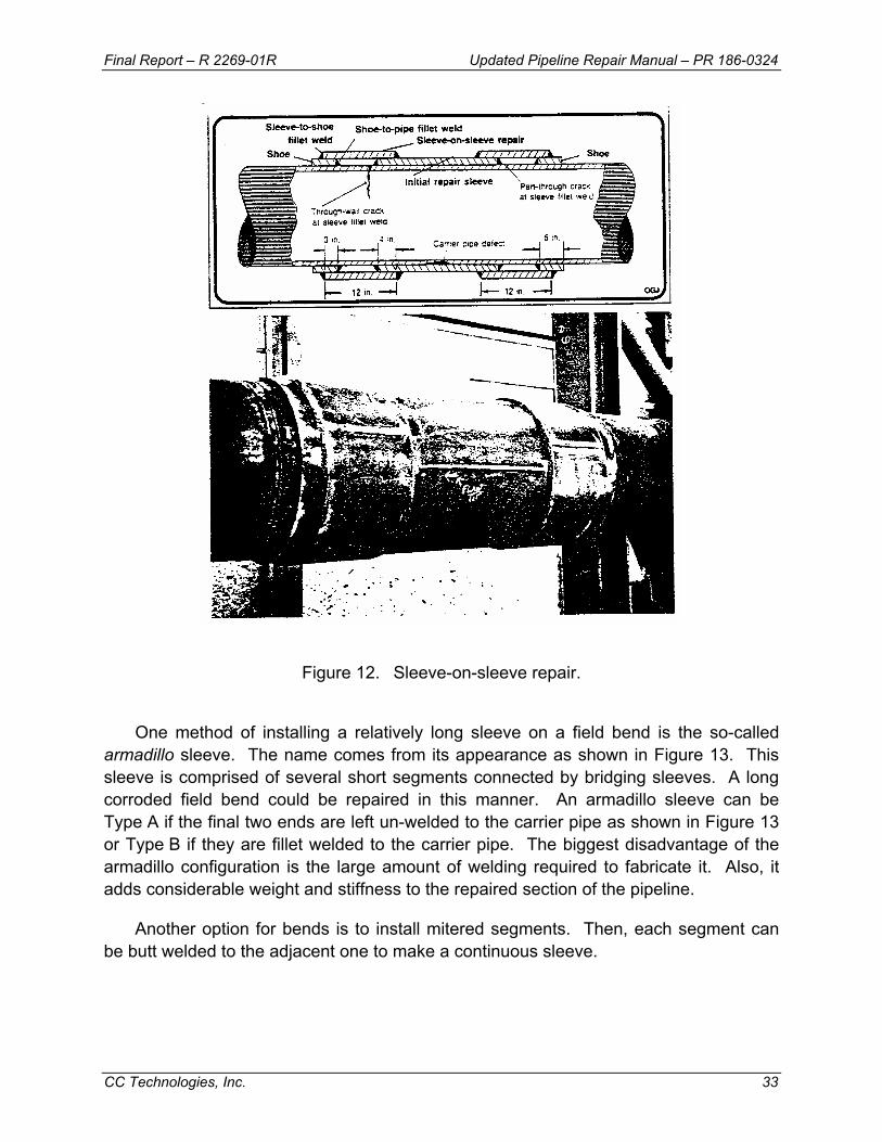
Final Report – R 2269-01R Updated Pipeline Repair Manual – PR 186-0324
CC Technologies, Inc. 33
Figure 12. Sleeve-on-sleeve repair.
One method of installing a relatively long sleeve on a field bend is the so-called armadillo sleeve. The name comes from its appearance as shown in Figure 13. This sleeve is comprised of several short segments connected by bridging sleeves. A long corroded field bend could be repaired in this manner. An armadillo sleeve can be Type A if the final two ends are left un-welded to the carrier pipe as shown in Figure 13 or Type B if they are fillet welded to the carrier pipe. The biggest disadvantage of the armadillo configuration is the large amount of welding required to fabricate it. Also, it adds considerable weight and stiffness to the repaired section of the pipeline.
Another option for bends is to install mitered segments. Then, each segment can be butt welded to the adjacent one to make a continuous sleeve.

Final Report – R 2269-01R Updated Pipeline Repair Manual – PR 186-0324
CC Technologies, Inc. 34
Figure 13. Armadillo sleeve repair.
3.4 – Defect Repair Using Composite Reinforcement Sleeves Composite materials have been used in aerospace structural applications for many
years. In recent years, composite sleeves have been developed and used for the repair of nonleaking pipeline defects. The various composite sleeves are proprietary products produced by specific vendors. Most of the composites are fiberglass materials, but some are other types of materials, such as carbon fiber-based composites. There are two basic types of fiberglass composites being used as reinforcement sleeves. One is a rigid material, while the other is a flexible material. The production quality of the rigid materials is controlled in the factory, whereas the flexible materials are applied and cured in the field. The rigid materials are limited to relatively straight sections of pipe much as steel sleeves. The flexible materials can be applied to bends, elbows, and tees.
The advantages of composite reinforcements compared with steel sleeves are easier handling of the materials, lower skill requirements for installation personnel, more rapid installation, and lower overall cost. The training to learn to install composite reinforcements typically can be completed in one day or two days. Proper personnel qualification and training and carefully following the manufacturer’s installation procedures are essential to ensure proper installation and satisfactory performance of a composite repair.
Composite repair methods have been proven and have gained regulatory and code acceptance for specific applications, such as blunt corrosion defects. They have been accepted as a permanent repair method for blunt wall-loss defects by the U.S. Department of Transportation (DOT) and are permitted by CSA Z662.(10) Because composite repair is still expanding and evolving into new applications, the following discussion is not intended to restrict their use but rather to describe the key elements of performance and testing that should be addressed to gain confidence in their use. The discussion addresses composite reinforcements in general.
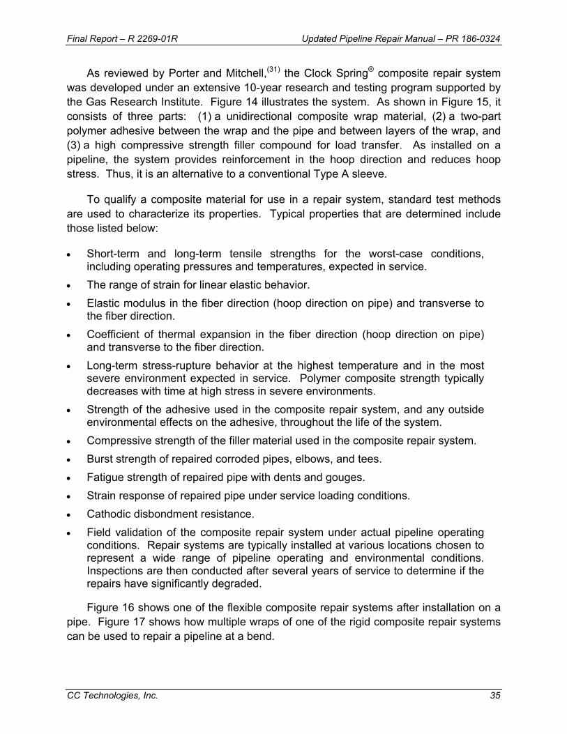
Final Report – R 2269-01R Updated Pipeline Repair Manual – PR 186-0324
CC Technologies, Inc. 35
As reviewed by Porter and Mitchell,(31) the Clock Spring® composite repair system was developed under an extensive 10-year research and testing program supported by the Gas Research Institute. Figure 14 illustrates the system. As shown in Figure 15, it consists of three parts: (1) a unidirectional composite wrap material, (2) a two-part polymer adhesive between the wrap and the pipe and between layers of the wrap, and (3) a high compressive strength filler compound for load transfer. As installed on a pipeline, the system provides reinforcement in the hoop direction and reduces hoop stress. Thus, it is an alternative to a conventional Type A sleeve.
To qualify a composite material for use in a repair system, standard test methods are used to characterize its properties. Typical properties that are determined include those listed below:
• Short-term and long-term tensile strengths for the worst-case conditions, including operating pressures and temperatures, expected in service.
• The range of strain for linear elastic behavior. • Elastic modulus in the fiber direction (hoop direction on pipe) and transverse to
the fiber direction. • Coefficient of thermal expansion in the fiber direction (hoop direction on pipe)
and transverse to the fiber direction. • Long-term stress-rupture behavior at the highest temperature and in the most
severe environment expected in service. Polymer composite strength typically decreases with time at high stress in severe environments.
• Strength of the adhesive used in the composite repair system, and any outside environmental effects on the adhesive, throughout the life of the system.
• Compressive strength of the filler material used in the composite repair system. • Burst strength of repaired corroded pipes, elbows, and tees. • Fatigue strength of repaired pipe with dents and gouges. • Strain response of repaired pipe under service loading conditions. • Cathodic disbondment resistance. • Field validation of the composite repair system under actual pipeline operating
conditions. Repair systems are typically installed at various locations chosen to represent a wide range of pipeline operating and environmental conditions. Inspections are then conducted after several years of service to determine if the repairs have significantly degraded.
Figure 16 shows one of the flexible composite repair systems after installation on a pipe. Figure 17 shows how multiple wraps of one of the rigid composite repair systems can be used to repair a pipeline at a bend.
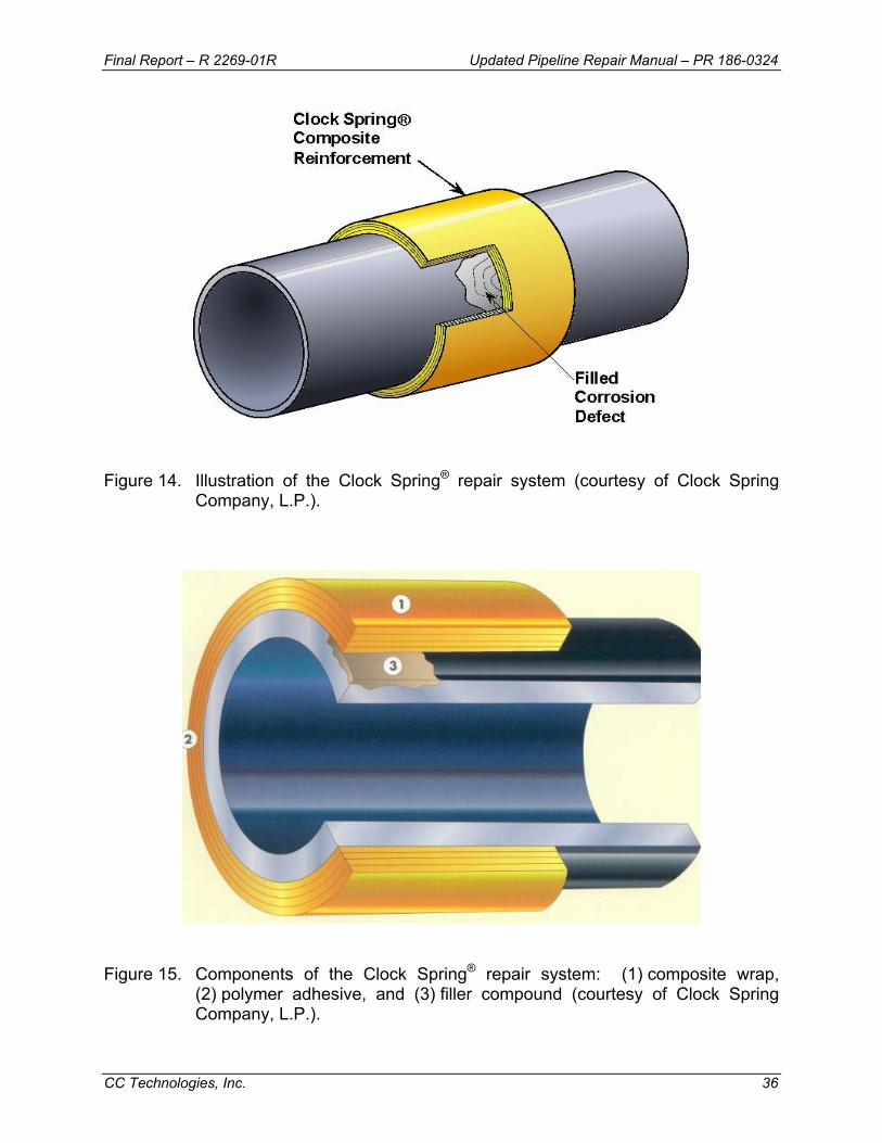
Final Report – R 2269-01R Updated Pipeline Repair Manual – PR 186-0324
CC Technologies, Inc. 36
Figure 14. Illustration of the Clock Spring® repair system (courtesy of Clock Spring
Company, L.P.).
Figure 15. Components of the Clock Spring® repair system: (1) composite wrap,
(2) polymer adhesive, and (3) filler compound (courtesy of Clock Spring Company, L.P.).
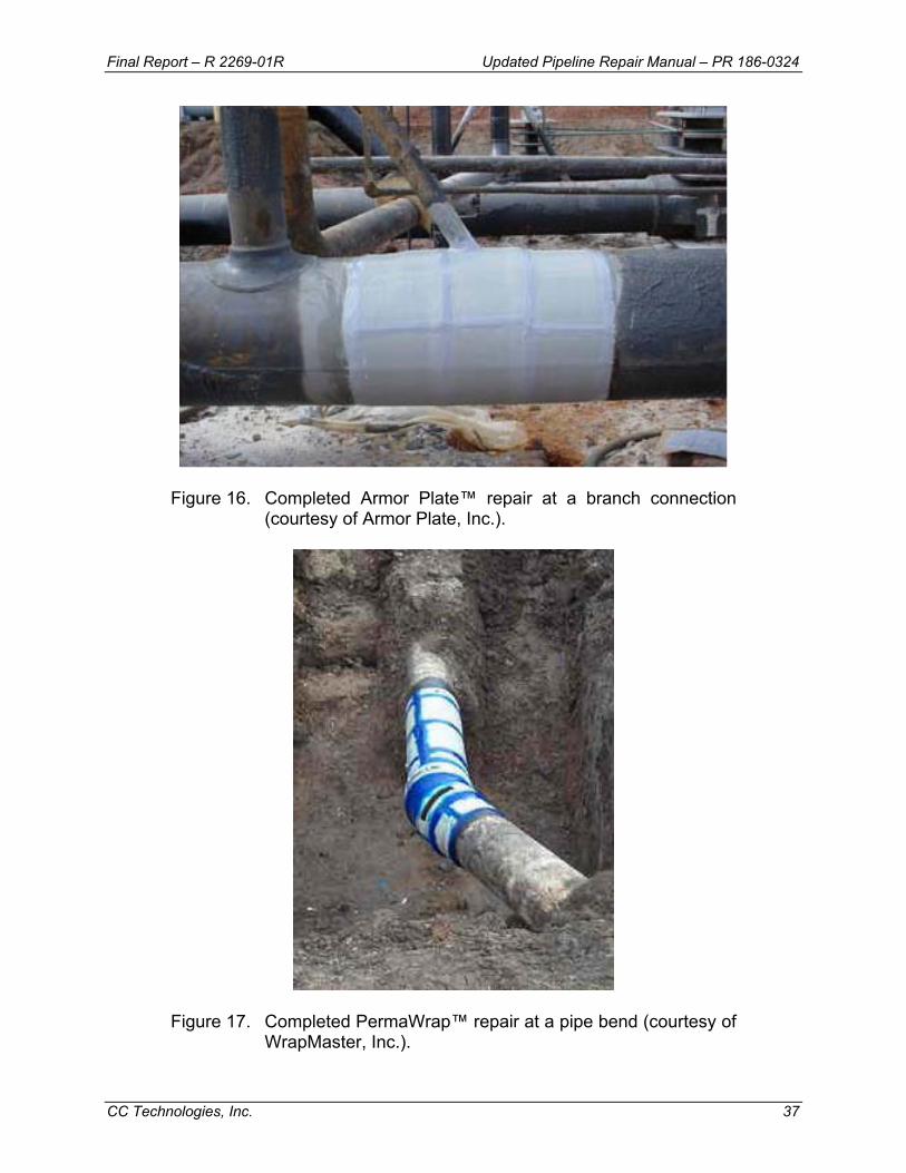
Final Report – R 2269-01R Updated Pipeline Repair Manual – PR 186-0324
CC Technologies, Inc. 37
Figure 16. Completed Armor Plate™ repair at a branch connection (courtesy of Armor Plate, Inc.).
Figure 17. Completed PermaWrap™ repair at a pipe bend (courtesy of WrapMaster, Inc.).

Final Report – R 2269-01R Updated Pipeline Repair Manual – PR 186-0324
CC Technologies, Inc. 38
3.4.1 – Design of Repair Using Composite Reinforcements Composite reinforcement repairs should satisfy the same fundamental design
criteria as steel sleeves. Composite repairs of defects should be demonstrated by means of testing and/or analysis to be capable of withstanding a hydrostatic pressure test to the maximum test pressure level for the repaired location without threat to subsequent pipeline integrity throughout the life of the repair. This pressure level is usually that equivalent to a minimum stress of 100% SMYS in the pipeline.
A composite repair can be designed using detailed analysis and testing when little design data and field experience are available or using graphs and tables and/or special-purpose software provided by the manufacturer. For a given length, width, depth, and severity (degree of stress concentration) defect, the composite reinforcement design procedures should define the following four parameters:
• The minimum thickness of reinforcement required • The pressure at which the repair system should be installed • The pretension load that should be applied to the composite material • The minimum length of reinforcement needed beyond the ends of the defect
The minimum thickness establishes the fundamental level of reinforcement that can be obtained with the repair. Generally, composite thickness should increase as the defect depth and length increase. Just as with steel sleeves, the installation pressure helps control the fit-up and amount of preload that is achieved. Sleeve performance and repair integrity are improved as the ratio of repair pressure to operating pressure is decreased (see Figures 3 and 4). The composite sleeve should not end at the end of the defect edge but should extend at least 50 mm (2 inches) beyond the defect. Similar to installation pressure, pretension of the reinforcement helps control the fit-up and amount of preload achieved. However, pre-tensioning typically produces much less preload than clamping or shrink-fit methods used with steel sleeves.
3.4.2 – Requirements for Using Composite Sleeves CSA Z662 (10) includes requirements for the use of fiberglass composite sleeves.
These were used to formulate the following general requirements for the application of composite sleeves to permanent pipeline repair. The first set of requirements is that applicable to any type of reinforcing sleeve:
• The sleeve should extend longitudinally at least 50 mm (2 inches) beyond the ends of the defect.
• If present, internal corrosion should be arrested. • Consider the concentration of bending stresses in the pipe at the ends of a
repair sleeve and between closely spaced repair sleeves.
Final Report – R 2269-01R Updated Pipeline Repair Manual – PR 186-0324
CC Technologies, Inc. 39
• Consider the design compatibility of the repair sleeve and piping materials. • Consider the spacing of other devices on the pipe. • Ensure adequate support of the repair sleeves during installation and operation. • Make sure that sleeve is acceptable for present and future operating and
pressure-testing conditions.
The second set of requirements is that specifically applicable to composite reinforcing sleeves:
• Based on the results of stress-rupture tests, the repair system should have an extrapolated minimum service life of at least 50 years.
• The system should show satisfactory performance in cathodic disbondment tests.
• Results of immersion tests should show that the product in the pipeline does not degrade the system.
• The load-carrying capacity of the repaired pipe should be at least equal to that of the originally installed pipe.
• An engineering assessment should be performed to determine the stress transfer from the pipe to the sleeve. The maximum stress on the sleeve should not exceed the maximum allowed stress level based on results of the stress-rupture tests. The assessment also should determine the maximum allowable pressure permitted during the installation and curing of the sleeve system.
• The repair system should be designed to operate over the temperature range expected during operation of the pipeline.
• Storage, handling, transportation, and installation of sleeve system components should be carried out in accordance with manufacturer's specifications and procedures. This should include protection from ultraviolet (UV) radiation on exposed pipe that has been wrapped with a composite.
• Personnel who install the sleeves should be trained and qualified in the installation procedures. There should be a written procedure for personnel to follow during the installation process. The procedure should include design calculations, preparation of the pipe surface, preparation and application of the adhesive and filler materials, sealing of the ends of the sleeve, curing of the repair materials, back filling, and all other steps necessary for a proper repair.
3.5 –Weld Deposition Repair Pipeline repair by direct deposition of weld metal, or weld deposition repair, is an
attractive alternative to the installation of full-encirclement sleeves or composite reinforcement for repair of wall loss defects on in-service pipelines.(32) This is especially true for wall loss in bend sections and fittings, where the installation of full-encirclement sleeves and composite reinforcement is difficult or impossible. Weld deposition repair is

Final Report – R 2269-01R Updated Pipeline Repair Manual – PR 186-0324
CC Technologies, Inc. 40
attractive because it is direct, relatively quick and inexpensive to apply, does not create additional corrosion concerns, and requires no additional materials beyond welding consumables.
3.5.1 – Background There are two primary concerns with welding onto in-service pipelines and piping
systems. The first is for maintenance crew safety. During repair, welding there is a risk of the welding arc penetrating the pipe wall, allowing the contents to escape. The second concern is for the integrity of the system following repair welding, since welds made in service typically cool at an accelerated rate as the result of the flowing contents' ability to remove heat from the pipe wall. These welds, therefore, may have hard heat-affected zone (HAZ) microstructures and may be susceptible to hydrogen cracking.
Detailed discussion of the issues related to welding onto in-service pipeline is provided in Appendix A. The two primary concerns, as they relate to weld deposition repair, are discussed briefly below.
3.5.2 – Burnthrough A burnthrough will occur when welding onto a pressurized pipe if the unmelted area
beneath the weld pool has insufficient strength to contain the pressure within the pipe. The risk of burnthrough will increase as the pipe wall thickness decreases and the weld penetration increases. For weld deposition repair, the remaining ligament (i.e., the effective wall thickness) tends to be thin. Penetration of the welding arc into the pipe wall is a function of the welding parameters and, to a lesser degree, the welding process. Penetration increases as heat input increases, or for a given heat input, as the welding current increases.
3.5.3 – Hydrogen Cracking When welding onto an in-service pipeline, fast cooling rates result from the
presence of the pressurized, flowing contents that tends to remove heat from the pipe wall, and as a result of heat input limitations needed to control the risk of burnthrough. These fast weld cooling rates, combined with high-carbon-equivalent (CE) material typical of older pipelines, tends to result in the development of hard, crack-susceptible weld microstructures. The development of these microstructures tends to make in-service pipeline repair welds particularly susceptible to hydrogen cracking. For hydrogen cracking to occur, three primary independent conditions must be satisfied simultaneously. These conditions are hydrogen in the weld, the development of a crack-susceptible weld microstructure, and a tensile stress acting on the weld.
To prevent hydrogen cracking, at least one of the three conditions necessary for its occurrence must be eliminated. The first step taken towards avoiding hydrogen
Final Report – R 2269-01R Updated Pipeline Repair Manual – PR 186-0324
CC Technologies, Inc. 41
cracking in welds made onto in-service pipelines is to minimize the hydrogen level by using low-hydrogen electrodes or a low-hydrogen process. As added assurance against hydrogen cracking, since low hydrogen levels cannot always be guaranteed, procedures that minimize the formation of crack-susceptible microstructures should also be used.
The most commonly used options for preventing hydrogen cracking in welds made onto in-service pipelines, beyond the use of low-hydrogen electrodes, are the specification of a minimum-required heat input level and/or the use of a temper-bead deposition sequence. However, the use of heat input levels that are sufficiently high to achieve acceptable weld cooling rates and hardness levels may create a burnthrough risk for the pipe wall thickness of interest. As an alternative approach, HAZ hardness levels can be minimized using procedures designed to make use of tempering from subsequent passes or tempering from subsequent layers of a multi-layer repair. These procedures are generally referred to as temper bead procedures.
A temper bead procedure typically involves depositing a first layer or “buttering” layer using stringer beads that are deposited in such a way as to maximize the amount of grain refinement and tempering by subsequent passes within the layer. For repairs requiring multiple layers, higher heat input levels are used for the second and subsequent layers to further refine and temper the HAZ of the first layer.
3.5.4 – Deposition of Repairs The temper bead technique is well suited to weld deposition repairs. The most
effective technique for making weld deposition repairs was found to be a series of perimeter welds that are followed by layers of consecutive parallel fill passes that are deposited in a “stringer bead” manner. This technique is illustrated in Figure 18.
Prior to welding, it is prudent to remove corrosion products and other contaminants from the damaged area and, in some cases, to grind the damage to a favorable profile for welding. Care should be taken to ensure that the wall thickness is not reduced to less than that which is acceptable for the operating pressure of the pipeline. The remaining wall thickness should be 3.2 mm (0.125 inch) or greater. The remaining wall thickness should be checked using appropriate ultrasonic testing equipment and techniques.
The initial perimeter weld defines the boundary beyond which no subsequent welding is allowed. The intent is to avoid any inadvertent un-tempered HAZs beyond the perimeter. This initial perimeter pass also allows starts and stops of the first layer to be made on weld metal as opposed to base metal, which results in completed repairs that are a bit neater than those made using other techniques. Following the completion of the first layer (described below), grinding is performed on the initial perimeter pass so
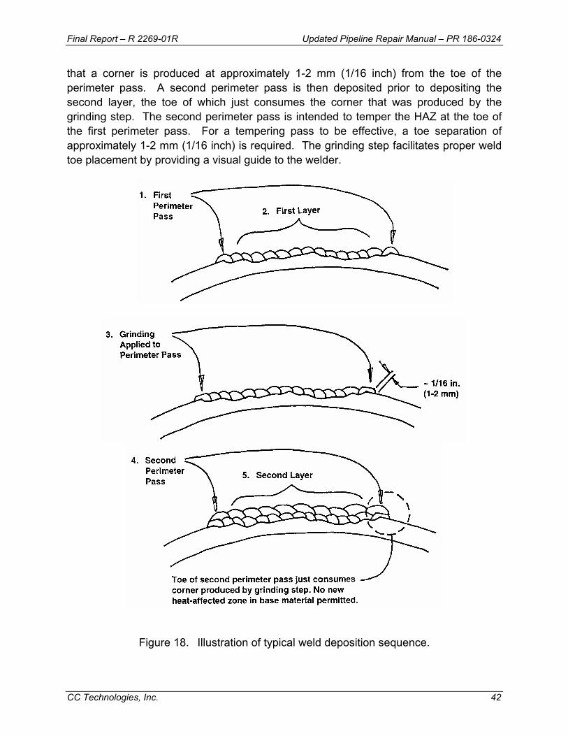
Final Report – R 2269-01R Updated Pipeline Repair Manual – PR 186-0324
CC Technologies, Inc. 42
that a corner is produced at approximately 1-2 mm (1/16 inch) from the toe of the perimeter pass. A second perimeter pass is then deposited prior to depositing the second layer, the toe of which just consumes the corner that was produced by the grinding step. The second perimeter pass is intended to temper the HAZ at the toe of the first perimeter pass. For a tempering pass to be effective, a toe separation of approximately 1-2 mm (1/16 inch) is required. The grinding step facilitates proper weld toe placement by providing a visual guide to the welder.
Figure 18. Illustration of typical weld deposition sequence.
Final Report – R 2269-01R Updated Pipeline Repair Manual – PR 186-0324
CC Technologies, Inc. 43
The first layer should be deposited using established heat input limits to minimize the risk of burnthrough. The fill passes are deposited using stringer beads in a parallel, consecutive, or buttering layer, manner. During deposition of the buttering layers, the electrode is aimed at the toe of the previous pass, resulting in a bead overlap of approximately 50%. Cosmetic grinding between layers is performed only to remove layer height irregularities (i.e., a "half-bead" technique is not used). Higher heat input levels are used for the second and subsequent layers to refine and temper the HAZ of first or previous layer. Higher heat input fill passes can be used for the second and subsequent layers since deposition of the first layer increases the remaining wall thickness.
Multiple layer repairs result in the highest amount of tempering. Multiple layers are not ideal for shallow repairs, however, as excessive reinforcement may result. The need for either one or multiple layers of weld metal depends on the depth of corrosion and the need for tempering. Multiple layer repairs are appropriate for depths of 3.2-mm (0.125-inch) or greater. Shallower wall loss can be filled using a single layer and bead overlap can be adjusted slightly to insure proper filling. Additionally, the choice of electrode size, whether for a single or multiple layer repairs, can be used to achieve proper reinforcement height. Since multiple layers result in more tempering than single layers, the deletion of multiple layers should be considered an essential variable for procedure qualification (i.e., requalification should be required if a multi-layer procedure is to be used for a single layer repair). When using multiple layers for either greater tempering or complying with an essential variable, the second layer may be removed by grinding, if desired.
The use of this sequence results in the most consistent weld profile, the least amount of welder induced discontinuities and the highest amount of tempering from subsequent passes. This tempering, combined with the use of low hydrogen electrodes and the relatively low level of restraint inherent with weld deposition repairs, minimizes the risk of hydrogen cracking.
The depth of actual corrosion damage tends to be irregular. Where necessary, the general technique (i.e., a perimeter weld followed by consecutive parallel fill passes) can first be applied to the deepest areas of wall loss until a uniform remaining depth is established. The general technique can then again be applied to the entire area of wall loss until the desired amount of weld metal is deposited. A repair sequence for a typical repair is shown in Figures 19 through 22.
The factors that render this technique effective are believed to be as follows. The first layer of fill passes is deposited using an established heat input limit to minimize the risk of burnthrough. Depositing these passes in a buttering layer manner maximizes tempering by subsequent passes within the first layer. Higher heat input fill passes

Final Report – R 2269-01R Updated Pipeline Repair Manual – PR 186-0324
CC Technologies, Inc. 44
used for subsequent layers, if used, tend to further temper the initial passes. Welder induced discontinuities tend to be minimized by the use of small diameter electrodes. These electrodes permit the welder to adhere to heat input limits comfortably, minimizing the inherent risk of burnthrough.
Figure 19. Deposition of perimeter pass and several first layer passes. Initial attention
was given to filling deeper areas in this example, simplifying filling of the remaining area.
Figure 20. Grinding applied to perimeter pass and first layer. Separation between weld
toe and ground surface should be about 1-2 mm (1/16 inch).
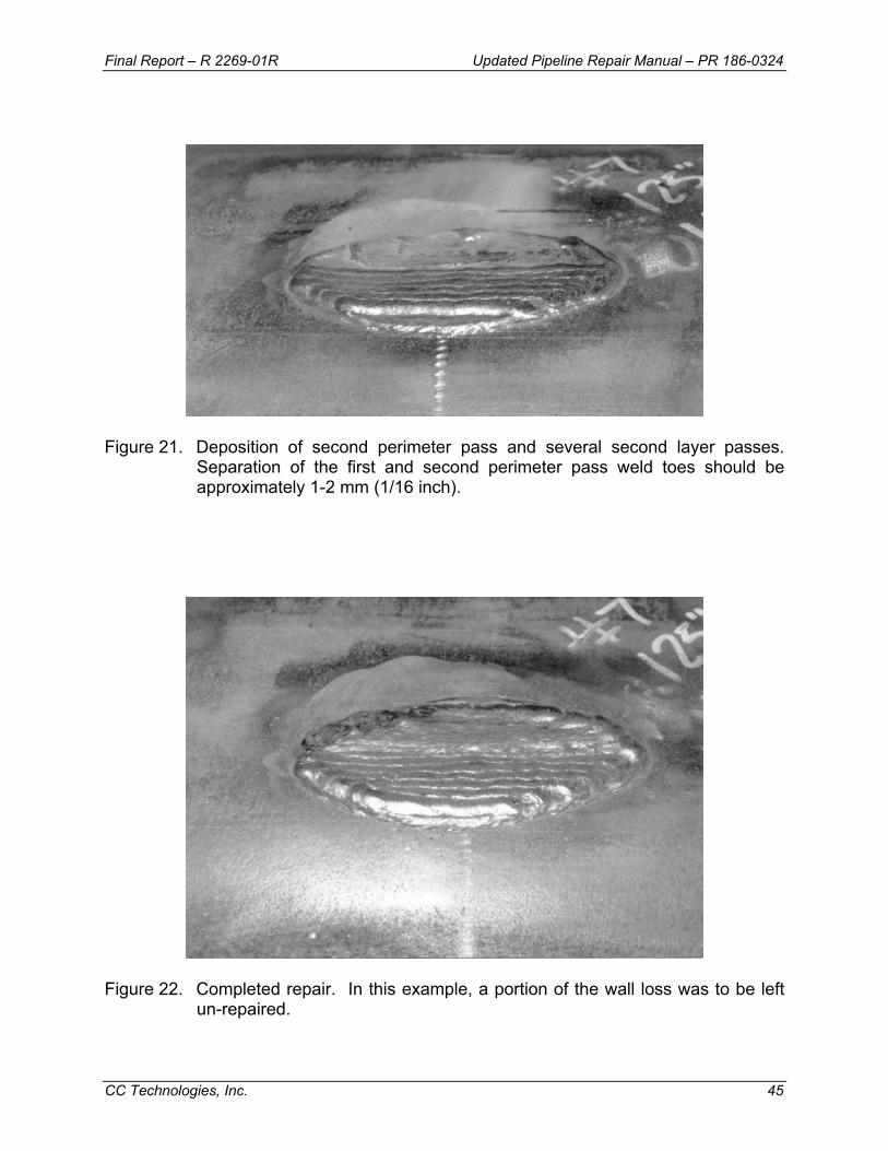
Final Report – R 2269-01R Updated Pipeline Repair Manual – PR 186-0324
CC Technologies, Inc. 45
Figure 21. Deposition of second perimeter pass and several second layer passes.
Separation of the first and second perimeter pass weld toes should be approximately 1-2 mm (1/16 inch).
Figure 22. Completed repair. In this example, a portion of the wall loss was to be left
un-repaired.
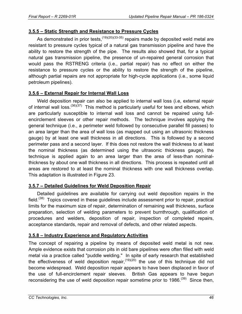
Final Report – R 2269-01R Updated Pipeline Repair Manual – PR 186-0324
CC Technologies, Inc. 46
3.5.5 – Static Strength and Resistance to Pressure Cycles As demonstrated in prior tests,(19)(20)(33-35) repairs made by deposited weld metal are
resistant to pressure cycles typical of a natural gas transmission pipeline and have the ability to restore the strength of the pipe. The results also showed that, for a typical natural gas transmission pipeline, the presence of un-repaired general corrosion that would pass the RSTRENG criteria (i.e., partial repair) has no effect on either the resistance to pressure cycles or the ability to restore the strength of the pipeline, although partial repairs are not appropriate for high-cycle applications (i.e., some liquid petroleum pipelines).
3.5.6 – External Repair for Internal Wall Loss Weld deposition repair can also be applied to internal wall loss (i.e, external repair
of internal wall loss.(36)(37) This method is particularly useful for tees and elbows, which are particularly susceptible to internal wall loss and cannot be repaired using full-encirclement sleeves or other repair methods. The technique involves applying the general technique (i.e., a perimeter weld followed by consecutive parallel fill passes) to an area larger than the area of wall loss (as mapped out using an ultrasonic thickness gauge) by at least one wall thickness in all directions. This is followed by a second perimeter pass and a second layer. If this does not restore the wall thickness to at least the nominal thickness (as determined using the ultrasonic thickness gauge), the technique is applied again to an area larger than the area of less-than nominal-thickness by about one wall thickness in all directions. This process is repeated until all areas are restored to at least the nominal thickness with one wall thickness overlap. This adaptation is illustrated in Figure 23.
3.5.7 – Detailed Guidelines for Weld Deposition Repair Detailed guidelines are available for carrying out weld deposition repairs in the
field.(38) Topics covered in these guidelines include assessment prior to repair, practical limits for the maximum size of repair, determination of remaining wall thickness, surface preparation, selection of welding parameters to prevent burnthrough, qualification of procedures and welders, deposition of repair, inspection of completed repairs, acceptance standards, repair and removal of defects, and other related aspects.
3.5.8 – Industry Experience and Regulatory Activities The concept of repairing a pipeline by means of deposited weld metal is not new. Ample evidence exists that corrosion pits in old bare pipelines were often filled with weld metal via a practice called "puddle welding." In spite of early research that established the effectiveness of weld deposition repair,(19)(20) the use of this technique did not become widespread. Weld deposition repair appears to have been displaced in favor of the use of full-encirclement repair sleeves. British Gas appears to have begun reconsidering the use of weld deposition repair sometime prior to 1986.(39) Since then,
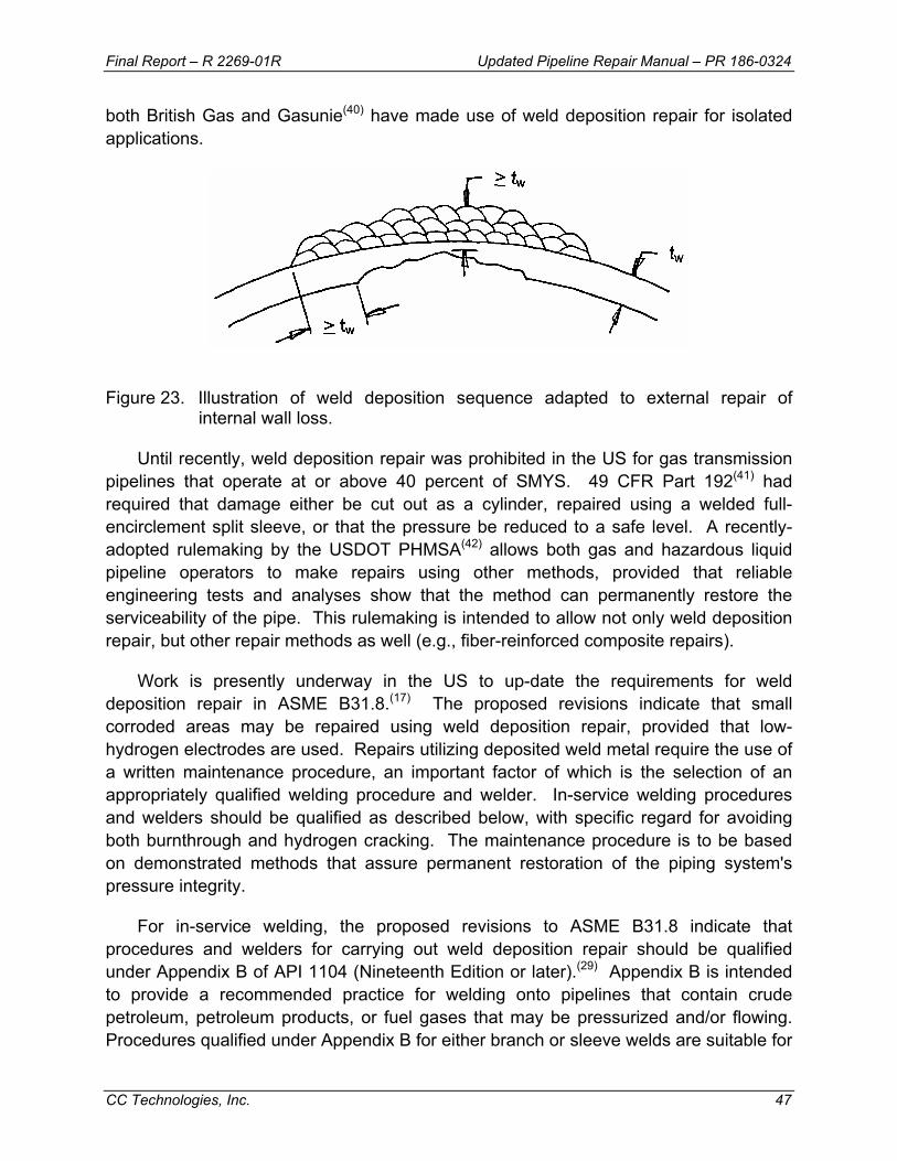
Final Report – R 2269-01R Updated Pipeline Repair Manual – PR 186-0324
CC Technologies, Inc. 47
both British Gas and Gasunie(40) have made use of weld deposition repair for isolated applications.
Figure 23. Illustration of weld deposition sequence adapted to external repair of
internal wall loss.
Until recently, weld deposition repair was prohibited in the US for gas transmission pipelines that operate at or above 40 percent of SMYS. 49 CFR Part 192(41) had required that damage either be cut out as a cylinder, repaired using a welded full-encirclement split sleeve, or that the pressure be reduced to a safe level. A recently-adopted rulemaking by the USDOT PHMSA(42) allows both gas and hazardous liquid pipeline operators to make repairs using other methods, provided that reliable engineering tests and analyses show that the method can permanently restore the serviceability of the pipe. This rulemaking is intended to allow not only weld deposition repair, but other repair methods as well (e.g., fiber-reinforced composite repairs).
Work is presently underway in the US to up-date the requirements for weld deposition repair in ASME B31.8.(17) The proposed revisions indicate that small corroded areas may be repaired using weld deposition repair, provided that low-hydrogen electrodes are used. Repairs utilizing deposited weld metal require the use of a written maintenance procedure, an important factor of which is the selection of an appropriately qualified welding procedure and welder. In-service welding procedures and welders should be qualified as described below, with specific regard for avoiding both burnthrough and hydrogen cracking. The maintenance procedure is to be based on demonstrated methods that assure permanent restoration of the piping system's pressure integrity.
For in-service welding, the proposed revisions to ASME B31.8 indicate that procedures and welders for carrying out weld deposition repair should be qualified under Appendix B of API 1104 (Nineteenth Edition or later).(29) Appendix B is intended to provide a recommended practice for welding onto pipelines that contain crude petroleum, petroleum products, or fuel gases that may be pressurized and/or flowing. Procedures qualified under Appendix B for either branch or sleeve welds are suitable for

Final Report – R 2269-01R Updated Pipeline Repair Manual – PR 186-0324
CC Technologies, Inc. 48
weld deposition repair, provided the procedure is appropriate for the remaining wall thickness to which it is being applied.
B31.8 allows repairs of other defects (i.e., other than corrosion, such as grooves and gouges) by grinding, provided that the defect is not dented. After grinding, if the ground area does not meet the remaining wall thickness requirement (i.e., enough wall thickness to meet either the B31G or the RSTRENG criterion), the proposed revisions allow the area to be repaired by filling it with deposited weld metal, provided that the area is small.
3.5.9 – Limitations on the Use of Weld Deposition Repair The minimum remaining thickness for which weld deposition repair should be
attempted is 3.2 mm (0.125 inch). When the remaining thickness is thin, small diameter electrodes should be used in conjunction with a procedure that limits heat input to that which is appropriate for the remaining wall thickness. The use of weld deposition repair should be limited to corrosion caused metal loss and other non-dented defects that can be properly prepared for welding. The use of weld deposition repair for defects in or near ERW seams and for crack-like defects should be prohibited. Partial repairs are not appropriate for high pressure-cycle applications.
3.6 – Mechanical Clamps Mechanical clamps include both bolt-on clamps and leak clamps.
3.6.1 – Bolt-On Clamps Several types of mechanical clamps are available from various commercial vendors.
Figure 24 shows a photograph of a typical bolt-on clamp. These clamps are designed to contain full pipeline pressure, so they are generally rather thick and heavy because of the large bolts used to provide the required clamping force.(43) The clamps normally have elastomeric seals to contain the pressure if the pipeline is leaking at the defect. They can be either installed like a Type A sleeve, or most can be fillet welded to the pipe like a Type B sleeve to contain a leak in case the seals fail. Operators who intend to weld such clamps to the pipeline should consider all of the implications of welding on a live pipeline as reviewed in Appendix A.
There are also split, bolt-on sleeves for subsea permanent pipeline repairs; these could potentially be used to repair onshore pipelines. Some of these are designed with circumferential clamping mechanisms at each end of the sleeve so that axial loads are transferred through the sleeve rather than the carrier pipe. This feature can be useful for repairing severe damage, such as a circumferential crack in a girth weld.
Final Report – R 2269-01R Updated Pipeline Repair Manual – PR 186-0324
CC Technologies, Inc. 49
Figure 24. Typical mechanical bolt-on clamp (courtesy of T. D. Williamson, Inc.). 3.6.2 – Leak Clamps
A leak clamp is used to repair a leaking external corrosion pit. It consists of relatively lightweight metal bands with a single draw bolt to tighten it onto the pipe. Figure 25 shows a typical leak clamp. The clamp has a threaded fitting located 180 degrees from the draw bolt. It is used to force a neoprene cone into the leaking pit. This type of clamp is used on isolated pits and is usually considered to be a temporary repair, which needs to last only until a permanent repair can be made. A leak clamp should be used only if (1) results of an engineering analysis show that rupture of the general corrosion around the leak is not possible, or (2) the pressure level is reduced to a safe level until a permanent repair is made. A leak clamp should not be used to repair a selectively corroded ERW or flash-welded longitudinal seam. A leak clamp can be made into a permanent repair by encapsulating it in a domed fitting.
3.7 – Hot Tapping Hot tapping can be used to remove a defect from an in-service pipeline. Typically,
the following three requirements should be satisfied when using hot tapping. First, as is the case for any defect of unknown extent, the pressure may need to be reduced prior to inspection and repair as recommended previously. This may be required even if the normal hot-tapping procedure requires no pressure reduction. Second, the size of the branch to be installed should be based on the need to contain the entire defect within the area of pipe wall that is to be removed by hot tapping. In other words, the section of material to be removed by the hole-cutting saw should contain the entire defect. Third,
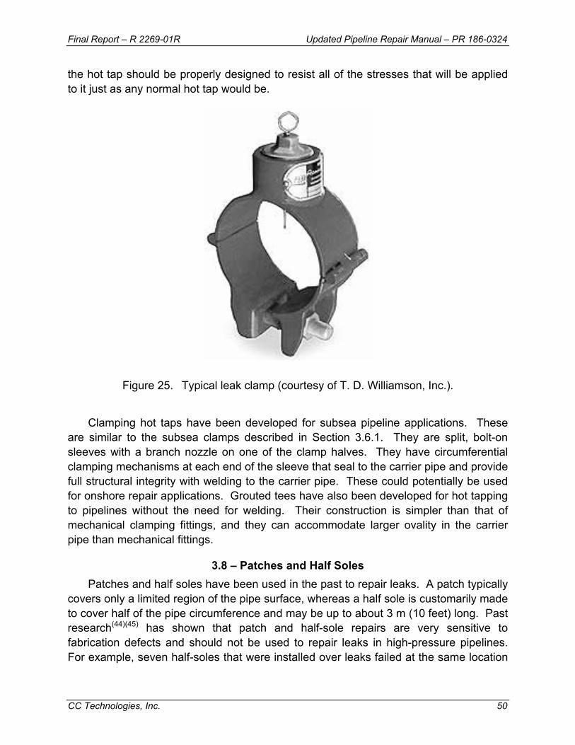
Final Report – R 2269-01R Updated Pipeline Repair Manual – PR 186-0324
CC Technologies, Inc. 50
the hot tap should be properly designed to resist all of the stresses that will be applied to it just as any normal hot tap would be.
Figure 25. Typical leak clamp (courtesy of T. D. Williamson, Inc.).
Clamping hot taps have been developed for subsea pipeline applications. These
are similar to the subsea clamps described in Section 3.6.1. They are split, bolt-on sleeves with a branch nozzle on one of the clamp halves. They have circumferential clamping mechanisms at each end of the sleeve that seal to the carrier pipe and provide full structural integrity with welding to the carrier pipe. These could potentially be used for onshore repair applications. Grouted tees have also been developed for hot tapping to pipelines without the need for welding. Their construction is simpler than that of mechanical clamping fittings, and they can accommodate larger ovality in the carrier pipe than mechanical fittings.
3.8 – Patches and Half Soles Patches and half soles have been used in the past to repair leaks. A patch typically
covers only a limited region of the pipe surface, whereas a half sole is customarily made to cover half of the pipe circumference and may be up to about 3 m (10 feet) long. Past research(44)(45) has shown that patch and half-sole repairs are very sensitive to fabrication defects and should not be used to repair leaks in high-pressure pipelines. For example, seven half-soles that were installed over leaks failed at the same location
Final Report – R 2269-01R Updated Pipeline Repair Manual – PR 186-0324
CC Technologies, Inc. 51
(the junction between the longitudinal fillet weld and the half sole) during pressure testing. All seven failures occurred at or below stress levels needed to cause gross yielding of the carrier pipe. The test results showed that the static strength of such repairs was marginal for a pipeline operating at a hoop stress level of 72% SMYS. It is also likely that their fatigue lives would be relatively short because of the inherently high stress concentrations at the fillet welds.
Results of additional burst tests(44)(45) of pipe with nonleaking defects showed somewhat improved performance for half-sole repairs. When used in this manner, half soles and patches could be as effective as Type A sleeves in providing structural reinforcement of the defect. However, the longitudinal fillet-weld-to-pipe joint is a potential weak point that does not exist with Type A sleeves. Therefore, the use of half soles and patches for repairing highly stressed pipelines, leaking or not, is not recommended.
4.0 – APPROPRIATE REPAIRS FOR VARIOUS TYPES OF DEFECTS The choice of a repair method depends on the characteristics of the defect that is to
be repaired. The kinds of defects that have been found in pipelines are well documented.(46) For the purpose of choosing a repair method, these are grouped into the following categories:
• External metal loss. This type of defect is usually as a result of external corrosion and is characterized by visible pits or large irregular depressions. It may also be from grinding beyond acceptable limits.
• Internal defects. These are usually as a result of internal corrosion. Pits or large irregular depressions exist but are detectable from the outside only by ultrasonic wall thickness measurements. Other types of internal defects might include scores, laps, and slivers. All internal defects fall into this category whether they are corrosion, cracks, or anything else. Any other defect discussed in the remainder of this list is assumed to have arisen at or near the outer surface of the pipe.
• Indented defects. These are plain dents and dents with gouges or scrapes that are usually caused by the contact of excavating equipment. Dents may also contain fatigue cracks, stress-corrosion cracks, or arc burns. At a dent, the local curvature is no longer part of the circular arc having the same radius as the pipe. In this section and in this document, indented is taken to mean any amount of indentation that can be measured or visually detected. For all other defects, except hard spots, it is assumed that the defect is completely free of indentation.
• Longitudinally oriented cracks, scratches, scores, notches, or grooves. • Transversely oriented defects not at a girth weld. For the purposes of this
document, these are grouped with girth-weld defects.

Final Report – R 2269-01R Updated Pipeline Repair Manual – PR 186-0324
CC Technologies, Inc. 52
• Cracks oriented along a spiral angle. For the purposes of this document, these are grouped with longitudinally oriented cracks.
• Girth weld defects, including cracks. • Hard spots. These are usually also locally flat spots in an otherwise round pipe
and are created by accidental quenching of the area during hot rolling of the skelp. A hard spot may also contain cracks.
• Buckles or wrinkles. These are usually a result of curvature being imposed on the pipe. A severe buckle or wrinkle may contain a crack.
• Arc burns as a result of unintentional contact from a welding electrode and contact burns.
• Blisters and hydrogen-induced stepwise cracking.
The selection of repair methods is impacted by the characteristics of the above categories of defects. For example, grinding is inappropriate for internal defects because the inside surface of the pipe is not accessible. Sleeves that have to make intimate contact with the defective region are not recommended for repairing buckles or wrinkles. This section of the repair manual provides guidance for matching defects that need to be repaired with recommended repair methods. A summary table is first presented to provide an overview of the applicability of various repair methods to various types of defects. Then, a second summary table is presented to provide an overview of important qualifying factors that may influence the choice of repair method. Finally, a flowchart for each defect category provides detailed procedures for that category.
4.1 – Overview of Repair Applications Table 1 provides an overview of pipeline repair applications that can typically be
applied to various types of defects. Presentation of this table is not intended to suggest that the repair methods listed are the only acceptable methods. This type of table should only be used a part of overarching repair procedure which covers the details including limitations and procedures for each repair method. Some of the limitations applicable to this table are outlined below. The left-most column of Table 1 lists twelve types of defects to which repairs are typically applied. Table 2 summarizes qualifying factors that may affect the application of the various repair techniques. The left-most column of Table 2 lists eight qualifying factors that may influence the selection of a repair method. Each of the remaining ten columns in the tables provides information regarding the applicability of the repair method listed in the title row to the type of defect (Table 1) or qualifying factor (Table 2) identified in that row.

Final Report – R 2269-01R Updated Pipeline Repair Manual – PR 186-0324
CC Technologies, Inc. 53
Table 1. Summary of repair options for various types of defects.
Type of Defect (a) Grinding Type A SleeveCompression
Sleeve Type B SleeveComposite
SleeveWeld
Deposition
Bolt-On Clamp With
SealsForce Screw Leak Clamp
Welded Patch or Half Sole
Hot Tapping (b)
1. Leak (from any cause) or defect > 0.8t
No No No Permanent No No Permanent Temporary (c) No Permanent
2a. Shallow to Moderate Pitting < 0.8t
No Permanent Permanent Permanent Permanent Permanent Permanent No Temporary Permanent
2b. Deep Pitting ≥ 0.8t No No No Permanent No No Permanent No No Permanent2c. Selective Seam Attack
No No Permanent Permanent (d) No No Permanent (d) No Temporary No
3. Internal Defect or Corrosion
No Permanent (e) Permanent (e) Permanent Permanent (e) No Permanent (e) No No No
4. Gouge or Other Metal Loss on Pipe Body
Permanent (f) Permanent (g) Permanent (g) Permanent (h) Permanent (g) Permanent (g) Permanent (h) No No Permanent
5. Arc Burn, Inclusion, or Lamination
Permanent (f) Permanent Permanent Permanent Permanent (g) Permanent (g) Permanent No No Permanent
6. Hard Spot No Permanent Permanent Permanent No No Permanent No No Permanent
7a. Smooth Dent No Permanent (i) Permanent (i) Permanent Permanent (j) No Permanent No No No7b. Dent With Stress Concentrator on Seam Weld or Pipe Body
Permanent (k) Permanent (g) (i) (j)
Permanent (g) (i) (j)
Permanent Permanent (g) (i) (j)
No Permanent No No Permanent
7c. Dent With Stress Concentrator on Girth Weld
Permanent (k) No Permanent (g) (i) (j)
Permanent No No Permanent (l) No No No
8a. Shallow Crack < 0.4t Permanent (f) Permanent (g) Permanent Permanent (d) Permanent (g) Permanent (g) Permanent (d) No Temporary Permanent
8b. Deep Crack ? 0.4t and not more than 0.8t
No Permanent (g) Permanent Permanent (d) Permanent (g) Permanent (g) Permanent (d) No No Permanent
9a. Volumetric Defect Permanent (f) Permanent (g) Permanent Permanent Permanent (g) No Permanent No No Permanent9b. Linear Defect Permanent (f) Permanent (g) Permanent Permanent (d) Permanent (g) No Permanent (d) No No Permanent9c. Defect In or Near an ERW Seam
No No Permanent Permanent (d) No No Permanent (d) No No No
10. Girth Weld Defect Permanent (f) No No Permanent No Permanent (m) Permanent (l) No No No11. Wrinkle Bend, Buckle, or Coupling
No No No Permanent (n) No No No No No No
12. Blisters, HIC No Permanent Permanent Permanent No No Permanent No No No
(a) Replacement of the affected pipeline section can be used to repair any defect.(b) Hot tapping can be applied only to defects that are small enough to be removed by the hot tap.(c) A force screw leak clamp can be applied only to small leaks that can sealed by such a clamp.(d) Make sure defect length is subcritical or pressurize sleeve.(e) Make sure that internal defect or corrosion does not continue to grow beyond acceptable limits.(f) Grinding alone up to 0.4t depth may be used, provided that defect and defective metal are removed and that local wall loss is acceptable.(g) Repair may be used for defects less than 0.8t deep, provided that damaged material has been removed by grinding and removal has been verified by inspection.(h) It is recommended that the damaged material be removed with removal verified by inspection or that the carrier pipe be tapped for this repair.(i) Use of filler material in dent and engineering assessment of fatigue are recommended.(j) Code and regulatory restrictions on maximum dent size should be followed.(k) Code and regulatory limits on amount of permitted grinding should be satisfied.(l) The split-sleeve clamp should be the type that transfers axial loads and provides full structural integrity.(m) Defect should be removed by grinding and area inspected before and after welding.(n) Sleeve should be designed and fabricated to special "pumpkin" configuration.
2. External Corrosion
7. Dent
8. Crack or Cracking
9. Seam Weld Defect

Final Report – R 2269-01R Updated Pipeline Repair Manual – PR 186-0324
CC Technologies, Inc. 54
Table 2. Summary of qualifying factors for various repair options.
Qualifying Factor (a) GrindingType A Sleeve
Compression Sleeve
Type B Sleeve
Composite Sleeve
Weld Deposition
Split-Sleeve Bolt-On
Clamp With Seals
Force Screw Leak Clamp
Welded Patch or Half
SoleHot Tapping
(b)1. Onshore Permanent Permanent Permanent Permanent Permanent Permanent Permanent Temporary (b) Temporary Permanent2. Offshore Permanent No No No Permanent (c) No Permanent No No No3. Straight Pipe Permanent Permanent Permanent Permanent Permanent Permanent Permanent Temporary (b) Temporary Permanent4. Gradual Bend Permanent Permanent (d) No Permanent (d) Permanent Permanent Permanent Temporary (b) Temporary Permanent5. Sharp Bend Permanent Permanent (d) No Permanent (d) Permanent (d) Permanent No No No No6. Fitting Permanent No No No No Permanent No Temporary (b) No No7. Heat Sink Permanent Permanent Permanent Permanent (e) Permanent Permanent (e) Permanent Temporary (b) No Permanent (e)8. High Carbon Equivalent (CE) Steel
Permanent Permanent Permanent Permanent (e) Permanent Permanent (e) Permanent Temporary (b) No Permanent (e)
(a) Replacement of the affected pipeline section can be used to repair any defect.(b) Use of this repair method is limited, as described in the text of this document.(c) The composite wrap should be qualified for underwater application. It should be applied over a good clean surface; this is especially important in splash zones.(d) A special sleeve configuration is required.(e) A special welding procedure is required.

Final Report – R 2269-01R Updated Pipeline Repair Manual – PR 186-0324
CC Technologies, Inc. 55
The notation used in Tables 1 and 2 is as follows:
• Footnote (a) indicates that pipe replacement can be used to replace any type of defect. However, in many cases, replacement is not feasible or desirable.
• Permanent indicates a repair method that typically can be used to permanently repair the type of defect. In some cases, a footnote(s) is added to indicate qualifying conditions for the method to be considered permanent.
• Temporary indicates a repair method that typically can be used to temporarily repair the type of defect. In some cases, a footnote(s) is added to indicate qualifying conditions for the method to be employed.
• No indicates a repair method that typically is not recommended for repair of the type of defect. These are highlighted in yellow (shaded in black and white printing) for quick recognition by the user.
Just because a method is indicated to be Permanent or Temporary does not mean that it can always be applied. Also, just because a No is indicated for a method does not mean that it is prohibited; it just indicates cases where the repair method is not routinely applied. Good engineering judgment should be exercised in selecting a repair method for a specific situation. Table 1 and the associated flowcharts that follow are provided as a tool. Specific details may lead an operator to legitimately choose an alternative repair method to the one that would be prescribed by using the table and flowcharts.
As is indicated in Row 1 of Table 1, a leak imposes significant limitations on the choice of repair method. In general, only a Type B sleeve, a mechanical sleeve, or pipe removal is appropriate. For very small leaks, such as at a deep corrosion pit, a force type screw clamp can be used to make a temporary repair. With liquid lines, it is sometimes possible to isolate the leaking section using freeze plugs if a removal repair is required. This option is not available for gas pipelines. When using a sleeve to repair a leaking pipeline, venting as described previously in Section 3.3.3.4 may be essential.
Rows 2a, 2b, and 2c of Table 1 highlight methods applicable for the repair of external corrosion including the consideration of maximum pit depth. Any method, except grinding and application of a leak clamp, is acceptable for relatively shallow to moderately deep external corrosion (d < 0.8t). Very deep external corrosion (d ≥ 0.8t) should be repaired only using methods that are appropriate for leaks. Prior to implementing a repair, a pipeline operator should evaluate the severity of the corrosion using ASME B31G,(3) RSTRENG,(4) or a similar acceptable method to see if a repair is actually required. Selective seam attack typically is only repaired using a technique that minimizes the potential for sudden fracture along the seam.
Final Report – R 2269-01R Updated Pipeline Repair Manual – PR 186-0324
CC Technologies, Inc. 56
Internal defects, which are addressed in Row 3 of Table 1, present special challenges for repair. First and foremost, it is difficult to adequately characterize their nature and measure their size. Grinding is not applicable unless there is direct access to the defect. Weld metal deposition can only be applied if engineering assessment shows that it provides adequate reinforcement of the area containing the defect. Hot tapping is not recommended because of the uncertainty usually associated with determining the extent of the defect. A Type A sleeve or a composite sleeve is appropriate only if it can be assured that the defect will not grow and potentially become a leak in the future. If it is possible that internal corrosion may still occur at the defect location, then these methods are only temporary repairs. In cases where the corrosion may be continuing, only a Type B sleeve or a mechanical sleeve should be considered as a permanent repair.
A gouge or other metal loss on the pipe body that is not associated with a dent should be treated as summarized in Row 4 of Table 1. As indicated, metallurgically damaged or altered material should be removed by grinding, with its removal verified by inspection and etching the damaged area. Such removal is recommended even when a repair technique other than grinding is to be subsequently applied.
Arc burns, inclusions, or laminations, Row 5 of Table 1, are a sign of poor original workmanship or manufacturing processes on older pipelines. Today they would be a cause for rejecting a weld or pipe during construction. Arc burns are generally not serious enough to require an in-service repair unless the pipe material is known to exhibit brittle fracture initiation. If arc burns are to be repaired, grinding or grinding followed by weld metal deposition are simple and appropriate repair methods. It is excessive to use a sleeve to repair something as insignificant as the typical arc burn. Imbedded inclusions and laminations are not usually a serious problem unless hydrogen-induced cracking (HIC) occurs. (See Row 12 of Table 1.) If inclusions or laminations are surface breaking, they should be treated as wall-loss defects (Rows 4).
Row 6 of Table 1 addresses a hard spot, a defect created by accidental local quenching during hot rolling of the skelp that contains no crack. A hard spot can be repaired using one of the various steel sleeving techniques or by hot tapping. Steel sleeves provide structural reinforcement and tend to shield the region from cathodic protection that otherwise might cause hydrogen cracking to develop in the hard spot. A hard spot that is already cracked should be repaired in the same manner as a deep crack (see Row 8b of Table 1).
Dents are addressed in Row 7 of Table 1. Plain dents are those that contain none of the following: gouge, scrape, scratch, crack, metal loss, compressed or crushed pipe wall, and low-toughness seam or girth weld. (An average Charpy impact energy of at least 40.7 (30 ft-lb) or minimum Charpy impact energy of at least 29.8 J (22 ft-lb) at

Final Report – R 2269-01R Updated Pipeline Repair Manual – PR 186-0324
CC Technologies, Inc. 57
minimum operating temperature is sometimes used as an acceptance criterion for adequate toughness.) Any other dent should be classified as a dent and gouge and treated accordingly. A truly plain dent up to 6% of the pipe diameter deep does not need to be repaired. However, the potential of fatigue cracking should be evaluated if the dent depth exceeds 2% of the pipe diameter. Plain (smooth) dents deeper than 6% of pipe diameter may be repaired by the methods shown in Row 7a of Table 1. If a dent is deep enough to interfere with pigging, especially the passage of an ILI tool, it should be removed.
A dent with a stress concentrator (gouge, groove, arc burn, or crack) is covered by Line 7b of Table 1 if it is on the pipe body or a seam weld or by Line 7c of Table 1 if it is on a girth weld. Grinding or a Type A sleeve with filler may be used provided that the stress concentrator is removed in accordance with the requirements for grinding repairs prior to the dent being assessed for acceptability, with the depth of the ground area being excluded from the dent depth. Grinding repair is not acceptable unless both of the following apply: (1) the dent depth is acceptable, and (2) the remaining cyclic life of the pipe is considered to be acceptable, based upon an engineering assessment that includes consideration of fatigue testing results for pipe without a sleeve. A Type B sleeve, a mechanical sleeve, or a compression sleeve (plus grinding removal of the stress concentrator for a girth weld) may also be used. Hot tapping or a composite sleeve may be used on the pipe body or a mill seam weld but not on a girth weld. The following requirements also should be satisfied for use of a composite sleeve: (1) the dent depth is 15% or less of the nominal outside diameter of the pipe, (2) any stress concentrators in the dent are removed by grinding in accordance with the requirements grinding repairs, (3) a suitable material is used to fill the dent prior to application of the sleeve, in order to prevent re-rounding of the pipe, (4) the remaining cyclic life of the pipe is considered to be acceptable, based upon an engineering assessment that includes consideration of fatigue testing results for the sleeve system that is to be used.
Cracks are covered in Row 8 of Table 1. Shallow cracks (d < 0.4t) can be repaired by a variety of methods as indicated in Row 8a. However, when grinding or grinding followed by weld metal deposition is employed, the removal of all of the stress concentrators should be confirmed by means of DPI or MPI. The repair of deep cracks (≥ 0.4t) is limited to compression sleeves, Type B sleeves, mechanical sleeves, or hot tapping when they are not ground out before application of the repair. Often a deep crack is ground out at an appropriately reduced pressure prior to implementing one of the repair techniques applicable to metal-loss defects (Row 4 of Table 1). When the crack is to be left in the pipe and sleeved or patched, it should be shown that the crack size would remain subcritical during future operations. Thus, it should be demonstrated that the crack will not grow and that no load will be imposed such that the existing crack will be of a critical size during anticipated future service.
Final Report – R 2269-01R Updated Pipeline Repair Manual – PR 186-0324
CC Technologies, Inc. 58
Seam weld defects are addressed in Row 9 of Table 1. A variety of methods are used to repair volumetric defects as indicated in Row 9a. These same methods can be applied to repair linear defects (Row 9b), provided that the defects are removed and their removal is verified or they are shown to be subcritical or the sleeve is pressurized for sleeves that are sealed.
Defects in or near ERW seams including bondline flaws, hook cracks in the upturned fiber region, hard-weld-zone cracks, and selective corrosion should be treated as especially critical because of the well-known low toughness of old ERW and flash-welded pipe. Of course, modern ERW seams can be of high quality and toughness. However, unless the pipeline operator knows this to be the case for the pipe to be repaired, the ERW-related defects listed in Line 9c of Table 1 should be repaired using compression sleeves, Type B sleeves, or mechanical sleeves. With the latter two options, tapping the carrier pipe after installing the sleeve to relieve the stress on the defect is recommended. Tapping is not needed for compression sleeves because they induced a compressive stress on the defect.
Some operators have employed grinding to remove ERW seam defects as long as the measured wall thickness meets or exceeds the nominal value, the grinding removes no more than 10% of the pipe wall, and the pressure is reduced to a level where the hoop stress is equal to or less than 30% SMYS. However, this type of grinding repair is not normally recommended, so its use needs to be evaluated by a qualified engineer on a case by case basis before it is applied.
Row 10 of Table 1 refers to typical girth weld defects. It is possible that small externally connected defects in girth welds could be repaired by grinding or by grinding followed by deposition of additional weld metal. Before grinding is attempted ultrasonic inspection should be performed to assure that the root and interior of the weld is sound. For more serious external flaws or for internal defects, a Type B sleeve or a mechanical sleeve may be required. Where the defect has appreciable circumferential extent, such as being more than 1/12 of the circumference, or where the longitudinal stress is unusually high, a Type B sleeve is preferred because it is capable of relieving some of the longitudinal stress on the defect. When a Type B sleeve is used over a girth weld (see Section 3.3.4.1), a humped sleeve configuration may be needed to permit the sleeve ends to fit closely to the pipe for fillet welding. Bolt-on clamps that are designed to transfer axial loads and provide full structural integrity can be used to repair girth welds. Such clamps have been developed for and applied to offshore, underwater pipelines.
Wrinkles, buckles, and couplings, Row 11 of Table 1, require standoff repairs such as pumpkin sleeves or standoff rings at the ends of conventional sleeves or removal. Slight buckles or wrinkles should not be repaired. Industry experience(47) has shown
Final Report – R 2269-01R Updated Pipeline Repair Manual – PR 186-0324
CC Technologies, Inc. 59
that buckles or wrinkles that have a peak-to-trough height no greater than 2.4 mm (0.094 inch) have no significant effect on pipeline integrity as long as they do not involve the seam weld of the pipe.
Blisters and hydrogen stepwise cracking (HIC), Row 12 of Table 1, are a potential problem for pipelines in sour product service. They tend to arise at laminations or large nonmetallic inclusions. They can become quite serious. Because of their association with laminations, hot tapping is not recommended as a repair method.
The first two rows of Table 2 are for the categories of onshore and offshore. The information in the first row reveals that all ten of the repair methods are applicable to onshore pipelines. In contrast, the information in the second row indicates the only grinding, mechanical sleeves, and some composite sleeves are usually applicable to offshore pipelines. Of course, some companies have repaired and will continue to repair offshore pipelines using welded sleeves. They could also repair them by hot tapping because welded hot taps are made on offshore lines. However, making these types repairs underwater requires very special approaches, such as the use of habitats or wet welding, that are not exactly routine procedures. Furthermore, if an offshore or underwater pipeline can be raised above the water, then possibly any of the repair methods would be applicable.
Rows 3 through 7 of Table 2 address defect and/or pipeline system component configurations that affect reparability. Any of the methods are appropriate for repairing straight pipe (Row 3 of Table 2). All repair methods, except compression sleeves, can be used to repair gradual bends (Row 4 of Table 2). In the case of sharp bends or fittings (Rows 5 and 6 of Table 2), special sleeve configurations may be needed. Some of these special configurations that are relevant to sharp bends or fittings were discussed previously in Sections 3.3.4 and Section 3.6. Row 7 of Table 2 indicates that repairs involving welding are restricted or need to be modified when a high heat sink is present at the location to be repaired.
Row 8 of Table 2 calls attention to the risks associated with welding under high heat-sink conditions on an in-service pipeline made of a high carbon-equivalent (CE) steel. Under these conditions, welding on the carrier pipe should be performed in accordance with a procedure that has been developed to avoid or minimize the risk of hydrogen cracking. Appendix A provides guidance on such welding procedures. Patches or half soles should not be used under such conditions. For high CE line pipe, the methods that avoid welding on the carrier pipe may be the most appropriate.
Finally, repairs should be made only on anomalies that truly need to be repaired. In many cases and not just for corrosion-caused metal loss, a fitness-for-service
Final Report – R 2269-01R Updated Pipeline Repair Manual – PR 186-0324
CC Technologies, Inc. 60
analysis(5)(6) or an engineering critical assessment(8) may show that the anomaly has no significant effect on pipeline integrity. In such a case, no repair is necessary.
4.2 – Detailed Selection Criteria This section provides and discusses general guidelines for selecting a repair
method for a particular type of defect or situation. These are not necessarily unique because each operator may modify them to fit their own situation or may develop its own flow chart. They illustrate typical selection criteria for the following ten categories of defects and/or other situations that may require in-service pipeline repair:
1. External corrosion Figure 26
2. Internal corrosion Figure 27
3. Plain dents or dents with stress concentrators Figure 28
4. Longitudinal cracks and arc burns Figure 29
5. Girth-weld defects Figure 30
6. Wrinkle bends/buckles Figure 31
7. Hard spots Figure 32
8. Blisters and hydrogen-induced cracking Figure 33
9. Couplings Figure 34
10. Defective prior repairs Figure 35
Use of the selection criteria illustrated in Figures 26 through 35 are described in the following subsections.
4.2.1 – External Corrosion External corrosion can usually be readily inspected and characterized as to its effect
on pipeline integrity. The exceptions are selective corrosion of an ERW or flash-welded seam and corrosion with extensive circumferential extent in conjunction with unusually high axial stress in the pipeline. One should not attempt to repair selective seam corrosion using the external corrosion repair criteria. Selective seam corrosion should be addressed using the longitudinal crack repair criteria (see Section 4.2.4). Cases with large circumferential extent and high axial stress can be addressed using the girth weld defects criteria (see Section 4.2.5).

Final Report – R 2269-01R Updated Pipeline Repair Manual – PR 186-0324
CC Technologies, Inc. 61
Repairs to external corrosion can be selected using the guidelines in Figure 26. For use of these criteria, as well as the others covered Sections 4.2.2 through 4.2.10, it is strongly recommended that the pressure be reduced to a level that would be expected to prevent a near-failure defect from failing during the repair process. For this purpose, the following two pressure levels are defined:
• Pd = pressure at the time the defect is discovered. • Ph = historical high pressure known to have occurred during the past year.
Pressure reduction is recommended for safety. The operator should consider when and how much pressure reduction is needed to provide an acceptable safety margin during excavation, inspection, and repair. Reducing the pressure to 0.8Pd or 0.8Ph is recommended prior to examination and repair of a region of external corrosion. It is possible to make an exception if the results of an in-line inspection (ILI) within the past year indicate that the failure pressure is at least 1.25 times the current pressure. A thorough cleaning of the pipe by blasting with sand, walnut shells, water, etc. or by power wire brushing should be completed prior to examining the corroded area.
Prior to repairing an area of external corrosion, one should verify the nominal (uncorroded) wall thickness of the pipe by ultrasonic testing and measure the pipe diameter. The axial length, circumferential extent, and maximum depth of penetration should be measured, also. Detailed measurements of the depths of wall loss are needed if a RSTRENG(4) calculation is to be performed.
The criteria for repairs of external corrosion (see Figure 26) begins by considering the maximum depth of pitting. If the depth is greater than 80% of the nominal wall thickness, and if the pipe is not leaking at the defect, the appropriate repair choices are a Type B sleeve, a mechanical sleeve, hot tapping (if it can remove the entire anomaly), or a patch (subject to code and regulatory restrictions). If the defect is leaking, the appropriate repair choices are a Type B sleeve, a mechanical sleeve, hot tapping (if it can remove the entire anomaly), a leak clamp (if the anomaly is an isolated pit), or a patch (subject to code and regulatory restrictions).
For regions of external corrosion where the deepest penetration is less than 80% of the wall thickness, an ASME B31G(3) or RSTRENG(4) evaluation of acceptable defect length (L) can be conducted. The acceptable circumferential extent (c) of the defect should be evaluated using Figure 36, which is Figure 5-7 of API RP 579,(6) where t is the nominal pipe wall thickness, d is the maximum defect depth, and D is the nominal pipe diameter. Pipe that is not severely corroded enough to fail either of the criteria for acceptable defect length and the criterion for acceptable defect circumferential extent requires no repair except recoating and backfilling.
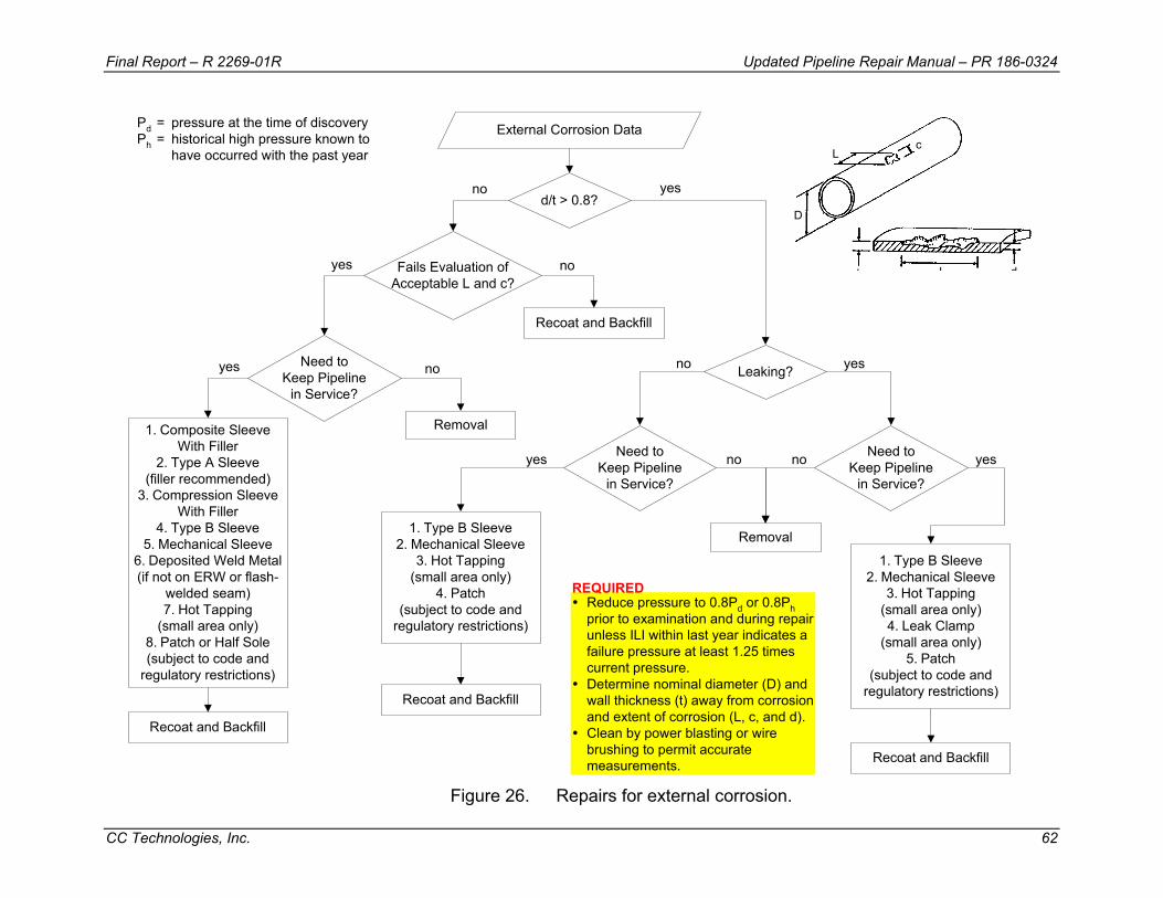
Final Report – R 2269-01R Updated Pipeline Repair Manual – PR 186-0324
CC Technologies, Inc. 62
External Corrosion Data
d/t > 0.8?
Fails Evaluation ofAcceptable L and c?
no yes
Recoat and Backfill
no
Need toKeep Pipeline
in Service?
yes
yes
Removal
no
1. Composite SleeveWith Filler
2. Type A Sleeve(filler recommended)
3. Compression SleeveWith Filler
4. Type B Sleeve5. Mechanical Sleeve
6. Deposited Weld Metal(if not on ERW or flash-
welded seam)7. Hot Tapping
(small area only)8. Patch or Half Sole(subject to code and
regulatory restrictions)
Recoat and Backfill
Leaking?
Need toKeep Pipeline
in Service?
Need toKeep Pipeline
in Service?
Removal
no no
no yes
1. Type B Sleeve2. Mechanical Sleeve
3. Hot Tapping(small area only)
4. Patch(subject to code and
regulatory restrictions)
Recoat and Backfill
yes
1. Type B Sleeve2. Mechanical Sleeve
3. Hot Tapping(small area only)4. Leak Clamp
(small area only)5. Patch
(subject to code andregulatory restrictions)
Recoat and Backfill
yes
Pd = pressure at the time of discoveryPh = historical high pressure known to
have occurred with the past year
Reduce pressure to 0.8Pd or 0.8Phprior to examination and during repairunless ILI within last year indicates afailure pressure at least 1.25 timescurrent pressure.Determine nominal diameter (D) andwall thickness (t) away from corrosionand extent of corrosion (L, c, and d).Clean by power blasting or wirebrushing to permit accuratemeasurements.
REQUIRED
L
L d
c
t
D
Figure 26. Repairs for external corrosion.
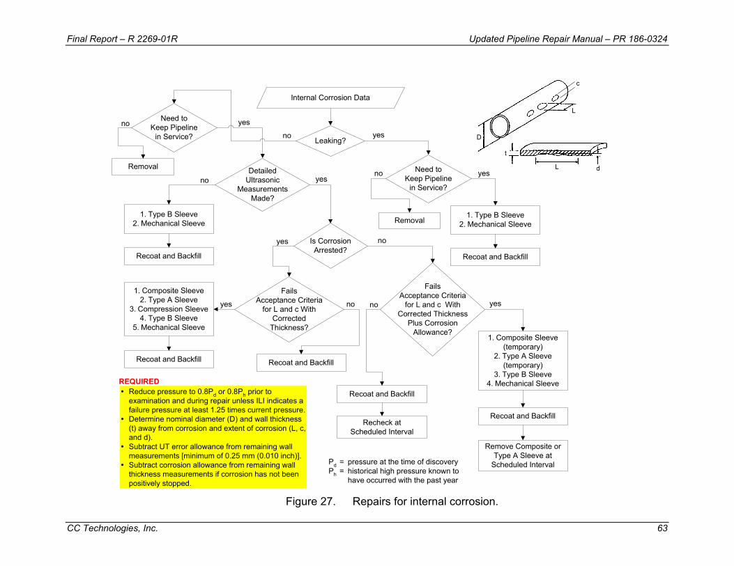
Final Report – R 2269-01R Updated Pipeline Repair Manual – PR 186-0324
CC Technologies, Inc. 63
D
t
L
L
d
c
Internal Corrosion Data
Leaking?
DetailedUltrasonic
MeasurementsMade?
no yes
noyes
1. Composite Sleeve2. Type A Sleeve
3. Compression Sleeve4. Type B Sleeve
5. Mechanical Sleeve
Recoat and Backfill
FailsAcceptance Criteria
for L and c WithCorrected
Thickness?
no
noyes
1. Type B Sleeve2. Mechanical Sleeve
Recoat and Backfill
yes
1. Composite Sleeve(temporary)
2. Type A Sleeve(temporary)
3. Type B Sleeve4. Mechanical Sleeve
Recoat and Backfill
yes
Pd = pressure at the time of discoveryPh = historical high pressure known to
have occurred with the past year
Reduce pressure to 0.8Pd or 0.8Ph prior toexamination and during repair unless ILI indicates afailure pressure at least 1.25 times current pressure.Determine nominal diameter (D) and wall thickness(t) away from corrosion and extent of corrosion (L, c,and d).Subtract UT error allowance from remaining wallmeasurements [minimum of 0.25 mm (0.010 inch)].Subtract corrosion allowance from remaining wallthickness measurements if corrosion has not beenpositively stopped.
REQUIRED
Need toKeep Pipeline
in Service?
Removal1. Type B Sleeve
2. Mechanical Sleeve
Recoat and Backfill
Is CorrosionArrested?
yes
Recoat and Backfill
no
FailsAcceptance Criteria
for L and c WithCorrected Thickness
Plus CorrosionAllowance?
Recoat and Backfill
Recheck atScheduled Interval
no
Remove Composite orType A Sleeve at
Scheduled Interval
Need toKeep Pipeline
in Service?
Removal
no yes
Figure 27. Repairs for internal corrosion.
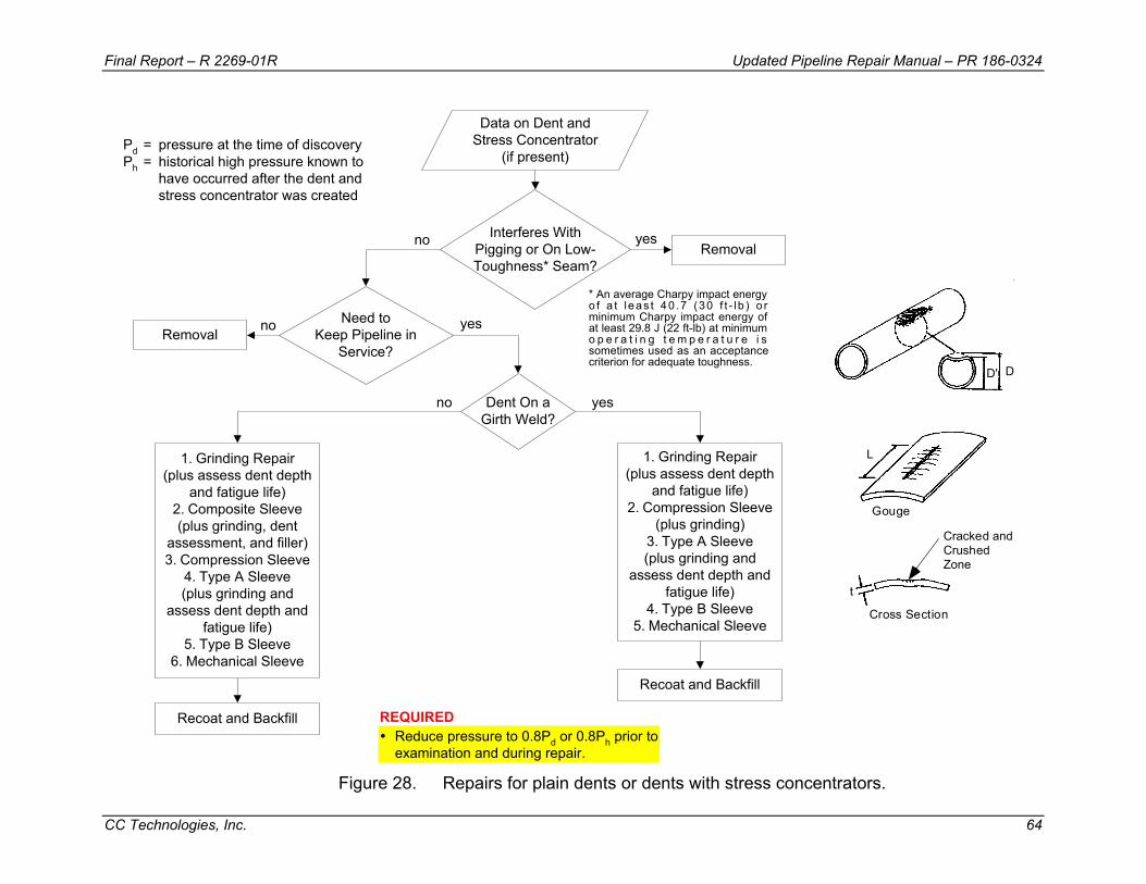
Final Report – R 2269-01R Updated Pipeline Repair Manual – PR 186-0324
CC Technologies, Inc. 64
DD'
L
t
Gouge
Cracked andCrushedZone
Cross Section
Data on Dent andStress Concentrator
(if present)
Interferes WithPigging or On Low-Toughness* Seam?
Need toKeep Pipeline in
Service?
no yes
1. Grinding Repair(plus assess dent depth
and fatigue life)2. Composite Sleeve(plus grinding, dent
assessment, and filler)3. Compression Sleeve
4. Type A Sleeve(plus grinding and
assess dent depth andfatigue life)
5. Type B Sleeve6. Mechanical Sleeve
Recoat and Backfill
1. Grinding Repair(plus assess dent depth
and fatigue life)2. Compression Sleeve
(plus grinding)3. Type A Sleeve(plus grinding and
assess dent depth andfatigue life)
4. Type B Sleeve5. Mechanical Sleeve
yes
Pd = pressure at the time of discoveryPh = historical high pressure known to
have occurred after the dent andstress concentrator was created
Reduce pressure to 0.8Pd or 0.8Ph prior toexamination and during repair.
REQUIRED
Removal
yes
no
Recoat and Backfill
Dent On aGirth Weld?
Removalno
* An average Charpy impact energyo f a t leas t 40 .7 (30 f t - lb ) o rminimum Charpy impact energy ofat least 29.8 J (22 ft-lb) at minimumo p e r a t i n g t e m p e r a t u r e i ssometimes used as an acceptancecriterion for adequate toughness.
Figure 28. Repairs for plain dents or dents with stress concentrators.

Final Report – R 2269-01R Updated Pipeline Repair Manual – PR 186-0324
CC Technologies, Inc. 65
Data on LongitudinalCracks (not in a dent)
Leaking?
Need toKeep Pipeline
in Service?
Need toKeep Pipeline
in Service?
no yes
Removal
no no
1. Type B Sleeve2. Mechanical Sleeve
3. Hot Tapping(small area only)
yes
Recoat and Backfill
Located inLow-Toughness*
ERW or Flash-WeldedSeam?
yes
1. Compression Sleeve(accommodate weld cap)
2. Type B Sleeve(pressurize)
3. Mechanical Sleeve(pressurize)
Recoat and Backfill
Can Defect BeRemoved by Grinding to
Depth No More Than 0.4t OverMaximum L Acceptable per
B31G or RSTRENG?
noyes
1. Compression Sleeve2. Composite Sleeve
(plus grinding)3. Type A Sleeve
(plus grinding)4. Type B Sleeve
(subcritical or pressurize)5. Mechanical Sleeve
(subcritical or pressurize)6. Hot Tapping
(small area only)
Recoat and Backfill
no
Defect Is anArc Burn?
yes
Recoat and Backfill
no
Grind OutMetallurgical Anomaly
Within Above Limits?
yes
yes
1. Type A Sleeve2. Compression Sleeve
3. Type B Sleeve4. Mechanical Sleeve
5. Hot Tapping(small area only)
Recoat and Backfill
no
Pd = pressure at the time of discoveryPh = historical high pressure known to
have occurred with the past year
Reduce pressure to 0.8Pd or 0.8Phprior to examination and during repair.Determine nominal diameter (D) andwall thickness (t) away from grindingand extent of grinding (L and d).Verify absence of metallurgicalanomaly if arc burn is repaired solelyby grinding.
REQUIRED
ERW or Flash-Welded Seamcold weldhook crackselective seam corrosion
SAW Seamstoe crackoffseam weldtransportation fatigue crack
Pipe Bodyplug scoresgouges, scrapes, scratcheslaps or seamsstress corrosion crackshydrogen attack
Arc Burns
Types of Longitudinal Cracks(not in a dent)
Dt
tL
L
d
* An average Charpy impact energyo f a t l eas t 40 .7 (3 0 f t - l b ) o rminimum Charpy impact energy ofat least 29.8 J (22 ft-lb) at minimumo p e r a t i n g t e m p e r a t u r e i ssometimes used as an acceptancecriterion for adequate toughness.
Figure 29. Repairs for longitudinal cracks and arc burns.
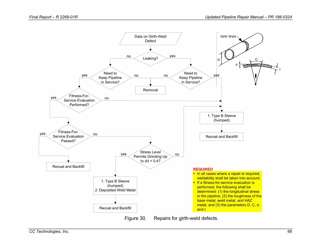
Final Report – R 2269-01R Updated Pipeline Repair Manual – PR 186-0324
CC Technologies, Inc. 66
Dd
C
t
q
Girth WeldData on Girth-WeldDefect
Leaking?
Need toKeep Pipeline
in Service?
Need toKeep Pipeline
in Service?
no yes
Removal
no no yes
Fitness-For-Service Evaluation
Performed?
yes
noyes
In all cases where a repair is required,weldability shall be taken into account.If a fitness-for-service evaluation isperformed, the following shall bedetermined: (1) the longitudinal stressin the pipeline, (2) the toughness of thebase metal, weld metal, and HAZmetal, and (3) the parameters D, C, d,and t.
REQUIRED
Fitness-For-Service Evaluation
Passed?
Recoat and Backfill
yes
Stress LevelPermits Grinding Up
to d/t = 0.4?
no
1. Type B Sleeve(humped)
2. Deposited Weld Metal
Recoat and Backfill
yes
1. Type B Sleeve(humped)
Recoat and Backfill
no
Figure 30. Repairs for girth-weld defects.

Final Report – R 2269-01R Updated Pipeline Repair Manual – PR 186-0324
CC Technologies, Inc. 67
Data on Wrinkle Bendor Buckle
h > 2.4 mm(0.094 inch) or CracksPresent or Leaking?
noyes
Recoat and Backfill
Removal
Pd = pressure at the time of discoveryPh = historical high pressure known to
have occurred with the past year
Need toKeep Pipeline
in Service?
no
1. Type B PumpkinSleeve
Recoat and Backfill
yes
Reduce pressure to 0.8Pd or 0.8Phprior to examination and during repair.Determine buckle height (h).Use D, t, SMYS, and h to show thatbuckle height is acceptable if no repairis made.
REQUIRED
D
t
h
Figure 31. Repairs for wrinkle bends/buckles.
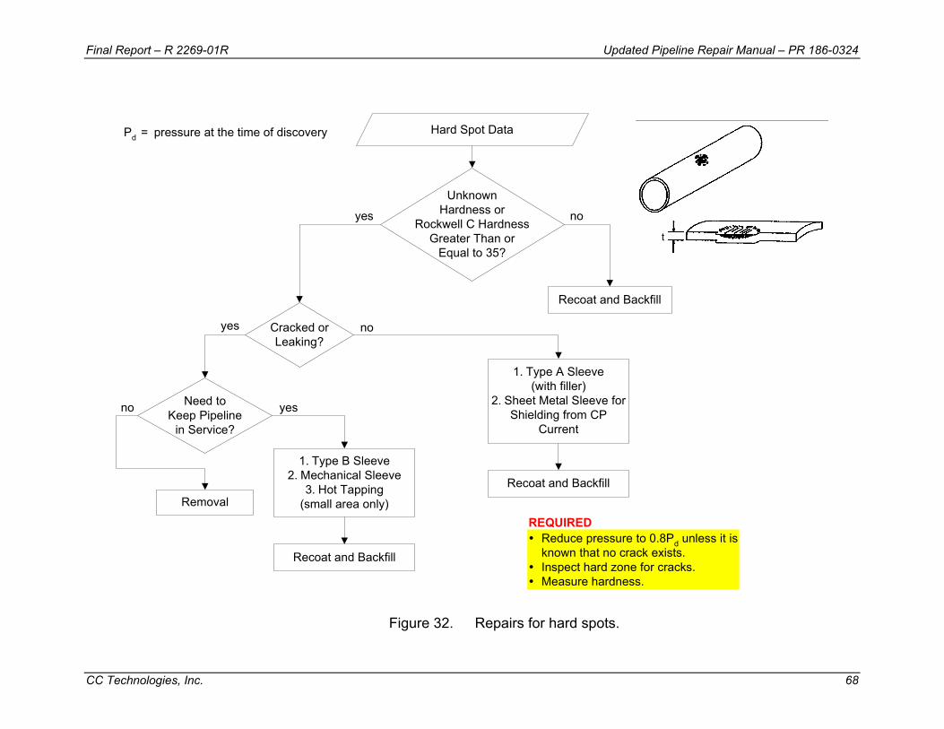
Final Report – R 2269-01R Updated Pipeline Repair Manual – PR 186-0324
CC Technologies, Inc. 68
Hard Spot Data
UnknownHardness or
Rockwell C HardnessGreater Than or
Equal to 35?
noyes
Pd = pressure at the time of discovery
Recoat and Backfill
Cracked orLeaking?
Need toKeep Pipeline
in Service?
yes
1. Type A Sleeve(with filler)
2. Sheet Metal Sleeve forShielding from CP
Current
Recoat and Backfill
1. Type B Sleeve2. Mechanical Sleeve
3. Hot Tapping(small area only)
Recoat and Backfill
no
Removal
Reduce pressure to 0.8Pd unless it isknown that no crack exists.Inspect hard zone for cracks.Measure hardness.
REQUIRED
t
no yes
Figure 32. Repairs for hard spots.

Final Report – R 2269-01R Updated Pipeline Repair Manual – PR 186-0324
CC Technologies, Inc. 69
HIC (hydrogen-inducedstep-wise cracking)
t
t
Data on Blisters andHydrogen-Induced Cracking
Leaking?
Need toKeep Pipeline
in Service?
Need toKeep Pipeline
in Service?
no yes
Removal
no no yesyes
1. Type A Sleeve2. Compression Sleeve
3. Type B Sleeve4. Mechanical Sleeve
Recoat and Backfill
Pd = pressure at the time of discoveryPh = historical high pressure known to
have occurred with the past year
1. Type B Sleeve2. Mechanical Sleeve
Recoat and Backfill
Reduce pressure to 0.8Pd or 0.8Phprior to examination and during repair.Map blister and/or cracked areas usingUT to prevent welding into a blister if aType B sleeve is used and to assurecoverage for all methods.
REQUIRED
Figure 33. Repairs for blisters and HIC.
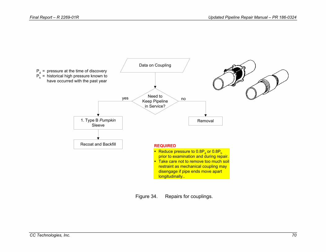
Final Report – R 2269-01R Updated Pipeline Repair Manual – PR 186-0324
CC Technologies, Inc. 70
Data on Coupling
Need toKeep Pipeline
in Service?
no
Removal
yes
1. Type B PumpkinSleeve
Recoat and Backfill
Pd = pressure at the time of discoveryPh = historical high pressure known to
have occurred with the past year
Reduce pressure to 0.8Pd or 0.8Phprior to examination and during repair.Take care not to remove too much soilrestraint as mechanical coupling maydisengage if pipe ends move apartlongitudinally..
REQUIRED
Figure 34. Repairs for couplings.
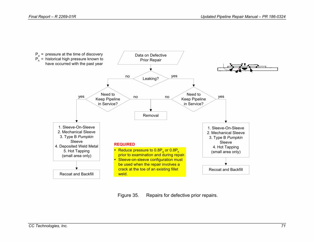
Final Report – R 2269-01R Updated Pipeline Repair Manual – PR 186-0324
CC Technologies, Inc. 71
Data on DefectivePrior Repair
Leaking?
Need toKeep Pipeline
in Service?
Need toKeep Pipeline
in Service?
no yes
Removal
no no yesyes
1. Sleeve-On-Sleeve2. Mechanical Sleeve3. Type B Pumpkin
Sleeve4. Deposited Weld Metal
5. Hot Tapping(small area only)
Recoat and Backfill
Pd = pressure at the time of discoveryPh = historical high pressure known to
have occurred with the past year
1. Sleeve-On-Sleeve2. Mechanical Sleeve3. Type B Pumpkin
Sleeve4. Hot Tapping
(small area only)
Recoat and Backfill
Reduce pressure to 0.8Pd or 0.8Phprior to examination and during repair.Sleeve-on-sleeve configuration mustbe used when the repair involves acrack at the toe of an existing filletweld.
REQUIRED
Figure 35. Repairs for defective prior repairs.

Final Report – R 2269-01R Updated Pipeline Repair Manual – PR 186-0324
CC Technologies, Inc. 72
Repair choices for pipe that has sustained enough metal loss to fail the defect acceptance criteria include a composite sleeve with filler material, a Type A sleeve with filler material, a compression sleeve with filler material, a Type B sleeve, a mechanical sleeve, deposited weld metal if the remaining wall thickness is at least 3.2 mm (0.125 inch), hot tapping if it can completely remove the anomaly, or a patch or half sole subject to code or regulatory restrictions.
After the pipeline has been repaired, it should be recoated and backfilled. Then, the normal operating pressure can be restored if appropriate.
0
0.1
0.2
0.3
0.4
0.5
0.6
0.7
0.8
0.9
1
0 1 2 3
Figure 5-7 from API RP 579
(t-d
)/t
c/D
ACCEPTABLE
UNACCEPTABLE
Figure 36. Acceptance criterion for circumferential extent of metal-loss defect.
4.2.2 – Internal Corrosion
The repair selection criteria for internal corrosion are shown in Figure 27. While it might be reasonable to expect internal corrosion to be treatable in the same manner as external corrosion, the lack of direct access to the region of metal loss places additional limits on repairs for internal corrosion. As for external corrosion, reducing the pressure is desirable unless it has been shown by an ILI within the past year that the region of the pipeline with metal loss would not be expected to fail at less than 1.25 times the current pressure.
It is possible to use the ASME B31G or RSTRENG approach and Figure 36 to assess internal metal loss. The difficulty with doing so is that the critical dimensions

Final Report – R 2269-01R Updated Pipeline Repair Manual – PR 186-0324
CC Technologies, Inc. 73
needed for the assessment usually should be determined from the external surface of the pipe by means of ultrasonic testing. For this reason, it is recommended that 0.25 mm (0.010 inch) be subtracted from the ultrasonically measured values of wall thickness in the corroded area. Furthermore, if the internal corrosion is expected to continue at a predictable rate, then a future corrosion allowance also should be subtracted from each measurement before evaluating the remaining strength of the pipe. The amount to be subtracted will depend on how long the repair decision is to be left in place without taking further remedial action. The implications of this requirement are (1) that if no repair is made because the anomaly has adequate remaining strength, the region will be reevaluated at a defined future time when the metal loss may be begin to encroach on the defined limits or (2) that if a repair method is chosen that cannot contain a leak, the repair will be regarded as temporary with a permanent repair scheduled for a defined future time.
Keeping the points discussed above in mind, one can use Figure 27 to select an appropriate repair method for an internal corrosion defect.
4.2.3 – Plain Dents or Dents with Stress Concentrators Plain dents or dents with stress concentrators can be repaired following the criteria
shown in Figure 28. These criteria are consistent with those in CSA Z662.(10)h Plain dents on the pipe body that are up to 6% of the pipe diameter deep and truly contain no stress concentrator (gouge, crack, groove, or arc burn) have little or no effect on pipeline integrity.(48) A depth of 2% of the pipe diameter is considered acceptable for plain dents on welds.(10) Unless the pipeline is subjected to many large pressure cycles or the dent interferes with pigging, a plain dent up to 6% deep on the pipe body or up to 2% deep on a weld normally does not require repair. Any amount of damage within a dent, such as a gouge, crack, groove, arc burn, scrape, score, or abrasion, makes it a dent with a stress concentrator. Such a dent should be treated as a potentially severe defect. In addition, any dent that involves a low-toughness seam, especially a low-frequency ERW or flash-welded seam, should be a candidate for repair. An average Charpy impact energy of at least 40.7 (30 ft-lb) or minimum Charpy impact energy of at least 29.8 J (22 ft-lb) at minimum operating temperature is sometimes used as an acceptance criterion for adequate toughness.
There is a concern that some plain dents may have a sharp profile. In the industry survey (Appendix B), some operators reported through-wall fatigue failures (leaks) at sharp dents that were much less than 6% deep. The sharpness of a dent can be quantified by calculating the strain within the dent. It has been found that the likelihood of punctures and cracking is high when strain exceeds 12%, so ASME B31.8(17)
h Criteria for repair of plain dents or dents with stress concentrators contained in US codes vary somewhat and are
slightly different from those contained in CSA Z662.
Final Report – R 2269-01R Updated Pipeline Repair Manual – PR 186-0324
CC Technologies, Inc. 74
includes a strain limit of 6% that may be applied to plain dents of any depth. Appendix R of ASME B31.8(17) provides guidance on strain calculations. A procedure for estimating the strain in a dent from ILI data has also been developed.(49) In the industry survey, some operators indicated that ILI data are not detailed enough to provide an accurate estimate of strain in a sharp dent.
The criteria in Figure 28 permit repair of a dent with a stress concentrator by one of the six following methods when it is located on the pipe body or a seam weld: grinding, composite sleeve, compression sleeve, Type A sleeve, Type B sleeve, or mechanical sleeve. Grinding should follow the requirements for such repairs (see Section 3.2), plus the dent depth excluding the ground area should be acceptable per the limits indicated in above and remaining fatigue should be found to be acceptable based on the results of an engineering assessment. Use of a composite sleeve requires grinding to remove all stress concentrators and damaged material, an acceptable dent depth per the limits for a plain dents indicated above, use a filler material in the dented region, and acceptable remaining fatigue life as demonstrated by means of an engineering assessment. Use of a Type A sleeve requires grinding to remove all stress concentrators and damaged material, an acceptable dent depth per the limits for a plain dents indicated above, and acceptable remaining fatigue life as demonstrated by means of an engineering assessment. Except for composite sleeves, these same repair methods can be used for a dent on a girth weld. However, grinding should be used to remove all stress concentrators before a compression sleeve is applied to a dent on a girth weld.
4.2.4 – Longitudinal Cracks and Arc Burns Other than corrosion and external damage, the most likely repair situations will fall
into the category of longitudinal cracks and arc burns. The repair selection criteria for this category are illustrated in Figure 29. A leaking defect in this category can be repaired by using a Type B sleeve, by using a mechanical sleeve, or by hot tapping if the anomaly is small enough to be completely removed and not in a low-toughness ERW or flash-welded seam. A nonleaking defect in a low-toughness ERW or flash-welded seam can be repaired by using a compression sleeve, a Type B sleeve, or a mechanical sleeve.
For other longitudinal cracks and arc burns, grinding to remove cracked or metallurgically altered material or both is permitted. The depth and length of grinding should not exceed that allowed by the ASME B31G or RSTRENG criterion or applicable codes and regulations, whichever is used. The depth and length of grinding can go beyond these limits if the pressure is reduced to an appropriate level and the resulting wall loss defect is repaired using one of the methods for external corrosion (Section 4.2.1). If the defect is an arc burn or other metallurgically altered material, its removal should be confirmed by metallographic examination.
Final Report – R 2269-01R Updated Pipeline Repair Manual – PR 186-0324
CC Technologies, Inc. 75
Hot tapping can also be used if the area is to be removed is small. If a crack or portion of a crack is left in the pipe, only a compression sleeve, a Type B sleeve, or a mechanical sleeve can be used. In this case, the Type B or mechanical sleeve should be pressurized or an engineering assessment should be made to show that the crack will not reach a critical size during the remaining service life of the pipe. A metallurgical anomaly that cannot be ground out within acceptable limits can be repaired using a Type A sleeve, a compression sleeve, a Type B sleeve, a mechanical sleeve, or hot tapping (a small area only).
4.2.5 – Girth-Weld Defects Girth-weld defects and certain other circumferentially oriented defects may be
repaired in accordance with the criteria illustrated in Figure 30. Dents on girth welds are covered in Section 4.2.3. If the defect is not leaking, a fitness-for-service (FFS) evaluation may be performed to determine whether or not it is expected to affect the integrity of the pipeline. FFS evaluation requires knowledge of (1) pipe dimensions, (2) defect size, (3) material properties of base, weld, and heat-affected zone (HAZ) metal (including fracture toughness values if the defect is a type other than metal loss), and applied longitudinal stress. In effect, the operator should perform a FFS analysis or an engineering critical assessment (ECA) to show that the defect is acceptable as is or can be repaired by grinding or by grinding and weld metal deposition. To address this issue, informative Annexes J and K of CSA Z662(10) provide guidelines for ECA and acceptance standards based on fracture toughness. If the operator is not prepared to carry out such an assessment, the repair should be made by means of a Type B sleeve with its ends welded to the carrier pipe to provide some reinforcement in the longitudinal direction. There are also some clamp-on mechanical sleeves that provide for axial load transfer and structural integrity. These have been developed for and applied to offshore pipelines, but they could be used for onshore applications as well.
4.2.6 – Wrinkle Bends/Buckles As shown in Figure 31, wrinkle bends/buckles either can be evaluated by an
engineer to determine if they affect the integrity of the pipeline or repaired using a Type B pumpkin sleeve. Based on industry experience,(47) no repair is required when the peak-to-trough height (h) is less than 2.4 mm (0.094 inch). Specific calculations also could be used to demonstrate that a larger peak-to-trough height than this would be acceptable without repair.
4.2.7 – Hard Spots Figure 32 shows the criteria for repairing hard spots. Action should be taken if the
hardness is not known or is measured and found to be greater than or equal to 35 Rockwell C. A Type A sleeve with filler or a special sheet metal sleeve that provides cathodic shielding can be used for repair if there is no crack or leak. The sleeve should

Final Report – R 2269-01R Updated Pipeline Repair Manual – PR 186-0324
CC Technologies, Inc. 76
be installed so that corrosive media does not enter the annulus between it and the carrier pipe. If the hard spot is cracked or leaking, it can be repaired using a Type B sleeve, a mechanical sleeve, or hot tapping (for a small area only).
4.2.8 – Blisters and Hydrogen-Induced Cracking Figure 33 shows the criteria for repairing blisters and hydrogen-induced cracking
(HIC). If the pipe is not leaking, a Type A sleeve, a compression sleeve, a Type B sleeve, or a mechanical sleeve can be used to repair the defect. If the pipe is leaking, only a Type B or a mechanical sleeve may be used to repair the defect. When cracking is present, an engineering assessment should be performed to show that it will not grow to cause a leak with a Type A sleeve or a compression sleeve and that it will not be or grow to a critical size in future service for any type of sleeve repair.
4.2.9 – Couplings Figure 34 shows the criteria for repairing couplings. Removal and use of a Type B
pumpkin sleeve are the only two viable repair options for this case.
4.2.10 – Defective Prior Repairs Figure 35 shows the criteria for repairing defective prior repairs. For this case, a
sleeve-on-sleeve configuration, a mechanical sleeve, a Type B pumpkin sleeve, or hot tapping (for a small area only) are viable repair options. If the defective region is not leaking, a weld deposition repair may also be considered.
5.0 – REPAIR METHODS IN EUROPE Repair methods are also important to operators of pipelines in Europe. These were
briefly reviewed in the previous version of this manual.(1) During preparation of this updated manual attempts were made to obtain more recent information on the repair methods used in Europe. Unfortunately, these attempts were unsuccessful, so no new information was obtained for this section of the manual. Therefore, just the information from the original manual is included here. That information was based on suggestions from a European project team working on the repair of gas pipelines as follows:
• Stopple Fittings. This manual does not mention stopple fittings although the practice of using them is well known and they are used in both Europe and North America. Instead of including a section on stopple fittings, the reader is referred to References 50 and 51 for details of their use. The use of stopple fittings is more complex than any of the repair methods described in this manual.
• Type A Sleeves. European companies apparently prefer to use the epoxy-filled shells described in Reference 25 as opposed to the Type A sleeves, which are more widely used in North America than in Europe.
Final Report – R 2269-01R Updated Pipeline Repair Manual – PR 186-0324
CC Technologies, Inc. 77
• Deposited Weld Metal. European companies have been conducting research on weld deposition repair in addition to the research that has been conducted in North America. Available results are incorporated into this manual (see Appendix A).
• Type B Sleeves. Ruhrgas has commonly used Type B sleeves as an alternative to butt welding for tie-in welds. They also have used induction preheating to stress relieve and metallurgically improve welds made on in-service pipelines.
• Composite Sleeves: Composite sleeves are coming into use throughout the world. Some of the alternatives to Clock Spring® were developed in Europe.
• Dent With a Stress Concentrator: Repair of a dent with a stress concentrator has been the subject of studies in both Europe and North America. Some operators still consider removal to be the only acceptable repair method. Other methods, such as those discussed in this manual, are beginning to be used based on the results of research.
• General Procedures: Reference 52 summarizes procedures that have been used by British Gas, which are similar to many of those described in this manual.
• Welding on Pressurized Pipe: Various studies of welding on pressurized pipe have been conducted in Europe. For example, see References 53 and 54. Also, Reference 14 summarizes work on repair of steel pipelines in Australia. Two important comments regarding Appendix A of this manual are as follows: (1) European companies tend to rely on test welding under simulated and actual field conditions to validate welding parameters as opposed to using cooling rates calculated by a thermal analysis model and (2) many European companies appear to believe that strict adherence to low-hydrogen welding practices makes it possible to inspect a weld immediately upon cool-down instead of waiting for 24 to 48 hours to make sure that there is no delayed cracking.
6.0 – GUIDELINES FOR A REPAIR PROCEDURE The generic repair procedure of the original manual has been updated and is shown
in Appendix C. To facilitate its use by pipeline operators, it is also available as a separate file. This procedure cannot be used as is and individual pipeline operators can easily customize it for use or use it to benchmark or upgrade an existing procedure.
The repair guidelines address the major topics of scope, repair policy, definitions applicable to pipeline repairs, methods, application procedures, inspection and documentation, and backfilling.
Final Report – R 2269-01R Updated Pipeline Repair Manual – PR 186-0324
CC Technologies, Inc. 78
7.0 – REFERENCES 1. Kiefner, J. F., Bruce, W. A., and Stephens, D. R., “Pipeline Repair Manual,”
Catalog Number L51716, Pipeline Research Council International, Inc., Arlington, VA, December 31, 1994.
2. Bruce, W. A., “Overview Of In-Service Welding Research At EWI” First International Conference on Welding onto In-Service Petroleum Gas and Liquid Pipelines, Welding Technology Institute of Australia, Wollongong, Australia, March 2000.
3. ASME B31G, “Manual for Determining the Remaining Strength of Corroded Pipelines, A Supplement to ASME B31 Code for Pressure Piping, B31G,” The American Society of Mechanical Engineers, New York, 1991.
4. Kiefner, J. F., and Vieth, P. H., “The Remaining Strength of Corroded Pipe,” Paper 29, Proceedings of the Eighth Symposium on Line Pipe Research, Catalog No. L51680, American Gas Association, Inc., Arlington, VA, 1993.
5. BS 7910, “Guide on methods for assessing the acceptability of flaws in metallic structures,” British Standards Institution, London, 1999.
6. API RP 579, “Fitness-For-Service,” American Petroleum Institute, Washington, D.C., January 2000.
7. Kiefner, J. F., Maxey, W. A., Eiber, R. J., and Duffy, A. R., “Failure Stress Levels of Flaws in Pressurized Cylinders,” Progress in Flaw Growth and Fracture Toughness Testing, STP 536, ASTM International, West Conshohocken, PA, 1973, pp. 461-481.
8. Jaske, C. E., and Beavers, J. A., “Development and Evaluation of Improved Model for Engineering Critical Assessment of Pipelines,” Paper IPC2002-27027, Proceedings of the International Pipeline Conference 2002, Part B, The American Society of Mechanical Engineers, New York, 2002, pp. 1459-1466.
9. Leis, B.N. and Ghadiali, N., “Pipeline Failure Criterion – PFC – A Suite of Pipeline Failure Criteria, Release 1.0,” PRCI Software with Concurrent Release of Deliverables for PR-3-9901, PR-3-9708, and PR-3-9608, Pipeline Research Council International, Inc., Arlington, VA, 2001.
10. CSA Z662, “Oil and Gas Pipeline Systems,” Canadian Standards Association, Mississauga, Ontario, June 2003.
11. Cosham, A., and Hopkins, P., “A Review of the Time Dependent Behavior of Line Pipe Steel,” Paper IPC04-0084, Proceedings of the International Pipeline Conference 2004, Volume 2, The American Society of Mechanical Engineers, New York, 2004, pp. 1145-1158.
12. http://www.tdwilliamson.com/hottaptdw/freeze.html
Final Report – R 2269-01R Updated Pipeline Repair Manual – PR 186-0324
CC Technologies, Inc. 79
7.0 – REFERENCES (continued) 13. D. A. Lobmeyer and Z. F. Nagy. Cryogenic Freeze Plug Using Alternative
Fluid. AIP Conference Proceedings June 23, 2004: Volume 710, Issue 1, pp. 1883-1890.
14. “Repair of Steel Pipelines,” WTIA Technical Note No. 20, Welding Technology Institute of Australia, Silverwater, NSW, Australia, 2004.
15. API SPEC 5L, “Specification for Line Pipe,” 43rd Edition, American Petroleum Institute, Washington, D.C., March 2004.
16. ASME B31.4, “Pipeline Transportation Systems for Liquid Hydrocarbons and Other Liquids,” The American Society of Mechanical Engineers, New York, 2002.
17. ASME B31.8, “Gas Transmission and Distribution Piping Systems,” The American Society of Mechanical Engineers, New York, 2003.
18. Corder, I, and Burn, J., “The Dressing of Pipeline Damage With Rotary Tools,” British Gas Engineering Research Station,” Report No. ERS R.2695, March 1983.
19. Kiefner, J. F., and Duffy, A. R., “A Study of Two Methods for Repairing Defects in Line Pipe,” Final Report to the Pipeline Research Committee of the American Gas Association, Catalog No. L22275, October 1974.
20. Kiefner, J. F., and Whitacre, G. R., “Further Studies of Two Methods for Repairing Defects in Line Pipe,” Final Report to the Pipeline Research Committee of the American Gas Association, Catalog No. L22279, March 1978.
21. Kiefner, J. F., “Repair of Line-Pipe Defects by Full-Encirclement Sleeves,” Welding Journal, Vol. 57, No. 6, June 1977.
22. Kiefner, J. F., “Full-Encirclement Sleeve Repair Methods Given for Dented or Corroded Pipe,” Oil and Gas Journal, Vol. 81, December 26, 1983.
23. Brongers, M. P., Maier, C. J., Jaske, C. E., Vieth, P. H., Wright, M. D., and Smyth, R. J., “Evaluation and Use of a Steel Compression Sleeve to Repair Longitudinal Seam-Weld Defects,” 52nd Annual Pipeline Conference, San Antonio, TX, April 17 – 18, 2001.
24. Brongers, M. P., Maier, C. J., Jaske, C. E., Vieth, P. H., Wright, M. D., and Smyth, R. J., “Tests, Field Use Support Compression Sleeve for Seam-Weld Repair,” Oil and Gas Journal, Volume 99, June 11, 2001.
25. Corder, I., “Cost-Effective On-Line Repair of Pipeline Damage Using Epoxy-Filled Shells,” Pipeline Risk Assessment, Repair and Rehabilitation Conference, Houston, TX, May 20-23, 1991.
Final Report – R 2269-01R Updated Pipeline Repair Manual – PR 186-0324
CC Technologies, Inc. 80
7.0 – REFERENCES (continued) 26. Corder, I., “Repairing Transmission Pipelines by Epoxy-Filled Shells: The
Safest, Best and Cheapest Method,” IGE 58th Autumn Meeting, London, November 24-25, 1992.
27. PetroSleeve™ Historical Test Results and Data, PetroSleeve, Inc., Nisku, Alberta, 2000.
28. Smyth, R. J., “Repairing Pipe Defects (Cracking, Arc Burns, Corrosion, Dents) Without Operational Outages Using the PetroSleeve Compression Sleeve Repair Technique,” Proceedings of the 1998 International Pipeline Conference, Volume 1, The American Society of Mechanical Engineers, New York, 1998, pp. 231-239.
29. API STD 1104, “Welding Pipelines and Related Facilities,” 19th Edition, American Petroleum Institute, Washington, D.C., October 31, 2001.
30. Kiefner, J. F., and Maxey, W. A., “Tests Validate Pipeline Sleeve Repair Technology,” Oil and Gas Journal, Vol. 87, August 28, 1989.
31. Porter, P. C., and Mitchell, J. L., “Pipeline Inspection and Rehabilitation Using Clock Spring®,” Proceedings of the 2000 International Pipeline Conference, Volume 2, The American Society of Mechanical Engineers, New York, 2000, pp. 1473-1477.
32. Bruce, W. A., Swatzel, J. F., and Dorling, D. V., “Repair of Pipeline Defects Using Weld Deposition,” Proceedings of the 3rd International Pipeline Technology Conference, Brugge, Belgium, 2000.
33. Phelps, B., Cassie, B. A., and Evans, N. H., “Welding Onto Live Natural Gas Pipelines,” British Welding Journal, Vol. 8, No. 8, 1976, p. 350.
34. Bruce, W. A., Mishler, H. D., and Kiefner, J. F., “Repair of Pipelines by Direct Deposition of Weld Metal,” A.G.A. Pipeline Research Committee, Project PR-185-9110, Edison Welding Institute, Columbus, Ohio, June 1993.
35. Bruce, W. A., Holdren, R. L., Mohr, W. C, and Kiefner, J. F., “Repair of Pipelines by Direct Deposition of Weld Metal - Further Studies,” PRC International, Project PR-185-9515, Edison Welding Institute and Kiefner and Associates, Columbus, Ohio, November 1996.
36. Bruce, W. A., and Wang, Y.-Y., “Stress Analysis of External Weld Deposition Repair for Internal Wall Loss,” EWI Project No. 07723CAP, PRC International, Contract No. PR-185-9633, November 17, 1995.
37. Bruce, W. A., “External Weld Deposition Repair for Internal Wall Loss in Tees and Elbows,” EWI Project No. 45490CAP, PRC International, Contract No. GRI-9506, August 26, 2004.
Final Report – R 2269-01R Updated Pipeline Repair Manual – PR 186-0324
CC Technologies, Inc. 81
7.0 – REFERENCES (continued) 38. Bruce, W. A., “Guidelines for Weld Deposition Repair on Pipelines,” American
Gas Association, Arlington, VA, Catalog No. L51782, 1998.
39. Cassie, B. A., and Prosser, K., “Weld Metal Deposition - A Repair Technique in Need of Exploitation,” Welding and Performance of Pipelines, TWI, Cambridge, UK, November 1986.
40. Unknown, “Repairs in Tricky Places - Looking Back on a Successful Experiment,” Article from Gasuniek, September 1990.
41. CFR Part 192, U. S. Department of Transportation, "Pipeline Safety Regulations," October 1997.
42. Federal Register, Vol. 64, No. 239, U. S. Department of Transportation, Research and Special Programs Administration, Pipeline Safety: Gas and Hazardous Liquid Pipeline Repair, Rules and Regulations, 64 FR 69660, December 14, 1999.
43. Goddard, D. H., “Repair of High Pressure Natural Gas Pipelines Using Leak Clamps as the Method of Repair,” Proceedings of the American Gas Association Operating Section, Arlington, VA, 1989.
44. Scott, P. M., and Kiefner, J. F., “Effectiveness of Pipeline Half-Sole Technique Is Evaluated,” In-Service Pipeline Repair, Oil and Gas Journal, Vol. 82, December 4, 1984.
45. Scott, P. M., and Kiefner, J. F., “Test Results for Leaking, Nonleaking Line Defects,” In-Service Pipeline Repair - 2, Oil and Gas Journal, Vol. 82, December 10, 1984.
46. Eiber, R. J., “Causes of Pipeline Failures,” Proceedings of the 6th Symposium on Line Pipe Research, Catalog No. L30175, American Gas Association, Arlington, VA, November 1979, pp. C-1 to C-20.
47. “Recommended Standards for Cold Bending of Pipe and Tube,” TPA-CBS-98, Tube & Pipe Association, International, Rockford, IL, 1998.
48. Eiber, R. J., “The Effects of Dents on Failure Characteristics of Line Pipe,” NG-18 Report 125, Catalog No. L51403, American Gas Association, Arlington, VA, 1981
49. Rosenfeld, M. J., Porter, P. C., and Cox, J. A., “Strain Estimation Using Vetco Deformation Tool Data,” Proceedings of the International Pipeline Conference, The American Society of Mechanical Engineers, New York, 1998, pp. 389-397.
50. VerNooy, B., “Design and Handling of a Large Pipeline Plugging Job,” Transmission Conference, American Gas Association, May 1983.
Final Report – R 2269-01R Updated Pipeline Repair Manual – PR 186-0324
CC Technologies, Inc. 82
7.0 – REFERENCES (continued) 51. Engel, A., “Stoppling Gas Transmission Pipelines,” International Gas Union,
Proceedings of the 16th World Gas Conference, Munich, 1985.
52. Pallan, W., “Pipeline Maintenance and Repair,” British Gas, E601, September 1987.
53. Rietjens, P., “Procedures for Damage Assessment, In-Service Welding and Repair of Pipelines,” International Gas Union, Proceedings of the 16th World Gas Conference, Munich, 1985.
54. Lamberts, G., “Considerations of Welding Methods Adopted on Pipelines During Service,” Document IIW-SCXI-E, November 14, 1985.

APPENDIX – A
WELDING ONTO AN IN-SERVICE PIPELINE
ii
CONTENTS
1.0 – INTRODUCTION.................................................................................................A-1
2.0 – BACKGROUND...................................................................................................A-1 2.1 – Burnthrough and Unstable Decomposition Concerns ....................................A-1 2.2 – Hydrogen Cracking Concerns ........................................................................A-2
3.0 – PREVENTING BURNTHROUGH........................................................................A-6 3.1 – Pressure Reduction .......................................................................................A-6 3.2 – Evaluating Burnthrough Risk..........................................................................A-7 3.3 – Development of Simple Burnthrough Prevention Guidelines .........................A-7 3.4 – Control of Heat Input Levels.........................................................................A-10 3.5 – Electrode Diameter Restrictions...................................................................A-10 3.6 – General Observations and Rules of Thumb for Burnthrough .......................A-10
4.0 – PREVENTING HYDROGEN CRACKING .........................................................A-11 4.1 – Hydrogen in the Weld ..................................................................................A-11 4.2 – Crack-Susceptible Weld Microstructures .....................................................A-12 4.3 – Tensile Stresses Acting on the Weld ...........................................................A-12
5.0 – PROCEDURE OPTIONS FOR IN-SERVICE WELDING...................................A-12 5.1 – Predicting Required Heat Input Levels.........................................................A-13 5.2 – Temper Bead Procedures............................................................................A-19 5.3 – Preheat Control Procedures.........................................................................A-23 5.4 – General Observations for Procedure Options ..............................................A-23
6.0 – QUALIFICATION OF PROCEDURES AND WELDERS FOR IN-SERVICE WELDING .................................................................................................................A-24
6.1 – Qualification of In-Service Welding Procedures ...........................................A-24 6.2 – In-Service Welder Qualification....................................................................A-26 6.3 – HAZ Hardness Limits ...................................................................................A-27 6.4– HAZ Hardness Testing..................................................................................A-28
7.0 – FIELD WELDING GUIDANCE...........................................................................A-28 7.1 – Wall Thickness Determination/Inspection ....................................................A-29 7.2 – Chemical Composition Determination..........................................................A-29 7.3 – Electrode Procurement ................................................................................A-31
7.3.1 – Electrode Classification/Supplemental Designations...........................A-31 7.3.2 – Packaging............................................................................................A-31
7.3.2.1 – Packaging Type...........................................................................A-31 7.3.2.2 – Package Size ..............................................................................A-32 7.3.2.3 – Special Packaging.......................................................................A-32
7.4 – Storage of Electrodes in Unopened Cans/Cartons ......................................A-32 7.5 – Sleeve Fit-Up ...............................................................................................A-33 7.6 – Backing Strips ..............................................................................................A-33
iii
7.7 – Welding Sequence.......................................................................................A-33 7.8 – Electrode Handling.......................................................................................A-33
7.8.1 – Electrodes Intended for Later Use .......................................................A-34 7.8.2 – Electrodes Intended for Immediate Use...............................................A-35 7.8.3 – Atmospheric Exposure Limits ..............................................................A-36 7.8.4 – Electrode Drying/Re-Conditioning .......................................................A-37
7.9 – Additional Precautions for Weld Hydrogen Levels .......................................A-38 7.10 – Control of Heat Input Levels.......................................................................A-38
7.10.1 – Conventional Equipment....................................................................A-39 7.10.2 – Dedicated Arc Monitoring Equipment ................................................A-40 7.10.3 – Run-Out Ratio Scheme......................................................................A-40 7.10.4 – Avoiding Excessive Heat Input ..........................................................A-41
7.11 – Temper Bead Sequence ............................................................................A-41 7.12 – Preheating..................................................................................................A-41
7.12.1 – Preheating Method ............................................................................A-44 7.12.2 – Preheat Temperature.........................................................................A-44 7.12.3 – Measurement of Preheat Temperatures ............................................A-45
7.12.3.1 – Measurement Location..............................................................A-45 7.12.3.2 – Measurement Method ...............................................................A-45
7.12.4 – Maintenance of Preheat During and After Welding............................A-45 7.12.4.1 – Tack Welding.............................................................................A-46
7.13 – Welder-Induced Discontinuities..................................................................A-46 7.14 – Fillet Weld Size ..........................................................................................A-46 7.15 – Inspection and Nondestructive Testing ......................................................A-47 7.16 – Delay Time Prior to Inspection for Hydrogen Cracking ..............................A-48 7.17 – Repair and Removal of Defects .................................................................A-50 7.18 – Proof Testing..............................................................................................A-50 7.19 – Verification of Procedure Suitability ...........................................................A-50 7.20 – Coating and back-fill ..................................................................................A-50
8.0 – RELATED AREAS OF CONCERN....................................................................A-51 8.1 – Internal Combustion and Other Products of Concern ..................................A-51 8.2 – Hot Tap Welding for Sour Service Pipelines ................................................A-52 8.3 – Hot Tap Welding for Lines Charged with Hydrogen .....................................A-52 8.4 – Hot Tap Welding for Duplex Stainless Steel Pipelines.................................A-53
9.0 – SUMMARY........................................................................................................A-53
10.0 – REFERENCES................................................................................................A-54
iv
TABLES
Table A-1. General rules of thumb for pipe material chemical composition............A-30
Table A-2. Run-out ratios for electrodes containing little or no iron powder.(33).............................................................................................A-42
Table A-3. Run-out ratios for electrodes containing some iron powder (including most EXX18-yype electrodes).(33) See Figure A-24. ............A-42
Table A-4. Run-out ratios for electrodes containing high iron powder contents.(33) ...........................................................................................A-42
Table A-5. Advantages and disadvantages of various NDT methods. ...................A-49
v
FIGURES
Figure A-1. Typical burnthrough on 3.2 mm (0.125 inch) thick pipe. .........................A-2
Figure A-2. Relationship of factors affecting the occurrence of burnthrough for in-service welding. .............................................................................A-3
Figure A-3. Typical hydrogen crack at toe of fillet weld of full-encirclement sleeve (metallographic section). .............................................................A-4
Figure A-4. Relationship of factors affecting the occurrence of hydrogen cracking for in-service welding................................................................A-5
Figure A-5. Example of simplified burnthrough prediction guideline – methane gas at 4.14 MPa (600 psi). .......................................................A-8
Figure A-6. Example of simplified burnthrough prediction guideline* – heavy crude oil. .................................................................................................A-9
Figure A-7. Example of Battelle thermal analysis computer model output (minimum-required heat input as a function of CE level) – methane gas at 5.17 MPa (750 psi). .....................................................A-14
Figure A-8. Heat sink capacity measurement. .........................................................A-15
Figure A-9. Example of heat sink capacity relationships (minimum-required heat input as a function of CE level) for 6.4 mm (0.250 inch) thick pipe. ......................................................................................................A-16
Figure A-10. Critical hardness level for in-service welds vs. CEIIW and weld hydrogen level – limited to materials 9.5 mm (0.375 inch) thick or less and %c greater than 0.10. .........................................................A-19
Figure A-11. Example of PRCI thermal analysis computer model output – methane gas at 5.17 MPa (750 psi). .....................................................A-20
Figure A-12. Schematic illustration of temper bead deposition sequence. ................A-21
Figure A-13. Example of temper bead technique applied to a sleeve fillet weld........A-21
Figure A-14. Demonstration weld showing temper bead sequence applied to a sleeve fillet weld....................................................................................A-22
Figure A-15. Example of temper bead technique applied to a branch groove weld. .....................................................................................................A-22
Figure A-16. Set-up for procedure qualification for in-service welding.......................A-26
vi
FIGURES (continued)
Figure A-17. HAZ hardness indent locations. ............................................................A-28
Figure A-18. Bead sequence – stacking away from pipe material. ............................A-34
Figure A-19. Electrode holding oven. ........................................................................A-34
Figure A-20. Portable electrode ovens. .....................................................................A-35
Figure A-21. Canister for electrode storage...............................................................A-36
Figure A-22. Electrode re-drying/conditioning oven...................................................A-38
Figure A-23. Digital meter for measuring welding current..........................................A-40
Figure A-24. Run-out ratios for electrodes containing some iron powder (including most EXX18-type electrodes). See Table A-3. ....................A-43
Figure A-25. Fillet weld leg size – compensation for gap. .........................................A-47
Figure A-26. Confirmation weld scheme....................................................................A-51

Final Report – R 2269-01R Appendix A – Welding onto an In-Service Pipeline
CC Technologies, Inc. A-1
1.0 – INTRODUCTION There are often significant economic incentives to performing repair without
removing the pipeline from service. These incentives include the ability to maintain operations and the ability to avoid the cost of evacuating and retaining pipeline contents or, for natural gas, venting the contents of the pipeline to the atmosphere. Since methane is a so-called “greenhouse gas,” there are also environmental incentives for avoiding the venting of large quantities of gas into the atmosphere.
There are two primary concerns with welding onto in-service pipelines, whether for installing repair sleeves or installing a branch connection prior to "hot tapping." The first is for welder safety during welding, since there is a risk of the welding arc causing the pipe wall to be penetrated allowing the contents to escape or, for certain products (e.g., ethylene), a risk that the heat from welding will cause unstable decomposition of the product (i.e., fire or explosion). The second concern is for the integrity of the system following welding, since welds made in-service cool at an accelerated rate as the result of the flowing contents' ability to remove heat from the pipe wall. These welds, therefore, may have high heat-affected zone (HAZ) hardness values and may be susceptible to hydrogen cracking.
A thorough understanding of the factors that affect these concerns allows repairs and modifications to in-service pipelines to be made with confidence. The proper use of in-service welding allows both economic and environmental benefits to be realized by avoiding pipeline shutdown and interruption of service
2.0 – BACKGROUND 2.1 – Burnthrough and Unstable Decomposition Concerns
A burnthrough, or blowout as it is sometimes referred, will occur when welding onto a pressurized pipe if the unmelted area beneath the weld pool has insufficient strength to contain the internal pressure of the pipe. An illustration of a typical burnthrough is shown in Figure A-1. A burnthrough typically results in a small pin-hole in the bottom of what was the weld pool. The risk of burnthrough will decrease as the pipe wall thickness increases and the weld penetration decreases. The relationship of these factors is shown schematically in Figure A-2.
Penetration of the welding arc into the pipe wall is a function of the welding parameters and, to a lesser degree, the welding process. Penetration increases as heat input increases, or for a given heat input, as the welding current increases. Penetration also increases as the hydrogen potential of the welding process increases. A low-hydrogen process, such as shielded metal arc welding (SMAW) using low-hydrogen (basic-coated) electrodes (EXX18-type), in conjunction with a low heat input level results in the least amount of penetration. Conversely, a high-hydrogen potential
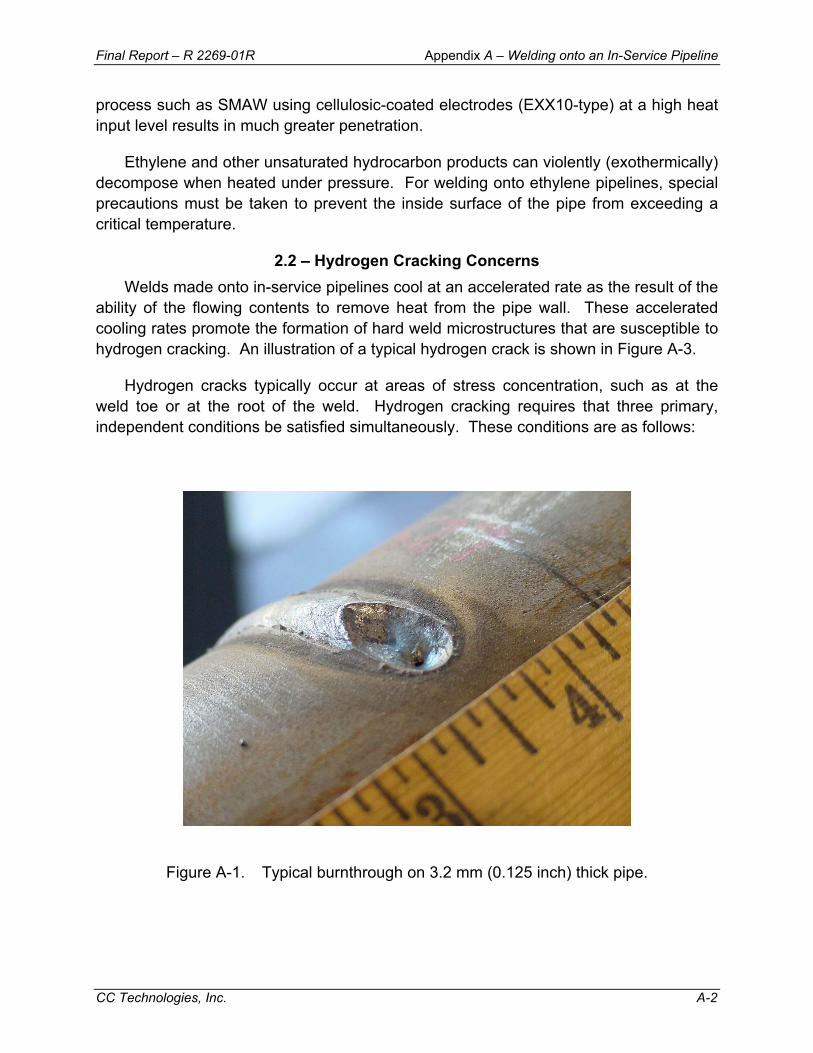
Final Report – R 2269-01R Appendix A – Welding onto an In-Service Pipeline
CC Technologies, Inc. A-2
process such as SMAW using cellulosic-coated electrodes (EXX10-type) at a high heat input level results in much greater penetration.
Ethylene and other unsaturated hydrocarbon products can violently (exothermically) decompose when heated under pressure. For welding onto ethylene pipelines, special precautions must be taken to prevent the inside surface of the pipe from exceeding a critical temperature.
2.2 – Hydrogen Cracking Concerns Welds made onto in-service pipelines cool at an accelerated rate as the result of the
ability of the flowing contents to remove heat from the pipe wall. These accelerated cooling rates promote the formation of hard weld microstructures that are susceptible to hydrogen cracking. An illustration of a typical hydrogen crack is shown in Figure A-3.
Hydrogen cracks typically occur at areas of stress concentration, such as at the weld toe or at the root of the weld. Hydrogen cracking requires that three primary, independent conditions be satisfied simultaneously. These conditions are as follows:
Figure A-1. Typical burnthrough on 3.2 mm (0.125 inch) thick pipe.

Final Report – R 2269-01R Appendix A – Welding onto an In-Service Pipeline
CC Technologies, Inc. A-3
BURNTHROUGH
WALL THICKNESS WELD PENETRATION/HEAT INPUT
OPERATINGCONDITIONS
Nominal Actual
Corrosion Lamination
WeldingProcess
WeldingParameters
HydrogenPotential Current
ElectrodeDiameter
Pressure(Gas Only) Temperature
FlowRate
PipelineContents
Voltage TravelSpeed
PreheatTemperature
Figure A-2. Relationship of factors affecting the occurrence of burnthrough for in-service welding.

Final Report – R 2269-01R Appendix A – Welding onto an In-Service Pipeline
CC Technologies, Inc. A-4
Figure A-3. Typical hydrogen crack at toe of fillet weld of full-encirclement sleeve (metallographic section).
• Hydrogen in the weld. All arc-welding processes introduce hydrogen into the weld
to some extent. Hydrogen can originate from moisture in electrode coatings, in the atmosphere (humidity) or on the pipe surface (condensation). Hydrogen can also originate from hydrocarbons, grease, or other organic contaminants on the pipe or on the welding consumable.
• Susceptible weld microstructure. In general, hard HAZ microstructures are most
susceptible to hydrogen cracking. Such microstructures are promoted by steel that has a high carbon-equivalent (CE) value and by rapid weld cooling rates. Weld cooling rates are determined by welding heat input and pipeline operating conditions. Operating conditions that influence weld-cooling rates include product type, flow rates, ambient temperatures, and pipe wall thickness. Weld metal microstructures can also be susceptible to hydrogen cracking.
• Tensile stresses acting on the weld. Tensile stresses can be either applied or
residual. Applied stresses can result from movement of a pipeline due to soil settlement or other causes. Residual stresses arise from the restraint of the welded connection and strains imposed by the contraction of the weld on cooling.
The relationship of the conditions necessary for hydrogen cracking to occur is
shown schematically in Figure A-4.

Final Report – R 2269-01R Appendix A – Welding onto an In-Service Pipeline
CC Technologies, Inc. A-5
HYDROGEN CRACKING
HYDROGEN
AtmosphericHumidity
WeldingProcess
ProperUse
Preheat/Postheat
HydrogenPotential Clean Dry
STRESS
Residual
WeldMetal
Strength
Joint/Root
Geometry
WeldingSequence
Applied
MICROSTRUCTURE
WELDCOOLING
RATE
CHEMICAL COMPOSITION/CARBON EQUIVALENT
PipeMaterial
FittingMaterial
WeldMetal
Buttering
SUBSEQUENTTHERMAL
TREATMENT
TemperBead
Sequence
WELDING PARAMETERS/HEAT INPUT
PIPELINEOPERATINGCONDITIONS
Current Voltage TravelSpeed
PreheatTemperature
ElectrodeSize
Pressure(Gas Only) Temperature Wall
ThicknessFlowRate
PipelineContents
Ambient PipeSurface
Figure A-4. Relationship of factors affecting the occurrence of hydrogen cracking for in-service welding.

Final Report – R 2269-01R Appendix A – Welding onto an In-Service Pipeline
CC Technologies, Inc. A-6
3.0 – PREVENTING BURNTHROUGH Previous work concluded that a burn-through will not occur if the inside surface
temperature beneath the welding arc is less than 982ºC (1800ºF) when welding with low-hydrogen electrodes.(1-3) This temperature is unlikely to be reached if the wall thickness is 6.4 mm (0.250 inch) or greater, provided that normal welding practices are used.(4) The risk of burnthrough is, therefore, extremely remote under these conditions regardless of the internal pressure.
Welding onto thinner wall materials is possible and considered routine by many companies although special precautions are often specified. These precautions include minimizing the penetration of the arc into the pipe wall by using a low-hydrogen process and a procedure that limits heat input. The wall thickness should be checked using appropriate ultrasonic testing equipment to ensure that the actual wall thickness does not differ greatly from the nominal wall thickness as a result of corrosion or erosion and that there are no material defects in the repair area.
There are several common misconceptions pertaining to operating practices required to prevent burnthrough. One is that some level of flow must always be maintained to prevent burnthrough and another is that the operating pressure must always be reduced. While maintaining flow does result in lower inside surface temperatures, it can be shown that inside surface temperatures are often less than 982ºC (1800ºF) due to the thermal mass of the pipe wall itself and the thermal properties of the contents, even at little or no flow.
3.1 – Pressure Reduction While a pressure reduction may be justified to prevent a defect from rupturing
during the installation of a full encirclement sleeve on the basis of protecting the repair crew, previous work concluded that stress level in the pipe wall has a relatively small effect on the risk of burnthrough.(4) The reason for this is the size of the area heated by the welding arc is small, and the stress in the pipe wall can redistribute itself around the heated area, as it does around a small corrosion pit. Pressure reductions are, therefore, relatively ineffective at preventing burnthrough and are often unnecessary.
Some companies use one of several available formulas for calculating a “safe” pressure level for welding onto in-service pipelines or piping systems. The use of such formulas, an example of which is given below, is generally unnecessary:
P = 2S (t-c) 0.72
D

Final Report – R 2269-01R Appendix A – Welding onto an In-Service Pipeline
CC Technologies, Inc. A-7
where: P = pressure (psi) S = specified minimum yield strength of pipe (psi) t = nominal pipe wall thickness (inch) D = nominal pipe diameter (inch) c = allowance for heated metal loss of strength
When the unmelted area beneath the weld pool has been heated to a sufficient temperature (i.e., significantly above 982ºC [1800ºF]), a burnthrough will occur even at very low pressures. Pressure reductions are, therefore, relatively ineffective at preventing burnthrough. A more appropriate approach to preventing burnthrough is to control inside surface temperature by limiting heat input to that which is appropriate for a given application..
3.2 – Evaluating Burnthrough Risk The most useful tool for evaluating the risk of burnthrough is thermal analysis
computer modeling using either the Battelle model(5, 6) or the PRCI model.(7) These computer models predict inside surface temperatures as a function of the welding parameters (current, voltage and travel speed), geometric parameters (wall thickness, etc.) and the operating conditions (contents, pressure, flow rate, etc.). The models can assess the risk of burnthrough for a given application or the limiting welding parameters (heat input level) for a given set of operating conditions can be determined.
Thermal analysis modeling can also be used in a similar manner for evaluating or minimizing the risk of unstable decomposition of products such as ethylene. Knowledge of the critical temperature that must be avoided for the specific product is required.
Thermal analysis modeling is not the only way to evaluate burnthrough risk for welding onto in-service thin-wall pipelines. Empirical welding parameters limits for preventing burnthrough have also been developed. (8, 9)
3.3 – Development of Simple Burnthrough Prevention Guidelines While the PRCI model is fairly user friendly, the Battelle model requires some
experience to operate, and neither is always accessible to field personnel. Simplified guidelines can be developed using thermal analysis modeling that enable field personnel to evaluate burnthrough risk for a wide range of routine applications. To do this, iterative thermal analysis modeling runs can be made to develop heat input limits (i.e., to prevent inside surface temperatures in excess of 1800ºF [982ºC]) for a variety of wall thicknesses and pipeline flow parameters. A series of graphs can be produced showing the maximum-allowable heat input as a function of flow conditions for various pipe wall thicknesses. Examples of these are shown for methane gas at 4.14 MPa (600 psi) and for heavy crude oil in Figures A-5 and A-6, respectively.
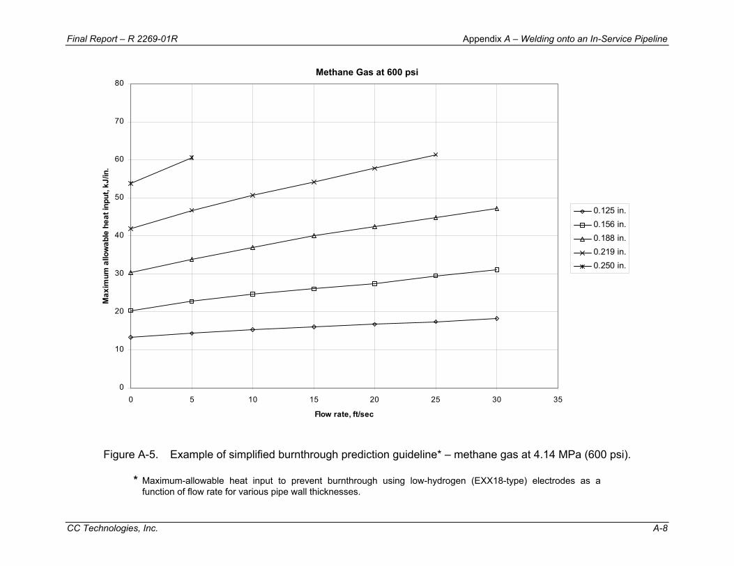
Final Report – R 2269-01R Appendix A – Welding onto an In-Service Pipeline
CC Technologies, Inc. A-8
Methane Gas at 600 psi
0
10
20
30
40
50
60
70
80
0 5 10 15 20 25 30 35
Flow rate, ft/sec
Max
imum
allo
wab
le h
eat i
nput
, kJ/
in.
0.125 in.0.156 in.0.188 in.0.219 in.0.250 in.
Figure A-5. Example of simplified burnthrough prediction guideline* – methane gas at 4.14 MPa (600 psi).
* Maximum-allowable heat input to prevent burnthrough using low-hydrogen (EXX18-type) electrodes as a function of flow rate for various pipe wall thicknesses.
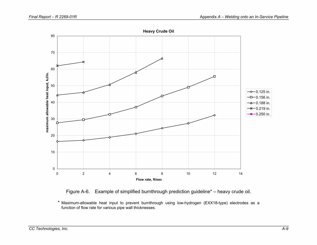
Final Report – R 2269-01R Appendix A – Welding onto an In-Service Pipeline
CC Technologies, Inc. A-9
Heavy Crude Oil
0
10
20
30
40
50
60
70
80
0 2 4 6 8 10 12 14
Flow rate, ft/sec
max
imum
allo
wab
le h
eat i
nput
, kJ/
in.
0.125 in.0.156 in.0.188 in.0.219 in.0.250 in.
Figure A-6. Example of simplified burnthrough prediction guideline* – heavy crude oil.
* Maximum-allowable heat input to prevent burnthrough using low-hydrogen (EXX18-type) electrodes as a function of flow rate for various pipe wall thicknesses.
Final Report – R 2269-01R Appendix A – Welding onto an In-Service Pipeline
CC Technologies, Inc. A-10
3.4 – Control of Heat Input Levels During welding, it is necessary to insure that the maximum-allowable heat input to
prevent burnthrough is not exceeded. Accurate measurement of heat input levels can be achieved using conventional equipment (amp tongs, voltmeter, stop watch, etc.) or purpose-built arc monitoring equipment. The run-out ratio scheme (the length of the weld deposited to the length of electrode consumed) can also be used to control heat input levels. The use of these methods is described further in Section 7.10.
3.5 – Electrode Diameter Restrictions Electrode diameter (in relation to welding current), in addition to heat input, is
important.(8, 9) The use of smaller diameter electrodes (lower current levels) allows the use of higher heat input levels. In other words, for a given heat input level, the use of smaller diameter electrodes (lower current levels) is safer.
3.6 – General Observations and Rules of Thumb for Burnthrough Thermal analysis modeling can be used to show that an inside surface temperature
in excess of 982ºC (1800ºF) is unlikely to be reached if the wall thickness is 6.4 mm (0.250 inch) or greater, provided that normal welding practices are used.(4) Therefore, the use of thermal analysis modeling is only required if the wall thickness is less than 6.4 mm (0.250 inch), because for greater wall thicknesses, the risk of burnthrough is negligible.
Thermal analysis modeling can also be used to show the effect of pressure on burnthrough risk. As indicated above, pressure reductions are relatively ineffective at preventing burnthrough and are often unnecessary. Interestingly, thermal analysis modeling can be used to show that, since flowing gas more effectively conducts heat at higher pressure (assuming a constant linear flow rate greater than zero), pressure reduction results in higher inside surface temperatures and an increase in burnthrough risk. The effect of pressure is secondary to other factors, however. This phenomenon does not occur for liquid pipeline contents, as the thermal conductivity of liquids do not vary greatly with pressure. To prevent areas with defects from rupturing during the repair process, a pressure reduction may be justified on the basis of protecting the repair crew, however.
The use of a procedure that limits heat input may conflict with other requirements, such as the need to use a sufficiently high heat input to avoid hydrogen cracking. For some applications, the heat input required to avoid cracking may be greater than the heat input allowed to avoid burnthrough, prohibiting the use of a procedure that relies on a sufficiently high heat input level. As an alternative approach, hydrogen cracking risk can be minimized using procedures designed to make use of tempering from subsequent passes. These procedures are generally referred to as temper bead procedures. Temper bead procedures, which are described further in Section 5.2,

Final Report – R 2269-01R Appendix A – Welding onto an In-Service Pipeline
CC Technologies, Inc. A-11
typically involve depositing a first layer or "buttering" layer using stringer beads that are deposited within the acceptable heat input range for preventing burnthrough. Subsequent passes are deposited in such a way as to maximize the amount of grain refinement and tempering of the buttering layer. The buttering layer increases the local pipe wall thickness, allowing higher heat input levels to be used for the subsequent passes.
4.0 – PREVENTING HYDROGEN CRACKING To prevent hydrogen cracking, at least one of the three conditions necessary for its
occurrence must be eliminated or reduced to below a threshold level. A significant amount of residual tensile stress acting on the weld cannot be avoided and must always be assumed. The first step taken by many companies toward avoiding hydrogen cracking in welds made onto in-service pipelines is to minimize the hydrogen level by using low-hydrogen electrodes or a low-hydrogen welding process. As added assurance against hydrogen cracking, since low hydrogen levels cannot always be guaranteed, many companies have developed and follow procedures that minimize the formation of crack-susceptible microstructures.
4.1 – Hydrogen in the Weld All welding processes introduce hydrogen into the weld to some extent. There is no
such thing as a “no hydrogen” welding process. Hydrogen cracking susceptibility increases with increasing amounts hydrogen in the weld. Low hydrogen welding processes include shielded metal arc welding (SMAW) using AWS EXX18-type (basic coated) electrodes and gas shielded processes such as gas metal arc welding (GMAW) and gas tungsten arc welding (GTAW). Diffusible hydrogen levels are measured as a volume of hydrogen (in ml) per 100 g of deposited weld metal. Welding processes that are considered to be low hydrogen typically introduce on the order of 4 to 5 ml/100 g of hydrogen or less. In contrast, SMAW using AWS EXX10-type (cellulosic coated) electrodes introduce a considerable amount of hydrogen into the weld – on the order of 50 to 60 ml/100 g. For this reason, the use of cellulosic-coated electrodes for in-service welding applications where fast weld cooling rates are anticipated is generally discouraged.
Hydrogen in the weld can also come from other sources. These include organic compounds, such as grease, oil and solvents, dirt and dust, wire lubricants, and coating residue. Moisture is also a significant source of hydrogen in welds. Moisture can be present in the electrode coating, in hydrated oxides (rust), in humid air, and on the surfaces that are being welded (condensation). Organic compounds that are hydrocarbon based and moisture, which is water (H2O), can break down (disassociate) in the intense heat of the welding arc. The resulting atomic hydrogen is then absorbed by the liquid weld metal and can diffuse to the HAZ where it can contribute to hydrogen cracking.
Final Report – R 2269-01R Appendix A – Welding onto an In-Service Pipeline
CC Technologies, Inc. A-12
The diffusion rate of hydrogen in steel is very much dependent on temperature. Welds made under in-service conditions tend to cool quickly so that the hydrogen that enters the weld tends to become trapped there. Preheating tends to slow the weld cooling rate which allows hydrogen diffusion and reduces hydrogen cracking susceptibility. Welds made under in-service conditions tend to be difficult to preheat, however.
The various aspects of controlling of hydrogen levels are described further in Sections 7.3, 7.4, 7.8, and 7.9.
4.2 – Crack-Susceptible Weld Microstructures The development of weld microstructures that are susceptible to cracking depends
on the chemical composition of the materials being welded, on the weld cooling rate, and on any subsequent thermal treatment (e.g., tempering).
In general, hard HAZ microstructures are most susceptible to hydrogen cracking. Such microstructures are promoted by steel that has a high CE value and by rapid weld cooling rates. For welds made onto in-service pipelines, weld-cooling rates are determined by welding heat input and pipeline operating conditions. Operating conditions that influence weld-cooling rates include product type, pressure, flow rates, ambient temperatures, and pipe wall thickness. Weld metal microstructures can also be susceptible to hydrogen cracking.
As indicated above, many companies have developed procedures that minimize the formation of crack-susceptible microstructures as added assurance against hydrogen cracking in welds made onto in-service pipelines, since low hydrogen levels cannot always be guaranteed.
4.3 – Tensile Stresses Acting on the Weld When a weld solidifies and cools, it develops residual stresses that can be of yield
strength magnitude. These residual stresses result from the restraint of the welded connection and strains imposed by the contraction of the weld on cooling. Although residual stresses are inevitable, it is important to take appropriate measures to ensure that applied stresses are avoided. One example of this is making sure that the pipeline is properly supported following welding so that applied stresses are not produced as the result of soil settlement.
5.0 – PROCEDURE OPTIONS FOR IN-SERVICE WELDING There are three commonly used options for preventing hydrogen cracking in welds
made onto in-service pipelines beyond the use of low-hydrogen electrodes: specification of a minimum required heat input level, specification of a minimum required preheat temperature, specification of a temper-bead deposition sequence, or some combination

Final Report – R 2269-01R Appendix A – Welding onto an In-Service Pipeline
CC Technologies, Inc. A-13
of these three options. The most common procedures for welding onto in-service pipelines use a sufficiently high heat input level to overcome the effect of the flowing contents.
5.1 – Predicting Required Heat Input Levels Previous work by Battelle and Edison Welding Institute (EWI) has attempted to
address the need for determining the minimum required heat input necessary to avoid the formation of a hardness above a certain level. Two methods currently exist for predicting the required heat input for welding onto in-service pipelines; thermal analysis computer modeling and heat sink capacity measurement.
The first method is the thermal analysis computer model developed by Battelle,(5, 6) which in addition to predicting inside surface temperatures, allows the prediction of weld cooling rates over a wide range of conditions. The model uses two-dimensional numerical solutions of heat transfer equations to predict cooling rates for single-pass fillet welds at the end of a sleeve or a branch-to-carrier pipe groove-weld. A thorough knowledge of the pipeline operating conditions is required. An example of the output from the Battelle model is shown in Figure A-7.
The second method was developed at EWI(10) and involves measuring the ability of the flowing contents to remove heat from the pipe wall using a simple field test. This test involves quickly heating a 50-mm (2-inch) -diameter area on the pipeline with an oxy-fuel torch to between 300 and 325ºC (572 and 617ºF). The time required for the area to cool from 250 to 100ºC (482 and 212ºF) is then measured using a digital contact thermometer and a stopwatch (Figure A-8). Six heat-sink-capacity measurement trials are made and the average calculated. The average value is referred to as the heat-sink capacity of the pipeline. The heat-sink capacity value is used to predict the weld-cooling rate using empirical relationships from data generated in the field and in the laboratory for a wide range of conditions. An example of these relationships for 6.4 mm (0.250 inch) wall thickness pipe is shown in Figure A-9. A detailed procedure for measuring heat-sink capacity is given elsewhere(11) along with notes for guidance.
With both of these methods, the predicted weld cooling rate is reported as a function of heat input for a given set of pipeline operating conditions. Limits on the weld cooling rates are established based on the maximum tolerable HAZ hardness predicted using previously established empirical correlations(12) and the anticipated CE of the pipe material. These methods allow welding parameters (i.e., heat input levels) to be selected based on anticipated weld cooling rates. The Battelle model can predict the effect of preheat while the EWI method cannot, and neither technique can predict the effect of tempering by subsequent passes.
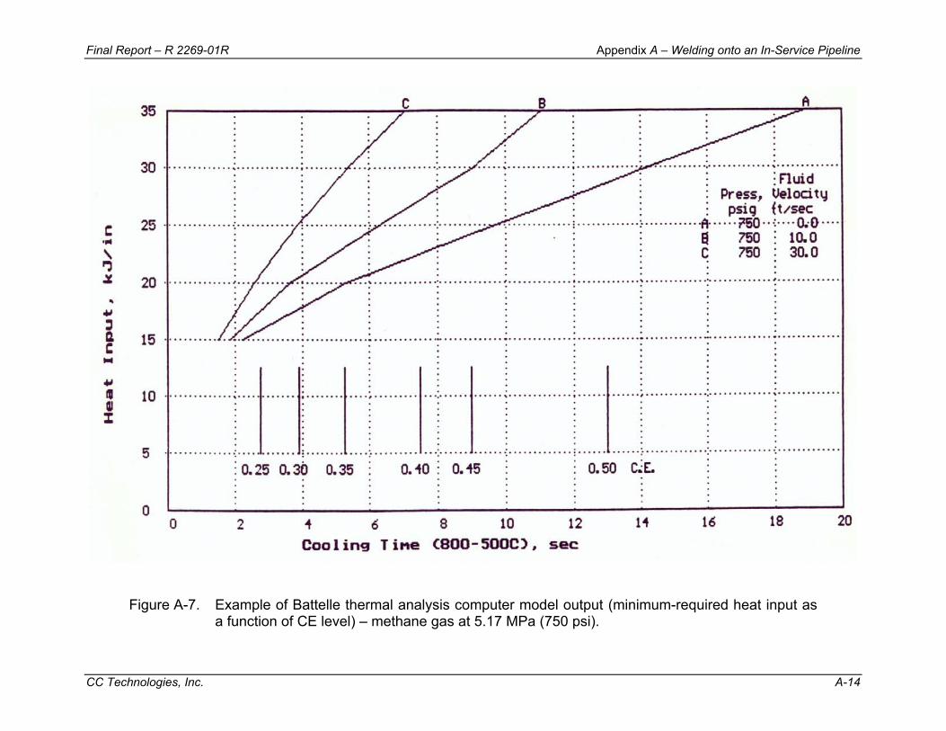
Final Report – R 2269-01R Appendix A – Welding onto an In-Service Pipeline
CC Technologies, Inc. A-14
Figure A-7. Example of Battelle thermal analysis computer model output (minimum-required heat input as a function of CE level) – methane gas at 5.17 MPa (750 psi).

Final Report – R 2269-01R Appendix A – Welding onto an In-Service Pipeline
CC Technologies, Inc. A-15
Figure A-8. Heat sink capacity measurement.
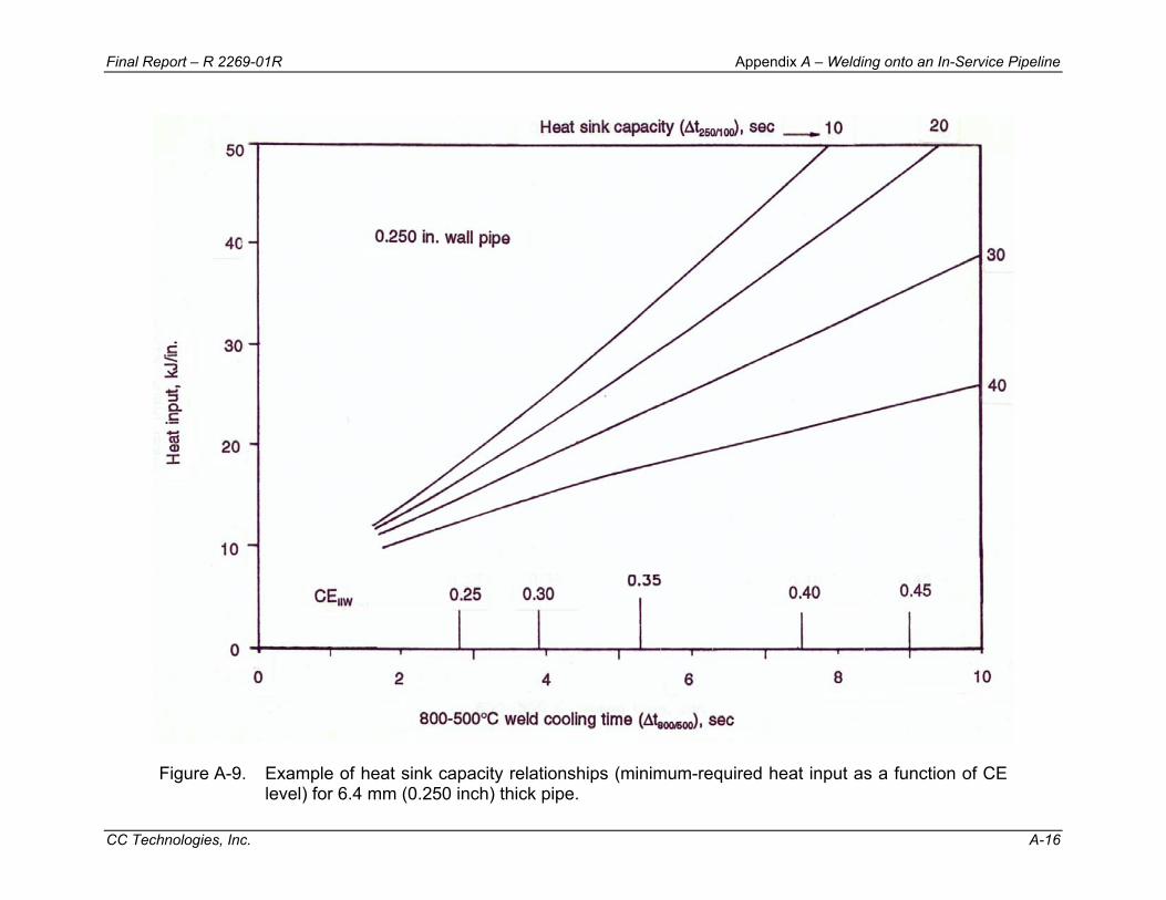
Final Report – R 2269-01R Appendix A – Welding onto an In-Service Pipeline
CC Technologies, Inc. A-16
Figure A-9. Example of heat sink capacity relationships (minimum-required heat input as a function of CE level) for 6.4 mm (0.250 inch) thick pipe.
Final Report – R 2269-01R Appendix A – Welding onto an In-Service Pipeline
CC Technologies, Inc. A-17
The Battelle model, while having served the industry well, has a number of shortcomings. First, the finite-element meshes that are used by the model have a fixed number of elements, so when the thickness of the materials of interest increases, the mesh becomes unacceptably coarse. This effect begins to occur at thicknesses of about 12.7 mm (0.5 inch) or so. Since burnthrough risk is negligible for pipe wall thickness of 6.4 mm (0.250 inch) and greater, this does not affect the burnthrough risk prediction capabilities of the model. In terms of weld cooling rates, however, an unacceptably coarse finite-element mesh produces results that are very conservative with regard to hydrogen cracking risk.
The second shortcoming of the Battelle model is the way in which hydrogen cracking risk is predicted from weld cooling rate predictions. For an individual run, the model uses the predicted weld cooling rate to identify a material CE for which welds made under the conditions of interest will have a HAZ hardness less than a fixed value of 350 HV. This may be very conservative for some applications and non-conservative for others. The third shortcoming of the Battelle model is that it is not particularly user friendly.
An improved thermal analysis model was recently developed.(7) The PRCI Thermal Analysis Model for Hot Tap Welding is Windows-based and uses a proprietary finite-element solver that was developed at EWI. Mesh generation capabilities include: sleeve, branch, and bead-on-pipe geometries (the latter for buttering layers and weld deposition repairs). Heat-sink capacity values can also be predicted for comparison with field-measured values. The user interface allows multiple cases to be run and heat input selection curves to be generated.
The input parameters are entered on one of three data input screens: Pipe Joint, Weld Conditions (or Heating Conditions for heat-sink capacity cases), and Pipe Contents. The Pipe Joint data input panel contains fields for entering details pertaining to the pipe material of interest and other details depending on which geometry has been selected. This data input panel also contains access to a Base Metal Chemistry input panel that is needed if the user requires HAZ hardness predictions, which are calculated using an algorithm developed by Yurioka.(13) If base metal chemistry is entered, hardness predictions appear in tabular form on the printed report after running the program and as part of the enhanced heat input selection curves described below. The Weld Conditions data input panel contains fields for entering details pertaining to the welding parameters, including welding current, voltage, and travel speed. Alternatively, the user can choose to enter a value for heat input only, whereby the software selects specific values for welding current, voltage, and travel speed according to a preset algorithm. This input panel also allows multiple cases to be run from a single input file. The Pipe Contents data input panel contains fields for entering details pertaining to the pipe contents. Fields pertaining to the Pipe Contents include Gas (or Liquid) Type,
Final Report – R 2269-01R Appendix A – Welding onto an In-Service Pipeline
CC Technologies, Inc. A-18
Linear (or Volumetric) Flow Rate, Temperature, and Pressure. Pull-down menus containing a list of common pipeline contents are provided.
Previously entered data sets can be modified either by simply opening the data file and making changes, or by using the Duplicate Project feature. This feature allows the user to begin with parameters from a previously entered data set and is particularly useful for cases that involve the same welding conditions but different flow parameters, for example. After a data set has been entered, running the finite-element solver will generate results for the file selected. Once the program has completed running the selected file, the results can be viewed in tabular form or a heat input selection curve can be generated.
To evaluate the risk of hydrogen cracking, the program uses the predicted weld cooling time between 800 and 500ºC (1472 to 932ºF), or Δt8-5, and the chemical composition of the pipe material to predict the HAZ hardness using the Yurioka algorithm. The hardness level above which hydrogen cracking can be expected to occur, or the critical hardness level, depends on the CE level of the materials and on the hydrogen level of the welding process. The critical hardness level for in-service welds is shown as a function of CE level and weld hydrogen level in Figure A-10. The use of this criteria is limited to materials that are 9.5 mm (0.375 inch) thick or less and that have %C greater than 0.10. Additional work is currently underway to develop criteria for a wider range of applications.
To evaluate the risk of hydrogen cracking, the user can compare the predicted hardness to those shown in Figure A-10. Alternatively, an enhanced heat input selection curve can be plotted from which the required heat input can be determined.
An example of an enhanced heat input selection curve is shown in Figure A-11. The required heat input is determined by selecting the critical hardness for the CE level and weld hydrogen level of interest from Figure A-10, selecting the corresponding Δt8-5 time from the Yurioka predictions from the bottom part of the graph, and then using the heat input selection curve in the top part of the graph to determine the required heat input level.
Both thermal analysis modeling and the heat-sink capacity method allow required welding parameters to be predicted based on anticipated weld cooling rates. The EWI method is additionally useful in that the heat-sink capacity measurement can be used at the time of actual welding to ensure that the conditions on which the predictions are based have not changed. These predictive methods do not guarantee that these parameters are practical under field conditions, however. To demonstrate that the parameters are practical, a welding procedure based on these predictions should be qualified under simulated conditions.
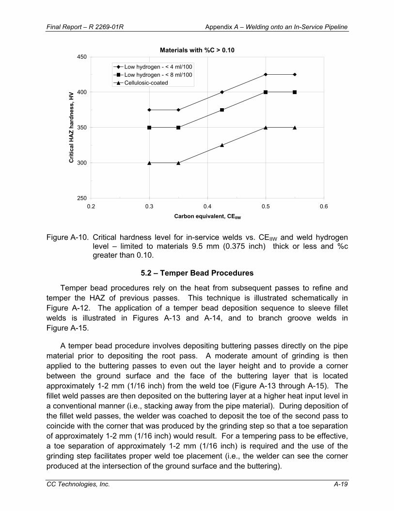
Final Report – R 2269-01R Appendix A – Welding onto an In-Service Pipeline
CC Technologies, Inc. A-19
Materials with %C > 0.10
250
300
350
400
450
0.2 0.3 0.4 0.5 0.6
Carbon equivalent, CEIIW
Crit
ical
HA
Z ha
rdne
ss, H
VLow hydrogen - < 4 ml/100Low hydrogen - < 8 ml/100Cellulosic-coated
Figure A-10. Critical hardness level for in-service welds vs. CEIIW and weld hydrogen
level – limited to materials 9.5 mm (0.375 inch) thick or less and %c greater than 0.10.
5.2 – Temper Bead Procedures
Temper bead procedures rely on the heat from subsequent passes to refine and temper the HAZ of previous passes. This technique is illustrated schematically in Figure A-12. The application of a temper bead deposition sequence to sleeve fillet welds is illustrated in Figures A-13 and A-14, and to branch groove welds in Figure A-15.
A temper bead procedure involves depositing buttering passes directly on the pipe material prior to depositing the root pass. A moderate amount of grinding is then applied to the buttering passes to even out the layer height and to provide a corner between the ground surface and the face of the buttering layer that is located approximately 1-2 mm (1/16 inch) from the weld toe (Figure A-13 through A-15). The fillet weld passes are then deposited on the buttering layer at a higher heat input level in a conventional manner (i.e., stacking away from the pipe material). During deposition of the fillet weld passes, the welder was coached to deposit the toe of the second pass to coincide with the corner that was produced by the grinding step so that a toe separation of approximately 1-2 mm (1/16 inch) would result. For a tempering pass to be effective, a toe separation of approximately 1-2 mm (1/16 inch) is required and the use of the grinding step facilitates proper weld toe placement (i.e., the welder can see the corner produced at the intersection of the ground surface and the buttering).
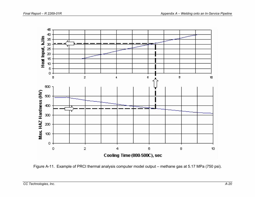
Final Report – R 2269-01R Appendix A – Welding onto an In-Service Pipeline
CC Technologies, Inc. A-20
Figure A-11. Example of PRCI thermal analysis computer model output – methane gas at 5.17 MPa (750 psi).

Final Report – R 2269-01R Appendix A – Welding onto an In-Service Pipeline
CC Technologies, Inc. A-21
R > C > P
Figure A-12. Schematic illustration of temper bead deposition sequence.
Figure A-13. Example of temper bead technique applied to a sleeve fillet weld.
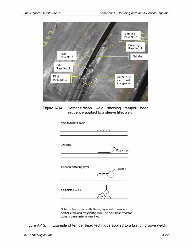
Final Report – R 2269-01R Appendix A – Welding onto an In-Service Pipeline
CC Technologies, Inc. A-22
Figure A-14. Demonstration weld showing temper bead sequence applied to a sleeve fillet weld.
Figure A-15. Example of temper bead technique applied to a branch groove weld.
Buttering Pass No. 1
Buttering Pass No. 2
Grinding Fillet Pass No. 1
Fillet Pass No. 2
Fillet Pass No. 3
Aprox. 1/16 inch weld toe spacing
Final Report – R 2269-01R Appendix A – Welding onto an In-Service Pipeline
CC Technologies, Inc. A-23
5.3 – Preheat Control Procedures
One method of avoiding hydrogen cracking involves controlling the weld cooling rate. The application of preheat does tend to slow the weld cooling rate somewhat, but more importantly allows hydrogen diffusion during and after welding. Preheating also tends to burn off moisture and other contaminants prior to welding.
The use of preheating for in-service welding lessens the need to closely control heat input levels. The effective use of 93ºC (200ºF) preheat is equivalent to an increase in heat input by a factor of approximately 1.6 (e.g., from 0.6 to 1.0 kJ/mm [15 to 25 kJ/inch] or from 1.0 to 1.6 kJ/mm [25 to 40 kJ/inch]).(14)
For hydrogen diffusion after welding to occur, it is important to maintain the application of heat for some time after the weld is complete. In previous work,(15) it was suggested that preheat maintenance (i.e., post-heating) for 15 minutes would seem to be a reasonable time for temperatures in the 200 to 250ºF (93 to 121ºC) range and for the range of thicknesses that are encountered during most typical in-service welding applications. Longer times should be considered for thicker materials (e.g., pipe wall thickness greater than 12.7 mm [0.5 inch] and/or heavy-wall fittings) and/or for lower temperatures. When using post-heating to allow hydrogen diffusion, the post-heating must be applied prior to crack initiation.
Conventional methods of applying preheat, such as gas torches, are difficult to control and can be slow and inefficient. The application of preheating to in-service welds is discussed further in Section 7.12. An additional benefit of preheating is that its use may justify shortening or eliminating the time delay required prior to inspection for hydrogen cracking. This is discussed further in Section 7.16.
5.4 – General Observations for Procedure Options None of the commonly-used procedure options are entirely straightforward.
Maintaining heat input above specified minimum required levels can be difficult to monitor, and field control can be difficult. Excessive heat input levels may result in an increased risk of burnthrough, particularly for thin wall pipe. Under certain severe conditions, even high heat input welds can cool faster than the threshold value required to avoid the formation of a hard, crack-susceptible microstructure. Under these severe conditions, it is often a better approach to use a temper-bead procedure.
Temper-bead procedures rely on heat from subsequent passes to refine and temper the HAZ of previous passes. These procedures require considerable skill on the part of the welder and are not necessary for more favorable conditions, such as for low CE materials and less severe thermal conditions. Also, unscheduled departures from the temper-bead procedure can result in higher finished-weld hardness levels than if a standard procedure had been used. For more favorable conditions, it is often a better
Final Report – R 2269-01R Appendix A – Welding onto an In-Service Pipeline
CC Technologies, Inc. A-24
approach to use a standard multi-pass procedure. Temper-bead procedures have been known to result in welds with an unfavorable profile since weld bead placement is prescribed by tempering requirements and cannot be changed to suit the requirements for proper filling of each individual weld.
For procedures based on preheat control, maintaining specified preheat levels is often difficult, particularly for thin wall pipe. If non-continuous preheating methods are used, the re-heating interval may be very short. Monitoring of preheat levels in the field can also be difficult.
For some in-service welding applications, even the simplest procedures (e.g., standard fillet welds) result in acceptable hardness levels. This approach is most attractive in that simple procedures are the least expensive to execute and involve fewer opportunities for errors. The most cost-effective approach to welding onto in-service pipelines is to have a standard set of procedures qualified ranging in complexity, and then to specify the least complex procedure required for each application. In other words, heat input control procedures should be used where possible and temper bead procedures should only be used when necessary.
6.0 – QUALIFICATION OF PROCEDURES AND WELDERS FOR IN-SERVICE WELDING
The purpose of qualifying a welding procedure is to demonstrate that the procedure is capable of producing sound welds under production conditions. The purpose of a welder qualification is to show that a particular welder is capable of executing a qualified procedure under production conditions. It is clearly unrepresentative to qualify procedures and welders for welding onto in-service pipelines using a length of pipe that contains static air. Without simulating the ability of the in-service pipeline to remove heat from the pipe wall, unrealistically slow weld cooling rates result, in addition to different solidification characteristics of the weld pool.
Recommended practices for qualifying procedures for welding onto in-service pipelines are contained in various industry codes including API 1104 Appendix B (Nineteenth Edition and later).(16) Appendix B indicates that the requirements for fillet welds in the main body of API 1104 should be applied to in-service welds that contact the carrier pipe, except for the alternative and/or additional requirements that are specified in the appendix.
6.1 – Qualification of In-Service Welding Procedures
The Specification Information section of API 1104 Appendix B indicates that the CE of the material to which the in-service welding procedure applies should be identified in addition to the specified minimum yield strength (which is waived as an essential variable), and that CE levels may be grouped. This provision for allowing in-service
Final Report – R 2269-01R Appendix A – Welding onto an In-Service Pipeline
CC Technologies, Inc. A-25
welding procedures to be qualified according to CE groups as opposed to specified minimum yield strength groups was included because hydrogen cracking susceptibility is more a function of CE level than it is of specified minimum yield strength, and CE level can vary widely depending on pipe manufacturer and vintage. For example, a modern API 5LX-52 material that has been thermo-mechanically treated may have a low CE value (and, therefore, a high resistance to hydrogen cracking); whereas, most 1950s-vintage X-52 materials have a high CE value. API 1104 Appendix B also indicates that the pipeline operating conditions (pipe contents, flow rate, etc.) for which the procedure applies should be identified and that conditions may be grouped. For procedures intended to overcome the effect of the flowing contents by using a sufficiently high heat input level (heat input control procedures), the required heat input range should be specified. Similarly, for procedures intended to overcome the effect of the flowing contents by a using temper bead deposition sequence (temper bead procedures), the required weld deposition sequence should be specified.
In addition to waiving the essential variable requirement for specified minimum yield strength, the Essential Variables section of API 1104 Appendix B also waives the essential variable requirement for pipe wall thickness. For in-service welds, the thermal severity (in terms of the weld cooling rates that result for a given heat input, etc.) depends not only on wall thickness, but also on the pipeline operating conditions (pipe contents, flow rate, etc.). So instead of pipe wall thickness, the appendix indicates that an increase in the severity of the pipeline operating conditions above the group qualified constitutes an essential variable. In other words, wall thickness should be considered along with thermal severity. The appendix also indicates that a change from a temper bead deposition sequence to some other deposition sequence constitutes an essential variable.
The Welding of Test Joints section of API 1104 Appendix B indicates that the pipeline operating conditions that affect the ability of the flowing contents to remove heat from the pipe wall should be simulated while the test joints are being made. A note in the appendix is provided that indicates that filling the test section with water and allowing water to flow through the test section while the test joint is being made has been shown to produce thermal conditions equivalent to or more severe than most typical in-service welding application, and that procedures qualified under these conditions are therefore suitable for most typical in-service applications.(17) The appendix also indicates that other media (e.g., motor oil) may be used to simulate less severe thermal conditions (e.g., low-pressure, thinner-wall natural gas pipelines operating at low flow rates). The use of this technique is illustrated in Figure A-16.

Final Report – R 2269-01R Appendix A – Welding onto an In-Service Pipeline
CC Technologies, Inc. A-26
Figure A-16. Set-up for procedure qualification for in-service welding.
The Testing of Welded Joints section of API 1104 Appendix B includes provisions for taking specimens from test welds made using either a sleeve weld or a branch weld configuration. A table listing the type and number of specimens that should be taken is included. A description of the Macro Section Test is included in the appendix. Separate paragraphs for preparation, visual examination, hardness testing, and acceptance requirements are also provided. The purpose of the Macro Section Test is to reveal any significant discontinuities, including hydrogen cracking that may be present. To facilitate this, the appendix indicates that at least one face should be ground to a minimum of a 600-grit finish and etched prior to examination. Hardness testing is intended to reveal the presence of any hard HAZ microstructures. The appendix indicates that procedures that produce HAZ hardness values in excess of 350 HV should be evaluated with regard to hydrogen cracking risk. HAZ hardness values in excess of 350 HV are not necessarily unacceptable, but below this level, it is generally agreed that hydrogen cracking is not expected. A further discussion of HAZ hardness limits for procedure qualification is provided in Section 6.3. A description of the Face Bend Test for branch and sleeve welds is also included in the appendix. The purpose of this test, which is taken from the Canadian code CSA Z662 - Oil and Gas Pipeline Systems - is to reveal any hydrogen cracking at the weld toe areas. The test involves removing the sleeve or branch portion of the specimen, and the weld reinforcement, and bending the specimen so that the weld toe is placed in tension.
6.2 – In-Service Welder Qualification
The In-Service Welder Qualification section of API 1104 Appendix B indicates that the welder should be qualified to apply the specific procedure being used except for the alternative/additional requirements specified in the appendix.

Final Report – R 2269-01R Appendix A – Welding onto an In-Service Pipeline
CC Technologies, Inc. A-27
The Welding of Test Assembly section of API 1104 Appendix B indicates that the pipeline operating conditions that affect heat removal from the pipe wall by the contents should be simulated while the test assembly is being made. The same note pertaining to filling the test section with water or other media and providing flow while the test assembly is being made is included in this section. The appendix indicates that, for heat input control procedures, the welder should be able to demonstrate the ability to maintain a heat input level within the specified range. Similarly, for temper bead procedures, the welder should be able to demonstrate proper bead placement.
In the Records section, API 1104 Appendix B indicates that the pipeline operating conditions (pipe contents, flow rate, etc.) for which the welder is qualified should be identified, and that conditions may be grouped.
6.3 – HAZ Hardness Limits
During the qualification of procedures for in-service welding, there is often a requirement for HAZ hardness testing. HAZ hardness is often used as an indicator of the susceptibility of a microstructure to hydrogen cracking. A widely used value below which it is generally agreed that hydrogen cracking is not expected is 350 HV.
Critical hardness level, or the hardness level below which hydrogen cracking is not expected, depends on the hydrogen level of the welding process being used and on the chemical composition (carbon content and CE level) of the materials being welded. The risk of hydrogen cracking increases as hydrogen level increases. Closer control of hydrogen level allows higher hardness to be tolerated. Conversely, lower limits on hardness are required where higher hydrogen levels are anticipated.
While HAZ hardness is often used as an indicator of cracking susceptibility, the true susceptibility depends on the microstructures present in the HAZ. A better indicator of cracking susceptibility might be the volume fraction of martensite in the HAZ. For a material of a given chemical composition, HAZ hardness is a good indicator of the relative amount of martensite present in the HAZ. The hardness of martensite depends on the carbon level of the material being welded, however. The measured hardness in the HAZ of a low carbon material that consists mostly of martensite may be lower than the measured hardness in a higher carbon material with a much lower volume fraction of martensite, yet the cracking susceptibility in the lower carbon material is higher. In other words, lower carbon content materials tend to crack at lower hardness levels. Conversely, higher hardness can be tolerated when welding higher carbon content materials.
The hardness evaluation criteria shown in Figure A-10, which is a modification of previous work at TWI,(18) was developed for welds made under simulated in-service conditions.(14) The use of this criteria is limited to materials that are 9.5 mm (0.375 inch)
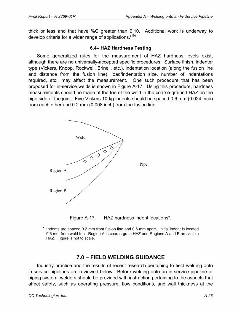
Final Report – R 2269-01R Appendix A – Welding onto an In-Service Pipeline
CC Technologies, Inc. A-28
thick or less and that have %C greater than 0.10. Additional work is underway to develop criteria for a wider range of applications.(19)
6.4– HAZ Hardness Testing Some generalized rules for the measurement of HAZ hardness levels exist,
although there are no universally-accepted specific procedures. Surface finish, indenter type (Vickers, Knoop, Rockwell, Brinell, etc.), indentation location (along the fusion line and distance from the fusion line), load/indentation size, number of indentations required, etc., may affect the measurement. One such procedure that has been proposed for in-service welds is shown in Figure A-17. Using this procedure, hardness measurements should be made at the toe of the weld in the coarse-grained HAZ on the pipe side of the joint. Five Vickers 10-kg indents should be spaced 0.6 mm (0.024 inch) from each other and 0.2 mm (0.008 inch) from the fusion line.
Weld
Pipe Region A
Region B
Figure A-17. HAZ hardness indent locations*.
* Indents are spaced 0.2 mm from fusion line and 0.6 mm apart. Initial indent is located 0.6 mm from weld toe. Region A is coarse-grain HAZ and Regions A and B are visible HAZ. Figure is not to scale.
7.0 – FIELD WELDING GUIDANCE Industry practice and the results of recent research pertaining to field welding onto
in-service pipelines are reviewed below. Before welding onto an in-service pipeline or piping system, welders should be provided with instruction pertaining to the aspects that affect safety, such as operating pressure, flow conditions, and wall thickness at the

Final Report – R 2269-01R Appendix A – Welding onto an In-Service Pipeline
CC Technologies, Inc. A-29
location of welding. Welders should also be familiar with the safety precautions associated with cutting and welding on piping that contains or has contained crude petroleum, petroleum products, or fuel gases. Some guidance is provided in API 1104 Appendix B. Additional guidance can be found in API Recommended Practice 2201.(20)
7.1 – Wall Thickness Determination/Inspection The wall thickness should be checked using appropriate ultrasonic testing
equipment to ensure that corrosion or erosion has not greatly affected the actual wall thickness from the nominal value. An ultrasonic wall thickness check can also be used to investigate for the presence of defects. This should include inspection for, lamination, blistering, hydrogen induced cracking (HIC), and other forms of cracking in the areas to be welded. If relevant indications are revealed during this inspection, in-service welds should be relocated to no less than 50 mm (2 inches) from the nearest indication.
7.2 – Chemical Composition Determination Procedure selection for avoiding hydrogen cracking is often made based on the
chemical composition of the pipe material. Unfortunately, records that contain chemical composition information for older, existing pipelines are often difficult or impossible to locate. In these cases, estimates of chemical composition can be made based on the maximum allowable limits of the specification to which the materials were produced. This usually results in an overestimation of the tendency for unacceptably high hardness levels to result and can be restrictively over-conservative.
The chemical composition of an in-service pipeline can be determined by direct analysis using portable equipment or by removal of samples for laboratory analysis. The most promising technique for performing an analysis in the field is optical emission spectrography (OES) via a fiber-optic umbilical cord. Several companies offer systems that can be used in the field, although these are relatively expensive and require a significant calibration and maintenance effort. Several OES analyzers claim to be capable of analyzing for elements down to atomic number 5 (boron), some with accuracy of 0.001% at 0.04% quoted for carbon.(21)
Chemical composition determination by removal of samples for laboratory analysis is relatively simple and can be quite accurate; provided that care is taken in removing the samples and that they are properly analyzed. A flat area can be machined on an in-service pipeline provided that the remaining wall thickness is greater than the specified nominal wall thickness minus the pipe mill tolerance, which can be up to 12.5 percent for pipe diameters less than 508.0 mm (20 inches).(22) The amount of material required for direct spectrographic analysis of re-melted machining chips is 10 to 20 grams (0.35 to 0.71 oz),(23) with 20 grams (0.71 oz) being ideal. Care should be taken to prevent oxidation (i.e., overheating) of the machining chips. Low-cost portable milling machines

Final Report – R 2269-01R Appendix A – Welding onto an In-Service Pipeline
CC Technologies, Inc. A-30
that are used primarily to cut key-ways in shafts can be used for this purpose.(24) Separate spectrographic calibration standards are required for re-melted and solid samples.(25-26) Care must also be taken to prevent oxidation during re-melting, as this can result in lower apparent content of certain elements.
A second method of analyzing a sample of material removed from a pipeline is to analyze the sample directly (i.e., without re-melting). This method is advantageous in that chips of a certain size are not required, which allows removal using a simpler piece of equipment, such as a high-speed rotary file (burr grinder). The rotary file should be inspected following use to insure that teeth have not broken off. The inclusion of teeth in the filings can raise the apparent content of certain elements, particularly carbon. The filings can be analyzed using traditional wet chemistry (i.e., titration methods) or using the inductively coupled plasma (ICP) method. The combustion-in-oxygen method using a LECO analyzer can be used to accurately determine carbon and sulfur levels of samples composed of filings.
In the absence of other information, estimates of pipe material chemical composition can be made. Operating companies should develop a database of chemical composition information for material in their system for this purpose. Some very general rules of thumb pertaining to pipe material chemical composition are provided in Table A-1. It should be noted that there are many exceptions to these rules. In general, the highest CE materials that are encountered in North America are API 5L-X52 grades that were manufactured in the 1950’s and early 1960’s.
Table A-1. General rules of thumb for pipe material chemical composition. *
Property Value Trend
Modern Lower CE Vintage
Older Higher or lower CE depending on grade
ERW or SAW Lower CE Manufacturing Method
Seamless Higher CE
Higher strength (e.g., X70) Lower CE
Intermediate strength (e.g., X52) Higher CE Grade
Lower strength (e.g., Grade B, X42)
Probably lower CE, but may be down-graded X52
* Note: These are general rules of thumb only. There are many, many exceptions to these rules.

Final Report – R 2269-01R Appendix A – Welding onto an In-Service Pipeline
CC Technologies, Inc. A-31
7.3 – Electrode Procurement
Many of the potential problems associated with minimizing hydrogen levels for welds made onto in-service pipelines can be addressed at the electrode procurement stage. Specific guidance is given below.
7.3.1 – Electrode Classification/Supplemental Designations
Many modern low-hydrogen electrodes (EXX18-type) produce weld hydrogen levels that are less than 4 to 5 ml/100 g in the as-received condition. With the amount of moisture in the electrode coating that is permissible (0.6% according to AWS A5.1), hydrogen levels in welds made using low-hydrogen electrodes can be as high as 16 ml/100 g, which is excessive for many in-service welding applications. AWS has introduced optional supplementary designators in AWS A5.1 that allow a specific maximum-allowable hydrogen level to be specified. These designators are H4, H8, and H16, where “H” indicates hydrogen and “4, 8, and 16” refer to the average maximum-allowable hydrogen level in ml/100 g in the "as-received" condition.(27) In other parts of the world, a similar system is used although the hydrogen levels are H5, H10, and H15. The United States military also has a stricter limit of 2 ml/100 g for some applications.
In addition, AWS has introduced an “R” designator that allows a moisture resistant coating to be specified. The R designator indicates that the electrodes have passed an absorbed moisture test after exposure to an environment of 26.7ºC (80ºF) and 80% relative humidity for a period of not less than 9 hr. Electrodes that meet this requirement have coating moisture limits that are lower than their non-moisture-resistant counterparts. For example, AWS A5.1 requires that E7018-H4R electrodes must have a coating moisture level of less than 0.4% (as opposed to 0.6%).
For in-service welding applications for which low hydrogen levels are required, operators should consider specifying electrodes with the H4R designator. These are becoming more common and, while there may be a price premium, this is negligible compared to the cost for remedial action that would be required following the discovery or failure of an in-service weld with hydrogen cracks.
7.3.2 – Packaging
7.3.2.1 – Packaging Type Many low-hydrogen electrodes are packaged in hermetically-sealed cans.
Cardboard cartons are also used to some extent by some manufacturers and in some parts of the world. These cardboard cartons may be sealed in plastic wrap. Even if plastic wrap is used to seal these cartons, damage may occur in transit or during storage that would allow the electrode coatings to absorb moisture. Some manufacturers that supply low-hydrogen electrodes packaged in cardboard cartons
Final Report – R 2269-01R Appendix A – Welding onto an In-Service Pipeline
CC Technologies, Inc. A-32
specify that the electrodes must be dried prior to use. While this is common in some parts of the world, it is less common in North America.
For in-service welding applications for which low hydrogen levels are required, the use of electrodes that are packaged in hermetically-sealed cans (i.e., appropriate for use in the as-received condition) are preferable. If electrodes packaged in cardboard cartons are used, care must be taken to ensure that drying is not required by the manufacturer prior to their use in the as-received condition. If the electrodes are intended to be used in the as-received condition and they are packaged in plastic-sealed cardboard containers, care should be taken to ensure that the plastic wrap is not damaged. If drying is required, care must be taken to ensure that the drying is carried out properly. Electrode drying is discussed further in Section 7.8.4.
7.3.2.2 – Package Size In North America, a significant percentage of low-hydrogen electrodes are
packaged in 22.7-kg (50-lb) hermetically-sealed cans. Many manufacturers also offer low hydrogen electrodes that are packaged in 2.3- and 4.5-kg (5- and 10-lb) cans. Once low-hydrogen electrodes have been removed from a freshly opened package or from an electrode storage oven, they must be used prior to their exposure limit being exceeded (see Section 7.8.3 below). For in-service welding applications for which low hydrogen levels are required, it may be advantageous to purchase and use low-hydrogen electrodes in smaller quantities (e.g., 4.5-kg [10-lb] cans). This is particularly true for smaller jobs (e.g., small diameter lines) where it would be difficult to use an entire 22.7-kg (50-lb) can.
7.3.2.3 – Special Packaging Taking the small package size concept one step further, several manufacturers offer
low-hydrogen electrodes in small quantity, vacuum sealed foil packages. Two examples of this are Lincoln/Smitweld Sahara Ready Packs and ESAB VacPacs. The concept for this type of packaging is that the entire contents can be used prior to the exposure limit being exceeded. These do not appear to be widely available in North America, however.
7.4 – Storage of Electrodes in Unopened Cans/Cartons Some manufacturers indicate that unopened cans or cartons will retain the proper
moisture content indefinitely when stored in good condition. Other manufacturers indicate that electrodes packaged in plastic-wrapped cardboard cartons can be kept for a maximum of one year for normal use if stored properly.
In general, unopened cans/cartons of low-hydrogen electrodes should be stored in such a way as to prevent damage to the packaging. A climate-controlled storage room is better than a storage room that is not climate controlled. The storage room should be

Final Report – R 2269-01R Appendix A – Welding onto an In-Service Pipeline
CC Technologies, Inc. A-33
organized in such a way that allows for rotation of stock (i.e., makes use of the “first in/first out” principle). Hermetically sealed containers should not be opened until the electrodes are needed for use. If the electrodes have been stored in a cold place, they should be allowed to reach ambient temperature before the container is opened.
7.5 – Sleeve Fit-Up Care should be taken to ensure that full encirclement repair sleeves and fittings fit
snugly around the pipe. This increases the effectiveness of the reinforcement provided by the repair sleeve or fitting and minimizes the complications associated with fillet welding in the presence of a gap. The most common method of facilitating proper fit up the use of chains and hydraulic jacks. Purpose-built clamps are also available for this purpose.
7.6 – Backing Strips For full-encirclement sleeves and fittings, the longitudinal seams should be fitted
with a mild steel back-up strip or suitable tape to prevent penetration of the weld into the carrier pipe. Penetration of the longitudinal butt weld into the carrier pipe is undesirable since any crack that might develop is exposed to the hoop stress in the carrier pipe.
7.7 – Welding Sequence For full-encirclement sleeves fittings requiring circumferential fillet welds, the
longitudinal seams should be completed before beginning the circumferential welds. The circumferential weld at one end of the fitting should be completed before beginning the circumferential weld at the other end. For other types of fittings, a welding sequence that minimizes residual stress should be used.
For welds that contact the carrier pipe, even for non-temper-bead procedures, the beads should be deposited is such a way as to maximize tempering. To do this, the beads should be stacked away from the carrier pipe material. This technique is illustrated in Figure A-18. Stringer beads, where weaving is limited to no more than one core wire diameter, are preferable to weave beads.
7.8 – Electrode Handling Low-hydrogen electrodes must be properly stored and handled to ensure that low
hydrogen levels result. Moisture can be absorbed by the electrode coating during storage and handling. Since different low-hydrogen electrodes behave differently with respect to moisture absorption, it is important to follow the specific electrode manufacturer’s recommendations for storage and handling.
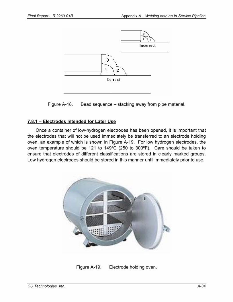
Final Report – R 2269-01R Appendix A – Welding onto an In-Service Pipeline
CC Technologies, Inc. A-34
Figure A-18. Bead sequence – stacking away from pipe material. 7.8.1 – Electrodes Intended for Later Use
Once a container of low-hydrogen electrodes has been opened, it is important that the electrodes that will not be used immediately be transferred to an electrode holding oven, an example of which is shown in Figure A-19. For low hydrogen electrodes, the oven temperature should be 121 to 149ºC (250 to 300ºF). Care should be taken to ensure that electrodes of different classifications are stored in clearly marked groups. Low hydrogen electrodes should be stored in this manner until immediately prior to use.
Figure A-19. Electrode holding oven.
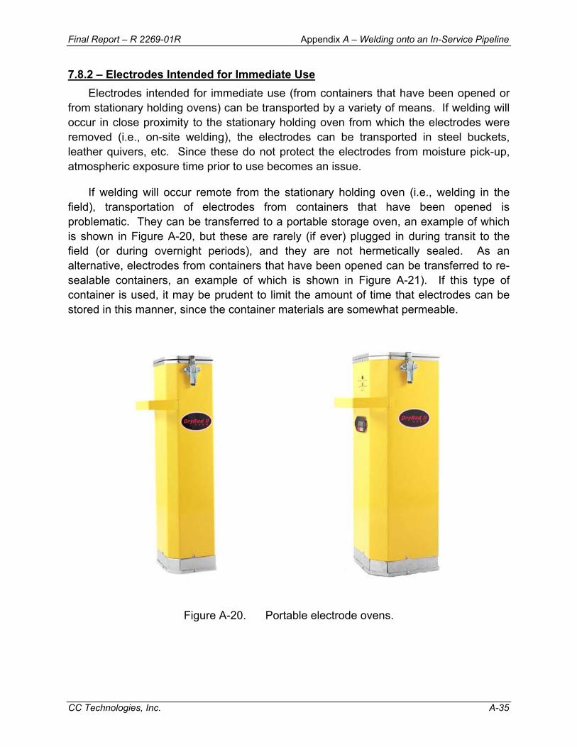
Final Report – R 2269-01R Appendix A – Welding onto an In-Service Pipeline
CC Technologies, Inc. A-35
7.8.2 – Electrodes Intended for Immediate Use Electrodes intended for immediate use (from containers that have been opened or
from stationary holding ovens) can be transported by a variety of means. If welding will occur in close proximity to the stationary holding oven from which the electrodes were removed (i.e., on-site welding), the electrodes can be transported in steel buckets, leather quivers, etc. Since these do not protect the electrodes from moisture pick-up, atmospheric exposure time prior to use becomes an issue.
If welding will occur remote from the stationary holding oven (i.e., welding in the field), transportation of electrodes from containers that have been opened is problematic. They can be transferred to a portable storage oven, an example of which is shown in Figure A-20, but these are rarely (if ever) plugged in during transit to the field (or during overnight periods), and they are not hermetically sealed. As an alternative, electrodes from containers that have been opened can be transferred to re-sealable containers, an example of which is shown in Figure A-21). If this type of container is used, it may be prudent to limit the amount of time that electrodes can be stored in this manner, since the container materials are somewhat permeable.
Figure A-20. Portable electrode ovens.
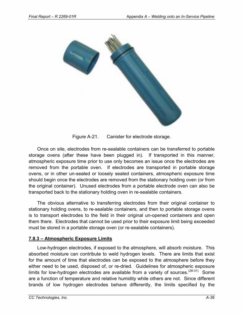
Final Report – R 2269-01R Appendix A – Welding onto an In-Service Pipeline
CC Technologies, Inc. A-36
Figure A-21. Canister for electrode storage.
Once on site, electrodes from re-sealable containers can be transferred to portable storage ovens (after these have been plugged in). If transported in this manner, atmospheric exposure time prior to use only becomes an issue once the electrodes are removed from the portable oven. If electrodes are transported in portable storage ovens, or in other un-sealed or loosely sealed containers, atmospheric exposure time should begin once the electrodes are removed from the stationary holding oven (or from the original container). Unused electrodes from a portable electrode oven can also be transported back to the stationary holding oven in re-sealable containers.
The obvious alternative to transferring electrodes from their original container to stationary holding ovens, to re-sealable containers, and then to portable storage ovens is to transport electrodes to the field in their original un-opened containers and open them there. Electrodes that cannot be used prior to their exposure limit being exceeded must be stored in a portable storage oven (or re-sealable containers).
7.8.3 – Atmospheric Exposure Limits
Low-hydrogen electrodes, if exposed to the atmosphere, will absorb moisture. This absorbed moisture can contribute to weld hydrogen levels. There are limits that exist for the amount of time that electrodes can be exposed to the atmosphere before they either need to be used, disposed of, or re-dried. Guidelines for atmospheric exposure limits for low-hydrogen electrodes are available from a variety of sources.(28-31) Some are a function of temperature and relative humidity while others are not. Since different brands of low hydrogen electrodes behave differently, the limits specified by the
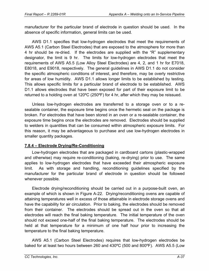
Final Report – R 2269-01R Appendix A – Welding onto an In-Service Pipeline
CC Technologies, Inc. A-37
manufacturer for the particular brand of electrode in question should be used. In the absence of specific information, general limits can be used.
AWS D1.1 specifies that low-hydrogen electrodes that meet the requirements of AWS A5.1 (Carbon Steel Electrodes) that are exposed to the atmosphere for more than 4 hr should be re-dried. If the electrodes are supplied with the “R” supplementary designator, the limit is 9 hr. The limits for low-hydrogen electrodes that meet the requirements of AWS A5.5 (Low Alloy Steel Electrodes) are 4, 2, and 1 hr for E7018, E8018, and E9018, respectively. The general guidelines in AWS D1.1 do not consider the specific atmospheric conditions of interest, and therefore, may be overly restrictive for areas of low humidity. AWS D1.1 allows longer limits to be established by testing. This allows specific limits for a particular brand of electrode to be established. AWS D1.1 allows electrodes that have been exposed for part of their exposure limit to be returned to a holding oven at 120ºC (250ºF) for 4 hr, after which they may be reissued.
Unless low-hydrogen electrodes are transferred to a storage oven or to a re-sealable container, the exposure time begins once the hermetic seal on the package is broken. For electrodes that have been stored in an oven or a re-sealable container, the exposure time begins once the electrodes are removed. Electrodes should be supplied to welders in quantities that can be consumed within atmospheric exposure limits. For this reason, it may be advantageous to purchase and use low-hydrogen electrodes in smaller quantity packages.
7.8.4 – Electrode Drying/Re-Conditioning Low-hydrogen electrodes that are packaged in cardboard cartons (plastic-wrapped
and otherwise) may require re-conditioning (baking, re-drying) prior to use. The same applies to low-hydrogen electrodes that have exceeded their atmospheric exposure limit. As with storage and handling, reconditioning guidelines specified by the manufacturer for the particular brand of electrode in question should be followed whenever possible.
Electrode drying/reconditioning should be carried out in a purpose-built oven, an example of which is shown in Figure A-22. Drying/reconditioning ovens are capable of attaining temperatures well in excess of those attainable in electrode storage ovens and have the capability for air circulation. Prior to baking, the electrodes should be removed from their container. The electrodes should be spread out in the oven so that all electrodes will reach the final baking temperature. The initial temperature of the oven should not exceed one-half of the final baking temperature. The electrodes should be held at that temperature for a minimum of one half hour prior to increasing the temperature to the final baking temperature.
AWS A5.1 (Carbon Steel Electrodes) requires that low-hydrogen electrodes be baked for at least two hours between 260 and 430ºC (500 and 800ºF). AWS A5.5 (Low
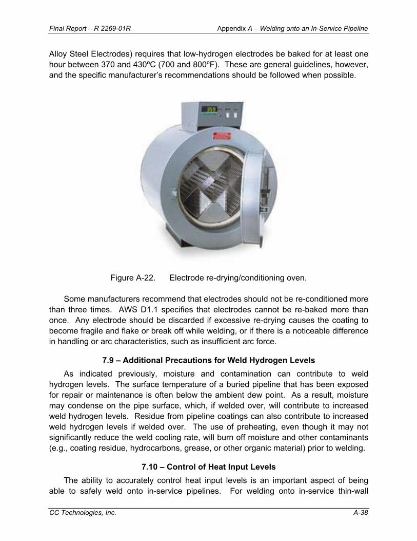
Final Report – R 2269-01R Appendix A – Welding onto an In-Service Pipeline
CC Technologies, Inc. A-38
Alloy Steel Electrodes) requires that low-hydrogen electrodes be baked for at least one hour between 370 and 430ºC (700 and 800ºF). These are general guidelines, however, and the specific manufacturer’s recommendations should be followed when possible.
Figure A-22. Electrode re-drying/conditioning oven.
Some manufacturers recommend that electrodes should not be re-conditioned more than three times. AWS D1.1 specifies that electrodes cannot be re-baked more than once. Any electrode should be discarded if excessive re-drying causes the coating to become fragile and flake or break off while welding, or if there is a noticeable difference in handling or arc characteristics, such as insufficient arc force.
7.9 – Additional Precautions for Weld Hydrogen Levels As indicated previously, moisture and contamination can contribute to weld
hydrogen levels. The surface temperature of a buried pipeline that has been exposed for repair or maintenance is often below the ambient dew point. As a result, moisture may condense on the pipe surface, which, if welded over, will contribute to increased weld hydrogen levels. Residue from pipeline coatings can also contribute to increased weld hydrogen levels if welded over. The use of preheating, even though it may not significantly reduce the weld cooling rate, will burn off moisture and other contaminants (e.g., coating residue, hydrocarbons, grease, or other organic material) prior to welding.
7.10 – Control of Heat Input Levels The ability to accurately control heat input levels is an important aspect of being
able to safely weld onto in-service pipelines. For welding onto in-service thin-wall
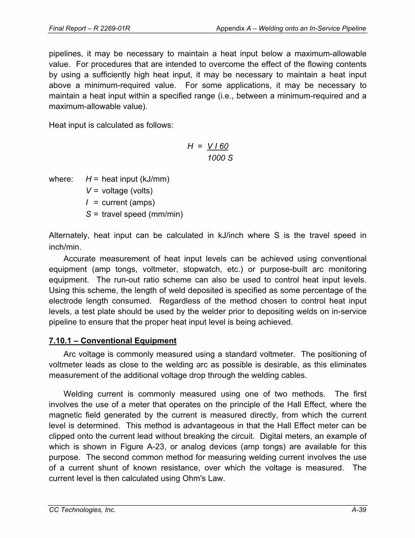
Final Report – R 2269-01R Appendix A – Welding onto an In-Service Pipeline
CC Technologies, Inc. A-39
pipelines, it may be necessary to maintain a heat input below a maximum-allowable value. For procedures that are intended to overcome the effect of the flowing contents by using a sufficiently high heat input, it may be necessary to maintain a heat input above a minimum-required value. For some applications, it may be necessary to maintain a heat input within a specified range (i.e., between a minimum-required and a maximum-allowable value).
Heat input is calculated as follows:
H = V I 60 1000 S
where: H = heat input (kJ/mm) V = voltage (volts) I = current (amps) S = travel speed (mm/min) Alternately, heat input can be calculated in kJ/inch where S is the travel speed in inch/min.
Accurate measurement of heat input levels can be achieved using conventional equipment (amp tongs, voltmeter, stopwatch, etc.) or purpose-built arc monitoring equipment. The run-out ratio scheme can also be used to control heat input levels. Using this scheme, the length of weld deposited is specified as some percentage of the electrode length consumed. Regardless of the method chosen to control heat input levels, a test plate should be used by the welder prior to depositing welds on in-service pipeline to ensure that the proper heat input level is being achieved.
7.10.1 – Conventional Equipment Arc voltage is commonly measured using a standard voltmeter. The positioning of
voltmeter leads as close to the welding arc as possible is desirable, as this eliminates measurement of the additional voltage drop through the welding cables.
Welding current is commonly measured using one of two methods. The first involves the use of a meter that operates on the principle of the Hall Effect, where the magnetic field generated by the current is measured directly, from which the current level is determined. This method is advantageous in that the Hall Effect meter can be clipped onto the current lead without breaking the circuit. Digital meters, an example of which is shown in Figure A-23, or analog devices (amp tongs) are available for this purpose. The second common method for measuring welding current involves the use of a current shunt of known resistance, over which the voltage is measured. The current level is then calculated using Ohm's Law.
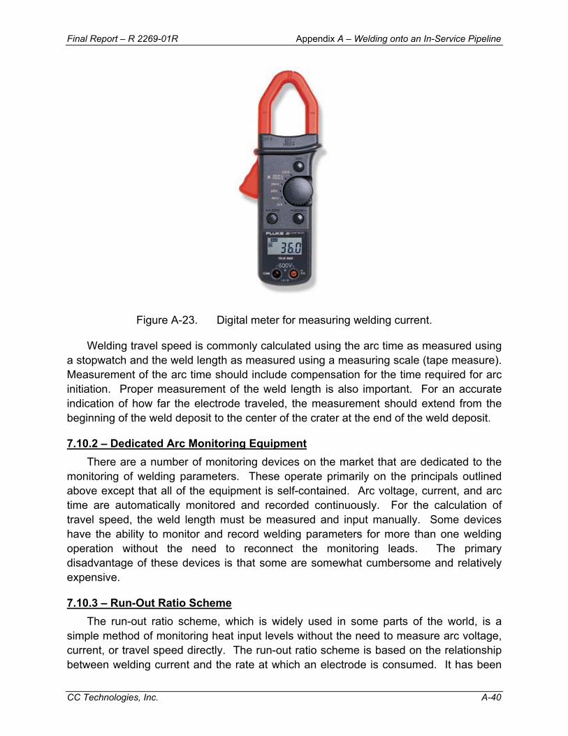
Final Report – R 2269-01R Appendix A – Welding onto an In-Service Pipeline
CC Technologies, Inc. A-40
Figure A-23. Digital meter for measuring welding current.
Welding travel speed is commonly calculated using the arc time as measured using a stopwatch and the weld length as measured using a measuring scale (tape measure). Measurement of the arc time should include compensation for the time required for arc initiation. Proper measurement of the weld length is also important. For an accurate indication of how far the electrode traveled, the measurement should extend from the beginning of the weld deposit to the center of the crater at the end of the weld deposit.
7.10.2 – Dedicated Arc Monitoring Equipment There are a number of monitoring devices on the market that are dedicated to the
monitoring of welding parameters. These operate primarily on the principals outlined above except that all of the equipment is self-contained. Arc voltage, current, and arc time are automatically monitored and recorded continuously. For the calculation of travel speed, the weld length must be measured and input manually. Some devices have the ability to monitor and record welding parameters for more than one welding operation without the need to reconnect the monitoring leads. The primary disadvantage of these devices is that some are somewhat cumbersome and relatively expensive.
7.10.3 – Run-Out Ratio Scheme The run-out ratio scheme, which is widely used in some parts of the world, is a
simple method of monitoring heat input levels without the need to measure arc voltage, current, or travel speed directly. The run-out ratio scheme is based on the relationship between welding current and the rate at which an electrode is consumed. It has been

Final Report – R 2269-01R Appendix A – Welding onto an In-Service Pipeline
CC Technologies, Inc. A-41
shown that the rate at which an electrode is consumed and the welding current are proportional(32) Therefore, for a given electrode diameter, the ratio of the length of electrode consumed to the length of the weld deposited is proportional to the heat input. The inverse of this ratio (i.e., the length of the weld deposited to the length of electrode consumed) is defined as the run-out ratio.
The run-out ratio scheme is used to control welding heat input by either specifying a run-out ratio that corresponds to the required heat input level or by specifying a run-out length for an entire electrode. Tables for run-out ratios for various types of electrodes depending on the iron powder content in the coating, and for various electrode sizes, are shown in Tables A-2 through A-4.(33) Most low-hydrogen electrodes (EXX18-type) fall into the “electrodes-with-some-iron-powder” category (Table A-3). To control the risk of burnthrough, the minimum required run-out ratio that corresponds to the maximum-allowable heat input should be specified. Alternatively, minimum required run-out length for an entire electrode could be specified. The values in Tables A-2 through A-4 tend to provide a good lower-bound estimate of heat input, so they should be used with caution to control the risk of burnthrough. The values shown in Table A-3 are also shown graphically in Figure A-24.
7.10.4 – Avoiding Excessive Heat Input Heat input is directly proportional to welding current and voltage and inversely
proportional to travel speed. The level of welding current required for a given electrode tends to increase proportionally with electrode diameter. A general rule of thumb is that the approximate current level required for a given electrode diameter is the diameter in inches times 1000 (e.g., 125 amps for a 3.2 mm [0.125-inch] diameter electrode). For a given machine setting (current level), heat input is high when travel speed is slow. For in-service welding, a slow travel speed is required to bridge a large gap between sleeve and pipe. Proper attention to sleeve fit-up will preclude the need for excessively slow travel speed. When other methods fail, weld metal buttering can be used to reduce the gap.
7.11 – Temper Bead Sequence The ability of a temper bead sequence to reduce hydrogen cracking risk is
dependent upon proper placement of the weld beads. During execution of a temper bead procedure the welder should be thoroughly familiar with the proper sequence. Between-pass inspection should be carried out to assure proper bead placement, particularly at the weld toes.
7.12 – Preheating
While there are many situations where in-service welding can be and has been safely carried out without preheating, the effective use of preheating results in an additional level of protection against hydrogen cracking.

Final Report – R 2269-01R Appendix A – Welding onto an In-Service Pipeline
CC Technologies, Inc. A-42
Table A-2. Run-out ratios* for electrodes containing little or no iron powder.(33)
Heat Input, kJ/inch (kJ/mm) Electrode Diameter, inch (mm) 15 (0.6) 20 (0.8) 25 (1.0) 30 (1.2) 35 (1.4) 40 (1.6) 45 (1.8) 50 (2.0) 3/32 (2.4) 0.53 0.40 0.32 0.27 0.23 – – – 1/8 (3.2) 0.87 0.65 0.52 0.44 0.37 0.33 0.29 0.26 5/32 (4.0) 1.35 1.01 0.81 0.67 0.58 0.50 0.45 0.40
Table A-3. Run-out ratios* for electrodes containing some iron powder (including most EXX18-yype electrodes).(33) See Figure A-24.
Heat Input, kJ/inch (kJ/mm) Electrode Diameter, inch (mm) 15 (0.6) 20 (0.8) 25 (1.0) 30 (1.2) 35 (1.4) 40 (1.6) 45 (1.8) 50 (2.0) 3/32 (2.4) 0.62 0.46 0.37 0.31 0.26 0.23 -- -- 1/8 (3.2) 1.01 0.76 0.60 0.50 0.43 0.38 0.34 0.30 5/32 (4.0) 1.57 1.18 0.94 0.79 0.67 0.59 0.52 0.47
Table A-4. Run-out ratios* for electrodes containing high iron powder contents.(33)
Heat Input, kJ/inch (kJ/mm) Electrode Diameter, inch (mm) 15 (0.6) 20 (0.8) 25 (1.0) 30 (1.2) 35 (1.4) 40 (1.6) 45 (1.8) 50 (2.0) 3/32 (2.4) 0.79 0.59 0.48 0.40 0.34 0.30 0.26 0.24 1/8 (3.2) 1.30 0.97 0.78 0.65 0.56 0.49 0.43 0.39 5/32 (4.0) 2.02 1.52 1.22 1.01 0.87 0.76 0.67 0.61
* Length of weld deposited to length of electrode consumed. Values tend to provide a good lower-bound estimate of heat input, and should
be used with caution to control the risk of burnthrough.
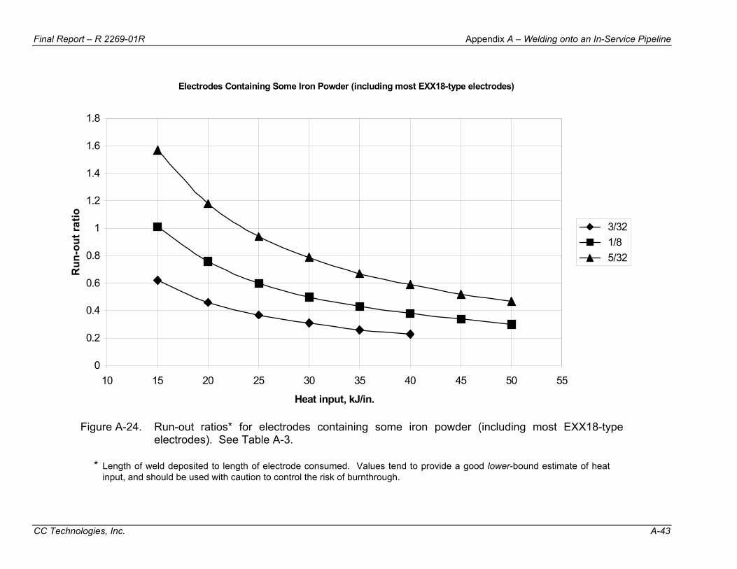
Final Report – R 2269-01R Appendix A – Welding onto an In-Service Pipeline
CC Technologies, Inc. A-43
Electrodes Containing Some Iron Powder (including most EXX18-type electrodes)
0
0.2
0.4
0.6
0.8
1
1.2
1.4
1.6
1.8
10 15 20 25 30 35 40 45 50 55
Heat input, kJ/in.
Run
-out
ratio
3/32 1/8 5/32
Figure A-24. Run-out ratios* for electrodes containing some iron powder (including most EXX18-type electrodes). See Table A-3.
* Length of weld deposited to length of electrode consumed. Values tend to provide a good lower-bound estimate of heat
input, and should be used with caution to control the risk of burnthrough.
Final Report – R 2269-01R Appendix A – Welding onto an In-Service Pipeline
CC Technologies, Inc. A-44
7.12.1 – Preheating Method
Conventional methods of applying preheat, such as gas torches, are difficult to control and can be slow and inefficient. The primary advantages of gas torches are cost and portability. The primary disadvantage is the inability to apply continuous, even heating. Both electrical resistance blankets and induction coils are effective continuous heating methods for in-service welding applications. (15) Induction heating has several advantages over resistance heating; however, the most important of which is the ability to more thoroughly heat the pipe wall as opposed to the surface of the pipe.
In addition to burning off moisture and other contaminants, preheating allows hydrogen diffusion during and after welding. For this to occur, it is important to maintain the application of heat for some time after the weld is complete. Preheat maintenance (i.e., post-heating) for 15 minutes has been suggested as a reasonable time for temperatures in the 93 to 121ºC (200 to 250ºF) range and for the range of thicknesses that are encountered during most typical in-service welding applications. (15) Longer times should be considered for thicker materials (e.g., pipe wall thickness greater than 12.7 mm [0.5 inch] and/or heavy-wall fittings) and/or for lower temperatures. When using post-heating to allow hydrogen diffusion, the post-heating must be applied prior to the onset of cracking.
7.12.2 – Preheat Temperature The application of preheat for the prevention of hydrogen cracking is carried out for
one or both of two reasons: to allow diffusion of hydrogen and to control or limit the formation of crack susceptible microstructures. To achieve the latter, preheat temperatures in excess of those that are generally attainable during in-service welding applications are required. As indicated earlier, the primary benefit of preheating for in-service welding applications is diffusion of hydrogen. To achieve diffusion of hydrogen, preheat temperatures in the 200 to 250ºF (93 to 121ºC) range are sufficient. Lower preheat temperatures are also effective at allowing hydrogen diffusion, but the time required becomes exponentially longer as preheat temperature is reduced. The driving force for hydrogen diffusion is time at temperature (i.e., the area beneath the time-temperature curve).
Preheating carbon steel to a precise temperature is generally not required. It is usually acceptable to exceed the minimum-required preheat temperature by approximately 56°C (100°F). For in-service welding applications, care must be taken to ensure that the pipe wall is not overheated to a point where loss of strength becomes an issue. Above 315ºC (600ºF), the yield strength of line pipe steel begins to decrease significantly. An upper limit of 204 to 232ºC (400 to 450ºF) would seem to be a reasonable upper limit from a safety standpoint.
Final Report – R 2269-01R Appendix A – Welding onto an In-Service Pipeline
CC Technologies, Inc. A-45
7.12.3 – Measurement of Preheat Temperatures Because of the significant temperature gradients that can be produced as the result
of the continuous removal of heat by the flowing contents, measurement of preheat temperatures for in-service welding applications is a subjective exercise at best.
7.12.3.1 – Measurement Location AWS D1.1 indicates that the base metal should be preheated in such a manner that
the parts on which the weld is being deposited are above the specified minimum temperature for a distance equal to the thickness of the part being welded, but not less than 75 mm (3 inches) in all directions from the point of welding. The purpose of this requirement is to ensure that the full material volume surrounding the joint is thoroughly heated. Other preheating guidance indicates that the heat should be applied to the side opposite of that which is to be welded, and measurements should be made on the surface adjacent to the joint. Still other guidance indicates that, where this is impractical, time should be allowed for the temperature to equalize after removal of the heat source before the temperature is measured. Obviously, none of this is possible for in-service welding applications where there is no access to the inside of the pipe and there is continuous removal of heat by the flowing contents.
Preheat temperature measurement for in-service welding applications where continuous heating methods are used should occur in the weld joint, but consideration should also be given to the temperature in the vicinity of the weld joint. For non-continuous preheating methods, preheat temperature should also occur in the weld joint, but temperature decay as a function of time should be considered. This can be accomplished using the re-heating interval technique, where the time allowed for welding is determined by measuring the time required for the temperature in the preheated area to drop from some maximum temperature to the minimum-required preheat temperature.
7.12.3.2 – Measurement Method Temperature measurement methods commonly used for other welding applications
are suitable for in-service welding applications. These include contact thermometers (digital or analog), non-contact infrared pyrometers, etc. Temperature indicating crayons (e.g., Tempilsticks™) may be suitable for welding applications where continuous heating methods are used but are not ideally suited to measuring temperature decay for the re-heating interval technique.
7.12.4 – Maintenance of Preheat During and After Welding Most general preheating guidance indicates that the minimum-required preheat
temperature should be maintained throughout the welding operation. Once welding begins, this temperature is generally referred to as the interpass temperature. If the welding operation is interrupted, preheating should be reapplied until the minimum-
Final Report – R 2269-01R Appendix A – Welding onto an In-Service Pipeline
CC Technologies, Inc. A-46
required preheat temperature is re-established. AWS D1.1 indicates that the minimum-required interpass temperature should be equal to the minimum-required preheat temperature unless otherwise indicated.
For many welding applications, the heat from the welding operation is sufficient to maintain the desired temperature without the continuous external application of heat. For in-service welding applications where extreme thermal conditions exist (e.g., high thermal conductivity contents and/or high flow rates) and non-continuous preheating methods are being used, this will rarely be the case.
When using post-weld preheat maintenance to minimize the risk of cracking (i.e., to allow hydrogen diffusion), the post-weld heating must be applied prior to the onset of cracking. Post-weld preheat maintenance to minimize the risk of cracking is useless once cracks have formed.
7.12.4.1 – Tack Welding If preheating is specified in the welding procedure, it should also be applied when
tack welding. Hydrogen cracks that develop in tack welds that are not completely consumed by the final weld can initiate hydrogen cracks in the final weld.
7.13 – Welder-Induced Discontinuities Although hydrogen cracking is the most significant discontinuity with respect to the
integrity of the pipeline or piping system, the presence of welder-induced discontinuities can also be significant. Welder-induced, or workmanship, discontinuities are those which can generally be controlled by the skill of the welder (e.g., porosity, slag inclusions, undercut, etc.), whereas hydrogen cracking generally cannot. Welder-induced discontinuities can be controlled by good practice with regard to welder technique and by following a qualified welding procedure. Proper use of welding procedure and welder qualification, combined with close monitoring in the field to ensure that the welding procedure is being followed, should minimize the occurrence of welder-induced discontinuities.
7.14 – Fillet Weld Size When the thickness of a full encirclement repair sleeves is equal to the carrier pipe
wall thickness, the leg length of the fillet weld should be equal to the pipe wall thickness (i.e., a full size fillet weld). If the sleeve thickness exceeds that of the carrier pipe by more than 2.4 mm (3/32 inch), it is recommended that the ends be tapered to the carrier pipe thickness on a 4 to 1 slope (four units along the sleeve for one unit of thickness).
For some proprietary full encirclement sleeves tees (hot tap fittings), the manufacturer may have specific requirements for fillet weld size. For example, one manufacturer recommends a fillet weld leg length that is approximately 1.5 times the

Final Report – R 2269-01R Appendix A – Welding onto an In-Service Pipeline
CC Technologies, Inc. A-47
carrier pipe thickness. This requirement is intended to ensure that the fillet weld throat thickness is no less than the carrier pipe thickness.
If there is a gap between the pipe and the sleeve (or fitting), the fillet weld leg length should be increased by an amount equal to the gap (Figure A-25).
Figure A-25. Fillet weld leg size – compensation for gap.
7.15 – Inspection and Nondestructive Testing Welds made onto in-service pipelines are more likely to contain significant
discontinuities than other welds since they may be susceptible to hydrogen cracking. This justifies the application of additional quality assurance measures such as inspection and nondestructive testing (NDT). Since in-service welds that contact the carrier pipe are particularly susceptible to hydrogen cracking, an inspection method that is capable of detecting these cracks, particularly at the carrier pipe weld toe, should be used.
During welding, particular attention should be given to monitoring welding procedure variables and welder technique. Conventional equipment (e.g., amp tongs, voltmeter, stopwatch and pyrometer) or purpose-built arc-monitoring equipment can be used for this purpose. It is also important to perform between-pass visual inspections for discontinuities such as cracking, porosity, proper slag removal, etc.
Effective NDT of welds made onto in-service pipelines is difficult as the result of the inherently difficult-to-inspect geometries associated with these welds. As a result, amount of NDT given to these welds has historically been minimal.
Surface inspection methods applicable to welds made onto in-service pipelines include magnetic particle inspection (MPI) and liquid penetrant inspection (PT). In a development program conducted jointly between EWI and TWI in the U.K.,(34) it was concluded that MPI performed significantly better than PT. The reason for this is that some discontinuities may be located slightly below the surface. Both the wet
Final Report – R 2269-01R Appendix A – Welding onto an In-Service Pipeline
CC Technologies, Inc. A-48
fluorescent and visible (black) ink over white contrast paint techniques performed equally well and the choice of optimum technique depends on illumination conditions available.
Volumetric inspection of welds made onto in-service pipelines is limited to ultrasonic testing (UT), since radiography is made difficult by the complex geometries and gross thickness changes associated with these welds. The effectiveness of a UT procedure depends on the method used to set test sensitivity, the choice of probe angles and scanning surfaces and the criteria for evaluating and reporting discontinuities. The choice of procedure also depends on the weld geometry to be inspected (sleeve fillet welds or branch groove welds). The distance/amplitude correction method for setting test sensitivity is appropriate for thicker pipe materials (sound path greater than 50 mm [2 inches]).(34) For sleeve fillet welds, scans should be carried out on both pipe and sleeve surfaces using at least 45 degree probes and ideally 70 degree probes also. There is a general tendency to undersize discontinuity length, with length measurements of around 50% of actual size being typical. Measurement of discontinuity through-wall height was not practical, and it is recommended that the maximum signal amplitude should be recorded instead. For characterization or determination of discontinuity type, this is best carried out by noting the position of the discontinuity with respect to the weld. For branch groove welds, ultrasonic scanning should not be restricted to the branch surface but should be carried out on both branch and pipe surfaces. Pipe toe cracking discontinuities were best detected by 45 degree probe scans on the pipe surface.
Acceptance criteria for discontinuities detected during NDT are described in Appendix B of API 1104.(16)
Even though the geometries associated with these welds make them inherently difficult to inspect, there is a psychological benefit of specifying some form of NDT in the form of increased welder performance with respect to welder-induced discontinuities. If a welder knows that a completed weld will be subjected to NDT, he is more likely to closely follow the welding procedure and to ensure that welder-induced discontinuities are avoided. The advantages and disadvantages of the various NDT methods that are typically applied to welds in general are summarized in Table A-5.
7.16 – Delay Time Prior to Inspection for Hydrogen Cracking Hydrogen cracking, which is also referred to as delayed cracking, requires time to
occur. The reason for this is that time is required for the hydrogen to diffuse to areas with crack susceptible microstructures. Prior to inspection for hydrogen cracking, a sufficient delay time should be allowed to elapse. When determining appropriate delay times prior to inspection, the time-dependant nature of hydrogen cracking should be considered, as well as the expected susceptibility of the weld to cracking. Longer delay times decrease the chance that cracking can occur after inspection has been
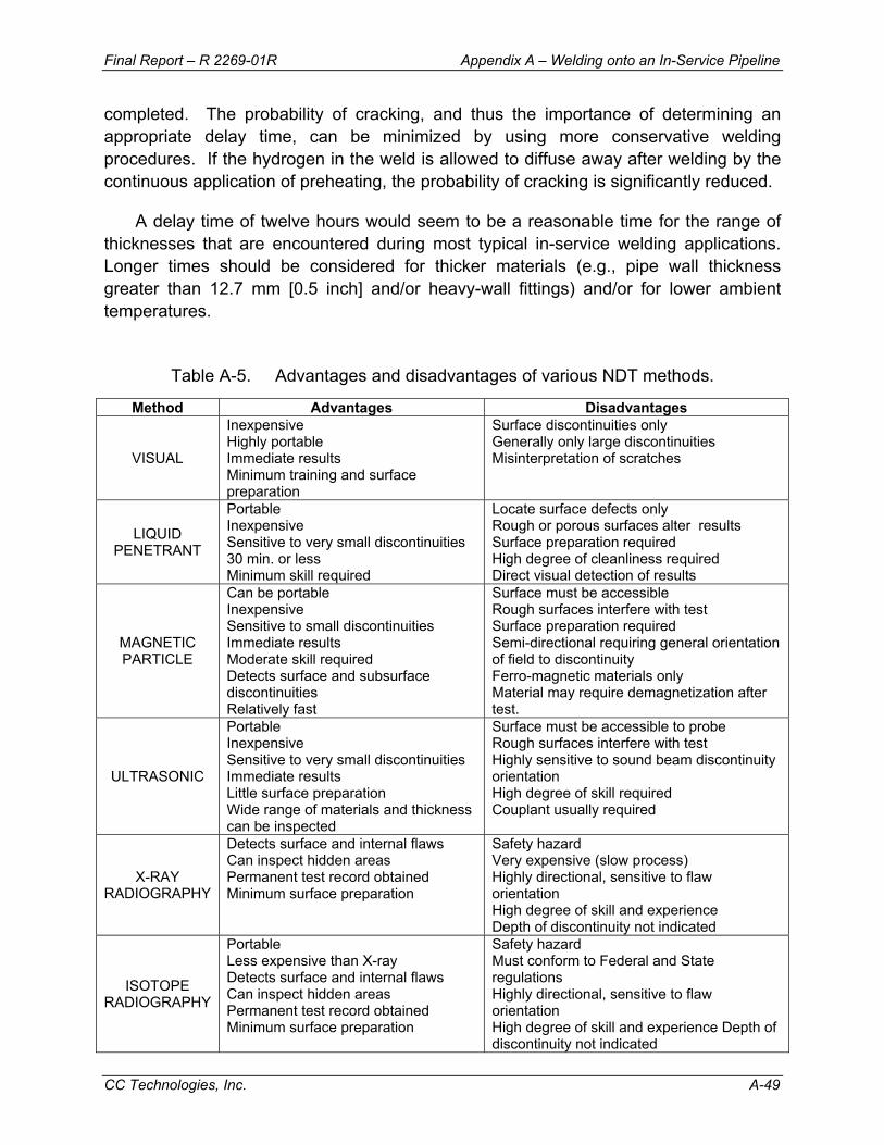
Final Report – R 2269-01R Appendix A – Welding onto an In-Service Pipeline
CC Technologies, Inc. A-49
completed. The probability of cracking, and thus the importance of determining an appropriate delay time, can be minimized by using more conservative welding procedures. If the hydrogen in the weld is allowed to diffuse away after welding by the continuous application of preheating, the probability of cracking is significantly reduced.
A delay time of twelve hours would seem to be a reasonable time for the range of thicknesses that are encountered during most typical in-service welding applications. Longer times should be considered for thicker materials (e.g., pipe wall thickness greater than 12.7 mm [0.5 inch] and/or heavy-wall fittings) and/or for lower ambient temperatures.
Table A-5. Advantages and disadvantages of various NDT methods.
Method Advantages Disadvantages
VISUAL
Inexpensive Highly portable Immediate results Minimum training and surface preparation
Surface discontinuities only Generally only large discontinuities Misinterpretation of scratches
LIQUID PENETRANT
Portable Inexpensive Sensitive to very small discontinuities 30 min. or less Minimum skill required
Locate surface defects only Rough or porous surfaces alter results Surface preparation required High degree of cleanliness required Direct visual detection of results
MAGNETIC PARTICLE
Can be portable Inexpensive Sensitive to small discontinuities Immediate results Moderate skill required Detects surface and subsurface discontinuities Relatively fast
Surface must be accessible Rough surfaces interfere with test Surface preparation required Semi-directional requiring general orientation of field to discontinuity Ferro-magnetic materials only Material may require demagnetization after test.
ULTRASONIC
Portable Inexpensive Sensitive to very small discontinuities Immediate results Little surface preparation Wide range of materials and thickness can be inspected
Surface must be accessible to probe Rough surfaces interfere with test Highly sensitive to sound beam discontinuity orientation High degree of skill required Couplant usually required
X-RAY RADIOGRAPHY
Detects surface and internal flaws Can inspect hidden areas Permanent test record obtained Minimum surface preparation
Safety hazard Very expensive (slow process) Highly directional, sensitive to flaw orientation High degree of skill and experience Depth of discontinuity not indicated
ISOTOPE RADIOGRAPHY
Portable Less expensive than X-ray Detects surface and internal flaws Can inspect hidden areas Permanent test record obtained Minimum surface preparation
Safety hazard Must conform to Federal and State regulations Highly directional, sensitive to flaw orientation High degree of skill and experience Depth of discontinuity not indicated
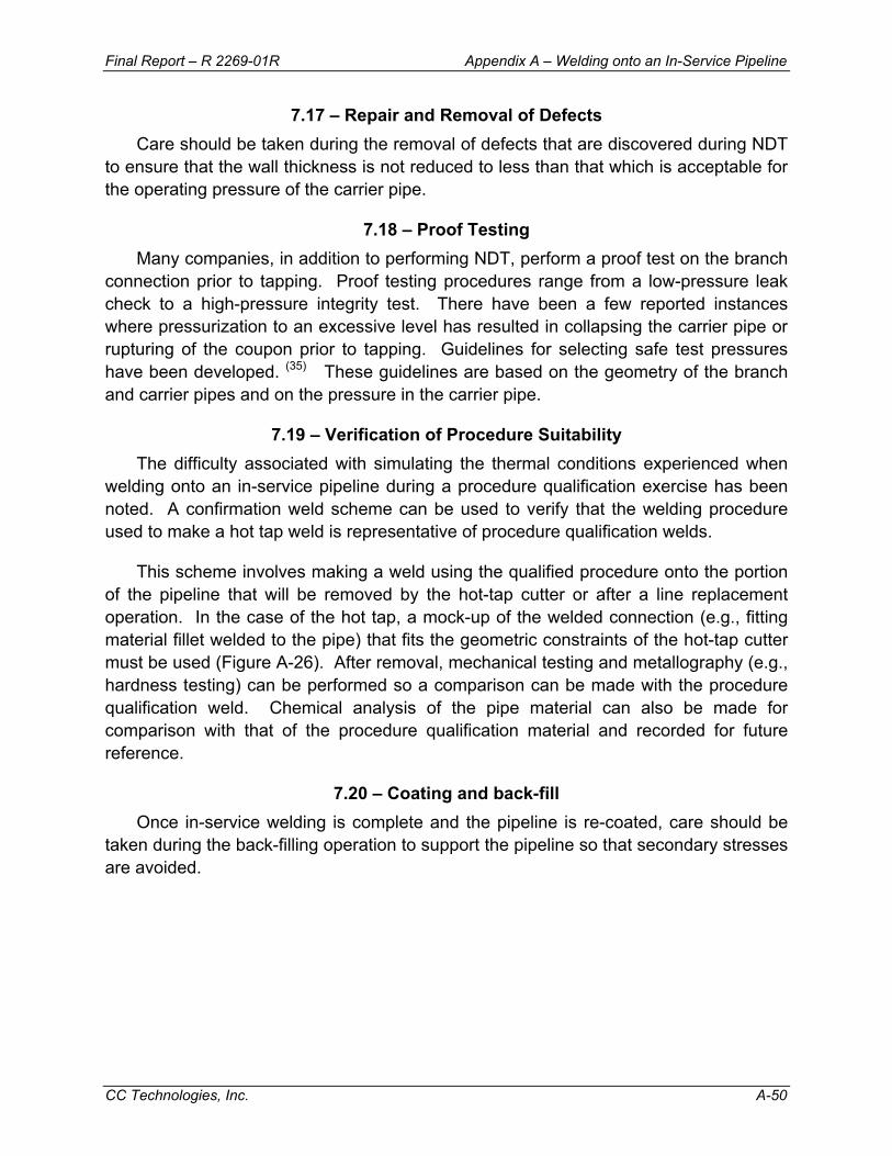
Final Report – R 2269-01R Appendix A – Welding onto an In-Service Pipeline
CC Technologies, Inc. A-50
7.17 – Repair and Removal of Defects Care should be taken during the removal of defects that are discovered during NDT
to ensure that the wall thickness is not reduced to less than that which is acceptable for the operating pressure of the carrier pipe.
7.18 – Proof Testing Many companies, in addition to performing NDT, perform a proof test on the branch
connection prior to tapping. Proof testing procedures range from a low-pressure leak check to a high-pressure integrity test. There have been a few reported instances where pressurization to an excessive level has resulted in collapsing the carrier pipe or rupturing of the coupon prior to tapping. Guidelines for selecting safe test pressures have been developed. (35) These guidelines are based on the geometry of the branch and carrier pipes and on the pressure in the carrier pipe.
7.19 – Verification of Procedure Suitability The difficulty associated with simulating the thermal conditions experienced when
welding onto an in-service pipeline during a procedure qualification exercise has been noted. A confirmation weld scheme can be used to verify that the welding procedure used to make a hot tap weld is representative of procedure qualification welds.
This scheme involves making a weld using the qualified procedure onto the portion of the pipeline that will be removed by the hot-tap cutter or after a line replacement operation. In the case of the hot tap, a mock-up of the welded connection (e.g., fitting material fillet welded to the pipe) that fits the geometric constraints of the hot-tap cutter must be used (Figure A-26). After removal, mechanical testing and metallography (e.g., hardness testing) can be performed so a comparison can be made with the procedure qualification weld. Chemical analysis of the pipe material can also be made for comparison with that of the procedure qualification material and recorded for future reference.
7.20 – Coating and back-fill Once in-service welding is complete and the pipeline is re-coated, care should be
taken during the back-filling operation to support the pipeline so that secondary stresses are avoided.
Final Report – R 2269-01R Appendix A – Welding onto an In-Service Pipeline
CC Technologies, Inc. A-51
Figure A-26. Confirmation weld scheme.
8.0 – RELATED AREAS OF CONCERN
8.1 – Internal Combustion and Other Products of Concern For certain types of lines, such as flare lines, there is the possibility of an explosive
mixture being present inside the pipe as the result of air ingress into the system. Also, compressed air lines may contain oil deposits or an oil mist of a potentially explosive mixture. When welding on such a line, there is a danger of internal combustion due to the heat of welding. The risk of this can be minimized by providing a positive flow during welding on a flare line and by prohibiting welding on other lines that may contain explosive mixtures. Welding on oxygen and chlorine lines should also be prohibited, as the pipe steel can burn in the presence of these at high temperature. Welding onto a line containing caustics or acids can result in the initiation of stress corrosion cracking at high temperature and should be avoided.
Final Report – R 2269-01R Appendix A – Welding onto an In-Service Pipeline
CC Technologies, Inc. A-52
8.2 – Hot Tap Welding for Sour Service Pipelines Welding onto in-service pipelines that transport or will eventually be used to
transport sour products presents an additional challenge. The high hardness levels that can result make these welds susceptible to sulfide stress cracking (SSC) in subsequent service. Previous experience has shown that the maximum allowable hardness criterion of Rockwell C 22 (Vickers 248) which is recommended in NACE MR-01-75(36) to avoid SSC, is often difficult to meet using conventional welding techniques.
In a previous program,(37) a procedure that results in hardness levels less than the NACE limit was developed for a specific application. Several techniques, including standard multipass welds, multipass welds made at high heat inputs and various temper-bead deposition sequences, were investigated. For the material and thermal conditions of concern in this program, the best results were obtained using a temper-bead deposition sequence. The optimized procedure involved application of weld metal buttering to the weld preparation of a preheated fitting, since normal deposited weld metals have a substantially lower CE than many hot-formed fitting materials. Weld metal buttering was also used on the pipe side of the joint. The top portion of this buttering layer was ground away to promote more complete tempering by subsequent passes. A GTAW root pass with an autogenous re-melt pass was used to allow tempering in the root region. Special requirements for weld toe placement were used to ensure that this critical area receives adequate tempering. A unique scheme to facilitate weld toe placement was devised.
A variation of this optimized procedure was determined to be best with regard to minimizing weld hardness levels for the application of interest. This elaborate procedure is not required for all applications, however, to produce acceptable hardness levels for sour service. In fact, for some combinations of low CE material and less severe pipeline operating conditions, standard multi- and even single-pass welds result in acceptable hardness levels. In a follow-on program, a set of guidelines is being developed to define what welding procedures are required under what conditions so that hardness levels below the NACE limit can be expected.
8.3 – Hot Tap Welding for Lines Charged with Hydrogen Pipelines that have been exposed to sour products for some time prior to welding,
or that have operated in high pressure hydrogen service, present an additional problem in that the steel itself may be charged with hydrogen, providing a hydrogen source for hydrogen cracking. For these applications, it may be necessary to use a procedure that limits HAZ hardness to a level that is appropriate for the amount of hydrogen that is present in the weld. Additional work in this area is required to determine the level of hydrogen that is present in a weld made onto steel that is charged with hydrogen.
Final Report – R 2269-01R Appendix A – Welding onto an In-Service Pipeline
CC Technologies, Inc. A-53
8.4 – Hot Tap Welding for Duplex Stainless Steel Pipelines Duplex stainless steel is now beginning to take over from both solid-wall and
internally clad austenitic stainless steel pipelines since they offer good corrosion resistance and tensile properties at a relatively low cost. These tensile properties result from the presence of around 50% ferrite in a matrix of austenite. Welding parameters must be tightly controlled during construction welding to maintain this balance in the weld metal and the HAZ. The rapid cooling that results from welding onto an in-service pipeline would adversely affect the phase balance and could adversely affect the corrosion resistance and mechanical properties. A reduction in corrosion resistance would only be of concern, of course, for weld regions that come into contact with the corrosive environment, however. Procedures for hot tap welding onto in-service 22% Cr duplex stainless steel pipelines have been successfully developed.(38)
9.0 – SUMMARY 1. There are two primary concerns with welding onto in-service pipelines. The first is
for "burnthrough" where the welding arc causes the pipe wall to be penetrated. The second concern is for hydrogen cracking, since welds made in-service cool at an accelerated rate as the result of the flowing contents' ability to remove heat from the pipe wall.
2. Burnthrough is unlikely if the wall thickness is 6.4 mm (0.250 inch) or greater,
provided that low hydrogen electrodes and normal welding practices are used. For welding onto thinner in-service pipelines, small diameter electrodes and a procedure that limits heat input should be used.
3. Control of weld hydrogen levels should be the first line of protection against
hydrogen cracking in welds made onto in-service pipelines. Many of the potential problems associated with minimizing hydrogen levels can be addressed at the electrode procurement stage. Proper handling and use is also important.
4. For additional protection against hydrogen cracking, procedures that limit the
formation of crack-susceptible microstructures should be developed and followed. The most common procedures for welding onto in-service pipelines use a sufficiently high heat input level to overcome the effect of the flowing contents. Procedures that make use of a temper bead deposition sequence can be used for more difficult applications. Preheating can also be use as additional protection against hydrogen cracking.
Final Report – R 2269-01R Appendix A – Welding onto an In-Service Pipeline
CC Technologies, Inc. A-54
5. The proper use of in-service welding allows repairs and modifications to be made with confidence, allowing both economic and environmental benefits to be realized by avoiding pipeline shutdown and interruption of service.
10.0 – REFERENCES
1. D. G. Howden, “Welding on Pressurized Pipeline,” Loss Prevention, Vol. 9 (New York, NY: American Institute of Chemical Engineers), pp. 8-10.
2. J. B. Wade, “Hot Tapping of Pipelines,” Australian Welding Research Association Symposium, paper no. 14 (Melbourne, Australia, 1973).
3. B. A. Cassie, “The Welding of Hot Tap Connections to High Pressure Gas Pipelines,” J. W. Jones Memorial Lecture (Pipe Line Industries Guild, October 1974).
4. J. F. Kiefner and R. D. Fischer, “Repair and Hot Tap Welding on Pressurized Pipelines,” Symposium during 11th Annual Energy Sources Technology Conference and Exhibition, New Orleans, LA, January 10-13, 1988 (New York, NY: American Society of Mechanical Engineers, PD-Vol. 14., 1987) pp. 1-10.
5. J. F. Kiefner, R. D. Fischer, and H. W. Mishler, “Development of Guidelines for Repair and Hot Tap Welding on Pressurized Pipelines,” Final Report, Phase 1, to Repair and Hot Tap Welding Group, Battelle Columbus Division, Columbus, OH, September 1981.
6. T. A. Bubenik, R. D. Fischer, G. R. Whitacre, D. J. Jones, J. F. Kiefner, M. J. Cola, and W. A. Bruce, “Investigation and Prediction of Cooling Rates During Pipeline Maintenance Welding,” Final Report to American Petroleum Institute, December 1991.
7. Bruce, W. A., Li, V., Citterberg, R., Wang, Y.-Y., and Chen, Y., “Improved Cooling Rate Model for Welding on In-Service Pipelines,” PRCI Contract No. PR-185-9633, EWI Project No. 42508CAP, Edison Welding Institute, Columbus, OH, July 2001.
8. Bruce, W. A, “Welding onto In-Service Thin-Wall Pipelines,” Final Report to PRC International for PR-185-9908, EWI Project No. 41732CAP, Edison Welding Institute, Columbus, OH, July 2000.
9. Bruce, W. A, “Burnthrough Limits for In-Service Welding,” Final Report to PRC International for GRI-8441, EWI Project No. 44732CAP, Edison Welding Institute, Columbus, OH, August 2003.
10. M. J. Cola, J. F. Kiefner, R. D. Fischer, D. J. Jones, and W. A. Bruce, “Development of Simplified Weld Cooling Rate Models for In-Service Gas Pipelines,” Project Report No. J7134 to A.G.A. Pipeline Research Committee, Edison Welding Institute, Kiefner and Associates and Battelle Columbus Division, Columbus, OH, March 1991.

Final Report – R 2269-01R Appendix A – Welding onto an In-Service Pipeline
CC Technologies, Inc. A-55
10.0 – REFERENCES (continued) 11. Bruce, W. A., “Refinement of Cooling Rate Prediction Methods for In-Service
Welds,” Draft Final Report to PRC International for PR-185-01128, EWI Project No. 44731CAP, Edison Welding Institute, Columbus, OH, July 2003.
12. B. A. Graville and J. A. Read, "Optimization of Fillet Weld Sizes," Welding Research Supplement, Welding Journal, April 1974.
13. Yurioka N., “Weldability of Offshore Structure Steels”, Evalmat '89, International Conference, Kobe, Japan, ISIJ, November 20-23, 1989.
14. W. A. Bruce, “Qualification and Selection of Procedures for Welding onto In-Service Pipelines and Piping Systems,” EWI Project No. J6176 to an international group of sponsors, Edison Welding Institute, Columbus, OH, January 1996.
15. Bruce, W. A., and Boring, M. A., “Evaluation of Preheat Requirements for In-Service Welding,” Draft Final Report to PRC International for PR-185-0350, EWI Project No. 46347CAP, Edison Welding Institute, Columbus, OH, December 2004.
16. API Standard 1104 - Nineteenth Edition, “Welding of Pipelines and Related Facilities,” American Petroleum Institute, Washington, DC, September 1999.
17. Bruce, W. A. and Threadgill, P. L., “Evaluation of the Effect of Procedure Qualification Variables for Welding onto In-Service Pipelines,” Final Report to A.G.A. Pipeline Research Committee for PR-185-9329, EWI Project No. J7141, Edison Welding Institute, Columbus, OH, July 1994.
18. Hart, P.H.M. and Matharu, I. S., “Heat-Affected Zone (HAZ) Hydrogen Cracking Behaviour of Low Carbon Equivalent C-Mn Structural Steels,” TWI Research Report No. 290/1985, November 1985.
19. Bruce, W. A., and Boring, M. A., “Realistic Hardness Limits for In-Service Welding,” Draft Final Report to PRC International for GRI-8758, EWI Project No. 46344CAP, Edison Welding Institute, Columbus, OH, to be published.
20. API Recommended Practice 2201 - Fifth Edition, “Safe Hot Tapping Practices in the Petroleum & Petrochemical Industries,” American Petroleum Institute, Washington, DC, July 2003.
21. Product Literature, Belec Compact Port Optical Emission Spectrometer, Georgsmarienhütte, Germany, http://www.belec.de/english/emain.htm.
22. API Spec 5L – Forty-Third Edition, “Specification for Line Pipe,” American Petroleum Institute, Washington, DC, March 2004.
23. Stevens S. M., Private Communication, November 1990.
Final Report – R 2269-01R Appendix A – Welding onto an In-Service Pipeline
CC Technologies, Inc. A-56
10.0 – REFERENCES (continued) 24. Climax Model KM65 Key Mill, Climax Portable Machine Tool trade literature,
Climax Portable Machine Tool, Inc., 2712 East Second Street, P.O. Box 230, Newberg, OR 97132.
25. S. M. Stevens, “Remelting for the Preparation of Ferrous Samples for Analysis by Optical Emission Spectroscopy,” TWI Research Bulletin, November 1984.
26. S. M. Stevens, “The Effect of Remelting on OES Calibrations for Ferritic Steels,” TWI Research Report 246/1984, August 1984.
27. AWS A5.1-91, Specification for Carbon Steel Electrodes for Shielded Metal Arc Welding, American Welding Society, Miami, FL, 1991.
28. Unknown, Storing and Re-drying Electrodes, The Lincoln Electric Company, Cleveland, OH, http://lincolnelectric.com/knowledge/articles/content/storing.asp.
29. Unknown, Recommendations for the Storage, Re-drying and Handling of ESAB Consumables, ESAB AB, Göteborg, Sweden, http://www.esab.com/ ESABHtml/pdf/Handling%20&Storage%20of%20Consumables(1).pdf.
30. AWS D1.1:2004, Structural Welding Code – Steel, American Welding Society, Miami, FL, 2004.
31. WTIA Technical Note 3, Care and Conditioning of Arc Welding Consumables, WTIA TN-3-94, Welding Technology Institute of Australia, Silverwater, NSW, 1994.
32. Jackson, C. E., and Shrubsall, A. E., Welding Journal, Vol. 29, pp. 231s-242s (1950).
33. Coe, F. R., “Welding Steels Without Hydrogen Cracking,” The Welding Institute, Cambridge, UK, 1973.
34. W. A. Bruce and B. W. Kenzie, “Development of Non-Destructive Inspection Methods for Welding Made Onto In-Service Pipelines,” 8th Symposium on Lin Pipe Research, A.G.A. Pipeline Research Committee, September 1993.
35. M. J. Rosenfeld and W. A. Maxey, “Proof Testing of the Pre-Hot-Tap Branch Connection,” NG-18 Report No. 175 to A.G.A. Line Pipe Research Supervisory Committee, Battelle Columbus Division, Columbus, OH, August 1988.
36. NACE Standard MR-01-75, “Sulfide Stress Cracking Resistant Metallic Materials for Oil Field Equipment,” National Association of Corrosion Engineers, 1984.
37. R. D. Felix, W. A. Bruce, and P. L. Threadgill, "Development of Procedures for Hot Tap Welding Onto Sour Service Pipelines," International Arctic Technology Conference, Society of Petroleum Engineers, May 1991.

Final Report – R 2269-01R Appendix A – Welding onto an In-Service Pipeline
CC Technologies, Inc. A-57
38. D. N. Noble, W. A. Bruce, and R. N. Gunn, "Hot Tapping of 22% Cr Duplex Stainless Steel. Duplex World ‘97 Conference and Exposition (Maastricht, The Netherlands), 1997.
APPENDIX B
SURVEY OF PIPELINE OPERATORS
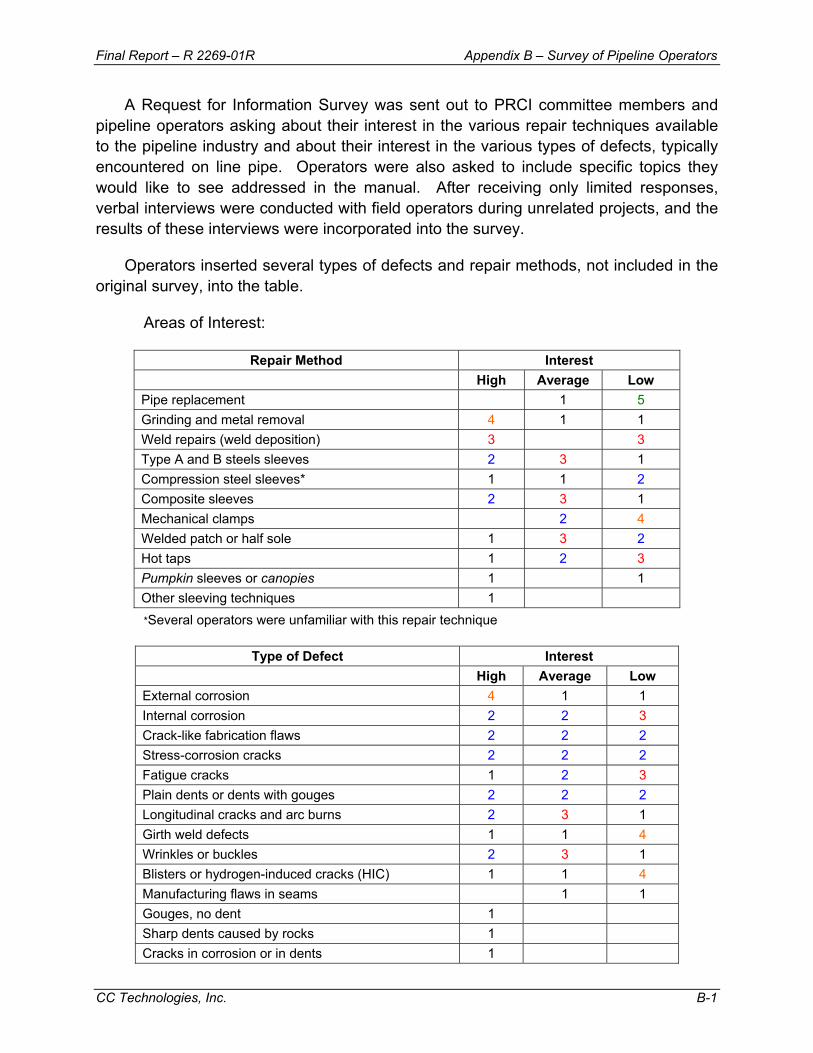
Final Report – R 2269-01R Appendix B – Survey of Pipeline Operators
CC Technologies, Inc. B-1
A Request for Information Survey was sent out to PRCI committee members and pipeline operators asking about their interest in the various repair techniques available to the pipeline industry and about their interest in the various types of defects, typically encountered on line pipe. Operators were also asked to include specific topics they would like to see addressed in the manual. After receiving only limited responses, verbal interviews were conducted with field operators during unrelated projects, and the results of these interviews were incorporated into the survey.
Operators inserted several types of defects and repair methods, not included in the original survey, into the table.
Areas of Interest:
Repair Method Interest High Average Low Pipe replacement 1 5 Grinding and metal removal 4 1 1 Weld repairs (weld deposition) 3 3 Type A and B steels sleeves 2 3 1 Compression steel sleeves* 1 1 2 Composite sleeves 2 3 1 Mechanical clamps 2 4 Welded patch or half sole 1 3 2 Hot taps 1 2 3 Pumpkin sleeves or canopies 1 1 Other sleeving techniques 1 *Several operators were unfamiliar with this repair technique
Type of Defect Interest
High Average Low External corrosion 4 1 1 Internal corrosion 2 2 3 Crack-like fabrication flaws 2 2 2 Stress-corrosion cracks 2 2 2 Fatigue cracks 1 2 3 Plain dents or dents with gouges 2 2 2 Longitudinal cracks and arc burns 2 3 1 Girth weld defects 1 1 4 Wrinkles or buckles 2 3 1 Blisters or hydrogen-induced cracks (HIC) 1 1 4 Manufacturing flaws in seams 1 1 Gouges, no dent 1 Sharp dents caused by rocks 1 Cracks in corrosion or in dents 1
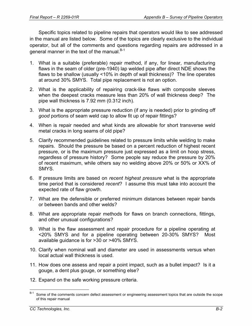
Final Report – R 2269-01R Appendix B – Survey of Pipeline Operators
CC Technologies, Inc. B-2
Specific topics related to pipeline repairs that operators would like to see addressed in the manual are listed below. Some of the topics are clearly exclusive to the individual operator, but all of the comments and questions regarding repairs are addressed in a general manner in the text of the manual.B-1
1. What is a suitable (preferable) repair method, if any, for linear, manufacturing flaws in the seam of older (pre-1940) lap welded pipe after direct NDE shows the flaws to be shallow (usually <10% in depth of wall thickness)? The line operates at around 30% SMYS. Total pipe replacement is not an option.
2. What is the applicability of repairing crack-like flaws with composite sleeves when the deepest cracks measure less than 20% of wall thickness deep? The pipe wall thickness is 7.92 mm (0.312 inch).
3. What is the appropriate pressure reduction (if any is needed) prior to grinding off good portions of seam weld cap to allow fit up of repair fittings?
4. When is repair needed and what kinds are allowable for short transverse weld metal cracks in long seams of old pipe?
5. Clarify recommended guidelines related to pressure limits while welding to make repairs. Should the pressure be based on a percent reduction of highest recent pressure, or is the maximum pressure just expressed as a limit on hoop stress, regardless of pressure history? Some people say reduce the pressure by 20% of recent maximum, while others say no welding above 20% or 50% or XX% of SMYS.
6. If pressure limits are based on recent highest pressure what is the appropriate time period that is considered recent? I assume this must take into account the expected rate of flaw growth.
7. What are the defensible or preferred minimum distances between repair bands or between bands and other welds?
8. What are appropriate repair methods for flaws on branch connections, fittings, and other unusual configurations?
9. What is the flaw assessment and repair procedure for a pipeline operating at <20% SMYS and for a pipeline operating between 20-30% SMYS? Most available guidance is for >30 or >40% SMYS.
10. Clarify when nominal wall and diameter are used in assessments versus when local actual wall thickness is used.
11. How does one assess and repair a point impact, such as a bullet impact? Is it a gouge, a dent plus gouge, or something else?
12. Expand on the safe working pressure criteria.
B-1 Some of the comments concern defect assessment or engineering assessment topics that are outside the scope
of this repair manual
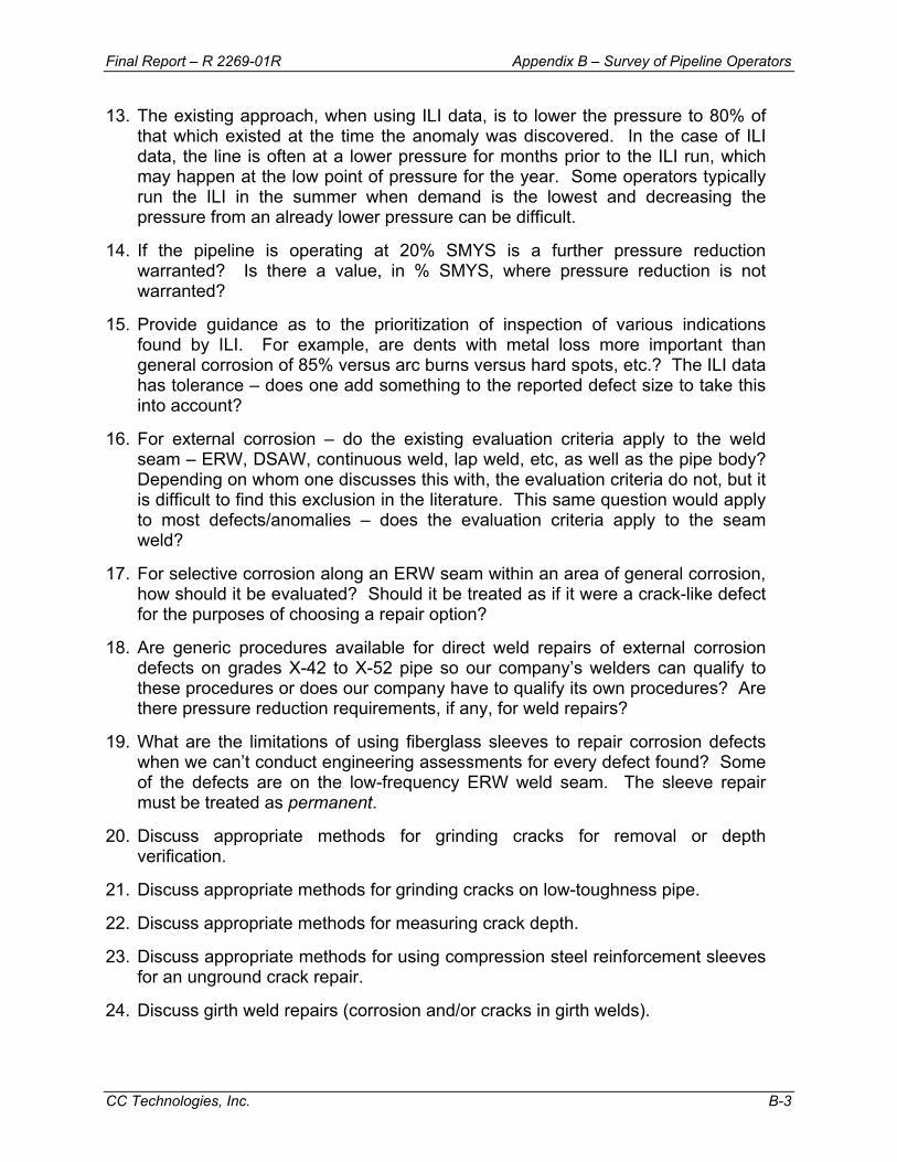
Final Report – R 2269-01R Appendix B – Survey of Pipeline Operators
CC Technologies, Inc. B-3
13. The existing approach, when using ILI data, is to lower the pressure to 80% of that which existed at the time the anomaly was discovered. In the case of ILI data, the line is often at a lower pressure for months prior to the ILI run, which may happen at the low point of pressure for the year. Some operators typically run the ILI in the summer when demand is the lowest and decreasing the pressure from an already lower pressure can be difficult.
14. If the pipeline is operating at 20% SMYS is a further pressure reduction warranted? Is there a value, in % SMYS, where pressure reduction is not warranted?
15. Provide guidance as to the prioritization of inspection of various indications found by ILI. For example, are dents with metal loss more important than general corrosion of 85% versus arc burns versus hard spots, etc.? The ILI data has tolerance – does one add something to the reported defect size to take this into account?
16. For external corrosion – do the existing evaluation criteria apply to the weld seam – ERW, DSAW, continuous weld, lap weld, etc, as well as the pipe body? Depending on whom one discusses this with, the evaluation criteria do not, but it is difficult to find this exclusion in the literature. This same question would apply to most defects/anomalies – does the evaluation criteria apply to the seam weld?
17. For selective corrosion along an ERW seam within an area of general corrosion, how should it be evaluated? Should it be treated as if it were a crack-like defect for the purposes of choosing a repair option?
18. Are generic procedures available for direct weld repairs of external corrosion defects on grades X-42 to X-52 pipe so our company’s welders can qualify to these procedures or does our company have to qualify its own procedures? Are there pressure reduction requirements, if any, for weld repairs?
19. What are the limitations of using fiberglass sleeves to repair corrosion defects when we can’t conduct engineering assessments for every defect found? Some of the defects are on the low-frequency ERW weld seam. The sleeve repair must be treated as permanent.
20. Discuss appropriate methods for grinding cracks for removal or depth verification.
21. Discuss appropriate methods for grinding cracks on low-toughness pipe.
22. Discuss appropriate methods for measuring crack depth.
23. Discuss appropriate methods for using compression steel reinforcement sleeves for an unground crack repair.
24. Discuss girth weld repairs (corrosion and/or cracks in girth welds).
Final Report – R 2269-01R Appendix B – Survey of Pipeline Operators
CC Technologies, Inc. B-4
25. Discuss how to determine when to stop sleeving areas of corrosion (deep areas are covered, but there is more general corrosion).
26. During recent inspections, we have uncovered repairs (patches and soles welded in the late 60’s and early 70’s) and seen distortion in the pipe in some of those areas, probably from the welding. Can the area be repaired using another technique or should the pipe be replaced?
APPENDIX – C
GUIDELINES FOR A REPAIR PROCEDURE
XYZ PIPELINE COMPANY PIPELINE REPAIR PROCEDURES
NO. XXX
Prepared By
Name of Author Date
Author Signature:
Approvals:
i
CONTENTS
1.0 – SCOPE............................................................................................................... C-1
2.0 – POLICY .............................................................................................................. C-1
3.0 – DEFINITIONS..................................................................................................... C-2
4.0 – ACCEPTABLE REPAIR METHODS .................................................................. C-5 4.1 – Permanent Repairs of Nonleaking Defects or Damage – Onshore ............... C-5 4.2 – Permanent Repairs of Leaks – Onshore ....................................................... C-5 4.3 – Permanent Repairs – Offshore...................................................................... C-5 4.4 – Temporary Repairs – Onshore ...................................................................... C-6
5.0 – APPLICATION OF REPAIR METHODS ............................................................ C-6 5.1 – Removal of the Defective, Damaged, or Leaking Pipe.................................. C-6 5.2 – Repair by Grinding ........................................................................................ C-7 5.3 – Repair by Deposited Weld Metal................................................................... C-9 5.4 – Repair by Use of Type A Sleeve ................................................................. C-10
5.4.1 – Materials ............................................................................................. C-10 5.4.2 – Sleeve Length..................................................................................... C-11 5.4.3 – Accommodating Pipe Seam-Weld Reinforcement.............................. C-11 5.4.4 – Repair Pressure Level ........................................................................ C-11 5.4.5 – Installation Procedure......................................................................... C-12 5.4.6 – Fabrication of Side Seams.................................................................. C-12
5.5 – Repair by Use of a Compression Sleeve .................................................... C-13 5.6 – Repair by Use of Type B Sleeve ................................................................. C-13
5.6.1 – Design and Materials .......................................................................... C-14 5.6.2 – Sleeve Length..................................................................................... C-15 5.6.3 – Accommodating Pipe Seam-Weld Reinforcement.............................. C-15 5.6.4 – Repair Pressure Level ........................................................................ C-15 5.6.5 – Installation Procedure......................................................................... C-16 5.6.6 – Fabrication of Side Seams and Fillet Welding of the Ends ................. C-17 5.6.7 – Special Configurations........................................................................ C-18 5.6.8 – Temporary Repair of Defects in Bondlines of ERW Seams................ C-18
5.7 – Repair by Use of Composite Sleeve ........................................................... C-19 5.7.1 – Testing and Qualification .................................................................... C-19 5.7.2 – Design ................................................................................................ C-19 5.7.3 – General Handling and Installation Requirements ............................... C-20 5.7.4 – Reinforcement Length ........................................................................ C-20 5.7.5 – Accommodating Pipe Seam-Weld Reinforcement.............................. C-20 5.7.7 – Return to Operating Pressure............................................................. C-20 5.7.8 – Records .............................................................................................. C-21
5.8 – Repair by Hot Tapping ................................................................................ C-21 5.9 – Repair by Mechanical Clamping ................................................................. C-21
ii
6.0 – INSPECTION AND DOCUMENTATION .......................................................... C-22 6.1 – Prior to Repair............................................................................................. C-22 6.2 – After Repair................................................................................................. C-22
7.0 – RECOATING AND BACKFILLING ................................................................... C-23 7.1 – Surface Preparation .................................................................................... C-23 7.2 – Material Application..................................................................................... C-23 7.3 – Curing ......................................................................................................... C-23 7.4 – Approved Coating Materials........................................................................ C-23 7.5 – Special Procedure for Type A Sleeve ......................................................... C-24

iii
FORM FORM 1 – Documentation of Anomaly and Repair ................................................... C-24
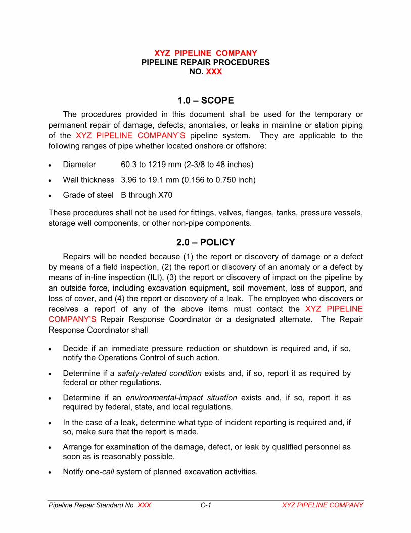
Pipeline Repair Standard No. XXX C-1 XYZ PIPELINE COMPANY
XYZ PIPELINE COMPANY PIPELINE REPAIR PROCEDURES
NO. XXX
1.0 – SCOPE The procedures provided in this document shall be used for the temporary or
permanent repair of damage, defects, anomalies, or leaks in mainline or station piping of the XYZ PIPELINE COMPANY’S pipeline system. They are applicable to the following ranges of pipe whether located onshore or offshore:
• Diameter 60.3 to 1219 mm (2-3/8 to 48 inches)
• Wall thickness 3.96 to 19.1 mm (0.156 to 0.750 inch)
• Grade of steel B through X70
These procedures shall not be used for fittings, valves, flanges, tanks, pressure vessels, storage well components, or other non-pipe components.
2.0 – POLICY Repairs will be needed because (1) the report or discovery of damage or a defect
by means of a field inspection, (2) the report or discovery of an anomaly or a defect by means of in-line inspection (ILI), (3) the report or discovery of impact on the pipeline by an outside force, including excavation equipment, soil movement, loss of support, and loss of cover, and (4) the report or discovery of a leak. The employee who discovers or receives a report of any of the above items must contact the XYZ PIPELINE COMPANY’S Repair Response Coordinator or a designated alternate. The Repair Response Coordinator shall
• Decide if an immediate pressure reduction or shutdown is required and, if so, notify the Operations Control of such action.
• Determine if a safety-related condition exists and, if so, report it as required by federal or other regulations.
• Determine if an environmental-impact situation exists and, if so, report it as required by federal, state, and local regulations.
• In the case of a leak, determine what type of incident reporting is required and, if so, make sure that the report is made.
• Arrange for examination of the damage, defect, or leak by qualified personnel as soon as is reasonably possible.
• Notify one-call system of planned excavation activities.
Pipeline Repair Standard No. XXX C-2 XYZ PIPELINE COMPANY
• Make sure that any needed pressure reduction is made before the damage, defect, or leak is examined.
• Review the information collected by the examination team and determine the appropriate repair response.
• If needed, arrange for further pressure reduction or shutdown prior to performing the repair.
• Authorize the appropriate repair.
• Verify completion and inspection of the repair and re-coating and backfilling of the pipeline.
• Review reports of defect characterization, repair configuration and location, coating and backfilling for accuracy and conformance to these procedures.
• Make sure that the above reports are distributed to appropriate XYZ PIPELINE COMPANY personnel and jurisdictional representatives, filed in XYZ PIPELINE COMPANY'S permanent records, and integrated into XYZ PIPELINE COMPANY'S pipeline integrity management system.
The primary concern of these procedures is safety. Safety includes but is not necessarily limited to preserving the remaining integrity of the damaged, defective, or leaking pipeline segment so that no harm comes to persons or property until a permanent or adequate temporary remedy is implemented. If a pressure reduction or shutdown of the system is judged to be necessary to assure preservation of the remaining integrity of the pipeline segment, then the pressure reduction or shutdown shall be implemented. Furthermore, qualified personnel shall, in the manner prescribed in this standard, carry out the examination of the damage, defect, or leak such that no harm comes to persons and that damage to the environment is minimized.
3.0 – DEFINITIONS1 Actual Wall Thickness, ta. The representative value of pipe wall thickness,
unaffected by any anomaly, which is measured for a particular sample of pipe.
Anomaly. An imperfection, a defect (including metal loss or a crack), or an area of damage that may impair the pipeline integrity in terms of its capacity to withstand internal pressure or resist other stresses imposed on it.
Buckle. A full or partial collapse of the pipe wall caused by bending or compressive axial loading of the pipeline.
Bulge. A local outward change in surface contour that is not accompanied by metal loss. 1 Local codes should be consulted for the proper use of these terms with regards to pipeline repairs.

Pipeline Repair Standard No. XXX C-3 XYZ PIPELINE COMPANY
Crack. A stress-induced separation of the steel that, without any other influence, is not large enough to cause complete rupture of the material. Cracks are of concern because they may grow by fatigue or stress corrosion until they reach a critical size that result in material rupture.
Damage. Pipeline damage includes dents, bulges, wrinkles, buckles, gouges, scratches, combinations of these, or loss of pipeline support, and unplanned change in pipeline alignment, or loss of cover.
Defect. An anomaly, other than external corrosion-caused metal loss, that (1) exists either in an electric-resistance-welded (ERW) or flash-welded seam or cannot be removed by grinding to a depth less than 12.5% of the nominal wall thickness or (2) corrosion metal loss where the minimum remaining wall thickness is less than 90% of the nominal wall thickness. A defect must be evaluated with respect to its effect on the integrity of the pipeline; the defect will require remedial action if its effect is found to be significant.
Dent. A local inward change in surface contour caused by mechanical impact, but not accompanied by metal loss. A dent with a stress concentrator may pose a serious threat to the integrity of the pipeline. Double dents consist of two dents that overlap along the axis of the pipe, creating a central area of reverse curvature in the longitudinal direction. Fatigue cracks are prone to develop in the saddle region between two the two dents and are likely to grow to critical sizes more quickly than fatigue cracks at single dents.
Discovery Pressure, Pd. The pressure existing at the location of an anomaly at the time it is discovered or reported.
Gouge. Elongated grooves or cavities in the pipe wall caused by mechanical removal of metal. Gouges can be recognized by the sharpness of their edges. Gouges may pose a serious threat to the integrity of the pipeline.
Groove. A long narrow channel or depression in the metal surface. Grooves are of concern because they are stress concentrators and can be especially detrimental if their long axis is oriented perpendicular to the direction of maximum stress.
Historical Pressure, Ph. A pressure greater than the discovery pressure that is known to have existed at the anomaly location after the anomaly was present in its current state. For a gas pipeline, no pressure may be considered a historical value if it occurred more than 1 year (365 days) before the discovery of the anomaly. For a liquid pipeline, no pressure may be considered a historical value if it occurred more than 60 days before the discovery of the anomaly. A previous hydrostatic test pressure can be used as a historical pressure if it meets the time requirements.

Pipeline Repair Standard No. XXX C-4 XYZ PIPELINE COMPANY
Imperfection. An anomaly, other than corrosion-caused metal loss, that is not in an electric-resistance-welded (ERW) or flash-welded seam that can be eliminated by grinding to a depth not exceeding 12.5% of the nominal wall thickness of the pipe or corrosion-caused metal loss where the minimum remaining wall thickness is at least 90% of the nominal wall thickness. An imperfection requires no repair other than grinding to remove any stress concentrator.
Metallurgical Anomaly. An area of metal, excluding (1) intentionally deposited filler metal or factory fabricated seams and their associated normal heat-affected zones, (2) metal affected by induction bending, and (3) areas where cathodic protection (CP) leads are attached, in which the microstructure has been altered from that of the parent metal by local contact deformation or where the parent metal has been transformed by local heating and cooling.
Minimum Allowable Wall Thickness, tm. The nominal wall thickness minus the under thickness tolerance of the relevant pipe specification.
Minimum Remaining Wall Thickness, tr. The minimum wall thickness that exists at the bottom of an anomaly after any stress concentrator or metallurgical anomaly has been removed by grinding.
Minimum Sleeve Wall Thickness, ts. The minimum wall thickness for a sleeve to conform to the requirements of these procedures.
Maximum Operating Pressure, MOP. The maximum steady state pressure permitted by the pipeline design criteria, the governing jurisdictional regulations, or XYZ PIPELINE COMPANY'S operating procedure, whichever is the lowest value.
Nominal Wall Thickness, tn. The pipe wall thickness specified by the pipeline design criteria.
Notch. A V-shaped or U-shaped indentation or discontinuity in the metal surface. Notches are of concern because they are stress concentrators.
Permanent Repair. A repair that is expected to last for the life of the pipeline.
Repair Pressure, Pr. The pressure at the anomaly location at the time the repair is performed.
Scratch. A small linear mark in the metal surface caused by scraping a sharp object along the pipe surface.
Stress Concentrator. A crack, gouge, scratch, notch, or groove that will appreciably increase the local intensity of any stress applied to the pipeline.

Pipeline Repair Standard No. XXX C-5 XYZ PIPELINE COMPANY
Temporary Repair. A repair that is to be replaced by a permanent repair within a two-year period.
Wrinkle. Transverse surface irregularities normally found in the crotch of a pipe bend. Wrinkles can typically be recognized as ripples on the inside of a bend.
4.0 – ACCEPTABLE REPAIR METHODS The acceptable repair methods for the XYZ PIPELINE COMPANY’S pipeline are
divided into four categories: (1) permanent repairs of onshore nonleaking defects or damage, (2) permanent repairs of onshore leaks, (3) permanent offshore repairs, and (4) temporary onshore repairs.
4.1 – Permanent Repairs of Nonleaking Defects or Damage – Onshore • Cut-out and removal of old pipe followed replacement with new pipe
• Removal of the defect by grinding
• Replacement of external corrosion-caused metal loss by weld metal deposition
• Application of a Type A sleeve
• Application of a compression sleeve
• Application of a composite sleeve
• Hot tapping
4.2 – Permanent Repairs of Leaks – Onshore • Cut-out and removal of old pipe followed replacement with new pipe
• Application of a Type B sleeve
• Hot tapping
4.3 – Permanent Repairs – Offshore • Cut-out and removal of old pipe followed replacement with new pipe
• Special purpose devices
Note 1: If the affected area of the pipeline is not leaking and can be raised above the water, repair by grinding, deposited weld metal (if appropriate), or by a Type B sleeve is permitted.
Note 2: Temporary repairs shall not be used offshore or in any other submerged location.

Pipeline Repair Standard No. XXX C-6 XYZ PIPELINE COMPANY
4.4 – Temporary Repairs – Onshore • Bolt-on clamp
• Leak clamp
• Type A sleeve for internal corrosion
• Composite sleeve for internal corrosion
• Type B sleeve for defects in the bondlines of ERW or flash-welded seams
5.0 – APPLICATION OF REPAIR METHODS The application of each of the acceptable repair methods is covered in this section.
5.1 – Removal of the Defective, Damaged, or Leaking Pipe Repair by removal is permitted for any type of damage, defect, or leak. Repair by
this method shall not begin until the Repair Response Coordinator assures that the pipeline has been depressurized and purged or drained in the case of a liquid product. Prior to cutting into the pipeline, a 25-mm (1-inch) Thread-O-Ring™ fitting shall be welded onto the cylinder of the pipe to be replaced. A hot-tapping valve and cutter shall be attached to the fitting and used to penetrate the pipe wall to assure that the pipeline is indeed safe for removal.
A cylinder of pipe at least long enough to extend 102 mm (4 inches) beyond the ends of the defective, damaged, or leaking area but in no case less than three pipeline diameters long shall be removed. The replacement cylinder of pipe shall be of a wall thickness greater than or equal to that of the existing pipe and shall be of the same grade of material as the existing pipe. If the wall thickness of the replacement pipe exceeds that of the existing pipe by more than 2.4 mm (3/32 inch), the ends of the segment of replacement pipe shall be machined or back-beveled on a 4-to-1 slope to the same wall thickness as the existing pipe.
The replacement pipe shall have been pre-tested to a minimum pressure level of 1.25 times the MOP of the pipeline. If the replacement pipe is within a high-consequence area (HCA) or an unusually sensitive area (USA), the minimum pre-test pressure level shall be 1.5 times the MOP of the pipeline. The replacement cylinder shall be welded into the pipeline by tie-in girth welds, and the welds shall be 100% inspected by means of radiography or shear-wave ultrasonics to assure that they meet the workmanship requirements of API Standard 1104.
If the target defect is a manufacturing defect in the bondline or heat-affected zone (HAZ) of an ERW seam, the entire joint of pipe including the girth welds at either end shall be removed and replaced. Removal is the only type of permanent repair permitted
Pipeline Repair Standard No. XXX C-7 XYZ PIPELINE COMPANY
for such defects. (See Section 5.5.8 for temporary repair of such defects by use of Type B sleeves.)
If the pipeline to be repaired by removal of a cylinder of pipe is located offshore or in another type of submerged area, the repair shall be made by raising the affected portion of the pipeline above the water or underwater by means of special-purpose devices. If the pipeline is to be raised above the water, the Repair Response Coordinator shall order the conduction of an appropriate stress and lifting analysis to assure that the pipeline is not damaged or buckled as the result of lifting and lowering after the repair. The analysis shall account for the weight of the water or other liquid in the pipeline if the pipeline is to be lifted while filled with water or liquid. The analytical requirements shall apply to cases where the repair of the lifted pipeline is to consist of grinding, repair by weld metal deposition, or the application of a Type B sleeve. For these latter types of repairs, it is not necessary to take the pipeline completely out of service. However, the repair response pressure, Pr, shall not exceed the lower of the levels dictated by
• 80% of the historical pressure, Ph
• The level dictated by the established limit on the total longitudinal stress determined in the lifting analysis
5.2 – Repair by Grinding Except for internal defects and defects in the bondlines of ERW or flash-welded
line-pipe materials, grinding may be used to repair non-leaking defects as specified below. Grinding may be used in the repair of girth welds at a pressure equal to or less than 80% of Ph but only to a depth such that tr is at least 3.18 mm (0.125 inch) and only if the resulting groove is filled by a repair weld.
Grinding as the sole means of repair may be applied to any imperfection. An imperfection is considered to have been repaired in this manner if no trace of it remains after grinding to a depth not greater than 12.5% of tn. If any evidence of the anomaly (as determined through nondestructive inspection) remains after grinding to a depth of 12.5% of tn, the anomaly shall be reclassified as a defect. Further attempts to repair the defect by grinding shall be made only if the repair pressure, Pr, is less than or equal to 80% of Ph.
Grinding may used as the sole means of repair of any nonleaking defect provided that
• The repair pressure, Pr, is less than or equal to 80% of Ph during the repair process.
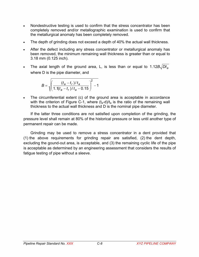
Pipeline Repair Standard No. XXX C-8 XYZ PIPELINE COMPANY
• Nondestructive testing is used to confirm that the stress concentrator has been completely removed and/or metallographic examination is used to confirm that the metallurgical anomaly has been completely removed.
• The depth of grinding does not exceed a depth of 40% the actual wall thickness.
• After the defect including any stress concentrator or metallurgical anomaly has been removed, the minimum remaining wall thickness is greater than or equal to 3.18 mm (0.125 inch).
• The axial length of the ground area, L, is less than or equal to aDtB12.1 where D is the pipe diameter, and
115.0/)(1.1
/)( 2
−
−−
−=
ara
arattt
tttB
• The circumferential extent (c) of the ground area is acceptable in accordance with the criterion of Figure C-1, where (ta-d)/ta is the ratio of the remaining wall thickness to the actual wall thickness and D is the nominal pipe diameter.
If the latter three conditions are not satisfied upon completion of the grinding, the pressure level shall remain at 80% of the historical pressure or less until another type of permanent repair can be made.
Grinding may be used to remove a stress concentrator in a dent provided that (1) the above requirements for grinding repair are satisfied, (2) the dent depth, excluding the gound-out area, is acceptable, and (3) the remaining cyclic life of the pipe is acceptable as determined by an engineering assessment that considers the results of fatigue testing of pipe without a sleeve.

Pipeline Repair Standard No. XXX C-9 XYZ PIPELINE COMPANY
0
0.1
0.2
0.3
0.4
0.5
0.6
0.7
0.8
0.9
1
0 1 2 3
Figure 5-7 of API RP 579(t
a -
d)/t a
c/D
ACCEPTABLE
UNACCEPTABLE
Figure C-1. Acceptance criterion for circumferential extent of metal-loss defect.
5.3 – Repair by Deposited Weld Metal Where permitted by codes and regulations, weld-metal deposition may be used to
repair metal-loss damage caused by corrosion on in-service pipelines. The minimum remaining wall thickness on which such a repair shall be attempted is 3.18 mm (1.25 inch). Only those portions of the corrosion damage that do not meet the ASME B31G or RSTRENG criterion, whichever is used, should be repaired. Welding procedure development tests shall be conducted as outlined in Welding Procedure Specification RW-1 prior to making deposited weld-metal repairs.
Prior to welding, all corroded areas to be repaired shall be cleaned to bare metal and, if necessary, ground to an appropriate profile for welding. The area should be free from oxide, scale, coating, moisture, and other contamination. The remaining wall thickness shall be verified by subtracting the maximum depth of the corroded area (measured using established techniques) from the uncorroded wall thickness or the remaining wall thickness shall be measured using an ultrasonic thickness gage.
The first layer of weld metal on a 3.18-mm (0.125-inch) thick area shall be deposited with a 2.4-mm (3/32-inch) diameter or less electrode, and the heat input shall not exceed 0.59 kJ/mm (15 kJ/inch). Consumables for deposited weld-metal repairs shall be restricted to E7018 (low-hydrogen) SMAW electrodes.

Pipeline Repair Standard No. XXX C-10 XYZ PIPELINE COMPANY
A temper-bead deposition sequence should be used to minimize HAZ hardness levels. Combined with the use of good low-hydrogen practice this process minimizes the risk of hydrogen cracking. An initial perimeter pass shall be used; it defines the boundary beyond which no subsequent pass is allowed. A second perimeter pass, following completion of the entire first layer, shall be used to temper the HAZ at the toe of the first perimeter pass.
The fill passes of both layers should be deposited using stringer beads in a parallel, consecutive, or buttering layer manner. During deposition of the buttering layers, the electrode should be aimed at the toe of the previous pass, resulting in a bead overlap of approximately 50%. Grinding between layers should be performed only to remove layer height irregularities (i.e., a half-bead technique is not required).
Multiple layer repairs are necessary only for corrosion depths of 3.18 mm (0.125 inch) or greater. Corrosion depths less than 3.18 mm (0.125 inch) may be filled using a single layer and bead overlap can be adjusted to ensure proper filling. Heat-input levels higher than 0.59 kJ/mm (15 kJ/inch) may be used for remaining wall thicknesses greater than 3.18 mm (0.125 inch) for the second layer of a multiple layer repair. The Battelle computer model should be used to predict heat-input limits in these instances.
The repair may be either ground flush to facilitate effective recoating of the pipe or the weld reinforcement may be left in place. The repair should be inspected as outlined in NDT Standard ZZZ using magnetic particle inspection (MPI) prior to returning the pipeline to normal service.
5.4 – Repair by Use of Type A Sleeve Except for defects in girth welds, internal corrosion, and defects in the bondline of
ERW seams, a Type A sleeve may be used to permanently repair nonleaking defects as specified below. A Type A sleeve also may be used as a temporary repair for internal corrosion defects. A Type A sleeve may not be used if the minimum remaining wall thickness is less than 20% of ta. The Type A sleeve shall be fabricated and applied as follows.
5.4.1 – Materials The sleeve halves shall be fabricated from a piece of steel plate of the same or
greater thickness than the carrier pipe that is obtained from an approved vendor. The specified minimum yield strength (SMYS) of the sleeve material, if made from pipe, shall be the same as that of the carrier pipe. If the sleeve material is obtained from a vendor, its SMYS shall be at least 248 MPa (36 ksi) if the carrier pipe is Grade B or at least 345 MPa (50 ksi) if the carrier pipe is Grade X42 through Grade X52. If the grade of the carrier pipe is greater than X52, the grade of the sleeve material shall be at least equal to the grade of the carrier pipe or 345 MPa (50 ksi) SMYS sleeve material obtained from

Pipeline Repair Standard No. XXX C-11 XYZ PIPELINE COMPANY
a vendor may be used provided that the sleeve thickness exceeds that of the carrier pipe by an amount that would give it the same pressure rating as the carrier pipe. Where doubler bars are to be used to join the sleeve halves, the bars shall be of the same material as the sleeve.
5.4.2 – Sleeve Length The length of the sleeve shall be at least 102 mm (4 inches), and the sleeve shall
also be long enough to extend at least 51 mm (2 inches) beyond both ends of the defect. While there is no upper limit on sleeve length, the Repair Response Coordinator shall consider the practical implications of sleeve length, including weight, snugness of fit, influence (if any) of carrier pipe curvature, influence of girth weld reinforcement or any high-low condition on the pipe surface, and the ability of the repair crew to install the sleeve effectively.
When required, two or more sleeves shall be butted and joined by welding. In this case, sleeves shall be joined by a circumferential groove butt weld, with weld preparation and joint designed the same as the longitudinal welds used to join the sleeve halves. In the event this is not possible, the Repair Response Coordinator shall approve other options for installing the sleeves.
5.4.3 – Accommodating Pipe Seam-Weld Reinforcement To facilitate snugness of fit of the sleeve, the longitudinal seam-weld reinforcement
of the carrier pipe, if any, may be accommodated by one of the following actions:
• Removal of the reinforcement by grinding after a pressure reduction to a level not exceeding 80% of Ph
• Grinding an accommodating groove in the sleeve
• Locating the gap between the sleeve halves over the seam when the overlapping fillet-welded doubler bar method is used to join the sleeve halves
• Filling all voids in the area where the sleeve bridges the seam-weld reinforcement with epoxy or polyester filler material
5.4.4 – Repair Pressure Level The pressure level, Pr, during application of a Type A sleeve shall not exceed
• 80% of Ph if hardenable filler (epoxy or polyester) is used to fill the annular space between the sleeve and the defective area of the carrier pipe
• 67% of Ph if no filler is used
• 90% of Ph if filler is used and the chain-clamp method is used to install the sleeve as described in Section 5.4.5.
Pipeline Repair Standard No. XXX C-12 XYZ PIPELINE COMPANY
5.4.5 – Installation Procedure The entire circumference of the carrier pipe in the area to be covered by the Type A
sleeve shall be cleaned to bare metal. Care shall be taken to be sure that the sleeved area and the sleeve are long enough to extend at least 51 mm (2 inches) beyond both ends of the defect. A coating of mastic material paint shall be applied to the two 51-mm (2-inch) wide bands on the carrier pipe where the ends of the sleeve will be located to assist in sealing the ends against water penetration. If hardenable filler is used, it shall be trowelled onto any indentations, pits, voids, or depressions. If overlapping doubler bars are to be used to join the halves of the sleeve, these shall be prewelded or tack welded to one half of the sleeve. With the pressure at Pr and before the filler sets up, the sleeve halves shall be place around the pipe in a manner that centers one of the halves over the center of the worst area of the defect. The sleeve placement shall be the same even if filler is not used.
While the sleeves are being held temporarily in place and before the filler sets up, at least one chain for each 0.91-m (3-foot) length of sleeve shall be wrapped loosely around the sleeve halves. One 100 x 100-mm (4 × 4-inch) wooden skid shall be inserted between each sleeve half and the chain and it shall be centered on the sleeve half. One 90-kN (10-ton) hydraulic jack per chain shall be placed between the chain and one of the wooden skids. Each chain shall be drawn tight by means of the jacks until the sleeve halves fit as snugly as possible. The jacks shall be used to maintain tightness as needed until the welding of the longitudinal seams has been completed to an extent that precludes the need for the jacks and chains. Make sure that the cathodic protection (CP) system is connected to the sleeve before starting any welding. The jack-and-chain method or the chain-clamp method shall be used as described above to attach any Type A sleeve whether or not filler material is used.
5.4.6 – Fabrication of Side Seams If the overlapping doubler-bar method is used, the bars shall be at least as strong
and as thick as the sleeve material and shall be first joined at least by tack welds to one of the sleeve halves. Alternatively, the use of sleeves with preformed overlaps is permitted. Doubler bars shall be attached to the sleeve halves along both edges by means of fillet welds. The fillet weld leg lengths shall be equal to the thickness of the sleeve within ±10% of ts. The welding shall conform to the requirements of Welding Procedure Specification RW-1. If single vee butt-welded side seams are used, the fabrication shall be done in accordance with the procedures of Section 5.6.6 of this standard, and the welding shall conform to the requirements of Welding Procedure Specification RW-1
Pipeline Repair Standard No. XXX C-13 XYZ PIPELINE COMPANY
5.5 – Repair by Use of a Compression Sleeve Except for girth-weld defects and internal corrosion, a compression sleeve may be
used to permanently repair nonleaking defects, including defects in bondlines of ERW or flash-welded seams, as specified below. A compression sleeve also may be used as a temporary repair for internal corrosion defects. A compression sleeve may not be used if the minimum remaining wall thickness is less than 20% of ta.
A steel compression sleeve is a special Type A sleeve that is installed so that the carrier pipe remains in compression when the pipeline operates at pressures up to MOP. Installation of a compression sleeve requires good quality control and trained personnel. A compression sleeve shall be installed only by the sleeve manufacturer’s trained personnel or by personnel who have properly trained and qualified by the sleeve manufacturer.
The compression in the carrier pipe is achieved by a combination of pressure reduction during installation and heating the sleeve until welding is completed, which permits it to thermally shrink and compress the carrier pipe upon cooling. The Repair Response Coordinator shall consult with the manufacturer to obtain the appropriate sleeve design and installation parameters prior to installing a compression sleeve. The following steps shall be followed during sleeve installation:
• Clean the outside surface of the carrier pipe to bare metal in the same manner as used to prepare for installation of a conventional Type A sleeve.
• Trial fit the sleeve around the carrier pipe, and mark its end locations.
• Apply the epoxy around the pipe between the sleeve markings.
• Lift the top of the sleeve onto the pipe.
• Lift the bottom of the sleeve onto the pipe.
• Place three chains over the sleeve and tighten them to the prescribed load.
• Heat the sleeve to the predetermined temperature.
• Complete the field fillet welds.
• Allow the sleeve to cool.
• Check the quality of installation using caliper measurements.
5.6 – Repair by Use of Type B Sleeve Except for defects in the bondlines of ERW seam or flash-welded seam materials, a
Type B sleeve may be used to permanently repair defects, damage, or leaks as specified below. A Type B sleeve may be used to temporarily repair defects in the bondlines ERW seam or flash-welded seam materials as specified in Section 5.6.8.
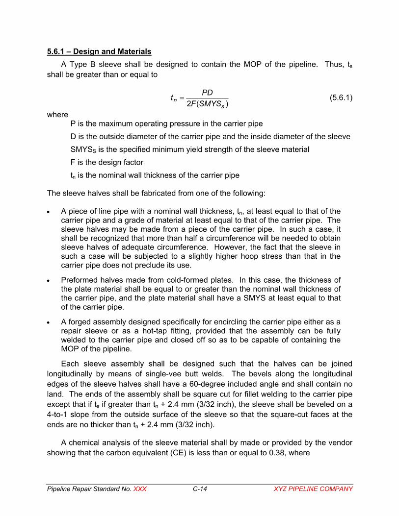
Pipeline Repair Standard No. XXX C-14 XYZ PIPELINE COMPANY
5.6.1 – Design and Materials A Type B sleeve shall be designed to contain the MOP of the pipeline. Thus, ts
shall be greater than or equal to
)(2 s
n SMYSFPDt = (5.6.1)
where P is the maximum operating pressure in the carrier pipe D is the outside diameter of the carrier pipe and the inside diameter of the sleeve SMYSS is the specified minimum yield strength of the sleeve material F is the design factor tn is the nominal wall thickness of the carrier pipe
The sleeve halves shall be fabricated from one of the following: • A piece of line pipe with a nominal wall thickness, tn, at least equal to that of the
carrier pipe and a grade of material at least equal to that of the carrier pipe. The sleeve halves may be made from a piece of the carrier pipe. In such a case, it shall be recognized that more than half a circumference will be needed to obtain sleeve halves of adequate circumference. However, the fact that the sleeve in such a case will be subjected to a slightly higher hoop stress than that in the carrier pipe does not preclude its use.
• Preformed halves made from cold-formed plates. In this case, the thickness of the plate material shall be equal to or greater than the nominal wall thickness of the carrier pipe, and the plate material shall have a SMYS at least equal to that of the carrier pipe.
• A forged assembly designed specifically for encircling the carrier pipe either as a repair sleeve or as a hot-tap fitting, provided that the assembly can be fully welded to the carrier pipe and closed off so as to be capable of containing the MOP of the pipeline.
Each sleeve assembly shall be designed such that the halves can be joined longitudinally by means of single-vee butt welds. The bevels along the longitudinal edges of the sleeve halves shall have a 60-degree included angle and shall contain no land. The ends of the assembly shall be square cut for fillet welding to the carrier pipe except that if ts if greater than tn + 2.4 mm (3/32 inch), the sleeve shall be beveled on a 4-to-1 slope from the outside surface of the sleeve so that the square-cut faces at the ends are no thicker than tn + 2.4 mm (3/32 inch).
A chemical analysis of the sleeve material shall by made or provided by the vendor showing that the carbon equivalent (CE) is less than or equal to 0.38, where
Pipeline Repair Standard No. XXX C-15 XYZ PIPELINE COMPANY
5156
VMoCrNiCuMnCCE +++
+++= (5.6.2)
Equation (5.6.2) is from Appendix B of API Standard 1104. 5.6.2 – Sleeve Length
The length of the sleeve shall be at least 102 mm (4 inches), and the sleeve shall also be long enough to extend at least 51 mm (2 inches) beyond both ends of the defect. While there is no upper limit on sleeve length, the Repair Response Coordinator shall consider the practical implications of sleeve length, including weight, snugness of fit, influence (if any) of carrier pipe curvature, influence of girth-weld reinforcement or any high-low condition on the pipe surface, and the ability of the repair crew to install the sleeve effectively.
When required, two or more sleeves shall be butted and joined by welding. In this case, sleeves shall be joined by a circumferential groove butt weld, with weld preparation and joint designed the same as the longitudinal welds used to join the sleeve halves. In the event this is not possible, the Repair Response Coordinator shall consider other options for installing the sleeve.
5.6.3 – Accommodating Pipe Seam-Weld Reinforcement To facilitate snugness of fit of the sleeve, the longitudinal seam reinforcement of the
carrier pipe, if any, may be accommodated by one of the following actions:
• Removal of the reinforcement by grinding after a pressure reduction to a level not exceeding 80% of Ph
• Grinding an accommodating groove in the sleeve provided that the actual sleeve thickness, ts, is equal to tn + the depth of the accommodating groove.
5.6.4 – Repair Pressure Level For the repair of nonleaking defects or damage, the repair pressure level, Pr, during
the application of a Type B sleeve shall not exceed 80% of Ph. For the repair of a leaking defect, the repair pressure level during the application of a Type B sleeve shall not exceed the lower of
• 80% of Ph
• 30% of SMYS of the carrier pipe
• The pressure at which it is possible to safely contain the leaking fluid
Pipeline Repair Standard No. XXX C-16 XYZ PIPELINE COMPANY
5.6.5 – Installation Procedure The entire circumference of the carrier pipe in the area to be covered by the Type B
sleeve shall be cleaned to bare metal. Care shall be taken to be sure that the sleeved area and the sleeve are long enough to extend at least 51 mm (2 inches) beyond both ends of the defect. No two Type B sleeves shall be installed within one-half pipe diameter of one another. The sleeve halves shall be placed around the pipe in a manner that centers one of the halves over the center of the worst area of the defect. In the case of a leak, the sleeve placement shall be such that one of the halves is centered over the leak.
While the sleeves are being held temporarily in place, at least one chain for each 0.91-m (3-foot) length of sleeve shall be wrapped loosely around the sleeve halves. One 100 × 100-mm (4 × 4-inch) wooden skid shall be inserted between each sleeve half and the chain, and it shall be centered on the sleeve half if venting of a leak is not required. One 90-kN (10-ton) hydraulic jack per chain shall be placed between the chain and one of the wooden skids. If venting is required, the hydraulic jack shall be placed 180 degrees from the venting device. Each chain shall be drawn tight by means of the jacks until the sleeve halves fit as snugly as possible. The jacks shall be used to maintain tightness as needed until the welding of the longitudinal seams has been completed to an extent that precludes the need for the jacks and chains. Make sure that the cathodic protection (CP) system is connected to the sleeve before starting any welding. If venting of a leak is required, two 100 x 100-mm (4 x 4-inch) skids shall be placed one on each side of the venting device to separate the chain from the sleeve.
If the defect is a small leak in terms of both physical size and rate, it is permissible to install one of the sleeve halves over the leak with an attached neoprene cookie centered over the leaking area. If the leak can then be completely sealed by jacking the load, the repair operation can be continued to completion. If, however, the leak cannot be stopped in this manner, venting as described below shall be carried out.
First, the two sleeve halves are fit loosely around the pipeline next to but not over the leak. The halves are temporarily to be held loosely by chains and hydraulic jacks. The chains should be sufficiently slack that the sleeve halves can be slid over the top of the leak with ease. Two winches, one on each side, can be used to pull the sleeve halves against a stationary line-up clamp. Both sleeve halves must be equipped on both sides with temporary eyes for the winch chain hooks.
The sleeve half that is to fit over the leak must be equipped with a previously applied branch nipple and a firmly attached concentrically located donut-shaped neoprene gasket. This half of the sleeve must be lined up circumferentially so that the nipple will slide directly over the leak, and the pulling distance should be accurately measured so that the nipple will end up directly over the leak after pulling.
Pipeline Repair Standard No. XXX C-17 XYZ PIPELINE COMPANY
The sleeve shall be pulled into place with the vent nipple in position to vent the gas or product. Then, the circumferential chains shall be drawn tight with the hydraulic jacks so that the neoprene gasket is compressed enough to force all of the gas or product to go through the nipple. Vent piping shall be attached to conduct the gas or product away from the trench while the sleeve halves are being welded. The vent piping shall be supported sufficiently to resist the tendency of the thrust of the flowing gas or product to unscrew joints at elbows. The vent nipple itself must be a special 51-mm (2-inch) fitting such as a Thread-O-Ring™ Fitting, Weldolet, or Save-A-Valve. A full-opening valve shall be attached to this type of fitting. After the repair has been completed, a tapping machine shall be attached to the valve. The tapping machine shall be used to insert the internal plug into the fitting so that the valve can be removed. The fitting shall then be closed with a threaded cap.
5.6.6 – Fabrication of Side Seams and Fillet Welding of the Ends The fabrication of a Type B sleeve shall start with the welding of both side seams
and continue with the fillet welding of first one end and then the other end to the carrier pipe. The side seams shall be single-vee butt welds. Overlapping doubler bars shall not be used with Type B sleeves. There shall be no welding on the carrier pipe in an area where the wall thickness is less than that away from the defect. Welds shall be made in areas where the wall thickness is sufficient to preclude burnthrough.
Backing strips comprised of 1.52-mm-thick (16-gage) mild steel shall be used at the bases of the two vee-grooves between the sleeve halves to prevent penetration of the root bead into the carrier pipe. If a backing strip relief groove is present on the inside surface along each longitudinal edge of the sleeve half, the overall thickness of the sleeve, ts, shall be greater than or equal to the tn + the depth of the backing-strip relief groove.
With the sleeves being held in place by chains and jacks as described in Section 5.6.5, the gaps and fit-up of the sleeve shall be checked by visual inspection and by measurement. Neither gap between halves at the base of the vee-groove shall exceed 1.6 mm (1/16 inch). If the gaps exceed this amount, one side (or both sides) of one or both bevels shall be built up as needed by depositing butter passes of weld metal. If the gaps close and thereby prevent intimate contact between the sleeve and the carrier pipe, material shall be removed from one side (or both sides) of one or both bevels as needed to achieve intimate contact between the sleeve halves and the carrier pipe.
The gap between the sleeve and the carrier pipe shall not exceed 1.5 mm (0.06 inch). This gap shall be measured around both ends of the sleeve by means of a feeler gage. If at any point on either end a 1.5-mm (0.06-inch) feeler gage can be passed into the gap for a continuous 25 mm (1 inch) or more of the circumference, the sleeve shall be temporarily moved aside and weld metal buttering passes shall be made
Pipeline Repair Standard No. XXX C-18 XYZ PIPELINE COMPANY
on the carrier pipe to close the gap. The gap shall be rechecked before the sleeve is welded in place to make sure that it does not exceed 1.5-mm (0.06-inch).
The single-vee longitudinal welds shall be made one at a time or simultaneously by two welders in accordance with the procedures of Welding Procedure Specification RW-1. The end fillet welds shall be made one at a time by two welders, one on each side of the carrier pipe, in accordance with Welding Procedure Specification RW-1.
XYZ PIPELINE COMPANY or its approved contractor shall perform magnetic particle examination (MPI) of the welds prior to re-insulating the pipe. The acceptance criteria shall be per API Standard 1104.
5.6.7 – Special Configurations Defective, nonleaking girth welds may be repaired by means of a special Type B
humped sleeve. A humped sleeve shall be installed with the hump centered over the girth weld and in the same manner as the conventional Type B sleeve with two exceptions. First, because of the hump, two chain clamps rather than one are required to tighten the sleeve and hold it in place. A chain clamp must be placed on each side of the hump. Second, because sealing a leak is physically difficult with the humped configuration, it is not recommended for the repair of a leaking girth weld.
A mechanical coupling, wrinkle bend, bulge, or buckle may be repaired with a pumpkin configuration of a Type B sleeve. The pumpkin must be properly designed for the internal pressure of the pipeline taking into account its significantly larger diameter. The coupling, wrinkle bend, bulge, or buckle must fit within the enlarged annular space without interference and such that the side seams can be joined and the reduced ends can be fillet welded to the carrier pipe. One chain clamp arrangement shall be used on each of the two reduced ends to hold the pumpkin sleeve halves for welding. The pumpkin configuration may be used to repair a leaking coupling if the leaking gas or product can be adequately vented to a safe area. The use of a pumpkin to repair any other type of leak is prohibited. In all other respects, a pumpkin sleeve shall be installed in the same manner as a conventional Type B sleeve.
5.6.8 – Temporary Repair of Defects in Bondlines of ERW Seams A Type B sleeve may be used to temporarily repair a leaking or nonleaking defect in
an ERW or flash-welded seam. If the defect is leaking, no attempt shall be made to seal the leak. Instead, the gas or product shall be vented and a Type B sleeve shall be installed as described previously. If the defect is not leaking, a 50-mm (2-inch) Thread-O-Ring™ fitting shall by welded to the sleeve. Then, after the sleeve has been installed, inspected, and accepted, a tapping valve and tapping machine shall be installed on the fitting. The carrier pipe shall be tapped through to permit pressurization of the annular space.
Pipeline Repair Standard No. XXX C-19 XYZ PIPELINE COMPANY
5.7 – Repair by Use of Composite Sleeve Except for defects in girth welds, internal corrosion, and defects in the ERW seam
bondlines, a composite reinforcement repair sleeve may be used to permanently repair nonleaking defects as specified below. A composite reinforcement repair sleeve also may be used as a temporary repair for nonleaking internal corrosion defects. A composite reinforcement sleeve may not be used if tr is less than 20% of ta.
5.7.1 – Testing and Qualification The Repair Response Coordinator shall verify that the composite sleeve system has
been tested and qualified as follows:
• Standardized stress-rupture and creep tests have been conducted to verify the performance of the sleeve system on line pipe under the intended application, including both static and cyclic loading. The tests shall have been conducted over the range of applicable environments and temperatures, including maximum design temperature and fully saturated water conditions. The extrapolated results of the tests shall indicate satisfactory service performance for at least 50 years.
• Results of cathodic disbondment tests show that the sleeve system is compatible with XYZ PIPELINE COMPANY’S cathodic protection (CP) system.
• Immersion or exposure tests have been conducted to show that the components of the sleeve system are not affected by the product(s) carried in the pipeline.
5.7.2 – Design The Repair Response Coordinator shall verify that the composite sleeve system
satisfies the following design requirements:
• The combined nominal load-carrying capacity of the sleeve system and defective area of the pipe shall be equal to or greater than that of the original carrier pipe.
• An engineering assessment shall have been made using established procedures and principles to determine the required pipe-to-sleeve load transfer and the resultant maximum stress on the sleeve. This maximum stress shall not exceed that established from the results of the testing described in Section 5.7.1. The engineering assessment shall also have established a maximum Pr allowed during installation and curing of the sleeve system.
• The sleeve system shall have been designed to operate over the full range of operating pressures, service temperatures, and soil environments expected for the pipeline.
Pipeline Repair Standard No. XXX C-20 XYZ PIPELINE COMPANY
5.7.3 – General Handling and Installation Requirements The repair sleeve system shall be stored, handled, transported, and installed in
accordance with the manufacturer’s procedures and specifications. Sleeve installation personnel shall be fully trained and qualified for installation of the sleeve system either by the manufacturer or by personnel who have been fully trained and qualified by the manufacturer.
If required, a permanent in-line inspection (ILI) marker device shall be placed at the location of the installation so that the repair location can be clearly identified during any future ILI. The marker device shall be detectable by all tools that are anticipated to be used in future ILI.
5.7.4 – Reinforcement Length The composite reinforcement sleeve shall extend at least 50 mm (2 inches) beyond
each end of the defect. Multiple composite reinforcement sleeves may be installed adjacent to one another to satisfy this requirement. While there is no upper limit to the maximum number of composite reinforcement sleeves that may be installed, the Repair Response Coordinator shall consider the practical implications of the influence of girth weld reinforcement, carrier pipe curvature (if any), and the ability of the repair crew to install a large number of sleeves effectively.
5.7.5 – Accommodating Pipe Seam-Weld Reinforcement With respect to snugness of fit of the sleeve, the longitudinal seam reinforcement of
the carrier pipe, if any, may be accommodated by one of the following actions:
• Removal of the reinforcement by grinding after reducing the pressure to a level not exceeding 80% of Ph
• Filling all voids in the area where the sleeve bridges the seam-weld reinforcement with the manufacturer's approved defect filler compound.
5.7.6 – Repair Pressure Level The repair pressure level, Pr, during the application of a composite sleeve system
shall not exceed
• 80% of Ph for defects up to 40% of ta
• The manufacturer's recommended installation pressure for deeper defects
5.7.7 – Return to Operating Pressure Following installation of the composite sleeve system, the pipeline shall remain at Pr
for the manufacturer's recommended period (not less than 2 hours) to allow for cure of the adhesive.

Pipeline Repair Standard No. XXX C-21 XYZ PIPELINE COMPANY
5.7.8 – Records Upon completion of a defect repair, the following data shall be recorded and
retained in XYZ PIPELINE COMPANY’S files:
• Location on pipeline
• Defect dimensions: maximum axial length, maximum circumferential extent, and maximum depth, including the defect depth profile if such measurements are made
• Number of units installed
• Composite sleeve serial number(s)
• Adhesive lot number
• Date of installation
• Pipe temperature and internal pressure during installation
• Ambient temperature and weather conditions
• Staff performing installation
5.8 – Repair by Hot Tapping A non-indented defect, leaking or nonleaking, may be removed by hot tapping. This
method shall be used only if the defect will be entirely removed with the coupon upon hot tapping. The hot tap shall be made in accordance with XYZ PIPELINE COMPANY'S standard hot tapping procedure.
5.9 – Repair by Mechanical Clamping Any defect or leak in an offshore pipeline may be permanently repaired and any
defect or leak in an onshore pipeline may be temporarily repaired by means of a bolt-on mechanical clamp, provided that the length of the clamp is sufficient to extend beyond the ends of the defect so that the leak seals can be properly seated. The clamp must be of a design that is capable of containing the MOP of the carrier pipe.
An isolated leaking external corrosion pit may be temporarily repaired by means of a Smith+Clamp clamp. Prior to the installation of such a clamp, a determination of whether or not the leaking pit is isolated shall be made. Using the center of the pit as a reference point, the repair foreman shall measure an axial length of one-half the pipe's diameter in each direction. Other than the isolated pit itself, no portion of the pipe within this one-diameter region shall have a tr less than 20% of tn. No two such clamps shall be installed within one pipe diameter of each other.
Pipeline Repair Standard No. XXX C-22 XYZ PIPELINE COMPANY
6.0 – INSPECTION AND DOCUMENTATION Inspection and documentation are required both before and after repair.
6.1 – Prior to Repair After excavation and prior to application of the repair, the carrier pipe shall be
completely exposed and cleaned to bare metal to an extent necessary to reveal all of the anomaly or anomalies. The nature and extent of each anomaly shall be determined and documented. The actual wall thickness of the pipe, ta, shall be measured by means of an ultrasonic pulse-echo device, and the measured values shall be recorded. If extensive corrosion-caused metal loss has removed the original inner or outer surface over a large area, ta shall be determined at convenient locations by grinding flat areas away from the deepest pits. These flat spots of known wall thickness shall be used as reference points to document the amount of metal loss. The relevant data shall be recorded on Form 1.
Grinding shall be performed as necessary to characterize or repair a stress concentrator or arc burn. If grinding is expected to proceed to a depth greater than 12.5% of tn, such grinding shall not be performed until or unless Pr is less than or equal to 80% of Ph. Whether or not the stress concentrator has been removed shall be verified by means of magnetic particle inspection or dye penetrant inspection. All of the required characterization data shall be provided on the Form 1.
6.2 – After Repair After repair, appropriate inspections shall be performed. These include but are not
necessarily limited to the following:
• Where grinding is the sole means of repair, a check shall be made as described above to assure removal of the stress concentrator, the overall length, circumferential extent, and depth of the repair shall be recorded, and the values required on Form 1 shall be calculated.
• The area of an arc burn repaired by grinding shall be checked with a 10% ammonium persulfate solution or a 5% nital solution to assure that the entire metallurgical anomaly has been removed.
• All weldments shall be examined visually for workmanship and absence of obvious flaws.
• 100% inspection of all fillet welds at the ends of Type B sleeves shall be carried out in accordance with XYZ PIPELINE COMPANY'S NDT standard.
• 100% inspection of the side seams of Type A, compression, and Type B sleeves shall be carried out in accordance with XYZ PIPELINE COMPANY'S NDT standard.
Pipeline Repair Standard No. XXX C-23 XYZ PIPELINE COMPANY
7.0 – RECOATING AND BACKFILLING After the repair has been inspected and accepted, the pipe shall be recoated and
backfilled. Prior to backfilling, the following steps shall be taken to restore the protective coating.
7.1 – Surface Preparation All exposed surfaces shall be cleaned of rust, scale, weld slag, weld splatter, flux,
charred coating, and other foreign material. Oil and grease shall be removed with a non-oily solvent and sharp edges, burrs, tack welds, arc burns, and slivers shall be removed by grinding prior to sandblasting or equivalent surface treatment.
Surfaces that are to be coated shall be sand blasted or prepared by an equivalent treatment to white metal that is free of scale, weld slag, weld splatter, foreign matter, and shading caused by previous coating or rust impingement in the anchor pattern. Prepared surfaces shall not be allowed to stand overnight without the specified coating. Adjacent coating shall be tapered leaving no sharp or abrupt edges.
7.2 – Material Application On the same day that the surface is prepared by sandblasting or an equivalent
procedure, spray apply one of the approved primers (see Section 7.4) to attain a dry-film thickness of 0.05 to 0.08 mm (0.002 to 0.003 inch). Refer to the appropriate paint datasheet for instructions on mixing, application, and time-to-recoat.
After the specified drying time, spray apply two 0.23-mm (0.009-inch) dry-film coats of coal tar epoxy to attain a total dry-film thickness of 0.46 mm (0.018 inch). The second coat should be in a color that contrasts to that of the first one, if available. An alternate, equivalent coating process may be used upon approval of the Repair Response Coordinator. Refer to the appropriate paint datasheet for mixing, application, and time-to-recoat instructions. It the proper dry-film thickness is not obtained, an additional coat or additional coats shall be applied as required.
If a coal-tar epoxy coating is allowed to cure for 72 or more hours, the surface shall be treated with M.I.B.K. (Methyl Isobutyl Ketone) and lightly wire brushed prior to applying subsequent coats.
7.3 – Curing After completion of final coating application, a minimum of 5 days shall be allowed
for cure prior to backfilling. Backfilling may be done sooner for coatings that can be fully cured more rapidly.
7.4 – Approved Coating Materials
Pipeline Repair Standard No. XXX C-24 XYZ PIPELINE COMPANY
Coatings shall be obtained from an approved and qualified supplier of coating materials. Some sources of approved coating materials are listed below:
• Ameron International: http://www.ameroncoatings.com/
• International Protective Coatings: http://www.international-coatings.com/
• Porter Coatings: http://www.porterpaints.com/
7.5 – Special Procedure for Type A Sleeve Apply approved filler material to seal the ends of the sleeve and form 50-mm
(2-inch) bevels from the sleeve to the carrier pipe on both ends of the sleeve. Then, install a wraparound heat-shrink sleeve of approved coating material centered with half its width over the pipe and half its width over the repair sleeve.
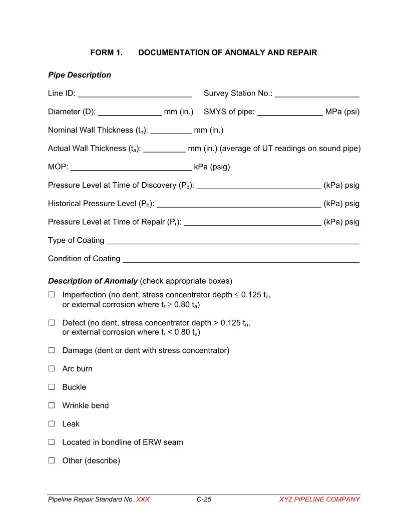
Pipeline Repair Standard No. XXX C-25 XYZ PIPELINE COMPANY
FORM 1. DOCUMENTATION OF ANOMALY AND REPAIR Pipe Description Line ID: Survey Station No.:
Diameter (D): mm (in.) SMYS of pipe: MPa (psi)
Nominal Wall Thickness (tn): mm (in.)
Actual Wall Thickness (ta): mm (in.) (average of UT readings on sound pipe)
MOP: kPa (psig)
Pressure Level at Time of Discovery (Pd): (kPa) psig
Historical Pressure Level (Ph): (kPa) psig
Pressure Level at Time of Repair (Pr): (kPa) psig
Type of Coating
Condition of Coating
Description of Anomaly (check appropriate boxes)
Imperfection (no dent, stress concentrator depth ≤ 0.125 tn, or external corrosion where tr ≥ 0.80 ta)
Defect (no dent, stress concentrator depth > 0.125 tn, or external corrosion where tr < 0.80 ta)
Damage (dent or dent with stress concentrator)
Arc burn
Buckle
Wrinkle bend
Leak
Located in bondline of ERW seam
Other (describe)
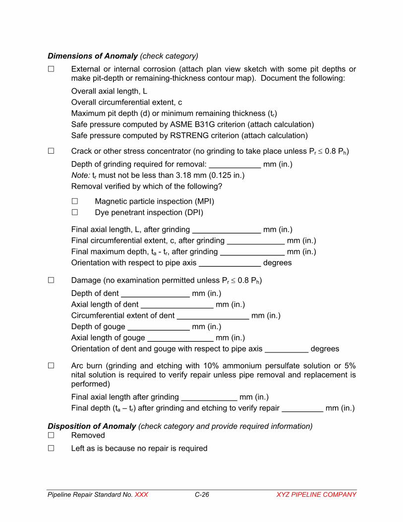
Pipeline Repair Standard No. XXX C-26 XYZ PIPELINE COMPANY
Dimensions of Anomaly (check category) External or internal corrosion (attach plan view sketch with some pit depths or
make pit-depth or remaining-thickness contour map). Document the following: Overall axial length, L Overall circumferential extent, c Maximum pit depth (d) or minimum remaining thickness (tr) Safe pressure computed by ASME B31G criterion (attach calculation) Safe pressure computed by RSTRENG criterion (attach calculation)
Crack or other stress concentrator (no grinding to take place unless Pr ≤ 0.8 Ph) Depth of grinding required for removal: mm (in.) Note: tr must not be less than 3.18 mm (0.125 in.) Removal verified by which of the following?
Magnetic particle inspection (MPI) Dye penetrant inspection (DPI)
Final axial length, L, after grinding mm (in.) Final circumferential extent, c, after grinding mm (in.) Final maximum depth, ta - tr, after grinding mm (in.) Orientation with respect to pipe axis degrees
Damage (no examination permitted unless Pr ≤ 0.8 Ph) Depth of dent mm (in.) Axial length of dent mm (in.) Circumferential extent of dent mm (in.) Depth of gouge mm (in.) Axial length of gouge mm (in.) Orientation of dent and gouge with respect to pipe axis degrees
Arc burn (grinding and etching with 10% ammonium persulfate solution or 5% nital solution is required to verify repair unless pipe removal and replacement is performed) Final axial length after grinding mm (in.) Final depth (ta – tr) after grinding and etching to verify repair mm (in.)
Disposition of Anomaly (check category and provide required information)
Removed Left as is because no repair is required
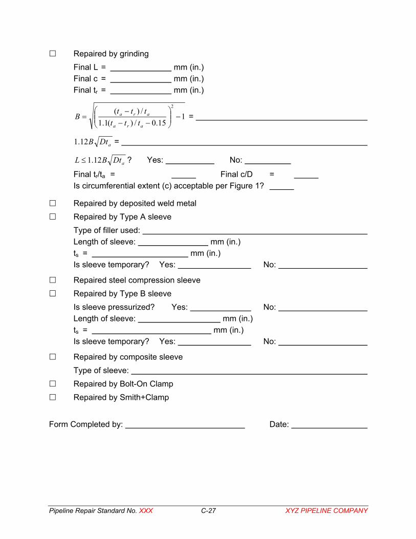
Pipeline Repair Standard No. XXX C-27 XYZ PIPELINE COMPANY
Repaired by grinding Final L = mm (in.) Final c = mm (in.) Final tr = mm (in.)
115.0/)(1.1
/)(2
−
−−
−=
ara
ara
tttttt
B =
aDtB12.1 =
aDtBL 12.1≤ ? Yes: No:
Final tr/ta = Final c/D = Is circumferential extent (c) acceptable per Figure 1?
Repaired by deposited weld metal Repaired by Type A sleeve
Type of filler used: Length of sleeve: mm (in.) ts = mm (in.) Is sleeve temporary? Yes: No:
Repaired steel compression sleeve Repaired by Type B sleeve
Is sleeve pressurized? Yes: No: Length of sleeve: mm (in.) ts = mm (in.) Is sleeve temporary? Yes: No:
Repaired by composite sleeve Type of sleeve:
Repaired by Bolt-On Clamp Repaired by Smith+Clamp
Form Completed by: Date: