FILE COPY 90 o3,2o 099 - DTIC
50
~~1 1 FILE COPY F-16 LIMITED FIELD-OF-VIEW VISUAL SIMULATOR TRAINING EFFECTIVENESS EVALUATION DT C FINAL REPORT A,,ELECTE 6 MAR 2 11990 - JULY 1987 0 . Prepared 'y: LINDA WIEKHORST, Captain, USAF TAC Project Manager KEVIN W. DIXON, ILt, USAF AFHRL Project Manager Submitted by: RAYMOND C. WILLCOX, Lieutenant Colonel, USAF Chief, Training Systems Division Directorate of Training, Tactical Air Command Reviewed by: CECIL 0. DAVENPORT, Colonel, USAF Director of Training Tactical Air Command Approved for pu'bic reeaase Aproved by: MARCUS A. ANDERSON, Major General, USAF Deputy Chief of Staff, Operations Tactical Air Command 90 o3,2o 099
-
Upload
khangminh22 -
Category
Documents
-
view
0 -
download
0
Transcript of FILE COPY 90 o3,2o 099 - DTIC

~~1 1 FILE COPY
F-16 LIMITED FIELD-OF-VIEW VISUAL SIMULATORTRAINING EFFECTIVENESS EVALUATION
DT C FINAL REPORTA,,ELECTE
6 MAR 2 11990
- JULY 1987
0 .
Prepared 'y: LINDA WIEKHORST, Captain, USAFTAC Project Manager
KEVIN W. DIXON, ILt, USAFAFHRL Project Manager
Submitted by: RAYMOND C. WILLCOX, Lieutenant Colonel, USAFChief, Training Systems DivisionDirectorate of Training, Tactical Air Command
Reviewed by: CECIL 0. DAVENPORT, Colonel, USAFDirector of TrainingTactical Air Command
Approved for pu'bic reeaase
Aproved by: MARCUS A. ANDERSON, Major General, USAFDeputy Chief of Staff, OperationsTactical Air Command
90 o3,2o 099

UNCLASSIFIEDSECURITY CLASSIFICATION OF THIS PAGE
REPORT DOCUMENTATION PAGEla. REPORT SECURITY CLASSIFICATION lb. RESTRICTIVE MARKINGS
Unclassified
2a SECURITY CLASSIFICATION AUTHORITY 3. DISTRIBUTION /AVAILABILITY OF REPORT
,_...._ Approved for public release; distribution2b. DECLASSIFICATION /DOWNGRADING SCHEDULE unlimited
4. PERFORMING ORGANIZATION REPORT NUMBER(S) 5. MONITORING ORGANIZATION REPORT NUMBER(S)
6a. NAME OF PERFORMING ORGANIZATION 6b. OFFICE SYMBOL 7a. INAME OF MONITORING ORGANIZATION(if applicable)
HQ TAC DOT AFHRL/OT
6c. ADDRESS (City, State, and ZIP Code) 7b. ADDRESS (City, State, and ZIP Code)
Langley AFB VA 23665-5001 Williams AFB AZ
8a. NAME OF FUNDING/SPONSORING Sb. OFFICE SYMBOL 9. PROCUREMENT INSTRUMENT IDENTIFICATION NUMBERORGANIZATION (If applicable)
HO TAC I DO8c. ADDRESS (City, State, and ZIP Code) 10 SOURCE OF FUNDING NUMBERS
PROGRAM PROJECT TASK WORK UNIT
Langley AFB VA 23665-5001 ELEMENT NO. NO. NO ACCESSION NO
11. TITLE (Include Security Classification) F-16 Partial Field-of-View Visual Simulator Training
Effectiveness Evaluation
12. PERSONAL AUTHOR(S)LINDA WIEKHORST. (Capit. USAF Kevin Dixon, iLt. USAF13a. TYPE OF REPORT 13b. TIME COVERED j14. DATE OF REPORT (Year, Month, Day) IS PAGE COUNTSpecial Project _ FROM 860701 TO 870131 I July 198716. SUPPLEMENTARY NOTATION
17. COSATI CODES 18. SUBJECT TERMS (Continue on reverse if necessary and identify by block number)
FIELD GROUP I SUB.GROUP Limited Field-of-View Flight SimulatorField of View Visual SystemiAircrew Training Devices Training Requirements
19. ABSTRACT (Continue on reverse if necessary and identify by block number)This report covers the F-16 partial Field-of-View (FOV) visual simulator training effective-ness evaluation. An Image lIT visual system was integrated on the F-16C operational flighttrainer at the 58 TTW Luke AFB, AZ. F-16C instructor pilots and students evaluated theability of a partial field-of-view visual system to support formal school training. Taskareas evaluated were conversion, safety-of-flight, emergency procedures, air-to-air and air-to-surface. The results of this evaluation will be used by HQ TAC to determine if a partialFOV visual system can adequately support RTU training. From this a strategy for incorporat-ing additional simulator training into the training syllabi can be developed. This studyprovided TAC the opportunity to verify F-16 simulator training task analysis.
20. DISTRIBUTION /AVAILABILITY OF ABSTRACT 21. ABSTRACT SECURITY CLASSIFICATIONM UNCLASSIFIEDUNLIMITED 0 SAME AS RPT 0 DTIC USERSI UNCLASSIFIED
220. NAME OF RESPONSIBLE INDIVIDUAL 22b. TELEPHONE (Include Area Code) I 22c. OFFICE SYMBOL
LINDA WIEKHORST. CaDt. USAF 804-764-7785 HQ TAC/DOT
DD FORM 1473, 84 MAR 83 APR edition may be used until exhausted SECURITY CLASSIFICATION OF THIS PAGEAll other editions are obsolete.

FOREWORD
The F-16 Limited Field-of-View Visual System TrainingEffectiveness Evaluation was managed and conducted by the Directorateof Training, Tactical Air Command, Langley AFB, VA; the Air ForceHuman Resources Laboratory, Williams AFB, AZ; the 58 Tactical TrainingWing, and Detachment 1, 4444 Operations Squadron, Luke AFB, AZ. Theevaluation began 1 Jul 86 and ended 31 Dee 86. The evaluation wassupported by the F-16 System Program Office, Aeronautical SystemsDivision (ASD/YWF), Tactical Air Command (TAC) and the Singer-LinkCompany.
The following personnel were responsible for the conduct of theevaluation and preparation of the final report:
HQ TAC Project Officer L. WIEKHORSTProject Manager CAPT, USAF
HQ TAC/DOTS
AFHRL Project Officer K. DIXONDeputy Project Manager ILT, USAF
AFHRL/OTE
F-16 TRAIII G LIAISON C. I.ARTINDALELTC, USAFDET 1, 4444 OPS SQD
SINGER-LINK LIAISON ROSS 'ILES
TRAINING SYSTENS ANALYST HANK KUMPUNENED TUMLINSONJERRY KLUMAS
SINGER LINK PROJECT ENGINEER JOE PACIARONI
Personnel from the followin& organizations contributed greatly to theoverall success of the programu:
58 TT. F-16 C/D instructor pilots and students Accesion ForDet 1, 4444 Ops Sq educational specialists NTIS CRA&ISinger-Link on-site maintenance personnel DTIC TAB 0
UIwdlfo:srced 0Justiic, i uo
By
Distribution fAvailabil:ty Codes
i Avail nd -ot
Dist Sc
/1 Aj

SUI.24ARY
Singer-Link Company offered to loan the USAF a limited field-of-viewvisual system at no cost for a six-month evaluation. During thisevaluation period Singer-Link maintained and installed the visual system onthe F-16C operational flight trainer at Luke AFB, AZ. As part of thisinstallation, Singer also provided several special databases to supporttraining at Luke AFB.
The evaluation involved an assessment by instructor and studentpilots. All data collected was a subjective evaluation on the trainingeffectiveness of the limited field-of-view visual system. Students andinstructor pilots were interviewed one-on-one by a professional researchscientist from the Air Force Human Resources Laboratory. Two simulatorsorties were developed by training personnel to use the visual system inthe current training curriculum.
Pilot acceptance of the visual system was very high. Over 80 percentof the pilots participating in the evaluation indicated the visual systemenhanced simulator training. The highest payoff was in the conversion areafor emergency and safety-of-flight tasks, especially those tasks involvingweather effects. Training effectiveness was also enhanced for air-to-surface and air-to-air tasks. With the addition of this visual system,pilots were able to optimize their instrument/tactical crosscheck thusimproving the time sharing between in/out of cockpit duties. Now, with theadded capability to train tasks such as transition to land, limited air-to-surface and air-to-air weapons euployment, limited BFE, VID, air refueling,VFR navigation, students were able to accomplish much more on the groundprior to their first flight.
ii

TABLE OF CONTENTS
PageForeword .. ................ *... ...... ........ i
Graphs and Tables .......................... ivAbbreviations... ................ v
Paragraph
SECTION 1
INTRODUCTION
1.*1 Background. ..... *................. ........ ... ...... 1
1.3 Scope and Limiting Factors.........................2
1.5 Description .............................1.6 Operational .onept................................ 6
SECTION 2
METHOD OF ACCOMPLISHMENT
2.1 Method..............................................102.2 Subjects............................................ 102.3 Pr.du........................................... 112.4 Data Collection ............... . ... 11
SECTION 3
RESULTS AND DISCUSSION
3.1 Training Effectiveness... o4oo4o44133.1.1 Training Task Assessmen ........................... 133.1.2 Conversion Training Task Analysis...................143.1.3 Air-to-Air Training TaskAnalysis...................153.1.4 Air-to-Surface Training Task Analysis...............163.1.5 Initial Sortie Performance Level Assessment........173.1.6 Overall Assessment of Training Effectiveness........18
3.2 Pilot Acceptance.. ................................. 203.2.1 Student Pilot Acceptance. .......... .. ....... ..203.2.2 Instructor Pilot Acceptance. .......... ... ....... 213.2.3 Overall Assessment of Pilot Acceptance..............223.3 Visual System Hardware/Software Assessment... ...... 223.3.1 Data Base Assessment ............................. 223.3.2 Availability of Scheduled Training Hours............243.4 Additional Observations........................ .... 243.4.1 Additional Tasks Recommended for Simulator Training.24

SECTION 14
CONCLUSIONS AND RECOMMENDATIONS
4.1 Conclusions...*. .... .. .. .. .*9o@ o * oo*0 oo9~* . .. . . 26
4~.2 Recommendations.,.. ........Ooogo *..... . . . . ........ 26
AnnexA -IOS Instruction aeOooo eeeoo**ooA-B - Data Base Feature......... ...................... B-1C -Simulator Sortie BriefingGuds........C-D aQuestionnaires. . ........................... D-1
FIGURES AND TABLES
FIGURES
1-1 Facility Layout .....................................4
1-2 Three View Visual System Installation Diagram ....... 51-3 Visual Scene.............................2-1 Flowchart of Evaluation Method......................123-1 Prioritized Pilot Resposne Summary..................19
TABLES
2-1 Evaluation Schedule............................ 103-1 Training Task Analysis..........................133-2 Conversion Task Analysis ....................... 143-3 Air-to-Air Task Analysis.......................153-4 Air-to-Surface Task Analysis .............. .173-5 Areas of Improvement.......................... 183-6 TX Student Pilot Opinion........................203-7 Overall Instructor Pilot Opinion .............. 223-8 Visual Data Base Refinements...................233-9 Task Comparison Assessment.......... ............ 233-10 IMAGE IIIT Availability Rates...................243-11 Additional Tasks ............................... 25
iv

LIST OF ABBREVIATIONS
AFHRL - Air Force Human Resources LaboratoryB COURSE - Basic Course
BFM - Basic Fighter ManeuversCRT - Cathode Ray TubeCX - Conversion CourseDTC - Data Transfer CartridgeEP - Emergency ProceduresFAA - Federal Aviation AdministrationFOV - Field of ViewGOR - General Officer ReviewHUD - Heads Up DisplayHQ TAC - Headquarters Tactical Air CommandHZ - HertzIG - Inspector GeneralINS - Inertial Navigation SystemIOS - Instructor Operator StationIP - Instructor PilotOFT - Operational Flight TrainerOTD - Operations Training DetachmentLATN - Low Altitude Tactical NavigationRTU - Replacement Training UnitSMS - Stores Management SystemTAC - Tactical Air CommandTFTS - Tactical Fighter Training SquadronTTW - Tactical Training WingTX - Transition Course
V

SECTION 1
INTRODUCTION1
1.1 BACKGROUND.
1.1.1. Previous training system task analysis studies conducted for the F-16have indicated a potentially high training effectiveness payback for simulatorswith a visual system. A major recommendation derived from these task analyseswas to implement a system that contained a visual and to study actual trainingeffectiveness from the simulator. Previous sl-dies also indicated that avisual systei will increase training effectiveiess of an Operational FlightTrainer (OFT), F-15 Limited Field-of-View study, (Jul 84). This improvementstems from increasing pilot skill levels and higher pilot acceptance of thesimulator.
1.1.2. During an F-16 Aircrew Training Devices General Officer Review (GOR) in1985, the investigation of implementing a visual capability on F-16 simulatorsat the schoolhouses was proposed. Det 1, 4444 Operations Squadron providedresults of a training requirements task analysis which indicated that visualsystems can provide a substantial increase in training capability foroperations and training squadrons. The schoolhouse mission and environmentwould provide the highest payback for the investment required for simulatorvisual systems.
1.1.3. In Jan 1986 Singer-Linlk Flight Simulation Division proposed to installand maintain a limited Field-of-View (FOV) visual system on the F-16 OFT atLuke AFB for six months at no cost to the government. The purpose of this loanwas to demonstrate the utility of a visual system in an actual trainingenvironment. Singer maintains the F-16 OFT contract logistics support at LukeAFB, AZ and maintained the visual system at no cost during the loan period.This is tie first implementation of a day/night visual system on a USAF F-16OFT, and no previous Air Force evaluations of this system have been conducted.The installation of the visual system did not obligate the Air Force tocontinue use, buy, or lease the system after the six- month loan period.
1.2. PURPOSE.
1.2.1. The purpose of this special project was to evaluate the effectivenessof a limited FOV visual system on an OFT in an replacement training unit (RTU)environment. This sttudy looked specifically at possible enhancements of air-to-air and air-to-surface simulator missions with the proposed visual system.Included in these missions were several conversion, safety-of-fli ht, andemergency procedures tasks. Other factors examined were pilot acceptance of avisual system and impact of a visual system on training.
1.2.2. The results of this evaluation will be used by HQ TAC to determine if a36 X 126 degree limited FOV visual system can adequately support RTU training.This study provided TAC the opportunity to verify an F-16 training taskanalysis and increased understanding of the benefits of simulator visualsystems as a training tool.
1
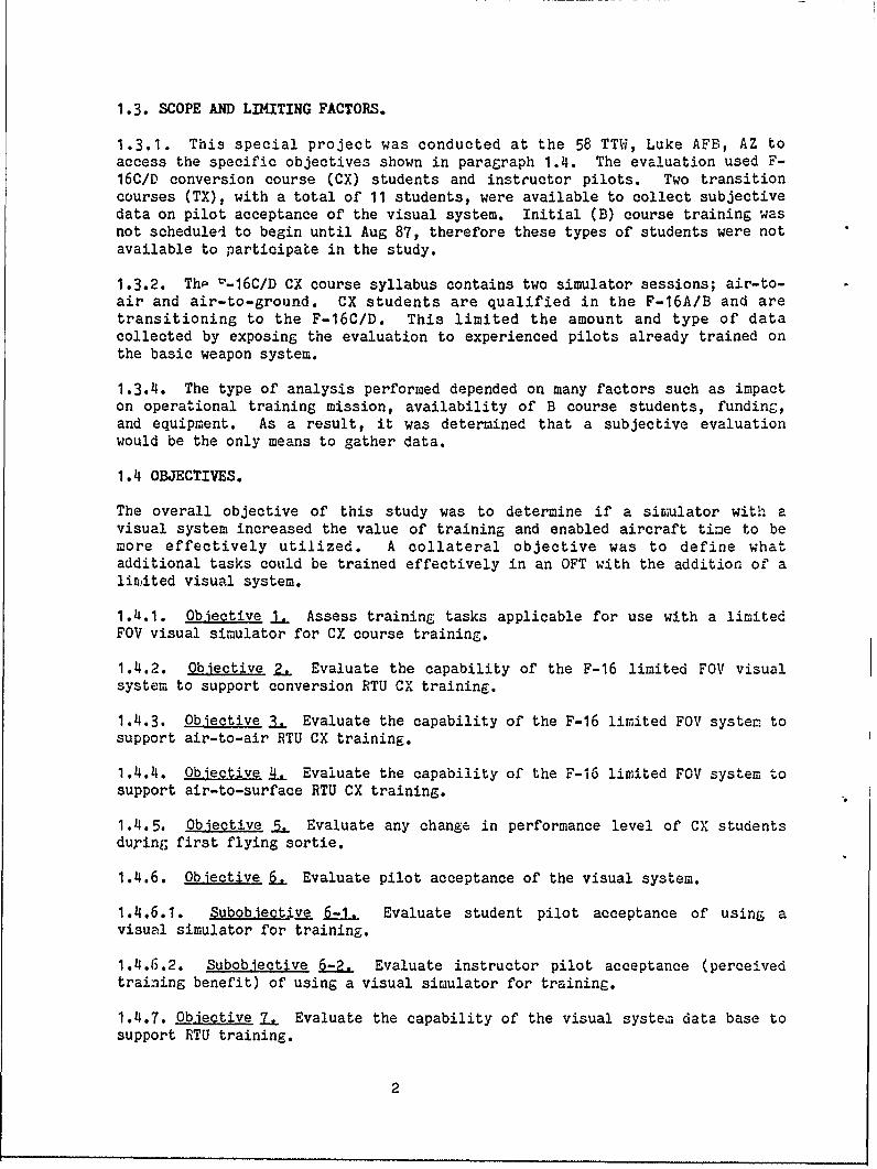
1.3. SCOPE AND LIMITING FACTORS.
1.3.1. This special project was conducted at the 58 TTW, Luke AFB, AZ toaccess the specific objectives shown in paragraph 1.4. The evaluation used F-16C/D conversion course (CX) students and instructor pilots. Two transitioncourses (TX), with a total of 11 students, were available to collect subjectivedata on pilot acceptance of the visual system. Initial (B) course training wasnot scheduled to begin until Aug 87, therefore these types of students were notavailable to participate in the study.
1.3.2. Thp v-16C/D CX course syllabus contains two simulator sessions; air-to-air and air-to-ground. CX students are qualified in the F-16A/B and aretransitioning to the F-16C/D. This limited the amount and type of datacollected by exposing the evaluation to experienced pilots already trained onthe basic weapon system.
1.3.4. The type of analysis performed depended on many factors such as impacton operational training mission, availability of B course students, funding,and equipment. As a result, it was determined that a subjective evaluationwould be the only means to gather data.
1.4 OBJECTIVES.
The overall objective of this study was to determine if a simulator with avisual system increased the value of training and enabled aircraft time to bemore effectively utilized. A collateral objective was to define whatadditional tasks could be trained effectively in an OFT with the addition of alinited visual system.
1.4.1. Objective IL Assess training tasks applicable for use with a limitedFOV visual simulator for CX course training.
1.4.2. Objective 2. Evaluate the capability of the F-16 limited FOV visualsystem to support conversion RTU CX training.
1.4.3. Objective 3. Evaluate the capability of the F-16 limited FOV system tosupport air-to-air RTU CX training.
1.4.4. Objective _ Evaluate the capability of the F-16 limited FOV system tosupport air-to-surface RTU CX training.
1.4.5. Objective 5, Evaluate any change in performance level of CX studentsduring first flying sortie.
1.4.6. Objective 61. Evaluate pilot acceptance of the visual system.
1.4.6.1. Subobjecti.ve " Evaluate student pilot acceptance of using avisual simulator for training.
1.4.6.2. Subobjective 6-2. Evaluate instructor pilot acceptance (perceivedtraining benefit) of using a visual simulator for training.
1.4.7. Objective 7. Evaluate the capability of the visual system data base tosupport RTU training.
2

1.4.8. Objective 8 Identify additional tasks that could be trained in asimulator with a visual system that are nnt currentlyincluded in the training syllabus.
1.5. DESCRIPTION.
1.5.1. Visual System Description. Link provided the Air Force amicroprocessor based IMAGE IIIT visual system with texture. The Image IIIT isa day/dusk/night visual system developed by Singer Link-Miles which meets FAAPhase III advance simulation requirements. The system provided is a three-channel, three-window, wide-angle, collimated zero gap display and an operatorrepeater display. Integration of the visual system did not interfere with thefunctioning of the OFT and did not require any permanent modifications. Majorcomponents of the visual system are:
a) Image Generator (IG). This is a three-channel IG electronic systemwith texture capable of producing up to 250 surfaces simultaneously in eachchannel. The nominal update/refresh rate is 50 HZ.
b) Display System. Three-window, wide-angle, collimated zero gap displaywith a 126 degree (+/-63) horizontal FOV and 36 degree (+29, -15) articulatedvertical FOV. The displays are a raster/calligraphic, high resolution, shadow-mask color CRT. The resolution (per line) of three arc minutes and 6-footlamberts of brightness.
c) Instructor Operating Station (IOS). Repeat visual display thatoptically combines Heads-Up-Display (HUD) with forward visual display. Sampleinstruction pages for operation of the visual system are provided in Annex A.
1.5.2. Visual System Capabilities. The IMAGE IIIT visual system producesreal-time, out-the-window scenes of colored surfaces and objects representingthe actual visual environment. The visual system responds to OFT data definingviewing conditions and presents corresponding updated images to the pilot. Thevisual system produces successive images at a rate sufficient to give theimpression of smooth motion as the observer or a movin& scene object changesposition and/or altitude.
'ii

0 -
5~~J uJJ~ uI z, Z'u MX Zi0
iu t~L-J 1
I01 V- IL
cc L L..
j 0j % >. ec=I~~~~~l I rI I~- C r
LL.
L!2 I - rL1 ILJr ..- IL..
I N ,NIINIc
A~. LcIJ LJ
4 --J4

Figure 1-23-View Visual Installation Diagram
CRT monitor
collimating mirror
beamsplitter
(A) Typical arrangement of 3 display heads
horizontal F.O.V. =1280
(B) Plan view of display heads showing horizontal F.O.V.
total F.O.V. =3e'
(C) Cross section through X-X showing vertical F.O.V.
5

1.5.2.1. The data base utilized during the evaluation was developed by Singer-
Link at their facility in Lancing, England. The visual system depicts a
variety of scene elements consistent with training requirements. A list of
priority scene content features was defined by Det 1, 4444 Ops Sqd, AFHRL, and
Singer-Link. This was done to provide the minimum scene content necessary to
for effective training based on the known syllabus, and to give Singer-Link a
prioritized list which could be used to plan the development of the data base.
Available data bases included Luke AFB, air-to-air/air-to-surface ranges, low-
level navigation route, Phoenix, and Nap-of-the-Earth. Characteristics ofthese databases included weather effects, weapons scoring, color,
day/night/dusk, and moving models. A complete list is in Annex B. An example
of the visual scene is presented in Figure 1-4.
1.5.3. OFT Description. The F-16 OFT consists of a pilot station, IOS, and acomputer system. The pilot station is a replica of the F-16C/D cockpit. It
consists of a cockpit assembly, environmental control, processor/controller andelectronic equipment assemblies, and a G-cuing system. The IOS consists of a
control console, a cathode ray tube display system, and a keyboard display
system. The IOS is located adjacent the pilot station. The computer systemincludes the computers and peripherals needed to control inputs, performs areal-time solution of the total system mathematical model, and provides outputsnecessary to accurately represent the static and dynamic behavior of the
aircraft.
1.6. OPERATIONAL CONCEPT.
1.6.1. The limited FOV visual system provided in this evaluation was used byupgrading F-16C/D pilots in air-to-air and air-to-surface tasks at the RTU.Instructor pilots were qualified in simulator instruction on the system priorto student implementation.
1.6.1.1. The limited FOV visual system was used as a full-task trainer to
increase proficiency in all normal procedures prior to the students first air-to-air and air-to-surface sorties. This included safety-of-flight tasks,emergency procedures, and instrument approaches and landing.
1.6.1.2. The limited FOV visual system was used to provide familiarizationtraining of air-to-air flying tasks, improve intercept training by providing a
visual conclusion to intercepts includin6 visual weapons employment againstnon-maneuvering and maneuvering targets.
1.6.1.3. The limited FOV visual system was used to train subtasks of air-to-surface weapons employment such as initial pipper placement, targetpipper/relationships, and pipper tracking.
1.6.2. Supporting Operations. OFT training sessions were controlled by the IPwho was supported by a simulator techi~ician/specialist.
6

PAGES 7 - 9 ARE NOT AVAILABLE
IN ALL COPIES

SECTION 2
METHOD OF ACCOMPLISHET
2.1. INTRODUCTION This study consisted of three phases of subjective datacollection. In Phase I a general questionnaire was given to all pilots flyingsorties (except CX course). A training task analysis performed by the Det 1,4444 Ops Sq was validated during this effort. The second phase consisted of asubjective evaluation by CX course students following air-to-air and air-to-surface simulator sorties and flying sorties. End-of-course critiquessubmitted by students provided valuable comments on the visual system. A thirdphase consisted of a questionnaire given to IPs to assess perceived benefit ofthe visual system and to recommend changes/enhancements that could improve useof the system.
2.2 SUBJECTS
2.2.1. This evaluation utilized 93 F-16C CX course students, 11 F-16C TXcourse students, 25 F-16C IPs, and 14 F-16C line pilots (Phase I only). Allpilots, except some involved in phase I, were either IPs or students fro the312th TFTS. F-16C TX course students, F-16C IPs and pilots participated inPhase I of the evaluation. F-16C CX students participated in Phase II and312th TFTS IPs participated in Phase III (Table 2-1).
Table 2-1. Evaluation Schedule
PHASE DATA COLLECTIOtl IJO. OF SUBJECTDATES SUBJECTS TYPE
I AUG 86 - SEP 86 36 IPS, TX COURSEII SEP 86 - JAI 87 93 CX COURSEIII JA! 87 - FEB 87 15 IPS
2.2.2. All IPs were trained on system operation prior to the beginning of theevaluation and use of the siD.ulator. This included a checkout sortie to ensureIPs were familiar with console operation. Students and other pilots receivedno formal training on console operation. CX Course students are F-16A/B pilotsconverting to the F-16C/D. These pilots had previous F-16 experience andreceived simulator training in an F-16A OFT with a single window night onlyvisual system. TX course students are fighter pilots transitioning to the F-16C/D from a fighter aircraft other than an F-16.
10

2.3 PROCEDURE.
2.3.1. General Procedure. The evaluation consisted of three phases ofsubjective data collection as outlined in Table 2-1.
2.3.2. Phase I. The first phase of the evaluation began immediately after thesystem was operational. Operations Training Detachment (OTD) personnelperformed a task analysis to determine appropriate tasks for inclusion in thetraining syllabus (Objective 1). This -.nsisted of a general questionnaire(see Annex D) given to pilots receiving simulator fliehts. Pilots filled outthe questionnaire imamediately upon completion of the sortie. TX studentsutilized the simulator for eight simulator sessions during scheduled trainin,.They were interviewed for subjective opinion of the capabilities and uses ofthe simulator (Objectives 1, 2, 3, 4, 6-1, 7, and 8). IPs and line pilots wereinterviewed for their subjective opinion of the visual system, data base andtrainingl potential of the simulator (Objectives 1, 2, 3, 4, and 7). IPs forstudent traininb were interviewed after console operation to collect data onease of console operation (Objective 6-2). Sortie missions evaluated wereorientation fliLhts, air-to-air, air-to-around, emergency procedures, aniinstruments.
2.3.3. Phase II. The second phase began with students following the scheduleof trainin; as prescribed in F16COCXOAL, USAF Conversion Pilot Training: CourseF16C/D. Each student was interviewed followin3 siulator sorties 0-1 and 0-2.Tasr:s for sorties 0-1 and 0-2 were evaluated and discrepancies noted by tcstudents were recorded (Objectives 1, 2, 3, 4, and 7). CX students wereinterviewed after the designated simulator sorties by a research psychologist(AF-HL) to collect the students responses (See Annex D). At the completion ofeach class students filled out an end-of-course questionnaire that jrovideastudent opinion about the OFT. (Objective 6-1).
2.3.4. Phase III. The third phase of the evaluation consisted of an IPquestionnaire (See Annex D) administered durin. the last class of theevaluation. This allowed IPs sufficient use of the systei. to provideintuitive data concerning how well tne simulator visual system supported thevarious phases of training and what additional tasks could be incorporated intothe trainin, syllabus. (Objectives 5, 6-2, and 8).
2.4. Data Collection. Data for all phases was collected through subjectivequestionnaires and analyses of simulator perforLance and cor.parison ofsimulator/aircraft performance. The data was collected in three situations:1) Suojective interviews with CX students after simulator sorties, 2)Subjective interviews with IPs after simulator training sorties and flyingsorties, and 3) Subjective ratings by IPs, pilots, and TX course students ortraining capability of a limited FOV simulator. During Phase II it becaL:eapparent the original ata base required refinement; therefore, results arepresented as before and after the refinement.
11

Figure 2-1
Flowchart of Evaluation Method
Phase I GeneralQuestionnaire
-obj 2, 3, 4 6, 6-1, 6-2
N Measure YacceptabilityPhase Il of subtasks
Unoacceptabl FullI I accepted
LSpecific
Source of
SPercentage of
acceptability
Evaluation Program
-obj 2, 3,.4
Phase III F IP Questionnaire
-obj 5. 6-2,1 6. 8, 8-1
Student Cres
-obi 6, 6-1. 6-2
12

SECTION 3
RESULTS ANlD DISCUSSIOC
3.1 . TRAINING EFFECTIVENESS.
3.1.1. Objective 1. Assess training tasks applicable for use with a limitedFOV visual simulator for CX course training.
3.1.1.1. Criteria. The F-16 Operations Training Development (Det 1, 4444 OpsSqd) team evaluated the simulator training tasks for CX training to developappropriate simulator sorties. Candidate tasks were identified where traininLcould possibly be enhanced by use of a limited FOV visual system. These ta3ksare listed in Table 3-1.
Table 3-1Training Tasks UtilizinZ a Limited Field-of-View for Training
CONICRSION
Normal Takeoff Night ApproachesTrail Departure Overhead PatternsSingle Ship Landing Emergency ProceduresInstrument Approach Low Altitude NavigationWeather Breakout Instruz:ent Landin;
AIR-TO-AIR
Weapons Checks Missile Gun ParametersCollision Course :ntercepts Air Refueling RendevousStern Intercepts Offensive BF,, *Ion-cocperative Targets * Low Altitude Intercepts
AIR-TO-SURFACE
Range Orientation Strafe *Bombing Pattern/Recovery * Offset AiminL DeliveryNuclaar Procedures Threat ReactionLevel Bcob Pop-up Attacks '
Climbing Delivery Night Range ProceduresDiving Delivery *
* Limited performance of task
13

3.1.1.2. Results and Discussion. The task analysis resulted in thedevelopment of two simulator sorties (one air-to-air, one air-to-surface). Thesorties included conversion, air-to-air and air-to surface tasks used in theoverall evaluation. The completed task briefing guides outlining the sortiesare listed in Anne): C.
3.1.2. Objective 2. Evaluate the capability of the F-16 limited FOV visualsystem to support Conversion RTU CX training.
3.1.2.1. Measures. The conversion tasks identified in the two simulatorsorties included representative emergency procedures, selective jettisonprocedures, medium altitude electrical system malfunction, simulated miniiuzfuel (Home) recovery, and instrument approach and landing. Data was collectedfrom questions 3, 4 and 5 of the general questionnaire (Phase I) and throughpilot responses immediately after each simulator sortie (Phase II). Theresponses frow the general questionnaire produced a calculated mean score ofperceived training improvement. Responses from the student pilot interview(Phase iI) produced an overall percentage of pilots who perceived a trainingenhanceLent by using the visual syster.
3.1.2.2 Results and Discussion. The limited FOV visual system can effectivelyenhance conversion 2TU CX training includin, emergency procedures and safety-of-flight. Transition training was enhanced with the use of the limited FOVvisual systeL;.
3.1.2.2.1. Phase I. Pilot opinion of the ability of the visual system tosupport conversion training was high. On a scale of one to five, all threeta3,2s rated over 4.0.: Take Off and Departure (4.06), Approach and Landini.(4.26), Situational Awareness/EPs (4.18).
3.1.2.2.2. Phase II. The use of the visual was rated very hi,4h. Over 90percent of the students indicated the visual system enhanced traininL inconversion task areas. This is due to the capability of the visual to supportadverse weather effects during approach, landinL, and departure procedures. Asdemonstrated in Phase I results, students also indicated the visual syste.:enhanced training. Data base refineiaents made during the evaluation hal noapparent effect on trainin0 effectiveness (Table 3-2). This is to be expecteddue to the generic nature of conversion tasks.
Table 3-2
Conversion Tasks Analysis
TASK EEFORE AFTER OV2RALLENHANCE:E:NTS ENHANCEIKETS% (pos/tot)* % (pos/tot)*
Representative Emergency Procedures 92P (35/38) 92% (124/135) 92%Instrument Approach and Landings 98% (50/51) 961 (123/128) 97%Trail Departure 91% (10/11) 98% (56/ 7) 92%
pos=POSITIVE RESPONSES tot=TOTAL RESPOIUSES
14

The majority of those responding that training was not enhanced indicated nodeficiency in the visual systeru, rather that it did not aid or hinderperformance. Only one negative response was due to visual system attributes.Other responses indicated problems in operation of the simulator (not thevisual system).
3.1.3. Objective 3. Evaluate the capability of the F-16 limited FOV visualsystem to support air-to-air RTU CX training.
3.1.3.1. Measures. The air-to-air tasks identified in the two siD:ulator. sorties included weapon syst m checks, collision course intercepts, stern
conversion from varying intercept geometries, missile and radar modeswitchology, missile/gun attack and weapons parameters, and multiple targetsorting. Data was collected from question 6 of the general questionnaire andthrough pilot responses immediately after each simulator sortie. The responsesfrom the general questionnaire (Phase I) produced a calculated mean score ofperceived training improvement. The responses from the student pilot interview(Phase II) produced percentages of pilots who perceived a trainingenhancement.
3.1.3.2 Results and Discussion. The limited FOV visual system can effectivelyenhance air-to-air RTU CX training.
3.1.3.2.1. Phase I. The calculated mean responses for visual support of air-to-air training was 4.00 on a scale of one to five (five being excellent).This indicated a potential for a simulator with a limited FOV to enhance air-to-air trainin6. However, the tasks tested in this phase were general innature due to the level of instruction provided in an RTU environament.
3.1.3.2.2 Phase 11. Poor responses during initial student pilot evaluationsindicated a potential problem area in air-to-air training. A closer look atthe air-to-air data base indicated enhancements were required to better supporttrainin,. These enhancements were accomplished during the evaluation periodand are discussed in more detail in Objective 7 (hardware/software). Afterdata base enhancements the visual system was rated very high (Table 3-3). Anaverage of all respondents indicates over 80 percent indicated the limited FOVenhanced air-to-air training. This is well below the perceived benefit forconversion and air-to-ground training. Although several tasks (weapons systez.checks, switchology, and multiple target sorting) are not "visual intensive"tasks, the last portion of these tasks result in a visual conversion providingreinforcement of correct procedures. The ability to do this task in "realtimne" allowed students to see the complete task rather than just parts. Due tothe limited FOV Basic Fighter Maneuvers (BFI) were not included in th-esimulator sortie. However, liuited BFiA was performed on a voluntary basis toprovide students an orientation of BFM concepts.
15

Table 3-3Air-to-Air Task Analysis
TASK BEFORE AFTER OVERALLENHANCEmENTS ENHANCEMENTS% (pos/tot)* % (pos/tot)*
Weapons System Checks 65% (13/20) 93% (26/28) 81%Collision Course Intercepts 414% (11/25) 98% (63/64) 83%Stern Conversion from varying
Intercept Geometries 72% (18/25) 85% (44/52) 81%Missile & Radar Mode Switcholog F'! % (21/25) 95% (61/64) 92%Missile/gun Attack & Weapons
Parameters 68% (17/25) 86% (56/65) 81%Multiple Target Sorting 555 (17/22) 89% (58/65) 86%
pos=POSITIVE RESPONSES tot=TOTAL RESPONSES
The majority of those responding that training was not enhanced, indicated nodeficiency in the visual system, rather that it did not aid or hinderperformance. The range for target identification was a problem for collisionintercepts, stern conversions, wissile parameters, and multiple target sorting.This problem was reduced through data base modifications during the evaluation.Several respondents indicated the missile/gun attack and weapons paraLeterstask was affected by the size of the visual FOV. Remaining negative responsesconcerned the operation of the simulator, unrealistic radar representations, orcomputer system malfunctions.
3.1.4. Objective 4. Evaluate the capability of the F-16 limited FOV visualsystem to support air-to-surface RTU CX training.
3.1.4.1. Measures. The air-to-surface tasks identified in the two simulatorsorties included Storage iana&ement Systea (SMS) air-to-ground progra:,rming &Data Transfer Cartridge (DTC) loads, Low Altitude Tactical Navisation (LATN)using Inertial Navigation Systems (INS), nuclear deliveries (radar & visual),and conventional computed deliveries. Data was collected froa question 7 ofthe general questionnaire and through pilot responses immediately after eachsil.ulator sortie. The responses from the general questionnaire (Phase I)produced a calculated mean score of perceived training improvement. Theresponses fro.a the student pilots (Phase II) produced percentages of perceivedtraining enhancement.
3.1.4.2 Results and Discussion. The limited FOV visual system did effectivelyenhance air-to-surface RTU CX training.
3.1.4.2.1. Phase I. The calculated mean responses of pilots was 4.80 on ascale of one to five (five being excellent). This indicates a very highcapability of the visual system to enhance air-to-surface training.
3.1.4.2.2. Phase II. Students did not rate the capability of the visualsyste i to enhance training as high as the IPs and experienced pilots, althoughratings were still high. This may be due to the fact experienced pilotsrequire fewer visual cues to perforn the task than the novice. Experiencedpilots given a few cues (limited FOV) can assess the whole situation. The
16

limited FOV lacks the ability to provide some downwind and base leg visual cuesthat novice pilots need to more accurately assess their position. However, thepresence of a visual system allows these tasks to be performed, even in alimited manner. Without a visual system these tasks could only be practicedthrou&h instruments. Table 3-4 illustrates the percentage of CX studentsindicatinG a training enhancement.
Table 3-4Air-to-Surface Task Analysis
TASK BEFORE AFTER OVERALLENZHANCE1-ENTS ENHANCEMENTS% (pos/tot)* % (pos/tot)*
SI.NS Air-to-Ground Programming 81% (22/27) 87% (53/61) 8 5& DTC Loads
Low Altitude Tactical Nav (LATIh) 85% (23/27) 80% (47/59) 81%using INS
Nuclear Deliveries (radar/vis) 100% (25/25) 855 (541/63) 90%Conventional Computed Deliveries 63% (15/24) 89% (57/64) 82;
• pos=POSITIVE RESPONSES tot=TOTAL RESPONSES
SIIS air-to-ground programming and DTC loads are not "visual intensive" tasr.s;however, the ability to do this task in "real time" allowed students to see tnecoLplete task rather than just parts. The deficiencies noted by the rer.ainderof the students were (a) not aided with the addition of the visual, (b) rangedeficiencies on identifying target, and (c) inadequate horizontal\vertical FOV.The reason for the noted deficiencies were in part due to type of tasks becausemany pilots rely on instruments to perform, the task or could not identifyproper outside cues to aid in flying the maneuver. A deficiency is alwaysnoted for simulators with less than a full FOV especially when peripheral cuesare necessary to complete the task.
3.1.5 Objective 5. :valuate any change in perfornance level of CX studentsduring first flying sortie.
3.1.5.1. Measure. IPs were asked to assess the student's performance oninitial flying sortie following the applicable simulator sortie. This data wascollected on the IF questionnaire (Phase III).
3.1.5.2. Results and Discussion. The 15 IPs interviewed responded thatstudents demonstrated improvement in flying skills since the addition of thevisual system for training. The primary areas of improvement are identified inTable 3-5. Emergency Procedures and instrument training showed the highest areaof improvement. It is difficult to truly assess the benefit of local areaprocedures because most of the students received prior trainin6 in the Luke AFBarea. It should also be noted that the IPs indicated the visual system ;ave anadded dimension of realism that enabled the students to concentrate more on thewhole task, thereby increasing their skill level prior to flying the aircraft.
17

Table 3-5Areas of Improvement in Performance
AREA IM1PROVED AFTER SIM AFTER SORTIE
Situational Awareness 20% 20%Local Area Procedures - 20%Avionics - 25%Emergency Procedures 33% 35%Instruments 40% 20%Weapons Employment 27% 27%Switchology - 27%All Areas 53% 40%
3.1.6. Overall Training Effectiveness. The visual system allowed students torealistically practice cockpit management tasks, especially the allocation ofin/out of cockpit time. Students tended to fly the simulator more lil:3 theywould the aircraft. any tasks that previously could not be practiced in thesimulator could now be familiarized to the student before flying the aircraft.Overall, the perceived benefit of using a liimited visual system in simulatortraining was very high. Over 80 percent of the pilots responded the visualsystem enhanced training in one or more areas. The highest payoff was in theconversion task area followed by air-to-Zround and air-to-air, respectively.Figure 3-1 shows a prioritized listin , of tasks according to students'perception of trainin, benefit. The enhance.,ents required after initial database development, indicated the importance of appropriate visual cues in thevisual scene.
18

Figure 3-1
PRIF M2ED PILOT RECSPON'J SUMMARlY110 -'
loo - 9,7 97 98icc 97 9 93 92 90 89 88 - 83 83
0.
90 a81 81 80so
Zoo
Lii
IJI
I-
Ua:0
LU
z0 oa"3 40LUi
20
10
1 2 3 4 5 6 7 8 9 10 11 12 13 14 15
SLTAS IS
*SUBTASKS
1)INSTRUMIENT APPROACH AND LANDING (CONVERSION)2)TRIAL DEPARTURE (RADAR) AS NO. 4 IN FLIGHT OF FOUR (CONVERSION)3)SIMULATED MINIMUM FUEL (HOME) RECOVERY (CONVERSION)4)SELECTIVE JETTISON PROCEDURES (CONVERSION)5)MISSILE AND RADAR MODE SWITCHOLOGY (AIR-TO-AIR)6)NUCLEAR DELIVERIES (AIR-TO-SURFACE)7)LOW ALTITUDE TACTICAL NAVIGATION (LATN) USING INS (TOS,CARA) (AIR-TO-SURFACE)8).ULTIPLE TARGET SORTING (AIR-TO-AIR)9)EMERGENCY PROCEDURES (CONVERSION)10) SMS AIR-TO-SURFACE PROGRAMMING AND DTC LOADS (AIR-TO-SURFACE)11)COLLISION COURSE INTERCEPTS (AIR-TO-AIR)12)CONVENTIONAL COMPUTED DELIVERIES (AIR-TO-SURFACE)13)WEAPON SYSTEM CHECK (AIR-TO-AIR)14) MISSILEIGUN ATTACK AND WEAPONS PARAMETERS (AIR-TO-AIR)15) STERN CONVERSION FROM VARYING INTERCEPT GEOMETRIES (AIR-TO-AIR)
19

3.2 PILOT ACCEPTANCE OF LIMITED FOV SIMULATOR VISUAL SYSTEM
3.2.1. Objective 6. Evaluate pilot acceptance of the visual system.
3.2.1.1. Suuobjective 6-1. Evaluate student pilot acceptance of usinL a visualsimulator for training.
3.2.1.1.2 Measures. TX course students answered a general questionnaire(Phase I) and CX course students completed end-of-course critiques. Acalculated mean from TX student responses was used to assess their overallimpression of the limited FOV visual system. A summary of end-of-coursecritique responses was used to derive CX course student opinion.
3.2.1.1.3. Results and Discussion. TX and CX course students indicated a verypositive attitude towards the use of a limited FOV visual simulator.
3.2.1.1.3.1. TX Course Students. TX Students flew selected types of simulatormissions and rated its ability to support these areas of traininc. TX studentswere the "test" class to identify potential areas requiring enhancement.Therefore, it was expected these ratings would be lower than CX studentcritiques. These ratings indicate a training benefit and pilot acceptancebefore any enhancements were implemented. Students rated each area on a scaleof 1 to 5, with 5 being excellent. As seen on Table 3-6 TX course studentsrated the visual very high. The addition of the visual systerc to the OFT andthe quality of the visual presentation were rated the highest. This indicatesthe visual scene is somewhat realistic and aids in training.
Table 3-6
TX Student Pilot Opinion
QUESTION 1:EAN
- Overall Opinion ------
Eating of Visual Presentation 4.92Ability to Support Flying Sir 4.54Addition of Visual to Simulator 4.33
- Areas of Training ------Take-off and Departure 4.12Approach and Landing 4.60Situational Awareness/EP 4.38Air-to-Air Training 4.58Air-to-Surface Training 4.69
* Scale: 1 to 5 (1=poor, 5=excellent)
3.2.1.1.3.2. CX Course Students. At tie end of the course students areroutinely asked to provide feedback on the quality of traininL they received.No specific request was made to assess the OFT, however a ieneral question is
20

asked as to the adequacy of training devices. In general simulators areusually rated low, and conments to reduce the number of simulator sessions arecomiaon. However, several student critiques indicated "The OFT is outstandin;,""I hate to suggest it, but another ride, perhaps an extra simulator(intercept)," "Excellent simulator training,"| "Could get more out of OFTtraining," "It would be an advantage to have one more simulator prior to firstaircraft ride," "Simulator is one of the finest I have seen," "Need moresimulator time," "OFT fantastic (for a sim)." Overall, the students indicatedthe simulator visual system made the OFT training session more enjoyable. Astudent in class 87-ECL summed it up; The "Simulator is the best I've seer..Not only for A/A, A/G, switchology and procedures, but also for instrumentapproaches breaking out near minimums. Great training aid. I actually enjoyedthe simulator. Without the visual it would be the same as any sim, but thevisual display really makes it good."
3.2.1.2. Subobjective 6-2. Evaluate instructor pilot acceptance (perceivedtraining benefit) of using a visual simulator for training.
3.2.1.2.1 1ieasures. IPs were asked to evaluate the visual system based ontheir experience as pilots during Phase I (general questionnaire). IPsassessed the value of adding the visual systew to a simulator for trairin,enhancement (IP questionnaire) as the evaluation was nearing an end (PhaseIII). This allowed IPs to formulate an opinion during the six-month period foran overall assessment.
3.2.1.2.2 Results and Discussion, IPs indicated a high acceptance for the useof a sim~ulator with a visual system for training.
3.2.1.2.2.1. Phase I (General Questionnaire). IPs were used to verify theappropriate use of the simulator visual system in the CX course. Therefore, itwas expected these ratings would be lower than TX course students. Theseratings indicate a training benefit and pilot acceptance of the visual syste:..Table 3-7 presents IP responses to the general questionnaire. IPs flewselected types of simulator missions and rated its ability to support theseareas of training on a scale of 1 to r, with 5 being excellent.
21

Table 3-7Overall Instructor Pilot Opinion
QUESTION MEAN *
------ Overall Opinion-------Rating of Visual Presentation 4.15Ability to Support Flying Sim 4.05Addition of Visual to Simulator 4.50
------ Areas of Training ----Take-off and Departure 3.96Approach and Landing 3.95Situational Awareness/EP 4.0Air-to-Air Training 3.13Air-to-Surface Training 3.75
* Scale: 1 to 5 (1=poor, 5=excellent)
3.2.1.2.2.2. Phase III (IP Questionnaire) The calculated mean of the valueIPs indicated for the use of a visual system for training was 9.0 (scale of 1-10). This takes into consideration perceived training benefit andease/difficulty to use. This indicates an increase in IP opinion of the visualsystem. After being able to use the OFT for training, IPs indicated a higheracceptance of the visual system and identified additional areas where OFTtraining could be enhanced (see objective 8).
3.2.2. Overall Assessment of Pilot Acceptance. Pilot acceptance of the visualsystem was extremely high. While the opinion of the IPs was acceptable at taeonset of the evaluation, by the end of the evaluation period their acceptancewas very high. Discussions with IPs and students further support the collecteddata on acceptance of the visual system and an increased training effectivenessfor the simulator sorties. The comment by several students to add a simulatormission to the syllabus is very unusual and exeriplifies the acceptance of avisually oriented OFT.
3.3 VISUAL SYSTEM HARDWARE/SOFTWARE ASSESSMENT
3.3.1. Objective 7. Evaluate the capability of the data base to support RTUtraining.
3.3.1.1. Measures. An interactive process of feedback from pilots andprogrammers provided the initial visual data bases. The first data baseconsisted of preliminary versions of Luke airfield and Range 4. Visual-relatedcomments were gathered throughout the evaluation phase for future reference.
3.3.1.1 Results and Discussion
3.3.1.1.1. Phase I. During the beginning of the evaluation instructor pilotsand TX course students assessed the adequacy of the visual data base content(01 Aug -- 10 Nov 86). Recommended refinements are listed in Table 3-8. Theserefinements were implemented on the system within a two-week period.
22

Table 3-8Visual Data Base Refinements
PROBLEM AREA SUGGESTION
Luke Runways Adjust Scene Sizes
Air-to-Surface Range Add Hat Mtn, Pop-up ptNight Flare Pots
Low Level Route Add Real Offsets
Air-to-Air Increase Target Range
Luke Airfield Area Add Caterpillar Parking Lot,Add Section Lines
3.3.1.1.2. Phase II. During student evaluations it became apparent thatadditional enhancements would increase training effectiveness. This data baserevision resulted in a significant increase in positive ratings for the air-to-air sortie tasks (See Table 3-9). This was due to an increased identificationrange and a flashing beacon positioned on air-to-air targets. Air-to-surfacetasks were enhanced by better weapons effects and a complete modeling of therange area. Conversion tasks were adequately modeled in the initial data baseand were minimally affected by the data base revision. This indicates a needto have adequate data bases, regardless of the visual system capabilities.Data bases must be continually evaluated for currency and adequacy.
Table 3-9Task Comparison Assessment
(Acceptance Before/After Data Base Enhancements)
Task Area Before After% No. % 1o.
Air-to-Air Tasks 65% (92/142) 91% (308/338)Air-to-Surface Tasks 835 (85/103) 8 5 (211/247)Conversion Tasks 95% (95/100) 914% (302/320)
3.3.2. Availability of Scheduled Training Hours. The availability of thevisual system for training was very high. This indicates Singer-Link was ableto maintain the visual system and that simulator missions did not have to bealtered due to a lack of visual scene. Table 3-10 shows monthly availabilityrates for the Image IIIT visual system during the evaluation period.
23

Table 3-10
IMAGE lilT Availability Rates
MONTH AVAILABILITY RATE
July 100%August 100%September 91%October 97%November 99.4%December 94%January 100%February 100%
Average for 8-month period: 97.7%
3.4 ADDITIONAL OBSERVATIONS
3.4.1. Objective 8. Identify additional tasks that could be trained on asimulator with a visual system that are not currently included in simulatorsorties.
3.4.1.1. Criterion. IPs were asked to recommend additional tasks to thestudent syllabus. These recompmendations will be used to revise current syllabiand in the development of a new B Course syllabi. The additional tasks caL.efrom the IP questionnaire (Phase III) administered at the end of theevaluation.
3.4.1.2. Results and Discussion. Table 3-11 shows the additional taskssuggested by IPs. The general responses tend to fall into three categories: (a)Emergency procedures, (b) Aircraft restricted tasks, and (c) Night and weatheroperations. These categories are three areas ideally suited for simulatortraining and further enhanced with the addition of a visual system. Theaddition of these and other tasks that are suitable for the limited FOVsiMulator would allow more effective use of aircraft flight time to developskills that can only be trained in actual flying.
24

Table 3-11Additional Tasks Recommended for the Simulator
ADDITIONAL TASKS % No. responding
Low Approach 20% (3/15)Vertical Conversions (Night) 15% (2/15)Horizontal Conversions (Night) 15% (2/15)Tanker Boom For AAR/NAAR 25% (4/15)Engine Failure Low Altitude 30% (5/15)Tactical Intercepts (Weather) 10% (1/15)Moving Target Attacks 40% (6/15)Tactical Range Events 10% (1/15)Low Level Flight 20% (3/15)Simulated Flame Out 30% (5/15)None 50% (8/15)
% -percentage of those responding* No.-number responded/total number responded
The main constraint of assigning additional air-to-air tasks is that anylimited FOV simulator is limited only to those tasks that can be performed inthe forward henisphere. The student can still gain benefits from a limited FOVsimulator for air-to-air tasks in emergency operations, weather tasks, andfamiliarization with procedures. Other benefits are produced fro; practicingtasks that are rarely performed due to operational constraints or weather, suchas low-level procedures and weather tactical intercepts.
25

SECTION 4
CONCLUSIONS AND RECOM4NENDATIONS
4.1. CONCLUSIONS.
4.1.1. F-16 simulator training on an OFT in an RTU environment issubstantially enhanced by the addition of a limited FOV visual system. In anRTU the OFT mission is to familiarize and practice tasks that students have themost difficulty in learning or have safety-of-flight implications. Theaddition of the visual system enhances the simulator sortie to provide thestudent with a realistic trainin6 environment and visual confirmation of thetask.
4.1.2. A limited FOV visual system increases pilot acceptance of simulatortraining and provides a positive impact on training.
4.1.3. The task analysis and recorai.ended additional tasks provided a basis todevelop simulator missions for B Course students to begin training later in theyear. This will allow for more proauctive use of simulator tim e and flyin.sorties.
4.1.4. Comments concerning the data base characteristics and trainin%effectiveness illustrated the importance of accurate and appropriate visualcues.
4.1.5. The evaluation process indicated visual data bases can be updated in atimely manner to meet current training needs and objectives and increasetraining effectiveness.
4.1.6. The visual system reliability indicated it can successfully sudport a
normal training schedule without a decrease in training.
4.2. RECOMMENDATIONS.
4.2.1. To enhance the trainin, of the OFT in an RTU environment a liLoited FOVsyste:; with at least the same capability of the evaluated syste;j should bepurchased or retained for lon,-term use.
4.2.2. Simulator missions developed for the B Course should be evaluated fortrainin6 effectiveness. The B Course should benefit more with the use of avisual system than advanced (CX/TX) students.
26

Annex A
IOS INSTRUCTION PAGES
IOS Instructor Controls
o 5 IOS CRT Pages-3 visual system control-2 visual weather effects
o Iniatial Condition (IC) Sets-runway 3R arming area-runway 3R before takeoff-inbound to Monti-inbound to Range 4-quick access positions
-14 mile final-Range 4 initial pass
o Repeater Monitor-monitor next to IOS-cabinet with HUD repeater will be
available soon
ACTUAL CONTROL PAGES
IMAGE iIIT
VISUAL DATABASE
DATABASE SELECTION
01 LUKE 07 SPARE02 AIR-AIR/AIR-SURFACE 08 SPARE03 PHOENIX 09 SPAREO VALLEY 10 SPARE05 MIAII 11 SPARE06 DFW 12 SPARE
13 AUTOMATIC DATABASE SELECT ON
CURRENT DATABASE LOADED I
PAGE ADVANCE FOR IMAGE IIIT VISUAL CONTROL
A-I

Annex A - cont
VISUAL CONTROL
01 BLANK VISUAL DISPLAYS OFF02 FIELD OF VIEW DOWN03 VISUAL AMBIENCE SETTING a (0-5)04 VISUAL TIME OF DAY a (0-5)
0 = BLACK NIGHT1 = NIGHT2 = TWILIGHT3 = DAWN/DUSK4 = DAY5 = BRIGHT DAY
AIRFIELD LIGHTING05 APPROACH LIGHTS INTENSITY 3 (0-5)06 TAXIWAY LIGHTS INTENSITY a (0-5)07 BARRETTES INTENSITY a (0-5)08 RUNWAY LIGHTING INTENSITY a (0-5)09 ENVIRONMENTAL LIGHTS INTENSITY a (0-5)
PAGE ADVANCE FOR IMAGE IIIT VISUAL TARGET SELECT
VISUAL TARGET SELECT
TARGET VISUALNU1M4BER MODELS PROFILE
Da I a.oaI
VALIDMODELS
(1) F-16(2) MIG-23(3) TANK(4) TRUCK(5) KC-10 TANKER
99 EXPRESS KEY SETUP (SCENARIOS)
SCENARIOS INTERCEPTSE RADAR TRIAL DEPARTURE E 180 HCAF PINCER F 135 HCAG BEAM/DRAG G 90 HCAH RESET H 10 HCA
PAGE ADVANCE TWICE FOR IMAGE IIIT VISUAL DATABASE
A-2

Annex A - cont
VISUAL WEATHER EFFECTS
01 Canned Weather Sets: Q (0-5)
0 = Clear, Unlimited Visibility1 = 800 Ft Ceiling, Visibility Unlimited2 = 500 Ft Ceiling, Visibility 5 Miles3 = 300 Ft Ceiling, Visibility 2 Miles4 = 200 Ft Ceiling, Visibility 2 Miles5 = Real Bad Day
PAGE ADVANCE FOR IMAGE IIIT VISUAL WEATHER CONTROL
VISUAL WEATHER CONTROL
01 VISIBILITY l9 (0-49 MILES)02 RVR MIMIMUM a (0-5 MILES)03 RVR VARIATION IN FOG Q (0-5000 FT)04 CLOUD TOP D (0-65000 FT)05 CLOUD BOTTOM D (0-65000 FT)06 FOG TOP A (0-32000 FT)07 CLOUD GRANULARITY D (0-7)08 FOG GRANULARITY A (0-7)09 RAGGED CLOUD OFF10 RAIN OFF11 LIGHTNING OFF12 THUNDERSTROM OFF
PAGE ADVANCE FOR IMAGE IIIT VISUAL WEATHER EFFECTS
A-3

Annex B
DATABASE FEATURES
O CONTINUOUUS TERRAIN (CT) DATABASE-LUKE AIRFIELD-LOW LEVEL ROUTE VR245-CONVENTIONAL RANGE 4
0 CORRELATION WITH RADAR SURFACE TARGETS (RSTs)-RANGE 4
-10 IP POINT-NUCLEAR CIRCLE
-RSTs AT EACH STEERPOINT OF VR245
O ARRESTMENT CABLES-VISUAL CABLE BOXES AT EACH END OF 3R AND 3L-INTEGRATED WITH SIMULATOR FOR PROPERHOOK AND OFF RUNWAY CRASH DETECTION
O F-16S VISIBLE UP TO 4 MILES
O VISUAL SCENE CONTENT LIST
Listing of Prioritized Databases
Priority Feature
1. Luke Airfield Area- Dual Runways- Approach Lights- VASI Lights- Taxiway/Ramp Area- Large buildings (selected from base map)
2. Controlled Air-Surface Range- Nuclear Target with Circles- Nuclear run-in line w/ 45IP, 201P, 1OIP- Conventional Target (left and right)- "Bat Wings"- Range Towers- Strafe Target and Run-in- Offset Aim Point (radar targets)- Radar Target (same as visual nuc target)
3. Low Level Route (VR245)- Radar Altimeter (+-100 ft accuracy)- Contours for Visual Flight- "Fix" points (2)- ACAL points (can be same as fixed points)
B-i

Annex B - cont
Air-to-Air- Horizon Line- Enemy Fighters (min 4)
5. Effects- Missile Fly-out- Gun Tracers- Weather
- Clouds- Visibility
6. KC-10 Tanker
7, Luke Airfield Area- Cattle Pens- Caterpillar- Gila Bend AFB (Buckeye)- Aux 1 Runway- Section Lines
8. Effects- Weather (night)- SAMS/AAA- Bomb Impact/damage
B-2

Annex C
SIMULATOR SORTIE BRIEFING GUIDES
Sortie Syllabus Objectives
OPERATIONAL FLIGHT TRAINER (0)
0-1 1:1 Ratio1.0 Hours
MISSION OBJECTIVES: Practice using the FCR in the following(sub)modes: RWS, spotlight, TWS AUTO, TWS MAN, ULS, VS, AND ERVA.Practice trial departure. Practice looking on in all the abovemodes. Practice cruise energy management and intercepts againstsingle and multiple targets. Practice the switchology to changefrom RWS SST to TWS, and from TWS to SST. Practice use of F-16C/D specific avionics. Accomplish a TACAN penetration andapproach, or ILS approach. Accomplish other approaches as timepermits.
0-2 1:1 Ratio1.0 Hours
MISSION OBJECTIVES: Practice using the Nuc Rotary to accomplisha Radar LOFT using the CCRP mode. Practice using GM, FTT, GMT,GMTT, EXP, DBS1, DBS2, and freeze radar (sub)modes. Practicemoving the cursors and zeroing the cursors. Practice FCR Fix,FCR Mark , and FCR ACAL. Accomplish a TACAN penetration andapproach, ILS, or PAR to minimums. Review F-16C/D avionics astime permits.
AIR-TO-AIR BRIEFING GUIDE
CX COURSE
I. OBJECTIVES
1. Trial departure (RADAR) as No. 4 in flight of four2. Weapons system checks3. Collision course intercepts4. Stern conversion from varying intercept geometries5. Missile and radar mode switchology6. Missile/Gun Attack and Weapons Parameters7. Multiple target sorting8. Electrical system malfunction (medium altitude) or other
appropriate emergency situation9. Simulated minimum fuel (HOME) recovery
10. Instrument approach and landing
C-i

Annex C - cont
I. ADMINISTRATIVE REQUIREMENTS
MISSION TIME: 1.0 HOURBRIEF TIME: 0.3 HOURDEBRIEF TIME: 0.3 HOURPREREQUISITES: AFT-21IP/P RATIO: 1:1
MISSION PURPOSE: To familiarize the student with air-to-airprocedures and techniques for interceptsagainst single and multiple targets.Additionally to practice instrumentprocedures and representative emergencyprocedures.
II. OFT/14ISSION PARAMETERS
A. Initial Conditions1. Iniatize trainer for Luke Training Mission 2.2. After iniatilizing, load missiles using Weapons
Load Page 2 or the DTC (14 AIM-9L/M, GUN-510).3. Verify that all targets are activated, no JARMs are
required.
B. Operational Requiremients
1. Radio Frequenciesa. Squad Cm................Ch9b.* Luke SOF ...................... ooo.......Ch 14co* Ground Control .............o....... ....o*Ch 1d owr..................h 2e.* Phoenix D/A...................h 3f.* ABQ Center .................. h 6go* LukeGA.................C8
2. APP Plates Requireda. Tiron-Gladden Departure... .*....... . .... . Chl2b.* HI-TACAN HWY 03R................. oo*. o*Chl 5ca. HI-ILS Hwy 03R ...... 9*.*....... .. .. #Ch1
3. NAy FACs Requireda. ILS/GCA 03R ............................... Ch77
C-2

Annex C - cont
IV. INSTRUCTOR RESPONSIBILITIES (GENERAL)1. Start the briefing at least 15 minutes prior to the
scheduled takeoff time.2. Brief student on mission objecties and sequence.3. Answer questions concerning the mission.4. Conduct Training Mission.
a. Monitor performance from IOSb. Use local radio procedures.c. Act as appropriate communications agency and
aircraft crewchief.5. Electrical malfunction or other appropriate
emergency6. Instrument approach and landing
Remember this is a guide. The IP has the authority to modify thelesson content, based on the student's progress and emphasesrequired upon special subjects. Tasks should be repeated if theyare not performed well (time permitting).
VI. OFT MISSION BRIEFING GUIDE1. Ground procedures2. Radar Trial Departure3. Weapons System Check4. Intercepts
a. Collision Course geometryb. Front quarter and beam interceptsc. Stern conversionsd. Performance in all radar modese. Sorting exercise
5. Emergency6. Approach and landing
CONVENTIONAL SURFACE ATTACK OFT BRIEFING GUIDE
CX COURSE
I. OBJECTIVES
1. Perform SAS Air-to-Surface Programming and DTCLoads.
2. Perform Low Altitude Tactical Navigation (LATN)using (TOS, CARA).
3. Perform Nuclear Deliveries (Radar and Visual).4. Perform Convential Computed Deliveries.5. Perform Representative Emergency Procedures.6. Perform Selective Jettison Procedures.7. Perform Instrument Approach and Landing.
C-3

Annex C - cont
II. ADMINISTRATIVE REQUIREMENTS
MISSION TIME: 1.0 HOURBRIEF TIME: 0.3 HOURDEBRIEF TIME: 0.3 HOURPREREQUISITES:IP/P RATIO: 1:1
MISSION PURPOSE: To familiarize the student with SMSAir-to-Surface procedures, LATN usingINS, nuclear and conventionaldeliveries on a controlled range,representative emergency, andinstrument approaches.
III. OFT/MISSION PARAMETERS
A. Initial Conditions1. Iniatilize trainer for Luke Training Mission 6.2. No JARMs required.3. Aircraft on ground, engine running, wing tanks,
1 SUU-20 with 6 MK-106s and 1 SUU-20 with 6BDU-33s, 20MM.
B. Operational Requirements
1. Radio Frequenciesa. Squad Comm................................Ch 9b. Luke SOF .................................. Ch 4c. Ground Control1... . .............. Ch 1d. Tower.....................................Ch 2e. Phoenix D/A .............. ............... Ch 3f. ABQ Center ............................... Ch 5g. GBN Range Ops ........................... ..Chl0h. Range 4. . . . . . . . . . . . . . . . . C 1
i. Luke CA... .................... Ch18
2. APP Plates Required--41-ILS 03R
3. NAV FACs Required
a. ILS/GCA 03R ............................... Ch77
C-4

Annex C - cont
IV. INSTRUCTOR RESPONSIBILITIES (GENERAL)
1. Start briefing at least 15 minutes prior to thescheduled takeoff time.
2. Brief student on mission objectives and sequence.3. Answr student questions concerning mission.4. Conduct Training Mission.
a. Monitor performance from IOSb. Use local radio procedures.. Act as appropriate communications agency,
aircraft crewchief, and Range Control, andRange Officer.
d. Simulate emergency5. Complete AFTO Form 369 before departing OFT.6. Complete OFT grade sheet following debriefing.
V. OFT MISSION BRIEFING GUIDEThis OFT lesson encompasses the following tasks:1. Perform before takeoff procedures
a. SMS Air-to-Surface programmingb. Verify DTC load change as necessary
2. Perform LATN (Initialize to VR-245 Entry Point)a. Fly first two legs (to Dam)b. Use INS, TOS, CARA, FIX
3. Perform Nuclear Deliveries (Initialize to Range 445 IP)a. Fix/ACAL Proceduresb. Nuclear
(1) Laydown (Visual and Radar)(2) LADD (Visual and Radar)(3) Loft (Visual only)
4. Perform Conventional Computed Deliveriesa. 30 Dive Toss (Roll-out to final only)b. 20 LALD CCIP (Roll-out to final only)c. Low angle strafe (Roll-out to final only)
5. Perform Representative Emergency6. Perform Selective Jettison7. Perform penetration and ILS approach with asymmetric
stores (initialize to Luke).
Remember this is a guide. The IP has the authority to modify thelesson content, based on the student's progress and emphasesrequired upon special subjects. Tasks should be repeated if theyare not performed well (time permitting).
C-5

Annex C -cont
VI. OFT MISSION DEBRIEFING GUIDE
1. Before takeoff procedures2. Low altitude tactical navigation (LATN)3. Avionics operations4. Nuclear
a. Laydownb. LADDc. LOFT
5. Conventionala. Dive Tossb. CCIPa. Strafe
6. Emergency7. Selective Jettison8. ILS approach with asymmetric stores
C-6

Annex D
Sample Phase I Questionaire
Name: Rank -_ Course Date:
Please take a moment of your time to aid in the evaluation ofthis visual system. You're input is greatly appreciated andwill be used to determine the implementation of a visual system.
INSTRUCTIONS: Answer questions A-D and use the rating scale toanswer questions 1-8. If Not applicable put 0.
1 2 3 4 5poor adequate excellent
A. Number of Rides in Simulator with visual attached?Mean IPs:3.3 Mean TXs=1.5B. Number of Rides in Simulator without visual?Mean IPs=7.1 Mean TXs:1.07C. Number of hours in F-16? Mean IPs:751 Mean TXs=119D. Identify Purpose of Simulator Flight.
(i.e., Orientation,Air to Air,Ep's,etc)1) How would you rate the visual presentation.IPs:5,2.5,3,4,5,3,5,5,5,5,4,5,2,5,5,5,4,4,5,4, Mean= 83/20=4.15TXs:5,5,5,5,5,5,5,5,5,5,,4,5,5, Mean= 64/13=4.92
2) How well did the visual support your ability to flythe simulator.
IPs:4,3,34,4,4,4, 5,5,5,5,4,3,14,3,5,4,3,5,4, Mean= 81/20=4.05TXs: 5,4,5,5,3,5,5,t4,5,t4,5,14,5, Mean= 59/133=4.554
FOR SYLLABUS STUDENTS ONLY (QUESTIONS 3-7)3) How well did the visual support Take-off and Departure Training.
IPs:3. 5,5,4,5,3,3,4,5,33,5t14, Mean= 47.5/12=3.96TXs:4,3, 5,5,3,5,5,5,14,3, Mean: 42/10:.2
4) How well did the visual support Approach and Landing Training.IPs:3. 5,5,3,5,1,5,4,5,3,5,4, Mean= 43.5/11=3.95TXs:4,5,5,4,4,5,5,5,5,4, Mean= 46/10=4.6
5) How well did the visual support Situational Awareness andAircraft Control during Emergency Procedures Training.
IPs:4,5,5,4,5,3,5,3,2, Mean= 36/9=4.0TXs:5,3,5,5,3,5,5,4, Mean: 35/8=4.38
6) How well did the visual support Air-to-Air Trqining.IPs:1.5,3,4,4, Mean= 12.5/4=3.13TXs:3.5,4,5,5,5,5, Mean= 27.5/6=4.58
7) How well did the visual support Air-to-Surface Training.IPs:5,4,4,3,4, Mean= 20/5=4.0TXs:3. 5,145,5,5,5,5,5, Mean= 37.5/8z4.69
8) How would you rate the addition of a visual to this system.!Ps: 4, 5,5,4,5,3,55,5,5,3,5, Mean= 54/12=4.5TXs: 5,5,5,5,3,5,5,5,5,5,5,5, Mean= 58/12=4.83
9) Additional Comments?TXs: Great Sim, A/C problem on A/S,Radar package needs updating, Keep it,IPs:Good basic work(Inst,EPs) neg for A/A, more visual the better, needmore peripheral vision cuesexcellent,tremendous training tool,outstandinvisual enhance training 100%,Superb IMC--Need it in Europe.
D-1

Annex D
Sample Phase II Evaluation
For each "NO" response given for the subtasks of the Air-to-Surface and Air-to-Air sortie, the computer generated programlisted the noted deficiency from the lists below.
DID THE VISUAL AID YOU IN THE PERFORMANCE OF TASKS FORCONVENTIONAL SURFACE ATTACK CX COURSE IN THE SIMULATOR?
SUBTASK YIN
1. SMS AIR-TO-GROUND PROGRAMMING & DTC LOADS2. LOW ALT TACTICAL NAV (LATN) USING INS (TOS,CARA)3. NUCLEAR DELIVERIES (RADAR & VIS)4. CONVENTIONAL COMPUTED DELIVERIES5. REPRESENTATIVE EMERGENCY PROCEDURES6. SELECTIVE JETTISON PROCEDURES7. INSTRUMENT APPROACH AND LANDING
DID THE VISUAL AID YOU IN THE PERFORMANCE OF TASKS FORAIR-TO-AIR CX COURSE IN THE SIMULATOR?
SUBTASK YIN
1. TRIAL DEPARTURE (RADAR) AS NO.4 IN FLIGHT OF FOUR2. WEAPONS SYSTEM CHECKS3. COLLISION COURSE INTERCEPTS4. STERN CONVERSION FROM VARYING INTERCEPT GEOMETRIES5. MISSILE AND RADAR MODE SWITCHOLOGY6. MISSILE/GUN ATTACK AND WEAPONS PARAMETERS7. MULTIPLE TARGET SORTING8. MAD ALT ELECT S1 NALF OR APPROP EMERGENCY SITUATION9. SIMULATED MINIMUM ;'UEL (HOME) RECOVERY10. INSTRUMENT APPROACH AND LANDING
IDENTIFY THE SPECIFIC DEFICIENCY THAT LIMITED TRAINING
A. VISUALAl. SCENE CONTENT
1. NOT ENOUGH OBJECTS PHESENTED IN VISUAL2. THE DISPLAY NOT REPRESENTATIVE OF THE REAL WORLD3. OTHER
A2. ALTITUDE CUEING1. VISUAL DID NOT PROVIDE PROPER CUES TO JUDGE ALT2. VISUAL REPRESENTATION DID NOT MATCH ALT3. OTHER
A3. DISTANCE CUEING1. VISUAL DID NOT PROVIDE PROPER CUES TO JUDGE DIS2. VISUAL REPRESENTATION DID NOT MATCH DISTANCE CUES3. OTHER
D-2

Annex D - Cont
A4. TARGET IDENTIFICATION1. UNABLE TO IDENTIFY/DETECT TARGET2. TARGET UNREALISTIC REPRESENTATION3. RANGE FOR ID TOO LONG4. RANGE FOR ID TOO SHORT5. OTHER
A5. FIELD OF VIEW1. VERTICAL SIZE OF FOV WAS INADEQUATE FOR TASK2. HORIZONTAL SIZE OF FOV WAS INADEQUATE FOR TASK3. OTHER
A6. QUALITY OF VISUAL REPRESENTATION1. VISUAL WAS NOT REPRESENTATIVE OF REAL WORLD WITH
RESPECT TO LUMINANCE2. VISUAL WAS NOT REPRESENTATIVE OF REAL WORLD WITH
RESPECT TO CONTRAST.3. OTHER
A7. OTHER
B. SIMULATOR/AIRCRAFT CORRELATION
Bi. RADAR/VISUAL CORRELATION1. RADAR WAS NOT REPRESENTATIVE OF ACTUAL RADAR2. IMPROPER RADAR/VISUAL CORRELATION
3. OTHER
B2. INSTRUMENT/AIRCRAFT CORRELATION1. INSTRUMENTS DID NOT RESPOND LIKE ACTUAL A/C2. INSTRUMENTS AHEAD OF VISUAL3. INSTRUMENTS BEHIND VISUAL SYSTEM4. IMPROPER INSTRUMENT/VISUAL CORRELATION
5. OTHER
B3. VISUAL RESPONSE TO CONTROL INPUT1. VISUAL RESPONSE SLOWER THAN REAL WORLD2. VISUAL RESPONSE FASTER THAN REAL WORLD3. OTHER
B4. AIRCRAFT HANDLING QUALITIES1. RESPONSE SLOWER THAN REAL WORLD2. RESPONSE FASTER THAN REAL WORLD3. OTHER
B5. OTHER
C. SYSTEM MALFUNCTIONS
Cl. INSTRUMENTS1. INSTRUMENTS DID NOT OPERATE PROPERLY2. OTHER
D-3

Annex D - Cont
C2. MULTI-FUNCTION DISPLAY1. INSTRUMENTS DID NOT OPERATE PROPERLY
2. OTHER
C3. HEADS-UP DISPLAY1. HEADS-UP DISPLAY DID NOT OPERATE PROPERLY
2. OTHER
C4. OTHER
D. OTHER DEFICIENCIES WHICH LIMITED TASK TRAINING
1. Did not aid or hinder
2. Did not perform task
3. Other
D-4

Annex D
Sample Phase III Questionnaire
Instructor Pilot Evaluation
Name and Rank Date
Organization
Instructions: Please answer the following questions and returnthe questionnaire to 2Lt Dixon at your convenience. Your answerswill provide input that will be useful in determining theeffectiveness of the simulator,
1) Do you feel the addition of the visual to the simulator hasincreased:a) Student performance in the simulator? if "yes" in what
respect.Emergency Procedures (4/15) Improved Acceptance (5/15)Situational Awareness (3/15) All Areas (8/15)Instrument Training (6/15)Weapons Employment (4/15)
b) Student performance on initial sortie followingsimulator? if "yes" in what respect.
Emergency Procedures (5/15) Instruments (5/15)Situational Awareness (3/15) Weapons Employment (4/15)Local Area Procedures (3/15) Switchology (4/15)Avionics (4/15) All Areas (6/15)
2) What changes or additions to the simulator would you make toincrease the value of training?
Keep Upgraded (4/15) More Visual Targets (4/15)Upgrade to Block 30 (5/15) Better Close Formation Mock-up (3/15)Upgrade Radar (6/15) Better Manuevering target (2/15)More Realistic Trial Departure (4/15)
3) What additional tasks would you suggest be trained in thesimulator with the visual attached?
Low Approach (3/15) Engine Failure Low Alt (5/15)Vertical Conversions (night) (2/15) Tactical Intercepts(weather)(1/15)Horizontal Conversions (night) (2/15) Moving Target Attacks (6/15)Tanker Boom for AAR/NAAR (4/15) Tactical Range Events (1/15)Low Level Flight (3/15) Simulated Flame out(5/15)None (8/15)
4) On a scale of "1" to "10" (10 being highest) how would yourate the value of the F-16C visual simulator.
IPs:7.5,10,7,10,9,10,8.5,10,9.5,10,8.5,9,9,9.5,7.5 Mean=t35/15=9.0
D-5

DISTRIBUTION LIST
HQ USAF ASDWASH DC 20330 WRIGHT PATTERSON AFB OH 45433
XOO 1 TACSO-A 1RDP 1 TAF 1RDQ 1 YW 1LEY 1 YWE 1
HQ AAC/DOO 1 USAFTAWCELMENDORF AFB AK 99506 EGLIN AFB FL 32542
DO 1HQ AFSC HO 1ANDREWS AFB MD 20334 OA 1
DLS 1 TN 1SDT 1
USAFTFWC/DOT 2HQ TAC NELLIS PFB NV 89191LANGLEY AFB VA 23665
DOO I O0-ALC/MMI 1DOT 1 HILL AFB UT 84056DRF 1XPP 1 HQ AFISC
NORTON AFB CA 92409HQ PACAF/DOO 1 SEL 1HICKAM AFB HI 86853 LGM 1
HQ USAFE/DOO 1 HQ AFOTECAPO NEW YORK 09012-5430 KIRTLAND AFB NM 87115
TE 15 AF/DOT 1 TEL IAPO SAN FRANCISCO CA 96328 OAY 1
HOA 1
9 AFSHAW AFB SC 29152 DET 2 AFOTEC 2
DOO 1 EGLIN AFB FL 32542DOT 1
1 TFW/DO 157 FWW LANGLEY AFE VA 23665NELLIS AFB NV 89191
DO 1 18 TFW/DO 1DT 1 APO SAN FRANCISCO CA 96239
12 AF 21 TFW/DO 1BERGSTROM AFB TX 78743 ELMENDORF AFB AK 99506
DOO 1DOT i 23 TFW/DO 1
ENGLAND AFB LA 7130117 AFAPO NEW YORK 09130 33 TFW/DO 1
DOO 1 EGLIN AFB FL 32542DOT 1

DISTRIBUTION LIST--CONTINUED
36 TFW/DO 1 DEFENSE TECHNICAL INFORMATION 2
APO NEW YORK 09132 CENTERCAMERON STATION
49 TFW/DO 1 ALEXANDRIA VA 22314
HOLLOMAN AFB NM 88330AD/DLOD 2
354 TFW/DO 1 EGLIN AFB FL 32542
MYRTLE BEACH AFB SC 29577SINGER LINK 4
363 TFW/DO 1 2224 BAY AREA BLVD
SHAW AFB SC 29152 HOUSTON TX 77058
388 TFW/DO 1 SINGER LINK 3HILL AFB UT 84056 MAIL STOP 249
BINGHAMTON NY 13902-1237474 TFW/DO 1NELLIS AFB NV 89191 GENERAL ELECTRIC 2
P.O. BOX 250056 TTW/DO 1 DAYTONA BEACH FL 32015
MACDILL AFB FL 33608
58 TTW/DO 1LUKE AFB AZ 85309
355 TTW/DO 1DAVIS-MONTHAN AFB AZ 85707
405 TTWLUKE AFB AZ 85309
DO 1TD I
AFHRLBROOKS AFB TX 78235
cc 1XR 1
AFHRL/OT 2WILLIAMS AFB AZ 85224