ffiil#ffi*rtffiffiil - WordPress.com
18
ffiil#ffi*rtffiffiil ffiymffimffiil# ffi . Charging t
-
Upload
khangminh22 -
Category
Documents
-
view
0 -
download
0
Transcript of ffiil#ffi*rtffiffiil - WordPress.com

ffiil#ffi*rtffiffiil
ffiymffimffiil# ffi. Charging
t
&ou=*u'r*
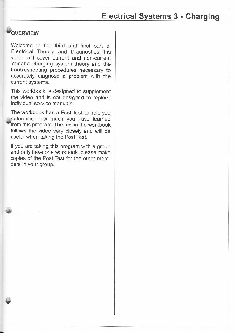
Welcome to the third and final part ofElectrical Theory and Diagnostics.Thisvideo will cover current and non-currentYamaha charging system theory and thetroubleshooting procedures necessary toaccurately diagnose a problem with thecurrent systems.
This workbook is designed to supplementthe video and is not designed to replaceindividual service manuals.
The workbook has a Post Test to help you
l4determine how much you have learned-from this program. The text in the workbook
follows the video very closely and will beuseful when taking the Post Test.
lf you are taking this program with a groupand only have one workbook, please makecopies of the Post Test for the other mem-bers in your group.
Electrical S stems 3 - Gha in

Electrical Systems 3 - Charging
o*rr= oF ..NTENTS
ovERVtEW .......iINTRODUCTION ...3
CHARGING SYSTEMTHEORY ......4TROUBLESHOOTINGPROCEDURES .....15
CLOSING . . 18
PROGRAM PARTICIPATION
e, Post-Test ..19Videotraining Evaluatiuon Form .....21
,$
{&

Electrical Systems 3 - Charging
(9,*r*oDUcroN
Much like the ignition systems, Yamahacharging systems use the same basicdesign and components and vary mostly inapplication and output.
The main purpose of a charging system isto replenish the power being consumedfrom the battery by electronic equipment,such as ignition systems, lights and acces-sories.
This is achieved by producing AC current,converting it to DC current, and then regu-
r.rlatinq it to maintain a constant balance ofUpo*Er consumption and output.

CHARGING SYSTEM THEORY
The 5 main componentstem are:
a charging sys-
Gharge or Lighting Coil and Magnets:Often referred to as the stator, it producesAC current for the system as magnets spinaround it. The faster the magnets spin themore current the coil produces until itreaches its maximum output.
A diode or series of diodes that are respon-sible for converting the AC current from thestator to DC current for battery chargingand powering DC loads, such as lightingsystems and accessories.
30WxlSOlil x I
Voltage Regulator:After the AC voltage is converted to DC, itgoes to the regulator to prevent the batteryfrom being overcharged. The regulatorinternally monitors the output of the statorand the requirements of the loads.Depending on the type of system, the reg-ulator either sends the excess voltage toground or it cuts off the current to the fieldcoil, which in turn stops the output from thestator.
ln most cases, the regulator and rectifierare incorporated into one solid state com-ponent.
And the Battery: stores the electricity thatis generated by the charging system.
lchomicai actionl

[9ft'" two types of charging systems are ACmagneto and AC generator. The main dif-ference between these is the magneto typeuses permanent magnets and the AC gen-erator uses an electromagnet.
Once we know how the comPonents all
work, the troubleshooting procedures canbe broken into each section.
There are three variations of the magneto-type system. The least complicated is theSingle Phase Half Wave SYstem.
, r lt is called single phase because it usesvon" single lead coil and half wave because
a single diode rectifier is used to eliminatehalf of the AC output to convert it to DCpower.
This system is typically used on 6-volt orsmall 12-volt applications that require mini-mal output.
On some scooters, this type is also used topower AC lighting systems before beingconverted to DC power.
{&Whit" Off-Road applications like theWR400 and Banshee, use this sYstemwithout a rectifier to make it a regulated AClighting system.
For applications that require a little moreoutput, a Single-Phase FullWave Systemis better suited. This system uses a duallead coil and a four-diode rectifier. The duallead coil supplies AC current from bothleads into a configuration of four diodes.
This diode configuration is known as a fullbridge rectifier, because they are all
ll,bridged together so both sides of the ACcurrent is captured.
Electrical Systems 3 - Charging
SINGLE-PHASEAC SINGLE-PHASE,HALF-WAVE R ECTIFICATION
fuA+{_M
SINGLE.PHASE AC SINGLE-PHASEFULL-WAVERECTIFICATION
I
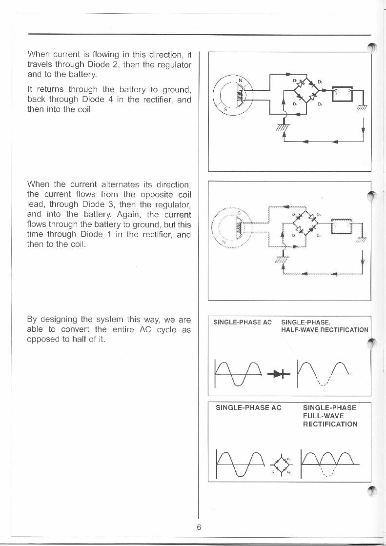
When current is flowing in this direction, ittravels through Diode 2, then the regulatorand to the battery.
It returns through the battery to ground,back through Diode 4 in the rectifier, andthen into the coil.
When the current alternates its direction,the current flows from the opposite coillead, through Diode 3, then the regulator,and into the battery. Again, the currentflows through the battery to ground, but thistime through Diode 1 in the rectifier, andthen to the coil.
By designing the system this way, we areable to convert the entire AC cycle asopposed to half of it.
SINGLE-PHASEAC SINGLE-PHASE,HALF-WAVE R ECTI FICATION
SINGLE.PHASE AC SINGLE-PHASEFULL.WAVERECTIFICATION
t6

Electrical Systems 3 - Charqinq
lsfor models that need the most output froma compact sized charging system, a Three-Phase FullWave System is typically used.
These models include larger motorcycles,such as the Venture and Road Star, as wellas larger outboard models like the 225 and250 horsepower models.
Due to the power required from manyaccessories and DC powered ignition sys-tems, the three-phase full wave system isbest suited for this application.
A three phase full wave charging systemuses three coils wired together as opposed
[$lo one dual lead coil in the single-phasesystem.
This system also uses six diodes instead offour, because it takes two diodes per coillead in a full wave system (two more diodes
(,"*[gre added to compensate for the third coilYead). As you can see, the diode configura-
tion in this rectifier is somewhat differentthan that of a single phase full wave sys-tem.
AC MAGNETO
MAINFUSE

The three-phase full wave system actuallyhas six different combinations that currentcan flow through the coils. As the magnetspins by the A and B coils, current flowsthrough it in one direction and follows thepath you see here.
When a magnet with opposite poles pass-es by the same coils, it flows in the oppositedirection through the coil. However, thediode configuration causes it to take aslightly different path through the rectifier.
The same thing occurs when the magnetspass by the A and C coils, and then theopposite magnets pass by them as well.
Electrical Systems 3 - Charging
$t
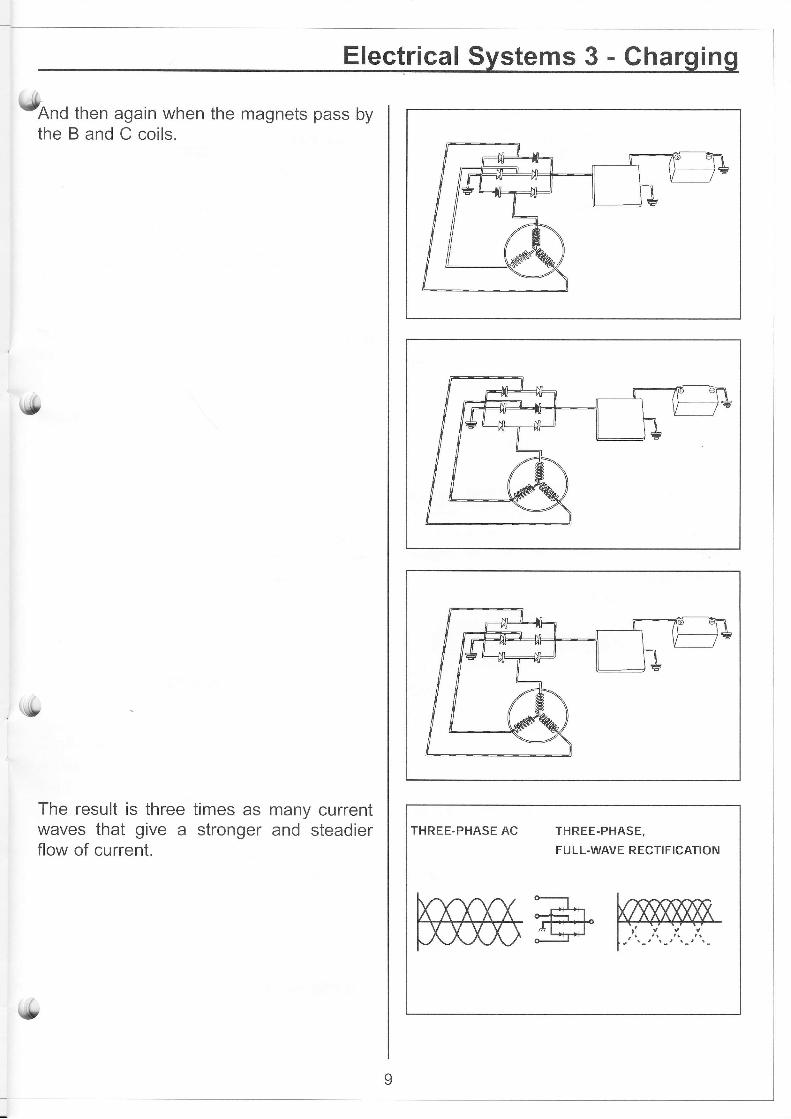
UonO then again when the magnets pass bytheBandCcoils.
The result is three times as many currentwaves that give a stronger and steadierflow of current.
s9
\,
THREE-PHASE AC THREE-PHASE,
FU LL-WAVE RECTIFICATION

The other type of charging system Yamahauses is the AC Generator. This system isalso a three phase fully rectified system forhigh output.
As mentioned earlier, the AC generatoruses an electromagnet instead of a perma-nent magnet to produce current within thestator.
Some models have a fixed field that usesDC current from the regulator to power thefield coil. When the engine is started, asteel rotor spins around the energized fieldcoil and becomes a large magnet. Theelectromagnet spinning inside of the statornow creates the necessary current insidethe stator, which is then rectified and regu-lated before being sent to the battery.
Other models have a rotating field designthat uses a set of brushes and slip rings toenergize the field coil that is rotating insidethe stator. Once again, the spinning elec-tromagnet creates current flow in the stator,which is rectified and regulated for batterycharging.
The method of regulation on this type ofsystem is somewhat different from themagneto-type. The magneto system bleedsexcess current to ground, where the ACgenerator cuts off the current to the fieldcoil by disconnecting the negative side ofthe field. This completely disables thecharging system until the regulator detectsthe need for more current. lt then recon-nects the current to the field coil and thecharging systems functions again. Becauseit is transistor controlled within the regula-tor, this all happens many times per sec-ond.
Full wave rectification of these two systemsalso uses six diodes, exactly the same aswith the magneto-type system.
AC GENERATOR
FUSF
,r=BAr
rFRY
f,SATTERY
f'
&rn" final system used by Yamaha is the
integrated AC generator. This system actu-
ally operates exactly the same as the brush
type AC generator. The only difference isthe regulator and rectifier are built inside
the generator instead of being separatecomponents.
Before we get into the actual troubleshoot-ing of the charging system, let's review the
tools required to do the job, and then deter-
mine if there is a problem with the charging
system.
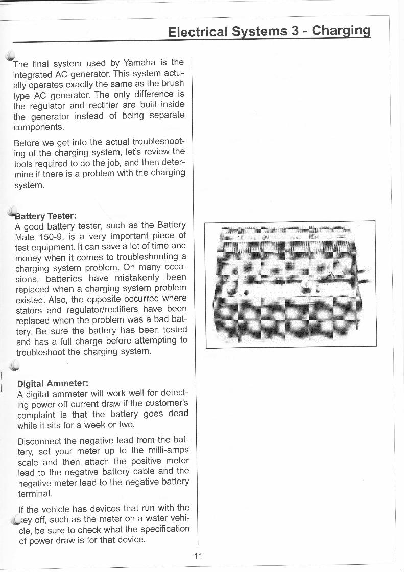
lrlBattery Tester:A good battery tester, such as the BatteryVtJte 150-9, is a very important piece oftest equipment. lt can save a lot of time and
money when it comes to troubleshooting a
charging system problem. On many occa-
sions, batteries have mistakenly beenreplaced when a charging system problem
existed. Also, the opposite occurred wherestators and regulator/rectifiers have been
replaced when the problem was a bad bat-
tery. Be sure the battery has been tested
and has a full charge before attempting to
troubleshoot the charging system'
-it
Digital Ammeter:A digital ammeter will work well for detect-
ing power off current draw if the customer'scomplaint is that the battery goes dead
while it sits for a week or two.
Disconnect the negative lead from the bat-
tery, set your meter up to the milli-ampsscale and then attach the positive meterlead to the negative battery cable and the
negative meter lead to the negative batteryterminal.
lf the vehicle has devices that run with the
*{',(ey off, such as the meter on a water vehi-
cle, be sure to check what the specificationof power draw is for that device.
!
I
Electrical Svstems 3 - Cha rn

ln this case the current draw should not bemore than 10 milli-amps. lf it is more, thendetermine if the device is the problem or ifsomething else is causing the higher thannormal current draw.
Remove the device from the circuit and ifthe current draw is eliminated, then weknow the device is the problem.
lf the current draw remains, check thediodes in the rectifier for a short to ground.
lf the vehicle you are working on does nothave any devices that run with the key off,there should be zero current draw. lf thereis a current draw, then the rectifier is prob-ably bad and is bleeding the battery currentto ground. Replace it as necessary.
Analog DC Ammeter:This meter will be used to perform the firsttest on the actual charging system. A digi-tal meter with a shunt will also work, but theanalog version is visually easier to read.
This type of .meter is polarity sensitive andhas the needle in the center. lt will measurewhen there is a current draw by swinging tothe negative side of the scale and alsoshow what the current output from thecharging system is by how far the needlegoes into the positive side of the scale. Youshould use an ammeter that has a mini-mum capability of 20 amps.
This test can be performed on any DCcharging system but does not apply to AClighting systems. Check the service manualof the model you are working on for specifi-cations.
Locate and remove the main fuse. Connectthe meter leads to the fuse holders and turnthe main switch to the ON position. Themeter reading should be on the negativeside. lf not, the polarity is wrong and theleads should be switched.
Student Nofes; +
f
th
Electrical Systems 3 - Gharging
\turt the engine and let it idle. The needlewill still be slightly in the negative (approxi-mately 1 to 3 amps). lf it is any higher thanthat, check for things like a mis-adjustedbrake light switch or high current drawingaccessories activated.
Slowly accelerate the engine while watch-ing the ammeter. As the engine rpm rises,the needle should begin moving towardszero. When it reaches zero, note the rpm'This is what is known as the "break even"point and is typically between 1,500 and3,000 rpm.
,, The needle should swing to the positivevside of the meter and climb towards maxi-
mum output as the rpm rises. This indicatesthe charging system is in good workingcondition.
However, if the needle does not movetowards the break even point or does notreach it until the engine rpm is approachingwhere maximum output should be, there isdefinitely a problem with the charging sys-tem that will now require troubleshooting ofthe system.
Once you have determined that a problemwith the charging system does in fact exist,
tlrhe following two tools can be used to trou-bleshoot the system:
Multi-meter:Preferably digital, will be used to measurevoltage outputs and perform resistance andshort to ground tests.
Peak Reading Voltmeteror Rapair Adaptor:This can be used to measure peak voltageoutput from a magneto charging systemsstator under cranking conditions. This is avery accurate test that is most frequentlyused when conditions make it impossible to
run the engine.{'
Student Nofes;

After a problem with the charging systemhas been established, but before you begintroubleshooting the system, verify that allconnectors and wires are in good condition.
A very frequent charging system problem isnot the failure of a component, but in fact acorroded connector that melted from theheat build up; caused by the increasedresistance.
lf that all checks out as good, then proceedwith troubleshooting the system.
Every charging system has a coil of onetype or another as an AC power source, arectifier to convert it to DC current and aregulator to limit the amount of current flowto the battery. ln most cases today, thecharging systems incorporate the rectifierand the regulator into one solid state com-ponent.
This makes the actual troubleshootingprocess quite easy. lf the stator has the cor-rect AC output, the problem can only be theregulator/rectifier.
lf the problem is overcharging, the onlyfaulty component can be the voltage regu-lator. A good indicator of an overchargingcondition with a conventional battery, is thatit constantly needs water added, becausethe heat generated by the constant charg-ing evaporates the water. A sealed batterywill constantly be very warm to touch. Bothtypes will eventually fail from the heat.
The typical charging system problem iseither no charging or low charging rates.Some of the commonly found causes forthese problems are an open or shorted toground stator, an open or shorted diodeinside the rectifier or a regulator malfunc-tion.
Student Nofes: a
.il
4it
14
'TI
Electrical Systems 3 - Charging
utROUBLESHOOTING PROCEDURES
AG Lighting System:Although this system technically is not acharging system, it still falls into that cate-gory.
lf the system does not work at all, check thelight switch, wiring and bulbs first. lf theIights work but are dim, disconnect the yel-low bullet connector and insert the positivelead of your voltmeter. Attach the negativemeter lead to ground and set the meter tomeasure 30 volts AC.
6lr3tart and rev the engine to 5,000 rpm. Themeter should read a minimum of 30 voltsAC. lf it does, the regulator is the problemand should be replaced. lf it does not, thelighting coil is the problem. Perform a resis-tance test on the lighting coil to back upyour findings.
lf the complaint is "it keeps blowing lightbulbs," first verify that the correct bulbshave been installed. lf so, the regulator isnot functioning properly and should bereplaced.
Single-Phase Full Wave System:This system is used mainly on Wave-
S''f.unners and small to medium sized out-boards.
Due to the fact it is sometimes difficult torun these models in your shop, we willdemonstrate how to troubleshoot this sys-tem at cranking speed instead of with theengine running.
Using the Rapair Adaptor, we can checkthe cranking output from the charge coil ofthe stator. Connect the Rapair leads to thetwo coil leads and crank the engine over.On this model, we should get a DC voltageof 8 to 9 volts. lf the meter indicates the out-
,, put of the coil is good, then replace the reg-('ulator/rectifier. lf lt indicates it is bad, verify
Student Nofes:

your findings by performing a resistanceand short to ground test and replace asnecessary.
Magneto Three Phase Full Wave System:This is the most common system usedtoday byYamaha because of its high outputability, minimal size and fewest parts. Youwill find it on almost all motorcycles, ATV'sand large outboards.
Start by locating and disconnecting thethree-pin connector of the stator. Typically, ithas three white wires. Set your meter toread at least 1O0volts AC. The three voltagetests we will perform are from A to B, B toC and A to C. Measure the voltage at allthree points with the engine rpm highenough to get a reading of 50 to 60 voltsAC. lf the voltage is substantially lower, per-form a resistance and short to ground testand replace as necessary. lf all three testsare good, then replace the regulator/rectifi-er.
Integrated AC Generator:As mentioned earlier, this system uses anelectromagnet instead of a permanent one.
When using this type of system, it is nec-essary to test the input side of the stator aswell as the output side. The input side iswhat is known as the field coil. When it isenergized, it becomes the electromagnet.
Before testing components, check thephysical condition of the brushes and theirwires. lf they are worn out, replace themand retest the system output at the mainfuse using the ammeter.
lf the brushes are in good condition, testthe rotor at the slip rings before reinstallingthe brushes. First, check the resistancebetween the two slip rings and then checkfor a short to ground between one of theslip rings and the core of the rotor.
Student Nofes: n
o
'ID
16
tt}

(9Reinstall the brush assembly and check forbattery voltage at the positive brush. Repairthe wiring (as necessary) if battery voltageis not present.
Next, is the regulator bypass test. Use ajumper wire from ground to the negativebrush holder and start the engine. lf thecharging system now functions, replace thevoltage regulator.
lf not, check for AC voltage from the stator.It should be approximately g volts at an idleand as high as 12 to 13 at 4,000 rpm. Besure to check all three-wire combinations. lf
{9n" or all are below specification, the statoris bad. Once again, back up your findingsby doing a resistance and short to groundtest.
Electrical Systems 3 - Gharging
Student Nofes:
lf the voltage is good, then the rectifier isbad and should be replaced.
lf these procedures are followed, youshould be able to properly diagnose acharging system problem quickly and accu-rately without replacing parts unnecessari-ly.
tlr
c


![Awdrrtr]@ffi. - KVIC](https://static.fdokumen.com/doc/165x107/631d5607b8a98572c10d504e/awdrrtrffi-kvic.jpg)