ferd_arc_1_999.pdf - WordPress.com
781
This is archive of FE R&D group messages (https://groups.yahoo.com/neo/groups/ferd/info) Attachments/files/referenced links saved into subfolders with name same as message number Contents #1 deleted................................................................................................................................... 20 #2 Hello :-) ................................................................................................................................ 20 #3 Re: Hello :-) .......................................................................................................................... 21 #4 RE: [ferd] Re: Hello :-)......................................................................................................... 21 #5 ferd041 archive ..................................................................................................................... 22 #6 [offtopic] Tao of FE ;-) ......................................................................................................... 23 #7 RE: [ferd] Re: Hello :-)......................................................................................................... 24 #8 Re: [ferd] [offtopic] Tao of FE ;-) ........................................................................................ 25 #9 RE: [ferd] [offtopic] Tao of FE ;-)........................................................................................ 25 #10 new member ....................................................................................................................... 25 #11 RE: [ferd] Re: Hello :-)....................................................................................................... 25 #12 [offtopic] conspiracy...about Patrick Kelly's book :-) ........................................................ 26 #13 Re: [ferd] Re: Hello :-) ....................................................................................................... 29 #14 Re: [ferd] [offtopic] conspiracy...about Patrick Kelly's book :-) ........................................ 30 #15 Re: [ferd] Re: Hello :-) ....................................................................................................... 30 #16 RE: [ferd] Re: Hello :-)....................................................................................................... 30 #17 RE: [ferd] [offtopic] conspiracy...about Patrick Kelly's book :-) ....................................... 31 #18 RE: [ferd] Re: Hello :-)....................................................................................................... 31 #19 Re: [ferd] Re: Hello :-) ....................................................................................................... 32 #20 Re: [ferd] new member ....................................................................................................... 33 #21 RE: [ferd] Re: Hello :-)....................................................................................................... 33 #22 Re: [ferd] Hello :-) .............................................................................................................. 34 #23 Re: [ferd] new member ....................................................................................................... 36 #24 Re: [ferd] Hello :-) .............................................................................................................. 36 #25 RE: [ferd] new member ...................................................................................................... 36 #26 FW: ferd041 archive ........................................................................................................... 37 #27 RE: [ferd] Hello :-) ............................................................................................................. 37 #28 Re: [ferd] FW: ferd041 archive .......................................................................................... 37 #29 Re: [ferd] Hello :-) .............................................................................................................. 37 #30 RE: [ferd] Hello :-) ............................................................................................................. 38 #31 RE: [ferd] new member (projects) ...................................................................................... 39 #32 Re: [ferd] Hello :-) .............................................................................................................. 41 #33 RE: [ferd] new member (projects) ...................................................................................... 41 #34 RE: [ferd] Hello :-) ............................................................................................................. 42 #35 Re: [ferd] new member (projects) ...................................................................................... 42 #36 RE: [ferd] Hello :-) ............................................................................................................. 45 #37 RE: [ferd] new member (projects) ...................................................................................... 45 #38 Re: [ferd] new member (projects) ...................................................................................... 46 #39 Re: [ferd] Hello :-) .............................................................................................................. 46 #40 [reading] Bucking Coils produce Energy Gain .................................................................. 47 #41 Re: [ferd] [reading] Bucking Coils produce Energy Gain.................................................. 48 #42 Re: [ferd] new member (projects) ...................................................................................... 48 #43 Re: [ferd] new member (projects) ...................................................................................... 50 #44 Re: [ferd] new member (projects) ...................................................................................... 50 #45 Re: [ferd] new member (projects) ...................................................................................... 51 #46 RE: [ferd] new member (projects) ...................................................................................... 52
-
Upload
khangminh22 -
Category
Documents
-
view
0 -
download
0
Transcript of ferd_arc_1_999.pdf - WordPress.com

This is archive of FE R&D group messages (https://groups.yahoo.com/neo/groups/ferd/info) Attachments/files/referenced links saved into subfolders with name same as message number Contents
#1 deleted...................................................................................................................................20 #2 Hello :-) ................................................................................................................................20 #3 Re: Hello :-) ..........................................................................................................................21 #4 RE: [ferd] Re: Hello :-).........................................................................................................21 #5 ferd041 archive .....................................................................................................................22 #6 [offtopic] Tao of FE ;-).........................................................................................................23 #7 RE: [ferd] Re: Hello :-).........................................................................................................24 #8 Re: [ferd] [offtopic] Tao of FE ;-) ........................................................................................25 #9 RE: [ferd] [offtopic] Tao of FE ;-)........................................................................................25 #10 new member .......................................................................................................................25 #11 RE: [ferd] Re: Hello :-).......................................................................................................25 #12 [offtopic] conspiracy...about Patrick Kelly's book :-) ........................................................26 #13 Re: [ferd] Re: Hello :-) .......................................................................................................29 #14 Re: [ferd] [offtopic] conspiracy...about Patrick Kelly's book :-)........................................30 #15 Re: [ferd] Re: Hello :-) .......................................................................................................30 #16 RE: [ferd] Re: Hello :-).......................................................................................................30 #17 RE: [ferd] [offtopic] conspiracy...about Patrick Kelly's book :-) .......................................31 #18 RE: [ferd] Re: Hello :-).......................................................................................................31 #19 Re: [ferd] Re: Hello :-) .......................................................................................................32 #20 Re: [ferd] new member.......................................................................................................33 #21 RE: [ferd] Re: Hello :-).......................................................................................................33 #22 Re: [ferd] Hello :-)..............................................................................................................34 #23 Re: [ferd] new member.......................................................................................................36 #24 Re: [ferd] Hello :-)..............................................................................................................36 #25 RE: [ferd] new member ......................................................................................................36 #26 FW: ferd041 archive...........................................................................................................37 #27 RE: [ferd] Hello :-) .............................................................................................................37 #28 Re: [ferd] FW: ferd041 archive ..........................................................................................37 #29 Re: [ferd] Hello :-)..............................................................................................................37 #30 RE: [ferd] Hello :-) .............................................................................................................38 #31 RE: [ferd] new member (projects)......................................................................................39 #32 Re: [ferd] Hello :-)..............................................................................................................41 #33 RE: [ferd] new member (projects)......................................................................................41 #34 RE: [ferd] Hello :-) .............................................................................................................42 #35 Re: [ferd] new member (projects) ......................................................................................42 #36 RE: [ferd] Hello :-) .............................................................................................................45 #37 RE: [ferd] new member (projects)......................................................................................45 #38 Re: [ferd] new member (projects) ......................................................................................46 #39 Re: [ferd] Hello :-)..............................................................................................................46 #40 [reading] Bucking Coils produce Energy Gain ..................................................................47 #41 Re: [ferd] [reading] Bucking Coils produce Energy Gain..................................................48 #42 Re: [ferd] new member (projects) ......................................................................................48 #43 Re: [ferd] new member (projects) ......................................................................................50 #44 Re: [ferd] new member (projects) ......................................................................................50 #45 Re: [ferd] new member (projects) ......................................................................................51 #46 RE: [ferd] new member (projects)......................................................................................52
2
#47 RE: [ferd] new member (projects)......................................................................................55 #48 Re: [ferd] new member (projects) ......................................................................................56 #49 Re: [ferd] new member (projects) ......................................................................................56 #50 Re: [ferd] new member (projects) ......................................................................................56 #51 Re: [ferd] new member (projects) ......................................................................................57 #52 Re: [ferd] new member (projects) ......................................................................................59 #53 Re: [ferd] new member (projects) ......................................................................................60 #54 Re: [ferd] new member (projects) ......................................................................................60 #55 Off topic: New Hendershot posting by Akula. ...................................................................61 #56 RE: [ferd] new member (projects)......................................................................................61 #57 RE: [ferd] new member (projects)......................................................................................61 #58 RE: [ferd] new member (projects)......................................................................................62 #59 new member .......................................................................................................................63 #60 Re: [ferd] new member.......................................................................................................63 #61 [offtopic] Bi-Toroid Transformer demo.............................................................................64 #62 Re: [ferd] new member.......................................................................................................64 #63 Re: [ferd] [offtopic] Bi-Toroid Transformer demo ............................................................64 #64 Re: [ferd] [offtopic] Bi-Toroid Transformer demo ............................................................65 #65 Re: [ferd] [offtopic] Bi-Toroid Transformer demo ............................................................66 #66 Re: [ferd] new member.......................................................................................................66 #67 Re: [ferd] [offtopic] Bi-Toroid Transformer demo ............................................................66 #68 RE: [ferd] [offtopic] Bi-Toroid Transformer demo............................................................67 #69 question - what is this component on the pictures..............................................................68 #70 Re: [ferd] [offtopic] Bi-Toroid Transformer demo ............................................................70 #71 Re: [ferd] [offtopic] Bi-Toroid Transformer demo ............................................................72 #72 Re: [ferd] [offtopic] Bi-Toroid Transformer demo ............................................................72 #73 Re: [ferd] question - what is this component on the pictures .............................................73 #74 Re: [ferd] [offtopic] Bi-Toroid Transformer demo ............................................................74 #75 Re: [ferd] [offtopic] Bi-Toroid Transformer demo ............................................................75 #76 RE: [ferd] [offtopic] Bi-Toroid Transformer demo............................................................75 #77 RE: [ferd] question - what is this component on the pictures ............................................75 #78 Re: [ferd] [offtopic] Bi-Toroid Transformer demo ............................................................76 #79 On how to get OU...............................................................................................................76 #80 Re: [ferd] [offtopic] Bi-Toroid Transformer demo ............................................................78 #81 Re: [ferd] [offtopic] Bi-Toroid Transformer demo ............................................................79 #82 Re: [ferd] new member.......................................................................................................82 #83 RE: [ferd] [offtopic] Bi-Toroid Transformer demo............................................................82 #84 Re: [ferd] [offtopic] Bi-Toroid Transformer demo ............................................................84 #85 Linear regulator ..................................................................................................................84 #86 RE: [ferd] Linear regulator .................................................................................................86 #87 Re: [ferd] [offtopic] Bi-Toroid Transformer demo ............................................................86 #88 Re: [ferd] Linear regulator..................................................................................................87 #90 RE: [ferd] [offtopic] Bi-Toroid Transformer demo............................................................87 #91 Re: [ferd] [offtopic] Bi-Toroid Transformer demo ............................................................99 #92 Re: [ferd] [offtopic] Bi-Toroid Transformer demo ..........................................................100 #93 Re: [ferd] [offtopic] Bi-Toroid Transformer demo ..........................................................101 #94 Re: [ferd] [offtopic] Bi-Toroid Transformer demo ..........................................................102 #95 Re: [ferd] [offtopic] Bi-Toroid Transformer demo ..........................................................103 #96 Re: [ferd] [offtopic] Bi-Toroid Transformer demo ..........................................................103 #97 Re: [ferd] [offtopic] Bi-Toroid Transformer demo ..........................................................104 #98 Re: [ferd] [offtopic] Bi-Toroid Transformer demo ..........................................................104 #99 RE: [ferd] [offtopic] Bi-Toroid Transformer demo..........................................................106
3
#100 Re: [ferd] [offtopic] Bi-Toroid Transformer demo ........................................................106 #101 Re: [ferd] [offtopic] Bi-Toroid Transformer demo ........................................................110 #102 Re: [ferd] [offtopic] Bi-Toroid Transformer demo ........................................................110 #103 Re: [ferd] [offtopic] Bi-Toroid Transformer demo ........................................................111 #104 Re: [ferd] [offtopic] Bi-Toroid Transformer demo ........................................................112 #105 Re: [ferd] [offtopic] Bi-Toroid Transformer demo ........................................................112 #106 1200V MOSFET ............................................................................................................113 #107 [offtopic] Silicon Carbide based devices........................................................................113 #108 Re: [ferd] [offtopic] Silicon Cabbide based devices ......................................................113 #109 [offtopic] grid tied inverter .............................................................................................114 #110 Re: [ferd] [offtopic] Bi-Toroid Transformer demo ........................................................114 #111 RE: [ferd] [offtopic] Bi-Toroid Transformer demo........................................................115 #112 group messages archive..................................................................................................116 #113 RE: [ferd] [offtopic] Silicon Cabbide based devices......................................................116 #114 Re: [ferd] [offtopic] Silicon Cabbide based devices ......................................................117 #115 Re: [offtopic] grid tied inverter ......................................................................................117 #116 Re: [ferd] [offtopic] Bi-Toroid Transformer demo ........................................................117 #117 [offtopic] Power and Creed ............................................................................................118 #118 Re: [ferd] [offtopic] Power and Creed............................................................................123 #119 capacitor coil as a secondary ..........................................................................................123 #120 RE: [ferd] [offtopic] Power and Creed...........................................................................126 #121 RE: [ferd] [offtopic] Bi-Toroid Transformer demo........................................................126 #122 Re: [ferd] [offtopic] Bi-Toroid Transformer demo ........................................................127 #123 Re: [ferd] capacitor coil as a secondary..........................................................................128 #124 Re: [ferd] capacitor coil as a secondary..........................................................................128 #125 Re: [ferd] [offtopic] Bi-Toroid Transformer demo ........................................................129 #126 Re: [ferd] capacitor coil as a secondary..........................................................................130 #127 Re: [ferd] [offtopic] Bi-Toroid Transformer demo ........................................................130 #128 RE: [ferd] capacitor coil as a secondary.........................................................................130 #129 RE: [ferd] capacitor coil as a secondary.........................................................................131 #130 RE: [ferd] capacitor coil as a secondary.........................................................................132 #131 RE: [ferd] [offtopic] Bi-Toroid Transformer demo........................................................133 #132 [offtopic] ferroelectric capacitors ...................................................................................134 #133 Re: [ferd] capacitor coil as a secondary..........................................................................135 #134 Re: [ferd] [offtopic] Bi-Toroid Transformer demo ........................................................136 #135 Re: [ferd] capacitor coil as a secondary..........................................................................136 #136 Re: [ferd] capacitor coil as a secondary..........................................................................137 #137 Re: [ferd] [offtopic] Bi-Toroid Transformer demo ........................................................137 #138 RE: [ferd] capacitor coil as a secondary.........................................................................138 #139 RE: [ferd] capacitor coil as a secondary.........................................................................138 #140 RE: [ferd] capacitor coil as a secondary.........................................................................139 #141 Re: [ferd] capacitor coil as a secondary..........................................................................139 #142 Re: [ferd] [offtopic] Bi-Toroid Transformer demo ........................................................139 #143 [offtopic] ferroelectric capacitors ...................................................................................140 #144 Re: [ferd] capacitor coil as a secondary..........................................................................140 #145 RE: [ferd] capacitor coil as a secondary.........................................................................141 #146 Re: [ferd] [offtopic] Bi-Toroid Transformer demo ........................................................141 #147 Re: [ferd] [offtopic] Bi-Toroid Transformer demo ........................................................142 #148 Re: [ferd] [offtopic] Bi-Toroid Transformer demo ........................................................142 #149 Re: [ferd] [offtopic] Bi-Toroid Transformer demo ........................................................143 #150 [offtopic] World's Simplest Electric Train .....................................................................144 #151 Bi Toriod Transformer :Simple Anti Lenz circuit..........................................................145

4
#152 Re: Bi Toriod Transformer :Simple Anti Lenz circuit ...................................................146 #153 Re: [ferd] Re: Bi Toriod Transformer :Simple Anti Lenz circuit...................................149 #154 RE: [ferd] Re: Bi Toriod Transformer :Simple Anti Lenz circuit..................................151 #155 Re: [ferd] Re: Bi Toriod Transformer :Simple Anti Lenz circuit...................................152 #156 Re: [ferd] Re: Bi Toriod Transformer :Simple Anti Lenz circuit...................................153 #157 RE: [ferd] Re: Bi Toriod Transformer :Simple Anti Lenz circuit..................................153 #158 Re: [ferd] Re: Bi Toriod Transformer :Simple Anti Lenz circuit...................................154 #159Re: [ferd] capacitor coil as a secondary...........................................................................154 #160 Re: [ferd] capacitor coil as a secondary..........................................................................155 #161 Power supply ..................................................................................................................162 #162 RE: [ferd] capacitor coil as a secondary.........................................................................166 #163 RE: [ferd] Power supply.................................................................................................167 #164 Re: [ferd] Power supply..................................................................................................167 #165 Re: [ferd] Power supply..................................................................................................167 #166 Re: [ferd] Power supply..................................................................................................168 #167 Re: [ferd] Power supply..................................................................................................169 #168 RE: [ferd] Power supply.................................................................................................169 #169 Re: [ferd] Power supply..................................................................................................170 #170 Re: [ferd] Power supply..................................................................................................170 #171 Re: [ferd] Power supply..................................................................................................171 #172 Re: [ferd] Power supply..................................................................................................171 #173 RE: [ferd] Power supply.................................................................................................172 #174 [offtopic] Movement using inertia forces.......................................................................174 #175 Re: [ferd] [offtopic] Movement using inertia forces ......................................................175 #176 RE: [ferd] [offtopic] Movement using inertia forces......................................................176 #177 Re: [ferd] [offtopic] Movement using inertia forces ......................................................179 #178 Re: [ferd] [offtopic] Movement using inertia forces ......................................................180 #179 Re: [ferd] [offtopic] Movement using inertia forces ......................................................180 #180 RE: [ferd] [offtopic] Movement using inertia forces......................................................181 #181 Re: [ferd] [offtopic] Movement using inertia forces ......................................................182 #182 New landscapes for EM theory ?....................................................................................182 #183 Re: [ferd] New landscapes for EM theory ? ...................................................................183 #184 RE: [ferd] Power supply [4 Attachments] ......................................................................183 #185 Re: [ferd] Power supply..................................................................................................184 #186 Re: [ferd] Power supply..................................................................................................186 #187 [offtopic] one more useless toy :-)..................................................................................186 #188 [reading] The Interference Anomaly ..............................................................................187 #189 Re: [ferd] [reading] The Interference Anomaly .............................................................201 #190 Re: [ferd] [reading] The Interference Anomaly .............................................................201 #191 Re: [reading] The Interference Anomaly........................................................................202 #192 RE: [ferd] Re: [reading] The Interference Anomaly ......................................................202 #193 RE: [ferd] Re: [reading] The Interference Anomaly ......................................................202 #194 [ferd] Re: [reading] The Interference Anomaly .............................................................203 #195 Re: [ferd] Re: [reading] The Interference Anomaly.......................................................203 #196 RE: [ferd] Re: [reading] The Interference Anomaly ......................................................206 #197 [ferd] Re: [reading] The Interference Anomaly .............................................................206 #198 RE: [ferd] Re: [reading] The Interference Anomaly ......................................................206 #199 [ferd] Re: [reading] The Interference Anomaly .............................................................207 #200 Re: [ferd] Re: [reading] The Interference Anomaly.......................................................207 #201 Re: [ferd] Re: [reading] The Interference Anomaly.......................................................215 #202 Re: [ferd] Re: [reading] The Interference Anomaly.......................................................215 #203 Re: [ferd] Re: [reading] The Interference Anomaly.......................................................216

5
#204 Re: [ferd] Re: [reading] The Interference Anomaly.......................................................216 #205 Re: [ferd] Re: [reading] The Interference Anomaly.......................................................216 #206 RE: [ferd] Re: [reading] The Interference Anomaly ......................................................217 #207 RE: [ferd] Re: [reading] The Interference Anomaly ......................................................217 #208 Re: [ferd] Re: [reading] The Interference Anomaly.......................................................218 #209 Re: [ferd] Re: [reading] The Interference Anomaly.......................................................218 #210 Re: [ferd] Re: [reading] The Interference Anomaly.......................................................218 #211 Some device explanations ..............................................................................................219 #212 RE: [ferd] Some device explanations .............................................................................219 #213 Re: [ferd] Some device explanations..............................................................................220 #214 Different subjects- some off topis ..................................................................................220 #215 RE: [ferd] Different subjects- some off topis .................................................................222 #216 Re: [ferd] Different subjects- some off topis..................................................................225 #217 [ferd] Different subjects- some off topis ........................................................................226 #218 RE: [ferd] Different subjects- some off topis .................................................................227 #219 Re: [ferd] Different subjects- some off topis..................................................................227 #220 Re: [ferd] Different subjects- some off topis..................................................................228 #221 [ferd] Different subjects- some off topis ........................................................................228 #222 Re: [ferd] Different subjects- some off topis..................................................................228 #223 AuKW.............................................................................................................................229 #224 [ferd] Different subjects- some off topis ........................................................................230 #225 Re: [ferd] AuKW............................................................................................................230 #226 [ferd] AuKW...................................................................................................................231 #227 RE: [ferd] Different subjects- some off topis .................................................................231 #228 RE: [ferd] AuKW ...........................................................................................................232 #229 Re: [ferd] AuKW............................................................................................................232 #230 RE: [ferd] AuKW ...........................................................................................................232 #231 Tools for the lab..............................................................................................................233 #232 RE: [ferd] Tools for the lab ............................................................................................234 #233 Re: [ferd] AuKW............................................................................................................234 #234 Re: [ferd] Tools for the lab.............................................................................................234 #235 RE: [ferd] AuKW ...........................................................................................................235 #236 Re: [ferd] AuKW............................................................................................................235 #237 Re: [ferd] Tools for the lab.............................................................................................236 #238 RE: [ferd] AuKW ...........................................................................................................236 #239 Re: [ferd] AuKW............................................................................................................237 #240 RE: [ferd] AuKW ...........................................................................................................238 #241 tubes ;-) ...........................................................................................................................239 #242 1st April entertainment ...................................................................................................240 #243 RE: [ferd] AuKW ...........................................................................................................240 #244 Re: [ferd] tubes ;-) ..........................................................................................................241 #245 Re: [ferd] AuKW............................................................................................................241 #246 Re: [ferd] AuKW............................................................................................................242 #247 Re: [ferd] AuKW............................................................................................................242 #248 RE: [ferd] tubes ;-)..........................................................................................................242 #249 Re: [ferd] tubes ;-) ..........................................................................................................243 #250 FW: History bits - Negative Resistance Oscillators / Dynatron effect / Negatron / Screen grid tetrode...............................................................................................................................243 #251 [offtopic] Hand Made Vacuum Tubes............................................................................244 #252 RE: [ferd] tubes ;-)..........................................................................................................244 #253 Re: [ferd] [offtopic] Hand Made Vacuum Tubes ...........................................................244 #254 Re: [ferd] [offtopic] Hand Made Vacuum Tubes ...........................................................245

6
#255 RE: [ferd] [offtopic] Hand Made Vacuum Tubes ..........................................................245 #256 Re: [ferd] AuKW............................................................................................................246 #257 Re: [ferd] 1st April entertainment ..................................................................................246 #258 RE: [ferd] 1st April entertainment..................................................................................247 #259 Re: [ferd] AuKW............................................................................................................247 #260 Re: [ferd] tubes ;-) ..........................................................................................................248 #261 Re: [ferd] tubes ;-) ..........................................................................................................248 #262 Re: [ferd] 1st April entertainment ..................................................................................249 #263 Re: [ferd] tubes ;-) ..........................................................................................................249 #264 Re: [ferd] tubes ;-) ..........................................................................................................250 #265 Re: [ferd] tubes ;-) ..........................................................................................................250 #266 Status ..............................................................................................................................251 #267 Re: Status........................................................................................................................251 #268 Re: [ferd] Status..............................................................................................................252 #269 RE: [ferd] Status .............................................................................................................253 #270 RE: [ferd] Status .............................................................................................................253 #271 FW: [ferd] 1st April entertainment.................................................................................254 #272 Re: [ferd] Status..............................................................................................................256 #273 Re: [ferd] 1st April entertainment ..................................................................................256 #274 RE: [ferd] Status .............................................................................................................257 #275 Re: [ferd] Status..............................................................................................................257 #276 Re: [ferd] Status..............................................................................................................258 #277 [ferd] 1st April entertainment .........................................................................................258 #278 Re: [ferd] 1st April entertainment ..................................................................................258 #279 Re: [ferd] Status..............................................................................................................259 #280 RE: [ferd] 1st April entertainment..................................................................................259 #281 RE: [ferd] Status .............................................................................................................260 #282 RE: [ferd] Status .............................................................................................................260 #283 RE: [ferd] Status .............................................................................................................261 #284 Silicon Carbide MOSFET ..............................................................................................262 #285 Re: [ferd] Silicon Carbide MOSFET..............................................................................262 #286 Re: Silicon Carbide MOSFET........................................................................................263 #287 [ferd] Status ....................................................................................................................263 #288 Torsion fields..................................................................................................................264 #289 Re: [ferd] Status..............................................................................................................265 #290 RE: [ferd] Status .............................................................................................................266 #291 [ferd] Entertainment, more fun ;-) ..................................................................................267 #292 RE: [ferd] Torsion fields.................................................................................................267 #293 Re: [ferd] Entertainment, more fun ;-)............................................................................267 #294 [ferd] Torsion fields........................................................................................................268 #295 RE: [ferd] Torsion fields.................................................................................................268 #296 [ferd] Torsion fields........................................................................................................269 #297 another project idea ........................................................................................................269 #298 Re: another project idea..................................................................................................270 #299 auto transformer..............................................................................................................270 #300 Re: auto transformer .......................................................................................................271 #301 Re: auto transformer .......................................................................................................272 #302 Re: [ferd] Re: auto transformer ......................................................................................272 #303 RE: [ferd] Re: auto transformer......................................................................................273 #304 Re: [ferd] Re: auto transformer ......................................................................................273 #305 Re: [ferd] Re: auto transformer ......................................................................................274 #306 Re: [ferd] Re: auto transformer ......................................................................................274
7
#307 Re: [ferd] another project idea........................................................................................275 #308 Re: [ferd] Re: auto transformer ......................................................................................275 #309 Re: [ferd] another project idea........................................................................................276 #310 RE: [ferd] another project idea .......................................................................................276 #311 RE: [ferd] Torsion fields.................................................................................................277 #312 Re: [ferd] another project idea........................................................................................277 #313 Re: [ferd] Torsion fields .................................................................................................278 #314 RE: [ferd] Torsion fields.................................................................................................278 #315 RE: [ferd] another project idea .......................................................................................278 #316 Harold Aspepden ............................................................................................................279 #317 RE: [ferd] Harold Aspepden...........................................................................................281 #318 Re: [ferd] Harold Aspepden ...........................................................................................281 #319 [ferd] Torsion fields........................................................................................................281 #320 Re: [ferd] Harold Aspden, Cyril Smith,... ......................................................................283 #321 RE: [ferd] Harold Aspden, Cyril Smith,.........................................................................284 #322 Re: [ferd] Harold Aspden, Cyril Smith,... ......................................................................284 #323 CEMF .............................................................................................................................284 #324 Re: [ferd] CEMF.............................................................................................................286 #325 Re: [ferd] CEMF.............................................................................................................287 #326 Re: [ferd] CEMF.............................................................................................................288 #327 Re: [ferd] CEMF.............................................................................................................289 #328 Re: [ferd] CEMF.............................................................................................................291 #329 Re: [ferd] CEMF.............................................................................................................291 #330 Re: [ferd] CEMF.............................................................................................................292 #331 RE: [ferd] CEMF............................................................................................................294 #332 RE: [ferd] CEMF............................................................................................................294 #333 Re: [ferd] CEMF.............................................................................................................296 #334 Re: [ferd] CEMF.............................................................................................................297 #335 Re: [ferd] CEMF.............................................................................................................297 #336 Re: [ferd] CEMF.............................................................................................................299 #337 Re: [ferd] CEMF.............................................................................................................300 #338 Re: [ferd] CEMF.............................................................................................................300 #339 Re: [ferd] CEMF.............................................................................................................302 #340 Re: [ferd] CEMF.............................................................................................................302 #341 Re: [ferd] CEMF.............................................................................................................303 #342 Re: [ferd] CEMF.............................................................................................................305 #343 Re: [ferd] CEMF.............................................................................................................308 #344 Re: [ferd] CEMF.............................................................................................................308 #345 Re: [ferd] CEMF.............................................................................................................308 #346 Re: [ferd] CEMF.............................................................................................................309 #347 Re: [ferd] CEMF.............................................................................................................309 #348 Re: [ferd] CEMF.............................................................................................................310 #349 [offtopic] slow start for incandescent light bulbs ...........................................................310 #350 Re: [offtopic] slow start for incandescent light bulbs ....................................................311 #351 RE: [ferd] Re: [offtopic] slow start for incandescent light bulbs ...................................312 #352 [ferd] another project idea - How to build free energy device from your air humidifier.................................................................................................................................................312 #353 Re: [ferd] another project idea - How to build free energy device from your air humidifier ................................................................................................................................314 #354 Re: [ferd] another project idea - How to build free energy device from your air humidifier ................................................................................................................................316
8
#355 RE: [ferd] another project idea - How to build free energy device from your air humidifier ................................................................................................................................316 #356 RE: [ferd] another project idea - How to build free energy device from your air humidifier ................................................................................................................................317 #357 Re: [ferd] another project idea - How to build free energy device from you air humidifier.................................................................................................................................................318 #358 [ferd] another project idea - How to build free energy device from you air humidifier 318 #359 Re: [ferd] another project idea - How to build free energy device from you air humidifier.................................................................................................................................................319 #360 [offtopic] Evaluating NASA's Futuristic EM Drive.......................................................320 #361 Re: [ferd] [offtopic] Evaluating NASA's Futuristic EM Drive ......................................329 #362 RE: [ferd] [offtopic] Evaluating NASA's Futuristic EM Drive......................................329 #363 Re: [ferd] [offtopic] Evaluating NASA's Futuristic EM Drive ......................................329 #364 RE: [ferd] another project idea - How to build free energy device from you air humidifier ................................................................................................................................330 #365 FW: [reading] "The torsion generator of energy" ..........................................................330 #366 RE: [ferd] another project idea - How to build free energy device from you air humidifier ................................................................................................................................333 #367 Re: [ferd] another project idea - How to build free energy device from you air humidifier.................................................................................................................................................333 #368 Re: [ferd] another project idea - How to build free energy device from you air humidifier.................................................................................................................................................333 #369 Re: [ferd] another project idea - How to build free energy device from you air humidifier.................................................................................................................................................334 #370 Tesla Battery...................................................................................................................334 #371 Re: [ferd] Tesla Battery ..................................................................................................335 #372 RE: [ferd] Tesla Battery .................................................................................................335 #373 Re: [ferd] Tesla Battery ..................................................................................................335 #374 RE: [ferd] Tesla Battery .................................................................................................336 #375 [offtopic] Magnets with an OFF Switch.........................................................................336 #376 Re: [offtopic] Magnets with an OFF Switch ..................................................................345 #377 Re: [ferd] [offtopic] Gerry magnet motor.......................................................................346 #378 RE: [ferd] [offtopic] Gerry magnet motor......................................................................348 #379 Re: [ferd] [offtopic] Gerry magnet motor.......................................................................349 #380 Re: [ferd] AuKW............................................................................................................349 #381 IPC Quadra .....................................................................................................................355 #382 RE: [ferd] IPC Quadra....................................................................................................366 #383 Re: [ferd] IPC Quadra ....................................................................................................366 #384 Re: [ferd] IPC Quadra ....................................................................................................367 #385 RE: [ferd] IPC Quadra....................................................................................................367 #386 Re: [ferd] IPC Quadra ....................................................................................................368 #387 Re: [ferd] IPC Quadra ....................................................................................................370 #388 RE: [ferd] IPC Quadra....................................................................................................377 #389 Re: [ferd] [offtopic] Gerry magnet motor.......................................................................377 #390 Re: [ferd] IPC Quadra ....................................................................................................380 #391 Re: [ferd] [offtopic] Gerry magnet motor.......................................................................381 #392 RE: [ferd] [offtopic] Gerry magnet motor......................................................................381 #393 Re: [ferd] [offtopic] Gerry magnet motor.......................................................................382 #394 Measuring output wattage ..............................................................................................382 #395 RE: [ferd] Measuring output wattage .............................................................................383 #396 Re: [ferd] Measuring output wattage..............................................................................385 #397 Re: Measuring output wattage........................................................................................385
9
#398 Re: [ferd] Re: Measuring output wattage .......................................................................386 #399 RE: [ferd] Measuring output wattage .............................................................................387 #400 [ferd] Measuring output wattage ....................................................................................390 #401 Re: [ferd] Measuring output wattage..............................................................................391 #402 [ferd] Measuring output wattage ....................................................................................391 #403 Re: [ferd] Measuring output wattage..............................................................................391 #404 Re: [ferd] Measuring output wattage..............................................................................392 #405 RE: [ferd] Measuring output wattage ............................................................................392 #406 Thane Heins bi-toroid transformer test...........................................................................392 #407 Re: [ferd] Thane Heins bi-toroid transformer test ..........................................................392 #408 Re: [ferd] Thane Heins bi-toroid transformer test ..........................................................393 #409 [ferd] Measuring output wattage ....................................................................................393 #410 Weird fly-back phenomenon ..........................................................................................393 #411 RE: [ferd] Weird fly-back phenomenon.........................................................................394 #412 Re: [ferd] Weird fly-back phenomenon..........................................................................394 #413 one more crazy idea........................................................................................................395 #414 Re: [ferd] one more crazy idea .......................................................................................395 #415 RE: [ferd] one more crazy idea.......................................................................................396 #416 Re: [ferd] one more crazy idea .......................................................................................396 #417 Re: [ferd] one more crazy idea .......................................................................................397 #418 Re: [ferd] one more crazy idea .......................................................................................397 #419 Re: [ferd] one more crazy idea .......................................................................................398 #420 Re: [ferd] one more crazy idea .......................................................................................398 #421 RE: [ferd] one more crazy idea.......................................................................................399 #422 Re: [ferd] one more crazy idea .......................................................................................399 #423 RE: [ferd] one more crazy idea.......................................................................................399 #424 Re: [ferd] one more crazy idea .......................................................................................400 #425 Re: [ferd] one more crazy idea .......................................................................................400 #426 RE: [ferd] one more crazy idea.......................................................................................401 #427 RE: [ferd] one more crazy idea.......................................................................................401 #428 Re: [ferd] one more crazy idea .......................................................................................401 #429 Re: [ferd] one more crazy idea .......................................................................................402 #430 Re: [ferd] one more crazy idea .......................................................................................403 #431 reading - Parametric Oscillator Experiment ...................................................................403 #432 Re: [ferd] one more crazy idea .......................................................................................407 #433 Re: [ferd] one more crazy idea .......................................................................................408 #434 RE: [ferd] one more crazy idea.......................................................................................408 #435 Re: [ferd] one more crazy idea .......................................................................................409 #436 Re: [ferd] one more crazy idea .......................................................................................409 #437 RE: [ferd] one more crazy idea.......................................................................................410 #438 Re: [ferd] one more crazy idea .......................................................................................411 #439 RE: [ferd] one more crazy idea.......................................................................................412 #440 Parametric Oscillation ....................................................................................................412 #441 Re: [ferd] one more crazy idea .......................................................................................414 #442 Re: [ferd] Parametric Oscillation....................................................................................415 #443 Re: Parametric Oscillation..............................................................................................415 #444 Re: [ferd] Re: Parametric Oscillation .............................................................................415 #445 Re: [ferd] Parametric Oscillation....................................................................................416 #446 Re: [ferd] Parametric Oscillation....................................................................................416 #447 RE: [ferd] one more crazy idea.......................................................................................417 #448 Re: [ferd] Re: Parametric Oscillation .............................................................................417 #449 reading - Energy Unlimited magazine and more............................................................417

10
#450 IPC quadra ......................................................................................................................417 #451 Re: [ferd] one more crazy idea .......................................................................................421 #452 RE: [ferd] one more crazy idea [3 Attachments]............................................................423 #453 [offtopic] HYDRAs - hygroscopy driven artificial muscles power a miniature car ......423 #454 Re: [ferd] one more crazy idea .......................................................................................423 #455 Re: [ferd] one more crazy idea .......................................................................................423 #456 Re: [ferd] one more crazy idea .......................................................................................424 #457 Re: [ferd] one more crazy idea .......................................................................................424 #458 Re: [ferd] one more crazy idea .......................................................................................426 #459 Re: [ferd] one more crazy idea .......................................................................................426 #460 Re: [ferd] one more crazy idea .......................................................................................427 #461 RE: [ferd] one more crazy idea.......................................................................................427 #462 Re: [ferd] one more crazy idea .......................................................................................427 #463 RE: [ferd] one more crazy idea.......................................................................................428 #464 RE: [ferd] one more crazy idea.......................................................................................429 #465 Re: [ferd] one more crazy idea .......................................................................................429 #466 Re: [ferd] one more crazy idea .......................................................................................430 #467 mixing magnetic flux......................................................................................................430 #468 Re: mixing magnetic flux ...............................................................................................433 #469 Re: [ferd] Re: mixing magnetic flux ..............................................................................434 #470 Re: [ferd] Re: mixing magnetic flux ..............................................................................435 #471 Re: [ferd] Re: mixing magnetic flux ..............................................................................436 #472 Re: [ferd] Re: mixing magnetic flux ..............................................................................438 #473 reading - Verification and theoretical explanation of the Osamu Ide experiment..........439 #474 Re: [ferd] reading - Verification and theoretical explanation of the Osamu Ide experiment ...............................................................................................................................439 #475 RE: [ferd] reading - Verification and theoretical explanation of the Osamu Ide experiment ...............................................................................................................................440 #476 Re: [ferd] reading - Verification and theoretical explanation of the Osamu Ide experiment ...............................................................................................................................440 #477 RE: [ferd] reading - Verification and theoretical explanation of the Osamu Ide experiment ...............................................................................................................................441 #478 More digging ... ..............................................................................................................442 #479 Re: [ferd] Re: mixing magnetic flux ..............................................................................448 #480 Re: More digging ...........................................................................................................449 #481 Re: [ferd] Re: More digging ... .......................................................................................450 #482 Re: [ferd] More digging .................................................................................................450 #483 RE: [ferd] More digging ... .............................................................................................451 #484 Re: [ferd] Re: More digging ... .......................................................................................451 #485 Re: [ferd] Re: More digging ... .......................................................................................452 #486 Re: [ferd] Re: More digging ... .......................................................................................453 #487 Re: [ferd] Re: More digging ... .......................................................................................454 #488 Re: [ferd] More digging .................................................................................................455 #489 Re: [ferd] More digging .................................................................................................455 #490 Re: [ferd] reading - Verification and theoretical explanation of the Osamu Ide experiment ...............................................................................................................................456 #491 Re: [ferd] More digging .................................................................................................456 #492 Re: [ferd] More digging .................................................................................................457 #493 Re: [ferd] More digging .................................................................................................458 #494 Re: [ferd] More digging .................................................................................................458 #495 RE: [ferd] More digging ... .............................................................................................461 #496 Re: [ferd] More digging .................................................................................................462
11
#497RE: [ferd] More digging ... ..............................................................................................462 #498 Re: [ferd] More digging .................................................................................................463 #499 Re: [ferd] More digging .................................................................................................464 #500 Re: [ferd] More digging .................................................................................................464 #501 Re: [ferd] More digging .................................................................................................465 #502 Re: [ferd] More digging .................................................................................................466 #503 Re: [ferd] More digging .................................................................................................467 #504 RE: [ferd] More digging ... .............................................................................................468 #505 Re: [ferd] More digging .................................................................................................469 #506 Re: [ferd] More digging .................................................................................................469 #507 Re: [ferd] More digging .................................................................................................470 #508 Re: [ferd] More digging .................................................................................................471 #509 Re: [ferd] More digging .................................................................................................472 #510 Re: [ferd] More digging .................................................................................................472 #511 Re: [ferd] More digging .................................................................................................473 #512 RE: [ferd] More digging ... .............................................................................................474 #513 Flower Power - unusual battery design ..........................................................................475 #514 RE: [ferd] More digging ... .............................................................................................478 #515 Re: [ferd] Flower Power - unusual battery design..........................................................478 #516 RE: [ferd] Flower Power - unusual battery design .........................................................478 #517 more crazy ideas .............................................................................................................479 #518 Re: [ferd] More digging .................................................................................................480 #519 Re: [ferd] More digging .................................................................................................480 #520 Re: [ferd] More digging .................................................................................................481 #521 Re: [ferd] More digging .................................................................................................482 #522 Re: [ferd] More digging .................................................................................................482 #523 Re: [ferd] More digging .................................................................................................483 #524 Re: [ferd] More digging .................................................................................................483 #525 Re: [ferd] More digging .................................................................................................484 #526 Re: [ferd] more crazy ideas [1 Attachment] ...................................................................485 #527 Re: [ferd] More digging .................................................................................................486 #528 Re: more crazy ideas.......................................................................................................487 #529 Next Steps ......................................................................................................................488 #530 Re: [ferd] More digging .................................................................................................488 #531 Re: [ferd] More digging .................................................................................................488 #532 RE: [ferd] More digging ... .............................................................................................489 #533 RE: [ferd] More digging ... .............................................................................................489 #534 RE: [ferd] Re: more crazy ideas .....................................................................................490 #535 RE: [ferd] more crazy ideas............................................................................................490 #536 RE: [ferd] More digging ... .............................................................................................490 #537 Re: [ferd] More digging .................................................................................................491 #538 Re: [ferd] More digging .................................................................................................491 #539 Re: [ferd] more crazy ideas ............................................................................................492 #540 RE: [ferd] Next Steps ... .................................................................................................492 #541 Re: [ferd] Next Steps ... ..................................................................................................493 #542 RE: [ferd] more crazy ideas............................................................................................494 #543 RE: [ferd] Next Steps ... .................................................................................................494 #544 Re: [ferd] more crazy ideas ............................................................................................494 #545 RE: [ferd] more crazy ideas............................................................................................495 #546 Re: [ferd] More digging .................................................................................................496 #547 cause: phase transitions -> effect: parameter variation ..................................................496 #548 RE: [ferd] cause: phase transitions -> effect: parameter variation .................................497

12
#549 Re: [ferd] cause: phase transitions -> effect: parameter variation..................................497 #550 Re: [ferd] cause: phase transitions -> effect: parameter variation..................................498 #551 RE: [ferd] cause: phase transitions -> effect: parameter variation .................................498 #552 crazy idea's development - second FE principle illustration ..........................................499 #553 [ferd] crazy idea's development - second FE principle illustration ................................500 #554 RE: [ferd] crazy idea's development - second FE principle illustration.........................500 #555 [ferd] crazy idea's development - second FE principle illustration ................................501 #556 RE: [ferd] crazy idea's development - second FE principle illustration.........................502 #557 [ferd] crazy idea's development - second FE principle illustration ................................503 #558 RE: [ferd] crazy idea's development - second FE principle illustration.........................503 #559 RE: [ferd] crazy idea's development - second FE principle illustration.........................504 #560 [ferd] crazy idea's development - second FE principle illustration ................................507 #561 RE: [ferd] crazy idea's development - second FE principle illustration.........................507 #562 [ferd] crazy idea's development......................................................................................507 #563 [ferd] crazy idea's development......................................................................................509 #564 RE: [ferd] crazy idea's development...............................................................................509 #565 [ferd] crazy idea's development......................................................................................509 #566 RE: [ferd] crazy idea's development...............................................................................510 #567 Re: [ferd] crazy idea's development ...............................................................................510 #568 Re: [ferd] crazy idea's development ...............................................................................511 #569 Re: [ferd] crazy idea's development ...............................................................................511 #570 Re: [ferd] crazy idea's development - second FE principle illustration..........................512 #571 Re: [ferd] crazy idea's development - second FE principle illustration..........................512 #572 Re: [ferd] crazy idea's development - second FE principle illustration..........................514 #573 Re: [ferd] crazy idea's development - second FE principle illustration..........................514 #574 [ferd] crazy idea's development......................................................................................518 #575 Re: [ferd] crazy idea's development - second FE principle illustration..........................519 #576 [ferd] crazy idea's development......................................................................................519 #577 [ferd] crazy idea's development......................................................................................520 #578 RE: [ferd] crazy idea's development...............................................................................520 #579 Re: [ferd] crazy idea's development ...............................................................................521 #580 Re: [ferd] crazy idea's development ...............................................................................521 #581 Re: [ferd] crazy idea's development ...............................................................................522 #582 RE: [ferd] crazy idea's development...............................................................................522 #583 RE: [ferd] crazy idea's development...............................................................................523 #584 Re: [ferd] crazy idea's development ...............................................................................523 #585 Re: [ferd] crazy idea's development ...............................................................................524 #586 Re: [ferd] crazy idea's development ...............................................................................525 #587 Re: [ferd] crazy idea's development ...............................................................................525 #588 Re: [ferd] crazy idea's development ...............................................................................526 #589 Re: [ferd] crazy idea's development ...............................................................................526 #590 Re: [ferd] crazy idea's development ...............................................................................527 #591 Melnichenko ...................................................................................................................527 #592 Re: [ferd] Melnichenko ..................................................................................................529 #593 Re: [ferd] Melnichenko ..................................................................................................530 #594 Re: [ferd] Melnichenko ..................................................................................................530 #595 Re: Melnichenko ............................................................................................................533 #596 Re: [ferd] Re: Melnichenko............................................................................................533 #597 Re: [ferd] Melnichenko ..................................................................................................534 #598 [ferd] Melnichenko.........................................................................................................535 #599 Re: [ferd] Melnichenko ..................................................................................................535 #600 Re: [ferd] Re: Melnichenko............................................................................................535

13
#601 Re: [ferd] Re: Melnichenko............................................................................................538 #602 Re: [ferd] Re: Melnichenko............................................................................................540 #603 Extracting from tank at current peak ..............................................................................541 #604 Re: [ferd] Extracting from tank at current peak .............................................................542 #605 RE: [ferd] Re: Melnichenko ...........................................................................................543 #606 Re: [ferd] Re: Melnichenko............................................................................................543 #607 The universe (ethons, pretons,...) ...................................................................................544 #608 Re: [ferd] Extracting from tank at current peak .............................................................544 #609 Re: [ferd] Extracting from tank at current peak .............................................................545 #610 Re: [ferd] Extracting from tank at current peak .............................................................545 #611 Re: [ferd] Extracting from tank at current peak .............................................................546 #612 Re: [ferd] The universe (ethons, pretons,...)...................................................................547 #613 Re: [ferd] Extracting from tank at current peak .............................................................556 #614 Re: [ferd] Extracting from tank at current peak .............................................................556 #615 Re: [ferd] The universe (ethons, pretons,...)...................................................................558 #616 Re: [ferd] The universe (ethons, pretons,...)...................................................................558 #617 Re: [ferd] The universe (ethons, pretons,...)...................................................................559 #618 Re: [ferd] The universe (ethons, pretons,...)...................................................................560 #619 reading ............................................................................................................................560 #620 reading - Maxwell original equations.............................................................................560 #621 Hectors Autotransformer ................................................................................................561 #622 Re: [ferd] reading - Maxwell original equations ............................................................561 #623 Re: [ferd] The universe (ethons, pretons,...)...................................................................562 #624 RE: [ferd] reading - Maxwell original equations............................................................562 #625 reading - The Life of Nikola Tesla by John J. O'Neill ...................................................563 #626 Re: [ferd] reading - Maxwell original equations ............................................................563 #627 Re: [ferd] reading - Maxwell original equations ............................................................563 #628 Re: [ferd] The universe (ethons, pretons,...)...................................................................564 #629 Re: [ferd] The universe (ethons, pretons,...)...................................................................565 #630 Gyrokinetic Engine.........................................................................................................565 #631 Re: [ferd] Gyrokinetic Engine ........................................................................................566 #632 Re: [ferd] Gyrokinetic Engine ........................................................................................566 #633 offtopic - Akula's device - real or scam ? .......................................................................567 #634 Re: [ferd] offtopic - Akula's device - real or scam ? ......................................................567 #635 Oscilloscope probes........................................................................................................568 #636 Vector Potential is real ...................................................................................................568 #637 Re: [ferd] Vector Potential is real...................................................................................569 #638 Re: [ferd] Vector Potential is real...................................................................................569 #639 Re: [ferd] Vector Potential is real...................................................................................570 #640 Re: [ferd] Vector Potential is real...................................................................................570 #641 Re: [ferd] Vector Potential is real...................................................................................571 #642 Re: [ferd] Vector Potential is real...................................................................................571 #643 Re: [ferd] Vector Potential is real...................................................................................573 #644 Re: [ferd] Vector Potential is real...................................................................................575 #645 Re: [ferd] Vector Potential is real...................................................................................576 #646 Re: [ferd] Vector Potential is real...................................................................................577 #647 Re: [ferd] Vector Potential is real...................................................................................577 #648 Re: [ferd] Vector Potential is real...................................................................................579 #649 Re: [ferd] Vector Potential is real...................................................................................579 #650 Re: [ferd] Vector Potential is real...................................................................................580 #651 [history] Röntgen's other experiment .............................................................................581 #652 Re: [ferd] [history] Röntgen's other experiment.............................................................581
14
#653 Re: [ferd] Vector Potential is real...................................................................................581 #654 Explaining inertia ...........................................................................................................582 #655 Re: [ferd] [history] Röntgen's other experiment.............................................................583 #656 Re: [ferd] [history] Röntgen's other experiment.............................................................583 #657 Re: [ferd] [history] Röntgen's other experiment.............................................................583 #658 Re: [ferd] [history] Röntgen's other experiment.............................................................584 #659 Re: [ferd] [history] Röntgen's other experiment.............................................................585 #660 Re: [ferd] [history] Röntgen's other experiment.............................................................585 #661 ethon reception rate ........................................................................................................586 #662 Re: [ferd] [history] Röntgen's other experiment.............................................................586 #663 Re: [ferd] ethon reception rate........................................................................................586 #664 Re: [ferd] ethon reception rate........................................................................................587 #665 Re: ethon reception rate..................................................................................................587 #666 Re: [ferd] ethon reception rate........................................................................................588 #667 RE: [ferd] [history] Röntgen's other experiment ............................................................588 #668 RE: [ferd] [history] Röntgen's other experiment ............................................................588 #669 Re: [ferd] [history] Röntgen's other experiment.............................................................591 #670 Re: [ferd] [history] Röntgen's other experiment.............................................................592 #671 Re: [ferd] [history] Röntgen's other experiment.............................................................593 #672 reading - Energy from magnetic vector potential...........................................................593 #673 Re: [ferd] reading - Energy from magnetic vector potential ..........................................594 #674 Re: [ferd] reading - Energy from magnetic vector potential ..........................................594 #675 RE: [ferd] reading - Energy from magnetic vector potential..........................................595 #676 [ferd] reading - Energy from magnetic vector potential.................................................595 #677 more crazy ideas .............................................................................................................599 #678 offtopic - not only fuelless cars were suppressed...........................................................600 #679 [ferd] reading - Energy from magnetic vector potential................................................600 #680 [ferd] more crazy ideas ...................................................................................................601 #681 RE: [ferd] more crazy ideas............................................................................................601 #682 Re: [ferd] reading - Energy from magnetic vector potential ..........................................601 #683 ;-) ....................................................................................................................................602 #684 Re: [ferd] reading - Energy from magnetic vector potential ..........................................603 #685 Re: [ferd] more crazy ideas ............................................................................................603 #686 RE: [ferd] more crazy ideas............................................................................................603 #687 extremely crazy idea, speculation :-)..............................................................................603 #688 [ferd] extremely crazy idea, speculation :-)....................................................................606 #689 Re: [ferd] reading - Energy from magnetic vector potential ..........................................606 #690 Re: [ferd] extremely crazy idea, speculation :-) .............................................................607 #691 RE: [ferd] extremely crazy idea, speculation :-).............................................................608 #692 Re: [ferd] extremely crazy idea, speculation :-) .............................................................608 #693 RE: [ferd] extremely crazy idea, speculation :-).............................................................609 #694 [ferd] extremely crazy idea, speculation :-)....................................................................610 #695 RE: [ferd] extremely crazy idea, speculation :-).............................................................610 #696 Re: [ferd] extremely crazy idea, speculation :-) .............................................................610 #697 Re: [ferd] extremely crazy idea, speculation :-) .............................................................611 #698 Re: [ferd] more crazy ideas ............................................................................................612 #699 [ferd] extremely crazy idea, speculation :-)....................................................................614 #700 RE: [ferd] extremely crazy idea, speculation :-).............................................................614 #701 RE: [ferd] extremely crazy idea, speculation :-).............................................................614 #702 RE: [ferd] more crazy ideas............................................................................................614 #703 Induction.........................................................................................................................615 #704 Re: [ferd] more crazy ideas ............................................................................................615

15
#705 Re: [ferd] more crazy ideas ............................................................................................615 #706 Re: [ferd] extremely crazy idea, speculation :-) .............................................................616 #707 RE: [ferd] extremely crazy idea, speculation :-).............................................................616 #708 Re: [ferd] Induction ........................................................................................................617 #709 [ferd] extremely crazy idea, speculation :-)....................................................................617 #710 offtopic - weekend project - clock..................................................................................618 #711 Re: [ferd] offtopic - weekend project - clock .................................................................618 #712 RE: [ferd] offtopic - weekend project - clock.................................................................618 #713 Re: [ferd] offtopic - weekend project - clock .................................................................619 #714 [ferd] offtopic - weekend project - clock........................................................................620 #715 RE: [ferd] offtopic - weekend project - clock.................................................................620 #716 RE: [ferd] offtopic - weekend project - clock.................................................................620 #717 Re: [ferd] offtopic - weekend project - clock .................................................................620 #718 Re: [ferd] offtopic - weekend project - clock .................................................................621 #719 Re: [ferd] Induction ........................................................................................................621 #720 Re: [ferd] offtopic - weekend project - clock .................................................................622 #721 Re: [ferd] offtopic - weekend project - clock .................................................................622 #722 Re: [ferd] offtopic - Dr Schwartz ERR & Rod generators .............................................623 #723 RE: [ferd] offtopic - Dr Schwartz ERR & Rod generators.............................................623 #724 Re: [ferd] offtopic - Dr Schwartz ERR & Rod generators .............................................624 #725 Propagation Speed of Flux (Aether Wind) in materials .................................................624 #726 [ferd] Induction..............................................................................................................624 #727 Re: [ferd] Induction ........................................................................................................625 #728 Re: [ferd] Propagation Speed of Flux (Aether Wind) in materials.................................625 #729 Re: [ferd] offtopic - Dr Schwartz ERR & Rod generators .............................................626 #730 Re: [ferd] Propagation Speed of Flux (Aether Wind) in materials.................................626 #731 Re: [ferd] offtopic - Dr Schwartz ERR & Rod generators .............................................626 #732 Re: [ferd] Propagation Speed of Flux (Aether Wind) in materials.................................627 #733 Re: [ferd] Propagation Speed of Flux (Aether Wind) in materials.................................627 #734 Re: [ferd] offtopic - Dr Schwartz ERR & Rod generators .............................................628 #735 RE: [ferd] Propagation Speed of Flux (Aether Wind) in materials................................630 #736 RE: [ferd] offtopic - Dr Schwartz ERR & Rod generators.............................................630 #737 Re: [ferd] Propagation Speed of Flux (Aether Wind) in materials.................................631 #738 RE: [ferd] Propagation Speed of Flux (Aether Wind) in materials................................631 #739 Re: [ferd] Induction ........................................................................................................632 #740 Re: [ferd] Propagation Speed of Flux (Aether Wind) in materials.................................632 #741 Re: [ferd] Induction ........................................................................................................633 #742 [ferd] offtopic - weekend project - another clock...........................................................633 #743 Re: [ferd] Induction ........................................................................................................634 #744 Re: [ferd] Induction ........................................................................................................635 #745 Re: [ferd] Induction ........................................................................................................635 #746 Re: [ferd] Induction ........................................................................................................636 #747 [ferd] Induction...............................................................................................................636 #748 Re: [ferd] Induction ........................................................................................................636 #749 Transformer OU .............................................................................................................637 #750 [ferd] Transformer OU ...................................................................................................637 #751 Re: [ferd] Transformer OU.............................................................................................637 #752 Simulation of Ether Particles Behavior ..........................................................................638 #753 Re: [ferd] Transformer OU.............................................................................................639 #754 RE: [ferd] Transformer OU ...........................................................................................639 #755 Re: [ferd] Simulation of Ether Particles Behavior..........................................................639 #756 RE: [ferd] Simulation of Ether Particles Behavior.........................................................640
16
#757 Re: [ferd] Simulation of Ether Particles Behavior..........................................................640 #758 Re: [ferd] Simulation of Ether Particles Behavior..........................................................640 #759 Re: [ferd] Simulation of Ether Particles Behavior..........................................................641 #760 Re: [ferd] Transformer OU.............................................................................................641 #761 [ferd] Transformer OU [2 Attachments] ........................................................................642 #762 RE: [ferd] Simulation of Ether Particles Behavior.........................................................642 #763 RE: [ferd] Transformer OU............................................................................................642 #764 New file uploaded to ferd ...............................................................................................643 #765 New file uploaded to ferd ...............................................................................................643 #766 New file uploaded to ferd ...............................................................................................643 #767 Re: [ferd] Transformer OU.............................................................................................644 #768 Re: [ferd] Transformer OU.............................................................................................645 #769 Re: [ferd] Transformer OU............................................................................................645 #770 Re: [ferd] Transformer OU............................................................................................646 #771 Re: [ferd] Transformer OU............................................................................................647 #772 Re: [ferd] Simulation of Ether Particles Behavior..........................................................648 #773 [offtopic] India permits free energy technology.............................................................649 #774 Re: [ferd] [offtopic] India permits free energy technology... .........................................649 #775 Re: [ferd] Simulation of Ether Particles Behavior..........................................................649 #776 RE: [ferd] Simulation of Ether Particles Behavior.........................................................650 #777 Re: [ferd] [offtopic] India permits free energy technology... .........................................650 #778 Re: [ferd] Simulation of Ether Particles Behavior..........................................................650 #779 Re: [ferd] [offtopic] India permits free energy technology... .........................................651 #780 RE: [ferd] Simulation of Ether Particles Behavior.........................................................651 #781 Re: [ferd] [offtopic] India permits free energy technology... .........................................652 #782 Re: [ferd] Simulation of Ether Particles Behavior [1 Attachment] ................................652 #783 RE: [ferd] Simulation of Ether Particles Behavior.........................................................652 #784 Re: [ferd] Simulation of Ether Particles Behavior..........................................................653 #785 Re: [ferd] Simulation of Ether Particles Behavior..........................................................654 #786 Re: [ferd] Simulation of Ether Particles Behavior..........................................................654 #787 Re: [ferd] Simulation of Ether Particles Behavior..........................................................655 #788 Re: [ferd] Simulation of Ether Particles Behavior..........................................................656 #789 Re: [ferd] Simulation of Ether Particles Behavior..........................................................657 #790 Re: [ferd] Simulation of Ether Particles Behavior..........................................................658 #791 Re: [ferd] Simulation of Ether Particles Behavior..........................................................658 #792 Off topic: Spin current Hall effect..................................................................................659 #793 [ferd] Off topic: Spin current Hall effect........................................................................659 #794 Re: [ferd] Off topic: Spin current Hall effect ................................................................660 #795 Re: [ferd] Off topic: Spin current Hall effect.................................................................660 #796 Re: [ferd] Off topic: Spin current Hall effect ................................................................661 #797 Re: [ferd] Transformer OU............................................................................................661 #798 Re: [ferd] Transformer OU.............................................................................................664 #799 RE: [ferd] Transformer OU ...........................................................................................666 #800 Re: [ferd] Transformer OU.............................................................................................666 #801 Re: [ferd] Transformer OU.............................................................................................668 #802 Re: [ferd] Transformer OU.............................................................................................668 #803 Re: [ferd] Transformer OU.............................................................................................668 #804 Re: [ferd] Transformer OU.............................................................................................669 #805 RE: [ferd] Transformer OU............................................................................................670 #806 group messages archive..................................................................................................670 #807 Re: [ferd] Transformer OU.............................................................................................670 #808Re: [ferd] Transformer OU..............................................................................................670
17
#809 Re: [ferd] Transformer OU.............................................................................................670 #810 Re: [ferd] Transformer OU.............................................................................................671 #811 Re: [ferd] Transformer OU.............................................................................................673 #812 Re: [ferd] Transformer OU.............................................................................................673 #813 Re: [ferd] Simulation of Ether Particles Behavior..........................................................673 #814 Re: [ferd] Simulation of Ether Particles Behavior..........................................................674 #815 Re: [ferd] Simulation of Ether Particles Behavior..........................................................674 #816 Re: [ferd] Simulation of Ether Particles Behavior..........................................................674 #817 Re: [ferd] Simulation of Ether Particles Behavior..........................................................675 #818 Re: [ferd] Simulation of Ether Particles Behavior..........................................................675 #819 Re: [ferd] Simulation of Ether Particles Behavior..........................................................676 #820 Re: [ferd] Simulation of Ether Particles Behavior..........................................................677 #821 Re: [ferd] Simulation of Ether Particles Behavior..........................................................678 #822 Re: [ferd] Simulation of Ether Particles Behavior..........................................................678 #823 Re: [ferd] Simulation of Ether Particles Behavior..........................................................679 #824 Re: [ferd] Simulation of Ether Particles Behavior..........................................................679 #825 Re: [ferd] Simulation of Ether Particles Behavior..........................................................680 #826 Re: [ferd] Simulation of Ether Particles Behavior..........................................................681 #827 Re: [ferd] Simulation of Ether Particles Behavior..........................................................685 #828 offtopic - Gravity Visualized..........................................................................................687 #829 Re: [ferd] offtopic - Gravity Visualized .........................................................................687 #830 still looking into unusual BH curves ..............................................................................688 #831 Re: [ferd] still looking into unusual BH curves..............................................................692 #832 RE: [ferd] still looking into unusual BH curves.............................................................693 #833 Re: [ferd] still looking into unusual BH curves..............................................................695 #834 RE: [ferd] still looking into unusual BH curves.............................................................696 #835 Re: [ferd] still looking into unusual BH curves..............................................................696 #836 Re: [ferd] still looking into unusual BH curves..............................................................697 #837 RE: [ferd] still looking into unusual BH curves.............................................................697 #838 RE: [ferd] still looking into unusual BH curves.............................................................698 #839 offtopic - power meter / pulse generator board..............................................................698 #840 [ferd] still looking into unusual BH curves ....................................................................699 #841 Re: [ferd] still looking into unusual BH curves..............................................................699 #842 RE: [ferd] still looking into unusual BH curves.............................................................700 #843 Re: [ferd] still looking into unusual BH curves..............................................................700 #844 RE: [ferd] still looking into unusual BH curves.............................................................700 #845 RE: [ferd] still looking into unusual BH curves.............................................................701 #846 Re: [ferd] still looking into unusual BH curves..............................................................701 #847 Re: [ferd] still looking into unusual BH curves..............................................................701 #848 Re: [ferd] still looking into unusual BH curves..............................................................701 #849 [ferd] transformer with magnetic shield setup update ....................................................702 #850 Re: [ferd] transformer with magnetic shield setup update .............................................702 #851 Re: [ferd] still looking into unusual BH curves..............................................................703 #852 RE: [ferd] transformer with magnetic shield setup update.............................................703 #853 RE: [ferd] transformer with magnetic shield setup update.............................................704 #854 Re: [ferd] transformer with magnetic shield setup update .............................................704 #855 Re: [ferd] offtopic - power meter / pulse generator board..............................................704 #856 RE: [ferd] offtopic - power meter / pulse generator board .............................................705 #857 Simulation of Ether Particles Behavior ..........................................................................705 #858 Karl Schappeller - Aether ...............................................................................................708 #859 RE: [ferd] Karl Schappeller - Aether..............................................................................709 #860 Re: [ferd] Karl Schappeller - Aether ..............................................................................709
18
#861Towards Hodowanec enhanced tool................................................................................709 #862 RE: [ferd] Towards Hodowanec enhanced tool .............................................................709 #863[ferd] Towards Hodowanec enhanced tool......................................................................710 #864 [ferd] still looking into unusual BH curves ....................................................................710 #865 RE: [ferd] still looking into unusual BH curves.............................................................710 #866 Re: [ferd] still looking into unusual BH curves..............................................................710 #867 Re: [ferd] still looking into unusual BH curves..............................................................710 #868 RE: [ferd] still looking into unusual BH curves.............................................................711 #869 [ferd] New poll for ferd ..................................................................................................711 #870 Scalar Physics.................................................................................................................711 #871 [ferd] Scalar Physics.......................................................................................................712 #872 offtopic - gravity wheel ..................................................................................................712 #873 [ferd] offtopic - gravity wheel ........................................................................................713 #874 RE: [ferd] offtopic - gravity wheel .................................................................................713 #875 RE: [ferd] offtopic - gravity wheel .................................................................................713 #876 [ferd] offtopic - gravity wheel ........................................................................................715 #877 [ferd] recent developments .............................................................................................715 #878 Re: [ferd] recent developments.......................................................................................717 #879 Re: [ferd] recent developments.......................................................................................717 #880 RE: [ferd] recent developments......................................................................................718 #881 Re: [ferd] recent developments.......................................................................................718 #882 [reading] Rediscovering Zaev's ferro-kessor..................................................................718 #883 [ferd] [reading] Rediscovering Zaev's ferro-kessor........................................................719 #884 RE: [ferd] [reading] Rediscovering Zaev's ferro-kessor.................................................719 #885 Re: [ferd] [reading] Rediscovering Zaev's ferro-kessor .................................................719 #886 RE: [ferd] [reading] Rediscovering Zaev's ferro-kessor.................................................720 #887 Re: [ferd] [reading] Rediscovering Zaev's ferro-kessor .................................................721 #888 RE: [ferd] [reading] Rediscovering Zaev's ferro-kessor.................................................721 #889 How to observe transformer core cooling ......................................................................721 #890 Re: How to observe transformer core cooling................................................................722 #891 RE: [ferd] Re: How to observe transformer core cooling ..............................................723 #892 Re: [ferd] How to observe transformer core cooling......................................................723 #893 RE: [ferd] How to observe transformer core cooling.....................................................723 #894 RE: [ferd] How to observe transformer core cooling.....................................................724 #895 Re: [ferd] How to observe transformer core cooling......................................................724 #896 RE: [ferd] How to observe transformer core cooling.....................................................725 #897 Re: [ferd] How to observe transformer core cooling......................................................726 #898 Re: [ferd] How to observe transformer core cooling......................................................727 #899 RE: [ferd] How to observe transformer core cooling.....................................................727 #900 Re: How to observe transformer core cooling................................................................727 #901 RE: [ferd] Re: How to observe transformer core cooling ..............................................728 #902 Re: [ferd] How to observe transformer core cooling......................................................728 #903 RE: [ferd] How to observe transformer core cooling.....................................................728 #904 [ferd] How to observe transformer core cooling............................................................729 #905 Re: [ferd] Re: How to observe transformer core cooling ...............................................729 #906 Re: [ferd] Re: How to observe transformer core cooling ...............................................730 #907 RE: [ferd] How to observe transformer core cooling.....................................................730 #908 spark gap.........................................................................................................................731 #909 Re: [ferd] spark gap ........................................................................................................732 #910 RE: [ferd] spark gap .......................................................................................................732 #911 Re: [ferd] spark gap ........................................................................................................733 #912 Re: [ferd] spark gap ........................................................................................................733
19
#913 Sharing a simple circuit ..................................................................................................733 #914 RE: [ferd] Sharing a simple circuit.................................................................................735 #915 Greetings.........................................................................................................................736 #916 Re: [ferd] Sharing a simple circuit .................................................................................737 #917 [ferd] Greetings...............................................................................................................737 #918 Re: [ferd] Greetings........................................................................................................737 #919 RE: [ferd] Sharing a simple circuit.................................................................................737 #920 RE: [ferd] Sharing a simple circuit.................................................................................738 #921 Re: [ferd] Greetings........................................................................................................738 #922 RE: [ferd] Sharing a simple circuit.................................................................................738 #923 Re: [ferd] Sharing a simple circuit .................................................................................739 #924 Re: [ferd] Sharing a simple circuit .................................................................................739 #925 [reading] Energy Around Us ..........................................................................................739 #926 [ferd] [reading] Energy Around Us ................................................................................739 #927 RE: [ferd] [reading] Energy Around Us.........................................................................740 #928 [ferd] [reading] Energy Around Us ................................................................................741 #929 RE: [ferd] [reading] Energy Around Us.........................................................................741 #930 [ferd] [reading] Energy Around Us ................................................................................742 #931 [ferd] [reading] Energy Around Us ................................................................................742 #932 RE: [ferd] [reading] Energy Around Us.........................................................................742 #933 RE: [ferd] [reading] Energy Around Us.........................................................................742 #934 RE: [ferd] [reading] Energy Around Us.........................................................................743 #935 [ferd] [reading] Energy Around Us ................................................................................743 #936 Re: [ferd] [reading] Energy Around Us..........................................................................743 #937 Re: [ferd] [reading] Energy Around Us..........................................................................744 #938 Re: [ferd] [reading] Energy Around Us..........................................................................744 #939 Re: [ferd] [reading] Energy Around Us..........................................................................744 #940 Re: [ferd] [reading] Energy Around Us..........................................................................745 #941 RE: [ferd] [reading] Energy Around Us.........................................................................745 #942 [ferd] [reading] Energy Around Us ................................................................................746 #943 [ferd] [reading] Energy Around Us ................................................................................746 #944 Re: [ferd] [reading] Energy Around Us..........................................................................746 #945 Re: [ferd] [reading] Energy Around Us..........................................................................747 #946 Re: [ferd] [reading] Energy Around Us..........................................................................747 #947 Re: [ferd] [reading] Energy Around Us..........................................................................747 #948 [ferd] [reading] Energy Around Us ................................................................................748 #949 Re: [ferd] [reading] Energy Around Us..........................................................................748 #950 [offtopic] Rupert Sheldrake - The Science Delusion ;-).................................................749 #951 Re: [ferd] [offtopic] Rupert Sheldrake - The Science Delusion ;-) ................................749 #952 RE: [ferd] [offtopic] Rupert Sheldrake - The Science Delusion ;-) ...............................750 #953 New Tom Bearden book re-issued. "Star Wars Now!" - Forword by Dr. Steven Greer750 #954 RE: [ferd] New Tom Bearden book re-issued. "Star Wars Now!" - Forword by Dr. Steven Greer ............................................................................................................................751 #955 Voltage x Current concept development ........................................................................751 #956 Re: [ferd] Voltage x Current concept development........................................................752 #957 RE: [ferd] Voltage x Current concept development.......................................................752 #958 Re: [ferd] Voltage x Current concept development........................................................753 #959 Re: [ferd] Voltage x Current concept development........................................................753 #960 [ferd] Voltage x Current concept development ..............................................................756 #961 RE: [ferd] Voltage x Current concept development.......................................................756 #962 RE: [ferd] Voltage x Current concept development.......................................................756 #963 Re: [ferd] Voltage x Current concept development........................................................757

20
#964 offtopic - wouldn't it be nice ?........................................................................................757 #965 Energy Sink ....................................................................................................................757 #966 Re: [ferd] Energy Sink....................................................................................................758 #967 Re: [ferd] Energy Sink....................................................................................................759 #968 Re: [ferd] Energy Sink....................................................................................................759 #969 Re: [ferd] Energy Sink - Addendum ..............................................................................760 #970 Re: [ferd] Energy Sink - Addendum ..............................................................................760 #971 Re: [ferd] Energy Sink - Addendum ..............................................................................761 #972 RE: [ferd] Energy Sink - Addendum..............................................................................761 #973 Re: [ferd] Energy Sink - Addendum ..............................................................................761 #974 RE: [ferd] Energy Sink - Addendum..............................................................................762 #975 Re: [ferd] Energy Sink....................................................................................................762 #976 Re: [ferd] Energy Sink....................................................................................................763 #977 Re: [ferd] Energy Sink....................................................................................................764 #978 Royer UDT .....................................................................................................................764 #979 Re: [ferd] Royer UDT.....................................................................................................764 #980 Re: Royer UDT...............................................................................................................766 #981 Re: [ferd] Re: Royer UDT..............................................................................................766 #982 Re: [ferd] Re: Royer UDT..............................................................................................766 #983 Re: [ferd] Re: Royer UDT..............................................................................................767 #984 Re: [ferd] Re: Royer UDT..............................................................................................767 #985 Re: [ferd] Re: Royer UDT..............................................................................................767 #986 Re: [ferd] Re: Royer UDT..............................................................................................768 #987 Re: [ferd] Royer UDT.....................................................................................................768 #988 Re: [ferd] Re: Royer UDT..............................................................................................769 #989 Re: [ferd] Royer UDT.....................................................................................................769 #990 Re: [ferd] Re: Royer UDT..............................................................................................769 #991 Re: [ferd] Re: Royer UDT..............................................................................................770 #992 Re: [ferd] Re: Royer UDT..............................................................................................770 #993 About Dielectric Absorption ..........................................................................................770 #994 [ferd] About Dielectric Absorption ................................................................................778 #995 Re: About Dielectric Absorption....................................................................................778 #996 [reading] Messias Machine.............................................................................................779 #997 Transmission line findings .............................................................................................779 #998 Re: Transmission line findings .......................................................................................780 #999 Re: [ferd] Transmission line findings.............................................................................780
#1 deleted
#2 Hello :-)
Alexey Jan 27 8:01 PM
Hello, A few members of FE R&D group said to me in private that they will miss FE R&D group. This made me reconsider my decision and I decided create a new group. This will be a public group with more relaxed rules.
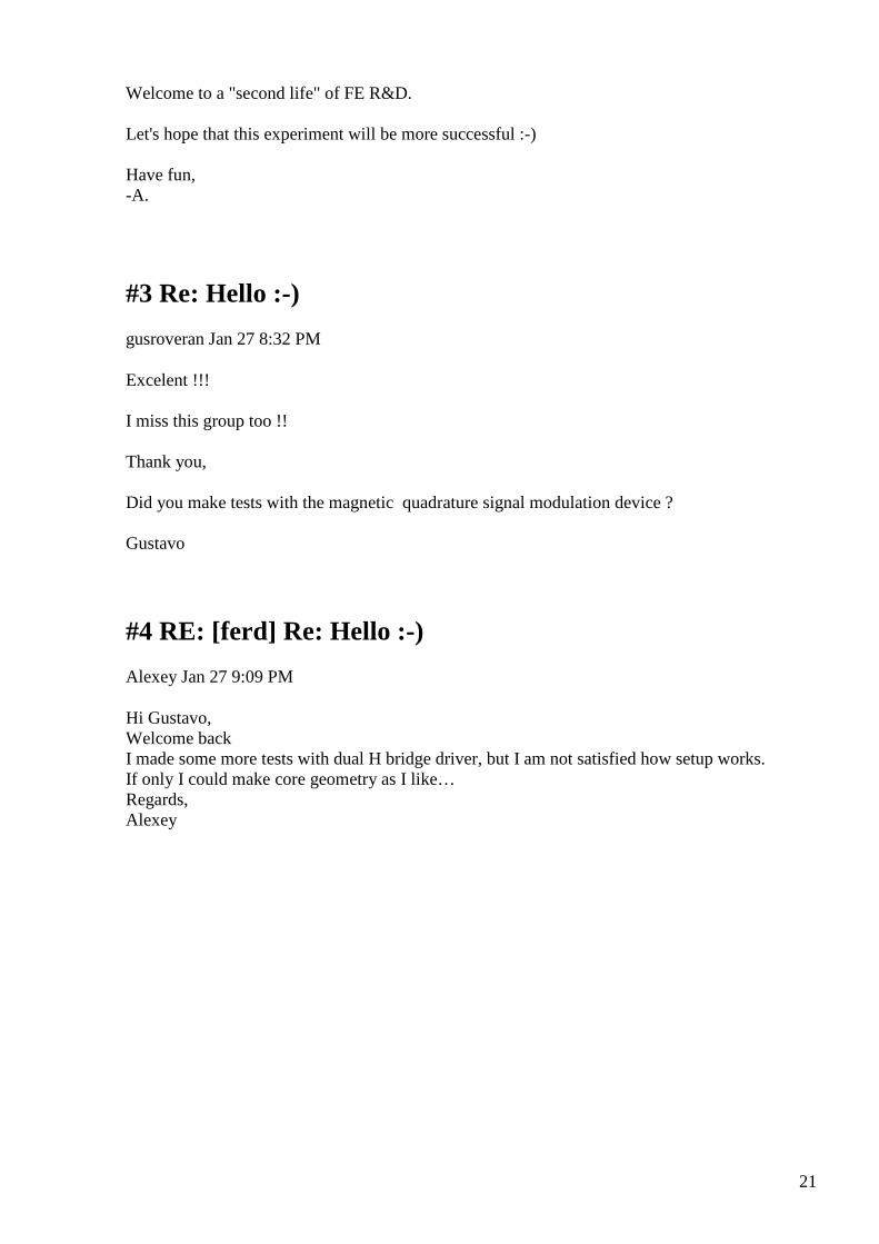
21
Welcome to a "second life" of FE R&D. Let's hope that this experiment will be more successful :-) Have fun, -A.
#3 Re: Hello :-)
gusroveran Jan 27 8:32 PM
Excelent !!! I miss this group too !! Thank you, Did you make tests with the magnetic quadrature signal modulation device ? Gustavo
#4 RE: [ferd] Re: Hello :-)
Alexey Jan 27 9:09 PM
Hi Gustavo, Welcome back I made some more tests with dual H bridge driver, but I am not satisfied how setup works. If only I could make core geometry as I like… Regards, Alexey
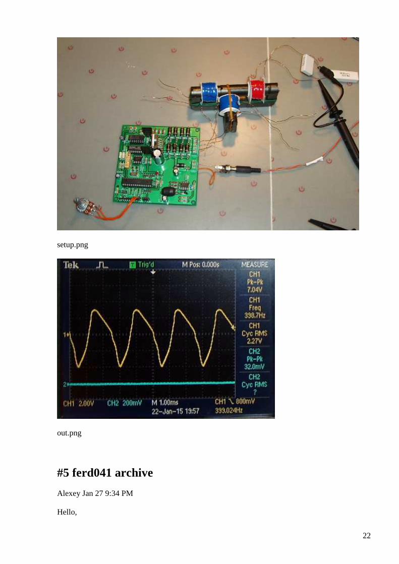
22
setup.png
out.png
#5 ferd041 archive
Alexey Jan 27 9:34 PM
Hello,
23
Just in case somebody interesting in ferd041 archive here a link: https://www.idrive.com/idrive/sh/sh?k=f2b2v9u1k7 Have fun, -A. PS I hope that nobody objects that I share this...
#6 [offtopic] Tao of FE ;-)
Alexey Jan 27 11:16 PM
Tao of Free Energy
The Tao that can be told is not the
eternal Tao.
The name that can be named is not the
eternal name.
The nameless is the beginning of
heaven and Earth.
The named is the mother of the ten
thousand things.
Ever desireless, one can see the
mystery.
24
Ever desiring, one sees the
manifestations.
These two spring from the same source
but differ in name; this appears as
darkness.
Darkness within darkness.
The gate to all mystery.
One can’t buy FE device. If FE device being sold it is fake. If you try sell FE device you are dead. True FE researcher learns how to recognize a Guru and not wasting time following him. He thinks with his head and doing own research. He respect mainstream science and learn where it gone wrong. He understands scale and complexity of the challenge and not expects fast results. He works hard when inspiration comes, and does nothing when he decides so. Time has no meaning for eternity, one not frustrated by failures but use them to learn. He searches for ideas, not for ready devices. Wise researcher knew that FE will not safe the world from itself. He does not arguing with ignorant man but gives chance to learn to every one. ;-)
#7 RE: [ferd] Re: Hello :-)
Gustavo Roveran Jan 28 3:32 AM
Hi Alexey, Nice to meet all you again. Very professional design. What type of core topology are you looking for?
25
The secret could be in the intersection core volume ? Regards Gustavo
#8 Re: [ferd] [offtopic] Tao of FE ;-)
Gustavo Roveran Jan 28 4:24 AM
Interesting, and deep thoughts. This could be a born of a technological templar society. But it also teaches how life would be lived. Hope this guide could be understood, learned and applied. Regards Gustavo.
#9 RE: [ferd] [offtopic] Tao of FE ;-)
Alexey Jan 28 9:01 AM
It’s a joke
#10 new member
Alexey Jan 28 9:22 AM
Hello Dear All, Please let me introduce new group member Ole. Welcome, Vasik041 :-)
#11 RE: [ferd] Re: Hello :-)
Alexey Jan 28 9:32 AM
Hi Gustavo,
I would like to try setup like 2 (see attached picture) but I don’t have proper size core part currently…
” Very professional design.”
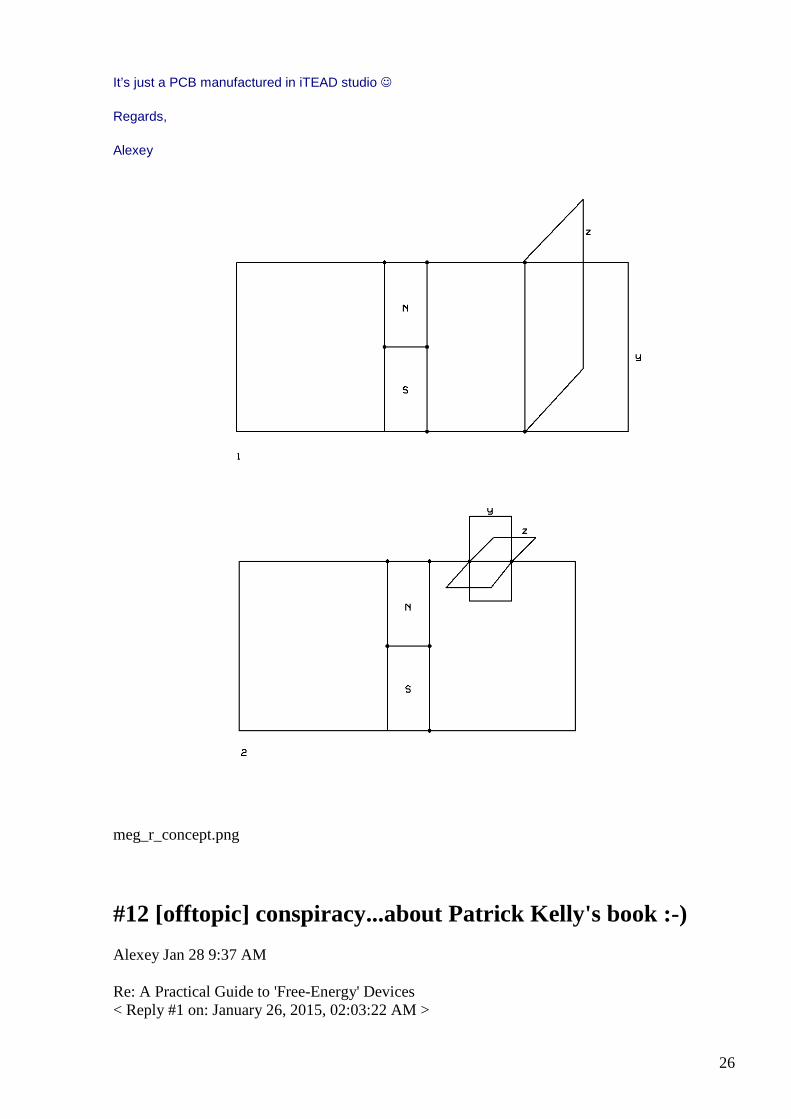
26
It’s just a PCB manufactured in iTEAD studio
Regards,
Alexey
meg_r_concept.png
#12 [offtopic] conspiracy...about Patrick Kelly's book :-)
Alexey Jan 28 9:37 AM
Re: A Practical Guide to 'Free-Energy' Devices < Reply #1 on: January 26, 2015, 02:03:22 AM >
27
--Quote from: Spirit on January 25, 2015, 10:25:33 PM http://www.free-energy-info.co.uk/NewcomerIndex.html Quote-- The page is wrong in its very first paragraph and continues being wrong throughout. The source of the energy in waterwheels, hydroelectric dam systems and so on is NOT GRAVITY. It is the sun, which is responsible for lifting the water in the first place. The flow is caused by gravity, but when the upper reservoir runs out, then what? To complete the cycle the water must be LIFTED UP to refill the reservoir. Do you think this happens by magic, or by gravity? No, it happens because of the sun evaporating water and driving weather which produces rainfall which then runs down to fill up the reservoir. The energy comes from the sun, not gravity. The same is true for wind power. The device which occupies another great section of that front page will not operate like you think it will. That is, it is nothing more than an offcenter flywheel, that will not produce a _steady_ output any greater than the steady input from its drive motor. Like any flywheel it can store up energy in the form of angular momentum, and this energy can be released at higher _peak power_ than the drive motor may be able to produce... but not for long, and the flywheel will slow down when it does. It's simple enough, why don't you just build one and demonstrate it running itself? I know why, and so do you. The solar powered lamp or solar powered recharging lamp is nothing new and it is basically the same thing as the Garden Lights you can buy for a dollar at the Dollar store: A battery, a PV panel, some cheap circuitry and an LED or array. We have people on this forum who use such devices every day for lighting around their homes. The James Hardy device is a well-known hoax. It does not run itself. The Thane Heins claims are also false, due to improper measurements of ordinary phenomena. He has never been able to provide the necessary proof: A self-looped system. And neither has anyone else who has reproduced his work. LTseung is a well known perpetrator and promoter of delusions. He claimed OU from simple Joule Thief circuits for a long long time, even sent out many examples of his claimed OU circuit to other researchers for testing... and his incorrect measurements were eventually tracked down to poorly calibrated Atten low-end digital oscilloscopes. Recently he has claimed that "money is no object" and that he could "Easily donate 100,000 dollars to WITTS" to purchase a 'working' QEG that would run itself. But he has not done so, because he cannot, because there is no such thing as a "working" QEG from WITTS or anywhere else. The Charles Campbell system is also incapable of running itself or providing
28
more energy out than in. Bedini... and a claim of 800 percent OU !! Now I am starting to laugh out loud! NO Bedini system has EVER produced any more energy out than input! There are probably dozens of people on this very forum who have worked with Bedini systems and not a single one of them, INCLUDING BEDINI, has ever made a self-runner, which would be trivial to do if the devices even put out 130 percent OU !! Next you have another LTseung device which is also a case of bad measurements and faulty interpretations, which cannot run itself in spite of the large OU claims. Now we move on to "simple permanent magnet motors" which don't work, and even SMOTs !! No self looping, no self running, power comes from "mister Hand" in every case. Next we have another real device that scavenges energy from stray RF in the environment. "Free energy" yes... because somebody else paid for the energy, radiated from radio stations and leaking from house wiring electromagnetic fields. Nothing new here at all and certainly not free in the usual sense of the word. Then we come to LTseung's poorly measured "FLEET" Joule Thief. There are a couple of long running threads on this forum concerning that fiasco, which is not OU at all, it is an ordinary JT and if you bother to do your homework you will find out the source of the mismeasurements. Lawrence himself doesn't even promote that one any more. Next comes some battery chargers for which more incorrect claims are made like 200 percent OU. These aren't even worthy of discussion any more, since they have been done to death and when properly measured the "ou" goes away. It's very shy you know, afraid of things like oscilloscopes and power analyzers, and only shows up when DMMs are used to measure no-load terminal voltages of the "charged" batteries. Next come the inevitable electrolysis systems, which also incorporate lots of nonsense and false claims. HHO for example. Hydrogen gas produced by electrolysis is always diatomic, and so is oxygen gas. Many of these systems "microboil" water between the plates and thus produce high gas volume outputs... wet gas consisting of large amounts of water vapor. Not a single system of electrolyzer-ICE-generator has ever been shown to run itself, producing excess power. Then there's the Joe Cell ! What a joke that one is! "The Joe Cell can channel this energy into the engine of a vehicle and run it without using any fuel at all." Right, and Santa Claus uses one to power his sled instead of reindeer !! And finally.... the claims of Robert Hull. Stick a wire down your dipstick hole, connect it to some unpowered coils, and you'll get 25 percent greater gas mileage. Also a false claim, not reproducible under properly controlled
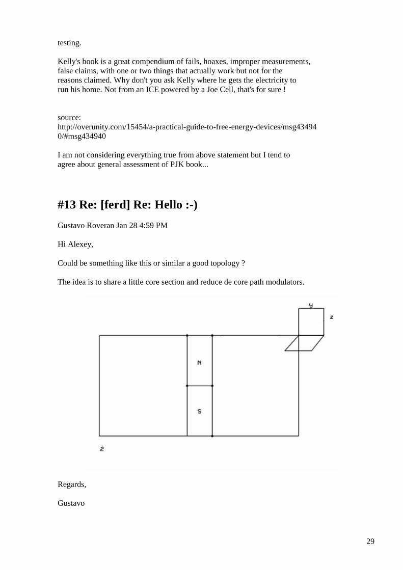
29
testing. Kelly's book is a great compendium of fails, hoaxes, improper measurements, false claims, with one or two things that actually work but not for the reasons claimed. Why don't you ask Kelly where he gets the electricity to run his home. Not from an ICE powered by a Joe Cell, that's for sure ! source: http://overunity.com/15454/a-practical-guide-to-free-energy-devices/msg43494 0/#msg434940 I am not considering everything true from above statement but I tend to agree about general assessment of PJK book...
#13 Re: [ferd] Re: Hello :-)
Gustavo Roveran Jan 28 4:59 PM
Hi Alexey,
Could be something like this or similar a good topology ?
The idea is to share a little core section and reduce de core path modulators.
Regards,
Gustavo
30
#14 Re: [ferd] [offtopic] conspiracy...about Patrick Kelly's book :-)
Gustavo Roveran Jan 28 5:07 PM
Hi Alexey,
I think that PK did not want to lie, he wanted to contribute from his "bad knowledge", but obviously is important that someone clarify about devices within his book.
Regards,
Gustavo
#15 Re: [ferd] Re: Hello :-)
Andreas Höschler Jan 28 6:24 PM
Hi Alexey and Gustavo,
On 28 Jan 2015, at 13:59, Gustavo Roveran [email protected] [ferd] <[email protected]> wrote:
Could be something like this or similar a good topology ?
The idea is to share a little core section and reduce de core path modulators.
Sorry for jumping into this thread (being deeply burrowed into my DC supply project)! What’s the basic idea of these core geometries? Are you trying to alter the reluctance of a magnetic flux part by saturating a core section with a perpendicular path? If so I have tried that in the past with not so much luck. I got a result but the efficiency was terrible even when trying to do that with a parallel tank circuit (high non-linear resonance). The key to such a setup would be to main this highly-non-linear resonance with very low input wattage, something I never managed to do. The input wattage always maxed when I got close to resonance and got the jump resonance effect. :-(
Andreas
#16 RE: [ferd] Re: Hello :-)
Alexey Jan 28 7:41 PM
Hi Gustavo,
31
Yes, it could be…but I don’t think that it is easier to implement
Regards,
Alexey
#17 RE: [ferd] [offtopic] conspiracy...about Patrick Kelly's book :-)
Alexey Jan 28 7:46 PM
Hi Gustavo,
I think that it is not possible that Patrick didn’t know about the situation by this time.
He should be honest and write about this on every page…otherwise he just damaging FE ”reputation”…along with others fake makers
(It’s just my opinion)
Regards,
Alexey
#18 RE: [ferd] Re: Hello :-)
Alexey Jan 28 7:51 PM
Hi Andreas, Welcome back The idea is to modulate PM field by rotating domains in two perpendicular planes. It should be possible without saturation and therefore give hopes that such modulator will be not so energy consuming as one which use saturation. How your project going, I thought that you got power supply working ? Regards, Alexey
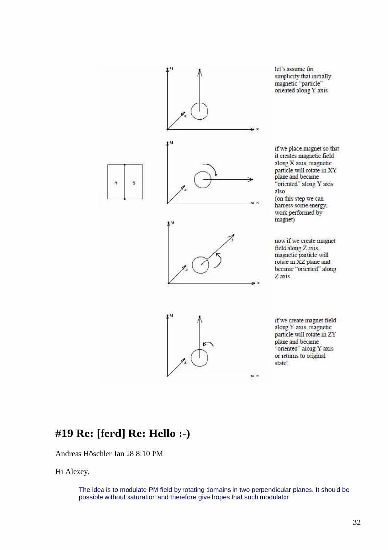
32
#19 Re: [ferd] Re: Hello :-)
Andreas Höschler Jan 28 8:10 PM
Hi Alexey,
The idea is to modulate PM field by rotating domains in two perpendicular planes. It should be possible without saturation and therefore give hopes that such modulator
33
will be not so energy consuming as one which use saturation.
You wil see an effect by just reorienting the domains but at least when I tried this the effect was rather small and thus the overall efficiency not even close to unity. The result depends on a lot of factors. My failure does not necessarily mean the concept is bad.
How your project going, I thought that you got power supply working ?
Finishing touches … I just included a current measurement module and introduced a new command that allows me to request the voltage and current. The values returned will not even be close to precise but will give at least an orientation. I can thus roughly monitor the input wattage going into any device without blocking a scope. That’s at least the idea. The current measurement unit I am using is for 0..20A though, not very suitable to measure currents in the 500mA range. So I might have to utilise one of my UT61E meters for the current measurement instead. They have a serial interface. Getting those to work (connected to the controlling computer) is not easy either. The beast extracts power for the optos form the DTR line. This is not supported on most USB-serial adaptors. I hope to get this all sorted out today to finally be able to continue my research. :-)
Best wishes,
Andreas
#20 Re: [ferd] new member
Gustavo Roveran Jan 28 8:38 PM
Hi Ole,
Very welcome, are you from Spain ?
regards,
Gustavo
#21 RE: [ferd] Re: Hello :-)
Alexey Jan 28 8:58 PM
Hi Andreas, ”The beast extracts power for the optos form the DTR line. This is not supported on most USB-serial adaptors.”

34
I haven’t used serial interface for quite a while but as far as I know USB converters behaves in a same way as old hardware ones. You just need manually set DTR to 1 and then you can take power from it… Regards, Alexey
#22 Re: [ferd] Hello :-)
Andreas Höschler Jan 28 9:45 PM
Hi all,
How your project going, I thought that you got power supply working ?
Done!! :-)
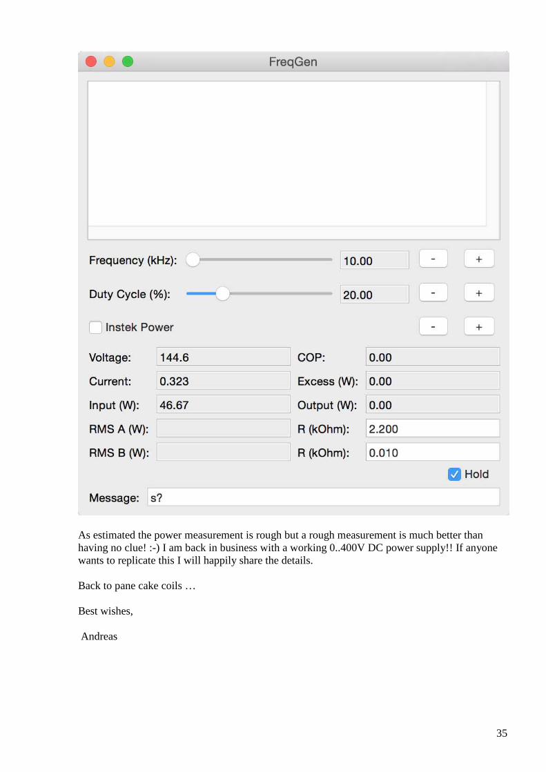
35
As estimated the power measurement is rough but a rough measurement is much better than having no clue! :-) I am back in business with a working 0..400V DC power supply!! If anyone wants to replicate this I will happily share the details. Back to pane cake coils … Best wishes, Andreas
36
#23 Re: [ferd] new member
onielsen2000 Jan 28 9:45 PM
Hi Gustavo, Much further to the north. Denmark. Regards Ole
#24 Re: [ferd] Hello :-)
Andreas Höschler Jan 28 9:55 PM
Hi Alexey,
I haven’t used serial interface for quite a while but as far as I know USB converters behaves in a same way as old hardware ones.
You just need manually set DTR to 1 and then you can take power from it…
I remember to have already done that in the past but I can’t find the code anymore that does this in a POSIX serial port environment. Whatever, the rough measurement is working and integrating the UTE61 meters is therefore rather pointless right now. I might revisit this later!
Thanks a lot,
Andreas
#25 RE: [ferd] new member
Alexey Jan 28 10:50 PM
Hi Ole,
I saw some of your messages on EVGRAY and Andreas mentioned that he have good cooperation with you.
So, I thought that it would be nice that you join our group.
It would be also interesting to know what FE projects you are working on (if you like to share).
Welcome to the group
Alexey

37
#26 FW: ferd041 archive
Alexey Jan 28 10:52 PM
Hello, just in case you don't want download all 2Gb archive here a shorter version (without attachments) as one pdf file, only 1245 pages ;-) https://www.idrive.com/idrive/sh/sh?k=g6h0w3l6u2 Have fun, -A.
#27 RE: [ferd] Hello :-)
Alexey Jan 28 10:52 PM
Hi Andreas,
Nice progress!
I am not going to replicate it but I think it would nice if you could post schematic...just for reference…
- Alexey
#28 Re: [ferd] FW: ferd041 archive
Gustavo Roveran Jan 28 11:01 PM
Hi,
I had downloaded all !!
Thanks
Gustavo
#29 Re: [ferd] Hello :-)
Andreas Höschler Jan 28 11:18 PM
Hi Alexey,
38
I am not going to replicate
Of course not. I understand you already have such a beast for a while!?
it but I think it would nice if you could post schematic...just for reference…
I unfortunately have none (not yet drawn). All I have is this description
• WIZNet110R (provides ethernet connectivity)
• Arduino Duemilanove (receives commands and controls the H-Bridge, generates PWM signal on OC1 pin using Timer1)
• Multiplexer based on 7473 and 7408 (generates the two signals for the H-Bridge from the OC1 PWM signal)
• H-Bridge based on ADUM4223 chip (actually 4 isolated MOSFET switches configured as a H-Bridge)
• 4 X IXFB132N50P3 MOSFETs mouted on heat sink
• A 1:1.2 ferrite torroid transfomer
• A MUR860 based FWBR
• 1uF output cap
in my documentation from which I could easily derive what I had to do in case I had to redo this. I believe everyone here is able to build a H-Bridge. Everything else should be clear from the above description (more or less self-evident)!?
Back to the bench …
Andreas
#30 RE: [ferd] Hello :-)
Alexey Jan 28 11:51 PM
Hi Andreas,
” I understand you already have such a beast for a while!?”
My version is not so advanced. I didn’t make remote control and it gives only up to 50v (I am trying avoid high voltage/power :-)
Regards,
Alexey
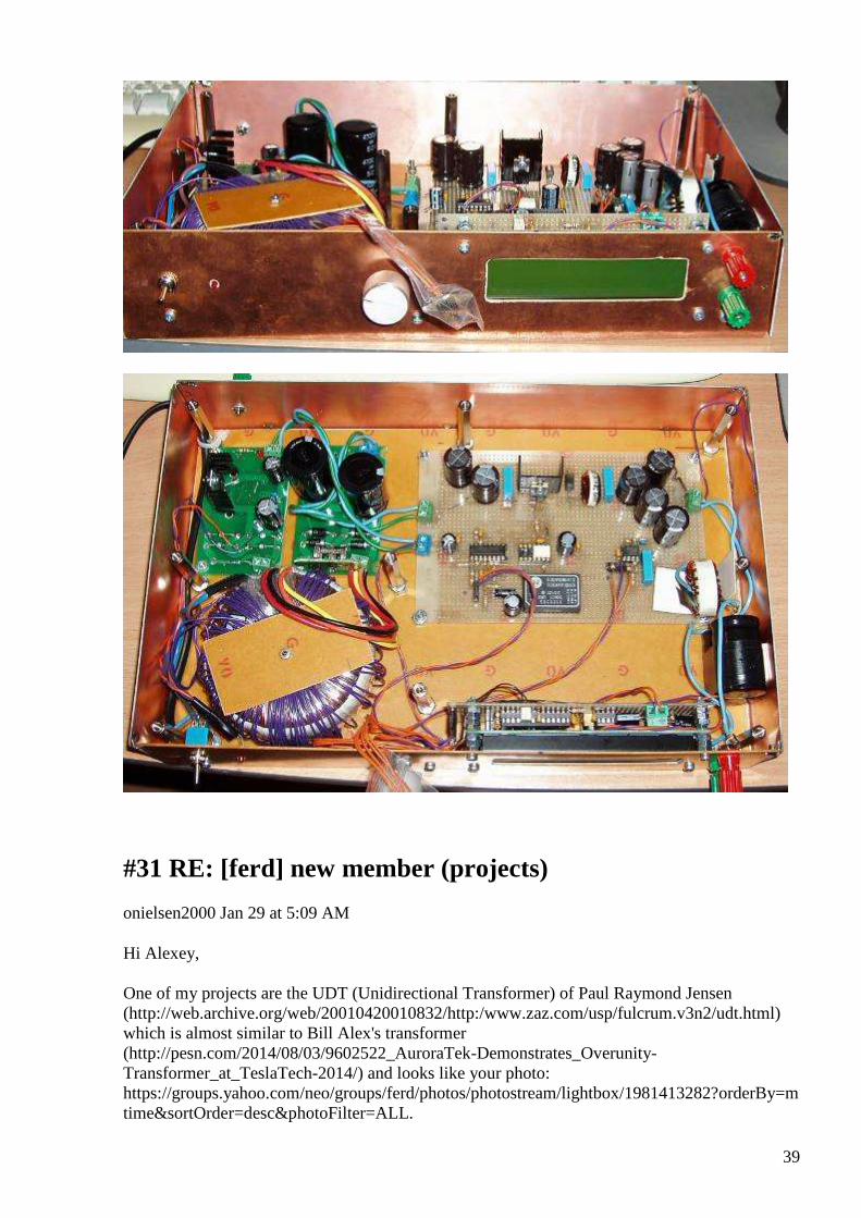
39
#31 RE: [ferd] new member (projects)
onielsen2000 Jan 29 at 5:09 AM
Hi Alexey, One of my projects are the UDT (Unidirectional Transformer) of Paul Raymond Jensen (http://web.archive.org/web/20010420010832/http:/www.zaz.com/usp/fulcrum.v3n2/udt.html) which is almost similar to Bill Alex's transformer (http://pesn.com/2014/08/03/9602522_AuroraTek-Demonstrates_Overunity-Transformer_at_TeslaTech-2014/) and looks like your photo: https://groups.yahoo.com/neo/groups/ferd/photos/photostream/lightbox/1981413282?orderBy=mtime&sortOrder=desc&photoFilter=ALL.
40
With a capacitor in parallel to the primary it can change reactive power to real power when the input frequency is twice the LC resonance frequency. I have only tested it with an audio amplifier that don't like supporting reactive power. It dissipates at lot of heat in the output stage as this delivers both voltage and current at the same time. Switching technology or a synchronous generator is what is needed. Another project is one of the Akula lanterns Eternal lantern No.4 = AKULA0083
(https://www.youtube.com/watch?v=nl9E8F1gOD0)
Eternal lantern No.4 = AKULA0083 http://renuar.blogspot.com/2014/08/reala-brivas-energijas-shema-no4.html Akula (no Ruslan Kulabuhov) small free energy generator from Germany https://www.yo...
View on www.youtube.com Preview
by Yahoo
which I'm studying at the moment. I think the similarity between these transformers are the way to "create energy out of the cosmic background" as formulated by Wilbert B. Smith in "The New Science" by the use of coherent fields. This works as seen from a mathematical point of view and now seems to have been proved by some hardware probably starting with Tariel Kapanadze, Andrey Melnichenko, Akula (Роман Карноухов or Ruslan Kulabuhov) and probably others. Anybody here that can demonstrate free energy from electronics or just have seen a glimpse of it? Regards Ole

41
#32 Re: [ferd] Hello :-)
Gerry Jan 29 at 9:16 AM
Nice work Andreas!
Gerry
#33 RE: [ferd] new member (projects)
Alexey Jan 29 at 9:31 AM
Hi Ole,
” With a capacitor in parallel to the primary it can change reactive power to real power when the input frequency is twice the LC resonance frequency”
It is interesting – Andreas and Gerry made a lot of experiments with UDT-like setup, but as far as I know they didn’t try resonance modes. I made some experiments also, but it wasn’t very successful.
” I have only tested it with an audio amplifier that don't like supporting reactive power. It dissipates at lot of heat in the output stage”
Perhaps you can try build H-bridge or class D amplifier, then you can reduce loses significantly
According to my information Роман Карноухов and Ruslan Kulabuhov (and some others) are team of scammers and just trying make money selling schematics.
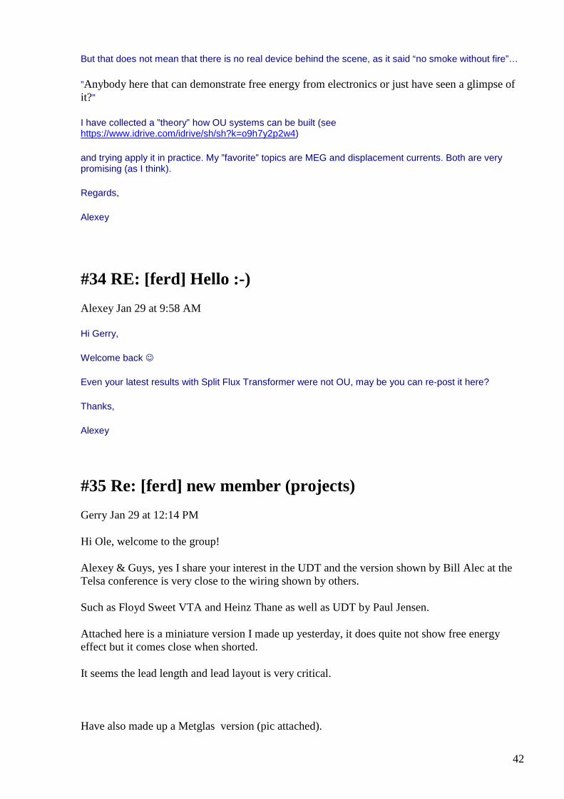
42
But that does not mean that there is no real device behind the scene, as it said “no smoke without fire”…
”Anybody here that can demonstrate free energy from electronics or just have seen a glimpse of it?”
I have collected a ”theory” how OU systems can be built (see https://www.idrive.com/idrive/sh/sh?k=o9h7y2p2w4)
and trying apply it in practice. My ”favorite” topics are MEG and displacement currents. Both are very promising (as I think).
Regards,
Alexey
#34 RE: [ferd] Hello :-)
Alexey Jan 29 at 9:58 AM
Hi Gerry,
Welcome back
Even your latest results with Split Flux Transformer were not OU, may be you can re-post it here?
Thanks,
Alexey
#35 Re: [ferd] new member (projects)
Gerry Jan 29 at 12:14 PM
Hi Ole, welcome to the group!
Alexey & Guys, yes I share your interest in the UDT and the version shown by Bill Alec at the Telsa conference is very close to the wiring shown by others.
Such as Floyd Sweet VTA and Heinz Thane as well as UDT by Paul Jensen.
Attached here is a miniature version I made up yesterday, it does quite not show free energy effect but it comes close when shorted.
It seems the lead length and lead layout is very critical.
Have also made up a Metglas version (pic attached).
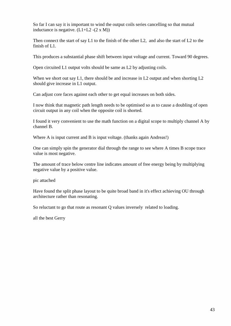
43
So far I can say it is important to wind the output coils series cancelling so that mutual inductance is negative. (L1+L2 -(2 x M))
Then connect the start of say L1 to the finish of the other L2, and also the start of L2 to the finish of L1.
This produces a substantial phase shift between input voltage and current. Toward 90 degrees.
Open circuited L1 output volts should be same as L2 by adjusting coils.
When we short out say L1, there should be and increase in L2 output and when shorting L2 should give increase in L1 output.
Can adjust core faces against each other to get equal increases on both sides.
I now think that magnetic path length needs to be optimised so as to cause a doubling of open circuit output in any coil when the opposite coil is shorted.
I found it very convenient to use the math function on a digital scope to multiply channel A by channel B.
Where A is input current and B is input voltage. (thanks again Andreas!)
One can simply spin the generator dial through the range to see where A times B scope trace value is most negative.
The amount of trace below centre line indicates amount of free energy being by multiplying negative value by a positive value.
pic attached
Have found the split phase layout to be quite broad band in it's effect achieving OU through architecture rather than resonating.
So reluctant to go that route as resonant Q values inversely related to loading.
all the best Gerry
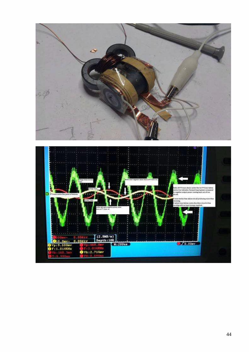
44
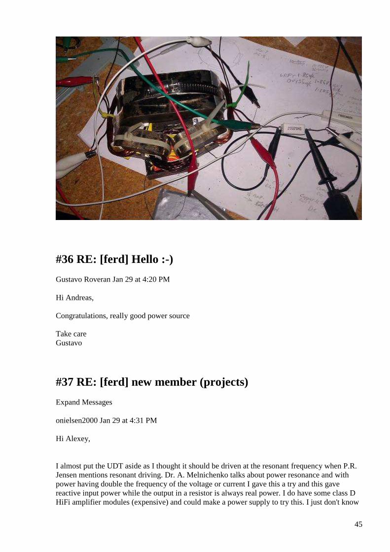
45
#36 RE: [ferd] Hello :-)
Gustavo Roveran Jan 29 at 4:20 PM
Hi Andreas, Congratulations, really good power source Take care Gustavo
#37 RE: [ferd] new member (projects)
Expand Messages
onielsen2000 Jan 29 at 4:31 PM
Hi Alexey,
I almost put the UDT aside as I thought it should be driven at the resonant frequency when P.R. Jensen mentions resonant driving. Dr. A. Melnichenko talks about power resonance and with power having double the frequency of the voltage or current I gave this a try and this gave reactive input power while the output in a resistor is always real power. I do have some class D HiFi amplifier modules (expensive) and could make a power supply to try this. I just don't know
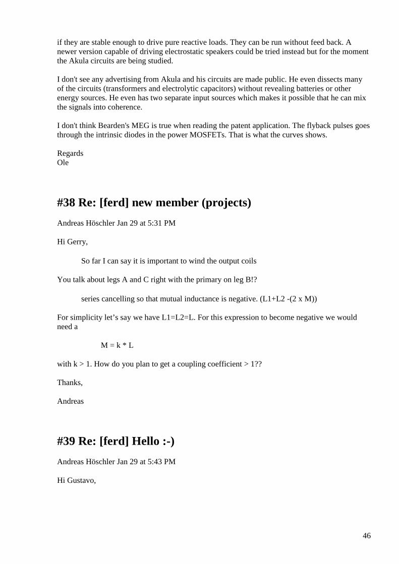
46
if they are stable enough to drive pure reactive loads. They can be run without feed back. A newer version capable of driving electrostatic speakers could be tried instead but for the moment the Akula circuits are being studied. I don't see any advertising from Akula and his circuits are made public. He even dissects many of the circuits (transformers and electrolytic capacitors) without revealing batteries or other energy sources. He even has two separate input sources which makes it possible that he can mix the signals into coherence. I don't think Bearden's MEG is true when reading the patent application. The flyback pulses goes through the intrinsic diodes in the power MOSFETs. That is what the curves shows. Regards Ole
#38 Re: [ferd] new member (projects)
Andreas Höschler Jan 29 at 5:31 PM
Hi Gerry,
So far I can say it is important to wind the output coils
You talk about legs A and C right with the primary on leg B!?
series cancelling so that mutual inductance is negative. (L1+L2 -(2 x M))
For simplicity let’s say we have L1=L2=L. For this expression to become negative we would need a
M = k * L
with k > 1. How do you plan to get a coupling coefficient > 1??
Thanks,
Andreas
#39 Re: [ferd] Hello :-)
Andreas Höschler Jan 29 at 5:43 PM
Hi Gustavo,
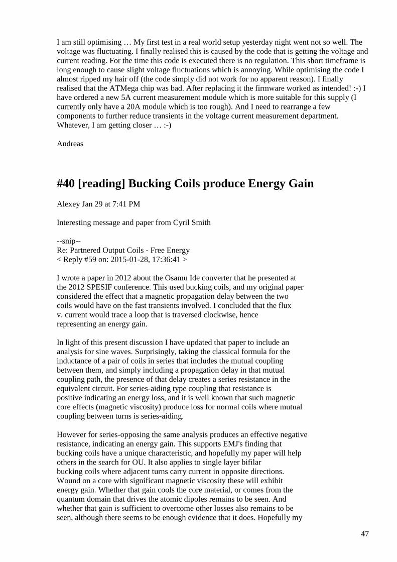
47
I am still optimising … My first test in a real world setup yesterday night went not so well. The voltage was fluctuating. I finally realised this is caused by the code that is getting the voltage and current reading. For the time this code is executed there is no regulation. This short timeframe is long enough to cause slight voltage fluctuations which is annoying. While optimising the code I almost ripped my hair off (the code simply did not work for no apparent reason). I finally realised that the ATMega chip was bad. After replacing it the firmware worked as intended! :-) I have ordered a new 5A current measurement module which is more suitable for this supply (I currently only have a 20A module which is too rough). And I need to rearrange a few components to further reduce transients in the voltage current measurement department. Whatever, I am getting closer … :-)
Andreas
#40 [reading] Bucking Coils produce Energy Gain
Alexey Jan 29 at 7:41 PM
Interesting message and paper from Cyril Smith --snip-- Re: Partnered Output Coils - Free Energy < Reply #59 on: 2015-01-28, 17:36:41 > I wrote a paper in 2012 about the Osamu Ide converter that he presented at the 2012 SPESIF conference. This used bucking coils, and my original paper considered the effect that a magnetic propagation delay between the two coils would have on the fast transients involved. I concluded that the flux v. current would trace a loop that is traversed clockwise, hence representing an energy gain. In light of this present discussion I have updated that paper to include an analysis for sine waves. Surprisingly, taking the classical formula for the inductance of a pair of coils in series that includes the mutual coupling between them, and simply including a propagation delay in that mutual coupling path, the presence of that delay creates a series resistance in the equivalent circuit. For series-aiding type coupling that resistance is positive indicating an energy loss, and it is well known that such magnetic core effects (magnetic viscosity) produce loss for normal coils where mutual coupling between turns is series-aiding. However for series-opposing the same analysis produces an effective negative resistance, indicating an energy gain. This supports EMJ's finding that bucking coils have a unique characteristic, and hopefully my paper will help others in the search for OU. It also applies to single layer bifilar bucking coils where adjacent turns carry current in opposite directions. Wound on a core with significant magnetic viscosity these will exhibit energy gain. Whether that gain cools the core material, or comes from the quantum domain that drives the atomic dipoles remains to be seen. And whether that gain is sufficient to overcome other losses also remains to be seen, although there seems to be enough evidence that it does. Hopefully my

48
paper will help in the search for the truth behind all this. I intend to extend that paper to include the variation of the mutual coupling in respect of separation distance to allow some optimisation of the negative resistance. Using my derived formula the resistor value is zero at zero separation (because the delay is zero) and is also zero at large separation (because the mutual-inductance coupling is zero), so obviously there is an optimum separation distance. Smudge --snip-- source: http://www.overunityresearch.com/index.php?topic=2760.msg44861#msg44861 :-)
#41 Re: [ferd] [reading] Bucking Coils produce Energy Gain
Andreas Höschler Jan 29 at 9:35 PM
Hi Alexey,
Interesting message and paper from Cyril Smith
Indeed! Thanks a lot for forwarding this master piece. Not really new info but I have not yet seen such a nice and concrete presentation of the issue! Very good!!
Thanks,
Andreas
#42 Re: [ferd] new member (projects)
Gerry Jan 30 at 12:06 AM
Hi Andreas, very good question.....
I found by measurement that it all hinges on delaying the current by more than can be done with regular linear inductance,
(see my Tesla wire idea and pic presented to group earlier).
Also as explained by Cyril Smith from page 3 para 3 in his paper,
L1 and L2 terms are more immediate terms whilst Mutual inductance is a reflected term influenced by magnetic path factors.
49
I believe this is also where Bill Alec calls for non linear magnetic medium on page 9 of his pdf, attached to my earlier post.
So effectively L1 and L2's value is not a fixed thing it is able to be varied and it does vary during the d phi/dt process.
Especially where the components of M are involved.
Also if we have ac fluxes or a currents (A and B) and simply combine them applying per simplified L1 + L2 = Lt formula without the M term.
The all we get out............... is is currents or fluxes (A+B) or (A-B) simple addition or subtraction.
When we introduce multiplication term (part of M ) we get currents or fluxes (A+B)*(A-B) which is difference of 2 squares . (A*A) - (B*B) ....we can also get 2 A*B terms.
When ac term Sine wave or Cosine wave is substituted into the (A and B terms) there are frequencies involved
Now our frequencies A and B actually modulate each other and depending on the delay and non-linearity, additional phase shifted components appear.
Eg:
(Sin A)* (Sin A) = 1/2 -1/2 Cos 2*A
and
(Cos A) * (Cos A) = 1/2 + 1/2 Cos 2A
notice that a DC term has appeared in the form of 1/2 ....and a second harmonic!
also
and frequencies, Sin A * Sin B = 1/2 Cos (A-B) - 1/2 Cos (A+B) so hence the sum and difference (modulation) frequencies.
So M term gets quite messy and by no means a fixed value, during driving cycle.
(See Cyril Smiths paper for more eloquent explanations)
I don't want to make this too long but could say much more about simple ways to see these effects.
And also how to visualise them in your mind.
Thanks for making me explain I hope this helps you.
Gerry
50
#43 Re: [ferd] new member (projects)
Gerry Jan 30 at 12:29 AM
Hi Andreas,
One more thing is just think of M term and it's components as an "apparent inductance" not a real one.
It is caused by "induced current" not by directly applied current.
And as we already know from parametric amplification, changes in apparent inductance or capacitance can and do give rise to amplification.
Under the right conditions of course.
all the best Gerry
#44 Re: [ferd] new member (projects)
onielsen2000 Jan 30 at 5:45 AM
Hi Gerry, Andreas, I believe this is also where Bill Alec calls for non linear magnetic medium on page 9 of his pdf, attached to my earlier post. This is one thing also observed in the UDT. There has to be a big reactive current flowing in the primary. Iron (and Ferrite) are nonlinear magnetic conductors that will go into saturation when the circulating current becomes big. For mixing signals into coherence a nonlinear medium is used. This is also used i optical phase conjugated mirrors for mixing light. Beams of light normally just travels through each other. The big current becomes a problem for the signal generator when using a linear amplifier that has to deliver a big current while having a voltage across it which creates heat to be dissipated (loss). An audio amplifier has a very low output impedance because of the feed back loop but still has higher impedance internally in the output transistors. I attached a measurement on the UDT. The curves are as following. The top window is showing: Input: Blue is primary voltage Green is current into the primary LC-tank Magenta is input power Output Red is secondaries voltage Yellow is output current into the load
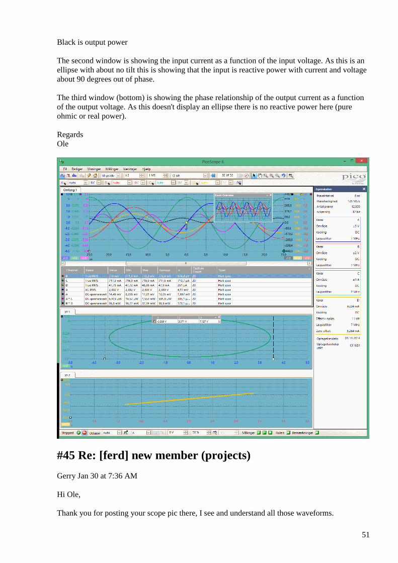
51
Black is output power The second window is showing the input current as a function of the input voltage. As this is an ellipse with about no tilt this is showing that the input is reactive power with current and voltage about 90 degrees out of phase. The third window (bottom) is showing the phase relationship of the output current as a function of the output voltage. As this doesn't display an ellipse there is no reactive power here (pure ohmic or real power). Regards Ole
#45 Re: [ferd] new member (projects)
Gerry Jan 30 at 7:36 AM
Hi Ole,
Thank you for posting your scope pic there, I see and understand all those waveforms.
52
They make logical sense.
You have quite a nice 90 degree E vs I phase shift on the input there.
So E * I * Cos 90 = E * I * zero = zero input power over one cycle.
We can see that your power went equally negative and positive over one complete cycle giving average input of zero.
Also the Lissajous Pattern from X versus Y forming the elipse below, shows little or no phase distortion on input.
I'm not sure what your setup is....
If the there is change of permeability in those output laminations there would be phase distortion on the input vs output current.
I think the maximum non linearity's are supposed to occur at the start and finish of the BH loop as it is traversed by the signal.
Before and after the "knee point" I mean.
If we can push the input current to our split phase transformers further behind the rotating applied voltage vector.
Then the Cosine of angles > 90 become negative in the second and third quadrants.
Meaning input will feed energy back into the source (as claimed by Bill Alec in his Auroratek device).
That Cyril Smith paper made me realise that I need high resistance in my output coils, not heavy copper leads as I have been using.
I may be wrong here, happy to hear otherwise.
But if reflected equivalent Rp becomes negative then the higher it is the more negative resistance we get back as gain?
Gerry
#46 RE: [ferd] new member (projects)
Alexey Jan 30 at 9:45 AM
Hi Ole, Nice picture I think Gerry right; you don’t have saturation on your picture. I made small simulation in LTSpice as an illustration how picture changes when current amplitude grows (see attached pictures) BTW I think we have here at least 3 version of H-bridge build by Andreas, Gustavo an me. I can find schematics if you would like build one. Regards,
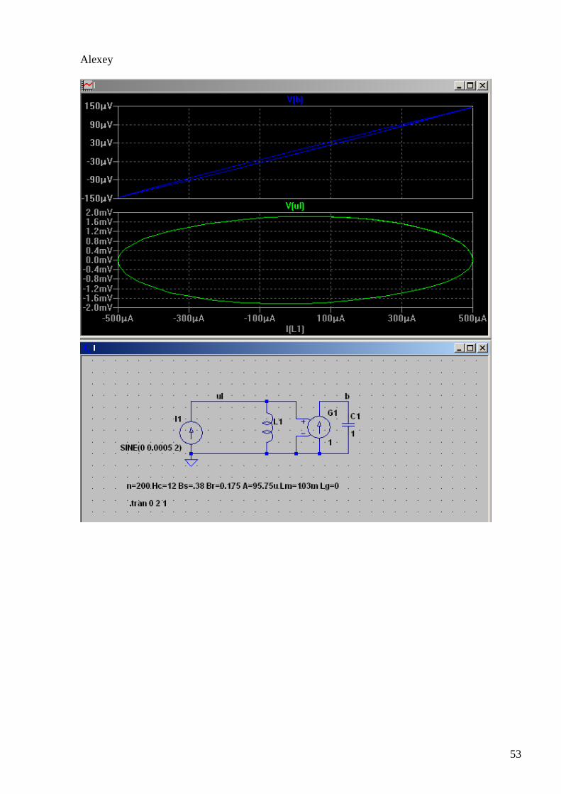
53
Alexey
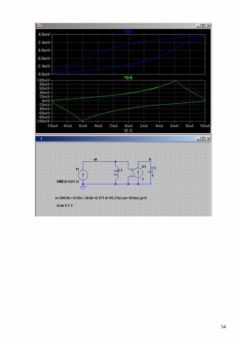
54
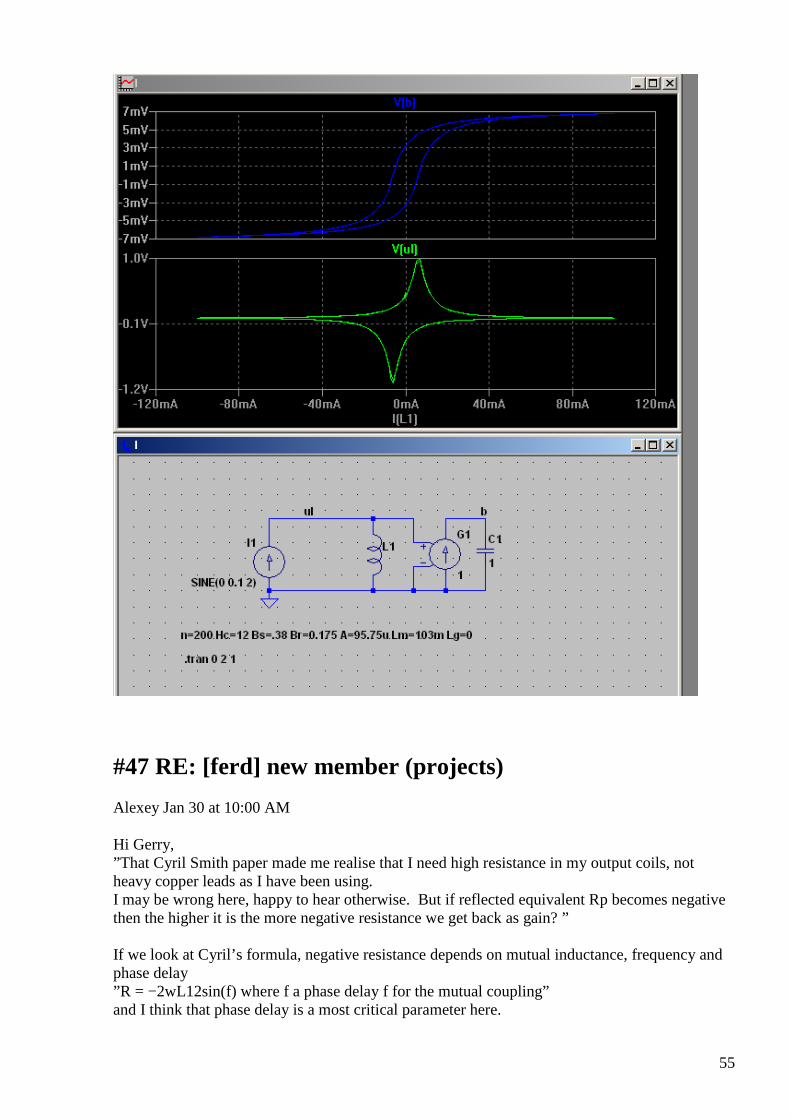
55
#47 RE: [ferd] new member (projects)
Alexey Jan 30 at 10:00 AM
Hi Gerry, ”That Cyril Smith paper made me realise that I need high resistance in my output coils, not heavy copper leads as I have been using. I may be wrong here, happy to hear otherwise. But if reflected equivalent Rp becomes negative then the higher it is the more negative resistance we get back as gain? ” If we look at Cyril’s formula, negative resistance depends on mutual inductance, frequency and phase delay ”R = −2wL12sin(f) where f a phase delay f for the mutual coupling” and I think that phase delay is a most critical parameter here.
56
In practice it means that we need to use laminate core (not metgglass) with no gap, place coils as far as possible from each other and use frequency as high as possible … Regards, Alexey
#48 Re: [ferd] new member (projects)
Gerry Jan 30 at 10:28 AM
Thanks Alexey,
I find that the paper by Mr Smith is a bit perplexing because I do not see how he can call this value , a Resistance value
when it appears to be totally reactive from his own formula.
In my days equivalent parallel resistance is Rp = R series* (1+Q²).
I guess I understand the principle of what you're saying though.
Will do some more experiments in this regard.
Gerry
#49 Re: [ferd] new member (projects)
Gerry Jan 30 at 11:10 AM
Hi again Ole,
I was looking again at your results with UDT.
Is the transformer therefore OU at 40 KHz ?
What was the output power?
For your input as shown.
Gerry
#50 Re: [ferd] new member (projects)
onielsen2000 Jan 30 at 1:58 PM
Hi Gerry, The frequency with OU or 90 degrees phase shift at the primary is determined by double the frequency of the input LC-tank circuit. By changing the paralleled capacitor (or primary
57
inductance) another frequency can be chosen. The output power at this measurement was 36.8 mW with 0.685 mW entering the primary parallel LC-tank. At higher power input the audio amplifier will heat fast because of the high internal dissipated power. The power entering the UDT is small but as most of it is reflecting back into the amplifier an output capable of delivering reactive power is what is needed. By adjusting the frequency even more power can go back into the amplifier like Bill Alek demonstrated (power becomes negative). Regards Ole
#51 Re: [ferd] new member (projects)
Andreas Höschler Jan 30 at 4:14 PM
Hi Alexey,
Thanks for pulling this straight. Gerry, low real resistance in your secondary is good. So keep your thick wire. The negative resistance we are after is a virtual resistance caused by the mutual inductance as Alexey has explained. A too high wire resistance is likely to compensate a potential virtual negative resistance and thus kills the effect (under unity).
I have done a quick and dirty experiment a couple of weeks ago. See attached PDF.
The bad news is I did not get OU. The good news is the efficiency was significantly better in bucking mode. This confirms the Smith paper.
Regards,
Andreas
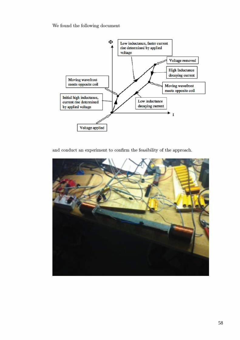
58
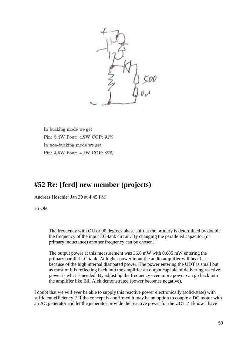
59
#52 Re: [ferd] new member (projects)
Andreas Höschler Jan 30 at 4:45 PM
Hi Ole,
The frequency with OU or 90 degrees phase shift at the primary is determined by double the frequency of the input LC-tank circuit. By changing the paralleled capacitor (or primary inductance) another frequency can be chosen. The output power at this measurement was 36.8 mW with 0.685 mW entering the primary parallel LC-tank. At higher power input the audio amplifier will heat fast because of the high internal dissipated power. The power entering the UDT is small but as most of it is reflecting back into the amplifier an output capable of delivering reactive power is what is needed. By adjusting the frequency even more power can go back into the amplifier like Bill Alek demonstrated (power becomes negative).
I doubt that we will ever be able to supply this reactive power electronically (solid-state) with sufficient efficiency!? If the concept is confirmed it may be an option to couple a DC motor with an AC generator and let the generator provide the reactive power for the UDT!? I know I have
60
no place for such beasts either but … a generator coil has no problem with supplying reactive power. :-)
Andreas
#53 Re: [ferd] new member (projects)
onielsen2000 Jan 30 at 8:54 PM
Hi Andreas, Many modern inverters for solar power already has the capability to deliver reactive power to the grid. This function is used at night time or when a cloud moves in front of the solar panels. This stabilizes the grid and compensates consumers using reactive power by making the power factor in the opposite direction of the present load of the grid to only let real power pass the wires. This creates less heat in the wires which is real power loss as the wires has resistance. Reactive power can be achieved by using a digital signal processor for controlling the inverter. Regards Ole
#54 Re: [ferd] new member (projects)
Gerry Jan 30 at 12:36 AM
Wow, that's quite an achievement there Ole.
Gotta admire your tenacity in getting there.
We all have been struggling to keep going after many many failures.
This is at least re assuring it can be done.
And UDT concept not fake.
I know what you mean about needing huge Volts or out of phase amps from reactive source.
I sometimes use a 300 Watt + 300 Watt car audio amp to drive some of my own attempts.
The slightest dc offset or non symmetrical distortion like saturation can make big difference,
and it's not hard to get this when swinging through large dynamic range of signal.
Thanks for sharing,
Gerry
61
#55 Off topic: New Hendershot posting by Akula.
smokyatgroups Jan 30 at 4:17 AM
Hi guys a friend sent me this link, if this clip is not a fake it looks very simple to make.
Akula Generator 25W (https://www.youtube.com/watch?v=HmYfcgvf6Jc)
Akula Generator 25W This feature is not available right now. Please try again later.
View on www.youtube.com Preview
by Yahoo
Comments:
I think it looks like some kind of differential magnetic amplifier, using pieces of ferrite biased to steep part of BH curve with permanent magnet.
Signal into amp fed from two Hi Q tuned antennas 180 degrees out of phase, frequency seems to be about 50 KHz.
The basket weave coil minimises capacitance between adjacent turns keeping L to C ratio high, and hence Q.
Gerry
#56 RE: [ferd] new member (projects)
onielsen2000 Jan 30 at 5:51 AM
Hi Alexey, You're right. Saturation would of course be seen on the curves as you show. I need to make the hysteresis curve for the core to be able to set the optimal working point. Regards Ole
#57 RE: [ferd] new member (projects)
62
Alexey Jan 30 at 12:09 PM
Hi Ole,
I am wondering if you have measured coil inductances and coupling coefficients of your setup?
You also mentioned that ”OU” occurs when driver frequency is 2x more that LC resonance frequency
” frequency with OU or 90 degrees phase shift at the primary is determined by double the frequency of the input LC-tank circuit.”
Is it experimental finding or there is something more behind it ?
Thanks,
Alexey
PS there is simple method to determine coupling coefficient using L meter described here http://www.cliftonlaboratories.com/ferrite_transformers.htm
#58 RE: [ferd] new member (projects)
onielsen2000 Jan 31
Hi Alexey, The inductances were measured but the P.R. Jensen document tells to have four times the reluctance in the driving leg than in the secondaries legs when using a standard E-I core that has the same cross sectional area in the middle leg as in the two side legs added. It shouldn't be as critical in ferrite transformers according to Jensen. The coupling coefficients weren't measured. The reluctance between the primary leg and he ring with the secondaries can be adjusted with layers of paper. Also balancing the primary leg to the two side legs are possible in the experimental set up using a ring and a C-core. The C-core can be slided sideways on the secondary ring. The reason for trying twice the resonant frequency was because someone talked about energy resonance (Bill Alek or perhaps the Andre Melnichenko patent application).When adjusting to that frequency the phase angle between the input voltage and current becomes 90 degrees out of phase as shown in the oscilloscope readings. The closer to 90 degrees phase shift achieved the smaller the real part of the input power becomes. Fluctuations may occur at exactly 90 degrees shift. The reactive power gets big which requires a generator capable for delivering that kind of power. Inverters can be much better at this than synchronous generators. 17 different algorithms are known for that purpose and they are much faster than synchronous generators to adjust the phase. Regards Ole
Pub. No.: WO/2010/117306 International Application No.: PCT/RU2010/000160
Publication 14.10.2010
International Filing Date:
07.04.2010
63
Date: IPC: H01F 38/42 (2006.01), H01F 38/08 (2006.01) Applicants: MELNICHENKO, Andrei Anatolievich [RU/RU]; (RU)
Inventors: MELNICHENKO, Andrei Anatolievich; (RU)
Agent: APARINA, Tatiana Viktorovna; Patent Law Firm «Aparina&Partners», LLC ul. Suschevskaya, 8-12, str.1 Moscow, 127055 (RU)
Priority Data:
2009113271 09.04.2009 RU
Title (EN) REVERSE TRANSFORMER WITH CONVERSION OF SECONDARY MAGNETIC LEAKAGE FIELDS (EMBODIMENTS) (FR) TRANSFORMATEUR INVERSE À CONVERSION DES CHAMPS MAGNÉTIQUES SECONDAIRES DE DISPERSION (ET VARIANTES) (RU) ОБРАТНОХОДОВЫЙ ТРАНСФОРМАТОР С ПРЕОБРАЗОВАНИЕМ ВТОРИЧНЫХ МАГНИТНЫХ ПОЛЕЙ РАССЕЯНИЯ (ВАРИАНТЫ)
Abstract: (EN)The invention relates to reverse transformers configured on several ferromagnetic cores divided by an air gap. A magnetizing winding is configured on only one or a part of the cores, forming a magnetizing inductor. When a current is supplied to the magnetizing winding, the ferromagnetic core of the inductor is magnetized, as are the neighbouring cores via the air gap. The air gap is selected so that a significant part of the magnetic field of the cores is closed across the air, forming a secondary magnetic leakage field. Part of the magnetic field of all the cores is closed across the magnetic circuit via the air gap, forming a common magnetic circuit and a common magnetic flux. The magnetic leakage field of the cores is closed outside the inductor and does not play a part in the magnetic interaction of said components, nor does it form a common magnetic flux linkage with the magnetizing winding of the inductor. Thus, it does not affect the establishment of a current in the inductor winding because it does not generate emf against the current during magnetization. The windings of the secondary cores encompass the entire magnetic field thereof and serve merely to convert all the secondary magnetic leakage fluxes into electrical energy during demagnetization. This results in a more complete conversion of all the magnetic energy in the structure into electrical energy.
#59 new member
Alexey Feb 5 at 8:02 PM
Hello Dear All, Please let me introduce new group member Anders Heerfordt. Welcome, Vasik041 :-)
#60 Re: [ferd] new member

64
Andreas Höschler Feb 5 at 8:11 PM
Hi Anders,
Please let me introduce new group member Anders Heerfordt.
Welcome to this group!! You might want to introduce yourself and your current/past projects with a couple of sentences so that we get an idea!? :-)
Best wishes,
Andreas
#61 [offtopic] Bi-Toroid Transformer demo
Alexey Feb 6 at 9:43 PM
Just in case somebody haven't seen this https://www.youtube.com/watch?v=k2H5BerC9Go Why it "works" for Thane and does not work for us? ha ha :-)
#62 Re: [ferd] new member
Gerry Feb 6 at 1:58 AM
Hi Anders welcome to our group!
Gerry
#63 Re: [ferd] [offtopic] Bi-Toroid Transformer demo
65
Andreas Höschler Feb 6 at 4:15 AM
Hi Alexey,
Just in case somebody haven't seen this
https://www.youtube.com/watch?v=k2H5BerC9Go Why it "works" for Thane and does not work for us?
Thanks for posting the link. I had not seen this very video but the concept - as we all know - is pretty old. I have played with this a lot and did not find significant efficiency wonders. His statement that no flux reflects back into the primary is simply wrong. Of course it does. What he does not tell (may be not know) is that the counter flux of the other secondary has a pushing effect on the counter flux of the the opposite secondary. Those two fluxes meet in the junction over the primary and then a significant portion of this flux goes back into the primary. That’s at least what I found.
The only difference between his and my setup is that I was using ferrite cores and a H-Bridge to drive the primary instead of a sine wave. If the concept had merit I should have found something!? If he got at least 100W excess wattage out of this monster device I would reconsider it but you not even see the bulbs glowing at all. I don’t hold my breath regarding this one. Any other experiences?
Best wishes,
Andreas
#64 Re: [ferd] [offtopic] Bi-Toroid Transformer demo
Gerry Feb 6 at 5:02 AM
Hi Andreas,
Thanks for posting this I checked it out again, though had seen & downloaded these videos before.
Heinz Thanes always seem to work only at low power levels I noticed and the geometry is hard to replicate easily.
Have made some slow but important progress on split phase transformer Auroratek style.
Had to break each function down and build mockup little transformers to test the ideas separately.
Have learnt a lot, which I'm sure you guys already know.
Still testing here & believe there is light at end of tunnel for this approach as well as another simpler way to do it..

66
Gerry
#65 Re: [ferd] [offtopic] Bi-Toroid Transformer demo
onielsen2000 Feb 6 at 5:51 AM
Hi Andreas, All, I neither have seen this video before. The oscilloscope (and power meter) very clearly shows reactive power. This is like the Jensen UDT. The reactive power may have to be big which requires a generator capable of supplying that kind of power. I've been researching the Akula lantern no. 4 on mixing fields from two independent sources. No conclusion yet as there are quite many variables. But the generators are controlled by TL494 pulse width modulator (PWM) switching regulators. It should be possible to change the output stage to a totem-pole stage and modulate a sine wave to drive the UDT to avoid the reactive power becoming real or active power inside the generator. Switching mode is either on of off giving power dissipation only during switching transitions and when the switches are turned on as on resistance power dissipation. For dual phase the H-bridge is OK but then there is no null or ground reference point making it harder (more expensive) to do measurements. When working on higher power use an H-drive but first make it work in a simple way that is easy to replicate. Regards Ole
#66 Re: [ferd] new member
onielsen2000 Feb 6 at 5:58 AM
Welcome to Anders. I do know some of your projects which has inspired me. Regards Ole
#67 Re: [ferd] [offtopic] Bi-Toroid Transformer demo
Gerry Feb 6 at 8:03 AM
Hi Andreas,
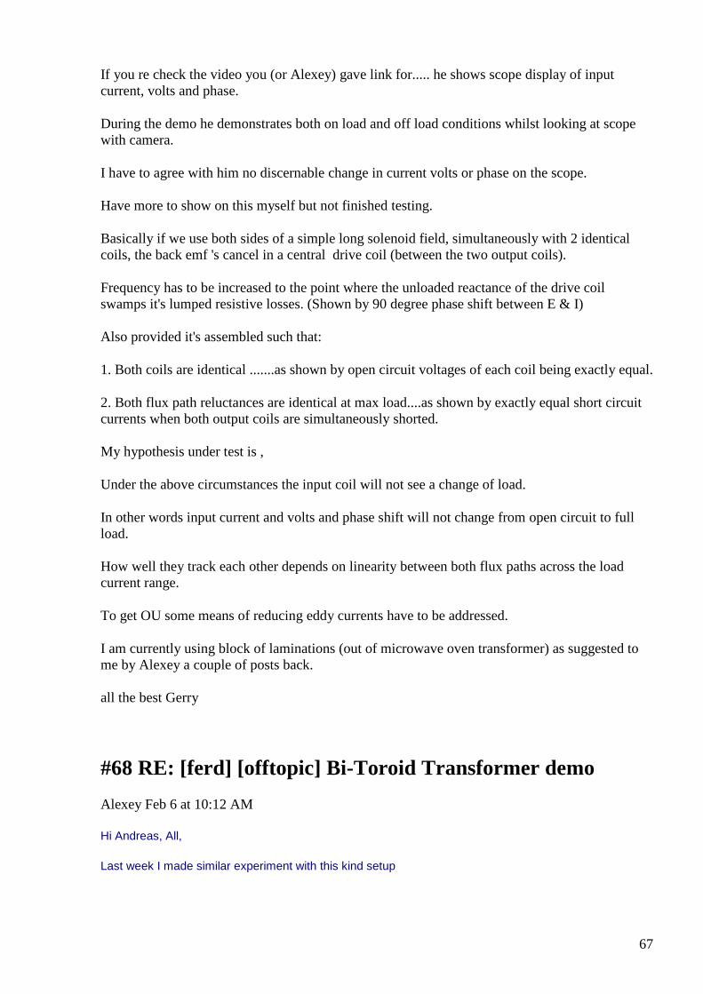
67
If you re check the video you (or Alexey) gave link for..... he shows scope display of input current, volts and phase.
During the demo he demonstrates both on load and off load conditions whilst looking at scope with camera.
I have to agree with him no discernable change in current volts or phase on the scope.
Have more to show on this myself but not finished testing.
Basically if we use both sides of a simple long solenoid field, simultaneously with 2 identical coils, the back emf 's cancel in a central drive coil (between the two output coils).
Frequency has to be increased to the point where the unloaded reactance of the drive coil swamps it's lumped resistive losses. (Shown by 90 degree phase shift between E & I)
Also provided it's assembled such that:
1. Both coils are identical .......as shown by open circuit voltages of each coil being exactly equal.
2. Both flux path reluctances are identical at max load....as shown by exactly equal short circuit currents when both output coils are simultaneously shorted.
My hypothesis under test is ,
Under the above circumstances the input coil will not see a change of load.
In other words input current and volts and phase shift will not change from open circuit to full load.
How well they track each other depends on linearity between both flux paths across the load current range.
To get OU some means of reducing eddy currents have to be addressed.
I am currently using block of laminations (out of microwave oven transformer) as suggested to me by Alexey a couple of posts back.
all the best Gerry
#68 RE: [ferd] [offtopic] Bi-Toroid Transformer dem o
Alexey Feb 6 at 10:12 AM
Hi Andreas, All,
Last week I made similar experiment with this kind setup
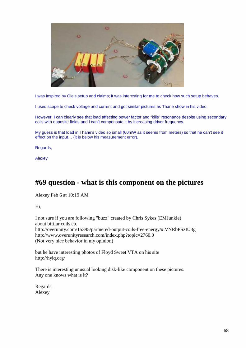
68
I was inspired by Ole’s setup and claims; it was interesting for me to check how such setup behaves.
I used scope to check voltage and current and got similar pictures as Thane show in his video.
However, I can clearly see that load affecting power factor and “kills” resonance despite using secondary coils with opposite fields and I can’t compensate it by increasing driver frequency.
My guess is that load in Thane’s video so small (60mW as it seems from meters) so that he can’t see it effect on the input… (it is below his measurement error).
Regards,
Alexey
#69 question - what is this component on the pictures
Alexey Feb 6 at 10:19 AM
Hi, I not sure if you are following "buzz" created by Chris Sykes (EMJunkie) about bifilar coils etc http://overunity.com/15395/partnered-output-coils-free-energy/#.VNRbPSzIU3g http://www.overunityresearch.com/index.php?topic=2760.0 (Not very nice behavior in my opinion) but he have interesting photos of Floyd Sweet VTA on his site http://hyiq.org/ There is interesting unusual looking disk-like component on these pictures. Any one knows what is it? Regards, Alexey
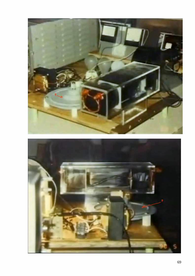
69
70
#70 Re: [ferd] [offtopic] Bi-Toroid Transformer demo
smokyatgroups Feb 6 at 2:19 PM
Hi Alexey ..all,
Please find attached the simple setup required to test and defeat Lenz effect.
As described in my post below.
I have only tested it with sine waves over 50 to 1000 Hz ...but it seems to work!
If you guys have time to try, it is worth the effort, as principle is closely aligned with split phase concept.
Secondary coils do not need to be counter wound to each other.
Need to monitor input for E vs I and be able to see phase shift with scope.
Gerry
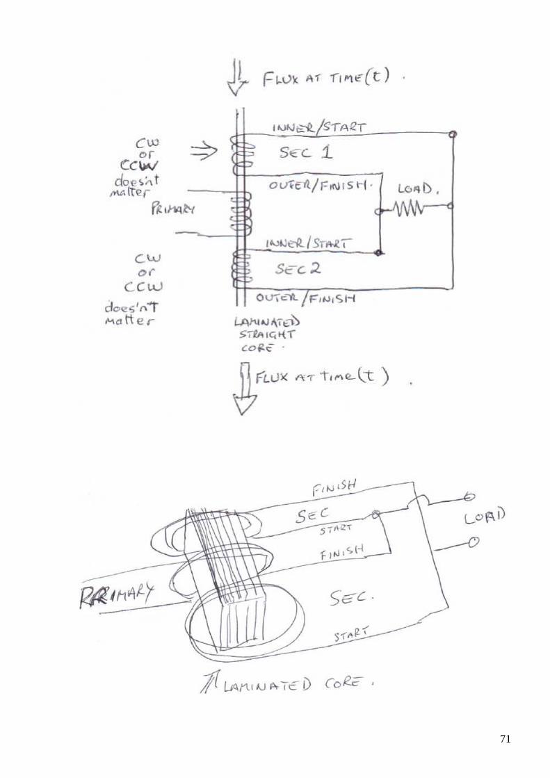
71
72
#71 Re: [ferd] [offtopic] Bi-Toroid Transformer demo
Andreas Höschler Feb 6 at 2:47 PM
Hi Gerry,
Also provided it's assembled such that:
1. Both coils are identical .......as shown by open circuit voltages of each coil being exactly equal.
2. Both flux path reluctances are identical at max load....as shown by exactly equal short circuit currents when both output coils are simultaneously shorted.
My hypothesis under test is ,
Under the above circumstances the input coil will not see a change of load.
In other words input current and volts and phase shift will not change from open circuit to full load.
How well they track each other depends on linearity between both flux paths across the load current range.
To get OU some means of reducing eddy currents have to be addressed.
I am currently using block of laminations (out of microwave oven transformer) as suggested to me by Alexey a couple of posts back.
Why don’t you use ferrite??
Gerry, this is an interesting project and am I am sure something will come out of it. I have reported my results of a similar quick hack experiment a few days ago in which I found a significant difference between bucking and aiding configuration. However, I don’t buy the current understanding of flux cancelling a la Thane Heins. It’s a bit more complicated. If we find something then probably rather due to another effect that has to do with infinite propagation speed of fields (aether disturbance). We need to keep both eyes open and look in all directions.
Andreas
#72 Re: [ferd] [offtopic] Bi-Toroid Transformer demo
Andreas Höschler Feb 6 at 2:54 PM
Hi Alexey,
73
I was inspired by Ole’s setup and claims; it was interesting for me to check how such setup behaves.
I used scope to check voltage and current and got similar pictures as Thane show in his video.
However, I can clearly see that load affecting power factor and “kills” resonance despite using secondary coils with opposite fields and I can’t compensate it by increasing driver frequency.
Thanks for sharing. That's exactly what I found. The counter flux meets in the junction and then bursts into the primary killing everything. I am therefore looking into
• infinite propagation speed
• discharging coils into caps
My guess is that load in Thane’s video so small (60mW as it seems from meters) so that he can’t see it effect on the input… (it is below his measurement error).
As said as long as he does not show a 100W bulb brightly glowing I don’t hold my breath.
Andreas
#73 Re: [ferd] question - what is this component on the pictures
Gerry Feb 6 at 4:12 PM
Sorry Alexey,
I do not know what that component is it was good find to notice it in those pics.
If you ask me to have a guess I would say it could be an early version of a solid state strain gauge,
which is nowadays commonly used to measure a persons weight, (bathroom scales).
So possibly monitoring change of weight of device?
Re: Chris Sykes yes I know him as a fellow Aussie he lives approx 1000 Kms North of me.
Have visited him once.
He keeps a nicely updated website and makes nice looking videos.
However we disagree very often and have strongly argued over interpretation of what he thinks he is measuring.
I know what I think of some of his public claims, looks like some others of same opinion.
74
Prefer to leave it at that, I guess.
Gerry
#74 Re: [ferd] [offtopic] Bi-Toroid Transformer demo
Gerry Feb 6 at 6:01 PM
Hi Andreas,
I did a quick try with ferrite making up a split phase transformer out of Ferrite tube about 30 mm long driven by a pair of ferrite toroids.
It worked, but only at high frequency and I could not get Cos phi to go negative, now I know why and how ... at least I think I do.
If ferrite is to be used or any other solid type material it should either be laminated longitudinally or be in shape of a tube.
Otherwise internal eddy currents will circulate in a circular fashion inside the coils.
Flux needs to travel side ways only from each coil to adjacent coil, no rotational flux!
With metal laminations the plates are insulated from one another and direct flux sideways impeding circular currents.
If is in shape of tube at least one single shorted turn must be wound along outer length of tube and back down the centre of tube.
So equal but opposite flux developed to hamper circular currents, then the input & output coils wound as normal over the top.
Similar idea to shorted start winding on shaded pole motors.
For me is a work in progress, just sharing what I've found so far.
If trying the little sketch I attached, you'll find it easy to get the volts and current 90 degrees out of phase with each other.
Though it doesn't reduce the reactive currents needed, which Ole talked about.
After this concentrating on getting Cos phi to go negative will change the direction of the reactive currents (or at least part of it).
Gerry
75
#75 Re: [ferd] [offtopic] Bi-Toroid Transformer demo
Andreas Höschler Feb 6 at 6:14 PM
Hi Gerry,
Otherwise internal eddy currents will circulate in a circular fashion inside the coils.
Flux needs to travel side ways only from each coil to adjacent coil, no rotational flux!
I suppose I don’t get what you mean! Aren’t eddy currents circulatory by their very definition? :-) And they are usually generated when flux travels from coil to coil. Where do you expect rotational flux? With flux we normally refer to magnetic flux which correspond to rotational aether winds. Do you really mean rotational magnetic flux? If so I probably need a drawing to get your point! And ferrite is supposed to be not electrically conducting (therefore no eddy currents in ferrite). I know that this is not 100% true. Especially when working with HV you should not rely on the non-conductance of ferrite and better not touch the core in a kV environment but under normal circumstances eddy currents are not an issue when using ferrite!??
Best wishes,
Andreas
#76 RE: [ferd] [offtopic] Bi-Toroid Transformer dem o
Alexey Feb 6 at 7:58 PM
Hi Gerry,
I would like to confirm one thing about your test setup – ”polarity” of the output coils.
Did you get current flowing when you connect output coils even without load ?
According to your drawing answer is not. So it’s just two coils in parallel. They will produce flux with same direction. How these fluxes can compensate each other?
Regards,
Alexey
#77 RE: [ferd] question - what is this component on the pictures
Alexey Feb 6 at 7:58 PM
Hi Gerry,
76
My first guess was that this is a high voltage capacitor, but now, when you said pressure sensor, I think it make more sense.
Most probably it was used to measure weight change of the device… interesting
Thanks,
Alexey
#78 Re: [ferd] [offtopic] Bi-Toroid Transformer demo
Gerry Feb 6 at 12:29 AM
Hi mate,
Yes I think you're right about low eddies in ferrite due to each piece of metal insulated from the next.
Just if we think of each tiny piece of ferrite as an individual magnet, it takes a certain amount of energy to rotate this magnet.
If we stop the field it wants to align with it's neighboring magnet, but as field is moving it drags behind.
The more it drags the more energy it takes to move it.
So a certain amount of material depth below surface is needed to get our required permeability, but after this amount we don't need to drag the whole central core into alignment every half cycle.
I guess more relevant with solid steel best used as a pipe shape or even the iron dust cores at power line frequencies.
So from OU point of view was just looking to minimise losses,
When flux generated around a wire it is perpendicular to current flow, so it inherently at right angles to coil wound in parallel winds.
So most useful flux permeates adjacent coils as much as possible with laterally laminated structure.
Hope it makes sense, I am terrible with diagrams unlike you guys.
Gerry
#79 On how to get OU
77
smokyatgroups Feb 7 at 1:04 AM
Hi Alexey all,
Just want to share some thoughts on how to get OU with our projects.
I we have a perfect Inductor or Capacitor the current is displaced from the voltage by 90 degrees.
We all know this.
Taking Inductive device for example if we can get our devices to provide output power whilst having input current lagging the applied voltage by 90 degrees.
It means we power deice for half the time and equal amount of power is returned to the source input the other half of the time.
So mathematically speaking Cosine of 90 degrees is zero so E x I x Cos 90 = E x I x zero = zero.
So we have a very efficient device, requiring little or no power over all.
But what if we could make the current lag by say 135 degrees what this mean and how would we do it?
Now Cosine 135 degrees is -0.707 so we'd get E x I x Cos 135 = E x I x -0.707
The negative sign means that we are receiving back out of our Inductive device 70 percent more than what we put in, it sounds ridiculous doesn't it.
When we apply sine wave voltage at say 50 Hz to our inductive device, the voltage doesn't peak until a quarter of a cycle, or 90 degrees.
Now the input current doesn't reach it's peak until another quarter cycle after this.
So the question becomes how can we FURTHER delay the current from occurring in our Inductive device after the voltage has been applied?
In terms of time 90 degrees is a quarter of a cycle and the cycle time is 1/50Hz which is 20 milliseconds.
So we get 1/4 of 20 milliseconds which is 5 milliseconds current delay in our perfect inductor device.
To get 135 degrees we need to delay the current for (90 + 45) degrees, or another 1/8 th of the cycle time.
20 milliseconds x 1/8 = 2.5 milliseconds.
So we looking for total delay of 7.5 milliseconds at 50Hz.
Have think about how we could get this delay to occur, then we share our ideas on best way.
Gerry
78
#80 Re: [ferd] [offtopic] Bi-Toroid Transformer demo
Gerry Feb 6 at 4:39 AM
Hi Alexey,
Thanks for your question it is a good one.
Have attached some pics.
@ 1000 Hz
With secondaries not connected:
Primary input current is 205.7 mA
Primary voltage is 15.35 V rms
Phase shift approx 88 degrees as near as I can read it. (2.45 Divs offset in 10)
With secondaries connected:
Primary input current is 206.3 mA
Primary input voltage is 15.36 V rms
Phase shift 88 degrees near as I can read it again (2.45 Divs offset in 10)
So no discernable difference in input magnetising current connected to un connected.
My open circuit output volts are 8.2 V rms ( one coil is 8.56 V the other 7.9 V ).
Shorting my output coils at load terminals, I do get increase in input current but it is because my microwave oven primaries (used as secondaries here) do not exactly match.
When I use a resistor to match up the shorted currents from the higher current output coil side, then there is no increase in input current from open circuit to full load.
However this stuffs up the phase shift because using resistor is not correct way, (as time constant is affected, from E exp -t/LR) really need to balance
inductances and coil dc resistances properly.
*It is most important that start of one secondary coil connects to finish of the other, otherwise phase shift will not approach 90 degrees.
Gerry
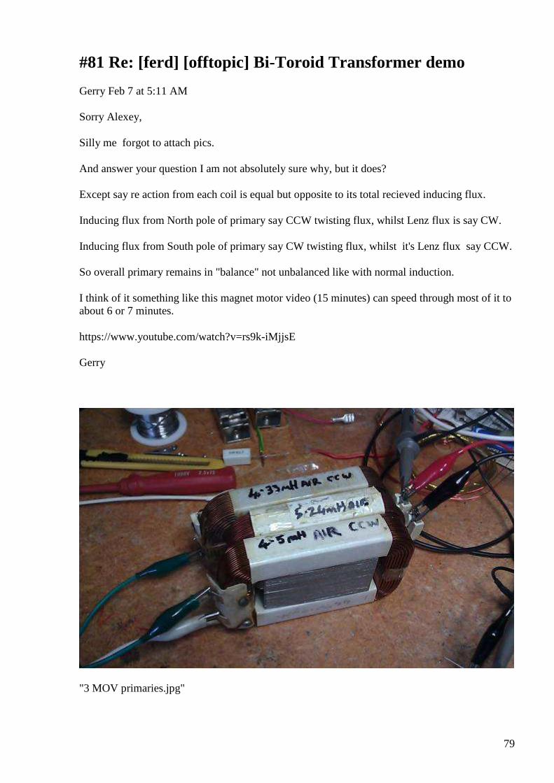
79
#81 Re: [ferd] [offtopic] Bi-Toroid Transformer demo
Gerry Feb 7 at 5:11 AM
Sorry Alexey,
Silly me forgot to attach pics.
And answer your question I am not absolutely sure why, but it does?
Except say re action from each coil is equal but opposite to its total recieved inducing flux.
Inducing flux from North pole of primary say CCW twisting flux, whilst Lenz flux is say CW.
Inducing flux from South pole of primary say CW twisting flux, whilst it's Lenz flux say CCW.
So overall primary remains in "balance" not unbalanced like with normal induction.
I think of it something like this magnet motor video (15 minutes) can speed through most of it to about 6 or 7 minutes.
https://www.youtube.com/watch?v=rs9k-iMjjsE
Gerry
"3 MOV primaries.jpg"
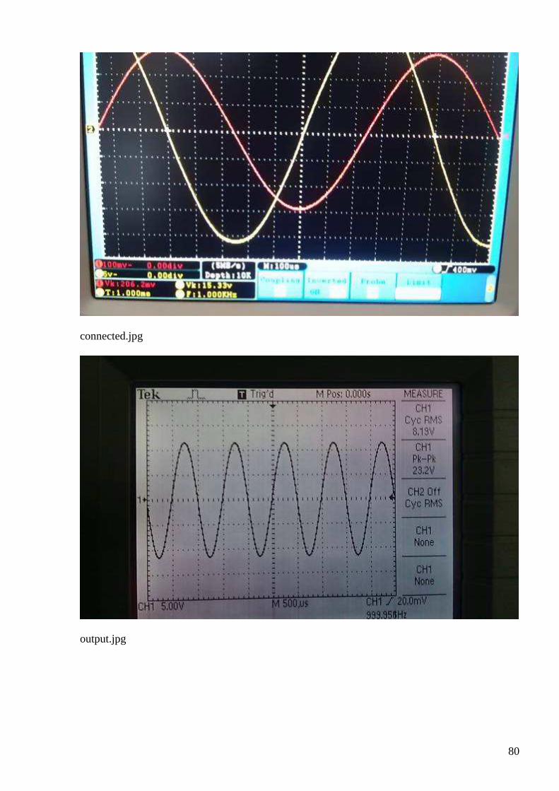
80
connected.jpg
output.jpg
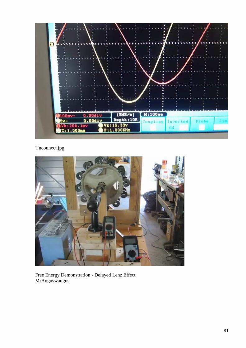
81
Unconnect.jpg
Free Energy Demonstration - Delayed Lenz Effect MrAnguswangus
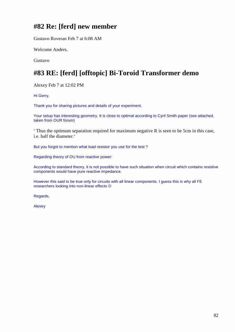
82
#82 Re: [ferd] new member
Gustavo Roveran Feb 7 at 6:08 AM
Welcome Anders. Gustavo
#83 RE: [ferd] [offtopic] Bi-Toroid Transformer dem o
Alexey Feb 7 at 12:02 PM
Hi Gerry,
Thank you for sharing pictures and details of your experiment.
Your setup has interesting geometry. It is close to optimal according to Cyril Smith paper (see attached, taken from OUR forum)
” Thus the optimum separation required for maximum negative R is seen to be 5cm in this case, i.e. half the diameter.”
But you forgot to mention what load resistor you use for the test ?
Regarding theory of OU from reactive power:
According to standard theory, it is not possible to have such situation when circuit which contains resistive components would have pure reactive impedance.
However this said to be true only for circuits with all linear components. I guess this is why all FE researchers looking into non-linear effects
Regards,
Alexey
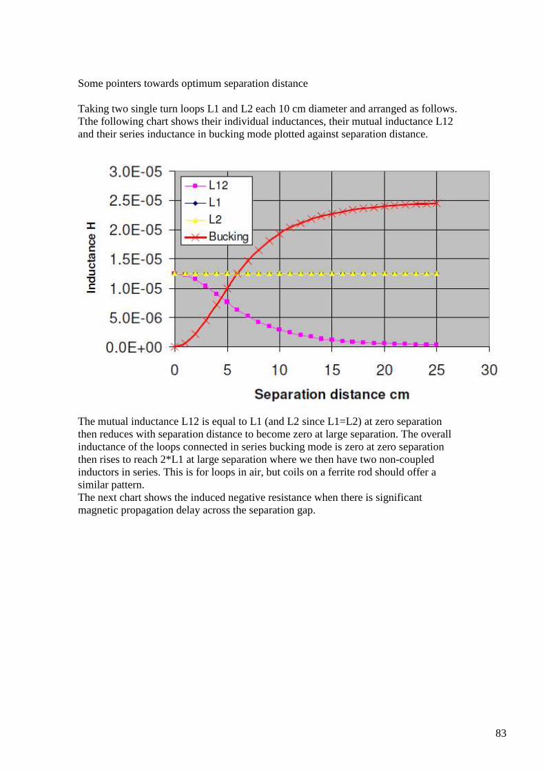
83
Some pointers towards optimum separation distance Taking two single turn loops L1 and L2 each 10 cm diameter and arranged as follows. Tthe following chart shows their individual inductances, their mutual inductance L12 and their series inductance in bucking mode plotted against separation distance.
The mutual inductance L12 is equal to L1 (and L2 since L1=L2) at zero separation then reduces with separation distance to become zero at large separation. The overall inductance of the loops connected in series bucking mode is zero at zero separation then rises to reach 2*L1 at large separation where we then have two non-coupled inductors in series. This is for loops in air, but coils on a ferrite rod should offer a similar pattern. The next chart shows the induced negative resistance when there is significant magnetic propagation delay across the separation gap.
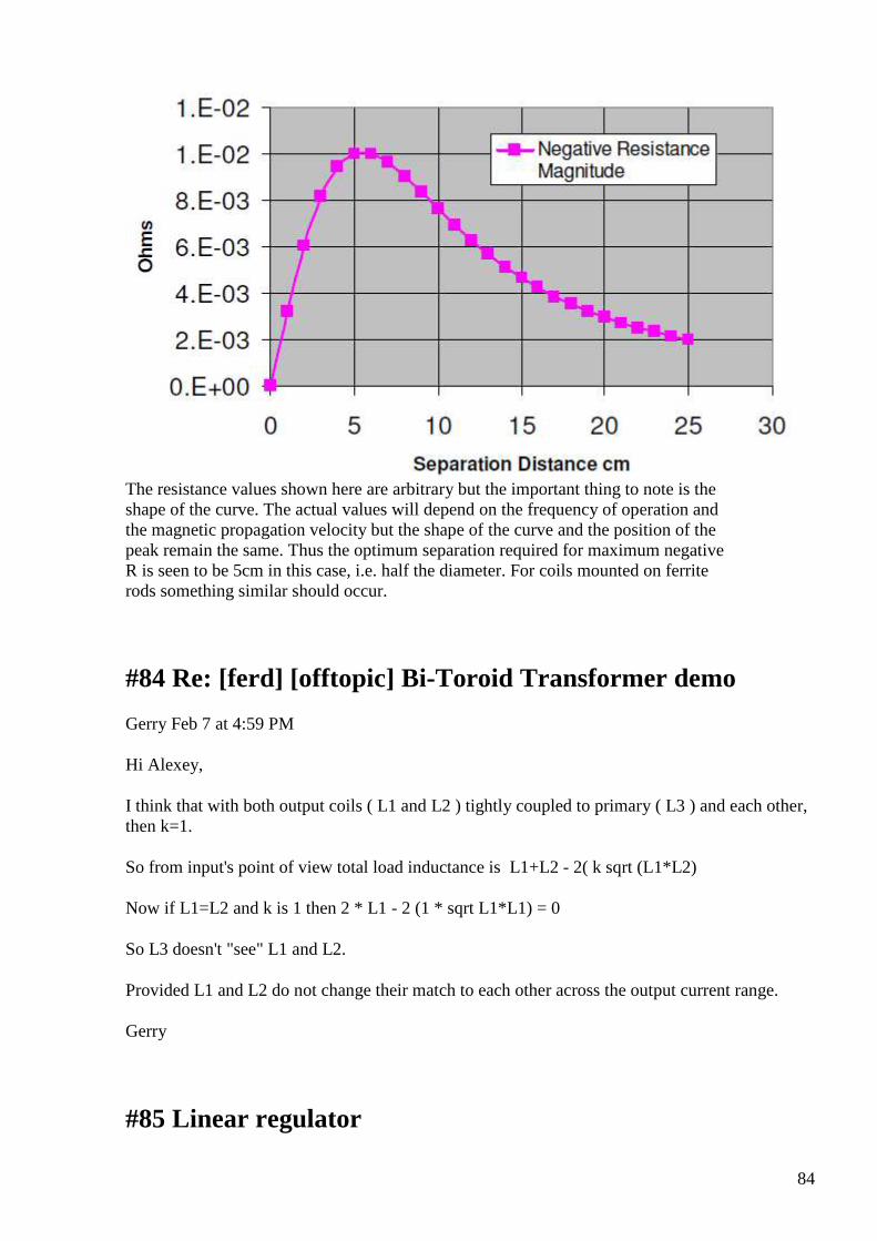
84
The resistance values shown here are arbitrary but the important thing to note is the shape of the curve. The actual values will depend on the frequency of operation and the magnetic propagation velocity but the shape of the curve and the position of the peak remain the same. Thus the optimum separation required for maximum negative R is seen to be 5cm in this case, i.e. half the diameter. For coils mounted on ferrite rods something similar should occur.
#84 Re: [ferd] [offtopic] Bi-Toroid Transformer demo
Gerry Feb 7 at 4:59 PM
Hi Alexey,
I think that with both output coils ( L1 and L2 ) tightly coupled to primary ( L3 ) and each other, then k=1.
So from input's point of view total load inductance is L1+L2 - 2( k sqrt (L1*L2)
Now if L1=L2 and k is 1 then 2 * L1 - 2 (1 * sqrt L1*L1) = 0
So L3 doesn't "see" L1 and L2.
Provided L1 and L2 do not change their match to each other across the output current range.
Gerry
#85 Linear regulator
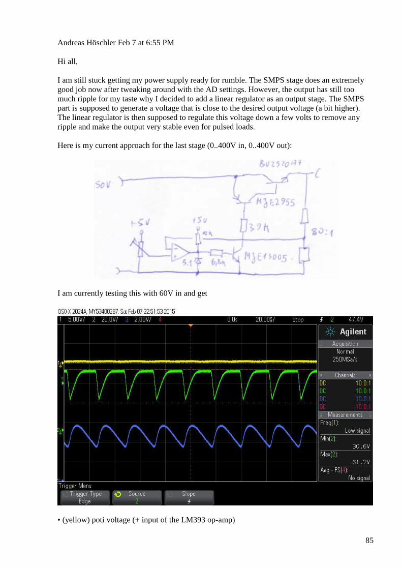
85
Andreas Höschler Feb 7 at 6:55 PM
Hi all, I am still stuck getting my power supply ready for rumble. The SMPS stage does an extremely good job now after tweaking around with the AD settings. However, the output has still too much ripple for my taste why I decided to add a linear regulator as an output stage. The SMPS part is supposed to generate a voltage that is close to the desired output voltage (a bit higher). The linear regulator is then supposed to regulate this voltage down a few volts to remove any ripple and make the output very stable even for pulsed loads. Here is my current approach for the last stage (0..400V in, 0..400V out):
I am currently testing this with 60V in and get
• (yellow) poti voltage (+ input of the LM393 op-amp)

86
• (green) collector voltage of the MJE13005 • (blue) output voltage This is obviously not what I want. I can regulate the voltage up and down with the poti but the beast is oscillating. Any idea? I don't want to waste anyones time but if anybody immediately sees my error I would be very grateful for a hint. Back into datasheets and looking for application notes ... :-) Thanks a lot, Andreas
#86 RE: [ferd] Linear regulator
Alexey Feb 7 at 7:44 PM
Hi Andreas, LM393 is comparator, not an op-amp (see http://www.ti.com/lit/ds/symlink/lm393-n.pdf) You need something like LM358 (see http://www.ti.com/lit/ds/symlink/lm358.pdf) Also I would change schematic (please see attached)… Regards, Alexey
#87 Re: [ferd] [offtopic] Bi-Toroid Transformer demo
Gerry Feb 8 at 12:30 AM
Hi Alexey,
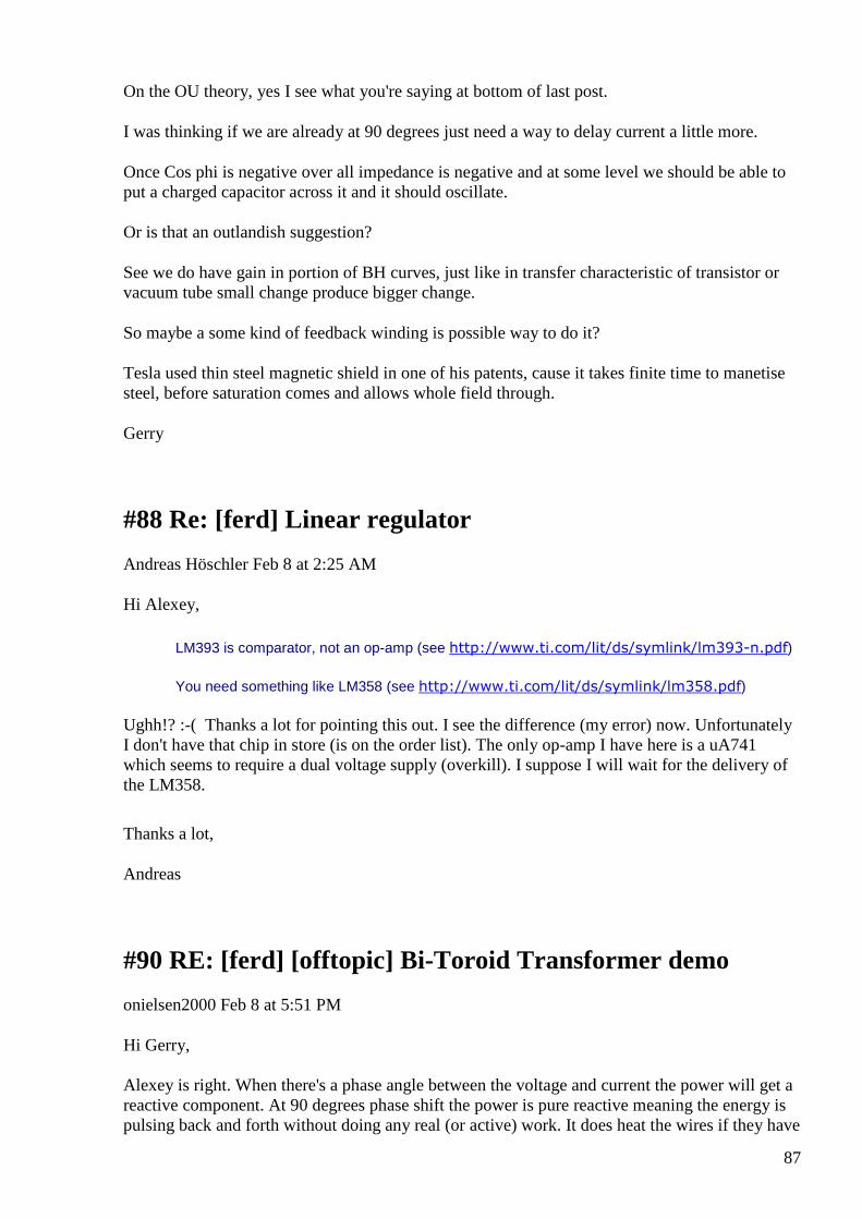
87
On the OU theory, yes I see what you're saying at bottom of last post.
I was thinking if we are already at 90 degrees just need a way to delay current a little more.
Once Cos phi is negative over all impedance is negative and at some level we should be able to put a charged capacitor across it and it should oscillate.
Or is that an outlandish suggestion?
See we do have gain in portion of BH curves, just like in transfer characteristic of transistor or vacuum tube small change produce bigger change.
So maybe a some kind of feedback winding is possible way to do it?
Tesla used thin steel magnetic shield in one of his patents, cause it takes finite time to manetise steel, before saturation comes and allows whole field through.
Gerry
#88 Re: [ferd] Linear regulator
Andreas Höschler Feb 8 at 2:25 AM
Hi Alexey,
LM393 is comparator, not an op-amp (see http://www.ti.com/lit/ds/symlink/lm393-n.pdf)
You need something like LM358 (see http://www.ti.com/lit/ds/symlink/lm358.pdf)
Ughh!? :-( Thanks a lot for pointing this out. I see the difference (my error) now. Unfortunately I don't have that chip in store (is on the order list). The only op-amp I have here is a uA741 which seems to require a dual voltage supply (overkill). I suppose I will wait for the delivery of the LM358.
Thanks a lot,
Andreas
#90 RE: [ferd] [offtopic] Bi-Toroid Transformer dem o
onielsen2000 Feb 8 at 5:51 PM
Hi Gerry, Alexey is right. When there's a phase angle between the voltage and current the power will get a reactive component. At 90 degrees phase shift the power is pure reactive meaning the energy is pulsing back and forth without doing any real (or active) work. It does heat the wires if they have
88
resistance thus giving a small part of real power being dissipated. Read the following links to get an understanding: Beckhoff Information System - English
http://infosys.beckhoff.com/english.php?content=../content/1033/el3413/html/bt_el3413_functionality.htm&id=
Beckhoff Information System - English Components for Automation and Control: TwinCAT NT-Realtime-System, Bus terminal, Industrial PC, BECKHOFF-Lightbus
View on infosys.beckhoff.com Preview
by Yahoo
AC power - Wikipedia, the free encyclopedia
http://en.wikipedia.org/wiki/AC_power
AC power - Wikipedia, the free encyclopedia Power in an electric circuit is the rate of flow of energy past a given point of the circuit. In alternating current circuits, energy storage elements such as induc...
View on en.wikipedia.org Preview
by Yahoo
Regards Ole
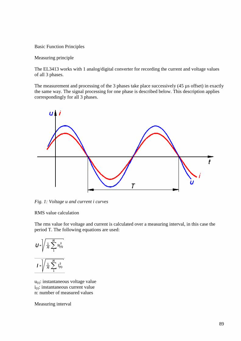
89
Basic Function Principles Measuring principle
The EL3413 works with 1 analog/digital converter for recording the current and voltage values of all 3 phases.
The measurement and processing of the 3 phases take place successively (45 µs offset) in exactly the same way. The signal processing for one phase is described below. This description applies correspondingly for all 3 phases.
Fig. 1: Voltage u and current i curves
RMS value calculation
The rms value for voltage and current is calculated over a measuring interval, in this case the period T. The following equations are used:
u(t): instantaneous voltage value i(t): instantaneous current value n: number of measured values
Measuring interval
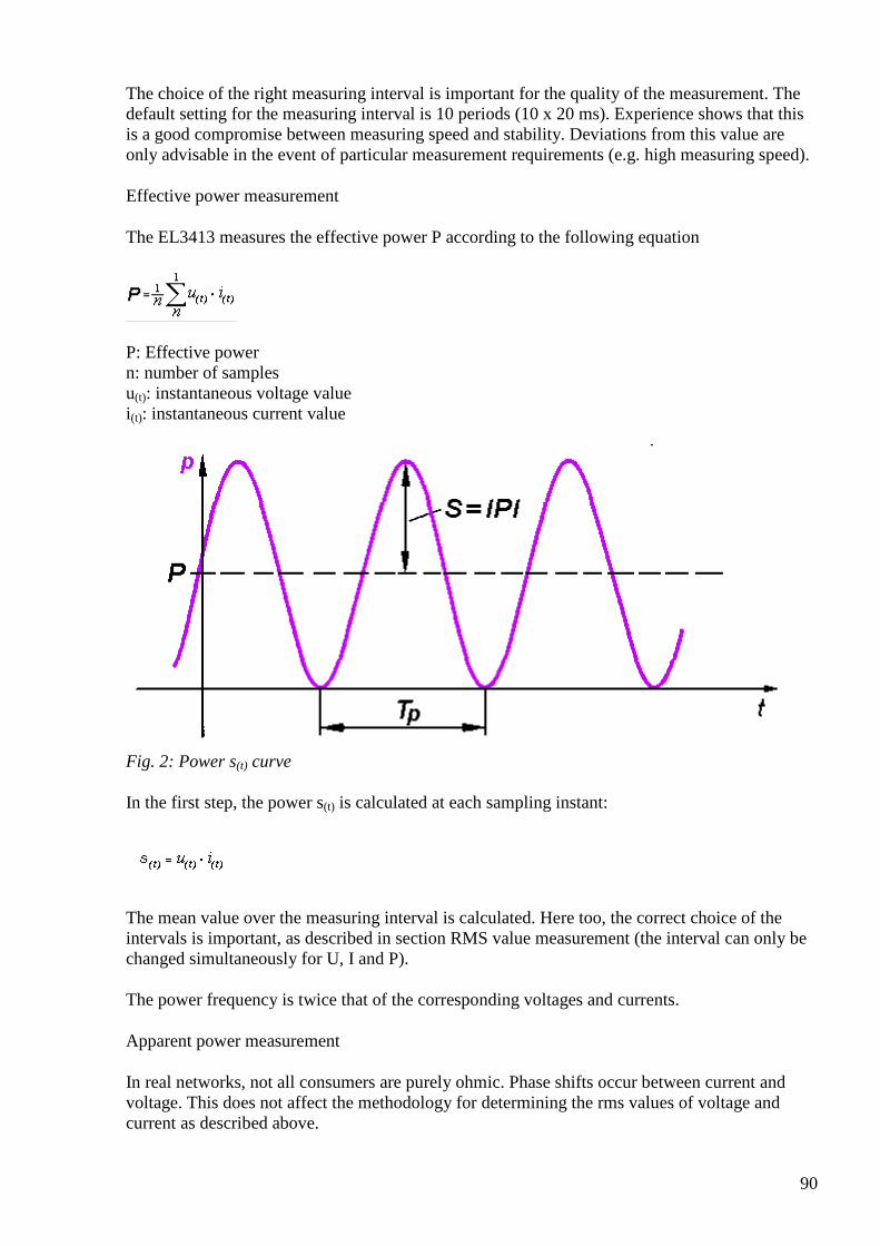
90
The choice of the right measuring interval is important for the quality of the measurement. The default setting for the measuring interval is 10 periods (10 x 20 ms). Experience shows that this is a good compromise between measuring speed and stability. Deviations from this value are only advisable in the event of particular measurement requirements (e.g. high measuring speed).
Effective power measurement
The EL3413 measures the effective power P according to the following equation
P: Effective power n: number of samples u(t): instantaneous voltage value i(t): instantaneous current value
Fig. 2: Power s(t) curve
In the first step, the power s(t) is calculated at each sampling instant:
The mean value over the measuring interval is calculated. Here too, the correct choice of the intervals is important, as described in section RMS value measurement (the interval can only be changed simultaneously for U, I and P).
The power frequency is twice that of the corresponding voltages and currents.
Apparent power measurement
In real networks, not all consumers are purely ohmic. Phase shifts occur between current and voltage. This does not affect the methodology for determining the rms values of voltage and current as described above.
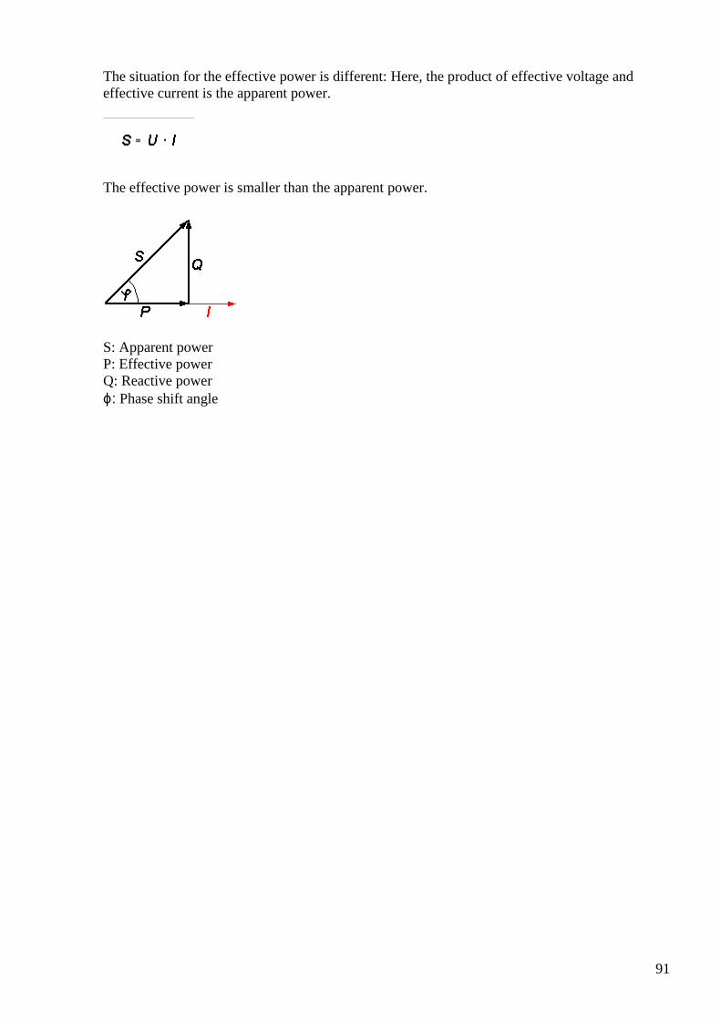
91
The situation for the effective power is different: Here, the product of effective voltage and effective current is the apparent power.
The effective power is smaller than the apparent power.
S: Apparent power P: Effective power Q: Reactive power ϕ: Phase shift angle
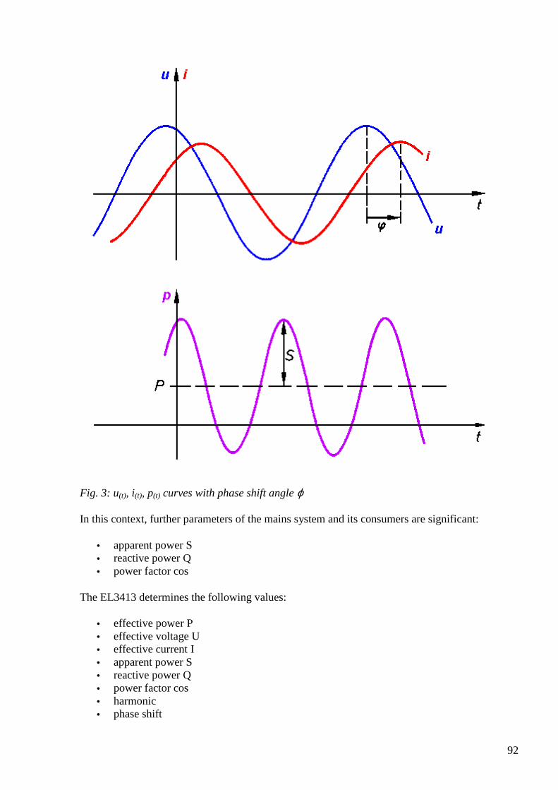
92
Fig. 3: u(t), i(t), p(t) curves with phase shift angle ϕ
In this context, further parameters of the mains system and its consumers are significant:
• apparent power S • reactive power Q • power factor cos
The EL3413 determines the following values:
• effective power P • effective voltage U • effective current I • apparent power S • reactive power Q • power factor cos • harmonic • phase shift
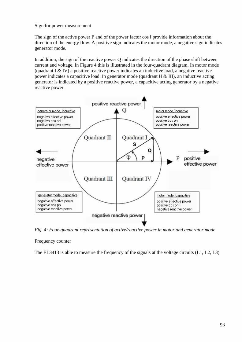
93
Sign for power measurement
The sign of the active power P and of the power factor cos f provide information about the direction of the energy flow. A positive sign indicates the motor mode, a negative sign indicates generator mode. In addition, the sign of the reactive power Q indicates the direction of the phase shift between current and voltage. In Figure 4 this is illustrated in the four-quadrant diagram. In motor mode (quadrant I & IV) a positive reactive power indicates an inductive load, a negative reactive power indicates a capacitive load. In generator mode (quadrant II & III), an inductive acting generator is indicated by a positive reactive power, a capacitive acting generator by a negative reactive power.
Fig. 4: Four-quadrant representation of active/reactive power in motor and generator mode
Frequency counter
The EL3413 is able to measure the frequency of the signals at the voltage circuits (L1, L2, L3).
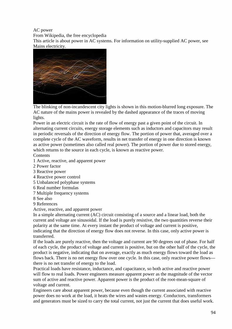
94
AC power From Wikipedia, the free encyclopedia This article is about power in AC systems. For information on utility-supplied AC power, see Mains electricity.
The blinking of non-incandescent city lights is shown in this motion-blurred long exposure. The AC nature of the mains power is revealed by the dashed appearance of the traces of moving lights. Power in an electric circuit is the rate of flow of energy past a given point of the circuit. In alternating current circuits, energy storage elements such as inductors and capacitors may result in periodic reversals of the direction of energy flow. The portion of power that, averaged over a complete cycle of the AC waveform, results in net transfer of energy in one direction is known as active power (sometimes also called real power). The portion of power due to stored energy, which returns to the source in each cycle, is known as reactive power. Contents 1 Active, reactive, and apparent power 2 Power factor 3 Reactive power 4 Reactive power control 5 Unbalanced polyphase systems 6 Real number formulas 7 Multiple frequency systems 8 See also 9 References Active, reactive, and apparent power In a simple alternating current (AC) circuit consisting of a source and a linear load, both the current and voltage are sinusoidal. If the load is purely resistive, the two quantities reverse their polarity at the same time. At every instant the product of voltage and current is positive, indicating that the direction of energy flow does not reverse. In this case, only active power is transferred. If the loads are purely reactive, then the voltage and current are 90 degrees out of phase. For half of each cycle, the product of voltage and current is positive, but on the other half of the cycle, the product is negative, indicating that on average, exactly as much energy flows toward the load as flows back. There is no net energy flow over one cycle. In this case, only reactive power flows—there is no net transfer of energy to the load. Practical loads have resistance, inductance, and capacitance, so both active and reactive power will flow to real loads. Power engineers measure apparent power as the magnitude of the vector sum of active and reactive power. Apparent power is the product of the root-mean-square of voltage and current. Engineers care about apparent power, because even though the current associated with reactive power does no work at the load, it heats the wires and wastes energy. Conductors, transformers and generators must be sized to carry the total current, not just the current that does useful work.
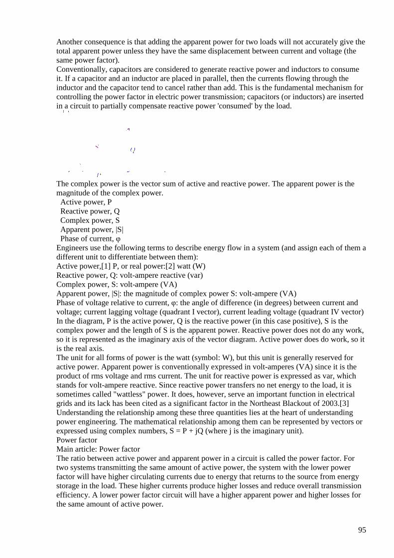
95
Another consequence is that adding the apparent power for two loads will not accurately give the total apparent power unless they have the same displacement between current and voltage (the same power factor). Conventionally, capacitors are considered to generate reactive power and inductors to consume it. If a capacitor and an inductor are placed in parallel, then the currents flowing through the inductor and the capacitor tend to cancel rather than add. This is the fundamental mechanism for controlling the power factor in electric power transmission; capacitors (or inductors) are inserted in a circuit to partially compensate reactive power 'consumed' by the load.
The complex power is the vector sum of active and reactive power. The apparent power is the magnitude of the complex power. Active power, P Reactive power, Q Complex power, S Apparent power, |S| Phase of current, φ Engineers use the following terms to describe energy flow in a system (and assign each of them a different unit to differentiate between them): Active power,[1] P, or real power:[2] watt (W) Reactive power, Q: volt-ampere reactive (var) Complex power, S: volt-ampere (VA) Apparent power, |S|: the magnitude of complex power S: volt-ampere (VA) Phase of voltage relative to current, φ: the angle of difference (in degrees) between current and voltage; current lagging voltage (quadrant I vector), current leading voltage (quadrant IV vector) In the diagram, P is the active power, Q is the reactive power (in this case positive), S is the complex power and the length of S is the apparent power. Reactive power does not do any work, so it is represented as the imaginary axis of the vector diagram. Active power does do work, so it is the real axis. The unit for all forms of power is the watt (symbol: W), but this unit is generally reserved for active power. Apparent power is conventionally expressed in volt-amperes (VA) since it is the product of rms voltage and rms current. The unit for reactive power is expressed as var, which stands for volt-ampere reactive. Since reactive power transfers no net energy to the load, it is sometimes called "wattless" power. It does, however, serve an important function in electrical grids and its lack has been cited as a significant factor in the Northeast Blackout of 2003.[3] Understanding the relationship among these three quantities lies at the heart of understanding power engineering. The mathematical relationship among them can be represented by vectors or expressed using complex numbers, S = P + jQ (where j is the imaginary unit). Power factor Main article: Power factor The ratio between active power and apparent power in a circuit is called the power factor. For two systems transmitting the same amount of active power, the system with the lower power factor will have higher circulating currents due to energy that returns to the source from energy storage in the load. These higher currents produce higher losses and reduce overall transmission efficiency. A lower power factor circuit will have a higher apparent power and higher losses for the same amount of active power.
96
The power factor is one when the voltage and current are in phase. It is zero when the current leads or lags the voltage by 90 degrees. Power factors are usually stated as "leading" or "lagging" to show the sign of the phase angle of current with respect to voltage. Purely capacitive circuits supply reactive power with the current waveform leading the voltage waveform by 90 degrees, while purely inductive circuits absorb reactive power with the current waveform lagging the voltage waveform by 90 degrees. The result of this is that capacitive and inductive circuit elements tend to cancel each other out. Where the waveforms are purely sinusoidal, the power factor is the cosine of the phase angle (φ) between the current and voltage sinusoid waveforms. Equipment data sheets and nameplates often will abbreviate power factor as " " for this reason. Example: The active power is 700 W and the phase angle between voltage and current is 45.6°. The power factor is cos(45.6°) = 0.700. The apparent power is then: 700 W / cos(45.6°) = 1000 VA.[4] Reactive power
This section does not cite any references or sources. Please help improve this section by adding citations to reliable sources. Unsourced material may be challenged and removed. (October 2014)
In a direct current circuit, the power flowing to the load is proportional to the product of the current through the load and the potential drop across the load. Energy flows in one direction from the source to the load. In alternating current (AC) systems power may periodically reverse direction during each cycle of voltage (or current). Stored energy in the magnetic or electric field of a load device, such as a motor or capacitor, causes an offset between the current and the voltage waveforms. The power flow has two components - one component flows steadily from source to load and can perform work at the load, the other portion, known as "reactive power", is due to the delay between voltage and current and cannot do useful work at the load. To distinguish reactive power from active power, it is measured in units of "volt-amperes reactive", (var). While reactive power does not provide useful work, it is a necessary component of power flow in an alternating current system. Reactive power required by customer load must be supplied in some way. Reactive power flow is needed in an alternating-current transmission system to support the transfer of active power over the network. In alternating current circuits, energy is stored temporarily in inductive and capacitive elements. AC connected devices that store energy in the form of a magnetic field include inductors (a large coil of wire). When a voltage is initially placed across the coil, a magnetic field builds up, and it takes a period of time for the current to reach full value. This causes the current to lag behind the voltage in phase; hence, these devices are said to be sources of lagging reactive power. A capacitor is an AC device that stores energy in the form of an electric field. When current is driven through the capacitor, it takes a period of time for a charge to build up to produce the full voltage difference. On an AC network, the voltage across a capacitor is constantly changing – the capacitor will oppose this change, causing the voltage to lag behind the current. In other words, the current leads the voltage in phase; hence, these devices are said to be sources of leading reactive power. The power system requires both types of power — active and reactive — in order to function properly. Electric generators supply reactive power (in addition to active power) that is consumed by customer load. The shifting effect of motors can also be offset using devices that counteract this shift—the most common are capacitors. Such capacitors are the largest source of this offsetting reactive power and are commonly used throughout the power system. Another source of reactive power is a synchronous condenser—a kind of electric generator that does not produce active power, only reactive power. There are also other devices that use high-power electronics to rapidly control reactive power from large banks of capacitors.
97
Energy stored in capacitive or inductive elements of the network give rise to reactive power flow. Reactive power flow strongly influences the voltage levels across the network. Voltage levels and reactive power flow must be carefully controlled to allow a power system to be operated within acceptable limits. Reactive power control Transmission connected generators are generally required to support reactive power flow. For example on the United Kingdom transmission system generators are required by the Grid Code Requirements to supply their rated power between the limits of 0.85 power factor lagging and 0.90 power factor leading at the designated terminals. The system operator will perform switching actions to maintain a secure and economical voltage profile while maintaining a reactive power balance equation: Generator_MVARs + System_gain + Shunt_capacitors = MVAR_Demand + Reactive_losses + Shunt_reactors The ‘System gain’ is an important source of reactive power in the above power balance equation, which is generated by the capacitive nature of the transmission network itself. By making decisive switching actions in the early morning before the demand increases, the system gain can be maximized early on, helping to secure the system for the whole day. To balance the equation some pre-fault reactive generator use will be required. Other sources of reactive power that will also be used include shunt capacitors, shunt reactors, Static VAR Compensators and voltage control circuits. Unbalanced polyphase systems While active power and reactive power are well defined in any system, the definition of apparent power for unbalanced polyphase systems is considered to be one of the most controversial topics in power engineering. Originally, apparent power arose merely as a figure of merit. Major delineations of the concept are attributed to Stanley's Phenomena of Retardation in the Induction Coil (1888) and Steinmetz's Theoretical Elements of Engineering (1915). However, with the development of three phase power distribution, it became clear that the definition of apparent power and the power factor could not be applied to unbalanced polyphase systems. In 1920, a "Special Joint Committee of the AIEE and the National Electric Light Association" met to resolve the issue. They considered two definitions:
that is, the quotient of the sums of the active powers for each phase over the sum of the apparent power for each phase.
that is, the quotient of the sums of the active powers for each phase over the magnitude of the sum of the complex powers for each phase. The 1920 committee found no consensus and the topic continued to dominate discussions. In 1930 another committee formed and once again failed to resolve the question. The transcripts of their discussions are the lengthiest and most controversial ever published by the AIEE (Emanuel, 1993). Further resolution of this debate did not come until the late 1990s. Real number formulas A perfect resistor stores no energy, so current and voltage are in phase. Therefore there is no reactive power and . Therefore for a perfect resistor
For a perfect capacitor or inductor there is no net power transfer, so all power is reactive. Therefore for a perfect capacitor or inductor:
98
Where X is the reactance of the capacitor or inductor. If X is defined as being positive for an inductor and negative for a capacitor then we can remove the modulus signs from S and X and get
Instantaneous power is defined as:
where v(t) and i(t) are the time varying voltage and current waveforms. This definition is useful because it applies to all waveforms, whether they are sinusoidal or not. This is particularly useful in power electronics, where nonsinusoidal waveforms are common. In general, we are interested in the active power averaged over a period of time, whether it is a low frequency line cycle or a high frequency power converter switching period. The simplest way to get that result is to take the integral of the instantaneous calculation over the desired period.
This method of calculating the average power gives the active power regardless of harmonic content of the waveform. In practical applications, this would be done in the digital domain, where the calculation becomes trivial when compared to the use of rms and phase to determine active power.
Multiple frequency systems Since an RMS value can be calculated for any waveform, apparent power can be calculated from this. For active power it would at first appear that we would have to calculate loads of product terms and average all of them. However if we look at one of these product terms in more detail we come to a very interesting result.
however the time average of a function of the form cos(ωt+k) is zero provided that ω is nonzero. Therefore the only product terms that have a nonzero average are those where the frequency of voltage and current match. In other words it is possible to calculate active (average) power by simply treating each frequency separately and adding up the answers. Furthermore, if we assume the voltage of the mains supply is a single frequency (which it usually is), this shows that harmonic currents are a bad thing. They will increase the rms current (since there will be non-zero terms added) and therefore apparent power, but they will have no effect on the active power transferred. Hence, harmonic currents will reduce the power factor. Harmonic currents can be reduced by a filter placed at the input of the device. Typically this will consist of either just a capacitor (relying on parasitic resistance and inductance in the supply) or
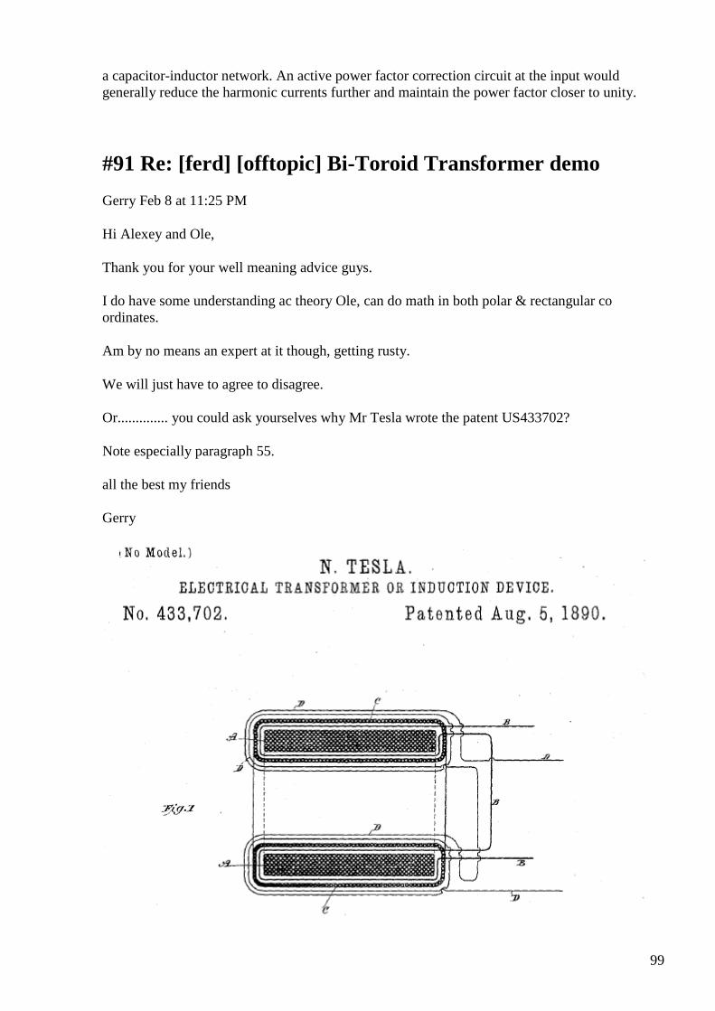
99
a capacitor-inductor network. An active power factor correction circuit at the input would generally reduce the harmonic currents further and maintain the power factor closer to unity.
#91 Re: [ferd] [offtopic] Bi-Toroid Transformer demo
Gerry Feb 8 at 11:25 PM
Hi Alexey and Ole,
Thank you for your well meaning advice guys.
I do have some understanding ac theory Ole, can do math in both polar & rectangular co ordinates.
Am by no means an expert at it though, getting rusty.
We will just have to agree to disagree.
Or.............. you could ask yourselves why Mr Tesla wrote the patent US433702?
Note especially paragraph 55.
all the best my friends
Gerry
100
#92 Re: [ferd] [offtopic] Bi-Toroid Transformer demo
Gerry Feb 9 at 12:40 AM
Hi again, Alexey and Ole,
Please imagine we are plotting an input impedance on a graph,
where the horizontal axis is minus R to plus R and the vertical axis is minus jX to plus jX
Now now mostly our normal everyday impedances lie on the right hand side of the vertical axis, even though they sometimes are either above or below the horizontal axis.
When our say reactive component becomes very great in comparison to our resistive component our phase angle becomes close to 90 degrees (from tan^-1 (jX/R).
So now what would happen if we could force our reactive component to respond a little later on the inductive side of the graph.
Our reactive component would then "crossover into no man's land".
So just potting our delayed point again on this same graph, we would notice that even though our +jX remains positive our "R" component has become Negative , this is very important because it means we have manufactured a negative impedance.
Impedances especially reactive ones are not fixed they move, the reactive component rotates at 2 times Pi times frequency (on our graph).
So the response at our usually thought of 90 degrees relative to R , is actually a speed corresponding to 1/4 of the reciprocal of the ac frequency per second.
101
Hence it is appropriate to think in terms of delay to achieve our goals.
best Gerry
#93 Re: [ferd] [offtopic] Bi-Toroid Transformer demo
Andreas Höschler Feb 9 at 1:03 AM
Hi Gerry,
I see two misconceptions (at least IMHO) in your analysis (see below):
Please imagine we are plotting an input impedance on a graph,
where the horizontal axis is minus R to plus R and the vertical axis is minus jX to plus jX
Now now mostly our normal everyday impedances lie on the right hand side of the vertical axis,
even though they sometimes are either above or below the horizontal axis.
When our say reactive component becomes very great in comparison to our resistive component our phase angle becomes close to 90 degrees (from tan^-1 (jX/R).
So now what would happen if we could force our reactive component to respond a little later on the inductive side of the graph.
Nice idea but how do you think this can be established? The 90° phase shift caused by an ideal inductance is a direct result of
U = L dI / dt
Increasing of decreasing the inductance (in the ideal case of R = 0) has no effect on the phase shift. It stays at dead 90°. The only way to change that is to introduce resistance (positive of negative).
Our reactive component would then "crossover into no man's land”.
Only as a result of introducing a negative resistance by whatever means.
This all depends on how you plan to cause this delay I guess.
Impedances especially reactive ones are not fixed they move, the reactive component rotates at 2 times Pi times frequency (on our graph).
102
No, I don’t think so. The impedance is a complex constant. Only voltage and current are rotating around this graph! :-(
Andreas
#94 Re: [ferd] [offtopic] Bi-Toroid Transformer demo
Gerry Feb 9 at 2:59 AM
Hi mate,
It's all ok we can agree to disagree, we're friends here.
To establish the idea in your head is a bit complicated but it goes like this.
1. When we talk about impedances we might say (R+ jX), now the reactive part of this is the part +jX.
This breaks down to 2*Pi *Frequency* Inductance L, in our case because its +j , which is inductive.
The 2*Pi* Frequency, gives us the speed of rotation in radians per second.
Now we should think of it as occurring a speed because if we double the frequency the reactance automatically doubles.
So we get R + (2*current J value (at current frequency)).
In other words inductive reactance rises direct proportion with frequency.
Resistance part doesn't rotate because its pure resistance with no reactive component.
Now whether we speaking of an impedance as a vector magnitude with a phase angle, say z Ohms at angle 88 degrees or in rectangular form R+ jX above.
It is important to realise these above impedances area moment frozen in time, where the measurement is taken.
If this speed of rotation was varied during any single 360 degree cycle it will only affect the reactive component not the resistive.
Believe it or not this is exactly the same reason they coat the lenses in your camera or binoculars.
They are gradually matching the velocity of the light wave to it's velocity in glass. To reduce reflections and increase transmission.
103
Gradual change of velocity gives conjugate match which is geometric mean of velocity now and velocity we want to achieve.
Another example might be to look at circumference of Smith Chart and see how impedance changes with wavelength,
remembering wavelength changes depending on characteristics of material it is propagating through.
Sorry can't explain better at the moment ...except to say if we have a complete short circuit at a particular ac frequency
then 1/4 wavelength away it appears to be an open circuit on the transmission line.
This effect is often used as a matching stub in antennas but only good at that particular impedance at that particular frequency moment "frozen in time".
Gerry
#95 Re: [ferd] [offtopic] Bi-Toroid Transformer demo
onielsen2000 Feb 9 at 3:49 AM
Hi Garry, You're doing a good job here. I've been thinking of parametric changes in impedance to "create" energy by parametric pumping. By varying the frequency this is achieved without having to change any physical parameters of inductance or capacitance as the impedance is changed by just pumping the frequency instead. This I think is the explanation of the energy generated by the UDT by doubling the frequency of the primary LC-tank. This also makes it much easier to make free energy. Thank you for the great inspiration. Regards Ole
#96 Re: [ferd] [offtopic] Bi-Toroid Transformer demo
Andreas Höschler Feb 9 at 4:36 AM
Hi Ole,
You're doing a good job here. I've been thinking of parametric changes in impedance to "create" energy by parametric pumping. By varying the frequency this is achieved without having to change any physical parameters of inductance or capacitance as the impedance is changed by just pumping the frequency instead.
104
Pumping frequency? Have you still your resonated UDT primary in mind here? What do you mean by pumping the frequency? How can you change the frequency up and down within one cycle? This of course does not work. I guess you have mixing two frequencies in mind (super positioning two sine waves)!?
Andreas
#97 Re: [ferd] [offtopic] Bi-Toroid Transformer demo
onielsen2000 Feb 9 at 5:03 AM
Hi Andreas, Some modern grid tie inverters for solar power are capable of delivering reactive power. They can regulate the frequency in less than one period which is much faster than any synchronous generator. I'm looking at class D audio amplifiers at the moment. Many of these are fast enough for HiFi use with switching frequencies of above a few hundred kHz. I wonder if a cheap IC one can be extended with a home built high power totem-pole or H-bridge output stage. Akula does mix two frequencies in his lantern circuits. This may not be necessary if just pumping one generator up and down in frequency. This will give the wanted shift in frequency. Perhaps it may even work with square waves as done in switched mode power supplies by pulse width modulating the signal if done the right way. Of course that's the conventional way used to step up or step down the voltage (depending on topology) which doesn't seem to "create" any energy. The LC-tank i another part of the equation. Regards Ole
#98 Re: [ferd] [offtopic] Bi-Toroid Transformer demo
Gerry Feb 9 at 5:05 AM
Hi Ole,
Thank you, for your kind words there.
Yes the parametric pumping also needs also same non linearity to make it work,
so that either total permittivity (delta C) varies or total permeability (delta L) varies.
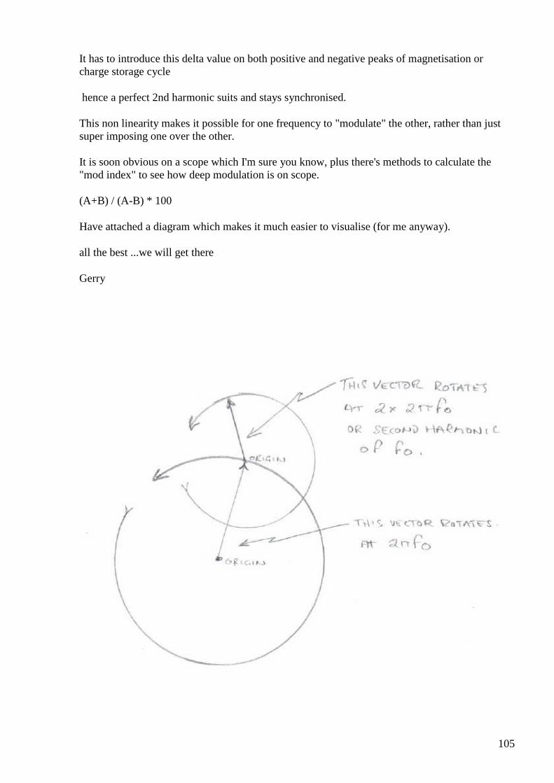
105
It has to introduce this delta value on both positive and negative peaks of magnetisation or charge storage cycle
hence a perfect 2nd harmonic suits and stays synchronised.
This non linearity makes it possible for one frequency to "modulate" the other, rather than just super imposing one over the other.
It is soon obvious on a scope which I'm sure you know, plus there's methods to calculate the "mod index" to see how deep modulation is on scope.
(A+B) / (A-B) * 100
Have attached a diagram which makes it much easier to visualise (for me anyway).
all the best ...we will get there
Gerry

106
#99 RE: [ferd] [offtopic] Bi-Toroid Transformer dem o
Alexey Feb 9 at 9:46 AM
Hi Gerry, All,
I have an example simulation of parametric circuit which I think often called Tesla switch.
It produces asymmetric current with negative component higher than positive… Do you think it is a FE device? ;-)
Regards,
Alexey
#100 Re: [ferd] [offtopic] Bi-Toroid Transformer demo
Gerry Feb 9 at 12:01 PM
Hi Alexey,
I am sorry Alexey ...I have to say I don't know.
From the things I posted before you probably think I have all the answers, but I don't I am just trying here like everyone else.
107
To be OU, total power output has to exceed total input in power terms.
I know it doesn't take much power to switch modern FET switches. If they are say charging is parallel and discharging in series or whatever.
In old days VHF & UHF receivers they used to use parametric amplifiers because they had low noise figure as no active devices in the signal path.
The varicap diodes themselves operate in reverse bias mode so very little electron recombination noise created across PN junctions.
They had to pump the things at twice the operating frequency though which was a big ask in those days.
Even so they had high voltage gains not necessarily high power gains (as charge Q =C* V) and lowering C after charging just increases the V, so Q value remains constant.....not exactly power for free.
But I guess from Energy = 0.5 C*V^2 maybe there is some benefit?
Also charged capacitor plates are highly attracted to each other and it takes a finite amount of energy to separate them.
So I guess it depends what we get back for what we give.
Gerry
ps have attached a pic from today's testing of MOV primary coils.
You can see what appears to be negative impedance result, as phase current (red trace) has moved to about 122 degrees after voltage (yellow trace).
Current seemed to be travelling in reverse direction as voltage across series current resistor exceeded total voltage coming out of the amplifier.
It is hard to get this consistently though.
Gerry
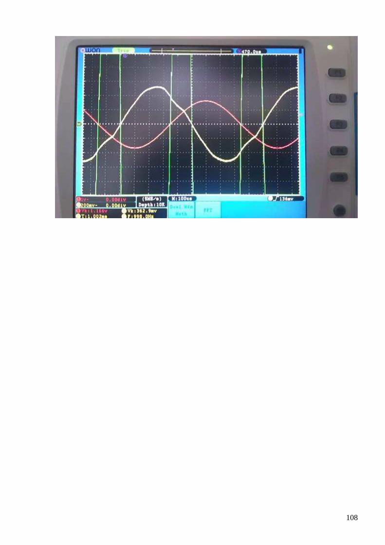
108
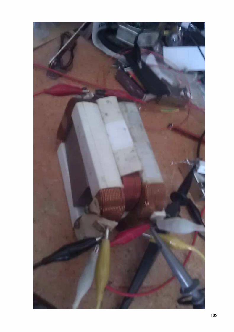
109
110
#101 Re: [ferd] [offtopic] Bi-Toroid Transformer demo
onielsen2000 Feb 9 at 3:16 PM
Hi Garry, The nonlinearity is probably needed too to mix the signals to prevent them from just riding through each other. The UDT works better at not too low power which a linear amplifier doesn't like. But on the other hand if the impedance changes not because of the material constants changing but only because the frequency changes this may actually be enough to cohere the signals. This gives two different conditions which is one for input and another for output which should make it harder for the signals to separate after mixing. I don't know if Wilbert B. Smith ever build a device to prove that energy is created by coherence of fields. With his background in radio engineering he must have known how to mix the signals. Seen from a mathematical point of view it does work. I have searched for the solution for years and is seems easy with the technology now at hands and measurement equipment becoming better cheaper and affordable to see what happens. Also computer simulations is a way to investigate this field. Regards Ole
#102 Re: [ferd] [offtopic] Bi-Toroid Transformer demo
Andreas Höschler Feb 9 at 4:36 PM
Hi Ole,
Some modern grid tie inverters for solar power are capable of delivering reactive power. They can regulate the frequency in less than one period which is much faster than any synchronous generator. I'm looking at class D audio amplifiers at the moment. Many of these are fast enough for HiFi use with switching frequencies of above a few hundred kHz. I wonder if a cheap IC one can be extended with a home built high power totem-pole or H-bridge output stage.
Interesting concept. I have a basic idea what you mean and how this “regulate frequency in one period” could be realised. This might indeed lead to impedance modification within one cycle. But if you want to use that to pump a tank we normally need to kick this tank with its resonance frequency (or a harmonic). How can we do that and simultaneously modify the driving frequency? We might be able to do this in a small frame around the resonance frequency but this again would lead to rather small changes of the impedance and thus hardly any pumping effect!?
If we couple this with non-linear effects (jump resonance) we have a real mess to deal with! :-)
Please let me know what you find out class D amplifier wise. This could open one or two doors for us.
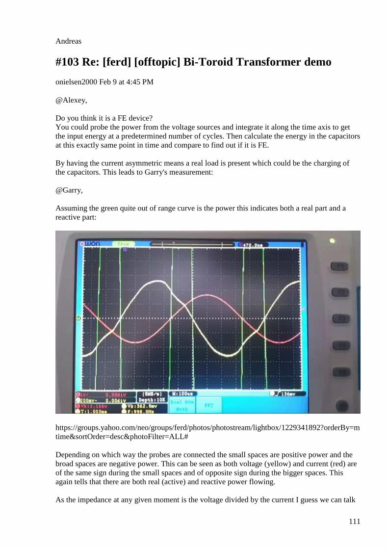
111
Andreas
#103 Re: [ferd] [offtopic] Bi-Toroid Transformer demo
onielsen2000 Feb 9 at 4:45 PM
@Alexey, Do you think it is a FE device? You could probe the power from the voltage sources and integrate it along the time axis to get the input energy at a predetermined number of cycles. Then calculate the energy in the capacitors at this exactly same point in time and compare to find out if it is FE. By having the current asymmetric means a real load is present which could be the charging of the capacitors. This leads to Garry's measurement: @Garry, Assuming the green quite out of range curve is the power this indicates both a real part and a reactive part:
https://groups.yahoo.com/neo/groups/ferd/photos/photostream/lightbox/1229341892?orderBy=mtime&sortOrder=desc&photoFilter=ALL#
Depending on which way the probes are connected the small spaces are positive power and the broad spaces are negative power. This can be seen as both voltage (yellow) and current (red) are of the same sign during the small spaces and of opposite sign during the bigger spaces. This again tells that there are both real (active) and reactive power flowing. As the impedance at any given moment is the voltage divided by the current I guess we can talk
112
about negative resistance during parts of the cycle. But in that way a generator or a battery has negative impedance/resistance and as such they act as energy sources. Regards Ole
#104 Re: [ferd] [offtopic] Bi-Toroid Transformer demo
onielsen2000 Feb 9 at 5:19 PM
Hi Andreas, For the UDT it seems to be sufficient to drive it at double the LC resonant frequency and just keep it at that frequency. It is interesting if it also works for normal transformers and LC-tanks. Have to try that but first need the generator capable of driving reactive loads without destroying itself. In the grid tie inverters and also vector controllers for motors a digital signal processor (DSP) is used. Regards Ole
#105 Re: [ferd] [offtopic] Bi-Toroid Transformer demo
Andreas Höschler Feb 9 at 5:25 PM
Hi Ole,
For the UDT it seems to be sufficient to drive it at double the LC resonant frequency and just keep it at that frequency. It is interesting if it also works for normal transformers and LC-tanks. Have to try that but first need the generator capable of driving reactive loads without destroying itself. In the grid tie inverters and also vector controllers for motors a digital signal processor (DSP) is used.
I have no idea how a circuit had to look like to do that (generate sine wave and allow reactive currents). Do you have a conceptional design/circuit that demonstrates the principle? And what exactly is the job of the signal processor in this scenario? This seems far form trivial.
Thanks,
Andreas
113
#106 1200V MOSFET
Andreas Höschler Feb 9 at 6:42 PM
Hi all,
see what I have just found:
C2M0025120D
MOSFET SIC MOSFET 1200V RDS ON 25 mOhm
What a beast!? Unfortunately quite pricy! :-(
Best wishes,
Andreas
#107 [offtopic] Silicon Carbide based devices
Alexey Feb 9 at 8:32 PM
”SiC is currently the only wide bandgap material to address the power electronics market needs for high performance 1200V and 1700V devices”
http://www.cree.com/Power/Document-Library
#108 Re: [ferd] [offtopic] Silicon Cabbide based devices
Andreas Höschler Feb 9 at 9:03 PM
Hi Alexey,
”SiC is currently the only wide bandgap material to address the power electronics market needs for high performance 1200V and 1700V devices”
http://www.cree.com/Power/Document-Library
25mOhm is even better than the MOSFETs I am currently using and that at 1.2kV. It took me a while to overcome my self-composure but I finally ordered two of these beasts. All we have for the research … :-)

114
Best wishes,
Andreas
#109 [offtopic] grid tied inverter
Alexey Feb 9 at 9:03 PM
” The power processing circuits of a GTI are similar to that of a conventional portable DC-AC converter that operates as a stand-alone device. The main differences are in their control algorithm and safety features. A GTI basically takes a variable voltage from a DC source, such as solar panels array or a wind system, and inverts it to AC synchronized with the mains. It can provide power to your loads and feed an excess of the electricity into the grid.” Some reading about grid tied inverters http://solar.smps.us/grid-tie-inverter-schematic.html http://www.st.com/st-web-ui/static/active/en/resource/technical/document/application_note/CD00253868.pdf http://homemadecircuitsandschematics.blogspot.fi/2012/10/designing-grid-tie-inverter-circuit.html
#110 Re: [ferd] [offtopic] Bi-Toroid Transformer demo
Gerry Feb 9 at 9:11 PM
Hi Ole,
Yes my scope was doing the multiplication of channel Red by channel Yellow for me,
and it was hugely below the centre line!
Centre of of this double frequency waveform was well below zero!
I had probes clips at common earth point amp out -ve and single series 1 Ohm resistor in earthy side to sense current.
The red value (Vk) was 1.16 V rms across 1 Ohm resistor and the yellow (Vk) 362 mV rms is total output from amp.
The 1 Ohm was getting very hot & I was thinking........ how can voltage across current sense resistor exceed total volts coming from amp?
So I changed current sense resistor to 0.1 Ohms and the effect disappeared.
I put the original 1 Ohms back again and get nothing like original readings, just 90 degrees shift, about 15V output and 0.5 amps current.
So need to have to have serious go at neatening things up.
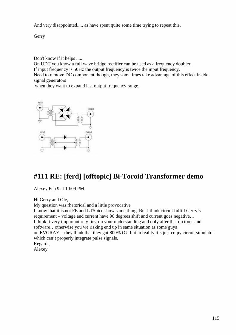
115
And very disappointed..... as have spent quite some time trying to repeat this.
Gerry
Don't know if it helps ..... On UDT you know a full wave bridge rectifier can be used as a frequency doubler. If input frequency is 50Hz the output frequency is twice the input frequency. Need to remove DC component though, they sometimes take advantage of this effect inside signal generators when they want to expand last output frequency range.
#111 RE: [ferd] [offtopic] Bi-Toroid Transformer de mo
Alexey Feb 9 at 10:09 PM
Hi Gerry and Ole, My question was rhetorical and a little provocative I know that it is not FE and LTSpice show same thing. But I think circuit fulfill Gerry’s requirement – voltage and current have 90 degrees shift and current goes negative… I think it very important rely first on your understanding and only after that on tools and software…otherwise you we risking end up in same situation as some guys on EVGRAY – they think that they got 800% OU but in reality it’s just crapy circuit simulator which can’t properly integrate pulse signals. Regards, Alexey
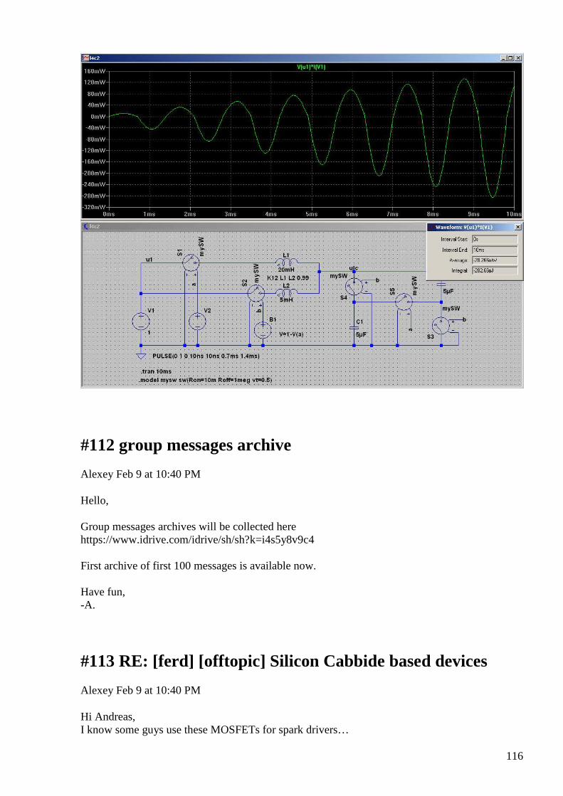
116
#112 group messages archive
Alexey Feb 9 at 10:40 PM
Hello, Group messages archives will be collected here https://www.idrive.com/idrive/sh/sh?k=i4s5y8v9c4 First archive of first 100 messages is available now. Have fun, -A.
#113 RE: [ferd] [offtopic] Silicon Cabbide based devices
Alexey Feb 9 at 10:40 PM
Hi Andreas, I know some guys use these MOSFETs for spark drivers…
117
They are very nice but we still have to figure out what to do with them Regards, Alexey
#114 Re: [ferd] [offtopic] Silicon Cabbide based devices
Andreas Höschler Feb 9 at 12:07 AM
Hi Alexey,
I know some guys use these MOSFETs for spark drivers…
They are very nice but we still have to figure out what to do with them
Indeed! I will use them in a boost converter setup. The high break down voltage allows to use small caps that are pumped up to 1000V with one fly-back pulse. The cap is then pulsed into a load. This sounds ridiculously trivial but my intuition tells me that Hector has a point here. There is some special capacitance that does something special. I unfortunately can’t check this out until my power supply is working properly (still waiting for parts)!
Andreas
#115 Re: [offtopic] grid tied inverter
onielsen2000 Feb 10 at 5:57 AM
Here is a description on how the reactive power is created: http://cci.anu.edu.au/storage/1-Micro-Inverters%20and%20Reactive%20power.pdf This article doesn't describe how the inverters are working. The following article describes how to run an inverter delivering reactive power (VAr) on just its DC rail capacitor by letting it have a little active or real power once in a while to compensate for the losses: http://www.floridaenergy.ufl.edu/wp-content/uploads/S2-PV-Ali-Var-Paper-_-Final3.pdf. Something like that would be fine for the UDT and just require some start up energy. This would be like Akula demonstrates with his self-running lanterns that are started by a small battery cell and then delivers energy for their losses and to the output load using the same DC rail. He has one regulated PWM output and one free running (locked) PWM output delivering power to the same transformer core. Regards Ole
#116 Re: [ferd] [offtopic] Bi-Toroid Transformer demo
118
Gerry Feb 10 at 6:35 PM
Hi Ole,
I was going over some old notes and came across this great quote from Laurent Damois, (one of cleverest guys I know of).
Quote:
Magnetic hysteresis: http://en.wikipedia.org/wiki/Hysteresis (curve is material dependent, the material need to be non linear) - values generaly given by the provider
The inductance is not interesting because it is a linear value (if the core is linear, the device don't works)
the magnetic density energy is B x H / 2, if B and H have always the same sign , the energy sign is always positive (linear)
For nonlinear material part of the hysteresis loop give a B H product negative (energy extraction)
Laurent DAMOIS
and also another:
Source of energy is spin variation. So if speed of time is not constant, you have energy creation (energy conservation law is true only if speed of time is constant) Source of spin is charge, but charge density is divergence of Field, so origin of spin is also Field, so origin of energy is also Field. Because Origin of E Field (E=-dA/dt) and B Field (B=curl(A)) is A vector Field, so A vector is origin of ALL Laurent DAMOIS
End quote.
I hope is ok to share this as it seems quite relevant to our earlier discussion.
Gerry
#117 [offtopic] Power and Creed
Alexey Feb 11 at 9:05 PM
119
Interesting reading ;-) http://www.overunityresearch.com/index.php?topic=2760.msg45862#msg45862
Re: Partnered Output Coils « Reply #458 on: Today at 17:26:20 »
Meanwhile, on a senior member's suggestion, the following is from the "Power and Creed" document posted in the thread of the same name. This is a must read for Free Energy researchers, particularly for newer members to OUR. The Free Energy Researcher’s: POWER & CREED - A must read for those on the quest for Free Energy at OUR. Prepared by: Darren Kozey (poynt99) Document Date: 2009/12/13 Revision: V2.0 The Free Energy Researcher’s: POWER & CREED Preface The world needs an alternative to conventional energy sources; dare we call this alternative source “free energy”? Free Energy research is alive and well on a number of public and private forums. There are many people actively researching in this area; the vast majority of which are younger and less experienced folks. This is fantastic and will hopefully secure a better future for all. However, with youth and/or inexperience, often comes over-enthusiasm and haste. Many times indeed, it is the experienced and technically-trained researchers that fall into the all-too-familiar trap of letting their excitement, hope, enthusiasm, or lack of know-how, get in the way of better judgment. To declare something extraordinary and make claims of “overunity” without solid substantiating evidence or proof to back it up, does a great disservice to all on the FE quest, especially when the claim turns out to be a false alarm or a deception. The aim of this document is to serve as a guide to help all FE researchers avoid the pitfalls of making an unsubstantiated claim. To follow is a creed by which I strongly encourage all to study it, understand it, and above all…apply it! Dedication This document is dedicated to all the brilliant and determined minds working in Free Energy research…all those in the present, the past, and the future. Thank you for your tenacity and your commitment to the FE quest. INTRODUCTION Most claims of overunity turn out to be the result of erroneous assumptions, measurement errors, nonexistent measurements, suspicious measurements, or equipment limitations. As such, a short guide is needed that all FE researchers can refer to and apply while conducting their research and publishing their results. The following CREED, MAKING CLAIMS AND DISCLOSING RESPONSIBLY, and MAKING PROPER POWER MEASUREMENTS (for electronics devices) sections

120
make up this guide. It is by no means perfect or complete, but a starting point at least, and one that would surely go a long way in avoiding much frenzy, anxiety, wasted time, effort and money, embarrassment, flaming, loss of respect and integrity, and arguing etc., for all interested parties involved. If only it can be followed. THE FE RESEARCHER’S CREED “As a Free Energy Researcher, I dedicate my knowledge and skill to the advancement and betterment of human welfare. I strive for integrity, accuracy, and completeness in my work and my releases to the public. I pledge in conducting my FE research: - To give the utmost of performance; - To make no assumptions, no matter how “obvious” things may appear to me; - To never jump to conclusions when apparent anomalies are observed; - To investigate and strive to eliminate ALL possible sources of error BEFORE making conclusions about any observed anomalies; - To exercise due diligence in regards to fully understanding what I am doing, and how I am doing it; - To conduct my experiments, tests, and measurements in a scientific manner and with the correct and most appropriate equipment; - To strive for and take steps towards making COP measurements that are flawless and accurate, while understanding and accounting for the limitations and idiosyncrasies of my test equipment; - To place integrity before ego; - To post claims of overunity only when backed up with solid proof and evidence in the form of fully documented, and accurate measurements and test setup diagrams; - To do my best in explaining and illustrating my disclosures, and be well-prepared to answer any questions on things I may have overlooked; - To seek advice, guidance, and review from my un-biased peers and those with more technical know-how BEFORE I post any extraordinary claims of overunity; - To do my homework (all of the above). In humility and with need for Collective/Higher Guidance, I make this pledge.” MAKING CLAIMS AND DISCLOSING RESPONSIBLY For anyone planning on disclosing something or making a claim, please use the following as a guide to do so: 1) Decide and state what exactly you are about to claim: Options here include: a) 100% certainty you have achieved overunity. b) You are not 100% sure and asking for help to determine if it is so. c) You are only observing strange effects and you would like other users to provide helpful feedback. 2) Regardless of which option fits your case, please provide in your post the following minimum parts: a) A complete drawing or schematic of your prototype or test setup. b) A clear description of what the device or circuit is, what you think the circuit is doing, or what you wanted it to do. c) A list of references to any other devices or documentation you based your device on.
121
d) A list of proper power measurements (see Power Measurements at OUR). e) A photo of your setup is optional, but may be helpful. 3) For those with limited Free Energy Research experience, and/or electronics experience, please post a request for someone to review your steps 1) and 2) above BEFORE making your post and claim. 4) Refine all the above listed elements with the feedback received from the more technically-experienced forum users. 5) Make your claims / disclosure post. MAKING PROPER POWER MEASUREMENTS Accurate power measurements are probably the most difficult and least understood, yet the most meaningful measurements to perform, especially in the Free Energy circles. If one makes a claim of overunity and their measurement of input power vs. output power is either not supplied, or is questionable in its accuracy, no one will be interested in delving further into or inquiring about their work…and rightly so. Far too often researchers are fooled by assuming that their test equipment or method is yielding true and accurate measurements, when more often than not, this is probably not the case. In fact, most researchers probably don’t understand the basics of how meters work and what separates a truly TRUE RMS measurement from an “average” one. The following is a quote from Bob Paddock’s “POWER MEASUREMENT” article linked at the end of this document: "I had a need to make a power measurement of an unusual high-frequency wave form for an application I was working on. Because of the esoteric nature the application had, I wanted to be sure I would not be hearing the words "Measurement Errors". Far too often I've seen others try to do high-frequency power measurements by looking at the signal on their oscilloscope, or by using their bench multimeter without understanding its specifications. Looking at a complex high-frequency wave form with a multimeter designed for 60-Hz sine waves simply does not give meaningful results." [pony99: unless one is looking for the average value of a signal, then DC meters perform well in this task] A great deal of FE research involves the use of non-sinusoidal, spikey, and noisy inputs and outputs. As such there are some “precautions” one must take to ensure that any measurements performed on such devices under test (DUT’s) will yield true and meaningful results. Devices utilizing or creating high frequency components are especially susceptible to measurement errors and it is imperative that this is understood. Special care and considerations are required in these cases in order that good measurements can be obtained. Please refer to the Power Measurements and High Frequency Measurements threads for detailed information on performing accurate and obtaining meaningful power measurements. Following are some relevant terms that require definition and clarification: OPEN AND CLOSED SYSTEMS An Open System is one in which power or energy from outside the device’s immediate domain, may be added to the system for free. This outside energy or
122
power is not the energy or power supplied by you the user to make the system operate, but is energy or power supplied by the environment, universe, aether or ZPF etc. This “outside” energy supplement is what makes “overunity” possible. A Closed System is one in which no energy from outside the immediate domain of the device can or will enter the system. The device sees only the energy or power that you the user supply to it. Closed systems are therefore inherently under, or at unity, but never overunity. EFFICIENCY (η) The efficiency of a DUT in a closed system, is simply the ratio between the power converted by the device, namely “the output power”, to the power supplied to the device by the user, namely “the input power”. Devices that operate strictly in a closed system will always have an efficiency of 100% or less. The efficiency of a DUT in an open system, is a little more complicated, but as I’ll explain, not necessarily relevant to FE research. Strictly speaking, the efficiency of a DUT in an open system is computed the same way as that for a closed system. However, it may be difficult if not impossible to calculate, depending on the device and its overunity mechanism. If for example your DUT requires 10 Watts of input power to operate, wastes 9 Watts of power in heat (as measured with a calorimeter with no load), but puts out 100 Watts, the efficiency of the device is only a meager 10% ! In this case, at least 99 Watts of power is freely entering the system from the “outside” and being converted and output by the device, but the efficiency is still only 10%. To say that this device has an efficiency of 1000% is simply not correct ! Even in open systems, the efficiency can not and must not be higher than 100%. So by all means, strive to make your energy device as efficient as possible, but the real and meaningful FE quest is to obtain more output power than is required as input power for the device to operate. COEFFICIENT OF PERFORMANCE (COP) Again we must examine this parameter in the context of open and closed systems. In a closed system, the COP will be equal to the efficiency in a sense, but is expressed as a ratio as follows: 1:1 (η=100%), 0.8:1 (η=80%), etc. So one should conclude from the discussion so far, that the COP in a closed system will never be higher than 1:1. In an open system, the COP could be anywhere from 0.1:1 to 106:1. It all depends on the efficiency of the device (with low COP’s), and how much energy or power is freely added to the system from the “outside” with a given input power. COP in open systems is computed by taking the ratio between the freely added “outside” power (POopen), PLUS the output power (if any) supplied by the closed system (POclosed), to the user-supplied input power (PI). In equation form: COP = (POopen + POclosed)/PI OR = POtotal/PI Do we care if we are measuring collected open-system power PLUS closed system
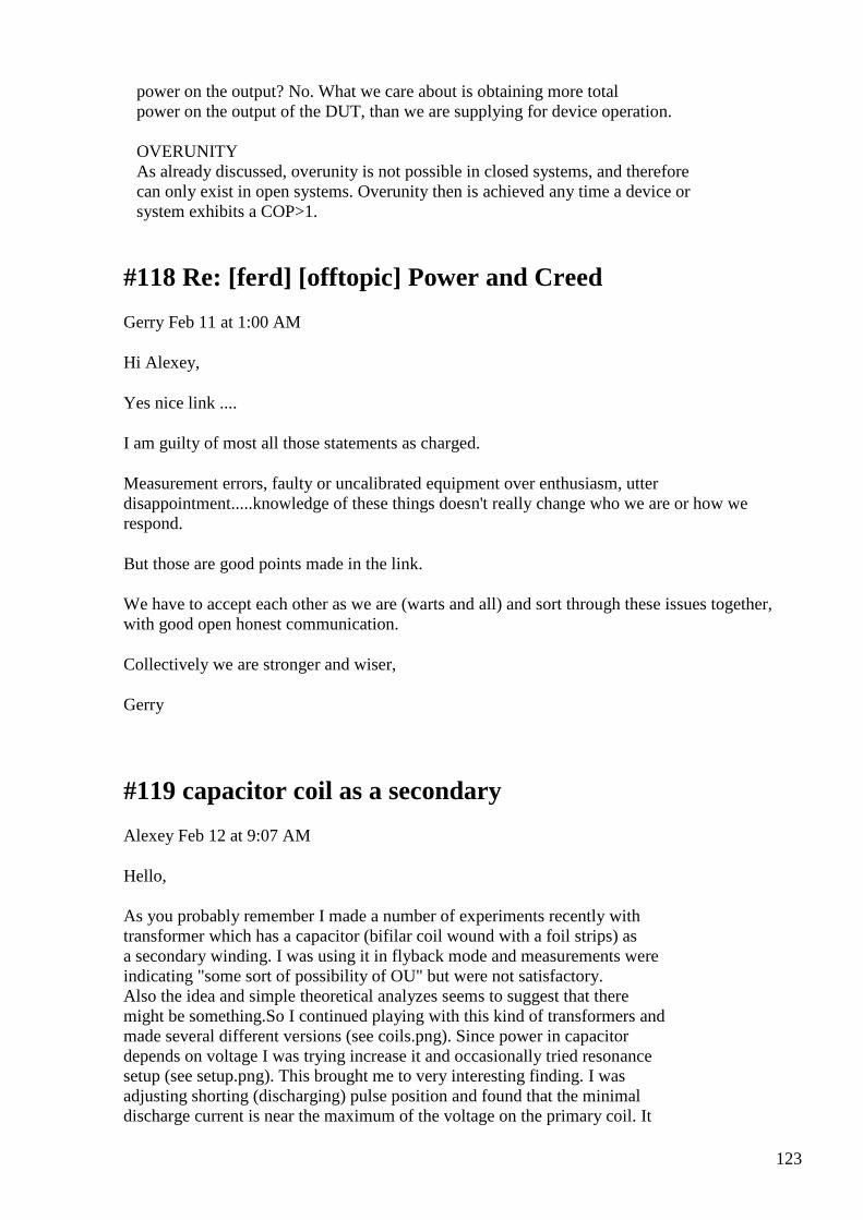
123
power on the output? No. What we care about is obtaining more total power on the output of the DUT, than we are supplying for device operation. OVERUNITY As already discussed, overunity is not possible in closed systems, and therefore can only exist in open systems. Overunity then is achieved any time a device or system exhibits a COP>1.
#118 Re: [ferd] [offtopic] Power and Creed
Gerry Feb 11 at 1:00 AM
Hi Alexey,
Yes nice link ....
I am guilty of most all those statements as charged.
Measurement errors, faulty or uncalibrated equipment over enthusiasm, utter disappointment.....knowledge of these things doesn't really change who we are or how we respond.
But those are good points made in the link.
We have to accept each other as we are (warts and all) and sort through these issues together, with good open honest communication.
Collectively we are stronger and wiser,
Gerry
#119 capacitor coil as a secondary
Alexey Feb 12 at 9:07 AM
Hello, As you probably remember I made a number of experiments recently with transformer which has a capacitor (bifilar coil wound with a foil strips) as a secondary winding. I was using it in flyback mode and measurements were indicating "some sort of possibility of OU" but were not satisfactory. Also the idea and simple theoretical analyzes seems to suggest that there might be something.So I continued playing with this kind of transformers and made several different versions (see coils.png). Since power in capacitor depends on voltage I was trying increase it and occasionally tried resonance setup (see setup.png). This brought me to very interesting finding. I was adjusting shorting (discharging) pulse position and found that the minimal discharge current is near the maximum of the voltage on the primary coil. It
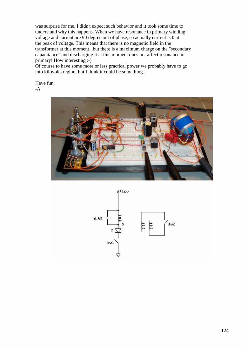
124
was surprise for me, I didn't expect such behavior and it took some time to understand why this happens. When we have resonance in primary winding voltage and current are 90 degree out of phase, so actually current is 0 at the peak of voltage. This means that there is no magnetic field in the transformer at this moment...but there is a maximum charge on the "secondary capacitance" and discharging it at this moment does not affect resonance in primary! How interesting :-) Of course to have some more or less practical power we probably have to go into kilovolts region, but I think it could be something... Have fun, -A.
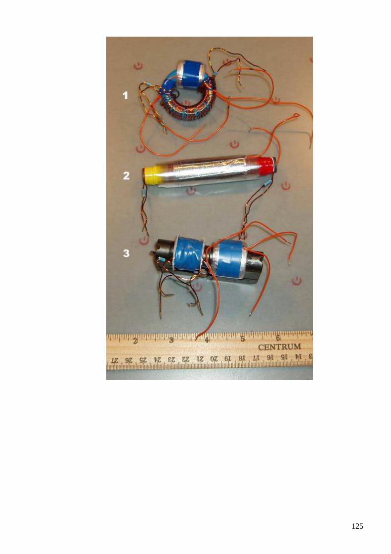
125

126
#120 RE: [ferd] [offtopic] Power and Creed
Alexey Feb 11 at 9:29 AM
Hi Gerry, Yes, I agree, we all do mistakes from time to time. But we need to try constructively cooperate, otherwise there will be no progress. Regards, Alexey
#121 RE: [ferd] [offtopic] Bi-Toroid Transformer de mo
Alexey Feb 11 at 9:56 AM

127
Hi Gerry, I've been looking on your scope traces and I think there is something interesting going on in these regions (I marked with red circles). Its probably worth to investigate where this non-linearity come from…may be its just a core hysteresis, but usually it not visible so distinctively… Regards, Alexey
#122 Re: [ferd] [offtopic] Bi-Toroid Transformer demo
Gerry Feb 12 at 1:05 PM
Thanks for your reply there Alexey,
I was just using those two reasonably matched coils either side of a primary drive coil, on a piece of core I'd cut from a microwave oven transformer.
So it was a single open solenoid core, nothing elaborate. But Laminated as you suggested to me, a few posts back.
The current with a 1 Ohm resistor on earthy side of drive current to primary.
The 1 Ohm resistor was getting quite hot with 1.16 v across it, so I changed it for a 0.1 Ohms ....at this point the effect disappeared!
For the life of me I still can't understand why there would be more voltage across the sense resistor than the total output across the signal generation source!
128
I put original 1 Ohm resistor back and still could not repeat this effect, spent all afternoon and most of that evening trying to get effect back.
One scope with one earth point, one channel monitoring input current the other monitoring input voltage. Both probes earthed at same point, earth.
I honestly don't know how this came about or how to repeat it, only lucky I took a couple of pics at the time.
All I can say is maybe earth became disconnected from my probe or something?
But the frequency was 1000Hz and no hum was apparent.
Thanks for looking Alexey & sorry to have wasted precious time for anyone.
Gerry
#123 Re: [ferd] capacitor coil as a secondary
Gerry Feb 12 at 1:09 PM
Hi Alexey,
I was wondering if you could post another shot with gate drive pulses synchronised to the other 2 traces?
As have to admit I don't quite understand your setup in terms of drive stimulus and subsequent shorting of coils.
Gerry
#124 Re: [ferd] capacitor coil as a secondary
Andreas Höschler Feb 12 at 2:25 PM
Hi Alexey,
As you probably remember I made a number of experiments recently with
transformer which has a capacitor (bifilar coil wound with a foil strips) as a secondary winding. I was using it in flyback mode and measurements were indicating "some sort of possibility of OU" but were not satisfactory. Also the idea and simple theoretical analyzes seems to suggest that there might be something.So I continued playing with this kind of transformers and made several different versions (see coils.png). Since power in capacitor
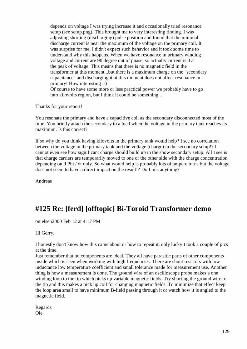
129
depends on voltage I was trying increase it and occasionally tried resonance setup (see setup.png). This brought me to very interesting finding. I was adjusting shorting (discharging) pulse position and found that the minimal discharge current is near the maximum of the voltage on the primary coil. It was surprise for me, I didn't expect such behavior and it took some time to understand why this happens. When we have resonance in primary winding voltage and current are 90 degree out of phase, so actually current is 0 at the peak of voltage. This means that there is no magnetic field in the transformer at this moment...but there is a maximum charge on the "secondary capacitance" and discharging it at this moment does not affect resonance in primary! How interesting :-) Of course to have some more or less practical power we probably have to go into kilovolts region, but I think it could be something...
Thanks for your report!
You resonate the primary and have a capacitive coil as the secondary disconnected most of the time. You briefly attach the secondary to a load when the voltage in the primary tank reaches its maximum. Is this correct?
If so why do you think having kilovolts in the primary tank would help? I see no correlation between the voltage in the primary tank and the voltage (charge) in the secondary setup!? I cannot even see how significant charge should build up in the show secondary setup. All I see is that charge carriers are temporarily moved to one or the other side with the charge concentration depending on d Phi / dt only. So what would help is probably lots of ampere turns but the voltage does not seem to have a direct impact on the result!? Do I mis anything?
Andreas
#125 Re: [ferd] [offtopic] Bi-Toroid Transformer demo
onielsen2000 Feb 12 at 4:17 PM
Hi Gerry, I honestly don't know how this came about or how to repeat it, only lucky I took a couple of pics at the time. Just remember that no components are ideal. They all have parasitic parts of other components inside which is seen when working with high frequencies. There are shunt resistors with low inductance low temperature coefficient and small tolerance made for measurement use. Another thing is how a measurement is done. The ground wire of an oscilloscope probe makes a one winding loop to the tip which picks up variable magnetic fields. Try shorting the ground wire to the tip and this makes a pick up coil for changing magnetic fields. To minimize that effect keep the loop area small to have minimum B-field passing through it or watch how it is angled to the magnetic field. Regards Ole
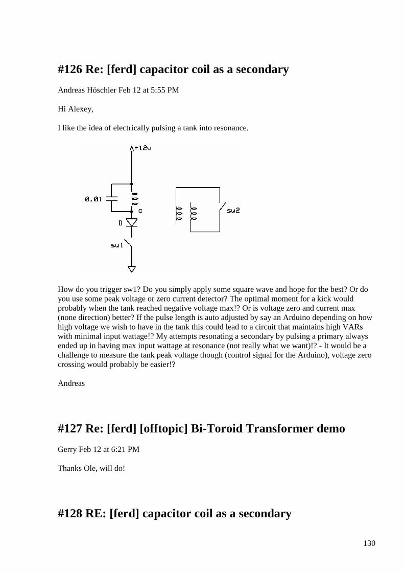
130
#126 Re: [ferd] capacitor coil as a secondary
Andreas Höschler Feb 12 at 5:55 PM
Hi Alexey,
I like the idea of electrically pulsing a tank into resonance.
How do you trigger sw1? Do you simply apply some square wave and hope for the best? Or do you use some peak voltage or zero current detector? The optimal moment for a kick would probably when the tank reached negative voltage max!? Or is voltage zero and current max (none direction) better? If the pulse length is auto adjusted by say an Arduino depending on how high voltage we wish to have in the tank this could lead to a circuit that maintains high VARs with minimal input wattage!? My attempts resonating a secondary by pulsing a primary always ended up in having max input wattage at resonance (not really what we want)!? - It would be a challenge to measure the tank peak voltage though (control signal for the Arduino), voltage zero crossing would probably be easier!?
Andreas
#127 Re: [ferd] [offtopic] Bi-Toroid Transformer demo
Gerry Feb 12 at 6:21 PM
Thanks Ole, will do!
#128 RE: [ferd] capacitor coil as a secondary
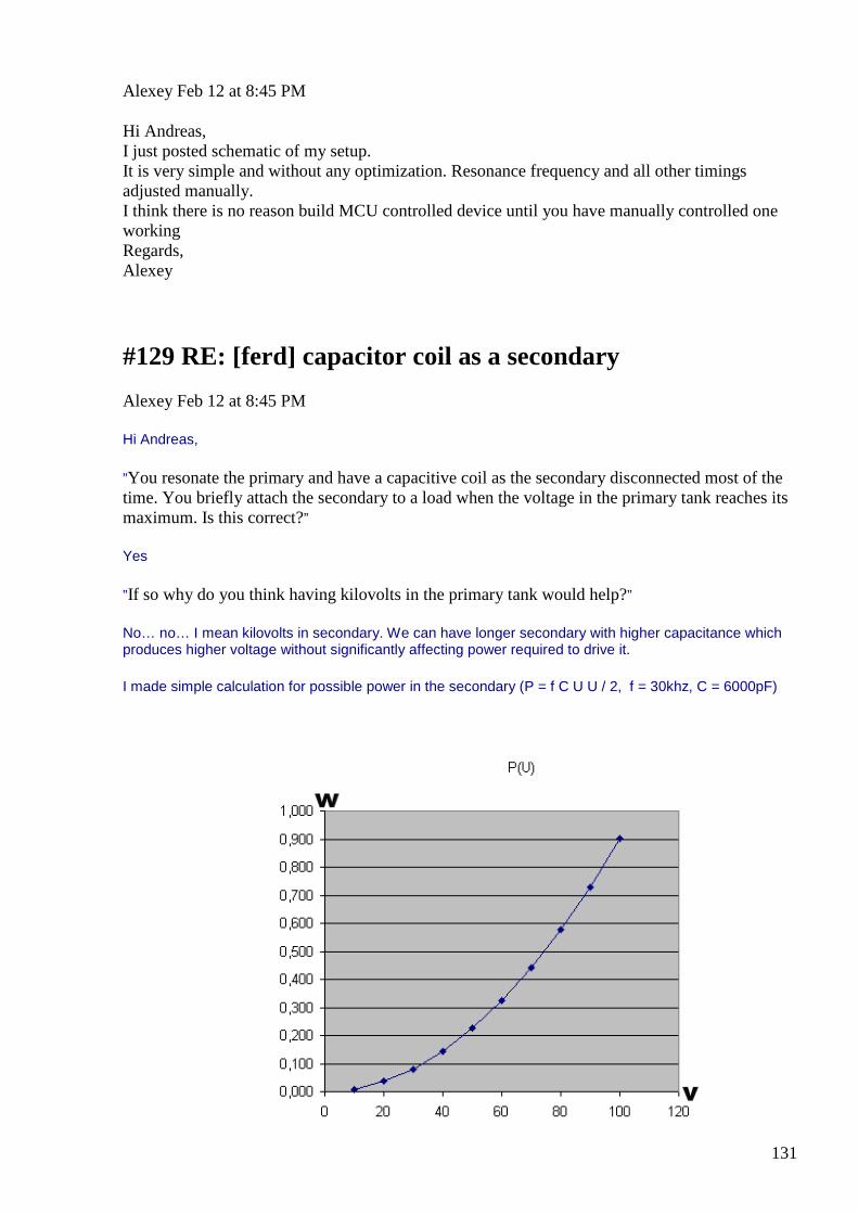
131
Alexey Feb 12 at 8:45 PM
Hi Andreas, I just posted schematic of my setup. It is very simple and without any optimization. Resonance frequency and all other timings adjusted manually. I think there is no reason build MCU controlled device until you have manually controlled one working Regards, Alexey
#129 RE: [ferd] capacitor coil as a secondary
Alexey Feb 12 at 8:45 PM
Hi Andreas,
”You resonate the primary and have a capacitive coil as the secondary disconnected most of the time. You briefly attach the secondary to a load when the voltage in the primary tank reaches its maximum. Is this correct?”
Yes
”If so why do you think having kilovolts in the primary tank would help?”
No… no… I mean kilovolts in secondary. We can have longer secondary with higher capacitance which produces higher voltage without significantly affecting power required to drive it.
I made simple calculation for possible power in the secondary (P = f C U U / 2, f = 30khz, C = 6000pF)
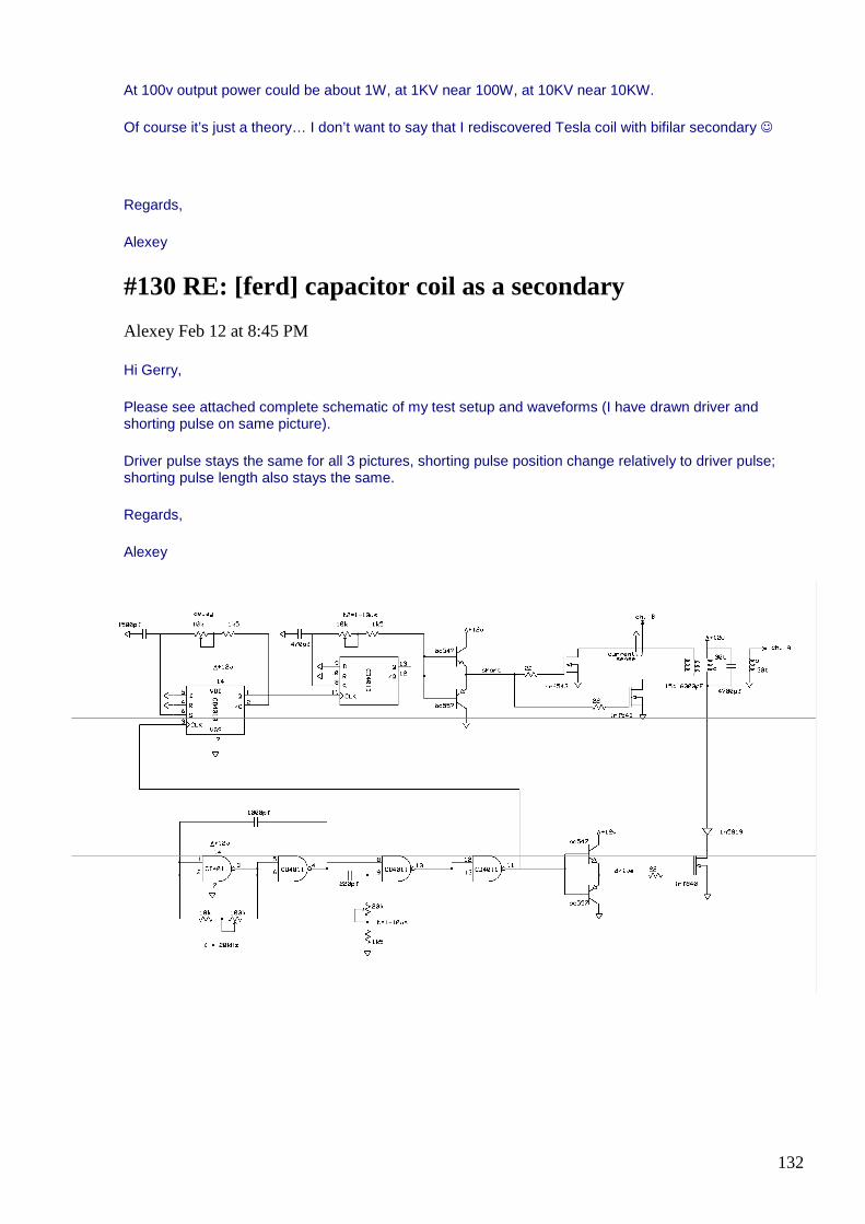
132
At 100v output power could be about 1W, at 1KV near 100W, at 10KV near 10KW.
Of course it’s just a theory… I don’t want to say that I rediscovered Tesla coil with bifilar secondary
Regards,
Alexey
#130 RE: [ferd] capacitor coil as a secondary
Alexey Feb 12 at 8:45 PM
Hi Gerry,
Please see attached complete schematic of my test setup and waveforms (I have drawn driver and shorting pulse on same picture).
Driver pulse stays the same for all 3 pictures, shorting pulse position change relatively to driver pulse; shorting pulse length also stays the same.
Regards,
Alexey
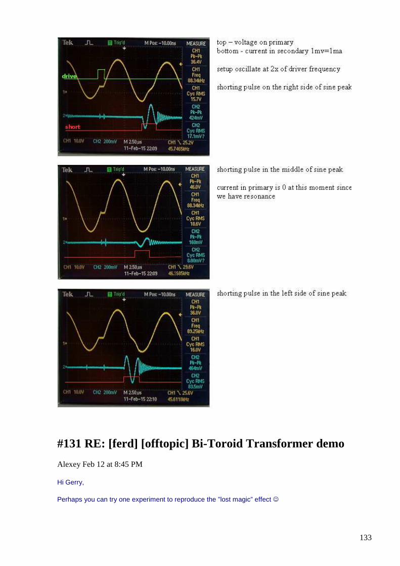
133
#131 RE: [ferd] [offtopic] Bi-Toroid Transformer de mo
Alexey Feb 12 at 8:45 PM
Hi Gerry,
Perhaps you can try one experiment to reproduce the ”lost magic” effect
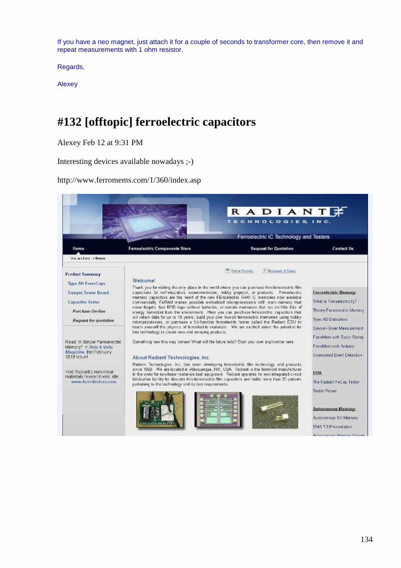
134
If you have a neo magnet, just attach it for a couple of seconds to transformer core, then remove it and repeat measurements with 1 ohm resistor.
Regards,
Alexey
#132 [offtopic] ferroelectric capacitors
Alexey Feb 12 at 9:31 PM
Interesting devices available nowadays ;-) http://www.ferromems.com/1/360/index.asp
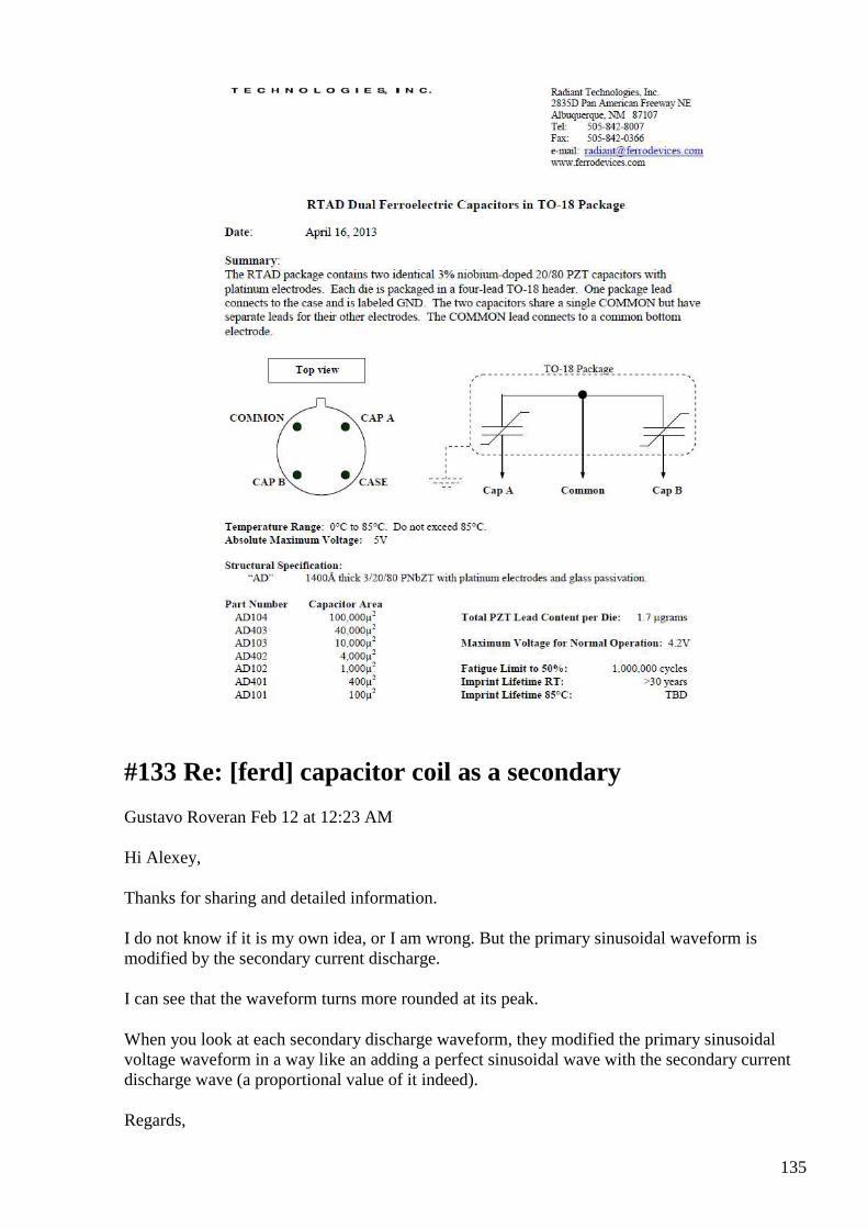
135
#133 Re: [ferd] capacitor coil as a secondary
Gustavo Roveran Feb 12 at 12:23 AM
Hi Alexey, Thanks for sharing and detailed information. I do not know if it is my own idea, or I am wrong. But the primary sinusoidal waveform is modified by the secondary current discharge. I can see that the waveform turns more rounded at its peak.
When you look at each secondary discharge waveform, they modified the primary sinusoidal voltage waveform in a way like an adding a perfect sinusoidal wave with the secondary current discharge wave (a proportional value of it indeed).
Regards,
136
Gustavo
#134 Re: [ferd] [offtopic] Bi-Toroid Transformer demo
Gerry Feb 13 at 3:39 AM
Thanks Alexey, good suggestion.
I will set up and give it a go.......... again.
Am just investigating something else with regard to split phase at this moment.
Gerry
#135 Re: [ferd] capacitor coil as a secondary
Gerry Feb 13 at 4:12 AM
Hi Alexey,
Thanks for doing this it shows the picture of what is happening and when it happens more clearly.
We can see you pulsing the main tank into oscillation there.
Can also see the effect of delaying the short on the special bifilar capacitor.
Looking at scope picture 1 right side of negative sine peak, this angle seems to be greater than 270 degrees.
Amplitude is only 17.1 mA rms.
Interestingly, for angles at and after 270 degrees, all Cosines are positive in value so likely current and voltage are both positive values.
Looking at bottom scope shot though, right side of positive peak, which I estimate is greater than 135 degrees up to maybe 270 point.
The Cosines are all negative in this area indicating product of E and I are likely negative values.
So energy is negative over this point or being returned for where it was stored..
So if we look at the amplitude on scope readout for this point we get 83.5 mA, considerably more.
For angles 0 to 90 and 270 to 360 we could call this reactive power,
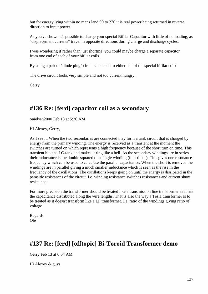
137
but for energy lying within no mans land 90 to 270 it is real power being returned in reverse direction to input power.
As you've shown it's possible to charge your special Bifilar Capacitor with little of no loading, as "displacement currents" travel in opposite directions during charge and discharge cycles.
I was wondering if rather than just shorting, you could maybe charge a separate capacitor from one end of each of your bifilar coils.
By using a pair of "diode plug" circuits attached to either end of the special bifilar coil?
The drive circuit looks very simple and not too current hungry.
Gerry
#136 Re: [ferd] capacitor coil as a secondary
onielsen2000 Feb 13 at 5:26 AM
Hi Alexey, Gerry, As I see it: When the two secondaries are connected they form a tank circuit that is charged by energy from the primary winding. The energy is received as a transient at the moment the switches are turned on which represents a high frequency because of the short turn on time. This transient hits the LC-tank and makes it ring like a bell. As the secondary windings are in series their inductance is the double squared of a single winding (four times). This gives one resonance frequency which can be used to calculate the parallel capacitance. When the short is removed the windings are in parallel giving a much smaller inductance which is seen as the rise in the frequency of the oscillations. The oscillations keeps going on until the energy is dissipated in the parasitic resistances of the circuit. I.e. winding resistance switches resistances and current shunt resistance. For more precision the transformer should be treated like a transmission line transformer as it has the capacitance distributed along the wire lengths. That is also the way a Tesla transformer is to be treated as it doesn't transform like a LF transformer. I.e. ratio of the windings giving ratio of voltage. Regards Ole
#137 Re: [ferd] [offtopic] Bi-Toroid Transformer demo
Gerry Feb 13 at 6:04 AM
Hi Alexey & guys,
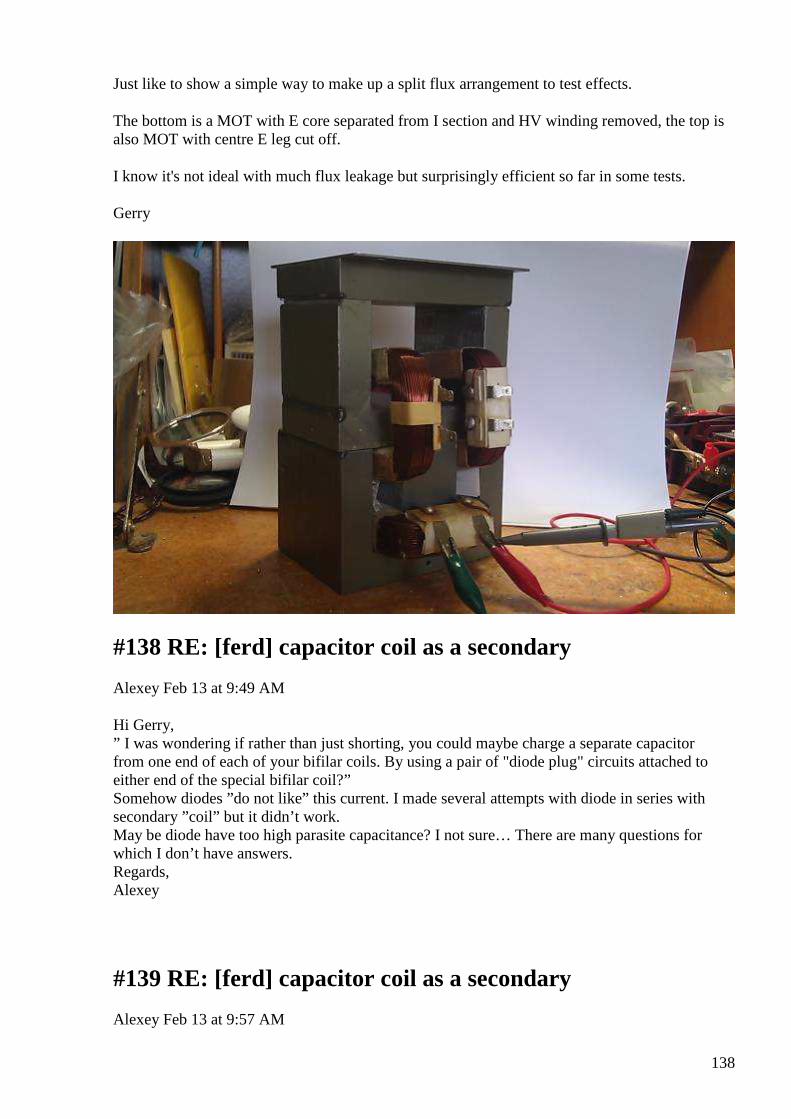
138
Just like to show a simple way to make up a split flux arrangement to test effects.
The bottom is a MOT with E core separated from I section and HV winding removed, the top is also MOT with centre E leg cut off.
I know it's not ideal with much flux leakage but surprisingly efficient so far in some tests.
Gerry
#138 RE: [ferd] capacitor coil as a secondary
Alexey Feb 13 at 9:49 AM
Hi Gerry, ” I was wondering if rather than just shorting, you could maybe charge a separate capacitor from one end of each of your bifilar coils. By using a pair of "diode plug" circuits attached to either end of the special bifilar coil?” Somehow diodes ”do not like” this current. I made several attempts with diode in series with secondary ”coil” but it didn’t work. May be diode have too high parasite capacitance? I not sure… There are many questions for which I don’t have answers. Regards, Alexey
#139 RE: [ferd] capacitor coil as a secondary
Alexey Feb 13 at 9:57 AM
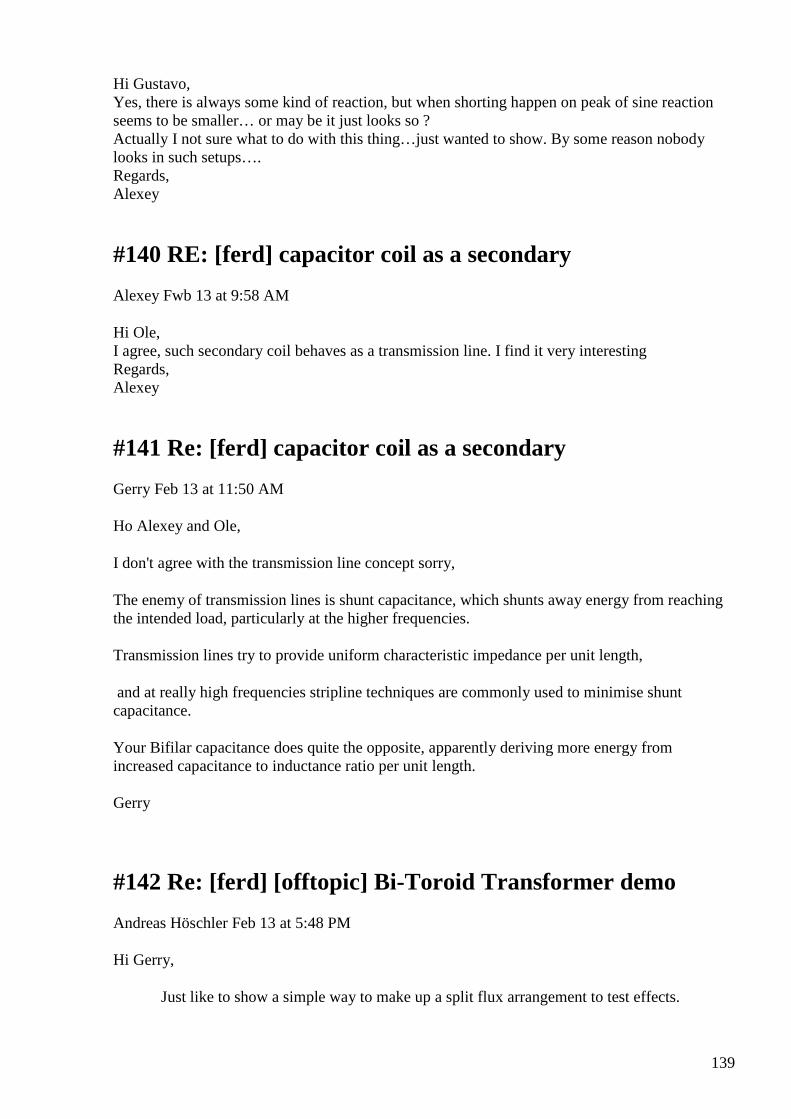
139
Hi Gustavo, Yes, there is always some kind of reaction, but when shorting happen on peak of sine reaction seems to be smaller… or may be it just looks so ? Actually I not sure what to do with this thing…just wanted to show. By some reason nobody looks in such setups…. Regards, Alexey
#140 RE: [ferd] capacitor coil as a secondary
Alexey Fwb 13 at 9:58 AM
Hi Ole, I agree, such secondary coil behaves as a transmission line. I find it very interesting Regards, Alexey
#141 Re: [ferd] capacitor coil as a secondary
Gerry Feb 13 at 11:50 AM
Ho Alexey and Ole,
I don't agree with the transmission line concept sorry,
The enemy of transmission lines is shunt capacitance, which shunts away energy from reaching the intended load, particularly at the higher frequencies.
Transmission lines try to provide uniform characteristic impedance per unit length,
and at really high frequencies stripline techniques are commonly used to minimise shunt capacitance.
Your Bifilar capacitance does quite the opposite, apparently deriving more energy from increased capacitance to inductance ratio per unit length.
Gerry
#142 Re: [ferd] [offtopic] Bi-Toroid Transformer demo
Andreas Höschler Feb 13 at 5:48 PM
Hi Gerry,
Just like to show a simple way to make up a split flux arrangement to test effects.
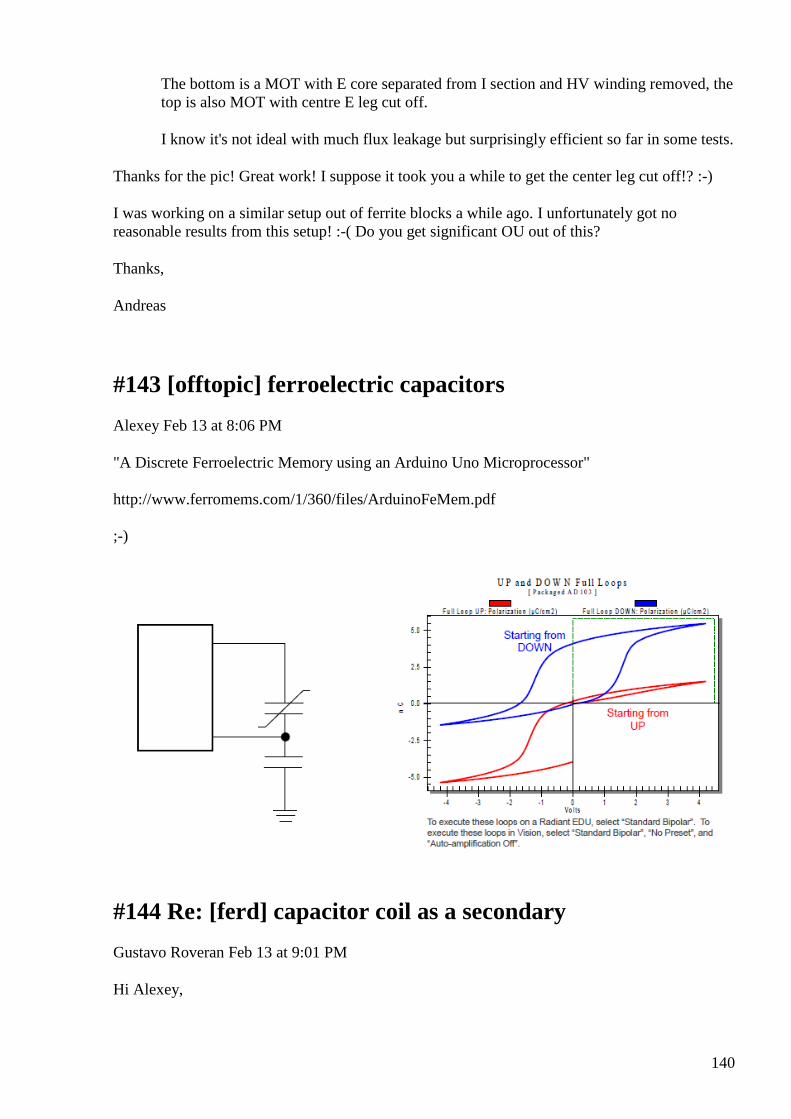
140
The bottom is a MOT with E core separated from I section and HV winding removed, the top is also MOT with centre E leg cut off.
I know it's not ideal with much flux leakage but surprisingly efficient so far in some tests.
Thanks for the pic! Great work! I suppose it took you a while to get the center leg cut off!? :-)
I was working on a similar setup out of ferrite blocks a while ago. I unfortunately got no reasonable results from this setup! :-( Do you get significant OU out of this?
Thanks,
Andreas
#143 [offtopic] ferroelectric capacitors
Alexey Feb 13 at 8:06 PM
"A Discrete Ferroelectric Memory using an Arduino Uno Microprocessor" http://www.ferromems.com/1/360/files/ArduinoFeMem.pdf ;-)
#144 Re: [ferd] capacitor coil as a secondary
Gustavo Roveran Feb 13 at 9:01 PM
Hi Alexey,
141
I have built your set-up the first time you presented it. And did a poor test to see if the charge is accumulated in the secondary coil-cap.
I know I have to go on with it. I think that another thing to do is to put more than one coil-cap one beside the other and put all of them in parallel to reduce the secondary inductance, well bal bla sorry more action and less words...
Best Regards,
Gustavo
#145 RE: [ferd] capacitor coil as a secondary
Alexey Feb 13 at 9:32 PM
Hi Gustavo, It would be nice to know more about your setup and results. Please post more details if you can. Thanks, Alexey
#146 Re: [ferd] [offtopic] Bi-Toroid Transformer demo
Gerry Ауи 13 at 10:27 PM
Hi Andreas,
Yes cutting it off took me some time with hacksaw.
No by no means not even close to OU, I think best as a transformer at 50Hz was 50%.
It is an interesting test bed for exploring relationships between the split phases and effects with coils.
By loading say left side coil with resistor, then going from open to short circuit on right side coil, produces increase in left side output.
From left sides point of view time wise, this flux is negative and for right side, coil flux from left coil is also negative.
Negative flux is special in nature as it constitutes a collapsing field.
There's supposed to be certain phenomena surrounding it including cooling and negative resistance effects.
Trying to understand how and why so I can apply to Auroratek split phase design.
Gerry
142
#147 Re: [ferd] [offtopic] Bi-Toroid Transformer demo
Andreas Höschler Feb 13 at 12:06 AM
Hi Gerry,
Yes cutting it off took me some time with hacksaw.
No by no means not even close to OU, I think best as a transformer at 50Hz was 50%.
It is an interesting test bed for exploring relationships between the split phases and effects with coils.
By loading say left side coil with resistor, then going from open to short circuit on right side coil, produces increase in left side output.
From left sides point of view time wise, this flux is negative and for right side, coil flux from left coil is also negative.
Negative flux is special in nature as it constitutes a collapsing field.
There's supposed to be certain phenomena surrounding it including cooling and negative resistance effects.
Trying to understand how and why so I can apply to Auroratek split phase design.
Thanks for the report. So many test beds! :-) I reached around 92% with my ferrite setup but never more, so ... :-( We need to figure out what exactly triggers these special transformation effects (heat -> electricity, coherence, mutation,…) we are looking for.
Andreas
#148 Re: [ferd] [offtopic] Bi-Toroid Transformer demo
onielsen2000 Feb 14 at 3:23 AM
Hi Andreas, We need to figure out what exactly triggers these special transformation effects (heat -> electricity, coherence, mutation,…) we are looking for. Try coherence as described by Wilbert B. Smith, Andrey Melnichenko and Janos Vajda and demonstrated by Melnichenko, Tariel Kapanadze, Bill (William) Alek, Akula (Roman Karnouhov) etc.
143
As it works in theory (mathematics) this may actually be working in nature too. This can also be explained as parametric pumping. Input two separate amounts of energy to the same space then mix into coherence and extract the energy in coherent form where it represents double the amount of the two inputs before the mixing. This is because of the square law representing the energy of the fields. Regards Ole
#149 Re: [ferd] [offtopic] Bi-Toroid Transformer demo
Gerry Feb 15 at 5:31 PM
Hi Ole, Alexey, guys
I finally found the source of my problem with the sudden change of phase difference between voltage trace and current trace.
It is something to do with the trigger on my cheap Chinese OWON scope, when it gets to high phase differences somehow it triggers on internal noise.
Mucking up the time relationship between red and yellow traces. The OU was still there just the scope was out of whack!
In the old analog scope days we could just select "chop" instead of "alternate" to avoid these problems.
Have dragged out my old Tektronix scope and using it's cursors, I can confirm it is easy to get phase differences like the one attached here.
At 50 Hz
Delay between current and applied voltage is 7.2 milliseconds whilst period is 20 milliseconds.
7.2/20 = 0.36 and 0.36 x 360 = 129.6 degrees
Cos 129.6 = - 0.637
At 1000Hz, the simple setup gave a phase shift of 244.8 degrees.
Whilst providing 0.352 watts into 1 Ohm load and feeding back -1.19 watts into the amplifier generator source.
It is very easy to do & I will post my circuit tomorrow as 12:30 am here.
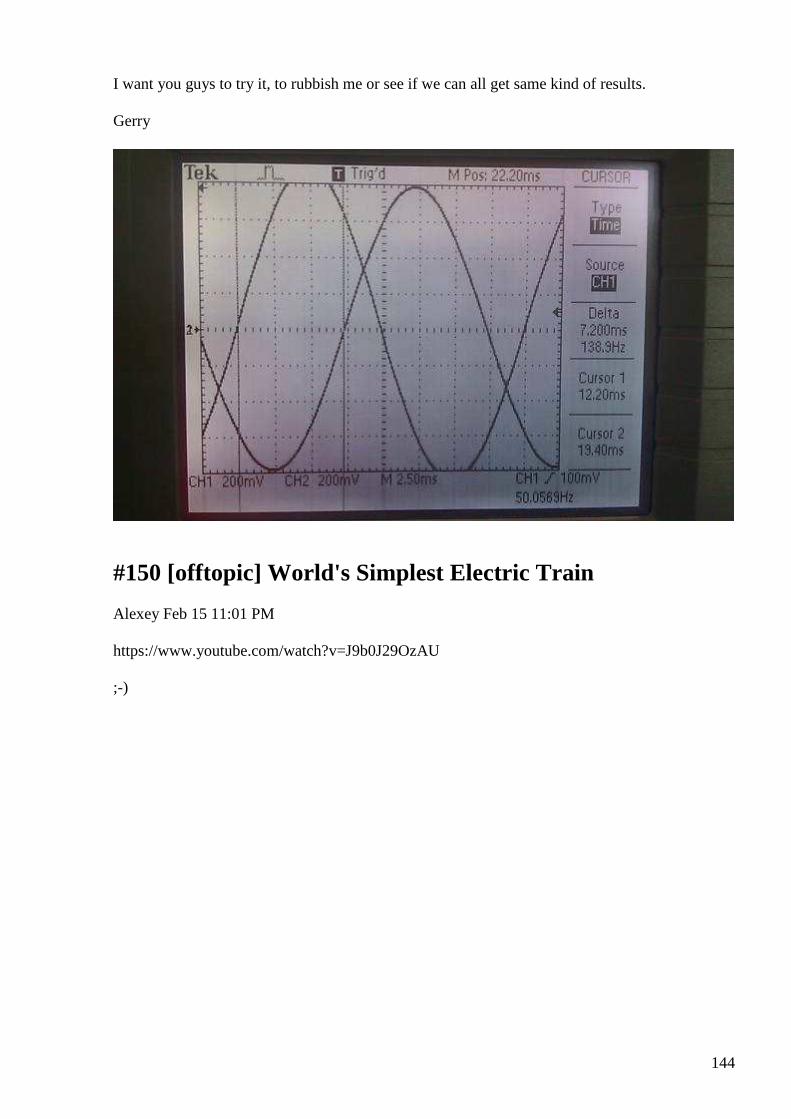
144
I want you guys to try it, to rubbish me or see if we can all get same kind of results.
Gerry
#150 [offtopic] World's Simplest Electric Train
Alexey Feb 15 11:01 PM
https://www.youtube.com/watch?v=J9b0J29OzAU ;-)
145
#151 Bi Toriod Transformer :Simple Anti Lenz circuit
smokyatgroups Feb 16 at 1:55 AM
Hi Alexey, guys
Please find attached a simple anti Lenz circuit I finally arrived at to get the OU results posted about last night.
I hope you guys can replicate and achieve same results as me.
The two outer coils need to match each other reasonably.
The Negative Cos Phi value seems to improve with increasing load.
Frequency response is reasonably flat but I get better results at 1000Hz than 50Hz.
I am thinking this type of connection has to also be applied to my Auroratek S.F. Transformer replication attempt, up till now I had been relying on inductive coupling only.
Going to setup and try on 50Hz mains via variac and home made isolation transformer, but might need more inductance for bigger loads.
all the best Gerry
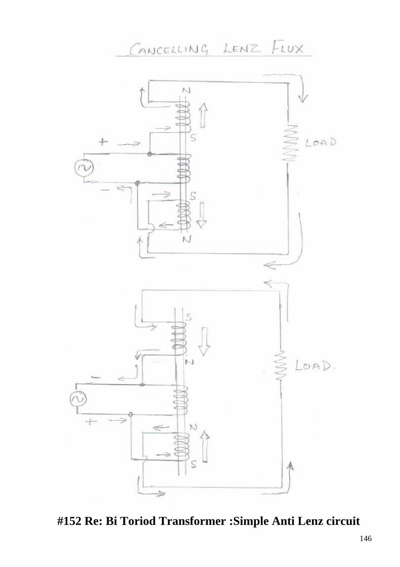
146
#152 Re: Bi Toriod Transformer :Simple Anti Lenz circuit
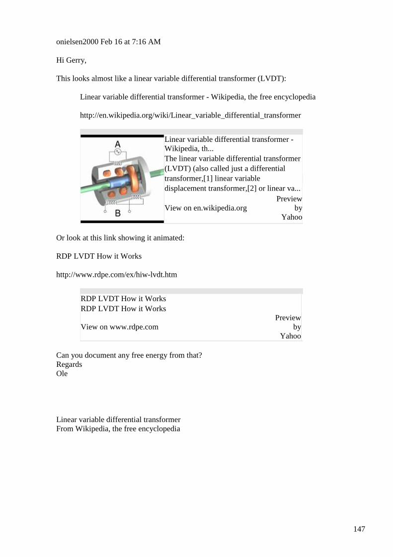
147
onielsen2000 Feb 16 at 7:16 AM
Hi Gerry, This looks almost like a linear variable differential transformer (LVDT):
Linear variable differential transformer - Wikipedia, the free encyclopedia
http://en.wikipedia.org/wiki/Linear_variable_differential_transformer
Linear variable differential transformer - Wikipedia, th... The linear variable differential transformer (LVDT) (also called just a differential transformer,[1] linear variable displacement transformer,[2] or linear va...
View on en.wikipedia.org Preview
by Yahoo
Or look at this link showing it animated:
RDP LVDT How it Works
http://www.rdpe.com/ex/hiw-lvdt.htm
RDP LVDT How it Works RDP LVDT How it Works
View on www.rdpe.com
Preview by
Yahoo
Can you document any free energy from that? Regards Ole
Linear variable differential transformer From Wikipedia, the free encyclopedia
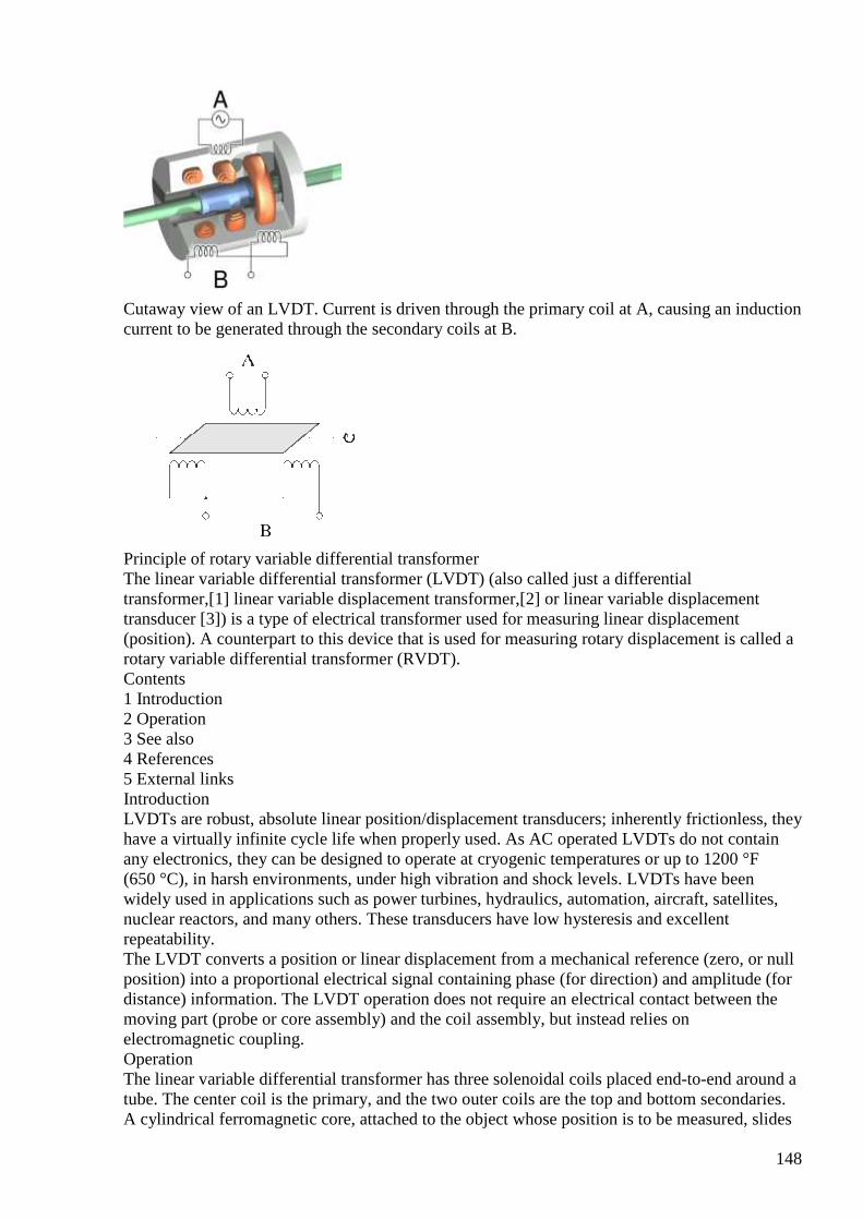
148
Cutaway view of an LVDT. Current is driven through the primary coil at A, causing an induction current to be generated through the secondary coils at B.
Principle of rotary variable differential transformer The linear variable differential transformer (LVDT) (also called just a differential transformer,[1] linear variable displacement transformer,[2] or linear variable displacement transducer [3]) is a type of electrical transformer used for measuring linear displacement (position). A counterpart to this device that is used for measuring rotary displacement is called a rotary variable differential transformer (RVDT). Contents 1 Introduction 2 Operation 3 See also 4 References 5 External links Introduction LVDTs are robust, absolute linear position/displacement transducers; inherently frictionless, they have a virtually infinite cycle life when properly used. As AC operated LVDTs do not contain any electronics, they can be designed to operate at cryogenic temperatures or up to 1200 °F (650 °C), in harsh environments, under high vibration and shock levels. LVDTs have been widely used in applications such as power turbines, hydraulics, automation, aircraft, satellites, nuclear reactors, and many others. These transducers have low hysteresis and excellent repeatability. The LVDT converts a position or linear displacement from a mechanical reference (zero, or null position) into a proportional electrical signal containing phase (for direction) and amplitude (for distance) information. The LVDT operation does not require an electrical contact between the moving part (probe or core assembly) and the coil assembly, but instead relies on electromagnetic coupling. Operation The linear variable differential transformer has three solenoidal coils placed end-to-end around a tube. The center coil is the primary, and the two outer coils are the top and bottom secondaries. A cylindrical ferromagnetic core, attached to the object whose position is to be measured, slides
149
along the axis of the tube. An alternating current drives the primary and causes a voltage to be induced in each secondary proportional to the length of the core linking to the secondary.[1] The frequency is usually in the range 1 to 10 kHz. As the core moves, the primary's linkage to the two secondary coils changes and causes the induced voltages to change. The coils are connected so that the output voltage is the difference (hence "differential") between the top secondary voltage and the bottom secondary voltage. When the core is in its central position, equidistant between the two secondaries, equal voltages are induced in the two secondary coils, but the two signals cancel, so the output voltage is theoretically zero. In practice minor variations in the way in which the primary is coupled to each secondary means that a small voltage is output when the core is central. When the core is displaced toward the top, the voltage in the top secondary coil increases as the voltage in the bottom decreases. The resulting output voltage increases from zero. This voltage is in phase with the primary voltage. When the core moves in the other direction, the output voltage also increases from zero, but its phase is opposite to that of the primary. The phase of the output voltage determines the direction of the displacement (up or down) and amplitude indicates the amount of displacement. A synchronous detector can determine a signed output voltage that relates to the displacement. The LVDT is designed with long slender coils to make the output voltage essentially linear over displacement up to several inches (several hundred millimetres) long. The LVDT can be used as an absolute position sensor. Even if the power is switched off, on restarting it, the LVDT shows the same measurement, and no positional information is lost. Its biggest advantages are repeatability and reproducibility once it is properly configured. Also, apart from the uni-axial linear motion of the core, any other movements such as the rotation of the core around the axis will not affect its measurements. Because the sliding core does not touch the inside of the tube, it can move without friction, making the LVDT a highly reliable device. The absence of any sliding or rotating contacts allows the LVDT to be completely sealed against the environment. LVDTs are commonly used for position feedback in servomechanisms, and for automated measurement in machine tools and many other industrial and scientific applications.
#153 Re: [ferd] Re: Bi Toriod Transformer :Simple Anti Lenz circuit
Gerry Feb 16 at 8:35 AM
Hi Ole,
Yes I believe so......
But you probably should make up your own mind about it.
I just used the big chunk of laminations cut off the centre E arm of MOV transformer for the core.
The 3 coils were all MOV primaries and the two outer ones not perfectly matched but pretty close.
I saw it worked by trial and error then scope played up and I didn't believe it myself.
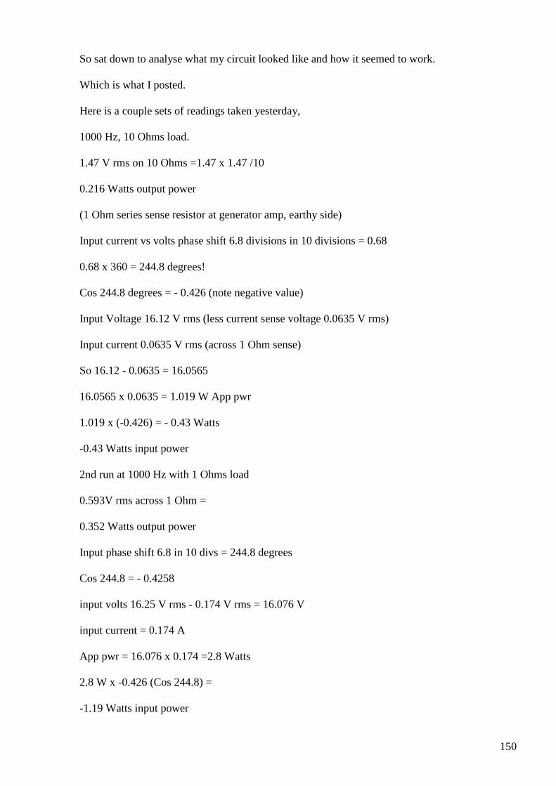
150
So sat down to analyse what my circuit looked like and how it seemed to work.
Which is what I posted.
Here is a couple sets of readings taken yesterday,
1000 Hz, 10 Ohms load.
1.47 V rms on 10 Ohms =1.47 x 1.47 /10
0.216 Watts output power
(1 Ohm series sense resistor at generator amp, earthy side)
Input current vs volts phase shift 6.8 divisions in 10 divisions = 0.68
0.68 x 360 = 244.8 degrees!
Cos 244.8 degrees = - 0.426 (note negative value)
Input Voltage 16.12 V rms (less current sense voltage 0.0635 V rms)
Input current 0.0635 V rms (across 1 Ohm sense)
So 16.12 - 0.0635 = 16.0565
16.0565 x 0.0635 = 1.019 W App pwr
1.019 x (-0.426) = - 0.43 Watts
-0.43 Watts input power
2nd run at 1000 Hz with 1 Ohms load
0.593V rms across 1 Ohm =
0.352 Watts output power
Input phase shift 6.8 in 10 divs = 244.8 degrees
Cos 244.8 = - 0.4258
input volts 16.25 V rms - 0.174 V rms = 16.076 V
input current = 0.174 A
App pwr = 16.076 x 0.174 =2.8 Watts
2.8 W x -0.426 (Cos 244.8) =
-1.19 Watts input power
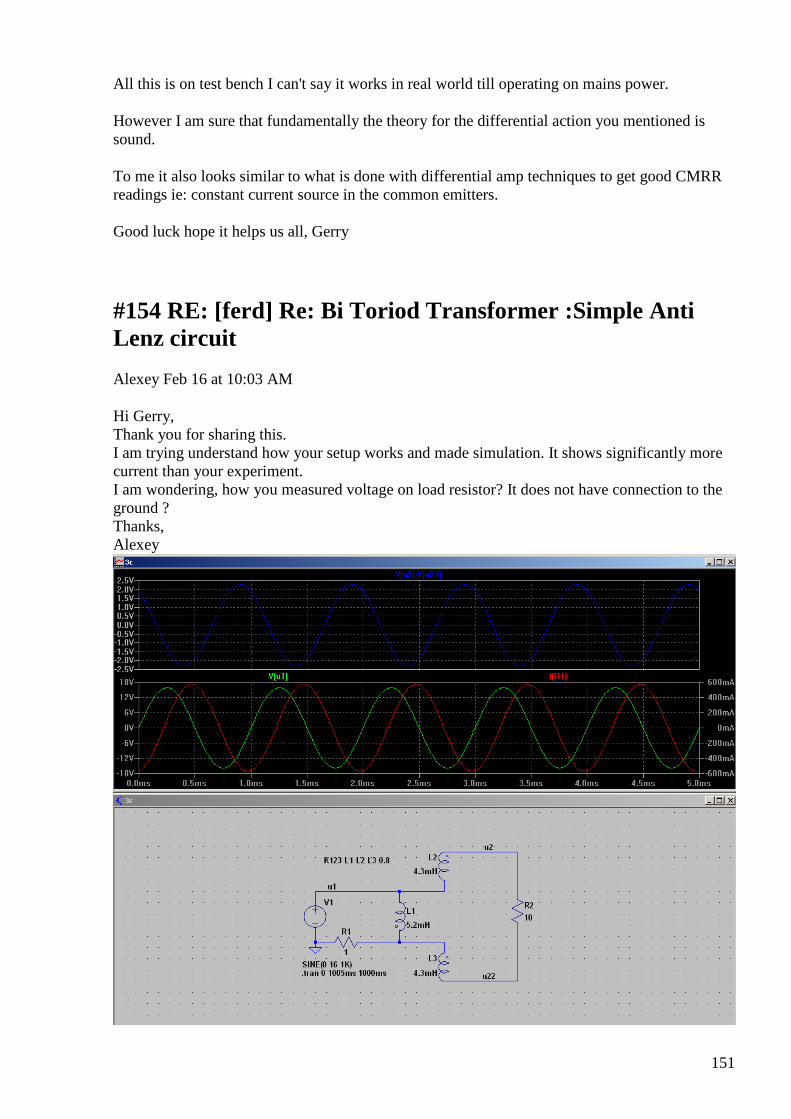
151
All this is on test bench I can't say it works in real world till operating on mains power.
However I am sure that fundamentally the theory for the differential action you mentioned is sound.
To me it also looks similar to what is done with differential amp techniques to get good CMRR readings ie: constant current source in the common emitters.
Good luck hope it helps us all, Gerry
#154 RE: [ferd] Re: Bi Toriod Transformer :Simple Anti Lenz circuit
Alexey Feb 16 at 10:03 AM
Hi Gerry, Thank you for sharing this. I am trying understand how your setup works and made simulation. It shows significantly more current than your experiment. I am wondering, how you measured voltage on load resistor? It does not have connection to the ground ? Thanks, Alexey
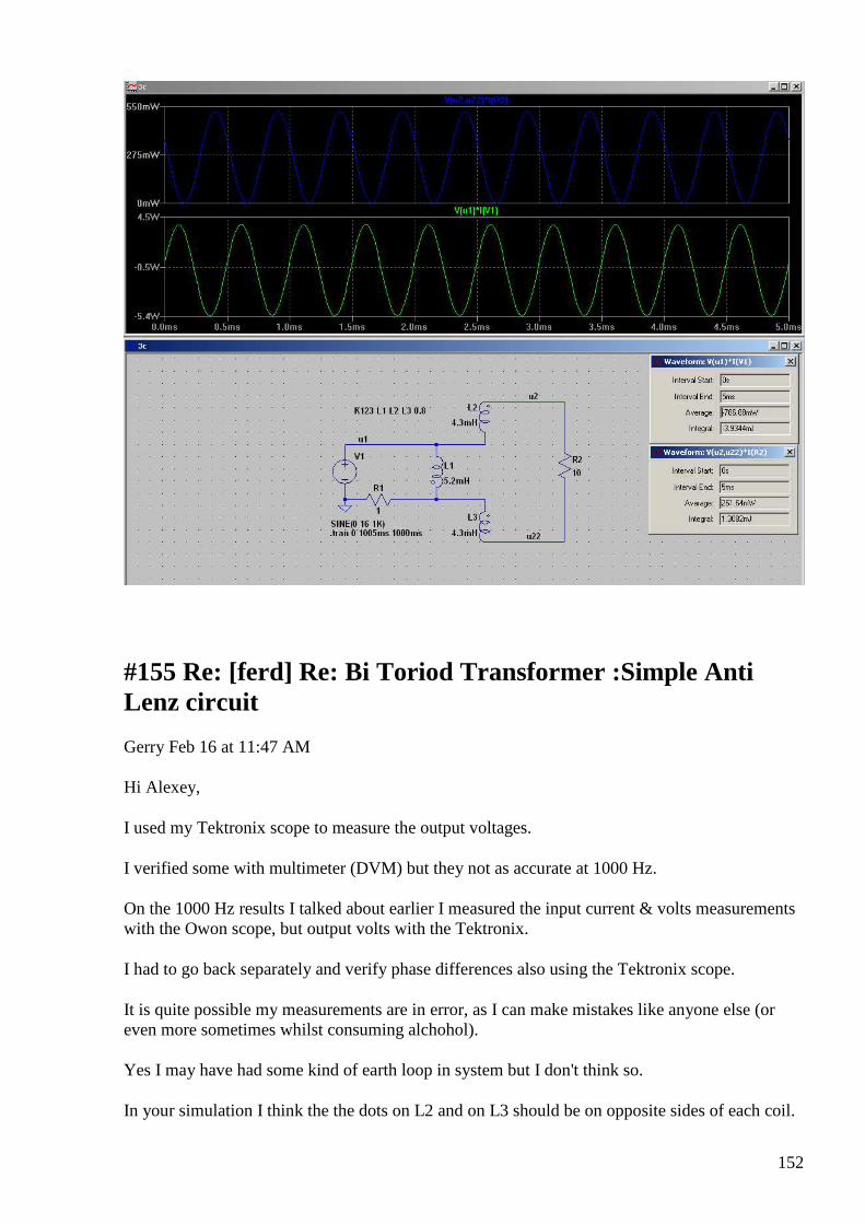
152
#155 Re: [ferd] Re: Bi Toriod Transformer :Simple Anti Lenz circuit
Gerry Feb 16 at 11:47 AM
Hi Alexey,
I used my Tektronix scope to measure the output voltages.
I verified some with multimeter (DVM) but they not as accurate at 1000 Hz.
On the 1000 Hz results I talked about earlier I measured the input current & volts measurements with the Owon scope, but output volts with the Tektronix.
I had to go back separately and verify phase differences also using the Tektronix scope.
It is quite possible my measurements are in error, as I can make mistakes like anyone else (or even more sometimes whilst consuming alchohol).
Yes I may have had some kind of earth loop in system but I don't think so.
In your simulation I think the the dots on L2 and on L3 should be on opposite sides of each coil.
153
I checked the opposition of my poles using a battery to energise circuit and a compass.
During measurements I kept checking the current sense resistor, it never became excessively hot.
You comments about higher current makes a lot of sense....... due to the shunting effect of the two cancelling inductors and load should appear across primary.
There was though considerably more input current at 1 Ohms load when compared to 10 Ohms in measurements.
I don't have any particular barrow to push here, I just present what my findings were.
And share it
Gerry
#156 Re: [ferd] Re: Bi Toriod Transformer :Simple Anti Lenz circuit
Gerry Feb 16 at 12:19 PM
Hi Alexey,
I forgot to mention as long as phase shift results are correct, as being greater than 90 degrees.
It's likely not critical about actual currents.... because the direction of the power (E x I x Cos phi) is reversed.
At least that's my thinking
#157 RE: [ferd] Re: Bi Toriod Transformer :Simple Anti Lenz circuit
Alexey Feb 16 at 9:31 PM
Hi Gerry,
” In your simulation I think the dots on L2 and on L3 should be on opposite sides of
each coil. ”
I tried that and it produces much higher voltage than you measured.
Unfortunately I don’t have at hand suitable coils and laminate core piece at the moment to try this now…
Thanks,
154
Alexey
#158 Re: [ferd] Re: Bi Toriod Transformer :Simple Anti Lenz circuit
Gerry Feb 17 at 1:14 AM
Hi Alexey,
It's ok thanks for trying Alexey.
I think it can be replicated using a straight piece of ferrite rod for the core, especially at the higher frequencies.
OFF topic:
Recently was re reading the free energy basics pdf's you posted.
I didn't agree with the cup of water analogy, because cup of water best describes "stored charge".
When we think about our "free energy" we want to receive then "time" becomes involved, or rate of flow of energy.
So thought maybe I should try to think of better analogy, not just criticise, but I can't right now.
best Gerry
#159Re: [ferd] capacitor coil as a secondary
Gustavo Roveran Feb 18 12:33 AM
Hi Alexey,
I could find the way to recover my possibility to response yahoo mails.
I have to improve my experiments before share some data.
Regards,
Gustavo
155
#160 Re: [ferd] capacitor coil as a secondary
Gustavo Roveran Feb 20 at 3:37 AM
Hi Alexey,
I did some measures towards behaviour understanding of the capcoil transformer.
InputVoltageCurrent.jpg -> Voltage input and Current consumption CapCoilTrafo.jpg -> CapCoil transformer topology. Input is a serial resonance circuit between primary coil and a 47 nF faradays capacitor
InputCapVoltage.jpg -> Input capacitor voltage 50V/div 20uS/Div InputPrimaryVoltage.jpg -> Input primary coil voltage 50V/div 20uS/div Secondary_1_Voltage.jpg -> Up -> Input capacitor voltage 50V/div 20uS/Div Down -> Output Secondary 1 Voltage 5V/div Secondary_2_Voltage.jpg -> Up -> Input capacitor voltage 50V/div 20uS/Div Down -> Output Secondary 1 Voltage 5V/div Sec1_Leg1ToSec2_Leg1_Voltage.jpg Up -> Input capacitor voltage 50V/div 20uS/Div Down -> Output Secondary 1 Leg 1 to Secondary 2 Leg 1 Voltage 1V/div Sec1_Leg1ToSec2_Leg2_Voltage.jpg Up -> Input capacitor voltage 50V/div 20uS/Div Down -> Output Secondary 1 Leg 1 to Secondary 2 Leg 2 Voltage 5V/div
Are these measures correct ? At least the wave forms. Opinions Advises ...
Regards,
Gustavo
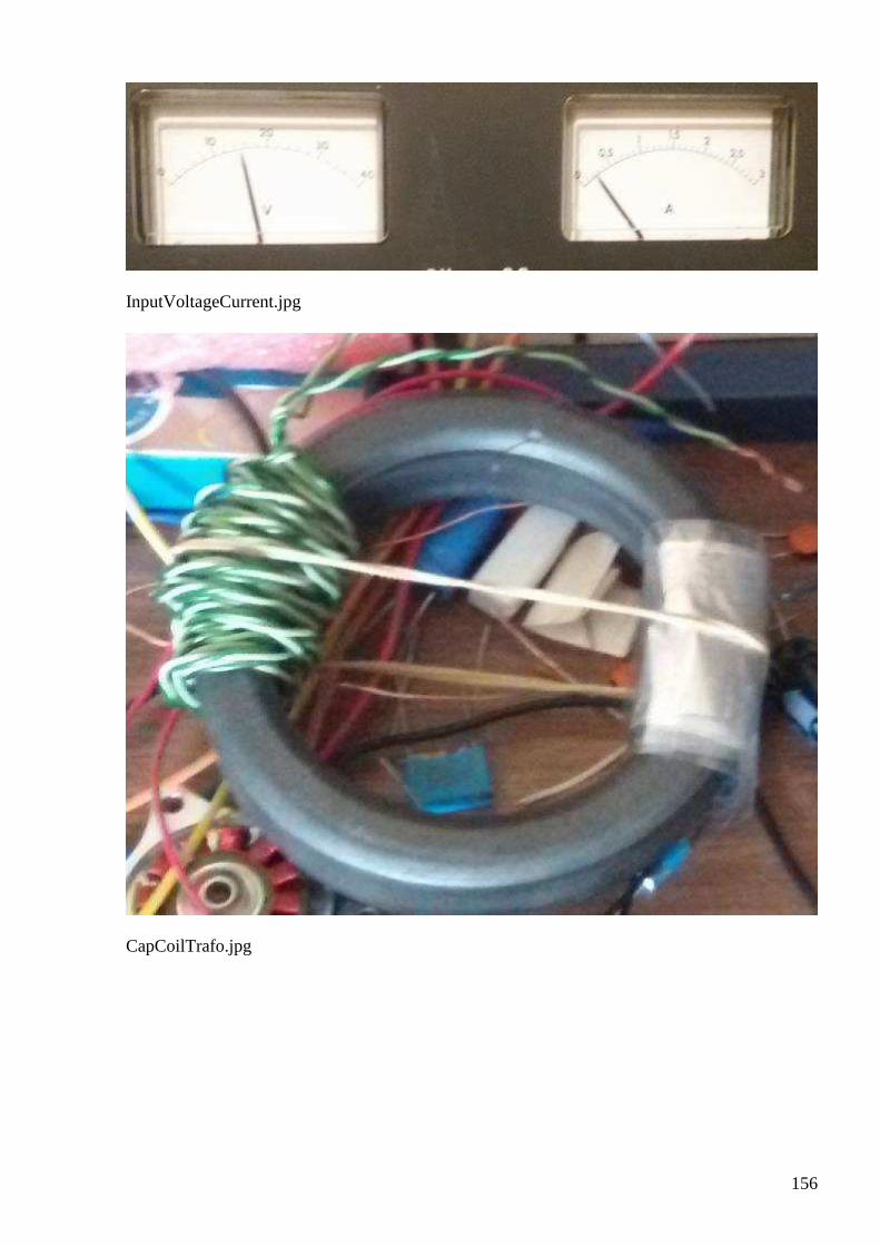
156
InputVoltageCurrent.jpg
CapCoilTrafo.jpg
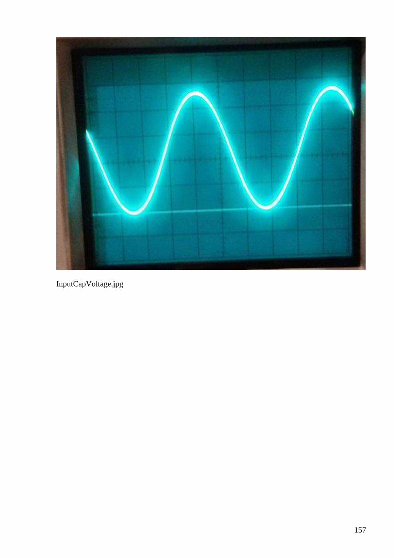
157
InputCapVoltage.jpg
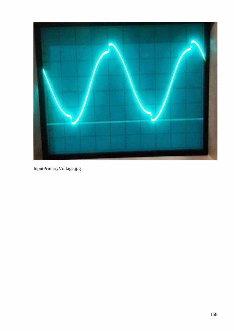
158
InputPrimaryVoltage.jpg
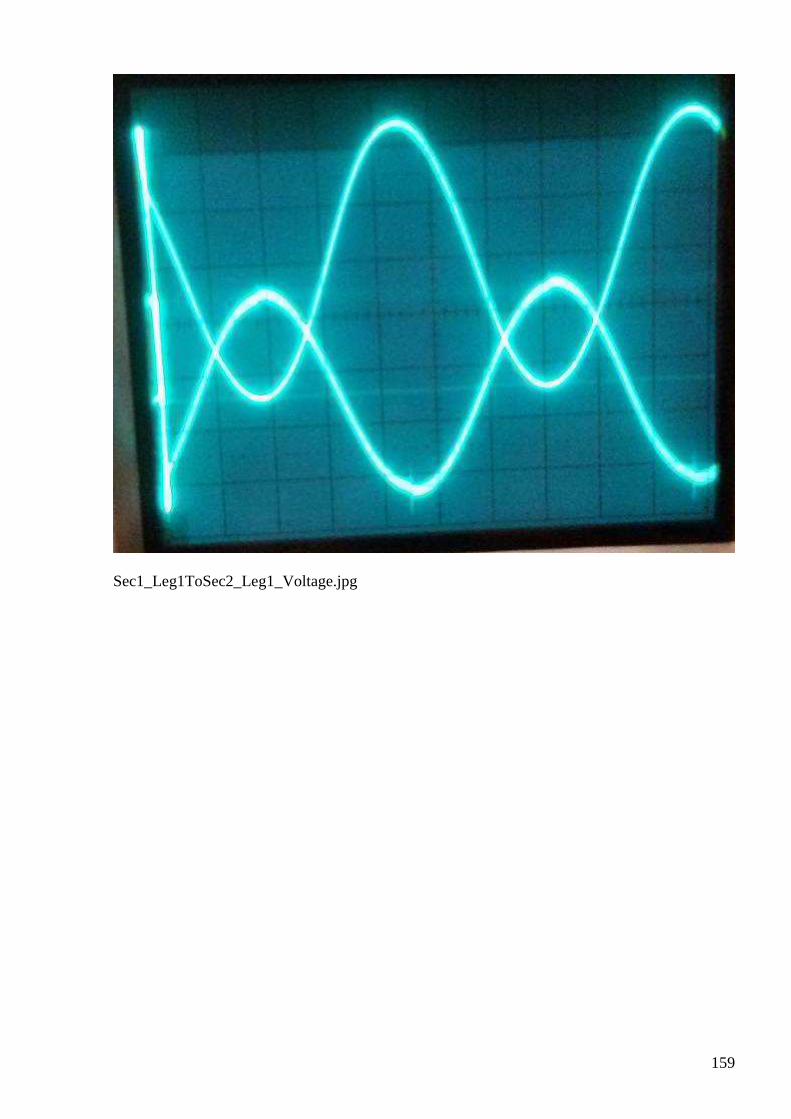
159
Sec1_Leg1ToSec2_Leg1_Voltage.jpg
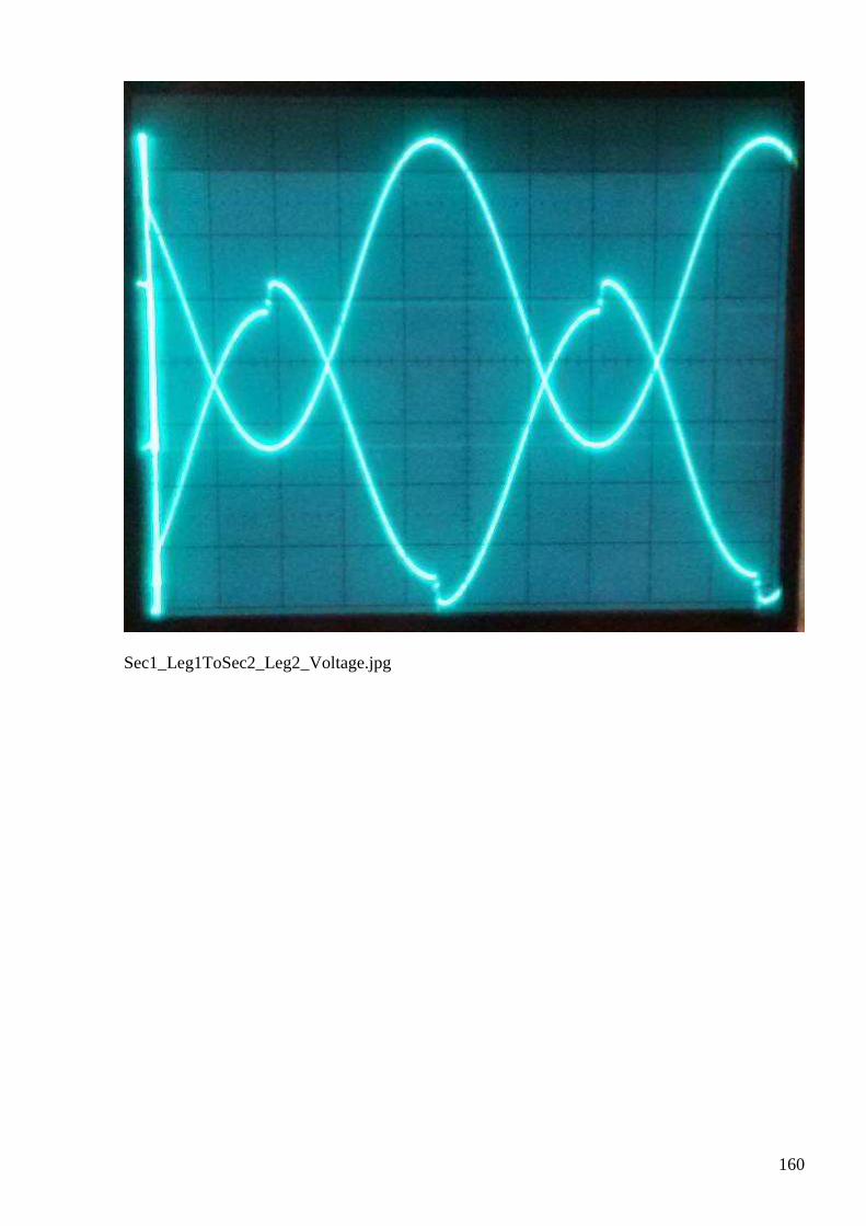
160
Sec1_Leg1ToSec2_Leg2_Voltage.jpg
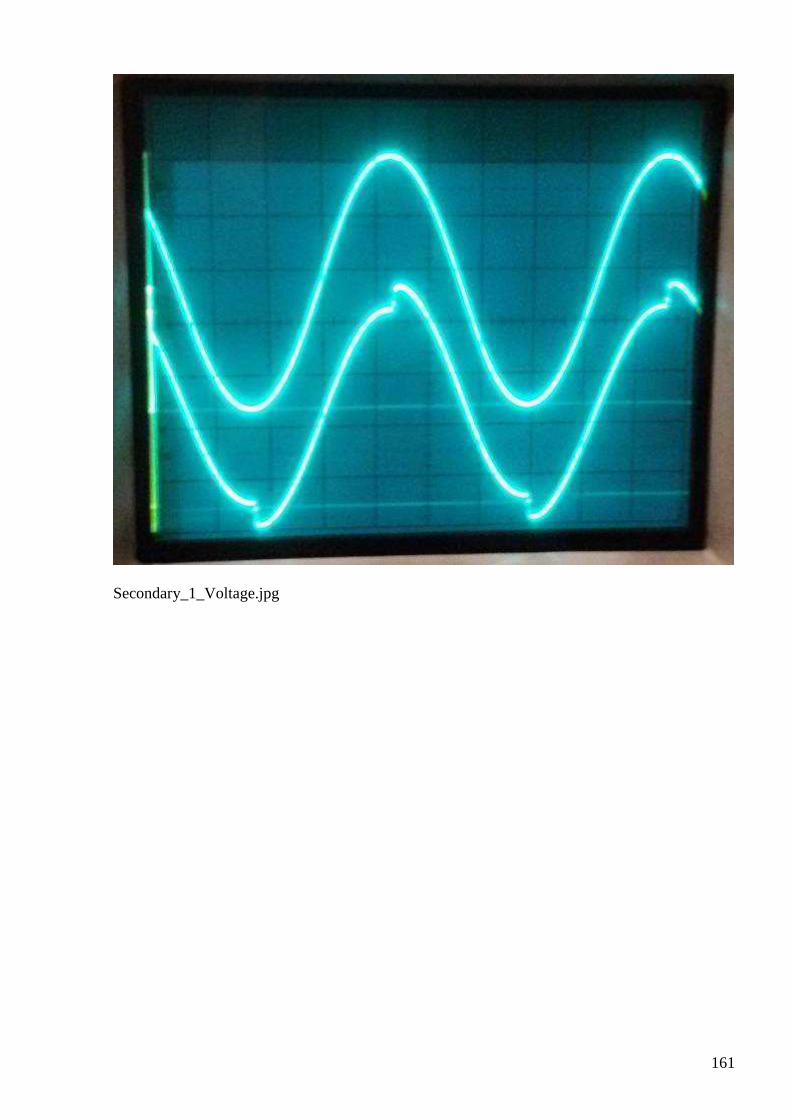
161
Secondary_1_Voltage.jpg
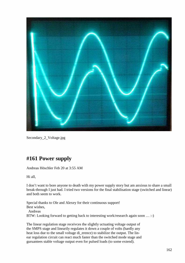
162
Secondary_2_Voltage.jpg
#161 Power supply
Andreas Höschler Feb 20 at 3:55 AM
Hi all, I don’t want to bore anyone to death with my power supply story but am anxious to share a small break-through I just had. I tried two versions for the final stabilisation stage (switched and linear) and both seem to work.
Special thanks to Ole and Alexey for their continuous support! Best wishes, Andreas BTW: Looking forward to getting back to interesting work/research again soon … :-) The linear regulation stage receivces the slightly uctuating voltage output of the SMPS stage and linearily regulates it down a couple of volts (hardly any heat loss due to the small voltage di_erence) to stabilize the output. The lin- ear regulation circuit can react much faster than the switched mode stage and guruantees stable voltage output even for pulsed loads (to some extend).
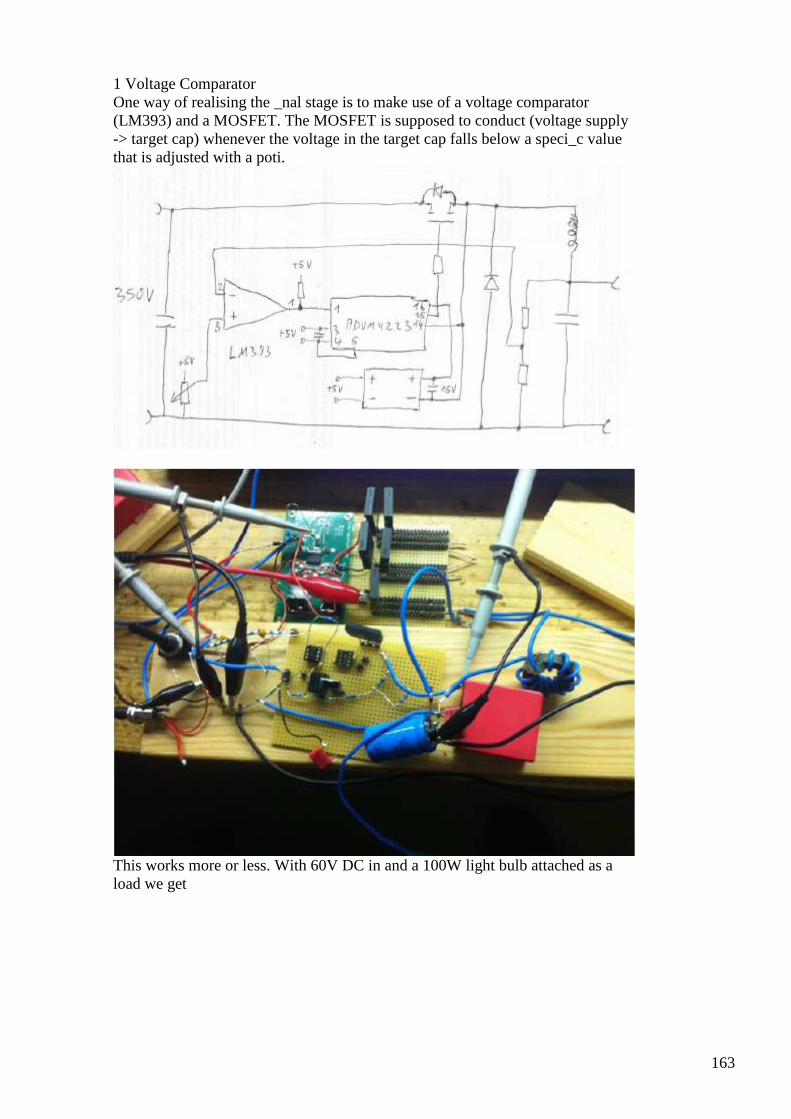
163
1 Voltage Comparator One way of realising the _nal stage is to make use of a voltage comparator (LM393) and a MOSFET. The MOSFET is supposed to conduct (voltage supply -> target cap) whenever the voltage in the target cap falls below a speci_c value that is adjusted with a poti.
This works more or less. With 60V DC in and a 100W light bulb attached as a load we get
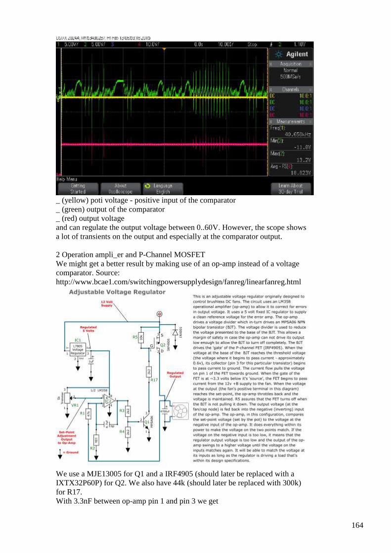
164
_ (yellow) poti voltage - positive input of the comparator _ (green) output of the comparator _ (red) output voltage and can regulate the output voltage between 0..60V. However, the scope shows a lot of transients on the output and especially at the comparator output. 2 Operation ampli_er and P-Channel MOSFET We might get a better result by making use of an op-amp instead of a voltage comparator. Source: http://www.bcae1.com/switchingpowersupplydesign/fanreg/linearfanreg.html
We use a MJE13005 for Q1 and a IRF4905 (should later be replaced with a IXTX32P60P) for Q2. We also have 44k (should later be replaced with 300k) for R17. With 3.3nF between op-amp pin 1 and pin 3 we get
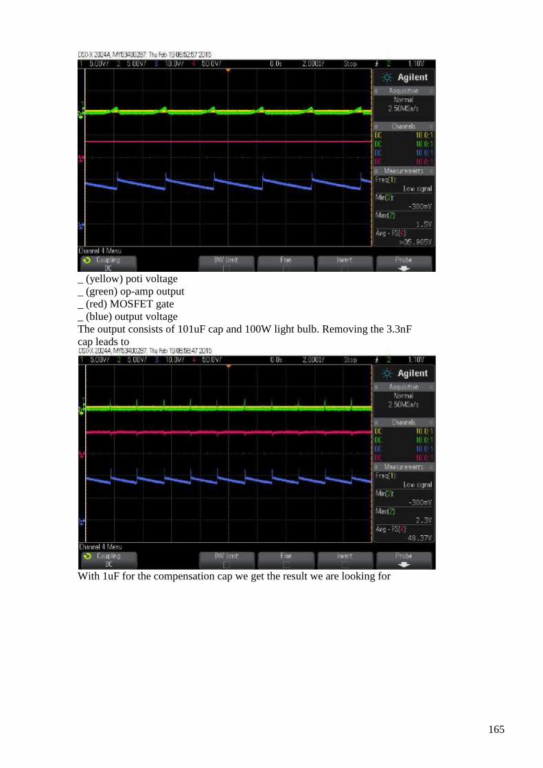
165
_ (yellow) poti voltage _ (green) op-amp output _ (red) MOSFET gate _ (blue) output voltage The output consists of 101uF cap and 100W light bulb. Removing the 3.3nF cap leads to
With 1uF for the compensation cap we get the result we are looking for
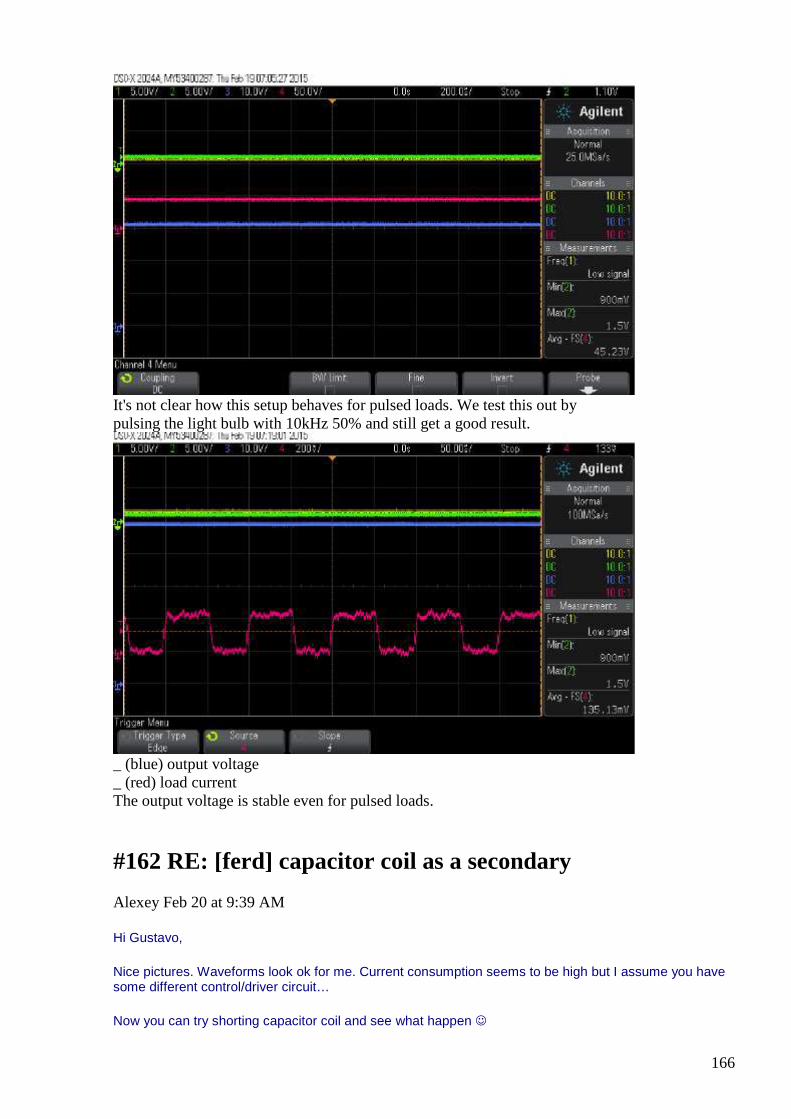
166
It's not clear how this setup behaves for pulsed loads. We test this out by pulsing the light bulb with 10kHz 50% and still get a good result.
_ (blue) output voltage _ (red) load current The output voltage is stable even for pulsed loads.
#162 RE: [ferd] capacitor coil as a secondary
Alexey Feb 20 at 9:39 AM
Hi Gustavo,
Nice pictures. Waveforms look ok for me. Current consumption seems to be high but I assume you have some different control/driver circuit…
Now you can try shorting capacitor coil and see what happen
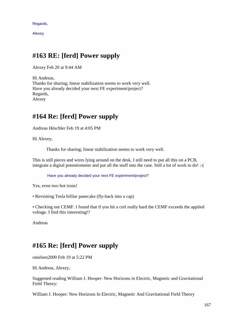
167
Regards,
Alexey
#163 RE: [ferd] Power supply
Alexey Feb 20 at 9:44 AM
Hi Andreas, Thanks for sharing; linear stabilization seems to work very well. Have you already decided your next FE experiment/project? Regards, Alexey
#164 Re: [ferd] Power supply
Andreas Höschler Feb 19 at 4:05 PM
Hi Alexey,
Thanks for sharing; linear stabilization seems to work very well.
This is still pieces and wires lying around on the desk. I still need to put all this on a PCB, integrate a digital potentiometer and put all the stuff into the case. Still a lot of work to do! :-(
Have you already decided your next FE experiment/project?
Yes, even two hot irons!
• Revisiting Tesla bifilar panecake (fly-back into a cap)
• Checking out CEMF. I found that if you hit a coil really hard the CEMF exceeds the applied voltage. I find this interesting!?
Andreas
#165 Re: [ferd] Power supply
onielsen2000 Feb 19 at 5:22 PM
Hi Andreas, Alexey, Suggested reading William J. Hooper: New Horizons in Electric, Magnetic and Gravitational Field Theory: William J. Hooper: New Horizons In Electric, Magnetic And Gravitational Field Theory
168
http://www.rexresearch.com/hooper/horizon.htm
rexresearch.com William J. HOOPER Motional Electric Field Commentaries & Reviews US Patent # 3,610,971 US Patent # 3,656,013 Frances Gibson: The All-El...
World Science Database
http://www.worldsci.org/php/index.php?tab0=Scientists&tab1=Scientists&tab2=Display&id=479
View count: 594 New Horizons in Electric, Magnetic and Gravitational Field Theory by Prof. William J. Hooper KeyWords: gravity Pages: 108 Publisher: Electrodynamic There is a controversy at the EvGray group about the meaning of CEMF. In electronics the kick back voltage generated when trying to stop a current flow is called the fly back voltage. This is used in flyback converters like the inverter. It has been used for a very long time in analog TV sets in the flyback transformer that also generates the extremely high tension (EHT) voltage used to accelerate the electrons in the electron gun. This kind of voltage will always adopt to the impedance to let the current flow at the same strength it had when disrupted. The current in an inductance can't be discontinuous (i.e. can't make a jump) thus the voltage has to adapt to that current at this impedance. U=Z x i or the voltage equals the impedance multiplied by the current. This way the voltage is stepped up when the impedance is stepped up (i.e. circuit opened). This is not free energy only "free" voltage. The higher the voltage is stepped up the shorter the pulse as it contains the same amount of energy. Regards Ole
#166 Re: [ferd] Power supply
Andreas Höschler Feb 19 at 6:03 PM
Hi Ole,
There is a controversy at the EvGray group about the meaning of CEMF. In electronics the kick back voltage generated when trying to stop a current flow is called the fly back voltage. This is used in flyback converters like the inverter. It has been used for a very long time in analog TV sets in the flyback transformer that also generates the extremely high tension (EHT) voltage used to accelerate the electrons in the electron gun. This kind of voltage will always adopt to the impedance to let the current flow at the same strength it had when disrupted. The current in an inductance can't be discontinuous (i.e. can't make a jump) thus the voltage has to adapt to that current at this impedance. U=Z x i or the voltage equals the impedance multiplied by the current. This way the voltage is stepped up when the impedance is stepped up (i.e. circuit opened). This is not free energy only "free" voltage. The higher the voltage is stepped up the shorter the pulse as it contains the same amount of energy.
May be you should repost this to EVGRAY!? :-) I am quite sure everyone on this board is quite aware of the difference of CEMF and flyback-pulse and also that under normal circumstances
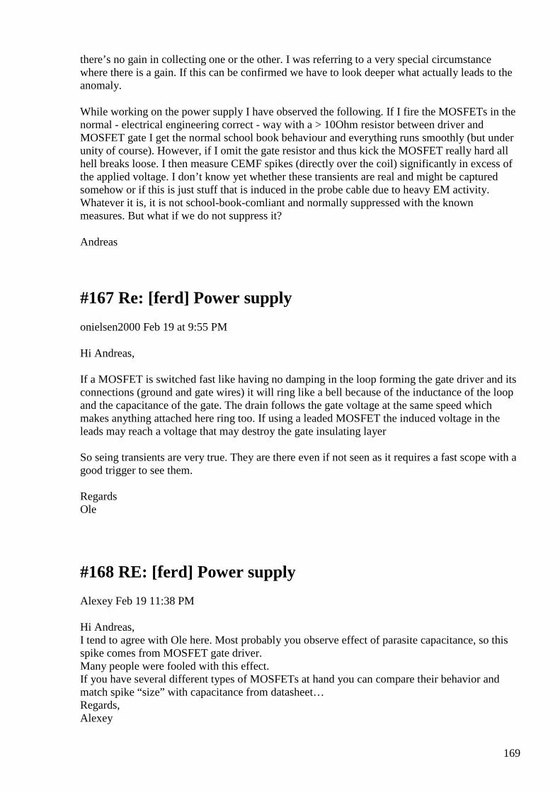
169
there’s no gain in collecting one or the other. I was referring to a very special circumstance where there is a gain. If this can be confirmed we have to look deeper what actually leads to the anomaly.
While working on the power supply I have observed the following. If I fire the MOSFETs in the normal - electrical engineering correct - way with a > 10Ohm resistor between driver and MOSFET gate I get the normal school book behaviour and everything runs smoothly (but under unity of course). However, if I omit the gate resistor and thus kick the MOSFET really hard all hell breaks loose. I then measure CEMF spikes (directly over the coil) significantly in excess of the applied voltage. I don’t know yet whether these transients are real and might be captured somehow or if this is just stuff that is induced in the probe cable due to heavy EM activity. Whatever it is, it is not school-book-comliant and normally suppressed with the known measures. But what if we do not suppress it?
Andreas
#167 Re: [ferd] Power supply
onielsen2000 Feb 19 at 9:55 PM
Hi Andreas, If a MOSFET is switched fast like having no damping in the loop forming the gate driver and its connections (ground and gate wires) it will ring like a bell because of the inductance of the loop and the capacitance of the gate. The drain follows the gate voltage at the same speed which makes anything attached here ring too. If using a leaded MOSFET the induced voltage in the leads may reach a voltage that may destroy the gate insulating layer So seing transients are very true. They are there even if not seen as it requires a fast scope with a good trigger to see them. Regards Ole
#168 RE: [ferd] Power supply
Alexey Feb 19 11:38 PM
Hi Andreas, I tend to agree with Ole here. Most probably you observe effect of parasite capacitance, so this spike comes from MOSFET gate driver. Many people were fooled with this effect. If you have several different types of MOSFETs at hand you can compare their behavior and match spike “size” with capacitance from datasheet… Regards, Alexey
170
#169 Re: [ferd] Power supply
Andreas Höschler Feb 20 at 3:34 AM
Hi Ole and Alexey,
The drain follows the gate voltage at the same speed which makes anything attached here ring too.
Hmmgh, the MOSFET switches on and off correspondingly. The voltage measured between drain and source would depend on a bunch of factors. However, I measured the voltage directly over the coil (primary) with a differential probe and I got this (blue curve):
See the first spike of the blue curve well in excess of the applied voltage? Ringing or not. The scope measures 160% of the applied voltage over the coil for a brief moment before it starts to oscillate down to 100% o the applied voltage. What do you think is the state of the MOSFET in this very moment of the first peak? It must have -60% of the applied voltage over the drain source junction which should not be possible with the intrinsic diode in place!?
The ringing thing does not explain the observation exhaustingly for me!? See what I mean?
Andreas
#170 Re: [ferd] Power supply
onielsen2000 Feb 20 at 4:03 AM
171
Hi Andreas, What are the other colors showing? When energizing the coil which also has capacitance (when having more than one winding) it rings too. Actually all wires have both inductance and capacitance. They are transmission lines when the frequency is high or the pulse length is short. All transients represents a high frequency. If your scope has a spectrum analyzer the different frequencies can be revealed to find out what parasitic components are in the circuit. Regards Ole
#171 Re: [ferd] Power supply
Andreas Höschler Feb 20 at 4:16 AM
Hi Ole
What are the other colors showing?
• (yellow) PWM signal
• (green) one of the two H-Bridge signals (behind the multiplexer)
• (blue) voltage over the primary measured with a differential probe
• (red) current through the primary measured over an 1R shunt also with a differential probe
When energizing the coil which also has capacitance (when having more than one winding) it rings too.
Actually all wires have both inductance and capacitance. They are transmission lines when the frequency
is high or the pulse length is short. All transients represents a high frequency.
I have no problem with the ringing. That’s for sure caused by inductance and stray capacitance in the circuit. What puzzles me is the initial amplitude which is 160% of the applied voltage. Can this be explained with stray capacitance alone?
Andreas
#172 Re: [ferd] Power supply
onielsen2000 Feb 20 at 5:22 AM
Hi Andreas,
172
At switch on the current increases fast. This is not inductance which makes a slow increase in current. This is capacitance. The charge of the capacitance is then transferred to the inductance making it ring. As the voltage overshoots the circuit is under-damped meaning the resistive part is to low to dissipate the energy fast enough. It is hard to see the phase relationship between the current and voltage during the transient part of the signal (I.e. during the voltage step). At switch off it is clearly seen that the current is lagging the voltage Consider the primary together with a parasitic capacitance that forms an LC-tank. During switch on the capacitor is charged very fast while the current increases much slower through the inductance of the primary. When the capacitor is charged it starts discharging to the primary that is also receiving current from the power supply. With not enough damping it overshoots. Some links about second order systems: ebook: Engineering Analysis using Scilab and C
http://engineeronadisk.com/book_analysis/diffeqna4.html
ebook: Engineering Analysis using Scilab and C
1.3 Responses Solving differential equations tends to yield one of two basic equation forms. The e-to-the-negative-t forms are the first-order responses and...
Look at the last page here: http://ocw.mit.edu/courses/mechanical-engineering/2-003-modeling-dynamics-and-control-i-spring-2005/readings/notesinstalment2.pdf or the last two pages here: https://web.stanford.edu/~boyd/ee102/2nd_order.pdf Those are circuits containing LCR components making a second order system which can do overshoots if under-damped. Regards Ole
#173 RE: [ferd] Power supply
Alexey Feb 20 at 10:24 AM
Hi Andreas, I used MOSFET model from here http://www.simonbramble.co.uk/lt_spice/ltspice_lt_spice_tutorial_6.htm and created a simulation. It show peak at the MOSFET switching on (see 2.png in red circle). With more realistic model and parameters it is probably became larger and oscilate. I would suggest you do some experiments and see what affects this peak and etc… Regards, Alexey

173
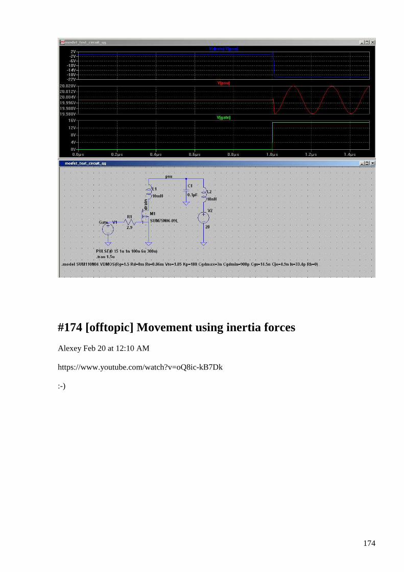
174
#174 [offtopic] Movement using inertia forces
Alexey Feb 20 at 12:10 AM
https://www.youtube.com/watch?v=oQ8ic-kB7Dk :-)
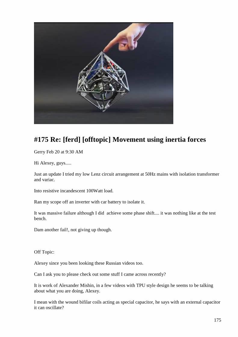
175
#175 Re: [ferd] [offtopic] Movement using inertia forces
Gerry Feb 20 at 9:30 AM
Hi Alexey, guys.....
Just an update I tried my low Lenz circuit arrangement at 50Hz mains with isolation transformer and variac.
Into resistive incandescent 100Watt load.
Ran my scope off an inverter with car battery to isolate it.
It was massive failure although I did achieve some phase shift.... it was nothing like at the test bench.
Dam another fail!, not giving up though.
Off Topic:
Alexey since you been looking these Russian videos too.
Can I ask you to please check out some stuff I came across recently?
It is work of Alexander Mishin, in a few videos with TPU style design he seems to be talking about what you are doing, Alexey.
I mean with the wound bifilar coils acting as special capacitor, he says with an external capacitor it can oscillate?

176
My wife is Ukraine and helps me but I can barely understand some very few words (like the numbers etc) but because it is very technical.
Anyhow here is a link to a short version
https://www.youtube.com/watch?v=4gm7qHVBJJw
He goes over the theory in other long winded videos, do you understand better than me or us here?
Gerry
#176 RE: [ferd] [offtopic] Movement using inertia forces
Alexey Feb 21 at 1:21 PM
Hi Gerry,
here a translation of the video:
Resonant power multiplier from Mishin
Skype screen, text chat: Alexander Mishin Yaroslav (*): Do you want show it on Skype or do you want come to X-City (*)? Alexander Mishin: I can show it on Skype Yaroslav: Shall I record it on video or not? Alexander Mishin: yea, we can make a short video; I can explain all details tomorrow on web conference Yaroslav: ok, good, take care, no rash… Alexander Mishin: let’s record 5min now Yaroslav: ok, switching camera on J Alexander Mishin: I missed you J Video transcript 0:00 AM: Hi Slava (*) Y: Hi, how are you ? AM: I will show it to you shortly today I made a small simple setup with toroid Y: ok AM: I will direct camera downwards, here it is Here the toroid, I used it already earlier in a different mode here in addition to toroid (with no core) a capacitor (* white cylinder) capacitor wound on a tube, symmetrical parametric capacitor here load – two LEDs, one in one direction, one in another capacitor in series (* blue), I added it just to remove pulsations otherwise it was unpleasant for my eyes 1:00 the setup working on disconnected power circuit, antenna and ground I don’t have ground at home so I tried use two antennas, it works but very dimly I can show you how it works from multimeter, 0.1v
177
… it starts from any static electricity near by attaching leads capacitance measuring mode on multimeter now let’s see if metallic pen will be enough to start it up ok, not enough let’s start it this way, ok, here it work multimeter provides frequency about 10hz 2:00 so 0.1second applied a saw-like signal, next 0.1 second circuit is open so its ”time of life” about 0.2 seconds, it works without power ok ok, so far I haven’t made any attempts to self power it here a unused inductance of this capacitor which can be used for this purpose for future experiments and so here it is, works ok capacitor here not mandatory I can short it with metallic pen ok, you on web cam can’t see any difference Y: yea, I can’t see any difference AM: in general its kind of funny situation you can take any piece of wire, at least 15-20 centimeters long just touch the setup and it starts working 3:00 well, I could understand it, here these power supply wires here it is interesting, I can connect it directly to load so, now I will connect it directly to LEDs ok, here it is obviously 0.1v is not enough to start this device but if you have a battery (I don’t have right now) you can touch any contact in the circuit, just make any small pulse and it starts here I switched on multimeter (you can hear a sound of switch) in this mode they working brightly but pulsations are higher when connected directly frequency defined by this parametric capacitor currently there is about 5.8 volts almost clear sinusoidal signal yesterday I spend quite some time tuning these capacitors 4:00 otherwise it could go into megahertz range very unstable oscillations ok, so its clear resonance acceleration windings, here actually used only two windings Y: how we can use this effect? AM: well, its just a standard principle of producing energy with resonance Y: what power we can get ? AM: power depends of applied voltage Y: ok AM: increasing voltage lead to quadratic current rise Y: so, this is a power multiplier? AM: yes, trivial resonance power multiplier main requirement is that it works only when power supply circuit is open antenna – ground 5:00 ok, with a light hand move J ha ha
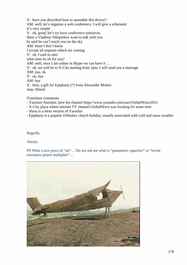
178
Y: have you described how to assemble this device? AM: well, let’s organize a web conference, I will give a schematic it’s very simple Y: ok, good, let’s try have conference tomorrow there a Vladimir Shlapnikov want to talk with you he said he can’t reach you on the sky AM: hmm I don’t know I accept all requests which are coming Y: ok, I said so also what time its ok for you? AM: well, once I am online in Skype we can have it … Y: ok, we will be in X-City starting from 1pm; I will send you a message AM: yea, ok Y: ok, bye AM: bye Y: here, a gift for Epiphany (*) from Alexander Mishin stop, filmed. Translator comments: - Yaroslav Staruhin, here his channel https://www.youtube.com/user/GlobalWave2012 - X-City place where internet TV channel GlobalWave was locating for some time - Slava is a short version of Yaroslav - Epiphany is a popular Orthodox church holiday, usually associated with cold and snow weather
Regards,
Alexey
PS What a nice piece of “art”… Do not ask me what is “parametric capacitor” or “trivial resonance power multiplier”…

179
#177 Re: [ferd] [offtopic] Movement using inertia forces
Gerry Feb 21 at 3:03 PM
Thank you kindly for doing this translation Alexey.
It looks similar concept to your special bifilar capacitor in your last project.
Remember if the magnetic field is cancelled in a bifilar coil arrangement where current equal but opposite.
A step change in current can pass through this arrangement much faster than nature intended?
It is easily seen on scope, as we know.
Plus...... I thought from what you were saying about your special bifilar capacitor,
that the capacitor formed between these two windings can be charged exceedingly quickly and not in the normal delayed way.
Without the normal exponential rise in volts as charge grows?
From watching those Alexander Mishin videos and reading Mr Floyd Sweets "Nothing is Something Notes".
They give impression that although the magnetic field is cancelled in above arrangements like yours.
The electro-static filed is doubled Mr Sweet shows the math for this, in his document.
I will attach it here.
So possibly the charge on your special cap not only happens quicker than nature intended but with twice the charge?
Sorry forgot to comment on OFF TOPIC video link you posted,
That box containing gyros reminds me of early inertial guidance mechanism inside our guided missile "Tartar" system.
The gyros used to be driven by air to spin them up (at 10,000 psi), rather than electric used in the video.
They used this provided a stable plane from which to navigate and track their targets.
Guess it's old stuff nowdays

180
Gerry
#178 Re: [ferd] [offtopic] Movement using inertia forces
Gerry Feb 21 at 3:18 PM
Hi Alexey,
Sorry for endless post just want to say I think what he is calling parametric capacitor is same as what you already made.
However in Mr Mishin's toroid............. E field is probably vertical to the toroid and the white "special bifilar capacitor" is approximately in vertical plane.
So it may be that this white "special bifilar capacitor" is being charged and discharged at twice the rate by the E field of the toroid, no?
Hence the term parametric.
Maybe it's just wild speculation but also maybe not.
Worth to share tho.
Gerry
#179 Re: [ferd] [offtopic] Movement using inertia forces
Gerry Feb 21 at 3:52 PM
Hi again Alexey,
The circuit is attached
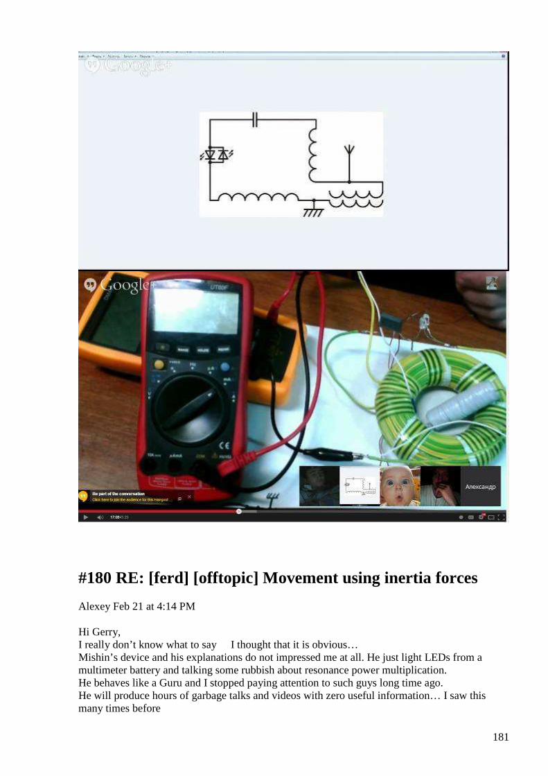
181
#180 RE: [ferd] [offtopic] Movement using inertia forces
Alexey Feb 21 at 4:14 PM
Hi Gerry, I really don’t know what to say I thought that it is obvious… Mishin’s device and his explanations do not impressed me at all. He just light LEDs from a multimeter battery and talking some rubbish about resonance power multiplication. He behaves like a Guru and I stopped paying attention to such guys long time ago. He will produce hours of garbage talks and videos with zero useful information… I saw this many times before

182
There also a lot of nonsense around Floyd Sweet device in the internet. As far as I understand ,it is some version of MEG, device where field of permanent magnets modulated and so allow use this field of PM to power some load. We probably will never know how it worked. It sealed reliably in Bearden & Co safe case and full load of disinformation spread around. In my setup with capacitor coil I was trying charge capacitor ”indirectly”, by placing it inside magnetic field, so the energy required for charging is minimal and does not depend on capacitance. I still not 100% sure if it is a valid working principle. There are some difficulties to construct a coil with high capacitance… Regards, Alexey
#181 Re: [ferd] [offtopic] Movement using inertia forces
Gerry Feb 21 at 1:17 AM
Ok Alexey,
You are right, I am easily mislead and very often wrong in technical aspects of things I see.
Gerry
#182 New landscapes for EM theory ?
Gustavo Roveran Feb 21 at 5:10 AM
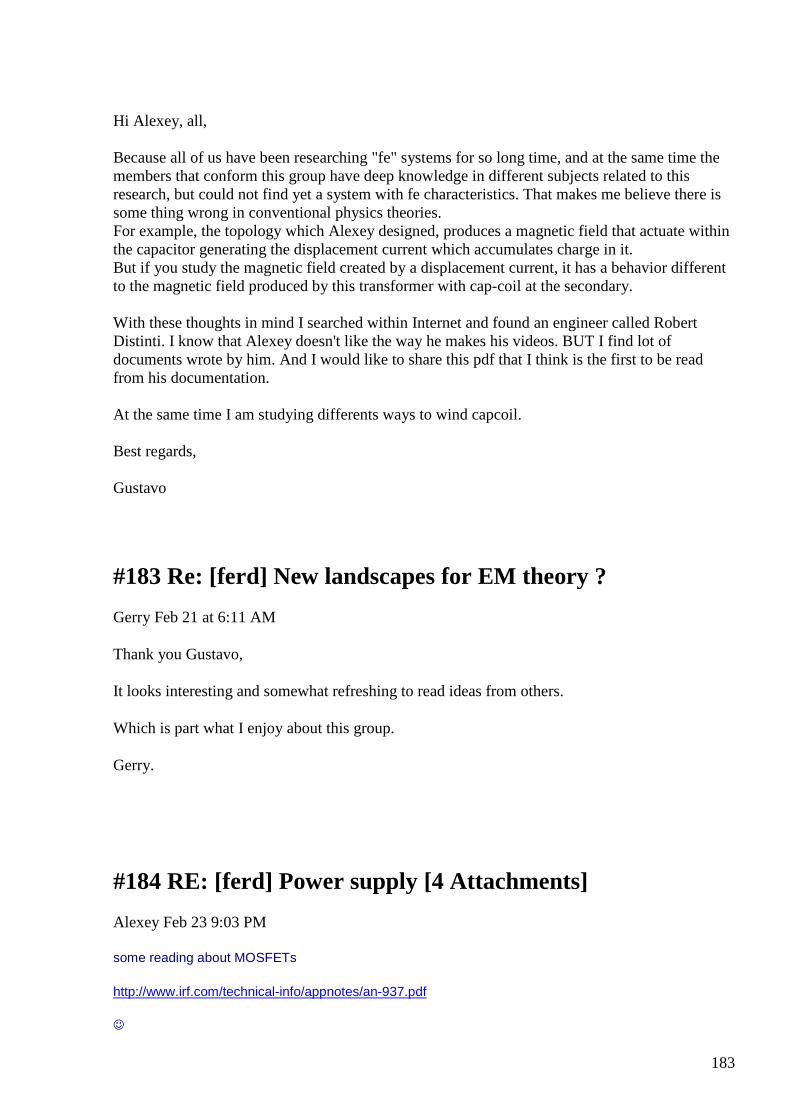
183
Hi Alexey, all, Because all of us have been researching "fe" systems for so long time, and at the same time the members that conform this group have deep knowledge in different subjects related to this research, but could not find yet a system with fe characteristics. That makes me believe there is some thing wrong in conventional physics theories. For example, the topology which Alexey designed, produces a magnetic field that actuate within the capacitor generating the displacement current which accumulates charge in it. But if you study the magnetic field created by a displacement current, it has a behavior different to the magnetic field produced by this transformer with cap-coil at the secondary. With these thoughts in mind I searched within Internet and found an engineer called Robert Distinti. I know that Alexey doesn't like the way he makes his videos. BUT I find lot of documents wrote by him. And I would like to share this pdf that I think is the first to be read from his documentation. At the same time I am studying differents ways to wind capcoil. Best regards, Gustavo
#183 Re: [ferd] New landscapes for EM theory ?
Gerry Feb 21 at 6:11 AM
Thank you Gustavo,
It looks interesting and somewhat refreshing to read ideas from others.
Which is part what I enjoy about this group.
Gerry.
#184 RE: [ferd] Power supply [4 Attachments]
Alexey Feb 23 9:03 PM
some reading about MOSFETs
http://www.irf.com/technical-info/appnotes/an-937.pdf
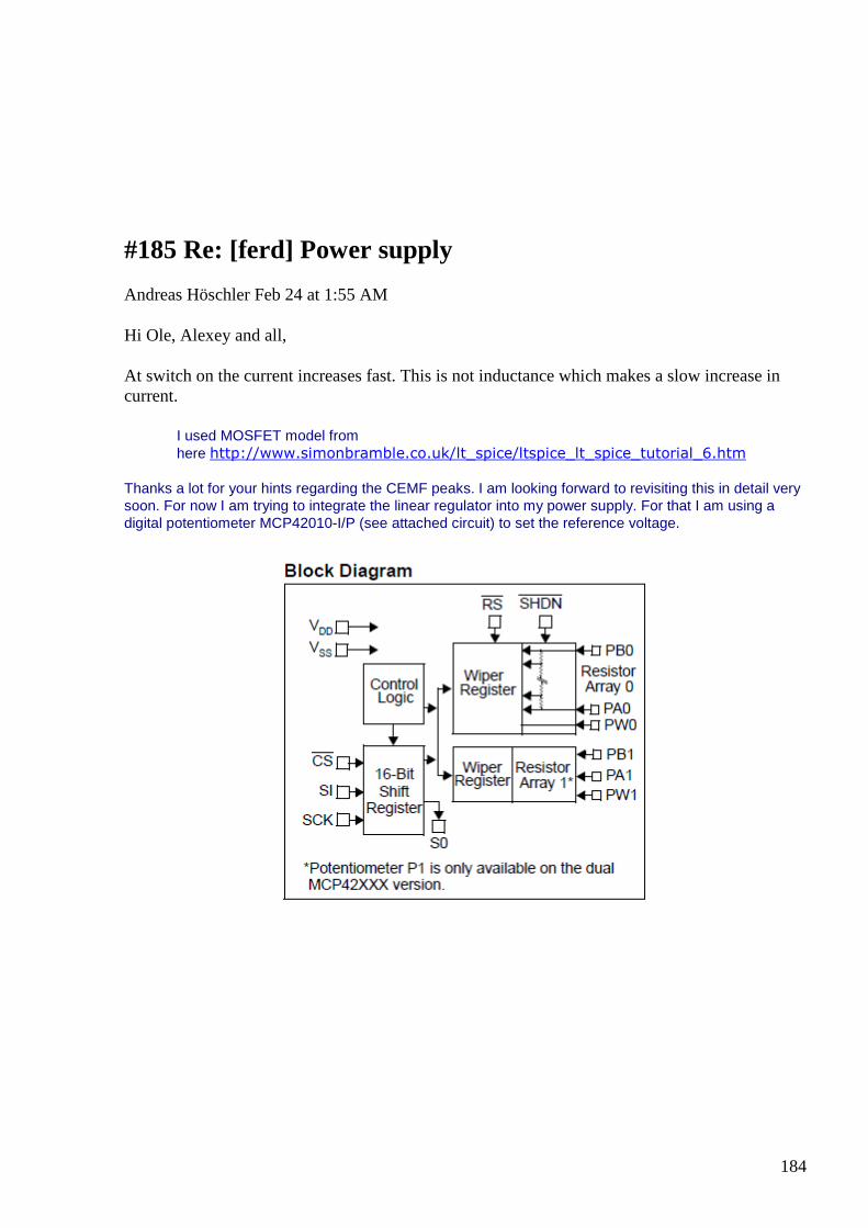
184
#185 Re: [ferd] Power supply
Andreas Höschler Feb 24 at 1:55 AM
Hi Ole, Alexey and all,
At switch on the current increases fast. This is not inductance which makes a slow increase in current.
I used MOSFET model from here http://www.simonbramble.co.uk/lt_spice/ltspice_lt_spice_tutorial_6.htm
Thanks a lot for your hints regarding the CEMF peaks. I am looking forward to revisiting this in detail very soon. For now I am trying to integrate the linear regulator into my power supply. For that I am using a digital potentiometer MCP42010-I/P (see attached circuit) to set the reference voltage.
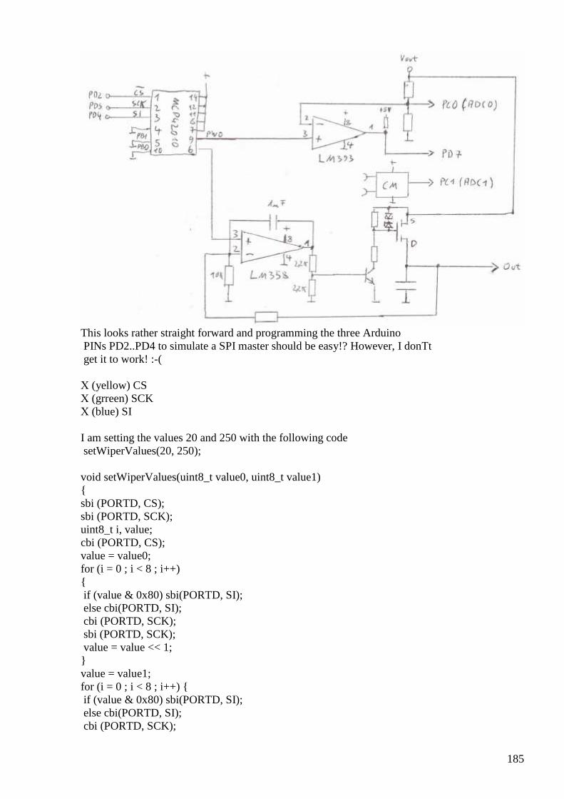
185
This looks rather straight forward and programming the three Arduino PINs PD2..PD4 to simulate a SPI master should be easy!? However, I donТt get it to work! :-( Х (yellow) CS Х (grreen) SCK Х (blue) SI I am setting the values 20 and 250 with the following code setWiperValues(20, 250); void setWiperValues(uint8_t value0, uint8_t value1) sbi (PORTD, CS); sbi (PORTD, SCK); uint8_t i, value; cbi (PORTD, CS); value = value0; for (i = 0 ; i < 8 ; i++) if (value & 0x80) sbi(PORTD, SI); else cbi(PORTD, SI); cbi (PORTD, SCK); sbi (PORTD, SCK); value = value << 1; value = value1; for (i = 0 ; i < 8 ; i++) if (value & 0x80) sbi(PORTD, SI); else cbi(PORTD, SI); cbi (PORTD, SCK);
186
sbi (PORTD, SCK); value = value << 1; sbi (PORTD, CS); The scope shot shows exactly what I had intended. However, the MCP424010 output pins 9 and 6 exhibit a constant 2.54V which seems to be a default value (wiper in the center position) totally ignoring my programming efforts! :-( Anyone any experience programming a SPI slave and an idea what I might have done wrong? Thanks a lot, Andreas
#186 Re: [ferd] Power supply
Andreas Höschler Feb 24 at 2:43 AM
Hi all,
Thanks a lot for your hints regarding the CEMF peaks. I am looking forward to revisiting this in detail very soon. For now I am trying to integrate the linear regulator into my power supply. For that I am using a digital potentiometer MCP42010-I/P (see attached circuit) to set the reference voltage.
Please ignore my last mail. Reading the manual to the very end often helps! :-)
It works now!
Best wishes,
Andreas
#187 [offtopic] one more useless toy :-)
Alexey Mar 1 8:20 PM
https://www.youtube.com/watch?v=6xe19XnX5L0 http://www.elektor-labs.com/project/inverted-pendulum.14309.html ;-)
187
#188 [reading] The Interference Anomaly
Alexey Mar 5 at 7:56 PM
http://users.hal-pc.org/~rcanup/anomaly.html P.S. anyone still reading this group ? ;-)
Abstract:
A simple mathematical model is constructed and explored. A description of the physics behind the model is included. The mathematical model predicts anomalous conditions under which energy is not conserved.
The Interference Anomaly
Let us begin our discussion with some information about waves. A physical wave in air can be considered a moving record of the forces exerted on the air. There are a number of ways that these forces can be created. The simplest and most common cause of pressure waves is a moving object, although nature incorporates other methods of generation. For example, thunder is created when an electric discharge heats the air causing it to expand and deliver the force of that expansion to the surrounding air.
Other methods of generating sound waves include resonant columns (an organ pipe for example) or heating of moist air by means of focused micro waves, or the alternating separation of Von Karman vortex sheets (a whistle for example works on this principle). Typically the sound produced on a 'human scale' represents pressure changes in the microbar region. That is, the pressure variations in the air represent changes is pressure of about one millionth of normal sea
188
level atmospheric pressure. At these small pressure changes sound waves may be treated as linear disturbances in the air. Working at the microbar level, the differences in the property of the air under compression and rarefaction is small enough that we may safely ignore them in the first approximation.
A typical very loud stereo system might produce a radiant field which has a power flow of about one watt. The speaker system then radiates away about one joule per second. The common practice is to consider that the air represents a radiation resistance to the speaker - thus absorbing the power the speaker radiates. In some ways the air may be considered a three dimensional transmission line. Just as a transmission line has a characteristic impedance which is determined by its electrical properties, so does a gas have a mechanical impedance generated by its distributed mass and effective spring constant.
Let us investigate the generation of sound waves by a typical vibrating object. When the object moves first in one direction less space is available for the atoms of air on the side toward which the object moves. Conversely on the side away from the direction of movement of the moving object more space is available to the air in the immediate vicinity of the object. Since air pressure is determined by the number of atoms in a region of space and their temperature, the side toward which the object is moving will have an increased pressure, since the temperature is held constant, but the volume is reduced.
Statistically on the side of increased pressure atoms directly outside of the region of direct movement of the object will feel more impacts in a given period of time on the side toward the object than on their side away from the object. Thus we see a pressure build up propagate through the air, as each succeeding region feels more impacts from one direction than another.
In a similar fashion air on the side away from movement feels more impacts in a given period of time from the side away from the object than on the side toward the object. Thus we can see a rarefaction wave propagated away from the object as each succeeding region moves in response to the rarefaction. Sound waves may be seen then as a statistical phenomenon.
When the object reverses its direction of vibration the side which was experiencing a rise in pressure now experiences a rarefaction wave and vice versa. Once a wave is initiated into free air it continues away from the radiating object. The frequency of the wave in the air is the same as the frequency of vibration of the object.
Experiments have shown that the wave motion progresses through a gas at a speed which depends upon temperature, the molecular weight of the gas, and the pressure. As a first approximation the speed of sound in air at STP may be given as about 1100 ft/sec. Dividing the speed of sound in distance/sec by the frequency in cycles/sec yields a distance/cycle. This is the unit of measurement of the wavelength. Were you to freeze the wave motion in time the wavelength would be the physical distance between repetitions of the wave pattern.
Thus the object in the proceeding description behaves as a dipole radiator. If the wave pattern surrounding a dipole radiator radiating at low frequencies is drawn it may be seen that it consists of two semi circular wave fronts 180 degrees out of phase. The rarefactions from one radiator line up with the increased pressure areas from the other. The molecules from the high pressure side tend to flow into rarefaction area from the other wavefront - weakening the pressure differences on both sides.
This process is repeated for each succeeding wave front - meaning that the pressure of each wave is diminished much more rapidly than would occur did the other wavefront not exist. This
189
circulation of air 'unloads' the dipole at low frequencies decreasing its ability to radiate power away into the air. If the frequency of vibration is low enough very little energy is radiated away from a dipole source since the air from one side of the radiator simply flows to the other side, preventing waves from ever being formed.
If one creates a barrier between the two wave fronts created by a dipole radiator the frequency at which the dipole loses its ability to radiate is lowered - the larger the barrier, the lower the frequency the dipole may effectively radiate. By closing the barrier in on itself, so that the radiation from one side of the dipole is completely enclosed by the barrier, we form what is called in the sound reproduction field an 'infinite baffle'.
An infinite baffle enclosed radiator does not have the low frequency limitations of a dipole. As the frequency being produced by such an infinite baffle enclosed speaker is lowered the volume producing ability of the device begins to decrease at some point. This is because in order to produce waves at a lower frequency it is necessary for the wave producing device to sustain the pressure on the air for a longer period of time.
At a given volume of sound - at some low frequency - the movement of the membrane becomes large enough to reach the physical limits of the range of motion of the membrane. As the frequency is lowered below this point the volume ( amplitude of the wave) has to be lowered to prevent the membrane from attempting to exceed its physical range of movement limitation.
For the purposes of this paper we may imagine a pulsating sphere - which may be pictured as a dipole which is closed in on itself, forming its own infinite baffle. Such a radiator has no low frequency dipole limitations.
In this paper the mathematical descriptions will be first order algebraic treatments. This is a judgment call on the part of the author; understanding new concepts is difficult enough without having to wade through a paper where someone is attempting to impress everyone with how much math he knows. Carried to its extremes this behavior can make the simplest concepts unintelligible.
The fundamental premise of Fourier analysis is that any repetitive waveform may be described as a series of sine waves. This premise means that instead of having to handle mathematically difficult wave shapes we may safely confine our mathematical analysis of sound to only sine waves, since they may be used to create any other repetitive wave form.
The usual mathematical treatment of sound waves at a given point in space is to model them by sin(wt) where 't' is the time and 'w' is an angular velocity - usually given in radians per second. Multiplying an angular velocity by a time gives an (angular) distance. It is sometimes useful to describe a sound wave as sin(x) where 'x' is a physical distance in space. This representation describes a wave frozen at a moment in time instead of one frozen in a reference position as the sin(wt) representation does.
Measurements of the amplitude of the waves which would be produced by an ideal spherical speaker would show that the amplitude of the wave falls off as 1/r where r is the distance from the center of the speaker. Of course this 1/r relationship fails to obtain inside the speaker itself - much in the same way that Newton's gravitational equation fails to hold its 1/r2 relationship inside of a mass.
The energy transferred by a sound wave obeying the 1/r amplitude relationship over a unit of area falls off as 1/r2. This may be understood by noting the following:
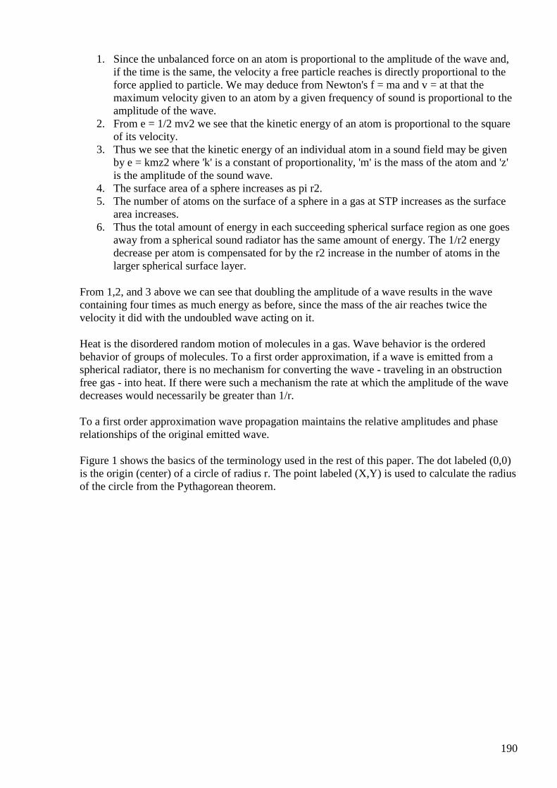
190
1. Since the unbalanced force on an atom is proportional to the amplitude of the wave and, if the time is the same, the velocity a free particle reaches is directly proportional to the force applied to particle. We may deduce from Newton's f = ma and v = at that the maximum velocity given to an atom by a given frequency of sound is proportional to the amplitude of the wave.
2. From e = 1/2 mv2 we see that the kinetic energy of an atom is proportional to the square of its velocity.
3. Thus we see that the kinetic energy of an individual atom in a sound field may be given by e = kmz2 where 'k' is a constant of proportionality, 'm' is the mass of the atom and 'z' is the amplitude of the sound wave.
4. The surface area of a sphere increases as pi r2. 5. The number of atoms on the surface of a sphere in a gas at STP increases as the surface
area increases. 6. Thus the total amount of energy in each succeeding spherical surface region as one goes
away from a spherical sound radiator has the same amount of energy. The 1/r2 energy decrease per atom is compensated for by the r2 increase in the number of atoms in the larger spherical surface layer.
From 1,2, and 3 above we can see that doubling the amplitude of a wave results in the wave containing four times as much energy as before, since the mass of the air reaches twice the velocity it did with the undoubled wave acting on it.
Heat is the disordered random motion of molecules in a gas. Wave behavior is the ordered behavior of groups of molecules. To a first order approximation, if a wave is emitted from a spherical radiator, there is no mechanism for converting the wave - traveling in an obstruction free gas - into heat. If there were such a mechanism the rate at which the amplitude of the wave decreases would necessarily be greater than 1/r.
To a first order approximation wave propagation maintains the relative amplitudes and phase relationships of the original emitted wave.
Figure 1 shows the basics of the terminology used in the rest of this paper. The dot labeled (0,0) is the origin (center) of a circle of radius r. The point labeled (X,Y) is used to calculate the radius of the circle from the Pythagorean theorem.
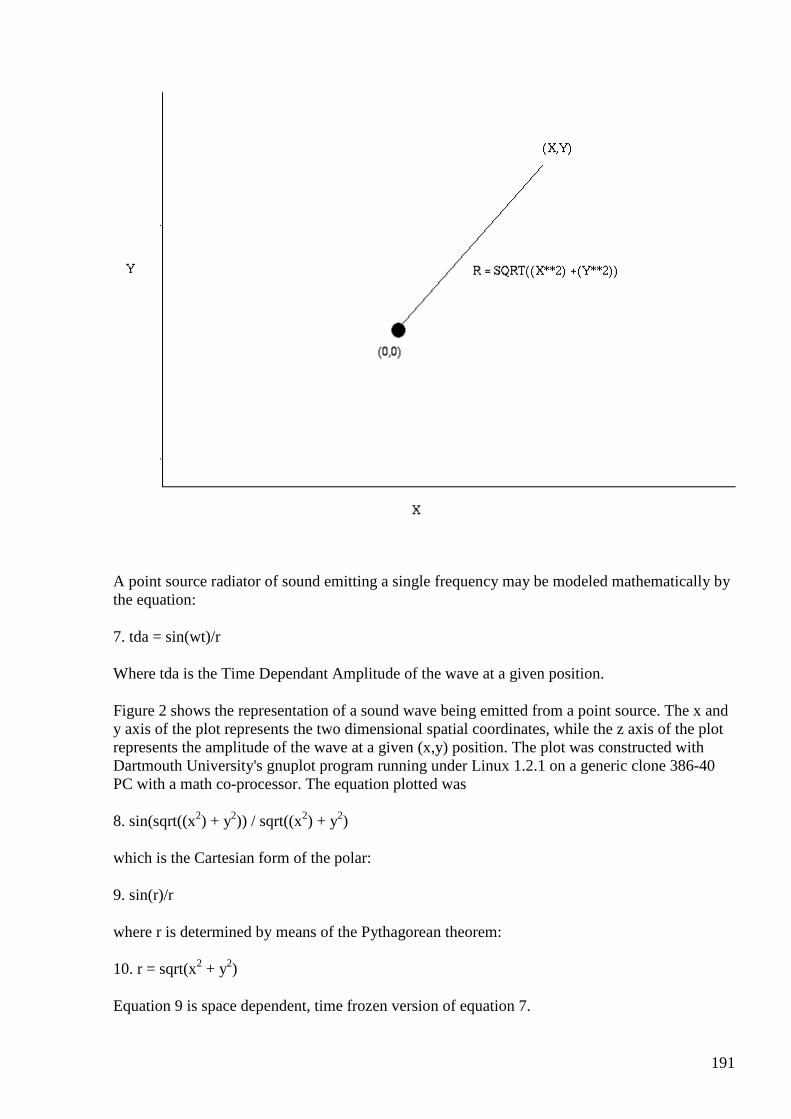
191
A point source radiator of sound emitting a single frequency may be modeled mathematically by the equation:
7. tda = sin(wt)/r
Where tda is the Time Dependant Amplitude of the wave at a given position.
Figure 2 shows the representation of a sound wave being emitted from a point source. The x and y axis of the plot represents the two dimensional spatial coordinates, while the z axis of the plot represents the amplitude of the wave at a given (x,y) position. The plot was constructed with Dartmouth University's gnuplot program running under Linux 1.2.1 on a generic clone 386-40 PC with a math co-processor. The equation plotted was
8. sin(sqrt((x2) + y2)) / sqrt((x2) + y2)
which is the Cartesian form of the polar:
9. sin(r)/r
where r is determined by means of the Pythagorean theorem:
10. r = sqrt(x2 + y2)
Equation 9 is space dependent, time frozen version of equation 7.
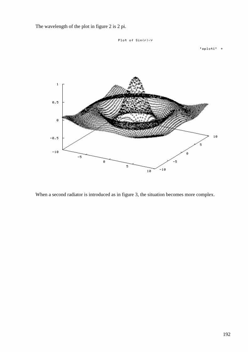
192
The wavelength of the plot in figure 2 is 2 pi.
When a second radiator is introduced as in figure 3, the situation becomes more complex.
193
In figure 3 we see two radiators, each displaced an equal distance +/-(b) from the origin on the X axis. In a fashion similar to figure 1 R is the radius of a circle centered on (0,0). The lines A and B represent the distance from the left and right radiators respectively to the point (X,Y) on the circle described by (0,0) and R. By constructing an imaginary right triangle the length of line A is given by:
11. A = sqrt((X+b)2 + Y2)
and the length of B is given by:
12. B = sqrt((X-b)2 + Y2)
The sound produced by the left radiator may be modeled by:
13. sin(A)/A
While the sound produced by the right radiator is given by:
14. sin(B)/B
The composite sound field from the two radiators may be given by:
15. sin(A)/A +/- sin(B)/B
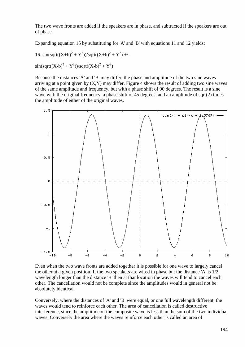
194
The two wave fronts are added if the speakers are in phase, and subtracted if the speakers are out of phase.
Expanding equation 15 by substituting for 'A' and 'B' with equations 11 and 12 yields:
16. sin(sqrt((X+b)2 + Y2))/sqrt((X+b)2 + Y2) +/-
sin(sqrt((X-b)2 + Y2))/sqrt((X-b)2 + Y2)
Because the distances 'A' and 'B' may differ, the phase and amplitude of the two sine waves arriving at a point given by (X,Y) may differ. Figure 4 shows the result of adding two sine waves of the same amplitude and frequency, but with a phase shift of 90 degrees. The result is a sine wave with the original frequency, a phase shift of 45 degrees, and an amplitude of sqrt(2) times the amplitude of either of the original waves.
Even when the two wave fronts are added together it is possible for one wave to largely cancel the other at a given position. If the two speakers are wired in phase but the distance 'A' is 1/2 wavelength longer than the distance 'B' then at that location the waves will tend to cancel each other. The cancellation would not be complete since the amplitudes would in general not be absolutely identical.
Conversely, where the distances of 'A' and 'B' were equal, or one full wavelength different, the waves would tend to reinforce each other. The area of cancellation is called destructive interference, since the amplitude of the composite wave is less than the sum of the two individual waves. Conversely the area where the waves reinforce each other is called an area of
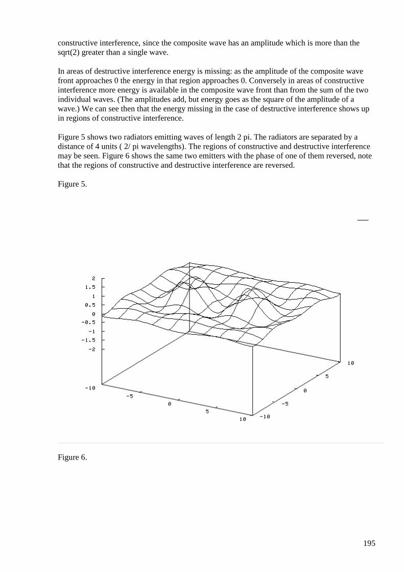
195
constructive interference, since the composite wave has an amplitude which is more than the sqrt(2) greater than a single wave.
In areas of destructive interference energy is missing: as the amplitude of the composite wave front approaches 0 the energy in that region approaches 0. Conversely in areas of constructive interference more energy is available in the composite wave front than from the sum of the two individual waves. (The amplitudes add, but energy goes as the square of the amplitude of a wave.) We can see then that the energy missing in the case of destructive interference shows up in regions of constructive interference.
Figure 5 shows two radiators emitting waves of length 2 pi. The radiators are separated by a distance of 4 units ( 2/ pi wavelengths). The regions of constructive and destructive interference may be seen. Figure 6 shows the same two emitters with the phase of one of them reversed, note that the regions of constructive and destructive interference are reversed.
Figure 5.
Figure 6.
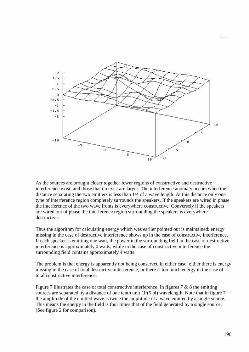
196
As the sources are brought closer together fewer regions of constructive and destructive interference exist, and those that do exist are larger. The interference anomaly occurs when the distance separating the two emitters is less than 1/4 of a wave length. At this distance only one type of interference region completely surrounds the speakers. If the speakers are wired in phase the interference of the two wave fronts is everywhere constructive. Conversely if the speakers are wired out of phase the interference region surrounding the speakers is everywhere destructive.
Thus the algorithm for calculating energy which was earlier pointed out is maintained: energy missing in the case of destructive interference shows up in the case of constructive interference. If each speaker is emitting one watt, the power in the surrounding field in the case of destructive interference is approximately 0 watts, while in the case of constructive interference the surrounding field contains approximately 4 watts.
The problem is that energy is apparently not being conserved in either case: either there is energy missing in the case of total destructive interference, or there is too much energy in the case of total constructive interference.
Figure 7 illustrates the case of total constructive interference. In figures 7 & 8 the emitting sources are separated by a distance of one tenth unit (1/(5 pi) wavelength. Note that in figure 7 the amplitude of the emitted wave is twice the amplitude of a wave emitted by a single source. This means the energy in the field is four times that of the field generated by a single source. (See figure 2 for comparison).
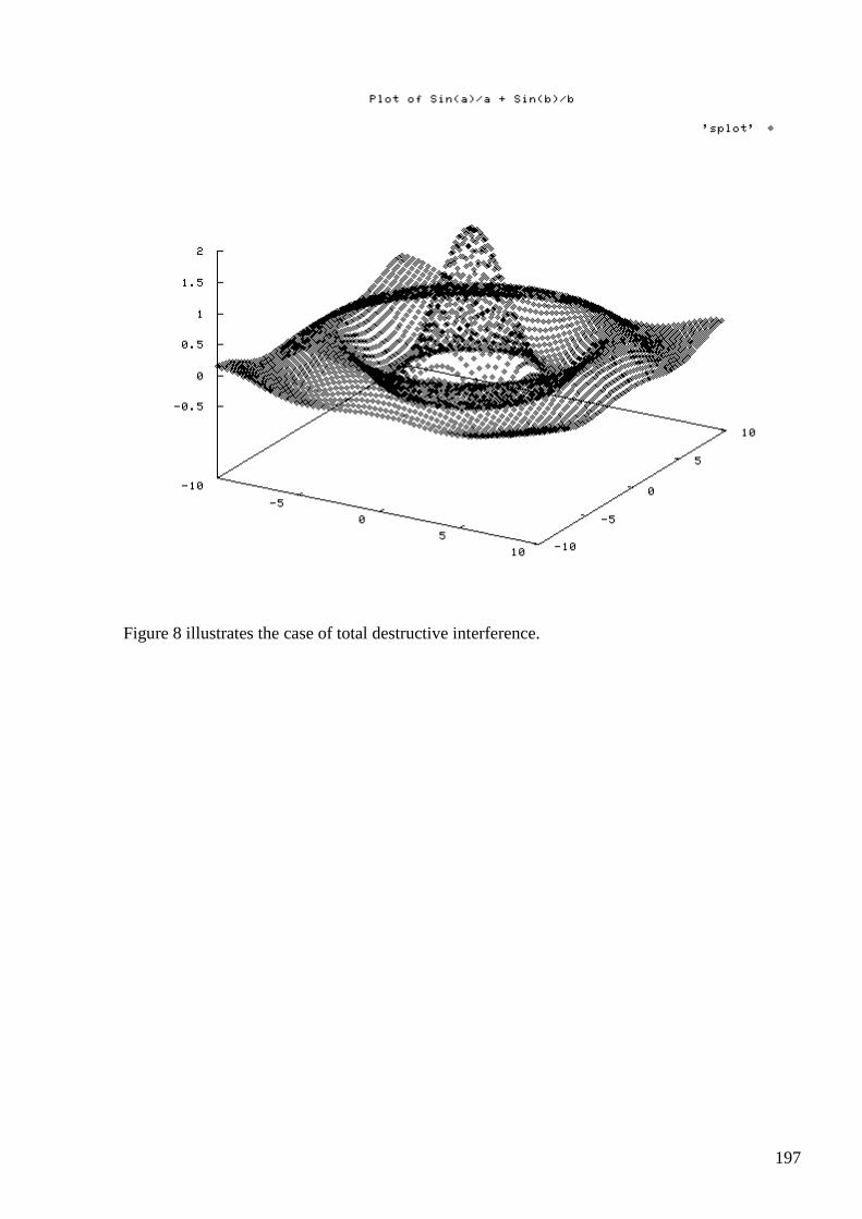
197
Figure 8 illustrates the case of total destructive interference.
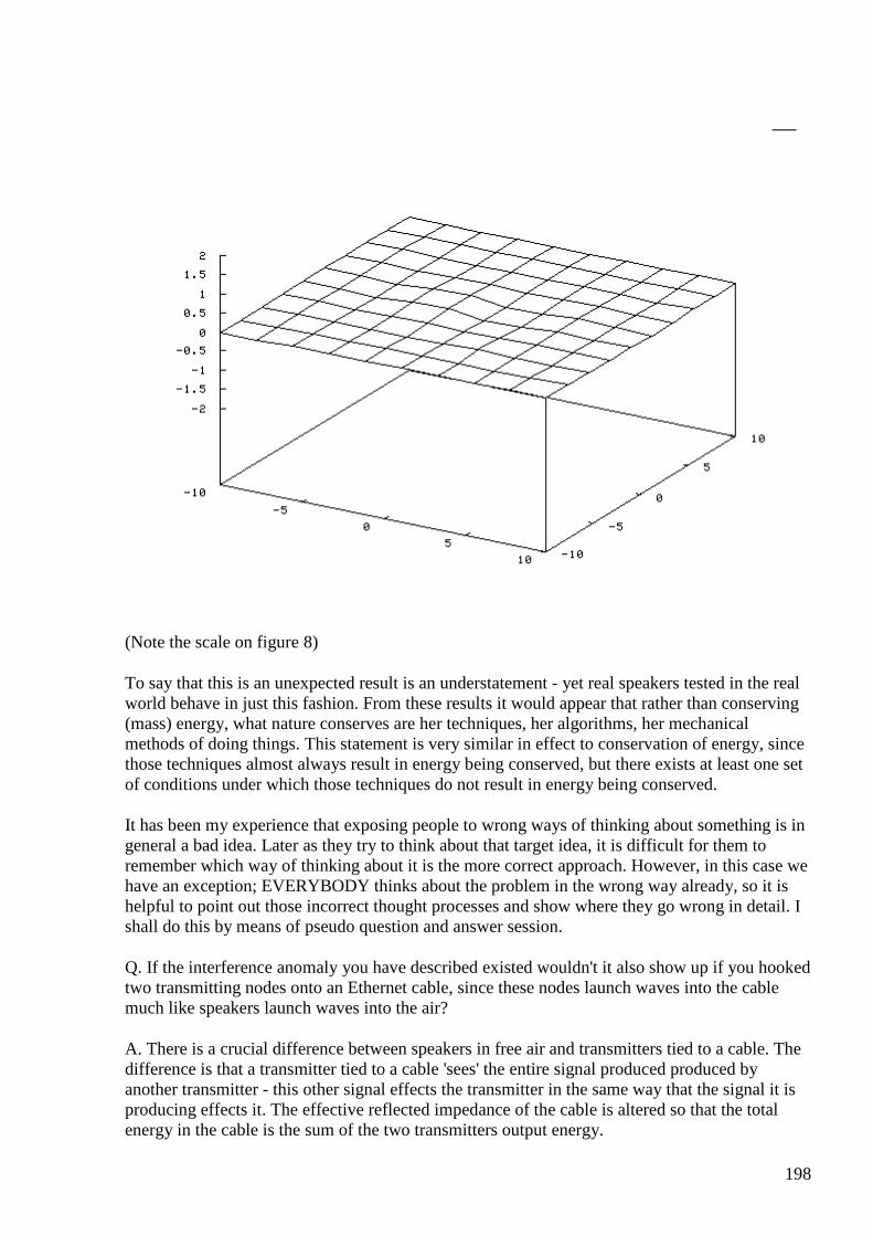
198
(Note the scale on figure 8)
To say that this is an unexpected result is an understatement - yet real speakers tested in the real world behave in just this fashion. From these results it would appear that rather than conserving (mass) energy, what nature conserves are her techniques, her algorithms, her mechanical methods of doing things. This statement is very similar in effect to conservation of energy, since those techniques almost always result in energy being conserved, but there exists at least one set of conditions under which those techniques do not result in energy being conserved.
It has been my experience that exposing people to wrong ways of thinking about something is in general a bad idea. Later as they try to think about that target idea, it is difficult for them to remember which way of thinking about it is the more correct approach. However, in this case we have an exception; EVERYBODY thinks about the problem in the wrong way already, so it is helpful to point out those incorrect thought processes and show where they go wrong in detail. I shall do this by means of pseudo question and answer session.
Q. If the interference anomaly you have described existed wouldn't it also show up if you hooked two transmitting nodes onto an Ethernet cable, since these nodes launch waves into the cable much like speakers launch waves into the air?
A. There is a crucial difference between speakers in free air and transmitters tied to a cable. The difference is that a transmitter tied to a cable 'sees' the entire signal produced produced by another transmitter - this other signal effects the transmitter in the same way that the signal it is producing effects it. The effective reflected impedance of the cable is altered so that the total energy in the cable is the sum of the two transmitters output energy.
199
However, in the case of two speakers radiating into free air, the couple between the two speakers is not 100% as it is in the case of transmitters on a cable. If the two speakers are physically small compared to the distance between them the energy coupling between them is poor.
For example let us assume that we have two speakers of radius one separated by a distance of 10 units. Because of the 1/r relationship of a sound field to distance, the signal strength of a speaker would only be 1/10 of the strength of signal the it produced by the time it reached the other speaker. Even were the speakers 100% efficient at producing and absorbing sound (i.e. they were perfect microphones as well as perfect speakers) the sound energy falling on the second speaker would only be 1% of the energy the first speaker produced. Thus the two speakers are hardly 'aware' of each others signal.
Q. Doesn't the air simply churn back and forth between the two radiators like a dipole if the speakers are wired out of phase?
A. To a certain extent the back and forth movement of the air does occur. If you look at the movement of the air under these circumstances you realize that it does not look like the normal loading which occurs under different conditions. Indeed if the speakers are closer than 1/4 wave apart instead of looking like a resistive load, the air between the speakers begins to resemble a simple mass. That is; there is movement, but very little compression which takes place.
Conversely if the speakers are wired in phase under these circumstances, the impedance of the air between the speakers resembles a spring, There is compression, but little movement. However, this is once again a second order effect, as the rest of the surrounding air continues to have primarily a resistive transmission line component to its impedance.
Neither a spring nor a mass (capacitive and inductive impedances in electrical terms) can serve as an energy sink - they do not absorb energy - it takes a combination of mass and spring to act as a transmission line, and thus as an infinite sink for energy.
Q. Exactly, doesn't this mass like quality of the air under out of phase conditions account for the missing energy - that is, doesn't the inductive property of the air prevent energy from being pumped into it?
A. No, please note that the capacitive spring like property of air during in phase conditions also won't act like an energy sink. Electrically the air surrounding a speaker could be modeled as a low impedance resistor in parallel with a high impedance, variable, inductor and capacitor network. Under out of phase conditions, the capacitor is adjusted to its highest impedance setting, and the inductor to its lowest.
Conversely during in phase operation the inductor is set to its highest impedance setting, while the capacitor is set to its lowest impedance setting. These adjustments have little effect on the over all behavior of the circuit because of the relative differences in the impedance of the reactive section to the resistive component of the circuit. The circuit remains primarily resistive in nature.
The real first order issues to be considered are:
• Are the equations I describe accurate to a first order approximation? • Do the equations predict the effect I describe? • Does an actual physical experiment confirm that the effect predicted by the equations
actually occurs?
200
Satisfy yourself in the following areas:
• Study the equations presented until you either find a first order error in them, or you are convinced of their correctness.
• Satisfy yourself through study of standard references that interference effects do work in the manner described.
• Wire up a set of physical infinite baffle speakers to an amplifier and a sine wave signal generator. Using a sound pressure meter investigate interference effects. Satisfy yourself that the equations do correctly describe interference conditions. Note that in areas of constructive interference the sound pressure rises by approximately 6db (4 times the power) compared to the sound pressure of a single speaker at the same volume setting. Note that in regions of destructive interference that the sound pressure drops by 20db (a factor of 100 in power) or more, compared to a single speaker. Adjust the frequency so that the conditions for the interference anomaly obtain:
o The radiating surface is small compared to the distance between the speakers. o The wave length of the sine wave being emitted is more than 4 times the distance
between the speakers. • Confirm that the power in the radiated field is approximately 6db higher than the power
radiated by a single speaker when the speakers are in phase. • Wire the speakers out of phase and confirm that the power in the radiated field is more
than 20db lower than the power radiated by a single speaker.
At the current time I am only entertaining questions or confirmations of the above first order issues. Don't write to me about second order effects like the near field antenna effect, or questions of speaker efficiency. First things first. It is only after everyone is satisfied on the first order issues that we may move on to second order cases.
Back to the home page email addresss: [email protected] Postscript:
One of the only things remaining from the certainty of nineteenth century physics is conservation of energy. Yet even that is not unchanged; first Einstein's discovery that mass and energy are two sides of the same coin changed conservation of energy into conservation of mass-energy. Secondly the way we look at conservation of energy has changed. What started as a conjecture, then became an important principle, then an inviolate law, has now become an item of religious dogma. Anyone who dares to question that dogma becomes the scientific equivalent of a heretic - a pariah to be cast from the house of physics.
Yet nothing in physics is properly dogma: all is hypothesis - to be discarded as soon as evidence to the contrary is presented.
There was once a movement in computer programming to construct programs only of algorithms which were provably correct; the idea being that a combination of provably correct routines would itself be free of error. That movement collapsed when it was realized that it was still possible to write programs full of errors even when using only provably correct routines. After all - each of the instructions for a typical microprocessor is free of error and provably correct - but it is still possible to write programs with those error free instructions which are themselves full of mistakes.
201
I believe that the case in physics is very similar: each of the laws of physics can be demonstrated to conserve energy - but that does not necessarily mean that combinations of those laws will be bug free.
In the years that this web page has been up only one professional physicist has bothered to investigate the claims made here. What he found was deeply disturbing to him: he found no error in my math or physics; the plots of interference patterns did indeed show a violation of conservation of energy - his independent reworking of the equations gave the same results. I furnished him with data on a simple experiment conducted with two real speakers, an amplifier and a sine wave generator. After inspecting my crude data gathered with a commercial sound pressure meter he agreed that the data tended to support the predictions of the equations. Even in a crude experiment such as I was able to run he was forced to admit that the effect did seem to exist.
He finally decided that the 'error' I was making had to lie in the fact that I was using simple superposition of waves instead of a rigorous 'exact' solution for the production of sound - since it was 'impossible' that a real violation of conservation of energy could occur. And here he found 'the problem'; the 'exact' solution for the emission of sound from a point 'guaranteed' that energy would be conserved mathematically; and that was enough for him to decide that he now had proven that all was right with the world. I did not think that it was my place to point out to him that the simple method I had used also conserved energy for a single speaker - that the whole point of the discussion was that it was only when more than one speaker interacted that the anomaly appeared. We parted ways cordially and no one since has done anything concerning the paper.
If there is anyone else who would care to look at this paper I would be more than happy to provide him with my admitidly crude experimental results to inspect.
#189 Re: [ferd] [reading] The Interference Anomaly
Andreas Höschler Mar 5 at 8:13 PM
Hi Alexey,
P.S. anyone still reading this group ? ;-)
Yes! Am bogged down again with lots of stuff but try hard to make progress …
Thanks for the link (put onto the list)! :-)
Best wishes,
Andreas
#190 Re: [ferd] [reading] The Interference Anomaly
202
Gerry Mar 5 11:50 PM
Hi Alexey, Andreas guys
Just returned from quick trip to nut farm, macadamia variety, lol.
Checked out the other link you sent though.
Looking forward to getting back into it here.
thanks Gerry
#191 Re: [reading] The Interference Anomaly
onielsen2000 Mar 7 at 6:02 AM
Hi Alexy, Just read the paper. This experiment is quite interesting. It demonstrates the energy generating effect using sound waves like Dr. Andrey Melnichenko discovered in his "Transgeneration" using microwaves. Janos Vajda proves it using mathematics: Janos Vajda: VIOLATION OF THE ENERGY THESIS IN WAVE-FIELD and W.B. Smith describes it as using coherence to take out energy from the cosmic background (second last paragraph in chapter X in "The New Science." Regards Ole
#192 RE: [ferd] Re: [reading] The Interference Anomaly
Alexey Mar 7 10:57 AM
Hi Ole,
It seems to be a universal effect because it observer with many different types of field.
Perhaps we can find a way use it for our goals. May be it will be easier build system based on sound waves ? …
Regards,
Alexey
#193 RE: [ferd] Re: [reading] The Interference Anomaly
203
onielsen2000 Mar 7 5:22 PM
Hi Alexy, When comparing the laws of physics the same formulas are used to describe different systems. This also means that the effect can be used on different systems and is also like using system equivalence to describe one system by making a simulation in a different system. Think of analog computers using electronic components to describe a mechanical system or vice versa. Or look at Tariel Kapanadze's mechanical self-runner (https://www.youtube.com/watch?v=3thvqFhFIfY) and compare it to his later electronic ones. I don't see why we shouldn't be able to use this principle when many others are already using it now. Regards Ole
#194 [ferd] Re: [reading] The Interference Anomaly
Gustavo Roveran Mar 8 at 7:02 AM
Hi All, Interesting. If we considering that em waves are spherical it would be possible to demonstrate that it isn't only for sound waves. I understand that and spherical wave presents a longitudinal component. PS: Yes of course, I am here reading the messages.
#195 Re: [ferd] Re: [reading] The Interference Anomaly
Gerry Mar 8 at 7:16 AM
Hi Alexey & Ole,
I found in my files a snippet (attached) talks about energy from these interference effects.
Gerry
LETTER & POEM FROM DONALD P. WALTON
204
From: NEN, Vol. 4, No. 2, June 1996, pp. 19-20.
New Energy News (NEN) copyright 1996 by Fusion Information Center, Inc. COPYING NOT ALLOWED without written permission. ALL RIGHTS RESERVED.
The quatrain previously submitted was inspired by the description of an experiment undertaken by a good friend formerly residing in Hawaii. He is an excellent engineer and also has many of the gifts associated with Edgar Cayce. So when he told me that this project arose from intuition, and had been undertaken successfully, I was cautiously optimistic. I am sure he would feel that information freely given is meant to be shared internationally.
From the quatrain many references are quoted which were studied by myself, e.g. Worrell-Keeley, Tom Beardon, Bhuddist and Hindu philosophy, plus many fringe science papers including publications on how the pyramids were really built and references to levitation by Bhuddist monks of Tibet. The NASA technical briefs on levitation were also investigated. If you assemble all the pieces of a jig-saw, then the whole picture is presented.
At this point a few extracts from his letter would seem appropriate:
"Each energy level has three unique frequencies, also due to the constructive and destructive interaction of the three frequencies produces a specific composite energy level." The levels may be designated 1 through 4, with 1 being the highest. For our purposes the frequencies are not important (they vary from 1021 to 1024). What s important is the relationship these frequencies have to each other within their respective energy levels.
By interfering the frequency relationship of the highest energy level such that the particular frequencies we choose generate earth resonances as one of its heterodynes, we can create a most powerful field that actively interferes with the earth's magnetic envelope.
The frequency ratios of that level are 1;4; and 5, or in musical terms: do, fa, so. By selecting as representative frequencies 48Hz; 64Hz; and 72Hz - but moving the three down just a hairsbreadth so that the heterodyne of the two highest frequencies becomes 7.83 Hz, we achieve just that.
Since the quality of the actual energy level is that of Scalar Standing Waves, longitudinal in nature, using sound waves can simulate or mirror their interaction if the medium through which we convey them is ionic.
I set up a waveguide with three arms converging to a center, each on a 120 degrees leg. Each leg was cut from square cross-section PVC gutter pipe and measured to correspond to an exact fraction of the wavelength for one of the frequencies, that is 12, 9 and 8 inches or multiples thereof. Transducers capable of producing 120dB in the medium selected must be used and these are placed at the ends of the cavities. Measurement is done from the face of the transducer to the point of intersection."
Generating the required frequencies is relatively straightforward and we should start with a master oscillator with fine incremental tuning operating at 576Hz, this is coupled to three buffer amplifiers whose outputs are taken to: 1. A divide by 8 which = 72Hz 2. A divide by 9 which = 64Hz 3. A divide by 12 which = 48Hz.
All three are then taken via a square to sin convertor and to the transducers vial power amplifiers. Not being partial to noise, not least 3 x 120dB, I am considering the possibility of alternatives to the above. Do beware of "Pop" music groups standing in a circle, do not stand at the focal point or you might just become closer to heaven than you would wish.

205
**No claims are made by myself and the above is passed on purely as a gift. On the basis of my own investigation I would suggest there is a better than average chance of success.
Yours sincerely, Donald P. Walton
A Quatrain for Today's Boffins (Can anyone rise to the challenge?) In ancient times monks of Tibet With music found that they could get Rocks and stones to levitate - Against the laws of gravitation In disbelief by western nations. Around about 1895, a Keeley boffin did arrive, It's elementary, you must be fools, It's all related to intervals. Not only that, but he had a notion, How to create perpetual motion. Some years later the American nation Saw in print this revelation. The government were not impressed, They declared it SECRET with great zest. It is quite laughable to say I was attempted by N.S., S.A. From what they published there's no doubt They haven't much to shout about. THESE MONKS KNEW A THING OR TWO. Three frequencies must be played in bursts, All three below 100 Hertz, And if you've got the signals right, You will behold a wondrous sight. REMEMBER THE INDIAN ROPE TRICK. Although it has not yet been stated, Schuman frequencies are related. Combine this with what Keeley said, See objects float above your head. To get results don't throw the dice, Geometry must be precise. If you would rise above your station Be sure to use the right equation. Think carefully, don't be naive, Standing waves you must achieve. Tonight before you go to bed
206
Think on what Tom Beardon said. If you would build a pyramid Do what the Tibetans did. I'm sure by now you all well see - A need for mental agility... May the FORCE be with you..
Donald P. Walton (Apologies to Nostradamus)
#196 RE: [ferd] Re: [reading] The Interference Anomaly
Alexey Mar 8 at 11:59 AM
"Tonight before you go to bed Think on what Tom Beardon said." ha ha
#197 [ferd] Re: [reading] The Interference Anomaly
Gustavo Roveran Mar 8 at 3:48 PM
Hi Alexey, I have " Energy from the Vacuum" book written by Bearden. I bought it 11 years ago. Should I have to read it again? Btw I think that cemf could be understood as a second source, with time delay. Would there be a way to implement a transformer where the core with primary and secondary were calculated to generate this interference anomaly? I found this document with relation to this concept, I did not finish to read it yet. http://www.vasantcorporation.com/downloads/Delayed_Lenzs_Law_04-27-2014.pdf Regards Gustavo
#198 RE: [ferd] Re: [reading] The Interference Anomaly
Alexey Mar 8 at 4:07 PM
Hi Gustavo,
Well, you could read Bearden again, but for myself I decided that I stop wasting time and trying understand this nonsense.
207
He had several working FE devices at hand and didn’t care share details in a normal understandable way.
For me that is a clear indication of his real intentions.
I tend to think that separation between action and reaction is a mathematical abstraction and does not exist in real world…
Regards,
Alexey
#199 [ferd] Re: [reading] The Interference Anomaly
Gustavo Roveran Mar 8 at 4:36 PM
Hi Gerry, I wrote a message that was lost I am rewriting it. It was a funny poem but I remember that the first time I read about Tibetans technic was in a David Wilcock document. And there was a little graph the represents the way tibetans stand around the rock and some of the musical instruments they used. Regards Gustavo
#200 Re: [ferd] Re: [reading] The Interference Anomaly
onielsen2000 Mar 8 at 5:37 PM
Acoustic Levitation Of Stones
http://www.bibliotecapleyades.net/ciencia/antigravityworldgrid/ciencia_antigravityworldgrid08.htm
Acoustic Levitation Of Stones Acoustic Levitation Of Stones by Bruce Cathie Monastery construction, Tibetan style according to Swedish Designer Henry Kjellson ...
View on www.bibliotecapleya... Preview
by

208
Yahoo
/Ole
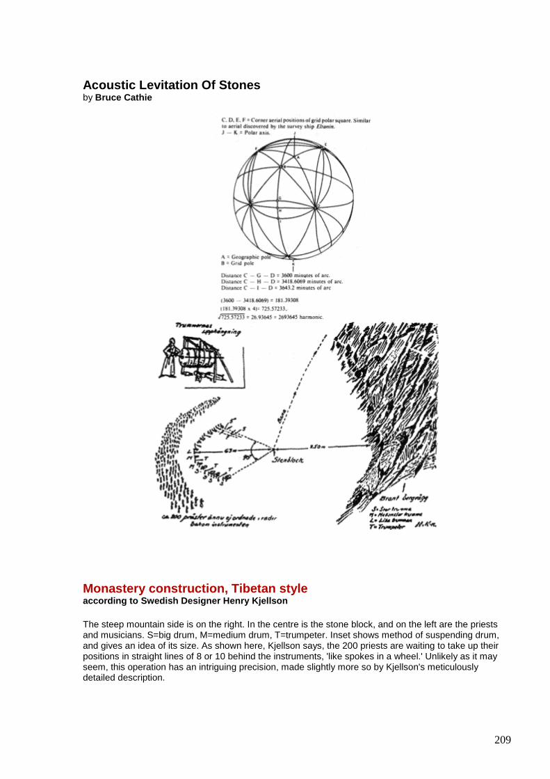
209
Acoustic Levitation Of Stones by Bruce Cathie
Monastery construction, Tibetan style according to Swedish Designer Henry Kjellson The steep mountain side is on the right. In the centre is the stone block, and on the left are the priests and musicians. S=big drum, M=medium drum, T=trumpeter. Inset shows method of suspending drum, and gives an idea of its size. As shown here, Kjellson says, the 200 priests are waiting to take up their positions in straight lines of 8 or 10 behind the instruments, 'like spokes in a wheel.' Unlikely as it may seem, this operation has an intriguing precision, made slightly more so by Kjellson's meticulously detailed description.
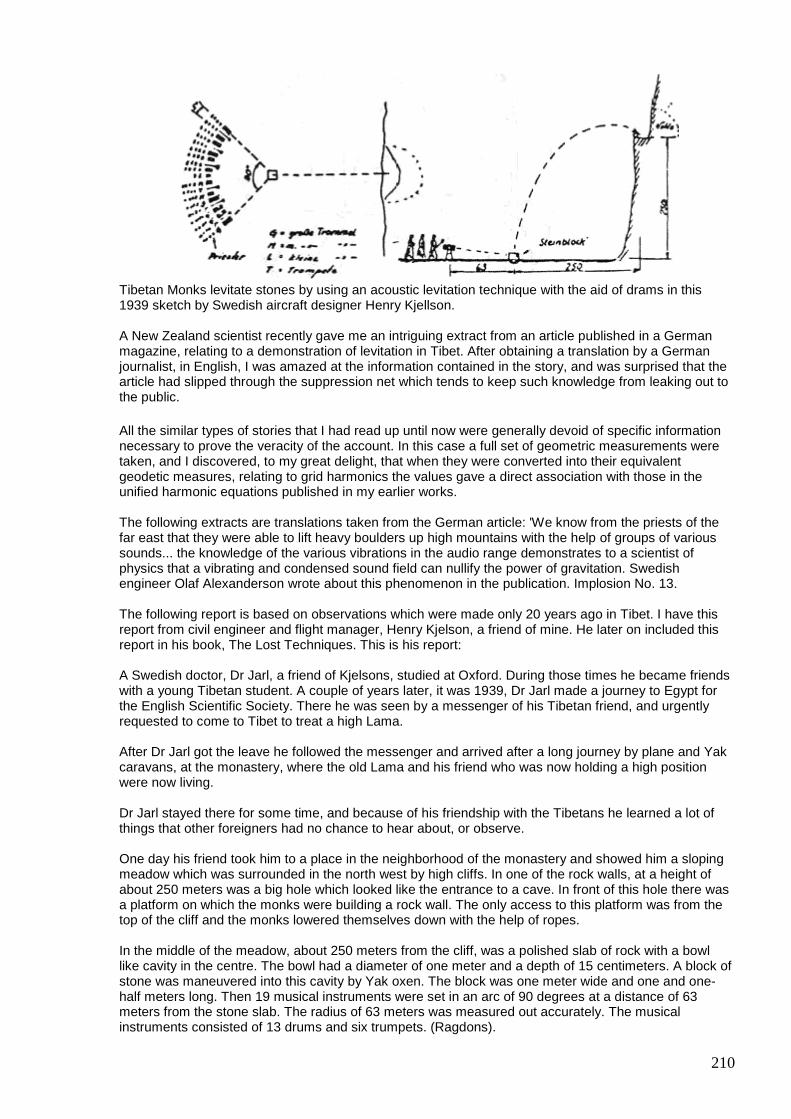
210
Tibetan Monks levitate stones by using an acoustic levitation technique with the aid of drams in this 1939 sketch by Swedish aircraft designer Henry Kjellson. A New Zealand scientist recently gave me an intriguing extract from an article published in a German magazine, relating to a demonstration of levitation in Tibet. After obtaining a translation by a German journalist, in English, I was amazed at the information contained in the story, and was surprised that the article had slipped through the suppression net which tends to keep such knowledge from leaking out to the public. All the similar types of stories that I had read up until now were generally devoid of specific information necessary to prove the veracity of the account. In this case a full set of geometric measurements were taken, and I discovered, to my great delight, that when they were converted into their equivalent geodetic measures, relating to grid harmonics the values gave a direct association with those in the unified harmonic equations published in my earlier works. The following extracts are translations taken from the German article: 'We know from the priests of the far east that they were able to lift heavy boulders up high mountains with the help of groups of various sounds... the knowledge of the various vibrations in the audio range demonstrates to a scientist of physics that a vibrating and condensed sound field can nullify the power of gravitation. Swedish engineer Olaf Alexanderson wrote about this phenomenon in the publication. Implosion No. 13. The following report is based on observations which were made only 20 years ago in Tibet. I have this report from civil engineer and flight manager, Henry Kjelson, a friend of mine. He later on included this report in his book, The Lost Techniques. This is his report: A Swedish doctor, Dr Jarl, a friend of Kjelsons, studied at Oxford. During those times he became friends with a young Tibetan student. A couple of years later, it was 1939, Dr Jarl made a journey to Egypt for the English Scientific Society. There he was seen by a messenger of his Tibetan friend, and urgently requested to come to Tibet to treat a high Lama. After Dr Jarl got the leave he followed the messenger and arrived after a long journey by plane and Yak caravans, at the monastery, where the old Lama and his friend who was now holding a high position were now living. Dr Jarl stayed there for some time, and because of his friendship with the Tibetans he learned a lot of things that other foreigners had no chance to hear about, or observe. One day his friend took him to a place in the neighborhood of the monastery and showed him a sloping meadow which was surrounded in the north west by high cliffs. In one of the rock walls, at a height of about 250 meters was a big hole which looked like the entrance to a cave. In front of this hole there was a platform on which the monks were building a rock wall. The only access to this platform was from the top of the cliff and the monks lowered themselves down with the help of ropes. In the middle of the meadow, about 250 meters from the cliff, was a polished slab of rock with a bowl like cavity in the centre. The bowl had a diameter of one meter and a depth of 15 centimeters. A block of stone was maneuvered into this cavity by Yak oxen. The block was one meter wide and one and one-half meters long. Then 19 musical instruments were set in an arc of 90 degrees at a distance of 63 meters from the stone slab. The radius of 63 meters was measured out accurately. The musical instruments consisted of 13 drums and six trumpets. (Ragdons).
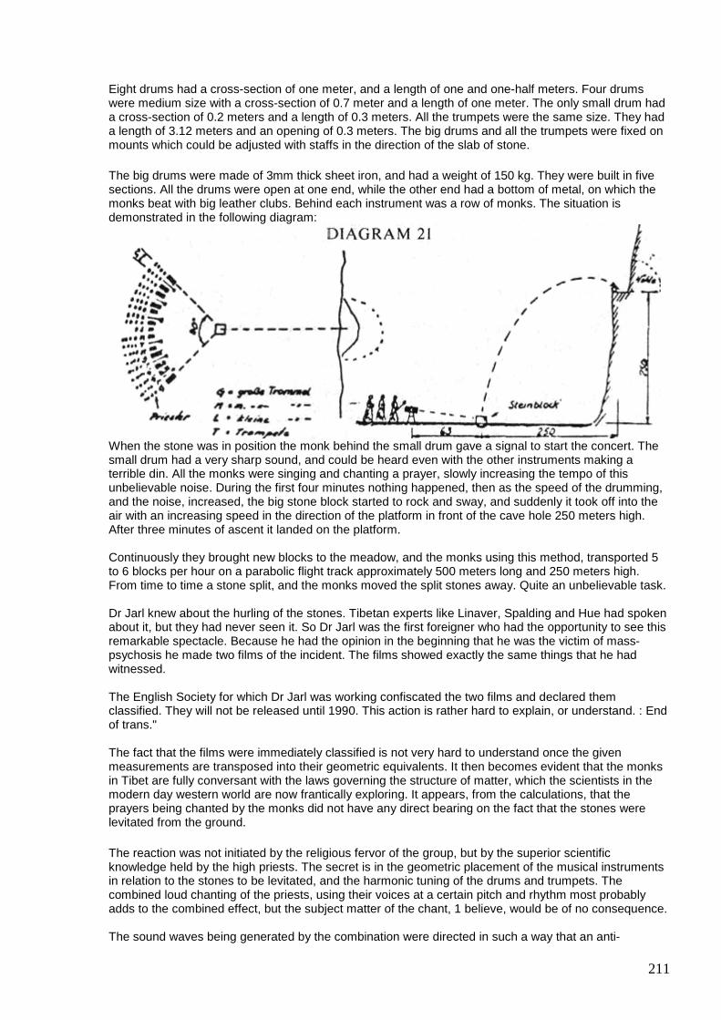
211
Eight drums had a cross-section of one meter, and a length of one and one-half meters. Four drums were medium size with a cross-section of 0.7 meter and a length of one meter. The only small drum had a cross-section of 0.2 meters and a length of 0.3 meters. All the trumpets were the same size. They had a length of 3.12 meters and an opening of 0.3 meters. The big drums and all the trumpets were fixed on mounts which could be adjusted with staffs in the direction of the slab of stone. The big drums were made of 3mm thick sheet iron, and had a weight of 150 kg. They were built in five sections. All the drums were open at one end, while the other end had a bottom of metal, on which the monks beat with big leather clubs. Behind each instrument was a row of monks. The situation is demonstrated in the following diagram:
When the stone was in position the monk behind the small drum gave a signal to start the concert. The small drum had a very sharp sound, and could be heard even with the other instruments making a terrible din. All the monks were singing and chanting a prayer, slowly increasing the tempo of this unbelievable noise. During the first four minutes nothing happened, then as the speed of the drumming, and the noise, increased, the big stone block started to rock and sway, and suddenly it took off into the air with an increasing speed in the direction of the platform in front of the cave hole 250 meters high. After three minutes of ascent it landed on the platform. Continuously they brought new blocks to the meadow, and the monks using this method, transported 5 to 6 blocks per hour on a parabolic flight track approximately 500 meters long and 250 meters high. From time to time a stone split, and the monks moved the split stones away. Quite an unbelievable task. Dr Jarl knew about the hurling of the stones. Tibetan experts like Linaver, Spalding and Hue had spoken about it, but they had never seen it. So Dr Jarl was the first foreigner who had the opportunity to see this remarkable spectacle. Because he had the opinion in the beginning that he was the victim of mass-psychosis he made two films of the incident. The films showed exactly the same things that he had witnessed. The English Society for which Dr Jarl was working confiscated the two films and declared them classified. They will not be released until 1990. This action is rather hard to explain, or understand. : End of trans." The fact that the films were immediately classified is not very hard to understand once the given measurements are transposed into their geometric equivalents. It then becomes evident that the monks in Tibet are fully conversant with the laws governing the structure of matter, which the scientists in the modern day western world are now frantically exploring. It appears, from the calculations, that the prayers being chanted by the monks did not have any direct bearing on the fact that the stones were levitated from the ground. The reaction was not initiated by the religious fervor of the group, but by the superior scientific knowledge held by the high priests. The secret is in the geometric placement of the musical instruments in relation to the stones to be levitated, and the harmonic tuning of the drums and trumpets. The combined loud chanting of the priests, using their voices at a certain pitch and rhythm most probably adds to the combined effect, but the subject matter of the chant, 1 believe, would be of no consequence. The sound waves being generated by the combination were directed in such a way that an anti-
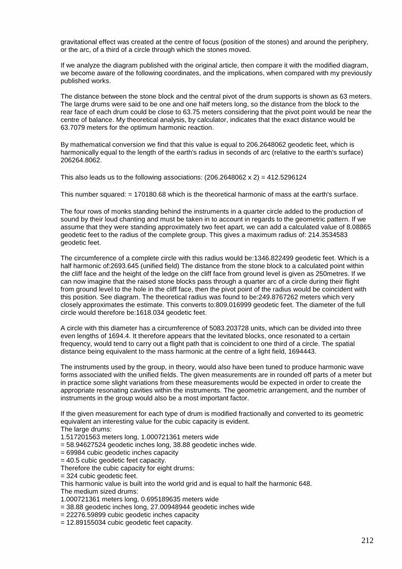
212
gravitational effect was created at the centre of focus (position of the stones) and around the periphery, or the arc, of a third of a circle through which the stones moved. If we analyze the diagram published with the original article, then compare it with the modified diagram, we become aware of the following coordinates, and the implications, when compared with my previously published works. The distance between the stone block and the central pivot of the drum supports is shown as 63 meters. The large drums were said to be one and one half meters long, so the distance from the block to the rear face of each drum could be close to 63.75 meters considering that the pivot point would be near the centre of balance. My theoretical analysis, by calculator, indicates that the exact distance would be 63.7079 meters for the optimum harmonic reaction. By mathematical conversion we find that this value is equal to 206.2648062 geodetic feet, which is harmonically equal to the length of the earth's radius in seconds of arc (relative to the earth's surface) 206264.8062. This also leads us to the following associations: (206.2648062 x 2) = 412.5296124 This number squared: = 170180.68 which is the theoretical harmonic of mass at the earth's surface. The four rows of monks standing behind the instruments in a quarter circle added to the production of sound by their loud chanting and must be taken in to account in regards to the geometric pattern. If we assume that they were standing approximately two feet apart, we can add a calculated value of 8.08865 geodetic feet to the radius of the complete group. This gives a maximum radius of: 214.3534583 geodetic feet. The circumference of a complete circle with this radius would be:1346.822499 geodetic feet. Which is a half harmonic of:2693.645 (unified field) The distance from the stone block to a calculated point within the cliff face and the height of the ledge on the cliff face from ground level is given as 250metres. If we can now imagine that the raised stone blocks pass through a quarter arc of a circle during their flight from ground level to the hole in the cliff face, then the pivot point of the radius would be coincident with this position. See diagram. The theoretical radius was found to be:249.8767262 meters which very closely approximates the estimate. This converts to:809.016999 geodetic feet. The diameter of the full circle would therefore be:1618.034 geodetic feet. A circle with this diameter has a circumference of 5083.203728 units, which can be divided into three even lengths of 1694.4. It therefore appears that the levitated blocks, once resonated to a certain frequency, would tend to carry out a flight path that is coincident to one third of a circle. The spatial distance being equivalent to the mass harmonic at the centre of a light field, 1694443. The instruments used by the group, in theory, would also have been tuned to produce harmonic wave forms associated with the unified fields. The given measurements are in rounded off parts of a meter but in practice some slight variations from these measurements would be expected in order to create the appropriate resonating cavities within the instruments. The geometric arrangement, and the number of instruments in the group would also be a most important factor. If the given measurement for each type of drum is modified fractionally and converted to its geometric equivalent an interesting value for the cubic capacity is evident. The large drums: 1.517201563 meters long, 1.000721361 meters wide = 58.94627524 geodetic inches long, 38.88 geodetic inches wide. = 69984 cubic geodetic inches capacity = 40.5 cubic geodetic feet capacity. Therefore the cubic capacity for eight drums: = 324 cubic geodetic feet. This harmonic value is built into the world grid and is equal to half the harmonic 648. The medium sized drums: 1.000721361 meters long, 0.695189635 meters wide = 38.88 geodetic inches long, 27.00948944 geodetic inches wide = 22276.59899 cubic geodetic inches capacity = 12.89155034 cubic geodetic feet capacity.
213
Therefore the cubic capacity for four drums: = 51.56620136 cubic geodetic feet. 14.97414932 centimeters = 5.895334377 inches -5.817764187 geodetic inches = 0.484813682 geodetic feet. As the dish-shape was focused upwards towards the stone block to be levitated it would be expected that some type of reaction would take place which had an effect on the mass. The geometric shape of the cavity does seem to be engineered in such a way that the projected frequency vortex causes a reciprocal reaction to the mass harmonic of each block. The reciprocal of: 0.484813682 = 2.062648055 Twice this value: = 4.12529611 The square of this value: = 17.018068 (the harmonic of mass at the earth's surface, 17018068) I believe that there is not much doubt that the Tibetans had possession of the secrets relating to the geometric structure of matter, and the methods of manipulating the harmonic values, but it we can grasp the mathematical theory behind the incident, and extend the application, then an even more fascinating idea presents itself. In my last book I mentioned the flying machines described in ancient records, that flew through the air with a melodious sound, and theorized that the sonic apparatus was tuned to the harmonic unified equations. Now the Tibetans have given us a direct indication of how to construct a sonically propelled anti-gravitational flying machine. All that is necessary is to complete the circle of sonic generators, indicated by the drums, trumpets, etc., and we have a disc which creates an anti-gravitational lifting force at the centre, (see diagram 23). To create this diagram I made four photo-copies of the original illustration showing the arrangement of drums, trumpets etc. and then cut out the 90 degree segments and fitted them together into a circular pattern. This was then photo-copied a second time in the relationship with a disc-shaped vehicle. When the circular pattern was formed it became evident that the Tibetans had placed the drums and trumpets on the arc of a quarter circle, but the placement of the Priests behind the drums tended to form a spiral. This conforms with the concept of the formation of matter due to the spiralling, vortexual, wave motions in space, discussed in my earlier works. Similar wave motions would have to be created in order to manipulate matter. The inner diameter of the sonic generators in the theoretical vehicle would be 412.5296 geodetic feet, with the previously described harmonic associations. The outer diameter, estimated from the placement of the Tibetan priests, would be 428.7069166 geodetic feet. If we square the inner diameter we have the harmonic of mass 17018068 relative to the earth's surface, and the outer diameter would give a circumference tuned to the unified equation. The lift vectors through the centre would resonate at harmonic frequencies in opposition to the mass value at the centre of a unified, or light, field = 1694443. From this it would appear that a vehicle could be constructed that would resonate at frequencies in sympathy with the unified fields demonstrated throughout this work. It is my opinion that our own scientific establishments are far ahead in this type of research, and that many experimental vehicles have already been constructed. High frequency generators have probably taken the place of the low frequency sonic methods, and electronic systems produced which would allow complete control of movement. With this type of research going on, I would say that the days of the conventional aeroplane are numbered.
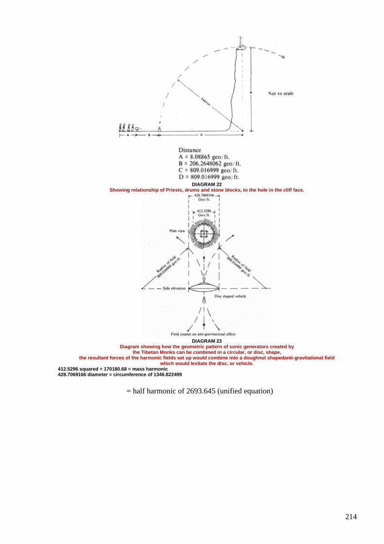
214
DIAGRAM 22
Showing relationship of Priests, drums and stone blocks, to the hole in the cliff face.
DIAGRAM 23
Diagram showing how the geometric pattern of sonic generators created by the Tibetan Monks can be combined in a circular, or disc, shape,
the resultant forces of the harmonic fields set up would combine into a doughnut shapedanti-gravitational field which would levitate the disc, or vehicle.
412.5296 squared = 170180.68 = mass harmonic 428.7069166 diameter = circumference of 1346.822499
= half harmonic of 2693.645 (unified equation)
215
#201 Re: [ferd] Re: [reading] The Interference Anomaly
Gustavo Roveran Mar 8 at 6:21 PM
Hi Ole,
That was exactly the graph a saw
Thanks
Gustavo
#202 Re: [ferd] Re: [reading] The Interference Anomaly
Gerry Mar 9 at 1:38 AM
Hi Gustavo, guys...
Thanks for info on David Wilcock, very interested to check out this and also video link too from Ole.
Gustavo I never read the "Free Energy from the Vacuum" book, but in the book "Free Energy Generation" by Bearden most of the useful stuff is written by Bedini, who seems a more hands on guy.
I have also the book "Spin Wave Technology" by Vasant corporation , it was given to me by the author George J Bugh for which I'm very grateful.
Alexey you seem to be a very skeptical about Beardon and to a certain extent I have to agree with you... a lot seems like useless "double talk and waffle".
It's OK to scoff, "ha ha" but we should keep open mind and not throw the whole baby out with the bath water.
If this was all you could find in the attachment, then I am sorry.
Separation of action and reaction is a proven real world concept, it lives in the realm of propagation delay.
It is not just a mathematical abstraction, here is a device by Greg Watson,
http://www.nanoworld.org.ru/data/01/data/club/overuni/pmod.htm
216
I just posted it to share, not to say I tried anything therein, I know all here have been trying for many years and we collect lot's of junk on the way.
In at least one of Telsa's patents he says to match the length of transformer primary to a quarter of the wavelength, if I remember correctly.
Gerry
#203 Re: [ferd] Re: [reading] The Interference Anomaly
Gerry Mar 9 at 2:03 AM
Hi guys,
Thanks for those very interesting links.
Found this modern day version on YouTube also https://www.youtube.com/watch?v=669AcEBpdsY&t=16
It is just a short clip.
Gerry
#204 Re: [ferd] Re: [reading] The Interference Anomaly
Gustavo Roveran Mar 9 at 3:09 AM
Hi Gerry,
Thank you for share your experience and opinion.
I did not finish to read the George J Bugh document I shared. Did you read it ?
Did you read some of the document from Robert Distinti, or watched some of his videos ?
Take care,
Gustavo
#205 Re: [ferd] Re: [reading] The Interference Anomaly
217
Gerry Mar 9 at 5:00 AM
Hey Gustavo,
Yes I did spend quite some time reading the Robert Distinti pages you linked to, I downloaded and read the "displacement dilemma" and also the "Secrets of qvxb".
I do not pretend to understand all of it, but the math that I could follow made sense to me.
Have not watched any of the Distinti videos, yet.
The George Bugh document is very much aligned with his book slight changes to the titles.
eg: pdf Heading "Lenz's Law and a Dynamo" is headed "Lenz's Law and a Generator" on page 57 of his book.
There's more detail in the book, but it is still a superficial treatise.
His book is very wide ranging and mainly generalised in nature, not really specific enough for our needs here (IMHO).
ciao amigo, Gerry
#206 RE: [ferd] Re: [reading] The Interference Anomaly
Alexey Mar 9 at 9:54 AM
Hi Gustavo,
You seems to like Distini’s work, I am wondering was you able find any practically useful information there?
Regards,
Alexey
#207 RE: [ferd] Re: [reading] The Interference Anomaly
Alexey Mar 9 at 9:59 AM
Hi Gerry,
” Alexey you seem to be a very skeptical about Beardon and to a certain extent I
have to agree with you... a lot seems like useless "double talk and waffle".
I propose very simple test, we know http://www.cheniere.org/ is Bearden’s web site.
218
Now try http://www.cheniere.com/
Can it be coincidence ? ha ha
Regards,
Alexey
#208 Re: [ferd] Re: [reading] The Interference Anomaly
Gerry Mar 9 11:51 AM
Hi Alexey,
I can't see what you are on about.
One is Tom Bearden's website the other is an oil company.
Tom Bearden is not mentioned on the board of directors.
Are we supposed to judge Mr. Bearden harshly for his "crime" in name of Oil company?
Sorry I think anyone deserves benefit of doubt, unless proven guilty.
Gerry.
#209 Re: [ferd] Re: [reading] The Interference Anomaly
vasik041 Mar 9 1:39 PM
Hi Gerry, I just find it is strange. But of course everyone can do own decisions and pay or not pay attention to such details ;-) Regards, Alexey
#210 Re: [ferd] Re: [reading] The Interference Anomaly
Gustavo Roveran Mar 10 3:23 AM
Hi Alexey,
219
The first two practical things I want to do is to test the cap-coil secondary transformer (and its different possible topologies) and to try and old trafo topology I had designed about the possibility to take profit from the retarded cemf.
The sound effects you have shared are really interesting to test too.
However, the understandings derived from practical ways of calculation that Distinti presented have catch my attention. I know that I have not the meticulous level you have, so I would like if you at least read some of the documents I have proposed (not the videos), and perhaps you could break the enchantment produced by Distinti in my mind.
;)
Gustavo
#211 Some device explanations
smokyatgroups Mar 11 9:38 AM
Hi Alexey, guys
Can you help?......... me having brain fade.
I found a detailed explanation of some devices in Melinchenko my files here, have attached it.
Was wondering if any of you guys could help me to understand Bogatyr's Device on page 3.
I don't quite understand how flux adds to double in one leg of core and somehow yet cancels later on.
best Gerry
#212 RE: [ferd] Some device explanations
Alexey Mar 11 7:46 PM
Hi Gerry,
There is a coil on a central core’s leg, it powered thru an inductor with a big inductance. This arrangement is similar to a permanent magnet inserted into central leg.
Big inductor in series with a coil will not allow current change and so magnetic field and flux thru central leg will be more or less stable.
This flux equally divided between two side core legs.
Coils on side legs arranged so that they have same direction and so sum flux will be canceled in one side leg and doubled in the other.
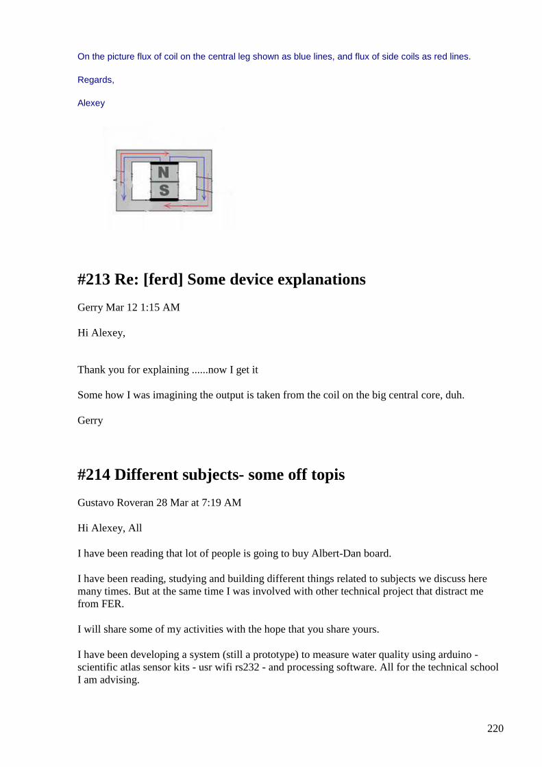
220
On the picture flux of coil on the central leg shown as blue lines, and flux of side coils as red lines.
Regards,
Alexey
#213 Re: [ferd] Some device explanations
Gerry Mar 12 1:15 AM
Hi Alexey,
Thank you for explaining ......now I get it
Some how I was imagining the output is taken from the coil on the big central core, duh.
Gerry
#214 Different subjects- some off topis
Gustavo Roveran 28 Mar at 7:19 AM
Hi Alexey, All
I have been reading that lot of people is going to buy Albert-Dan board.
I have been reading, studying and building different things related to subjects we discuss here many times. But at the same time I was involved with other technical project that distract me from FER.
I will share some of my activities with the hope that you share yours.
I have been developing a system (still a prototype) to measure water quality using arduino - scientific atlas sensor kits - usr wifi rs232 - and processing software. All for the technical school I am advising.

221
I have built three secondary cap-coil to add to the special transformer which seems to take profit from displacement current. Photo was added
I Built a static torsion field generator which consists in an aluminum pyramid. Photo was added
I was reading about vhdl, this technology would be really very interesting to develop very high speed logic circuits to control complex signals, like FER could need.
Finally I want to share this video from David Wilcock related to the investigation of the source field. David Wilcock - investigaciones sobre el campo de la fuente subtitulos español
https://www.youtube.com/watch?v=klvct1l0Gwg
David Wilcock - investigaciones sobre el campo de la fue...
Ver en www.youtube.com
Vista previa por Yahoo
Take care,
Gustavo
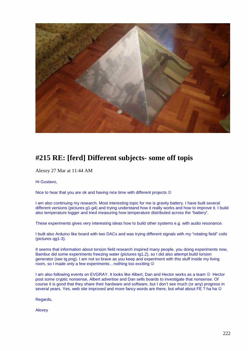
222
#215 RE: [ferd] Different subjects- some off topis
Alexey 27 Mar at 11:44 AM
Hi Gustavo,
Nice to hear that you are ok and having nice time with different projects
I am also continuing my research. Most interesting topic for me is gravity battery. I have built several different versions (pictures g1-g4) and trying understand how it really works and how to improve it. I build also temperature logger and tried measuring how temperature distributed across the “battery”.
These experiments gives very interesting ideas how to build other systems e.g. with audio resonance.
I built also Arduino like board with two DACs and was trying different signals with my “rotating field” coils (pictures qg1-3).
It seems that information about torsion field research inspired many people, you doing experiments now, Bambur did some experiments freezing water (pictures tg1,2), so I did also attempt build torsion generator (see tg.png). I am not so brave as you keep and experiment with this stuff inside my living room, so I made only a few experiments…nothing too exciting
I am also following events on EVGRAY. It looks like Albert, Dan and Hector works as a team Hector post some cryptic nonsense, Albert advertise and Dan sells boards to investigate that nonsense. Of course it is good that they share their hardware and software, but I don’t see much (or any) progress in several years. Yes, web site improved and more fancy words are there, but what about FE ? ha ha
Regards,
Alexey
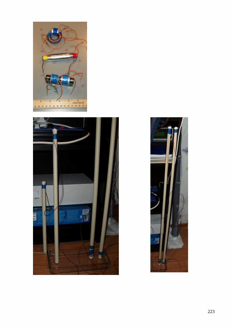
223

224
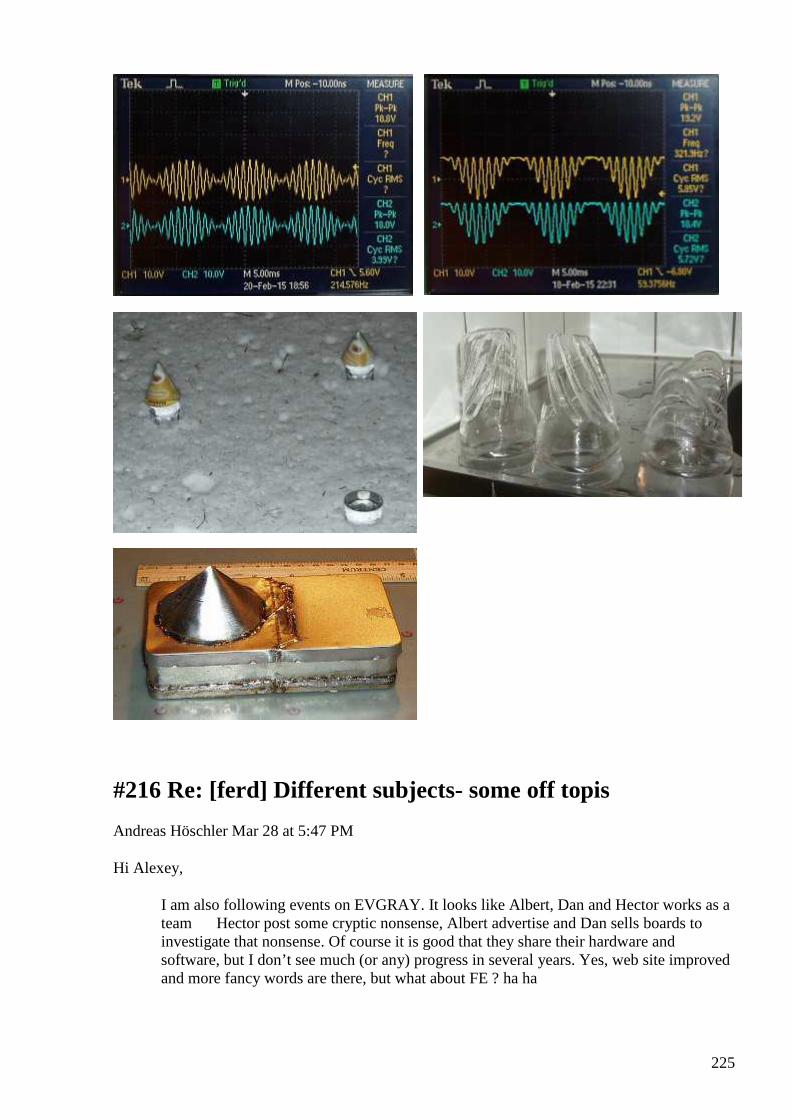
225
#216 Re: [ferd] Different subjects- some off topis
Andreas Höschler Mar 28 at 5:47 PM
Hi Alexey,
I am also following events on EVGRAY. It looks like Albert, Dan and Hector works as a team Hector post some cryptic nonsense, Albert advertise and Dan sells boards to investigate that nonsense. Of course it is good that they share their hardware and software, but I don’t see much (or any) progress in several years. Yes, web site improved and more fancy words are there, but what about FE ? ha ha
226
I agree that there is no FE anywhere yet on EVGRAY and definitely not on my bench top. But I appreciate the most recent development on EVGRAY (more cooperation). After having spent months on building an EMI-save H-Bridge with wire-wrapping technics I appreciate the availability of the tantratron board. I have ordered a couple and will give the board a try (ground plain,...). Meanwhile I have learned a lot about H-Bridge pitfalls and will share my findings here in case anyone is going to build one. I wished I had this experience/knowledge earlier. This would have saved me a lot of time:
• I found that once a MOSFET starts conducting the gate capacitance changes significantly which leads to extreme switch on-ringing (that tends to destroy the whole mess). I could get rid of this switch on ringing by adding a 22nF cap across gate and sink (thus there is less relative capacitance change) and increasing the gate resistance to 65 Ohm. This is a lot which means significant switch on losses but it at least works. Hopefully using the tantratron board with a reasonable ground plain will allow to reduce this resistance again a bit!?
• I was not able to get rid of the switch off ringing using the above mentioned technics though!? I finally (after months) found out that switch off ringing is caused by the diodes of the FWBR connected to the transformer secondary (again capacitance change when they start conducting) . Once I replaced the whole mess (FWBR, caps, load,...) connected to the secondary with a resistance (actually a light bulb) the ringing was completely gone and the signals nice and clean. Since my aim is a DC power supply I of course can't do that. However, this insight made me replace the FWBR of MUR diodes with very fast Schottky diodes. This did not completely solve the problem but at least reduced it. After Hectors latest H-Bridge autotransformer coil announcement and him mentioning that this autotransformer sucks away transients I thought what the heck, built one and tried it out in my DC power supply. And voila, the switch off ringing is not completely gone but significantly smaller, so much smaller that this might even work after all. :-)
I had this other idea of putting a 4.7R power resistor in series with the FWBR. This is an absolute no-go efficiency-wise but if this snubs away the transients and finally allows me to finish this project and look into real stuff again I will do it.
This said, I think it might me worth looking into the autotransformer design suggested by Hector. We might learn something from it. I surely will once I have closed the PS case.
All the best,
Andreas
BTW: Gustavo, thanks for your projects report. Interesting stuff ..
#217 [ferd] Different subjects- some off topis
Gustavo Roveran Mar 28 at 6:54 PM
Hi Andreas, Perhaps do you have this application note. But I am sharing it, just in case. Regards
227
Gustavo
#218 RE: [ferd] Different subjects- some off topis
Alexey Mar 28 at 7:01 PM
Hi Andreas,
I saw that you ordered boards on EVGRAY.
It is going to be first independent test of these boards.
Please let us know if they work good as advertised.
Regards,
Alexey
#219 Re: [ferd] Different subjects- some off topis
Andreas Höschler Mar 28 7:53 PM
Hi Alexey,
I saw that you ordered boards on EVGRAY.
It is going to be first independent test of these boards.
Please let us know if they work good as advertised.
I will! And I really hope they will. The PCBs are cheap, the parts aren't. Quite an investment! :-(
Best wishes,
Andreas
228
#220 Re: [ferd] Different subjects- some off topis
Andreas Höschler Mar 28 7:54 PM
Hi Gustavo,
Perhaps do you have this application note. But I am sharing it, just in case.
There was nothing attached to the mail!? :-(
Andreas
#221 [ferd] Different subjects- some off topis
Gustavo Roveran Mar 28 9:19 PM
Hi Andreas, Sorry this is the link http://web.mit.edu/6.131/www/document/float_drive.pdf Regards Gustavo
#222 Re: [ferd] Different subjects- some off topis
Andreas Höschler Mar 29 at 3:15 AM
Hi all, I have finally closed the power supply case! Thanks God! And thanks to all that gave helpful hints in this endeavour. I ended up way below my original objectives. But my last test was with a 125Ohm resistive load and I was able to regulate the voltage between 16V and 170V. This gives 200W! I have not yet tested heavier loads. The voltage limit is due to a 3:2 transformer ratio (or so) which reduces switching losses a lot. The efficiency of the beast is significantly > 80%. I was not yet able to integrate reasonable current measurement into the device. The modules I bought simply do not work and I was too lazy/exhausted after months of tinkering to build one from scratch (for now). But I can remote control the beast via a TCP-socket and at least read the output voltage (better than nothing). I am ready to rumble now ... :-) Best wishes

229
Andreas
#223 AuKW
Alexey Mar 29 at 8:39 PM
https://translate.googleusercontent.com/translate_c?depth=1&hl=en&rurl=translate.google.com&sl=auto&tl=en&u=http://gaia-energy.org/es-ist-soweit-mach-dich-energieautark/&usg=ALkJrhh4wN1-Qd1r73yeb-ZDwW7A_dFoBw https://www.youtube.com/watch?v=nsno0cxzd0I FACTS ON INVESTMENT PERFORMANCE: Net power: guaranteed for about 5 kilowatts Voltage: 230 VAC, single phase Daily output over 100 kWh, it is a potential annual energy crowd of over 36,500 kWh of electrical energy is obtained when to integrated operation 365 days OPERATION: The movement of the buoyancy tank is forwarded via a gearbox to a generator that produces electricity therefrom. A compressor continuously pumps air into the buoyancy tank to support their natural buoyancy. A special generator is tailored to suit these revolutions resistant and produces a total of more electricity than is benötig to obtain the movement. Here, the components used are partially protected. BENEFITS: Reduce the need for external power to a minimum! Support your existing heating with a strong heating cartridge including buffer and permanently save thousands of euros for fossil fuels! Operate a healthy infrared heating independent of energy providers with lowest cost! Create your own electricity for air conditioning systems and other electrical loads! As an entrepreneur, you increase your competitiveness by reducing your cost base! SERVICE & WARRANTY: Occasional visual inspections of the moving parts is recommended Monitoring of the system by an intelligent control Generators and compressors / pumps are produced by renowned industry suppliers and are certified components with 12 months warranty By a suitable filling the system should operate in winter easily COSTS: Unique € 14,160.00 EUR gross incl. Standard local VAT. The costs include the workshop and the complete material of construction of the plant. For individual connections necessary components such as rectifiers, backup batteries, 3-phase inverter, mounting hardware and other small parts are procured locally. Monthly cost about 15.00 € (maximum once a year to check mechanical components, replaced as
230
necessary.) Freight costs about 200-300 euros depending on the country, city and deliverability ... ;-)
#224 [ferd] Different subjects- some off topis
Gustavo Roveran Mar 29 11:27 PM
Hi Alexey, This message was lost as a draft. Thank you for sharing. I am also glad to hear about you and continuing researching. So you have 3 main courses of researching. Battery gravity, torsion fields and displacement current. Do you have a summary about that? The frozen water has a torsion effect ? What did he use to generate the torsion field? Regards Gustavo
#225 Re: [ferd] AuKW
Andreas Höschler Mar 29 11:39 PM
Hi Alexey,
https://translate.googleusercontent.com/translate_c?depth=1&hl=en&rurl=translate
.google.com&sl=auto&tl=en&u=http://gaia-energy.org/es-ist-soweit-mach-dich-
energieautark/&usg=ALkJrhh4wN1-Qd1r73yeb-ZDwW7A_dFoBw
https://www.youtube.com/watch?v=nsno0cxzd0I
FACTS ON INVESTMENT
PERFORMANCE:
Net power: guaranteed for about 5 kilowatts
Voltage: 230 VAC, single phase
Daily output over 100 kWh, it is a potential annual energy crowd of over 36,500 kWh of electrical
energy is obtained when to integrated operation 365 days
OPERATION:
The movement of the buoyancy tank is forwarded via a gearbox to a generator that produces
electricity therefrom. A compressor continuously pumps air into the buoyancy tank to support
their natural buoyancy. A special generator is tailored to suit these revolutions resistant and
231
produces a total of more electricity than is benötig to obtain the movement. Here, the components
used are partially protected.
Thanks for forwarding the links. Extremely interesting!!
Andreas
#226 [ferd] AuKW
Gustavo Roveran Mar 29 11:49 PM
Hi Alexey, Is it possible that this invention is not from Germany. I think that I saw this from Indian inventor. I have to search. Thank you for sharing. Gustavo
#227 RE: [ferd] Different subjects- some off topis
Alexey Mar 29 11:58 PM
Hi Gustavo,
”So you have 3 main courses of researching”
Actually I am looking for new ideas. Something really new and “fresh”. I consider all previous projects as a failed… nothing really practically useful came out.
Even I know that principles are ok, but always some obstacles come into action
Whether power is too small, or some special materials required or overall setup is so dangerous, that I don’t want build it at home…
” The frozen water has a torsion effect? What did he use to generate the torsion field? Water was frozen under small metallic pyramids (you can see it on tg1.png picture in original post)
Regards,
Alexey
232
#228 RE: [ferd] AuKW
Alexey Mar 29 11:58 PM
Hi Gustavo,
This idea was discussed on Russian forums somewhere in 2000, so it is ”open source” now…and still unconfirmed
Regards,
Alexey
#229 Re: [ferd] AuKW
Andreas Höschler Mar 29 at 12:22 AM
Hi all,
Is it possible that this invention is not from Germany. I think that I saw this from Indian inventor. I have to search.
Invention? Where do you see an invention here? The principle of operation is so simple that a kid could have come up with it 100 years ago! I see no invention! Engineering such a beast is the challenge at least if you want to do this at home on your own. If the parts are produced professionally in mass this could become a kicker.
I hope nobody is trying to patent this. I rather guess it has already been patented and the patent has expired eons ago!?
Every new building built from now on should have a slot from the cellar to the roof for such a beast.Such a slot costs almost nothing when planning a home building and at least allows to easily install such thing later on. This even makes a heat pump superfluous. With 5kW you can heat your home electrically.
Andreas
#230 RE: [ferd] AuKW
Alexey Mar 30 at 12:33 PM
Here a translation of a newspaper article found in the internet ;-)
By prescription of Leonardo da Vinci
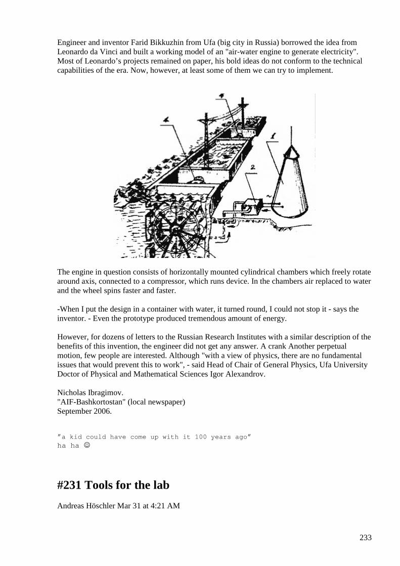
233
Engineer and inventor Farid Bikkuzhin from Ufa (big city in Russia) borrowed the idea from Leonardo da Vinci and built a working model of an "air-water engine to generate electricity". Most of Leonardo’s projects remained on paper, his bold ideas do not conform to the technical capabilities of the era. Now, however, at least some of them we can try to implement.
The engine in question consists of horizontally mounted cylindrical chambers which freely rotate around axis, connected to a compressor, which runs device. In the chambers air replaced to water and the wheel spins faster and faster. -When I put the design in a container with water, it turned round, I could not stop it - says the inventor. - Even the prototype produced tremendous amount of energy. However, for dozens of letters to the Russian Research Institutes with a similar description of the benefits of this invention, the engineer did not get any answer. A crank Another perpetual motion, few people are interested. Although "with a view of physics, there are no fundamental issues that would prevent this to work", - said Head of Chair of General Physics, Ufa University Doctor of Physical and Mathematical Sciences Igor Alexandrov. Nicholas Ibragimov. "AIF-Bashkortostan" (local newspaper) September 2006. ” a kid could have come up with it 100 years ago ” ha ha
#231 Tools for the lab
Andreas Höschler Mar 31 at 4:21 AM
234
Hi all, I made some progress today, at least tool-wise. The aim was to be able to continuously measure the input and output wattage of a setup and thus have a continuous display of the COP value. For the output wattage we of course use the math function of the scope. But what can we do to simultaneously measure the input wattage? A second digital multi channel scope would do the trick but is out of question money-wise. We therefore retrofit two UT61E multimeters. They are pretty cheap, offer a serial interface and with some tinkering can be equipped with a TCP-socket interface using WIZNet boards. See attached PDF:
Sorry for the noise (boring engineering stuff) but may be helpful nevertheless. Back to the real stuff ... Best wishes, Andreas
#232 RE: [ferd] Tools for the lab
Alexey Mar 31 at 9:32 AM
Hi Andreas,
Thanks for sharing!
Every small automation saves time and helps concentrate on main goal.
Regards,
Alexey
#233 Re: [ferd] AuKW
Gustavo Roveran Mar 31 at 6:44 PM
Hi Andreas, Alexey,
What I wanted to mean is, if this device really works as they say. If the response is yes, this is unbelievable why no body built one before. And if the concept is so obvious why we didn´t build it before, if we are fe researchers for so many years.
Regards,
Gustavo
#234 Re: [ferd] Tools for the lab

235
Gustavo Roveran Mar 31 at 6:50 PM
Hi Andreas,
This is a tool that every fe researcher must have.
Thanks,
Gustavo
#235 RE: [ferd] AuKW
Alexey Mar 31 at 7:26 PM
Hi Gustavo,
I would say same worlds as Igor Alexadrov - ”there are no fundamental issues that would prevent this to work".
”If the response is yes, this is unbelievable why no body built one before”
Well, some people did. I heard that there were small versions built at home using fish tank compressor… also several years ago there were message on EVGRAY that some farmer in America built huge system based on such principle…
“why we didn´t build it before, if we are fe researchers for so many years.”
If you want build one such system from scratch you have to spend huge amount of time and effort, so at the end it is not reasonable, until you are going to do it for fun. At the same time nobody will invest in such R&D… It is obvious for me that that this technology not compatible with current society. You can’t make money effectively with it
There are many “why” about which nobody cares… e.g. why most of modern products designed to fail in a short time? http://en.wikipedia.org/wiki/Planned_obsolescence ;-)
Regards,
Alexey
#236 Re: [ferd] AuKW
Andreas Höschler Mar 31 at 8:01 PM
Hi Gustavo and all,
What I wanted to mean is, if this device really works as they say. If the response is yes, this is unbelievable why no body built one before. And if the concept is so obvious why we didn´t build it before, if we are fe researchers for so many years.
236
I have thought this through a lot these days, even dared to make plans (just for fun) for building a new home with such a beast in the center of the building! :-) I have not yet made any calculations as to how much energy is required to compress air to the pressure of 5m water height. But I see no direct relation between this energy and the work performed by the uprising bottles full of air. So there might very well be a point where we reach break even or even excess energy. There are many non-technical reasons for not seeing this in every home yet. But let's concentrate on the technical difficulties here. How do we connect the air pressure outtake - more or less gas tight - to the rotating gas tanks with the whole setup moving all the time. This is an engineering challenge, I guess not for someone with hangars full of machinery but surely for me with my screwdriver and soldering iron. May be one could design the parts with some CAD software and get them professionally produced by whomever not telling what the parts are good for. This would be a major project probably beyond the means of most of us. To be honest I would prefer a smaller solid-state solution but we have looked for this for so long and ... Another advantage of the AuKW is it does not require fancy electronics and is thus EMP proof. :-)
Has anyone else wondered where the potential excess energy might come from? We are playing with gravity here??
Andreas
#237 Re: [ferd] Tools for the lab
Andreas Höschler Mar 31 at 8:03 PM
Hi Gustavo,
This is a tool that every fe researcher must have.
Thanks! :-)
Andreas
#238 RE: [ferd] AuKW
Alexey Mar 31 at 8:50 PM
Hi Andreas,
Another possible FE device using environmental heat – most abundant “free” energy source…
Also unlikely easy to build at home…
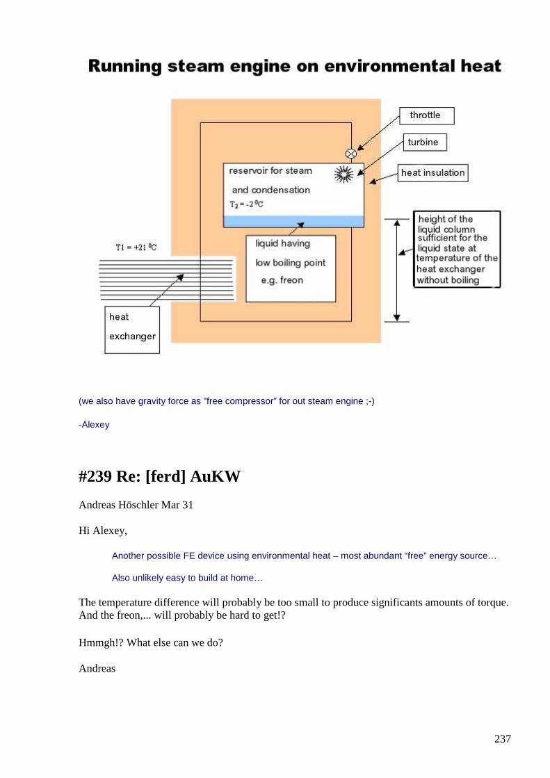
237
(we also have gravity force as ”free compressor” for out steam engine ;-)
-Alexey
#239 Re: [ferd] AuKW
Andreas Höschler Mar 31
Hi Alexey,
Another possible FE device using environmental heat – most abundant “free” energy source…
Also unlikely easy to build at home…
The temperature difference will probably be too small to produce significants amounts of torque. And the freon,... will probably be hard to get!?
Hmmgh!? What else can we do?
Andreas
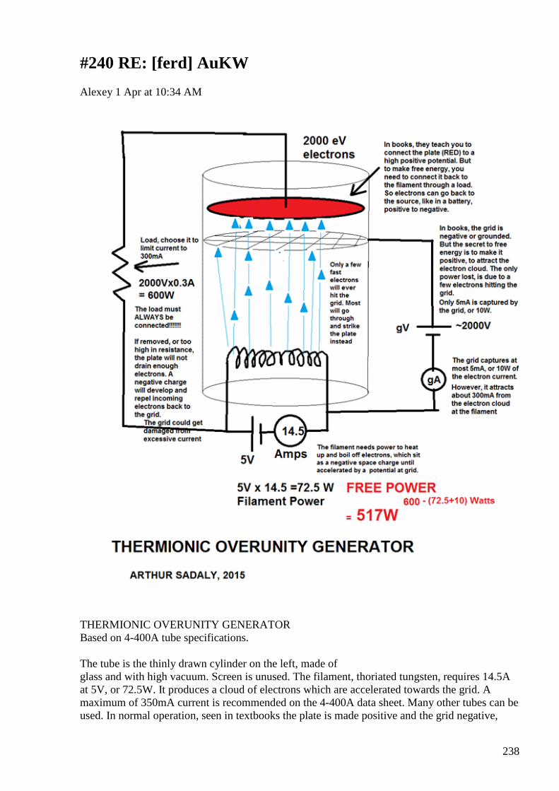
238
#240 RE: [ferd] AuKW
Alexey 1 Apr at 10:34 AM
THERMIONIC OVERUNITY GENERATOR Based on 4-400A tube specifications. The tube is the thinly drawn cylinder on the left, made of glass and with high vacuum. Screen is unused. The filament, thoriated tungsten, requires 14.5A at 5V, or 72.5W. It produces a cloud of electrons which are accelerated towards the grid. A maximum of 350mA current is recommended on the 4-400A data sheet. Many other tubes can be used. In normal operation, seen in textbooks the plate is made positive and the grid negative,
239
however, to produce free energy, we connect a positive voltage to the grid instead, and simply connect the plate to a load. Operation: The gV supply makes the grid highly positive, a few thousand volts normally. The cloud of electrons is accelerated to great speed towards the grid. Now, you would think that the electrons would all hit the grid and cause a large current to be shown at current meter gA , instead, just as described in the 1930’s Farnsworth multipactor patents ,most will pass straight through, because of the thin wire and large spaces used to make the grid, and also due to their great momentum. These electrons have great energy, in fact, 2000 eV or more, depending of the voltage used at the grid. The plate, collects these electrons and discharges them through a load, back to the filament, just like a battery does. The secret is to use the grid voltage to provide a potential but not as a current source! We are utilizing the 2000V potential to do work, but not draining it by allowing a current to flow.(5mA). Assuming a typical potential of 2000V at the grid and 305mA current. Some 5mA will be collected at the grid, under optimum tuning, leaving us with 300mA to flow through the load. 2000x300mA=600W. 600W-72.5W-10W=517 watts of real free energy. In 1957 our entire laboratory was shut down when we accidentally re-discovered this phenomenon, and foolishly, with good will, wrote an article to be published in Wireless World. People have been murdered trying to release such information to the public four years after the shutdown, please spread this information as widely as possible and quickly, I am old and don’t have long to live and I want this secret to be know to help the world in need. Textbooks will never show you this secret. With Love, A.S. 2015 ;-) PS http://en.wikipedia.org/wiki/Multipactor_effect
#241 tubes ;-)
Alexey 1 Apr at 11:15 AM
https://www.youtube.com/watch?feature=player_embedded&v=4KG3USFCkEA Tiger2007 Uploaded on Mar 14, 2011 Transcript: Ok, today we will make experiment to get free energy from vacuum tube based on effect of "explosive electron emission" Here our schematic We have a push-pull generator made of two transistors Modified high voltage transformer from TV It provides sinusoidal voltage about 2-3KV Here a typical voltage doubler but it connected to the vacuum tube The idea is to "knock" electrons fron catode and send them to anode and get extra power in the load Electric bulb (load) connected thru spark gap to achieve better tuning Ok, let's try First let's take a look on the setup
240
Here we have generator with two transistors here high voltage transformer here two high voltage diodes vacuum tube GM-70 (EC360) spark gap load, 100W light bulb power supply here we have two, battery and lab power supply because tube required heater voltage 20 volts Let's switch it on Here it is, we see heater is on, here spark gap, here 100w light bulb So, effect of "explosive electron emission" can be used to create extra current There is a problem that this mode of operation is critical for tubes Ok, let's switch it off Previously I used for this experiment different tubes 6P3C While adjusting setup I damaged them, they not supposed to be used in this mode But I can say that effect was much more intense So this tube GM-70 (used in RF transmitters) not operates in full capability Other tubes like 6p3s (6L6), 6p44 (ECC88) from TV used in line scan, HV modules, can be used to get free energy however the reliability of tubes in this mode raise some concerns that's all :-)
#242 1st April entertainment
Alexey 1 Apr at 1:21 PM
https://www.youtube.com/watch?v=PZ55zqrJt30 https://www.youtube.com/watch?v=_3mPnOj-f7g ;-)
#243 RE: [ferd] AuKW
onielsen2000 1 Apr at 3:30 PM
Hi Alexey, Very good find. I ordered a book from India explaining some of those effects inside tubes. Unfortunately it never arrived and was sold out when reordered. On Google books it stopped just where the important info was. These effects aren't explained in popular books about tubes. Perhaps it is time to get a big tube to play with. They are quite expensive as compared to
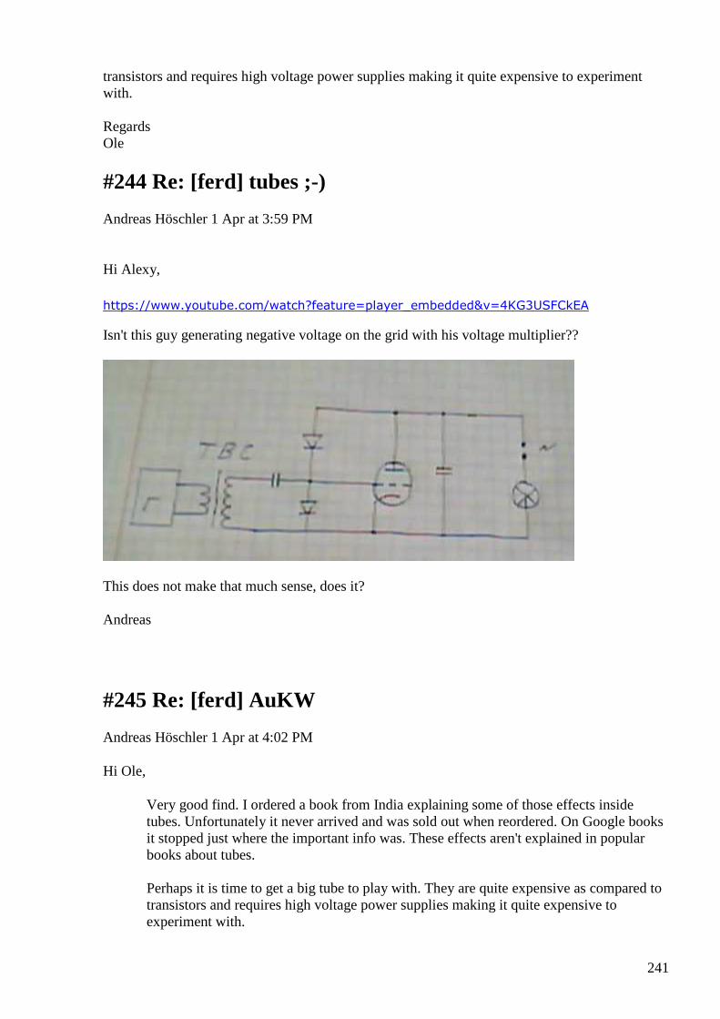
241
transistors and requires high voltage power supplies making it quite expensive to experiment with. Regards Ole
#244 Re: [ferd] tubes ;-)
Andreas Höschler 1 Apr at 3:59 PM
Hi Alexy, https://www.youtube.com/watch?feature=player_embedded&v=4KG3USFCkEA
Isn't this guy generating negative voltage on the grid with his voltage multiplier??
This does not make that much sense, does it? Andreas
#245 Re: [ferd] AuKW
Andreas Höschler 1 Apr at 4:02 PM
Hi Ole,
Very good find. I ordered a book from India explaining some of those effects inside tubes. Unfortunately it never arrived and was sold out when reordered. On Google books it stopped just where the important info was. These effects aren't explained in popular books about tubes. Perhaps it is time to get a big tube to play with. They are quite expensive as compared to transistors and requires high voltage power supplies making it quite expensive to experiment with.
242
I agree. We should look into this. I am convinced enough to give it a try. Have you already found a supply for a suitable tube?
Andreas
#246 Re: [ferd] AuKW
onielsen2000 1 Apr at 4:20 PM
Hi Andreas, No I have not looked into power supplies for tubes. It was just that Steven Mark recommended studying a double diode tube for strange effects. Regards Ole
#247 Re: [ferd] AuKW
Andreas Höschler 1 Apr at 5:07 PM
Hi Ole,
No I have not looked into power supplies for tubes. It was just that Steven Mark recommended studying a double diode tube for strange effects.
I was not referring to power supplies but to suppliers for these components and especially selecting a suitable one for a test.
How far fetched is it to build tubes on our own?
• vacuum pump
• tungsten wire for the heating element
• ...
Anyone into glass melting? May be a ceramic hull?
Sounds complicated but easier than bulding an AukW! :-)
Andreas
#248 RE: [ferd] tubes ;-)
243
Alexey 1 Apr at 6:29 PM
Hi Andreas,
Yes, diodes shown in wrong direction.
May be he just following tradition and give intentionally wrong schematic… to protect technology from unconscious replicators
-Alexey
#249 Re: [ferd] tubes ;-)
Andreas Höschler 1 Apr at 6:34 PM
Hi Alexey,
Yes, diodes shown in wrong direction.
May be he just following tradition and give intentionally wrong schematic… to protect technology from unconscious replicators
I have found this website
http://www.rell.com/products/Electron-Tubes-Vacuum-Devices/Triode.html
They offer all kinds of triodes! Should we order one or two and give this a shot? Which one might be best suited for a start? I have zero experience with tubes! :-(
Andreas
#250 FW: History bits - Negative Resistance Oscillators / Dynatron effect / Negatron / Screen grid tetrode
Alexey 1 Apr at 6:34 PM
Reposting some old messages from ferd041 group, just in case... Negatron http://www.radiomuseum.org/forum/negative_resistance_oscillators.html http://www.radiomuseum.org/tubes/tube_negatron.html Accidentally I found 24a tetrode curves on the web http://www.bartola.co.uk/valves/2012/11/08/24a-tetrode-curves/ * notice negative resistance area
244
Nice curve tracer used to obtain these curves http://www.bartola.co.uk/valves/category/valves/valve-curve-tracer/ Did Nikola use same tubes in 1931 ? ha ha ;-) ;-)
#251 [offtopic] Hand Made Vacuum Tubes
Alexey 1 Apr at 6:34 PM
https://www.youtube.com/watch?v=EzyXMEpq4qw
#252 RE: [ferd] tubes ;-)
Alexey 1 Apr at 6:49 PM
Hi Andreas,
Earlier I made some experiments with EL84 (http://www.drtube.com/datasheets/el84-jj2003.pdf)
Maximum current in such non standard mode I got is 2 uA (microamperes)
That is too small. I did not try high voltages, only about 200 volts.
Negative resistance considered as “undesirable” effect and special construction used to reduce it.
Before buying something perhaps it is better to study all materials in details…
- Alexey
#253 Re: [ferd] [offtopic] Hand Made Vacuum Tubes
Andreas Höschler 1 Apr at 7:04 PM
Hi Alexey,
https://www.youtube.com/watch?v=EzyXMEpq4qw
Got the message. So may be in my next live! Man ...
Back to purchasing and misusing tubes for a not-intended purpose. :-)
What do you think about
http://www.rell.com/filebase/en/src/Datasheets/Datasheet-Triodes/ITK2-1.pdf
245
Operating such a beast looks like a challenge:
• water cooling required
• 35A filement current
What might this beast do if we apply +1000V to the grid? :-)
Andreas
#254 Re: [ferd] [offtopic] Hand Made Vacuum Tubes
Andreas Höschler 1 Apr at 7:15 PM
Hi all,
What do you think about
http://www.rell.com/filebase/en/src/Datasheets/Datasheet-Triodes/ITK2-1.pdf
Operating such a beast looks like a challenge:
• water cooling required
• 35A filement current
What might this beast do if we apply +1000V to the grid? :-)
This one
http://frank.pocnet.net/sheets/120/t/T380-1.pdf
might be managed and operated more easily. Bumahh, it goes for 330 EUR! :-(
Andreas
#255 RE: [ferd] [offtopic] Hand Made Vacuum Tubes
Alexey 1 Apr at 7:25 PM
” What might this beast do if we apply +1000V to the grid?”
Datasheet says cathode current 1,2A, anode voltage 7.2kV

246
Let’s suppose we achieve 10% of this power in our device, so it will give us about 900W (-200W for heating and something for cooling)
#256 Re: [ferd] AuKW
onielsen2000 1 Apr at 8:58 PM
Hi Andreas, There are Chinese tubes or copy tubes too. Power tubes for audio amplifiers and guitar amplifiers are quite expensive. There are also highpower tubes in metal cans for radio transmitters. They'er probably very expensive. The power supply can be a step up transformer with tube rectifiers or modern semiconductor rectifiers. I haven't really worked with tubes. There are homepages with people building HiFi tube amplifiers. They are quite expensive but gives a good sound. Tubes go to 200MHz. This would require special HF transistors to do. Regards Ole
#257 Re: [ferd] 1st April entertainment
Gustavo Roveran 1 Apr at 9:11 PM
Hi Alexey,
Do you have more information about this ?
What type of IC he is using ?
Why he did not use a toroid core ?
One of the secrets would be in the lot of turns he usee in primary and secondary ...
At first sight seems to be a very high efficient switching power source.
Regards,
Gustavo
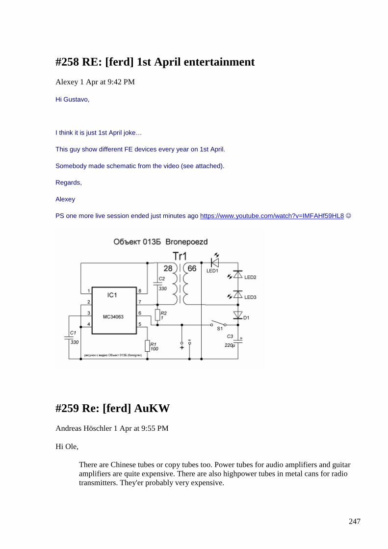
247
#258 RE: [ferd] 1st April entertainment
Alexey 1 Apr at 9:42 PM
Hi Gustavo,
I think it is just 1st April joke…
This guy show different FE devices every year on 1st April.
Somebody made schematic from the video (see attached).
Regards,
Alexey
PS one more live session ended just minutes ago https://www.youtube.com/watch?v=IMFAHf59HL8
#259 Re: [ferd] AuKW
Andreas Höschler 1 Apr at 9:55 PM
Hi Ole,
There are Chinese tubes or copy tubes too. Power tubes for audio amplifiers and guitar amplifiers are quite expensive. There are also highpower tubes in metal cans for radio transmitters. They'er probably very expensive.
248
A couple of hundred EUR, yes. But if we got 600W excess out of them without further (complicated) ado this would be worth it.
The power supply can be a step up transformer with tube rectifiers or modern semiconductor rectifiers. I haven't really worked with tubes. There are homepages with people building HiFi tube amplifiers. They are quite expensive but gives a good sound. Tubes go to 200MHz. This would require special HF transistors to do.
I don't see any need for this. We don't want to build a sender, just a collector for electrons. Don't you think just putting (pulsed) DC on the grid would do the trick?
Andreas
#260 Re: [ferd] tubes ;-)
Gerry 2 Apr at 1:49 AM
Hi Andreas, guys,
That circuit certainly unusual.
There's no Anode HT volts & I'm not sure if there's any heater filament voltage either.
On the grid the first diode is clamping the positive drive excursion at ground plus whatever the forward drop of diode is.
If say there's 10 junctions in the first diode the max positive on Grid will be about + 6V with respect to Cathode.
The Anode would be clamped at an additional + 6 Volts above this, so + 12V with respect to Cathode.
So assuming Cathode can emit electrons .......Grid is slightly more positive so can have limited Grid current flowing.
Grid is only mesh, so far more electrons are able to pass through Grid spaces to travel on to the Anode.
The ratio of the Anode current to Grid current will likely have a ratio greater than 1 (as current multiplier).
Most tubes are not usually supposed to handle grid current but in old CRT television's the line output tube like 6CM5's
or the old audio beam power 6L6 pentodes could handle it.
Gerry
#261 Re: [ferd] tubes ;-)
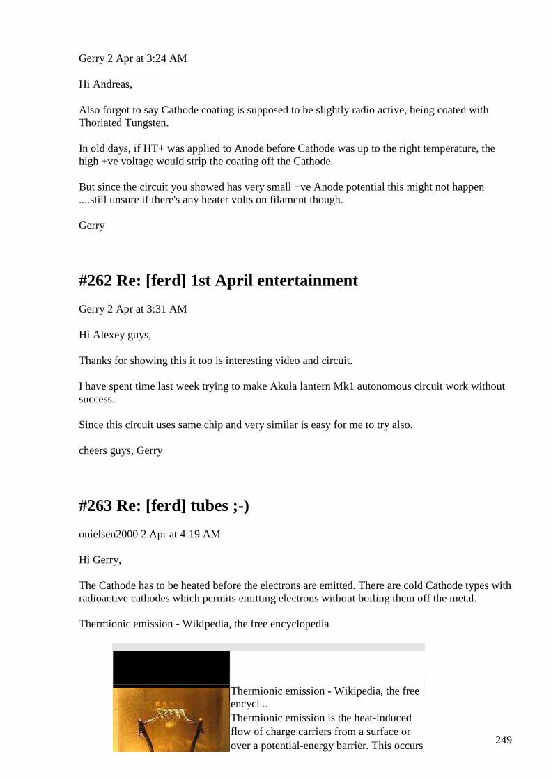
249
Gerry 2 Apr at 3:24 AM
Hi Andreas,
Also forgot to say Cathode coating is supposed to be slightly radio active, being coated with Thoriated Tungsten.
In old days, if HT+ was applied to Anode before Cathode was up to the right temperature, the high +ve voltage would strip the coating off the Cathode.
But since the circuit you showed has very small +ve Anode potential this might not happen ....still unsure if there's any heater volts on filament though.
Gerry
#262 Re: [ferd] 1st April entertainment
Gerry 2 Apr at 3:31 AM
Hi Alexey guys,
Thanks for showing this it too is interesting video and circuit.
I have spent time last week trying to make Akula lantern Mk1 autonomous circuit work without success.
Since this circuit uses same chip and very similar is easy for me to try also.
cheers guys, Gerry
#263 Re: [ferd] tubes ;-)
onielsen2000 2 Apr at 4:19 AM
Hi Gerry, The Cathode has to be heated before the electrons are emitted. There are cold Cathode types with radioactive cathodes which permits emitting electrons without boiling them off the metal. Thermionic emission - Wikipedia, the free encyclopedia
Thermionic emission - Wikipedia, the free encycl... Thermionic emission is the heat-induced flow of charge carriers from a surface or over a potential-energy barrier. This occurs
250
because the thermal energy given to t...
View on en.wikipedia.org Preview
by Yahoo
Regards Ole
#264 Re: [ferd] tubes ;-)
Gerry 2 Apr at 5:32 AM
Hi Ole,
Yes I am embarrassed to say I remember many of these old tube types from my heyday.
There were filament ranges from 1.25V for old portable tube type radios,
& for the 1B3 EHT rectifier to 6.3V for 6AU6 I.F. amplifier etc to 12V for 12AX7 low noise dual triode pre amp etc.
There were direct and indirectly heated types of cathode also.
The gain of the Pentodes used to be specified in gm transconductance values (mA per V).
So when FET's first came along they shared this nomenclature of being transconductance amplifiers.
From delta output current divided by delta input volts so instead of (E/I = Ohms) they used (I/E =Mho's).
In that video the tubes he holds up ......they look like the old beam power tetrodes, type 6L6 I think,
link here http://en.wikipedia.org/wiki/6L6
Lots of stuff which is very foggy to me now at over 65 years.
Gerry
#265 Re: [ferd] tubes ;-)
Andreas Höschler Apr 2 1:52 PM
Hi Gerry,
251
Most tubes are not usually supposed to handle grid current but in old CRT television's the line output tube like 6CM5's
or the old audio beam power 6L6 pentodes could handle it.
Thanks, I made a note and will look for them when revisiting this idea. For now I am back to bifilar coils experimentation. :-)
Andreas
#266 Status
Andreas Höschler Apr 3 at 3:11 AM
Hi all, I put the power supply and fancy new measurement equipment to use tonight and revisited the tesla bifilar coil boost converter setup I played a couple of months ago with (this made me start the PS endeavour). What I saw (once again) turned out to be measurement errors. I can easily reach 100% efficiency with this beast (very small duty cycly) but that's it. No OU whatsoever. :-( I am open for fresh ideas again! :-) I might look into the thermionic tube thing if I find a suitable tube. I guess what we need is a grid close to the anode while most commercial tubes probably have the grid close to the cathode!? Whatever ... What are you guys currently working on?? Ole, any progress with your amplifier/UDT? Best wishes, Andreas
#267 Re: Status
onielsen2000 Apr 3 at 3:30 AM
Hi Andreas, UDT status The class D amplifier can drive the UDT because of its true low output impedance not just made by a feed back loop as in a linear amplifier. This has caused another problem as the 800 kHz PWM carrier frequency goes right into the parallel capacitor of the primary LC circuit of the UDT. So now I'm looking into at filter between the amplifier and the UDT to better filter away the carrier wave. I changed all the windings of the UDT and don't have any overunity at the moment. Working on a solution.
252
Arthur Sadaly tube circuit
The Russian text below the Tiger video has someone mention that the cathode in his replication gets stripped by about half the coating after two hour of running. Perhaps the energy source is ions from the electron emitting coating (thoriated tungsten?). Regards Ole
#268 Re: [ferd] Status
Gerry Apr 3 at 4:23 AM
Hi Andreas Ole & guys,
Andreas congrats on your nice power supply!..... have been looking at the missed posts, multimeters on data bus idea great too.
I think Ole's UDT project seems to have been most successful and honest and non scam one we've come across so far.
In my own split flux transformer I do get the effect of load on one side boosting the output on the other. So yes I believe in UDT concept works.
I have pulled apart Akula version of Lantern circuit just getting bits together to try it with Alexey posted recent circuit ...
the pin connections seem to make sense so am trying it.
Guys there's a fellow down in Victoria about 600 Kms South of here I was talking to.
He was trying to sell a generator head/motor combination which was self powering once started.
It was being advertised on eBay here ...I have attached the advert.
He sent me details on how to do this ...
Happy to share this...... if it is of interest to anyone here.
I would like to try this myself however the components are quite expensive (down here anyway).
Also I have not seen this unit work myself.

253
Gerry
#269 RE: [ferd] Status
Alexey Apr 3 at 10:11 AM
Hi Andreas,
Unfortunately I don’t have good idea which is simple to try right now.
I am currently sorting and trying bring into order my archive files and hoping that I find some good idea.
Personally I am quite skeptical about UDT and not going waste any more time with it.
There is a big “temptation” to continue with audio TPU but it requires huge experimental efforts and completely unknown “territory” for me…
Regards,
Alexey
#270 RE: [ferd] Status
Alexey 3 Apr at 10:52 AM
Hi Gerry,
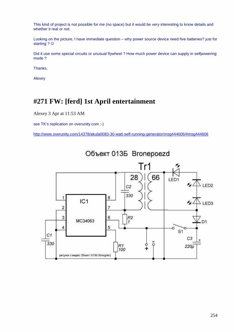
254
This kind of project is not possible for me (no space) but it would be very interesting to know details and whether it real or not.
Looking on the picture, I have immediate question – why power source device need five batteries? just for starting ?
Did it use some special circuits or unusual flywheel ? How much power device can supply in selfpowering mode ?
Thanks,
Alexey
#271 FW: [ferd] 1st April entertainment
Alexey 3 Apr at 11:53 AM
see TK’s replication on overunity.com ;-)
http://www.overunity.com/14378/akula0083-30-watt-self-running-generator/msg444606/#msg444606
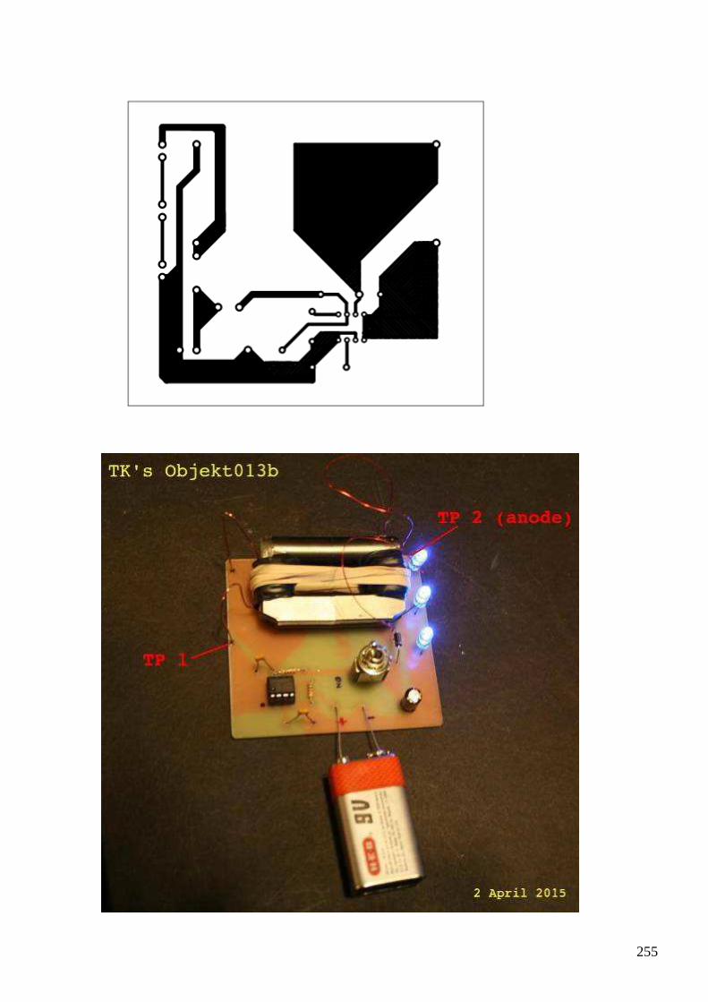
255
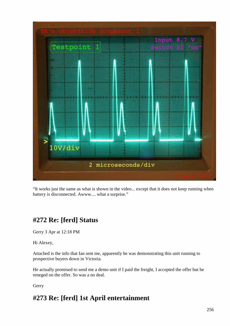
256
“It works just the same as what is shown in the video... except that it does not keep running when battery is disconnected. Awww.... what a surprise.”
#272 Re: [ferd] Status
Gerry 3 Apr at 12:18 PM
Hi Alexey,
Attached is the info that Ian sent me, apparently he was demonstrating this unit running to prospective buyers down in Victoria.
He actually promised to send me a demo unit if I paid the freight, I accepted the offer but he reneged on the offer. So was a no deal.
Gerry
#273 Re: [ferd] 1st April entertainment

257
Gerry 3 Apr at 12:22 PM
Thanks for this link Alexey, I checked it out.
Mine does not self run when power removed either..... the clock is running at 52KHz.
I am going to tune the tank circuit primary by varying the C value till it resonates at this frequency, whilst loaded with the LEDs.
Gerry
#274 RE: [ferd] Status
Alexey 3 Apr at 1:49 PM
Hi Gerry,
Thanks for the info… looks very suspicious for me, too good to be true, but who knows…
Regards,
Alexey
#275 Re: [ferd] Status
Andreas Höschler Apr 3 11:22 PM
Hi Alexey,
Unfortunately I don’t have good idea which is simple to try right now.
I am currently sorting and trying bring into order my archive files and hoping that I find some good idea.
Please let me know if you find something you consider worth trying. I worked through my archive today and tried (quick hack) this and that (followed my intuition) but got nothing our of it so far. Whatever I do, I get very close to unity but never beyond it! :-(
Personally I am quite skeptical about UDT and not going waste any more time with it.
I agree! I have put this on ice as well.
There is a big “temptation” to continue with audio TPU but it requires huge experimental efforts and completely unknown “territory” for me…

258
This thing was too complex for me as well so far ...
Andreas
#276 Re: [ferd] Status
Andreas Höschler Apr 3 11:28 PM
Hi Gerry,
Andreas congrats on your nice power supply!..... have been looking at the missed posts, multimeters on data bus idea great too.
Thanks! The new toys allowed me to conduct a couple of experiments already but nothing came out of it so far. :-(
I think Ole's UDT project seems to have been most successful and honest and non scam one we've come across so far.
Yes, but the real power coming out of the device was extremely small so far. We will see how this works out. Since Ole is already working on this with good expertise we might check out other concepts in the meanwhile until one of us shouts "sign. OU"! :-)
Andreas
#277 [ferd] 1st April entertainment
Gustavo Roveran 3 Apr at 3:28 AM
Hi Alexey So "see TK’s replication on overunity.com ;-) " He sais that this circuit is a 30 w self powered ... Did you test it ? I did not calculate anyththing yet, However it is very interesting how a 220 uF capacitor charged to 9 volts can feed so many minutes those three power leds. Regards. Gustavo
#278 Re: [ferd] 1st April entertainment
Gerry 3 Apr at 4:54 AM
Hi Gustavo,
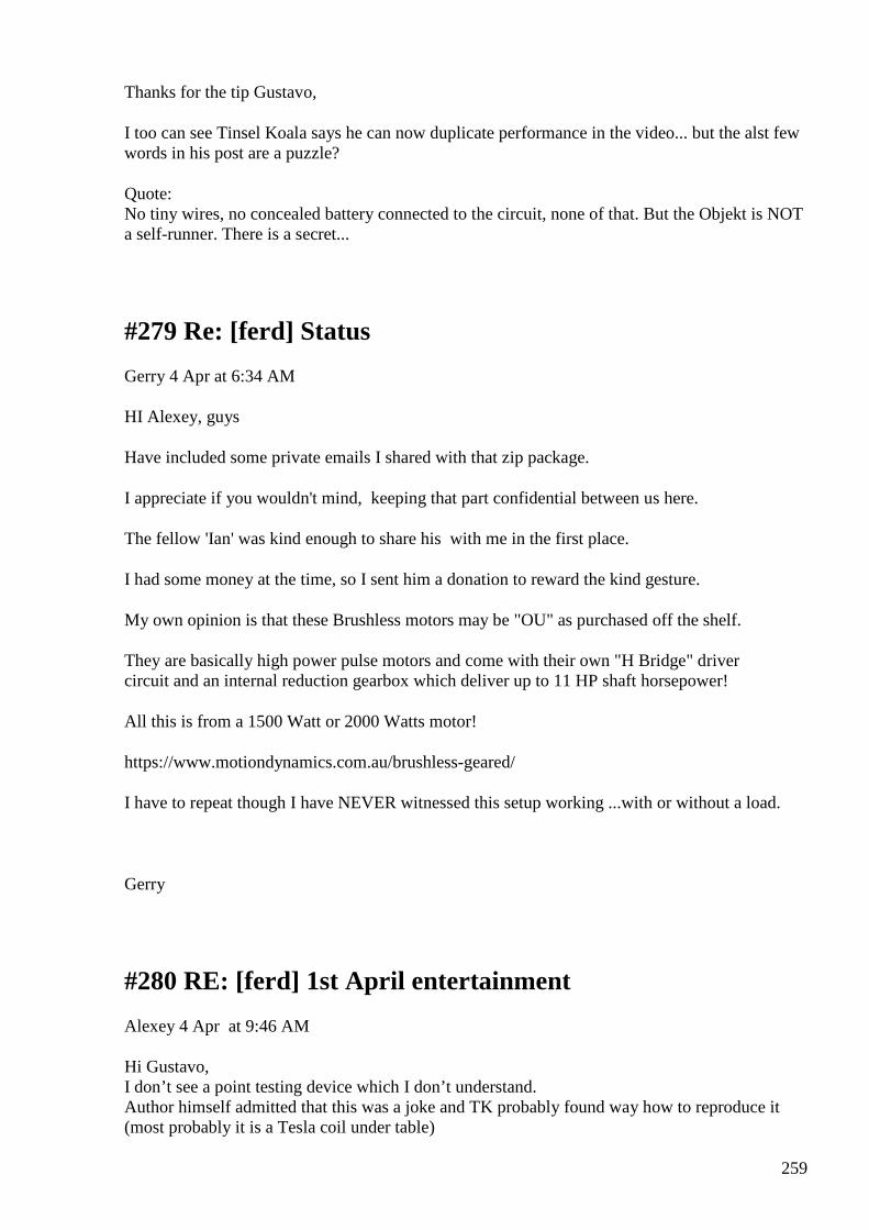
259
Thanks for the tip Gustavo,
I too can see Tinsel Koala says he can now duplicate performance in the video... but the alst few words in his post are a puzzle?
Quote: No tiny wires, no concealed battery connected to the circuit, none of that. But the Objekt is NOT a self-runner. There is a secret...
#279 Re: [ferd] Status
Gerry 4 Apr at 6:34 AM
HI Alexey, guys
Have included some private emails I shared with that zip package.
I appreciate if you wouldn't mind, keeping that part confidential between us here.
The fellow 'Ian' was kind enough to share his with me in the first place.
I had some money at the time, so I sent him a donation to reward the kind gesture.
My own opinion is that these Brushless motors may be "OU" as purchased off the shelf.
They are basically high power pulse motors and come with their own "H Bridge" driver circuit and an internal reduction gearbox which deliver up to 11 HP shaft horsepower!
All this is from a 1500 Watt or 2000 Watts motor!
https://www.motiondynamics.com.au/brushless-geared/
I have to repeat though I have NEVER witnessed this setup working ...with or without a load.
Gerry
#280 RE: [ferd] 1st April entertainment
Alexey 4 Apr at 9:46 AM
Hi Gustavo, I don’t see a point testing device which I don’t understand. Author himself admitted that this was a joke and TK probably found way how to reproduce it (most probably it is a Tesla coil under table)
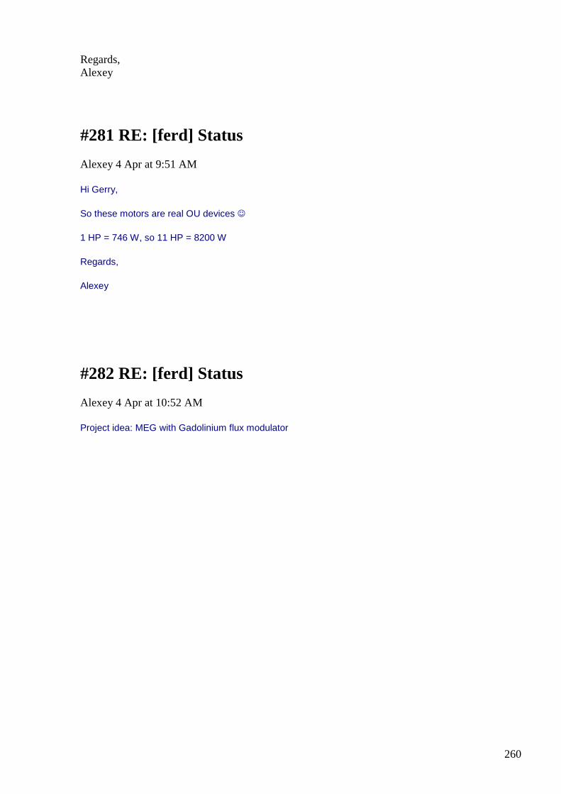
260
Regards, Alexey
#281 RE: [ferd] Status
Alexey 4 Apr at 9:51 AM
Hi Gerry,
So these motors are real OU devices
1 HP = 746 W, so 11 HP = 8200 W
Regards,
Alexey
#282 RE: [ferd] Status
Alexey 4 Apr at 10:52 AM
Project idea: MEG with Gadolinium flux modulator
261
This guy making a motor https://www.youtube.com/watch?v=VonUp5Wicwk but we can make same thing in solid state using peltier module to heat/cool piece of gadolinium
(and also recycle some heat)
source for gadolinium “cubes”
http://www.ebay.com/itm/99-99-High-Purity-Gadolinium-Rare-Earth-Metal-Gd-10mm-Cube-element-collection-/261785058910?pt=LH_DefaultDomain_0&hash=item3cf39afe5e
-Alexey
#283 RE: [ferd] Status
Alexey 4 Apr at 1:50 PM
Hi Gerry,
I have removed attachment you sent from group files.
After some considerations I came to conclusion that this is a fake with high probability.

262
Here my calculations:
Let’s take second motor from the link you provided (https://www.motiondynamics.com.au/brushless-gear-motor-60v-2000w-600-700-rpm-85nm-controller-accessories.html)
In the table, highest efficiency is 81.5% and at this mode motor consumes 2897w and provides 40.7Nm at 554 rpm
To get 1500 rpm required by standard generator we have to use 2.7 gear (554 * 2.7 = 1500) and torque will be 40.7 / 2.7 = 15 Nm (https://en.wikipedia.org/wiki/Torque)
For example this generator http://www.aliexpress.com/item/STC-7-5KW-AC-Three-Phase-Brush-Diesel-Generator/1619057512.html?tracelog=ae-app-ios-sharefor-shkmail
to produce 7.5 KW will require 46Nm (assuming COP 100% and 56Nm at 85%)
So, this is why a set of batteries needed ;-)
Regards,
Alexey
#284 Silicon Carbide MOSFET
Andreas Höschler 4 Apr at 4:37 PM
Hi all, I have purchased two Silicon Carbide MOSFETs (C2M0025120D) and would like to use them for a PMOD effect experiment. These new beasts have special requirements regarding driving the gate. They prefer +20V to switch on and -5V to switch off. Any idea how to drive them? I have not yet found readily-produced MOSFET drivers for these beasts and a quick brainstorming session for coming up with a discrete TTL -> totem pole diver (+20V/-5V) went nowhere so far! :-( If you have seen a corresponding circuit or driver chip anywhere please let me know! :-) Thanks a lot in advance! Andreas
#285 Re: [ferd] Silicon Carbide MOSFET
Andreas Höschler 4 Apr at 5:20 PM
Hi all,
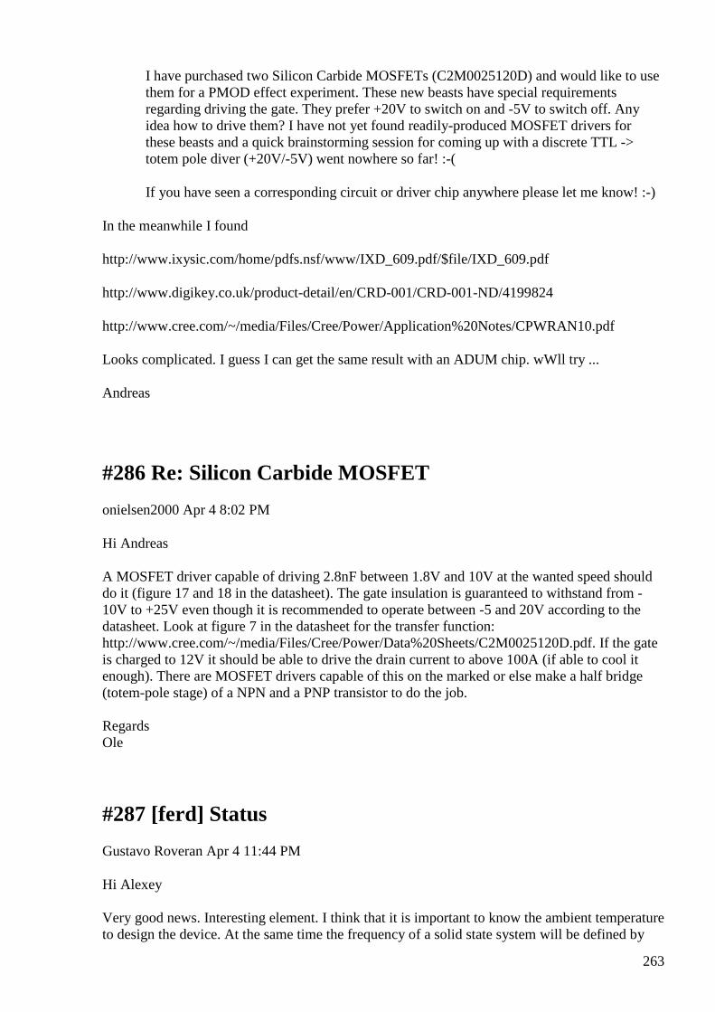
263
I have purchased two Silicon Carbide MOSFETs (C2M0025120D) and would like to use them for a PMOD effect experiment. These new beasts have special requirements regarding driving the gate. They prefer +20V to switch on and -5V to switch off. Any idea how to drive them? I have not yet found readily-produced MOSFET drivers for these beasts and a quick brainstorming session for coming up with a discrete TTL -> totem pole diver (+20V/-5V) went nowhere so far! :-(
If you have seen a corresponding circuit or driver chip anywhere please let me know! :-)
In the meanwhile I found
http://www.ixysic.com/home/pdfs.nsf/www/IXD_609.pdf/$file/IXD_609.pdf
http://www.digikey.co.uk/product-detail/en/CRD-001/CRD-001-ND/4199824
http://www.cree.com/~/media/Files/Cree/Power/Application%20Notes/CPWRAN10.pdf
Looks complicated. I guess I can get the same result with an ADUM chip. wWll try ...
Andreas
#286 Re: Silicon Carbide MOSFET
onielsen2000 Apr 4 8:02 PM
Hi Andreas A MOSFET driver capable of driving 2.8nF between 1.8V and 10V at the wanted speed should do it (figure 17 and 18 in the datasheet). The gate insulation is guaranteed to withstand from -10V to +25V even though it is recommended to operate between -5 and 20V according to the datasheet. Look at figure 7 in the datasheet for the transfer function: http://www.cree.com/~/media/Files/Cree/Power/Data%20Sheets/C2M0025120D.pdf. If the gate is charged to 12V it should be able to drive the drain current to above 100A (if able to cool it enough). There are MOSFET drivers capable of this on the marked or else make a half bridge (totem-pole stage) of a NPN and a PNP transistor to do the job. Regards Ole
#287 [ferd] Status
Gustavo Roveran Apr 4 11:44 PM
Hi Alexey Very good news. Interesting element. I think that it is important to know the ambient temperature to design the device. At the same time the frequency of a solid state system will be defined by
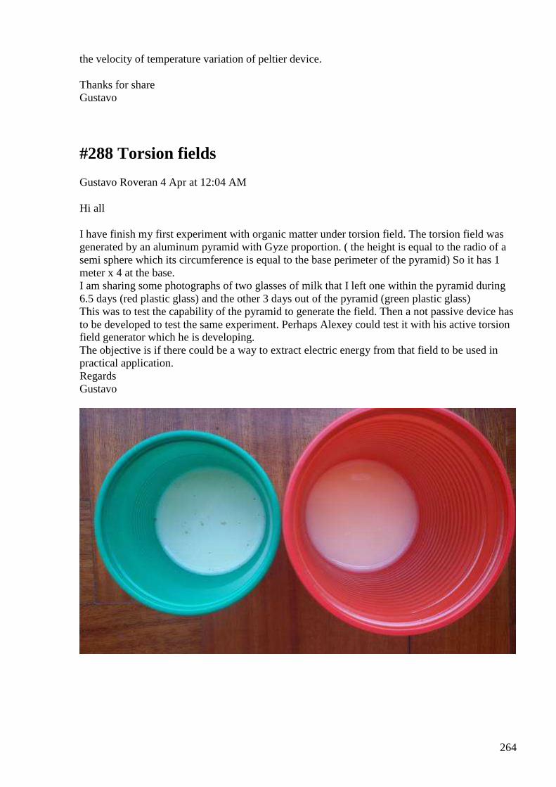
264
the velocity of temperature variation of peltier device. Thanks for share Gustavo
#288 Torsion fields
Gustavo Roveran 4 Apr at 12:04 AM
Hi all I have finish my first experiment with organic matter under torsion field. The torsion field was generated by an aluminum pyramid with Gyze proportion. ( the height is equal to the radio of a semi sphere which its circumference is equal to the base perimeter of the pyramid) So it has 1 meter x 4 at the base. I am sharing some photographs of two glasses of milk that I left one within the pyramid during 6.5 days (red plastic glass) and the other 3 days out of the pyramid (green plastic glass) This was to test the capability of the pyramid to generate the field. Then a not passive device has to be developed to test the same experiment. Perhaps Alexey could test it with his active torsion field generator which he is developing. The objective is if there could be a way to extract electric energy from that field to be used in practical application. Regards Gustavo
265
#289 Re: [ferd] Status
Gerry 5 Apr at 4:30 AM
Hi Alexey & guys,
Happy Easter to you all!

266
Alexey thank you for going to the trouble to work this out for me, I did try but I get confused with the Torque concept.
If Torque is measured in Newton Metres then surely the overall equivalent torque, measured at 1 Metre from turning centre doesn't change no matter what size of pulley is fitted?
Yep understand the torque is multiplied down for larger pulley and up for smaller but this doesn't change the Torque exerted by the motor itself as radial speed traded off to get any change.
In 2014 when I was communicating with "Ian" the larger motor was not available, his machine used the 1500 Watt unit which looks marginally more efficient in the specs.
On the advert for the 1500W motor they do claim 60NM but looking at the manufacturers table..... I cannot see where it was achieved.
From memory Ian said he was overdriving the dc motor somewhat to get the required 1500 rpm with pulley specified.
I really wish I could've seen the unit being demonstrated with loads, but his place is actually over 600 miles from here not 600 Kms.
All of our attempts at free energy devices here no matter what the design, they have a common principle.
That is they all have an "energy consumed versus energy expended" aspect to them. ie generator and a prime mover aspect.
Even though neither device is 100% efficient as long as our rate of production exceeds the rate of expenditure eventually free energy must accumulate over time.
Or at least that's how I think of it, which could be wrong too.
Anyhow thanks again I do hope one of us can make some kind of success at our common goal.
My Akula attempt not going real well after many more hours of tuning chopping and changing ...it's a bit of a mess now actually.
all the best guys Gerry
#290 RE: [ferd] Status
Alexey 5 Apr at 10:40 AM

267
#291 [ferd] Entertainment, more fun ;-)
Alexey 5 Apr at 11:51 AM
https://www.youtube.com/watch?v=L7Gv74u5tG8#t=37
#292 RE: [ferd] Torsion fields
Alexey Apr 5 12:52 PM
Hi Gustavo,
So you can confirm now that pyramid affects somehow food placed inside it ?
Thanks,
Alexey
#293 Re: [ferd] Entertainment, more fun ;-)
Andreas Höschler Apr 5 4:50 PM

268
Hi Alexey,
https://www.youtube.com/watch?v=L7Gv74u5tG8#t=37
No OU of course. But I am still impressed. I played a bit with induction cookers. If I remember correctly it generates 18kHz AC (could also have been 36kHz). The question that remains for me is
Why can he transfer these 200W over such thin wires? Would be interesting to see what happens if he connected 2kW of bulbs! :-)
It is clear why he ist not electrocuted when touching the water. The electrical power is galvanically isolated from earth so ...
Andreas
#294 [ferd] Torsion fields
Gustavo Roveran Apr 5 5:09 PM
Hi Alexey The food keep without decomposition inside the pyramid. Could you see the photographs? I read that pyramid has two main properties, one is to accumulate neutrinos inside and the ohter to stop the sol-gel cell cycle. There are more properties like not let evolve saprophyt bacterias... Regards and happy Pascuas for all. Gustavo
#295 RE: [ferd] Torsion fields
Alexey Apr 6 at 11:40 AM
Hi Gustavo,
Thanks for confirmation.
I can see photos but for my inexperienced eyes them all looks almost the same.
Thanks,
Alexey

269
#296 [ferd] Torsion fields
Gustavo Roveran Apr 6 at 6:38 PM
Hi Alexey The green glass has been only 3 days, out of the pyramid. You can see little black point on Its surface. They are mushrooms produced by bacteria. The other glass, the green glass has been 6,5 days and there is not any black point on its surface. Regards Gustavo
#297 another project idea
Alexey 6 Apr at 9:52 PM
Hi Dear All,
Recently I spent lots of time with my BH curve tracer (I described it some time earlier).
I have measured all different cores I have in countless modes and setup variations.
Finally I was able to identify particular process (current shape) which produce clockwise hysteresis loop and creates negative resistance.
The ”amount” of free energy is very small here but it is clearly visible.
Perhaps studding and optimizing this effect one could proceed to working FE device (which use environmental heat to run).
This could be another “new” project.
Have fun,
-Alexey
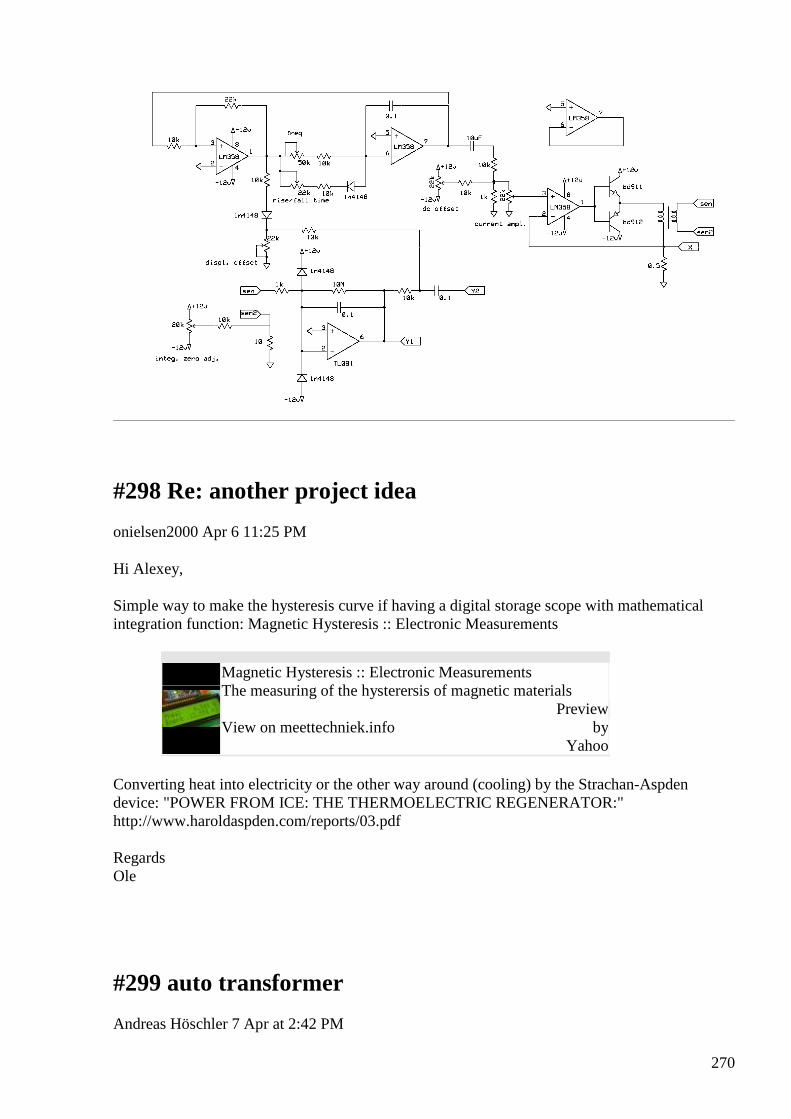
270
#298 Re: another project idea
onielsen2000 Apr 6 11:25 PM
Hi Alexey, Simple way to make the hysteresis curve if having a digital storage scope with mathematical integration function: Magnetic Hysteresis :: Electronic Measurements
Magnetic Hysteresis :: Electronic Measurements The measuring of the hysterersis of magnetic materials
View on meettechniek.info
Preview by
Yahoo
Converting heat into electricity or the other way around (cooling) by the Strachan-Aspden device: "POWER FROM ICE: THE THERMOELECTRIC REGENERATOR:" http://www.haroldaspden.com/reports/03.pdf Regards Ole
#299 auto transformer
Andreas Höschler 7 Apr at 2:42 PM
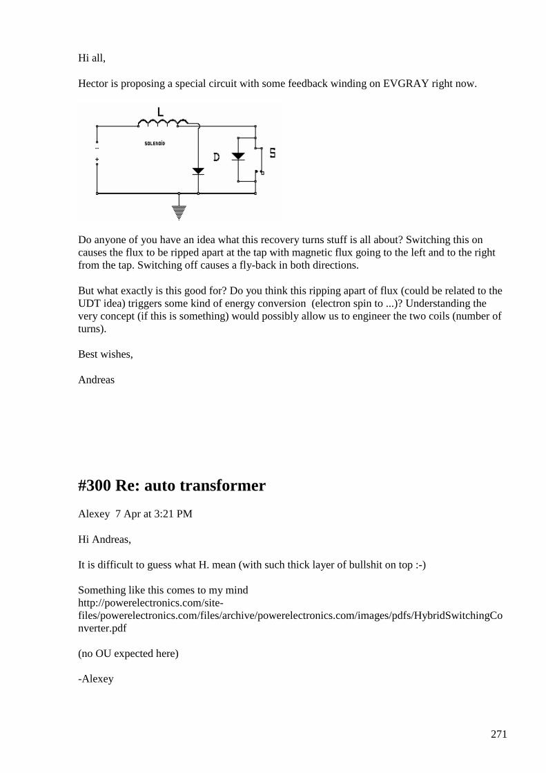
271
Hi all,
Hector is proposing a special circuit with some feedback winding on EVGRAY right now.
Do anyone of you have an idea what this recovery turns stuff is all about? Switching this on causes the flux to be ripped apart at the tap with magnetic flux going to the left and to the right from the tap. Switching off causes a fly-back in both directions.
But what exactly is this good for? Do you think this ripping apart of flux (could be related to the UDT idea) triggers some kind of energy conversion (electron spin to ...)? Understanding the very concept (if this is something) would possibly allow us to engineer the two coils (number of turns).
Best wishes,
Andreas
#300 Re: auto transformer
Alexey 7 Apr at 3:21 PM
Hi Andreas, It is difficult to guess what H. mean (with such thick layer of bullshit on top :-) Something like this comes to my mind http://powerelectronics.com/site-files/powerelectronics.com/files/archive/powerelectronics.com/images/pdfs/HybridSwitchingConverter.pdf (no OU expected here) -Alexey
272
#301 Re: auto transformer
onielsen2000 7 Apr at 3:28 PM
Hi Andreas, It's an autotransformer (step up in this case). Autotransformers shares the same winding for both the primary and secondary and as such isn't galvanic isolated. http://en.wikipedia.org/wiki/Autotransformer. Regards Ole
#302 Re: [ferd] Re: auto transformer
Expand Messages
Andreas Höschler 7 Apr at 3:58 PM
Hi all,
It's an autotransformer (step up in this case). Autotransformers shares the same winding for both the primary and secondary and as such isn't galvanic isolated. http://en.wikipedia.org/wiki/Autotransformer.
If we switch on the MOSFET, current starts to flow in the four turns to the left of the
tap. CEMF will generate current in the one turn coil to the right of the tap. This current
is short-circuited by the conducting MOSFET and the diode. So we could expect high
current and relatively low loss (when using a Schottky diode). When switching off the
current in the one-turn coil to the right continues to flow and now - no longer being
shorted by MOSFET - would seek its way into the battery (power supply) having a
recharging effect!?
The question is how this interacts with the fly-back spike of the left hand coil which will most likely dominate and thus render the above mentioned effect meaningless!?
Hmgh!?
Something like this comes to my mind http://powerelectronics.com/site-files/powerelectronics.com/files/archive/powerelectronics.com/images/pdfs/HybridSwitchingConverter.pdf
Thanks Alexey! Reading ...
Andreas
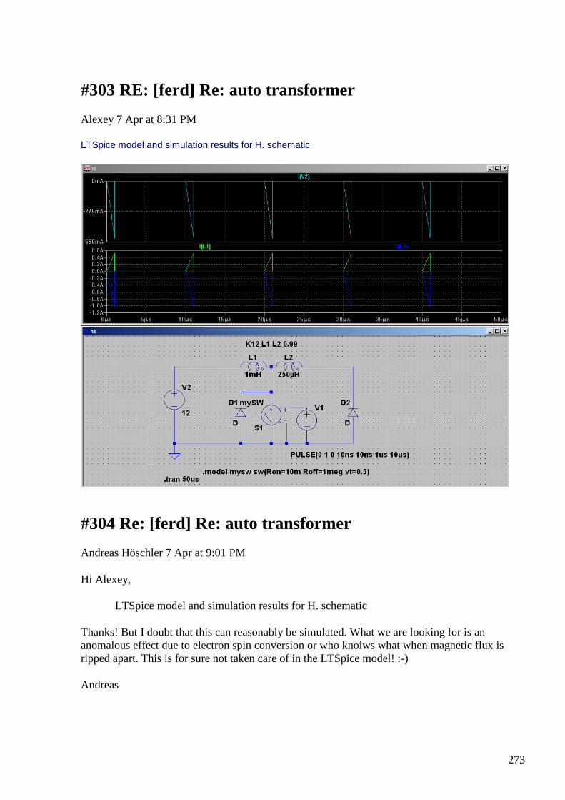
273
#303 RE: [ferd] Re: auto transformer
Alexey 7 Apr at 8:31 PM
LTSpice model and simulation results for H. schematic
#304 Re: [ferd] Re: auto transformer
Andreas Höschler 7 Apr at 9:01 PM
Hi Alexey,
LTSpice model and simulation results for H. schematic
Thanks! But I doubt that this can reasonably be simulated. What we are looking for is an anomalous effect due to electron spin conversion or who knoiws what when magnetic flux is ripped apart. This is for sure not taken care of in the LTSpice model! :-)
Andreas
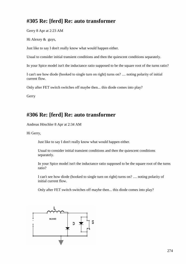
274
#305 Re: [ferd] Re: auto transformer
Gerry 8 Apr at 2:23 AM
Hi Alexey & guys,
Just like to say I don't really know what would happen either.
Usual to consider initial transient conditions and then the quiescent conditions separately.
In your Spice model isn't the inductance ratio supposed to be the square root of the turns ratio?
I can't see how diode (hooked to single turn on right) turns on? .... noting polarity of initial current flow.
Only after FET switch switches off maybe then... this diode comes into play?
Gerry
#306 Re: [ferd] Re: auto transformer
Andreas Höschler 8 Apr at 2:34 AM
Hi Gerry,
Just like to say I don't really know what would happen either.
Usual to consider initial transient conditions and then the quiescent conditions separately.
In your Spice model isn't the inductance ratio supposed to be the square root of the turns ratio?
I can't see how diode (hooked to single turn on right) turns on? .... noting polarity of initial current flow.
Only after FET switch switches off maybe then... this diode comes into play?

275
It would conduct current in the MOSFET switch on phase due to the CEMF induced in the right coil due to the rising current in the left coil (both coils sitting on the same core). This induced EMF is short-circuited by the conducting MOSFET and the diode.
Regards,
Andreas
#307 Re: [ferd] another project idea
Gustavo Roveran 8 Apr at 5:00 AM
Hi Alexey,
I am trying to find the pdf where I read about the Larmor Precession. When you magnetized a core with a low speed ramp and the demagnetized with a high speed ramp there could be a gain energy that comes from Larmor Precession.
I go on searching.
I think its time to make a list of "new" project to aim our attention.
Regards,
Gustavo
#308 Re: [ferd] Re: auto transformer
Gerry 8 Apr at 4:29 AM
Thanks Andreas,
I get what you're saying ........ but doesn't current rise only slowly in left coil due to CEMF?
So even with close to with zero ampere turns during switch on ...... somehow this CEMF creates enough enough useful current to turn on the diode?
I guess it has to because there's no diode current due to simple conduction.
As you said very interesting circuit.
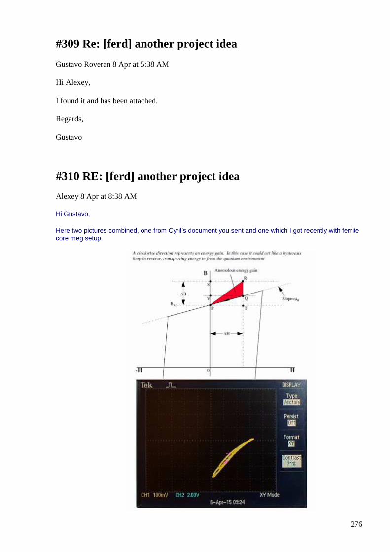
276
#309 Re: [ferd] another project idea
Gustavo Roveran 8 Apr at 5:38 AM
Hi Alexey,
I found it and has been attached.
Regards,
Gustavo
#310 RE: [ferd] another project idea
Alexey 8 Apr at 8:38 AM
Hi Gustavo,
Here two pictures combined, one from Cyril’s document you sent and one which I got recently with ferrite core meg setup.
277
It seems that I am making a progress
Regards,
Alexey
#311 RE: [ferd] Torsion fields
Alexey Apr 8 8:56 AM
Hi Gustavo,
There is a question which I am 100% sure you will be asked if you try share your results with somebody who not familiar with torsion fields theory etc.
How you can be sure that it is actually pyramid affects food properties?
Could it be that temperature inside it just smaller or there is no light inside and due to these factors (not related to shape effect) food preserved better?
What would you answer to this? ;-)
Regards,
Alexey
#312 Re: [ferd] another project idea
Gustavo Roveran 9 Apr at 4:42 AM
Hi Alexey,
Really seems to be a good news, in fact The News.
The graph you obtained was the best from different amplitudes and frequencies for that core ?
Could you find which are the characteristics of the core with the best behavior.
Supposing that the core has a bandwidth from where we can induce the maximum "slew rate" for that core. If the magnetizing process is done with a "slew rate" below than the maximum but the demagnetizing is done with a "slew rate" above than maximum "slew rate" calculated, I think that this could produce the best gain for that core.
Regards,
Gustavo
278
#313 Re: [ferd] Torsion fields
Gustavo Roveran 9 Apr at 5:26 AM
Hi Alexey,
In the year 2005 I did the same experiment with a pyramid with 1,5 meters of side and was built with only edges of aluminum. So the milk was exposed to the same air and same light and temperature. This is a way I have to test that a pyramid is working. By the way, the experiment is continuing in my new pyramid, and the milk is still there and also there are two pieces of banana. Sorry it is a bit weird for a FER group but it is about a type of energy I am studying, which someone called torsion fields.
Regards,
Gustavo
#314 RE: [ferd] Torsion fields
Alexey 9 Apr at 8:15 AM
Hi Gustavo,
It is very interesting
Please keep sharing you results.
I believe that torsion fields technologies will make similar revolution in 21st century as electricity made in 20th, if only humanity find courage to develop in a positive direction.
Thanks,
Alexey
#315 RE: [ferd] another project idea
Alexey Apr 9 at 8:15 AM
Hi Gustavo,
This is new, unexplored area for me, so I don’t have ready answers yet.
I will continue my studies and will try all the answers as time and inspiration allows.
279
May be I will build a better core tracer, MCU controlled, so it could obtain different curves automatically…
Anyway I think it is very nice that we can see now this effect even with simple tracer.
Regards,
Alexey
#316 Harold Aspepden
Andreas Höschler Apr 10 6:36 PM
Hi all, Alexey posted a PDF recently describing the Nernst Effect.
I did a quick and dirty test as a proof of concept. Below you see a laminated steel (from a transformer) sandwiched between two (three) power resistors and the whole setup sandwiched between two magnets.
The power resistor below the laminated steel sheet is not connected to anything and supposed to act as a heat sink. The upper power resistor is heated by applying DC voltage thus giving a vertical heat gradient in the sandwiched laminated steel sheet.
I connected a voltmeter to the steel sheet. Following the aspden document I should measure a DC voltage due to the heat gradient in a magnetic field. The theory makes sense IMHO but I measure absolutely nothing. I heated the above resistor to at least 65°C while the lower one was hardly above room temperature. The megnettic feild is rather string and perpendicular to the temperature gradient. But I measure nothing, not even a single mV!? :-(
Any idea? Can we throw this in the bin as heresy or do I miss anything?
Andreas
BTW: I also did a quick test with a aluminum and carbon in a salt water solution to build a battery. I got 0.9V but zero amperage! :-(
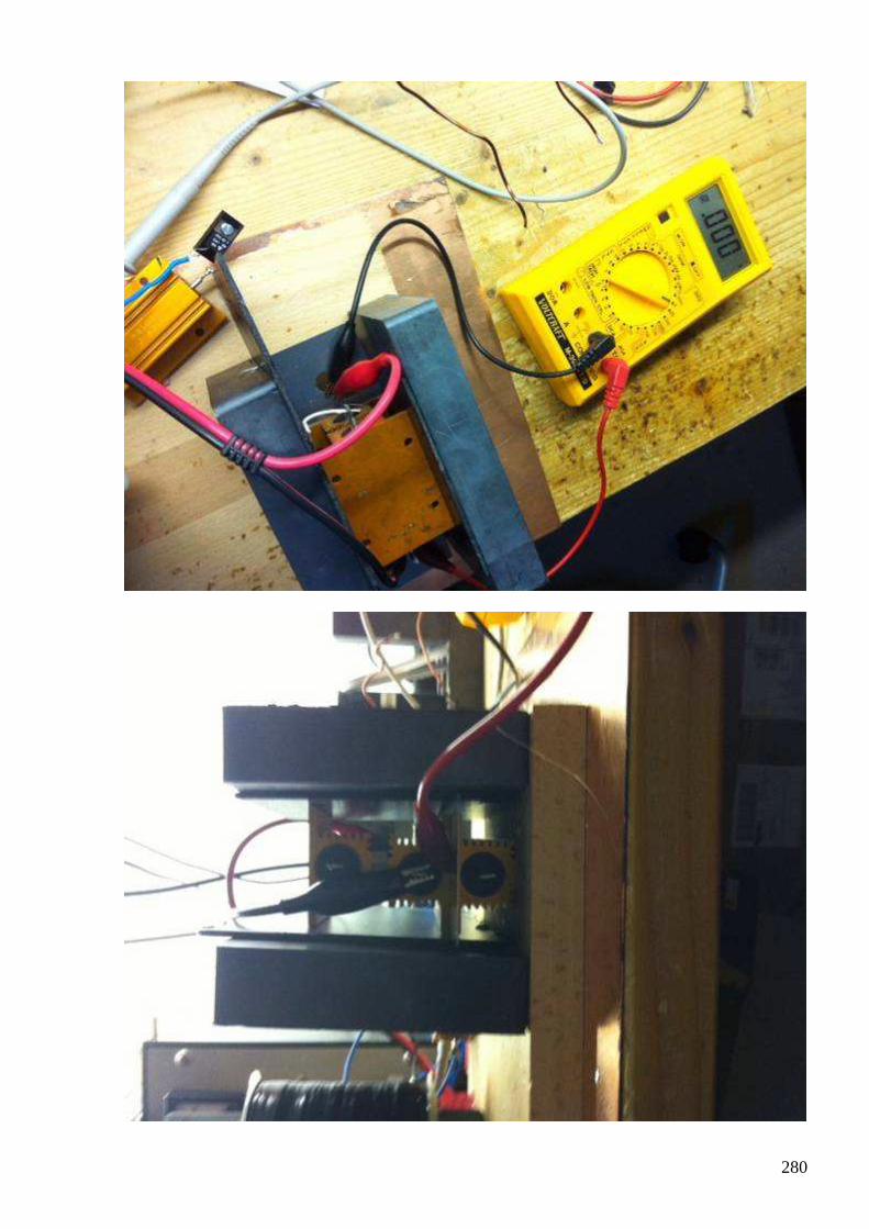
280
281
#317 RE: [ferd] Harold Aspepden
Alexey Apr 10 6:55 PM
Hi Andreas,
I think it was Ole who posted this document (I am quite skeptical about H. Aspden)
As far as I know, the Hall effect produce very small voltages (micro volts), but Nernst effect even smaller (in nano volts range) in metals
http://canfield.physics.iastate.edu/course/EM_35.pdf
Regards,
Alexey
#318 Re: [ferd] Harold Aspepden
Andreas Höschler Apr 10 11:35 PM
Hi Alexey,
I think it was Ole who posted this document (I am quite skeptical about H. Aspden)
As far as I know, the Hall effect produce very small voltages (micro volts), but Nernst effect even smaller (in nano volts range) in metals
http://canfield.physics.iastate.edu/course/EM_35.pdf
Thanks! nV!?? Here it goes into the heresy box!
I am just reading the Cyril Smith document ...
Best wishes,
Andreas
#319 [ferd] Torsion fields
Gustavo Roveran 11 Apr at 2:45 AM
Hi Alexey I have had to disassemble the pyramid for a while because the living room was needed ... However I attached twophotographs that show milk and two pieces of banana exposed for 12 days.
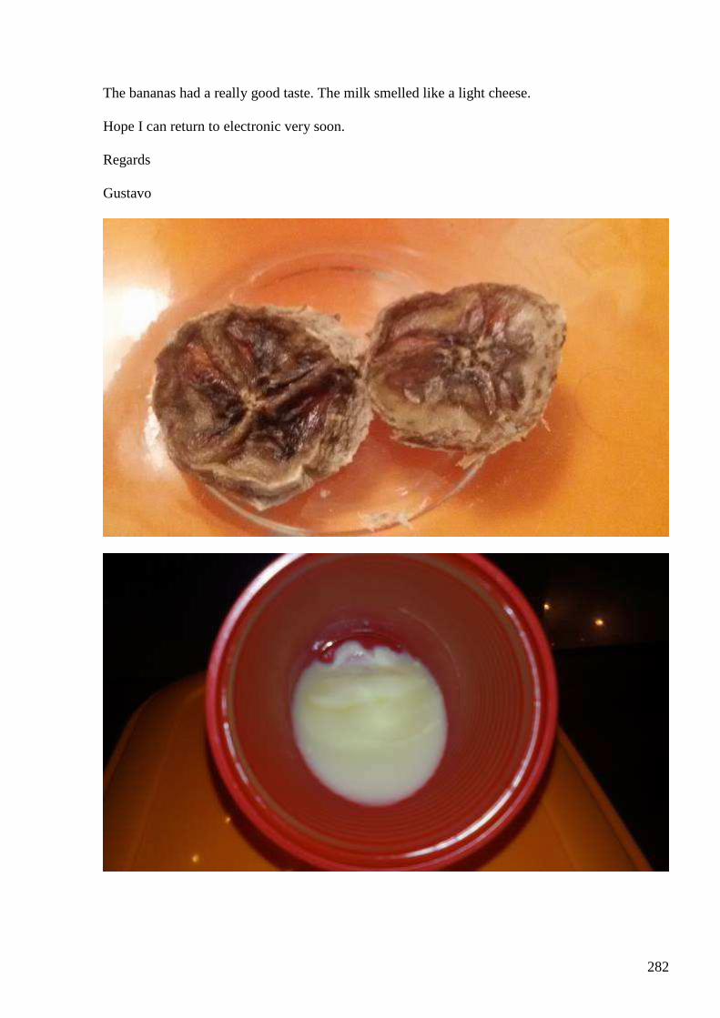
282
The bananas had a really good taste. The milk smelled like a light cheese. Hope I can return to electronic very soon. Regards Gustavo
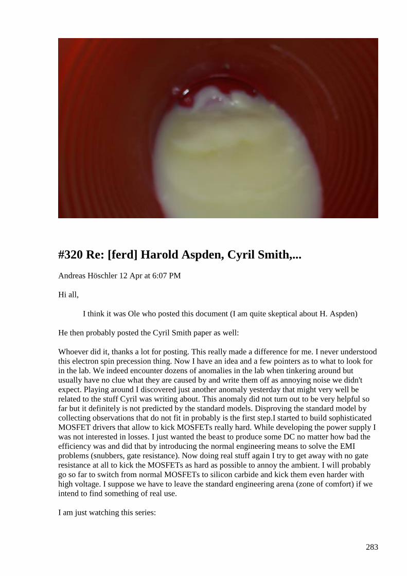
283
#320 Re: [ferd] Harold Aspden, Cyril Smith,...
Andreas Höschler 12 Apr at 6:07 PM
Hi all,
I think it was Ole who posted this document (I am quite skeptical about H. Aspden)
He then probably posted the Cyril Smith paper as well:
Whoever did it, thanks a lot for posting. This really made a difference for me. I never understood this electron spin precession thing. Now I have an idea and a few pointers as to what to look for in the lab. We indeed encounter dozens of anomalies in the lab when tinkering around but usually have no clue what they are caused by and write them off as annoying noise we didn't expect. Playing around I discovered just another anomaly yesterday that might very well be related to the stuff Cyril was writing about. This anomaly did not turn out to be very helpful so far but it definitely is not predicted by the standard models. Disproving the standard model by collecting observations that do not fit in probably is the first step.I started to build sophisticated MOSFET drivers that allow to kick MOSFETs really hard. While developing the power supply I was not interested in losses. I just wanted the beast to produce some DC no matter how bad the efficiency was and did that by introducing the normal engineering means to solve the EMI problems (snubbers, gate resistance). Now doing real stuff again I try to get away with no gate resistance at all to kick the MOSFETs as hard as possible to annoy the ambient. I will probably go so far to switch from normal MOSFETs to silicon carbide and kick them even harder with high voltage. I suppose we have to leave the standard engineering arena (zone of comfort) if we intend to find something of real use.
I am just watching this series:
284
https://www.youtube.com/watch?v=9sUe6SL22NA&index=1&list=PL2fbwSsQ2zlVv-7nYJfnhhTicspymWThP
I am currently at emV007 and haven't learned that much so far but Mr. Distinti has a point (probably worth the time).Ole, please post whatever other related papers you have in your library. One never knows what this will do.
Best wishes to all,
Andreas
#321 RE: [ferd] Harold Aspden, Cyril Smith,...
Alexey 12 Apr at 6:18 PM
Hi Andreas,
Here an archive with all Cyril’s papers I have in my files
https://www.idrive.com/idrive/sh/sh?k=s1d0f8x7b7
Regards,
Alexey
#322 Re: [ferd] Harold Aspden, Cyril Smith,...
Andreas Höschler 12 Apr at 6:38 PM
Hi Alexey,
Here an archive with all Cyril’s papers I have in my files
https://www.idrive.com/idrive/sh/sh?k=s1d0f8x7b7
Pieff!! So much to read ...
Thanks a lot!!!
Andreas
#323 CEMF
Andreas Höschler 15 Apr at 12:11 AM
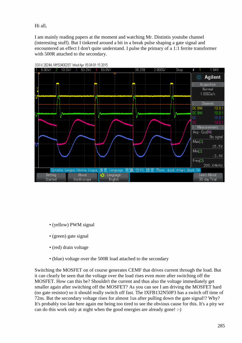
285
Hi all,
I am mainly reading papers at the moment and watching Mr. Distintis youtube channel (interesting stuff). But I tinkered around a bit in a break pulse shaping a gate signal and encountered an effect I don't quite understand. I pulse the primary of a 1:1 ferrite transformer with 500R attached to the secondary.
• (yellow) PWM signal
• (green) gate signal
• (red) drain voltage
• (blue) voltage over the 500R load attached to the secondary
Switching the MOSFET on of course generates CEMF that drives current through the load. But it can clearly be seen that the voltage over the load rises even more after switching off the MOSFET. How can this be? Shouldn't the current and thus also the voltage immediately get smaller again after switching off the MOSFET? As you can see I am driving the MOSFET hard (no gate resistor) so it should really switch off fast. The IXFB132N50P3 has a switch off time of 72ns. But the secondary voltage rises for almost 1us after pulling down the gate signal!? Why? It's probably too late here again me being too tired to see the obvious cause for this. It's a pity we can do this work only at night when the good energies are already gone! :-)
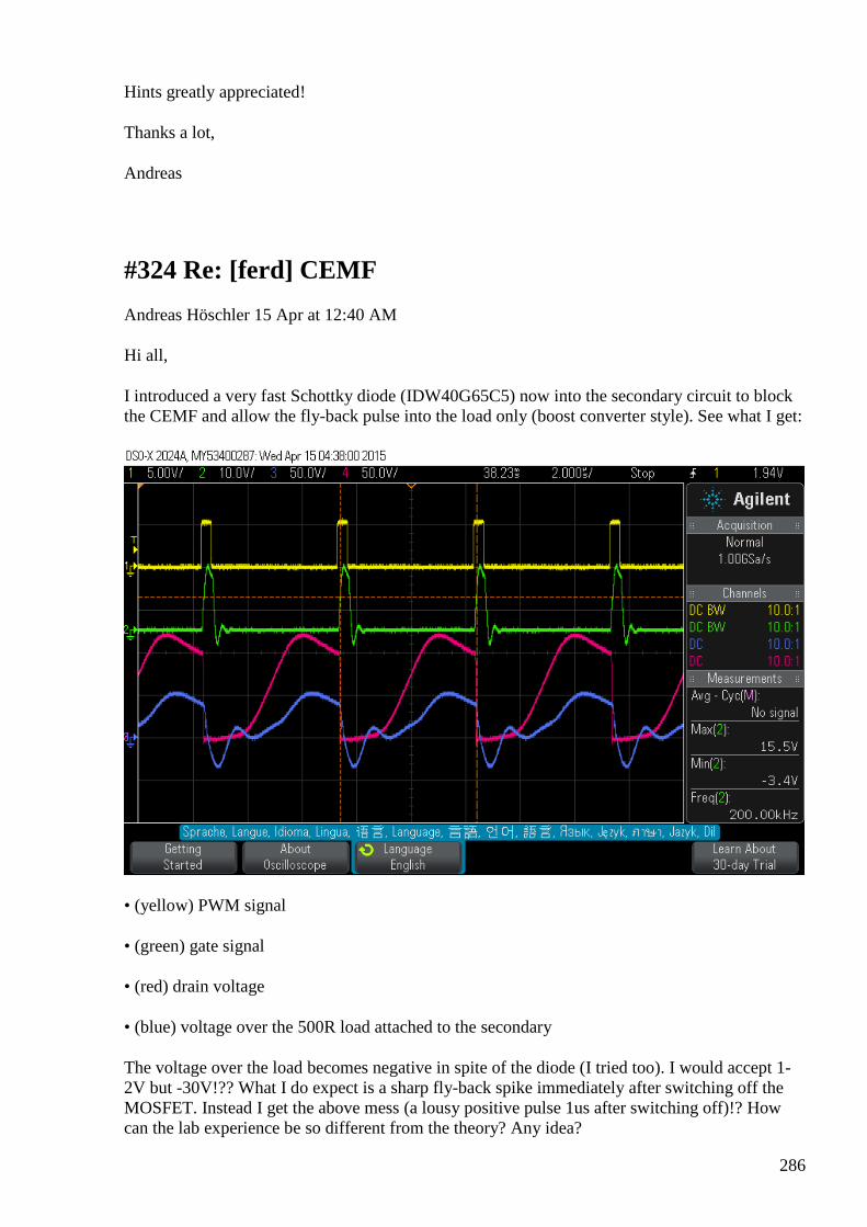
286
Hints greatly appreciated!
Thanks a lot,
Andreas
#324 Re: [ferd] CEMF
Andreas Höschler 15 Apr at 12:40 AM
Hi all,
I introduced a very fast Schottky diode (IDW40G65C5) now into the secondary circuit to block the CEMF and allow the fly-back pulse into the load only (boost converter style). See what I get:
• (yellow) PWM signal
• (green) gate signal
• (red) drain voltage
• (blue) voltage over the 500R load attached to the secondary
The voltage over the load becomes negative in spite of the diode (I tried too). I would accept 1-2V but -30V!?? What I do expect is a sharp fly-back spike immediately after switching off the MOSFET. Instead I get the above mess (a lousy positive pulse 1us after switching off)!? How can the lab experience be so different from the theory? Any idea?
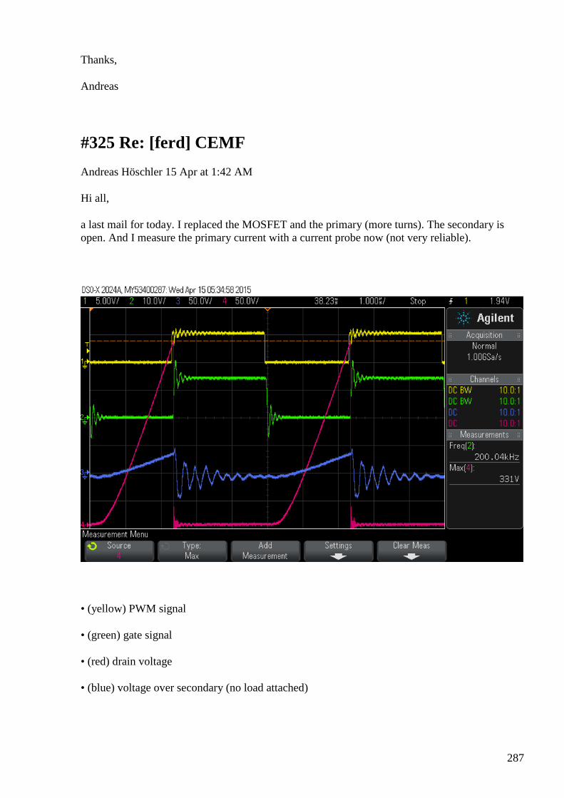
287
Thanks,
Andreas
#325 Re: [ferd] CEMF
Andreas Höschler 15 Apr at 1:42 AM
Hi all,
a last mail for today. I replaced the MOSFET and the primary (more turns). The secondary is open. And I measure the primary current with a current probe now (not very reliable).
• (yellow) PWM signal
• (green) gate signal
• (red) drain voltage
• (blue) voltage over secondary (no load attached)
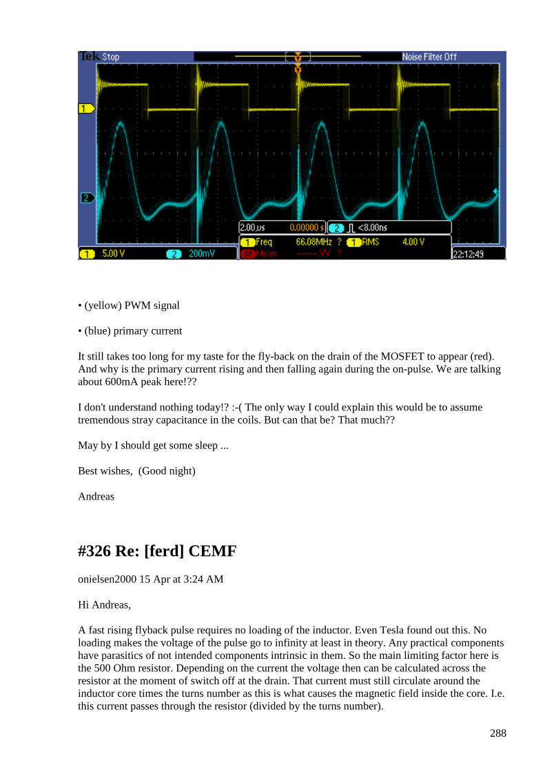
288
• (yellow) PWM signal
• (blue) primary current
It still takes too long for my taste for the fly-back on the drain of the MOSFET to appear (red). And why is the primary current rising and then falling again during the on-pulse. We are talking about 600mA peak here!??
I don't understand nothing today!? :-( The only way I could explain this would be to assume tremendous stray capacitance in the coils. But can that be? That much??
May by I should get some sleep ...
Best wishes, (Good night)
Andreas
#326 Re: [ferd] CEMF
onielsen2000 15 Apr at 3:24 AM
Hi Andreas, A fast rising flyback pulse requires no loading of the inductor. Even Tesla found out this. No loading makes the voltage of the pulse go to infinity at least in theory. Any practical components have parasitics of not intended components intrinsic in them. So the main limiting factor here is the 500 Ohm resistor. Depending on the current the voltage then can be calculated across the resistor at the moment of switch off at the drain. That current must still circulate around the inductor core times the turns number as this is what causes the magnetic field inside the core. I.e. this current passes through the resistor (divided by the turns number).
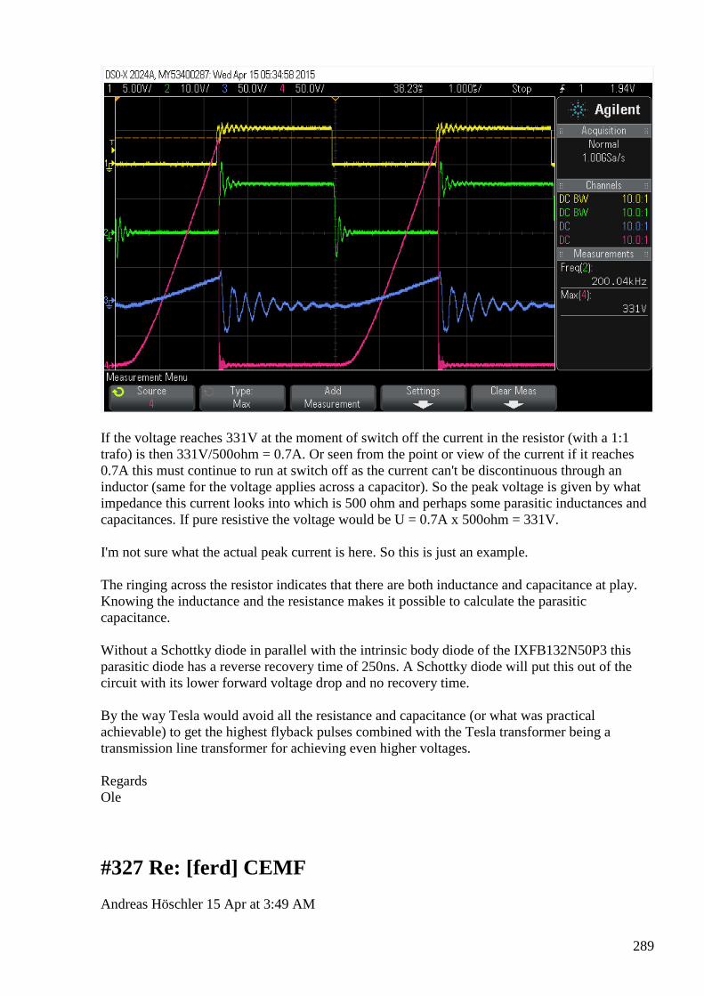
289
If the voltage reaches 331V at the moment of switch off the current in the resistor (with a 1:1 trafo) is then 331V/500ohm = 0.7A. Or seen from the point or view of the current if it reaches 0.7A this must continue to run at switch off as the current can't be discontinuous through an inductor (same for the voltage applies across a capacitor). So the peak voltage is given by what impedance this current looks into which is 500 ohm and perhaps some parasitic inductances and capacitances. If pure resistive the voltage would be U = 0.7A x 500ohm = 331V. I'm not sure what the actual peak current is here. So this is just an example. The ringing across the resistor indicates that there are both inductance and capacitance at play. Knowing the inductance and the resistance makes it possible to calculate the parasitic capacitance. Without a Schottky diode in parallel with the intrinsic body diode of the IXFB132N50P3 this parasitic diode has a reverse recovery time of 250ns. A Schottky diode will put this out of the circuit with its lower forward voltage drop and no recovery time. By the way Tesla would avoid all the resistance and capacitance (or what was practical achievable) to get the highest flyback pulses combined with the Tesla transformer being a transmission line transformer for achieving even higher voltages. Regards Ole
#327 Re: [ferd] CEMF
Andreas Höschler 15 Apr at 3:49 AM

290
Hi Ole,
thanks for your reply (see comments in the text):
Any practical components have parasitics of not intended components intrinsic in them. So the main limiting factor here is the 500 Ohm resistor. Depending on the current the voltage then can be calculated across the resistor at the moment of switch off at the drain. That current must still circulate around the inductor core times the turns number as this is what causes the magnetic field inside the core. I.e. this current passes through the resistor (divided by the turns number).
If the voltage reaches 331V at the moment of switch off the current in the resistor (with a 1:1 trafo)
is then 331V/500ohm = 0.7A.
That would be correct if I still had the 500R connected and if the red line would show the secondary voltage. But there is no resistor in this experiment and the red curve shows the drain/sink voltage on the primary side. I have no problem with this thing only developing 331V fly-back spike due to intrinsic losses (capacitance, resistance,...). That's more or less expected. What I have a problem with is the 300ns between switch off and the fly-back voltage showing up and then taking eternity to reach the 331V. Fly-back spikes (if not dampened by resistance) usually appear instantaneously and are gone (energy consumed) rapidly (for high impedances). But this thing is slowly developing as if charging a significant capacitance!?
The ringing across the resistor indicates that there are both inductance and capacitance at play.
The ringing (blue curve) happens at the secondary and is probably caused by the stray capacitance of the secondary winding. But this has hardly any effect on the primary side (red curve). I completely removed the secondary winding for a test so that I was left with just the primary winding on a ferrite core and the red curve still behaved as shown above,
Without a Schottky diode in parallel with the intrinsic body diode of the IXFB132N50P3 this
parasitic diode has a reverse recovery time of 250ns.
I am wondering what exactly recovery time means here. This intrinsic diode should never conduct, neither during the on-phase (shorted by the drain/sink junction) nor in the off-phase (biased in non-conducting direction), right!? So what is it supposed to recover from? However, the time between switch off and the drain voltage to slowly build up is amazingly close to 250ns!?
A Schottky diode will put this out of the circuit with its lower forward voltage drop and no
recovery time.
It will never conduct as well, right? But put additional capacitance on the drain/source!?
Thanks,
Andreas
291
#328 Re: [ferd] CEMF
Gerry 15 Apr at 3:42 AM
Hi Andreas,
Thanks for sharing your scope shots and detailing what they indicate so well.
I have been thinking about the negative going voltage across the load, and must be getting too old for this stuff.
As the answer doesn't pop into my head like it used to, maybe Ole can help more.
Just some thoughts mate, dunno if it helps.....
Am used to seeing inductor volts go negative in order to sustain interrupted currents, which we know inductors don't like current changes.
When those Drain volts drop to zero so quick the current pulse might initially be quite huge (like with air core transformer & winding resistance + interwinding capacity only).
Until domains inside ferrite have time to align, then current flow is opposed and should rise exponentially as normal with Barkhaussen bumps.
So maybe the negative swing on the load is the ringing response to the Drain current pulse?
Gerry
#329 Re: [ferd] CEMF
Gerry 15 Apr at 4:03 AM
Hi again Andreas,
On the red trace do you see how slowly the FET Drain recovers from the shorted or ON condition ?
Have you attached any surface mount style or ceramic decoupling capacitors close to the FET where the ferrite transformer primary connects to Vdd?
Because the dV/dt looks quite slow which could be from a lack of immediate short term current ...
and or stray capacitance around drain side of FET when FET is off it might be taking a while to charge this capacitance?
292
I like your blue current trace ...very nice.
Can see an immediate surge or spike followed by a more exponential rise (along with the bumps).
I think it's like I suggested ...the current spike is so fast that the inductance of the core is initially quite low,
the mag field from the spike has to penetrate the core and magnetise it before inductance effect appears properly.
The little ripples on the current rise are the Barkhaussen jumps as the little domains start to line up in the core.
There's a David Watson paper on Naudins site explains this effect (we talked about it before here) and how to obtain free energy from it.
Gerry
#330 Re: [ferd] CEMF
onielsen2000 15 Apr at 5:48 AM
Hi Andreas, Answer is in the text. ---In [email protected], <ahoesch@...> wrote : Hi Ole,
thanks for your reply (see comments in the text):
Any practical components have parasitics of not intended components intrinsic in them. So the main limiting factor here is the 500 Ohm resistor. Depending on the current the voltage then can be calculated across the resistor at the moment of switch off at the drain. That current must still circulate around the inductor core times the turns number as this is what causes the magnetic field inside the core. I.e. this current passes through the resistor (divided by the turns number).
If the voltage reaches 331V at the moment of switch off the current in the resistor (with a 1:1 trafo)
is then 331V/500ohm = 0.7A.
That would be correct if I still had the 500R connected and if the red line would show the secondary voltage. But there is no resistor in this experiment and the red curve shows the drain/sink voltage on the primary side. I have no problem with this thing only developing
293
331V fly-back spike due to intrinsic losses (capacitance, resistance,...). That's more or less expected. What I have a problem with is the 300ns between switch off and the fly-back voltage showing up and then taking eternity to reach the 331V. Fly-back spikes (if not dampened by resistance) usually appear instantaneously and are gone (energy consumed) rapidly (for high impedances). But this thing is slowly developing as if charging a significant capacitance!?
This must be the reverse recovery of the intrinsic body diode of the MOSFET switch. According to the datasheet this time is 250ns. Try bypassing it with a Schottky diode rated to withstand the voltage and current. The slow rise is not limited by a resistor which only limits the amplitude (not the speed) at least if being ideal. I.e. no capacitance and inductance. The slow speed indicates something being charged with the energy.
The ringing across the resistor indicates that there are both inductance and capacitance at play.
The ringing (blue curve) happens at the secondary and is probably caused by the stray capacitance of the secondary winding. But this has hardly any effect on the primary side (red curve). I completely removed the secondary winding for a test so that I was left with just the primary winding on a ferrite core and the red curve still behaved as shown above,
There must be a reactive component to do this. Try reading some of the theory from this page like the solid state Tesla coils using power MOSFETS: Richie's Tesla Coil Web Page
Richie's Tesla Coil Web Page Tesla Coil design, construction, operation and measurement information
View on www.richieburnett.co.uk Preview
by Yahoo
Without a Schottky diode in parallel with the intrinsic body diode of the IXFB132N50P3 this
parasitic diode has a reverse recovery time of 250ns.
I am wondering what exactly recovery time means here. This intrinsic diode should never conduct, neither during the on-phase (shorted by the drain/sink junction) nor in the off-phase (biased in non-conducting direction), right!? So what is it supposed to recover from? However, the time between switch off and the drain voltage to slowly build up is amazingly close to 250ns!?
How exactly is this circuit? Is is just a MOSFET and a coil in series between some good decoupled supply rails or is it something else? Also there are different kinds of ferrite with different sizes of distributed inuctance and capacitance. Some are for fast signals while others only can take slow signals. If the ferrite heats by continuously pulsing the signals then this is where the energy goes.
A Schottky diode will put this out of the circuit with its lower forward voltage drop and no
recovery time.
294
It will never conduct as well, right? But put additional capacitance on the drain/source!?
Schottky diodes are point contact diodes (oldest semiconductor diode type) having minimal capacitance which makes them the fastest diodes. They are fast enough to be used as detector diodes in radio receivers. Put up an LC-tank of good Q (quality) at a frequency of an AM radio station and rectify the AM-signal by a Schottky diode. Amplify that signal and listen to the station (or use high impedance head phones). Even microwaves can be rectified by Schottky diodes so sub MHz signals is no problem for them. They start conducting at less voltage than non Schottkys of the same semiconductor material. For Si Schottkys the forward conduction voltage is max 0.5V compared to 0.7V for Si non Schottkys. Regards Ole
#331 RE: [ferd] CEMF
Alexey 15 Apr at 8:34 AM
Hi Andreas,
I think you are observing parasite capacitance effects.
Decrease frequency (and increase pulse length) 10x or 100x and you will see what you expected (but be careful with core saturation).
Regards,
Alexey
#332 RE: [ferd] CEMF
Alexey 15 Apr at 9:17 AM
Hi Andreas, All, I made small flyback model in LTSpice. fb.png present ideal case and fb_parcap.png present effect of switch parasite capacitance. Regards, Alexey
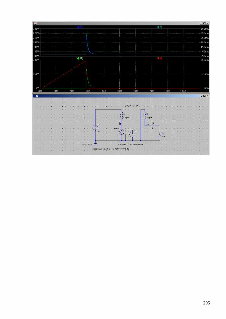
295
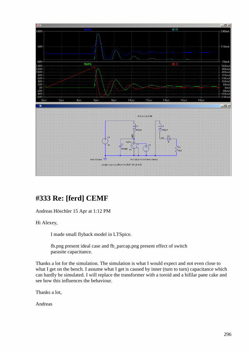
296
#333 Re: [ferd] CEMF
Andreas Höschler 15 Apr at 1:12 PM
Hi Alexey,
I made small flyback model in LTSpice.
fb.png present ideal case and fb_parcap.png present effect of switch parasite capacitance.
Thanks a lot for the simulation. The simulation is what I would expect and not even close to what I get on the bench. I assume what I get is caused by inner (turn to turn) capacitance which can hardly be simulated. I will replace the transformer with a toroid and a bifilar pane cake and see how this influences the behaviour.
Thanks a lot,
Andreas
297
#334 Re: [ferd] CEMF
Andreas Höschler 15 Apr at 2:53 PM
Hi Gerry,
nice to hear/read from you! :-)
Thanks for sharing your scope shots and detailing what they indicate so well.
I have been thinking about the negative going voltage across the load, and must be getting too old for this stuff.
That was my feeling as well tonight! Now in the sunshine things seem a bit more logical again! :-)
As the answer doesn't pop into my head like it used to, maybe Ole can help more.
Just some thoughts mate, dunno if it helps.....
Am used to seeing inductor volts go negative in order to sustain interrupted currents, which we know inductors don't like current changes.
Yes,we know that well. The problem I had was rather that there simply could not be negative voltage over the load since this should have been blocked by the diode. I double checked (tested) the diode in a test circuit and it works fine there (blocks DC in one direction). Weird stuff. I am working with 100kHz. That should not be too high for super fast diodes!? Strange stuff. Who knows ...
Best wishes,
Andreas
#335 Re: [ferd] CEMF
Andreas Höschler 15 Apr at 3:03 PM
Hi Gerry,
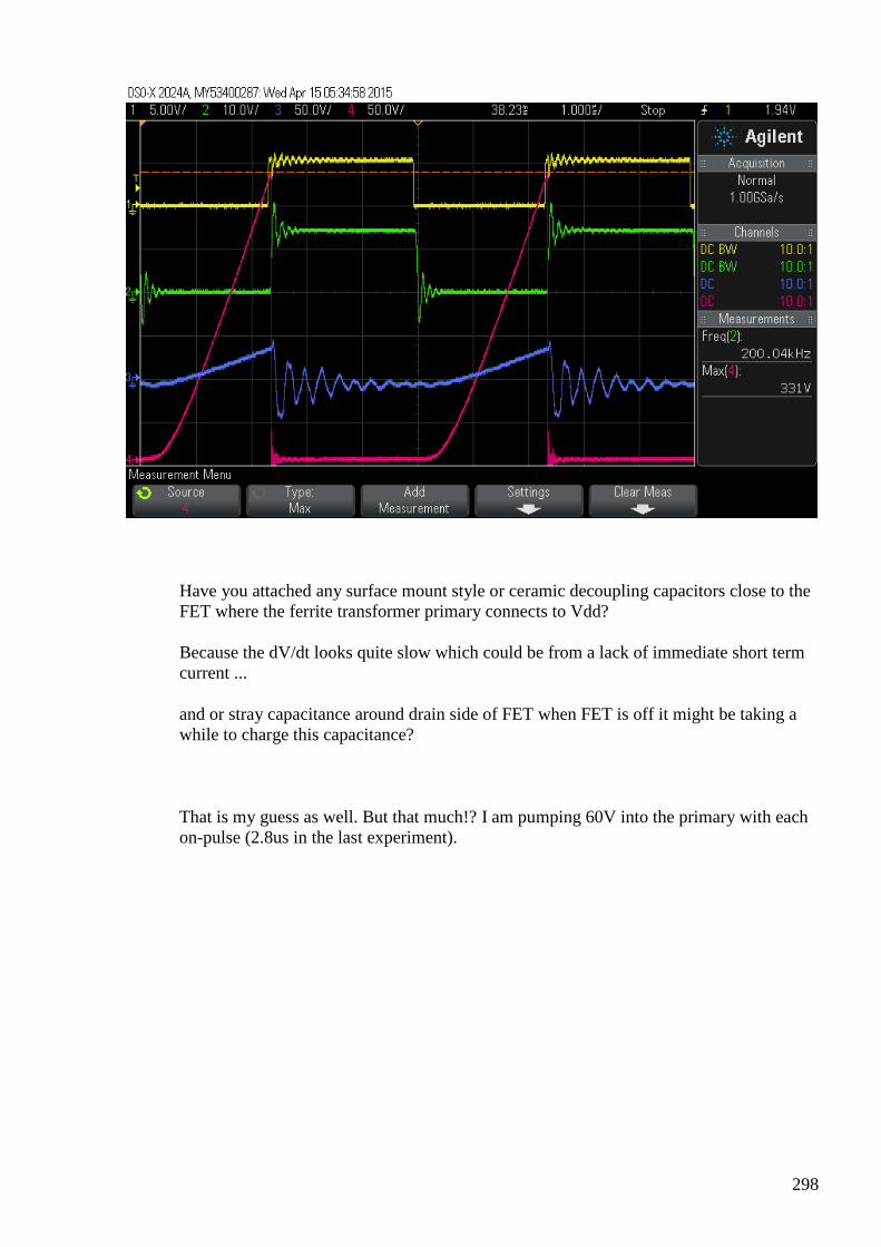
298
Have you attached any surface mount style or ceramic decoupling capacitors close to the FET where the ferrite transformer primary connects to Vdd?
Because the dV/dt looks quite slow which could be from a lack of immediate short term current ...
and or stray capacitance around drain side of FET when FET is off it might be taking a while to charge this capacitance?
That is my guess as well. But that much!? I am pumping 60V into the primary with each on-pulse (2.8us in the last experiment).
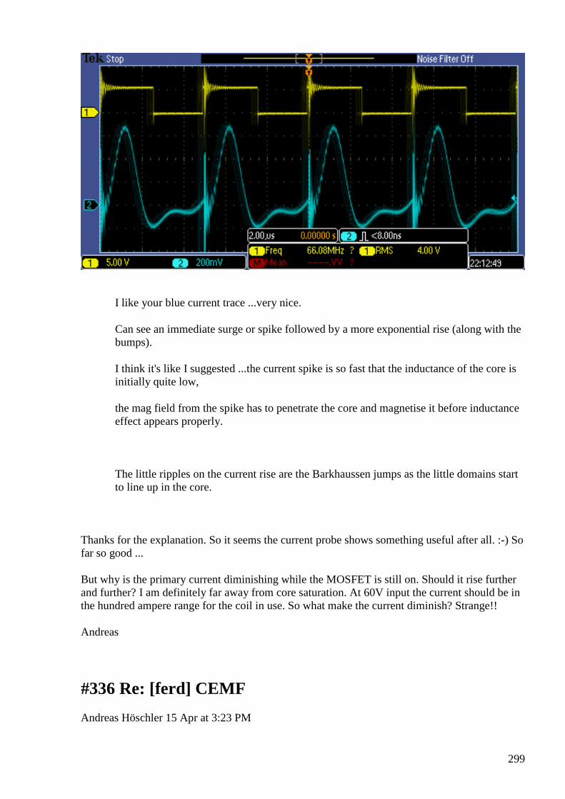
299
I like your blue current trace ...very nice.
Can see an immediate surge or spike followed by a more exponential rise (along with the bumps).
I think it's like I suggested ...the current spike is so fast that the inductance of the core is initially quite low,
the mag field from the spike has to penetrate the core and magnetise it before inductance effect appears properly.
The little ripples on the current rise are the Barkhaussen jumps as the little domains start to line up in the core.
Thanks for the explanation. So it seems the current probe shows something useful after all. :-) So far so good ...
But why is the primary current diminishing while the MOSFET is still on. Should it rise further and further? I am definitely far away from core saturation. At 60V input the current should be in the hundred ampere range for the coil in use. So what make the current diminish? Strange!!
Andreas
#336 Re: [ferd] CEMF
Andreas Höschler 15 Apr at 3:23 PM
300
Hi Ole,
This must be the reverse recovery of the intrinsic body diode of the MOSFET switch. According to the datasheet this time is 250ns. Try bypassing it with a Schottky diode rated to withstand the voltage and current.
I will give this a try tonight!
There must be a reactive component to do this.
I guess it's the interwinding capacitance but am surprised a bit how high that is! I will verify this my trying a toroid and then compare the results.
Thanks a lot,
Andreas
#337 Re: [ferd] CEMF
onielsen2000 15 Apr at 3:52 PM
Hi Andreas,
---In [email protected], <ahoesch@...> wrote :
Hi Ole,
Be careful as if there is no damping the flyback pulse will reach a destructive level. In CRT TV sets the EHT flyback transformers the flyback pulses are limited by a capacitor in parallel to the collector-emitter or drain-source to stay within the transistors max rating.
There must be a reactive component to do this.
I guess it's the interwinding capacitance but am surprised a bit how high that is! I will verify this my trying a toroid and then compare the results. It could also be from the ferrite core itself. Regards Ole
#338 Re: [ferd] CEMF
Gerry 15 Apr at 7:07 PM
Silly me forgot to attach snip, duh.
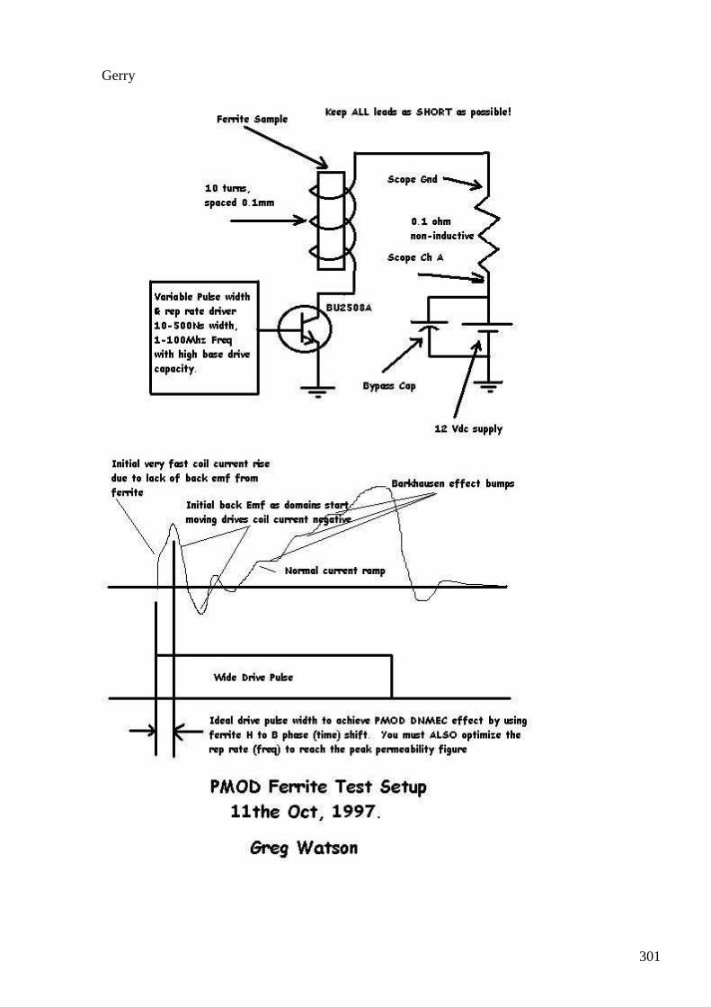
301
Gerry
302
#339 Re: [ferd] CEMF
Gerry 15 Apr at 6:48 PM
Hi Andreas,
Am replying to this post because my Gmail seems to have deleted your later reply.
Have attached a snip from JLN's Greg Watson's PMOD project.
His circuit had no secondary so it was simpler but on the snip it shows that this portion of the waveform.
Where the initial current goes negative ....this is free energy.
Please take a look and see if similarity to your findings ...he also was able to magnify the waveform by placing one pole of a ferrite magnet against the core.
I have been a bit quiet because I have been working on something else, along lines of electric generator which may (or more likely will not self run).
Trying to keep it my problem unless it works.
Gerry
#340 Re: [ferd] CEMF
Gerry Apr 15 9:36 PM
Hi Andreas,
More thoughts about your negative voltage on load resistor, hope no one here minds me being verbose.
Provided load resistor is only resistive (no reactive component):
When scope shows positive volts across load resistor, load is absorbing current and delivering heat into the environment at rate of I*I*R*time.
When scope shows negative volts across load resistor, resistor is sourcing current back into transformer secondary and likely (cooling or heating?) the environment from -I*-I*R*time.
The only way this can happen is for the transformer itself to look like a negative resistance (impedance) for that moment in time.
This situation is understandable,
303
because when nature (God) sees that "Andreas" has turned on a FET switch really fast demanding big current immediately along with it's correct magnetic flux density from the core.
The core hasn't yet had time to deliver the mathematically correct flux density for it's present total permeability state.
So the core is momentarily deficient to it's surroundings from the demands being made on it from the fast rising current step.
Being momentarily deficient like this, places it in a net "negative energy balance" to it's immediate environment.
So to me the core appearing a negative impedance at this moment in time isn't all that surprising.
OU can only happen when the total sources of negative energy in power per unit time, exceeds the total positive input energy over that same unit time.
When the FET was switched off and current continues to rise I'm not sure why.
But I would definitely increase the frequency whilst watching the blue and red traces.
To try to have situation where you have blue trace showing negative voltage across load resistor for more time than it's positive.
and minimise time for positive voltage across load resistor to occur.
By re triggering FET before drain voltage reaches such a high level.
From red trace we can see that whilst max Drain current E across FET is minimal yet our load current is negative.
So here may be the negative energy you're looking for, great start Andreas!
Back to bed now.
#341 Re: [ferd] CEMF
Andreas Höschler 16 Apr at 4:09 AM
Hi Gerry,
More thoughts about your negative voltage on load resistor, hope no one here minds me being verbose.
Provided load resistor is only resistive (no reactive component):
When scope shows positive volts across load resistor, load is absorbing current and delivering heat into the environment at rate of I*I*R*time.
304
When scope shows negative volts across load resistor, resistor is sourcing current back into transformer secondary and likely (cooling or heating?) the environment from -I*-I*R*time.
The only way this can happen is for the transformer itself to look like a negative resistance (impedance) for that moment in time.
This situation is understandable,
because when nature (God) sees that "Andreas" has turned on a FET switch really fast demanding big current immediately along with it's correct magnetic flux density from the core.
The core hasn't yet had time to deliver the mathematically correct flux density for it's present total permeability state.
So the core is momentarily deficient to it's surroundings from the demands being made on it from the fast rising current step.
Being momentarily deficient like this, places it in a net "negative energy balance" to it's immediate environment.
So to me the core appearing a negative impedance at this moment in time isn't all that surprising.
I have no clear picture of the involved processes yet but I learn new stuff very day. In ferrite there is this aligning of magnetic domains. But the effect that I am even more interested in and that might turn out to extract energy from the ambient is sudden changes to the external H which causes the precession to get temporarily get out of balance which in turn makes the ambient kick in to fix the issue. This might cause anomalous dB/dt that might be harnessed. However, I am not sure whether commercially available diodes are fast enough to collect these anomalous OU spikes!?
OU can only happen when the total sources of negative energy in power per unit time, exceeds the total positive input energy over that same unit time.
When the FET was switched off and current continues to rise I'm not sure why.
But I would definitely increase the frequency whilst watching the blue and red traces.
To try to have situation where you have blue trace showing negative voltage across load resistor for more time than it's positive.
and minimise time for positive voltage across load resistor to occur.
By re triggering FET before drain voltage reaches such a high level.
305
From red trace we can see that whilst max Drain current E across FET is minimal yet our load current is negative.
So here may be the negative energy you're looking for, great start Andreas!
More experimentation is needed. Essentially reducing the frequency leads to the expected result (immediate sharp fly-back spike). So it seems the low energy chunks I put into the core (short pulses) where just consumed by parasitic capacitances.
I am into building super hard MOSFET kickers right now in the hope to generate an anomalous effect by these sudden changes (TESLA style). We will see ...
Best wishes,
Andreas
#342 Re: [ferd] CEMF
onielsen2000 16 Apr at 5:17 AM
Hi Gerry, Andreas,
"When the FET was switched off and current continues to rise I'm not sure why.
But I would definitely increase the frequency whilst watching the blue and red traces.
To try to have situation where you have blue trace showing negative voltage across load resistor for more time than it's positive.
and minimise time for positive voltage across load resistor to occur."
Only Schottky diodes can switch off at moment of reversal of the current. Other diodes can't do that before they are depleted of charge. They just continue to conduct in the reverse direction for while until they are discharged. http://en.wikipedia.org/wiki/Diode#Reverse-recovery_effect
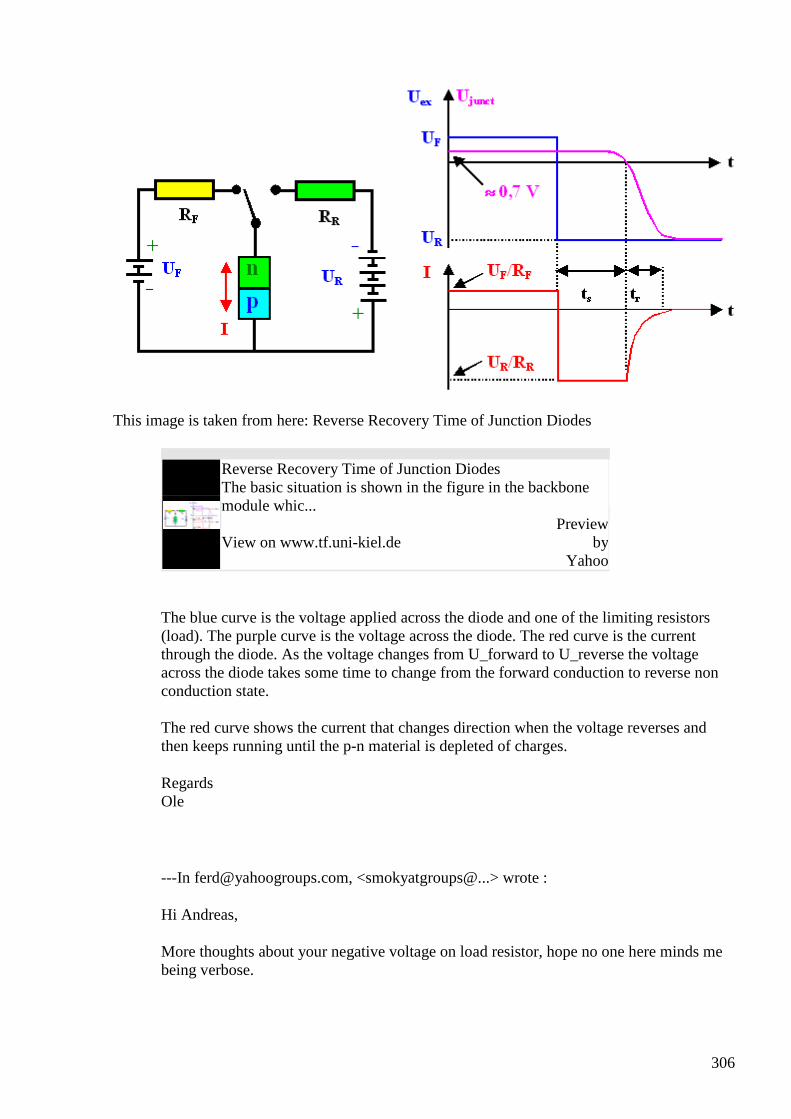
306
This image is taken from here: Reverse Recovery Time of Junction Diodes
Reverse Recovery Time of Junction Diodes The basic situation is shown in the figure in the backbone module whic...
View on www.tf.uni-kiel.de Preview
by Yahoo
The blue curve is the voltage applied across the diode and one of the limiting resistors (load). The purple curve is the voltage across the diode. The red curve is the current through the diode. As the voltage changes from U_forward to U_reverse the voltage across the diode takes some time to change from the forward conduction to reverse non conduction state. The red curve shows the current that changes direction when the voltage reverses and then keeps running until the p-n material is depleted of charges.
Regards Ole
---In [email protected], <smokyatgroups@...> wrote :
Hi Andreas,
More thoughts about your negative voltage on load resistor, hope no one here minds me being verbose.
307
Provided load resistor is only resistive (no reactive component):
When scope shows positive volts across load resistor, load is absorbing current and delivering heat into the environment at rate of I*I*R*time.
When scope shows negative volts across load resistor, resistor is sourcing current back into transformer secondary and likely (cooling or heating?) the environment from -I*-I*R*time.
The only way this can happen is for the transformer itself to look like a negative resistance (impedance) for that moment in time.
This situation is understandable,
because when nature (God) sees that "Andreas" has turned on a FET switch really fast demanding big current immediately along with it's correct magnetic flux density from the core.
The core hasn't yet had time to deliver the mathematically correct flux density for it's present total permeability state.
So the core is momentarily deficient to it's surroundings from the demands being made on it from the fast rising current step.
Being momentarily deficient like this, places it in a net "negative energy balance" to it's immediate environment.
So to me the core appearing a negative impedance at this moment in time isn't all that surprising.
OU can only happen when the total sources of negative energy in power per unit time, exceeds the total positive input energy over that same unit time.
When the FET was switched off and current continues to rise I'm not sure why.
But I would definitely increase the frequency whilst watching the blue and red traces.
To try to have situation where you have blue trace showing negative voltage across load resistor for more time than it's positive.
and minimise time for positive voltage across load resistor to occur.
By re triggering FET before drain voltage reaches such a high level.
From red trace we can see that whilst max Drain current E across FET is minimal yet our load current is negative.
So here may be the negative energy you're looking for, great start Andreas!
Back to bed now.
308
#343 Re: [ferd] CEMF
onielsen2000 16 Apr at 5:37 AM
Hi Gerry, Andreas, Addendum The p-n diode on the schematic should be turned around as it looks like is has been placed in the wrong direction or the F and R markings are wrong. The F and R indexes on the graphs are right when the diode is reversed. Regards Ole
#344 Re: [ferd] CEMF
Gerry 16 Apr at 9:11 AM
Thanks Ole yeah
To be honest I haven't looked at Andreas' circuit.
Mainly commenting on the scope shots. I probably should follow more closely the posts here.
I was imagining that it was just the FET Drain driving the primary side.
So not sure which forward conducting then reverse bias diodes you mean (at the moment).
Or are you speaking about the effective junction capacitance of the internal protection diode on the FET itself?
Was just trying to help with some info & comments.
I will check out his schematic before opening my big mouth again.
Gerry
#345 Re: [ferd] CEMF
onielsen2000 16 Apr at 2:50 PM
Hi Gerry, It is the internal parasitic body diode which is an ordinary p-n junction which does has the recovery time. To bypass this parasite a better diode with less forward voltage drop and faster
309
reverse recovery time is needed. A candidate for this is a Schottky diode. Traditionally they were only made for low voltages. Now with SiC or other semiconductor materials higher voltages are possible. Another possibility to bypass the intrinsic body diode would be to use an active rectifier like using another MOSFET to bypass the diode. This can give very low conduction voltage drops. MOSFETs will conduct in both directions when switched on and with less voltage drop across it than any conducting diode. I don't know the circuit of Andreas so actually can't tell if this is the real problem. I.e. switching a diode from conducting to blocking state. Regards Ole
#346 Re: [ferd] CEMF
Andreas Höschler Apr 16 6:58 PM
Hi Ole,
Only Schottky diodes can switch off at moment of reversal of the current. Other diodes can't do that before they are depleted of charge. They just continue to conduct in the reverse direction for while until they are discharged.
The blue curve is the voltage applied across the diode and one of the limiting resistors (load). The purple curve is the voltage across the diode. The red curve is the current through the diode. As the voltage changes from U_forward to U_reverse the voltage across the diode takes some time to change from the forward conduction to reverse non conduction state. The red curve shows the current that changes direction when the voltage reverses and then keeps running until the p-n material is depleted of charges.
Thanks for the detailed explanation. That is clear so far.
But in my case the current in the intrinsic diode never changes direction. It's always zero. The drain/source voltages is almost zero when the MOSFET conducts and >> 0 when the coil fires (fly back).
Andreas
#347 Re: [ferd] CEMF
Andreas Höschler Apr 16 7:07 PM
Hi Gerry,
To be honest I haven't looked at Andreas' circuit.
310
Mainly commenting on the scope shots. I probably should follow more closely the posts here.
I was imagining that it was just the FET Drain driving the primary side.
So not sure which forward conducting then reverse bias diodes you mean (at the moment).
Or are you speaking about the effective junction capacitance of the internal protection diode on the FET itself?
Was just trying to help with some info & comments.
I will check out his schematic before opening my big mouth again.
You were completely on track. I indeed was doing exactly what you described:
rail plus --- transformer primary ---- (D MOSFET S) --- rail minus
So the intrinsic diode never sees forward voltage.
Andreas
#348 Re: [ferd] CEMF
Gerry Apr 17 at 1:16 AM
Hi Andreas & Ole,
Maybe what Ole is meaning is that when voltage across your load swings negative.
It is reversing the voltage on the FET drain .....back via transformer action.
But we can't 'see it' because protection diode has turned on clamping the Drain voltage.
So only after the negative swing has ceased ...then when the internal diode turns off,
it releases it's stored depletion zone electrons slowing the positive swing upward of the Drain.
?
Gerry
#349 [offtopic] slow start for incandescent light bulbs
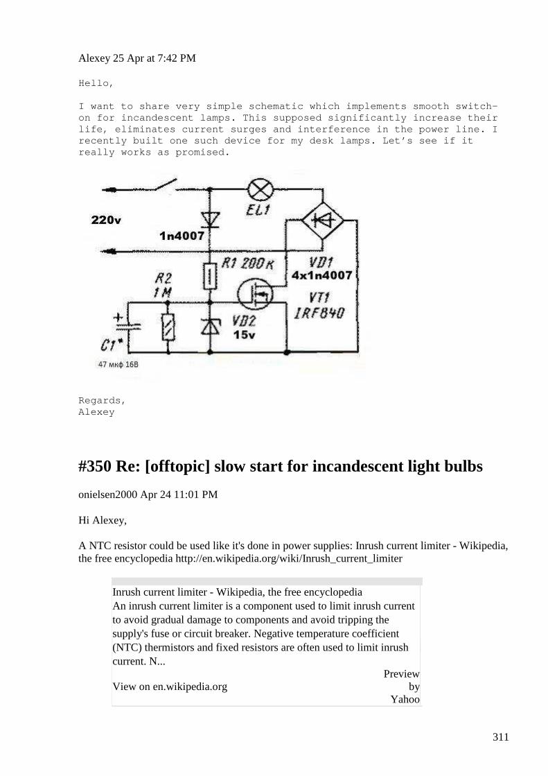
311
Alexey 25 Apr at 7:42 PM
Hello, I want to share very simple schematic which impleme nts smooth switch-on for incandescent lamps. This supposed significan tly increase their life, eliminates current surges and interference in the power line. I recently built one such device for my desk lamps. L et’s see if it really works as promised.
Regards, Alexey
#350 Re: [offtopic] slow start for incandescent light bulbs
onielsen2000 Apr 24 11:01 PM
Hi Alexey, A NTC resistor could be used like it's done in power supplies: Inrush current limiter - Wikipedia, the free encyclopedia http://en.wikipedia.org/wiki/Inrush_current_limiter
Inrush current limiter - Wikipedia, the free encyclopedia An inrush current limiter is a component used to limit inrush current to avoid gradual damage to components and avoid tripping the supply's fuse or circuit breaker. Negative temperature coefficient (NTC) thermistors and fixed resistors are often used to limit inrush current. N...
View on en.wikipedia.org Preview
by Yahoo
312
Regards Ole
#351 RE: [ferd] Re: [offtopic] slow start for incandescent light bulbs
Alexey Apr 24 11:15 PM
Hi Ole,
Interesting, somehow I forgot about this component.
So schematic could be even simpler
Thanks,
Alexey
#352 [ferd] another project idea - How to build free energy device from your air humidifier
Alexey 25 Apr at 12:10 AM
How build a free energy device from you air humidifier
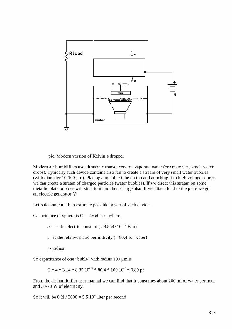
313
pic. Modern version of Kelvin’s dropper
Modern air humidifiers use ultrasonic transducers to evaporate water (or create very small water drops). Typically such device contains also fan to create a stream of very small water bubbles (with diameter 10-100 µm). Placing a metallic tube on top and attaching it to high voltage source we can create a stream of charged particles (water bubbles). If we direct this stream on some metallic plate bubbles will stick to it and their charge also. If we attach load to the plate we got an electric generator
Let’s do some math to estimate possible power of such device.
Capacitance of sphere is C = 4π ε0 ε r, where
ε0 - is the electric constant (≈ 8.854×10⁻¹² F/m)
ε - is the relative static permittivity (= 80.4 for water)
r - radius
So capacitance of one “buble” with radius 100 µm is
C = 4 * 3.14 * 8.85 10-12 * 80.4 * 100 10-6 = 0.89 pf
From the air humidifier user manual we can find that it consumes about 200 ml of water per hour and 30-70 W of electricity.
So it will be 0.2l / 3600 = 5.5 10-4 liter per second
314
Volume of sphere is V = 4/3 π r3, so volume of one bubble is
V = 4 * 3.14 * 10-12 / 3 = 4.19 10-12 l
and we will get 5.5 10-4 / 4.19 10-12 = 1.31 108 bubbles per second
Assume we are using 5KV high voltage source each bubble will transfer charge
Q = CU = 0.89 10-12 * 5 103 = 4.47 nQ
and total charge transfer will be 4.47 nQ * 1.31 108 = 0.58 Q/s (Amperes)
So optimistically we can expect output power in as range
P = UI = 5KV * 0.58 A = 2.9KW
even if we will get 1/10 of these estimate in reality the system still will be about 3x OU
Interesting ? ;-)
References:
1. http://en.wikipedia.org/wiki/Capacitance
#353 Re: [ferd] another project idea - How to build free energy device from your air humidifier
Andreas Höschler 25 Apr at 1:06 AM
Hi Alexey,
Modern air humidifiers use ultrasonic transducers to evaporate water (or create very small water drops). Typically such device contains also fan to create a stream of very small water bubbles (with diameter 10-100 µm). Placing a metallic tube on top and attaching it to high voltage source we can create a stream of charged particles (water bubbles). If we direct this stream on some metallic plate bubbles will stick to it and their charge also. If we attach load to the plate we got an electric generator
I can't follow your logic! :-( I assume you have the triode in mind and plan to replace it (since we have a hard time finding one) with such a humidifier!?
The water reservoir is earthed, right? I consider the bubbles are neutral when starting their vertical voyage!? They now enter the tube. A few will hit the tube wall and thus be positively charged. Most will pass the tube and stay neutral and thus not transfer any charge to the load. I can't see how this could ever be OU!? Am I missing anything?

315
I have reason to believe that the triode will work though (just a guess but)!
Andreas
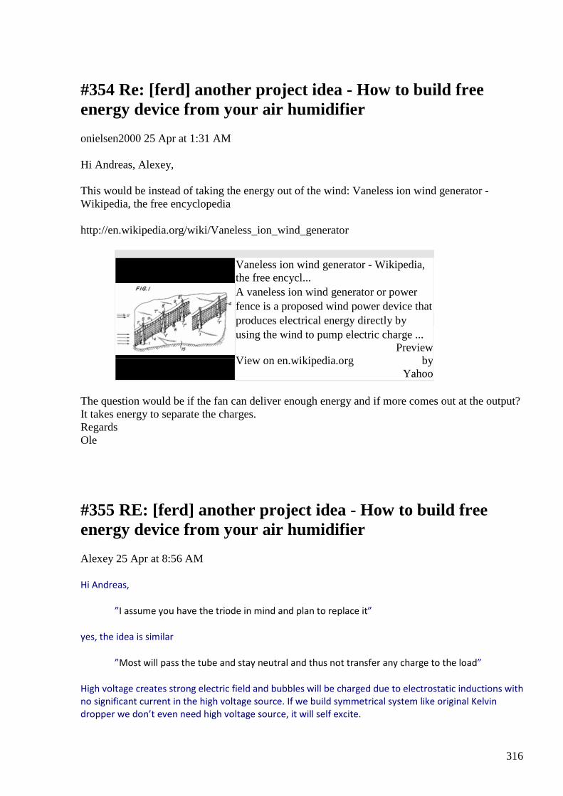
316
#354 Re: [ferd] another project idea - How to build free energy device from your air humidifier
onielsen2000 25 Apr at 1:31 AM
Hi Andreas, Alexey, This would be instead of taking the energy out of the wind: Vaneless ion wind generator - Wikipedia, the free encyclopedia
http://en.wikipedia.org/wiki/Vaneless_ion_wind_generator
Vaneless ion wind generator - Wikipedia, the free encycl... A vaneless ion wind generator or power fence is a proposed wind power device that produces electrical energy directly by using the wind to pump electric charge ...
View on en.wikipedia.org Preview
by Yahoo
The question would be if the fan can deliver enough energy and if more comes out at the output? It takes energy to separate the charges. Regards Ole
#355 RE: [ferd] another project idea - How to build free energy device from your air humidifier
Alexey 25 Apr at 8:56 AM
Hi Andreas,
”I assume you have the triode in mind and plan to replace it”
yes, the idea is similar
”Most will pass the tube and stay neutral and thus not transfer any charge to the load”
High voltage creates strong electric field and bubbles will be charged due to electrostatic inductions with
no significant current in the high voltage source. If we build symmetrical system like original Kelvin
dropper we don’t even need high voltage source, it will self excite.
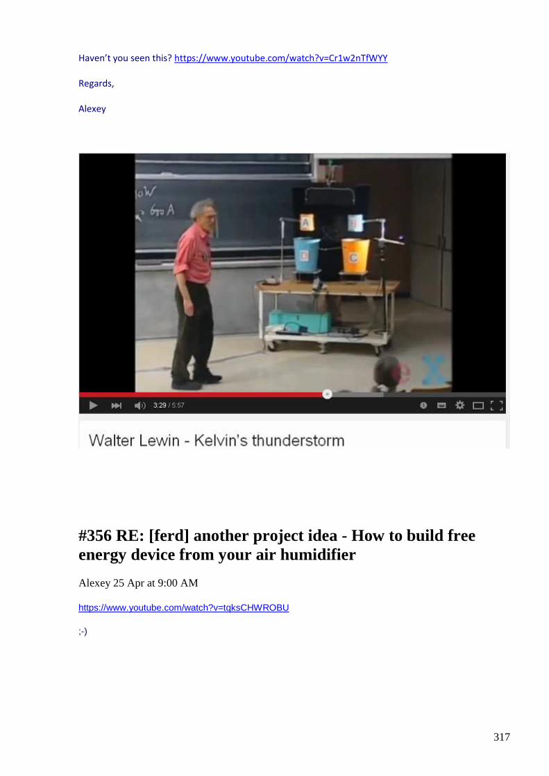
317
Haven’t you seen this? https://www.youtube.com/watch?v=Cr1w2nTfWYY
Regards,
Alexey
#356 RE: [ferd] another project idea - How to build free energy device from your air humidifier
Alexey 25 Apr at 9:00 AM
https://www.youtube.com/watch?v=tqksCHWROBU
;-)
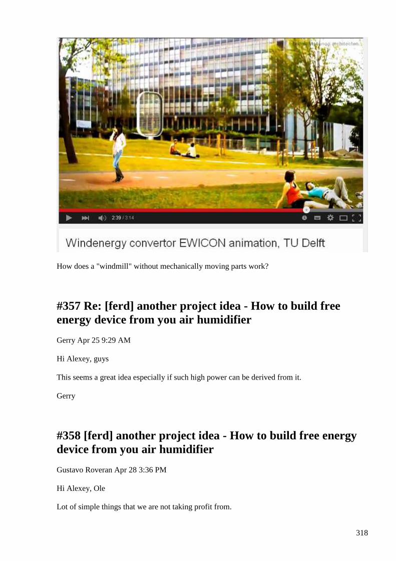
318
How does a "windmill" without mechanically moving parts work?
#357 Re: [ferd] another project idea - How to build free energy device from you air humidifier
Gerry Apr 25 9:29 AM
Hi Alexey, guys
This seems a great idea especially if such high power can be derived from it.
Gerry
#358 [ferd] another project idea - How to build free energy device from you air humidifier
Gustavo Roveran Apr 28 3:36 PM
Hi Alexey, Ole Lot of simple things that we are not taking profit from.
319
Thanks Gustavo
#359 Re: [ferd] another project idea - How to build free energy device from you air humidifier
Andreas Höschler Apr 28 9:45 PM
Hi Alexey,
sorry for the late response. I somehow missed your mail.
”I assume you have the triode in mind and plan to replace it”
yes, the idea is similar
”Most will pass the tube and stay neutral and thus not transfer any charge to the load”
High voltage creates strong electric field and bubbles will be charged due to electrostatic
inductions with no significant current in the high voltage source. If we build symmetrical system
like original Kelvin dropper we don’t even need high voltage source, it will self excite.
Haven’t you seen this? https://www.youtube.com/watch?v=Cr1w2nTfWYY
No, I hadn't seen that clip. I now have. Interesting but I doubt this is of any use. One cubic meter of rain water kept on the roof at a height of 2m has potential energy of 6Wh. This is close to nothing. I doubt dropping this water through the proposed device yields more output power than the classical potential energy value!?
Back to your proposal. You are generating fine droplets with your us transducer and blow them up with a fan through an E-field. ..Here I get stuck. I can't see where electrostatic induction could help out here.
I was playing around with the Cyril Smith idea yesterday, thought I had something but got finally disillusionized again.:-(
For the time being I strongly recommend the youtube publications of www.distinti.com. I have worked through his first 47 clips in the meanwhile. Amazing stuff. I am looking forward to going through his new math model.
Bst wishes,
Andreas
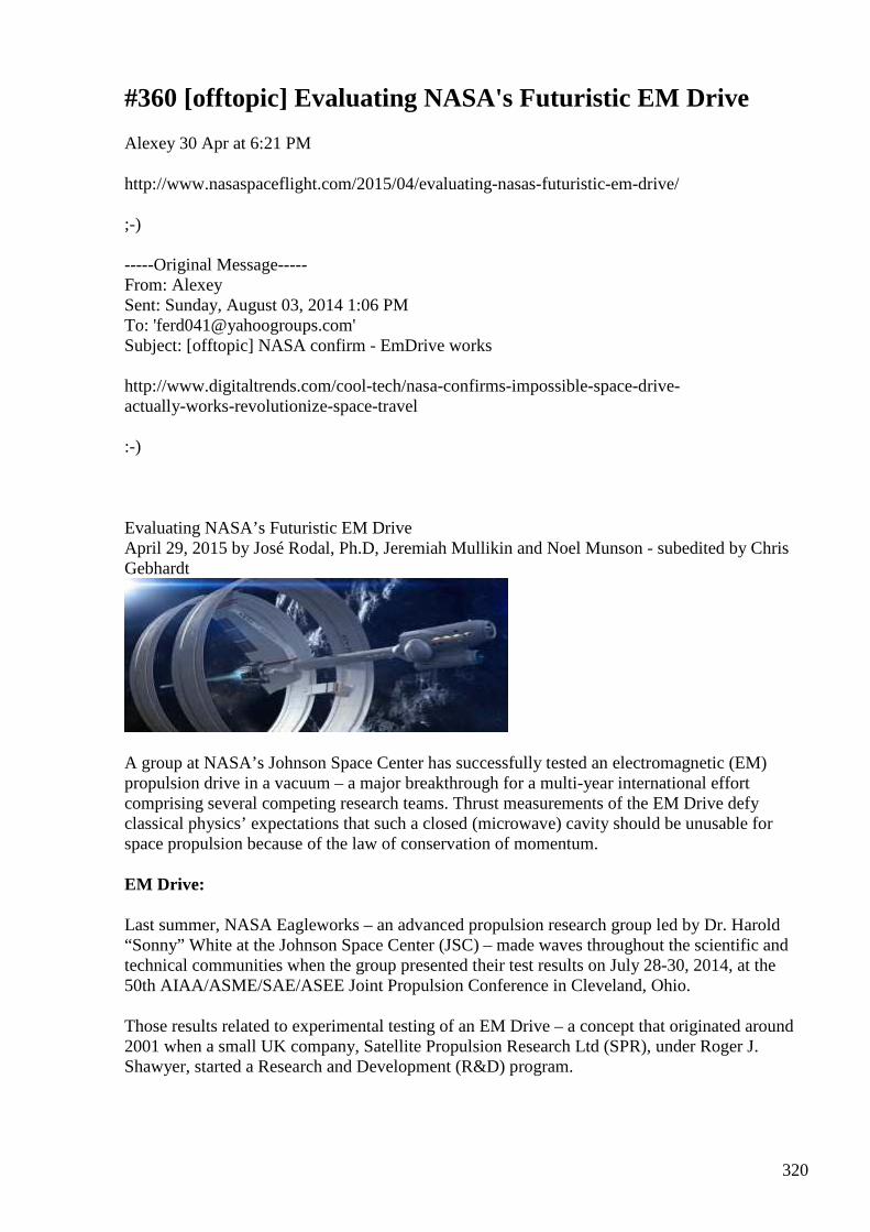
320
#360 [offtopic] Evaluating NASA's Futuristic EM Dri ve
Alexey 30 Apr at 6:21 PM
http://www.nasaspaceflight.com/2015/04/evaluating-nasas-futuristic-em-drive/ ;-) -----Original Message----- From: Alexey Sent: Sunday, August 03, 2014 1:06 PM To: '[email protected]' Subject: [offtopic] NASA confirm - EmDrive works http://www.digitaltrends.com/cool-tech/nasa-confirms-impossible-space-drive- actually-works-revolutionize-space-travel :-)
Evaluating NASA’s Futuristic EM Drive April 29, 2015 by José Rodal, Ph.D, Jeremiah Mullikin and Noel Munson - subedited by Chris Gebhardt
A group at NASA’s Johnson Space Center has successfully tested an electromagnetic (EM) propulsion drive in a vacuum – a major breakthrough for a multi-year international effort comprising several competing research teams. Thrust measurements of the EM Drive defy classical physics’ expectations that such a closed (microwave) cavity should be unusable for space propulsion because of the law of conservation of momentum. EM Drive:
Last summer, NASA Eagleworks – an advanced propulsion research group led by Dr. Harold “Sonny” White at the Johnson Space Center (JSC) – made waves throughout the scientific and technical communities when the group presented their test results on July 28-30, 2014, at the 50th AIAA/ASME/SAE/ASEE Joint Propulsion Conference in Cleveland, Ohio.
Those results related to experimental testing of an EM Drive – a concept that originated around 2001 when a small UK company, Satellite Propulsion Research Ltd (SPR), under Roger J. Shawyer, started a Research and Development (R&D) program.

321
The concept of an EM Drive as put forth by SPR was that electromagnetic microwave cavities might provide for the direct conversion of electrical energy to thrust without the need to expel any propellant.
This lack of expulsion of propellant from the drive was met with initial skepticism within the scientific community because this lack of propellant expulsion would leave nothing to balance the change in the spacecraft’s momentum if it were able to accelerate.
However, in 2010, Prof. Juan Yang in China began publishing about her research into EM Drive technology, culminating in her 2012 paper reporting higher input power (2.5kW) and tested thrust (720mN) levels of an EM Drive.
In 2014, Prof. Yang’s papers reported extensive tests involving internal temperature measurements with embedded thermocouples.
It was reported (in SPR Ltd.’s website) that if the Chinese EM Drive were to be installed in the International Space Station (ISS) and work as reported, it could provide the necessary delta-V (change in velocity needed to perform an on-orbit maneuver) to compensate for the Station’s orbital decay and thus eliminate the requirement of re-boosts from visiting vehicles. Despite these reports, Prof. Yang offered no scientifically-accepted explanation as to how the EM Drive can produce propulsion in space.
Dr. White proposed that the EM Drive’s thrust was due to the Quantum Vacuum (the quantum state with the lowest possible energy) behaving like propellant ions behave in a MagnetoHydroDynamics drive (a method electrifying
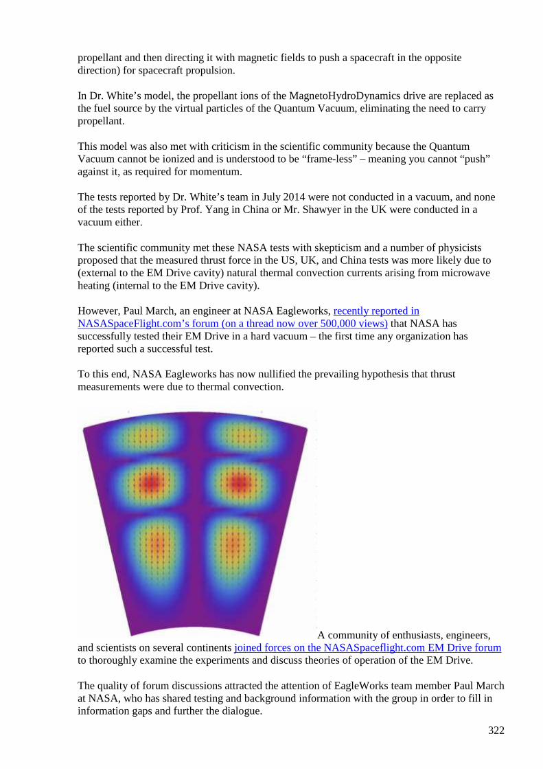
322
propellant and then directing it with magnetic fields to push a spacecraft in the opposite direction) for spacecraft propulsion.
In Dr. White’s model, the propellant ions of the MagnetoHydroDynamics drive are replaced as the fuel source by the virtual particles of the Quantum Vacuum, eliminating the need to carry propellant.
This model was also met with criticism in the scientific community because the Quantum Vacuum cannot be ionized and is understood to be “frame-less” – meaning you cannot “push” against it, as required for momentum.
The tests reported by Dr. White’s team in July 2014 were not conducted in a vacuum, and none of the tests reported by Prof. Yang in China or Mr. Shawyer in the UK were conducted in a vacuum either.
The scientific community met these NASA tests with skepticism and a number of physicists proposed that the measured thrust force in the US, UK, and China tests was more likely due to (external to the EM Drive cavity) natural thermal convection currents arising from microwave heating (internal to the EM Drive cavity).
However, Paul March, an engineer at NASA Eagleworks, recently reported in NASASpaceFlight.com’s forum (on a thread now over 500,000 views) that NASA has successfully tested their EM Drive in a hard vacuum – the first time any organization has reported such a successful test.
To this end, NASA Eagleworks has now nullified the prevailing hypothesis that thrust measurements were due to thermal convection.
A community of enthusiasts, engineers, and scientists on several continents joined forces on the NASASpaceflight.com EM Drive forum to thoroughly examine the experiments and discuss theories of operation of the EM Drive.
The quality of forum discussions attracted the attention of EagleWorks team member Paul March at NASA, who has shared testing and background information with the group in order to fill in information gaps and further the dialogue.
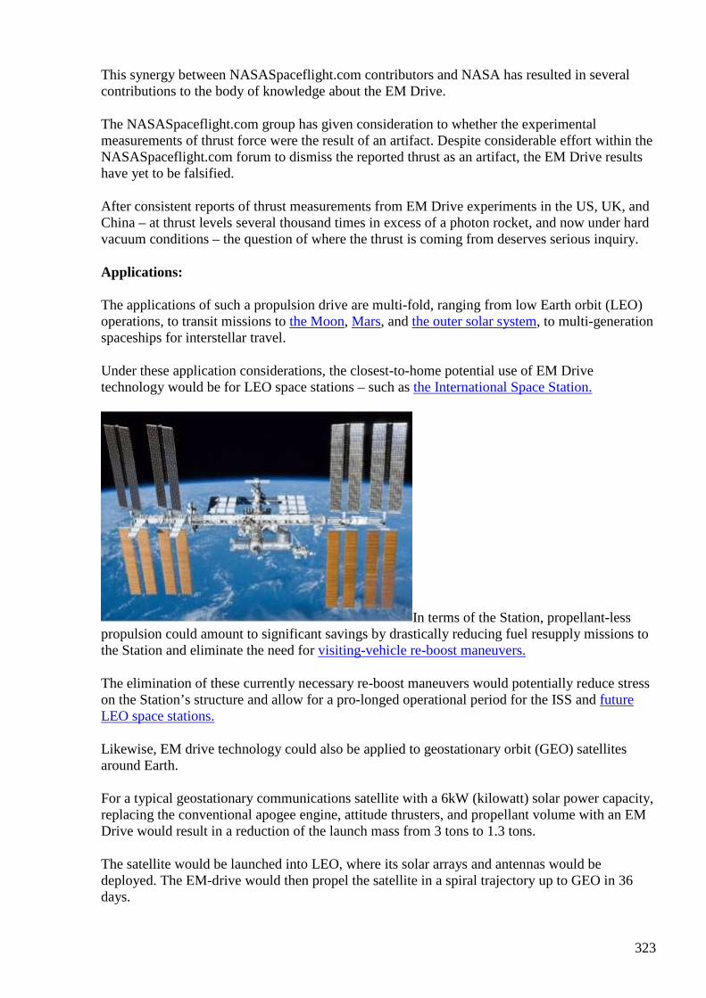
323
This synergy between NASASpaceflight.com contributors and NASA has resulted in several contributions to the body of knowledge about the EM Drive.
The NASASpaceflight.com group has given consideration to whether the experimental measurements of thrust force were the result of an artifact. Despite considerable effort within the NASASpaceflight.com forum to dismiss the reported thrust as an artifact, the EM Drive results have yet to be falsified.
After consistent reports of thrust measurements from EM Drive experiments in the US, UK, and China – at thrust levels several thousand times in excess of a photon rocket, and now under hard vacuum conditions – the question of where the thrust is coming from deserves serious inquiry.
Applications:
The applications of such a propulsion drive are multi-fold, ranging from low Earth orbit (LEO) operations, to transit missions to the Moon, Mars, and the outer solar system, to multi-generation spaceships for interstellar travel.
Under these application considerations, the closest-to-home potential use of EM Drive technology would be for LEO space stations – such as the International Space Station.
In terms of the Station, propellant-less propulsion could amount to significant savings by drastically reducing fuel resupply missions to the Station and eliminate the need for visiting-vehicle re-boost maneuvers.
The elimination of these currently necessary re-boost maneuvers would potentially reduce stress on the Station’s structure and allow for a pro-longed operational period for the ISS and future LEO space stations.
Likewise, EM drive technology could also be applied to geostationary orbit (GEO) satellites around Earth.
For a typical geostationary communications satellite with a 6kW (kilowatt) solar power capacity, replacing the conventional apogee engine, attitude thrusters, and propellant volume with an EM Drive would result in a reduction of the launch mass from 3 tons to 1.3 tons.
The satellite would be launched into LEO, where its solar arrays and antennas would be deployed. The EM-drive would then propel the satellite in a spiral trajectory up to GEO in 36 days.
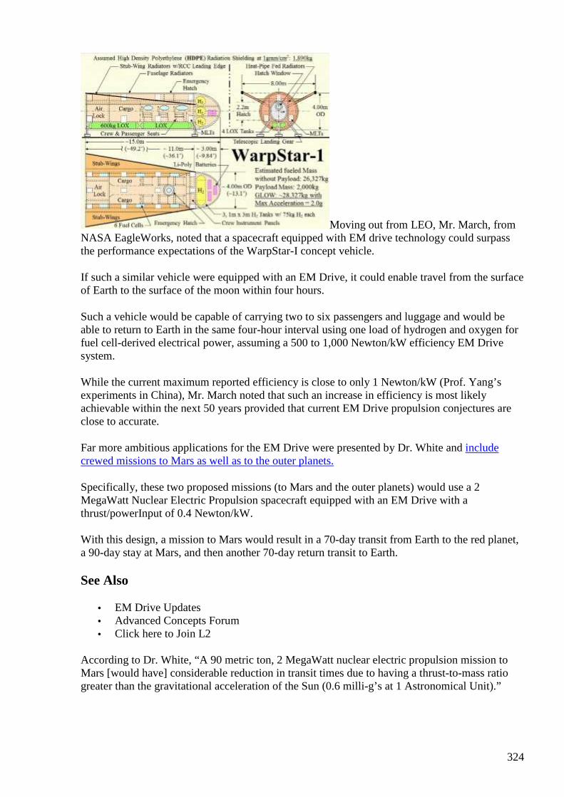
324
Moving out from LEO, Mr. March, from NASA EagleWorks, noted that a spacecraft equipped with EM drive technology could surpass the performance expectations of the WarpStar-I concept vehicle.
If such a similar vehicle were equipped with an EM Drive, it could enable travel from the surface of Earth to the surface of the moon within four hours.
Such a vehicle would be capable of carrying two to six passengers and luggage and would be able to return to Earth in the same four-hour interval using one load of hydrogen and oxygen for fuel cell-derived electrical power, assuming a 500 to 1,000 Newton/kW efficiency EM Drive system.
While the current maximum reported efficiency is close to only 1 Newton/kW (Prof. Yang’s experiments in China), Mr. March noted that such an increase in efficiency is most likely achievable within the next 50 years provided that current EM Drive propulsion conjectures are close to accurate.
Far more ambitious applications for the EM Drive were presented by Dr. White and include crewed missions to Mars as well as to the outer planets.
Specifically, these two proposed missions (to Mars and the outer planets) would use a 2 MegaWatt Nuclear Electric Propulsion spacecraft equipped with an EM Drive with a thrust/powerInput of 0.4 Newton/kW.
With this design, a mission to Mars would result in a 70-day transit from Earth to the red planet, a 90-day stay at Mars, and then another 70-day return transit to Earth.
See Also
• EM Drive Updates • Advanced Concepts Forum • Click here to Join L2
According to Dr. White, “A 90 metric ton, 2 MegaWatt nuclear electric propulsion mission to Mars [would have] considerable reduction in transit times due to having a thrust-to-mass ratio greater than the gravitational acceleration of the Sun (0.6 milli-g’s at 1 Astronomical Unit).”
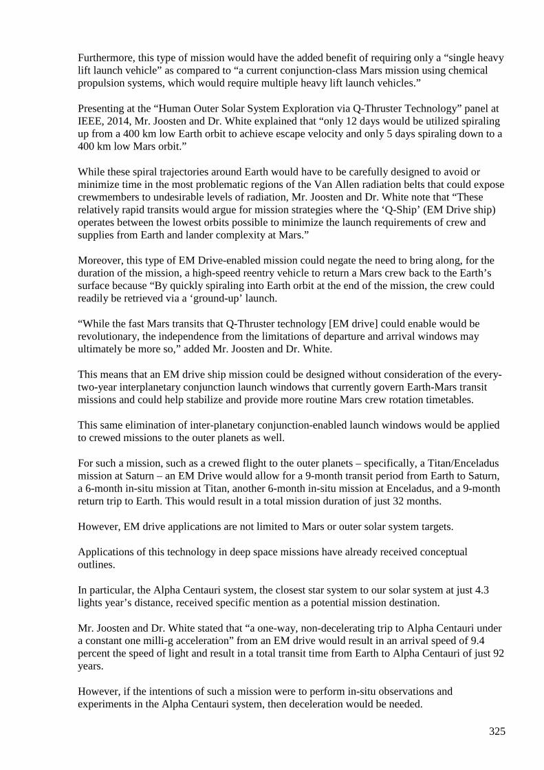
325
Furthermore, this type of mission would have the added benefit of requiring only a “single heavy lift launch vehicle” as compared to “a current conjunction-class Mars mission using chemical propulsion systems, which would require multiple heavy lift launch vehicles.”
Presenting at the “Human Outer Solar System Exploration via Q-Thruster Technology” panel at IEEE, 2014, Mr. Joosten and Dr. White explained that “only 12 days would be utilized spiraling up from a 400 km low Earth orbit to achieve escape velocity and only 5 days spiraling down to a 400 km low Mars orbit.”
While these spiral trajectories around Earth would have to be carefully designed to avoid or minimize time in the most problematic regions of the Van Allen radiation belts that could expose crewmembers to undesirable levels of radiation, Mr. Joosten and Dr. White note that “These relatively rapid transits would argue for mission strategies where the ‘Q-Ship’ (EM Drive ship) operates between the lowest orbits possible to minimize the launch requirements of crew and supplies from Earth and lander complexity at Mars.”
Moreover, this type of EM Drive-enabled mission could negate the need to bring along, for the duration of the mission, a high-speed reentry vehicle to return a Mars crew back to the Earth’s surface because “By quickly spiraling into Earth orbit at the end of the mission, the crew could readily be retrieved via a ‘ground-up’ launch.
“While the fast Mars transits that Q-Thruster technology [EM drive] could enable would be revolutionary, the independence from the limitations of departure and arrival windows may ultimately be more so,” added Mr. Joosten and Dr. White.
This means that an EM drive ship mission could be designed without consideration of the every-two-year interplanetary conjunction launch windows that currently govern Earth-Mars transit missions and could help stabilize and provide more routine Mars crew rotation timetables.
This same elimination of inter-planetary conjunction-enabled launch windows would be applied to crewed missions to the outer planets as well.
For such a mission, such as a crewed flight to the outer planets – specifically, a Titan/Enceladus mission at Saturn – an EM Drive would allow for a 9-month transit period from Earth to Saturn, a 6-month in-situ mission at Titan, another 6-month in-situ mission at Enceladus, and a 9-month return trip to Earth. This would result in a total mission duration of just 32 months.
However, EM drive applications are not limited to Mars or outer solar system targets.
Applications of this technology in deep space missions have already received conceptual outlines.
In particular, the Alpha Centauri system, the closest star system to our solar system at just 4.3 lights year’s distance, received specific mention as a potential mission destination.
Mr. Joosten and Dr. White stated that “a one-way, non-decelerating trip to Alpha Centauri under a constant one milli-g acceleration” from an EM drive would result in an arrival speed of 9.4 percent the speed of light and result in a total transit time from Earth to Alpha Centauri of just 92 years.
However, if the intentions of such a mission were to perform in-situ observations and experiments in the Alpha Centauri system, then deceleration would be needed.

326
This added component would result in a 130-year transit time from Earth to Alpha Centauri – which is still a significant improvement over the multi-thousand year timetable such a mission would take using current chemical propulsion technology.
The speeds discussed in the Alpha Centauri mission proposal are sufficiently low that relativity effects are negligible.
Bringing EM Drives to reality:
While such mission proposals are important to consider, equally as important are the considerations toward development of the needed technology and procurement long-lead items necessary to make this power technology a reality.
Specifically, a useful EM Drive for space travel would need a nuclear power plant of 1.0 MWe (Megawatts-electric) to 100 MWe.
While that sounds significant, the U.S. Navy currently builds 220 MW-thermal reactors for its “Boomer” Ohio class ICBM vehicles.
Thus, the technology to build such reactors is available, and the technology needed to build such a device for space-based operations has been around since the 1980s.
The limiting factors for further testing and development of this potentially revolutionary space exploration technology are funding to verify and characterize its operations, and the political will to develop nuclear power for space applications.
Progress Update:
On April 5, 2015, Paul March reported at NASAspaceflight.com’s Forum that Dr. White and Dr. Jerry Vera at NASA Eagleworks have just created a new computational code that models the EM Drive’s thrust as a three-dimensional magnetohydrodynamic flow of electron-positron virtual particles.
These simulations explain why in NASA’s experiments it was necessary to insert a high density polyethylene (HDPE) dielectric into the EM Drive, while the experiments in the UK and China were able to measure thrust without a dielectric insert.
The code shows two reasons for this: 1) the experiments in the UK and China used (unlike the ones in the US) a magnetron to generate the microwaves and 2) the experiments in the UK and China were performed with much higher input power: up to 2.5 kiloWatts, compared to less than 100 Watts in the US experiments.
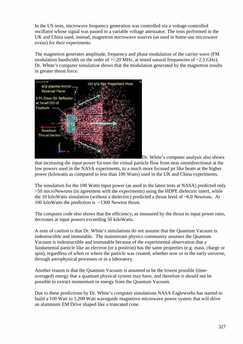
327
In the US tests, microwave frequency generation was controlled via a voltage-controlled oscillator whose signal was passed to a variable voltage attenuator. The tests performed in the UK and China used, instead, magnetron microwave sources (as used in home-use microwave ovens) for their experiments.
The magnetron generates amplitude, frequency and phase modulation of the carrier wave (FM modulation bandwidth on the order of +/-20 MHz, at tested natural frequencies of ~2.5 GHz). Dr. White’s computer simulation shows that the modulation generated by the magnetron results in greater thrust force.
Dr. White’s computer analysis also shows that increasing the input power focuses the virtual particle flow from near omnidirectional at the low powers used in the NASA experiments, to a much more focused jet like beam at the higher power (kilowatts as compared to less than 100 Watts) used in the UK and China experiments.
The simulation for the 100 Watts input power (as used in the latest tests at NASA) predicted only ~50 microNewtons (in agreement with the experiments) using the HDPE dielectric insert, while the 10 kiloWatts simulation (without a dielectric) predicted a thrust level of ~6.0 Newtons. At 100 kiloWatts the prediction is ~1300 Newton thrust.
The computer code also shows that the efficiency, as measured by the thrust to input power ratio, decreases at input powers exceeding 50 kiloWatts.
A note of caution is that Dr. White’s simulations do not assume that the Quantum Vacuum is indestructible and immutable. The mainstream physics community assumes the Quantum Vacuum is indestructible and immutable because of the experimental observation that a fundamental particle like an electron (or a positron) has the same properties (e.g. mass, charge or spin), regardless of when or where the particle was created, whether now or in the early universe, through astrophysical processes or in a laboratory.
Another reason is that the Quantum Vacuum is assumed to be the lowest possible (time-averaged) energy that a quantum physical system may have, and therefore it should not be possible to extract momentum or energy from the Quantum Vacuum.
Due to these predictions by Dr. White’s computer simulations NASA Eagleworks has started to build a 100 Watt to 1,200 Watt waveguide magnetron microwave power system that will drive an aluminum EM Drive shaped like a truncated cone.
328
Initially a teeter-totter balance system will be used in ambient conditions to see if similar thrust levels (0.016 to 0.3 Newton) as reported in the US and China can be reproduced at NASA with this approach.
For the last three years, Dr. White’s team has been conducting experiments to find out whether it is possible to measure, with an interferometer, a distortion of spacetime produced by time-varying electromagnetic fields.
The ultimate goal is to find out whether it is possible for a spacecraft traveling at conventional speeds to achieve effective superluminal speed by contracting space in front of it and expanding space behind it. The experimental results so far had been inconclusive.
During the first two weeks of April of this year, NASA Eagleworks may have finally obtained conclusive results. This time they used a short, cylindrical, aluminum resonant cavity excited at a natural frequency of 1.48 GHz with an input power of 30 Watts.
This is essentially a pill-box shaped EM Drive, with much higher electric-field intensity, aligned in the axial direction. The interferometer’s laser light goes through small holes in the EM Drive.
Over 27,000 cycles of data (each 1.5 sec cycle energizing the system for 0.75 sec and de-energizing it for 0.75 sec) were averaged to obtain a power spectrum that revealed a signal frequency of 0.65 Hz with amplitude clearly above system noise. Four additional tests were successfully conducted that demonstrated repeatability.
One possible explanation for the optical path length change is that it is due to refraction of the air. The NASA team examined this possibility and concluded that it is not likely that the measured change is due to transient air heating because the experiment’s visibility threshold is forty times larger than the calculated effect from air considering atmospheric heating.
Encouraged by these results, NASA Eagleworks plans to next conduct these interferometer tests in a vacuum.
329
#361 Re: [ferd] [offtopic] Evaluating NASA's Futuristic EM Drive
Andreas Höschler 30 Apr at 6:46 PM
Hi Alexey,
http://www.nasaspaceflight.com/2015/04/evaluating-nasas-futuristic-em-drive/
That's just distraction to keep the monkeys busy. They have much better (more effective) stuff in the drawer. I saw once drawings of a little machine of the size of a standard 7.5kW AC motor that consisted of a bunch of rotating fly-wheels that generated thrust. All you needed to power this thing was torque on the shaft and it generates significant thrust by means of centrifugal force thus immediately defying this so called "momentum conservation law". The mechanic in this thrust generator by only mechanical means was highly complicated though. We unfortunately cannot do that in our garage! :-(
Andreas
#362 RE: [ferd] [offtopic] Evaluating NASA's Futuri stic EM Drive
Alexey 30 Apr at 6:57 PM
Hi Andreas,
Well, I think that mechanical device with some small thrust can be built very easy at home.
But mechanics are always a problem if you want travel fast and long distance…
It is also funny observe how people react and say that it is not possible…even it works in their lab
Regards,
Alexey
#363 Re: [ferd] [offtopic] Evaluating NASA's Futuristic EM Drive
Andreas Höschler 30 Apr at 7:27 PM
Hi Alexey,
330
Well, I think that mechanical device with some small thrust can be built very easy at home.
But mechanics are always a problem if you want travel fast and long distance…
It is also funny observe how people react and say that it is not possible…even it works in their lab
They have flawed models already proven to be incorrect and call them irrefutable laws. Hard (almost impossible) to drag them out of their own mud. :-(
I have started assembling the first IPC board yesterday. Man, these SMD components are even smaller than I thought. :-)
Andreas
#364 RE: [ferd] another project idea - How to build free energy device from you air humidifier
Alexey 30 Apr at 7:28 PM
Hi Andreas,
”For the time being I strongly recommend the youtube publications of www.distinti.com. I have worked through his first 47 clips in the meanwhile. Amazing stuff. I am looking forward to going through his new math model.”
I am wondering have you found any hints how to build OU device from these lections?
Any info which can help in a practical way?
Thanks,
Alexey
#365 FW: [reading] "The torsion generator of energy"
Alexey 30 Apr at 7:40 PM
May be interesting new thread on overunity.com http://www.overunity.com/15740/the-torsion-generator-of-energy/
331

332
333
#366 RE: [ferd] another project idea - How to build free energy device from you air humidifier
Alexey May 1 9:23 PM
Good explanation how Kelvin’s dropper works https://www.youtube.com/watch?v=dB-76NdfTbU ;-)
#367 Re: [ferd] another project idea - How to build free energy device from you air humidifier
Andreas Höschler May 2 at 12:22 AM
Hi Alexey,
”For the time being I strongly recommend the youtube publications of www.distinti.com. I have worked through his first 47 clips in the meanwhile. Amazing stuff. I am looking forward to going through his new math model.”
I am wondering have you found any hints how to build OU device from these lections?
Any info which can help in a practical way?
Unfortunately not yet. But if this were so it would be the most profound event thinkable. Mr. Distinti starts at the very beginning with Newton, Maxwell,... points out flaws in their models and works out replacements, so called gateway models that are finally to be replaced with even better (more precise) ones. That's what he needs the new math for.
If this approach led to directly usable hints this would be more than awesome.
In the meanwhile I continue to assemble the first IPC quadra board (almost done)!
Andreas
#368 Re: [ferd] another project idea - How to build free energy device from you air humidifier
Andreas Höschler May 2 at 12:33 AM
Hi Alexey,
Good explanation how Kelvin’s dropper works
334
https://www.youtube.com/watch?v=dB-76NdfTbU
Good one! Thanks for the link!
But I still consider this a toy to get kids away from their playstation and interested into physics. I see no potential in this as an energy device (practically no power at all!)?
Regards,
Andreas
#369 Re: [ferd] another project idea - How to build free energy device from you air humidifier
Andreas Höschler May 2 at 12:44 AM
On 01 May 2015, at 19:23, Alexey <[email protected]> wrote:
Good explanation how Kelvin’s dropper works
https://www.youtube.com/watch?v=dB-76NdfTbU
I have found that explains the physics behind it very well
https://www.youtube.com/watch?v=rv4MjaF_wow
and also gives a clue how much power is generated (close to nothing). :-)
Andreas
#370 Tesla Battery
Andreas Höschler May 4 4:49 PM
Hi all,
our friend Elon (the new Steve Jobs) just made another announcement:
https://www.youtube.com/watch?v=yKORsrlN-2k
I love this guy! Every time I see him on stage I am even more excited and motivated to push our endeavour forward. :-)
The IPC quadra is completely soldered but not yet tested (too much work on the desk right now)! :-(
Best,

335
Andreas
#371 Re: [ferd] Tesla Battery
Gerry May 4 8:39 PM
Hi Andreas, guys
Thanks for posting this I found it inspirational to watch.
These guys are really putting their money on the line to push the envelope back toward where it should be.
Compared to mobile phone and computer technology our power grid & feed systems are primitive.
I haven't been posting much as making attempt at a self running motor setup.
Hack sawing cutting up notches into old stators and waiting for Neo magnets to arrive, mid May.
Gerry
#372 RE: [ferd] Tesla Battery
Alexey May 4 10:36 PM
Hi Andreas,
I know, you like Elon Musk but… I don’t really see a reason to be excited.
Put 100 kg of highly flammable and dangerous substance in every house – what a brilliant idea :-/
Build an automatic factory which produce enormous amount of waste…even better idea
Why not spend some money on real thing, FE research?
(I think answer is simple – nobody really wants it)
Regards,
Alexey
#373 Re: [ferd] Tesla Battery
Andreas Höschler May 5 2:28 AM
336
Hi Alexey,
but… I don’t really see a reason to be excited.
Put 100 kg of highly flammable and dangerous substance in every house – what a brilliant idea :-/
Build an automatic factory which produce enormous amount of waste…even better idea
Totally see your point here and agree!
Why not spend some money on real thing, FE research?
(I think answer is simple – nobody really wants it)
I suppose the answer is not that simple. We at least have to define "nobody" here. The current elite fears change and does everything necessary to prevent it. But that's a minority (though powerful). We in this group want change, the 1000 or so members of EVGRAY want it and I am sure 95% of the worlds population wants it as well deep in their hearts. They are just too brainwashed and mislead to actually see the alternative and demand it.
With regard to Elon: We of course don't know what exactly he is up to. But investing all his money (180 million) into something like Tesla motors and Space X tells a story. I bet if he was briefed and convinced that FE is possible he would certainly invest resources into it in spite of the obvious dangers of doing so.
Whois going to brief him with what?
Andreas
#374 RE: [ferd] Tesla Battery
Alexey May 5 8:56 AM
Hi Andreas,
” Whois going to brief him with what?”
He probably very busy man and don’t have time even read letters from ”nuts” like us
Very small chance if we can reach him…
Regards,
Alexey
#375 [offtopic] Magnets with an OFF Switch
Alexey May 6 at 8:38 AM

337
http://www.kjmagnetics.com/blog.asp?p=magswitch https://www.youtube.com/watch?v=DPwoFnQnBPk :-)
Magnets with an OFF Switch Can neodymium magnets be turned on and off?
Generally, no. The neodymium magnets we provide are also called, “permanent magnets.” The word “permanent” means they stay magnetized for a long time. They are always on.
This is the opposite of an electromagnet, where you have to run an electric current through a wire whenever you want it to act like a magnet. No flow of electricity, no magnet.
It's also opposite of a "temporary" magnet, like when you stick a (permanent) magnet to a steel paperclip, and that steel acts like a magnet as long as the (permanent) magnet is stuck to it. Remove the magnet, and the paperclip stops acting so magnet-like.
When people ask us for magnets that can be turned off, we say it’s not possible. Neodymium magnets, large and small, tend to stay ON. That's part of what makes them so useful.
A simple magnet doesn’t come with an ON/OFF switch.
An ingenious solution
There are products available that do provide this sort of functionality. Their construction is a little more complex than a single magnet, though.
A popular kind we like are Magswitch® magnets. You can now get some of these useful magnets here at K&J Magnetics:
• MJ-95 MagJig 95 provides up to 95 lb of pull force. • MJ-150 MagJig 150 provides up to 150 lb of pull force. • MS-400 MagSquare is a larger, more powerful magnet that provides up to 400 lb of
force.
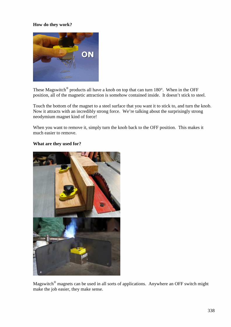
338
How do they work?
These Magswitch® products all have a knob on top that can turn 180°. When in the OFF position, all of the magnetic attraction is somehow contained inside. It doesn’t stick to steel.
Touch the bottom of the magnet to a steel surface that you want it to stick to, and turn the knob. Now it attracts with an incredibly strong force. We’re talking about the surprisingly strong neodymium magnet kind of force!
When you want to remove it, simply turn the knob back to the OFF position. This makes it much easier to remove.
What are they used for?
Magswitch® magnets can be used in all sorts of applications. Anywhere an OFF switch might make the job easier, they make sense.
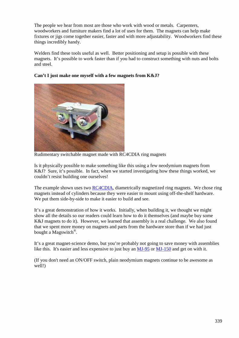
339
The people we hear from most are those who work with wood or metals. Carpenters, woodworkers and furniture makers find a lot of uses for them. The magnets can help make fixtures or jigs come together easier, faster and with more adjustability. Woodworkers find these things incredibly handy.
Welders find these tools useful as well. Better positioning and setup is possible with these magnets. It’s possible to work faster than if you had to construct something with nuts and bolts and steel.
Can’t I just make one myself with a few magnets from K&J?
Rudimentary switchable magnet made with RC4CDIA ring magnets
Is it physically possible to make something like this using a few neodymium magnets from K&J? Sure, it’s possible. In fact, when we started investigating how these things worked, we couldn’t resist building one ourselves!
The example shown uses two RC4CDIA, diametrically magnetized ring magnets. We chose ring magnets instead of cylinders because they were easier to mount using off-the-shelf hardware. We put them side-by-side to make it easier to build and see.
It’s a great demonstration of how it works. Initially, when building it, we thought we might show all the details so our readers could learn how to do it themselves (and maybe buy some K&J magnets to do it). However, we learned that assembly is a real challenge. We also found that we spent more money on magnets and parts from the hardware store than if we had just bought a Magswitch®.
It’s a great magnet-science demo, but you’re probably not going to save money with assemblies like this. It's easier and less expensive to just buy an MJ-95 or MJ-150 and get on with it.
(If you don't need an ON/OFF switch, plain neodymium magnets continue to be awesome as well!)
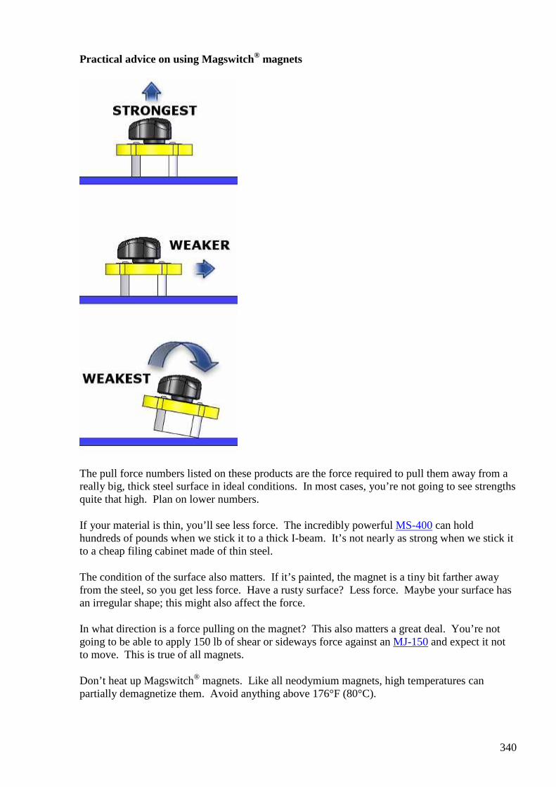
340
Practical advice on using Magswitch® magnets
The pull force numbers listed on these products are the force required to pull them away from a really big, thick steel surface in ideal conditions. In most cases, you’re not going to see strengths quite that high. Plan on lower numbers.
If your material is thin, you’ll see less force. The incredibly powerful MS-400 can hold hundreds of pounds when we stick it to a thick I-beam. It’s not nearly as strong when we stick it to a cheap filing cabinet made of thin steel.
The condition of the surface also matters. If it’s painted, the magnet is a tiny bit farther away from the steel, so you get less force. Have a rusty surface? Less force. Maybe your surface has an irregular shape; this might also affect the force.
In what direction is a force pulling on the magnet? This also matters a great deal. You’re not going to be able to apply 150 lb of shear or sideways force against an MJ-150 and expect it not to move. This is true of all magnets.
Don’t heat up Magswitch® magnets. Like all neodymium magnets, high temperatures can partially demagnetize them. Avoid anything above 176°F (80°C).
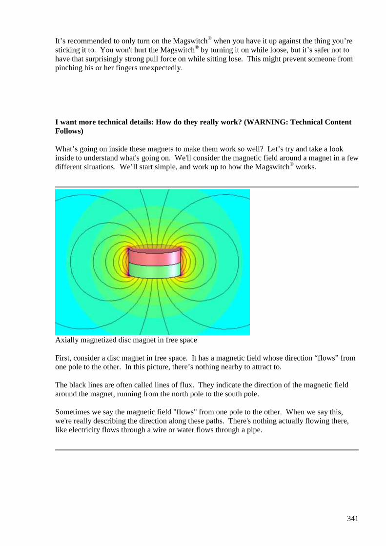
341
It’s recommended to only turn on the Magswitch® when you have it up against the thing you’re sticking it to. You won't hurt the Magswitch® by turning it on while loose, but it’s safer not to have that surprisingly strong pull force on while sitting lose. This might prevent someone from pinching his or her fingers unexpectedly.
I want more technical details: How do they really work? (WARNING: Technical Content Follows)
What’s going on inside these magnets to make them work so well? Let’s try and take a look inside to understand what's going on. We'll consider the magnetic field around a magnet in a few different situations. We’ll start simple, and work up to how the Magswitch® works.
Axially magnetized disc magnet in free space
First, consider a disc magnet in free space. It has a magnetic field whose direction “flows” from one pole to the other. In this picture, there’s nothing nearby to attract to.
The black lines are often called lines of flux. They indicate the direction of the magnetic field around the magnet, running from the north pole to the south pole.
Sometimes we say the magnetic field "flows" from one pole to the other. When we say this, we're really describing the direction along these paths. There's nothing actually flowing there, like electricity flows through a wire or water flows through a pipe.
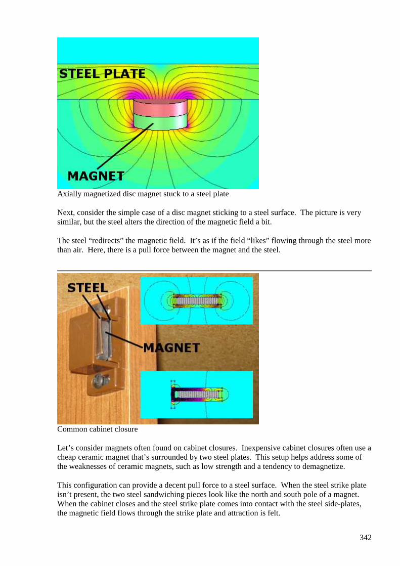
342
Axially magnetized disc magnet stuck to a steel plate
Next, consider the simple case of a disc magnet sticking to a steel surface. The picture is very similar, but the steel alters the direction of the magnetic field a bit.
The steel “redirects” the magnetic field. It’s as if the field “likes” flowing through the steel more than air. Here, there is a pull force between the magnet and the steel.
Common cabinet closure
Let’s consider magnets often found on cabinet closures. Inexpensive cabinet closures often use a cheap ceramic magnet that’s surrounded by two steel plates. This setup helps address some of the weaknesses of ceramic magnets, such as low strength and a tendency to demagnetize.
This configuration can provide a decent pull force to a steel surface. When the steel strike plate isn’t present, the two steel sandwiching pieces look like the north and south pole of a magnet. When the cabinet closes and the steel strike plate comes into contact with the steel side-plates, the magnetic field flows through the strike plate and attraction is felt.

343
The two field pictures show the setup both with and without the steel strike plate of a cabinet door.
In the lower right depiction, we might describe the direction of the magnetic field like this: The lines of flux "flow" out of the north pole, turn to run in the plane of the steel side-plate, and then out the side. If the steel strike plate is present, the field flows through it, making a strong attraction force. The direction then flows back out of the strike plate, through the other steel side-plate, and back into the magnet at the south pole.
Diametrically Magnetized Disc Magnets
OK, now let’s get back to how the Magswitch® works. Consider the ON position first. In this position, we find that the path of the magnetic field is quite similar to that common cabinet closure.
The Magswitch® has two diametrically magnetized disc magnets inside, stacked on one another. In the ON position, the north poles are pointing in the same direction. When positioned like this, we can think of it as a single magnet.
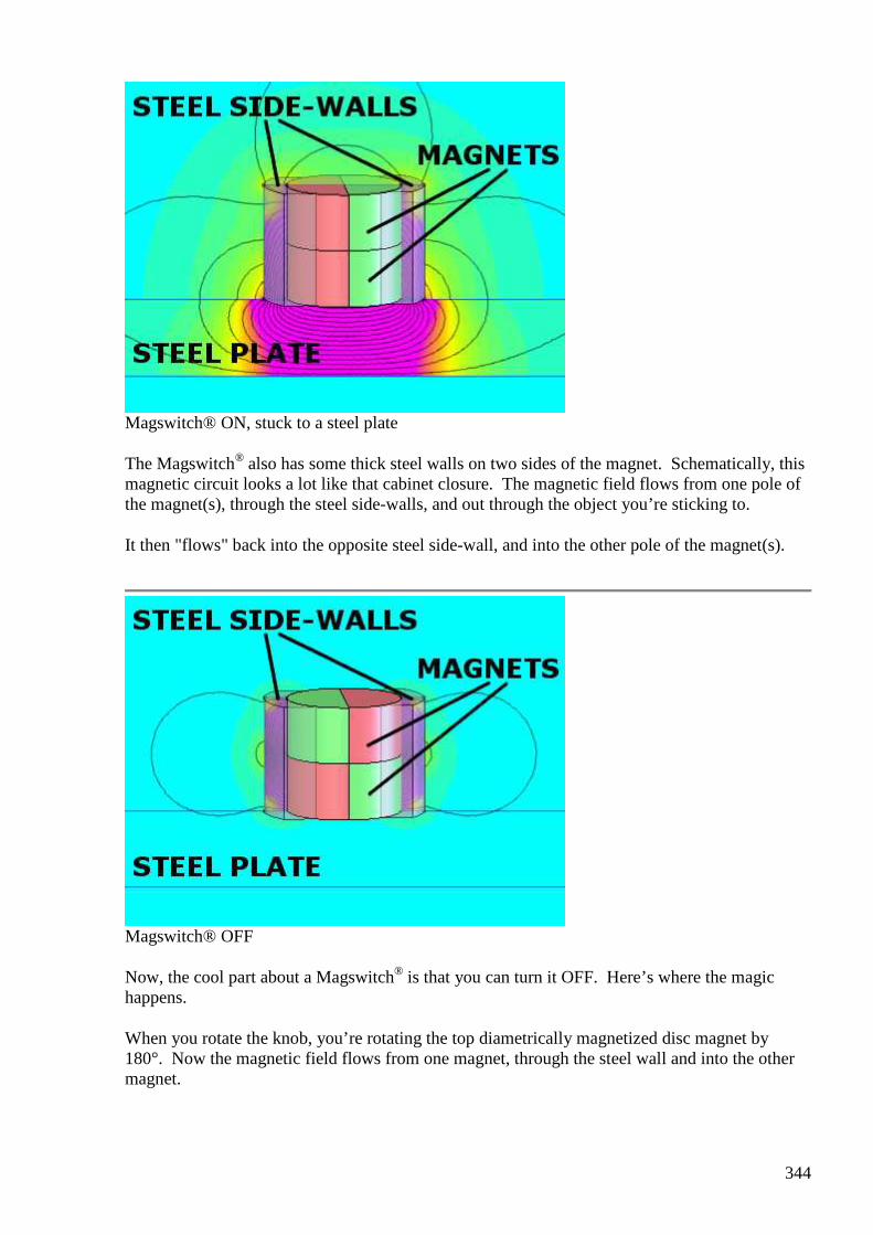
344
Magswitch® ON, stuck to a steel plate
The Magswitch® also has some thick steel walls on two sides of the magnet. Schematically, this magnetic circuit looks a lot like that cabinet closure. The magnetic field flows from one pole of the magnet(s), through the steel side-walls, and out through the object you’re sticking to.
It then "flows" back into the opposite steel side-wall, and into the other pole of the magnet(s).
Magswitch® OFF
Now, the cool part about a Magswitch® is that you can turn it OFF. Here’s where the magic happens.
When you rotate the knob, you’re rotating the top diametrically magnetized disc magnet by 180°. Now the magnetic field flows from one magnet, through the steel wall and into the other magnet.

345
The folks at Magswitch® must have done their math right, because the steel structure is shaped and sized just right to keep all of the magnetic field flowing inside the assembly. It doesn’t reach outside at all! In this position, no pull force is felt.
We've tried it ourselves, and these powerful magnets won't even pick up a single paperclip in the OFF position.
Note: Those magnetic field depictions aren't from Magswitch®. We made them up here at K&J to help describe what's going on. They may not be perfectly accurate, but we hope they show the general idea well enough to see what's going on inside these incredibly cool magnets. Please accept our apologies for any quick-and-dirty inaccuracies!
You can find short videos of these magnets in action on the product pages. Click on the links and hit the "Video" tab on the product page to find them: MJ-95, MJ-150 and MS-400.
#376 Re: [offtopic] Magnets with an OFF Switch
onielsen2000 May 6 1:34 PM
Hi Alexey, Electric switchable magnets (NASA magnetic boots): The Tom Bearden Website
http://www.cheniere.org/misc/astroboots.htm
The Tom Bearden Website Well, it doesn't take a genius to see that, when you can switch a permanent magnet's fields easily, and the magnet also has a ...
View on www.cheniere.org Preview
by Yahoo
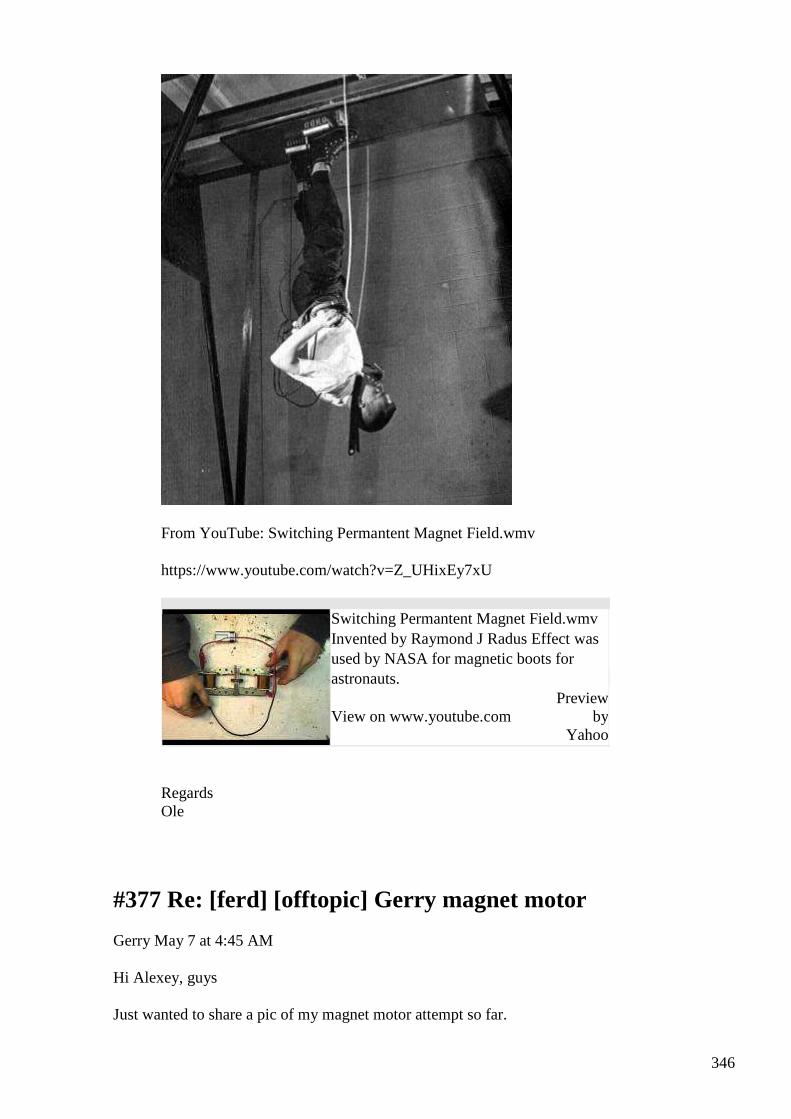
346
From YouTube: Switching Permantent Magnet Field.wmv
https://www.youtube.com/watch?v=Z_UHixEy7xU
Switching Permantent Magnet Field.wmv Invented by Raymond J Radus Effect was used by NASA for magnetic boots for astronauts.
View on www.youtube.com Preview
by Yahoo
Regards Ole
#377 Re: [ferd] [offtopic] Gerry magnet motor
Gerry May 7 at 4:45 AM
Hi Alexey, guys
Just wanted to share a pic of my magnet motor attempt so far.
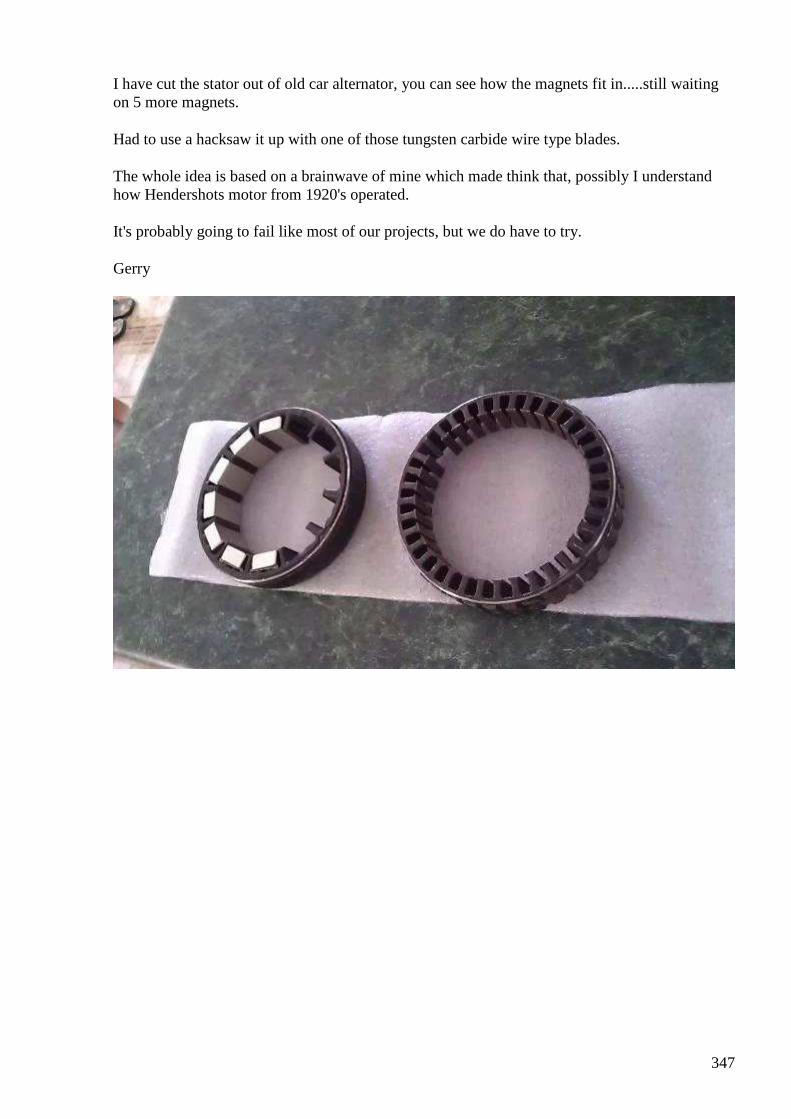
347
I have cut the stator out of old car alternator, you can see how the magnets fit in.....still waiting on 5 more magnets.
Had to use a hacksaw it up with one of those tungsten carbide wire type blades.
The whole idea is based on a brainwave of mine which made think that, possibly I understand how Hendershots motor from 1920's operated.
It's probably going to fail like most of our projects, but we do have to try.
Gerry
348
#378 RE: [ferd] [offtopic] Gerry magnet motor
Alexey May 7 at 8:28 AM
Hi Gerry,
Thank you for sharing your project. Please let us know about your results, when you get magnets and complete the setup.
In my opinion mechanical OU device should be easier to build than “pure electronic” device. I just don’t have lab space and tools to do mechanic works…
Regards,
Alexey
349
#379 Re: [ferd] [offtopic] Gerry magnet motor
Gerry May 7 at 9:08 AM
Hi Alexey,
Thanks for comment, the concept is a simple one.
Metal in rotor arm is attracted toward magnet and induces voltage in rotor coil.
By shorting out rotor coil high current causes Lenz effect propelling rotor arm past the pole face.
It will be high cogging and needs to reach enough speed to free run itself...at least that's the plan.
Very similar to magnetic motor in this video https://www.youtube.com/watch?v=Xb6_gy7j3k0
Gerry
#380 Re: [ferd] AuKW
Andreas Höschler May 10 at 4:14 AM
Hi all,
https://translate.googleusercontent.com/translate_c?depth=1&hl=en&rurl=translate.google.com&sl=auto&tl=en&u=http://gaia-energy.org/es-ist-soweit-mach-dich-energieautark/&usg=ALkJrhh4wN1-Qd1r73yeb-ZDwW7A_dFoBw
https://www.youtube.com/watch?v=nsno0cxzd0I
FACTS ON INVESTMENT
PERFORMANCE:
Net power: guaranteed for about 5 kilowatts
Voltage: 230 VAC, single phase
Daily output over 100 kWh, it is a potential annual energy crowd of over 36,500 kWh of electrical energy
is obtained when to integrated operation 365 days
A new Cassiopeia release motivated me to have a look into this AuKW concept:
http://www.advanced-science.com/Auftriebskraftwerk.html
http://www.advanced-science.com/publications/Auftriebskraftwerk.pdf
I did this in German since the apparatus is offered on the German market but you might get the idea by looking at the equations and plots anyway. My take is that this thing is OU but the COP is not very interesting. My calculations are rough but I strongly doubt one can extract 5kW from such a unit!? :-(
350
Bet wishes,
Andreas
Lift power plant after GAIA / Rosch In recent months, a so-called lift power plant was presented at various trade fairs, which will generate 5kW excess power in a design option with 5m apparatus height. Offered the buoyant power plant is of a club named GAIA and manufactured by a company Rosh Innovation AG.
Distributors of Rosh Innovation AG include:
• www.e-cat-deutschland.de • www.annoncen.org • www.schweiz-247.de • www.afrika-123.de • www.info-finder.net • www.fast-alles.net • www.pressefeuer.at • www.hasselwander.co.uk • www.marbach-academy.de • www.vecernji.hr • www.ne-nord-energy.com • www.energietechnik-weiden.de • www.romanfeser.de • www.genogen-energy.de • www.markt.de • www.offenes-presseportal.de • www.nachrichten.net • www.news4press.com
There have opponents of this idea partially reported with dedicated websites for word, claiming that the proposed approach can not work (source the following figure http://gaia.ws1.eu/):
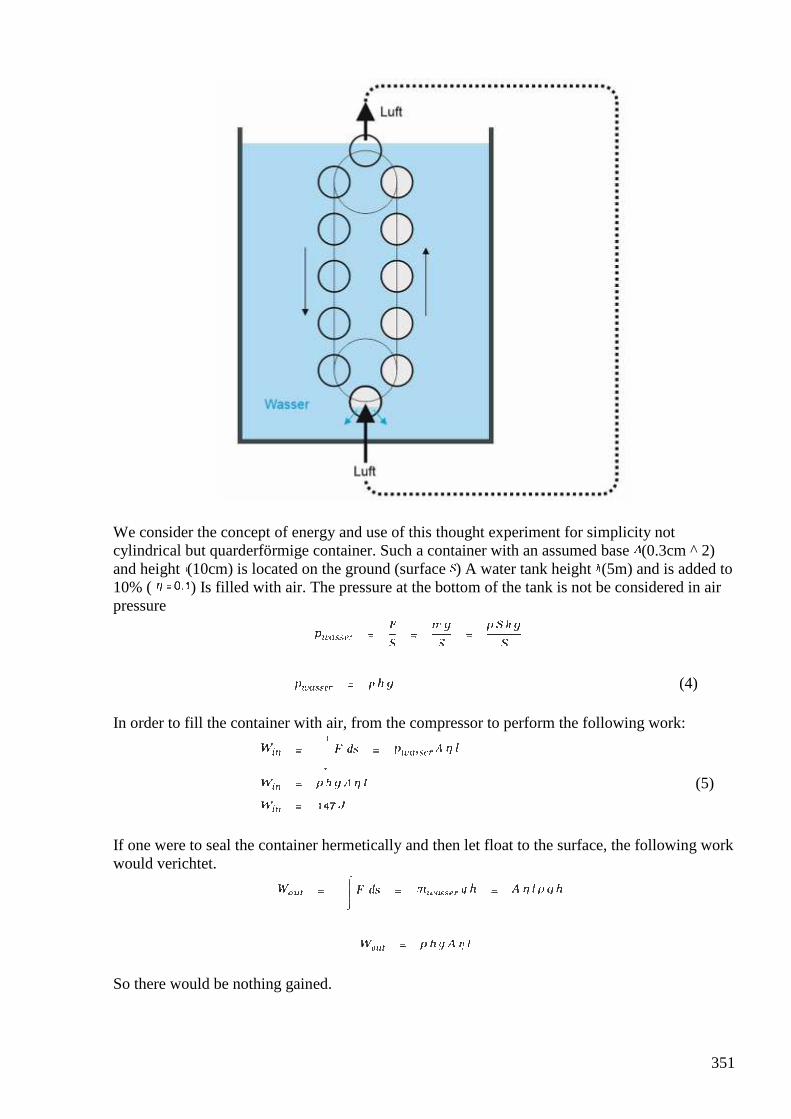
351
We consider the concept of energy and use of this thought experiment for simplicity not cylindrical but quarderförmige container. Such a container with an assumed base (0.3cm ^ 2) and height (10cm) is located on the ground (surface ) A water tank height (5m) and is added to 10% ( ) Is filled with air. The pressure at the bottom of the tank is not be considered in air pressure
(4) In order to fill the container with air, from the compressor to perform the following work:
(5)
If one were to seal the container hermetically and then let float to the surface, the following work would verichtet.
So there would be nothing gained.
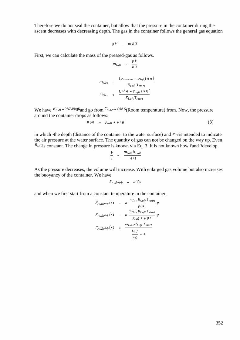
352
Therefore we do not seal the container, but allow that the pressure in the container during the ascent decreases with decreasing depth. The gas in the container follows the general gas equation
First, we can calculate the mass of the pressed-gas as follows.
We have and go from (Room temperature) from. Now, the pressure around the container drops as follows:
(3) in which the depth (distance of the container to the water surface) and is intended to indicate the air pressure at the water surface. The quantity of gas can not be changed on the way up. Even
is constant. The change in pressure is known via Eq. 3. It is not known how and develop.
As the pressure decreases, the volume will increase. With enlarged gas volume but also increases the buoyancy of the container. We have
and when we first start from a constant temperature in the container,

353
we see that the buoyancy force increases slightly by the expansion of the gas in the container. The work done during the ascent work is then
We need to determine the constant of integration. At is the initial work sinnigerweise 0. It follows , We then obtain for
The ratio of output and input working work generally calculated as follows:
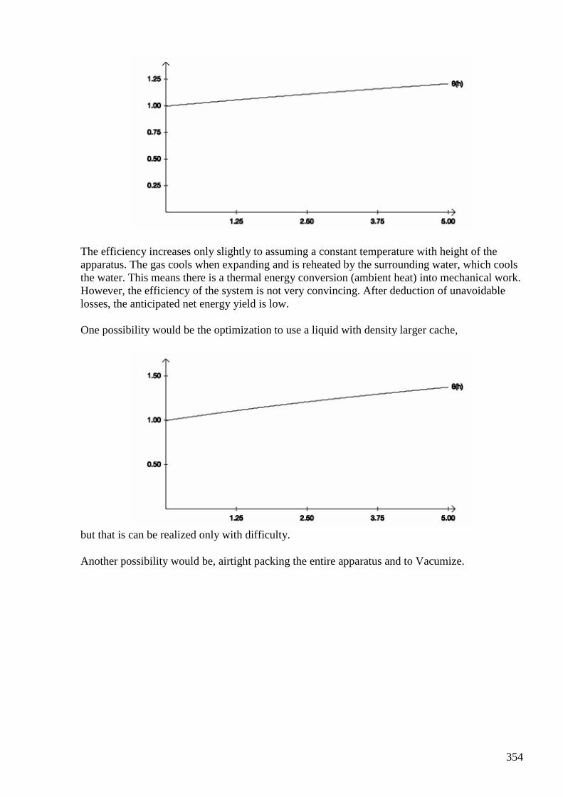
354
The efficiency increases only slightly to assuming a constant temperature with height of the apparatus. The gas cools when expanding and is reheated by the surrounding water, which cools the water. This means there is a thermal energy conversion (ambient heat) into mechanical work. However, the efficiency of the system is not very convincing. After deduction of unavoidable losses, the anticipated net energy yield is low.
One possibility would be the optimization to use a liquid with density larger cache,
but that is can be realized only with difficulty.
Another possibility would be, airtight packing the entire apparatus and to Vacumize.
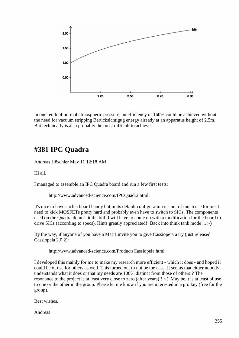
355
In one tenth of normal atmospheric pressure, an efficiency of 160% could be achieved without the need for vacuum stripping Berücksichtigug energy already at an apparatus height of 2.5m. But technically is also probably the most difficult to achieve.
#381 IPC Quadra
Andreas Höschler May 11 12:18 AM
Hi all,
I managed to assemble an IPC Quadra board and run a few first tests:
http://www.advanced-science.com/IPCQuadra.html
It's nice to have such a board handy but in its default configuration it's not of much use for me. I need to kick MOSFETs pretty hard and probably even have to switch to SICs. The components used on the Quadra do not fit the bill. I will have to come up with a modification for the board to drive SICs (according to specs). Hints greatly appreciated!! Back into think tank mode ... :-)
By the way, if anyone of you have a Mac I invite you to give Cassiopeia a try (just released Cassiopeia 2.0.2):
http://www.advanced-science.com/ProductsCassiopeia.html
I developed this mainly for me to make my research more efficient - which it does - and hoped it could be of use for others as well. This turned out to not be the case. It seems that either nobody understands what it does or that my needs are 100% distinct from those of others!? The resonance to the project is at least very close to zero (after years)!! :-( May be it is at least of use to one or the other in the group. Please let me know if you are interested in a pro key (free for the group).
Best wishes,
Andreas
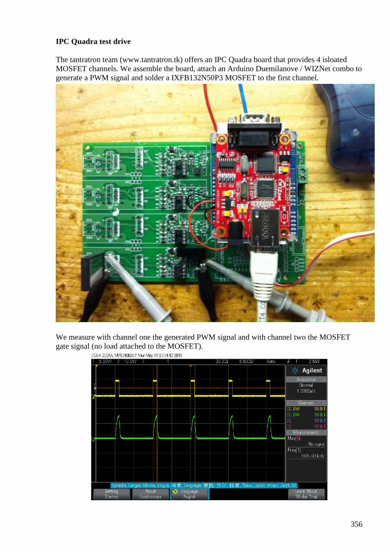
356
IPC Quadra test drive
The tantratron team (www.tantratron.tk) offers an IPC Quadra board that provides 4 isloated MOSFET channels. We assemble the board, attach an Arduino Duemilanove / WIZNet combo to generate a PWM signal and solder a IXFB132N50P3 MOSFET to the first channel.
We measure with channel one the generated PWM signal and with channel two the MOSFET gate signal (no load attached to the MOSFET).
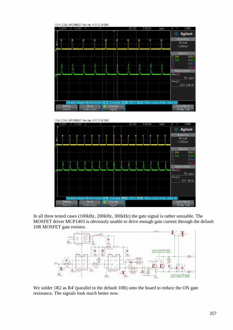
357
In all three tested cases (100kHz, 200kHz, 300kHz) the gate signal is rather unusable. The MOSFET driver MCP1403 is obviously unable to drive enough gate current through the default 10R MOSFET gate resistor.
We solder 1R2 as R4' (parallel to the default 10R) onto the board to reduce the ON gate resistance. The signals look much better now.
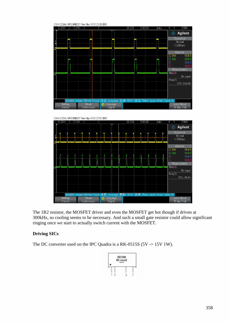
358
The 1R2 resistor, the MOSFET driver and even the MOSFET get hot though if driven at 300kHz, so cooling seems to be necessary. And such a small gate resistor could allow significant ringing once we start to actually switch current with the MOSFET.
Driving SICs
The DC converter used on the IPC Quadra is a RK-0515S (5V -> 15V 1W).
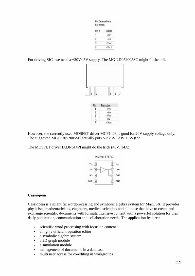
359
For driving SICs we need a +20V/-5V supply. The MGJ2D052005SC might fit the bill.
However, the currently used MOSFET driver MCP1403 is good for 20V supply voltage only. The suggested MGJ2D052005SC actually puts out 25V (20V + 5V)!??
The MOSFET driver IXDN614PI might do the trick (40V, 14A):
Cassiopeia
Cassiopeia is a scientific wordprocessing and symbolic algebra system for MacOSX. It provides physicists, mathematicians, engineers, medical scientists and all those that have to create and exchange scientific documents with formula intensive content with a powerful solution for their daily publication, communication and collaboration needs. The application features:
• scientific word processing with focus on content • a highly efficient equation editor • a symbolic algebra system • a 2D graph module • a simulation module • management of documents in a database • multi user access for co-editing in workgroups
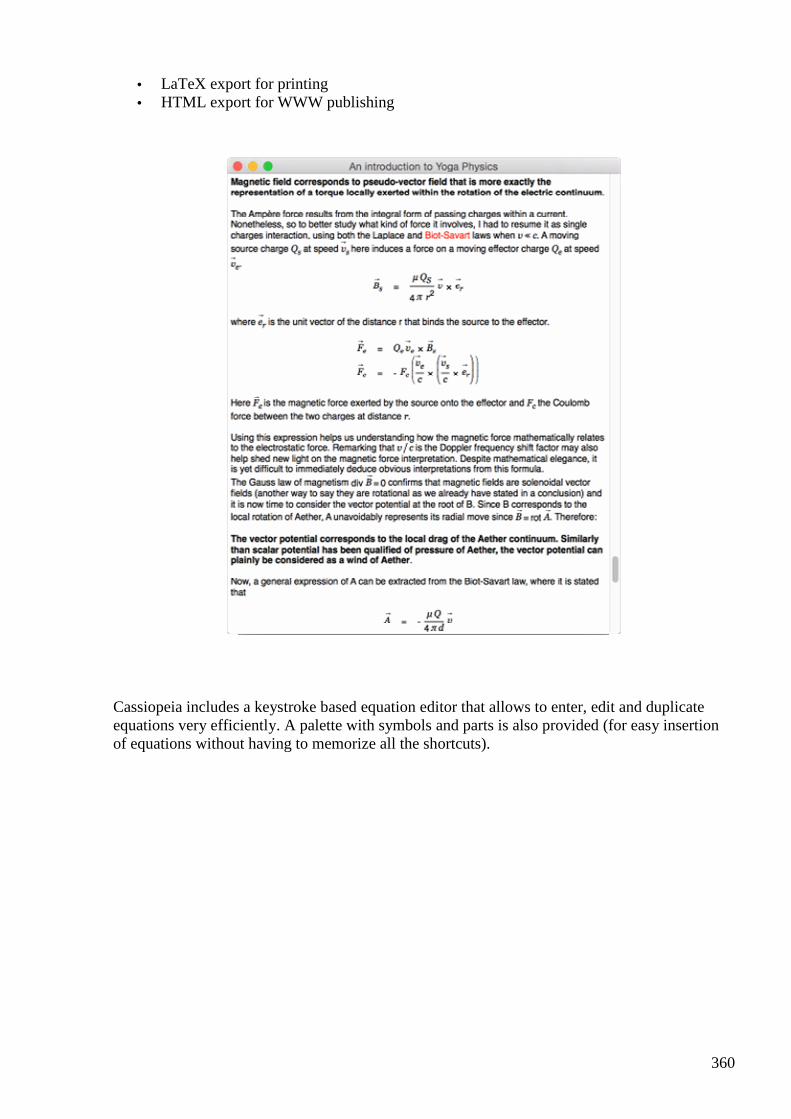
360
• LaTeX export for printing • HTML export for WWW publishing
Cassiopeia includes a keystroke based equation editor that allows to enter, edit and duplicate equations very efficiently. A palette with symbols and parts is also provided (for easy insertion of equations without having to memorize all the shortcuts).
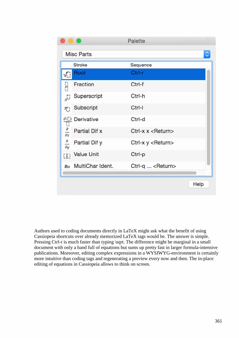
361
Authors used to coding documents directly in LaTeX might ask what the benefit of using Cassiopeia shortcuts over already memorized LaTeX tags would be. The answer is simple. Pressing Ctrl-r is much faster than typing \sqrt. The difference might be marginal in a small document with only a hand full of equations but sums up pretty fast in larger formula-intensive publications. Moreover, editing complex expressions in a WYSIWYG-environment is certainly more intuitive than coding tags and regenerating a preview every now and then. The in-place editing of equations in Cassiopeia allows to think on screen.
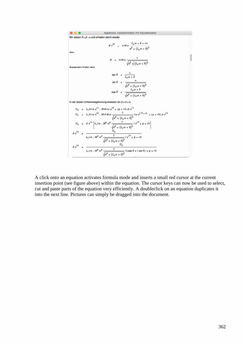
362
A click onto an equation activates formula mode and inserts a small red cursor at the current insertion point (see figure above) within the equation. The cursor keys can now be used to select, cut and paste parts of the equation very efficiently. A doubleclick on an equation duplicates it into the next line. Pictures can simply be dragged into the document.
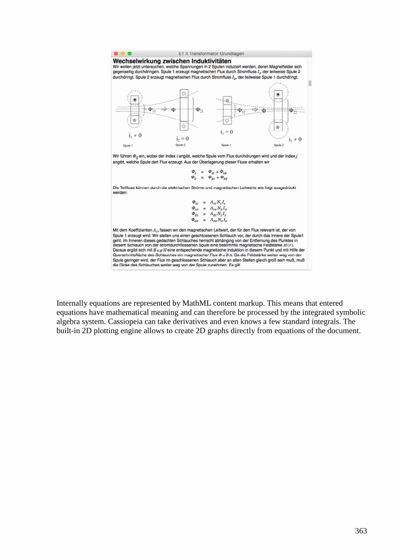
363
Internally equations are represented by MathML content markup. This means that entered equations have mathematical meaning and can therefore be processed by the integrated symbolic algebra system. Cassiopeia can take derivatives and even knows a few standard integrals. The built-in 2D plotting engine allows to create 2D graphs directly from equations of the document.
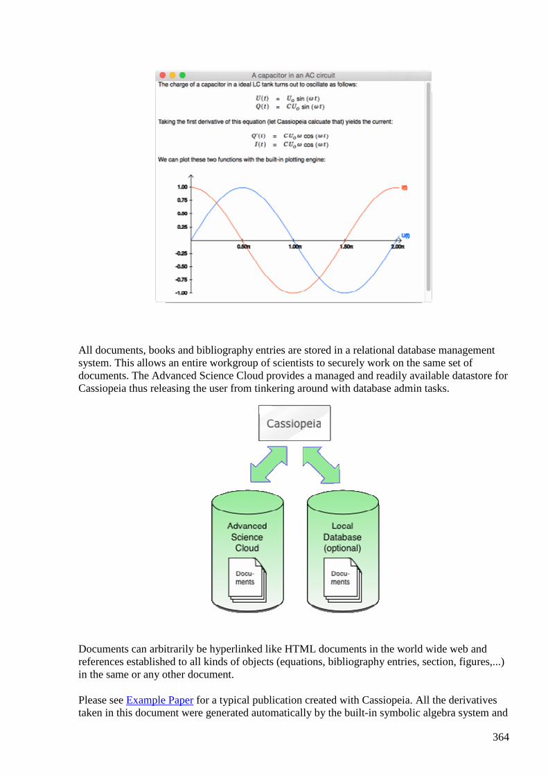
364
All documents, books and bibliography entries are stored in a relational database management system. This allows an entire workgroup of scientists to securely work on the same set of documents. The Advanced Science Cloud provides a managed and readily available datastore for Cassiopeia thus releasing the user from tinkering around with database admin tasks.
Documents can arbitrarily be hyperlinked like HTML documents in the world wide web and references established to all kinds of objects (equations, bibliography entries, section, figures,...) in the same or any other document.
Please see Example Paper for a typical publication created with Cassiopeia. All the derivatives taken in this document were generated automatically by the built-in symbolic algebra system and
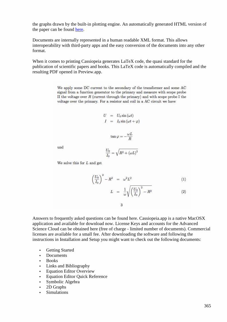
365
the graphs drawn by the built-in plotting engine. An automatically generated HTML version of the paper can be found here.
Documents are internally represented in a human readable XML format. This allows interoperability with third-party apps and the easy conversion of the documents into any other format.
When it comes to printing Cassiopeia generates LaTeX code, the quasi standard for the publication of scientific papers and books. This LaTeX code is automatically compiled and the resulting PDF opened in Preview.app.
Answers to frequently asked questions can be found here. Cassiopeia.app is a native MacOSX application and available for download now. License Keys and accounts for the Advanced Science Cloud can be obtained here (free of charge - limited number of documents). Commercial licenses are available for a small fee. After downloading the software and following the instructions in Installation and Setup you might want to check out the following documents:
• Getting Started • Documents • Books • Links and Bibliography • Equation Editor Overview • Equation Editor Quick Reference • Symbolic Algebra • 2D Graphs • Simulations
366
If you encounter any problems feel free to contact our support team at [email protected]. Your questions are welcome and feedback is greatly appreciated!
#382 RE: [ferd] IPC Quadra
Alexey May 11 10:39 PM
Hi Andreas,
“I need to kick MOSFETs pretty hard and probably even have to switch to SICs”
Interesting, I got impression that these boards already several KW capable, do you need even more ?
About Cassiopeia - thank you for offer, but I still use paper and pen for drawing and formulas. Old, fast and reliable tools
Regards,
Alexey
#383 Re: [ferd] IPC Quadra
Andreas Höschler May 11 10:58 PM
Hi Alexey,
“I need to kick MOSFETs pretty hard and probably even have to switch to SICs”
Interesting, I got impression that these boards already several KW capable, do you need even more ?
I don't measure my needs in kW. It might be that one can build a brute force standard switched mode power supply with these boards but that's nothing I am interested in. What I found is that the MOSFET and the MOSFET driver get pretty hot (requires a fan to keep this operatable) at only 200kHz even without attaching any load to the MOSFETs. I don't consider this the ultimate solution for all possible scenarios on the bench and the board seems completely unsuitable for doing PMOD effect experiments. I have roughly figured out yesterday evening of how to drive a SIC. I have to start from scratch again with wire-wrapping to implement a suitable driver! :-(
Don't take me wrong, the boards are fine for standard projects like building a SMPS. I simply can't make use of them for this very special experiment I am planning to conduct.
About Cassiopeia - thank you for offer, but I still use paper and pen for drawing and formulas. Old, fast and reliable tools
:-)
367
Best wishes,
Andreas
#384 Re: [ferd] IPC Quadra
onielsen2000 May 12 at 2:15 AM
Hi Andreas, If you're building a radio transmitter there are RF power MOSFETs available. They may be very expensive. Use a search engine to find them or visit some home pages of semiconductor companies. There are power MOSFETs for HF, VHF or UHF and GaAs FETs for GHz range. Perhaps something like this expensive device: http://www.st.com/web/en/resource/technical/document/datasheet/CD00003656.pdf Or UHF LDMOS(FET) (laterally diffused metal oxide semiconductor) from NXP Semiconductors: UHF broadcast power transistors (470-860 MHz) :: NXP Semiconductors
http://www.nxp.com/products/mosfets/rf_power_transistors_ldmos/broadcast/470_860_mhz_uhf_broadcast/#products
UHF broadcast power transistors (470-860 MHz) :: NXP Semiconductors NXP's leading LDMOS technologies, together with advanced package concepts, en...
View on www.nxp.com Preview
by Yahoo
Regards Ole
#385 RE: [ferd] IPC Quadra
Alexey May 12 at 8:41 AM
Hi Andreas,
From my experience I can say that sometimes smaller MOSFETs works better for such applications, because they have smaller capacitance.
Regards,
368
Alexey
P.S. RF amplifier with MOSFETs http://www.w5jgv.com/400w-ssb-amp/
#386 Re: [ferd] IPC Quadra
Andreas Höschler May 12 at 7:16 PM
Hi Alexey and Ole,
From my experience I can say that sometimes smaller MOSFETs works better for such applications, because they have smaller capacitance.
Thanks for your hints. I will see how others transistors perform:
Here is a little refresher about special relativity for the break! :-)
http://www.advanced-science.com/TimeDilatation.html
Andreas
Special Relativity - A new approach There is this one thing about special relativity that always made me wonder. It is claimed that there is no absolute reference frame and that everything is relative. It takes a little girl minutes to come up with a problem that completely dismantles Einsteins work of 1905. Her argument goes us follows:
There are two siblings, one stays on earth, the other gets into a rocket, flies around for a while and eventually returns to earth. It turns out that the sibling that stayed on earth got grey hair in the meanwhile while his flying sibling remained young and coltish. This effect can be doubtlessly demonstrated with atomic watches. The little girl now argues if everything is relative why can't we consider the flying rocket to be stationary and the earth with the sibling be moving? If looked on it that way the other sibling should have aged, shouldn't he!?
This paradox is usually discussed away with the argument that the flying sibling is accelerated twice and that therefore special relativity does not apply. Moreover, the obvious paradox is promised to be resolved (later) by general relativity. This argument is foolish for at least two reasons:
• It is easy to say that something is explained by another fancy theory far too complex to be ever looked at much less understood by the majority of graduating students. It took Einstein himself 30 years to work through this mess of tensor algebra. So the reference to a mysterious second theory that hardly anyone knows or ever has the chance to look at
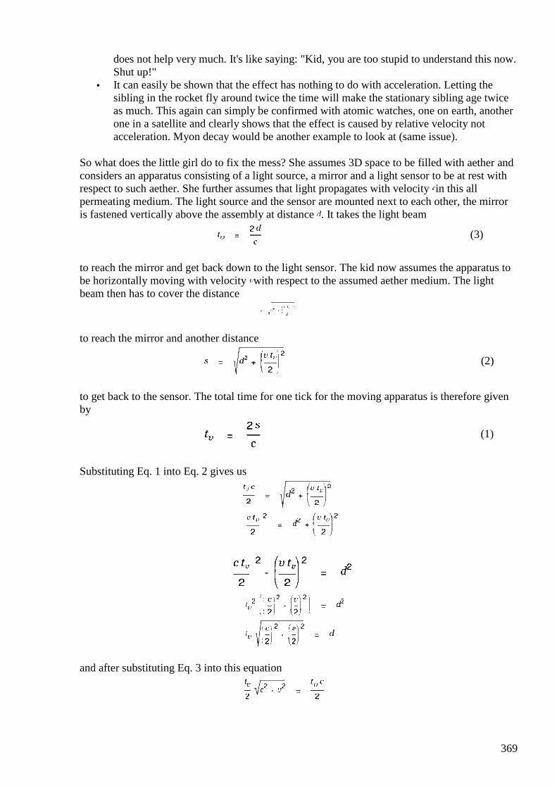
369
does not help very much. It's like saying: "Kid, you are too stupid to understand this now. Shut up!"
• It can easily be shown that the effect has nothing to do with acceleration. Letting the sibling in the rocket fly around twice the time will make the stationary sibling age twice as much. This again can simply be confirmed with atomic watches, one on earth, another one in a satellite and clearly shows that the effect is caused by relative velocity not acceleration. Myon decay would be another example to look at (same issue).
So what does the little girl do to fix the mess? She assumes 3D space to be filled with aether and considers an apparatus consisting of a light source, a mirror and a light sensor to be at rest with respect to such aether. She further assumes that light propagates with velocity in this all permeating medium. The light source and the sensor are mounted next to each other, the mirror is fastened vertically above the assembly at distance . It takes the light beam
(3)
to reach the mirror and get back down to the light sensor. The kid now assumes the apparatus to be horizontally moving with velocity with respect to the assumed aether medium. The light beam then has to cover the distance
to reach the mirror and another distance
(2)
to get back to the sensor. The total time for one tick for the moving apparatus is therefore given by
(1)
Substituting Eq. 1 into Eq. 2 gives us
and after substituting Eq. 3 into this equation
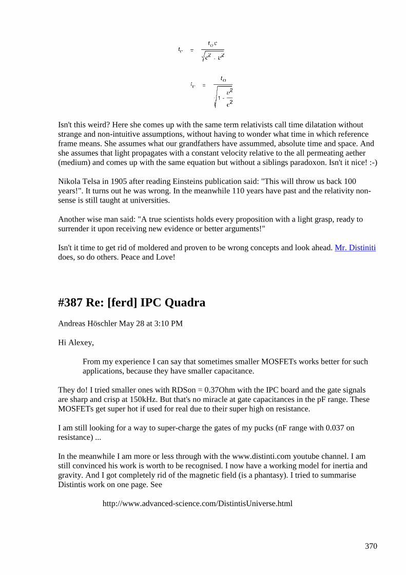
370
Isn't this weird? Here she comes up with the same term relativists call time dilatation without strange and non-intuitive assumptions, without having to wonder what time in which reference frame means. She assumes what our grandfathers have assummed, absolute time and space. And she assumes that light propagates with a constant velocity relative to the all permeating aether (medium) and comes up with the same equation but without a siblings paradoxon. Isn't it nice! :-)
Nikola Telsa in 1905 after reading Einsteins publication said: "This will throw us back 100 years!". It turns out he was wrong. In the meanwhile 110 years have past and the relativity non-sense is still taught at universities.
Another wise man said: "A true scientists holds every proposition with a light grasp, ready to surrender it upon receiving new evidence or better arguments!"
Isn't it time to get rid of moldered and proven to be wrong concepts and look ahead. Mr. Distiniti does, so do others. Peace and Love!
#387 Re: [ferd] IPC Quadra
Andreas Höschler May 28 at 3:10 PM
Hi Alexey,
From my experience I can say that sometimes smaller MOSFETs works better for such applications, because they have smaller capacitance.
They do! I tried smaller ones with RDSon = 0.37Ohm with the IPC board and the gate signals are sharp and crisp at 150kHz. But that's no miracle at gate capacitances in the pF range. These MOSFETs get super hot if used for real due to their super high on resistance.
I am still looking for a way to super-charge the gates of my pucks (nF range with 0.037 on resistance) ...
In the meanwhile I am more or less through with the www.distinti.com youtube channel. I am still convinced his work is worth to be recognised. I now have a working model for inertia and gravity. And I got completely rid of the magnetic field (is a phantasy). I tried to summarise Distintis work on one page. See
http://www.advanced-science.com/DistintisUniverse.html
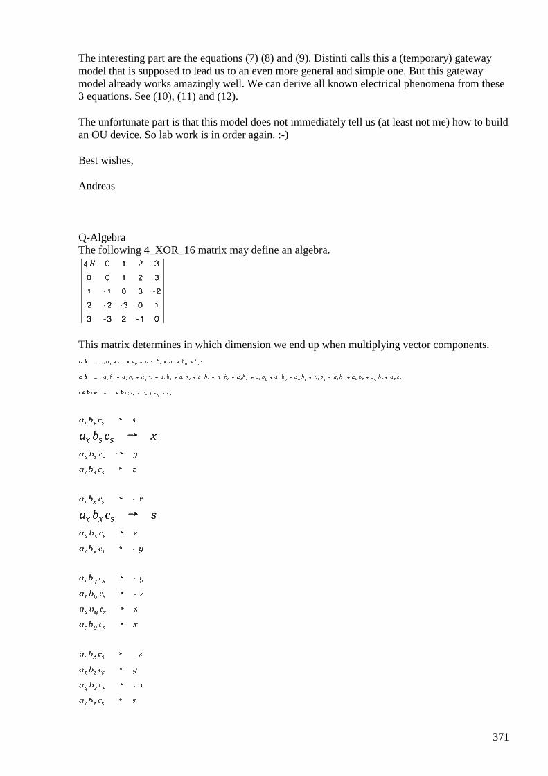
371
The interesting part are the equations (7) (8) and (9). Distinti calls this a (temporary) gateway model that is supposed to lead us to an even more general and simple one. But this gateway model already works amazingly well. We can derive all known electrical phenomena from these 3 equations. See (10), (11) and (12).
The unfortunate part is that this model does not immediately tell us (at least not me) how to build an OU device. So lab work is in order again. :-)
Best wishes,
Andreas
Q-Algebra The following 4_XOR_16 matrix may define an algebra.
This matrix determines in which dimension we end up when multiplying vector components.
372
373
The result of multiplying vectors and can obviously be written as a 4x4 matrix!
We honor this finding by defining
(1)
(2)
374
(3) Looking rigorously at Eq. 2 yields
We can therefore write
(4) This also gives us the following sums and differences:
(5)
(6) Pythagorean Theorem Let's say we have two arbitrary verctors and and the sum of these two vectors
With our new algebra we can square this equation without producing ambiguities.
This turns out to be the well known cosinus relationship for arbitrary triangles. New Electromagnetism We have found the following three equations (gateway model) for new electromagnetism:
(7)
(8)
(9)
Let's look at Eq. 7 first.
Our model for an electron is two pretonic charges rotating around each other with speed . This gives us the following for Eq. 7.
In the special case of the two pretonic charges constituting an electron and are parallel with opposite direction and perpendicular to at all times. We can therefore simplify to
375
(10)
So Eq. 7 gives us Coulombs law if we look at two pretonic charges rotating with around each other. In the general case (two arbitrary charges with arbitrary velocities) we end up with an additional term
(11)
Let's look at Eq. 8 and Eq. 9 now.
A moving charge generates a field at distance . A target charge feels a force if this field (at the location of ) changes. The field at the location may change due to a change of (limited propagation speed) but the more probable reason is that moved to another location with a different .
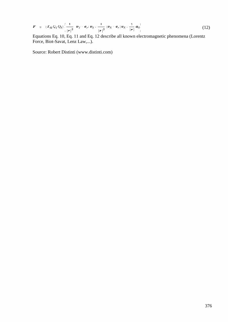
376
(12)
Equations Eq. 10, Eq. 11 and Eq. 12 describe all known electromagnetic phenomena (Lorentz Force, Biot-Savat, Lenz Law,...). Source: Robert Distinti (www.distinti.com)
377
#388 RE: [ferd] IPC Quadra
Alexey May 28 at 6:44 PM
Hi Andreas,
Nice to hear from you
” I tried to summarise Distintis work on one page. See http://www.advanced-science.com/DistintisUniverse.html”
That’s lots of formulas, not so easy to get something practical from it.
No progress on my side, I am completely “buried” with my day work…
Here a news, if you haven’t seen it yet: AuKW seems to be a fake, see http://overunity.com/15773/gaia-rosch-aukw-auftriebskraftwerk-kpp-why-it-does-not-work/msg451521
For me it is so weird, that people make such huge fakes why ? :-/
Regards,
Alexey
#389 Re: [ferd] [offtopic] Gerry magnet motor
Gerry May 28 at 8:01 PM
Hi Alexey, Andreas ..guys
Just an update on my magnet motor project.
Have attached some shots above.
(The idea for this project came from some old pics I saw of Lester Hendershots self running motor.)
I had to wrap the stator magnets individually (shown in 0672a) with adhesive backed Aluminum foil tape to stop em from moving in the stator assembly.
Finally put it back together into original alternator body as can be seen in image 0682a.
Using an old type 3 phase speed controller (from a previous project) I started driving the modified alternator/ magnet motor with the fan belt connection.
378
The prime mover motor is an old 3 phase (pool pump?) motor I found by the side of the road a couple of years back.
The 3 phase motor runs smoothly on it's own and is easily controlled by the controller.
However when hooked up with fan belt to magnet motor and started using the controller, it begins to accelerate uncontrollably and scares me from the rpm it generates.
I think my modified alternator starts to drive the 3 phase motor as a prime mover itself once a certain level of rpm is attained.
When I shut it down the controller throws a magnetic brake on the 3 phase motor and it comes to sudden halt.
Due to magnetic cogging on the alternator it all shudders as it grinds to a halt.
The alternator still has it's original brushes and rotor coil, if I short wires from brushes out during operation, the rotor shaft and belt gets very very hot and the load on the prime mover increases considerably.
Thankfully slowing it all down though.
Am trying to figure how to disconnect the controller during operation without blowing the thing up from back volts of inductive load.
So that I can to see if the setup can self run ...I think I can shut it down by shorting out rotor wires on the magnet motor.
Perhaps I can then use 3 phase (pool pump) motor and as an alternator energy source, at least that's my thoughts.
all the best Gerry
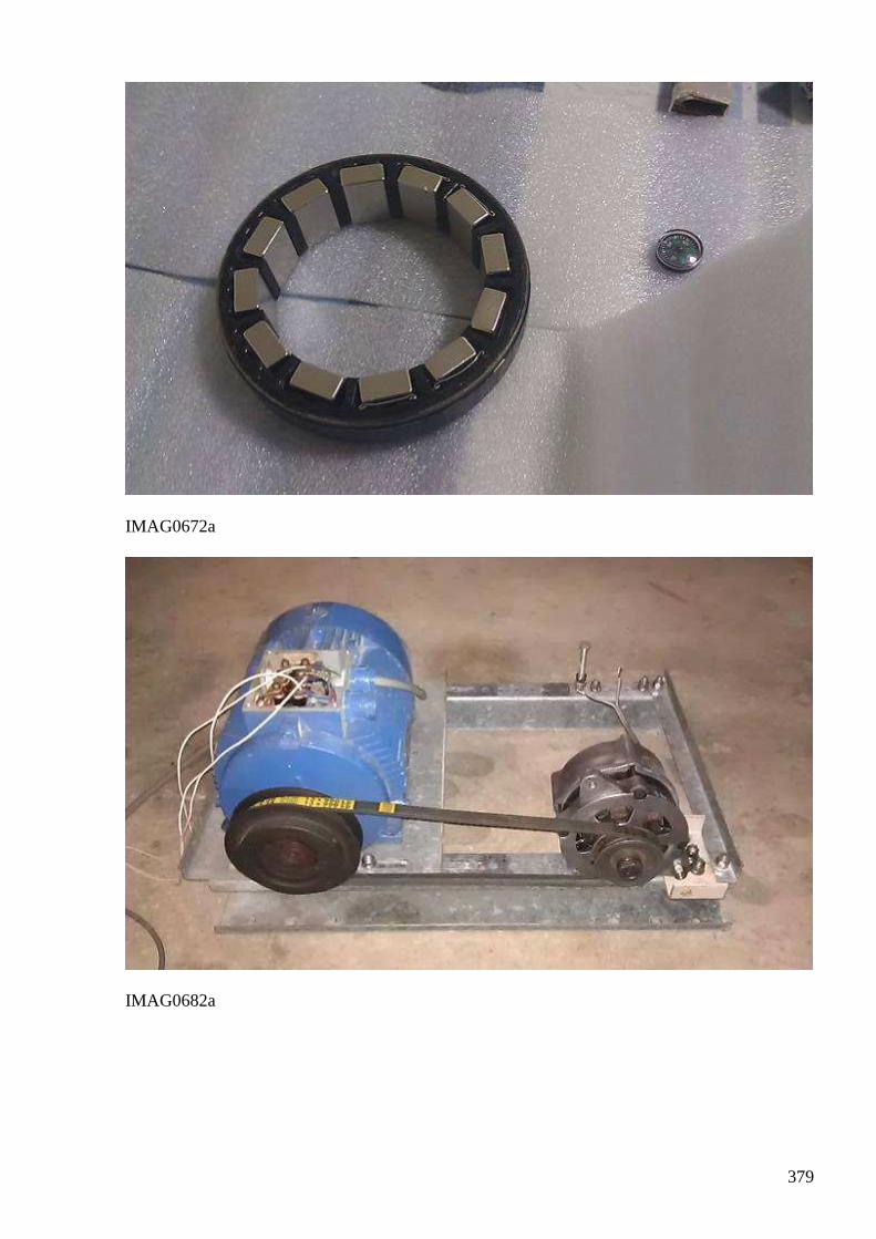
379
IMAG0672a
IMAG0682a
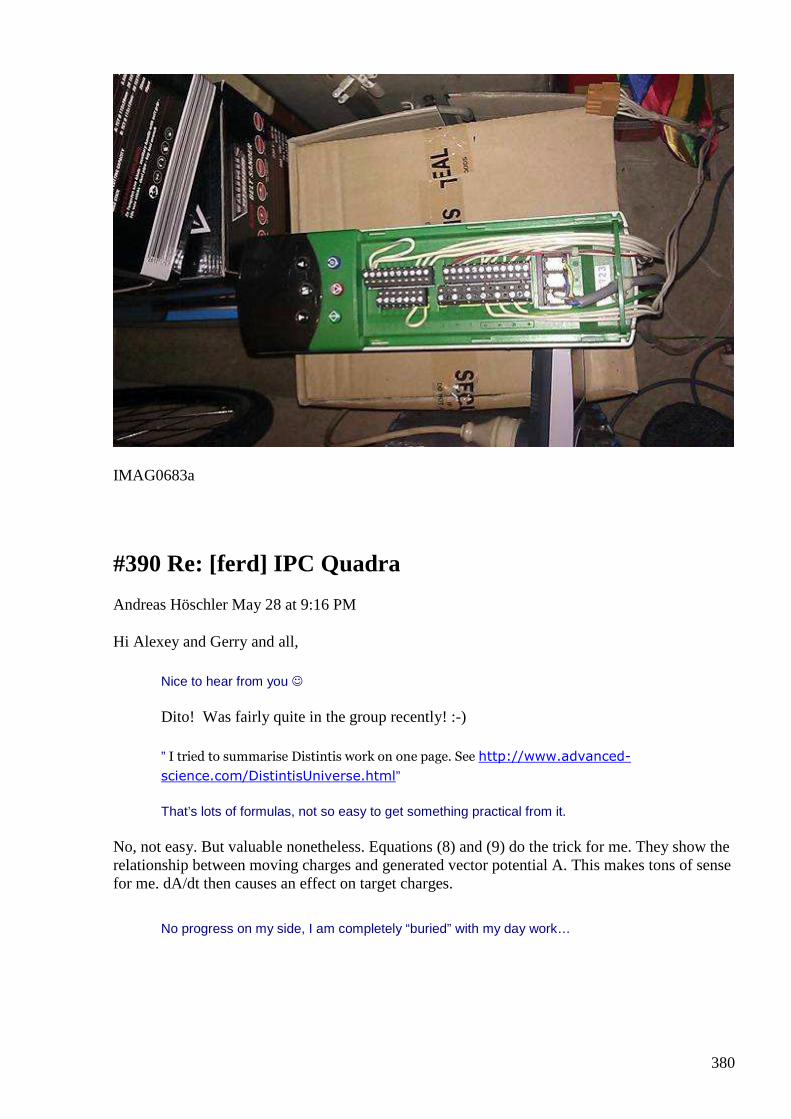
380
IMAG0683a
#390 Re: [ferd] IPC Quadra
Andreas Höschler May 28 at 9:16 PM
Hi Alexey and Gerry and all,
Nice to hear from you
Dito! Was fairly quite in the group recently! :-)
” I tried to summarise Distintis work on one page. See http://www.advanced-
science.com/DistintisUniverse.html”
That’s lots of formulas, not so easy to get something practical from it.
No, not easy. But valuable nonetheless. Equations (8) and (9) do the trick for me. They show the relationship between moving charges and generated vector potential A. This makes tons of sense for me. dA/dt then causes an effect on target charges.
No progress on my side, I am completely “buried” with my day work…
381
So am I, unfortunately. I at least managed to release a new Cassiopeia version and make a new demo video: :-)
https://www.youtube.com/watch?v=U-Wz0cbgVFc&feature=youtu.be
Doing this research should at least be fun (and super efficient)! :-)
Here a news, if you haven’t seen it yet: AuKW seems to be a fake, see http://overunity.com/15773/gaia-rosch-aukw-auftriebskraftwerk-kpp-why-it-does-not-
work/msg451521
For me it is so weird, that people make such huge fakes why ? :-/
As explained earlier this thing basically works and is OU. You need nothing but school physics (11th grade) to show this beyond a shadow of a doubt. These so called experts (quantum physicists TU Wien) making fun of it, their ignorance and stupidity drives me crazy. The device converts heat energy to kinetic energy. It's so simple that a kid in school could determine the COP of the device and find it to be OU. However, the COP is too bad to justify the effort of building and operating such a beast. 5kW is ridiculous. This number is faked unless there is some effect at play that is not covered by school physics. Could very well be but for the moment I doubt it. I am therefore back examining electromagnetic phenomena. :-)
Best wishes,
Andreas
#391 Re: [ferd] [offtopic] Gerry magnet motor
Andreas Höschler May 28 at 9:22 PM
Hi Gerry,
Just an update on my magnet motor project.
Have attached some shots above.
Thanks for the update! We may make some progress this or that way soon! Have fun and keep us posted! :-)
Best wishes,
Andreas
#392 RE: [ferd] [offtopic] Gerry magnet motor
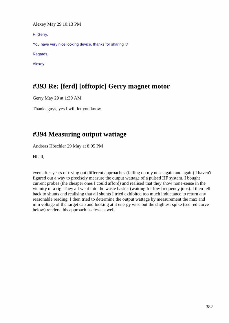
382
Alexey May 29 10:13 PM
Hi Gerry,
You have very nice looking device, thanks for sharing
Regards,
Alexey
#393 Re: [ferd] [offtopic] Gerry magnet motor
Gerry May 29 at 1:30 AM
Thanks guys, yes I will let you know.
#394 Measuring output wattage
Andreas Höschler 29 May at 8:05 PM
Hi all,
even after years of trying out different approaches (falling on my nose again and again) I haven't figured out a way to precisely measure the output wattage of a pulsed HF system. I bought current probes (the cheaper ones I could afford) and realised that they show none-sense in the vicinity of a rig. They all went into the waste basket (waiting for low frequency jobs). I then fell back to shunts and realising that all shunts I tried exhibited too much inductance to return any reasonable reading. I then tried to determine the output wattage by measurement the max and min voltage of the target cap and looking at it energy wise but the slightest spike (see red curve below) renders this approach useless as well.
383
I very much appreciate any hint or idea to get a reasonable reading. This said, what are you guys currently working on or considering to have merit? Ole, haven't heard from you for a while!?? :-( Have a nice weekend! Andreas
#395 RE: [ferd] Measuring output wattage
Alexey May 29 at 9:56 PM
Hi Andreas, ”what are you guys currently working on or considering to have merit”
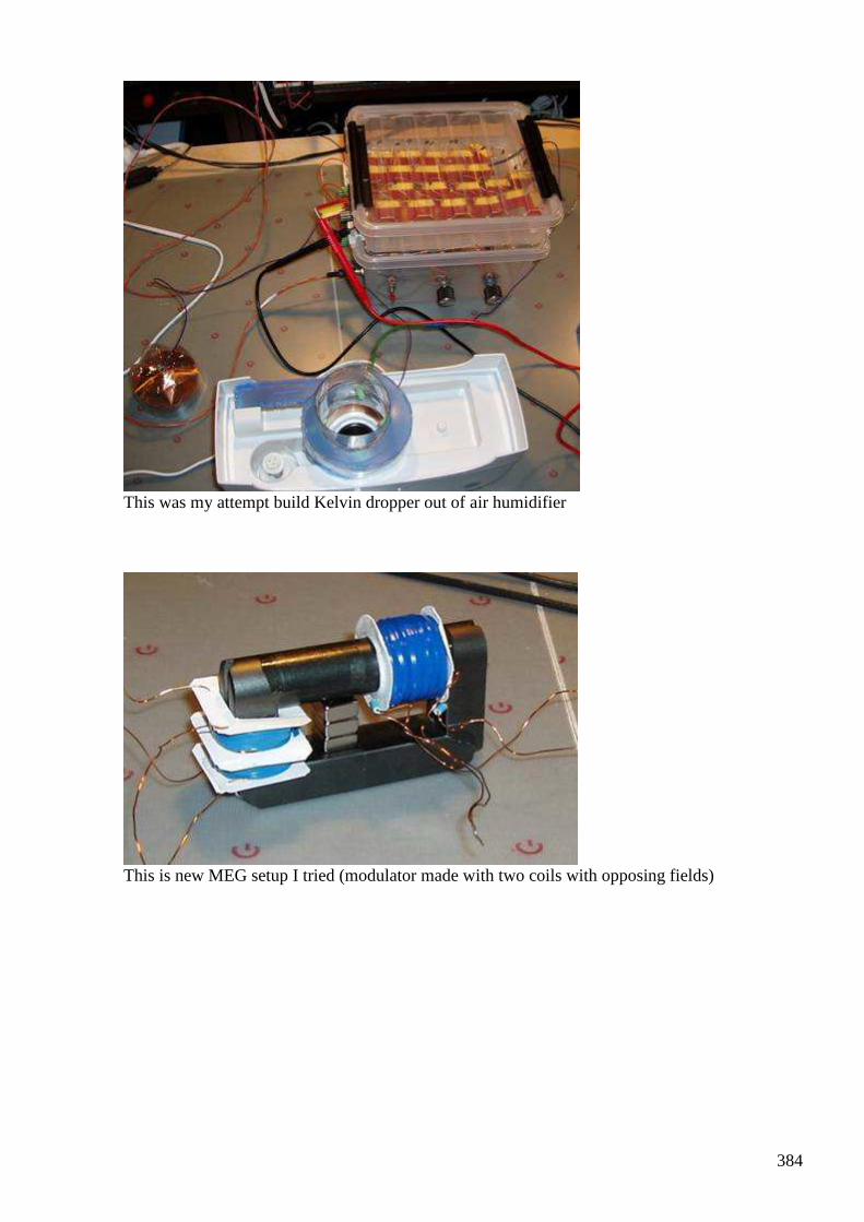
384
This was my attempt build Kelvin dropper out of air humidifier
This is new MEG setup I tried (modulator made with two coils with opposing fields)
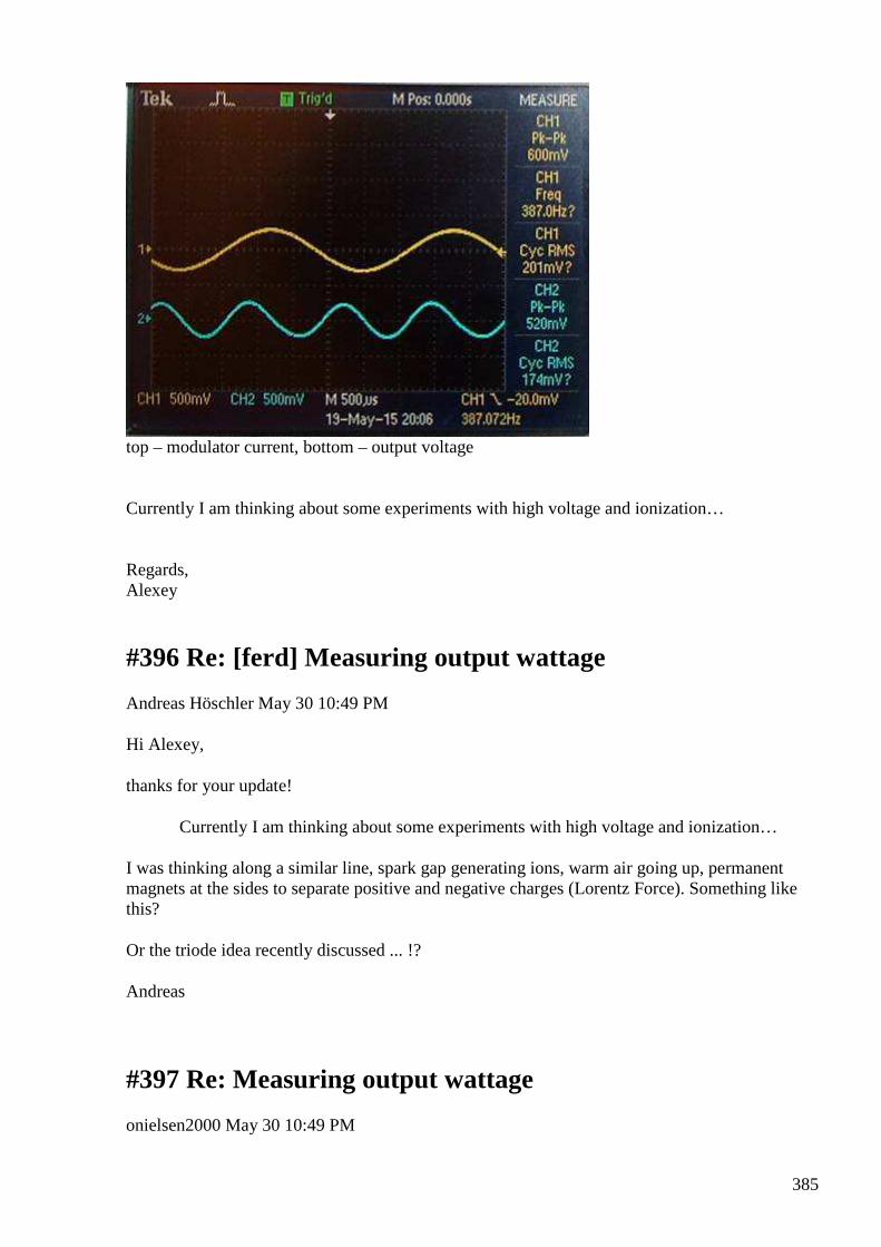
385
top – modulator current, bottom – output voltage Currently I am thinking about some experiments with high voltage and ionization… Regards, Alexey
#396 Re: [ferd] Measuring output wattage
Andreas Höschler May 30 10:49 PM
Hi Alexey,
thanks for your update!
Currently I am thinking about some experiments with high voltage and ionization…
I was thinking along a similar line, spark gap generating ions, warm air going up, permanent magnets at the sides to separate positive and negative charges (Lorentz Force). Something like this?
Or the triode idea recently discussed ... !?
Andreas
#397 Re: Measuring output wattage
onielsen2000 May 30 10:49 PM
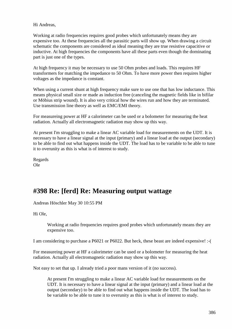
386
Hi Andreas, Working at radio frequencies requires good probes which unfortunately means they are expensive too. At these frequencies all the parasitic parts will show up. When drawing a circuit schematic the components are considered as ideal meaning they are true resistive capacitive or inductive. At high frequencies the components have all these parts even though the dominating part is just one of the types. At high frequency it may be necessary to use 50 Ohm probes and loads. This requires HF transformers for matching the impedance to 50 Ohm. To have more power then requires higher voltages as the impedance is constant. When using a current shunt at high frequency make sure to use one that has low inductance. This means physical small size or made as induction free (canceling the magnetic fields like in bifilar or Möbius strip wound). It is also very critical how the wires run and how they are terminated. Use transmission line theory as well as EMC/EMI theory. For measureing power at HF a calorimeter can be used or a bolometer for measuring the heat radiation. Actually all electromagnetic radiation may show up this way. At present I'm struggling to make a linear AC variable load for measurements on the UDT. It is necessary to have a linear signal at the input (primary) and a linear load at the output (secondary) to be able to find out what happens inside the UDT. The load has to be variable to be able to tune it to overunity as this is what is of interest to study. Regards Ole
#398 Re: [ferd] Re: Measuring output wattage
Andreas Höschler May 30 10:55 PM
Hi Ole,
Working at radio frequencies requires good probes which unfortunately means they are expensive too.
I am considering to purchase a P6021 or P6022. But heck, these beast are indeed expensive! :-(
For measureing power at HF a calorimeter can be used or a bolometer for measuring the heat radiation. Actually all electromagnetic radiation may show up this way.
Not easy to set that up. I already tried a poor mans version of it (no success).
At present I'm struggling to make a linear AC variable load for measurements on the UDT. It is necessary to have a linear signal at the input (primary) and a linear load at the output (secondary) to be able to find out what happens inside the UDT. The load has to be variable to be able to tune it to overunity as this is what is of interest to study.
387
Sounds cumbersome! Good luck with that. Please keep us posted!
Andreas
#399 RE: [ferd] Measuring output wattage
Alexey 31 May at 12:12 PM
Hi Andreas,
here is a paper which describes device I think worth to explore...
Regards,
Alexey
Generating electricity from the atmosphere using an antenna and receiver Kasyanov GT Open laboratory "Vortex electricity" It is generally known that dielectrics in electrical circuits do not always act as insulators. Actually, they contain no fewer charges than the conductors, but charges in insulators “fixed” on their places by an internal electric field, i.e. balanced, and can’t move freely as in conductors. Therefore, no electrical (conductivity) currents - flow of charges, controlled by applied voltage occur. This implies that the dielectric is insulator. However, there are conditions under which the equilibrium of the charges in the dielectric may be broken, and they can act as conductors. Well-known example - the film dielectrics used in capacitors. Films are having a great AC electric conductivity. However, this current - not a flow of charges as in conductors, but only shift of charges from their designated places. And yet, such a movement of the charges - also electric current. Although it has somewhat different properties than the conductivity current. This is - the polarization current. The phenomenon of polarization occurs in any insulator if it is placed in an external electric field. Under the influence of this field there are formed electric dipoles, wherein on the boundary surfaces of the dielectric having uncompensated electric charges [1]. Of course, if you change the intensity of the external field, for example, the periodic law, the dielectric polarization current occurs, changing by the same law. [2] This phenomenon occurs in all dielectric, as long as it was in the electric field. Using this physical phenomenon could be explained, for example, such a phenomenon as the work of single-ended (non-closed) electrical circuits, examples of which are described in detail a hundred years ago a brilliant experimenter Nikola Tesla. In these circuits conductivity current can be easily (Tesla technology) by breaking the circuit converted into polarization current propagating in the dielectric medium, and using such current circuit can be closed and actually run a load.
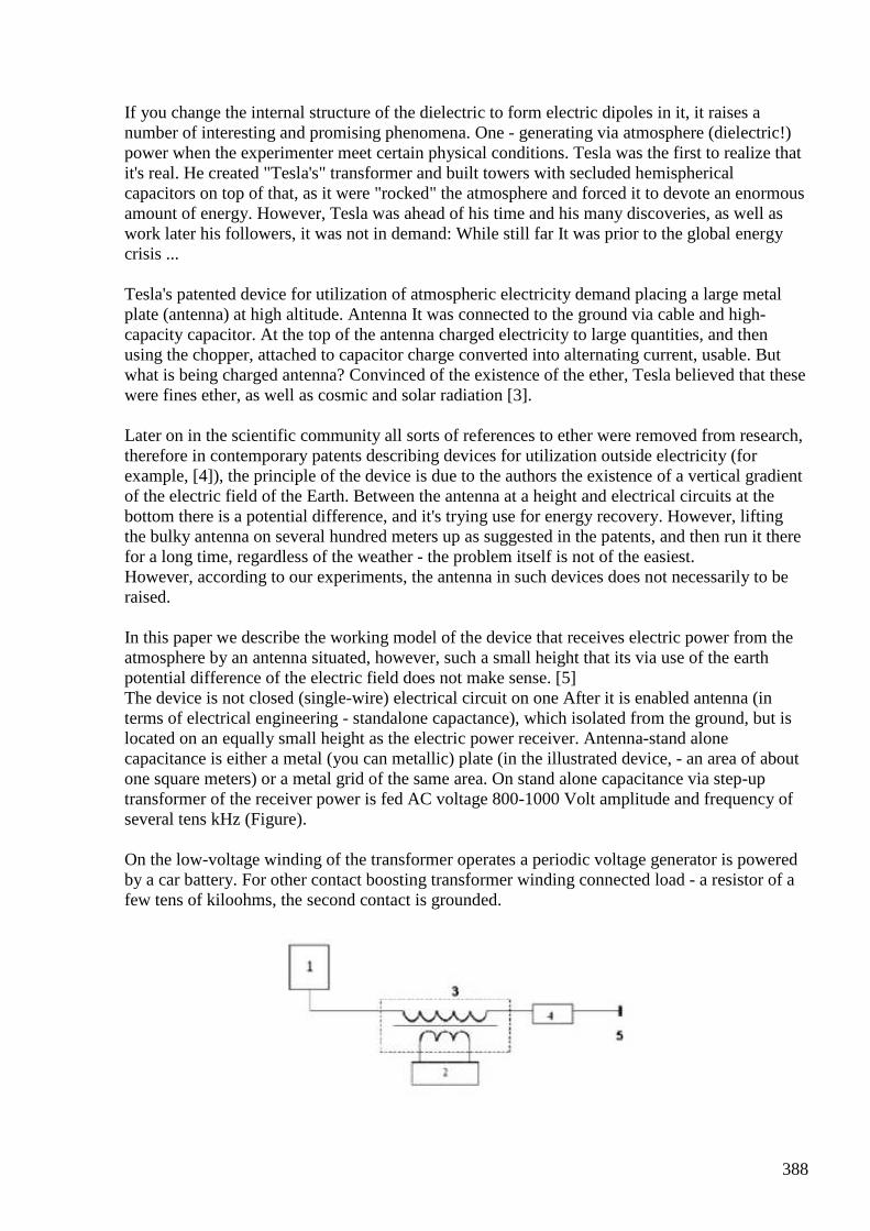
388
If you change the internal structure of the dielectric to form electric dipoles in it, it raises a number of interesting and promising phenomena. One - generating via atmosphere (dielectric!) power when the experimenter meet certain physical conditions. Tesla was the first to realize that it's real. He created "Tesla's" transformer and built towers with secluded hemispherical capacitors on top of that, as it were "rocked" the atmosphere and forced it to devote an enormous amount of energy. However, Tesla was ahead of his time and his many discoveries, as well as work later his followers, it was not in demand: While still far It was prior to the global energy crisis ... Tesla's patented device for utilization of atmospheric electricity demand placing a large metal plate (antenna) at high altitude. Antenna It was connected to the ground via cable and high-capacity capacitor. At the top of the antenna charged electricity to large quantities, and then using the chopper, attached to capacitor charge converted into alternating current, usable. But what is being charged antenna? Convinced of the existence of the ether, Tesla believed that these were fines ether, as well as cosmic and solar radiation [3]. Later on in the scientific community all sorts of references to ether were removed from research, therefore in contemporary patents describing devices for utilization outside electricity (for example, [4]), the principle of the device is due to the authors the existence of a vertical gradient of the electric field of the Earth. Between the antenna at a height and electrical circuits at the bottom there is a potential difference, and it's trying use for energy recovery. However, lifting the bulky antenna on several hundred meters up as suggested in the patents, and then run it there for a long time, regardless of the weather - the problem itself is not of the easiest. However, according to our experiments, the antenna in such devices does not necessarily to be raised. In this paper we describe the working model of the device that receives electric power from the atmosphere by an antenna situated, however, such a small height that its via use of the earth potential difference of the electric field does not make sense. [5] The device is not closed (single-wire) electrical circuit on one After it is enabled antenna (in terms of electrical engineering - standalone capactance), which isolated from the ground, but is located on an equally small height as the electric power receiver. Antenna-stand alone capacitance is either a metal (you can metallic) plate (in the illustrated device, - an area of about one square meters) or a metal grid of the same area. On stand alone capacitance via step-up transformer of the receiver power is fed AC voltage 800-1000 Volt amplitude and frequency of several tens kHz (Figure). On the low-voltage winding of the transformer operates a periodic voltage generator is powered by a car battery. For other contact boosting transformer winding connected load - a resistor of a few tens of kiloohms, the second contact is grounded.
389
Model of the device that receives energy from the atmosphere via the antenna: 1 - antenna (stand alone capacitance), 2 - alternator voltage supply battery, 3 - Step-up transformer, 4 - load 5 - grounding Thus, in the circuit diagram created for the charge / discharge stand alone capacitor connected with the earth, with the charge / discharge current flows through the load, highlighting it useful energy. The experiment shows that the current and the useful energy in the load increase with the square of the capacitor lone antenna. Note that structural capacitance of the capacitor-antenna relative to the ground in the ongoing processes It is not important: it is too small and, moreover, if the container further reduce, for example, stand alone raising capacitor higher charge / discharge current is not only not reduced, and on the contrary, it tends to increase. Almost in the scheme shown in the figure, at the above parameters managed get the output of more than 20 watts of power at a cost of battery, not exceeding 9.5 watts. Also in the load resistor they were used and worked LED string and small bulbs. It is also possible to connect (through matching transformers) charger for mobile phones and other schemes. If you disconnect the capacitor from the standalone-up transformer during operation generator, the current through the load is reduced by four to five orders of magnitude. Receiver without antenna ceases to obtain additional energy from the outside - from the atmosphere. How it is possible to explain the process of extracting electrical energy from the atmosphere an antenna and a generator of periodic voltage? Vertical Gradient the electric field of the earth in this case irrelevant. No information on the existence of fines ether in the available scientific literature. Let's look again at the picture. The antenna is connected to the high voltage winding transformer hardly emits radio waves into the space at the frequency of oscillation voltage generator, since the wavelength of the oscillations produced by the generator, select the order of 10-15 kilometers, and the length of the antenna satisfying mobility and small describes the devices chosen by thousands of times shorter. But antenna produce in a local region of space around them a variable high voltage electric field. Field polarizes the molecules in the air, turning them into electric dipoles (See para. [1]). The polarized molecules line up along the lines of the field strength, at the same time the rotation axes of symmetry of polarized molecules along the lines of tension increases the force their interaction with the external field source (antenna). As a result, the process of spatial ordering of electric dipoles in an organized external field medium. Next, the following occurs. The principal difference between standalone capacitor antenna from conventional capacitor with parallel plates and the uniform electric field between them, is that the finite size of the capacitor Lone creates around himself dielectric (in this case - in the atmosphere) for the electric inhomogeneous field; Indeed, the field strength decreases with distance from the secluded capacitor, therefore, the field inhomogeneous. It’s known that dipoles are in a non uniform electric field, are drawn in the direction bigger intensity. [6] Therefore, at the beginning of each period of charge of stand alone atmospheric condenser dipoles will tend to stay as close as possible to its surface with a force proportional to the gradient of the field strength. Thus, while the charge due to field inhomogeneity increases volumetric (and superficial) density electric charges at the surface of the capacitor secluded. Naturally, the increase in charge density near the surface causes an increase in the total charge Q secluded capacitor. In accordance with the known formula Q = CU, where C - capacity capacitor, U - voltage on it.
390
When a constant amplitude of the voltage U at the capacitor defined by the generator, increasing charge Q is equivalent to increasing the capacitance C of the capacitor secluded. By increasing increased capacity and charge / discharge current is determined by the formula: I = C dU / dt. The increase in current leads to an increase in load power. Note the following. Change the capacity of the capacitor takes place secluded synchronously with the processes of its charge and discharge, i.e. tied to periodic voltage U, issued by the generator. If this voltage is in shape and positively, and negative half-wave of the oscillation period, the change in capacity will take place in two often times the frequency of the oscillator repetition Atmospheric dipoles are rotated to the surface of the capacitor one, then another of its charge over the same period. But a batch process with a change in capacitance twice as likely than the oscillation frequency of the main generator, from the point of view of the theory of electrical circuits with variable parameters has the features of one of the variants of the parametric process [7], and in it the source of the pump, in our case, is the atmosphere. We believe that the amount of energy generator and pump energy, to give atmosphere, just highlights the receiver described in this paper. Possibly, part of the pump source for devices such as those described herein may not play only the atmosphere, but other dielectrics. Is this true and which could dielectrics to fulfill this role more effectively - should show experience. Antenna location secluded capacitor near the earth's surface near the receiver electricity greatly simplifies and makes more reliable method of producing energy from atmosphere. It is understood that in actual use it would significantly reduce the the production costs of such devices and hence reduce the cost of the resulting electricity. Bibliography: 1. Jaworski BM Detlaf AA Handbook of physics. - M .: Nauka, 1985. - pp 165, 167. 2. Jaworski BM Detlaf AA Handbook of physics. - M .: Nauka, 1985. - 250 pp. 3. Apparatus for the Utilization of Radiant Energy. N. Tesla. Patent USA 685, 957. Patented Nov. 5 1901. 4. Sedov AN Veryovkin VN A method of storage of atmospheric electricity: Patent Russia number 2293451 on 07/20/2004. 5. Kasyanov GT, IG Kasyanov Kasyanov V. Atmospheric power source: Patent Russia number 120830 on 11.1.2012. 6. Feynman R., Leighton R., Sands M. The Feynman Lectures on Physics. - M .: Mir, 1966. - T.5. - S. 209. 7. Zernov NV, Karpov VG, Theory of radio circuits. - M .: Energia, 1972. - S. 779.
#400 [ferd] Measuring output wattage
Gustavo Roveran May 31
391
Hi good people I didn't get any fer progress because I have been a bit far from this task. However it was very good to know all research you are doing, like mechanical fer, new meg and Distinti summary. My little daughter has born 2 days ago and this was the beautiful culmination of a very difficult pregnancy carried by my wife. At the same time we had different helthy problems within my family. But now all is better. From technology point of view, I built and design a wifi multi-parameter measurement device for a technology school project about water quality. And reading vhdl and fpga. A way to design logical electronic direct by hardware programming. Did anyone make progress with cap-coil device, torsion field, I would like to test those technologies for little energy harvesting devices when I return to fer. ps: I moving my little lab from future daughter's room to the balcony. Best regards Gustavo
#401 Re: [ferd] Measuring output wattage
Gerry 1 Jun at 1:40 AM Congratulations Gustavo and Mrs. Gustavo !! God bless for a happy healthy future for your family. Gerry
#402 [ferd] Measuring output wattage
Gustavo Roveran Jun 1 at 5:53 AM Hi Gerry Thank you very much. Gustavo
#403 Re: [ferd] Measuring output wattage
Gerry Jun 1 at 7:20 AM Hi Andreas, I started to write a detailed email about this but have deleted it. Ole already said most of what I was going to say. No matter the technique it is very difficult..........а With thermal responding devices like Thermistor mounts and Thermo couple mounts and HP power meters, they require a fixed (or at least known) source andа50 Ohm load impedances.
392
Otherwise there are reflections and re reflections up and down the transmission line, modified by the reflection co efficient at each pass. So source to load match mismatch is critical. Measuring current pulse into known load doesn't tell whole story either as pulse source is continuously charging and discharging the shunt capacity in and around the transmission line. These currents can obviously bypass the load. Sorry mate, Gerry
#404 Re: [ferd] Measuring output wattage
Gerry Jun 1 at 7:21 AM same as #403
#405 RE: [ferd] Measuring output wattage
Alexey Jun 1
Hi Gustavo,
Congratulations and best wishes to you and your family!
Alexey
#406 Thane Heins bi-toroid transformer test
Alexey Jun 2
https://www.youtube.com/watch?v=j-dZj4-PU9s ;-)
#407 Re: [ferd] Thane Heins bi-toroid transformer test
Gerry Jun 2 at 11:00 AM Thanks Alexey, I loved all that beautiful test gear!! How does a simple home tester afford all that? Trying to think about why he didn't get OU ...his input current phase shift was very poor. It should have been closer to 90 degrees phase lag. Gerry
393
#408 Re: [ferd] Thane Heins bi-toroid transformer test
Andreas Höschler Jun 2
Hi Alexey,
https://www.youtube.com/watch?v=j-dZj4-PU9s
;-)
Thanks for the link. One more guy that wasted lots of time with this Bi-Torroid none-sense. This will never fly. We have to learn the basics of induction first. I still recommend to look at Distintis work. He really pushes the issue (observes nature rigorously) and identifies discrepancies between accepted models and the real world. May be this gives us a clue some day how to exploit such a discrepancy.
Best wishes,
Andreas
#409 [ferd] Measuring output wattage
Gustavo Roveran Jun 3 12:24 AM Hi Alexey Thank you and your wife too!!! LIFE is another "technique" of free energy. Hehe Best regards Gustavo.
#410 Weird fly-back phenomenon
Andreas Höschler Jun 6 at 8:55 PM Hi all, I am pulsing a permanent magnet with three coils. The center coil is pulsed, the top panecake pushes the CEMF back into the power supply, the third pane cake fly backs into a load.
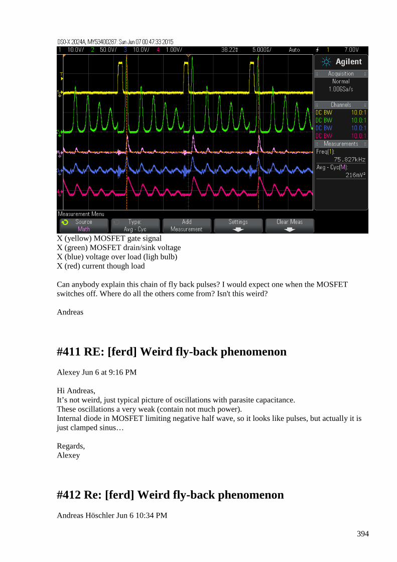
394
Х (yellow) MOSFET gate signal Х (green) MOSFET drain/sink voltage Х (blue) voltage over load (ligh bulb) Х (red) current though load Can anybody explain this chain of fly back pulses? I would expect one when the MOSFET switches off. Where do all the others come from? Isn't this weird? Andreas
#411 RE: [ferd] Weird fly-back phenomenon
Alexey Jun 6 at 9:16 PM Hi Andreas, It’s not weird, just typical picture of oscillations with parasite capacitance. These oscillations a very weak (contain not much power). Internal diode in MOSFET limiting negative half wave, so it looks like pulses, but actually it is just clamped sinus… Regards, Alexey
#412 Re: [ferd] Weird fly-back phenomenon
Andreas Höschler Jun 6 10:34 PM
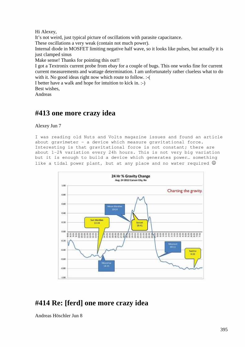
395
Hi Alexey, It’s not weird, just typical picture of oscillations with parasite capacitance. These oscillations a very weak (contain not much power). Internal diode in MOSFET limiting negative half wave, so it looks like pulses, but actually it is just clamped sinus Make sense! Thanks for pointing this out!! I got a Textronix current probe from ebay for a couple of bugs. This one works fine for current current measurements and wattage determination. I am unfortunately rather clueless what to do with it. No good ideas right now which route to follow. :-( I better have a walk and hope for intuition to kick in. :-) Best wishes, Andreas
#413 one more crazy idea
Alexey Jun 7
I was reading old Nuts and Volts magazine issues an d found an article about gravimeter – a device which measure gravitati onal force. Interesting is that gravitational force is not cons tant; there are about 1-2% variation every 24h hours. This is not v ery big variation but it is enough to build a device which generates power… something like a tidal power plant, but at any place and no w ater required
#414 Re: [ferd] one more crazy idea
Andreas Höschler Jun 8
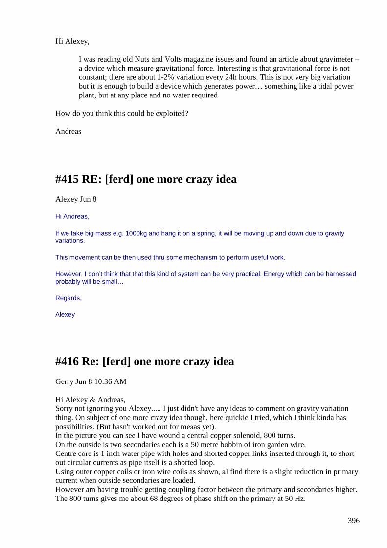
396
Hi Alexey,
I was reading old Nuts and Volts magazine issues and found an article about gravimeter – a device which measure gravitational force. Interesting is that gravitational force is not constant; there are about 1-2% variation every 24h hours. This is not very big variation but it is enough to build a device which generates power… something like a tidal power plant, but at any place and no water required
How do you think this could be exploited?
Andreas
#415 RE: [ferd] one more crazy idea
Alexey Jun 8
Hi Andreas,
If we take big mass e.g. 1000kg and hang it on a spring, it will be moving up and down due to gravity variations.
This movement can be then used thru some mechanism to perform useful work.
However, I don’t think that that this kind of system can be very practical. Energy which can be harnessed probably will be small…
Regards,
Alexey
#416 Re: [ferd] one more crazy idea
Gerry Jun 8 10:36 AM Hi Alexey & Andreas, Sorry not ignoring you Alexey..... I just didn't have any ideas to comment on gravity variation thing. On subject of one more crazy idea though, here quickie I tried, which I think kinda has possibilities. (But hasn't worked out for meаas yet). In the picture you can see I have wound a central copper solenoid, 800 turns. On the outside is two secondaries each is a 50 metre bobbin of iron garden wire. Centre core is 1 inch water pipe with holes and shorted copper links inserted through it, to short out circular currents as pipe itself is a shorted loop. Using outer copper coils or iron wire coils as shown, аI find there is a slight reduction in primary current when outside secondaries are loaded. However am having trouble getting coupling factor between the primary and secondaries higher. The 800 turns gives me about 68 degrees of phase shift on the primary at 50 Hz.
397
Your suggestions appreciated Gerry
#417 Re: [ferd] one more crazy idea
Andreas Höschler Jun 8 1:03 PM Hi Alexey, If we take big mass e.g. 1000kg and hang it on a spring, it will be moving up and down due to gravity variations. This movement can be then used thru some mechanism to perform useful work. However, I don’t think that that this kind of system can be very practical. Energy which can be harnessed probably will be small… That's my take on it. Far from practical I would guess, even with 1000kg. You would rather need 1000t to get usefull amounts of energy. Lifting 1000kg a few cm or even a meter does not take/yield much energy. :-( Next one. What else do we have (not yet checked out)? :-) Best wishes, Andreas
#418 Re: [ferd] one more crazy idea
onielsen2000 Jun 8 1:11 PM
398
Hi Alexey, Andreas, Parametric pumping could be used. Raise the big mass during low gravity and take out the difference by lowering during high gravity. It would require almost lossless energy transformation during those processes to gain any energy. So first step would be to invent some friction less or super low friction methods to transfer the energy. Another way is to let the gravity do all the work like using the water flowing between two oceans: http://en.wikipedia.org/wiki/Tidal_power Tidal power, also called tidal energy, is a form of hydropower that convert... This way a huge mass of water is available flowing in both directions. This is not just a 24 hour cycle but actually happens twice as fast as the water rises at the side facing the moon but also at the side pointing away from the moon. Regards Ole
#419 Re: [ferd] one more crazy idea
onielsen2000 Jun 8 1:30 PM Hi Garry, "Centre core is 1 inch water pipe with holes and shorted copper links inserted through it, to short out circular currents as pipe itself is a shorted loop." This just makes the currents take some other loops down through the center. To prevent circular current in the iron tube it has to be slit along its length. http://www.boredofstudies.org/wiki/images/a/ab/Sci_phys_motor_eddy_pipes.png The image is from here: http://www.boredofstudies.org/wiki/The_relative_motion_between_a_conductor_and_magnetic_field_is_used_to_generate_an_electrical_voltage Regards Ole
#420 Re: [ferd] one more crazy idea
Gerry Jun 8 6:15 PM Hi Alexey, guys Thanks for that link Ole, good info.
399
I have a number of ferrite rods I could try, instead through the centre. Alexey: I have a comment for you about gravity waves or on that line of thought. I think that gravity is likely correlated with Earths magnetic flux. When we magnetize a steel rod or a magnet itself we are aligning the spin axes inside the rod. Lets say this magnetic flux is supplied by the Earth itself and not the magnet we have made. Imagining the strength of this flux is a property of the magnet via it's concentrating ability, not as the actual source of flux. Now if Earths flux has variation just like Gravity has variation. Halfway between the North and South poles of our magnet there is a null point, we call it a Bloch wall I think. So perhaps a steel plate suspended at right angles to the rod magnet, right at the Bloch wall. We will get large variations in flux gradient as the null point shifts left or right along our rod. Taking this further if the rod is a magnet concentrically wound with many turns, it's inductance will change providing us an induced voltage across the coil, from the moving suspended plate. ie: If flux variations are fast enough. another crazy idea, Gerry
#421 RE: [ferd] one more crazy idea
Alexey Jun 8 10:32 PM Hi Gerry, I think you need try make secondary coils closer, then coupling coefficient will be higher…but I don’t think that this going to work. It looks like another variation of UDT. Important “ingredient” of OU system is missing Ц phase transition. Anyway, have fun, nice to hear from you. BTW how you motor-generator setup doing? Alexey
#422 Re: [ferd] one more crazy idea
Andreas HЎschler Jun 8 10:57 PM Hi Alexey, It looks like another variation of UDT. Important “ingredient” of OU system is missing Ц phase transition. What exactly do you mean by "phase transition"? Thanks, Andreas
#423 RE: [ferd] one more crazy idea
Alexey Jun 8 11:23 PM
400
Hi Andreas,
”A phase transition is the transformation of a thermodynamic system from one phase or state of matter to another one by heat transfer. The term is most commonly used to describe transitions between solid, liquid and gaseous states of matter, and, in rare cases, plasma.”
see more here http://en.wikipedia.org/wiki/Phase_transition
here http://marie.ph.surrey.ac.uk/~phs1rs/teaching/ising.pdf
and here for more generic definition http://www2.physics.ox.ac.uk/sites/default/files/CrystalStructure_Handout10_0.pdf
- Alexey
#424 Re: [ferd] one more crazy idea
Gerry Jun 9 2:13 AM Hi Alexey, With the "gravity variation" comment in my last email I forgot to say...... ....the vertical plate suspended above the Bloch wall of magnet should be connected to an antenna wire. Also This comment or idea is not my own and belongs to Mr Lester Hendershot (circa 1928) , where those beautiful old minds did far more with far less than us. My motor from alternator idea accelerated and centre shaft of rotor became extremely hot. After this it did not accelerate as before. I think the centre field coil on the rotor may now have shorted turns. Have pulled it down and started dismantling another old (same model alternator to compare inductance of rotor coil). I have also been trying to split the claws on the rotor into the two halves with a 3 arm puller, however it is distorting the pole faces on the rotor in the process. Still very keen to try all ideas on this machine though. Thank you for your interest, wish all you very smart guys in the group were here to help. I know we could achieve more, as a group working together. all the best Gerry ps You are right about the UDT style in the last jpg I posted ...remember how I used a microwave oven centre core piece with a secondary on each side? Its along those lines of thinking. Where Lenz flux cancels in centre winding.
#425 Re: [ferd] one more crazy idea
401
Andreas Höschler Jun 10 at 2:28 PM Hi Alexey,
“A phase transition is the transformation of a thermodynamic system from one phase or state of matter to another one by heat transfer. The term is most commonly used to describe transitions between solid, liquid and gaseous states of matter, and, in rare cases, plasma.”
Thanks for the PDFs. Interesting stuff. I suppose the transition we should look after is from ferro-magnetic to paramagnetic and vice-versa!? Still more questions than answers .. Best, Andreas
#426 RE: [ferd] one more crazy idea
Alexey Jun 10 at 6:38 PM Hi Gerry, Earth’s magnetic field itself is very weak, so I think it would be difficult to get any practical amount of power out of it. But harvesting some RF noise with crystal radio like setup became almost mainstream solution for low power “free energy” Regards, Alexey
#427 RE: [ferd] one more crazy idea
Alexey Jun 10
Hi Andreas, Magnetization and saturation two phase transitions which could help us. Also there are similar effects in dielectrics (ferroelectrics) http://en.wikipedia.org/wiki/Ferroelectricity but these are exotic materials so far… Regards, Alexey
#428 Re: [ferd] one more crazy idea
Gerry Jun 10 at 2:46 AM Hi Alexey, I strongly agree with your statement "the Earth's" field is very weak. However after the Earth's field is concentrated by a simple magnet it is enhanced millions of times.
402
The Hendershot generator was able to source over 100 watts continuously without semi conductors, vacuum tubes or batteries. My Gravity variation comment idea was taken directly from the design of the early MkI version of his generator. He used a "differential" setup, where atmospheric currents were introduced onto a steel strip. The steel strip is delicately balanced between the two magnet poles. (the "quiet" zone where pull from either pole is equal). The tiny currents on the strip were enough to cause it to trip alternatively to one side then the other. So I think your idea about crystal radio is a good one and could be utilised to drive a differential set up bar between poles of Neo magnet. Instead of the old head phone or crystal earpiece. Have attached a zipped Hendershot doc for anyone interested. Don't give up now guys we are very close. Gerry
#429 Re: [ferd] one more crazy idea
onielsen2000 Jun 10 at 3:28 AM Hi Gerry, Akula (Roman Karnouhov) seems to be able to replicate the Hendershot device: Akula Generator 25W
Akula Generator 25W This feature is not available right now. Please try again later.
View on www.youtube.com Preview
by Yahoo
Arthur C. Aho did it too together with Lester Hendershot but the device didn't work after the dead of Hendershot.
Regards Ole
403
#430 Re: [ferd] one more crazy idea
Gerry Jun 10 at 5:13 AM Hi Ole, Yes I saw this one, thank you for the link. In the Hendershot machine the basket weave coils were the highest Q method they could achieve at that time. My idea of it is like this, Each basket coil is resonated to a frequency within approx 50 Hertz of each other. The coils between the horseshoe magnet then magnetises the strip to the difference frequency between the basketweave coils. This trips the differential threshold attracting or repelling the bar at an audio (Hz) rate. As the bar enters the stronger flux field it is accelerated according to its mass etc causing larger avalanche flux change, with many frequency components present. Feedback windings keep the basket weave coils oscillating. etc etc. You may like this Ole as it has UDT similarities. You know my 3 coil setup idea I have been working on? The Russians seem to have perfected it here. https://www.youtube.com/watch?v=I6LRshJwht4 It is clever approach, they are smart fellows....we could all start saving energy using this simple scheme at 50Hz. It is hooked up as auto transformer as mine was, however they turn the outer coils by 90 degrees. In this way the outer coils receive minimal primary inductive coupling yet contribute an equal but opposite Lenz flux to the core. Have attached a scribble sketch hope it's enough to get idea across. Gerry
#431 reading - Parametric Oscillator Experiment
Alexey Jun 13 11:01 AM http://www.vk2zay.net/article/150
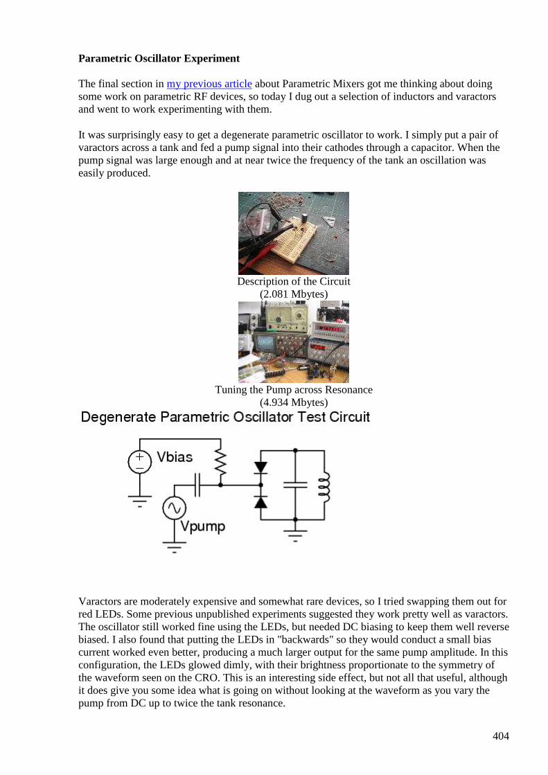
404
Parametric Oscillator Experiment
The final section in my previous article about Parametric Mixers got me thinking about doing some work on parametric RF devices, so today I dug out a selection of inductors and varactors and went to work experimenting with them.
It was surprisingly easy to get a degenerate parametric oscillator to work. I simply put a pair of varactors across a tank and fed a pump signal into their cathodes through a capacitor. When the pump signal was large enough and at near twice the frequency of the tank an oscillation was easily produced.
Description of the Circuit
(2.081 Mbytes)
Tuning the Pump across Resonance
(4.934 Mbytes)
Varactors are moderately expensive and somewhat rare devices, so I tried swapping them out for red LEDs. Some previous unpublished experiments suggested they work pretty well as varactors. The oscillator still worked fine using the LEDs, but needed DC biasing to keep them well reverse biased. I also found that putting the LEDs in "backwards" so they would conduct a small bias current worked even better, producing a much larger output for the same pump amplitude. In this configuration, the LEDs glowed dimly, with their brightness proportionate to the symmetry of the waveform seen on the CRO. This is an interesting side effect, but not all that useful, although it does give you some idea what is going on without looking at the waveform as you vary the pump from DC up to twice the tank resonance.
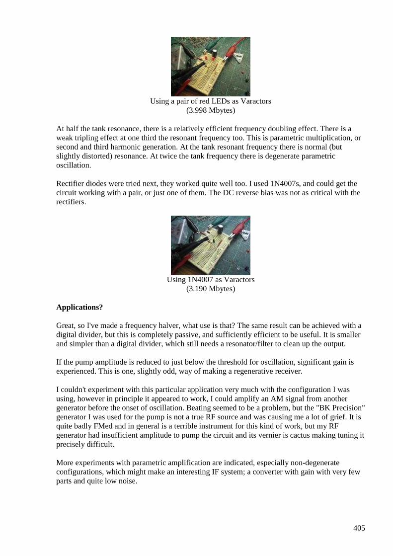
405
Using a pair of red LEDs as Varactors
(3.998 Mbytes)
At half the tank resonance, there is a relatively efficient frequency doubling effect. There is a weak tripling effect at one third the resonant frequency too. This is parametric multiplication, or second and third harmonic generation. At the tank resonant frequency there is normal (but slightly distorted) resonance. At twice the tank frequency there is degenerate parametric oscillation.
Rectifier diodes were tried next, they worked quite well too. I used 1N4007s, and could get the circuit working with a pair, or just one of them. The DC reverse bias was not as critical with the rectifiers.
Using 1N4007 as Varactors
(3.190 Mbytes)
Applications?
Great, so I've made a frequency halver, what use is that? The same result can be achieved with a digital divider, but this is completely passive, and sufficiently efficient to be useful. It is smaller and simpler than a digital divider, which still needs a resonator/filter to clean up the output.
If the pump amplitude is reduced to just below the threshold for oscillation, significant gain is experienced. This is one, slightly odd, way of making a regenerative receiver.
I couldn't experiment with this particular application very much with the configuration I was using, however in principle it appeared to work, I could amplify an AM signal from another generator before the onset of oscillation. Beating seemed to be a problem, but the "BK Precision" generator I was used for the pump is not a true RF source and was causing me a lot of grief. It is quite badly FMed and in general is a terrible instrument for this kind of work, but my RF generator had insufficient amplitude to pump the circuit and its vernier is cactus making tuning it precisely difficult.
More experiments with parametric amplification are indicated, especially non-degenerate configurations, which might make an interesting IF system; a converter with gain with very few parts and quite low noise.
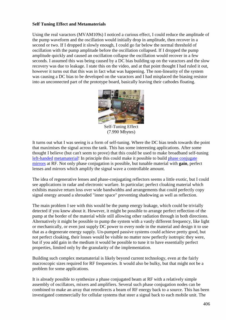
406
Self Tuning Effect and Metamaterials
Using the real varactors (MVAM109s) I noticed a curious effect, I could reduce the amplitude of the pump waveform and the oscillation would initially drop in amplitude, then recover in a second or two. If I dropped it slowly enough, I could go far below the normal threshold of oscillation with the pump amplitude before the oscillation collapsed. If I dropped the pump amplitude quickly and caused an oscillation collapse the oscillation would recover in a few seconds. I assumed this was being caused by a DC bias building up on the varactors and the slow recovery was due to leakage. I state this on the video, and at that point thought I had ruled it out, however it turns out that this was in fact what was happening. The non-linearity of the system was causing a DC bias to be developed on the varactors and I had misplaced the biasing resistor into an unconnected part of the prototype board, basically leaving their cathodes floating.
Self-Tuning Effect
(7.990 Mbytes)
It turns out what I was seeing is a form of self-tuning. Where the DC bias tends towards the point that maximises the signal across the tank. This has some interesting applications. After some thought I believe (but can't seem to prove) that this could be used to make broadband self-tuning left-handed metamaterial! In principle this could make it possible to build phase conjugate mirrors at RF. Not only phase conjugation is possible, but tunable material with gain, perfect lenses and mirrors which amplify the signal wave a controllable amount.
The idea of regenerative lenses and phase-conjugating reflectors seems a little exotic, but I could see applications in radar and electronic warfare. In particular; perfect cloaking material which exhibits massive return loss over wide bandwidths and arrangements that could perfectly copy signal energy around a shrouded "inner space" preventing shadowing as well as reflection.
The main problem I see with this would be the pump energy leakage, which could be trivially detected if you knew about it. However, it might be possible to arrange perfect reflection of the pump at the border of the material while still allowing other radiation through in both directions. Alternatively it might be possible to pump the system with a vastly different frequency, like light or mechanically, or even just supply DC power to every node in the material and design it to use that as a degenerate energy supply. Un-pumped passive systems could achieve pretty good, but not perfect cloaking, their losses would be visible no matter now perfectly isotropic they were, but if you add gain in the medium it would be possible to tune it to have essentially perfect properties, limited only by the granularity of the implementation.
Building such complex metamaterial is likely beyond current technology, even at the fairly macroscopic sizes required for RF frequencies. It would also be bulky, but that might not be a problem for some applications.
It is already possible to synthesize a phase conjugated beam at RF with a relatively simple assembly of oscillators, mixers and amplifiers. Several such phase conjugation nodes can be combined to make an array that retrodirects a beam of RF energy back to a source. This has been investigated commercially for cellular systems that steer a signal back to each mobile unit. The
407
phase isn't perfectly conjugated in practice, and is modulated to carry the intelligence. With large arrays of interconnected nodes significant gain is achievable. The system is essentially an automatic electronic beam-former that requires no computational effort to track the mobile nodes.
For communication, such systems are excellent, but for radar cloaking (anti-phase equi-power conjugation, aka "active absorption") they are limited by the physical granularity of their construction (and bandwidth). By implementing the same thing in a broadband isotropic metamaterial with gain, much more perfect "absorption" cloaking would be possible, and perhaps the "ray bending" discussed above. Pumped non-linear resonators sound like one way to implement such a metamaterial with gain.
#432 Re: [ferd] one more crazy idea
Alexey Jun 13 9:58 PM Hi all, here a transcript of https://www.youtube.com/watch?v=I6LRshJwht4 video "half of transformer - 3 light bulbs 1kw + hot air blower 1.8kw + electric kettle 2.4kw" you can now decide for your self how "advanced" Russian guys :-) Good evening my friends I think that in last 3 days, next 3 days, nothing new will be shown, but I not sure, may be... let's do this way, let's take a chance now let's do video while powering from auto transformer, but then we will do video with power taken from wall socket 220v max current 6a Let's show that 1. here is a half of our transformer, here a second half, it will be not used, we will use only first one half of transformer 2. this half of transformer should not work according to classical electro technical science It should not work because core is not closed, second part of core was removed, and therefore there should be zero on the output and zero on the input next, this core work at 500w max power 3. we made some changes in the windings 4. load attached to this half core, which should not work even with 10w power, attached load 3 lamps, 1kw each Electric kettle, power 2.4kw, BTW it will be very nicely visible how it glows and industrial hot air blower 1800w this half core is not completely ready, we need about 3 more days it costs a lot, let's say components...
408
after out modification it will be possible to plug this core into wall socket with max power 220v x 6a = 1300w but it will easily power load about 10kw let's try this now switching meters on switching on auto trafo, it set to zero input voltage now 2,54v but please note the more load we attach the lower this number will be I give camera to my friend, he will continue filming and I will show you ok, increasing voltage let's switch on air blower now let's switch kettle on lamps also on this is output (right) and this is input (left) in other words we have 500w open core which not supposed to work at all it is powering 7.2w load wow, coil is hot, first time in my experience --end-- Have fun, Alexey
#433 Re: [ferd] one more crazy idea
onielsen2000 Jun 13 10:30 PM Hi Alexey, There are no power measurements! The big lamps are burning quite dim. I don't think they're at full rated power and the other appliances probably aren't either. If he is claiming free energy he ought to prove it by making it a self-runner or at least do some proper measurements like what is the real input power and what is the real output power. The rated power of an appliance is its max power at its rated voltage. Regards Ole
#434 RE: [ferd] one more crazy idea
Alexey Jun 14 12:34 PM Hi Ole, Yes, I agree.
409
Several posts earlier Gerry posted link to that video with a comment “The Russians seem to have perfected it here.” So I thought that it would be nice if everyone understand what guys doing there. I think they don't know how properly measure power (or even worse, doing misleading claims on purpose). Regards, Alexey
#435 Re: [ferd] one more crazy idea
Gerry Jun 14 1:16 PM Hi Alexey, guys... Thank you Alexey for posting the translation transcript on that video using this transformer idea. It helps a great deal. I also found the attached diagram I recently came across on the net ...... am in process of trying it by winding onto a cut down microwave oven transformer "U" shape. (the ones I already cut the centre "I" post off) , for those previously encouraging experiments with this approach. It took ages to wind the primary I have 2 secondaries to go. Will let you guys know how it performs, it may take a few modifications with turns ratio before useful results though. I have a couple of those plug in energy monitors which should give a good indication. best Gerry
#436 Re: [ferd] one more crazy idea
Andreas Höschler Jun 14 9:06 PM Hi all, I have just spent a while in the lab making use of the IPC and my new Textronix current probe. Could you help me make sense out of tis measurement? I measure a phase shift of > 90? I also measure negative wattage in the tank. It seems I cannot even trust this Textronix P6021 probe!? :-( Thanks, Andreas We make use of an IPC Quadra (H-Bridge conguration) and pulse the primary of a rig.
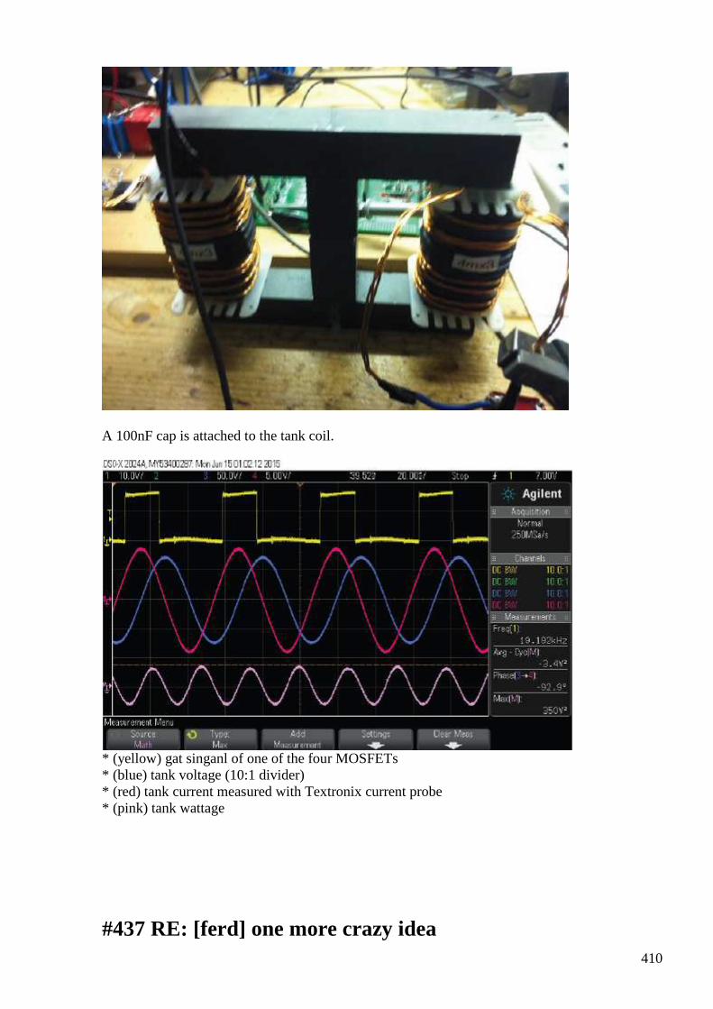
410
A 100nF cap is attached to the tank coil.
* (yellow) gat singanl of one of the four MOSFETs * (blue) tank voltage (10:1 divider) * (red) tank current measured with Textronix current probe * (pink) tank wattage
#437 RE: [ferd] one more crazy idea
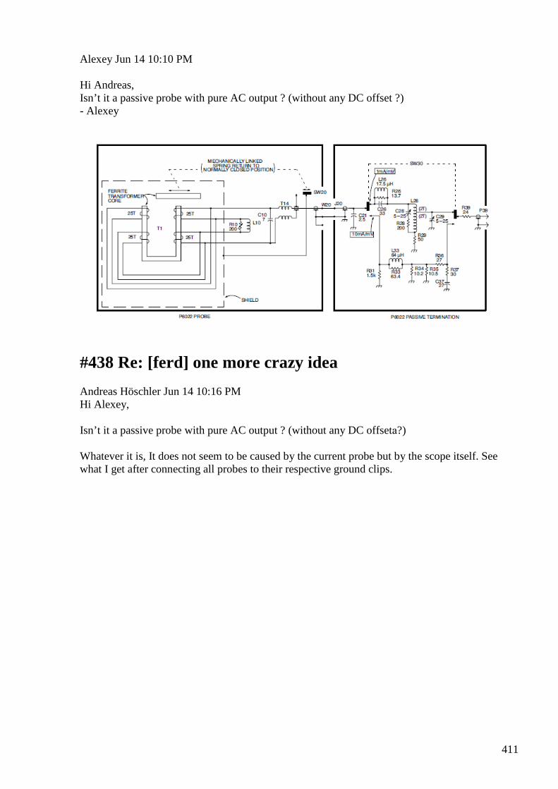
411
Alexey Jun 14 10:10 PM Hi Andreas, Isn’t it a passive probe with pure AC output ? (without any DC offset ?) - Alexey
#438 Re: [ferd] one more crazy idea
Andreas Höschler Jun 14 10:16 PM Hi Alexey, Isn’t it a passive probe with pure AC output ? (without any DC offsetа?) Whatever it is, It does not seem to be caused by the current probe but by the scope itself. See what I get after connecting all probes to their respective ground clips.
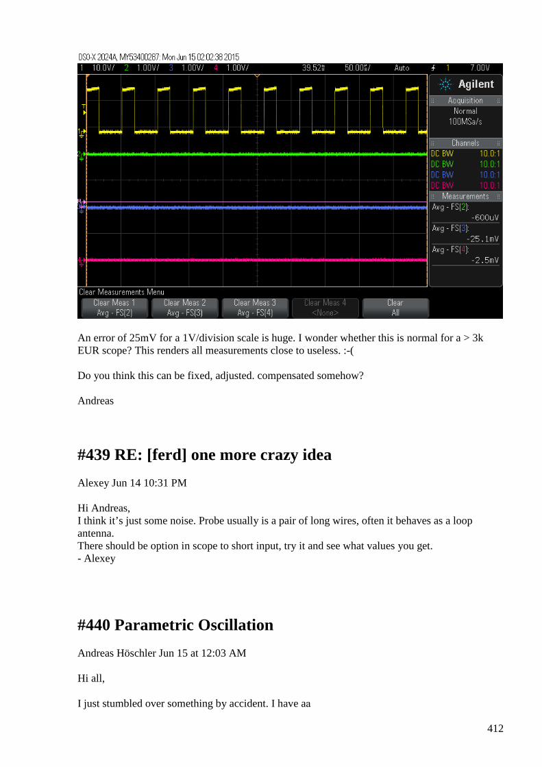
412
An error of 25mV for a 1V/division scale is huge. I wonder whether this is normal for a > 3k EUR scope? This renders all measurements close to useless. :-( Do you think this can be fixed, adjusted. compensated somehow? Andreas
#439 RE: [ferd] one more crazy idea
Alexey Jun 14 10:31 PM Hi Andreas, I think it’s just some noise. Probe usually is a pair of long wires, often it behaves as a loop antenna. There should be option in scope to short input, try it and see what values you get. - Alexey
#440 Parametric Oscillation
Andreas Höschler Jun 15 at 12:03 AM Hi all, I just stumbled over something by accident. I have aа
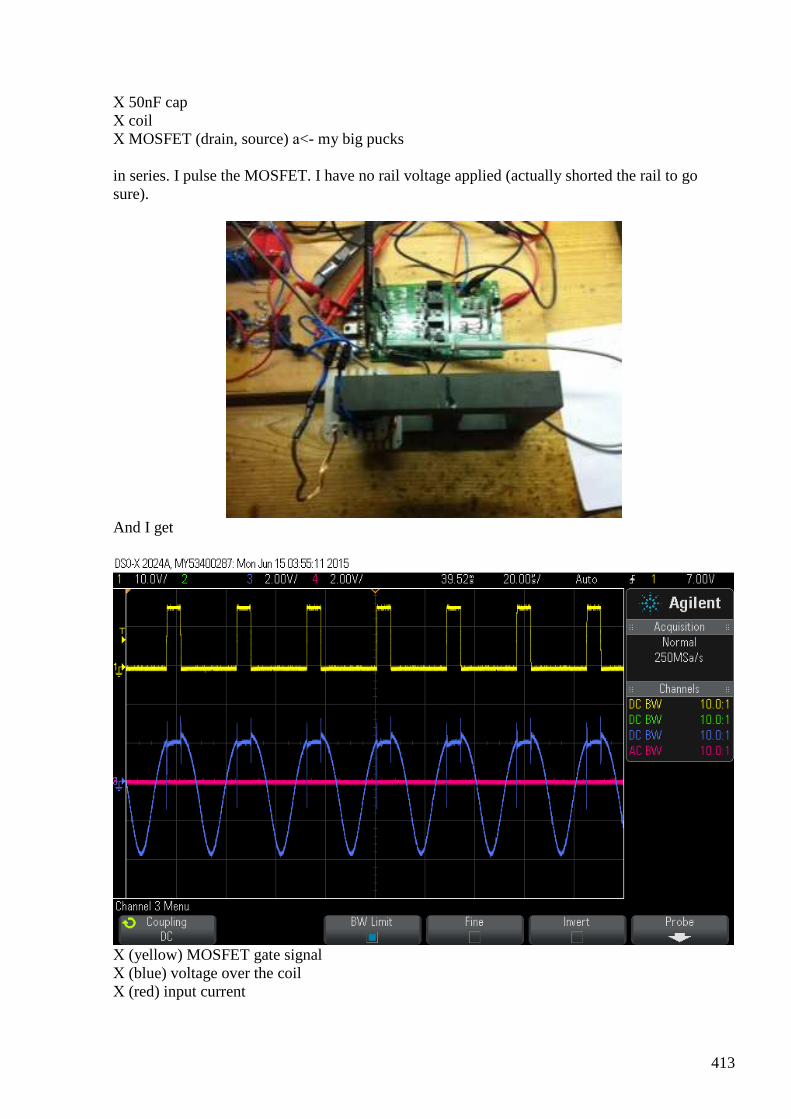
413
Х 50nF cap Х coil Х MOSFET (drain, source) а<- my big pucks in series. I pulse the MOSFET. I have no rail voltage applied (actually shorted the rail to go sure).
And I get
Х (yellow) MOSFET gate signal Х (blue) voltage over the coil Х (red) input current
414
I tune the beast from below (< 68kHz) and slowly increase the frequency to 71kHz. The above is the result. If I increase the frequency any further the resonance abruptly breaks down to close to zero. Since I don't apply any external voltage (except to the control logic powering the MOSFET gate) this seems to be some parametric oscillation effect!? The drain source capacitance seems to be modified by the gate pulses thus causing this oscillation (without external power applied). Even stranger, if I actually apply rail voltage this does not change one bit. Zero input current and the wave form stays exactly the same!? Does this make any sense to anyone? Andreas
#441 Re: [ferd] one more crazy idea
Gerry Jun 15 at 1:49 AM Hi Andreas, We used to use the old Tektronix P6042 ... Like this http://www.ebay.com/itm/TEKTRONIX-P6042-CURRENT-PROBE-DC-TO-50MHZ-FREE-SHIP-/131532370511 We would always have to place the probe in the degaussing receptacle and degauss before each use. Nice clean wave forms by the way on the pdf, with 90 degrees phase shift energy input is returned to source every half cycle. To get OU need you need to load it without phase degradation or get the phase shift to go well beyond 90 degrees toward 180 where cos phi goes toward -1. These probes are Hall effect chip devices, not passive inductive toroids from memory, though both are probably easily magnetised by extraneous sources. Which could produce the offset. Does trace return to zero once current probe removed? Gerry
415
#442 Re: [ferd] Parametric Oscillation
Gerry Jun 15 at 1:57 AM Hi Andreas, I am just guessing with this one so speculative answer. If Q of your tank is very high then electrostatic coupling could set it oscillating. When pulsing for oscillations it's ok to pulse below the resonant frequency cause a damped waveform results before next pulse arrives. Once resonant frequency is exceeded though the tank doesn't get to complete it's cycle before next pulse arrives ..(well out of sync). This is highly disruptive and damps oscillations immediately. It can be pulsed twice per cycle if every second pulse is reverse polarised and it held in sync with natural frequency. Gerryа
#443 Re: Parametric Oscillation
onielsen2000 jun 15 at 3:37 AM Hi Andreas, Depending on how the wires are hooked up they are radiating. Remember the energy is in between the wires and not inside the conductors. All loops carrying time varying currents radiates. So to avoid electromagnetic radiations use coaxial cables as they carry most of the energy in the dielectric between the conductors. The magnetic part almost cancels out on the outside of a coaxial cable. The motional electric field can't be screened. Read HYPERLINK "http://www.rexresearch.com/hooper/horizon.htm" \t "_blank" W.J. Hooper for the theory and experiments proving this. They are at Rex Research. Twisted pairs also minimizes the radiations by keeping the loop areas alternating and thus canceling at some distance. Regards Ole
#444 Re: [ferd] Re: Parametric Oscillation
Andreas Höschler Jun 15 1:14 PM Hi Ole, On 15 Jun 2015, at 01:37, wrote: Depending on how the wires are hooked up they are radiating. Remember the energy is in between the wires and not inside the conductors. All loops carrying time varying currents radiates. So to avoid electromagnetic radiations use coaxial cables as they carry most of the energy in the dielectric between the conductors. The magnetic part almost cancels out on the
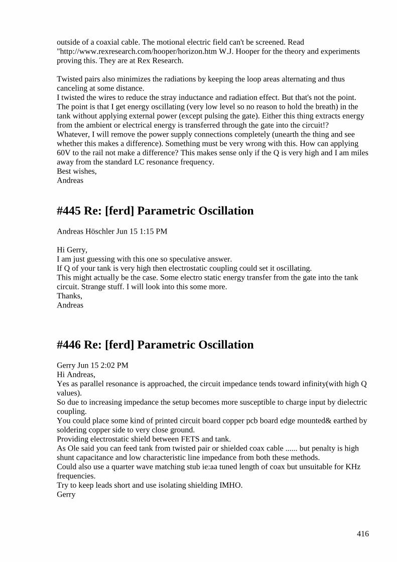
416
outside of a coaxial cable. The motional electric field can't be screened. Read "http://www.rexresearch.com/hooper/horizon.htm W.J. Hooper for the theory and experiments proving this. They are at Rex Research. Twisted pairs also minimizes the radiations by keeping the loop areas alternating and thus canceling at some distance. I twisted the wires to reduce the stray inductance and radiation effect. But that's not the point. The point is that I get energy oscillating (very low level so no reason to hold the breath) in the tank without applying external power (except pulsing the gate). Either this thing extracts energy from the ambient or electrical energy is transferred through the gate into the circuit!? Whatever, I will remove the power supply connections completely (unearth the thing and see whether this makes a difference). Something must be very wrong with this. How can applying 60V to the rail not make a difference? This makes sense only if the Q is very high and I am miles away from the standard LC resonance frequency. Best wishes, Andreas
#445 Re: [ferd] Parametric Oscillation
Andreas Höschler Jun 15 1:15 PM Hi Gerry, I am just guessing with this one so speculative answer. If Q of your tank is very high then electrostatic coupling could set it oscillating. This might actually be the case. Some electro static energy transfer from the gate into the tank circuit. Strange stuff. I will look into this some more. Thanks, Andreas
#446 Re: [ferd] Parametric Oscillation
Gerry Jun 15 2:02 PM Hi Andreas, Yes as parallel resonance is approached, the circuit impedance tends toward infinity(with high Q values). So due to increasing impedance the setup becomes more susceptible to charge input by dielectric coupling. You could place some kind of printed circuit board copper pcb board edge mounted& earthed by soldering copper side to very close ground. Providing electrostatic shield between FETS and tank. As Ole said you can feed tank from twisted pair or shielded coax cable ...... but penalty is high shunt capacitance and low characteristic line impedance from both these methods. Could also use a quarter wave matching stub ie:аa tuned length of coax but unsuitable for KHz frequencies. Try to keep leads short and use isolating shielding IMHO. Gerry
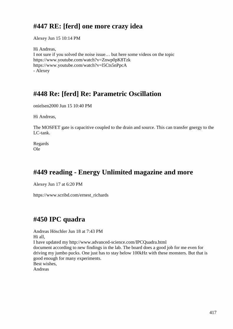
417
#447 RE: [ferd] one more crazy idea
Alexey Jun 15 10:14 PM Hi Andreas, I not sure if you solved the noise issue… but here some videos on the topic https://www.youtube.com/watch?v=Znwp0pK8Tzk https://www.youtube.com/watch?v=l5Cts5nPpcA - Alexey
#448 Re: [ferd] Re: Parametric Oscillation
onielsen2000 Jun 15 10:40 PM Hi Andreas, The MOSFET gate is capacitive coupled to the drain and source. This can transfer gnergy to the LC-tank. Regards Ole
#449 reading - Energy Unlimited magazine and more
Alexey Jun 17 at 6:20 PM https://www.scribd.com/ernest_richards
#450 IPC quadra
Andreas Höschler Jun 18 at 7:43 PM Hi all, I have updated my http://www.advanced-science.com/IPCQuadra.html document according to new findings in the lab. The board does a good job for me even for driving my jumbo pucks. One just has to stay below 100kHz with these monsters. But that is good enough for many experiments. Best wishes, Andreas
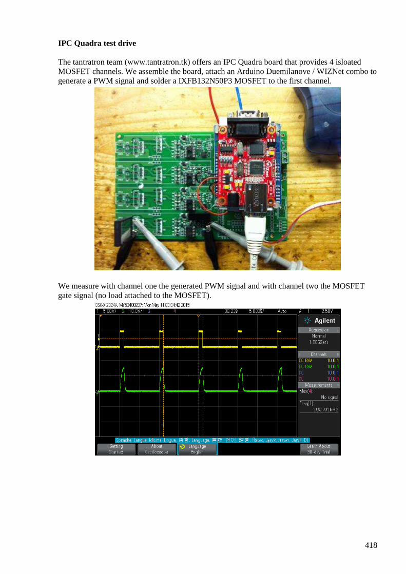
418
IPC Quadra test drive
The tantratron team (www.tantratron.tk) offers an IPC Quadra board that provides 4 isloated MOSFET channels. We assemble the board, attach an Arduino Duemilanove / WIZNet combo to generate a PWM signal and solder a IXFB132N50P3 MOSFET to the first channel.
We measure with channel one the generated PWM signal and with channel two the MOSFET gate signal (no load attached to the MOSFET).
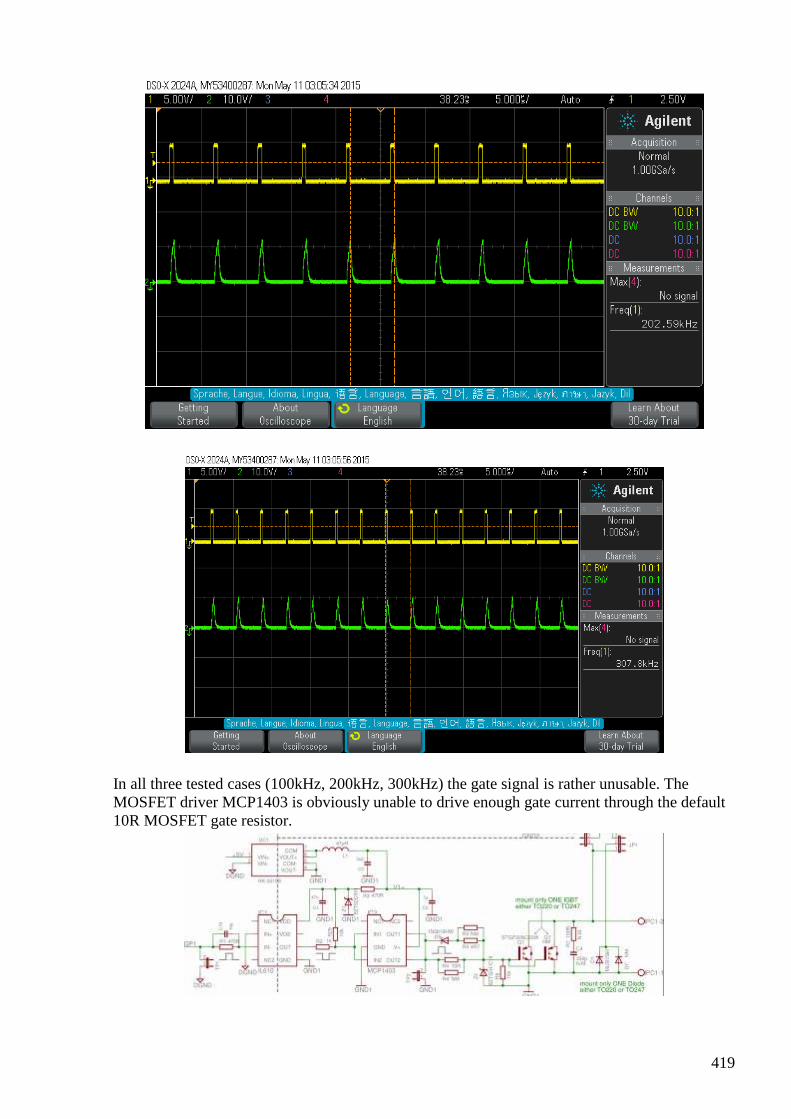
419
In all three tested cases (100kHz, 200kHz, 300kHz) the gate signal is rather unusable. The MOSFET driver MCP1403 is obviously unable to drive enough gate current through the default 10R MOSFET gate resistor.
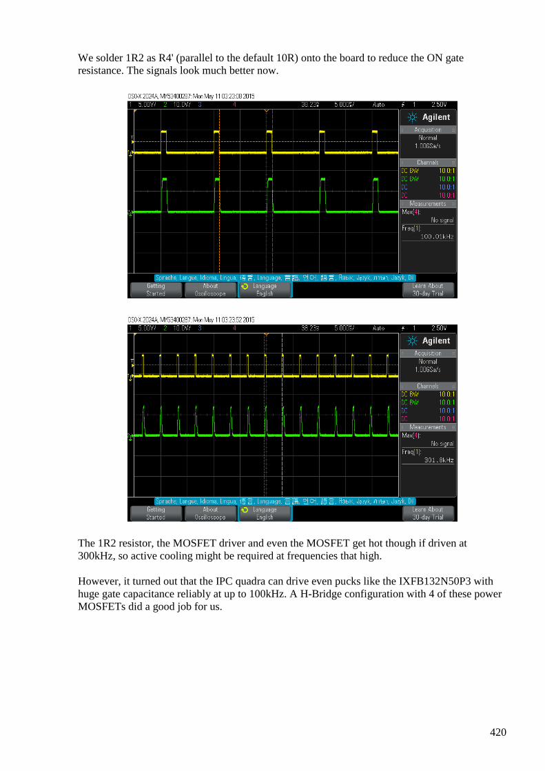
420
We solder 1R2 as R4' (parallel to the default 10R) onto the board to reduce the ON gate resistance. The signals look much better now.
The 1R2 resistor, the MOSFET driver and even the MOSFET get hot though if driven at 300kHz, so active cooling might be required at frequencies that high.
However, it turned out that the IPC quadra can drive even pucks like the IXFB132N50P3 with huge gate capacitance reliably at up to 100kHz. A H-Bridge configuration with 4 of these power MOSFETs did a good job for us.
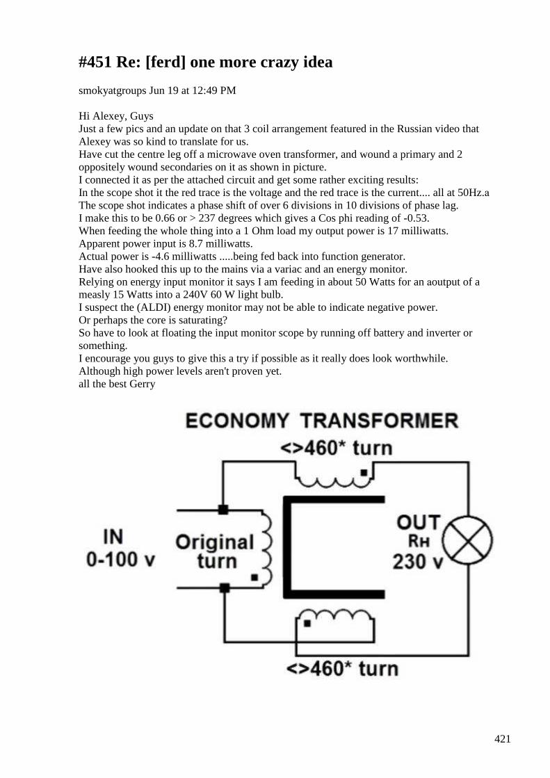
421
#451 Re: [ferd] one more crazy idea
smokyatgroups Jun 19 at 12:49 PM Hi Alexey, Guys Just a few pics and an update on that 3 coil arrangement featured in the Russian video that Alexey was so kind to translate for us. Have cut the centre leg off a microwave oven transformer, and wound a primary and 2 oppositely wound secondaries on it as shown in picture. I connected it as per the attached circuit and get some rather exciting results: In the scope shot it the red trace is the voltage and the red trace is the current.... all at 50Hz.а The scope shot indicates a phase shift of over 6 divisions in 10 divisions of phase lag. I make this to be 0.66 or > 237 degrees which gives a Cos phi reading of -0.53. When feeding the whole thing into a 1 Ohm load my output power is 17 milliwatts. Apparent power input is 8.7 milliwatts. Actual power is -4.6 milliwatts .....being fed back into function generator. Have also hooked this up to the mains via a variac and an energy monitor. Relying on energy input monitor it says I am feeding in about 50 Watts for an аoutput of a measly 15 Watts into a 240V 60 W light bulb. I suspect the (ALDI) energy monitor may not be able to indicate negative power. Or perhaps the core is saturating? So have to look at floating the input monitor scope by running off battery and inverter or something. I encourage you guys to give this a try if possible as it really does look worthwhile. Although high power levels aren't proven yet. all the best Gerry
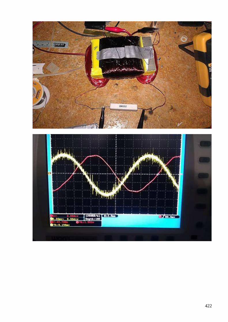
422
423
#452 RE: [ferd] one more crazy idea [3 Attachments]
Alexey Jun 21 at 3:19 PM Hi Gerry, Thanks for sharing your experiment. It could be that “effect” is lost with higher power. You could try some smaller lamps or just resistors as load. But even 5mW would be nice, if only it could be looped.
- Alexey
#453 [offtopic] HYDRAs - hygroscopy driven artificial muscles power a miniature car
Alexey Jun 21 at 3:19 PM https://www.youtube.com/watch?v=KQ7nau28qp0 :-)
#454 Re: [ferd] one more crazy idea
Gerry Jun 22 at 2:15 AM Hi Alexey, guys I humbly appologise but my phase shift scope shot is an error. Had another scope across the load which caused an earth loop. Sorry guys. Have attached a relevant patent for this current transformer idea. Gerry
#455 Re: [ferd] one more crazy idea
onielsen2000 Jun 22 at 3:40 AM Hi Gerry, This looks like being a way to reduce the parasitic capacitance in a transformer for being able to achieve higher frequencies. Here are some other examples: US3299384: http://worldwide.espacenet.com/publicationDetails/originalDocument?CC=US&NR=3299384A&KC=A&FT=D&ND=6&date=19670117&DB=worldwide.espacenet.com&locale=en_EP US5093613:
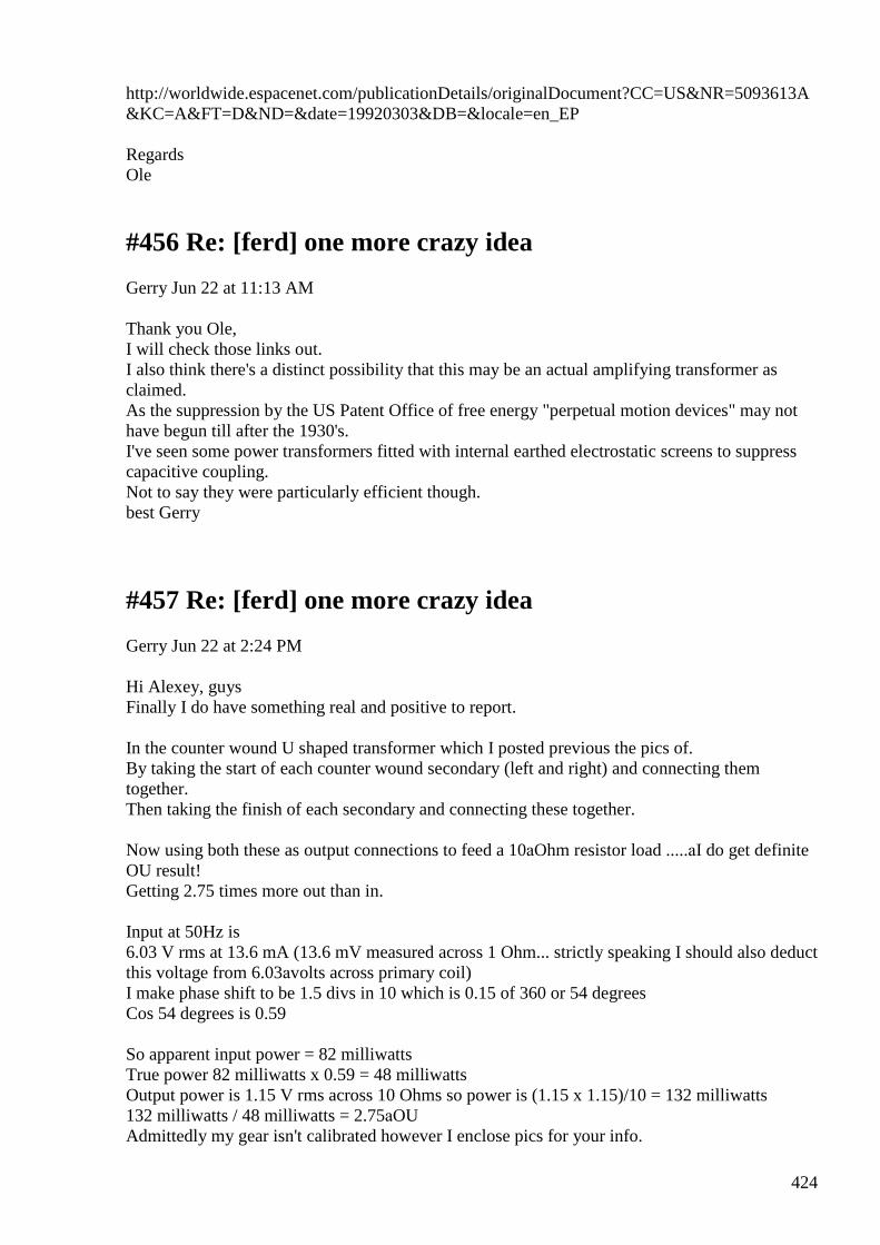
424
http://worldwide.espacenet.com/publicationDetails/originalDocument?CC=US&NR=5093613A&KC=A&FT=D&ND=&date=19920303&DB=&locale=en_EP Regards Ole
#456 Re: [ferd] one more crazy idea
Gerry Jun 22 at 11:13 AM Thank you Ole, I will check those links out. I also think there's a distinct possibility that this may be an actual amplifying transformer as claimed. As the suppression by the US Patent Office of free energy "perpetual motion devices" may not have begun till after the 1930's. I've seen some power transformers fitted with internal earthed electrostatic screens to suppress capacitive coupling. Not to say they were particularly efficient though. best Gerry
#457 Re: [ferd] one more crazy idea
Gerry Jun 22 at 2:24 PM Hi Alexey, guys Finally I do have something real and positive to report. In the counter wound U shaped transformer which I posted previous the pics of. By taking the start of each counter wound secondary (left and right) and connecting them together. Then taking the finish of each secondary and connecting these together. Now using both these as output connections to feed a 10аOhm resistor load .....аI do get definite OU result! Getting 2.75 times more out than in. Input at 50Hz is 6.03 V rms at 13.6 mA (13.6 mV measured across 1 Ohm... strictly speaking I should also deduct this voltage from 6.03аvolts across primary coil) I make phase shift to be 1.5 divs in 10 which is 0.15 of 360 or 54 degrees Cos 54 degrees is 0.59 So apparent input power = 82 milliwatts True power 82 milliwatts x 0.59 = 48 milliwatts Output power is 1.15 V rms across 10 Ohms so power is (1.15 x 1.15)/10 = 132 milliwatts 132 milliwatts / 48 milliwatts = 2.75аOU Admittedly my gear isn't calibrated however I enclose pics for your info.
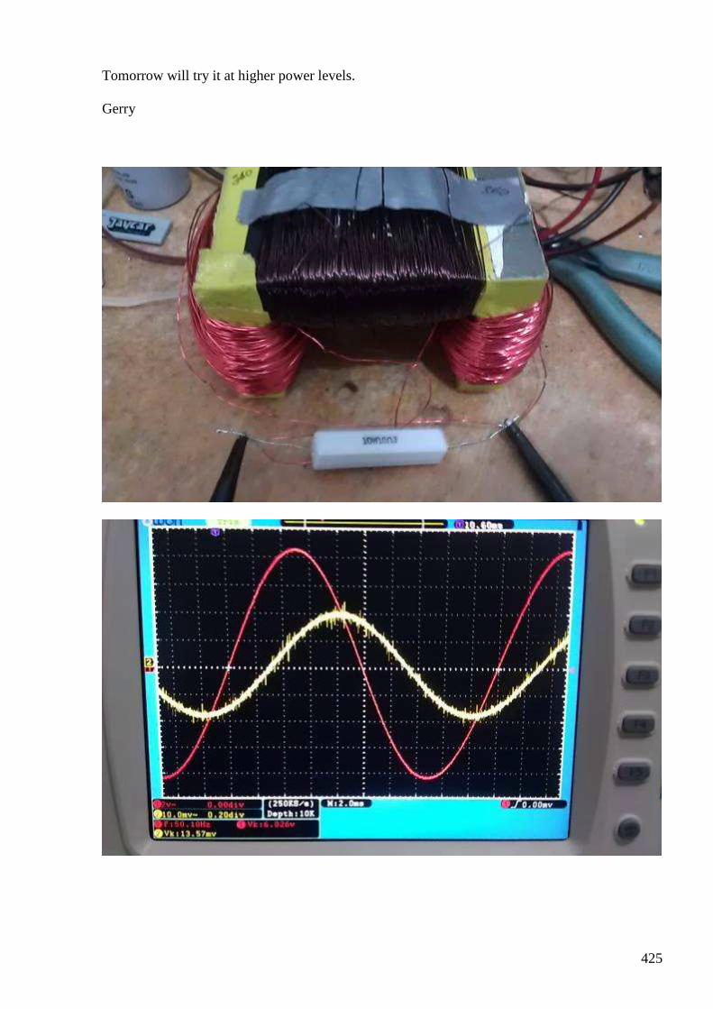
425
Tomorrow will try it at higher power levels. Gerry
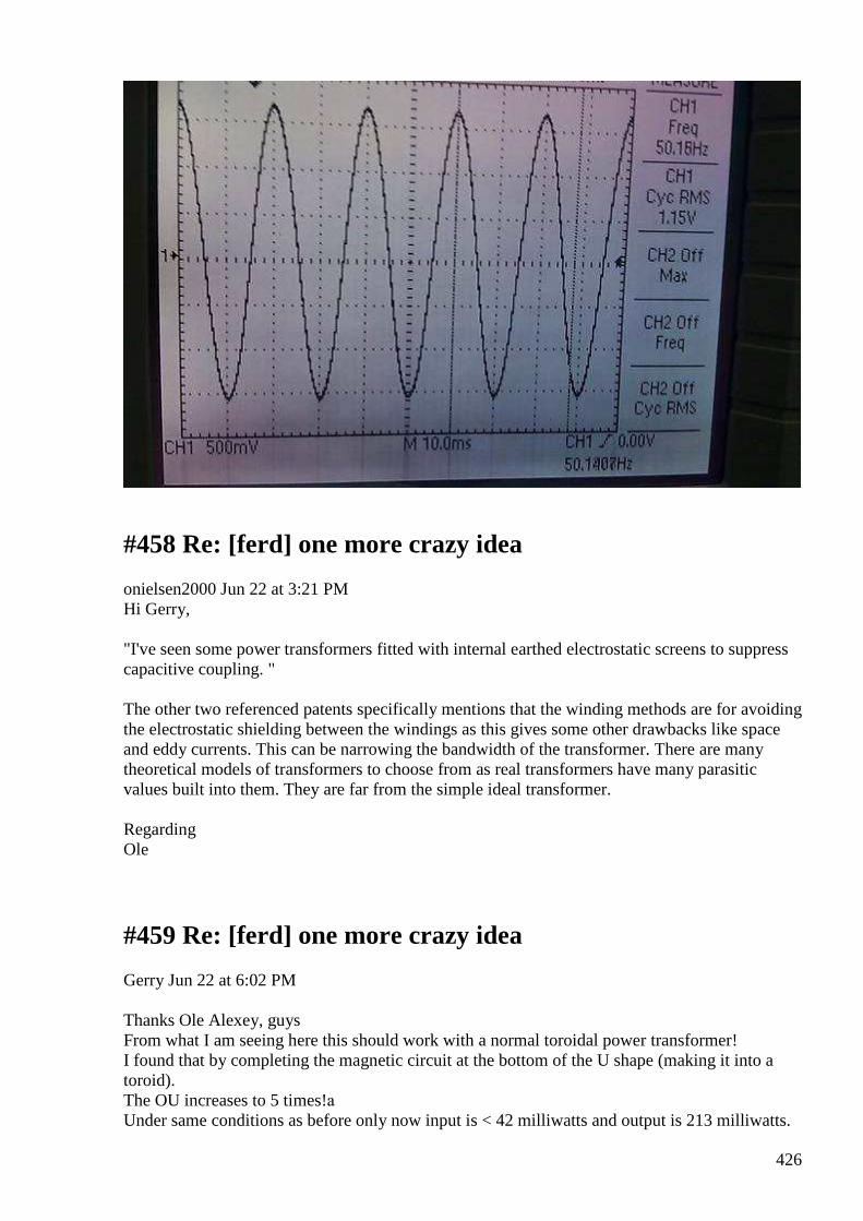
426
#458 Re: [ferd] one more crazy idea
onielsen2000 Jun 22 at 3:21 PM Hi Gerry, "I've seen some power transformers fitted with internal earthed electrostatic screens to suppress capacitive coupling. " The other two referenced patents specifically mentions that the winding methods are for avoiding the electrostatic shielding between the windings as this gives some other drawbacks like space and eddy currents. This can be narrowing the bandwidth of the transformer. There are many theoretical models of transformers to choose from as real transformers have many parasitic values built into them. They are far from the simple ideal transformer. Regarding Ole
#459 Re: [ferd] one more crazy idea
Gerry Jun 22 at 6:02 PM Thanks Ole Alexey, guys From what I am seeing here this should work with a normal toroidal power transformer! I found that by completing the magnetic circuit at the bottom of the U shape (making it into a toroid). The OU increases to 5 times!а Under same conditions as before only now input is < 42 milliwatts and output is 213 milliwatts.
427
If you trust me ....give this a try.. Take normal toroidal power transformer place it so that the 240V primary connections are at 12 'O’clock position opposite you. Now wind say 50 turns of enameled copper wire around core in clockwise direction....а in a sector starting atа2 O'clock to say 4 O'clock which is finish. Next wind say 50 turns of enameled copper wire around core in anti clockwise direction.... in a sector from 10 O'clock to say 8 O'clock which is finish. Connect the two starts together ie 2 O'clock and 10 O'clock wires. Then connect the two finishes together 10 O'clock and 8 O'clock wires. Use the two connected start wires as one Output terminal and the two finish wires as the other OUTPUT terminal. Make some measurements, you're going to be very pleasantly surprised. Gerry
#460 Re: [ferd] one more crazy idea
Gerry Jun 23 1:55 AM Hi Ole, That last reference of yours is a very good one US5093613 I mean. It has a good explanation too ...I don't often see Thevenin's or Norton's theorems used anywhere these days. Gerry
#461 RE: [ferd] one more crazy idea
Alexey Jun 23 8:38 AM
Hi Gerry,
I think every member of this group spent considerable time building and testing UDT-like setups.
Some even got OU, but later it appeared measurement error.
I would suggest you re-check your measurements, may be use some different method to estimate efficiency… and to be 100% sure try looping your setup. With 5х OU it should be easy.
Thanks,
Alexey
#462 Re: [ferd] one more crazy idea
Gerry Jun 23
428
Alexey
I think on balance you are likely right,
It is probably another measurement error on my part,
I have not had time today to recheck at higher power levels.
Don't know if anyone here has seen the demonstration by Bill Alec when describing "Cooper Pairs".
Gyroscopes are interesting as their behavior mimics that of an electron in the earths magnetic field.
Anyhow he spins up a single gyroscope and it's inertia resists movement, then Bill Alec attaches a second gyro scope.
..he then spins them both up in opposite directions and the gyros then cancel each others inertia moving with ease from one direction to the other.
This is a direct analogy to the freedom of movement on an electron once it's magnetic field is cancelled by an equal but opposite field.
Upon this principle rests many free energy devices including the split flux approach ... however, it's just so damned hard to prove out the concept.
Gerry
#463 RE: [ferd] one more crazy idea
onielsen2000 Jun 23 4:25 PM Hi Alexey, I'm not through with the UDT. The working point for the UDT needs to be found. For this is needed an adjustable load as the load changes when changing almost any other parameter. A linear electronic AC load would be ideal for this purpose. That's what I'm working on among some other small experiments besides reading. This one was publicized on April 1st and thus may be a fake:
БТГ от бронепоезда
БТГ от бронепоезда Демонстрация крайне простого генератора, вырабатывающего электроэнергию без топлива. Мы не можем гарантировать, что это не пе...
429
View on www.youtube.com Preview
by Yahoo
And here is a copy that's not a selfrunner: Форум заряд схема от Бронепоезда является ФЭЙКОМ
Форум заряд схема от Бронепоезда является Ф... Схема от бронепоезда с форума Заряд. схема взята отсюда http://zaryad.com/2015/04/02/prostoj-btg-ot-bronepoezda-bez-kupyur/
View on www.youtube.com Preview
by Yahoo
I have a problem with the oscilloscope reading of the first video. This shows a frequency of above 600kHz while the regulator IC (MC34063) only goes to 100kHz according to the datasheet. The duty cycle is symmetric. This makes the primary coil have low inductance. If the frequency was one tenth of the readout it would fit much better. I tried to wind the transformer on a core looking about the same size. But there are many different ferrite types. My one has the frequency one tenth of the one in the video. Regards Ole
#464 RE: [ferd] one more crazy idea
Alexey Jun 23 9:39 PM Hi Ole, I can't say about UDT... but I know this Bronepoezd guy from realstrannik.ru forum. ItТs a bad 1st April joke. There is a battery inside ferrite core (most probably). Watch his video one more time and notice strange shape of the core. Regards, Alexey
#465 Re: [ferd] one more crazy idea
Gerry Jun 25 at 8:37 AM Hi Alexey, guys... Once again apologies my OU claims were wrong.
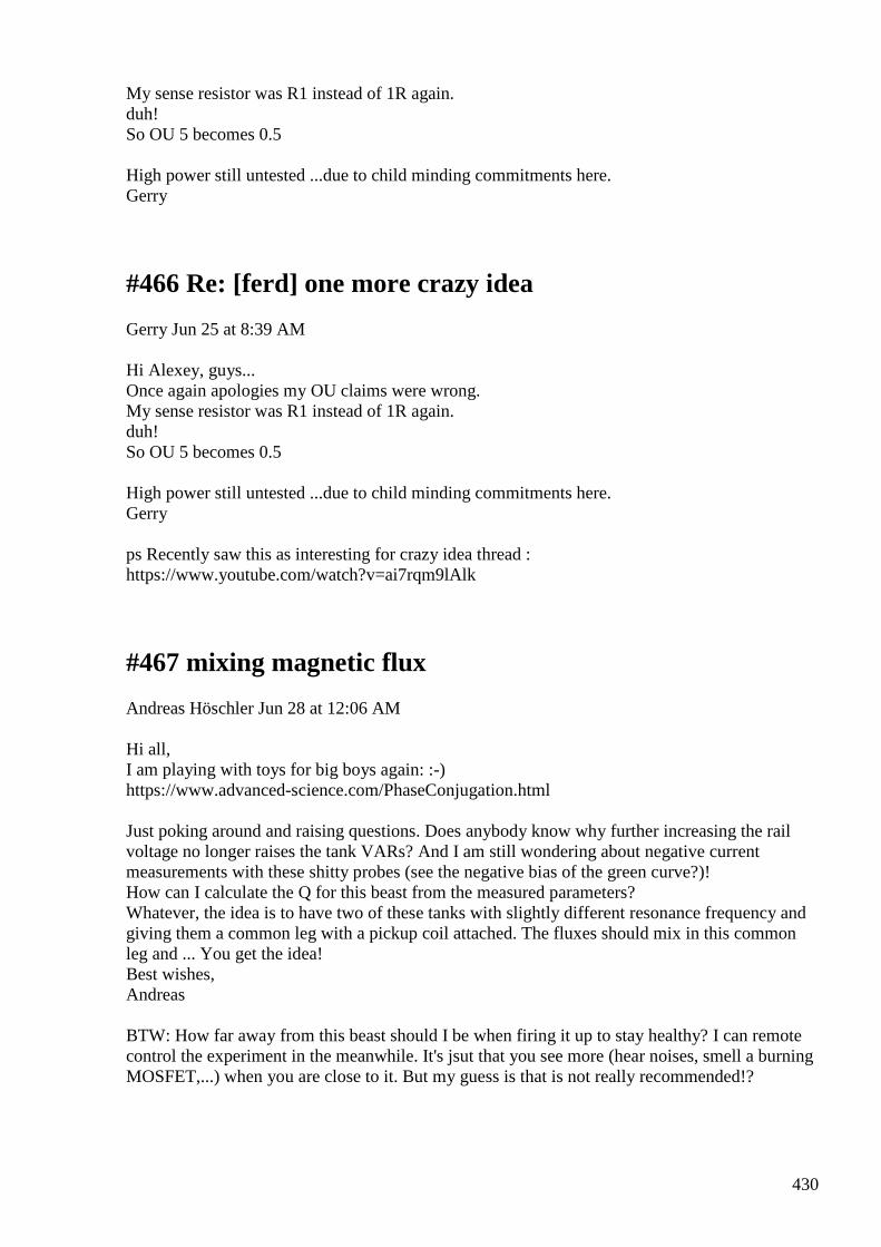
430
My sense resistor was R1 instead of 1R again. duh! So OU 5 becomes 0.5 High power still untested ...due to child minding commitments here. Gerry
#466 Re: [ferd] one more crazy idea
Gerry Jun 25 at 8:39 AM Hi Alexey, guys... Once again apologies my OU claims were wrong. My sense resistor was R1 instead of 1R again. duh! So OU 5 becomes 0.5 High power still untested ...due to child minding commitments here. Gerry ps Recently saw this as interesting for crazy idea thread : https://www.youtube.com/watch?v=ai7rqm9lAlk
#467 mixing magnetic flux
Andreas Höschler Jun 28 at 12:06 AM Hi all, I am playing with toys for big boys again: :-) https://www.advanced-science.com/PhaseConjugation.html Just poking around and raising questions. Does anybody know why further increasing the rail voltage no longer raises the tank VARs? And I am still wondering about negative current measurements with these shitty probes (see the negative bias of the green curve?)! How can I calculate the Q for this beast from the measured parameters? Whatever, the idea is to have two of these tanks with slightly different resonance frequency and giving them a common leg with a pickup coil attached. The fluxes should mix in this common leg and ... You get the idea! Best wishes, Andreas BTW: How far away from this beast should I be when firing it up to stay healthy? I can remote control the experiment in the meanwhile. It's jsut that you see more (hear noises, smell a burning MOSFET,...) when you are close to it. But my guess is that is not really recommended!?

431
We wind two coils with thick multi-stranded wire and assemble the following circuit.
We use an IDW12G65C5 for the diode and a IXFB132N50P3 for the MOSFET.
The MOSFET is pulsed with a square wave (8.7kHz 20% duty cycle) making use of an IPC quadra channel. We slowly increase the input voltage until further increments no longer raise the VARs in the tank.
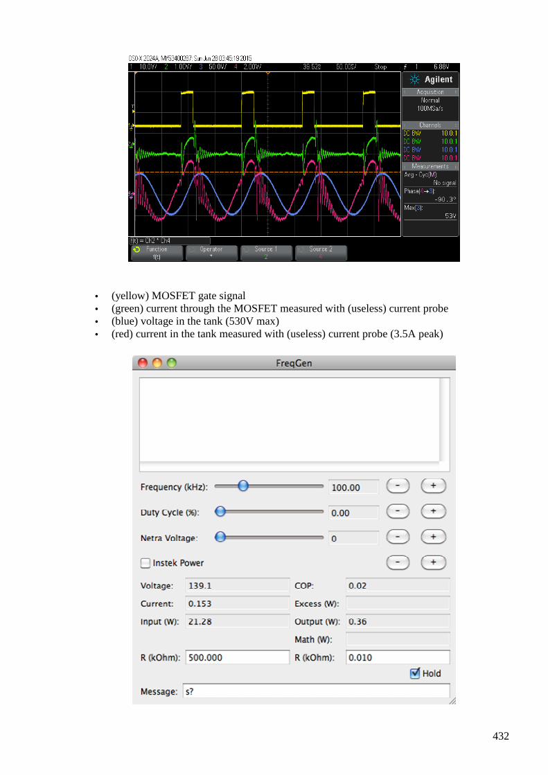
432
• (yellow) MOSFET gate signal • (green) current through the MOSFET measured with (useless) current probe • (blue) voltage in the tank (530V max) • (red) current in the tank measured with (useless) current probe (3.5A peak)
433
At an input wattage of 21W we get
The current is not yet non-linear. We introduce an air gap. This increases the reluctance, decreases the inductivity and thus increases the resenance frequency and the current.
We now get the expected highly non-lienar current and jump resonance.
#468 Re: mixing magnetic flux
onielsen2000 Jun 28 at 1:09 AM Hi Andreas, Answer is in the text. Regards Ole ---In [email protected], <ahoesch@...> wrote : Hi all, I am playing with toys for big boys again: :-) https://www.advanced-science.com/PhaseConjugation.html Just poking around and raising questions. Does anybody know why further increasing the rail voltage no longer raises the tank VARs? Because the losses are increasing just as fast as the increase in voltage. And I am still wondering about negative current measurements with these shitty probes (see the negative bias of the green curve?)! My current probe has a zero adjustment to compensate for the Earth magnetic field. If moving the probe around it has to be adjusted anew. My probe doesn't have a magnetic ring core. How can I calculate the Q for this beast from the measured parameters? Give the system an impulse or a step response and measure the ringing. Then from the
434
measurement the quality factor can be calculated: Measuring the Q-factor of a resonator with the ring-down method
Measuring the Q-factor of a resonator with the ring-down... Measuring the Q-factor of a resonator with the ring-down method Introduction Resonance is a very common phenomenon, especially in electronics,...
View on www.giangrandi.ch Preview
by Yahoo
http://www.arrl.org/files/file/QEX_Next_Issue/Jan-Feb_2012/QEX_1_12_Audet.pdf
Q = the resonant frequency divided by the 3dB bandwidth. See figure 3 here: http://ocw.mit.edu/courses/electrical-engineering-and-computer-science/6-071j-introduction-to-electronics-signals-and-measurement-spring-2006/lecture-notes/resonance_qfactr.pdf Whatever, the idea is to have two of these tanks with slightly different resonance frequency and giving them a common leg with a pickup coil attached. The fluxes should mix in this common leg and ... You get the idea! Don't be so sure about that mixing. The signals might just ride right through each other. In the UDT it seems to be very critical to get the mixing correct if that is really what happens. I believe that to be the case to get free energy. Best wishes, Andreas BTW: How far away from this beast should I be when firing it up to stay healthy? I can remote control the experiment in the meanwhile. It's jsut that you see more (hear noises, smell a burning MOSFET,...) when you are close to it. But my guess is that is not really recommended!?
#469 Re: [ferd] Re: mixing magnetic flux
Andreas Höschler Jun 28
Hi Ole,
And I am still wondering about negative current measurements with these shitty probes (see the negative bias of the green curve?)! My current probe has a zero adjustment to compensate for the Earth magnetic field.
My (this cheap one) has as well. But that's not the point. If I switch off the device the probe shows a nice flat line at zero amps. If I switch it on I get this negative bias as if it were real. But it cannot unless the diode supposed to block current going back into the power supply is toast!?
435
Whatever, the idea is to have two of these tanks with slightly different resonance frequency and giving them a common leg with a pickup coil attached. The fluxes should mix in this common leg and ... You get the idea! Don't be so sure about that mixing. The signals might just ride right through each other. In the UDT it seems to be very critical to get the mixing correct if that is really what happens. I believe that to be the case to get free energy.
But how do we get this mixing? What are the prerequisites/conditions under which this happens? It's the purpose of the current experiment to find this out. I hope this might happen when the core (common leg) hits the saturation line!? But that's just a wild guess. Just poking around without the slightest clue as always ... :-)
Thanks,
Andreas
#470 Re: [ferd] Re: mixing magnetic flux
onielsen2000 Jun 28 at 3:12 AM Hi Andreas,
Show message history An IR camera would reveal where the power gets dissipated. Perhaps the iron is magnetized to the knee point of the magnetization curve (BH-curve). This would give an abrupt increased iron loss. And I am still wondering about negative current measurements with these shitty probes (see the negative bias of the green curve?)! My current probe has a zero adjustment to compensate for the Earth magnetic field. My (this cheap one) has as well. But that's not the point. If I switch off the device the probe shows a nice flat line at zero amps. If I switch it on I get this negative bias as if it were real. But it cannot unless the diode supposed to block current going back into the power supply is toast!? Is the signal extending what the current probe is capable of? Check the datasheet for the current probe. Is it going into some kind of saturation which requires some period of time to come out of? If it is a pure AC probe the curve has to have the same area above the zero line as below the zero line as it will not show any DC level. The mean value is then zero (or has to be for proper function). Also check the D1 diode for a short and its reverse recovery time to be shorter than the negative half period of the current. Look at this video posted over at EvGray when changing the frequency from 60 Hz to 300 kHz. The 1N4007 diode shown isn't fast enough to recover in the reverse current direction: What is a schottky diode?
436
What is a schottky diode? A tutorial covering the advantages and disadvantages of schottky diodes over regular silicon diodes. How to support the channel: http://www.afrotechmods.com/...
View on youtu.be Preview
by Yahoo
Whatever, the idea is to have two of these tanks with slightly different resonance frequency and giving them a common leg with a pickup coil attached. The fluxes should mix in this common leg and ... You get the idea! Don't be so sure about that mixing. The signals might just ride right through each other. In the UDT it seems to be very critical to get the mixing correct if that is really what happens. I believe that to be the case to get free energy. But how do we get this mixing? What are the prerequisites/conditions under which this happens? It's the purpose of the current experiment to find this out. I hope this might happen when the core (common leg) hits the saturation line!? But that's just a wild guess. Just poking around without the slightest clue as always ... :-) For mixing the signals to not just pass through each other the mixing has to be done in a nonlinear medium. This will be the case in iron when working around the knee point of the BH-curve. This also means extended loss if passing too much into saturation. After the knee point the curve is again linear. So mixing has to be done at the right working point. Regards Ole
#471 Re: [ferd] Re: mixing magnetic flux
Andreas Höschler Jun 28 at 3:34 AM Hi Ole, Show message history Perhaps the iron is magnetized to the knee point of the magnetization curve (BH-curve). This would give an abrupt increased iron loss. I am actually looking for this point. But this should be seen in the current wave form (highly non-linear). But the currrent is completely linear (pure sine)!?
437
And I am still wondering about negative current measurements with these shitty probes (see the negative bias of the green curve?)! My current probe has a zero adjustment to compensate for the Earth magnetic field. My (this cheap one) has as well. But that's not the point. If I switch off the device the probe shows a nice flat line at zero amps. If I switch it on I get this negative bias as if it were real. But it cannot unless the diode supposed to block current going back into the power supply is toast!? Is the signal extending what the current probe is capable of? Chauvin Arnoux current probe E3n No! This probe has a 100kHz limit but is good for up to 100A. I am far away from this current limit. Check the datasheet for the current probe. Is it going into some kind of saturation which requires some period of time to come out of? If it is a pure AC probe NO, it is DC/AC! Also check the D1 diode for a short I will ... and its reverse recovery time to be shorter than the negative half period of the current. It's a schottky diode! :-)
IDW12G65C5
650V SiC Schottky Diode 12A Whatever, the idea is to have two of these tanks with slightly different resonance frequency and giving them a common leg with a pickup coil attached. The fluxes should mix in this common leg and ... You get the idea! Don't be so sure about that mixing. The signals might just ride right through each other. In the UDT it seems to be very critical to get the mixing correct if that is really what happens. I believe that to be the case to get free energy. But how do we get this mixing? What are the prerequisites/conditions under which this happens? It's the purpose of the current experiment to find this out. I hope this might happen when the core (common leg) hits the saturation line!? But that's just a wild guess. Just poking around without the slightest clue as always ... :-)
438
For mixing the signals to not just pass through each other the mixing has to be done in a nonlinear medium. This will be the case in iron when working around the knee point of the BH-curve. This also means extended loss if passing too much into saturation. After the knee point the curve is again linear. So mixing has to be done at the right working point. OK, so we have to find this exact point. My approach is observing the tank current and finding with swett spot where it becomes non-linear. But my scope shot still shows linear current. And nevertheless I don't get any further! I will check the diode and double-check the current measurement... Thanks, Andreas
#472 Re: [ferd] Re: mixing magnetic flux
onielsen2000 Jun 28
Hi Andreas, OK, so we have to find this exact point. My approach is observing the tank current and finding with swett spot where it becomes non-linear. But my scope shot still shows linear current. And nevertheless I don't get any further!
I will check the diode and double-check the current measurement... One easy way to find the saturation point is to have a winding to DC magnetize the core and another winding to measure the inductance. When saturation occurs the inductance reading begins to decrease. At full saturation the inductance is that of the winding without the magnetic core in place. Just be careful to adjust the voltage (current) slowly while the inductance reading is made and be sure to have good connections to the power supply. If the current shuttenly gets interrupted a huge voltage flyback will happen to keep the current flowing at the value is had during the interruption. This may destroy the inductance meter or even the insulation of the winding. Instead of an inductance or LCR-meter a signal generator and an oscilloscope or audio frequency AC voltmeter can be used on the test winding to see when the inductance starts to decrease. Same rules apply for limiting big changes in the current to avoid destroying the equipment by transformer action between the windings. The saturation point could also be calculated from the parameters of the Ferrite given in the datasheet and its dimensions. A measurement would be much faster though. If the power supply can't deliver enough current then increase the current by putting more turns through the core. The ringing in the current readings can probably be removed by minimizing the parasitic values
439
of the set-up. E.g. removing current loops formed by the wires and capacitance between the turns. For removing capacitance of the windings the methods discussed earlier could be used. Low capacitance winding methods: https://groups.yahoo.com/neo/groups/ferd/conversations/messages/454 and https://groups.yahoo.com/neo/groups/ferd/conversations/messages/455. Regards Ole
#473 reading - Verification and theoretical explanation of the Osamu Ide experiment
Alexey Jul 1 8:57 PM
http://www.overunityresearch.com/index.php?topic=3111.msg49941#msg49941
#474 Re: [ferd] reading - Verification and theoretical explanation of the Osamu Ide experiment
Andreas Höschler Jul 3 at 12:02 AM
Hi Alexey,
However, I am not so impressed by the effect or its interpretation. If I understood the paper correctly they claim to observe a short positive current peak before the current starts to rise according to
U = L dI/dt
For me this simply means that it tales a while for the iron (high permeability) to react to the applied field. So we first see the reaction of the air core alone which gives a very high current rise due to the small inductivity. The the iron gets active and causes due to the now increased inductivity a slower current rise. This is well described by standard formulae at least if we take
U = L dI/dt
as given. The price question of course is what is this
U = L dI/dt
440
all about. What is self-inductance, inertia,... caused by and how can it be exploited?
In my experiments I have seen a negative current peak at switch on, meaning that the CEMF is larger than the applied voltage thus pushing current back into the power supply. This is of much greater interest to me. However, I doubt that significant energy is delivered by this CEMF pulse (too short). :-(
Best wishes,
Andreas
#475 RE: [ferd] reading - Verification and theoretical explanation of the Osamu Ide experiment
Alexey Jul 3 at 9:08 AM
Hi Andreas,
I not sure if you remember original Osamu Ide paper about bifilar coils in motor (please see attached) What I am trying to say is 1. Bifilar coils (UDT like setups etc etc) are not source of OU, it is just a method of obtaining very high dI/dt 2. Fields are coexists in same point, they are not sum or interact, it is math but not reality 3. Inertia related to torsion field and considered as “external” force, using it is a key to extract energy from the media (or environment) So, on the practical side, to get UDT working we need to feed it with very short sharp pulses. And to get you last setup working you need to add one primary coil in opposite to first one. You may not agree with me, but its how I understand the situation. Regards, Alexey
#476 Re: [ferd] reading - Verification and theoretical explanation of the Osamu Ide experiment
Andreas Höschler Jul 3 at 3:22 PM
Hi Alexey,
What I am trying to say is
1. Bifilar coils (UDT like setups etc etc) are not source of OU, it is just a method of obtaining very high dI/dt
Bifilar is technically not the correct term for a UDT. It's just a double coil in opposing configuration.
2. Fields are coexists in same point, they are not sum or interact, it is math but not reality
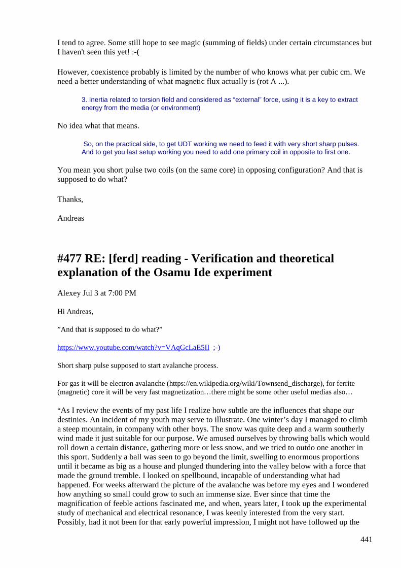
441
I tend to agree. Some still hope to see magic (summing of fields) under certain circumstances but I haven't seen this yet! :-(
However, coexistence probably is limited by the number of who knows what per cubic cm. We need a better understanding of what magnetic flux actually is (rot A ...).
3. Inertia related to torsion field and considered as “external” force, using it is a key to extract energy from the media (or environment)
No idea what that means.
So, on the practical side, to get UDT working we need to feed it with very short sharp pulses. And to get you last setup working you need to add one primary coil in opposite to first one.
You mean you short pulse two coils (on the same core) in opposing configuration? And that is supposed to do what?
Thanks,
Andreas
#477 RE: [ferd] reading - Verification and theoretical explanation of the Osamu Ide experiment
Alexey Jul 3 at 7:00 PM
Hi Andreas,
”And that is supposed to do what?”
https://www.youtube.com/watch?v=VAqGcLaE5II ;-)
Short sharp pulse supposed to start avalanche process.
For gas it will be electron avalanche (https://en.wikipedia.org/wiki/Townsend_discharge), for ferrite (magnetic) core it will be very fast magnetization…there might be some other useful medias also…
“As I review the events of my past life I realize how subtle are the influences that shape our destinies. An incident of my youth may serve to illustrate. One winter’s day I managed to climb a steep mountain, in company with other boys. The snow was quite deep and a warm southerly wind made it just suitable for our purpose. We amused ourselves by throwing balls which would roll down a certain distance, gathering more or less snow, and we tried to outdo one another in this sport. Suddenly a ball was seen to go beyond the limit, swelling to enormous proportions until it became as big as a house and plunged thundering into the valley below with a force that made the ground tremble. I looked on spellbound, incapable of understanding what had happened. For weeks afterward the picture of the avalanche was before my eyes and I wondered how anything so small could grow to such an immense size. Ever since that time the magnification of feeble actions fascinated me, and when, years later, I took up the experimental study of mechanical and electrical resonance, I was keenly interested from the very start. Possibly, had it not been for that early powerful impression, I might not have followed up the
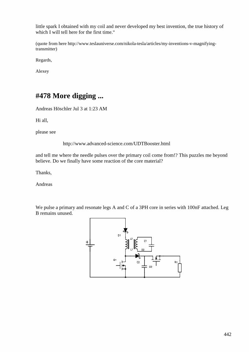
442
little spark I obtained with my coil and never developed my best invention, the true history of which I will tell here for the first time.”
(quote from here http://www.teslauniverse.com/nikola-tesla/articles/my-inventions-v-magnifying-transmitter)
Regards,
Alexey
#478 More digging ...
Andreas Höschler Jul 3 at 1:23 AM
Hi all,
please see
http://www.advanced-science.com/UDTBooster.html
and tell me where the needle pulses over the primary coil come from!? This puzzles me beyond believe. Do we finally have some reaction of the core material?
Thanks,
Andreas
We pulse a primary and resonate legs A and C of a 3PH core in series with 100nF attached. Leg B remains unused.
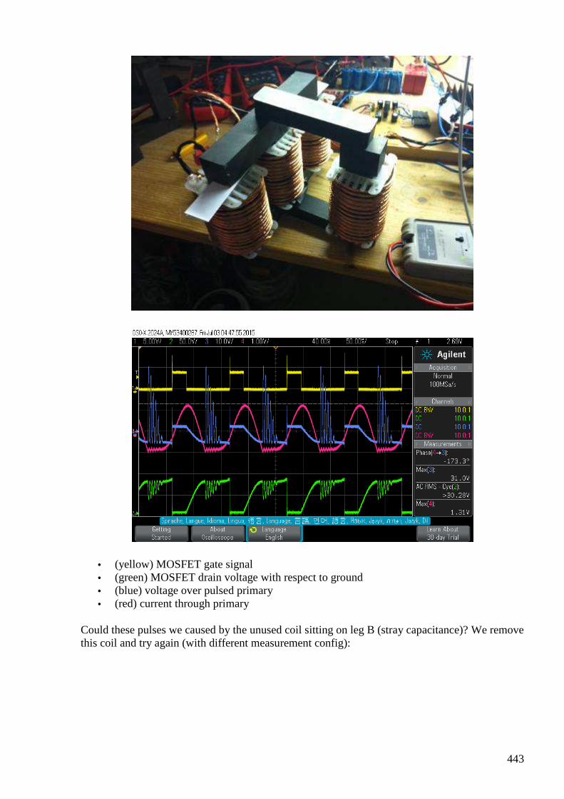
443
• (yellow) MOSFET gate signal • (green) MOSFET drain voltage with respect to ground • (blue) voltage over pulsed primary • (red) current through primary
Could these pulses we caused by the unused coil sitting on leg B (stray capacitance)? We remove this coil and try again (with different measurement config):
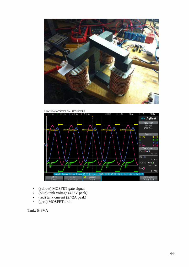
444
• (yellow) MOSFET gate signal • (blue) tank voltage (477V peak) • (red) tank current (2.72A peak) • (gree) MOSFET drain
Tank: 648VA
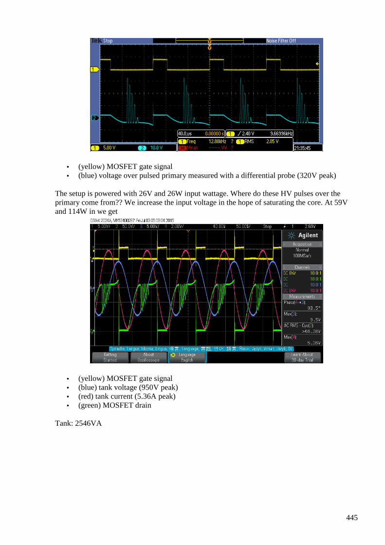
445
• (yellow) MOSFET gate signal • (blue) voltage over pulsed primary measured with a differential probe (320V peak)
The setup is powered with 26V and 26W input wattage. Where do these HV pulses over the primary come from?? We increase the input voltage in the hope of saturating the core. At 59V and 114W in we get
• (yellow) MOSFET gate signal • (blue) tank voltage (950V peak) • (red) tank current (5.36A peak) • (green) MOSFET drain
Tank: 2546VA
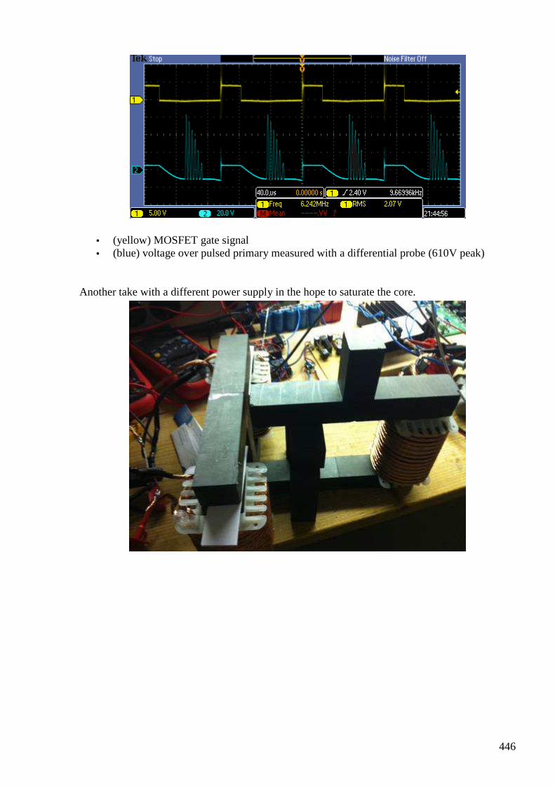
446
• (yellow) MOSFET gate signal • (blue) voltage over pulsed primary measured with a differential probe (610V peak)
Another take with a different power supply in the hope to saturate the core.
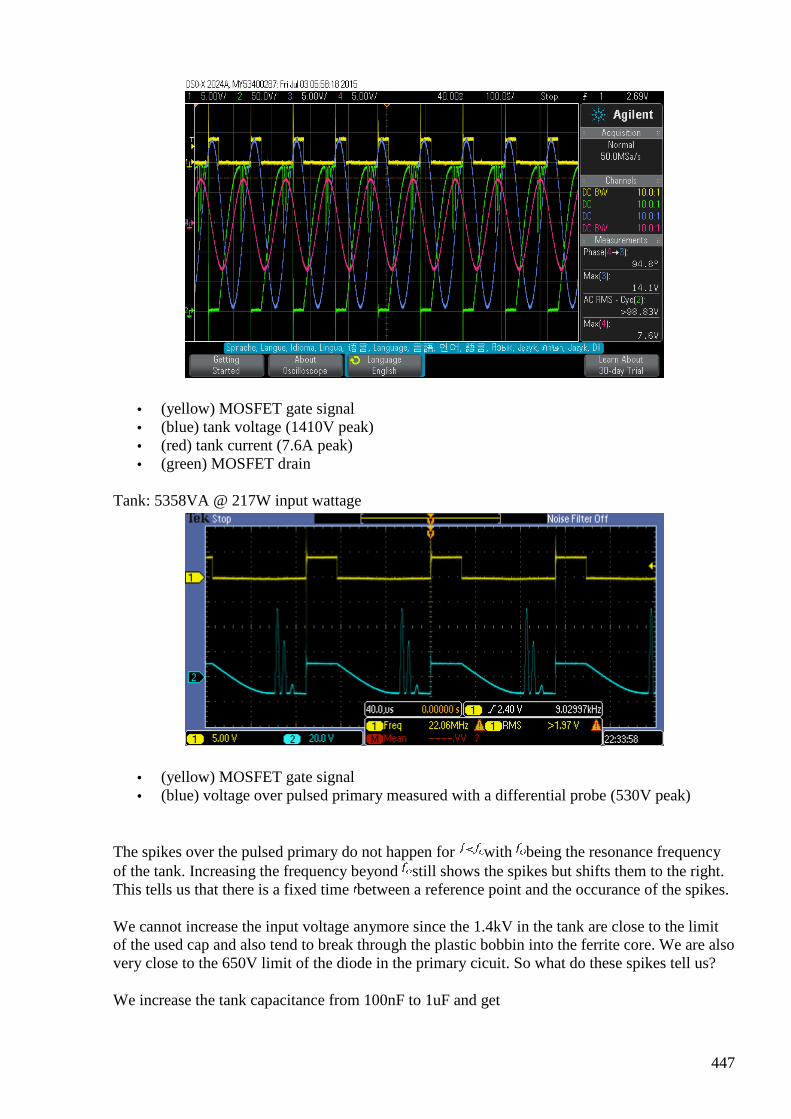
447
• (yellow) MOSFET gate signal • (blue) tank voltage (1410V peak) • (red) tank current (7.6A peak) • (green) MOSFET drain
Tank: 5358VA @ 217W input wattage
• (yellow) MOSFET gate signal • (blue) voltage over pulsed primary measured with a differential probe (530V peak)
The spikes over the pulsed primary do not happen for with being the resonance frequency of the tank. Increasing the frequency beyond still shows the spikes but shifts them to the right. This tells us that there is a fixed time between a reference point and the occurance of the spikes.
We cannot increase the input voltage anymore since the 1.4kV in the tank are close to the limit of the used cap and also tend to break through the plastic bobbin into the ferrite core. We are also very close to the 650V limit of the diode in the primary cicuit. So what do these spikes tell us?
We increase the tank capacitance from 100nF to 1uF and get
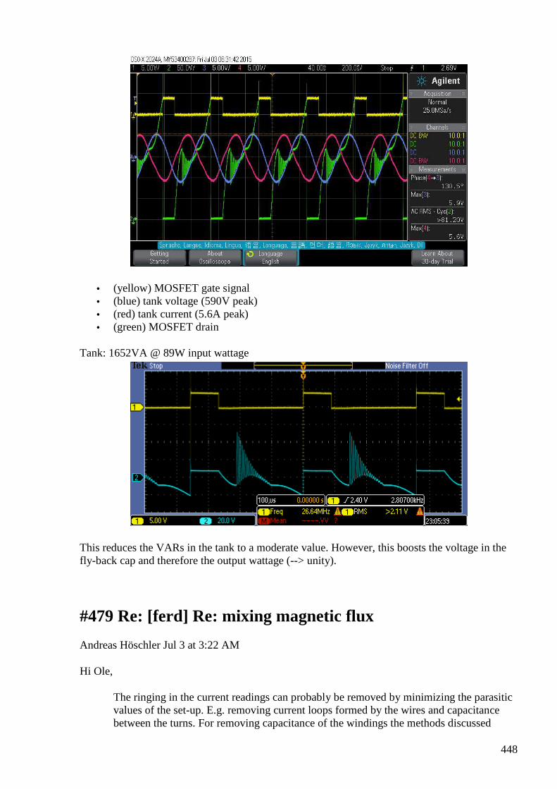
448
• (yellow) MOSFET gate signal • (blue) tank voltage (590V peak) • (red) tank current (5.6A peak) • (green) MOSFET drain
Tank: 1652VA @ 89W input wattage
This reduces the VARs in the tank to a moderate value. However, this boosts the voltage in the fly-back cap and therefore the output wattage (--> unity).
#479 Re: [ferd] Re: mixing magnetic flux
Andreas Höschler Jul 3 at 3:22 AM
Hi Ole,
The ringing in the current readings can probably be removed by minimizing the parasitic values of the set-up. E.g. removing current loops formed by the wires and capacitance between the turns. For removing capacitance of the windings the methods discussed
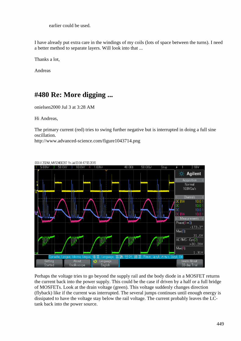
449
earlier could be used.
I have already put extra care in the windings of my coils (lots of space between the turns). I need a better method to separate layers. Will look into that ...
Thanks a lot,
Andreas
#480 Re: More digging ...
onielsen2000 Jul 3 at 3:28 AM
Hi Andreas, The primary current (red) tries to swing further negative but is interrupted in doing a full sine oscillation. http://www.advanced-science.com/figure1043714.png
Perhaps the voltage tries to go beyond the supply rail and the body diode in a MOSFET returns the current back into the power supply. This could be the case if driven by a half or a full bridge of MOSFETs. Look at the drain voltage (green). This voltage suddenly changes direction (flyback) like if the current was interrupted. The several jumps continues until enough energy is dissipated to have the voltage stay below the rail voltage. The current probably leaves the LC-tank back into the power source.
450
Regards Ole
#481 Re: [ferd] Re: More digging ...
Andreas Höschler Jul 3 at 3:47 AM
Hi Ole,
please reload the document. The circuit was missing for whatever reason (now at the top of the page):
Perhaps the voltage tries to go beyond the supply rail and the body diode in a MOSFET returns the current back into the power supply.
Note the Schottky above the primary. There is no way for any current to go back into the power supply. The diode blocks such current. The sole purpose of this diode is to prevent exactly that. Otherwise you could never drive a tank into resonance with a single MOSFET.
This could be the case if driven by a half or a full bridge of MOSFETs. Look at the drain voltage (green). This voltage suddenly changes direction (flyback) like if the current was interrupted. The several jumps continues until enough energy is dissipated to have the voltage stay below the rail voltage. The current probably leaves the LC-tank back into the power source.
Please check out the second scope shot on the page. It shows tank voltage and current (nice since waves). I can't see how this normal LC oscialltion could cause these pulses!?
The pulses happen when the tank current goes high. Hmmghh!???
Thanks,
Andreas
#482 Re: [ferd] More digging ...
Gerry Jul 3 at 4:06 AM
Hi Andreas, guys
Looking on your scope shots.....IMHO
It looks like it's initiated by initial spike in voltage on the pulsed primary.
The pulse travels along the ferrite core or core block for total approximately 56 microseconds at a particular velocity.
451
Then it strikes a discontinuity as it enters another ferrite block. (discontinuity like entering & leaving flat end faces causes a reflection of pulse which is modified by rho value on each pass).
The next block it enters must be shorter than the first, as there are multiple reflections between each end of the block faces.
We can see that they gradually diminish as the reflection or echo traverses the block multiple times.
To reduce this effect you might need to coat the ends of the blocks with some sort of heavy grease or ferrite paste.
Just like thy do when you go for an ultra sound.
This then gives a more gradual change between the density of the ferrite and the density of the very slight air gap between the blocks.
It would be interesting to know the ratio of the distance (time) between the initial pulse and the first part of the return spike. (about 56 uS).
and the distance (time) between the damped rings.
The time ratio between these two, might match the length (mm) ratio, between the ferrite blocks.
But have to remember that initial pulse had to traverse the initial distance twice (up to initial discontinuity and back again)
before we can see it on at scope probe measurement point.
I hope this helps, Gerry
#483 RE: [ferd] More digging ...
Alexey Jul 3 at 9:10 AM
Hi Andreas, I think that parasite capacitance of diode is responsible for these oscillations. You can try different diode or just connect small capacitor in parallel and you will see how it affects oscillations… Regards, Alexey BTW I think making more space between coil turns increase parasite capacitance, to decrease capacitance you need change “winding pattern” e.g. like this https://en.wikipedia.org/wiki/Basket_winding
#484 Re: [ferd] Re: More digging ...
onielsen2000 Jul 3 at 12:13 PM
452
Hi Andreas,
---In [email protected], <ahoesch@...> wrote :
Hi Ole,
please reload the document. The circuit was missing for whatever reason (now at the top of the page):
Perhaps the voltage tries to go beyond the supply rail and the body diode in a MOSFET returns the current back into the power supply.
Note the Schottky above the primary. There is no way for any current to go back into the power supply. The diode blocks such current. The sole purpose of this diode is to prevent exactly that. Otherwise you could never drive a tank into resonance with a single MOSFET.
The current flows in the LC-tank in the voltage supply loop (when Q1 is on) and in the loop through C2 whenever the drain voltage reaches above the voltage across C2. I tried a manipulation on the second scope image. The first half of the curves is simply flipped across the zero line. This clearly shows that the oscillations are not symmetric in amplitude. This is because some of the energy is lost during the passive part of the period.
#485 Re: [ferd] Re: More digging ...
onielsen2000 Jul 3 at 12:21 PM
Hi Andreas, The image didn't come through so now it is attached. Ole
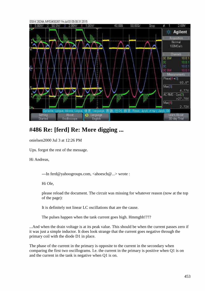
453
#486 Re: [ferd] Re: More digging ...
onielsen2000 Jul 3 at 12:26 PM
Ups. forgot the rest of the message. Hi Andreas,
---In [email protected], <ahoesch@...> wrote :
Hi Ole,
please reload the document. The circuit was missing for whatever reason (now at the top of the page):
It is definitely not linear LC oscillations that are the cause.
The pulses happen when the tank current goes high. Hmmghh!???
...And when the drain voltage is at its peak value. This should be when the current passes zero if it was just a simple inductor. It does look strange that the current goes negative through the primary coil with the diode D1 in place. The phase of the current in the primary is opposite to the current in the secondary when comparing the first two oscillograms. I.e. the current in the primary is positive when Q1 is on and the current in the tank is negative when Q1 is on.
454
Regards Ole
#487 Re: [ferd] Re: More digging ...
Andreas Höschler Jul 3 at 1:00 PM
Hi Ole,
please reload the document. The circuit was missing for whatever reason (now at the top of the page):
Perhaps the voltage tries to go beyond the supply rail and the body diode in a MOSFET returns the current back into the power supply.
Note the Schottky above the primary. There is no way for any current to go back into the power supply. The diode blocks such current. The sole purpose of this diode is to prevent exactly that. Otherwise you could never drive a tank into resonance with a single MOSFET.
The current flows in the LC-tank in the voltage supply loop (when Q1 is on) and in the loop through C2 whenever the drain voltage reaches above the voltage across C2. I tried a manipulation on the second scope image. The first half of the curves is simply flipped across the zero line. This clearly shows that the oscillations are not symmetric in amplitude. This is because some of the energy is lost during the passive part of the period.
No, it does not show that. It just shows that I should not have spent 300 EUR on this shitty used Textronix current probe. It exhibits a negative bias when in action. You can't rely on this. It's not real. Check the phase shift between tank current and voltage (on the right). It says 93.8°. If this were real somethhing extra-ordinary would happen. But it does not. The current measurement is wrong. We should assume it to be vertically symmetrical aroind the zero line and the phase shift to be close to 90° but not exactly (small losses). The Q is rather good.
<image corrupted, probably same as in previous post>
• (yellow) MOSFET gate signal • (blue) tank voltage (477V peak) • (red) tank current (2.72A peak) • (green) MOSFET drain
Try to measure the current through D2 and different places of the loop made of the voltage supply D1 primary and Q1 to see if this is where the current goes. It has to be a sudden change in current to make the ringing. This would fit fine with a diode which is highly nonlinear. The ringing voltage keeps increasing until Q1 turns on. Another suggestion is to check the current
455
probe with an only positive (or negative) square wave to see if it AC filters the signal. It does look like the primary current is symmetric around the zero line. In the first scope shot one can see this primary current. See the negative bias? This is bullshit (can't be real). This current is completely impossible with the diodes in place. The Textronix probe is really a piece of junk. You think the spikes is ringing in the primary circuit? May be the inductance of the primary and the capacity of the Schottky above it in series!? Thi smight explain it. But aren't Schottky suposed to have a very small stray capacitance? The IDW40G65C5 according to the datasheet has a capacitance of 147pF. Hmmgh! That in series with the capacitance of the MOSFET (around 150pF) gives a total capacitance of 80pF or so. Yeah, that's probably it! Again no core effect! :-( Thanks for helping to clear this up!! Best wishes, Andreas
#488 Re: [ferd] More digging ...
Andreas Höschler Jul 3 at 1:11 PM
Hi Gerry,
thanks a lot for your response.
Again only standard stuff and nothing extraordinary gained (discovered)! :-(
Thanks for your comments/help!
Keep on keeping ... :-)
Best wishes,
Andreas
#489 Re: [ferd] More digging ...
Gerry Jul 4 at 1:59 AM
Hi Andreas, guys
Yes I was looking at the 40uS at top of the scope pic there & somehow thought this must be 40uS per major division.
Your scope is a really nice 'time domain' measurement machine, but it doesn't differentiate frequencies out very well.
456
But scope's also good for time vs distance so can use a single loop around the core and slide it along till the discontinuity is reached.
Anyhow putting a hand or something like Alu foil near the tank circuit you should be able to see if this delayed "ringing" effect is damped or detuned.
Careful not to blow your FET's though.
If it is a discontinuity problem in the core's magnetic circuit, the time delay...... where it starts to occur wont change very much.
Cause as you rightly pointed out, the propagation through the ferrite itself is at a relatively fixed speed,
so no matter what pulse repetition frequency used the delay between spike and "ring" response will be constant.
As Ole said it's possible to get lower interwinding capacitance by breaking up the winding etc.
Also thin ferrite beads threaded on the leads from the drive circuit to the tank can stop parasitic oscillations from building up.
Gerry
#490 Re: [ferd] reading - Verification and theoretical explanation of the Osamu Ide experiment
Gerry Jul 4 at 2:14 AM
Hi Alexey,
Thanks for this link ...I enjoyed reading the stuff at OU forum, and downloaded much pdf's.
Gerry
#491 Re: [ferd] More digging ...
Gerry Jul 4 at 6:27 AM
Hi Andreas,
I was thinking about that high initial spike, in your scope shots.
It reminded me of something we all talked about before here.
Remember the Greg Watson PMOD device explanation he gave regarding the huge current spike followed by a more gradual increase?
457
Here is a quote
"....
Date: Thu, 09 Oct 1997 11:03:00 +0930
From: Greg Watson <[email protected]>
Organization: Greg Watson Consulting
Hi All,
Here are the basic DNMEC OU secrets I have discovered.
1) PMOD. If we have a coil and ferrite core, it is possible to time separate the current applied to the coil by an external Emf source and the resultant back Emf generated as the ferrites domains align. I have found that there is a time delay of approx 20-30ns from the application of the coils H field and the domains starting to rotate into alignment and producing a back Emf. If the coil is driven for only 20-30ns, only a small amount of self induced back Emf is generated (the coil acts like the ferrite is not there). After the 20-30ns wide drive pulse, the coils H field is gone but the domains are still moving (they have inertia) and will generate quite a large back Emf which can be tapped.
........end of quote
Not saying this is cause of your effect Andreas, just reminding you in case you
consider it may be relevant.
Gerry
#492 Re: [ferd] More digging ...
Andreas Höschler Jul 4 at 3:29 PM
Hi Gerry,
I was thinking about that high initial spike, in your scope shots.
It reminded me of something we all talked about before here.
Remember the Greg Watson PMOD device explanation he gave regarding the huge current spike followed by a more gradual increase?
Here is a quote

458
Thanks for bringing this to our attention once again. It's hard (almost impossible with my parts in stock) to generate such short pulses of 20ns. I am seriously considering to check out the Xenon tube approach Hector was proposing. Has anybody in this group any experience with Xenon flash tubes as a replacement for MOSFETs to generate super short pulses and super high dI/dt?
Thanks,
Andreas
#493 Re: [ferd] More digging ...
onielsen2000 Jul 4 at 4:05 PM
Hi Andreas, Flash tubes works fine for generating short pulses. I used that to measure the propagation speed of the magnetic field in ferrite rings. Those tubes flash at a high voltage which is practical when it is hard to go below 50 Ohm in the transmission lines. Another way is to use transistors in avalanche mode. This also can generate very short pulses. I used a flash tube from a disposable camera. Those cameras already have the electronics to generate the high voltage (from a 1,5V cell). The discharge capacitor has to be much smaller to generate ns pulses. Use a coaxial cable instead of the capacitor. This way the pulse length is defined by the length of the cable and the signal speed of the type of cable used. To have smaller than 50 Ohm impedance a transformer has to be used but then the signal can't be sent further on in a new cable as the cables has higher impedances. They must be treated as transmission lines when working with short pulses or radio frequencies. Regards Ole
#494 Re: [ferd] More digging ...
Andreas Höschler Jul 5 at 2:39 AM
Hi all,
I was thinking about that high initial spike, in your scope shots.
It reminded me of something we all talked about before here.
Remember the Greg Watson PMOD device explanation he gave regarding the huge current spike followed by a more gradual increase?
It turned out that my P6022 may be functioning well (shows AC only) and that the measured phase shift between tank current and voltage of > 100° might actually be real. If that is so ... well .. not sure what this means actually. But I would like that. :-)
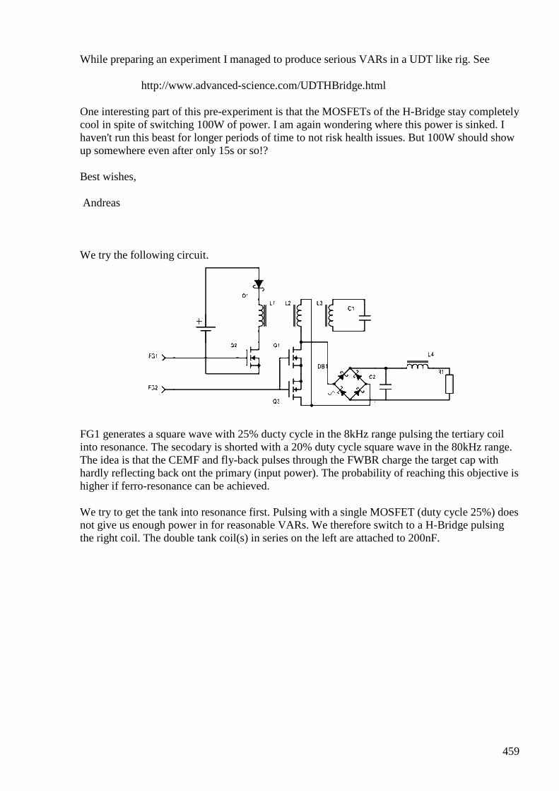
459
While preparing an experiment I managed to produce serious VARs in a UDT like rig. See
http://www.advanced-science.com/UDTHBridge.html
One interesting part of this pre-experiment is that the MOSFETs of the H-Bridge stay completely cool in spite of switching 100W of power. I am again wondering where this power is sinked. I haven't run this beast for longer periods of time to not risk health issues. But 100W should show up somewhere even after only 15s or so!?
Best wishes,
Andreas
We try the following circuit.
FG1 generates a square wave with 25% ducty cycle in the 8kHz range pulsing the tertiary coil into resonance. The secodary is shorted with a 20% duty cycle square wave in the 80kHz range. The idea is that the CEMF and fly-back pulses through the FWBR charge the target cap with hardly reflecting back ont the primary (input power). The probability of reaching this objective is higher if ferro-resonance can be achieved.
We try to get the tank into resonance first. Pulsing with a single MOSFET (duty cycle 25%) does not give us enough power in for reasonable VARs. We therefore switch to a H-Bridge pulsing the right coil. The double tank coil(s) in series on the left are attached to 200nF.
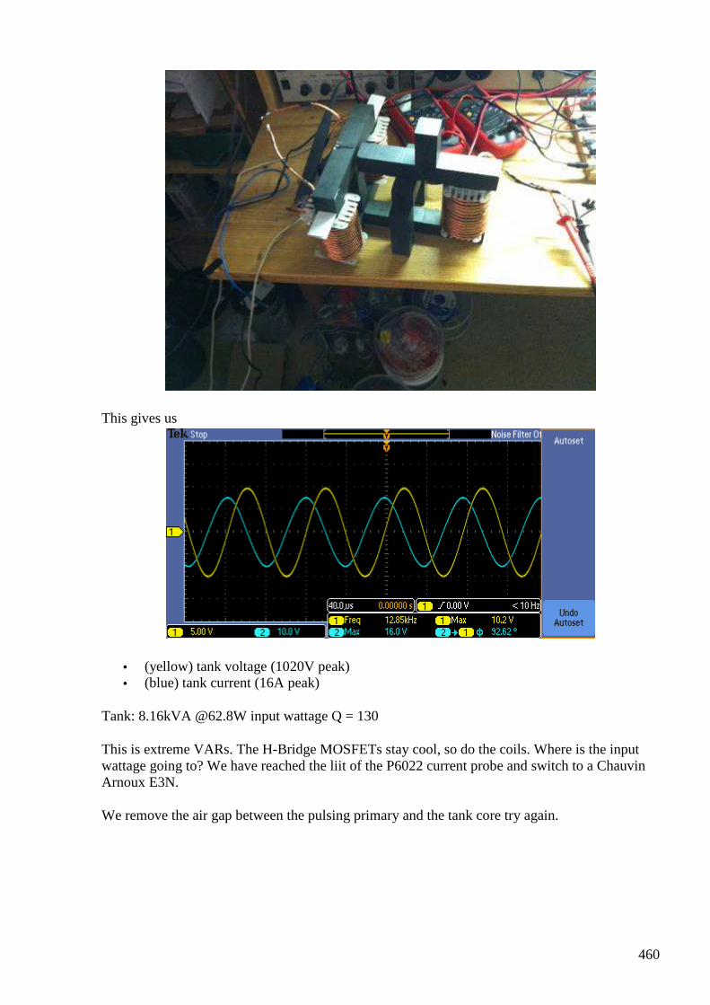
460
This gives us
• (yellow) tank voltage (1020V peak) • (blue) tank current (16A peak)
Tank: 8.16kVA @62.8W input wattage Q = 130
This is extreme VARs. The H-Bridge MOSFETs stay cool, so do the coils. Where is the input wattage going to? We have reached the liit of the P6022 current probe and switch to a Chauvin Arnoux E3N.
We remove the air gap between the pulsing primary and the tank core try again.
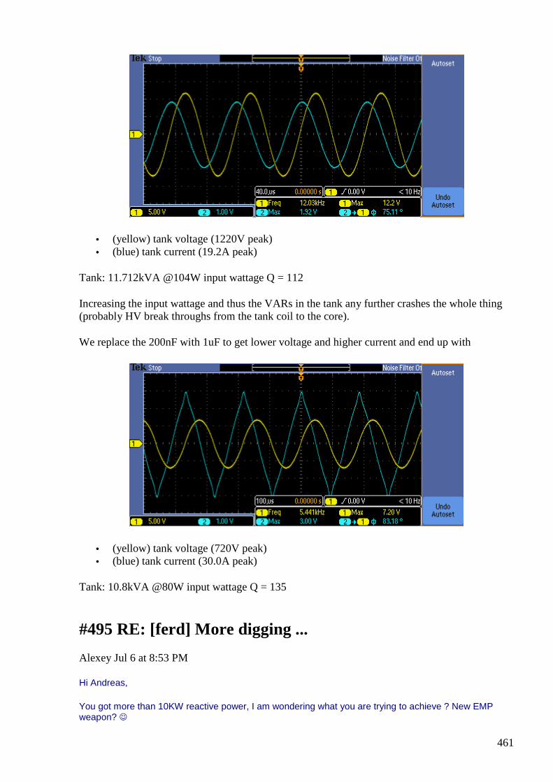
461
• (yellow) tank voltage (1220V peak) • (blue) tank current (19.2A peak)
Tank: 11.712kVA @104W input wattage Q = 112
Increasing the input wattage and thus the VARs in the tank any further crashes the whole thing (probably HV break throughs from the tank coil to the core).
We replace the 200nF with 1uF to get lower voltage and higher current and end up with
• (yellow) tank voltage (720V peak) • (blue) tank current (30.0A peak)
Tank: 10.8kVA @80W input wattage Q = 135
#495 RE: [ferd] More digging ...
Alexey Jul 6 at 8:53 PM
Hi Andreas,
You got more than 10KW reactive power, I am wondering what you are trying to achieve ? New EMP weapon?
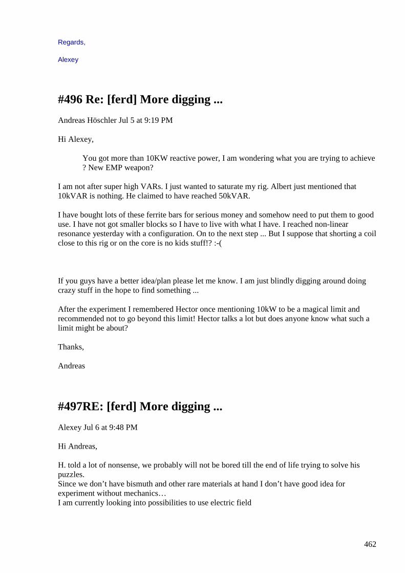
462
Regards,
Alexey
#496 Re: [ferd] More digging ...
Andreas Höschler Jul 5 at 9:19 PM
Hi Alexey,
You got more than 10KW reactive power, I am wondering what you are trying to achieve ? New EMP weapon?
I am not after super high VARs. I just wanted to saturate my rig. Albert just mentioned that 10kVAR is nothing. He claimed to have reached 50kVAR.
I have bought lots of these ferrite bars for serious money and somehow need to put them to good use. I have not got smaller blocks so I have to live with what I have. I reached non-linear resonance yesterday with a configuration. On to the next step ... But I suppose that shorting a coil close to this rig or on the core is no kids stuff!? :-(
If you guys have a better idea/plan please let me know. I am just blindly digging around doing crazy stuff in the hope to find something ...
After the experiment I remembered Hector once mentioning 10kW to be a magical limit and recommended not to go beyond this limit! Hector talks a lot but does anyone know what such a limit might be about?
Thanks,
Andreas
#497RE: [ferd] More digging ...
Alexey Jul 6 at 9:48 PM
Hi Andreas, H. told a lot of nonsense, we probably will not be bored till the end of life trying to solve his puzzles. Since we don’t have bismuth and other rare materials at hand I don’t have good idea for experiment without mechanics… I am currently looking into possibilities to use electric field
463
Regards, Alexey BTW Albert seems to be doing some kind of campaign against H., I got some emails from him and there is buzz on EVGRAY about that
#498 Re: [ferd] More digging ...
Andreas Höschler Jul 5 at 10:11 PM
Hi Alexey,
I unfortunately have no place yet for mechanical experiments, not even for a RV setup.
I am currently looking into possibilities to use electric field.
Neat! I should hold one over my rig when operating and see if it lights up! :-)
BTW Albert seems to be doing some kind of campaign against H., I got some emails from him and there is buzz on EVGRAY about that
Yes, he contacted me as well (obviously needs backing for his campaign). I would rather like to stay neutral on this one. Both parties have a point.
Even if Hector is not the all-knowing guru but as clueless as we all, his emissions still inspire a lot of people and makes them trying out things. That is good IMHO.
464
Best wishes,
Andreas
#499 Re: [ferd] More digging ...
Gustavo Roveran Jul 6 11:47 PM
Hi Alexey, All
I am here again, after 5 weeks of taking care to my little daughter. Her first days in this World. I have read some words about Hector vs Albert.
¿ Did you take the tube lamp from its middle point ?
¿Are you returning to the sources? ¿Tesla ideas ? I remember that you are not a close friend to wireless energy transmission, do you ?
Best Regards,
Gustavo
#500 Re: [ferd] More digging ...
Gerry Jul 7 at 2:15 AM
Hi Alexey, Andreas ...guys,
Andreas: Those scope shots at your link there look really good!
If you truly do have greater than 90 degrees phase shift... then in polar co ordinates
you have impedance z at angle >90 degrees. Imagine your impedance plot now in
rectangular co- ordinates. Above horizontal x axis, you have +jx inductive , below you
have -jx capacitive. Now thinking of vertical axis ...to the right you have +R ohms
resistive...to the left you have -R ohms resistive
Can you see that once over 90 degrees and all the way to 270 degrees (in the second
and third quadrants) that R ohms value has to be negative?
This means that dissipation of real power in the resistive component of the
impedance has ceased. And instead the resistive component is sourcing power back
into the circuit it is connected to. With current probes I think there will be phase
error, long before it's bandwidth limit is reached.
465
ps: It is possible to estimate bandwidth by looking at a fast rising step function with
it.Measure the risetime in nanoseconds from 10% to 90% of step with current probe.
350 divided by risetime in nanoseconds = approx bandwidth of current probe scope
combination.
Gerry
#501 Re: [ferd] More digging ...
Andreas Höschler Jul 7 at 3:28 AM
Hi Gerry,
Andreas: Those scope shots at your link there look really good!
If you truly do have greater than 90 degrees phase shift...
This means that dissipation of real power in the resistive component of the
impedance has ceased.
And instead the resistive component is sourcing power back into the circuit it
is connected to.
I am not yet sure about this. A cheap probe shows a phase shift of 80°, The expensive Textronix one a phase shift > 100°. I checked both probes by pulsing a light bulb. The current curve of the Textronix probe was instantaneous and ultra precise and sharp. But it's an AC only probe which means that it tends to have a bias which could render the phase shift measurement of the scope useless (not sure about that). The cheap probe showed a clear delay and proved to be completely useless for precise measurements. But it at least showed no bias.
I am seriously considering to invest bucks in an expensive Agilent current probe that is good to 50MHz and 30A (DC and AC) to make precise phase shift measurements. But man, this equipment is pricy. The last penny for our quest! :-)
The interesting part is that the MOSFETs of the H-Bridge (no heat sinks) stay completely cool in spite of pumping > 100W into the circuit.
If you recheck
http://www.advanced-science.com/UDTHBridge.html
you will see that I pushed the thing to the next level VAR-wise. See the last scope shot!? It shows a phase shift or 80° but that is with the cheap probe (wrong measurement) since the Textronix is good for 15A only and I am way beyond that with this rig. I know for sure that the phase shift is a lot better than 80°. It may well be 90° or even more. But I can't say this for sure without reasonable equipment.
466
Also check out the Agilent scope shot and on this page (the blue curve). Do you see the CEMF spikes when the MOSFETs switches on? There might be some power going back into the power supply when this happens. Who knows?
Wild stuff! But there can't be any surplus energy or the thing would explode. I am just again wondering where the 100W are going to. I don't plan to spend too much time next to this beast when in operation! :-)
Best wishes,
Andreas
#502 Re: [ferd] More digging ...
Gerry Jul 7 at 6:08 AM
Hi Andreas,
Yes I saw this, I agree not being too close if something breaks at these levels it's
going to really go off with a bang!
In that last shot see how the current has become very linear?
It reminds me of "slew rate limiting" in operational amplifier IC's, which happens
because internal transistors or fets have reached their output current limit & no
longer able to faithfully follow input sinewave. So it gives effect of charging a
capacitor with a "constant current source" ...ie: that straight sawtooth rise & fall we
see there in your shots. I think is same with your circuit.
See because the load is so reactive and highly phase shifted (around 90 degrees).....
the peak currents now occur when the output voltage is approximately zero.
So we may as well say the FET's in your bridge "see" an absolute short circuit at this
moment in time. Also at this moment in time, there is little self inductance effect left
in the inductor to limit current anymore, the only thing limiting current is the dc
resistance of the winding & associated circuitry back to the power supply.
I found (when driving with sinewaves) I could ease the burden on my source
components by using a 100 uF 250V non polarized motor start capacitor across the
source.So some of the huge reactive current is sourced from the external cap.
The best way I found to measure phase is using a series current sense resistor in the
earthed side of the source.
467
Then use a battery powered scope with two channels .........one channel probe
monitoring the high side voltage (with no earth clip attached).
Second probe monitoring input voltage (current) across (known sense resistor)
.....this probe has earth clip attached at signal drive earth.
Just have to remember to deduct the sense resistor volts from the applied volts ( &
not forget value of sense resistor, which I seem to do quite often, I know)
I'm sure you already know all this stuff anyhow.
I hope you understood about resistance value going negative once phase lag goes
beyond 90 degrees?
it's easy seen when plotting the (R+/- jX) on rectangular graph paper
all the best ...and be careful
Gerry
#503 Re: [ferd] More digging ...
Gerry Jul 7 at 6:09 AM
Hi Andreas,
Yes I saw this, I agree not being too close if something breaks at these levels it's
going to really go off with a bang!
In that last shot see how the current has become very linear?
It reminds me of "slew rate limiting" in operational amplifier IC's,
which happens because internal transistors or fets have reached their output current
limit & no longer able to faithfully follow input sinewave.
So it gives effect of charging a capacitor with a "constant current source" ...ie: that
straight sawtooth rise & fall we see there in your shots.
I think is same with your circuit.
See because the load is so reactive and highly phase shifted (around 90 degrees).....
the peak currents now occur when the output voltage is approximately zero.
468
So we may as well say the FET's in your bridge "see" an absolute short circuit at this
moment in time.
Also at this moment in time, there is little self inductance effect left in the inductor
to limit current anymore, the only thing limiting current is the dc resistance of the
winding & associated circuitry back to the power supply.
I found (when driving with sinewaves) I could ease the burden on my source
components by using a 100 uF 250V non polarized motor start capacitor across the
source.
So some of the huge reactive current is sourced from the external cap.
The best way I found to measure phase is using a series current sense resistor in the
earthed side of the source.
Then use a battery powered scope with two channels .........one channel probe
monitoring the high side voltage (with no earth clip attached).
Second probe monitoring input voltage (current) across (known sense resistor)
.....this probe has earth clip attached at signal drive earth.
Just have to remember to deduct the sense resistor volts from the applied volts ( &
not forget value of sense resistor, which I seem to do quite often, I know)
I'm sure you already know all this stuff anyhow.
I hope you understood about resistance value going negative once phase lag goes
beyond 90 degrees?
it's easy seen when plotting the (R+/- jX) on rectangular graph paper
all the best ...and be careful
Gerry
#504 RE: [ferd] More digging ...
Alexey Jul 7 at 9:01 AM
Hi Gustavo,
nice to hear from you
”Did you take the tube lamp from its middle point ?”

469
I not sure what you mean, lamp is shining near Tesla coil no mater how you take it, lamp from garbage bin BTW
”Are you returning to the sources? Tesla ideas ?”
I never step away from it…just a little tired repeating again and again ”you need phase transition to get OU”
”I remember that you are not a close friend to wireless energy transmission, do you ?”
no, I am not… don’t like be burned alive
Regards,
Alexey
#505 Re: [ferd] More digging ...
Gerry Jul 7 at 10:36 AM
Hi Gustavo,
Welcome back mate, it is probably even harder now to have time.. as family comes
first.
Hope you can get chance to get back to your projects also.
Gerry
#506 Re: [ferd] More digging ...
onielsen2000 Jul 7 at 2:31 PM
Hi Andreas, Also check out the Agilent scope shot and on this page (the blue curve). Do you see the CEMF spikes when the MOSFETs switches on? There might be some power going back into the power supply when this happens. Who knows?
<image missing>
The spikes at turn on are most probably ringing caused by hitting some parasitic component values by the sharp edges of the signal. This makes them ring with a decaying oscillation. If
470
zooming in on the time axis this should be seen more clearly. It looks like the voltage over the primary (blue) is turned on at both positive and negative voltage as the phase is changed at half the frequency of the gate signal (yellow)?! Then after an on part the primary makes a full oscillation cycle during the off part of the cycle. The cycle during the off time hits the supply rails as they aren't sinusoidal. There are several LC values in the system as it has several resonant frequencies. Or are the switches (power MOSFETs) actually turned on during part of the off cycle of the yellow signal? This could be checked by comparing the actually gate signals of the MOSFETs with the FG-signal (yellow). The yellow curve doesn't seem to be directly controlling the MOSFETs. There is a frequency division or something between them. Regards Ole
#507 Re: [ferd] More digging ...
Andreas Höschler Jul 7 at 2:53 PM
Hi Ole,
Also check out the Agilent scope shot and on this page (the blue curve). Do you see the CEMF spikes when the MOSFETs switches on? There might be some power going back into the power supply when this happens. Who knows?
<image missing> The spikes at turn on are most probably ringing caused by hitting some parasitic component values by the sharp edges of the signal. This makes them ring with a decaying oscillation. If zooming in on the time axis this should be seen more clearly. It looks like the voltage over the primary (blue) is turned on at both positive and negative voltage as the phase is changed at half the frequency of the gate signal (yellow)?! Then after an on part the primary makes a full oscillation cycle during the off part of the cycle. The cycle during the off time hits the supply rails as they aren't sinusoidal. There are several LC values in the system as it has several resonant frequencies. Or are the switches (power MOSFETs) actually turned on during part of the off cycle of the yellow signal? This could be checked by comparing the actually gate signals of the MOSFETs with the FG-signal (yellow). The yellow curve doesn't seem to be directly controlling the MOSFETs. There is a frequency division or something between them.
It does! This part works perfectly! :-) The yellow signal comes from the FG and feeds a demux that generates the two MOSFET signals for the H-Bridge (one left, one right). So yes, this is actually a frequency divider (by 2). The blue curve (voltage over the primary) is exactly as it should be. And yes, the on spikes look like ringing. But what the heck. It's 134V peak on a 42V rail voltage. May be the intrinsic MOSFET diodes have enough time to switch on and let something through (back to the power supply). It won't be much though (too short). The magic (if there is any) probably rather occurs in the UDT tank (> 90° phase shift). How can we determine whether OU is involved in this? I have the well-known ferro-resonance (jump resonance) effect again with its weird effects, e.g. increasing the input voltage does nothing anymore,... When the jump happens the system goes into kind of a locked state in which
471
peak voltage and current in the tank are somewhat constant no matter what (until input voltage is decreased or increased too much which kills the resonance). What happens energy-wise in this state? The power of the supply must go somewhere. Could there theoretically even be small OU in this that is compensated by losses (maybe radiation) preventing the thing from flying apart? Man, we know nothing! :-( I would like to have a clear indication of OU before investing too much time in extraction magic again (was there already and have a grave yard of wire-wrapped boards with voltage and current zero-crossing detection circuitry). Diode-plug, shorting some coil,... ? Deja-vue! I don't want to get stuck again. :-( Any suggestions? Thanks, Andreas
#508 Re: [ferd] More digging ...
onielsen2000 Jul 7 at 3:04 PM
Hi Andreas, The message got split so converted the image to jpg-format. Hope it doesn't block the rest of the message now. Also check out the Agilent scope shot and on this page (the blue curve). Do you see the CEMF spikes when the MOSFETs switches on? There might be some power going back into the power supply when this happens. Who knows?
<image missing>
The spikes at turn on are most probably ringing caused by hitting some parasitic component values by the sharp edges of the signal. This makes them ring with a decaying oscillation. If zooming in on the time axis this should be seen more clearly. It looks like the voltage over the primary (blue) is turned on at both positive and negative voltage as the phase is changed at half the frequency of the gate signal (yellow)?! Then after an on part the primary makes a full oscillation cycle during the off part of the cycle. The cycle during the off time hits the supply rails as they aren't sinusoidal. There are several LC values in the system as it has several resonant frequencies. Or are the switches (power MOSFETs) actually turned on during part of the off cycle of the yellow signal? This could be checked by comparing the actually gate signals of the MOSFETs with the FG-signal (yellow). The yellow curve doesn't seem to be directly controlling the MOSFETs. There is a frequency division or something between them. Regards Ole
472
#509 Re: [ferd] More digging ...
onielsen2000 Jul 7 at 4:19 PM
Hi Andreas, Is it intended to have two frequencies at the primary? There is the positive/negative turn on at each positive cycle of the yellow curve besides the double positive/negative turn on at each negative cycle of the yellow curve. The front edge of the first turn on (blue curve) at each low of the yellow curve is tilting downwards. This could look like a flyback pulse hitting the positive supply rail and "discharging" current back into the voltage supply. This would also explain where the energy goes. The current from the voltage supply could be measured to see if there is unidirectional flow or if the current is slushing back (reactive current). PS. The messages are missing most of the information. Yahoo breaks it if the system can't handle the format or some kind of error. Regards Ole
#510 Re: [ferd] More digging ...
Andreas Höschler Jul 7 at 4:30 PM
Hi Ole,
Is it intended to have two frequencies at the primary? There is the positive/negative turn on at each positive cycle of the yellow curve besides the double positive/negative turn on at each negative cycle of the yellow curve. The front edge of the first turn on (blue curve) at each low of the yellow curve is tilting downwards. This could look like a flyback pulse hitting the positive supply rail and "discharging" current back into the voltage supply. This would also explain where the energy goes. The current from the voltage supply could be measured to see if there is unidirectional flow or if the current is slushing back (reactive current). PS. The messages are missing most of the information. Yahoo breaks it if the system can't handle the format or some kind of error.
Here my last message again:
It does! This part works perfectly! :-) The yellow signal comes from the FG and feeds a demux that
generates the two MOSFET signals for the H-Bridge (one left, one right). So yes, this is actually a
frequency divider (by 2). The blue curve (voltage over the primary) is exactly as it should be. And yes, the
on spikes look like ringing. But what the heck. It's 134V peak on a 42V rail voltage. May be the intrinsic
MOSFET diodes have enough time to switch on and let something through (back to the power supply). It
473
won't be much though (too short). The magic (if there is any) probably rather occurs in the UDT tank (>
90° phase shift).
How can we determine whether OU is involved in this? I have the well-known ferro-resonance (jump resonance) effect again with its weird effects, e.g. increasing the input voltage does nothing anymore,... When the jump happens the system goes into kind of a locked state in which peak voltage and current in the tank are somewhat constant no matter what (until input voltage is decreased or increased too much which kills the resonance). What happens energy-wise in this state? The power of the supply must go somewhere. Could there theoretically even be small OU in this that is compensated by losses (maybe radiation) preventing the thing from flying apart? Man, we know nothing! :-(
I would like to have a clear indication of OU before investing too much time in extraction magic again (was there already and have a grave yard of wire-wrapped boards with voltage and current zero-crossing detection circuitry). Diode-plug, shorting some coil,... ? Deja-vue! I don't want to get stuck again. :-( Any suggestions?
***
The blue curve is very symmetric. Note, demux and H-Bridge! The spikes you see are CEMF spikes. The fly-back pulses are comparatively calm and simply (part of them) go back into the power supply. The CEMF spikes are rather aggressive!
Best wishes,
Andreas
#511 Re: [ferd] More digging ...
Gerry Jul 7 at 6:40 PM
Hi Alexey, Andreas, Ole, all
I have suggestion that Andreas' tank circuit needs to be modified to produce more
negative resistance.
Because he has an extremely high Q value of about 180 it means the R value is very
small compared to the reactive impedance.
As long as R to X ratio is high like this, it makes the circuit have extremely high peak
currents and peak voltages.
Because the lower the R value the closer to 90 degrees will be the phase shift & the
higher the tank z goes toward infinity.
Now this might seem perverse but I suggest insulated resistance wire could be used
for the tank winding.
474
This will lower the peak voltages and currents and once the R value moves into the
negative zone,
(however it is achieved) the negative resistance component will be far greater.
This equally applies to SFT transformers etc, I believe.
eg: say Andreas now has 1 Ohm dc component and 180 Ohms reactive or (1+j180)
...... once his circuit gets past 90 degrees he gets (-1+j180).
The first impedance has angle 89.68 degrees so Cos phi is 5 exp -3
So E times I times Cos phi is very small real power input to maintain tank oscillation.
But huge voltage & current overheads.
and the second angle is 90.3 degrees whilst Cos phi is the same value, however it is
now a negative number.
So this negative resistance makes small contribution to keep tank oscillating
But still with huge E & I overheads.
If resistance wire is used he may get as extreme example, dc resistance of 90 Ohms
and reactive component 90 Ohms (Q=1)
He now gets 45 degrees phase shift as R and X values equal, Cos phi = 0.707
Once his circuit turns R negative he will have -90 Ohms of negative resistance and
Cos phi becomes -0.707
So increasing the resistance as increased the negative resistance contribution from -
5 exp-3 to -0.707 a huge ratio.
Whilst reducing circuit power overheads at same time.
Hope you guys understand concept just wanted to share it.
Gerry
#512 RE: [ferd] More digging ...
Alexey Jul 7 at 9:45 PM
Hi Andreas, Ole, All,
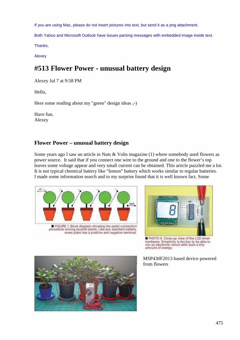
475
If you are using Mac, please do not insert pictures into text, but send it as a png attachment.
Both Yahoo and Microsoft Outlook have issues parsing messages with embedded image inside text.
Thanks,
Alexey
#513 Flower Power - unusual battery design
Alexey Jul 7 at 9:58 PM
Hello, Here some reading about my "green" design ideas ;-) Have fun, Alexey
Flower Power – unusual battery design Some years ago I saw an article in Nuts & Volts magazine (1) where somebody used flowers as power source. It said that if you connect one wire to the ground and one to the flower’s top leaves some voltage appear and very small current can be obtained. This article puzzled me a lot. It is not typical chemical battery like “lemon” battery which works similar to regular batteries. I made some information search and to my surprise found that it is well known fact. Some
MSP430F2013 based device powered from flowers

476
use trees instead of flowers and one guy even got patent for device which can charge mobile phone from a tree. But despite many people tried use this effect nobody really knows (or shares) why it really works. Only recently after building “gravity” battery I got idea how it works. Water while rising from the roots move also some ions and creates a concentration gradient. I don’t like idea of damaging flowers and trees (3) but similar process can be created artificially. So I built a “vaporization” battery.
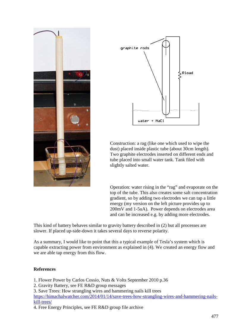
477
Construction: a rag (like one which used to wipe the dust) placed inside plastic tube (about 30cm length). Two graphite electrodes inserted on different ends and tube placed into small water tank. Tank filed with slightly salted water.
Operation: water rising in the “rag” and evaporate on the top of the tube. This also creates some salt concentration gradient, so by adding two electrodes we can tap a little energy (my version on the left picture provides up to 200mV and 1-5uA). Power depends on electrodes area and can be increased e.g. by adding more electrodes.
This kind of battery behaves similar to gravity battery described in (2) but all processes are slower. If placed up-side-down it takes several days to reverse polarity. As a summary, I would like to point that this a typical example of Tesla’s system which is capable extracting power from environment as explained in (4). We created an energy flow and we are able tap energy from this flow. References 1. Flower Power by Carlos Cossio, Nuts & Volts September 2010 p.36 2. Gravity Battery, see FE R&D group messages 3. Save Trees: How strangling wires and hammering nails kill trees https://himachalwatcher.com/2014/01/14/save-trees-how-strangling-wires-and-hammering-nails-kill-trees/ 4. Free Energy Principles, see FE R&D group file archive
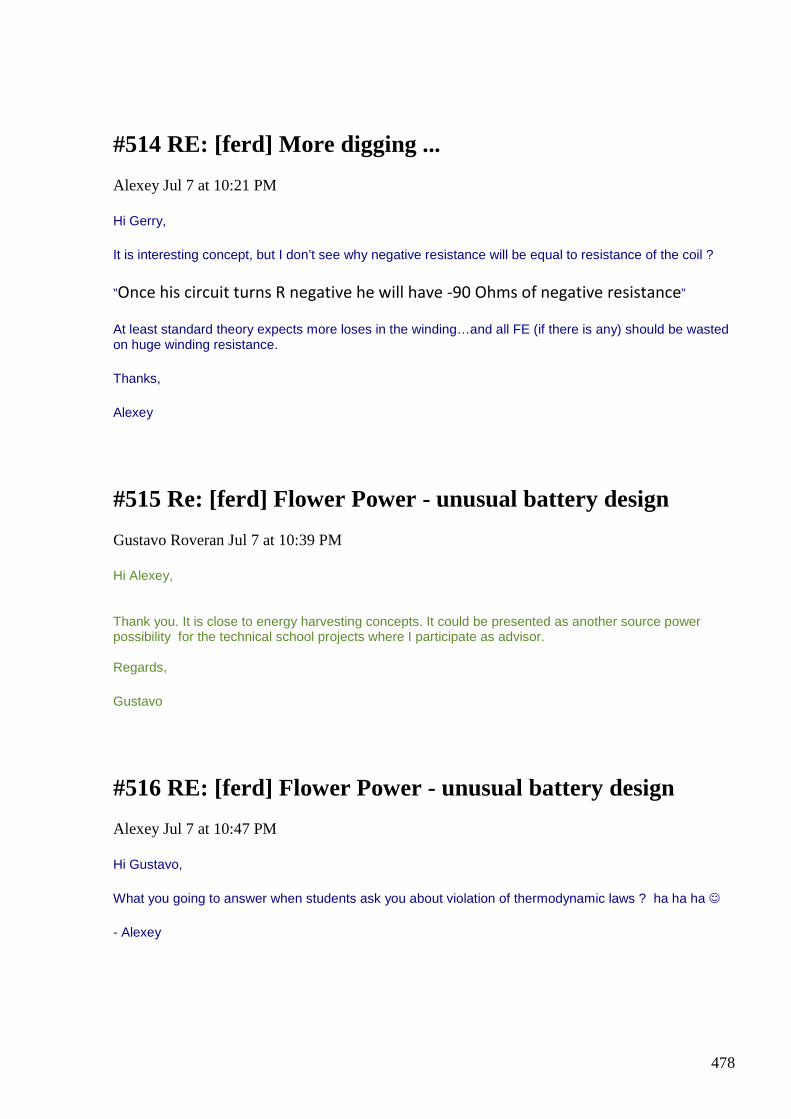
478
#514 RE: [ferd] More digging ...
Alexey Jul 7 at 10:21 PM
Hi Gerry,
It is interesting concept, but I don’t see why negative resistance will be equal to resistance of the coil ?
”Once his circuit turns R negative he will have -90 Ohms of negative resistance”
At least standard theory expects more loses in the winding…and all FE (if there is any) should be wasted on huge winding resistance.
Thanks,
Alexey
#515 Re: [ferd] Flower Power - unusual battery design
Gustavo Roveran Jul 7 at 10:39 PM
Hi Alexey, Thank you. It is close to energy harvesting concepts. It could be presented as another source power possibility for the technical school projects where I participate as advisor. Regards,
Gustavo
#516 RE: [ferd] Flower Power - unusual battery design
Alexey Jul 7 at 10:47 PM
Hi Gustavo,
What you going to answer when students ask you about violation of thermodynamic laws ? ha ha ha
- Alexey
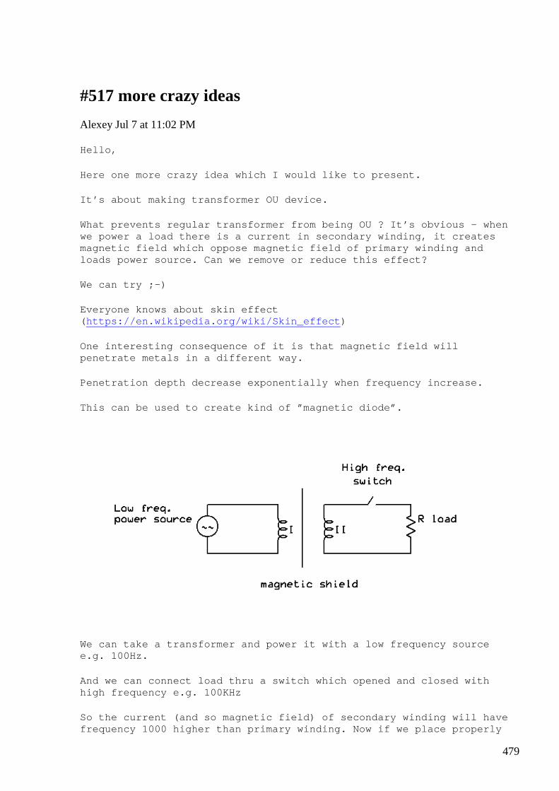
479
#517 more crazy ideas
Alexey Jul 7 at 11:02 PM
Hello,
Here one more crazy idea which I would like to pres ent.
It’s about making transformer OU device.
What prevents regular transformer from being OU ? I t’s obvious – when we power a load there is a current in secondary win ding, it creates magnetic field which oppose magnetic field of prima ry winding and loads power source. Can we remove or reduce this ef fect?
We can try ;-)
Everyone knows about skin effect ( https://en.wikipedia.org/wiki/Skin_effect )
One interesting consequence of it is that magnetic field will penetrate metals in a different way.
Penetration depth decrease exponentially when frequ ency increase.
This can be used to create kind of ”magnetic diode” .
We can take a transformer and power it with a low f requency source e.g. 100Hz.
And we can connect load thru a switch which opened and closed with high frequency e.g. 100KHz
So the current (and so magnetic field) of secondary winding will have frequency 1000 higher than primary winding. Now if we place properly

480
selected magnetic shield between winding, it will b e transparent for primary’s magnetic field but will stop secondary’s magnetic field, and load will not affect power source.
According to some rumors, this is how one of Andrei Melnichenko’s devices work. He used aluminum bear can as a shield .
Have fun,
Alexey ;-)
#518 Re: [ferd] More digging ...
Gustavo Roveran Jul 7 11:30 PM
Hi Alexey, Gerry, Andreas, Ole All
Thank you both, I am trying to return to the "road"...
"I not sure what you mean, lamp is shining near Tesla coil no mater how you take it, lamp from garbage bin BTW"
I made an experiment some years ago with a car coil instead of Tesla coil. When I used to take the lamp from its middle, the part that turns on was from the middle to the extreme closer to the car coil. However the real objective of that experiment was for Kirlian Camera, but I did not go on with that experiment.
"I never step away from it…just a little tired repeating again and again ”you need phase transition to get OU”
Would you mind explaining me, what is the theory o experience that drives you to advise us about phase transition is direct related to OU. Do you have different examples of phase transistion which we can focus our efforts. IMHO I think it is very important to present and to describe the different process that we have to take into account when we make FER experiments. For example, Alexey is talking about phase transition. But if some one knows other process, it would be interesting if you write and explain it. Then we can make a process list and try to align the FER experiment with the selected process from the list. Because if we do not walk towards a premise, we will be lost again in H universe or other X universe.
Andreas, you are making a very good research. Taking into account what I have expressed ¿what is your chosen process ?
Thanks All
Gustavo
#519 Re: [ferd] More digging ...
481
Andreas Höschler Jul 7 11:31 PM
Hi Gerry,
It is interesting concept, but I don’t see why negative resistance will be equal to resistance of the coil ?
”Once his circuit turns R negative he will have -90 Ohms of negative
resistance”
At least standard theory expects more loses in the winding…and all FE (if there is any) should be wasted on huge winding resistance.
I agree. This simply detunes the tank and prevents it from going into jump resonance mode.
If the phase angle is indeed > 90° then this is probably due to having the tank on a UDT (opposing flux). This might somehow do some magic we have no clue about.
Regards,
Andreas
#520 Re: [ferd] More digging ...
Andreas Höschler jul 8 at 12:02 AM
Hi Gerry,
Because if we do not walk towards a premise, we will be lost again in H universe or other X universe.
Andreas, you are making a very good research. Taking into account what I have expressed ¿what is your chosen process ?
I unfortunately got lost in the lab again, blindly digging around. That's not good. I just tried to add a simple diode plug to the tank and see what comes out. This of course just detuned the tank and got me a miserable COP. This makes no sense (is a waste of time). We have to adopt a very strict scientific process to get anywhere! :-(
Has anybody (except me partially) studied the work of Mr Distinti (www.distinti.com)? He derived the vector potential (not even calling it that) from close to nothing. This is actually very related to Alexeys last idea (skin effect). I will read that email now ...
Best wishes,
Andreas
482
#521 Re: [ferd] More digging ...
Andreas Höschler Jul 8 at 1:39 AM
Hi Gerry,
Andreas, you are making a very good research. Taking into account what I have expressed
¿what is your chosen process ?
I left the high VAR (ferro resonance) research once again. As soon as you try to extract something, the thing detunes and breaks down. I somehow doubt this will ever lead to anything. Just getting high VARs is not worth a penny (just fries your brain). Back to the blackboard and coming up with something totally different.
Alexey, how far did you get with your foil coils?
Best wishes,
Andreas
#522 Re: [ferd] More digging ...
Gerry Jul 8 at 1:41 AM
Hi Alexey,
In Andreas circuit design coil dc resistance becomes approx zero when FET's do coil
shorting trick.
Removing DC resistance from collapsing flux path.
So in my example original 90 + j90 becomes 0 + j 90 on discharge.
Hence discharge is minus the original 90 ohms.
It is also easier to short a large finite resistance than a small one.
In SFT transformers it's a bit more complicated.
But input output paths are also separated.
Gerry
483
#523 Re: [ferd] More digging ...
Gerry Jul 8 at 2:16 AM
Hi Alexey,
Maybe I can try explain better, the resistance doesn't actually become negative.
However it effectively becomes negative.
Because it is missing from the flux discharge path during a portion of the complete
charge discharge cycle.
Since Q value is energy stored / energy dissipated.
The real part of the tank impedance is represented by R and is the dissipative
element.
The imaginary part of the tank impedance is represented by +jX and is the storage
element.
Storage element is being discharged into very low real resistance path compared to
charge, compressing time constant.
By removing (shorting in this case) dissipative element on flux collapse, the phase of
the cycle where dissipative element acts shifts.
Moving the phase angle well past the 90 degree zone allowing Cos phi to go
negative, effectively changing circuit resistance.
Now I probably made it even more confusing, sorry
Gerry
#524 Re: [ferd] More digging ...
onielsen2000 Jul 8 at 2:37 AM
Hi Andreas, My answer and question didn't show up so here I go again.
484
"The blue curve is very symmetric. Note, demux and H-Bridge! The spikes you see are CEMF spikes. The fly-back pulses are comparatively calm and simply (part of them) go back into the power supply. The CEMF spikes are rather aggressive!" What I don't understand is why there are two frequencies involved on the primary winding (blue). There is the long on time following the FG positive signal (yellow) and then there is a complete cycle during the negative or zero level part of the FG signal. Is there some purpose for that? Scope shot image is attached and also inserted as a jpg-file after the message. If this is not made on purpose it would look like an LC-tank making a complete cycle but being limited by the voltage on the supply rails. The front (left) part of the positive short cycle looks like it tries to swing above the positive supply voltage and then discharges until the steady state supply voltage is reached. If this is the case the current is sent back into the voltage supply. This could be be tested by measuring the current in the supply rails. Perhaps try to measure the current between the high side switch and the decoupling capacitor if space permits this. Then it could be seen if the current is unidirectional or sloshes back into the capacitor and voltage supply. If the last is the case the current is reactive or partly reactive meaning the average of the current is zero or at least less than the RMS value of the current. This would also explain where the energy goes. Remember the reverse coupled parasitic diode inside all Power MOSFETs. This will start to conduct if trying to increase the output signal beyond the supply rails. Regards Ole
#525 Re: [ferd] More digging ...
onielsen2000 Jul 8 at 2:39 AM
forgot the attachment once again. Here it is.
/Ole
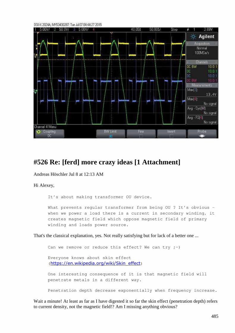
485
#526 Re: [ferd] more crazy ideas [1 Attachment]
Andreas Höschler Jul 8 at 12:13 AM
Hi Alexey,
It’s about making transformer OU device.
What prevents regular transformer from being OU ? I t’s obvious –
when we power a load there is a current in secondar y winding, it
creates magnetic field which oppose magnetic field of primary
winding and loads power source.
That's the classical explanation, yes. Not really satisfying but for lack of a better one ...
Can we remove or reduce this effect? We can try ;-)
Everyone knows about skin effect
( https://en.wikipedia.org/wiki/Skin_effect)
One interesting consequence of it is that magnetic field will
penetrate metals in a different way.
Penetration depth decrease exponentially when frequ ency increase.
Wait a minute! At least as far as I have digested it so far the skin effect (penetration depth) refers to current density, not the magnetic field!? Am I missing anything obvious?
486
This can be used to create kind of ”magnetic diode” .
We can take a transformer and power it with a low f requency
source e.g. 100Hz.
And we can connect load thru a switch which opened and closed
with high frequency e.g. 100KHz
So the current (and so magnetic field) of secondary winding will
have frequency 1000 higher than primary winding. No w if we place
properly selected magnetic shield between winding, it will be
transparent for primary’s magnetic field but will s top
secondary’s magnetic field, and load will not affec t power
source.
According to some rumors, this is how one of Andrei Melnichenko’s
devices work. He used aluminum bear can as a shield .
Please exactly define magnetic shield! Winding alum foil around the primary and letting the layers touch each other would just constitute a shorted one turn and cook the thing to death. So I assume you isolate the alum foil layers from each other to prevent the short. But what effect do you expect from this then??
Thanks,
Andreas
#527 Re: [ferd] More digging ...
Andreas Höschler Jul 8 at 2:45 AM
Hi Ole,
My answer and question didn't show up so here I go again. "The blue curve is very symmetric. Note, demux and H-Bridge! The spikes you see are CEMF spikes. The fly-back pulses are comparatively calm and simply (part of them) go back into the power supply. The CEMF spikes are rather aggressive!" What I don't understand is why there are two frequencies involved on the primary winding (blue). There is the long on time following the FG positive signal (yellow) and then there is a complete cycle during the negative or zero level part of the FG signal. Is there some purpose for that? Scope shot image is attached and also inserted as a jpg-file after the message. If this is not made on purpose it would look like an LC-tank making a complete cycle but being limited by the voltage on the supply rails. The front (left) part of the positive short cycle looks like it tries to swing above the positive supply voltage and then discharges until the steady state supply voltage is reached. If this is the case the current is sent back into the voltage supply. This could be be tested by measuring the current in the supply rails. Perhaps try to measure the current
487
between the high side switch and the decoupling capacitor if space permits this. Then it could be seen if the current is unidirectional or sloshes back into the capacitor and voltage supply. If the last is the case the current is reactive or partly reactive meaning the average of the current is zero or at least less than the RMS value of the current. This would also explain where the energy goes. Remember the reverse coupled parasitic diode inside all Power MOSFETs. This will start to conduct if trying to increase the output signal beyond the supply rails.
• Upper left and lower right H-Bridge MOSFETs are switched ON (duty cycle 60%), we see positive voltage on the primary.
• The MOSFETs are switched off and fly-back spike drives the voltage over the primary negative. This takes a while.
• Then via transforming effect (the tank is doing sinusoidal stuff) the primary voltage is made positive again until
• the lower left and upper right MOSFETs of the bridge are switched on to begib the second half of a complete cycle
It's simple transformer effect (tank -> primary) that puzzles you!? Does this make sense?
Best wishes,
Andreas
#528 Re: more crazy ideas
onielsen2000 Jul 8 at 2:51 AM
Hi Alexey, I don't think this would work as both the primary and the secondary uses the field in the same core thus anything showing up in one winding is also seen in the other winding. The signals just follow the windings ratio. If shielded the windings won't see each other and the transformer action is lost in both directions. A ferro resonant voltage regulating transformer is shielded until the voltage is high enough to saturate the magnetic shunt (shield) to diverge the magnetic field which then holds the voltage at the desired level. Regards Ole
488
#529 Next Steps ...
Andreas Höschler Jul 8 at 2:52 AM
Hi All,
I have prepared a site with a couple of ideas I currently consider worthwhile to check out:
http://www.advanced-science.com/NextSteps.html
Hints greatly appreciated! Let's brainstorm a bit before wasting time in the lab! :-)
Thanks,
Andreas
#530 Re: [ferd] More digging ...
onielsen2000 Jul 8 at 3:03 AM
Hi Andreas, "It's simple transformer effect (tank -> primary) that puzzles you!? Does this make sense?" That was my first thought and the answer then to where the energy goes is that is reflects back into the voltage supply. This should be measurable as current traveling in both directions instead of only traveling from the supply to the H-bridge LC-tank set up. If measuring the power it will will be seen as reactive power. Regards Ole
#531 Re: [ferd] More digging ...
Andreas Höschler Jul 8 at 3:11 AM
Hi Ole,
"It's simple transformer effect (tank -> primary) that puzzles you!? Does this make sense?"
That was my first thought and the answer then to where the energy goes is that is reflects back into the voltage supply. This should be measurable as current traveling in both directions instead of only traveling from the supply to the H-bridge LC-tank set up. If measuring the power it will will be seen as reactive power.

489
I don't agree. I have a huge cap bank between the DC power supply and the H-Bridge. Some energy might be back transferred from the primary to this cap bank to be re-injected again with the next pulse ... but the thing was definitely consuming 100W of real power (netto). And nothing got hot!? Still a miracle for me!
I have a bit of a headache right now and hope it's only the heat outside and lack of sleep, not the effect of this device toasting my brain. I better rest this case/device for a while and try something else (less radiative)! :-(
Thanks,
Andreas
#532 RE: [ferd] More digging ...
Alexey Jul 8 at 9:12 AM
Hi Andreas,
” Alexey, how far did you get with your foil coils? ”
not so far actually. I see that it is ”promising” but construction/design difficulties also high. I haven’t done much experiments in this direction…
Regards,
Alexey
#533 RE: [ferd] More digging ...
Alexey Jul 8 at 9:12 AM
Hi Gustavo,
Well, what can I say… It seems that there is some kind of psychological block which prevents people even from reading these explanations about OU principles.
I am attaching a document which I made several years ago and posted already many times.
If you don’t ”want” read it all, check page 6 and 7… and if you don’t understand something, please ask. We will have a chance improve explanations
Regards,
Alexey

490
#534 RE: [ferd] Re: more crazy ideas
Alexey Jul 8 at 9:27 AM
Hi Ole,
This setup requires some special core and coils arrangement. And I think it is possible to have such arrangement when secondary ”see” primary’s field but not vice versa.
I will make a picture and post it later.
Regards,
Alexey
#535 RE: [ferd] more crazy ideas
Alexey Jul 8 at 9:27 AM
Hi Andreas,
Magnet shields works because alternating magnetic field induce currents in the shield material and these currents produce magnetic field which oppose to original one.
(see here two types of shields, I am referring to second one https://en.wikipedia.org/wiki/Electromagnetic_shielding)
Regards,
Alexey
#536 RE: [ferd] More digging ...
Alexey Jul 8 at 9:29 AM
Hi Gerry,
Sorry, it is confusing
We probably need to start drawing vector diagrams…
Thanks,
Alexey
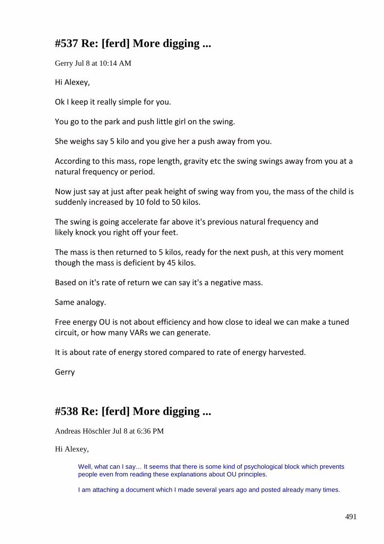
491
#537 Re: [ferd] More digging ...
Gerry Jul 8 at 10:14 AM
Hi Alexey,
Ok I keep it really simple for you.
You go to the park and push little girl on the swing.
She weighs say 5 kilo and you give her a push away from you.
According to this mass, rope length, gravity etc the swing swings away from you at a
natural frequency or period.
Now just say at just after peak height of swing way from you, the mass of the child is
suddenly increased by 10 fold to 50 kilos.
The swing is going accelerate far above it's previous natural frequency and
likely knock you right off your feet.
The mass is then returned to 5 kilos, ready for the next push, at this very moment
though the mass is deficient by 45 kilos.
Based on it's rate of return we can say it's a negative mass.
Same analogy.
Free energy OU is not about efficiency and how close to ideal we can make a tuned
circuit, or how many VARs we can generate.
It is about rate of energy stored compared to rate of energy harvested.
Gerry
#538 Re: [ferd] More digging ...
Andreas Höschler Jul 8 at 6:36 PM
Hi Alexey,
Well, what can I say… It seems that there is some kind of psychological block which prevents people even from reading these explanations about OU principles.
I am attaching a document which I made several years ago and posted already many times.

492
If you don’t ”want” read it all, check page 6 and 7… and if you don’t understand something, please ask. We will have a chance improve explanations
Thanks a lot for this doc. Still reading ...
Andreas
#539 Re: [ferd] more crazy ideas
Andreas Höschler Jul 8 at 6:42 PM
Hi Alexey,
Magnet shields works because alternating magnetic field induce currents in the shield material and these currents produce magnetic field which oppose to original one.
And this opposing field effects both, the primary on one side and the secondary on the other. If you allow current, you actually have a short (eddy currents), Lenz Law, back-reflection to the primary and thus high input current. I can't see how this could effect one winding but not the other!?
Andreas
#540 RE: [ferd] Next Steps ...
Alexey Jul 8 at 7:20 PM
Hi Andreas,
About second picture on your page: This picture from H. presents”low tech” sketch for Gray (Tesla) circuit.
I think it is very interesting but also very challenging research area. It involves high voltage, very short pulses, possible neutron and other dangerous emissions and requires special discharge tubes to get high power output. There is no doubt that it will work if one manage to get everything correct.
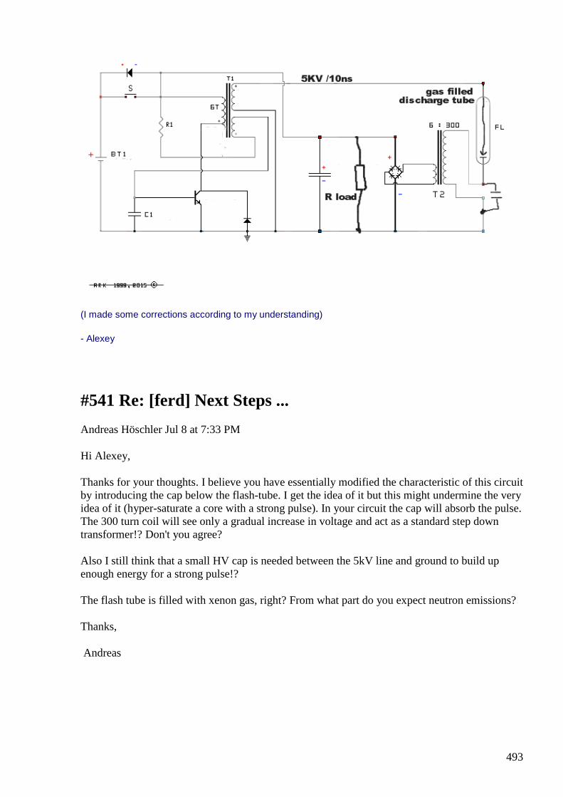
493
(I made some corrections according to my understanding)
- Alexey
#541 Re: [ferd] Next Steps ...
Andreas Höschler Jul 8 at 7:33 PM
Hi Alexey,
Thanks for your thoughts. I believe you have essentially modified the characteristic of this circuit by introducing the cap below the flash-tube. I get the idea of it but this might undermine the very idea of it (hyper-saturate a core with a strong pulse). In your circuit the cap will absorb the pulse. The 300 turn coil will see only a gradual increase in voltage and act as a standard step down transformer!? Don't you agree?
Also I still think that a small HV cap is needed between the 5kV line and ground to build up enough energy for a strong pulse!?
The flash tube is filled with xenon gas, right? From what part do you expect neutron emissions?
Thanks,
Andreas
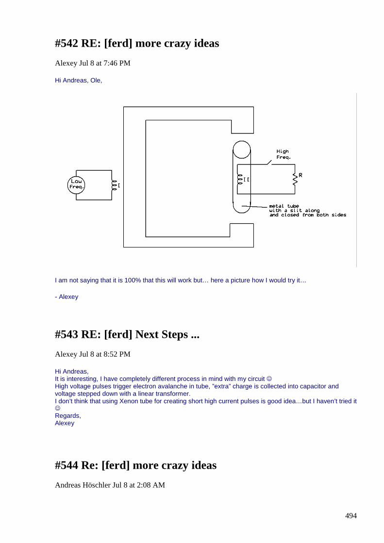
494
#542 RE: [ferd] more crazy ideas
Alexey Jul 8 at 7:46 PM
Hi Andreas, Ole,
I am not saying that it is 100% that this will work but… here a picture how I would try it…
- Alexey
#543 RE: [ferd] Next Steps ...
Alexey Jul 8 at 8:52 PM
Hi Andreas, It is interesting, I have completely different process in mind with my circuit High voltage pulses trigger electron avalanche in tube, ”extra” charge is collected into capacitor and voltage stepped down with a linear transformer. I don’t think that using Xenon tube for creating short high current pulses is good idea…but I haven’t tried it Regards, Alexey
#544 Re: [ferd] more crazy ideas
Andreas Höschler Jul 8 at 2:08 AM
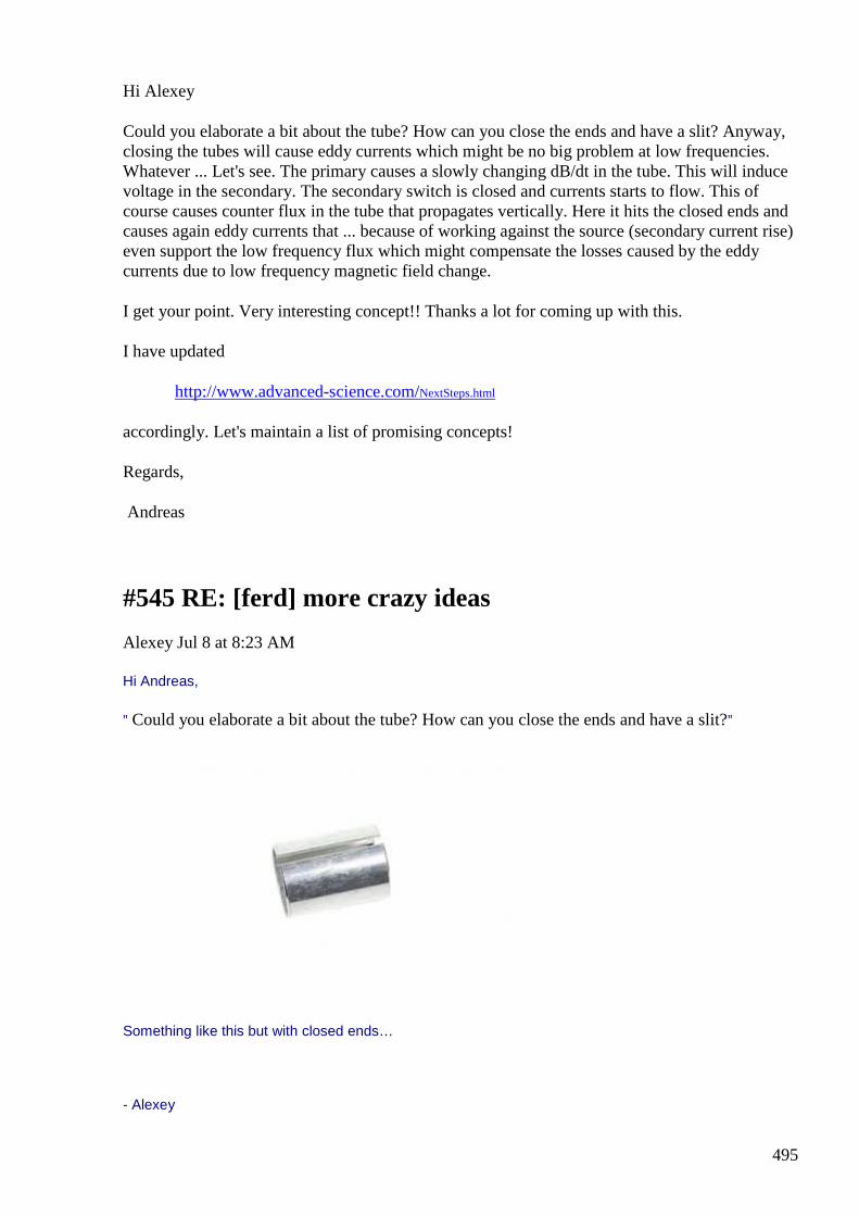
495
Hi Alexey
Could you elaborate a bit about the tube? How can you close the ends and have a slit? Anyway, closing the tubes will cause eddy currents which might be no big problem at low frequencies. Whatever ... Let's see. The primary causes a slowly changing dB/dt in the tube. This will induce voltage in the secondary. The secondary switch is closed and currents starts to flow. This of course causes counter flux in the tube that propagates vertically. Here it hits the closed ends and causes again eddy currents that ... because of working against the source (secondary current rise) even support the low frequency flux which might compensate the losses caused by the eddy currents due to low frequency magnetic field change.
I get your point. Very interesting concept!! Thanks a lot for coming up with this.
I have updated
http://www.advanced-science.com/NextSteps.html
accordingly. Let's maintain a list of promising concepts!
Regards,
Andreas
#545 RE: [ferd] more crazy ideas
Alexey Jul 8 at 8:23 AM
Hi Andreas,
” Could you elaborate a bit about the tube? How can you close the ends and have a slit?”
Something like this but with closed ends…
- Alexey
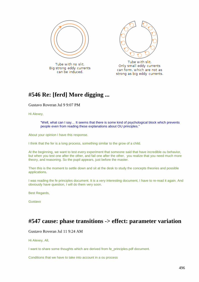
496
#546 Re: [ferd] More digging ...
Gustavo Roveran Jul 9 9:07 PM
Hi Alexey,
"Well, what can I say… It seems that there is some kind of psychological block which prevents people even from reading these explanations about OU principles."
About your opinion I have this response.
I think that the fer is a long process, something similar to the grow of a child.
At the beginning, we want to test every experiment that someone said that have incredible ou behavior, but when you test one after the other, and fail one after the other, you realize that you need much more theory, and reasoning. So the pupil appears, just before the master.
Then this is the moment to settle down and sit at the desk to study the concepts theories and possible applications.
I was reading the fe principles document. It is a very interesting document, I have to re-read it again. And obviously have question, I will do them very soon.
Best Regards,
Gustavo
#547 cause: phase transitions -> effect: parameter variation
Gustavo Roveran Jul 11 9:24 AM
Hi Alexey, All,
I want to share some thoughts which are derived from fe_principles.pdf document.
Conditions that we have to take into account in a ou process
497
1) A field have to be present
2) An essential parameter variation in the system
3) The parameter variation has to have at least two states, one of the state has to differ with the other in relation to the interaction with the field
4) The energy used to produce the parameter variation, has to come from Nature / Ambient or has to be less than the energy obtained from the interaction with the field thanks to the parameter variation.
I understand that phase transition is one of the possible causes which produce a parameter variation effect. For example the water phase transition from liquid to gas, produce the a parameter variation called density. And electrolysis is the cause of the same effect, but in this case the gas is also a combustible.
I think that the brainstorming now would be to propose different essential parameters that apply with point 3 and 4, but at the same time, have to describe what processes would be used to generate its variation.
If we could not still find a way to produce ou energy yet, was because we could not find response to "my" last paragraph.
What are you opinion ?
Regards,
Gustavo
PD1: What is the meaning of 3, 6 and 9 which Tesla talk about?
PD2: Electric field ionization example would be used without fun, with a different HF system topology. Based on the HV lifter effect.
#548 RE: [ferd] cause: phase transitions -> effect: parameter variation
Alexey Jul 12 at 11:02 PM
Hi Gustavo,
Most of my ”crazy ideas” are different application of this OU principle, so they are not so crazy… but to get from idea to working device some engineering work required
I am glad that you read it, hope others will follow your example.
Regards,
Alexey
#549 Re: [ferd] cause: phase transitions -> effect: parameter variation
498
Andreas Höschler Jul 12 11:11 PM
Hi Alexey,
Most of my ”crazy ideas” are different application of this OU principle, so they are not so crazy… but to get from idea to working device some engineering work required
I am glad that you read it, hope others will follow your example
I have/had read it as well, just had no chance for a significant reply. Thanks for this paper. I have found nothing in it that can readily be applied. But it illustrates the principles quite well.
I just followed the auto transformer route of Hector trying to understand what happens when we short the CEMF in extra coils. No miracles so far …
Best wishes,
Andreas
#550 Re: [ferd] cause: phase transitions -> effect: parameter variation
Andreas Höschler Jul 14 at 1:06 AM
Hi Alexey, I have played around a bit with your secondary shielding idea (taking out energy with high freq pulses)! No luck! :-( Regards, Andreas
#551 RE: [ferd] cause: phase transitions -> effect: parameter variation
Alexey Jul 14 at 8:25 AM
Hi Andreas,
I think that as any new concept this require a little more than just ”playing around” ;-)
Anyway, thanks for looking into this. Perhaps you post some info what you have tried ?
Regards,
Alexey
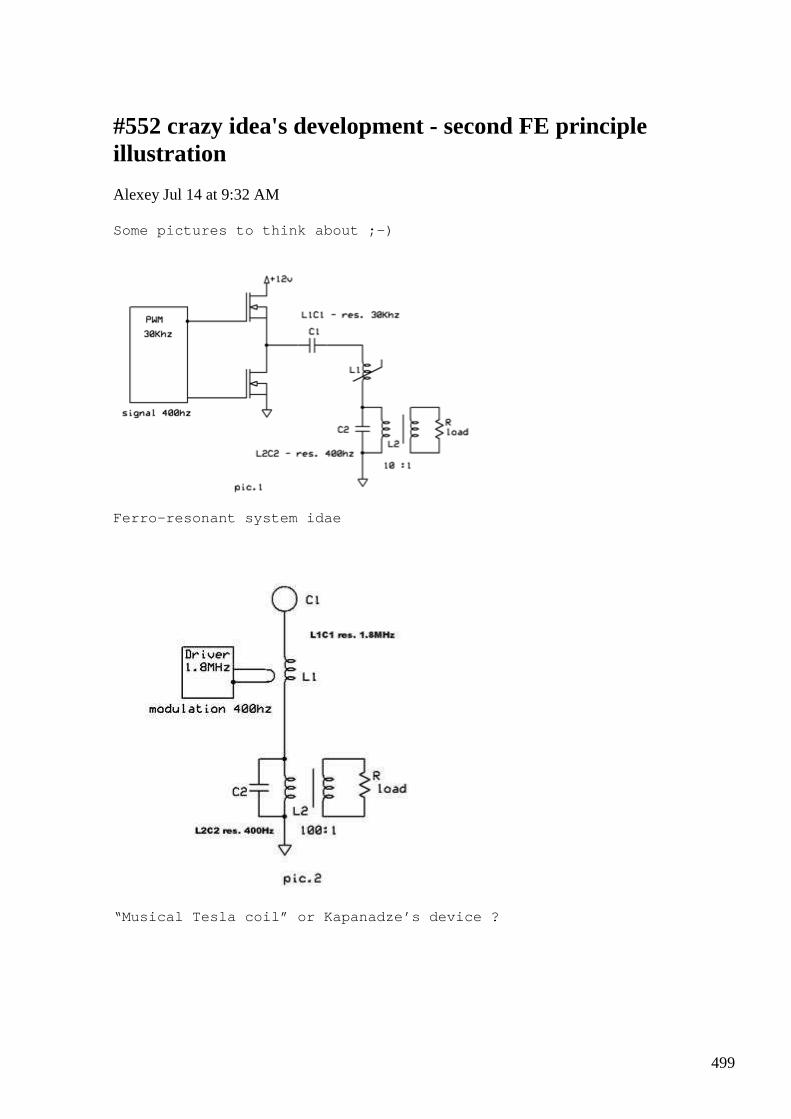
499
#552 crazy idea's development - second FE principle illustration
Alexey Jul 14 at 9:32 AM
Some pictures to think about ;-)
Ferro-resonant system idae
“Musical Tesla coil” or Kapanadze’s device ?
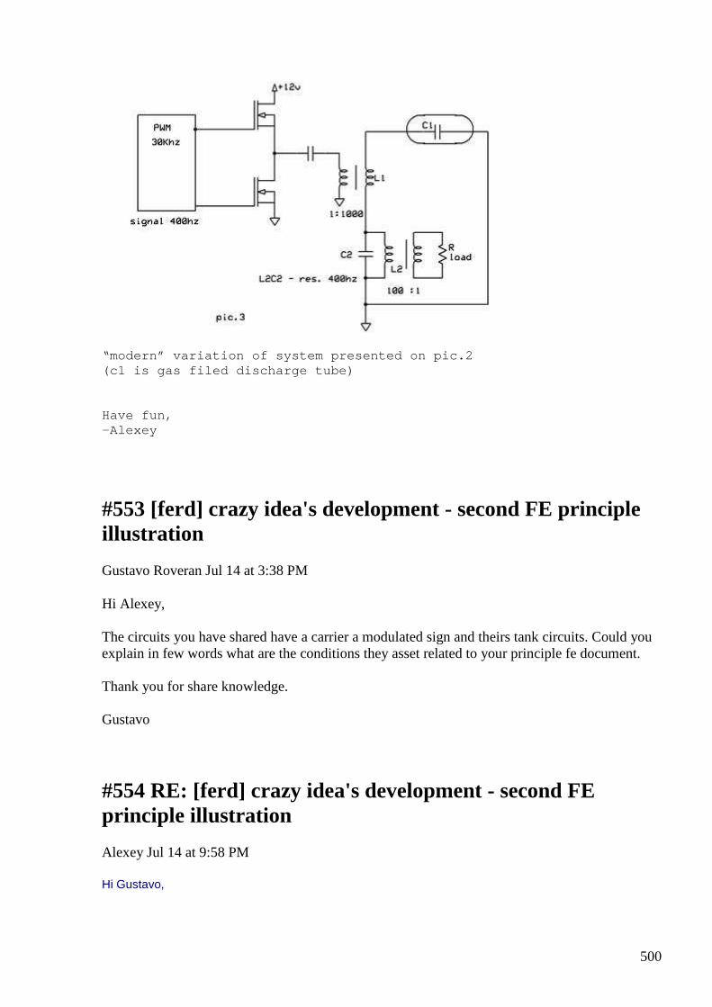
500
“modern” variation of system presented on pic.2 (c1 is gas filed discharge tube) Have fun, -Alexey
#553 [ferd] crazy idea's development - second FE principle illustration
Gustavo Roveran Jul 14 at 3:38 PM
Hi Alexey, The circuits you have shared have a carrier a modulated sign and theirs tank circuits. Could you explain in few words what are the conditions they asset related to your principle fe document. Thank you for share knowledge. Gustavo
#554 RE: [ferd] crazy idea's development - second FE principle illustration
Alexey Jul 14 at 9:58 PM
Hi Gustavo,
501
All three schematics use both first and second (synergetic) principles.
They consist of two LC tanks. One has relatively high frequency and contains non-linear component (this is where FE come from).
Second LC circuit used to store and ”multiply” what is obtained in first LC circuit.
If first LC circuit would be linear, there will be no oscillations on second LC circuit. No mater how strongly you load second LC circuit it will not affect HF power source.
If you remember H. was talking something about such system, but never give normal explanations. Also Albert was wondering abound low frequency oscillations in his transverter but never managed to move forward away from H. “design”.
Hope this helps
Alexey
#555 [ferd] crazy idea's development - second FE principle illustration
Gustavo Roveran Jul 15 3:14 AM
Hi Alexey, Could you be more specific? For example, I think that this is what I could understand, Second principle The non linear element are dielectric within the capacitor and the ferromagnetic within the coil First principle Parameter variation like permittivity and permeability ought to fields variations in a non linear medium. Do you think that these circuits could work with air coil and air capacitor? While I was in H transverter's era I used to understand that the core over saturation ( when the peak current appear) produced the permeability variation, not only because of saturation but because of mater distortion ought to the rapid and abruptly change of magnetic field. ( magnetostriction ) This link is in the fe_principle doc but it doesn't work. http://www.youtube.com/watch?v=XaaP1bWFjDA#t=2680 Take care
Gustavo
502
#556 RE: [ferd] crazy idea's development - second FE principle illustration
Alexey Jul 15 8:37 AM
Hi Gustavo,
please see my comments below
-Alexey
From: [email protected] [mailto: [email protected] ]
Sent: Wednesday, July 15, 2015 2:15 AM To: ferd
Subject: [ferd] crazy idea's development - second FE principle illustration [3 Attachments]
Hi Alexey, Could you be more specific? I think I am too specific…thousands of pages of information were posted in last two years
For example, I think that this is what I could understand, Second principle The non linear element are dielectric within the capacitor and the ferromagnetic within the coil I would say at some conditions 1+1=4
First principle Parameter variation like permittivity and permeability ought to fields variations in a non linear medium. I would say – phase transition makes object ”invisible” to the field
Do you think that these circuits could work with air coil and air capacitor? ionization of the air can give “non linear” capacitor
While I was in H transverter's era I used to understand that the core over saturation ( when the peak current appear) produced the permeability variation, not only because of saturation but because of mater distortion ought to the rapid and abruptly change of magnetic field. ( magnetostriction ) Magnetization-demagnetization is a quantum phase transition.
If you remember my experiments with core tracer you will see ”signs of FE” there…
This link is in the fe_principle doc but it doesn't work. http://www.youtube.com/watch?v=XaaP1bWFjDA#t=2680
503
This was a MIT lecture where professor Lewin demonstrates electrostatic charging. By some reason they closed access to the videos…probably want more money, what a nice example of open sourcing. I have video in my file archive, it’s about 4Gb. But at the end the were not many interesting things, professor acts often like a clown and admit it himself
Take care Gustavo
#557 [ferd] crazy idea's development - second FE principle illustration
Gustavo Roveran Jul 15 8:23 PM
Hi Alexey, First of all thanks again and for your patient. I do not want you to get uncomfortable because of my need about more specific explanation. But lot of información and knowledge we have and you shared, which it suppose would drive us to a ou application, didn't come true. So I need you describe your thoughts about each part of your circuit to assure me if i am thinking the same point of view. IMHO I have to say that one of the better achievement you have shared, was the core trace about magnetization and demagnetization experiment which agree with Zaev theory. Zaev was the first scientific I found at the beginning of my research who encourage towards transverter experiment. This was at least 10 years ago. However none of us were able to implement an application or device based in that theory yet. I want to make an experiment where after feeding a primary with a pulse, then shortcircuit it immediately in a way that, the secondary's bemf, rebound in the short circuited primary, until all that energy be consumed, to start again the process. Did you test something similar? The first problem seems to be time. Regards Gustavo
#558 RE: [ferd] crazy idea's development - second FE principle illustration
Alexey Jul 15 9:23 PM
Hi Gustavo,
504
” This was at least 10 years ago. However none of us were able to implement an application or device based in that theory yet.”
It could be that special material needed and it will not work with ferrite available for us. But the idea in general is correct. I also realized at some point that this is quite advanced system, and it can be achieved only step by step, starting from simpler systems and developing them and learning from that process. You can’t build a supersonic jet before you know how to build simple plane with propeller
” I want to make an experiment where after feeding a primary with a pulse, then shortcircuit it immediately in a way that, the secondary's bemf, rebound in the short circuited primary, until all that energy be consumed, to start again the process. Did you test something similar? The first problem seems to be time.”
Yes, I made such experiments and results were posted here. I think also Andreas just did something like this recently. It is educational but...its unlikely that it will work as you describe it.
Regards, Alexey
#559 RE: [ferd] crazy idea's development - second FE principle illustration
onielsen2000 Jul 16 at 1:01 AM
Hi Alexey, The reason for removing professor Lewin's videos are here: Despite M.I.T.'s decision to delete, Walter Lewin's lecture videos live on | InsideHigherEd
Despite M.I.T.'s decision to delete, Walter Lewin... Since the Massachusetts Institute of
Technology in December cut ties with him over
its finding that he had engaged in online sexual
harassment, former phy...
View on www.insidehighered...
Preview by
Yahoo
505
https://www.insidehighered.com/news/2015/03/10/despite-mits-decision-delete-walter-lewins-lecture-videos-live
Lewin's Legacy March 10, 2015 By Carl Straumsheim
Since the Massachusetts Institute of Technology in December cut ties with him over its finding that he had engaged in online sexual harassment, former physics professor Walter H. G. Lewin has focused on his legacy, not litigation.
Lewin, who turned 79 in January, still personally challenges the harassment claims brought to M.I.T. by a learner in a massive open online course he taught in fall 2013 but is not preparing to challenge the institute, according to an e-mail he sent to a former fan. Lewin is instead working to make sure his video lectures live on, in some cases asking fans to compile and share the clips on platforms such as Facebook and YouTube.
The institute in December stripped Lewin of his emeritus title and removed his lectures from M.I.T. OpenCourseWare, a repository of free educational content, to "help prevent further harassment." M.I.T. justified the removal by saying the courses “presented a [real] danger for people... expecting a student-teacher relationship and getting something that was inappropriate.”
A spokeswoman for M.I.T. did not respond to a request for comment. Speaking to Inside Higher Ed in January, Provost Martin A. Schmidt said the institute did not know if Lewin was communicating with former students, but that it had “closed the communication channels through M.I.T.”
The principles behind OpenCourseWare -- “delivering on the promise of open sharing of knowledge” -- are now ensuring that students have multiple ways of accessing Lewin’s video lectures. The content on OpenCourseWare is made available under a Creative Commons license, meaning users are free to share and adapt it for noncommercial purposes as long as they “give appropriate credit.”
M.I.T.’s decision to remove the videos has some physics students and scholars crying censorship, and has renewed the debate about if -- or to what extent -- a celebrity’s actions outside the spotlight should tarnish his professional achievements. Some view Lewin’s lectures as a crucial resource for learning physics, regardless of the creator’s personal life. Others have been unable to disconnect them from the man who, according to M.I.T.’s investigation, “engaged in online sexual harassment” of several women.
A summary of those competing arguments can be seen in two comments posted in response to Inside Higher Ed’s article explaining the details behind M.I.T.’s decision:
“I think that before any of us turns to Lewin’s videos or recommends them to others, we ought to consider what it means for the physics community to champion him as a great educator,” one commenter wrote. “Lewin violated a fundamental social contract between teacher and student.... I agree that Lewin's personal conduct has no bearing on his physics research, but his offenses are of the sort that should disqualify anyone from being considered a great educator.”
Those who oppose taking the videos down, meanwhile, often bring up the transgressions of other famous scientists. “I don’t care that Newton was a petty asshole, an alchemist and a religious nut; I don’t care that Feynman was misogynist; I don’t care that Heisenberg worked for the
506
Nazis; and I don’t care about Lewin either,” another commenter wrote. “I care about their knowledge that they gave to the world. I am not responsible for their lives, that’s their goddamn headache, but don’t punish me for their sins by restricting my access to their material.”
Harvey A. Silverglate, Lewin’s lawyer, declined on behalf of his client to discuss the First Amendment implications of M.I.T. deleting the videos. Silverglate cofounded and serves as chairman of the board of directors for the Foundation for Individual Rights in Education, an organization that advocates for free speech at colleges and universities.
Despite M.I.T.’s actions, the videos are still only a search away. Web sites that hosted the videos before the institute took them down remain unaffected, and over the last three months, YouTube channels such as For the Allure of Physics and Lectures by Walter Lewin. They Will Make You ♥ Physics, among others, have sprung up. The former, launched a day after M.I.T. announced it had removed Lewin’s lectures, has more than 3,000 subscribers and 98 videos. By crediting the institute, explaining any edits and publishing the videos under the same license as OpenCourseWare, the channels are free to operate.
Lewin’s videos have also long been popular in Facebook groups generally related to physics or, in some cases, created as fan clubs. Before he left social media as details of the sexual harassment case became public, Lewin participated in some of those groups.
Even though he is no longer active on Facebook, Lewin has been in touch with at least one administrator behind one of the groups.
Todd L. Giroux, a Los Angeles-based photographer, founded the Facebook group For the Love of Physics -- also the title of Lewin’s 2011 book -- in 2012. He dedicated the group to a handful of researchers and professors, including Lewin, whose videos he said “completely changed how I looked at the world.” The group now has more than 1,200 members.
The videos made Lewin seem like “such a nice professor that is willing to help out all the time,” Giroux, 39, said in an interview. But after forming a friendship with the professor, Giroux said he noticed Lewin sometimes acted “cold and rude” -- particularly in response to students giving incorrect answers.
Lewin joined For the Love of Physics and soon assumed an administrative role, at times telling Giroux to add new members or kick others out, threatening to leave if Giroux didn’t follow through. “I dedicated the page to him and I learned so much, so I might as well help out as much as I can so he doesn’t leave,” Giroux said of his mind-set at the time.
“I looked at him like a father figure,” Giroux said. “I felt like he manipulated the situation for me to do it. He knew I had a soft spot for him.”
Lewin’s activity in the group was punctuated with the occasional break, Giroux said, but he vanished completely from social media in fall 2014 as M.I.T. began investigating the sexual harassment claims. Then, last month, Lewin resurfaced in an e-mail from a private account, asking Giroux to post a link to a YouTube channel to a handful of Facebook groups, including For the Love of Physics.
Giroux obliged, but said he challenged Lewin to be honest about the sexual harassment case. In an e-mail response obtained by Inside Higher Ed whose authenticity Giroux confirmed, Lewin described M.I.T.’s actions as “irrational and illogical” and said that the institute deleted his videos “for PR reasons” and that none of the accusations against him are substantiated. He has
507
since been advised to "lie low and let it all pass," Giroux said. Lewin did not respond to multiple requests to comment about the allegations in January.
When Giroux learned the full details of the case, however, he said he felt he had been “taken advantage of.” Last week, he posted an apology to For the Love of Physics, saying “those lectures will never be posted on OUR group page in the future again.”
“I gave him a chance to tell me what happened... but he tried saying it was a misunderstanding,” Giroux said. “That’s the part where I completely lost all trust in him. It was hard for me to see that caring professor anymore. I can’t even watch the lectures, because that person is not who that person is.”
#560 [ferd] crazy idea's development - second FE principle illustration
Gustavo Roveran Jul 16 at 6:10 AM
Hi Ole I don't known if it is true or not. But in this system, when they want to discredit someone. They accustomed to charge with a sexual cause against that person. Thank you for the research. Gustavo
#561 RE: [ferd] crazy idea's development - second FE principle illustration
Alexey Jul 16 at 8:11 AM
Hi Ole,
Thanks for this information.
It is amazing why would any reasonable man do such things…but anyway, Gustavo you can watch now how electrostatic charging works
Thanks,
Alexey
#562 [ferd] crazy idea's development
Alexey Jul 16 at 8:37 AM
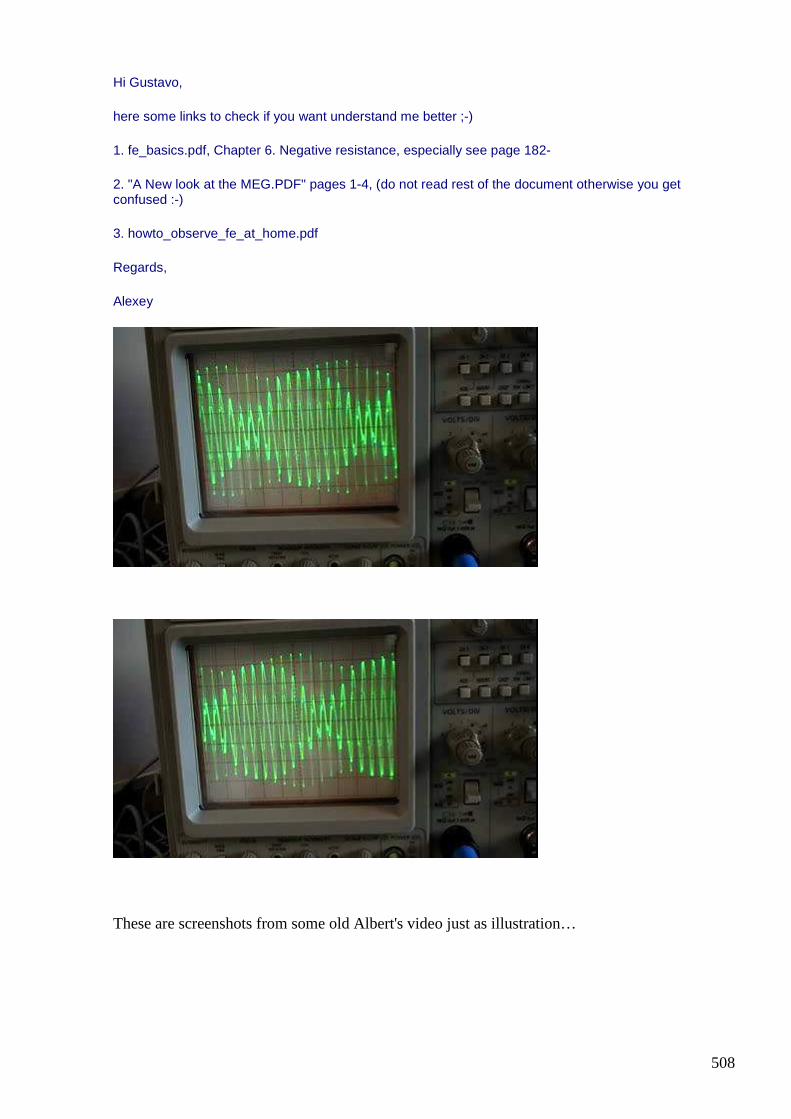
508
Hi Gustavo,
here some links to check if you want understand me better ;-)
1. fe_basics.pdf, Chapter 6. Negative resistance, especially see page 182-
2. "A New look at the MEG.PDF" pages 1-4, (do not read rest of the document otherwise you get confused :-)
3. howto_observe_fe_at_home.pdf
Regards,
Alexey
These are screenshots from some old Albert's video just as illustration…

509
#563 [ferd] crazy idea's development
Gustavo Roveran Jul 16 10:06 PM
Hi Alexey Thank you for your effort to join all these information. Homework to do now. I remember the Roseiro's screen shot from his experiment about parametric resonance. Did you buy Gadolinium? I have a 100 w peltier. About torsion measure. I am going to add the msgeq7 ic at the output of the Hodowanec circuit. I have to implement it with Arduino to read the equalizer ic output. Best Regards Gustavo
#564 RE: [ferd] crazy idea's development
Alexey Jul 16 10:25 PM
Hi Gustavo,
”Did you buy Gadolinium?” not yet, may be later.
I remember the Roseiro's screen shot from his experiment about parametric resonance.
these shots taken with a regular TV setup!
Regards,
Alexey
#565 [ferd] crazy idea's development
Gustavo Roveran Jul 17 at 1:11 AM
Hi Alexey, "these shots taken with a regular TV setup!" Yes I remember, I used to be in touch with him doing the same chaos resonance TV system (am fm) there is a frequency that fire that state. But not OU in my case. https://m.youtube.com/watch?v=nBlrYSvb8VY Sorry it is not so professional. Regards Gustavo

510
#566 RE: [ferd] crazy idea's development
Alexey Jul 17 at 8:43 AM
Hi Gustavo,
It is nice video. Now my idea is that if you add second LC tuned to this low frequency (”am fm modulation”) you will have better chance to see OU.
Instead of extracting energy on every cycle you will be collecting it in this additional LC circuit, so if you have e.g. 30khz driver frequency and got oscillations on 1khz
”free” energy from 30 cycles will be collected in one cycle of extraction circuit and this ratio can be increased by changing frequencies.
That’s idea behind that schematics I posted recently. Does it make sense?
Regards,
Alexey
#567 Re: [ferd] crazy idea's development
Andreas Höschler Jul 17 at 3:57 PM
Hi Alexey,
It is nice video. Now my idea is that if you add second LC tuned to this low frequency (”am fm modulation”) you will have better chance to see OU.
Instead of extracting energy on every cycle you will be collecting it in this additional LC circuit, so if you have e.g. 30khz driver frequency and got oscillations on 1khz
”free” energy from 30 cycles will be collected in one cycle of extraction circuit and this ratio can be increased by changing frequencies.
That’s idea behind that schematics I posted recently. Does it make sense ?
No, not as far as I comprehend it. What's the value of waiting 30 cycles before putting your hand on the meat? You still need a process that generates gain. If you have one, you can also extract in each cycle!?
I suppose we are still not seeing the core in spite of standing directly in front of it. My intuition tells me we are very close, just have to think a little unconventional and ...
Andreas
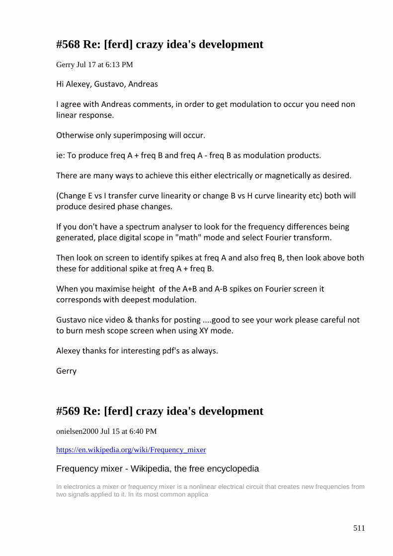
511
#568 Re: [ferd] crazy idea's development
Gerry Jul 17 at 6:13 PM
Hi Alexey, Gustavo, Andreas
I agree with Andreas comments, in order to get modulation to occur you need non
linear response.
Otherwise only superimposing will occur.
ie: To produce freq A + freq B and freq A - freq B as modulation products.
There are many ways to achieve this either electrically or magnetically as desired.
(Change E vs I transfer curve linearity or change B vs H curve linearity etc) both will
produce desired phase changes.
If you don't have a spectrum analyser to look for the frequency differences being
generated, place digital scope in "math" mode and select Fourier transform.
Then look on screen to identify spikes at freq A and also freq B, then look above both
these for additional spike at freq A + freq B.
When you maximise height of the A+B and A-B spikes on Fourier screen it
corresponds with deepest modulation.
Gustavo nice video & thanks for posting ....good to see your work please careful not
to burn mesh scope screen when using XY mode.
Alexey thanks for interesting pdf's as always.
Gerry
#569 Re: [ferd] crazy idea's development
onielsen2000 Jul 15 at 6:40 PM
https://en.wikipedia.org/wiki/Frequency_mixer Frequency mixer - Wikipedia, the free encyclopedia
In electronics a mixer or frequency mixer is a nonlinear electrical circuit that creates new frequencies from two signals applied to it. In its most common applica
512
Regards Ole
#570 Re: [ferd] crazy idea's development - second FE principle illustration
Gerry Jul 17 at 7:15 PM
Hi Alexey, Andreas guys,
I know I said this before about using resistance type wire in given type of coil.
No one understood....
Just to remind about coils and basic theory.
With coils time constant is given as inductance / resistance (L/R) so if L really big and
R is very small then time constant very long.
eg: 100 millihenries / 0.5 Ohm = 200 milliseconds over 5 time constants is 1 second.
eg2: 100 millihenries / 5 Ohms = 20 milliseconds over 5 time constants is 0.1
seconds.
So for a given current can charge coil to same field strength 10 times faster if
resistance wire is used.
If resistance wire is primary coil ...then Lenz back flux, sees a larger series equivalent
resistance in series with primary.
Helping to reduce Lenz effect.
Gerry
#571 Re: [ferd] crazy idea's development - second FE principle illustration
Andreas Höschler Jul 17 at 7:31 PM
Hi Gerry,
513
I know I said this before about using resistance type wire in given type of coil.
No one understood....
Just to remind about coils and basic theory.
With coils time constant is given as inductance / resistance (L/R) so if L really
big and R is very small then time constant very long.
eg: 100 millihenries / 0.5 Ohm = 200 milliseconds over 5 time constants is 1
second.
eg2: 100 millihenries / 5 Ohms = 20 milliseconds over 5 time constants is 0.1
seconds.
So for a given current can charge coil to same field strength 10 times faster if
resistance wire is used.
If resistance wire is primary coil ...then Lenz back flux, sees a larger series
equivalent resistance in series with primary.
Helping to reduce Lenz effect.
Interesting thought! So you suggest a 1:1 transformer with a primary of very thin wire (high resistance) and a secondary of thick wire (low resistance). The secondary gets heavily loaded and we apply some AC to the primary. Let's see ...
• We apply AC voltage to the primary, resulting in dI / dt and thus d flux / dt
• The changing flux induces voltages in the secondary that immediately results in secondary current and counter flux
• Within nanoseconds this counter flux reaches the primary and compensates forward flux leading to less inductive resistance and thus a higher (real) current in the primary.
The power source will just see high ohms resistance and burn electrical energy to heat. Your L/R and time constant thoughts are for charging a coil but as Ole has recently explained there is hardly anything like that happening in a loaded transformer.
I still don't understand and doubt your L/R concept can be applied to a loaded transformer!?? :-(
Best wishes,
Andreas
514
#572 Re: [ferd] crazy idea's development - second FE principle illustration
onielsen2000 Jul 17 at 7:37 PM
Hi Gerry, This must be why Donald L. Smith uses a resistor in parallel with his LC-tank. This makes it dissipative and thus faster but decreases the quality factor. By the way fast oscilloscope probe coaxial cables also have resistive wire as the center wire. This is for reducing reflections that would otherwise be between the cable ends. "The Secret World of Oscilloscope Probes:" https://www.dfad.com.au/links/THE%20SECRET%20WORLD%20OF%20PROBES%20OCt09.pdf Regards Ole
#573 Re: [ferd] crazy idea's development - second FE principle illustration
Gerry Jul 17 at 6:36 AM
Hi Alexey, Andreas, Ole guys
It is not really my L/R ratio thoughts .... it's an empirical fact just based on the theory.
It isn't my place to tell you how to best utilise this in your own experiments but just
trying to help.
I appreciate you guys have always done same for me.
If you want to listen to more, here is more...
I have attached a couple of pics of Bill Alec's Split Flux Transformer, second pic
shows also my own copy of it underneath.
Notice the resistance values printed on Bill Alec's input and output coil locations.
It took me a while to figure this out and why it would be so.
Partly it's down to L/R ratio as already said in prior post.
Now all UDT (Jenssen), SFT (Alec) and Bi Toroid (Heinz Thane) share many similar
characteristics.

515
1. They all seek to raise input impedance via some means...... be it via lower
permeabilty material on input or increasing via series air gap or increased input coil
resistance.
2. They all seek to cause output current flux to flow to left side to right side and vice
versa. Thus diverting it away somewhat from input stage.
I myself know that this 2nd thing is very effective, as loading left side output coil with
a short increases right side coil output and vice versa.
However I could not get the magic OU mainly due to Lenz flux finding its way back to
input coil.
So flux takes easiest path, indeed just as these guys predicted.
Some Lenz flux still finds it's way back because inevitably some part of output circuit
coil has to be exposed to input flux.
So output flux divides according to permeability and circuit resistance ratios.
Floyd Sweet, Bill Alec and others say that once a current's flux is cancelled, electron
current can move at much greater speed than normal 6Kms per hour.
In AuroraTek videos Bill Alec claims output coils become "superconductor losing all
resistance" via Cooper Pair effect.
He demonstrates this in video with two gyros strapped together no longer
experience pull or lag of earth's field.
So if we consider the above last idea to be true.
Then it doesn't matter if our output coils are made from resistance wire..... because
output resistance drops to a very low number once output flux is coupled across.
With SFT part of each output coil is wound around input toroids and this part does
not have it's output flux cancelled via output cross coupling.
So instead we can size the resistances of our input to output coil circuits to divide
output/input flux.
It would would normally divide according only to mA/turns ratio all else being equal.
We have now freedom to control Lenz current via input to output resistance ratios.
Hope it makes some sense.
516
Ole: Yes am with you on scope divider probes having resistance wire up the centre,
it's also often thinner than a human hair. In order to get the inner to outer conductor
diameter ratios correct for transmission line to match input 1 Meg Ohm impedance
on scope.
I'm sure you already know this too.
When I read your posts they are always insightful and helpful, I suspect you are from
test lab background.
Gerry

517
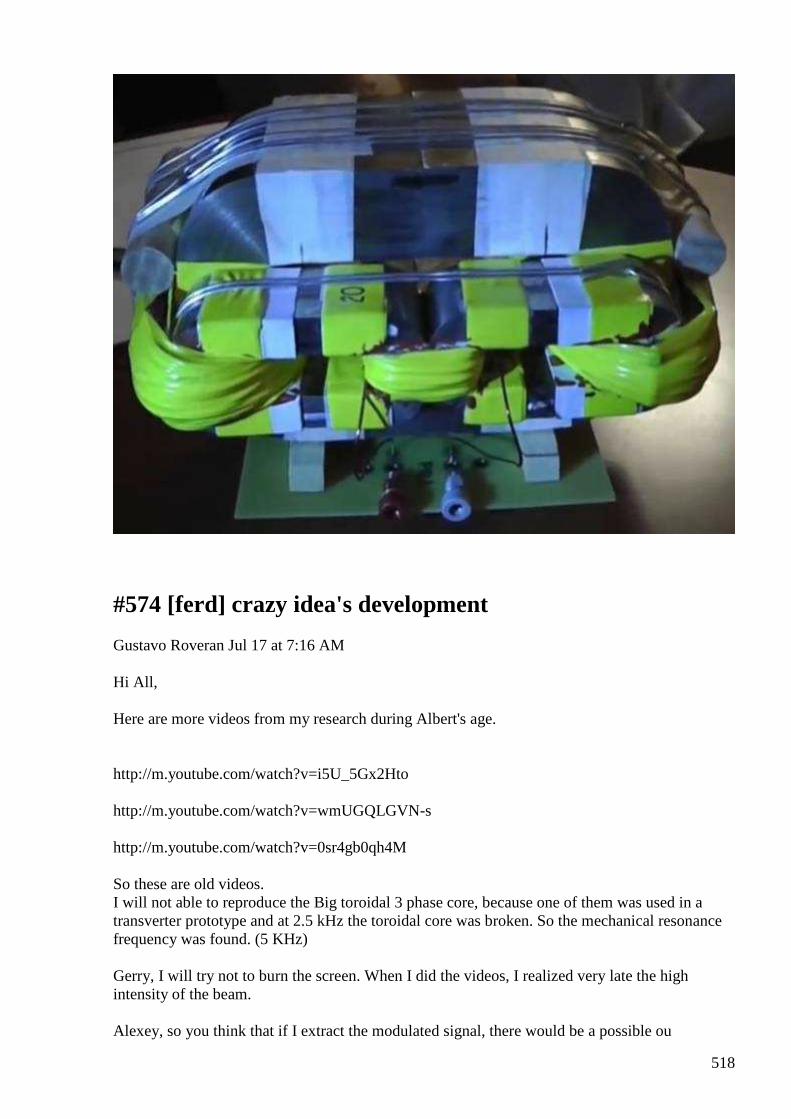
518
#574 [ferd] crazy idea's development
Gustavo Roveran Jul 17 at 7:16 AM
Hi All, Here are more videos from my research during Albert's age. http://m.youtube.com/watch?v=i5U_5Gx2Hto http://m.youtube.com/watch?v=wmUGQLGVN-s http://m.youtube.com/watch?v=0sr4gb0qh4M So these are old videos. I will not able to reproduce the Big toroidal 3 phase core, because one of them was used in a transverter prototype and at 2.5 kHz the toroidal core was broken. So the mechanical resonance frequency was found. (5 KHz) Gerry, I will try not to burn the screen. When I did the videos, I realized very late the high intensity of the beam. Alexey, so you think that if I extract the modulated signal, there would be a possible ou
519
extraction. Regards Gustavo
#575 Re: [ferd] crazy idea's development - second FE principle illustration
onielsen2000 Jul 17 at 3:59 PM
Hi Gerry, "In order to get the inner to outer conductor diameter ratios correct for transmission
line to match input 1 Meg Ohm impedance on scope." Thecharacteristic impedance of the cable is still around 50 Ohm. It is just that it is dissipating some of the energy to remove the reflections from the ends that has the 1 MOhm compensation network attached. E.g. 1/10 1/100 or other dividers. At higher frequencies the capacitance starts dominating and thus changes the impedance of the probes. By using resistive wire it is possible to go linear beyond 100MHz and explains why the probes then become expensive. "I suspect you are from test lab background." Actually I haven't been working professionally with electronics for some time. Else it was doing development or repair jobs. Now it's for hobby doing FE research. Regards Ole
#576 [ferd] crazy idea's development
Gerry Jul 17 at 7:02 PM
Hi Gustavo,
On OU from modulation ..... just speaking from own experience,
I once used used to calibrate HP355, step attenuators using PRD reciever with
external mixers and external local oscillators.
If we took a frequency A and frequency B and mix them to get a sum and difference
frequency Freq A + Freq B (upper and lower sidebands) in non linear network.
There's no OU effect appears.
520
But if we take 2nd harmonic of frequency A and mix this with frequency B then yes a
definite strange effect occurs like negative resistance.
It only happens when output is taken from low minus side not upper side.
So 2* Freq A - Freq B = neg resistance effect
but 2*Freq A + Freq B = normal input to output signal change.
The above is called 3rd order intermodulation.
Gerry
#577 [ferd] crazy idea's development
Gustavo Roveran Jul 17 at 8:25 PM
Hi Gerry Interesting research. Do you think that you will put your hands again on this ? BTW I think that perhaps there is something that didn't be explained very well. The experiments I did, were done with an only one frequency input. But for some reason a parameter variation appear ( in the non linear core ) that generate an AM modulation and an FM too. So what I understand is that something outside from my own input add an energy that produce the AM effect. And this is why Alexey proposed to extract the modulated signal. Did you understand in this way ? Thanks for share you experience. Regards Gustavo
#578 RE: [ferd] crazy idea's development
Alexey Jul 18 9:04 PM
Hi Gustavo,
You got my idea. In addition, if we make resonance on this ”extra” frequency there could be some more magic happen…like non-linear growth of “accumulated” FE. (crazy idea :-)
Regards,
Alexey
521
#579 Re: [ferd] crazy idea's development
Gerry Jul 18 at 3:39 AM
Hi Gustavo, Alexey, guys
Please note that the effects I used to get was in in high MHz range of frequencies.
Not audio or supersonic frequencies like Alexey is referring to.
Non the less such negative resistance effects were once well known to engineers and
even utilised for magnetic amplification of signals.
I've shown patents before here using of similar approach ...please find another one
attached it is simpler than many others.
Gustavo in the first video you showed where sound changes and spikes appear on
scope it could be that you're saturating the cores.
To the extent that loss of inductance occurs and then big current spikes on scope.
Usually for parametric gains it's good to change impedance during the cycle, but not
to extent that there is only air left to magnetise.
You do not seem to use the timebase trigger controls much to synchronise your
scope display.
Looking at Lissajou pattern I cannot tell much except to say there's nice 90 degree
phase shift when 'O' shape appears.
Gerry
#580 Re: [ferd] crazy idea's development
Gerry Jul 18 at 3:56 AM
Hi Alexey,
I have been trying to reconcile in my mind about girl on swing analogy.
I think I am wrong in what I have said, because if raising resistance makes inductor
charge faster.
Then swing push time is shorter to reach max stored energy.
522
Now if (stored flux) collapse energy collection is via a separate low resistance copper
winding,
then the swing doesn't accelerate and hit us harder with more energy ... it just takes
even longer to come back to starting push point.
...and coil shorting quickly pushes swing back to where it started on stored energy
collapse side.
noting that max rate of change occurs at vertical zero crossing line.
....... it really does my head in thinking about this stuff.
Gerry
#581 Re: [ferd] crazy idea's development
Gerry Jul 18 at 6:53 AM
Hi Alexey, guys
Here is a link from my Drop Box to a simple OU machine.
It was on YouTube and uses a simple vacuum cleaner motor.
https://www.dropbox.com/s/6nqyt91yzv6220a/The%20rotary%20transformer%20V
3.mp4?dl=0
For some reason all traces have been removed. Funny how good things are covered
up quickly.
So I advise download and keep to try, when old motor is available to you.
Gerry
#582 RE: [ferd] crazy idea's development
Alexey Jul 19 at 9:39 AM
Hi Gerry,
I still don’t understand. Energy stored in coil L * I * I / 2
If we have bigger coil resistance, we need apply bigger voltage to the coil to achieve same current.

523
This will result in more I * I * R loses, right?
Regards,
Alexey
#583 RE: [ferd] crazy idea's development
Alexey Jul 19 at 10:09 AM
Hi Gerry,
According to the measurements Pin = 13,4 * 0,7 = 9,38W and Pout = 10,4 * 1,6 = 16,64W
but it is not clear what schematic on the small board ? and what exact schematic ?
Do you have some link to forum where this discussed ?
Thanks,
Alexey
#584 Re: [ferd] crazy idea's development
Gerry Jul 19 at 10:58 AM
Hi Alexey,
Yes me too having trouble reconciling all this.
In that formula 1/2 L*I*I ....notice that R is not mentioned.
I guess it's cause the energy is potential energy and not moving, so no actual current
flow.
When we use the inductor time constant either with L/R or in e exp -(t *L/R) form
the charge time is definitely reduced.
I was roughly working out that losses through R are about the same for high & low
values of R because energy dissipated is E * I * time.
So in 1st example if R equiv series was 0.5 Ohms then time constant is 10 times
longer than if it were R equiv series was 5 Ohms where it's 10 times shorter.
524
I do know how to do the actual math for this but lazy slob now days and hard to get
motivated to do it.
Thinking it's something like -L integral i dt
See in Andreas coil shorting I read that he was shorting twice per pulse cycle.
So I was rightly or wrongly assuming flux charge path has one time constant ... whilst
flux discharge path takes another with less series equivalent resistance.
But it turns out that given a zero Ohms total equivalent series resistance in the flux
path, prevents the flux from collapsing altogether, as time constant becomes huge.
I think about rates of energy input storage dissipation ie: pushing the swing forward.
Compared to rate of energy harvesting on the back swing.
Sometimes I should just give up.
Gerry
#585 Re: [ferd] crazy idea's development
Gerry Jul 19 at 11:01 AM
Hi Alexey,
The motor only has two field coils one on left one on right.
The switch on pcb is double pole double throw..... one side just shorts left hand field
coil completely.
The other side of switch simultaneously connects the lamp load circuit.
Lamp load circuit contains filter cap and rectifier is all.
I cannot supply more info otherwise me guilty of duplicity.
This video was public before & I downloaded it.
Gerry
525
#586 Re: [ferd] crazy idea's development
onielsen2000 Jul 19 at 2:05 PM
Hi Gerry, This guy has more than 4000 videos on his YouTube channel. He has several rotary transformers there. Perhaps a better version exists of the removed video. Here he claims a self powering oscillator: Self running Oscillator, power source yet unknown
Self running Oscillator, power source yet unknown This is the build and first run of my new
magnetic enhanced coil. It was designed in the
hope of being able to run off the reactive
power generator to provid...
View on www.youtube.com
Preview by
Yahoo
Regards Ole
#587 Re: [ferd] crazy idea's development
onielsen2000 Jul 19 at 5:35 PM
Tinman is on overunity.com Tinman's Rotary Transformer
The rotary transformer V3 Originally on the Tinmanpower channel. More
discussion
http://overunity.com/15395/partnered-output-
coils-free-energy/4065/
View on www.youtube.com
Preview by
Yahoo
Here is copy of the YouTube video from another user: The rotary transformer V3 And some other videos of this project: Brad Power
526
Brad Power RTv3 ground loop isolation test - Duration: 19 minutes. by Brad Power...
View on www.youtube.com
Preview by
Yahoo
The more than 4000 videos from TinManPower is not the number of videos but the number of followers. Sorry for wrong information. Regards Ole
#588 Re: [ferd] crazy idea's development
Gerry Jul 19 at 7:17 PM
Hi Ole,
Thanks for the link...... hadn't seen that before.
I put some comments for him about scope display not changing much even though
it's frequency readout changed a great deal.
Also about transistor acting as a diode.
From the way the neon illuminates it's also possible to tell if pickup signal is ac or dc.
Either way it's just high impedance pickup of some kind ....not some super
regenerative HV power signal.
It seems he lives somewhere north of me....... in Queensland (about 1000 Km away).
Gerry
#589 Re: [ferd] crazy idea's development
Gerry Jul 19 at 8:14 PM
Hi Ole,
Hadn't seen this stuff either, but I do think it's a useful thing for us here to be able to
try for ourselves at some stage.
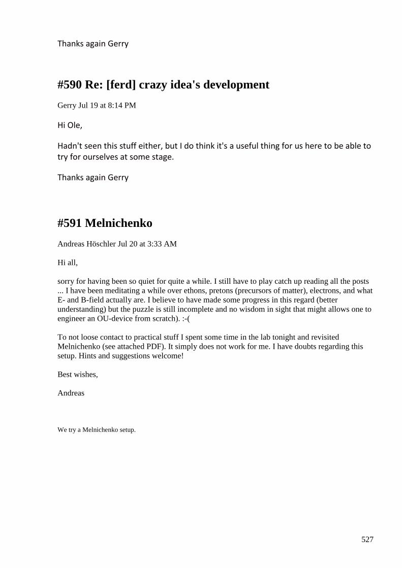
527
Thanks again Gerry
#590 Re: [ferd] crazy idea's development
Gerry Jul 19 at 8:14 PM
Hi Ole,
Hadn't seen this stuff either, but I do think it's a useful thing for us here to be able to
try for ourselves at some stage.
Thanks again Gerry
#591 Melnichenko
Andreas Höschler Jul 20 at 3:33 AM
Hi all, sorry for having been so quiet for quite a while. I still have to play catch up reading all the posts ... I have been meditating a while over ethons, pretons (precursors of matter), electrons, and what E- and B-field actually are. I believe to have made some progress in this regard (better understanding) but the puzzle is still incomplete and no wisdom in sight that might allows one to engineer an OU-device from scratch). :-( To not loose contact to practical stuff I spent some time in the lab tonight and revisited Melnichenko (see attached PDF). It simply does not work for me. I have doubts regarding this setup. Hints and suggestions welcome! Best wishes, Andreas
We try a Melnichenko setup.
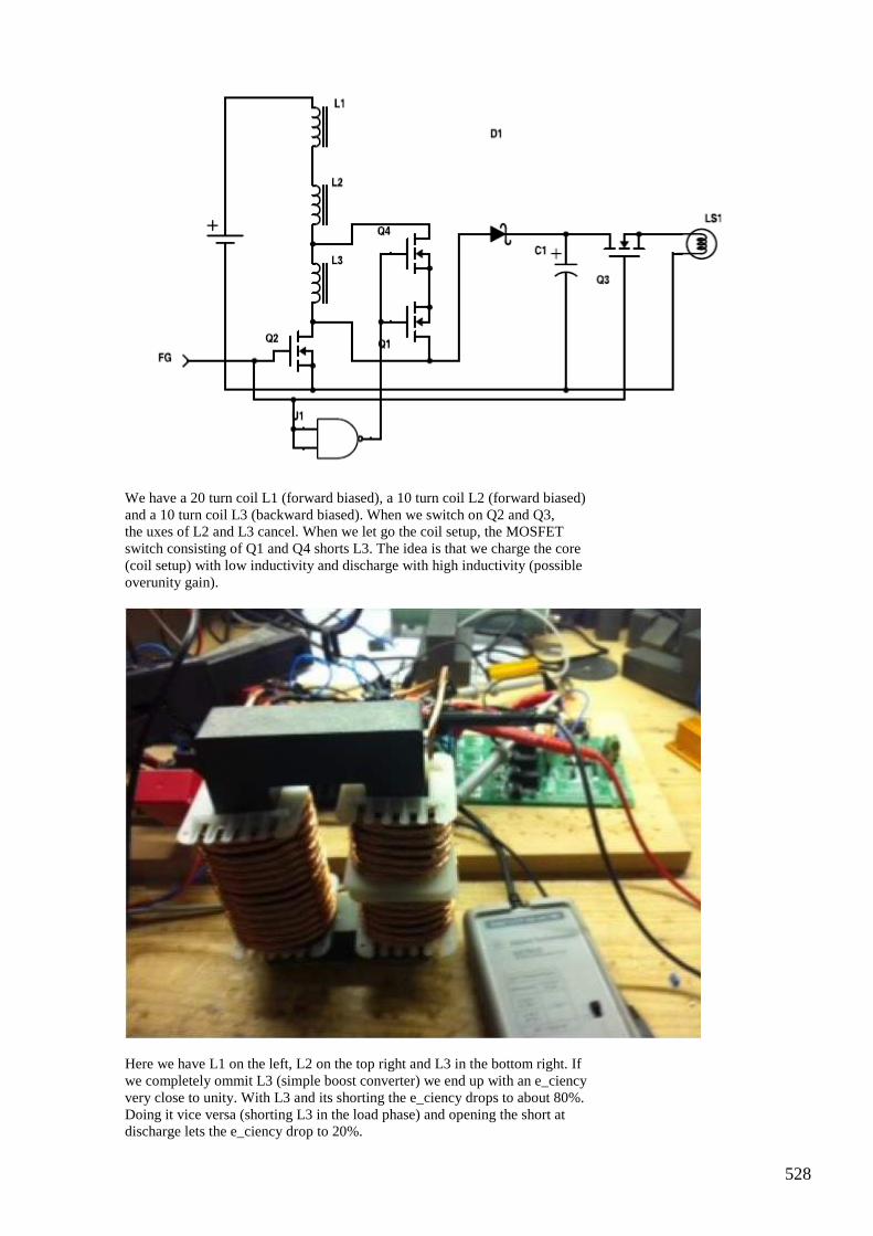
528
We have a 20 turn coil L1 (forward biased), a 10 turn coil L2 (forward biased) and a 10 turn coil L3 (backward biased). When we switch on Q2 and Q3, the uxes of L2 and L3 cancel. When we let go the coil setup, the MOSFET switch consisting of Q1 and Q4 shorts L3. The idea is that we charge the core (coil setup) with low inductivity and discharge with high inductivity (possible overunity gain).
Here we have L1 on the left, L2 on the top right and L3 in the bottom right. If we completely ommit L3 (simple boost converter) we end up with an e_ciency very close to unity. With L3 and its shorting the e_ciency drops to about 80%. Doing it vice versa (shorting L3 in the load phase) and opening the short at discharge lets the e_ciency drop to 20%.
529
#592 Re: [ferd] Melnichenko
Gerry Jul 20 at 4:56 AM
Hi Andreas,
Nice to here how you're going with your projects,
I too have spent considerable time on this Melnichenko concept,
I used the MC34063 chip which has convenient in built control & protection circuitry.
Haven't blown one up yet despite having excessive spikes from too much L values.
I couldn't duplicate the self run effect yet ..... though have gotten total current draw
down from over 140mA to now approx 7mA with all 3 LEDs lit (in series).
Even though I've failed in the execution of this approach it does not invalidate the
concept.
For it is easily seen when the two inductors hooked in series but magnetically
cancelling (L1 + L2 - 2M) we can pass undistorted square waves right through them.
Thus totally defeating the normal L/R time constants which immediately appear by
manually shorting out either single inductor in the series arrangement.
I know I keep harping on about this but it's easier for a FET to short out a decent
finite resistance than some incredibly low value.
As current will divide proportional to the inverse of the resistance ratio.
I think my own failure at the Melnichenko technique is my inability to effectively
short these coils in a dynamic situation.
So again thinking to rewind coils with resistance wire, I have no problems getting the
charge into the coils, it's the extracting by shorting which seems to be failing in my
case.
Over here in Australia we have nothing and items like resistance wire has to come
from UK or USA.
And is getting worse as we are now an economic basket case......
Gerry
530
#593 Re: [ferd] Melnichenko
Gerry Jul 20 1:20 PM
Hi again Andreas,
Your circuit looks really good ....
Have attached a pic of mine I took this afternoon showing input current with led's lit.
It sort of looks like there's a step missing from the process doesn't it.
Whilst Q2 and Q3 both "on", L1 charges via battery and Q2 , but input to diode and
C1 must be nil due to Drain of Q2 near earth potential.
Because L1 is the largest inductor it requires the longest charge time.
Immediately Q2 turns "off".... L1 and L2 both supposed to discharge into C1, whilst
flux in L3 is momentarily stored by a short cct across it from Q1 & Q4.
Instead of releasing this short circuit for final L3 discharge into C1..... the circuit
immediately grounds one end of L3 again, restarting the initial process.
So wondering if L3's charge usefulness is ever realised?
I followed a link from Ole and downloaded a Melnichenko doc, don't know if you
have it so also attached it here.
Gerry
#594 Re: [ferd] Melnichenko
Gerry Jul 20 1:21 PM
duplicate of #593
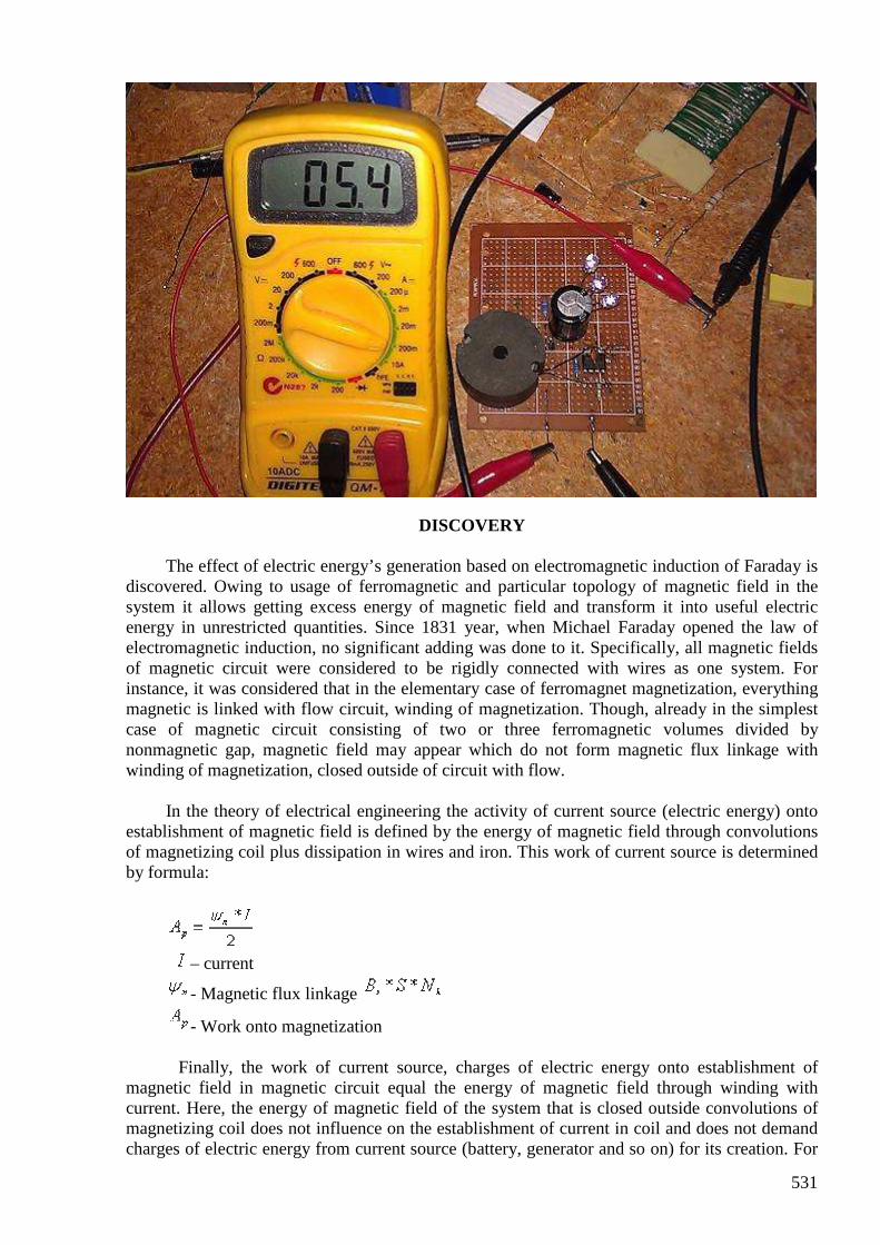
531
DISCOVERY
The effect of electric energy’s generation based on electromagnetic induction of Faraday is discovered. Owing to usage of ferromagnetic and particular topology of magnetic field in the system it allows getting excess energy of magnetic field and transform it into useful electric energy in unrestricted quantities. Since 1831 year, when Michael Faraday opened the law of electromagnetic induction, no significant adding was done to it. Specifically, all magnetic fields of magnetic circuit were considered to be rigidly connected with wires as one system. For instance, it was considered that in the elementary case of ferromagnet magnetization, everything magnetic is linked with flow circuit, winding of magnetization. Though, already in the simplest case of magnetic circuit consisting of two or three ferromagnetic volumes divided by nonmagnetic gap, magnetic field may appear which do not form magnetic flux linkage with winding of magnetization, closed outside of circuit with flow.
In the theory of electrical engineering the activity of current source (electric energy) onto
establishment of magnetic field is defined by the energy of magnetic field through convolutions of magnetizing coil plus dissipation in wires and iron. This work of current source is determined by formula:
– current
- Magnetic flux linkage
- Work onto magnetization Finally, the work of current source, charges of electric energy onto establishment of
magnetic field in magnetic circuit equal the energy of magnetic field through winding with current. Here, the energy of magnetic field of the system that is closed outside convolutions of magnetizing coil does not influence on the establishment of current in coil and does not demand charges of electric energy from current source (battery, generator and so on) for its creation. For
532
example, if we magnetize iron (ferromagnetic) cake and place one more near, separating it by a small air-gap, here the second magnetic cake will also magnetize. But, apart from common magnetic field of cakes, around the second cake appears its own magnetic field, closed only around it and not taking part in magnetic interaction of two ferromagnetic objects. I have named this field as secondary. This field does not have any inductive connection with winding of magnetization on the first magnetic cake, and, what is most important does not demand any electric energy on its establishment from current source for magnetization. Secondary magnetic field possesses certain energy that can be transformed into useful electric energy. For that, during demagnetization (cutting off, decreasing of current in the coil on the first rod) on the second ferromagnetic capacity (rod, cake) a special demountable winding is set which connects to loading only during demagnetization (does not take part in magnetization). Thereby, all energy of secondary magnetic filed can be transformed into additional useful energy by cycle.
Quantity of iron (ferromagnetic) rods in magnetic circuit at definite conditions can be
boundless. In some ferromagnetic medium magnetic interactions can be propagated onto infinity. For example, turn of domains in ferrodielectric, electromagnetic oscillations in powders form ferromagnetic.
In such systems the most part of magnetic field’s energy of magnetic circuit does not have
direct inductive connection with magnetization source. There exist enormous quantities of magnetic circuits in which secondary magnetic fields can be got, closed outside magnetization coils. This secondary magnetic energy can be used for generation of electric energy. There developed tens of devices for electric energy generation on pulse and alternating current including directly sinusoidal current on commercial frequency 50:60Hz. For this, ordinary iron transformer, wires and elements of power electronics is enough.
As an author, I have named this discovered physical effect of energy generation as
Transgeneration of electric energy. The effect is brilliantly confirmed in the elementary experiments and was thoroughly studied in investigations on various ferromagnets and types of magnetic circuits.
At the present time international patenting of inventions on the basis of present effect is in
process in many countries of the world. Not only is method of electric energy generation being patented but also a number of facilities on the basis of this method.
*** In the view of theoretical physics present effect of generation is possible because of special
quantum nature of ferromagnet. Magnetic field is formed by spins of electrons – magnet moments of electrons.
As distinct from ordinary currents in the wires spins of electrons absolutely do not react on
so-called rotational electric field of Maxwell, establishing electromotive force of induction in wires under alteration of magnetic flow during magnetization of ferromagnets. Consequently, ferromagnet possesses so-called zero inductive impedance (resistance). During magnetization only magnetic field needs to be applied but not electric energy like in coils with electric current. Additional energy of magnetic field appears (generates) in magnetic systems with secondary magnetic field which can be easily transformed into additional useful electric energy in a pure form.

533
In the systems with secondary magnetic field also appears secondary electric field which together forms energy flux of Poynting vector directed inside ferromagnetic volume from surrounding physical continuum but not from wires of magnetization coil.
Transgeneration of electric energy allows generating pure electric energy from
ferromagnets in unlimited quantity. Ferromagnet plays role of quantum electromagnetic pump getting electric energy from physical continuum and transforming it into electric energy at the expense of Faraday Effect.
#595 Re: Melnichenko
onielsen2000 Jul 20 1:42 PM
Hi Andreas, Remember the air gap which is very improtant acording to Melnichenko. Regards Ole
#596 Re: [ferd] Re: Melnichenko
Andreas Höschler Jul 20 2:23 PM
Hi Ole,
Remember the air gap which is very improtant acording to Melnichenko.
Between L2 and L3 (the two cancelling coils) or between L1 and L2/L3?
It might also be important (idea I got tonight) to first short the coil and then (100ns later or so) let got the charging MOSFET!?
What is with golden mean ratio? Anyone think that is important?
Another thing I am wondering about is whether L2 and L3 should be over the same region of core (may be even bifilar) or over separate regions as in my case? Any insights (hints anywhere)?
Thanks,
Andreas
534
#597 Re: [ferd] Melnichenko
Andreas Höschler Jul 20 2:31 PM
Hi Gerry,
Your circuit looks really good ....
Have attached a pic of mine I took this afternoon showing input current with
led's lit.
It sort of looks like there's a step missing from the process doesn't it.
Whilst Q2 and Q3 both "on", L1 charges via battery and Q2 , but input to
diode and C1 must be nil due to Drain of Q2 near earth potential.
Because L1 is the largest inductor it requires the longest charge time.
Immediately Q2 turns "off".... L1 and L2 both supposed to discharge into C1,
whilst flux in L3 is momentarily stored by a short cct across it from Q1 & Q4.
Instead of releasing this short circuit for final L3 discharge into C1..... the
circuit immediately grounds one end of L3 again, restarting the initial process.
So wondering if L3's charge usefulness is ever realised?
Interesting! Thanks for pointing this out. I will have to meditate a bit about that. My take was that there is no magnetic energy in L2/L3 since they are charged while cancelling each other out. But this might not be entirely true. Generating the signals for this beast starts to become a challenge! :-) Seems I have to make use of an Arduino for this.
I followed a link from Ole and downloaded a Melnichenko
doc, don't know if you have it so also attached it here.
Reading ...
Thanks a lot,
Andreas
535
#598 [ferd] Melnichenko
Gustavo Roveran Jul 20 3:18 PM
Hi Andreas So you are going deeper into Distinti theories. I think that it would be interesting to write a detailed question about his theories applied to OU system. But the question must be soft, no so direct. I do not know If he "believe" in ou systems. We have to find the way to ask. I did a question in his youtube chanel but I could not receive a direct response. Regards Gustavo
#599 Re: [ferd] Melnichenko
Andreas Höschler Jul 20 3:43 PM
Hi Gustavo,
So you are going deeper into Distinti theories. I think that it would be interesting to write a detailed question about his theories applied to OU system. But the question must be soft, no so direct. I do not know If he "believe" in ou systems. We have to find the way to ask. I did a question
in his youtube chanel but I could not receive a direct response.
Great! You have looked into his stuff as well!? :-) No, he does not seem to respond. I wrote him an email after donating some bucks but never got a response. My question was stupid anyway and I found the solution on my own later on. No, he does not seem to believe in OU yet (that's beyond his current field of research). However, lot's of his findings (concepts) make tons of sense IMHO though not all. He got the thing with the displacement current completely wrong (made a kids mistake) which astonishes me since other derivations of him are very sophisticated.
Whatever, we have to pick up all the puzzle pieces (experimental finings, concepts,...) and put them together to a working model explaining inductivity, inertia, gravity,... If we manage to do that we can engineer whatever we like (no longer blind tinkering). I feel that we get closer but not there yet. However, I feel far enough already to laugh my "a.." off when considering what concepts established science is stuck with (relativity, heavy mass,...). Many of the equations are correct but the interpretation is entirely wrong ... :-(
Best wishes,
Andreas
#600 Re: [ferd] Re: Melnichenko
onielsen2000 Jul 20 6:54 PM
536
Hi Andreas, The air gap is between L3 and the bifilar L1-L2. Take a look at the attached document "111.docx" from here: https://translate.google.dk/translate?sl=ru&tl=en&js=y&prev=_t&hl=da&ie=UTF-8&u=http%3A%2F%2Frealstrannik.ru%2Fforum%2F39-kapanadze%2F134467-qgenerator-energii-na-nelinejnoj-induktivnostiq.html%3Fstart%3D18%23147092&edit-text=
The schematic on page 4 upper right corner shows the cross section of the transformer with the air gap. A similar schematic is here even showing the phase relationships of the coils: http://mazeto.net/index.php?PHPSESSID=n6t607s94rag10enoelirqvb50&action=dlattach;topic=8699.0;attach=35444;image
This one is from this message (translated by Google) here: https://translate.googleusercontent.com/translate_c?depth=1&hl=da&ie=UTF8&prev=_t&rurl=translate.google.dk&sl=ru&tl=en&u=http://mazeto.net/index.php/topic,8699.msg56252.html%3FPHPSESSID%3Dbldu1tidlqj5cs5p14qthsgge0&usg=ALkJrhiBmElwl2cZ6RzuoR-UR4CSslnTUw#msg56252 Regards Ole
Power generator on nonlinear inductance (111.docx)
Already, the two constantly reminded of this article is to walk on the Internet.
Power generator on nonlinear inductance
Designed and assembled unit with an efficiency greater than 1. Works in Samoa mode, thus
highlighting enormous amount of energy it takes to incandescent glow. ........ Valery. [email protected]
At time t1: The current from the pre-charged capacitor C1 flows through L1 - L2 - L3, while the switch S1 is closed. This S2 open: Since the L1 and L2 are included in opposite (Accumulation of energy in the L1 and L2 does not occur, since their magnetic fields cancel each other) the accumulation of energy occurs in the coil L3 At time t2: Opens switch S1 and closes switch S2. Thus there EMF in the coils L1 and L3 (Since the S2 is closed) Coils L1 and L3 are included in phase (in antiphase inclusion EMF subtracted, and common-formed) Since the current in the coils of the same, we believe the resulting EMF at time t2 twice more with respect to the cost of the accumulation energy at the moment t1. As used herein, represents one cycle of the one coil. The control circuit provides a repetition of the process described above. The feedback loop returns a portion of the received power at the input of the circuit, for the next cycle of operation. The resulting increase in power consumed R - load.
537
1
So! I drank a beer once, and the idea came to me! Well, boys! Stagnant Slavic idea, full of chatter went in search of money and bodily pleasures! Let's Let
us serious reengineering tasks proposed by Valery. It must be said that the information he put a lot of
though spervonachalu not say. To begin, assume that the device really exists and works. The theory is
described in sufficient clarity and perhaps truthfully. It is possible that some important aspects are not
accentuated. In order to further a proper understanding, I wish it were that you would repeatedly have
carefully read the original description of the device, and carefully considered the proposal by the author
photo. So, let's begin! The first thing we wanted to draw attention to is that the device is clearly applied KA34063 chip. This
chip has in its composition reference voltage, the comparator compares the reference voltage with the
output (via a divider) controls the output of the internal oscillator amplifier key (1.5 A) mikroshemka
very typical single-cycle flaybeka and the theory described by the author is included under the scheme
Step-UP where Ui.> = Vout. The most interesting is that it is the basis of the device. This is evident based on the
fact that inherently can not be used without inductor. And judging by the photos, available in only one
inductance coil trifilyarnoy a pot-core. So we can assume that a switch S1 we have is that this chip KA34063 (TS34063) For normal operation of the chip as the strapping must be present: a) inductance - L1 + L2 + L3 + + diode electrolyte + Rnagruzki b) Ct-510pf capacitor Timing c) Goshkoobrazny core OB30 M1500 -3 winding (50 turns of PEL inductance 0.35 - 3 x 716 uH) at the
two-piece (the standard for this type of cores) coil. In one section bifilyar L1 and L2, in other L3.Nu and
naturally air zazorchik to 0.5mm (both in theory should be). g) plus ostalnoё stuff (look for AN920 http://onsemi.com mikruhi on the application in the internet)
Well, sort of scheme begins to take his face. So, about the one against KA34063 has nothing ?! And she
arose as the S1 (the author) quite nicely. Now more. We need key S2! Well, let's vtupuyu votknёm
polevichok on the theory of the author. Where we did not disappear!
Well, I turned up eragrostis 2N7000 500 mA so I planted them in a couple (also a passage channel
resistance twice reduced from 5 to 2.5 ohm) Driving like a self-sufficient and on the theory should work. But it is unlikely, though, if only because in
the photo we see a e esch mikruhu 14 feet plus tying a tuning resistor, a capacitor (it is a chain of timing)
well and rest a little junk in the form of resistors. Prior to that, I think doberёmsya at the time. Well ... of course I am including, of course does not work as it would be desirable! Points A and B in the
course of the two beams of C1-99. Picture somewhat unusual. The frequency of the order of 2 kHz. The duty cycle of about 5, which is not
according to the author. Porosity must be 2 and the frequency is about 100 kHz.
So, clearly shows that the surge occurs after the closing of S2 at the wrong time, ie while the
public key S1. At this time, L3 already saturated current key and the surge in the L2 only useless
oversaturate L3. By the way this pulse power explicitly frail There is the desire to find the culprit Seoul and move forward in time ie shorten by half the opening key
S2. As a result, it is expected that the surge will appear in the second half-time private key S1 and was
supposed to be put through the diode to natural buffer capacitor and the load. How? After going
through all available memory such elements, I came to the conclusion that this is a common chip called
155AG1. It is best suited for this purpose. By the way, she has 14 legs. Here are just a power puncture. You just need a 5 volts. It does not matter in the scheme of adding a low-power three-pin parametric
stabilizer 78L05 (100mA would be enough), plus elektrolitik 100mkfh10volt. Well, in order not to
e155AG1 knocked input 5 (start leading edge, entrance 3 on the ground) high voltage divider restrictive
set of resistors and 750th stabilitronchika KS147 than limit the amplitude of the trigger pulse. Now, on
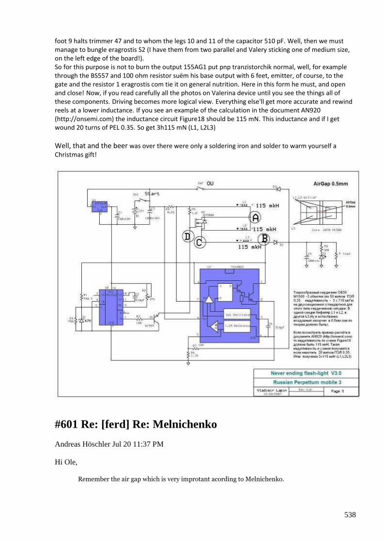
538
foot 9 halts trimmer 47 and to whom the legs 10 and 11 of the capacitor 510 pF. Well, then we must
manage to bungle eragrostis S2 (I have them from two parallel and Valery sticking one of medium size,
on the left edge of the board!). So for this purpose is not to burn the output 155AG1 put pnp tranzistorchik normal, well, for example
through the BS557 and 100 ohm resistor suёm his base output with 6 feet, emitter, of course, to the
gate and the resistor 1 eragrostis com tie it on general nutrition. Here in this form he must, and open
and close! Now, if you read carefully all the photos on Valerina device until you see the things all of
these components. Driving becomes more logical view. Everything else'll get more accurate and rewind
reels at a lower inductance. If you see an example of the calculation in the document AN920
(http://onsemi.com) the inductance circuit Figure18 should be 115 mN. This inductance and if I get
wound 20 turns of PEL 0.35. So get 3h115 mN (L1, L2L3)
Well, that and the beer was over there were only a soldering iron and solder to warm yourself a
Christmas gift!
#601 Re: [ferd] Re: Melnichenko
Andreas Höschler Jul 20 11:37 PM
Hi Ole,
Remember the air gap which is very improtant acording to Melnichenko.
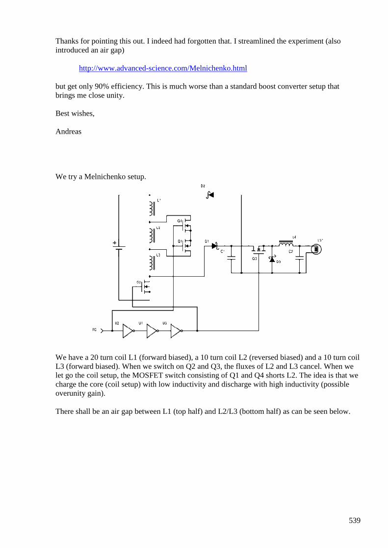
539
Thanks for pointing this out. I indeed had forgotten that. I streamlined the experiment (also introduced an air gap)
http://www.advanced-science.com/Melnichenko.html
but get only 90% efficiency. This is much worse than a standard boost converter setup that brings me close unity.
Best wishes,
Andreas
We try a Melnichenko setup.
We have a 20 turn coil L1 (forward biased), a 10 turn coil L2 (reversed biased) and a 10 turn coil L3 (forward biased). When we switch on Q2 and Q3, the fluxes of L2 and L3 cancel. When we let go the coil setup, the MOSFET switch consisting of Q1 and Q4 shorts L2. The idea is that we charge the core (coil setup) with low inductivity and discharge with high inductivity (possible overunity gain).
There shall be an air gap between L1 (top half) and L2/L3 (bottom half) as can be seen below.
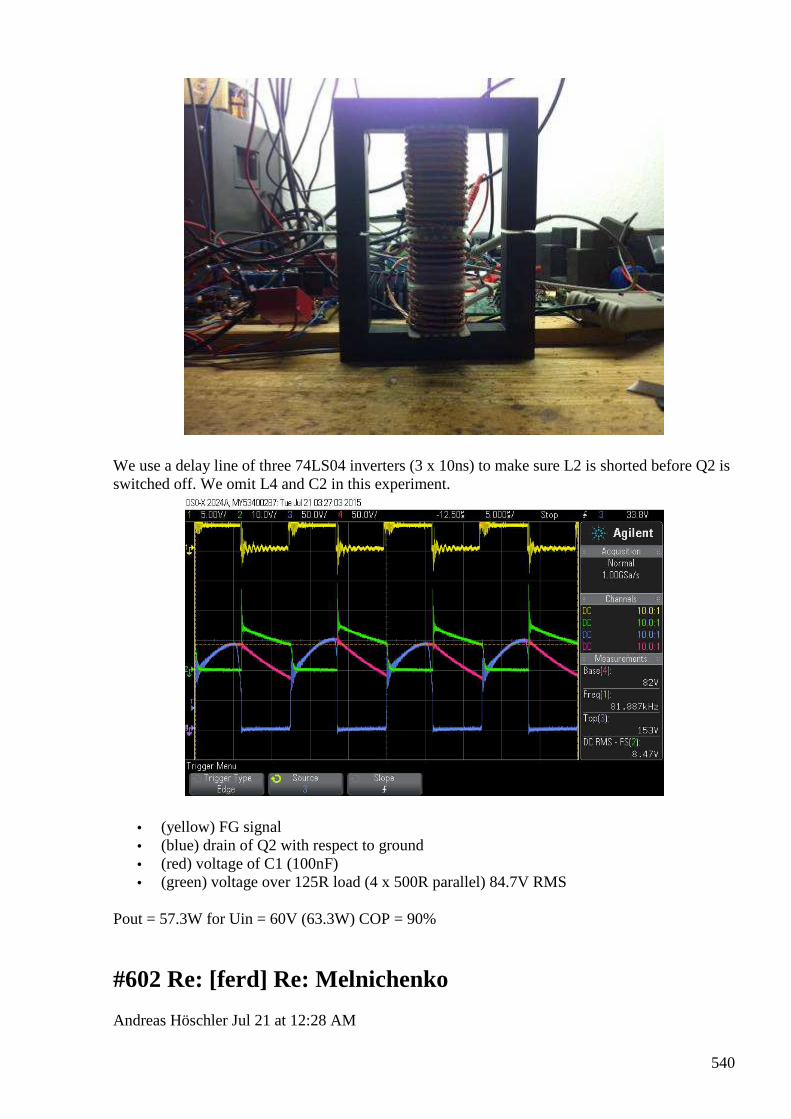
540
We use a delay line of three 74LS04 inverters (3 x 10ns) to make sure L2 is shorted before Q2 is switched off. We omit L4 and C2 in this experiment.
• (yellow) FG signal • (blue) drain of Q2 with respect to ground • (red) voltage of C1 (100nF) • (green) voltage over 125R load (4 x 500R parallel) 84.7V RMS
Pout = 57.3W for Uin = 60V (63.3W) COP = 90%
#602 Re: [ferd] Re: Melnichenko
Andreas Höschler Jul 21 at 12:28 AM
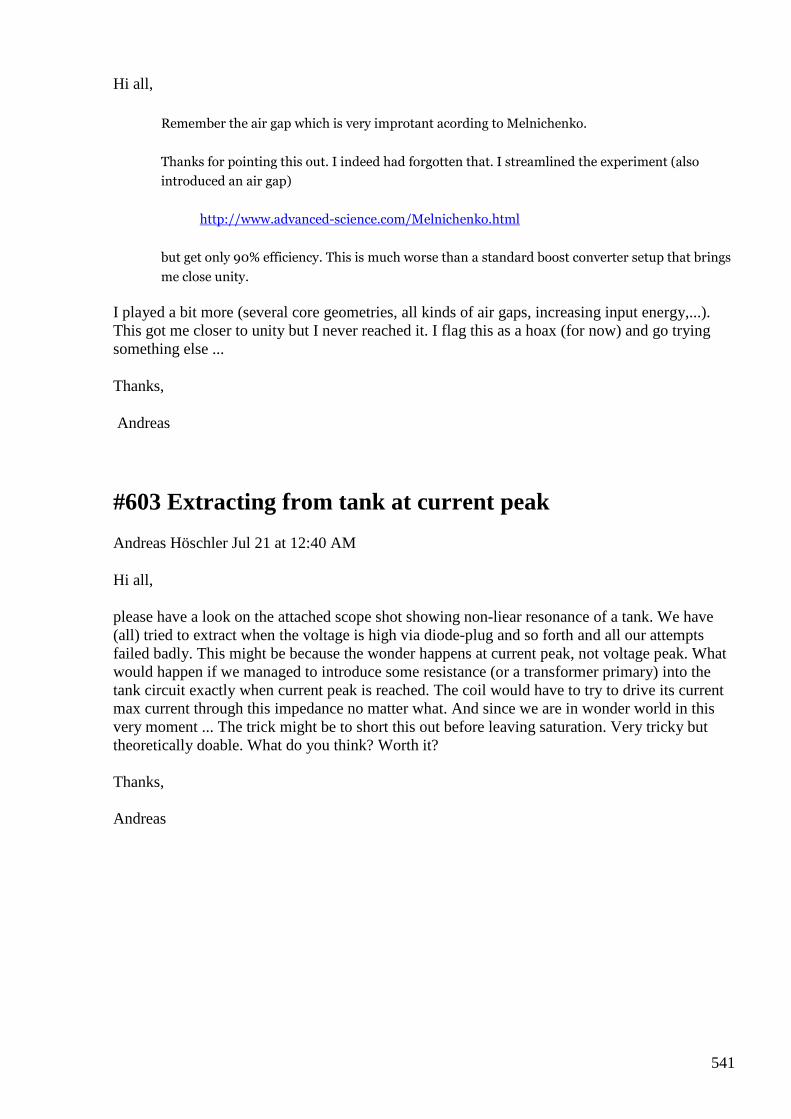
541
Hi all,
Remember the air gap which is very improtant acording to Melnichenko.
Thanks for pointing this out. I indeed had forgotten that. I streamlined the experiment (also
introduced an air gap)
http://www.advanced-science.com/Melnichenko.html
but get only 90% efficiency. This is much worse than a standard boost converter setup that brings
me close unity.
I played a bit more (several core geometries, all kinds of air gaps, increasing input energy,...). This got me closer to unity but I never reached it. I flag this as a hoax (for now) and go trying something else ...
Thanks,
Andreas
#603 Extracting from tank at current peak
Andreas Höschler Jul 21 at 12:40 AM
Hi all, please have a look on the attached scope shot showing non-liear resonance of a tank. We have (all) tried to extract when the voltage is high via diode-plug and so forth and all our attempts failed badly. This might be because the wonder happens at current peak, not voltage peak. What would happen if we managed to introduce some resistance (or a transformer primary) into the tank circuit exactly when current peak is reached. The coil would have to try to drive its current max current through this impedance no matter what. And since we are in wonder world in this very moment ... The trick might be to short this out before leaving saturation. Very tricky but theoretically doable. What do you think? Worth it? Thanks, Andreas
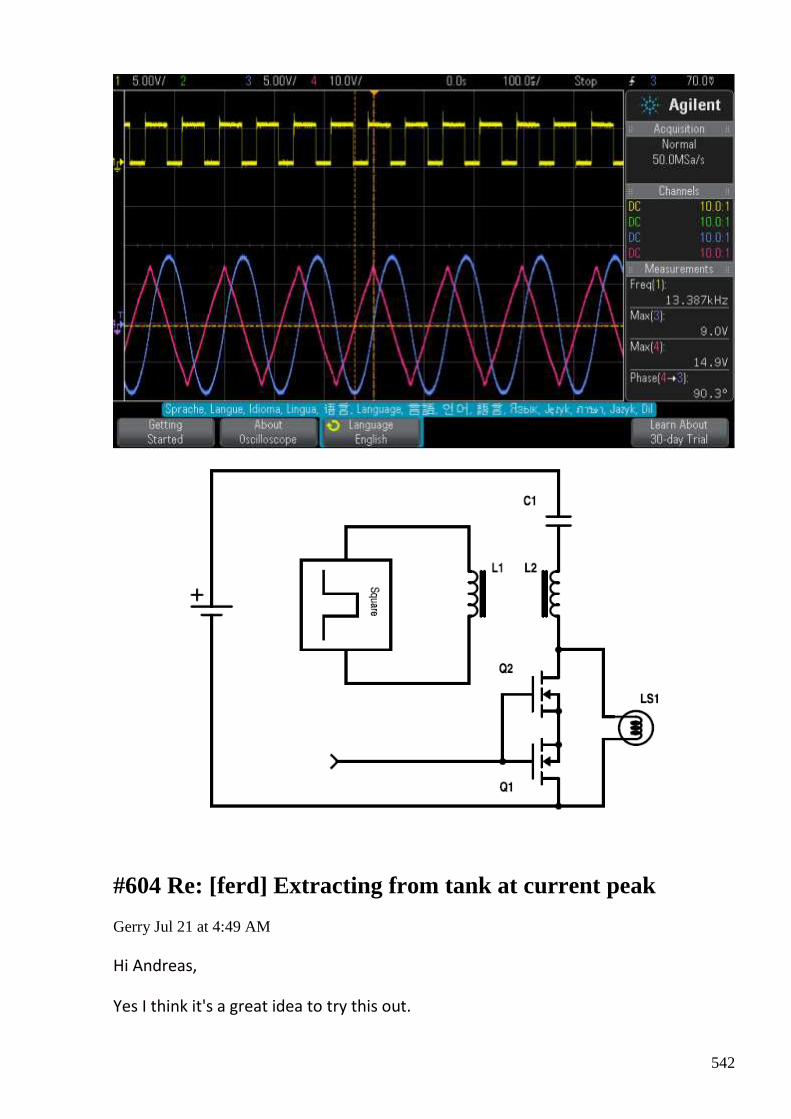
542
#604 Re: [ferd] Extracting from tank at current peak
Gerry Jul 21 at 4:49 AM
Hi Andreas,
Yes I think it's a great idea to try this out.

543
The higher the series resistance the closer the discharging coil comes to a perfect
constant current source.
You could permanently wire in a non inductive potentiometer, then short it out
during discharge.
If you have option to compare shorting during charge and shorting discharge it
would be interesting too.
I have to go back and look at my theory books because I have difficulty with
visualising L's time constant and how it affects Q value.
Normally Q = energy stored/ energy dissipated.
Or XL / R..... so you playing with R value higher supposed to reduce Q ......and
incidentally also increases bandwidth of coil response.
As Q also = resonant freq / bandwidth at - 3dB points.
Doing a Fourier series on this means that more of actual pulse's shape (bandwidth)
could be stored but peak response is sacrificed.
Gerry
#605 RE: [ferd] Re: Melnichenko
Alexey Jul 21 at 8:56 AM
Hi Guys,
Just in case you haven’t seen it https://www.youtube.com/watch?v=acUc2jg-ZrU
As far as I know video came out several days ago on mazeto.net. They claim that it works 6 days before ferrite goes apart (very useful thing )
- Alexey
#606 Re: [ferd] Re: Melnichenko
Gerry Jul 21 12:41 PM
Thanks Alexey,
I took a look at the video, it didn't seem to show much.
544
And most comments were in Cyrillic.
Gerry
#607 The universe (ethons, pretons,...)
Andreas Höschler Jul 21 11:03 PM
Hi Gustavo,
So you are going deeper into Distinti theories. I think that it would be interesting to write a detailed question about his theories applied to OU system. But the question must be soft, no so direct. I do not know If he "believe" in ou systems. We have to find the way to ask. I did a question in his youtube chanel but I could not receive a direct response.
Since you have looked into Distinti as well we might brainstorm a bit about his concepts and potentially develop them further to get an idea of how the universe works and finally be able to engineer an OU device instead of blindly tinkering around (costs too much time).
A summary of the distinti stuff can be found here: http://qdl.scs-inc.us/2ndParty/Pages/13353.html
He basically says that ether consists of positively charged p-ethons, negatively charged n-ethons and neutral ethon-pairs. We have to mix in (define) the permeability of space and with only these puzzle pieces (the interaction of these components) explain the propagation of light.
Once we have managed to do that all the rest (inertia, self-inductance, gravity,...) should be almost self-evident!?
Any idea (suggestions for the interaction rules of ethons)?
Best wishes,
Andreas
#608 Re: [ferd] Extracting from tank at current peak
Gustavo Roveran Jul 21 11:28 PM
Hi Andreas,
The scheme you shared shows a serial resonance tank. What happens if you use a parallel one, and the transformers is placed between capacitor and coil ?
545
I understand that the serial resonance produce high voltage in the components of the tank, but parallel resonance produces high current, and at the same time, you do not need to put a power source at the tank. Am I wrong ?
Regards,
Gustavo
#609 Re: [ferd] Extracting from tank at current peak
Andreas Höschler Jul 21 11:33 PM
Hi Gustavo,
The scheme you shared shows a serial resonance tank. What happens if you use a parallel one, and the transformers is placed between capacitor and coil ?
I understand that the serial resonance produce high voltage in the components of the tank, but parallel resonance produces high current, and at the same time, you do not need to put a power source at the tank. Am I wrong ?
No, you aren't. Parallel tank (excluding the power supply) probably makes sense!
Andreas
#610 Re: [ferd] Extracting from tank at current peak
Andreas Höschler Jul 22 at 2:15 AM
Hi Gerry and all,
Yes I think it's a great idea to try this out.
The higher the series resistance the closer the discharging coil comes to a
perfect constant current source.
please have a look on the attached scope shot showing non-liear resonance of a tank. We have (all) tried to
extract when the voltage is high via diode-plug and so forth and all our attempts failed badly. This might
be because the wonder happens at current peak, not voltage peak. What would happen if we managed to
introduce some resistance (or a transformer primary) into the tank circuit exactly when current peak is
reached. The coil would have to try to drive its current max current through this impedance no matter
what. And since we are in wonder world in this very moment ... The trick might be to short this out before
leaving saturation. Very tricky but theoretically doable. What do you think? Worth it?
I just came up wit the following circuit that potentially could generate the signal for the MOSFET switch:
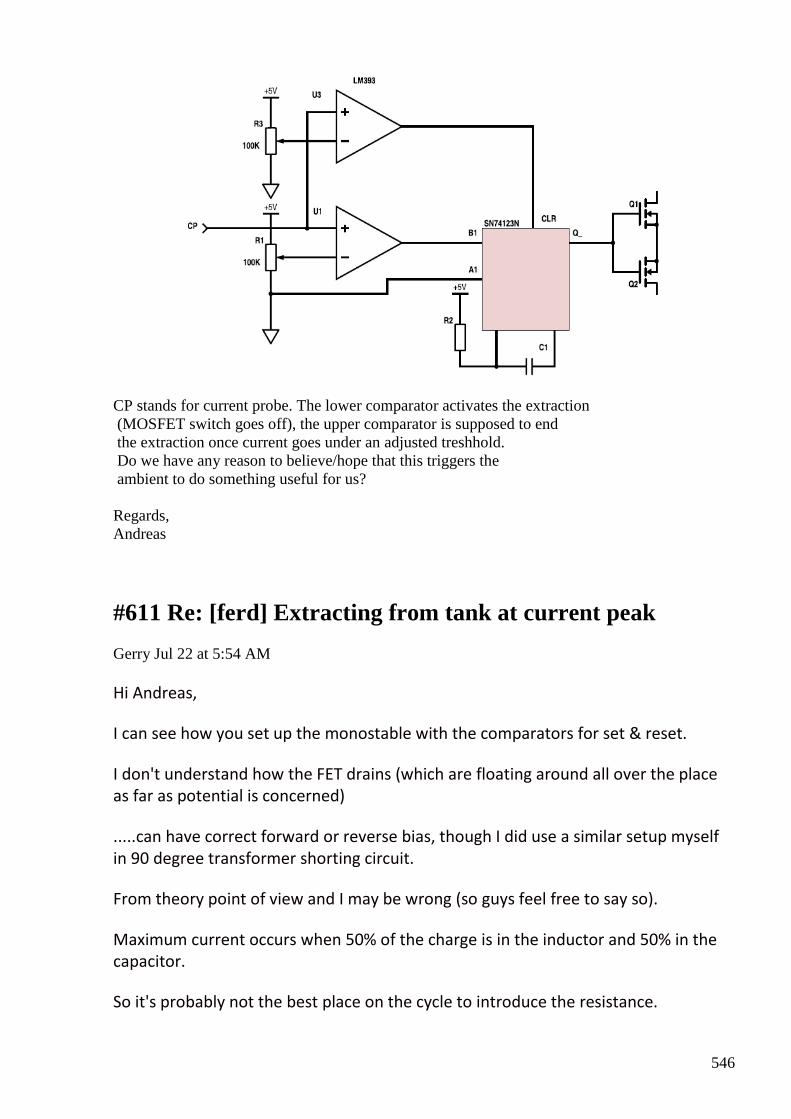
546
CP stands for current probe. The lower comparator activates the extraction (MOSFET switch goes off), the upper comparator is supposed to end the extraction once current goes under an adjusted treshhold. Do we have any reason to believe/hope that this triggers the ambient to do something useful for us? Regards, Andreas
#611 Re: [ferd] Extracting from tank at current peak
Gerry Jul 22 at 5:54 AM
Hi Andreas,
I can see how you set up the monostable with the comparators for set & reset.
I don't understand how the FET drains (which are floating around all over the place
as far as potential is concerned)
.....can have correct forward or reverse bias, though I did use a similar setup myself
in 90 degree transformer shorting circuit.
From theory point of view and I may be wrong (so guys feel free to say so).
Maximum current occurs when 50% of the charge is in the inductor and 50% in the
capacitor.
So it's probably not the best place on the cycle to introduce the resistance.

547
The maximum current equals by analogy, the maximum velocity reached on the
child's swing as it crosses thru the vertical plane.
Which again is halfway between capacitive and inductive discharge.
Is also 0, 180, 360 degrees point on sine wave voltage cycle = max velocity.
That's why when we differentiate Sine 0, 180, 360 it goes to Cosine 1, -1 ,1
I recommend:
introducing resistor (removing short cct across it) at 90, 270, etc on voltage wave
which is where current = zero.
At this moment all current has been changed into flux energy out there in the
ambient around the coil.
Now introducing resistor right here.... is where current starts increasing whilst
voltage is diminishing.
As flux returns from the ambient.
Anytime we have a situation where diminishing voltage results in an increasing
current....we have Negative resistance.
Now the larger we can make the "negative resistance" (from our unshorted
resistor) in ohms terms ...the larger the power gain in our circuit.
Because -E times R = a power gain not a loss.
Hope this makes sense.
Gerry
#612 Re: [ferd] The universe (ethons, pretons,...)
Gustavo Roveran Jul 22 at 6:09 AM
Hi Andreas,
I had read it some month ago, and that subject seems to be interesting to study in a deeper way. I have to read it again. But I think that we need very high voltage to generate some unbalance in ether to take some profit.
For example, there is a patent from Ludwig Sullos, an Hungarian man who lived and died in my Country. He talked about something similar, but his idea was about using high voltage to move the ether from one
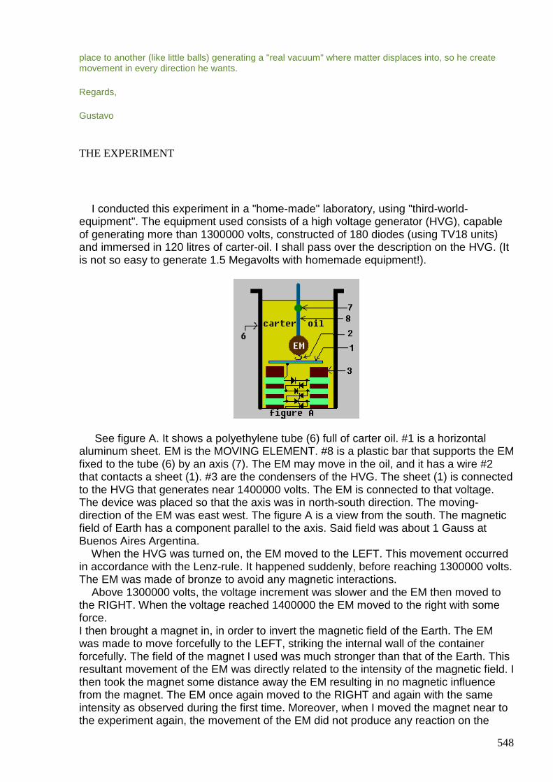
548
place to another (like little balls) generating a "real vacuum" where matter displaces into, so he create movement in every direction he wants.
Regards,
Gustavo
THE EXPERIMENT
I conducted this experiment in a "home-made" laboratory, using "third-world-equipment". The equipment used consists of a high voltage generator (HVG), capable of generating more than 1300000 volts, constructed of 180 diodes (using TV18 units) and immersed in 120 litres of carter-oil. I shall pass over the description on the HVG. (It is not so easy to generate 1.5 Megavolts with homemade equipment!).
See figure A. It shows a polyethylene tube (6) full of carter oil. #1 is a horizontal aluminum sheet. EM is the MOVING ELEMENT. #8 is a plastic bar that supports the EM fixed to the tube (6) by an axis (7). The EM may move in the oil, and it has a wire #2 that contacts a sheet (1). #3 are the condensers of the HVG. The sheet (1) is connected to the HVG that generates near 1400000 volts. The EM is connected to that voltage. The device was placed so that the axis was in north-south direction. The moving-direction of the EM was east west. The figure A is a view from the south. The magnetic field of Earth has a component parallel to the axis. Said field was about 1 Gauss at Buenos Aires Argentina. When the HVG was turned on, the EM moved to the LEFT. This movement occurred in accordance with the Lenz-rule. It happened suddenly, before reaching 1300000 volts. The EM was made of bronze to avoid any magnetic interactions. Above 1300000 volts, the voltage increment was slower and the EM then moved to the RIGHT. When the voltage reached 1400000 the EM moved to the right with some force. I then brought a magnet in, in order to invert the magnetic field of the Earth. The EM was made to move forcefully to the LEFT, striking the internal wall of the container forcefully. The field of the magnet I used was much stronger than that of the Earth. This resultant movement of the EM was directly related to the intensity of the magnetic field. I then took the magnet some distance away the EM resulting in no magnetic influence from the magnet. The EM once again moved to the RIGHT and again with the same intensity as observed during the first time. Moreover, when I moved the magnet near to the experiment again, the movement of the EM did not produce any reaction on the
549
magnet. I grasped the magnet and did not feel any reaction-force, not even a weak force. The EM was a heavy bronze sphere weighing approximately 1 Kilogram. This resultant movement was so strong as to strike the container tube with quite some force. Three new phenomenon can be observed: 1) The rule of Lenz was inverted. 2) A still electrical charge moved by a still magnetic field. 3) Failure of the action-reaction principle. At least, this appears to be the case! Yes, I know it is unbelievable. But, please, before you discard this do the described experiment. It is single and cheap. I have repeated this experiment 25 times. I have checked the value of the voltage and I have noted no flows within the oil around the bronze EM. The date of this experiment was 23 July 1995. The first publication-date of this research by Internet was December 1996. This research is PATENTED. (october - 13 - 1998 - Argentina) Now, please allow me to attempt a theory for these observations. At any rate, every new theory starts initially as science fiction. Consider me if you will as a science-fiction writer. Examine and read the following text as a new branch of physics-fiction. In this case however there is a slight difference. The experiment here was real. It happened and it was a phenomenon of nature. Only my explanation (theory) is a "story of physics-fiction"!
GEOKINETIC ENERGY
I will try to explain this experiment according to current knowledge of physics. The solar system moves around the centre of our galaxy with a high velocity of 220 km/sec. The planet Earth, with that speed, has an enormous kinetic energy. The Galactic Orbital Velocity (GOV) vector is oriented almost towards the Swan constellation (Deneb star). This direction, in relation to the local horizon, changes according to the date, time and the geographic position on the planet. Let us take an object moving on a circle like the parts of a wheel and let us analyse its kinetic energy variations. There are two vectorial components of the object’s movement. The P component which is parallel to the GOV and the N component which is perpendicular to the GOV. This N component is situated on the perpendicular plane to the said vector of the GOV. Now there are two energy-clusters. The N cluster and the P cluster. The kinetic energy of N is e = 1/2m.(vn)² where m is the mass of the object and vn is the N velocity-component in relation to the environment. Let us take the angle between the GOV and the velocity of that object as æ. Then, the kinetic energy of P cluster will be:
E = 1/2m.(v.cos α . 220000)²
Where v is the velocity in relation to the planet in the system. Energies of the N cluster are small. Energies of the P cluster are enormous. Clusters P and N can not interact. Every acceleration of an object in the N component takes its energy from the N cluster. And every acceleration of an object in the P component takes its energy from the powerful P cluster. There is however a way to transfer energy from P to N. Of course, not by any mechanical means. We can not accelerate a car without contact with the environment via the tires. By coupling a dynamo to one of the wheels, we can brake the car and convert its kinetic energy into electric power. In the same way, if we "brake" the planet Earth we can convert its kinetic energy into useful mechanical power. To brake
550
the car, we must connect the wheels to the pavement. What is the "pavement" for the Earth? It is the SPACE itself.
THE PHYSICS-FICTION STORY
If you currently fully accept the theory of relativity please read the next link:
http://web.archive.org/web/20030210030404/http:/www.lilysullos.com.ar/mimoing.htm
Every object is immersed in space. Now if we push an object, the inertia generates a contrary force equal and opposite to it. Our primitive human mind imagines that the object generates this opposition to the force (inertia). We think that the object is the opponent, the enemy here that does not allow us to move it. Let us imagine that the space is full of sub-atomic particles. Each of these particles is composed of sub-particles consisting of both polarities, which can be ionised. At this stage please postpone any objections regarding this theory. Let us also suppose that it is possible to "break" the space-particles into negative and positive sub-ions. By polarizing electrically, an object with 1300000 negative volts it is possible to generate on its surface a charge of positive sub-ions. The theoretical breaking voltage here is 1022 KV. The practical value is about 1300 KVolts. (Refer to THE EXPERIMENT). The negative sub-ions form a large cloud around the object. If a magnetic field is introduced into the area the result is a movement of the sub-ionic charges such that the positive charges move from one side of the object to the other. The negative charges must also move – moving far around the object. This ionization at one side of the object and the deionization at the opposite side causes a migration of the space-particles. Further let us suppose that the said space-particles may be compressed, reaching a higher energy level generating a pressure-wave in this medium. Let us suppose that if a particle is compressed, it does not change instantaneously because an internal clock forces it to wait a fixed interval. In this case the diameter of the particles can be divided by the said interval producing the value for the speed of the light. The particles are the conducting-medium of light. If the particles of a zone are more compressed (are smaller) then that zone can be regarded as a denser zone. Let us now suppose that every wave (could be light) that travels in this medium and finds a denser zone in said medium is refracted in that direction (like light being refracted by water). These matter-waves (De Broglie waves) are also refracted towards that denser zone of the space. What are these matter-waves? After experiments with electron beams and interference-phenomenon in crystals, we can guess a theory. 1) They have a frequency according to mass-by-velocity of a particle, using the Max Planck constant. 2) They induce a wave-particle ambiguity. A moving particle is smaller than a still one. It has more energy, like a wave. 3) The wavelength and velocity of these particles are related. The kinetic energy of a particle is related to the matter-waves. 4) This obstinate tendency of the particles to move on a straight line is due directly to the matter-waves. The kinetic energy of any particle is due to the behaviour of the matter-waves. 5) Matter-waves have no electric vectors and can create forces among particles. If not, interference phenomenon would not exist. These matter-waves also have a new role. They are the origin of the kinetic energy
551
and not a by-product. If a denser zone of the space can refract these matter-waves then by artificially densifying space, we can drive an object’s moving direction. Now assume these said particles are compressible. Let us suppose that when an object is moving through space, it must compress these space-particles (much like a boat traveling through water). Let us also suppose that this space compressing is linearly proportional to the energy required for this compressing. Such that the density of this "compressed space" increases linearly with the increasing of the object’s speed. Thus, by doubling the speed, the density increases by double and the amount of space-particles also increases by double. Therefore, the energy needed to compress and sweep is the square of the velocity. But this sweeping is not continuous. Time by energy must equal the constant of Max Planck. This is why matter-waves have a frequency dependant on the mass by the velocity of the object. Let us suppose that every object or atomic particle (electron, proton, neutron, etc.) is made of compressed space-particles. Then, if a particle is "sweeping" space, it is also creating matter and it is incorporating said matter to its own mass. However if the mass of a particle increases, it becomes unstable. The half lifetime of this extra-mass is the half period of the matter-wave. So, the particle, after "eating" that mass, emits it, after said half period. This eating occurs at the front of said particle and is emitted at the back where the space-particles expand, returning the energy back to the particle. Said energy is used to compress the next matter-wave in front. The particle has a "pulse-reactor" that forces it to advance forward by hops. The length of each hop is equal to the actual Compton-length of the particle. Between two following hops, the particle stops. When the expanding begins, the particle increases its speed; at the half time of the hop, it moves with the speed of the light. Measuring this speed on a long stretch, we can obtain precise values however the position seems to be uncertain. Reducing this long stretch to a stretch approaching the size of the particle near to the size, the position becomes much more precise. However the velocity becomes uncertain. De Broglie discovered these matter-waves. In this he found a gold mine! At the time though he didn’t realize it. I have decided to name this wave as an INTRON. I have this right because I have found a way to use it and drive it. De Broglie only considered the wave-particle ambiguity however I have taken it to the next stage considering the wave as a wave of real existence, able to provide us with practical utilities. By ionizing space-particles (using voltages of over 1022KV), we can create denser space-zones and refract the INTRONS. A weak densification will create a small refraction-angle. However the frequency of the INTRON is very high. Every refracted INTRON "remembers" the direction of the previous INTRON. So, each refracting angle is added to the previous providing a very useful value of vector-rotation of the velocity. This can be obtained by a weak space-densification. We have seen that the INTRON adds an extra mass to the moving particle. The kinetic energy increases with the square of the velocity. Said energy is:
E=m.c²
Where m is that mass and c is the speed of the light. Also:
E=1/2.M.v²
Where M is the mass of the still particle and v is its velocity. Considering this we can conclude that:
1/2.M.v² = m.c²
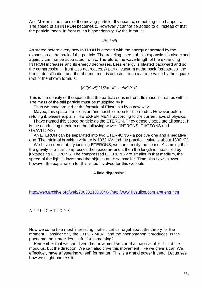
552
And M + m is the mass of the moving particle. If v nears c, something else happens. The speed of an INTRON becomes c. However v cannot be added to c. Instead of that; the particle "sees" in front of it a higher density. By the formula:
c²/(c²-v²)
As stated before every new INTRON is created with the energy generated by the expansion at the back of the particle. The traveling speed of this expansion is also c and again, v can not be subtracted from c. Therefore, the wave-length of the expanding INTRON increases and its energy decreases. Less energy is blasted backward and so the compression in front also decreases. A partial vacuum at the back "sabotages" the frontal densification and the phenomenon is adjusted to an average value by the square root of the shown formula:
[c²/(c²-v²)]^1/2= 1/(1 - v²/c²)^1/2
This is the density of the space that the particle sees in front. Its mass increases with it. The mass of the still particle must be multiplied by it. Thus we have arrived at the formula of Einstein’s by a new way. Maybe, this space-particle is an "indigestible" idea for the reader. However before refuting it, please explain THE EXPERIMENT according to the current laws of physics. I have named this space-particle as the ETERON. They densely populate all space. It is the conducting medium of the following waves (INTRONS, PHOTONS and GRAVITONS) An ETERON can be separated into two ETER-IONS - a positive one and a negative one. The minimal breaking voltage is 1022 KV and the practical value is about 1300 KV. We have seen that, by ionising ETERONS, we can densify the space. Assuming that the gravity of a star compresses the space around it then the length is measured by juxtaposing ETERONS. The compressed ETERONS are smaller in that medium, the speed of the light is lower and the objects are also smaller. Time also flows slower, however the explanation for this is too involved for this web site.
A little digression:
http://web.archive.org/web/20030210030404/http:/www.lilysullos.com.ar/eleng.htm
A P P L I C A T I O N S
Now we come to a most interesting matter. Let us forget about the theory for the moment. Consider only the EXPERIMENT and the phenomenon it produces. Is the phenomenon it provides useful for something? Remember that we can divert the movement-vector of a massive object - not the modulus, but the direction. We can also drive this movement, like we drive a car. We effectively have a "steering wheel" for matter. This is a grand power indeed. Let us see how we might harness it.
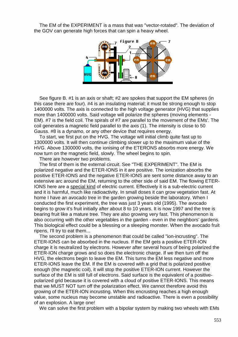
553
The EM of the EXPERIMENT is a mass that was "vector-rotated". The deviation of the GOV can generate high forces that can spin a heavy wheel.
See figure B. #1 is an axis or shaft; #2 are spokes that support the EM spheres (in this case there are four). #4 is an insulating material; it must be strong enough to stop 1400000 volts. The axis is connected to the high voltage generator (HVG) that supplies more than 1400000 volts. Said voltage will polarize the spheres (moving elements - EM). #7 is the field coil. The spirals of #7 are parallel to the movement of the EMs'. The coil generates a magnetic field parallel to the axis (1). The intensity is close to 50 Gauss. #8 is a dynamo, or any other device that requires energy. To start, we first put on the HVG. The voltage will initial climb quite fast up to 1300000 volts. It will then continue climbing slower up to the maximum value of the HVG. Above 1300000 volts, the ionising of the ETERONS absorbs more energy. We now turn on the magnetic field, slowly. The wheel begins to spin. There are however two problems. The first of them is the external circuit. See "THE EXPERIMENT". The EM is polarized negative and the ETER-IONS in it are positive. The ionization absorbs the positive ETER-IONS and the negative ETER-IONS are sent some distance away to an extensive arc around the EM, returning to the other side of said EM. The flowing ETER-IONS here are a special kind of electric current. Effectively it is a sub-electric current and it is harmful, much like radioactivity. In small doses it can grow vegetation fast. At home I have an avocado tree in the garden growing beside the laboratory. When I conducted the first experiment, the tree was just 3 years old (1995). The avocado begins to grow it’s fruit initially after about 8 to 10 years. It is now 1997 and the tree is bearing fruit like a mature tree. They are also growing very fast. This phenomenon is also occurring with the other vegetables in the garden - even in the neighbors’ gardens. This biological effect could be a blessing or a sleeping monster. When the avocado fruit ripens, I'll try to eat them... The second problem is a phenomenon that could be called "ion-incrusting". The ETER-IONS can be absorbed in the nucleus. If the EM gets a positive ETER-ION charge it is neutralized by electrons. However after several hours of being polarized the ETER-ION charge grows and so does the electronic charge. If we then turn off the HVG, the electrons begin to leave the EM. This turns the EM less negative and more ETER-IONS leave the EM. If the EM is covered with a grid that is polarized positive enough (the magnetic coil), it will stop the positive ETER-ION current. However the surface of the EM is still full of electrons. Said surface is the equivalent of a positive-polarized grid because it is covered with a cloud of positive ETER-IONS. This means that we MUST NOT turn off the polarization effect. We cannot therefore avoid this growing of the ETER-ION incrusting. When this encrusting reaches a high enough value, some nucleus may become unstable and radioactive. There is even a possibility of an explosion. A large one! We can solve the first problem with a bipolar system by making two wheels with EMs
554
on the same axis and then polarizing them with opposite voltages we lessen the external current. To avoid the ion incrusting the voltage of each EM can be alternated one or two times by minute. However during the voltage-commutation, the wheel has a dead point. To solve this problem, we make two systems of double-wheels. When one of them is at a dead point, the other is at the maximum power point with a difference of phase of 90 degrees. Observe that the double wheel most have two coils, one with opposite current in relation to the other. By adding a control system, a shield, and a protecting wall around the device, we have a power station that needs NO FUEL, and makes ZERO POLLUTION, is not radioactive and it is completely silent! Now a single wheel is definitely much cheaper than the system just described however if somebody does makes a single wheel device I'll be going far from that laboratory... I name this device an INTRON TURBINE. It uses geo-kinetic energy. Maybe, the worst problem is that nobody believes it. Maybe, at this very moment an alien is watching the "pollution show" of the earthlings and is making the comment, "Which will finish first? The air or the oil?" Sometimes, I imagine I am just a respectable teacher of physics and there appears a lunatic with (this) subject on the web. This lunatic appears very sure about the "laws of nature" however I think I know better and I kick him out. That is why many physicists have kicked me out.
http://web.archive.org/web/20030210030404/http:/www.lilysullos.com.ar/halfturb.htm
THE SPACE
If you have read my web site up to here and it is almost certain that you may then you probably think that I am plain crazy. I can however prove that I am much crazier than you currently suppose. Considering that the EM opens a huge door to space (as proved by THE EXPERIMENT).
Figure C represents a flying device. #1 is the central hull and #2 is the peripheral hull. #3 is a low-voltage high-current generator. #4 is the propelling coil creating a magnetic field. #5 are insulators that join the two hulls. #6 is the direction of the electronic current in the coil and #7 is the HVG, able to produce 3 Megavolts. Now the HVG polarizes both hulls with a voltage difference of 3 MV between them. The problem regarding the encrusted ETER-IONS becomes more complex. Both the hulls must be covered around the outside by a thin metal layer. By doing this it lessens this encrusting phenomenon. By commuting (reversing) the polarity using intervals of more or less 15 minutes it becomes possible to operate the vehicle on a long trip. The
555
external circuit will not harm the crew providing they stay inside the hull because the sub-particle charges move on and outside the surface. Observe figure C again. With the polarities shown, the vector-rotator effect will push the saucer down. Using the vector GOV rotation, we only can generate forces in a perpendicular plane to the GOV. If the vector GOV is vertical, we can not fly up. It depends on the date, time and geographical position of the saucer. Let us put an EM in a flying craft. It will be a VECTOR-PROPULSION (VP) engine. It will always be possible to soar with this vehicle however the landing is another problem. Think of an airplane that only has propulsion on an inclined plane and this plane is always shifting in direction. Of course, if we put a heavy EM in a spacecraft, the starting is very easy and fast. But the landing is not as simple. Either we leave the EM up there or we wait for a determined time and land at a determined place, where the GOV has its perpendicular plane in such a position that allows a fine landing. If we want to land anywhere, the direct VP can not be used. Nevertheless, for putting in orbit heavy loads, a VP engine is can be very useful, cheap and fast. Think about it. $2000 for orbiting 1 kg with the current rocket-engine technology as apposed to a few dollars for orbiting 1 ton with VP. Let us now consider going deep into space…. Up till now, I was crazy. From now on, I shall be regarded as (crazy)²! It is easy to densify the space when in the atmosphere. The matter (atmosphere) has high impedance for the FLOWING of ETERONS. To move the ETERONS in relation to the matter (atmosphere) is the same as moving the matter in relation to the ETERONS. In both cases, INTRONS (waves) are created and kinetic energy appears. However in a vacuum, the ETERON-FLOWING is not stopped and the impedance is low. Therefore in space it is very difficult to densify local space however it is easy to move the ETERONS. What happens if we move the ETERONS from the bow to the stern of a vessel? In front of the vessel a partial ETERON vacuum will pull and at the rear an ETER-ION-pressure will push, thus the spacecraft must move forward. It will be a very low density-difference, but enough to kill all inertia. The partial-ETERON-vacuum eliminates the increasing of the INTRONS. So, with only a few kilowatts, a big spacecraft can travel with speeds of over 10.000 km/sec. We can say that we "take the space" in front and we "put it behind", and we do not allow the ETERON-sweeping by the particles of the craft. If there is no sweeping, there will be no energy-increase of the INTRONS. Each particle densifies the ETERONS according to its mass and speed. But if there are no ETERONS to compress (we have taken them away), mass increasing of the particles is not possible. So, mass and speed do not matter. The kinetic energy is effectively "switched off". This is a NON-INERTIAL-DRIVE (NID) ie the "space-drive" of Arthur Clarke. His prophecy has come true! Now, for those that believe I am (crazy)² I will now become (crazy)³! Consider that the "waiting-interval" or the diameter of the ETERONS determines the speed of light. This diameter limits the inertial speed to that of light. It is the speed of the compressing for the ETERONS. Because of this, every wave travels with said speed. However the speed of the ETER-IONS (the positive and negative sub-particles), like a sub-electric current, is VERY MUCH HIGHER. Maybe, we can multiply the speed of the light by millions, or more. I do not know the exact value, but it is the limit of the non-inertial speed. Far from the Sun, where the "space-compression" is low, the craft can surpass the speed of the light by hundreds. I refer to an inter-stellar craft. You do not believe this? I can understand...However make a spacecraft and send it far but please do not let me be one of the crew! At least not for the first ten years of technical development!
556
I was born in 1938 on August 16 at Budapest in Hungary. My parents were born on planet Earth in Hungary also (But I am alien!) My actual identity: Name: Ludwig Süllös Address: Díaz Vélez 1360 LA LUCILA (c.p. 1636) Pcia. Buenos Aires, REPUBLICA ARGENTINA Thank you for reading my site. I hope it was good amusement.
BUT KNOW THAT THE EXPERIMENT WAS REAL.
Well, maybe the universe is just one big amusement made for all of us.
This research is patented, but the sole owners are the people on planet Earth. Earthlings need this. If not, they will have nothing to eat and breathe sometime within the next century. Let’s face it, planet Earth is in a hurry. (I however am not...)
Patented in Argentina Nr. 980105149 Nr. 980105150
#613 Re: [ferd] Extracting from tank at current peak
Gerry Jul 22 at 6:19 AM
Hi again Andreas,
Just want to also say that if R gets too high it will destroy the coil's Q value.
Q= Stored energy / dissipated energy
Which means the 2 * pi * freq * inductance of coil / series R total value should be >>
10 to 1 ratio.
Gerry
#614 Re: [ferd] Extracting from tank at current peak
557
Andreas Höschler Jul 22 7:55 PM
Hi Gerry,
I can see how you set up the monostable with the comparators for set & reset.
I don't understand how the FET drains (which are floating around all over the
place as far as potential is concerned)
Don't take that part of the circuit too serious. There is of course an IPC board (isolated MOSFET drivers) between the TTL world and the MOSFETs (not shown).
From theory point of view and I may be wrong (so guys
feel free to say so).
Maximum current occurs when 50% of the charge is in the inductor and 50%
in the capacitor.
No, that's not true. You have max current when the voltage in the cap reaches 0.
So it's probably not the best place on the cycle to introduce the resistance.
The maximum current equals by analogy, the maximum velocity reached on
the child's swing as it crosses thru the vertical plane.
Yes! And there we have amplitude zwro which corresponds to voltage zero inthe cap! :-)
Which again is halfway between capacitive and inductive discharge.
No, the cap is completely discharged at this moment and starts to get charged the other way around.
Is also 0, 180, 360 degrees point on sine wave voltage cycle = max velocity.
Yes!
That's why when we differentiate Sine 0, 180, 360 it goes to Cosine 1, -1 ,1
I recommend:
introducing resistor (removing short cct across it) at 90, 270, etc on voltage
wave which is where current = zero.
I have been there. That just kills the resonance and gets you nothing.
558
At this moment all current has been changed into flux energy out there in the
ambient around the coil.
Now introducing resistor right here.... is where current starts increasing whilst
voltage is diminishing.
As flux returns from the ambient.
Flux returns from the potential energy in the cap.
Thanks,
Andreas
#615 Re: [ferd] The universe (ethons, pretons,...)
Andreas Höschler Jul 23 at 12:15 AM
Hi Gustavo,
I had read it some month ago, and that subject seems to be interesting to study in a deeper way. I have to read it again. But I think that we need very high voltage to generate some unbalance in ether to take some profit.
For example, there is a patent from Ludwig Sullos, an Hungarian man who lived and died in my Country. He talked about something similar, but his idea was about using high voltage to move the ether from one place to another (like little balls) generating a "real vacuum" where matter displaces into, so he create movement in every direction he wants.
Thanks so much for forwarding this document. I am not even half through and the english of the author is horrible (close to unreadable). However, the document triggered something in me (may be the missing link). I am currently pretty productive (just writing down thoughts) and seem to finally make some progress. I will report in detail if I really end up somewhere but so far it looks pretty good. Just wanted to share my joy about the current progess! Sorry for the (so far nonsensical) noise! :-)
Best wishes,
Andreas
#616 Re: [ferd] The universe (ethons, pretons,...)
Andreas Höschler Jul 23 10:34 PM

559
Hi all, pretty quiet in the group!? :-) Please let me seed a teaser. We all know the Lorentz Force and the corresponding equation F = q * v x B we learned in Kindergarden. I have more and more doubts whether this (purely descriptive) equation is correct. Could it be rather F = |q| * v x B I am serious! Do you know any experiment that clearly shows that the deflection direction changes when using a positive instead of a negative charge? We find not that many positrons in the lab to experiment with and positively charged ions are probably too heavy to show a significant (measurable) deflection!? Can anyone point me to convincing evidence that the established equation is correct? If so my current understanding of the universe needs a significant revision. Otherwise I might be close. :-) Your help is greatly appreciated!! Thanks in advance, Andreas
#617 Re: [ferd] The universe (ethons, pretons,...)
onielsen2000 Jul 23 11:27 PM
Hi Andreas, A cloud chamber can detect both positive and negative particles: Positron - Wikipedia, the free encyclopedia
Positron - Wikipedia, the free encyclopedia The positron or antielectron is the antiparticle
or the antimatter counterpart of the electron.
The positron has an electric charge of +1 e, a
spin of ½, and has th...
View on en.wikipedia.org
Preview by
Yahoo
560
Regards Ole
#618 Re: [ferd] The universe (ethons, pretons,...)
Andreas Höschler Jul 24 at 2:38 AM
Hi Ole,
A cloud chamber can detect both positive and negative particles: Positron - Wikipedia, the
free encyclopedia
Thanks a lot for the link. Prove enough. This asymmetry is interesting. We now need a way to incorporate this in the model ...
Best wishes,
Andreas
#619 reading
Alexey Jul 24 8:22 AM
http://www.anandgholap.net/AB_CWL_Occult_Chemistry.htm ;-)
#620 reading - Maxwell original equations
Alexey Jul 27 10:04 PM
Hi Andreas, I saw that you interested in Maxwell's original papers. I have some files in my archive, not sure if it useful, but anyway here a link to archive https://www.idrive.com/idrive/sh/sh?k=u0o7a1r7s1 - Alexey
561
#621 Hectors Autotransformer
Andreas Höschler Jul 27 at 3:02 AM
Hi all, I spent some time in the lab again and tried out Hectors autotransformer concept which at least theoretically makes some sense. However, I could not verify any advantage of the concept. The efficiency is even lower than conventional push/pull. See attached PDF:
Next one ... Best wishes, Andreas
#622 Re: [ferd] reading - Maxwell original equations
Andreas Höschler Jul 29 at 1:09 AM
Hi Alexey,
I saw that you interested in Maxwell's original papers. I have some files in my archive, not sure if it useful, but anyway here a link to archive
https://www.idrive.com/idrive/sh/sh?k=u0o7a1r7s1
Thanks a lot! I have some trouble with rar-Archive on my Unix-environment. Anyway, have you worked through these papers and learned something from it? Quaternions or field equations?
I am a little desperate to finally getting a clue of what magnetism actually is. I am almost convinced that vector potential A is simply
A = n v e
where n is the number of ethon-pairs going (with average velocity v) through an infinitesimal small area element with direction e. B is then
B = curl A
If charges move from areas of small A to larger A they exhibit a force. I just don't get yet how exactly this happens. The static E-field can be explained relatively easy (lots of n-ethons and p-ethons flying around) but the magnetic field is tricky.
Once we have at least a clue we can probably simply design a device and it works immediately. But so long ... one failure after the next. :-(
Thanks,
Andreas
562
#623 Re: [ferd] The universe (ethons, pretons,...)
Andreas Höschler Jul 29 at 1:13 AM
Hi Gustavo,
Thanks a lot for this link. I worked through the document. Pretty interesting reading. However, I have some doubts regarding the values given in the doc. This guy has generated 1.4 million volts in his garage!? That's hard to believe. The device shown would never withstand this high voltage unless completely in oil and even then ...
Anyway, what could have caused the anomalous behaviour reported? Any idea? I have not (so far)! :-(
Thanks,
Andreas
#624 RE: [ferd] reading - Maxwell original equations
Alexey Jul 29 at 8:49 AM
Hi Andreas,
Here same files but in zip archive https://www.idrive.com/idrive/sh/sh?k=l3u4w0e4f7
From my point of view Maxwell’s papers has mainly historical value. We can see how all these stuff was created.
As you probably know, I am quite skeptical about H. and N.W. They are behaving as typical internet trolls and we should not waste our time on their claims.
Most of texts posted by N.W. sounds for me as a “yellow press”, cheap sensation targeting low educated and unsophisticated auditory. Most of them are full of nonsense.
I am also not sharing your optimism about building new theory.
Math is a tool, when mixed with reality it gives illusion of understanding and produce monsters like theory of relativity.
Here an example
http://magneticuniverse.com/uploads/FileUpload/e4/24d9314e3aa202313fd3cf4259d19e.pdf
Does it really help us? I don’t think so.
Instead of building new formulas it is much more useful search for understanding how nature behaves, for such “simple” questions which math can’t give answers like “where capacitor store it’s charge” or “does magnetic field belongs to magnet (or space)”. Since most of scientists like math and don’t like say “we don’t really know” there are plenty of such “simple” questions without answers…and for most of them it is a bad manner to ask about such things
563
Regards,
Alexey
#625 reading - The Life of Nikola Tesla by John J. O'Neill
vasik041 Jul 29 at 12:39 PM
PRODIGAL GENIUS The Life of Nikola Tesla by John J. O'Neill (1944)
http://www.rastko.rs/istorija/tesla/oniell-tesla.html
#626 Re: [ferd] reading - Maxwell original equations
Andreas Höschler Jul 29 at 2:41 PM
Hi Alexey,
Instead of building new formulas it is much more useful search for understanding how nature behaves, for such “simple” questions which math can’t give answers like
“where capacitor store it’s charge” or “does magnetic field belongs to magnet (or space)”.
That's exactly what I am after. We know of a bunch of phenomena:
• The standard stuff engineers are taught, e.g. Maxwells Equations that work at least under some conditions
• The anomaly written about on the article Gustavo posted recently
• rotating magnets and the homopolar generator
• ....
We just have to put all this stuff on the table and brainstorm until we have found a concept/model (not necessarily a mathematical description) that explains all the observed phenomena. That can't be so hard if we keep our mind open.
#627 Re: [ferd] reading - Maxwell original equations
Andreas Höschler Jul 29 at 6:57 PM
Hi Alexey,
564
Here an example
http://magneticuniverse.com/uploads/FileUpload/e4/24d9314e3aa202313fd3cf
4259d19e.pdf
Does it really help us? I don’t think so.
The first few pages were at least entertaining (light ball phenomena). The rest is either gibberish or so far away from known notation (over my head) that I could not make much sense out of it.
Still a lot of puzzle pieces on the desk ... :-)
Andreas
#628 Re: [ferd] The universe (ethons, pretons,...)
Gustavo Roveran Jul 29 10:42 PM
Hi Adreas,
Yes, is very difficult to believe that we can implement a 1.4 millon volts power source at home, but seems that he tested that.
I think that this experiment is related with the theory shared in the next document, which you can download from an old site, I think that you know about this site.
http://jnaudin.free.fr/lifters/docs/UnconventionalScience.pdf
And all the experiments related with -> The Lifters Experiments home page by Jean-Louis Naudin
The Lifters Experiments home page by Jean-Louis Naudin created on October 10th, 2001 - JLN Labs -
Last update January 27, 2010
Ver en jnaudin.free.fr Vista previa por Yahoo
Best regards,
Gustavo
565
#629 Re: [ferd] The universe (ethons, pretons,...)
Andreas Höschler Jul 30 at 12:52 AM
Hi Gustavo,
Yes, is very difficult to believe that we can implement a 1.4 millon volts power source at home,
but seems that he tested that.
I think that this experiment is related with the theory shared in the next document, which you can
download from an old site, I think that you know about this site.
http://jnaudin.free.fr/lifters/docs/UnconventionalScience.pdf
Thanks a lot. It was just today that I tried to recall the specifics of the Bielefeld Brown experiments. I appended the following comment to my notes:
• [Bielefeld Brown Effekt] A sufficiently charged (asymmetric) capacitor with dielectrics exhibits thrust. The greater force is achieved when the small electrode is positively charged (but opposite polarity works as well).
Now let's try to make sense of this using Distintis ethon/preton model and see where we end up! :-)
Thanks,
Andreas
#630 Gyrokinetic Engine
vasik041 Jul 31
http://www.rgenergy.com/index.html
What is a Gyrokinetic Engine ?
The principle of the gyrokinetic engine is deceptively basic and simple: A hermetic telescoping gas chamber is filled with a relatively inexpensive, abundant, and harmless charge of inert gases. These gases are subjected to controlled low voltage electronic pulses and frequency effects to create a powerful expansion. Removal or reversal of the pulses causes a contraction leaving the gases ready to cycle again. During this cycle electrons are released in sufficient quantity to provide for the power requirements of the opposing cylinder. This cyclic energy release does not release significant amounts of heat.
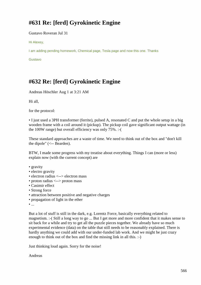
566
#631 Re: [ferd] Gyrokinetic Engine
Gustavo Roveran Jul 31
Hi Alexey,
I am adding pending homework, Chemical page, Tesla page and now this one. Thanks
Gustavo
#632 Re: [ferd] Gyrokinetic Engine
Andreas Höschler Aug 1 at 3:21 AM
Hi all, for the protocol: • I just used a 3PH transformer (ferrite), pulsed A, resonated C and put the whole setup in a big wooden frame with a coil around it (pickup). The pickup coil gave significant output wattage (in the 100W range) but overall efficiency was only 75%. :-( These standard approaches are a waste of time. We need to think out of the box and "don't kill the dipole" (<-- Bearden). BTW, I made some progress with my treatise about everything. Things I can (more or less) explain now (with the current concept) are • gravity • electro gravity • electron radius <--> electron mass • proton radius <--> proton mass • Casimir effect • Strong force • attraction between positive and negative charges • propagation of light in the ether • ... But a lot of stuff is still in the dark, e.g. Lorentz Force, basically everything related to magnetism. :-( Still a long way to go ... But I get more and more confident that it makes sense to sit back for a while and try to get all the puzzle pieces together. We already have so much experimental evidence (data) on the table that still needs to be reasonably explained. There is hardly anything we could add with our under-funded lab work. And we might be just crazy enough to think out of the box and find the missing link in all this. :-) Just thinking loud again. Sorry for the noise! Andreas
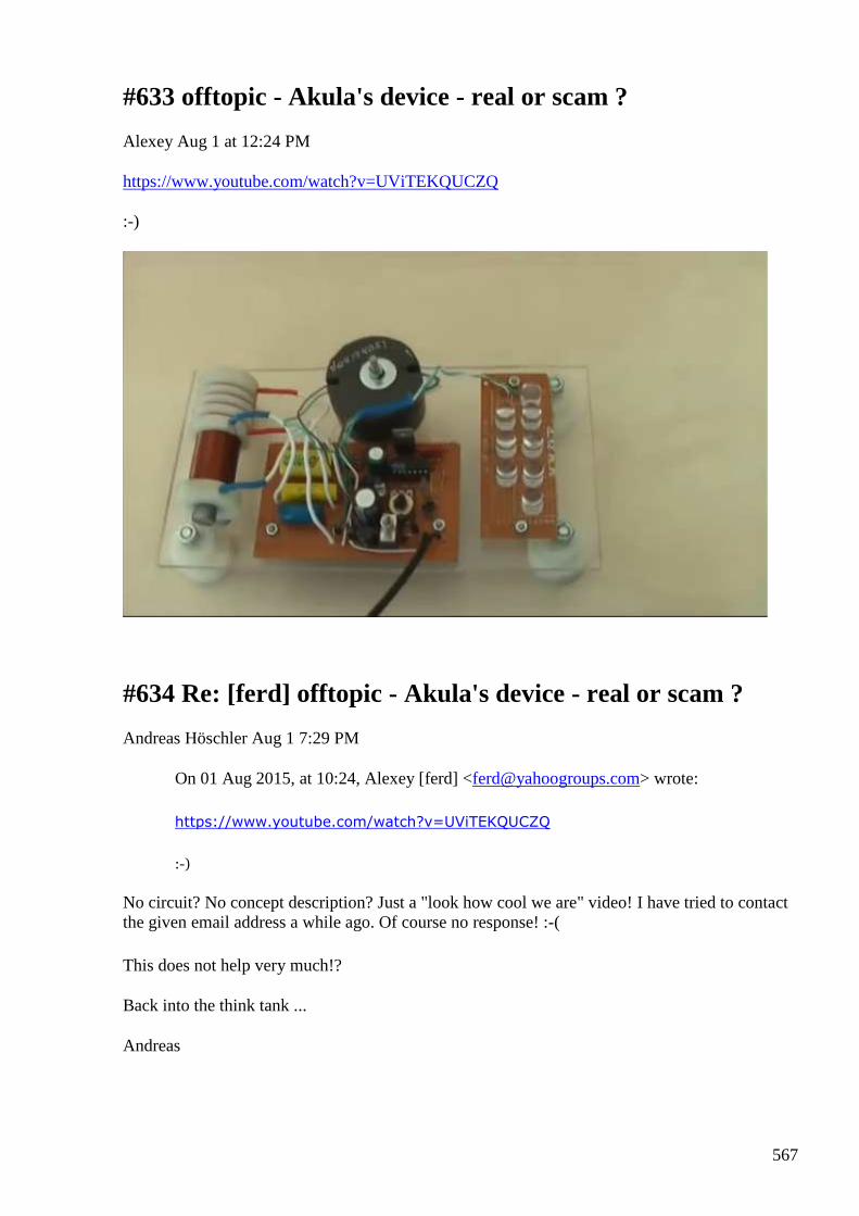
567
#633 offtopic - Akula's device - real or scam ?
Alexey Aug 1 at 12:24 PM
https://www.youtube.com/watch?v=UViTEKQUCZQ :-)
#634 Re: [ferd] offtopic - Akula's device - real or scam ?
Andreas Höschler Aug 1 7:29 PM
On 01 Aug 2015, at 10:24, Alexey [ferd] <[email protected]> wrote:
https://www.youtube.com/watch?v=UViTEKQUCZQ
:-)
No circuit? No concept description? Just a "look how cool we are" video! I have tried to contact the given email address a while ago. Of course no response! :-(
This does not help very much!?
Back into the think tank ...
Andreas
568
#635 Oscilloscope probes
onielsen2000 Aug 3 7:28 PM
Great video about oscilloscope probes: Whats All This Scope Probe Stuff, Anyhow?
https://youtu.be/2vzvWUqUtb8
Whats All This Scope Probe Stuff, Anyhow? Bob Pease andf friends discuss high frequency
scope probes and high-speed measurement
tips. Featuring Paul Rako, Paul Grohe, and
Ken Price (Tektronix).
View on youtu.be
Preview by
Yahoo
Regards Ole
#636 Vector Potential is real
Andreas Höschler Aug 4 at 1:59 AM
Hi all, I can't believe it but I just got a very convincing result by doing some mathematical magic with an expression Distinti derived (his new induction model). I had to move a factor but then could prove that his expression for I is actually the vector potential A. The assumption (claimed in many books) that the vector potential A has no physical meaning is utter non-sense!! The opposite is the case. Richard Feynman was right and many of his colleagues (book authors) have not the slightest clue. A stream of n-Pretons in a current carrying conductor drags ethon-pairs and thus causes a vector potential (aether wind). Everything falls into place now (even quantitatively). Please see the attached document to get a clue what I am talking about (sorry for the german text, was not originally meant for publication):
Please note the last two expressions for a short and a long straight current carrying conductor and ignore equation (1) which is non-sense! This result has profound consequences. It explains gravity, strong force, the Casimir Effect and even Electro Gravity. Life is great! :-)
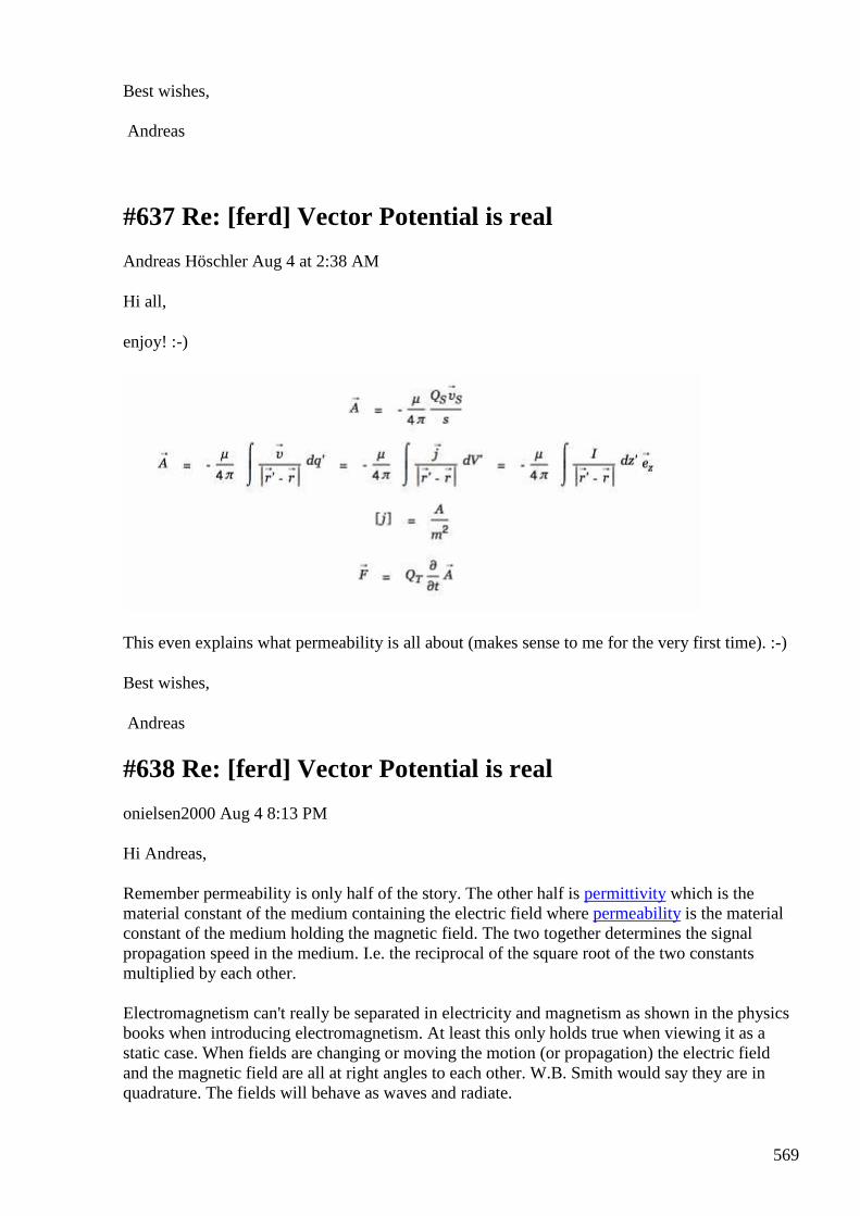
569
Best wishes, Andreas
#637 Re: [ferd] Vector Potential is real
Andreas Höschler Aug 4 at 2:38 AM
Hi all,
enjoy! :-)
This even explains what permeability is all about (makes sense to me for the very first time). :-)
Best wishes,
Andreas
#638 Re: [ferd] Vector Potential is real
onielsen2000 Aug 4 8:13 PM
Hi Andreas, Remember permeability is only half of the story. The other half is permittivity which is the material constant of the medium containing the electric field where permeability is the material constant of the medium holding the magnetic field. The two together determines the signal propagation speed in the medium. I.e. the reciprocal of the square root of the two constants multiplied by each other. Electromagnetism can't really be separated in electricity and magnetism as shown in the physics books when introducing electromagnetism. At least this only holds true when viewing it as a static case. When fields are changing or moving the motion (or propagation) the electric field and the magnetic field are all at right angles to each other. W.B. Smith would say they are in quadrature. The fields will behave as waves and radiate.
570
Regards Ole
#639 Re: [ferd] Vector Potential is real
Gustavo Roveran Aug 4 9:55 PM
Hi Andreas, Perhaps He could help you more, he is German, and may have responses for your/our research. -- I am only sending you different things that I have touched some time ago, and they are still unconnected. --
Best Regards,
Meyl - Scalarwave-Technology - The european website of www.k-meyl.de
http://www.meyl.eu/go/index.php?dir=10_Home&page=1&sublevel=0
Meyl - Scalarwave-Technology - The european website of w... The european website of Prof. Dr. Meyl
Ver en www.meyl.eu Vista previa por Yahoo
#640 Re: [ferd] Vector Potential is real
Andreas Höschler Aug 4 11:19 PM
Hi Ole,
Electromagnetism can't really be separated in electricity and magnetism as shown in the physics books when introducing electromagnetism. At least this only holds true when viewing it as a static case. When fields are changing or moving the motion (or propagation) the electric field and the magnetic field are all at right angles to each other. W.B. Smith would say they are in quadrature. The fields will behave as waves and radiate.
That's thinking in the old domain (many contradictions depending on which book you take, e.g. no phase shift between magnetic and electric field amplitude which is of course utter none-sense). I of course could be mistaken but my current understanding is that
the electric field and the magnetic field are all at right angles to each other. W.B. Smith would say they are in quadrature. The fields will behave as waves and radiate.
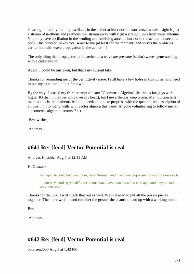
571
is wrong. In reality nothing oscillates in the aether at least not for transversal waves. Light is just a stream of n-ethons and p-ethons that stream away with c (in a straight line) from some antenna. You only have oscillation in the sending and receiving antenna but not in the aether between the both. This concept makes total sense to me (at least for the moment) and solves the problems I earlier had with wave propagation in the aether. :-)
The only thing that propagates in the aether as a wave are pressure (scalar) waves generated e.g. with a caduceus coil .
Again, I could be mistaken, but that's my current take.
Thanks for reminding me of the permittivity issue. I still have a few holes in this corner and need to put my intention on that for a while.
By the way, I started my third attempt to learn "Geometric Algebra". Je, this is for guys with higher IQ than mine (certainly over my head), but I nevertheless keep trying. My intuition tells me that this is the mathematical tool needed to make progress with the quantitative description of all this. I hit to many walls with vector algebra this week. Anyone volunteering to follow me on a geometric algebra discourse? :-)
Best wishes,
Andreas
#641 Re: [ferd] Vector Potential is real
Andreas Höschler Aug 5 at 12:11 AM
Hi Gustavo,
Perhaps He could help you more, he is German, and may have responses for your/our research. -- I am only sending you different things that I have touched some time ago, and they are still unconnected. --
Thanks for the link. I will check that out as well. We just need to put all the puzzle pieces together. The more we find and consider the greater the chance to end up with a working model.
Best,
Andreas
#642 Re: [ferd] Vector Potential is real
onielsen2000 Aug 5 at 1:43 PM
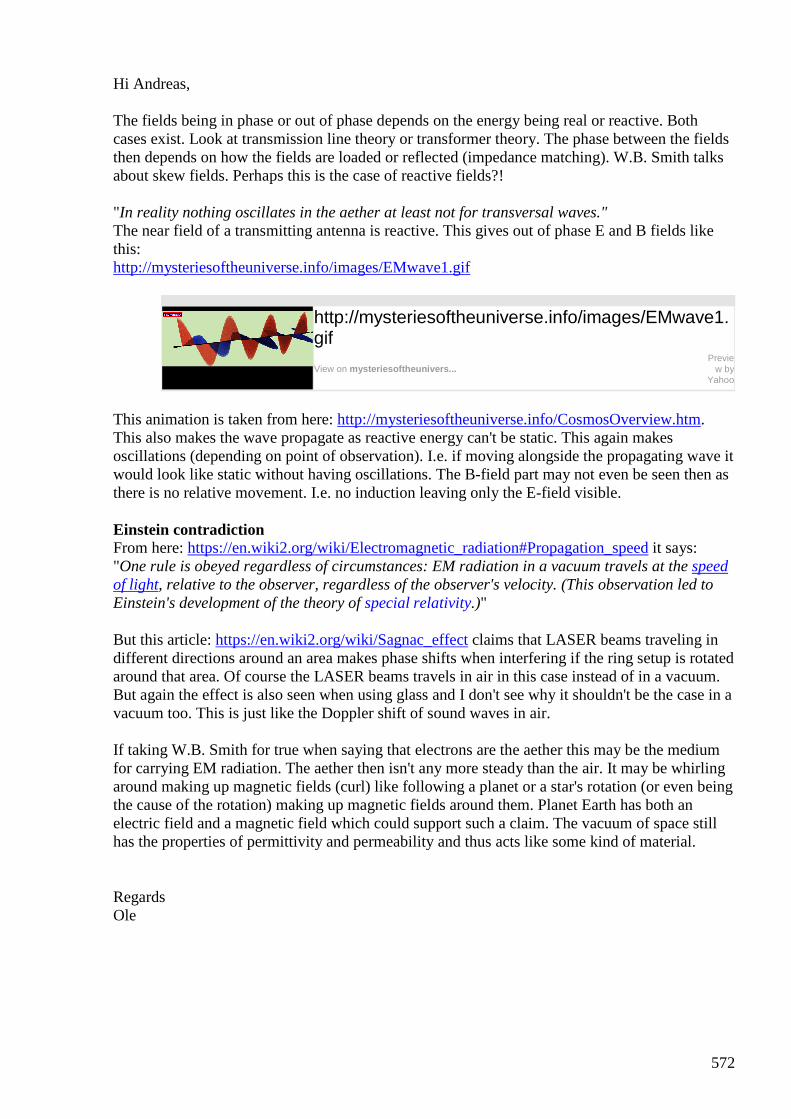
572
Hi Andreas, The fields being in phase or out of phase depends on the energy being real or reactive. Both cases exist. Look at transmission line theory or transformer theory. The phase between the fields then depends on how the fields are loaded or reflected (impedance matching). W.B. Smith talks about skew fields. Perhaps this is the case of reactive fields?! "In reality nothing oscillates in the aether at least not for transversal waves." The near field of a transmitting antenna is reactive. This gives out of phase E and B fields like this: http://mysteriesoftheuniverse.info/images/EMwave1.gif
http://mysteriesoftheuniverse.info/images/EMwave1.gif
View on mysteriesoftheunivers...
Preview by
Yahoo
This animation is taken from here: http://mysteriesoftheuniverse.info/CosmosOverview.htm. This also makes the wave propagate as reactive energy can't be static. This again makes oscillations (depending on point of observation). I.e. if moving alongside the propagating wave it would look like static without having oscillations. The B-field part may not even be seen then as there is no relative movement. I.e. no induction leaving only the E-field visible. Einstein contradiction From here: https://en.wiki2.org/wiki/Electromagnetic_radiation#Propagation_speed it says: "One rule is obeyed regardless of circumstances: EM radiation in a vacuum travels at the speed of light, relative to the observer, regardless of the observer's velocity. (This observation led to Einstein's development of the theory of special relativity.)"
But this article: https://en.wiki2.org/wiki/Sagnac_effect claims that LASER beams traveling in different directions around an area makes phase shifts when interfering if the ring setup is rotated around that area. Of course the LASER beams travels in air in this case instead of in a vacuum. But again the effect is also seen when using glass and I don't see why it shouldn't be the case in a vacuum too. This is just like the Doppler shift of sound waves in air. If taking W.B. Smith for true when saying that electrons are the aether this may be the medium for carrying EM radiation. The aether then isn't any more steady than the air. It may be whirling around making up magnetic fields (curl) like following a planet or a star's rotation (or even being the cause of the rotation) making up magnetic fields around them. Planet Earth has both an electric field and a magnetic field which could support such a claim. The vacuum of space still has the properties of permittivity and permeability and thus acts like some kind of material.
Regards Ole
573
#643 Re: [ferd] Vector Potential is real
Andreas Höschler Aug 5at 2:58 PM
Hi Ole,
Einstein contradiction From here: https://en.wiki2.org/wiki/Electromagnetic_radiation#Propagation_speed it says: "One rule is obeyed regardless of circumstances: EM radiation in a vacuum travels at the speed of light, relative to the observer, regardless of the observer's velocity. (This observation led to Einstein's development of the theory of special relativity.)"
This sentence is complete none-sense for obvious reasons. I can't believe that this BS is still printed and taught. :-(
But this article: https://en.wiki2.org/wiki/Sagnac_effect claims that LASER beams traveling in different directions around an area makes phase shifts when interfering if the ring setup is rotated around that area. Of course the LASER beams travels in air in this case instead of in a vacuum. But again the effect is also seen when using glass and I don't see why it shouldn't be the case in a vacuum too. This is just like the Doppler shift of sound waves in air.
Of course there is a phase shift in glass. The matter drags the aether around and light travels with c relative to the (moving) aether.
The fields being in phase or out of phase depends on the energy being real or reactive. Both cases exist. Look at transmission line theory or transformer theory. The phase between the fields then depends on how the fields are loaded or reflected (impedance matching). W.B. Smith talks about skew fields. Perhaps this is the case of reactive fields?!
I can't make any sense out of this. Loaded fields in a propagating wave in the vacuum???? I don't buy that! We can only have a wave if "something" oscillates. The first question therefore must be what oscillates in a light wave (this requires some force that pulls back to a zero potential)!? I reflected over this a lot and finally concluded that the whole concept is gibberish. There is oscillation in the antennas but not in the vacuum between them (for lack of oscillators). Please see the attached picture for my idea what happens when an antenna sends out a transverse electromagnetic wave (<-- the term is wrong since it is electro only). The circled plusses and minuses radiating away from the antenna in a straight line are p-ethons and n-ethons. If these beasts hit the receiving antenna they interact with the freely moving n-pretons in the conductor of the receiver and make them oscillate.
"In reality nothing oscillates in the aether at least not for transversal waves." The near field of a transmitting antenna is reactive. This gives out of phase E and B fields like this:
I really recommend to stop thinking in terms of B fields. This is very misleading and keeps "scientists" in a blind alley. B-fields do not exist (check out Feynman)!! If you think they do please explain with convincing arguments why and what exactly they are. - What exists is aether
574
wind (movement of ethon-pairs). Whenever a charge sees a changing aether wind some accelerating force acts on the charge. http://mysteriesoftheuniverse.info/images/EMwave1.gif
http://mysteriesoftheuniverse.info/images/EMwave1.gif
View on mysteriesoftheunivers... Preview by Yahoo
This animation is taken from here: http://mysteriesoftheuniverse.info/CosmosOverview.htm. This also makes the wave propagate as reactive energy can't be static. This again makes oscillations (depending on point of observation).
No again! Please tell me what you think oscillates here? E-field and B-field is no valid answer (too abstract concepts).
If taking W.B. Smith for true when saying that electrons are the aether
This is wrong for obvious reasons. There must be duality in the aether or we could not have transverse waves.
this may be the medium for carrying EM radiation. The aether then isn't any more steady than the air. It may be whirling around making up magnetic fields (curl) like following a planet or a star's rotation
Yes! It's neutral ethon-pairs that make up the aether and whirl around with the planets and stars. Matter is fed with ethon-pairs to exists. There you have gravity, strong force, Casimir effect,...
(or even being the cause of the rotation) making up magnetic fields around them. Planet Earth has both an electric field and a magnetic field which could support such a claim. The vacuum of space still has the properties of permittivity and permeability and thus acts like some kind of material.
permeability is simple. permittivity as well (think lots of n-ethons and p-ethons) moving through the ethon-pair soup. Feynman was again right. The truth is extremely simple and beautiful. It seems we have to unlearn tons of BS (invalid concepts) before we can approach the truth. This makes me sick. Tesla was right when stating that the Hertz wave model would throw us 100 years back. :-( Please let's rigorously look at all these concepts now and throw away (once for ever) what can't stand our examination. We have no more time for mind games ... Andreas
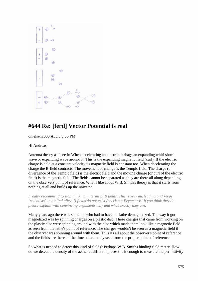
575
#644 Re: [ferd] Vector Potential is real
onielsen2000 Aug 5 5:36 PM
Hi Andreas, Antenna theory as I see it: When accelerating an electron it drags an expanding whirl shock wave or expanding wave around it. This is the expanding magnetic field (curl). If the electric charge is held at a constant velocity its magnetic field is constant too. When decelerating the charge the B-field contracts. The movement or change is the Tempic field. The charge (or divergence of the Tempic field) is the electric field and the moving charge (or curl of the electric field) is the magnetic field. The fields cannot be separated as they are there all along depending on the observers point of reference. What I like about W.B. Smith's theory is that it starts from nothing at all and builds up the universe. I really recommend to stop thinking in terms of B fields. This is very misleading and keeps "scientists" in a blind alley. B-fields do not exist (check out Feynman)!! If you think they do please explain with convincing arguments why and what exactly they are. Many years ago there was someone who had to have his lathe demagnetized. The way it got magnetized was by spinning charges on a plastic disc. These charges that came from working on the plastic disc were spinning around with the disc which made them look like a magnetic field as seen from the lathe's point of reference. The charges wouldn't be seen as a magnetic field if the observer was spinning around with them. Thus its all about the observer's point of reference and the fields are there all the time but can only seen from the proper points of reference. So what is needed to detect this kind of fields? Perhaps W.B. Smiths binding field meter. How do we detect the density of the aether at different places? Is it enough to measure the permittivity
576
and permeability to know the density of the aether etc.?
If taking W.B. Smith for true when saying that electrons are the aether
This is wrong for obvious reasons. There must be duality in the aether or we could not have transverse waves.
There is. The basic particle has four modes according to Smith. It is stable when closing in on itself somewhat like a smoke ring. The ring then can spin two ways as well as the torus can spin into or out of the center hole. This gives both the electron and the positron depending on the different modes of spin. When cluttering together in strings of toruses quarks and all kinds of elementary particles can be made according to Smith. When combining this theory with wave theory all kinds of forces can be made as wave interferences. Even matter can be described as waves. Look at the theory of Rhytmodynamics: http://rhythmodynamics.com/index_en.htm Regards Ole
#645 Re: [ferd] Vector Potential is real
Andreas Höschler Aug 5 7:28 PM
Hi Ole,
thanks for the additional info!!
There is. The basic particle has four modes according to Smith. It is stable when closing in on itself somewhat like a smoke ring. The ring then can spin two ways as well as the torus can spin into or out of the center hole. This gives both the electron and the positron depending on the different modes of spin. When cluttering together in strings of toruses quarks and all kinds of elementary particles can be made according to Smith. When combining this theory with wave theory all kinds of forces can be made as wave interferences. Even matter can be described as waves. Look at the theory of Rhytmodynamics: http://rhythmodynamics.com/index_en.htm
I will need some time to digest that. There might be a direkt mapping between the ethon/preton stuff of Distinti and the smoke-rings of Smith (very similar concepts, just different denotations for the same beasts). Anyway, we seem to get closer to the ultimate goal of being able to actually engineer a device from the ground up and knowing what we are doing. No more blind tinkering ... :-)
Thanks,
Andreas
577
#646 Re: [ferd] Vector Potential is real
Gustavo Roveran Aug 5 7:50 PM
Hi Andreas,
Seems that Disinti read your mind and made another video for displacement current theory.
emv002C: Addendum/Overview: Maxwell's Displacment current fraud
emv002C: Addendum/Overview: Maxwell's Displacment...
Ver en www.youtube.com Vista previa por Yahoo
If I am not wrong, Alexey demonstrate that displacement current produce magnetic field,
Best Regards,
Gustavo
#647 Re: [ferd] Vector Potential is real
onielsen2000 Aug 5 8:55 PM
Hi Gustavo, Andreas, Displacement current really isn't needed to explain a capacitor as this would require infinite signal speed for the charges to distribute about the plates. Instead if treating the capacitors as made up of transmission lines they have permittivity and permeability determining the signal speed which means that the charges flows like in transmission lines to be distributed across the plates with reflections and all of the characteristics of transmission lines. Read Ivor Catt and his Catt anomaly that finally got solved. Catt learned it the hard way by experimenting with the very fast emitter coupled digital electronics when this was invented. The signals traveled at finite speed which made it impossible for the current to reach the destination of the switches (emitter coupled transistors) in time. The solution was using capacitors as small energy reservoirs (decoupling capacitors) storing the energy close to where it was needed for transmitting a digital pulse transition. The leads then had to be treated as transmission lines. In a transmission line the energy is transferred in the space between two conductors as movement electric field and magnetic field all at right angles to each other. The Catt controversy was about where the charge on the neutral wire (return wire) comes from. The solution is that the charges are just moved by the fields reaching from the first wire. The charges are already in the conductors or even in the vacuum of space according to W.B Smith.
578
I.e. the aether is electrons. Some links to Ivor Catt's site that can be quite hard to navigate:
Electromagnetic Theory.
http://www.ivorcatt.co.uk/x3118.htm
http://www.ivorcatt.co.uk/x3118.htm Electromagnetic Theory. 8 My books. Electromagnetism 1 2002 . The new
approach to Electromagnetic Theory starting with the Transverse
Electromagnetic Wave (TEM Wave) travelling at the speed of light.
View on www.ivorcatt.co.uk
Preview by
Yahoo
http://www.ivorcatt.co.uk/x311.htm
http://www.ivorcatt.co.uk/x311.htm Index to Ivor Catts work on Electromagnetic Theory. [email protected] .
Welcome to Catt's World There are a number of aspects to my fifty years
researching electromagnetic theory.
View on www.ivorcatt.co.uk
Preview by
Yahoo
Electromagnetic Theory; Maxwell's Equations; Ivor Catt
Electromagnetic Theory; Maxwell's Equations; Ivor Catt The software output proves that Ian Darney does not know that in the
configuration shown, the crosstalk (noise) is flat topped, not a damped sine
wave. See the oscilloscope photographs published in IEEE Transactions
on Electronic Computers.
View on www.ivorcatt.co.uk
Preview by
Yahoo
Regards Ole
579
#648 Re: [ferd] Vector Potential is real
Andreas Höschler Aug 5 8:56 PM
Hi Gustavo,
Seems that Disinti read your mind and made another video for displacement current theory.
emv002C: Addendum/Overview: Maxwell's Displacment current fraud
emv002C: Addendum/Overview: Maxwell's Displacment...
Ver en www.youtube.com Vista previa por Yahoo
Thanks for bringing this up. IMHO Distintis reasoning is bogus in this case (course could be mistaken as always). I don't see any dD/dt in the wire. There we have a continuous stream of n-pretons and at least statistically the averaged dD/dt will be zero there. So Maxwells expression could theoretically be correct. But if it were correct this would mean that a rising number of n-ethons/p-ethons passing the gap (in the capacitor) would cause rot H or more exactly aether wind. This could be. But why should it? I can't see this being necessary.
I am with Distinti here. His reasoning in the video is bogus but I agree with his result. We have aether wind caused by n-pretons moving with v (so due to current flowing in a wire only). Any yes, the wave model is completely bogus. No oscillations, no wave, just a stream of n-ethons/p-ethons.
If I am not wrong, Alexey demonstrate that displacement current produce magnetic field,
How? Alexey? I would love to have a look on this!?
Andreas
#649 Re: [ferd] Vector Potential is real
Andreas Höschler Aug 5 9:04 PM
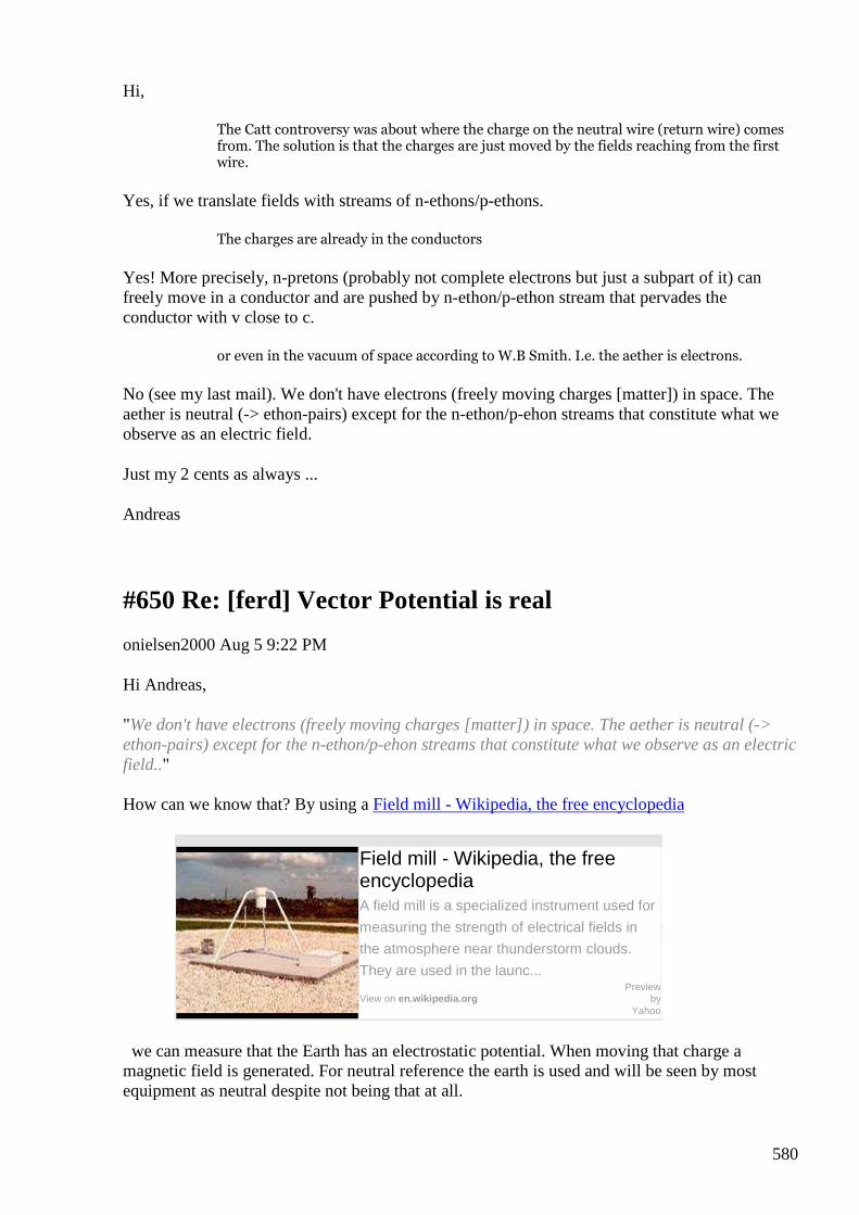
580
Hi,
The Catt controversy was about where the charge on the neutral wire (return wire) comes from. The solution is that the charges are just moved by the fields reaching from the first wire.
Yes, if we translate fields with streams of n-ethons/p-ethons.
The charges are already in the conductors
Yes! More precisely, n-pretons (probably not complete electrons but just a subpart of it) can freely move in a conductor and are pushed by n-ethon/p-ethon stream that pervades the conductor with v close to c.
or even in the vacuum of space according to W.B Smith. I.e. the aether is electrons.
No (see my last mail). We don't have electrons (freely moving charges [matter]) in space. The aether is neutral (-> ethon-pairs) except for the n-ethon/p-ehon streams that constitute what we observe as an electric field.
Just my 2 cents as always ...
Andreas
#650 Re: [ferd] Vector Potential is real
onielsen2000 Aug 5 9:22 PM
Hi Andreas, "We don't have electrons (freely moving charges [matter]) in space. The aether is neutral (-> ethon-pairs) except for the n-ethon/p-ehon streams that constitute what we observe as an electric field.." How can we know that? By using a Field mill - Wikipedia, the free encyclopedia
Field mill - Wikipedia, the free encyclopedia A field mill is a specialized instrument used for
measuring the strength of electrical fields in
the atmosphere near thunderstorm clouds.
They are used in the launc...
View on en.wikipedia.org
Preview by
Yahoo
we can measure that the Earth has an electrostatic potential. When moving that charge a magnetic field is generated. For neutral reference the earth is used and will be seen by most equipment as neutral despite not being that at all.

581
Regards Ole.
#651 [history] Röntgen's other experiment
Alexey Aug 5 9:28 PM
Hello guys,
I am offering a historical reading related to the topic ;-)
- Alexey
#652 Re: [ferd] [history] Röntgen's other experiment
Andreas Höschler Aug 5 9:36 PM
Hi Alexey,
I am offering a historical reading related to the topic ;-
Thanks! Reading ... Let's get this straight and make some progress!!
Andreas
#653 Re: [ferd] Vector Potential is real
Andreas Höschler Aug 5 9:34 PM
Hi Ole,
"We don't have electrons (freely moving charges [matter]) in space. The aether is neutral (-> ethon-pairs) except for the n-ethon/p-ehon streams that constitute what we observe as an electric field.."
How can we know that? By using a Field mill - Wikipedia, the free encyclopedia
Field mill - Wikipedia, the free encyclopedia A field mill is a specialized instrument used for
measuring the strength of electrical fields in the
atmosphere near thunderstorm clouds. They are
used in the launc...
View on en.wikipedia.org Preview by Yahoo
582
we can measure that the Earth has an electrostatic potential. When moving that charge a magnetic field is generated. For neutral reference the earth is used and will be seen by most equipment as neutral despite not being that at all.
There are of course tons of ions in the atmosphere caused high high energy radiation from the sun hitting matter in the air. So you have charges floating around in the atmosphere causing thunderstorms, have this huge earth cap Tesla was tapping,... But this has nothing to do with space. I am talking about the empty nothingness between galaxies (no matter in sight for light years). This nothingness is a medium in which light can propagate in spite of being void of matter.
Why not adopting the very simple and intuitive model that charges emit (n-ethons/p-ethons) all the time (I have a detailed explanation/model in my tank notes - unfortunately in german) with these n-ethon/p-ethons traveling through space in straight lines? This solves all problems and answers almost all questions!? Actually not even that is (probably) the case (have a more detailed idea) but the concept is good enough for now (for me at least)!?
Andreas
#654 Explaining inertia
Andreas Höschler Aug 6 12:06 AM
Hi all, I just came to another conclusion I would like to share. The story is not yet complete but already interesting: Let's consider a Preton moving through empty space with velocity v. • Why is it moving with constant velocity? • What is inertia? Distintis "new induction model" equations describe what we see on a very deep level but they still don't explain the phenomena (why?). It is intuitively clear that we have div A +1/c dPhi / dt = 0 in free space (no matter in sight). This means if we have wind going into a region of space the pressure rises. If we have wind going out of this region pressure decreases. Back to the Preton - which is actually just a sphere shaped vortex - moving through space. We now that aether is dragged in the direction of the movement causing B = rot A. However, what do we have directly in from of the preton and behind it? The aeter-soup has to go around the preton. This means in front of the preton we have div > 0 d Phi / dt < 0 low pressure
583
and behind the preton we have div < 0 d Phi / dt > 0 high pressure This looks like a self sustaining scenario with lots of pressure in the back pushing us through the super dense aether soup compensating the pressure at the front due to our movement (==> constant velocity). This also would imply a second magnetic field around the preton perpendicular to the one we all know for so long!? Does this make any sense? Can you see what I mean? Is this a satisfying explanation for inertia (or at least a hint in the right direction)? Andreas
#655 Re: [ferd] [history] Röntgen's other experiment
Gustavo Roveran Aug 6 6:07 PM
Hi Alexey and Ole,
Thank you both for Röntgen Current !! and Ivor Catt
Regards,
Gustavo
#656 Re: [ferd] [history] Röntgen's other experiment
Andreas Höschler Aug 6 8:47 PM
Hi all,
Thank you both for Röntgen Current !! and Ivor Catt
I am offering a historical reading related to the topic ;-)
I second that. Good reading, though probably wrong interpretation of experimental evidence. I am still evaluating ... We have to be very careful with E, D, P,... Whatever, the experiment nicely demonstrates that a continuous preton-stream (even in a dielectric) causes aether wind and in this case a macroscopic rotation of such and thus a constant magnetic field. An A for the genuine experiment, a D ... F (case not yet closed) for the interpretation of the result (another Michelson Morely like disaster). :-(
Andreas
#657 Re: [ferd] [history] Röntgen's other experiment
584
Gerry Aug 7 2:42 AM
Hi Alexey guys,
Thanks for pdf's too.
Sorry cannot contribute to discussion on highly theoretical stuff.
Don't know what you guys are currently doing?
Have now received some resistance wire from Bulgaria to rewind the split phase
transformer & retest.
But it is very thin so may have to parallel some strands up, also I remember from
experience it's very hard to solder.
In meantime have been trying to replicate an old patent application from 1920's.
When folks did far more with much less.
I now have much higher respect for Leedscalnin's writings, I previously thought was
rubbish but I was a fool to dismiss it so lightly.
cheers guys
Gerry
#658 Re: [ferd] [history] Röntgen's other experiment
Andreas Höschler Aug 7 3:34 AM
Hi Gerry,
Thanks for pdf's too.
Sorry cannot contribute to discussion on highly theoretical stuff.
Don't know what you guys are currently doing?
Waiting for intuition and/or universal conscience to kick in (guidance)! :-)
In the meanwhile it might make sense to watch these 5 short vids of Distiniti (good rules for lab work):
585
https://www.youtube.com/watch?v=fiipAVl44Fw
https://www.youtube.com/watch?v=jGSTuyghXec
...
I now have much higher respect for Leedscalnin's writings, I previously
thought was rubbish but I was a fool to dismiss it so lightly.
Good luck with your experiments. Please let us know your findings!
Best,
Andreas
#659 Re: [ferd] [history] Röntgen's other experiment
Gerry Aug 7 5:40 AM
Thanks Andreas,
Will check those links out.
I don't expect too much from my experiments. Which is mostly failures.
This time it might be easier as they claim only DC input and amplified DC output.
Gerry
#660 Re: [ferd] [history] Röntgen's other experiment
Andreas Höschler Aug 7 4:13 PM
Hi all,
I am offering a historical reading related to the topic ;-) I had another look on the Röntgen PDF and am a little annoyed due to the lack of rigor. It is not mentioned in the PDF where (around the apparatus) exactly a magnetic field was measured and in which direction!? This makes the paper worthless (we have to guess)! :-( Do we have any more info from other sources? Thanks, Andreas

586
#661 ethon reception rate
Andreas Höschler Aug 7 6:53 PM
Hi all, I am brainstorming about how moving pretons cause a magnetic field and got stuck with a simple mathematical problem I currently don't see the solution for. Must be the heat! :-( An electron sends out n-ethons at a rate [n_s] = N / s. A receiver at some distance receives these n-ethons at [n_r] = N / s. The ethons move with c from source to target (in the medium at rest). If the source is at rest we of course have n_s = n_r But what is if the source (electron) approaches the target with v or moves away from it with -v? What n_r do we get then? I can't see that right now (but must be ultra simple and obvious)!? Any idea? Help is greatly appreciated! Seems I brainstormed too much recently! :-) Thanks, Andreas
#662 Re: [ferd] [history] Röntgen's other experiment
Gustavo Roveran Aug 7 7:12 PM
Hi Andreas,
When I said, that Alexey demonstrated the existence of displacement current, was about his experiment related to cap-coil transformer.
Regards,
Gustavo
#663 Re: [ferd] ethon reception rate
Andreas Höschler Aug 7 7:15 PM
On 07 Aug 2015, at 16:53, Andreas Höschler [ferd] <[email protected]> wrote:
587
I am brainstorming about how moving pretons cause a magnetic field and got stuck with a simple mathematical problem I currently don't see the solution for. Must be the heat! :-( An electron sends out n-ethons at a rate [n_s] = N / s. A receiver at some distance receives these n-ethons at [n_r] = N / s. The ethons move with c from source to target (in the medium at rest). If the source is at rest we of course have n_s = n_r But what is if the source (electron) approaches the target with v or moves away from it with -v? What n_r do we get then? I can't see that right now (but must be ultra simple and obvious)!? Any idea? Help is greatly appreciated! Seems I brainstormed too much recently! :-)
I have
n_r = n_s / ( 1 - v/c)
but am not so sure about it. This looks weird to me if the electron moves away with -c (--> N_2 = n_s / 2). Shouldn't it become zero then?
Thanks,
Andreas
#664 Re: [ferd] ethon reception rate
Gustavo Roveran Aug 7 7:41 PM
Hi Andreas,
Just yesterday, begun to read the site you had sent about summary of ethons theory by Distinti .
BTW, I had found Distinti channel, while I was searching information about displacement current.
Regards,
#665 Re: ethon reception rate
onielsen2000 Aug 7 7:44 PM
Hi Andreas, Read W.J. Hooper's experiments with the motional fields from moving charges. The speed of the electrons can be detected by measuring the motional electric field from a generator where the magnetic fields cancel. The motional electric field can't be shielded (just like gravity can't either) as it is generated by moving negative charges (electrons). Therefore the electric field doesn't cancel but the magnetic field does as electrons moving in one direction has the magnetic field curl around in one direction while electrons moving in the opposite direction has the magnetic
588
field curling around in the other direction thus canceling out. With the same current the motional E-field will be bigger in a poor conductor having few electrons moving fast than in a conductor with many electrons moving at low speed at the same current. Thus a plasma current could generate a much bigger motional E-field than a metallic conductor would by accelerating the charges to a high speed. This could be one approach for gravity control. W.J. Hooper doesn't tell what the aether is. He just experiments with the effects. W.B. Smith tells that electrons (and positrons) are the aether. Anything smaller is not physical according to Smith. Regards Ole
#666 Re: [ferd] ethon reception rate
onielsen2000 Aug 7 9:18 PM
Hi Andreas, If the electron moves away with -c doesn't this mean that it moves toward with c? Read the relativity given to Daniel Fry from the ETs. Some of the formulas change sign at some speeds. Regards Ole
#667 RE: [ferd] [history] Röntgen's other experiment
Alexey Aug 8 10:53 PM
Hi Andreas,
I would suggest you read about Eichenwald’s experiment.
Unfortunately I can’t find any document in the internet except books on google books
https://books.google.fi/books?id=MbTvCAAAQBAJ&pg=PA103&lpg=PA103&dq=eichenwald+experiment&source=bl&ots=DCoIFBtQ3s&sig=bmLtInSsOx6Z43yuAZwE4h0BGCw&hl=en&sa=X&ved=0CB8Q6AEwAGoVChMI3OXs3ZKaxwIVTFksCh3wOghm#v=onepage&q=eichenwald%20experiment&f=false
Regards,
Alexey
#668 RE: [ferd] [history] Röntgen's other experiment
589
onielsen2000 Aug 8 11:40 PM
Here is a short description of the experiment: Eichenwald, Aleksandr Aleksandrovich – Dictionary definition of Eichenwald, Aleksandr Aleksandrovich | Encyclopedia.com: FREE online dictionary
Eichenwald, Aleksandr Aleksandrovich – Dictionary definition of Eichenwald, Aleksandr Aleksandrovi... Definition of Eichenwald, Aleksandr Aleksandrovich – Our online dictionary
has Eichenwald, Aleksandr Aleksandrovich information from Complete
Dictionary of Scientific Biography dictionary. Encyclopedia.com: English,
psychology and medical dictionaries
View on www.encyclopedia.com
Preview by
Yahoo
Regards Ole
Eichenwald, Aleksandr Aleksandrovich Complete Dictionary of Scientific Biography | 2008 | 700+ words | Copyright Eichenwald, Aleksandr Aleksandrovich
(b. St. Petersburg, Russia, 4 January 1864; d. Milan[?], Italy, 1944)
physics, engineering.
Eichenwald’s father was a photographer and artis; his mother, a professor of harp at the St. Petersburg Conservatory and, later, a soloist of the Bolshoi Theater orchestra in Moscow. His sisters and brother were also professional musicians, and he himself was a pianist and a connoisseur of music, which stimulated his interest in acoustics.
While in high school, from which he graduated in 1883, he formed his friendship with the future physicist P. N. Lebedev. After completing two years of study at the Faculty of Physics and Mathematics of Moscow University, Eichenwald entered the St. Petersburg Railway Institute, from which he graduated in 1888. After working for seven years as an engineer, he went to Strasbourg to continue his education and devoted himself to physics. K. F. Braun was his instructor in experimental physics, and Emil Cohn in theoretical physics. His Ph.D. dissertation was entitled “Absorption elektrischer Welled bei Elektrolyten” (1897).
From 1897 to 1921 Eichenwald worked at the Moscow Engineering College (now the Moscow Institute of Railway Engineers). In the excellent scientific laboratory that he organized there, he carried out the fundamental experiments described in his dissertation for a Russian doctorate, O magnitnom deystvii tel, dvizhushchikhsya v elektrostaticheskom pole (“On the Magnetic Action of Bodies Moving in an Electrostatic Field”, 1904), and undertook investigations of the propagation of electromagnetic and sound waves. In 1905–1908 Eichenwald was director of the Institute of Railway Engineers and from 1901 was also an instructor at the Higher Women’s Courses and, in 1906–1911, at Moscow University. After Lebedev’s death he headed the Moscow Physics Society, which Lebedev had founded. In 1917–1920 he participated in the reorganization of higher education. After two operations in Moscow and Berlin for cancer, Eichenwald moved to Milan, where he wrote textbooks that were published in the Soviet Union.
590
His textbook on electricity saw eight editions from 1911 to 1933. In 1926–1932 the first three and the sixth volumes of Theoretical Physics were published.
Eichenwald was simultaneously a keen experimenter, a serious theoretician, a brilliant lecturer and methodologist, and an inventor of demonstration apparatus. He won world fame by his unquestionable proof that the motion of an electrically charged body produces an electric field, by his exact proof of the equivalence of convection and conduction currents, and by the first proof, based on direct measurements, of the existence of a magnetic field when the polarization of a dielectric changes, i.e., a magnetic field of a displacement current (1901–1904).
By his direct and accurate experiments on the detection and measurement of the magnetic field of convection currents, Eichenwald completed the final step in a series of experiments with contradictory results that had been started by H. A. Rowland (1876) and continued by V. Grémieu, Ernst Lecher, and Harold Pender (1902).
Besides the magnetic field created by the motion of charged conductors, Eichenwald measured the currents produced by the motion of a dielectric in a nonuniform electric field (they had been discovered by Roentgen in 1888) and organized a new type of experiment (the Eichenwald experiment), by means of which the existence of the magnetic field of the displacement current in dielectrics was established and its magnitude was measured for the first time.
Half of a disk made from a dielectric and rotating about its axis passed constantly between the plates of one capacitor, and the other half between those of another capacitor. The electric fields in the capacitors were oppositely directed. When each element of the dielectric passed from the zone of one capacitor to that of the other, the polarization of this element became the opposite of what it had been. Eichenwald discovered the magnetic field of the displacement current appearing in the dielectric by observing the change in the oscillations of a small magnetic needle when the disk was stationary and in motion. The needle was arranged so as not to react to convection currents. The experiment was organized in connection with the question of the conduction of ether by moving bodies. The result conformed with the theories of H. A. Lorentz and E. Cohn, in which motionless ether was assumed, but after the appearance of the theory of relativity Eichenwald proved that his experiment could be interpreted in accordance with the new concept.
In “O dvizhenii energii pri polnom vnutrennem otrazhenii sveta” (“On the Motion of Energy With Complete Internal Reflection of Light,” 1908), Eichenwald completely explained this phenomenon from the standpoint of J. C. Maxwell’s electromagnetic theory of light, indicating the reason for Drude’s error. (According to Drude’s theory of the motion of light energy along a reflecting surface, the direction of the vector of the electric field coincides with the direction of this motion, instead of being perpendicular to it.)
The equations deduced in this work, reflecting the curvilinear nature of the propagation of light in a reflecting medium, were also applicable in other cases and were published in a generalized form in “Das Feld der Lichtwellen bei Reflexion und Brechung” (1912).
In the investigation “Akusticheskie volny bolshoy amplitudy” (“Sound Waves of Large Amplitude”), a different, simpler, and physically more illustrative method of calculation than that of Riemann was proposed for strong sounds, when the approximate equations of wave propagation cannot be used.
BIBLIOGRAPHY
591
I. Original Works. Some of Eichenwald’s works ware collected as Izbrannye trudi (“Selected Works”), A. B. Mlodzeevsky, ed. (Moscow, 1956), with remarks and a biographical essay. Among his writings are “Absorption elektrischer Wellen bei Elektrolyten,” in Annalen der Physik und Chemie, 62 (1897), 571–587; “Über die magnetischen Wirkungen elektrischer Konvektion,” in Jahrbuch der Radioaktivität und Elektronik, 5 , no. l (1908), 82–98—see also L. Graetz, Handbuch der Elektrizität und des Magnetismus, II (Leipzig, 1914), 337–365; “O dvizhenii energii pri polnom vnutrennem otrazhenii sveta” (“On the Motion of Energy With Complete Internal Reflection of Light”), in Izvestiya Moskovskago inzhenernogo uchilishcha (Apr. 1908), 15–14—see also Annalen der Phsik, 35 (1911), 1037–1040; “Das Feld der Lichtwellen bei Reflexion und Brechung,” in Festschrift Heinrich Weber (Leipzig, 1912), 37–56; and “Akusticheskie volny bolshoy amplitudy” (“Sound Waves of Large Amplitude”), in Uspekhi fizicheskikh nauk, 14 , no. 5 (1934), 552–585—see also Rendiconti del Seminario matematico e fisico di Milano, 6 , no. 10 (1932), 1–28.
II. Secondary Literature. On Eichenwald and his work, see N. A. Kaptsov, “Aleksandr Aleksandrovich Eichenwald,” in Uchenye zapiski Moskouskogo gosudarstvennogo universiteta, Jubilee ser., no. 52 (1940), 166–171; G. Mie, Elektrodynamik (Leipzig, 1952), pp. 51–54, 60–62; and A. B. Mlodzeevsky, “A. A. Eichenwald,” in Ocherki poistorii fiziki v Rossii (“Essays on the History of Physics in Russia,” Moscow, 1949).
O. Lezhneva
#669 Re: [ferd] [history] Röntgen's other experiment
Andreas Höschler Aug 9 at 12:41 AM
Hi all,
thanks for the given links. I will check them out as soon as possible. I completed my thought experiment today and streamlined my idea of the vector potential just being aether wind. Bingo! :-)
Here is the result: Aether wind (vector potential) consists of three kinds of streams:
• ethon-pairs
• n-ethons (thrown out by negative charges)
• p-ethons (thrown out by positive charges)
What we normally have in the vicinity of a big mass (e.g. earth) is a stream of ethon-pairs (feeding the mass). This actually is gravitation. You also have n-ethon and p-ethon streams but they are almost identical in size and neutralise each other.
Let's consider a single charge now, e.g. an n-preton. It continuously sends out n-ethons in all directions (moving with c in the aether soup). This is what we conceive as an electrical field. But it is evenmore. It's actually vector potential (radial field). A radial field is curl free. We therefore have no magnetic field around a charge at rest.

592
But see what happens if we make this charge moving with velocity v (on the x-axis). (Hope you can see the attachment)
The compressed vector potential field is no longer curl free. We get the expected magnetic field of a moving charge:
Can you see how profound this result is?
Distinti simply postulated that a moving charge generates an A field. He actually not even realised that what he was/is talking about is the vector potential since he put the factors in a different place. He therefore called his field I.
I was now able to deduct exactly this vector potential field simply by assuming that the n-ethon stream emitted by a negative charge actually is aether wind. This is huge!!!
We are getting closer ... :-)
Best,
Andreas
#670 Re: [ferd] [history] Röntgen's other experiment
Andreas Höschler Aug 9 at 2:37 AM
Hi all,
Here is the result: Aether wind (vector potential) consists of three kinds of streams:
My equation is incomplete. The action of a charge fly-by is actually way more complex! :-(
Still in the think tank ... :-)
Andreas

593
#671 Re: [ferd] [history] Röntgen's other experiment
Andreas Höschler Aug 9 at 11:00 PM
Hi Ole,
Here is a short description of the experiment: Eichenwald, Aleksandr Aleksandrovich –
Dictionary definition of Eichenwald, Aleksandr Aleksandrovich | Encyclopedia.com:
FREE online dictionary
Eichenwald, Aleksandr Aleksandrovich – Dictionary definition of Eichenwald, Aleksandr Aleksandrovi... Definition of Eichenwald, Aleksandr Aleksandrovich – Our online dictionary
has Eichenwald, Aleksandr Aleksandrovich information from Complete
Dictionary of Scientific Biography dictionary. Encyclopedia.com: English,
psychology and medical dictionaries
View on www.encyclopedia.com Preview by Yahoo
Thanks a lot for pointing to this article. My derivations took me to an equation that predicts accelerating force on a charge at rest in distance R from a current carrying conductor!? This puzzled me a lot since this is not predicted by Lorentz Force and all the other standard theory equations. I figured that the force is there but most like too small to be measured due to the slow drift velocity of charges in a conductor. I further figured that this force would probably be measurable when shooting charges with high velocity into a vacuum chamber ...
In the Eichenwald article I just read:
"He won world fame by his unquestionable proof that the motion of an electrically charged body produces an electric field"
Life is great! :-)
Andreas
#672 reading - Energy from magnetic vector potential
Alexey Aug 9 at 11:03 PM
594
Another Cyril Smith's paper source: http://www.overunityresearch.com/index.php?topic=3137.0 :-)
#673 Re: [ferd] reading - Energy from magnetic vector potential
Andreas Höschler Aug 10 1:55 AM
Hey Alexey,
On 09 Aug 2015, at 21:03, Alexey [ferd] <[email protected]> wrote:
Another Cyril Smith's paper
source: http://www.overunityresearch.com/index.php?topic=3137.0 :-)
Thanks for the link. Good reading with lots of useful info, e.g. vector potential of the earth or drift velocity of electrons in a copper wire.
However, I am not convinced of his device idea and see at least two flaws in his reasoning:
• He says the electro kinetic energy q v • A is additional to the normal kinetic energy associated to mass. This is due to him not understanding what inertial mass really is. My take is these two are actually identical
• He arguments that v • A has the characteristic of a potential since E = grad v • A. However, this is not aquivalent to a potential caused by a charge (totally different beast). I am quite sure that this won't induce charge on a cap plate!?
Still interesting reading!
Best wishes,
Andreas
#674 Re: [ferd] reading - Energy from magnetic vector potential
Gustavo Roveran Aug 13 2:02 AM
Hi Alexey, So the videos within link are related to Cyril proposal ?Did you test the magnetic vector potential (A) harvester ?
595
Regards, Gustavo
#675 RE: [ferd] reading - Energy from magnetic vector potential
Alexey Aug 13 8:32 AM
Hi Gustavo,
” Did you test the magnetic vector potential (A) harvester ?”
no, it’s too exotic for me
- Alexey
#676 [ferd] reading - Energy from magnetic vector potential
Alexey Aug 15 at 10:35 AM
and some guys already testing it, ha ha http://overunity.com/15940/dr-stifflers-new-quantum-energy-reciever/msg459088/#msg459088 conradelektro Re: Dr. Stiffler's "New" Quantum Energy Reciever. « Reply #111 on: August 13, 2015, 02:37:39 PM » I did a few tests. The circuit was built as demonstrated by Siffler and Lidmotor. I used a 10 µF capacitor (not an electrolytic capacitor) after the full bridge rectifier (4 Diodes 1N4148) and three different capacitors with two different sets of Neodymium magnets. Unfortunately my tests showed no charging of the 10 µF capacitor. If a lamp (even a incandescent lamp) is moved very close to the capacitor with the magnets some charging (up to 100 mV) can be observed. This also works without magnets. It seems to be heat which cause a chemical reaction in the capacitor charging it a bit. I hope other experimenters have more luck. Greetings, Conrad

596

597
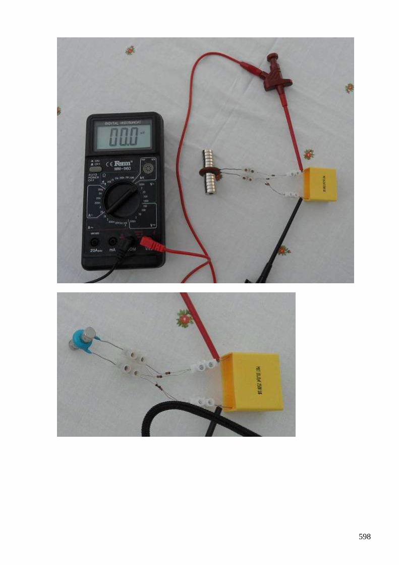
598
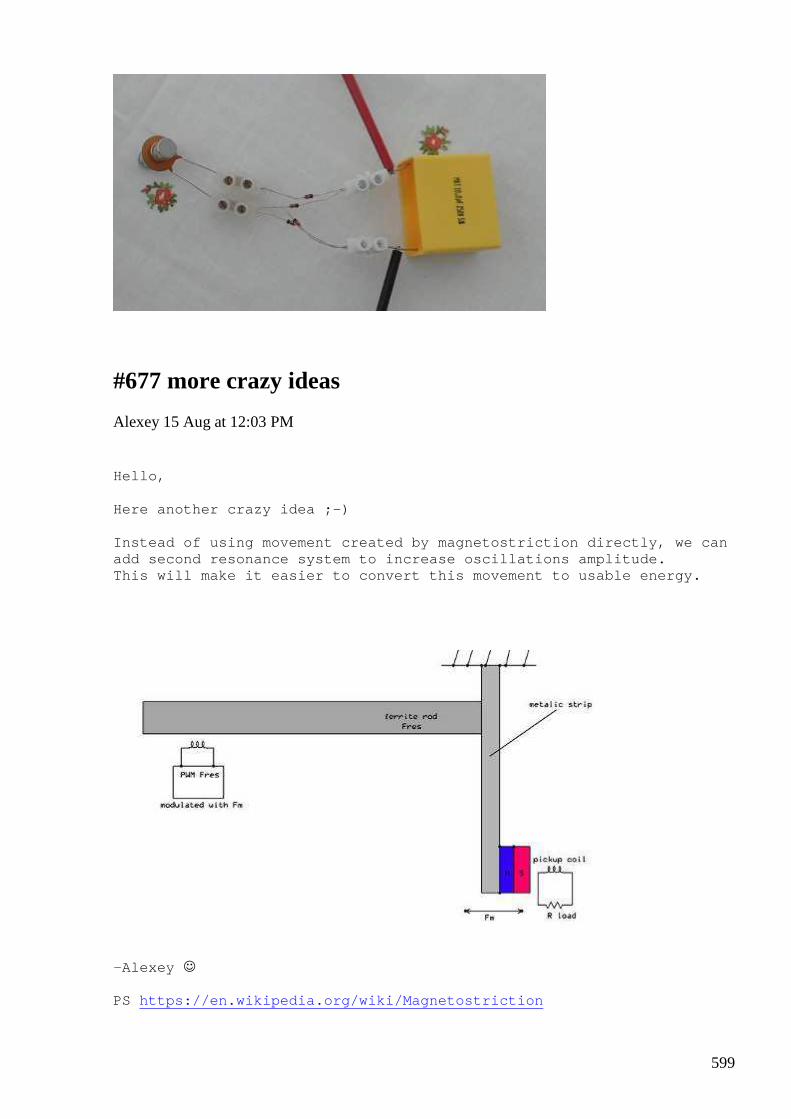
599
#677 more crazy ideas
Alexey 15 Aug at 12:03 PM
Hello, Here another crazy idea ;-) Instead of using movement created by magnetostricti on directly, we can add second resonance system to increase oscillation s amplitude. This will make it easier to convert this movement t o usable energy.
-Alexey PS https://en.wikipedia.org/wiki/Magnetostriction
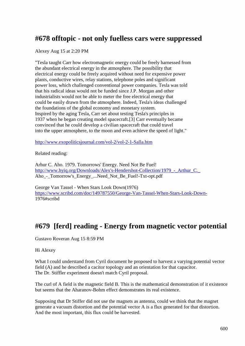
600
#678 offtopic - not only fuelless cars were suppressed
Alexey Aug 15 at 2:20 PM
"Tesla taught Carr how electromagnetic energy could be freely harnessed from the abundant electrical energy in the atmosphere. The possibility that electrical energy could be freely acquired without need for expensive power plants, conductive wires, relay stations, telephone poles and significant power loss, which challenged conventional power companies. Tesla was told that his radical ideas would not be funded since J.P. Morgan and other industrialists would not be able to meter the free electrical energy that could be easily drawn from the atmosphere. Indeed, Tesla's ideas challenged the foundations of the global economy and monetary system. Inspired by the aging Tesla, Carr set about testing Tesla's principles in 1937 when he began creating model spacecraft.[3] Carr eventually became convinced that he could develop a civilian spacecraft that could travel into the upper atmosphere, to the moon and even achieve the speed of light." http://www.exopoliticsjournal.com/vol-2/vol-2-1-Salla.htm Related reading: Arhur C. Aho. 1979. Tomorrows' Energy. Need Not Be Fuel! http://www.hyiq.org/Downloads/Alex's-Hendershot-Collection/1979_-_Arthur_C._ Aho_-_Tomorrow's_Energy_...Need_Not_Be_Fuel!-Txt-opt.pdf George Van Tassel - When Stars Look Down(1976) https://www.scribd.com/doc/149787550/George-Van-Tassel-When-Stars-Look-Down- 1976#scribd
#679 [ferd] reading - Energy from magnetic vector potential
Gustavo Roveran Aug 15 8:59 PM
Hi Alexey What I could understand from Cyril document he proposed to harvest a varying potential vector field (A) and he described a cacitor topology and an orientation for that capacitor. The Dr. Stiffler experiment doesn't match Cyril proposal. The curl of A field is the magnetic field B. This is the mathematical demonstration of it existence but seems that the Aharanov-Bohm effect demonstrates its real existence. Supposing that Dr Stiffer did not use the magnets as antenna, could we think that the magnet generate a vacuum distortion and the potential vector A is a flux generated for that distortion. And the most important, this flux could be harvested.
601
Regards Gustavo
#680 [ferd] more crazy ideas
Gustavo Roveran Aug 15 9:07 PM
Hi Alexey Interesting idea. Why a pwm instead of a resonance circuit. Gustavo
#681 RE: [ferd] more crazy ideas
Alexey Aug 15 9:36 PM
Hi Gustavo,
Resonance circuit also can be used. Important that we need two frequencies, one, high should match ferrite rod’s resonance frequency and second, low, should match mechanical resonance frequency of output ”spring” holding magnet. I think PWM easier to control and adjust.
This system represents idea of a scalar (pressure) “waves” used to extract energy form ambient media which I believe was discovered by Tesla…and used in many of his devices.
Two frequencies signal creates this “pressure waves”… Ferrite rod is very hard and can create very strong force but “loading” this force will not affect our power source
(save this post and think carefully about this!)
Regards,
Alexey
#682 Re: [ferd] reading - Energy from magnetic vector potential
Andreas Höschler Aug 15 9:38 PM
Hi Gustavo,
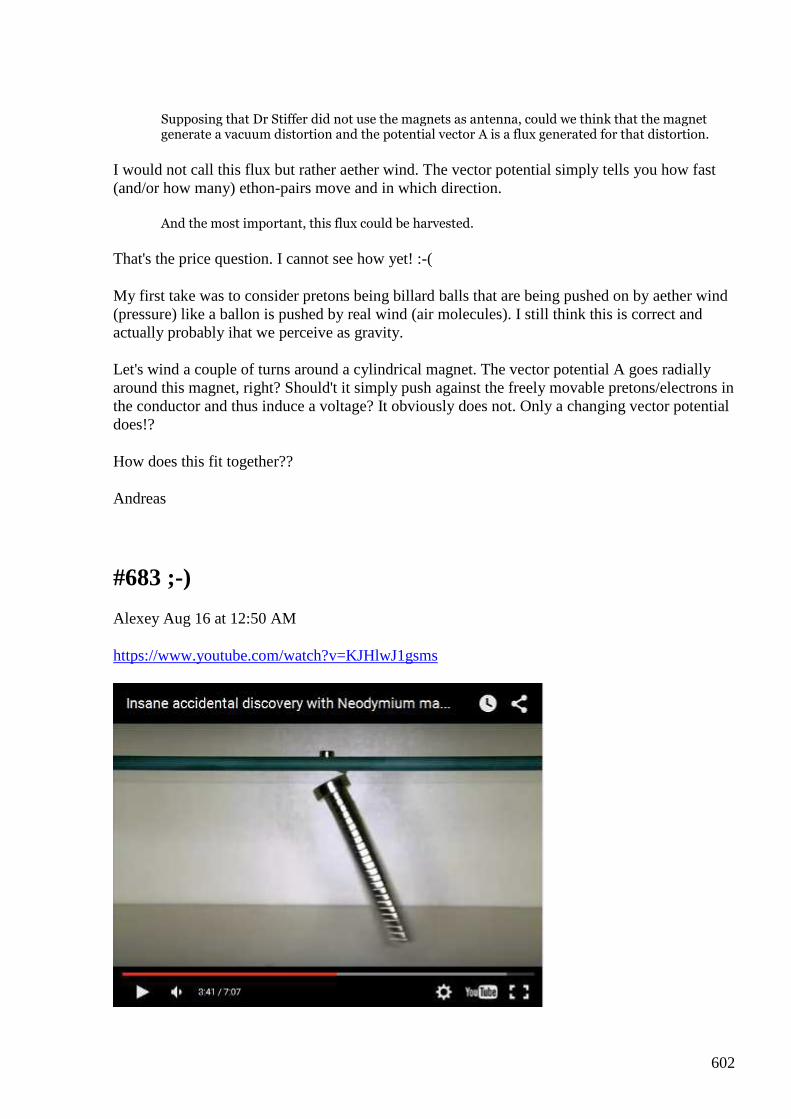
602
Supposing that Dr Stiffer did not use the magnets as antenna, could we think that the magnet generate a vacuum distortion and the potential vector A is a flux generated for that distortion.
I would not call this flux but rather aether wind. The vector potential simply tells you how fast (and/or how many) ethon-pairs move and in which direction.
And the most important, this flux could be harvested.
That's the price question. I cannot see how yet! :-(
My first take was to consider pretons being billard balls that are being pushed on by aether wind (pressure) like a ballon is pushed by real wind (air molecules). I still think this is correct and actually probably ihat we perceive as gravity.
Let's wind a couple of turns around a cylindrical magnet. The vector potential A goes radially around this magnet, right? Should't it simply push against the freely movable pretons/electrons in the conductor and thus induce a voltage? It obviously does not. Only a changing vector potential does!?
How does this fit together??
Andreas
#683 ;-)
Alexey Aug 16 at 12:50 AM
https://www.youtube.com/watch?v=KJHlwJ1gsms
603
#684 Re: [ferd] reading - Energy from magnetic vector potential
Gustavo Roveran Aug 16 at 5:35 AM
Hi Andreas,
What I could understand from Distinti, is that he explains within his theory that matter needs energy to exist. So matter extract the energy from vacuum, and vacuum is conform by positive and negative ethons. Then, the matter because of its needs to exist, eats ethons and that is what I understand as aether wind or gravity. If you said that potential vector magnetic field (A) is aether wind, the magnetic B field produce a gravity effect. So the first step would be managing to measure gravity distortion. Perhaps Hodowanec have some responses on how to measure.
Then, if it is right, we can put the magnet in some topology or direction that produce an effect on matter and take profit from this. For example, weaken the links between O and H in water to produce electrolysis with less energy ....
Gustavo
#685 Re: [ferd] more crazy ideas
Gustavo Roveran Aug 16 at 5:50 AM
Hi Alexey, The resonance frequency of the rod ferrit should be its mechanical ? If the rod is in touch with another element, Does it change its mechanical frequency ? I heard some years ago, that Telsa put a small resonator (mechanical resonator) at the base of a building in construction and after some time the building begun to "dance".
Gustavo
#686 RE: [ferd] more crazy ideas
Alexey Aug 16 at 10:23 AM
Hi Gustavo, ”The resonance frequency of the rod ferrite should be its mechanical ?” Yes If the rod is in touch with another element, Does it change its mechanical frequency ? May be, but it is not important. Ferrite rod is just an example, any media cam be used, e.g. ether…the principle is universal
- Alexey
#687 extremely crazy idea, speculation :-)
Alexey Aug 16 at 11:04 AM
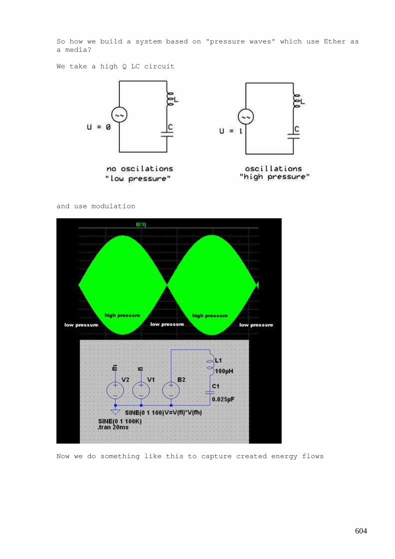
604
So how we build a system based on "pressure waves" which use Ether as a media? We take a high Q LC circuit
and use modulation
Now we do something like this to capture created en ergy flows

605
and if we lucky we will get this
or this
Suggested reading:
606
https://en.wikipedia.org/wiki/Poynting_vector http://physics.stackexchange.com/questions/44127/po ynting-vector-of-a-wire-between-capacitors Have fun, - Alexey
#688 [ferd] extremely crazy idea, speculation :-)
Gustavo Roveran Aug 16 at 7:07 PM
Hi Alexey Pointing vector is based in Maxuell equations. And is used to calculate the direction and the power of an EM wave. You are saying that an am signal, modulated at its 100% could produce "the effect" presented here at a distance? The concept is to transfer energy through a media to a destination, knowing the destination resonance frequency. But because you need to transfer that energy with the minimal loss you choose the better carrier (and impedance matching) for that media. But the problem is to know if the frequency resonance for the destination "element" produce the effect required it means the energy gain from the "vacuum". So we again are looking for the magic resonance frequency of an element. Am I right? Gustavo
#689 Re: [ferd] reading - Energy from magnetic vector potential
Andreas Höschler Aug 16 at 7:38 PM
Hi Gustavo,
What I could understand from Distinti, is that he explains within his theory that matter needs energy to exist. So matter extract the energy from vacuum, and vacuum is conform by positive and negative ethons. Then, the matter because of its needs to exist, eats ethons and that is what I understand as aether wind or gravity.
Yes! But we have to be rigorous here. Ether mainly consists of neutral ethon-pairs. It's those ethon-pair that fall into matter and thus cause gravity. p-ethons and n-ethons streams coming out of charges is what we perceive as electric fields.
If you said that potential vector magnetic field (A) is aether wind, the magnetic B field produce a gravity effect.
607
NO, not the B. B is the rotation of A. And in a very ideal case the A field around a planet is radial (no rotation). In reality it's of course not purely radial but it's the radial part that generates gravity by exerting pressure when hitting pretons. This also causes the strong force that holds atomic cores together. That's at least my current take in this.
So the first step would be managing to measure gravity distortion.
If we push huge mounts of current through a vertically aligned copper pipe we should see a gravity anomaly around and especially in the pipe due to the aether wind caused by the current. But this anomaly might be very small (hard to measure) unless we use many 100 amps. No idea ...
Perhaps Hodowanec have some responses on how to measure.
Then, if it is right, we can put the magnet in some topology or direction that produce an effect on matter and take profit from this. For example, weaken the links between O and H in water to produce electrolysis with less energy ....
No idea! :-)
Andreas
#690 Re: [ferd] extremely crazy idea, speculation :-)
Andreas Höschler Aug 16 at 8:01 PM
Hi Alexey,
Suggested reading:
https://en.wikipedia.org/wiki/Poynting_vector
http://physics.stackexchange.com/questions/44127/poynting-vector-of-a-
wire-between-capacitors
Thanks for the links. But what do you think this trickery with the E and B fields is good for except being beautiful? Have you got any insights from these readings? We know "in the meantime" (since Feynmans) that B is totally imaginary and does not tell us the whole story (better to look at A in moist cases). What's the point of creating just another imaginary beast by multiplying B with E?
So how we build a system based on "pressure waves" which use Ether as a media?
We take a high Q LC circuit and use modulation
Now we do something like this to capture created en ergy flows
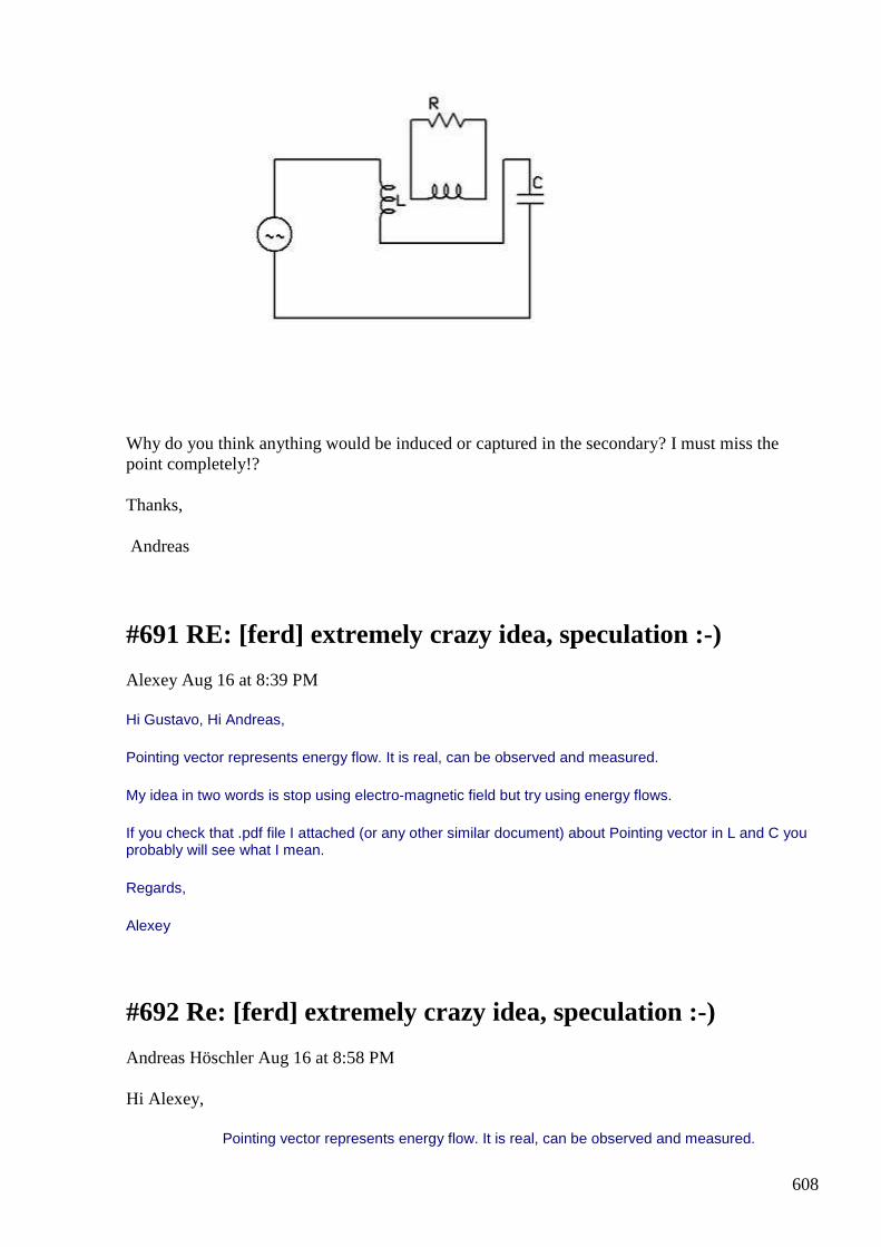
608
Why do you think anything would be induced or captured in the secondary? I must miss the point completely!?
Thanks,
Andreas
#691 RE: [ferd] extremely crazy idea, speculation :-)
Alexey Aug 16 at 8:39 PM
Hi Gustavo, Hi Andreas,
Pointing vector represents energy flow. It is real, can be observed and measured.
My idea in two words is stop using electro-magnetic field but try using energy flows.
If you check that .pdf file I attached (or any other similar document) about Pointing vector in L and C you probably will see what I mean.
Regards,
Alexey
#692 Re: [ferd] extremely crazy idea, speculation :-)
Andreas Höschler Aug 16 at 8:58 PM
Hi Alexey,
Pointing vector represents energy flow. It is real, can be observed and measured.

609
My idea in two words is stop using electro-magnetic field but try using energy flows.
If you check that .pdf file I attached (or any other similar document) about Pointing vector in L and C you probably will see what I mean
You attached a PDF?? Which mail?
Do you have any info about the modus operandi of this other device you brought forward?
Thanks,
Andreas
#693 RE: [ferd] extremely crazy idea, speculation :-)
Alexey Aug 16 at 10:09 PM
Hi Andreas,
PointingVector.pdf was attached to my first email in this thread, you can download it from here (it is last one, may be you need scroll right attachments list)
https://groups.yahoo.com/neo/groups/ferd/conversations/messages/687
I guess that both Hubbard’s and last Hendershot’s devices operates in a way I am trying describe here.
Regards,
Alexey
610
#694 [ferd] extremely crazy idea, speculation :-)
Gustavo Roveran Aug 16 at 10:19 PM
Hi Alexey Before I responded your message a read that PDF. It resulted interesting how energy enter or exit the passive components L and C studying the E and B and I instant situation but I don't understand why you suppose that hitting a remote site with pointing vector you achieve fe. How do you know that remote resonance frequency is the key for that remote element. If we could not find close by us why we will find it far away or crossing ether. At the same time you are saying that we could see S as the longitudinal wave that Tesla used to talk about.
#695 RE: [ferd] extremely crazy idea, speculation :-)
Alexey Aug 16 at 10:35 PM
Hi Gustavo,
I not sure why you think that I am proposing to transmit energy? I am not.
Before this discussion started I thought that Pointing vector can give good intuitive ”clue” to my idea…obviously it is not.
We can say that all space is filed with Ether with some ”pressure”. Now if we create oscillator it will create local area of increased pressure and some outwards flow.
If we modulate oscillator from outside it will be seen as ”pulsating pressure”. Now it is obvious that media, Ether, will try compensate these pressure waves. If we place a device which utilize this ”media response” we could get FE.
Not sure if it this explanations better… but I don’t have any other.
-Alexey
#696 Re: [ferd] extremely crazy idea, speculation :-)
Andreas Höschler Aug 16 11:35 PM
Hi Alexey, We can say that all space is filed with Ether with some ”pressure”. Now if we create oscillator it will create local area of increased pressure
I am not even sure about that. What we know (or at least assume) for now is that a stream of pretons/electrons causes aether wind via drag and viscosity. This not necessarily means that aether is compressed. I assume that in 99.9% of all cases (normal engineering stuff) aether isn't
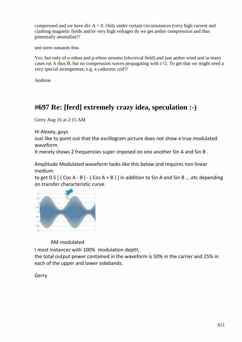
611
compressed and we have div A = 0. Only under certain circumstances (very high current and clashing magnetic fields and/or very high voltages do we get aether compression and thus potentially anomalies!? and some outwards flow.
Yes, but only of n-ethon and p-ethon streams (electrical field) and just aether wind and in many cases rot A thus B, but no compression waves propagating with c^2. To get that we might need a very special arrangement, e.g. a caduceus coil!? Andreas
#697 Re: [ferd] extremely crazy idea, speculation :-)
Gerry Aug 16 at 2:15 AM
Hi Alexey, guys Just like to point out that the oscillogram picture does not show a true modulated
waveform. It merely shows 2 frequencies super imposed on one another Sin A and Sin B . Amplitude Modulated waveform looks like this below and requires non linear
medium to get 0.5 [ ( Cos A - B ) - ( Cos A + B ) ] in addition to Sin A and Sin B ....etc depending
on transfer characteristic curve.
AM modulated
I most instances with 100% modulation depth, the total output power contained in the waveform is 50% in the carrier and 25% in
each of the upper and lower sidebands. Gerry
612
#698 Re: [ferd] more crazy ideas
Gerry Aug 16 at 3:09 AM
Hi Alexey, guys
Sorry to crash your thread here.
While I was waiting for my resistance wire I have been playing with an old
German/Norwegian invention from 1920's to 1940's.
It was apparently destroyed in war and no working versions exist.
It has DC input and DC output.
Have attached my very rough attempt at this machine to look at it.
It has some interesting design ideas & concepts.
I would much appreciate your input or help with how or why it should/wont or
may work.
Because it doesn't .... right now anyway
I have read that a normal DC current has some electrons with spin up whilst others
have their spins down.
By passing DC current through a permanent ferro magnet or an electromagnet
apparently all their spins become aligned as either spin up or spin down.
When electrons are flowing along a sheet surface they get deflected by Lorentz force
from B field above, see Hall effect.
According to literature a "super conductor" effect comes into existence at the very
edge of the sheet,
where electrons are impinged and cannot complete their spins properly.
My rough replication isn't all that good, I know.
I can supply more info if you're interested and have patience to read.
Gerry
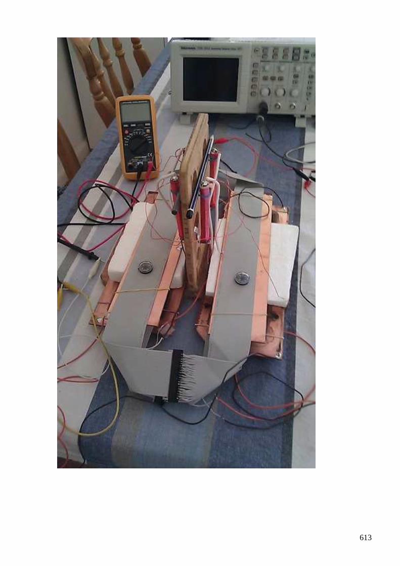
613

614
#699 [ferd] extremely crazy idea, speculation :-)
Gustavo Roveran Aug 16 at 3:42 AM
Hi Alexey Sorry but I couldn't guess exactly what you think. Nos is clear. Thanks Gustavo
#700 RE: [ferd] extremely crazy idea, speculation :-)
onielsen2000 Aug 17 at 3:44 AM Hi Alexey, I think Akula aka Роман Карноухов (Roman Karnouhov) is one of the few that has managed to make a working model of the Hendershot device: Akula Generator 25W https://www.youtube.com/watch?v=HmYfcgvf6Jc Arthur C. Aho managed it too but his device could only be started by the help of Hendershot. Aho couldn't start it after Hendershot died. Regards Ole
#701 RE: [ferd] extremely crazy idea, speculation :-)
Alexey Aug 17 at 7:45 PM Thanks for your feedback guys, sorry for coming up with unclear ideas. -Alexey
#702 RE: [ferd] more crazy ideas
Alexey Aug 17 at 7:45 PM Hi Gerry, Nice looking setup you have, but I don’t have idea how it could work. The hall effect is very very small… - Alexey
615
#703 Induction
Andreas Höschler Aug 17 9:13 PM Hi all, I would like to throw in some thoughts I just came up with. The attached paper at least qualitatively shows what induction is. The integral is too complex to be solved analytically but might serve as a base for a simulation!? Does this help us anyhow? Probably not! Still interesting IMHO!? Regards, Andreas
#704 Re: [ferd] more crazy ideas
Gerry Aug 18 at 6:37 AM Hi Alexey, To be honest neither do I understand, I was hoping for some ideas from you guys. I have tried a lot of combinations of wiring and connections without any joy ....other than normal Ohms Law result. Capt Hans Coler claimed to have invented this in 1940's, but as can be seen from patent appl. someone else tried to patent it in 1920's. Either way the British interrogators were able to supply the materials and verify that it worked but could not explain how at that time. In my picture you can see I used IDC ribbon cable with 40 conductors. I wired these to plugs and sockets ...except I took pin 1 to pin 2 and pin 2 to pin 3 etc etc to make a BIG flat coil. I these coils output load current circulates from conductor 1 right through to conductor 40. So just say load current is 1 amp ... then top left of coil over highest copper plate, has load current travelling away from camera toward scope 40 times. Giving 40 times magnetic field of 1 conductor radiating through the copper plate underneath. Top right of coil also carries load current in opposite direction 40 times. This should cause load current flowing through copper plate to bend to the left or right. Vertical bars with coils are "electro magnets" and are, I think supposed to align spins of time delayed current passing through centre iron cores. Where centre cores are wired down to plates I am unsure what's supposed to happen, but it possibly could be spin current injection onto the copper plate plate. So plates provide electrostatic charge V and coils provide B electromagnetic charge to move charges in plates Q=VxB shifting. Mr Coler used aluminum strips down each side of the copper plates but I thought these were just spacers which could be wrong too. I have put it aside to have a bit more of think about it, Gerry
#705 Re: [ferd] more crazy ideas
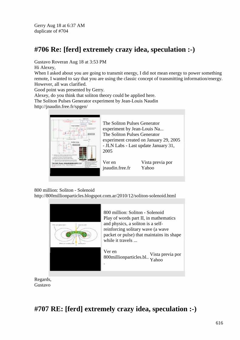
616
Gerry Aug 18 at 6:37 AM duplicate of #704
#706 Re: [ferd] extremely crazy idea, speculation :-)
Gustavo Roveran Aug 18 at 3:53 PM Hi Alexey, When I asked about you are going to transmit energy, I did not mean energy to power something remote, I wanted to say that you are using the classic concept of transmitting information/energy. However, all was clarified. Good point was presented by Gerry. Alexey, do you think that soliton theory could be applied here. The Soliton Pulses Generator experiment by Jean-Louis Naudin http://jnaudin.free.fr/spgen/
The Soliton Pulses Generator experiment by Jean-Louis Na... The Soliton Pulses Generator experiment created on January 29, 2005 - JLN Labs - Last update January 31, 2005 Ver en jnaudin.free.fr
Vista previa por Yahoo
800 million: Soliton - Solenoid http://800millionparticles.blogspot.com.ar/2010/12/soliton-solenoid.html
800 million: Soliton - Solenoid Play of words part II, in mathematics and physics, a soliton is a self-reinforcing solitary wave (a wave packet or pulse) that maintains its shape while it travels ... Ver en 800millionparticles.bl...
Vista previa por Yahoo
Regards, Gustavo
#707 RE: [ferd] extremely crazy idea, speculation :-)
617
Alexey Aug 18 9:52 PM Hi Gustavo, ” Alexey, do you think that soliton theory could be applied here.” Unfortunately I don’t know much about solitons… and I don’t trust JLN - Alexey
#708 Re: [ferd] Induction
Gustavo Roveran Aug 18 10:15 PM Hi Andreas, I think that we have to go step by step. First of all, we have to know how the ether react within matter, or matter within ether. What happens when ferrite saturate, then what happens outside the ferrite at that moment. If the electron is within an "ether" that has more neg. ethons than pos. ethons or viceversa. Static and dynamic situation. If an atom is within an "ether" that has more neg. ethons than pos. ethons or viceversa. Static and dynamic situation. Distinti says: Electron is form by at least 2 neg. pretons Proton is form by at least 2 pos. pretons Neutron is form by at least n even number of pos. net. pretons Ether is form by pairs of neg pos ethons neg. pretons eats pos ethons -> then radiate neg. ethons pos. pretons eats neg ethons -> then radiate pos. ethons So perhaps all these staff could be studied by an analogy to a closer known system, For example: Air instead of ether Wave sound instead of ether wind Spheric speaker instead of electron For example, from this analogy I think that could be understandable why repulsion, why current at a secondary, etc BTW did you read pdfs from Distinti site ? Regards, Gustavo
#709 [ferd] extremely crazy idea, speculation :-)
Gustavo Roveran Aug 19 at 12:08 AM Hi Alexey Something like this is a soliton wave https://m.youtube.com/watch?v=MADng1fqECY But in the ether Gustavo
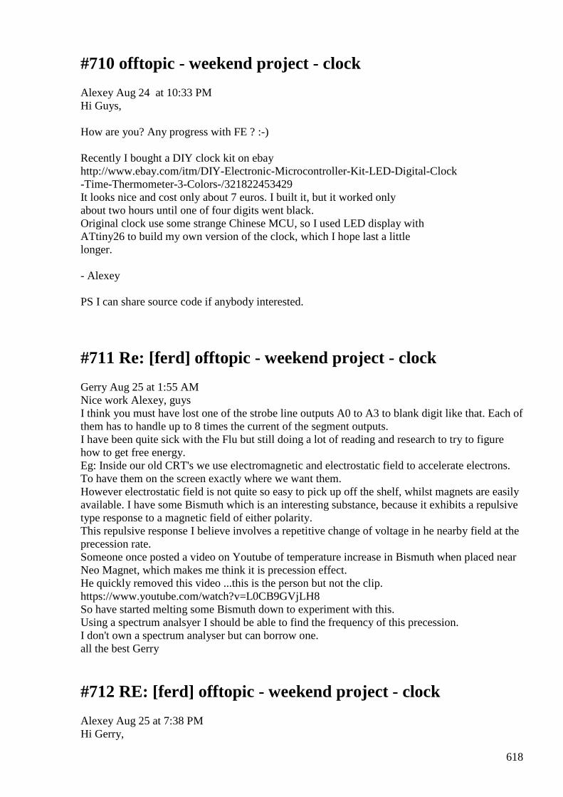
618
#710 offtopic - weekend project - clock
Alexey Aug 24 at 10:33 PM Hi Guys, How are you? Any progress with FE ? :-) Recently I bought a DIY clock kit on ebay http://www.ebay.com/itm/DIY-Electronic-Microcontroller-Kit-LED-Digital-Clock -Time-Thermometer-3-Colors-/321822453429 It looks nice and cost only about 7 euros. I built it, but it worked only about two hours until one of four digits went black. Original clock use some strange Chinese MCU, so I used LED display with ATtiny26 to build my own version of the clock, which I hope last a little longer. - Alexey PS I can share source code if anybody interested.
#711 Re: [ferd] offtopic - weekend project - clock
Gerry Aug 25 at 1:55 AM Nice work Alexey, guys I think you must have lost one of the strobe line outputs A0 to A3 to blank digit like that. Each of them has to handle up to 8 times the current of the segment outputs. I have been quite sick with the Flu but still doing a lot of reading and research to try to figure how to get free energy. Eg: Inside our old CRT's we use electromagnetic and electrostatic field to accelerate electrons. To have them on the screen exactly where we want them. However electrostatic field is not quite so easy to pick up off the shelf, whilst magnets are easily available. I have some Bismuth which is an interesting substance, because it exhibits a repulsive type response to a magnetic field of either polarity. This repulsive response I believe involves a repetitive change of voltage in he nearby field at the precession rate. Someone once posted a video on Youtube of temperature increase in Bismuth when placed near Neo Magnet, which makes me think it is precession effect. He quickly removed this video ...this is the person but not the clip. https://www.youtube.com/watch?v=L0CB9GVjLH8 So have started melting some Bismuth down to experiment with this. Using a spectrum analsyer I should be able to find the frequency of this precession. I don't own a spectrum analyser but can borrow one. all the best Gerry
#712 RE: [ferd] offtopic - weekend project - clock
Alexey Aug 25 at 7:38 PM Hi Gerry,
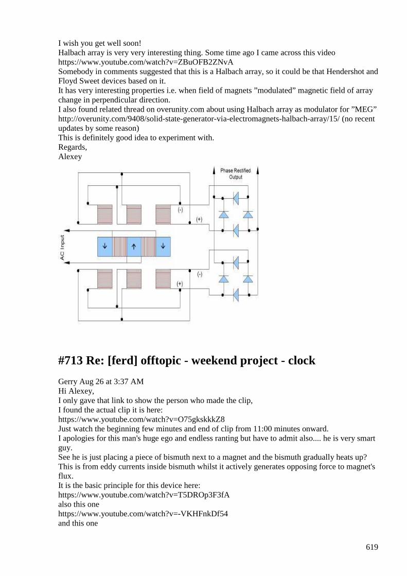
619
I wish you get well soon! Halbach array is very very interesting thing. Some time ago I came across this video https://www.youtube.com/watch?v=ZBuOFB2ZNvA Somebody in comments suggested that this is a Halbach array, so it could be that Hendershot and Floyd Sweet devices based on it. It has very interesting properties i.e. when field of magnets ”modulated” magnetic field of array change in perpendicular direction. I also found related thread on overunity.com about using Halbach array as modulator for ”MEG” http://overunity.com/9408/solid-state-generator-via-electromagnets-halbach-array/15/ (no recent updates by some reason) This is definitely good idea to experiment with. Regards, Alexey
#713 Re: [ferd] offtopic - weekend project - clock
Gerry Aug 26 at 3:37 AM Hi Alexey, I only gave that link to show the person who made the clip, I found the actual clip it is here: https://www.youtube.com/watch?v=O75gkskkkZ8 Just watch the beginning few minutes and end of clip from 11:00 minutes onward. I apologies for this man's huge ego and endless ranting but have to admit also.... he is very smart guy. See he is just placing a piece of bismuth next to a magnet and the bismuth gradually heats up? This is from eddy currents inside bismuth whilst it actively generates opposing force to magnet's flux. It is the basic principle for this device here: https://www.youtube.com/watch?v=T5DROp3F3fA also this one https://www.youtube.com/watch?v=-VKHFnkDf54 and this one
620
https://www.youtube.com/watch?v=WFqwY8q-5ZE&list=PL000F7CAE2CCE2D62 I have a rough idea of how this works. Gerry
#714 [ferd] offtopic - weekend project - clock
Gustavo Roveran Aug 26 at 3:56 AM Hi Alexey I had to travel because of work. But I was developing before I left my city, a tool to enhance the Hodowanec circuit to measure gravity/torsion field. I use an arduino to communicate with a msgq7 (7 band spectrum audio frequency analyzer IC) and a pc with Processing language connected by serial port to Arduino to show how the 7 frequency audio bands change. The next step would be to connect the output of Hodowanec circuit to the input of my circuit. The idea is to measure instant changes in audio spectrum when the circuit is exposed to torsion field. The most important thing will be to shield the system very well from ambient em noise. Regards Gustavo
#715 RE: [ferd] offtopic - weekend project - clock
Alexey Aug 26 at 8:49 AM Hi Gerry, I remember this was discussed on overunity.com sometimes ago. I would be nice to try and use some ”normal” temperature sensor instead of IR sensor. 9 degrees difference can be easily detected… but some how person and all his bla-bla-bla do not give much hope that this actually true. Regards, Alexey
#716 RE: [ferd] offtopic - weekend project - clock
Alexey Aug 26 at 9:00 AM Hi Gustavo, I see, you are making advance in pseudoscience https://en.wikipedia.org/wiki/Torsion_field_%28pseudoscience%29 ha ha For shielding I was using aluminum boxes for electronics equipment something like this http://www.ebay.com/itm/Extruded-aluminum-electronic-power-enclosure-PCB-instrument-Box-Case-Project-DIY-/331210803660 They come in all kind of different shapes and sizes… - Alexey
#717 Re: [ferd] offtopic - weekend project - clock
Gerry Aug 26 at 9:54 AM Hi Alexey,
621
Yes I agree with everything you said. Sometimes brilliant minds like this bla-bla-bla man, doesn't go with understanding, caring or sensitivity toward others. None the less we all here need to keep trying to help each other. I have ordered from eBay 2 of these little vibrator motors with weights attached. http://www.ebay.com.au/itm/331614623524?_trksid=p2057872.m2749.l2649&ssPageName=STRK%3AMEBIDX%3AIT Am going to glue the weights face to face so one unit runs as generator the other as a prime mover. From the "lead in theory" gravity and momentum from badly out of balance spinning weights supposed to add extra energy. I thought it was a simple cheap way to try out this theory anyhow. I have attached a screen grab taken from high power version currently on YouTube. Gerry
#718 Re: [ferd] offtopic - weekend project - clock
Andreas Höschler Aug 26 at 2:17 PM Hi Gerry, thanks for the links!! Would you share your idea how this device works with us? I have no clue! :-( He mentions a couple of layers of aluminum and bismuth and coils integrated into the plates. But how exactly are they integrated. And what exactly is the bismuth doing in it. I begin to understand that bismuth has very low permeablity!? Less than air/vacuum? Still, how could this be exploited? Thanks, Andreas
#719 Re: [ferd] Induction
Andreas Höschler Aug 26 at 7:39 PM Hi Gustavo, sorry for the late response. I was bogged down by day job duties for quite a while! :-( We released a new version of Cassiopeia today with a neat example paper about the vector potential (aether wind): :-) http://www.advanced-science.com/publications/VectorPotential.pdf I think that we have to go step by step. First of all, we have to know how the ether react within matter, or matter within ether. What happens when ferrite saturate, then what happens outside the ferrite at that moment. If the electron is within an "ether" that has more neg. ethons than pos. ethons or viceversa. Static and dynamic situation. If an atom is within an "ether" that has more neg. ethons than pos. ethons or viceversa. Static and dynamic situation. I slowly get an idea of what permeability is all about. The interesting part is how aether behaves at the boundary layer between air and ferrite. Is the vector potential continuous here or not? Another interesting question is what happens in the ferrite if the core carries wind in different directions. And yes, what exactly happens when the core saturates??
622
BTW did you read pdfs from Distinti site ? Only briefly and only a couple. I mainly watched his vids which seem to reflect his most recent understanding. Best wishes, Andreas
#720 Re: [ferd] offtopic - weekend project - clock
Gerry Aug 27 at 10:10 AM Hi Andreas, guys We would need to have a long and detailed conversation about it. I can only explain in my own terms which you might not agree with from your current views on the ether and how it all fits together. To start we need to be on same page about many things, so we can walk in step through it. Can I start by asking a question..................are you familiar with fresnel lens? http://www.ebay.com/itm/28-x-36-Linear-Fresnel-Lens-Solar-Oven-Solar-Hot-Water-Solar-Project-/181320910057 You know the old clear plastic stick on types we used to put in rear windscreen of vans & station wagons to help us reverse park. These behave just like a magnifying glass (only it is flat) because incident light is made to converge toward the focal point. So think of the thin aluminum and the thin bismuth laminate as a lens which focuses incoming EM radiation to produce gain just like a magnifying glass except it handles slightly lower frequencies. For EM wave to pass through our laminate lens undistorted ....... the medium it passes through must correct for both electric and magnetic fields. Now it happens that bismuth has a negative response to magnetic fields (negative susceptibility), whilst aluminum, magnesium etc have a negative response to electric fields (negative permittivity). You know when we see a fish in the water it is physically displaced from where it appears to be? This is because incident light normally bends away at an angle, when travelling from a less dense medium like air to a more dense medium like water. Now if we gradually lower our eye till it's very close to the water surface the water then appears to be a perfect mirror, this is a boundary condition for "total internal reflection" back into our medium which is air. So when the angle is right all light rays bounce and diverges away dispersing, instead of penetrating the water. Our negative laminate material does exactly the opposite it causes EM wave (rays) to converge and increase in intensity. I guess that's enough for now, next time how bismuth and aluminum interact to make make this occur. Gerry
#721 Re: [ferd] offtopic - weekend project - clock
Andreas Höschler aug 27 at 1:12 PM Hi Gerry, Our negative laminate material does exactly the opposite it causes EM wave (rays) to converge and increase in intensity.
623
Good one! Very interesting stuff. Thanks a lot! I guess that's enough for now, next time how bismuth and aluminum interact to make make this occur. Please continue ... :-) Best wishes, Andreas
#722 Re: [ferd] offtopic - Dr Schwartz ERR & Rod generators
Gerry Aug 27 at 2:02 AM Hi Andreas, Alexey, guys I have changed the subject line to make these posts easier to refer back to. This part of my explanation on how bismuth interacts with aluminum is fairly easy. As you (Andreas & guys) need to simply watch listen and download this video clip. Try to read every word on screen then think and digest the content. https://www.youtube.com/watch?v=Q9cFOqIDgqc Listen particularly to the words at 2:10 seconds and thereafter. I recommend download and keep this clip. Remember the old stainless steel upright am/fm car radio antenna of the early pre 1970's cars? If we tune an am station on the car radio, and then grab onto the antenna at it's base near the mudguard ...nothing happens. Now if we touch the very tip of the car radio antenna it kills the radio signal. We call this aerial a quarter wave base driven dipole antenna. This is because impedance and voltage (electric field) is highest at tip of antenna, whilst minimum impedance with maximum current (magnetic field) is at the base, where the feeder cable connects. Imagine now our piece of bismuth sheet as the car body, and the thickness of the aluminum layer is the antenna. Aluminum is very weakly magnetic, it's surface atoms freely move in response to magnetic field from the bismuth, especially moving EM fields. Minutely altering the thickness of the plate in a pattern across the surface, as the video states, it forms a type of Fresnel lens. Enough for now again, there's much more to wade through. Cheers Gerry
#723 RE: [ferd] offtopic - Dr Schwartz ERR & Rod generators
Alexey Aug 28 at 6:33 PM Hi Gerry, Thank you for posting these explanations. I not sure what to do with it, it is very interesting but also sounds quite advanced for ”home science”. Please continue Regards, Alexey BTW here an original video about Bismuth https://www.youtube.com/watch?v=vyIo-c7VmIM
624
#724 Re: [ferd] offtopic - Dr Schwartz ERR & Rod generators
Andreas Höschler Aug 28 at 9:01 PM Hi all, Thank you for posting these explanations. I not sure what to do with it, it is very interesting but also sounds quite advanced for ”home science”. I second that! Please continue! Yes, please! Just for the sake I am adding the doc I am currently working on. Note the set of equations at the end of the PDF representing my current understanding. Does this make any sense at all? Just brainstorming in the hope to end up somewhere ... Best wishes, Andreas
#725 Propagation Speed of Flux (Aether Wind) in materials
Andreas Höschler Sug 29 at 1:08 AM Hi all, does anyone of you have a detailed table of propagation speeds of flux in different materials? I remember Alexey mentioning 1.6us/m for flux in ferrite!? Is this definite and correct? What about laminated iron? Other materials? If we consider a normal transformer the energetic problem arises due to the counter flux reaching the primary almost immediately thus breaking its inductive resistance and increasing (real) input current. We would immediately have an FE device if we could delay this by half the cycle. Then the counter flux would actually support the primary flux (probably build-up of a standing wave) in the core material. If using ferrite, assuming 1.6us/m propagation speed and using 200kHz the primary and secondary must be 1m apart for this to happen. This does not sound completely unrealistic to me!?? Thoughts? Best wishes, Andreas
#726 [ferd] Induction
Gustavo Roveran Aug 29 at 1:45 AM Hi Andreas
625
Do you think that would be possible to simulate the theory of Distinit using a 2d graphical simulation. Then a 3d simulation. I mean, what happens if we simulate ethons and pretons interactions. Do you know some software that let us simulate it entering the edge conditions. Regards Gustavo
#727 Re: [ferd] Induction
Andreas Höschler Aug 29 at 1:56 AM Hi Gustavo, Do you think that would be possible to simulate the theory of Distinit using a 2d graphical simulation. Then a 3d simulation. I mean, what happens if we simulate ethons and pretons interactions. Do you know some software that let us simulate it entering the edge conditions. I don't know any such software and would probably write one on my own. I thought about that already a few times. But I still need a more completely model before going into this endeavour. Have you seen the set of equations at the end of my 19:18 mail (paper attached) from today? I am still not sure if this set is complete. We have • Aether Drag by moving pretons • Aether consumption by matter • Bernoullie effect (pressure change due to aether moving with some speed) Anything else? This is quite complex stuff!? No wonder we are using over-simplified equations like Lorentz Force without having a clue what happens under the hood! :-) Best wishes, Andreas
#728 Re: [ferd] Propagation Speed of Flux (Aether Wind) in materials
Andreas Höschler Aug 29 at 1:50 AM Hi all, does anyone of you have a detailed table of propagation speeds of flux in different materials? I remember Alexey mentioning 1.6us/m for flux in ferrite!? Is this definite and correct? What about laminated iron? Other materials? If we consider a normal transformer the energetic problem arises due to the counter flux reaching the primary almost immediately thus breaking its inductive resistance and increasing (real) input current. We would immediately have an FE device if we could delay this by half the cycle. Then the counter flux would actually support the primary flux (probably build-up of a standing wave) in the core material. If using ferrite, assuming 1.6us/m propagation speed and using 200kHz the primary and secondary must be 1m apart for this to happen. This does not sound completely unrealistic to me!?? I just did a quick and dirty test to determine the propagation speed in ferrite. I got 1900km/s which is only 0.6% of c but still a lot faster than 1.6us/m!? Alexey? If my measurement is correct this would mean a 3m long transformer at 200kHz. Do you think this is a feasible approach? Best wishes, Andreas
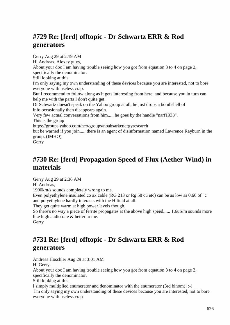
626
#729 Re: [ferd] offtopic - Dr Schwartz ERR & Rod generators
Gerry Aug 29 at 2:19 AM Hi Andreas, Alexey guys, About your doc I am having trouble seeing how you got from equation 3 to 4 on page 2, specifically the denominator. Still looking at this. I'm only saying my own understanding of these devices because you are interested, not to bore everyone with useless crap. But I recommend to follow along as it gets interesting from here, and because you in turn can help me with the parts I don't quite get. Dr Schwartz doesn't speak on the Yahoo group at all, he just drops a bombshell of info occasionally then disappears again. Very few actual conversations from him..... he goes by the handle "narf1933". This is the group https://groups.yahoo.com/neo/groups/noahsarkenergyresearch but be warned if you join..... there is an agent of disinformation named Lawrence Rayburn in the group. (IMHO) Gerry
#730 Re: [ferd] Propagation Speed of Flux (Aether Wind) in materials
Gerry Aug 29 at 2:36 AM Hi Andreas, 1900km/s sounds completely wrong to me. Even polyethylene insulated co ax cable (RG 213 or Rg 58 cu etc) can be as low as 0.66 of "c" and polyethylene hardly interacts with the H field at all. They get quite warm at high power levels though. So there's no way a piece of ferrite propagates at the above high speed...... 1.6uS/m sounds more like high audio rate & better to me. Gerry
#731 Re: [ferd] offtopic - Dr Schwartz ERR & Rod generators
Andreas Höschler Aug 29 at 3:01 AM Hi Gerry, About your doc I am having trouble seeing how you got from equation 3 to 4 on page 2, specifically the denominator. Still looking at this. I simply multiplied enumerator and denominator with the enumerator (3rd binom)! :-) I'm only saying my own understanding of these devices because you are interested, not to bore everyone with useless crap.
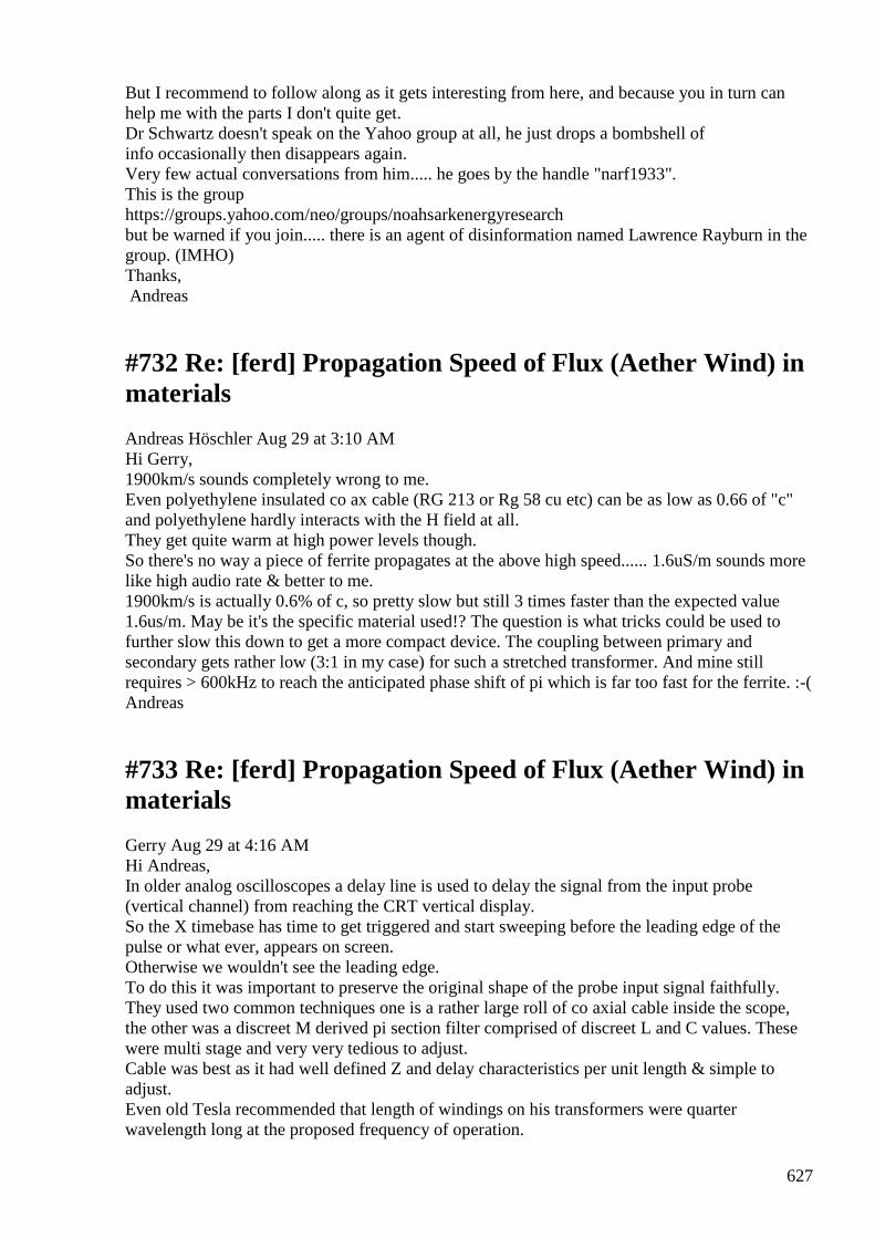
627
But I recommend to follow along as it gets interesting from here, and because you in turn can help me with the parts I don't quite get. Dr Schwartz doesn't speak on the Yahoo group at all, he just drops a bombshell of info occasionally then disappears again. Very few actual conversations from him..... he goes by the handle "narf1933". This is the group https://groups.yahoo.com/neo/groups/noahsarkenergyresearch but be warned if you join..... there is an agent of disinformation named Lawrence Rayburn in the group. (IMHO) Thanks, Andreas
#732 Re: [ferd] Propagation Speed of Flux (Aether Wind) in materials
Andreas Höschler Aug 29 at 3:10 AM Hi Gerry, 1900km/s sounds completely wrong to me. Even polyethylene insulated co ax cable (RG 213 or Rg 58 cu etc) can be as low as 0.66 of "c" and polyethylene hardly interacts with the H field at all. They get quite warm at high power levels though. So there's no way a piece of ferrite propagates at the above high speed...... 1.6uS/m sounds more like high audio rate & better to me. 1900km/s is actually 0.6% of c, so pretty slow but still 3 times faster than the expected value 1.6us/m. May be it's the specific material used!? The question is what tricks could be used to further slow this down to get a more compact device. The coupling between primary and secondary gets rather low (3:1 in my case) for such a stretched transformer. And mine still requires > 600kHz to reach the anticipated phase shift of pi which is far too fast for the ferrite. :-( Andreas
#733 Re: [ferd] Propagation Speed of Flux (Aether Wind) in materials
Gerry Aug 29 at 4:16 AM Hi Andreas, In older analog oscilloscopes a delay line is used to delay the signal from the input probe (vertical channel) from reaching the CRT vertical display. So the X timebase has time to get triggered and start sweeping before the leading edge of the pulse or what ever, appears on screen. Otherwise we wouldn't see the leading edge. To do this it was important to preserve the original shape of the probe input signal faithfully. They used two common techniques one is a rather large roll of co axial cable inside the scope, the other was a discreet M derived pi section filter comprised of discreet L and C values. These were multi stage and very very tedious to adjust. Cable was best as it had well defined Z and delay characteristics per unit length & simple to adjust. Even old Tesla recommended that length of windings on his transformers were quarter wavelength long at the proposed frequency of operation.
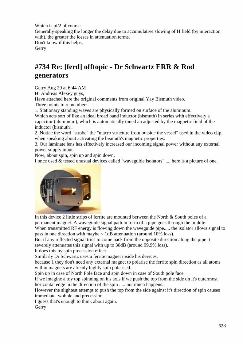
628
Which is pi/2 of course. Generally speaking the longer the delay due to accumulative slowing of H field (by interaction with), the greater the losses in attenuation terms. Don't know if this helps, Gerry
#734 Re: [ferd] offtopic - Dr Schwartz ERR & Rod generators
Gerry Aug 29 at 6:44 AM Hi Andreas Alexey guys, Have attached here the original comments from original Yay Bismuth video. Three points to remember: 1. Stationary standing waves are physically formed on surface of the aluminum. Which acts sort of like an ideal broad band inductor (bismuth) in series with effectively a capacitor (aluminum), which is automatically tuned an adjusted by the magnetic field of the inductor (bismuth). 2. Notice the word "strobe" the "macro structure from outside the vessel" used in the video clip, when speaking about activating the bismuth's magnetic properties. 3. Our laminate lens has effectively increased our incoming signal power without any external power supply input. Now, about spin, spin up and spin down. I once used & tested unusual devices called "waveguide isolators"..... here is a picture of one.
In this device 2 little strips of ferrite are mounted between the North & South poles of a permanent magnet. A waveguide signal path in form of a pipe goes through the middle. When transmitted RF energy is flowing down the waveguide pipe..... the isolator allows signal to pass in one direction with maybe < 1dB attenuation (around 10% loss). But if any reflected signal tries to come back from the opposite direction along the pipe it severely attenuates this signal with up to 30dB (around 99.9% loss). It does this by spin precession effect. Similarly Dr Schwartz uses a ferrite magnet inside his devices, because 1 they don't need any external magnet to polarise the ferrite spin direction as all atoms within magnets are already highly spin polarised. Spin up in case of North Pole face and spin down in case of South pole face. If we imagine a toy top spinning on it's axis if we push the top from the side on it's outermost horizontal edge in the direction of the spin ......not much happens. However the slightest attempt to push the top from the side against it's direction of spin causes immediate wobble and precession. I guess that's enough to think about again. Gerry
629
This video is about Moving catalyst atoms around using bismuths diamagnetic physical movement capacity to make a structure able to dynamically change the monoatomic reaction surface of a catalyst to make it eleven or more times more effective from the outside of the reaction container I've seen diamagnetic things levitate with magnetic effect Bismuth is the most Diamagnetic element Here we borrow the imagery of the awesome n nformative periodic videos video on Bismuth visit the original click the link at C EN April 7 2008 at the Gabor Somorjai article http://pubs.acs.org/subscribe/journal... there is a graph that describes the way reactions like heptane to toluene are 7 or more times more effective with staggered geometry compared to square geometry The way atoms are arranged on the surface affects rate I'm sure we all like the idea of gas refineries that are seven times more efficient Further a stepped atom surface is 11 or more times as reactive converting isobutane to n-butane This is the time on Unnamed Eastern Occupational government sprockets when we view the diagrams as annotations as state has not authorized this video truthfully I go to onetruemedia.com n the browser displays http://www.lib.ucdavis.edu/img/dotted... OOOOOOOOOOOOOOOOOOOOOOOO metal catalyst atom layer OOOOOOOOOOOOOOOOOOOOOOOO another metal catalyst atom layer OOOOOOOOOOOOOOOOOOOOOOOO another metal catalyst atom layer ;;;;;;;;;;;;;;;;;;;;;;;;;;;;;;;;;;;;;;;;;;;;;;;;;;;;;;;;;;;;;;;;;;;;;;;;;;;;; diamagnetic molecule layer Then Activate magnetism to change monoatomic surface geometry OOOOOOOOOOOOOOOOOOOOOOOO metal catalyst atom layer OOOOOOOOOOOOOOOOOOOOOOOO another metal catalyst atom layer OOOOOOOOOOOOOOOOOOOOOOOO another metal catalyst atom layer ;;;;;;;;;;;;;;;;;;;;;;;;;;;;;;;;;;;;;;;;;;;;;;;;;;;;;;;;;;;;;;;;;;;;;;;;;;;;; diamagnetic molecule layer OUTSIDE THE REACTOR CONTAINER Use EM tuned to a MACROSTRUCTURE frequency to change the active monoatomic surface layer geometry / Bismuth_________________ / /OOOOOOOOOOOOOOOOOOOOOOOO/ /OOOOOOOOOOOOOOOOOOOOOOOO/ /________________________/ _____________________________ _____________________________ / Bismuth / /OOOOOOOOOOOOOOOOOOOOOOOO/ /OOOOOOOOOOOOOOOOOOOOOOOO/ /________________________/ The idea is that using a layer of diamagnetic molecules under a certain number of monoatomic layers of catalyst atom the surface of the catalyst can be strobed with effective magnetism to cause bulging which causes the eleven times more effective stepping geometry to occur It might actually look like a FRESNEL LENS as it bulges with response to EM Yo visualize a diffraction grating now just an array of lines Frequency specific Is it not More wonderful is the idea of placing an array of lines of the catalyst at ruled ntervals then the diamagnetic catalyst layering is associated with a particular light or EM radiation frequency Rather like a diffraction grating the depthy linear catalyst structures respond when the right frequency of radiation reaches them They could either bulge or flatten as a response to absorbed radiation changing the diamagnetism molecule layer
630
Being able to dynamically change the reaction surface of a catalyst to make it eleven or more times more effective from the outside of the reaction container gives a way to literally BEAM HYPER-EFFICIENCY to different areas of a fluidized bed chemical reactor with regard to available reagents plus the way the stuff is variably spread This also gives a way to regenerate catalysts with EM radiation When refineries make things they use catalysts the idea that a neural network could learn to tune the surface monoatomic layer of a catalyst to precisely match reactor plus reaction chemicals creates much greater efficiency geometry I thought diamagnetism was a bulk effect this is even more effective as a diamagnetic molecule Anyway Chemistry is super awesome Category: Science & Technology Tags: Diamagnetic catalyst with bismuth has tunable surface monoatomic layer regeneration chemistry chemical process
#735 RE: [ferd] Propagation Speed of Flux (Aether Wind) in materials
Alexey Aug 29 at 9:31 AM Hi Andreas, I think your setup is not measuring propagation speed in ferrite. First you need a one piece of ferrite, not many glued together. Then you need a very short pulse (shorter than propagation delay). Also coil should be short (to minimize it’s parasite influence). You will see that first field propagates very fast as if there is no ferrite and then “heavy” domains starts slowly turning and aligning on magnetic field. This is quite complex dynamic process. It also depends on setup’s geometry (you will see all sort of reflections etc) I think everyone in this group will disagree with me but I think that concept of “delaying of reaction” (like in UDT) is wrong in principle. Delay is not giving us OU (and we see it in practice). You can’t separate action and reaction this way. Regards, Alexey PS https://en.wikipedia.org/wiki/Telegrapher's_equations
#736 RE: [ferd] offtopic - Dr Schwartz ERR & Rod generators
Alexey Aug 29 at 10:58 AM Hi Gerry, I was member of that group but I decided to leave. There were some empty bla bla going on and narf1933 was demanding personal information (name, address etc). Looks for me like a perfect fraud setup :-/ Regards, Alexey
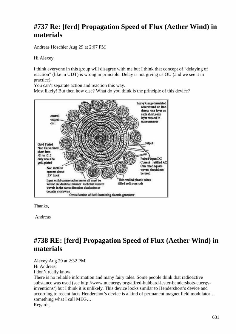
631
#737 Re: [ferd] Propagation Speed of Flux (Aether Wind) in materials
Andreas Höschler Aug 29 at 2:07 PM Hi Alexey, I think everyone in this group will disagree with me but I think that concept of “delaying of reaction” (like in UDT) is wrong in principle. Delay is not giving us OU (and we see it in practice). You can’t separate action and reaction this way. Most likely! But then how else? What do you think is the principle of this device?
Thanks, Andreas
#738 RE: [ferd] Propagation Speed of Flux (Aether Wind) in materials
Alexey Aug 29 at 2:32 PM Hi Andreas, I don’t really know There is no reliable information and many fairy tales. Some people think that radioactive substance was used (see http://www.nuenergy.org/alfred-hubbard-lester-hendershots-energy-inventions/) but I think it is unlikely. This device looks similar to Hendershort’s device and according to recent facts Hendershot’s device is a kind of permanent magnet field modulator… something what I call MEG… Regards,
632
Alexey
#739 Re: [ferd] Induction
Gustavo Roveran Aug 30 at 4:15 AM Hi Andreas, I read your pdf. However a would like to figure out the behavior of Distinti theory in an intuitive way. I think for example that it would be interesting to simulate different situations like interaction of masses of the same size, and between very small and very big mass (like earth and an object on it). Some thoughts *Objects on Earth stay on it because of the flux of ethons pairs entering into Earth. The flux of ethons conform the media where objects stay, but at the same time enters (feeds) into the object more easily, due to be near earth. *Suppose you have a planet that does not rotate, ¿does the flux which enters into it, make that planet rotate ? Similar to the water entering into a sink at the bottom of a swimming pool? *Is there an angle between the surface of the Earth and the direction of the flux which enters into Earth ? *The part of an object that is upstream of the ethons flux receive more pairs of ethons than the part that is downstream, when the object is near a massive element like earth ? Or the flux enter into the object, feeds it, and the ethons that are not needed, go direct into the Earth. *A current of electrons "eats" positive ethons, so this means that if you put a high current, above an object, this will reduce the possibility of ethons pairs to feed the object below the current, an the flux of ethons pairs will diminish. This implies two effects, one of them, is that matter that conform the object will not "eat" and at the same time the flux of ethons pairs towards earth will decrease. This means that the object will be "less heavy". *If we take a fixed electron, we know that It eats positive ethons, then generates an spherical longitudinal wave of negative eathons going out from him, if you put more electrons, then, they generate something similar to lot of spherical longitudinal wave of neg ethons. So the spherical waves produce interferometry when they superimpose each other. Can we say that a magnetic field is conform by displacement interferometry which behaves like aether wind, but it is not a real wind. It would be something similar to the wind (displacement ether interferometry) and the ocean waves (magnetic field) ? ......... .... .. Al this things could be seen in a good simulation 2D/3D software. Regards, Gustavo
#740 Re: [ferd] Propagation Speed of Flux (Aether Wind) in materials
633
Andreas Höschler Aug 30 Hi all, I think everyone in this group will disagree with me but I think that concept of “delaying of reaction” (like in UDT) is wrong in principle. Delay is not giving us OU (and we see it in practice). You can’t separate action and reaction this way I spend a bit more time in the delay line idea. Interesting experiment but no cigar. See attached PDF. Best wishes, Andreas
#741 Re: [ferd] Induction
Andreas Höschler Aug 30 11:58 PM Hi Gustavo, However I would like to figure out the behavior of Distinti theory in an intuitive way. I think for example that it would be interesting to simulate different situations like interaction of masses of the same size, and between very small and very big mass (like earth and an object on it). I am putting together a paper summarising my current understanding. We need at least a little math (quantitative model) if we want to simulate the universe or a device. Here are the first two sections for whomever cares to read the mess! :-) Comments welcome! Best wishes, Andreas BTW: I have ordered all books of Oleg Jemifenko. His work is based on retarded potentials (finite propagation velocity of fields). I think this is very import to make some progress. Lot's of stuff to read (vector algebra nightmare)! :-)
#742 [ferd] offtopic - weekend project - another clock
Alexey Aug 31 Hello, here another my weekend project - extremely low power clock based on msp430f2013 and consume about 5uW (2v 2.5uA) This gives about 8 years run time while powering with CR2032 lithium cell... Alexey :-) PS can share source code if somebody interested...
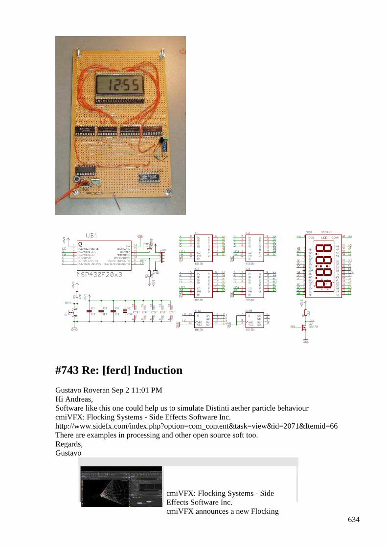
634
#743 Re: [ferd] Induction
Gustavo Roveran Sep 2 11:01 PM Hi Andreas, Software like this one could help us to simulate Distinti aether particle behaviour cmiVFX: Flocking Systems - Side Effects Software Inc. http://www.sidefx.com/index.php?option=com_content&task=view&id=2071&Itemid=66 There are examples in processing and other open source soft too. Regards, Gustavo
cmiVFX: Flocking Systems - Side Effects Software Inc. cmiVFX announces a new Flocking
635
System training video that teaches the basic principles of a multi-agent system and how to create crowd simulations in ...
Ver en www.sidefx.com Vista previa por Yahoo
#744 Re: [ferd] Induction
Gustavo Roveran Sep 3 11:36 PM Hi Andreas, This soft is free and could be programmed to simulate ethons and pretons, i have to study how NetLogo Home Page http://ccl.northwestern.edu/netlogo/ Regards,
NetLogo Home Page NetLogo is a multi-agent programmable modeling environment. It is used by tens of thousands of students, teachers and researchers worldwide. It also p... Ver en ccl.northwestern.edu
Vista previa por Yahoo
#745 Re: [ferd] Induction
Andreas Höschler Sep 3 11:47 PM Hi Gustavo, This soft is free and could be programmed to simulate ethons and pretons, i have to study how Sorry for my lazy responses. I am in some trouble here (financially) due to a mistake of my accountant and therefore can hardly concentrate on anything. The pressure on all of us (society) seems to be increased tremendously these days. If we only were allowed to be the creative beings that we are supposed to be! :-( Good luck with checking out this software. Please let us know your progress. I am out of order for a while! :-( All the best, Andreas BTW: I started to get my way into another book of Oleg Jemifenko (Retarded potentials and relativity). Man, this is heavy stuff, but probably needed to setup a reasonable simulation!?
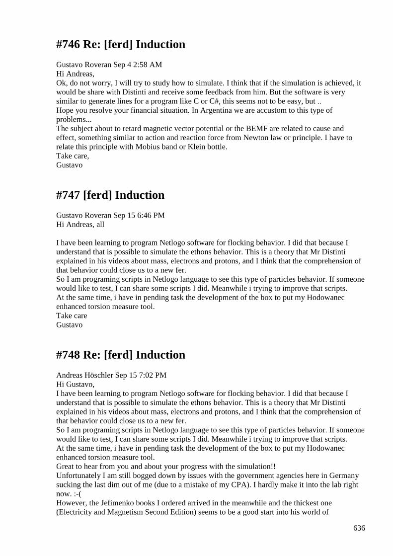
636
#746 Re: [ferd] Induction
Gustavo Roveran Sep 4 2:58 AM Hi Andreas, Ok, do not worry, I will try to study how to simulate. I think that if the simulation is achieved, it would be share with Distinti and receive some feedback from him. But the software is very similar to generate lines for a program like C or C#, this seems not to be easy, but .. Hope you resolve your financial situation. In Argentina we are accustom to this type of problems... The subject about to retard magnetic vector potential or the BEMF are related to cause and effect, something similar to action and reaction force from Newton law or principle. I have to relate this principle with Mobius band or Klein bottle. Take care, Gustavo
#747 [ferd] Induction
Gustavo Roveran Sep 15 6:46 PM Hi Andreas, all I have been learning to program Netlogo software for flocking behavior. I did that because I understand that is possible to simulate the ethons behavior. This is a theory that Mr Distinti explained in his videos about mass, electrons and protons, and I think that the comprehension of that behavior could close us to a new fer. So I am programing scripts in Netlogo language to see this type of particles behavior. If someone would like to test, I can share some scripts I did. Meanwhile i trying to improve that scripts. At the same time, i have in pending task the development of the box to put my Hodowanec enhanced torsion measure tool. Take care Gustavo
#748 Re: [ferd] Induction
Andreas Höschler Sep 15 7:02 PM Hi Gustavo, I have been learning to program Netlogo software for flocking behavior. I did that because I understand that is possible to simulate the ethons behavior. This is a theory that Mr Distinti explained in his videos about mass, electrons and protons, and I think that the comprehension of that behavior could close us to a new fer. So I am programing scripts in Netlogo language to see this type of particles behavior. If someone would like to test, I can share some scripts I did. Meanwhile i trying to improve that scripts. At the same time, i have in pending task the development of the box to put my Hodowanec enhanced torsion measure tool. Great to hear from you and about your progress with the simulation!! Unfortunately I am still bogged down by issues with the government agencies here in Germany sucking the last dim out of me (due to a mistake of my CPA). I hardly make it into the lab right now. :-( However, the Jefimenko books I ordered arrived in the meanwhile and the thickest one (Electricity and Magnetism Second Edition) seems to be a good start into his world of
637
mathematics that might be appropriate to describe Distintis model quantitatively. I am trying to get acquainted with Helmholtz Theorems, Gauge Transformation and retarded potentials. This takes me to my current intellectual limit (waiting for the third DNA strand to kick in ...) but I at least make some/slow progress whenever I have a couple of minutes and enough tranquility to read a few pages. Lab-wise I really don't know what to try right now (head is void of ideas)! :-( Best, Andreas
#749 Transformer OU
smokyatgroups Sep 17 1:46 AM Hi Alexey, guys Just writing to let you know I have finally been able go go over unity with the Auroratek design split flux transformer. But just like Ole, with UDT it takes larger reactive power just to get a small real power at least so far. The OU gain also varies with load for example using 10 Ohms at 3KHz getting over 4 times the power input. Changing load to 100 Ohms the gain drops to just over 3 times input. The reason for this breakthrough for me came from reading one of Harold Aspens pages on transformers and air gaps. I found his page here to be very helpful http://www.haroldaspden.com/reports/01.htm ENERGY SCIENCE REPORT NO. 1 POWER FROM MAGNETISM © HAROLD ASPDEN, 1994 Contents Introduction 'Free Energy': Defining the... He rightly points out that there's little or no energy stored in a magnetic core. The same way there's little or no energy being dissipated in a very low value resistor at high current. He shows a method for adjusting air gaps to produce OU results. So I wound some new coils and adjusted the input air gaps to achieve genuine OU result. Now concentrating on increasing useful output energy. all the best Gerry
#750 [ferd] Transformer OU
Gustavo Roveran Sep 17 4:56 AM Hi Gerry It is a really very good news. Could you mind sharing more information. Values measured, circuit used, schemes photographs. Take care Gustavo
#751 Re: [ferd] Transformer OU
Gerry Sep 18 1:05 AM
Hi Gustavo,
638
No problem, happy to oblige.
I have pulled it down to make heavier output coils as they get warm on outer
surfaces where they wind around outside of core.
The unit is same one I previously showed here below. But merely pulling the input
cores apart and pushing spacers in between the pole faces.
It reaches a point where the output coil current no longer reflects back on input coil
inductance.
However the tradeoff to do this is loss of output power.
Please persist with reading the page from Harold Aspden, that info is quite
enlightenning.
Gerry
#752 Simulation of Ether Particles Behavior
Gustavo Roveran Sep 21 8:51 PM Hi Al, I am sharing the simulation about Ether Particles behaviour. https://youtu.be/9-U8OVv5CiI -> Ether Particles - Ethons Pairs - Low Mass - Low Gravity https://youtu.be/ShKbMDQf7uU -> Ether Particles - Ethons Pairs - High Mass High Gravity https://youtu.be/E0fa2I-ZbDY -> Ether Particles - Ethons Pairs - low gravity mass orbiting around a low gravity mass https://youtu.be/ZnPVQBB6rvc -> Ether Particles - Ethons Pairs - low gravity mass orbiting around a high gravity mass https://youtu.be/Cpe3zwqyWd4 -> Ether Particles - Ethons Pairs and Negative Ethons - an Electron https://youtu.be/AbHMptyPUD8 -> Ether Particles - Ethons Pairs and Negative Ethons - two Electrons https://youtu.be/9T3gJq5p1lQ -> Ether Particles - Ethons Pairs and Negative Ethons - three Electrons https://youtu.be/kY9-n4RqB5w -> Ether Particles - Ethons Pairs and Negative Ethons - four Electrons https://youtu.be/RbL7wXyuXfU -> Ether Particles - Ethons Pairs and Negative Ethons - nine Electrons The software I used was the Netlogo NetLogo Home Page it is free. NetLogo is a multi-agent programmable modeling environment. It is used by tens of thousands of students, teachers and researchers worldwide. It also powers HubNet... Ver en ccl.northwestern.edu
639
I think that, from these simulation, could be explained the magnetic field and why a Planet does not fall into the Sun. But the final idea is to understand in a intuitive way the ether behaviour towards a new path to fer. Take care, Gustavo
#753 Re: [ferd] Transformer OU
Gustavo Roveran Sep 22 7:15 PM
Hi Gerry,
Did you have more progress in this path ?
I am reading the document you sent.
Alexey, you are very skilled in this subject. What do you think about it?
Gustavo
#754 RE: [ferd] Transformer OU
Alexey Sep 22 8:54 PM
Hi Gustavo,
From my point of view Gerry’s claim probably a measurement error (as it appeared 3 previous times).
There is no required ”ingredients” in this setup to get OU.
Regarding H. Aspden article - unfortunately I can’t find any new or useful information for me in this article…
but obviously I am not in target auditory (”major corporation research laboratories”)
Regards,
Alexey
#755 Re: [ferd] Simulation of Ether Particles Behavior
Gustavo Roveran Sep 22 10:08 PM
Hi All,
Did any one watch the videos ?
640
I will release more simulations, these are introductory .
Regards,
Gustavo
#756 RE: [ferd] Simulation of Ether Particles Behavior
Alexey Sep 22 10:15 PM
Hi Gustavo,
I watched some of your videos. Very nice looking simulation but I would like to understand what math or algorithms behind it…
It would be nice if you make some kind of description how you got the simulations.
Thanks,
Alexey
#757 Re: [ferd] Simulation of Ether Particles Behavior
Andreas Höschler Sep 22 10:30 PM
Hi Gustavo,
Did any one watch the videos ?
I will release more simulations, these are introductory .
I have watched them. Thanks a lot for your effort to set this up. I could not make out anything unexpected. But it's nice (helps) to see this life and graphically and animated. Great work! Please continue ...
I am still somewhat bogged down but hope to recover soon and will join you in this research field again.
Best wishes,
Andreas
#758 Re: [ferd] Simulation of Ether Particles Behavior
Gustavo Roveran Sep 22 10:41 PM
641
Hi Alexey,
If you want to download Netlogo I can share the scripts ?
By now the criteria is very simple, mass attract ethons, electron attracts ethons, converts them into negative ethons and then repels them.
Now I am implementing current .... Gustavo
#759 Re: [ferd] Simulation of Ether Particles Behavior
Gustavo Roveran Sep 22 11:16 PM
Hi Andreas,
The Idea is to analyse, if the theory proposed by Distinti, coincide with known effects. I will continue sharing more videos.
Hope you can resolve your financial problems very soon.
Regards,
Gustavo
#760 Re: [ferd] Transformer OU
Gerry Sep 23 at 6:23 AM Hi Alexey, Gustavo Andreas Ole ...guys, Yes I agree with you re measurement error, with the Auroratek Jensen UDT and Heinz Thane designs ...the OU readings rest very strongly on how accurately the phase shift can be measured. Also the source has to be capable of high out of phase volts and amps. I found that by introducing air gap (of 6mm total) on each of the two metglass input toroids. A point was reached where the input looks like a perfect inductor with quite close to 90 degree input phase shift. Yet at the same time I was still able to extract up to 400mW from the output coils ...which isn't going to power my house I know. Trouble is I have feed in so much out of phase signal that the benefits are small and arguable as you already pointed out. The page I mentioned from Harold Aspden, describes how most magnetic core's are similar to a low value resistor. Not much power dissipated or stored inside them as low drop around the loop. However an air gap is similar to placing a large value resistor in series with a low resistance circuit ...... and that most energy is concentrated across here.
642
In that paper he describes a technique for optimising these air gaps. Different topic: A friend sent me some info from the 2015 Tesla conference where Graham Gunderson presented some information. I have attached some pdf's mentioned during the presentation for your interest. Gerry
#761 [ferd] Transformer OU [2 Attachments]
Gustavo Roveran Sep 23 at 4:03 PM
Hi Gerry Thanks for sharing your experience. And for docs too. Take care. Gustavo
#762 RE: [ferd] Simulation of Ether Particles Behavior
Alexey Sep 23 at 9:36 PM
Hi Gustavo,
I never used Netlogo before but anyway it would be interesting to see what scripts you made, may be you can put some of them into group files ?
Regards,
Alexey
#763 RE: [ferd] Transformer OU
Alexey Sep 23 at 9:42 PM
Hi Gerry,
Thanks for sharing these documents, for me it looks like some kind of power factor correction device.
It seems not claimed as OU, only as an energy saver…
Regards,
Alexey
643
#764 New file uploaded to ferd
[email protected] Sep 23 11:34 PM
Hello, This email message is a notification to let you know that a file has been uploaded to the Files area of the ferd group. File : /MassMoving_v1.nlogo Uploaded by : gusroveran Description : Script for Netlogo Software - Simulation of Ether Particles called ethons pairs absorbed by mass in different situations. You can access this file at the URL: https://groups.yahoo.com/neo/groups/ferd/files/MassMoving_v1.nlogo Regards, gusroveran
#765 New file uploaded to ferd
[email protected] Sep 23 11:38 PM
Hello, This email message is a notification to let you know that a file has been uploaded to the Files area of the ferd group. File : /Electron_v1.nlogo Uploaded by : gusroveran <[email protected]> Description : Script for Netlogo Software. Simulation of ether particles called ethons pairs and negative ethons, interacting with one or more electrons. You can access this file at the URL: https://groups.yahoo.com/neo/groups/ferd/files/Electron_v1.nlogo Regards, gusroveran
#766 New file uploaded to ferd
644
[email protected] Sep 23 11:54 PM
Hello, This email message is a notification to let you know that a file has been uploaded to the Files area of the ferd group. File : /Current_3.nlogo Uploaded by : gusroveran <[email protected]> Description : Script for Netlogo Software. Simulation of ether particles called ethons pairs and negative ethons, interacting with moving electrons, current. In lineal path and circular path. You can access this file at the URL: https://groups.yahoo.com/neo/groups/ferd/files/Current_3.nlogo Regards, gusroveran
#767 Re: [ferd] Transformer OU
Gerry Sep 24 at 1:04 AM
Hi Alexey,
Please take the time to read as follows and the associated table from 'real world'
factory testing.
"The Energy Trimmer" page 3, 3rd paragraph and subsequent table.
Quote:
and volts. One monitored the input power and the other the power being dissipated in the loads. The results showed that only 1,013 watts and 494 volts were supplied from the main power source, while 1,343 watts and 292 volts were delivered to the loads. By deactivating only one of the return windings which would deactivate a part of the Energy Conservation Circuit, instead of requiring only 1013 watts, the system required 1247 watts of input power. When all the return windings were deactivated the system required 1,343 watts of input power. Thus, a savings averaging 300 watts was recorded which is approximately 19% savings in electricity costs in running the lights on the facility
end of quote
Gerry
645
#768 Re: [ferd] Transformer OU
onielsen2000 Sep 23 at 4:25 AM
Hi Gerry, Alexey... A comment on measurement error regarding the phase measurement. The real power on the output can be measured while varying the phase shift to both sides of the 90 degrees phase shift. This is the case even if it's not possible to measure the phase shift correct. This then shows that real output power is possible when the input is truly reactive as this will be the case somewhere during a sweep of the phase shift from below to above the 90 degrees point. The biggest problem in measurement is the great difference in high reactive input power compared to the low real power output. The reactive input power is quite big but doesn't require much real work as only the loss (real power) has to be compensated for when the LC-tank is energized and resonating. Real power even seems to be running towards the generator. Real power should not enter the output of the generator. At least this is bad when using a solid state generator like a class D amplifier getting its power from a power supply that is not shunt regulated. Most power supplies don't like a higher voltage into their output than the output voltage is set to. The regulator will stop regulating and it may even break down. The voltage will increase and may cause trouble when the power direction is reversed. Regards Ole
#769 Re: [ferd] Transformer OU
Gerry Sep 23 at 5:25 AM
Hi Ole, Alexey guys,
Yes Ole we seem to think on similar wavelengths ....
Here is a class D amp i was looking at on eBay, was considering if to purchase or not.
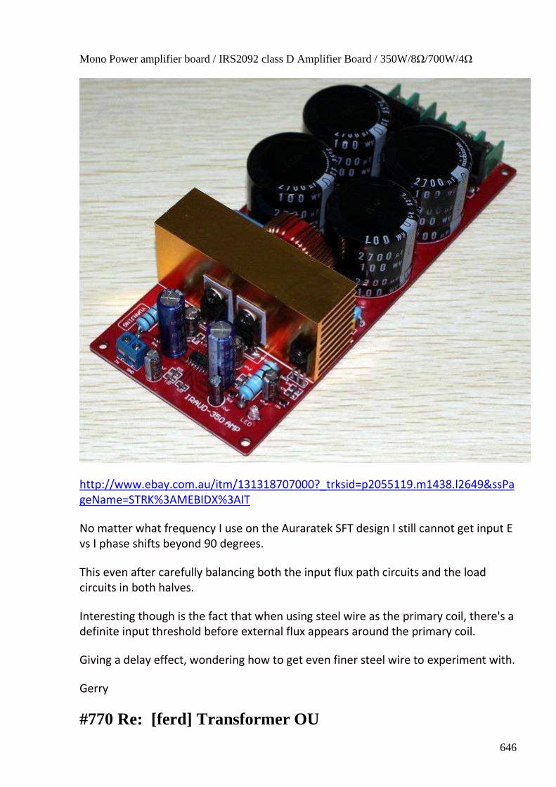
646
Mono Power amplifier board / IRS2092 class D Amplifier Board / 350W/8Ω/700W/4Ω
http://www.ebay.com.au/itm/131318707000?_trksid=p2055119.m1438.l2649&ssPa
geName=STRK%3AMEBIDX%3AIT
No matter what frequency I use on the Auraratek SFT design I still cannot get input E
vs I phase shifts beyond 90 degrees.
This even after carefully balancing both the input flux path circuits and the load
circuits in both halves.
Interesting though is the fact that when using steel wire as the primary coil, there's a
definite input threshold before external flux appears around the primary coil.
Giving a delay effect, wondering how to get even finer steel wire to experiment with.
Gerry
#770 Re: [ferd] Transformer OU
647
onielsen2000 Sep 23 at 2:16 PM
Hi Gerry, The UDT has to be driven at double the resonant frequency of the primary LC-tank to get overunity. I couldn't make it work before I tried this. It was actually Bill Alek that mentioned power resonance and the power has double the frequency of the driving voltage (and current). This statement actually doesn't make sense I just come to realize as the frequency should be halved if the power would have the frequency of the LC-tank. But anyway the trick does work even though the reason probably is something else. By using steel wire for the winding makes the winding has higher loss as steel is a bad conductor of electricity as compared to copper. Because of the high level of reactive power the loss may be big then. This power loss ends up as heat (real power or active power) which may require some sort of cooling of the transformer to prevent its temperature from getting to high. I'm using an IRS2092 based amplifier too. It is capable of delivering reactive power. The only problem is that the current goes back into the output and then continues through the intrinsic reverse voltage protection diodes in the power MOSFETs and ends up in the power supply. This makes the amplifier auto shut down when the voltage goes beyond its limits. My next experiment regarding the UDT will take active power from the primary LC-tank to limit the voltage and prevent the amplifier from shutting down. Regards Ole
#771 Re: [ferd] Transformer OU
Gerry Sep 25 2:05 AM
Thanks for your considered reply Ole,
I was wondering how you were going with your UDT.
Hoped the "Cobb" pdf documents I just posted might help in some way.
I downloaded and saved the two videos from Bill Alec's demo have watched these
many times.
To me, where he says he gets good results at around 3KHz seemed to suggest it was
an untuned setup, or possibly that's what he wanted folks to think.
From what is written on the yellow shrink wrap and said in the video re turns ratio
20: 120, I calculated the inductance ratios & it seems to support the values shown.
The resistances do seem very high for the number of turns though.
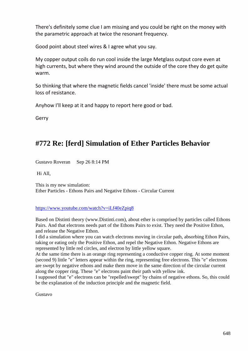
648
There's definitely some clue I am missing and you could be right on the money with
the parametric approach at twice the resonant frequency.
Good point about steel wires & I agree what you say.
My copper output coils do run cool inside the large Metglass output core even at
high currents, but where they wind around the outside of the core they do get quite
warm.
So thinking that where the magnetic fields cancel 'inside' there must be some actual
loss of resistance.
Anyhow I'll keep at it and happy to report here good or bad.
Gerry
#772 Re: [ferd] Simulation of Ether Particles Behavior
Gustavo Roveran Sep 26 8:14 PM Hi All, This is my new simulation: Ether Particles - Ethons Pairs and Negative Ethons - Circular Current https://www.youtube.com/watch?v=iLf40eZpiq8 Based on Distinti theory (www.Distinti.com), about ether is comprised by particles called Ethons Pairs. And that electrons needs part of the Ethons Pairs to exist. They need the Positive Ethon, and release the Negative Ethon. I did a simulation where you can watch electrons moving in circular path, absorbing Ethon Pairs, taking or eating only the Positive Ethon, and repel the Negative Ethon. Negative Ethons are represented by little red circles, and electron by little yellow square. At the same time there is an orange ring representing a conductive copper ring. At some moment (second 9) little "e" letters appear within the ring, representing free electrons. This "e" electrons are swept by negative ethons and make them move in the same direction of the circular current along the copper ring. These "e" electrons paint their path with yellow ink. I supposed that "e" electrons can be "repelled/swept" by chains of negative ethons. So, this could be the explanation of the induction principle and the magnetic field. Gustavo
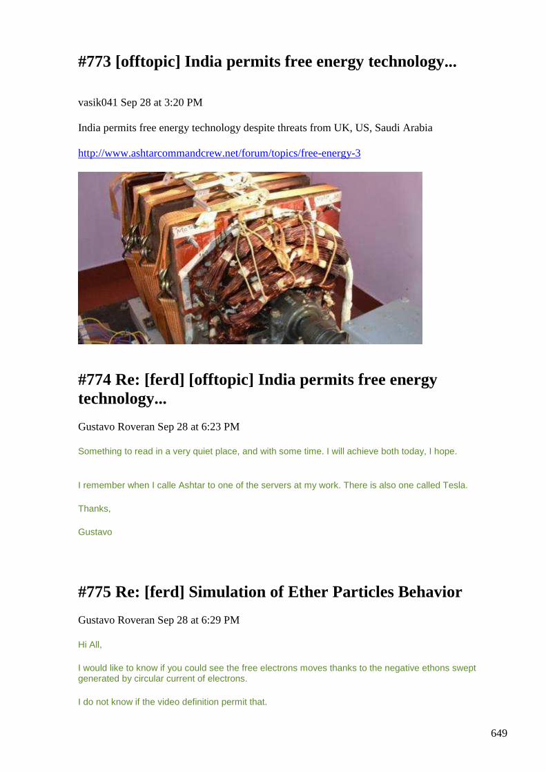
649
#773 [offtopic] India permits free energy technology...
vasik041 Sep 28 at 3:20 PM India permits free energy technology despite threats from UK, US, Saudi Arabia http://www.ashtarcommandcrew.net/forum/topics/free-energy-3
#774 Re: [ferd] [offtopic] India permits free energy technology...
Gustavo Roveran Sep 28 at 6:23 PM
Something to read in a very quiet place, and with some time. I will achieve both today, I hope.
I remember when I calle Ashtar to one of the servers at my work. There is also one called Tesla.
Thanks,
Gustavo
#775 Re: [ferd] Simulation of Ether Particles Behavior
Gustavo Roveran Sep 28 at 6:29 PM
Hi All,
I would like to know if you could see the free electrons moves thanks to the negative ethons swept generated by circular current of electrons.
I do not know if the video definition permit that.
650
Regards,
Gustavo
#776 RE: [ferd] Simulation of Ether Particles Behavior
Alexey Sep 28 at 10:34 PM
Hi Gustavo,
Thanks for sharing these simulations and scripts. I find scripts quite big and difficult to understand.
Do you think there are some practical results possible?
Regards,
Alexey
#777 Re: [ferd] [offtopic] India permits free energy technology...
Gerry Sep 29 at 1:16 AM
Hi Gustavo,
Nice link it was a good read.
I downloaded some of the papers.
Tewari's generator, the theory of operation appears to be based upon Lenz force
cancellation by conductors carrying equal but opposite currents.
Along lines of current bench experiments by us all, which reinforces our motivation
to keep trying.
Thanks Gerry
#778 Re: [ferd] Simulation of Ether Particles Behavior
Gustavo Roveran Sep 29 at 3:51 AM
Hi Alexey, I am trying to convince the audience :) with these simulations, that it would be a possible practical application thanks to the approach demostration that the behavior of ether particles would explain known phenomenons but that are not really understood, with a new point of view towards a new practical fer ideas.
651
In the simulation I did an approach of a demonstration that is possible to understand that: Gravity, could be explained as a flux of particles [ethons pairs -> negative and positive ethons] entering into the mass (atoms). More dense mass, then, more particles`s flux Between two masses there is a "vacuum" of ethons pairs, that produce an attraction force. But at the same time the necessity to absorb ethons from every direction, generates a "repulsion" force that keep both masses one far from the other. (obviously if one of the masses are no so dense in relation to the other, or the distance is not so small) The electric field could be explained as lots of ether particles (negative ethons) that are radiated by the electron. The electron absorbs ethons pairs and takes the positive ethon and repels the negative ethon. So, two electron are repelled by themselves. At the same time, when both electrons are close, an interference pattern of negative ethons appear. The electron in motion generate a pattern of negative ethons, something similar to a moving wave, a wave of negative ethons that propagate from the electron. That wave represents a concentration of negative ethons in motion, that could be the Magnetic Field. More than one electron in motion generate an interference pattern of negative ethons, that could be the cause of induction. These two next suppositions were not simulated yet, but if the gravity and the electricity, share the same ether particle (ethons pairs) it would be possible to interfere ethons pairs´s flux which enters into the mass (gravity) with electrons (electric field). A possible antigravity effect.
And taking into account the phenomenons measured below pyramids staying at the surface of earth, we can deduce that ethons pairs´s flux (gravity) that pass through pyramid matter, are interfered with its atoms and the flux is distorted and generates a pattern of ether particles inside the pyramid. This pattern generate strange effects known as Torsion fields.
What do you think ?
Gustavo
#779 Re: [ferd] [offtopic] India permits free energy technology...
Gustavo Roveran Sep 29 at 3:56 AM
Hi Gerry,
Thank you. I have to read it as soon as possible. But it was shared by Alexey.
Yes, interesting that the bemf could be "eluded".
Best Regards,
Gustavo
#780 RE: [ferd] Simulation of Ether Particles Behavior
Alexey Sep 29 at 9:19 AM
Hi Gustavo,
You know what I think about Destini’s ”theory” ;-)
May be you would like to read attached article and compare EGS (electricity-gravity-spin) concept with Destini’s theory …
(There is a more detailed work “Akimov A.E., Tarasenko V.J. Models of polarized states of physical vacuum and torsion fields” but I can’t find it)
652
Regards,
Alexey
#781 Re: [ferd] [offtopic] India permits free energy technology...
Gerry Sep 29 4:57 PM
Hi guys,
Ah...sorry Gustavo
Thanks for the information as always Alexey.
Am still playing with the Lenz cancelling things like UDT and Auroratek SFT.....
so Tewari link was of good interest.
Gerry
#782 Re: [ferd] Simulation of Ether Particles Behavior [1 Attachment]
Gustavo Roveran Sep 29 8:49 PM
Hi Alexey,
I remember you share a document similar to this one some month ago. That document was translated by you and people of this group (me too).
At the same time, I think that Distinti take his ideas from others. However, the simulation and the "conclusion" I shared are no from Distinti, I only use the idea to think the ether and fields as a universe of particles instead of forces at distance, basdd in the idea about ethos.
I do not know what do you think about this point of view.
I will re-read the document you sent, but it is very similar to that you share before, isn´t it ?
Regards,
Gustavo
#783 RE: [ferd] Simulation of Ether Particles Behavior
Alexey Sep 29 9:40 PM
Hi Gustavo,
653
Yes, this document is ”similar” to what we translated, but it is an original translation (I assume it is better and was approved by Akimov himself, since this was published while he was still with us). There is no doubt for me that what we call particles (electrons, protons etc) are different kinds of ether vortexes.
I don’t want be skeptical, but explaining some unexplained things thru other hypothetical things does not help much (it’s a typical scientific approach :-)
Regards,
Alexey
#784 Re: [ferd] Simulation of Ether Particles Behavior
Andreas Höschler Sep 29 11:17 PM
Hi Gustavo and all,
On 28 Sep 2015, at 16:29, Gustavo Roveran [ferd] <[email protected]> wrote:
I would like to know if you could see the free electrons moves thanks to the negative ethons swept generated by circular current of electrons.
I do not know if the video definition permit that.
>Based on Distinti theory (www.Distinti.com), about ether is comprised by particles called Ethons Pairs. And that >electrons needs part of the Ethons Pairs to exist. They need the Positive Ethon, and release the Negative Ethon.
I would clarify this a little. When we study the electro gravity phenomena it appears that positive charges do consume ether (ethon-pairs) while negative charges emit ether or at least consume less ether. This assumption at least would explain all the Townsed Brown observations.
This means p-pretrons consume ethon-pairs, break them apart, emit the p-ethon and suck in (4d vortex the n-ethon). The n-ethons reappear at the other side of the vortex which is a n-preton. Most of the n-ethons getting out of the tnnel are simply emitted making up the electrical field of a negative charge. Some recombine with p-ethons in the environment of the n-preton thus producing ethon-pairs.
The net effect of a n-preton/p-preton pair is the consumption of ether and the emission of p-ethons and n-ethon. So ether is actually converted into electrical fields while keeping matter (the p-preton/p-preton vortex) alive.
That's at least my current take!?
I also think that we can/should postulate that a high concentration of n-ethons repels n-pretons while a high concentration of p-ethons repels p-pretons? This would at least explain why charges are accelerated by a static electrical field!?
But what exactly happens when the free n-pretons in a conductor get moving? Does this lead to a net movement of ethon-paris in the direction of the n-preton movement? I would say YES. So we have our ether-wind!?
654
But how does it come that dA/dt (change of ether wind) causes n-pretons to be accelerated in one direction and p-prtons to be accelerated into the opposite direction? This is still a mystery to me! :-(
Any idea?
Andreas
#785 Re: [ferd] Simulation of Ether Particles Behavior
Gustavo Roveran Sep 29 at 12:21 AM
Hi Andreas, I think that we both are the only who read or are interested in Distinti "Theory". In my opinion, to understand this ether particle behaviour I prefer to summarize the group of n-pretons in an Electron. And the group of (p-pretons and n-pretons) in the Mass. So, I understand that there are 3 types of ether "winds", 1) ethons-pairs, 2) n-ethons and 3) p-ethons (the last one was not studied neither simulated by me ... yet) So ether winds are comprise by gravity and electric fields. The other effects known by us, magnetic field, Induction, and torsion field appears thanks to the interference of these winds. I think that the response to your question, is related to the interference pattern between winds.
Another question similar to yours is the bemf, and perhaps there could be a way to add something that reduces, attenuates or deviates the wind interference which produce bemf.
I know only ideas, within a brainstorming context.
Gustavo
#786 Re: [ferd] Simulation of Ether Particles Behavior
Andreas Höschler Sep 30 at 2:49 AM
Hi Gustavo,
I think that we both are the only who read or are interested in Distinti "Theory".
At least two. That's a start! :-)
In my opinion, to understand this ether particle behaviour I prefer to summarize the group of n-
pretons in an Electron. And the group of (p-pretons and n-pretons) in the Mass.
I agree. However, it could very well be that our presumption that electrons move in a conductor is wrong, that what is moving a rather n-pretons hopping from one atom/electron to the next.
655
This is just a theory but could very well be (makes the moast sense to me). I therefore usually consider single pretons moving instead of complete set of pretons. But this probably makes not much of a difference when considering the ethon streams.
So, I understand that there are 3 types of ether "winds", 1) ethons-pairs, 2) n-ethons and 3) p-
ethons
I agree! The question is, what stream constitutes what we perceive as a magnetic field. Only the ethon-pair stream, or is it a sum of all the three!?
So ether winds are comprise by gravity and electric fields. The other effects known by us,
magnetic field, Induction, and torsion field appears thanks to the interference of these winds. I
think that the response to your question, is related to the interference pattern between winds.
Another question similar to yours is the bemf, and perhaps there could be a way to add
something that reduces, attenuates or deviates the wind interference which produce bemf.
I know only ideas, within a brainstorming context.
Yes! We need to find a way to extend the model in such a fashion that it explains all the observed phenomena:
• electro gravitcs
• gravity and inertia
• self induction
• ...
My current take of the model does not explain all of this satisfactorily to me!? :-(
Consider two straight conductors (supra conductingh for now). You apply an electrical field to the ends of conductor A. The p-ethons and n-ethons streaming with c throzgh the conductor do accelerate the free n-pretons (electrons) in the conductor. This somehow leads to ethon-pair wind in the vicinity (vector potential). Somehow this dA/dt causes n-pretons in the second straight conductor to be accelerated in one direction and p-pretons in the opposite direction. Isn't this weird. How can we intuitively explain this?
Best wishes,
Andreas
#787 Re: [ferd] Simulation of Ether Particles Behavior
onielsen2000 Sep 30 at 4:39 AM Hi Andreas, All,

656
"Yes! We need to find a way to extend the model in such a fashion that it explains all the observed phenomena: • electro gravitcs • gravity and inertia • self induction • ... My current take of the model does not explain all of this satisfactorily to me!? :-( " Then what about a unified field theory? Unified Field Theory http://www.grantchronicles.com/astro128.htm Regards Ole
#788 Re: [ferd] Simulation of Ether Particles Behavior
Gustavo Roveran Sep 30
Hi Andreas,
"I agree! The question is, what stream constitutes what we perceive as a magnetic field. Only the ethon-pair stream, or is it a sum of all the three!?" I think, taking into account the very simplified model proposed by Distinti, and interpreted/missinterpreted by me that: Gravity is ethons pairs flux Electric field is negative ethons flux Magnetic Field is the displacement of negative ethons flux interference
"Consider two straight conductors (supra conductingh for now). You apply an electrical field to the ends of conductor A. The p-ethons and n-ethons streaming with c throzgh the conductor do accelerate the free n-pretons (electrons) in the conductor. This somehow leads to ethon-pair wind in the vicinity (vector potential). Somehow this dA/dt causes n-pretons in the second straight conductor to be accelerated in one direction and p-pretons in the opposite direction. Isn't this weird. How can we intuitively explain this?"
When you said "streaming with c" are you referring to light speed ? Because I think that virtual particles (ethons) have to have a speed much more greater than the electron.
For example, if I simulate an electron and ethons pairs, moving at the same velocity, the effect is totally different. And it does not coincide with the expected.
Alexey has shared an very interesting document recently and I recommend you to read. Because, in that document, you can see another point of view about the conformation of the vacuum. And in my opinion, has some similarities with Distinti, but better explained and more complex theory. Hi Ole
657
I understand that there are a lot of TOE theories, or at least, lot of branches. Did you read the branch you shared ?
Regards,
Gustavo
#789 Re: [ferd] Simulation of Ether Particles Behavior
Andreas Höschler 1 Oct at 12:43 AM
Hi Gustavi,
"I agree! The question is, what stream constitutes what we perceive as a magnetic field. Only the ethon-
pair stream, or is it a sum of all the three!?"
I think, taking into account the very simplified model proposed by Distinti, and interpreted/missinterpreted
by me that:
Gravity is ethons pairs flux
Electric field is negative ethons flux
What about the electric field of a p-ethon? Wouldn't that be the p-ethons emitted away?
Magnetic Field is the displacement of negative ethons flux interference
I don't undersand what you mean by that!? :-(
"Consider two straight conductors (supra conductingh for now). You apply an electrical field to the ends of
conductor A. The p-ethons and n-ethons streaming with c throzgh the conductor do accelerate the free n-
pretons (electrons) in the conductor. This somehow leads to ethon-pair wind in the vicinity (vector
potential). Somehow this dA/dt causes n-pretons in the second straight conductor to be accelerated in
one direction and p-pretons in the opposite direction. Isn't this weird. How can we intuitively explain this?"
When you said "streaming with c" are you referring to light speed?
Yes!
Because I think that virtual particles (ethons) have to have a speed much more greater than the electron.
Why? Isn't it reasomable to assume that the electrical field propagates with c which would be a stream of p- or n-ethons being emitted away from charges?
For example, if I simulate an electron and ethons pairs, moving at the same velocity, the effect is totally
different. And it does not coincide with the expected.
658
I consider the actual velocity ethon-pairs (vector potential A) to be relatively free depending on how many ethon-pairs move, something like
A = N * v
where N is a particle density of moving ethon-pairs and v the average velocity of the ethon pairs!?
dA/dt causes accelration on charges then a rot A is B!
Alexey has shared an very interesting document recently and I recommend you to read. Because, in that
document, you can see another point of view about the conformation of the vacuum. And in my opinion,
has some similarities with Distinti, but better explained and more complex theory.
I got lost. Which email (day/time) was that?
Thanks,
Andreas
#790 Re: [ferd] Simulation of Ether Particles Behavior
onielsen2000 Oct 1 at 4:06 AM
Hi Gustavo, I understand that there are a lot of TOE theories, or at least, lot of branches. Did you read the branch you shared ? I have read some of it. This site has progressed slowly but there seems to come forth a lot of new pages at the moment. There is no contact info. The theory is very ET inspired. All forces acting at a distance like electric, magnetic and gravity fields are particle interactions and there are many kinds of particles to do the interactions. I think the theory is in line with W.B. Smith's claim with the electron being the smallest physical particle which builds up everything bigger. The theory also talks about different signal speeds caused by different densities of the medium. Even density shifting is possible it is claimed. This is a way to achieve faster than light travel than at the light speed at the density of the physical universe. Regards Ole
#791 Re: [ferd] Simulation of Ether Particles Behavior
Gustavo Roveran Oct 2 2:58 AM
Thanks Ole, for you information.
659
"The theory also talks about different signal speeds caused by different densities of the medium. Even density shifting is possible it is claimed"
Something similar to the velocity of sound in different mediums (solid liquid or gaseous). Hi Andreas, What about the electric field of a p-ethon? Wouldn't that be the p-ethons emitted away? The electric field or negative electric field, comes from the electron. And is conform by a "radiation" of n-ethons. The positive electric field comes from proton, and is conform by p-ethons. In my opinion, if there is a region where lot of n-ethons go, and p-ethons come, is because electron and proton are too close, and that means you are inside the atom, or an electron is approaching to be added in an atom. Why? Isn't it reasomable to assume that the electrical field propagates with c which would be a stream of p- or n-ethons being emitted away from charges? I understand that, fields like gravity and electric are superluminal. I got lost. Which email (day/time) was that? I am attaching the pdf shared by Alexey. Take care, Gustavo
#792 Off topic: Spin current Hall effect
smokyatgroups Oct 4 at 4:23 AM Hi Alexey ..all I found the attached articles to be very interesting and informative regarding OU effects. So in interests of sharing please find them attached. all the best guys Gerry
#793 [ferd] Off topic: Spin current Hall effect
Gustavo Roveran Oct 4 4:51 PM
Hi Gerry Coul it be possible that you sent something similar a pair of months ago.?

660
Thanks Gustavo
#794 Re: [ferd] Off topic: Spin current Hall effect
Gerry Oct 5 1:53 AM
Hi Gustavo, guys
Yes you're probably right, I may have already done this ...
I'm definitely losing my memory.
The main message I wanted to get across from "spin current" doc is first paragraph
on page 3
Quote:
This effect is known as the classical spin Hall effect, and quantum mechanics adds a dramatic
twist on top. The quantum-mechanical wave nature of the travelling electrons organizes them
into neat channels along the edges of the sample. In the bulk of the material, there is no net
spin. But at each edge, there form exactly two electron-carrying channels, one for spin-up
electrons and one for spin-down. These edge channels possess a further remarkable property:
the electrons that move in them are impervious to the disorder and imperfections that usually
cause resistance and energy loss.
So we can think a superconducting effect results from properly setup "spin Hall edge
channels"
It was the above that made me attempt to replicate the very old German "Stromzer"
device as I believe this might be the principle on which it operates.
Apologies for wasting everyone's time.
Gerry
#795 Re: [ferd] Off topic: Spin current Hall effect
Gustavo Roveran Oct 5 2:50 AM
Hi Gerry,
There was no wasting time. I reread all and I think that the spin Hall effect for light, was not presented before.
661
Thanks
Gustavo
#796 Re: [ferd] Off topic: Spin current Hall effect
Gerry Oct 5 4:20 AM
Hi Gustavo,
In that part of the document they are explaining to us what "spin Hall effect" is and
how it works.
As applied to electrons in a laminated type conductor (conductor/ insulator/
conductor) .....in computer hard drive for working example.
Notice that this is a dc effect not the usual "inductive or capacitive coupling" we are
more used to.
So no at this part of explanation it just back grounding us on the effect, before
applying it to light itself.
Gerry
#797 Re: [ferd] Transformer OU
Gerry 6 Oct at 4:06 AM
Hi Alexey, Ole guys,
I made up a version of UDT from a old MOV transformer with 140 turns on each
outer leg. (No specific air gaps yet).
Wound them in solenoid style, so all layers wound say clockwise from left to right
and on opposite leg anticlockwise with all layers from right to left.
Attached are a few pics of this and how it appears to perform with output of 6.4
watts into 10 Ohms load.
Scope is running with no earth back to 50Hz mains ...yet I get an enormous phase
shift current lags by 7.6 to 7.7 milliseconds in the 20 millisecond period (50Hz).
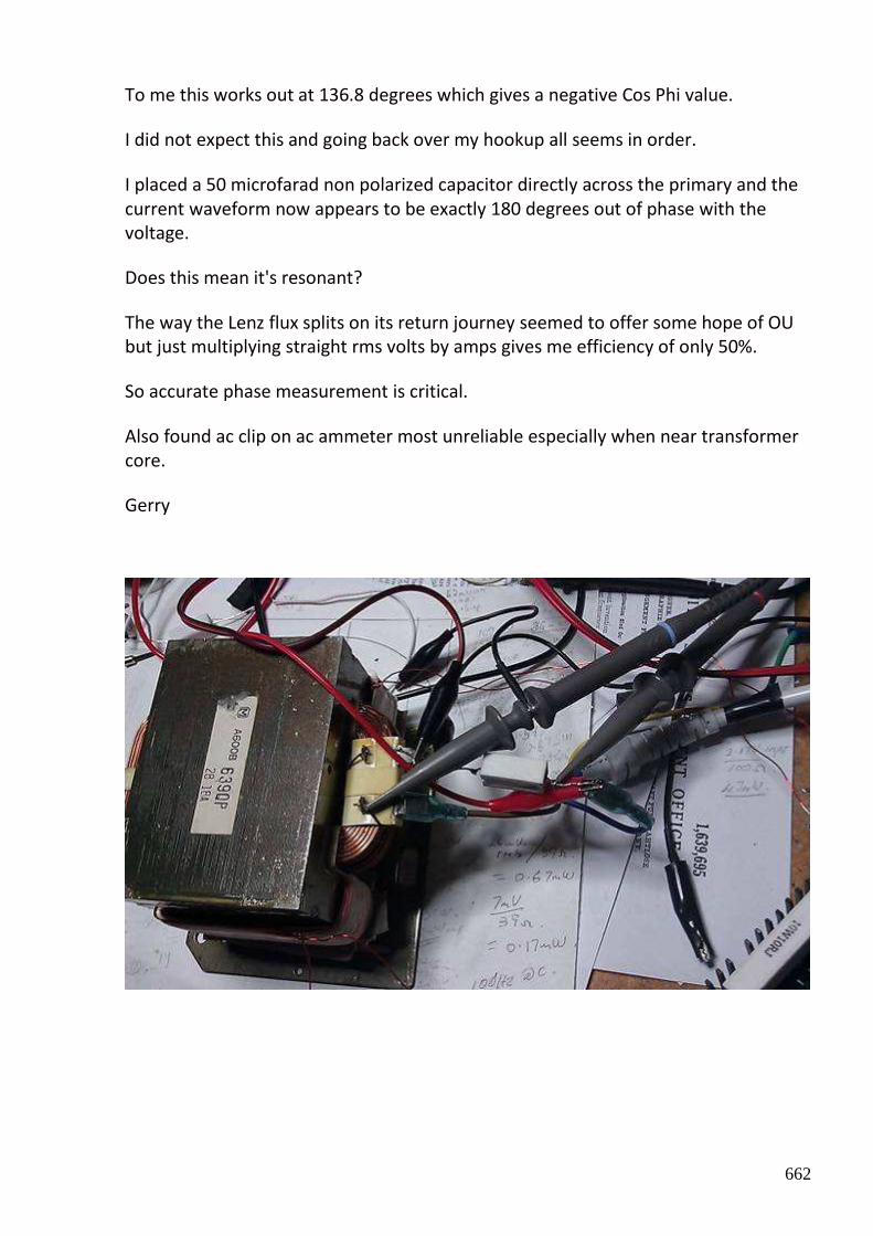
662
To me this works out at 136.8 degrees which gives a negative Cos Phi value.
I did not expect this and going back over my hookup all seems in order.
I placed a 50 microfarad non polarized capacitor directly across the primary and the
current waveform now appears to be exactly 180 degrees out of phase with the
voltage.
Does this mean it's resonant?
The way the Lenz flux splits on its return journey seemed to offer some hope of OU
but just multiplying straight rms volts by amps gives me efficiency of only 50%.
So accurate phase measurement is critical.
Also found ac clip on ac ammeter most unreliable especially when near transformer
core.
Gerry
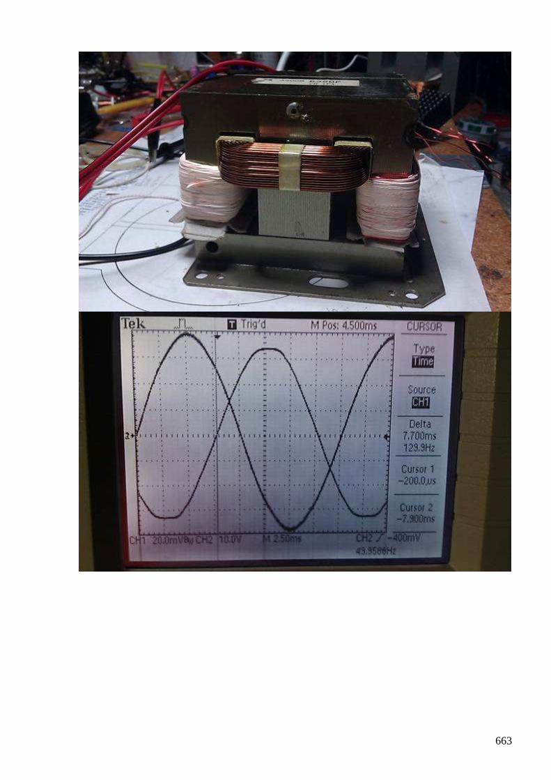
663
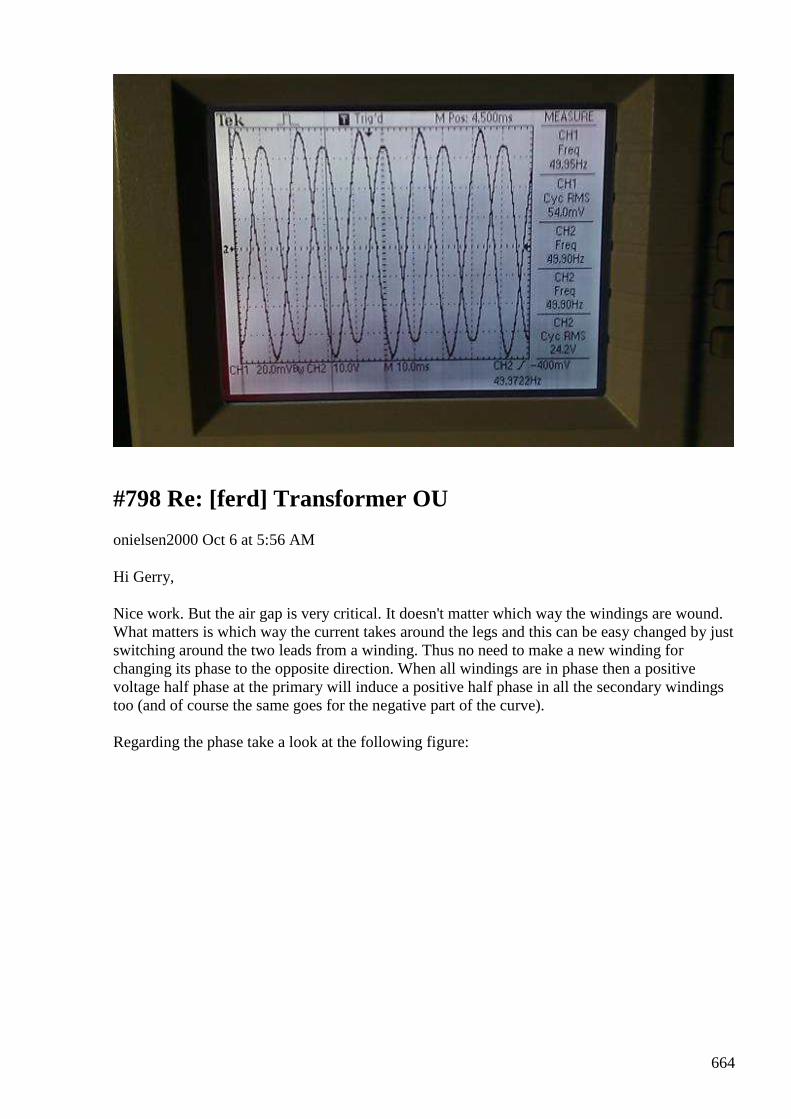
664
#798 Re: [ferd] Transformer OU
onielsen2000 Oct 6 at 5:56 AM
Hi Gerry, Nice work. But the air gap is very critical. It doesn't matter which way the windings are wound. What matters is which way the current takes around the legs and this can be easy changed by just switching around the two leads from a winding. Thus no need to make a new winding for changing its phase to the opposite direction. When all windings are in phase then a positive voltage half phase at the primary will induce a positive half phase in all the secondary windings too (and of course the same goes for the negative part of the curve). Regarding the phase take a look at the following figure:
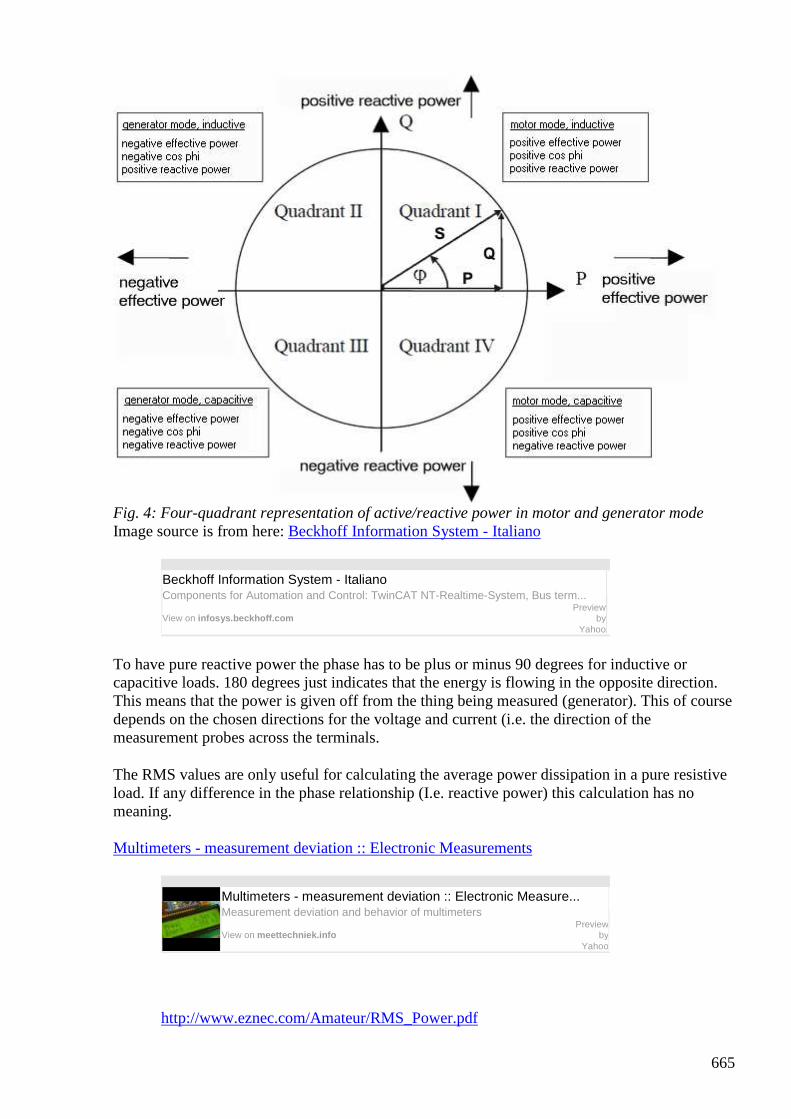
665
Fig. 4: Four-quadrant representation of active/reactive power in motor and generator mode Image source is from here: Beckhoff Information System - Italiano
Beckhoff Information System - Italiano Components for Automation and Control: TwinCAT NT-Realtime-System, Bus term...
View on infosys.beckhoff.com
Preview by
Yahoo
To have pure reactive power the phase has to be plus or minus 90 degrees for inductive or capacitive loads. 180 degrees just indicates that the energy is flowing in the opposite direction. This means that the power is given off from the thing being measured (generator). This of course depends on the chosen directions for the voltage and current (i.e. the direction of the measurement probes across the terminals.
The RMS values are only useful for calculating the average power dissipation in a pure resistive load. If any difference in the phase relationship (I.e. reactive power) this calculation has no meaning. Multimeters - measurement deviation :: Electronic Measurements
Multimeters - measurement deviation :: Electronic Measure... Measurement deviation and behavior of multimeters View on meettechniek.info
Preview by
Yahoo
http://www.eznec.com/Amateur/RMS_Power.pdf
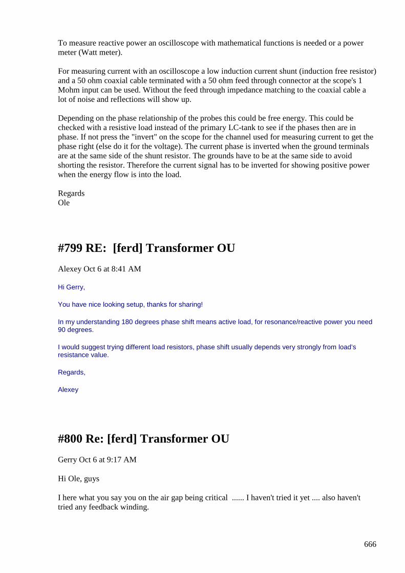
666
To measure reactive power an oscilloscope with mathematical functions is needed or a power meter (Watt meter). For measuring current with an oscilloscope a low induction current shunt (induction free resistor) and a 50 ohm coaxial cable terminated with a 50 ohm feed through connector at the scope's 1 Mohm input can be used. Without the feed through impedance matching to the coaxial cable a lot of noise and reflections will show up. Depending on the phase relationship of the probes this could be free energy. This could be checked with a resistive load instead of the primary LC-tank to see if the phases then are in phase. If not press the "invert" on the scope for the channel used for measuring current to get the phase right (else do it for the voltage). The current phase is inverted when the ground terminals are at the same side of the shunt resistor. The grounds have to be at the same side to avoid shorting the resistor. Therefore the current signal has to be inverted for showing positive power when the energy flow is into the load. Regards Ole
#799 RE: [ferd] Transformer OU
Alexey Oct 6 at 8:41 AM
Hi Gerry,
You have nice looking setup, thanks for sharing!
In my understanding 180 degrees phase shift means active load, for resonance/reactive power you need 90 degrees.
I would suggest trying different load resistors, phase shift usually depends very strongly from load’s resistance value.
Regards,
Alexey
#800 Re: [ferd] Transformer OU
Gerry Oct 6 at 9:17 AM
Hi Ole, guys
I here what you say you on the air gap being critical ...... I haven't tried it yet .... also haven't tried any feedback winding.
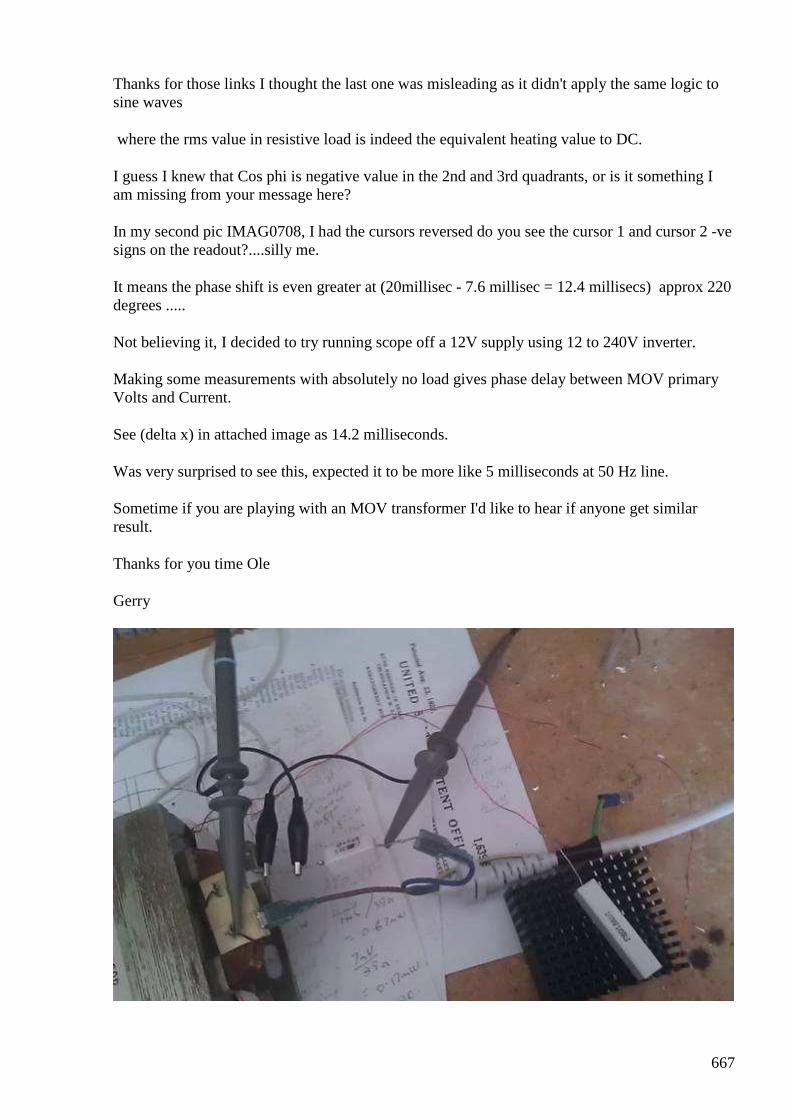
667
Thanks for those links I thought the last one was misleading as it didn't apply the same logic to sine waves
where the rms value in resistive load is indeed the equivalent heating value to DC.
I guess I knew that Cos phi is negative value in the 2nd and 3rd quadrants, or is it something I am missing from your message here?
In my second pic IMAG0708, I had the cursors reversed do you see the cursor 1 and cursor 2 -ve signs on the readout?....silly me.
It means the phase shift is even greater at (20millisec - 7.6 millisec = 12.4 millisecs) approx 220 degrees .....
Not believing it, I decided to try running scope off a 12V supply using 12 to 240V inverter.
Making some measurements with absolutely no load gives phase delay between MOV primary Volts and Current.
See (delta x) in attached image as 14.2 milliseconds.
Was very surprised to see this, expected it to be more like 5 milliseconds at 50 Hz line.
Sometime if you are playing with an MOV transformer I'd like to hear if anyone get similar result.
Thanks for you time Ole
Gerry
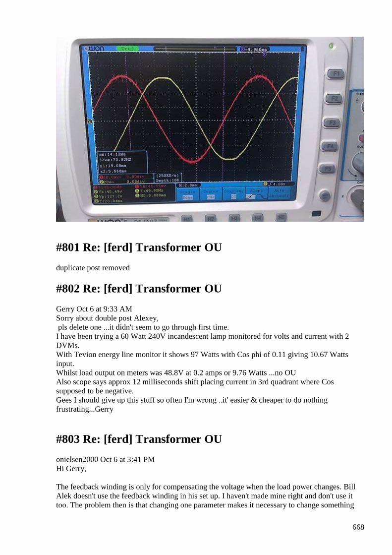
668
#801 Re: [ferd] Transformer OU
duplicate post removed
#802 Re: [ferd] Transformer OU
Gerry Oct 6 at 9:33 AM Sorry about double post Alexey, pls delete one ...it didn't seem to go through first time. I have been trying a 60 Watt 240V incandescent lamp monitored for volts and current with 2 DVMs. With Tevion energy line monitor it shows 97 Watts with Cos phi of 0.11 giving 10.67 Watts input. Whilst load output on meters was 48.8V at 0.2 amps or 9.76 Watts ...no OU Also scope says approx 12 milliseconds shift placing current in 3rd quadrant where Cos supposed to be negative. Gees I should give up this stuff so often I'm wrong ..it' easier & cheaper to do nothing frustrating...Gerry
#803 Re: [ferd] Transformer OU
onielsen2000 Oct 6 at 3:41 PM Hi Gerry, The feedback winding is only for compensating the voltage when the load power changes. Bill Alek doesn't use the feedback winding in his set up. I haven't made mine right and don't use it too. The problem then is that changing one parameter makes it necessary to change something
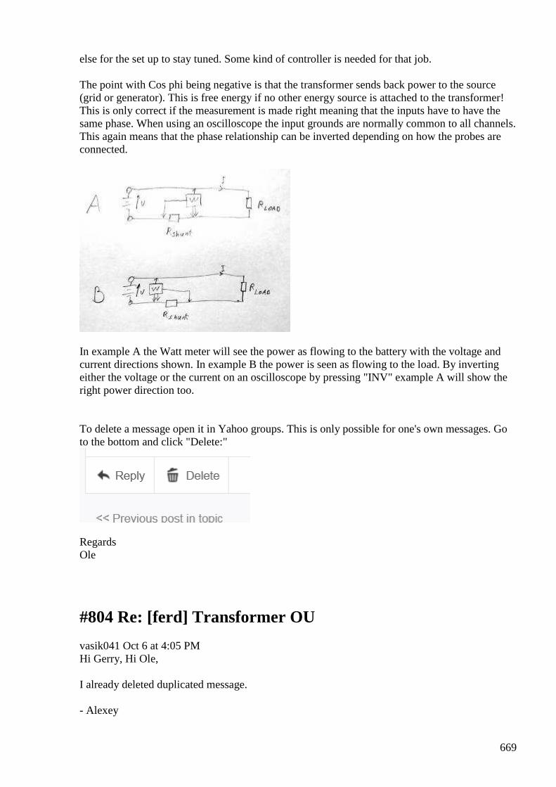
669
else for the set up to stay tuned. Some kind of controller is needed for that job. The point with Cos phi being negative is that the transformer sends back power to the source (grid or generator). This is free energy if no other energy source is attached to the transformer! This is only correct if the measurement is made right meaning that the inputs have to have the same phase. When using an oscilloscope the input grounds are normally common to all channels. This again means that the phase relationship can be inverted depending on how the probes are connected.
In example A the Watt meter will see the power as flowing to the battery with the voltage and current directions shown. In example B the power is seen as flowing to the load. By inverting either the voltage or the current on an oscilloscope by pressing "INV" example A will show the right power direction too. To delete a message open it in Yahoo groups. This is only possible for one's own messages. Go to the bottom and click "Delete:"
Regards Ole
#804 Re: [ferd] Transformer OU
vasik041 Oct 6 at 4:05 PM Hi Gerry, Hi Ole, I already deleted duplicated message. - Alexey

670
#805 RE: [ferd] Transformer OU
Alexey Oct 6 7:44 PM Hi Gerry, Please don’t be frustrated. I was many times in same situation and I think that every failure should be taken as a chance to learn something. We can’t expect that Nature change the way it works just because we want it. In opposite, we have to learn she’s ways and try use it for our goals. I think by now it is pretty clear that there is no OU in UDT setup as it described in the internet. But from my point of view there is no reason to limit research and experiments to this one concept, there are many many others unexplored areas. Regards, Alexey
#806 group messages archive
Alexey Oct 6 7:53 PM Hello, I would like to remind that the group messages archive located here https://www.idrive.com/idrive/sh/sh?k=a4o5d7m1y9 Please make your own (local) copy of it from time to time, just in case... Regards, Alexey a.k.a FE R&D group administrator
#807 Re: [ferd] Transformer OU
Gerry Oct 7 at 4:14 AM Thanks for the tip Ole, Moving the probes common earth point to below the sense resistor fixed it. Now getting 4.16 milliseconds delay unloaded ....a lot more sensible. If you have the chance I'd love to see a pic your replication of your UDT. all the best Gerry
#808Re: [ferd] Transformer OU
duplicate
#809 Re: [ferd] Transformer OU
Gerry Oct 7 at 4:21 AM Thanks for your support Alexey & guys,
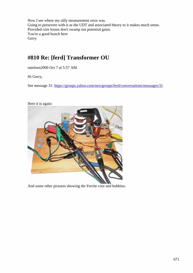
671
Now I see where my silly measurement error was. Going to persevere with it as the UDT and associated theory to it makes much sense. Provided core losses don't swamp out potential gains. You're a good bunch here Gerry
#810 Re: [ferd] Transformer OU
onielsen2000 Oct 7 at 5:57 AM
Hi Gerry, See message 31: https://groups.yahoo.com/neo/groups/ferd/conversations/messages/31
Here it is again:
And some other pictures showing the Ferrite core and bobbins:
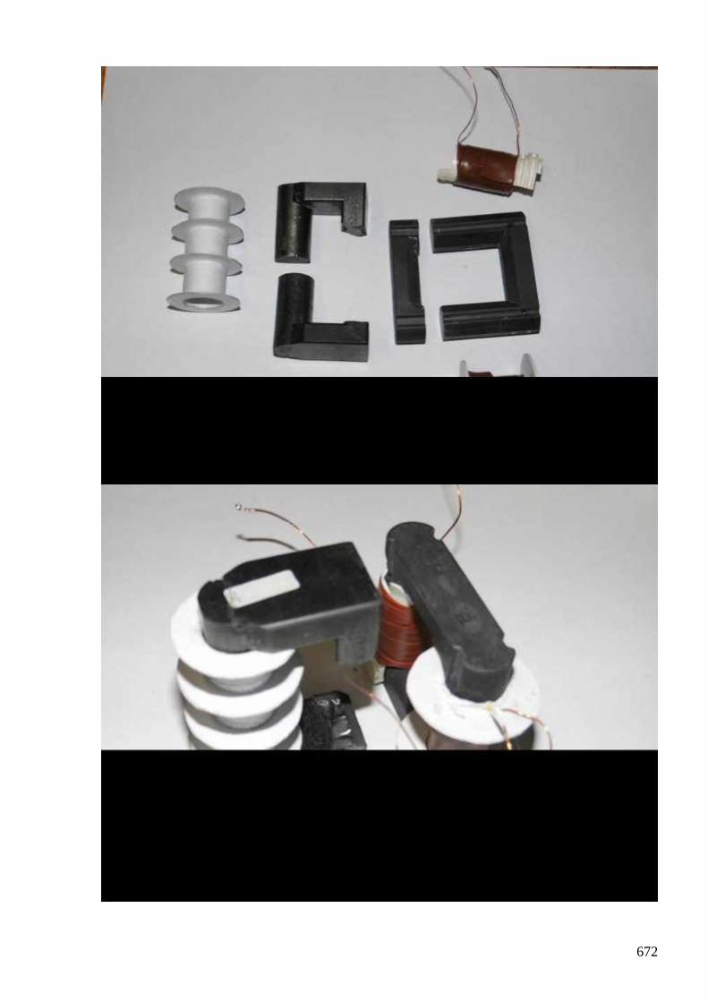
672
673
Regards Ole
#811 Re: [ferd] Transformer OU
Gerry Oct 7 at 7:37 AM Nice Ole, Good to see how you interpret the concept. Thinking your core losses would be far less than my steel laminations. Can also see where you were resonating the primary. I might have a go at this too reducing the resonant frequency to 25 Hz whilst driving it at 50 Hz & see what happens. Currently at 100V ac I am dissipating 14 watts just to magnetise core with no load. When loaded, input goes up to 17 Watts for a usable output of only 5 Watts from secondary (50V at 0.1 A into 60W globe) . regards Gerry
#812 Re: [ferd] Transformer OU
onielsen2000 Oct 6 at 1:49 PM Hi Gerry, Without actually having measured the core loss I think this will be hard to avoid as the core has to go to reasonably high magnetization. I believe the field mixing only takes place in the non linear part of the magnetization curve which is around the knee points. If the excess energy comes from making the B-field coherent this is a must. This powerful magnetization is in the region around saturation point which does heat the core. The load is also critical. With a variable load the working point can be found without having to rewind the secondaries. Everything seems to have to match each other. Regards Ole
#813 Re: [ferd] Simulation of Ether Particles Behavior
Gustavo Roveran Oct 7 11:48 PM Hi Andreas, I did a new an enhanced simulation, where electron and proton interacts with ethons. In the future I will try to include pretons. There you can see what I mean with neg. ethons go and pos. ethons comes. Ether Particles - Ethons Pairs - Negative and Positive Ethons - Proton - Electron - Atom Ether Particles - Ethons Pairs - Negative and Positive E... Ver en www.youtube.com
674
Different situations are generated when the speed of ethons and electron are modified, and also when adds more electrons and protons. Regards, Gustavo
#814 Re: [ferd] Simulation of Ether Particles Behavior
Andreas Höschler Oct 8 at 12:07 AM Hi Gustavo, Thanks for this PDF. I try to learn something from it but failed. I stopped reading after the first couple of pages since I culd not make out where they were going with their argumentation. Still looking for additional input that I am able to digest ... Thanks for your continued efforts! Best wishes, Andreas
#815 Re: [ferd] Simulation of Ether Particles Behavior
Andreas Höschler Oct 8 at 12:17 AM Hi Ole, I have looked into a couple of these documents now, e.g. http://www.grantchronicles.com/astro19.htm They don't make any sense to me either. The english is horrible. Very hard to estimate (at least for me) whether the author has any clue or just poured a bucket of words into a fan and posted the result! :-( Have you learned anything from these pages? Looking further ... Best wishes, Andreas
#816 Re: [ferd] Simulation of Ether Particles Behavior
onielsen2000 Oct 8 at 3:24 AM Hi Andreas, Some of the pages has to be read before reading others as they contain basic prerequisites for the understanding. Read the "Grant Cronicles" page on particle movement (http://www.grantchronicles.com/astro05.htm) which is the basic for transferring forces at a distance. If a single particle stream is in one direction in a field the particles gets compressed in that direction (longitudinal). This again means resistance which makes the stream buckle (transverse). This transverse movement is what we on our planet measures as waves because our
675
equipment isn't able to discern the single particles. An experiment with water to show the effect is mentioned. Gustavo's simulation "Ether Particles - Ethons Pairs - Negative and Positive Ethons - Proton - Electron - Atom " would be made in another way if made according to Grant's theory. Then the particles would accumulate inside the atoms until bursts of particles (gravity particles) shoots out like a string of particles following each other's tail. Other particles partly orbits outside and inside the atom nucleus. I don't know if anybody has made simulations of this theory or even set up the mathematics. The theory starts from nothing at all just like the theory of Wilbert B. Smith in "The New Science". I.e. an infinite void of space. But of course they both claim this extra terrestrial origin which could be from the same source. Regards Ole
#817 Re: [ferd] Simulation of Ether Particles Behavior
onielsen2000 Oct 8 at 4:24 AM A Nobel prize was given for discovering that the neutrino particle has mass: http://www.nobelprize.org/nobel_prizes/physics/laureates/2015/popular-physicsprize2015.pdf Regards Ole
#818 Re: [ferd] Simulation of Ether Particles Behavior
Gustavo Roveran Oct 8 at 5:44 AM Hi Andreas, Yes, green dots are ethon pairs. This is the description of the last simulation I shared, could you read it ? Based on Distinti theory (www.Distinti.com), about ether is comprised by particles called Ethons Pairs. Ethon Pairs are comprised by Positive and Negative Ethons. And that electrons needs part of the Ethons Pairs to exist. They needs the Positive Ethon, and releases the Negative Ethon. While protons needs part of the Ethons Pairs to exist, in this case they need the Negative Ethon, and release the Positive Ethon. I did a new and enhanced simulation where: "P" = Proton "e" = Electron Green ball = Ethon Pair Blue Ball = Positive Ethon Red Ball = Negative Ethon This simulation is divided in four parts:
676
Part -1- Proton "P" in the middle of the screen is "eating" Ethon Pairs, and repels Positive Ethons. Part -2- Electron "e" at the right of the screen is "eating" Ethon Pairs, and repels Negative Ethons. Part -3- A static situation of an Electron and a Positron, where you can see that Electron attracts Positive Ethons while eats Ethon Pairs and repels Negative Ethons, while Proton attracts Negative Ethons while eats Ethon Pairs and repelling Positive Ethons. Part -4- The Electron is orbiting around the Proton. Like an Atoms situation. "It could very well be that only the p-preton consumes ether (inlet of a vortex) and the n-preton (outlet of the vortex) even emits a few ethon-pairs after recombination of n-ethon coming through the vortex and p-ethon hitting the n-preton from the outside!?" I think we have to re-watch Distinti´s videos related to this subject. I know that I am simplicating his "theory" because I use proton and electron instead of p-pretons and n-pretons, if I not misunderstand your concept, you are saying that a free electron does not eat ether (ethon-pairs) to exist. Any way, my next step is to try to include pretons in simulation, induction, magnetic field and mass.... Hi Ole, if you tell me what lines I have to read to simulate Grant´s theory, I could try to do it. About Nobel Prize, some Russian theories tell that torsion fields are formed by neutrinos, and some scientist demonstrated that inside a pyramid neutrinos are accumulated. In Spanish language Kajita sounds like "little box" in English, the other ones who won was McDonald .... :) Regards Gustavo
#819 Re: [ferd] Simulation of Ether Particles Behavior
Andreas Höschler Oct 8 12:50 PM Hi Gustavo, Based on Distinti theory (www.Distinti.com), about ether is comprised by particles called Ethons Pairs. Ethon Pairs are comprised by Positive and Negative Ethons. And that electrons needs part of the Ethons Pairs to exist. They needs the Positive Ethon, and releases the Negative Ethon. While protons needs part of the Ethons Pairs to exist, in this case they need the Negative Ethon, and release the Positive Ethon. >"It could very well be that only the p-preton consumes ether (inlet of a vortex) and the n-preton (outlet of the >vortex) even emits a few ethon-pairs after recombination of n-ethon coming through the vortex and p-ethon hitting >the n-preton from the outside!?" I think we have to re-watch Distinti´s videos related to this subject. Distinti explains it like you have in the first paragraph (which does not necessarily have to be entirely correct). The second paragraph above is my modification (attempt) of his theory after looking at electro gravity. Townsed Brown and others realised that an asymmetrical condensor with the positive pole at the top (ideally very small, e.g. just a wire) and the negative pole at the
677
bottom (larger) produces an anti-gravity effect. This can easily be explained if only the p-pretons consume ether and the n-pretons even emit a few ethon-pairs. This also explains the p-preton/n-preton pairs appearing out of nothing. Such a pair is just a vortex with the p-preton being the inlet and then-preton the outlet. This theory unfortunately still does not explain everything for me (still just a gateway model that gives a few clues). :-( I would like to re-raise the "displacement current causes magnetic field" issue. In my opinion Distinti - though being a brilliant mind - got this completely wrong. Do all remember the research paper we had mentioned here a couple of weeks ago regarding Röntgen apparently proving that displacement current causes a magnetic field? The conclusion of his experiment is completely wrong in my opinion. As soon as we have a dielectricum between the plates we have preton movement, in Röntgens case even continuous preton movement in the dielectricum. And we already know (at least presume in our models) that preton movement causes aether wind (vector potential). So Röntgens experiment just nicely confirms what we already know/believe but helps not one bit to understand what happens if we replace the dielectricum with a perfect vacuum. Imagine a very big plate cap in space (perfect vacuum) and then (somehow) charge the plates. Would we measure a magnetic field between the plates? Would this be constant over the full length d of the gap? If we don't have matter between the plates there are no pretons that can be moved that can then cause aether wind. All we have between the plates is an increasing stream of p-ethons in one direction and n-ethons in the other. If my above mentioned theory modification is correct we would also see ethon-pairs moving from the negative plate to the positive plate. And exactly that would make us measure a magnetic field even for a vacuum cap but only outside of the cap, not within it because the ethon-pairs stream would be homogen between the plates, therefore no B = curl A there! Just brainstorming ... But can you follow my reasoning? What I still don't get is how a dA/dt at some point B can cause EMF (force on pretons) at point A with the points being significantly away from each other. And also why n-pretons are accelerated in one direction and p-pretons inthe other. This puzzles me!?? I know that I am simplicating his "theory" because I use proton and electron instead of p-pretons and n-pretons, if I not misunderstand your concept, you are saying that a free electron does not eat ether (ethon-pairs) to exist. Yes (see above)! Any way, my next step is to try to include pretons in simulation, induction, magnetic field and mass.... Good luck (please let us know)! :-) Best wishes, Andreas
#820 Re: [ferd] Simulation of Ether Particles Behavior
onielsen2000 Oct 8 3:17 PM Hi Gustavo, I would suggest starting by reading: "Particle Movement - The Behavior of Subatomic Particles through a Field Medium." Then there is a rather long article "The Universal Laws of Gravity and Repulsion Particle" about the different kinds of interactions between elementary particles. This article has figures showing the interactions.
678
Regards Ole
#821 Re: [ferd] Simulation of Ether Particles Behavior
Gustavo Roveran Oct 8 8:00 PM Hi Ole, All Thank you for both links. I will read and try to simulate. PD: Taking a nontraditional approach, magnetism is derived as a relativistic effect. -> https://www.u-cursos.cl/usuario/6c35e35ec55a71af969f59a168a300a7/mi_blog/r/Electricity_and_Magnetism_-_Purcell_01_-_100_-_ConiF.pdf Regards, Gustavo
#822 Re: [ferd] Simulation of Ether Particles Behavior
Gustavo Roveran Oct 9 at 4:47 AM Hi Andreas, "This can easily be explained if only the p-pretons consume ether and the n-pretons even emit a few ethon-pairs." However this could also be explained if proton (more massive than electron) generate an inlet flux of ethon pairs greater than the electron`s inlet.This situation will produce a "vacuum effect" in the positive side. And then, both still are eating ethon pairs "This also explains the p-preton/n-preton pairs appearing out of nothing. Such a pair is just a vortex with the p-preton being the inlet and then-preton the outlet. " I think that this could also be explain by tunnel effect. Quantum tunnelling - Wikipedia, the free encyclopedia
Quantum tunnelling - Wikipedia, the free encyclopedia Quantum tunnelling or tunneling (see spelling differences) refers to the quantum mechanical phenomenon where a particle tunnels through a barrier that i...
Ver en en.wikipedia.org
Vista previa por Yahoo
679
I have done another simulation with proton eating ethon pairs at bigger rate than electron, and also add gravity effect to the simulation. Regards, Gustavo
#823 Re: [ferd] Simulation of Ether Particles Behavior
Andreas Höschler Oct 11 10:51 PM Hi all, I am just reading (for the second time) http://montalk.net/science/109/scalar-superpotential-theory http://scalarphysics.com/resources/thomas_minderle/thomas_minderle-a_brief_introduction_to_scalar_physics.pdf This time it makes much more sense to me. The clue (hint I missed so far) is that - at least according to his theory/model - ether is not compressible which leads to P_vector being identical to A_vector. This simplifies things a lot. Just for the case anybody is interested in studying this approach as well ... Ole, I went through the William B. Smith documents. Interesting reading but I got no real new insights from it. :-( Best wishes, Andreas
#824 Re: [ferd] Simulation of Ether Particles Behavior
Gustavo Roveran Oct 12 7:20 PM Hi Andreas, I read the introduction, and seems that every new ether theory we find, adds a new point of view that clarify something new. But at the same time an explanation we has found with some sense in one theory, does not match with another which we also found with some sense. In Thomas Minderle web introduction (not pdf yet) said "The ether is dragged along by electric currents, in the direction of current flow." Electric current (electrons) moves very very slow along a wire (obviously, depends on wire size, material of wire, and voltage). In that phrase, "Current flow" , means electrons or the energy flow. "Since electric fields are accelerative flows in the ether, a diverging or converging electric field has within it a compressive or expansive ether component. Negative charges like electrons exhibit a slight antigravitational effect, and positive charges like protons a gravitational effect." Electrons and protons are masses, what I understood is that mass "Ether flows outward from every point in space into the center of every mass." So I think that it is not necessary that electron be an anti-gravity mass, it is enough that proton and electron has a relative difference between to obey with Biefeld-Brown effect. How can something drag another thing, if it "repels" what it drags. I have the ether theory from Ludwing Sullos, the man who has a patent to generate impulse with 1,5 millon Volts. It is also interesting, it explain very well inertia subject (similar to "Accelerating through the ether creates a locally experienced gradient in this pressure, creating a

680
gravitational force field opposite the direction of acceleration and inducing the phenomenon of inertia." but explained in detail). I will try to translate his theory because it was written in Spanish, hope I find time to do that. I did not follow all your math development, could you explain " ether is not compressible which leads to P_vector being identical to A_vector." I think that we have to find coincidences and contradiction between different ether theories to conclude something useful towards an understanding and an application. Regards, Gustavo
#825 Re: [ferd] Simulation of Ether Particles Behavior
Andreas Höschler Oct 12 8:35 PM Hi Gustavo, I did not follow all your math development, could you explain " ether is not compressible which leads to P_vector being identical to A_vector." Well, my idea was that we have a super potential chi that could be interpreted as a pressure and a P_vector = grad chi that points to higher pressure. My idea of vector potential A_vector was then A_vector = - k * P_vector with a unit number of ether particles per time though an infinitely small are element. Since masses consume ether it was clear to me that A_vector pointed radially from infinity to the center of a mass (e.g. a star). If we look at the universe that way we have to look at the viscosity of the ether to determine the constant k. The above model also implies (at least allows) that ether can be compressed and the we have something like div A_vector + 1/c^2 d chi/dt = 0 Thomas Minderle follows a totally different approach. In his theory there is no P_vector and A_vector points to the higher value of his super potential. His super potential is some very weird property that can no longer be interpreted as pressure in the common sense. He e.g. calculates the curl of a A_vector = k * 1 / r which we obviously see around a long solenoid (also a long torroid). The curl of such a vetor potential is zero outside of the coil (which is exactly what we observe). He then calculates his super potential chi from this vector potential and ends up with an expression chi (r) = phi where phi is the angle in cylinder coordinates. Do you see the problem I have with this? The grad of this chi gives the vector potential A-vector we expect around such a coil but this chi is not even a function has an infinite number of values ofr each position around the coil which makes this property hard to grasp (does not liek a value of physical meaning). Another thing why I dismissed his theory at the first attempt was that he says that eletrical potential is equal to d chi / dt. How cna this be if we have static charge at some point P in the universe? Wouldn't that mean that chi increases infinitely over time at this point!? This again is hard to grasp!? On the other hand I thought what the heck. My Distinti based model with slight modifications was not conclusive so how could it hurt to look over the fence and check out other ideas. I suppose we have to do exactly that and mix together the best of all in some conclusive form. I am not yet through with Mindele. It might very well be that I will dismiss his idea again. But at least I understood a little more of his concept this time.
681
"The ether is dragged along by electric currents, in the direction of current flow." Electric current (electrons) moves very very slow along a wire (obviously, depends on wire size, material of wire, and voltage). In that phrase, "Current flow" , means electrons or the energy flow. I was wondering about that as well and still am. It seems that preton movement somehow causes ether movement but how exactly how may parts with which velocity is the question. The naive idea of little steel balls (pretons) dragging water droplets (ethon-pairs) seems to be inadequate. We alos have to keep in mind that pretons are most likely nothing more (or less) than vortex inlets and outlets into hyperspace (a fourth dimension). So the steel ball analogy is insufficient. How does a vortex inlet or outlet drags ether? How come such an inlet/outlet can move with constant velocity through the ether with almost no resistance. How comes we experience resistance if such a beast is accelerated (inertia)? Many more questions than answers ... "Since electric fields are accelerative flows in the ether, a diverging or converging electric field has within it a compressive or expansive ether component. Negative charges like electrons exhibit a slight antigravitational effect, and positive charges like protons a gravitational effect." Electrons and protons are masses, what I understood is that mass "Ether flows outward from every point in space into the center of every mass." So I think that it is not necessary that electron be an anti-gravity mass, it is enough that proton and electron has a relative difference between to obey with Biefeld-Brown effect. I can't see how this could suffice? But who knows. We should keep both options in mind for now. How can something drag another thing, if it "repels" what it drags. see above. How exactly does a vortex inlet or outlet drag?? I have the ether theory from Ludwing Sullos, the man who has a patent to generate impulse with 1,5 millon Volts. It is also interesting, it explain very well inertia subject (similar to "Accelerating through the ether creates a locally experienced gradient in this pressure, creating a gravitational force field opposite the direction of acceleration and inducing the phenomenon of inertia." but explained in detail). I will try to translate his theory because it was written in Spanish, hope I find time to do that. I would be very thankful for this translation or at least a summary of his idea. I guess we are still in the data collection phase and need lots of more input to put together the puzzle pieces!? Best wishes, Andreas
#826 Re: [ferd] Simulation of Ether Particles Behavior
Gustavo Roveran Oct 14 11:13 PM Hi Andreas, All I have began to translate Ludwing theory of ether, which seems to drive us to a practical application. I will share the first part below. At the same time I found a document with lot of devices about ether and torsion field. Some of them have been shared before other haven´t, but all thing are in one document. Lot of Russian scientist. THE ETHERONIC THEORY The following is a summary of the etheronic theory. You will find new names and concepts; to understand, it is the
682
GLOSSARY introduction to the basics Given the new phenomena and concepts, we must invent new words or expressions. "Etheron" is the elementary particle. The etherons compactly fill the space. Imagine the caviar. They have complex internal structure. The etherones are conductive medium gravity and light. "Ether" is the known as etheronic medium. It consists of a finite amount of etherons. "Ether density" is the compression of a given set of etherons; how much more compressed an etheron is a greater internal energy contains. Etheron each can be on a different compression level, or having all the same level. "Etheronic Flow", "etheric flow", "etheronic current" or "etheric stream" is a set of etherons moving inside the still etheronic medium around it. An example is an etheric "river" whose "banks" are still etherónic medium. "Graviton" is a pressure wave conducted by the etheric medium. The same applies to the photon. The graviton no electrical activity; the photon has an electric vector perpendicular to the line of movement. Obeys quantum rules. "Photon" is the same as was identified in the 20th century as "the light"; It is a wave (see "graviton"). We retain its name in honor of Einstein. "Ether neutral" is the same ether of space (the conductive media) without electrical activity. "Etheronic Dipole" is the etheron´s electric field having a dipole field generator that extends outside the etheron. Etheron that generates such a field is in "dipole state." The sum of the electrical charges is zero; field is generated by a separation of opposing, internal charges. "Polar Thread" is a chain of etherones in dipole etheron state where each is attached to its adjacent at their ends opposite dipole. "Polar Beam" is a pair of two adjacent pile threads, the orientation of the dipoles in both strands are in the same direction. "Ether-ion" is an etheron that has an electric charge, either by acquiring an electric charge in excess, or by losing it. That is, one of the loads is in excess. "Subelectricity" is the stream of ether-ions. "Main Space" is the three-dimensional space (where we live) that are the etherons. It is a 3-dimensional hyperspheric surface on a hypersphere of 4 dimensions. "Hyper-platform" is the hypersphere (the outer surface) on which is the "hollow hypersphere" which is the main 3d space. "Parallel Space" are two 3D spaces as the main, adjacent thereto. One, the lower (presumably negative) within the direction of the hypersphere center below the main space; the other, the upper (supposedly positive), in the opposite direction, above the main space. The set of three concentric and adjacent spaces rest on the hyper-platform. "Chronon" (a wave or a particle) is much smaller than etheron, and is a unit which triggers events. Leaving the center of the hypersphere and cross perpendicular to the three 3d space, triggering events within etherons. Compressed etheron lower volume (higher energy state) has a lower surface 4d (3d volume) and is crossed by less chronons and live more slowly. Moreover, each chronon traversing an etheron gives a (minimum) amount of internal energy, leaving a bit more compressed. BASIC CONCEPTS
683
The space is compactly filled with particles called "etherons". The etherons touch each other. This media, I call it "ether." Nuclear particles are submerged (surrounded by) in ether. The etherons having a given diameter and can be compressed to smaller diameters. Compression of etherons requires energy. Decompression of etherons releases energy. The density of an etheron is proportional to its internal energy. E = k.1 / R³ where E is the internal energy, r is the radius of etheron k is a constant. The etherons tend to decompress. If an etheron is subjected to a force it is compressed; if the force ceases immediately returns to its original state. If the strength persists for an interval "t", the etheron remains permanently compressed, with a much smaller force: the maintenance. If such force ceases, the etheron not decompressed immediately but after an interval: the same "t". Compression and decompression of etherons follow quantum rules. (Time x energy = constant) The particles are composed by etherons. In fact, the particles are highly compressed sets of etherons. If a particle moves, should make space, in a space full of etherons. But instead of pushing them sideways, absorbs, increasing its own mass. After the quantum interval (greater energy in less time) expels them from the rear. The etherons in minimum energy state (maximum diameter) repel each other while you are playing with a smaller force that we call as "barrier". When two etherons are pressed against each other with greater force, suddenly they begin to attract and "stick". This cohesive force is proportional to the energy level of the etherons. This phenomenon, seemingly paradoxical, is the basis of quantum behavior: a greater thrust force corresponds more cohesive force. The stronger the etherons are compressed to a smaller diameter and in less time, resulting in shorter waves. If a wave progresses, all the energy is concentrated in a single facing sheet etheron thick. Compressing this happens at a sheet interval "t". Then follows the compression of the next sheet. Thus, the feed rate is given by the sequence of the "t" by the diameter of the etherons which are compressed. It is the speed of light. A star with its gravity compresses (slightly) the etherons and in its area such speed decreases (torsion of space). A particle that plays very weakly to etherons tends to push them away from himself. But once the force barrier is surpassed, it compresses and absorbs. Then the particle has mass excess, becomes unstable and after the quantum interval (absorbed energy x time = constant), issues the excess by back. The broadcast is decompressed and releases energy that the particle invests ahead to compress the next batch of etherons. The particle advances to jumps, generating a wave (wave field) therethrough in opposite its movement and the speed of light direction. Each wave is born and fades. Flashing waves centered on the particle moves (slower than light). We call this wave, "intron", wave of inertia. A double velocity of particle corresponds double density of etherons in half the time (half the wavelength). Therefore, the extra energy that takes the particle is proportional to the square of its speed. The particle stops in each cycle and jumps to the next position with the speed of light. This concept is very "indigestible" for physicists of the 20th century. And now we ask mindedness. The intrinsic inertia of the matter does not exist. Move matter in space full of etherons requires get rid of them obstructing the path. There are two ways: 1) Pushing the etherons. It simply pushing an object, is not achieved. 2) Compressing the etherons ahead, absorbing and issue from the rear. This process generates introns that require energy and limit the rate at lower than that of light. The order to compress the etherons can not move faster than a etheronic diameter multiplied by "t". This is the mechanism of inertia in known space. If a particle is placed in space without etherons (eg. In the upper parallel space), you can move much faster than light speeds.
684
Thus, in the main space, the particles move generating introns, living a "symbiotic life" with them. Both (particle and wave) are defined at all times in terms of internal energy, size, speed and location. This clarifies the original idea of wave-particle ambiguity. In a moving particle we might call "wavelet". (The uncertainty principle is ridiculous) Every movement is an entity over another entity. The concept of motion in empty space is irrational; empty no elements to measure length or position. "Nothing" is an irrational concept measurable. Space is not "nothing". The etherons constitute the structure of space and also act as measurement units. A particle gains kinetic energy with respect to the surrounding etheronic medium. If, by any means, we get a bundle of etherons move into the surrounding ether, a submerged mass in such lump moves from the surrounding ether, but is stationary with respect to the package. By varying the speed of the package, you need to use the same amount of energy with or without the mass within the package. Take a lump of ether as a thick ring. Let rotate about its main axis. The ether ring moves and surrounding ether doesn´t. If we put a mass within the thickness of the ring, we will rotate the ring, but not increase its kinetic energy. Now with a fixed lever on the outside, try to "stop" the mass inside the ring. By introducing the lever, for a short interval you will feel a force in the direction of flow. Moments later, the submerged portion of the lever, still on the outside, will be moving relative to the ring. It does not feel any force. The lever will collide with the mass. You feel the force of the crash lever from outside. The lever accelerate the mass relative to the ring, but from the outside will be seen that "the lever stopped mass". At this time, we lever and stationary mass, but the mass absorbed kinetic energy was flattened in the direction of movement relative to the ether and increased its mass. Energy was at the expense of the movement of the ring generator. In the "edge" of the river-ring there is an interface through which passes the lever. Since the stationary ether until the moving ether is a gradual speed variation of the flow, as in a river. At such speeds the mass of the lever fits in the space of interface. There is no mass forces between the lever and the attachment point of the lever on the outside. If we increase the flow velocity of the ring, you will feel on the lever (on the outside) the force accelerating the mass in the value of the variation of flow velocity. We deliver energy because we are accelerating the mass, despite see it still from the outside. Now, the generator-off which keeping the flow ring. Suddenly, the mass will exert a force in the opposite direction to the flow was in the ring, fully demonstrating its kinetic energy. The conclusion is: move matter against ether is the same to move ether against matter. In both conditions introns are generated and the kinetic energy is increased. Imagine a heavy mass moving in space, empty of matter (not without ether) and in free-fall condition. No matter or mass or speed: there is no such force between mass and any other which does not touch. Moreover, its speed is measured only with respect to the ether that surrounds it. And based on this speed is the wavelength of introns, the growth kinetic mass and kinetic measurements and time variation. Now take another model: an imaginary cylinder into the ether. Consider the ether-cylinder; Suppose, by some means, we can move this ether with respect to the ether outside the cylinder. For that, a certain power consuming device is used. It is able to make one of the bases of the cylinder ether disappears and reappears the opposite base at the same rate. Thus, the ether is moved parallel to the cylinder axis. If we introduce a heavy mass in the cylinder, dragging the ether without requiring increased power to achieve the same movement. The ether drag the mass without inertia because nothing stops with respect to such ether. The question arises in a closed box with empty inside, there is ether. Is it possible to move this ether by moving the box? No, it is not possible. Considering each atom separately, moving box, each moving with respect to the surrounding ether, either inside or outside the box. When you move the box, it will move with respect to the ether is stationary. That is, the ether "through" the wall of the housing or the housing wall through the ether. Each individual atom form the intron to move. Each intron "pumps" the ether from one side wall to the other.

685
In short, surrounding a bundle of ether with matter can not move to the ether. We need a special way that no introns are formed. But how? If we try to move the package directly, the package will behave as a particle moving compress ether and generate introns. If we can "disappear" ether at one end of the cylinder and "reappears" at the other end without the compression of etherons, then we not need to deliver energy. In Ether CURRENT chapter we will see how this is achieved. But first we must explain something about the electrical properties of ether.
#827 Re: [ferd] Simulation of Ether Particles Behavior
Gustavo Roveran Oct 23 7:07 PM Hi All, this is the second part of Ludwing Sullos ether theory translated by me and google.... POLAR BEAM The etherons have electrical properties. They are composed of "sub-etherons" of both polarities. In a neutral etheron they are distributed in a way that no significant electric field is generated outside the etheron. If distribution is uneven, there will be an axis along which a dipole field is generated which also acts outside the etheron. In this case, the etheron is "dipole state"; It is an etheron with dipole. The etherons with dipole can be aligned, touching and connected via their ends opposite poles. (+ -) (+ -) (+ -) (+ -) Each parentheses represents an etheron. This training is called as "polar thread". A thread has polar orientation. In the example, it is negative to the right and left positive. Two adjacent pairs of wires of the same polar orientation we call "polar beam". Two polar threads in this condition, if not move, they repel each other. But by their nature they can not stand still. Each one moves in the opposite direction and then they attract each other laterally strongly. Several parallel Polar threads of the same orientation arranged so that it can attract each other, forming a compact field in space: the Polar beam field (PBF). The polar opposite orientation beams repel hard and do not form field. Two PBF opposite direction repel. An electric charge (like an electron) moving generates a PBF; Close to a mobile electron the polar beams are oriented parallel to its movement with the negative end in the direction of such movement. (Suggested reading: THE ELECTRON) The PBF generated by an electron tends to move all negative charge in the same direction and all positive charge in the opposite direction. The PBF consists of polar threads; half negative move forward in the direction of movement of electron (negative flow) and the other half moves with positive forward in the opposite direction (positive flow). Two movements dipole ether chainsin dipole state, opposing and the same intensity each, with no resulting movement of neutral ether. The PBF extends radially from a moving charge and its intensity decreases with the square of the distance. A polar thread tends to create dipoles in touched etherons: the PBF propagates at the speed of light. PBF reaching a certain intensity can create ether-ion, ie ionize ether. If potential reaches 1022 kV then ionized. In this case it has a current ether-ions we call as "subelectricidad". A particle with static electric charge generates polar radial beams: PBF static-like sea urchin. The ether-ions are directly driven by a PBF. That is, a non-variant PBF generates a subelectric voltage. If ether-free ions are present, a subelectric current is generated. The PBF transfers its energy to the subelectric current. The subelectricity has a quality that is not common electricity: exit the main space 3d and
686
flowing in parallel 3d spaces. (Remember "above space is positive" and "negative the below space".) In such spaces there are NO etherons and movement of the ether-ions is on the order of a billion times faster than the speed of light. In these areas there is also a conductive medium: the sub-ether. The equivalent "t" is much shorter, in the order mentioned. An electrode with more than 1022 KV ether therearound is ionized; the ether-ions of opposite polarity are concentrated on the electrode surface; those of the same polarity formed around a cloud of ether-ionic charges of the same pole to the electrode, decreasing intensity with distance. If ether-ions of both polarities are routed elsewhere and the reattached (regenerate), then in the first place etherons disappear and reappear in the second place. So is that ether-ions move by parallel spaces, without interfering with etherons filling the interspace. Thus, in the vanish zone there will be a hole of ether. Etherons, in the appearing zone have to take place to enter the main space. Etherons move toward the hole and fill it. Between both places will be neutral ether as a cylinder which moves into the gap and a continuous flow is established (if the subelectric current is continuous). Moreover, the neutral ether (in the main space) not need to compress other etherons to move. In the hole there would be a vacuum ether. There the etherons touch with less force to the barrier and etherons not stick to start the quantum behavior. By not having to compress etherons, one should not expect the interval "t" in every movement equal to etheronic diameter so that the flow rate going to the super-speed, such as the ether-ions. An apparatus capable of ionizing ether, conducting he ether-ions by two different ducts and combine in another place, is a pumper of ether. An intron is also capable of pumping ether. A moving particle does. But there is a huge difference between the two modes of pumping. The intron compresses etherons in proportion to the mass of the particle by its speed, requiring a lot of energy; and is restricted to less than the speed of light. The intron is the wave of inertia. It is a compression wave of eteronic medium. Born by a particle moving against stationary ether. Particle compresses etherons, forming a direct front halfwave. When the particle exhausts its energy and stops (because it can not compress etherons to a higher energy level), compressed package that just formed tends to expand; it does toward the particle because it is denser than the opposite space: is the inverse half wave. The particle absorbs etherons compressed, increasing its mass and flatens in direction of movement due to the pressure. Or, the inverse half-wave is through the particle, but is absorbed by it. This particle, heavier, is unstable and, according to energy values in excess (following Planck's constant concerning such energy) emits backward, the half-wave generating reverse flow which is mirroring from the first half wave, and going a "particle diameter". Decompression of reverse halfwave feds the formation next directly half wave front, and so on. The particle goes forward one diameter step and the "flashing" intron “flashes”, traversing the particle in each cycle. The graviton has the same structure as the intron, but lacks particle. As the intron, it has their energy according to the inverse of the wavelength. It is generated in a bundle of compressed ether, to decompress, generating a direct front half wave, that is not inverted. This half-wave, instead of being absorbed by a particle, is continuously decompressed, back, regenerating a front half-wave, also continuously. Thus it flows. The flow fed halfwave forming the front half-wave. Note that the intron is born and dies back before each cycle centered on the particle moving in the opposite direction, to less than the speed of light. The intron itself, its front and rear extension of the particle, is formed at the speed of light. Graviton without particle at its center, it moves continuously, the speed of light. If an intron and graviton are moving in the same direction (the graviton leave it behind because the intron is "subject" to the particle), the graviton gives energy in proportion to the energy of the
687
intron. If you are facing (in opposite directions) the graviton energy removes intron in the same proportion. If an object falls, their introns move upward; to find gravitons that also move upwards, they remove energy gravitons. The object accelerates (shortening introns) and gravitons are left with less energy (lengthen). If an object goes up, their introns move downward. When meeting with gravitons climbing, delivered energy (kinetic object) to gravitons. It is a version of the Doppler effect. This is the energy exchange between intron and graviton. This results in the phenomenon of potential energy. A graviton and a particle moving perpendicular to each other not exchange energy. If intron formation happens within the wavefront graviton, then the graviton density produces a refractive of the frontal direct half wave of the intron. So, when particle compresses ether ahead, it does altering its trajectory toward the densest area. Once the direct front half-wave finishes, it is reversed (becomes reverse front halfwave) retaining deflection angle, through the particle. The speed module of particle does not change, but the direction. It is the case of a perfectly circular orbit satellite. If this orbit begins to stop being circular begins to have energy exchange. Polar beams do move through space at the velocity of light. A polar beam transfers its dipole states and their state of compression (both involve energy) to the etherons that are adjacent dipole perpendicular to its axis. This is the case of the photon. The transfer is perpendicular to the polar beam. It is a relative of the graviton. One can say that a photon is a graviton has acquired polar beams (electric vector). Best Regards, Gustavo
#828 offtopic - Gravity Visualized
Alexey Oct 24 8:08 PM https://www.youtube.com/watch?v=MTY1Kje0yLg
#829 Re: [ferd] offtopic - Gravity Visualized
Andreas Höschler Oct 24 9:43 PM
Hi all,
On 24 Oct 2015, at 18:08, Alexey [ferd] <[email protected]> wrote: https://www.youtube.com/watch?v=MTY1Kje0yLg
16 million hits for this outdated non-sense!? Einstein himself has pulled his house of cards down. When will they start to come up something new that might eventually work?
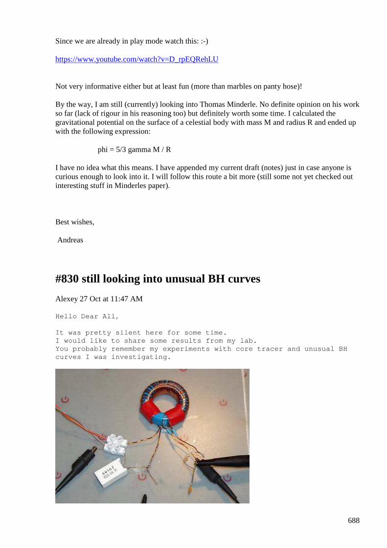
688
Since we are already in play mode watch this: :-)
https://www.youtube.com/watch?v=D_rpEQRehLU
Not very informative either but at least fun (more than marbles on panty hose)!
By the way, I am still (currently) looking into Thomas Minderle. No definite opinion on his work so far (lack of rigour in his reasoning too) but definitely worth some time. I calculated the gravitational potential on the surface of a celestial body with mass M and radius R and ended up with the following expression:
phi = 5/3 gamma M / R
I have no idea what this means. I have appended my current draft (notes) just in case anyone is curious enough to look into it. I will follow this route a bit more (still some not yet checked out interesting stuff in Minderles paper).
Best wishes,
Andreas
#830 still looking into unusual BH curves
Alexey 27 Oct at 11:47 AM Hello Dear All, It was pretty silent here for some time. I would like to share some results from my lab. You probably remember my experiments with core trac er and unusual BH curves I was investigating.
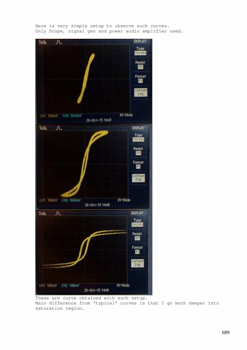
689
Here is very simple setup to observe such curves. Only Scope, signal gen and power audio amplifier us ed.
These are curve obtained with such setup. Main difference from “typical” curves is that I go much deeper into saturation region.
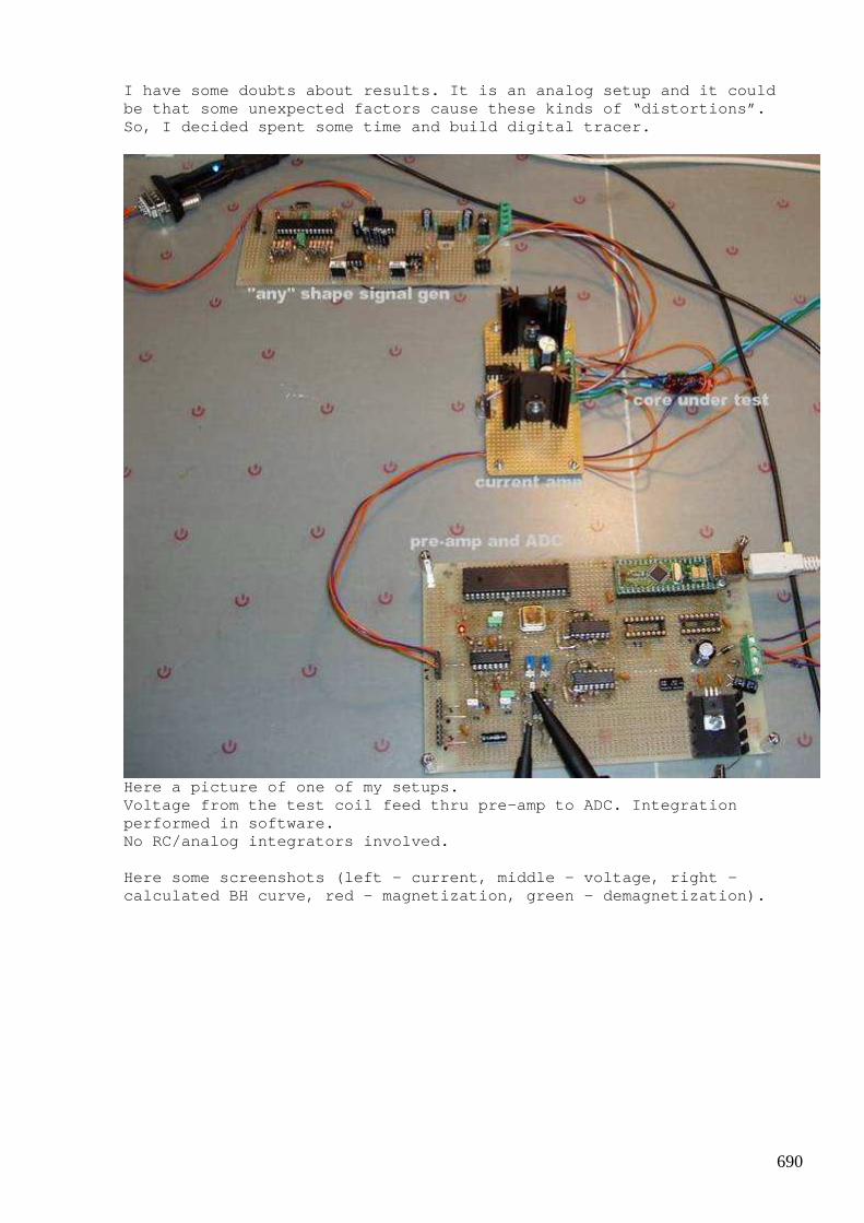
690
I have some doubts about results. It is an analog s etup and it could be that some unexpected factors cause these kinds o f “distortions”. So, I decided spent some time and build digital tra cer.
Here a picture of one of my setups. Voltage from the test coil feed thru pre-amp to ADC . Integration performed in software. No RC/analog integrators involved. Here some screenshots (left – current, middle – vol tage, right – calculated BH curve, red – magnetization, green - d emagnetization).
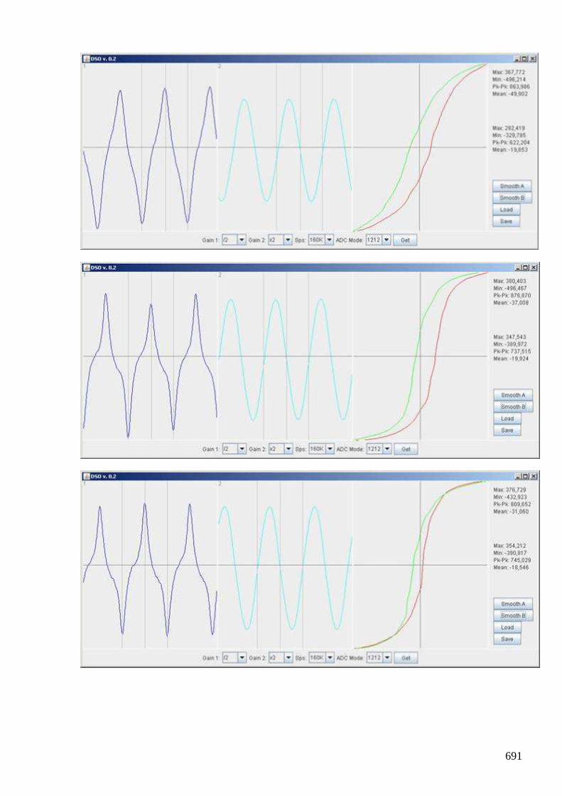
691
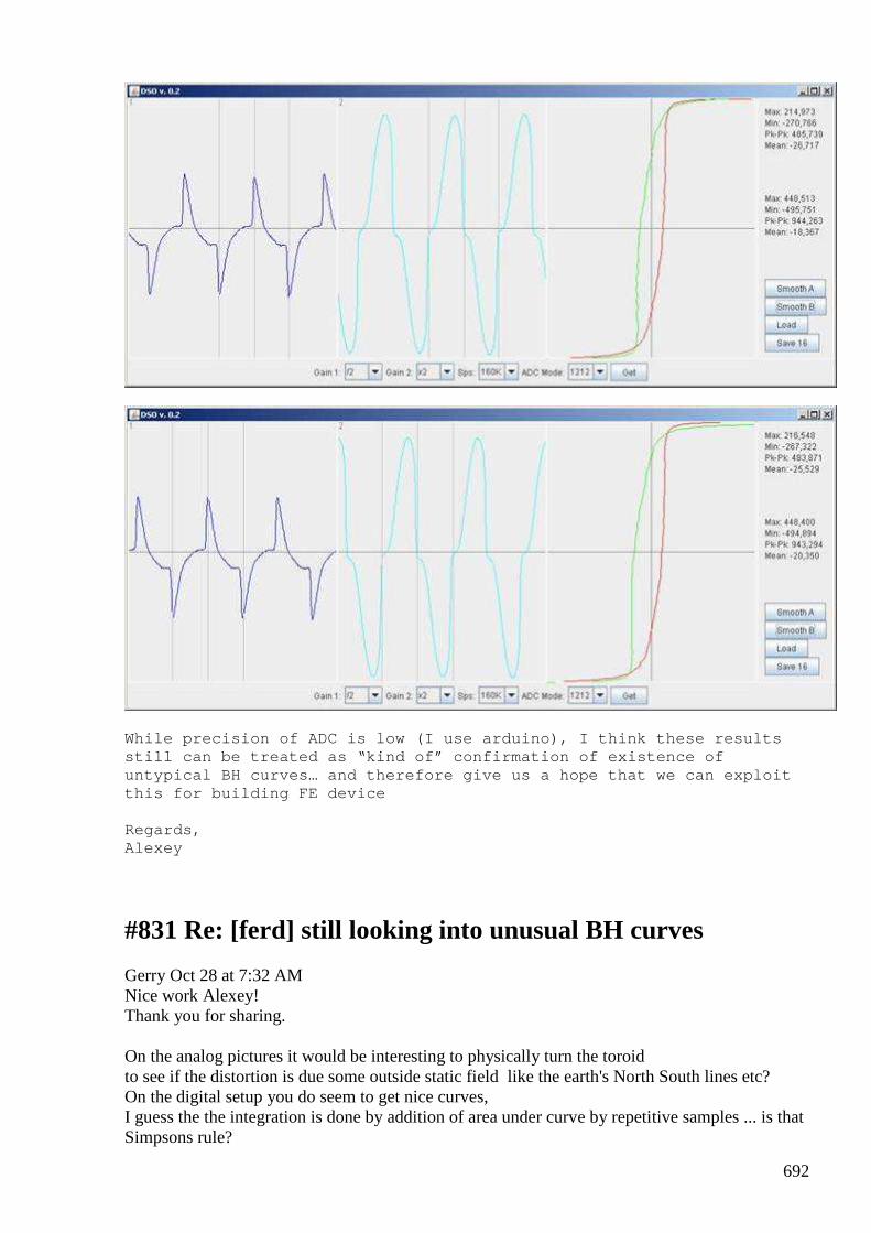
692
While precision of ADC is low (I use arduino), I th ink these results still can be treated as “kind of” confirmation of e xistence of untypical BH curves… and therefore give us a hope t hat we can exploit this for building FE device Regards, Alexey
#831 Re: [ferd] still looking into unusual BH curves
Gerry Oct 28 at 7:32 AM Nice work Alexey! Thank you for sharing. On the analog pictures it would be interesting to physically turn the toroid to see if the distortion is due some outside static field like the earth's North South lines etc? On the digital setup you do seem to get nice curves, I guess the the integration is done by addition of area under curve by repetitive samples ... is that Simpsons rule?
693
I am still playing with Melvin Cobb power transformer concept US4687947. (Combination of auto transformer and normal transformer). Found that when magnetic fields are cancelled out..... my digital voltmeters don't like being close to the transformer, they latch up & read inaccurately. Gerry
#832 RE: [ferd] still looking into unusual BH curves
Alexey Oct 28 at 10:18 AM Hi Gerry, ” it would be interesting to physically turn the toroid” I agree, it is interesting idea. I haven’t tried it yet, but I see this effect in several different setups and coils were in different orientations. It could be some hysteresis effect also… ” I guess the integration is done by addition of area under curve by repetitive samples ... is that Simpsons rule?” Yes, I am using one of simple numeric integration algorithms. I tried Simpson method also. As you know, I don’t believe in magnetic field cancellation. With opposing coils field just ”squeezed” out of core and that is what you see with meters near by. There is a nice picture from Russian forum about this (see attached). Regards, Alexey
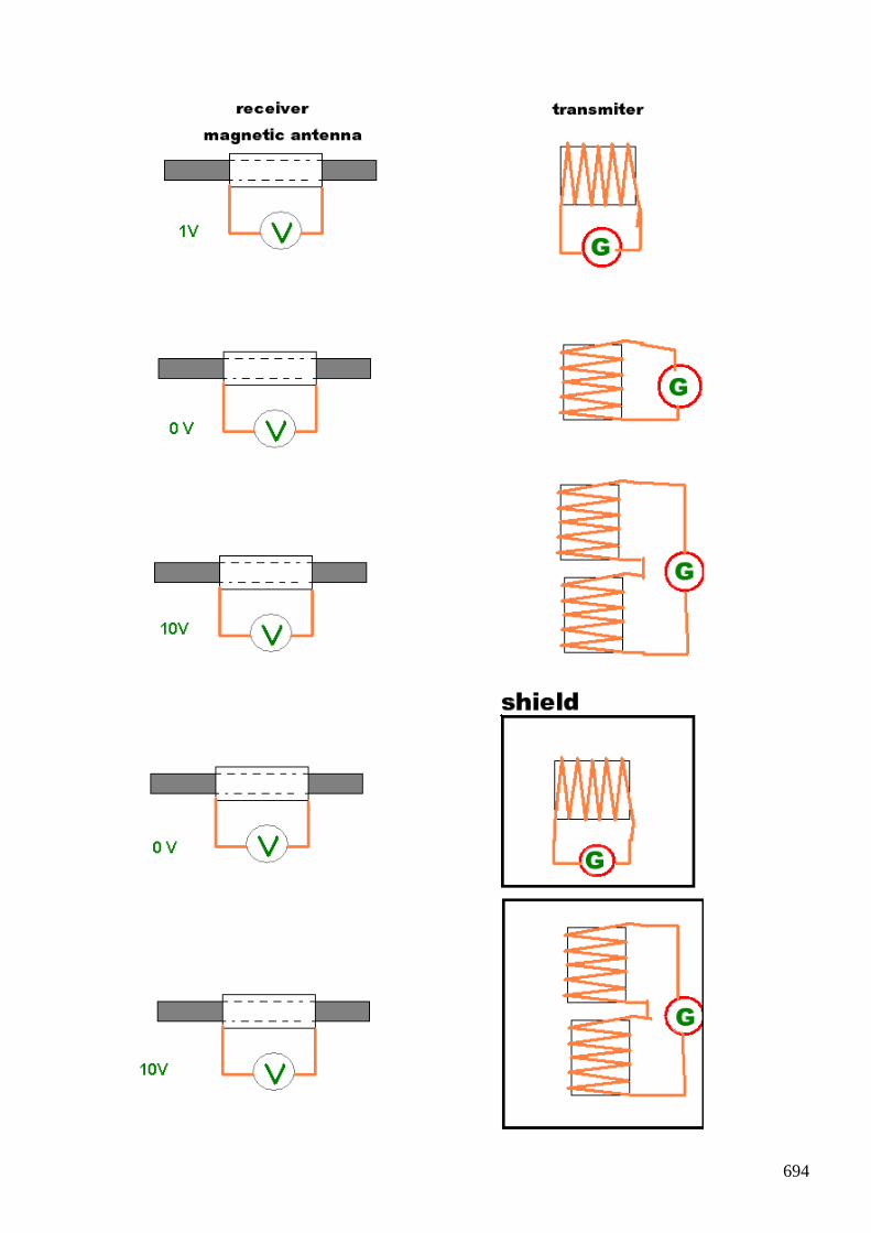
694

695
#833 Re: [ferd] still looking into unusual BH curves
Gerry Oct 28 12:57 PM
Hi Alexey,
Thanks for the reply especially regarding the strange effects on nearby meters.
I had not seen that Russian diagram before ...very interesting.
In Floyd Sweets notes "Nothing is Something" Sweet mathematically shows
that if 2 equal waves passing through each other in opposite directions
at point where H fields cancel...... an unshieldable E field standing wave appears at double the intensity of either wave E field.
At the bench I thought I was imagining things, I tried several of my digital meters & they are all affected.
Sometimes indicating voltages which are too high and also latching up with fixed readings on the display.
Digital scope readings seems to be correct, as scope not sitting very close to the test setup.
Alexey have you ever heard of the Russian "Chobi' car..... I think from Inkomp Energy?
They use magnetic cancellation effect to charge capacitors ...very much like Akula lantern setup.
The group "Inkomp Energy" video here https://www.youtube.com/watch?v=XpxMp8fw7j0
Also they claim to be able to quadruple the range of electric vehicle using their magnetic module.
See text below video.
Have attached an example of their circuit above.
So I know you are skeptical about magnetic cancellation effects but others are getting results and it can be because we don't know correct way to utilise it yet.
all the best Gerry
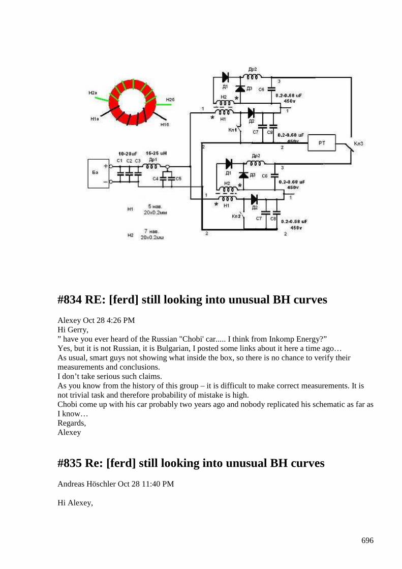
696
#834 RE: [ferd] still looking into unusual BH curves
Alexey Oct 28 4:26 PM Hi Gerry, ” have you ever heard of the Russian "Chobi' car..... I think from Inkomp Energy?” Yes, but it is not Russian, it is Bulgarian, I posted some links about it here a time ago… As usual, smart guys not showing what inside the box, so there is no chance to verify their measurements and conclusions. I don’t take serious such claims. As you know from the history of this group – it is difficult to make correct measurements. It is not trivial task and therefore probability of mistake is high. Chobi come up with his car probably two years ago and nobody replicated his schematic as far as I know… Regards, Alexey
#835 Re: [ferd] still looking into unusual BH curves
Andreas Höschler Oct 28 11:40 PM
Hi Alexey,
697
As you know, I don’t believe in magnetic field cancellation. With opposing coils field just ”squeezed” out of core and that is what you see with meters near by. There is a nice picture from Russian forum about this (see attached).
This looks pretty interesting. Do you (the picture) say that a repelling magnetic field squeezed out between the two coils induces voltage in a receiver coil aligned perpendicular to the sender coils!?
We should really slowly start to get an idea of what a magnetic field actually is to understand these weird effects ... This highly interesting!
Best wishes,
Andreas
#836 Re: [ferd] still looking into unusual BH curves
Gustavo Roveran Oct 28 11:48 PM Hi Alexey, I congratulate you for this experiment, and about all tools developed to achieve it. Could it be done helped by a magnet ? Set the working point, close to core saturation, and then oversaturate, applying current to the coil. While,it is measuring the hysteresis curve to watch if effect is still produced. BTW I share this site Particle Store | Build your connected product
Particle Store | Build your connected product Shop for Particle's IoT development kits, including the Photon, Electron, and the Spark Core. You'll also find shields, swag, and more!
Ver en store.particle.io
Vista previa por Yahoo
What I understand, they are Arduino compatible but enhanced capabilities. Best regards, Gustavo
#837 RE: [ferd] still looking into unusual BH curves
Alexey Oct 29 at 10:48 AM Hi Andreas,
698
This is well known effect even for mainstream physics. Real picture will be more complex, but in the middle point between coils in near proximity you can say that magnetic field is perpendicular (see e.g. this https://www.youtube.com/watch?v=SD4fq8wPee0) It is interesting that if we have alternating fields this will produce some kind of longitudinal magnetic wave (vector B oriented along propagation path). This gives”high penetration” property and probably other interesting effects. Setups like this only now slowly coming into applications in electronics (e.g. in power supplies and antennas design). Regards, Alexey
#838 RE: [ferd] still looking into unusual BH curves
Alexey Oct 29 at 10:48 AM Hi Gustavo, Yes, I think it is good idea to use magnet to adjust working point. The main problem is where find strong magnets and suitable core. According to rumors guys use magnets from hard drive to saturate ferrite ring. There is wide field for experiments Regards, Alexey
#839 offtopic - power meter / pulse generator board
Alexey Oct 29 at 12:56 PM
I use these power meters for a quite long time as indicators in my power supplies. They assembled on bread boards. But now I made some enhancements and made PCB. Board based on ATtiny26 (or ATtiny861) It can measure voltage, current, temperature, calculate power, send data to PC over serial output. Recently I made modified program and board can be used as pulse generator. I found it easy "hackable" and very useful :-) If somebody interested I can share source code, Eagle project, gerber files or PCB :-)

699
-Alexey
#840 [ferd] still looking into unusual BH curves
Gustavo Roveran Oct 29 at 4:03 PM Hi Alexey, HD magnets are good point because they are neodymium and have both magnetic poles in the same face. Regards Gustavo
#841 Re: [ferd] still looking into unusual BH curves
Andreas Höschler Oct 29 4:32 PM Hi Alexey, This is well known effect even for mainstream physics. Real picture will be more complex, but in the middle point between coils in near proximity you can say that magnetic field is perpendicular (see e.g. this https://www.youtube.com/watch?v=SD4fq8wPee0) It is interesting that if we have alternating fields this will produce some kind of longitudinal magnetic wave (vector B oriented along propagation path). This gives”high penetration” property and probably other interesting effects. Setups like this only now slowly coming into applications in electronics (e.g. in power supplies and antennas design).
Thanks for the extra explanation. In the meanwhile I can even roughly imagine what happens in terms of vector potential for the given geometry. What I don't get yet is why this cannot be shielded with a copper cage!? This dB/dt being squeezed out to the left and right should induce eddy currents in the copper cage that neutralise the field, shouldn't it!?
The other issue I am wondering about is whether and if how a load attached to the secondary (perpendicular coil) reflects back to the two primaries!? Could this be a geometry that prevents this back-reflection? Most likely not completely. But if there was an asymmetry between the driving force and what is returned by the secondary? Probably worth a look!!
Andreas
700
#842 RE: [ferd] still looking into unusual BH curves
Alexey Oct 29 9:01 PM Hi Andreas, ” What I don't get yet is why this cannot be shielded with a copper cage!? This dB/dt being squeezed out to the left and right should induce eddy currents in the copper cage that neutralise the field, shouldn't it!?” It seems to be a different kind of field / induction. Some experimental study needed to answer questions. There is reaction from load, at least in that cases which I tried. I agree, geometry is a major factor here. If only we could freely handle 4D images…it would be easy find answer Regards, Alexey
#843 Re: [ferd] still looking into unusual BH curves
Andreas Höschler Oct 29 9:08 PM Hi Alexey, ” What I don't get yet is why this cannot be shielded with a copper cage!? This dB/dt being squeezed out to the left and right should induce eddy currents in the copper cage that neutralise the field, shouldn't it!?” It seems to be a different kind of field / induction. Some experimental study needed to answer questions. There is reaction from load, at least in that cases which I tried.
What have you tried? Do you have a picture of your setup? I believe using a T-ferrite core won't do the trick (this ends up in the same old stuff). It probably must be either air core or the whole setup soaked into a core (e.g. iron powder resign mess).
Andreas
#844 RE: [ferd] still looking into unusual BH curves
onielsen2000 Oct 29 9:46 PM In EMC/EMI theory the schreening has to have the right thickness and conductivity (resistance) to be able to propper schreen the fields. Eddy currents are induced where the field hits the schreen and this can be measured on the opposite side where it shows up as voltages. Regards Ole
701
#845 RE: [ferd] still looking into unusual BH curves
Alexey Oct 29 9:58 PM Hi Andreas, ”What have you tried? Do you have a picture of your setup?” see fe_basics.pdf in group files, chapter 4, starting page 113 I think there is something wrong with my writings…nobody read them L Regards, Alexey
#846 Re: [ferd] still looking into unusual BH curves
Andreas Höschler Oct 29 11:28 PM Hi Ole, In EMC/EMI theory the schreening has to have the right thickness and conductivity (resistance) to be able to propper schreen the fields. Eddy currents are induced where the field hits the schreen and this can be measured on the opposite side where it shows up as voltages. I don't get that! Aren't eddy currents only just that, currents through a low resistance conductor? Where and how could there be a measurable voltage drop? Thanks, Andreas
#847 Re: [ferd] still looking into unusual BH curves
onielsen2000 Oct 29 11:40 PM Hi Andreas, When a changing B-field goes through a conductor the current curls around forming eddy currents as opposed to windings where the current has to follow the insulated wires. Regards Ole
#848 Re: [ferd] still looking into unusual BH curves
Andreas Höschler Oct 29 11:49 PM Hi Ole, When a changing B-field goes through a conductor the current curls around forming eddy currents as opposed to windings where the current has to follow the insulated wires. That's eddy currents with (almost) no voltage drop. Where do you intend to measure a voltage? Let's align two solenoidal coils on the same axis with a sheet of copper between them, power the left with AC and measure voltage induced in the right. The dB/dt will induce eddy currents in the sheet that match with incoming stuff from the primary with opposite polarity. Do we measure anything in the secondary or do the original flux and the

702
flux caused by the induced eddy currents cancel out perfectly? Or does the secondary only sees the flux caused by the induced eddy currents and nothing of the original flux? Thanks, Andreas
#849 [ferd] transformer with magnetic shield setup update
Alexey Oct 29 11:33 PM
We can benefit from ”high penetration” of the field from opposing coils… just one more crazy idea J
#850 Re: [ferd] transformer with magnetic shield setup update
Andreas Höschler Oct 30 at 12:13 AM
Hi Alexey,
Just (re)read chapter 4 and chapter 5 of your doc. Thanks! You used an air core and measured back reflection!? Hmmgh!? :-( We can benefit from ”high penetration” of the field from opposing coils… just one more crazy idea
Why would we see different penetration patterns for the squeezed out repelling field and a horizontally aligned coil? Any idea? Is this confirmed in the lab?
Thanks,
703
Andreas
#851 Re: [ferd] still looking into unusual BH curves
onielsen2000 Oct 30 2015 Hi Andreas, Voltage is how fast the B-field changes. A faster change gives a higher voltage when the peak magnitude of the B-field stays the same (dB/dt is bigger). If a good conductor like copper is used the induced eddy current is (almost) the same as the source or magnetizing current when all the magnetic flux passes (or tries to pass) the conductor. The induced magnetic field is opposed to the source field (repels it). If the conductor is a super conductor all the B-field is reflected and this is a way to detect a super conductor which will float on or in an external B-field. For a super conductor there is no resistive voltage drop along a turn. But there are still inductance and capacitance because of permeability and permittivity. They are always present in our universe. Thus reactive current must be present in any material. This means that the voltage and current is out of phase and doesn't dissipate the energy as it is just reflected. The coupling between the conductors or windings if it was a transformer determines the induced field compared to the source field. What we see in the secondary coil on the other side of the sheet of copper depends on many factors: https://www.nde-ed.org/EducationResources/CommunityCollege/EddyCurrents/Physics/mutualinductance.htm
The coupling between the conductors or windings if it was a transformer determines the induced field compared to the source field. Regards Ole
#852 RE: [ferd] transformer with magnetic shield setup update
Alexey Oct 30 2015 Hi Andreas, ” Why would we see different penetration patterns for the squeezed out repelling field and a horizontally aligned coil? Any idea? Is this confirmed in the lab?” Opposing coils fields will help us get primary field outside thru the shield and high frequency switching make it more difficult for secondary field penetrate back. No, it is not confirmed in the lab. Regards, Alexey
704
#853 RE: [ferd] transformer with magnetic shield setup update
onielsen2000 Oct 30 2015 Hi Alexey, Andreas, Also the field is concentrated when squeezed into the small space between the opposing coils. This gives a higher magnitude of the field strength at this place. Bedini has made experiments by modulating the field of two opposing permanent magnets with a coil around. Look up his scalar beamer. Regards Ole
#854 Re: [ferd] transformer with magnetic shield setup update
Gustavo Roveran Oct 30 2015 Hi Ole, An old page about the scalar beam (which could be related to torsion field generator) There are al lot of more sites about this subject.. http://amasci.com/freenrg/bedini.html At the end of this page, "Use an opamp buffer and an audio amplifier to listen to the noise output of a capacitor which is shielded in a thick copper box, (or does a resistor or transistor work better?) then aim the beam at the box and listen for signals, or monitor changes to component values. See: http://amasci.com/freenrg/grav3.txt, Hodowanec's capacitor-based gravity detector, for more info." Hodowanec device appears again. ( I have to finish me measurement tool) Regards, Gustavo
#855 Re: [ferd] offtopic - power meter / pulse generator board
Gustavo Roveran Oct 31 2015 Hi Alexey, Good to log solar panels energy too. What are its maximum rates ? What are the functions of the little switch ? Do you think that it can be re-programmable to actuate when some value (V, I or Pw) is achieved ? or other task ?
705
Regards, Gustavo
#856 RE: [ferd] offtopic - power meter / pulse generator board
Alexey Oct 31 2015 Hi Gustavo, ”What are its maximum rates ?” With component values shown on schematic it will measure voltage 0..40v (40mv step) and current 0...4a (4ma step) Measuring ranges can be adjusted by changing resistors values. What are the functions of the little switch ? you mean four buttons ? they not used in power meter currently, in pulse generator allow to select frequency and pulse length. Do you think that it can be re-programmable to actuate when some value (V, I or Pw) is achieved ? or other task ? Yes, why not? Board itself takes about 40mW power, should be ok for solar power. Regards, Alexey
#857 Simulation of Ether Particles Behavior
Gustavo Roveran 1 Nov at 7:54AM Hi all, This is the most important part of the Ludwing Sullos Ether theory. It explains from where the magnetic field comes, and why the BckEMF exists. THE ELECTRON Electron model discussed below. We believe that this particle has two mechanisms of inertia. 1) The matter wave whose energy is e = pvc where p is the amount of movement, v is the speed and h is Planck's constant. The matter wave, by relying on the Planck constant, reveals its nature of wave energy leads according to their length and increases with its inverse squared (frequency). The internal energy of the electron is E = m.c2 , where M is the mass of the electron and c is the speed of light. The total energy contained in the moving electron is E + e. The additional mass due to velocity is m = e / c2. Thus, the total mass is M + m. This means that the electron (and other particles) is able to obtain extra mass of space. And m is a mass because it actually behaves as such on an electron beam.
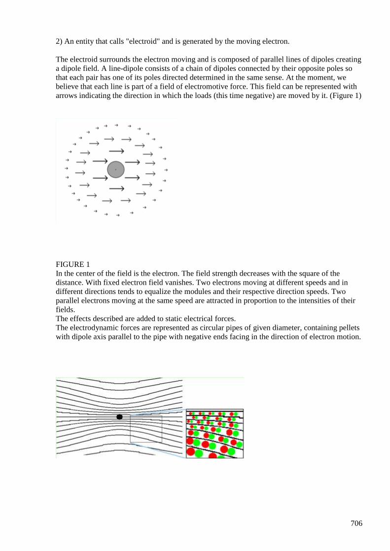
706
2) An entity that calls "electroid" and is generated by the moving electron. The electroid surrounds the electron moving and is composed of parallel lines of dipoles creating a dipole field. A line-dipole consists of a chain of dipoles connected by their opposite poles so that each pair has one of its poles directed determined in the same sense. At the moment, we believe that each line is part of a field of electromotive force. This field can be represented with arrows indicating the direction in which the loads (this time negative) are moved by it. (Figure 1)
FIGURE 1 In the center of the field is the electron. The field strength decreases with the square of the distance. With fixed electron field vanishes. Two electrons moving at different speeds and in different directions tends to equalize the modules and their respective direction speeds. Two parallel electrons moving at the same speed are attracted in proportion to the intensities of their fields. The effects described are added to static electrical forces. The electrodynamic forces are represented as circular pipes of given diameter, containing pellets with dipole axis parallel to the pipe with negative ends facing in the direction of electron motion.
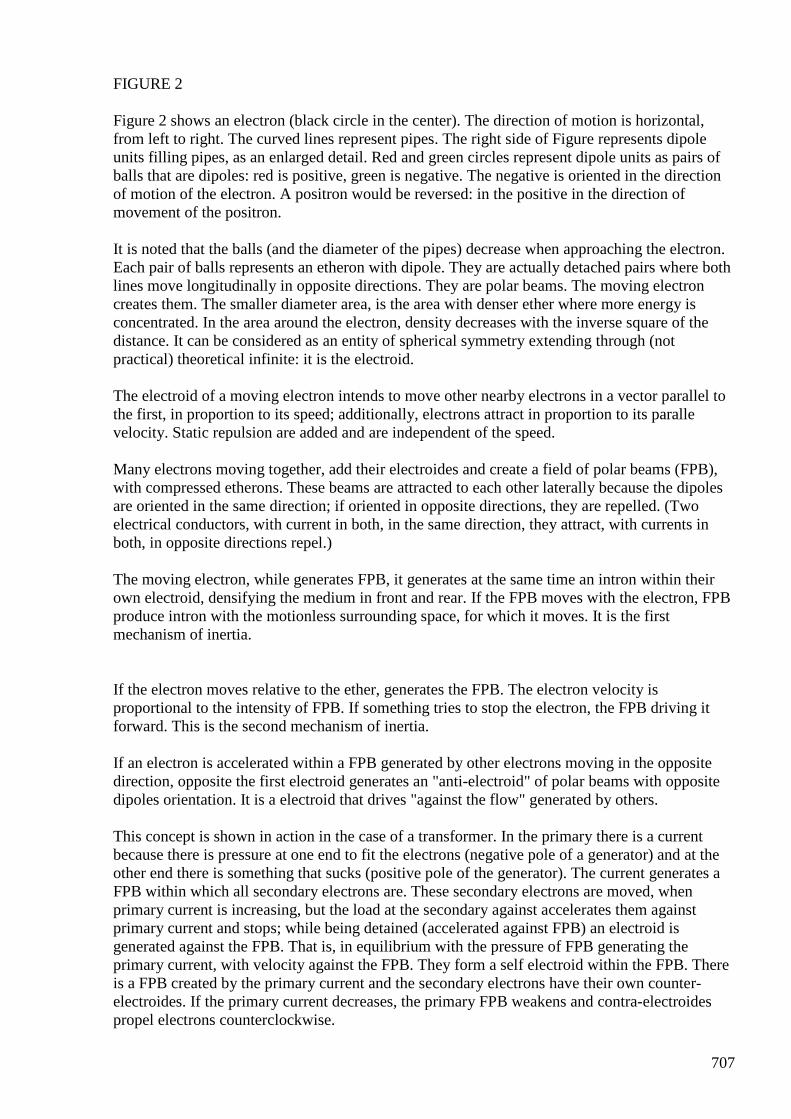
707
FIGURE 2 Figure 2 shows an electron (black circle in the center). The direction of motion is horizontal, from left to right. The curved lines represent pipes. The right side of Figure represents dipole units filling pipes, as an enlarged detail. Red and green circles represent dipole units as pairs of balls that are dipoles: red is positive, green is negative. The negative is oriented in the direction of motion of the electron. A positron would be reversed: in the positive in the direction of movement of the positron. It is noted that the balls (and the diameter of the pipes) decrease when approaching the electron. Each pair of balls represents an etheron with dipole. They are actually detached pairs where both lines move longitudinally in opposite directions. They are polar beams. The moving electron creates them. The smaller diameter area, is the area with denser ether where more energy is concentrated. In the area around the electron, density decreases with the inverse square of the distance. It can be considered as an entity of spherical symmetry extending through (not practical) theoretical infinite: it is the electroid. The electroid of a moving electron intends to move other nearby electrons in a vector parallel to the first, in proportion to its speed; additionally, electrons attract in proportion to its paralle velocity. Static repulsion are added and are independent of the speed. Many electrons moving together, add their electroides and create a field of polar beams (FPB), with compressed etherons. These beams are attracted to each other laterally because the dipoles are oriented in the same direction; if oriented in opposite directions, they are repelled. (Two electrical conductors, with current in both, in the same direction, they attract, with currents in both, in opposite directions repel.) The moving electron, while generates FPB, it generates at the same time an intron within their own electroid, densifying the medium in front and rear. If the FPB moves with the electron, FPB produce intron with the motionless surrounding space, for which it moves. It is the first mechanism of inertia. If the electron moves relative to the ether, generates the FPB. The electron velocity is proportional to the intensity of FPB. If something tries to stop the electron, the FPB driving it forward. This is the second mechanism of inertia. If an electron is accelerated within a FPB generated by other electrons moving in the opposite direction, opposite the first electroid generates an "anti-electroid" of polar beams with opposite dipoles orientation. It is a electroid that drives "against the flow" generated by others. This concept is shown in action in the case of a transformer. In the primary there is a current because there is pressure at one end to fit the electrons (negative pole of a generator) and at the other end there is something that sucks (positive pole of the generator). The current generates a FPB within which all secondary electrons are. These secondary electrons are moved, when primary current is increasing, but the load at the secondary against accelerates them against primary current and stops; while being detained (accelerated against FPB) an electroid is generated against the FPB. That is, in equilibrium with the pressure of FPB generating the primary current, with velocity against the FPB. They form a self electroid within the FPB. There is a FPB created by the primary current and the secondary electrons have their own counter-electroides. If the primary current decreases, the primary FPB weakens and contra-electroides propel electrons counterclockwise.
708
In general, a current creates a FPB which, in turn, draws the electrons in their direction. If anything slows the electrons, they develop anti-electroide and stop. If the original FPB ceases, electrons want to move in the opposite direction. One can see that the electric induction is explained regardless of the concept of magnetic field. So what is the magnetic field? Polar beams do attract laterally if their dipoles are oriented in the same direction and repel if oriented in opposite directions. This attraction-repulsion is perpendicular to the motion of charges and forces that make generates the magnetic field. The magnetic field is virtual. The field of polar beams is real. The electroid is surrounding the electron therefore moves in the space at velocity of the electron. Therefore, it can not reach the speed of light. It does not end abruptly at a certain radius, but extends further, reducing its intensity with the square of the distance. The electroid is not a photon, but it does have a given amount of energy. The similarity is that the photon energy and electroid energy may be the same, in which case one can become the other and vice versa. When an electron accelerates, begins to extend its electroid. This extension is the speed of light. During growth, there is a great similarity with a photon, but not a photon. The electroid advances in the direction of the electric vector, while the photon does perpendicularly to them. An electron moving in its electroid may receive a lateral push of a photon, be fast or be delayed (even stopped) and exchange energy. Thus, an electron can be stopped and lose their electroid which, in turn, becomes a photon. Or, the photon can become electroid and give the electron speeds according to their energy. When a photon becomes electroid, it moves away perpendicularly because the dipoles retain their orientation. When a photon collides with an electron, if it becomes electroid, the electron velocity becomes perpendicular to the direction of the photon. Best Regards, Gustavo
#858 Karl Schappeller - Aether
Gustavo Roveran Nov 4 4:38 PM Hi All, Has anyone tested or read with some deep Karl Schapeller Theory/Device ? Regards, Gustavo
709
#859 RE: [ferd] Karl Schappeller - Aether
Alexey Nov 4 11:05 PM Hi Gustavo, I haven’t heard about this device. I found this page http://www.bibliotecapleyades.net/ufo_aleman/rfz/schappellerchapter4b.htm but it is not very ”practical”… Regards, Alexey
#860 Re: [ferd] Karl Schappeller - Aether
Gustavo Roveran Nov 4 11:36 PM Hi Alexey, Thanks. I am reading this book http://www.free-energy-info.com/Davson.pdf very slowly, so this was why I am asking about Schappeller. Best Regards, Gustavo
#861Towards Hodowanec enhanced tool
Gustavo Roveran Nov 4 11:46 PM Hi Alexey, All I built the enhanced Hopdowanec tool. Using the msgq7 at the output of Hodowanec device tool (without audio amplifier, only capacitor + operational) However, I have to shield the device, but I would like to share something. It seems that in the 63 Hertz band, the energy oscillates at near 10 hz ratio. I have to test it in other place to see if that it is a background energy frequency everywhere or only at my work office. I am sharing the video about the panel of the measuring tool. It is a compressed ".mov" video file created by Krut software. Regards, Gustavo
#862 RE: [ferd] Towards Hodowanec enhanced tool
Alexey Nov 7 11:50 PM Hi Gustavo, It is possible that you observing some communications, ELF widely used by electric utilities and military for communications. Nice work! - Alexey

710
#863[ferd] Towards Hodowanec enhanced tool
Gustavo Roveran Nov 9 3:56 AM Hi Alexey It is probable what you said. The next day I did new measures and couldn't find that behavior again. However i found that the ground of the circuit is crucial to amplifie frequencies. For example, I used a metal box from a PC power source. So I connected a wire from the circuit (Hodowanec) ground to that metal box and put the circuit inside. This type of configuration produce a gain at the highest frequency of the band. But if the circuit is out of the box and the wire connected to the circuit ground but not connected to the box. Then the lowest frequencies of the band are amplified more then the highest. These type of behavior are very difficult to find a way to tune the system for torsion field measure. Thanks Gustavo
#864 [ferd] still looking into unusual BH curves
Gustavo Roveran Nov 12 3:40 PM Hi Alexey Did you test something more about this very interesting subject? For example the addition of a magnet to select the ideal working point in the hysteresis curve ? Or the way to recover the energy that comes from the core? Best regards Gustavo
#865 RE: [ferd] still looking into unusual BH curves
Alexey Nov 12 8:23 PM ” I think there is something wrong with my writings…nobody read them ”
#866 Re: [ferd] still looking into unusual BH curves
Gustavo Roveran Nov 12 8:43 PM Are you saying that the response of my questions are in "see fe_basics.pdf in group files, chapter 4, starting page 113" Gustavo
#867 Re: [ferd] still looking into unusual BH curves
711
Gustavo Roveran Nov 12 9:11 PM Hi Alexey, I could not find what I am asking. Where did you show the magnet and the way of extracting, for a device with the over saturating core towards acquiring the core gain energy behaviour ? Regards, Gustavo
#868 RE: [ferd] still looking into unusual BH curves
Alexey Nov 12 9:50 PM Hi Gustavo, I thought that you asking about bifilar coils, there is quite extensive investigation of bifilar coils behavior in “basics” and “experiments” documents. Regarding saturated core, there were some experiments with magnets earlier with analog core tracer. I do not think that this is very promising and I haven’t done any more experiments. If somebody would want to develop this theme next step could be building more precise tracer and do extensive measuring with different cores and in different modes. I don’t have “inspiration” for this at least now Regards, Alexey
#869 [ferd] New poll for ferd
[email protected] Nov 22 10:21 PM
Enter your vote today! A new poll has been created for the ferd group:
Hello,There were not much activity in the group recently. Do you think its time to finally close it ?- Alexey
Created by: vasik041 yes no I don't care + Add Options
Thanks!
#870 Scalar Physics
Andreas Höschler Nov 22 10:45 PM Hi all,

712
I just wanted to place a sign of life here after having been silent (busy) for quite a while. I am still alive and striving for truth and wisdom! :-) My journey brought me to this page: http://scalarphysics.com/ I am still digesting the publications (lots of stuff to read). It also brought me here: http://www.montalk.net <— highly recommended reading Man, this guy has achieved a tremendous amount of wisdom. I am dragged back and forth between physics and meta physics at the moment and try to evenly distribute my time to both realms. With respect to physics I believe to have got a good grasp (working model) of gravity (based on Distintis concept) and am currently investigating the link (one that makes sense to me) to electro-magnetism. I really believe (in the meanwhile) that we have to dive into theoretical modelling to make any further progress. Blindly tinkering around in the lab probably won’t take us anywhere (if so only by sheer luck) in our current life-time. Working theoretically carries the danger of drifting away into mathematical none-sense. We probably need a balanced mixture of both and a lot of divine assistance … I really vote for keeping this platform alive and open for discussions about whatever issues, ideas, concepts we encounter on our journey. Eight eyes see more than two. All the best, Andreas
#871 [ferd] Scalar Physics
Gustavo Roveran Nov 24 3:49 AM Hi All, I think that a group like this will be very difficult to replicate again during our life. First of all due to the subjects we treat and second the human quality. I vote to keep it alive. Take care. Gustavo
#872 offtopic - gravity wheel
Alexey Nov 29 https://www.youtube.com/watch?v=bYZMUB3eNaM
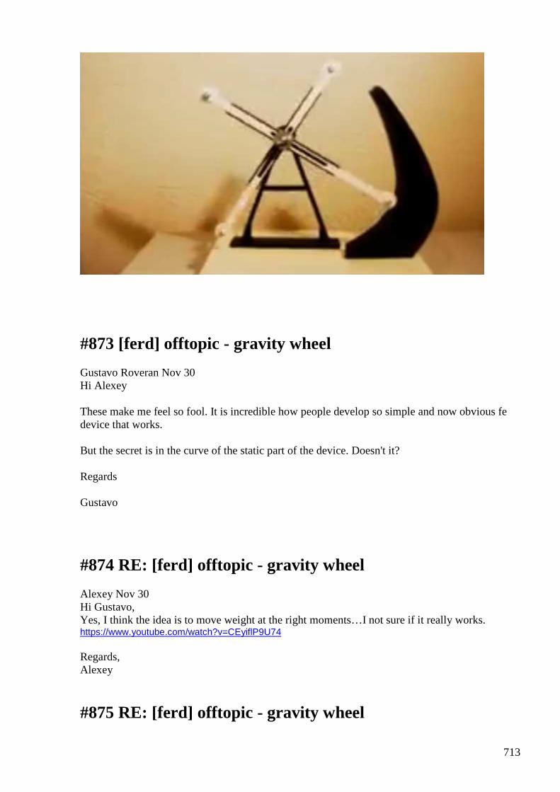
713
#873 [ferd] offtopic - gravity wheel
Gustavo Roveran Nov 30 Hi Alexey These make me feel so fool. It is incredible how people develop so simple and now obvious fe device that works. But the secret is in the curve of the static part of the device. Doesn't it? Regards Gustavo
#874 RE: [ferd] offtopic - gravity wheel
Alexey Nov 30 Hi Gustavo, Yes, I think the idea is to move weight at the right moments…I not sure if it really works. https://www.youtube.com/watch?v=CEyiflP9U74 Regards, Alexey
#875 RE: [ferd] offtopic - gravity wheel
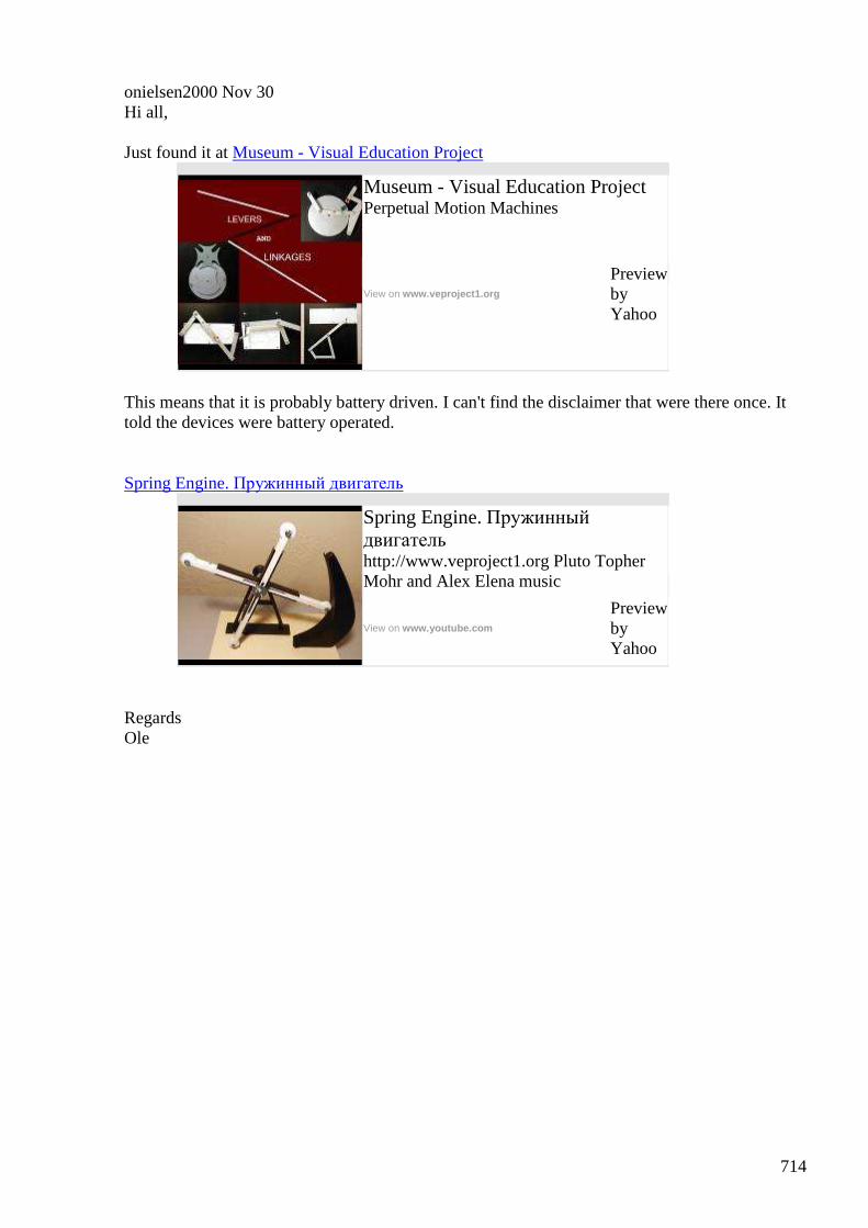
714
onielsen2000 Nov 30 Hi all, Just found it at Museum - Visual Education Project
Museum - Visual Education Project Perpetual Motion Machines
View on www.veproject1.org
Preview by Yahoo
This means that it is probably battery driven. I can't find the disclaimer that were there once. It told the devices were battery operated.
Spring Engine. Пружинный двигатель
Spring Engine. Пружинный двигатель http://www.veproject1.org Pluto Topher Mohr and Alex Elena music
View on www.youtube.com
Preview by Yahoo
Regards Ole
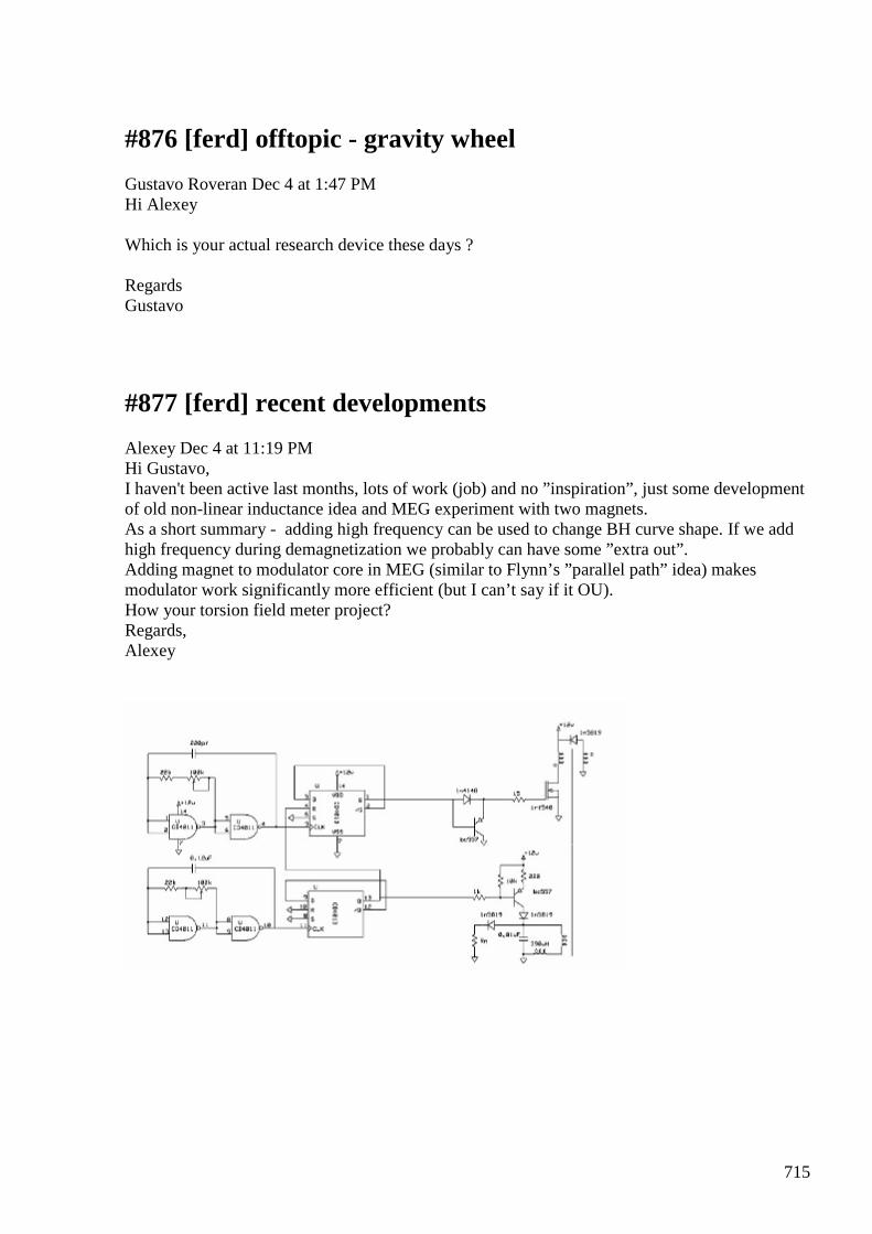
715
#876 [ferd] offtopic - gravity wheel
Gustavo Roveran Dec 4 at 1:47 PM Hi Alexey Which is your actual research device these days ? Regards Gustavo
#877 [ferd] recent developments
Alexey Dec 4 at 11:19 PM Hi Gustavo, I haven't been active last months, lots of work (job) and no ”inspiration”, just some development of old non-linear inductance idea and MEG experiment with two magnets. As a short summary - adding high frequency can be used to change BH curve shape. If we add high frequency during demagnetization we probably can have some ”extra out”. Adding magnet to modulator core in MEG (similar to Flynn’s ”parallel path” idea) makes modulator work significantly more efficient (but I can’t say if it OU). How your torsion field meter project? Regards, Alexey
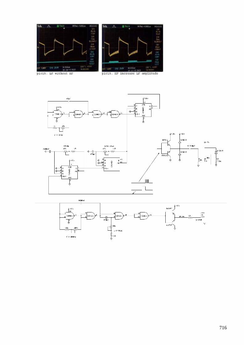
716
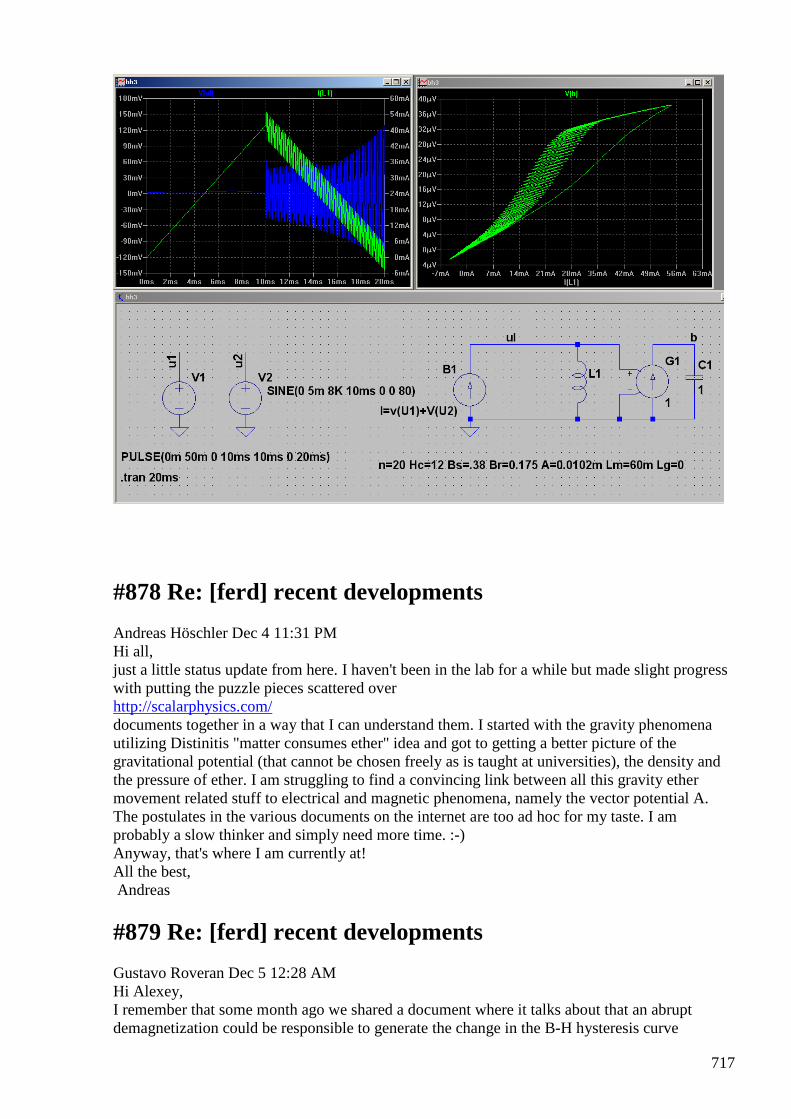
717
#878 Re: [ferd] recent developments
Andreas Höschler Dec 4 11:31 PM Hi all, just a little status update from here. I haven't been in the lab for a while but made slight progress with putting the puzzle pieces scattered over http://scalarphysics.com/ documents together in a way that I can understand them. I started with the gravity phenomena utilizing Distinitis "matter consumes ether" idea and got to getting a better picture of the gravitational potential (that cannot be chosen freely as is taught at universities), the density and the pressure of ether. I am struggling to find a convincing link between all this gravity ether movement related stuff to electrical and magnetic phenomena, namely the vector potential A. The postulates in the various documents on the internet are too ad hoc for my taste. I am probably a slow thinker and simply need more time. :-) Anyway, that's where I am currently at! All the best, Andreas
#879 Re: [ferd] recent developments
Gustavo Roveran Dec 5 12:28 AM Hi Alexey, I remember that some month ago we shared a document where it talks about that an abrupt demagnetization could be responsible to generate the change in the B-H hysteresis curve
718
demagnetization, which could produce gain. But I did not know that adding a high frequency could do it too. Seems to be very difficult the task to measure power output of this experiment, doesn´t it ? I could not go on with the torsion field meter because I have to prepare a project for the technical school that I am advising. At the same time, I am trying to read and understand Schapeller document. Thanks for sharing, Regards, Gustavo
#880 RE: [ferd] recent developments
Alexey Dec 5 3:05 PM Hi Gustavo, Precise measurements are always difficult, but for our purposes some rough estimation or comparison is enough. Regards, Alexey
#881 Re: [ferd] recent developments
Gustavo Roveran Dec 7 4:10 AM Hi Andreas, Recently ESA's LISA Pathfinder lifted off earlier today on a Vega rocket from Europe's spaceport in Kourou, French Guiana, on its way to demonstrate technology for observing gravitational waves from space. ESA Science & Technology: ESA PR 47-2015: LISA Pathfinder en route to gravitational wave demonstration ESA Science & Technology: ESA PR 47-2015: LISA Pathfi...ESA PR 47-2015: LISA Pathfinder en route to gravitational wave demonstration Ver en sci.esa.intVista previa por Yahoo and recently too, Distinti upload 3 new videos (about wave behaviour ) towards the enhancement of "his" aether theory. Regards, Gustavo
#882 [reading] Rediscovering Zaev's ferro-kessor
Alexey 14 Dec at 10:21 AM
Some reading ;-)
719
#883 [ferd] [reading] Rediscovering Zaev's ferro-kessor
Gustavo Roveran Dec 17 at 4:40 AM Hi Alexey I thought that my response has been sent but i found it hasn't. The Zaev experiment was the first one which drove me to meg fer. But I couldn't achieve a good result. The document you sent is a very interesting i think you are sharing a very good clue. Interesting what you presented about capacitors. But if we return to ferro resonance concept, do you think that there would be a correct procedure with cap and coil that take profit of both in a one circuit? Thank for share, you have recovered your inspiration. Gustavo
#884 RE: [ferd] [reading] Rediscovering Zaev's ferro-kessor
Alexey Dec 17 at 9:34 AM Hi Gustavo, Capacitor alone is good candidate to build an OU device. According to my current understanding no special non-linear capacitor needed, just bad enough, with high TCC (http://www.atceramics.com/Userfiles/temp_coef.pdf) There is also known effect – dielectric absorption – now I just have clear understanding what is causing it. ”But if we return to ferro resonance concept, do you think that there would be a correct procedure with cap and coil that take profit of both in a one circuit? ” My experiments show that piezoelectric transducers, like one I was using to vibrate ferrite rod, behaves as non-linear capacitor once they tuned in resonance. And if I touch transducer (create non-linear mechanic force on it) circuit produce DC offset voltage while I am feeding it with AC from signal generator. This kind of setup looks similar to Norman Wootan MRA J He probably has no clue how it was working but it is possible. Regards, Alexey
#885 Re: [ferd] [reading] Rediscovering Zaev's ferro-kessor
Gustavo Roveran Dec 18 12:30 AM Hi Alexey, I remember when I did ferroresonant experiments, I used to work with ceramic capacitors. The problem of this was these capacitors made me believe that may experiment was an OU one,
720
when it did not really OU. It was because they decreased theirs capacitance with the increase of temperature. Do you think that those capacitors could be a good candidate to experiment ? What about supercapacitors ? In the adiabatic experiment with ferrite core. The idea is to magnetize the core "very" slowly, so the domains arrange their orientation and then demagnetize it very quickly. 1) Are you using the best way to achieve this ? Is your experiment the most rapid way to demagnetize the core 2) Is really important to enter into over saturation of the core ? In the rubber example at the beginning of your document you do to have to "over stretch". Where does the energy of the rubber go ? Gustavo
#886 RE: [ferd] [reading] Rediscovering Zaev's ferro-kessor
Alexey Dec 18 9:52 AM Hi Gustavo, You have so many questions J Please see my answers below… Regards, Alexey From: [email protected] [mailto: [email protected] ] Sent: Thursday, December 17, 2015 10:31 PM To: [email protected] Subject: Re: [ferd] [reading] Rediscovering Zaev's ferro-kessor Hi Alexey, I remember when I did ferroresonant experiments, I used to work with ceramic capacitors. The problem of this was these capacitors made me believe that may experiment was an OU one, when it did not really OU. It was because they decreased theirs capacitance with the increase of temperature. Do you think that those capacitors could be a good candidate to experiment ? yes, this is similar effect to saturation (coil lose some inductance) What about supercapacitors ? I don’t know In the adiabatic experiment with ferrite core. The idea is to magnetize the core "very" slowly, so the domains arrange their orientation and then demagnetize it very quickly. 1) Are you using the best way to achieve this ? Is your experiment the most rapid way to demagnetize the core In ”flyback with saturation” experiment I magnetize coil fast and demagnetize it slow, similar to ferro resonance conditions. This achieved by proper timing (short pulse, long pause) and small load resistance which does not allow field collapse fast. 2) Is really important to enter into over saturation of the core ? saturation in other words means that all domains are oriented along field lines, so this is important In the rubber example at the beginning of your document you do to have to "over stretch". Where does the energy of the rubber go ? into environment (air)
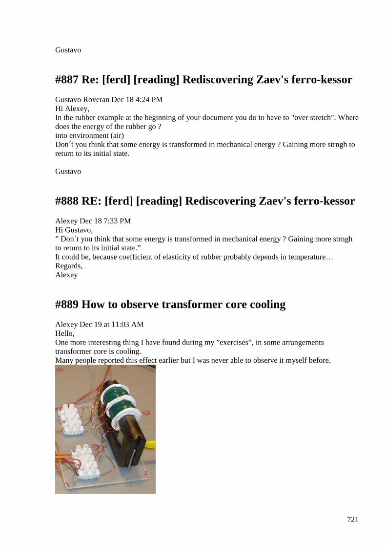
721
Gustavo
#887 Re: [ferd] [reading] Rediscovering Zaev's ferro-kessor
Gustavo Roveran Dec 18 4:24 PM Hi Alexey, In the rubber example at the beginning of your document you do to have to "over stretch". Where does the energy of the rubber go ? into environment (air) Don´t you think that some energy is transformed in mechanical energy ? Gaining more strngh to return to its initial state. Gustavo
#888 RE: [ferd] [reading] Rediscovering Zaev's ferro-kessor
Alexey Dec 18 7:33 PM Hi Gustavo, ” Don´t you think that some energy is transformed in mechanical energy ? Gaining more strngh to return to its initial state.” It could be, because coefficient of elasticity of rubber probably depends in temperature… Regards, Alexey
#889 How to observe transformer core cooling
Alexey Dec 19 at 11:03 AM Hello, One more interesting thing I have found during my ”exercises”, in some arrangements transformer core is cooling. Many people reported this effect earlier but I was never able to observe it myself before.
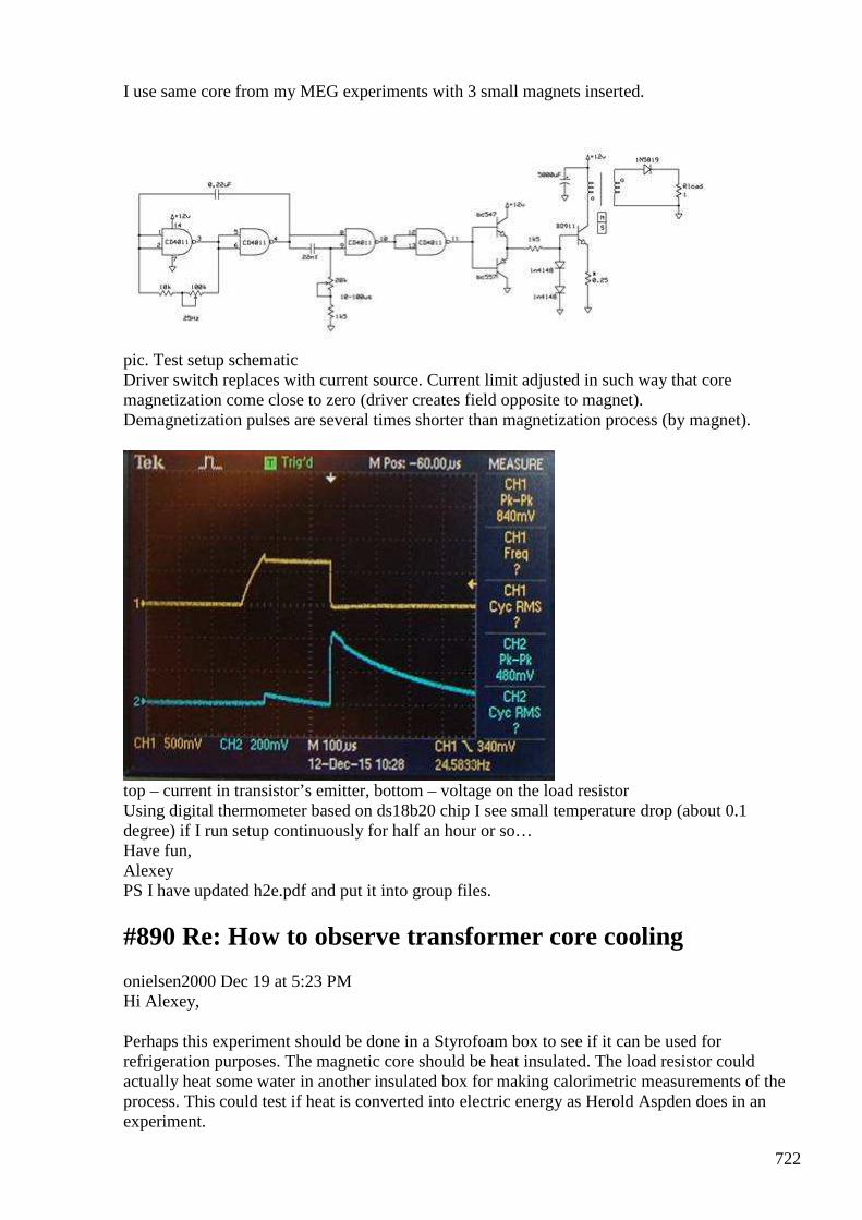
722
I use same core from my MEG experiments with 3 small magnets inserted.
pic. Test setup schematic Driver switch replaces with current source. Current limit adjusted in such way that core magnetization come close to zero (driver creates field opposite to magnet). Demagnetization pulses are several times shorter than magnetization process (by magnet).
top – current in transistor’s emitter, bottom – voltage on the load resistor Using digital thermometer based on ds18b20 chip I see small temperature drop (about 0.1 degree) if I run setup continuously for half an hour or so… Have fun, Alexey PS I have updated h2e.pdf and put it into group files.
#890 Re: How to observe transformer core cooling
onielsen2000 Dec 19 at 5:23 PM Hi Alexey, Perhaps this experiment should be done in a Styrofoam box to see if it can be used for refrigeration purposes. The magnetic core should be heat insulated. The load resistor could actually heat some water in another insulated box for making calorimetric measurements of the process. This could test if heat is converted into electric energy as Herold Aspden does in an experiment.
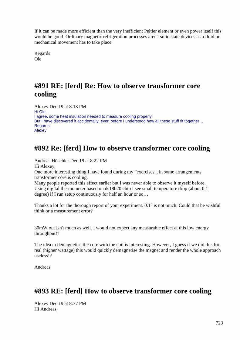
723
If it can be made more efficient than the very inefficient Peltier element or even power itself this would be good. Ordinary magnetic refrigeration processes aren't solid state devices as a fluid or mechanical movement has to take place. Regards Ole
#891 RE: [ferd] Re: How to observe transformer core cooling
Alexey Dec 19 at 8:13 PM Hi Ole, I agree, some heat insulation needed to measure cooling properly. But I have discovered it accidentally, even before I understood how all these stuff fit together… Regards, Alexey
#892 Re: [ferd] How to observe transformer core cooling
Andreas Höschler Dec 19 at 8:22 PM Hi Alexey, One more interesting thing I have found during my ”exercises”, in some arrangements transformer core is cooling. Many people reported this effect earlier but I was never able to observe it myself before. Using digital thermometer based on ds18b20 chip I see small temperature drop (about 0.1 degree) if I run setup continuously for half an hour or so…
Thanks a lot for the thorough report of your experiment. 0.1° is not much. Could that be wishful think or a measurement error?
30mW out isn't much as well. I would not expect any measurable effect at this low energy throughput!?
The idea to demagnetise the core with the coil is interesting. However, I guess if we did this for real (higher wattage) this would quickly demagnetise the magnet and render the whole approach useless!?
Andreas
#893 RE: [ferd] How to observe transformer core cooling
Alexey Dec 19 at 8:37 PM Hi Andreas,
724
” Thanks a lot for the thorough report of your experiment. 0.1° is not much. Could that be wishful think or a measurement error? ” I agree, 0.1” is not much, and it can be a measurement error, but it fit quite ok into overall picture. ”I guess if we did this for real (higher wattage) this would quickly demagnetise the magnet and render the whole approach useless!?” According to my understanding magnet behaves similar to current source. It does not care whether we do something with it flux or not. I would not expect any issue until we heat it or damage mechanically. The main problem, as I see, is proper core material. GE use some very special allow for magnetic cooling. Its unlikely that we can get something like this Regards, Alexey
#894 RE: [ferd] How to observe transformer core cooling
onielsen2000 Dec 19 at 9:16 PM Hi Andreas, Alexey, As long as the magnetizing force doesn't become negative (crosses the residual B-field point) on the BH-curve for the magnet this shouldn't be a problem. If this happens the energy comes from demagnetizing the magnet. If the magnets are rare earth magnets like Neodymium or Samarium-Cobalt the ferrite is probably saturated long before reaching the residual B-field point of the magnet. Thus it won't cause any problem. Regards Ole
#895 Re: [ferd] How to observe transformer core cooling
Andreas Höschler Dec 19 at 9:12 PM Hi Alexey, ”I guess if we did this for real (higher wattage) this would quickly demagnetise the magnet and render the whole approach useless!?”
According to my understanding magnet behaves similar to current source. It does not care whether we do something with it flux or not. I would not expect any issue until we heat it or damage mechanically.
This would be helpful if it turned out to be true. I just remember Hector mentioning something about demagnetising magnets by using them in repelling environments. He therefore recommended to always use "core is attracted to magnets" arrangements. This of course is only heresy and not at all reliable intel, but probably something we at least should keep in mind.
725
The main problem, as I see, is proper core material. GE use some very special allow for magnetic cooling. Its unlikely that we can get something like this
Who is GE? Yes, if special materials are required we are probably out of luck. We just don't have the funds and time to try out thousands of materials and find seldom anomalies on our own. I still hope that we finally find a way to accomplish something with standard materials just with an unusual configuration.
***
I had been thinking/writing a lot recently and for the first time got a "good" idea of the vector potential A (puzzled me ever since). I had to put electrical phenomena to the side for a while and approach the beast from the gravity side of the coin. This brought a small breakthrough. A is no flow (N / s m^2) but flow integrated over time. A is therefore a signature of something that happened to establish a specific state, e.g. the existence of some matter at point P in space or the rotation of ether in a permanent magnet. A has the unit N / m^2, epsilon is nothing else but simply ether density and mu is the reciprocal of ether pressure. I would have to go into much more detail to justify these statements. I am just mentioning this to say that we can make some real progress even in our garages with limited funds with the right mixture of thinking and tinkering. There are so many experiments that have already been conducted (e.g. electro gravity), waiting to be analysed and correctly understood. Once we get a glimpse of the universe we can simply engineer whatever we want. That's at least the plan! :-)
Please all keep on going wherever intuition leads you to and report your results. I personally am still completely bogged down by several issues. The next year will hopefully bring some relief and the opportunity for more research and progress.
All the best,
Andreas
#896 RE: [ferd] How to observe transformer core cooling
Alexey Dec 19 at 9:28 PM GE = General Electric https://www.youtube.com/watch?v=WlKKKMTA7XM
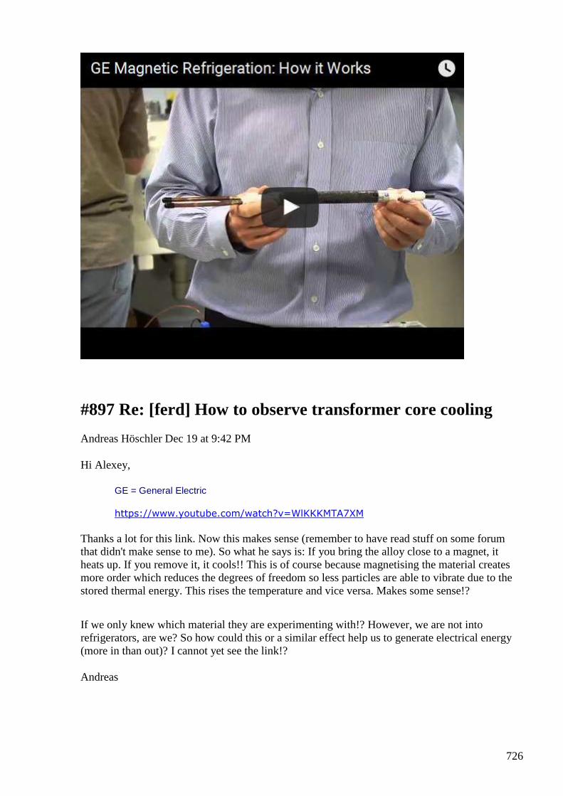
726
#897 Re: [ferd] How to observe transformer core cooling
Andreas Höschler Dec 19 at 9:42 PM
Hi Alexey,
GE = General Electric
https://www.youtube.com/watch?v=WlKKKMTA7XM
Thanks a lot for this link. Now this makes sense (remember to have read stuff on some forum that didn't make sense to me). So what he says is: If you bring the alloy close to a magnet, it heats up. If you remove it, it cools!! This is of course because magnetising the material creates more order which reduces the degrees of freedom so less particles are able to vibrate due to the stored thermal energy. This rises the temperature and vice versa. Makes some sense!?
If we only knew which material they are experimenting with!? However, we are not into refrigerators, are we? So how could this or a similar effect help us to generate electrical energy (more in than out)? I cannot yet see the link!?
Andreas
727
#898 Re: [ferd] How to observe transformer core cooling
onielsen2000 Dec 19 at 9:47 PM
Hi Andreas, Try Gadolinium. https://en.wiki2.org/wiki/Magnetic_refrigeration
Regards Ole
#899 RE: [ferd] How to observe transformer core cooling
Alexey Dec 19 at 9:55 PM
Hi Andreas,
Heat affects BH curve.
If we manage create a magnetization-demagnetization cycle which benefits from this change we will get OU device which converts environmental heat to electricity, Zaev’s ferro-kessor.
Please take some time to check links at the end of the document (h2e.pdf) if you interested.
Regards,
Alexey
#900 Re: How to observe transformer core cooling
smokyatgroups 20 Dec at 2:11 AM Hi Alexey, guys Thanks for posting this information about your experiment findings. Sorry not posting for a while, we had some major health issues. I recently saw a YouTube video which looks quite similar setup to your experiments. It might be totally unrelated? I found it interesting non the less. TROS MAGNACOASTER -- "motionless" https://www.youtube.com/watch?v=MWhsJWXEER4
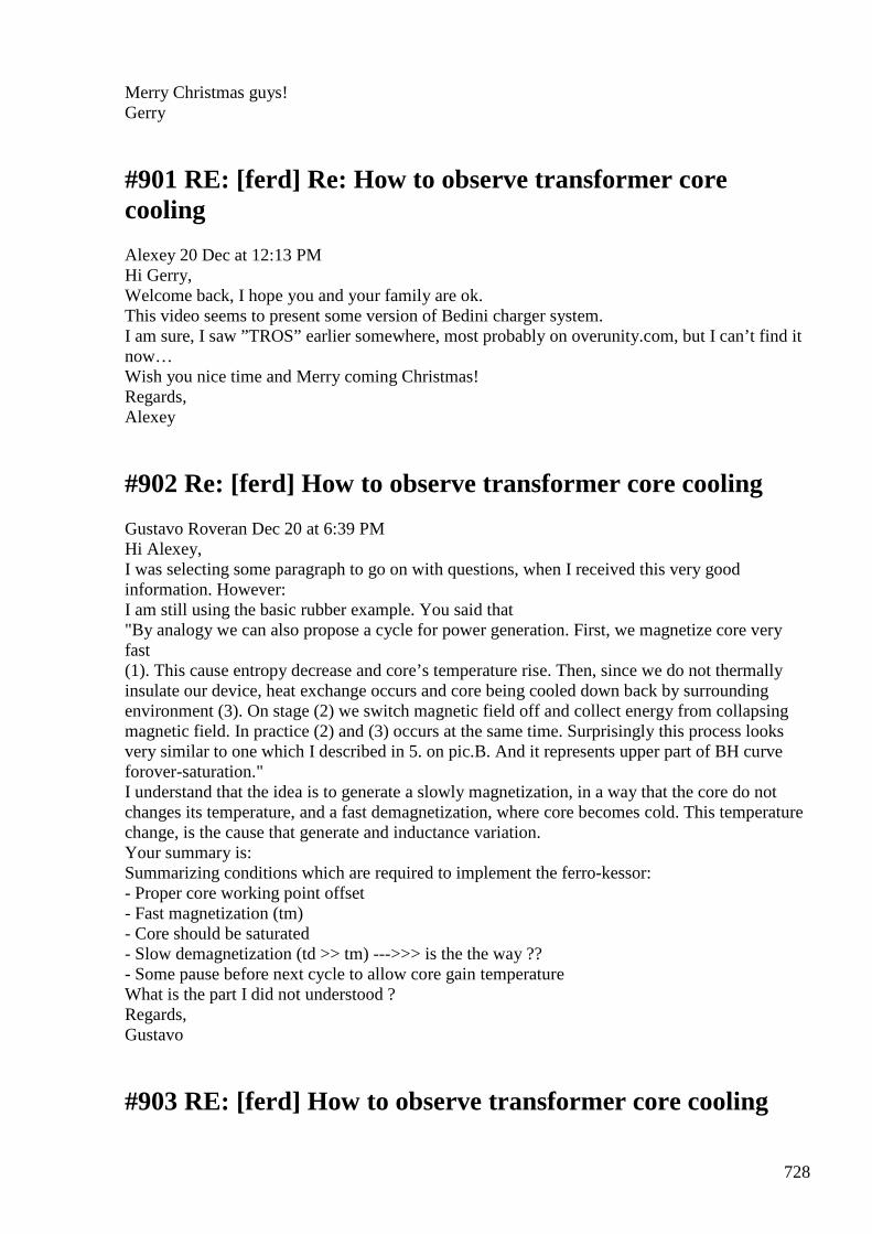
728
Merry Christmas guys! Gerry
#901 RE: [ferd] Re: How to observe transformer core cooling
Alexey 20 Dec at 12:13 PM Hi Gerry, Welcome back, I hope you and your family are ok. This video seems to present some version of Bedini charger system. I am sure, I saw ”TROS” earlier somewhere, most probably on overunity.com, but I can’t find it now… Wish you nice time and Merry coming Christmas! Regards, Alexey
#902 Re: [ferd] How to observe transformer core cooling
Gustavo Roveran Dec 20 at 6:39 PM Hi Alexey, I was selecting some paragraph to go on with questions, when I received this very good information. However: I am still using the basic rubber example. You said that "By analogy we can also propose a cycle for power generation. First, we magnetize core very fast (1). This cause entropy decrease and core’s temperature rise. Then, since we do not thermally insulate our device, heat exchange occurs and core being cooled down back by surrounding environment (3). On stage (2) we switch magnetic field off and collect energy from collapsing magnetic field. In practice (2) and (3) occurs at the same time. Surprisingly this process looks very similar to one which I described in 5. on pic.B. And it represents upper part of BH curve forover-saturation." I understand that the idea is to generate a slowly magnetization, in a way that the core do not changes its temperature, and a fast demagnetization, where core becomes cold. This temperature change, is the cause that generate and inductance variation. Your summary is: Summarizing conditions which are required to implement the ferro-kessor: - Proper core working point offset - Fast magnetization (tm) - Core should be saturated - Slow demagnetization (td >> tm) --->>> is the the way ?? - Some pause before next cycle to allow core gain temperature What is the part I did not understood ? Regards, Gustavo
#903 RE: [ferd] How to observe transformer core cooling
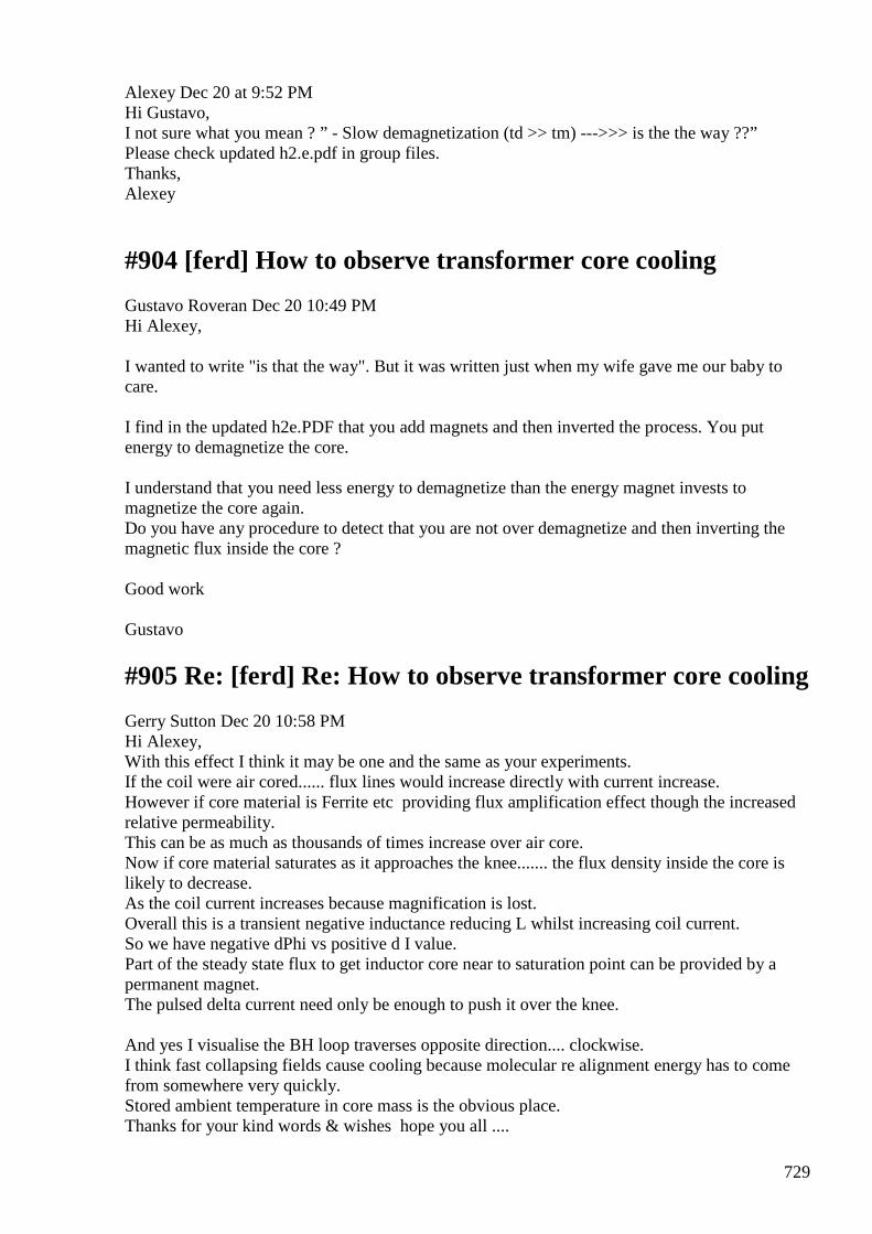
729
Alexey Dec 20 at 9:52 PM Hi Gustavo, I not sure what you mean ? ” - Slow demagnetization (td >> tm) --->>> is the the way ??” Please check updated h2.e.pdf in group files. Thanks, Alexey
#904 [ferd] How to observe transformer core cooling
Gustavo Roveran Dec 20 10:49 PM Hi Alexey, I wanted to write "is that the way". But it was written just when my wife gave me our baby to care. I find in the updated h2e.PDF that you add magnets and then inverted the process. You put energy to demagnetize the core. I understand that you need less energy to demagnetize than the energy magnet invests to magnetize the core again. Do you have any procedure to detect that you are not over demagnetize and then inverting the magnetic flux inside the core ? Good work Gustavo
#905 Re: [ferd] Re: How to observe transformer core cooling
Gerry Sutton Dec 20 10:58 PM Hi Alexey, With this effect I think it may be one and the same as your experiments. If the coil were air cored...... flux lines would increase directly with current increase. However if core material is Ferrite etc providing flux amplification effect though the increased relative permeability. This can be as much as thousands of times increase over air core. Now if core material saturates as it approaches the knee....... the flux density inside the core is likely to decrease. As the coil current increases because magnification is lost. Overall this is a transient negative inductance reducing L whilst increasing coil current. So we have negative dPhi vs positive d I value. Part of the steady state flux to get inductor core near to saturation point can be provided by a permanent magnet. The pulsed delta current need only be enough to push it over the knee. And yes I visualise the BH loop traverses opposite direction.... clockwise. I think fast collapsing fields cause cooling because molecular re alignment energy has to come from somewhere very quickly. Stored ambient temperature in core mass is the obvious place. Thanks for your kind words & wishes hope you all ....
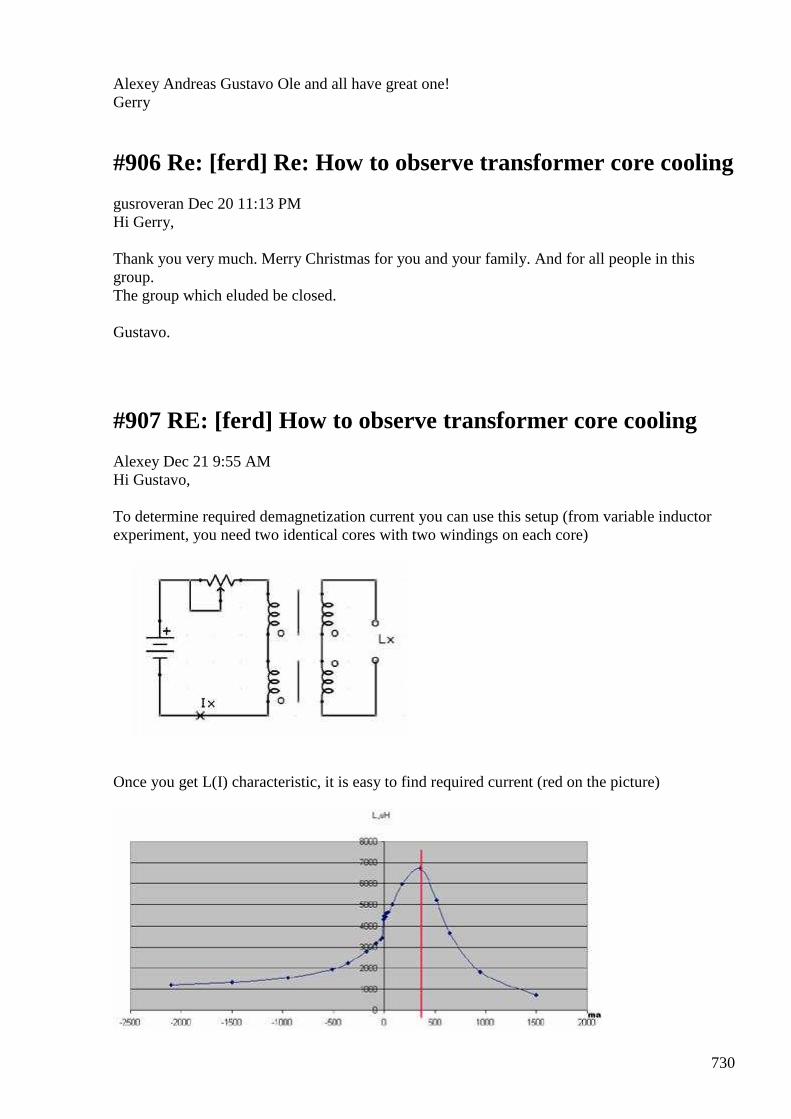
730
Alexey Andreas Gustavo Ole and all have great one! Gerry
#906 Re: [ferd] Re: How to observe transformer core cooling
gusroveran Dec 20 11:13 PM Hi Gerry, Thank you very much. Merry Christmas for you and your family. And for all people in this group. The group which eluded be closed. Gustavo.
#907 RE: [ferd] How to observe transformer core cooling
Alexey Dec 21 9:55 AM Hi Gustavo, To determine required demagnetization current you can use this setup (from variable inductor experiment, you need two identical cores with two windings on each core)
Once you get L(I) characteristic, it is easy to find required current (red on the picture)
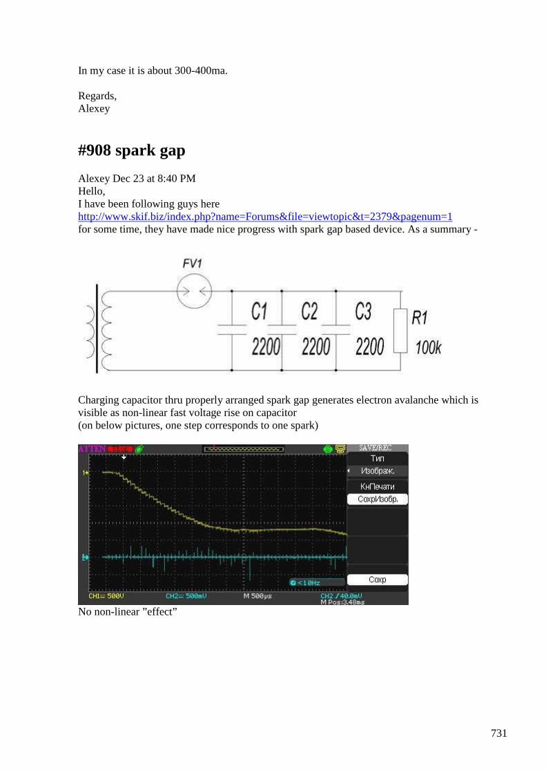
731
In my case it is about 300-400ma. Regards, Alexey
#908 spark gap
Alexey Dec 23 at 8:40 PM Hello, I have been following guys here http://www.skif.biz/index.php?name=Forums&file=viewtopic&t=2379&pagenum=1 for some time, they have made nice progress with spark gap based device. As a summary -
Charging capacitor thru properly arranged spark gap generates electron avalanche which is visible as non-linear fast voltage rise on capacitor (on below pictures, one step corresponds to one spark)
No non-linear ”effect”
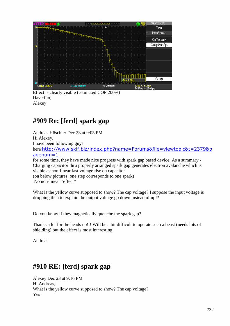
732
Effect is clearly visible (estimated COP 200%) Have fun, Alexey
#909 Re: [ferd] spark gap
Andreas Höschler Dec 23 at 9:05 PM Hi Alexey, I have been following guys here http://www.skif.biz/index.php?name=Forums&file=viewtopic&t=2379&p
agenum=1 for some time, they have made nice progress with spark gap based device. As a summary - Charging capacitor thru properly arranged spark gap generates electron avalanche which is visible as non-linear fast voltage rise on capacitor (on below pictures, one step corresponds to one spark) No non-linear ”effect”
What is the yellow curve supposed to show? The cap voltage? I suppose the input voltage is dropping then to explain the output voltage go down instead of up!?
Do you know if they magnetically quenche the spark gap?
Thanks a lot for the heads up!!! Will be a bit difficult to operate such a beast (needs lots of shielding) but the effect is most interesting.
Andreas
#910 RE: [ferd] spark gap
Alexey Dec 23 at 9:16 PM Hi Andreas, What is the yellow curve supposed to show? The cap voltage? Yes
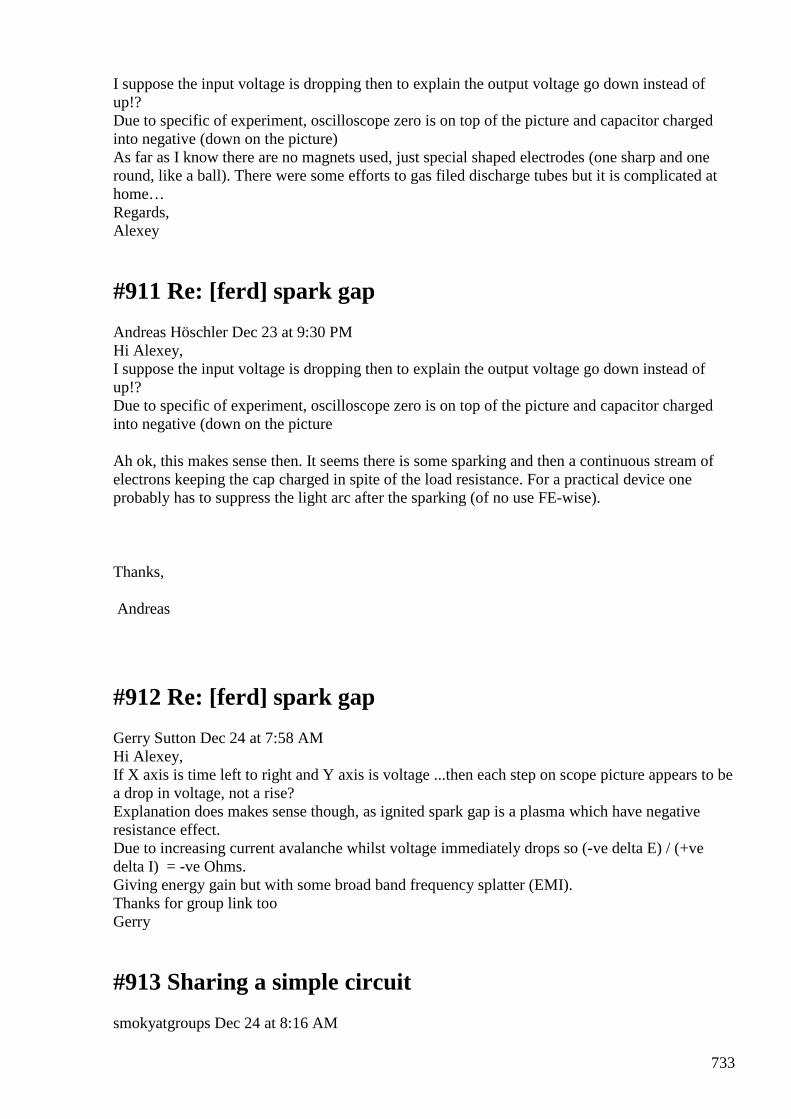
733
I suppose the input voltage is dropping then to explain the output voltage go down instead of up!? Due to specific of experiment, oscilloscope zero is on top of the picture and capacitor charged into negative (down on the picture) As far as I know there are no magnets used, just special shaped electrodes (one sharp and one round, like a ball). There were some efforts to gas filed discharge tubes but it is complicated at home… Regards, Alexey
#911 Re: [ferd] spark gap
Andreas Höschler Dec 23 at 9:30 PM Hi Alexey, I suppose the input voltage is dropping then to explain the output voltage go down instead of up!? Due to specific of experiment, oscilloscope zero is on top of the picture and capacitor charged into negative (down on the picture
Ah ok, this makes sense then. It seems there is some sparking and then a continuous stream of electrons keeping the cap charged in spite of the load resistance. For a practical device one probably has to suppress the light arc after the sparking (of no use FE-wise).
Thanks,
Andreas
#912 Re: [ferd] spark gap
Gerry Sutton Dec 24 at 7:58 AM Hi Alexey, If X axis is time left to right and Y axis is voltage ...then each step on scope picture appears to be a drop in voltage, not a rise? Explanation does makes sense though, as ignited spark gap is a plasma which have negative resistance effect. Due to increasing current avalanche whilst voltage immediately drops so (-ve delta E) / (+ve delta I) = -ve Ohms. Giving energy gain but with some broad band frequency splatter (EMI). Thanks for group link too Gerry
#913 Sharing a simple circuit
smokyatgroups Dec 24 at 8:16 AM
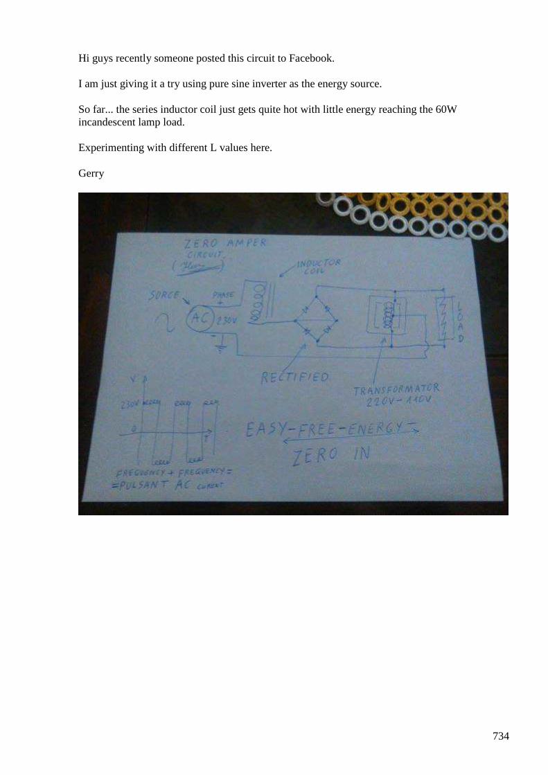
734
Hi guys recently someone posted this circuit to Facebook.
I am just giving it a try using pure sine inverter as the energy source.
So far... the series inductor coil just gets quite hot with little energy reaching the 60W incandescent lamp load.
Experimenting with different L values here.
Gerry
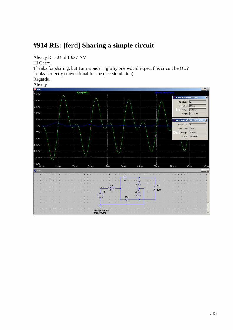
735
#914 RE: [ferd] Sharing a simple circuit
Alexey Dec 24 at 10:37 AM Hi Gerry, Thanks for sharing, but I am wondering why one would expect this circuit be OU? Looks perfectly conventional for me (see simulation). Regards, Alexey
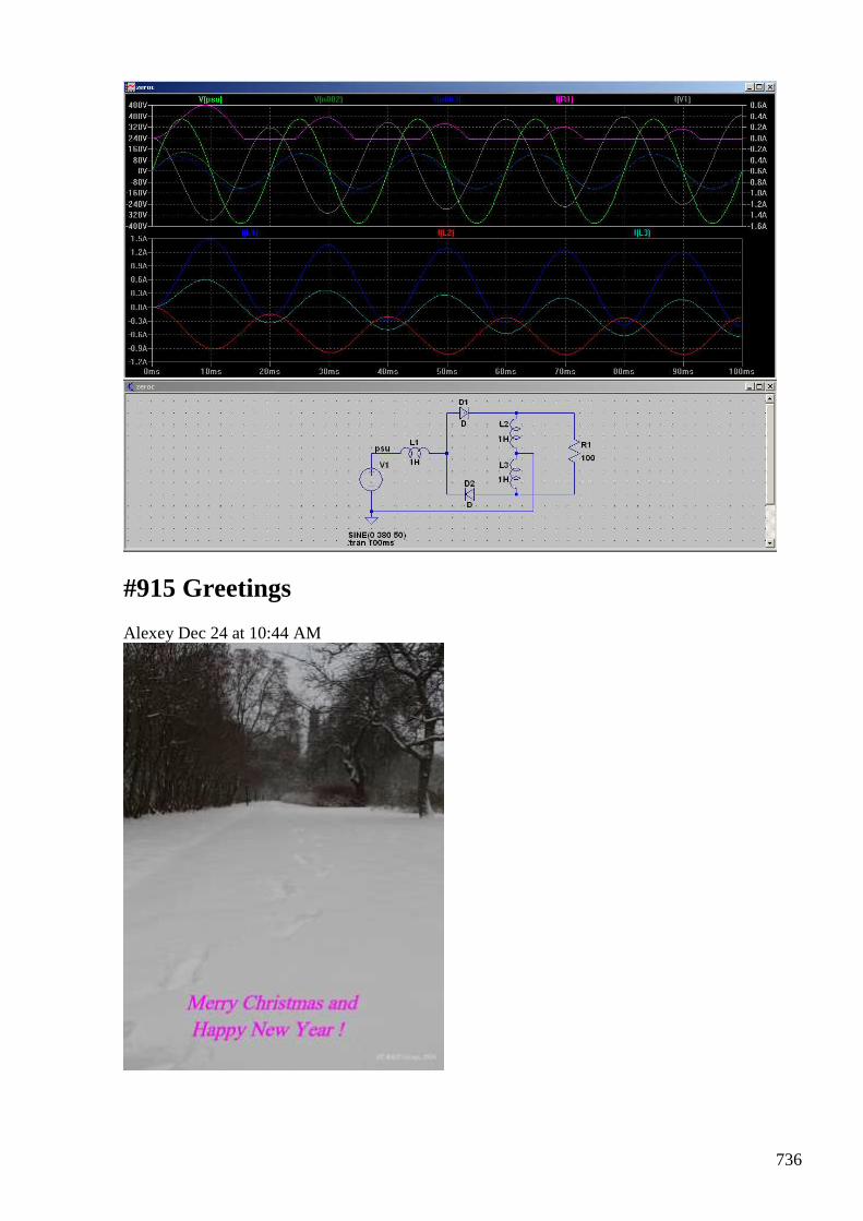
736
#915 Greetings
Alexey Dec 24 at 10:44 AM
737
#916 Re: [ferd] Sharing a simple circuit
Gerry Sutton Dec 24 at 12:26 PM Hi Alexey, Thank you so much for running a simulation. Though I do not understand the scope pics entirely. The input power reading appears to be negative and output power positive from the inset panel on 1st jpg is this right? Someone posted this and made an OU claim on Facebook ...with my available gear here . ... I thought it easy to try it out. In my own head the circuit looked interesting because I thought the input inductor was delaying the current through the halfwave pulsing diodes by up to 90 degrees. And the auto transformer across the load was providing the missing half of the output voltage during sequential positive and negative pulses by auto transformer action. It may come to nothing .... will post if I do any good with it. all the best Gerry
#917 [ferd] Greetings
Gustavo Roveran Dec 24 at 3:18 PM Hi Alexey, Andreas, Gerry, Ole and All, Merry Christmas for all of you too. And enjoying the avalanche of ideas and promising fe devices exposed just at the end of the year. Congratulations Gustavo
#918 Re: [ferd] Greetings
Gerry Sutton Dec 24 11:17 PM Thank you Gustavo!! Merry Christmas to you too Time to enjoy our families and appreciate our friends, care for those less fortunate than ourselves. Gerry
#919 RE: [ferd] Sharing a simple circuit
onielsen2000 Dec 25 10:45 PM Hi Alexey, Try to make a measurement of v(psu)*i(v1) and v(R1)*i(R1) to see output power is greater than
738
input power. If taking the mean values of the calculations this tells if more power is given off than is consumed. @Gerry, If the inductor is getting hot is has resistance which dissipates the power as heat. Regards Ole
#920 RE: [ferd] Sharing a simple circuit
Alexey Dec 25 at 12:34 AM Hi Ole, That is exactly what I measured (on zeroc2.png). Regards, Alexey
#921 Re: [ferd] Greetings
Andreas Höschler Dec 25 at 2:52 AM Dear all, Thank you Gustavo!! Merry Christmas to you too Time to enjoy our families and appreciate our friends, care for those less fortunate than ourselves. Merry Christmas and best wishes for 2016 from me as well. I haven’t made it into the lab recently. But I had a chance to spend a couple of hours on the organ bench http://www.acrux-gmbh.de/music/Var2.mp3 http://www.acrux-gmbh.de/music/Var2.mp3 http://www.acrux-gmbh.de/music/BWV646.mp3 and study this other aspect of the universe! :-) ”Music is a higher revelation than all wisdom and philosophy" May the universe bless our research and let’s hope 2016 becomes the year of the big breakthrough allowing better lives for everyone. Best wishes, Andreas
#922 RE: [ferd] Sharing a simple circuit
onielsen2000 Dec 26 3:11 PM Hi Alexey, OK. No free energy then! L2 and L3 is an autotransformer (sharing the same core) in Garry's original document.
739
Regards Ole
#923 Re: [ferd] Sharing a simple circuit
Gerry Sutton Dec 26 4:17 PM Hi Ole, Alexey, Thanks for good ideas re the input inductor heating. Have been using various windings on a toroidal power transformer as input choke. Don't want to damage it..... will dig out an old fluorescent light choke or heavier gauge transformer to try. My small 600 watt sine inverter just trips overload even with load lamp disconnected, so now using a variac straight off mains supply and a plug in energy monitor. I hate doing it this way....dangerous. Should half wave DC pulses displaced by 20 milliseconds into top & bottom of transformer cause heavy current flow in this circuit? Maybe it saturates the windings? Gerry
#924 Re: [ferd] Sharing a simple circuit
onielsen2000 Dec 26 5:00 PM Hi Garry, The magnetic core is only magnetized in one direction as the current is pulsed DC. This may cause saturation of the core. When working with the mains always have an isolating transformer between the experiment and the mains. Use a laboratory/repair shop variable isolating transformer or one isolating transformer followed by a non-isolating variable transformer (autotransformer). Regards Ole
#925 [reading] Energy Around Us
Alexey Dec 28 at 12:25 AM
Energy-inversion, unlike genetics and cybernetics, still considered as a pseudoscience :-)
#926 [ferd] [reading] Energy Around Us
Gustavo Roveran Dec 29 7:54 PM Hi Alexey I did not know about this subject "energy inversion" explained in this way.
740
Interesting document. Gustavo
#927 RE: [ferd] [reading] Energy Around Us
Alexey Dec 29 10:23 PM Hi Gustavo, Here a (translated) fragment from A.Frolov book “New Energy Sources” with a summary about energy inversion --snip— People from Oshchepkov’s institute, created a theory, and performed calculations for the design of electronic systems to produce electrical current by converting the energy of the environment. Created and work several experimental electronic equipment which convert ambient energy directly into electric current. In the specially created circuits of resistors and specially processed semiconductor diodes (they created "a rough analog" of potential barrier) was able to create a device which generates a voltage of more than ten volts. In the magazine Youth Technology, 11, 1983, the classification of the main methods of inversion of the thermal energy of the medium were considered. We'll take it as a basis, but supplemented by new methods. Photo inversion. Known properties of certain substances (luminophores) re-emit the light falling on them, but on the other, an increase in wavelength (so-called "Stokes luminescence"). Later cases have been found to reduce the wavelength re-emitted light, ie increasing the photon energy (the so-called "anti-Stokes luminescence"). The increase in the photon energy is going through the transformation of its own heat energy to the phosphor in fluorescent light. Due to the selection of heat phosphor is cooled, and lowering the temperature compensated heat gain from the environment. Consequently, the energy increase in fluorescent emission occurs ultimately by heat concentration of the environment, and this increase can be very significant. Theoretically, it may reach 160%, that is, the phosphor may provide power 60% higher than it receives it in the form of radiation. Currently, intensive work performed on the practical application of this effect (cooling facilities masers fluorescent, luminescent photo multiplication and so on.). Chemical inversion. Energetically open catalytic systems have the ability to store energy, and exist in a non-equilibrium thermodynamic state. This process is possible by combining the exothermic reaction occurring on the catalyst to the endothermic reaction (cooled) catalyst. These are capable of self-maintenance (and heal) reaction realized on the absorption of scattered heat protection, open prospects for the creation of new technological processes. There galvanic elements running on the endothermic reactions. The energy for these reactions shown by the lattice structure, whereby the housing member is cooled (covered with frost), and it continuously flows (concentrates) the thermal energy of the environment. Consequently, electric energy in a chemical source of energy, partly due to absorption of energy from the environment. Mechanical inversion. There are various ways to use the kinetic energy of the air molecules. These devices may be passive or active, i.e. cavitations and streaming technology. Gravity inversion. Since the gravitational field of the environment makes patchy, then it should make "distortion" in the process of leveling the thermodynamic condition characterized by an indicator of increasing entropy. This fact is still commemorated by Maxwell and Tsiolkowski, who expressed the idea that the atmosphere under the influence of the gravitational field, should
741
arise the vertical temperature gradient. Tsiolkovsky predicted that this gradient should depend on the molecular composition of the gas. Thermo inversion. Consider a piston engine operating on the injection into the chamber with a cylinder of liquefied non-combustible gas (nitrogen, helium, air). The pressure of produced gas will move the piston, the cylinder will be cooled as the gas expands, and it will direct the flow to the thermal energy from the environment. Employment of such an engine, in the amount will be half of the work of expanding gases, but also there will be some increase due to the use of thermal energy of the environment. Electric inversion. In this research, great expectations were associated with P.K.Oschepkov’s semiconductor converters heat into electricity (*). * there were reports that Oshepkov demonstrated in the mid 80’s a device based on special Cu Al allow which was able to light a small light bulb using environmental heat. Metals were arranged in the piece of wire in such way that concentration of one metal slow increase and concentration of other decrease. This arrangement creates a potential barrier and “rectifies” heat noise. --snip— Have fun, Alexey
#928 [ferd] [reading] Energy Around Us
Gustavo Roveran Dec 31 at 3:55 PM Hi Alexey, So Zaev based his ferrokasor experiment in this theory. But he didn't implement a special input waveform. Do you know what type of technique he use to transform heat into electricity.? Does the way he arranged serial input transformers and parallel output ? Or there is something else. Thanks Gustavo
#929 RE: [ferd] [reading] Energy Around Us
Alexey Dec 31 at 4:46 PM Hi Gustavo, Primary coils connected in parallel and secondary coils in series. This gives small primary inductance and big secondary inductance (and corresponding pulse times). Regards, Alexey
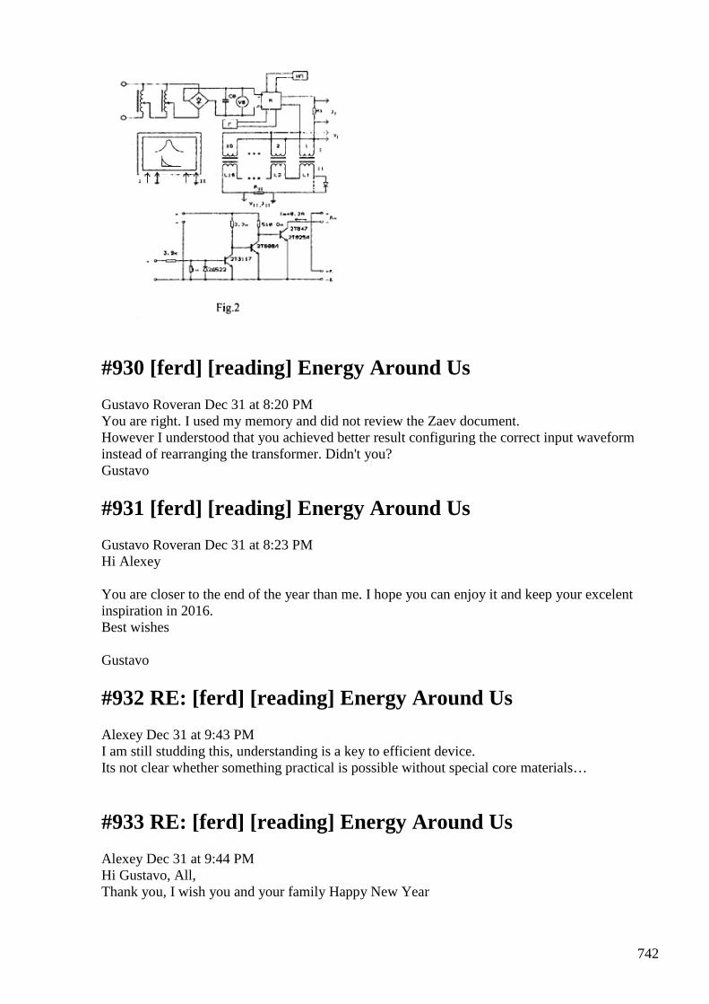
742
#930 [ferd] [reading] Energy Around Us
Gustavo Roveran Dec 31 at 8:20 PM You are right. I used my memory and did not review the Zaev document. However I understood that you achieved better result configuring the correct input waveform instead of rearranging the transformer. Didn't you? Gustavo
#931 [ferd] [reading] Energy Around Us
Gustavo Roveran Dec 31 at 8:23 PM Hi Alexey You are closer to the end of the year than me. I hope you can enjoy it and keep your excelent inspiration in 2016. Best wishes Gustavo
#932 RE: [ferd] [reading] Energy Around Us
Alexey Dec 31 at 9:43 PM I am still studding this, understanding is a key to efficient device. Its not clear whether something practical is possible without special core materials…
#933 RE: [ferd] [reading] Energy Around Us
Alexey Dec 31 at 9:44 PM Hi Gustavo, All, Thank you, I wish you and your family Happy New Year
743
Best Regards, Alexey
#934 RE: [ferd] [reading] Energy Around Us
onielsen2000 Jan 2 4:14 AM Hi Alexey, Gustavo, "Primary coils connected in parallel and secondary coils in series. This gives small primary inductance and big secondary inductance (and corresponding pulse times)." This is also what is happening in a normal step up transformer with low inductance (few turns) in the primary and high inductance in the secondary (many turns). When loading the transformer the inductance of the secondary cancels the inductance of the primary winding. The voltage and current in the primary then has their phases aligned when heavy loaded. Regards Ole
#935 [ferd] [reading] Energy Around Us
Gustavo Roveran Jan 3 2:27 PM Hi Ole So the step up transformer behaves as a power factor correction for low residtance/impedance as load. In Zaev device he use the core in different way from a conventional transformer core. I am trying to understand the theory Alexey share about stressing core in a very slow way and then free it instantly to produce ambient energy transformation. This conversion is demonstrated in the B-H curve path invertion. But I couldn't see the connection of this theory and the design of Zaev transformer. Regards Gustavo
#936 Re: [ferd] [reading] Energy Around Us
744
Gustavo Roveran Jan 3 2:40 PM Hi Alexey, "I am still studding this, understanding is a key to efficient device. Its not clear whether something practical is possible without special core materials…" Did you test iron core ? Could be possible that the clue is in the input waveform and frequency instead of core material ? Gustavo
#937 Re: [ferd] [reading] Energy Around Us
onielsen2000 Jan 3 3:53 PM Hi Gustavo, Step up or step down transformers have the same behavior. Unloaded they're inductances as only the primary is seen (no current in the secondary). Inductance stores magnetic energy. When shorted the secondary winding produces an opposite magnetic field of exactly the same size as that of the original field made by the primary winding. Thus they cancel out and the primary behaves as a short too without inductance. I.e. no energy storage. For power factor correction it can only be used when not loaded as it then behaves like a coil (with inductance). This can only be used for power factor correcting a capacitive load then. This is just ordinary transformer theory. The connection to Zaev lies somewhere else. Regards Ole
#938 Re: [ferd] [reading] Energy Around Us
Andreas Höschler Jan 3 9:08 PM Hi Gustavo, I have just watched the three new Distinti videos your mentioned recently. https://www.youtube.com/watch?v=25rpEAOhRsc https://www.youtube.com/watch?v=vu9d-hAPmqs https://www.youtube.com/watch?v=jef-OlAm4yo Very informative in my opinion. I can’t wait to see the next one. He tends to always stop (a series) when it starts to get exciting though. :-) Nevertheless, good stuff! Best wishes, Andreas
#939 Re: [ferd] [reading] Energy Around Us
onielsen2000 Jan 3 9:55 PM Hi Andreas,
745
That was wave theory. He even mentions that there must be a propagation medium for electromagnetic waves like light. Next he could try to measure if what is thought is a vacuum has physical properties like permeability and permittivity. If it does Einstein's relativity theories are false I guess as Einstein claims there is no aether for propagating electromagnetic waves. For finding those constants a capacitor and an inductor with vacuum as the working medium is needed as well as a capacitance and an inductance meter (or an LCR meter). The formulas for designing capacitors and inductors are also needed. I.e. vacuum does have these properties which determines the speed of propagation of electromagnetic waves in that medium. Regards Ole
#940 Re: [ferd] [reading] Energy Around Us
Andreas Höschler Jan 4 at 1:05 AM Hi Ole, That was wave theory. He even mentions that there must be a propagation medium for electromagnetic waves like light. Next he could try to measure if what is thought is a vacuum has physical properties like permeability and permittivity. If it does Einstein's relativity theories are false I guess as Einstein claims there is no aether for propagating electromagnetic waves. I am not so sure Einstein claimed that! My understanding is that he tried to find a universal description of all forces based on field equations. He got so badly stuck and ended up with a mess. I am really lucky I never invested the time to work through his tensor algebra monster publications. That would have been a total waste of time. For finding those constants a capacitor and an inductor with vacuum as the working medium is needed as well as a capacitance and an inductance meter (or an LCR meter). The formulas for designing capacitors and inductors are also needed. Such an experiment is difficult to conduct for us garage scientists (requires huge vacuum chambers). I feel no need to perform such an experiment. I am quite sure we would measure the capacitance of a plate cap predicted by standard formulas. Thus empty space indeed has permittivity which means presence of ether since permittivity is actually aether density (at least according to my current understanding). I believe to have a good understanding of gravity, permittivity and the vector potential in the meanwhile but no satisfying understanding of charges so far (currently trying to figure this out). In some readings charges are treated as changing ether densities. But how could that be? Changing to what? This does not make too much sense for me yet. Anyway! Best wishes, Andreas
#941 RE: [ferd] [reading] Energy Around Us
Alexey Jan 4 at 8:30 PM
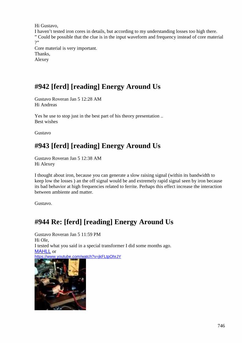
746
Hi Gustavo, I haven’t tested iron cores in details, but according to my understanding losses too high there. ” Could be possible that the clue is in the input waveform and frequency instead of core material ?” Core material is very important. Thanks, Alexey
#942 [ferd] [reading] Energy Around Us
Gustavo Roveran Jan 5 12:28 AM Hi Andreas Yes he use to stop just in the best part of his theory presentation .. Best wishes Gustavo
#943 [ferd] [reading] Energy Around Us
Gustavo Roveran Jan 5 12:38 AM Hi Alexey I thought about iron, because you can generate a slow raising signal (within its bandwidth to keep low the losses ) an the off signal would be and extremely rapid signal seen by iron because its bad behavior at high frequencies related to ferrite. Perhaps this effect increase the interaction between ambiente and matter. Gustavo.
#944 Re: [ferd] [reading] Energy Around Us
Gustavo Roveran Jan 5 11:59 PM Hi Ole, I tested what you said in a special transformer I did some months ago. MAHLL or https://www.youtube.com/watch?v=jkFLtpOhrJY
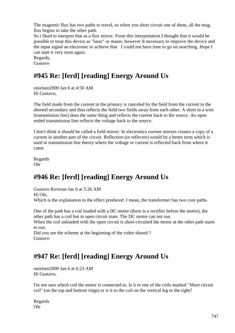
747
The magnetic flux has two paths to travel, so when you short circuit one of them, all the mag. flux begins to take the other path. So i liked to interpret that as a flux mirror. From this interpretation I thought that it would be possible to treat this device as "laser" or maser, however It necessary to improve the device and the input signal an electronic to achieve that I could not have time to go on searching. Hope I can start it very soon again. Regards, Gustavo
#945 Re: [ferd] [reading] Energy Around Us
onielsen2000 Jan 6 at 4:50 AM Hi Gustavo, The field made from the current in the primary is canceled by the field from the current in the shorted secondary and thus reflects the field two fields away from each other. A short in a wire (transmission line) does the same thing and reflects the current back to the source. An open ended transmission line reflects the voltage back to the source. I don't think it should be called a field mirror. In electronics current mirrors creates a copy of a current in another part of the circuit. Reflection (or reflector) would be a better term which is used in transmission line theory where the voltage or current is reflected back from where it came. Regards Ole
#946 Re: [ferd] [reading] Energy Around Us
Gustavo Roveran Jan 6 at 5:26 AM Hi Ole, Which is the explanation to the effect produced. I mean, the transformer has two core paths. One of the path has a coil loaded with a DC motor (there is a rectifier before the motor), the other path has a coil but in open circuit state. The DC motor can not run. When the coil unloaded with the open circuit is short-circuited the motor at the other path starts to run. Did you see the scheme at the beginning of the video shared ? Gustavo
#947 Re: [ferd] [reading] Energy Around Us
onielsen2000 Jan 6 at 6:23 AM Hi Gustavo, I'm not sure which coil the motor is connected to. Is it to one of the coils marked "Short circuit coil" (on the top and bottom rings) or is it to the coil on the vertical leg to the right? Regards Ole
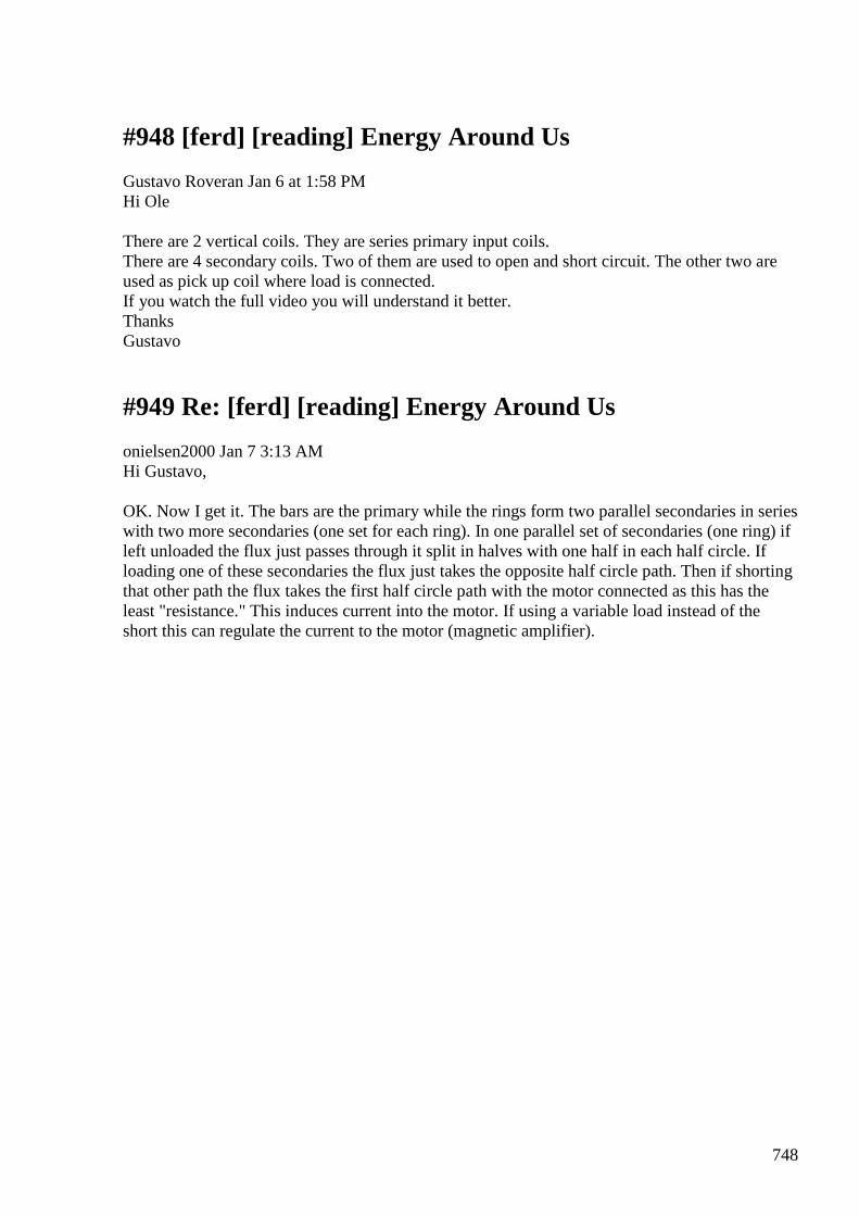
748
#948 [ferd] [reading] Energy Around Us
Gustavo Roveran Jan 6 at 1:58 PM Hi Ole There are 2 vertical coils. They are series primary input coils. There are 4 secondary coils. Two of them are used to open and short circuit. The other two are used as pick up coil where load is connected. If you watch the full video you will understand it better. Thanks Gustavo
#949 Re: [ferd] [reading] Energy Around Us
onielsen2000 Jan 7 3:13 AM Hi Gustavo, OK. Now I get it. The bars are the primary while the rings form two parallel secondaries in series with two more secondaries (one set for each ring). In one parallel set of secondaries (one ring) if left unloaded the flux just passes through it split in halves with one half in each half circle. If loading one of these secondaries the flux just takes the opposite half circle path. Then if shorting that other path the flux takes the first half circle path with the motor connected as this has the least "resistance." This induces current into the motor. If using a variable load instead of the short this can regulate the current to the motor (magnetic amplifier).
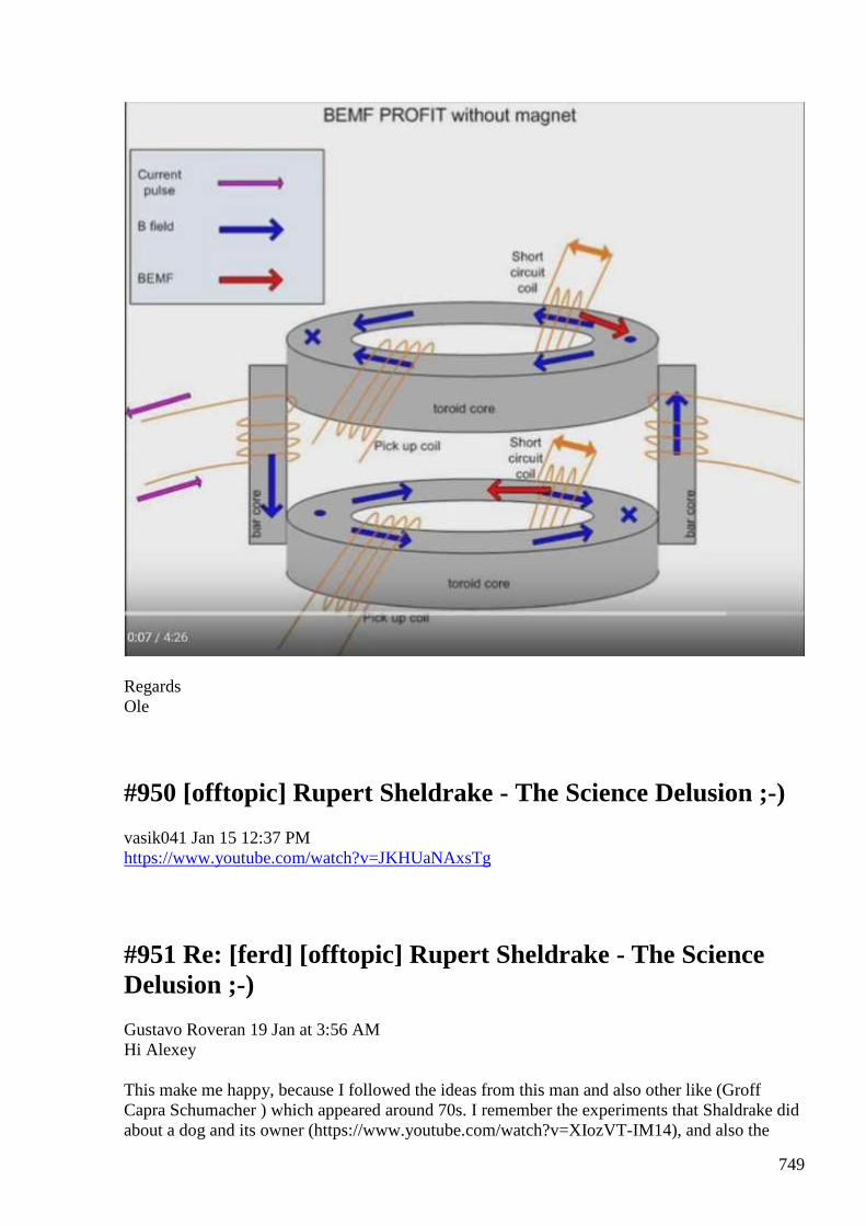
749
Regards Ole
#950 [offtopic] Rupert Sheldrake - The Science Delusion ;-)
vasik041 Jan 15 12:37 PM https://www.youtube.com/watch?v=JKHUaNAxsTg
#951 Re: [ferd] [offtopic] Rupert Sheldrake - The Science Delusion ;-)
Gustavo Roveran 19 Jan at 3:56 AM Hi Alexey This make me happy, because I followed the ideas from this man and also other like (Groff Capra Schumacher ) which appeared around 70s. I remember the experiments that Shaldrake did about a dog and its owner (https://www.youtube.com/watch?v=XIozVT-IM14), and also the
750
image he shared to "measure" the morphgentic field (http://www.context.org/iclib/ic12/sheldrak/), or the theory of the one hundred monkey. For example in the case of Schumacher, he wrote "Small is beautiful" a book gifted by my father, and this was the inspiration for this enhanced Savonius I did some years ago ... https://www.youtube.com/watch?v=UwFAhI3GHK8 Thanks Gustavo
#952 RE: [ferd] [offtopic] Rupert Sheldrake - The Science Delusion ;-)
Alexey Jan 19 9:15 PM Hi Gustavo, Thank you for the links. It is interesting how everything is “interconnected” J Regards, Alexey
#953 New Tom Bearden book re-issued. "Star Wars Now!" - Forword by Dr. Steven Greer
Gustavo Roveran Jan 22 3:57 AM I do not know what happens with his meg device, but ... Forget about the George Lucas and Disney Star Wars, as this book tells us about the real “Star Wars”. These events began March 25, 1983, at the height of the Cold War with Russia, when our president, Ronald Reagan, made a televised speech to this nation proposing a Strategic Defense Initiative (SDI) as a strategy to protect the nation against Soviet attack. The SDI was nicknamed “Star Wars” as it involved space-based weaponry. Lt. Col. Thomas E. Bearden (US Army, Retired) was alarmed. One of the world’s leading conceptual experts on long-suppressed Tesla physics (about which he has written extensively), he was greatly concerned that Russia was far ahead of the United States with non-conventional, scalar, Tesla weaponry, and that the United States was extremely vulnerable. Few in the U.S. understood the potential iterations of these weapons, so in this subsequent 1984 book Star Wars Now! Tom lays out in intricate detail not only the true science that is involved, but what specific hostile applications these weapons can takeall the while being hidden in plain sight! This was also the first time that the public spotlight had been shone on the Aharonov-Bohm effect, which states that when two zero-field scalar wave beams are crossed, real physical effects can be affected within a distant interference zone or region. This was the inside joke that was referred to in the movie Ghostbusters when the heroes were warned by the Dr. Egon Spengler character when trying to bring down the Stay Puft marshmallow man with electromagnetic streams from their energy pistols to “don't cross the streams”. Incidentally, this movie was loosely based on the work being done at the Stanford Research Institute (SRI) by physicists Puthoff, Targ, etc., but was played for laughs, disguising the seriousness of the research and development work that was actually going on.
751
Taken together with chapter and verse from field test observations, the list of Aharanov-Bohm effects is long, ranging from radar invisibility and earthquake induction, to ABM defense. All of which has been and is now confirmed by most high-level U.S. political officials including Secretary of Defense William Cohen, while he was in office. This 2nd Edition features a Foreword by Dr. Steven M. Greer, head of The Disclosure Project, who brings us up to date on an unexpected and surprising current purpose of these now-deployed space-based weapons, as well as how President Reagan was manipulated into championing their development under false pretenses. The chilling effects demonstrated and delineated in Star Wars Now! are all the more alarming today, as this weaponized technology finds its way into mainstream media and news coverage. Available on The Tom Bearden Website at http://cheniere.org/sales/buy-starwarsnow.htm Regards Tony Craddock Executive Producer/ Web Administrator Energy from the Vacuum Website www.energyfromthevacuum.com
#954 RE: [ferd] New Tom Bearden book re-issued. "Star Wars Now!" - Forword by Dr. Steven Greer
Alexey Jan 22 11:07 PM Hi Gustavo, Do not spend money on this nonsense Regards, Alexey
#955 Voltage x Current concept development
Alexey Jan 28 at 11:13 PM
Hello, I would like to share a document which is being discussed quite actively on several russian OU related forums.
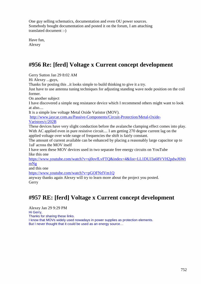
752
One guy selling schematics, documentation and even OU power sources. Somebody bought documentation and posted it on the forum, I am attaching translated document :-) Have fun, Alexey
#956 Re: [ferd] Voltage x Current concept development
Gerry Sutton Jan 29 8:02 AM Hi Alexey ...guys, Thanks for posting this ..it looks simple to build thinking to give it a try. Just have to use antenna tuning techniques for adjusting standing wave node position on the coil former. On another subject I have discovered a simple neg resistance device which I recommend others might want to look at also.... It is a simple low voltage Metal Oxide Varistor (MOV). http://www.jaycar.com.au/Passive-Components/Circuit-Protection/Metal-Oxide-Varistors/c/202B These devices have very slight conduction before the avalanche clamping effect comes into play. With AC applied even in pure resistive circuit.... I am getting 270 degree current lag on the applied voltage over wide range of frequencies the shift is fairly constant. The amount of current available can be enhanced by placing a reasonably large capacitor up to 1uF across the MOV itself I have seen these MOV devices used in two separate free energy circuits on YouTube like this one https://www.youtube.com/watch?v=sj0ovfLvFTQ&index=4&list=LL1DUJ3a68VVH2pdwJ6WtmNg and this one https://www.youtube.com/watch?v=pGOFNrlVm1Q anyway thanks again Alexey will try to learn more about the project you posted. Gerry
#957 RE: [ferd] Voltage x Current concept development
Alexey Jan 29 9:29 PM Hi Gerry, Thanks for sharing these links. I know that MOVs widely used nowadays in power supplies as protection elements. But I never thought that it could be used as an energy source…
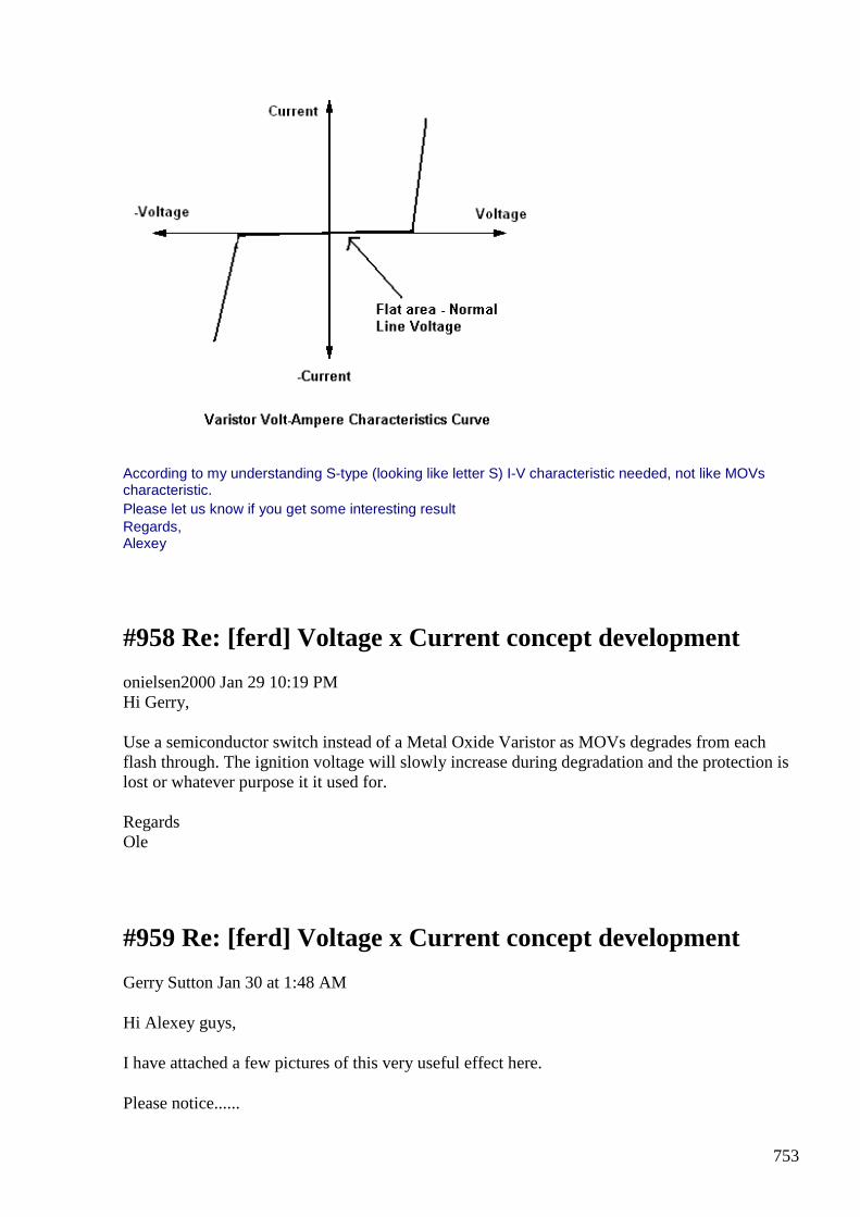
753
According to my understanding S-type (looking like letter S) I-V characteristic needed, not like MOVs characteristic. Please let us know if you get some interesting result Regards, Alexey
#958 Re: [ferd] Voltage x Current concept development
onielsen2000 Jan 29 10:19 PM Hi Gerry, Use a semiconductor switch instead of a Metal Oxide Varistor as MOVs degrades from each flash through. The ignition voltage will slowly increase during degradation and the protection is lost or whatever purpose it it used for. Regards Ole
#959 Re: [ferd] Voltage x Current concept development
Gerry Sutton Jan 30 at 1:48 AM
Hi Alexey guys,
I have attached a few pictures of this very useful effect here.
Please notice......
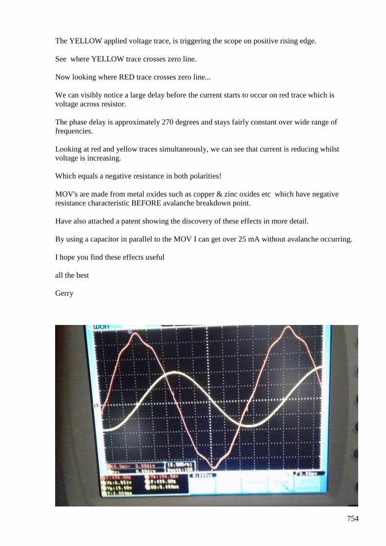
754
The YELLOW applied voltage trace, is triggering the scope on positive rising edge.
See where YELLOW trace crosses zero line.
Now looking where RED trace crosses zero line...
We can visibly notice a large delay before the current starts to occur on red trace which is voltage across resistor.
The phase delay is approximately 270 degrees and stays fairly constant over wide range of frequencies.
Looking at red and yellow traces simultaneously, we can see that current is reducing whilst voltage is increasing.
Which equals a negative resistance in both polarities!
MOV's are made from metal oxides such as copper & zinc oxides etc which have negative resistance characteristic BEFORE avalanche breakdown point.
Have also attached a patent showing the discovery of these effects in more detail.
By using a capacitor in parallel to the MOV I can get over 25 mA without avalanche occurring.
I hope you find these effects useful
all the best
Gerry
755
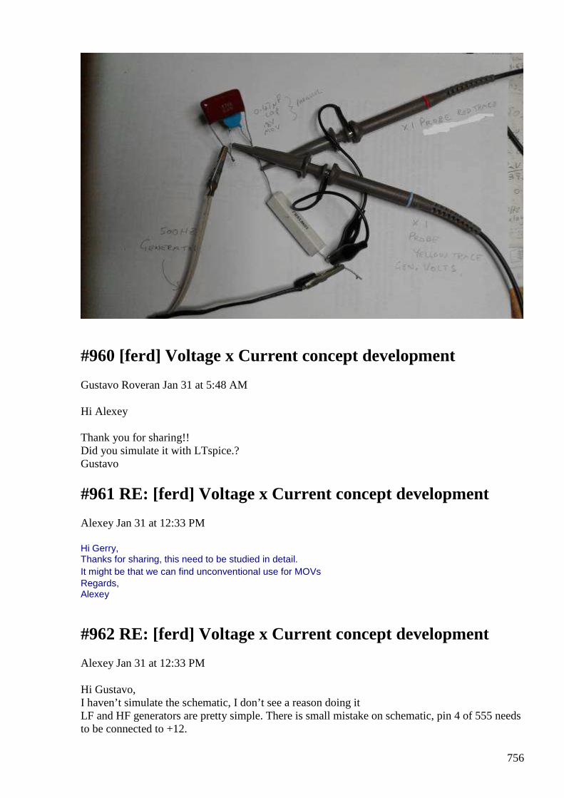
756
#960 [ferd] Voltage x Current concept development
Gustavo Roveran Jan 31 at 5:48 AM
Hi Alexey Thank you for sharing!! Did you simulate it with LTspice.? Gustavo
#961 RE: [ferd] Voltage x Current concept development
Alexey Jan 31 at 12:33 PM
Hi Gerry, Thanks for sharing, this need to be studied in detail. It might be that we can find unconventional use for MOVs Regards, Alexey
#962 RE: [ferd] Voltage x Current concept development
Alexey Jan 31 at 12:33 PM
Hi Gustavo, I haven’t simulate the schematic, I don’t see a reason doing it LF and HF generators are pretty simple. There is small mistake on schematic, pin 4 of 555 needs to be connected to +12.
757
It is obvious for me that without some ”magic key” device will not work as OU device. Some important detail is missing. Regards, Alexey
#963 Re: [ferd] Voltage x Current concept development
Gerry Sutton Feb 1 1:08 AM
Hi Alexey, guys
Yes if you need a device which starts to conduct current at the 90 and / or 270 degree voltage points the MOV seems a simple way to achieve it.
I also experimented with amplifying this effect ......by using the MOV to source the Base current into a transistor and running Load off the Emitter..
Hooking Collector back to generator.
This works quite well however transistors are single polarity & don't like reverse bias on input junction so it gets a bit complicated.
As Sine Cos and Tan are all positive in the first quadrant and Cos of current lag only becomes negative from 90 to 270,
So I'm still spending some time trying to change the current lag angle to less than the 270 degrees this also gets complicated but if achieved will source energy back into generator.
Allowing self run effects like in the You Tube videos I previously posted.
Gerry
#964 offtopic - wouldn't it be nice ?
vasik041 Feb 2 2:11 PM
https://www.youtube.com/watch?v=0v2xnl6LwJE ;)
#965 Energy Sink
Andreas Höschler Jan 4 at 5:15 AM
Hi all, I have played a bit with a Royer Oscillator (see attached PDF):
758
This beats sinks 40W with no apparent output. All components stay cool even after letting the beast run for quite a while. The MOSFETs are cold, the coil of course is cold. No other nearby components involved that could convert EM to heat. Am I cooking my brain sitting next to this? Note the frequency. The thing is oscillating at only 26kHz. Any idea where the energy is going to? This puzzles me!? Also note the phase shift of 79°!? If I look at the two curves this looks like a neat 90°, but the scope measures a lot less!? What the heck? How cab this thing sink 40W without anything getting at least warm? Thanks, Andreas
#966 Re: [ferd] Energy Sink
Gerry Sutton Feb 4 at 6:50 AM
Hi Andreas nice to hear you still at it!
When we look at power supply current (the green no.2 trace) seems to be less than 1 amp average .......to get 40W from 60V supply.
The input current never seems to go negative.
Whilst input volts are also always positive also so input power is always in first quadrant where Cos Phi is always positive.
So input DC power is real.
However in tank circuit and it's current carrying components:
instantaneous heating of FET's etc occurs when Volts (Vds) & Amps are positive or negative at the same moment in time from (Power dissipated = V inst x I inst ) or (Power dissipated = -ve V inst x -ve I inst ).
And instantaneous cooling happens when either -ve Volts occur when Amps are +ve or +ve Volts and -ve Amps (Power Generated = Negative Power extracted from latent heat = - ve Volts x +ve Amps) or vice versa.
From the looks of your input current peaks it looks like the FETs are only ON long enough to pulse the tank into oscillation.... about 90 degrees or less?
So the reactive currents in the tank can be far higher than the pulse which generated the oscillation depending on the tanks Q value.
As a result this circuit can be very efficient ...it reminds me of Class C operation in valve circuits.
dunno if this helps, all the best Gerry
759
#967 Re: [ferd] Energy Sink
onielsen2000 Feb 4 at 4:24 PM
Hi Gerry, Andreas, I'm doing experiments with a Markov transformer driven by a Royer alike oscillator (the same MOSFET version with the chokes). I'm having big trouble measuring current on this differential output to the transformer. I first used a current probe but suspects the big stray fields to influence the readings. Then i bought a differential probe able to do X1 (1:1) measurements and using a current shunt resistor for reading the current. This is also suspected to be influenced by the stray field. To solve the measurement problem a single end output may have to be used. Using a class D amplifier with single end output is easy to measure but a simple and efficient power oscillator like the Royer alike is what is wanted. Next step to try could be a class C amplifier. Else some way of shielding and/or putting the wires in a way minimizing the influence from the stray field may have to be used. A half bridge output stage driven at resonance would solve the measurement problem but has another problem by being limited by the rail voltage(s). Perhaps the measurements you're doing Andreas may suffer the same problems. @Gerry, "And instantaneous cooling happens when either -ve Volts occur when Amps are +ve or +ve Volts and -ve Amps (Power Generated = Negative Power extracted from latent heat = - ve Volts x +ve Amps) or vice versa." Don't expect cooling. A generator still heats even though the current and voltages are opposite that of a motor. A motor and a generator can be exactly the same component just driven in different ways. As long as it has resistance heat will be dissipated when current runs through it. The direction (phase) determines whether it is a motor or a generator. Regards Ole
#968 Re: [ferd] Energy Sink
Andreas Höschler Feb 4 at 4:55 PM
Hi Gerry and Ole
thanks to both of you for your input!
Perhaps the measurements you're doing Andreas may suffer the same problems.
They may and cause uncertainty with respect to the measured phase shift in the tank. But for the effect I currently see I need no scope and no current probe. I am definitely inputting 40W of real power into this device and everthing stays cool, so no transformation to heat at least no within

760
the circuit. If this transformation happened in my brain instead (sitting next to this beast for a couple of minutes while operating) I would probably be dead by now. I am also not so much concered about this at a frequency in the 25kHz range. So the main question that puzzles me is, where is the significant energy going to? The only components inthe circuit that could hide 40W for a while may be the two choke cores. But I highly doubt that!?
"And instantaneous cooling happens when either -ve Volts occur when Amps are +ve or +ve Volts and -ve Amps (Power Generated = Negative Power extracted from latent heat = - ve Volts x +ve Amps) or
vice versa." Don't expect cooling. A generator still heats even though the current and voltages are opposite that of a motor. A motor and a generator can be exactly the same component just driven in different ways. As long as it has resistance heat will be dissipated when current runs through it. The direction (phase) determines whether it is a motor or a generator.
Gerry, what you suggest would mean positive voltage over the DS junction and negative current through the MOSFET. This would mean that the MOSFET itself converts heat to electricity and appears as a negative resistor. This is pretty unlikely, isn't it!?
Best wishes,
Andreas
#969 Re: [ferd] Energy Sink - Addendum
Andreas Höschler Feb 4 at 5:15 PM
Hi all, sinking energy is of course not what we are after. But if we understand how to sink energy we might also be able to source energy by reversing the process!? I guess we have to follow any hint (anomaly) we get. I already encountered situations in the past where I suspected an energy imbalance. I usually discussed it away by assuming that the cores would swallow the energy due to core losses. However, this time I use air core coil (except the for the chokes). There is not much mass in the rig that could hide thermal energy and the wires are HF-multistand and extra thick. They can definitely carry the relatively small current in the whole circuit, even in the tank. Again, no apparent heat anywhere for 40W real wattage going missing somewhere!? Best wishes, Andreas
#970 Re: [ferd] Energy Sink - Addendum
onielsen2000 Feb 4 at 9:56 PM
Hi Andreas, You would have to measure each component to isolate where the energy is going. An air core spreads out the flux to the ambient. What is below or around the core like metals which
761
dissipates the energy? Regards Ole
#971 Re: [ferd] Energy Sink - Addendum
Andreas Höschler Feb 4 at 10:04 PM
Hi Ole,
On 04 Feb 2016, at 18:56, onielsen [ferd] <[email protected]> wrote: You would have to measure each component to isolate where the energy is going. An air core spreads out the flux to the ambient. What is below or around the core like metals which dissipates the energy?
Nothing within a range of 40cm. If we have to consider an even greater radius nailing the thing becomes problematic (too far spread and hardly any measurable effect). But that's probably where the energy is going (metal frame of the neon light, some tools lying around on the table (in great distance). However, I hovered a coil with a light bulb attached directly over the work coil, and this hardly increased the input wattage and hardly extracted any energy form the system (< 10%). I can therefore hardly imagine that the 40W are lost that way!?
Thanks,
Andreas
#972 RE: [ferd] Energy Sink - Addendum
Alexey Feb 4 at 10:27 PM
Hi Andreas, nice to hear from you I am wondering - how you measure input power ? may be measurement not accurate and cause the confusion ? Thanks, Alexey
#973 Re: [ferd] Energy Sink - Addendum
Andreas Höschler Feb 4 at 10:31 PM
Hi Alexey,
nice to hear from you I am wondering - how you measure input power ? may be measurement not accurate and cause the confusion ?
762
The DC power supply has a built-in wattage measurement feature (proven to be very reliable). I additionally measure the input current with a current probe averaging to about 0.8A. At 60V this gives 40W. The input wattage is real.
Thanks,
Andreas
#974 RE: [ferd] Energy Sink - Addendum
Alexey Feb 4 10:59 PM
Hi Andreas, Well, so far it looks like you made a nice VLF transmitter. But beware of submarines ;) https://en.wikipedia.org/wiki/Very_low_frequency Regards, Alexey
#975 Re: [ferd] Energy Sink
smokyatgroups Feb 5 at 2:35 AM
Hi Ole, Andreas, Alexey guys
Yes it's not easy to measure fast changing currents especially out of high source impedance circuits.
We end up pushing stray currents into stray capacitance around the circuit.... equipment like test probes and mechanical housing only adds to it all.
If the tank is parallel resonant then the equivalent series resistance in it's circuit is magnified (multiplied) by the Q value giving also very large high impedance situation, so same story as above.
Ole I guess there's no centre tap where the balanced currents amalgamate and with differential the whole lot is floating above earth, so yes I see your problem.
When dealing with voltage sources the source impedances are much lower so impedance is harder to shunt down causing less stray current issues when making measurements.
In recent Russian circuit posted by Alexey for example they are using a a full wave resonant transformer.
It appears as a series resonant circuit with approx zero impedance at resonance.
763
Acts like more like a constant voltage circuit ...easier to deal with but there are still nodes and anti nodes of impedance along the length.
Gerry
#976 Re: [ferd] Energy Sink
smokyatgroups Feb 5 at 3:47 AM
Hi Andreas,
Not at all, if we could scope instantaneous heat on same time frame as your volts & amps traces ... and provided thermal inertia is not an issue.
We would see FET temperature rising during Volts and Amps in phase ( both positive or both negative).
ie: pushing temperature up at fast rate.
And we would see temperature dropping during Volts and Amps out of phase (one positive and one negative).
ie: pulling temperature down at fast rate.
This is because the whole FET & heatsink body has a thermal mass connected to normal ambient temperature by a thermal resistance......until it is acted upon by junction Volts & Amps in our case.
If mark space ratio of in phase compared to out of phase Volts & Amps is varied.
We would see FET temp rise or fall below ambient accordingly, as the mass becomes a source OR a sink of thermal energy.
I built one of those Professor Sieke oscillators out of MJE3055 and it amazed me how much current the transistors could sink whist staying dead cold.
Generators of energy only get hot because of their internal losses, superconductive coils can carry currents indefinitely without loss and without heat generation.
When we divide delta +ve Volts by delta -ve Amps we get delta -ve Ohms this can be a relative negative resistance or an absolute negative resistance when taken over a complete cycle.
Resulting in above ambient or below ambient thermal mass temperatures.
When stored energy is returned from the environment it always has a relative negative value.
Be it from charged inductor, charged capacitor, heated hot water system or even a volcano erupting.
Gerry
764
#977 Re: [ferd] Energy Sink
Andreas Höschler Feb 5 at 5:04 AM
Hi Gerry and all,
When we divide delta +ve Volts by delta -ve Amps we get delta -ve Ohms this can be a relative negative resistance or an absolute negative resistance when taken over a complete cycle.
Resulting in above ambient or below ambient thermal mass temperatures.
When stored energy is returned from the environment it always has a relative negative value.
Be it from charged inductor, charged capacitor, heated hot water system or even a volcano erupting.
Thanks for your input. I re-conducted the experiment with the wooden box work coil and got the following:
I have still plenty of watts vanishing into the unknown. Thanks Alexey for the submarine reference. I got no response from one so far though! :-) Thanks, Andreas
#978 Royer UDT
Andreas Höschler Feb 5 at 5:14 AM
Hi all, I let the energy sink case rest for a while and combined the Royer Oscillator with an UDT:
No reason to shout OU here since the output wattage measurement is rough (500R load resistor heats up) but I got a few hits. The setup seems to be at least pretty efficient!! Does this teach us anything? I have no idea (already too tired)!
Good night!
Andreas
#979 Re: [ferd] Royer UDT
Gerry Sutton Feb 5 at 6:32 AM
Hi Andreas,
Looking your results..... you did some nice work there.
765
See how the gate signal changes with & without Vdd applied?
I think this might be Miller effect because whilst FET is in transition between ON and OFF states.
it has an enormous current gain at this time.
Delta Ig compared to Delta Id is very great.
The gate to drain capacitance is effectively multiplied by the stage gain.......
Because the reactive current through this capacitance increases both due to the rate of change of the current and the voltage differential across it.
So thinking this is Miller feedback.
Where input current goes negative it is sourcing current back into the supply, if ratio of negative per cycle exceeds positive per cycle you are making energy as well as powering the tank.
The tank has a natural resonant frequency which can be gauged by pulsing gate with narrow pulse at very low frequency ...then look at resultant ring on the tank cct. measure it's frequency.
If the ring is very high frequency try to load it down with HV parallel caps across tank.... till its in range of the FETs happy zone to run. As higher freq = more stray capacitance effects and component stress.
If the Q is very high.... the tank can be pulsed only once every two or three cycles to conserve input energy. Gate pulses should be narrow also to conserve energy and just kick the tank into oscillation.
Whilst varying the gate input frequency you can monitor the relative peak to peak tank volts with a few turns of wire placed nearby and attached to the scope.
1: Find the centre frequency with highest amplitude on scope write this frequency down as "freq C", (BW centre freq) and also note how many vertical divisions you have on the scope.
2: Now increase the gate drive frequency higher, till scope vertical display drops to 0.7 of value noted above, write this down as "freq A" (at its -3dB point).
3: Now decrease the gate drive frequency to below BW centre frequency till scope again drops to 0.7 of vertical deflection noted in 1 above, write this down as "freq B" (at it's -3dB point).
4: Take recorded centre frequency "C" and divide it by (freq A - freq B) ...the answer will be a number usually between 5 and 100, it will be your effective Q value.
Or another way of saying it ...it's the direct ratio of your energy STORED to energy DISSIPATED in the tank and it's associated components.
Gerry
766
#980 Re: Royer UDT
onielsen2000 Feb 6 8:53 PM
Hi Andreas, My experience with the Jensen UDT is that is has to be driven at double the LC-tank resonant frequency to give off free energy. The Royer alike (Mazzilli) oscillator runs at only the resonant frequency which won't be effective with the UDT. Regards Ole
#981 Re: [ferd] Re: Royer UDT
Andreas Höschler Feb 7 at 3:31 AM
Hi Ole,
My experience with the Jensen UDT is that is has to be driven at double the LC-tank resonant frequency to give off free energy. The Royer alike (Mazzilli) oscillator runs at only the resonant frequency which won't be effective with the UDT.
I remember you mentioning this. But I am still not clear about what you mean by resonance frequency. This sis about the coils on leg A and C in series with their intrinsic capacitance? SO you hit the primary or secondary and then observe the ringing of the secondary? Wouldn’t this frequency be very high? Could be tough to drive the primary with twice this frequency, at least with my pucks!? :-)
Have you done that? How much OU did you get? Is saturation a must?
Thanks,
Andreas
#982 Re: [ferd] Re: Royer UDT
onielsen2000 Feb 7 at 4:01 AM
Hi Andreas, The resonant frequency is the one given by the parallel LC-tank formed by the capacitor in parallel with the primary coil. Regards Ole
767
#983 Re: [ferd] Re: Royer UDT
onielsen2000 Feb 7 at 4:03 AM
Hi Andreas, "Have you done that? How much OU did you get? Is saturation a must?" The phase between the input voltage and current can be adjusted to close to 90 degrees which means pure reactive power. My amplifier and power supply becomes unstable at this condition as the power also goes back into the amplifier and further through this to the power supply. In theory this is close to infinity or at least a very high coefficient of performance as there will always be losses. I still haven't made a BH-curve for the transformer core. But it doesn't work at too low power levels and normally it takes some non-linearity to mix signals into coherence. I'm working on a power oscillator for the Markov transformer with single ended output as I find the Royer alike oscillator hard to do proper measurements on with its differential output. I mean measuring on the floating transformer primaries without reference to ground. Regards Ole
#984 Re: [ferd] Re: Royer UDT
onielsen2000 Feb 7 at 5:06 AM
Hi Andreas, The UDT is also load dependent. If the load changes something else has to be adjusted too. This makes it quite hard to work with as many parameters depend on each other. This requires a regulator to keep it tracking the load. Regards Ole
#985 Re: [ferd] Re: Royer UDT
Gerry Sutton Feb 7 at 8:11 AM
Hi Ole,
This may be a silly suggestion but if you can pass a portion of the output through a full wave bridge?
The rectified frequency will always be double the input...... just need a way to extract the second harmonic component perhaps by blocking the DC level with a series cap is enough?
This reminds me of Parametric amplification where one of the circuit parameters is varied twice per cycle (either L or C ).
768
Gerry
#986 Re: [ferd] Re: Royer UDT
onielsen2000 Feb 7 at 2:41 PM
Hi Gerry, I rectify filter and pass the output through a buck-boost converter to be able to have a constant load at the output. Else it is very hard to find the optimal working point. If you're thinking of putting the output directly back to the input this is no good idea. If you ever have heard what happens when putting a microphone an amplifier and a loudspeaker into loop (i.e. loop gain greater than 1) you'll see the problem. This could mean fast self destruction by exponential growth of the energy if nothing limiits the growth. Regards Ole
#987 Re: [ferd] Royer UDT
Andreas Höschler Feb 7 8:24 PM
Hi Ole,
The resonant frequency is the one given by the parallel LC-tank formed by the capacitor in parallel with the primary coil. The phase between the input voltage and current can be adjusted to close to 90 degrees which means pure reactive power. My amplifier and power supply becomes unstable at this condition
What about a Royer oscillator at 2f powering a 1:1 standard transformer and the secondary of this 1:1 transformer being used as the generator for the UDT?
Or what about a H-Bridge pulsing the primary of this 1:transformer an the output powering the UDT?
as the power also goes back into the amplifier and further through this to the power supply. In theory this is close to infinity or at least a very high coefficient of performance as there will always be losses. I still haven't made a BH-curve for the transformer core. But it doesn't work at too low power levels and normally it takes some non-linearity to mix signals into coherence. I'm working on a power oscillator for the Markov transformer with single ended output as I find the Royer alike oscillator hard to do proper measurements on with its differential output. I mean measuring on the floating transformer primaries without reference to ground.
I see no problem in that as long as you have a differential probe for the voltage and a reasonable current probe. I am not quite sure if measuring the current over a shunt will me significant more reliable. I wouldn’t bet anything on the measured phase shift in both cases.
Thanks,
Andreas
769
#988 Re: [ferd] Re: Royer UDT
Andreas Höschler Feb 7 8:34 PM
Hi Ole,
My experience with the Jensen UDT is that is has to be driven at double the LC-tank resonant frequency to give off free energy.
Do you have an explanation for this proposition? Why would that be so?
Thanks,
Andreas
#989 Re: [ferd] Royer UDT
onielsen2000 Feb 7 11:59 PM
Hi Andreas, Putting transformers in between the stages requires frequency matching of all stages in the line as they all have to transfer the same frequency at resonance. This is like building a radio receiver and requires the skills to do that. I like something simpler. Perhaps this may work if the Royer oscillator doesn't see a change in the impedance. I just have a problem doing repeatable measurements with the Royer oscillator and Markov transformer. That problem doesn't exist when using the half bridge class-D output that is referenced to ground. I just want something simpler driving the transformer. A bridged output is just like the Royer oscillator but can of course drive at other frequencies than the resonant frequency which the Royer oscillator can't. Regards Ole
#990 Re: [ferd] Re: Royer UDT
onielsen2000 Feb 8 at 1:16 AM
Hi Andreas, Only explanation is from Bill Alek and I think also from professor P.M. Kanarev. As the output is energy or power this is what is being resonated instead of just voltage or current resonance. At least it is at this frequency the phase between the input voltage and current is 90 degrees which means reactive power instead of active power being consumed. Regards Ole
770
#991 Re: [ferd] Re: Royer UDT
Gerry Sutton Feb 8 at 1:41 AM
Hi Ole, yes I get what you're saying there.
It was just a suggestion and exponential growth of free energy is exactly what I had in mind.
Though with cored transformers saturation usually is limiting loop gain factor.
I never have situation of too much free energy for me it's always been none or not enough :(
As with Op Amps the conditions for oscillation have to be met for phase margin and gain margin or not met whatever you looking for.
If you need frequency and gain stability you may have to look at PLL route, though far more complex.
I spent some time here looking for a very simple circuit from Greg Watson an accomplished local free energy engineer/inventor.
It used inductors & diodes as FWB setup ...sorry can't find it will forward if I do.
good luck mate Gerry
#992 Re: [ferd] Re: Royer UDT
onielsen2000 Feb 10 6:51 AM
Hi Gerry, "I never have situation of too much free energy for me it's always been none or not enough :(" Just remember other free energy pioneers like Viktor Schauberger, Richard Clem, Steven Mark and Bob Boyce who had their devices run away to self-destruction because no regulator or not good enough regulators were used. This can be quite violent like the lightning flashes experienced by Mark and Boyce or the mechanical centrifugal explosion which happened for Schauberger and Clem. Regards Ole
#993 About Dielectric Absorption
Alexey Feb 26 at 2:40 PM
771
Hello, It was silent in the group for some time. I hope you guys are ok and still interested in OU. Here some of my recent experiments with capacitors ;-) Have fun, Alexey
Observing dielectric absorption “Dielectric absorption is the name given to the effect by which a
capacitor, that has been charged for a long time, discharges only incompletely when briefly discharged. Although an ideal capacitor would remain at zero volts after being discharged, real capacitors will develop a small voltage from time-delayed dipole discharging, a phenomenon that is also called dielectric relaxation, "soakage", or "battery action". For some dielectrics, such as many polymer films, the resulting voltage may be less than 1–2% of the original voltage, but it can be as much as 15% for electrolytic capacitors.”
source: https://en.wikipedia.org/wiki/Dielectric_absorption There are smart theories about dielectric absorption, why and how it happens. For me it is obvious that it is a result of entropy manipulation. If we charge (or discharge) a capacitor, we change orientation of dielectric’s molecules and so, we manipulate entropy. But nature doesn’t like irregularities and try compensating them. If we do change fast, we can see effects of this “compensation”. Earlier I presented experiments with transformer cores but similar effects can be also observed in capacitors. I use my old tiny charger board for this experiment.
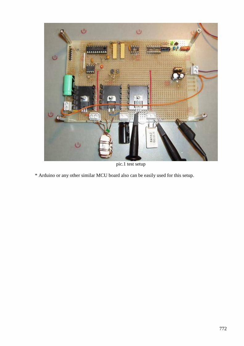
772
pic.1 test setup
* Arduino or any other similar MCU board also can be easily used for this setup.
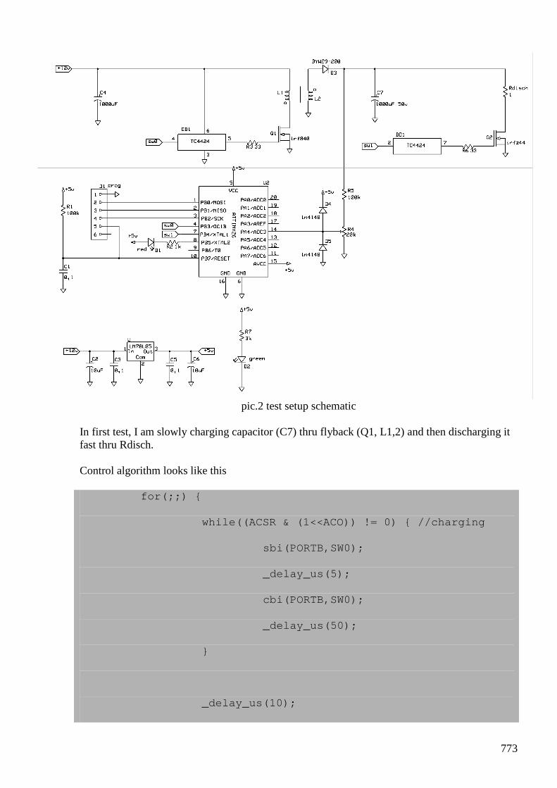
773
pic.2 test setup schematic
In first test, I am slowly charging capacitor (C7) thru flyback (Q1, L1,2) and then discharging it fast thru Rdisch. Control algorithm looks like this for(;;)
while((ACSR & (1<<ACO)) != 0) //charging
sbi(PORTB,SW0);
_delay_us(5);
cbi(PORTB,SW0);
_delay_us(50);
_delay_us(10);
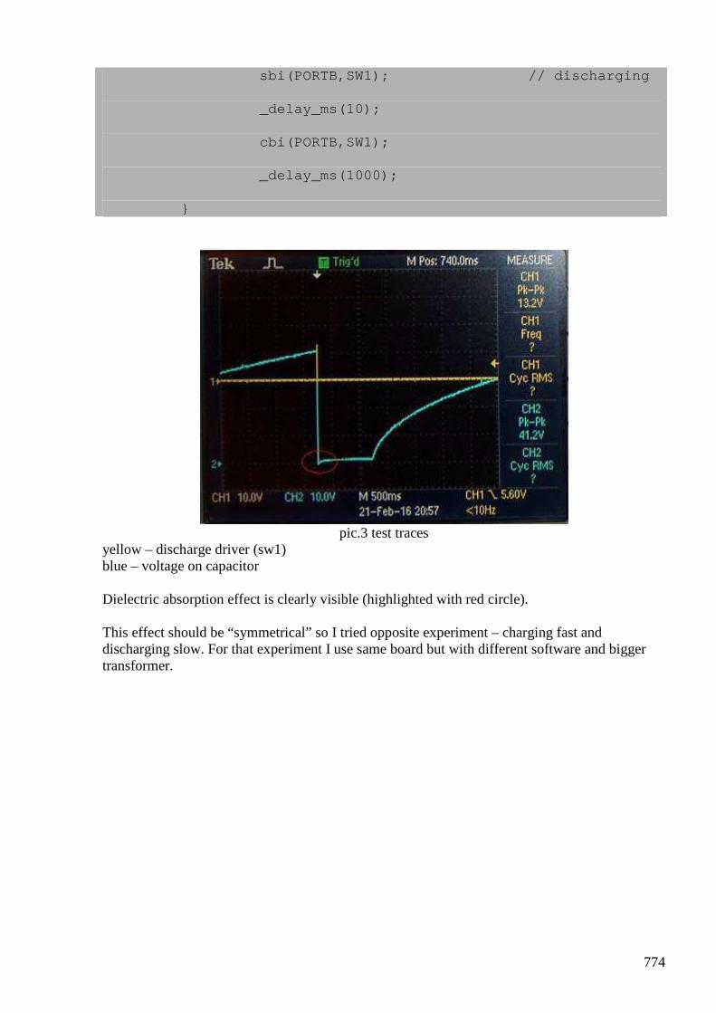
774
sbi(PORTB,SW1); // discharging
_delay_ms(10);
cbi(PORTB,SW1);
_delay_ms(1000);
pic.3 test traces
yellow – discharge driver (sw1) blue – voltage on capacitor Dielectric absorption effect is clearly visible (highlighted with red circle). This effect should be “symmetrical” so I tried opposite experiment – charging fast and discharging slow. For that experiment I use same board but with different software and bigger transformer.
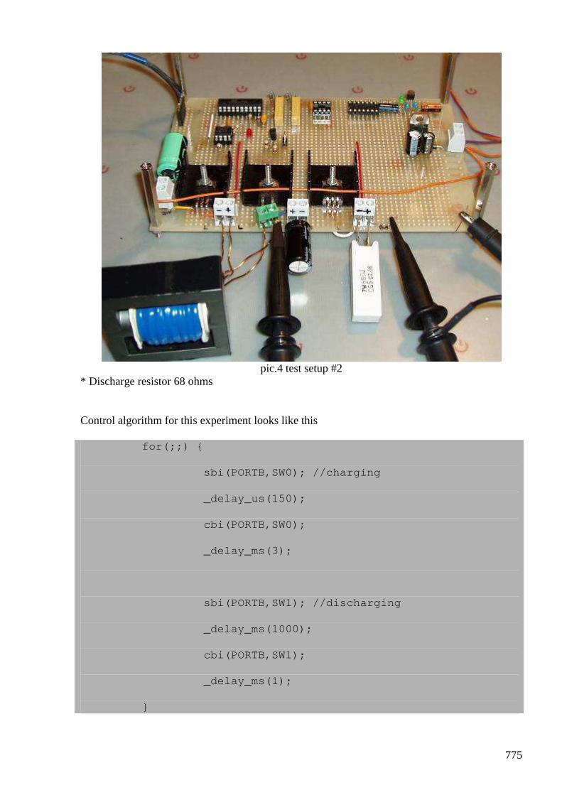
775
pic.4 test setup #2
* Discharge resistor 68 ohms Control algorithm for this experiment looks like this for(;;)
sbi(PORTB,SW0); //charging
_delay_us(150);
cbi(PORTB,SW0);
_delay_ms(3);
sbi(PORTB,SW1); //discharging
_delay_ms(1000);
cbi(PORTB,SW1);
_delay_ms(1);
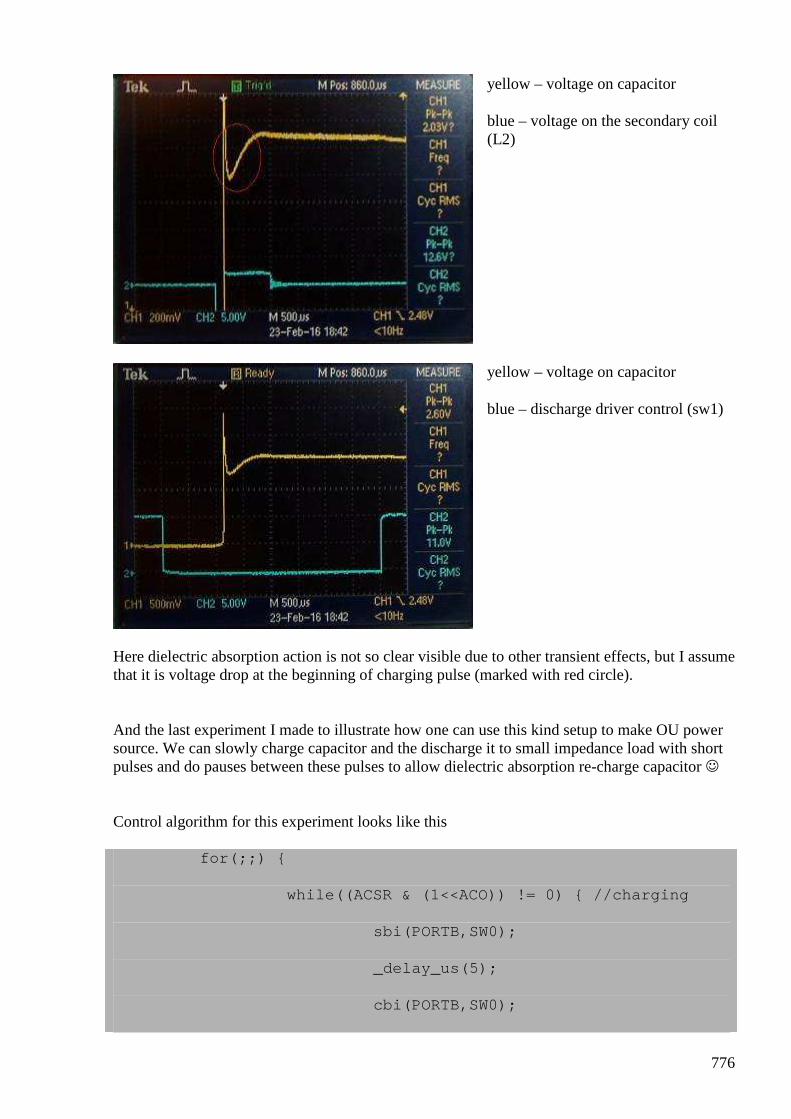
776
yellow – voltage on capacitor
blue – voltage on the secondary coil (L2)
yellow – voltage on capacitor
blue – discharge driver control (sw1)
Here dielectric absorption action is not so clear visible due to other transient effects, but I assume that it is voltage drop at the beginning of charging pulse (marked with red circle). And the last experiment I made to illustrate how one can use this kind setup to make OU power source. We can slowly charge capacitor and the discharge it to small impedance load with short pulses and do pauses between these pulses to allow dielectric absorption re-charge capacitor Control algorithm for this experiment looks like this for(;;)
while((ACSR & (1<<ACO)) != 0) //charging
sbi(PORTB,SW0);
_delay_us(5);
cbi(PORTB,SW0);
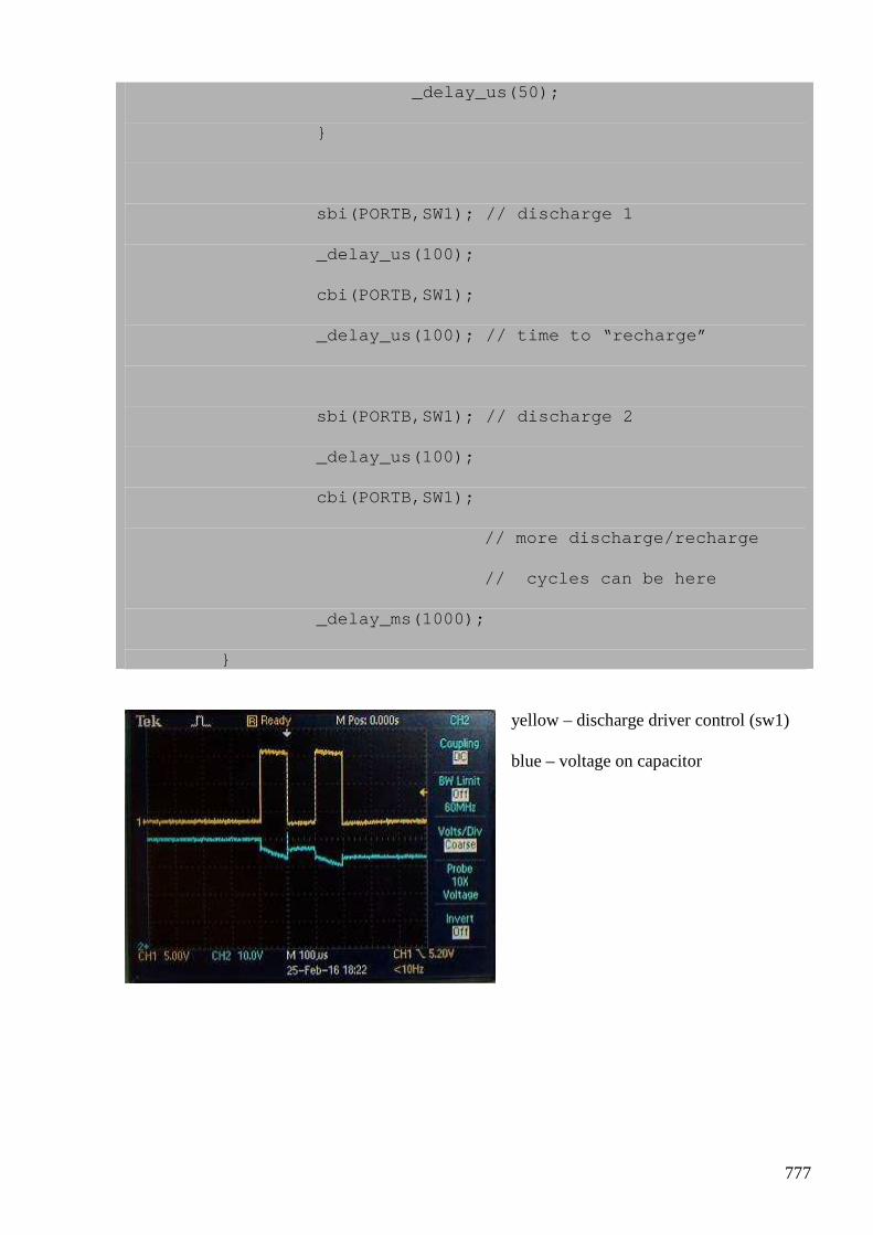
777
_delay_us(50);
sbi(PORTB,SW1); // discharge 1
_delay_us(100);
cbi(PORTB,SW1);
_delay_us(100); // time to “recharge”
sbi(PORTB,SW1); // discharge 2
_delay_us(100);
cbi(PORTB,SW1);
// more discharge /recharge
// cycles can be here
_delay_ms(1000);
yellow – discharge driver control (sw1)
blue – voltage on capacitor
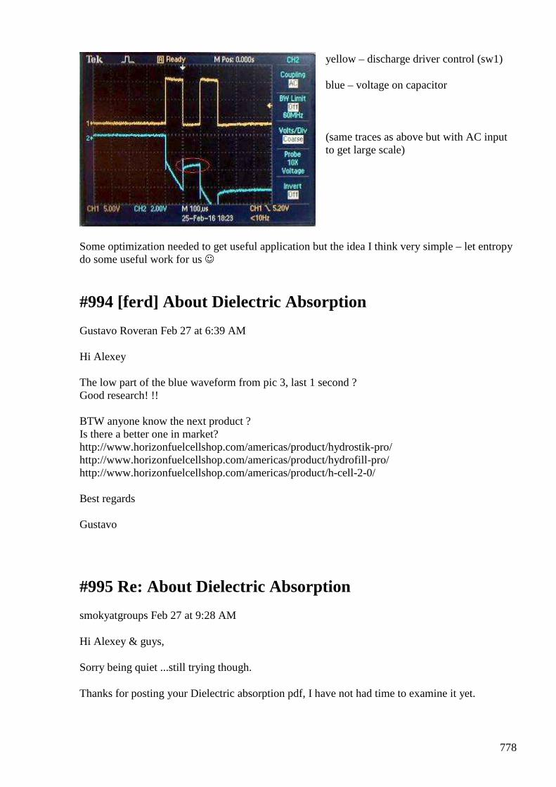
778
yellow – discharge driver control (sw1)
blue – voltage on capacitor
(same traces as above but with AC input to get large scale)
Some optimization needed to get useful application but the idea I think very simple – let entropy do some useful work for us
#994 [ferd] About Dielectric Absorption
Gustavo Roveran Feb 27 at 6:39 AM
Hi Alexey The low part of the blue waveform from pic 3, last 1 second ? Good research! !! BTW anyone know the next product ? Is there a better one in market? http://www.horizonfuelcellshop.com/americas/product/hydrostik-pro/ http://www.horizonfuelcellshop.com/americas/product/hydrofill-pro/ http://www.horizonfuelcellshop.com/americas/product/h-cell-2-0/ Best regards Gustavo
#995 Re: About Dielectric Absorption
smokyatgroups Feb 27 at 9:28 AM
Hi Alexey & guys,
Sorry being quiet ...still trying though.
Thanks for posting your Dielectric absorption pdf, I have not had time to examine it yet.
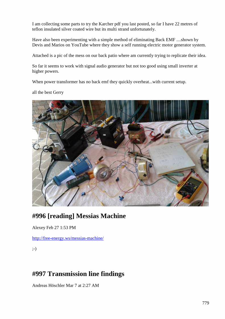
779
I am collecting some parts to try the Karcher pdf you last posted, so far I have 22 metres of teflon insulated silver coated wire but its multi strand unfortunately.
Have also been experimenting with a simple method of eliminating Back EMF ....shown by Devis and Marios on YouTube where they show a self running electric motor generator system.
Attached is a pic of the mess on our back patio where am currently trying to replicate their idea.
So far it seems to work with signal audio generator but not too good using small inverter at higher powers.
When power transformer has no back emf they quickly overheat...with current setup.
all the best Gerry
#996 [reading] Messias Machine
Alexey Feb 27 1:53 PM
http://free-energy.ws/messias-machine/ ;-)
#997 Transmission line findings
Andreas Höschler Mar 7 at 2:27 AM

780
Hi all, nothing special from me but I tried this and that in the lab today and the following transmission line experiments might be worthwhile mentioning though I do not yet know what to do with it.
Just interesting to note!
Best wishes,
Andreas
#998 Re: Transmission line findings
onielsen2000 Mar 7 at 4:08 AM
Hi Andreas, There are lots of experiments to do to study transmission lines (and delay lines). Transmission lines have characteristic impedance. When there are impedance mismatch the waves are split in a forward traveling wave and a reflected wave. If the far end is open the voltage is doubled by super position during reflection at this point while the current is zero at the same point. If the far end is shorted the voltage is zero at this point while the current is doubled. If the far end is terminated with the characteristic impedance of the transmission line the wave travels into the termination resistor and dissipates the power without any reflection. This would be like just adding another piece of the same kind of transmission line to make it longer which makes the wave continue into the next piece without any reflections (provided the connector also has the characteristic impedance of the line. The same rules applies for the input end of a transmission line connected to a signal generator. Regards Ole
#999 Re: [ferd] Transmission line findings
Gerry Sutton Mar 7 at 12:01 PM
Hi Andreas,
Just as Ole says the voltage at any point along the line is the vector sum of the forward and reflected signals at that point.
The signal going forward traditionally has a clockwise rotating vector whilst the reflected signal has a counter clockwise vector.
781
These forward and reflected travelling vectors add & subtract along the line to create stationary "standing waves" at points on the line.
The ratio between the maximum and minimum standing wave voltages can be used to calculate the standing wave ratio as well as V forward and V reflected.
If we take (V max + V min) and divide it by (V max - V min) it gives us the standing wave ratio.
This ratio also exists for max and minimum CURRENTS along the line giving a a current standing wave ratio (iSWR) , at high rf powers coaxial cable can heat up at the current anti nodes even melting the dielectric occasionally.
At the points where high standing volts are measured there is usually minimum current making the impedance at that point very high.
Similarly where standing voltage minimum occurs, the standing current is usually high making impedance at that point very low.
So as a result impedance varies along the line when there's a significant SWR value, interestingly though the Forward and Reflected power along the line is relatively constant at any point (as long as line losses are low).
To complicate matters: the reflected signal from the mismatched load travels back all the way to to the source end of the line again (if line loss is low) and if the source impedance of the generator doesn't match the line impedance.
Then this reflected signal gets re- reflected toward the load after being modified by the reflection co-efficient between the line and the source itself.
If the generator source is a constant voltage source then it's impedance becomes effectively zero impedance.
If it's a constant current source like a FET or a Transistor then it tends toward infinity.
Both these situations allowing the re reflections to finish up being dissipated at the load end of the line after multiple reflection and re reflections.
All this is a very interesting subject utilised in matching stubs transmission line tuned length transformers etc.
It is partly what makes the last Alexey Karcher pdf project loo like a worthwhile one.
Gerry