
Feasibility Study for Vitrification of Sodium-Bearing Waste
550
INEEUEXT-2000-00952 .. NOW 0 I 2000 ? I r - OSTb Feasibility Study for Vitrification of Sodium-Bearing Waste J. J. Quigley B. D, Raivo S. 0. Bates S. M. Berry D. N. Nishioka I? J. Bunnell Published September 2000 Idaho National Engineering and Environmental Laboratory High-Level Waste Department Idaho Falls, Idaho 83415 Prepared for the U.S. Department of Energy Assistant Secretary for Environmental Management Under DOE Idaho Operations Off ice Contract DE-AC07-991D13727
-
Upload
khangminh22 -
Category
Documents
-
view
17 -
download
0
Transcript of Feasibility Study for Vitrification of Sodium-Bearing Waste

INEEUEXT-2000-00952
. . NOW 0 I 2000 ? I
r - OSTb
Feasibility Study for Vitrification of Sodium-Bearing Waste
J. J. Quigley B. D, Raivo S. 0. Bates S. M. Berry
D. N. Nishioka I? J. Bunnell
Published September 2000
Idaho National Engineering and Environmental Laboratory High-Level Waste Department
Idaho Falls, Idaho 83415
Prepared for the U.S. Department of Energy
Assistant Secretary for Environmental Management
Under DOE Idaho Operations Off ice Contract DE-AC07-991D13727

. ..

This report was .prepared as an account of work sponsored by an agency of the United States Government. Neither the United States Government nor any agency thereof, nor any of their employees, make any warranty, express or implied, or assumes any legal liability or responsibility for the accuracy, completeness, or usefulness of any information, apparatus, product, or process disclosed, or represents that its use would not infringe privately owned rights. Reference herein to any specific commercial product, process, or service by trade name, trademark, manufacturer, or otherwise does not necessarily constitute or imply its endorsement, recommendation, or favoring by t h e United States Government or any agency thereof. The views and opinions of authors expressed herein do not necessarily state or reflect those of t h e United States Government or any agency thereof.

DISCLAIMER
. Portions of this document may be illegible in electronic image products. Images are produced from the best available original document.
I

ABSTRACT
Treatment of sodium-bearing waste (SBW) at the Idaho Nuclear Technology and Engineering Center (INTEC) within the Idaho National Engineering and Environmental Laboratory is mandated under a Settlement Agreement between the Department of Energy and the State of Idaho. One of the requirements of the Settlement Agreement is the complete calcination (Le., treatment) of all SBW by December 31,2012. One of the proposed options for treatment of SBW is vitrification. This study will examine the viability of SBW vitrification.
This study describes the process and facilities to treat the SBW, from beginning waste input from the INTEC Tank Farm to the final waste forms. Schedules and cost estimates for construction and operation of a Vitrification Facility are included. The study includes a facility layout with drawings, process description and flow diagrams, and preliminary equipment requirements and layouts.
iii

.
iv

EXECUTIVE SUMMARY
Treatment of sodium-bearing waste (SBW) at the Idaho Nuclear Technology and Engineering Center (INTEC) at the Idaho National Engineering and Environmental Laboratory (INEEL) is mandated under a Settlement Agreement between the Department of Energy (DOE) and the State of Idaho. One of the requirements of the Settlement Agreement is the complete calcination (i.e., treatment) of all SBW by December 31,2012. One of the proposed options for treatment of SBW is vitrification. This study will examine the viability of SBW vitrification.
This study describes the process and facilities to treat the SBW, from beginning waste input from the INTEC Tank Farm to the final waste forms. Schedules and cost estimates for construction and operation of a Vitrification Facility are included. The study includes a facility layout with drawings, process description and flow diagrams, and preliminary equipment requirements and layouts.
Time constraints for financing, permitting, technical development, design, construction, and startup testing extend the start of SBW processing to January 1, 2013. The anticipated completion date for SBW treatment is December 31, 2014. A 2-year operation schedule was chosen to complete processing as quickly as possible. The melter and off-gas system are large enough to treat all calcine waste by the Settlement Agreement milestone of 2035.
Facility Siting and Layout
The SBW facility is sited near the northeast comer of INTEC. Installation of a direct transfer route from the SBW storage tanks WM-180, WM-181, WM- 187, and WM-188 would be optimal. The SBW process area will be a multistory structure with a footprint of approximately 380 x 169 ft. The physical structure will extend 32 ft below finished grade and approximately 70 ft above finished grade. The Administrative/Support area will be a single-story structure with a footprint of approximately 190 x 70 ft. This structure will be located at grade level and adjacent to the SBW process area.
The process area of this facility will be constructed of a concrete superstructure that extends approximately 50 ft abovegrade level. The cell walls will consist of 3-ft-thick concrete extending to support a formed, cast-in-place concrete roof with removable hatches for overhead maintenance and equipment removalheplacement. A bridge crane will be installed above to accommodate hatch cover removal and equipment removal. Process equipment cell walls will consist of 3-ft-thick, concrete walls and will extend 32 ft belowgrade level forming the foundation walls. Operating corridor perimeter walls will be constructed of reinforced concrete to 32 ft belowgrade level. All horizontal process separations, i.e., ceiling-floor and hatch structures will consist of 3-ft-thick reinforced concrete.
Stainless steel (SST) surfaces will be applied to all cells of the process areas. The lining for the floors will be 1/4-in.-thick SST; all other surfaces will be lined with 1/8-in.-thick SST.

An engineered metal building system will be used for the administrative area. The floors will consist of 6-in.-thick reinforced concrete, slab on grade. Concrete grade beams and isolated column spread footings will support the structural steel frame of the building.
Occupancy Classification
The SBW Vitrification Facility is classified as a UBC Group H, Division 7/Group By Mixed Occupancy. The H-7 occupancy applies to buildings or portions thereof utilized for storage, or handling of materials that constitute a high health hazard. This area includes the central core of the facility contained within the shielding walls on all floors. The process equipment canyon, pump and valve corridor, the maintenance areas, canister filling and capping, welding, and decon areas are some of the major areas.
The Group B Mixed Occupancy applies to building or portions thereof used for office, laboratories, etc. that are not classified as Group H for hazardous materials. This area includes the abovegrade portion of the building that is outside of the shielding walls (office/administrative areas, mechanical, HVAC, electrical, communications rooms, etc).
Remote Operations
The SBW Vitrification Facility will feature remote handling operations for processes and tasks that cannot be provided by a direct hands-on approach due to high radiation fields and/or high contamination areas. The basic approach will be to have the Vitrification Facility divided into a canyon and a remote service corridor (RSC) configuration for the purposes of remote maintenance activities.
The canyon approach will be used for those large vessels and equipment that typically have long intervals between maintenance actions (>5-10 years). These items will be located in a concrete-shielded enclosure structure that is accessed by shielded hatch covers when maintenance activities are required.
The remote service comdor approach will be used for pieces of equipment that require nkintenance and/or replacement at periodic intervals (c5-10 years) and that can be located away from the actual vessels being served by this particular equipment. The type of equipment that typically would be located in the RSC include valves, pumps, and instrumentation that can be located away from the tank vessels located in the canyon area. In the RSC approach, jumper assemblies with the included piece of equipment (e.g., pump, valve, instrument) using a standard 3-bolt flange system interfaces with vertical wall-mounted flanges of corresponding size to complete a circuit. The jumper assemblies will be remotely removed from service by remotely operated in-cell (in the corridor) crane and wall-mounted electro-mechanical (PaR) manipulator.
Process
SBW is transferred from the Tank Farm Facility (TFF) at INTEC to a workoff storage tank located within in the Vitrification Facility. This tank provides a 12-day storage supply of raw SBW. Sugar and frit are added to the
vi

SBW and formed into a slurry within one of four mix tanks. The mixture is then sampled and analyzed to form a qualified feedstream, adjustments are made to the mixture if necessary. The mix tank capacity provides a 2-3 day workoff storage with a 6-day sample and analysis feedback t i m e h e . The qualified feed is transferred to one of two feed tanks and is controlled as qualified processing feed material. This mixture is then fed into a joule-heated borosilicate glass melter. Water is evaporated from the mixture and the solids including all SBW undissolved solids (UDS) are formed into a borosilicate glass. The glass is then discharged into stainless steel canisters and sealed with welded lids. This process creates a contained glass waste which is suitable for disposal at either the Waste Isolation Pilot Plant (WIPP) or Yucca Mountain. Radiation levels of the glass canisters are estimated to be approximately 65 rendhour.
The Vitrification Facility will be capable of treating not only about one million gal of SBW, but also newly generated liquid waste (NGLW) and the estimated 45,000 gal of sludge from the closure of the TFF. The facility has sufficient melter size and off-gas capacity to vitrify calcine with a new feed and mixing system.
Off-gas from the melter will be high in NOx, water vapor, and CO. The off-gas will also contain halogen contaminants chlorine and fluorine as well as mercury vapor and other unknown toxic or heavy metals. The off-gas is treated by secondary thermal treatment prior to entering an off-gas cleansing system. The secondary thermal treatment consists of a three-stage combustion process. The first stage consists of high temperature 1,220'C (2,200OF) treatment under reducing conditions for 2 seconds residence time. The goal for the first stage is to strip off the oxygen from the NO, and reduce to N2. Mercury compounds such as HgO and HgC12 are anticipated to be dissociated into elemental mercury vapor. The halogens (chlorine and fluorine) will pass through the first stage in the gaseous state.
In the second stage, the off-gas is partially quenched to a temperature below the auto-ignition temperature of the gas (nominally 1,4OO0F) in a water or steam quench section. Gas exiting stage two then enters stage three.
Stage three is controlled to complete the combustion of CO and H2 in the off-gas while minimizing NO, reformation. This is accomplished via injecting air to initiate auto-ignition of the gases, CO and H2. The temperature in the third stage tends to float and is established by the combustion potential of the gas stream. The air injected is controlled to minimize excess oxygen. The goal is to provide an Nz-rich exit gas stream with minimal NO,. Halogens (chlorine and fluorine) and mercury are anticipated to pass .through the third stage in the gaseous state.
From stage three, the gas enters a quick quencher that reduces the temperature of the off-gas exiting the thiid stage from >1,540°F to a temperature of approximately 180-1 85°F. The quenching action is anticipated to minimize the recombination of Hg and 0 2 in the off-gas from the multi-stage combustion denitrator, and also minimize the potential reformation of dioxins/furans from pre-cursors in the feed stream. The quench process will tend to remove large

particulates from the gas stream to the quench water and act as a first stage of off-gas cleaning.
Subsequent cleaning of the off-gas includes a gas handling system and a liquid side scrub solution system. The gas-to-liquid interface includes the quench tower and a wet scrubber, which remove particulates and water-soluble gases, including halogens. Scrubbing liquid is provided by and returns back to the scrub solution system. The gas side system includes a scrubber with knockout drum, a demister with knockout drum, a gas reheater, HEPA final filters, and granulated activated carbon polishing filters. The granulated activated carbon (GAC) beds (sulfur impregnated) are anticipated to remove elemental mercury from the off-gas. Periodically, the GAC beds will be sent to an outside contractor, such as Envirocare, for mercury recovery and disposal. This completes the disposition of the mercury cycle. Bulk nitrogen gas (N2) with very little NOx is anticipated to exit the carbon beds and be released through the stack. This completes the disposition of the nitrogen contained in the original SBW feed stream.
The scrubbing action of the off-gas cleanup system will remove particulate and other contaminants, which will then be entrained in the liquid. The scheme includes settling of sludge and recycling of scrubbed residue back to the inlet feed stream in the mix tank. The recycling will allow re-incorporation of the contaminants back into the glass product. Mercury particles or soluble compounds in the sludge are then recycled back to elemental mercury in the melter and multi-stage combustor for subsequent partitioning to the gas stream for removal by the activated carbon beds.
Scrub liquid is also removed from the settling tank as blowdown. The liquid passes through a prefilter to remove any entrained particulate and then enters an ion exchange column. The ion exchange system uses alkali metal alumino silicate ion exchange media to remove cesium and strontium from the blowdown. This ion exchange media is also recycled back to the mix tanks. The effluent is then stored and periodically grouted as low-level waste. Approximately 3% of the cesium is expected to volatilize in the melter and be partitioned to the off-gas and scrub system. It is anticipated that the majority of this cesium will be captured by the scrub system and recycled back to the melter for incorporation into the glass.
Waste Form Qualification
The basic Waste Form Qualification (WFQ) strategy has been utilized at the Defense Waste Processing Facility (DWPF) at Savannah River Site and the West Valley Demonstration Projeit. This WFQ strategy is based on the concept that a well-defined and controlled feed stream processed through a well-defined and controlled treatment process will produce a qualified waste form. This qualified waste form will not need to be sampled or tested except on a very limited basis during operation.
The relationship between process control and waste form qualification overlap. The canisters of glass are assumed to be going to the Yucca Mountain repository. The drums of grout are assumed to be contacted handled and will be
' I
' I
. I
I
... Vll l

sent to WlPP if the grout waste form has contains more than 100 nCi/g TRU or some other waste site (e.g. Hanford) if less than 100 nCi/g TRU. Because the canisters of vitrified waste and the grout drums are assumed to be going to different repositories (Yucca Mountain and WIPP respectively), the waste form qualification requirements will be different. However, the basic qualification strategy will be the same for both waste forms.
The process for implementing the WFQ strategy entails the following major tasks:
Development of a qualified waste form compositional envelope. A range or envelope of waste form compositions for both the glass and grout waste forms will be developed.
Development testing, nonradioactive facility testing, and radioactive facility testing for process qualification. The treatment process will be qualified so that when a qualified feed is added to the treatment process and is operated within established parameters, the glass produced will be acceptable.
Operational Control and Documentation. Once a qualified compositional envelope and process are established, facility operations will be conducted so that no waste is processed outside of these boundaries.
Cost Estimate
As currently envisioned, this facility consists of a processing building measuring approximately 380 x 169 ft at grade level, with basement levels extending 32 ft belowgrade and roof elevation at 75 ft. In addition to the main processing building, there are two truck bays attached, one measuring 80 x 40 f t and one measuring 30 x 20 ft. The office area measures 189 x 68 ft with an assumed eave height of 14 ft. The boiler building is a concrete masonry unit (CMU) building measuring 60 x 52 x 30 ft high.
The Total Project Cost is presented in Table El. This cost includes Conceptual Design costs, Project Support costs, Permitting costs, Construction Management costs, Engineering costs, Quality Assurance costs, Project Management costs, direct and indirect construction costs, System OperatiodStartup costs, Procurement Fee, G&A, escalation and contingency. The cost for an interim storage facility and for storage are not included in this study.
Table El. Total project costs.
Estimate Element Estimate Subtotal Escalation Contingency Total
Total Estimated Cost (TEC) $321,252,222 $87,927,984 $173,048,352 $582,228,558
Other Project Costs (OPC) $78,935,317 $171107,921 $59,413,968 $155,457,206 & Total Pro'ect Cost (TPC) $105,035,905 $232,462,320 $737,685,764

Issues and Recommended Studies
Section 12 of the report discusses requirements, uncertainties, and issues. The following items should be addressed in subsequent studies and design efforts.
0 Disposal at WIPP
It is assumed that either the SBW will be delisted for U134 (uncomplexed hydrofluoric acid, HF) or that the U134 waste code will be added to the WIPP WAC. Another assumption is that the incidental waste ruling for SBW will be that it is not HLW. Both of these assumptions impact whether the vitrified SBW can be accepted at WIPP. The delisting of SBW for U134 or the addition of U134 to the WIPP WAC must be vigorously pursued. Failure to obtain one or the other will result in the vitrified waste not being accepted at WIPP. The incidental waste ruling for SBW has been requested. However, the ruling has not yet been made. If SBW is ruled to be HLW, the glass waste will be disposed of at Yucca Mountain rather than WIPP.
Radiological
During the conceptual design of the Vitrification Facility, additional radiological assessments must be made. Preliminary evaluations of radiation levels in the Vitrification Facility have been made to determine appropriate wall thickness and personnel protection requirements. As the design is developed, this issue should be re-evaluated to verify the radiation exposure levels to operating personnel.
0 MaterialBalance
The material balance will need to be revised as information from additional studies becomes available. Issues of concern include sugar chemistry, mercury speciation, decontamination factor (DF) for species in the melter and off-gas systems, and off-gas chemistry.
0 Grout Recipe
The grout recipe for solidification of the scrubber blowdown needs to be tailored to the composition of the blowdown.
Multi-Stage Combustor
' I
. I
Actual operational data is needed for the multi-stage combustor with gas streams similar to the off-gas from the melter. Data needed includes efficiency and reliability. Operation should evaluate the use of water vs steam for the Stage 2 quench. Stage 3 combustion should be evaluated at low excess oxygen conditions.
X

0 Operating 'Conditions
The temperature of the SBW and SBW mixtures must be maintained below 60°C until the SBW feed enters the melter. The high concentrations of chlorides in the SBW will cause severe stress cracking and corrosion issues above 60"C, based on historical experience at INTEC.
Operating Life
The lifetime of the plant is assumed to be 2 years. Increases in assumed lifetime may require additional margins to be included in the design of the piping (e.g. corrosion and erosion allowances or design for remote replacement).
Characterization of SBW
Additional characterization of SBW is needed for the conceptual design. Further characterization of the UDS in the SBW is required. There are some elements that even small amounts (>0.5 wt% in the glass) have significant melter processing impacts. Noble metals, S, P, are some elements that should be tested for.
0 . Ion Exchange Media for Cesium Removal
The ion exchange media chosen for removal of cesium and strontium are UOP IONSlV@ E-95 and A-51 respectively. The alkali metal, alumino-silicate ion exchange media are compatible with the melter and frit used for vitrification of SBW. Cesium and strontium (and their daughter products Ba-137m and Y-90) have the highest concentration levels of the radionuclides in the scrub blowdown. Cesium is a gamma emitter and is removed from the blowdown to reduce the radiation levels of the grout to contact-handled material. Strontium is a beta emitter, which is a strong contributor to the heat emission due to radioactive decay.
Other ion exchange media are available for removal of cesium from the scrub blowdown. UOP IONSIV@ E-91 1 is a crystalline silicotitanate (CST) with a high affinity for cesium, even in the presence of high concentrations of sodium and acid. The absorption of cesium on the sorbent is virtually irreversible. CST will also remove strontium from liquid waste; however, strontium can be stripped from the media.
The choice of ion exchange media should be re-evaluated based on the results of off-gas and scrubber characterization studies for SBW.
Water Reduction in SBW
Evaporation of water from the SBW in the SBW storage tank, the mixing tanks, or the feed tanks would decrease the electrical requirements and increase the efficiency of the melter. However, evaporation would increase the stresdcorrosion effects of chlorine. Also, the temperature in the tanks would need to be maintained less that 60°C to reduce the corrosion rate. Added margin
xi

for stress-cracking concerns are accomplished by using a higher-grade material for the tanks such as Nitronic 50.
Mercury Speciation
A better understanding of mercury speciation in the melt, the combustor, and in the scrub system is needed. Studies should be conducted to determine the amount of mercury which remains in the glass and the amount partitoning to the different systems.
0 Elemental Mercury Adsorption in Off-Gas
A study should be performed on the adsorption of elemental mercury from the off-gas of the melter to determine the best adsorbent and optimal conditions.
Slurry Characteristics
The characteristics of the feed slurry are unknown. The assumption is that the mixture can be maintained as slurry sufficient for homogeneous mixing with adequate pumping and material transfer capabilities. However, the solids and real case characteristics may present unknown difficulties both for in-tank mixing and material transfer (pumping).
0 SugarAddition
The scope of work for the feasibility study calls for the addition of sugar to the SBW and frit as part of the melter feed. The sugar is added to reduce the oxidation potential of the glass melt to control foaming of the molten glass. The nitric acid from the SBW will react with sugar to produce heat and N2, NO,, CO, COz, and HzO The interactions between sugar and nitric acid waste have been previously studied. However, experiments are needed to determine the stability of the sugarhitric acid solution, the potential for an increased risk of flammability or explosion potential from reaction products, and the potential for use of other reductants.
Melter Operation and Decontamination Factors
The method of control of melter and multi-stage combustor system component pressures needs to be reviewed. The design goal is to create a very homogeneous feed stream within the mix and feed tanks prior to entry into the melter. This will help to minimize potential for fluctuations. The effects of high alkali level waste (Na) feeds should be evaluated. The use of an evaporator in the SBW Work-off Tank or between the Work-off Tank and the mixing tanks should be investigated. The addition of nitric acid waste feed with a high percentage of water presents special design challenges. Successful resolution of these challenges will benefit from detailed design modeling for transient heat transfer and fluid flow, as well as thermophysical and chemical reaction modeling. The effects of inlet geometry and feed distribution on the melt should be investigated.
. I
xii

Off-Gas and Scrubber Characterization
Further research must be performed to measure the off-gas and scrubber concentrations for constituents of concern. Particulate size distribution within the gas stream should be determined for the design of the scrubbing system. The effect of the pH and temperature of the scrub solution on scrubbing efficiency and scrub system materials is needed. Experiments on melter off-gas using GAC for mercury removal are needed to determine the optimal residence time and bed loading. Acid gases in the gas stream may liberate hydrogen sulfide (HZS) gas, with subsequent damage to the beds and additional potential safety problems for dealing with this gas. Experiments should be performed to optimize gas scrubbing and HEPA filter life.
Facility Siting Study
A siting study should be performed to determine the optimal placement of the Vitrification Facility. The study will review the impacts of this facility on site utilities and the surrounding infrastructure. The study will encompass topography, existing soil conditions, subsurface rock formations, and road and structure locations both above and below ground level.

XiV

ACKNOWLEDGMENTS
The following team of people made significant contributions of their time and expertise to this study. Their work is reflected throughout this report and its appendices:
R. D. Adams
V. J. Balls
S. 0. Bates
J. L. Benson
S . M. Berry
P. J. Bunnell
C. G. Cox
J. C. Dobbins
R. R. Kimmitt
L. Le
W. E. May
J. L. Moncur
.D. N. Nishioka
B. C. Norby
H. K. Peterson
J. J. Quigley
B. D. Raivo
S. J. Reese
R. J. Turk
Schedule and Construction Cost Estimate
Project Engineer
Melter Technology and Sampling Strategy
W A C Design
Remote Systems Design
Electrical Instrumentation and Controls
Remote Camera Placement
Remote Sample Stations
Material Balance, ViMication Expertise
Electrical Power Design
Technical Editor
Drafting and Facility Layout
AE Facility Design, Floor Plans, Manloading
Materials Selection
Radiation and Shielding Calculations
Technical Team Lead, Material Balance, Process Design
Mechanical Process Design
Mechanical Engineering Support
Life Cycle Cost Estimate

' I
xvi

CONTENTS
.
.
1 . INTRODUCTION ................................................................................................................. 1
2 . DESIGN BASIS AND ASSUMPTIONS ............................................... L. .............................. 2
2.1
2.2
2.3
2.4
Design Basis ............................................................................................................... 2
Assumptions ............................................................................................................... 3
2.2.1
Regulatory Requirements ............................................................................................ 6
Scope of Work ............................................................................................ 3 2.2.2 Consensus Assumptions .............................................................................. 4
Functional and Operational Requirements ................................................................. 6
2.4.1 Siting Requirements .................................................................................... 6 Facility Interface Requirements .................................................................. 6
2.4.3 Functional Requirements ............................................................................ 6 2.4.4 ArchitecturalEngineering Requirements .................................................... 6 2.4.5 Waste Storage and Handling Requirements ................................................ 7 2.4.6 WTPP WAC ................................................................................................. 7 2.4.7 Yucca WAC ................................................................................................ 8
WASTE DESCRIPTION .................................................................................................... 13
3.1 HLW-Glass Canisters ............................................................................................ 13
2.4.2
3 .
3.1.1 Waste Volume ........................................................................................... 13
3.1.3 Radiological Composition ......................................................................... 15 3.1.4 Radiation Levels ....................................................................................... 16 3.1.5 Disposal Site ............................................................................................. 16 LLW - Grout ............................................................................................................ 16
3.1.2 Chemical Composition .............................................................................. 13
3.2
3.2.1 Waste Volume ........................................................................................... 16 3.2.2 Chemical Composition .............................................................................. 16 3.2.3 Radiological Composition ......................................................................... 18 3.2.4 Radiation Levels ....................................................................................... 19 3.2.5 Disposal Site ............................................................................................. 19 LLW-Ion Exchange Zeolite ................................................................................... 20 3.3
3.3.1 ChemicaVPhysical Properties .................................................................... 20 3.3.2 Radiological Composition ......................................................................... 21 3.3.3 Disposal Site ............................................................................................. 21
3.4 LLW - Activated Carbon ......................................................................................... 21
3.4.1 Physical and Chemical Properties ............................................................. 21 3.4.2 Radiological Considerations ..................................................................... 22 3.4.3 Disposal Site ............................................................................................. 22
3.5 Wastewater ............................................................................................................... 22

...... L
4 .
5 .
6 .
PROCESS DESCRIPTION ................................................................................................. 23
4.1
4.2
4.3
4.4
4.5
4.6
SBW Feed System .................................................................................................... 23
4.1.1 SBW Feed ................................................................................................. 23 4.1.2 Flow Rate .................................................................................................. 24 4.1.3 Piping ........................................................................................................ 24 4.1.4 Pumps ........................................................................................................ 24 4.1.5 Storage Tanks ............................................................................................ 24 SBWlFritISugar Mixing ............................................................................................ 24
4.2.1 Frit Feed .................................................................................................... 24
4.2.3 Mixing Tanks ............................................................................................ 26 4.2.4 Feed Tanks ................................................................................................ 26 4.2.5 Pumps ........................................................................................................ 26
Vitrification Unit ...................................................................................................... 27
4.2.2 Sugar Feed ................................................................................................. 25
4.2.6 Piping ........................................................................................................ 26
4.3.1 Melter ........................................................................................................ 27 4.3.2 Melter Operation ....................................................................................... 27 4.3.3 Feed Inlet ................................................................................................... 28 4.3.4 Glass Taps ................................................................................................. 28 Off-Gas System ......................................................................................................... 29
4.4.1 Multi-stage Combustor ............................................................................. 29 4.4.2 Quench ...................................................................................................... 30 4.4.3 Venturi Scrubber ....................................................................................... 31 4.4.4 Mist EliminatorKnockout Drum .............................................................. 32 4.4.5 Off-Gas Heater .......................................................................................... 32 4.4.6 HEPA Filters ............................................................................................. 32 4.4.7 Activated Carbon/Sulfur Absorbent .......................................................... 32 Scrubber Wastewater ................................................................................................ 32
4.5.1 Scrub Recycle ........................................................................................... 33 4.5.2 Scrub Blowdown ....................................................................................... 33 Grout Liquid Waste .................................................................................................. 33
SAMPLING STRATEGY .................................................................................................. 34
5.1 Waste Form Qualification ......................................................................................... 34
5.2 Regulatory Requirements ......................................................................................... 35
5.3
5.4 Sampling Hardware .................................................................................................. 40
5.5 Changes in Sampling and Analysis for WIPP .......................................................... 43
REMOTE SYSTEMS ......................................................................................................... 45
Sample Locations and Matrix ................................................................................... 36
' I
xviii

6.1 Remote Handling and Operations ............................................................................. 45
..
.
6.2 Remote Maintenance Philosophy and Systems ........................................................ 46
6.2.1 6.2.2
Remote Maintenance Philosophy .............................................................. 46 Remote Maintenance Systems .................................................................. 46
6.3 Mochps ................................................................................................................... 51
6.3.1 Maintenance Requirements ....................................................................... 51 Remote Equipment Change/Cut-upDisposal Scenarios ........................... 52 6.3.2
Remote Decontamination Systems ........................................................................... 53 6.4
6.4.1 Decontamination Philosophy and Operations ........................................... 53 7 . MECHANICAL SYSTEMS ............................................................................................... 57
7.1 Container Fill System ............................................................................................... 57
Empty Canister Handling System ............................................................. 57 7.1.1 7.1.2 7.1.3
Canister Fill System .................................................................................. 57 Full Canister Handling System ................................................................. 58
7.2 Cranes ....................................................................................................................... 59
8 . FACILITY DESCRIE'TION ................................................................................................ 60
8.1
8.2
8.3
8.4
8.5
8.6
Civil .......................................................................................................................... 60
8.1.1 Siting ......................................................................................................... 60 8.1.2 Physical Protection .................................................................................... 60 8.1.3 Underground Utilities ............................................................................... 60 8.1.4 Site Demolition ......................................................................................... 60 8.1.5 Site Improvements, Pavement ................................................................... 60 Architectural Requirements ...................................................................................... 61
8.2.2 Facility Layout .......................................................................................... 61
8.2.4 Abovegrade Features ................................................................................. 61
8.2.1 General ................................................................................ ..................... 61
8.2.3 Belowgrade Features ................................................................................. 61
Structural Features .................................................................................................... 62
8.3.1 General ...................................................................................................... 62 Occupancy Classification ......................................................................................... 62
8.4.1 General ...................................................................................................... 62 Structural Features .................................................................................................... 63
8.5.1 General ...................................................................................................... 63 Building W A C ........................................................................................................ 63
8.6.1 8.6.2 8.6.3
Heat Recovery Systems ............................................................................. 67 Heating loads and steam requirements ...................................................... 67 Ventilation Fans. hp .................................................................................. 68
........ - I .. I - _. ....... _i-.---.-~ .

'..
8.7
8.8
8.9
8.10
8.11
8.12
8.6.4 Cooling. Compressor and Fan hp .............................................................. 69 Electrical ................................................................................................................... 70
8.7.1 Requirements ............................................................................................ 70 8.7.2 Power Requirements ................................................................................. 72
8.7.4 Design Description .................................................................................... 74 8.7.5 Utility Control System and Fiber-optic Cable .......................................... 75 Instrumentation and Control ..................................................................................... 76
8.7.3 Lighting ..................................................................................................... 73
8.8.1 Control System Software for Man-Machine Interface .............................. 77 8.8.2 Instrumentation ......................................................................................... 77 8.8.3 8.8.4 Support Utilities ........................................................................................ 78 8.8.5 Telecommunications ................................................................................. 79 8.8.6 Security Equipment ................................................................................... 79
Computer Hardware and Software ............................................................ 78
Steam Facility ........................................................................................................... 79
Fire Protection Systems and Equipment ................................................................... 80
Utility Control System and Fiber-optic Cable .......................................................... 80
Vitrification Facility StafFng .................................................................................... 81
9 . ESTIMATED COST ....................................................................................... ................... 83
9.1 Planning Cost Estimate ............................................................................................. 83
9.1.1 Basis .......................................................................................................... 83 9.1.2 Assumptions .............................................................................................. 83 9.1.3 Contingency .............................................................................................. 84
9.2 Life-Cycle Cost Estimate .......................................................................................... 84
PROJECT SCHEDULE ...................................................................................................... 86 10 .
11 . REQUIREMENTS AND ASSESSMENTS ........................................................................ 87
11.1 Disposal at WIPP ...................................................................................................... 87
11.2 Radiological .............................................................................................................. 87
11.3 Material Balance ....................................................................................................... 87
11.4 Grout Recipe ............................................................................................................. 87
11.5 Multi-Stage Combustor ............................................................................................ 87
11.6 Operating Conditions ................................................................................................ 88
Temperature of SBW ................................................................................ 88 UNCERTAINTIES & ADDITIONAL STUDIES .............................................................. 89
11.6.1 12 .

12.1
12.2
Open Issues ............................................................................................................... 89
12.1.1 Operating Life ........................................................................................... 89 12.1.2 Characterization of SBW .......................................................................... 89 12.1.3 Ion Exchange Media for Cesium Removal ............................................... 89 12.1.4 Water Reduction in SBW .......................................................................... 89 Required Studies ....................................................................................................... 90
3
..
12.2.1 Mercury Speciation ................................................................................... 90 12.2.2 Elemental Mercury Adsorption in Off.Gas ............................................... 90 12.2.3 Slurry Characteristics ................................................................................ 90 12.2.4 Sugar Addition .......................................................................................... 90 12.2.5 Melter Operation and Decontamination Factors ....................................... 91 12.2.6 Off-Gas and Scrubber Characterization .................................................... 91 12.2.7 Other W.aste Streams ................................................................................. 92 12.2.8 Facility Siting Study .................................................................................. 92
13 . REFERENCES .................................................................................................................... 93
Appendix A - S B W Composition
Appendix B-Flow Sheet and Material Balance
Appendix C-Schedule
Appendix D-Total Project Costs
Appendix E-Life-Cycle Cost Estimate
Appendix F-wui pment List
Appendix G-Sketches
Appendix H-Engineering Design Files
Appendix I P o d e s and Standards
Appendix J-Vendor Data
FIGURES
Figure 1 . West Valley waste vitrification system. ...................................................................... 28
Figure 2 . Multistage combustor process flow diagram (top) and process illustration ............... 29
Figure 3 . Particulate removal equipment efficiencies ................................................................ 31
Figure 4 . Projected INTEC thermal energy demands, FY-00 through FY-40 ........................... 80

TABLES
Table El . Total project costs ....................................................................................................... ix
Table 1 . WIPP remote-handled WAC .......................................................................................... 7
Table 2 . Yucca Mountain waste acceptance criteria summary ..................................................... 8
Table 3 . Carryover of chemical species ...................................................................................... 13
Table 4 . Chemical composition of vitrified waste ...................................................................... 14
Table 5 . Percent radionuclide carryover in off-gas ..................................................................... 15
Table 6 . Radionuclide composition of vitrified waste ................................................................ 15
Table 7 . Grout containers ............................................................................................................ 16
Table 8 . Grout recipe .................................................................................................................. 16
Table 9 . Chemical composition of grout ..................................................................................... 17
Table 10 . Radiological composition of grout ............................................................................. 18
Table 11 . Radiological characteristics of grout .......................................................................... 19
Table 12 . Grout TCLP expectations ........................................................................................... 19
Table 13 . Volume of ion exchange media E-95 and A-51 ........................................................ 20
Table 14 . Amount of cesium and strontium in ion exchange media .......................................... 21
Table 15 . Off-gas compositions .................................................................................................. 21
Table 16 . Composition of SBW ................................................................................................. 23
Table 17 . Frit composition .......................................................................................................... 24
Table 18 . Multi-stage combustor gas compositions ................................................................... 30
Table 19 . Sampling matrix ......................................................................................................... 37
Table 20 . Sample stations ........................................................................................................... 41
Table 21 . Crane list ..................................................................................................................... 59
Table 22 . Room and zone requirements ..................................................................................... 65
Table 23 . HVAC equipment list ................................................................................................. 66
Table 24 . HVAC static pressure drop ......................................................................................... 68

Table 25. W A C zone horsepower requirements ....................................................................... 68
Table 26. Cooling loads .............................................................................................................. 70
Table 27. Connected load. .......................................................................................................... 71
Table 28. Demand load ............................................................................................................... 71
Table 29. Standby power requirements. ..................................................................................... 72
Table 30. Instrumentation and controls equipment. ................................................................... 77
Table 31. Personnel loading. ...................................................................................................... 81
Table 32. Total project costs ....................................................................................................... 83
Table 33. Project schedule .......................................................................................................... 86

xxiv

ACRONYMS
AJE
AHU
ALm
Btu
CCTV
CEM
Cfm
CH
CMA
CMU
CFR
CRWMS
CSIX
CST
D&D
DCS
DF
decon
DWPF
DOE
ECS
EUSU
G&A
GAC
H&R
Architectural/Engheering
air handling units
as low as reasonably achievable
british thermal unit
cell closed-circuit television
continuous emissions monitor
cubic feet per minute
contact-handled
Crane Maintenance Area
concrete masonry unit
Code of Federal Regulations
Civilian Radioactive Waste Management System
cesium ion exchange
crystalline silicotitanate
decontamination and decommissioning
distributed control system
decontamination factor
decontamination
Defense Waste Processing Facility
Department of Energy
Emergency Communication System
Electrical and Utility System Upgrade
General and Administrative
granulated activated carbon
(remote) handling and replacement

-- -%+.-..-.-., . . , _---- -- +- .- ,'i --I----
H A P S
KEPA
HLW
HLLWE
W A C
E E E
INEEL
INTEC
ISF
ITDF
iwg
LAN
LAW
LDR
LCC
LLW
MACT
meq
NGLW
NRC
NWCF
OMB
OPC
P&V
PaR
PE
hazardous air pollutants
high-efficiency particulate air (filter)
high-level waste
High-Level Liquid Waste Evaporator
heating, ventilating, and air conditioning
Institute of Electrical and Electronics Engineers
Idaho National Engineering and Environmental Laboratory
Idaho Nuclear Technology and Engineering Center
Interim Storage Facility
INTEC Technology Development Facility
inches water gage
. local area network
Low Activity Waste
Land Disposal Restrictions
life-cycle cost
low-level waste
Maximum Achievable Control Technology
milli equivalents
newly generated liquid waste
Nuclear Regulatory Commission
New Waste Calcining Facility
Office of Management and Budget
Other Project Costs
pump and valve
electro-mechanical manipulator
Plutonium Equivalent
' I
. I
xxvi

,--
1 --
PCS
QA
QARD
RAL
RCRA
RH
RMTF
RMSS
RSC
RW
SBW
SRS
SST
Plant Control System
quality assurance
Quality Assurance Requirements and Description
Remote Analytical Laboratory
Resource Conservation and Recovery Act
remote-handled
Remote Mockup and Test Facility
remote maintenance service stations
Remote Service Corridor
Office of Civilian Radioactive Waste Management (DOE)
sodium-bearing waste
Savannah River Site
Stainless steel
TBD to be determined
TEC Total Estimated Cost
TFF Tank Farm Facility
TIA/EIA
TOC total organic compounds
Telecommunications Industry AssociationElectronics Industries Association
TPC
ucs UDS
UNEX
UMSS
UOP
UPS
VWO
Total Project Cost
Utility Control System
undissolved solids
Universal Extraction Process
utility maintenance service stations
Universal Oil Products
Unintermptible Power Supply
Vitrified Waste Option

WAC waste acceptance criteria
WA-SRD
WCP Waste Form Compliance Plan
WFQ waste form qualification
WIPP Waste Isolation Pilot Plant
WQR Waste Form Qualification Report
WVDP West Valley Demonstration Project
Waste Acceptance System Requirements Document
xxviii

Feasibility Study for Vitrification
c
of Sodium-Bearing Waste 1. INTRODUCTION
Treatment of Sodium Bearing Waste (SBW) at the Idaho Nuclear Technologies Engineering Center (INTEC) within the Idaho National Engineering and Environmental Laboratory (INEEL) is mandated under a “Settlement Agreement” between the Department of Energy (DOE) and the State of Idaho (DOE 1995). One of the requirements of the Settlement Agreement is the complete calcination (i.e., treatment) of all SBW by December 31,2012. One of the proposed options for treatment of SBW is vitrification. This study will examine the viability of the vitrification of SBW.
The first task of the feasibility study for vitrification of SBW is to determine a timeline for this capital project for design, technical development, construction, and testing/start-up. The time required for these tasks was evaluated by Cost Estimating Services (Appendix D) to extend through 2012. This study was not started early enough to meet the Settlement Agreement milestone for treatment of SBW.
Although this process cannot meet the 2012 milestone for SBW treatment, the feasibility study was continued. A 2-year operating life for the SBW Vitrification Facility was chosen instead of the originally proposed 4-year life. There were several factors related to this decision. One factor was the desire to treat the SBW in a timely manner. The difference in cost to build the Vitrification Facility for 2 or 4 years of operation was small since much of the facility is essentially the same, regardless of process flow rates. The shielding required, the canister handling system, and the support services are the same. The extra 2 years of operations costs far exceed the cost of the larger facility. Another consideration is that the 2-year Vitrification Facility has sufficient capacity to vitrify the calcine to meet the Settlement Agreement milestone for treatment of all calcine by 2035. For the Vitrification Facility to be used for treatment of calcine, as well as SBW, the design should be modified to incorporate a dry feed and mixing system in addition to the liquid feed system. Addition of a second melter would ensure continuous operation during melter changeout.
The Vitrification Facility would be available for processing other wastes when SBW treatment is completed. As paxt of the closure of the Tank Farm Facility 0, there will be an estimated 45,000 gal of sludge which can be vitrified. Additionally, newly generated liquid waste (NGLW) can be treated by vitrification.
This study describes the process and facilities to treat the SBW only, from beginning waste input from the INTEC Tank Farm to final wasE forms. Schedules and cost estimates for construction and operation of the Vitrification Facility are included. The study includes a facility layout with drawings, process description and flow diagrams, and preliminary equipment requirements and layouts. Previous feasibility studies (Lopez 1999, Lopez & Kimmitt 1998) were used as starting bases for this study.
The process for treatment is that SBW (Appendix A) is removed from the TFF at INTEC to a storage tank in the Vitrification Facility. Sugar and frit are added to the SBW. This mixture is fed into the joule-heated melter. Water is evaporated and the solids are formed into a borosilicate glass. The glass is discharged into stainless steel canisters with welded lids. This creates a waste which is suitable for disposal at the Waste Isolation Pilot Plant (WIPP). However, sampling requirements for disposal at Yucca Mountain have been included in the study.

2. DESIGN BASIS AND ASSUMPTIONS
2.1 Design Basis
The follow design bases and requirements are provided in the scope of work for this feasibility study (HLW 1999).
Provide capability to mix SBW feed with frit and other necessary additives. Provide capability to vitrify the SBW with the necessary control to ensure that the product will meet waste acceptance criteria of the proposed disposal facility including packaging and shipping requirements. Provide ancillary unit processes such as off-gas removal and treatment as required.
Feed transfer capability from INTEC Tank Farm and receiving capability at the process facility have been addressed in the reference documents. This information will be used for this study.
Provide final waste product handling capability. This will include handling equipment, transportation, and storage.
Provide for final waste product interim storage if the product cannot be shipped to the final disposal facility in a reasonable amount of time and cannot be handled by surge storage capacity. Do not include design and cost of interim storage in th is feasibility study.
Determine disposal paths for low-activity waste (LAW) streams from the vitrification process (e.g., elemental mercury, activated carbon).
Provide surge capacity or de-couple the major unit processes as required.
Provide process system reliability through redundancy and remote removal and replacement, transportation, and maintenance capability for failure-prone equipment such as valves and pumps.
Provide chemical makeup area and equipment to receive, store, and make-up process chemicals.
Provide remote sampling capability to ensure process/product qualification and process operation as required. Provide sample transfer to analytical facilities. Here again, the intent is not a detailed design, but enough to include the costs of these items in the total costs.
Maximize the use of low-maintenance process equipment in radioactive areas, and provide remotely operated decontamination capabilities for cells, cubicles, and internal and external equipment surfaces as required.
Provide adequate support of hands-on maintenance activities, e.g., shielded cell entryways, permanent scaffolding, utility maintenance service stations.
Provide equipment and areas for performing decontamination and repair of manipulators, cranes, etc., as required to support the remote functions of the facility.
' I
2

Provide radiation shielding and contamination control of process areas (e.g., hot process cells) to minimize personnel radiation exposure during operations and maintenance activities. Incorporate “as low as reasonably achievable” (ALARA) principles throughout the design.
Provide heating, cooling, and ventilation as required for environmental control and contamination containment.
Provide a central control area for process monitoring, recording, alarming, and process control. Heating, ventilating, and air conditioning (WAC), fire protection, and contamination control systems will also be controlled and monitored in the control area.
0 Use existing INTEC utility and support systems as far as practicable.
Provide necessary electrical power and utilities as required. Provide for, or ensure there exists, support for emergency power and unintermptible power as required as emergency power backup for essential equipment and system.
2.2 Assumptions
The assumptions listed be1o.w are the major process and design assumptions for the feasibility study. Numerous assumptions are made for selection of individual pieces of equipment and for design considerations that are explained as needed.
2.2.1 Scope of Work
The follow assumptions are provided in the scope of work for this feasibility study (HLW 1999).
1. The calciner in the New Waste Calcine Facility (NWCm will not operate again. This process will treat all SBW.
2. There will be an incidental waste ruling that SBW is not high-level waste (HLW).
3. The U134 waste code will be added to the WlPP Waste Acceptance Criteria (WAC) or the SBW will be delisted for U134.
4. All SBW must be treated before the end of 2012. If the study finds that this is not possible, it should be clearly stated that it is not possible and a schedule of when it is possible shall be provided.
5. Operating efficiency for the process shall be on a 24 hr/day, 200 daydyeas basis.
6. The High-Level Liquid Waste Evaporator (€ILLWE) currently located in NWCF will remain in operation. The Process Equipment Waste (PEW) Evaporator will also remain in operation. They may be used to support this process.
7. When planning schedules, assume funding will be available on a normal request schedule for line item projects.

2.2.2 Consensus Assumptions
The following assumptions were made during the weekly design meetings, by consensus of design team present and concurrence with meeting minutes by those not present.
2.2.2. I
1.
2.
3.
4.
5.
6.
7.
8.
9.
10.
2.2.2.2
11.
12.
13.
General
The SBW Vitrification Facility will not need to be licensed by the Nuclear Regulatory Commission (NRC).
Possible use of the Vitrification Facility for treatment of calcine will be mentioned in the feasibility study. No accommodation will be made in the design for calcine treatment.
The INTEC Technical Development Facility (ITDF) will not be available to support the vitrification of SBW.
For materials of construction, Appendix M of the Architectural and Engineering (A/E) Standard will be used. The TFF and NWCF off-gas piping specifications will be used.
An Interim Storage Facility (ISF) will be required for the storage of filled glass canisters prior to shipment to permanent disposal, but is not part of this estimate.
A mock-up area is required for the Vitrification Facility.
Infrastructure services (electricity, raw water, sewer, etc.) are available at curb.
Steam heat will be used for the facility. The facility will need to supply its own steam generation.
Risk-Based Clean Closure of facility.
Off-gas will meet Maximum Achievable Control Technology (MACT) requirements for incinerators (thermal treatment).
Process
A continuous emissions monitor (CEM) is needed for mercury.
Off-gas system continues to function if power is lost. A 20-minute unintermptible power supply (UPS) is required.
The water from the SBW will exit the facility as vapor in the stack. Water will not be condensed for disposal.
2.2.2.2. I General
14.
15.
16.
Valves around blowers on off-gas system will be butterfly valves.
1,000,000 Btu/hr cooling is required for process cells.
Temperature sensors are needed for the carbon beds.
' I
4

17. The scrub solution is not neutralized but will be maintained at a pH below 2 for removal of oxidized mercury.
18. Heaters in the off-gas system will raise the temperature 20°C above the saturation temperature of water to prevent condensation in the high-efficiency particulate air (HEPA) filters or granulated activated carbon (GAC) beds.
2.2.2.2.2 Melter
19. Lid heaters are used in the melter.
20. Only one T-tap is needed for the melter.
2.2.2.2.3 Canister Handling System
21.
22.
23.
24.
25.
2.2.2.3
26.
27.
28.
29.
2.2.2.4
30.
31.
2.2.2.5
32.
Transfer cart for moving canisters from facility to interim storage will be similar to that used for the Vitrified Waste Option (VWO) study (Lopez and Kimmitt 1998).
Interim storage is not included in the scope of the feasibility study.
A turntable approach will be used for canister handling.
The emergency/final melter tap will use a single index linear canister system.
A gross weight sensor is required for the canister turntable.
Sampling and Analysis
Sampling plan will include samples necessary to send waste to Yucca Mountain for disposal.
For the purposes of sample planning, samples will be sent to the Remote Analytical Laboratory (RAL) at INTEC for analysis. No analytical capability will be supplied at the treatment facility. The existing laboratory facilities will be used to support the SBW Vitrification Facility.
Samples will be sent to analytical laboratory by pneumatic transfer system.
There will be a sample storage area in the facility. Samples will be stored until the glass canister is accepted for storage.
Storage
Storage is required for empty canisters. Controls are required since canisters require quality assurance (QA) inspection.
Storage for filled glass canisters is required only during cooling. Glass-filled canisters will not be stored in the treatment facility.
Disposal
Zeolite from the cesium ion exchange (CsE) process will be vitrified in the SBW Vitrification Facility.

33.
34.
35.
36.
The glass canister waste form will be qualified for both WIPP and the Yucca Mountain repository.
The low-level waste (LLW) grout drums will be sent to Hanford. 71-gal square drums such as those used at the West Valley Demonstration Project (WVDP) will be used for grout.
Mercury will not be retorted before amalgamation. A new law is being passed. This will be consistent with the assumptions for the Universal Extraction Process (UNEX) study.
GAC with mercury can be sent to a vendor for off-site treatment.
2.3 Regulatory Requirements
The design shall comply with the latest edition in effect at design start date. Appendix I is a listing of codes and standards which may be applicable.
2.4 Functional and Operational Requirements
2.4.1 Siting Requirements
Siting of the new facility and necessary support structures shall take into consideration its proximity to the waste (product) source, utility access, and site flexibility to optimize the flow of service. All existing physical attributes (roadways, structures, utilities, etc.) shall be surveyed and located for the final site layout and facility location design. ' I
2.4.2 Facility Interface Requirements
Utilities shall include power, potable water, firewater for fire suppression systems, raw water and treated water, sanitary waste lines, steam, and plant air (Assumption 7). The electrical study for this facility indicates that a new substation is not required to support the facility. No site steam is required since the facility will have steam generation capability. The existing facilities at INTEC will be sufficient for the disposal of wastewaters such as sanitary waste and service waste. Plant instrument and breathing air will be provided by the existing INTEC utilities.
2.4.3 Functional Requirements
The primary function of th is facility is to safely process SBW into a waste form that can optimize containerization and transportation to a final disposal site. The facility will also provide for the housing of ancillary and support functions staffed by the required personnel.
2.4.4 ArchitecturaVEngineering Requirements
The physical facility shall enclose a staging area to receive and transfer process materials. The structural process enclosure shall contain the processing of the waste and protect occupants from the hazardous properties of the waste. The structure shall provide sufficient area for occupant and process circulation. The overall layout shall provide adequate mechanical space for the process as well as the administrative area. Support areas shall include circulation and access provisions including mezzanines, stairs, catwalks, platforms; maintenance corridors and rooms; utility corridors and areas; personnel hygiene facilities, commons areas, offices interstitial areas, and storage areas.
6

2.4.5 Waste Storage and Handling Requirements
. .
. -
The SBW will be transferred directly to Vitrification Facility, and will not require interim or lag storage. Storage shall be provided for process materials requiring bulk onsite storage, i.e., a 6-month supply of frit. Minimal storage of varying process times will be required to accommodate each activity such as cooling, sampling and analysis, and curing.
2.4.6 WIPP WAC
WIPP is a possible storage location for vitrified SBW if it is declared to not be HLW by a waste incidental to reprocessing ruling. The waste to be shipped to WIPP must be delisted for Resource Conservation and Recovery Act (RCM) waste code U134, hydrofluoric acid, or the WIPP RCRA permit must have U134 added to it. Table 1 shows the pertinent acceptance criteria for WIPP remote handled (RH) waste.
Table I. WIPP remote-handled WAC.
Criteria Limits SBW GIass Canisters
Container Description Canister Gross Weight
Removable Surface Contamination
Dunnage Filter Vents Liquids
PU-239 fissile gram equivalent (FGE) Pu-239 Equivalent (PE) Activity Contact Dose Rate
Thermal Power TRU Alpha Activity
Pyrophoric Materials
DOT Type A RH Canister
< 8,000 Ib < 20 dpd100 cm2 Alpha Will be decontaminated to these
limits. < 200 dpd100 cm2 Beta-Gamma(4) Limited to inside canister None Canisters vented Yes No liquid Wastes < 6 liters total residual liquid per canister < 1 in. (2.5 cm) in the bottom of any container < 325 g/Cask
No Free Liquids - Solid Glass
87.3 g Pu-239 FGE/canister
< 1,000 PE-Ci/ canister < 1,000 re& per canister Preapproval received for > 100 re& per canister < 200 mre& per Cask < 300 wattslcanister 5.7 watts/canister > 100 nCi/g of waste matrix and < 23 Cifliter 6.53E-6 Cfiter < 1% Radionuclides Pyrophorics No nonradionuclide pyrophorics
9.2 PE CYcanister 65 re&
6,530 nCVg
No nonradionuclide pyrophorics

Table 1. (Continued)
Criteria Limits SBW Glass Canisters
U-134 needs to be added to WIPP WAC or delisted from waste.
Mixed Wastes Characterization per QAPP
Limited to EPA Waste Codes listed in WAC LDR none
Total metals based on feed analysis
Chemical Compatibility
Hazardous Constituents
Explosives, Corrosives and None Present None Compressed Gases
PCBs Concentration < 50 ppm None
Table 1.2.7 Flammable VOCs . < 500 ppm in canister headspace No VOCs.
VOC Concentration < Limits show in WAC No VOCs.
Chemicals allowed by the RH- TRAMPAC
Target analytes and TICS reported per QAPP
2.4.7 Yucca WAC
The Yucca Mountain repository is the proposed alternate disposal location for the canisters of vitrified SBW if WIPP is unable to take the waste either due to space limitations or SBW is declared to be HLW. The waste acceptance criteria for HLW are found in the DOE'S Waste Acceptance System Requirements Document (WA-SRD) (DOE 1999). For the glass waste form, the waste acceptance criteria fall under three general areas: Glass, Canister, and Finished Product. Specific requirements are summarized in Table 2 below.
Table 2. Yucca Mountain waste acceptance criteria summary.
Chemical Composition Material Free Liquid Radionuclide Inventory Fabrication and Closure Gas Product Consistency (durability) Identification and Labeling Explosives, Pyrophorics,
Phase Stability Organic Materials Not a hazardous waste as defined in 40 CFR 261
Glass Canister Finished Product
Combustibles
Fill Height
Surface Contamination Heat Generation Dose Rate Chemical Compatibility Subcriticality Weight, Length, Diameter, Overall Dimensions Drop Test Handling
,
8

The following is from the WA-SRD (DOE 1999) from which waste acceptance criteria for the SBW waste will be generated. Draft revision 4 to the WA-SRD has been issued for comment but not released as some the provisions are still being debated. There are few changes to the current revision 3. However, where there are proposed changes, these will be identified in the following applicable items below in footnotes.
1. Canister Specifications
a. The standard vitrified HLW form shall be borosilicate glass sealed inside an austenitic stainless steel canister(s) with a concentric neck and lifting flange.
b. Total length shall be 3.0 m (+0.005, -0.020 m)” or alternatively 4.5 m (+0.005, -0.020 in>”.
c.
d.
Diameter shall be 61.0 cm (+1.5, -1.0 cm)a.
Weight shall not exceed 2500 kg, or alternatively 4200 kg, for the 4.5-m canister.
e. Fill height shall be equivalent to at least:
(1) 80% of the volume of the empty canister for the WVDP and the Savannah River Site (SRS).
(2) 87% of the volume of the empty 4.5-m canister.
f. .
Total heat generation rate shall not exceed 1,500 watts per 3.0-m canister at the year of shipment, or alternatively 2,540b watts per 4.5-m canister at the year of shipment.
2. Material Compatibility - The producer shall report to the DOE Office of Civilian Radioactive Waste Management (RW), the American Society for Testing and Materials alloy specification (or other nationally recognized specification) and composition of the fill canister material, secondary canister material, canister label material, and any filler material used for welding, and the method of fabrication of the fill canister and any secondary canister.
3. Radiation Protection Criteria - The canistered HLW shall not exceed a maximum surface gamma dose rate of 105 rem per hour and a maximum neutron dose rate of 10 rem per hour at the time of shipment. The dose rate may either be measured or calculated from a radionuclide content.
4. Surface Contamination
a. The Producer shall inspect the canistered waste form and remove visible waste glass from the exterior surface of the canister before shipment.
a. The minimum dimension may be measured prior to filling.
b. Draft WA-SRD Rev. 4 value is 1,970 watts. SBW thermal output is estimated to be less that 5.7 watts/canister.

_-. --
b. The Producer shall report to RW an estimate of the amount of canister material (particularly wall thickness) removed during decontamination of the canister surface.
The draft WA-SRD Rev. 4 adds the following provision for surface contamination:
“The level of non-fixed (removable) radioactive contamination on external HLW canister surfaces at the time of loading into transport casks shall not exceed (1) 220 dpd100 cm2 for alpha emitting radionuclides, or (2) 2,200 dpd100 cm’ for beta and gamma emitting radionuclides.”
This provision is still being debated. If it is retained, decontamination of the canister will be continued until this level is met.
5. Chemical Composition
a. The Producer shall report to RW the chemical composition and crystalline phase projections for vitrified HLW.
b. The Producer shall report to RW the oxide concentration of elements present in concentrations greater than 0.5% by weight (of glass) and the estimate of the error of these concentrations for vitrified HLW.
6. Radionuclide Inventow - The Producer shall report to RW the estimated total and individual canister inventory of radionuclides (in Curies) that have half-lives longer than 10 years and that are or will be present in concentrations greater than 0.05% of the total radioactive inventory. The estimates shall be indexed to the years 2010 and 31 10. The Producer shall also report the estimate of the uncertainty with the radionuclide inventories.
7. Phase Stability and Integrity
a. The Producer shall ensure the phase structure and composition of the vitrified HLW are not degraded after initial cooldown by maintaining the waste form below 400°C to ensure the glass transition temperature is not exceeded.
b. The Producer shall provide the Time-Temperature Transformation diagrams for the vitrified HLW.
8. Product Consistency
a. The Producer shall demonstrate control of waste form production by comparing production samples or process control information, separately or in combination to the Environmental Assessment benchmark glass using the Product Consistency Test or equivalent.
b. For acceptance, the mean concentrations of lithium, sodium, and boron in the leachate, after normalization for the concentrations in the glass, shall be less than those of the benchmark glass.
10

9. Canister Impact Characteristics
a. Requirements shall be allocated to the handling facility, barriers, transfer cell, and canister to protect the safety of the work force and the public. The HLW canisters shall be capable of withstanding a drop of 7 meters onto a flat, essentially unyielding surface without breaching or dispersing radionuclides.
b. Drop test results shall include information on the measured canister leak rates and canister deformation after the test.
10. Canister Handling
a.
b.
C.
d.
. e.
The Producer shall provide a grapple design suitable for use in loading or unloading a transportation cask with a standard 3.0-meter HLW canister or a standard 4.5-meter canister.
The grapple, when attached to the hoist and engaged with the flange, shall be capable of moving the canistered waste form in the vertical direction.
The grapple shall be capable of being remotely engaged with and remotely disengaged from the HLW canister flange.
The grapple shall be capable of being engaged or disengaged while remaining within the projected diameter of the waste form canister (61.0 centimeters (+1.5, -1.0 cm)),
The grapple shall include features that prevent inadvertent release of a suspended canistered waste form.
11. Condition at Deliverv - At time of delivery, the HLW form shall stand upright without support on a flat horizontal surface and properly fit into a right-circular, cylindrical cavity (64 cm diameter and 3.01 meters length or alternatively 64 cm diameter and 4.51 meters length.
12. Reportinn Requirements
a. The Producer shall submit documentation to RW td demonstrate compliance of the HLW form with Civilian Radioactive Waste Management System (CRWMS) acceptance criteria. This documentation includes a Waste Form Compliance Plan (WCP), Waste Form Qualification Report (WQR), Production Records, and Storage and Shipping Records.
EM, as the cognizant organization within DOE for HLW form production, shall produce waste form production specifications, which describe the form and content to demonstrate compliance with CRWMS acceptance criteria.
b.
c. The WCP shall describe the Producer plan for demonstrating compliance with CRWMS acceptance criteria, including a description of tests, analyses, and process controls to be performed by the Producer. The WCP also identifies records that will be provided as evidence of compliance.
11

d. The WQR shall compile the results from waste form testing and analysis to demonstrate the ability of the Producer to comply with CRWMS acceptance criteria.
The Production Records shall describe the actual canistered waste form.
The Storage and Shipping Record shall describe the physical attributes of each canistered waste forin and identify any unexpected events, such as thermal excursions, which have occurred during storage. Specifically, the Shipping records for HLW shall provide written documentation and certification:
(1)
(2)
e.
f.
of cask conditions and contents prior to transfer to the receiving party.
that the transportation cask subsystem has been packaged to meet DOE, Department of Transportation (DOT), and NRC requirements, and to transfer care, custody, and control of the shipment.
of the activity in terms of the appropriate International System of Units (SI) (e.g. Becquerel, Terabecquerel, etc.) contained in each shipping package and the name of each radionuclide in each shipping package in accordance with 49 CFR Part 172.203(d)( 1) and (4).
that the standard HLW did not exceed 400°C after initial cooldown to ensure the glass transition temperature was not exceeded.
(3)
(4)
Producer shall provide annual reports of waste generation and projections of quantities of vitrified HLW requiring disposal.
DOE-EM shall provide information concerning canister label in accordance with the WQR, the WCP, and the Memorandum of Agreement between the Office of Civilian Radioactive Waste Management (RW) and EM.
g.
h.
13. Additional Requirements
The draft WA-SRD Rev 4 also included an additional provision for canister sealing. This provision states:
a. Canisters of vitrified HLW shall be backfiiled with an inert gas (e.g., helium), seal- welded, and leak tested using a Quality Assurance Requirements and Description (QARD)-compliant method (prepared under the QARD, an NRC-licensed program, or a QA program approved by RW on a case-by-case basis) that is capable of detecting a leak rate of at least 1 x 10⁻⁴ atm-cm3/s helium.
Where canistered HLW is stored for an extended period of time prior to shipment to the CRWMS, canister leak rates shall be re-evaluated within 6 months of shipment to the CRWMS if there is evidence that the canister leak rate has increased since initially test e d .
b.
While this provision is still being debated and maybe removed, the current design will accommodate this provision. Weld leak checking is in the current design. To provide the “backfill with an inert gas (e.g., helium),” a leak source will be placed in the top of the canister before to weld closure. This will provide the inert backfill and a source for the leak check. If this is determined in the future not to adequately meet this requirement, the welding unit will need to be designed with an enclosure that will allow for a purge of the canister head space and then welding.
’ I
12

3. WASTE DESCRIPTION
3.1 HLW-Glass Canisters
3.1 .I Waste Volume
Based on the material balance (Appendix B), a feed of 395 l i t e rh of SBW into the Viflication Facility results in 127 kg/hr of glass. For the 3.8 million liters of SBW to be treated, this results in 1.2 million kg of vitrified waste. With a density of approximately 2,600 kg/m3, this is 470 m3 of glass. Each glass canister holds 0.72 m3 of glass. Therefore, about 653 canisters are required. This does not include treatment of the ion exchange zeolite from the grouting system, treatment of newly generated liquid waste, or treatment of sludge from the TFF closure.
3.1.2 Chemical Composition
These compositions are based on a 1% carryover in the off-gas for each chemical unless otherwise specified in Table 3. The other 99% of the chemical species in the feed stay in the glass melt. For some of the chemical species, 99% retention is a conservative assumption. The chemical composition of the vitrified waste is presented in Table 4.
Table 3. Carryover of chemical species.
Carryover Chemical Species fraction
Ag" 0.02
c1-' 0.50
CS+l
F' Hf' Hg"
NO;' RuA SeA
SO,"
I
Tc'~
0.0333
0.25
1
1
1
0.04
0.25
0.2
0.9 1
0.5
At 0.91
Br-'
C* 0.705
1
13

Table 4. Chemical composition of vitrified waste.
Ionic Species Molesihr Moles/hr Molesihr g/mole kg/hr wtfraction
SBW Frit Glass Oxidized Species Molecular Wt Glass Composition
Ag+' 0.01 17 Ag20 0.00583 231.7354 0.00135 9.12E-06 258. d 2 0 3 129 10 1.96 13 13.2 0.08908
0.0153 197.8414 0.00303 2.04E-05 As+3 0.031 AS203 B+3 11.28 B203 175 69.6182 12.2 0.0822 Ba" 0.0260 BaO 0.0260 153.3294 0.00399 2.69E-05 ca+' 22.6 CaO 22.6 56.0794 1.27 0.00856
Cd" 2.20 CdO 2.20 128.4094 0.283 0.00191
~ r + ~ 2.33 Cr203 1.17 151.9902 0.177 0.00120 c1-l 7.08 c1- 7.08 35.453 0.25 1 0.00169
28 1.8 102 0.000507 3.42E-06 CS+' 0.00360 cs20 0.00180 F1 31.2 F 15.6 40.08 0.625 0.00422 Fe'3 10.0 Fez03 63.3 159.6922 10.1 0.0682 K+' 74.4 K20 37.2 94.196 3.50 0.0237 Mg+* 0.763 MgO 0.763 40.31 14 0.0308 0.000208 Mn" 5.81 MnO 5.81 70.9374 0.412 0.00278 Mo4 0.487 Moo3 0.487 143.9382 0.0700 0.000473
Na+' 666 Na20 666 61.97894 41.3 0.279 Ni+' 1.12 NiO 0.562 74.6994 0.0420 0.000284
Pb"' 0.463 PbO 0.463 446.3988 0.207 0.00140 poi3 4.68 p205 2.34 269.9397 0.631 0.00426 Ru* 0.183 RuO2 0.183 133.0688 0.0244 0.000165 Sed 0.00606 SeO2 0.00606 110.9588 0.000672 4.54E-06 Si* 1.67 Si02 942 60.0843 56.6 0.382
0.00831 sod2 15.4 so3 15.4 80.0582 1.23 n* 7.40 z r o 2 7.40 123.2188 0.91 1 0.00616 L F 0.881 uo2 0.881 .270.0278 0.238 0.00161 zn" 0.327 ZnO 0.327 162.7388 0.0533 0.00036 B203 169 Li20 75 Liz0 74.4 29.8814 2.22 0.0150
Si02 941 Ti02 32 Ti02 32.0 79.8988 2.55 0.0172 Fez03 58
148 1 .ooo
14

3.1.3 Radiological Composition
Unless otherwise specified in Table 5,1% of the radionuclides in the melter feed is assumed to exit the melter as part of the off-gas stream. The other 99% of the radionuclides in the feed stay in the glass melt. For many of the radionuclides, 99% retention is a conservative assumption.
Table 5. Percent radionuclide canyover in off-gas.
Radionuclide Carryover
Ba- 137m 0.0333
(2-134 0.0333
fraction
CS-135
(3-137
0.0333
0.0333
TC-99 0.5
H-3 1
1-129 0.91
The radionuclide composition of the vitrified SBW waste is given in Table 6. The composition is calculated using the retention assumptions listed above.
Table 6. Radionuclide composition of vitrified waste.
Radionuclide ci/kg Radionuclide Cikg Radionuclide ci/kg Am-24 1 1.65E-03 U-234 3.7OE-06 Eu-155 2.43E-04
Am-243 6.61E-07 U-235 9.53E-08 Pm-147 3.49E-04
Cm-244 5.48E-05 U-23 6 1.71E-07 Pr- 144 2.7OE-09
Np-237 5.92506 U-23 8 9.14E-08 Ni-63 1.8 1E-04
Pu-23 8 3.72E-03 Ba-137m 1.6OE-01 Ru-106 4.17E-08
Pu-239 2.74E-04 Ce-144 2.70E-09 Sb-125 1.3OE-04
1.78E-03 Pu-240 7.92E-05 CO-60 2.01E-04 Sm-151
Pu-24 1 1.72E-03 CS-134 1.03E-04 Sr-90 1.64E-0 1 Pu-242 6.72E-08 CS-135 2.82E-06 To99 9.23E-05
Th-23 0 1.43E-09 CS-137 1.69E-01 Y-90 1.64E-01
U-232 7.07E-09 Eu-152 1.03E-05 1-129 6.55E-06
U-233 2.36E-11 Eu- 154 6.12E-04
15

3.1.4 Radiation Levels
The maximum contact radiation level, calculated for the worst-case waste type, is 65 Rem/hr for the canister. The canisters will be remote handled due to the high radiation level. The maximum thermal power is calculated at 5.7 wattskanister.
3.1.5 Disposal Site
The waste disposal site for the vitrified waste has not yet been determined. However, the waste will be suitable for disposal at either WIPP or Yucca Mountain.
3.2 LLW - Grout
3.2.1 Waste Volume
The blowdown from the scrub system is 1.1 literkr based on the material balance. This is a total of 10,500 liter during the treatment of SBW. Using the grout formula in Section 3.2.2, this results in about 20 m3 of grout. Depending on the acceptance criteria for the selected waste disposal site, either 55-gal drums or 71-gal square drums (used at the West Valley Demonstration Project) will be used for the grout. Table 7 shows the capacity of the two drums and the number required.
Table 7. Grout containers.
Nominal Volume Grout Volume Number of Container (gal) (m3> Containers
Standard Drum 55 0.21 95
WVDP Drum 71 0.27 74
These calculations do not include wastes created by treatment of the ion exchange (IX) zeolite from the grouting system, treatment of newly generated liquid waste, or treatment of sludge from the TFF closure, or closure of the vitrification plant.
3.2.2 Chemical Composition
The grout formula used is the same used for grouting the scrubber blowdown from the 1999 vitrification feasibility study. This is documented in the report for final waste forms for INTEC radioactive waste in Banaee et al. (1999). The density of the grout is assumed to be 1,826 kg/m3. The actual grout recipe for the scrubber blowdown should be determined by analysis of the actual blowdown and laboratory experience. The recipe shown in Table 8 is tentative based on previous experience solidifying similar waste matrices.
Table 8. Grout recipe.
Ingredient wt%
Blowdown liquid 28.7%
Cement 35.5%
Slag 35.5%
Blowdown solids 0.25%
16

The chemical composition of the grout is based on the chemical and radiological composition of the blowdown from the scrub system from the material balance. Two cases were considered with and without cesium and strontium removal by ion exchange media. The chemical compositions for both cases are given in Table 9.
Table 9. Chemical composition of grout.
Species Moleshr g moleshr * g
Blowdown with Cesium Effluent without Cesium
,- - H20
Ag'l
As+3 .-
B+3
Ba+2
Ca+2
Cd+2
c1-'
~ r + ~
cs+' F' Fe+3
J P
Hgt2
I<+' Mg+2
Mn+2
Mo6
Na+'
Ni+2
NO;'
Pb+2
PO,-^ RuM
SeM
Si*
so," zrM w
..
60.76
7.13E-06
7.83E-02
9.27E-06
3.4OE-03
7.88E-06
6.84E-03
6.67E-04
1.85E-02 7.06E-04
3.72E-06
2.74E-02
3.03E-03
4.58E-02
1.97E-03
2.25E-02
2.31E-04
1.76E-03
1.47E-04
2.02E-01
3.41E-04
O.OOE+OO
1.4OE-04
1.42E-03
2.29E-04 6.07E-05
5.05E-04
O.OOE+OO
2.24E-03
2.67E-04
1,095
7.7E-04
2.1E-140
6.9E-04
3.7E-02
l.lE-03
2.7E-01
7.5E-02
6.5E-01
3.7E-02
4.9E-04
5.2E-01
1.7E-01
4.6E-02
3.9E-01
8.8E-01
7.9E-03
9.7E-02
1.4E-02
4.6EtoO
2.0E-02
O.OEtO0
2.9E-02
1.3E-01
2.3E-02
4.8E-03
1.4E-02
O.OE+OO
2.0E-01
6.4E-02
287
2.0E-04
5.5E-01
1.8E-04
9.6E-03
2.8E-04
7.2E-02
2.0E-02
1.7E-01
9.6E-03
1.3E-04
1.4E-0 1
4.4E-02
1.2E-02
1 .OE-0 1
2.3E-01
2.1E-03
2.5E-02
3.7E-03
1.2Ei-00
5.2E-03
O.OE+OO
7.6E-03
3.5E-02
6.1E-03
1.3E-03
3.7E-03
0.0EtOO
5.4E-02
1.7E-02
60.8
7.1E-06
7.8E-02
9.3E-06
3.4E-03
7.9E-06
6.8E-03
6.7E-04
1.8E-02
7.1E-04
3.7E-10
2.7E-02
3.0E-03
4.6E-02
2.0E-03
2.3E-02
2.3E-04
1.8E-03
1.5E-04
2.0E-01
3.4E-04
O.OE+OO
1 -4E-04
1.4E-03
2.3E-04
6.1E-05
5.1E-04
O.OEto0
2.2E-03
2.7E-04
1,095
7.7E-04
2.1EtOO
6.9E-04
3.7E-02
l.lE-03
2.7E-01
7.5E-02
6.5E-01
3.7E-02
4.9E-08
5.2E-01
1.7E-01
4.6E-02
3.9E-01
8.8E-01
7.9E-03
9.7E-02
1.4E-02
4.6EtOO
2.0E-02
O.OE+OO
2.9E-02
1.3E-01
2.3E-02
4.8E-03
1.4E-02
O.OEtO0
2.0E-01
6.4E-02
287
2.OE-04
5.5E-01
1.8E-04
9.6E-03
2.8E-04
7.2E-02
2.0E-02
1.7E-01 9.6E-03
1.3E-08
1.4E-01
4.4E-02
1.2E-02
1 .OE-0 1
2.3E-01
2.1E-03 2.5E-02
3.7E-03
1.2Etoo
5.2E-03
O.OEto0
7.6E-03
3.5E-02
6.1E-03
1.3E-03
3.7E-03
O.OEtO0
5.4E-02
1.7E-02
Zn+2 9.92E-05 6.5E-03 1.7E-03 9.9E-05 6.5E-03 1.7E-03
17

Total 1,105 290 1,105 290
3.2.3 Radiological Composition
The radioactivity of the grout comes from the contamination of the liquid (blowdown or ion exchange effluent) used to make the grout. Table 10 provides the radionuclides present in the grout in ci/kg.
Table 10. Radiological composition of grout. Blowdown with Cesium Effluent without Cesium
Curiesh Curieskg nCi/g Curiesh Curieskg nCi/g Am-241 Am-243 Cm-244 Np-237 Pu-23 8 Pu-239 Pu-240 Pu-241 Pu-242 Th-230 U-232 U-233 U-234 U-235 U-236 U-238 B a- 137m Ce-144 CO-60 CS-134 CS-135 CS-137 Eu-152 Eu-154 Eu-155 Pm-147 Pr- 144 Ni-63 Ru-106 Sb-125 Sm-151 Sr-90 Tc-99
6.34E-05 2.54E-08 2.11E-06 2.28E-07 1.43E-04 1.05E-05 3.04E-06 6.62E-05 2.58E-09 5.51E-11 2.72E-10 9.08E-13 1.42E-07 3.66E-09 6.59E-09 3.5 1E-09 2.09E-02 1.04E-10 7.7 1E-06 1.35E-05 3.70E-07 2.21E-02 3.95E-07 2.35E-05 9.33E-06 1.34E-05 1.04E-10 6.97E-06 8.35E-09 4.98E-06 6.82E-05 6.3OE-03 3.51E-04
1.66E-05 6.65E-09 5.52E-07 5.96E-08 3.75E-05 2.76E-06 7.97E-07 1.73E-05 6.76E-10 1.44E-11 7.12E-11 2.38E-13 3.73E-08 9.59E-10 1.73E-09 9.2OE-10 5.48E-03 2.72E-11 2.02E-06 3.53E-06 9.70E-08 5.80E-03 1.04E-07 6.17E-06 2.44E-06 3.5 1E-06 2.72E-11 1.83E-06 2.19E-09 1.31E-06 1.79E-05 1.65E-03 9.2OE-05
17 0 1 0
37 3 1
17 0 0 0 0 0 0 0 0
5,483 0 2 4 0
5,801 0 6 2 4 0 2 0 1
18 1,65 1
92
6.34E-05 2.54E-08 2.1 1E-06 2.28E-07 1.43E-04 1.05E-05 3.04E-06 6.62E-05 2.58E-09 5.51E-11 2.72E-10 9.08E-13 1.42E-07 3.66E-09 6.59E-09 3.51E-09 2.09E-06 1.04E-10 7.71E-06 1.35E-09 3.7OE-11 2.21E-06 3.95E-07 2.35E-05 9.33E-06 1.34E-05 1.04E-10 6.97E-06 8.35E-09 4.98E-06 6.82E-05 6.30E-06 3.51E-04
1.66E-05 6.65E-09 5.52E-07 5.96E-08 3.75E-05 2.76E-06 7.97E-07 1.73E-05 6.76E- 10 1.44E-11 7.1 2E-11 2.38E-13 3.73E-08 9.59E-10 1.73E-09 9.20E-10 5.48E-07 2.72E-11 2.02E-06 3.53E-10 9.70E- 12 5.80E-07 1.04E-07 6.17E-06 2.44E-06 3.5 1E-06 2.72E-11 1.83E-06 2.19E-09 1.31E-06 1.79E-05 1.65E-06 9.20E-05
16.6 0.0 0.6 0.1
37.5 2.8 0.8
17.3 0.0 0.0 0.0 0.0 0.0 0.0 0.0 0.0 0.5 0.0 2.0 0.0 0.0 0.6 0.1 6.2 2.4 3.5 0.0 1.8 0.0 1.3
17.9 1.7
92.0 Y-90 6.30E-03 1.65E-03 1,65 1 6.30E-06 1.65E-06 1.7
18
' I

H-3 0 0 0 0 0 0.0 I- 129 2.50E-04 6.55E-05 66 2.50E-04 6.55E-05 65.5
3.2.4 Radiation Levels
Calculations were performed (Peterson 2000) for both cases considered for grout. For these calculations, the grout was assumed to be in a 55-gal drum. However, the results are relevant for the 71- gal drums as well. For the grout containers to be contact handled, the blowdown must be processed to remove cesium,
Table 11. Radiological characteristics of grout.
Heat Generation Contact 1 meter 2 meter 3 meter Grout watts mR/hr mR/hr mRkr mR/hr
Treated 1.9 E-4 2.6 0.18 0.06 0.03
Untreated 3.4 E-3 460 33 10 5
3.2.5 Disposal Site
Using the rule-of-thumb 20 times the leaching requirement, Table 12 shows that the only element of concern for meeting Land Disposal Restrictions (LDR) is mercury. Therefore, although not shown as part of the process, a packed bed of GAC may be needed downstream of the CslX unit to remove elemental and oxidized mercury before the scrubber blowdown is grouted. The grouted waste is e100 nCi/g TRU and can be disposed of at Hanford.
Table 12. Grout TCLP expectations.
Regulatory Requirements
Grout (TCLP m a ) Blowdown Species Concentration Concentration Rule-of-Thumb RCRA UTS
Ag 7.03B04 0.20 0.01 5 0.14
As 6.34B04 0.18 0.01 5 5
Ba 9.8 8E-04 0.28 0.01 100 21
Cd 6.85E-02 20 0.98 1 1.22
Cr(+3) 3.35E-02 9.6 0.48 5 0.11
Hg 3.61E-01 103 5.17 0.2 0.025
Pb 2.66E-02 7.6 0.38 5 0.75
Se 4.37E-03 3.7 0.19 1 0.16
19

3.3 LLW-Ion Exchange Zeolite
3.3.1 Chemical/Physical Properties
UOP IONSIV' E-95 and A-5 1 are alkali metal alumino silicate ion exchange media. E-95 is a Cesium specific zeolite; A-5 1 is Strontium specific. IONSIV' E-95 has a capacity of 2.0-2.5 meq/gm in its anhydrous state. The capacity for IONSIV' A-51 is 5.0-5.5 meq/gm. Both zeolites are available in 20 x 50-mesh form. According to Universal Oil Products (UOP), the selectivity of IONSIV' E-95, in order of increased preference is:
Li<Na<Ca<Cs
The selectivity of IONSIV' A-5 1 is:
Cs<Li<RkK<Na . MgCNacCacSr
For E-95, a Decontamination Factor (DF) of lo4 for cesium is expected with 5 bed volumes per hour. The DF for strontium is lo3. Since A-51 is strontium specific, an overall DF of lo4 is conservatively expected for strontium. Since IONSIV' E-95 and A-5 1 are non-organic ion exchange media, they do not degrade in a high radiation field. Table 13 shows the calculated volumes of ion exchange material needed to remove all Na, Ca, and Cs ions assuming 2.0 meq/gm for E-95 and to remove K, Na, Mg, Ca, and Sr ions assuming 5.0 meq/gm for A-51. The actual volume of ion exchange material that will be needed by the process must be determined by laboratory experimentation.
Table 13. Volume of ion exchange media E-95 and A-5 1.
Moles in IX Concentration Column Volume (molesfliter) (moles) Meq Grams m3
UOP IONSIV E-95
Li None None None
Na 1.84E-0 1 1947 1,946,837 973,419 0.3 14
Ca 6.25E-03 66 66,021 33,010 0.01 1
c s 3.40E-06 0 36 18 5.78E-06
UOP IONSN A-5 1
K 2.06E-02 217 217,366 43,473 0.014
Na 1.84E-0 1 1947 1,946,837 389,367 0.126
Mg 2.1 1E-04 2 2,229 446 1.44E-04
Ca 6.25E-03 66 66,021 13,204 0.004
Sr 3.24E-07 0 3 1 2.21E-07
20

3.3.2 Radiological Composition
Cesium and strontium (with daughter products Ba-137m and Y-90) are the radionuclides of concern in the zeolite. Of these, the controlling radionuclide is Cs-137 based on the gamma radiating nuclides. For cesium ion exchange, the non-radioactive C S + ~ ion and the long-lived (3-135 have the highest concentrations. Based on the capacity of IE-95, only about 67 grams of material would be needed to remove the cesium. However, additional IE-95 is required to remove the cations for which it has a lesser affinity.
Table 14. Amount of cesium and strontium in ion exchange media. Curies in IX Moles in IX
Half-Life Activity Constant Activity Column Conc. Column (moles) Radionuclide (year) (Vyear) (CiAiter) Ci (molesfliter)
NA NA None None 6.4OE-6 0.068 68 0 -134 2.05 0.34 1.23E-05 0.13 7.05E-11 7.4E-7 0.001 (3-135 3,000,000 2.3E-7 3.38E-07 0.004 2.84E-6 0.030 30 CS-137 30.23 0.023 2.02E-02 213 1.71E-6 0.018 18 Ba-137m NA NA 1.91E-02 202 1.62E-6 0.017 17 Sr-90 20.1 0.345 5.76Ei-03 61 3.24E-7 0.003 3 Y-90 5.76E-03 61 3.24E-7 0.003 3
Meq
3.3.3 Disposal Site
The ion exchange media will be vitrified in the SBW melter at the completion of the processing of SBW. Both of the alkali metal alumino silicate ion exchange media are compatible with the frit used for SBW. Additional testing is required to determine the exact vitrification formula.
3.4 LLW - Activated Carbon A sulfur impregnated, activated carbon is used to remove elemental mercury from the off-gas. For
this study, MERSORB@ by NUCON International, Inc. was the product considered.
3.4.1 Physical and Chemical Properties
IvERSOlU3@ is available in extruded pellets of uniform diameter of 1.5 mm, 3 mm, or 4 mm with a bulk density of about 34 lb&. The surface area of the carbon is 1,000 m2 per gram. The sulfur content is 13 wt% and the adsorbent has a capacity of at least 20 wt% mercury. Typical as contact time is 10 seconds to reduce mercury concentrations to less than 1 microgram Hg/Nm . To meet MACT. requirements, the mercury concentration in the gas leaving the stack must be reduced to 40 pg/dscm. The concentration of mercury in the off-gas to the GAC is about 200,000 pg/dscm, as shown in Table 15. Therefore, a DF of about 4,000 is required.
$
Table 15. Off-gas compositions. Off-Gas to GAC Beds Dry Basis
1465 sm3/hr 754 sm3/hr Flow Rate
sm3/hr mole sm3/hr mole pgldscm %by %by
co2 6,731 11.2% 6,73 1 21.8% 296,221 392,800,000 0.032% 278 400,000 co 9.9 0.017% 9.9
H20@ 29,030 48.5% 0 0 N2 23,144 38.7% 23,144 75.1% 648,336 859,600,000
21

3.4.2
40 0.067% 1.1 0.00 19%
591 0.99% 9.4 0.016% 6.3 0.011%
282 0.47% 8.5 0.014% 0.8 0.0013%
59,853 100.00% Radiological Considerations
40 1.1
591 9.4 6.3 282 8.5 0.8
30,823
0.13% 0.0037% 1.9% 0.030% 0.021% 0.91% 0.028% 0.0024% 100%
1,201 53
18,913 188 23 1
18,035 1,709
152
1,600,000 100,000
25,100,000 200,000 300,000
23,900,000 2,300,000
200,000
The MERSOB@ packed bed columns are downstream of the off-gas scrub system and the HEPA filters. 1-129 is present in the off-gas at a concentration of 4.58E-08 Ci/sm3. Some of the radioactive iodine will be adsorbed by the GAC. The GAC is expected to be contact-handled mixed waste.
3.4.3 Disposal Site
The GAC can be treated and disposed of by a commercial radioactive waste contractor, such as Envirocare.
3.5 Wastewater
Wastewater from the Vitrifkation Facility will be spent cooling water from the chillers and condensate from the steam plant. This water can be disposed of in the new perk ponds. Steam demand for the facility is 27,000 lbhr as discussed in Section 8.6.2. During the winter months, this results in 3,240 gal per hour of steam condensate. To cool the off-gas in the knockout drum, treated water is used. To condense about 1,050 liters per hour of water from the off-gas, about 4,600 gpm are used, assuming a 60°F rise in water temperature. Some cooling may be required for the mixing tanks when sugar is added to the SBW. Reaction between the sugar and nitric acid is minimal as long as the temperature of the solution is. at room temperature. Cooling jackets are provided around the mixing tanks. Peak demand for cooling the mixing tanks should not exceed 1,000 gal per hour. Therefore, the maximum flow of wastewater will be about 9,000 gal per hour (150 gpm). This is a small portion of the anticipated capacity of the new INTEC percolation ponds.
22

4. PROCESS DESCRIPTION
4.1 SBW Feed System
4.1.1 SBW Feed
The SBW is currently stored in tanks at the TFF at INTEC. For the material balance calculations, a composite waste stream is used. There are approximately 3.8 million liters of SBW to be treated. The composition for SBW used for the feasibility study comes from Valles et al. (1999), to be consistent with other treatment studies and is shown in Table 16. The undissolved solids (UDS) in the SBW are not filtered, but are fed into the melter with the liquid portion.
__
Table 16. Composition of SBW. Species molesfit Species C a t e r Species C a t e r Ag+l Al+3 As+3 B+3 Ba+2 Ca+2 Cd+2 c1-1 Cr+3 Cs+l F-1 Fe+3 H+l Hg+2 K+l Mn+2 Mo+6 Na+l Ni+2
Pb+2 PO4-3 Se+4 so4-2 a+4 u+4 H-3 I- 129 H20 UDS
NO3-1
2.95E-05 6.52E-01 7.74E-05 2.04E-02 6.58E-05 5.65E-02 5.53E-03 3.15E-02 5.77E-03 9.11OE-06 9.81OE-02 2.4OOE-02 2.12OE+OO 1.82OE-03 1.87OE-01 1.45E-02 7.42E-04 1.68E+00
6.09E+OO
7.72E-03
2.39E-03
1.15E-03
1.55E-05 4.41E-02 1.43E-02 2.23E-03 3.67305 1.45E-07 47.28 0.63
Am-241 Am-243 Cm-242 Cm-244 Np-237 PU-238 PU-239 PU-240 Pu-241 PU-242 Th-230 U-232 U-233 U-234 U-235 U-236 U-238
5.26E-04 2.12E-07 1.60E-08 1.76E-05 1.85E-06 9.71E-04 7.69E-05 2.19E-05 4.37E-04 1.64E-08 4.6OE-10 2.27E-09 7.58E-12 1.12E-06 2.90E-08 5.43E-08 2.91E-08
B a-l37m Ce-144 CO-60 CS-134 CS-135 CS-137 EU-152 EU-154 EU-155 Pm-147 Ni-63 RU-106 Sb-125 Sm-151 Sr-90 TC-99 Y-90
4.46E-02 8.67E-10 6.26E-05 9.96E-06 9.07E-07 4.72E-02 3.30E-06 1.95E-04 7.79E-05 1.12E-04 5.82E-05 1.34E-08 9.19E-06 5.7OE-04 3.68E-02 1.75E-05 3.68E-02

The SBW will be stored in a 30,000-gal tank in the new Vitrification Facility. The SBW is not filtered. A recirculating pump is used to keep the UDS in suspension in the SBW feed tank. The material handling scheme for SBW is presented on drawing SBWO1.
4.1.2 Flow Rate
Steam jets are used to remove liquid from the SBW tanks in the INTEC TFF. The steam jets are capable of removing 50 gpm (1 1,000 liters per hour) of the liquid waste.
4.1.3 Piping
The piping used will be 304 Stainless Steel to be compatible with the existing TFF piping. Line class AR (as defined by Appendix M of AE Standard) is used. The plan is to connect to the existing TFF piping at a valve box. Underground double encased piping will connect the TFF piping to the Vitrification Facility.
4.1.4 Pumps
A pump will be used to maintain the flow of SBW from the TFF up into the SBW storage tank in the Vitrification Facility. The pump will drive the liquid about 30 ft to the top of the storage tank.
4.1.5 Storage Tanks
The unheated storage tank is made from 316 stainless steel, as are the SBW tanks in the TFF. The tank is 30,000 gal to provide a 12-day reserve of waste for processing.
4.2 SBW/Frit/Sugar Mixing
4.2.1 Frit Feed
A commercial frit is used for making glass in the melter. Experiments by Applied Technology and Clemson University have determined that this mixture of frit is suitable for vitrification of SBW (Table 17). The input frit material handling scheme is presented on drawing SBWO1.
Table 17. Frit composition.
Species Weight Fraction
B203 0.143
Lis0 0.027
Si02 0.686
Ti02 0.03 1
Frit is packaged in supersack soft-sided containers. The containers are transported to the site in bulk transport and offloaded to unheated covered interim storage. When needed, a supersack is transported to the facility and loaded to the supersack hopper where the bag is punctured and the frit conveyed to a bin. The bin has one of two frit system isolation gates to preclude back flow of contaminants. At no time are both isolation gates open. The first isolation gate is opened intermittently
24

and frit is allowed to flow into the weigh conveyor where it is conveyed to an auger feeder bin. The weigh conveyor will provide accumulated mass flow data. The weigh conveyor drops a measured batch of frit to an auger feeder hopper and the isolation gate is closed. A second isolation gate is located at the exit of the auger feeder. When this gate is opened, the auger feeder activates and pushes frit to the entrance of a one-to-two diverter. This diverter diverts the flow to either of two more one-to-two diverters. The second level of one-to-two diverters then diverts the flow to one of four mix tanks. This system provides 1 to 4 flow diversion with two isolation gates. The flow transport is mainly by gravity. The transport piping also has an isolation valve at the entrance to each mix tank.
4.2.2 Sugar Feed
Sugar in the form of sucrose, C12HzO11, is added to the SBW and frit to create reducing conditions in the melt. Section 4.2.2.1 shows the reactions with sugar and "03 that are expected. The addition of sugar appears to facilitate the nitrate decomposition reactions. Addition of sugar has been observed to reduce foaming and decrease melt time. The material handling scheme for sugar is presented on drawing SBWO1.
4.2.2.7 sugar, sucrose, and components of SBW. It is assumed that each reaction predominates in the given temperature range.
Sugar Reactions. R. R. Kimmitt has compiled the following list of possible reactions for
Below 120°C
12 HNO3 + C1zHzO11+ 17 H20 + 6 NO + 6 NO2 + 12 CO
120 - 170°C
4 Al(N03)3 + ClzHzzOll+ 11 H20 + 6 NO + 6 NO2 + 12 CO + 2 AlzO3
170 - 350°C
350 - 600°C
4 NaN03 + 8 C 3 2 Na2O +Nz + 2 NO + 8 CO
4 KN03 + 8 C+ 2 K20 +N2 + 2 NO + 8 CO
Above 600°C
Fe03 + C 3 2 FeO + 8 CO
Notes:
1. About 99% of all NO< can be accounted for in the reactions above. It is assumed that nitrate salts of other metals (Ni, Cry and Cd) account for the remainder.

2. The reactions shown above are not the only ones possible. For example, nitric acid can react as follows in concentrated form:
48 HNO3 + C12H22011+ 35 H2O + 48 NO2 + 12 COS
The reactions shown above that form CO are assumed to be the aggregate of possible reactions.
3. It has been observed that the addition of activated carbon to the SBW-frit mixture results in a significant increase in melt rate. One possible reason for this is that it facilitates nitrate decomposition. Because of the very large amount of nitrate in the SBW, it is likely that nitrate salts must decompose to produce glass-forming species (K20, Na20, A1203, etc.). Nitrate decomposition reactions then become rate limiting. Sugar causes such reactions to occur more easily, possibly at lower temperatures.
4.2.3 Mixing Tanks
The plant includes four 5,000-gal mix tanks. The tanks provide a means for batching and sampling and adjustment of batch mixture for process control. The 20,000 gal capacity (four 5,000-gal tanks) provides 2-3 day workoff storage with a 6-day sample and analysis feedback timeframe. The mixing tanks consist of a vertical cylindrical tank with a cone bottom and a dome top. Inputs to the tank include SBW liquid, frit, sugar, recycled materials including scrub solution sludge blowdown, CsM: material, and grout decon wash water. The sugar initiates an exothermic reaction with the SBW nitric acid and therefore the tanks are cooled to maintain temperature. Also, input of SBW and sugar can be controlled to maintain reactions within limits. The tanks are vented to the melter system to siphon off NOx-laden fumes. The mixture in the tank is a slurry, therefore the tanks are continuously agitated via a motor driven top mounted paddle mixer and also agitated via pumped heel recirculation. A nominal 5-1096 heel is maintained in the tank. A controlled bleed from the heel recirculation provides the input stream to the feed tanks. Plumbing is also provided to pump off the heel and empty the tank. High and low sample lines are provided for process control. The mixing tank scheme is presented on drawing SBWO1.
4.2.4 Feed Tanks
The feed tanks are duplicates of the mix tanks with the following differences. Once the slurry enters the feed tanks, the slurry is destined for the melter as process certified feed material. The tanks have a mix tank feed input and a vent output at the top as well as the top mounted paddle mixer. The tanks are also agitated via a recycled heel and provide for top and bottom sampling. The feed tanks are heated to initiate evaporation of water to lessen the effects on the melter. The feed tank scheme is presented on drawing SBWO1.
4.2.5 Pumps
The main feed pumps are positive displacement progressing cavity variable speed pumps capable of pumping slurry and controlling the rate of flow. The assumption is that the mix and feed tanks generate and maintain a homogeneous mixture with little variation.
4.2.6 Piping
Piping in the system will be designed for pressure, pressure drop, flow rate, and materials compatibility according to the characteristics of the fluid being transferred at the specific locations within
26

the system (temperature, composition, pH, abrasiveness, etc.). The use of double-walled piping will be used where necessary for lifetime and containment requirements.
The feed stream initially is a nitrate rich feed in conjunction with variable amounts of halogens (chlorides and fluorides). The nitrates in the original high concentration states are passivators for the stainless steels and benefit the stainless materials issues. The vitrification process with multistage combustion is a denitrating process and therefore the effects of the halogens (chlorides) become more relevant as the nitrate concentrations are reduced. The end result is a materials selection problem where increased margins of safety are required for material compatibility through the process. The increased chloride levels will dictate higher margin material selections (e.g. Nitronic 50) for the low-temperature piping and components. As the temperature is increased to high temperatures, stress corrosion cracking issues become a driving design factor. For the higher temperature components that see reduced nitrates and increased chlorides (halogens), additional margin for materials is desired. For these conditions, Hastelloy C22 or Inconel 625 are the preferred base materials.
4.3 Vitrification Unit
4.3.1 Melter
A joule-heated melter, similar to those used successfully at the Defense Waste Processing Facility (DWPF) at SRS and WVDP, is selected for the Vitrification Facility (see Figure 1). Joule-heated melters heat the glass by passing a current through the molten glass. The internal electrical resistance of glass causes the molten glass to generate heat like the filament of a light bulb. This is joule heating. Joule- heated melters are the most mature melter technology in use in the United States today, having been used in actual plant operations and having undergone years of testing. The operating life of joule-heated melters has been demonstrated to be up to 4 to 5 years between changeouts. The assumption is that this technology will allow the Vitrification Facility to complete the SBW processing campaign SBW without a melter change.
Other types of melter technology are currently used throughout the world. Induction melters are widely used in France. However, induction melters have not been tested or used that have the production capacity required for processing SBW in 2 years. Multiple melter units would be required, complicating the design and increasing the size of the facility. Induction melters that have been used in plants in France and England have had variable melter life before changeout is required. This would require that a melter changeout be planned for (but possibly not used) after 1 year of processing to cover that uncertainty. Induction melters offer some some specific advantages in that the heat source is externally provided (via induction); this advantage also tends to limit use of induction melters due to size and scale.
Other types of melter technologies are emerging throughout the world for use in the process, mineral, metals, and waste treatment industries. These include both alternating current (AC), direct current (DC), hybrid, and specialty type units. For the purposes of this report, the joule-heated borosilicate glass type melter is considered the base case due to the known capabilities and accumulated quantity of information available within the DOE system. Alternate or emerging melter technologies may provide some advantages; however, any advantages would be considered unproven for this report.
4.3.2 Melter Operation
The melter will operate at a nominal glass temperature of 1150°C. The Vitrification Facility melter will have a melt surface area of approximately 3 m2. The volume of glass within the melter will be approximately 2,500 liters. The melter will be lined with K-3 refractory with Inconel 690 electrodes. Power to the melter electrodes will be approximately 160kW 0 50 Vac.
27

Oil-gas film cooler ...
Overflow heaters .__ ...
,*- - Turntable frame
Turntable assembly
Figure 1. West Valley waste vitrification system.
Melter viewing system
:ouples
I==I w..
-. .Melter electrodes I.-.-
3
North 1..
cell wall
GUYl M17
The melter will also be equipped with plenum heaters. These heaters will be used to start the melter and to boost the evaporation of the water and nitric acid in the feed. The plenum heaters will require approximately 210 kW. The vitrification melter scheme is presented on drawing SBW02.
Based on the operation of the DWPF at SRS, the inflow of air to the melter will be about 200 scmlhr.
4.3.3 Feed Inlet
The feed inlet to the melter will be a vertical piping arrangement located at the melter head. The feed stream will flow through the inlet and drop vertically to the melt surface. Special attention will be given to the geometry, materials, and operating conditions of the feed inlet to ensure reliable operations. Special precautions such as redundant inlets, inlet flushing devices, and monitoring instrumentation may be installed to ensure reliability.
4.3.4 Glass Taps
Redundant primary glass taps will be installed on the melter for primary tapping of the glass product into the glass canisters. The tappers and tapper-to-canister interfaces will incorporate lessons
28

learned and design improvements from similar proven designs utilized at DOE West Valley and Savannah River plants or other radioactive glass production plants around the world. The primary tappers are assumed to be side mounted siphon weir underflow/overflow taps with vacuum assist and auxiliary tapper heaters.
One bottom drain tap will be installed with its own dedicated canister for draining the melter for melter replacement or plant end-of-life decontamination and decommissioning. The bottom drain tap is assumed to be a solidified plug type with integral cooling and tap heating.
4.4 Off-Gas System
4.4.1 Multi-stage Combustor
Note: This section contains non-proprietary vendor information obtained from the John Zink Company, Tulsa Oklahoma (Rawlins 1997).
Off-gas from the melter will be high in NOx, water vapor, and CO. The off-gas will also contain halogen contaminants chlorine and fluorine as well as mercury vapor and other unknown toxic or heavy metals. The off-gas is treated by secondary thermal treatment prior to entering the off-gas cleansing system. The secondary thermal treatment consists of a three-stage combustion process. The first stage consists of high-temperature (1,220"C [2,200"4) treatment under reducing conditions for 2 seconds residence time. The first stage utilizes a fuel-fired burner to maintain temperature and auxiliary injected fuel to maintain reducing conditions. The goal for the first stage is to strip off the oxygen from the NO, and reduce it to N2. Mercury compounds such as HgO and HgClz will be dissociated into elemental mercury vapor. The halogens (chlorine and fluorine) will pass through the first stage in the gaseous state. The exit temperature is a control parameter, and the gas residence time is a design parameter. The offgas leaving stage 1 is monitored for combustion products for feedback to control schemes (see Figure 2).
Clean flue gas
Waste Sta e 1 Stage 3
Fuel Air a=% 2,200'F 1n400'F 1,800'F Reduction Re-oxidation t
t I 1
Quench Air medium
Combustion
Re-oxidation air blower
Stack
Reduction furnace air blower
1 I Nitrogen-bearing I
waste stream Flue gas recycle blower
Gd)O 0418
Figure 2. Multistage combustor process flow diagram (top) and process illustration.

. . .
In the second stage, the off-gas is partially quenched to a temperature below the auto-ignition temperature of the gas (nominally 1,550”F) in a water (steam) injected partial quench section. The exit temperature is a control parameter for regulating the amount of cooling water (steam) injected.
Stage three is controlled to complete the combustion of CO and H2 in the off-gas while minimizing NO, reformation. This is accomplished via injecting air to initiate auto-ignition of the gases, CO and H2. The temperature in the third stage tends to float and is established by the combustion of the gas. The air injected is controlled to minimize excess oxygen to 2-3% of that needed for complete combustion. The goal is to provide an N2 exit gas stream with minimal NO,. The residence time and/or mixing in stage three may need to be increased to ensure sufficient margin for reaction dynamics and oxidation with operations under low excess air (oxygen) conditions. Halogens (chlorine and fluorine) and mercury will pass through the third stage in the gaseous state.
The melter and multi-stage combustion process off-gas handling scheme is presented on drawing SBW02. Table 18 presents the effects of multi-stage combustion on off-gas compositions.
4.4.2 Quench
Note: This section contains information obtained from preliminary studies for the WERF incinerator MACT upgrade project (Option 4) 1998, and non-proprietary vendor information obtained from MeltTran Inc. Idaho Falls, ID (Rawlins 1997).
The quencher is termed a “full wet quencher” and consists of a corrosion-resistant, non-lined metal tube with two or more water injection nozzles. Water is injected into the gas stream under pressure at sufficient flow to ensure a complete quenching action. The quencher reduces the temperature of the off- gas coming out of the third stage of the combustor from >1540°F to a temperature of approximately 180°F - 185°F.
Table 18. Multi-stage combustor gas compositions. Melter Off-Gas Stage One Stage Two Stage Three
Gas Mole Mole Mole Mole Component Fraction scm/hr Fraction scm/hr Fraction scm/hr Fraction scm/hr
0.06855 0 0.58152 0.25778 0.02524 0.02524 0.03789 0.00023 0.00015 0.00329 0.00008 0.00002 0
76 0
645 286 28 28 42
0.25 0.17 3.64 0.09 0.02 0
0.1 1289 0.01231 0.53082 0.30754 0.00074
0 0.00019 0.00013 0.00366 0.00007 0.00001 0.03153
o.ooop2
149 16
699 405
0.98 0.03 0 0.25 0.17 4.82 0.09 0.02
42
0.091 12 0.00993 0.62132 0.24822 0.00060 0.00002 0 0.00015 0.00010 0.00295 0.0 0 0 0 6 0.00001 0.02545
0 0 0.00009 0.11 0.00007
30
149 16
1014 405
0.98 0.03 0 0.25 0.17 4.82 0.09 0.02
42 0.11
0.09099 0.00013 0.58330 0.31287 0.00054 0.00002 0.00799 0.00014 0.0 0 0 0 9 0.00381 0.00012 0.00001 0 0
165 0
1056 566
0.98 0.03
14 0.25 0.17 6.89 0.21 0.02 0 0

Mercury is not oxidized at room temperatures but is slowly oxidized when heated to form HgO (Neberghall, Schmidt, and Holtzclaw 1976). To prevent the recombination of Hg and 0 2 in the off-gas from the multi-stage combustion denitrator, an immediate water quench is used to quickly cool the gas to minimize Hg oxidation. The rapid cooling will also minimize the potential re-formation of dioxins/furans from pre-cursors while transitioning through the temperature range of 400 - 800°F. This action will tend to remove large particulates from the stream to the quench water and act as a first stage of offgas cleaning. A dry particulate removal system is not used since it would increase the available reaction time between elemental mercury and oxygen and for the formation of dioxin/furan. The off-gas quench scheme is presented 0; drawing SBWOZ
4.4.3 Venturi Scrubber
The baseline off-gas scrubber utilized in the feasibility study is the venturi scrubber. The venturi scrubber removes particulates and strips soluble gases by forcing interaction of the gas stream with the scrub water through pressure &op across the venturi and injection of scrub water at an injection stream pressure. The goal is to cause as much interaction as possible between the scrub liquid and the gas stream. Figure 3 presents a graph of scrubber efficiency vs. particle diameter. The baseline scrubber uses a 10-in. water differential pressure drop across the venturi. The off-gas scrubber scheme is presented on drawing SBWOZ
99.99
99.9
99
95 90
80
50
30
10 5
Glass fiber Metal fiber
Sintered metal
Coldside ESP
* * -.
Steam-hydro scrubber
0.01 0.05 0.1 0.5 1 5 10 GCOO 0418 Particle diameter (microns)
Figure 3. Particulate removal equipment efficiencies.
31

4.4.4 Mist Eliminator/Knockout Drum
The mist eliminator and knockout drum are combined as one piece of equipment. The off-gas enters the side of the vessel through a rough mist eliminator mesh, which removes liquid entrained by the venturi scrubber. The off-gas in the vessel is chilled from 80 to 71°C (176-160°F) with treated water to condense water. A second mist eliminator mesh collects the condensate. Approximately 1,040 l i tersh are condensed from the off-gas: about 810 litershr will be used as makeup water for the venturi scrub and 230 litershr will be used in the second stage of the multi-stage combustor as quench water.
The temperature of the treated water used for cooling increases from 13 to 46°C (55 to 115°F) in the knockout drum. The rate of cooling water required is 77 gpm (17,500 literh).
4.4.5 Off-Gas Heater
The off-gas leaving the demister will be heated to approximately 101°C (214"F), an increase of 30°C (128°F) to prevent water from condensing in the downstream HEPA filters and GAC beds. An in- line 24 kw electrical heater will be used. The temperature of the off-gas exiting from the HEPA filters controls the heater. The outlet temperature must be maintained above the dewpoint of the gas stream.
4.4.6 HEPA Filters
The gas stream flows through a HEPA filter bank. The bank consists of four rows by two HEPA filters in series and each proceeded by a prefilter. This allows one row of filters to be taken off-line for changeout. The individual HEPA filters have DOP test ports between the filters for testing the installed condition of the filters. The HEPA filters are standard 24 x 24-in. filter with a nominal capacity of 1,000 cfm. The capacity of the bank is then about 3,000 cfm. The HEPA bank incorporates a deluge water system for fire protection. The process off-gas HEPA filter and activated gas handling scheme is presented on drawing SBW03.
4.4.7 Activated Carbon/Sulfur Absorbent
After the HEPA filter bank, the GAC beds (sulfur impregnated) remove elemental mercury from the off-gas. There are three GAC beds in the system: one is used as the primary bed, a second is used as a polishing bed, while the third is in reserve or being changed out. When the primary bed is saturated it is taken out of service for GAC replacement. The polishing bed becomes the primary bed and the reserve bed becomes the polishing bed.
The current plan for mercury recovery is to send the GAC to an outside contractor (such as Envirocare) for mercury recovery and disposal. Potential methods for activated carbon handling include spent carbon bulk material transfer out of the storage tanks using dry granular material handling techniques with bulk material transfer of new activated carbon into the tanks. Alternate methods include replacing the entire spent tank with a new tank and with refill and recycle of the tank from a treatment vendor. The process off-gas HEPA filter and activated gas handling scheme is presented on drawing SBW03.
4.5 Scrubber Wastewater
There are two scrubber tanks in the scrubber system. The flow of scrub water is from cleaner to dirtier to optimize the use of the water. Relatively clean water is used for the venturi scrub. The wastewater from the venturi scrub is used as makeup water for the quench, which is the initial cleaning component.
32

The 2,000-gal scrub t h k provides water to the venturi scrubber and makeup water for the quench tank. It receives water from the mist eliminatorknockout drum and return liquid from the venturi scrubber. Fresh makeup water can also be added.
The 2,000-gal quench tank provides chilled water to the quench tower. A recyclehlowdown stream is drawn from the quench tank into a 1,000-gal settling tank. Makeup water from the scrub tank and water from the quench tower are returned to the quench tank.
The off-gas liquid scrub cleanup and grouting scheme is presented on drawing SBW04.
4.5.1 Scrub Recycle
Approximately 35 liters per hour is drawn from the bottom of the settling tank to be added to the mixing tanks. Particulates, which have been scrubbed from the off-gas, settle to the bottom of the tank and are recycled. Mercury particles or soluble compounds in the quench are recycled to elemental mercury in the melter and multi-stage combustor. This ensures that almost all of the mercury in the system is elemental and removed by the GAC.
Since 3.3% of the cesium is expected to volatilize in the melter, the recycle returns most of the escaped cesium to the vitrified glass.
4.5.2 Scrub Blowdown
About'l.5 liter per hour of scrub water is removed from the settling tank as blowdown. This liquid is taken from the middle of the tank to minimize particulate entrainment. The liquid passes through a prefilter to remove any entrained particulate. An ion exchange system using alkali metal alumino silicate ion exchange media (Section 3.3) is used to remove cesium and strontium from the blowdown. The effluent is then stored in a 2,000-gal tank for a grouting campaign.
4.6 Grout Liquid Waste
The grout system utilizes a grout pre-mix blend procured based on sample analysis of the effluent storage tank. Then, the effluent is combined with the pre-mixed grout in a mixer and transferred to 71-gal drum. The calculated radiation levels of the effluent are of the order of 3 mrem/hr and are <lOOnCi/g TRU. Therefore, the effluent and grout mix operations can be a hands-on operation and the disposition assumption is as contact-handled LLW.

5. SAMPLING STRATEGY
5.1 Waste Form Qualification The Waste Form Qualification (WFQ) strategy to be used will depend on where the waste forms
will be sent. If it is ruled that SBW is not high-level waste, the glass will be disposed of at WIPP. If SBW is ruled to be high-level waste, the glass will be disposed of at the Yucca Mountain repository. The drums of grout are contacted handled and will be sent to WIPP if the grout waste form contains more than 100 nCi/g TRU, or some other waste site (e.g. Hanford) if less than 100 nCi/g TRU. However, because the final disposition of the waste is not known, the waste form qualification and sampling requirements address and meet the requirement for both options.
For either of the disposal options, the basic Waste Form Qualification (WFQ) strategy will be similar to that utilized at the Defense Waste Processing Facility (DWPF) at Savannah River Site and the West Valley Demonstration Project. This WFQ strategy is based on the concept that a well-defined and controlled feed stream processed through a well-defined and controlled treatment process will produce a qualified waste form. This qualified waste form will not need to be sampled or tested except on a very limited basis during operation.
The relationship between process control and waste form qualification overlap and are intimately related. The sampling requirements for process control are more extensive than is required for WFQ regardless of the disposal option. Sampling of the glass as it is going into the canister for process control or waste form qualifications is unrealistic. If the glass or grout is found to be out of specification (WFQ or process control specifications), there is little that can be done to recycle or bring the glass back into specification.
The process for implementing this WFQ strategy entails the following major tasks:
Development of a qualified waste form compositional envelope- A range or envelope of waste form compositions for both the glass and grout waste forms will be developed. Laboratory testing will be conducted of melter feed (waste, frit, and sugar) and grout feed that will produce an acceptable waste form if processed within acceptable melter operating parameters. The envelope will be as large a possible to account for variations in SBW composition, analytical uncertainties, and process variation while still ensuring that the waste form produced will meet WFQ requirement. If the glass is to be sent to WIPP, the limits on the compositional range may be extended to increase waste loading in the glass. This compositional work should be conducted in laboratory testing as soon as possible and be refined during full-scale and facility testing.
Development testing, nonradioactive facility testing, and radioactive facility testing for process qualification - The treatment process will be qualified so that when a qualified feed is added to the treatment process and is operated within established parameters, the glass produced will be acceptable. Establishment of these parameters will begin in laboratory tests at various scales ranging from bench to full-scale. Testing will confirm and establish which parameters must be controlled and what variation is acceptable. Once the facility is constructed, nonradioactive facility testing will be conducted. This nonradioactive testing will confirm laboratory testing, begin the documentation of the process, and start facility system operability testing. Non- radioactive testing will be followed by radioactive testing and system operability. During testing, additional sampling (including sampling of the final waste form) will be conducted that will not be needed during operations. These samples, along with process documentation, will be used to qualify the process.
34

Operational Control and Documentation - Once a qualified compositional envelope and process are established, facility operations will be conducted so that no waste is processed outside of these boundaries. An example of the types of operational controls that must be followed is that no melter feed is moved into the melter feed tanks or to the melter until all analytical data confirms that the melter feed is within the qualified compositional envelope. The analytical data for the feeds to the melter and grout mixer will be documented along with the process parameters used to treat. This combined data package will be the waste form qualification documentation equivalent to actual sampling and analysis of the waste form. Limited glass and grout samples will be taken during facility operation (approximately once every four-six months) to c o n f i i that the process is performing as expected. -.
- 5.2 Regulatory Requirements
If the waste is to be sent to WIPP, the treatment systems used for the vitrification of the SBW and the secondary wastes from the vitrification process will be required to comply with regulations under the Resource Conservation and Recovery Act (RCRA) subject to the RCRA statutory exclusions applicable for WIPP. WlPP is excluddfrom the LDR standards by the Land Withdrawal Act. In addition, the system will have to comply with those regulation promulgated under the MACT program (Rawlins 1997) for all deposal options.
Permit testing is required under RCRA. The testing process must be structured to show that the facility design and operation will be protective of human health and the environment. Unless a different decision is made at a later date, any of these facilities would be regulated as "Miscellaneous Units" under 40 CFR 264 Subpart X. This part sets standards for activities such as inspections, testing and maintenance of equipment, and corrective actions. Specific permit testing requirements for miscellaneous units are stated in 40 CFR 270.23. Basically, any treatment unit must demonstrate the effectiveness of treatment, based on the results of laboratory or field data. Permit testing involves characterization of feed and all primary and secondary waste products, including solids, liquids, and gases. Permit testing for this facility would be similar to trial burn testing for DOE incinerators to verify compliance with the MACT standards (Rawlins 1997).
Applicable Federal and State air pollution regulations deal with releases of hazardous and toxic air pollutants from the treatment operations. The EPA requires air permit testing as described in 40 CFR 60 Subpart A (New Stationary Source Performance Standards). However, if incinerator standards are applied as suggested above, federal regulations do not require air permit testing for sources with waste feed rates below 45 tons per day (40 CFR 60 Subpart B). This facility would be below this waste feed rate.
The EPA also sets release limits for contaminants it defines as hazardous air pollutants (HAPS). The general regulations covering emissions of these species are covered in 40 CFR 61, Subpart A. Specific testing and standards that apply to incinerators are included in 40 CFR 61 Subpart C (beryllium).
The State of Idaho regulates the air emissions of a variety of materials in its HWMA regulations 16.01.05.004 (40 CFR 260) through 16.01.05.012 (40 CFR 270). The regulated materials are called toxic air pollutants, and specific allowable emissions rates are listed. Permit testing will have to demonstrate compliance with those emissions limits.
One test plan should only be required to meet the regulations. This plan would be part of the laboratory, nonradioactive, and radioactive testing to be conducted as part of the waste form qualification and system operability test. No additional sampling equipment will be required for this testing, but some additional types of samples and analyses will be required.
35

5i3 Sample Locations and Matrix
The locations of each sampling station are shown in the process flow diagram found in Appendix G and are identified as “Sx” points were x is the sample location number. Each sampling station is numbered. The sampling matrix shown in Table 19 lists the sampling points by number and location, the type of sample, handling requirements, sampling frequency, the type of analysis to be conducted, how the results will be used, and if the samples are routine or for start-up testing.
36

x
3 t-c -
m
x
37
x
X
- x -

X X X
X X X x x x
$ I *
X
3
I x X X x x
2 3 -
z! a ff a .-
,
r- e
38

x
x
x
x
- 3 3
x x
1 8
8
-
Y a
b n -
Y a 8 ;ix
8 I 8
wl
a a a
39

5.4 Sampling Hardware
The following describes the sampling hardware to be used. Where possible, the sampling hardware and description that are recommended in Adams et al. (1999) were used. This was done to reduce duplication of efforts and to provide for a more common basis for a cost estimate. Table 20 summarizes the different samples taken at each sampling station, the type of samples, and the equipment required.
Sample station 1 is for dry glass frit delivered to the Vitrification Facility. Samples of the frit are necessary to c o n f i i that the correct frit chemistry has been delivered. The samples are manually withdrawn from within the bulk delivered frit using a D-tube sampler. The handles are first positioned 180 degrees apart to open the sample probe. The probe is then pushed into the glass frit to the depth desired, and each handle is rotated 90 degrees to close and lock a frit sample in the probe. The probe is then withdrawn from the frit and opened in a sample can.
Sample station 2 is to sample the Sugar storage tank. The sugar will be in the form of a thick molasses fluid. Samples are necessary to c o n f i i the composition and concentration of the sugar solution. The sampling system consists of a manual valve located off the pump piping to allow for recirculation of the syrup before sampling.
Sampling stations 3-5 are for the SBW work-off tank, mixing tanks, and feed tanks. The generic liquid collection sample station consists of a shield window, a pair of master slave manipulators, a sampling table, a portable liquid sample skid with flexible hoses, a double door seal transfer system, quick disconnect fittings and piping to and from the tanks to be sampled, pneumatic and electric controls, and a decon service piping and controls. Most of these items are in use at various nuclear facilities.
Pipes run from near the bottom and top of each tank to quick disconnect fittings located on the top of the sample table. The inlet flexible hose from the sample skid is connected a quick disconnect fitting from one of the tanks. The outlet flexible hose is connected to the other tank fitting. The pump circulates agitated liquid from the tank, past the sampler, and back to the tank. The samples are taken after the sufficient circulation is established. By switching the connections, samples can be drawn from near the top and bottom of the tank. Before the connections are made with the quick disconnects for the next tank, the skid lines can be flushed with water. The flush water is piped to a drain tank.
The sample skid consists of a section of 1-in. pipe with an electrically powered centrifugal slurry pump and a liquid sampler similar to the type marketed by Bristol Equipment Company. The skid inlet pipe is connected to a quick connect fitting for the location on the tank where samples will be taken (the top or bottom). The outlet skid pipe is connected to a quick connect fitting for the other location on the tank that will act as the slurry return line. When the pump is energized, a continuous slurry stream is drawn through the piping. The Bristol-type sampler is mounted transverse to the continuous slurry stream. The sampler is a double-acting pneumatic cylinder that inserts a hollow probe into the slurry stream in a direction transverse to the slurry pipe. When the cylinder is retracted, a small amount of slurry is entrained with it, which automatically drains into a 500-ml sample container. The sampler is operated by a pneumatic valve located outside of the cell. This valve can be manually actuated, or actuated automatically by a program that takes samples at predetermined times. The skid can be easily moved for maintenance or replacement.
After the sample container has been filled, the master slave manipulator removes the sample bottle, seals it, and places it in the shielded can located in the transfer port.
40

Table 20. Sample stations. Sample Sample Station ID Handlin Number Number System Sample Type g Items required
4
5
6
7 8
9 10
1
2
3-4
5-8,13,14
9-12,15, 16
17
18
19-22
24 25
Frit Storage Bins
Sugar Storage Tanks
SBW Work-off Tank
Mixing Tanks 1 & 2, Feed Tank 1
Mixing Tanks 3 & 4, Feed Tank2
Canister Glass
Kerosene Storage Tank
Quench, Scrub, and Settling Tanks
CSM Effluent Storage Tank
drypowder CH
Thickmuid CH
Liquidslurry Agitated RH
Agitated RH LiquidISlurry
Agitated RH LiquidISlurry
Glass RH
Liquid CH
Liquidslurry Agitated RH
Liquid TBD
Grout Pre-Mix Storage Drypowder CH
Manual D-Tube sampler
Manual Valve off pump piping
Pumpfiquid sampler skid Sample table Hex hoses Quick disconnect ports Sampler control system (air) Pump motor control Shield window Master-slave manipulator Sample transfer system
Pumpfiquid sampler skid Sample table Flex hoses Quick disconnect ports Sampler control system (air) Pump motor control Shield window Master-slave manipulator Sample transfer system
Pumpfiquid sampler skid Sample table Flex hoses Quick disconnect ports Sampler control system (air) Pump motor control Shield window Master-slave manipulator Sample transfer system
Shield window Master-slave manipulator Sample transfer system Sample Can
Manual Valve off pump piping
Pumpkquid sampler skid Sample table Flex hoses Quick disconnect ports Sampler control system (air) Pump motor control Shield window Master-slave manipulator Sample transfer system
TBD depending on RH or CH
Manual D-Tube sampler

Table 20. (continued).
Sample Sample Station ID Handlin
Number Number System Sample Type g Items required 11
12
13
14
15
16
26
27
28
29
30
31
32-34
35
36
37
Grout Cure Rate Chemical Storage
Decon Chemical Storage
Mixer Wash Tank
Mixer Decon Waste Water Tank
Grout Mixer
Grout Drum Smear
Dry Grout
Process Stack
Process Stack
Canister Leak Check
Glass Canister Smears
Liquid
Liquid
Liquid
Liquid
Wet Grout
Smear patch
Dry Grout
Gas
Gas
Gas
Smear Patch
CH
CH
CH
CH
CH
CH
CH
CH
CH
RH RH
Manual sampling prior to addition to the tank.
Manual valve on tank
Manual valve on tank
Manual valve on tank
Sample Table Grout pipinghalving Water flush system
Manual sampling
Manual sampling
Continuous Emissions Monitors -
0 2 (paramagnetism)
Is0 Kinetic Sampler
He Leak Check
DWPF type smear sample system Swipe pass through system Rotating crane svstem
Sample station 6 will sample vitrified glass product. The samples will be taken in the canister turntable. The sample station consists of a shield window, a pair of mastedslave manipulators, and a transfer system. The overhead crane will place a sample can in the top neck of a standard SRS canister and position the canister in the canister lifting mechanism. The lifting mechanism will raise the canister and sample can to the glass filling position. A glass sample will be poured into the sample can and the canister will be lowered. The overhead crane will remove the can and place it on the sample station table where the manipulators will pass the sample can out to the cell using the double-door seal transfer system. The can and sample will then be delivered to the analytical laboratory for analysis.
Sample station 7 will sample the kerosene used in the NOxidizer. The sampling system consist of a manual valve located off the pump piping to allow for recirculation of the kerosene prior to sampling.
Sample station 8 will collect samples from the Quench, Scrub, and Settling tanks. The sampling hardware is the same as used in sampling stations 3-5 listed above.
Sample station 9 will collect the CsIX effluent itorage tanks. The hardware to collect this liquid sample has not been identified and depends on if the liquid is contact handled.
Sample station 10 is used to collect samples of the grout Premix as it is delivered to the facility. Samples of the pre-mixed grout are necessary to confirm that the correct mix chemistry has been delivered. The samples are manually withdrawn from within the bulk-delivered frit using a D-tube sampler identical to sample station 1.
42

Sampling Stations 11 and 12 will sample the liquids in the Decon chemical storage, mixer wash, and mixer decon waste water tanks. Sample will be take from manual valves located on the tanks.
Sample station 13 will sample the wet grout samples from the grout mixer. The sample station consists of glovebox access, a sampling table, a double-door seal transfer system, a pneumatically operated diaphragm sludge pump, grout piping and valving from the evaporator bottoms grout mixer, a can filling station, flush water system for the grout piping, and a grout flush drain.
The sample is taken after the grout valve is opened and the pump is energized. When the sample can is filled, the glove box is used to remove, seal, and place it in the can located in the double-door seal transfer port. The can is removed and delivered to the analytical laboratory for analysis. The piping must be flushed with water prior to the grout hardening. This is done by opening the grout valve and the water flush line. The flushed grout is drained into the existing holding tank used to flush the mixer. A check valve in the piping near the mixer prevents sample flush water from entering the mixer.
Sample stations 14 and 15 are for off-gas samples taken from the facility process stack. Sample station 14 is for the continuous emissions monitors (CEM) via a shrouded probe. The CEMs Sample station 15 iffor an isokinetic sampler. The station consists of a commercial sampler and a tubing run placed in parallel with the isokinetic sampler pump. The gas sampler has a three-way valve that is manually actuated to fill the sample bomb with stack off-gas and isolate the sample. The sample bomb uses quick disconnects for installation and removal. Once the sample is taken, the bomb is manually removed and sent the analytical laboratory for analysis. The sample station will be located in the isokinetic sampler panel adjacent to the stack.
Sampling station 16 is for surface smear samples taken from the exterior of the glass canisters that are used to hold the vitrified glass product. The canisters are 2 ft in diameter and 10 ft long. The samples will be taken in the smear cell. The sample system consists of a shield window, a pair of long-reach master-slave manipulators, a canister elevatingrotating mechanism, a manipulator support stand, a pneumatic transport system with shielded radiation counter, a sample tray passthrough system, and an operator platform. The manipulators, canister elevating/rotating mechanism, manipulator support system, and pneumatic transport system with shielded radiation counter are similar in design to those used at Savannah River Site (SRS) in the DWPF smear cell. DWPF drawings W752328 through W752332 are arrangement views of the DWPF smear cell with the smear station equipment. The DWPF smear cell takes smears of SRS canisters identical to those that will be used in this facility. The canister will be placed in the elevatinglrotating mechanism by the existing overhead crane located in the smear cell. Each long-reach manipulator, equipped with a smear pad, can be placed at one of three sampling locations in the manipulator support stand. The canister is elevated and rotated as necessary to smear the proper area. The smear pad is then deposited in the pneumatic transport pipe and transported to a shielded counter just outside the cell. M e r counting, the pad is returned to the cell, removed from the transport system and placed in a used-smear-pad shielded can. When the can is full, it is passed through port and is discarded as LLW. The passthrough port is also used to deliver fresh pads to the cell. The operator platform provides proper height for correct operation of the manual manipulators.
5.5 Changes in Sampling and Analysis for WlPP
zf it is determined that the SBW glass will be sent to WlPP instead of Yucca Mountain, the sampling requirements changes are note in Table 19 but change little. Most of the sampling and analyses that are being done is also required for process control and other regulatory requirements such as MACT. However, there are a few specific sampling and analysis changes that will need to be met.
43

The following changes to existing sampling and analyses will be required for disposal at WIPP:
0 The canister leak check will not be required, as all WIPP containers must be vented.
The weight of the canister will need to be determined, but this could be calculated from the fill height of glass in the canister.
The removable surface contamination requirements for both alpha (<20 dpm/100cm2) and beta-gamma (<200 dpm/lOOcm*) are an order of magnitude lower for WIPP than is required in the WA-SRD draft Rev.4.
The following additional samples or analyses will be required for disposal at WIPP:
Radiation dose rates of the canister at the surface and at 2 meters will need to be measured. This could be done at the same time surface contamination swipes are taken.
The canister headspace gas must be sampled for volatile organic compounds (VOC). As there are no VOC in the glass, waiver could be applied for to remove this requirement. If no waiver could be obtained, sampling could be conducted through the vent that must be placed in each canister. However, the draft RH-TRU WAC allows for process knowledge to minimize exposure to workers to radiation. Process knowledge may allow for a waiver of this requirement.
44

6. REMOTE SYSTEMS
6.1 Remote Handling and Operations
The SBW Vitrification Facility will be designed for remote handling operations for those processes and tasks that cannot be provided by a direct hands-on approach due to high radiation fields and/or high contamination areas. The basic approach will be to have the Vitrification Facility divided into a canyon and remote service corridor (RSC) configuration for the purposes of remote maintenance activities.
The canyon approach will be used for those large vessels and equipment that typically have long intervals between maintenance actions (5-10 years). These items will be located in a concrete shielded enclosure structure that is accessed by shielded hatch covers when maintenance activities are required. An overhead crane located in the maintenance area above the hatches will access the hatch covers. Due to processing requirements, the four 5,000-gal mixing tanks and the two 5,000-gal melter feed tanks will require mechanical mixers (stirrers) to be located on top of the vessels. These mechanical mixers along with at least some of the tank instrumentation may require periodic (maintenance intervals of less than 5- 10 years). To accommodate this requirement, remote maintenance activities will be pedormed using the facility overhead crane located in the maintenance area above the shield blocks (hatch covers) to pull these units and provicIe access. An overhead electro-mechanical manipulator (PaR) would also be provided above the hatch covers for use in remote maintenance activities in conjunction with the overhead crane. The overhead PaR along with the overhead crane would be used to remotely disconnect (aided by strategically placed video cameras) the stirrers or instrumentation equipment for repair or replacement activities. During the time that hatch cover(s) over the canyon area have been removed for maintenance and/or repair activities, the ventilation systems serving this area would have to accommodate sufficient air flow to maintain a negative pressure versus the maintenance area above the hatches.
Before remote removal of equipment such as stirrers from the canyon area, tanks contents would likely be emptied and preliminary decon operations carried out within the vessel to remove as much of the high-level radioactive constituents as practical. When removing the equipment, such as a stirrer, bagging or sleeving would be required upon lifting the unit into the maintenance area above the canyon. Once “contained,” the equipment would be moved to the decon cell area and lowered down via an access provided by a shielded hatch cover. The decon cell hatch cover would also be handled by the overhead facility crane in the maintenance area. Once in the decon cell, further decontamination efforts would be carried out on the unit to allow hands-on maintenance or repair if practicable. If existing equipment is not repairable, then disposition as rad waste will be required and new equipment will be installed remotely in the canyon area. Personnel entrance points into the canyon area would need to be provided for D&D activities and for those times that remote maintenance would not be practical. Segregation of tank vessels into separate cells within the canyon area would be provided to lessen the amount of tank content removal and decontamination activities required prior to personnel entry in order to reduce the rad fields to reasonable levels in accordance with ALARA principles.
The RSC approach will be used for those pieces of equipment requiring remote maintenance and/or remote replacement at intervals less than 10 years and that can be located away from the actual vessels being served by this particular equipment. The type of equipment that typically would be located in the RSC are valves, pumps, and some of the instrumentation that can be located away from the tank vessels located in the canyon area. The basic concept will be to use the 3-bolt flange system currently in use at INTEC for remotely maintainable piping assemblies, commonly know as “jumpers.’’ The “jumper” interfaces with vertical, wall-mounted flanges of corresponding size to complete the piping circuit for a given section of piping function. The “jumper” contains the particular piece of equipment such as valve, pump, or instrument that requires more frequent maintenance or replacement.

In the RSC approach, jumper assemblies with the included piece of equipment (e.g., pump, valve, instrument) will be removed from service by a remotely operated, in-cell crane and a wall-mounted electro-mechanical (PaR) manipulator. These units will be teleoperated by personnel viewing directly through shielding windows and as needed by strategically placed video camera(s) in the corridor. This approach allows the failed equipment component to be readily removed from service, remotely moved to the decon cell area for decontamination, and then placed in the hands-on maintenance area for direct contact repair or replacement. Some equipment may be remotely repaired in the decon cell through the use of master-slave manipulators located in this area of the Vitrification Facility. It should be noted that with proper design and/or modification, some maintenance and repair activities might be carried out directly in the RSC with the aid of in-cell crane and PaR manipulator.
Personnel located in the “operating” corridor would control the in-cell crane and manipulator located in the RSC. This operation would be via portable control consoles that can be moved from station to station at strategically located shielded viewing windows. Operation of the in-cell crane and manipulator could be “passed” from one control console to another via appropriate control interlocks. Provisions for personnel entrance into the RSC would need to be provided for final decontamination and decommissioning (D&D) activities as well as any non-routine hands-on maintenance activities.
In the RSC approach, jumper assemblies with the included piece of equipment (e.g., pump, valve, instrument) will be remotely removed from service by teleoperated, in-cell (in-the comdor) crane and electro-mechanical (PaR) manipulator. These units will be teleoperated by personnel viewing directly through shielding windows and as needed by strategically placed video camera(s) in the corridor. This approach allows the failed equipment component to be readily removed from service, remotely moved to the decon cell area for decontamination, and then placed in the hands-on maintenance area for direct contact repair or replacement. Some equipment may be remotely repaired in the decon cell through the use of master-slave manipulators located in this area of the Vitrification Facility. It should be noted that with proper design and/or modification, some maintenance and repair activities may be carried out directly in the RSC with the aid of in-cell crane and manipulator.
6.2 Remote Maintenance Philosophy and Systems
6.2.1 Remote Maintenance Philosophy
The SB W Vitrification Facility design will provide for remote replacement of highly radioactive contaminated process equipment, which past experience has shown to be prone to failure. Equipment such as tanks and vessels that have anticipated maintenance intervals of greater than 10 years will be designed for hands-on maintenance after proper decontamination steps have been taken.
The terms “remote maintenance” and “remote replacement” are generally used interchangeably. Items requiring maintenance at the SBW Vitrification Facility will be remotely removed from service and decontaminated. Then, hands-on maintenance will be performed.
6.2.2 Remote Maintenance Systems
6.2.2.1 Component Configuration and Essential Features for Remote Maintenance. The features of the SBW Vitrification Facility that will provide the remote handling capabilities of the facility include the following:
RSC - A shielded and enclosed area designed and equipped to provide remote handling and replacement for those items that must be isolated from the main process cells due to their
,
46

high maintenance frequency and radiation hazard. Features required for direct maintenance will also be provided.
Manipulator/Crane Parking and Maintenance Areas - Shielded areas designed for maintenance of major in-cell remote handling equipment. These areas will have the capability of being isolated and shielded from the RSC during maintenance operations and will permit isolation of the major remote handling equipment from the high radiation and contamination areas when the equipment is not being used.
Remotely Operated Manipulators - Electro-Mechanical manipulators with extended reach and intermediate handling capability that can be controlled (teleoperated) from a number of locations in the operating corridor.
Remotely Operated Cranes - Conventional cranes for lifting and transporting heavy items inside the shielded areas of the facility operated (teleoperated) from control stations adjacent to shielded viewing windows with control transferable from one station to another.
Master-Slave Manipulators - Mechanical arms directly operated by personnel located at viewing stations when highly dexterous remote manipulation is required. NOTE: Certain models of master-slave manipulators have an electrical interface and are not strictly mechanical; therefore, force feedback is not provided on those models.
Shielded Viewing Windows - Stations that permit direct viewing of operational areas inside the shielded cells while providing proper protection for operating personnel.
Remotely Replaceable Lighting - Removable lighting units which provide adequate lighting in the shielded areas. Lighting units may be replaced using remote handling equipment.
Filtered Exhaust Ventilation - A remotely changeable system designed to achieve maximum contamination control by filtering cubicle and corridor ventilation air at its exhaust point. Provisions for increased airflow during hatch removal will be provided. The preferred approach is the top-loading filter system for handling the changeout.
Smear Cell - A dedicated shielded cell for taking smears and minor decontamination work on the canisters after decontamination efforts have been carried out in the decon cell located in the basement area of the facility. This is the Gal checkpoint for verifying that canister surface contamination levels meet the requirements for transport to the interim storage facility. This cell will be equipped with master-slave manipulators, shielding windows, and a small overhead bridge crane that is remotely (teleoperated) operated for handling and surveying the canisters.
0 Decontamination Cell - A shielded area for decontamination, packaging, and transfer of failed equipment to other waste disposal facilities/areas. This area will be served with master-slave manipulators and a rotary turntable.
Hands-on Maintenance (Repair) Area - A minimall y shielded area for manual repair of decontaminated equipment.
The following will also be provided to permit in-cell remote handling operations and to reduce operator exposure:
47

0 Permanently located lifting devices and scaffolding to aid in direct or remote maintenance operations
0 Tool ports, in-cell tool racks, and tables
0 Decontamination system for external and internal equipment surfaces as well as cell surfaces
Quick-disconnect piping connections/remote 3-bolt flange system with captive bolts
0 Controlled entry for personnel access
0 Remotely controlled video-viewing systems
Stainless steel lining for the inside of high contamination areas as appropriate to facilitate decontamination
Remote maintenance service stations with remote connectors for utilities needed inside the shielded areas, including air, fluids (water, decontamination solutions) electric and video.
6.2.2.2 exchangers, cell, vessel off-gas HEPA filters, and instrumentation. These items will be grouped into common shielded areas and the areas provided with remote equipment, ( e g , cranes, manipulators, and viewing windows). The remote areas must also be adequately illuminated with remotely replaceable lights, remote maintenance service stations (RMSS), tool-drop ports, tool storage areas, and worktables. Closed circuit video capability will also be provided if supplemental viewing is required.
Equipmenf kerns. High-maintenance equipment items include valves, pumps, heat
Equipment that is not prone to failure such as tanks, vessels, columns, and airlifts will also be located in shielded cells, but the cells will not be equipped to permit easy remote replacement of these items. Rather, maintenance of these items will be hands-on. These areas will be equipped for maintenance access and equipment removal without interference from adjacent equipment. Permanently installed working platforms with ladders for maintenance access will be considered on a case-by-case basis. Although certain equipment items are identified as hands-on maintenance items, to reduce operator exposure remote features such as quick-disconnects, remote flanges, captive bolts, and lifting bales may be incorporated into their design if such features are determined to be cost effective. The purpose of these features is twofold: (a) to permit potential hands-on maintenance activities to proceed more rapidly, and (b) to permit remote or partially remote (i.e., overhead crane and overhead manipulator) operations to take place if the radiation fields are expected to be excessively high.
“Skyrights” will be provided to ensure equipment accessibility with overhead equipment. In addition, visibility, accessibility, and interferences must be considered during facility design. Center-of- gravity lifting bails will be provided on all remotely removable process equipment (e.& valves). Remotely removable valves, pumps, instrumentation, and other equipment will be installed on self- aligning jumper assemblies in a remotely maintained service corridor to enhance remote removal and replacement.
’ I
Throughout the facility, remote concepts and equipment must be “proven” technology. Development items and unproven state-of-the-art items will not be included in the production facility unless the concepts/equipment can be proven by demonstration before incorporation. Remote tooling and equipment provisions must be maintained as practical, straightforward, and simple as possible. Standardization (sizes, shapes, arrangement) will also be maximized.
48

To provide remote handling in the SBW Vitrification Facility, certain remote capabilities are
. ..
required:
0
0
0
0
0
0
0
0
0
0
0
0
0
0
0
The capability for viewing and remotely transferring radioactive items and materials as required to maintain personnel radiation exposures to as-low-as-reasonably achievable levels.
Remote process equipment will be accessible for ease of operation and maintenance.
All in-cell mechanical and electrical equipment (windows, video equipment, manipulators, electrical enclosures, etc.) will be sealed or otherwise protected from penetration of corrosive solutions and gases.
In-cell lights for remote cells will be designed for remote replacement.
Provision will be made for tool storage and worktables as required.
Closed circuit video will be provided for supplemental viewing with both fixed and movable in-cell support assemblies as necessary.
Ladders, piping and platforms will provide m u m interference with equipment replacement and will be remotely removable where necessary.
Remote cell cranes and manipulators will be equipped with retrieval systems. Remote cell cranes will be equipped with remote load lowering devices.
To ensure maximum ease and efficiency of remote maintenance of jumpers, inspection ports and equipment, each operation will be defined and described in detail. Exact location of remote flanges, bolts and other disconnect devices relative to manipulator operation and viewing will be studied in front, top and side views to verify impact wrench clearances, equipment installation, removal clearances, and potential interference problems.
Clearances for standard operation and removal of master-slave manipulators will be provided.
Decontamination capability will include remotely controlled sprays and wash-down techniques.
Remote connectors, bolts, flanges, wrenches, sockets, extensions, and other tooling should be standardized to the extend possible to reduce the need for wrench changes and varied operating envelopes during equipment replacement.
' Equipment will be movable, maintainable and replaceable without disturbing adjacent equipment whenever possible.
Design of in-cell equipment supports and concrete embedments will consider possible retrofit of alternate process equipment.
Equipment components and subsystems will be of modular design, if feasible, to facilitate removal and replacement.

0 All remotely serviced equipment will be checked for dimensional fit and proper operation prior to installation.
6.2.2.3 Facility building will include the following requirements:
Facility Requirements. To accommodate remote requirements, the SBW Vitrification
0 Incorporation of embedments for viewing windows and master-slave manipulators (where applicable).
0 Ceiling hatch access to all cells.
0 Incorporation of a bridge crane and electro-mechanical manipulator in the RSC area.
0 Labyrinth cell entryways with utility maintenance service stations (UMSS).C
0 A sufficient number of crane and electro-mechanical manipulator control station outlets will be adjacent to viewing windows and other operating locations to permit unrestricted remote operation.
0 Sufficient clearances will be provided both ends of all master-slave manipulators to permit unrestricted movement and easy removal and replacement of the arms. Manipulator counterweight motions must also be considered.
0 Dedicated shielded areas, which can be isolated from any radioactive sources, will be provided for parkinghnaintenance in-cell cranes and electro-mechanical manipulators, to permit decontamination and hands-on maintenance.
6.2.2.4 exposure and radiological hazards justifies the additional facility cost. Failure-prone equipment will be located within this comdor. Basic equipment and process design will minimize the total amount of maintenance that will be required. When maintenance or vessel inspection is required, the facility design will provide features that will reduce radiation exposure to personnel. The operational features of such philosophy will include both remote and direct capabilities.
Operational Requirements. An RSC will be near those processing areas where radiation
Some of the operational features of this philosophy would include the following remote capabilities:
0 Draining and flushing capabilities of all equipment that can contain process solutions. Remote replacement of failed equipment.
Transporting tools, failed equipment, and/or HEPA filters to a shielded decontamination, packaging, and transfer area.
0 Packaging of contaminated items in an area separate from the maintenance area and preparing for transport to a specified decontamination area.
0 Maintenance of radiation and contamination control at all times. ~~
c. A centralized grouping of selected utilities located in process cell entryways that will be available for use during cells enhies
50

. .
--
Arrangements of equipment to facilitate remote and direct maintenance operations.
0 Collection of decontamination and process solutions for recycle to salvage or waste disposal collection systems.
Remote replacement of exhaust HEPA filters for the melter and corridor/canyon off-gas systems in the service corridor, if required.
Adequate lighting, viewing, and utility systems to support remote handling and replacement operations.
6.2.2.5 manipulators, wall-mounted electro-mechanical manipulators, bridge-mounted electro-mechanical manipulators, bridge cranes, and jib cranes, etc. The primary usage of this equipment will be for remote maintenance and remote handling activities. All in-cell remote handling equipment will be provided with redundant features and retrieval systems to minimize the effect of failures.
Remote Equipment. Standard remote handling equipment will include master-slave
Shielded viewing windows will provide unrestricted viewing of remote operations, and will provide additional viewing angles from adjacent windows. Remote operating and maintenance tasks will be located within the normal viewing angle of the windows. Remotely replaceable hot-side shields will be provided for the viewing windows where necessary.
6.3 Mockups
All critical SBW Vitrification Facility remote equipment, and major remote operations, will be mocked up in full scale and tested before design completion and procurement. Mockups will include mechanical equipment, remote handling equipment, viewing, and cell sizes and arrangements. Items being checked will include accessibility, interference, visibility, maintainability, operability, transfer routes, and lifting mechanisms and devices.
6.3.1 Maintenance Requirements
The facility will be designed to provide for repair or replacement of any process component while minimizing personnel radiation or contamination exposures, maintenance cost, and downtime. All mechanical equipment, windows, video cameras, and other equipment in potentially radioactive or contamination areas will be sealed or otherwise designed to prevent penetration by contaminated and/or decontamination solutions. Materials such as plastics and insulation that degrade in radiation or high- temperature environments will be excluded whenever possible. If used, they will be encased and shielded or otherwise protected from excessive radiation exposure and/or heat. These materials will be installed for periodic inspection and replacement.
The maintenance philosophy for radioactive process equipment in the SBW Vitrification Facility will be to replace high-maintenance items such as pumps and valves. These components will be isolated from the system (if required), uncoupled from the system, and removed to a decontamination area. The repaired or replacement component will then be reinstalled and r e w e d to service. In selected cases, spare components will be available for service. Direct contact maintenance will be used for items that are not expected to fail more than once every 10 years and in areas where the component can be decontaminated with resultant expected radiation levels to be minimal.
Ekpipment will be designed to permit decontamination, inspection, replacement, and/or repair with minimum radiation exposure to personnel. Cells will have provisions for visual inspection or radiation
51

monitoring without exposing the inspector to radiation or contamination hazards. Access ports for transfer of small tools and equipment will be provided in areas requiring remote replacement or repair operations. RMSS will be located in selected remote maintenance cells and will be equipped with remote connectors for electrical, video, air and water utilities.
6.3.2 Remote Equipment Change/Cut-up/Disposal Scenarios
Equipment in the RSC that requires routine changeout will be able to be connected & disconnected, handled, and moved remotely. The basic philosophy for a typical jumper changeout would involve the use of an in-cell, wall-mount, electro-mechanical manipulator and in-cell bridge crane to remove the defective jumper from the RSC and transport it to the decontamination cell. These areas need to be accessible to each other and arranged to afford adequate crane coverage to perform initial decontamination activities. The crane maintenance and decontamination areas allow movement of equipment from higher contamination /rad-level environments to that of a lower level environment. After a jumper is repaired in the hands-on maintenance room and surveyed to be clean, this unit may then be transported to a clean storage area for reuse.
A jumper storage room will also be provided for clean and/or refurbished jumpers to be stored for future replacements of defective process jumpers. Jumpers would be re-introduced into the RSC by way of the air lock for the grout cell into the hands-on maintenance cell and finally on into the RSC. The crane maintenance area (CMA), decontamination cell, and hands-on maintenance area will be provided with shield doors to allow isolation between successive areas.
The philosophy will be to use a single wall-mount manipulator in the RSC. The RSC will also have a small bridge crane running the full length, including into the maintenance areas. This crane will be used to bring routine maintenance equipment into the RSC and move defective equipment into the decontamination (decon) cell area for the cleanup and possible repair. A small teleoperated bridge crane located at right angles to the RSC crane will be provided to travel from the hands-on maintenance cell to the CMA. This crane will provide the capability to move equipment and materials from the CMA to the hands-on maintenance cell and vice-versa.
The basic philosophy will be to take contaminated equipment first to the decontamination cell, and then to the hands-on maintenance cell for repair. Remote maintenance may be conducted in the decontamination cell using master-slave manipulators to perform various repair tasks on remotely maintainable equipment without having to use the hands-on maintenance cell.
If equipment cannot be refurbished, then disposal of this material will be required. After decontaminating to appropriate levels, this equipment will be placed in proper disposal containers for transfer through the hatch cover (loadout) area. Disposal of melter cell components will require a different approach to the standard service corridor concept. A bottom loading shield type container (cask) will be used to interface with the melter cell to allow the components to be withdrawn up into this container for transport to a cutup cell and minimize the spread of contamination. The cut-up cell will include equipment for dismantling of large, failed components. A plasma torch is preferred in the cut-up cell for reducing the size of metal components to that compatible with standard loadout boxes.
The Vitrification Facility melter cell poses unique remote maintenance problems due to the amount and complexity of associated equipment located within. To adequately address remote maintenance activities, the melter cell will be equipped with an overhead crane and an overhead electro-mechanical manipulator to facilitate equipment changeout of failed components. These in-cell teleoperated remote handling units will be used in conjunction with the large overhead facility crane in the maintenance area to remove and install equipment in the melter cell.
52

6.4 Remote Decontamination Systems
6.4.1 Decontamination Philosophy and Operations
6.4.1. I Components Configuration and Essential Features. The basic components for the Vitrification Facility decontamination capability shall include the items described in the following paragraphs. Materials of construction shall be resistant to radiation damage and the corrosive effects of the various decontamination solutions (e.g., oxalic, citric, tartaric, and nitric acids, and caustic solutions).
Decontamination Cell - An area shall be provided, within the Vitrification Facility, to decontaminate failed process equipment. This area shall be located near the CMA and shall be equipped with remote handling capability and equipment. Remote equipment will include master-slave manipulators, an overhead bridge crane, and viewing windows. The overhead bridge crane shall traverse between the hands-on maintenance area and the CMA to provide adequate coverage of these areas and interface with the RSC crane.
Cell Decontamination System - Spray nozzles and piping networks shall be designed and located throughout the SBW Vitrification Facility process cells and remote handling and replacement areas to provide adequate surface wetting and will not interfere with remote or direct maintenance activities, cell lighting or vessel removal. Special attention shall be given to ensuring sprays are directed at potential collection “dead spots” or points such as cell corners. Capability shall also be provide to “spot decon” as required using master-slave or electro-mechanical manipulators to hold and control portable spray wands.
EquipmentNessel Decontamination System - The EquipmentNessel Decontamination System shall deliver decontamination solutions to the interior surfaces of process vessels and equipment. Where effective, these solutions shall be distributed by sprays. However, such situations will also require access and provisions for nozzle removal and replacement. Agitation for decontamination solution shall also be provided (e.g., sparges) where practical.
Decontamination Distribution System - A piping system shall be provided to deliver heated decontamination solutions to process cells, remote service stations and equipment. Piping shall be insulated in normally occupied areas.
Decontamination Solution Makeup Area - An area shall be provided which will be equipped with multi-purpose vessels and used for makeup of decontamination solutions. This area may be part of a cold chemical makeup area that is also used for other purposes.
6.4.1.2 Decontamination Cell. The SBW Vitrification Facility Decontamination cell will provide the equipment and services required to remove contaminates from equipment retrieved from the RSC area and canyon process cells. Remote decontamination and disassembly of the equipment will be performed to reduce the radiation level on the components to levels that will permit hands-on maintenance. Small waste items shall be removed through a shielded loadout port; larger items shall be transferred to the hands-on maintenance cell for loading hito a waste container, which is at ground level. This approach will facilitate final loadout via the grout cell air lock to a suitable transport vehicle. Items to consider during design include the following:
Cleaning and decontamination techniques, materials, and equipment should be as simple as possible. Dry or damp methods are preferable to wet methods in most cases, since wet methods generate secondary waste streams that are harder to handle. Recycling andlor reuse of decontamination solutions should be practiced.
53

Capability to decontaminate to hands-on level.
Capability to remotely disassemble equipment as necessary to be able to decontaminate to a hands-on level.
Containment of contamination and decon solutions from external areas.
Capability to transfer equipment into and out of the cell.
Full viewing of all decontamination operations using either windows or auxiliary viewing methods.
Any decontamination or cleaning technique should minimize the amount of secondary waste created.
Techniques that tend to spread contamination beyond the immediate area being cleaned should be avoided.
The choice of techniques should accommodate a goal of no liquid discharge. All liquids should be recycled or solidified.
The decontamination area and access points shall be sized to accommodate anticipated equipment.
Design should allow for ease of cleanup.
Capability to monitor equipment without cell entry by personnel.
Provisions for cutting and packaging solid wastes for disposal.
The basis for design of the decontamination cell is to provide a shielded area where radioactive contaminates can be removed by remote operations that permit maintenance of the equipment by contact methods. The decon cell shall require shielding windows located to visually observe decon operations along with a turntable and remote handling equipment such as master-slave manipulators and an overhead crane that will permit disassembly and transport of various equipment items.
6.4.1.3 Cell and Equipmen Wessel Decontamination System. The Cell and EquipmentNessel decontamination system shall consist of makeup and injection of heated decontamination solutions into process areas and process vessels, and a method where solutions within vessels can be recirculated. Recirculation of the decontamination solution is necessary to minimize waste generation. Recirculation capability will be provided for the 30,000-gal SBW workoff storage tank, 5,000 gal mixing tanks, and 5,000 gal feed tanks.
An area shall be designed to permit decontamination solutions to be made up in a safe and controlled manner. Equipment shall be provided to blend and heat decontamination solutions, while pumps and insulated piping shall deliver the solutions under pressure to the process areas. Curbed and stainless-steel-lined collection areas shall be provided in the makeup area to permit operators to wash down chemical spills. Emergency showers and eye wash stations shall also be located in the makeup area for personnel safety. A combination of directly and remotely controlled sprays and wipe-down techniques shall be used to decontaminate cell walls and the exterior surfaces of equipment within the RSC. The decontamination piping system shall permit spraying, flushing, and flooding the inside
54

surfaces of equipment in contact with radioactively contaminated process liquids and solids located in the canyon areas.
To facilitate cleanup andor decommissioning, critically safe sumps are needed in all decontaminable areas. Either transfer jets or critically safe pumps will be installed so that decontamination solutions can be collected for sampling, recycling, and transferring to the appropriate system.
The SBW Vitrification Facility and equipment installed in the facility shall include features to reduce the duration and frequency of decontamination efforts. Experience gained from decontamination efforts in the existing DWEC facilities indicates areas for improvement that shall be incorporated into the SBW Vitrification Facility. Included are:
0
a
0
0
0
0
0
0
0
a
6.4.1.4
“Dead” areas in vessels and piping must be eliminated to the maximum extent practical. Areas that could contribute to radiation fields (reducers, flanges, and orifices) shall not be located near the bottom of a vessel.
Process piping or vessel construction shall not allow non-draining low points or pockets.
Heat exchangers shall have vertical or inclined tubes.
Vessel design shall enhance the complete removal of process and decontamination solutions and the associated undissolved solids and shall include sloped bottoms to allow free draining. Interior and exterior crevices must be excluded.
Equipment with high failure potential shall be located in the RSC and be remotely replaceable.
Flat plates mounted on flat surfaces on equipment located in contaminated areas (pump bases, etc.) shall be avoided. Valves shall be provided with flushing and draining capabilities, where practical.
The RSC and canyon (cell) floor and walls shall be stainless steel lined.
Cell floors shall be adequately sloped and a means of decontaminating sump areas included.
Electro-polishing of component and cell liner surfaces shall be considered where cost compared to benefit is effective.
Strippable coatings may be used in areas of frequent expected decontamination and should be considered on a case-by-case basis. Any coatings used must be compatible with waste disposal systems.
Cell and Equipmen Wessel Decontamination Sysfem Operational Requifemenfs. The Cell and EquipmentNessel Decontamination System will consist of two basic operational functions: (1) to deliver heated decontamination solutions to process cells (for cell walls and external equipment and piping surfaces) and process equipment (internal surfaces) to achieve “the first cut” of gross reduction in radiation levels; (2) to continue the decontamination process without generating large volumes of radioactive waste. This will be accomplished by recycling decontamination solutions through the contaminated process equipment. This process will continue until the radiation fields are reduced to levels that will permit contact maintenance. Process areas serviced by this decontamination
55

. ___---
system will be evaluated individually according to costs and reduction in potential radiation risks. The basic operational requirements shall be to:
Provide tankage in a multi-purpose zone of the cold makeup area for preparing and feeding all the required decontaminating solutions to any area or equipment item in the facility requiring such service.
0 Provide heating of the solutions and insulated piping for delivering heated solution to the process area or equipment item.
Provide a remote decontamination spray system in each process cell (or separated area) which will enable thorough flushing of cell walls, ceilings, floors, and external surfaces of each piece of equipment and piping.
0 Provide a system in each cell to remove solutions from the floor and process equipment; the solutions shall be transferred to the waste sampling tanks, or the waste collection tanks.
Provide means to recirculate decontamination solutions within each piece of equipment or through portion of the process (i.e., remove from the bottom of vessel and recirculate back through the vessel inlet).
Provide contamination control for all operational phases of the decontamination system.
Provide for decontaminationldecommissioninglclosure requirements for removal of residues, contamination, and/or contaminated equipment and structures.
6.4.7.5 facility to monitor and decontaminate personnel. This area shall contain a shower, sink and provide storage space for collecting contaminated personnel protective clothing.
Personnel Decontamination. An area shall be provided on all operating levels of the
56

7. MECHANICAL SYSTEMS
7.1 Container Fill System
7.1.1 Empty Canister Handling System
Empty containers will be transferred to the facility from storage one or two at a time by a flatbed transport truck or forklift. The canisters will be wrapped, packaged, and placed on pallets. The transport and canisters will enter the receiving truck bay and be off-loaded to the receiving area. The canisters will then be unpackaged and removed from the pallet, and again checked for QA compliance. Maintenance or receiving cleaning will be performed if necessary. A facility forklift operator will then attach a forklift- mounted special canister handling device to a canister and transfer it from the receiving area into the facility operating corridor and into the clean canister drop alcove. The forklift will be detached and the clean canister lowered through the main floor canister drop to the clean canister storage area. Once in the clean canister storage area, the storage area polar crane will be attached to the canister via a special handling tool and the canister transferred to the staging area in clean canister storage.
When a canister is required for the filling operation, it will be transferred to the canister service corridor by the clean canister storage area polar crane. This operation can occur since one of the polar crane’s unique features is the rotating jib boom suspended beneath the trolley. The trolley, in turn, is located on the crane bridge, which allows excellent hook coverage within the wall boundaries and beyond through openiilgs such as shield doors. This procedure is used to move the clean canister from the dedicated storage area out through a sliding shield door into the canister service corridor. At this point in the canister handling process, the canister service corridor overhead bridge crane engages the empty canister and transfers the unit down to the next sliding shield door area, which allows access into the caniste; cooling room below the melter cell. The next step is for the polar crane in the canister cooling room to reach through the sliding shield door opening and engage the empty canister for transfer into the cooling room. Once in the canister cooling room, the canister will be positioned below the melter access port location for retrieval into the melter cell by the bridge crane located in that area.
The’port in the melter cell floor will be opened and the hook (with proper handling device) on the bridge crane will be lowered down into the canister cooling area to engage the empty canister and lift it into the melter cell. At this point, the melter cell bridge crane will lower the empty canister into the proper position on the melter canister turntable. Once on the turntable, the canister will be staged for turntable indexing and the melter filling operation.
7.1.2 Canister Fill System
The canister fill system consists of a remotely operated index table and a melter tapper interface shroud for the glass fill operation. For canister filling, the canister is indexed on the index table 90 degrees to the staging position. On the next index cycle, the canister is indexed another 90 degrees to the melter tapper mating position. Once located at the mating position, the tapper to canister interface shroud is remotely lowered into a mating position on the canister. A tap stream is initiated via the operation of the melter tapper and the liquid glass flows into the canister for the filling operation. When the canister is greater than 80% full as monitored by weight or thermal imaging, the canister is declared full and tapping operations ceased for subsequent canister changeout.
The melter also provides for a bottom drain tap and a dedicated drain canister. For this capability, a clean canister is transferred into the melter cell through the main floor port similar to above and loaded onto a transfer cart instead of the index table. The drain canister (cart) is then remotely relocated to position the canister below the melter drain. A tapper-to-canister interface shroud similar to the primary
57

fill canister system is lowered to confine the drain canister. The drain canister is provided for maintenance and end-of-life melter draining and will be used very little. Therefore, the transfer cart is dedicated to this canister.
7.1.3 Full Canister Handling System
At the determination of a full canister and cessation of tapping operations, the tapper-to-canister interface shroud is retracted back to the tapper and the table indexed 90 degrees for the mating of another empty canister to the tapping position. The full canister resides on the index table at the 270 degree position until the next index operation for canister changeout. The canister filling cycle is nearly 20 hours long; therefore, canister and glass cooling will be continuous from the start of tapping operations, and excessive instantaneous bulk heat will not be generated during canister filling or at the 270 degree index position of the index table. The glass will start cooling from an initial 1050 -1 150°C and transition to a slower cooling rate as the overall canister temperature drops and approaches room temperature. After the second index cycle, the full ca&er is at the 360 degree (0 degree) initial position.
The melter cell bridge crane will then be attached to the full canister via the special handling device and the melter cell floor canister transfer port opened. The full canister will be raised, transferred horizontally to the port position and lowered through the melter floor port, back down to the canister cooling area. The melter bridge crane will then be detached, the crane hook raised and relocated to the standby position, and the melter floor port closed.
The full canister, now located in the canister (CAN) cooling area, will be engaged by the polar crane in this area and moved to position for cool down. After sufficient time has elapsed for cooling, approximately 36 hours, the canister cooling area polar crane would once again engage the full canister and transport the unit through the sliding shield door back into the canister service corridor. At this point, handling of the full canister would be transferred to the canister service corridor bridge crane for relocation underneath the weld cell access port. The bridge crane would be disconnected, the weld cell access port opened, and the weld cell bridge crane hook lowered down into the corridor to retrieve the full canister. The full canister would be raised up into the weld cell for remote welding of the canister closure lid and the access port closed. After remote welding of the closure lid has been completed and the weld has been inspected, the weld cell overhead bridge crane will once again engage the sealed, full canister and lower the unit down through a second weld cell floor access port to the canister decon cell area. Once in the canister decon cell area, the weld cell crane will disengage from the filled canister.
At this point, the sealed, full canister will undergo decontamination procedures in preparation for transfer to the canister smear cell located at the main floor elevation. After decontamination, the canister decon cell overhead crane will engage the sealed canister and move the unit to a location beneath the canister smear cell access port. The floor access port in the smear cell will be opened and the overhead bridge crane hook with engagement device in the smear cell will be lowered down into the decon cell and the filled canister retrieved up into the smear cell area. The next step is to smear the filled canister for external contamination and if determined to be at acceptable levels, prepare the canister for transport to interim storage. The overhead crane in the canister smear cell would again engage the filled canister and lower the unit down through a second floor port to the transfer tunnel area below in the basement. The canister smear cell overhead crane would be disconnected and the canister positioned by the transfer tunnel bridge crane for arrival of the transfer tunnel cart system. This cart system is the preferred method for transporting sealed, filled canisters to the interim storage complex that will be located adjacent to and supplied by others for the Vitrification Facility.
58

7.2 Cranes
Table 21 is a list of the cranes included in the Vitrification Facility.
Table 21. Crane list.
Item .. No. Crane Description Location
1
2
3
4
-. .
5
6
7
8
9
10
11
12
13
14
15
16
17
Overhead Facility Bridge Crane - 50 Ton with 5 Ton Maintenance Area Auxiliary Hook - Pendant Control Overhead PaR Model 6000 with Standard Control System Maintenance Area and 50 ft Tube Extension Overhead Bridge Crane - 2 Ton Teleoperated and Remote Remote Service Comdor Controlled from Multiple Stations Wall Mount PAR Model 4350 with Cimroc Control Remote Service Corridor System and Multiple Remote Control Stations Overhead Bridge Crane - 5 Ton Capacity with Pendant Truck Airlock Control Monorail Hoist - 4 ton Capacity with Pendant Control and Main moor - Truck Airlock Motorized Trolley Overhead Polar Bridge Crane - 5 Ton Remote Controlled Cut-up, Decon, and Hands-on from Multiple Stations Maintenance Cells
Overhead Bridge Crane - 5 Ton Remote Controlled from Canister Weld Cell Multiple Stations Overhead Bridge Crane - 5 Ton Remote Controlled from Canister Smear Cell Multiple Stations Overhead Bridge Crane - 5 Ton Remote Controlled from Melter Cell Multiple Stations Overhead Bridge Mount PaR Model 6350 with Cimroc Melter Cell Control System Remote Controlled from Multiple Stations and 45 ft Tube Extension Overhead Polar Bridge Crane - 2 Ton Capacity with Pendant and Single Remote Control Station Overhead Polar Bridge Crane - 5 Ton Capacity Remote Controlled from Multiple Stations Overhead Bridge Crane - 5 Ton Capacity Remote Controlled from Multiple Stations Corridor
Overhead Bridge Crane - 5 Ton Capacity with Motorized Hook Remote Controlled from Multiple Stations Overhead Bridge Crane - 5 Ton Capacity Remote Controlled from Multiple Stations Tunnel
Rail Mounted Canister Transfer Cart - 20 Ton Capacity
Basement - Clean Canister Storage Area Basement - Canister Cooling Cell
Basement - Canister Service
Basement - Canister Decon Cell
Basement - Canister Transfer
Basement - Canister Transfer - .
Remote Controlled from Multiple Stations Tunnel
59

. 8. FACILITY DESCRIPTION
8.1 Civil
8.1.1 Siting
The SBW facility is sited in the northeast comer of INTEC. Installation of a direct transfer route from the SBW storage tanks WM-180, WM-181, WM-187, and WM-188 would be optimal.
Previous studies and reports describe the existing soils as consisting of gravely and sandy alluvial deposits ranging from 35 to 40 ft deep. These deposits lay over an eight-ft thick clay layer with basalt bedrock below. The groundwater is not located above the basalt elevation.
A siting study should be performed. The study will review the impacts of this facility on site utilities and the surrounding infrastructure. The study will encompass topography, existing soil conditions, subsurface rock formations, and road and structure locations both above and below ground level.
8.1.2 Physical Protection
The facility is located within the present INTEC security system and fence and will not require individual consideration for such protection.
8.1.3 Underground Utilities
Existing underground utilities shall be extended to service the SBW facility. Utilities required for the operation of the SBW include potable water, raw water, firewater, sanitary waste, power, steam, and plant air, communications including alarms, phone, voice and data. Design of potable water systems shall be in accordance with the State of Idaho Department of Health and Welfare, Idaho Regulations for Public Drinking Water Systems. Sanitary wastewater shall be routed to the INTEC sewage treatment system.
Water used in decontamination processes shall be removed by floor drains and sumps and captured in double containment while being monitored for hazardous materials, before release or disposal.
8.1.4 Site Demolition
Demolition of existing structures, abovegrade or belowgrade will be determined at final site determination and requirements.
8.1.5 Site Improvements, Pavement
Provide pavement of parking area(s) and all access and service roads to and from the proposed SBW facility. Slope all pavement away from buildings and structures at a 1% minimum slope. The design for paved roads shall conform to Idaho State Highway Standard Specifications and AASHTO HS-20 loading.
60

8.2 Architectural Requirements
8.2.1 General
The Architectural design shall be in accordance with the DOE-ID Architectural Engineering Standards, DOE Order 420 (replacing DOE Order 6430.1A), and the following design criteria. The facility shall have a minimum design life of 40 years.
8.2.2 Facility Layout
The SBW process area will be a multistory structure with a footprint of about 380 x 169 ft. The physical structure will extend 32 f t below finished grade and approximately 70 f t above finished grade.
The Administrative/Support area will be a single-story structure with a footprint of approximately 190 x 70 ft. This structure will be located at grade and adjacent to the SBW process area.
8.2.3 Belowgrade Features
The belowgrade area will house the canister process activities including the clean canister drop and store area, canister filling turntable and capping cell, cool down area, canister lid welding cell, and canister decontamination cell. Minimal short-term lag storage of full canisters will be provided as an interim to transfer to detached storage provided within another structure. The filled canister transfer system will be located belowgrade. *
c. The physical structure surrounding the areas of canister processing, filling and handling will consist of three-ft thick concrete shielding walls with decontaminable surface preparation. An estimated volume of firewater and decontamination solution will be collected in a liquid collection area. The containment of liquids could be accomplished with the use of tanks located on this level.
Required personnel egress shall be provided and strategically located to accommodate the safe exit of personnel and access to critical functions.
Transfer of canisters, horizontally and vertically, will be accomplished via a crane system and hydraulic lifts where shown.
8.2.4 Abovegrade Features
The grade-level floor in will accommodate the delivery and batch storage of frit and sugar utilized in mix with SBW. The process equipment canyon will be located on this level and include the mixing and feed tanks preceding the melter and multi-stage combustor. Canister weld, smear, and decon cells will also be located at this level (above the canister filling, cooling and capping functions of the level below. The process equipment in the canyon will require minimum maintenance.
Maintenance functions of larger process equipment will be housed in a remote maintenance cell, decon cell and hands-on handling cell. Equipment cut-up and dismantljng cell as well as an equipment loadout area will be located near the maintenance cell functions. Decon activities including the decon solution makeup room and decon solution distribution equipment room will be located near the loadout area.
Delivery and load/transport area will be provided in this vicinity to support the equipment maintenance/decon activities.

Maintenance of process system components, in-line, will be handled through pump and valve corridors running parallel with the process equipment canyon and along both sides of the process activities. Corridors will allow for remote viewing and maintenance of these system components, i.e., jumpers, valves, pumps, piping, seals, controls, etc.
Physical separations surrounding areas of contamination will consist of three-ft thick concrete shielding with decontaminable surface applications. These include walls around and ceiling above, floor below.
Clean areas or zones will include administrative and support spaces to house personnel involved in the SBW process activities. These spaces include offices, controllcomputer rooms, restrooms and change rooms, and conference room. Ancillary support areas include electrical rooms, communications and fire suppression equipment. Separate mechanical W A C equipment areas will service the administrative and the process areas. Circulation areas accommodating personnel and equipment movement include corridors, airlocks for both personnel and vehicular access/exit, and enclosed stairways.
Above grade level, elevation 22 ft will provide overhead space in the process equipment canyon. This space will be necessary for the height configuration of the equipment as well as accommodate the ease of movement of remote equipment providing maintenance. This level will provide intermediate viewing and access to the remote maintenance activities in the pump and valve corridor.
8.3 Structural Features
8.3.1 General
The process area of this facility will be constructed of a concrete superstructure to approximately 50 f t abovegrade level. The cell walls will consist of 3-ft-thick concrete extending to support a formed, cast-in-place concrete roof with removable hatches for overhead maintenance and equipment removalheplacement. A 75-ton bridge crane will be installed above to accommodate hatch cover removal and equipment removal. Process equipment cell walls will consist of 3-ft-thickY concrete walls and will extend 32 ft belowgrade level forming the foundation walls. Operating corridor perimeter walls will be constructed of reinforced concrete to 32 f t belowgrade level. All horizontal process separations, Le., ceiling-floor and hatch structures will consist of 3-ft-thick reinforced concrete.
Stainless steel (SST) surfaces will be applied to all cells of the process areas. The lining for the floors will be 1/4-in.-thick SST; all other surfaces will be lined with 1/8-in.-thick SST.
An engineered metal building system will be utilized for the administrative area. The floors will consist of 6-in.-thick reinforced concrete, slab on grade. Concrete grade beams and isolated column spread footings will support the structural steel frame of the building.
8.4 Occupancy Classification
8.4.1 General
The SBW Vitrification Facility is classified as a UBC Group H, Division 7/Group B, Mixed Occupancy. The H-7 occupancy applies to buildings or portions thereof utilized for storage, or handling of materials that constitute a high health hazard. This area includes the central core of the facility contained within the shielding walls on all floors. The process equipment canyon, pump and valve corridor, the maintenance areas, canister filling and capping, welding, and decon areas are some of the major areas.
62

The Group B Mixed Occupancy applies to building or portions thereof used for office, laboratories, etc. that are not classified as Group H for hazardous materials. This area includes the abovegrade portion of the building that is outside of the shielding walls (such as office/administrative areas, mechanical, HVAC, electrical, communications rooms). The UBC required separation between H-7 occupancy and B is one-hour construction.
An H-7 occupancy requires construction or exterior bearing walls to be 4-hour fire rated; interior bearing walls to be 2-hours fire rated; permanent partition to be 1-hour fire rated; and structural frame, floors, and ceilings to be 1-hour fire rated. Doors will need to be fire rated. A 1-hour occupancy separation wall will be required between the H-7 and B occupancy. Final selection of doors, windows, and fire walls will be made by a fire protection engineer during title design.
8.5 Structural Features
8.5.1 General
The construction type classification is UBC Type II-F.P. The allowable floor area for a B occupancy is unlimited if automatic sprinklered. The allowable floor area for an H-7 occupancy, Type II- F.P. is 39,900 ft2*and twice the area, 79,800 ft2, if automatic sprinklered.
8.6 Building HVAC
In addition to the off-gas system, the Vitrification Facility will have two ventilation confinement zones per DOE Order 6430.1A. This section addresses the two confinement zones, and the non- confinement area. A ventilation confinement system, in conjunction with physical barriers, maintain a continuous airflow pattern from areas of low potential contamination to areas of high potential contamination. The objectives of the confinement systems are to prevent the spread of radioactive and other hazardous materials to occupied areas; and to minimize the release of radioactive and other hazardous materials in facility effluents. The primary confinement area consists of process hot cells and hot maintenance areas, which will be exhausted through two stages of HEPA filters. The primary confinement boundary will comprise hot cell walls, welded stainless steel ductwork, and HVAC equipment designed to maintain its structural integrity during and after operational and natural- phenomena design basis accidents @BAS). The secondary confinement boundary consists of the operating corridors and other building structures that surround the primary confinement. The secondary confinement boundary contains all ventilation system equipment such as HEPA filter units and exhaust fans. The non-confinement boundary consists of offices, control rooms and support areas outside the secondary confinement boundary. The non-confinement zones do not require once through ventilation systems and will be maintained at a slight positive pressure with respect to ambient. HEPA filters will remove contaminated particulates, but no carbon absorber beds will be provided in the primary filter trains, because semi-volatile fission products and iodine will be removed by the off-gas system.
Drawings HV-1 and HV-2 (Appendix G) depict the air flow diagram of the HVAC system for the Vitrification Facility. Up to four air-handling units (AHU) will supply 143,600 cfm of conditioned air to the secondary confinement zones. Air from the secondary confinement zones will be directed into the primary confinement zones via AHUs, each consisting of a supply blower and a single stage testable HEPA filter.
The faciliw will be provided with an independent chilled water system consisting of central chillers andapumps, delivering chilled water to various cooling coils. The facility will utilize steam for heating the once through, air and for the office and other occupied areas. The W A C system will be controlled by a central electronic system located within the facility.
63

Redundancy will ensure proper ventilation confinement during HEPA filter replacement or fan maintenance. Exhaust ductwork will be located in areas that will not be normally occupied. HEPA filter housings will have the capability to be leak tested and tested for filter efficiency in place. Single stage HEPA filtration will be provided at the hot cell intakes to prevent possible contamination from momentary back flow to the occupied areas. HEPA filters units will be designed per the American Society of Mechanical Engineers (ASME), N509, “Nuclear Power Plant Air-Cleaning Units and Components,” and tested per ASME N510, “Testing of Nuclear Air Treatment Systems.” Confinement boundaries will be sealed to maintain isolation when pressure differentials fall below normal conditions. Exhaust systems for the primary and secondary confiiements will be round stainless steel, welded ductwork designed and installed in accordance with the Sheet Metal and Air Conditioning Contractors National Association, Uniform Mechanical Code, and American Conference of Governmental Industrial Hygienists standards.
Confinement zones will be supplied by once-through ventilation. Airflow from the secondary confinement zones will be HEPA filtered and directed into the primary confinement zones. The primary zone ventilation air will be HEPA filtered and discharged to the exhaust stack, with no air recirculation. Each HEPA filter unit includes a stainless steel plenum housing, a deluge system, demister, prefilter, two stages of side-bagout HEPA filters for the primary zone exhaust, single-stage side-bagout HEPA filters for secondary zone exhaust and primary supply, DOP test sections and ports, and an exhaust fan. The exhaust fans have integral adjustable flow control. It is assumed that the supply and exhaust fans for the hot cells can be powered from the INEEL site standby power grid. This allows the ventilation confinement to be maintained in the hot cells during a loss of off-Site power condition.
Automatic local stand-alone controllers will be provided with the HVAC equipment. Graphic displays mimicking the HVAC system will be available in the control room for monitoring and for remote manual override control. The HVAC system will have local operator stations. However, the control room operator will have supervisory control capability to start and stop the HVAC system and to change setpoints. Alarms and out-of-tolerance conditions will be annunciated in the control room. It is assumed that a shielded probe system can be used in the Vitrification Facility exhaust stack to monitor the discharge from the ventilation system and off-gas exhaust.
This facility will be designed with the following ventilation parameters:
Eight air changes per hour for primary confinement
Four air changes per hour for secondary confiiement
One cfm per square f t for administrative areas
Two cfm per square f t for the control room
One stage of testable HEPA filters for secondary confinement exhaust
Two stages of testable HEPA filters for hot cell exhaust
One stage of testable HEPA filters for hot cell inlet
Once through ventilation for primary and secondary confiiement zones
Room pressures maintained in accordance with Table 22.
64

It is assumed that areas with large in-cell heat loads, which exceed normal nuclear ventilation capability, will require cooling and no additional heating.
I ROOmS Offices and other Rms ~p;lm2mlRm Computer Rm Elec Rm near Offices c o r n Rm Mech Rm 'West Outer Truck Lock East Outer Truck Lock Storage TooVRepair Equip Stor. Elec Rm near HVAC Personnel Air Lock Personnel Air Lock Personnel Air Lock Truck Air Lock Exit Corridor NW Exit Corridor SW Exit Corridor SE Personnel Air Lock Personnel Air Lock Personnel Air Lock Clean Canister Stor Operating Corridor Operating Corridor W A C Room HVAC Room 'Exit Corridor NE 'Operating Corridor Operating Corridor HatcWCrane Floor Remote. Sew Corridor Par and Crane Maint Crane Repair room Melter Multi-Stage Combustion off-Gas cell Canister Weld Cell Decon Cell Sub Melter Cell Canister Smear Cell csix cell
I
. -
Table 22. Room and zone I piremen
Zone ne
0 2
K .- VI
Floor Elevevation
(ft) 0
0
0
0
0
0
0
0
0
0
0
0
0
0
0 0
-32 -32 -32 -32 -32 -32 -3 2 0
-3 2 0 16 -32 16 32 48 0 0 32 0 0 0 0
-32 -32 0 0
65
static pressure
(iwg) 0.1 0.1 0.1 0.1 0.1 0.1 0.1 -0.25 -0.25 -0.25 -0.25 -0.25 -0.25 -0.25 -0.25 -0.25 -0.25 -0.25 -0.25 -0.25 ,
-0.25 -0.25 -0.25 -0.25 -0.25 -0.25 -0.25 -0.25 -0.25 -0.25 -0.75 -0.75 -0.75 -0.75 -0.75 -0.75 -0.75 -0.75 -0.75 -0.75 -0.75 -0.75
Flow by Room (ft3/min) 6,808 1,800 2,700 2,100 190
. 90 283 640 640
2,078 2,424 1,885 435 134 224 269
1,939 653 653 448 448
448 8,782 16,256 41,363 12,466 17,140 1,939 17,304 14,997 91,661 25,805 3,405 4,614 7,680 6,554 6,144 2,688 1,787 5,120 2,688 3,398
Total by Zone (ft3/min) 6,808
6.600
563
79,720
63.846
125.485

Room
Grout Cell cut u p cell Decon Cell Hands On Maint Cell Decon Holding Tanks
Feed Tanks Mixing Tank N Mixing Tank S
Sample Cubicle Can Cooling SBW Work Off Tank
Flow by Room (ft3/min)
3,587
4,378
5,198
3,405
9,088
5,120
3,789
3,789
2,816 11,404
3,686
Zone Total by Zone
(ft3/min)
61,715
30,604
c' M .-
Floor Elevevation
(ft) 0
0
0
0
-32
0
0
0
0
-32
0
static pressure
( iwd -0.75
-0.75 -0.75
-0.75
-0.75
-0.75
-0.75
-0.75
-0.75
-0.75
-0.75
The primary confinement areas require the largest volume of once-through air. The air exhausted from the secondary confinement zones is supplied to the primary confinement areas. As shown in the HVAC Flow Diagrams (sheets E-6 and E-7, Appendix G) additional cfm is required to meet the capacity of the primary zones. The cost to heat, cool, filter and force the once through air through the facility is mainly attributed to the volume of primary confinement zones. The primary confinement zones are the principle factor affecting HVAC system capital and operational costs.
Table 23 shows the preliminary equipment list for the HVAC feasibility study. This is not an all- inclusive list of instruments, components and equipment.
Table 23. HVAC equipment list. Quantity Quipment Description Size/Power/Capacity Comments
11 Ventilation Centrifugal Fans 60 hp Includes standby fans 24 Ventilation Centrifugal Fans 50 hp Includes standby fans 2 Ventilation Centrifugal Fans 75 hp Includes standby fans 28 16 filters per bank 17 16 filters per bank 1 Chiller: Compressors and Fans 600 hp combined 1 Chiller: Compressors and Fans 625 hp combined
HEPA 4 x 4 Banks Single Stage HEPA 4 x 4 Banks Dual Stage
one filter is 24 x 24 in. one filter is 24 x 24 in.
multiple Actuated Air Dampers 0.5 hp each flow control to rooms Pre filters 217,800 cfm. outside air filters Heating coils 217,800 cfm steam heat Cooling coils
Heat Recovery coils 17 Heat Recovery coils for each dual HEPA bank
with intake headcool coils
66

The ventilation fans and €-IEPA filter banks will require three rooms based upon the current W A C floor plan size of 240 x 50 ft. The chillers will be located outside on concrete pads. The prefilters and the cooling and heating coils will also require an additional structure or room other than the existing W A C rooms. The storage and toolhepair equipment storage rooms may be used on the second and third floor for the heating and cooling coils and fans for supplying the facility with the required once through air.
8.6.1 Heat Recovery Systems
It is assumed that later stages of design will provide greater detail and a more specific system description. The inclusion of a heat recovery system may have the potential to reduce operational costs. Here are two types of heat recovery systems applicable to this facility that completely separates air streams and eliminates cross-contamination. The face velocity is a primary factor in effectiveness and capital costs.
Coil energy recovery loops have an effectiveness range of 45 - 65%. The effectiveness is directly correlated to the delta T and the minimum low temperature in order to prevent freezing. Relative to other system parameters, the Vitrification Facility has a low delta T and a freezing limitation. Expected effectiveness is in the low end of the range, approximately 45%. Coil energy recovery loops require a liquid loop, typically a refrigerant and compressors. This system has more moving parts than other heat recovery systems and thus requires more maintenance.
Heat pipe heat exchangers have a higher effectiveness than coil energy recovery loops, but also have freeze protection problems. The performance of heat pipes is correlated directly to face velocities and the number of rows or heat pipes. Doubling the number of rows of heat pipes in a 60% effective heat exchanger increases the effectiveness to 75%. Effectiveness is also based upon the proper selection of fluid for the operating temperature range. According to Heat Pipe Technology Inc., typical costs range from $0.50 to $1.00 per cfm for a heat pipe recovery system.
-Fixed plate exchangers have potential for cross contamination and are not considered here.
A coil energy recover loop is recommended primarily due to the flexibility of locating the heat exchangers in both exhaust and intake air streams. This will not require special routing of ducts in order to get close proximity that is required in a heat pipe exchanger system. Special duct routing would require additional floor space and added cost to the building structure. The heat recovery system exchangers can be located in line with the intake steam and cooling coils and just behind the HEPA filter banks prior to going to the exhaust stack. The cost would be similar to a heat pipe system at $0.50 to $1.00 per cfm.
8.6.2 Heating loads and steam requirements
Primary and secondary confinement zones are used to determine the heating load for the facility. The loads for the office areas are small compared to those for the confinement zones and are neglected. Typically, air is heated to 95°F (DOE-ID 1999), but due to the high rate of volume changeout, 80°F is used for more realistic results that are still conservative. The design basis for heat load is for outside an air temperature of -19°F (DOE-ID 1999). The formula used to calculate the heat load is Q = l.l*(cfm)*(T~ - TI) in units Of Btu/hr (ASHRAE 1997).
Secondary confinement areas, zones four and five in Table 22, require 143,566 cfm. The electrical room has a high heat load from the transformers. Therefore, 1885 cfm for this room is removed from the overall secondary requirements due to the high heat load from the transformers.
67

cfm = 143,566 - 1,885 = 141,681
AT = 80°F- (-19°F) = 99°F
Q = 1.1*(141,681)*(99"F) = 15.4 million Btu/hr
Primary confinement areas, zones six, seven, and eight in Table 22, require 217,804 cfm. .However, since air from the secondary confinement area is forced into the primary confinement area, 143,566 cfm is removed from the primary heating requirements. The process cells that contain the melter, multi-stage combustion, and off-gas are removed from the primary heating requirements due to the high heat load from the process equipment. Therefore, 27,995 cfm is removed.
cfm = 217,804 - 143,566 - 27,995 = 46,243
Q = 1.1*(46,243)* (99°F) = 5.0 million Btu/hr
The confinement areas excluded above are considered separately below. This air is typically , but due to the high rate of volume changeout, 65°F is used for more heated ~ ~ o F E I T O ~ ! Bookmark not defined.
realistic results that are still conservative.
cfm = 1,885 + 27,995 = 29,880
AT = 65°F- (-19°F) = 84°F
Q = 1.1 (29,880) (84°F) = 2.8 million Btu/hr
The total heat load for the facility is 23.2 million Btu/hr. For 150 psi saturated steam, 860 Btu are available per pound of steam. Therefore, the steam load for the facility is 27,000 lb steam/hr.
8.6.3 Ventilation Fans, hp
The ventilation fan sizing was based upon software and vendor data to ensure common fan motor sizes. The static pressures for each zone were conservatively approximated and all filters were assigned worst case pressure losses. The following table details the assigned pressure drops, final static pressures were based upon additional pressure drops through each zone.
Table 24. HVAC static pressure drop. Equipment Static Pressure Loss
Pre-filter for intake from atmosphere 1 iwg Heating and cooling coils 1 iwg Single HEPA filter bank 3 iwg Dual HEPA filter bank 6 iwg Each zone total 4 iwg Duct to stack 1 iwg
According to the flow diagrams HV-1 and HV-2, the fan hp and cfm are shown. Each confinement zone is given a standby fan for immediate backup.
Table 25. W A C zone horsepower requirements.
68

Zone Total Static Pressure hp Requirements
i +. 1 supply 5 iwg 15
2 supply 5 iwg 15
3 supply 5 iwg 3
4 supply 5 iwg 125
4 exhaust 6 iwg 150
5 supply 5 iwg 90
. 5 exhaust 6 iwg 100
6 supply 5 iwg 200
7 supply 5 iwg 90
6 ,7 & 8 supply 3 iwg 60
6 exhaust 9 iwg 300
7 exhaust 9 iwg 150
8 supply 5 iwg 50
8.exhaust 9 iwg 75
Horsepower requirements are based upon centrifugal fans from GreenHeck, based upon cfm and static pressure loads.
8.6.4 Cooling, Compressor and Fan hp
For cooling the facility, primary and secondary confinement zones are used to determine the cooling load. The loads for the office areas are small compared to those for the confinement zones and are neglected. The design basis for cooling load is for outside an air temperature of 95°F (DOE-ID 1999). Typically, air is cooled to 55"F, but due to the high rate of volume changeout, 65OF is used for more realistic results that are still conservative. The formula used to calculate the heat load is Q = l.l*(cfm)*(Tz - TI) in units of Btulhr (ASHEWE 1997).
-
For the secondary confinement areas, zones four and five in Table 22,143,566 cfm are required.
cfm = 143,566 - 1,885 = 141,681
AT = 95°F- (65°F) = 30°F
Q = 1.1*(141,681)*(3OoF) = 4.7 million Btu/hr
For primary confinement zones, zones six, seven, and eight in Table 22,217,804 cfm is required. However, since air from the secondary confinement area is forced into the primary confinement area, 143,566 cfm is removed from the primary heating requirements.
cfm = 217,804 - 143,566 = 74,238
AT = 95°F- (65OF) = 30°F

Q = 1.1*(74,200)*( 30°F) = 2.4 million Btu/hr
The cfm exhausted from the secondary confinement zones is reused to supply the primary confinement zones. The assumed exit temperature from the secondary confinement zone is 78°F. The air will be cooled to 65°F.
cfm= 143,566
AT = 78°F - (65°F) = 13°F
Q = 1.1*(143,566)*(13"F) = 2.1 million Btu/hr
The cooling load can be converted into tons of cooling using the conversion factor 12,000 Btu/hr = 1 ton. Based upon Product Data from Carrier, the 30GU series FlotronicTM Air-Cooled Reciprocating Liquid Chillers, 60 Hz, require the following combined hp from fans and compressors for the tonnage calculated.
Table 26. Cooling loads.
Confinement Area Million Btu/hr Tons hp
Secondary 4.7 390 625
primary 2.4 200 323
To Primary from Secondary 2.1 175 277
Total 9.2 765 1225
8.7 Electrical
8.7.1 Requirements
The electrical requirements for the SBW Vitrification Facility were analyzed and determined to be 4,747 kVA connected, with a demand projected to be 4,444 kVA. The details of the analysis are shown in Table 27 and Table 28. The major loads with the Vitrification Facility are joule-heated melter, process HEPA filters, facility W A C , and lighting. A combination of new and existing duct banks will be used to route the 13.8 kV electrical feeders to the Vitrification Facility from existing substation 15. The Electrical and Utility System Upgrade (EUSU) project, which is currently under construction, will install a new 13.8 kV electrical distribution system throughout the complex including substation 15.
70
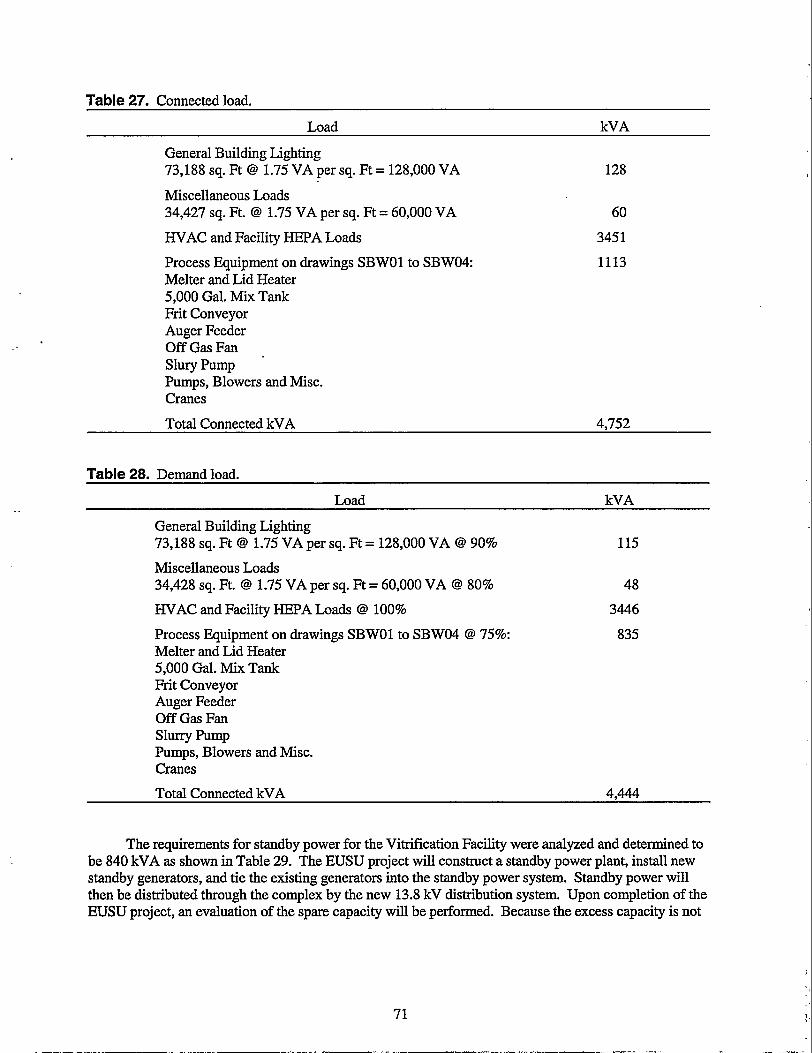
Table 27. Connected load.
General Building Lighting 73,188 sq. Ft @ 1.75 VA per sq. Ft = 128,000 VA
Miscellaneous Loads 34,427 sq. Ft. @ 1.75 VA per sq. Ft = 60,000 VA
HVAC and Facility HEPA Loads
Process Equipment on drawings SBWOl to SBW04: Melter and Lid Heater 5,000 Gal. Mix Tank Frit Conveyor Auger Feeder Off Gas Fan Slury Pump Pumps, Blowers and Misc. Cranes
Total Connected kVA
128
60
345 1
1113
4.752
Table 28. Demand load.
Load kVA
General Building Lighting 73,188 sq. Ft @ 1.75 VA per sq. Ft = 128,000 VA @ 90%
Miscellaneous Loads 34,428 sq. Ft. @ 1.75 VA per sq. Ft = 60,000 VA @ 80%
115
48
HVAC and Facility HEPA Loads @ 100% 3446
Process Equipment on drawings SBWOl to SBWO4 @ 75%: Melter and Lid Heater 5,000 Gal. Mix Tank Frit Conveyor Auger Feeder Off Gas Fan Slurry Pump Pumps, Blowers and Misc. Cranes
835
Total Connected kVA 4,444
The requirements for standby power for the Vitrification Facility were analyzed and determined to be 840 kVA as shown in Table 29. The EUSU project will construct a standby power plant, install new standby generators, and tie the existing generators into the standby power system. Standby power will then be distributed through the complex by the new 13.8 kV distribution system. Upon completion of the EUSU project, an evaluation of the spare capacity will be performed. Because the excess capacity is not
71

Table 29. Standby power iequirements.
Load Standby Power kVA
General Building Lighting 10% of 128 = 13 13
Miscellaneous Loads 10% of 60 = 6 6
HVAC and Facility Loads 605
(Identified by Process Engineer)
Process Equipment on drawings SBWOl to SBW04: (Identified by Process Engineer) Melter and Lid Heater 5,000 Gal. Mix Tank Frit Conveyor Auger Feeder Off Gas Fan Slurry Pump Pumps, Blowers and Misc. Cranes
22 1
Total Standby kVA 845
known, it will be assumed that the Vitrification Facility will provide a new 2,000-kVA diesel generator and associated equipment in the standby generator plant. The Utility Control System (UCS) will control the usage of standby power.
A solid state UPS with a static transfer switch will be provided. The UPS will be provided with 20-minute battery backup. Both the normal feed and bypass feed to the UPS will be on standby power. The U P S will support the following loads: voice paginglevacuation systems, environmental monitoring system, and other critical instrumentation loads.
8.7.1.1 INEEL loop at Substation 2, which is located outside the area fence to the south. Substation 2 transforms the 138kV to 13.8kV and provides power to Substation 15, which is located within the INTEC complex. Power at 13.8kV will be distributed from Substation 15 to the Vitrification Facility.
Existing and Planned Electrical Utilities at ICPP. The INTEC ties into the 138-kV
Currently, standby power is provided by each facility at INTEC. Standby generators are located at various facilities and operate as an island of power during a normal power outage. The EUSU project will construct a standby power plant, install new standby generators and tie existing generators into the standby power system. Standby power will then be distributed through the complex by the new 13.8-kV distribution system. The Utility Control System (UCS) will control the usage of standby power.
8.7.2 Power Requirements
8.7.2.1 feeders from existing Substation 15. Two new Power Sectionalizing Switches (PSS), PSS-NCE- 1507AAA and PSS-NCE-1557AA7 will be installed and they will be fed from two existing Power Sectionalizing Switches, PSS-NCE-1507A and PSS-NCE-1557A. A combination of new and existing duct banks will be used to route the feeders.
Normal Power. Normal power will be supplied to the Vitrification Facility by 13.8-kV
72

8.7.2.2
0
0
0
0
0
Standby Power. The standby loads for the Vitrification Facility consist of the following:
UPS Normal and Bypass feeders
Selected lighting and miscellaneous loads
Exhaust and exhaust fans
Bath electrode
Other loads as determined in the Title designs.
Standby power to the Vitrification Facility will be provided over the normal power distribution system from Substation 60, the Standby power plant substation via Substation 15. The standby power system is at or near capacity. Upon completion of the EUSU project, an evaluation of the spare capacity will be performed. If necessary, a 2,000-kVA diesel generator and associated equipment will be installed in the space available in the standby generator plant. The UCS will perform shedding of the non-essential loads. The UCS will control the operation of circuit breakers and equipment to ensure that only those loads requiring standby power remain in operation. ’
8.7.2.3 redundant feeders. The EUSU project will install a redundant pair of sectionalizing switches in the north east quadrant of the complex. These switches, PSS-NCE-1507A and PSS-NCE-1557A are supplied by one set of 5OOKCMIL cables each. These switches are fed directly from Substation 15 and are very lightly loaded. New duct banks will be run from these switches to two new power sectionalizing switches and then a new load center. The load center will be double ended and will provide a redundant source of power to the Vitrification Facility.
Distribution System. Both normal and standby power will be provided by one set of
.
I -
8.7.2.4 will be provided. The UPS will be provided with a 20-minute battery backup. Both the normal feed and the bypass feed to the UPS will be on standby power. The UPS will feed a 208Y/120-Volt panel. The UPS and the panel will be located in the electrical room. The UPS will support the following loads: Voice paging/evacuation systems, environmental monitoring system and other critical loads.
Uninterruptable Power Supply (UPS). A solid-state UPS with a static transfer switch
8.7.3 Lighting
8.7.3.7 recess-mounted fluorescent fixtures. These fixtures will be operated at 277 Volts and will be locally switched. Motion detectors will be utilized in areas of low occupancy. Lighting in high bay areas will be will be supplied by metal halide fixtures operating at 277 Volts. The metal halide fixtures will be switched at the lighting panel.
Interior Lighting- Lighting in office areas and other low ceiling areas will be supplied by
8.7.3.2 equipment via an in-cell closed-circuit television (CCTV) system or by operation through cell windows. Lighting of the cells will be provided utilizing fixtures mounted in “K” plugs. The number, location, and size of the fixtures and associated “K” plugs will be coordinated with the cell design during the conceptual phase. The fixtures will be designed and fabricated to facilitate installation and removal for replacement of the light source. Metal Halide light sources are desired and will be given preference during the final design. The lighting design will take into account light loss through the translucent panels as well as the light lost in viewing operations through the cell windows.
Cell Lighting. Lighting in the cells will be designed to allow for remote operation of the

8.7.3.3 sodium wall pack fixtures mounted over each personnel door. Loading areas will be provided with high- pressure sodium wall pack fixtures on each side of the doors. The need for area lighting in maneuvering areas will be evaluated during the conceptual and final designs.
Exterior Lighting. The exterior of the building will be illuminated with high-pressure
8.7.3.4 Emergency and Exit Lighting, Emergency egress lighting will be in accordance with NFPA 101, Life Safety Code. In areas where illumination is provided by fluorescent fixtures, selected fixtures will be provided with integral battery backup. In areas where illumination is provided by metal halide fixtures, selected fixtures will be provided with a quartz lamp, which will be used, for emergency lighting. The quartz lamp will be connected to the UPS system or will be provided with an integral battery.
8.7.4 Design Description
8.7.4.7 elevation of 5,000 ft above sea level.
Site Conditions. Electrical equipment will be rated for continuous operation at an
8.7.4.2 handling of hazardous materials. An evaluation will be performed during the conceptual design and the final design to determine the effects of these materials on the installation of electrical equipment. “Flammable and Combustible Liquids Codes” NFPA 30: “National Electrical Code,” NFPA 70; and “Recommended Practice for Classification of Class I Hazardous Locations for Electrical Installations in Chemical Process Areas,” NFPA 497A, will be used in making the determination.
Hazardous Locafions. Several areas within the facility will, be used for storing or
8.7.4.3 Services
8.7.4.3.7 Primary Servic+Two 13.8 kV feeders will be provided for the primary service to the site. The feeders will originate from Substation 2 located outside the fence. Power for the Vitrification Facility will be carried over existing feeders up to Substation 15. From Substation 15, new feeders will be routed through new and existing duct banks.
8.7.4.3.2 Standby Power4tandby power will be provided at 13.8kV over the existing primary distribution system. The existing UCS in conjunction with the Plant Control System will be installed in the Vitrification Facility. These existing systems will control selected circuit breakers to limit the standby power distribution only to those loads deemed important.
8.7.4.3.3 Utilization Voltages-Three and possibly four utilization voltages will be provided for the Vitrification Facility. Transformers and load centers located near the facility will transform the 13.8kV to 480Y/277 Volts; transformers downstream will transform the 480 Volts to 208Y/120 Volts. The third and fourth utilization will be determined during the conceptual and title designs. 4160Y/2400 Volts is desired as the third utilization however, the INTEC currently utilizes 2400Y/1386 Volts. Preferably, only one will be used. Equipment selection and operating personnel preference will determine the voltage to be utilized.
Electrical loads will be assigned voltages as follows:
0 Motors 100 hp and larger - 4160V, 3 phase or 2400V, 3 phase
0 Resistive loads 100 kVA and larger - 4160V, 3 phase or 2400V, 3 phase
0 Motors Yz hp to less than 100 hp - 480V, 3 phase
74

0 Resistive loads 1 kVA to less than 100 kVA - 480 V, 3 phase
Motors less than !h hp 120 V, single phase
0 Miscellaneous loads less than 1 kVA - 120 V, single phase
0 Lighting - 277 V single phase.
In certain circumstances, 480 V, 3 phase will be utilized for motors over 100 hp and loads over 100 kVA. This will be determined on an individual basis after the effects have been evaluated.
8.7.4.4 Equipmen f
8.7.4.4.7 Load Cenfers-One load center will be provided. The load center will be located outside the Vitrification Facility and will be a "4 3R Walk-in type similar to the load centers currently in use at the INTEC. The load center will provide 480Y/277 Volts and will be double ended. Each transformer will be sized to provide service to all loads on the load center. The load center will be provided with all equipment and wiring to ensure that it is fully compatible with the existing UCS System.
8.7.4.4.2 Transformer~Transformers 5,000 kVA and below will be cast coil, dry type transformers. Transformers over 5,000 kVA will be oil filled.
8.7.4.4.3 Lighfing-Lighting levels will conform to the Illuminating Engineer's Society (IES) handbook and standard practices at the N E C . In general, the design will provide the following illumination levels:
Work Stations 70 foot-candles
WorkAreas 30 to 50 foot-candles depending on activity
0 Non-Work-&eas 10 foot-candles, 50 foot-candles where data is obtained
8.7.4.5 installed in all duct banks and ground rods installed in every manhole; this in turn is solidly connected to the casing of the deep wells. Facilities and structures throughout the INTEC are connected to this ground system. As well, the Vitrification Facility will be connected to the ground system. Grounding within the facility and at the outdoor load centers and other structures will be accomplished in accordance with the National Electrical Code and IEEE Standard 142-1991, IEEE Recommended Practice for Grounding of Industrial and Commercial Power Systems.
Grounding. Grounding at the n\TTEC is accomplished with bare copper conductors
8.7.4.6 Lightning Protection Code.
Lighting Profecfion. Lightning protection will be provided in accordance with " P A 78,
8.7.5 Utility Control System and Fiber-optic Cable
The existing UCS fiber-optic cable loop at INTEC consists of six dedicated fibers in a 36-fiber, fiber-optic cable. Three loops of fiber-optic cable encircle the n\TTEC site and control and monitor the UCS, the fire alarm system, the voice paging and public address system, the criticality alarms, and local area network (LAN) systems. To connect the Vitrification Facility into these system, one of the loops

. ,_--
must have all 36 fibers cudsplice and the loop expanded to include the Vitrification Facility. All above systems must be tested to ensure proper functioning before reactivation.
The UCS controls the main and tie breakers of all load control centers at INTEC, while the Plant Control System (PCS) controls the main and tie breakers on the downstream motor control center and power control centers. In addition, the PCS controls starting and stopping of all loads in the facilityhuilding. The UCS and PCS combined allow load shedding of unimportant loads from the electrical system, thus limiting and controlling the standby load requirement at INTEC.
The Vitrification Facility will be located directly over the top of an existing duct bank. The duct bank and the associated fiber-optic cable will be routed around the east side of the Vitrification Facility. The fiber-optic loop will splice in an existing manhole. New fiber-optic cable and duct bank will be routed to the Vitrification Facility from this location. Rerouting of existing fiber-optic cable or duct bank option is not required.
8.8 Instrumentation and Control
Throughout the Vitrification Facility, the design objective shall be to standardize across equipment systems. Process equipment shall be controlled by a control system that uses standardized programmable logic controllers (PLCs) and CRT-based operator workstations. Process variables shall be sensed and measured with “Smartyy Transmitters that can be configured and calibrated with all parameters accessible to standard software manipulation on computer workstations. Processes that are judged to be sufficiently sensitive or critical shall be designed for redundant control and access to emergency power (UPS).
The Control System hardware will be capable of integrating with a variety of devices through such standards-based networks as DeviceNet, ControlNet and Ethernet. The system will include such features as flash-upgradable firmware and shall employ a passive data bus that utilizes “producer/consumer” network technology. Within a hardware chassis, this feature will permit multiple processors, networks, and inputdoutputs (YO) to be mixed without restrictions, even if the system grows substantially from the original design.
The Control System hardware will be arranged in a hiearchal network comErising three levels: Level 3 (bottom level) - This level is best described as equal to “DeviceNet” and capable of discrete (digital) and analog input and output devices.
Level 2 (mid level) - This level is described as “automation and control,” where rapid two-way communication takes place between local man-machine interface (MMI) consoles, intelligent power controllers such as variable frequency drives (VFDs) and modular racks of remote YO modules.
Level 1 (top level) - This highest level is described as the “information” level. At the “information” level, process data is shared at “Ethernet” speeds with all workstations, MMI, extending into the Intranet domain and beyond to the Internet. This will make it possible for engineers and scientists at any location in the world to observe updated graphical displays of the process or historical data, such as trends or alarms, assuming they have the passwords for the various levels of access that have been configured.
,
The following estimates the total number of YOs for the SBW Vitrification Facility. The data in this table indicate that the control system for this facility will need to accommodate approximately 2,000 hardware tags. It is estimated that with the additional “internal” tags to be defined during the course of the development and configuration of the system, the total number of tags will not be greater than 5,000.
76

Table 30. Instrumentation and controls eauinment.
Total for Number
Analog in signals 179
Analog out signals 46
Discrete inputs 796
Discrete outputs 796
Tags 1817
Motors 101
8.8.1 Control System Software for Man-Machine Interface
This software will provide a complete control window into the overall process. It will be an integrated, component-based MMI software for monitoring and controlling the process. It will include customizable ActiveX objects that embed directly into the graphic displays. (ActiveX objects consist of thousands of 3d party developed objects representing complicated machinery or devices that are analogous to equipment in the process.) For example, the selection of an ActiveX object from a library on the Internet can be downloaded and embedded in a process graphical display. This ActiveX object can then be easily linked to the process tags that will determine the mode of anhation or display desired. Such tools will save engineering time and provide vivid and descriptive representation of the Vitrification process.
The control system software will have the capability of selecting the logic tags that have been previously defined in the database of a PLC and importing all or any portion of the tags for use in the h4IvlI display. The linking of these tags to the objects in the MMI graphical displays will be the simple process of highlighting a graphical symbol and then selecting the appropriate tag, assign the desired animation effects and click on “OK”.
8.8.2 Instrumentation
As described in the “Remote Systems” section, the Vitrification Facility will be designed for remote control of those processes and tasks that cannot be accessed closely or visually. This is primarily due to high radiation fields andor high contamination areas. These factors will result in a Vitrification Facility that is divided into a canyon service corridor configuration for the purposes of remote maintenance and control activities.
Much of the process equipment will be located in a concrete shielded enclosure that is accessed by shielded hatch covers only when a maintenance task is required. Because human access will be infrequent, and also because of the destructive effects of high radiation on sensitive electronics, it will be a requirement to keep control instrumentation and (I/O) hardware out of the concrete shielded enclosure. These devices will be located in the RSC and be connected to the sensors and devices that must be located in the shielded enclosure with self-aligning jumper assemblies that are accessible to the master-slave manipulators. This will allow changeout, removal, and replacement of devices that have failed, without human entry into the high radiation areas within the concrete shielded enclosure. Every device within the shielded, concrete enclosure shall be selected and deployed with the idea in mind, that the way it is mounted, where it is mounted, what cable is connected to it, where the cable is terminated, etc., will require service by master-slave manipulators.

State-of-the-art-technology has provided instrumentation that seldom requires calibration and provides for remote configuration utilizing digital communications that share the signal cable that is feeding the data to the distributed UO modules. These devices can therefore be configured “on the fly” or accessed for maintenance and diagnostic checks from the MMI console.
8.8.3 Computer Hardware and Software
The control room will provide CRT- based control stations to give MMI and supervision for the vitrification processes and possibly additional facility utility functions, such as monitoring and control of the HVAC and HEPA filter systems and security monitoring.
There should be a minimum of two MMI control stations for redundancy and to allow attention to be given to multiple, simultaneous operations. It is recommended that sufficient console desktop space be allocated for as many as 4 or 5 MMI control stations to accommodate potential growth in processes and function.
The MMI control stations should be state-of-the-art technology. At the very minimum, the requirement will be CAT 5e (350 Mhz) [current standard as of March 20001 or the latest standard which has been accepted by the TIA/EIA (Telecommunications Industry AssociationElectronics Industries Association) at the time of design. Design consideration shall be given to the use of fiberoptic cable in lieu of copper cable for individual workstation and control station network drops. The workstation computers will be capable of running with the Microsoft Windows NT operating system of 500 MHz Dual-Pentium processors, preferably rack mounted. The monitors shall be a minimum of 20-in., Super VGA with 800 x 600 or greater resolution. Consideration shall be given to providing touch screen and/or track ball control in combination with conventional keyboards. Each computer workstation shall have a minimum of 96 MB of RAM and 12 GB of hard disk space. In addition, each computer workstation shall have a network card, capable of bi-directional transmission of data.
8.8.4 Support Utilities
The conceptual design will determine the extent of instrumentation and controls into such utilities as the W A C and monitoring of critical systems, such as the status of the HEPA filters. Close coordination during the conceptual and/or title design with the mechanical disciplines will be necessary to ensure that such capabilities as the following are covered
Alphdnumerical displays to allow observation of room temperature and humidity.
0 Normal operating modes (heating, cooling, humidification, and dehumidification)
Monitoring of individual equipment operation and the ability to activate an audible and visual alarm in the event of the such alarm conditions as high temperature, low temperature, high humidity, low humidity, restricted air filters, high pressure, and low pressure.
0 Provide building utility alarm conditions to the building security system for display and operator action on designated control workstations where the security and access software resides.
78

8.8.5 Telecommunications
Telephone backboards will be installed in a dedicated Communications Room to allow termination of underground cable conductors to splicing terminal boards and patch panels and other telephone communication equipment.
Computer networwdata system racks will also be located in the Communications Room and will be separated from the telephone equipment to minimize potential for crossing of systems. The data system will have its own termination backboards to allow use of different power supplies, surge suppression equipment, and switching equipment. The Vitrification Facility will require integration into the INEEL, network or LAN system. With the rapid development of this technology, it is assumed that the requirement for the Vitrification Facility will be that all of the individual PC workstations and process control stations will be state-of-the-art technology. At the very minimum, the requirement will be CAT 5e (350 MHz) [current standard as of January 20001 or the latest standard which has been accepted by the Telecommunications Industry AssociatiordElectronics Industries Association (TIA/EIA) at the time of design. Design consideration shall be given to the use of fiber-optic cable in lieu of copper cable for individual workstation and control station drops.
8.8.6 Security Equipment
The security systems racks will also be located in the Communications Room and will be separated from the telephone and data equipment termination racks to minimize potential for crossing of systems. The telecommunication network group will control tie points between data systems, telephone communications, and security systems. The security system will have its own termination backboards to allow use of different power supplies, supervision, surge suppression equipment, and switching equipment. Part of the security system at INTEC has a separated security duct bank system that will need to be home run from an existing duct bank and extended to some of the new duct banks being installed into the Vitrification Facility. It is assumed that all building exterior entrances will have card readers inside and outside of each door. It will be left to the conceptual study to determine the complete extent of the security system, as to whether or not any of the interior spaces, such as the hot cell gallery, or control room will require card readers or other security devices. Such devices as magnetic door switches or photoelectric sensors may be required. All security systems will be connected into the existing security system at INTEC.
8.9 Steam Facility
The Vitrification Facility requires an estimated maximum steam supply of 27,000 l b h . The existing steam supply is from CPP-606. Currently the boilers are undergoing replacement and are scheduled for completion by October 2000. The CPP-606 Boiler Replacement project will install four new boilers with an operating capacity of 23,000 l b h for each boiler. The total for the four boilers combined is approximately 92,000 l b h . According to the INTEC Thermal Energy Study Final Report (Balls et al. 1999), the maximum steam supplied does not allow for the additional capacity from this proposed Vitrification Facility until after FY 2015, as shown in Figure 4.
A new steam facility is planned to meet the steam demand for the Vitrification Facility. A plan view of the building and the layout of two boilers are shown in the drawings (Appendix G). Two boilers are shown: one for operational demands arid the second as an immediate standby. At this stage of design a standby is included, later stages may determine whether a standby boiler is justified. The cost estimate and information from the CPP-606 Boiler Replacement project was used for the drawing and the two boiler cost estimate. The boiler building provides adequate room for installation, associated utilities and

+ A v e r a g e S t e a m - M a x i m u m S t e a m
~~~~~~ . ~ . - ~~~~
~~~~ ~~ ~ ~~ ~~~
2000 2005 2010 2015 2020 2025. 2030 2035 2040
Figure 4. Projected INTEC thermal energy demands, FY-00 through FY-40.
changeout of the boilers. The drawing does not detail the multiple utilities and systems required for the boiler, but they are incorporated into the cost estimate.
8.1 0 Fire Protection Systems and Equipment
At INTEC, there is an existing Emergency Communication System (ECS) which integrates the functions of Emergency Evacuation with alert tones, Fire Alarms, and the Personnel Address System. All new facilities at INTEC must be incorporated into this ECS and become an integral part of the overall system. This will require that the system components be 100% compatible and matched “like for like.” It will also require that any additions to the INTEC system will be battery backed and capable of operating for a period no less than 24 hours upon loss of electrical power. The facility will require a new fire alarm panel connected into the fire alarm communications fiberoptic network for INTEC. The fire alarm system will consist of manual pull stations located next to each exit door, ceiling mounted smoke detectors in all corridors and rooms, and other places designated for special areas or equipment. Fire alarm strobe lights in high ambient noise areas will be required. Fire alarm notification will be via the ENS (Emergency Notification System). ENS speakers will be required in those areas identified during the conceptual study.
8.1 1 Utility Control System and Fiber-optic Cable
The existing UCS fiber-optic cable loop at INTEC consists of six dedicated fibers in a 36-fiber, fiber-optic cable. Three loops of fiber-optic cable encircle the INTEC site and control and monitor the UCS, the fire alarm system, the voice paging and public address system, the criticality alarms, and local area network (LAN) systems. To connect the Vitrification Facility into these systems, one of the loops must have all 36 fibers cut and the loop expanded to include the Vitrification Facility. All above systems must be tested to ensure proper functioning before reactivation.
The UCS controls the main and tie breakers of all load control centers at INTEC, while the Plant Control System (PCS) controls the main and tie breakers on the downstream motor control center and power control centers. In addition, the PCS controls starting and stopping of all loads in the
80

facilityhuilding. The UCS and PCS combined allow load shedding of unimportant loads from the electrical system, thus limiting and controlling the standby load requirement at INTEC.
The Vitrification Facility will be located directly over the top of an existing duct bank. The duct bank and the fiber-optic cable will be routed around the east side of the Vitrification Facility. The fiber- optic loop will occur in an existing manhole. New fiber-optic cable and duct bank will be routed to the Vitrification Facility from this location. Rerouting of the existing fiber-optic cable or duct bank is not required in this option.
8.12 Vitrification Facility Staffing
Total estimated personnel needed for operating the Vitrification Facility is 109. Table 31 details the personnel needed. The following assumptions were made for estimating personnel needs.
0 One shift (4-10s) for the main process, administration and support.
0 Continuous process operations will require four rotating shifts for the 2-year duration of operations.
0 " E C will have infrastructure services and capabilities to accommodate some tasks not unique to this project. These include:
- Additionaldrafting
- Facility maintenance
- Laboratory testing and analysis capabilities
Table 31. Personnel loading.
Manager(s)/Supervisor(s) 2 4 Administrative Support (Including SecretariaVClerical, BudgetKOst Control, and 3
Engineering (Facility) 2 Engineering (Process/Support) 2 4 Control Systems Tech - Ref: pg 4, I & C Technicians (Matrix personnel during 1
construction, overhaul, redesign or mods)
Rad-con Tech (RCr'/hp) Manager

'able 31. (continued). FunctionPacility Requirement Main Shift Rotating
'ROCESS CONTROL (Process Control Console, Alarm Panels, Communications) SBW feed and frit mixing (Includes Melter feed and Canister Fill, Glass and Gas - 12
Canister Decontamination - 16
8 Canister Curemewatering, Transfers 4 4 4
Sampling and Analysis, Grouting System, and Off-gas Handling)
-
Can Sealing and Inspection - Canister Tomographic Inspection -
- Canister Recycle 3 S & Q
- Safety 1 RCT (Rad-Con Tech) 1 4
Quality Industrial Hygienist - 4
SupervisorsForeman 1
4 -
PROCESS MAINTENANCE - 4
4
4
- Electrician Mechanic I&C Technicians Maintenance Planner 1 Preventive MaintenanceNork Order 1
-
- -
-
82

. 9. ESTIMATED COST
9.1 Planning Cost Estimate
A planning cost estimate was prepared for the Vitrification Facility, which includes an office area and two truck bays (Appendix D). An oil-fired steam generator (boiler) to produce steam for process and provide building heat was included in the estimate. The Total Project Cost (TPC) is $738,000,000. This cost includes Conceptual Design costs, Project Support costs, Permitting costs, Construction Management costs, Engineering costs, Quality Assurance costs, Project Management costs, direct and indirect construction costs, System OperatiodStartup costs, Procurement Fee, G&A, escalation and contingency.
As currently envisioned, this facility consists of a processing building measuring approximately 380 x 169 f t at grade level, with basement levels extending 32 f t belowgrade and roof elevation at 75 ft. In addition to the main processing building, there are two truck bays attached; one measuring 80 x 40 ft and one measuring 30 x 20 ft. The office area measures 189 x 68 ft with an assumed eave height of 14 ft. The boiler building is a concrete masonry unit ( 0 building measuring 60 x 52 x 30 f t high.
Table 32. Total project costs.
Estimate Element Estimate Subtotal Escalation Contingency Total
Total Estimated Cost (TEC) $321,252,222 $87,927,984 $173,048,352 $582,228,558
Other Project Costs (OPC) $78,935,3 17 $17,107,921 $59,413,968 $155,457,206
Total Project Cost (TPC) $400,187,539 $105,035,905 $232,462,320 $737,685,764
9.1.1 Basis
This estimate is based on information obtained by material take-off of preliminary facility sketches in Appendix G. Also used were several lists addressing process equipment, mechanical W A C equipment; instrumentation, and sampling equipment in Appendix F. A one-line electrical load sketch, in Appendix G, was used to establish the electrical distribution equipment.
Much of the detail estimating was based on construction databases such as Means and the Construction Unit Price Book. Several of the special pieces of equipment were priced using preliminary vendor quotes in Appendix J.
9.1.2 Assumptions
These assumptions are conditions that are accepted or supposed true without proof of demonstration. These assumptions have a direct impact on the total estimated cost.
Construction of this project will be competitively bid among subcontractors familiar with this type of construction and DOE projects at the INEEL.
Design, management, quality assurance, and contractor general conditions costs are based on historical percentages and/or factors from similar site projects.
0 No contaminated soil will be encountered during excavation for this project.

All direct costs are in present-day dollars, escalated to the appropriate schedule midpoint
No asbestos will be encountered during this project.
Allowances for distribution piping, electrical, HVAC ductwork, structural steel, and distributed control system (DCS) are based on historical information from similar hot-cell facilities and applied parametrically by area.
Very little information is available for Nitronic 50 alloy materials. Historically, this alloy’s costs are approximately double those of stainless steel. A factor of two was used to estimate the costs of Nitronic 50 materials. Welding and machining labor is approximately 30% more than stainless steel.
Rock will not be encountered during excavation activities. Historically, rock is located more than 35 f t below the surface at the northeast comer of INTEC.
Although the elevation sketch indicates a 1-ft floor thickness at the hatch level, the estimate assumes three f t of concrete for shielding of personnel in the crane bay.
Fire protection sprinkler systems throughout the process facility were assumed to be wet- pipe sprinkler systems similar to that proposed for Fuel Processing Restoration Facility (FpR).
- = I The design team identified areas requirement stainless steel cell lining and epoxy coating. All other exposed concrete surfaces are assumed to be sealed or painted.
All concrete is assumed to be 400 psi. No high-density concrete is included.
All exterior concrete walls will be covered with semi-rigid insulation and metal siding.
Mechanical and electrical jumpers will be similar to those intended for use in FPR.
Additional basis can be found in the estimate details in Appendix D.
9.1.3 Contingency
The risk associated with this project, and therefore the contingency needed, could be considerably greater than that addressed in the INEEL Cost Estimating Guide. The contingency to cover the risks associated with this project and the level of estimate have been addressed using the @Risk contingency program. This program statistically calculates the monies required to mitigate perceived risks by using range inputs and Monte Carlo or Latin Hypercube simulations. Appendix D contains the data used in this program.
9.2 Life-Cycle Cost Estimate
The economic and life-cycle cost (LCC) evaluation (Appendix E) assumes a 36-year period (2002- 2038) since this is the estimated time to complete all of the anticipated remediation activities. The LCC evaluates the initial development, construction, operation, and post-operation costs over the life-cycle of the facility. The discounted LCC analysis assumes a constant-dollar basis, discounted at 6.30% annually per the Office of Management and Budget ( O m ) Circular A-94. All costs are conservatively discounted
84

assuming the end-of-year convention. Annual costs for operations and maintenance are based on actual FY-98 costs and projected to a future cost based on operations and engineering judgement. These costs were increased and compounded by a 3.0% annual inflation rate. The discounted LCC for the SBW Vitrification Facility is $606 million.
The LCC analysis is generated to match cost estimating cost structure. These costs include Permitting, Direct and Indirect Construction, G&A, Procurement Fee, Engineering, Inspection, Project Management, Construction Management, Escalation and Contingency costs. To evaluate costs, the factors of reliability, maintainability, and capacity are evaluated to determine an overall operational availability. These risks and costs are evaluated using a Monte-Carlo simulation with @Risk, a computer simulation program. The simulation defines uncertain model variables according to a probability distribution of risk. The simulation then randomly selects the value of this variable based on the distribution of occurrence. The costs generated by the program are reviewed as to their reasonableness using engineering and operations judgement.
The yearly discounted LCC is determined by adding annual tangible and intangible costs for a total annual cost, discounting each year's annual cost to the FY-00 base-year using OMB's discount rate of 6.3%. The yearly discounted LCC is summed together to get a cumulative discounted LCC.

___-
IO. PROJECT SCHEDULE
The design, construction, and operation project schedule, which is included in Appendix C, is summarized in Table 33. The entire schedule spans from start of conceptual design and project management in January 2002 until the end of D&D in December, 2038 with a hiatus from the end of processing in December 2014 until the beginning of D&D in January 2036. The construction campaign is 4 years long from July 2007 through July 201 1. Startup operations’ testing is expected to last 2 years from January 201 1 through January 2013. The processing operation will last two years from January 2013 through December 2014.
Conceptual Design
Project Support
Permitting
RCRA Permits
Delist HLW
Delist LLW
Air Permits
Title Design
Project Managem
Table 33. Project schedule.
Days Schedule Start Schedule Finish
Total Project Schedule 9653 01/02/02 12/3 1/3 8
783 01/02/02 12/31/04
2870 0 1/02/02 01/01/13
2348 01/02/04 0 110 1 /13
1044 0 1 /02/04 01/02/08
1305 0 1/02/08 0 1/0 1/13
1305 01/02/08 01/01/13
782 0 1 /04/10 0 110 1/13
65 1 01/03/05 07/02/07
1694 01/03/05 06/30/11
1694 01/03/05 06/30/11
Construction Management 1044 7/03/07 07/01/11
Construction 1044 7/03/07 07/01/11
SO TesdStartup 522 01/03/11 01/01/13
n
Quality Assurance
Start Processing
Process
0 01/01/13
522 01/01/13
0 1/0 1/13
12/3 1/14
D, D&D 783 1/2/36 12/3 1/3 8
86

11. REQUIREMENTS AND ASSESSMENTS
11.1 Disposal at WIPP
It is assumed that either the SBW will be delisted for U134 (uncomplexed hydrofluoric acid, HF) or that the U134 waste code will be added to the WIPP WAC. Another assumption is that the incidental waste ruling for SBW will be that it is not HLW. Both of these assumptions impact whether the vitrified SBW can be accepted at WIPP. The delisting of SBW for U134 or the addition of U134 to the WIPP WAC must be vigorously pursued. Failure to obtain one or the other will result in the vitrified waste not being accepted at WIPP. The incidental waste ruling for SBW has been requested. However, the ruling has not yet been made. If SBW is ruled to be HLW, the glass waste will be disposed of at Yucca Mountain, rather than WIPP.
Negotiations with WIPP are needed to alter the WIPP WAC to add U134 to the list of accepted waste codes. Disposal space for RH waste is limited at WIPP. A waste acceptance agreement is needed between WIPP and the INEEL for the vitrified waste.
11.2 Radiological
During the conceptual design of the Vitrification Facility, additional radiological assessments must be made. Preliminary evaluations of radiation levels in the Vitrification Facility have been made to determine appropriate wall thickness and personnel protection requirements. As the design is developed, this issue should be re-evaluated to verify the radiation exposure levels to operating personnel.
11.3 Material Balance
The material balance will need to be revised as information from additional studies becomes available. Issues of concern include:
0 Sugarchemistry
0 Mercury speciation
0 Decontamination factor for species in the melter and offgas systems
Off-gas chemistry.
11.4 Grout Recipe
The grout recipe for solidification of the scrubber blowdown needs to be tailored to the composition of the blowdown.
11 -5 Multi-Stage Combustor
Actual operational data is needed for the multi-stage combustor with gas streams similar to the off- gas from the melter. This should include:
Actual performance data for efficiency and reliability.

0 Effect of a large amount of water vapor in the off-gas stream; it is assumed that water vapor will be an additional heating requirement and pass through the system.
Steam or water quench for Stage 2, steam may be safer.
0 Gas residence timing and mixing of Stage 3 to ensure complete combustion at low excess oxygen conditions.
11.6 Operating Conditions
11.6.1 Temperature of SBW
The temperature of the SBW and SBW mixtures must be maintained below 60°C until the SBW feed enters the melter. The high concentrations of chlorides in the SBW will cause severe stress cracking and corrosion issues above 60°C based on historical experience at INTEC.
88

12. UNCERTAINTIES & ADDITIONAL STUDIES
12.1 Open Issues
12.1.1 Operating Life
The lifetime of the plant is assumed to be 2 years. Increases in assumed lifetime may require additional margins to be included in the design of the piping (e.g. corrosion and erosion allowances or design for remote replacement).
12.1.2 Characterization of SBW
Additional characterization of SBW is needed for the conceptual'design. Further characterization of the UDS in the SBW is required. There are some elements that even small amounts (>OS wt% in the glass) have significant melter processing impacts. SBW should be tested for elements such as noble metals, sulfur, and phosphorus.
12.1.3 Ion Exchange Media for Cesium Removal
The ion exchange media chosen for removal of cesium and strontium are UOP IONSIV@ E-95 and A-5 1 respectively. The alkali metd alumino-silicate ion exchange media are compatible with the melter and frit used for vitrification of SBW. Cesium and strontium (and their daughter products Ba-137m and Y-90) have the highest concentration levels of the radionuclides in the scrub blowdown. Cesium is a gamma emitter and is removed from the blowdown to reduce the radiation levels of the grout to contact handled material. Strontium is a beta emitter which is a strong contributor to the heat emission due to radioactive decay.
Other ion exchange media are available for removal of cesium from the scrub blowdown. UOP IONSIP IE-N 1 is a crystalline silicotitanate (CST) with a high affinity for cesium, even in the presence of high concentrations of sodium and acid. The absorption of cesium on the sorbent is virtually irreversible. CST will also remove strontium from liquid waste; however, strontium can be stripped from the media.
The choice of ion exchange media should be re-evaluated based on the results of off-gas and scrubber characterization studies for SBW. Neutralization of the scrub blowdown should be considered to optimize the ion exchange process.
12.1.4 Water Reduction in SBW
Evaporation of water from the SBW in the SBW storage tank, the mixing tanks, or the feed tanks would decrease the electrical requirements and increase the efficiency of the melter. However, evaporation would increase the stress/corrosion effects of chlorine. Also, the temperature in the tanks would need to be maintained less that 60°C to reduce the corrosion rate. Added margin for stress- cracking concerns are accomplished by using a higher-grade material for the tanks such as Nitronic 50.

12.2 Required Studies
12.2.1 Mercury Speciation
A better understanding of mercury speciation in the melt, the combustor, and in the scrub system is needed. Studies should be conducted to determine the amount of mercury that remains in the glass. There are conflicting data for mercury retention in the glass given in Stegen (1997). Mercury compounds such as HgO and HgC12 are expected to decompose in the combustor to elemental Hg and 0 2 and Cl2 gas. The kinetics of reoxidation of the elemental mercury in the off-gas and the subsequent removal of the mercury compounds by the scrub system need to be investigated.
In the material balance, (Quigley 2000), mercury removal in the quench is assumed to be 99%, for the venturi scrubber, 99%, and for the mist eliminator, 99.5%. All mercury is assumed to be in the melter off-gas stream with no mercury retained in the glass. This results in 2.5% of the mercury from SBW in the scrub solution. The amount of mercury in the scrub solution may change significantly based on the mercury speciation research.
Although not shown as part of the process, a packed bed of GAC may be needed downstream of the CsM unit to remove elemental and oxidized mercury before the scrubber blowdown is grouted. Preliminary evaluation of the mercury concentrations in the scrub indicates that the grout would not meet leachability requirements for RCRA.
12.2.2 Elemental Mercury Adsorption in Off-Gas
A study should be performed on the adsorption of elemental mercury from the off-gas of the melter to determine the best adsorbent and optimal conditions.
12.2.3 Slurry Characteristics
The characteristics of the slurry are unknown. The assumption is that the mixture can be maintained as slurry sufficient for homogeneous mixing with adequate pumping and material transfer capabilities. However, the solids and real case characteristics may present unknown difficulties both for in-tank mixing and material transfer (pumping). To accurately sample the mixture, homogeneous mixing is required.
Pump performance with the frit/sludge/SBW slurry should be evaluated. The effect of variable speed pumping and an envelope of operation conditions should be determined. Final pump selection should be based on this research.
12.2.4 Sugar Addition
The scope of work for the feasibility study, (HLW 1999), calls for the addition of sugar to the SBW and frit as part of the melter feed. The sugar is added to reduce the oxidation potential of the glass melt to control foaming of the molten glass. The nitric acid from the SBW will react with sugar to produce heat and N2, NO,, CO, COz, and H20. The interactions between sugar and nitric acid waste have been studied in Marshall (1996). However, experiments are needed to determine the following:
0
. The stability of the sugarhtric acid solution. This includes the kinetics of the reactions between the sugar and nitric acid, the reaction products, and the heat released.
90

The potential for an increased risk of flammability or explosion potential from reaction products.
Other reductants should be tested as well as sugar.
The temperature within the mixing tanks will be maintained less that 60°C to reduce the corrosion rate. Cooling has been added to the mixing tanks to remove the heat from the sugar/acid reaction. The rate at which the sugar is added to the SBW can also be used to control the temperature and should be quantified. There is some indication that the reaction progresses rapidly and then slows. This may impact when samples of the tank should be taken.
12.2.5 Melter Operation and Decontamination Factors
During operation, the melter is maintained at a slight negative pressure to ensure that contaminants within the melter are drawn through the off-gas system. The carryover of particulates and volatile species needs to be evaluated for the SBW feed and melter system. The DFs are based on recommendations in Stegen (1997). However, none of the melters used for this study are liquid feed, cold cap melters. The retention of heavy metals and radionuclides in the melt needs to be researched.
The method of control of melter and multi-stage combustor system component pressures needs to be reviewed. The design goal is to create a very homogeneous feed stream within the mix and feed tanks before entry into the melter. This will help to minimize potential for fluctuations.
System pressure control is usually accomplished via a draft blower at the end of the off-gas system. However, the effect of the multi-stage combustor on this is not known. How can the negative pressure in the melter be maintained at a relatively constant level with the multi-stage combustor just after the melter? Will the large amount of evaporation of " 0 3 also cause a pressure problem?
' 0 In some melters with high alkali level waste (Na) feeds, there tend to be significant volatility in the off gas of these components. There have been some cases where there has been enough to clog the off gas line. The potential for this to occur should be evaluated.
The use of an evaporator in the SBW Work-off Tank or between the Work-off Tank and the mixing tanks should be investigated. The evaporation of SO%+ of the water and nitric acid would significantly increase melter feed rates, decrease the size of the melter and lid heaters, decrease the size of the off-gas system, and reduce the carry-over of waste components into the off-gas system.
The addition of nitric acid waste feed with a high percentage of water presents special design challenges. Successful resolution of these challenges may benefit from detailed design modeling for transient heat transfer and fluid flow, as well as thermophysical and chemicd reaction modeling. The effects of inlet geometry and feed distribution on the melt should be investigated.
12.2.6 Off-Gas and Scrubber Characterization
Further research must be performed to measure the off-gas and scrubber concentrations for constituents of concern. Particulate size distribution within the gas stream should be determined for the design of the scrubbing system. The effect of the pH and temperature of the scrub solution on scrubbing efficiency and scrub system materials is needed.
91

Experiments on melter off-gas using GAC for mercury removal are needed to determine the optimal residence time and bed loading. Acid gases in the gas stream may liberate hydrogen sulfide (H2S) gas, with subsequent damage to the beds and additional potential safety problems for dealing with this gas.
Low-efficiency gas scrubbing will allow chlorine at sufficient levels to pass to the HEPA bank. Increased levels of chlorine will introduce corrosion issues in the HEPA bank. Standard filter banks are 300 series stainless, which is readily attacked by hydrochloric acid (HCl). High-efficiency caustic scrubbers convert chlorine to salt (NaC1). Some level of salt particulate matter may be entrained in the gas stream and reduce the operating life of the HEPA filters due to salt blinding. Experiments should be performed to optimize gas scrubbing and HEPA filter life.
12.2.7 Other Waste Streams
Although this study only considered vitrification of liquid SBW, other waste streams might be treated using the Vitrification Facility. These include TFF heel solids, NGLW, and calcine.
Although the feed system is designed to handle liquids with UDS, further work is required to determine whether the equipment suggested is suitable for TFF heel solids that have significantly more solids. The composition of all the tank heel solids has not yet been determined. Sludge in tanks WM-182 and WM-183 have been recently sampled and analyzed. Other tanks are scheduled for sampling. Waste loading and canister radiation levels can only be grossly estimated until characterization of the TFF heel solids is completed.
Treatment of the various NGLW streams depends on the characteristic of the streams. The Vitrification Facility has a contact-handled grout system that could be used for NGLW. Further evaluation is required to determine whether the grout system is large enough to handle the expected volume of NGLW and whether addition treatment systems are required.
Several issues should be addressed if the Vitrification Facility is to treat calcine. Two feed systems have been proposed for vitrification of calcine: a dry mix of calcine and frit and a slurry of calcine and frit suspended in water. The wet feed system for SBW should be evaluated for use with the calcine slurry. If a dry feed system is chosen, provision should be made in the Vitrification Facility design for addition of a dry feed system. Addition of a second, joule-heated melter, which would ensure continuous operation during a melter change out, should be considered for calcine vitrification.
12.2.8 Facility Siting Study
A siting study should be performed to determine the optimal placement of the Vitrification Facility. The study will review the impacts of this facility on site utilities and the surrounding infrastructure. The study will encompass topography, existing soil conditions, subsurface rock formations, and road and structure locations both above and below ground level.
92

13. REFERENCES
Adams R. D, et.al., 1999, Process Sampling Study for High-Level Waste Treatment for Non-Separations Options, INEELEXT-99-00883, Bechtel BWXT Idaho, LLC, Idaho Falls, Idaho.
AS=, 1997, ASHRAE Handbook, Fundamentals, Inch-Pound Edition, American Society of Heating, Refrigeration, and Air-conditioning Engineers.
Banaee, J., J. Bosley, R. Kimmitt, and A. Poloski, 1999, Final Waste Form Requirements and Path to Disposal-Volume 11: Evaluation of Potential Disposal Sites for INTEC Radioactive Mixed Wastes, INEELEXT-99-01175.
DOE, 1995, Consent Order and Settlement Agreement Between DOE and the State of Idaho Regarding Spent Fuel and Nuclear Waste Issues, October 17, 1995.
DOE, 1999, Waste Acceptance System Requirements Document, Revision 03 (E00000000-00811-1708- OOOOl), DOERW-0351, U.S Department of Energy, Washington D.C., April 1999.
DOE-ID, 1999, “Architectural Engineering Standards,” Table 1550-1.
“EDFs Related to HLW EIS Projects for Vitrifying SBW and Calcine (P88) and Calcine Blending and Vitrification (P60),” April 1998.
Harrell, Dennis J., A/% Scope of Work for FY-2000 Feasibility Studies the High Level Waste Program; Appendix B, Scope of Work for the Vitrijication of Sodium-bearing Waste Feasibility Study.
Lopez, D. A., High-Level Waste Vitrification Facility Feasibility Study, INEELJEXT-99-00792, August 1999.
Lopez, D. A. and R. R. Kimmitt, Vitrified Waste Option Shrdy Report, INEEUEXT-97-01389, February 1998.
Marshall, D. W., Report on the Sugar-Nitrate Interaction and Sugar-Calcine Reactivity Study - DWM- 03-96, June 25,1996.
Neberghall, W. H, F. C. Schmidt, and H. F. Holtzclaw Jr., General Chemisty, 5” Edition, D. C. Heath and Company, 1976.
Peterson, H. K., “Radiological Calculations for Specified SBW Waste Packages” - HKP-07-00, March 14,2000.
Quigley, J. J., EDF-1416, Material Balance for Vitrification of SBW, June 2000.
Rawlins, J. K., Feasibility Study Report for NWCF MXCT Compliance Facility, Volumes 1 & 2, NEL/INT-97-00992, NOV. 1997.
Stegen, G. E., Melter Offgas Technology Information - DSI97-GES-024, June 30,1997.
Valles, N. 0. et al., Sodium-Bearing Waste to W P P Waste (SBW‘, Optimization Study, INEEMXT-99- 00975, dated November 1999.


Appendix A
SBW Composition

Appendix A SBW Composition
Ag+l A1+3
I Species Imoles/lit I Species I Ciliter I Species I Cilliter 2.95E-05 Am-241 5.26E-04 Ba-l37m 4.46E-02 6.52E-01 Am-243 2.12E-07 Ce-I44 8.67E-10
Ca+2 Cd+2
I I I I 1 i
5.65E-02 Pu-238 9.71 E-04 CS-1 37 4.72E-02 5.53E-03 Pu-239 7.69E-05 Eu-152 3.30 E-06
I As+3 I 7.74E-05 I Cm-242 I 1.60E-08 I (20-60 I 6.26E-05
CI-1 Cr+3 Cs+l
I B+3 I 2.04E-02 I Cm-244 I 1.76E-05 I Cs-I34 I 9.96E-06
3.15E-02 Pu-240 2.19E-05 Eu-1 54 1.95E-04 5.77E-03 ' Pu-241 4.37E-04 Eu-155 7.79E-05
9.1 1 OE-06 Pu-242 1.64E-08 Pm-147 1.12E-04
I Ba+2 I 6.58E-05 I Np-237 I 1.85E-06 I CS-135 I 9.07E-07
F-1 Fe+3
9.81 OE-02 Th-230 4.60E-IO Ni-63 5.82E-05 2.400E-02 U-232 2.27E-09 Ru-I06 1.34E-08
I I I 1 1
K+I Mn+2
1.870E-01 U-235 2.90E-08 Sr-90 3.68E-02 1.45E-02 U-236 5.43E-08 TC-99 I .75E-05
Mo+6 Na+l
I H+1 12.120E+00 I U-233 I 7.58E-12 I Sb-125 I 9.19E-06
7.42E-04 U-238 I 2.91E-08 I Y-90 I 3.68E-02 1.68E+00
I Hg+2 I 1.820E-03 I U-234 I 1.12E-06 I Sm-I51 I 5.70E-04
TOC 0.45
Ni+2 2.39E-03 N03-1
1.15E-03 7.72E-03 1 .55E-05 4.41 E-02 1.43E-02 2.23E-03 3.67E-05
1-129 1.45E-07 47.28
UDS 0.63
1

Appendix B
Flow Sheets and Material Balance

aumw WATER - A I v
AIR I I A
KEROSENE
\'
NOXlDaER
AIR I - 1
I I
FRIT
SUGAR
UDS
SBW
I I I 6 5 8 7

- MNNRl , MIST QUENCH TANK SCRUBBER EUMINATOR
-0
Q 4
ACTIVATED CARBON WITH
sum I
L
4 1 3 I
,
A

Vitrification of SBW 7 73/31/00

Stream Number 1 2
Stream Name SBW Liquid UDS Units liffhr Whr Volume or Rate 395 1
'/31/00
3 4 5 6
SBW Sugar SBW Frit SBW & Recycle liVhr liffhr kglhr liffhr 396 88 82 51 9
2 of 14

_-
Vitrification of SBW
3 of 14
7/31/00

Vitrification of SBW 7/31/00
4 of 14

Vitrification of SBW 7/
5 of 14
‘31/00

Stream Number
Stream Name Units Volume or Rate
6 of 14
13 14 15 16 17 18 NOX Cooling NOX Oxidize Quench Water
Water NOX Cool OG NOX Oxidize Air OG Quench Water out Whr sm3/hr sm3/hr sm3/hr lit/hr Whr 232 1,632 207 1,810 13,970 13,150

Vitrification of SBW 7
7 of 14
‘/31/00

-
Stream Number I 19
Vitrification of SBW 7/3 1 /00
20 I 21 22 I 23 I 24
Stream Name Units Vnlttrnw nr Rate
Makeup QScrub Blowdown Quench OG Venturi Water o u t Makeup VScrub IitJhr litlhr sm3/hr liffhr litlhr Sihr 6 36 2.925 4.388 4.383 6
8 of 14

- Vitrification of SBW 1
9 of 14
'131 100

‘31/00
10 of 14

Vitrification of SBW 7
11 of 14
‘/3 1 /00

Vitrification of SBW 7/31/00
12 of14

Vitrification of SBW Stream Number 37 38
Stream Name LLW Grout Off-Gas to Stack
Flow Units kglhr sm3/hr Volume or Rate 5.1 2870
7/31/00
~~
I.
Specific Gravity 1.826 1.00 Temperature, C Temoerature. F
gmlsm3 gmlsm3 - H20 0.287 15.42398799 0 0 0

Vitrific
Units I kglhr Volume or Rate 1 5.1
I
Stream Name sm3/hr 2,870
Eu-1 52 1.03E-07 Eu-1 54 6.1 6E-06 Eu-1 55 2.44E-06
Pu-242 6.76E-10 1.66E-13 Th-230 1.44E-11 3.54E-15 U-232 7.12E-11 1.75E-14
2.54E-11 1.51 E-09 6.00E-10
2.19E-09 5.37E-13 1.31 E-06 3.21E-10 1.79E-05 4.39E-09 1.65E-06 4.05E-07 9.1 1 E-05 2.24E-08 1.65E-06 4.05E-07
5.05E-06 .. .
1-1 29 I 6.11E-05 I 4.27E-08
_. _-
:ation of SBW 7/31/00
,
14 of 14

Appendix C
Schedule

VITRIFICATION OF SBW
10 CONSTRUCTION
, , I , I I I I I l l
91 CONSTRUCTION MANAGEMENT I 1044dl 07/03/0d 07/01/11 I O%I I I I I I I& 1044d 07/03/0 07/01/11 I 0%
11 I S 0 TESTISTARTUP 522d
17 PROCESS
18 D,D&D
Default
I I I 1
5224 01/01/13 12/31/14 O%I
783d 01/02/36 12/31/3Ej 0%
a _ _ _ _ ---- Total Float (+) Total float (-) b h Y NorrResource &
El 6 m + Complete Complete Milestone Remaining Remaining Milestone Free Float
Critical
W Remaining Remaining Milestone
Parent
0 0 Remaining Remaining Milestone

I

Appendix D
Total Project Costs

.
INTEROFFICE MEMORANDUM
Date: May 24,2000
To: J. J. Quigley MS 3625 6-3416
From: R D. Adams / $ MS 3655 6-2963
Subject: VITIUFICATIONFOR SODIUMBEARING WASTE (SBW)
Estimating Services has prepared a Planning Estimate for the subject project. This estimate was based on information received March 10,2000, through May 23,2000.
The Total Project Cost (TPC) is $738,000,000. This cost includes Conceptual Design costs, Project Support costs, Permitting costs, Construction Management costs, Engineering costs, Quality Assurance costs, Project Management costs, direct and indirect construction costs, System OperatiodStartup cos& Procurement Fee, G&A, escalation and contingency. The estimated costs have been escalated to the midpoints represented in the attached schedule. For more detailed information, please refer to the Cost Estimate Support Data Recapitulation form.
Attached for your review are the TPC Summary Report, the Cost Estimate Support Data Recapitulation form, Project Summary Report, Construction Detail Item Report, Contractor Distribution Report, and Project Schedule.
Due to minimal detail and scoping definition, this estimate is considered a "Planning" estimate and is not intended to be used to establish a cost baseline.
If you have any questions regarding this estimate, please contact me at 526-2963, or E-mail at [email protected].
Attachments
cc: Estimate File 2555 R J. Turk MS 3878 R D. Adams File (RDA-09-00)

a
n 0 n e CI u) s
L a 5 0
0 0 0
0 0
m r- 433
0"
co"
0 0 0 0 0 0 7
cn
2
e U c = 0
0 I- n
u)
E, U 4 r i a
d
0 0 0 a $
e s

Bechtel BWXT Idaho, LLC
COST ESTIMATE SUPPORT DATA RECAPITULATION
Project Title: vlTRIFICATI0NFACIL;rTy FOR SBW Estimator: R D. Adams Date: May 23,2000 Estimate Type: Planning File: 2555,
I Approved By: A I. SCOPE OF WORE Brief &scription of fheproposedproject
This project would construct a facility that would receive liquid Sodium Bearing Waste (SBW), process it Gough vitrification, treat the off-gas, and grout secondary waste streams. An office area is included at one end of the proposed facility. An oil-fired steam generator (boiler) would also be required to produce steam for process and building heating needs. As currently envisioned, this fkcility would consist of a processing building measuring approximately 380’ by 169’ at grade level, with basement levels extending 32’ below grade and roof elevation at 75’. lh addition to the main processing building, there are two truck bays attached; one measuring 80’ by 40’ and one measuring 30’ by 20’. The office area would measure 189’ by 68’ with an assumed eave height of 14’. The boiler building would be a concrete masonry unit (CMQ building measuring 60’ by 52’ by 30’ high.
JI. BASIS OF T€E ESTIMATE: Drcnuing, Design RepoH, EngineersNofes d m other CIoCumenfafion T o n which the esfimafe is origtfmtd
This estimate is based on information obtained by material take-off of preliminary fhcility sketches supplied with the feasibility study estimate request. Also included with the request were several lists addressing process equipment, mechanical WAC equipment, instrumentati04 and sampling equipment. A one-line electrical load sketch was used to
. establish the electrical distribution equipment.
Much of the detail estimating was based on construction databases such as Means and the Construction Unit Price Book Several of the special pieces of equipment were priced using preliminary vendor quotes.
-.
lII. ASsTMPTlONS: ConcIirions sfafemenz3 accepfed or w o s e d frue withoutproof of &monsfrafion An assumption has a direct imp& on fofaz estimated cost
A Construction of this project will be competitively.bid among subcontractors hniliar
B. Design, management, quality assurance, and contractor general conditions costs are with this type of construction and DOE projects at the INEElL.
based on historical percentages and/or fzzctors fiom similar site projects.
.I_ ~ ,. .- -- - .

L
COST ESTIMATE SUPPORT DATA RECAPITULATION - Continued-
Project Title: File: 2555
ITIRIFICATION FACILITY FOR SBW
Page 2 L
C. No contaminated soil will be encountered during excavation for this project. D. All direct costs are in present-day dollars, escalated to the appropriate schedule mid
E. No asbestos will be encountered during this project. F. Allowances for distribution piping, electrical, W A C ductwork, structural steel, and
DCS are based on historical information from similar hot-cell facilities and applied parametrically by area.
G. Very little information is available for Nitronic 50 alloy materials. Historically this alloy's costs are approximately double those of stainless steel. A factor of two was used to estimate the costs of Nitronic 50 materials. Welding and machining labor is approximately thirty percent more than stainless steel.
E Rock will not be encountered during excavation activities. Historically, rock is located more than 35' below the Surface at the northeast corner of INTEC.
L Although the elevation sketch indicates a one-foot floor thickness at the hatch level, the estimate assumes three feet of concrete for shielding of personnel in the crane bay.
J. Fire protection sprinkler systems throughout the process ikcility were assumed to be wet-pipe sprinkler systems similar to that proposed for FPR
R The design team identified keas requiring stainless steel cell lining and epoxy coating. All other exposed concrete surfaces are assumed to be sealed or painted.
L. All concrete is assumed to be 4000 psi. No high-density concrete is included. M. All exterior concrete walls will be covered with semi-rigid insulation and metal
N. Mechanical and electrical jumpers will be similar to those intended for use in F'PR 0. Additional basis can be found in the estimate details via attached memos.
point.
siding.
IV. CONTINGENCY GTJJDELJNE IMPLEMEXTATIOW. %percentage wedfor contingency CIS aktennined by the coniingency allowance guidelines can be altered to
. reflect fhe fype of coytsfrucfion and conditions that may impact the total esfimafed cost.
Concerns when determining the amount of contingency needed to successllly complete this project: A Project definition is at a planning levet The maturity of design is not sufficient to
accurately determine the project cost. B. This is a very complex project. At least sixteen major process steps can be identified.
This compounds the riskthat all processes will work as planned to produce a desired outcome.
C. The level of innovation currently employed in this project, while not necessarily first- of-a-kind applications, could not be viewed as "tried-and-true" when considering chemistries and materials-of-construction. Extensive process development activities are planned to verify the processes, but monies may be spent pursuing a design that process development later determines is not viable.

I COST ESTIMATE SUPPORT DATARECAPITULATION I - Continued- Project Title: File: 2555
IOTREICATION FAClLITY FOR SBW
Page 3
D. Much of the material identified for the various processes is of an exotic alloy nature. Allowances have been made to estimate the price of the items made of exotic alloys, but equipment and pipe manufacturers may not provide competitive prices for their products containing these alloys. Several of the vendors contacted for pricing were ullfamiliar with the alloy and not confident of their ability to mandacture with it.
The risk associated with this project, and therefore the contingency needed, could be considerably more than addressed in the INEEL Cost Estimating Guide. Contingency to cover the risks associated with this project and level of estimate have been addressed using our @Risk contingency tool. This program Statistically calculates monies required to mitigate perceived risks by using range inputs and Monte Carlo or Latin Hypercube simulations. See the backup attached.
V. OTHER COMMENTS/CONC!ERNS SPECIFIC TO THE ESTIMATE
A Subcontractor labor costs reflect INEEL Site Jurisdictional Agreement craft labor rates.
B. Subcontractor overheads and profits are those customarily seen for work at the INEEZ and projects approaching this size.
C. Procurement fee of 4.1 percent of subcontract dollars and BBWI G&A rate of 37.5 percent of the procurement fee are the current published rates for FY 2000 and beyond.
D. Due to minimal detail and scoping defmition, this estimate is considered a ‘CPlanning” estimate and is not intended to be used to establish a cost baseline.
’

U m 9
9 3
m .
N Q)
v)
m "- 2
0 l- c
U b c
0 b
0 v)
a-
l- (19
U m b In W u,
b-
N U
cc) W
co In- IC
0 0 u,
m- W- m 01 cn
b U u, 5 %-
In v)
Y l- (19
r N
m cu 2
m 01 s In N (19
m In
l- 0 In v)
r 0
c9 (u
b tt)
k U m 0-
"- E
0 m
E l- b
U 0
In U
In N -- N r- v) l-
6 0 I-
e3 R
m W
ID Ln u, l-
F W c c
~ -- OD m In v)
l-
l- Q) IC
5 in in
W o z z W I-
a
z 9 5 u. 0
3
z 0 o u) z
n
\
E a U W P 0
h a a cn P I- U
W K
v)
Y
2 cn ?i a a
t;
z *.
U a v) r K a z I A W K
- p
0 0 In
P E 0
Q
K W W
z
$ z W ca z 0
> U W P 3 v) z 0
3 U I- 0 z 0
- E
- 5
y
0 0 l-
l-
v) I- v) 0 o I- o W n n 0: W I
z 0
3 U I- rn z 0
6
b -
Y
0 0 In l-
I- 6 z 0 A w > W 0 W Q
Y 0
Y U
a
2
0 0 m
P 0 E
v)
- E I
a I
I- o W
s U I- cn
a s g f
0 0 N N
I- z W
W K 0
W
2 W v)
5 a z a m
a Y v)
7
0 0 U
I- z W
2 s 2 w
0 A
- d z I o W k
0 0 0
o P 0
l-
rn A
I- z 0 o !-
z
Y s y
K n I
0 0 N %-
I- 5 if 9
t; B
E
W > W 0
w 7
n
0 0 0
0
v) W
> K W v)
0
K W W
0
z
z 9 y
0 0 m N
z I- 3
x W I-
7
0
x x B n
0 0 0 cv x 0
I- U
n. 3 v) c
2
ow p z 0 0
N l-
x 0
0 z 5 y K I- I
0 0 U l-
z v) W
P n - 2 c I- -
O 0 0 cu
U 0 c o 3
z 0 n
y
0 l- l- l-
. I ca v) W I Y
0 0 m %-
b 2 F? l- %-
0 0 0 1 2
z s E i

e3 e3 e3 0 z al 13)
2
c E m 0 B s
L 0 L
v) W
> LLI v)
(3
0 a
z a t 0
U
v) W
> W 0
0 a
0 E - B
I- !$ p a
z v) W
P
0
z 0 z W 0
" 0 9 0 7
0 0 0 s c! In 0
0
P - w o C Q C Q C T
8 8 0 0 0 In N
0 0 a 01
0 0 u) CQ
0 0 W CQ
0 0 0 ln
0 0 U 7-
0
- r N u ) u ) u )
O Z 8

m m
tu
f t9
x cu 0
0 z a, 0) Q a 2
a? m
rn
-I m 0 K n
5 LL 0
rn t- o K t- z 0 o 3 rn
a
m
G o a P z 0
z 0 x s E - n 0
I- U 2 n
a
3 cn W 9 w
LL
rn z 2 c P z 0 0
L 0 t s
?i a a
3 Y
z > t-
a
z 0
z 0 6
8
3 U I- cn z
z t- o 3 t- rn z 0
9
a
y
Q z 4 Q
L
> z U
a
8 B i
a B 5 (? i
L a 0 0 z UI
5
a a m w a
n U 7
I- cn z 8
Y f
I .

0 z
I
P P 0 - N P P 0 2. m P a v? 0 b
o 0
-I W
m F 0 2
c U
0 F
0 z n h s 0
1 a U 3 I- o 3 U $
z 0
a E (3
-I W m 4 v) s
y g
v) (I) z d W y
rz) U
0 2 p
w o ii a
fn W r v,
ca L m s Q i a
v) U 0 0
I-
f
r: c
o! c
@? c
o! x E
v
x z m
c
K m Z
o! m
m 2
x 0 6
x z m
2 2 Q)
2 0 7
m
d 0 m
m m
m 0 3-
d E 0
3-
Z

s: 2 5 m
In (D
0
t9
m
2
W I-
m m- m 8 s
m N
N m N te
0 01
m m C t9
9 6 s -. N t9
x 8 8
W (D
01 m t9
m m (D W
.m f N €9
m (D m
m In t9
a- - 10
d z
(D
In
In t9
m
m
IC I-
LD m 8
I- - Lo
t9
2 0 -
0 0
C N W t9
In?
- I-
U W t9
o? m 0 W
N W 01 t9
m
d m
I-
t9
- -
m In
W In
N.
5
W (D
N 9
s I- N
2 2
W Lo c
W' m t9
0 - c
0 N t9
In 0
0 01-
2 6p
m m OD W W 63
(D z - C t9
m In
6 69
m 0
ct m 0-
8
m a.
d
N
6 c
t9
m c
2- m t9
U In
0 01 (D t9
u z s (D t9
0 Lo
2 t9
In 0
m t9
C. - m 7
2 I- t9
In 0
ct (D 69
0 m s 0
IC 0 t9
2 2 m t9
W N
2 - €9
2
E E 9 u)
tn
Y 0 B s
z c
0 tn
P 3
P 1 0
U W !i ii
Y z 2 Y z
5 8 i5 g
c I W
v) Y z 2
a 8 y U
I a
P
y
i
l i U W
z - $I
y a
I 0 z W 3 y
0
3
- 6 y a :
v) a (? U p
U W
W !i f :
m 3 U 0 y i
a a Q 3 (I)
: I
2 -. 2 '1
x '1
c: 01 '1 0
c - c
m
c\!
m 7 7 c
c e e
m

0 (3 z 5 m 9
L
a z
a ii z I
v) 0 w 0
R
0 >
8
5 a
w
U. U. 0
0 a -I n z
2 y
2
p
U w z w
-I -I w
y 9
y w I
0 > a
o! 0 6
eu v- E
v) f f m

I-
d z
a
Q z 0 0 0
-I a w 2 rn Y z 2
a 8
y PI a I
u) a 0 ri p :
0 w w
@? rc N
u! N
d - 6
d 6 7

0 z al ul m n
0 e3 0
- c 3 0
0 te 0 0 0 0 t e e 3 t e t e
c E 9)
f 2 P E
u)
W U U
i2
B 0 z v) z I-
z z
a
0
8
m' c r 0 -
0 z a d Q Q - u)
-I U
z 0 0
P m' E 0
c 3 0
5 In > 0
I - - c z w 2 y 5 (li
t I- z w
h 3 0 y
I 0 z U a m
L-
r y W 5
c9
6 6
$ 2 - c

0 z
. ..
CJ w
8 m tt)
0 0
0 u, 0-
;i
0 0 z 0 N e3
m W
(0
0) v, m
W m u, W m e3
cf In R
0 cf m? s
0 (D
m N tn
U-
m
m m N N N E+
r',
0 0)
0 W W v,
'p
U 0
u (0 N tn
0 0
2 0
N tn -- d
u3
5
I- U
P 3 v)
2 0 a I- z 0 0
B 5 W U I-
U
0. 3 v) z I- 0 3 U I- v) z 0
2
P
Y
v) W a 3 W 0 n
g n 0 z I- a U W P 0
z 0 - k z n K 0 0 0
-I 0
z 0 0
2 0 z z a a
< I-
5 U W P p
'0 t m z
0 I- 0 3 U I- v) z 0
-
y
h P I-
u)
0
I- v) W I-
z n a z
a d (3 P
2 K
2 y
L > t v)
W K
2 y 8 S 0 z
z 0 y
i
i a 0
yj U U 0
0 0 0 * : 0
0 0 0 1 %
3 s
0 0
m l- 0 n 0
0 0 N m 0 $
0 0 m
P 0 z
0 0 cf m 0 $
0 0 u, m 0 P 0
0 0 (0 m 0 n 0
0 0 I- m 0 $
0 0 W
P G 0
0 0
m m
x 0
!k n a (3
0 0 m d)
0 0 cf m
0 0 In m


z 0
3 E a bi z 0 0
0 0 0 0 9 as ,- te
0 0 t9
0 0 tft
O 8
0 0 te
0 0 0 0 m m d as €e
0
ln =?
z3 8 W
0 0 0 0
8 $.
0 9 .-
!-
m n
s L

l- a 0 n w a z t w
a I- W n
O 8
O 8
s g 2 s COO
m
2 m e
?? w
0
U 9
' w e O 0 I
0 0 et9
3 0 14-
I 0 tn
0
0 n
,
t- U 0
3 m t-
a a
E i$ a

I
c P
9 2
51 ; f e a E s P 2
. L .
5
.
c
0 0 9 c
9 c
I- I-
m n
3
s s L L W n
3 e c j
0 % 0 0 W t f , 0 0 . 0 z 0 % 0 % 0%
og 0 % og 0 % 0s og
og 0 % 0 0 e + ? 0 0 og 0s
I- s 6 L W n
3
I- s 6 L W n
3
I- s 6 L rn n
3
I- s 6 L W n
=I

I- K 0 a UI a
I=
;i
E -I
I- UI P z 0 F 0 3 U I- V) z 0 0
I- i5 6 d
I
> w Q
I- C
UI 2 z
4 2
m m
a 9 z c P
E 2
9 w U. E
5 v ) d
0 a a U 0 K
0 3 m 2

0 0 0 0 1 6.3i
0 1 - 4
C e
0 tfl
f cu' 0
ff, 2
og og 0 % og og 0 % og og og 0 0 . 0 0 f f , *
og 0 % og og og og 0 % 0 0 0 0 ff, ff, Og 0 0 0
-6.3-
0% 0 % og 0 % og og 0 % og O 8 os O 8
0 0 08 0 % og og 0 % og 0 % 08 08 og ff,
I- s e L m n
3
I- s L m P
i- 4 L m n
3 e L m P
3
'9 L m 4. 0 3
!5 -I m P L
s s n L m
0' -I m L
n 2
2 W
z E
k 8
U m 0 -J
e 3 e
3 e 3 9
c I
A
P n
2 - a .
z 0
=E u) . w > z
2 w s n a
a 0 Y
s
0
8 z 0 Y U
P !! n r %
3 w
n.
n
w 2 E Z -
- 8 p" m >

0 E
0 r. 7-- m m -- N tn
0 11,
0 11,
0 to
0 tn
* b
m t 2 tn
0 0
H cy
I: a 0 c z 0 0

L
0 t!
0 0 0 0
z z 88
te
0 0 0 0
L. u e e 2 & g o 0
In In
0 W In * 0-
0 tn
Lo In
0 W In * 9
0 tl,
0 Y,
0
co m ",
m U W
.- e
NU O m 0 -
tf,
9L"
4
O8
0 0 te
0
2 m

I- a 2 W a B t
W n
Q
00 ff,ff,
> b
P 0)
0
0
U
N N
9
k v
00 Wff,
ooc * t e e
o o c * t e f f
300 set9
0 0 0 nteft, ?
r' 3
0 0 0
0 0 ff,
0 0
m m 0)
Z& 5
f ui m e
0 iz -0 0
In v?

c E 0
D
m N
U U tD tn
0-
0 (0
0 te
0 te
0 cn
m 01
U W H 3
a s
c
c 2
2
og 08
0 0 ff,
0 % og
0 0 t9 O 8
N - ? B W
c j t j
Y 3 3
N 0 x R te
0 te
0 te
0 69
0 n
N 0
3 k
E : u'
0 0 ((P
0 0 ff,
O 8
-:-.:.E . . . . ..,. _*-,?...----.__IC . . .r .. .-., j . , . . , .. - _-r_. . . . . . . _ - . --. : -, ,- . .. , .

B t
I- v) z 0 0
i

t
L
> O t etet
e- l - C 1 - C
m w
tn*
0- c 9
C w
0 ff)
0 t9
0 te,
- , 01
0 ' Cr l
1
9'
Hi
i: c c 0.n

I- ct
W ct B E t W
L in z 0 0
2 B m C
s 00 2 -
Q s
- m L
I .

a
og og 0% og og '00 0 0 e t 9
Og O 8 O 8 Og og og 0 %
og 0 % og og og 0 % og
og 0 % og 0s og 0 0 0 0 W f f ,
E N 1 Q,
tn
0 tn
0 tn
a n
3
1
i %

0 0 e9
0 0 te
0 0 te
m 0 6
f B
00 t9
0 0 t9
Q)
N 0 69
c9.
m E
0 0 0 0 I O 0
N- -r
0
2
0 0 m w $2 0 N R
te
0 0 t9
0 0 te
0 0 e3
0 0 m-r $ 0,
3ik te
=r d m te
0
E 0 0 0 0 0 0
N r- 7-
0
2
E I- W n
e '

I- oe 0 w n a
0 1 e<
0 1 e 4
O < t e 4
0 te
m m '4 8 CT e
C u
C m
0 ffl
0 te
01 m 7
IC- 2 te.
c1C F C
2: r a r tn
ft C
tr! C
C m
0 tf,
m m o? 6 01 ff,

I- U
W U z W t
B
d 4 I- W n
b
0% og 00 00 08 og og 00 0 0 00 - 6 4 t e 6 4 t e
0 0 0 0 0 0 00 0 0 00 og 0 % 00 64 64 NN 64 64
t9 v)m E; -- m m- m z 64 w
og 0 % 0% 0 % 0% 0 % 08 og og ,og
og 0 0 0 0 og og ff, ff, ff, teog t e t e
0 0 0 0 0 0 00
0 % 0% og
00 0 0 00 te NN te $ 2
"0 64
0 % 0% 0 0 te
0 % og 0 0 64
0 9 c
- 0 -1
P z $
0 s c 5 L m n
0 9 c
-1
m P L
ol: 3
0
ct 9
c 5
d L m P
3
2 2 O O
00 0 - g Y%
!!! r m
' I

0 % og
0 0 0 0
og og og og 0% 08 og 0 % og og
0 0 (c, og 0 0 - og 08 og og og og og
08 og d z
0 0 0 0 ( D W

0% og og og 00 00 0 0 og 00 L O0 te te t e t e t e
21 0 08
00 te
0 z (I) Ln tu n
00 te
W
0 1 00 00 t e e 00 te 08 00 0 0
t e f f , 00 00 00
t e t e t e 0 0 te
E 8 2 8 w s E 2 3 E
Q)
UP
i :E 0
0 9 - 0 z
rn U E m P
c 2 z a
c 0 -I
m P L L
m n
L
m P
4 0
x 's

0 % 0 0 og 0 % 0% og og og og 0 % og og og 0 % 0 % 0 % og og ff,
w ?
d z
0 0 ff, O 8 og og og og og og og og 0% og 0 0
ff, O 8 og og 0 %

0 N
og 0% 0 % og og og og og og og 0 % og 0 % 0 % og 0 % 0 % og d z Q) 0)
og og 08 og og og og og og og og og og 0 s l?
Og Og O 0 te
$1 - 0 % 08 og og og og 0% og og 0 % og og og og 0 % og og 08 4
og 0 % og og og og og og og og 0 0 1 O % 0 % 0% 08 (f, Og Og
c 6
0
I 3 2 5 - L d 2 B
>
>
n 0
W

0 0 te O 8
08 0 0 0 0 6 9 -
f w

Y Y x v)
", 5
0 69
0 69
e m Y *
1 % 2 0 W *
m Y)
s
0.) U m c 6
0 0 e3 4.3 Og Og O 0
E
W 0 4
z a '? 0
rn
8 5 $5
rn 0
Ud W U 3 0 4
- 8 z U K- 3 0 n
U mg 0 4
rn z 0 i= U n z 3 e B e
m U
Y 5 z 0 U
' I

t- pe
W LT 2
5 t
..
0 % og og og
og og og og
2 3 3 3
6 c In 0 r -
e
V
f 8

0 ln
2 ln
N tn
r- 7-
0 *
0 le
00 6969
00 6969
(0 c
2 0 I- *
L a I-
tn 2
m
0
D I,
m
7-
> i i
Q 0
0
Q
". m v?
0 *
W 0
ln 7-- b
3
E
fD m
2 E
I- K
LLI K 2 E LLI I- - -I
c ;z iu n z i- o 3 I- v) z 0 o
P
a
, I 2 7

c a B UI U
0 k!
6 0 0
o 2 01 a
3 -
P
0 0 e
-$ j og m- e
og " 8 - 0- N (f,
og og
m W - ? gs 3- 0
- . , , --*.. . .,. ,.. _., .. T,.. ,

Na m -
t9
o m d a-
0 0 fft
0 0 fft
mcu c u - 03 t9
N W z e 0 m-
tf,
c
8- UZ 9 82 U
CCO 0 -
0 9
L L v) L.
m n
I3 s
2 UJ e
rn 'p m E 9 0
00 t9
00 t9
"53 ?a- m N t9
0 0 t9
0 0 t9
v ) C s 7
N m m
a"
f 6
6 m
I
(D cu
d z (D 0 m a
E 2 % v)
0 0 0
v Ln 0
Q! Q!

k 2 B W a
I- -
og og og 08 og
r
3
e 0

.
OD N
d z 0 0 m n
00 e3
c K 0 P W K CIN
CIN N t n
. 6 3 0 N- P
W I- -
v '9
163
3
x x r a
W n
n o 3 h
3
0
0 0 9
a- -
b i
I E
x 9 f p
f 19 i f 9 - n P 0
0 0 0 e!
8 P

B ' I - -
=! a ti n
0 E
I I
0
8 I?

00 ff, E/ 0
0
2
n
I
0 ?
og 0 5
00 ff, og
d 6
0 tn
W m 3 r 67
0 m
d z a, 0) m n
c
b
0 0 0
w LD 0
c! c!

.. m
I- a
a B W
B I- - L h n z g a a ki z 0 0
._
E
I ! i
I
> c - d *
N ID
-I W W
0 0 0 0
€e 2 %
Oa
0 0 0 0
te 2 %
08
oa
08
0
0 9 Y
I- s L W 0.

--
8 s ln tn
0 tn
0 (I,
N U
8 In II,
D m
f ? n
U 1
00 te 00 if, 00 t9 00 t9
d z
00 t9 00 if, 00 t9 00 tQ
00 te 00 if, 00 t9
- 0 01
0 9 8
0 z 0 z 0
* 9
is L m n
4 s P
2
!!i
e L.
P
3
4 L m n
2
4
e L m n
3
m E 0 - '5
W
0 E
d m
m m 0 0 m
r 2
ui m 'E
W
0 m
:: m

z B w K
=! a ti n
0 E

! !
3 0 1 9-t
) O C f t 9 6
00 t#
0 21
0% 0% 08
C 6. " 8
C 6r
' s K t
0 r- - i
3:: 88 O l-7-
z 0 o 5 o
c 0
ii w I- o z 0 m a 9
zl' w m "K E > z 0 0 I P
t E 5
m m V
f 6
I- , P s 2 B
3 a w
E: "8
a n w w W U
E On 0
> z 0 u
zi
r P
t E E
- a w Q
I- K U
2 - c
E

m Lc? N
R U H
0 H
0 H
N IC
2 s H
0 H
LD v )
0 E
D W l-
2 3 rn c!
6 F l-
- m L
I
"-$ Z N m m NIT .-IT .-e
O 8
O 8
0 0 0 0 0 0
IT- 7 % t4
O 8
"-$ Z N o m r t 4
0'
a P 0
5 9 E 0 Q 0 3 0- Q E 0 .!=
-
a m E 0 U m m m m
d 3 9 E - E L
P 'E) m (D a
6 0 E 6 0 m
L
a
L m m - :: m

l- a 2 ~
w a E W t
sy:
& z m m cp v m
6)
00 te
00 te
0 0 00
z z N O
E
00 te
Ty: m m WN te
N
0
00 NlS
0 z
4
Q a
L m P
2- 0- u)
(D m
0 z W ul m Q
E 2 v) 2
x m

0% og
0 % og
0 0 te og
$3 ?J- z 0
O 88 NN
0 0 9 9 % - l -
h N
P h 9
k
0 m
0 m
6 0- m
E
0 n
W w
H n Y,
W IC m
a z a d LL K W I-
z 0 (D
m n
u, a
c l- c
- L
g i

zt ln". W O W - t9
00 ft,
00 t9
00 00 00
ft,
w N- 7
O ! 2
tt cn m *- W - e
(u
3: 9- z 0
00 Nct
8 oi
s L m P
2
00 t9ft,.
u) (D
ID
ie
-- v .-
00 6969 0 ie
00 00 0 0- %g t9
00 t9
00 tf,
00 00 00
ln t9 2 ln-
OW
00 e
In m
o o c t9-e
o o c etet9
0 t9
c e
0 fe
cn m
6 z 0 0,
h
8 s m 0
8
0 0 0 c! 3 m 0

0 % 0 8 , 0 %
z 0 E m
U m 0
a - - L
01 .
- 0

S I m
ln W
m N *
0 *
0 -t og 00
t9
6 z a, rn m a og 00
69
0 0 751 88 *
og 00 * I- K
W g a E
2? P v)
e v-
2 N *
0 0 m
0 t9
c
E E P s c B
A 01 .
2 m 0 z
Y E s 5 m 3
b ?
- 0
0 0 8: - n i E
L
P
n E 2
5 U
- d
9
m
-E 0 8

og og ooc I 64-6
gg 8 0 % 0 % 08 0 % og 0 % og 0 0 " 0 0 " 08
" fft 08 og 0 0 0 0 0 0 0 0 0 0 " " tff 08 O8 0 % gg 8
C e 0 0 0 0 " 0 % og og 0% og og og 0 0 " "
0 0 0 0 0 0 0 0 0 0 9 9 9 c u r r 9 9 9 9 g z z - - - -


. .
0 0 0 we69
0 0 0 *teff,
0 0 0 ff,t9tf,
0 0 9 9 7 . r
m U m + d
tn 0 og og 0 % og og og og 08 og 0 z m m 2
0 og og og 0 0 0 0 0 0 0 0 cn e ff, tf, t9 o % o g
ff, ff, O 8 O 0 ff, o8 0 0 0 08 og og 0 0 0 0 Y, tf,
0 0 0
Q- c! c! B

0 0 0 etet9
Q- Q-
0 0 te 0 0 0 0 6 9 6 9 00 t9 0 0 0 0
69 69 08 0 0 t9 0 0 t9 08 0 0 t9
0 z m
n 23: m
00 t9 0 0 te 0 0 0 0 t 9 t e 0 0 0 0
t e t e 0 % 0 %
3 3 5 2 9
> 3
> L !
0 0 te 0 % 00 te og 0 % 08 08
B t
iu P W
(1 9 0
m’ 0 0 0 0 0 0 03 0 0 0 0 0
u)
8 n I- v) z 0 0

a (D c
6 5 .
og og 0 0 t9 08 o8 t9 O 8 ~ 0 % og og 0 % og 0 0
dl 0 0 0 *tee 0 og
Y, 0 z a, U a a
og 0 % 0 % og og og 0 % og og 0 % 08 og 0 og Y,
0 0 0 etet9
og og 0 0 0 % 08 og og fff og og og og 0% t9 0 0 0 Y, 0 og
I- a B w a og 0 % og-og 0 % og 2% og og og e $2 $1 ar Og O 0 t9 5 I- - h n
i 0 e
(P - c 88 N N j
0 0 0 0 0 0 0 0 0 0 0 0 0 ss 4 0 0 F
e 0
4 s L. W
n
X
b

I- K
W K 2
d a L ill n
L
0 E
og 0% 08 0% og
08 00 00 00 In0 * te * w l n b m- 0 tf,
00 00 00 00 00 00 00 00 00 e s g 23 8s tf, -_ Ngj te * e
0 0 0 0 00 00 00 * - * e *
0 0 00 w z w m 00 00 00 00 mu) corn- - 0

-?g m m ' P W v ) - 0 0 - -te
0 0 69
O 8
0 0 0 0
z s m m te
0 0 69
-?g m m e wcn W t e
W 2':
i - a0 0
0 0 w w NCU
0 9 c
8 L m P 2
a 0 0 a a 0 0
b v
d z rn m
h
E 2 0 P
0 0 0
w ln 0
2 2

og 08 0% 00 tew
0 t9
W m
m W m-
g t9
0 te
s x m 8 -. te€
0 z
og og 0 %
d !a L iu n
8 8 " 0 0 8 0 0 0
N. 01 0 c
P W a
W- 3
g?l
0 0 0
Q.
In 0
c! c!

A a 0 m
5

I W t 2 W P
0 9 - ? 0 - 9
?
2 -0
P
t9 * 0 % og 00 0 0 0% 08 0% t 9 *
0 0 0 00 11,
d z
* 0% 0 0 0 0 0 0 og 0 0 0 0 * 0 0% 0% * * * *
og 0s 0 % 0 0 0 0 og og 0% * 08 t9
2 W 11,
CI
F 111 > z 0 0
z
0 r f m
0
S %
a I 0 v)
z- s
0 0 0
rt
In 0
Q! Q!

L 08 og d 0 0 0 0
6 3 6 9
t j t j 3 3
I
u) m 9 v 69
0 tn
% 3 Y,
0 N
m * B
m m Lc)
u,
OD b %-
b- 5
0 0 N

. .
c K
W K g
3 w n
0 0 00 00 0% 0% = t e e
00 00 00
m te - 0- 00 te
00 00
sg m "
00 "
00 te
00 tf,
0
0 s

m Lo
0 0 t9 0 0 t9 0 0 te 00 ff, 0 0 " 0 0 " 0 0 t9 0 0 t9 0 0 tf, 0 0 0 0 ff,
U
0 0 t9
08 0% og 0 0 te 0% og 0 % 0 0 te 0 0 t9 0 0 te O 8
e
- - '
w w E, 2 - n 0- m
> 0 a
r
W n. n -

~ og og og 81
og 0 0 q Og 69 LLI
0 0 0
N
9 2 2 m - I
0: 0 : " ui
3 3 3 -
W n B
In P -I
5 GJ F
og 0 0 69 0 % 08 og 0 % og
0 0 0 0 0 0 0 0 0 0 0 0 0 0 69 te te 69 * n I g te
69
0 0 og og og og og 0 % 69
0 0 0 0 0 0 0
w - - o w o % z z 9 9 $ S W T-
-
6 z a U m a
' I

I - -
s W I- -
o o tf, 21 0
E 0 0 1 Og og og og og og og ggg gg g 0% og og og 08
s c

w n
' I

I
0 0 0 -et9 0 0 (1469 0% og og o g , o g og 0 % 08
0 0 0 0 0 0 0% 0 % 0 % 0 % 08 " - e 3 I
3 C 26 2 i4
O C
u c -(. D Y
? a
3 C 9tt
0 e
0 Y,
L v)
dl E 2 P
v) v) m Y P
0 z F (13
F


I- a 0 n w a
I- cn z 0 0
m m 9 0 (1 N te
0
m m
z *
UJ m
m z CT
0 H
00 0 0 t e t 9
og 00 te
00 00 t e t e 00 te
og 00 00 0 0 te t9 00 08 O C
0% 08 og - 0- E
e
og 08 og og 00 te 0s og og
0 b r n m w W
' I
0 0 0 Q! P m 0

, -
C
E n ul -#
C m 3
P a m c

t K 0 n w K I w t 4
i- w Q
- a z 0 E
L
0
Ev W
E 2 v, I c
5 E P si! E
0 0 0 Q! . 3 LD 0

c a W op a s 4 W
0 % og og og og og 08 og og og og og .el 0)
0
0 0 0 0 0 % og 0 % og 08 og og og 0 % 0 %
W W "
3 0 9"
o c "e
I!
i
- 6 - I

I I- UI
$ UI n
L- og og og og 0% 0 % 0 % og 0% ow og 0 % 0%
51
og 0 0 00 og 0 % og 0 % 0 0 00 ff, " Og 4 9 - W Og O g Og
E! h
> 0 U -
w 9 n
U w P I 5 -
E! h
ul 5 4: x
oc "t
m r '(? c w c
- c * e
' I

tf, 0 % 0 0 0 0 ff, te O %
0 % og 0 % 0 0
El 0
I
0 % 0 0 te
9 0 % 0 % 0 0 ' 0 0 0 % 0% W t f ,
t- a
a E
: W
W t- -
0 0
9 s s . s s . 8
1 . N . N . N . N . N . N

c 0 P u
a
a
ill n z 0
3
v) z
E 2 8
E 22 2 fn

~ 0 % 09 og 0% 0 0 og og og 21 0
08 o g , o g og og 0 %
0 0 t9 0% og og og g s og og cur-
3 og og 0% 0 % og 0 0 0 0 te te Og og 0% og og 0 0
t9 O 8 "I 8
5 4 4 4 4 4
E! E
- E! n.
E! h
W n n - E!
B E H
W P n
W P n
E! E
W B n
W n n -
W P n
W n h -I T 0
m 0 P
8 v)
-
E 0 n n I> v) oll K w a W
2 ? l-
s
F z rn F
W 3 2
rn k a A r

- m m h m g f "
00 et9
0 z
08 00 49
000 ""tt,
8 k 6 N 67
c f
m
m 0 m
f 0' I E
b- i
m
u x
a E m
u)
3
6 r a 0
ai P i i
0 E
2 ffl k- a 0 n n 3 ffl d
B f

c%K R m-
og
0 0 t9
m- !%
0 0 t9
O5i
0% 0 % 0%. og og 0 0 t9
0 0 0 0 t9 og 0 % og og
88 2s *
0 0 t9 0 0 t9 og og og 08 0 0 t9
ctm
m Nt9
0)
0
2 z% 3 a.
0
2 z% 3 a.
0 s zs 3 P
(00 Q
0 "! 3"
6 - 0 0 7 0
0 9 v
0 9 r
4 L m n
L I . a

In m
2 tn
(DO - 0 ?% E! m
U r n t-tn
m zz
w m m m zz
0 t-
o z (D UJ a a
0 0 e* 00 e 0 0 e 0 0 te 00 0 0 00 e e e
00 0 0 0 0 w e e 00 e 00 te 0 0 e*
m t - " kg - 0 Nte
e %- -
0 0 e,tf) 0 0 e 00 0 0 0 0 e e e
c K 0
(Do m e N e
0 u 9 E
W t - an-
U 2s
u o m o -an OE! u o m u 263 ga sz "
(Dt- m m 9"
0
m 2 r-
0
2 22 3 0-
0
2 9g 3 P
0
N '9
z g 3 n
0
2 z g 3 n
c m 8 2
E c G
m 0,
m s c IC
l- U f D W
0 @?
mf- m m UN U x man m
8 m m E! 0
m 2 Y 0
o
0 0 z 8 rd
0 9 8
0
N 2
9 L m o.
i5
e 8 n
3
9
G L m 0.
3
5 L
P
2
U 2
m P
L
G 3
b - ai Q 0 N
oi m
E 0
b e ?
m z CZI a m - P 0 6. E
E m 9
c
2%

0 0 00 tft e 08
08 0 0 te O 8
0 0 og 08 "


og 0 0 te 08 0 0 te
0 % og 0 0 t e e 0 0
te 0s og 0 0 te
0 0

0 z a CI) m a

0 0 t9
L a 0
e n . w p: 0 0
0
0 0
0
* 9 0 0 0 9 9 9 w * g
b c
6 e k
- 0 c
a- 5 n

og 0 % 0 0 0 % og t9 0 0 -63 d z
(D 0 a a
0 % 0% 0 % og 0 %
og 0 % 0 0 t9
I- a 2 W K
W n
o o c
u u u' v ) v ) v )
w LL U
0 0

--
Og
O 8 0 0 69
0 0 0 0
m g tf,
00 0 0
N t- tf,
3g
88 % K (f,
0 0 W € 9 9 8 m (f,
E t- -
I I
L m a
3 e I
l
a
I € ;
U
$ 1 0 E
o w dq E I P c L
- E
E w" n a -
b I 0 P - E L
P m 0

I- a
w K
2
08 0 % og og
og og 0 % 0 0 te
m o ctm o 08 N V 0 0 2
i n
3
L m
e 6
m e e a 3
m d
m P L
2
o c tee
m t-
o o tf, 0 * 0 z ln 0 m a
0 y+ 0 0 te
E 2? P cn
(D N
1: L m P
2
0 0 0
3 Q! m 0


hi 5;n m F
I- 0 a
w n
0 E
E t m N m H
01 In
m m-
rn
w u. K
8
5 B n a
0
z u) Z
c
Z z 0 0 c Z w
8
E z: H
J
? v!
7- F m - m -
I
w N N -
mI- N O D (c,
"-8 o m
00 t9
00 00
o (c,
t22 m
i 0
m w s c
0 s m m
m '",
0: m P
3
0 co
d z O Ol a n
'b s
0 0 0 c! . 3 In 0

d m z P B L E
4
E 8 9 Q 0
!
W IC T In - 5
0 n
0 tn
D a e
2
3 D
J
i r

B t 1 a -Li n
I- v) z 0 0
. --
o c . e 4
' O C
C
t
00 00 og og 0 % 0% og - 6 9
0% og 00 0 % og 0 % 0% te
i
0 % 0% 0% 0 % 0% 0% og
0 0 $ 2 b2 "Q $8
m
- 6 .d
I . - -
C t

$ w n
0 E '
0 0 0 0 t 9 t e kl
t9
E s 4 0 8 ' 0 0
0 0 In0 m 4 NP - O
r' 0
- 91 s 8 8 E o
S a a g g 91
E -
0 0 t9
6 z
,-

a m a s- In- c 9-0:
m 0 c KIP- -
m - u w t e e
o c tee
o c tee
oc - 6
oc t e f
> o m r a t e 0
C P -
e t e
? m
00 tete
00 -49
00 et9
00 teff)
B o a ;tee
00 e t e 00 0% 0% 0% 08 og
L
s u t
r i !
k
d a G r; te
rn E
z P
I- tn Z 0 0
E W
m 5 G Q
3
I- s 6
Q 2
I- s L m a
2

og og og og 0 % 0 0 * * 0 0 og 0 % 0 0 te og og 0 % 0 % og 0 % 0% 0 %
O 8 - 0 % og og 0 0 * Og og 0 0 te og og 0 0 te og 0% 0 0 te 0 0 t+ 0 % 08 08 4 08 og og og og 0 0 - og og 0% 08 og 08 08 og 0% 0 % 08 0 0
te
* og og 0 % 0% og 0 0 og 0% 0 % og 0% og og og og 0% 08 * (II -I il O 0
0 0 0 0 0 0 0 0 0 0 0 0 0 0 0 0 0 0 el
0
m m -
m 0 I-
o
!2 m m
I,
0
m m 7
0 m m -
m 2
0
m m 7
0 z a U i? n z U
4 P
01
d a z U 2 0 I
I n 0 -

I- K
w K
2
L w n
og 00 te 08 0% og og og 00 te og og 0%
og 00 te 0%
og og og 00 00 q Og Oz te ee oz W
( D r n w m B B B E
0 0 0 88 88 0 0 0 0 0 00 0 00 00 Em- aa mln m m -
00 te
00 te
0
m te 2
0 E

Q E
1 t
C 6
C te
0 e
IIY m
x e €e
U 0
eo 3 *- z
0 tn
0 tn
3 n
3 n
T
r F Y
r n t 2: Nl N4 tn
1 t
C f
C te
0 e
0 0 - 6 49

I- oc
W 2 a s t UI
iu n z 0 6 ti 3 a z 0 0
0 E
m 0
2 W
N (I,
"-
0 tn
0 tn
0 (I,
0 tn
m
mi. m 0
W
3 tn
0 0
0-
2
u) W U
0 W 0 0 U P Q
a
z 2 8 U W
0 0
s 8
N U
h 8 k
0 H
0 H
0 H
0 (I,
N u
B i=
0 0
'L? n
z 8 z 0 U 0 0 0
3
U
n
k b
8 8
0 0 m
d C 0
2 10 2 b E

B I 2 3.
P I
0 0 0 0
0 0
8 2 p
0 0 t9ft)
0 0 t9t9
3 0 1 3 0 ( 3 0 i 6 3 0 $5
3 O C 9-t
ooc t9t9*
k x m a, In N tn
13 =- In N tn
0 tn
0 0 tft OS
0 0 tft O 5
0 % 0 0 ie
k 0 12 W cc E w c - iu P
0 0 m
a,-
'0,
m
cu r
r
e U 2
8

Y L 0 p.
2
a Y
0
-a % f 6

-I -4 I- O I- s I- o w U - n s
s
K 0 s z n.
K U I
g B 88 g 00 88 B ee B 00 00 0 e49 B *e 63
0 0 0 0
0 0 - - w
Z 6 cu-
0 0
a, cu 9
o m 0 R
E% e 88 g 00 ee B 00 ee g 00 e* B 0
e# * g
W 0
W cu_
0 Lo cu k
Lo w -- cu W

s m " 8 m c o
00 we3
0 0
dm- 00 0 0
o m %g
00 63-
a
a' 0 0
0
2
v, a,
(0 a,
0, 7-
B 88
8
8
8
B
88 8
88 8 88
00 tee3
8 88 8
88 0 0 e3w 8 8
m
m 0) m R

00000 w w w w w
0 0
c9 "?
(0 - 9 -
4 0
4 E E
8

K 0
!3
00000 tff*fiee3tt,
8
8
m cu m
C
c 8 E s 0

00000 4343434343
00000 4343434343 8 8
E 2 P v,

I- -0 L W
a
a 00000 e3e3ee3e3 8
aD N 0- s 0
ut 0 1 - m: 5;

L
Q) m Y h OD F- 0 0 -3 te
N N
-3 h
ln te
9
2
W
K z n
I-
0 8
m I
E 8 v, P
I-
0

EST. # 2555 VITRIFICATION FOR SBW 10:42 AM 5/24/00
CONTINGENCY $
$300,000,000
$250,000,000
$200,000,000
$1 50,000,000
$1 00,000,000
$50,000,000
$0
I-~CONTINGENCY 1
. PERCENT CONFIDENCE ?, -
Page 1 of 1

E i ! i z
t I 3 I
w m 5 5 0 0 5 c , E
E
I-
U (I
- z C

5 8 m L
E $2 7 K
- K
z z
m P n
z
3 i 0

Detail Statistics
@RISK Simulation of Book1 .XLS Name Desuiption Cell Minimum = Maximum = Mean = Std Deviation = Variance = Skewness = Kurtosis = Errors Calculated = Mode = 5% Pen:= 10% Perc = 15% Perc = 20% Perc = 25% Perc = 30% Perc = 35% Perc= 40% Perc = 45% Perc = 50% Perc = 55% Pen: = 60% Pen: = 65% Perc = 70% Perc= 75% Perc = 80% Perc= 85% Perc = 90% Perc = 95% Pen:= Filter Minimum = Filter Mm'mum = Type (1 or 2) = # Values Filtered = Scenario# = Scenario #2 = Scenario #f3 =
Run on 5/24/00, 9:17:10 AM Contingency output F2
7.20E+07 3.33E+08 1.95E+08 4.31 E+07 1.86E+15 0.1 584699 2.641 755
0 1.98E+08
$1 27,303,000 $1 38,529,000 $148,217,700 $156,968,900 $164,840,400 $1 70,542,700 $177,042,200 $182,465,800 $187,908,900 $193,791,700 $1 99,607,700 $205,220,800 $212,207,300 $218,116,400 $225,127,500 .$232,465,600 $241,891.1 00 $253,917,200 $268,128,900
>75% -25% >go%
I
0
Page 1

fn .c Q.
6 0 U (D
E C

cv 0 cv cc

r;: r: Q) al
Z E
Y B
6


Appendix E
Life-Cycle Cost Estimate

Date: July 7,2000
- To: J. J Quigley MS 3625 ' 6-34 16
' From: R J. Turk MS 3878 6-361 1
Subject: LIFE-CYCLE ~ ~ A L Y S I S FORVITRIFICATION FOR SODIUM BEARJNG WASTE (SBW)-R.JT-20-00
As requested an Economic and Life-Cycle Cost (LCC) has been conducted to evaluate the VITRIFICATION FOR SODIUM BEARDJG WASTE (SBW). . a s facility will accept l i q d Sodium Bearing Waste (SBW), process it through vibification, and treat the off-gas and grout secondary waste streams. This econonjic analysis is based on infomation provided by material take off of preliminary facilily sketches supplied with the feasibility study. R D. Adams provided cost estimates.
Methodology:
"he Economic Evaluation assumed a 36-year period, (2002-2038) since this is the estimated time required to complete all of the anticipated remediation activities. The LCC identifies evaluated the initial development, construction, operation and post-operating costs over the life-cycle. A discounted LCC analysis assumes a constantdollar basis, discounted at 6.30% annually per the Office of Management and Budget (Om) Circular A-94. All costs are conservatively discounted assuming the end-of-year convention.
Assumptions:
The scope of work and requhnents of all related activities are vague at this time. The LCC analysis was generated to match cost estimating cost structure. These costs include Permitting, Direct and. Indirect Cons~ction, G&A, Procurement Fee, Engineering, Tnspection, Project Management, Construction Management, Escalation and Contingency costs.
*
'
The design period is assumed to be accomplished in three years with construction completed in four years. The operational period for this facility was assumed to be two years, facility and processing costs were developed from historical experience associated with operations at the INEEL, followed by three years of postsperations activities. The Post operations costs were generated utilizing a DD&D program utilizing historical data and soha re program developed at the INEEL. Prior to demolition, the facility is put into surveillance and monitored for nineteen years then the building site is closed RCRA standards.

J. J. Quigley RJT-20-00 Page 2
To evaluate costs, the hctors of reliability7 maintainability7 and capacity were evaluated to determine an overall operational availability. These risks and costs were evaluated using EXCEL and @RISK (by Palisade Corporation). @sk allows for the evaluation of many possible outcomes using Monte-Carlo simulation. With Monte Carlo simulation, uncertain model variables are defined according to a probability distribution of risk. The simulation then randomly selects the value of this variable based on the distribution of occurrence. Lastly, these costs were reviewed as to their reasonableness using engineering and operations judgement.
.
In the final step of the discounted life-cycle cost (LCC) is determined by adding annual tangible and intangible costs for a total annual cost, discounting each year’s annual cost to the FY-00 base-year using O m ’ s (Office of Management and Budget) discount rate of 6.3% (as described in OMB Circular A-94, revised January 1999). The evaluation is complete when the discounted LCC is summed together to get a cumulative discounted LCC.
.
Annual costs for operations and maintenance for both options were based on actual FY-98 costs and projected to a future cost based on operations and engineering judgement. These costs were increased and compounded by a 3.0% annual inflation rate.
The analysis utilized the disposal and transportation cost as stated in the EIS review for 1999. It was assumed the waste would be transferred to Hanford for final disposition.
Results:
The VITIUFICATION FOR SODIUM BEARING WASTE (SBW) - has a Discounted LCC of $606 MILLION.
Attachments:
cc: R J. TurkFile

536,341 556,169 $75.997
S14.730 r P 7 6 6 530.803 Tow OPC(u*.O.*ud) m.= pusndukud $17,108 pusmkpnoyd $59.414
YEC row opclmlvmag nawlocsmgl mwr, aoonkprrl
533,094 $51.151 569,207
.%00,188
- 2 4 6 2 5105,036
s, 769
a 7 6 6
$57,151
536.113 %e=
SW1.023
S15.030 3.565 3.565 3.565 0 . 0 0 0 59,913 13,974 13,974 13.974 0 0 0 0
Si52879 3 6 S 2 36.262 36262 o 0 0 0
557,757
Wz966 536.773
s p 7 . 0 2 3
587.928 5773,048
$321252
ss2228
. - W , 7 0 7 36.262 36,262 36,262 39,437 39,437 125>82' aC&l &,49
1.130 1201 1277 1.357 1.443 1.534 1.630 1.73 Slz.rn8 s32cel S?o,le9 ~ , 4 w s29,056 $27,334 sw.759 ss7.659 ss4,52~
S27%&?6
as07 517.344 581,632 $13,713 547.365 %s46 sa
5113 $7.880 5584
571 1.101 s!x339 SZQ.626
%6$593 0 0 0 0 0 0 0 I 5285218 0 0 0 0 0 0 0 I
1 1.130 1201 1m 1.357 1.443 1534 1.630 1.m . . . . . . .. . 5125.0291 SO SO 50 SO SO So SO 0
1
Ssbf3 574,478
544.329 0 0 0 0 I
s57.755 0 0 0 0 0 0 0 I
sz7259 0 0 0
s5 104 0 0 0 0 0 0 0 I 107.188 0 0 0 0 0 0 0 I
1.130 1201 1277 1.357 1.443 1.534 1.630 1.m 18.751 S O S o 5 o S O S O s o S O S l
z z 9 z . a 1a.m 37.44s s .1~ ~1.m a0.m irn.ax 221.012 m,isr 17.127.513 3%- 36,262 36,262 39.437 33.437 i25 ,m 04,491 04,.
5724.143 16,723 1 8 . m 16,723 21,760 2l.m 69,187 52137 5213;
lt127.513 36,262 72524 108.786 148,222 187.659 313.051 407,542 SU2W 1.130 1201 Im 1.357 1.443 1.534 1.630 1.73
$32.081 SSQ.189 $28,400 $29.056 $27,334 -,755D S7.95Q ssP.52* 532 OB1 5622BD spO.680 $119,736 5147.070 528.829 S266.788 %1,31: n5.867

336.341 SS6.169 G3.907 S%,169 I 556.169
0 nwas Sl1.383 0 11.3U 11.383 0 0 0 0 0 0 0 0 2167 2167 0 0 0 0 0 0 0 0 8.496 8.4% 0 0 0 0 0 0 0 022.204622.015 0 0 0 0 0 0 0
Y.709 s1.709 0 0 ma3 n .
Lu.20.5 L u 2 ~ 52.137 52137 0 0 0 0 0 4 0 0 14270 14270 0 0 0 0 0 0 0 0 28.084 28.064 0 0 0 0 0 0 0 0 04.491 04,401 0 0 0 0 0 0 0 0
52137 63520 11,363 0 0 0 0 0 0 0
28.084 36.580 8.496 0 0 0 0 0 0 0
14.270 i 6 . w aim o o o o o o o
04.491 116537 22.015 0 0 0 0 0 0 0 1842 1.958 2082 2213 2w 2500 2658 2825 3.003 3.103
si203 sesii ~10501 to to so to IO EO SO
141.655 51.824 $5,746 w.%5 S*W
szO,o.osl S 4 s l
Y m IDU 5296
0 0
S%an S%zn 52655 J2mc
0 0 138.001 141.625 0 0 0 0 0 0 2 7 6 0 f B 3 3 0 0 0 0 0
1842 1.958 2082 2213 2352 2500 2858 2825 1003 3.193 IO IO SO 92.6l3 SS1.415 IO SO IO EO 50
0 0 0 (40.761 14.158 0 0 0 0 Q
8.613 759 750 750
o o o o o o 8.613 75s 759 me 0 4,733 454 484 619 0 0 0 0 0
O O O O O O 6 6 7 B O 6 2 64
52137 63,SZO 11.383 138,001 141,625 0 8.613 750 759 750 325285 188.800 400.184 S38.188 679,813 619.813 €48,426 680.18S 689.044 6W.703 04.491 116.537 22.015 140.761 144.4% 0 14.013 1260 1,305 1241
606.523 7l3.060 135.107 875.967 1.020325 1,020,325 1034,338 1,035607 1.036.012 1.0388263 i a u 1.958 2082 2213 msz zsw 2658 28s 3003 3.193

0 0 0 0 0 0 0 0 0 0 0 0 0 0 0 0 0 0 0 0 0 0 0 0 0 0 0 0 0 0 0 0 0 0 0 0 0 0 0 0

$ 3 6 9 1 SSS.169 $75,997
min nmn nux
256.160
522766
Sl.lS1
512966 556.113
SZOl.023
2Ej S58.913 0 0 0 0 0 0 0 0 0 0 0 0 0 0 0 0 0 0 0 0 0 0 0 0 0 0 0 0 0 0 0 0
0 0 0 0 0 0 0 0 0 0 0 0 0 0 0 0 0 0 0 0 0 0 0 0 0 0 0 0 0 0 0 0
0 0 0 0 0 0 0 0 0 0 0 0 0 0 0 0 0 0 0 0 0 0 0 0
0 0 0 0 0 0 0 0
Mbwhl Wso s3.m $6.623 23.762 I s.339 I w-- I 5270.6261 0 0 0 0 0 0

7
,. oh
P
2
0 >
0 a
0 - I E n
b- c? B
0-
f
a -

2 e t CT
’- I
0 ’ 2~ a

Appendix F Equipment List

SBW wo*off tank heater steam control
7/31/00

I I Electrical
Materials of Radiation Flow Height (fi.) Construdion Watt HP Feld Diagram Votes or Reference
I I
High nitratespassivate 304 SS, chlorides, 304 SS fluorides, mercury
Estimated cost Estimated Cost Basis

I I
Required Desaiptiin steam remote control valve isolation valves 2 upstream and 1
Nu*er I 3 downstream 2 Centrifugal 4 manualvalves 5 remote operated vahres 1
Mix tank heat exchange loop
Mix tank chiller Mix tank cooler chiller piping Mix tankcoolerchilled water control valve
Mix tank cooler chilled water control valve manual valves Mix tank agitator Mixtankagitator motor
Size or Capadty
1 7 1
1
1
i iremote operated valves I 1 ltanklow
7 top inlet pipes from SBW workoff, sugarstorage, frit storage, scrub blowdown recyde, mix tank recycle, CslX endof-lie blowdown, grout mb: tank decon wasterecyde inlet pipingshutoff valves tankvent line cooled m b tank to keep the SBW, sugar and frit in suspension and maintain temperature from exothermic
closed loop tank external coiled tubes or tank jacket chilled water to heat exchanger
closed loop refrigeration chiller to tank heat exchanger with
reaction of sugar and nitric acid 5.001
1 Iremote operated valves I I
1 remote control valve and control components remote control valve Isolation valves 2 u~stream and 1
I lcirculating pump 1 lchiller piping to tank I
-
1 I3-phase gear reduced I If I
Units
lal
P
Length (fl.)
7/31/00 2


#= an
I Ipositiie displacement variable I eedtankpumps 2 speed Feed tankvalves 4 manualvalves Feed tankvalves 3 remote operated valves Feed tanksample lines 2 tank high and tank low Feed tanksample iine valves 2 remote operated valves Feed tankpiping water flush line 1 waterfiush to dean lines
I
Feed Tank#;! 1 1 SameasfeedtankiVl I
7/31/00
Units Length (11.)
R/m2day 15.1
3.(

I Materials of Height (ft.) Construction
304 SS
nitronic 50
Electrical
i l T I t
+
304 SS shell w l
rw. 3
llobars
I I I I
I I
Radiation Flow Field Diagram Notes or Reference
I I
1 115 hp gear reduced - normal power I Istaridby power. The combined flow to the
melter is 491 liierhr ( 22 gpm) at s.g about 1.32. The pumps need to pump into 0 backpressure in the downstream equipment (feed and melter) but need to overcome head and friction losses. Assuming the pipes may exlend 40-50 feet high or so plus friction losses gives a pressure head of say 80-90 feet or :a. Say 100 feet pressure head or 45 psi. Tentatively mte pumps at 0.1-10 gpm at 50 psi, 1.32 s.g. slurry, nitronic 50 material (or high S hastelloy to compare).
I (Designed for solids-suspension Jwill not operate continuously I
160 kw meter power to electrodes at 25- 100 Volts (50 volts nominal) normal power; 21 0 kw, 460V 3 phase resistance heating to Sic lid heaters, normal power SS 304 shell, rnonofmx K-3 refractory. 1050- 11 OOOC glass cold cap, 250-30000 headspace. Sic headspace heaters, 4 opposed inconel 690 electrodes. 2 high 2 low. teapot taps, bottom freeze valve drain. 12 TC embedded, 1 themtowell melt TC, one headspace TC. video camera, meter pressure -05'tr.g. to -5.0 'w.g. Teapot tap vacuum assist with SE
:0.1
100 rem
100 rem embedded heaters
100 rem
HLW canister, 8000 Ib. weight limit, 2.0' dia x 10.0 ' high, 93-95% full, 0.7 m3 glasslcanister. 68 rem. 360% Cs to glass '8 rem
I l n o d power I
'a rem I
I (5 hp trolley motor, normal power I
Estimated Estimated Cost Basis
SBWViProcessBOM4-27-2OOOxLs

7/31/00
lulti-stage
Zquipmer Number
secondary combustor
Kerosene tank
Stage 1 rnunichambercombustion
Stage 1 to Stage 2 90 degree elbow
Staqe 2 rnutlichamber combustion
1
1
Required Desaiption
1
304L with refractory lined
partial quench (water) chamber
304L shell refractory limed, 22OOoF redudng chamber 2 seconds residence, fueVair
Size or Capacity
500
88
99'
Units
la1
anh
Length (n.)
14.0
4

. li
Flow liagram Height (tt.) Notes or Reference
n
22OOoF operation. reduang (sub stoichiometric) with excess fuel (kerosene), residence time of 2 seconds. Use burner running at stoichiometric and additional nozzle injecting additional fuel. Goal is to strip off oxygen from the nitrates (NOx). 882scmh (669 acfm) from melter. 3.0' ID x 5.5' OD x 15' high vertical. system pressure 0.5' 'w.g. to -5.0' 'w.g. High temperatures in presence of chlorides, fluorides and mercury present stress corrosion cracking issues. Assume 1 hp on burner fuel injedion and 1 hp on kerosene injection pump, normal power. From John Zink Co. NOXdiier (TM) not insulated and emits 1-2 million btuh with skin temp 175-26OoC
304L elbow shell with refractory lining 2.0' ID x 4.4' OD Ion!] radius elbow with flanges each end, pressure -0.5'w.g. to -5.0 'w.g., pressure -0.5' 'w.g. to -5.0' 'w.g.
Partial quench using water (or steam) to 1400oF opera!ion, residenrx time of 1 second. 991 sanh inlet fromstage 1.179 Vhr water injection, 1235 scmh (2594 acfm) out at 14OOoF. Should have CO, N2 very lor NOx. Chlorine (96% of input -form?). fluorine (form?), particulates and condensable. some Cs (approx 50% of input), and volatile heavy metals (Hg); 2.0' ID x 4.4' OD x 14' long horizontal. M3y be able to shorten residence time and total length. Pressure -0.S 'w.g. to. 5.0' 'w.g. Hi$? temperatures in presence of chlorides, fluorides and mercury present stress corrosion cracking issues .
Materials of Construdion
laynes 188 or 04 L shell ned with efractory
A4L shell with refractory. assume high alumina
refractory, assume high alumina
304L shell with refrad0ry assume high
Elec
Watt - tal
HP -
+1
Radiation Field
0-100 rem
0.1
5-100 rem
5-100 rem
5-100 rem
-I- One tanker truck is approximately 5000
Estimated Cost Basis
Estimate from vendor for typical industrial non-rad installation of similar size is S1,000,000 for equipment +
I
AulIiistage ;ombustor all 3 dages) IOOK-600K :arbon leel, 600 )OOK Xainless
ohn Zink Co. NOXdQer TM) budgetary quote

I
Ndth or Dia 7, (fl.) 1
!
I
I
,
i
5.0 !
,
4.4 '
2.0
35
I i = 1 i I
1 y i
!
i I ! I
I
5 i
1 304L with refractory lined
1
1
2 4 2
full wet water quench from 1500- 18000FtO 180-1-F
Water storage tank for emergency cooling water
centrifugal. 20 gpm @ 50 psi manualvalves remote operated valves mainlvforsvstem startup
Size or Capadty
123f
123
Number Required
iquipmenl Number - Length (lt.)
10s
Units
cmh
a n h
Description Component Item Subsystem
d 4 L shell refractory lined, 154ooF oxidizing chamberwith minimal excess air (oxygen),
itage 3 muhichamber combustion
itage 3 to quench 90 degree elbow
> Gas System ff-Gas SCl
m h 12% luench
loo(
2(
imergency cooling tank
imergency cooling tank pumps imergency cooling tankvalves imergency cooling tankvalves
~~
OJ! imemency cooling tank strainers imergency cooling water lines
~
enturi scrubber L venturi with knockout drum 21 08
7/31/00

Flow 3iagram Notes or Reference
154OoF operation. oxidizing with excess air (oxygen), residence time of about 1 second (non-controlling). Use burner for heatup onl) running at stoichiometric and additional air (oxygen) injecting nozzle. Goal is to oxidize the CO from stage 1 and 2 to C02. with minimal excess air to minimize NOx regeneration. Using minimum excess air may require longer residence t i e to control for complete combustion. 1235 scmh in from stage 2 + 7% scmh air in = 1296 scmh (2931 actm); 2.5 ID x 5.0’ OD x 10’ lg with about 1 second tesidence time. System pressure -05’ t1.g. to -5.0’ ’w.g. Should have C02. N2 very low NOx. Chlorine (96% of input -form?), fluorine (form?), particulates and condensable, =me Cs (approx 50% of.input), elemental Hg (form?), and other and volatile heavy metals. High temperatures in presence of chlorides, fluorides and mercury present stress cornsion cracking issues. Assume 1 hp on bumer fuel injection and 10 hp on air injection blower, normal power. 304L elbow shel; with refractory lining 2.0’ IC x 4.4’ OD long radius elbow with flanges each end, press!ire -0.S’w.g. to -5.O”w.g. High temperatures in presence of chlorides, fluorides and mercury present stress corrosion cracking issues.
Full wet water quench from 1500-18OOoF to 180-185oF; two main nozzles, upperand lower approximate 5-10 gpm each, two emergency cooling nozzles from emergency cooling pumpMank5 gpm each. High temperatures in presence of chlorides. fluorides and mercury present stress cornsion aackirig issues.
Emergency coolng water tank mounted high in the facility 3 hp, 20 gpm 50 psi water pumps, Standby power
i120-240K R Hastelloy :22 or nconel625
John Zink Co. quote, Includes pumps. instrumentation and pH controls
il80-300K i Hastelloy :22 or nconel625
John Zink Go. quote, includes pumps, instrumentation and pH controls. stainless not recommended for HF
~
Estimated I cal HP -
+10
Radiation Feu
5-100 rem
5-100 rem
Materials of Construction Height (It.)
-04L shell with
assume high alumina
304L shell with refractory. assume high alumina refract0
refractory
lhastelloy C22 o 15.0 inconel 625 - 5-100 rem
0.1
0.1 0.1 0.1
0.1 0.1
I
I Venturi with knockout drum. 2108 scmh (1,524 adm) inlet gas @ 180-185oF. -0.5 to 5.0 ’ w.g. downstream pressure 10‘ w.g. dP, 5.5 to - lSw.g. upstream; 2568 Vhr (11.6 gpm) scrub solution flow @ 45-55 psi. High temperatures in presence of chlorides. fluorides and mercury present stress cornsion aackhq .hues.
hastelloy C22 o 10.0 inconel625

713 1 100
4
3 2
2
Demister cooler Demister cooler chiller piping Demister cooler chilled water control valve
Demister cooler chilled water control valve manual valves
Reheater #I
Reheater #2 Reheater manual valves Reheater remote control dampers Reheater electrical controls
2 control dampers for beds and 1 bypassdamper charcoal fill line
isolation valve
Charcoal bed gas ducting Charcoal bed manual valves
Charcoal bed remote control dampers Charcoal bed charcoal fill piping Charcoal bed charcoal fill piping
I lisolation valve
Required DeSaiptiin
tankextemal coolercoiled tube or jacket chilled water heat
1 exchange 1 chiller piping to tank
remote control valve and control
remote control valve isolation valves 2 upstream and 1
in-line reheater. 2022 sanh (1499 adm) gas WOOF to 2100F
in-line reheater, 2022 s a n h (1499 adm) gas WOOF to 2100F
HEPAfilterbank4 rowx2HEPA filters 24k24' x 1T with 24' x 24
bulk sulfur Impregnated charcoal filter units for gas polishing and
gas side ducting from HEPA bankto charcoal beds and from charcoal bed to fans, with bypm
+ Size or
20221sanh I
ZlE 6 inch
6linch
Length (n.)
I
6

1 Height (fl.)
10s
Flow Iiagram
4.0
4.0
~~ ~~
I Estimated
Notes or Reference cost Estimated Cost Basii
10.0
I
I Elec
iastelloy C22 or nconel625
104L 104L
504L .
104L
I
iastelloy C22 or iconel625 j75?
Demister with hockout drum. 2022 scmh (1.499 adm) inlet gas @ 180-185oF. -10.5 to -15.0 * w.g. downstream pressure 1.0-3.0' w.g. dP, -11.5 to -18' w.g. upstream; 26 Ihr (0.12 gpm) oondensed liquid bacicto scrub tank High temperatures in presence of chlorides, fluorides and mercury present stress corroson cracking issues.
16L
16L
S17K in lnconel 625. (Style 326 inconell 625 S3,500. housing in inconel625 S13.000) Koch -Otto Yo& estimate
Climate Technologies Corporation estimate. knockout drum chiller @ 1.35 million btuh Q S54.15 S55K
16L 1
2022 scmh (1,499 adm) inlet gas @ 180oF, 21 OoF outlet !em., -11.5 to -18' w.g. pressure, 24 inch dia duct inlet and outlet, 8 Wsec vel. 4.0' long. High temperatures In presence of chlorides, fluorides and mercury S14,OOO present stress corrosion aacking issues. each in Standby power. inconel 625 inconel 625
S14,OOO each in inconel 625
CaloAech Inc. estimate, 2- 480V. 7 kW heaters In
redundant to reheater #l for maintenance and changeout for automatic control of reheater 460 Volt input
I I
+ 16L
2025 scmh (1581 adm) inlet at 2100F and - 18.o'w.g. hoising outlet 2050F-210F at - 18.0 to - 21 .O ' w.g. Outlet 12.0 dia 33 Wsec (2000 fpm) outlet velocity; HEPAfitter bank4 row x 2 HEPA filters 24'x 24' x 12' with 24' x 24' X 6' prefilters and DOP test units. High temperatures in presence of chlorides even at ppm level and mercury present stress corrosion aaCking issues.
Bulk sulfur impregnated charcoal filter units for gas polishing and elemental Hg capture. 2025 scmh (1580 adm) @ 2050F and -23' to -30' w.g. (-3.0 to -9.0'w.g. dP) 6.0' diax 10' high, 0.9 Wsec vel. 10 sec residence time. MERSORB (R) 1400 kg of mercury requiresfour tatches of &on, for redundancy fke batches. Condensation in carbon beds will quickly dog the pores and make it ineffective, add gases will liberate
Oll HP II
-
impregnated sulfur as H2S gas, organics > 2- 5 ppm will rapidly dog the bed
Radiation Field
10 mrhr
1 mrhr 0.1 mrhr
0.1 rnrhr
0.1 mrhr
stell @$5-7K each = SlO- S100.000 15K
10 mrkr
10 mrhr 10 mrhr 10 mrkr
I .o
1.1
1.1
1.1 1.1
1.1
Selective Adsorption Associates Inc. estimate. MERSORB (R) Q 4250 Ibhatch @ S4lD X 5 batches = S85,000,2- housing in coated carbon
2000 f m 33 IUsec) nominal velocity =I+

7/3 1 /00

cs
304L
31 6L
31 6L Lined carbon steel tined &on steel
uench 6 g p n n o n l e , 10 gpm @ 55 psi per
uench 6 gpr thon le , 10 gpm @ 55 psi per
quench 6 gpmlnonle, 10 gpm @ 55 psi per
inch w.g.; variable speed drives with variable speed frequency controller. 2000 fpm exhaust nominal 33 fJs - 45 WS, 14 inch exhaust duct, standby power
2025 scmh (1580 a d m ) @ 2050F. 2000- 2700 fpm (33.45 f/sec), 14 inch diameter
THC. 02 , C02, CO, HCL, Nox, 120 Volt
25 co.1 co.1
co.1
5 co.1 UPS power co.1
air 4OoF delrpoint oil-free, filtered, standby 10 co.1 power
5 co.1 120 Volt UPS power Size dependent on facility air volume +
Size dependent on facility air volume + co.1 process air volume
co.1 process air volume

as settling tank blowdown
I I I I operations tests and use when I I I I mainly for system startup
208
209
Suub pump strainers 2 needed centrifugal, (2530 Vhr/2) 115 gpm total scrub water to
Scrub #1 pump 1 scrubber 12 rJpm
7/31/00 8

Height (ft.) Estimated
Electrical I Materials of Radiation Flow
Construction Watt HP Field Diagram Notes or Reference cost Estimated Cost Basis centrifugal, (2314 Ihr 12) 10.4 gpm total quench 6 gpdnozzle. 10 gpm @ 55 psi per
nitronic 50 3 quench pow. normal power nitranic 50 nitronic 50
nitronic50 I nitronic 50 I
I I I I I I I
I
I I 1304L 304L
304L 304L
-
31 6L I
I lco.1 lcO.1
co.1 3 co.1 Normal power
I
Nitrunic 50 Nitrunic 50 Nitronic 50
I I
I
I I I
31 6L I
316L 31 6L I
I
~
I -1-
13 mrhr low tad after CSlX columns I I I ,
31 6L I 31 6L
~ ~ ~~

7/31/00 9


Line 302 303 304 31-15
7/31/00
1 I
Equipment Number Size or Width or t Number Subsystem Component Item Required Desuiption Capacity Units Length(11.) (fi.)
Mixed grout drum fill station Mixed grout drum weigh scale Filled dNm transfer system nntrn wine samnle I
2000 Ib manual transfer
1

Height (ft.)
Electrical Materials of Radiation Flow Estimated Construction Watt I HP Field Diagram Notes or Reference cost Estimated Cost Basis
304 L 304 L
I 1

L
\
\ I 1
t
i
Z < < J
! e
i *
z I
I 1 i / ! ! : i
a3 cr)
0 .c
r a, m m n

t Q 1 o '13 K m tj -
a, m m Q

-
cn
I ! I
I i I 1 1 I
l l 1 1 i 1
I
i I I I I !
Nl I
i
cu! Nj (\I
I I I
I co m

u) a, 0 > a, .- n
P 1
- - m L
Y u)
P) : - m c a, 3 D- a, (I)
.- c
3 m (I)
O I- Y-
5
I i I 1 I I
I
- 1 I - 1 - 1 I I I I I I 1
I / ! I
J - I IW ! W = I W lU
co m 0 d
rc
a, P)
2

a 0 =I 41j .
+
I 1 i
I is
l l I I
-TI-
i I
a3 m O In
Y-
a Ul m P

I I ! i
(u hl co 0
0 0
rc
a, ul m Q
9 W
i / i
3 I

i
I I I j ! !
i ! I
__;__ : I I I
I i l ! i
I
,. i I I I I -r
@
I I
I i NI NI I
N @ (u - m L
P U rn -I 0
.- N N @ (u
03 c9 0 t-
\c
a, m m P
2 3 m cn 0 IC
5
C
I

co Cr)
O co Y-
cu PI m a
I 91 cy wl I
> E:
I

I i I
i i
' ! f l
~i N
a, rn 2 r
2 2
. :
. I..c_ . _--. . - . . . . ._.... .,.

fn a, 0 > .- 0" - - m L
P CI fn -I m
.-
2 - m S a, 3 0- a, cn
.- -
3 m cn 0 Y-
5
co m O 0
Y-
7

I f
I
I
1
I i
-t 1
I I
r
2 i
I C i

! 1
, I ! I i
+ -I
i I- i
21 I ;
I $ 1 $ 1 e
I
7 ( v j r
. , I 1
nl
c o ' m 0 rc
Y a, rn 2
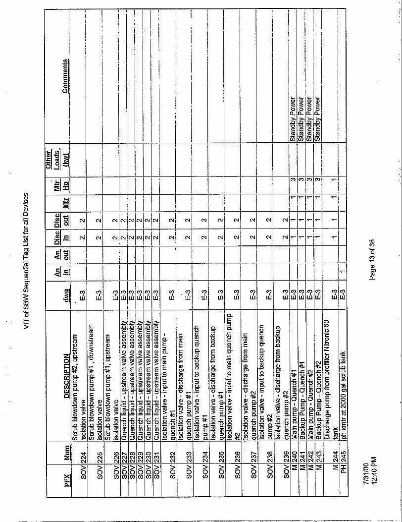
I I
! ! i I
1 I
I I
-& nl -
cu
i
I (vi N
n: co m 0 m u-
v
I
t "j
a, m 2 I
--I---
Q Q /f
c
= j f
m I

! I
i i / I !
co m 0 d.
a, m m
rc
?
a
,
5 o n e 0 'p: s 2
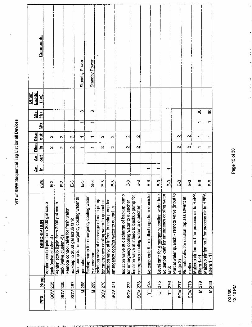
I 1 I f
I
I i
1 i T
I
I Nj hl
A2 7-
W I
i j
i I i ;
j !
I ! I
i I I I i ' i
i I I
_i
r m r
m
a, m m n
3 I I I
E
F L!2
a,
m .c 0 u)
-0
m
.- L .- L
P L
2 ? x
p!

I
i - i ? 1 3
- 9 m >
a, > m > - a, >
m > 1
- a, > m > >
-
> 1 %
! = : ! 3
+ N 1 ai fi !
I ! -i- i hl
w . m O (D
Y-
?
I I
T I F a, t3) m n i
!
I j T I ;hl
m Q) cv
(D Q) hl
2 m

I I ' I I /
- 9 P F >
25 3 m -
- 9 P F 2 m
>
- I -- I / / i ' i I 1
c\ (\I (v (v -?
co CI)
O b
Y-
F
a, rn m a
9 U.
-? w P U. 5 L v w L
I I

cv I cv1
- I i I El r d ! ! i i I
3 -
P W
ai a' n I N/ n I
!
I I ' I
i i I I ,
I W P 3' 9
!
co m 0 a3
rc
r a, 13) m a
,

1 1 I
i i
I i
I !
C
C h -
F _I -r 03 m O Y-
e a, w 2
T
U e 3 m (0
0 rc
5

v)
E' +4
E ' E' 0' 0
i
i I I
I !
I I , I , i i I I
I I
I I i !
I !
I I $13, 1 i i , I ! j I
I I I / I I
(V (V
(V co m 0 0 (V
rc <E[ . j i I
I ?
W 91 3/ W 9 W
,
io m

- - m L
le 3 U u)
cn F
Y- O
.. t >
I I
i 1
I
I I
I I I
(v
(v
(v
a, cn m a

I
i 1 i -
I l i i
I j I
co c')
O N N
Y-
a, m m n
' I

I i
I I
1 I I-
f I
i
i
) I
i
i I I
I
- 0 .T
u) a, 0 > a, .-
. n
I T
N
7 i
03 m O 0 N
Y-
i 9 3 W
Q, m m n L I . I
Y Y 3 rn v)
O Y-
5
W W
a, 5 3

I I 1 ! I
! i I I
I u1 ! I
51 :Il YI 0 1 : I -.
(v
Y W
(v
Y w
i
v
i (vl !
I N!
i
I. W m O w N
Y-
a, t3) m a

- N (v I N
- (v (v co m
0 LD N
'c I r
a, w m a
3 3 W
T u 2 2 G U
, I I
I n r E o c C D U

I
I
I
I
i I
c
c I I
I ! 0 m O CD N
Y- I I i
-71 - 7 1
I . I
I I !
I --!
a, &?I m n
I
I i
w $1 i
9 U G
I I ' I
i I ! E ! E m !
b-- I b-- cc, d E N
a, i= CI - 2 W I L
P
j i

I
' , - L i
I 1 0 m i i 1 I
-?
' I a- l l - I / I !
I I
! I I ,
I I
UI Lu: Lu
,
i !

I I I !
j
9 2 T.
a, ri= Y - 2
i2 2
W I E
c K s
0 m
9 W
0 m
2
U a, Y
.- E Y fn a,
c o - o O co N
Y-
% h

j x
a,
I I I 1 ! f !
] i I I
I
N N n N a, m 0 0, N
rc I I
1
!
x 9 W X 9
W x 'T w w
I I
,-
2 m

tn a, 0 > a, .- n
P 1
- - m L
c. tn
rn F - m K a, 3 u- a, 0
.-
.L
3 m
t
0 O
>
Y-
@ I '5 I I 1 I
a / L .-
- !
co c9 0 0 cr)
rc
a, 0)
h

I
I I
T cu
hl hl (Y N co m O Y-
a, en m a
9 W
9 W
9 w 9 W
9 W
X W 4
i
T
I I I
1 i I I

I
I * r
0 jo C f : x f m a 2 u r m
u)
E p! u
s W u) u) a,
Ir
N d- Lo - z
4 W
4 w
co m 0 N m
rc
a, cs) m n

I I I
1 I I
I I
i i
i I !
I
i
N N C
C N N N a3 m O c9 0
Y-
T 7 Y
a, rn 2 7 Y
I
x (? W x x U
U
c d E e! m u) Y
g
2 Y $!i
2
e ;
-0
N-
m
W I L.
P
> I
L 1 1
t
I 'e Id
s! E e! ([I
v) r:
u
Y
2
2
2
b-
N 2 - 8 i5
W I L P
!

, I i i ! I I I I
I
, 21 ..I I !
I
I
I I
i,- i
9 W
' I I
j j I !
cv
9 W
I
] j ! 1
,
N / Y! r
i 1 I
i
I !
a, u) m

I i l I
i j
I
!
i i !
I i i
1
I i i
I I
I I I !
I i
I
! 1 1
I I i I
I
! I
!
I / l i I I
I I
i i I-.. ! I
I
I
i I

I
E;
E
E
E 0 0
;
- ! i
!
I
I I I
- j
I
!
!
!
i
I
-
!
I
I
-
i
! I
i
I
I
- I I
1 I j
I i
I !
!
r j I I 1
i I i I i i
- i i i
I
- I
i ! I I
T i I
co m 0 a m
rc
a, u) m n

L
42 3 44 m
3 m 0)
0 I- >
IC
-
- I
i
I 1 i
a, m m Q

I
I
I
.El; I
a + (u 0 -
C - L
co m O co m
Y-
a, m m 0-
,

Appendix G
Sketches

C
C
3
B
5 9 S 8 i: A
I -2-
I
INTEC AREA MAP SCALE: l-=250.0'

, . I. .
- . . - _. .
DRAWING rmE b::.' DWG NO. Dm A-E No REV
1 T-1 SITE MAP, AREA MAP AND DRAWING INDEX
2 A-1 SBW-WT MAIN FLOOR PIAN 3 A-2 SEW-MT BASEMENT FLOOR PIAN 4 A-3 HATCH LML PLAN I
. 5
TO m uuIQ( Bum
t i i i i i I i i i i
I I i i I
I I
I I
L in
t 4
\ I
SITE MAP SCALE: NONE
I DRAWING INDEX I
t
A-4 BUILDING O-OIATION - WEST 5
I A-5 1 SECTION
VlTRmCATON OF SODIUM BEARING WASTE FAClllM
,

* m .' rn I
36'-0- L
PERSONNEL ROOM
CRANE
ROOM CONTROL $ 1 11 t - I
r AIR
CRANE Mp REMOT I 14'-0-
5 TON BRIDGE CRANE 7 i- 40'-0-
I WERl I

380*-0-
(0 I
(v v)
n t- 7 7
t
L)'-O' tttt- JUMPER AND
STORAGE ROOM TOOL/REPAIR EQUIPMENT (0
STORAGE A 0
45'-0- I
OPERATING CORRIDOR WALL MOUNTED
\ \
NG CORRIDOR
;iu- b n
15'4' 0.4
I I
FLOOR PLAN rnON = 0'-0'
-2
c
C I b cc
- TURNTABLE
- SHIELDED LOAD OUT PORT
* (C I
0: 7
VllRlRCATlON OF SODIUM BEARING WASTE FAClUlY
D
-
C
c
B
-
A
,
t 4 I 3 1 2 I 1

-N-
8
360'-11'
L - 102'-11"
7 POLAR CRANE OPERATING CORRIDOR
OPERATING CORRIDOR
1 90'-11
SBW-VIT BASEMENT FLO FINISH FLOOR EL = -32'-0'

. .
3'- 0- * LOCK
n n PERSONNEL b
DECON I ROOM 2 D L
Jll U I ' Y - '
w v 53'-3'
0 I
-0 4
*
Il 29'-11
2 PLAN
'TRANSFER CART AND RAIL
* - I a
t 4 I 3 I 2 I 1

C
C
B
s ul I
s 1 ul
: I
r i j 1 I
.!
I
1
!
I HAT$
1
8 7 6 1 5

LEVEL P I A N EL +4a'-4

. . . . . . . . . . . . . . . * . . .. .:. ..... =.:. . . . . . . . . . . . . . . . . . . . . . . . . . . . . _ . .:...:...: .. -.'
MEU
WEST ELE
8 I 7 1 6 I r; J

--
PROCESS BUILDING
TRUCK AIRLOW
ATlON

B
GRADE
r

I EL 50'-0'
I t
- CANISTER
PAR AND CRANE OPERATING MELTER MAINTENANCE CORRIDOR
1
CRANE
I I 7 OPERATING CORRIDOR
n I I I I I I I I
CANISTER1 1 OPERATING CORRIDOR !!
- L J
€AN CANISTER STORAGE
I I
EL 70'-0'
EL 48'-0"
EL 32*-0'
EL 16'-0'
EL 0'-0'
EL -32'-0' 1
t 4 I 3 I 2 I 1
I

20'-4
-N-
NEW VlTRlFlCASlON FAUUM

ILER J
f f < I , ,
I r
3'-0- DOOR
t 4
8- CMU BLOCK WALL MP
VITRIFICATION OF SODIUM BEARING WASTE FACIUN
D
-
C
c
B
-
A

6 5 r-m-acv u 8 7 FROM FRIT
STORAGE 1 I
MATERW HANOUNG SUBMOIGED CONVEYOR
INTEC SBW
3000,000 GAL
INTEC SBW
+lGH3kTESl 300,000 GAL
1
WORK OFF NmZONlC 50
STORAGE 811.5'X44'
,- NmZONlC 50
I 5

TRUCK TRANSPORT PUMPED LQUID
SYRUP
c SUGAR
c 1.5X
qTRUCK
STORAGE
TANKER
%I- & I
NmZONlC 50
I . I - I I
& 1 5-107. HEEL
T
C
F' @
1; .!. FLUSH WAlE3
_I 5-109; HEEL
Dl @ K X
I $ B
I
REcuEmR l m c -RIIM) VlTRlflCAllON OF SODIUM
Y BEARING WASTE FAClLilY ~ W J L S E E L E I NO SCALE
t 4 3

PARilAL WATER QUENCH 1 "8@c==
- 1 I I I I I I
AIR
El
KEROSENE
STAGE 3: TEMP. 180WF-200QF = LOW TO MINIMIZE NOX FORMATION
COMBUSION OF CO WITH LOW EXCESS AIR (APPROX 1 SECOND)
RESIDENCE n x TO COMPLETE
3041 w/REFRAc
TO A TEMP. FOR AUTOlGNmON O F GAS
NU QUENCH HAsrmOy c22
INCONEL 625 .LOW NITRATES
0 CHLORIDES FLOURIDES
STAGE 1: SUB STOlCHlOMElRlC
2 2 W F 0 2 SEC RESIDENCE ENHANCED MIXING W/BLJRNER
HIGH DP COMEUmON AIR
-E-
l
-;

4
EMERGENCY COOLING
1.000 GAL
BACK FLUSH
B
w\STEuOY c22 INCONEL 625
I W A I r M R
1 I /
bQ7c22 I INCONEL 625
- t FROM FRESH WATER
MAKEUP n
70-c TO QUENCH 81
70-c TO QUENCH. 82 .
05'X15' SCRUB TANK
NlTRONlC 50
1x3.
INK: 50
r-5 WATER MANUAL AODmON
wTm X TO SCRUB MNTURl W . I . .
SAMPLE - IN I Lb
VITRIFICATION OF SODIUM BEARING WASTE FAc1UM
( Js
T 4 I 3 I L I I

FACIUM CONFINEMENT
AIR FACIUM I = . HEPA
I
HAsrmOy c22 INCONEL 625
I- J. B5-l ELEcTRlc
REHPT
Y- ELECTRIC
II , 1 7
Os%!
c 316L REPIACEABLE

SAMPLE
f 4 I 3 I 2 I 1

\
I Ei
BIN -
7- DI WATER
VENDOR PRE-MIX -
I I L-- E S
1
F R O M ' PREFILTERS
8 I 7 1 6 1 5

MPANSION
316L
R/HR
CSIX E m U M
2 UTER/HR I
INTEC
WATER RECYCLE -
316L FOR DECON
+p CONVEYOR
r CHEMICAL STORAGE
x PUMP w
@ MANUAL
’ ADDMONS
DECON CHEMICAL
Q-
I - pq PUMP
”$
INTERIM STORAGE
TO MAIN MIXING TANKS 1.
2. 3 AND 4
YltC . l lmll ,-,,3N OF SODIUM BEARING WASTE FAClUM
D
-
C
c
B
-
A
4 I 3 I 2 I 1

f
M E L E R PROCESS
HW CANISTER
3 PLACES
CANISTER Fl TYPICAL BUIL.
1
8 7 6 I 5

. .
I N E AREA
POLAR CRANE
W I N G CELL n-
3W DIAGRAM
CORRIDOR.
~.
n -32'-0'
3
EL 45'-0'
EL 21'-0'
EL 0'-0'
GRADE
. MlRlRCAllON -OF SODIUM BEARING WASTE FAClUM
,
? 4 I 3 I 2 I 1

BQQMs E!& -6808 omcEsANoonimws o
PREFILTER ROOM CFM
ZONE 1
ASM
I 1
ixc!@& €I.€! ROOM CFM
ZONE 2 0 0 0
1800 CRANE CONTROL RM 2700 CONTROL RM Zt.00 COMPUTER RM
PREFILTER
- I I ATM I r---'
I I I I
.m!2!&' .aE! RooM_cN i ZONE 3
0
0
563cFM 1 1 8 9 E L E C R M N E A R O m C E S - 1 2 8 2 90 MEW COMM RM RM 0
HVAC FLOW DIAGRAM
I I I 7 6 5 8

6808 CRI I-
&, 6600 CFM
WIRIRCAiii)N-?lF SODIUM BEARING WASTE FACILITY

I A N 1 4 3 6 0 0 c -
50 HP - CFM
I STACK
c
- -
75 HP
2 l78DD CFM - - 1 6 -
75 HP
HVAC FLOW
STANDBY
8 7 6 5
1-w STANDBY
~~~
SECONDARY CONTAINMENT JWOM CFy R!x%!s
l7l40 HVAC ROOM 1 9 3 9 EXIT CORRIDOR NE 1 7 3 0 4 OPERATING CORRIDOR 1 4 9 9 7 OPERATING CORRIDOR
+- 6- STANDBY
HEPA BANK
HEPA BANK

W ’ STANDBY
53 60 HP _ _ ...
Ta- l MTANOBY
PREFILTER
50 HP
3587 GROUTCELL 4377 - M U P C O I 5198 OECON CELL 3404 HANDS ON MNNTCELL 0 9088 OECON HCUIING TANKS -32
c
- 5 1 2 0 FEED TANKS 0 - 50 HP -3788 MIXING TANK N 0 -
2816 SAMPLECUBICLE 0 - 1 1 4 0 4 CAN COOLING -32 -
-3686 SBW WORK OFF TANK 0 -
-33788 MIXING TANK S 0 -- 306oOcFM A -1
VlTRlflCATlON OF SODIUM BEARING WASTE FACILITY
t 4 I 3 I 2 I 1

-0C4v 2* 8 7
------------_-__-__ BLOCK 2i
i BLOG 6 2 0 I FROM EXISTING j j $ 2 0 0 0 A f 2000AF ZOOOAF ;(r I FRI +- 13L 138 KV INEEL -1-0
, ' s & ? N C . 2 2 T i 2 9 N C 5 ; I LO1 LOOP SCOVlUE 1
6 5
XFR-812-2 b:? 13.8KV - 13.8KV/7.97KV ! XFR -81 2-1
13.8KV - 13.8KV/7.97KV 20/26/33.3/MVA
OA/FA/FOA I - 20/26/33.3/MVA
I 0 A/FA/FO A I !
I
I PSS-NCE-1507A PSS-NCE-1557A I
&NEW TRANSFORMER. 5oooKvA T 1 3 . W - 480/2m
i I I
_i
A N E W TRANSFORMP "r"l"8KV - 480/27;
I I I I
I I
i 4 c c $ 3
208Y/120V CONTROUER
IN= AND MlSC LOADS MIX LOADS JOULE-HEASED
MELTER AND UD HEATER
p?l2r4 MlSC LOADS
ONE LINE DIAGRAM

:XISnNG INEEL
RA
t
LEGEND SCR SIUCON CONTROL mmrn NC NORMALLYCLOSE NO NORMALLYUPEN
NOTES I. ALL MOTOR LOADS ARE LESS mm 100 HP.

QCIIIJ.2 8 7 6 FROM FRlT STORAGE 1 7
MATERIAL HANDLING SUBMERGED CONVMOR
I
r----
+E I . I I I I I ' I
I - 1 !
NITRONIC 50
I - 1 !
lmc SBW
I m c SBW
300.000 GAL
3a4L STORAGE
- I/m sbw

/ r
STEAM

ADDED 02 /' I ! NU aumw STAGE 3-----1'
TEMP. l W F - 2 M ) V F = LOW TO MINIMIZE NOX FORMATION RESDENCE TIME TO COMPLETE COMBUSTION OF CO WITH LOW MCESS AIR (APPROX 1 SECOND)
STA!SE 1: SUB STOIMIOMETRIC = 22#F 0 2 SEC RESIDENCE
%g6z OLOW NmTES
0 CHLORIDES oyuRIDES ~PcL---- . (187 I -' r
ENHANCED MIXING W/BURNER HIGH DP COMBUSTION AIR
I I I I I I 304 FOR DECON 304 FOR OECON I -'TURNTABLE
/ I I ;=== '-iii7Z313 /
/ 1 I
/
I L E m I
- FROM QUENCH #l P - FROM QUENCH 82 P
P-
8 I 7 I 6 I 5

y.--..- INCONEL 625
H
BEARING WASTE FAClUM

8 7 c
A N 143600 CFM
r:
c
I jgt HEpA-34 HEPA-35 HEPA-38 HEPA-37
HEPA-21 HEPA-38 ' ~ 5 mA-22 HEPA-39 =- HEPA-23 HEPA-24 HEPA-25 HEPA-42 L(548
U 3

FACILITY CONFINEMENT
AIR cs
0- /- /- /- I AT> I AT-; I A:> I kL>
,439,' (44y <MI/ (442 I (443 I -r---I 7' -r' 'T'
P--

I
.' D
Ell UNLOADIN
7- DI WATER
B
I I
- . , . . ., .*., .,. . , :. m . : .".S <- I.- . - - - ~ . . ... I . .. .^ . . . .--. I . ,--. -- -~ -

\
5-
t
U 2 IJTER/HR
INTEC RECYCLE
WATER
W'x12' I I
4 I 3 1 2 I 1

C A I


E
. B
PREFILTER
;-@ CRANE CONTROL RM C CONTROL RM C COMPulER RM a
0 0 0
ELEC RM NEAR om= COMY RM MEW RM
HVAC FLOW DIAGRAM - -

-6808 CFM
] A 6 6 0 0 CFM
,
VITRIFICATION OF S BEARING WASTE FA

Appendix H
Engineering Design Fifes

431.02 08/12/98 Rev. 06
5.Sumrnary: . This study examines the viability of vitrification as a method for treating SBW for disposal. This includes a material balance of the process and evaluation of the final waste form for disposal at the Waste Isolation Pilot Plant (WIPP).
A material balance was performed using the program created by D. Taylor and C. Barnes. The vitrified SBW meets the Waste Acceptance Criteria for WlPP for remote handled waste.
Vitrification of SBW is a viable option. It is recommended that a feasibility study be performed to determine the cost and schedule for this option.
6. Distribution (complete package): D. J. Harrell A. L. Olson C. M. Barnes R. R. Kimmitt-
ENGINEERING DESIGN FILE Functional File No.
Page 1 of 1 EDF NO. EDF-1416
1, Project File No. 01 5735
3. Subtask Material Balance & WlPP WAC
2. Projectrrask Vitrification of SBW
14. Title: Material Balance for Vitrification of SBW

TABLE OF CONTENTS
Table of Contents ................................................................................................ i
Attachments ........................................................................................................ ii
Tables ................................................................................................................. II i ...
I
2
3
4
5
6
Introduction ................................................................................................ 4
1 . 1 Scope of Task .............................................................................................. 4 1.2 Purpose ........................................................................................................ 4 1.3 Conclusion ................................................................................................... 5
Design Basis and Assumptions ................................................................ 6 2.1 Assumptions ................................................................................................. 6 2.2 Functional and Operational Requirements .................................................... 6
Waste Description ...................................................................................... 7 3.1 HWL . Glass Waste in Canisters ................................................................. 7 3.2 Ion Exchange Zeolite .................................................................................... 7 3.3 LLW - Grout ................................................................................................. 8 3.4 LLW - Activated Carbon ............................................................................... 9 Process Description ................................................................................. I O . . 4.1 Melter Feed ................................................................................................ 11 4.2 Vitrification Unit .......................................................................................... 13
WlPP WAC ................................................................................................ 14
References ................................................................................................ 15 Regulations and Requirements .................................................................. 15
6.3 Reports ...................................................................................................... 15
5.1 Canister ...................................................................................................... 14
6.1 6.2 Reference Books ........................................................................................ 15
... -- ..... -.-- . ....... .-. ..--.-. . . . . * . . . . . . . . . . . . . ..*7.....- ,<.. ..-XI., . . . . .Cc-..- . v- . . . . . . . . . .

ATTACHMENTS
Attachment I Material Balance Model
Attachment 2 Glass Chemistry
Attachment 3 WIPP WAC
Attachment 4 Sugar Reactions
Attachment 5 Grout from Blowdown
Attachment 6 Radiological Calculations for Specified SBW Waste Packages
.. 11

TABLES
Table I Grout Recipe .................................................................................................................... 8
Table 2 Radiological Characteristics of Grout ........................................................................... 9
Table 3 Frit Composition ............................................................................................................ 11
Table 4 Sugar Reactions in Melter ............................................................................................ 12
..
I ..
iii

I INTRODUCTION
The Department of Energy (DOE) currently stores and manages calcined High Level Waste (HLW) and liquid Sodium Bearing Waste (SBW) that is left over from reprocessing spent nuclear fuel at the Idaho Nuclear Technologies and Engineering Center (INTEC), at the Idaho National Engineering and Environmental Laboratory (INEEL). In October of 1995 the DOE entered into a Settlement Agreement with the state of Idaho that requires the DOE to treat and convert the wastes into acceptable final waste forms for disposal. The Agreement contains several commitments for the treatment and disposal of the HLW and SBW. Under the Settlement Agreement, DOE agreed to meet the following milestones:
Complete calcination of all remaining non-sodium bearing liquid HLW by June 1998. This milestone is completed.
Commence negotiations with the State of Idaho concerning the plan and schedule for treatment of calcined waste by December 1999
Complete calcination (i.e. treatment) of all SBW by December 31, 2012.
Complete treatment of all calcined wastes by December 31, 2035 so that all HLW is "road ready" to be moved out of Idaho for disposal by the year 2035.
Based on the commitments, DOE must determine how to treat the HLW and associated waste streams at INTEC to facilitate ultimate disposal.
1.1 Scope of Task
This study will examine the viability of the vitrification of SBW. This will include updated material balances of the process and the evaluation of the final waste form for compatibility with the Waste Isolation Pilot Plant (WIPP) Waste Acceptance Criteria (WAC).
If the concept is possible, a feasibility study will be performed which will include process and facilities to treat the SBW, from beginning waste input from the INTEC Tank Farm to final waste forms. This will include schedule and cost estimates for construction and operation of the vitrification facility. This is not included in this report.
1.2 Purpose
The primary objective of this study is to determine the viability of direct vitrification of SBW. Calcine treatment with this facility is not included at this time. This EDF will include material balance and flowsheet for vitrification of SBW. The waste forms from the process will be evaluated for disposal. The Engineering Design File (EDF) will include documentation of the assumptions for the process design, material balance and flowsheet.
4

1.3 Conclusion
Vitrification is a viable treatment for SBW. The glass waste in the stainless steel canisters will meet the WlPP WAC, revision 4, for remote handled waste. All secondary waste can be disposed. Undissolved solids (UDS) can be treated by vitrification.
5

2 'DESIGN BASIS AND ASSUMPTIONS
2.1 Assumptions
2.1.1 The calciner in the New Waste Calcine Facility (NWCF) will not operate again. All SBW will be treated by vitrification.
2.1.2 An incidental waste ruling will rule that SBW is not HLW.
2.1.3 The U134 waste code will be added to the WIPP WAC or the SBW will be delisted for U134.
2.1.4 Mercury compounds such as HgCI2 and HgO are reduced to elemental mercury in the N oxid izet@.
2.2 Functional and Operational Requirements
2.2.1 Operating efficiency for the process shall be on a 24 hr per day, 200 days per year basis.
2.2.2 All SBW will be processed in two years.
2.2.3 The vitrified waste produced from SBW must meet the requirements of the WIPP WAC.
6

3 WASTE DESCRIPTION
The primary waste produced by vitrification of SBW is glass. The glass is poured into metal canisters for disposal at either WlPP or Yucca. Other wastes produced by the process include a grouted waste from a side-stream of the scrubber system. HEPA filters from the off- gas system will be changed out periodically and disposed. The GAC absorbs mercury from the off-gas. This will be sent to an off-site vendor for mercury recovery and disposal.
3.1 HWL - Glass Waste in Canisters
3.1.1 Chemical Composition
The chemical and radiological compositions of the vitrified waste a re presented in Attachment 1 , the material balance for the vitrification process.
3.1.2 Radiation Levels
The maximum contact radiation level, calculated for the worst case waste type, is 68 Rem/hr for the canister. The canisters will be remote handled due to the high radiation level. The maximum thermal power is calculated to by 5.7 wattdcanister.
3.1.3 Disposal Site
The canisters containing the vitrified waste are suitable for disposal at either WlPP or Yucca Mountain.
3.2 Ion Exchange Zeolite
3.2.1 Chemical Composition CesiumlStrontium Zeolite
UOP IONSIP IE-95 is a cesium specific, alkali metal alumino-silicate, (Na20, MgO, Ca0).AI2O3.4-6SiO2.H20, ion exchange media. IONSIP IE-95 has a capacity of 2.0-2.5 meqlgm in its anhydrous state. According to Dennis Fennelly (Reference 12), the selectivity of IONSIP IE-95, in order of increase preference is:
LicNacCacCs
UOP IONSIP A-51 is a strontium specific, alkali metal alumino-silicate, Na20.AI2O3.2SiO2.4.5H20, ion exchange media. The capacity for IONSIP A-51 is 5.0-5.5 meq/gm. The selectivity of IONSIP A-51 (Reference 12) is:
CscLicRbcKcNa MgeNaeCaeSr

' I
slag solids
Both UOP IONSIV@ I€-95 and A-51 zeolites a re available in 20x50-mesh form. For IE-95, a decontamination factor (DF) of 10,000 for cesium is expected with a residence time of 12 minutes based on experience at WVDP. The DF for strontium is expected to be about 1000. Since IONSI\$ IE-95 and A-51 a r e non-organic ion exchange media, they do not degrade in a high radiation field.
35.5% 0.25%
3.2.2 Radiological Composition
During operations, the IE-95 zeolite is expected to remove about 21 0 curies of cesium from the feed to the grouting system. About 50 curies of strontium will be removed by A-51. Other radionuclides will not be removed in quantity.
3.2.3 Radiation Levels
The radiation level of the ion exchange columns has not yet been calculated since no transportation is required. '
3.2.4 Disposal
The zeolites can be added to the melter feed. No other disposal is required.
3.3 LLW - Grout
3.3.1 Chemical Composition
The chemical composition of the grout is based on the chemical and radiological composition of the blowdown from the scrub system. Two cases were considered; with and without cesium and strontium removal by ion exchange media. The chemical compositions for both cases a r e given in Attachment 4.
The grout formula used is the s a m e used in for grouting t h e scrubber blowdown from the 1999 vitrification feasibility study. This is documented in the report for final waste forms for INTEC radioactive waste in Reference 8. The density of the grout is assumed to be 1826 kg/m3.
Table 1 Grout Recipe
water 28.7% I cement I 35.5% I
8

3.3.2 Radiological Composition
Grout Heat Generation
watts
Treated 1.9E-4
Untreated 3.4 E-3
The radioactivity of the grout comes from the contamination of the liquid (blowcawn or ion exchange effluent) used to make the grout. Attachment 4 provides the radionuclides present in the grout in Ci/kg.
Contact 1 meter 2 meter 3 meter mR/hr mR/hr mR/hr mR/hr
2.6 0.18 0.06 0.03
460 33 10 5
3.3.3 Radiation Levels
Table 2 Radiological Characteristics of Grout
3.3.4 Disposal Site
The grouted waste is not 400 nCi/g TRU and can be disposed of at Hanford.
3.4 LLW - Activated Carbon
3.4.1 Chemical Composition
A sulfur impregnated granulated activated carbon (GAC) know as MERSORB@ is used for mercury removal. MERSORB@ is 13% sulfur by weight; the remainder is activated carbon. Pellets are available in 1.5 mm, 3 mm or 4mm diameter. The mercury capacity is >20% by weight. Therefore, about 7000 kg of MERSORB@ are required to absorb the mercury in the off- gas.
3.4.2 Radiological Composition
The MERSORB@ absorbers are downstream of the second set of HEPA filters. The off- gas is considered non-radioactive at this point. Therefore, the spent MERSORB@ is not considered radioactive and can be processed by mercury recycling companies.
9

4 PROCESS DESCRIPTION
The SBW is stored in tanks WM-180, WM-181 , WM-184, and WM-186 at INTEC. For the material balance calculations, a composite waste stream is used. There are approximately 3.8 million liters of SBW to be treated.
The SBW will be stored in a tank in the new vitrification facility. The SBW is not filtered. A recirculating pump is used to keep undissolved solids (UDS) in suspension in the SBW feed tank. The SBW will be mixed with glass frit and a sucrose solution. The resulting mixture will be fed at essentially steady state into the melter.
The melter is joule-heated, with a cold cap, capable of producing 136 kg (300 Ib) of glass per hour with wet feed. The melter has a design temperature range of 11 00-1400°C; but is expected to operate between 1100-1 150°C. The melter is capable of handling wet, slurried, or dry waste feed. The cold cap on the melter is maintained by the incoming of feed.
Off-gas from the melter consists mainly of water, carbon monoxide and carbon dioxide, nitrogen and nitrous oxides (N2, NO, and NO2) and air. The off-gas goes to a two-stage Noxidizea. The first stage is the reduction phase. Fuel is combusted with a deficit of oxygen which causes the reduction NO and NO2 to elemental nitrogen, Nz and C02 to CO. The second stage is an oxidation phase. Fuel is burnt with an excess of oxygen at a lower temperature than the reduction phase. Carbon monoxide is oxidized to COz but the temperature of the chamber is insufficient to oxide NZ gas. Mercury compounds will be reduced to elemental mercury in the Noxidizea.
The gas from the Noxidizea is immediately cooled in a quench vessel: This sudden cooling will minimize reoxidation of elemental mercury. This will also provide liquid/gaseous contact for transfer of soluble things like cesium and nitrous oxide to the liquid phase. Entrained solids and condensed mercury will be knocked out of the gas.
This is followed by a venturi scrubber which provides additional liquidlgas contact between the scrubbing water and the off-gas. A demister vessel is used to remove entrained water from the off-gas. This also causes liquidlgas contact at the demister mesh. The gas leaving the demister is saturated with water.
A knock-out drum is used to cool the off-gas and condense some of the water vapor in the gas. The off-gas is heated to prevent condensation in the HEPA filters and the granulated activated carbon (GAC) beds. Two HEPA filters in series remove radioactive and other particulates. The HEPA FILTERS are at least 99.97% efficient on 0.3 micron particles or greater.
Granulated activated carbon filters are used to remove mercury from the off-gas before discharge to the atmosphere.
10

4.1 Melter Feed
4.1.1 SBW Feed
The composition for SBW used for the material balance comes from Reference 6. To meet the goal of completion of processing in two years, the SBW Feed rate will be 395 liter/hr. The SBW has an average density of 1.31 and average pH of -0.3. The SBW is not filtered. Undissolved solids (UDS) in the SBW are fed into the melter with the liquid SBW. The composition of SBW and UDS used is shown in Attachment 1, Table 3.
4.1.2 Frit Feed
A commercial frit is used for making glass in the melter. Experiments by Applied Technology and Clemson University have determined that this mixture of frit is suitable for vitrification of SBW. This frit makes a borosilicate glass.
Table 3 Frit Composition
I Species I Weight Fraction I I B203 I 0.143 I I LEO I 0.027 I
Fe203 0.1 13
4.1.3 Sugar Feed
Sugar in the form of sucrose (C12Hz011) is added to the SBW and frit to create reducing conditions in the melt. Attachment 3 shows the reactions with sugar and HN03 that are expected. The addition of sugar appears to facilitate the nitrate decomposition reactions. Addition of sugar has been observed to reduce foaming and decrease melt time. .-.
Table 4 shows the amount of sugar consumed in each of the projected reactions. For - each liter of SBW liquid (including UDS), 0.651 67 moles of sugar is required.

v 0 0 (D A -
LL
v 0 0 (D
- h
B z
9 0 Lo m -
& tn 3 CD
v s 0 - 0 n
P v
a
v 2
om
0
-
z I

4.2 Vitrification Unit
4.2.1 Melter
The melter is similar to the joule-heated melter in the Transportable Vitrification Unit (TVU). T h e melter will operate a t a temperature of about 1100°C. The melter will produce 124 kglhr (273 Ib/hr) of vitrified waste. The melter has lid heaters to facilitate start up heating of the melter. T h e s e heaters can also be used during operation to help evaporate water from the waste.
Normal operating conditions for the melter will include a continuous feed of SBW, frit, and sugar to the melter. This will maintain a "cold cap" on top of the melted glass. The cold cap helps trap volatile materials such as cesium in the melt. The operation modeled in the material balance does not u s e the lid heaters. The off-gas from the melter is modeled as 200°C.
T h e user specified melter air is the amount of air leaking into the melter d u e to the negative pressure of the system. This air cools fittings and connections on the melter and provides a driving force for carrying water vapor out of the melter. At Savannah River, the melter h a s a n influx of air of approximately 154 sm3/hr. For this material balance, a n influx of 200 sm3/hr (88 scfm) is used but additional air is added d u e to the reducing atmosphere created in the melter by the sugar.

5 WIPP WAC
Revision 7 of the Waste Acceptance Criteria (WAC) for the Waste Isolation Pilot Plant, Reference 2, does not address requirements for remote handled waste. Therefore, the requirements of Revision 5, Reference 1 are used for comparison of the glass waste. The requirements for remote-handled TRU (RH-TRU) must be met. Attachment 2 compares the WIPP WAC requirements to the vitrified SBW.
5.1 Canister
Canisters shall be noncombustible and meet, as a minimum, the structural requirements and design conditions for Type A packaging as contained in 49 CFR 173.41 2. All RH-TRU canisters shall be certified in accordance with DOT Specification 7A, Type A, and shall meet the Type A packaging specifications from the time of RH-TRU waste certification to disposal in the WIPP.
5.1 .I Dimensions
RH-TRU canisters shall be no larger than a nominal 26 inches (0.66 m) in diameter with a maximum length of 10 feet, 1 inch (3.1 m), including the pintle, per Rockwell International Drawing RI-H-2-91273. The weight of the RH-TRU canister must be no more than 8,000 Ibs when loaded.
5.1.2 Surface Contamination
Removable surface contamination on RH-TRU canisters shall not be greater than 20 dpm .per 100 cm2 for alpha-emitting radionuclides and 200 dpm per I00 cm2 for beta-gamma- emitting radionuclides.

6 REFERENCES
_-
6.1 Regulations and Requirements
I . Waste Acceptance Criteria for the Waste Isolation Pilot Plant, DOUWIPP-069, Rev. 5, Chg. 2, dated December 1996.
2. Waste Acceptance Criteria for the Waste Isolation Pilot Plant, DOUWIPP-069, Rev. 7, November 8,1999.
6.2 Reference Books
3. General Chemisty, 5" Edition, Neberghall, W. H, Schmidt, F. C., and Holtzclaw, H. F., Jr., D. C Heath and Company, 1976.
6.3 Reports
4. "Feasibility Study Report for NWCF MACT Compliance Facility", J. K. Rawlins, INEEUEXT-97-00992, November 1997.
5. "Summary of NWCF Calciner Emissions Inventory Data", R. D. Boardman, et. al., INEEUEXT-99-1190, November 1999.
6. "Sodium-Bearing Waste to WlPP Waste (SBW3) Optimization Study," N. 0. Valles, et. al., INEEUEXT-00-00975, November 1999.
7. "CslXTTRU Grout Feasibility Study," S. J. Losinski, C. M. Barnes, B. K. Grover, INEEUEXT-99-00034, November 1998.
8. "Final Waste Form Requirements and Path to Disposal-Volume II: Evaluation of Potential Disposal Sites for INTEC Radioactive Mixed Wastes," by J. Banaee, R. Kimmitt and A. Poloski.
9. "Vitrified Waste Option Study Report", INEEUEXT-97-01389, D. A. Lopez and R. R. Kimmitt, February 1998.
IO. "EDFs Related to HLW EIS Projects for Vitrifying SBW and Calcine (P88) and Calcine Blending and Vitrification (P60)", April 1998.
11. "High-Level Waste Vitrification Facility Feasibility Study", D. A. Lopez, INEEUEXT- 99-00792, August 1999.
12. D. Fennelly, UOP Molecular Sieves, faxed letter to J. Quigley, UOP lONSIV@ Ion Exchangers, October 26, 1995.

Attachment 1 Material Balance Model

TABLE OF CONTENTS
Table of Contents ................................................................................................ i
Tables .................................................................................................................. i i
1
2
3
4
5
6
7
Introduction ................................................................................................ 3
MODEL Spreadsheet .................................................................................. 4 Streams ................................................................................................................. 4
Basis for Input Parameters ........................................................................ 7 Melter .................................................................................................................... 7 NOX Reduce ......................................................................................................... 7 NOX Cool .............................................................................................................. 8 NOX Oxidize .......................................................................................................... 8 Quench .................................................................................................................. 9 Venturi ................................................................................................................... 9 Scrub Tank ............................................................................................................ 9 Demister ................................................................................................................ 9 Knock-Out Drum .................................................................................................. 10 Split Blowdown .................................................................................................... I O Melter Feed ......................................................................................................... 10
Compositions Spreadsheet ..................................................................... I O
In-Streams .......................................................................................................... 11 Offgas Sepn Factors ............................................................................................ 11 NOx Conv ............................................................................................................ 11 Volatility Facs ...................................................................................................... 11
Gas Cp ................................................................................................................ 19 Fuel Calcs ........................................................................................................... 19
Grout Formulation ................................................................................................ 21
Distribution Coefficients .......................................................................... 22
Components .......................................................................................................... 5
General Spreadsheet ............................................................................... 19
Properties ............................................................................................................ 19
References ................................................................................................ 23 Reference Books ................................................................................................. 23 Reports ................................................................................................................ 23

TABLES
Table 1 File: MODEL, Worksheet: Streams .............................................................................. 4
Table 2 File: MODEL, Worksheet: Components ...................................................................... 5
Table 3 File: COMPOSITIONS, Worksheet: In-Streams ...................................................... 12
Table 4 File: COMPOSITIONS, Worksheet: Offgas Sepn Factors ...................................... 18
Table 5 File: COMPOSITIONS, Worksheet: Volatility Facs .................................................. 18
Table 6 File: GENERAL, Worksheet: Gas Cp ......................................................................... 19
Table 7 File: GENERAL, Worksheet: Properties .................................................................... 21
' I
.. 11

I INTRODUCTION
Vitrification of sodium bearing waste (SBW) at the Idaho Nuclear Technology Engirieering Center (INTEC) of the Idaho National Engineering and Environmental Laboratory (INEEL) is being developed. SBW is a radioactive liquid waste with high concentrations of sodium in the waste. The waste is also a hazardous waste under RCRA. A model has been developed to generate the material balance for this process. The model uses Excel macro programs and user supplied input to create the material balance. The output is in the form of an Excel spreadsheet.
Presented in this report are the input used by the model to generate the material balance for vitrification of SBW and the basis for the input values. Also presented is the material balance and process flow diagrams (PFD) for the process.
3

2 MODEL SPREADSHEET
"From" Component "From" Component Stream Stream Stream ID "To" Component 'To" Component Type Type Stream Type
Input liquid SBW Liquid SBW Feed IN-aqueous
Input liquid UDS SBW Feed IN-aqueous
SBW Feed OUT-combined liquid SBW Melter Feed IN-aqueous
Input liquid Sugar Melter Feed IN-aqueous
Input solid SBW Frit Melter IN-frit
Melter Feed OUT-com bined liquid SBW & Sugar Melter IN-feed
Input gas Melter Air Melter IN-air
Melter OUTjlass solid Glass output
Melter OUT jas gas MelterOG NOX Reduce IN-offgas
Input gas NOX Reduce Air NOX Reduce IN-air
Input gas Fuel Reduce NOX Reduce IN-fuel
NOX Reduce OUT-offgas gas NOX Reduce OG NOX Cool IN-offgas
Input liquid NOX Cooling Water NOX Cool IN-water
NOX Cool OUT-offgas gas NOX Cool OG NOX Oxidize IN-offgas
Input gas NOX Oxidize Air NOX Oxidize IN-air
NOX Oxidize OUT-offgas gas NOX Oxidize OG Quench IN-offg as
Scrub Tank OUT-aqueous liquid Quench Water . Quench IN-quench
Quench OUT-quench liquid Quench Water Out Scrub Tank IN-aqueous
Quench OUT-offgas gas QuenchOG Venturi IN-offg as
Scrub Tank OUT-aqueous liquid Venturi Water Venturi IN-quench
Venturi OUT-quench liquid Venturi Water Out Scrub Tank IN-aqueous
Venturi OUT-offgas gas VenturiOG Demister IN-offgas
Demister OUT-liquid liquid Demister Water Scrub Tank IN-aqueous
Demister OUT-offgas gas Demister OG Knock-Out Drum IN-offgas
Knock-Out Drum OUT-liquid liquid Knock-Out Water Scrub Tank IN-aqueous
NOX Cool INTER-offgas gas NOX Cooling output
Knock-Out Drum OUT-offgas gas Knock-Out OG output
Scrub Tank INTER-aqueous liquid Scrub Comp output
Input liquid Makeup Scrub Scrub Tank IN-makeup
Scrub Tank OUT-ovefflow liquid Scrub Blowdown Split Blowdown IN-stream
Split Blowdown OUT-stream liquid Blowdown Recycle SBW Feed IN-aqueous
Split Blowdown OUT-stream liquid Blowdown output
Streams ' I
The model file defines the components and the material streams used by the model. The "Streams" worksheet defines how material balance streams connect components (unit operations or groups of unit operations). The input is shown in Table 1.
Table 1 File: MODEL, Worksheet: Streams
4

Components
Input on the "Components" worksheet names each component identifies which calculation module the model is to u s e for that component, and provides input parameters needed in the calculations for that component. Table 2 contains the input for components. The column on t h e right contains information that is not needed by the model. It is included to help identify t h e input parameter o r to ensure proper units for the parameter value.
Table 2 File: MODEL, Worksheet: Components
JAME TYPE PARAMETERS INDEX (0 for non- VALUE (units assumed in
delter Melter Waste type 0 ' SBW code or description) arrays)
Glass waste loading SBW 0.35 Glass waste loading AI calcine 0.07 Glass waste loading Zr calcine 0.09 Glass waste loading Na calcine 0.16 Excess air to melter 0 0 Fractional wnv HNOSN2 0 0.05
Nom02 ratio in offgas 0 1 Melter offgas temp4 0 200 User specified air 0 200 (sm3hr)
JOX Reduce LAW-DeNOx Fuel converted to C o r n 2 0 0 0.3855 fraction Fuel converted to COR120 0 0.1823 fraction Fuel converted to COZH2 0 0.4322 fraction NO conversion 0 0.965 fraction NO2 conversion 0 0.999 fraction Reduction temperature 0 1205 degrees C Energy release by NO reduction 0 21.6 kcaVmol Energy release by NO2 reduction 0 8.041 kcaUmol Fuel type 0 Kerosene "Kerosene" or
"Natural gas" NOX Cool LAW-Cool Quench water enthalpy change 0
Cooling chamber temperature 0 942.4 kcahg 760 degrees C
Solids heat capacity 0 0.233 caVgm-C=kcaVkg-C NOX Oxidize LAW-ReOx CO oxidation fraction 0 0.985
H2 oxidation fraction 0 1 H2S oxidation fraction 0 1 Fractional excess air 0 0.5
Quench LAW-Quench Quench tower temperature 0 81.9 "C
Solids heat capacity 0 0.233 caVg-OC Quench tower pressure 0 9.8 psia I Device type 0 Quench tower
Outlet liquid density 0 1 g/=
5

NAME N P E PARAMETERS INDEX (0 for non- VALUE (units assumed in
Venturi LAW-Quench Solids heat capacity 0 0.233 calIg-"C arrays) code or description)
Quench tower pressure 0 9.4 psia Liquid entrainment fraction 0 0.0010
Device type 0 Venturi ("Quench tower" or scrubber "Venturi scrubber")
LiquidlGas ratio 0 1.5 liffsm3
Outlet liquid density 0 1 glee
Scrub Tank LAW-Scrub- Makeup divided by total flow 0 Tank
0.0022
"03 molarity in makeup 0 0 Molar Scrub outlet temperature 0 75.4 degrees C
out drum") Demister LAW-KO Device type 0 Demister ("Demister" or "Knock
Liquid separation fraction 0 0.9
Outlet liquid density 0 1 Knock-Out LAW-KO Device type 0 Knock out ("Demister" or "Knock Drum drum out drum")
Knock out drum pressure 0 9.7 psia
Outlet liquid density 0 1 gmlcm3
Knock out drum temDerature 0 76.9 degrees C
ISplit Blowdown Split-liquid Flow fraction 0 Stream to receive fraction 0 I
0.97
Blowdown Recycle
SBW Feed Jct-liquid
Melter Feed Jct-liquid
6

3 BASIS FOR INPUT PARAMETERS
Type: Melter
The melter is similar to the joule-heated melter in the Transportable Vitrification Unit (TVU). The melter will operate at a temperature of about 1100°C. The melter has lid heaters to facilitate start up heating of the melter. These heaters can also be used during operation to help evaporate water from the waste. Normal operating conditions for the melter will include a continuous feed of SBW, frit, and sugar to the melter. This will maintain a "cold cap" on top of the melted glass. The cold cap helps trap volatile materials such as cesium in the melt. The operation modeled in the material balance does not use the lid heaters. The off-gas from the melter is modeled as 200"C, based on actual operation the Savannah River melter which ranges from 200 to 350°C.
The user specified melter air is the amount of air leaking into the melter due to the negative pressure of the system. This air cools fittings and connections on the melter and provides a driving force for carrying water vapor out of the melter. At Savannah River, the melter has an influx of air of approximately 154 sm3/hr. For this material balance, an influx of 200 sm3/hr (1 18 scfm) is used.
The waste loading is 35% on a dry basis taken from experimental results using a SBW simulant. Fractional conversion of "03 to N2 is assumed to be 0.05. The ratio of conversion to NO and NO2 is expected to be 1 :I.
Sugar is expected to be oxidized to CO and H20 in the melt. All organics in the feed, including the CO from the sugar, are assumed to be oxidized to C02 and H20 in the melter air. . The input parameter "Excess air to melter" sets the air rate to exceed the stoichiometric requirements for oxidation. Insufficient oxygen is available from the "User specified air" parameter. Additional air is added to oxidize the CO from sugar reduction to Con.
NOX Reduce
Type: LAW-DeNOx
The NOX Reduce module is the first of three modules needed to model a NoxidizerTM, which reduces nitrous oxides (NO,) to nitrogen gas (N2). John Zink Company manufactures the "NoxidizerTM. Information on the operation of the Noxidizerm is in Attachment 3 to Appendix E of Reference 3. The first stage is a high-temperature >1200"C (>2200"F) combustion chamber that operates in a reducing atmosphere by limiting the amount of available oxygen. An operating temperature of 1205°C (2200°F) is used in the model.
For the material balance, kerosene is used as the combustion agent. Natural gas could also be used but kerosene was chosen because it is already used at INTEC for the NWCF. The conversion fractions used for CO and H20, C02 and H2, C02 and H20, NO, and NO2 are based on the information from John Zink. The heats of reaction for the reduction of NO and NO2 are calculated from tables of standard heats of formation.
7

NOX Cool
Type: LAW-Cool
T h e second s tage is a partial quench of the g a s to 760°C (1400°F) based on operation information in Attachment 3 to Appendix E of Reference 3. This reduces the temperature so N2 and O2 don't recombine. Cooling water is sprayed into the gas. T h e quench water enthalpy change is taken from ASME Steam Tables, 3'' Edition, for 80°F quench water converted to 1400°F (760°C) steam. T h e heat capacity for entrained solids is assumed to b e 0.233 cal/g-"C which is the heat capacity of borosilicate glass taken from Chemical Engineers' Handbook, 5* Edition.
NOX Oxidize
Type: LAW-ReOx
T h e third-stage of the Noxidizer is another combustion chamber. T h e temperature of the combustion chamber is maintained between 980 - 1090°C (1800 - 2000°F) to limit the formation of thermal NOx. Excess air is added to create a n oxidizing atmosphere to combust the remaining fuel. Enough air is injected to give a n excess oxygen level of 1.5% to 2 % by volume on a dry basis in the final flue gases. Residence time is about 1 second.
T h e input for fraction of excess air is based on percent excess oxygen required for combustion rather than excess oxygen in the final flue gases . Therefore, the fractional excess air is found by trial to be 50% which results in a n excess oxygen level of 1.6% by volume on a dry basis in the flue gases.
8

Quench
Type: LAW-Quench
T h e component type "LAW-Quench" is used for both quench towers and venturi scrubbers. For this component, the input parameter "Device type" is set to "Quench Tower."
T h e temperature of t h e quench tower is s e t to keep the ratio of liquid to g a s similar to that in t h e quench tower operated with the calciner at NWCF. Information about the operating conditions of the NWCF quench tower a r e taken from Table A I of Reference 4. The ratio used is approximately 7.5 liters quench water per 1 sm3.
T h e heat capacity for entrained solids is assumed to b e 0.233 caVg-"C as discussed for NOX Cool. The quench tower pressure (9.8 psia) is based on a Noxidizer pressure of 10 psia. A density of 1 .OO g/cm3 is assumed for the quench liquid effluent.
Venturi
Type: LAW-Quench
T h e input parameter "Device type" is s e t to "Venturi scrubber" for this component. The liquid to gas ratio is based on the operating conditions of the NWCF venturi scrubber shown in Table A I of Reference 4. A ratio of 1.5 liters/sm3 is used. T h e heat capacity for entrained solids is assumed to b e 0.233 cal/g-"C. The pressure drop in the venturi is assumed to be 0.4 psi. T h e density of the liquid is assumed to be I .OO. T h e fraction of liquid entering the venturi scrubber which is entrained in t h e gas stream is 0.001. This assumes that there is a liquid collection drum after t h e venturi scrubber.
Scrub Tank
Type: LAW-Scrub-Tank
Cesium and other compounds accumulate in the scrub solution. A portion of the scrub solution is drawn off as a blowdown stream. T h e input variable "Makeup divided by total flow" is the ratio of the blowdown stream to the total flows into the scrub tank. A fraction of 0.0022 is used. Water is used to for make-up scrub solution with a HN03 molarity of 0. The scrub outlet temperature after cooling is assumed to be 754°C
Demister
Type: LAW-KO
T h e s a m e component type is used for both the Demister and Knock-Out Drum. For this component, the input parameter "Device type" is "Demister." The input "Liquid separation fraction is 0.90 since most entrained liquid is removed after the venturi scrubber. T h e liquid is assumed to have a density of 1.00.
9

Knock-Out Drum
Type: LAW-KO
This component includes a per-HEPA heater, a prefilter, two s tages of HEPA filters, a cooler, and a knock-out drum. The “Device type” is ”Knock out drum.” The pressue is 9.7 psia based on a fan upstream of the HEPA filters boosting the pressure to 12 psia and a 2.3 psi pressure drop across the filters and cooler. The temperature of the cooler is 76.9”C.
S pl it BI owdown
Type: Split-liquid
The component Split Blowdown divides the stream “Scrub Blowdown” into two streams, “Blowdown Recycle” and “Blowdown”. The flow faction to the stream “Blowdown Recycle” is 0.97.
SBW Feed
Type: Jct-Liquid
The SBW Feed component mixes the stream “SBW Liquid” with the stream “UDS” to create the liquid was te stream, “ S B W to the melter. No input parameters a r e required.
Melter Feed
Type: Jct-Liquid
The Melter Feed component mixes the stream “Blowdown Recycle” with the s t reams “ S B W and “Sugar“ to create the liquid waste stream, “SBW & Recycle” to the melter. No input parameters a r e required.
10

4 COMPOSITIONS SPREADSHEET
I n-Streams
The “In-Streams” worksheet is the only place that lists chemical and radionuclide species that are used in the model. The list is divided in to five sections: “chemicals,” which includes all ions, “nuclides,” “compounds,” gases,” and “others” which includes UDS, organics, fuels, ion exchange resins and grout additives. Also included is the charge for ionic species, molecular weights for ionic and gaseous species, and half-lives for radionuclides. This data is provided in Table 3.
The compositions of the sodium bearing waste liquid phase and undissolved solids phase are taken from “Sodium-Bearing Waste to WlPP Waste (SBW3) Optimization Study,” N. 0. Valles, et. al., INEEUEXT-00-00975, November 1999. This is consistent with the other SBW treatment feasibility studies being performed.
Offgas Sepn Factors
The “Offgas Sepn Factors” worksheet contains separation factors of the melter offgas components. The separation factors are given a s the fraction of the melter feed that is carried into the offgas. The values shown in Table 4 are taken from Reference 6
NOx Conv
The worksheet “NOx Conv” is not used for this model.
Volatility Facs
The “Volatility Facs” worksheet shows volatility factors for the off-gas treatment equipment. Factors are taken from Reference 5 with the exception of mercury. Mercury is expected to be in elemental form when it exits the Noxidizerm, not HgO or HgQ. The factors used are that 99% of the mercury passes through the quench and venturi scrubber and that 99.5% passes through the demister.
11

R
E
n E

N 8
0 4 c-
m 8 &! 7 c-
0 0 0 0

I- Q, m I- N 0 w - u - o r t c d
r c
w u 0 0
N I-

(9
(0 x
(D
10 x
0 0 0 0 0 0

. .. . - -. . . . . -
Q, c- s 2
m c-
0 2 k
0 0 0 0 0 0 0 0 0 0 0 0 0 0 0 0 0

0 0 0 c-
0 0 0 0 L

Table 4 File: COMPOSITIONS, Worksheet: Offgas Sepn Factors
SDecies Fraction Ag+l A1+3 As+3 B+3 Ba+2 Ca+2 Cd+2 Ce+4 CI-I Cr+3 Cs+l F-I Fe+3 H+l Hg+2 K+l Mg+2 Mn+2 Mo+6 Na+l Nb+5 Nd+3 NH4+1 Ni+2 N03-1 Pb+2 Pd+3 PO43 Pr+3
0.02 0.01 0.01 0.01 0.01 0.01 0.01 0.01 0.50 0.01
0.0333 0.25 0.01
1 1
0.01 0.01 0.01 0.01 0.01 0.01 0.01 0.01 0.01
1 0.01 0.01 0.01 0.01
Species Fraction Ru+4 0.04 Se+4 0.25 Si+4 0.01 Sn+4 0.01 Sr+2 0.01 SO4-2 0.2 Zr+4 0.01 Am+4 0.01 I 0.91 Np+4 0.01 Pu+4 0.01 Tc+7 0.5 u+4 0.01 Ac+3 0.01 At 0.91 Be+2 0.01 Bi+3 0.01 Br-I 0.705 c+4 1 Cf+3 0.01 Cm+3 0.01 Dy+3 0.01 Er+3 0.01 Eu+3 0.01 Fr+l 0.01 Ga+3 0.01 Gd+3 0.01 Ge+2 0.01 H0+3 0.01
Species Fraction ln+3 0.01 La+3 0.01 Li+l 0.01 Pa+4 0.01
. Pm+3 0.01 P0+2 0.01 Ra 1 Rb+3 0.01 Rh+3 0.01 Sb+4 0.01 Sm+3 0.01 Tb+3 0.01 Te+4 0.01 Th+4 0.01 T1+3 0.01 Tm+3 0.01 Y+3 0.01 Yb+3 0.01 Zn+2 0.01 Am-241 0.01 Am-243 0.01 Cm-242 0.01 Cm-244 0.01 Np-237 0.01 Pu-238 0.01 P~1-239 0.01 Pu-240 0.01 PU-241 0.01 PU-242 0.01
Species Fraction Th-230 0.01 Th-231 0.01 U-232 0.01 U-233 0.01 u-234 0.01 U-235 0.01 U-236 0.01 U-237 0.01 U-238 0.01 Ba-I 37m 0.0333 ce-I 44 0.01 c0-60 0.01 cs-I 34 0.0333 cs-I 35 0.0333 cs-I 37 0.0333 EU-I 52 0.01 Eu-I 54 0.01 Eu-155 0.01 Pm-147 0.01 Pr-144 0.01 Ni-63 0.01 RU-106 ' 0.04 Sb-125 0.01 Sm-151 0.01 Sr-90 0.01 To99 0.5 Y-90 0.01 H-3 1 1-1 29 0.91
Table 5 File: COMPOSITIONS, Worksheet: Volatility Facs
species Quench Venturi Demister Prefilter HEPA HEPA LAW KO tower scrubber Stage 1 Stage 2 drum
solids 0.05 0.05 0.05 0.05 0.005 0.01 1
HCI 0.1 0.1 0.5 1 1 1 1 HF 0.1 0.1 0.5 1 1 1 1
Hg 0.99 0.99 0.995 1 1 1 1 1-129 0.1 0.1 0.5 1 1 1 1 H-3 1 1 1 1 1 1 1
18

5 GENERAL SPREADSHEET
Gas Cp
Worksheet “Gas Cp” contains specific heat equations for gases taken from Table 2-1 94 of Reference 23. The equation form and constants for the equations are shown in Table 6.
Table 6 File: GENERAL, Worksheet: Gas Cp 1~
Specific heat equations (T in K), cal/K-gmol Gases A B C D Equation
Ar 4.97 Cp=A
c 0 2 10.34 2.74E-03 -1.96E+05 Cp=A+ B*T + C P 2
HCI 6.7 8.40E-04 Cp=A+ B T HF 6.6 8.40E-04 Cp=A+ B T
Hg(g) 4.97 Cp=A H20(g) * 8.22 1.5OE-04 1.34E-06 Cp=A+ B T + D*TA2
N2 6.5 1.00E-03 Cp=A+ B T
NO 8.05 2.33E-04 -1.56E+05 Cp=A+ B T + C/TA2 NO2 12.185 3.62E-04 -3.44E+05 Cp=A+ B T + C P 2 0 2 8.27 2.58E-04 -1.88E+05 Cp=A+ B T + C P 2
s o 2 7.7 5.30E-03 -8.30E-07 Cp=A+ B T + DTA2
Fuel Calcs
The “Fuel Calcs” worksheet performs fuel calculations for the denitrator and Noxidizerm. ..
The only input values on the worksheet are the sulfur content and molecular weight of the kerosene. The molecular weight is based on assuming an average formula for kerosene of C12H26. The sulfur content of kerosene is 0.0029 grams sulfur per gram of kerosene per Reference 5.
Properties
Worksheet “Properties” contains thermal properties of water, composition and heating values for natural gas and kerosene, composition of air, and the composition of organic species in terms of carbon, hydrogen, oxygen and nitrogen. Information for natural gas, air, NGLW, TRUEX solvent and SREX solvent are included because the program expects this information. The data is not used for calculations in this model.
19

However, to model the addition of sugar to the melter feed, HEDPA properties have been replaced with sugar properties. The number of moles of each element is calculated per gram of sugar as shown in Table 7. Since the hydrogen and oxygen are in stoichiometric ratio for water, the moles per gram are not included in the “Properties” worksheet. T h e water in the sugar is included in the water of dissolution for making the sugar solution.
C12H22011 Number of Molecular
C 12 ~12.01115
atoms weight
Values used for the “Properties” worksheet a r e shown in Table 1
gramslmole wt% Mlgram
144.1338 42% 0.0350569
Table 7 Sugar Properties
H 122 11.0079
0 I 1 15.9994
Total
22.1738 6% 0.0642709
175.9934 51 % 0.0321 355
342.30 1 100%
20

I aDie tl we: ULNLKAL, vvorKsneer: rropemes
Specie property ID value units H20(1) H20(1) latent heat, kcaUkg 544.8 1 kcal/kg
H20(1) heat capacity 1 kcal/kg-G H20(1) latent heat, kcal/mol H20 MW 18.0154
Natural gas C2H6 fraction Natural gas C3H8 fraction Natural gas C4HlO fraction Natural gas C02 fraction Natural gas N2 fraction Natural gas. heating value to COUH20 Natural gas heating value to CO/H20 Natural gas heating value to COUH2
9.814970074 kcal/mol
Natural gas Natural gas CH4 fraction 0.904 mole fraction 0.053 mole fraction 0.017 mole fraction
0.0066 mole fraction 0.0055 mole fraction 0.0139 mole fraction 203.91 kcaVmole natural gas
175.185 kcaUmole natural gas 84.384 kcaUmole natural gas
Kerosene Kerosene sulfur content 0.0029 wt%
, .
Kerosene density Kerosene heating value to COUH20 Kerosene heating value to CO/H20 Kerosene heating value to COUH2 Kerosene heating value to CH4/C2H4
0.75 kg/lit 1795.02 kcaVmole kerosene 1478.03 kcaVmole kerosene 1043.65 kcaVmole kerosene
0 kcaVmole kerosene Kerosene density 0.75 kg/lit
Mole fraction 0 2 in air Mole fraction Ar in air
NGLW M/gm C in NGLW 0.039934 M/gm H in NGLW 0.069251 M/gm 0 in NGLW 0.038721 M/gm N in NGLW 0.002962
Air Mole fraction N2 in air 0.78 mole fraction 0.21 mole fraction 0.01 mole fraction
HEDPA Mlgrn C in HEDPA 0.035056865 SUGAR M/gm H in HEDPA 0 Mlgrn 0 in HEDPA 0 M/gm N in HEDPA 0
M/gm 0 in Truex solvent M/gm N in Truex solvent
Mlgm 0 in SREX solvent M/gm N in SREX solvent
Truex solvent Mlgm C in Truex solvent 0.0713 0.1426 0 0
SREX solvent M/gm C in SREX solvent 0.071 3 0.1426 0 0
Mlgm H in Truex solvent
M/gm H in SREX solvent
Grout Formulation Although the worksheet "Grout Formulation" is included in the file "GENERAL" the model
does not use the information.
21

6 DISTRIBUTION COEFFICIENTS SPREADSHEET
T h e distribution coefficients a re not used for this model. The file is included because the program expects to find it.
' I
22

7 REFERENCES
Reference Books
I. General Chemisty, 5" Edition, Neberghall, W. H, Schmidt, F. C., and Holtzclaw, H. F., Jr., D. C Heath and Company, 1976.
2. Chemical Engineers' Handbook, 7" Edition, Perry.
Reports
3.
4.
5.
6.
"Feasibility Study Report for NWCF MACT Compliance Facility", J. K. Rawlins, INEEUEXT-97-00992, November 1997.
"Summary of NWCF Calciner Emissions Inventory Data", R. D. Boardman, et. ai., INEEUEXT-99-1190, November 1999.
CMB-06-99, TRANSMITTAL OF INTEC SODIUM-BEARING WASTE AND CALCINE FULL SEPARATIONS MATERIAL BALANCE MODEL INPUT AND BASIS, dated September 14, 1999.
.DS197-GES-024, MELTER OFFGAS TECHNOLOGY INFORMATION, dated June 30,1997.

-ci-nN X l 8 7
QUENCH WATER A
6 5
NOXlDltER
I t 10
- "p I
SUGAR
UDS
SBW
c
r I
M A E UP WATER I
34
GROUT
8 I 7 1 6 1 . 5

t JENCH -- E N l l J R I M l S T TANK SCRUBBER ELIMINATOR
D
NOXlDEf?
2 . 4
e-
--@
ACTIVATED CARBON WITH sum 1
- A
t
J I

Vitrification of SBW 512
1 of 14
- -------- . ..--.. . . . . ~ I . ... . . . .. -72-7 --_F_T

. . . -. . .
Vitrification of SBW 5/24/00
2 of 14

.. .
Vitrification of SBW 512
3 of 14
:4/00

Vitrification of SBW 5/24/00
Stream Name Units Volume or Rate
SBW 8 Sugar Melter Feed Melter Air Glass Melter OG NOX Reduce Air
lit/hr kglhr sm3Ihr kg/hr sm3lhr sm3/hr 524 773 364 127 I 1,114 122
4 of 14

Vitrification of SBW 5/24/00
0

Vitrification of SBW 5/24/00
h
Stream Number 11 12 0 14 15 16
Stream Name Fuel Reduce OG NOX Cooling Water NOX Cool OG NOX Oxidize Air Units kglhr sm3lhr sm3Ihr Whr s m 3 h sm3lhr Volume or Rate 52 1,328 1,328 232 1,643 208
NOX Reduce NOX Cooling
6 of 14

Vitrification of SBW 5/24/00

Vitrification of SBW 5/24/00
8 of 14

r
Vitrification of SBW 5/24/00
9 of 14

.
Stream Name Units Volume or Rate
Vitrification of SBW 5/24/00
Venturi OG Demister Water I Demister OG Water Knock-Out OG Makeup Scrub sm3lhr litlhr 1 sm3lhr liihr sm3hr litlhr 2,893 4 2,892 808 1,796 21
I
‘ I
10 of 14

Vitrification of SBW 512,
11 of 14
4/00

Vitrification of SBW 5/24/00
Stream Number
Stream Name Units Volume or Rate
29 30 31 32 33
Scrub Comp Scrub Water Scrub Blowdown Recycle Blowdown IX liffhr liffhr liffhr liffhr W h r liffhr 18.383 18,342 40 39 1.2 1.2
Blowdown Blowdown after
12 of 14

Stream Number
Stream Name
5/24/00 34 35 36
Dry Grout Mix LLW Grout Off-Gas to Stack
Hg(g) 0 2.36E-09 H 2 0 O.OOEiO0 H2S 0 O.OOEiO0
13 of 14

.
Stream Name Units Volume or Rate
Dry Grout Mix LLW Grout Off-Gas to Stack kglhr kglhr sm3lhr 3.0 4.2 1,796
Pu-240 Pu-241 Pu-242
7.15E-07 7.85E-16 1.56E-05 1.71 E-I4 6.06E-10 6.66E-19
Th-230 U-232 U-233
1.29E-11 1.42E-20 6.39E-11 7.01 E-20 2.13E-13 2.34E-22
cs-134 cs-I 35 cs-I 37
3.17E-10 3.48E-15 8.69E-12 9.55E-17 5.20E-07 5.71 E-I 2
~ ~~~ .~
11-129 I I 4.17E-05 I 1.97E-07 1
Sb-125 Sm-I51 Sr-90
5/24/00
1.17E-06 1.29E-15 1.6OE-05 1.76E-14 1.48E-06 1.63E-12
14 of 14
To99 8.21 E-05 Y-90 1 -48E-06 H-3 0
9.01E-14 1.63E-12 8.08E-06

Attachment 2 Glass Chemistry

Attachment 3 WIPP WAC
Container Description Canister Gross Weight
CRITERIA I LIMITS 0
0 <8000Ibs DOT Type A RH Canister
0 20 dpmlIO0 cm2 Alpha 0 200 dpml100 cm2 Beta-
Gamma'"'
Removable Suiface Contamination
Will be decontaminated to these limits.
Dunnage Filter Vents Liquids
Pu-239 FGE Pu-239 Eauivalent Activity
0 Limited to inside canister None 0 Canisters vented Yes 0 No liquid Wastes . No Free Liquids - Solid Glass 0
0
0 ~325glCask 87.3 g Pu-239 FGUcanister 0 1000 PE-CV canister 9.2 PE CVcanister
6 liters total residual liquid
1 in. (2.5 cm) in the bottom per canister
of any container
Contact Dose Rate .
Thermal Power
0 1000 remlhr per canister 68 remlhr 0 Preapproval received for
> 100 rem/hr per canister 200 mremlhr per Cask
0 300 wattslcanister 5.7 wattslcanister TRU Alpha Activity
Pyrophoric Materials
Mixed Wastes
Chemical Compatibility
0 > 100 nCi/g of waste matrix 6530 nCilg
0 1% Radionuclides No non-radionuclide pyrophorics
0 No non-radionuclide
0 Characterization per QAPP U-123 needs to be added to wlpp WAC or delisted from
0 Chemicals allowed by the
and 23 CVliter 6.53E-6 Cilliter
Pyrophorics
pyro p ho rics
Limited to EPA Waste Codes listed in WAC waste.
RH-TRAMPAC Hazardous Constituents
Explosives, Corrosives and ComDressed Gases
0 Target analytes and TICS
0 None Present None reported per QAPP
PCBs Concentration Table 1.2.7 Flammable VOCs
VOC Concentration
0 <50ppm None 0 500 ppm in canister No VOCs.
0 Limits show in WAC No VOCs. headspace

Attachment 4 Sugar Reactions
R. R. Kimmitt has compiled the following list of possible reactions for sugar, sucrose, and components of SBW. It is assumed that each reaction predominates in the given temperature range.
Below 120°C
12 "03 + C12H22014 -+ 17 H 2 0 + 6 NO + 6 NO2 + 12 CO
120°C - 170°C
4 AI(N03)3 + C12H22011 11 H 2 0 + 6 NO + 6 NO2 + 12 CO + 2 A1203
170°C - 350°C
350°C - 600°C
4 NaN03 + 8 C -+ 2 N a 2 0 + N 2 + 2 NO+ 8 CO
4 K N 0 3 + 8 C -+ 2 K 2 0 + N 2 + 2 NO + 8 CO
Above 600°C
Fe203 + C -+ 2 FeO + 8 CO
Notes:
1. About 99% of all NOycan be accounted for in the reactions above. it is assumed that nitrate salts of other metals (Ni, Cr, and Cd) account for the remainder.
2. The reactions shown above are not the only ones possible. For example, nitric acid can react as follows in concentrated form:
The reactions shown above that form CO are assumed to be the aggregate of possible reactions.
3. It has been observed that the addition of activated carbon to the SBW-frit mixture results in a significant increase in melt rate. One possible reason for this is the facilitation of nitrate decomposition. Because of the very large amount of nitrate in the SBW, it is likely that nitrate salts must decompose to produce glass-forming species (K20, Na20, A1203, etc.). Nitrate decomposition reactions then become rate limiting. Sugar causes such reactions to occur more easily, possibly at lower temperatures.

Attachment 5 Grout from Blowdown
.-
density l- Cs+l
F-I
Fe+3
H+l
Blowdown with Cesium
1.11
1.01
Moleslhr
Hg+2
K+l
Mg+2
Mn+2
Mo+6
Na+l
Ni+2
N03-1
Pb+2
PO4-3
Ru+4
Se+4
si+4
so4-2
Zr+4
u+4
Zn+2
Total
7.10E-06
7.79E-02
9.22E-06
3.38~-03
7.84E-06
6.81E-03
6.64E-04
2.56E-02
7.02E-04
3.70E-06
3.77E-02
3.01E-03
6.33E-02
1.26E-06
2.24E-02
2.30E-04
1.75E-03
1.47E-04
2.01 E-01
3.39E-04
O.OOE+OO
1.40E-04
1.41 E-03
1.8OE-04
6.02E-05
5.02E-04
O.OOE+OO
2.23E-03
2.66E-04
9.87E-05
7.7E-04
2.1E+00
6.9E-04
3.7E-02
l.lE-03
2.7E-01
7.5E-02
9.1E-01
3.7E-02
4.9E-04
7.2E-01
1.7E-01
6.4E-02
2.5E-04
8 .8~41
7.9E-03
9.6E-02
1.4E-02
4.6E+OO
2.OE-02
O.OE+OO
2.9E-02
1.3E-01
1.8E-02
4.8~-03
1.4E-02
O.OE+OO
2.OE-01
6.3E-02
6.5E-03
1.8E-04
5.0E-01
1.6E-04
8.6E-03
2.5E-04
6.4E-02
I .8E-02
2.1 E-01
8.6~-03
1.2E-04
1.7E-01
4.OE-02
1.5E-02
6.0E-05
2.1E-01
1.9E-03
2.3E-02
3.3E-03
l.lE+OO
4.7E-03
O.OE+OO
6.8E-03
3.2E-02
4.3E-03
1.1E-03
3.3E-03
O.OE+OO
4.8~-02
1.5E-02
1.5E-03
1,225 289
3luent without Cesium
1.11
1.0072
moledhr gmlhr g m g
67.4 1,215 287
7.1 E-06
7.8E-02
9.2806
3.4E-03
7.8~-06
6.8~-03
6.6E-04
2.6E-02
7.OE-04
3.7E-10
3.8E-02
3.OE-03
6.3E-02
1.3E-06
2.2E-02
2.3E-04
I .8~-03
1.5E-04
2.0E-01
3.4E-04
O.OE+OO
1 -4E-04
1.4E-03
1.8E-04
6.OE-05
5.OE-04
O.OE+OO
2.2E-03
2.7E-04
9.9E-05
7.7E-04
2.1 E+OO
6.9E-04
3.7E-02
l.lE-03
2.7E-01
7.5E-02
9.1 E-01
3.7E-02
4.9E-08
7.2E-01
1.7E-01
6.4E-02
2.5E-04
~ . ~ E - o I 7.9E-03
9.6E-02
1.4E-02
4.6E+OO
2.OE-02
O.OE+OO
2.9E-02
1.3E-01
1.8E-02
4.8E-03
1 -4E-02
O.OE+OO
2.0E-01
6.3E-02
6.5E-03
I .8~-04
5.OE-01
1.6E-04
8.6E-03
2.5E-04
6.4E-02
1.8E-02
2.1 E-01
8.6~-03
1.2E-08
1.7E-01
4.OE-02
1.5E-02
6.OE-05
2.1 E-01
1.9E-03
2.3E-02
3.3E-03
l.lE+OO
4.7E-03
O.OE+OO
6.8E-03
3.2E-02
4.3E-03
1.1E-03
3.3E-03
O.OE+OO
4.8E-02
1.5E-02
1.5E-03
1,225 289

Am-241 Am-243 Cm-244 Np-237 Pu-238 Pu-239 PU-240
Pu-241 PU-242 Th-230 U-232 U-233
u-234 U-235 U-236 U-238 Ba-I 37m
ce-144 co-60
cs-I 34 cs-I 35 cs-I 37
EU-I 52 Eu-I 54 Eu-I 55
Pm-147
Pr-144 Ni-63
Ru-I 06 Sb-I 25 Sm-151 Sr-90 To99 Y-90 H-3
1-1 29
Curieslhr Curieslkg nCVg
6.31 E-05 2.52E-08 2.10E-06 2.26E-07 1.42E-04 1.05E-05 3.03E-06
6.58E-05 2.57E-09 5.48E-11 2.70E-I 0 9.03E-13 1.42E-07 3.64E-09 6.55E-09 3.49E-09 2.08E-02 1.03E-10 7.67E-06
1.34E-05 3.68E-07 2.20E-02
3.93E-07 2.34E-05 9.28E-06 1.33E-05
1.03E-10 6.93E-06
6.58E-09 4.96E-06 6.79E-05 6.27E-03 3.48E-04 6.27E-03 O.OOE+OO
1.49E-05 5.96E-09 4.95E-07 5.35E-08 3.36E-05 2.47E-06 7.15E-07
I .56E-05 6.06E-10 1.29E-11 6.39E-11 2.13E-13 3.34E-08 8.60E-10 1.55E-09 8.25E-10 4.92E-03 2.44E-11 1.81 E-06
3.17E-06 8.69E-08 5.20E-03
9.28E-08 5.53E-06 2.19E-06
3.15E-06 2.44E-11 1.64E-06
1.55E-09 1.17E-06 1.6OE-05 1.48E-03
8.21 E-05 1.48E-03 O.OOE+OO
1.77E-04 4.17E-05
15 0
0
0 34 2 1
16 0 0
0 0 0 0 0 0
4,916 0
2
3
0
5,201
0 6 2
3 0 2
0 1 16
1,480 82
1,480 0
42
Curieslhr Curieska nCila
6.31 E-05 2.52E-08 2.1 OE-06 2.26E-07 1.42E-04 1.05E-05 3.03E-06
6.58E-05 2.57E-09 5.48E-11 2.70E-10 9.03E-13 1.42E-07
3.64E-09 6.55E-09 3.49E-09 2.08E-06
1.03E-10 7.67E-06
1 .ME-09 3.68E-11 2.20E-06
3.93E-07 2.34E-05 9.28E-06 1.33E-05
1.03E-10 6.93E-06
6.58E-09 4.96E-06 6.79E-05 6.27E-06 3.48E-04 6.27E-06
0 1.77E-04
1.49E-05 5.96E-09 4.95E-07 5.35E-08 3.36E-05 2.47E-06 7.15E-07
1.56E-05 6.06E-10 1.29E-11 6.39E-11 2.13E-13 3.34E-08 8.60E-10 1.55E-09 8.25E-10 4.92E-07 2.44E-11 1.81 E-06
3.17E-10
8.69E-12 5.20E-07
9.28E-08 5.53E-06 2.1 9E-06 3.15E-06 2.44E-11
1.64E-06 1.55E-09 1.17E-06 1.60E-05
1.48E-06 8.21E-05 1.48E-06
0
4.17E-05
14.9
0.0 0.5
0.1 33.6 2.5 0.7
15.6 0.0
0.0
0.0
0.0 0.0 0.0
0.0
0.0
0.5 0.0
1.8
0.0
0.0 0.5
0.1 5.5 2.2 3.2 0.0
1.6 0.0
1.2 16.0
1.5 82.1 1.5
0.0 41.7

Attachment 6
Radiological Calculations for Specified SBW Waste Packages

. . ".. , : .
INTEROFFICE MEMORANDUM
Date: March 14,2000
To: RRKimmitt MS 3625
From: H. K. Peterson MS 2107
6-5158
6-8657
Subject: RADIOLOGICAL CALCULATIONS FOR SPECWED SBW WASTE PACKAGES - HKP-07-00
References: a) Excel spreadsheet entitled "SBW Vitrification Study-Glass Activity b) ' E-mail note from J. J. Quigley to H. K. Peterson entitled "Grout Rad Calcs",
c) Microshield, Version5.01, Grove Engineering, Inc. Rockville, MD 03/06/2000
Calculations have been performed to determine the radiation field and heat generation for specified packages of SBW as defined in references a and b. The calculations were made with the MicroShield code (Ref.c) with input/output listings attached for docuqentation purposes. The first package is a canister [26 inches (0.66 meters) in diameter by 10-feet (3.1 meters) in length] of vitr5ed waste from waste stream WM-189 (Ref.a). The density of this vitrified product assumed to be 2.7 g/cc. The radiation field calculated for the outside (1 cm from the canister surface) of the side midpoint is 65 R/hr (SBWGL189.MS5). The max heat generation for this package is 5.7 watts.
The second package, a 55-gallon drum, is calculated for two options: a) one with an untreated waste, and b) one with a "treated" waste where cesium (Cs) and strontium (Sr) have been removed. Radionuclide concentrations for these wastes were assumed to be 28.7% of the weight of the drum, Le., 109 kg. Therefore, the concentrations for the dnuns are 109 times the "Curies/kg" values of the spreadsheet. The density of the grout is assumed to be 1.826 g/cc. The radiation field at the midpoint of theside of a drum of "untreated" waste is calculated to be 480 mR/hr (JJQUTRMSS) and the maximu calculated heat generation for this package is 3.4E-3 watts. The radiation field cdculated for a dnun of "treated" waste is 2.6 mR/br (JJQTR.MS5) and the maximum heat generation for this package is 1.9E-4 watts. For the 55-gal drums, the percentages of the surface dose rates for various distances from the Surface are as follows: 7.09% at 1 meter; 2.22% at 2 meters; and 1.06% at 3 meters.
If there are any comments or questions concerning the above analysis, please call me at the above-listed number.
Attachments as stated
cc: P. D. Ritter, BBWI, MS 2107 I'PR G. J. Stormberg, BBWI, MS 2107k
J. J. Quigley, BBWI, MS 3625 HKP Letter File

Reference A
SBW Vitrification Study - Glass Activity I I I I

Reference B
J
Jennifer J Quigley 03/06/2000 1 1: 1023 AM
To: Henry K PetersonlHKP/CCOl/lNEES@lNEL cc: Vondell J Balls/BALLVJ/CCOl/lNEEVUSBINEL Fax to: Subject Grout Rad Calcs
Henry - I have attached the spreadsheet lor the grout composition. There are two cases. In one, the liquid is passed through ion exchange to remove Cs and Sr before being grouted. The second is not
'* treated.
The grout will be placed in 55 gallon drums. Assume that the drums are fi.111 (worst case). Please . calculate the contact radiation levels, 3 meter rad levels (id possible) and the energy generated.
Could you please document the results of ihese calculations and the ones you performed earlier for Rod Kimmitt and myself (glass cannisters for Virified SBW) in a letter?
- Please call me at 6-341 6 with any questions.
Thanks a lot.
Jenna
?

. . . ... . .
c
stream-name Grout Liquid conc-un*h fiow-units flow density
A w l A+3 As+3 B+3 Ba+2 ca+2 cd+2 CI-1 Cr+3 CS+l F-1 Fe+3 Hi1 Hg+2 Ki1 Mw2 MW-6 Na+l Ni+2 N03-1 Pb+2 PO4-3 58+4 so4-2 a4 U 4 Total
Am-241 Am-243 Ctn-242 cm-244 NP-237 Pu-238 PU-239 Pu-240 Pu-241 pu-242 7-h-230 U-232 u-233 u-234 u-235 U-236 U-238 Ba-137m -144 cCb60 -134 CS-135 cs-137 Eu-152
molesnit l i r
1.13 1.01
1 S E - 0 4 5.31 E-01 1.75E-04 6.65E-03 2.73E-W 6.83E-02 1.88E-M 2.99E-01 9.05E-03 124E-08 9.1 9E-03 4.04E-02 8.98E-03 214E-01 221E-01 2.40E-02 2.15- . 1.17E+W 423E-03 O.OOE+OO 7.19- 221 E-02 121E-03 O.OOE+OO
1.60E-02 2707464952
158699E-05 6.39623E-09 4.8273!3E-10 i' ' 5.31 OO8E-07 /, 5.!j8162M8~'
2.32014E-06 < 6.60743E-07 1.31 847E-05 <: 4.94803E-10' I .38786E-11/ 6.8488E-114.
3s7914E-08 */ 8.74957E-10J.
8.77974E-10J .
261582E-111 * 1.8887E-06 J
1.02395E-10 9.32ME-12 J 4.85246E-07
!3Ws
2.9296E-05 / .
228696E-13 /
1.63828E-09J
-v
9s64E-08 J
c
1.58699E-05 6.39623E-09 4.82735E-10
5.581 62E-08 29296E-05
232014E-06 6.60743E-07 1.31 847E-05 4.948O3E-10 138786511 6.8488E-11
228696E-13 3.37914E-08 8.7-1 0 1.63828E-09 8.n974E-10
261 5-1 1 1.88m-06
1.02395E-06 9.32454E-08 0.00485246 J'
9.9564E-08
551 O O ~ E - O ~
0.004585164 J
' I

L-
r EU-154
Pm-147 NE63
sb-125. Sm-151 Sr-90
Eu-155
RU-1dIh
5.88333E-06 235031 E96 i .''* 3.37914E-061. *
1.75595E-06 i' 1.66593E99J 2.77271 E97 1.71 974E-05 1.11029E-06<~
5.88333E-06 235031 E46 3.37914E-06 1.75595E-06 1.66593E-09 277271 E-07 1.71 974E-05 0.001 1 lo29
P ,:o ct TC-99 5.05833E-Od 5.05833E-05 Y-90 1.11029E96d 0.001 11 M9 1-129 2.47718E-064
Total Welght
wt% gmlhr 8 - cement 35.6% 1405 / % water 28.80? 11344- dag ' * 35.6% 1405
3944 a i d s 10.7
3954
assumedensityofgrout
volume groutmr 0.00217 rn-r z 3, 1 -1 34 aterlhr
0.00191 M i r
2 yoperation 10,887 Her 12,644 Mer in saub tank 23,531 Iiters
Volume of grout total 44.9 m3

Microshield v5.01 (5.01-00121) Lockheed Martin Idaho Technologies Company
File Ref: ,4fp,@o.7-4 Page : 1 DOS File: SBWGL189.MS5 Run Date: March 14, 2000 Run Time: 2:36:24 PM Duration: 00:03:47
By :
Case Title: SBWkhmuLtt Description: R/hr at surface of WM-189 Glass log Geometry: 7 - Cylinder Volume - Side Shields
Source Dimensions Height -’ 310.0 cm 10 ft 2 0 in Radius J32.385 cm 1 ft 0.7 in
.l?ucJ-i-de JAm-241 Am-243 Ba-137m Ce-144 cm-242 Cm-244 CO-60 CS-134 CS-135 4s-137 Eu-152 Eu-154 Eu-155 1-129
Np-237 Pm-147
Pu-238 Pu-239 Pu-240
Ni-63
Pr-144
Dose Points
# 1 34.02 cm 155 cm 0 cm 1 ft 1.4 in 5 ft 1.0 in 0.0 in
.x x .z.
Shields Shield .Name Qim3W-i.on N3t.eri-d .Qens.it.V. Source 1.02e+06 ~m~Concrete2.7 Transit ion 1.0 cm Air 0.0011
Wall Clad -635 cm Iron 7.86 -7 cm Iron 7.86 Top Clad
ir Gap Air 0.00122 J Source Input
Grouping Method : Standard Indices Number of Groups : 25
Lower Energy Cutoff : 0.015 Photons < 0.015 : Excluded
Library : ICRP-38 .c.uKiEs- hec.w.ereb. I4c.i. /.cn 3- .Bq/.c.m3.
5.0700e+000 1.8759e+011 4.9637e+000 1.8366e+005 1.5000e-003 .5.5500e+007 1.4686e-003 5.4337e+001 5.8200e+002 2.1534e+013 5.6980e+002 2.1083e+007 5.4600e-006 2.0202e+005 5.3456e-006 1.9779e-001 4.8900e-004 1.8093e+007 4.7875e-004 1.7714e+001 1.8200e-001 6.7340e+009 1.7819e-001 6.5929e+003 3.4800e-001 1.2876e+010 3.4071e-001 1.2606e+004 1.6700e-001 6.1790e+009 1.6350e-001 6.0495e+003 1.1900e-002 4.4030e+008 1.1651e-002 4.3107e+002 6.1600e+002 2.2792e+013 6.0309e+002 2.2314e+007 3.8500e-002 1.4245e+009 3.7693e-002 1.3946e+003 2.2700e+000 8.3990e+010 2.2224e+000 8.2230e+004 4.9600e-001 1.8352e+010 4.8560e-001 1.7967e+004 1.0500e-004 3.8850e+006 1.0280e-004 3.8036e+000 3.7200e-001 1.3764e+010 3.6420e-001 1.3476e+004 4.0800e-002 1.5096e+009 3.9945e-002 1.4780e+003 7.0100e-001 2.5937e+010 6.8631e-001 2.5393e+004 5.4600e-006 2.0202e+005 5.3456e-006 1.9779e-001 1.3200e+001 4.8840e+011 1.2923e+001 4.7816e+005 6.1500e-001 2.2755e+010 6.0211e-001 2.2278e+004 1.2400e-001 4.5880e+009 1.2140e-001 4.4918e+003

DOS File: SBWGL189 .MS5 Run Date: March 14, 2000 Run Time: 2:36:24 PM Duration: 00:03:47
Fnercnr
0.015 0.02 0.03 0.04 0.05 0.06 0.08 0.1 0.15 0.2 0.3 0.4 0.5
_ - 0.6 0.8 1.0 1.5 2.0 3.0
Nuclide Pu-241 Pu-242 Rh-106 Ru-106 Sb-125 Sm-151 Sr-90 TC-99 Th-230 U-232 U-233 U-234 ' U-235 U-236 U-238 Y-90
curies 5.8700e+000 1.6900e-004 8.3200e-005 8.3200e-005 6.0000e-002 3.5800e+000 3.3900e+002 9.5200e-002 9.8800e-006 1.3800e-005 1.6800e-007 6.8600e-003 1.7200e-004 3.4000e-004 8.9700e-005 3.3900e+002
beccruerel s 2.1719e+011 6.2530e+006 3.0784e+006 3.0784e+006 2.2200e+009 1.3246e+011 1.2543e+013 3,5224e+009 3.6556e+005 5.1060e+005 6.2160e+003 2.5382e+008 6.3 640e+0 0 6 1.2580e+007 3.3189e+006 1.2543e+013
pCi /cm3 5.7470e+000 1.6546e-004 8.1456e-005 8.1456e-005 5.8742e-002 3.5050e+000 3.3189e+002 9.3205e-002 9.6729e-006 1.3511e-005 1.6448e-007 6.7162e-003 1.6839e-004 3.3287e-004 8.7820e-005, 3.3189e+002
Ba/cm3 2.1264e+005 6.1219e+000 3.0139e+000 3.0139e+000 2.1735e+003 1.2968e+005 1.2280e+007 3.4486e+003 3 S790e-001 4.9990e-001 6.0857e-003 2.4850e+002 6.2306e+000 1.2316e+001 3.2493e+000 1.2280e+007
Buildup The material reference is : Source
Integration Parameters Radial 30 Circumferential 30 Y Direction (axial) 32
Activitv . photons/sec
Fluence Rate MeV/cm2/sec No Buildur, 1.23 Oe-136 3.556e-60 1.93.Oe-16 5.358e-06
' 1.3.34e.-03 1.3 59e+00 6.316e+00 2.189e+02 4.544e+00 3.933e+02 8.519e+01 3.604e+02 2.570e+02 9.665e+06 3.110e+04 4.848e+04 1.145e+'05 6.888e+00 7.690e-03
Results Fluence Rate MeV/cmz/sec With Builduz, 1.728e-22 3.602e-22 3.916e-16 1.753e-05 6.373.e-03 8.263ei.00 4.498e+01 1.572e+03 2.876e+01 2.210e+03 4.008et-02 1.488e+03 9.575e+02 3.303e+07 9.346e+04 1.326e+05 2.673e+05 1 - 464e+01 1.453e-02
m o s u r e Rate J ? . ! L ! k
No Buildur, 1.055e-137 1.232e-61 1,913e-18 2.370e-08 3.553e-06 2.699e-03 9.995e-03 3.349e-01 7.483e-03 6.941e-01 1.616e-01 7.022e-01 5.045e-01 1.886e44 5.916e+01 8.937e+OI 1.927e+02 1.065e-02 1.043e-05
m o s u r e Rate mR/hr
With Buildur, 1.482e-23 1.248e-23 3,881e-18 7.753e-08 1.698e-05 1. ale-02 7.118e-02 2.405e+00 4.735e-02 3.900e+00
, 7.603e-01 2.898e+00. 1.879e+00 6.448e+04 1.778e+02 2.444e+02 4.497e+02 2.264e-02 1.972e-05

DO5 File: SBWGL189 .MS5 Run Date: March 14, 2000 Run Time: 2:36:24 PM Duration: 00:03:47
Enerw Act ivi tv Fluence Rate Fluence Rate photons/sec MeV/cm2/sec MeV/cm2/sec
No BuilduD With Buildup TOTALS : 2.135e+13 9.860e+06 3.353e+07
Emosure Rate mR/hr
No BuilduD 1.921e+04
Emosure Ratt mR/hr
with Builduc 6.53 6e+04

L
4.
/ '
Isotope
Am-241 Am-243 Ba-137m Ce-144 Cm-242 Cm-244 (20-60 CS-134 CS-135 CS-137 ELI-152 ELI-154 ELI-155 1-129
Np-237 Pm-147
Pu-238 Pu-239 Pu-240 Pu-241 Pu-242 Rh-106 Ru-106 Sb-125 Sm-151
Tc-99 Th-230 U-232 U-233 U-234 U-235 U-236 U-23 8 Y-90
- - Ni-63
Pr-144
Sr-90
~
Microshield v5.01 (5.01-00121) Lockheed Martin Idaho Technologies Company
Case File Eeat Generation Case File: SBWGL189.MS5 Case T i t l e : S B W k W t t . .
Act ivi tv curies
5 .-0700e+000 1.5000e-003 5.8200e+002 5.4600e-006 4.8900ey004 1.8200e-001 3.4800e-001 1.6700e-00.1 1.1900e-002 6.1600e+002 3.8500e-002 2.2700e+000 4.9600e-001 1.0500e-004 3.7200e-001 4.0800e-002 7.0100e-001 5,4600e-006 1.3200e+001 6.1500e-001 1.2400e-001 5.8700e+000 1.6900e-004 8.3200e-005 8.3200e-005 6:0000e-002 3.5800e+000 3.3900e+002 9.5200e-002 9,8800e-006 1.3800e-005 1.6800e-007 6.8600e-003 1.7200e-004 3,4000e-004 8.9700e-005 3.3900e+002
Activitv Bemerels
Total
Heat Generation Watts/Curie
3.2755e-002 3.1599e-002 3.5403e-003 6.0991e-004 3.6195e-002 3.4375e-002 1.5417e-002 1.0149e-002 3.9913e-004 1.1086e-003 7.3864e-003 8.7221e-003 6.4902e-004
. 4.7222e-004 1.0154e-004 2.8548e-002 3.6732e-004 7.3470e-003 3.2552e-002 3.0531e-002 3.0591e-002 3.1773e-005 2.9012e-002 9.5865e-003 5.9466e-005 .3.0911e-003 1.1669e-004 1.1603e-003 6.0024e-004 2.7709e-002 3.1460e-002 2.8571e-002 2.8232e-002 2.7030e-002 2.6729e-002 2.4838e-002 5.5407e-003
H e a t Generation:
V 3 / A L y / v v
Heat Generation Watts
1.6607e-001 4.7399e-005 2.0604e+000 3.3301e-009 1.7699e-005 6.2563e-003 I : , ..c
5.3650e-003 1.6949e-003 4.7496e-006 6.8287e-001 2.8438e-004 1.9799e-002 3.2192e-004 4.9583e-008 3.7774e-005 1.1648e-003 2.5749e-004 .0115e-008
1.8777e-002 3.7933e-003 1.8651e-004 4.9030e-006 7.9760e-007 4.9476e-009 1.8547e-004 4.1773e-004 - 3.9334e-001 5.7143e-005 2.7377e-007 4.3415e-007 4.8000e-009 1.9367e-004 4.6492e-006 9.0880e-006 2.2280e-006 1.8783e+000
1 IL d.2969e-001 \ o b '

Microshield 6 - 0 1 (5.01-00121) Lockheed Martin Idaho Technologies Company
Page : 1 File Ref: /s/l(p-o?-c.t Run Date: March 8, 2000 Run Time: 9:49:43 AM Checked: Duration: 00:03:28
. DOS File: JJQUTR.MS5
Case Title: JJQ
Geometry: 7 - Cylinder Volume - Side Shields Description: R/hr for drum of grouted "untreated" waste-(Cs & Sr removed)
L
Am-243 Ba-137m Ce-144 Cm-242 Cm-244 CO-60 CS-134 CS-135
JCS-137 Eu-152 Eu-154 Eu-155 1-129
Np-237 Pm-147
Pu-23 8 Pu-239 Pu-240
Ni-63
Pr-144
Source Dimensions 2 ft 10.0 in Height 86.36 cm
Radius 29.21 cm 11.5 in
Dose Points Y x z
# 1 30.37 cm 43.18 cm 0 cm 12.0 in 1 ft 5.0 in 0.0 in
Shields S-hie1.d Nw.e Dimensism &at.eqi.alDens-i.ty dSource 2.31e+05 ~m~Concrete1.826 . Transition 1.0 cm Air 0.001- Air Gap Air 0.0011 Wall Clad .16 cm Iron 7.86 Top Clad .16 cm Iron 7.86
Source Input Grouping Method : Standard Indices
Number of Groups : 25 Lower Energy Cutoff : 0.015 Photons < 0.015 : Excluded
Library : 1-038 .c?4ri.e.s. %ec.w-eqel.s. lAci/-c.IQ3. .Bq/.c.IQ3.
1,7300e-003 6.4010e+007 7.4734e-003 2.7652e+002 6.9720e-007 2.5796e+004 3.0118e-006 1.1144e-001 5.0030e-001 1.8511e+010 2.1612e+000 7.9966e+004 2.8510e-009 1.0549e+002 1.2316e-008 4.5569e-004 5.2610e-008 1.9466e+003 2.2727e-007 8.4090e-003 5.7880e-005 2.1416e+006 2.5004e-004 9.2513e+000 2.0590e-004 7.6183e+006 8.8947e-004 3.2910e+001 1.1160e-008 4.1292e+002 4.8210e-008 1.7838e-003 1.0160e-009 3.7592e+001 4.3890e-009 1.6239e-004 5.2890e-001 1.9569e+010 2.2848e+000 8.4538e+004 1.0850e-005 4.0145e+005 4.6871e-005 1.7342e+000 6.4120e-004 2.3724e+007 2.7699e-003 1.0249e+002 2.5620e-004 9.4794e+006 1.1068e-003 4.0950e+001 2.7000e-004 9.9900e+006 1.1664e-003 4.3156e+001 1.9140e-004 7.0818e+006 8 -2683e-004 3.0593e+001 6.0840e-006 2.2511e+005 2.6282e-005 9.7245e-001 3.6830e-004 1.3627e+007 1.5910e-003 5.8868e+001 2.8510e-009 1.0549e+002 1.2316e-008 4.5569e-004 3.1940e-003 1.1818e+008 1.3798e-002 5.1052e+002 2,5290e-004 9.3573e+006 1.0925e-003 4.0423e+001 7.2020e-005 2.6647e+006 3.1112e-004 1.1511e+001

DOS File: JJQUTR.MS5 Run Date: March 8, 2000 Run The: 9:49:43 AM Duration: 00:03:28
Enercrv MeV
0.015 0.02 0.03 0.04 0.05 0.06 0.08 0.1 0.15 0.2 0.3 0.4 0.5 0.6 0.8 1.0 1.5 2.0 3.0
Nuclide curies Pu-241 1.4370e-003 Pu-242 5.3930e-008 Rh-106 1.8160e-007 Ru-106 1.8160e-007 Sb-125 3.0230e-005 Sm-151 1.8750e-003 Sr-90 1.2100e-001 Tc-99 5.5130e-003 Th-230 1.5130e-009 U-232 7.4650e-009 U-233 2.493 Oe-011 U-234 3.6830e-006 U-235 9.5380e-008 U-236 1.7850e-007 U-238 9.5700e-008 Y-90 1.2100e-001
pCi/cm3 6.2077e-003 2.3297e-007 7.8450e-007 7.8450e-007 1.3059e-004 8.0998e-003 5.2271e-001 2.3816e-002 6.5360e-009 3.2248e-008 1.0770e-010 1.5910e-005 4.1203e-007 7.7110e-007 4.1342e-007 5.2271e-001
Buildup . The material reference is : Source
Integration Parameters Radial 34
Y Direction (axial) 34 Circumferential 24
Activitv photons/sec
1.330e+07 2.061e+07 1.130e+09 2.745e+08 1.9 05e+0 6 2.300e+07 3.006e+06 1.172e+07 4.344e+04 1.747e+06 1.670e+05 5.694e+05 2.262e+05 1.662e+10 9.005e+06 1.516e+07 1.700e+07 5.372e+02 1.403e+00
Fluence Rate MeV/cm2 /sec No Buildup 3.233e-36 4.369e-17 1.549e-04
7.282e-03 4.586e-01 3.163e-01 2.781e+00 2.708e-02 1.813e+00 3.283e-01 1.734e+00 9.664e-01 9.364e+04 7.877e+01 1.870e+02 3.927e+02 1.924e-02 9.137e-05
4.780e-02
Bcr/cm3 2.2969e+002 8.62O.Oe-003 2.9026e-002 2.9026e-002 4.8319e+000 2.9969e+002 1.9340e+004 8.8118e+002 2.4183e-004 1.1932e-003 3.9847e-006 5.8868e-001 1.5245e-002 2.8531e-002 1.5296e-002 1.9340e+004
Results Fluence Rate MeV/cm2/sec With Buildun 1.540e-25 5.506e-17 2.593e-04 1.072e-01 2.118e-02 1.600e+00 1.290e+00 1.174e+01 1.090e-01 6.827e+00 1.096e+00 5.253e+00 2.711e+00 2.459e+05 1.873e+02 4.133e+02 7.639e+02 3.466e-02 1.489e-04
ExDosure Rate mR/hr
Bo Buildup 2.773e-37
. 1.513e-18 1.535e-06 2.114e-04 1.940e-05 9.109e-04 5.005e-04 4.255e-03 4.459e-05 3.200e-03 6.228e-04 3.379e-03 1.897e-03 1.828et.02 1.498e-01 3.448e-01. 6.607e-01 2.975e-05 1.240e-07
ExDosure Rate mR/hr
With Buildun 1.321e-26 1.907e-18 2.569e-06 4.740e-04 5.641e-05 3.178e-03 2.041e-03 1.797e-02 1.795e-04 1.205e-02 2.078e-03 1.023e-02 5.322e-03 4.800e+02 3.562e-01 7.618e-01 1.285e+00 5.360e705 2.020e-07

_ _
DOS File: JJQUTR.MS5 Run Date: March 8, 2000 Run Time: 9:49:43 AM Duration: 00:03:28
osure Rate Enerw Activitv Fluence Rate Fluence Rate Emosure Rate Exr> M A photons/sec MeV/cm2/sec MeV/cm2/sec mR/hr mR/hr
TOTALS: 1.814er-10 9.431e+04 2.473e+05 1.840e+02 4.825e+02 No Buildup With Builduz No BuilduD With Buildup

L
Microshield v5-01 (5.01-00121) Lockheed Martin Idaho Technologies Company
I L
IsotoDe Act ivi tv Curies
Am-241 1.7300e-003 Am-243 6.9720e-007 Ba-137m 5.0030e-001 Ce-144 h-242 h-244 CO-60 CS-134 CS-135 CS-137 Eu-152 Eu-154 Eu-155 1-129
Np-237 PIII-147
Pu-238 Pu-239 Pu-240 Pu-241 Pu-242 Rh-106 Ru-106 Sb-125
Ni-63
Pr-144
Sm-151 Sr-90 TC-99 Th-230 U-232 U-2.33 U-234 U-235 U-23 6 U-238 Y-90
2.8510e-009 5.2610e-008
' 5.7880e-005 2.0590e-004 1.1160e-008 1.0160e-009 5.2890e-001 1.0850e-005 6.4120e-004 2.5620e-004 2.7000e-004 1.9140e-004
. 6.0840e-006 3.6830e-004 2.8510e-009 3.1940e-003 2.5290e-004 7.2020e-005 1.4370e-003 5.3930e-008 1.8160e-007 1.8160e-007 3.0230e-005 1.8750e-003 1.2100e-001 5.5130e-003 1.5130e-009 7.4650e-009 2.493 Oe-011 3.6830e-006 9.5380e-008 1.7850e-007 9.5700e-008 1.2100e-001
Case Pile Heat Generation Case File: JJQOTR.MS5
Case Title: JJQ
Activitv Beauerels
6.4010e+007 2.5796e+004 1.8511e+010 1.0549e+002 1.9466e+003 2.1416e+006 7.6183e+006 4.1292e+002 3.7592e+001 1.9569e+010 4.0145e+005 2.3724e+007 9.4794$+006 9.9900e+006 7.0818e+006 2.2511e+005 1.3627e+007 1.0549e+002 1.1818e+008 9.3573e+006 2.6647e+006 5.3169e+007 1.9954e+003 6.7192e+003 6.7192e+003 1.1185e+006 6.9375e+007 a.4770e+009 2.0398e+008 5.5981e+001 2.7621e+002 9.2241e-001 1.3 627e+ 0 0 5 3.5291e+003 6.6045e+003 3.5409e+003 4.4770e+009
Total
Heat Generation Watts/Curie
3.2755e-002 3.1599e-002 3.5403e-003 6.0991e-004 3.6195e-002 3.4375e-002 1.5417e-002 1: 0149e-002 3.9913e-004 1.1086e-003 7.3864e-003 8.7221e-003 6.4902e-004 4.7222e-004 1.0154e-004 2.8548e-002 3.6732e-004 7.3470e-003 3.2552e-002 3.0531e-002 3.0591e-002 3.1773e-005 2.9012e-002 9.5865e-003 5.9466e-005 3.0911e-003 1.1669e-004 1,1603e-003 6.0024e-004 2.7709e-002 3.1460e-002 2.8571e-002 2.8232e-002 2.7030e-002 2.6729e-002 2.4838e-002 5.5407e-003
Heat Generation Watts
5.6666e-005 ' 2.2031e-008
1.7712e-003 1.7389e-012 1.9042e-009 1.9897e-006 3.1743e-006 1.1326e-010 4.0551e-013 5.8631e-004 8.0143e-008 5.5926e-006 1.6628e-007 1.2750e-007 1.9435e-008 1.7369e-007 1.3528e-007 2.0946e-011 1.0397e-004 7.7214e-006 2.2032e-006 4.5658e-008 1.5646e-009 1.7409e-009 1.0799e-011 9.3445e-008 2.1879e-007 1.4040e-004 3.3091e-006 4.1924e-011 2.3485e-010 7.1228e-013 1.0398e-007 2.5782e-009 4.7712e-009 2.3770e-009 6.7042e-004
Heat Generation: 3.3542e-003
Page 1

- - .____ -
Microshield v 5 . 0 1 (5.01-00121) Lockheed Martin Idaho Technologies Company
Page : 1 F i l e R e f : DOS F i l e : JJQTR.MS5 D a t e : R u n D a t e : March 8, 2000 B y : R u n Time: 9:21:30 AM Duration: 00:03:23
Case Title: JJQ Description: R/hr for drum of grouted "treated" waste-(Cs t Sr removed)
Geometry: 7 - Cylinder Volume - Side Shields
L
Nw.1-i.&
Ba-137m Ce-144
Am-241 Am-243
Cm-242 (31-244 CO-60 CS-134
J::rl;; Eu-152 Eu-154 Eu-155 1-129
Np-237 Pm-147
Pu-238 Pu-239 Pu-240
Ni-63
Pr-144
Source Dimensions H e i g h t 86 .36 c m 2 f t 1 0 . 0 i n Radius 29'.21 c m 11.5 i n
Dose Points x x z
# 1 30.37 c m 43.18 c m 0 c m 1 2 . 0 i n 1 f t 5 . 0 i n 0 .0 i n
Shields s.hi.el.d -Nan% Dimens-icn ??aterial .??ens.i-tx Source 2.31e+05 cm3Concrete 1 .826 T r a n s i t i o n 1 . 0 c m A i r 0.001? A i r G a p A i r 0 . 0 0 1 1 W a l l C l a d - 1 6 c m Iron 7 .86 Top C l a d .16 c m Iron 7 .86
Source Input Grouping Method : Standard Indices
Number of Groups : 25 Lower Energy Cutoff : 0.015 Photons < 0.015 : Excluded
Library : IC--38 .C*UKi.e.S. bec.w.ere1.s- RCi/.C.Q3. .Bq/.cn3.
1.7300e-003 6.4010e+007 7.4734e-003 2.7652e+002 6.9720e-007 2.5796e+004 3.0118e-006 1.1144e-001 5.0030e-005 1.8511e+006 2.1612e-004 7.9966e+000 2.8510e-009 1.0549e+002 1.2326e-008 4.5569e-004 5.2610e-008 1.9466e+003 2.2727e-007 8.4090e-003 5.7880e-005 2.1416e+006 2.5004e-004 9.2513e+000 2.0590e-004 ?.6183e+006 8.8947e-004 3.2910e+001 1.1160e-008 4.1292e+002 4,8210e-008 1.7838e-003 1.0160e-009 3.7592e+001 4.3890e-009 1.6239e-004 5.2890e-005 1.9569e+006 2.2848e-004 8.4538e+000 1.0850e-005 4.0145e+005 4.6871e-005 1.7342e+000 6.4120e-004 2.3724e+007 2.7699e-003 1.0249e+002 2.5620e-004 9.4794e+006 1,1068e-003 4.0950e+001 2.7000e-004 9.9900e+006 1.1664e-003 4.3156e+001 1.9140e-004 7.0818e+006 8.2683e-004 3.0593e+001 6.0840e-006 2.2511e+005 2.6282e-005 9.7245e-001 3.6830e-004 1.3627e+007 1.5910e-003 5.8868e+001 2.8510e-009 1.0549e+002 1.2316e-008 4.5569e-004 3.1940e-003 1.1818e+008 1.3798e-002 5.1052e+002 2.5290e-004 9.3573e+006 1.0925e-003 4.0423e+001 7,2020e-005 2.6647e+006 3.1112e-004 1.1511e+001

DOS File: JJQTR.MS5 Run Date: March 8, 2000 Run Time: 9:21:30 AM Duration: 00:03:23
Enerav M A
0.015 0.02 0.03 0.04 0.05 0.06 0.08 0.1 0.15 0.2 0.3 0.4 0.5 0.6 0.8 1.0 1.5 2.0 3.0
-
Nuclide Pu-241 Pu-242 Rh-106 Ru-106 Sb-125 Sm-151 Sr-90 TC-99 Th-23 0 U-232 U-233 U-234 U-235 U-236 U-238 Y-90
curies 1.4370e-003 5.3930e-008 1.8160e-007 1.8160e-007 3.0230e-005 1.8750e-003 1.2100e-004 5.5130e-003 1.5130e-009 7.4650e-009 2.4930e-011 3.6830e-006 9.5380e-008 1.7850e-007 9.5700e-0.08 1.2100e-004
beccruerels 5.3169e+007 1.9954e+003 6.7192e+003 6.7192e+003 1.1185e+006 6 - 9375e+007 4.4770e+006 2.0398e+008 5.5981e+001 2.7621e+002 9.2241e-001 1.3627e+005 3.5291e+003 6.6045e+003 3.5409e+003 4.4770e+006-
pCi/cm3 6.2077e-003 2.3297e-007 7.8450e-007 7.8450e-007 1.3059e-004 8.0998e-003 5.2271e-004 2.3816e-002 6.5360e-009 3 -2248e-008 1.0770e-010 1.5910e-005 4.1203e-007 7.7110e-007 4.1342e-007 5.2271e-004
Bcr/cm3 2.2969e+002 8.6200e-003 2.9026e-002 2.9026e-002 4.8319e+000 2.9969e+002 1.9340e+001 8.8118e+002 2.4183e-004 1.1932e-003 3.9847e-006 5.8868e-001 1.5245e-002 2.8531e-002 1.5296e-002 1.9340e+001
Buildup The material reference is : Source
Integration Parmeters Radial 34 Circumferential 24 Y Direction (axial) 34
Activity photons/sec
Fluence Rate MeV/cm2/sec No Buildup 3.137e-36 4.353e-17 1.277e-06 1.418e-03 7.282e-03 4.586e-01. 3.163e-01 2.781e+00 2.708e-02 . 1.813e+00 3.283e-01 1.734e+00
' 9.664e-01 2.033e+01 7.877e+01 1.870e+02 3.927e+02 1.924e-02 . 9.137e-05
Results Fluence Rate MeV/cm2/sec With Buildup 1.494e-25 5.486e-17 2.139e-06 3.180e-03 2.118e-02 1.600e+00 1.290e+00 1.174e+01 1.090e-01 6.827e+00 1.096e+00 5.253e+00 2.711e+00 5.339e+01 1.873e+02 4.133e+02 7.639e+02 3.466e-02 1.489e-04
Emosure Rate mR/hr
No Buildup 2.691e-37 1.508e-18 1.2 66e-08 6.273e-06 1.940e-05 9 .loge-04 5.005e-04 4.255e-03 4.459e-05 3.200e-03 6.228e-04 3.379e-03 1.897e-03 3.968e-02 1.498e-01 3.448e-01 6.607e-01 2.975e-05 1.240e-07
m o s u r e Rate mR/hr
With Buildun 1.282e-26 1.900e-18 2.119e-08 1.406e-05 5.641e-05 3.178e-03 2.041e-03 1.797e-02 1.795e-04 1.205e-02 2.078e-03 1.023e-02 5.322e-03 1.042e-01 3.562e-01 7.618e-01 1.285e+00 5.360e-05 2.020e-07

-
DOS File: JJQTR.MS5 Run Date: March 8, 2000 Run T h e : 9:21:30 AM Duration: 00:03:23
Enerw Activitv Fluence Rate Fluence Rate Emosure Rate Emosure Rate
No Buildur> With Buildur> No Buildur> With Buildur> MeV photons/sec MeV/cm2/sec MeV/cm2/sec mR/hr mR/hr
TOTALS: 1.381e+08 6.873e+02 1.449ei-03 1.210e+00 2.561e+00
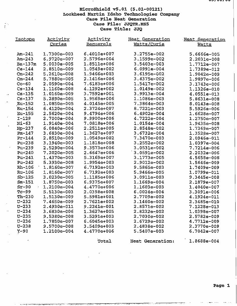
V 3 / U Q I V U
Microshield v5.01 (5.01-00121) fiockheed Martin Idaho Technologies Company
Case Pile Heat Generation Case File:'JJQTR.MS5
Case T i t l e : JJQ - - I
Isotope
Am-241 Am-243
- Ba-137m Ce-144 Cm-242 Cm-244 (20-60 CS-134
-- CS-135 CS-137
- .E~1-152 ELI-154 ELI-155
' 1-129 Ni-63 Np-237 Pm-147
Pu-238 ' Pu-239
PU'240 Pu-241 PU-242 Rh-106 Ru-106 Sb-125
Pr-144
Sm-151 Sr-90 TC-99 Th-230 U-232 U-233 U-234 U-235 U-236 U-238 Y-90
Activity Curies
1.7300e-003 6.9720e-007 5.0030e-005 2.8510e-009 5.2610e-008 5.7880e-005 2.0590e-004 1.1160e-008 1.0160e-009 5.2890e-005 1.0850e-005 6.4120e-004 2.5620e-004 2.7000e-004 1.9140e-004 6.0840e-006 3.6830e-004 2.8510e-009 3.1940e-003 2.5290e-004 7.2020e-005 1.4370e-003 5.3930e-008 1.8160e-007 1.8160e-007 3.0230e-005 1.8750e-003 1.2100e-004 5.5130e-003 1.5130e-009 7.4650e-009 2.4930e-011 3.6830e-006 9.5380e-008 1.7850e-007 9.5700e-008 1.2100e-004
Activitv Beauerels
6.4010e+007 2.5796e+004 1.8511e+006 1.0549e+002 1.9466e+003 2.1416e+006 7.6183e+006 4.1292e+002 3.7592e+001 1.9569e+006 4.0145e+005 2. 3724e+OA07 9.4794e+006 9.9900e+006 7.0818e+006 2.2511e+005 1.3627e+007 1.0549e+002 1.1818e+008 9.3573e+006 2.6647e+006 5.3169e+007 1.9954e+003 6.7192e+003 6.7 192 e+ 0 03 1.1185e+006 6.9375e+007 4.4770e+006 2.0398e+008. 5.5981e+001 2.7621e+002 9.2241e-001 1.3 627e+005 3.52,91e+003 6.6045e+003 3.5409e+003 4.4770e+006
Total
Heat Generation Watts/Curie
3 -2755e-002 3.1599e-002 3 S403e-003 6.0991e-004 3.6195e-002 3.4375e-002 1.5417e-002 1.0149e-002 3.9913e-004 1.1086e-003 7.3864e-003 8.7221e-003 6.4902e-004 4.7222e-004 1.0154e-004 2.8548e-002 3 - 6732e-004 7.3470e-003 3.2552e-002
3.0591e-002 3.1773e-005 2.9012e-002 9.5865e-003 5.9466e-005 3.0911e-003 1.1669e-004 1.1603e-003 6.0024e-004 2.7709e-002 3.1460e-002 2.8571e-002 2.8232e-.002 2.7030e-002 2.6729e-002 2 A838e-002 5.5407e-003
3.0531e-002
Heat Generation:
Heat Generation Watts
5.6666e-005 2.2031e-008 1.7712e-007 1.7389e-012 1.9042e-009 1.9897e-006 3.1743e-006 1.1326e-010 4.0551e-013 5.8631e-008 8.0143e-008 5.5926e-006 1.6628e-007 1.2750e-007 1.9435e-008 1.7369e-007 1.3528e-007 2 - 0946e-011 1.0397e-004 7.7214e-006 2.2032e-006 4.5658e-008 1.5646e-009 1.7409e-009 1.0799e-011 9.3445e-008 2.1879e-007 1.4040e-007 3.3091e-006 4.1924e-011 2.3485e-010 7.1228e-013 1.0398e-007 2.5782e-009 4.7712e-009 2.3770e-009 6.7042e-007
1.8688e-004

-. -. - MicroShield v5.01 (5.01-00121)
Lockheed Martin Idaho Technologies Company Page : 1 FileD:;: i g~+& DOS File: JJQTRl.MS5 Run Date: March 8, 2000 By : Run Time: 2:27:51 PM Checked: fbf? 3 / . % Duration: 00:03:31
Case Title: 354 Description: R/hr for drum of grouted "treated" waste-(Cs & Sr removed)
Geometry: 7 - Cylinder Volume - Side Shields
L
Nw-Iide Am-241 Am-243 ,
Ba-137m Ce-144 em-242 Cm-244 CO-60 CS-134 CS-135
Eu-152 Eu-154 Eu-155 1-129
Np-237 Pm-147
Pu-238 Pu-239 Pu-240
'Cs-137
Ni-63
Pr-144
Source Dimensions Height 86.36 cm 2 ft 10.0 in Radius 29.21 cm 11.5 in
Dose Points
# 1 129.37 cm 43.18 cm 0 cnt 4 ft 2.9 in 1 ft 5.0 in 0.0 iE
' X Y z
Shields SWe1.d .Name Qimew.i.cn Mqt.eri-ql. .Qewi.tx Source 2.31e+05 ~m~Concrete1.826 Transition 100.0 cm Air 0.0011 Air Gap Air 0.00122 Wall Clad -16 cm Iron 7.86 Top Clad -16 cm Iron 7.86 . ,
Source Input Grouping Method : Standard Indices
Number of Groups : 25 Lower Energy Cutoff : 0.015 Photons < 0.015 : Excluded
Library : ICRP-38 .c.wi.es. beGw-erelS l?3../.a-3. .Eiq/.c.m3.
1.7300e-003 6.4010e+007 7.4734e-003 2.7652e+002 6.9720e-007 2.5796e+004 3.01.18e-006 1.1144e-001 5.0030e-005 1.8511e+006 2.1612e-004. 7.9966e+000 2.8510e-009 1.0549e+002 1.2316e-008 4.5569e-004 5.2610e-008 1.9466e+003 2.2727e-007 8.4090e-003 5.7880e-005 2.1416e+006 2.5004e-004 9.2513e+000 2.0590e-004 7,-6183e+006 8.8947e-004 3.2910e+001 1.1160e-008 4.1292e+002 4.8210e-008 1.7838e-003 1.0160e-009 3.7592e+001 4.3890e-009 1.6239e-004 5.2890e-005 1.9569e+006 2.2848e-004 8.4538e+000 1.0850e-005 4.0145e+005 4.6871e-005 1.7342e+000 6.4120e-004 2.3724e+007 2.7699e-003 1.0249e+002 2.5620e-004 9.4794e+006 1.1068e-003 4.0950e+001 2.7000e-004 9.9900e+006 1.1664e-003 4.3156e+001 1.9140e-004 7.0818e+006 8.2683e-004 3.0593e+001 6.0840e-006 2.2511e+005 2.6282e-005 9.7245e-001 3.6830e-004 1.3627e+007 1.5910e-003 5.8868e+001 2.8510e-009 1.0549e+002 1.2316e-008 4.5569e-004 3.1940e-003 1.1818e+008 1.3798e-002 5.3052e+002 2.5290e-004 9.3573e+006 1.0925e-003 4.0423e+001 7.2020e-005 2.6647e+006 3.1112e-004 1.1511e+001

DOS File: JJQTRl.MS5 Run Date: March 8, 2000
..Run Time: 2:27:51 PM Duration: 00:03:31
Enerav MeV
0.015 0.02 0.03 0.04 0.05
. 0.06 0.08 0.1 0.15 0.2 0.3 0.4
* 0.5 0.6 0.8 1.0 1.5 2.0 3.0
Nuclide Pu-241 Pu-242 Rh-106 Ru-106 Sb-125 Sm-151 Sr-90 TC-99 Th-230 U-232 U-233 U-234 U-235 U-236 .
.-. U-238 Y-90
curies 1.4370e-003 5.3930e-008 1.8160e-007 1.8160e-007 3.0230e-005 1.8750e-003 1.2100e-004 5.5130e-003 1.5130e-009 7.4650e-009 2.4930e-011 3.6830e-006 9.5380e-008
9.5700e-008 1.2100e-004
1.785Oe-007
beccruerels 5.3169e+007 1.9954e+003 6.7192e+003 6.7192e+003 1.1185e+006 6.9375e+007 4.4770e+006 2.0398e+008 5.5981e+001 2.7621e+002 9.2241e-001 1.3 62 7e+0 05 3.5291e+003 6.6045e+003 3.5409e+003 4.4770e+006
pCi /cm3 6.2077e-003 2.3297e-007 7.8450e-007 7.8450e-007 1.3059e-004 8.0998e-003 5.2271e-004 2.3816e-002 6.5360e-009 3.2248e-008 1.0770e-010 1.5910e-005 4.1203e-007 7.7110e-007 4.1342e-007 5.2271e-004
Bcr/cm3 2.2969e+002 8.6200e-003 2.9026e-002 2.9'026e-002 4.8319e+000 2.9969e+002 1.9340e+001 8.811.8e+002 2.4183e-004 1.1932e-003 3.9847e-006 5.8868e-001 1.5245e-002 2.8531e-002 1.5296e-002 1.9340e+001
Buildup The material reference is : Transition
Integration Parameters Radial 34 Circumferential 24 Y Direction (axial) 34
Fluence Rate MeV/cmz/sec No BuilduD 1.144e-35 1.405e-17 2.061e-07 2.048e-04 9.237e-04 5.124e-02 2.972e-02 2.377e-01 2.094e-03 1.353e-01 2.378e-02 1.237e-01 6.819e-02 1.422e+00 5.438e+00 1.278e+01 2.635e+01 1.276e-03 5.973e-06
Results Fluence Rate MeV/cm2 /sec With BuilduD 1.482e-26 5.190e-17 2.002e-06 3.410e-03 1.744e-02 8.919e-01 3.838e-01 2.369e+00 1.410e-02 7.145e-01 9.586e-02 4.226e-01 2.077e-01 3.969e+00
' 1.335e+01 2.878e+01 5.146e+01 2.284e-03 9.601e-06
ExDosure Rate mR/hr
No Buildur> 9.809e-37 4.866e-19 2.042e-09 9.058e-07 2.461e-06 1.018e-04 4.703e-05 3.636e-04 3.449e-06 2.388e-04 4.511e-05 2.410e-04 1.338e-04 2.776e-03 1.034e-02 2.356e-02 4.433e-02 1.972e-06 8.104e-09
EkDosure Rate mR/hr
With Buildup 1.272e-27 1.798e-18 1.984e-08 1.508e-05 4.645e-05 1.772e-03 6.074e-04 3.625e-03 2.323e-05 1.261e-03 1.818e-04 8.234e-04 4.077e-04 7.747e-03 2.540e-02 5.306e-02 8.658e-02 3.533e-06 1.303e-08

-.
DOS File: JJQTRl.MS5 Run Date: March 8, 2000 Run Time: 2:27:51 PM Duration: 00:03:31
Enerav Activitv Fluence Rate Fluence Rate MeV photons/sec MeV/cm2/sec MeV/cm2/sec
No Buildur> With Buildur> TOTALS: 1.381e+08 4.666e+01 1.027e+02
m o s u r e Rate Sure Rate mR/hr mR/hr
No Buildux> With BuilduD 8 -219e-02 1.815e-01

MicroShield v5.01 (5.01-00121) Lockheed Martin Idaho Technologies Company
File Ref: H.p-07-e Date: By : ziz2ikk
Page : 1 DOS File: JJQTRl.MS5 Run Date: March 8, 2000 Run Time: 2:11:41 PM * Checked : Duration: 00:03:33
Case Title: JJQ Description: R/hr for drum of grouted "treated" waste-(Cs & Sr removed)
Geometry: 7 - cylinder Volume - Side Shields Source Dimensions
Height 86.36 cm 2 ft 10.0 in Radius 29.21 cm 11.5 in
0 Dose Points .x .Y .z.
# 1 229.37 cm 43.18 cm o m X 7 ft 6.3 in 1 ft 5.0 in 0.0 in
Shields S.hi.eld -Nw.e &WJXS.~.QQ Vat.eri&&w.i.tx
Nwl.i.& Am-241 Am-243 Ba-137111 Ce-144 Cm-242 Cm-244 CO-60 CS-134 CS-135 CS-137 Eu-152 Eu-154 Eu-155 1-129
Np-237 hn-147
Pu-238 Pu-239 Pu-240
Ni-63
Pr-144
~
Source 2,31e+05 cm3 Concrete1.826 Transition 200.0 c m Air 0.0011 Air Gap Air 0.00122 Wall Clad -16 cm Iron 7.86 Top Clad -16 cm Iron 7.86
. Source Input Grouping Method : Standard Sndices
Number of Groups : 25 Lower Energy Cutoff : 0.015 Photons < 0,015 : Excluded
L i b r a r y : ICRP-38 .c.wi.e,s. bec.W.eYe1.s. 14ci./.c.m3. B.S/.C.Q3.
1.7300e-003 6,4010e+007 7.4734e-003 2.7652e+002 6.9720e-007 2.5796e+004 3.0118e-006 1.1144e-001 5.003Oe-005 1.8511e+006 .2.1612e-004 7.9966e+000 2.8510e-009 1.0549e+002 1.2316e-008 4.5569e-004 5.2610e-008 1.9466e+003 2.2727e-007 8.4090e-003 5.7880e-005 2.1416e+006 2,5004e-004 9.2513e+000 2.0590e-004 7.6183e+006 8.8947e-004 3.2910e+001 1.1160e-008 4.1292e+002 4.8210e-008 1.7838e-003 1.0160e-009 3.7592e+001 4.3890e-009 1.6239e-004 5.2890e-005 1.9569e+006 2.2848e-004 8.4538e+000 1,0850e-005 4.0145e+005 4,6871e-005 1.7342e+000 6.4120e-004 2.3724e+007 2.7699e-003 1.0249e+002 2.5620e-004 9.4794e+006 1.1068e-003 4.0950e+001 2.7000e-004 9.9900e+006 1.1664e-003 4.3156e+001 1.9140e-004 7.0818e+006 8.2683e-004 3.0593e+001 6.0840e-006 2.2511e+005 2.6282e-005 9.7245e-001. 3.6830e-004 1.3627e+007 1.5910e-003 5.8868e+001 2.8510e-009 1,0549e+002 1.2316e-008 4.5569e-004 3.1940e-003 1.1818e+008 1.3798e-002 5.1052e+002 2.5290e-004 9.3573e+006 1.0925e-003 4.0423e+001 7.2020e-005 2.6647e+006 3.1112e-004 1.1511e+001

DOS File: JJQTRl.MS5 R u n Date: March 8, 2000 R u n Time: 2:11:41 PM Duration: 00:03:33
Enera-v M*
0.015 0.02 0.03
-0.05 0.06 0.08 0.1 0.15 0.2 0.3 0.4 0.5 0.6 0.8 1.0 1.5 2.0 3.0
0.09
Nuclide Pu-241 PU-242 Rh-106 Ru-106 Sb-125 Sm-151 Sr-90 TC-99 Th-230 U-232 U-233 U-234 U-235 U-23 6 U-238 Y-90
curies 1.4370e-003 5.3930e-008 1.8160e-007 1.8160e-007 3.0230e-005 1.8750e-003 1.2100e-004 5 I 5130e-003 1.5130e-009 7.4650e-009 2.4930e-011 3.6830e-006 9.5380e-008 1.7850.e-007 9.5700e-008 1.2100e-004
yCi/cm3 6.2077e-003 2.3297e-007 7.8450e-007 7.8450e-007 1.3059e-004 8.0998e-003 5.2271e-004 2.3816e-002 6.5360e-009 3.2248e-008 1.0770e-010 1.5910e-005 4.1203e-007 7.7110e-007 4.1342e-007 5.2271e-004
Bcr/cm3 2.2969e+002 8.6200e-003 2.9026e-002 2.9026e-002 4.8319e+000 2.9969e+002 1.9340e+001 8.8118e+002 2.4183e-004 1.1932e-003 3.9847e-006 5.8868e-001 1.5245e-002 2.8531e-002 1.5296e-002 1.9340e+001
Buildup The material reference is : Transition
Integration Parameters Radial 34 Circumferential 24 Y Direction (axial) 34
Act ivi tv photons/sec
Fluence Rate MeV/cm2/sec Po Buildux> 5.099e-3 6 5.862e-18 7.158e-08. 6.575e-05 2.872e-04 1.572e-02 9.034e-03 7.203e-02 6.343e-04 4.104e-02 7.238e-03 3.774e-02 2.085e-02 4.357e-01 1.671e+00 3.937e+00 8.155e+00 3.961e-04 1.864e-06
Results Fluence Rate MeV/cm2/sec With BuilduD 4.755e-27 2.163e-17 6.905e-07 1.085e-03 5.390e-03 2.738e-01 1.177e-01 7.294e-01 4.3 67e-03 2.218e-01 2.981e-02 1.316e-01 6.473e-02 1.238e+00 4.171e+00 9.004e+00 1.614e+01 7.180e-04 3.025e-06
Emosure Rate mR/hr
Po Buildup 4.373e-37 2.031e-19 7.094e-10 2.908e-07 7.651e-07 3.123e-05 1.43 Oe-05 1.102e-04 1.045e-06 7.244e-05 1.373e-05 7.353e-05 4.092e-05 8.504e-04 3.178e-03 7.257e-03 1.372e-02 6.126e-07 2.528e-09
Emosure Rat5 mR/hr
With Buildup 4.079e-28 7.493e-19 6.843e-09 4.799e-06 1.436e-05 5.439e-04 1.862e-04 1.116e-03 7.191e-06 3.914e-04 5.655e-05 2.563e-04 1.271e-04 2 -416e-03 7.934e-03 1 - 660e-02 2.716e-02 1.110e-06 4.104e-09

DOS File: JJQTRl.MS5 Run Date: March 8, 2000 Run Time: 2:11:41 PM Duration: 00:03:33
osure Rate
No BuilduD With Buildup No Buildup . With Buildup
Enercnr Activitv Fluence Rate Fluence Rate E ~ D osure Rate M a photons/sec MeV/cm2/sec MeV/cm2/sec mR/hr mR/hr
TOTALS: 1.381e+08 1.440e+01 3.213e+01 2.53 6e-02 5.681e-02

Microshield v5.01 (5.01-00121) Lockheed Martin Idaho Technologies Company
Page : 1 File Ref: DOS File: JJQTRl.MS5 Date: Run Date: March 8, 2000 By : Run The: 2:17:26 PM Checked: Duration: 00:03:33
Case Title: JJQ Description: R/hr for drum of grouted "treated" waste-(Cs & Sr removed)
Geometry: 7 - Cylinder Volume - Side Shields Source Dimensions
Height 86.36 cm 2 ft 10.0 in Radius 29.21 ern 11.5 in
e Dose Points ?5 x z.
329.37 cm 43.18 cm 0 cm 10 ft 9.7 in 1 ft 5.0 in 0.0 in x
7 Shields L ShisliI .%me Db.ens.i.cm N&eri.d..Dew.i.tx
Source 2.31e+05 ~m~Concrete1.826 Transition '300.0 cm Air 0.0011 Air Gap Air 0.00122 Wall Clad -16 cm Iron 7.86 Top Clad -16 an Iron 7.86
Source Input Grouping Method : Standard Indices
Number of Groups : 25 Lower Energy Cutoff : 0.015 Photons < 0.015 : Excluded
Library : ICRP-38
Am-241 1..7300e-O03 6.4010e+007 7.4734e-003 2.7652e+002 Am-243 6.9720e-007 2.5796e+004 3.0118e-006, 1.1144e-001 Ba-137m 5.0030e-005 1.8511e+006 2.1612e-004 7.9966e+000 Ce-144 2.8510e-009 1.0549e+002 1.2316e-008 4.5569e-004 Cm-242 5.2610e-008 1.9466e+003 2.2727e-007 8.4090e-003 Cm-244 5.7880e-005 2.1416e+006 2.5004e-004 9.2513e+000 Co-60 2.0590e-004 7.6183e+006 8.8947e-004 3.2910e+001 Cs-134 1.1160e-008 4.1292e+002 4.8210e-008 1.7838e-003 Cs-135 1.0160e-009 3.7592e+001 4.3890e-009 1.6239e-004 Cs-137 5.2890e-005 1.9569e+006 2.2848e-004 8.4538e+000 Eu-152 1.0850e-005 4.0145e+005 4.6871e-005 1.7342e+000 Eu-154 6.4120e-004 2.3724e+007 2.7699e-003 1.0249e+002 Eu-155 2.5620e-004 9.4794e+006 1.1068e-003 4.0950e+001 1-129 2.7000e-004 9.9900e+006 1.1664e-003 4.3156e+001 Ni-63 1.9140e-004 7.0818e+006 8.2683e-004 3.0593e+001 Np-237 6.0840e-006 2.2511e+005 2.6282e-005 9.7245e-001 Pm-147 3.6830e-004 1.3627e+007 1.5910e-003 5.8868e+001 Pr-144 2.8510e-009 1.0549e+002 1.2316e-008 4.5569e-004 Pu-238 3.1940e-003 1.1818e+008 1.3798e-002 5.1052e+002 Pu-239 2.5290e-004 9.3573e+006 1.0925e-003 4.0423e+001 Pu-240 7.2020e-005 2.6647e+006 3.1112e-004 1.2511e+001
NWJ.ide .c.lAri.es* bekw-ere1.s. lACiJ.c-m.3- .m/.c.m.3.

_ - - - -
DO; File: JJQTRl.MS5 Run Date: March 8, 2000 Run Time: 2:17:26 PM Duration: 00:03:33
Nuclide Fu-241 Pu-242 Rh-106 Ru-106 Sb-125 Sm-151 Sr-90 TC-99 Th-230 U-232 U-233 U-234 U-235 U-23 6 U-238 Y-90
curies 1.4370e-003 5.3930e-008 1.8160e-007 1.8160e-007 3.0230e-005 1.8750e-003 1.2100e-004 5.5130e-003 1.5130e-009 7.4650e-009 2.493 Oe-011 3.6830e-006 9.5380e-008 1,7850e-007 9,5700e-008 1.2100e-004
becauerels 5.3169e+007 1.9954e+003 6.7192e+003 6.7192e+003 1.1185e+006 6.9375e+007 4.4770e+006 2.0398e+008 5.5981e+001 2.7621et-002 9.2241e-001 1.3627e+005 3.5291e+003 6.6045e+003 3 .S409e+003 4.4770e+006
pCi / cm3 6.2077e-003 2.3297e-007 7.8450e-007 7.8450e-007 1.3059e-004 8.0998e-003 5.2271e-004 2.3816e-002 6.5360e-009 3.2248e-008 1.0770e-010 1.5910e-'005 4.1203e-007 7.7110e-007 4.1342e-007 .5 - 2271e-004
Ba/cm3 2.2969e+002 8.6200e-003 2.9026e-002 2.9026e-002 4.8319e+000 2.9969e+002 1.9340e+001 8.8118e+002 2.4183e-004 1.1932e-003 3.9847e-006 5.8868e-001 1.5245e-002 2.8531e-002 1.5296e-002 1.9340e+001
Buildup The material reference is : Transition
Integration Parameters Radial Circumferential Y Direction (axial)
Results Enerw Act ivi tv Fluence Rate Fluence Rate
M e V
0.015 0.02 0.03 0.04 0.05 0.06 0.08 0.1 0.15 0.2 0.3 0.4 0.5 0.6 0.8 1.0 1.5 2.0 3.0
MeV/cm2/sec No Buildup 2.514e-36 2.859e-18 3.388e-08 3.080e-05 1.341e-04 7.341e-03 4.218e-03 3 -366e-02 2.973e-04 1.927e-02 3.408e-03 1.780e-02 9.849e-03 2.061e-01 7.919e-01 1.869e+00 3.883e+00 1.890e-04 8.915e-07
MeV/cmz/sec With Buildup 2.311e-27 1.055e-17 3.268e-07 5.093e-04 2.531e-03 1.290e-01 5.572e-02 3.468e-01 2.082e-03 1.059e-01 1.424e-02 6.289e-02 3.096e-02 5.923e-01 1.997e+00 4.314e+00 7.745e+00 3 449e-04 1.455e-06
34 24 34
m o s u r e Rate mR/hr
No Buildup 2.156e-37 9.904e-20 3.3S8e-10 1.362e-07 3.574e-07 1.458e-05 6.676e-06 5.150e-05 4.895e-07 3.401e-05 6.464e-06 3.468e-05 1.933e-05 4.022e-04 1.506e-03 3.445e-03 6.532e-03 2.923e-07 1.210e-09
I . Emosure R a t e
mR/hr With BuilduP 1.982e-28 3.654e-19 3.239e-09 2.253e-06 6.743e-06 2.561e-04 8.817e-05 5.306e-04 3 A29e-06 1.868e-04 2.702e-05 1.225e-04 6.077e-05 1.156e-.03 3.799e-03 7.952e-03 1.303e-02 5.334e-07 1.974e-09

- - a- - __ DOS File: JJQTRl .MS5 Run Date: March 8, 2000 Run Time: 2:17:26 PM Duration: 00:03:33
Eneruv &c t ivi tv Fluence Rate Fluence Rate E ~ D osure Rate kcr, osure Rate
No Buildup With Buildup photons/sec MeV/cm2/sec MeV/cm*/sec mR/hr mR/hr
No Buildux,. With Buildup TOTALS: 1.381e+08 6.846e+00 1.540e+01 1.205e-02 2.722e-02

PROJECT FILE NO. 01 5735
AUTHOR CHECKED DATE D. E. Nlshioka M.S. 3650 M.S. 321 1 .
E. P. Wagner
BBWI REVIEW DATE
EDF-I505 EDF SERIAL NO.
FUNCTIONAL FILE NO. ENGINEERING DESIGN FILE
AF'PROVEDIACCEPTED DATE
M.S. 3650
BEWIREVIEW ' DATE
S. L. Austad, P. w+q
~
PROJECT/TASK HIGH LEVEL WASTE
EDFPAGENO. 1 OF 5 - - S U m S K Vitrification of Sodium Bearina Waste :
MAN-LOADING AND PHYSICAL SPACE IDENTIFICATION
SUMMARY
The following investigation identifies associated activities that may be required for the operation of this facility.. Space allocation based on these activities has been estimated. Man-loading has been extrapolated from previous projects similar in nature, resource documents, and engineering judgment based on experience.
QUAUTYLNEL 0 1 0 2 m 3
KEYWORDS (e.g. area, structure no., general subject matter, ek)
Man-loading, Space, High Level Waste DISTRIBUTION (COMPLEIE PACKAGE):
.
D. J. Harrell, M.S. 3211, J. J. Quigley, M.S. 3625, V. J. Balls, M.S. 3650, Project File DISRIBUTION (COVER SHEET ONLY):
>

ENGINEERING DESIGN FILE Vitrification of Sodium Bearing Waste
Attachment A
Project File No. - 01 5735 EDF Serial No. - EDF-1505
Page 2 of 5
MAN-LOADING for 2 YEAR CAMPAIGN
February 21,2000
Assume: One (4)-I 0’s shift for main process, administrative and support. Continuous process operations will require (4) rotating shifts for the 2 year duration. Total man-loading is 109 personnel.
FUNCTIOWACILITY REQUIREMENT MAIN SHIFT ROTATING
FAClLlN - ADMINISTRATION
An attached building will house approximately 30+ personnel and ancillary spaces supporting the main process and its functions. Physical requirements have been estimated based on an average of 500 square feet allowance per person.
Manager(s)/Supervisor(s) 2 4 Administrative Support 3 - SecretariaVClerical Budg et/Cost Control Schedule
(Receipt, Entry, Examination, Sampling, Repack, Storage/Shipping, etc., Manifest, Chain of Custody
Waste TrackinglData Acquisition Tech 1 4
File/Document Storage Office Machines
FACILITY - TECHNICAL SUPPORT
Engineering (Facility) 2 - 0 Engineering (Process/Support) 2 4
Control Systems Tech - Ref: pg 4, I & C Technicians 1 -
Draftsman I - (Matrix personnel during const. Overhaul, redesign or mods)
Assume: INTEC will have infrastructure services and capabilities to accommodate some tasks not unique to this project. Additional drafting is assumed to be one of these.
Storage - spare parts, work bench for repaidmaintenance

Project File No. - 01!335 EDF Serial No. - EDF-1505
ENGINEERING DESIGN FILE Vitrification of Sodium Bearing Waste
FUN CTlO N/FACI LlTY REQUIREMENT MAIN SHIFT ROTATING
Page 3 of 5
FACILITY - DOCUMENT CONTROL
Document control personnel 2
File/Document Storage Fire Vault, Library, Off ice Machines
FACILITY - TRAINING (Phvsical requirements onlv)
Conference Room - utilized for training and equipment storage
FACILITY - COMMON ANCILLARY SPACE (Phvsical requirements onlv) *
Lunch Roomreak Room Toilet Rooms, Showers and Lockers Janitor Room Storage Circulation Electrical Communications Mechanical
FACILITY - MAINTENANCE
Assume: INTEC will have.infrastructure services and capabilities to accommodate some tasks not unique to this project. Facility maintenance is assumed to be one of these.
Off ice Space for foreman
DOE TRANSIENTS @ FACILITY OFFICE(S1- (Phvsical requirements onlv)
Offices (1) '+'

ENGINEERING DESIGN FILE Vitrification of Sodium Bearing Waste
Project File No. - 01 5735 EDF Serial No. - EDF-1505
Page 4 of 5
FUNCTIONIFACILIN REQUIREMENT MAIN SHIFT ROTATING
PROCESS FACILIN/OPERATIONS
Rad-con Tech (RCT/HP) Manager 1 - Assume: INTEC will have infrastructure services and capabilities to accommodate some tasks not unique to this project. Laboratory testing and analysis capabilities is assumed to be one of these.
File/Document Storage Office Machines
PROCESS CONTROL (Process Control Console, Alarm Panels, Communications)
Note: In high rad areas, require a minimum of (2) people suited and (1) high rad guard.
a SBW feed and frit mixing (personnel for this Operation will provide oversight for the (4) processes below Melter feed and Canister Fill Glass and Gas Sampling and Analysis Grouting System Off gas Handling Canister Decontamination Canister CureDewatering, Transfers Can Sealing and Inspection Canister Tomographic Inspection Canister Recycle
E S & Q
Safety RCT (Rad-Con Tech) Quality Industrial Hygienist
1 1 -
12
- 16 8 4 4 4
- 4 4 4
Equipment storage (surveillance, analyzers, etc) ..-
, I

ENGINEERING DESIGN FILE Vitrification of Sodium Bearing Waste
Project File No. - 015735 EDF Serial No. - EDF-1505
Page 5 of 5
FUNCTION/FACILITY REQUIREMENT MAIN SHIFT ROTATING
PROCESS MAINTENANCE
Supervisors/Foreman Electrician Mechanic I&C Technicians Maintenance Planner Preventive MaintenanceNork Order Attendant
PROCESS SUPPORT (Phvsical Requirements onlv)
Anti-C Issue Rooms Change Rooms/Shower Rooms Personnel Decon Area Ready Room (Break Room) Toilet Rooms and Janitor Room Emergency Equipment Room Process Mechanical Area Facility Mechanical Room
0 Electrical and Communications Stack Emissions Monitoring Room (CEM and Rad monitoring) Shop - Materials and Equipment Storage, Work Bench Area
0 Instrument Shop - I&C, Protected Storage for Calibrated Instruments, Work Bench Contaminated, Hot Maintenance Area Tool Room - Storage of Issue Tools Storage - Clears Containers Storage - Lag/Lead Storage - Process Interim
Assume: INTEC will have infrastructure services and capabilities to accommodate some tasks not unique to this project. The following functions and facilities have been assumed to exist and have the capabilities of servicing this process:
Machine Shop 0 Welding Shop 0;- Storage Warehouse 0 Mock-up Area
LaydownArea

PROJECT R E NO. 015735
I
~
Energy Requirements for SBW Vitrification HVAC System
ENGINEERING. DESIGN FILE EDF SERIAL NO. EDF-1509
FUNCTIONAL R E NO.
PROJECTnASK SBW Vitrification Facility Feasibility Study
EDFPAGENO. 1 OF 1 SUETASK i
HVAC and HEPA filtration preliminary design - -
SUMMARY
This EDFdetails the HVAC energy requirements for the new SBW Vitrification Facility. Energy requirements are summarized for cooling, heating, fan power and HEPA filtration. This report defines the primary and secondary confinement zones for the new SBW Vitrification Facility and the required peak seasonal heating and cooling loads. The HEPA filtration system and fan layout are also stated.
Peak heating: 23.2 million Btu/hr equivalent to 27,000 Ibshr 150 psi saturated steam Fan HP total: 1423 HP Peak cooling: 1225 HP equivalent to 774 tons of cooling
See Attachment
W O R D S (e.g. area, stn~cture no., general subject matter, etc.)
DISTRIBUTION (COMPLETE PACKAGE):
s ._ DISTRIBUTION (COVER SHEET ONLY):
. -
APPROVEDIACCEPTED E.C.Ande n, P.E.
AUTHOR DATE CHECKED DATE
BBWl REVIEW EEWl R M R N DATE

HVAC
In addition to the offgas system, the VF will be required to have two vefztliation confinement zones per DOE Order 6430.1A. This section addresses the two confinement zones, and the non- confinement area. A ventildon confinement system in conjunction with physical barriers, maintain a continuous airflow pattern fiom areas of low potentid contamination to areas of high potential contamination. The objectives of the confinement systems are to prevent the spread of radioactive and other hazardous materials to occupied areas; and to minimize the release of radioactive and other hazardous materials in hili-& effluents. The primary confinement area consists of process hot cells and hot maintenance areas, which will be exhausted through two stages of HEPA filters. The primary confinement boundary will be comprised of hot.cell walls, welded stainless steel d~ctwork and WAC equipment designed to maintain its structural integrity Cturing and after operational andnatural-phenomena designbasis accidents @BAS). The secondary confinement boundary consists of the operating comdors and other building structures that mound the primary confinement. The secondary confinement boundary contains all ventilation system equipment such as HEPA filter units and exhaust fans. The non-confinement boundary consists of offices, control rooms and support areas outside the secondary confinement boundary. The non-codinement zones do not require once through v+tion systems and will be maintained at a slight positive pressuie with respect to ambient. HEPA filters will remove
trains, beczqse semivolatile fission products and iodine will be removed by the offgas system. a contamma ted particulates, but no carbon absorber beds will be provided inthe primary filter
The fk%ty will be provided with an independent chilled water system consisting of cexrtral chillers and pumps, delivering chilled water to various,cooling coils. The facdity will utilize steam for heating the once through air and for the office and other occupied areas. The HVAC system will be controlled by a central electxonic system located within the fkility.
,
Redundancy will ensure proper vedation confinement during HEPA filter replacement or h l z m b m a n ce. Exhaust ductwork will be located in areas that will not be normally occupied. HEPA filter housings will have the capability to be leak tested and tested for filter efficiency in place. Single stage HEPA filtration will be provided at the hot cell intakes to prevent possiile C O I l m m I m h * 'on fiom momentary back flow to the occupied areas. HEPA filters units will be designed per the American Socieiy of Mechanical Engineers (ASME), N509, Nuclear Power PlantAir-Cleaning Units and Components, andtestedperASMEN510, Testing OfNuclearAir Treatment Systems. Confhement boundaries will be sealed to isolation when pressure differentials fall below normal conditions. Exhaust Systenis for the primary and Secondary confinements will be round stainless steel welded joint ductwork designed and installed in .
accordance with applicable Sheet Metal and Air Conditioning Contractors National Association, Uniform Mechanical Code, and American Conference of Governmental hdushial H y g i d standards.
Confinement zones will be supplied by once though ventilatioa Airflow fiom the secondary co-ent zones will be HEPA filtered to the primary w f i e m e n t zones. The once through ventilation will be HEPA filtered and dischargedto the exhaust stack, withno air recirculation. Each HEPA filter unit includes a stainless steel plenum housing, a deluge system, demister, prefilter, two stages of side-bagout HEPA filters for the primary zone exhaust, single
'- stage side-bagout HEPA filters for secondary zone exhaust and- supply, DOP test sections and ports, and an exhaust f8n. The exhaust assumed that the supply and exhaust fans for the hot cells can be powered fiomthe INEEL site standby power grid. This allows the ventilation confinement to be maintained in the hot cells during a loss of off-Site power condition.
have mk@ adjustable flow control. It is

Automatic local stand-alone controllers wil l be provided with the HVAC equipment. Graphic displays mimicking the W A C system will be available in the control room for monitoring and for remote manual ovemde control. The HVAC system will have local operator stations. However, the control room operator will have supervisory control capability to start and stop the W A C system and to change setpoints. Alarms and out-of-tolerance conditions wil l be annunciated in the corrtrol room.. It is assumed that a shielded probe system can be used in the VF exhaust stack to monitor the discharge from the ventilation system and off@ exhaust.
This fkcihty will be designed with the following ventilation parameters: .
iwg 0.1 0.1
Eight air changes per hour for primary confinement
Four air changes per hour for secondary confinement
One c k per square foot for admmdra tive areas
Two cfin per square foot for the coIltrol room
One stage of testable HEPA filters for secondary confinement exhaust
Two stages of testable HEPA filters for hot cell exhaust
One stage of testable HEPA filters for hot cell inlet
Once through ventilation for primary and secondary confinement zones
Room pressures maintahed in accordance with Table 1.
. .
Zone 6808 total 6808 1800
It is assumed that are& with large in-cell heat loads, which exceed no& nuclear ventilation capability, will require cooling and no additional heating.
0.1 0.1
Table 1 Room and Zone Re uire * 2100 total 660C . 190
Offices and other Rms Crane Control Rm C m o l R m computer Rm Elec Rmnear Offices comm Rm Mech Rm West Outer Truck Lock East Outer Truck Lock Storage Tool/Repair w p Stor. Elec Rm near €WAC
0.1 -0.25
nents Floor Elev
283 total 562 640
0 0 0 0 0 0 0 0 0 0 0 0
-0.25 -0.25 -0.25 -0.25
Static Pressure I Room CFM I Total CFM /
640 2078 2424 1885
0.11 2700 I
0.11 901 ' I

l r n n e l Air Lock Personnel Air Lock Clean Canister Stor Operating Corridor operating Corridor HVAC Room W A C Room Exit Corridor NE
Oieratini Corridor Hatch/Crane Floor
-3 2 0
* Remote Sew Corridor IPar and Crane Phaint
-0.25 41363 total7972( -0.25 12466
Crane Repair room Melter
16 -32 16
-0.25 17140 -0.25 1939 -0.25 17304
0 0 0 0
-32 -32 -32 -32 -32 -3 2 -32
0
32 48
-0.25 -0.25 -0.25 -0.25 -0.25 -0.25 -0.25 -0.25 -0.25 -0.25 -0.25 -0.25
-0.25 149971 total6384f -0.75 916611
435 134 224 269
1939 653 653 448 448 448
8782 16256
.
Multi-Stage Combustion Off-Gas Cell Canister WeId Cell Decon Cell Sub MeIter Cell Canister Smear Cell Csix Cell Groutcell Cut Up Cell Decon Cell Hands On Maint Cell Decon Holding Tanks Feed Tanks MixingTankN MirringTankS Sample Cubicle . can cooling SBW Work Off Tank
0 0 0
-3 2 -32
0 0 0 0 0 0
-0.75 '-0.75 -0.75 -0.75 -0.75 -0.75 -0.75 -0.75 -0.75 -0.75 -0.75
0 O1 -0.75
-32 0
-0.75 9088 total61712 -0.75 5 120
4614 7680 6554 6144 2688 1787 5 120 2688 3398 3587 4378 5198 3405
total 125482
-0.75 Ij/ -0.751 ;% -0.75 2816 -0.75 11404 -0.75 3686 total 30601
The primary,conjjnemd areas require the largest volume of once through air. The air . . exhausted fiom the secondary confinement zones is supplied to the primary confinement areas. '* As shown inthe W A C How Diagram additional CFM is rec&edto meetthe capacity ofthe
primary zones. The cost to heat, cool, filter and force the once through air through the fkdity is mainly athiiuted to the volume of primary confinement zones. The primary confinement zones are the principle f$ctor affecting HVAC system capital and operational costs.

The following table shows the preIiminary equipment list for the W A C feasibility study. This is not an &-inclusive list of instruments, components and equipment.
The vedlation fans and HEPA filter banks will require three rooms based upon the ament W A C floor plan size of 240'-5" by 50'4". The chillers shall be located outside on concrete pads. The pre-filters and the cooling and heating coils will also require an additional structure or room other than the existing W A C rooms. The storage and tooVrepair equipment storage rooms may be used on the second and third floor for the heating and cooling coils and fkus for supplying the facility with the required once through air.
Heat Recovery Systems
It is assumed that later stages of design will provide greater detail and a more specific system description. The inclusion of a heat recovery system may have the potential to reduce operational costs. Here are two mes of heat recovery systems applicable to this i&ilitythat completely separates air streams and eliminating c r o s s - c o ~ . -on. The face velocity is a primary factor in effectiveness and capital costs.
Coil energy recovery loops have an effectiveness range of 45% to 65%. The effectiveness is directly correlated to the delta T and the minimum low t e m p e e in order to prevent freezing. Relative to other system parameters, the Vitrification Facility has a low delta T and a freezing limitation. Expected effectiveness is in the low end of the range, approximately 45%. Coil energy recovery loops require a liqpid loop, typically a refigerant and compressors. This system has more moving parts than other heat recovery systems and thus requires more maintenan ce.
' I
Heat pipe heat exchangers have a higher effectiveness than coil energy recovery loops but also have freeze protection problems. The performance of heat pipes is correlated directly to fixe
-.- velocities and the number of rows or heat pipes. Doubling the number of rows of heat pipes in a 60% effective heat exchanger mcreases the effectiveness to 75%. Effectiveness is also based upon the proper selection of fluid for the operating t e m p e k e range. According to Heat Pipe Technology hc. typical costs range from $0.50 to $1.00 per CFM for a heat pipe recovery system.

Fixed plate exchangers have potential for cross contaminaton and are not considered here.
A coil energy recover loop is recommended primarily due to the flexiid3.y of locating the heat exchangers in both exhaust and intake air streams. This will not require special routing of ducts in order to get close p r o w that is required in a heat pipe exchanger system. Special duct routing would require additional floor space and added cost to the building strucaue. The heat recovery sym exchangers can be located in line with the irrtake steam and cooling coils and just behind the HEPA filter banks prior to going to the exhaust stack. The cost would be similar to a heat pipe system $0.50 to $1.00 per CFM.
. .-

__ . .-
Heating loads and steam requirements
As referenced from ASHRAEi Fundamentals Handbook. Q = 1.1 ( CFM ) ( T2 -Ti ) in& of Btu/hr
Based upon the CFM requirements for the secondary confinement zones.
CFM= 143,500 - 1,885.3 = 141,614.7 The electrical room reqyires 1,885.3 CFM and is removed fiomthe overall secondary requirements due to the high heat load fiom the transformers.
Typically air is heated to 95"F, but due to the high rate of volume change out 80°F is used for more realistic results that are still conservative.
T2 = 80°F
TI = -19°F
Q = 1.1 ( 141,614.7 ) (80- (-19)) = 15.4 million Btu / hr
Based upon the CFM requirements for the primary confinement zones.
CFM = 74,200 - 27,995.2 = 46,204.8 The various process cells that contain the melter, multi-stage combustion, off gas and etc. require 27,995.2 CFM and is removed from the overall primary requirements due to the high heat load from the process equipment.
Typically air is heated to 95"F, but due to the high rate of volume change out 80°F is used 'for more realistic results that &e still conservative.
T2 = 80°F
TI = -19°F
Q=1 .1 (46,204.8) (80-(-19))=5.0milli0nBt~/hr
Based upon the tatal rooms and cells not requiring 80°F heat.
CFM = 1,885.3 + 27,995.2 = 29,881.5 This volume of air is considered heated separately for dculation purposes only. These are the combined secondary and primary CFM heated to 65°F.
Typically air is heated to 95"F, but due to the high rate of volume change out 80°F is used for more realistic results that are s t i l l conservative.
T2 = 65°F
Ti = -19°F
Q= 1.1 (29,881.5) (65-(-19))=2.8milli0nBtU/hr
Total Q = 23.2 million Btu / hr
Using 150 psi saturated steam, 860 Btu / lb of steam.
'>'
' I
Total steam,load is = 23,200,000 Btu / hr * 1 lb/860 Btu = 27.000 lbs / hr steam

Ventilation Fans, HP
The ventilation f8n sizing was based upon software and vendor datato ensure common ~ motor sizes. The static pressures for each zone were conservatively approximated and all filters were assigned worst case pressure losses. The following table details the assigned pressure drops, final static pressures were based upon additional pressure drops through each zone.
According to the flow diagrams HV-1 and HV-2 the fkn Hp and CFM are shown. Each confinement zone is given a standby fim for immediate backup.
I Zone I Total static pressure I HP requirements I 1 supply I . 5iwg I 15 2 supply 5 iwg 15
7 supply 5 iwg 90
8exhaust 9 iwg 75
7exhaUst 9 iwg 150 8 supply. 5 iwg 50
HEJ requirements are based upon ce&rX@al fans from GreenHeck, based upon CFM and static pressure loads.

Cooling, Compressor and Fan HP
Q=1.1 ( C F M ) ( T 2 - T i ) i n d o f B t u / h r
Based upon the CFM requirements for the secondary confinement zones. - I
CFM = 143,500
Tz=95"F . - TI = 65°F
Typically air is cooled to 55"F, but due to the high rate of volume change out 65OF is used for more realistic results that are st i l l conservative.
Q = 1.1 ( 143,500 ) (95- 65) = 4.75 million Btu / hr
. Based upon the CFM reqUirements for the primary codinement zones.
CFM = 74,200 The CFM from the secondary confinement zones is supplied to the primary confinement zones. The additional air reguired fiom the atmosphere is cooled.
T2 = 95°F TI = 65°F
Typically air is cooled to 55"F, but due to the high rate of volume change out 65OF is used for more realistic results that are still c o n s d v e .
Q = 1.1 ( 74,200 ) (95 - 65) = 2.45 million Btu / hr
CFM = 143,500 This is the CFM exhhuskd from the secondary confinemmt zones and is reused to supply the primary confinement zones.
The assumed the errit temperature fiomthe secondary confinement zones.
Typically air is cooled to 55"F, but due to the high rate of volume change out 65°F is used for more realistic results that are st i l l conservative.
. TZ=78"F
TI = 65OF
Q = 1.1 ( 143,500 ) (78- 65) = 2.1 million Btu / hr
Converting the Btu / hr to tons the conversion is 12,000 Btu / hr = 1 ton
Based upon Product Data fkom Carrier. The 30GU series Flotronicm Air-Cooled Recipro&g
tonnagecalculated. -.- Liquid Chillers 60 H[z require the following combined HP fiom%.m and compressors for the
4.75 million Btu / hr = 395 tons requiring a combined 625 HP 2.45 million Btu / hr = 204.2 tons requiring a combined 323 HP

2.1 million Btu / hr = 175 tons requiring a combined 277 Hp Total HP = 1,225 Hp

431 . O S ENGINEERING DESIGN FILE Function File Number - 0611 7/97 Rev. #04
EDF Serial Number - EDF-1639 Page 1 of 1
Iuthor Dept. ,uong V. Le Facilities
Design
Project File Number .
Reviewed Date Approved Date
BBWl Review Date BBWl Approval Date %l%Mt& IrSepDo ywd IYScpm
Projectrrask HLW Vitrification of Sodium Bearing Waste Feasibility Studies
Subtask Vitrification of Sodium Bearing Waste (SBW)
ritle:
Summary:
Electrical Requirements for Vitrification of SBW
This EDF evaluated the electrical requirements for the Vitrification of SBW Facility. The connected loads were estimated to be 4.747 MVA, an evaluation of the usage indicated that the demand would be approximately 4.444 MVA. The majority of the demand is from the joule-heated melters. The Bath Electrode requires a source of standby power. The estimated standby requirement is 840 kVA. The standby power system at the ICPP is presently undergoing a complete redesign and the final configuration and spare capacity is not known. It would be safe to assume that a new standby generator would be needed. This generator would be installed in the existing standby generator building and would be connected to the Substation 60 which distributes standby power to the ICPP. Normal power would be supplied from Substation 15 via two existing Power Sectionalizing Switches. These switches which are located in the northeast quadrant of the INTEC will be supplied power to two new power sectionalizing switches and then would supply a 13.8kV feed to the new load center. The load center would supply a secondary voltage of 480 Volts for building and process loads. Standby power would be supplied through this load center from Substation 60 via 2400-480\//277 VAC transformer.

m w VITRIFICATION OF SODIUM BEARING WASTE
1.0 ELECTRICAL REQUIREMENTS
1.1 EXISTING AND PLANNED ELECTFUCAL UTILITIES AT ICPP
The INTEC ties into the 138kV INEEL loop at Substation 2, which is located outside the area fence to the south. Substation 2 transforms the 138kV to 13.8kV and provides power to Substation 15, which is located within the INTEC complex. Power at 13.8kV will be distributed fiom Substation 15 to the Vitrification of SBW Facility.
Currently, standby power is provided by each facility. Standby generators are located at various facilities and operate as an island of power during a normal power outage. The EUSU project will construct a standby power plant, install new standby generators and tie existing generators into the standby power system. Standby power will then be distributed through the complex by the new 13.8kV distribution system. The Utility Control System (UCS) will control the usage of standby power.
1.2 POWER REQUIREMENTS
1.2.1 NORMALPOWER
The electrical requirements of the Vitrification of liquid Sodium Bearing Waste (SBW) Facility were analyzed and determined to be 4,752 kVA connected, with a demand projected to be 4,444 kVA. The results of the analysis are shown in Tables 1 and 2. The major loads with the Vitrification of SBW Facility are the joule-heated melter, lid heater, W A C equipment, and lighting.
Normal power will be supplied to the Vitrification of SBW Facility by 13.8 kV feeders fiom existing Substation 15. Two new Power Sectionalizing Switches (PSS), PSS-NCE-1507AAA and PSS-NCE-1557AAY will be installed and they will be fed fiom two existing Power Sectionalizing Switches, PSS-NCE-1507A and PSS-NCE-1557A. A combination of new and existing duct banks will be used to route the feeders.

TABLE 1
VITRIFICATION OF SBW FACILITY
CONNECTED LOAD
Total connected kVA
LOAD General Building Lighting 73,188 sq. Ft @, 1.75 VA per sq. Ft = 128,000 VA Miscellaneous Loads . 34,427 sq. Ft. @/ 1.75 VA per sq. Ft = 60,000 VA
4,752
W A C and Facility HEPA Loads Process Equipment on drawings SBWOl to SBW04: Melter and Lid Heater 5000 Gal. Mix Tank Frit Conveyor Auger Feeder Off Gas Fan
Pumps, Blowers and Misc Cranes
Slury Pump
kVA
128
60 345 1 1113

TABLE 2
VITRIFICATION SBW FACILITY
DEMAND LOAD
LOAD General Building Lighting 73,188 sq. Ft @, 1.75 VA per sq. Ft = 128,000 VA @, 90% Miscellaneous Loads 34,428 sq. Ft. @, 1.75 VA per sq. Ft = 60,000 VA @, 80% W A C and Facility HEPA Loads @? 100%
Process Equipment on drawings SBWOl to SBW04 @ 75%: Melter and Lid Heater 5000 Gal. Mix Tank Frit Conveyor Auger Feeder Off Gas Fan
Pumps, Blowers and Misc Cranes
Slury Pump
I
kVA
115
48 3446
835
Total connected kVA 4,444

.
1.2.2 STANDBY POWER
The requirements for standby power for the Vitrification of SBW Facility were analyzed and determined to be 845 kVA. The results of the analysis are shown in Table 3. The standby loads for the Vitrification of SBW Facility will consist of the following:
UPS Normal and Bypass feeders 0 Selected lighting and miscellaneous loads
Exhaust and exhaust fans Bath electrode
0 Other loads as determined in the Title designs
Standby power to the Vitrification of SBW Facility will be provided over the normal power distribution system from Substation 60, the Standby power plant substation via Substation 15. The standby power system is at or near capacity. Upon completion of the EUSU project, an evaluation of the spare capacity will be performed. If necessary, a 2000 kVA diesel generator and associated equipment will be installed in the space available in the standby generator plant. The UCS will perform shedding of the non-essential loads. The UCS will control the operation of circuit breakers and equipment to assure that only those loads requiring standby power remain in operation.
1.2.3 DISTRIBUTION SYSTEM
Both normal and standby power will be provided by one set of redundant feeders. The EUSU project will install a redundant pair of sectionalizing switches in the north east quadrant of the complex. These switches, PSS-NCE-1507A and PSS- NCE- 1557A are supplied by one set of 5OOKCMIL cables each. These switches are fed directly from Substation 15 and are very lightly loaded. New duct banks will be run fi-om these switches to two new power sectionalizing switches and then a new load center. The load center will be double ended and will provide a redundant source of power to the Vitrification of SBW Facility.
1.2.4 U"TERRUBTAl3LE POWER SUPPLY (UPS)
A solid state UPS with a static transfer switch will be provided. The UPS will be provided with a 20-minute battery backup. Both the normal feed and the bypass feed to the UPS will be on standby power. The UPS will feed a 208Y/120 Volt panel. The UPS and the panel will be located in the electrical room. The U P S will support the following loads: Voice paginglevacuation systems, environmental monitoring system and other critical loads.

TABLE 3
VITRIFICATION OF SEW FACILITY
STANDBY POWER REQUIREMENTS
LOAD STANDBY POWER General Building Lighting Miscellaneous Loads W A C and Facility Loads (Identified bv Process Engineer)
10% of 128 = 13 10% of 60 = 6
Process Equipment on drawings SBWOl .to SBWO4: (Identified by Process Engineer) Melter and Lid Heater 5000 Gal. Mix Tank Frit Conveyor Auger Feeder Off Gas Fan
Pumps, Blowers and Misc Cranes
Slury Pump
I I
Total Standbv kVA I
kVA- 13 6
605
221
845

1.3 LIGHTING
1.3.1 INTERIOR LIGHTING
Lighting in office areas and other low ceiling areas will be supplied by recess mounted fluorescent fixtures. These fixtures will be operated at 277 Volts and will be locally switched. Motion detectors will be utilized in areas of low occupancy. Lighting in high bay areas will be will be supplied by metal halide fixtures operating at 277 Volts. The metal halide fixtures will be switched at the lighting panel.
1.3.2 CELL LIGHTING
Lighting in the cells will be designed to allow for remote operation of the equipment via an in cell closed-circuit television (CCTV) system or by operation through cell windows. Lighting of the cells will be provided utilizing fixtures mounted in “K’ plugs. The number, location, and size of the fixtures and associated “K’ plugs will be coordinated with the cell design during the conceptual phase. The fixtures will be designed and fabricated to facilitate installation and removal for replacement of the light source. Metal Halide light sources are desired and will be given preference during the final design. The lighting design will take into account light loss through the translucent panels as well as the light lost in viewing operations through the cell windows.
1.3.3 EXTERIOR LIGHTING
The exterior of the building will be illuminated with high pressure sodium wall pack fixtures mounted over each personnel door. Loading areas will be provided with high pressure sodium wall pack fixtures on each side of the doors. The need for area lighting in maneuvering areas will be evaluated during the conceptual and final designs.
1.3.4 EMERGENCY AND EXIT LIGHTING
Emergency egress lighting will be in accordance with NFPA 101, Life Safety Code. In areas where illumination is provided by fluorescent fixtures, selected fixtures will be provided with integral battery back up. In areas where illumination is provided by metal halide fixtures, selected fixtures will be provided with a quartz lamp, which will be used, for emergency lighting. The quartz lamp will be connected to the UPS system or will be provided with an integral battery.
1.4 DESIGN DESCRIPTION
1.4:1 SITE CONDITIONS

Electrical equipment will be rated for continuous operation at an elevation of 5,000 feet above sea level.
1.4.2 HAZARDOUS LOCATIONS
Several areas within the facility will be used for storing or handling of hazardous materials. An evaluation will be performed during the conceptual design and the final design to determine the effects of these materials on the installation of electrical equipment. Flammable and Combustible Liquids Codes NFPA 30: National Electrical Code, NFPA 70; and Recommended Practice for Classification of Class I Hazardous Locations for Electrical Installations in Chemical Process Areas, NFPA 497A will be used in making the determination.
1.4.3 SERVICES
1.4.3.1 PRIMARY SERVICE
Two 13.8 kV feeders will be provided for the primary service to the site. The feeders will originate from Substation 2 located outside the fence. Power for Vitrification of SBW Facility will be carried over existing feeders up to Substation 15. From Substation 15, new feeders will be routed through new and existing duct banks.
1.4.3.2 STANDBY POWER
Standby power will be provided at 13.8kV over the existing primary distribution system. The existing UCS in conjunction with the Plant Control System will be installed in the Vitrification of SBW Facility. These existing systems will control selected circuit breakers to limit the standby power distribution only to those loads deemed important.
1.4.3.3 UTLIZATIONVOLTAGES
Three and possibly four utilization voltages will be provided for the Vitrification of SBW Facility. Transformers and load centers located near the facility will transform the 13.8kV to 480Y/277 Volts; transformers down stream will transform the 480 Volts to 208Y/120 Volts. The third and fourth utilization will be determined during the conceptual and title designs. 4160Y/2400 Volts is desired as the third utilization however, the INTEC currently utilizes 2400Y/1386 Volts. Preferably, only one will be used. Equipment selection and operating personnel preference will determine the voltage to be utilized.
Electrical loads will be assigned voltages as follows:
.. ~- ~ - ._ , . . , , . -, . , . > A ,,.l __.- . . - * - - c m : 2 ~ . . . *..-.i , " .-TT.-.:x.A;. . - , . ...- ,

. -.-
0
0
0
0
Motors 100 HP and larger - 4 160V, 3 phase or 2400V, 3 phase Resistive loads 100 kVA and larger - 4160V, 3 phase or 2400V, 3 phase Motors ?4 HP to less than 100 HP - 480V, 3 phase Resistive loads 1 kVA to less than 100 kVA - 480V, 3 phase Motors less than ?h HP 120V, single phase Miscellaneous loads less than 1 kVA - 120V, single phase Lighting - 277V single phase.
In certain circumstances, 480V, 3 phase will be utilized for motors over 100 HP and loads over 100 kVA. This will be determined on an individual basis after the effects have been evaluated.
I
1.4.4 EQUIPMENT
1.4.4.1 LOAD CENTERS
One load center will be provided. The load center will be located outside the Vitrification of SBW Facility and will be a NEMA 3R Walk-in type similar to the load centers currently in use at the INTEC. The load center will provide 480Y/277 Volts and will be double ended. Each transformer will be sized to provide service to all loads on the load center. The load center will be provided with all equipment and wiring to insure that it is fully compatible with the existing UCS System.
1.4.4.2 TRANSFORMERS
Transformers 5,000 kVA and below will be cast coil, dry type transformers. Transformers over 5,000 kVA will be oil filled.
1.4.5 LIGHTING
Lighting levels will conform to the Illuminating Engineer’s Society (IES) handbook and standard practices at the INTEC. In general, the design will provide the following illumination levels:
0 Work Stations 70 foot candles WorkAreas 30 to 50 foot candles depending on activity
0 Non-Work Areas 10 foot candles, 50 foot candles where data is obtained
1.4.6 GROUNDING
Grounding at the INTEC is accomplished with bare copper conductors installed in all duct banks and ground rods installed in every manhole this in turn is solidly connected to the casing of the deep wells. Facilities and structures throughout the

INTEC are connected to this ground system. As well, the Vitrification of SBW Facility will be connected to the ground system. Grounding within the facility and at the outdoor load centers and other structures will be accomplished in . accordance with the National Electrical Code and IEEE Standard 142-1991, IEEE Recommended Practice for Grounding of Industrial and Commercial Power Systems.
1.4.7 LIGHTNING PROTECTION
Lightning protection will be provided in accordance with NFPA 78, Lightning Protection Code.

Appendix I
Codes and Standards

Appendix I
Codes and Standards 1. Code of Federal Regulations
2. Department of Energy
- - DOE-ID Orders
- DOE Procedures
DOE-ID Architectural Engineering Standards (AES)
- DOESTD
- DOEMan~als - DOEEMSTD - DOE HDBK Handbook
3. Congressional Acts
4. American Disabilities Act
- - - Endangered Species Act" -
Executive Order 11988, "Floodplain Management Guidelines." USC Title 16 "Conservation" Chapter 1A section 469, USC Title 16 Chapter 35
Idaho Administrative Procedures Act (IDAPA)
. 5. Applicable Codes and Standards
Division 1 General Requirements
Subdivision 0100 - General Desipn Reauirements
DOE 0 420.1, Facility Safety DOE 0 430.1, Life Cycle Asset Management 29 CFR 1910, Occupational Safety and Health Standards 29 CFR 1910, Subpart A, General 29 CFR 1910, Subpart B, Adoption and Extension of Established Federal Standards 29 CFR 1926, Occupational Safety and Health Standards for the Construction Industry (for construction activities, such as shoring) ANSI A1 17.1, Specifications for Making Buildings and Facilities Accessible to, and Useable by, Physically Handicapped People, 40 CFR 265.1 101, required PE certification of building compliance to design standards 40 CFR 265 Subpart I, waste container/generator compliance 40 CFR 265 Subpart J, waste Wgenerator compliance 40 CFR 265 Subpart W, drip padgenerator compliance 40 CFR 265 Subpart DD, generator compliance w/containment building requirements 40 CFR 266 "Standards for Materials Being Recycled/Reused" ASCE Standard 795, Minimum Design Loads for Buildings and Other Structures ICBO, Uniform Building Code NFPA 101, Life Safety Code ASTM and ASHTO Standards when specifying materials
1-1
..
Subdivision 01 10 - Architectural
AES 01001, Codes and Standards NFPA 101, Life Safety Code NFPA Codes applicable to special occupancies or materials I DOE M 440.11 , DOE Explosive Safety Manual I ICBO, Uniform Building Code (VBC) ICBO, Uniform Fire Code (UFC) NFPA 80A Protection from Exposure Fires NFPA 101A, Alternative Approaches to Life Safety NFPA 220 Standard Types of building Construction FM Engineering Association Approval Guide FM Loss Prevention Data Sheet, FM1-14, Construction Systems FM Loss Prevention Data Sheet, FM1-20, Protection Against Exterior Fire Exposure FM Loss Prevention Data Sheet, FM1-31, Metal Roof Systems FM Loss Prevention Data Sheet, FM1-57, Rigid Plastic Building Materials I UL Fire ResistanceDirectory I 29 CFR 1910, Occupational Safety and Health Standards.
Subdivision 01 11 - Structural Design
AES 01001, Codes and Standards DOE Order 420.1 , Facility Safety DOESTD 1020, Natural Phenomena Hazards Design and Evaluation Criteria for Department of Energy Facilities DOE STD 1021, Natural Phenomena Hazards Performance Categorization Guidelines for Structures, Systems, and Components ASCE 4 Seismic Analysis of Safety Related Nuclear Structures ASCE 7, Minimum Design Loads for Buildings and Other Structures Factory Mutual Data Sheet 154 USNRC Regulatory Guide 1.60 DOE ID 121 18, Climatography of the INEL, 2nd Ed., December 1,1989 FM Loss Prevention Data Sheet, FMl-7, Wind Forces on Buildings and Other Structures FM Loss Prevention Data Sheet, FM1-9, Roof Anchorage FM Loss Prevention Data Sheet, FM1-54, Roof Loads for New Construction
Subdivision 01 12 - Enerm Conservation
AES 01001, Codes and Standards 10 CFR 435, Energy Conservation Voluntary Performance Standards for New Buildings, Mandatory for Federal Buildings DOE 0 430.2 In House Energy Management ASHRAE Standard 100 shall apply to existing construction. NBS Handbook 135, Life Cycle Cost Manual for Federal Energy Management Programs ASHRAE publication, Passive Solar Heating Analysis, J. Douglas Balcomb, et al., 1984 NAVFAC DM4.9, Naval Facilities Engineering Command Design Manual ID12118, Climatography of the INEL, Second Edition, Dec. 1,1989 REA 83050, A 33 Year Statistical Study of the Air Temperature at the INEL DOE AD 0006/1, DOE Facilities Solar Design Handbook CR 82.030, Standardized EMCS Energy Saving Calculations
1-2

Subdivision 0140 - Oualitv Assurance
- - - -
AES 01001, Codes and Standards. 10 CFR 830.120, Quality Assurance Requirements (applicable to nuclear facilities) '1 DOE-ID Order 5700.6C, Quality Assurance ANSYASME NQA-1, American National Standard quality Assurance program Requirements for Nuclear Power Plants
Subdivision 0180 - Security
- - - - - - - - - - -
AES 01001, Codes and Standards DOE 1360.B, Unclassified Computer Security Program DOE 5636.C, Protection and Control of Safeguards and Security Interests DOE 5639.6A, Classified Automated Information System Security Program DOE G 5632.1C1, The Guide for Implementation of Classified Matter Protection and Control DOE M 5632.1C1, Manual for Protection and Control of Safeguards and Security Interests DOE 0 5632. lC, requirements for physical protection of security interest NFPA 780, Lightning Protection Code ANSUNFPA 70,75, False floor cable runs UL,, approved emergency exit hardware 10 CFR 1046, Physical Protection of Security Interests
Subdivision 0185 -Fire Protection
A E S 01001, Codes and Standards National Fire Protection Association (NFPA) Codes and Standards. DOE 0 420.1, Facility Safety DOE 0 440.1, Worker Protection Management for DOE Federal and Contractor Employees Other DOE Orders and statutory requirements, not listed above, that contain requirements of a more limited extent relating to the DOE Fire Protection Program. DOE HDBK 1062, DOE Fire Protection Handbook FM Loss Prevention Data Sheet, Fh4 2-8, Earthquake Protection FM Loss Prevention Data Sheet, FM 2-8N, Installation of Sprinkler Systems FM Loss Prevention Data Sheet, FM 3-26, Fire Protection Water Demand for Nonstorage Properties FM Loss Prevention Data Sheet, FM 8-0, General Storage Safeguards FM Loss Prevention Data Sheet, FM 8-1, Commodity Classification FM Loss Prevention Data Sheet, FM 8-9, Storage of Class 1,2,3, and 4 Plastic Conjmodities NFPA 13, Standard for the Installation of Sprinkler Systems DOE STD 1088, Fire Protection for Relocatable Structures (See Appendix K) DOE STD 1061, Fire Protection Design Criteria (in draft) Factory Mutual Loss Prevention Data Sheets. American Petroleum Institute Guidelines. Product Directories of Underwriters Laboratories, together with the periodic supplements (UL). Factory Mutual Research Corporation Approval Guide (FM) ICBO UFC, Uniform Fire Code 29 CFR 1910, Subpart E, Means of Egress 29 CFR 1910, Subpart L, Fire Protection
Subdivision 0190 - Environmental. Safety, and Health
- AES OlOb1, Codes and Standards

DOE Order 420.1 "Facility Safety", section 4.4 "Natural Phenomena Hazard Mitigation" DOE M 41 1.1 1 Manual of Safety Management Functions, Responsibilities, and Authorities. DOE M 435.1 Radioactive Waste Management (Staging for longer than 90 days) DOE P 450.4, Safety Management System Policy, and DOE P 450.5, Line Environment, Safety and Health Oversight sections DOE Order 460.1A "Packing and Transportation Safety". DOE Order 460.2 "Departmental Materials Transportation and Packing Management". DOE Order 5400.1 "General Environmental Protection Program" DOE Order 5400.5 "Radiation Protection of the Public and the Environment". ALARA DOE Order 5480.23 "Nuclear Safety Analysis Reports" (Hazard Category) DOE Order 5480.4 "Environmental Protection, Safety, and Health Protection DOE ID Order 5481.1B Safety Analysis and Review System DOE EM STD 5502 "Hazard Baseline Documentation" DOE STD 1027 "Hazard Categorization and Accident Analysis Techniques for Compliance with DOE Order 5480.23, DOE/EV/1830T5, A Guide to Reducing Radiation Exposures to ALARA 10 CFR 71, Packaging and Transportation of Radioactive Material 10 CFR 73, Physical Protection of Plants and Materials 10 CFR 1021, (DOE 0 5440.1DY 40 CFR 1500-1508, SEN 15-90), NEPA implementing procedures 10 CFR 1022, Compliance with Floodplain-Wetlands Environmental Review Requirements 10 CFR 830, Nuclear Safety Management 10 CFR 835, Occupational Radiation Protection, ALARA 29 CFR 1910, Occupational Safety and Health Standards 29 CFR 1910, Subpart C, General Safety and Health Provisions 29 CFR 1910, Subpart D, Walking, Working Surfaces 29 CFR 1910, Subpart I, Personal Protective Equipment 29 CFR 1910, Subpart J, General Environmental Controls 29 CFR 1910, Subpart K, Medical and First Aid 29 CFR 1910, Subpart H, Hazardous Materials, (Compressed gas) 29 CFR 1926, Safety and Health Regulations for Construction 40 CFR 260 etseq., Hazardous Waste Management system: General (Resource Conservation and Recovery Act (RCRA)). 40 CFR 261, Identification and Listing of Hazardous Waste 40 CFR 262, Standards Applicable to Generators of Hazardous Waste (sample and sample residue management) 40 CFR 264, Subpart N, Appendix V, examples of incompatible wastes 40 CFR 264 Subpart N Paragraph 312, "Special requirements for Ignitable or Reactive Waste" 40 CFR 264 Subpart A4 "Air Emission Standards for Process Vents" 40 CFR 264 Subpart BB "Air Emission Standards for Equipment Leaks" 40 CFR 268, Land Disposal Restrictions, Subparts C and D. 40 CFR 268.4 "Treatment Standards for Hazardous Waste" 40 CFR 268.48, Universal Treatment Standards (UTS) 40 CFR 268.49 "Alternative LDR Treatment Standards for Contaminated Soils" 40 CFR 268.50, Land Disposal Restrictions (Decontamination water) 40 CFR 300 et.seq., National Oil and Hazardous Substances Pollution Contingency Plan (Operations-MSDS and chemical inventory) 40 CFR 761 Subpart D paragraph 761.79 "Decontamination Standards and Procedures" 49 CFR 173, Subpart I, Shippers- General Requirements for Shipments and Packages Radioactive Materials (surfaces of transport packages) ANSVANS 8.1 (R1988), American National Standard Nuclear Criticality Safety in Operations with Fissionable Material Outside Reactors (Criticality analysis/safety)
I
1-4

- ANSUANS 8.3, American National Standard Criticality Accident Alarm System (Criticality analysidsafety) ANSUANS 8.17 (R1989), American National Standard Criticality Safety Criteria for Handling, Storage, and Transportation of LWR Fuel Outside Reactors (Criticality analysis/safety)
-
Division 2 Site and Civil Engineering
Subdivision 0200 - Civil Design
AES 01001, Codes and Standards ICBO - UBC, 1997, Soil profile types, seismic calculations a R C L A , Comprehensive Environmental Response, Compensation, and Liability Act RCRA, Resource Conservation and Recovery Act TSCA, Toxic Substance Conservation Act AASH'TO Standards. NESC, National Electrical Safety Code State of Idaho Transportation Department, Division of Highways, Standard Specifications for Highway Construction Union Pacific Railroad, Technical Specifications for Industrial Tracks DOE Order 420.1, Facility Safety DOE STD1020, Natural Phenomena Hazards Design and Evaluation Criteria for Department of Energy Facilities DOE STD1021, Natural Phenomena Hazards Performance Categorization Guidelines for Structures, Systems, and Components 40 CFR 270.14, EPA Administered Permit Programs: The Hazardous Waste Permit Program Contents of Part B: General Requirements 40 CFR 761.65, Polychlorinated Biphenyls (PCBs) Manufacturing, Processing, Distribution in Commerce and Prohibitions Storage for Disposal Executive Order 1 1988, "Floodplain Management Guidelines." USC Title 16 "Conservation" Chapter 1A section 469, USC Title 16 Chapter 35 'Endangered Species Act". 36 CFR Part 65 "National Historic Landmarks Program"
Subdivision 0260 - Undermound Piping
- - AES 01001, Codes and Standards
AES 015401, Codes and Standards

c . I
Subdivision 0266 - Water Distribution Svstem
- - - - - - Department of Water Resources - National Sanitation Foundation Listings - -
-
AES 01001, Codes and Standards "A and FM references applicable to combined fxewater and potable water systems. Idaho Regulations For Public Drinking Water Systems, State of Idaho Department of Health and Welfare (IDAPA 16.01.08.550) Well Construction Standards, Rules and Regulations, State of Idaho
American Water Works Association (AWWA) Standards FM Loss Prevention Data Sheet, FM3-10, InstallatiodMaintenance of Private Service Mains and their Appurtenances NFPA 13, Standard for the Installation of Sprinkler Systems
Subdivision 0269 - Oil Distribution Svstems
- - - - -
AES 01001, Codes and Standards 40 CFR 264.190, Hazardous Waste Treatment, Storage and Disposal Facilities 40 CFR 280, Underground Storage Tanks NFPA 30, Flammable and Combustible Liquids Code NFPA 3 1, Oil Burning Equipment
Subdivision 0270 - Sewerage and Sewage Treatment Svstems
- -
-
AES 01001, Codes and Standards Idaho Water Quality Standards and Waste Water Treatment Requirements (Idaho Code, Title 1, Chapter 2) Recommended Standards for Wastewater Facilities, Great Lakes Upper Mississippi River Board of State Public Health and Environmental Managers
Division 3 - Concrete
Subdivision 0300 - Concrete
' I
- - - - -
ACI 318, Building Code Requirements for Reinforced Concrete ACI 349, Code Requirements for Nuclear Safety Related Concrete Structures ACI 350, Environmental Engineering Concrete Structures ACI Manual of Concrete Practice as applicable to the specific project I AASHT.0, Standard Specifications for Highway Bridges
' I
1-6

Division 4 - Masonry
- - - ICBO, Uniform Building Code - - -
- - - - - SDI, Diaphragm Design Manual -
AES 01001, Codes and Standards AASHTO, Standard Specifications for Highway Bridges [
AISC, Specification for Structural Steel Buildings, Allowable Stress Design, Plastic Design AISC, Load and Resistance Factor Design Specification for Structural Steel Buildings ANSUAISC N690, Specification for the Design, Fabrication, and Erection of Steel Safety Related Structures for Nuclear Facilities I AISI, Specification for the Design of Cold Formed Steel Structural Members ASME Section 111, Division 1, Article NF MBMA, Metal Building Systems Manual SDI, Design Manual for Composite Decks, Form Decks and Roof Decks
SIl, Standard Specification for Open Web Steel Joists.
Division 5 - MetalsSubdivision 0512 - Structural Steel
AES 01001, Codes and Standards AASHTO, Standard Specifications for Highway Bridges AISC, Specification for Structural Steel Buildings, Allowable Stress Design, Plastic Design AISC, Load and Resistance Factor Design Specification for Structural Steel Buildings ANSUAISC N690, Specification for the Design, Fabrication, and Erection of Steel Safety Related Structures for Nuclear Facilities ANSUACI 349, Code Requirements for Nuclear Safety Related Concrete Structures ANSUASCE 7, Minimum Design Loads for Buildings and Other Structures AISI, Specification for the Design of Cold Formed Steel Structural Members ASME Section III, Division 1, Article NF MBMA, Metal Building Systems Manual SDI, Design Manual for Composite Decks, Form Decks and Roof Decks SDI, Diaphragm Design Manual AWS D1.l, Structural Welding Code Steel INEL Welding Manual SJI Standard Specifications Load Tables and Weight Tables for Steel Joists and Joist Girders
Subdivision 0532 - Welding
- - - INEL Welding Manual [ - - - -
AES 01001, Codes and Standards AWS, American Welding Society Welding Codes [
ANSUASME B&PV Code, Standards, applicable sections including certification, examination (welding and brazing qualifications) ANSYAPI 620, Rules for Design and Construction of Large Welded, Low Pressure Storage Tanks ANSUAPI 650, Welded Steel Tanks for Oil Storage (for tanks) 29 CFR 1910, Subpart Q, Welding, Cutting and Brazing
Division 6 - Wood and Plastics
- ICBO, Uniform Building Code

Division 7 - Thermal and Moisture Protection
Subdivision 0720 - Insulation. Sealants. and Joints
- - - - ICBO, Uniform Building Code - FM, Factory Mutual - UL, Underwriters Laboratories
AES 01001, Codes and Standards 10 CFR 435, Energy Conservation NAASR 10100, Conventional Buildings for Reactor Containment
Subdivision 0750 - Roofine; Svstems
- - - - - -
- - - - MBMA various publications. - - NRCA Steep Roofing Manual - -
AES 01001, Codes and Standards ASCE 7, Minimum Design Loads for Buildings and Other Structures FM 128, Wind Loads to Roof Systems and Roof Deck Securement FM 128S, Wind Uplift Pressures on Roofs FM Approval Guide (or other equivalent national standard) AFM 9136 BuiltUp Roof Management Program with enclosed BUR Repairmeplacement Guide Specifications ARMA Residential Asphalt Roofing Manual ARMA Guide to Preparing BuiltUp Roofing (BUR) Specifications, Recommended Performance Criteria for Roofing Membranes using Polymer Modified Bituminous Products
NRCA Roofing and Waterproofing Manual, Handbook of Accepted Roofmg Knowledge
SMACNA Architectural Sheet Metal Manual SPRI A Professionals Guide to Specifications, Parts IIV Wind Design Guide for Ballasted Single Ply Roofing Systems, Wind Design Guide for Mechanically Attached Single Ply Roofing Systems, Wind Design Guide for Fully Adhered Single Ply Roofing Systems 29 CFR 1926, Fall Protection -
Division 8 - Doors and Windows
AES 01001, Codes and Standards ANSI A156 series, Door and Window Hardware I NFPA 80, Fire Doors and Windows I NFJ?A 10 1 , Life Safety Code I ISDSI 102, Installation Standard for Insulated Steel Door Systems I SDI 100, Standard Steel Doors and Frames I SDI 108, Selection and Usage Guide for Standard Steel Doors I ASTM E 283, Rate of Air Leakage Through Exterior Windows, Curtain Walls, and Doors NFPA 80, Fire Doors and Windows NFPA 101, Life Safety Code SDI100, Steel Door Institute ICBO, Uniform Building Code
Division 9 -Finishes
- - -
ANSI N 512, Protective Coatings (Paints) for the Nuclear Industry SSPCPA, Steel Structures Painting Council, Paint Application Guide No. 4 UBC Standard 4718, Metal Suspension Systems for Acoustical Tile and for LayIn Panel Ceilings
1-8

Division 10 - Specialties
- - ICBO, Uniform Building Code
NFPA 232, Protection of Records
Division 11 - Equipment
ICBO, Uniform Building Code 40 CFR Part 264 Subpart DD "Containment Buildings" 40 CFR 264, Subpart J "Tank Systems" 40 CFR 264 Subpart S paragraph 264.553"Temporary Units" 40 CFR 264, Subpart X "Miscellaneous Units" 40 CFR 460, Parts 464 and 465, Subpart DD, "Containment Buildings" 40 CFR 761 Subpart D paragraph 761.79 "Decontamination Standards and Procedures" 40 CFR 761 Subpart D "Storage and Disposal" and paragraph 761.65 "Storage for Disposal"
Division 12 - Furnishings
- ICBO, Uniform Building Code
Division 13 - Special Construction
Subdivision 1385 -Fire alarm Systems
AES 01001, Codes and Standards A E S 01854.1 and 4.2. AES1390, Fire Protection Systems AES 1600, Electrical Design ANSI S3.5, Methods of Calculation of the Speech Intelligibility Index Code of Federal Regulations, parts 1900,1910 NFPA101, Life Safety Code NFPA72, National Fire Alarm Code DOE Order 420.1 "Facility Safety" ("Fire Protection") ICBO, Uniform Building Code

.
Subdivision 1390 - Fire Protections Svstems
AES 01001, Codes and Standards AES 0185 1.1, Applicable Codes and Standards ANSI/NFPA 10, American National standard for Portable Fire Extinguishers ANSI/NFPA 13, American National Standard for Installation of Sprinkler Systems ANSI/NFPA 14, American National Standard for Installation of Standpipe and Hose Systems ANSI/NFPA 72, American National Standard National Fire Alarm Code, Smoke Detectors NFPA 101, Life Safety Code ICBO UFC, Uniform Fire Code Cross Connection Control Manual, Accepted Procedure and Practice Pacific Northwest Section of AWWA IDAPA, MIL-F-5 1068C, Filter: Particulate High Efficiency, Fire Resistant IDAPA, MIL-F-5 1079A, Filter Medium: Fire Resistant High Efficiency FM Loss Prevention Data Sheet, FM 2-8, Earthquake Protection FM Loss Prevention Data Sheet, FM 2-8N, Installation of Sprinkler Systems FM Loss Prevention Data Sheet, FM3-26, Fire Protection Water Demand for Nonstorage Properties FM Loss Prevention Data Sheet, FM 8-0, General Storage Safeguards FM Loss Prevention Data Sheet, FM 8-1, Commodity Classification FM Loss Prevention Data Sheet, FM 8-9, Storage of Class 1,2,3, and 4 Plastic Commodities Factory Mutual Approval Guide
Subdivision 1392 - Fire Water Storage and Distribution
- - -
-
AES 01001, Codes and Standards A E S 02661, Applicable Codes and Standards FM Loss Prevention Data Sheet, FM3-10, InstallatiodMaintenance of Private Service Mains and their Appurtenances NFPA 13, Installation of Sprinkler Systems
Division 14 - Conveying Systems
Subdivision 1460 - Cranes and Hoists
- - - - -
-
-
- -
AES 01001, Codes and Standards ASh4E B30.2, Overhead and Gantry Cranes ANSI B30.11, Monorails and Underhung Cranes ANSI B30.16, Overhead Hoists (Underhung) ANSUASME NOG-1, American National Standard Rules for Construction of Cranes, Overhead and Gantry Cranes (Top Running Bridge, Multiple Girder) CMAA 70, Crane Manufacturers Association of America, Inc., Specification for Electric Overhead Traveling Cranes CMAA 74, Crane Manufacturers Association of America, Inc., Specification for Top Running and Under Running Single Girder Electric Overhead Traveling Cranes DOE STD 1090 Hoisting and Rigging 29 CFR 1910, Subpart N, Materials Handling and Storage (Cranes and Rigging Equip)
I- 10

Division 15 - Mechanical (General)
DOE-ID Architectural Engineering Standards ANSI N 510, Testing of Nuclear Air Treatment Systems IAPMO, Uniform Plumbing Code NFPA 45, Standard on Fire Protection for Laboratories Using Chemicals UL 555, Safety Fire Dampers UL 5558, Safety Leakage Rated Dampers for Use in Smoke Control Systems ACGM, American Conference of Government Industrial Hygienist (Chapter 3 & 10) 40 CFR Part 264 Subpart AA "Air Emission Standards for Process Vents" 10 CFR 435, Energy Conservation Voluntary Performance Standards for New Buildings; Mandatory for Federal Buildings
Subdivision 1500 - Mechanical Design
- - A E S 0512, Structural Steel - - IAPMOUCBO, Uniform Mechanical Code
A E S 01001, Codes and Standards
ASME Boiler and Pressure Vessel Codes
- ISAStandard~ - TIMAStandards - 29 CFR 1910.147, Locking devices
Subdivision 1540 -.Piping: - General Reauirements
AES 01001, Codes and Standards I ASWANSI B3 1.1, Power Piping. I ASWANSI B31.3, Chemical Plant and Petroleum Refinery Piping. I ASWANSI B3 1.9, Building Service Piping. I IAPMO, Uniform Plumbing Code I NFPA 54/ANSI A223.1, National Fuel Gas Code. I NFPA 58, Standard for the Storage and Handling of Liquefied Petroleum Gases. NEC 31010 and 3842, for common space runs ANSI A131, Color coding of a l l exposed piping AES 16604, Cathodic protection requirements where required by project
Subdivision 1541 - Plumbing System
- AES 01001, Codes and Standards - IAMPO, Uniform Plumbing Code - ICBO, Uniform Building Code Chapter 29
Subdivision 1542 - Plant Utilitv Piping
- - - -
AES 01001, Codes and Standards AES 15401.1, Applicable Codes and Standards ICBO/UPC, Uniform Plumbing Code, Piping IDAPA 16.08.550, Public Drinking Water System, Piping Design

Subdivision 1543 - Chemical Process Piping
- - -
Subdivision 1550 - Heating and Ventilation
AES 01001, Codes and Standards I ASWANSI B3 1.3, Chemical Plant and Petroleum Refinery Piping 40 CFR 264.193 Containment and Detection of Releases
AES 01001, Codes and Standards AES 01 12, Energy Conservation ASHRAE American Society of Heating, Refrigerating, and Air-Conditioning, Energy Handbooks and Standards NFPA Standards applicable to ovens, furnaces and boilers NFPA 9OA, Standard for the Installation of Air Conditioning and Ventilating Systems NFPA 90B, Standard for the Installation of Warm Air Heating and Air Conditioning Systems ASME Boiler and Pressure Vessel Codes ACGIH, Industrial Ventilation Manual of Recommended Practice 10 CFR 435, Energy Conservation Performance Standards for New Buildings 29 CFR 1910, Subpart G, Occupational Health and Environmental Control (HVAC, noise) 29 CFR 1910, Subpart M, Compressed Gas and Compressed air Equipment 29 CFR 1910, Subpart 2, W A C FM Loss Prevention Data Sheet, FM 6-4, Oil and Gas Fired Single Burner Boilers
Subdivision 1551 - Suecial Requirements for Nuclear and Sensitive Dum HVAC
- - - AES 1595, Controls -
- -
-
AES 01001, Codes and Standards A E S 1550, Heating and Ventilation
DOE G 420. lX, Implementation Guide for Nonreactor Nuclear Safety Design Criteria and Explosives Safety Criteria ERDA 762 1, Nuclear Air Cleaning Handbook ANSYASME N509, American National Standard for Nuclear Power Plant air Cleaning Units and Components ANSYASME N5 10, American national Standard for Testing of Nuclear Air Cleaning Systems
Subdivision 1554 - Filtration Svstem
- - - - - - - - - - -
AES 01001, Codes and Standards AES 15501.1, Applicable Codes and Standards I AES 1551 1.1, Applicable Codes and Standards I UL 900, Test Performance of Air Filter Units NEF 345T, Nuclear Standard Specification for HEPA Filters Used by DOE Contractors 40 CFR 50, National Primary and Secondary Ambient air Quality Standards 40 CFR 51, Requirements for Preparation, Adoption, and Submittal of Implementation Plans 40 (3% 52, Approval and Promulgation of Implementation Plans 40 CFR 53, ambient air Monitoring Reference and Equivalent Methods (Storage Area, HEPA) 40 CFR 58, Ambient air quality Surveillance (Storage Area, HEPA) IDAPA 16.01.01000-01999, Clean Air Act, HVAC/HEPA filtration
' I
1-12

Subdivision 1560 - Engineered Comuonents
- - - -
A E S 01001, Codes and Standards ASME Boiler and Pressure Vessel Code ACGH Manual, Threshold Limit Values for Chemical Substances and Physical Agents ANSIMB23, National Board bspection Code
Subdivision 1589 - Stack Design Criteria
- - - - -
AES 01001, Codes and Standards 40 CFR 61, National Emission Standards for Hazardous Air Pollutants 40 CFR 61 Subpart A, "General Requirements" 40 CFR 61 Subpart H "National Emission Standards for Emissions Other Than Radon From DOE Facilities" requirements: 40 CFR 61 Subpart M "National Emission Standard for Asbestos"
Division 16 - Electrical
- -
NFPA 70, National Electric Code NFPA 101, Life Safety Code
Subdivision 1600 - Electrical Design
AES 01001, Codes and Standards AES 1121, Codes and Standards A E S 1801, Codes and Standards (as applicable to security systems) ANSZ/NFPA 70 National Electric Code (NEC) ANSUC2, National Electrical Safety Code (NESC) NEMAstandards UL Standards and Product Directories FM Approval Guide, and FM Loss Prevention Data Sheets ISA Electrical Guide for Control Centers, Recommended Practice W60 AES 11 11, Codes and Standards ANSI/IEEE 242, Recommended Practice for Protection and Coordination of Industrial and Commercial Power Systems ANSI/IEEE 493, Recommended Practice for Design of Reliable Industrial and Commercial Power Systems ANSIM13.1, Guide to Sampling Airborne Radioactive Materials in Nuclear Facilities ANSIM42.17 B, Performance specification for Health Physic Instrumentation Occupational Airborne Radioactivity Monitoring Instrumentation DOE 0 420.1, Facility Safety ICEA Standards Implementation Guide for Nonreactor Nuclear Safety Design Criteria and Explosives Safety Criteria NFPA 780, Lightning Protection Code " E C , Hazard Classification 29 CFR 1910.47, Locking Devices ANSUC57.110, UL verification
Subdivision 1630 - Exterior Electrical Utilitv Service
- A b 01001, Codes and Standards

__ _ _ - _ _
AES 1600 1.1, Applicable Codes and Standards ANSI/IEEE C37 series, Circuit Breakers, Switchgear, Relays, Sndations and Fuses ANSI/IEEE 242, Recommended Practice for Protection and Coordination of Industrial and Commercial Power Systems ANSI/TEEE 399, Recommended Practice for Power Systems Analysis ANSI/IEEE 493, Recommended Practice for Design of Reliable Industrial and Commercial Power Systems REA Bulletin 501 Standard T805B REA Bulletin 503 Standard D804 REA Bulletin 506 Standard D806 Factory Mutual Loss Prevention Data Sheet 5.4. NFPA 70, Demand and Diversity Factors NEC Article 710, NESC, Pole line rating Federal Specification TTW00571 J IEEE 48, Class I Standards, Use of Termination Kits
Subdivision 1639 - Grounding
- - - -
- NESC, Fence Grounding
AES 01001, Codes and Standards A E S 16001.1, Applicable Codes and Standards I ANSUIEEE 80, Safety in AC Substation Grounding I ANSUEEE 142, Grounding of Industrial and Commercial Power Systems Section 250, Building Grounding Electrode System
Subdivision 1640 - Service and Distributions Equipment
- - -
AES 01001, Codes and Standards AES 16001.1, Applicable Codes and Standards I AES 01 12, Energy Conservation
Subdivision 1641 -Wiring; Methods and Materials
- - -
AES 01001, Codes and Standards AES 16001.1, Applicable Codes and Standards I ANSI/IEEE 383, Type Test of Class 1E Electrical Cables, Field Splices, and Connections for Nuclear Power Generating Stations I ANSI/IEEE 576, Recommended Practice for Installation, Termination, and Testing of Insulated Power Cable as Used in the Petroleum and Chemical Industry
-
Subdivision 1642 - Raceways
- - AES 1600, Electrical Design
AES 01001, Codes and Standards
Subdivision 1645 - Receptacles and Outlets
- -
AES 01001, Codes and Standards AES 16001.1, Applicable Codes and Standards I
' I
I- 14

Subdivision 1646 - Electrical Comuonent Marking
-
Subdivision 1655 Lighting
- - - IES Lighting Handbook I Subdivision 1660 - Suecial Systems
- - - -
- - - -
AES 01001, Codes and Standards
AES 01001, Codes and Standards. AES 16001.1, Applicable Codes and Standards I
AES 16001, Codes and Standards DOE 0 420.1, Facility Safety DOE G 420.1X, Implementation Guide for Nonreactor Nuclear Safety Design Criteria and Explosives Safety Criteria ANSI/IEEE 484, Recommended Practice for Design and Installation of Large Lead Storage Batteries for Generating Stations and Substations NFPA 101, Life Safety Code NFPA 110, Emergency and Standby Power Systems NFPA 780, Standard for the Installation of Lightning Protection Systems 40 CFR 280, Cathodic Protection for Underground Storage Tanks
Subdivision 1665 - Instrumentation
- - - - - ASME, Fluid Meters Handbook - - -
AES 01001, Codes and Standards AES’ 16001.1, Applicable Codes and Standards I ANSI/HFS 100 1988 Human Factors Engineering of Video Display Terminal Woi&ation. ANSI Y32.UIEEE 3 1575 & 3 15A86, Electrical and Electronics Graphic Symbols and Reference Designations
ISA, Standards and Practices for Instrumentation ANSI/ IEE Standard 576, IEEE Recommended Practice for Installation, Termination, and Testing of Insulated Power Cables ANSUANS 58.91981, ANSI/IEEE 3791977, and USNRC Reg. Guide 1.53, Single Failure Analysis Standards
Subdivision 1670 - Communications
-. - A E S 1600, Electrical Design
AES 01001, Codes and Standards

Appendix J
Vendor Data

Mersorb Product Data from Selective Adsorption Associates, Inc. h t t p ~ l ~ . s e l e c t i v ~ ~ o r p t i o n . c o m l m e ~ o . h ~
-1 of 2
PRODUCT DATA
BEN EF ITS
Longer Service Life High Hg Removal Efficiency Less Blower Horsepower
Clean Operation Proven Performance Dependable Technical Support
Required
ME RSORB@
MERCURY ADSORBENT
MERCURY VAPOR REMOVAL FROM: AIR, HYDROGEN, & OTHER GASES
PERFORMANCE FEATURES
Pellets Minimize Flow Channelling, thus Maximizing Adsorbent Performance 50 % Lower Pressure Drop than 4x1 0 granular Hard, Low Dust Pellets Many Commercial Installations, Worldwide Backed by Extensive Lab & Field Test Data
1/18/00 1216 PM

Mersorb Product Data from Selective Adsorption Associates, Inc. http://www.selectiveadsorption.com/merso htm
PRODUCT FEATURES
FORM: Extruded Pellets o mm, 3 mm, or 4 mm.
Uniform Diameter, , .railable in Pellet Diameters of 1.
IMPREGNATION: Elemental Sulfur Dispersed on High Surface Area Activated Carbon. SURFACE AREA of CARBON SUBSTRATE: 1,000 sq. meters per gram (by N2 BET test method) HARDNESS: 97 % Hardness, Minimum (ASTM D 3802) PACKED BULK DENSITY: 34 Lbs per Cu. Ft. (550 Kg/Cu. Meter)(ASTM D 2854) SULFUR CONTENT: 13 Wt. %, Typical MERCURY CAPACITY: 2 20 Wt. % Hg Adsorption Capacity is Typical in Dynamic, Gas-Treatment Applications MOISTURE CONTENT: 3 Wt. %, Maximum (ASTM D 2867)
RECYCLING: Spent, Hg-loaded Adsorbent Can Be Processed by Mercury Recycling Companies.
pH: 6-8 (ASTM D 3838)
APPLICATIONS
MERSORB@ mercury adsorbent has proven performance in many commercial applications requiring removal of mercury vapor to extremely low concentrations in air, hydrogen, and other gases. Typically, a gas contact time of 10 seconds is used in designing process systems with MERSORB@ adsorbent. MERSORB@ mercury adsorbent installations have demonstrated performance for reducing mercury concentrations to in both dry and water saturated gases, with appropriate gas contact times. Extensive technical data, adsorption design and field technical services are available.
1 microgram Hg/Nm3
CAUTION: Wet activated carbon removes oxygen from air. Thus, an asphyxiation hazard exists inside enclosed spaces containing activated carbon. Use appropriate safety precautions when entering vessels or other enclosed spaces containing activated carbon.
MERSORB@ is a registered trademark of NUCON International, Inc. (NUCON@) for impregnated activated carbons u s e d to remove mercury from gases and liquids. Information presented herein is believed to be accurate and reliable but does not provide any guarantee or warrantee by NUCON International, Inc. or by Selective Adsorption Associates, Inc. Nothing herein shall be construed as an invitation to use processes covered by patents without proper arrangements with individuals or companies owning those patents.
Selective Adsorption Associates, Inc. 534 Gables Court Langhorne, PA 19047 USA Telephone: (21 5) 702-0323 FAX: (21 5) 702-0577 Email: [email protected]
~ _ _ _ ~___ ~~ - ~____
HOME I TECHNICAL SUPPORT I CUSTOM I APPLICATION REQUEST
Copyright 1998 0 Selective Adsorption Associates, Inc. Site design by Competitive Desiqn Services
http://w.selectiveadsorption.com
2 of2 1/18/00 12:16 PM 1

JAN 14 '88 83:35PM UOP MT. LFIUREL NJ , P.3A
, i b h
IONSlV@!A&O ION. EXCHAMGE'R SERIES
,
: ' S h l j p i n g ~ f m d n
IONSI"@ A-50 Ion Excha&er Series are availabIe, in powder and 2Ox5Omesh onn Samples may be
Rqenm&n. i . may, regeneration -$be accdmplished by the use OfNaCI solutioa as &eregenerant fluid.
r , obtaindonrequest. . 1 ' . I
I
T ' s . I
t i i
I
I
I
I
. -

I
P.24 . JRN 14 '00 03:35PM UOP MT. LRUREL NJ
IONSIP IE-910 ION'EXCHANGER SERIES
. . I

# JRN 14 'ao E I : ~ P M UOP m. LAUREL ru P. 1A I
MOUW 0 I . PRODUCT iN$ORMATTON ADSORBENTS h a p m d u a a f W .
IONPIP IE-95 ION EXCHANGER. ' I
I Dewription UOP IONSIV%-95 Ionbchanger is an alkali metal alumina siiicate supified in the mixed ionic @a+, Mgi-i-, Ca+)-form;
, i C ~ ~ F o r ~ a @+O, MgO, CaO) AI2(& 4-6 SiO, H20
f ibping Informtion 1 IONSw IE-95 Ton Exchger is available in 20 ' x SO mesh form. samp1es:may be OF@ on , request.
t
*
I
I . %
! Regeneration. ' i Typically, regeneration mi& be accomplished by the use of NaCl solution 4 the regkerant fluid. ,
4 t
I
PoreOpm&s : ......... .... .;.. 3.7x42'Aand26A ' . Bulk- .Asr&ippd ....-....-...--.. * .....-..--. I(olbs/CrrfL
6 4 O k g / C p L Eyhrea, pacckcd e.. -. .. . . - . . . . . . . . . . . . . 46 wkft
740kgfm BSgiDDeasity Lhychaptd) . . . . -. . . - -. . . 38 &&urn.
610 kg/cum.
K O Conteat As shippod.. -. -. - - . - - :-. -. . -. . 1-10 w&% HycLatea . . . . . . . . . . .. . . . . . . . . . . . . . . . . I2-17N%
Ian l2ccbnge capadry. - - . . - - . . . . . . . . . zq-2.3 ineqlgm
l)pM Appl tdon Arm UOP IONWE-95 IonExchangerProducts have been found to be efkdve for recovery and storage of radio-nuclides and for &on qchpige h m mild acid solutions. '
' , a .
. *
- I - - -. a '
,, ,
Bullet& &&sing additiinal application ufUOP Molecular Sieves are available. W or write your n e a r e s t ' ~ ~ ~ 0 1 e c ~ l a r rive Saies office. . \ f 1
.
, , -... "- . ,, .

. . . .. ... .. 9 - . . .
* . . , t
30GU . .* FIotroniP Air-Cooled
Reciprocating Liquid Chillers ._ .. .. 50/60'Hz
P rod u ct 'Data .
. . . . , .. -. . . . . . . . *
. : . Nominal' Capacity: 25 to 280 Tons 88 to 985 kW
Qualify Assurance ~ . .
Performance Assurance ~-
. _ - Rated in accordance with ARI Standard 590-92 A * . , .;. .' .. .. .ii
! : . . * . ... 1so9oa2 (60 Hz only)
. . *. . . EN29ca
* . .. BsmoPART2. cadfktcNoFM21837 * .wmgg2
y . . : -
. ;.,
* .
. ..
r. .. , . .#.: .
. . . .
. .. . . . . ... _.. ... : . ... =: . . . ... . .
1. . .
. .
. . . - . .. . ..
4
4
. . - . I .
* .
New catalog in process at time of printing. Contact your Carrier Representative for most recent information.
. . State of the Art-Chiilers with Ad;&ced Microprocessor-Based Electronic . Controls for Years of Reliability
wide size range for every appl ihon . .
need .: .* flexibility through multiple:compressors
efficient, reliable 06E semi-hermetic and refrigerant circuits I
com~ressors . factdry charged with R-134a - tested under load q u d &Wuction, and sturdy, pmtec-
Flotronic controls. tive s 'x ipping package . .
Feat u restBen ef i t s Quality design and construction Model ~ O G U ~otroiic chi~ers are the r e d of extensbe engineering develop Oment and testing. Every component has been tested to provide many years of superior performance in every climate. Units are UL (Underwriters' Laboratories) kited. Major components are quaEed to 500hour salt spray test according to the American Society for Testing and Materials 0 B-117 Standard to as- sure longevity and reliabfity.
AllexportchiUersarepacka edwith woodb~ard coil protection a n 2 h a r c i m ~ to capApo leiinba witharustin- h€Lor is &-ppei a r o d the miti for increased protection against hazards of !and and sea transpartation, and ensures product dellvery in original factory condition. Advanced technology and serviceability The powerful 3OGU Flotronic chine^ incorporate the latest in integrated micro- processor control and refn' eratfon cycle optimization devices. The 8xtronic acpan- sion valve 0 and the microprocessor controller let the chiUer o pressure differentials, Z t a con trol refri emnt superheat during start-up and ~Jchanges . The is efficient energy usage and accurate leaving-fIuid
te at low
137 Copyright 1997 Carrier Carpomtion
I --- .. . -
Form 3OGU-1 PD

Table. . . of contents , . . . . . . . .
page Pa % FeaturWBenefitS ................................ .1,2 Application Data ............................... .33- Model Number Nornendature .3 . Selection Procedure .42
Factory-hstded Options .20 Efectrical Data .'. .64-7- Dimensions .22-32. Typical Piping and Wiring 75 .
Guide Spe&cations ............................ .80-83
..l'ya f.'.. Physic4 Data ....................... : .4-19 Performance Data .............................. .4=3 :;.G ................................. ............................
........................... ..................... .......... .................................. ........................ . .
. . .. . ....
Fie ld -Med Accessories i ................... .21 Controls ........... .: ........................ .76;
Model number nomenclature
...
30GU - I T
Alr-Cooled Uquid Chillers 30GU - FlotronicfM Controls
Cornpressor Start
P--Part-Windstart . . . - -Am-ThsiineStart ' ,
Unit Sizes*
045 080 130 210 270 360 050 090 150 230 2%) 390 060 100 170 245 315 420 -
. . _.. ~. - . 040 070 110 190 2&j 330
,
. . :. . Module Deslgnatlon (230-420 U n h y A 0
. "
Sound Option . . - -None . L - Low Noise Condenser Fans
I
b , . . .
: Packaging .
. . . . . . . . . . . I ! .
I . .- NOtUmd
." - -Copper Tubeiiuminum Fins ' , - . - ''
C - Copper Tube, Copper Fins' H -Copper Tube, Heresite Coated'Aluminum Fins @;;st J -Copper Tube, Heresite Copper Fins (past coated)" K - Copper Tube, Pre-Coated Aluminum Fins" - -
LEGEND W-E!€lElectronicExpansbnvahre ' .
139
coated)*
3

t a cbr-
.4 tons 7 kW
m m
n
A) ai of each r.,
L 'size 3 Y Z X a pres-
v ate: htd, is m e of e iom 3 330.
, I
*e mini-
I ztpaaty 1.
. . 5 . - kW 5.8 kW
i
I . I
j
3feach 1
I I *
" i 4 )a t
dsized 2
y-,*.. . .
:e :op 2g8 3 g-te. f at is f meof 1 rate, II~ for f 12 JeU
' + i
I i
i
ARI - Air Condltionlng and Refrigeration Institute COP - Coefficient of Performance EER - EnergyEfficiencyWo *Per ARI Standd 590-92
.. . _ .. . .: . . .:..: ... ._ . . . .:. I
. I . . . e . . .
ri . .. . .. ...
. . . . . . *.. . .-. . . . . . . . . . . . . ' . . . . . ,. . . 2.
.-.. . . + - . .* z.2 ,.: . ' . NOE 95 F ( 3 ~ C) dondenser entering air temperature; 54 F (122 C) entering44 F (6.7 C leavin cooler water;
EER I COP =
-1. . :. . -. .. . . :
. I . .. . .__
.a0025 @ hr "F/Btu (.000044 3 ''4 cooler fouling allowance. -.. :L . . I . e . . . . 'i .. . .
Capacity (Btuh) ' Unlt Input Power (w) . . b. .. . . ..:. Unit Input Power (kw)
. . . . -.
c
*
179 43

D i mens . . . ions (con t) . . . -
MOUNTING WEIGHTS (Approximate); 30GU130-210,230A-315A, 330A/B-420A/B (50 Hz)
I
...
77.S' (1979)-130 TO 170 . e .. . . : . . . 113.7 (2888)-190,210*
1133 0 .... C 422(1072) B. e
POWER Box
. - .
"B" C O M P m F i S .
E
1
COOLER SlDE
G
50 Hz
31.7 (2328)
H . '
. . . . . . - .. -.. . . . . . . . - . . . .
50Ht . '
-. . . . .-
- .. - -. . . . . -..- . - . - . .- .. - -- .. _. ,. I-
. LEGEND' ... .. ..... #.:#.- . . . .." . . . . . . . . . . . . . . . . . . . . . . - * . GAL - Copper Tubing -Aluminum Fins .
'And assodated modules . NOTE: Dimensions in ( ) are in millimeters.
CC - Copper Tubing - Copper Fins . . . , . _.- . . . .
. . -., . . . . . . . . . . " .
. .RiGGiNG-CENTER OF GRAVITY .
.- I
1 1
!
,
8 .
I d
k .
1 1
C C
5
r t
I 1 r
; i! t t 1 € I t
C
32 168

- MersorbLW Product Data from Selective Adsorption Associates, Inc. httpJ/www.selectiveadsorption.com/mersorlw. htm
PRODUCT MERSORBe LW DATA
MERCURY REMOVAL FROM:
LIQUID WATER
PRODUCT INFORMATION MERSORB@ LW mercury adsorbent is a pelleted, steam activated, coal-based activated carbon which has been sulfur impregnated to remove mercury from water. The base carbons, chosen for their high surface area and open pore structure, provide optimum mercury adsorption capacity and adsorption kinetics for removal of Hg & Hg ions from liquid water. This product is available in:
1.5 mm pellet diameter 3.0 mm pellet diameter
APPLICATIONS MERSORB@ LW mercury adsorbent is a commercially proven adsorbent for applications where Hg must be reduced to extremely 1ow.levels in water. Effluent water containing 0.lppBw Hg has been achieved from feed water containing several ppMw of Hg. See "Design & Performance Characteristics of MERSORB@ Mercury Adsorbents in Liquids and Gases" for data useful in designing adsorption systems for specific applications.
TYPICAL PHYSICAL PROPERTIES 1,000 ,$/gram
60 weight % Surface Area, base carbon, NZ BET CCk activity (ASTM D 3467)
97 % Hardness (ASTM D 3802)
34 Ibslft3 (550 kg/m3) Apparent Density (ASTM D 2854) Moisture Content (ASTM D 2867) weight %, max., as packed
TYPICAL CHEMICAL PROPERTIES Sulfur Content pH (ASTM D 3838) Hg Capacity, max.
13 weight %
75 weight % 6-8
-i of2 6/15/00 3 5 8 PM

~ -. ~
MersorbLW Product Data from Selective Adsorption Associates, hc . http://www.selectiveadsorption.com/mersorlw. htm
CAUTION: Wet activated carbon removes oxygen from air. Thus, an asphyxiation hazard exists inside enclosed spaces containing activated carbon. Use appropriate safety precautions when entering vessels or other enclosed spaces containing activated carbon.
MERSORB@ is a registered trademark of NUCON International, Inc. (NUCON? for impregnated activated carbons used to remove mercury from gases and liquids. Information presented herein is believed to be accurate and reliable but does not provide any guarantee or warrantee by NUCON International or by Selective Adsorption Associates, Inc. Nothing herein shall be construed a s an invitation to use processes covered by patents without proper arrangements with individuals or companies owning those patents.
Selective Adsorption Associates, Inc. 534 Gables Court Langhorne, PA 19047 USA Telephone: (215) 702-0323 FAX: (215) 702-0577 Email: saai(@selectiveadsorption.com
HOME I TECHNICAL SUPPORT I CUSTOM I APPLICATION REQUEST
Copyright 1998-2000 0 Selective Adsorption Associates, Inc. Site design by Competitive Desicln Services
http://www.selectiveadsorption.com
2of2 6/15/00 358 rM

,- Mersorb - Product Data from Selective Adsorption Associates, Inc. httpd/www.selectiveadsorption.com/merso. htm
PRODUCT DATA
BENEFITS
Longer Service Life High Hg Removal Efficiency Less Blower Horsepower
Clean Operation Proven Performance Dependable Technical Support
Required
MERSORBa
MERCURY ADSORBENT
MERCURY VAPOR REMOVAL FROM: AIR, HYDROGEN, & OTHER GASES
PERFORMANCE FEATURES
Pellets Minimize Flow Channelling, thus Maximizing Adsorbent Performance 50 % Lower Pressure Drop than 4x10 granular Hard, Low Dust Pellets Many Commercial Installations,
Backed by Extensive Lab'& Field Test Worldwide
Data
TOf2 6/15/00 3:56 PM

.~ .__ - .
Mersorb Product Data from Selective Adsorption Associates, Inc.
PRODUCT FEATURES
0
0
0
0
0
0
0
0
0
FORM: Extruded Pellets c mm, 3 mm, or 4 mm.
http://www.selectiveadsorption.com/rnerw +tn
Jniform Diameter, Available in Pellet Diameters o
IMPREGNATION: Elemental Sulfur Dispersed on High Surface Area Activated Carbon.
1. I
SURFACE AREA of CARBON SUBSTRATE: 1,000 sq. meters per gram (by N2 BET test method) HARDNESS: 97 % Hardness, Minimum (ASTM D 3802) PACKED BULK DENSITY: 34 Lbs per Cu. Ft. (550 Kg/Cu. Meter)(ASTM D 2854) SULFUR CONTENT: 13 Wt. %, Typical MERCURY CAPACITY: 2 20 Wt. % Hg Adsorption Capacity is Typical in Dynamic, Gas-Treatment Applications MOISTURE CONTENT: 3 Wt. %, Maximum (ASTM D 2867)
RECYCLING: Spent, Hg-loaded Adsorbent Can Be Processed by Mercury Recycling Companies.
pH: 6-8 (ASTM D 3838)
APPLl CATIONS
MERSORB@ mercury adsorbent has proven performance in many commercial applications requiring removal of mercury vapor to extremely low concentrations in air, hydrogen, and other gases. Typically, a gas contact time of 10 seconds is used in designing process systems with MERSORB@ adsorbent. MERSORB@ mercury adsorbent installations have demonstrated performance for reducing mercury concentrations to in both dry and water saturated gases, with appropriate gas contact times. Extensive technical data, adsorption design and field technical services are available.
1 microgram Hg/Nm3
CAUTION: Wet activated carbon removes oxygen from air. Thus, an asphyxiation hazard exists inside enclosed spaces containing activated carbon. Use appropriate safety precautions when entering vessels or other enclosed spaces containing activated carbon.
MERSORB@ is a registered trademark of NUCON International, Inc. (NUCON@) for impregnated activated carbons used to remove mercury from gases and liquids. Information presented herein is believed to be accurate and reliable but does not provide any guarantee or warrantee by NUCON International, lnc. or by Selective Adsorption Associates, Inc. Nothing herein shall be construed as an invitation to use processes covered by patents without proper arrangements with individuals or companies owning those patents.
Selective Adsorption Associates, Inc. 534 Gables Court Langhorne, PA 19047 USA Telephone: (215) 702-0323 FAX: (215) 702-0577 Email: [email protected]
HOME I TECHNICAL SUPPORT I CUSTOM I APPLICATION REQUEST
Copyright 1998-2000 0 Selective Adsorption Associates, Inc. Site design by Comoetitive Desisn Services
http://www.selectiveadsorption.com
2 of2
‘ I
6/15/00 3:56 PM 1

' PORTAGE . '
I
. .. . - . ,
' I
' . .
t
* '.. t I I - '\ *
. I
. . . ) . . . / ' 1
. I . ' , . .
- . . V I
\ . I
1 .
c . . '
* .
-- NativeAmericanOwnFd ' - . - I 8 (a].Certifietl SDB .
, .- .
1 .. . I
I '
' . - * I
Portage Environmental, lnc.
, , Idaho 'Falls, I D 83403 ' I
Phone: (208) 528-6608
: E-mail: [email protected] .
' P.O. Box 3726 ' *
. . . . hx: (208) 523-8860
, . . . . . ,I * . . . 1.
' $ww,portageeriv.com
1 - 4 . .
PortageEnvironmm'Inc. . . P-0. Box 3726 -
- . . . . 1d;aho Falls, ID'83403 . . * ..
, . I . -
# . \ . . . , , . -.
cc: Keviri Poor ' . . . .
e .
.. - .
' . .: 6 -
1 .
- . s- . ~
. I . I
.. .- . . ' . . , . . .. 1 . .
\
8 . . - . ., - ,
I . . . I
- . . I
. - . . . '
I . , - - - . I . I ..
1 . - I . a .. r . - .t
: . , ..'
. .
. . . -
1 . . . . 8-
. .
e. . * . . . . \ .
' . . c
. L
..
. . .
Jennif& J. Quigley * ..
Bechtel BW)CT'Idaho, LLC - . . . - ProjectMapager . -
. ._ . P.O.BOx.1625 .* . . . . ' - Idaho Falls, ID.83415 . . ' .
Jme 26,2000
I
.. .
.- . . DearJenna; . . . . '
Please fiaamched kalcylations kd,mercury vapor pressure vs, tempepture plot that shows the physical state of mer- h the wet-ScFb system associated with:vitrification of soZum%eahgw&te. As can be seen fiom the calculations, the quench system , operated at the design temperahes will result in nearly all of the mercury being captured
. ' on the sulfur-impregnated granuk activated carbon (GAC) c01hn.n~. If it is required to condense the mer@uy out of the off-gas stream in the wdt-scrub system and into the - .
' settling tank, the exit temperature ofthe off-gas would have40 be bwer-than 13OC (55%).
... ' . '. . . . . ~ _.- .
, I
, Bthdwater spiy temperature remains at 83OC, the mckury A be captured wiihin the .- ' GAC columns and polishing unit. These.columns can be transported to Envirocare of utah for mercury amalgamation at the-completion ofthq project. AItemativeIyi s t h e mercury is takeqout in the wet scrub system by reducing the quepch temperature, the. ,
However, merkury iepoved in the scrubber could potentially become Egh-IFvel waste requiring tlisposa! at a c'ertified facility.
7
'
- .merquy can be collected in,the settling'&& or passed through a wet GAC col&. , I
I
. .

co2 6.873 12625.018 saom 44 291.478 4451SE-CQ 207EIoI co 10 16.660 00131% 28 666 l.OlT7K-c-l 5.73E.02
44.385 827es.w 58.1638% 16 4599.172 7.0237ZE-01 3.2?€+02 m(g) Nz 24.W 44.845.5?8 31.5076% 26 1.M11.628 2.44556E-01 1.14E.m NO 50 7 4 . w 0.0524% 30 2488 3.7896oE-c-l 1.77E.01 NQL 1 1.886 0 0013% 46 41 6.lsx4Eo8 288E-m 02 614 1.145.724 0.8050)( 32 35.803 5 46707EJZ 25bE100 KF 22 41.052 O.m88% 20 2051 3 13sB7E.04 1.46E-01 Ha 15 27.890 00197% 3845 768 1.1727ZE-W 5.45E.m & 283 546.73 03841% 38.85 13.888 2.09M2E-93 9 RE91 soz 9 16.77M 00118% e4 262 4 00739EQs 1.88E-02
1 1.866 00013% 2W.S 8 1.42059E.06 661E-W IQ 0 0 O O X W 2 0 0 woOoEI00 O.CC€.CO Ha (s)
Tola 78276 i 4 z m . m ~ 1 6.548.054 1 465
P,. 8314 m3PalmdK T- 1.111 K P (-1 = 565 mmHg p. 61.6% Pa P (Pa) = 61.6% Pa
V. 875.751 m3 I h
. n*i6e.aar V.nRTR T (C) = rs 6.54aCs mDuh T W = R 8314 nUPalmdK T= J W K P(mmHg)= 465 mno F= 61.995 Pa P (a) = 61.6% Pa
V = 312751 m 3 1 h
-Idszdgu(u(a)'P=p'(~ZmOl(rJ1Dno(a
- E 6 0 =
P .. 2
6
-50 -40 -30 -20 -10 0 10 20 30 40 50 60 70 80 40 100
TmpntYn (C)
vapor kino
parka1 pressure of Hg
paft!al pressure of He i in Quencherouuet
I UQ
-38 .38 -34 32 -30 -28 -28 -24 -22 -20 -18 -16 -14 -12 -10 4 -6 -4 -2 0 2 4 6 6
10 12 14 16 18 20 22 24 26 28 30 32 34 38 38 40 42 44 46 .la 50 52 s 53 53 Bo 62 e4 68 68 m R 74 76 78 80 82 04 88 ea Bz 7M
ea
m
sa
mIlH!a o.ooiKa145 OooxD187 0.0000968 0-9 0.-78
0.- O.oowo828 0.mMlD8 O,wa)14
O.OoM161 O.oco3p2 aaamss aMxx1yI
a m i a0000808 acmm ao303854 0003118 0.003148 0 003lffi O M m u ) OCCO278 0.- 0.oOwDj
O W 9 OcQo588 0.003X0 OoooM8 0001009 0001201 0 001428 0 001681
0.0p 0- omzm 0037281 0.- O.OoM71 O.oOpl8 O.ooM78 0.w7067
00382 0 ooM87
0 01267 0 01458
0m(a5 0.mXLs 002524
003287
0m251 004825 005688 008169 0 06863
aoiw
o m m
am74
Gmn Ua ooye mmdDm (465 mwg. a c), &nil tegnlommensea! abM 13 C.
007888 0.0888
0 1 0.1124 0.1281 0.1413 0.1582 0.1768 0.1976 0zx2 0 2451

r
Feasibility Study for Vitrification of Sodium Bearing Waste Cost Estimate for Components of the Off-Gas Treatment System Prepared by: Stephen Reese, 4/12/00
SllIUmarV This report contains costing information for components of the off-gas treatment system. The components included are the multi-stage combustor; wet quench; venturi scrubber; .
mist eliminator; reheater; granulated, activated carbon bed; and chillers for the knock-out drum, quench, and mixing tanks (not part of the off-gas system).
Apparently the chillers are no longer required, due to the availability of ampIe once- through, treated cooling water. The price estimates for the chillers are included for comparison should that availability change.
These prices are rough estimates only, suitable only for the level of detail of this feasibility study.
. . .
Multi-stage Combustor, Wet Quench, & Venturi Scrubber Quote received from: .
Lawrence L. Crynes - John Zink Company, U C , a division of Koch-Glitsch, Inc. P.O. Box 21220
(918) 234-1800 Tulsa, OK 74121-1220
NOXidizerB multi-stage combustor, in carbon steel: NOXidizerB multi-stage combustor, in stainless steel:
$400,000 - 600,000 $600,000 - 900,000
Includes instrumentation for burner management and safety, and combustion air fans.
Includes pumps, instrumentation, and pH controls. Quench system, in Hastelloy C22 or Inconel 625: $120,000 - $240,000
Venturi scmbber system, in Hastelloy C22 or Inconel 625: $180,000 - 300,000
Notes: John Zink Company typicdy does not recommend using stainless steel when HF is present in the waste stream. The refractory's lifespan is very operation dependent If the pr6per operating conditions are followed, it should last ten years or more. .With abuse, it may fail within one year. Installation costs are not included. That service would be sub-contracted if John Zink were asked to provide it.
0 The skin temperature of the NOXidizerB is 175 - 26OoC, and it emits 1-2 million Btum of heat into the facility. It is not insulated.
Page 1 of 3

Mist Eliminator Quote received from:
Scott Ecklund, Western Regional Sales Manager Koch - Otto York (316) 828-8889
DemisterB Style 326 *st eliminator, in Inconel 625: $3,500 Housing for demister, in Inconel 625: $13,000 1 om: G l ' / , ~
Reheaters Quote received from:
Kevin Pender Caloritech, Inc. 25 Hazelwood Drive Amherst,NY 14228 (800) 974-6333
2 - 480V, 7 kW heaters, in Inconel 625 @ $14,000 each $28,000
Granulated, Activated, Sulphur-Impregnated Carbon Bed Quote received from:
Bob Sofle (sp?) Selective Adsorption Associates, Inc. 534 Gables Court Langhorne, PA 19047 (215) 702-0323
MEFSORBB mercury adsorbent @ 4,250 lbs. per batch @ $4/lb X 5 batches: $85,000
2 - Housings, in coated carbon steel @ $5,000 - 7,000 each 1 om: $1-
$10,000 -15,000 - _ -
Notes: Four batches of MERSORBO mercury adsorbent will be needed to fdter out 1400 kg of carbon. Since two housing are planned, for redundancy, at least five batches of carbon will be needed to ensure a second, clean carbon bed is available at all times. If condensation occurs in the carbon bed, it will quickly clog the porosity of the bed, making it ineffective for mercury filtering. Design efforts will have to ensure that condensation will be avoided in this piece of the process.
Page 2 of 3

Acidic gases in the waste stream will liberate the impregnated sulphur as H2S gas, damaging the bed and creating a hannful constituent at the end of the waste ' '
stream treatment process. As a result, should the gas stream prove to still contain such contaminates at.this step in the process, additional upstream filtering maybe necessary. . . It should be noted that if organics are present in amounts greater than 2-5 ppm, they will rapidly clog the bed, rendering it useless. The-NOXidizer should destroy any organics in the waste stream, but due to the low concentrations that are significant in this case, this factor merits mention.
,L
Chillers Quote received from: Ken Ignagni Climate Technologies dorporation 43334 W. Seven Mile Road Northville, MI 48 167-2280 (248) 380-2020
2 Quench chillers @ 185,000 Btu/h @ $17,250 each Knock-out drum chiller @ 1.35 million Btulh: Mixing tank chiller @ 420,000 Btu/h:
$35,000 $54,150 $21,250
Total: $1 11,m
Note: Each chiller is a reciprocating compressor, air-cooled package chiller. The two quench chillers will operate in parallel, thus each will only shoulder half of the load. I incorrectly reque6ed a quote for two chillers each 'capable of handling the full load, thus the $35k price is somewhat inflated. The load calculated for the mixing tank chiller is based upon mixing only one batch at a time. Should the design evolve to call for more than one tank to mix at a time, a higher capacity chiller would be required.
Page 3 of 3
. .

xx by: dZ FLARES r- .
-
91 82341 986;
FAX TRANSMITTAL FORM JOHN ZlNK COMPANY, LLC
A Division of Koch - Glitsch, Inc. P.O. Box 21220
Tulsa, OK 74121-1220
DELIVER TO: Steve Reese DATE; 312a1oo COMPANY: INEEL FAX NUMBER: TOTAL PAGES: 3
SENDER'S NAME Lawrence L. Crynes, Ph.D. MSG. NO.:
OUR REFERENCE: TG-12767 NOxidizer System
2&*- 30 $- Sab-106 -
YOUR REFERENCE: Glass Srnefter Off-Gas Treatment < 9le-z34-IW
03/29/00 5:03PM; J e # 8 1 1 ;Page 1
I IF MISSENT. PLEASE TELEPHONE 918 234-1849. MIS MESSAGE IS BEING SENT FROM FAX (918) 234-1987
I have reviewed your application and can offer the following preliminary information for your feasibility study. The offgas components would be destroyed in our patented, multistage NOxidizer unit. The NOxidizer minimizes NOx formation while destroying NOx contained in the incoming waste. In this system, the waste and assist fuel are fired through a low-NOx burner into the reducing chamber which is operated at substoichiometric oxygen levels. The operating temperature in this chamber is 2200 to 2600OF. The products from the reducing zone' are then cooled to about 1400 to 1600°F by water injection in the quench zone. Air is then introduced and the remaining combustibles are oxidized at about 1800OF in the third, oxidation chamber. This flue gas then flows into a quench system which would use cooling water to reduce the flue temperature to about 170°F. The quench system consists of a water weir, water contactor, downcomer and quench tank. After the quench, the flue gas enters the venturi scrubber.
The NOxidizer is constructed of carbon steel. We would typically not recommend the use of stainless steel when HF is present in the waste. The actual physical layout can be varied to meet your application needs. It comes complete with a corrosion resistant mastic lining and shop installed castable refractory. The steel shell temperature is maintained at about 350°F to prevent condensation of HCI and H2S04. Special materials such as Hastelloy, lnconnsl or Zirconium are used for the quench and scrubber to prevent corrosion.

__ - __ - .- Sent by: -LIZ FLARES 91 82341 986; 03/29/00 5 : 0 3 P M ; ] ~ # 8 1 1 ;Page 2/4
J O B N ZZNK C O l Q J A w m c h 28, 2000 PAGE 2
Equipment sizing is based on a relatively constant flow of the following off-gas at 572°F: Component Mol/Hr c02 0.766 H20 (gas) 12.966 N2 2.515 NO 0.587 NO2 0.587 02 0.804 HF 0.0002 HCI 0.003 Ar 0.032 so2 0.002 Hg (gas) 0.0004
During normal operation, the NOxidizer will require approximately 2 MMBtu/hr of an assist fuel such as natural gas. It will also utilize about 120 SCFM of combustion air, 80 SCFM of re- oxidation air and 1 gpm of quench water.
Budgetary pricing for a John Zink NOxidizer System consisting of one burner, multistage NOxidizer and instrumentation is ................................................................ $350,000 to 500,000
Budgetary pricing for the Quench System (weir, contactor, downcomer and tank) is ................................................................................................................. $100,000 to 200,000
Budgetary pricing for the Venturi Scrubber System is ................................ $150,000 to 250,000
The NOxidizer scope includes standard John Zink instrumentation for burner management and safety. Combustion air fans are included to provide enough motive force to move the combustion and re-oxidation air through the oxidizer, quench and scrubber. The quench scope includes pumps, instrumentation and pH controls for the quench system. Instrumentation includes a John Zink supplied PLC with critical safeties hardwired. The instrumentation is designed for a nonhazardous area classification. Neither scope includes detonation arrestors or DCS.
Pricing is approximate for the purposes of your feasibility study. It could vary depending on final details of your application and specifications. The current design is based on John Zink standards. Our pricing does not include interconnect piping or wiring, installation, foundations, structural supports, chemicals and the like. A vent stack has not been included since you indicate that there will be charcoal beds and filters downstream of the John Zink equipment.

Sent by: dZ FLARES 91 82341 986; 03/29/00 5:03PM;J&rx #81 I ;Page 314
JOEM ZINR C O P A N Y March 2 8 , 2000 PAGE 3
We recommend that the incoming waste streams be insulated to prevent condensation of HCI or H2S04. You might also consider injecting a small amount of alkali into the quench water in order to neutralize HF and some of the other corrosive compounds. We would expect that neutralizing to a pH of 7 to 7.5 would be sufficient. This would be especially effective if you intend to operate the equipment continuously on a long-term basis.
Should you have questions, please feel free to call me at 91 8-234-1 849.
Best Regards, I
#W+ awrence I. tynes, Ph.D. Applications Engineer

. I
"Ecklund, Scott" [email protected]> on 04111/2000 01:01:39 PM
To: "'reessj Qinel.gov'" creessjQ inel.goD cc: Subject: DEMISTER(R) Quote
"*Misc Unifin CPI Sales,(30)" cjfokQteleport.com
Steve,
You will want to go with a 24" diameter Demister. The cost for a DEMISTER(R) Style 326, 24" diameter X 6" thick with 1" thick top and bottom grids in Alloy 625 is $3,500.00. If your inlet and outlet piping to this mist eliminator is less than 24" dia. then you will need to swedge up to the 24" dia. using a reducer. I am not sure what material you want for the housing, but a budget price for an Alloy 625 housing would be $ 13,000.00.
I will fax the Demister data sheets (English and Metric).
If you have any questions please do not hesitate to give me a call or our representative in your area, Jim Fok at 503-361-7975.
Best Regards,
Scott Ecklund Western Regional Sales Manager Koch-Otto York Ph. 316-828-8889 Fax 316-828-8018

RPR 11 '80 02:02PM KOCH ENGINEERING P. 1
I .- -- -.. - ..-. --- E&Iund, Scott A .- _. .r'
-. F m : Senf: TO: Cc: Subject:
Steve, You wlH want to o witb a 24" diameter Demlster. The cost for a DEMISTER(R) Style 326,24" diameter X 6" thlclc wfth 1" thick top and bo & m grids ln Alloy 625 is $3,500.00. If your iniet and outlet plping to thls mfst aliminator is tess than 24'' dia. then you will need io swedge u to ?he 24" dia. usln a raducer. I am not sure what mtefial you want for the houslng,
I wlll fax the Demistet data sheet8 (English and Metric). If you have any questions p&fs da not hesffate to give me a call or our represenfathe in your area, Jim Fok at 503-361- 7975.
B8st Regards,
but a budget price for an Alloy 626 R oilsing would ba $ 7 3,000.00.
, SmttEckiund Western Rtglonai SI& Manager KochdtfD York m, 316-828%889 FW 316-828-8018 .

P.2
OTTO YORR REF. : LGCATIi>N:Wkhita RS
KO&l-GLrITGCH XNC., OTTO Y O X DfV., MIST@ MIST ELIMZXATGR DZSXUN PROGRAM WORLD HEADQUARTERS:Parsippany, NJ USA PHONE: (973) 299-9200 FAX: (973) 299-9401 OTTO YORK Nv: Merksem, Belgium PHONE:-(32)3-647-2847 FAX:-(32)3-647-2879
-W1LIcBTION SEECTED: No AppLicatioa Selected
PROCESS DATA :
Vapor Elow rate: Vapor density: Vapor viscosity: Molecular weight: Compressibility factor: Operating pressure: Operating ternperatEre: L i q u i d loading : Liquid viscosity: L i q u i d density: Surface tension:
1820.000 normal cubic netera/hoxx. 0.982 kilograms/cubic meter .02 centipoise (aasmed typical value) 29.000 I. 000 100.000 kilopascale a h e l u t e 8 2 . 0 0 0 degrees Centigrade e 2 . 5 cu. m/hr/sq. rn (assumed to be highest a m o u n t ) c20 centipoise (esslirned to ba highest value) 1000.000 kFlograms/c-&ic m e t e r . >15 Syne/crn (assumed to be a minimum value)
MIST ELIMINATOR SPECIFICATIONS:
DEMISTER STY= 329’ Diameter (specified) : 0.610 m e t e r s Area (specified) : 0.292 square meters Thickness : 152.400 mfllimetres
PERFORMANCE DATA:
Design velocity: 2 - 7.21 meter/second Allowable velocity range: 0.816 to 2.993 metsr/second Velocity through an existing vessel: 2.284 meter/second
The following performance data wag calculated f o r a velocity of: 2.284 meter/second
K (C-factor) : F- Factor : Pressure drop :
0.07 meters/second 2.26 meters/Becond*(kilograms/cubic rnete~)~.5 1.77 nun Hg
Collection efficiency for the DEMIBTER at a given particle diameter, Percent:
Par t ic le diameter, microns: 3 5 8 10 Roppeneckes method: 85.77 9a - 98 99.92 99.98
PRtCE : No P r i c e
2.0
100.00
PROPRIETARY AND CONFIDENTIAL: INFORMATION CONTAINED HEREIN IS CONFIDENTIAL AND M7ST NOT BE REPROGUCED WITHOUT WFtITTEN PERMISSION FROM TEE KOCH-GLITSCH, INC.

' 'Okl!H-GLZTGCH I N C . , OTTO YORK D I V . , MIST@ MIST ELIHXNATUR DESIGN PROGEL%
OTTO YORK NV: Merksem, Belgium PXONE:-(32)3-647-2847 FAX:-(32)3-647-2879 ORLD IGADQUARTERS:Parsippany, NJ USA PHONE:(9?3)299-9200 FAX:(973)299-9401
PDLICATIOX SELECTED: No Application Selected
PROCESS DATA:
'apor flow rate : Vapor density: y7apox viscosity : f :olecular weight: -dompresaibility factor: Operating pressure: Iperating temperature:
Amid Loading: L i q u i d viscosity: . 'dquid density: lurface tension:
1031.070 SCFM. 0.061 pounds/cubic foot .02 centipoise (a6sumed typical valile) 29.000 1.000 14.500 psia 179,600 degrees Fahrenheit e1 gprn/sq. .ft. (assumed to be highest amount) e20 centipoise (assumed to be highegt value) 62.400 pounds/cubic Eoot. >15 dyne/cm (assumed to be a minimum value)
-MIST ELZMINATOR SPECIFICATIONG: 3EMLg:TER STYLE 326 Diameter (specified) : 2.000 feet "sea (specified) : !hickneee : 6.000 inchea
3.142 square feet
PERFORMANCE DATA:
Jesign velocity: 8.927 feet/second Allowable velocity range: 2.678 to 9.820 feet/second "ielocity through an :xieting vessel: 7.494 feet/second
The following performance data was ialculated fo r a velocity of: 7.494 feet/second
K (C-factor) : 7 -Fact or : %esBure drop :
0.24 feet/aecond 1.86 feet/second* (poundsjcubic foot) A .5 0.95 inches of water column
/loJ.lection e€E'iciency for the DEMISTER at: a given particle diameter, Percent:
Qarticle diameter, microns:
Copgenecker method: 35.77 98.98 99.92
3 5 a 10
99.38
20
100.00
-?RICE : ;fo Price
PROPRIETARY AND CONE'IDZNTIAL: WD MUST NOT BE =PRODUCED WITHOUT WRITTEN PERMISSION FROM THE KOCH-GLITSCE, INC
INFORMATION CONTAINED ==IN IS CONFIDENTIAL

F.4
DESIGN NOTZS:
Because the internal geometry of a y installatior, may affect the proper operation of a mist eliminator, you should coosider reviswing the vessel design with an O t t o York ensireer bezore it is finalized.
The performance data given above is based on test work carried out under conditions which may not apply to your requirements. Xc warranties or guarant e are expressed or implied
PROPRIETARY AND CONFIDENTIAL: AND MUST NOT BE REPRODUCED WITXOUT WRITTEN PERMISSION FROM THE KOCH-GLITSCH, INC.
INFORMATION CONTAIN$D l E R 2 I X IS CONFIDX"TUIJ

Feasibility Study for Vitrification of Sodium Bearing Waste Cost Estimate for Components of the Off-Gas Treatment System Prepared by: Stephen Reese, 4/12/00
summm This report contains costing information for components of the off-gas treatment system. The components included are the multi-stage combustor; wet quench; venturi scrubber; mist eliminator; reheater; granulated, activated carbon bed; and chillers for the knock-out drum, quench, and miXing tanks (not part of the off-gas system).
Apparently the chillers are no longer required, due to the availability of ample once- through, treated cooling water. The price estimates for the chillers are included for comparison should that availability change.
These prices are rough estimates only, suitable only for the level of detail of this feasibility study.
Multi-stage Combustor, Wet Quench, 8z Venturi Scrubber Quote received from:
Lawrence L. Crynes John Zink Company, LLC, a division of Koch-Glitsch, Inc. P.O. Box 21220
(918) 234-1800 Tulsa, OK 74121-1220
NOXidizerB multi-stage combustor, in carbon steel: $400,000 - 600,000 NOXidizerB multi-stage combustor, in stainless steel: $600,000 - 900,000
Includes instrumentation for burner management and safety, and combustion air fans.
Includes pumps, instrumentation, and pH controls. Quench system, in Hastelloy C22 or Inconel 625: $120,000 - $240,000
Venturi scrubber system, in Hastelloy C22 or Inconel 625: $180,000 - 300,000
Notes: John Zink Company typically does not recommend using stainless steel when HF is present in the waste stream.
0 The refractory's lifespan is very operation dependent. If the prbper operating conditions are followed, it should last ten years or more. With abuse, it may fail within one year.
0 Installation costs are not included. That service would be sub-contracted if John Zink were asked to provide it.
0 The skin temperature of the NOXidizerB is 175 - 26OoC, and it emits 1-2 million Btum of heat into the facility. It is not insulated.
Page 1 of 3

Mist Eliminator Quote received from:
Scott Ecklund, Western Regional Sales Manager Koch - Otto York (316) 828-8889
DemisterB Style 326 mist eliminator, in Inconel 625: Housing for demister, in Inconel 625: $13,000 'I otal: &l'/,uuU
$3,500
Reheaters Quote received from:
Kevin Pender Caloritech, Inc. 25 Hazelwood Drive Amherst,NY 14228 (800) 974-6333
2 - 480V, 7 kW heaters, in Inconel 625 @ $14,000 each: $28,000
Granulated, Activated, Sulphur-Impregnated Carbon Bed Quote received from:
Bob Sofle (sp?) Selective Adsorption Associates, Inc. 534 Gables Court Langhorne, PA 19047 (215) 702-0323
MERSORBB mercury adsorbent @ 4,250 lbs. per batch @ $4/lb X 5 batches: $85,000
2 - Housings, in coated carbon steel @ $5,000 - 7,000 each: 1 otal: 3-
$10,000 - -15,000
Notes: Four batches of MERSORBB mercury adsorbent will be needed to filter out 1400 kg of carbon. Since two housing are planned, for redundancy, at least five batches of carbon will be needed to ensure a second, clean carbon bed is available at all times.
0 If condensation occurs in the carbon bed, it will quickly clog the porosity of the bed, making it ineffective for mercury filtering. Design efforts will have to ensure that condensation will be avoided in this piece of the process.
Page 2 of 3

0 Acidic gases in the waste stream will liberate the impregnated sulphur as H2S gas, damaging the bed and creating a harmful constituent at the end of the waste -'=.' stream treatment process. As a result, should the gas stream prove to still contain such contaminates atthis step in the process, additional upstream filtering may'be necessary.
0 It should be noted that if organics are present in amounts greater than 2-5 p p i they will rapidly clog the bed, rendering it useless. TheNOXidizer should destroy any organics in the waste stream, but due to the low concentrations that are significant in this case, this factor merits mention.
Y
Chillers Quote received from: Ken Ignagni Climate Technologies Corporation 43334 W. Seven Mile Road Northville, MI 48 167-2280 (248) 380-2020
2 Quench chillers 0 185,000 Btu/h 0 $17,250 each Knock-out drum chiller 0 1.35 million Btu/h: Mixing tank chiller 0 420,000 Btu/h: 'Iota: &ll l , rn
$35,000 $54,150 $21,250
Note: 0 Each chiller is a reciprocating compressor, air-cooled package chiller.
The two quench chillers will operate in parallel, thus each will only shoulder half of the load. I incorrectly requested a quote for two chillers each capable of handling the full load, thus the $35k price is somewhat inflated. The load calculated for the mixing tank chiller is based upon mixing only one batch at a time. Should the design evolve to call for more than one tank to mix at a time, a higher capacity chiller would be required.
Page 3 of 3

. - I--. . .

- 4 p ~ - l l - - ' 0 0 04:llP P-01
FAX c 0 R P
Comrnerckd & Industrial HVAC, Refrbefation, Architectural & Air PoNution Control
43334 W. Seven Mile Road m Northville, MI 48167-2280 a (248) 380-2020 P Fax: (248) 360-2025
3 .
.- -.. . . .- -..
-.- .. .. . I-- .'*-z$z- -. .. . . - --
. -. . -_ .... -.. -- ... .-- " .

Apr-11-00 04212P P-05
Modal# . . . . . . ..-.. . .. .--. AClllRBl.t2DARZa~N1YL~2NNNNNNNN"NN QUaRm . . . . .... ... "-. . ...-_ 1
Nofss
- Certified in accordance Program, which is based on ARI Sranuard-550A9D-98. - Meets ASHRAE 90.1-88 chiler minimum efficiency guidelines.
the ARI Water-Chifiing Packages Using the Vapor Compression Cyde Certification
Physical Speclfidons
Compreswrs . I . . (2)6DB3/(2)6=3 Shipping &ght ob) ..._ ._ . . -.. 8,888 . . . . I-... 10,231
Width (in) . . . ..__-__. ... 88.W Refrigerant .I _. -- . . . _ _ _ . . R-22 Height(in) .. . . . . . 86.61
Length (in) - . . . ._.-_.-..- . 210.75 Operating Weight (Ib] _. ...
Conditions of Senrkzt
Percent of full load .... .. __._.._.... . 100% Fan power (RW) _-._ _. ... ..--.. 16.0 Capacity (Tons) ..-.-.. .___-. 113.9 Energyefficiency(EEf3) _. ._ -.__ .... 9.5
Cumpressor power (kW) .... ----. .. 127.5 Unit power (kW) -- . ___. 143.5 lPLV(EER) ...... I _ _ _ 12.7
Model . . ExD12122JO9 Leaving fluidtemp. ("F) ..__ ... .- 44.0 Fluid .. __.... . . .."--.. . Water F u W facior (hr.fr-"FIBto) . . I .._ ._. 0.0001 0
...... Fluid flow rate (gaVmh) . . 273.6 Pressure drop (psi/ft w-g.) . . . . . . . 4.0120.8 Entering fluid temp. ("F) . -_-... . . . 54.0 Fluid freezing point (OF) . - .--.. 32.0
Condense?
. Design ambient ( O F ) ...-- ...... . 95.0 Mude(ft) ....".___._. Low ambient control to (OF) _.. _._ .. . 0.0
....... Unit power supply . 460\1/3160 Unit rated laad amps . ..... . 243 Unit ma%, fuse/HACR CB size . - -___ 300 Unitmin.circuitampacity .. -.- 258
Tuesday. Aprii 1 1,2000 Page 5 of 13 Version 2.50 - Rele2sed 2/15ROOQ - ODNE

Apr-11-00 04:12P P - 0 6
?& Full load Ton8 100% 113.9 75% e5.4 50% 56.9 25% 28.5
I Full 1ond Tons lob% 113.9 a40m 95.7 56% 64.1 34% 38.4
Snit iiW 143.5 S5.6 51.6 23.8
Unit kW 143.5 106.1 59.7 32.2
PERFQRMANCE SUMMARY * CH-3
Untitted
Comp kW Fan kW EER 127.5 16.0 9.5 84.2 11.4 11.4 45.1 6.7 13.4 21.4 2.4 14.4
Actual Unioading Points
Cemp. kW fan kW EER 127.5 16.0 9.5 90.1 16.0 10.8 51.7 8.5 12.9 28.3 3.2 14.8
Standard Equipherd
Cabinet Conststnntion - Units shall be constnrcted of heavy gauge gabanized steel 8nd aiurninurrc condenser Nbe steels. The control box and trim pan& at the opposite end of the unit are finished with paint that meets the requirements for outdoor unit application of 500 hour safr spray paint &xed in ~ c c o r d 8 n ~ e Vyith ASTM-B-117.
Semi Hermetic Compresasors Positive pump lubrication system - Crankcase heater@) - Suction 13 discharge service vatve8 Cylinder unloading (1 or2 compressor models onty) - Compressor stagmg
Air Coated Condenser 9 Capper tubes = Enhanced aluminum fins - Integral subcooler circuiifs)
Direct d i i fans with inwrnd motor protection Full coil tubesheet air dividers between each fan
Cooler Inner-fin design ASME approved - Heater rape with thermostet
* Fully insulated - Drain & vent plu- Refrigeration Specialties - Thermal expansion valve@) - Liquid line solenoid valwe(s)
Removable core fitterldriers(s) Rehigerant charge of R-22
section for superior head pressure control
Arnbierri 95.0 80.0 65.0 55.0
Ambient 95.0 BS.5 68.7
- 55.2
COlltfQiS - DB Directorfutt function Vdindwus based microcomputer contFolfer on all models - Two line 16 Ch8fact9r m a numeric display control functions
= Compressor loadingistaging bawd on leaving h i d temperature
= High and fow pressure pmrection Coder fluid freeze protection
- Anti-r-cie timing Fan cycling - Pump down control Remote monitoring via US-232 end RS-485 ports - Accepts remote start &stop signal - 0 to 5 VDC chilled water reset signd (standard) - Keyboard acrxseed LCD readouts, coniinuously
Cooler leaving fluid temperature
- Discharge and suction pressure for ail circuits
Sbggef6d starting of compressors
updated
CoDIer entering Ruid temperature
Separate refrigerant circuits (I or 2 compredaor madelc only) Two c o m ~ o r s p e r circuit (4 campraasM models only}
Units conPorm to WEC, NEMA. ANSUASHRAE 15 and ANSUASME 331.5. Units are rated and Mred In accordance with ARI std 5501590
Tuesday, April 1 I, ZOO0 Page6 of 13 Version 250 - Rdaased 2 1 SROOO - OONE

lpr-11-00 04:12P
PERFORMANCE SUMMARY CH-3
Untitled
Optional EquipmentlSeruice
Factory Mounted aptions Control circuit transformer 0 - Appropriae KVA rating to power the 7 15W1/60 control circuit and compressor oil heaters. Hot gas bypass (HGBI) - b for circuitW onlyta minimize compressor cycling when the toad is lass than the unit minimum mechanic4 capacity. Law ambient control (LAC) lo Q O F (-17.8 "C) minimum ambient - units use vatiable spe8d fans m conjunction with standard fan cycling. - Operating and safety lights (OSL) - inaMduel tights indicating control power to the unit and faults for hiQh discharge preeura, low evaporator pressure, low oil pressure and hfgh motor temperature and
'
Tuesaay, April 1 I, 2000
Fac&fy M o u n d Uptions (cont) alarm status. Gauge6 (GfiGZ) -includes suctian, discharge 8nd oil pressure for dl unit models The micro computer w a y s drscharge and suction pressure 50 thee readirlgs are redundant If OPM o w n is ordered, it mey &nate the need for gauges.
Acces8ories (Ship@ Loose) -Water flow switch (WFS) -paddle type frdd
adjusfabIe bw switch avaiWle.for remote coder option. UEUE~IY tied into the unitsafety circuits0 that the package will remain off until water flow is proved. Heips prevent cooler freeze up. NEMA 3R enclosure. for use on water or glycol circuits.
Pwe7 of 13 Version 2.50 - Reieased 2115ROOO - OGNE
P - 0 7

Model+% Quantity
PERFORMAMCE SUMMARY CH-4
Untitled
Reciprocating Compressor Air Coded Package C h i f k
...... . ..-..-. ...
.I ACiXE035SARZBNNI YLN2N2NNNN1 NNNNN
Notes
- Certified in accordance wid^ the ARI Watar-Chling Packages LJsing the Vapor Compression Cycle CertiAcation Program, which is bssed on ARI Standar6550A90-98. - Meets ASHWE 90.1-80 chiiler minimum efficiency guidehnes.
Compressors . . . . . . . 6DJ3 Shipping weignt (Ib) ._.___"._._ . 2,328 Length (in} . . . . . . . . . 128.75 Operating weightjfh) .. ..._._.._.._._ ._... 2.41 3 Width (in) - 43.00 Refrigerant . . . . . .- ... -. . . R-22 Haght (in} . . . . . . . .._..._.- 88.61
. . . . ....
Condirkrns of Service
Percent of full load . . _._l__l'_... 100°A Fen power (kWj .___ . . . Capacity (Tons) . . 35.2 Energy efficiency (EER) ......
Compressor power (kW) . . _ ....._. ......._ .. 38.9 Unitpower(kW) . . . . 43.7 iPLV(EER1 . . . . . . . .
4.8 9.7 12.2
Evapwator
Model CHS008601A Leaving Auid temp. ("F) - . . . . . . . . 44.0 . . . ..... .. . .-. 0.001)10 fluid ___.._._._..- Water Fooling factor (hr.ft-"FIBtu)
fluid flow rate (gal/min) . .._.- .-. ..____.. .. 84.6 Pressure drop (psm w.Q.) . 5.8l13.4 Entering fluid temp. (OF) . . _.____. 54.0 Fluid fr&ng point {"F) _-. . . _ . 32.0
Condenser
Design ambient (Of) Law ambient control to ("F)
..._.__._- _....-- 95.0 Attitude (ft) _._______. ._ .. ._...-...._ ~ .--.. 0.0
. o
El&caf Characteristics
Unitpowersupply . . . . . . 460V13160 Unit rated load amps ................ ..- . 73 Unit max. fusaMACR CB size .._ _ _ - 150 Unit min. circuit ampacity . ... - . .._-._... .... 80
Page 8 of 13 Version 2.50 - ReFeased 2/75/2000 - OONE

'Rpr-11-00 04:lZP P-09
% f uir load Tons UnitkW 100% 35.2 43.7 75% 26.4 30.4 50% 17.6 17.1 25% 8.8 . 7.7
% Full load Tons UnitkW 100% 352 43.7 78% 27.8 30.6 46OA 16.2 15.0
Cabinet Canstnrdion
ifLV Points
cWnp.kW FankW f=R 38. B 4.8 8.7 27.1 3.3 j1.2 75.3 1.8 127 6.8 0.9 13.7
Actual Unloading Poi&
Comp kW Fan kw EER 38.9 4.8 9.7 25.8 . 4.8 10.8 13.4 1.8 73.0
Standard Equipment
conb&
Ambient s5.0 80.0 85.0 55.0
Ambient 35.0 82.9 82.7
7ype Actoal Actual Actual
Unifs shall be constructed of heavy Qauge gaivanized steel and aluminurn condenser tube steels. The controt box end trim panels at the opposlte end of the unit are finished with paintthat meets the requirements for outdoor unitappkation of 500 hour Satt spray paint tested in accordance With ASTM-8-117.
Semi Hennetlc Compresssora Positive pump lubrication system - Crankcase heater&) - Suction 8, discharge &ce Vsrves Cylinder unloading (1 or 2 compressor models onty) Compressor staging
Alr Coaled Condenser
Enhanced aluminum tins Integral subcooler circu;t(s) Direct drive fans wifh internal motor protection . Full coil tubesheet air duiders bA4rueen each fan
COOhY - Inner-Fin design ASME approved Heater ape wrth thermostat Fully insulated - Drain & vent plugs
Refrigeration SpeclakIes - Thermal expansion vafve(s) Liquid line solenoid vdve#i) Removable core ffier/dkfs(s) - Refrigerant charge of R-22
. **cappeitubes
SeCtion for superior head pressure controi
- DB Director full Nnction Window baaed microcomputer controller on ali models - Two tine 16 character afpha numeric di6play control firntiarrs Cornpressor loadingls?aging based on leaving fiuid tempewre - High and iow pressure protection - Cooler fluid f ree protection Staggered sfartirig of compressors - Anti-recyde timing - Fan cycJing Pump down control Remote monitoring via RS-232 and RS-485 pcnts - Acceptn remote start stop signal I) to 5 VDC chilled water reset signal (standard) - Keyboard accessed LCO ktxloUt3, cor~iinuoudy
Cooler IeavinQ fluid temperare Coder entering !I uid temperature - Discharge and auctian pressure for atl circuifs
Separate refrigerant Cinuits {l or 2 compressor m W s only) Two compressom per cfrcuit {4 c ~ m p w ~ e a r m W s anly}
updated
Units conform to NEC, NEMA, ANSIIASHRAE 15 and ANSUASME B31.5. Unih are rated and tested in a c d w t e with ARJ &d. ds01!W
Tuesday, April 11,2000 Page 9 of 13 Version 2.50 - Reitiased 2 /75ROOO - OONE

Apr-11-00 04:13P P-10 I
PERFORMANCE SUMMARY 6 CH-4
Untied
Optiannl EquipmenffService
F & q Mounted Options Control Circuit transformer (TSF) - Appropriate KVA rating to pawer ttw 1151/11/BO conuwi circuit and compressor oil heaters.
4 Horgasbypass(HGBl)-isf~rcircuit#1 onlyto minimize compressor cycling when the-toad ie less than the unit minimum mechanical c a w . Low ambient control (LAC) to 0 "F (-17.8 "C) minimum ambient - units u88 variabie spead fans h canjunction with standard fan cyciing. . Opardng and safety Lighrs (OSL) - individual ti&& indicating control power to the unit and faults for high dmcharge pressure, low evaporator pressure, low oil pressure and high motor temperature and atarm status.
Factory Nfourrted Opiions fcont) . Gauges (GAG2) -includes suction, discharge and oil pressure for ay1 unit mod&. The micro computer displays discharge and suction pressure so these readings are redundant. tf OPM opiion is ordered, it may etiminate the need for gauges.
= Over an6 undervoftege and p h a e protection relay (UVW) - proteas against high and low incoming voiiage conditions 8s wdJ 68 single phasing, phase revered and phase imbalance by opening the conbd circuit. tt is 8n auzomwic me! device, ixrt the microcomputer can be set up for manual r e s e t to prevent unwanted r e m & . Suction Line insulation (INS) 1 suggested for medium and tow temperature appjicationa
Tuesday, April 11,2000 Page ?O of 13 Version 2 5 0 - Reieased 211 5ROOD - OONE

Apr-11-00 04:llP P-02
Reciprocating Compressor Air CwW Package CMIler
Model # . -.. . ---. . Quantity . ..... -1. .. 2
N o t e s
- Certified in accordance with the ARI Water-Chiiliig Packages Using the Vapor Cornpression Cycle Carmicatian Praaram, which is based on AR'I Starid&5505%S. - Meets ASHRAE 90.1-89 chiller minimum efficiency guidelines.
Physical Specifkatians
Compressors I I.. .I .. 4Di13 Shipping weight (lb) .. ._.. . I . . . .. ._ 1,712 Length (in) ._.. I..-._ . 92.75 Operating weight ilbj - .. -I ... 1 ,?E2
."._.. 43.00 Refrigerant ___.. . . . .... ._ 3-22 . Width(in) . Height (in) .. - ".__ . 86.81
CondtIons 6f Service
._I--- 100% Fan power(Kw) "_._._ - . . ..__.. . 3.2 Percent af full load . __.." .. . . . Capacity (Tons) .. 21.3 Energyeflciency(EER) .. 10.2
Unitpower(KW) . 25.0 IPLV (EER) .__. . . . . 12.9 ...... Compressar power (kW) ___."__. 21.8
Evap0ra-m
..... Model . CHS007601A Leaving duid temp. ("F) . . . 4 . 0 Fftid . - ..- . .. .-.__.- . Water Fouling facior (hr-fPFhu) ... Fluid flow rate (gaUrnin) . ...- - 51.2 Pre6sure drop (psirUtw.g.) . . ..-- 5.8113.4 Entering fluid temp. (OF) . .-.--_. . . 54.0 nuid freezing point (OF) ._.. . I-."- 320
.... 0.00D10
Cand enser
Design ambient ('F) - ..... -. . . Low ambient conuoi to ( O F ) .I - .._..___.
..-....--.. 0
Electricat Characteristics
......... Unit power supply 460Y/3/60 Unit rated load am6 . . . . . .._" . 43 .-_.-..._ 80 Unit min. circuitam& 53 ._._._ . . . . Unit max. fUSeMACR CB sire
Tuesday, April 1 1.2000 Page 11 of13 Vem-on 2 5 0 - ReieasedZI5RwO - OONE

Apr-11-00 04:llP P-03
IPLV Points
% Full load Tons UlritkW Comp kW FanW EER h b i e n t 1 u o x 21.3 25.0 21.8 3.2 10.2 95.0 75% 16.0 17.0 143 2.2 11.7 80.0 5Ooh 10.7 9.5 8.2 1.3 13.4 65.0 25% 5.3 4.3 3.6 0.0 15.0 55.0
Actual Unloading Pohb
% Ful load Tons Unit kW C m p kW Fan kW EER AmMenC 100% 21.3 25.0 21.8 3.2 10.2 95.0 82% 13.1 12.7 11.1 -1.6 G.4 72.0
Standard Equipment
CaMnet Construction Un-h shall be constructed of h e a y gauge galvanized st& and aluminum candenser sreek. The control box and trim panels at the opposite end of the unit are finished with paint that meets the requirements for outdoor unit application of !500 hour salt spray paint tested in accotdance \nrith ASTM-8-117.
Semi Herrnatic Cornpresssets Positive pump r u b r i h n -tern - Crankcase heater@)
8 Suction 8 discharge service valves - Cyhder unloading (1 or 2 compressor mod& OW) Compressor staging
A i Cooled Condenser Copper tubes Enhanced aluminum fins Integral subcook circuit(s) Direct drive fans with internal motor protection Full coil tubesheer air dividers between each fan
Cooler Inner-Fin design ASME approved Heater hpe wilb thermostat . Fully insulated Drain & vent plugs
Refrigeration Speciahs = Thermal expansion vaIv4s)
Liquid tine solenoid vetv.(s) Removable core Nter/dn'ers{s) . Refrigerant charge of R-22
section for superior heaa pressure control
Actual lnietpo!ated
Derated for cydmg Oerared for cydina
Type Actual Actual
Contrds 0 EB Director fuil funciion Windows based
microcomputer controller on all models Two line 16 character alpha numeric dBpiay conirot functions Compressor loadng/stsging based on leaving h i d temperature H a and low pressure protection Cooler h i d freeze protection
* Staggered sbrting of compressors - Anti-recyde timing Fan cycling Pump down control
= Remote moniiokg via RS-232 and RS-495 poris - Accepts remote start 8 stop signal 0 to 5 VDC chilled water reset signal (siarrdard) - Keyboard accessed LCD resdouts, continuously
Cooler leaving auid temperatitre Coolsr entering fluid temperature - Discharge and sunion pressure for all circuits
updated
separate refrfgwant circuits (1 or 2 c~nprepsor models only) Two asmpregs~s per circuit (41 compressor models only)
Units conform to NEC, NEMA, ANSllASHRAE I5 and ANSUASME 831.5. Units are rated anti tested in aocordance with ARI sfd. 560/59a
Tuesday, April 11.2000 Page 12 of 13 Version 2.50 - Released 2/15/2000 - OONE

Zp~-ll-00 04t13.P P-04
Tuesday, April 1 1,2GOO
PERFORMANCE SUMMARY CM-1&2
Untitf6d
Optha? EquiprnentBewice
Factory Mountad Opo-ons Control circuit transformer (TSF) - Appropriate W A razing to power the 175V/I60 conirci circuit and compressor ail healers,
4 Hot g8s.bypass (HGBl) - k for circujt#l ontyto minimhe cornprekso? cycling when the load is less than the unit minimum mechanical capacity- - Low ambient control (UC) to 0 :F (-17.8 %) minimum ambient - units use vafiae speeci fans m conjunction with standard fan cydirtg. Opersting and safely fight6 (OSL) -individual tights indicstlng control power to the unit and fsub for high discharge p r k u r e , law evaporaror pressure, low Oil pressure and high motor temperature and alarm status.
Factory Mounfee' QAow @UFIL) - Gauges (GAG2) -includes suction, discharge and ail pressure for all unit ma&. The micro computer displays riischarge and auction pressure SO these readings are redundant If OPM option is ordered, it may eiiminate the need for gauges. Over and'onder voftage ana phase protection rday (UVR2J - protecis against high and low incorning vafrsge condhona a6 well sinsle phasing, phase reversal and phase imbaiarm by opening the control circuit It is an automatic reset device, but the microcompi4er can be set up for manual reset to prevent unwanted restarts. - Suction fine insuld'an (INS) - suggested for medium and KW tempemwe appfbtions.
I
Page 13 of 13 Version 2.50 - Released 2/35/2060 - DONE

~ 04/10/2000 MON 08:b3 FAX # 001/001
electticai hecrilng equlpment for lndusfry 25 Hazelwood Drive, Amheist, NY 14228 ~Tel.(716)56400?0 Fax(716)564-0044
(soo) 974-6333 (SOO) 884-398 1