Feasibility Study and Techno-Economic Optimization Model for Battery Thermal Management System
12
FEASIBILITY STUDY AND TECHNO-ECONOMIC OPTIMIZATION MODEL FOR BATTERY THERMAL MANAGEMENT SYSTEM Mohammad Rezwan Khan 1 , Mads Pagh Nielsen and Søren Knudsen Kær Aalborg University Department of Energy Technology Denmark ABSTRACT The paper investigates the feasibility of employing a battery thermal management system (BTMS) in different applications based on a techno economic analysis considering the battery lifetime and application profile, i.e. current requirement. The preliminary objective is to set the decision criteria of employing a BTMS and if the outcome of the decision is positive, to determine the type of the employed BTMS. However, employing a BTMS needs to meet a number of application requirements and different BTMS associates a different amount of capital cost to ensure the battery performance over its lifetime. Hence, the objective of this paper is to develop and detail the method of the feasibility for commissioning BTMS called “The decision tool frame- work” (DTF) and to investigate its sensitivity to major factors (e.g. lifetime and application requirement) which are well-known to influence the battery pack thermal performance, battery pack performance and ultimately the performance as well as utility of the desired application. This DTF is designed to provide a common frame- work of a BTMS manufacturer and designer to evaluate the options of different BTMS applicable for different applications and operating conditions. The results provide insight into the feasibility and the required specifi- cation and configuration of a BTMS. Keywords: Batteries, Economical Analysis, Cash Flow, Batteries; Battery Storage; Techno Economic Model and Analysis; Battery Thermal Management; Lifetime; Feasibility Procurement. 1 INTRODUCTION Temperature excursions and non-uniformity of the temperature inside the battery systems are the main concern and drawback for any attempt to scale-up battery cells to the larger sizes as required for high power applications. The capacity of the battery pack increases as the operating temperature is raised for a battery pack. However, this is associ- ated with a very high expense of accelerated capac- ity fade. Subsequently the lifetime of the battery system is reduced. Moreover poor performance (limited capacity availability) is observed at low operating temperature [1, 2]. In addition, excessive or uneven temperature rise in a system or pack re- duces its cycle life significantly [3]. In general, temperature affects several aspects of a battery including operation of the electrochemical system such as round trip charge/discharge energy 1 Corresponding author, E-mail:[email protected]; [email protected] efficiency, charge acceptance, power and energy capability, reliability, lifetime, life cycle cost and so on [4].Thereof, temperature uniformity, within a cell and from cell to cell inside a pack (a collection of cells) and/or system (a collection of packs), is essential to achieve the maximum cycle life of bat- tery system [5]. The battery thermal management system (BTMS) is an integral part of a battery man- agement system (BMS) for this particular purpose. Basically, battery system design requires a trade- off between the risk of overheating individual cells of relatively large sizes and the cost of insulating or cooling a complex array of small cells. Usually, the BTMS is a combination of both hardware and software to preserve the temperature difference of battery cells in a pack in an optimal range to en- hance the lifetime while ensuring safe and secure operation. Simulation results showed that thermal management systems might improve battery per- formance by 30–40% [6]. Proceedings from The 55th Conference on Simulation and Modelling (SIMS 55), 21-22 October, 2014. Aalborg, Denmark 16
Transcript of Feasibility Study and Techno-Economic Optimization Model for Battery Thermal Management System
FEASIBILITY STUDY AND TECHNO-ECONOMIC OPTIMIZATION
MODEL FOR BATTERY THERMAL MANAGEMENT SYSTEM
Mohammad Rezwan Khan1, Mads Pagh Nielsen and Søren Knudsen Kær
Aalborg University
Department of Energy Technology
Denmark
ABSTRACT
The paper investigates the feasibility of employing a battery thermal management system (BTMS) in different
applications based on a techno economic analysis considering the battery lifetime and application profile, i.e.
current requirement. The preliminary objective is to set the decision criteria of employing a BTMS and if the
outcome of the decision is positive, to determine the type of the employed BTMS. However, employing a
BTMS needs to meet a number of application requirements and different BTMS associates a different amount
of capital cost to ensure the battery performance over its lifetime. Hence, the objective of this paper is to
develop and detail the method of the feasibility for commissioning BTMS called “The decision tool frame-
work” (DTF) and to investigate its sensitivity to major factors (e.g. lifetime and application requirement) which
are well-known to influence the battery pack thermal performance, battery pack performance and ultimately
the performance as well as utility of the desired application. This DTF is designed to provide a common frame-
work of a BTMS manufacturer and designer to evaluate the options of different BTMS applicable for different
applications and operating conditions. The results provide insight into the feasibility and the required specifi-
cation and configuration of a BTMS.
Keywords: Batteries, Economical Analysis, Cash Flow, Batteries; Battery Storage; Techno Economic Model
and Analysis; Battery Thermal Management; Lifetime; Feasibility Procurement.
1 INTRODUCTION
Temperature excursions and non-uniformity of the
temperature inside the battery systems are the main
concern and drawback for any attempt to scale-up
battery cells to the larger sizes as required for high
power applications. The capacity of the battery
pack increases as the operating temperature is
raised for a battery pack. However, this is associ-
ated with a very high expense of accelerated capac-
ity fade. Subsequently the lifetime of the battery
system is reduced. Moreover poor performance
(limited capacity availability) is observed at low
operating temperature [1, 2]. In addition, excessive
or uneven temperature rise in a system or pack re-
duces its cycle life significantly [3].
In general, temperature affects several aspects of a
battery including operation of the electrochemical
system such as round trip charge/discharge energy
1 Corresponding author, E-mail:[email protected]; [email protected]
efficiency, charge acceptance, power and energy
capability, reliability, lifetime, life cycle cost and
so on [4].Thereof, temperature uniformity, within a
cell and from cell to cell inside a pack (a collection
of cells) and/or system (a collection of packs), is
essential to achieve the maximum cycle life of bat-
tery system [5]. The battery thermal management
system (BTMS) is an integral part of a battery man-
agement system (BMS) for this particular purpose.
Basically, battery system design requires a trade-
off between the risk of overheating individual cells
of relatively large sizes and the cost of insulating
or cooling a complex array of small cells. Usually,
the BTMS is a combination of both hardware and
software to preserve the temperature difference of
battery cells in a pack in an optimal range to en-
hance the lifetime while ensuring safe and secure
operation. Simulation results showed that thermal
management systems might improve battery per-
formance by 30–40% [6].
Proceedings from The 55th Conference on Simulation and Modelling (SIMS 55), 21-22 October, 2014. Aalborg, Denmark
16
The BTMS designed on the basis of the given ap-
plication requirements can be described in terms of
its main characteristics. These form obviously the
BTMS design specifications, which list the require-
ments rooted from the application and also the out-
puts from the design process that characterize the
functions of the BTMS to have the long lasting life
within restricted constraints.
The feasibility study of a BTMS means the ap-
praisal of possibility and justification of employ-
ment of BTMS among possible alternative solu-
tions. The economic feasibility of BTMS depends
on several parameters: Thermal accessories’ prices,
battery prices, the corresponding lifetime, eco-
nomic parameters e.g. real interest rate, inflation,
financial stimulation structure etc. The preliminary
target is to provide management with enough infor-
mation to recommend BTMS is needed to be em-
ployed, if it is indeed needed to be employed what
type is better among the alternatives so that a selec-
tion can be made in subsequent phases and the de-
termination of a preferred alternative. A “go/no-
go” decision is the consequence of the feasibility
study by the management. Also the management
needs to examine the problem in the context of
broader business strategy [7]. However the design
process of BTMS for the particular application de-
sign process is typically is complicated by the large
number of variables involved for instance battery
pack configuration, battery materials, mechanism
of coolant flow etc. that require countless amount
of demonstrations to find variability of parameters
on different type of design. As a result of the vari-
ous simplifications and approximations, the BTMS
design problem is brought to a stage where it may
be solved analytically or numerically. The next step
in the BTMS design process is the evaluation of the
various designs obtained for determining feasibil-
ity. This BTMS design effort would generally di-
rect to a domain of acceptable or workable designs.
From this domain, the best BTMS design is chosen
based on different given criteria such as maximisa-
tion of return of investment (ROI).
Evaluating the feasibility of the design in terms of
the results from the simulation and the given design
problem statement is an important step in the de-
sign process because it involves the decision to
continue or stop the procurement of the BTMS for
desired application. Optimization is of particular
importance in choosing BTMS because of the
strong dependence of cost and application profile
on system design. Usually, the optimal design is
not easily determined from either available simula-
tion or acceptable design results. The optimization
process is obviously applied to acceptable designs
so that the given requirements and constraints are
satisfied. Then the design finally obtained is an op-
timal one, not just an acceptable one. Optimization
of a thermal system can be carried out in terms of
the design hardware or the operating conditions. In
these circumstances, modelling helps in obtaining
and comparing alternative BTMS designs by pre-
dicting the performance of each feasible design ul-
timately leading to an optimal design. With optimi-
zation indicates the values at which the perfor-
mance is optimal with respect to optimization cri-
teria of the ROI.
In different literature battery systems are found to
be in diverse applications. The applications may in-
clude electric power generating stations, substa-
tions, vehicles, telecommunications installations,
large industrial and commercial installations, large
uninterruptible power supply (UPS) installations
and renewable energy plant installations etc. [8, 9].
Typically, the storage for PV panels is used in
stand-alone applications [10, 11]. The potential
profits of grid-connected storage are studied with
help of a control mechanism but without dimen-
sioning the storage size [12]. In Ref. [13] an empir-
ical method is presented to determine the optimal
battery size to cover most of the electricity needs
using PV in a home. The financial aspects like bat-
tery costs were not taken into account while a sim-
ilar analysis in a commercial building [14]. Ref.
[15] presented an idea to use battery storage for dis-
trict level autonomy for multifunctional application
on transmission congestion and arbitrage applica-
tion he profit potential without dimensioning the
storage size based on a future peak pricing of elec-
tricity [16]. Ref. [17] performs an internal rate of
return calculation over a range of battery sizes and
prices of Real PV and consumption data and an
economical evaluation for domestic batteries with
Proceedings from The 55th Conference on Simulation and Modelling (SIMS 55), 21-22 October, 2014. Aalborg, Denmark
17

a cost range per kWh is explained [18]. Addition-
ally, most assumptions did not account explicitly
for the battery cost and life time. An economic
analysis based on the feed-in tariffs and an inflation
of 1.6%/annum is assumed [19]. Ref. [20] contains
a multi-objective optimisation technique to deter-
mine the trade-off between the quality of ancillary
services and its economic cost for a household with
a PV installation.
The paper introduces with the proposed methodol-
ogy on section 2, The decision framework on sec-
tion 3, the application load profiles, and the design
problem is formulated depicting requirements and
specification (section 3.1), given quantities of tech-
nical and financial input (section 3.2), design vari-
ables (section 3.3), constraints (section 3.4) and rel-
evant assumption (section 3.5). Within this a model
(section 3.6) is built on governing equations (sec-
tion 3.7). The results and discussions are elaborated
on section 4. Unless stated specifically the method-
ology are valid for all battery chemistries.
2 METHODOLOGY
Fig. 1 illustrates the method used in the paper for
the proposed feasibility study. A number of real life
profiles originated from electric vehicle (EV) and
photovoltaic (PV) application (specimen of the
profile Fig. 2) have been selected so that they rep-
resent the best correspondence for the particular
application. For a given battery chemistry with a
given configuration, a thermal model is executed to
find the temperature increase due to the current
profile. However, practical BTMSs are largely very
complex and must be simplified through idealiza-
tions and approximations to make the problem
manageable to a solution with necessary accuracy.
A mathematical model is employed. The mathe-
matical modelling of BTMS generally involves
modelling of the various components and subsys-
tems that constitute the thermal components in-
cluding the battery system, followed by a coupling
of all these batteries and the relevant accessories’
models to obtain the final, combined model for the
system. The general procedure outlined in the pre-
ceding may be applied to a component and the gov-
erning equations derived based on various simpli-
fications, approximations, and idealizations that
may be appropriate for the circumstance under par-
ticular application. The simplification is carried out
largely to reduce the number of independent varia-
bles in the problem besides to generalize the results
so that they may be used over wide ranges of con-
ditions. The thermal model is executed for a given
pack application. Using the result of the prospec-
tive increase of temperature range, the best suitable
thermal system is chosen according to satisfy the
application requirement. In this model, the econ-
omy based lifetime model is simulated to find the
best optimum configuration that satisfies the maxi-
mum return of investment (ROI).
Fig. 1 Methodology used in feasibility study.
Proceedings from The 55th Conference on Simulation and Modelling (SIMS 55), 21-22 October, 2014. Aalborg, Denmark
18
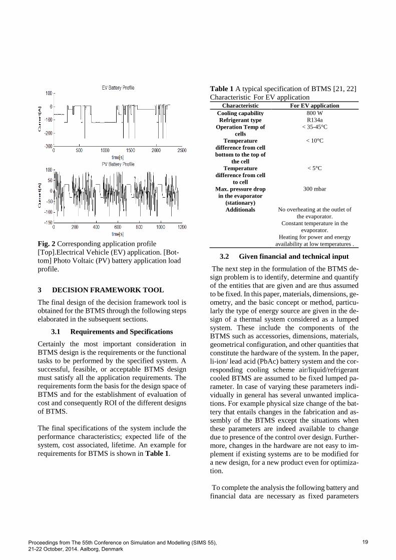
Fig. 2 Corresponding application profile
[Top].Electrical Vehicle (EV) application. [Bot-
tom] Photo Voltaic (PV) battery application load
profile.
3 DECISION FRAMEWORK TOOL
The final design of the decision framework tool is
obtained for the BTMS through the following steps
elaborated in the subsequent sections.
3.1 Requirements and Specifications
Certainly the most important consideration in
BTMS design is the requirements or the functional
tasks to be performed by the specified system. A
successful, feasible, or acceptable BTMS design
must satisfy all the application requirements. The
requirements form the basis for the design space of
BTMS and for the establishment of evaluation of
cost and consequently ROI of the different designs
of BTMS.
The final specifications of the system include the
performance characteristics; expected life of the
system, cost associated, lifetime. An example for
requirements for BTMS is shown in Table 1.
Table 1 A typical specification of BTMS [21, 22]
Characteristic For EV application Characteristic For EV application
Cooling capability 800 W
Refrigerant type R134a
Operation Temp of
cells
< 35-45°C
Temperature
difference from cell
bottom to the top of
the cell
< 10°C
Temperature
difference from cell
to cell
< 5°C
Max. pressure drop
in the evaporator
(stationary)
300 mbar
Additionals No overheating at the outlet of
the evaporator.
Constant temperature in the
evaporator.
Heating for power and energy
availability at low temperatures .
3.2 Given financial and technical input
The next step in the formulation of the BTMS de-
sign problem is to identify, determine and quantify
of the entities that are given and are thus assumed
to be fixed. In this paper, materials, dimensions, ge-
ometry, and the basic concept or method, particu-
larly the type of energy source are given in the de-
sign of a thermal system considered as a lumped
system. These include the components of the
BTMS such as accessories, dimensions, materials,
geometrical configuration, and other quantities that
constitute the hardware of the system. In the paper,
li-ion/ lead acid (PbAc) battery system and the cor-
responding cooling scheme air/liquid/refrigerant
cooled BTMS are assumed to be fixed lumped pa-
rameter. In case of varying these parameters indi-
vidually in general has several unwanted implica-
tions. For example physical size change of the bat-
tery that entails changes in the fabrication and as-
sembly of the BTMS except the situations when
these parameters are indeed available to change
due to presence of the control over design. Further-
more, changes in the hardware are not easy to im-
plement if existing systems are to be modified for
a new design, for a new product even for optimiza-
tion.
To complete the analysis the following battery and
financial data are necessary as fixed parameters
Proceedings from The 55th Conference on Simulation and Modelling (SIMS 55), 21-22 October, 2014. Aalborg, Denmark
19

Technology Attribute
costs and lifetime of the battery systems and re-
quired thermal accessories, their investment cost
and operating cost, the discount rate (nominal in-
terest rate) and the inflation as provided on Table
2.
Table 2 Different given model parameters used in
the simulation.
Lithium ion Lead Acid
Price/KWhr(€) 1000 400
Efficiency(Full Cycle) 92-96% 80-82%
Calender Lifetime yrs 20 10
Cycle Lifetime 5000 @60%
DOD
5000@90%
DOD
2500 @50%
DOD
2500@60%
DOD
Self-Discharge 3%/Month 5%/Month
Operating cost 1.5% 1%
Finally, the discount rate and inflation have to be
considered. A discount rate of 4.5% is based on the
yield of Danish loans on the secondary market.
This was taken from 15 year maturity bond market
between 4.2%-4.7 % [23]. The inflation is consid-
ered to be 2%, in line with the objective of the Cen-
tral European Bank [24].
3.3 Design Variables
The design variables are the quantities that may be
varied in a BTMS in order to satisfy the specified
application requirements. In this paper for instance,
the varying parameters are the choice of the battery
system, 𝑖 and associated accessories, j options of
cooling systems (details in section 3.7) for thermal
management. Therefore, during the BTMS design
process attention is primarily focused on these var-
ying parameters that determine the behaviour of the
BTMS and are then chosen so that the system meets
the given constraints of lifetime and financial as-
pects.
Three schemes are taken as the main factor to in-
vestigate in this study. Those are the air-cooling
scheme; refrigerant cooling scheme and a liquid-
cooling scheme. Fig. 3 illustrates the basic sche-
matics of the cooling options of the thermal man-
agement system while Table 3 corresponds a com-
parison of the three schemes.
Fig. 3 Cooling options of a battery thermal management system generic diagram. (a)Air cooling, (b) liquid
cooling, (c) Refrigerant cooling.
Economic
Project Period 1,3,5,10,15 year
Interest 4.8%
Inflation 2%
Air
BTMS(€)
Refrigerant Liquid
Lithium
ion
50 90 150
Lead Acid 30 70 120
Proceedings from The 55th Conference on Simulation and Modelling (SIMS 55), 21-22 October, 2014. Aalborg, Denmark
20
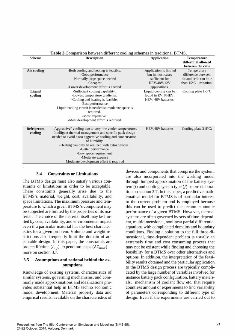
Table 3 Comparison between different cooling schemes in traditional BTMS. Scheme Description Application Temperature
differntial allowed
between the cells
Air cooling -Both cooling and heating is feasible.
-Good performance
-Normally large space needed
-Cheapest
-Lower development effort is needed
-Application is limited
but in most cases
sufficient for
HEV/48V/12V
applications.
Temperature
difference between
air and cells can be >
than 15°C limitation.
Liquid
cooling
-Sufficient cooling capability.
-Lowest temperature gradients.
-Cooling and heating is feasible.
-Best performance
-Liquid cooling circuit is needed so moderate space is
required.
-Most expensive.
-Most development effort is required
Liquid cooling can be
found in EV, PHEV,
HEV, 48V batteries.
Cooling plate 1-3°C
Refrigerant
cooling
-“Aggressive” cooling due to very low cooler temperatures.
Intelligent thermal management and specific pack design
needed to avoid a too aggressive cooling and condensation
of humidity
-Heating can only be realized with extra devices.
-Better performance
-Low space requirement
-Moderate expense
-Moderate development effort is required
HEV,48V batteries Cooling plate 3-8°C;
.
3.4 Constraints or Limitations
The BTMS design must also satisfy various con-
straints or limitations in order to be acceptable.
These constraints generally arise due to the
BTMS’s material, weight, cost, availability, and
space limitations. The maximum pressure and tem-
perature to which a given BTMS’s component may
be subjected are limited by the properties of its ma-
terial. The choice of the material itself may be lim-
ited by cost, availability, and environmental impact
even if a particular material has the best character-
istics for a given problem. Volume and weight re-
strictions also frequently limit the domain of ac-
ceptable design. In this paper, the constraints are
project lifetime (𝐿𝑖,𝑗), expenditure caps (ACmax)—
more on section 3.7.
3.5 Assumptions and rational behind the as-
sumptions
Knowledge of existing systems, characteristics of
similar systems, governing mechanisms, and com-
monly made approximations and idealizations pro-
vides substantial help in BTMS techno economic
model development. Material property data and
empirical results, available on the characteristics of
devices and components that comprise the system,
are also incorporated into the working model
through lumped approximation of the battery sys-
tem (𝑖) and cooling system type (𝑗)--more elabora-
tion on section 3.7. In this paper, a predictive math-
ematical model for BTMS is of particular interest
to the current problem and is employed because
this can be used to predict the techno-economic
performance of a given BTMS. However, thermal
systems are often governed by sets of time-depend-
ent, multidimensional, nonlinear partial differential
equations with complicated domains and boundary
conditions. Finding a solution to the full three-di-
mensional, time-dependent problem is usually an
extremely time and cost consuming process that
may not be existent while finding and choosing the
feasibility for a BTMS over other alternatives and
options. In addition, the interpretation of the feasi-
bility results obtained and the particular application
to the BTMS design process are typically compli-
cated by the large number of variables involved for
instance battery pack configuration, battery materi-
als, mechanism of coolant flow etc. that require
countless amount of experiments to find variability
of parameters corresponding to different type of
design. Even if the experiments are carried out to
Proceedings from The 55th Conference on Simulation and Modelling (SIMS 55), 21-22 October, 2014. Aalborg, Denmark
21

obtain the relevant input data for feasibility study
and design, the expense incurred in these experi-
ments makes it pragmatic to develop a model ap-
plicable for BTMS and the battery system to em-
phasis on the dominant parameters e.g. lifetime,
costs on different choices. Therefore, it is neces-
sary to neglect relatively unimportant aspects,
combine the effects of different variables in the
problem, employ idealizations to simplify the
BTMS design for the feasibility analysis, and con-
sequently reducing the number of design parame-
ters that govern the system for the specified appli-
cation but emphasising more on the economic ef-
fect of the system for instance ROI and costs, since
those may be the most important decision parame-
ter to build and procure a battery system for desired
application. Consequently, the first step is to con-
sider the simulation results in terms of the physical
nature of the system and to ascertain that the ob-
served trends somewhat agree with the expected
behaviour of the real BTMS in terms of the respec-
tive application load profile and corresponding life-
time. But the precaution is to be taken that all these
measures are relatively approximate indicators,
which generally suffice for the purpose of the fea-
sibility study and evaluation of the different de-
signs obtained. Since the design strategy, evalua-
tion of the BTMS designs developed, and final de-
sign are all dependent on the problem statement, it
is important to ensure that all of these aspects are
considered in adequate detail and quantitative ex-
pressions are obtained to characterize those as ex-
plained in section 3.7.
Estimates of the relevant quantities are used to
eliminate considerations that are of minor conse-
quence. In this paper, negligible effects are heat re-
moval rate, time to reach the required temperature
and so on. Practical BTMS and associated pro-
cesses are certainly not ideal. There are non-ex-
hausting list for instance undesirable energy losses,
friction forces, fluid leakages, operating conditions
and so forth, that affects the system behaviour.
However, in this paper a number of idealizations
are usually made to simplify the problem and to ob-
tain a solution that represents the best performance
for proposed feasibility analysis. Actual systems
may then be considered in terms of the ideal behav-
iour originating from this and the resulting perfor-
mance given in terms of efficiency, coefficient of
performance (COP), or effectiveness of this ideal
system. The paper can be used to estimate how the
specific BTMS perform against the representative
ideal system functioning on the given application.
Scaling laws are employed because they allow the
modelling of complicated systems in terms of sim-
pler, scaled-down versions. Using these laws, the
results from the models can be scaled up to larger
systems. All the results are shown in the paper con-
sider the utilization of battery of 200 cycles per
year is assumed as used in [1].
However in reality these refer to quantities of
BTMS that can often be varied relatively easily
over specified ranges with the holding the current
structure of the hardware of the given BTMS, such
as the operating settings for temperature, flow rate,
pressure, speed, power input, etc. Therefore, sev-
eral of these are generally kept fixed as stated sec-
tion 3.2 in this paper and the ranges over which the
others can be varied are determined from physical
constraints, availability of parts, and information
available from similar systems.
Even using the above mentioned simplifications
and idealizations the techno economic model is
said to have some level of precision due to inclu-
sion of degrees of freedom than can be found in the
literature [13, 15, 20, 25].
3.6 Modelling
The modelling of BTMS is an extremely important
step in the feasibility study based on the design and
optimization of the system. Modelling is generally
first applied to the obvious components, parts, or
subsystems related to its functionalities that make
up the BTMS for current consideration of commis-
sioning in battery system for the particular func-
tion. These models comprised of different type of
battery systems in this article lead acid and lithium
ion battery systems respectively as well as the cor-
responding accessories counterpart are assembled
with necessary cost information in order to take
into account the utility and interaction between the
integrated battery systems cost and lifetime those
Proceedings from The 55th Conference on Simulation and Modelling (SIMS 55), 21-22 October, 2014. Aalborg, Denmark
22
are worthwhile for the desired application. By exe-
cuting these individual models, the actual utility of
a battery system in term of costs with necessary ad-
justment inflation and real interest rate is calculated
with each other for finding the overall model that
satisfies the maximum ROI for the thermal system
is obtained. The model is subjected to a range of
project lifetime conditions due to various cost and
performance options to choose the best of the sys-
tem within the required constraints. A mathemati-
cal model that represents the performance and
characteristics of BTMS in terms of mathematical
equations is employed. The dominant considera-
tions in the particular BTMS are to determine the
important variables such as costs, lifetime costs etc.
and the governing parameters (the battery system
choice and the corresponding thermal system
choice) because of their considerable versatility in
obtaining quantitative results that are needed as in-
puts for the design. The price of different BTMS
depends on the scale, volume of cost, quality and
the lifetime as well as the financial aspects such as
year of the investment, interest rate, inflation etc.
Therefore it is imperative to take a financial cash
flow with adjusted interest rate that ensures com-
mon ground base for the calculation that includes
discount rate and inflation. Return on investment
(ROI) measures the gain or loss generated on an in-
vestment relative to the amount of money invested.
ROI is usually expressed as a percentage and is typ-
ically used for internal financial decisions, to com-
pare an enterprise’s profitability or to compare the
efficiency of different investments.
In order to calculate the real present values of the
battery systems with BTMS nominal interest rate is
converted to real interest rate to accommodate in-
flation. The nominal interest rate (sometimes
simply called the nominal rate) is the interest rate
that is quoted by central banks. It is the rate that is
used to discount actual, inflated future values. The
real interest is the rate earned on a capital invest-
ment after accounting for inflation. The real inter-
est rate should be used to discount future values
that are expressed in current monetary values. In
this article the real interest rates are considered than
the nominal interest rate.
Let:
𝑖 = the nominal interest rate,
𝑟 = the real interest rate, and
𝑘 = the inflation rate.
Now, the formula for combining the real interest
rate and the inflation rate to get the nominal interest
rate is:
𝑟 =(1+𝑖)
(1+𝑘)− 1… …(1)
Discount real future values with a real interest rate,
and discount nominal future values with a nominal
interest rate. Real future values are uninflated;
nominal future values are inflated.
To discount real future values, a real interest rate
is used. To discount nominal future values, a nom-
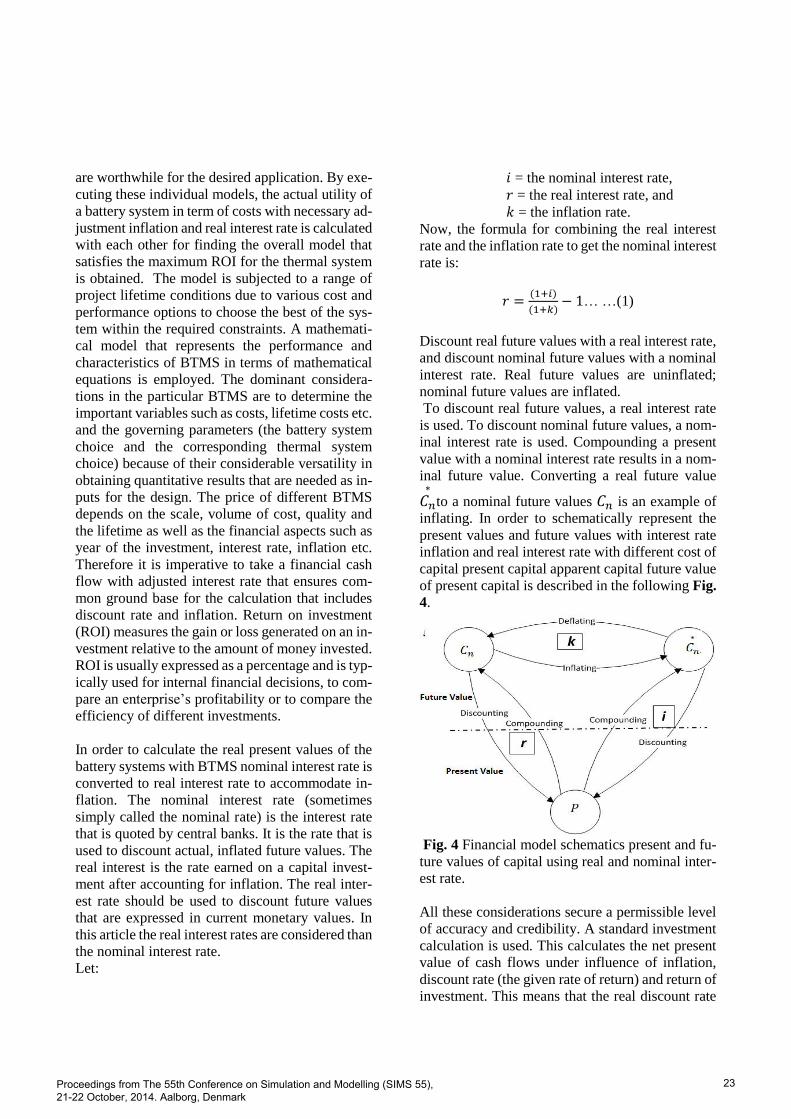
inal interest rate is used. Compounding a present
value with a nominal interest rate results in a nom-
inal future value. Converting a real future value
𝐶𝑛
∗
to a nominal future values 𝐶𝑛 is an example of
inflating. In order to schematically represent the
present values and future values with interest rate
inflation and real interest rate with different cost of
capital present capital apparent capital future value
of present capital is described in the following Fig.
4.
Fig. 4 Financial model schematics present and fu-
ture values of capital using real and nominal inter-
est rate.
All these considerations secure a permissible level
of accuracy and credibility. A standard investment
calculation is used. This calculates the net present
value of cash flows under influence of inflation,
discount rate (the given rate of return) and return of
investment. This means that the real discount rate
Proceedings from The 55th Conference on Simulation and Modelling (SIMS 55), 21-22 October, 2014. Aalborg, Denmark
23
is taken as reference instead of the nominal dis-
count rate (i.e. without inflation) [24]. The invest-
ment in a combination of thermal accessories and
battery system that leads to the highest ROI is the
most attractive option, since it is the highest profit
in absolute terms. In formula form this is expressed
as:
ROI =Lifetime Benefit−𝐿𝑖𝑓𝑒 𝑡𝑖𝑚𝑒 Cost
Cost… …(2)
Besides the net present value, also the internal rate
of return (IRR) and the payback period (PB) are
important financial indicators that can be incorpo-
rated into the calculation.
The payback period represents the operational year
that the sum of the cash flows starting from the in-
itiation of BTMS acquisition period is higher than
the investment without taking the discount rate (or
real interest) into account. It is also sometimes in-
dicated as simple payback period to emphasise that
no discounting is used. In the paper, the payback
period is not shown. In this paper, the base cost for
ROI calculation has been chosen as the choice
when there is no BTMS for the two battery sys-
tems. So in calculation of ROI of these systems,
this is worked like the lifetime cost. Since there is
a lifetime increase in case of BTMS usage, the ben-
efit is calculated. In all cases cost and benefits are
calculated per annum basis to have a common scale
for further comparison.
3.7 Governing equations
This section deals with mathematical modelling
based on physical insight recourse and on a consid-
eration of the governing principles that determine
the behaviour of a given thermal system.
The governing equations are first written. After the
governing equations are assembled, along with the
various approximations and idealizations outlined
here, further simplification can sometimes be ob-
tained by a consideration of the various terms in the
equations to determine if any of them are negligi-
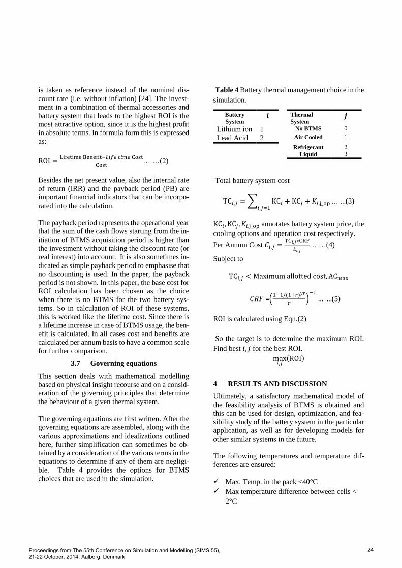
ble. Table 4 provides the options for BTMS
choices that are used in the simulation.
Table 4 Battery thermal management choice in the
simulation.
Battery
System 𝒊 Thermal
System 𝒋
Lithium ion 1 No BTMS 0
Lead Acid 2 Air Cooled 1
Refrigerant 2
Liquid 3
Total battery system cost
TC𝑖,𝑗 = ∑ KC𝑖 + KC𝑗 + 𝐾𝑖,j_op … …𝑖,𝑗=1
(3)
KC𝑖, KC𝑗, 𝐾𝑖,j_op annotates battery system price, the
cooling options and operation cost respectively.
Per Annum Cost 𝐶𝑖,𝑗 =TC𝑖,𝑗∗CRF
𝐿𝑖,𝑗… …(4)
Subject to
TC𝑖,𝑗 < Maximum allotted cost, ACmax
𝐶𝑅𝐹 =(1−1/(1+𝑟)yr
𝑟)
−1
… …(5)
ROI is calculated using Eqn.(2)
So the target is to determine the maximum ROI.
Find best 𝑖, 𝑗 for the best ROI.
max𝑖,𝑗
(ROI)
4 RESULTS AND DISCUSSION
Ultimately, a satisfactory mathematical model of
the feasibility analysis of BTMS is obtained and
this can be used for design, optimization, and fea-
sibility study of the battery system in the particular
application, as well as for developing models for
other similar systems in the future.
The following temperatures and temperature dif-
ferences are ensured:
Max. Temp. in the pack <40°C
Max temperature difference between cells <
2°C
Proceedings from The 55th Conference on Simulation and Modelling (SIMS 55), 21-22 October, 2014. Aalborg, Denmark
24

Max temperature difference cell bottom – cell
tap< 6°C
Two battery pack applications with cooling plates
(Fig. 3 ) on the bottom of the cells but different
cooling media have been introduced and validated
on the test stand. Air cooling can be critical in mat-
ter of terms of cooling capability and temperature
gradient within the battery pack. Besides that safety
and comfort aspects have to be considered in real
systems.
A sensitivity analysis is undertaken to determine
how the choice of BTMS varies with the design
variables and the operating conditions in order to
choose the most appropriate, convenient, and cost-
effective values at or near the extremum that would
optimize the system or its operation.
In this paper the project horizons of 3 and 5 year
(short term), 10 and 15 year (long term) are chosen.
Also to show the results with a base project span-
ning 1 year is used. The system is simulated on
same interest rate with inflation to compare each
other’s feasibility. Using the modelling methods
and governing equations the model is simulated to
find the maximum ROI. The short term result im-
plicated that PbAc battery systems are more feasi-
ble and yield more ROI than its lithium ion coun-
terpart. But if the project tenure is bigger than 5
years, Li-ion becomes the preferred technology.
The reason is that Li ion has higher longevity and
need to be replaced less times than PbAc counter-
part.One of the further comment can be that the
price of batteries are going down sharply for lith-
ium ion batteries and in coming years the trend is
going to persist. In that case again Li -ion batteries
offer more prospects to change their PbAc counter-
part.
The two applications EV and PV impose different
type of thermal system requirement. The thermal
system must adhere to the ever changing profile of
the EV application cycle. Due to the restrictions
that are needed to comply for EV application, the
system is best suited to go with liquid and refriger-
ant type cooling mechanism as illustrated on Fig. 5
So a cooling system is recommended to be em-
ployed while using the battery systems for EV sys-
tems. However, the choice among the liquid, refrig-
erant or air cooled may also be dictated by space
constrains. Additionally, selected cooling layout
can make use of battery’s thermal capacity also
participate on cost reduction of the whole vehicle.
Fig. 5 Feasibility result for Electrical Vehicle ap-
plication commissioned with different cooling
BTMS with different PbAc and Li-on Battery sys-
tem.
The result is congruent with real life project results.
Especially for large size battery systems liquid
cooling is the best compromise. Choice of cooling
concept depends on battery pack requirements as
well as on vehicle requirements and architecture.
But in case of PV application, the air and refriger-
ant type provide the optimized ROI criteria shown
on Fig. 6 . It is observed that PV profiles are not as
much as varying as EV power requirement that re-
sults less temperature increase and consequently
the stationary battery becomes more profitable by
avoiding extra expenditures of the expensive
BTMSs.
Proceedings from The 55th Conference on Simulation and Modelling (SIMS 55), 21-22 October, 2014. Aalborg, Denmark
25

Fig. 6 Feasibility result for Photovoltaic applica-
tion commissioned with different cooling BTMS
with different PbAc and Li-ion Battery system.
This techno economic effort also generalizes the
problem so that in future the results obtained from
the analytical result originate from the techno-eco-
nomic model can be compared to the experimental
study that can be used without major modifications
to other similar systems and circumstances cover-
ing all the scopes as detailed by this paper. Alter-
natively, if experimental data from a prototype are
available, a comparison between these and the re-
sults from the simulation could be used to deter-
mine the validity and accuracy of the latter.
Since the basic concept introduced in the paper is
not fixed, different concepts may be considered ir-
respective of battery chemistries resulting in con-
siderable flexibility in the design. However, in
many cases, different considerations may lead to
different scaling parameters and the appropriate
model may not be uniquely defined at least on the
feasibility stage.
5 CONCLUSIONS
This paper provides a complete feasibility analysis
of battery systems with necessary thermal manage-
ment accessories functional in transport and photo-
voltaic applications based on a statistical signifi-
cant amount of data, based on real system prices
and technical lifetime expectations. The method
takes into account technical parameters as battery
lifetime and application requirement. Future work
will be oriented towards applying the analysis to
different types of profiles using taking more de-
grees of freedom into account for example impact
of heating rate and method of cooling e.g. convec-
tion or forced based cooling and design of hybrid
optimal system. Furthermore the method can be ap-
plied to determine the feasibility of the inclusion of
any accessories that may be introduced over time
corresponding to increased lifetime for different
application criteria than PV-battery and EV-battery
systems. The present paper aims to serve as deci-
sion-making support for researchers, practitioners
and policy makers by reviewing costs and perfor-
mance of battery before purchasing or acquiring a
required BTMS. For most battery storage applica-
tions, the methodology can be used without major
modifications.
ACKNOWLEDGMENTS
The authors gratefully acknowledge the financial
support for this work from the Danish Strategic Re-
search Council to the Advanced Lifetime Predic-
tions of Battery Energy Storage (ALPBES) project.
REFERENCES
[1] H. S. Kim, B. W. Cho, and W. I. Cho, "Cycling
performance of LiFePO4 cathode material for
lithium secondary batteries," Journal of Power
Sources, vol. 132, pp. 235-239, May 2004.
[2] C. K. Huang, J. S. Sakamoto, J. Wolfenstine, and S.
Surampudi, "The Limits of Low‐Temperature
Performance of Li‐Ion Cells," Journal of The
Electrochemical Society, vol. 147, pp. 2893-2896,
August 1, 2000 2000.
[3] R. Sabbah, R. Kizilel, J. R. Selman, and S. Al-Hallaj,
"Active (air-cooled) vs. passive (phase change
material) thermal management of high power
lithium-ion packs: Limitation of temperature rise
and uniformity of temperature distribution," Journal
of Power Sources, vol. 182, pp. 630-638, Aug 2008.
[4] M. R. Khan, S. J. Andreasen, and S. K. Kær. (2014,
01.08.2014) Novel Battery Thermal Management
System for Greater Lifetime Ratifying Current
Quality and Safety Standard. Battery Connections.
6-10. Available:
http://www.batteryconnections.net/summer2014iss
ue/index.html
[5] R. Kizilel, R. Sabbah, J. R. Selman, and S. Al-Hallaj,
"An alternative cooling system to enhance the safety
of Li-ion battery packs," Journal of Power Sources,
vol. 194, pp. 1105-1112, Dec 2009.
0 5 10 15 200
1
2
3
4
5
6
7
8
9
10
Temperature Difference() between the cells
RO
I o
f B
att
ery
Syst
em
[%]
Feasibility of battery for PV application
Liquid Refrigerant Air-Cooled No BTMS
Proceedings from The 55th Conference on Simulation and Modelling (SIMS 55), 21-22 October, 2014. Aalborg, Denmark
26

[6] A. A. Pesaran, A. Vlahinos, and S. D. Burch,
"Thermal Performance of EV and HEV Battery
Modules and Packs," in 14th International Electric
Vehicle Symposium, Orlando, Florida, 1997.
[7] D. J. Bowen, M. Kreuter, B. Spring, L. Cofta-
Woerpel, L. Linnan, D. Weiner, et al., "How We
Design Feasibility Studies," American Journal of
Preventive Medicine, vol. 36, pp. 452-457, 5// 2009.
[8] B. Battke, T. S. Schmidt, D. Grosspietsch, and V. H.
Hoffmann, "A review and probabilistic model of
lifecycle costs of stationary batteries in multiple
applications," Renewable and Sustainable Energy
Reviews, vol. 25, pp. 240-250, 9// 2013.
[9] M. R. Khan, G. Mulder, and J. Van Mierlo, "An
online framework for state of charge determination
of battery systems using combined system
identification approach," Journal of Power Sources,
vol. 246, pp. 629-641, Jan 15 2014.
[10] D. U. Sauer and J. Garche, "Optimum battery design
for applications in photovoltaic systems —
theoretical considerations," Journal of Power
Sources, vol. 95, pp. 130-134, 3/15/ 2001.
[11] M. R. Khan, J. V. Barreras, A. I. Stan, M.
Swierczynski, S. J. Andreasen, and S. K. Kær,
"Behavior Patterns, Origin of Problems and
Solutions Regarding Hysteresis Phenomena in
Complex Battery Systems," in Hysteresis: Types,
Applications and Behavior Patterns in Complex
Systems, J. C. Dias, Ed., First ed: Nova Science
Publishers 2014, pp. 215-226.
[12] C. Clastres, T. T. Ha Pham, F. Wurtz, and S. Bacha,
"Ancillary services and optimal household energy
management with photovoltaic production," Energy,
vol. 35, pp. 55-64, 1// 2010.
[13] G. Mulder, F. D. Ridder, and D. Six, "Electricity
storage for grid-connected household dwellings with
PV panels," Solar Energy, vol. 84, pp. 1284-1293,
2010.
[14] J. Kathan, "Increasing BIPV self-consumption
through electrical storage –feasible demand-
coverage and dimensioning the storage system," in
5th international renewable energy storage
conference IRES, Berlin, Germany, 2010.
[15] M. R. Khan, G. Mulder, J. Van Mierlo, and S. K.
Kær, "The Integration and Control of
Multifunctional Stationary PV-Battery Systems in
Smart Distribution Grid," in EU PVSEC The 28th
European Photovoltaic Solar Energy Conference
and Exhibition Paris, France, 2013, pp. 3841 - 3851.
[16] K. Herter and S. Wayland, "Residential response to
critical-peak pricing of electricity: California
evidence," Energy, vol. 35, pp. 1561-1567, 4// 2010.
[17] G. Mulder and B. Claessens, "Insights in storage as
a solution for local renewable electricity
generation," e & i Elektrotechnik und
Informationstechnik, vol. 128, pp. 116-121,
2011/04/01 2011.
[18] V. Wachenfeld, "Technical and economic aspects of
storing electricity from PV to increase the share of
self-consumption," in 5th international renewable
energy storage conference(IRES), Berlin, Germany,
2010.
[19] M. Bost, "The impact of installation size, household
size, storage dimensioning and consumer behaviour
on the level of self-consumption, return on
investment and feed-in tariff costs for private
households," in 5th international renewable energy
storage conference IRES, Berlin, Germany, 2010.
[20] J. Tant, F. Geth, D. Six, P. Tant, and J. Driesen,
"Multiobjective Battery Storage to Improve PV
Integration in Residential Distribution Grids,"
Sustainable Energy, IEEE Transactions on, vol. 4,
pp. 182-191, 2013.
[21] M. Jäger, J. Ogrzewalla, and T. Hülshorst, "Layout
of a liquid-cooled highpower PHEV battery,"
presented at the Kraftwerk Batterie 2014 - Münster,
Münster,Germany, 2014.
[22] P. Pichler, N. Hochgatterer, K. Grieshofer, and T.
Hörmann, "Analysis of Cooling Requirements and
Solutions for Low and High-Voltage Automotive
Battery Packs," presented at the Kraftwerk Batterie
2014, Münster,Germany, 2014.
[23] K. M. Rasmussen, C. Madsen, and R. Poulsen,
"Realkreditradgivning - Et studie af danskernes valg
af realkreditlan og konverteringspraksis," ed.
Boligøkonomisk Videncenter, 2011.
[24] Monetary policy, T. E. C. Bank.
[25] G. Mulder, D. Six, B. Claessens, T. Broes, N. Omar,
and J. V. Mierlo, "The dimensioning of PV-battery
systems depending on the incentive and selling price
conditions," Applied Energy, vol. 111, pp. 1126-
1135, 11// 2013.
Proceedings from The 55th Conference on Simulation and Modelling (SIMS 55), 21-22 October, 2014. Aalborg, Denmark
27