DJSPARK_2020.pdf - Techno Journal IETE – SF
135
-
Upload
khangminh22 -
Category
Documents
-
view
4 -
download
0
Transcript of DJSPARK_2020.pdf - Techno Journal IETE – SF
DeclarationAllclaimedresultsexpresstheviewsofthenamedauthors.
Theworkdoesnotinfringethecopyrightofanypersonorotherpublishedwork.Themanuscripthasnotbeensenttoanyotherresearchjournalforpublication.


DJ SPARK 2020 EDITORS-IN-CHIEFDr.HariVasudevanDr.AmitA.Deshmukh
ASSOCIATEEDITORSProf.AnujaA.OdhekarProf.RahulTaware
IETE-SF Of
Department of Electronics and Telecommunication Engineering
i.

FirstImpression:April2020 ©IETE-SFDepartmentofElectronicsandTelecommunicationEngineering,DJSCE DJSPARK2020 ISBN:978-93-5391-520-9 Nopartof thispublicationmaybereproducedortransmitted inanyformbyanymeans,electronicormechanical,includingphotocopy,recording,oranyinformationstorage and retrieval system, without permission in writing from the copyrightowners.
DISCLAIMER Theauthorsare solely responsible for the contentsof thepaper compiled in thisvolume.Thepublishersoreditorsdonottakeanyresponsibilityforthesameinanymanner. Errors, if any, are purely unintentional and readers are requested tocommunicate such errors to the editors or publishers to avoid discrepancies infuture.
ii.

FromtheEditorialDesk
ElectronicsandTelecommunicationEngineeringhasalwaysplayedamajorroleintheadvancementoflatestinthetechnologyarena.Astechnologyprogressesrapidly,ithasbecomeessentialforengineersandtechnologiststokeepupwiththechangesintheirrespectiveareasofexpertise.TheIETE-StudentForum(IETE-SF)wasformedintheyear2005undertheDepartmentofElectronicsandTelecommunicationofD.J.SanghviCollegeofEngineering,tonotonlyfacilitate the flowof ideasand information,butalso toencourage theadvancement in the fieldofelectronicsandtelecommunicationengineering.Inordertokeepupwithnewtechnologies,IETE-SFconductstechnicalworkshopsand seminars to encourage them to work on their technical skills. This forum paves a way for students to gainknowledgeapartfromtheiracademiccurriculum.Inadditiontoconductingworkshopsandseminars,IETE-SFrunsthebook-bankfacilitywherestudentscanavailawiderangeoftechnicalbooks.Twoyearsanewinitiativewastakenby the student forum to run a component-bank facility, which enables students to avail of various electroniccomponents,which can be used for building technical projects. ‘DJ Strike ‘, a projectmentorship program,whichencourages students from the second, third and fourth years to teamup together to build technical projectswascontinuedthisyearaswellby the IETE-SF.Over the lasteightyears, theEXTCDepartmenthasorganizedvarioustechnicaleventslikeSTTPonMicrowaveandAntenna,ImageProcessingandWirelessNetworks.Thedepartmentalsoorganized,NationalconferencelikeNCCT-2011intheyear2011andInternationalConferenceslikeICCT-2013andICCT-2015intheyear2013and2015.Since2017thedepartmenthasbeenorganizingtheInternationalConferenceonWirelessCommunication(ICWiCOM2017,January2018andOctober2019)wheretheconferenceaddressesonlynarrowtopicsinthedomainofWirelessCommunication.ProceedingsoftheconferencesareavailableontheSpringerdigitallibrary.Incontinuation,ICWiCOM2021isscheduledtotakeplaceinOctober2021,andproceedingsforthesameshallbeavailableonSpringerdigitallibrary.Forthelasteightyears,IETE-SFhasbeenorganizing‘DJSpark’,astatelevelprojectcompetition.Thiscompetitionaimstoprovideaplatformforstudentstoshowcasetechnicalskillsaswellastechnicalpaperwritingskills.Afteravigorousreviewprocess,theresearchpapersofthebestprojectsarepublishedinthe‘DJSpark’Journal,whichhasarecognizedISBNNumber.DuetotheoverwhelmingresponsereceivedforDJSpark,IETESFhasbeenmotivatedtoorganize‘DJSpark2020’.ThebesttechnicalprojectsrelatedtothefieldofElectronicsandTelecommunicationbytheundergraduateandpostgraduatestudentswillbedisplayedduringthecompetition.WeherebyappreciatetheeffortstakenbyallthefacultymembersofthedepartmentofEXTCandtheIETE-SFstudentcommitteemembersfororganizing‘DJSpark2020’.CongratulationstoalltheparticipantsofDJSpark2020!Bestwishes.Dr.AmitA.Deshmukh Dr.HariVasudevanCo-Convener,DJSpark2020 Convener,DJSpark2020Professor&Head,EXTC,DJSCE Principal,DJSCE
iii.
DJSPARK2020Committee
ChiefPatron
ShriAmrishR.Patel(President,SVKM)
Patrons
ShriBhupeshR.Patel(JointPresident,SVKM)
ShriBharatM.Sanghvi ShriChintanA.Patel(Hon.VicePresident&Trustee,SVKM&I/C,DJSCE)(Hon.VicePresident&Trustee,SVKM)ShriSunandanR.DivatiaShriJagdishB.ParikhShriJayantP.Gandhi(Hon.Secretary,SVKM)(Hon.Treasurer,SVKM)(Hon.JtSecretary,SVKM)ShriShalinS.DivatiaShriHarshadH.ShahShriHaritH.Chitalia(Hon.Jt.Secretary,SVKM)(HonTreasurer,SVKM)(Hon.JtTreasurer,SVKM)
AdvisoryCommittee
ShriAsokeBasak(CEO,SVKM)Dr.A.C.Daptardar(VicePrincipal,Admin,DJSCE)Dr.ManaliJ.Godse(VicePrincipal,Acad,DJSCE)
Dr.A.Mahapatra(Prof.&Head,ChemicalDept,DJSCE)Dr.K.N.Vijaykumar(Prof.&Head,MechanicalDept,DJSCE)Dr.M.M.Narvekar(Prof.&Head,ComputerDept,DJSCE)Dr.P.S.Joshi(Prof.&Head,ElectronicsDept,DJSCE)
Dr.VinayaSawant(Head,ITDept,DJSCE)
iv.
DJSPARK2020FacultyCommittee
Convener
Dr.HariVasudevan(Principal)
Co-Convener
Dr.AmitA.Deshmukh(Prof.&Head,EXTCDept)
Co-ordinators
Prof.AnujaOdhekar(EXTCDept)Prof.RahulTaware(EXTCDept)
TechnicalCommittee
Prof.TanajiBiradar(EXTCDept)Prof.VishakaKelkar(EXTCDept)
Dr.SunilKaramchandani(EXTCDept)Prof.SanjayDeshmukh(EXTCDept)Prof.PoonamKadam(EXTCDept)
Prof.ShivaniBhattacharjee(EXTCDept)
OrganizingCommittee
Prof.AmeyaKadam(EXTCDept)Prof.RanjushreePal(EXTCDept)Prof.VenkataChavali(EXTCDept)Prof.MrunaliniPimpale(EXTCDept)Prof.ArchanaChaudhari(EXTCDept)
Prof.YuktiBandi(EXTCDept)Prof.AartiAmbekar(EXTCDept)Prof.RevathiA.S.(EXTCDept)
Prof.TusharSawant(EXTCDept)Prof.VenkataramananV.(EXTCDept)
v.
DJSPARK2019-20StudentCommittee
ParthiviMerchantBhavyaSekhani
AviDoshiAkshilPanchalHarshGohilShyamalOza
PrachiSadaranganiMansiParekhDevnaDave
PoojaSadarangani
AamirKhambati RushabhShroffVrutanshShah DishayShahAnujSardesai PoojaSadarangani
AshwinSwaminathan JanhviChitrodaKeaganPinto HarshSanghaviAnshDisawal KalpeshChaudharyKrinaShah DhruvBhavsar
RushabhNagada KaranShahJaiBeri MeghKatti
RiyanshiShah SoumyaWagleSanjayChauhan AnujaBarjeNisargShah MokshaShah
DivjyotSinghSaluja SaisriKrishnamoorthyAarushiRaichur NidhiGohilYuktaKanani DeepGosar
RitvikKhandelwal HetaShahLakshitaShetty
vi.

Contents Disclaimer ii
FromtheEditorialDesk iii
Committees iv1) VehicleTheftDetectiononRaspberryPi 12) GarbageSegregationandManagement 53) SmartStreetLightManagementSystem 84) DevelopmentofIOTBasedLandslideDetectionSystem 115) CollegeRecommendationSystem 16
6)WASHME-Web-ApplicationBasedSanitationAndHygieneMonitoringEmbeddedSystem 21
7) AutomatStationer 268) AccelerometerBasedCar 299) AutonomousandBluetoothControlled‘SPICKN-SPAN’Device 3410) CropFieldManagementbasedonIoTusingNodeMCU 3911) FireandExplosionDetectionUsingResidualNeuralNetworks 4412) TVAudienceSentimentAnalysis 4813) HousingAffordabilityModelUsingPython 5314) HealthMonitoringSystemusingIoTandAI 5815) AttendanceManagementUsingFaceRecognition 6216) IndustrialLiquidAutomationUsingPLCandMicrocontroller 6617) HomeAutomationSystemandSmartSecurityUsingR-PiandParticleCloud 7118) SpotClockUsingNodeMCU 7519) AndroidApplicationConnectingMentorsAndMentees 7920) SolarPoweredBeachCleaningMachine 8621)WirelessMedicomSystem 8922) BiometricsbasedVotingSystemusingIrisandFaceAuthenticationSystem 9423) AutomatedWasteSegregationusingRoboticArm 9924) ArduinoBasedSelfDrivingCarWithDrowsinessDetection 10225) EyeStick 10826) Barbot 11227) TrainingAndPlacementCellAndroidApplication 117
•Vehicle Theft Detection on Raspberry Pi
•Proceedings for DJ Spark 2020 ISBN: 978-93-5391-520-9
Vehicle Theft Detection on Raspberry Pi Madhura Vajarekar1, Krutika Patil1, Meera Yadate1, T. N. Sawant2
1 U. G. Student, Department of Electronics and Telecommunication, Bharati Vidyapeeth College of Engineering, Mumbai- 400614 2 Professor, Department of Electronics and Telecommunication, Bharati Vidyapeeth College of Engineering, Mumbai- 400614
E-mail: [email protected], [email protected], [email protected], [email protected]
Abstract - In recent years the crime related to vehicle theft has been a tremendous rise with intruders becoming smarter every day. As we know in serious crimes stolen vehicles are used that results in loss of life or physical injuries. This generates a crucial need for an effective vehicle theft diagnosis system. In this project, a compact, cheap and efficient system is studied, designed and explored using Raspberry Pi 3 as the core processing unit of the whole system. We are using the MEMS accelerometer sensor which is placed on the vehicle. First the key is inserting in key slot and it will be detected and if engine of car is started then owner will receive a message indicating that the engine is started using Global System for Mobile communication (GSM). We are also looking to rash driving situation. When driver is driving on high speed and taking dangerous drift it is detected by MEMS sensor placed on car then alert message is sent to the owner. This device functions in two modes which are user mode and theft mode. This paper explores the possibility of a compact, viable, cheap and efficient vehicle theft detection system.
Keywords-IR Sensor, Raspberry- Pi, GSM, Switch, MEMS ADxL 345, 16X2 LCD
I. INTRODUCTION
In recent years, we observe vehicle thefts are increasing at a high rate around the globe and people have started to use the theft control systems installed in their vehicles. Anti-theft vehicular systems which are available in market are very expensive. Hence, we are designing and developing simple and low-cost vehicle theft control scheme. This Anti-Theft Detection system provides a greater advantage to any person who can afford a cheap 9product which could provide anti-theft detection features to any vehicle. The Anti-theft detection system works by using Raspberry pi as hardware tool, IR sensor for detecting and GSM for sending message, accelerometer sensor for detection of rash driving and 16×2 LCD display. In this system there will be two modes user mode and theft mode. User mode and theft mode will be switched by using GSM module by sending themessage from the owner. Automatic monitoring of vehicles is possible which will be helpful for personal vehicles and rented cabs etc. The best solution for saving of money and reduction of man power is possible by using this system by using Raspberry pi board. The proposed system get information related to the vehicle like speed, rash driving and it will inform the owner.
II. PROPOSED SOLUTION
In this proposed system continuous monitoring of personal vehicles and school vehicles at real time is possible and if the unauthorized person tries to access the vehicle then this system helps to gather the information such as key detection, engine started or not and rash driving detection and it will gives the alert message to the owner’s Smartphone. The proposed system uses Raspberry pi board which placed inside the vehicle. In this system there should be two modes user modes and theft mode. In the user mode there will be normal operation that means owner or authorized person is driving the vehicle. When the user is not driving the vehicle then it will be in theft mode which is done by switching the modes by sending the messages to the system by using GSM and whenever the system in theft mode and if unauthorized person accesses the vehicle then it will send the alert message to the owner. Owner can switch the two modes that are user mode and theft mode by using GSM module.
The modes can be switched by sending the message to the system for user mode message will be User mode and for theft mode message will be Theft mode. When the system is operating in user mode, when key is detected and engine will be started no message will be sent to the owner. Hence, we can avoid unnecessary data in user mode. The GSM module would get communicate to raspberry pi board. Key detection is provided by IR sensor. If unauthorized person tries to insert key then IR sensor will detect it and message will be sent to the owner also if engine gets started then also it will send the message to the owner. If engine gets started then again message will be sent to the owner mobile number. By using GSM module this message will be delivered to the owner. That input will be given to the raspberry pi. The MEMS ADxL 345 is accelerometer sensor which will detect the condition of rash driving
•Vehicle Theft Detection on Raspberry Pi
•Proceedings for DJ Spark 2020 ISBN: 978-93-5391-520-9
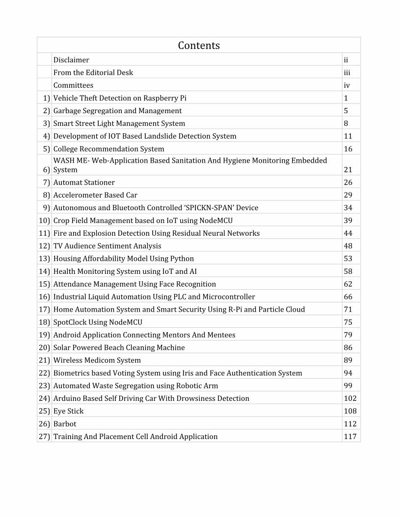
Fig1. System Block Diagram
III. MODULES USED
A. Raspberry Pi The Raspberry Pi is a type of computer which is single board and credit card sized. The aim of this device is to providing low-cost computers. Their ultimate goal is to provide small, affordable chip size computer. The price of raspberry pi board is Rs.2,495 for model B. The general-purpose input output pins on each board allow the user to connect other boards. Ethernet port is provided. Features of Raspberry pi b board are as follows:
1. 5V and 1A maximum power from an adaptor. 2. 700 MHz ARM1176JZF-S core (ARM11 family,
ARMv6 instruction set). 3. 1GHz operating speeds. 4. Four USB ports – keyboard, mouse and for external
memory 5. Raspberry pi 3 boards use IEEE 802.11 wireless
local area network. 6. HDMI port is available. 7. 40 general purpose input output pins are available.
Fig 2. Raspberry Pi
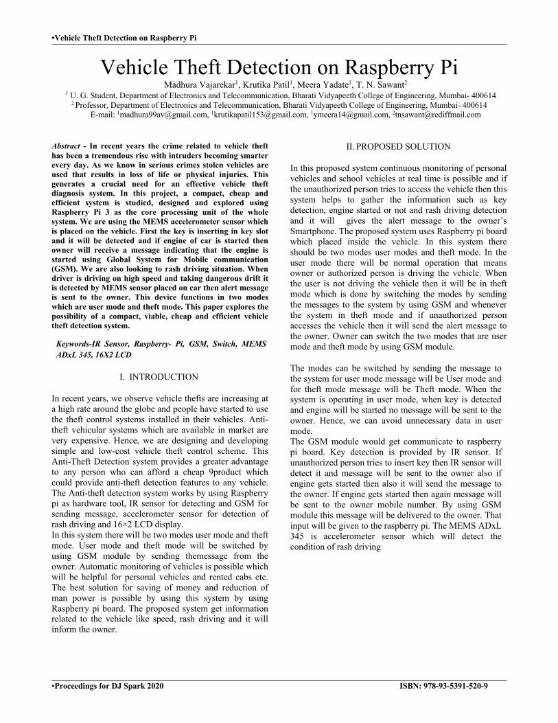
B. GSM MODEL GSM modem is a device that accepts any SIM card and operates just like a normal phone. It looks similar like a mobile phone. To communicate over mobile network this model is connected to computer. GSM modems provide mobile internet connectivity to the device.
Fig 3. Global System for Mobile Communication
C. IR SENSOR An infrared sensor is device that emits light so as to sense or to detect some objects in the environment. The sensors which measures infrared light, instead of emitting a light that’s known as a Passive.
Fig 4. IR LED
IR LED is again a simple diode which emits out the IR radiations. The function of this diode is to transform electricity into light. Electron-hole pair principle is used here.
Fig 5. Photodiode
The photodiode is also called as a p-n junction diode. It can be connected with the reverse bias direction. The detector is used to convert light into electricity.Whenever number of photons or a light fall on detector it works effectively. D. LCD DISPLAY LCD module area unit terribly usually employed in most embedded comes, the explanation being its low- cost worth, accessibility and software engineer friendly it's sixteen Columns and a pair of Rows. The 16×2 interprets to a show 16 characters per line in two such lines. During this digital display every character is displayed during a 5×7 element matrix.
•Vehicle Theft Detection on Raspberry Pi
•Proceedings for DJ Spark 2020 ISBN: 978-93-5391-520-9
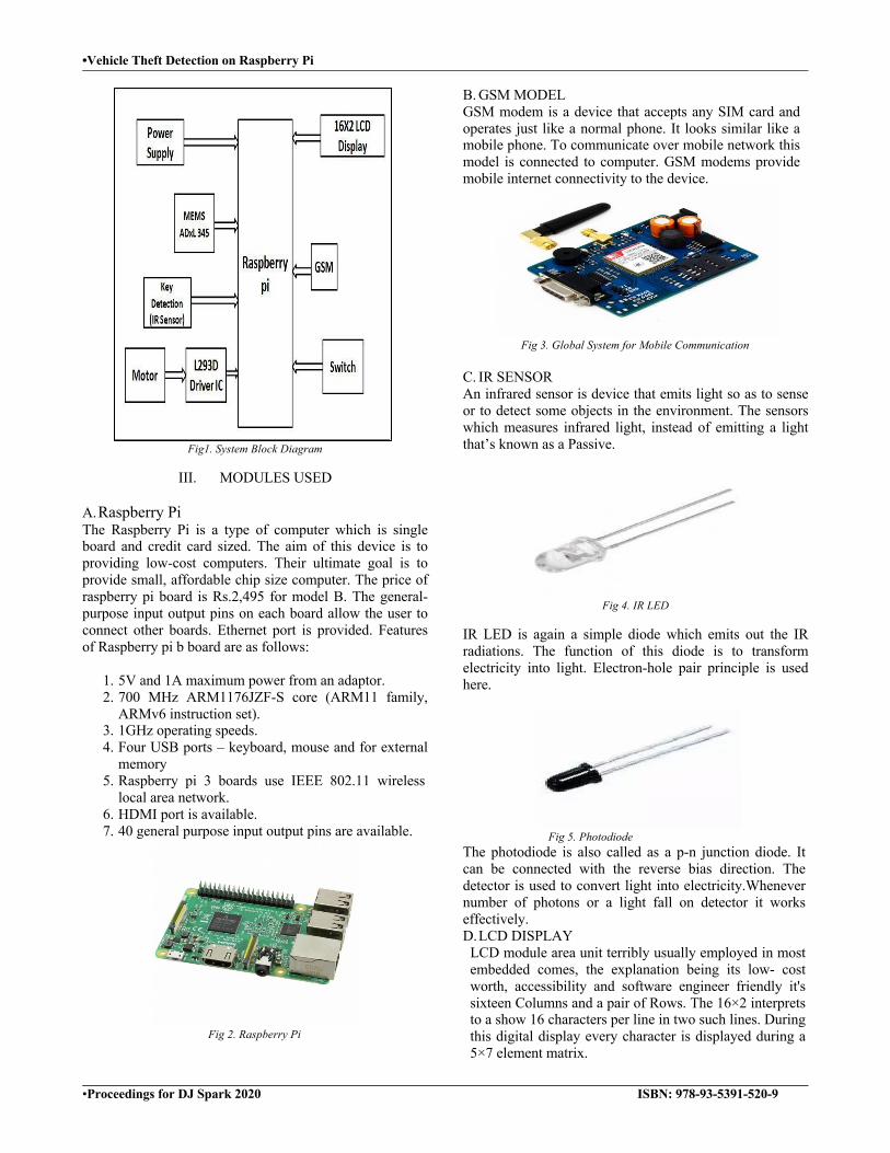
Fig 7. LCD display module
E. ADXL 345 The accelerometer ADXL345 could be a tiny, thin, ultra-low power, 3-axis measuring system. It measures the dynamic acceleration and static acceleration. In that serial communication can be done using I2C, SPI. If the static acceleration measuring then due to gravity, we find out the angle the device is tilted at with respect to the earth. And if the dynamic acceleration measuring, we can find the way the device is moving. This accelerometer sensor is used for mobile device applications. Several special sensing functions square measure provide. This accelerometer sensors is used in various applications.
Fig 8. ADxL345
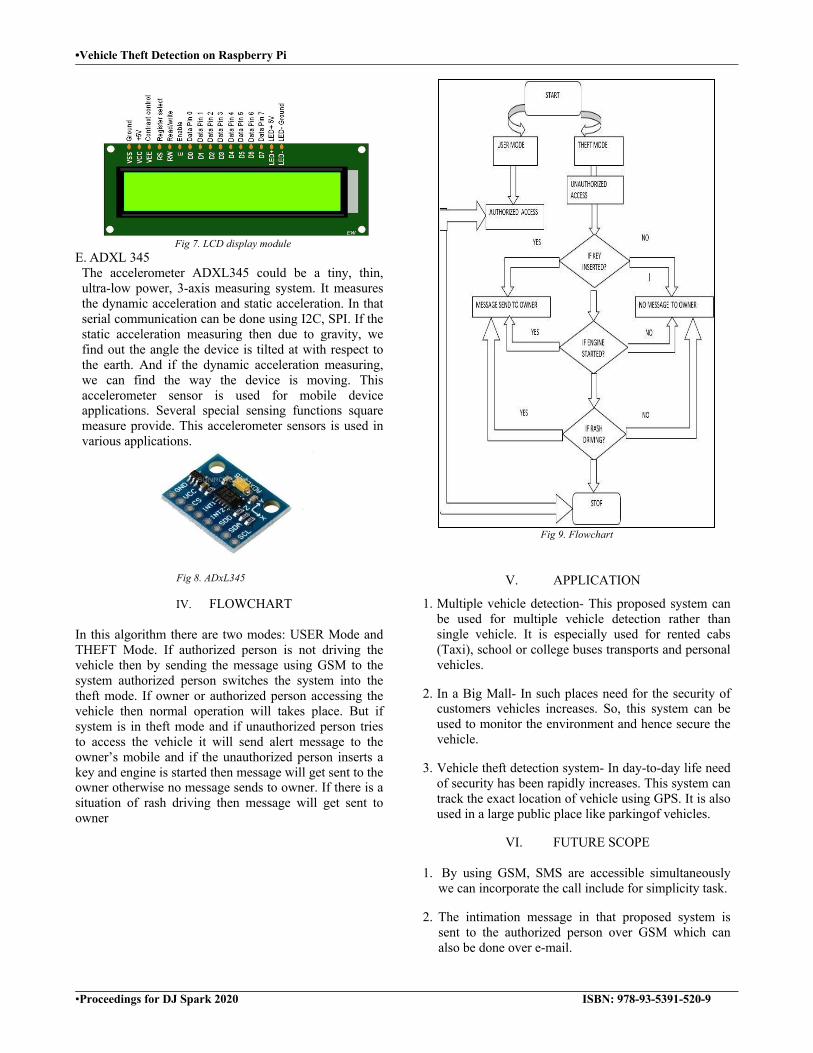
IV. FLOWCHART In this algorithm there are two modes: USER Mode and THEFT Mode. If authorized person is not driving the vehicle then by sending the message using GSM to the system authorized person switches the system into the theft mode. If owner or authorized person accessing the vehicle then normal operation will takes place. But if system is in theft mode and if unauthorized person tries to access the vehicle it will send alert message to the owner’s mobile and if the unauthorized person inserts a key and engine is started then message will get sent to the owner otherwise no message sends to owner. If there is a situation of rash driving then message will get sent to owner
Fig 9. Flowchart
V. APPLICATION
1. Multiple vehicle detection- This proposed system can be used for multiple vehicle detection rather than single vehicle. It is especially used for rented cabs (Taxi), school or college buses transports and personal vehicles.
2. In a Big Mall- In such places need for the security of customers vehicles increases. So, this system can be used to monitor the environment and hence secure the vehicle.
3. Vehicle theft detection system- In day-to-day life need of security has been rapidly increases. This system can track the exact location of vehicle using GPS. It is also used in a large public place like parkingof vehicles.
VI. FUTURE SCOPE
1. By using GSM, SMS are accessible simultaneously we can incorporate the call include for simplicity task.
2. The intimation message in that proposed system is sent to the authorized person over GSM which can also be done over e-mail.

•Vehicle Theft Detection on Raspberry Pi
•Proceedings for DJ Spark 2020 ISBN: 978-93-5391-520-9
3. This proposed system can be used for multiple vehicle detection rather than single vehicle.
4. This system is especially used for rented cab, School or college buses transports and personal vehicles.
5. This project is categorized under embedded system.
6. By using GPS, we can find the exact location of the system.
VII. CONCLUSION
The Vehicle theft detection system plays a major role. It can provide safety of vehicle and gives a security solution. The work of this system is cost-effective and reliable. In this system we are using switch for changing the user mode to theft mode. This system used for clients in various areas especially in large parking areas and it provides real-time information such as vehicle speed, vehicle rash driving situation and the time at which vehicle start and stop via SMS in users mobile. It also gives the alert message if any thieves access. The advantage of this system is that it provides reliability and security. Whenever there is any unauthorized access, it will alert the owner. It provides all essential information of vehicle to the owner a user mobile the vehicle theft detection is easy.
REFERENCES
[1] Prashant A. shinde, “Advanced vehicle monitoring and tracking system using raspberry pi”IEEE international conference on intelligent systems and control (ISCO), 2015
[2] VinothkumarSadagopan, Upendra Rajendran, Albert Joe Francis,“Anti-Theft Control System Design Using Embedded System”IEEE international conference on vehicular electronics and safety,2011
[3] Rahane Madhuri, Pathak Mayuri, Morerupali, “Study of Theft
Detection and Tracking using Raspberry pi and PIR Sensor” International Journal of Latest Trends in Engineering and Technology (IJLTET),2015
[4] Pritpalsimgh,Tanjotsethi, BibhutiBiswal,“Advanced Vehicle
Security System” IEEE sponsored 2nd international conference in information embedded and communication systems ICIIECS,2015
[5] https://images.app.goo.gl/aW75ZqVoLRgtrJ1U9 [6] https://images.app.goo.gl/HEheoyRA7XuVGUao8 [7] https://www.techbazar.com.bd/wp-
content/uploads/2019/04/IRTransmitterWhite5mm_5b 454e.png [8] https://images.app.goo.gl/5Csh4PM5jp3sDVXL7 [9] https://images.app.goo.gl/W85weYYdgWgMv2M Q8 [10] https://www.sunrom.com/p/adxl345-acceleration-sensor-digital-
inter
•Garbage Segregation and Management
•Proceedings for DJ Spark 2020 ISBN: 978-93-5391-520-9
Garbage Segregation and Management Sunil Verma1, Ajeet Verma1, Chetan Tambe1, Ashwith Yadav1, D.S. Raskar2
1U. G. Student, Department of Electronics and Telecommunication, Bharati Vidyapeeth College of Engineering, Navi Mumbai- 400614. 2Professor &Head, Electronics and Telecommunication Department, Bharati Vidyapeeth College of Engineering, Navi Mumbai- 400614.
E-mail: [email protected], [email protected], [email protected], [email protected], [email protected]
Abstract— Garbage monitoring and management system is a very innovative system which will help to keep the surrounding clean. Nowadays many actions are taken in order to improve the level of cleanliness in our country by placing separate dustbins for wet and dry and even people are taking great initiatives to clean their surroundings clean. The main purpose of our project is to design smart dustbin which will automatically segregate the waste between wet, dry and mix waste using moisture sensor and the best part is that we are not using any conveyor belt, because of which our dustbin is way more compact and light weight than the regular ones .This system collects the garbage as well as monitors the garbage and informs the level of garbage collected in the bins and an alert message will be given once garbage level is full via GSM ,the probability of garbage overflowing can also be monitored so that an immediate action can be taken by the cleaner based on real time .With the help of segregation the dry waste can be reused, recycle and even the mix waste can be used for fertilization purpose. This system will not only reduce the human efforts but it will also take a one step closer in keeping the environment clean and healthy for our as well as for the coming generations. Keywords— Ultrasonic sensor, Segregation of waste, IR sensor, Servo motor, Soil Moisture sensor, Vibrator motor, Segregation layer.
I. INTRODUCTION In India there are various problems that we face and one of it is garbage segregation. It is the difficult task that we have faced in the past years and we are been working on various technology to reduce this problem. Due to overpopulation the amount of garbage has increased in day today life. Marine life has a severe effect of garbage as they are the ones who suffer due to throwing of garbage. Various environmental problems like global warming, pollution has also increased which causes effect on life cycle of the earth. Categories of waste are Dry, Wet and mixture of waste (Dry Wet). Some waste is degradable or non-degradable. Methane gas can be produced by wet waste. Chemical fertilizers; biogas can be used as a source of energy. The waste can also be reused and recycled. Segregation of waste is a difficult job and it requires lot of human efforts. Government has taken some Initiative like placing two dustbins close to each other named as wet and dry at public places (Railway stations, mall etc.). Due to illiteracy and lack of awareness this method is not that much effective as it should be. So currently various technologies have come into existence that automatically segregates the waste. Till now segregation between dry and wet waste is easy but problem
arises for segregating mix waste. One of the techniques by which we can possibly achieve segregation is conveyer belt technique. In this segregation of dry, wet and metallic waste can be achieved by using various sensors, but there is difficulty in segregating mix waste. By using Conveyer belt the system gets bulkier and it is not portable. So, we have proposed a system which will be portable and also segregates the mix waste.
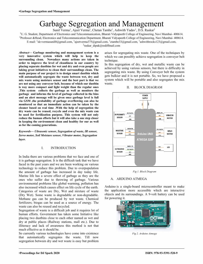
II. BLOCK DIAGRAM
Fig 1. Block Diagram
A. ARDUINO ATMEGA Arduino is a single-board microcontroller meant to make the application more accessible which are interactive objects and its surroundings. A 9-volt battery can be used for powering it.
Fig 2. Arduino Atmega
•Garbage Segregation and Management
•Proceedings for DJ Spark 2020 ISBN: 978-93-5391-520-9
B. SERVO MOTOR An electrical device which can push or rotate an object with great precision is called as servo motor. It is used for rotating segregation layer at a particular angle depending on moisture sensor value.
Fig 3. Servo motor
C. MOISTURE SENSOR
To measure the volumetric water content of soil we can use a soil moisture sensor. It is used to check the moisture content of substance for which it has been placed.
Fig 4. Moisture sensor
D. ULTRASONIC SENSOR A device used for detection and ranging of object. It is used to detect the waste dumped and level of garbage collected in the collector layer. The distance can be set as per the user’s availability.
Fig 5. Ultrasonic Sensor
E. IR SENSOR It is similar as ultrasonic sensor but with greater efficiency, small size. It cannot detect the distance but has a notch through which distance of detection can be set. It is used for same purpose as used for ultrasonic sensor.
Fig 6. IR Sensor
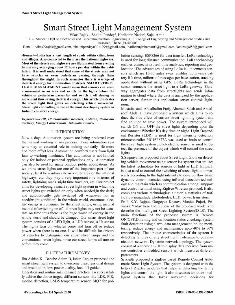
III. METHODOLOGY
Fig 7. Block Diagram of Methodology
The basic structure of the model(fig.3.1) is constructed by acrylic sheet and it consists of a metallic platform, IR sensor, moisture sensor, ultra-sonic sensor, vibrator motor, servo motor. It consists of three layers such as top layer, segregation layer, and collector layer. When garbage is dump in the dustbin the waste passes through the top layer where the IR sensor will detect the waste. The upper servo motors placed at the top layer will be started and the waste will be dumped on the segregation layer. The segregation layer is metallic plate which is placed at a certain height from the bottom of the container. Once the garbage is dumped on the segregation layer the vibrator motor will start vibrating the segregation layer plates so that waste gets distributed all over the plates. The segregation layer itself is divided into four region which is square in shape. There are three moisture sensors in every region (Fig 3.2), so in total there are 12 moisture sensors covering the entire segregation layer. For a particular region all the 3 sensor takes the reading and then these readings. On the basis of average of three readings the moisture sensor decides whether the waste is wet or dry. The moisture sensor gives the command to the servo motor which are placed on side of the plate’s. After detecting that the waste is wet or dry the servo motor flips the plate towards the bin and dumps the waste in collector layer. The

•Garbage Segregation and Management
•Proceedings for DJ Spark 2020 ISBN: 978-93-5391-520-9
collector layer is layer where waste gets collected. The collector layer has three section two dry sections and one wet section. For each region there will be two sections one for wet and one for dry. For every section there is an ultrasonic sensor which keeps on monitoring the level of the waste in the bin. A RGB color LED is placed on the dustbin which will indicated the level of dustbin based on the reading of ultrasonic sensor If the waste reaches the max level of the bin then the ultrasonic sensor gives an alert to the worker or cleaner by sending message to the cleaner using GSM module to empty the bins.
Fig 8. Main Body with sensors
Fig 9. Moisture Sensor Plate
IV. RESULTS
This are the expected results
Name of Waste Value obtained by moisture sensor
Paper 1203
Box 1109
Plastic 1359
Metal 1259 Table 1: Dry Waste
Name of waste Value obtained by moisture sensor
Wet cloths 826
Milk Packet 879 Table 2: Wet Waste
Name of Waste Value obtained by moisture sensor
Paper +wet cloths In between (800-1000) Table 3: Mixed Waste
V. CONCLUSION
The waste is increasing very fast due to urbanization. The environment needs to be protected and environmental stability can be achieved due to the technological growth and innovation and it can contribute towards cleanliness. Dry and wet waste separation can be done using this system monitoring the garbage containers waste segregation can be successfully implemented, since the segregation takes place in one component itself and with the help of multiple sensors the work can be done more efficiently.
VI. REFERENCES [1]. Prof. D. S. Raskar, Ms.Punam P. Telange, Ms.Aparna S. Jagdale, Ms.Supriya V. Chavan “Advance and smart garbage monitoring system” , International Journal for Science and Advance Research in Technology (IJSART), 2019. [2]. Sharanya.A, U. Harika, N. Sriya, Sreeja Kochuvila "Automatic waste segregation" , International conference on advances in computing, communications and informatics(ICACCI), 2017, pp 1313-1319. [3]. AnkitaKharade, PurnimaPisal,S. P. Vibhute, "Intelligent Waste Segregation and Monitoring System", International Journal of Engineering Science and Computing, May 2017 , pp 12005-12007. [4]. Y.K.Subbarao,Snehal Chavan, Mayuri Ramdham, LaxmikantKandharkar,"WASTE SEGREGATION USING SMART DUSTBIN", International journal of electrical and electronics engineers,1 June 2016, pp 1111-1115 [5]. Shamin. N, P.MoHAMEDFathimal, Raghavendran. R, Kamlesh Prakash, “Smart Garbage Segregation and [6]. Managemnet System”, International journal of electrical and electronics engineers. [7]. S. Sudha , M. Vidhyalakshmi, K. Pavithra “An Automatic Classification Method For Environment”,International journal of electrical and electronics engineers.2106, pp 65-70. [8]. M. K. Pushpa, Aayushi Gupta, Shariq Mohammed Shaikh, Stuti Jha, Suchitra.V, “MicrocontrollerBased Automatic Waste Segregator”, International journal of innovative research in Electrical,Electronics, Instrumentation and Control Engineering Vol. 3, issue 5, May 2015
•Smart Street Light Management System
•Proceedings for DJ Spark 2020 ISBN: 978-93-5391-520-9
Smart Street Light Management System Vikas Rajak1, Shalini Pandey1, Hariharan Nadar1, Sujal Amin1
1 U. G. Student, Dept of Electronics and Telecommunication Engineering K.C. College of Engineering and Management Studies and Research, Thane (E)-400603
E-mail: [email protected], [email protected], [email protected], [email protected]
Abstract—India has a vast length of roads within cities, town andvillages. Also connected to them are the national highways. Most of the streets and highways are illuminated from evening to morning averaging about 12 hours per day within the habi-tation. It is well understood that some of the streets may not have vehicles or even pedestrian passing through them throughout the night. In such scenarios there is wastage of electrical energy for illumination of streets. SMART STREET LIGHT MANAGEMENT would mean that sensors can sense a movement in an area and switch on the lights before the vehicle or pedestrian passes by and switch it off during no movement thus saving electrical energy. This article illustrates the street light that glows on detecting vehicle movement. Street light controlling is one of the most developing system in India to conserve energy. Keywords—LDR, IR Transmitter Receiver, Arduino, Photocon-ductivity, Energy Conservation, Automatic Control
I. INTRODUCTION Now a days Automation system are being preferred over the manual working in any process. These automation sys-tems play an essential role in making our daily life more and more effort less. Automation comforts users from light fans to washing machines. This automation is not limited only for indoor or personal applications only. Automation can also be used for many outdoor public applications. As we know street lights are one of the important part of our society, let it be a urban city or a ruler area or the national highways, etc. they play a very important role in terms of safety, lightning roads, night time travelers, etc. Our project aims for developing a smart street light system in which the street lights get switched on only when needed(in the dark) and automatically gets switched off whenever not in need(bright condition) in the whole world, enormous elec-tric energy is consumed by the street lamps, using manual method of switching on off of street lights may not be accu-rate on time thus there is the huge waste of energy in the whole world and should be changed. Our smart street light system consists of a LED light, a LDR sensor, a IR sensor The lights turn on vehicles come and turn off or reduce power when there is no one. It will be difficult for drivers of vehicles to distinguish our smart street lamps and the conventional street lights, since our street lamps all turn on before they come.
II. LITERATURE SURVEY Jha Ashish K., Bababe Adam B, Ishan Ranjan proposed the smart street light system to overcome unprofessional design and installation, low power quality, lack off guided Operation and routine maintenance practice. To successful-ly achive the above target, different sensors like LDR, PIR, motion detection, LM35 temperature sensor, MQ7 for pol-
lution sensing, ESP8266 for data transfer. LoRa technology is used for long distance communication. LoRa technology enables connectivity, real time analytics, reporting and geo-location. The advantages of using LoRa is , it connects sen-sors which are 15-30 miles away, ensbles multi years bat-tery life time, milions of messages per base station, tracking application without using GPS. LoRa technology in the sensor connects the street light to a LoRa gateway. Gate-way aggregates data from streetlights and sends infor-mation to cloud where the data is analyzed by the applica-tion server, further this application server controls light-ning. Mustafa saad, Abdalhalim Farij, Ahamed Salah and Abdal-roof Abdaljalilhave proposed a system which aims to re-duce the side effect of current street lightning system and find solution to save power. The system introduced will switch ON and OFF the street lights depending upon the environment Whether it’s day time or night. Light Depend-ent Resistor (LDR) is used for light intensity detection, microcontroller PIC16F877A was used as brain to control the street light system , photoelectric sensor is used to de-tect the presence of the object which will control the street lights. S.Suganya has proposed about Street Light Glow on detect-ing vehicle movement using sensor isa system that utilizes the latest technology for sources of light as LED lamps. It is also used to control the switching of street light automat-ically according to the light intensity to develop flow based dynamic control statistics using infrared detection technol-ogy and maintain wireless communication among lamppost and control terminal using ZigBee Wireless protocol. It also combines various technologies: a timer, a statistics of traf-fic flow magnitude, photodiodes, LED, power transistors. Prof. K.Y. Rajput, Gargeyee Khatav, Monica Pujari, Pri-yanka Yadav here the purpose of thr proposed work is to describe the Intelligent Street Lighting System(ISLS). The main functions of the proposed system is Remote ON/OFF,Dimming and on location status checking, system fault detection using alarm, data management, online moni-toring, reduce energy and maintenance upto 40% to 50% respectively. The unique characteristics of thr system is detecting failures of any street light, Tolerance to commu-nication network. Dynamic network topology. The system consist of a server a GUI to display data received from mi-cro controller embedded sensors which measures different parameters. Srikanth proposed a ZigBee based Remote Control Auto-matic Street Light System. The system is designed with the help of ZigBee modules that helps in detecting the faulty lights and control the light. It also discusses about an intel-ligent system that takes automatic decisions for
•Smart Street Light Management System
•Proceedings for DJ Spark 2020 ISBN: 978-93-5391-520-9
ON/OFF/DIMMING considering the vehicle movement or pedestrian and also the surrounding environment. PIR mo-tion sensor is used to detect movement of both living and non-living things. Ashutosh Gupta, Shipra Gupta The research aims to power conservation by varying the intensity of street lights. The aim is achieved by using microcontrollers, LDR, current sensors, etc. Light dimmer sensors are used to vary the in-tensity of light during darkness. The proposed project solves the problem of manual operation of street lights and 15% to 20% of energy is conserved by using current sensor and dimmer sensors. For future advancement the paper aims to install solar panel to use clean and green source of energy.
III. CONCEPT The concept behind this project is using a Light dependent resistor (LDR). Which will automatically switch ON the street lights as soon as the sunlight decrease during even-ing. On the other hand, IR Transmitter and receiver sensors are used to detect the movement of vehicle. For each sensor a set of street lights are connected. As soon as the sensor detect the presence of vehicle a set of street light connected with that respective sensor glows ON and once the vehicle reaches to next sensor the last set of street lights turn OFF and next set of light glows ON. Between the particular set of street lights one street light will continuously be ON for safety purpose. Once the sun rises the LDR will make all the street lights OFF till evening. This process repeat itself automatically.
IV. BLOCK DIAGRAM
Fig 1. Block diagram of proposed street lighting system
V. WORKING PRINCIPLE
The major components used in this project are IR sensor and LDR and a microcontroller to control the system. A. IR TtransmitterReceiver Sensor An infrared transmitter receiver sensor is an electronic component which produces infrared rays and detects it. IR transmitter receiver sensor is used to detect any obstacle in the surrounding. IR transmitter transmits infrared rays, this rays after getting reflected from any obstacle gets detected by the IR receiver.
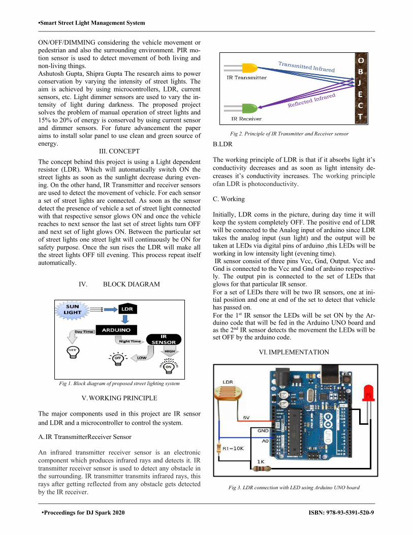
B.LDR The working principle of LDR is that if it absorbs light it’s conductivity decreases and as soon as light intensity de-creases it’s conductivity increases. The working principle ofan LDR is photoconductivity. C. Working Initially, LDR coms in the picture, during day time it will keep the system completely OFF. The positive end of LDR will be connected to the Analog input of arduino since LDR takes the analog input (sun light) and the output will be taken at LEDs via digital pins of arduino ,this LEDs will be working in low intensity light (evening time). IR sensor consist of three pins Vcc, Gnd, Output. Vcc and
Gnd is connected to the Vcc and Gnd of arduino respective-ly. The output pin is connected to the set of LEDs that glows for that particular IR sensor. For a set of LEDs there will be two IR sensors, one at ini-tial position and one at end of the set to detect that vehicle has passed on. For the 1st IR sensor the LEDs will be set ON by the Ar-duino code that will be fed in the Arduino UNO board and as the 2nd IR sensor detects the movement the LEDs will be set OFF by the arduino code.
VI. IMPLEMENTATION
Fig 3. LDR connection with LED using Arduino UNO board
Fig 2. Principle of IR Transmitter and Receiver sensor

•Smart Street Light Management System
•Proceedings for DJ Spark 2020 ISBN: 978-93-5391-520-9
VII. APPLICATIONS A. This working principle can be used in distance measure-
ment between two points and give an alert message via LED or buzzer.
B. This project is efficiently applicable on national highways or roads that have less vehicle during night.
VIII. FUTURE SCOPE A. Piezoelectric sensors can be installed on road which will
convert pressure exerted on road by vehicle into electric energy which can be further used to power the system.
B. Further advancement like installing cameras on street light can increase the security of the roads.
REFERENCES
[1] Street light that glows on detecting vehicle movement circuit and working, www.elprocus.com
[2] “Smart street light management system using LoRa technology” Jha Ashish K., Bababe Adam B, Ishan Ranjan, International journel of science and research.
[3] “Automatic Streetlight control system using microcontroller” Mustafa saad, Abdalhalim Farij, Ahamed Salah and Abdalroof Abdaljalil
[4] S. Suganya, R. Sinduja, T. Sowmiya& S. Senthilkumar, Street light glow on detecting vehicle movement using sensor
[5] [Prof. K.Y.Rajput , Gargeyee Khatav , Monica Pujari , Priyanka Yadav”Intelligent Street Lighting System Using Gsm” International Jour-nal of Engineering Science Invention
[6] Srikanth M, Sudhakar K N,ZigBee Based Remote Control Automatic Street Light System
[7] Ashutosh Gupta, Shipra Gupta,” Design of Automatic Intensity Varying Smart Street Lighting System” IOP Conference Series: Materials Science and Engineering
[8] Zain mMumtaz, Dr. Saleem Ullal, Zeeshan Llyas, Automatic streetlights that glow on detecting night and using arduino, June 2018. www.researchgate.net
[9] Anitha is a B.E(Electronics & Communication),Infra red sensor- how it works, applications, types advantage and disadvantages. www.electricalfundablog.com
[10] Arduinoproyek , Arduino project, Oct 14, 2018 [11] www.arduinoproyek.wordpress.com [12] Arduino Interface with IR Sensor, August 3, 2019, www.easytronic.net/
Fig 4. IR sensor connection with LED using Arduino UNO board
•Development of IOT Bases Landslide Detection System
•Proceedings for DJ Spark 2020 ISBN: 978-93-5391-520-9
Development of IOT Based Landslide Detection System
Surabhi Shende1,Pranav Sawant1,Poonam Mhaske1 1U. G. Student, Department of Instrumentation Engineering, Ramrao Adik Institue Of Technology, Mumbai, India
E-mail: [email protected] ,[email protected] ,[email protected]
Abstract—A landslide is a geological phenomenon that in-volves a vast array of ground motions. Maintaining routine surveillance is important to predict landslide activity and forecasting that can help to prevent large numbers of land-slides. This can help save a number of lives and can put an end to the loss of life and property as we can forecast the hazard and take the necessary safety steps. In this project, the IoT network is used which helps to update landslide information via the internet via the WiFi Module. Moisture sensor and vibration sensor are used which helps to detect landslides as some important values for these sensors are defined. When value goes beyond these threshold values, people will be up-dated on the landslides ahead and huge losses can be avoided. Arduino Uno collects information and uses a Wifi module attached to it to report the information to the website. A pro-ject based on telemetry helps warn the residents about the predicted mishap and can be averted.
Keywords—Internet of things, Deployment, Field Testing, Landslide Monitoring.
I. INTRODUCTION Landslides are gravitational movement of soil and rock down slopes which can cause vast damage to infrastructure. Numerous facility and structural failure caused by landslide have been recorded over year. Therefore, effort to measure and keep track of potential landslide are essential to ensure human security and to protect infrastructure. This system is used for prediction of disaster which if occurs can save peoples life by alerting them. In this system use of Sensors and Wifi Module is used for monitoring. This system in-cludes the web-based portal called telemetry used to moni-tor and update the threshold value. In recent technology advance communication media helps in the disaster moni-toring system. All sensors are working with specific appli-cations and generates an alert signal when it crosses a spec-ified value. Alert message is texted on mobile phone or an e-mail is sent. Alert system gives text message which uses alarm system to broadcast the message to local people and to all the nearby places.
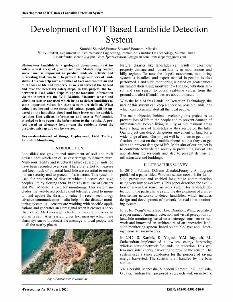
Fig 1. Phenomenon of Landslide
Natural disaster like landslides can result in enormous property damage and human fatality in mountainous and hilly regions. To note the slope's movement, monitoring system is installed, and expert manual inspection is also performed. Land slide monitoring is based on geotechnical instrumentation using moisture level sensor, vibration sen-sor and rain sensor to obtain real-time values from the ground and alert if landslides are about to occur.
With the help of this Landslide Detection Technology, the user of this system can keep a check on possible landslides which can occur and alert all the local people.
The main objective behind developing this project is to prevent loss of life to the people and to prevent damage of infrastructure. People living in hilly or mountainous areas have a huge risk of landslides as they reside on the hills. Our project can detect dangerous movement of land for a wide range of area. Our project will help them to get a noti-fication or a text on their mobile phones so that they can get alert and prevent damage of life. Main aim of our project is to contribute towards the society in preventing loss of life and alerting the residents and also to prevent damage of infrastructure and buildings.
II. LITERATURE SURVEY In 2015 , Y.Lami, D.Geno ,Catalot,Fourty , A .Lagreze published a paper titled Wireless sensor network for Land-slide prevention and enabled long range communication using very low power levels.This paper describes the evolu-tion of a wireless sensor network system for landslide de-tection in the particular area and the development of a wire-less sensor networks to detect landslides, which includes design and development of network for real time monitor-ing system.
In 2016, YongWan, Zhipu, Liu, DianhongWang published a paper named Anomaly detection and visual perception for landslide monitoring based on a heterogeneous sensor net-work and innovated an architecture of an innovative land-slide monitoring system based on double-layer and heter-ogeneous sensor networks.
In 2017, S. Karthik, K. Yogesh, Y.M. Jagadish, RK Satheendran implemented a low-cost energy harvesting wireless sensor network for landslide detection. This sys-tem uses solar energy harvesting to provide the sensor. The system uses a super condenser for the purpose of saving energy harvested. The system is all handled by the base station.
VN Deekshit, Maneesha, Vinodoni Ramesh, P.K. Indukala, G Jayachandran Nair proposed a research wok on network
•Development of IOT Bases Landslide Detection System
•Proceedings for DJ Spark 2020 ISBN: 978-93-5391-520-9
design and algorithm. It uses the Arduino-based data acqui-sition system with the Geophone network.
The article is set out as follows. Section II provides a Sur-vey of Literature. Section III gives details on Description of the System. Section IV shows the Design Methodology. Section V describes Working of the project.Section VI de-scribes the results of extensive network behavior analysis based on performance metrics gathered during the experi-mental campaign. Finally, Section VII concludes the paper, summarizing the most important finding.
III. DESCRIPTION OF THE SYSTEM
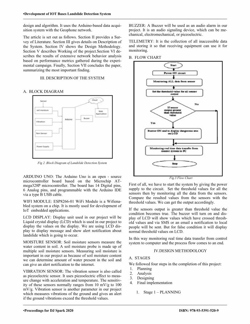
A. BLOCK DIAGRAM
Fig 2. Block Diagram of Landslide Detection System
ARDUINO UNO: The Arduino Uno is an open - source microcontroller board based on the Microchip AT-mega328P microcontroller. The board has 14 Digital pins, 6 Analog pins, and programmable with the Arduino IDE via a type B USB cable.
WIFI MODULE: ESP8266-01 WiFi Module is a Wifiena-bled system on a chip. It is mostly used for development of IoT embedded applications.
LCD DISPLAY: Display unit used in our project will be Liquid crystal display (LCD) which is used in our project to display the values on the display. We are using LCD dis-play to display message and show alert notification about landslide which is going to occur.
MOISTURE SENSOR: Soil moisture sensors measure the water content in soil. A soil moisture probe is made up of multiple soil moisture sensors. Measuring soil moisture is important in our project as because of soil moisture content we can determine amount of water present in the soil and can give an alert notification to the internet.
VIBRATION SENSOR: The vibration sensor is also called as piezoelectric sensor. It uses piezoelectric effect to meas-ure change with acceleration and temperature. The sensitiv-ity of these sensors normally ranges from 10 mV/g to 100 mV/g. Vibration sensor is another parameter in our project which measures vibrations of the ground and gives an alert if the ground vibrations exceed the threshold values.
BUZZER: A Buzzer will be used as an audio alarm in our project. It is an audio signaling device, which can be me-chanical, electromechanical, or piezoelectric.
TELEMETRY: It is the collection of all inaccessible data and storing it so that receiving equipment can use it for monitoring.
B. FLOW CHART
Fig.3 Flow Chart
First of all, we have to start the system by giving the power supply to the circuit. Set the threshold values for all the sensors then by monitoring all the data from the sensors. Compare the resulted values from the sensors with the threshold values. We can get the output accordingly.
If the sensors output is greater than threshold value the condition becomes true. The buzzer will turn on and dis-play of LCD will show values which have crossed thresh-old values and via SMS or an email a notification to local people will be sent. But for false condition it will display normal threshold values on LCD.
In this way monitoring real time data transfer from control system to computer and the process flow comes to an end.
IV.DESIGN METHODOLOGY
A. STAGES We followed four steps in the completion of this project: 1. Planning 2. Analysis 3. Designing 4. Final implementation
1. Stage 1 – PLANNING

•Development of IOT Bases Landslide Detection System
•Proceedings for DJ Spark 2020 ISBN: 978-93-5391-520-9
We discussed our project with our supervisor at the first stage of starting the project. He asked us to name our pro-ject after the idea was selected so we came up with the name "Iot Based Landslide Detection" taking into consider-ation our objectives. After the project was named, we budgeted our approximate project cost. We then looked at the background work on this area and surprisingly we dis-covered that there are not many researches done in this field in other countries such as America, Japan, China. There was some research done on this subject using differ-ent technologies such as embedded systems, sensor nodes, Raspberry Pi etc. Based on our research we discovered that the current technology that exists today also has limitations. So, we reviewed them, and planned to accomplish as much as we could.
2. Stage 2 – ANALYZING After planning of the project is done, we begin reviewing some of the earlier Landslide Detection System. We downloaded from the IEEE page some papers that helped us during the analysis. We have also seen a lot of videos about this kind of Landslide Detec-tion Systems on YOUTUBE. According to this analysis, we did our literature review section. Then we analyzed the operation of the hardware and its specifications that we are using. We studied differ-ent programming languages for different platforms to en-sure that the programming language is sufficient to build the proposed system and how different modules can be integrated into a meaningful system with different plat-forms To provide the user with useful information. We also analyzed the preceding work in this field at our university. There was a similar work to us but they had a lot of limita-tions that we were trying to solve in our project. We also reviewed some recent incidences where implementation of this Detection System may prove beneficial. As in the inci-dence of a landfall occurred in the village of Malin in talu-ka of the Pune district in Maharashtra, India. The landslide, which hit early in the morning while residents were asleep, was due to heavy rainfalls which killed 151 people in 2014.
3. Stage 3 – DESIGN From this stage the main project building process begins. Here the entire system will be designed according to the theory and will be implemented according to procedures and steps. We purchased and assembled all the hardware we needed for the project and started working on it. After all the designs and measurements were completed, we started implementing the theoretical designs where all hardware is joined together and functionality of the circui-ties tested.
4. Stage 4 – DESIGN IMPLEMENTATION First of all, we made all the connections with the Arduino Uno. All the sensors were used and attached to Arduino Uno, as Arduino is our project's central component. The Wifi module is then connected to the internet. Then other subsystems are connected and simulated one by one. On Arduino.ide, programming is done and connected to the model via Wifi Module. Finally, testing is performed after
all the hardware and software work is done, and results are noted.
V.WORKING
Fig 4. Circuit Diagram
Arduino Uno is the central component and it sends the in-formation on the internet via WifiModule. DC power sup-ply is used for supplying voltage to the circuit. Moisture sensor and vibration sensors are employed that detects the moisture in the soil or any vibration on that part of land. We have used two Moisture sensors and two Vibration Sensors and have named it as Area A and Area B. We can get values from both the areas individually and also simultaneously. Four graphs are created which includes two graphs of Moisture Sensors A and B and two graphs of Vibration Sensors A and B. Moisture sensor works on the principle and uses capaci-tance to measure dielectric permittivity of the soil. In soil, dielectric permittivity is a function of the water content. The sensor creates a voltage proportional to the dielectric permittivity, and therefore the water content of the soil. A critical value is set for moisture level in the soil and whenever the value exceeds the critical value it is consid-ered as a notification for upcoming landslide. The output of moisture sensor is analog, so ADC is used and values are sent to Arduino. The values are displayed on the LCD device. The buzzer beeps whenever the moisture level becomes above the threshold value. The information from the Arduino is taken by the Wifi module and is con-tinuously being updated on the webpage through a network of IoT. An alert is being generated if the obtained value crosses threshold value and alert is sent as a text message or via an email on mobile phone. The data is stored in teleme-try and compares obtained value and threshold value. Alert is created so that people can get aware of the landslide hap-pening and can save themselves and prevent loss of lives.
Fig 5. Signal Conditioning of Vibration Sensor
•Development of IOT Bases Landslide Detection System
•Proceedings for DJ Spark 2020 ISBN: 978-93-5391-520-9
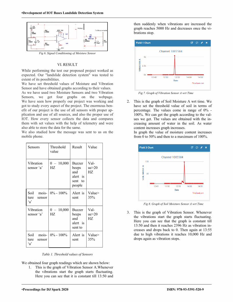
Fig 6. Signal Conditioning of Moisture Sensor
VI. RESULT While performing the test our proposed project worked as expected. Our "landslide detection system" was tested to extent of its possibilities. We have set threshold values of Moisture and Vibration Sensor and have obtained graphs according to their values. As we have used two Moisture Sensors and two Vibration Sensors, we get four graphs on the webpage. We have seen how properly our project was working and got to study every aspect of the project. The enormous ben-efit of our project is the use of all sensors with proper ap-plication and use of all sources, and also the proper use of IOT. How every sensor collects the data and compares them with set values with the help of telemetry and were also able to store the data for the same. We also studied how the message was sent to us on the mobile phone.
Sensors Threshold value
Result Value
Vibration sensor ‘a’
0 – 10,000 HZ
Buzzer beeps and alert is sent to people
Val-ue>20 HZ
Soil mois-ture sensor ‘a’
0% - 100% Alert is sent
Value> 35%
Vibration sensor ‘a’
0 – 10,000 HZ
Buzzer beeps and alert is sent to
Val-ue>20 HZ
Soil mois-ture sensor ‘a’
0% - 100% Alert is sent
Value> 35%
Table 1. Threshold values of Sensors
We obtained four graph readings which are shown below:
1. This is the graph of Vibration Sensor A.Whenever the vibrations start the graph starts fluctuating. Here you can see that it is constant till 13:50 and
then suddenly when vibrations are increased the graph reaches 5000 Hz and decreases once the vi-brations stop.
Fig 7. Graph of Vibration Sensor A wrt Time
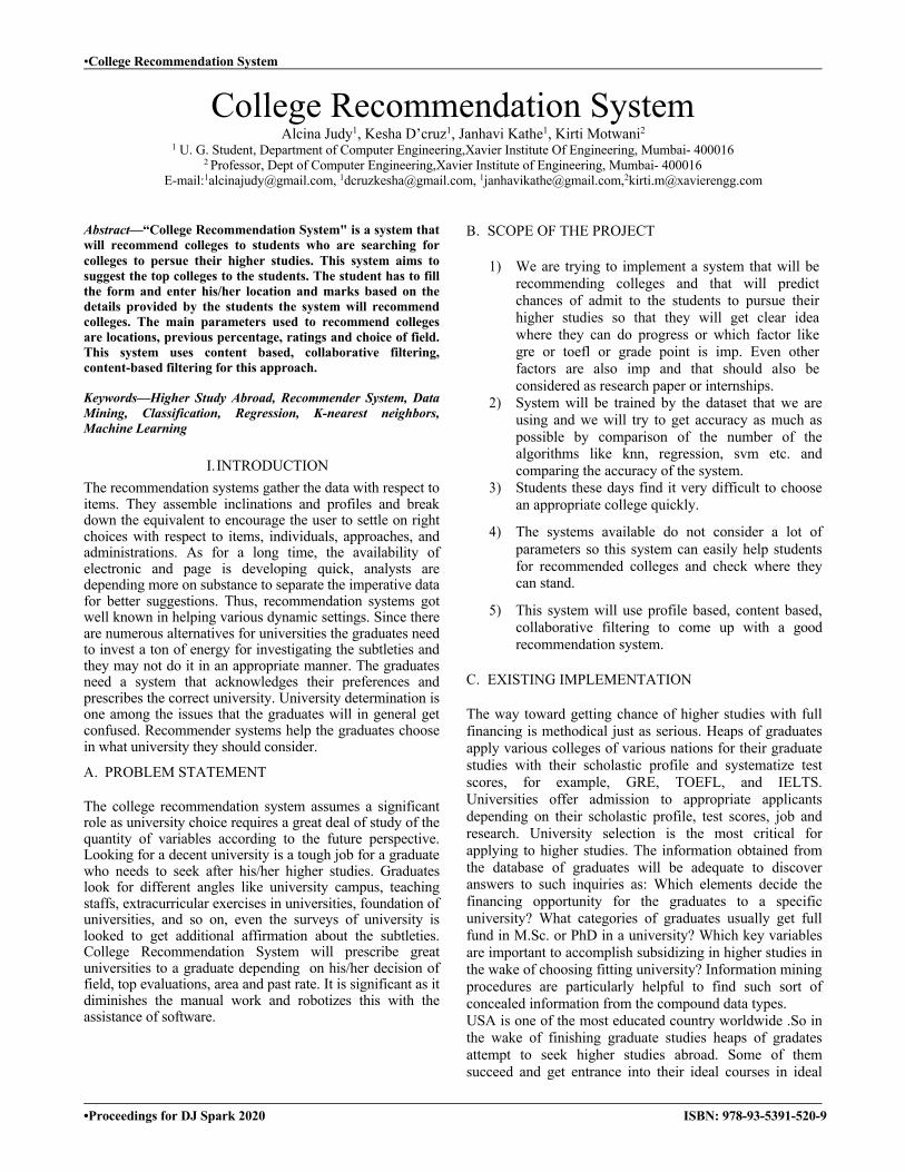
2. This is the graph of Soil Moisture A wrt time. We
have set the threshold value of soil in terms of percentage. The values come in range of 0% - 100%. We can get the graph according to the val-ues we get. The values are obtained with the in-creasing amount of water in the soil. As water content increases graph increases. In graph the value of moisture content increases from 0 to 50% and then to a maximum of 100%.
Fig 8. Graph of Soil Moisture Sensor A wrt Time
3. This is the graph of Vibration Sensor. Whenever
the vibrations start the graph starts fluctuating. Here you can see that the graph is constant till 13:50 and then it reaches 2396 Hz as vibration in-creases and drops back to 0. Then again at 13:55 due to high vibrations it reaches 10,000 Hz and drops again as vibration stops.

•Development of IOT Bases Landslide Detection System
•Proceedings for DJ Spark 2020 ISBN: 978-93-5391-520-9
Fig 9. Graph of Vibration Sensor B wrt Time
4. This is the graph of Soil Moisture B wrt time. We
have set the threshold value of soil in terms of per-centage. The values come in range of 0% - 100%. We can get the graph according to the values we get. The values are obtained with the increasing amount of wa-ter in the soil. As water content increases graph in-creases. Here at 13:55 the moisture content of soil reaches 100% which is an idea condition of heavy rainfall and an alert is sent regarding danger of Landslide. In graph the value of moisture content increases from 0 to 50% and then to a maximum of 100%.
Fig 10. Graph of Soil Moisture Sensor B wrt Time
This paper presents a new way of landslide detection using IOT. Experimental results were achieved giving our model different conditions. We will expand the range of our sys-tem by adding sensor relays for future work.
VII.CONCLUSION Real-time control of landslide is one of today's exciting and demanding research areas. It is an event where a device network primarily based on landslide detection system is deployed in an actual field. This system uses sensors and telemetry protocol to effectively deliver real-time data to the monitoring system and to provide residents with warnings and risk assessments. This project describes how a sensor is actually deployed to detect landslides. For effi-cient delivery of real-time data to the data management center, this system uses sensors, Arduino, Wifi Module, and internet. The data management center is fitted with the
software and hardware required to perform sophisticated data analysis. The results of the analysis in the form of landslide warnings and risk assessments will be provided to the residents of the region. The results of the study will be given to the region's inhabitants, in the form of landslide warnings and risk assessments. This work will be extended in the future to a full deploy-ment with increased spatial variability and the work is pro-gressing in this regard. Field experiments will be carried out to determine the sensor ranges of effects for the detec-tion of landslides induced by rainfall that may help in the development of low-cost Detection System for Landslides.
REFERENCES [1]. Y.Lami ; D.Geno ; CatalotFourty ; A.Lagreze “Wireless sensor net-work for Landslide prevention and enabled long range communication using very low power levels” IEEE. [2]. Yong Wan ;ZhipuLiu ; Dianhong Wang “ Anomaly detection and visual perception for landslide monitoring based on a heterogeneous sen-sor network” IEEE. [3]. S.Karthikvb ; K.Yokesh ; Y.M.Jagadeesh “Implementation of low-cost solar energy Harvesting Powered wireless sensor” IEEE. VN Deekshit ;Maneesha ; Vinodoni Ramesh ; P.K. Indukala ; G Jaya-chandran Nair “Network design and algorithm” IEEE. [4]. L. Zan ; G. Latini ; E. Piscina ; G. Polloni ; P. Baldelli “Landslides early warning monitoring system” IEEE. Shashank Kapoor ; Hitesh Pahuja ; Balwinder Singh “Real time monitor-ing alert system for landslide” IEEE . [5]. Ana Heryana ;EkasariNugraheni ; BudiariantoKusumo ; An-driFahrurRojie ; Bambang Setiadi “Applying agile methods in designing an earthquake and landslide early warning system application for An-droid” IEEE. [6]. Ramesh. M. V.,Ushakumari. P. “Threshold Based Data Aggregation Algorithm To Detect Rainfall Induced Landslides”, in Proceedings of the 2008 International Conference on Wireless Networks ;IEEE. [7]. PrakshepMehta ; Deepthi Chander ; Mohamed Shahim ; Kal-yanaTejaswi ; S. N. Merchant ; U. B. Desai “Distributed Detection for Landslide Prediction using Wireless Sensor Network ” IEEE . [8]. Shota Ishihara ;Masafumi Hashimoto ; Naoki Wakamiya ; Ma-sayuki Murata ; Yasutaka Kawamoto “A group-based scheduling method for landslide detection system with dense wireless sensor network” IEEE . [9]. Ming-ChihLu ; Tien-Yu Tang ; Cheng-Pei Tsai ; Wei-Yen Wang ; IHsum Li “Image-based landslide monitoring system” IEEE. [10]. https://www.nationalgeographic.org/encyclopedia/landslide/ [11]. https://www.usgs.gov/faqs/what-a-landslide-and-what-causes-one?qt-news_science_products=0#qt-news_science_products [12].https://en.wikipedia.org/wiki/Arduino_Uno [13].https://whatis.techtarget.com/definition/LCD-liquid-crystal-display
•College Recommendation System
•Proceedings for DJ Spark 2020 ISBN: 978-93-5391-520-9
College Recommendation System Alcina Judy1, Kesha D’cruz1, Janhavi Kathe1, Kirti Motwani2
1 U. G. Student, Department of Computer Engineering,Xavier Institute Of Engineering, Mumbai- 400016 2 Professor, Dept of Computer Engineering,Xavier Institute of Engineering, Mumbai- 400016
E-mail:[email protected], [email protected], [email protected],[email protected]
Abstract—“College Recommendation System" is a system that will recommend colleges to students who are searching for colleges to persue their higher studies. This system aims to suggest the top colleges to the students. The student has to fill the form and enter his/her location and marks based on the details provided by the students the system will recommend colleges. The main parameters used to recommend colleges are locations, previous percentage, ratings and choice of field. This system uses content based, collaborative filtering, content-based filtering for this approach.
Keywords—Higher Study Abroad, Recommender System, Data Mining, Classification, Regression, K-nearest neighbors, Machine Learning
I. INTRODUCTION The recommendation systems gather the data with respect to items. They assemble inclinations and profiles and break down the equivalent to encourage the user to settle on right choices with respect to items, individuals, approaches, and administrations. As for a long time, the availability of electronic and page is developing quick, analysts are depending more on substance to separate the imperative data for better suggestions. Thus, recommendation systems got well known in helping various dynamic settings. Since there are numerous alternatives for universities the graduates need to invest a ton of energy for investigating the subtleties and they may not do it in an appropriate manner. The graduates need a system that acknowledges their preferences and prescribes the correct university. University determination is one among the issues that the graduates will in general get confused. Recommender systems help the graduates choose in what university they should consider.
A. PROBLEM STATEMENT
The college recommendation system assumes a significant role as university choice requires a great deal of study of the quantity of variables according to the future perspective. Looking for a decent university is a tough job for a graduate who needs to seek after his/her higher studies. Graduates look for different angles like university campus, teaching staffs, extracurricular exercises in universities, foundation of universities, and so on, even the surveys of university is looked to get additional affirmation about the subtleties. College Recommendation System will prescribe great universities to a graduate depending on his/her decision of field, top evaluations, area and past rate. It is significant as it diminishes the manual work and robotizes this with the assistance of software.
B. SCOPE OF THE PROJECT
1) We are trying to implement a system that will be recommending colleges and that will predict chances of admit to the students to pursue their higher studies so that they will get clear idea where they can do progress or which factor like gre or toefl or grade point is imp. Even other factors are also imp and that should also be considered as research paper or internships.
2) System will be trained by the dataset that we are using and we will try to get accuracy as much as possible by comparison of the number of the algorithms like knn, regression, svm etc. and comparing the accuracy of the system.
3) Students these days find it very difficult to choose an appropriate college quickly.
4) The systems available do not consider a lot of parameters so this system can easily help students for recommended colleges and check where they can stand.
5) This system will use profile based, content based, collaborative filtering to come up with a good recommendation system.
C. EXISTING IMPLEMENTATION
The way toward getting chance of higher studies with full financing is methodical just as serious. Heaps of graduates apply various colleges of various nations for their graduate studies with their scholastic profile and systematize test scores, for example, GRE, TOEFL, and IELTS. Universities offer admission to appropriate applicants depending on their scholastic profile, test scores, job and research. University selection is the most critical for applying to higher studies. The information obtained from the database of graduates will be adequate to discover answers to such inquiries as: Which elements decide the financing opportunity for the graduates to a specific university? What categories of graduates usually get full fund in M.Sc. or PhD in a university? Which key variables are important to accomplish subsidizing in higher studies in the wake of choosing fitting university? Information mining procedures are particularly helpful to find such sort of concealed information from the compound data types. USA is one of the most educated country worldwide .So in the wake of finishing graduate studies heaps of gradates attempt to seek higher studies abroad. Some of them succeed and get entrance into their ideal courses in ideal
•College Recommendation System
•Proceedings for DJ Spark 2020 ISBN: 978-93-5391-520-9
universities. A non-benefit management gathers those graduate's information and structures a general database so that alternative graduates get advantage from that. The principle target of this investigation study is to construct and build up a recommender system for graduate admission seekers which can help them to determine university coordinating their whole profile utilizing scholarly information of graduates who have just got the chance to seek higher studies abroad.
II. IMPLEMENTATION A. PROFILE BASED
In profile based the list of universities will be displayed on the basis of the student’s gre verbal score, GRE quants score TOEFL score and CGPA. It will calculate the average and that average will be converted into the range. So first we will calculate average for each score that is gre verbal, gre quants and TOEFL score. So the formula for gre verbal and gre quants is (1),
GREV/GREQ= ((score-130)*100)/40 + 0
So 130 is the minimum score of GRE verbal or GRE quants, 100 is the maximum range , 0 is the minimum range, score is the value of GRE verbal or GRE quants and 40 is the difference between the maximum and the minimum score that is 170 and 130 respectively.
Same goes for TOEFL score is (2),
TOEFL=((score -0)*100)/120 + 20 (2)
So here 0 is the minimum score , 100 is the maximum range, 20 is the minimum range, score is the TOEFL score of the student and 120 is the difference between maximum score and minimum score that is 120 and 0 respectively. Now after calculating average of each score we can now obtain the range by formula given below is (3),
Range=(GREQ*2+GREV*1.5+TOEFL*0.4+percent*1)/3.9
So here 2, 1.5, 0.4 and 1 are the weights which are assumed. More weightage is given to GRE quants because normally universities gives first priority to GRE quants score. 3.9 is the addition of all the weights assumed . Now this range will be compared to the ranges of the universities. On the basis of that the list of universities will be listed with the user and system ratings.
B. HYBRIDFILTERING
1. Collaborative Filtering So here 2, 1.5, 0.4 and 1 are the weights which are assumed. More weightage is given to GRE quants because normally universitiesgivesfirstprioritytoGREquantsscore.3.9isthe addition of all the weights assumed. Now this range will be compared to the ranges of the universities. On the basis of
that the list of universities will be listed with the user and system ratings.
Steps:
1) Users similarity calculation :It uses Pearson correlation, cosine similarity and Euclidean distance
2) Top N nearest neighbors’ selection and
3) Prediction.
So, in collaborative based the list of universities will be displayed on the basis of student’s GRE total score and TOEFL score. It will compare the cut-off of the universities and on the basis of that the list of universities will be listed with the user and system ratings.
2. Content Based Filtering
In this technique recommendation to user is given only by the users individual behavior and data. First it analyses the description of items preferred by user to decide the preferences that can be utilized to describe these items. based on users’ choices user profile is created, next each item attribute is compared with user profile so that only related items are recommended to the user. So in collaborative based the list of universities will be displayed on the basis of student’s GRE verbal score , GRE quants score and TOEFL. It will compare the cut off of the universities and on the basis of that the list of universities will be listed with the user and system ratings.
3. Similarity and distance
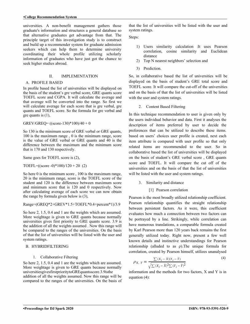
[1] Pearson correlation
Pearson is the most broadly utilized relationship coefficient. Pearson relationship quantifies the straight relationship between persistent factors. As it were, this coefficient evaluates how much a connection between two factors can be portrayed by a line. Strikingly, while correlation can have numerous translations, a comparable formula created by Karl Pearson more than 120 years back remains the first generally utilized today. Right now, present a few well known details and instinctive understandings for Pearson relationship (alluded to as ρ).The unique formula for correlation, created by Pearson himself, utilizes unanalysed
information and the methods for two factors, X and Y is in equation (4):
•College Recommendation System
•Proceedings for DJ Spark 2020 ISBN: 978-93-5391-520-9
Raw inspections are focused by subtracting their means and re-scaled by an estimate of standard deviations. An alternate
method to show a similar amount is as far as presume values, means μX, μY, and standard deviations σX, σY in equation (5):
Notice that the numerator of this division is much the same as above meaning of covariance, since mean and desire are frequently utilized reciprocally. Separating the covariance between two factors by the result of standard deviations guarantees that correlation will consistently fall between - 1 and 1. This makes deciphering the correlation coefficient a lot simpler. Let the set of items evaluated by the two users and be meant by I, at that point similarity coefficient between them is determined as in equation (6):
Here ru,i signifies the rating of user u for item i , and ru is the mean of all items given by user u. Additionally, rv ,i signifies the rating of user v for item i , and ru is the mean of
items given by user v .Let the set of items judged by the two users and be meant by I, at that point closeness coefficient between them is decided as in equation (7)
Here ru,i denotes the rating of user u for item i , and ruis the average rating of all items given by user u . Similarly, rv,i denotes the rating of user v for item i , and rvis the average rating of all items given by user v.
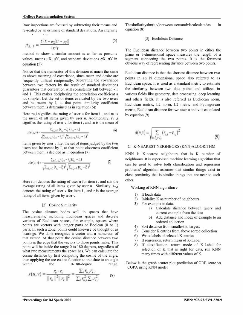
[2] Cosine Similarity
The cosine distance bodes well in spaces that have measurements, including Euclidean spaces and discrete variants of Euclidean spaces, for example, spaces where points are vectors with integer parts or Boolean (0 or 1) parts. In such a zone, points could likewise be thought of as bearings. We don't recognize a vector and a numerous of that vector. At that point the cosine distance between two points is the edge that the vectors to those points make. This point will be inside the range 0 to 180 degrees, regardless of what rate measurements the space has. We can calculate the cosine distance by first computing the cosine of the angle, then applying the arc-cosine function to translate to an angle within the 0-180-degree range.
Thesimilaritysim(u,v)betweenuseruandviscalculatedas in equation (8)
[3] Euclidean Distance The Euclidean distance between two points in either the plane or 3-dimensional space measures the length of a segment connecting the two points. It is the foremost obvious way of representing distance between two points.
Euclidean distance is that the shortest distance between two points in an N dimensional space also referred to as Euclidean space. It is used as a standard metric to estimate the similarity between two data points and utilized in various fields like geometry, data processing, deep learning and others fields. It is also referred as Euclidean norm, Euclidean metric, L2 norm, L2 metric and Pythagorean metric. Euclidean distance for two user u and v is calculated by equation (9)
C. K-NEAREST NEIGHBORS (KNN)ALGORITHM
KNN is K-nearest neighbours that is K number of neighbours. It is supervised machine learning algorithm that can be used to solve both classification and regression problems’ algorithm assumes that similar things exist in close proximity that is similar things that are near to each other.
Working of KNN algorithm :-
1) It loads data 2) Initialize K as number of neighbours 3) For example in data,
a) Calculate distance between query and current example from the data
b) Add distance and index of example to an ordered collection
4) Sort distance from smallest to largest 5) Consider K entries from above sorted collection 6) Write labels of selected K-entries 7) If regression, return mean of K-Label 8) If classification, return mode of K-Label for
selection of K that is right for data, run KNN many times with different values of K.
Below is the graph scatter plot prediction of GRE score vs CGPA using KNN model
(8)

•College Recommendation System
•Proceedings for DJ Spark 2020 ISBN: 978-93-5391-520-9
Fig.1 Scatter Plot Prediction GRE score vs CGPA
D. SUPPORT VECTOR MACHINE(SVM) SVM is supervised learning algorithm which are used for classification and regression important concepts are
1. Support Vectors- Datapoints that are closest to hyperplane and separating line will be defined with the help of these data points
2. Hyperplane- It is decision plane or space which is divided between a set of objects having different classes
3. Margin- It is gap between two lines on the closest data points of different classes. It is calculated as perpendicular distance from line to the support vectors.
4. Large margin is considered as good margin and small margin is bad margin
5. SVM is implemented with kernel that transforms the input data space into required form.
E. REGRESSION It is statistical analysis method. It finds the relationship between features like gre score and admit chance.
Y=mX+C
Where x can be Gre score, TOEFL score, CGPA, University rating and y is chance of admit. Comparison of Accuracy of different models: We have done the comparison of accuracy of svm, linear regression, knn and the accuracy are changing as we increase dataset records. Before increasing the dataset the accuracy of svm was 71% and later it increased to 83%. Same way the accuracy of linear regression is changing it was first 70% then it became 81%. But we have good accuracy of KNN model as compared with all as KNN gives 91% accuracy after increasing the dataset.
Graphs:
Fig.2 Input screen
Fig.3Graphs of Admit vs TOEFL score
Fig.4Admit vs GRE score
Fig.5KNN error rate graph
F. TRAINING DATA SET The CSV file that is dataset is split into train and test data in python machine learning. We used supervise machine learning algorithm to split data around 20% to 80% between testing and training stages. We used pandas for importing the dataset that is CSV file and skl earn for splitting the dataset. Here prediction is on the basis of
•College Recommendation System
•Proceedings for DJ Spark 2020 ISBN: 978-93-5391-520-9
GRE score, TOEFL score and CGPA. The trained data is fitted in the model to make to predictions by using any machine algorithm. We can use hybrid concept that is more than one algorithm to get better accuracy for the system. So we have three machine learning algorithms that is linear regression(which is used to solve regression problems), SVM(which is used to solve classification or regression problems) and KNN(which is used to solve both classification problems and regression problems). The most accurate algorithm amongst the three is KNN for this recommendation system. This system will the recommend top 10 universities to the users.
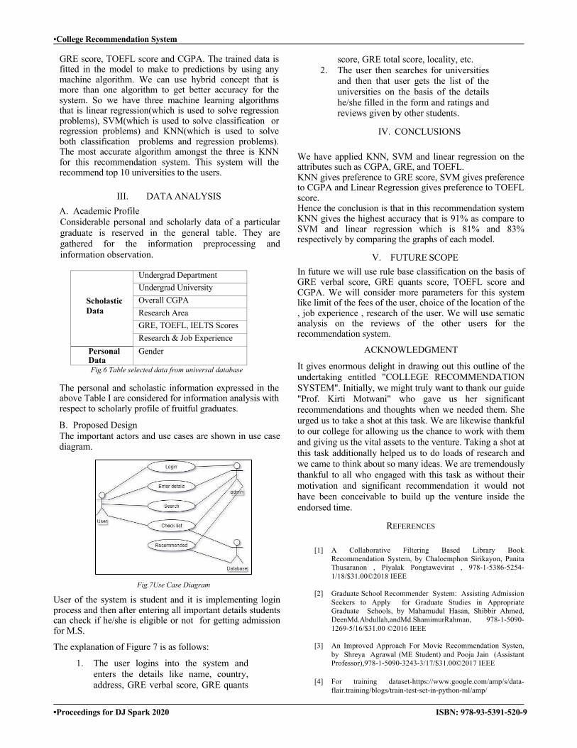
III. DATA ANALYSIS A. Academic Profile Considerable personal and scholarly data of a particular graduate is reserved in the general table. They are gathered for the information preprocessing and information observation.
Scholastic Data
Undergrad Department Undergrad University Overall CGPA Research Area GRE, TOEFL, IELTS Scores Research & Job Experience
Personal Data
Gender
Fig.6 Table selected data from universal database
The personal and scholastic information expressed in the above Table I are considered for information analysis with respect to scholarly profile of fruitful graduates.
B. Proposed Design The important actors and use cases are shown in use case diagram.
Fig.7Use Case Diagram
User of the system is student and it is implementing login process and then after entering all important details students can check if he/she is eligible or not for getting admission for M.S.
The explanation of Figure 7 is as follows:
1. The user logins into the system and enters the details like name, country, address, GRE verbal score, GRE quants
score, GRE total score, locality, etc. 2. The user then searches for universities
and then that user gets the list of the universities on the basis of the details he/she filled in the form and ratings and reviews given by other students.
IV. CONCLUSIONS We have applied KNN, SVM and linear regression on the attributes such as CGPA, GRE, and TOEFL. KNN gives preference to GRE score, SVM gives preference to CGPA and Linear Regression gives preference to TOEFL score. Hence the conclusion is that in this recommendation system KNN gives the highest accuracy that is 91% as compare to SVM and linear regression which is 81% and 83% respectively by comparing the graphs of each model.
V. FUTURE SCOPE In future we will use rule base classification on the basis of GRE verbal score, GRE quants score, TOEFL score and CGPA. We will consider more parameters for this system like limit of the fees of the user, choice of the location of the , job experience , research of the user. We will use sematic analysis on the reviews of the other users for the recommendation system.
ACKNOWLEDGMENT
It gives enormous delight in drawing out this outline of the undertaking entitled "COLLEGE RECOMMENDATION SYSTEM". Initially, we might truly want to thank our guide "Prof. Kirti Motwani" who gave us her significant recommendations and thoughts when we needed them. She urged us to take a shot at this task. We are likewise thankful to our college for allowing us the chance to work with them and giving us the vital assets to the venture. Taking a shot at this task additionally helped us to do loads of research and we came to think about so many ideas. We are tremendously thankful to all who engaged with this task as without their motivation and significant recommendation it would not have been conceivable to build up the venture inside the endorsed time.
REFERENCES
[1] A Collaborative Filtering Based Library Book Recommendation System, by Chaloemphon Sirikayon, Panita Thusaranon , Piyalak Pongtawevirat , 978-1-5386-5254-1/18/$31.00©2018 IEEE
[2] Graduate School Recommender System: Assisting Admission
Seekers to Apply for Graduate Studies in Appropriate Graduate Schools, by Mahamudul Hasan, Shibbir Ahmed, DeenMd.Abdullah,andMd.ShamimurRahman, 978-1-5090-1269-5/16/$31.00 ©2016 IEEE
[3] An Improved Approach For Movie Recommendation Systen,
by Shreya Agrawal (ME Student) and Pooja Jain (Assistant Professor),978-1-5090-3243-3/17/$31.00©2017 IEEE
[4] For training dataset-https://www.google.com/amp/s/data-
flair.training/blogs/train-test-set-in-python-ml/amp/
•WASH ME- Web-Application based Sanitation and Hygiene Monitoring Embedded System
•Proceedings for DJ Spark 2020 ISBN: 978-93-5391-520-9
WASH ME- Web-Application Based Sanitation And Hygiene Monitoring Embedded System
Siddhesh Deshmukh1, Krutika Gawde1, Swahum Gandhi1, Suraj Jadhav1 1 U. G. Student, Department of Electronics, Datta Meghe College of Engineering, Airoli, Navi-Mumbai.
E-mail: [email protected], [email protected], [email protected],[email protected]
Abstract—With extensive technological developments, the sanitary condition of the country needs to be monitored efficiently. The efforts to maintain hygienic conditions needs to be kept in pace with the growing advancements. The proposed system hereby deals with maintaining the hygiene and the usability of the public toilets on real time basis and generates an alert when the hygiene of the toilet deteriorates. The system also has a backup wherein if there is a failure to respond to the alert message generated; the toilet gets cleaned up by triggering the actuators installed. The timely monitoring of the public toilet and a regular track on the sweeper’s work is the key feature of the proposed system. The system also enables the civic administrators to keep a tab on the condition of the toilets along with the sweeper’s work by logging in the web-application provided.
Keywords— Smart System For Toilets, MQ-4, Detection Of Water Availability, Ultrasonic-Sensor, SMS, RFID, Actuators
I. INTRODUCTION Sanitation and Hygiene monitoring system for public toilets is the need of time to keep a track on the public toilets in urban areas. The smart system should be able to efficiently monitor the hygiene of the toilet and send timely alerts if the condition of the toilet worsens. With Embedded system gaining popularity now-a-days; its applications can be deployed to provide service to improve the standard of living of people living in urban slums. The real time sensing of various parameters like air quality, water availability etc. of public toilets will instruct the system to take actions according to the current status of the toilet and thus maintain the usability and hygienic conditions. There are many existing e-toilets, but the proposed system ensures accurate and cost-effective solution and is based on the technology that has a wide scope in the long run.
II. LITERATURE SURVEY Kitisak Osathanunkulhas proposed “Configurable Automatic Smart Urinal Flusher based on MQTT Protocol”, This paper examines one probable way to cut the wastage of clean water used in a public toilet. The system uses MQTT as an underlying communication protocol. The protocol is used in gathering, governing, powerful and correcting the system. The results in the testing environment show that using a flushing duration for 2.5 seconds is enough to satisfy most users while wasting clean water as less as possible. There are two part are involved
here. They are:1. Automatic Flusher Part (AFP) 2. Server part. The AFP detects if there is an object in front of its infrared sensor. When a user stands in front of the urinal, an infrared sensor can detect the user. If the user keeps staying in front of the sensor for 3 seconds continuously, it is considered that a user is currently using a urinal. After the urinal has been flushed AFP unit also sends a MQTT message about it usage data to the server part. In server part, it receives the usage data from AFP unit. The usage data will be stored into a database for a future use. ImanMorsia has proposed “Wireless Gas Detector System Using Microcontrollers, PLC and SCADA System for Monitoring Environmental Pollution”, Gas identification represents a big challenge for improving detection and pattern recognition of each gas by using inexpensive gas sensor. This paper presents a gas detector system which is built to monitor, and measure gas pollutant emissions in the air and also used to detect different gases. The pollutants are ethane (C2H6) and methane (CH4) which are located beside the fertilizer factories in Alexandria Egypt and some other gases as hydrogen (H2), propane (C3H8) and isobutane (C4H10). The system is controlled and monitored by using programmable logic controller PLC Step 7-200 from Siemens and Supervisory Control and Data Acquisition SCADA systems respectively. The principal component analysis PCA method is applied for clustering and distinguishing among different gases. Thomas Schlebuschhas proposed “Intelligent Toilet System for Health Screening”, Home monitoring is a promising technology to deal with the increasing amount of chronically ill patients while ensuring quality of medical care.Most systems available today depend on a high degree of interaction between the user and the device. Especially for people relying on advanced levels of care, this scheme is impracticable. In this paper we are presenting an “intelligent toilet” performing an extensive health check while being as simple to use as a conventional toilet. Main focus of the system is to support the treatment of diabetes and chronic heart failure, but additional applications are possible. Here the sensors like PT1000 sensor, Pressure sensor, and RFID reader are used here. PT1000 sensor used to measure the thigh temperature. Pressure sensor is used measure the pressure of the base portion of the toilet. Using RFID reader is used to sense the particular person result. It needs designing of the base portion of the toilet. It can sense all test results of patients through the toilet usage.
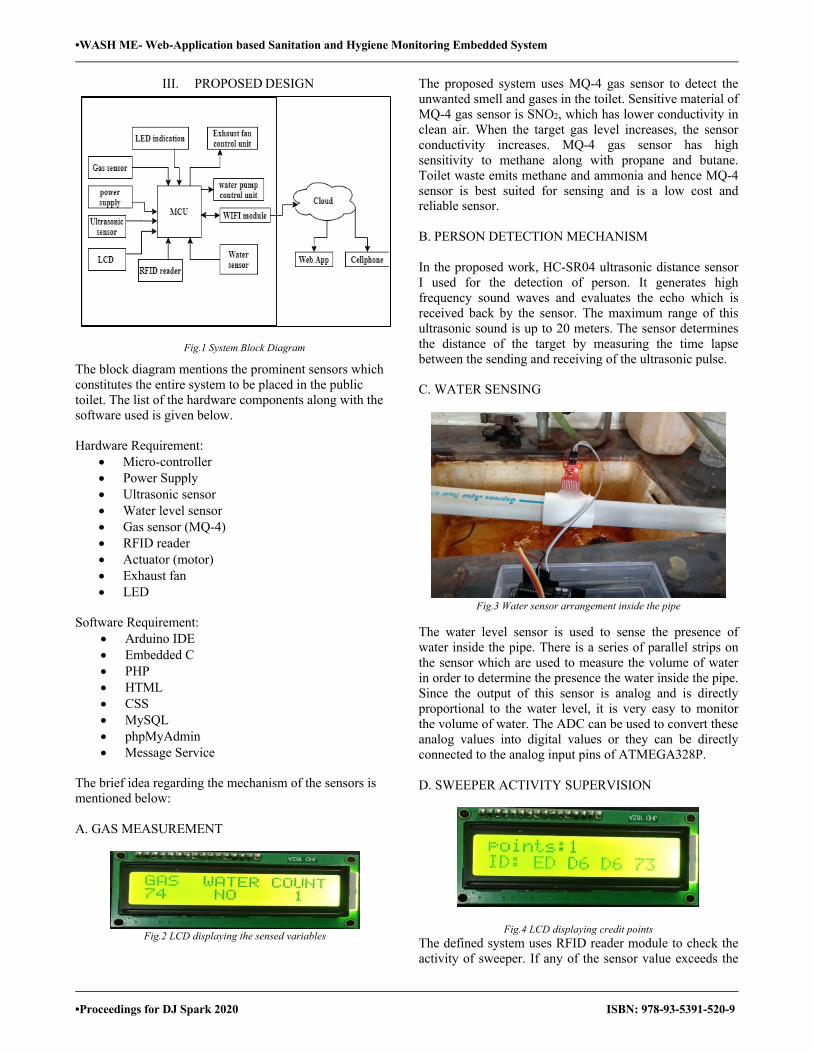
•WASH ME- Web-Application based Sanitation and Hygiene Monitoring Embedded System
•Proceedings for DJ Spark 2020 ISBN: 978-93-5391-520-9
III. PROPOSED DESIGN
Fig.1 System Block Diagram
The block diagram mentions the prominent sensors which constitutes the entire system to be placed in the public toilet. The list of the hardware components along with the software used is given below. Hardware Requirement:
• Micro-controller • Power Supply • Ultrasonic sensor • Water level sensor • Gas sensor (MQ-4) • RFID reader • Actuator (motor) • Exhaust fan • LED
Software Requirement:
• Arduino IDE • Embedded C • PHP • HTML • CSS • MySQL • phpMyAdmin • Message Service
The brief idea regarding the mechanism of the sensors is mentioned below: A. GAS MEASUREMENT
Fig.2 LCD displaying the sensed variables
The proposed system uses MQ-4 gas sensor to detect the unwanted smell and gases in the toilet. Sensitive material of MQ-4 gas sensor is SNO2, which has lower conductivity in clean air. When the target gas level increases, the sensor conductivity increases. MQ-4 gas sensor has high sensitivity to methane along with propane and butane. Toilet waste emits methane and ammonia and hence MQ-4 sensor is best suited for sensing and is a low cost and reliable sensor. B. PERSON DETECTION MECHANISM
In the proposed work, HC-SR04 ultrasonic distance sensor I used for the detection of person. It generates high frequency sound waves and evaluates the echo which is received back by the sensor. The maximum range of this ultrasonic sound is up to 20 meters. The sensor determines the distance of the target by measuring the time lapse between the sending and receiving of the ultrasonic pulse. C. WATER SENSING
Fig.3 Water sensor arrangement inside the pipe
The water level sensor is used to sense the presence of water inside the pipe. There is a series of parallel strips on the sensor which are used to measure the volume of water in order to determine the presence the water inside the pipe. Since the output of this sensor is analog and is directly proportional to the water level, it is very easy to monitor the volume of water. The ADC can be used to convert these analog values into digital values or they can be directly connected to the analog input pins of ATMEGA328P. D. SWEEPER ACTIVITY SUPERVISION
Fig.4 LCD displaying credit points The defined system uses RFID reader module to check the activity of sweeper. If any of the sensor value exceeds the
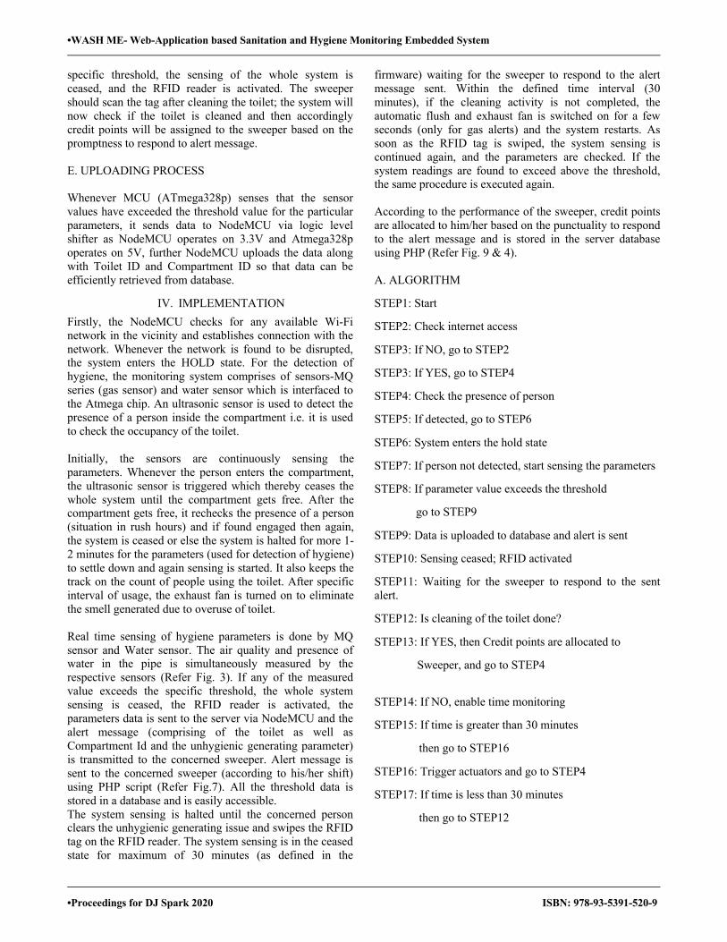
•WASH ME- Web-Application based Sanitation and Hygiene Monitoring Embedded System
•Proceedings for DJ Spark 2020 ISBN: 978-93-5391-520-9
specific threshold, the sensing of the whole system is ceased, and the RFID reader is activated. The sweeper should scan the tag after cleaning the toilet; the system will now check if the toilet is cleaned and then accordingly credit points will be assigned to the sweeper based on the promptness to respond to alert message. E. UPLOADING PROCESS Whenever MCU (ATmega328p) senses that the sensor values have exceeded the threshold value for the particular parameters, it sends data to NodeMCU via logic level shifter as NodeMCU operates on 3.3V and Atmega328p operates on 5V, further NodeMCU uploads the data along with Toilet ID and Compartment ID so that data can be efficiently retrieved from database.
IV. IMPLEMENTATION Firstly, the NodeMCU checks for any available Wi-Fi network in the vicinity and establishes connection with the network. Whenever the network is found to be disrupted, the system enters the HOLD state. For the detection of hygiene, the monitoring system comprises of sensors-MQ series (gas sensor) and water sensor which is interfaced to the Atmega chip. An ultrasonic sensor is used to detect the presence of a person inside the compartment i.e. it is used to check the occupancy of the toilet. Initially, the sensors are continuously sensing the parameters. Whenever the person enters the compartment, the ultrasonic sensor is triggered which thereby ceases the whole system until the compartment gets free. After the compartment gets free, it rechecks the presence of a person (situation in rush hours) and if found engaged then again, the system is ceased or else the system is halted for more 1-2 minutes for the parameters (used for detection of hygiene) to settle down and again sensing is started. It also keeps the track on the count of people using the toilet. After specific interval of usage, the exhaust fan is turned on to eliminate the smell generated due to overuse of toilet. Real time sensing of hygiene parameters is done by MQ sensor and Water sensor. The air quality and presence of water in the pipe is simultaneously measured by the respective sensors (Refer Fig. 3). If any of the measured value exceeds the specific threshold, the whole system sensing is ceased, the RFID reader is activated, the parameters data is sent to the server via NodeMCU and the alert message (comprising of the toilet as well as Compartment Id and the unhygienic generating parameter) is transmitted to the concerned sweeper. Alert message is sent to the concerned sweeper (according to his/her shift) using PHP script (Refer Fig.7). All the threshold data is stored in a database and is easily accessible. The system sensing is halted until the concerned person clears the unhygienic generating issue and swipes the RFID tag on the RFID reader. The system sensing is in the ceased state for maximum of 30 minutes (as defined in the
firmware) waiting for the sweeper to respond to the alert message sent. Within the defined time interval (30 minutes), if the cleaning activity is not completed, the automatic flush and exhaust fan is switched on for a few seconds (only for gas alerts) and the system restarts. As soon as the RFID tag is swiped, the system sensing is continued again, and the parameters are checked. If the system readings are found to exceed above the threshold, the same procedure is executed again. According to the performance of the sweeper, credit points are allocated to him/her based on the punctuality to respond to the alert message and is stored in the server database using PHP (Refer Fig. 9 & 4). A. ALGORITHM
STEP1: Start STEP2: Check internet access STEP3: If NO, go to STEP2 STEP3: If YES, go to STEP4 STEP4: Check the presence of person STEP5: If detected, go to STEP6 STEP6: System enters the hold state STEP7: If person not detected, start sensing the parameters STEP8: If parameter value exceeds the threshold go to STEP9 STEP9: Data is uploaded to database and alert is sent STEP10: Sensing ceased; RFID activated STEP11: Waiting for the sweeper to respond to the sent alert. STEP12: Is cleaning of the toilet done? STEP13: If YES, then Credit points are allocated to
Sweeper, and go to STEP4 STEP14: If NO, enable time monitoring STEP15: If time is greater than 30 minutes then go to STEP16 STEP16: Trigger actuators and go to STEP4 STEP17: If time is less than 30 minutes then go to STEP12
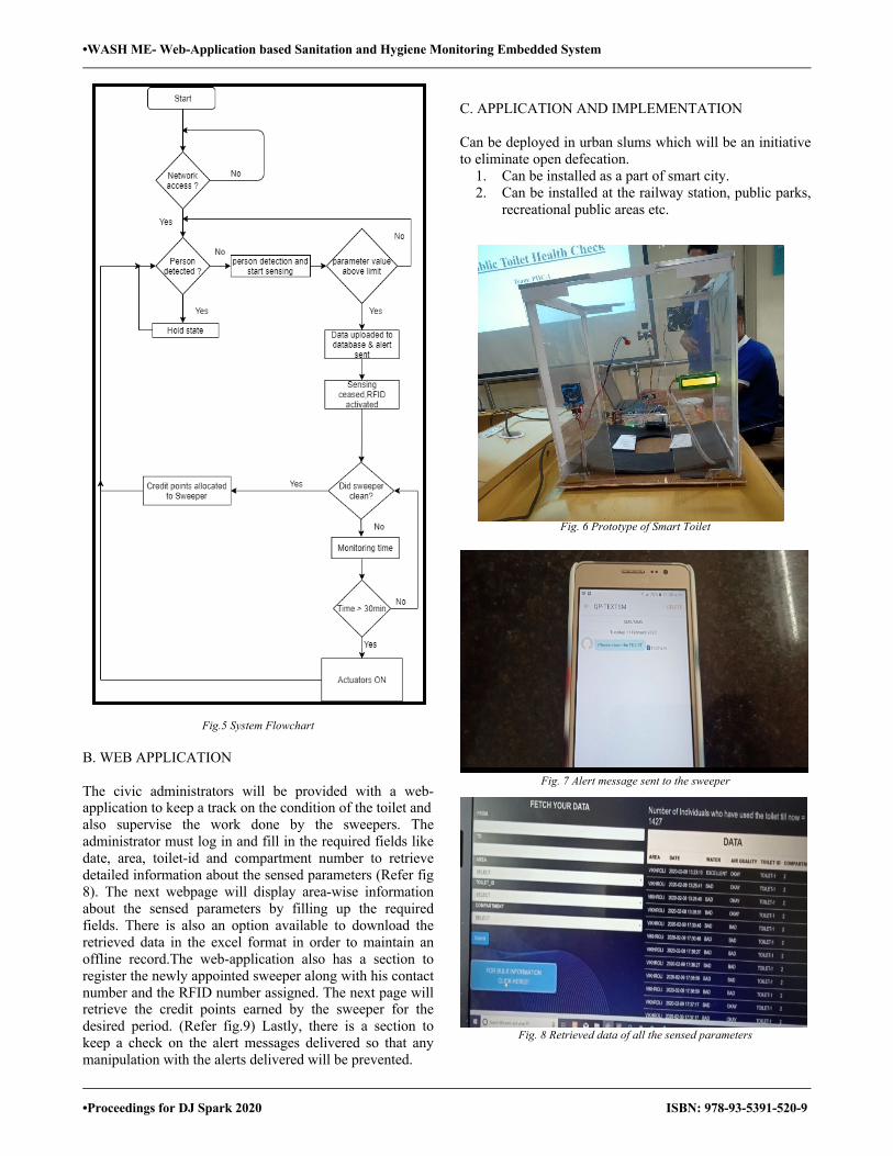
•WASH ME- Web-Application based Sanitation and Hygiene Monitoring Embedded System
•Proceedings for DJ Spark 2020 ISBN: 978-93-5391-520-9
Fig.5 System Flowchart
B. WEB APPLICATION The civic administrators will be provided with a web-application to keep a track on the condition of the toilet and also supervise the work done by the sweepers. The administrator must log in and fill in the required fields like date, area, toilet-id and compartment number to retrieve detailed information about the sensed parameters (Refer fig 8). The next webpage will display area-wise information about the sensed parameters by filling up the required fields. There is also an option available to download the retrieved data in the excel format in order to maintain an offline record.The web-application also has a section to register the newly appointed sweeper along with his contact number and the RFID number assigned. The next page will retrieve the credit points earned by the sweeper for the desired period. (Refer fig.9) Lastly, there is a section to keep a check on the alert messages delivered so that any manipulation with the alerts delivered will be prevented.
C. APPLICATION AND IMPLEMENTATION Can be deployed in urban slums which will be an initiative to eliminate open defecation.
1. Can be installed as a part of smart city. 2. Can be installed at the railway station, public parks,
recreational public areas etc.
Fig. 6 Prototype of Smart Toilet
Fig. 7 Alert message sent to the sweeper
Fig. 8 Retrieved data of all the sensed parameters
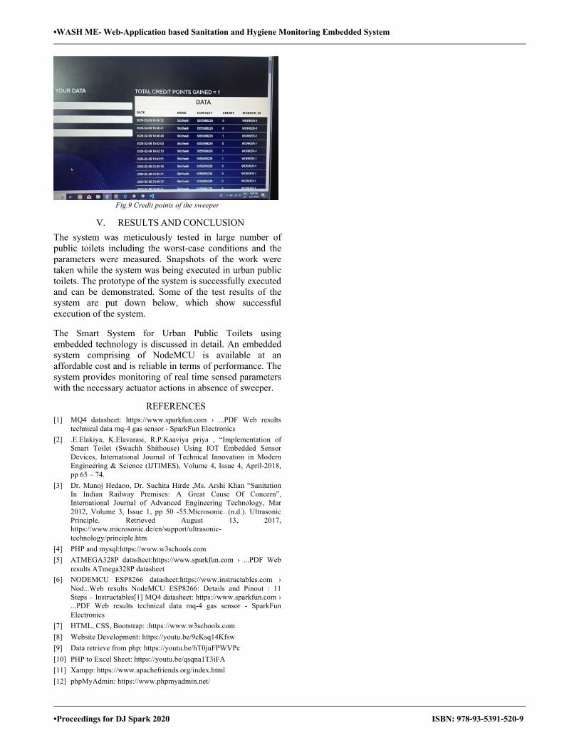
•WASH ME- Web-Application based Sanitation and Hygiene Monitoring Embedded System
•Proceedings for DJ Spark 2020 ISBN: 978-93-5391-520-9
Fig.9 Credit points of the sweeper
V. RESULTS AND CONCLUSION The system was meticulously tested in large number of public toilets including the worst-case conditions and the parameters were measured. Snapshots of the work were taken while the system was being executed in urban public toilets. The prototype of the system is successfully executed and can be demonstrated. Some of the test results of the system are put down below, which show successful execution of the system.
The Smart System for Urban Public Toilets using embedded technology is discussed in detail. An embedded system comprising of NodeMCU is available at an affordable cost and is reliable in terms of performance. The system provides monitoring of real time sensed parameters with the necessary actuator actions in absence of sweeper.
REFERENCES [1] MQ4 datasheet: https://www.sparkfun.com › ...PDF Web results
technical data mq-4 gas sensor - SparkFun Electronics [2] .E.Elakiya, K.Elavarasi, R.P.Kaaviya priya , “Implementation of
Smart Toilet (Swachh Shithouse) Using IOT Embedded Sensor Devices, International Journal of Technical Innovation in Modern Engineering & Science (IJTIMES), Volume 4, Issue 4, April-2018, pp 65 – 74.
[3] Dr. Manoj Hedaoo, Dr. Suchita Hirde ,Ms. Arshi Khan “Sanitation In Indian Railway Premises: A Great Cause Of Concern”, International Journal of Advanced Engineering Technology, Mar 2012, Volume 3, Issue 1, pp 50 -55.Microsonic. (n.d.). Ultrasonic Principle. Retrieved August 13, 2017, https://www.microsonic.de/en/support/ultrasonic-technology/principle.htm
[4] PHP and mysql:https://www.w3schools.com [5] ATMEGA328P datasheet:https://www.sparkfun.com › ...PDF Web
results ATmega328P datasheet [6] NODEMCU ESP8266 datasheet:https://www.instructables.com ›
Nod...Web results NodeMCU ESP8266: Details and Pinout : 11 Steps – Instructables[1] MQ4 datasheet: https://www.sparkfun.com › ...PDF Web results technical data mq-4 gas sensor - SparkFun Electronics
[7] HTML, CSS, Bootstrap: :https://www.w3schools.com [8] Website Development: https://youtu.be/9cKsq14Kfsw [9] Data retrieve from php: https://youtu.be/hT0juFPWVPc [10] PHP to Excel Sheet: https://youtu.be/qsqna1T3iFA [11] Xampp: https://www.apachefriends.org/index.html [12] phpMyAdmin: https://www.phpmyadmin.net/

•Automat Stationer
•Proceedings for DJ Spark 2020 ISBN: 978-93-5391-520-9
Automat Stationer Shubham Dadsena1, Anuj Shah1, Parth Kasodariya1, Radhika Laddha1, Sandeep Mishra2
1 U. G. Student, Department of Electronics and Telecommunication, K.J Somaiya College of Engineering &IT,Sion , Mumbai- 400022 2 Professor, Electronics and Telecommunication Department K.J Somaiya College of Engineering & IT Sion, Mumbai- 400022
E-mail: [email protected], [email protected], [email protected],[email protected],[email protected]
Abstract—The paper discusses about a unique system based on the initiative to vend the stationary items faster and safer with greater ease. The main idea behind the initiative is creating a self-sustainable system which can dissipates the required stationery product and precisely withdraw the amount directly from the student wallet by identifying their respective ID cards, aiming at a swift, reliable and fully automated process, thereby making the device to process and give the products without any human intervention. The RFID will contain the student’s name, data, remaining balance amount, The system is designed in such a manner that the authenticated RFID tag of the student will work as an input key for the further proceedings. Whenever the student swipes the card in the machine the system will display the available products in accordance with the remaining quantity. The student will have to select from the list of available products. After selecting the required product, system will start processing as per the given input and feeds the input data to the Arduino-Uno. The servo motor will start rotating as per the given input and give the required product through the output port, college ID’s having its own unique RFID tag is chosen so as to prevent any sort of adversities. This paper also tends to explore the unexplored territories so as to make way for new possibilities.
Keywords— Stepper Motor, RFID, Arduino
I. INTRODUCTION There are times when people go to a stationery shop and select the stuff manually causing the wastage of human energy and time. The supermarkets also need to keep a separate person for the billing procedure and the customer has to wait till the billing process is done. The device Automat Stationer is a perfect solution to avoid this as it is reliable and human friendly product automating this procedure reducing the human intervention and thereby error probability. Automat Stationer is a device which would give the desired quantity of a product by automatically deducting the amount generated from their RFID cards enabling quick, efficient and easy shopping process. The person have to scan his RFID card and all the details of that person will pop up on the display, later when he selects any stationary items the automat stationer sums up his total and automatically deducts the amount from his balance and the remaining balance is thereby displayed to the customer. This can also help to maintain a database and hence the buying patterns, spending al many other things can be calculated using Automat Stationer.
II. WORKING PRINCIPLE Automat Stationer works on the nature principle of gravitational pull as of when one product is pushed out form the pile the next one automatically falls down and is ready to be sold. The Automat Stationer works on the input given by the customer and the desired quantity. It would check for the different products and thereby activating their servo motors using an Arduino UNO. The desired product and their quantities would be made available one by one at their respective slots, also the amount deducted and the remaining balance would be displayed on the LCD screen.
III. BLOCK DIAGRAM
Fig. 1. Block Diagram of the structure
A. RFID tag and scanner
RFID tags contain an integrated circuit and an antenna which are used to transmit data to the RFID reader (also called an interrogator). The reader then converts the radio waves to a more usable form of data
B. Numeric Keypad
A numeric keypad, number pad or ten keys, is the palm-sized, 17-key section of a standard computer keyboard, usually on the far right. It provides calculator-style efficiency for entering numbers.
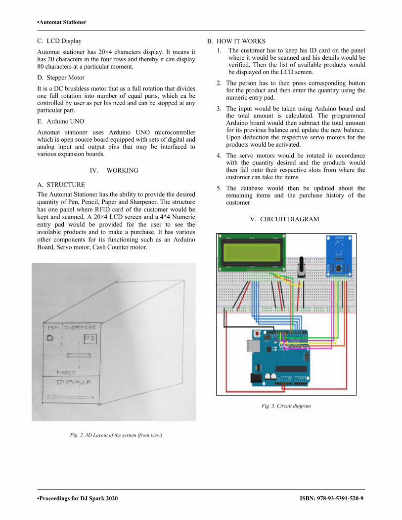
•Automat Stationer
•Proceedings for DJ Spark 2020 ISBN: 978-93-5391-520-9
C. LCD Display
Automat stationer has 20×4 characters display. It means it has 20 characters in the four rows and thereby it can display 80 characters at a particular moment.
D. Stepper Motor
It is a DC brushless motor that as a full rotation that divides one full rotation into number of equal parts, which ca be controlled by user as per his need and can be stopped at any particular part.
E. Arduino UNO
Automat stationer uses Arduino UNO microcontroller which is open source board equipped with sets of digital and analog input and output pins that may be interfaced to various expansion boards.
IV. WORKING
A. STRUCTURE The Automat Stationer has the ability to provide the desired quantity of Pen, Pencil, Paper and Sharpener. The structure has one panel where RFID card of the customer would be kept and scanned. A 20×4 LCD screen and a 4*4 Numeric entry pad would be provided for the user to see the available products and to make a purchase. It has various other components for its functioning such as an Arduino Board, Servo motor, Cash Counter motor.
Fig. 2. 3D Layout of the system (front view)
B. HOW IT WORKS 1. The customer has to keep his ID card on the panel
where it would be scanned and his details would be verified. Then the list of available products would be displayed on the LCD screen.
2. The person has to then press corresponding button for the product and then enter the quantity using the numeric entry pad.
3. The input would be taken using Arduino board and the total amount is calculated. The programmed Arduino board would then subtract the total amount for its previous balance and update the new balance. Upon deduction the respective servo motors for the products would be activated.
4. The servo motors would be rotated in accordance with the quantity desired and the products would then fall onto their respective slots from where the customer can take the items.
5. The database would then be updated about the remaining items and the purchase history of the customer
V. CIRCUIT DIAGRAM
Fig. 3. Circuit diagram

•Automat Stationer
•Proceedings for DJ Spark 2020 ISBN: 978-93-5391-520-9
VI. FLOW CHART
Fig.4. Flow Chart
VII. EFFECTS
Effect on the stores:
1. The Automat Stationer would help the shopkeepers or the shopping malls to keep a track on its inventory leading to ease of auditing and maintaining stock.
2. The stores can give the products more accurately and fast leading towards hassle free and improved sales and thereby more profits.
3. Additional employees for giving the stationary items are not required as the system is self-sustainable and automatic.
4. Human errors like accepting cash or mishandling of products can be avoided.
Effects on the human tendancy: 1. Immoral or non-ethical tendency of people such as
burglary will be reduced. 2. The human energy spent on selecting and taking
the products would be reduced.
3. Automat Stationer would promote Digital India by making payments digitally without cash.
4. The people will not have to stand in the long queues for the billing process and hence the time spent by the customer for any purchase would be reduced.
5. The stationary can be made available in the rural areas by setting up this small unit where the shopping marts or shops are not available.
VIII. CONCLUSION
When the person scans his card, all his data will be displayed and he has to make choice that what he wants to purchase. Suppose, he selects 1 pen, then the system will automatically provide him 1 pen. This system can be installed at super markets and malls where technology can perform a fool-proof job and humans will not be required to do such mechanical tasks also at public places like Railway Stations, Bus stands and Airports.
Further the number of containers can be increased for large scale application. Also, the size of the containers can also be increased for bulk storage. The automat stationer also has various other applications and it can be done in various form such as Smart Grocer which could vend grocery items, Smart Medico vending Medicines and various such applications.
Also, in near future Shopping malls can be made having all these machines and they would be total cashless and would promote Digital India where the transactions would be much quicker and the shopping work would be much easier.
ACKNOWLEDGMENT
The authors would like to thank the committee for organizing this technical paper competition, as this event has created a great rapport among the students as well as it has inculcated the feeling of new innovative research ideas among the young minds. Also, the authors would also like to thank our Principal Dr. Suresh Ukarande and the head of Department Dr. Jayashree Khanapuri for her thoughts and valuable suggestions, encouragement and support. We would like to thank our project guide Prof. Sandeep Mishra who helped us with his valuable suggestions, motivation and showed us the guiding light in preparing this.
REFERENCES
[1] Smart Ration Card, Volume 4, No. 4, April 2013, Journal of Global Research in Computer Science, ISSN2229371X.
[2] Kashinath Wakade, Pankaj Chidrawar, Dinesh Aitwade, “e-Ration System Using RFID and GSM Technology.
[3] https://ieeexplore.ieee.org/document/5600192
[4] https://www.intechopen.com/books/current-trends-and-challenges-in-rfid/the-study-on-secure-rfid-authentication-and-access-control
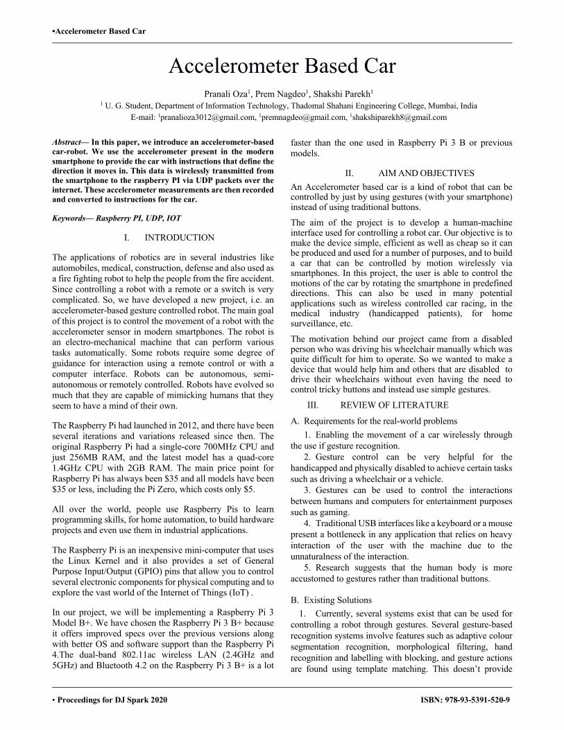
•Accelerometer Based Car
• Proceedings for DJ Spark 2020 ISBN: 978-93-5391-520-9
Accelerometer Based Car
Pranali Oza1, Prem Nagdeo1, Shakshi Parekh1 1 U. G. Student, Department of Information Technology, Thadomal Shahani Engineering College, Mumbai, India
E-mail: [email protected], [email protected], [email protected]
Abstract— In this paper, we introduce an accelerometer-based car-robot. We use the accelerometer present in the modern smartphone to provide the car with instructions that define the direction it moves in. This data is wirelessly transmitted from the smartphone to the raspberry PI via UDP packets over the internet. These accelerometer measurements are then recorded and converted to instructions for the car.
Keywords— Raspberry PI, UDP, IOT
I. INTRODUCTION
The applications of robotics are in several industries like automobiles, medical, construction, defense and also used as a fire fighting robot to help the people from the fire accident. Since controlling a robot with a remote or a switch is very complicated. So, we have developed a new project, i.e. an accelerometer-based gesture controlled robot. The main goal of this project is to control the movement of a robot with the accelerometer sensor in modern smartphones. The robot is an electro-mechanical machine that can perform various tasks automatically. Some robots require some degree of guidance for interaction using a remote control or with a computer interface. Robots can be autonomous, semi-autonomous or remotely controlled. Robots have evolved so much that they are capable of mimicking humans that they seem to have a mind of their own.
The Raspberry Pi had launched in 2012, and there have been several iterations and variations released since then. The original Raspberry Pi had a single-core 700MHz CPU and just 256MB RAM, and the latest model has a quad-core 1.4GHz CPU with 2GB RAM. The main price point for Raspberry Pi has always been $35 and all models have been $35 or less, including the Pi Zero, which costs only $5.
All over the world, people use Raspberry Pis to learn programming skills, for home automation, to build hardware projects and even use them in industrial applications.
The Raspberry Pi is an inexpensive mini-computer that uses the Linux Kernel and it also provides a set of General Purpose Input/Output (GPIO) pins that allow you to control several electronic components for physical computing and to explore the vast world of the Internet of Things (IoT) .
In our project, we will be implementing a Raspberry Pi 3 Model B+. We have chosen the Raspberry Pi 3 B+ because it offers improved specs over the previous versions along with better OS and software support than the Raspberry Pi 4.The dual-band 802.11ac wireless LAN (2.4GHz and 5GHz) and Bluetooth 4.2 on the Raspberry Pi 3 B+ is a lot
faster than the one used in Raspberry Pi 3 B or previous models.
II. AIM AND OBJECTIVES An Accelerometer based car is a kind of robot that can be controlled by just by using gestures (with your smartphone) instead of using traditional buttons.
The aim of the project is to develop a human-machine interface used for controlling a robot car. Our objective is to make the device simple, efficient as well as cheap so it can be produced and used for a number of purposes, and to build a car that can be controlled by motion wirelessly via smartphones. In this project, the user is able to control the motions of the car by rotating the smartphone in predefined directions. This can also be used in many potential applications such as wireless controlled car racing, in the medical industry (handicapped patients), for home surveillance, etc.
The motivation behind our project came from a disabled person who was driving his wheelchair manually which was quite difficult for him to operate. So we wanted to make a device that would help him and others that are disabled to drive their wheelchairs without even having the need to control tricky buttons and instead use simple gestures.
III. REVIEW OF LITERATURE
A. Requirements for the real-world problems 1. Enabling the movement of a car wirelessly through
the use if gesture recognition. 2. Gesture control can be very helpful for the
handicapped and physically disabled to achieve certain tasks such as driving a wheelchair or a vehicle.
3. Gestures can be used to control the interactions between humans and computers for entertainment purposes such as gaming.
4. Traditional USB interfaces like a keyboard or a mouse present a bottleneck in any application that relies on heavy interaction of the user with the machine due to the unnaturalness of the interaction.
5. Research suggests that the human body is more accustomed to gestures rather than traditional buttons.
B. Existing Solutions
1. Currently, several systems exist that can be used for controlling a robot through gestures. Several gesture-based recognition systems involve features such as adaptive colour segmentation recognition, morphological filtering, hand recognition and labelling with blocking, and gesture actions are found using template matching. This doesn’t provide
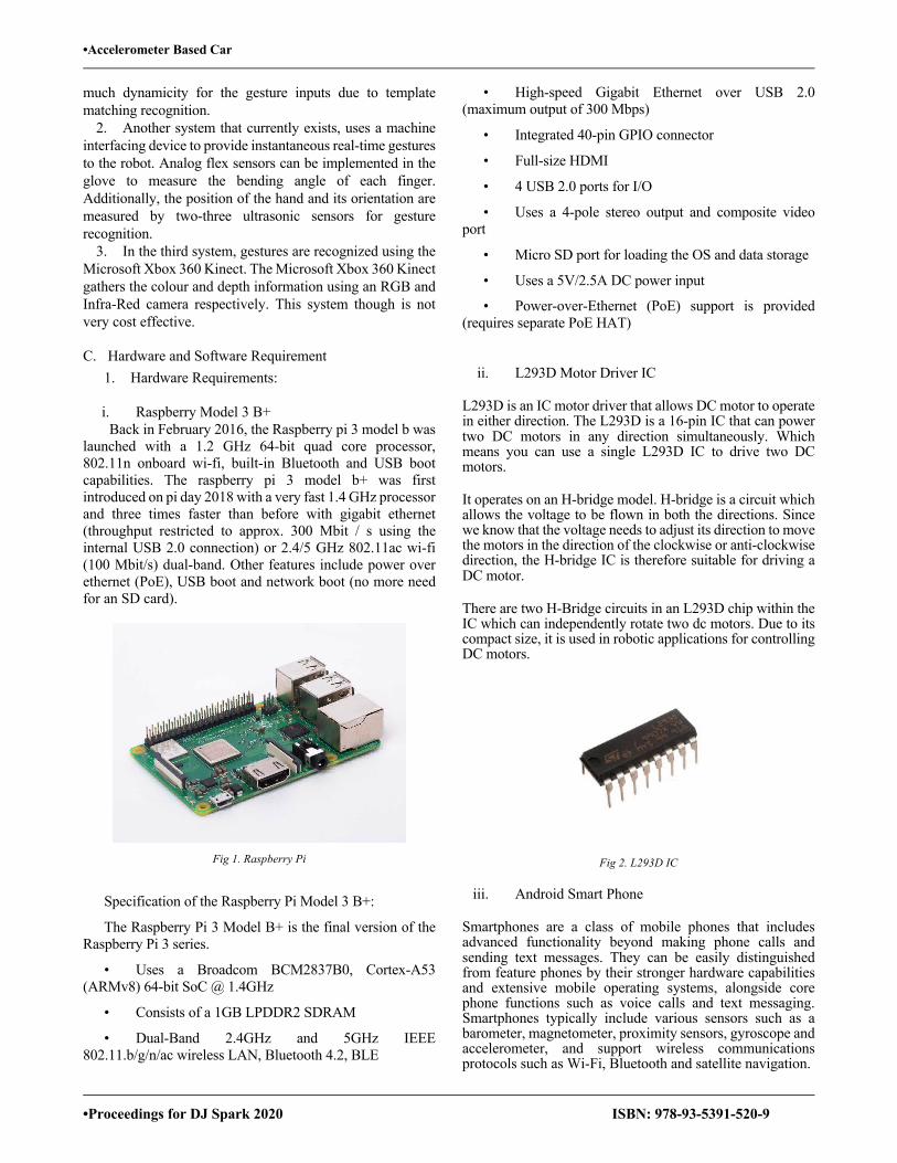
•Accelerometer Based Car
•Proceedings for DJ Spark 2020 ISBN: 978-93-5391-520-9
much dynamicity for the gesture inputs due to template matching recognition.
2. Another system that currently exists, uses a machine interfacing device to provide instantaneous real-time gestures to the robot. Analog flex sensors can be implemented in the glove to measure the bending angle of each finger. Additionally, the position of the hand and its orientation are measured by two-three ultrasonic sensors for gesture recognition.
3. In the third system, gestures are recognized using the Microsoft Xbox 360 Kinect. The Microsoft Xbox 360 Kinect gathers the colour and depth information using an RGB and Infra-Red camera respectively. This system though is not very cost effective.
C. Hardware and Software Requirement
1. Hardware Requirements:
i. Raspberry Model 3 B+ Back in February 2016, the Raspberry pi 3 model b was
launched with a 1.2 GHz 64-bit quad core processor, 802.11n onboard wi-fi, built-in Bluetooth and USB boot capabilities. The raspberry pi 3 model b+ was first introduced on pi day 2018 with a very fast 1.4 GHz processor and three times faster than before with gigabit ethernet (throughput restricted to approx. 300 Mbit / s using the internal USB 2.0 connection) or 2.4/5 GHz 802.11ac wi-fi (100 Mbit/s) dual-band. Other features include power over ethernet (PoE), USB boot and network boot (no more need for an SD card).
Fig 1. Raspberry Pi
Specification of the Raspberry Pi Model 3 B+:
The Raspberry Pi 3 Model B+ is the final version of the Raspberry Pi 3 series.
• Uses a Broadcom BCM2837B0, Cortex-A53 (ARMv8) 64-bit SoC @ 1.4GHz
• Consists of a 1GB LPDDR2 SDRAM
• Dual-Band 2.4GHz and 5GHz IEEE 802.11.b/g/n/ac wireless LAN, Bluetooth 4.2, BLE
• High-speed Gigabit Ethernet over USB 2.0 (maximum output of 300 Mbps)
• Integrated 40-pin GPIO connector
• Full-size HDMI
• 4 USB 2.0 ports for I/O
• Uses a 4-pole stereo output and composite video port
• Micro SD port for loading the OS and data storage
• Uses a 5V/2.5A DC power input
• Power-over-Ethernet (PoE) support is provided (requires separate PoE HAT)
ii. L293D Motor Driver IC
L293D is an IC motor driver that allows DC motor to operate in either direction. The L293D is a 16-pin IC that can power two DC motors in any direction simultaneously. Which means you can use a single L293D IC to drive two DC motors.
It operates on an H-bridge model. H-bridge is a circuit which allows the voltage to be flown in both the directions. Since we know that the voltage needs to adjust its direction to move the motors in the direction of the clockwise or anti-clockwise direction, the H-bridge IC is therefore suitable for driving a DC motor.
There are two H-Bridge circuits in an L293D chip within the IC which can independently rotate two dc motors. Due to its compact size, it is used in robotic applications for controlling DC motors.
Fig 2. L293D IC
iii. Android Smart Phone
Smartphones are a class of mobile phones that includes advanced functionality beyond making phone calls and sending text messages. They can be easily distinguished from feature phones by their stronger hardware capabilities and extensive mobile operating systems, alongside core phone functions such as voice calls and text messaging. Smartphones typically include various sensors such as a barometer, magnetometer, proximity sensors, gyroscope and accelerometer, and support wireless communications protocols such as Wi-Fi, Bluetooth and satellite navigation.
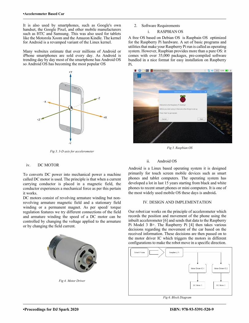
•Accelerometer Based Car
•Proceedings for DJ Spark 2020 ISBN: 978-93-5391-520-9
It is also used by smartphones, such as Google's own handset, the Google Pixel, and other mobile manufacturers such as HTC and Samsung. This was also used for tablets like the Motorola Xoom and the Amazon Kindle. The kernel for Android is a revamped variant of the Linux kernel.
Many websites estimate that over millions of Android or iPhone smartphones are sold every day. As Android is trending day by day most of the smartphone has Android OS so Android OS has becoming the most popular OS
Fig 3. 3-D axis for accelerometer
iv. DC MOTOR
To converts DC power into mechanical power a machine called DC motor is used. The principle is that when a current carrying conductor is placed in a magnetic field, the conductor experiences a mechanical force as per this pertain it works. DC motors consist of revolving armature winding but non-revolving armature magnetic field and a stationary field winding or a permanent magnet. As per speed/ torque regulation features we try different connections of the field and armature winding the speed of a DC motor can be controlled by changing the voltage applied to the armature or by changing the field current.
Fig 4. Motor Driver
2. Software Requirements i. RASPBIAN OS
A free OS based on Debian OS is Raspbain OS optimized for the Raspberry Pi hardware. A set of basic programs and utilities that make your Raspberry Pi run is called as operating system. However, Raspbian provides more than a pure OS: it comes with over 35,000 packages, pre-compiled software bundled in a nice format for easy installation on Raspberry Pi.
Fig 5. Raspbian OS
ii. Android OS
Android is a Linux based operating system it is designed primarily for touch screen mobile devices such as smart phones and tablet computers. The operating system has developed a lot in last 15 years starting from black and white phones to recent smart phones or mini computers. It is one of the most widely used mobile OS these days is android.
IV. DESIGN AND IMPLEMENTATION
Our robot/car works on the principle of accelerometer which records the position and movement of the phone using the inbuilt accelerometer [6] and sends that data to the Raspberry Pi Model 3 B+. The Raspberry Pi [4] then takes various decisions regarding the movement of the car based on the received information. These decisions are then passed on to the motor driver IC which triggers the motors in different configurations to make the robot move in a specific direction.
Fig 6. Block Diagram
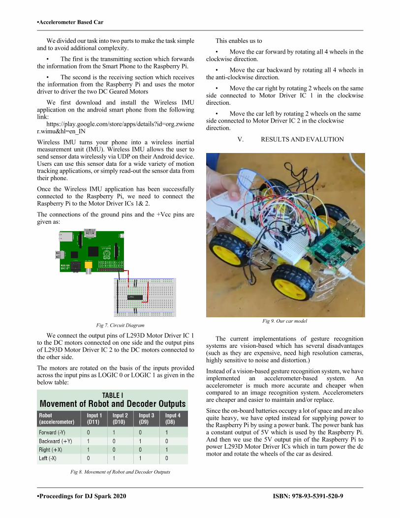
•Accelerometer Based Car
•Proceedings for DJ Spark 2020 ISBN: 978-93-5391-520-9
We divided our task into two parts to make the task simple and to avoid additional complexity.
• The first is the transmitting section which forwards the information from the Smart Phone to the Raspberry Pi.
• The second is the receiving section which receives the information from the Raspberry Pi and uses the motor driver to driver the two DC Geared Motors
We first download and install the Wireless IMU application on the android smart phone from the following link: https://play.google.com/store/apps/details?id=org.zwiener.wimu&hl=en_IN
Wireless IMU turns your phone into a wireless inertial measurement unit (IMU). Wireless IMU allows the user to send sensor data wirelessly via UDP on their Android device. Users can use this sensor data for a wide variety of motion tracking applications, or simply read-out the sensor data from their phone.
Once the Wireless IMU application has been successfully connected to the Raspberry Pi, we need to connect the Raspberry Pi to the Motor Driver ICs 1& 2.
The connections of the ground pins and the +Vcc pins are given as:
Fig 7. Circuit Diagram
We connect the output pins of L293D Motor Driver IC 1 to the DC motors connected on one side and the output pins of L293D Motor Driver IC 2 to the DC motors connected to the other side.
The motors are rotated on the basis of the inputs provided across the input pins as LOGIC 0 or LOGIC 1 as given in the below table:
Fig 8. Movement of Robot and Decoder Outputs
This enables us to
• Move the car forward by rotating all 4 wheels in the clockwise direction.
• Move the car backward by rotating all 4 wheels in the anti-clockwise direction.
• Move the car right by rotating 2 wheels on the same side connected to Motor Driver IC 1 in the clockwise direction.
• Move the car left by rotating 2 wheels on the same side connected to Motor Driver IC 2 in the clockwise direction.
V. RESULTS AND EVALUTION
Fig 9. Our car model
The current implementations of gesture recognition systems are vision-based which has several disadvantages (such as they are expensive, need high resolution cameras, highly sensitive to noise and distortion.)
Instead of a vision-based gesture recognition system, we have implemented an accelerometer-based system. An accelerometer is much more accurate and cheaper when compared to an image recognition system. Accelerometers are cheaper and easier to maintain and/or replace.
Since the on-board batteries occupy a lot of space and are also quite heavy, we have opted instead for supplying power to the Raspberry Pi by using a power bank. The power bank has a constant output of 5V which is used by the Raspberry Pi. And then we use the 5V output pin of the Raspberry Pi to power L293D Motor Driver ICs which in turn power the dc motor and rotate the wheels of the car as desired.

•Accelerometer Based Car
•Proceedings for DJ Spark 2020 ISBN: 978-93-5391-520-9
VI. FUTURE SCOPE
Future Work or Scope can include:
1) The robot becomes very heavy due to the use of batteries which occupy a lot of space. The alternative is to use DC motors with less power or some other power source for the batteries.
2) This planned system can be used in risky environments where a camera joined to the robot can be used in military by a user in his station who uses it to view footage.
3) This framework can likewise be utilized in clinical field where small robots are made that can help specialists for powerful medical procedure activities.
4) Entertainment purposes – Arcade units, PCs, Game consoles, and all such devices which require a combination of input devices are used for videogames today.Gesture acknowledgement can be used to give a player in the game world a real life experience like never before.
5) Automation systems –Gesture recognition can be used in homes, offices, transport vehicles to significantly expand ease of use and decrease the capital necessary to create essential or optional input systems like remote controls with buttons or similar.
6) Home safety – Live footage can be recorded by attaching a camera to the car while performing actions and it can be used for home surveillance.
VII. CONCLUSION
In conclusion, using this project we have controlled a car using accelerometer sensors in smartphones. It allows us to regulate the leftward, rightward, forward and backward predefined motions for controlling the robot car. User can control a robot directly from his smart phone without using any external hardware for assistance.
REFERENCES
[1] http://www.ijsdr.org/papers/IJSDR1805055.pdf
[2] https://www.pervasive.jku.at/Teaching/_2012SS/SeminarausPervasiveComputing/Begleitmaterial/Related%20Work/2009_GestureControlled%20user%20interfaces,%20what%20have%20we%20done%20and%20what%E2%80%99s%20next_Bhuiyan.pdf
[3] https://www.hackster.io/jithinsanal1610/mobile-phone-accelerometer-controlled-robot-using-rpi-553071
[4] https://en.wikipedia.org/wiki/Raspberry_Pi
[5] https://www.rakeshmondal.info/L293D-Motor-Driver
[6] https://play.google.com/store/apps/details?id=org.zwiener.wimu&hl=en_IN
.
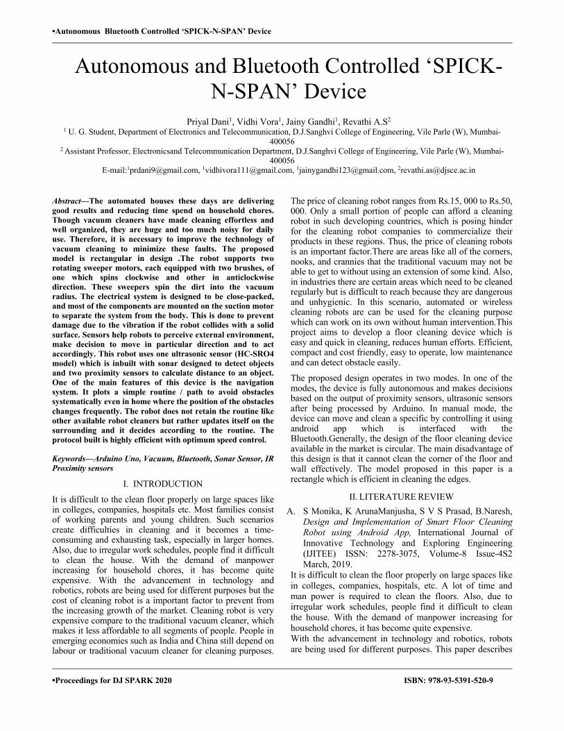
•Autonomous Bluetooth Controlled ‘SPICK-N-SPAN’ Device
•Proceedings for DJ SPARK 2020 ISBN: 978-93-5391-520-9
Autonomous and Bluetooth Controlled ‘SPICK-N-SPAN’ Device
Priyal Dani1, Vidhi Vora1, Jainy Gandhi1, Revathi A.S2 1 U. G. Student, Department of Electronics and Telecommunication, D.J.Sanghvi College of Engineering, Vile Parle (W), Mumbai-
400056 2 Assistant Professor, Electronicsand Telecommunication Department, D.J.Sanghvi College of Engineering, Vile Parle (W), Mumbai-
400056 E-mail:[email protected], [email protected], [email protected], [email protected]
Abstract—The automated houses these days are delivering good results and reducing time spend on household chores. Though vacuum cleaners have made cleaning effortless and well organized, they are huge and too much noisy for daily use. Therefore, it is necessary to improve the technology of vacuum cleaning to minimize these faults. The proposed model is rectangular in design .The robot supports two rotating sweeper motors, each equipped with two brushes, of one which spins clockwise and other in anticlockwise direction. These sweepers spin the dirt into the vacuum radius. The electrical system is designed to be close-packed, and most of the components are mounted on the suction motor to separate the system from the body. This is done to prevent damage due to the vibration if the robot collides with a solid surface. Sensors help robots to perceive external environment, make decision to move in particular direction and to act accordingly. This robot uses one ultrasonic sensor (HC-SRO4 model) which is inbuilt with sonar designed to detect objects and two proximity sensors to calculate distance to an object. One of the main features of this device is the navigation system. It plots a simple routine / path to avoid obstacles systematically even in home where the position of the obstacles changes frequently. The robot does not retain the routine like other available robot cleaners but rather updates itself on the surrounding and it decides according to the routine. The protocol built is highly efficient with optimum speed control.
Keywords—Arduino Uno, Vacuum, Bluetooth, Sonar Sensor, IR Proximity sensors
I. INTRODUCTION
It is difficult to the clean floor properly on large spaces like in colleges, companies, hospitals etc. Most families consist of working parents and young children. Such scenarios create difficulties in cleaning and it becomes a time-consuming and exhausting task, especially in larger homes. Also, due to irregular work schedules, people find it difficult to clean the house. With the demand of manpower increasing for household chores, it has become quite expensive. With the advancement in technology and robotics, robots are being used for different purposes but the cost of cleaning robot is a important factor to prevent from the increasing growth of the market. Cleaning robot is very expensive compare to the traditional vacuum cleaner, which makes it less affordable to all segments of people. People in emerging economies such as India and China still depend on labour or traditional vacuum cleaner for cleaning purposes.
The price of cleaning robot ranges from Rs.15, 000 to Rs.50, 000. Only a small portion of people can afford a cleaning robot in such developing countries, which is posing hinder for the cleaning robot companies to commercialize their products in these regions. Thus, the price of cleaning robots is an important factor.There are areas like all of the corners, nooks, and crannies that the traditional vacuum may not be able to get to without using an extension of some kind. Also, in industries there are certain areas which need to be cleaned regularly but is difficult to reach because they are dangerous and unhygienic. In this scenario, automated or wireless cleaning robots are can be used for the cleaning purpose which can work on its own without human intervention.This project aims to develop a floor cleaning device which is easy and quick in cleaning, reduces human efforts. Efficient, compact and cost friendly, easy to operate, low maintenance and can detect obstacle easily.
The proposed design operates in two modes. In one of the modes, the device is fully autonomous and makes decisions based on the output of proximity sensors, ultrasonic sensors after being processed by Arduino. In manual mode, the device can move and clean a specific by controlling it using android app which is interfaced with the Bluetooth.Generally, the design of the floor cleaning device available in the market is circular. The main disadvantage of this design is that it cannot clean the corner of the floor and wall effectively. The model proposed in this paper is a rectangle which is efficient in cleaning the edges.
II. LITERATURE REVIEW A. S Monika, K ArunaManjusha, S V S Prasad, B.Naresh,
Design and Implementation of Smart Floor Cleaning Robot using Android App, International Journal of Innovative Technology and Exploring Engineering (IJITEE) ISSN: 2278-3075, Volume-8 Issue-4S2 March, 2019.
It is difficult to clean the floor properly on large spaces like in colleges, companies, hospitals, etc. A lot of time and man power is required to clean the floors. Also, due to irregular work schedules, people find it difficult to clean the house. With the demand of manpower increasing for household chores, it has become quite expensive. With the advancement in technology and robotics, robots are being used for different purposes. This paper describes

•Autonomous Bluetooth Controlled ‘SPICK-N-SPAN’ Device
•Proceedings for DJ SPARK 2020 ISBN: 978-93-5391-520-9
the use of a robot as a smart floor cleaning robot. The smart cleaning robots are designed for home and office environment. It makes the cleaning process easy and efficient. It is a wireless robot which can be controlled using an Android App. proposed robot works on Arduino Uno and Bluetooth module. This wireless system has applications which run on Android App. The cleaning robot follows the commands that are given by the user through the app. The Bluetooth module is connected to the Arduino and the signal is sent to it. The Arduino is connected to motors and rotors to precede the robot in the specific direction and the clean the floors. The robot has water sprayer, robotic arm with cleaning pad for cleaning purpose. The features of this proposed design are that after cleaning the wet floor as per the commands given to it, it can dry the dirty water into the requisite container. The robotic arm is used for an effective and efficient wet floor cleaning purpose. It can also pick up waste and carry it along within the range of Bluetooth. The proposed model is a manual system as it is controlled by the user through the app and entirely depends on the commands given by the user. The benefits of this project are that it is efficient, reduces time and cost of maintenance. It has overcome the drawbacks of lack of efficiency of cleaning wet floors and also the problem of collision.
B. M Kushal N L, Hamara Chaudhuri, Nikithesh H R, “Autonomous Floor Cleaning Bot”, International Research Journal of Engineering and Technology (IRJET), Volume: 05 Issue: 06 | June-2018.
Nowadays household has become more automated. Home automation reduces time consumption and makes it much convenient for the people. In this research paper a robot which can be used for domestic purpose has been developed. A robot floor cleaner based on ATMEGA 2560 which works in two different modes as per the user convenience “Automatic and Manual” has been developed. This is not a vacuum cleaner robot unlike other floor cleaner robots. It performs sweeping and mopping operation which uses detachable mop for wet mopping. It works on 12V supply. In the automatic mode, robot performs all operations itself. Firstly the robot starts moving in the forward direction and performs cleaning action. Laser TOF sensor have been used for obstacle detection and to avoid hurdle. If any hurdle detected then robot changes its path, and continues cleaning action. It follows zigzag path for user convenience, water sprayer is attached which automatically spray water for mopping. When the mode selection switch is HIGH robot goes to manual mode. Manual mode allows the users to operate the robot at places where it is difficult to reach. The operator has freedom to command the robot to create any pattern of movement. When the mode selection switch is LOW robot goes to Automatic mode. Usually, automatic mode is guided by algorithms for path planning of the robot. Path planning is an important factor because the efficiency of
cleaning robot is very much dependent on it. The route map of the algorithm used here is like the letter ‘S’. This algorithm is the fastest process to cover the entire room area. With every collision with obstacle the turning direction of the robot continuously changes under this mode. It was found that the robot was quite efficient in its cleaning; around 80% of efficiency was achieved. The additional features that may be added in autonomous cleaner robot are GSM control system using mobile phones for cleaning process.
III. PROPOSED DESIGN
Figure 1. Block Diagram of the Device
IV. HARDWARE USED
Following are the list of components used in the project: A. Arduino Uno
Figure 2. Arduino Uno
The Arduino UNO is an Atmega328 based microcontroller board. It is an open source widely used microcontroller. It is easy programme, erase and reprogramme at any instant of time. The board has sets of digital and analog input/output (I/O) pins. The board has 6 Analog pins and 14 Digital pins.It is programmable with the Arduino IDE. The
•Autonomous Bluetooth Controlled ‘SPICK-N-SPAN’ Device
•Proceedings for DJ SPARK 2020 ISBN: 978-93-5391-520-9
Uno uses the Atmega8U2 which is programmed as a USB-to-serial converter instead of a USB-to-serial FTDI driver which makes it different from other boards.The Arduino Uno can be supplied power externally or with the help of a USB connection generally from a laptop but from other devices as well. The power source is selected automatically. It burns (uploads) a program to the microcontroller using a USB cable. It consists of a physical programmable circuit board and it also uses software, IDE (Integrated Development Environment). It runs on your computer where you are able to write and upload computer code to the physical board. It takes 5V as input power supply which can be given from a laptop via a USB cable or external power supply.
B. DC Motor
Figure 3.DC motor DC motor converts an electric power into mechanical power output. A rotational motion of the shaft is the motor output. The input can be either alternating or direct supply. The mechanism of dc motor is like a bar wound with wire is placed in between two magnets having north and south pole. When it is supplied with electric energy the wire becomes energized resulting in rotational motion and it leads to rotational output.
C. Bluetooth (HC - 06)
Figure 4. Bluetooth Module
The Bluetooth device acts as a communication link between the robot and the cellphone. HC-06 can receive data from phone as well as transmit data to it. It is used for converting serial port to Bluetooth. It works on two modes: Master and Slave. Bluetooth is a wireless communication protocol suitable for forming personal area networks and running at the speed of 2.4 GHz. It has client-server architecture. It is designed for low power devices such as mobile phones. Bluetooth protocol uses the MAC address
of the device and gives the connectivity between two devices using their MAC address.
D. IRProximity Sensor
Figure 5. IR Proximity Sensor IR Proximity Sensor is a multipurpose infrared sensor which can be used for obstacle sensing, color detection, fire detection, line sensing, etc. and also as an encoder sensor. The sensor provides a digital output. IR sensors are highly susceptible to ambient light and the IR sensor on this sensor is suitably covered to reduce effect of ambient light on the sensor.
E. Ultrasonic Sensor
Figure 6. Ultrasonic Sensor
This sensor is a high-performance ultrasonic range finder. It is compact and measures a wide range from 2cm to 4m. This ranger is a perfect for any robot navigation as well as factory automation. This sensor can be connected directly to the digital I/O lines of the microcontroller. Ultrasonic sensors emit ultrasonic waves and wait for the waves to reflect from the object and distance is measured in time required for travelling of the signal using simple formula as below. Distance = (Echo pulse width high time * Sound Velocity (340M/S)/2) or Distance in cm = (Echo pulse width high time (in us)*0.017) The module works on 5VDC input and also gives an output signal directly for detection of any obstacle up to 4M.Power up the sensor by 5VDC using pins “VCC” and “GND”. First of all, a 10us trigger input has to be given to the pin named “Trig” on the sensor. As soon as the signals are transmitted the “Echo” pin goes to high level. Until the same sound waves are not received by the receiver, it remains in high level. If the received sound waves are same as what the same sensor transmitted then the Echo pin goes to low level. The Echo signal will automatically go to low level if no object is detected within 5M after 30ms.
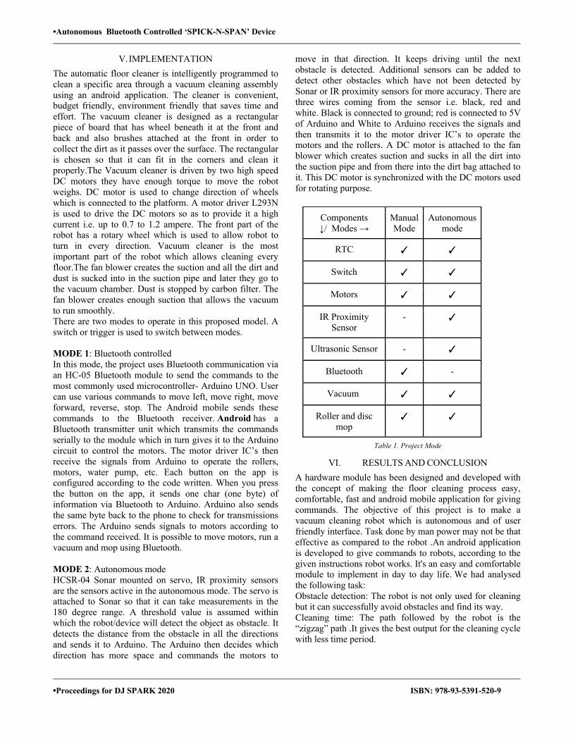
•Autonomous Bluetooth Controlled ‘SPICK-N-SPAN’ Device
•Proceedings for DJ SPARK 2020 ISBN: 978-93-5391-520-9
V. IMPLEMENTATION The automatic floor cleaner is intelligently programmed to clean a specific area through a vacuum cleaning assembly using an android application. The cleaner is convenient, budget friendly, environment friendly that saves time and effort. The vacuum cleaner is designed as a rectangular piece of board that has wheel beneath it at the front and back and also brushes attached at the front in order to collect the dirt as it passes over the surface. The rectangular is chosen so that it can fit in the corners and clean it properly.The Vacuum cleaner is driven by two high speed DC motors they have enough torque to move the robot weighs. DC motor is used to change direction of wheels which is connected to the platform. A motor driver L293N is used to drive the DC motors so as to provide it a high current i.e. up to 0.7 to 1.2 ampere. The front part of the robot has a rotary wheel which is used to allow robot to turn in every direction. Vacuum cleaner is the most important part of the robot which allows cleaning every floor.The fan blower creates the suction and all the dirt and dust is sucked into in the suction pipe and later they go to the vacuum chamber. Dust is stopped by carbon filter. The fan blower creates enough suction that allows the vacuum to run smoothly. There are two modes to operate in this proposed model. A switch or trigger is used to switch between modes. MODE 1: Bluetooth controlled In this mode, the project uses Bluetooth communication via an HC-05 Bluetooth module to send the commands to the most commonly used microcontroller- Arduino UNO. User can use various commands to move left, move right, move forward, reverse, stop. The Android mobile sends these commands to the Bluetooth receiver. Android has a Bluetooth transmitter unit which transmits the commands serially to the module which in turn gives it to the Arduino circuit to control the motors. The motor driver IC’s then receive the signals from Arduino to operate the rollers, motors, water pump, etc. Each button on the app is configured according to the code written. When you press the button on the app, it sends one char (one byte) of information via Bluetooth to Arduino. Arduino also sends the same byte back to the phone to check for transmissions errors. The Arduino sends signals to motors according to the command received. It is possible to move motors, run a vacuum and mop using Bluetooth. MODE 2: Autonomous mode HCSR-04 Sonar mounted on servo, IR proximity sensors are the sensors active in the autonomous mode. The servo is attached to Sonar so that it can take measurements in the 180 degree range. A threshold value is assumed within which the robot/device will detect the object as obstacle. It detects the distance from the obstacle in all the directions and sends it to Arduino. The Arduino then decides which direction has more space and commands the motors to
move in that direction. It keeps driving until the next obstacle is detected. Additional sensors can be added to detect other obstacles which have not been detected by Sonar or IR proximity sensors for more accuracy. There are three wires coming from the sensor i.e. black, red and white. Black is connected to ground; red is connected to 5V of Arduino and White to Arduino receives the signals and then transmits it to the motor driver IC’s to operate the motors and the rollers. A DC motor is attached to the fan blower which creates suction and sucks in all the dirt into the suction pipe and from there into the dirt bag attached to it. This DC motor is synchronized with the DC motors used for rotating purpose.
Table 1. Project Mode
VI. RESULTS AND CONCLUSION A hardware module has been designed and developed with the concept of making the floor cleaning process easy, comfortable, fast and android mobile application for giving commands. The objective of this project is to make a vacuum cleaning robot which is autonomous and of user friendly interface. Task done by man power may not be that effective as compared to the robot .An android application is developed to give commands to robots, according to the given instructions robot works. It's an easy and comfortable module to implement in day to day life. We had analysed the following task: Obstacle detection: The robot is not only used for cleaning but it can successfully avoid obstacles and find its way. Cleaning time: The path followed by the robot is the “zigzag” path .It gives the best output for the cleaning cycle with less time period.
Components ↓/ Modes →
Manual Mode
Autonomous mode
RTC ✓ ✓
Switch ✓ ✓
Motors ✓ ✓
IR Proximity Sensor
- ✓
Ultrasonic Sensor - ✓
Bluetooth ✓ -
Vacuum ✓ ✓
Roller and disc mop
✓ ✓
•Autonomous Bluetooth Controlled ‘SPICK-N-SPAN’ Device
•Proceedings for DJ SPARK 2020 ISBN: 978-93-5391-520-9
VII. APPLICATIONS The main applications of Spick-n-span devices are used in industrial field. Some of them are discussed below:
A. Hospitals Maintaining hygiene is the prime factor or essential foreach and every hospital. It consumes a lot of money and manpower. In such circumstances using floor cleaning machines can help them. These robots are structured in such a way that they are used in hospitals for both wet and dry cleaning. For clean surfaces, hospitals with their stringent sanitary needs seem a natural market for the automated cleaning products. Disinfection robots can light the way to cleaner hospitals.
B. Shopping malls
Automatic Floor cleaning machines can cover a wide area in short span of time with effective and efficient cleaning. Floor cleaning robots like Autovac can actually clean dirt and contaminants from the floor and has the best drying capacity. This can enable the mal customers to use the floor immediately.
C. Industry
The commonly used robots for cleaning industries are typically mobile, application-specific robots which have the feature of automate industrial cleaning processes. Many times, it's uncomfortable for humans to clean the industrial machinery and sometimes it's also risking human life for cleaning and maintaining the ambiance. For small factories, it is easy for humans to clean the floor but in the case of enormous or extremely large industries it is impossible to maintain cleanliness using man power, in such conditions it's beneficial to use floor cleaning robots. These robots are set on an automated routine which reduces the amount of time required dealing with cleaning processes. The variety of tasks is performed such as disinfecting a space and removing toxic paint. The current applications are fully automatic glass cleaning systems, vacuuming, wall climbing robots for boiler wall cleaning; paint removal for vessels and tanks; robotic hull cleaning of large ships; and robotic barn cleaners.
VIII. FUTURE SCOPE In the future we aim to make the robot smarter such that when it cleans a particular area or a room it has the capacity to store the information about that area, and that information is used for cleaning that area again. It will save the room information about obstacles and its locations. Multiple sensors and image mapping technology can be used to help robot vacuums understand and navigate in a room. They can make the robot smart and more capable of finding optimal ways to maneuver a space to clean it effectively. Another future scope of this robot is to add web server control using that we have to control our robot from any place. For example, suppose we must control our office place to our home. The robot automatically returns to its home base to recharge when the battery is low, then
resumes cleaning until the job is done. The different paths application can also be programmed such as circular, spiral, zigzag.
IX. CONCLUSION In this paper we have presented an automatic and
Bluetooth controlled floor cleaning device. This device uses Arduino, Bluetooth and sensors to give us better accuracy, precision and reduces the workload. The existing Floor Cleaning devices are of high cost, bulky in size, difficult to maintain and requires highly skilled operators. Our device overcomes these problems. It is of low cost and easy to control and there is no need of highly skilled operators. It needs less power for its operations. It can be used for long hours.
ACKNOWLEDGMENT Firstly, we would like to extend our sincere thanks to Prof. Revathi A.S our guide for her guidance and constant supervision as well as for providing necessary information regarding the project. We would like to express our gratitude towards Dr. Hari Vasudevan, our Principal, for granting us the use of college library for the reference of this project, as well as our Head of Department and other faculty members and support staff for allowing us the use of college laboratories and internet facilities.
REFERENCES [1] S Monika, K ArunaManjusha, S V S Prasad, B.Naresh, “Design and
Implementation of Smart Floor Cleaning Robot using Android App”, International Journal of Innovative Technology and Exploring Engineering (IJITEE) ISSN: 2278-3075, Volume-8 Issue-4S2 March, 2019
[2] Kushal N L, Hamara Chaudhuri, Nikithesh H R, “Autonomous Floor Cleaning Bot”, International Research Journal of Engineering and Technology (IRJET), Volume: 05 Issue: 06 | June-2018.
[3] Uman Khalid, Muhammad Faizan Baloch, Haseeb Haider, Muhammad Usman Sardar, Muhammad Faisal Khan, Abdul BasitZia ,Tahseen Amin Khan Qasuria, “Smart Floor Cleaning Robot (CLEAR)”.
[4] Manya Jain, Pankaj Singh Rawat, Assist. Prof. Jyoti Morbale, “Automatic Floor Cleaner”, International Research Journal of Engineering and Technology (IRJET) e-ISSN: 2395 -0056, Volume: 04 Issue: 04 | Apr -2017.
[5] C.R.Balamurugan, P.Kirubha, S.ArunKanna, E.R.Hariprasath, C.Anupriya, “Bluetooth Based Automatic Floor Cleaning System”, International Journal of ChemTech Research CODEN (USA): IJCRGG, ISSN: 0974-4290, ISSN(Online):2455-9555 ,Vol.11 No.04, pp 55-62, 2018.
[6] ] RizuwanaParween , VeerajagadheswarPrabakaran , Mohan Rajesh Elara , AyyalusamiVengadesh , And VinuSivanantham, “Application of Tiling Theory for Path Planning Strategy in a Polyiamond Inspired Reconfigurable Robot”, IEEE Access ( Volume: 6 ), ISSN: 2169-3536, June 2018 .
[7] Sushmita Deb, Sanjay Kumar K, Sushma T.P., Nadashree V.S., Sahana.T, “Design and Implementation of Low-Cost Vacuum Cleaner”, International Journal of Engineering Technology Science and Research IJETSR, Volume 4, Issue 10 October 2017, ISSN 2394 – 3386.
[8] T.B. Asafa, T.M. Afonja, E.A. Olaniyan, H.O. Alade, “Development of a vacuum cleaner robot”, Alexandria Engineering Journal (2018) 57, 2911–2920.
•Crop Field Management based on IoT using NodeMCU
•Proceedings for DJ Spark 2020 ISBN: 978-93-5391-520-9
Crop Field Management based on IoT using NodeMCU
Parth Gandhi1, Meet Kansara1, Pratik Karia1, Revathi A.S2
1U. G. Student, Dept of Electronics and Telecommunication, D.J.Sanghvi College of Engineering, Vile Parle (W), Mumbai- 400056 2Asst Prof, Dept of Electronics and Telecommunication, D.J.Sanghvi College of Engineering, Vile Parle (W), Mumbai- 400056
E-mail: [email protected], [email protected], [email protected], [email protected]
Abstract-It could be said that without technology agriculture would not have even risen; today, no development in the agricultural economy can be expected if we keep ignoring precise modern technological systems. Within the current domain, the major challenge identified is to supply farmers with the required information and help in time. To assist sustainable agriculture, it is difficult to seek out knowledge because it might not exist or rigorous to locate. The series of problems faced by the farmers can be solved by promoting the application of recent information technology in agriculture. It can lead to loss of production due to lack of tangible information and communication. Our paper is aimed to overcome these problems. The agriculture ecosystem based on IoT is facilitated by the system which gives an intelligent monitoring platform framework and system structure. It will act as a catalyst for transforming into modern farming from traditional farming. Opportunities for creating new technology and repair development in IoT farming applications are also provided. Everything is made connected through The Internet of Things.
Keywords- 28TIoT, Sensors, Automated Irrigation, Systems Integration, Crop yield
I. INTRODUCTION
We believe the best possible way to start this section of our report would be by introducing our objectives. The agriculture which is the main source of food is one of the most important aspects of human survival. It may be hectic to analyze data manually associatedwithsoil and crops because most of the farmers in our country use traditional way of farming. Using modem farming methods this problem can be overcome. One of the most important aspects of the country’s economic growth is agriculture, so to enhance the crop yield and help in developing the economy it is necessary to bring automation in agriculture. It has resulted into effective crop monitoring without human intervention within the field due to deployment of automation in agriculture. The components like microcontrollers and sensors cannot be connected to the internet directly so they are connected through Internet of things, as Internet of thingsisthe network of physical objects embedded with sensors, software and electronic. Good irrigation system gives better crop productivity. For maintaining the irrigation system productively, the sensor are placed in the field which measures the requirement of water for the soil and
provides automated irrigation. Through GSM technologythefarmerswould be able to view the data of their field.
One of the most important livelihood providers in Indiais agriculture. There is a need for increased agricultural production, with the rise in population. The amount of freshwater required to be used in irrigationto support larger production in farms also rises. Currently, 83% of the total water consumption in India,is used for agriculture. It would result in inadvertent wastage of water if the amount of water to be used is not properly planned.This advice that to prevent the water wastage, there is an urgent need to design such a system without imposing pressure on farmers. In the past 15 years, farmers started using computers, smartphones, and systems with software to arrange their financial data and keep track of their transactions with third parties and also monitor their crops more closely. In order to become more productive in production and communicating appropriate information, In this era of the internet, the agriculture is swiftly moving towards a data-intensive industry where farmers collects and assess a large amount of data from a different number of devices (sensors, farming machinery, etc.). It is viable to create devices that can monitor the soil moisture content and accordingly irrigating the fields or the landscape as an when needed, with the arrival of open-source NodeMCU boards along with cheap moisture sensors.
II. LITERATURE SURVEY
The crops are being monitored with the help of Arduino boards and GSM technology, in the existing system of agriculture, wherein Arduino boards act as a microcontroller but not as a server. NodeMCU with the latest version which acts both as a microcontroller as well as server is used to overcome all these features instead of Arduino Nano boards or Renesas. This methodology comes with many features which include cheap cost for installation and multiple advantages. The agriculture system can be accessed and controlled through laptop, cell phone or a computer. In this paper we have proposed a methodinwhich the humidity and soil moisture sensors are placed in the root zone of the plant. Based on the sensed values the NodeMCU is used to control the supply of water to the field. For getting high yield from the soil, the soil parameters such as pH, humidity, moisture, and temperature are measured. As
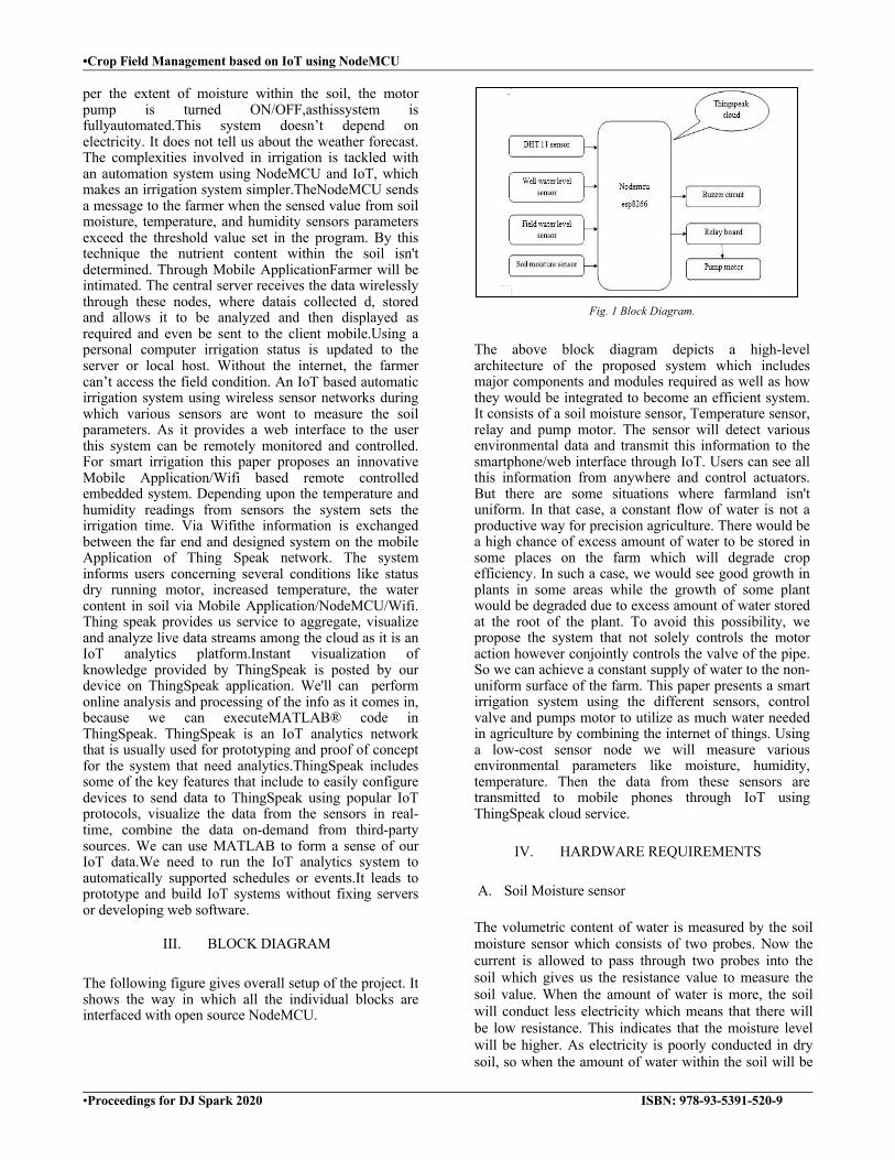
•Crop Field Management based on IoT using NodeMCU
•Proceedings for DJ Spark 2020 ISBN: 978-93-5391-520-9
per the extent of moisture within the soil, the motor pump is turned ON/OFF,asthissystem is fullyautomated.This system doesn’t depend on electricity. It does not tell us about the weather forecast. The complexities involved in irrigation is tackled with an automation system using NodeMCU and IoT, which makes an irrigation system simpler.TheNodeMCU sends a message to the farmer when the sensed value from soil moisture, temperature, and humidity sensors parameters exceed the threshold value set in the program. By this technique the nutrient content within the soil isn't determined. Through Mobile ApplicationFarmer will be intimated. The central server receives the data wirelessly through these nodes, where datais collected d, stored and allows it to be analyzed and then displayed as required and even be sent to the client mobile.Using a personal computer irrigation status is updated to the server or local host. Without the internet, the farmer can’t access the field condition. An IoT based automatic irrigation system using wireless sensor networks during which various sensors are wont to measure the soil parameters. As it provides a web interface to the user this system can be remotely monitored and controlled. For smart irrigation this paper proposes an innovative Mobile Application/Wifi based remote controlled embedded system. Depending upon the temperature and humidity readings from sensors the system sets the irrigation time. Via Wifithe information is exchanged between the far end and designed system on the mobile Application of Thing Speak network. The system informs users concerning several conditions like status dry running motor, increased temperature, the water content in soil via Mobile Application/NodeMCU/Wifi. Thing speak provides us service to aggregate, visualize and analyze live data streams among the cloud as it is an IoT analytics platform.Instant visualization of knowledge provided by ThingSpeak is posted by our device on ThingSpeak application. We'll can perform online analysis and processing of the info as it comes in, because we can executeMATLAB® code in ThingSpeak. ThingSpeak is an IoT analytics network that is usually used for prototyping and proof of concept for the system that need analytics.ThingSpeak includes some of the key features that include to easily configure devices to send data to ThingSpeak using popular IoT protocols, visualize the data from the sensors in real-time, combine the data on-demand from third-party sources. We can use MATLAB to form a sense of our IoT data.We need to run the IoT analytics system to automatically supported schedules or events.It leads to prototype and build IoT systems without fixing servers or developing web software.
III. BLOCK DIAGRAM The following figure gives overall setup of the project. It shows the way in which all the individual blocks are interfaced with open source NodeMCU.
Fig. 1 Block Diagram.
The above block diagram depicts a high-level architecture of the proposed system which includes major components and modules required as well as how they would be integrated to become an efficient system. It consists of a soil moisture sensor, Temperature sensor, relay and pump motor. The sensor will detect various environmental data and transmit this information to the smartphone/web interface through IoT. Users can see all this information from anywhere and control actuators. But there are some situations where farmland isn't uniform. In that case, a constant flow of water is not a productive way for precision agriculture. There would be a high chance of excess amount of water to be stored in some places on the farm which will degrade crop efficiency. In such a case, we would see good growth in plants in some areas while the growth of some plant would be degraded due to excess amount of water stored at the root of the plant. To avoid this possibility, we propose the system that not solely controls the motor action however conjointly controls the valve of the pipe. So we can achieve a constant supply of water to the non-uniform surface of the farm. This paper presents a smart irrigation system using the different sensors, control valve and pumps motor to utilize as much water needed in agriculture by combining the internet of things. Using a low-cost sensor node we will measure various environmental parameters like moisture, humidity, temperature. Then the data from these sensors are transmitted to mobile phones through IoT using ThingSpeak cloud service.
IV. HARDWARE REQUIREMENTS A. Soil Moisture sensor
The volumetric content of water is measured by the soil moisture sensor which consists of two probes. Now the current is allowed to pass through two probes into the soil which gives us the resistance value to measure the soil value. When the amount of water is more, the soil will conduct less electricity which means that there will be low resistance. This indicates that the moisture level will be higher. As electricity is poorly conducted in dry soil, so when the amount of water within the soil will be
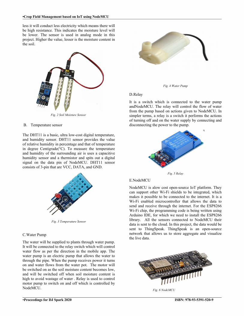
•Crop Field Management based on IoT using NodeMCU
•Proceedings for DJ Spark 2020 ISBN: 978-93-5391-520-9
less it will conduct less electricity which means there will be high resistance. This indicates the moisture level will be lower. The sensor is used in analog mode in this project. Higher the value, lesser is the moisture content in the soil.
Fig. 2 Soil Moisture Sensor
B. Temperature sensor The DHT11 is a basic, ultra low-cost digital temperature, and humidity sensor. DHT11 sensor provides the value of relative humidity in percentage and that of temperature in degree Centigrade(°C). To measure the temperature and humidity of the surrounding air is uses a capacitive humidity sensor and a thermistor and spits out a digital signal on the data pin of NodeMCU. DHT11 sensor consists of 3-pin that are VCC, DATA, and GND.
Fig. 3 Temperature Sensor
C.Water Pump
The water will be supplied to plants through water pump. It will be connected to the relay switch which will control water flow as per the direction in the mobile app. The water pump is an electric pump that allows the water to through the pipe. When the pump receives power it turns on and water flows from the water pot. The motor will be switched on as the soil moisture content becomes low, and will be switched off when soil moisture content is high to avoid wastage of water . Relay is used to control motor pump to switch on and off which is controlled by NodeMCU.
Fig. 4 Water Pump
D.Relay
It is a switch which is connected to the water pump andNodeMCU. The relay will control the flow of water from the pump based on actions given to NodeMCU. In simpler terms, a relay is a switch it performs the actions of turning off and on the water supply by connecting and disconnecting the power to the pump.
Fig. 5 Relay
E.NodeMCU
NodeMCU is alow cost open-source IoT platform. They can support other Wi-Fi shields to be integrated, which makes it possible to be connected to the internet. It is a Wi-Fi enabled microcontroller that allows the data to send and receive through the internet. For the ESP8266 Wi-Fi chip, the programming code is being written using Arduino IDE, for which we need to install the ESP8266 library. All the sensors connected to NodeMCU their data is sent to the cloud. In this project, the data would be sent to ThingSpeak. ThingSpeak is an open-source network that allows us to store aggregate and visualize the live data.
Fig. 6 NodeMCU

•Crop Field Management based on IoT using NodeMCU
•Proceedings for DJ Spark 2020 ISBN: 978-93-5391-520-9
F. Thingspeak ThingSpeak is an IoT analytics network which allows the data to be sent to the cloud from sensors, instruments, and websites where it is stored in a private or public channel. The data is stored in the private channel by default, and if we want to share the data with others then we need to use public channels. The data from the NodeMCU is sent to the ThingSpeak Server and its Mobile application. The ThingSpeak would analyze the data and plot a graph of the soil moisture and water level, Temperature, Humidity, etc for the ease of Farmer to understand. It would also send notifications about the current status of water level and soil moisture timely.
V.RESULT In this project Internet of Things controls the motor which depends upon temperature, humidity, and soil moisture level. The sensors measure the temperature, soil moisture, and humidity, depending upon the level of soil the motor will be switched ON/OFF automatically without human intervention.
Fig. 7 Snapshot of Implementation
As shown in the below figure 8 9and 10, these are visual graphs that appear on the screen of the phone and laptop of user to see the data and according to this data, the motor is switched ON/OFF.
Fig. 8 Snapshot of temperature in ThinkSpeak.
Fig. 9 Snapshot of Soil Moisture in ThinkSpeak
Fig. 10 Snapshot of Humidity in ThinkSpeak.
VI.CONCLUSION
Product quality, higher crop productivity, resource conservation, and cost control are just a few of the ways the Crop field irrigation Internet of Things promises to transform farming and food production in the future. It helps to increase crop productivity by managing and controlling such activities. A sufficient amount of water supply is essential for agriculture; crops can be damaged by either excess of water or shortage. The crop field irrigation using IoT has been experimentally proven to work satisfactorily by monitoring the values of humidity and temperature successfully. The motor in the field is controlled through the internet. It also stores the sensor parameters on time. This system will help the user to examine and analyze the conditions of various parameters in the field anytime anywhere. He can then control or maintain the parameters of the field properly. Finally, we conclude that automatic irrigation system is more efficient to use.
ACKNOWLEDGMENT
Firstly, we'd wish to extend our sincere due to Prof. Revathi A.S our guide for her guidance and constant supervision likewise as for providing necessary information regarding the project. We'd wish to express our gratitude towards Dr. Hari Vasudevan, our Principal, for granting us the utilization of the school library for the

•Crop Field Management based on IoT using NodeMCU
•Proceedings for DJ Spark 2020 ISBN: 978-93-5391-520-9
reference of this project, likewise as ourHead of Department and other faculty members and support staff for allowing us the utilization of school laboratories and internet facilities.
REFERENCES
[1] ChandanKumarSahu,Pramiteebehera,”A Low CostSmart Irrigation Control System,” IEEE sponsored 2ndICECS 2015.
[2] R.C.Gonzalez, R.E.Woods,”Color Image Processing,” in Digital Image Processing, 3rd ed., Pearson Education, Delhi, India, 2009, ch. 6, sec.7, pp465-466
[3] Joseph Haule, Kisangiri Michael, “Deployment of wireless sensor networks(WSN) in automated irrigation management and scheduling systems: a review”, Science, Computing and Telecommunicatons(PACT), 2014, Pan AfricanConference.
[4] K. Jyostsna Vanaja, Aala ,Suresh, S. Srilatha, K. Vijay Kumar, M. Bharath “IOT based Agriculture System Using NodeMCU” International Research Journal of Engineering (IRJET) vol 5,2013.
[5] M Anupama Reddy, D Anjaneyulu,”WSNin IoT environment interfacing with smart sensors using ARM7 with Zigbee for industries”, International Journal of Enginerring Research and Development 12(8), 54-60, 2016.
[6] Jairam Sankar, Ashik R,”IoT-based Smart Irrigation System and Nutrient DetectionwithDisease Analysis”, IEEE Region
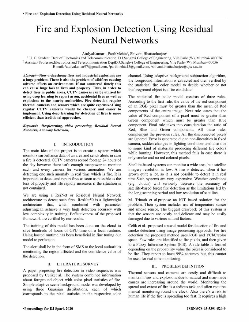
• Fire and Explosion Detection Using Residual Neural Networks
•Proceedings for DJ Spark 2020 ISBN:978-93-5391-520-9
Fire and Explosion Detection Using Residual Neural Networks
AtulyaKumar1, ParthMehta1, Shivani Bhattacharjee2 1 U. G. Student, Dept of Electronics and Telecommunication, D.J.Sanghvi College of Engineering, Vile Parle (W), Mumbai- 400056
2 Assistant Professor,Electronics and Telecommunication DeptD.J.Sanghvi College of Engineering, Vile Parle (W), Mumbai-400056 E-mail: [email protected], [email protected], [email protected]
Abstract—Now-a-dayshome fires and industrial explosions are a huge problem. There is also the problem of wildfires causing adverse effects on environment. If not countered timely this can cause huge loss to lives and property. Thus, in order to detect fires in public areas, CCTV cameras can be utilized by using deep learning to report arson, accidental fires as well as explosions to the nearby authorities. Fire detection require thermal cameras and sensors which are quite expensive.Using regular CCTV cameras would be cheaper and easier to implement. Using deep learning for detection of fires is more efficient than traditional approaches.
Keywords—Deeplearning, video processing, Residual Neural Networks, Anomaly Detection,
I. INTRODUCTION The main idea of the project is to create a system which monitors surveillance data of an area and sends alerts in case a fire is detected. CCTV cameras record footage 24 hours of the day however there isn’t enough manpower to monitor each and every camera for various anomalies. We are detecting one such anomaly in real time which is fire. It is important to detect and report fires as soon as possible as the loss of property and life rapidly increases if the situation is not contained.
We are using a ResNet or Residual Neural Network architecture to detect such fires. ResNet50 is a lightweight architecture that, when combined with parameter adjustingcan achieve a very high detection accuracy with low complexity in training. Eeffectiveness of the proposed framework are verified by our results.
The training of this model has been done on the cloud to save hundreds of hours of GPU time on a local runtime. Using hosted runtime has been beneficial in fine tuning our model to perfection.
The alert shall be in the form of SMS to the local authorities mentioning the region affected and the confidence value of the detection.
II. LITERATURE SURVEY A paper proposing fire detection in video sequences was proposed by Celiket al. The system combined information about foreground object with color pixel statistics of fire. Simple adaptive scene background model was developed by using three Gaussian distributions, each of which corresponds to the pixel statistics in the respective color
channel. Using adaptive background subtraction algorithm, the foreground information is extracted and then verified by the statistical fire color model to decide whether or not theforeground object is a fire candidate.
The statistical fire color model consists of three rules. According to the first rule, the value of the red component of an RGB pixel must be greater than the mean of Red components of the entire image. Next rule states that the value of Red component of a pixel must be greater than Green component which must be greater than Blue component. Final rule takes into consideration the ratio of Red, Blue and Green components. All these rules complement the previous rules. All the disconnected pixels are ignored. Error is generated due to non-linearities in fixed camera, sudden changes in lighting conditions and also due to some kind of materials producing different fire colors while burning. However, this method fails in case there is only smoke and no red colored pixels.
Satellite-based systems can monitor a wide area, but satellite imagery resolution is low. A fire is detected when it has grown quite a lot, so it is not possible to detect it in real time.Such systems are very expensive. Weather conditions (e.g. clouds) will seriously decrease the accuracy of satellite-based forest fire detection as the limitations led by the long scanning period and low resolution of satellites.
M. Trinath et al.propose an IOT based solution for the problem. Their system includes use of temperature sensor and smoke sensor. The biggest drawback of this system is that the sensors are costly and delicate and may be easily damaged due to various natural factors.
Celik et al. proposed a novel model for detection of fire and smoke detection using image processing approach. For fire detection the proposed method uses RGB and YCbCrcolor space. Few rules are identified to fire pixels, and then given to a Fuzzy Inference System (FIS). A rule table is formed depending on the probability value the pixel is considered to be fire. They report to have 99% accuracy but, this cannot be used for real time monitoring.
III. PROBLEM DEFINITION Thermal sensors and cameras are costly and difficult to maintain.Fires and explosions due to natural and man-made causes are increasing around the world. Monitoring the spread and extent of fire is a tedious task and often requires manual monitoring round the clock. Also there’s a risk to human life if the fire is spreading too fast. It requires a high
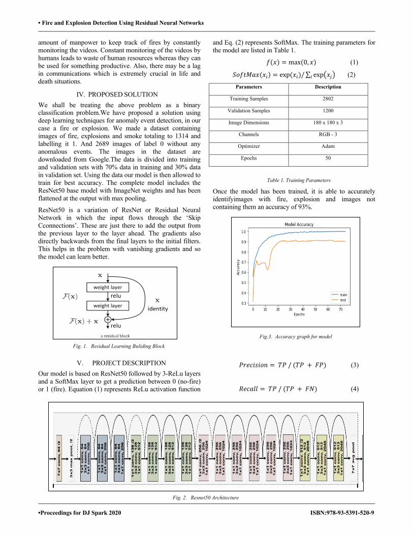
• Fire and Explosion Detection Using Residual Neural Networks
•Proceedings for DJ Spark 2020 ISBN:978-93-5391-520-9
amount of manpower to keep track of fires by constantly monitoring the videos. Constant monitoring of the videos by humans leads to waste of human resources whereas they can be used for something productive. Also, there may be a lag in communications which is extremely crucial in life and death situations.
IV. PROPOSED SOLUTION We shall be treating the above problem as a binary classification problem.We have proposed a solution using deep learning techniques for anomaly event detection, in our case a fire or explosion. We made a dataset containing images of fire, explosions and smoke totaling to 1314 and labelling it 1. And 2689 images of label 0 without any anomalous events. The images in the dataset are downloaded from Google.The data is divided into training and validation sets with 70% data in training and 30% data in validation set. Using the data our model is then allowed to train for best accuracy. The complete model includes the ResNet50 base model with ImageNet weights and has been flattened at the output with max pooling.
ResNet50 is a variation of ResNet or Residual Neural Network in which the input flows through the ‘Skip Cconnections’. These are just there to add the output from the previous layer to the layer ahead. The gradients also directly backwards from the final layers to the initial filters. This helps in the problem with vanishing gradients and so the model can learn better.
V. PROJECT DESCRIPTION Our model is based on ResNet50 followed by 3-ReLu layers and a SoftMax layer to get a prediction between 0 (no-fire) or 1 (fire). Equation (1) represents ReLu activation function
and Eq. (2) represents SoftMax. The training parameters for the model are listed in Table 1.
𝑓(𝑥) = max(0, 𝑥) (1)
𝑆𝑜𝑓𝑡𝑀𝑎𝑥(𝑥!) = exp(𝑥!)/∑ exp5𝑥"6! (2)
Parameters Description
Training Samples 2802
Validation Samples 1200
Image Dimensions 180 x 180 x 3
Channels RGB - 3
Optimizer Adam
Epochs 50
Table 1. Training Parameters
Once the model has been trained, it is able to accurately identifyimages with fire, explosion and images not containing them an accuracy of 93%.
𝑃𝑟𝑒𝑐𝑖𝑠𝑖𝑜𝑛 = 𝑇𝑃/(𝑇𝑃 + 𝐹𝑃) (3)
𝑅𝑒𝑐𝑎𝑙𝑙 = 𝑇𝑃/(𝑇𝑃 + 𝐹𝑁) (4)
Fig. 1. Residual Learning Buliding Block
Fig.3. Accuracy graph for model
Fig. 2. Resnet50 Architecture
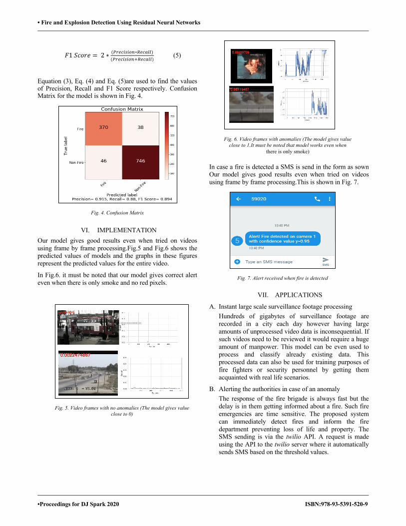
• Fire and Explosion Detection Using Residual Neural Networks
•Proceedings for DJ Spark 2020 ISBN:978-93-5391-520-9
𝐹1𝑆𝑐𝑜𝑟𝑒 = 2 ∗ ($%&'!(!)*∗,&'-..)($%&'!(!)*0,&'-..)
(5)
Equation (3), Eq. (4) and Eq. (5)are used to find the values of Precision, Recall and F1 Score respectively. Confusion Matrix for the model is shown in Fig. 4.
VI. IMPLEMENTATION Our model gives good results even when tried on videos using frame by frame processing.Fig.5 and Fig.6 shows the predicted values of models and the graphs in these figures represent the predicted values for the entire video.
In Fig.6. it must be noted that our model gives correct alert even when there is only smoke and no red pixels.
In case a fire is detected a SMS is send in the form as sown Our model gives good results even when tried on videos using frame by frame processing.This is shown in Fig. 7.
VII. APPLICATIONS
A. Instant large scale surveillance footage processing Hundreds of gigabytes of surveillance footage are recorded in a city each day however having large amounts of unprocessed video data is inconsequential. If such videos need to be reviewed it would require a huge amount of manpower. This model can be even used to process and classify already existing data. This processed data can also be used for training purposes of fire fighters or security personnel by getting them acquainted with real life scenarios.
B. Alerting the authorities in case of an anomaly The response of the fire brigade is always fast but the delay is in them getting informed about a fire. Such fire emergencies are time sensitive. The proposed system can immediately detect fires and inform the fire department preventing loss of life and property. The SMS sending is via the twilio API. A request is made using the API to the twilio server where it automatically sends SMS based on the threshold values.
Fig. 4. Confusion Matrix
Fig. 5. Video frames with no anomalies (The model gives value close to 0)
Fig. 6. Video frames with anomalies (The model gives value close to 1.It must be noted that model works even when
there is only smoke)
Fig. 7. Alert received when fire is detected
• Fire and Explosion Detection Using Residual Neural Networks
•Proceedings for DJ Spark 2020 ISBN:978-93-5391-520-9
C. Even in cases of explosion the appropriate authorities like police, fire brigades, ambulance and other government officials can be timely informed.
D. Wildfire Detection This system can also be installed in areas with high probabilities offorest fires as well as campsites. Since, wildfires spread at an alarming rate, timely response can be a huge life-saver.
E. Explosion and Fire Detection in Oil Refinires and Power Plants Even a small fire can lead to catastrophic consequences.If system is installed along with other fire prevention mechanisms. It will be a great boon.
F. Evidence Collection The system also proves useful for evidence collection by forensics in case of an Arson. This helps to greatly speed up the judicial process.
VIII. FUTURE SCOPE The above model only detects fire or explosions. In future this system can be combined along with a fire suppression system. The system can include water sprinklers or fire extinguishers. Moreover, transferring this system to GPU’s in future would make the process even faster.
IX. CONCLUSION In this paper, a real-time frame based efficient explosion and firedeep learning model has been presented with a very high accuracy score. The ResNet50 model is lightweight and has good detection capability. The training complexity and run time is lower than other deep learning techniques and gives better performance than the traditional techniques.
REFERENCES [1] T. Celik, H. Demirel, H. Ozkaramanli and M. Uyguroglu, “Fire
detection using statistical color model in video sequences”. [2] B.U.Toreyin, Y.Dedeoglu, A.E.Cetin, “Flame detection in video
using hidden Markov models”, Proceedings of IEEE International Conference on Image Processing, pp. 1230–1233,2005.
[3] Z. Li, S. Nadon, J. Cihlar, “Satellite detection of Canadian boreal forest fires: development and application of the algorithm”, International Journal of Remote Sensing, vol. 21, no. 16, pp. 3057- 3069, 2000.
[4] T. J. Lynham, C. W. Dull, and A. Singh, “Requirements for space- based observations in fire management: a report by the Wildland Fire Hazard Team, Committee on Earth Observation Satellites (CEOS) Disaster Management Support Group (DMSG),” IEEE International Geoscience and Remote Sensing Symposium, vol. 2, pp. 762-764, June 2002.
[5] M. Trinath Basu, Ragipati Karthik, J. Mahitha and V. Lokesh Reddy, “IoT based forest fire detection system”.
[6] T.Celik, H.Demirel, H.Ozkaramanli, “Fire and Smoke Detection without Sensors: Image Processing Based Approach”, Proceedings of 15th European Signal Processing Conference, Poland, September 3-7, 2007
[7] K. He, X. Zhang, S. Ren and J. Sun, “Deep Residual Learning for Image Recognition,” in CVPR, 2016.
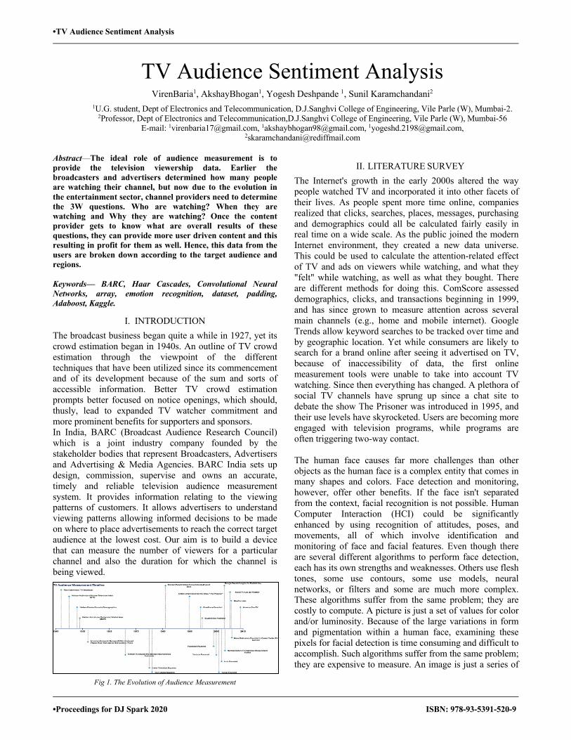
•TV Audience Sentiment Analysis `
•Proceedings for DJ Spark 2020 ISBN: 978-93-5391-520-9
TV Audience Sentiment Analysis VirenBaria1, AkshayBhogan1, Yogesh Deshpande 1, Sunil Karamchandani2
1U.G. student, Dept of Electronics and Telecommunication, D.J.Sanghvi College of Engineering, Vile Parle (W), Mumbai-2. 2Professor, Dept of Electronics and Telecommunication,D.J.Sanghvi College of Engineering, Vile Parle (W), Mumbai-56
E-mail: [email protected], [email protected], [email protected], [email protected]
Abstract—The ideal role of audience measurement is to provide the television viewership data. Earlier the broadcasters and advertisers determined how many people are watching their channel, but now due to the evolution in the entertainment sector, channel providers need to determine the 3W questions. Who are watching? When they are watching and Why they are watching? Once the content provider gets to know what are overall results of these questions, they can provide more user driven content and this resulting in profit for them as well. Hence, this data from the users are broken down according to the target audience and regions. Keywords— BARC, Haar Cascades, Convolutional Neural Networks, array, emotion recognition, dataset, padding, Adaboost, Kaggle.
I. INTRODUCTION The broadcast business began quite a while in 1927, yet its crowd estimation began in 1940s. An outline of TV crowd estimation through the viewpoint of the different techniques that have been utilized since its commencement and of its development because of the sum and sorts of accessible information. Better TV crowd estimation prompts better focused on notice openings, which should, thusly, lead to expanded TV watcher commitment and more prominent benefits for supporters and sponsors. In India, BARC (Broadcast Audience Research Council) which is a joint industry company founded by the stakeholder bodies that represent Broadcasters, Advertisers and Advertising & Media Agencies. BARC India sets up design, commission, supervise and owns an accurate, timely and reliable television audience measurement system. It provides information relating to the viewing patterns of customers. It allows advertisers to understand viewing patterns allowing informed decisions to be made on where to place advertisements to reach the correct target audience at the lowest cost. Our aim is to build a device that can measure the number of viewers for a particular channel and also the duration for which the channel is being viewed.
Fig 1. The Evolution of Audience Measurement
II. LITERATURE SURVEY The Internet's growth in the early 2000s altered the way people watched TV and incorporated it into other facets of their lives. As people spent more time online, companies realized that clicks, searches, places, messages, purchasing and demographics could all be calculated fairly easily in real time on a wide scale. As the public joined the modern Internet environment, they created a new data universe. This could be used to calculate the attention-related effect of TV and ads on viewers while watching, and what they "felt" while watching, as well as what they bought. There are different methods for doing this. ComScore assessed demographics, clicks, and transactions beginning in 1999, and has since grown to measure attention across several main channels (e.g., home and mobile internet). Google Trends allow keyword searches to be tracked over time and by geographic location. Yet while consumers are likely to search for a brand online after seeing it advertised on TV, because of inaccessibility of data, the first online measurement tools were unable to take into account TV watching. Since then everything has changed. A plethora of social TV channels have sprung up since a chat site to debate the show The Prisoner was introduced in 1995, and their use levels have skyrocketed. Users are becoming more engaged with television programs, while programs are often triggering two-way contact. The human face causes far more challenges than other objects as the human face is a complex entity that comes in many shapes and colors. Face detection and monitoring, however, offer other benefits. If the face isn't separated from the context, facial recognition is not possible. Human Computer Interaction (HCI) could be significantly enhanced by using recognition of attitudes, poses, and movements, all of which involve identification and monitoring of face and facial features. Even though there are several different algorithms to perform face detection, each has its own strengths and weaknesses. Others use flesh tones, some use contours, some use models, neural networks, or filters and some are much more complex. These algorithms suffer from the same problem; they are costly to compute. A picture is just a set of values for color and/or luminosity. Because of the large variations in form and pigmentation within a human face, examining these pixels for facial detection is time consuming and difficult to accomplish. Such algorithms suffer from the same problem; they are expensive to measure. An image is just a series of
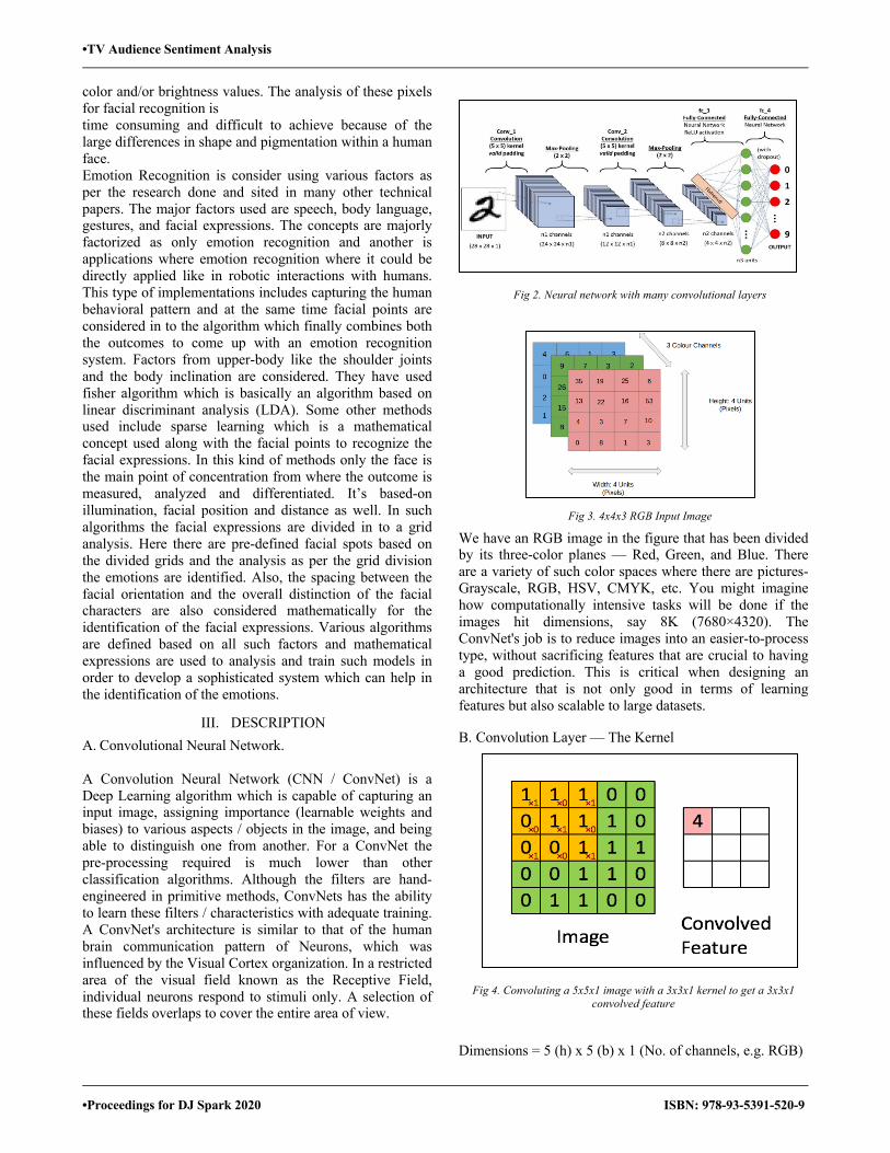
•TV Audience Sentiment Analysis `
•Proceedings for DJ Spark 2020 ISBN: 978-93-5391-520-9
color and/or brightness values. The analysis of these pixels for facial recognition is time consuming and difficult to achieve because of the large differences in shape and pigmentation within a human face. Emotion Recognition is consider using various factors as per the research done and sited in many other technical papers. The major factors used are speech, body language, gestures, and facial expressions. The concepts are majorly factorized as only emotion recognition and another is applications where emotion recognition where it could be directly applied like in robotic interactions with humans. This type of implementations includes capturing the human behavioral pattern and at the same time facial points are considered in to the algorithm which finally combines both the outcomes to come up with an emotion recognition system. Factors from upper-body like the shoulder joints and the body inclination are considered. They have used fisher algorithm which is basically an algorithm based on linear discriminant analysis (LDA). Some other methods used include sparse learning which is a mathematical concept used along with the facial points to recognize the facial expressions. In this kind of methods only the face is the main point of concentration from where the outcome is measured, analyzed and differentiated. It’s based-on illumination, facial position and distance as well. In such algorithms the facial expressions are divided in to a grid analysis. Here there are pre-defined facial spots based on the divided grids and the analysis as per the grid division the emotions are identified. Also, the spacing between the facial orientation and the overall distinction of the facial characters are also considered mathematically for the identification of the facial expressions. Various algorithms are defined based on all such factors and mathematical expressions are used to analysis and train such models in order to develop a sophisticated system which can help in the identification of the emotions.
III. DESCRIPTION A. Convolutional Neural Network. A Convolution Neural Network (CNN / ConvNet) is a Deep Learning algorithm which is capable of capturing an input image, assigning importance (learnable weights and biases) to various aspects / objects in the image, and being able to distinguish one from another. For a ConvNet the pre-processing required is much lower than other classification algorithms. Although the filters are hand-engineered in primitive methods, ConvNets has the ability to learn these filters / characteristics with adequate training. A ConvNet's architecture is similar to that of the human brain communication pattern of Neurons, which was influenced by the Visual Cortex organization. In a restricted area of the visual field known as the Receptive Field, individual neurons respond to stimuli only. A selection of these fields overlaps to cover the entire area of view.
Fig 2. Neural network with many convolutional layers
Fig 3. 4x4x3 RGB Input Image
We have an RGB image in the figure that has been divided by its three-color planes — Red, Green, and Blue. There are a variety of such color spaces where there are pictures-Grayscale, RGB, HSV, CMYK, etc. You might imagine how computationally intensive tasks will be done if the images hit dimensions, say 8K (7680×4320). The ConvNet's job is to reduce images into an easier-to-process type, without sacrificing features that are crucial to having a good prediction. This is critical when designing an architecture that is not only good in terms of learning features but also scalable to large datasets. B. Convolution Layer — The Kernel
Fig 4. Convoluting a 5x5x1 image with a 3x3x1 kernel to get a 3x3x1 convolved feature
Dimensions = 5 (h) x 5 (b) x 1 (No. of channels, e.g. RGB)
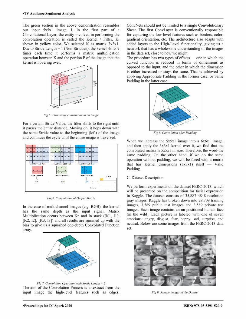
•TV Audience Sentiment Analysis `
•Proceedings for DJ Spark 2020 ISBN: 978-93-5391-520-9
The green section in the above demonstration resembles our input 5x5x1 image, I. In the first part of a Convolutional Layer, the entity involved in performing the convolution operation is called the Kernel / Filter, K, shown in yellow color. We selected K as matrix 3x3x1. Due to Stride Length = 1 (Non-Stridden), the kernel shifts 9 times each time it performs a matrix multiplication operation between K and the portion P of the image that the kernel is hovering over.
Fig 5. Visualizing convolution in an image
For a certain Stride Value, the filter shifts to the right until it parses the entire distance. Moving on, it hops down with the same Stride value to the beginning (left) of the image and continues the cycle until the entire image is traversed.
Fig 6. Computation of Output Matrix In the case of multichannel images (e.g. RGB), the kernel has the same depth as the input signal. Matrix Multiplication occurs between Kn and In stack ([K1, I1]; [K2, I2]; [K3, I3]) and all results are summed up with the bias to give us a squashed one-depth Convoluted Function array.
Fig 7. Convolution Operation with Stride Length = 2 The aim of the Convolution Process is to extract from the input image the high-level features such as edges.
ConvNets should not be limited to a single Convolutionary Sheet. The first ConvLayer is conventionally responsible for capturing the low-level features such as borders, color, gradient orientation, etc. The architecture also adapts with added layers to the High-Level functionality, giving us a network that has a wholesome understanding of the images in the data set, close to how we might. The procedure has two types of effects — one in which the curved function is reduced in terms of dimensions as opposed to the input, and the other in which the dimension is either increased or stays the same. That is achieved by applying Appropriate Padding in the former case, or Same Padding in the latter case.
Fig 8. Convolution after Padding
When we increase the 5x5x1 image into a 6x6x1 image, and then apply the 3x3x1 kernel over it, we find that the convoluted matrix is 5x5x1 in size. Therefore, the word-the same padding. On the other hand, if we do the same operation without padding, we will be faced with a matrix that has Kernel dimensions (3x3x1) itself — Valid Padding. C. Dataset Description
We perform experiments on the dataset FERC-2013, which will be presented on the competition for facial expression in Kaggle. The dataset consists of 35,887 4848 resolution gray images. Kaggle has broken down into 28,709 training images, 3,589 public test images and 3,589 private test images. Each image contains an un-positioned human face (in the wild). Each picture is labeled with one of seven emotions: angry, disgust, fear, happy, sad, surprise, and neutral. Below are some images from the FERC-2013 data set.
Fig 9. Sample images of the Dataset
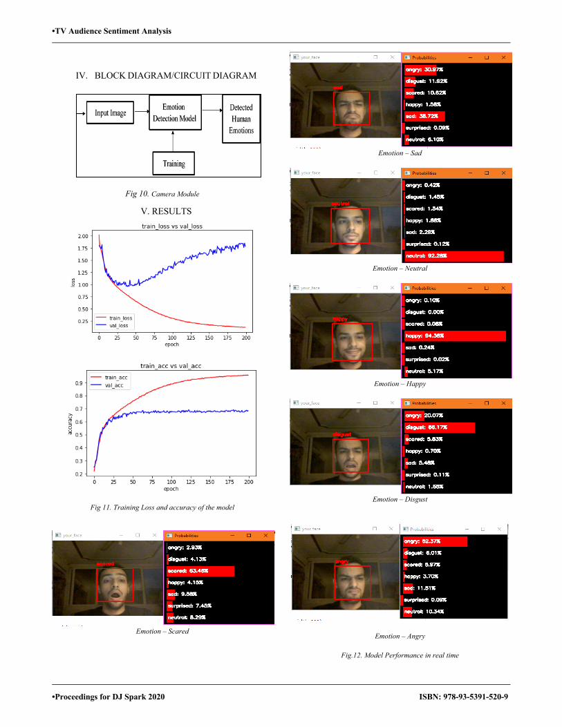
•TV Audience Sentiment Analysis `
•Proceedings for DJ Spark 2020 ISBN: 978-93-5391-520-9
IV. BLOCK DIAGRAM/CIRCUIT DIAGRAM
Fig 10. Camera Module
V. RESULTS
Fig 11. Training Loss and accuracy of the model
Emotion – Scared
Emotion – Sad
Emotion – Neutral
Emotion – Happy
Emotion – Disgust
Emotion – Angry
Fig.12. Model Performance in real time

•TV Audience Sentiment Analysis `
•Proceedings for DJ Spark 2020 ISBN: 978-93-5391-520-9
VI. CONCLUSION
Fig 13. Confusion Matrix with Accuracy
Using the system software, we could improvise the signal to noise ratios for the various allotted channels. The data fetched from the system could be used to develop the user and channel authorization system. Based on the external objectives like the user emotion recognition we were able to identify the systems allocated channel worth. The system hardware was verified to be stable enough to manage the channel data transmission as well as for the software-based emotion related data transfer.
VII. FUTURE SCOPE 1) The system can compute various important parameters
like TRP (Television Rating point), GRP (Gross Rating Point) etc. that effectively represents viewership of a particular channel. This collected data is of great value to various advertisement companies for optimizing their marketing framework. These companies will have access to the real time data that can be utilized to decide on how much resources are to be invested for advertising. Details like age distribution, gender distribution, and regional distribution etc. of the audience can boost the revenue of the companies as now they can access this information.
2) Taking advantage of the efficient, robust algorithm and transparent infrastructure any kind of manipulation in data can be avoided by collecting more samples and considering a wider demographic region.
3) For implementation customer is provided monthly subscription and other value-added offers. Also, he/she has the added privilege to control the content being displayed on the television as him watching a particular show will motivate the content providers to come up with more of that kind of shows.
4) Based on the viewership any vital information regarding various Government policies like Pradhan Mantri Jan Dhan Yojana (PMJDY), Pradhan Mantri Sukanya Samriddhi Yojana (PMSSY) or any measure to be implemented like demonetization can be spread more effectively over the required demographic areas.
5) Information regarding free medical camps, polling booths etc. can be advertised based this viewership data.
ACKNOWLEGEMENT
We would like to acknowledge our sincere thanks to the faculty members of Dwarkadas J. Sanghvi College of Engineering for their valuable guidance throughout the project. Special thanks to Prof. Sunil Karamchandani for guiding and reviewing the project as well as providing feedback at every stage of the project.
REFERENCES
[1] Gonzales and Woods, ―Digital Image Processingǁ, Pearson Education, India, Third Edition
[2] Singh, Prabhishek, and R. S. Chadha. "A survey of digital watermarking techniques, applications and attacks." International Journal of Engineering and Innovative Technology (IJEIT), 2013
[3] S. Hall, “TV audience measurement with big data,” Jun. 2014. [4] Sinha, Sanjana, PrajnatBardhan, SwarnaliPramanick,
AnkulJagatramka, Dipak K. Kole, and Aruna Chakraborty. "Digital video watermarking using discrete wavelet transform and principal component analysis." International Journal of Wisdom Based Computing, 2011.
[5] Wilson, Phillip Ian, and John Fernandez. "Facial feature detection using Haar classifiers." Journal of Computing Sciences in Colleges, 2006.
[6] Chen, Lawrence S., Thomas S. Huang, Tsutomu Miyasato, and RyoheiNakatsu. "Multimodal human emotion/expression recognition." In Proceedings Third IEEE International Conference on Automatic Face and Gesture Recognition, pp. 366-371. IEEE, 1998.
• Housing Affordability Model Using Python
•Proceedings for DJ Spark 2020 ISBN: 978-93-5391-520-9
Housing Affordability Model Using Python Advait Varma1, Chirag Thakkar1, MihirVithlani1,Mit Shah1, Ameya Kadam2
1U. G. Student, Dept of Electronics and Telecommunication, D.J.Sanghvi College of Engineering, Vile Parle (W), Mumbai-400056 2Assistant Professor, Electronics and Telecommunication Dept, D.J.Sanghvi College of Engineering, Vile Parle (W), Mumbai-400056
E-mail: [email protected], [email protected], [email protected], [email protected], [email protected]
Abstract—With the increasing property prices, the question arises whether an individual’s income in twenty years would enable him or her to afford a house despite the rising cost of public homeownership. Housing affordability is a concern that is mentioned frequently while describing factors like the current health and future outlook of real estate markets. Affordability holds a critical role in qualifying a borrower in the purchase of a home. This application model helps the user to find locations within the city to match ones budget. Logistic Regression, Decision Tree and Random Forest Algorithms are used to implement the decision using Python.
Keywords—Property prices, Individual’s income, Housing affordability, Logistic regression, Decision tree, Random forest, Python.
I. INTRODUCTION With the increasing property prices, the question arises whether an individual’s income in twenty years would enable him or her to afford a house despite the rising cost of public homeownership in Singapore. The measures of housing affordability that are used very frequently fundamentally include short-run indicators to compare current income with the cost of the houses. Despite the stress within the literature on the importance of long-term affordability, researchers haven't developed measures of lifetime income due to data constraints. Most of the developed countries publish annual household income by age of each of the house heads. Using these data for Singapore, we compute lifetime income from predicted annual household earnings over the working life for every birth cohort within the dataset. The lifetime income of Singapore households is divided into three income quantiles. This study throws new light on widening income gaps. The affordability index, defined because the ratio of lifetime income to deal with price, reveals informative trends and cycles in housing affordability in both the general public and therefore the private sectors.Our model revolves around determining the future value of disposable income after accounting for specific age group income and expenditure levels. Next, we compare the dollar amount of disposable income to determine amount of grants available to offset the forecasted price of a property to arrive at the final cost of homeownership in Singapore. We then derive the monthly mortgage payments and compare it against the dollar amount of disposable income to determine whether the individual can afford a property. The model computes, given age and income, whether a Singaporean would be able to afford a house or not after grants based on the dollar value of disposable income. We
are then able to determine affordability in the different kinds of estates in Singapore by 2040. Public housing is a crucial housing segment in Singapore, managed by the Housing and Development Board (HDB). With over 1 million flats completed across the nation, approximately 72% of Singaporean residents own these HDB flats. Homeowners can choose to either purchase new flats from Build-To-Order projects or transact in the resale market. Prices of HDB flats vary largely depending on the location of estates as well as the type of flats. Generally, the flats located in the mature estates are more expansive than those located in the non-mature estates for convenience, infrastructure and amenities in the areas. Within a HDB project, prices gradually step up from 2-room flats, 3-room flats, 4-room flats, 5-room flats to Executive Condominiums. Singapore government encourages home ownership by giving grants to qualified citizens and introducing housing loans. Besides, the Housing Development Board closely monitors and adjusts the housing prices based on the market and economic condition. However, there have been arguments and doubts concerning the degree of affordability of housing ownership in Singapore, especially given the high living cost in the country. Therefore, this report aims to examine whether public housing ownership in Singapore be affordable to its citizens in the next 20 years (2040). Housing affordability is a concern that is mentioned frequently while describing factors like the current health and future outlook of real estate markets. Affordability holds a critical role in qualifying a borrower in the purchase of a home. “What can I afford to buy?” is one of the first questions a potential home buyer asks himself/herself. There are countless thumb rules as to what one can afford, ranging anywhere from 2 times to as high as 5 times a buyer’s annual salary.
II. LITERATURE SURVEY Applied Machine Learning ProjectPrediction of real estate property prices analyzed the real estate property prices in Montreal. Real estate listings information was extracted from Centris.ca and duProprio.com. The listed and selling prices of real estate properties based on features such as geographical location, living area, and number of rooms, etc. were predicted using the model. The Montreal Open Data Portal was used to extract additional geographical features such as the nearest police station and fire station.
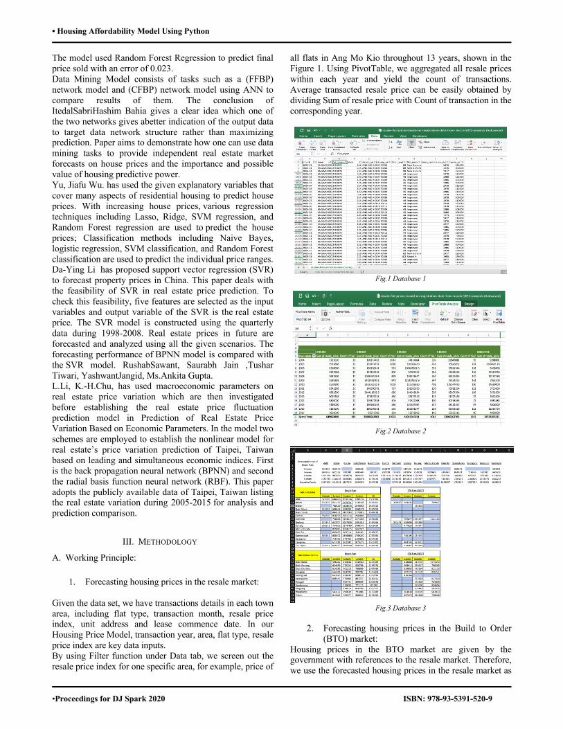
• Housing Affordability Model Using Python
•Proceedings for DJ Spark 2020 ISBN: 978-93-5391-520-9
The model used Random Forest Regression to predict final price sold with an error of 0.023. Data Mining Model consists of tasks such as a (FFBP) network model and (CFBP) network model using ANN to compare results of them. The conclusion of ItedalSabriHashim Bahia gives a clear idea which one of the two networks gives abetter indication of the output data to target data network structure rather than maximizing prediction. Paper aims to demonstrate how one can use data mining tasks to provide independent real estate market forecasts on house prices and the importance and possible value of housing predictive power. Yu, Jiafu Wu. has used the given explanatory variables that cover many aspects of residential housing to predict house prices. With increasing house prices, various regression techniques including Lasso, Ridge, SVM regression, and Random Forest regression are used to predict the house prices; Classification methods including Naive Bayes, logistic regression, SVM classification, and Random Forest classification are used to predict the individual price ranges. Da-Ying Li has proposed support vector regression (SVR) to forecast property prices in China. This paper deals with the feasibility of SVR in real estate price prediction. To check this feasibility, five features are selected as the input variables and output variable of the SVR is the real estate price. The SVR model is constructed using the quarterly data during 1998-2008. Real estate prices in future are forecasted and analyzed using all the given scenarios. The forecasting performance of BPNN model is compared with the SVR model. RushabSawant, Saurabh Jain ,Tushar Tiwari, YashwantJangid, Ms.Ankita Gupta. L.Li, K.-H.Chu, has used macroeconomic parameters on real estate price variation which are then investigated before establishing the real estate price fluctuation prediction model in Prediction of Real Estate Price Variation Based on Economic Parameters. In the model two schemes are employed to establish the nonlinear model for real estate’s price variation prediction of Taipei, Taiwan based on leading and simultaneous economic indices. First is the back propagation neural network (BPNN) and second the radial basis function neural network (RBF). This paper adopts the publicly available data of Taipei, Taiwan listing the real estate variation during 2005-2015 for analysis and prediction comparison.
III. METHODOLOGY
A. Working Principle:
1. Forecasting housing prices in the resale market: Given the data set, we have transactions details in each town area, including flat type, transaction month, resale price index, unit address and lease commence date. In our Housing Price Model, transaction year, area, flat type, resale price index are key data inputs. By using Filter function under Data tab, we screen out the resale price index for one specific area, for example, price of
all flats in Ang Mo Kio throughout 13 years, shown in the Figure 1. Using PivotTable, we aggregated all resale prices within each year and yield the count of transactions. Average transacted resale price can be easily obtained by dividing Sum of resale price with Count of transaction in the corresponding year.
Fig.1 Database 1
Fig.2 Database 2
Fig.3 Database 3
2. Forecasting housing prices in the Build to Order
(BTO) market: Housing prices in the BTO market are given by the government with references to the resale market. Therefore, we use the forecasted housing prices in the resale market as
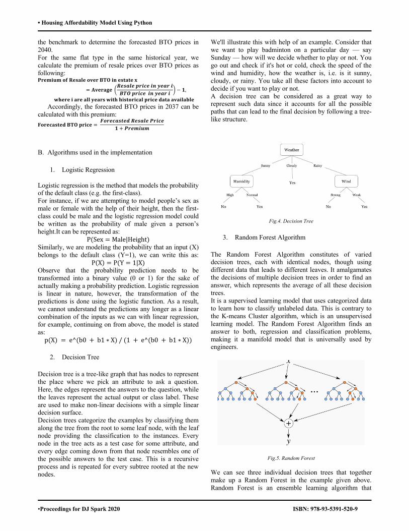
• Housing Affordability Model Using Python
•Proceedings for DJ Spark 2020 ISBN: 978-93-5391-520-9
the benchmark to determine the forecasted BTO prices in 2040. For the same flat type in the same historical year, we calculate the premium of resale prices over BTO prices as following: 𝐏𝐫𝐞𝐦𝐢𝐮𝐦𝐨𝐟𝐑𝐞𝐬𝐚𝐥𝐞𝐨𝐯𝐞𝐫𝐁𝐓𝐎𝐢𝐧𝐞𝐬𝐭𝐚𝐭𝐞𝐱
= 𝐀𝐯𝐞𝐫𝐚𝐠𝐞 8𝑹𝒆𝒔𝒂𝒍𝒆𝒑𝒓𝒊𝒄𝒆𝒊𝒏𝒚𝒆𝒂𝒓𝒊𝑩𝑻𝑶𝒑𝒓𝒊𝒄𝒆𝒊𝒏𝒚𝒆𝒂𝒓𝒊 G − 𝟏,
𝐰𝐡𝐞𝐫𝐞𝐢𝐚𝐫𝐞𝐚𝐥𝐥𝐲𝐞𝐚𝐫𝐬𝐰𝐢𝐭𝐡𝐡𝐢𝐬𝐭𝐨𝐫𝐢𝐜𝐚𝐥𝐩𝐫𝐢𝐜𝐞𝐝𝐚𝐭𝐚𝐚𝐯𝐚𝐢𝐥𝐚𝐛𝐥𝐞 Accordingly, the forecasted BTO prices in 2037 can be
calculated with this premium: 𝐅𝐨𝐫𝐞𝐜𝐚𝐬𝐭𝐞𝐝𝐁𝐓𝐎𝐩𝐫𝐢𝐜𝐞 =
𝑭𝒐𝒓𝒆𝒄𝒂𝒔𝒕𝒆𝒅𝑹𝒆𝒔𝒂𝒍𝒆𝑷𝒓𝒊𝒄𝒆𝟏 + 𝑷𝒓𝒆𝒎𝒊𝒖𝒎
B. Algorithms used in the implementation
1. Logistic Regression
Logistic regression is the method that models the probability of the default class (e.g. the first-class). For instance, if we are attempting to model people’s sex as male or female with the help of their height, then the first-class could be male and the logistic regression model could be written as the probability of male given a person’s height.It can be represented as:
P(Sex = Male|Height) Similarly, we are modeling the probability that an input (X) belongs to the default class (Y=1), we can write this as:
P(X) = P(Y = 1|X)Observe that the probability prediction needs to be transformed into a binary value (0 or 1) for the sake of actually making a probability prediction. Logistic regression is linear in nature, however, the transformation of the predictions is done using the logistic function. As a result, we cannot understand the predictions any longer as a linear combination of the inputs as we can with linear regression, for example, continuing on from above, the model is stated as: p(X) = e^(b0 + b1 ∗ X)/(1 + e^(b0 + b1 ∗ X))
2. Decision Tree
Decision tree is a tree-like graph that has nodes to represent the place where we pick an attribute to ask a question. Here, the edges represent the answers to the question, while the leaves represent the actual output or class label. These are used to make non-linear decisions with a simple linear decision surface. Decision trees categorize the examples by classifying them along the tree from the root to some leaf node, with the leaf node providing the classification to the instances. Every node in the tree acts as a test case for some attribute, and every edge coming down from that node resembles one of the possible answers to the test case. This is a recursive process and is repeated for every subtree rooted at the new nodes.
We'll illustrate this with help of an example. Consider that we want to play badminton on a particular day — say Sunday — how will we decide whether to play or not. You go out and check if it's hot or cold, check the speed of the wind and humidity, how the weather is, i.e. is it sunny, cloudy, or rainy. You take all these factors into account to decide if you want to play or not. A decision tree can be considered as a great way to represent such data since it accounts for all the possible paths that can lead to the final decision by following a tree-like structure.
Fig.4. Decision Tree
3. Random Forest Algorithm
The Random Forest Algorithm constitutes of varied decision trees, each with identical nodes, though using different data that leads to different leaves. It amalgamates the decisions of multiple decision trees in order to find an answer, which represents the average of all these decision trees. It is a supervised learning model that uses categorized data to learn how to classify unlabeled data. This is contrary to the K-means Cluster algorithm, which is an unsupervised learning model. The Random Forest Algorithm finds an answer to both, regression and classification problems, making it a manifold model that is universally used by engineers.
Fig.5. Random Forest We can see three individual decision trees that together make up a Random Forest in the example given above. Random Forest is an ensemble learning algorithm that

• Housing Affordability Model Using Python
•Proceedings for DJ Spark 2020 ISBN: 978-93-5391-520-9
helps to create more accurate results by using various models for inferencing. The algorithm uses the leaves, or final decisions, of each node to come to its own inference. The accuracy of the model is improved as it is comparing the results of various decision trees and finding an average.
4. Feature Extraction: Sometimes, a dataset may include some features that may not be as important as other features. Such features do not help much in classifying data or sometimes may lead to low accuracy. It is important to select the best features so that a better and efficient model is created. Using same features, again and again, can cause overfitting and underfitting of data. Techniques such as k-fold cross-validation can be used to solve overfitting. This will help in constructing a better model. Prediction of the house price is dependent on some of the major features of the house and few of them are Location, Parking, Amenities, Stamp Duty Rate, Number of rooms, Nearby Places(Hospitals, Railway Station,Gardens), Facing towards, etc.
C. Assumptions: 1) A citizen who plans to own a HDB flat will allocate all
of his or her disposable income to the monthly mortgage payment. In addition, it is assumed that the interested candidate has sufficient amount of savings for the down payment.
2) The total population in Singapore will grow by 2% every year.
3) Average disposable income per household will grow by 4% every year.
4) HDB loan rate will stay constant for the next 20 years as it did for the last 14 years.
5) HDB income ceilings that qualify a user to buy a BTO will be moderated upwards over the next 20 years as it has been for the last 10 years.
6) HDB grants stay the same for the next 20 years. 7) Resale activities for 2-room flats are too low to be
significant. 8) The model assumes that all individuals fulfil the criteria
of owning a BTO flat. 9) Individual using the model meets the criteria of
applying and owning a HDB flat.
D. Flowcharts
Fig.7. Database Model
Fig.6. Process flowchart
IV. IMPLEMENTATION In this project, we will predict the output based on the following models:
1. Mortgage Loan Payment Model
With the forecasted housing prices, we can determine the amount of mortgage loan which is 80% of housing price deducting amount of grants if an interested buyer is eligible based on his or her income level. Singapore has two types of housing grants, namely Additional Housing Grants and Special Housing Grants, both are given based on applicants’ income level. The maximum amount of grants is $40,000. Special Housing Grants are only available for flats that are non-mature estates.
HDB loans has a rate that’s pegged to the CPF Ordinary Account Interest Rate (2.5%) plus a spread of 0.1% which sums up to be 2.6% per year. Using Excel payment function, the model will return required amount of monthly mortgage payment for different type of flats, mature and non-mature estates in the resale and BTO market.
2. Disposable Income Model
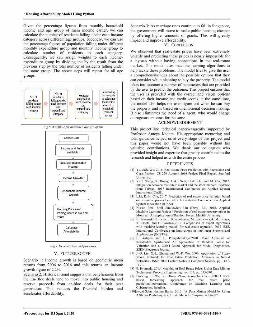
• Housing Affordability Model Using Python
•Proceedings for DJ Spark 2020 ISBN: 978-93-5391-520-9
Given the percentage figures from monthly household income and age group of main income earner, we can calculate the number of residents falling under each income category across different age groups. Secondly, we can use the percentage figures of population falling under different monthly expenditure group and monthly income group to calculate number of residents in each category. Consequently, we can assign weights to each income-expenditure group by dividing the by the result from the previous step by the total number of residents falling under the same group. The above steps will repeat for all age groups.
Fig.8. Workflow for individual age-group tab
Fig.9. General steps and processes
V. FUTURE SCOPE Scenario 1: Income growth is based on geometric mean returns from 2006 to 2016 and this returns an income growth figure of 2.2%. Scenario 2: Historical trend suggests that beneficiaries from the En-Bloc deals tend to move into public housing and reserve proceeds from en-bloc deals for their next generation. This reduces the financial burden and accelerates affordability.
Scenario 3: As marriage rates continue to fall in Singapore, the government will move to make public housing cheaper by offering higher amounts of grants. This will greatly impact and improve affordability.
VI. CONCLUSION We observed that real-estate prices have been extremely volatile and predicting these prices is nearly impossible for a layman without having connections in the real-estate market. This model uses machine learning algorithms to help tackle these problems. The model tries to give the user a comprehensive idea about the possible options that they can consider while planning to buy the property. The model takes into account a number of parameters that are provided by the user to predict the outcome. This project ensures that the user is provided with the correct and viable options based on their income and credit scores, at the same time, the model also helps the user figure out when he can buy the property and is based on unemotional decision making. It also eliminates the need of a agent, who would charge outrageous amounts for the same.
ACKNOWLEDGEMENT This project and technical paperwasgreatly supported by Professor Ameya Kadam. His appropriate mentoring and total guidance helped us at every stage of this project and this paper would not have been possible without his valuable contributions. We thank our colleagues who provided insight and expertise that greatly contributed to the research and helped us with the entire process.
REFERENCES [1] Yu, Jiafu Wu. 2016. Real Estate Price Prediction with Regression and
Classification, CS 229 Autumn 2016 Project Final Report, Stanford University.
[2] Y.-C. Wang, R. Huang, C.-C. Nieh, H.-K. Ou, and M. Chi, 2017. Integration between real estate market and the stock market: Evidence from Taiwan, 2017 International Conference on Applied System Innovation (ICASI).
[3] L.Li, K.-H. Chu, 2017. Prediction of real estate price variation based on economic parameters, 2017 International Conference on Applied System Innovation (ICASI).
[4] Nissan Pow, Emil Janulewicz, Liu (Dave) Liu, 2016. Applied Machine Learning Project 4 Prediction of real estate property prices in Montreal: An application of Random Forest, McGill University.
[5] B. Trawinski, Z. Telec, J. Krasnoborski, M. Piwowarczyk, M. Talaga, T. Lasota, and E. Sawilow,2017. Comparison of expert algorithms with machine learning models for real estate appraisal, 2017 IEEE International Conference on Innovations in Intelligent Systems and Applications (INISTA).
[6] E. Antipov and E. Pokryshevskaya,2010. Mass Appraisal of Residential Apartments: An Application of Random Forest for Valuation and a CART-Based Approach for Model Diagnostics, SSRN Electronic Journal.
[7] J.-G. Liu, X.-L. Zhang, and W.-P. Wu, 2006. Application of Fuzzy Neural Network for Real Estate Prediction, Advances in Neural Networks - ISNN 2006 Lecture Notes in Computer Science, pp. 1187-1191.
[8] E. Hromada, 2015. Mapping of Real Estate Prices Using Data Mining Techniques, Procedia Engineering, vol. 123, pp. 233-240.
[9] Da-Ying Li, Wei Xu, Hong Zhao, Rong-Qiu Chen, 2009.A SVR based forecasting approach for real estate price prediction,International Conference on Machine Learning and Cybernetics, Baoding.
[10] Itedal Sabri Hashim Bahia, 2013, “A Data Mining Model by Using ANN for Predicting Real Estate Market: Comparative Study”
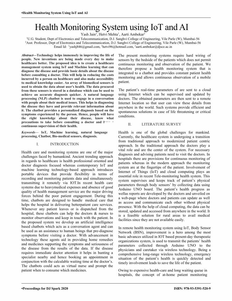
•Health Monitoring System Using IoT and AI
•Proceedings for DJ Spark 2020 ISBN: 978-93-5391-520-9
Health Monitoring System using IoT and AI Yash Jain1, Hetvi Mehta1, Aarti Ambekar2
1U.G. Student, Dept of Electronics and Telecommunication, D.J. Sanghvi College of Engineering, Vile Parle (W), Mumbai-56 2Asst. Professor, Dept of Electronics and Telecommunication, D.J. Sanghvi College of Engineering, Vile Parle (W), Mumbai-56
Email Id: [email protected], [email protected], [email protected]
Abstract—Technology helps immensely in improving the life of people. New inventions are being made every day to make healthcare better. The proposed idea is to create a healthcare management system using IoT and Machine learning that can diagnose the disease and provide basic details about the disease before consulting a doctor. This will help in reducing the costs incurred by a person on healthcare and also make accessibility to medical knowledge easier. An array of biomedical sensors is used to obtain the data about user's health. The data procured from these sensors is stored in a database which can be used to achieve an accurate diagnosis quicker. A natural language processing (NLP) chatbot is used to engage in a conversation with people about their medical issues. This helps in diagnosing the disease they have and provide relevant information about it. The chatbot provides a personalized diagnosis based on the symptoms experienced by the person. Hence, people will have the right knowledge about their disease, know what precautions to take before consulting a doctor and have a continuous supervision of their health.
Keywords— IoT, Machine learning, natural language processing, Chatbot, Bio-medical sensors, diagnosis.
I. INTRODUCTION
Health care and monitoring systems are one of the major challenges faced by humankind. Ancient trending approach in regards to healthcare is health professional oriented and doctor diagnosis focused whereas contemporary IoT and machine learning technology-based approach introduces portable devices that provide flexibility in terms of recording and monitoring patients data and simultaneously transmitting it remotely via IOT.In recent health care systems due to heavymedical expenses and absence of good quality of health management service are the major driving forces behind the poor patient engagement. During this time, chatbots are designed to handle medical care that helps the hospital in delivering betterpatient care services. Whenever any patient leaves or is dispatched from the hospital, these chatbots can help the doctors & nurses to monitor observations and keep in touch with the patient. In the proposed system we develop an artificial intelligence based chatbots which acts as a conversation agent and can be used as an assistance to human beings that pre-diagnose symptoms before visiting a doctor. With advancement in technology these agents aid in providing home remedies and medicines supporting the symptoms and seriousness of the disease from the results of the data. If the disease requires immediate doctor attention it helps in hunting a specialist nearby and hence booking an appointment in conjunction with the calculable waiting time at the doctor’s. The chatbots could acts as virtual nurse and prompt the patient when to consume which medicines.
The present monitoring systems require hard wiring of sensors by the bedside of the patients which does not permit continuous monitoring and observation of the patient. We therefore propose a health monitoring system that is integrated to a chatbot and provides constant patient health monitoring and allows continuous observation of a mobile patient.
The patient’s real-time parameters of are sent to a cloud using Internet which can be supervised and updated by doctors. The obtained parameters are then sent to a remote Internet location so that user can view these details from anywhere in the world. Such systems provide efficient and spontaneous solutions in case of life threatening or critical conditions.
II. LITERATURE SURVEY
Health is one of the global challenges for mankind. Currently, the healthcare system is undergoing a transition from traditional approach to modernized patient centric approach. In the traditional approach the doctors play a vital role and are the center of the system. For necessary diagnosis and advising patients need to visit the doctors. In hospitals there are provisions for continuous monitoring of patients whereas in the modern approach the monitoring system are at the fingertips of the patient. Involvement of Internet of Things (IoT) and cloud computing plays an essential role in recent Tele-monitoring health system. This system supervises and keeps track of patient’s physical parameters through body sensors’ by collecting data using Arduino UNO board. The patient’s health progress as wellas reports are developed by the doctors and unveiled on a web-page where doctors and patients can update as well as access and communicate each other without physical presence. With the help of cloud computing, the data can be stored, updated and accessed from anywhere in the world. It is a feasible solution for rural areas to avail medical facilities since they are not available easily.
In remote health monitoring system using IoT, Body Sensor Network (BSN), improvement is a hero among the most basic advances utilized in IOT based present-day therapeutic organizations system, is used to transmit the patients’ health parameters collected through Arduino UNO to the physicians and caretaker via wireless technology. Being a comprehensive long-range wireless technology, emergency situation of the patient’s health is quickly detected and timely involvement leads to save the life of the patient.
Owing to expensive health-care and long waiting queue in hospitals, the concept of at-home patient monitoring
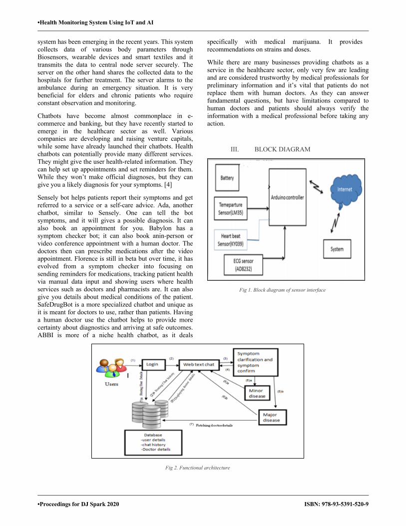
•Health Monitoring System Using IoT and AI
•Proceedings for DJ Spark 2020 ISBN: 978-93-5391-520-9
system has been emerging in the recent years. This system collects data of various body parameters through Biosensors, wearable devices and smart textiles and it transmits the data to central node server securely. The server on the other hand shares the collected data to the hospitals for further treatment. The server alarms to the ambulance during an emergency situation. It is very beneficial for elders and chronic patients who require constant observation and monitoring.
Chatbots have become almost commonplace in e-commerce and banking, but they have recently started to emerge in the healthcare sector as well. Various companies are developing and raising venture capitals, while some have already launched their chatbots. Health chatbots can potentially provide many different services. They might give the user health-related information. They can help set up appointments and set reminders for them. While they won’t make official diagnoses, but they can give you a likely diagnosis for your symptoms. [4]
Sensely bot helps patients report their symptoms and get referred to a service or a self-care advice. Ada, another chatbot, similar to Sensely. One can tell the bot symptoms, and it will gives a possible diagnosis. It can also book an appointment for you. Babylon has a symptom checker bot; it can also book anin-person or video conference appointment with a human doctor. The doctors then can prescribe medications after the video appointment. Florence is still in beta but over time, it has evolved from a symptom checker into focusing on sending reminders for medications, tracking patient health via manual data input and showing users where health services such as doctors and pharmacists are. It can also give you details about medical conditions of the patient. SafeDrugBot is a more specialized chatbot and unique as it is meant for doctors to use, rather than patients. Having a human doctor use the chatbot helps to provide more certainty about diagnostics and arriving at safe outcomes. ABBI is more of a niche health chatbot, as it deals
specifically with medical marijuana. It provides recommendations on strains and doses.
While there are many businesses providing chatbots as a service in the healthcare sector, only very few are leading and are considered trustworthy by medical professionals for preliminary information and it’s vital that patients do not replace them with human doctors. As they can answer fundamental questions, but have limitations compared to human doctors and patients should always verify the information with a medical professional before taking any action.
III. BLOCK DIAGRAM
Fig 1. Block diagram of sensor interface
Fig 2. Functional architecture

•Health Monitoring System Using IoT and AI
•Proceedings for DJ Spark 2020 ISBN: 978-93-5391-520-9
IV. WORKING PRINCIPLE
The proposed model comprises of a 3-Tier system.
Tier-1 consists of several biomedical sensors namely pulse sensor, body temperature sensor, blood pressure sensor, ECG sensor. All these sensors are placed on a human’s body to keep a record of the data which is helpful for an accurate diagnosis of a person’s medical problems. Pulse sensor keeps a continuous record of the person’s pulse, Blood pressure sensor measures a person’s blood pressure and a temperature sensor is used to keep a record of a person’s body temperature. All the sensors have been interfaced by an Arduino UNO as it is cheap, light in weight and functions smoothly well with these biomedical sensors. The sensor data received is stored in a database which forms the tier-2 of the model.
Tier-2 comprises of a database consisting of the data received from the various biomedical sensors. This helps in keeping a track of patients’ health which can help doctors come to their diagnosis quicker and more efficiently. It also helps the tier-3 of our proposed model to make accurate predictions and provide the . Correct preliminary diagnosis and the right medical knowledge of the disease to a person.
Tier-3 is a chatbot created with the help of supervised machine learning algorithms to engage in a conversation with a person using it. Firstly, the person enters its medical problems. These problems and the sensor data in the database are analyzed by the trained chatbot which comes to a decision and suggests the diagnosis depending on the symptoms entered by the user and the data from the database. Diseases are divided into minor disease and major diseases. If a minor disease is encountered by the chatbot, it will provide a diagnosis and the correct medical knowledge of it. If a major disease is encountered, it will suggest a doctor along with its details.
V. HARDWARE REQUIREMENTS
The hardware part constitutes the robotic arm which is primarily designed for lifting the waste and separating accordingly. For meeting these requirements, various components have been incorporated, as described below:
A. Temperature sensor
LM35D is one of the temperature sensor of the LM series. It is an analog temperature sensor used to measure the body temperature of a person. It can be interfaced with the Arduino UNO quite easily.
B. Arduino UNO
Arduino UNO is an Italian open-source hardware and Software company in addition to a project and user
community that is used to design and manufacture project kits for building of digital and interactive devices that can sense and control the digital world.
Fig 3. LM35D Temperature sensor
C. Pulse sensor
Pulse sensor is used to continuously measure the heartbeat of a person in beats per minute. It can easily be interfaced with the Arduino UNO.
Fig 5. Pulse sensor
VI. RESULTS AND IMPLEMENTATION
The chatbot implementation where a person suffers a hand ache is shown. The chatbot correctly collects the symptoms and suggests a treatment for it. Also, the chatbot provides the user with the relevant information.
Fig 4: Arduino Uno
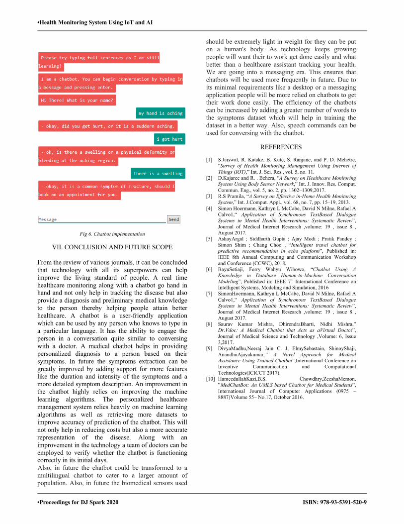
•Health Monitoring System Using IoT and AI
•Proceedings for DJ Spark 2020 ISBN: 978-93-5391-520-9
Fig 6. Chatbot implementation
VII. CONCLUSION AND FUTURE SCOPE
From the review of various journals, it can be concluded that technology with all its superpowers can help improve the living standard of people. A real time healthcare monitoring along with a chatbot go hand in hand and not only help in tracking the disease but also provide a diagnosis and preliminary medical knowledge to the person thereby helping people attain better healthcare. A chatbot is a user-friendly application which can be used by any person who knows to type in a particular language. It has the ability to engage the person in a conversation quite similar to conversing with a doctor. A medical chatbot helps in providing personalized diagnosis to a person based on their symptoms. In future the symptoms extraction can be greatly improved by adding support for more features like the duration and intensity of the symptoms and a more detailed symptom description. An improvement in the chatbot highly relies on improving the machine learning algorithms. The personalized healthcare management system relies heavily on machine learning algorithms as well as retrieving more datasets to improve accuracy of prediction of the chatbot. This will not only help in reducing costs but also a more accurate representation of the disease. Along with an improvement in the technology a team of doctors can be employed to verify whether the chatbot is functioning correctly in its initial days.
Also, in future the chatbot could be transformed to a multilingual chatbot to cater to a larger amount of population. Also, in future the biomedical sensors used
should be extremely light in weight for they can be put on a human's body. As technology keeps growing people will want their to work get done easily and what better than a healthcare assistant tracking your health. We are going into a messaging era. This ensures that chatbots will be used more frequently in future. Due to its minimal requirements like a desktop or a messaging application people will be more relied on chatbots to get their work done easily. The efficiency of the chatbots can be increased by adding a greater number of words to the symptoms dataset which will help in training the dataset in a better way. Also, speech commands can be used for conversing with the chatbot.
REFERENCES
[1] S.Jaiswal, R. Katake, B. Kute, S. Ranjane, and P. D. Mehetre, “Survey of Health Monitoring Management Using Internet of Things (IOT),” Int. J. Sci. Res., vol. 5, no. 11.
[2] D.Kajaree and R. . Behera, “A Survey on Healthcare Monitoring System Using Body Sensor Network,” Int. J. Innov. Res. Comput. Commun. Eng., vol. 5, no. 2, pp. 1302–1309,2017.
[3] R.S Pramila, “A Survey on Effective in-Home Health Monitoring System,” Int. J.Comput. Appl., vol. 68, no. 7, pp. 15–19, 2013.
[4] Simon Hoermann, Kathryn L McCabe, David N Milne, Rafael A Calvo1,“ Application of Synchronous TextBased Dialogue Systems in Mental Health Interventions: Systematic Review”, Journal of Medical Internet Research ,volume: 19 , issue 8 , August 2017.
[5] AshayArgal ; Siddharth Gupta ; Ajay Modi ; Pratik Pandey ; Simon Shim ; Chang Choo , “Intelligent travel chatbot for predictive recommendation in echo platform”, Published in: IEEE 8th Annual Computing and Communication Workshop and Conference (CCWC), 2018.
[6] BayuSetiaji, Ferry Wahyu Wibowo, “Chatbot Using A Knowledge in Database Human-to-Machine Conversation Modeling”, Published in: IEEE 7th International Conference on Intelligent Systems, Modeling and Simulation, 2016
[7] SimonHoermann, Kathryn L McCabe, David N Milne, Rafael A Calvo1,“ Application of Synchronous TextBased Dialogue Systems in Mental Health Interventions: Systematic Review”, Journal of Medical Internet Research ,volume: 19 , issue 8 , August 2017.
[8] Saurav Kumar Mishra, DhirendraBharti, Nidhi Mishra,” Dr.Vdoc: A Medical Chatbot that Acts as aVirtual Doctor”, Journal of Medical Science and Technology ,Volume: 6, Issue 3,2017.
[9] DivyaMadhu,Neeraj Jain C. J, ElmySebastain, ShinoyShaji, AnandhuAjayakumar,” A Novel Approach for Medical Assistance Using Trained Chatbot”,International Conference on Inventive Communication and Computational Technologies(ICICCT 2017).
[10] HameedullahKazi,B.S. Chowdhry,ZeeshaMemon, ”MedChatBot: An UMLS based Chatbot for Medical Students”, International Journal of Computer Applications (0975 – 8887)Volume 55– No.17, October 2016.
•Attendance Management using Face Recognition
• Proceedings for DJ SPARK 2020 ISBN: 978-93-5391-520-9
Attendance Management Using Face Recognition
Maitri Shah1, Vivek shah1, Rushabh shah1, Raj Shah1, Venkata Chavali2 1U. G. Student, Dept of Electronics and Telecommunication, D.J.Sanghvi College of Engineering, Vile Parle (W), Mumbai- 400056
2Assistant Professor, Dept of Electronics and Telecommunication, D.J.Sanghvi College of Engineering, Vile Parle (W), Mumbai-400056 E-mail: [email protected], [email protected], [email protected], [email protected],
Abstract—Face Recognition have contributed in major aspects in this modern world. Attendance System using Real-Time Face Recognition is a technique in order to maintain a record of attendance. Attendance using Face Recognition is a process of detecting the face of students for counting attendance using various algorithms and machine learning. In this face recognition project, a model will detect and recognize human faces quickly and precisely and real time images will be captured vial camera. Previously various algorithms and technologies have been developed for improvising the results of face recognition but in this paper, we have described the role of Machine Learning in the process of face recognition. Machine learning helps in the conversion of images into strings which recognizes the face of the student and fills the attendance sheet which is updated each time and attendance of the student is marked. Also, an email of the updated list is sent to the teacher.
Keywords – Face Detection, Database, Face Recognition, Attendance Marking, OpenCV, MySQL
I. INTRODUCTION Firstly, we retrospect the attendance system in the colleges where we answer our roll calls in the morning. It is a long and monotonous procedure for the teachers as well as students. Biometric technology has been very influential in managing the attendance system but the students have to wait in the queue which is also time consuming. So, implementing the Face Recognition Technology which identifies the most unique attribute of a human's face and stores the attendance of a person in the Database in fraction of seconds and the attendance of the student can be viewed anytime if it is to be sent to their parents for reporting them. Facial images can be captured from a distance and any special action is not required for authentication. Due to such characteristics, the face recognition technique is applied widely, not only to security applications but also to image indexing, image retrieval and natural user interface. This system strives to develop the constraints in the prevailing system by providing features such as detection of face, extraction of features, analysis of extracted features and student’s attendance. The Face will be recognized by storing images of the student from different angles and views the number of images stored per student will be around 300, so that if the student’s face is identified in any posture the attendance will be marked. The features of human usually identified are less likely to change frequently in the passing time like upper edges, regions around the cheekbones, sides of the mouth, nose shape and position of significant highlights comparative with one another.
II. WORKING PRINCIPLE
In order to generate a savvy attendance management system, few of these steps are necessary to accomplish the task efficiently. The steps used in the following process are:
A. Database Creation
B. Face Detection
C. Face Recognition
D. Attendance Marking
A. Database Creation
In this step, the student’s data such as Name, Sap I’d, Class is enrolled in the student database. Additionally, the database also consists of photos of children with 300 expressions clicked from a web camera for verification purposes. These pictures help in face recognition techniques and can be applied in order to match real time pictures for students attending the lecture.
B. Face Detection
In order to detect the faces, we will be specifying distinct features present on each and every student’s face. Based on the features of the face, the Viola and Jones algorithm will be used for face surrounding box detection and restricted local face tracking and face identification algorithm. C. Face Recognition For implementing the recognition of face in this prototype, we will be using local binary pattern histograms. The management of local binary patterns is very easy as it compares the assigned adjacent pixels of the image as a threshold ultimately resulting in a binary output. Then the recognized image is subjected to this Local binary pattern and it gives results in decimals which are represented as a histogram for each integral image. Face preprocessing is a technique which resolves issues such a brightness of the picture, contrast problems, noise factor that makes the picture unclear and makes sure that the facial features are always in position. Here we will be using histogram equalization for face pre-processing. For higher efficacy we use different pre-processing technique that is histogram equalization for left and right face. Hence, we do histogram equalization three times, initially it is done for the entire face
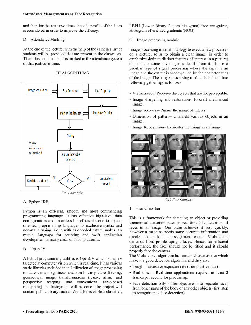
•Attendance Management using Face Recognition
• Proceedings for DJ SPARK 2020 ISBN: 978-93-5391-520-9
and then for the next two times the side profile of the faces is considered in order to improve the efficacy. D. Attendance Marking
At the end of the lecture, with the help of the camera a list of students will be provided that are present in the classroom. Then, this list of students is marked in the attendance system of that particular time.
III. ALGORITHMS
Fig .1 Algorithm A. Python IDE
Python is an efficient, smooth and most commanding programming language. It has effective high-level data configurations and an artless but efficient tactic to object-oriented programming language. Its exclusive syntax and non-static typing, along with its decoded nature, makes it a mutual language for scripting and swift application development in many areas on most platforms. B. OpenCV A hub of programming utilities is OpenCV which is mainly targeted at computer vision which is real-time. It has various static libraries included in it. Utilization of image processing module containing linear and non-linear picture filtering, geometrical image transformations (resize, affine and perspective warping, and conventional table-based remapping) and histograms will be done. The project will contain public library such as Viola-Jones or Hear classifier,
LBPH (Lower Binary Pattern histogram) face recognizer, Histogram of oriented gradients (HOG). C. Image processing module Image processing is a methodology to execute few processes on a picture, so as to obtain a clear image (in order to emphasize definite distinct features of interest in a picture) or to obtain some advantageous details from it. This is a peculiar type of signal processing where the input is an image and the output is accompanied by the characteristics of the image. The image processing method is isolated into following gatherings as follows: • Visualization- Perceive the objects that are not perceptible. • Image sharpening and restoration- To craft anenhanced
image. • Image recovery- Pursue the image of interest. • Dimension of pattern– Channels various objects in an
image. • Image Recognition– Extricates the things in an image.
Fig.2 Haar Classifier
1. Haar Classifier This is a framework for detecting an object or providing economical detection rates in real-time like detection of faces in an image. Our brain achieves it very quickly, however a machine needs some accurate information and checks. To make the assignment easier, Viola–Jones demands front profile upright faces. Hence, for efficient performance, the face should not be titled and it should properly face the camera. The Viola–Jones algorithm has certain characteristics which make it a good detection algorithm and they are: • Tough – excessive exposure rate (true-positive rate) • Real time – Real-time applications requires at least 2
frames per second for processing. • Face detection only - The objective is to separate faces
from other parts of the body or any other objects (first step to recognition is face detection).
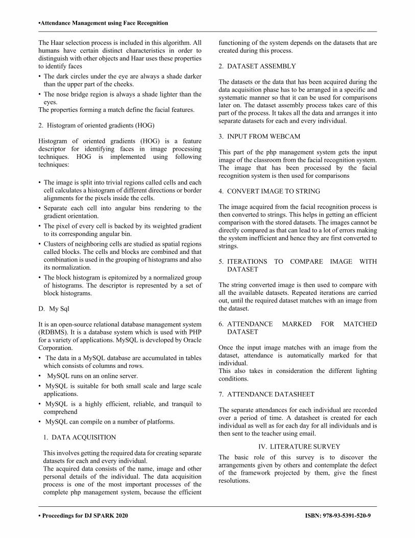
•Attendance Management using Face Recognition
• Proceedings for DJ SPARK 2020 ISBN: 978-93-5391-520-9
The Haar selection process is included in this algorithm. All humans have certain distinct characteristics in order to distinguish with other objects and Haar uses these properties to identify faces • The dark circles under the eye are always a shade darker
than the upper part of the cheeks. • The nose bridge region is always a shade lighter than the
eyes. The properties forming a match define the facial features. 2. Histogram of oriented gradients (HOG) Histogram of oriented gradients (HOG) is a feature descriptor for identifying faces in image processing techniques. HOG is implemented using following techniques: • The image is split into trivial regions called cells and each
cell calculates a histogram of different directions or border alignments for the pixels inside the cells. • Separate each cell into angular bins rendering to the
gradient orientation. • The pixel of every cell is backed by its weighted gradient
to its corresponding angular bin. • Clusters of neighboring cells are studied as spatial regions
called blocks. The cells and blocks are combined and that combination is used in the grouping of histograms and also its normalization. • The block histogram is epitomized by a normalized group
of histograms. The descriptor is represented by a set of block histograms.
D. My Sql It is an open-source relational database management system (RDBMS). It is a database system which is used with PHP for a variety of applications. MySQL is developed by Oracle Corporation. • The data in a MySQL database are accumulated in tables
which consists of columns and rows. • MySQL runs on an online server. • MySQL is suitable for both small scale and large scale
applications. • MySQL is a highly efficient, reliable, and tranquil to
comprehend • MySQL can compile on a number of platforms.
1. DATA ACQUISITION This involves getting the required data for creating separate datasets for each and every individual. The acquired data consists of the name, image and other personal details of the individual. The data acquisition process is one of the most important processes of the complete php management system, because the efficient
functioning of the system depends on the datasets that are created during this process.
2. DATASET ASSEMBLY The datasets or the data that has been acquired during the data acquisition phase has to be arranged in a specific and systematic manner so that it can be used for comparisons later on. The dataset assembly process takes care of this part of the process. It takes all the data and arranges it into separate datasets for each and every individual.
3. INPUT FROM WEBCAM This part of the php management system gets the input image of the classroom from the facial recognition system. The image that has been processed by the facial recognition system is then used for comparisons 4. CONVERT IMAGE TO STRING
The image acquired from the facial recognition process is then converted to strings. This helps in getting an efficient comparison with the stored datasets. The images cannot be directly compared as that can lead to a lot of errors making the system inefficient and hence they are first converted to strings.
5. ITERATIONS TO COMPARE IMAGE WITH
DATASET
The string converted image is then used to compare with all the available datasets. Repeated iterations are carried out, until the required dataset matches with an image from the dataset.
6. ATTENDANCE MARKED FOR MATCHED
DATASET
Once the input image matches with an image from the dataset, attendance is automatically marked for that individual. This also takes in consideration the different lighting conditions.
7. ATTENDANCE DATASHEET
The separate attendances for each individual are recorded over a period of time. A datasheet is created for each individual as well as for each day for all individuals and is then sent to the teacher using email.
IV. LITERATURE SURVEY The basic role of this survey is to discover the arrangements given by others and contemplate the defect of the framework projected by them, give the finest resolutions.
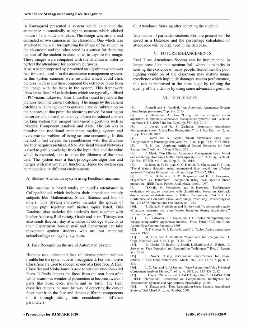
•Attendance Management using Face Recognition
• Proceedings for DJ SPARK 2020 ISBN: 978-93-5391-520-9
In Kawaguchi presented a system which calculated the attendance automatically using the cameras which clicked picture of the student in class. The design was simple and consisted of two cameras in the classroom. One which was attached to the wall for capturing the image of the student in the classroom and the other acted as a sensor for detecting the seat of the student in class so as to capture the image. These images were compared with the database in order to perfect the attendance for accuracy purposes. Also, a paper proposed by presented an algorithm which was real-time and used it in the attendance management system. In this system cameras were installed which could click pictures in class and then compared the extracted faces from the image with the faces in the system. This framework likewise utilized AI calculations which are typically utilized in PC vision. Likewise, Haar Classifiers used to prepare the pictures from the camera catching. The image by the camera catching will change over to grayscale and do subtraction on the pictures; at that point the picture is moved for storing on the server and is handled later. Jyotshana introduced a smart marking system that merged two varied algorithms such as Principal Component Analysis and ANN. The job was to dissolve the traditional attendance marking system and overcome its problem of being so time consuming. In this method it first detects the resemblances with the database and then acquires pictures. ANN (Artificial Neural Network) is used to gain knowledge from the input data and the value which is expected, also to solve the dilemma of the input data. The system uses a back-propagation algorithm and merges with mathematical functions. Hence the system can be recognized in different environments.
A. Student Attendance system using Feedback machine: This machine is based totally on pupil’s attendance in College/School which includes their attendance mainly subjects like Mathematics, Social Science and lots of others. This System moreover includes the grades of unique pupil together with his/her topics listed. This Database also includes the student’s facts together with his/her Address, Roll variety, Grade and so on. This system also sends thievery day attendance of college students to their Department through mail and Department can take movement against students who are not attending school/college on day by day basis. B. Face Recognition the use of Automated System: Humans can understand face of diverse people without trouble but the system doesn’t recognize it. For this motive Classifiers are used to recognize one of a kind face. A Haar Classifier and Viola-Jones is used to validate one-of-a-kind faces. It firstly detects the faces from the non-faces after which examines wonderful parameters to become aware of parts like nose, eyes, mouth and so forth. The Haar classifier detects the nose by way of detecting the darker facet near it on the face and detects different components of it through taking into consideration different parameters.
C. Attendance Marking after detecting the student: Attendance of particular students who are present will be saved in a Database and the percentage calculation of attendance will be displayed in the database.
V. FUTURE ENHANCEMENTS Real Time Attendance System can be implemented in larger areas like in a seminar hall where it benefits in sensing the existence of many people. Sometimes the poor lighting condition of the classroom may disturb image excellence which implicitly damages system performance, this can be improved in the latter stage by refining the quality of the video or by using some advanced algorithm.
VI. REFERENCES
[1]. Ahmedi and S. Nandyal, “An Automatic Attendance System Using Image processing,” pp. 1–8, 2015. [2]. V. Shehu and A. Dika, “Using real time computer vision algorithms in automatic attendance management systems,” Inf. Technol. Interfaces (ITI), 2010 32nd Int. Conf., pp. 397–402, 2010. [3]. J. Joseph and K. P. Zacharia, “Automatic Attendance Management System Using Face Recognition,” Int. J. Sci. Res., vol. 2, no. 11, pp. 327–330, 2013. [4]. J. Kanti and A. Papola, “Smart Attendance using Face Recognition with Percentage Analyzer,” vol. 3, no. 6, pp. 7321–7324, 2014. [5]. T. H. Le, “Applying Artificial Neural Networks for Face Recognition,” Adv. Artif. Neural Syst., 2011. [6]. P. Mehta, “An Efficient Attendance Management Sytem based on Face Recognition using Matlab and Raspberry Pi 2,” Int. J. Eng. Technol. Sci. Res. IJETSR, vol. 3, no. 5, pp. 71–78, 2016. [7]. S. Jeng, H. Y. M. Liao, C. C. Han, M. Y. Chern, and Y. T. Liu, “Facial feature detection using geometrical face model: An efficient approach,” Pattern Recognit., vol. 31, no. 3, pp. 273–282, 1998. [8]. P. N. Belhumeur, J. P. Hespanha, and D. J. Kriegman, “Eigenfaces vs. fisherfaces: Recognition using class specific linear projection,” IEEE Trans. Pattern Anal. Mach. Intell., 1997. [9. ]T.Ojala, M. Pietikainen, and D. Harwood, “Performance evaluation of texture measures with classification based on Kullback discrimination of distributions,” in Pattern Recognition, 1994. Vol. 1 - Conference A: Computer Vision amp; Image Processing., Proceedings of the 12th IAPR International Conference on, 1994. [10]. T. Ojala, M. Pietikäinen, and D. Harwood, “A comparative study of texture measures with classification based on feature distributions,” Pattern Recognit., 1996. [11]. G. J. Edwards, C. J. Taylor, and T. F. Cootes, “Interpreting face images using active appearance models,” Proc. Third IEEE Int. Conf. Autom. Face Gesture Recognit., 1998. [12]. T. F. Cootes, G. J. Edwards, and C. J. Taylor, Active appearance models. 1998. [13]. M. Turk and A. Pentland, “Eigenfaces for Recognition,” J. Cogn. Neurosci., vol. 3, no. 1, pp. 71–86, 1991. [14]. W. Haider, H. Bashir, A. Sharif, I. Sharif, and A. Wahab, “A Survey on Face Detection and Recognition Techniques,” Res. J. Recent Sci., 2014. [15]. L. Swets, “Using discriminant eigenfeatures for image retrieval,” IEEE Trans. Pattern Anal. Mach. Intell., vol. 18, no. 8, pp. 831–836, [16]. L. C. Paul and A. Al Sumam, “Face Recognition Using Principal Component Analysis Method,” vol. 1, no. 2012, pp. 135–139, 2012. [17]. I. Dagher, “Incremental PCA-LDA algorithm,” in CIMSA 2010 - IEEE International Conference on Computational Intelligence for Measurement Systems and Applications, Proceedings, 2010. [18]. Y. Kawaguchi, “Face Recognition-based Lecture Attendance System,” 3rd AEARU …, no. October, 2005.
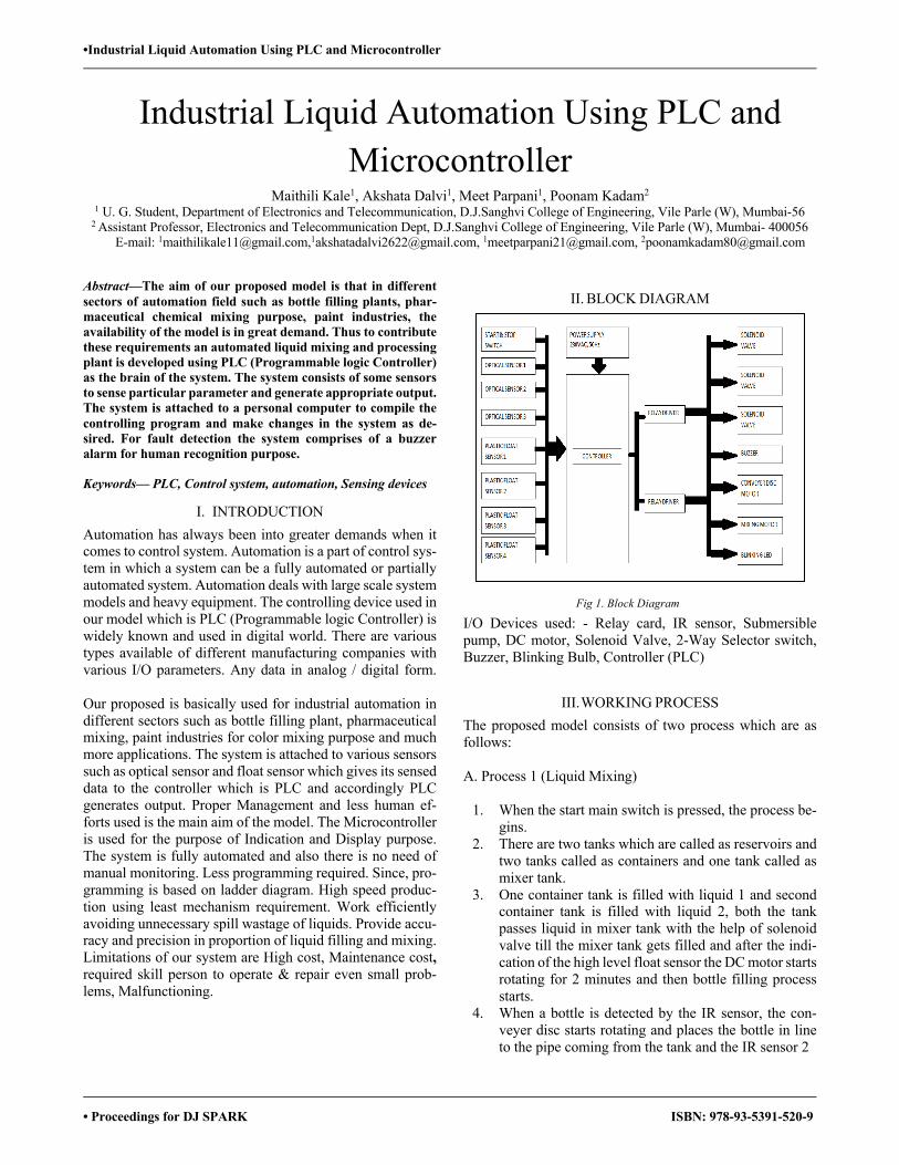
•Industrial Liquid Automation Using PLC and Microcontroller
• Proceedings for DJ SPARK ISBN: 978-93-5391-520-9
Industrial Liquid Automation Using PLC and Microcontroller
Maithili Kale1, Akshata Dalvi1, Meet Parpani1, Poonam Kadam2 1 U. G. Student, Department of Electronics and Telecommunication, D.J.Sanghvi College of Engineering, Vile Parle (W), Mumbai-56
2 Assistant Professor, Electronics and Telecommunication Dept, D.J.Sanghvi College of Engineering, Vile Parle (W), Mumbai- 400056 E-mail: [email protected],[email protected], [email protected], [email protected]
Abstract—The aim of our proposed model is that in different sectors of automation field such as bottle filling plants, phar-maceutical chemical mixing purpose, paint industries, the availability of the model is in great demand. Thus to contribute these requirements an automated liquid mixing and processing plant is developed using PLC (Programmable logic Controller) as the brain of the system. The system consists of some sensors to sense particular parameter and generate appropriate output. The system is attached to a personal computer to compile the controlling program and make changes in the system as de-sired. For fault detection the system comprises of a buzzer alarm for human recognition purpose.
Keywords— PLC, Control system, automation, Sensing devices
I. INTRODUCTION Automation has always been into greater demands when it comes to control system. Automation is a part of control sys-tem in which a system can be a fully automated or partially automated system. Automation deals with large scale system models and heavy equipment. The controlling device used in our model which is PLC (Programmable logic Controller) is widely known and used in digital world. There are various types available of different manufacturing companies with various I/O parameters. Any data in analog / digital form. Our proposed is basically used for industrial automation in different sectors such as bottle filling plant, pharmaceutical mixing, paint industries for color mixing purpose and much more applications. The system is attached to various sensors such as optical sensor and float sensor which gives its sensed data to the controller which is PLC and accordingly PLC generates output. Proper Management and less human ef-forts used is the main aim of the model. The Microcontroller is used for the purpose of Indication and Display purpose. The system is fully automated and also there is no need of manual monitoring. Less programming required. Since, pro-gramming is based on ladder diagram. High speed produc-tion using least mechanism requirement. Work efficiently avoiding unnecessary spill wastage of liquids. Provide accu-racy and precision in proportion of liquid filling and mixing. Limitations of our system are High cost, Maintenance cost, required skill person to operate & repair even small prob-lems, Malfunctioning.
II. BLOCK DIAGRAM
I/O Devices used: - Relay card, IR sensor, Submersible pump, DC motor, Solenoid Valve, 2-Way Selector switch, Buzzer, Blinking Bulb, Controller (PLC)
III. WORKING PROCESS The proposed model consists of two process which are as follows: A. Process 1 (Liquid Mixing)
1. When the start main switch is pressed, the process be-gins.
2. There are two tanks which are called as reservoirs and two tanks called as containers and one tank called as mixer tank.
3. One container tank is filled with liquid 1 and second container tank is filled with liquid 2, both the tank passes liquid in mixer tank with the help of solenoid valve till the mixer tank gets filled and after the indi-cation of the high level float sensor the DC motor starts rotating for 2 minutes and then bottle filling process starts.
4. When a bottle is detected by the IR sensor, the con-veyer disc starts rotating and places the bottle in line to the pipe coming from the tank and the IR sensor 2
Fig 1. Block Diagram

•Industrial Liquid Automation Using PLC and Microcontroller
• Proceedings for DJ SPARK ISBN: 978-93-5391-520-9
5. detects the bottle and starts liquid filling. It fills the bottle for few milliseconds delay.
6. Then again, the disc rotates and another bottle gets filled and the process goes on till the stop switch is pressed or both the tanks gets empty.
B. Process 2 (Tank Filling) There are total 5 tanks- 2 reservoirs, 2 container and 1 mixer tank. All the tanks are been attached with a float sensor to detect the level of liquid. When the low level of container tanks get detected, then solenoid valve of both the reservoir tanks gets activated for few milliseconds to fill the container tank. When the low level of mixer tank gets detected then both container tanks activate their solenoid valve and pass liquid to mixer tank till high level of the mixer tank is de-tected. When low level of reservoir tank gets detected then a buzzer gets activated indicating to refill the reservoirs.
IV.INTRODUCTION OF ALL HARDWARE I/O DEVICES
A. Programmable Logic Controller A programmable logic controller, PLC, or programmable controller is a digital computer used for automation of typi-cally industrial electromechanical processes, such as control of machinery on factory assembly lines, amusement rides, or light fixtures. PLCs are used in many machines, in many in-dustries. PLCs are designed for multiple arrangements of digital and analog inputs and outputs, extended temperature ranges, immunity to electrical noise, and resistance to vibra-tion and impact. Programs to control machine operation are typically stored in battery-backed-up or non-volatile memory. A PLC is an example of a "hard" real-time system since output results must be produced in response to input conditions within a limited time, otherwise unintended oper-ation will result. The main difference from other computers is that PLCs are armored for severe conditions (such as dust, moisture, heat, cold), and have the facility for extensive input/output ar-rangements. These connect the PLC to sensors and actuators. PLCs read limit switches, analog process variables (such as temperature and pressure), and the positions of complex po-sitioning systems. Some use machine vision. On the actuator side, PLCs operate electric motors, pneumatic or hydraulic cylinders, magnetic relays, solenoids, or analog outputs.
Software Tool To be used : V4.0 STEP 7 MicroWIN SP9. STEP- Siemens Technical Education Program. Model- PLC S7 200. Digital I/O Modules. Communication Cable used- PPI
B. Optical Sensor
TYPE P-N-P
CONTACT NO
OPERATING VOLTAGE RANGE
10-30 VOLTS
SENSITIVITY : TANSPARENT OBJECTS
SENSED AT 7cm
REFLECTIVE OBJECTS
SENSED AT 5cm
TYPE FIXED
NO. OF INPUTS 14 (DIGITAL)
NO. OF OUTPUTS 10 ( DIGITAL)
POWER SUPPLY 230V-AC/ 250V-AC
SOFTWARE USED V4.0 STEP7 MICROWIN
MODEL NO. 214-1BD22-0XB0
Fig 2. PLC Controller
Table 1: Specification of PLC
Fig 3. PLC Ladder diagram Programming
Table 2: Specification of Optical Sensor
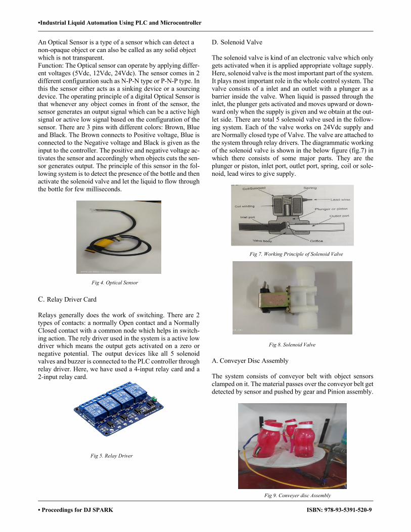
•Industrial Liquid Automation Using PLC and Microcontroller
• Proceedings for DJ SPARK ISBN: 978-93-5391-520-9
An Optical Sensor is a type of a sensor which can detect a non-opaque object or can also be called as any solid object which is not transparent. Function: The Optical sensor can operate by applying differ-ent voltages (5Vdc, 12Vdc, 24Vdc). The sensor comes in 2 different configuration such as N-P-N type or P-N-P type. In this the sensor either acts as a sinking device or a sourcing device. The operating principle of a digital Optical Sensor is that whenever any object comes in front of the sensor, the sensor generates an output signal which can be a active high signal or active low signal based on the configuration of the sensor. There are 3 pins with different colors: Brown, Blue and Black. The Brown connects to Positive voltage, Blue is connected to the Negative voltage and Black is given as the input to the controller. The positive and negative voltage ac-tivates the sensor and accordingly when objects cuts the sen-sor generates output. The principle of this sensor in the fol-lowing system is to detect the presence of the bottle and then activate the solenoid valve and let the liquid to flow through the bottle for few milliseconds.
C. Relay Driver Card
Relays generally does the work of switching. There are 2 types of contacts: a normally Open contact and a Normally Closed contact with a common node which helps in switch-ing action. The rely driver used in the system is a active low driver which means the output gets activated on a zero or negative potential. The output devices like all 5 solenoid valves and buzzer is connected to the PLC controller through relay driver. Here, we have used a 4-input relay card and a 2-input relay card.
D. Solenoid Valve
The solenoid valve is kind of an electronic valve which only gets activated when it is applied appropriate voltage supply. Here, solenoid valve is the most important part of the system. It plays most important role in the whole control system. The valve consists of a inlet and an outlet with a plunger as a barrier inside the valve. When liquid is passed through the inlet, the plunger gets activated and moves upward or down-ward only when the supply is given and we obtain at the out-let side. There are total 5 solenoid valve used in the follow-ing system. Each of the valve works on 24Vdc supply and are Normally closed type of Valve. The valve are attached to the system through relay drivers. The diagrammatic working of the solenoid valve is shown in the below figure (fig.7) in which there consists of some major parts. They are the plunger or piston, inlet port, outlet port, spring, coil or sole-noid, lead wires to give supply.
A. Conveyer Disc Assembly The system consists of conveyor belt with object sensors clamped on it. The material passes over the conveyor belt get detected by sensor and pushed by gear and Pinion assembly.
Fig 5. Relay Driver
Fig 7. Working Principle of Solenoid Valve
Fig 8. Solenoid Valve
8 Solenoid Valve
Fig 9. Conveyer disc Assembly
Fig 4. Optical Sensor
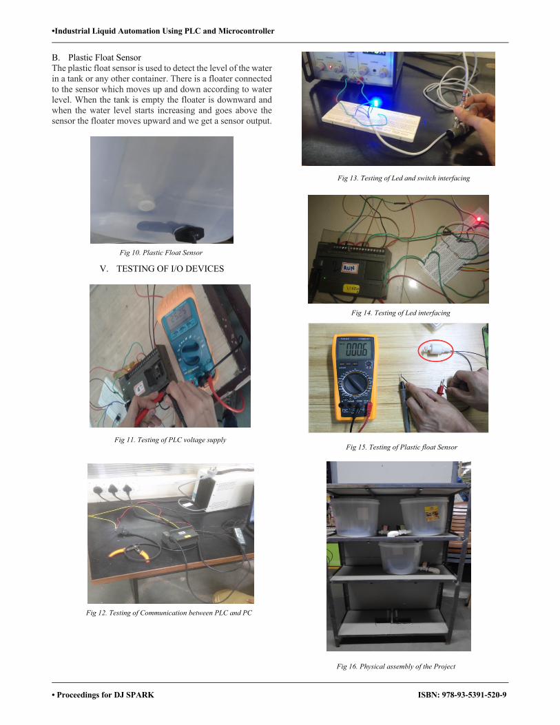
•Industrial Liquid Automation Using PLC and Microcontroller
• Proceedings for DJ SPARK ISBN: 978-93-5391-520-9
B. Plastic Float Sensor The plastic float sensor is used to detect the level of the water in a tank or any other container. There is a floater connected to the sensor which moves up and down according to water level. When the tank is empty the floater is downward and when the water level starts increasing and goes above the sensor the floater moves upward and we get a sensor output.
V. TESTING OF I/O DEVICES
Fig 10. Plastic Float Sensor
Fig 11. Testing of PLC voltage supply
Fig 13. Testing of Led and switch interfacing
Fig 14. Testing of Led interfacing
Fig 15. Testing of Plastic float Sensor
Fig 16. Physical assembly of the Project
Fig 12. Testing of Communication between PLC and PC
•Industrial Liquid Automation Using PLC and Microcontroller
• Proceedings for DJ SPARK ISBN: 978-93-5391-520-9
VI. CONCLUSION PLC are now-a-days can be too handy and easy to design, to monitor and to code using a ladder diagram logic. Our pro-posed is basically used for industrial automation in different sectors such as bottle filling plant, pharmaceutical mixing, paint industries for colour mixing purpose and much more applications. The main motive of our system to carry out liq-uid mixing and processing using Programmable Logic Con-troller. The design the whole system a literature survey was carried out in which the main concept used was SCADA which is upgrade of automation using PLC. Our system col-lects 2 different kind of liquid from reservoirs to small con-tainers and then mix them into another container and then carry out bottle filling process.
VII. APPLICATIONS Water management system, Process Industries, 3 –stage air conditioning system, Control of Planar machine.
REFERENCES [1]. K. Kalaivani, V. Anjalipriya, P. Surendar, “Monitoring and con-trol of grain storage using PLC”, Int. J. Res. Eng. Technol., vol. 1, no. 3, pp.282-288, 2012. [2]. S. Abdelhedi, K. Taouil, B. Hadjkacem, "Design of automatic vision based inspectionsystem for monitoring in an olive oil bottling line", Int. J. Comput. App., vol. 51, no. 21, pp. 39-46, 2012. [3] http://www.automation.siemens.com/mcms/programmable-logic-con-troller/en/Pages/Default.aspx
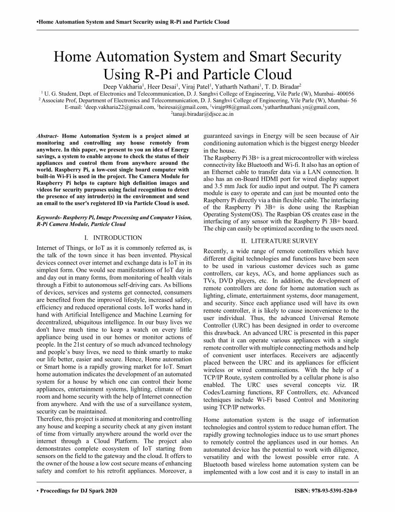
•Home Automation System and Smart Security using R-Pi and Particle Cloud
• Proceedings for DJ Spark 2020 ISBN: 978-93-5391-520-9
Home Automation System and Smart Security Using R-Pi and Particle CloudDeep Vakharia1, Heer Desai1, Viraj Patel1, Yatharth Nathani1, T. D. Biradar2
1 U. G. Student, Dept. of Electronics and Telecommunication, D. J. Sanghvi College of Engineering, Vile Parle (W), Mumbai- 400056 2 Associate Prof, Department of Electronics and Telecommunication, D. J. Sanghvi College of Engineering, Vile Parle (W), Mumbai- 56
E-mail: [email protected], [email protected], [email protected],[email protected], [email protected]
Abstract- Home Automation System is a project aimed at monitoring and controlling any house remotely from anywhere. In this paper, we present to you an idea of Energy savings, a system to enable anyone to check the status of their appliances and control them from anywhere around the world. Raspberry Pi, a low-cost single board computer with built-in Wi-Fi is used in the project. The Camera Module for Raspberry Pi helps to capture high definition images and videos for security purposes using facial recognition to detect the presence of any intruder(s) in the environment and send an email to the user's registered ID via Particle Cloud is used. Keywords- Raspberry Pi, Image Processing and Computer Vision, R-Pi Camera Module, Particle Cloud
I. INTRODUCTION Internet of Things, or IoT as it is commonly referred as, is the talk of the town since it has been invented. Physical devices connect over internet and exchange data is IoT in its simplest form. One would see manifestations of IoT day in and day out in many forms, from monitoring of health vitals through a Fitbit to autonomous self-driving cars. As billions of devices, services and systems get connected, consumers are benefited from the improved lifestyle, increased safety, efficiency and reduced operational costs. IoT works hand in hand with Artificial Intelligence and Machine Learning for decentralized, ubiquitous intelligence. In our busy lives we don't have much time to keep a watch on every little appliance being used in our homes or monitor actions of people. In the 21st century of so much advanced technology and people’s busy lives, we need to think smartly to make our life better, easier and secure. Hence, Home automation or Smart home is a rapidly growing market for IoT. Smart home automation indicates the development of an automated system for a house by which one can control their home appliances, entertainment systems, lighting, climate of the room and home security with the help of Internet connection from anywhere. And with the use of a surveillance system, security can be maintained. Therefore, this project is aimed at monitoring and controlling any house and keeping a security check at any given instant of time from virtually anywhere around the world over the internet through a Cloud Platform. The project also demonstrates complete ecosystem of IoT starting from sensors on the field to the gateway and the cloud. It offers to the owner of the house a low cost secure means of enhancing safety and comfort to his retrofit appliances. Moreover, a
guaranteed savings in Energy will be seen because of Air conditioning automation which is the biggest energy bleeder in the house. The Raspberry Pi 3B+ is a great microcontroller with wireless connectivity like Bluetooth and Wi-fi. It also has an option of an Ethernet cable to transfer data via a LAN connection. It also has an on-Board HDMI port for wired display support and 3.5 mm Jack for audio input and output. The Pi camera module is easy to operate and can just be mounted onto the Raspberry Pi directly via a thin flexible cable. The interfacing of the Raspberry Pi 3B+ is done using the Raspbian Operating System(OS). The Raspbian OS creates ease in the interfacing of any sensor with the Raspberry Pi 3B+ board. The chip can easily be optimized according to the users need.
II. LITERATURE SURVEY Recently, a wide range of remote controllers which have different digital technologies and functions have been seen to be used in various customer devices such as game controllers, car keys, ACs, and home appliances such as TVs, DVD players, etc. In addition, the development of remote controllers are done for home automation such as lighting, climate, entertainment systems, door management, and security. Since each appliance used will have its own remote controller, it is likely to cause inconvenience to the user individual. Thus, the advanced Universal Remote Controller (URC) has been designed in order to overcome this drawback. An advanced URC is presented in this paper such that it can operate various appliances with a single remote controller with multiple connecting methods and help of convenient user interfaces. Receivers are adjacently placed between the URC and its appliances for efficient wireless or wired communications. With the help of a TCP/IP Route, system controlled by a cellular phone is also enabled. The URC uses several concepts viz. IR Codes/Learning functions, RF Controllers, etc. Advanced techniques include Wi-Fi based Control and Monitoring using TCP/IP networks.
Home automation system is the usage of information technologies and control system to reduce human effort. The rapidly growing technologies induce us to use smart phones to remotely control the appliances used in our homes. An automated device has the potential to work with diligence, versatility and with the lowest possible error rate. A Bluetooth based wireless home automation system can be implemented with a low cost and it is easy to install in an
•Home Automation System and Smart Security using R-Pi and Particle Cloud
• Proceedings for DJ Spark 2020 ISBN: 978-93-5391-520-9
existing home, also they are found to be faster than Wireless and GSM systems. A low cost, user-friendly and robust home automation system using Bluetooth technology is proposed in this paper. Bluetooth module of HC-06 is ported with an Arduino board and home appliances are connected to the Arduino board via relay. An application on a smartphone is used for serial communication between the phone and Bluetooth module which is further interfaced with the Arduino board. Along with the ability to control appliances, it also has the ability to monitor sensors like a soil moisture sensor --- used for automating the irrigation system and ultrasonic sensor --- used for the detection of water level to provide more ease and facilities to users.[2] This paper deals with just security surveillance in the day to day life. It is a basic project which is based on a Raspberry Pi. The Pi camera module is used as a camera lens for the project. The notifications or alerts are sent via an SMS and it is based on a 3G modem. It doesn't support any other features like live streaming on Android devices or any wireless device. The project can't be used for any industrial purposes. The cost has been increased due to the use of a 3G modem. A GSM module could have done the job well for the project.[3]
III. BLOCK DIAGRAMS AND FIGURES
Fig 1. Raspberry Pi 3B+ Model
Fig 2. Raspberry Pi Camera Module
Fig 3. Communication between Raspberry Pi 3B+
Fig 4. Flowchart for Home Automation & Intrusion Detection

•Home Automation System and Smart Security using R-Pi and Particle Cloud
• Proceedings for DJ Spark 2020 ISBN: 978-93-5391-520-9
IV. DESIGN AND IMPLEMENTATION The above diagram shows complete implementation of Cloud based Home Automation and Intrusion detection System. The Raspberry Pi is the core of the system that acts as a Hub to which the sensors connect and also a gateway that exchanges the data with the Cloud. The entire project can be divided into two components: 1) Edge side implementation (Sensors-to-Gateway) The Edge side implementation consists of the Sensors that connect with the Raspberry Pi on a wired network (for demo). There is essentially two kinds of sensing and control in this implementation:
• Intrusion detection • Home Appliance Automation
The intrusion detection module consists of a PIR motion sensor and a Pi camera module. The PIR (Passive Infra Red) Sensor is an electronic sensor that has two slots each made of a special IR sensitive material that measures infrared light radiating from objects in the field of view. When a warm body like that of a human being trespasses, it first obstructs one half of the PIR sensor, which will cause a positive differential alteration between the two halves. When the human leaves the detecting area, the reverse happens, whereby the sensor generates a negative differential alteration. This change pulse is sensed and detected. The Pi camera module is activated when PIR sensor senses intruder. An email alert with the captured image is sent to the registered email ID as soon as the intrusion is detected. We intend to use Python script for implementing the Home security piece. The Home Appliance Automation module consists of a Temperature & humidity sensor DHT11 that measures the real time temperature. When the temperature crosses a given threshold, the application running on the RPi sends IR commands to the AC to switch the AC from cool mode to Fan mode or vice versa. Also, it is possible to switch the AC off from a web interface. In addition to this, a relay is connected to the RPi switches the Light connected to it On or Off depending on the commands pushed from the Web interface. We intend to use Python script through Particle agent to compile this piece. AC control through IR command is the challenging part. We intend to use the LIRC library on the Rasbian OS of raspberry Pi to decode the Signals of the Blue star AC. Again, a python script will be used for this. The Air conditioner IR commands are based on the NEC protocol which in its standard form looks like a waveform of standard marks and spaces shown below. Each combination of marks and spaces for a Binary 0 and a Binary 1.
Fig 5. Message contents on pressing a key
The 4 bytes of data bits are sent such that the LSB is sent foremost. The figure below explains the structure of an NEC Infrared Transmission Frame for a command of 16H and an address of 59H.
Fig 6. Example frame of message using the NEC Infrared
Transmission Protocol A command is transferred only a single time, even when any button on the remote controller remains pressed. A repeat code is transmitted for as long as the key remains down at every 110ms.
The Raspberry Pi not just acts as a controller that runs script for implementing the above two modules, but also as the middleware between the sensors and the cloud. 2) Cloud side implementation (sensor-to-gateway): We intend to connect the Raspberry Pi to the Particle Cloud. For this, a Particle agent needs to be installed on Raspberry Pi to connect it with the Particle Cloud. Particle Agent is a software service which runs in the background to interact with the GPIO pins of the Raspberry pi. Once the Particle agent is successfully installed on the RPi, the code for Home automation is written, compiled and flashed. Now from the Particle cloud Application, control your appliances remotely. Implementation of the security piece, however, is automated with only connection to the cloud being for the email SMTP server. The GUI will display the following parameters: • Temperature • Humidity • PIR sensor status • Alerts • Light status • Light on/ off button • AC status and AC Temperature setting We also intend to give AC Temperature control on the GUI. Intrusion detection will be seen on an email.

•Home Automation System and Smart Security using R-Pi and Particle Cloud
• Proceedings for DJ Spark 2020 ISBN: 978-93-5391-520-9
V. FUTURE SCOPE Thus, we have successfully designed a smart and cost-effective home automation system capable of controlling appliances, streaming live video and transmit it over the cloud platform. It can be viewed on any configured device. The user receives alerts on the device which he can override whenever needed. This project can be upgraded for various other applications of home automation systems like Lawn Irrigation Systems wherein if a rainstorm starts pouring and accumulates 50mm of rainwater on your lawn, the automatic sprinkler senses the saturation and deactivates its programmed watering. On the contrary, the system will also be notified to arid surroundings and provide the significant amount of nourishment, without over-watering. Or smart refrigerators which enables one to scan market bills and keep track of their commodities, and alerts them if a commodity is about to expire. Smart ovens can be synchronized with your smartphone and automatically preheat to the required temperature on the basis of a recipe chosen from your database. By automating your appliances of the kitchen and making them handy with the help of your smartphone or any smart device, you’re enabling cessation the electricity provided to unused devices and lessen your energy consumption and the costs for the same. Bearing in mind the number of machines an average household owns; this could save a considerable amount of money over a large time period.
VI. APPLICATIONS 1. Light Control: Smart lighting enables one to manage
blinds, lamps and wall switches. One can program when the lights should switch off and on, choose which particular room should be lit up at a certain time, set the level of light which should be released, and choose how specific lights behave through the sensitivity of motion.
2. Heating, ventilation, and Air Conditioning (HVAC) Regulation: With the automation of HVAC, one is capable of decreasing heat when an area is vacant or unoccupied and decrease or increase it at certain times based on their occupancy and schedule.
3. Surveillance system (Security): They can be used in hospitals for patient's surveillance, in any public transport to reduce the crime rate, in industries for machinery surveillance as well as theft protection.
REFERENCES
[1] T. Kim, H. Lee and Y. Chung, "Advanced universal remote controller for home automation and security," in IEEE Transactions on Consumer Electronics, vol. 56, no. 4, pp. 2537-2542, November 2010
[2] M. Asadullah and K. Ullah, "Smart home automation system using Bluetooth technology," 2017 International Conference on Innovations in Electrical Engineering and Computational Technologies (ICIEECT), Karachi, 2017, pp. 1-6
[3] Shivprasad Tavagad, ShivaniBhosle, Ajit Prakash Singh, Deepak Kumar. (2016),” SURVEY PAPER ON SMART SURVEILLANCE SYSTEM.
[4] Future of IOT report EY & NASSCOM
•SpotClock Using NodeMCU
• Proceedings for DJ Spark 2020 ISBN: 978-93-5391-520-9
SpotClock Using NodeMCU Hinal Panchal1, Rajat Gohil1, Keval Parmar1, Amee Panchal1, Prof. S.B Deshmukh2
1U. G. Student, Dept of Electronics and Telecommunication, D.J.Sanghvi College of Engineering, Vile Parle (W), Mumbai- 400056 2 Assistant Prof, Dept of Electronics and Telecommunication, D.J.Sanghvi College of Engineering, Vile Parle (W), Mumbai- 400056
Email: [email protected], [email protected], [email protected], [email protected], [email protected]
Abstract— The lack of education among the elderly people in the country results in them not using available technology to the fullest for their and family benefits, one among them is not being able to track their near and dear ones and not being able to keep a continuous watch on their whereabouts which may give them tension and unnecessary topics to worry. Also, the amount of time usage of every person is very important and wastage of it is clearly a issue in this modern and fast running world. The data provided with just a glance is far better than to actually go through some tech specific steps for the same data. Clock of Molly Weasley from Ron’s home, that is the Burrows from the Harry Potter novels, the most unusual clock was shown there. The clock was not used to show time but instead of having hands for seconds, minutes and hours, it had hands for each Weasley member. Each hand had a picture of each member which pointed to the status of each member which included holiday, in mortal peril, home, etc. SpotClock also provides data on glance for avoiding time wastage and not causing lack of education as a hurdle for the elderly to know about their concerned people.
Keywords— SpotClock, clock, Weasley clock, IFTTT app, Location, GPS, NodeMCU, Harry Potter clock, etc.
I. INTRODUCTION The SpotClock, Unlike Mrs. Weasley’s version, relies on modern technology rather than actual sorcery to accomplish the job. Using a companion app, each user can set specific locations on their phone corresponding to places like “work”, “gym”, or “school”. It works with a smart phone app to show you the locations of your friends and family members, using a fun, clock-style interface. It individually monitors whereabouts of the concerned people and simultaneously displays it on a modified clock. The NodeMCU board which has Wi-Fi connects to the Wi-Fi network available and then listens to any available clients. The user has the GPS on his/her phone on using which the IFTTT app runs in the background and continuously monitors the location for the trigger areas set and sends the response on server if specified area is crossed. The text in the response is used to identify the location and the corresponding LED of the concerned person is turned on or off accordingly. Useful for people (specifically old aged) who doesn't have much knowledge about the location services on mobile phones to have a track on their near and dear one’s just at a glance on the SpotClock. No need to stare at a tiny map on your phone or request an update, the SpotClock is always waiting for new coordinates and displays the whereabouts of your friends and family as a
piece of wall-hanging art. A clock which is straight-forward easy to interpret in a hassle freeway.
Fig 1: Block diagram of proposed system
II. LITERATURE SURVEY Technology which is currently developed and used are complex some of which involves using services like: Node-Red: It is a Node.js package set that makes connecting devices, services, and web APIs a snap. With the version of Node-Red installed Because of the constrained memory on the Pi there is a need to run Node-Red with the pi-specific "node-red-pi" command. This gives the ability to add an additional argument that sets at what point Node.js will begin to free up unused memory.
•SpotClock Using NodeMCU
• Proceedings for DJ Spark 2020 ISBN: 978-93-5391-520-9
Cloud MQTT: MQTT (Message Queuing Telemetry Transport) is a messaging protocol that uses a publisher/subscriber model for sending machine to machine messages on spotty connections. In order to use this messaging protocol, first step is to set up a broker that our phone will publish messages to. After that mobile devices are connected to MQTT app. Own Tracks: It is an app developed for both ios and android running devices. Once u set up the app it will continuously run as a background process. It monitors the phones location and waits for the system to tell that is has moved. Once this message is received the Own Tracks app will send out a message with its current coordinates. The app has access to Wi-Fi or 3g network so when the device tells it that is has moved it will contact a server which is running on a device like NodeMCU and the type of server can be HTTP or MQTT. MQTT is an open source easy to use protocol. So the device sends out location via the broker to server and goes in power saving mode until it gets new message regarding the location. The hardware used are costly and the mechanism used is to have turn clock hands to point at certain location markings at correct position with the help of servo motors. The servos are controlled with Pulse Width Modulation (PWMs). PWMs are signals sent at a steady pulse in whatever frequency you need to control electronics like LED lights and servos. By changing the length of time between the high and low signals that are sent to the servo motor it can control how far the servo's spline turns, which then points the clock hand wherever needed. The proposed system reduces the complexity of manufacturing as well as eases the usage of the clock. Since it is too complex to control many clock hands via servos, we decided to use LED’s instead. Also, the size of the clock would decrease with that. As in case of LED’s, each member will be assigned with a unique led color, it would be easier for the user to identify the person and place accurately.
III. OBJECTIVE
To monitor whereabouts of the concerned people and simultaneously displays it on a modified clock in a cost effective way with reduced complexities.
IV. BLOCK DIAGRAM EXPLANATION
A. Nodemcu Esp8266 LX106 core is commonly used as NODEMCU. It is an IOT platform which is easily available. It includes firmware as well as hardware, where firmware is based on ESP8266 Wi-Fi SOC and hardware is based on ESP-12 module. NODEMCU stringently is associated with the firmware instead of software development kit. The firmware is implemented using LUA scripting language. It relies on aLUA project, and built on the Espressif Non-OS SDK for ESP8266. Many open source projects are being used by it, for example lua-cjaon and SPIFFS. Esprinn systems started
manufacturing ESP8266 from December 30,2013. In IOT applications, Tensilica Xtensa is fused with ESP8266 which is a Wi-Fi SOC. NodeMCU came into existence soon after the launch of ESP8266. The Development board of NODEMCU comprises of analog pins, digital pins, Wi-Fi capability and serial communication protocols. The functioning of NODEMCU depends on the firmware installed or downloaded on its Development board. Variety of firmware are required by many users as per their needs, so to fulfill the demands there is an online NodeMCU custom builds available.
Fig 2: NodeMCU-ESP8266
B. IFTTT: The IFTTT stands for If This, Then That. This app
has its usage in both website and mobile. In 2010, this free service made headway with the following slogan: “Put the Internet to work for you”. With upgrading services of this app, there has been an improvement in automation of multiple task which helped in connecting several “services”. There are multiple ways to connect all your services, the combination of which is known as ‘Applets’. Applets assists us with the automation in our day to day life like managing smart home devices or apps and websites. For example, IFTTT automatically turns on the light every time you’re tagged in a Facebook photo if you own the Philips Hue smart lighting system. Also, it can automatically email readers when they comment on your Word press blog. The location service gives us the option to select what to trigger and when. The choices are ‘Enter’, ‘Exit’ and ‘Enter or Exit’ for ‘this’, that is if any of these happens it would trigger the ‘that’ condition. For ‘that’ we have to create a webhook where we enter the URL, which is a combination of IP address and port and the body containing the text according to represent a specific location.
•SpotClock Using NodeMCU
• Proceedings for DJ Spark 2020 ISBN: 978-93-5391-520-9
Fig 3: Display screen of IFTTT App
V. WORKING
The SpotClock is operated by NodeMCU, which is a microcontroller unit with inbuilt Wi-Fi used as the main control unit which carries out the task of accepting the input from the web page and making the decision and giving the output accordingly. Inbuilt Wi-Fi gives it the ability to connect to the internet and transmit and receive data wirelessly. The program embedded in the NodeMCU board creates a basic HTML website with desired number of links which basically represents the locations of a person/persons. The IFTTT app on the mobile device of the person will make a web request whenever it enters or leaves a certain geographical area. This web request will activate the link corresponding to the current location of the phone. The LEDs are used as the indicating device mounted on the clock face for the different geographical locations. When the person leaves the certain pre-determined location the LED corresponding to that location will be turned off by the Arduino control logic and simultaneously the LED for the ‘unknown’ location will be turned ON. The unknown location LED will remain ON until the person enters another pre-determined geographical location after which it will be turned OFF thus turning ON the LED corresponding to new location.
Fig 4: Flow Chart of the proposed system(Device)

•SpotClock Using NodeMCU
• Proceedings for DJ Spark 2020 ISBN: 978-93-5391-520-9
Fig 5: Flow Chart of the proposed system (App)
VI. MODEL
Fig 6: Expected model
Fig 7: Working of device (Home LED glowing)
VII. FUTURE SCOPE It can be used by the head of the sales company to keep a track on their sales employees in working hours about their sales locations. Encryption can be added to provide security to user. Alerts can be added, that is concerned people will be alerted if the person is at same location i.e. stuck for more than certain amount of time.
VIII. CONCLUSION It’s a cost effective project, which reduces the manual work to a great extent, it saves a lot of time as compared to old techniques. The addition and deletion of location is very simple which makes it easy to use and design. It is a flexible and elegant device. No need to stare at a tiny map on your phone or request an update, the SpotClock is always waiting for new coordinates and displays the whereabouts of your friends and family as a piece of wall-hanging art.
REFERENCES
[1] www.arduino.cc [2] www.watelectronics.com/arduino-uno-board-tutorial-and-its-
applications/ [3] https://www.instructables.com/id/Weasley-Clock/ [4] https://en.wikipedia.org/wiki/IFTTT [5] https://www.electronicscomp.com/esp8266-esp01-wifi-module
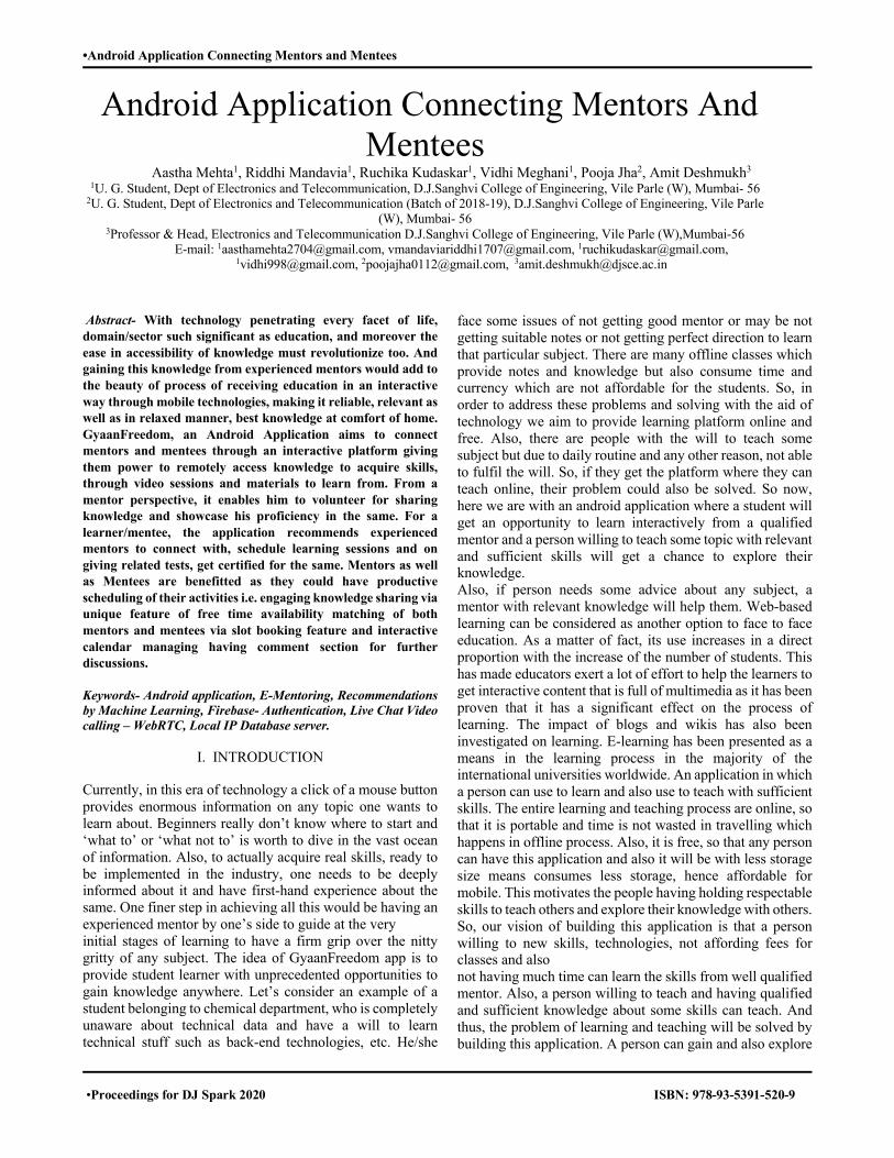
•Android Application Connecting Mentors and Mentees
•Proceedings for DJ Spark 2020 ISBN: 978-93-5391-520-9
Android Application Connecting Mentors And Mentees
Aastha Mehta1, Riddhi Mandavia1, Ruchika Kudaskar1, Vidhi Meghani1, Pooja Jha2, Amit Deshmukh3 1U. G. Student, Dept of Electronics and Telecommunication, D.J.Sanghvi College of Engineering, Vile Parle (W), Mumbai- 56
2U. G. Student, Dept of Electronics and Telecommunication (Batch of 2018-19), D.J.Sanghvi College of Engineering, Vile Parle (W), Mumbai- 56
3Professor & Head, Electronics and Telecommunication D.J.Sanghvi College of Engineering, Vile Parle (W),Mumbai-56 E-mail: [email protected], [email protected], [email protected],
[email protected], [email protected], [email protected]
Abstract- With technology penetrating every facet of life, domain/sector such significant as education, and moreover the ease in accessibility of knowledge must revolutionize too. And gaining this knowledge from experienced mentors would add to the beauty of process of receiving education in an interactive way through mobile technologies, making it reliable, relevant as well as in relaxed manner, best knowledge at comfort of home. GyaanFreedom, an Android Application aims to connect mentors and mentees through an interactive platform giving them power to remotely access knowledge to acquire skills, through video sessions and materials to learn from. From a mentor perspective, it enables him to volunteer for sharing knowledge and showcase his proficiency in the same. For a learner/mentee, the application recommends experienced mentors to connect with, schedule learning sessions and on giving related tests, get certified for the same. Mentors as well as Mentees are benefitted as they could have productive scheduling of their activities i.e. engaging knowledge sharing via unique feature of free time availability matching of both mentors and mentees via slot booking feature and interactive calendar managing having comment section for further discussions. Keywords- Android application, E-Mentoring, Recommendations by Machine Learning, Firebase- Authentication, Live Chat Video calling – WebRTC, Local IP Database server.
I. INTRODUCTION Currently, in this era of technology a click of a mouse button provides enormous information on any topic one wants to learn about. Beginners really don’t know where to start and ‘what to’ or ‘what not to’ is worth to dive in the vast ocean of information. Also, to actually acquire real skills, ready to be implemented in the industry, one needs to be deeply informed about it and have first-hand experience about the same. One finer step in achieving all this would be having an experienced mentor by one’s side to guide at the very initial stages of learning to have a firm grip over the nitty gritty of any subject. The idea of GyaanFreedom app is to provide student learner with unprecedented opportunities to gain knowledge anywhere. Let’s consider an example of a student belonging to chemical department, who is completely unaware about technical data and have a will to learn technical stuff such as back-end technologies, etc. He/she
face some issues of not getting good mentor or may be not getting suitable notes or not getting perfect direction to learn that particular subject. There are many offline classes which provide notes and knowledge but also consume time and currency which are not affordable for the students. So, in order to address these problems and solving with the aid of technology we aim to provide learning platform online and free. Also, there are people with the will to teach some subject but due to daily routine and any other reason, not able to fulfil the will. So, if they get the platform where they can teach online, their problem could also be solved. So now, here we are with an android application where a student will get an opportunity to learn interactively from a qualified mentor and a person willing to teach some topic with relevant and sufficient skills will get a chance to explore their knowledge. Also, if person needs some advice about any subject, a mentor with relevant knowledge will help them. Web-based learning can be considered as another option to face to face education. As a matter of fact, its use increases in a direct proportion with the increase of the number of students. This has made educators exert a lot of effort to help the learners to get interactive content that is full of multimedia as it has been proven that it has a significant effect on the process of learning. The impact of blogs and wikis has also been investigated on learning. E-learning has been presented as a means in the learning process in the majority of the international universities worldwide. An application in which a person can use to learn and also use to teach with sufficient skills. The entire learning and teaching process are online, so that it is portable and time is not wasted in travelling which happens in offline process. Also, it is free, so that any person can have this application and also it will be with less storage size means consumes less storage, hence affordable for mobile. This motivates the people having holding respectable skills to teach others and explore their knowledge with others. So, our vision of building this application is that a person willing to new skills, technologies, not affording fees for classes and also not having much time can learn the skills from well qualified mentor. Also, a person willing to teach and having qualified and sufficient knowledge about some skills can teach. And thus, the problem of learning and teaching will be solved by building this application. A person can gain and also explore

•Android Application Connecting Mentors and Mentees
•Proceedings for DJ Spark 2020 ISBN: 978-93-5391-520-9
the knowledge, is one of the unique features of the application. The usefulness of the application is that learning and teaching is portable, certification is an important perk, it is less time consuming than offline classes and it is free.
II. LITERATURE SURVEY Following are other tools which can be also used to connect to a mentor using Internet. Note that the information presented is surveyed and reviewed to latest of March of year 2020. The details of these tools are elaborated through following section: ‘OpenLearning’ and ‘Google classroom’: OpenLearning Limited (OLL) uses internet to deliver massive open courses, online degrees to student and short courses and is social online learning platform is listed on ASX(Australian Securities Exchange ). It has lists of available courses. Universities, colleges and educators can create, deliver, market, design online and communicate using social online learning. A student an also contribute and be teacher to teach any course of his best understanding. All the courses offered are paid and no mobile application is available for this learning site. Video calling feature is not included in the entire session and for validation of a person’s skillset no aptitude test is taken. Google classroom is used for distributing, creating and simplifying and grading assignments in a paperless way. It is web service which is free for all and developed by Google for schools. To streamline the process of sharing files between teachers and students is the primary purpose of Google Classroom. A student can’t contribute and be teacher to teach any course of his best understanding. Students can be invited to join a class through a private code, or automatically imported from a school domain. It is not possible to explore courses or content available. Communication is limited to known people and less exploration of website. No mobile application is available for this learning site. No online certification possible to avail for the knowledge acquired and no rating of the mentor is available. ‘Mentor cruise’ and ‘Anomalous educator’: Mentor cruise is built specific to Software Engineering, Programming, Machine Learning and other educational courses to connect and aspire students with industry professionals in Tech for mentorship. This mentoring site is limited to technical courses which are created depending of mass need and more demand amongst students. There is no mobile application for this learning site. All the courses offered made free only for a week and after the duration the mentees are charged. No online certification is provided in case if a student completes a course. The mobile phone verification is not done for verifying the registering new user. For validation of a person’s skillset no aptitude test is taken. The content shared on this site is brought up by different types of people who interact through courses and has shared responses. All the courses covered are business related and only students related to these domains can grasp the most of it. All the courses offered are paid and no mobile application is available for
this learning site. Video calling feature is not included in the entire session and for validation of a person’s skillset no aptitude test is taken. The mobile phone verification is not done for verifying the registering new user. For validation of a person’s skillset no aptitude test is taken. Content is limited and based on requirement the courses or podcasts are made available. ‘Envelop’, ‘iCouldbe’ and ‘iMentor’: Envelop is an innovative audio platform transforming the way consumers enjoy music and is also endorsed by Google Founder Sergei Brin. Renowned musician and educator Christopher Willits lead the team of Envelop. Envelop provides a space to deeply listen together with immersive audio venues and free open source spatial audio tools. Video calling feature is not included in the entire session and for validation of a person’s skillset no aptitude test is taken. Envelop hosts events such as live performances and listening activities, to wellness experiences and webinars on spatial audio education. The mobile phone verification is not done for verifying the registering new user. For validation of a person’s skillset no aptitude test is taken. All the courses covered are audio related and only students with such background can yield maximum. iCouldBe operates through classrooms across the country, where schools allow students to dedicate one class per week toward mentorship activities that promote academic success, career exploration, and post-secondary educational planning. This student-geared mentorship program encourages public high school students in the US to choose their own mentors. All the courses offered are paid and no mobile application is available for this learning site. Video calling feature is not included in the entire session and for validation of a person’s skillset no aptitude test is taken. No mobile application is available for this learning site. Students from Low-income communities to graduate high school and succeeding in college are all empowered by this online learning site. It is also another renowned student-focused program. Students meet with mentors one on one, either online or in person using this online learning site. All the courses offered are paid and no mobile application is available for this learning site. Video calling feature is not included in the entire session and for validation of a person’s skillset no aptitude test is taken. No mobile application is available for this learning site.
III. MOTIVATION Increased Instructor - Student Time: Personalized attention is not given to individuals in traditional classroom where all their doubts are not being solved completely. At reputed colleges, the class sizes are really small. This would create a problem for group of individuals as there will be limited number of seats. If a personalized instructor is provided for the student then the grasping power of the student is increased and he/she can maximize their understanding to the core concepts more efficiently and easily. Hence, saving student’s time and reducing the workload. Their problem-solving and communication skills is also improved.
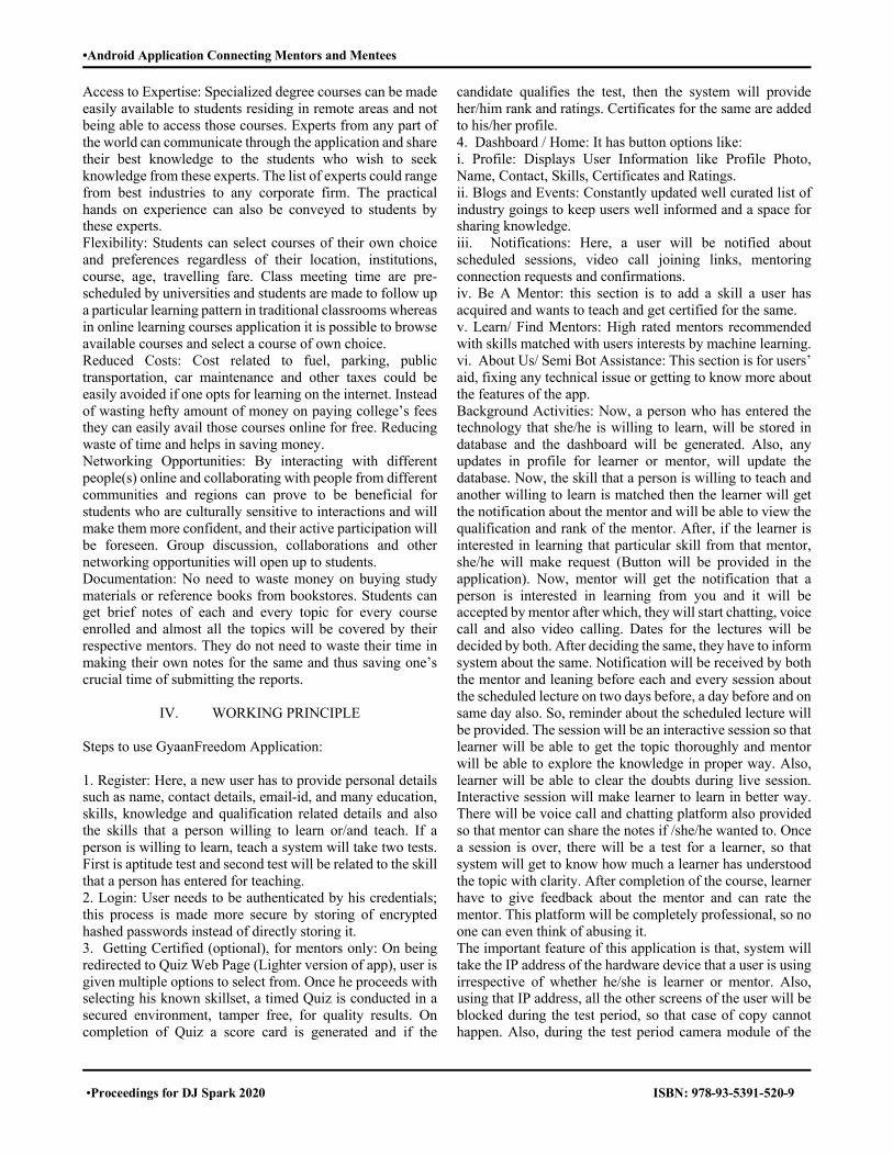
•Android Application Connecting Mentors and Mentees
•Proceedings for DJ Spark 2020 ISBN: 978-93-5391-520-9
Access to Expertise: Specialized degree courses can be made easily available to students residing in remote areas and not being able to access those courses. Experts from any part of the world can communicate through the application and share their best knowledge to the students who wish to seek knowledge from these experts. The list of experts could range from best industries to any corporate firm. The practical hands on experience can also be conveyed to students by these experts. Flexibility: Students can select courses of their own choice and preferences regardless of their location, institutions, course, age, travelling fare. Class meeting time are pre-scheduled by universities and students are made to follow up a particular learning pattern in traditional classrooms whereas in online learning courses application it is possible to browse available courses and select a course of own choice. Reduced Costs: Cost related to fuel, parking, public transportation, car maintenance and other taxes could be easily avoided if one opts for learning on the internet. Instead of wasting hefty amount of money on paying college’s fees they can easily avail those courses online for free. Reducing waste of time and helps in saving money. Networking Opportunities: By interacting with different people(s) online and collaborating with people from different communities and regions can prove to be beneficial for students who are culturally sensitive to interactions and will make them more confident, and their active participation will be foreseen. Group discussion, collaborations and other networking opportunities will open up to students. Documentation: No need to waste money on buying study materials or reference books from bookstores. Students can get brief notes of each and every topic for every course enrolled and almost all the topics will be covered by their respective mentors. They do not need to waste their time in making their own notes for the same and thus saving one’s crucial time of submitting the reports.
IV. WORKING PRINCIPLE
Steps to use GyaanFreedom Application: 1. Register: Here, a new user has to provide personal details such as name, contact details, email-id, and many education, skills, knowledge and qualification related details and also the skills that a person willing to learn or/and teach. If a person is willing to learn, teach a system will take two tests. First is aptitude test and second test will be related to the skill that a person has entered for teaching. 2. Login: User needs to be authenticated by his credentials; this process is made more secure by storing of encrypted hashed passwords instead of directly storing it. 3. Getting Certified (optional), for mentors only: On being redirected to Quiz Web Page (Lighter version of app), user is given multiple options to select from. Once he proceeds with selecting his known skillset, a timed Quiz is conducted in a secured environment, tamper free, for quality results. On completion of Quiz a score card is generated and if the
candidate qualifies the test, then the system will provide her/him rank and ratings. Certificates for the same are added to his/her profile. 4. Dashboard / Home: It has button options like: i. Profile: Displays User Information like Profile Photo, Name, Contact, Skills, Certificates and Ratings. ii. Blogs and Events: Constantly updated well curated list of industry goings to keep users well informed and a space for sharing knowledge. iii. Notifications: Here, a user will be notified about scheduled sessions, video call joining links, mentoring connection requests and confirmations. iv. Be A Mentor: this section is to add a skill a user has acquired and wants to teach and get certified for the same. v. Learn/ Find Mentors: High rated mentors recommended with skills matched with users interests by machine learning. vi. About Us/ Semi Bot Assistance: This section is for users’ aid, fixing any technical issue or getting to know more about the features of the app. Background Activities: Now, a person who has entered the technology that she/he is willing to learn, will be stored in database and the dashboard will be generated. Also, any updates in profile for learner or mentor, will update the database. Now, the skill that a person is willing to teach and another willing to learn is matched then the learner will get the notification about the mentor and will be able to view the qualification and rank of the mentor. After, if the learner is interested in learning that particular skill from that mentor, she/he will make request (Button will be provided in the application). Now, mentor will get the notification that a person is interested in learning from you and it will be accepted by mentor after which, they will start chatting, voice call and also video calling. Dates for the lectures will be decided by both. After deciding the same, they have to inform system about the same. Notification will be received by both the mentor and leaning before each and every session about the scheduled lecture on two days before, a day before and on same day also. So, reminder about the scheduled lecture will be provided. The session will be an interactive session so that learner will be able to get the topic thoroughly and mentor will be able to explore the knowledge in proper way. Also, learner will be able to clear the doubts during live session. Interactive session will make learner to learn in better way. There will be voice call and chatting platform also provided so that mentor can share the notes if /she/he wanted to. Once a session is over, there will be a test for a learner, so that system will get to know how much a learner has understood the topic with clarity. After completion of the course, learner have to give feedback about the mentor and can rate the mentor. This platform will be completely professional, so no one can even think of abusing it. The important feature of this application is that, system will take the IP address of the hardware device that a user is using irrespective of whether he/she is learner or mentor. Also, using that IP address, all the other screens of the user will be blocked during the test period, so that case of copy cannot happen. Also, during the test period camera module of the

•Android Application Connecting Mentors and Mentees
•Proceedings for DJ Spark 2020 ISBN: 978-93-5391-520-9
user device will be turned on, so that probability of cheating will be negligible. This pattern of tracing IP address and securing the test will be provided for all the tests of the application. The additional perk for the learner after receiving knowledge will be that she/he will be awarded with the certificate of completion of the course with the score. And perk for the mentor other than exploring the knowledge will be that she/he also get the certificate for mentoring and also can mention that she/he has mentored this much number of student and has this much rating. Also, they will be rewarded with some coupons of some useful things. Mentor can share their rating on some professional platform such as LinkedIn and also learner can mention that is certified learner for the particular course. Now, once learner has gained the sufficient knowledge for a particular skill and if she/he willing to teach the same skill, will also be possible. This also a unique feature of an application that a person can learn and also can teach.
V. DEPENDENCIES
A. XAMPP and Apache Server:
XAMPP is local server and an open source software developed by Apache friends which works on desktop used to test website before uploading it to the remote web server. Using HTTP server, one can serve files, documents and images if they are requested by clients. In this project, XAMPP is used for testing database entries and Apache server is used for requesting and responding. The details of user’s can be filled in Database automatically or dynamically using XAMPP.
B. SQL:
Structured Query Language is the standard language for relational database management systems used for providing communication with database. SQL can be used to insert, search, update and delete database records and can be used to accomplish nearly everything that one requirement to do with a database. SQL can do lots of operations that involve optimizing storing and retrieval time and the maintenance of databases. In this project, created a database and few entities is that database using SQL. Using XAMPP, made the project responding so that user’s registration details can be filled in database dynamically.
C. PHP:
Hypertext Pre-processor is a server-side scripting language used to create dynamic websites primarily used to build web-based software applications. PHP supports Apache, IIS and many other web servers and can be used on almost all operating system. In this project, PHP is used for connecting Android project with Database. The communication between the Entities in Database and Android Studio project is provided by PHP scripting Language.
D. Android Studio:
Android Studio is the official IDE for Android application development which is based on IntelliJ IDEA, a Java integrated development environment for software, and incorporates its code editing and developer tools. For new screen on Application, we create a new activity in android studio project which contains XML file and java class. XML is all about UI of the application and for making that UI responsive we use java class. Emulator in Android Studio is used for Virtual Device which signifies Android device. In Android Studio, we made projects which contains Registration or Login page, Dashboard page, Event Scheduling page to know the availability of the mentor, etc. To navigate between various activities i.e. from current activity which is running to the target one with transmitting of pre-specified formatted data packets as well.
E. Firebase Authentication:
By using Firebase Authentication in Android, we manage to verify the phone number of the user. Firebase provides a real time services which integrates database server and devices on which app is hosted. Firebase is having complementary feature that helps to build and developer Android application quickly. Also, firebase can be used for verifying email address. The features of the firebase include Authentication, Analytics, Predictions, App Indexing, Dynamic Links, Invites, Remote Config, Cloud Messaging, Performance Monitoring, Crash Reporting, and Crashlytics with no cost.
F. Agora SDK –Web RTC:
To provide feature of voice and video calling, we used Agora which includes all the development tools and cloud infrastructure required for applications. As, Agora is light in weight and easy to use, provides flexibility and high-quality signals. After developing the project, it can be installed either in our own device or on emulator. The Android Studio Project is connected to the SQL database using PHP scripting to make pages dynamically responsive.
G. Web Development Technologies:
1. HTML:
Hyper Text Mark-up Language is used to design documents which aims to display on web browser. Assisting language of HTML is JavaScript and Cascading Style Sheets. Here, in this project, HTML is used for Quiz sections. Quiz are made dynamic i.e. depends on user’s choice subject quiz is taken and score of individual user is stored in Database.
2. Javascript:
Javascript is a stand-alone and client-side scripting language
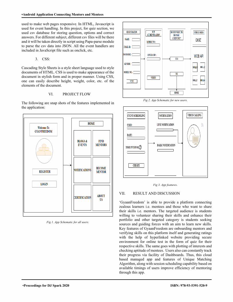
•Android Application Connecting Mentors and Mentees
•Proceedings for DJ Spark 2020 ISBN: 978-93-5391-520-9
used to make web pages responsive. In HTML, Javascript is used for event handling. In this project, for quiz section, we used csv database for storing question, options and correct answers. For different subject, different csv files will be there and it will be taken directly in script using Papa-parse module to parse the csv data into JSON. All the event handlers are included in JavaScript file such as onclick, etc.
3. CSS:
Cascading Style Sheets is a style sheet language used to style documents of HTML. CSS is used to make appearance of the document in stylish form and in proper manner. Using CSS, one can easily describe height, weight, color, etc. of the elements of the document.
VI. PROJECT FLOW
The following are snap shots of the features implemented in the application:
Fig 1. App Schematic for all users.
Fig 2. App Schematic for new users.
Fig 3. App features. VII. RESULT AND DISCUSSION ‘GyaanFreedom’ is able to provide a platform connecting zealous learners i.e. mentees and those who want to share their skills i.e. mentors. The targeted audience is students willing to volunteer sharing their skills and enhance their portfolio and other targeted category is students seeking sources and guiding forces with an aim to learn new skills. Key features of GyaanFreedom are onboarding mentors and verifying skills on this platform itself and generating ratings with the help of hyperlinked website providing secure environment for online test in the form of quiz for their respective skills. The same goes with plotting of interests and checking aptitude of mentees. Users also can constantly track their progress via facility of Dashboards. Thus, this cloud based managed app and features of Unique Matching Algorithm, along with session scheduling capability based on available timings of users improve efficiency of mentoring through this app.
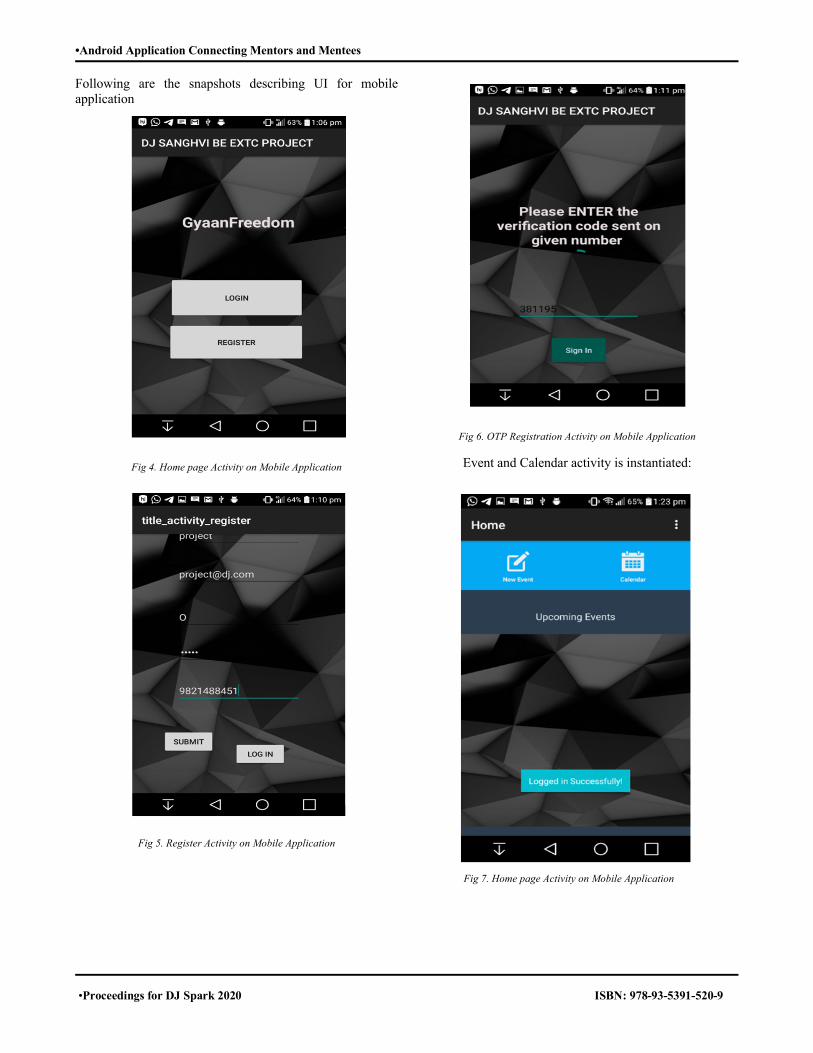
•Android Application Connecting Mentors and Mentees
•Proceedings for DJ Spark 2020 ISBN: 978-93-5391-520-9
Following are the snapshots describing UI for mobile application
Fig 4. Home page Activity on Mobile Application
Fig 5. Register Activity on Mobile Application
Fig 6. OTP Registration Activity on Mobile Application
Event and Calendar activity is instantiated:
Fig 7. Home page Activity on Mobile Application
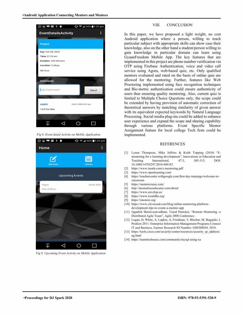
•Android Application Connecting Mentors and Mentees
•Proceedings for DJ Spark 2020 ISBN: 978-93-5391-520-9
Fig 8. Event detail Activity on Mobile Application
Fig 9. Upcoming Event Activity on Mobile Application
VIII. CONCLUSION In this paper, we have proposed a light weight, no cost Android application where a person, willing to teach particular subject with appropriate skills can show case their knowledge, also on the other hand a student/person willing to gain knowledge in particular domain can learn using GyaanFreedom Mobile App. The key features that are implemented in this project are phone number verification via OTP using Firebase Authentication, voice and video call service using Agora, web-based quiz, etc. Only qualified mentors evaluated and rated on the basis of online quiz are allowed for the mentoring. Further, features like Web Proctoring implemented using face recognition techniques and Bio-metric authentication could ensure authenticity of users thus ensuring quality mentoring. Also, current quiz is limited to Multiple Choice Questions only, the scope could be extended by having provision of automatic correction of theoretical answers by matching similarity of given answer with its equivalent expected keywords by Natural Language Processing. Social media plug-ins could be added to enhance user experience and expand the scope and sharing capability through various platforms. Event Specific Mentor Assignment feature for local college Tech fests could be implemented.
REFERENCES [1] Lynne Thompson, Mike Jeffries & Keith Topping (2010) “E‐
mentoring for e‐learning development”, Innovations in Education and Teaching International, 47:3, 305-315, DOI: 10.1080/14703297.2010.498182
[2] https://www.insala.com/e-mentoring.pdf [3] https://www.openlearning.com/ [4] https://teachercenter.withgoogle.com/first-day-trainings/welcome-to-
classroom [5] https://mentorcruise.com/ [6] http://anomalouseducator.com/about/ [7] https://www.envelop.us/ [8] https://www.icouldbe.org/ [9] https://imentor.org/ [10] https://www.cleveroad.com/blog/online-mentoring-platform-
development-tips-to-create-a-mentor-app [11] Jagadish Shrinivasavadhani, Vinod Panicker, “Remote Mentoring -a
Distributed Agile Team”, Agile 2008 Conference [12] Logan, D, White, A, Lapkin, A, Friedman, T, Blechar, M, Bugajski, J.
Predicts 2011: Enterprise Information Management Programs Connect IT and Business. Gartner Research ID Number: G00208054. 2010.
[13] https://tools.cisco.com/security/center/resources/security_ip_addressing.html
[14] https://teamtreehouse.com/community/mysql-using-xa

• Solar Powered Beach Cleaning Machine
•Proceedings for DJ Spark 2020 ISBN: 978-93-5391-520-9
Solar Powered Beach Cleaning Machine Arzan Mehta1, Deep Bhatia1, Ishan Mamadapur1, Vishal Mehta1
1 U. G. Student, Department of Mechanical Engineering, D.J.Sanghvi College of Engineering, Vile Parle (W), Mumbai- 400056
Email: [email protected], [email protected], [email protected], [email protected]
Abstract—Plastic waste is being accumulated on beaches throughout the world at an alarming rate. This garbage has detrimental effects on marine life like turtles and birds while also becoming a breeding ground for disease-spreading parasites. Initiatives to reduce this waste by regular beach cleaning operations employs methods that are expensive and require a lot of man-hours, with low operational efficiency. This paper presents the design and operation of a semi-autonomous electric beach cleaning system, on a vehicle powered by renewable energy, along with the performance evaluation and calculation of key design parameters. The beach cleaning machine undertakes the clearance of garbage with minimal human input while making use of commonly available hardware and electronic components to reduce cost. The machine collects sand along with the deposited waste by a raking action, segregates the sand from the waste with the help of a conveyor and static sieve arrangement and collects the garbage while the sand is filtered out back onto the beach.
Keywords— Beach Cleaning Machine, Solar-Powered, Plastic Waste, Semi-Autonomous
I. INTRODUCTION At least 8 million tons of plastic end up in our oceans every year and make up 80% of all marine debris from surface waters to deep-sea sediments. Marine species ingest or are entangled by plastic debris, which causes severe injuries and deaths. Plastic pollution threatens food safety and quality, human health, coastal tourism, and contributes to climate change. There is an urgent need to explore the use of existing legally binding international agreements to address marine plastic pollution. There are presently around one hundred million tons of garbage present in the ocean with around 460 thousand tons getting deposited daily on the beaches around the world[2]. The trash causes loss of habitat of turtles and other marine life. It also becomes a breeding ground for algae, bacteria, and mosquitoes that transmit deleterious diseases. It also defiles the natural beauty of the beach hence negatively affecting tourism.
The solutions implemented by the governments to tackle this problem often use human effort and large vehicles powered by IC engines and cause air pollution. The exhaust from these vehicles causes global warming due to the release of greenhouse gases. An internal combustion engine produces around 2.3kgs of Carbon Dioxide per liter of fuel burnt. Thus we decided to use a renewable source of energy in the form of solar energy. It helped us mitigate one problem while also ensuring that we do not advance another.
II. LITERATURE SURVEY When undergoing a project of this nature, it is important to consider the prior machines already in existence. Thus, a search was conducted for existing patents in the field of beach cleaning Devices. The first of the patents found utilized a roller to move garbage up and through the system into a collection Mechanism. The rollers were powered by combustion engines that were mounted to the frame. The entire structure was made using a sieving system, which allowed dry sand to fall through while keeping garbage in the system. The garbage was then pushed continuously until it reached the collection area at the rear of the system. For movement, the system may be drawn by a tractor or all-terrain vehicle. The next patent that was explored was significantly different from the previous one explored. It had a larger footprint and it was capable of working on wet sandy surfaces. The ability to work through wet sand was brought about through the commutator. This design also made use of a meshed conveyor belt that allowed any sand remnants to fall through. This conveyor belt had slats to prevent the garbage from sliding back down towards the front of the vehicle. The device was pulled by a tractor and had a rake on the rear end to smooth out the sand after cleaning. The final patent was the simplest system that was found during the search. It involved a mesh that allows sand to pass through while storing garbage on the way. When the tool became full of garbage, it was simply emptied into a nearby garbage bin. The tool was light enough that it can be pulled by hand. One immediate drawback of this system was that it may bounce around, causing it to miss garbage or drop it completely. With a good understanding of existing products, a proposed solution to the problem described was generated.
III. WORKING PRINCIPLE The beach cleaner works on the principle of mechanical raking and sifting action to deposit waste in a storage bin by combing out waste from under the sand’s surface and agitating the cohesive sand particles on a meshed conveyor before the waste gets deposited in the bin. Solar energy is used to power the drive train and the various subsystems.
A. Storage System The storage system (Annotation 3) was selected based on availability with respect to size and the maximum weight that can be accommodated by the machine. It is placed at the end of the machine for ease of attachment and detachment.
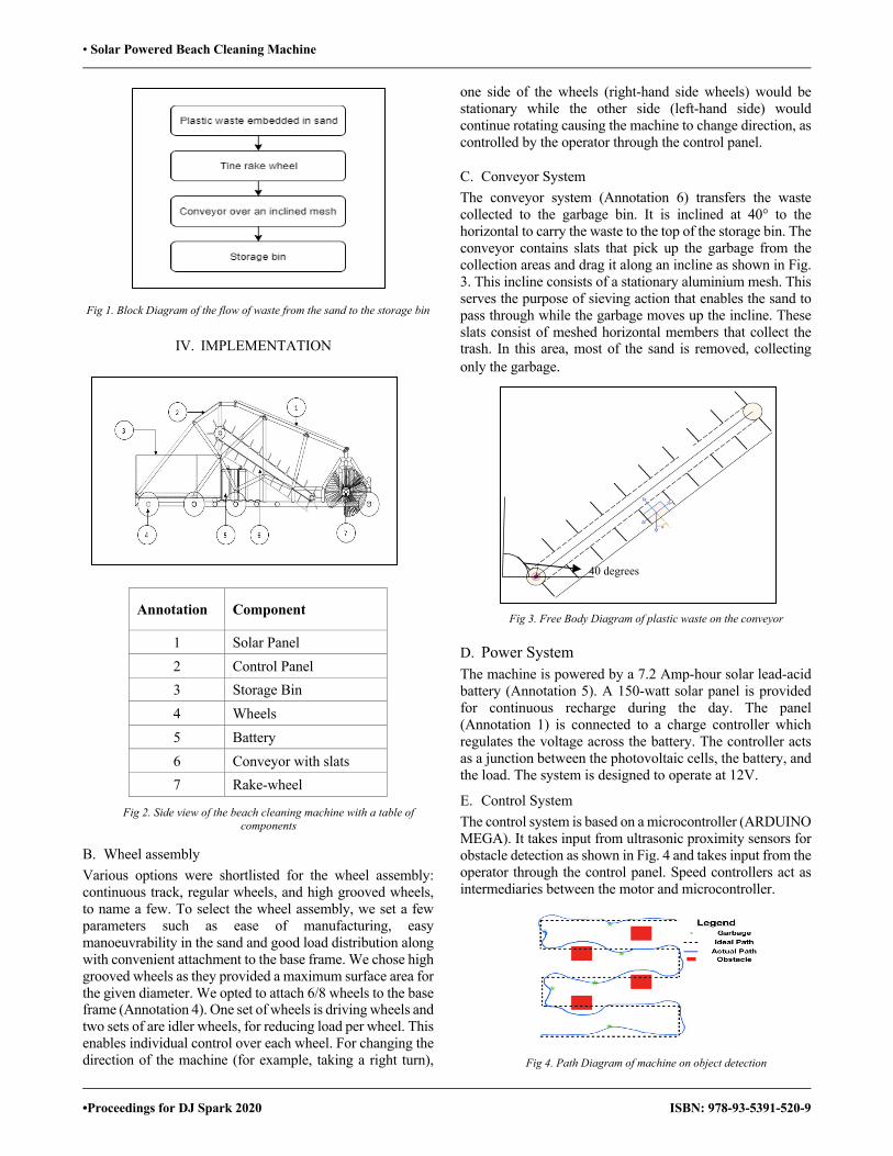
• Solar Powered Beach Cleaning Machine
•Proceedings for DJ Spark 2020 ISBN: 978-93-5391-520-9
Fig 1. Block Diagram of the flow of waste from the sand to the storage bin
IV. IMPLEMENTATION
Annotation Component
1 Solar Panel 2 Control Panel 3 Storage Bin 4 Wheels 5 Battery 6 Conveyor with slats 7 Rake-wheel
Fig 2. Side view of the beach cleaning machine with a table of components
B. Wheel assembly Various options were shortlisted for the wheel assembly: continuous track, regular wheels, and high grooved wheels, to name a few. To select the wheel assembly, we set a few parameters such as ease of manufacturing, easy manoeuvrability in the sand and good load distribution along with convenient attachment to the base frame. We chose high grooved wheels as they provided a maximum surface area for the given diameter. We opted to attach 6/8 wheels to the base frame (Annotation 4). One set of wheels is driving wheels and two sets of are idler wheels, for reducing load per wheel. This enables individual control over each wheel. For changing the direction of the machine (for example, taking a right turn),
one side of the wheels (right-hand side wheels) would be stationary while the other side (left-hand side) would continue rotating causing the machine to change direction, as controlled by the operator through the control panel.
C. Conveyor System The conveyor system (Annotation 6) transfers the waste collected to the garbage bin. It is inclined at 40° to the horizontal to carry the waste to the top of the storage bin. The conveyor contains slats that pick up the garbage from the collection areas and drag it along an incline as shown in Fig. 3. This incline consists of a stationary aluminium mesh. This serves the purpose of sieving action that enables the sand to pass through while the garbage moves up the incline. These slats consist of meshed horizontal members that collect the trash. In this area, most of the sand is removed, collecting only the garbage.
Fig 3. Free Body Diagram of plastic waste on the conveyor
D. Power System The machine is powered by a 7.2 Amp-hour solar lead-acid battery (Annotation 5). A 150-watt solar panel is provided for continuous recharge during the day. The panel (Annotation 1) is connected to a charge controller which regulates the voltage across the battery. The controller acts as a junction between the photovoltaic cells, the battery, and the load. The system is designed to operate at 12V.
E. Control System The control system is based on a microcontroller (ARDUINO MEGA). It takes input from ultrasonic proximity sensors for obstacle detection as shown in Fig. 4 and takes input from the operator through the control panel. Speed controllers act as intermediaries between the motor and microcontroller.
Fig 4. Path Diagram of machine on object detection
4140
40 degrees
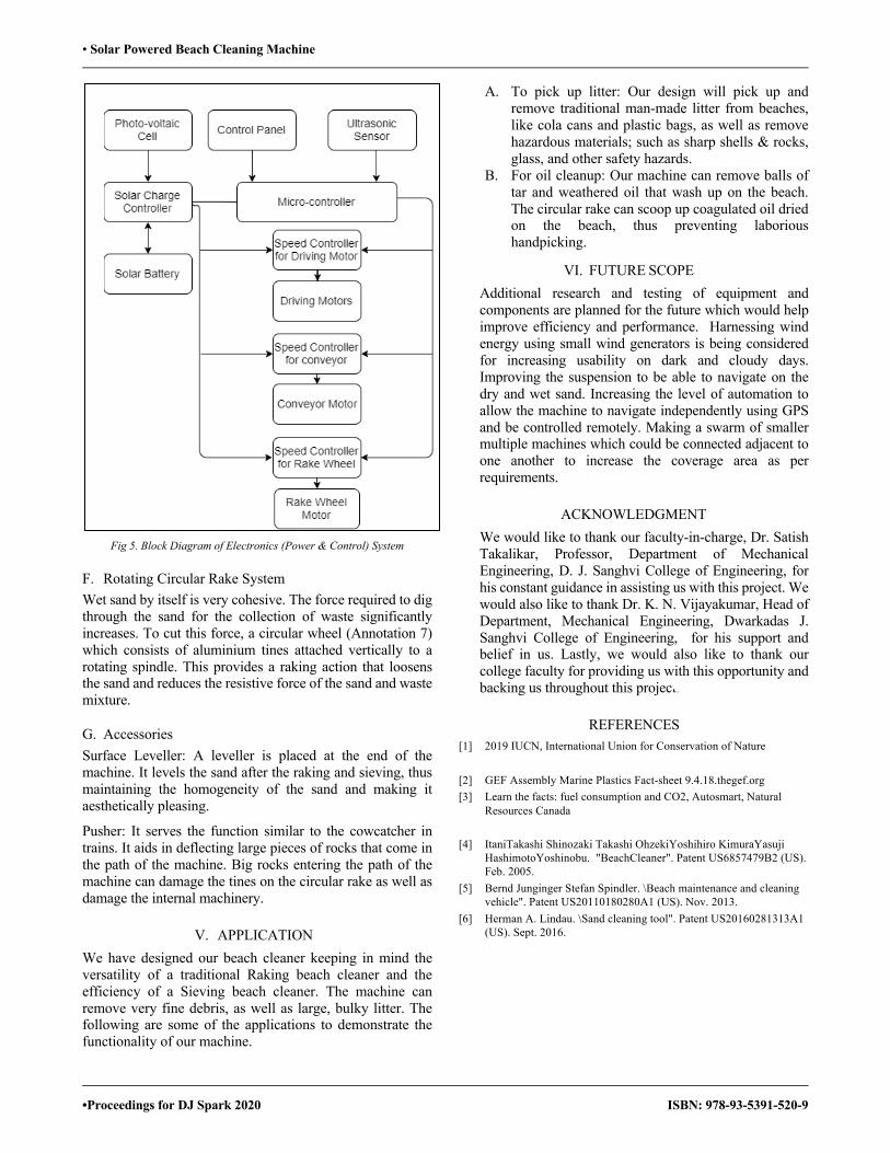
• Solar Powered Beach Cleaning Machine
•Proceedings for DJ Spark 2020 ISBN: 978-93-5391-520-9
Fig 5. Block Diagram of Electronics (Power & Control) System
F. Rotating Circular Rake System Wet sand by itself is very cohesive. The force required to dig through the sand for the collection of waste significantly increases. To cut this force, a circular wheel (Annotation 7) which consists of aluminium tines attached vertically to a rotating spindle. This provides a raking action that loosens the sand and reduces the resistive force of the sand and waste mixture.
G. Accessories Surface Leveller: A leveller is placed at the end of the machine. It levels the sand after the raking and sieving, thus maintaining the homogeneity of the sand and making it aesthetically pleasing.
Pusher: It serves the function similar to the cowcatcher in trains. It aids in deflecting large pieces of rocks that come in the path of the machine. Big rocks entering the path of the machine can damage the tines on the circular rake as well as damage the internal machinery.
V. APPLICATION We have designed our beach cleaner keeping in mind the versatility of a traditional Raking beach cleaner and the efficiency of a Sieving beach cleaner. The machine can remove very fine debris, as well as large, bulky litter. The following are some of the applications to demonstrate the functionality of our machine.
A. To pick up litter: Our design will pick up and remove traditional man-made litter from beaches, like cola cans and plastic bags, as well as remove hazardous materials; such as sharp shells & rocks, glass, and other safety hazards.
B. For oil cleanup: Our machine can remove balls of tar and weathered oil that wash up on the beach. The circular rake can scoop up coagulated oil dried on the beach, thus preventing laborious handpicking.
VI. FUTURE SCOPE Additional research and testing of equipment and components are planned for the future which would help improve efficiency and performance. Harnessing wind energy using small wind generators is being considered for increasing usability on dark and cloudy days. Improving the suspension to be able to navigate on the dry and wet sand. Increasing the level of automation to allow the machine to navigate independently using GPS and be controlled remotely. Making a swarm of smaller multiple machines which could be connected adjacent to one another to increase the coverage area as per requirements.
ACKNOWLEDGMENT We would like to thank our faculty-in-charge, Dr. Satish Takalikar, Professor, Department of Mechanical Engineering, D. J. Sanghvi College of Engineering, for his constant guidance in assisting us with this project. We would also like to thank Dr. K. N. Vijayakumar, Head of Department, Mechanical Engineering, Dwarkadas J. Sanghvi College of Engineering, for his support and belief in us. Lastly, we would also like to thank our college faculty for providing us with this opportunity and backing us throughout this project.
REFERENCES [1] 2019 IUCN, International Union for Conservation of Nature
[2] GEF Assembly Marine Plastics Fact-sheet 9.4.18.thegef.org [3] Learn the facts: fuel consumption and CO2, Autosmart, Natural
Resources Canada
[4] ItaniTakashi Shinozaki Takashi OhzekiYoshihiro KimuraYasuji HashimotoYoshinobu. "BeachCleaner". Patent US6857479B2 (US). Feb. 2005.
[5] Bernd Junginger Stefan Spindler. \Beach maintenance and cleaning vehicle". Patent US20110180280A1 (US). Nov. 2013.
[6] Herman A. Lindau. \Sand cleaning tool". Patent US20160281313A1 (US). Sept. 2016.

• Wireless Medicom System
• Proceedings for DJ SPARK 2020 ISBN : 978-93-5391-520-9
Wireless Medicom System Anuradha Pandey1, Dashmi Parui1, Prerna Patel1, Vishnupriya Singh1, Amit A. Deshmukh2, Pooja Jha3
1U.G. Student, Dept of Electronics and Telecommunication, D.J. Sanghvi College of Engineering, Vile Parle (W), Mumbai-400056 2 Professor & Head,Electronics and Telecommunication Dept,D.J.Sanghvi College of Engineering, Vile Parle (W), Mumbai- 400056
3Electronics and Telecommunication Department(Batch 2018-19), D.J. Sanghvi College of Engineering, Vile Parle (W), Mumbai-400056 Email: [email protected] , [email protected], [email protected], [email protected],
[email protected], [email protected]
Abstract—The healthcare sector is one of the fastest changing areas in a competitive environment. It has been more focused on ways to reduce expenses, save more patients’ lives and is more concerned about having the ability to accurately track and identify the patients. Taking into account the patient's identification and medical profile, The purpose of this paper is to illustrate a system based on a client-server model consisting of medical records of patients that are stored on the server, thus establishing a centralized medical database that eliminates all patient identification and retrieval issues. A Radio Frequency Identification Card is used, where all medical information is accessed by an electronic memory chip which is a transponder. Each patient is assigned a unique Radio Frequency Identification Card which gives access to medical records of the patient when scanned. We have also developed a smartphone application named ‘Pulse’, where patients can register themselves to book an appointment and view the prescribed medicines which tend to enhance the engagement of patients.
Keywords—Client-server model, Database, Electronic Medical Record System, Radio frequency identification, Smartphone application.
I. INTRODUCTION
Technology has always affected the healthcare sector in tremendous ways. We have seen the role of technology in the invention of the latest medical equipment to stimulate and encourage the fast treatment of patients. In recent times, this ever-developing technology is also seen in the administrations of the hospital. Hospitals and Health Care facilities are more concerned these days about having the ability to accurately track and identify the patients. Now, when the healthcare services and facilities are improving the risk inpatient care is also increasing. In the healthcare domain, the cost of technology is less concerned compared to highly valued services.
Manual medical records system stores data of patients within a medical record log. Patient record files are compiled by handand stored in a file rack and manually retrieved from the file rack. It is very difficult to arrange patient medical file in manual medical record system. Finding a patient medical record file is very clumsy. There are chances to make mistakes. There are possibilities to keep the files in wrong place. Sending files in proper medical department and returning back the files into medical record also time consuming. Manual Medical record is generally error prone. The proper management and structure of the patient file needs more time and effort through the health staff.
Error in patient identification can lead to improper dosage of medication to patients, as well as invasive surgery. Many similar errors in patient identification may lead to incorrect laboratory work and reported results for the wrong person, with consequences such as misdiagnoses and severe errors in the medication. For proper medication or identification of the individual or pulling up a history of treatment on a patient; Radio Frequency Identification (RFID) technology is a way to manage the information much more efficiently. It's an effective technology that saves lives, avoids mistakes saves costs and enhances protection. If an RFID system can prevent a patient from being mis-medicated, the value is high enough compared to other cost-effective systems.
Under such realization, we became motivated to carry out this investigation on RFID technology and its potential applicability within the healthcare sector. Our proposed system conducts patient recognition based on RFID, analyzing and obtaining medical data from multiple defined healthcare information management, as well as storing and supplying the clinicians with the most relevant clinically important information. The program also enables the identification and monitoring of RFID-tagged objects in order to provide new quality facilities for object functionality.
The RFID technology is employed so as to chop these clinical errors, to boost patient care and security. The patient's previous medical records may be stored and viewed at any given time. This will eliminate the manual paperwork of maintaining files. A doctor can view patient history and prescribe new medicines accordingly. Similarly, a chemist will just have to scan the RFID tag to view prescription.
II. LITERATURE SURVEY
In 2000, the United States (U.S.) National Institute of Medicine issued the report entitled: “To Err Is Human, Building a Safer Health System”, which drew attention on the spreading problem of often preventable medical errors throughout the U.S. hospitals (Kohn, Corrigan & Donaldson, 2000). The report underlines that over 98,000 deaths and 770,000 severe drug incidents in the U.S. each year are induced by preventable medical errors. These are significant numbers, given that the U.S. has the world's highest spending on healthcare. This paper demonstrates how innovations and online services for radio frequency

• Wireless Medicom System
• Proceedings for DJ SPARK 2020 ISBN : 978-93-5391-520-9
identification (RFID) can be used to create smarter healthcare by minimizing mistakes, improving patient safety and enhancing business operations. Improving patient care is one of the major aims. Thus, to decrease wait time in emergency ward can be an important improvement and this can be done by substituting paper-based process for emergency ward admission with solution based on electronic medical records. With such approaches in motion, hospitals have continued to save minutes every time they admit a patient, as they no longer require doctors and nurses to manually fill out forms and improve health results. It was estimated that 15 to 18 per cent of U.S. physicians are already using electronic health records. For example, a common goal of Microsoft and Google is to manage enormous quantities of personal health 0information to provide advantage to the users through Microsoft Health Vault and Google Health. Thus, such systems give confidence and support patients to maintain and be responsible for their own and family health related information records. Unluturk and Kurtel proposed an assisted-living system that integrates RFID technology and an online web service. The system can be applied in a nursing home to immediately locate patients that need help [2]. The only 200-year-old university clinic in the German state of Thuringia uses technology in combination with a SAP Net Weaver platform to check accurately and in real time from the hospital pharmacy to the patients to identify, track and match medication. This will certainly lead to improved treatment systems, increased quality of service in medical care and enhanced patient safety (e.g., elimination of undesired effects on medication). However, despite the highly functional and tactical capability of RFID's wireless sensor network transformation in healthcare; few empirical studies have been conducted to evaluate the efficacy of this technology in the sector. For hospital medical records RFID technology is also used to view and maintain medical files for patients. RFID is the most common technology for object or element recognition from the nearest distance. Computer-based device monitoring of medical records can also be combined with RFID. The existing barcode system for identifying a patient file can be replaced by RFID technology which tracks and identifies a patient medical record file quickly and easily. This research was carried out to manage medical files for patients in govt. Saudi Arabia hospitals. This paper suggests the implementation of RFID technology in the healthcare industry based on its improved flexibility, scalability, convenient-to-use and low cost capabilities. It program conducts RFID-based patient recognition, queries and retrieves medical data from various existing healthcare information systems, and stores and provides the clinically most important information to the clinicians.
III. COMPONENTS USED
A. Software used
1. Mobile application Android Studio[6] is the official integrated development environment for Google's Android operating system. The mobile application is made by using Android studio, which consists of activities, fragments, view and layout manager, device configuration and specific layouts and content provider. The Android Software Development Kit (SDK) contains the necessary tools which help to create, compile and package Android application. The android application can be tested without a real android phone as Android SDK provides an Android device emulator. We have also used Dalvik Virtual Machine (DVM) which is an android virtual machine optimized for mobile devices. It optimizes the virtual machine for memory, battery life and performance. The Dex compiler converts the class files into the .dex file that run on the Dalvik VM. The development of the application is done using JAVA coding language.
2. Desktop Application The desktop application is created using Visual Studio[7] and it uses professional C# (C Sharp) coding language. It is connected to the mobile application using Web service. Microsoft SQL server 2008 is used to form the database in which all the information about the patients will be stored at the source.
B. Hardware used
An RFID system consists of a reader and a transponder (or tag), which usually has a microchip with an antenna attached to it. There are different types of RFID systems, but usually the reader sends out electromagnetic waves with a signal the tag is designed to respond to. The Arduino Uno is an open-source microcontroller board based on the Microchip ATmega328P microcontroller which is connected to the RFID reader. By scanning the tags over the reader the unique RFID numbers are passed from the Arduino to the desktop application.
Fig 1. Desktop application using Visual Studio

• Wireless Medicom System
• Proceedings for DJ SPARK 2020 ISBN : 978-93-5391-520-9
Fig 2. Hardware setup for scanning RFID tags
IV. METHODOLOGY
The Electronic medical record system is an online database system. For the easy usage and modification of the medical database, a smartphone application is made. The patients are able to view their personal details and prescriptions given by the doctor at any point of time with the help of the application. In this project, an Android application named ‘PULSE’ has been developed. The application is made using the software ANDROID STUDIO and its peripheral libraries. The program is written using KOTLIN and JAVA language.After one starts the application, a registration page appears where the patient enters his/her credentials (email ID and password). Once the patient registers, he/she receives a randomly generated password on his/her email. The patient can now use this password to log-in into its account. After logging in, the homepage is seen where there are buttons on what the patient wants to view. These include appointments, prescription, medical details and profile. There is also a panic button included which is used to call the hospital or ambulance in case of an emergency. The patient then books an appointment of the respective doctor he/she wants to consult and the doctor confirms or rejects the appointment through the app depending on his availability.
Fig 3. Inter-connectivity of hardware and software with the web server
The entire system is based on client- server model. We have also developed a desktop application using VISUAL STUDIO. This desktop application is setup in the doctor’s clinic, admin and the chemist. When the appointment booked by the patient through the app is accepted, the patient visits the admin to the hospital. Admin has the authority to assign unique IDs to each patient and update it in the database. After each patient has been assigned a unique ID, the doctor adds the prescription and medical details of the respective patient through the desktop application. The database is modified and updated using MySQL server. The database can be accessed by the corresponding patients using only the right credentials. For other users, the database might be visible but cannot be accessed without the ID and password. This way security and organized structure is maintained in the database. Each patient is given an RFID (Radio frequency Identification) card which contains a unique tag. When the RFID is scanned using the reader, the data will be stored on the notepad. The patient in this case is the client. The data associated with that RFID tag will be stored in notepad as well as the database that is made using MySQL. The server then requests the data from the client and the corresponding file is transferred using File Transfer System to the doctors.
Fig 4. Android application inter-connectivity
V. FLOWCHART
The given flowchart demonstrates the procedure for file transfer when the RFID card is scanned. Here, the transfer takes place using a client server model which uses a web service as a middleware.
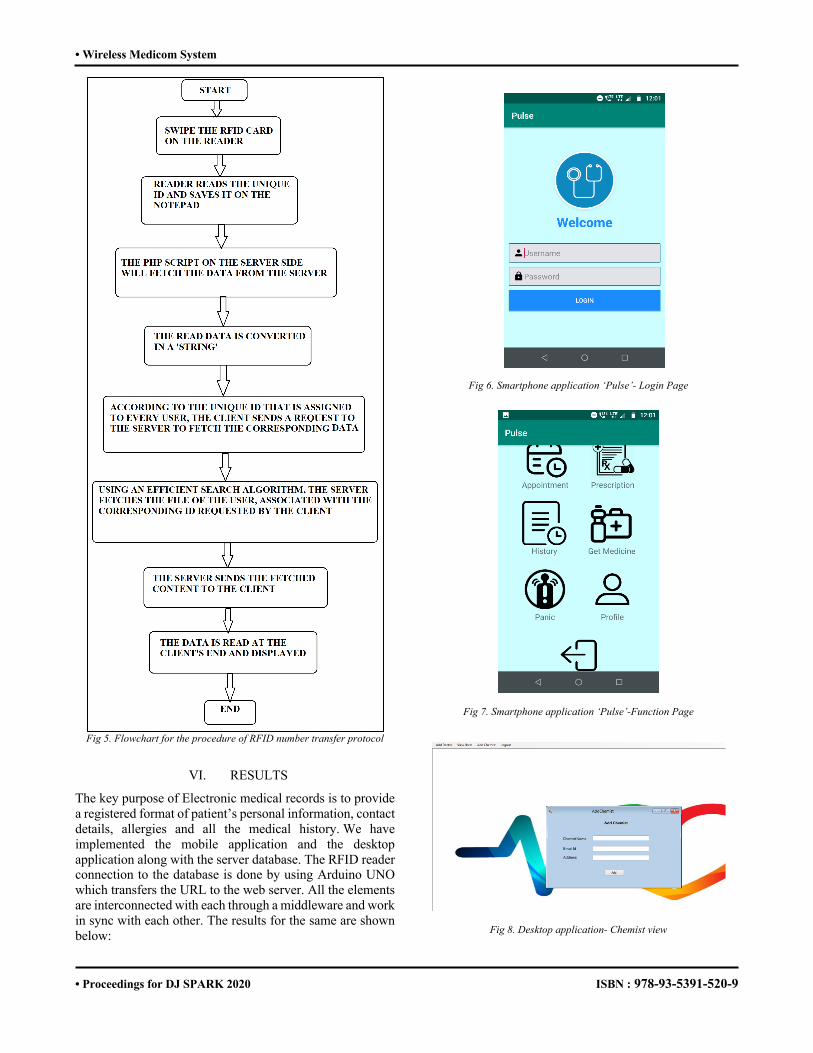
• Wireless Medicom System
• Proceedings for DJ SPARK 2020 ISBN : 978-93-5391-520-9
Fig 5. Flowchart for the procedure of RFID number transfer protocol
VI. RESULTS
The key purpose of Electronic medical records is to provide a registered format of patient’s personal information, contact details, allergies and all the medical history. We have implemented the mobile application and the desktop application along with the server database. The RFID reader connection to the database is done by using Arduino UNO which transfers the URL to the web server. All the elements are interconnected with each through a middleware and work in sync with each other. The results for the same are shown below:
Fig 6. Smartphone application ‘Pulse’- Login Page
Fig 7. Smartphone application ‘Pulse’-Function Page
Fig 8. Desktop application- Chemist view

• Wireless Medicom System
• Proceedings for DJ SPARK 2020 ISBN : 978-93-5391-520-9
Fig 9. Desktop application- Reading of RFID Tag with patient details
VII. FUTURE SCOPE The proposed system can be improved by adding additional features in it, such as another research carried out at a Greek hospital, introducing the application of RFID technology for the management of blood samples via a blood bank management system. Results from the study indicate that RFID in combination with barcodes can aid in better management of blood samples and reduce the risk of misidentification and wastage of blood samples. Similarly, it argues that RFID technologies can help transfusion departments to better manage blood samples and facilitate the identification and transfusion to the correct patient of blood products. Bendavid and Boeck, (2011) noted that healthcare's value is rapidly escalating and supply management is critical with high-value services in demand. Limiting waste by better tracking of inventories will improve transparency and deliver efficiency. RFID systems that are accustomed to handling health-care materials may help to offset waste costs. Further research regarding the value of implementation and potential savings will help organizations get an improved understanding of RFID potential. FID tag readability is still based on the location and orientation of the tag due to the reader's read distance. Site evaluation prior to implementation is critical for investigating Wi-Fi access and possible equipment that will pose a signaling barrier. The implementation of RFID technology therefore requires extensive monitoring of the possible disruption of current medical devices. Future research will concentrate on optimizing RFID transmission within the institutional framework (Bowen, Wingrave, Klanchar, & Craighead, 2013).
VIII. CONCLUSIONS
Implementing the concept which we have proposed in this paper for such purposes can reduce the chances of medical and human errors in hospitals and other healthcare institutions. This paper offers some specific real-time applications of RFID technologies in the domain of healthcare and briefly describes the benefits provided by our system for the management of the healthcare system. This includes using RFID for patient identification, patient tracking, and patient monitoring. The system which we have suggested provides immediate access to emergency medical information about the patient and offers safe and secure access to electronic health records. Hence, this system enables the cardholder to receive high-quality medical aid in emergencies, by using the mobile application ‘Pulse’ which we have mentioned in this paper. Our proposed system could be used in hospitals with numerous patients visiting and having a large volume of data records, allowing hospital staff to read patients’ identification tags, which can help overcome some medical errors, like giving patients improper prescriptions or someone else’s treatment. It automates various daily operations and enables smooth interactions of numerous users.
REFERENCES [1] Arma A Mehdi ,Dr Anil Kumar ,Dr A. K. Jaiswal ,“A review of RFID –WSN
healthcare applications and issues”, International Journal of Advanced Research in Electronics and Communication Engineering (IJARECE), June 2017, Vol. 6, Issue 6, ISSN: 2278 – 909X
[2] Chia-Chen Chen, Ya-Fen Chang, “Smart Healthcare Environment: Design with RFID Technology and Performance Evaluation”, Journal of Medical and Biological Engineering, 2013, Vol. 33 No. 4
[3] Arma A Mehdi ,Dr Anil Kumar ,Dr A. K. Jaiswal, “A review of RFID –WSN healthcare applications and issues”, International Journal of Advanced Research in Electronics and Communication Engineering (IJARECE), June 2017, Vol. 6, Issue 6, ISSN: 2278 – 909X
[4] Mohammad Mizanur Rahman, "Using RFID Technology for Managing Patient Medical File", American Journal of Computer Science and Information Technology, 2018, Vol.6 No.2:24
[5] Turcu, Cristina Elena and Cornel Turcu. “RFID-based Solutions for Smarter Healthcare.” ArXiv abs/1705.09855 (2017): n. pag.
[6] https://en.wikipedia.org/wiki/Android_Studio [7]https://visualstudio.microsoft.com/ [8]https://kotlinlang.org/ [9]Simarpreet Kaur, Kamaljeet Kaur, ‘Future of RFID Technology in Health Care
Systems: A Review Paper’, August 2012, Vol 2, Issue 8, pp 1373-1376 ISSN: 2231-0711
[10]“Integrating WSN with Web Services for Patient’s Record Management using RFID”, Advance Computing Conference (IACC) IEEE 3rd International, 2013, ISBN: 978-1-4673-4527-9, pp 605-609
[11]Haddara, Moutaz&Staaby, “Anne RFID Applications and Adoptions in Healthcare: A Review on Patient Safety”, Procedia Computer Science, 2018, Vol. 138, pp 80-88.

• Biometrics based Voting System using Iris and Face Authentication System
• Proceedings for DJ Spark 2020 ISBN: 978-93-5391-520-9
Biometrics based Voting System using Iris and Face Authentication System
Prachi Shah1, Nityashree Vaidya1, Kinjal Shah1, Janaki Shah1, Yukti Bandi2 1 U. G. Student, Dept of Electronics and Telecommunication, D.J.Sanghvi College of Engineering, Vile Parle (W), Mumbai- 400056 2 Professor, Electronics and Telecommunication DepartmentD.J.Sanghvi College of Engineering, Vile Parle (W), Mumbai- 400056
E-mail: [email protected], [email protected], [email protected],[email protected], [email protected]
Abstract: Biometric identification management systems offer higher security and convenience in the voting system. Out of the various biometric techniques, Iris and face recognition prove to be highly accurate and the combination itself creates a very unique identity for every individual. For Iris recognition, authentication algorithms such as Hamming distance and Haar cascade classifier were applied using MATLAB. The face recognition was implemented using Fisher and Local Binary Patterns Histogram (LBPH) algorithms through Python and OpenCV applications. As voting forms the base for any democratic country, higher security and authentication are the need of the hour and we believe that as time moves forward, we will see implementation of biometric technology continue to grow and be used in even more areas that touch our lives. Key Words: Image Processing, MATLAB, Web Camera, Python, OpenCV, Haar cascade classifier, Fisher and LBPH algorithm
I. INTRODUCTION Every voter and citizen of India are given a right to choose their government or political representative through the process of voting. It promotes not only social awareness but also energizes political cooperation. Almost all electoral processes include identification of voters, voting, creating a repository of votes, tallying the votes and the announcement of the results. Security is the most important part of the voting process. Proper identification of the voters is necessary. Therefore, it is very critical to have a secure voting system. This can be achieved by using biometric techniques like face and iris recognition. During elections, these biometric techniques can be adopted for the authentication of the voters. A voter is allowed to vote only when his biometric pattern matches with the one in the database. This process will also increase transparency in the system. The uniqueness of a human face and iris is the main component on which this biometrics-based voting system is proposed. This will increase the confidence of the voters in the system. It will also help in keeping the voter information confidential. For the voter registration and authentication processes that are performed, iris scanning is done by measuring the unique patterns in irises using the Haar cascade classifier and hamming distance. Similarly, face recognition is performed by considering the multiple unique features of the human face using Fisher and Local Binary Patterns Histogram (LBPH)
techniques. After this process, the pattern of face and iris are analyzed and these patterns will be converted into code which will be saved in the database. Multiple registrations are avoided by implementing this process. During the voting process, voters are expected to verify their biometric samples (face and iris) against the values stored in the database. These samples can be matched with the help of a unique voter identification number that is referred to during the registration. All the questions that may have cropped up on the eligibility of the voters and accreditation issues can be resolved by this.
II. LITERATURE SURVEY An iris recognition system was proposed which could verify both the singularity of the human iris and also its performance as a biometric identification tool. A biometric system provides automatic discerning of an individual based on a unique feature or characteristic possessed by them. This is regarded as the most reliable and accurate biometric identification tool available. This system consists of a self-regulating segmentation system that is based on the Hough transform, and locates the circular iris and pupil region, avoiding eyelids and eyelashes, and reflections. The extracted iris region is then normalized into a rectangular block with constant dimensions to account for imaging inconsistencies. Finally, the unique pattern of the iris is encoded into a bit-wise biometric template by extracting the phase data from 1D Log-Gabor filters and quantizing to four layers. The Hamming distance was employed for classification of iris templates, and two templates were found to match if a test of statistical independence was failed. A popular topic in biometrics research is Face detection and recognition from an image or a video. It is widely acknowledged that the face recognition plays an important role in applications such as a surveillance system as it doesn’t need the object’s co-operation. And thus, due to this enormous application value and market potential, it attracts widespread attention. The paper presents a real-time face recognition system based on Web camera and image set algorithm using Python programming environment. The system includes three parts: Detection module, training module and testing module. The paper develops the visual feature for face detection and recognition using OpenCV. The images of the persons are
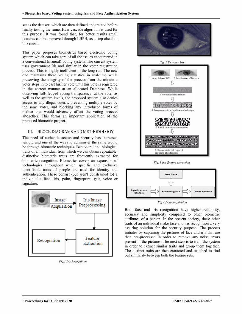
• Biometrics based Voting System using Iris and Face Authentication System
• Proceedings for DJ Spark 2020 ISBN: 978-93-5391-520-9
set as the datasets which are then defined and trained before finally testing the same. Haar cascade algorithm is used for this purpose. It was found that, for better results small features can be improved through LBPH, as a step ahead to this paper. This paper proposes biometrics based electronic voting system which can take care of all the issues encountered in a conventional (manual) voting system. The current system uses government Ids and similar in the voter registration process. This is highly inefficient in the long run. The new one maintains these voting statistics in real-time while preserving the integrity of the process from the minute a voter steps in to cast his/her vote until this vote is registered in the correct manner at an allocated Database. While observing full-fledged voting transparency, at the voter as well as the system levels, the proposed system also denies access to any illegal voter/s, preventing multiple votes by the same voter, and blocking any introduced forms of malice that would adversely affect the voting process altogether. This forms an important application of the proposed biometric project.
III. BLOCK DIAGRAMS AND METHODOLOGY The need of authentic access and security has increased tenfold and one of the ways to administer the same would be through biometric techniques. Behavioral and biological traits of an individual from which we can obtain repeatable, distinctive biometric traits are frequently extracted for biometric recognition. Biometrics covers an expansion of technologies throughout which specific and exclusive identifiable traits of people are used for identity and authentication. These consist (but aren't constrained to) a individual’s face, iris, palm, fingerprint, gait, voice or signature.
Fig.1 Iris Recognition
Fig. 2 Detected Iris
Fig. 3 Iris feature extraction
Fig 4 Data Acquisition
Both face and iris recognition have higher reliability, accuracy and simplicity compared to other biometric attributes of a person. In the present society, these other traits of an individual make face and iris recognition a very assuring solution for the security purpose. The process initiates by capturing the pictures of face and iris that are then pre-processed in order to remove any noise errors present in the pictures. The next step is to train the system in order to extract similar traits and group them together. The distinct traits are then extracted and matched to find out similarity between both the feature sets.

• Biometrics based Voting System using Iris and Face Authentication System
• Proceedings for DJ Spark 2020 ISBN: 978-93-5391-520-9
Fig. 5 Face Recognition
Fig. 6 Face Extraction
This project proposes to replace the current identification process of using IDs with biometrics (face & iris) at the voting booths to enhance the security for the voter. The chosen application finds a lot of importance in democratic countries with large populations. Hence, secure way of implementing the same is the need of the hour. Every individual has a unique iris pattern throughout his life. A pupil is a round black disk which is situated within the center of the eyeball. The pupil’s size changes with respect to the amount of light it is exposed to as it contracts in dark and dilates on exposure to light. Iris is the annular ring which lies between the pupil boundary and sclera that includes tons of minute detailed information. Face recognition is another biometric technique that is used to capture the performance of people’s daily routine lives. As a human’s natural biology cannot be vanished, stolen, forgotten, or fabricated, thus face recognition has been considered as a crucial technique compared to other biometric traits such as voice, gait, etc. The distinguishing traits of both the techniques, namely, iris and face recognition, have been compared through confusion matrices. Both provide different levels of accuracy and use different algorithms for training the system databases.
IV. WORKING PRINCIPLE A. Iris Recognition: The iris has a particularly data rich body and contains the flowery pattern that's unique to every individual. This pattern is highly stable and remains unchanged with age. The recognition system performs the analysis of the coloured tissue features that exist around the pupil. Overall, they form 250 points for comparison. Iris scanning process is subdivided into three key processes namely image/ signal gaining and dispensation, picture and identical process. The person first gets his iris scanned using a camera with inbuilt application to remove the surrounding eyelashes and eyelids. MATLAB is used for forming a template of the captured iris image and then stored into a database by giving an identity to it. During the matching process the required iris is scanned and the resulting template is compared with the database. If there is a match, the authentication is complete otherwise it is notified as different iris. B. Face Recognition: Face recognition process is of 4 stages given as input: test image or video, person face detection process, person face recognition process and output: person identification/verification. The process starts with the module detecting the face using a web cam. The data is gathered in a database by the way of extracting distinguishing features such as eyes, nose, mouth, face structure, etc. Considering the variations in background lighting and facial expressions, the unique traits are compared with the database. If matching occurs, the same is displayed with an accuracy rate. Otherwise the person is determined as unknown. OpenCV and Python environment has been used for the recognition system. OpenCV has three inbuilt recognizers which have been used and compared for their performances. The Eigen and Fisher face recognizers perform the capturing of only the unique traits in a face and under proper lighting. Local Binary Patterns Histogram compares all the pixels captured with the neighboring ones and uniqueness is identified. The matching rate generated from each of the recognizers are given to the decision module which decides if a person is authorized or not.
V. RESULTS
A. IRIS
Fig.7 Final output of iris recognition (1)

• Biometrics based Voting System using Iris and Face Authentication System
• Proceedings for DJ Spark 2020 ISBN: 978-93-5391-520-9
Fig. 8 Final output of iris recognition (2)
Initially, Canny-edge detection techniques were used along with Gabor filter for iris detection but it gave less robust results. When it was used with Gaussian filter it only recognized the boundaries and hence was less accurate for large dataset as boundaries for various iris can be similar. It was found that Haar Cascade Classifier coupled with Hamming distance proved to be the most accurate technique. Thus, a database of real time images and other predefined databases available online were tested upon to make the system highly efficient.
B. FACE
Fig. 9 Face Detection
Fig. 10 Face Authentication
For the Face recognition part, the 3 techniques implemented were Eigen Face recognizer, Fisher technique and LBPH. The former two require proper lighting to implement their respective algorithms. However, LBPH compares neighboring pixels and thus highlights the unique and otherwise ignored features of the face to form an accurate recognition system. However, the efficiency greatly depends on the database and larger the database more the training of the system, and more accurate it is. We achieved a reasonable amount of accuracy, but for higher level projects, a combination of two of the afore mentioned techniques would indeed provide better results.
C. STATISTICS
i) Iris
Fig. 11 Tabulation of iris samples
ii) Face
Fig. 12 Tabulation of face samples
iii) Combination of iris and face
Fig. 13 Tabulation of combination of iris and face samples
As per the Figure 11 it is seen that in Iris Recognition wherein CASIA dataset and a random database is used the accuracy is 72% as the number of correct identifications of iris is 90 out of the database of 125. While in a database of
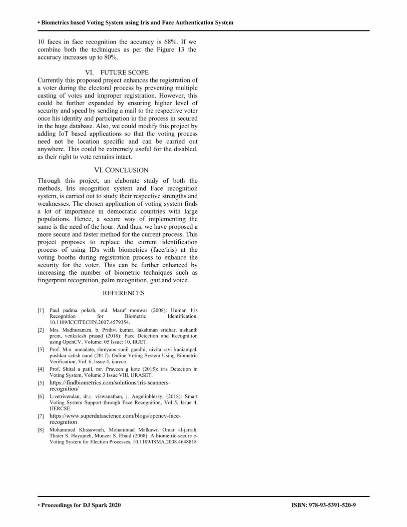
• Biometrics based Voting System using Iris and Face Authentication System
• Proceedings for DJ Spark 2020 ISBN: 978-93-5391-520-9
10 faces in face recognition the accuracy is 68%. If we combine both the techniques as per the Figure 13 the accuracy increases up to 80%.
VI. FUTURE SCOPE Currently this proposed project enhances the registration of a voter during the electoral process by preventing multiple casting of votes and improper registration. However, this could be further expanded by ensuring higher level of security and speed by sending a mail to the respective voter once his identity and participation in the process in secured in the huge database. Also, we could modify this project by adding IoT based applications so that the voting process need not be location specific and can be carried out anywhere. This could be extremely useful for the disabled, as their right to vote remains intact.
VI. CONCLUSION Through this project, an elaborate study of both the methods, Iris recognition system and Face recognition system, is carried out to study their respective strengths and weaknesses. The chosen application of voting system finds a lot of importance in democratic countries with large populations. Hence, a secure way of implementing the same is the need of the hour. And thus, we have proposed a more secure and faster method for the current process. This project proposes to replace the current identification process of using IDs with biometrics (face/iris) at the voting booths during registration process to enhance the security for the voter. This can be further enhanced by increasing the number of biometric techniques such as fingerprint recognition, palm recognition, gait and voice.
REFERENCES
[1] Paul padma polash, md. Maruf monwar (2008): Human Iris Recognition for Biometric Identification, 10.1109/ICCITECHN.2007.4579354.
[2] Mrs. Madhuram.m, b. Prithvi kumar, lakshman sridhar, nishanth prem, venkatesh prasad (2018): Face Detection and Recognition using OpenCV, Volume: 05 Issue: 10, IRJET.
[3] Prof. M.n. annadate, shreyans sunil gandhi, nivita ravi kaniampal, pushkar satish naral (2017): Online Voting System Using Biometric Verification, Vol. 6, Issue 4, ijarcce.
[4] Prof. Shital a patil, mr. Praveen g kote (2015): iris Detection in Voting System, Volume 3 Issue VIII, IJRASET.
[5] https://findbiometrics.com/solutions/iris-scanners-recognition/
[6] L.vetrivendan, dr.r. viswanathan, j. Angelinblessy, (2018): Smart Voting System Support through Face Recognition, Vol 5, Issue 4, IJERCSE.
[7] https://www.superdatascience.com/blogs/opencv-face-recognition
[8] Mohammed Khasawneh, Mohammad Malkawi, Omar al-jarrah, Thaier S. Hayajneh, Munzer S. Ebaid (2008): A biometric-secure e-Voting System for Election Processes, 10.1109/ISMA.2008.4648818
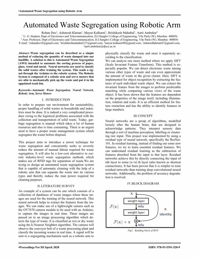
•Automated Waste Segregation using Robotic Arm
•Proceedings For DJ Spark 2020 ISBN: 978-93-5391-520-9
Automated Waste Segregation using Robotic ArmRohan Deo1, Ashutosh Khetan1, Mayur Kulkarni1, Hrishikesh Mahabal1, Aarti Ambekar2
1 U. G. Student, Dept of Electronics and Telecommunication, D.J.Sanghvi College of Engineering, Vile Parle (W), Mumbai- 400056 2 Asst. Professor, Dept of Electronics and Telecommunication, D.J.Sanghvi College of Engineering, Vile Parle (W), Mumbai- 400056
E-mail: [email protected], [email protected], [email protected], [email protected], [email protected]
Abstract--Waste segregation can be described as a simple method of reducing the quantity of waste dumped into our landfills. A solution to this is Automated Waste Segregation (AWS) intended to automate the sorting process of paper, glass, wood and metal. Neural networks are used to classify the solid wastes after training the system. This sends a sig-nal through the Arduino to the robotic system. The Robotic System is composed of a robotic arm and servo motors that are able to mechanically pick up the waste and put it in the appointed trash bin.
Keywords--Automatic Waste Segregation, Neural Network, Robotic Arm, Servo Motors
I. INTRODUCTION In order to prepare our environment for sustainability, proper handling of solid wastes in households and indus-tries must be done. It is indeed a very complicated proce-dure owing to the logistical problems associated with the collection and transportation of solid waste. Today, gar-bage segregation is manual which takes a lot of human resources and also is time consuming. There is an urgent need to have a proper waste management system which segregates the waste before disposal. This project aims to introduce a newer technique for waste segregation and concurrently seeks to severely reduce the amount of manual labour required for waste segregation. It will also be a low-cost alternative to cur-rent industry-level waste segregation methods which makes use of RFID tags for separation of waste.We are trying to design an automated waste segregation system that is capable of automatic cleaning with the help of a robotic arm that can separate the waste into its various types and thereby reduce the man power required for cleaning purposes.
II. LITERATURE SURVEY An example of a system can be one which consists of a collection of databases of waste images where these im-ages are used for the training of the neural network. This neural network helps to extract the features from the im-ages. We can make use of a lightweight camera such as the OV7670 camera module to be used with an Arduino, to capture the images in real time. These images are passed on to an image processing algorithm which de-tects the type of waste. It is classified as wet or dry waste using the k-Nearest Neighbor algorithm. The camera will observe the conveyer belt of a waste processing plant and classify the incoming wastes in real time. A signal will be sent to a segregating mechanism such as a robotic arm to
physically classify the waste and store it separately ac-cording to the classification. We can analyze one more method where we apply SIFT (Scale Invariant Feature Transform). This method is es-pecially popular. We can detect electronic waste among various other types of waste and can even approximate the amount of waste in the given cluster. Here, SIFT is implemented for object recognition by extracting the fea-tures of each individual waste object. We can extract the invariant feature from the images to perform predictable matching while comparing various views of the waste object. It has been shown that the features are dependent on the properties of the image itself; including illumina-tion, rotation and scale. It is an efficient method for fea-ture extraction and has the ability to identify features in large numbers.
III. CONCEPT Neural networks are a group of algorithms, modelled loosely after the human brain, that are designed to acknowledge patterns. They interpret sensory data through a sort of machine perception, labelling or cluster-ing raw input. This project was implemented by using a residual type of neural network, specifically the ResNet-101. In residual learning, instead of finding out some new features, we try to learn essential residual features. We can understand residual learning as the subtraction of features absorbed from the input to that layer. Residual networks achieve this by directly connecting the input of nth layer to some (x+n) th layer (also known as shortcut connections). It has been proven that it is simpler to train residual networks than training deep convolutional neural networks. Additionally, the problem of accuracy degrada-tion is resolved.
IV. BLOCK DIAGRAM
Fig1. Building block of RNN
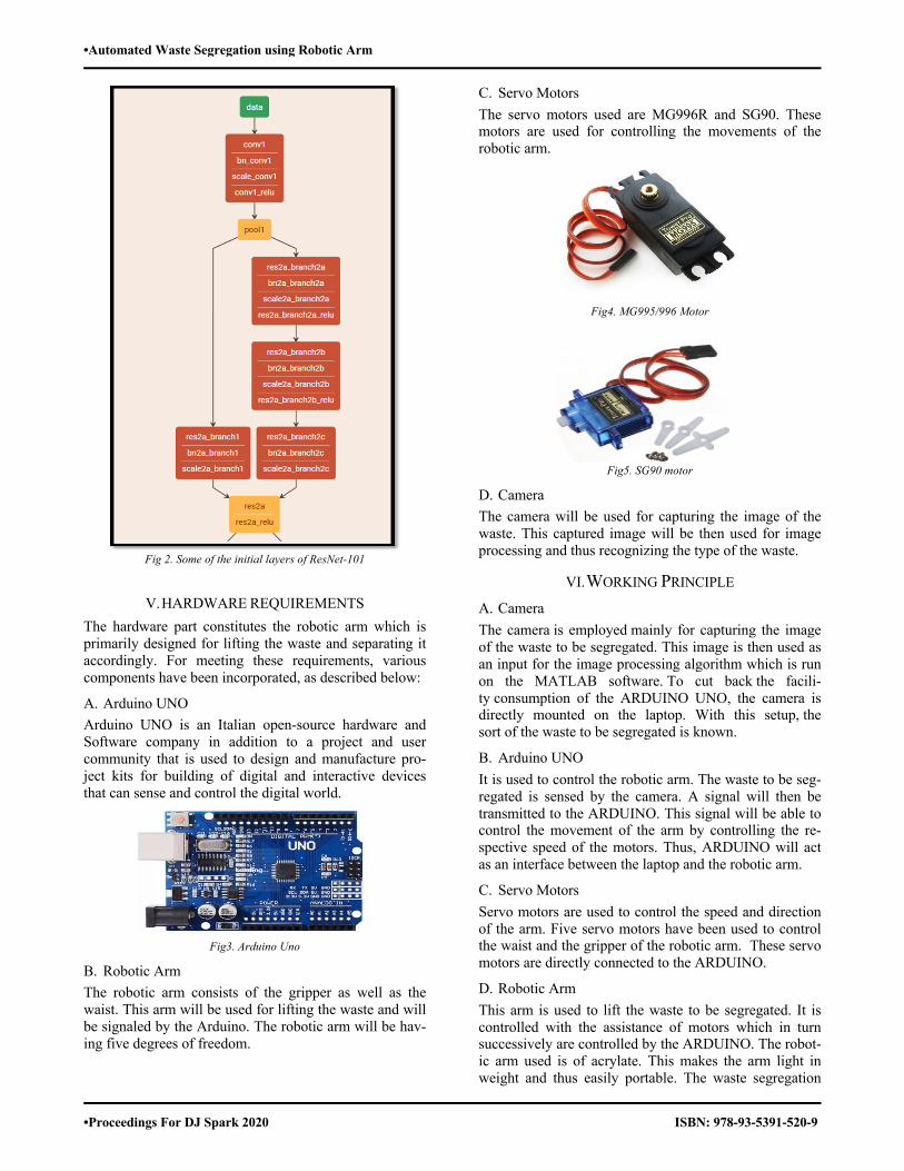
•Automated Waste Segregation using Robotic Arm
•Proceedings For DJ Spark 2020 ISBN: 978-93-5391-520-9
Fig 2. Some of the initial layers of ResNet-101
V. HARDWARE REQUIREMENTS The hardware part constitutes the robotic arm which is primarily designed for lifting the waste and separating it accordingly. For meeting these requirements, various components have been incorporated, as described below:
A. Arduino UNO Arduino UNO is an Italian open-source hardware and Software company in addition to a project and user community that is used to design and manufacture pro-ject kits for building of digital and interactive devices that can sense and control the digital world.
Fig3. Arduino Uno
B. Robotic Arm The robotic arm consists of the gripper as well as the waist. This arm will be used for lifting the waste and will be signaled by the Arduino. The robotic arm will be hav-ing five degrees of freedom.
C. Servo Motors The servo motors used are MG996R and SG90. These motors are used for controlling the movements of the robotic arm.
Fig4. MG995/996 Motor
Fig5. SG90 motor
D. Camera The camera will be used for capturing the image of the waste. This captured image will be then used for image processing and thus recognizing the type of the waste.
VI. WORKING PRINCIPLE A. Camera The camera is employed mainly for capturing the image of the waste to be segregated. This image is then used as an input for the image processing algorithm which is run on the MATLAB software. To cut back the facili-ty consumption of the ARDUINO UNO, the camera is directly mounted on the laptop. With this setup, the sort of the waste to be segregated is known.
B. Arduino UNO It is used to control the robotic arm. The waste to be seg-regated is sensed by the camera. A signal will then be transmitted to the ARDUINO. This signal will be able to control the movement of the arm by controlling the re-spective speed of the motors. Thus, ARDUINO will act as an interface between the laptop and the robotic arm.
C. Servo Motors Servo motors are used to control the speed and direction of the arm. Five servo motors have been used to control the waist and the gripper of the robotic arm. These servo motors are directly connected to the ARDUINO.
D. Robotic Arm This arm is used to lift the waste to be segregated. It is controlled with the assistance of motors which in turn successively are controlled by the ARDUINO. The robot-ic arm used is of acrylate. This makes the arm light in weight and thus easily portable. The waste segregation
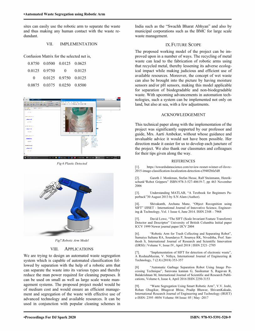
•Automated Waste Segregation using Robotic Arm
•Proceedings For DJ Spark 2020 ISBN: 978-93-5391-520-9
sites can easily use the robotic arm to separate the waste and thus making any human contact with the waste re-dundant.
VII. IMPLEMENTATION
Confusion Matrix for the selected net is,
0.8750 0.0500 0.0125 0.0625
0.0125 0.9750 0 0.0125
0 0.0125 0.9750 0.0125
0.0875 0.0375 0.0250 0.8500
Fig 6 Plastic Detected
Fig7.Robotic Arm Model
VIII. APPLICATIONS We are trying to design an automated waste segregation system which is capable of automated classification fol-lowed by separation with the help of a robotic arm that can separate the waste into its various types and thereby reduce the man power required for cleaning purposes. It can be used on small as well as large scale waste man-agement systems. The proposed project model would be of medium cost and would ensure an efficient manage-ment and segregation of the waste with effective use of advanced technology and available resources. It can be used in conjunction with popular cleaning schemes in
India such as the “Swachh Bharat Abhyan” and also by municipal corporations such as the BMC for large scale waste management.
IX. FUTURE SCOPE The proposed working model of the project can be im-proved upon in a number of ways. The recycling of metal waste can lead to the fabrication of robotic arms using that recycled metal, thereby lessening its adverse ecolog-ical impact while making judicious and efficient use of available resources. Moreover, the concept of wet waste can also be brought into the picture by having moisture sensors and/or pH sensors, making this model applicable for separation of biodegradable and non-biodegradable waste. With upcoming advancements in automation tech-nologies, such a system can be implemented not only on land, but also at sea, with a few adjustments.
ACKNOWLEDGEMENT
This technical paper along with the implementation of the project was significantly supported by our professor and guide, Mrs. Aarti Ambekar, without whose guidance and invaluable advice it would not have been possible. Her direction made it easier for us to develop each juncture of the project. We also thank our classmates and colleagues for their tips given along the way.
REFERENCES [1]. https://towardsdatascience.com/review-resnet-winner-of-ilsvrc-2015-image-classification-localization-detection-e39402bfa5d8
[2]. Gareth J. Monkman, Stefan Hesse, Ralf Steinmann, Henrik-schunk“Robot Grippers” ISBN:978-3-527-40619-7, pp 463 November 2006
[3]. Understanding MATLAB, “A Textbook for Beginners Pa-perback”30 August 2013 by S.N Alam (Author).
[4]. Shivakanth, Archana Mane, “Object Recognition using SIFT” IJISET - International Journal of Innovative Science, Engineer-ing & Technology, Vol. 1 Issue 4, June 2014. ISSN 2348 – 7968
[5]. David Lowe, “The SIFT (Scale Invariant Feature Transform) Detector and Descriptor” University of British Columbia Initial paper ICCV 1999 Newer journal paper IJCV 2004
[6]. “Robotic Arm for Trash Collecting and Separating Robot”, Sumaiya Sultana RA, Soundarya P, Soumya RK, Niveditha, Prof. San-thosh S, International Journal of Research and Scientific Innovation (IJRSI) | Volume V, Issue IV, April 2018 | ISSN 2321–2705
[7]. “Implementation of SIFT for detection of electronic waste”, A RoshnaMeeran, V. Nithya, International Journal of Engineering & Technology, 7 (2.8) (2018) 353-357
[8] “Automatic Garbage Separation Robot Using Image Pro-cessing Technique”, Saravana kannan G, Sasikumar S, Ragavan R, Balakrishnan M, International Journal of Scientific and Research Publi-cations, Volume 6, Issue 4, April 2016 ISSN 2250-3153
[9]. “Waste Segregation Using Smart Robotic Arm”, V.V. Joshi, Rohan Ghugikar, Bhagavat Bhise, Pradip Bhawar, ShivamKakade, International Research Journal of Engineering and Technology (IRJET) e-ISSN: 2395 -0056 Volume: 04 Issue: 05 | May -2017
•Arduino Based Self driving Car With Drowsiness Detection
•Proceedings for DJ Spark 2020 ISBN: 978-93-5391-520-9
Arduino Based Self Driving Car With Drowsiness Detection
Parth Kurhade1, Saniya Kirkire1, Shreya Nayak1, Nishi Modi1, Gaurang Kamat1,Anuja Odhekar2 1U.G. student, Dept of Electronics and Telecommunication, D.J. Sanghvi College of Engineering, Vile Parle (W), Mumbai-56
2Assistant Professor, Electronics and Telecommunication Dept D.J. Sanghvi College of Engineering, Vile Parle (W), Mumbai-56 Email:[email protected],[email protected],[email protected],[email protected],
[email protected], [email protected]
Abstract -- Since last decade there has been a huge technological advancement in automobiles right from traditional vehicles powered by steam engine to the newly emerging concept of self-drive cars. Interminable efforts are being made in this field to prioritize road safety and build smart cars which not only hold the potential to ensure effective transportation but also the key to minimize road accidents. In this paper we present an Arduino based self-drive car with added software-based features like drowsiness detection, voice control along with line following ability and obstacle detection. The system uses OpenCV-Python to achieve control over the car by voice commands. The drowsiness detector detects the expression of the driver and sends signals to the Arduino board. The Arduino switches the car to self- drive mode depending upon the signal received and it also sends a signal to an app which is linked with it. The app performs the task of sending SOS. It also accounts for controlling the sensors and motors which are responsible for obstacle detection and route following.
Keywords -- Drowsiness detection, Obstacle detection, Speech recognition, Automation, Hardware and Software, Arduino, Python-OpenCV.
I. INTRODUCTION
For a long time, the full driving task is a very complicated task due to many reasons such as distraction, drowsiness, etc. As human beings, we take for granted how much smartness is required to successfully attaining the awareness and understanding the complications of the situations. Even after many years, the problems of localization, mapping, vehicle control, scene perception, trajectory optimization, etc. which associated with self-driving vehicles remain full of open challenges that is yet to be fully solved by the present prosed systems. Hence, we propose a self-driving car which is capable of driving with little or no human intervention by sensing the surrounding environment. They are combined with special sensors to observe and act to the changes in their surroundings and software to control and navigate the car to the driver’s desired location. In few developed countries, there are partially autonomous cars which help in lane assistance, speed controls and applying emergency brakes. Although, it is currently used for safety purposes, this technology is becoming more common and will
impact the transportation systems. Most of the self-driving systems generate and maintain an internal map of their current environment by using their various sensors such as ultrasonic sensors. By the given inputs of the sensors, the software analyses and guides the car to the most appropriate path by controlling its acceleration, braking and steering in order to avoid any obstacle. In case of uncertain encounters or by the desire of the driver, he/she can intervene the system by the software used in this autonomous system.
The need for automobiles is ceaseless but it has led to some complications and a few threats to road safety. 94% of accidents occur due to human error often leading to loss of life and property. Self- drive cars have the potential to avert 75 to 90% of car accidents by. Emotion detection will stop the driver from manually controlling the vehicle on detection of an unstable state of mind while obstacle detection will stop the car at a certain distance from any obstacle. Speech recognition makes the car even more convenient. Together it will increase the ease and reduce the amount of accidents. By this project, we can study the human behavior and interaction with the advanced vehicle technology assisting the driver by primarily sensing the external environment and controlling the vehicle or vehicle communication with the driver based on the perceived state of surroundings. This self-driving technology is highly beneficial to those who are unable to drive by themselves such as elderly or disabled.
II. OBJECTIVE The main motive of this project is to use the concepts of machine learning to capture the images of the driver, analyse it using some pre-defined logic and give a relatable output using dedicated hardware. The specific objectives would be to analyse and evaluate how to program the Arduino Uno and Mega and link with the Python programs to interface the module with its camera to take images and to create an image processing technique to understand images correctly while giving it audio input which will navigate the autonomous vehicle to avoid obstructions and follow the path safely. After being implemented successfully, this system can correctly
102
•Arduino Based Self driving Car With Drowsiness Detection
•Proceedings for DJ Spark 2020 ISBN: 978-93-5391-520-9
guide self-driving car so that it can locate the desired location and making driving a little bit easier. For example, if a person needs to reach home and he is sleepy, he/she could just put the location on the app linked to the car and when the input location is given, the car uses the map to reach the user’s home. After recognizing the emotion of the driver, the conversion is done using a specific methodology. Matching the emotion and face of the driver with the dataset results to ensure the psychology of the driver is one of the important tasks. When the emotion detection is done by the Python code, it gives the commands to the Arduino by using the WiFi module device and the motors of the car. This system would be convenient to use and would make them independent in many ways. The driver can give voice commands which would be detected by using the app and the car could change its directions as per his/her will. He/she can also use RemoteXY app to control the path when he wants the car to be operated in manual mode. Thus, it helps in three ways- avoiding nearby obstacles faced by the car, using voice commands to control the car and driving in fully automatic mode depending on his/her emotions.
III. LITERATURE SURVEY
According to the SAE (The Society for Automotive engineers, India) [1], this car had three types of operation modes. The first mode is the manual mode in which the driver can drive the car by himself according to his will or use the application in his mobile phone to control the direction of the moving car. The second mode is the voice-control mode in which the user can tell the direction which the vehicle should follow. This is done by machine learning. The third mode is full automation mode in which the user the car finds its own path and follows the route according to its surroundings. This mode is already in use in Japanese public transport such as buses.
As per this system, the driver has to continuously press clutch, brake and acceleration during heavy traffic. This project provides an easier alternative in which the car makes smart enough decisions to drive automatically and maintain certain distance from other vehicles instead of tail-gating. The traffic situation in the major cities of India has led to design this prototype, which aims at relaxing the driver and creating the destination of the automated car dynamic as per the driver’s need.
In this research paper, the vehicles which are highly autonomous can exhibit better speeds and responses as compared to human drivers by using computer vision and integral memory microprocessors which could be designed for parallel processing and multitasking to react in real time. This will also enable adaptive cruising, lane discipline and automatic braking system.
According to this analysis [4], we could use computer vision to extract more information through the cameras
present in the car which are being used to analyse driver’s emotions, body language and the external driving scenario. We could also use GPS (Global Positioning System), IMU (Inertial Measurement Unit), CAN bus data to add detailed context and frequency of technological use. This could be further comprehended by detailed questionnaire and interviews which would be mainly related to the driver’s history, exposure to conventional and automatic technology, mental model evaluation, importance and view on safety, self-reported use and enjoyment. By using this interdisciplinary approach, the data would give us the analysis of the real-world advanced technology use that could help us identify the potential areas for design, policy and driver’s educational improvements.
IV. BACKGROUND
A. IR Sensors
IR Sensors are used to indicate any obstruct present in front of them. IR LED emits infrared light (wavelength is in the range of 700nm – 1mm) with light emitting angle of range of approximately 20 to 60 degrees and could detect the obstacle in its vicinity from few centimeters to several feet. Photodiode present on the sensor acts as IR receiver, which would conduct when the infrared light falls on it. Op-Amp LM358 is used as voltage comparator in the IR sensor. When its output becomes high it would indicate the detection of an object present ahead.
Fig 1: IR Sensor HW-201
B. Bluetooth Module
The Bluetooth technology enables wireless communication between two devices. This module can transmit and receive data from a host system by using the host controller interface (HCI). Bluetooth is free to use according to the wireless communication protocol as the range is lesser than the other wireless communication medium such as WiFi, etc.
Fig 2: Bluetooth Module HC-05
103
•Arduino Based Self driving Car With Drowsiness Detection
•Proceedings for DJ Spark 2020 ISBN: 978-93-5391-520-9
C. Arduino Uno
Arduino is an open-source computer hardware and software single-board microcontroller which is used for building digital and interactive devices and objects that can sense and control the physical world. The Arduino can be installed with code and thus it can prove to be a very helpful device for robotics. It is also deployed in artificial intelligence projects. Arduino is particularly used by designers and artists who do not need much of the technical knowledge to demonstrate their projects. It has a very large number of support libraries which makes it very great platform for making basic to complex circuits.
Fig 3: Arduino Uno
D. MPU6050 module
MPU6050 is a Micro Electro-mechanical system (MEMS) which accelerometer and gyroscope based on three axes. It is mainly used for the measurement of velocity, orientation, acceleration, displacement and other motion- related features. It has Digital Motion Processor (DMP), which solves complex calculations. It captures three-dimensional motion as it consists of a 16-bit analog to digital converter hardware.
Fig 4: MPU6050 (Accelerometer and Gyroscope)
E. Motor Driver IC
The motor driver IC allows the DC motor to drive either direction. L298N is an IC consisting 16 pins which can control two DC motors simultaneously in any direction. This IC works on the concept of H-Bridge which allows the voltage to be flown in any direction.
Fig 5: Motor Driver L298N
F. GPS Module
The GPS Module for Arduino is an electronic device which is used to get position and altitude, as well as speed, date and time on UTC (Universal Time Coordinated). It uses NMEA (National Marine Electronics Associated) protocol to transmit the position data via serial port. comprises of a built-in ceramic active antenna which provides strong satellite search capability.
Fig 6: GPS Module (Neo-6M)
G. Arduino Mega
The advantage of Arduino Mega over Arduino Uno is that it has 54 digital input/output pins, 16 analog inputs and 4 UARTs (hardware serial ports). The Mega 2560 R3 adds SDA and SCL pins next to AREF and there are two new pins placed near the RESET pin. One is the IOREF shields to adapt to the voltage provided from the board. The other one is not connected and is reserved for the future purposes.
Fig 7: Arduino Mega 2560 R3
H. Transreceiver Module
The wireless transreceiver module (NRF24L01) can transmit data at a rate up to 2Mbps for ultra-low power applications and operates in the 2.4GHz ISM frequency band with the communication range of 100 metres. This module can be used for 125 different channels making 125 independent working modems in one place.
Fig 8: Transreceiver module with antenna
104
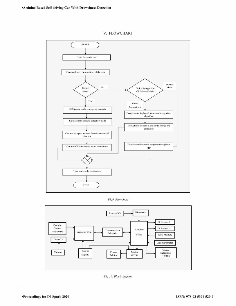
•Arduino Based Self driving Car With Drowsiness Detection
•Proceedings for DJ Spark 2020 ISBN: 978-93-5391-520-9
V. FLOWCHART
Fig9. Flowchart
Fig 10: Block diagram
105
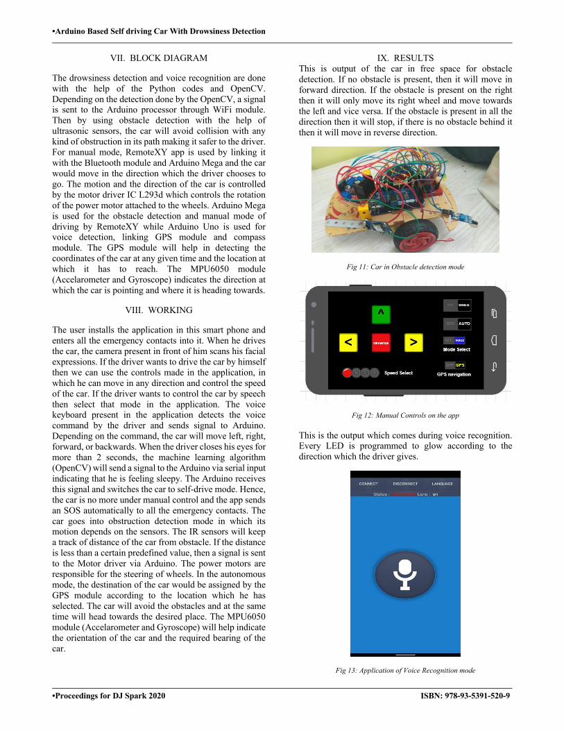
•Arduino Based Self driving Car With Drowsiness Detection
•Proceedings for DJ Spark 2020 ISBN: 978-93-5391-520-9
VII. BLOCK DIAGRAM
The drowsiness detection and voice recognition are done with the help of the Python codes and OpenCV. Depending on the detection done by the OpenCV, a signal is sent to the Arduino processor through WiFi module. Then by using obstacle detection with the help of ultrasonic sensors, the car will avoid collision with any kind of obstruction in its path making it safer to the driver. For manual mode, RemoteXY app is used by linking it with the Bluetooth module and Arduino Mega and the car would move in the direction which the driver chooses to go. The motion and the direction of the car is controlled by the motor driver IC L293d which controls the rotation of the power motor attached to the wheels. Arduino Mega is used for the obstacle detection and manual mode of driving by RemoteXY while Arduino Uno is used for voice detection, linking GPS module and compass module. The GPS module will help in detecting the coordinates of the car at any given time and the location at which it has to reach. The MPU6050 module (Accelarometer and Gyroscope) indicates the direction at which the car is pointing and where it is heading towards.
VIII. WORKING
The user installs the application in this smart phone and enters all the emergency contacts into it. When he drives the car, the camera present in front of him scans his facial expressions. If the driver wants to drive the car by himself then we can use the controls made in the application, in which he can move in any direction and control the speed of the car. If the driver wants to control the car by speech then select that mode in the application. The voice keyboard present in the application detects the voice command by the driver and sends signal to Arduino. Depending on the command, the car will move left, right, forward, or backwards. When the driver closes his eyes for more than 2 seconds, the machine learning algorithm (OpenCV) will send a signal to the Arduino via serial input indicating that he is feeling sleepy. The Arduino receives this signal and switches the car to self-drive mode. Hence, the car is no more under manual control and the app sends an SOS automatically to all the emergency contacts. The car goes into obstruction detection mode in which its motion depends on the sensors. The IR sensors will keep a track of distance of the car from obstacle. If the distance is less than a certain predefined value, then a signal is sent to the Motor driver via Arduino. The power motors are responsible for the steering of wheels. In the autonomous mode, the destination of the car would be assigned by the GPS module according to the location which he has selected. The car will avoid the obstacles and at the same time will head towards the desired place. The MPU6050 module (Accelarometer and Gyroscope) will help indicate the orientation of the car and the required bearing of the car.
IX. RESULTS This is output of the car in free space for obstacle detection. If no obstacle is present, then it will move in forward direction. If the obstacle is present on the right then it will only move its right wheel and move towards the left and vice versa. If the obstacle is present in all the direction then it will stop, if there is no obstacle behind it then it will move in reverse direction.
Fig 11: Car in Obstacle detection mode
Fig 12: Manual Controls on the app
This is the output which comes during voice recognition. Every LED is programmed to glow according to the direction which the driver gives.
Fig 13: Application of Voice Recognition mode
106
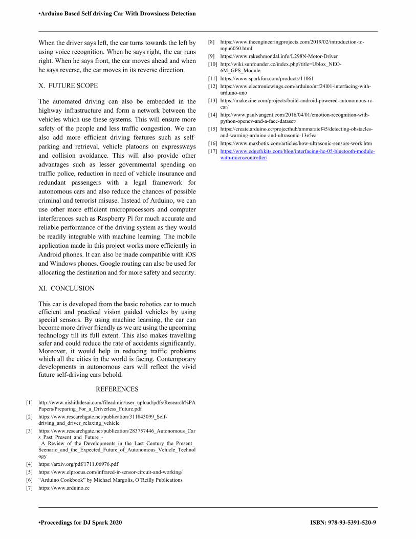
•Arduino Based Self driving Car With Drowsiness Detection
•Proceedings for DJ Spark 2020 ISBN: 978-93-5391-520-9
When the driver says left, the car turns towards the left by using voice recognition. When he says right, the car runs right. When he says front, the car moves ahead and when he says reverse, the car moves in its reverse direction.
X. FUTURE SCOPE
The automated driving can also be embedded in the highway infrastructure and form a network between the vehicles which use these systems. This will ensure more safety of the people and less traffic congestion. We can also add more efficient driving features such as self-parking and retrieval, vehicle platoons on expressways and collision avoidance. This will also provide other advantages such as lesser governmental spending on traffic police, reduction in need of vehicle insurance and redundant passengers with a legal framework for autonomous cars and also reduce the chances of possible criminal and terrorist misuse. Instead of Arduino, we can use other more efficient microprocessors and computer interferences such as Raspberry Pi for much accurate and reliable performance of the driving system as they would be readily integrable with machine learning. The mobile application made in this project works more efficiently in Android phones. It can also be made compatible with iOS and Windows phones. Google routing can also be used for allocating the destination and for more safety and security.
XI. CONCLUSION
This car is developed from the basic robotics car to much efficient and practical vision guided vehicles by using special sensors. By using machine learning, the car can become more driver friendly as we are using the upcoming technology till its full extent. This also makes travelling safer and could reduce the rate of accidents significantly. Moreover, it would help in reducing traffic problems which all the cities in the world is facing. Contemporary developments in autonomous cars will reflect the vivid future self-driving cars behold.
REFERENCES
[1] http://www.nishithdesai.com/fileadmin/user_upload/pdfs/Research%PAPapers/Preparing_For_a_Driverless_Future.pdf
[2] https://www.researchgate.net/publication/311843099_Self-driving_and_driver_relaxing_vehicle
[3] https://www.researchgate.net/publication/283757446_Autonomous_Cars_Past_Present_and_Future_-_A_Review_of_the_Developments_in_the_Last_Century_the_Present_Scenario_and_the_Expected_Future_of_Autonomous_Vehicle_Technology
[4] https://arxiv.org/pdf/1711.06976.pdf [5] https://www.elprocus.com/infrared-ir-sensor-circuit-and-working/ [6] “Arduino Cookbook” by Michael Margolis, O’Reilly Publications [7] https://www.arduino.cc
[8] https://www.theengineeringprojects.com/2019/02/introduction-to-mpu6050.html
[9] https://www.rakeshmondal.info/L298N-Motor-Driver [10] http://wiki.sunfounder.cc/index.php?title=Ublox_NEO-
6M_GPS_Module [11] https://www.sparkfun.com/products/11061 [12] https://www.electronicwings.com/arduino/nrf24l01-interfacing-with-
arduino-uno [13] https://makezine.com/projects/build-android-powered-autonomous-rc-
car/ [14] http://www.paulvangent.com/2016/04/01/emotion-recognition-with-
python-opencv-and-a-face-dataset/ [15] https://create.arduino.cc/projecthub/ammaratef45/detecting-obstacles-
and-warning-arduino-and-ultrasonic-13e5ea [16] https://www.maxbotix.com/articles/how-ultrasonic-sensors-work.htm [17] https://www.edgefxkits.com/blog/interfacing-hc-05-bluetooth-module-
with-microcontroller/
107
•Eye Stick
•Proceedings for DJ Spark 2020 ISBN: 978-93-5391-520-9
Eye Stick Shyamal Oza1,Vrutansh Shah1,Ujwala Dahimbekar1,Satvik Deshmukh1, Sachin Bhadoriya1, Rajus Nagwekar1, Shivani B2
1 U.G. Student, Dept of Electronic and Telecommunication, D.J.Sanghvi College of Engineering, Vile Parle (W), Mumbai-56 2 Asst Prof, Dept of Electronics and Telecommunication, D.J.Sanghvi College of Engineering, Vile Parle (W), Mumbai-56
E-mail: [email protected], [email protected], [email protected], [email protected],[email protected],[email protected],[email protected]
Abstract—Vision is one of the important sense of humans. But visually impaired people are devoid of this sense. In India there are about 12 million blind people against 39 million globally. The difficulties faced by them while travelling alone is unavoidable in absence of certain external help. Electronic Travel Aid (ETA) is the backbone mechanism of this project. Hence this advance technology driven stick would surely assist the blind and prove to ease out their travel, thus make them independent.
Keywords—Sensors, Arduino, GSM module, GPS module, LDR.
I. INTRODUCTION The core concept of this project is providing the blind with an aid that helps them to travel independently using the features that this Project possesses. The project includes designing of Stick that can guide the blind about the obstacles, water puddles, darkness and the directions to reach a particular place. Arduino is used as the brain of this project that performs interfacing of various components.
Ultrasonic sensors are attached to the stick that detects the obstacles and alerts the user by buzzer. Similarly, the presence of water puddle is detected by the moisture sensor, LDR notifies about the darkness in the surrounding area. The stick itself is covered with a LED strip that alerts the person walking around about the presence of a blind person. All the sensor’s activity is linked with a different frequency of buzzer. Hence the sensor alert can be distinguished and identified uniquely based upon the type of buzzer tone.
The Project also includes interfacing of the GPS module with Arduino that guides the blind about the path to a particular location. Text to speech feature is added that gives audio-based directions. GPS module is used for the same. A SOS button is mounted onto the stick that sends the emergency text message along with live location of the blind to the specified number as stored in the microprocessor. This system is implemented with GSM module. Overall on a broader aspect this Stick does all the work which practically proves to be an eye for the blind. Hence the name Eye Stick is selected for this project. Working as an Electronic Travel Aid this stick can assist the blind in their travel as stated earlier and can be also be worked upon as a part of future scopes for more functionalities.
II. LITERATURE SURVEY To understand the depth of this subject, the analysis of few sticks available presently is done. The stick based on the similar concept has buzzers indicating them about the
obstacles. Many proposed technologies include use of IR sensors as obstacle detection tool. Many research groups developed the stick with ultrasonic sensors and few with moisture sensor as well. The interfacing technologies differ broadly based upon the microprocessor used. Most of the projects are build up using Raspberry-Pie and Arduino UNO as their primary on-board chip processor acting as the brain for all the entire project working. A device that is already available as an Electronic Travel Aid was introduced in 1973 by Benjamin. Three laser diodes and three photo diodes are used as receivers. It is based on the optimal triangular reception. Obstacles at head-height, drop-offs in front of the user, and obstacles up to a range of 1.5 m or 3.5 m ahead of the user can be detected. Sonic Torch is the readily available hand-held device that works on the principal of ultrasonic sensors. The device basically operated on the principle of reflection and detection of ultrasonic beams in the forward direction. A research paper published in International Conference on Information Communication & Embedded Systems (ICICES 2014) journal depicted a fantastic mechanism to detect not only the obstacles but also measure the distance of the obstacles from the blind. Based upon the calculated distance the microcontroller is so programmed that it gives commands to buzzers to make beeps of different frequencies along with vibrating the stick. Arduino-UNO, Buzzers, Vibrators etc. An algorithm was devised to calculate the distance of the objects in the way. Thus, algorithm is presented in a tabular format called Output Distance Calculation.
III. STICK FEATURES Obstacle Detection: The stick detects the obstacle around the blind by using Ultrasonic sensors and guides the blind to take the clear path by beeping the buzzer of a particular determined frequency. An ultrasonic beam is sent from the transmitter and is in turn received by the receiver after reflection from the obstacle. Thus, this ultrasonic detection is performed for detecting the obstacles on the way of the blind.
Light Detection: The LDR Senses the presence of light around the bling and alerts him/her about the dark or danger prone areas. A specified frequency is set for the buzzer to beep on detection of light.
Moisture Sensing: The Moisture sensor attached at the stick end alerts the blind about the presence of any water puddles or any such hurdles.
GPS Tracker: The interfacing of GPS Module with the stick enables the Blind to get the live updates and
108
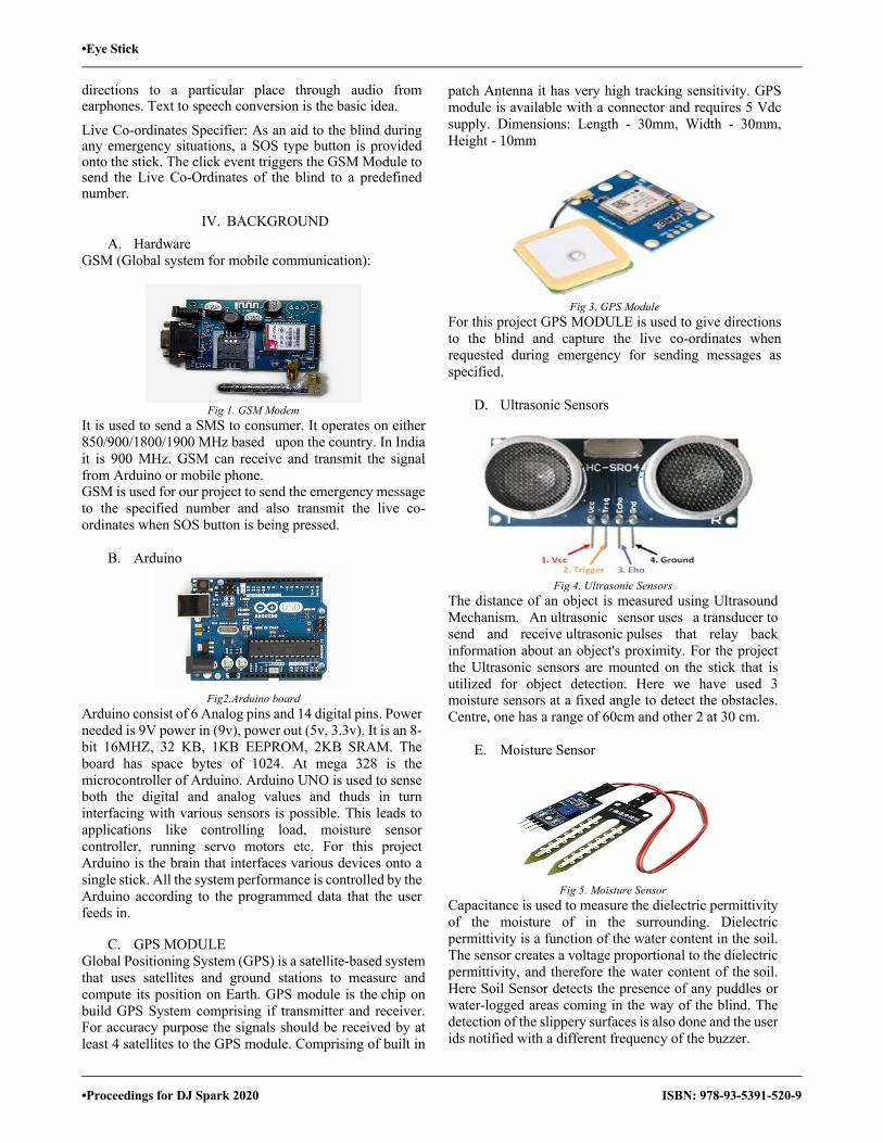
•Eye Stick
•Proceedings for DJ Spark 2020 ISBN: 978-93-5391-520-9
directions to a particular place through audio from earphones. Text to speech conversion is the basic idea.
Live Co-ordinates Specifier: As an aid to the blind during any emergency situations, a SOS type button is provided onto the stick. The click event triggers the GSM Module to send the Live Co-Ordinates of the blind to a predefined number.
IV. BACKGROUND A. Hardware
GSM (Global system for mobile communication):
Fig 1. GSM Modem
It is used to send a SMS to consumer. It operates on either 850/900/1800/1900 MHz based upon the country. In India it is 900 MHz. GSM can receive and transmit the signal from Arduino or mobile phone. GSM is used for our project to send the emergency message to the specified number and also transmit the live co-ordinates when SOS button is being pressed.
B. Arduino
Fig2.Arduino board
Arduino consist of 6 Analog pins and 14 digital pins. Power needed is 9V power in (9v), power out (5v, 3.3v). It is an 8-bit 16MHZ, 32 KB, 1KB EEPROM, 2KB SRAM. The board has space bytes of 1024. At mega 328 is the microcontroller of Arduino. Arduino UNO is used to sense both the digital and analog values and thuds in turn interfacing with various sensors is possible. This leads to applications like controlling load, moisture sensor controller, running servo motors etc. For this project Arduino is the brain that interfaces various devices onto a single stick. All the system performance is controlled by the Arduino according to the programmed data that the user feeds in.
C. GPS MODULE Global Positioning System (GPS) is a satellite-based system that uses satellites and ground stations to measure and compute its position on Earth. GPS module is the chip on build GPS System comprising if transmitter and receiver. For accuracy purpose the signals should be received by at least 4 satellites to the GPS module. Comprising of built in
patch Antenna it has very high tracking sensitivity. GPS module is available with a connector and requires 5 Vdc supply. Dimensions: Length - 30mm, Width - 30mm, Height - 10mm
Fig 3. GPS Module
For this project GPS MODULE is used to give directions to the blind and capture the live co-ordinates when requested during emergency for sending messages as specified.
D. Ultrasonic Sensors
Fig 4. Ultrasonic Sensors
The distance of an object is measured using Ultrasound Mechanism. An ultrasonic sensor uses a transducer to send and receive ultrasonic pulses that relay back information about an object's proximity. For the project the Ultrasonic sensors are mounted on the stick that is utilized for object detection. Here we have used 3 moisture sensors at a fixed angle to detect the obstacles. Centre, one has a range of 60cm and other 2 at 30 cm.
E. Moisture Sensor
Fig 5. Moisture Sensor
Capacitance is used to measure the dielectric permittivity of the moisture of in the surrounding. Dielectric permittivity is a function of the water content in the soil. The sensor creates a voltage proportional to the dielectric permittivity, and therefore the water content of the soil. Here Soil Sensor detects the presence of any puddles or water-logged areas coming in the way of the blind. The detection of the slippery surfaces is also done and the user ids notified with a different frequency of the buzzer.
109
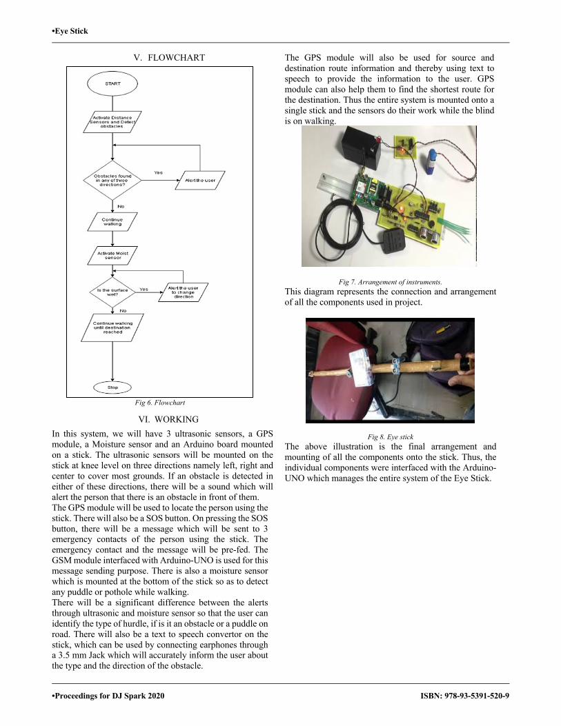
•Eye Stick
•Proceedings for DJ Spark 2020 ISBN: 978-93-5391-520-9
V. FLOWCHART
Fig 6. Flowchart
VI. WORKING In this system, we will have 3 ultrasonic sensors, a GPS module, a Moisture sensor and an Arduino board mounted on a stick. The ultrasonic sensors will be mounted on the stick at knee level on three directions namely left, right and center to cover most grounds. If an obstacle is detected in either of these directions, there will be a sound which will alert the person that there is an obstacle in front of them. The GPS module will be used to locate the person using the stick. There will also be a SOS button. On pressing the SOS button, there will be a message which will be sent to 3 emergency contacts of the person using the stick. The emergency contact and the message will be pre-fed. The GSM module interfaced with Arduino-UNO is used for this message sending purpose. There is also a moisture sensor which is mounted at the bottom of the stick so as to detect any puddle or pothole while walking. There will be a significant difference between the alerts through ultrasonic and moisture sensor so that the user can identify the type of hurdle, if is it an obstacle or a puddle on road. There will also be a text to speech convertor on the stick, which can be used by connecting earphones through a 3.5 mm Jack which will accurately inform the user about the type and the direction of the obstacle.
The GPS module will also be used for source and destination route information and thereby using text to speech to provide the information to the user. GPS module can also help them to find the shortest route for the destination. Thus the entire system is mounted onto a single stick and the sensors do their work while the blind is on walking.
Fig 7. Arrangement of instruments. This diagram represents the connection and arrangement of all the components used in project.
Fig 8. Eye stick The above illustration is the final arrangement and mounting of all the components onto the stick. Thus, the individual components were interfaced with the Arduino-UNO which manages the entire system of the Eye Stick.
110

•Eye Stick
•Proceedings for DJ Spark 2020 ISBN: 978-93-5391-520-9
VII. BLOCK DIAGRAM
Fig 9. Block Diagram
The brief block diagram explaining about the functionality of the stick is illustrated here. The Brain of the entire system is Arduino that controls the working of all the interfaced components in the system. Moisture Sensor, ultrasonic Sensors, LDR, Buzzers are interfaced with the Arduino. There is GSM -GPS interfacing which is the base of location tracking system.
VIII. APPLICATIONS AND FUTURE SCOPE The innovations behind visually impaired sticks are overhauling step by step. What's more, our model ensures one thing that is making the assignment of moving of a visually impaired individual simple and solace capable. The stick is likewise light and helpful to convey. Also, the segments or parts that we utilized in the stick are likewise effectively accessible and less in cost. What's more all that the fabricating cost is additionally very low, that makes the stick reasonable for individuals of all class and age. The further improvement and speculation is completed with the stick then it will be a significantly progressively viable gadget for the future world. A portion of the systems wherein this gadget can be altered are given beneath: Arduino can be supplanted by overhauled Microcontroller or chip. It can be additionally improved by utilizing VLSI innovation to plan the PCB unit. This can make the framework considerably increasingly minimal. More sensors can be utilized for additional application. Image preparing can be utilized for thinking about the volume of
deterrents and object designs. Android application can be created. High range ultrasonic sensor can be utilized. High range Laser sensors can be utilized. To give live demonstrations a text to speech.
IX. CONCLUSION This paper shows that there is an expansion in the versatility and exactness of the savvy stick for the outwardly impeded individuals. The primary point of the venture is to identify questions before the visually impaired individuals and make them to stroll effortlessly and more trust in some new ways and furthermore guarantee their security. The main aim behind this stick was to prove an eye for the blind and thus by various features of stick enlisted above we have achieved the objective and the project is open for further more modifications to make the stick smarter in terms of assisting the blind.
REFERENCES
[1] 2016 IEEE Students’ Conference on Electrical, Electronics and Computer Science DESIGN OF IOT BASED STICK (ICOE)
[2] https://www.ijeat.org/wp content/uploads/papers/v8i5S/E10040585S19.pdf
[3] Srinivasan, Srinidhi, and M. Rajesh. “Smart Walking Stick.” 2019 3rd International Conference on Trends in Electronics and Informatics (ICOEI), 2019, doi:10.1109/icoei.2019.8862753.
[4] Masudur Rahman, Noor-E-Jannat, Mohd. Ohidul Islam and Md. SerazusSalakin, Arduino and GSM Based Smart Stick, in Proceedings of 2nd Int’l Conf. on Electrical Engineering and Information Communication Technology (ICEEICT)2015 Jahangimagar University, Dhaka-I 342, Bangladesh, 21-23 May 2015.
[5] Dhananjayan, R. & Shanthi, E., “Blind stick ‘2014, pp.1397– 1403.
[6] Shahidi, S., Gaffar, M.A. & Salim, K.M., “Design and implementation of Stick assistance for blind using GSM network”, Proceedings of 2013 2nd International Conference on Advances in Electrical Engineering, ICAEE, 2013, pp.203– 206.
[7] Nayak, S., & Kumar, K. (2014). Smart Stick for Visually Impaired. Computer Science, Communication and Instrumentation Devices. doi: 10.3850/978-981-09-5247-1_019
[8] Smart Blind Stick. (2018). International Journal of Latest Trends in Engineering and Technology, 9(3). doi: 10.21172/1.93.45
[9] Mohapatra, S., Rout, S., Tripathi, V., Saxena, T., & Karuna, Y. (2018). Smart Walking Stick for Blind Integrated with SOS Navigation System. 2018 2nd International Conference on Trends in Electronics and Informatics (ICOEI). doi: 10.1109/icoei.2018.8553935
[10] Deore, T. (2019). Design and Development of Smart Blind Stick using Arduino. International Journal for Research in Applied Science and Engineering Technology, 7(6), 1134–1137. doi: 10.22214/ijraset.2019.6195.
111
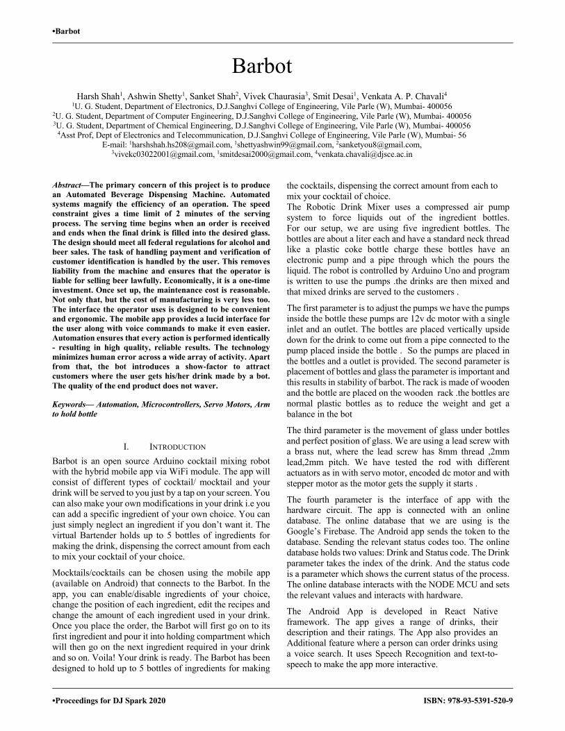
•Barbot
•Proceedings for DJ Spark 2020 ISBN: 978-93-5391-520-9
Barbot Harsh Shah1, Ashwin Shetty1, Sanket Shah2, Vivek Chaurasia3, Smit Desai1, Venkata A. P. Chavali4
1U. G. Student, Department of Electronics, D.J.Sanghvi College of Engineering, Vile Parle (W), Mumbai- 400056 2U. G. Student, Department of Computer Engineering, D.J.Sanghvi College of Engineering, Vile Parle (W), Mumbai- 400056 3U. G. Student, Department of Chemical Engineering, D.J.Sanghvi College of Engineering, Vile Parle (W), Mumbai- 400056 4Asst Prof, Dept of Electronics and Telecommunication, D.J.Sanghvi College of Engineering, Vile Parle (W), Mumbai- 56
E-mail: [email protected], [email protected], [email protected], [email protected], [email protected], [email protected]
Abstract—The primary concern of this project is to produce an Automated Beverage Dispensing Machine. Automated systems magnify the efficiency of an operation. The speed constraint gives a time limit of 2 minutes of the serving process. The serving time begins when an order is received and ends when the final drink is filled into the desired glass. The design should meet all federal regulations for alcohol and beer sales. The task of handling payment and verification of customer identification is handled by the user. This removes liability from the machine and ensures that the operator is liable for selling beer lawfully. Economically, it is a one-time investment. Once set up, the maintenance cost is reasonable. Not only that, but the cost of manufacturing is very less too. The interface the operator uses is designed to be convenient and ergonomic. The mobile app provides a lucid interface for the user along with voice commands to make it even easier. Automation ensures that every action is performed identically - resulting in high quality, reliable results. The technology minimizes human error across a wide array of activity. Apart from that, the bot introduces a show-factor to attract customers where the user gets his/her drink made by a bot. The quality of the end product does not waver.
Keywords— Automation, Microcontrollers, Servo Motors, Arm to hold bottle
I. INTRODUCTION Barbot is an open source Arduino cocktail mixing robot with the hybrid mobile app via WiFi module. The app will consist of different types of cocktail/ mocktail and your drink will be served to you just by a tap on your screen. You can also make your own modifications in your drink i.e you can add a specific ingredient of your own choice. You can just simply neglect an ingredient if you don’t want it. The virtual Bartender holds up to 5 bottles of ingredients for making the drink, dispensing the correct amount from each to mix your cocktail of your choice.
Mocktails/cocktails can be chosen using the mobile app (available on Android) that connects to the Barbot. In the app, you can enable/disable ingredients of your choice, change the position of each ingredient, edit the recipes and change the amount of each ingredient used in your drink. Once you place the order, the Barbot will first go on to its first ingredient and pour it into holding compartment which will then go on the next ingredient required in your drink and so on. Voila! Your drink is ready. The Barbot has been designed to hold up to 5 bottles of ingredients for making
the cocktails, dispensing the correct amount from each to mix your cocktail of choice. The Robotic Drink Mixer uses a compressed air pump system to force liquids out of the ingredient bottles. For our setup, we are using five ingredient bottles. The bottles are about a liter each and have a standard neck thread like a plastic coke bottle charge these bottles have an electronic pump and a pipe through which the pours the liquid. The robot is controlled by Arduino Uno and program is written to use the pumps .the drinks are then mixed and that mixed drinks are served to the customers .
The first parameter is to adjust the pumps we have the pumps inside the bottle these pumps are 12v dc motor with a single inlet and an outlet. The bottles are placed vertically upside down for the drink to come out from a pipe connected to the pump placed inside the bottle . So the pumps are placed in the bottles and a outlet is provided. The second parameter is placement of bottles and glass the parameter is important and this results in stability of barbot. The rack is made of wooden and the bottle are placed on the wooden rack .the bottles are normal plastic bottles as to reduce the weight and get a balance in the bot
The third parameter is the movement of glass under bottles and perfect position of glass. We are using a lead screw with a brass nut, where the lead screw has 8mm thread ,2mm lead,2mm pitch. We have tested the rod with different actuators as in with servo motor, encoded dc motor and with stepper motor as the motor gets the supply it starts .
The fourth parameter is the interface of app with the hardware circuit. The app is connected with an online database. The online database that we are using is the Google’s Firebase. The Android app sends the token to the database. Sending the relevant status codes too. The online database holds two values: Drink and Status code. The Drink parameter takes the index of the drink. And the status code is a parameter which shows the current status of the process. The online database interacts with the NODE MCU and sets the relevant values and interacts with hardware.
The Android App is developed in React Native framework. The app gives a range of drinks, their description and their ratings. The App also provides an Additional feature where a person can order drinks using a voice search. It uses Speech Recognition and text-to-speech to make the app more interactive.
112
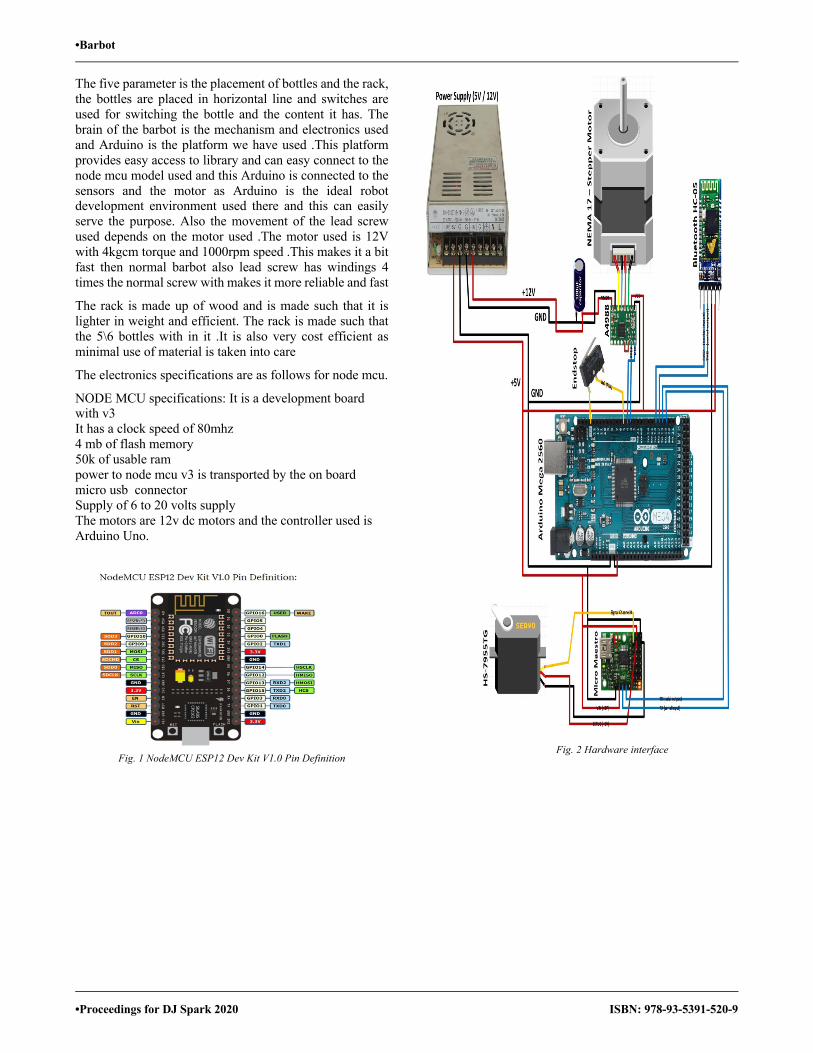
•Barbot
•Proceedings for DJ Spark 2020 ISBN: 978-93-5391-520-9
The five parameter is the placement of bottles and the rack, the bottles are placed in horizontal line and switches are used for switching the bottle and the content it has. The brain of the barbot is the mechanism and electronics used and Arduino is the platform we have used .This platform provides easy access to library and can easy connect to the node mcu model used and this Arduino is connected to the sensors and the motor as Arduino is the ideal robot development environment used there and this can easily serve the purpose. Also the movement of the lead screw used depends on the motor used .The motor used is 12V with 4kgcm torque and 1000rpm speed .This makes it a bit fast then normal barbot also lead screw has windings 4 times the normal screw with makes it more reliable and fast
The rack is made up of wood and is made such that it is lighter in weight and efficient. The rack is made such that the 5\6 bottles with in it .It is also very cost efficient as minimal use of material is taken into care
The electronics specifications are as follows for node mcu.
NODE MCU specifications: It is a development board with v3 It has a clock speed of 80mhz 4 mb of flash memory 50k of usable ram power to node mcu v3 is transported by the on board micro usb connector Supply of 6 to 20 volts supply The motors are 12v dc motors and the controller used is Arduino Uno.
Fig. 1 NodeMCU ESP12 Dev Kit V1.0 Pin Definition
Fig. 2 Hardware interface
113
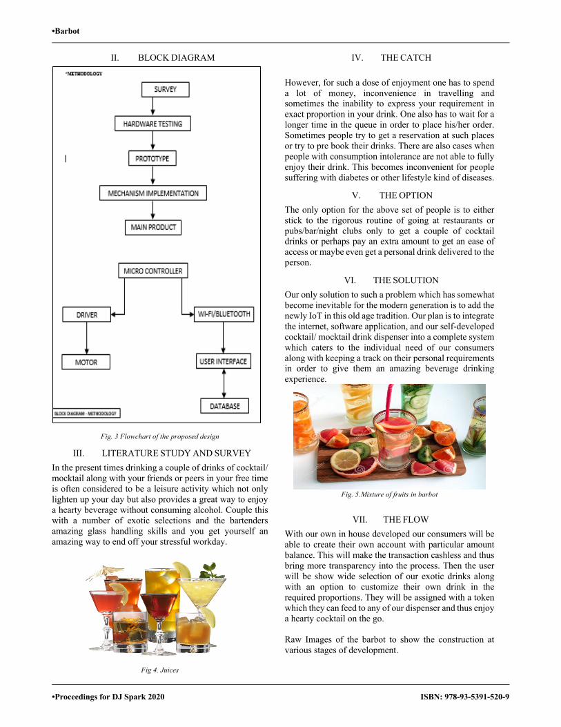
•Barbot
•Proceedings for DJ Spark 2020 ISBN: 978-93-5391-520-9
II. BLOCK DIAGRAM
Fig. 3 Flowchart of the proposed design
III. LITERATURE STUDY AND SURVEY In the present times drinking a couple of drinks of cocktail/ mocktail along with your friends or peers in your free time is often considered to be a leisure activity which not only lighten up your day but also provides a great way to enjoy a hearty beverage without consuming alcohol. Couple this with a number of exotic selections and the bartenders amazing glass handling skills and you get yourself an amazing way to end off your stressful workday.
Fig 4. Juices
IV. THE CATCH
However, for such a dose of enjoyment one has to spend a lot of money, inconvenience in travelling and sometimes the inability to express your requirement in exact proportion in your drink. One also has to wait for a longer time in the queue in order to place his/her order. Sometimes people try to get a reservation at such places or try to pre book their drinks. There are also cases when people with consumption intolerance are not able to fully enjoy their drink. This becomes inconvenient for people suffering with diabetes or other lifestyle kind of diseases.
V. THE OPTION The only option for the above set of people is to either stick to the rigorous routine of going at restaurants or pubs/bar/night clubs only to get a couple of cocktail drinks or perhaps pay an extra amount to get an ease of access or maybe even get a personal drink delivered to the person.
VI. THE SOLUTION Our only solution to such a problem which has somewhat become inevitable for the modern generation is to add the newly IoT in this old age tradition. Our plan is to integrate the internet, software application, and our self-developed cocktail/ mocktail drink dispenser into a complete system which caters to the individual need of our consumers along with keeping a track on their personal requirements in order to give them an amazing beverage drinking experience.
Fig. 5.Mixture of fruits in barbot
VII. THE FLOW With our own in house developed our consumers will be able to create their own account with particular amount balance. This will make the transaction cashless and thus bring more transparency into the process. Then the user will be show wide selection of our exotic drinks along with an option to customize their own drink in the required proportions. They will be assigned with a token which they can feed to any of our dispenser and thus enjoy a hearty cocktail on the go. Raw Images of the barbot to show the construction at various stages of development.
114

•Barbot
•Proceedings for DJ Spark 2020 ISBN: 978-93-5391-520-9
Fig. 6. Bottles and the pumps
Fig. 7. Stepper motor
Fig.8. Initial Testing using motor driver
Fig. 9. Setup with the platform
Fig. 10. App developed to order drinks(1/2)
Fig. 11. App developed to order drinks(2/2)
115

•Barbot
•Proceedings for DJ Spark 2020 ISBN: 978-93-5391-520-9
VIII. FUTURE SCOPE DDD is basically an automated drink machine which is an open source Arduino cocktail/mocktail mixing robot controlled with the hybrid mobile app (via Bluetooth). Your guests will flip when they get a perfectly crafted drink from an automated machine with an app from their cell phones. This shooter can mix and match combinations of different drinks with a single click. Just select your drink and give yourself a light show. The thought of replacing the current tradition of making and serving drinks manually by an Automated Barbot sounds exciting!! Preciseness and perfection are achieved when the same drink is made by a machine. Apart from innovation it : Cost effective, Helps you to save time, Easily executable, Fast speed, Online record of drinks ,No spilling of drinks and breaking of glasses, Choice based drinks.
A. SMART INVENTORY COUNTING-: DDD harnesses the power of smart devices and the cloud to manage your inventory.
B. COST AND TIME EFFECTIVE-: No pen & paper or costly proprietary hardware required. The free App works on iOS and Android devices.
C. FLEXIBLE-Track the inventory of off-the-shelf liquor or the contents of house brew tanks in multiple locations. REPORTING-DDD uses proprietary software to calculate the costs of drinks sold, pour costs and identify shrinkage while accelerating the ordering process. Automates invoice management. Fully auditable to the user level, One-time investment. Reduces human labor. The proposed DDD can be used in day to day life be it at commercial; because of its low maintenance cost and feasibility.
ACKNOWLEDGMENT This project and technical report were supported by Venkata APC. Her mentoring and total guidance helped us at every stage of this project. And this technical paper would not have been possible without her great help . We thank our colleagues who provided advice and guidance that greatly contributed to the development and helped us with the entire project. Also, the way everyone found our mistakes and corrected it is of great help to us. This project would not be possible without you all
REFERENCES
[1] G. Eason, B. Noble, and I. N. Sneddon, “On certain integrals of Lipschitz-Hankel type involving products of Bessel functions,” Phil. Trans. Roy. Soc. London, vol. A247, pp. 529–551, April 1955. (references)
[2] J. Clerk Maxwell, A Treatise on Electricity and Magnetism, 3rd ed., vol. 2. Oxford: Clarendon, 1892, pp.68–73.
[3] I. S. Jacobs and C. P. Bean, “Fine particles, thin films and exchange anisotropy,” in Magnetism, vol. III, G. T. Rado and H. Suhl, Eds. New York: Academic, 1963, pp. 271–350.
[4] R.Aravindhan, M.Ramanathan, D.SanjaiKumar, R.Kishore, “HOME AUTOMATION USING Wi-Fi INTERCONNECTION”,Department of Mechatronics engineering, Chennai Institute of Technology, Anna University Chennai, Tamil Nadu, India- 600069, (IRJET) e-ISSN: 2395 -0056 Volume: 04 Issue: 03 | Mar -2017 ,www.irjet.net.2542-2544pp.
[5] Y. Yorozu, M. Hirano, K. Oka, and Y. Tagawa, “Electron spectroscopy studies on magneto-optical media and plastic substrate interface,” IEEE Translate. J. Magn. Japan, vol. 2, pp. 740–741, August 1987 [Digests 9th Annual Conf. Magnetics Japan, p. 301, 1982].
[6] M. Young, The Technical Writer’s Handbook. Mill Valley, CA: University Science, 1989.
116
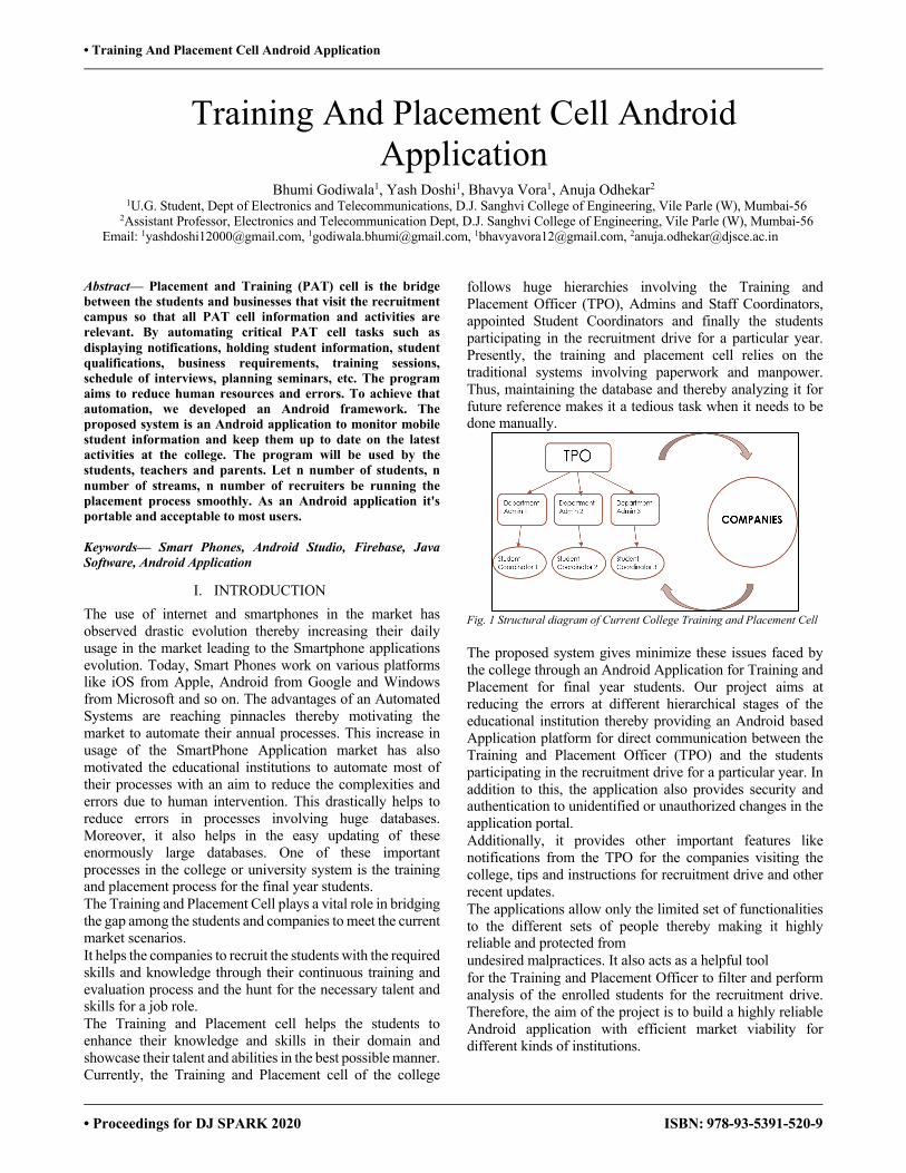
• Training And Placement Cell Android Application
• Proceedings for DJ SPARK 2020 ISBN: 978-93-5391-520-9
Training And Placement Cell Android Application
Bhumi Godiwala1, Yash Doshi1, Bhavya Vora1, Anuja Odhekar2 1U.G. Student, Dept of Electronics and Telecommunications, D.J. Sanghvi College of Engineering, Vile Parle (W), Mumbai-56 2Assistant Professor, Electronics and Telecommunication Dept, D.J. Sanghvi College of Engineering, Vile Parle (W), Mumbai-56
Email: [email protected], [email protected], [email protected], [email protected]
Abstract— Placement and Training (PAT) cell is the bridge between the students and businesses that visit the recruitment campus so that all PAT cell information and activities are relevant. By automating critical PAT cell tasks such as displaying notifications, holding student information, student qualifications, business requirements, training sessions, schedule of interviews, planning seminars, etc. The program aims to reduce human resources and errors. To achieve that automation, we developed an Android framework. The proposed system is an Android application to monitor mobile student information and keep them up to date on the latest activities at the college. The program will be used by the students, teachers and parents. Let n number of students, n number of streams, n number of recruiters be running the placement process smoothly. As an Android application it's portable and acceptable to most users. Keywords— Smart Phones, Android Studio, Firebase, Java Software, Android Application
I. INTRODUCTION The use of internet and smartphones in the market has observed drastic evolution thereby increasing their daily usage in the market leading to the Smartphone applications evolution. Today, Smart Phones work on various platforms like iOS from Apple, Android from Google and Windows from Microsoft and so on. The advantages of an Automated Systems are reaching pinnacles thereby motivating the market to automate their annual processes. This increase in usage of the SmartPhone Application market has also motivated the educational institutions to automate most of their processes with an aim to reduce the complexities and errors due to human intervention. This drastically helps to reduce errors in processes involving huge databases. Moreover, it also helps in the easy updating of these enormously large databases. One of these important processes in the college or university system is the training and placement process for the final year students. The Training and Placement Cell plays a vital role in bridging the gap among the students and companies to meet the current market scenarios. It helps the companies to recruit the students with the required skills and knowledge through their continuous training and evaluation process and the hunt for the necessary talent and skills for a job role. The Training and Placement cell helps the students to enhance their knowledge and skills in their domain and showcase their talent and abilities in the best possible manner. Currently, the Training and Placement cell of the college
follows huge hierarchies involving the Training and Placement Officer (TPO), Admins and Staff Coordinators, appointed Student Coordinators and finally the students participating in the recruitment drive for a particular year. Presently, the training and placement cell relies on the traditional systems involving paperwork and manpower. Thus, maintaining the database and thereby analyzing it for future reference makes it a tedious task when it needs to be done manually.
Fig. 1 Structural diagram of Current College Training and Placement Cell The proposed system gives minimize these issues faced by the college through an Android Application for Training and Placement for final year students. Our project aims at reducing the errors at different hierarchical stages of the educational institution thereby providing an Android based Application platform for direct communication between the Training and Placement Officer (TPO) and the students participating in the recruitment drive for a particular year. In addition to this, the application also provides security and authentication to unidentified or unauthorized changes in the application portal. Additionally, it provides other important features like notifications from the TPO for the companies visiting the college, tips and instructions for recruitment drive and other recent updates. The applications allow only the limited set of functionalities to the different sets of people thereby making it highly reliable and protected from undesired malpractices. It also acts as a helpful tool for the Training and Placement Officer to filter and perform analysis of the enrolled students for the recruitment drive. Therefore, the aim of the project is to build a highly reliable Android application with efficient market viability for different kinds of institutions.
117
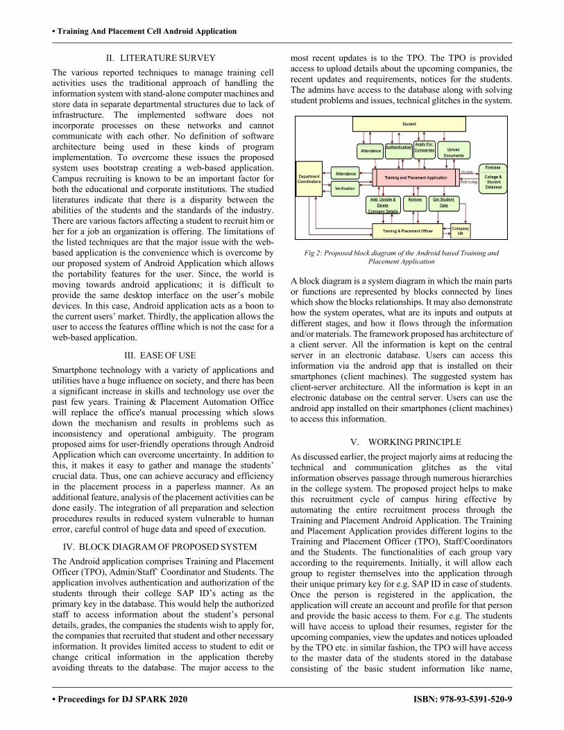
• Training And Placement Cell Android Application
• Proceedings for DJ SPARK 2020 ISBN: 978-93-5391-520-9
II. LITERATURE SURVEY The various reported techniques to manage training cell activities uses the traditional approach of handling the information system with stand-alone computer machines and store data in separate departmental structures due to lack of infrastructure. The implemented software does not incorporate processes on these networks and cannot communicate with each other. No definition of software architecture being used in these kinds of program implementation. To overcome these issues the proposed system uses bootstrap creating a web-based application. Campus recruiting is known to be an important factor for both the educational and corporate institutions. The studied literatures indicate that there is a disparity between the abilities of the students and the standards of the industry. There are various factors affecting a student to recruit him or her for a job an organization is offering. The limitations of the listed techniques are that the major issue with the web-based application is the convenience which is overcome by our proposed system of Android Application which allows the portability features for the user. Since, the world is moving towards android applications; it is difficult to provide the same desktop interface on the user’s mobile devices. In this case, Android application acts as a boon to the current users’ market. Thirdly, the application allows the user to access the features offline which is not the case for a web-based application.
III. EASE OF USE Smartphone technology with a variety of applications and utilities have a huge influence on society, and there has been a significant increase in skills and technology use over the past few years. Training & Placement Automation Office will replace the office's manual processing which slows down the mechanism and results in problems such as inconsistency and operational ambiguity. The program proposed aims for user-friendly operations through Android Application which can overcome uncertainty. In addition to this, it makes it easy to gather and manage the students’ crucial data. Thus, one can achieve accuracy and efficiency in the placement process in a paperless manner. As an additional feature, analysis of the placement activities can be done easily. The integration of all preparation and selection procedures results in reduced system vulnerable to human error, careful control of huge data and speed of execution.
IV. BLOCK DIAGRAM OF PROPOSED SYSTEM The Android application comprises Training and Placement Officer (TPO), Admin/Staff` Coordinator and Students. The application involves authentication and authorization of the students through their college SAP ID’s acting as the primary key in the database. This would help the authorized staff to access information about the student’s personal details, grades, the companies the students wish to apply for, the companies that recruited that student and other necessary information. It provides limited access to student to edit or change critical information in the application thereby avoiding threats to the database. The major access to the
most recent updates is to the TPO. The TPO is provided access to upload details about the upcoming companies, the recent updates and requirements, notices for the students. The admins have access to the database along with solving student problems and issues, technical glitches in the system.
Fig 2: Proposed block diagram of the Android based Training and Placement Application
A block diagram is a system diagram in which the main parts or functions are represented by blocks connected by lines which show the blocks relationships. It may also demonstrate how the system operates, what are its inputs and outputs at different stages, and how it flows through the information and/or materials. The framework proposed has architecture of a client server. All the information is kept on the central server in an electronic database. Users can access this information via the android app that is installed on their smartphones (client machines). The suggested system has client-server architecture. All the information is kept in an electronic database on the central server. Users can use the android app installed on their smartphones (client machines) to access this information.
V. WORKING PRINCIPLE As discussed earlier, the project majorly aims at reducing the technical and communication glitches as the vital information observes passage through numerous hierarchies in the college system. The proposed project helps to make this recruitment cycle of campus hiring effective by automating the entire recruitment process through the Training and Placement Android Application. The Training and Placement Application provides different logins to the Training and Placement Officer (TPO), Staff/Coordinators and the Students. The functionalities of each group vary according to the requirements. Initially, it will allow each group to register themselves into the application through their unique primary key for e.g. SAP ID in case of students. Once the person is registered in the application, the application will create an account and profile for that person and provide the basic access to them. For e.g. The students will have access to upload their resumes, register for the upcoming companies, view the updates and notices uploaded by the TPO etc. in similar fashion, the TPO will have access to the master data of the students stored in the database consisting of the basic student information like name,
118
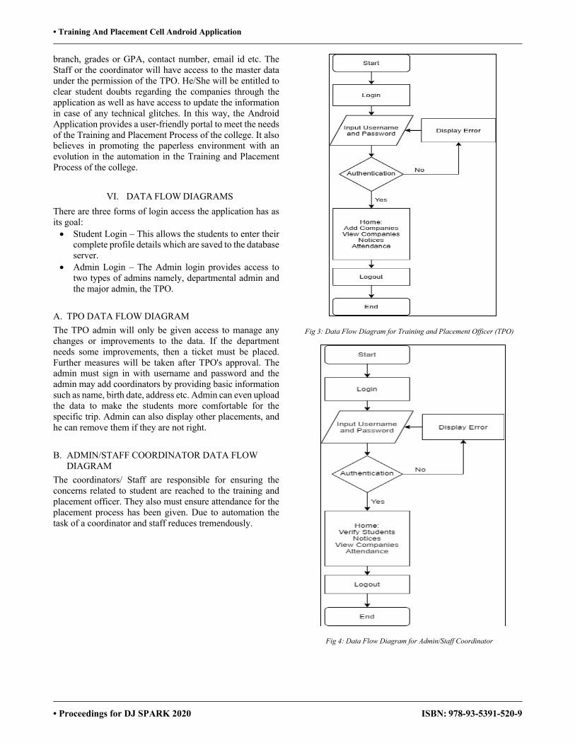
• Training And Placement Cell Android Application
• Proceedings for DJ SPARK 2020 ISBN: 978-93-5391-520-9
branch, grades or GPA, contact number, email id etc. The Staff or the coordinator will have access to the master data under the permission of the TPO. He/She will be entitled to clear student doubts regarding the companies through the application as well as have access to update the information in case of any technical glitches. In this way, the Android Application provides a user-friendly portal to meet the needs of the Training and Placement Process of the college. It also believes in promoting the paperless environment with an evolution in the automation in the Training and Placement Process of the college.
VI. DATA FLOW DIAGRAMS There are three forms of login access the application has as its goal: • Student Login – This allows the students to enter their
complete profile details which are saved to the database server.
• Admin Login – The Admin login provides access to two types of admins namely, departmental admin and the major admin, the TPO.
A. TPO DATA FLOW DIAGRAM The TPO admin will only be given access to manage any changes or improvements to the data. If the department needs some improvements, then a ticket must be placed. Further measures will be taken after TPO's approval. The admin must sign in with username and password and the admin may add coordinators by providing basic information such as name, birth date, address etc. Admin can even upload the data to make the students more comfortable for the specific trip. Admin can also display other placements, and he can remove them if they are not right.
B. ADMIN/STAFF COORDINATOR DATA FLOW DIAGRAM
The coordinators/ Staff are responsible for ensuring the concerns related to student are reached to the training and placement officer. They also must ensure attendance for the placement process has been given. Due to automation the task of a coordinator and staff reduces tremendously.
Fig 3: Data Flow Diagram for Training and Placement Officer (TPO)
Fig 4: Data Flow Diagram for Admin/Staff Coordinator
119
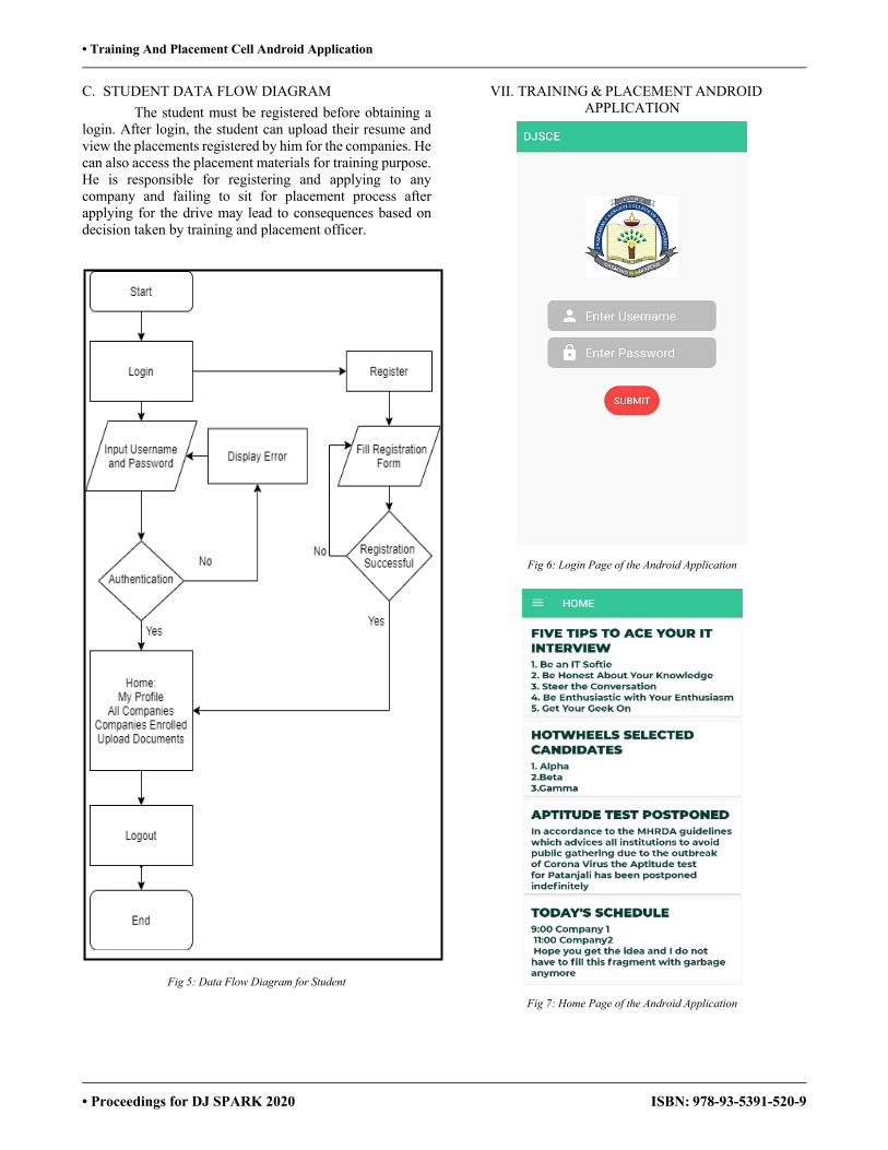
• Training And Placement Cell Android Application
• Proceedings for DJ SPARK 2020 ISBN: 978-93-5391-520-9
C. STUDENT DATA FLOW DIAGRAM The student must be registered before obtaining a
login. After login, the student can upload their resume and view the placements registered by him for the companies. He can also access the placement materials for training purpose. He is responsible for registering and applying to any company and failing to sit for placement process after applying for the drive may lead to consequences based on decision taken by training and placement officer.
Fig 5: Data Flow Diagram for Student
VII. TRAINING & PLACEMENT ANDROID APPLICATION
Fig 6: Login Page of the Android Application
Fig 7: Home Page of the Android Application
120
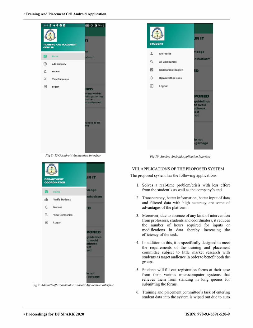
• Training And Placement Cell Android Application
• Proceedings for DJ SPARK 2020 ISBN: 978-93-5391-520-9
Fig 8: TPO Android Application Interface
Fig 9: Admin/Staff Coordinator Android Application Interface
Fig 10: Student Android Application Interface
VIII. APPLICATIONS OF THE PROPOSED SYSTEM The proposed system has the following applications:
1. Solves a real-time problem/crisis with less effort from the student’s as well as the company’s end.
2. Transparency, better information, better input of data and filtered data with high accuracy are some of advantages of the platform.
3. Moreover, due to absence of any kind of intervention from professors, students and coordinators, it reduces the number of hours required for inputs or modifications in data thereby increasing the efficiency of the task.
4. In addition to this, it is specifically designed to meet the requirements of the training and placement committee subject to little market research with students as target audience in order to benefit both the groups.
5. Students will fill out registration forms at their ease from their various microcomputer systems that relieves them from standing in long queues for submitting the forms.
6. Training and placement committee’s task of entering student data into the system is wiped out due to auto
121
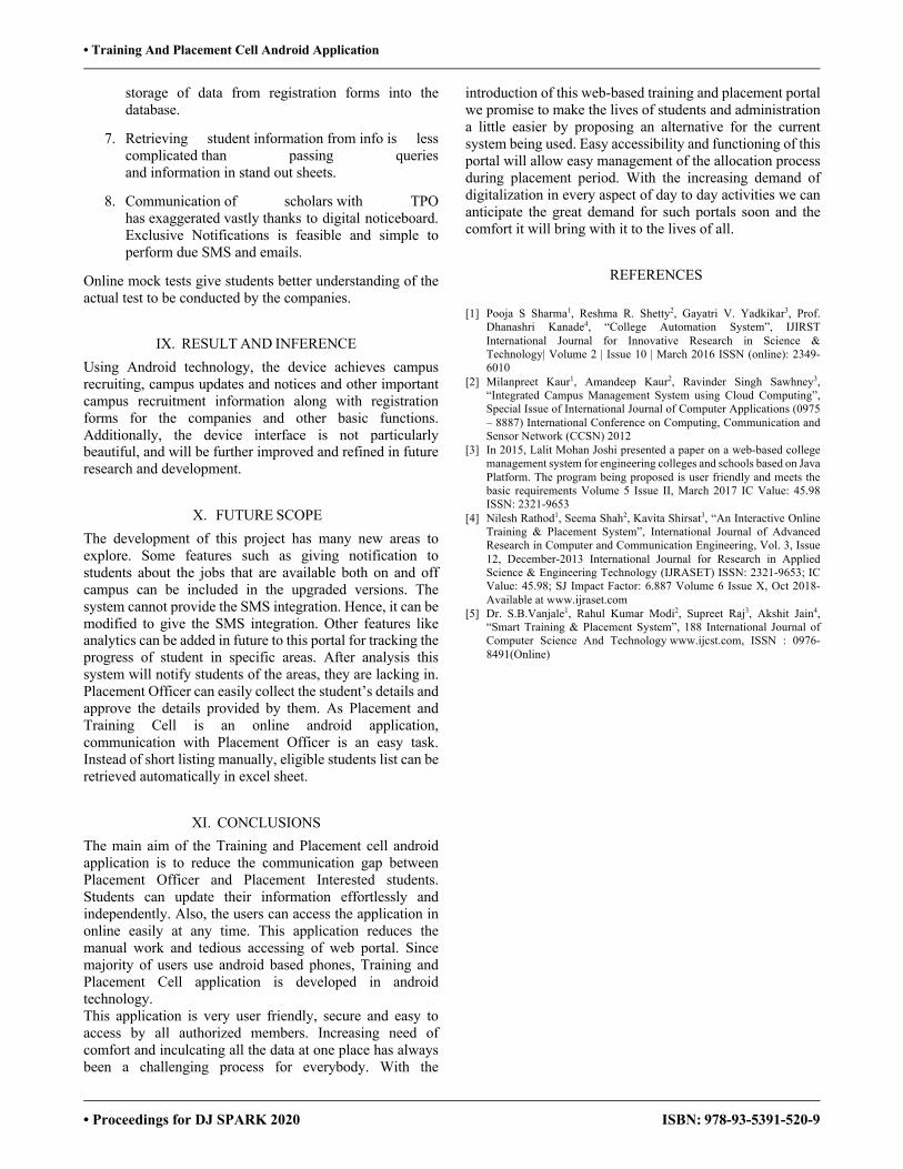
• Training And Placement Cell Android Application
• Proceedings for DJ SPARK 2020 ISBN: 978-93-5391-520-9
storage of data from registration forms into the database.
7. Retrieving student information from info is less complicated than passing queries and information in stand out sheets.
8. Communication of scholars with TPO has exaggerated vastly thanks to digital noticeboard. Exclusive Notifications is feasible and simple to perform due SMS and emails.
Online mock tests give students better understanding of the actual test to be conducted by the companies.
IX. RESULT AND INFERENCE Using Android technology, the device achieves campus recruiting, campus updates and notices and other important campus recruitment information along with registration forms for the companies and other basic functions. Additionally, the device interface is not particularly beautiful, and will be further improved and refined in future research and development.
X. FUTURE SCOPE The development of this project has many new areas to explore. Some features such as giving notification to students about the jobs that are available both on and off campus can be included in the upgraded versions. The system cannot provide the SMS integration. Hence, it can be modified to give the SMS integration. Other features like analytics can be added in future to this portal for tracking the progress of student in specific areas. After analysis this system will notify students of the areas, they are lacking in. Placement Officer can easily collect the student’s details and approve the details provided by them. As Placement and Training Cell is an online android application, communication with Placement Officer is an easy task. Instead of short listing manually, eligible students list can be retrieved automatically in excel sheet.
XI. CONCLUSIONS The main aim of the Training and Placement cell android application is to reduce the communication gap between Placement Officer and Placement Interested students. Students can update their information effortlessly and independently. Also, the users can access the application in online easily at any time. This application reduces the manual work and tedious accessing of web portal. Since majority of users use android based phones, Training and Placement Cell application is developed in android technology. This application is very user friendly, secure and easy to access by all authorized members. Increasing need of comfort and inculcating all the data at one place has always been a challenging process for everybody. With the
introduction of this web-based training and placement portal we promise to make the lives of students and administration a little easier by proposing an alternative for the current system being used. Easy accessibility and functioning of this portal will allow easy management of the allocation process during placement period. With the increasing demand of digitalization in every aspect of day to day activities we can anticipate the great demand for such portals soon and the comfort it will bring with it to the lives of all.
REFERENCES
[1] Pooja S Sharma1, Reshma R. Shetty2, Gayatri V. Yadkikar3, Prof. Dhanashri Kanade4, “College Automation System”, IJIRST International Journal for Innovative Research in Science & Technology| Volume 2 | Issue 10 | March 2016 ISSN (online): 2349-6010
[2] Milanpreet Kaur1, Amandeep Kaur2, Ravinder Singh Sawhney3, “Integrated Campus Management System using Cloud Computing”, Special Issue of International Journal of Computer Applications (0975 – 8887) International Conference on Computing, Communication and Sensor Network (CCSN) 2012
[3] In 2015, Lalit Mohan Joshi presented a paper on a web-based college management system for engineering colleges and schools based on Java Platform. The program being proposed is user friendly and meets the basic requirements Volume 5 Issue II, March 2017 IC Value: 45.98 ISSN: 2321-9653
[4] Nilesh Rathod1, Seema Shah2, Kavita Shirsat3, “An Interactive Online Training & Placement System”, International Journal of Advanced Research in Computer and Communication Engineering, Vol. 3, Issue 12, December-2013 International Journal for Research in Applied Science & Engineering Technology (IJRASET) ISSN: 2321-9653; IC Value: 45.98; SJ Impact Factor: 6.887 Volume 6 Issue X, Oct 2018- Available at www.ijraset.com
[5] Dr. S.B.Vanjale1, Rahul Kumar Modi2, Supreet Raj3, Akshit Jain4, “Smart Training & Placement System”, 188 International Journal of Computer Science And Technology www.ijcst.com, ISSN : 0976-8491(Online)
122
Author Index
A.S,Revathi Jadhav,Suraj Ambekar,Aarti Jain,Yash Amin,Sujal Jha,Pooja Bandi,Yukti Judy,Alcina Baria,Viren Kadam,Ameya Batia,Deep Kadam,Poonam Bhadoriya,Sachin Kale,Maithili
Bhattacharjee,Shivani Kamat,Gaurang Bhogan,Akshay Kansara,Meet Biradar,T.D Karamchandani,Sunil Chaurasia,Vivek Karia,Pratik Chavali,Venkata Kasodariya,Parth Dadsena,Shubham Kathe,Janhavi Dahimbekar,Ujwala Khetan,Ashutosh Dalvi,Akshata Kirkire,Saniya Dani,Priyal Kudaskar,Ruchika D'Cruz,Kesha Kulkarni,Mayur Deo,Rohan Kumar,Atulya Desai,Heer Kurhade,Parth Desai,Smit Laddha,Radhika Deshmukh,Amit Mahabal,Hrishikesh Deshmukh,S.B Mamadapur,Ishan Deshmukh,Satvik Mandavia,Riddhi
Deshmukh,Siddhesh Meghani,Vidhi Deshpande,Yogesh Mehta,Aastha Doshi,Yash Mehta,Arzan Gandhi,Jainy Mehta,Hetvi Gandhi,Parth Mehta,Parth Gandhi,Swahum Mhaske,Poonam Gawde,Krutika Mishra,Sandeep Godiwala,Bhumi Modi,Nishi
Gohil,Rajat Motwani,Kirti Nadar,Hariharan Shah,Vivek
Nagdeo,Prem Shah,Vrutansh Nagwekar,Rajus Shende,Surabhi Nathani,Yatharth Shetty,Ashwin Nayak,Shreya Singh,Vishnupriya
Odhekar,Anuja Tambe,Chetan Oza,Pranali Thakkar,Chirag Oza,Shyamal Vaidya,Nityashree Panchal,Amee Vajarekar,Madhura Panchal,Hinal Vakharia,Deep Pandey,Anuradha Varma,Advait Pandey,Shalini Verma,Ajeet Parekh,Shakshi Verma,Sunil
Parmar,Keval Vithlani,Mihir Parpani,Meet Vora,Bhavya Parui,Dashmi Vora,Vidhi Patel,Prerna Yadate,Meera Patel,Viraj Yadav,Ashwith Patil,Krutika Rajak,Vikas Raskar, D.S Sawant, T.N Sawant,Pranav Shah,Anuj Shah,Harsh Shah,Janaki Shah,Kinjal Shah,Maitri Shah,Mit Shah,Prachi Shah,Raj Shah,Rushabh Shah,Sanket