Feasibility of bilateral crossing c7 intralaminar screws: a cadaveric study
6
5 less bony purchase and thus its lower pullout strength can be problematic when applied to C7 3,6) . C7 pedicle screw fixation is known to be the biomechanically strongest method but the pedicle screw is technically difficult to apply due to its small size and critical neurovascular structure of the surrounding area 6,15) . Recently, C7 intralaminar screw technique has been used as an alternative or salvage technique to the pedicle screw fixation be- cause the method is technically simple and not limited by the position of vertebral artery. And, compared to the pedicle screw, it is significantly superior in all aspects except biomechanically INTRODUCTION Posterior cervical screw fixation has been widely used for the correction of cervical spine instability and deformity. Com- pared to the conventional posterior wiring technique, the fixa- tion method has several advantages such as higher fusion rate, no need of rigid external mobilization, and capability of con- nection between occipitocervical and cervicothoracic junction and fixation 1-4,9) . e fixation with lateral mass screw is relative- ly safe and easy to insert, but it has small and thin size causing Feasibility of Bilateral Crossing C7 Intralaminar Screws : A Cadaveric Study Tae-Hyun Baek, M.D., 1 Ilsup Kim, M.D., Ph.D., 1 Jae-Taek Hong, M.D., Ph.D., 1 Daniel H. Kim, M.D., 2 Dongsuk Shin, Ph.D., 2 Sang-Won Lee, M.D., Ph.D. 1 Department of Neurosurgery, 1 St. Vincent’s Hospital, College of Medicine, The Catholic University of Korea, Suwon, Korea Department of Neurosurgery, 2 Memorial Hermann Hospital, University of Texas Health Science Center at Houston, Houston, TX, USA Objective : When the pedicle screw insertion technique is failed or not applicable, C7 intralaminar screw insertion method has been used as an al- ternative or salvage fixation method recently. However, profound understanding of anatomy is required for safe application of the bilaterally crossing laminar screw at C7 in clinic. In this cadaveric study, we evaluated the anatomic feasibility of the bilateral crossing intralaminar screw insertion and especially focused on determination of proper screw entry point. Methods : The C7 vertebrae from 18 adult specimens were studied. Morphometric measurements of the mid-laminar height, the minimum laminar thickness, the maximal screw length, and spino-laminar angle were performed and cross-sectioned vertically at the screw entry point (spino-lami- nar junction). The sectioned surface was equally divided into 3 parts and maximal thickness and surface area of the parts were measured. All mea- surements were obtained bilaterally. Results : The mean mid-laminar height was 13.7 mm, mean minimal laminar thickness was 6.6 mm, mean maximal screw length was 24.6 mm, and mean spinolaminar angle was 50.8±4.7°. Based on the measured laminar thickness, the feasibility of 3.5 mm diameter intralaminar screw ap- plication was 83.3% (30 sides laminae out of total 36) when assuming a tolerance of 1 mm on each side. Cross-sectional measurement results showed that the mean maximal thickness of upper, middle, and lower thirds was 5.0 mm, 7.5 mm, and 7.3 mm, respectively, and mean surface area for each part was 21.2 mm 2 , 46.8 mm 2 , and 34.7 mm 2 , respectively. Fourteen (38.9%) sides of laminae would be feasible for 3.5 mm intralaminar screw insertion when upper thirds of C7 spino-laminar junction is the screw entry point. In case of middle and lower thirds of C7 spino-laminar junc- tion, 32 (88.9%) and 28 (77.8%) sides of laminae were feasible for 3.5 mm screw insertion, respectively. Conclusion : The vertical cross-sectioned area of middle thirds at C7 spinolaminar junction was the largest area and 3.5 mm screw can be accom- modated with 77.8 % of feasibility when lower thirds were the screw entry point. Thus, selection of middle and lower thirds for each side of screw en- try point in spino-laminar junction would be the safest way to place bilateral crossing laminar screw within the entire lamina. This anatomic study re- sult will help surgeons to place the screw safely and accurately. Key Words : C7 · Cervical spine · Intralaminar screw. Laboratory Investigation • Received : November 19, 2013 • Revised : March 29, 2014 • Accepted : July 15, 2014 • Address for reprints : Ilsup Kim, M.D., Ph.D. Department of Neurosurgery, St. Vincent’s Hospital, College of Medicine, The Catholic University of Korea, 93 Jungbu-daero, Paldal-gu, Suwon 442-723, Korea Tel : +82-31-245-8207, Fax : +82-31-245-5208, E-mail : [email protected] • This is an Open Access article distributed under the terms of the Creative Commons Attribution Non-Commercial License (http://creativecommons.org/licenses/by-nc/3.0) which permits unrestricted non-commercial use, distribution, and reproduction in any medium, provided the original work is properly cited. J Korean Neurosurg Soc 56 (1) : 5-10, 2014 http://dx.doi.org/10.3340/jkns.2014.56.1.5 Copyright © 2014 The Korean Neurosurgical Society Print ISSN 2005-3711 On-line ISSN 1598-7876 www.jkns.or.kr online © ML Comm
-
Upload
independent -
Category
Documents
-
view
0 -
download
0
Transcript of Feasibility of bilateral crossing c7 intralaminar screws: a cadaveric study

5
less bony purchase and thus its lower pullout strength can be problematic when applied to C73,6). C7 pedicle screw fixation is known to be the biomechanically strongest method but the pedicle screw is technically difficult to apply due to its small size and critical neurovascular structure of the surrounding area6,15). Recently, C7 intralaminar screw technique has been used as an alternative or salvage technique to the pedicle screw fixation be-cause the method is technically simple and not limited by the position of vertebral artery. And, compared to the pedicle screw, it is significantly superior in all aspects except biomechanically
INTRODUCTION
Posterior cervical screw fixation has been widely used for the correction of cervical spine instability and deformity. Com-pared to the conventional posterior wiring technique, the fixa-tion method has several advantages such as higher fusion rate, no need of rigid external mobilization, and capability of con-nection between occipitocervical and cervicothoracic junction and fixation1-4,9). The fixation with lateral mass screw is relative-ly safe and easy to insert, but it has small and thin size causing
Feasibility of Bilateral Crossing C7 Intralaminar Screws : A Cadaveric Study
Tae-Hyun Baek, M.D.,1 Ilsup Kim, M.D., Ph.D.,1 Jae-Taek Hong, M.D., Ph.D.,1 Daniel H. Kim, M.D.,2 Dongsuk Shin, Ph.D.,2 Sang-Won Lee, M.D., Ph.D.1
Department of Neurosurgery,1 St. Vincent’s Hospital, College of Medicine, The Catholic University of Korea, Suwon, KoreaDepartment of Neurosurgery,2 Memorial Hermann Hospital, University of Texas Health Science Center at Houston, Houston, TX, USA
Objective : When the pedicle screw insertion technique is failed or not applicable, C7 intralaminar screw insertion method has been used as an al-ternative or salvage fixation method recently. However, profound understanding of anatomy is required for safe application of the bilaterally crossing laminar screw at C7 in clinic. In this cadaveric study, we evaluated the anatomic feasibility of the bilateral crossing intralaminar screw insertion and especially focused on determination of proper screw entry point.Methods : The C7 vertebrae from 18 adult specimens were studied. Morphometric measurements of the mid-laminar height, the minimum laminar thickness, the maximal screw length, and spino-laminar angle were performed and cross-sectioned vertically at the screw entry point (spino-lami-nar junction). The sectioned surface was equally divided into 3 parts and maximal thickness and surface area of the parts were measured. All mea-surements were obtained bilaterally. Results : The mean mid-laminar height was 13.7 mm, mean minimal laminar thickness was 6.6 mm, mean maximal screw length was 24.6 mm, and mean spinolaminar angle was 50.8±4.7°. Based on the measured laminar thickness, the feasibility of 3.5 mm diameter intralaminar screw ap-plication was 83.3% (30 sides laminae out of total 36) when assuming a tolerance of 1 mm on each side. Cross-sectional measurement results showed that the mean maximal thickness of upper, middle, and lower thirds was 5.0 mm, 7.5 mm, and 7.3 mm, respectively, and mean surface area for each part was 21.2 mm2, 46.8 mm2, and 34.7 mm2, respectively. Fourteen (38.9%) sides of laminae would be feasible for 3.5 mm intralaminar screw insertion when upper thirds of C7 spino-laminar junction is the screw entry point. In case of middle and lower thirds of C7 spino-laminar junc-tion, 32 (88.9%) and 28 (77.8%) sides of laminae were feasible for 3.5 mm screw insertion, respectively.Conclusion : The vertical cross-sectioned area of middle thirds at C7 spinolaminar junction was the largest area and 3.5 mm screw can be accom-modated with 77.8 % of feasibility when lower thirds were the screw entry point. Thus, selection of middle and lower thirds for each side of screw en-try point in spino-laminar junction would be the safest way to place bilateral crossing laminar screw within the entire lamina. This anatomic study re-sult will help surgeons to place the screw safely and accurately.
Key Words : C7 · Cervical spine · Intralaminar screw.
Laboratory Investigation
• Received : November 19, 2013 • Revised : March 29, 2014 • Accepted : July 15, 2014• Address for reprints : Ilsup Kim, M.D., Ph.D. Department of Neurosurgery, St. Vincent’s Hospital, College of Medicine, The Catholic University of Korea, 93 Jungbu-daero, Paldal-gu, Suwon 442-723, Korea Tel : +82-31-245-8207, Fax : +82-31-245-5208, E-mail : [email protected]• This is an Open Access article distributed under the terms of the Creative Commons Attribution Non-Commercial License (http://creativecommons.org/licenses/by-nc/3.0) which permits unrestricted non-commercial use, distribution, and reproduction in any medium, provided the original work is properly cited.
J Korean Neurosurg Soc 56 (1) : 5-10, 2014
http://dx.doi.org/10.3340/jkns.2014.56.1.5
Copyright © 2014 The Korean Neurosurgical Society
Print ISSN 2005-3711 On-line ISSN 1598-7876www.jkns.or.kr
online © ML Comm
6
J Korean Neurosurg Soc 56 | July 2014
lateral bending range of motion5-7). Successful application of bilat-eral crossing laminar screw technique requires profound knowl-edge of anatomy for proper positioning of two screws in C7 lami-nar. To accommodate standard 3.5 mm cervical screw into the bilateral crossing intralaminar screw insertion technique at C7, the following two conditions are required. First, the minimum laminar thickness should be at least 5.5 mm when assuming a tolerance of 1 mm in each side of screw10,12). Second, bilateral two screws should not collide each other at the midline. Accu-rate screw start point should be selected to satisfy above men-tioned conditions in narrow C7 laminar area.
The bilateral crossing laminar screw technique was initially performed in C2 level by Wright14). However, exact same appli-cation on C7 does not guarantee the same results because of an-atomical differences. Thus, this study aims to determine optimal entry point of the bilateral crossing intralaminar screw insertion by measuring thickness and surface area of various vertical cross-sections of screw entry point (spino-laminar junction). Computed tomography (CT)-based anatomical study has been performed to test feasibility of the C7 intralaminar screws in previous reports, but, there is no cadaveric study focusing on the bilateral crossing C7 intralaminar screw8,11,16). The purpose of this cadaveric study is to provide and establish a guideline of selecting safe entry point of screws for preventing the possibili-ty of screw collision and investigate the usefulness of bilateral crossing laminar screws.
MATERIALS AND METHODS
Eighteen fresh cadaver spines from human adult were used for this study. The anatomic specimens were obtained from Univer-sity of Texas Health Science Center at Houston, Department of Neurosurgery. Demographic information including age and gen-der was available for each specimen. Donor criteria excluded the subjects with history of rheumatoid disease, spine trauma, infec-tion, tumor or any other bony diseases. Linear measurements were made by an electronic digital caliper (Mitutoyo, Kanagawa, Japan, accuracy 0.1 mm) for all specimens in the following points; height of C7 mid-lamina and C7 lateral mass, minimum lami-nar thickness, and maximal screw length (the length from the spino-laminar junction to the contralateral lamina-lateral mass junction) (Fig. 1, 2, 3). Digital photographs of all specimens were taken in the axial plane with an appropriate metric scale. The specimens were cross-sectioned bilaterally and vertically at the screw entry point (spino-laminar junction) with electric saw. After then, laminar height was measured at the cross-sec-tioned plane of screw entry point and the height was equally di-vided into three parts; upper, middle, lower parts. The maximal laminar thickness of upper 1/3, middle 1/3, and lower 1/3 were measured separately. All measurements were obtained bilateral-ly and additional digital photographs of the cross-sectioned area were taken. Using Image J software (National Institutes of Health, Bethesda, MD, USA), lateral spino-laminar angle (the
Fig. 1. Measurement of maximal C7 intralaminar screw length (the length from the spino-laminar junction to the contralateral lamina-lateral mass junction).
Fig. 2. Measurement of C7 minimum laminar thickness.
Fig. 3. Measurement of C7 mid-lamina height.
7
Bilateral Crossing C7 Intralaminar Screws | TH Baek, et al.
and 7.3±1.8 mm (range 4.1–11.1 mm), respectively (Table 2, Fig. 7). The mean surface area of upper, middle, and lower thirds at spino-laminar juction on the right side was 21.6±9.4 mm2 (range 7.8–33 mm2), 45.9±20.0 mm2 (range 22.3–84.8 mm2), and 31.5±10.6 mm2 (range 14.9–50.4 mm2), respectively. The mean surface area of upper, middle, and lower parts at the spino-laminar juction on the left side was 20.8±7.0 mm2 (range 9.6–33.6 mm2), 47.7±13.0 mm2 (range 26.3–67.6 mm2), and 38.0±13.1 mm2 (range 19.4–60.9 mm2), respectively. The mean bilateral surface area of upper, middle, and lower parts at the spi-no-laminar juction was 21.2±8.3 mm2 (range 7.8–33.6 mm2), 46.8±16.9 mm2 (range 22.3–84.8 mm2), and 34.7±12.4 mm2 (range 14.9–60.9 mm2), respectively (Table 3). In most cases, the screw entry point started at spino-lamina junction and vertical cross-section of the part showed various morphologies of C7 laminae. When upper thirds lamina was the start point, only 12 laminae out of 36 (33.3%) was thicker than 5.5 mm. For middle and lower thirds, 30 (83.3%) and 32 (88.9%) laminae were thicker than 5.5 mm, respectively. In surface area of the cross-sectional area, the area passing by 3.5 mm screw is 9.6 (1.75× 1.75×3.14) mm2. Considering 1 mm tolerance margin on each
angle formed by the C7 spinous process and a line parallel to the longitudinal axis of the C7 lamina) and area of the cross-sectioned surface at the screw entry point were measured (Fig. 4, 5). Statistical analysis using the Student t-test was performed with SPSS software (version 12.0; SPSS Inc., Chicago, IL, USA). Data on sex and laterality (right and left) were compared with anatomic measurement. The values of p<0.05 were considered as statistically significant.
RESULTS
Gross anatomyThe average age of cadaver specimen was 61±10.5 years (47–
83 years of range) and the ratio of male : female was 10 : 8. The mean maximal screw length on the right and left was 24.3±1.1 mm (range 22.8–26.5 mm) and 24.8±2.0 mm (range 23.0–29.0 mm), respectively. The mean bilateral maximal screw length was 24.6±1.6 mm (range 22.8–29.0 mm). The mean minimal laminar thickness on the right and left was 6.6±1.2 mm (range 4.0–7.4 mm) and 6.7±1.2 mm (range 5.3–7.9 mm), respectively. The mean bilateral minimal laminar thickness was 6.6±1.2 mm (range 4.0–7.9 mm). Assuming that 1 mm tolerance margin is needed on each side, 4 specimens (4/18, 22.2%) and 6 laminas (6/36, 16.7%) were found to be not applicable for 3.5 mm screw insertion (minimum laminar thickness is smaller than 5.5 mm). In the midline area where two of 3.5 mm screws might cross (3.5×2+2 mm=9 mm), the mid-laminar height was over 9 mm in all specimens and the mean mid-laminar height was 13.7± 2.5 mm (range 11.05–18.22 mm). The mean spino-laminar an-gle on the right and left was 52.1±3.1° (range 47.4–57.2°) and 49.5±5.5° (range 43.2–60.6°), respectively. The mean bilateral spino-laminar angle was 50.8±4.7° (range 43.2–60.6°). At the screw entry point, the mean laminar height on the right and left was 16.6±1.6 mm (range 14.7–19.0 mm) and 16.9±1.5 mm (range 15.3–19.5 mm), respectively. The mean lateral laminar height at the screw entry point was 16.8±1.6 mm (range 14.7–19.5 mm) (Table 1, Fig. 6).
Cross sectional anatomyAfter vertical cross-sectioning of spino-laminar junction,
lamina height was equally divided into 3 parts (upper, middle, and lower) and maximal thickness and surface area of each portion were measured bilaterally. The mean maximal thick-ness of upper, middle, and lower parts at the spino-laminar juc-tion on the right side was 4.7±1.2 mm (range 3.1–6.8 mm), 7.2±2.0 mm (range 4.3–11.0 mm), and 6.9±1.6 mm (range 4.2–9.9 mm), respectively. The mean maximal thickness of upper, middle, and lower parts at the spino-laminar juction on the left side was measured at 5.3±1.1 mm (range 3.6–7.6 mm), 7.9±2.0 mm (range 4.2–11.1 mm) and 7.7±2.0 mm (range 4.1–11.1 mm), respectively. The mean bilateral maximal thickness of upper, middle and lower parts at the spino-laminar juction was 5.0± 1.2 mm (range 3.1–7.6 mm), 7.5±2.0 mm (range 4.2–11.0 mm)
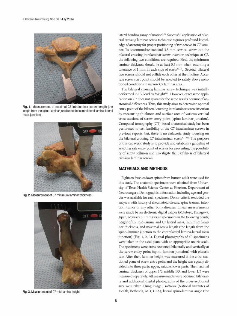
Fig. 4. Spinolaminar angle of C7 specimens were measured by the digi-tal photographs using Image J software.
Fig. 5. Cross sectional surface areas divided into 3 equal heights at screw entry point were measured by the digital photographs using Image J software.
8
J Korean Neurosurg Soc 56 | July 2014
side of screw, 23.7 (2.75×2.75×3.14) mm2 is thought to be enough surface area for placing screw. For screw entry point, 14 (38.9%), 32 (88.9%), and 28 (77.8%) sides laminae satisfied the con-dition in upper, middle and lower thirds lamina, respectively (Table 2, 3).
DISCUSSION
The C7 intralaminar screw technique reported by Hong et al.5) at 2008 has some advantages such as eliminating the risk of injury to neurovascular struc-
tures. When the vertebral artery courses into C7 transverse fora-men, the C7 pedicle screw insertion can induce injury of adjacent vertebral artery or spinal cord. The use of intralaminar screws al-lows immobilization of the C7 without risk of the vertebral artery injury. Another important advantage of the intralaminar screw fixation is that the screw can be placed and directly seen at outer cortex of lamina and all relevant structures without use of fluoro-scope or navigation system13). In biomechanical aspect, the stron-gest C7 fixation method is the application of pedicle screw. C7 in-tralaminar screw is not significantly different from the C7 pedicle screw fixation in flexion/extension, axial rotation and pull-out strength even though it is inferior in lateral bending6). Thus, the C7 intralaminar screw insertion has been used as an alternative or salvage technique recently when C7 pedicle screw insertion is not possible or failed because of small pedicle size of C7 or vertebral artery coursing through the C7 transverse foramen.
Table 1. Gross anatomic measurement in 18 cadaveric specimens of C7 (mean±SD, range)*
Measurement Right side Left side Bilateral sidesMid-laminar height (mm) - - 13.7±2.5 (11.05–18.22)Maximal screw length (mm) 24.3±1.1 (22.8–26.5) 24.8±2.0 (23.0–29.0) 24.6±1.6 (22.8–29.0) Minimal laminar thickness (mm) 6.6±1.2 (4.0–7.4) 6.7±1.2 (5.3–7.9) 6.6±1.2 (4.0–7.9)Spino-laminar angle (°) 52.1±3.1 (47.4–57.2) 49.5±5.5 (43.2–60.6) 50.8±4.7 (43.2–60.6)Laminar height at spino-laminar junction 16.6±1.6 (14.7–19.0) 16.9±1.5 (15.3–19.5) 16.8±1.6 (14.7–19.5)
*There were no significant statistical difference between right and left side (p<0.05)
Table 2. Maximal laminar thickness at the spino-laminar junction in 36 sides of C7 (mean±SD, range)
Right side Left side Bilateral sides Acceptable No. of 3.5 mm screw (%)
Upper 1/3 (mm) 4.7±1.2 (3.1–6.8) 5.3±1.1 (3.6–7.6) 5.0±1.2 (3.1–7.6) 12/36 (33.3)Middle 1/3 (mm) 7.2±2.0 (4.3–11.0) 7.9±2.0 (4.2–11.1) 7.5±2.0 (4.2–11.0) 30/36 (83.3)Lower 1/3 (mm) 6.9±1.6 (4.2–9.9) 7.7±2.0 (4.1–11.1) 7.3±1.8 (4.1–11.1) 32/36 (88.9)
Table 3. Cross sectional surface area at the spino-laminar junction in 36 sides of C7 (mean±SD, range)
Right side Left side Bilateral sides Acceptable No. of 3.5 mm screw (%)
Upper 1/3 (mm2) 21.6±9.4 (7.8–33) 20.8±7.0 (9.6–33.6) 21.2±8.3 (7.8–33.6) 14/36 (38.9)Middle 1/3 (mm2) 45.9±20.0 (22.3–84.8) 47.7±13.0 (26.3–67.6) 46.8±16.9 (22.3–84.8) 32/36 (88.9)Lower 1/3 (mm2) 31.5±10.6 (14.9–50.4) 38.0±13.1 (19.4–60.9) 34.7±12.4 (14.9–60.9) 28/36 (77.8)
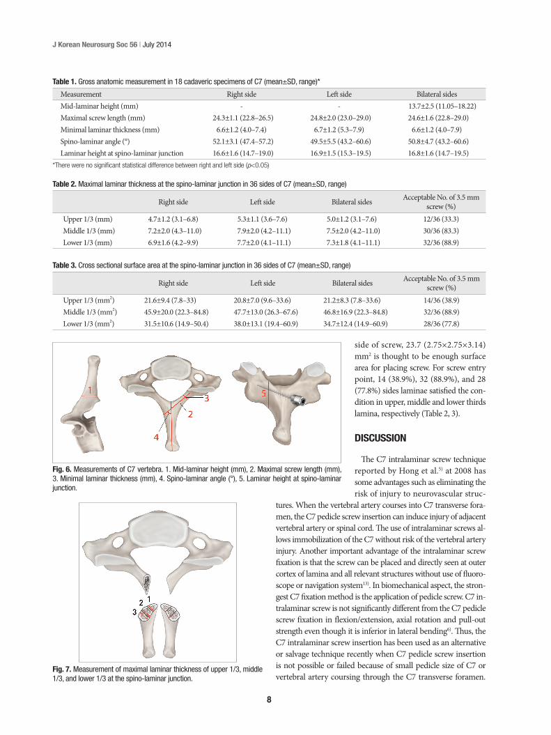
Fig. 6. Measurements of C7 vertebra. 1. Mid-laminar height (mm), 2. Maximal screw length (mm), 3. Minimal laminar thickness (mm), 4. Spino-laminar angle (°), 5. Laminar height at spino-laminar junction.
Fig. 7. Measurement of maximal laminar thickness of upper 1/3, middle 1/3, and lower 1/3 at the spino-laminar junction.
9
Bilateral Crossing C7 Intralaminar Screws | TH Baek, et al.
technique is relatively safe and easy, but precise anatomic knowl-edge is required for safe insertion of bilateral crossing C7 intrala-minar screws into narrow laminar space. Selection of proper screw entry point is the best way to reduce complications such as collision of two screws and violation of laminar cortex. The level of laminar thickness was the highest in middle thirds of C7 screw entry point cross-section and around 77% was avail-able for 3.5 mm screw insertion when lower thirds was chosen for the screw entry point. For bilateral crossing laminar screw insertion, middle and lower thirds of spino-laminar junction can be chosen for each side, respectively, as screw entry points to ensure safe application. The results of this cadaveric study are thought to be a good guideline for safe screw placement in clin-ical application.
References 1. Abumi K, Itoh H, Taneichi H, Kaneda K : Transpedicular screw fixation
for traumatic lesions of the middle and lower cervical spine : description of the techniques and preliminary report. J Spinal Disord 7 : 19-28, 1994
2. An HS, Gordin R, Renner K : Anatomic considerations for plate-screw fixation of the cervical spine. Spine (Phila Pa 1976) 16 (10 Suppl) : S548-S551, 1991
3. Bozkus H, Ames CP, Chamberlain RH, Nottmeier EW, Sonntag VK, Papadopoulos SM, et al. : Biomechanical analysis of rigid stabilization techniques for three-column injury in the lower cervical spine. Spine (Phila Pa 1976) 30 : 915-922, 2005
4. Harris BM, Hilibrand AS, Nien YH, Nachwalter R, Vaccaro A, Albert TJ, et al. : A comparison of three screw types for unicortical fixation in the lateral mass of the cervical spine. Spine (Phila Pa 1976) 26 : 2427-2431, 2001
5. Hong JT, Sung JH, Son BC, Lee SW, Park CK : Significance of laminar screw fixation in the subaxial cervical spine. Spine (Phila Pa 1976) 33 : 1739-1743, 2008
6. Hong JT, Tomoyuki T, Udayakumar R, Espinoza Orías AA, Inoue N, An HS : Biomechanical comparison of three different types of C7 fixa-tion techniques. Spine (Phila Pa 1976) 36 : 393-398, 2011
7. Hong JT, Yi JS, Kim JT, Ji C, Ryu KS, Park CK : Clinical and radiologic outcome of laminar screw at C2 and C7 for posterior instrumentation--review of 25 cases and comparison of C2 and C7 intralaminar screw fixation. World Neurosurg 73 : 112-118; discussion e15, 2010
8. Jang WY, Kim IS, Lee HJ, Sung JH, Lee SW, Hong JT : A computed to-mography-based anatomic comparison of three different types of c7
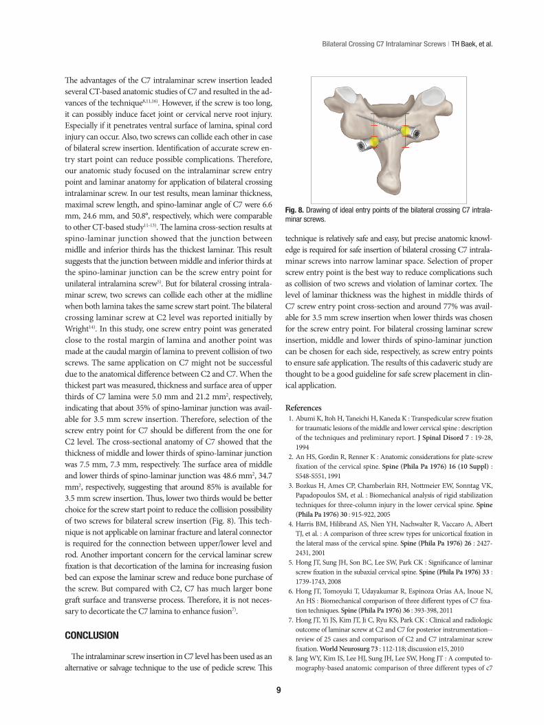
The advantages of the C7 intralaminar screw insertion leaded several CT-based anatomic studies of C7 and resulted in the ad-vances of the technique8,11,16). However, if the screw is too long, it can possibly induce facet joint or cervical nerve root injury. Especially if it penetrates ventral surface of lamina, spinal cord injury can occur. Also, two screws can collide each other in case of bilateral screw insertion. Identification of accurate screw en-try start point can reduce possible complications. Therefore, our anatomic study focused on the intralaminar screw entry point and laminar anatomy for application of bilateral crossing intralaminar screw. In our test results, mean laminar thickness, maximal screw length, and spino-laminar angle of C7 were 6.6 mm, 24.6 mm, and 50.8°, respectively, which were comparable to other CT-based study11-13). The lamina cross-section results at spino-laminar junction showed that the junction between midlle and inferior thirds has the thickest laminar. This result suggests that the junction between middle and inferior thirds at the spino-laminar junction can be the screw entry point for unilateral intralamina screw5). But for bilateral crossing intrala-minar screw, two screws can collide each other at the midline when both lamina takes the same screw start point. The bilateral crossing laminar screw at C2 level was reported initially by Wright14). In this study, one screw entry point was generated close to the rostal margin of lamina and another point was made at the caudal margin of lamina to prevent collision of two screws. The same application on C7 might not be successful due to the anatomical difference between C2 and C7. When the thickest part was measured, thickness and surface area of upper thirds of C7 lamina were 5.0 mm and 21.2 mm2, respectively, indicating that about 35% of spino-laminar junction was avail-able for 3.5 mm screw insertion. Therefore, selection of the screw entry point for C7 should be different from the one for C2 level. The cross-sectional anatomy of C7 showed that the thickness of middle and lower thirds of spino-laminar junction was 7.5 mm, 7.3 mm, respectively. The surface area of middle and lower thirds of spino-laminar junction was 48.6 mm2, 34.7 mm2, respectively, suggesting that around 85% is available for 3.5 mm screw insertion. Thus, lower two thirds would be better choice for the screw start point to reduce the collision possibility of two screws for bilateral screw insertion (Fig. 8). This tech-nique is not applicable on laminar fracture and lateral connector is required for the connection between upper/lower level and rod. Another important concern for the cervical laminar screw fixation is that decortication of the lamina for increasing fusion bed can expose the laminar screw and reduce bone purchase of the screw. But compared with C2, C7 has much larger bone graft surface and transverse process. Therefore, it is not neces-sary to decorticate the C7 lamina to enhance fusion7).
CONCLUSION
The intralaminar screw insertion in C7 level has been used as an alternative or salvage technique to the use of pedicle screw. This
Fig. 8. Drawing of ideal entry points of the bilateral crossing C7 intrala-minar screws.
10
J Korean Neurosurg Soc 56 | July 2014
13. Wang MY : Cervical crossing laminar screws : early clinical results and complications. Neurosurgery 61 (5 Suppl 2) : 311-315; discussion 315-316, 2007
14. Wright NM : Posterior C2 fixation using bilateral, crossing C2 laminar screws : case series and technical note. J Spinal Disord Tech 17 : 158-162, 2004
15. Xu R, Kang A, Ebraheim NA, Yeasting RA : Anatomic relation between the cervical pedicle and the adjacent neural structures. Spine (Phila Pa 1976) 24 : 451-454, 1999
16. Yusof MI, Shamsi SS : Translaminar screw fixation of the cervical spine in Asian population : feasibility and safety consideration based on com-puterized tomographic measurements. Surg Radiol Anat 34 : 203-207, 2012
posterior fixation techniques : pedicle, intralaminar, and lateral mass screws. J Korean Neurosurg Soc 50 : 166-172, 2011
9. Ludwig SC, Kramer DL, Vaccaro AR, Albert TJ : Transpedicle screw fixation of the cervical spine. Clin Orthop Relat Res (359) : 77-88, 1999
10. Ma XY, Yin QS, Wu ZH, Xia H, Riew KD, Liu JF : C2 anatomy and di-mensions relative to translaminar screw placement in an Asian popula-tion. Spine (Phila Pa 1976) 35 : 704-708, 2010
11. Şenoğlu M, Özkan F, Çelik M : Placement of C-7 intralaminar screws : a quantitative anatomical and morphometric evaluation. J Neurosurg Spine 16 : 509-512, 2012
12. Wang MY : C2 crossing laminar screws : cadaveric morphometric anal-ysis. Neurosurgery 59 (1 Suppl 1) : ONS84-ONS88; discussion ONS84-ONS88, 2006