Fast excitation wiggler field measurement results
27
BNL-47928 Informal Report ':5,?? Yf:: '_;i." FAST EXCITATION WIGGLER FIELD !i::'. :_.<._ MEASUREMENT RESULTS , ..,.. :,g..,..,, J Armendariz, 1.Gallardo,T. Romano _:_::::/:_,_<::_.... A.AugustV_.n Steenbergen1992 4_/i_,_.,)_ ,-. . . ',_,- _._ NATIONAL SYNCHROTRON LIGHTSOURCE ., BROOKHAVEN NATIONAL LABORATORY _ -_:: :- !. .,- ASSOCIATED UNIVERSITIES INC :i-:_-:(,.i " Under Contract No DE-AC02-76CH00016 with the MASTER : : " UNITEE' STATES DEPARTMENT OF ENERGY L ;[_- OISTRIBLITION OFTHISDOCUMENT IS UNLIM1TEII
-
Upload
independent -
Category
Documents
-
view
3 -
download
0
Transcript of Fast excitation wiggler field measurement results
BNL-47928
Informal Report
':5,??
Yf::
'_;i." FAST EXCITATION WIGGLER FIELD!i::'.
:_.<._ MEASUREMENT RESULTS, ..,..
:,g..,..,, J Armendariz, 1.Gallardo, T. Romano
_:_::::/:_,_<::_.... A.AugustV_.nSteenbergen1992 4_/i_,_.,)_
,-.
. .
',_,-
_._
NATIONALSYNCHROTRONLIGHTSOURCE.,
BROOKHAVEN NATIONAL LABORATORY_
-_:: :- !. .,- ASSOCIATED UNIVERSITIES INC
:i-:_-:(,.i " Under Contract No DE-AC02-76CH00016 with the MASTER: : " UNITEE' STATES DEPARTMENT OF ENERGY
L;[_-
OISTRIBLITIONOFTHISDOCUMENTIS UNLIM1TEII

e •
DISCI,AIMER
This report was prepared as an account of work sponsored by an agency of the UnitedStates Government. Neither the United States Government nor any agency thereof,nor any of their employees, nor any of their contractors, subcontractors, or theiremployees, makes any warranty, express or implied, or assumes any legal liability or Bresponsibility for the accuracy, completeness, or usefulness of any information,apparatus, product, or process disclosed, or represents that its use would not infringeprivately owned rights. Reference herein to any specific commercial product, process,or service by trade name, trademark, manufacturer, _;r otherwise, does not necessarilyconstitute or imply its endorsement: recommendation, or favoring by the United StatesGovernment or any agency, contractor or subcontractor thereof. The views andopinions of authors expressed herein do not necessarily state or reflect those of theUnited States Government or any agency, contractor or subcontractor thereof.

BNL--47928
FAST EXCITATION WIGGLER DE93 002327
FIELD MEASUREMENT RESULTS
J. Armendariz, J. Gmllardo-,
T. Romano, A. van Steenbergen
4
NSLS and Physics Department
Brookhaven National Laboratory
Upton, New York II973
As part of the program of Inverse Free Electron Laser (IFEL) Accelerator Devel-
opment, the development of fast excitation, planar wigglers with high K magnitude
has been pursued. This paper discusses the observed characteristics of a variable
period length, tapered, wiggler as well as the procedures of measurement. The be-
haviour of a constant period length magnet with varying Vanadium Permendur (VaP)
and field reflector thickness is also discussed.
INTRODUCTION
The IFEL accelerator[i], as parameterized, makes use of a quasi sinusoidal mag-
netic field with a variable period length. The tapered wiggler described in this paper
has varying period lengths (A) from approximately 2.98 to 5.04 cre. It is comprised of
easily stackable, geometrically alternating substacks of Vanadium Permendur (VaP)
. laminations, a ferromagnetic material wMch is driven in a fast excitation mode and

makes use of interleaving conductive, nonmagnetic, Copper (Cu) laminations, which
act as eddy current in'duce'_" "fi_ld=teftectot_. ''' The _v_aP laminations for this wiggler
design have been studied by means of two dimensional mesh computations (POIS-
SON) and by means of actual short wiggler model measurements. These laminations
are assembled in substacks and separated by the nonmagnetic, Cu laminations. Tie
rods, running from end to end through the laminations, hold the magnet compressed
and in piace. Four straight current conductors, parallel to the axis of the composite
assembly and interconnected only at the ends outside the magnet body, constitute
the single current excitation loop for the wiggler. Two pictorial views of the magnet
can be seen in Fig. 1 and Fig. 2.
For the IFEL objective the maximum magnetic field of the wiggler is required to
have a field magnitude of B=12.5 kG. The field reflectors are essential in order to
obtain this field strength within the 4 mm gap through which the electron and laser
beams will pass. The quasi sinusoidal characteristic of the magnetic field is produced
by alternating the polarit3r of adjacent poles within the magnet. This is accomplished
by simply rotating the substacks of VaP through 180° , every half period (_).
TECHNICAL DESCR.IPTION AND EXPER.IMENTAL OBSERVATIONS
A single loop of Cu wire with an approximate area of A=0.2258 cm 2 constitutes
the probe used for field measurements. Calibration of the probe was done on a "C"
magnet of known magnetic field strength. The current signal produced within the
probe by the magnetic field is integrated and amplified by a factor of approximately
10:1 and then routed to an oscilloscope where the signal c_n then be measured by
means of a digital current peak meter. The probe is housed within a strip of com-
pressed phenolic material approximately the size of the magnet gap. A mylar strip is
placed within the magnet to provide a snug fit and insure a consistent path of travel

for '_he probe; therefore, it is essential to always pull the probe through the length of
the magnet, to avoid inconsistent field readings.
A. TAPERED WIGGLER
Preliminary data obtained from a tapered wiggler model with varying period
lengths from approximately 2.98 to 5.04 cre, in which the ratio of VaP to Cu was
kept constant, indicated that the magnetic field on axis rises linearly with increasing
period length. Measurements of the field were taken for current values ranging from 1
to 7.7 kA. In all cases the linearity of the field vs. longitudinal coordinate was evident;
and the slope of the peaks of the magnetic field is a function of current. The slopes
ranged from 3 x 10⁻³ to 4 x 10 -2 kG/cm and the intercepts from 2.3 to 15.8 kG.
The full field measurement at 6 kA can be seen in Fig. 3 and the corresponding peak
values of the field in Figs. 4-5. It was previously assumed that the peak magnetic field
was a function of period length only, but as a result of the experimental observations,
it is now concluded that it is also dependent upon the ratio of VaP stack thickness
to period length. Figs. 6-7 are the plots of the slope vs. current and the intercepts
vs. current, respectively. The saturation effects can be seen in Fig. 7 as the current
increases. In Fig. 6 an almost quadratic increase is observed among the slope values.
Further analysis is described below.
B. CONSTANT PERIOD WIGGLER.
In a constant period wiggler with a constant ratio of VaP to Cu, experimental
results indicated that the maximum magnetic field on axis is essentially constant,
excluding end effects, throughout the length of the magnet as shown in Fig. 8. Again,
field measurements were taken for current values ranging from 1 to 7.7 kA producing
• slopes from 3.7 x 10 -4 to 1.8 x -3 kG/cm and intercepts from 2.3 to 16.6 kG. The

slopes in this case are, however, small and can be attributed to, exclusively, the end
etfects of the magnet. A symmetry about the center of the magnet is observed, and
can be seen in Figs. 9-10. With closer evaluation of the peak values of the magnetic
field an "elbowing" of the points about the center becomes evident. It is thought
that this elbowing is a result of the end effects of the magnet and that only about
the center, do the magnetic poles behave as if part of an infinitely long magnet. In
ai1 cases, the slopes of best fit lines calculated through the peak points leading up to
the center of the magnet are of opposite sign to those leading away from the center
of the magnet,
C. SHORT WIGGLER MODELS
A constantperiodwigglermagnet with a varyingratioofVaP to F was configured
and measured along with a tapered wiggler which kept the VaP constant and varied
the Cu reflectors. The full field measurements for these configurations at 6 kA can be
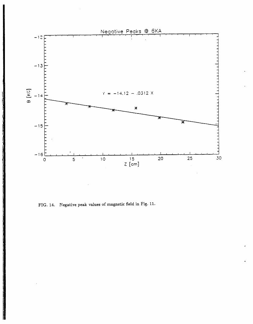
seen in Figs. 11-12 respectively. As can be seen in Figs. 13-14, a linearity is evident in
the peak values of the magnetic field of the magnet with constant period and varying
ratio of VaP to 7"_ Although this was a shorter wiggler model, the increase in slope
with respect to current for this magnet shows the same behaviour as noted earlier
for the varying period length, constant VaP to Cu ratio, wiggler magnet; as can be
seen in Fig. 15. This evidence tends to support the conjecture that a term dependent
upon the ratio of VaP thickness to (_) is necessary in order to be able to describe the
magnetic field properly, since the only common factor between the two magnets is the
increasing amount of Va?. In previous experiments it was observed that the optimum
ratio of VaP to Cu was 4 to 1. When this optimum setting is exceed the smooth
sinusoidal shape of the field is compromised. The "shouldering" effect observed in
the field of Fig. 12, depicts this effect.

To analyze the data, several fortran programs were written. These programs
consisted of routines which solved for the peak values of the fields and which would
then fit a polynomial to these points. Also utilized extensively for this purpose was
the IMSL library. PV Wave, a graphics package on the Vax cluster at the Brookhaven
National Laboratory, was used to provided the hard copy output of our data.
SUMMAKY OF RESULTS
Through measurement of the fields of four wiggler configurations a relationship
between the wiggler's magnetic field and the longitudinal coordinate has been devel-
oped. For current values less than 4 kA, below the onset of saturation, the magnetic
field can be described by:
B(z) [0"604(dr _z kG(NI) - 2.517 + _zz) + 0.128( )]z [--_---] (1)
drwhere NI is the number of ampere turns, _ is rate of change of the ratio of VaP to
-_2with respect to z, and ._ is the rate of change of the period with respect to z. In
the design of tapered wigglers, it is convenient to maintain a constant value of r, thus
giving ar =0. For A values greater than 3.2 cm, the empirical relationship
(NX) = 2.517+0.12s( )_ I-xi (2)
is then established. Table I shows the dimensions of the individual wiggler models, the
Aratio of VaP to (_) and taper of the several wiggler models assembled and measured
and subject of this report.
CONCLUSION
$
Fast excitation driven, laminated. Vanadium Permendur, wigglers with periodic
interleaving of conductive copper field reflectors, can provide state of the .rr wigglers.
It is evident from the preceding that the constant period wiggler satisfy FEL objec-
5

fives. It is further observed, that IFEL accelerator requirements can be fulfilled with
the tapered wiggler model.
ACKNOWLEDGEMENT
One of the authors (JA), participant in the Summer Research Program, gratefully
acknowledge support from the Department of Energy, Office of Educational Programs.
This work was supported by the U.S. Department of Energy under Contract No. DE-
ACO2-76-CH00016.
REFERENCES
1 E. Courant, A. Fisher, J. Gallardo, C. Pellegrini, J. Rogers, J. Sandweiss, J.
Sheehan, A. van Steenbergen, S. Ulc, M. Woodle, Inverse Free-Electron Laser
Accelerator Development, The Accelerator Test Facility Users' Meeting, October
15-16, 1991, BNL Report BNL-47000, CAP #81, ATF-91P.

TABLES
TABLE I. Table of wiggler dimensions.WIi o.nd WIe constitute the first and last
halves, respectively, of the magnet of Fig. 3. WII, WIII and WIV are the dimensions of the
magnets in Figs. 11, 12 and 8, respectively. Data is normalized to L_=24 cm and Ie_c=4
t
kA
__B [kG/cm] A [cre] w_, [cml (r)" (Bi) b [kG] (B,) ¢ [kG] _ [kG/cm] d_ [1/crnidz
WIi 2.98 1.19 0.798 9.57 - 0.0168 d .._ 0
var. A; const r 4.29 1.73 0.806 - 9.97 - -
WIe 4.29 1.73 0.806 9.97 - 0.0168 d _ 0
var. A; const r 5.04 1.98 0.786 - 10.37 - -
WII 3.96 1.07 0.540 10.05 - 0.01684 0.006
const A 3.96 1.37 0.692 - 10.45 - -
WIII 3.25 ]:.02 0.628 10.11 - 0.0072 -0.006
const Wp 4.27 1.02 0.478 - 10.28 - -
WlVi 3.76 1.52 0.808 10.06 - -t-0.0068 e _ 0
const A, r 3.76 1.52 0.808 - 9.89 - -
W
"r = _, Wr, denotes the thickness of the VaP
b Bi = B(z = 0) except for WIV where Bi = B(z = 24)
¢ Be = B(z = 24)except for WIV where Be = B(z = O)
a without partial saturation, 0.0145
end effects

Cu. Cu VaP laminations
VaP laminations
FI(;. t. Pictorial of Fast Excitation Wiggler with field reflection.

FIG. 2. Pictorial of Wiggler with a front view of the VaP laminations and approximate
positioning of the current conductors.

Field Measurement @ 6KA20 ..... ' .... _ ......... i ......... i ......... "l ......... ,,
-20 .... ,,,_,1,,,,,, i,,I,,,,,,,,_l ......... 1 ......... I,,
0 10 , 20 30 40 50z
FIG. 3. Full field measurement of Tapered Wiggler with varying period lengths, and
a constant VaP to Cu ratio.

Positive Peaks @ 6 KA
16 ......... I ......... J ...... '"', ' ' I ......... J ......... I' '/
7
. t_ Y = 13.34 + .(?299 × "_ 0
"_ 12--m Jm
o
10-
B
8 I 1 I I I t I T I I ' ' _ ' ' t t lt I I l I I I * ' * ' I I I 1 I T I ' ' ' 1 , _ , t J _ I i , I , ,
0 10 , 20 30 40 50
Z rcm]
FIG. 4. Positive peak values of magnetic field in Fig. 3.

- Neaative Peaks @ 6 KA
di -
m
i --10 -- --
l z -12-- -
m _ Y = -13.¢4 - .0312 X
-14 -
I I I I I I I l t i 1 I J I I I _ i I I I I .I I 1 I 1 J i _ t I I I J i t
I 0 10 , 20 ,,30 4. ,50z C_=]
i •FIG. 5. Negative peak values of magnetic field in Fig. 3.
iI'i
ii
i|

Current vs. Slo_e0.06 , , , j ' ' ' i ...... 1 ' ' _ j
-0.04- Positive slopes..-n
, °..°°°°°"
.°°°..°°°'°
_ °°°_,.-°'°'°°°° -- •
O.O2 - -¢,...
U '"_ _
•..... __ .° _
0.00 -- "-.**°
N ")K'--._"rO _
m -
-0.02 "
" °O.°o°°°. _
. "..°°..
°°-..°_,
-0.04.. -- Negative slopes -t006; . I _ _ a I ,. , ,-- . ' I , _ I , J, , I ,I I , ,
0 2, 4 6 8 10
Current [KA]
FIG. 6. Plot of slope vs. current for different current settings of the Tapered Wiggler
with varying period lengths and constant VaP to Cu ,atio.

Intercept vs. Current2.0. ' ' ' ' ' ' ' ' ' ' ' ' ' ' J.."l ' ' ' -
." . _ o......., o ..'''''''''''''''" _
Z Positive Int:e_ "_l_ --
" q
10.--
, :
¢ll . -
__ - _
-10 -- --_
-20 " I , i I I _ , I, z I I I L I , "'J , , ,0 2' 4 8 8 10
Current [KA]
FIG. 7. Plot of intercepts vs. current for different current settings of the Tapered
Wiggler with varying period lengths and constant VaP to Cu ratio.
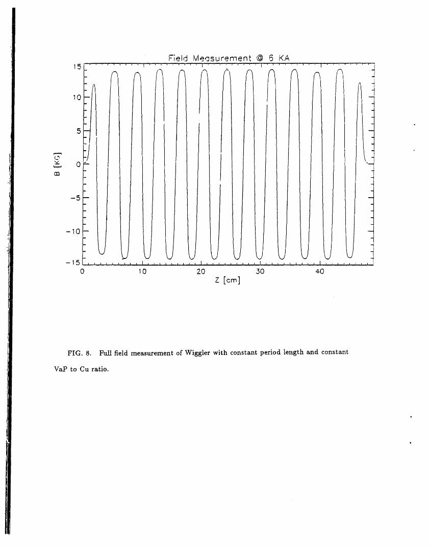
FIG. 8. Full field measurement of Wiggler with constant period length and constant
VaP to Cu ratio.

Positive Peaks @ 6KA15 "' '' ..... "' I"' "_" .... +" ..... ''' '"I ......... J ........-- q
-- q
_ ",_ ,_14-- _ _ "_ _ _ _ "
• : Y = 1.:t.973 + .00057 X :
13--
(2 :v_ . -3
,
rr_ - -I
: _ _,12-- -'1
11--
: _
- !10 - "
0 10 20 30 40 50
z [_]
FIG. 9. Positive Peak values of magnetic field in Fig. 8.

Neaative Peaks @ 6KA
; !-11 -- --
-12 -- -: q
0 -
rn -
-13 -- -
" ,_ Y = -14.077 - .00181 × ,"
- 14.-- _ ._. ,_,
15- I I I -l I I I I I I I I I I I 1 I I I I 1 ! I I i I I I l I_ I I 1 ! 1 1 I 1 I I I 1 I I I ! I , !
0 16 20 .30 ¢0 50
z[o_]
FIG. t0. Negative Peak values of magnetic field in Fig. 8.

Field Measurement @ 6KA20 .... I .... l .... I * " ' ' l .... 1 ....
f r
' ij,_. om
--20 L I I I I [ I I I I I I I
0 5 ' I0 15 20 25 30
FIG. 11. Full field measurement o5 Short Constant Period Wiggler with varying VaP
to _ ratio.

Field Meosurement @ 6KA20 .... _ .... _ .... _ .... I ....
4
/ "m
-20 l L, t i I i i i , I , , I , I , I l L, I L , , '
5' 250 10 15 20
z
FIG. 12. Full field measurement of Short Constant VaP Wiggler with varying Cu.

Positive Pe_ks @ 6KA16 _ ' '' ' " I .... I "'"' ' ' I ' _" ' * f ' , L, , _ .... j
v
..__._--_ _
- __ -
• -_ -C_ _
"--_14 --
_- Y = 14.055 + .0296 X -
15--
_ -_.. -._
- . -_
12" , , , .,. I _ _ , , I , , J , I L.., , , I , . , , .I L , .l., "I,i
0 5 10 15 20 25 50
z
FIG. 13. Positive peak values of magnetic field in Fig. 11.
Nearative Peeks @ 6KAJ 1
-17 .... IIl'III ' ' ' _ I I " ' ' ' I .... t .... I ' ' ._
-1.3 --
ii,i,l
o - r' = -14 12 - .0.512 X -"_ -14. --,----, -"t
- .
-15 -
-16 , , , , I .... , z I , I , , I z , i , I i , , I I , ....0 5 ' 10 15 20 25 50
FIG. 14. I',Tegative peak values of magnetic field in Fig. 11.

Slooe vs. Current, , , , ,, , ,,,,
0.06 ' ' ' J ' ' ' 1 ' ' ' i ' ' ' 1 ' ' '
0.04 -- Po " " " _m
,.°°. °°.°, ..°°°°, .°°, . r_
0.02t"
" U
_-_ ..
,_, 0.00 ":'" ".°.
N"O_ -
_ fT'} / "°°..°°
_ -
! -0.02 -i
i - -_ °''.°..,°......
i -0.04 --m
-0.05 , I , I _ _ I I J , I I I I , I , , ,0 2' 4 6 8 0
Current [KA]
FIG. 15. Plot of slope vs. current for different current settings of the Short Constant
Period Wiggler with varying ratio of VaP to _.