Comparison of Methods and Existing Tools for the Measurement of Usability in the Web
Upload
khangminh22Category
view
1download
0
168
CONTENTS
1 Units of Measure
2 Measurement Tools and How to Read Them
3 Measurements on Scale Drawings
Measurement and Measurement Tools
chapter 4

169
INTRODUCTIONAccurate measurement is critical to the success of many jobs performed by UBC members. Measuring lines, shapes, and angles is a fundamental skill in the building trades. This chapter discusses units of measure and how to convert measurements from one unit of measure to another. The chapter also describes some of the most commonly used measurement tools, how they are used, and their particular advantages. The chapter concludes by explaining how to read scale drawings.
KEY TERMSacute angle less than 90°
angle two straight lines with a common end point or vertex, measured in degrees
conversion factor number by which a measurement is multiplied or divided to change it to the same value in a different unit of measure
degree (°) unit of measure of an angle, 1360 of a circle
linear measurement finding the length of lines or distance
meter basic unit of linear measure in the metric system
micrometer high precision measuring tool
minute (') 160 of a degree
obtuse angle greater than 90°
order of operations the sequence in which arithmetic operations are performed when more than one is required to solve a problem
protractor instrument used to measure angles
right angle 90° angle
ruler straight edge marked in units of measure
scale divisions on a measuring tool
scale drawing presents an object in its exact shape but larger or smaller
second (") 160 of a minute
tolerance acceptable range of precision in measurement
upper and lower limit (±) measures plus or minus tolerance for a given figure, represents the limits of acceptable variation
vernier caliper slide caliper with a short, graduated scale that slides along a longer, graduated instrument and is used to indicate fractional parts of divisions
vertex point where the lines of an angle meet
OBJECTIVESUpon successful completion of this chapter, the participant should be able to:
1. Convert measurements from one unit of measure to another.
2. Identify common measurement tools and their uses.
3. Use measurement tools to measure lines and angles.
4. Accurately read measurements in scale drawings.

170 Math for the Trades
1 Units of MeasureUnits of measurement have existed for thousands of years. The earliest units of measure were based on body parts. Ancient Egyptians measured length in “cubits,” the distance from the elbow to the fingertips, and in “hands,” a measurement still in use today to describe the height of horses. The English “foot” was originally the length of the foot of the king; an “inch” was the width of his thumb. A “rod,” which is equal to 16.5 feet, is a unit of measure used by surveyors. According to folklore, the rod was defined by measuring the combined length of the left feet of the first 16 men to walk out of church one Sunday morning. “Fathoms,” which is a measure of the depth of water, originated from the Anglo-Saxon word for “embrace.” A fathom was the distance between the outstretched arms of a man.
UBC members working in the United States and Canada will need to work with linear measurements, the measurement of lines or distance in inches, feet, and yards and also in metric units of measure: millime-ters, centimeters, decimeters, and meters. Some jobs also involve the mea-surement of angles. Units of measure used with angles include degrees, minutes, and seconds. Although miles and kilometers are also commonly used units of measure, they are not often used in UBC trades and are not discussed in this chapter.
Converting Between Inches, Feet, and YardsInches, feet, and yards are English units of measure that came to Canada and the United States with the early English colonists. They describe dis-tance. Twelve inches equal one foot. Three feet equal one yard. Five thou-sand two hundred and eighty feet equal one mile. Figure 1 illustrates the relationship of inches, feet, and yards to each other. The examples also show the common abbreviations for inches, feet, and yards.
Inches, feet, and yards can all be divided into fractional parts. The most commonly used fractional parts are halves, fourths, eighths, and sixteenths and also tenths and hundredths. The steel scale shown in Figure 2 subdi-vides each inch into halves, fourths, eighths, sixteenths, thirty-seconds, and sixty-fourths. Figure 3 shows another steel scale that has inches subdivided into hundredths along one edge.
1 yard = 3 feet = 36 inches
Abbreviation: 1 yd.
1inch
Abbreviations: 1 in., 1˝
1 foot = 12 inches
Abbreviations: 1 ft., 1´
figure 1Relationship of inches, feet, and yards

Measurement and Measurement Tools 171
MEA
SUREM
ENT
Converting Measurements From One Unit of Measure to Another On the job, it may be necessary to convert measurements from one unit of mea-sure to another. That process requires a conversion factor, a number by which the existing unit of measure is multiplied or divided to express the same value in a different unit of measure. Conversion factors are based on the relationship of the two units of measure to each other. For example, there are 12 inches in a foot. Twelve is the conversion factor for feet and inches. To convert feet to inches, multiply the number of feet by 12. To con-vert inches to feet, divide the number of inches by 12. Figure 4 illustrates how 32˝ can be converted to 2 -8 . Table 1 lists conversion factors for feet, inches, and yards.
figure 2Fractional parts of an inch
1
164
64
116
132
18
14 1
2
1
figure 3Steel scale with inches in hundredths
figure 2Fractional parts of an inch
12 inches = 1 foot
1 ft. 2 ft. 2 ft. 8 in. or 32 in.
figure 4Conversion factor example

172 Math for the Trades
table 1Conversion chart for feet, inches, and yards
To convert Do this
Feet to inches Multiply by 12
Inches to feet Divide by 12
Feet to yards Divide by 3
Yards to feet Multiply by 3
Yards to inches Multiply by 36
Inches to yards Divide by 36
Example 1
To convert inches to feet, find the number of feet in that number of inches.
How many feet is 32 inches?
Step 1: To convert 32 inches to feet, divide 32 by 12. 2 R 812 ⎠ 32
24 8
32 inches × 1 foot = 2.67 feet 12 inches
Step 2: The equation is 32 ÷ 12 = 2 with a remainder of 8.
Step 3: The result can be expressed in three ways.
a) 32 in. = 2 ft. 8 in.
b) 32 in. = 2 812 ft. which reduced to lowest terms is 2 2
3 ft.
c) 32 in. = 2.67 ft.
Different Approaches to Conversion Problems On the job, converting measurements from one unit of measure to another may be just one part of a multi-part problem. For example, how many linear inches of 3˝ wide trim are needed to go around both sides and the top of the window in Figure 5? The diagram shows the dimensions: the height is 4 -5 , and the width of the top is 2 -6 . The width of the trim, 3 , needs to be added to the dimensions of the window, making the height 4 -8˝ and the width 3 . Remember to include both sides of the window trim in the calculations.
There are several ways to solve this problem. Example 1 demon-strates converting all of the measurements to inches and then add-ing the inches together to find the amount of trim needed. Example 2 adds the existing measurements together and then converts the
figure 5Window dimensions for side and top trim
3´-0˝
4´-8˝4´-5˝
3˝
3˝ 3˝2´-6˝

Measurement and Measurement Tools 173
MEA
SUREM
ENT
sum to inches. Example 3 shows how to add measure-ment using decimal feet, and Example 4 shows how to do the whole calculation with one equation.
Example 1
Adding inches.
The first step is to separate the measurement 4 -8˝ into feet and inch components. Then multiply the number of feet (4 ) by the correct conversion factor, in this case 12 . The result is 48 . Step 2 is to add the 48˝ back to the original 8˝ component.
4 -8˝
Step 1: 4 ft. × 12 in. = 48˝ 1 ft.
Step 2: 48˝ + 8˝ = 56˝
Remember that there are two sides of trim. 56˝ × 2 = 112 .
Step 3: Convert the top trim from feet to inches.
3 ft. × 12 in. = 36˝ 1 ft.
Step 4: Add the sides to the top 36˝ + 112˝ = 148˝ total trim required.
Example 2
Adding feet and inches.
Add all the inches together. Add all of the feet together. If the inch total is greater than 12, simplify.
Step 1: Add the inches. 4 -8˝ side
4 -8˝ side
3 -0˝ top 16˝
Step 2: Add the feet. 4 -8˝ side
4 -8˝ side
3 -0˝ top 11 -16˝
Step 3: Simplify. 11 -16˝ = 12 -4˝ total trim required
Example 3
Using decimal feet to make the calculation in one equation.
Separate the measurement into its feet and inch components. Convert the inch component to a decimal of a foot and add to the feet. Add the measurements together.

TRADE TIP
An easy way to remember mathematical order of operations is this:P = Please parenthesesE = Excuse exponentM = My multiplyD = Dear divideA = Aunt addS = Sally subtract
174 Math for the Trades
Step 1: 4´ component
8˝ component
Step 2: Convert 8˝ component to a decimal of a foot
812 = 12⎠ 8.0 = .67
Add the decimal component back to the feet component
4´ + .67´ = 4.67´
Step 3: Add the lengths of all the pieces of trim together. 4.67´ side 4.67´ side 3.00´ top 12.34´ total trim required
There is a way to solve the problem by combining the operations. In order to do so it is necessary to know the order of operations, which is the sequence in which mathematical operations must be performed. Operations inside parentheses come first, then operations outside the parentheses. Once the math operations inside the parentheses are com-leted, perform multiplication, division, addition, and subtraction to complete the problem in that order.
Example 4
This calculation uses decimal feet.
Step 1: Write an equation that totals the lengths of the sides.
2 × 4.67´
Step 2: Put that operation inside parenthesis, and add the length of the top piece of trim.
(2 × 4.67´) + 3´ =
Step 3: Perform the math.
9.34´ + 3´ = 12.34´ total trim required
SELF CHECK 1
1. List several common fractional parts into which inches are subdivided.
2. What is the conversion factor for converting feet into inches?
3. Convert 45 to feet.
4. Convert 7´ to yards.
5. Convert 3.5 yards to inches.
6. Convert 2 12 yd. to feet.
7. Convert 2 12 yd. to inches.
8. Convert 3 - 2 12
˝ to inches. (continued)

Measurement and Measurement Tools 175
MEA
SUREM
ENT
SELF CHECK 1
9. A straight line 3 -6 long was divided into 7 equal parts. What is the length in inches of each part?
10. Eight pieces, each 2 78 , were cut from a 3 - 2˝ metal bar. Allow-ing 3
32˝ waste for each cut, how many inches of the metal bar are
left?
(continued)
˝332
waste cut
Millimeters, Centimeters, Decimeters, and MetersThe metric system is a measurement system based on multiples of the num-ber 10. Although a French vicar may have created an early version of the metric system around 1670, it was not until the end of the 18th century that interest in decimal-based measurement systems became strong. Thomas Jefferson proposed such a system for the United States in 1790. Since 1866, the metric system has been legal in the United States, but not compulsory.
The meter is the basic unit of measure in the metric system. A meter is equal to 39.37 inches. Both tables below show the abbreviation for each metric unit of measure and demonstrate how the different units of mea-sure compare to each other. Table 2 lists metric units of linear measure that might be used by UBC members on the job.
table 2Comparison of commonly used metric units of measurements
Millimeters(mm)
Centimeters(cm)
Decimeters(dm)
Meters(m)
1 0.1 0.01 0.001
10 1 0.1 0.01
100 10 1 0.1
1,000 100 10 1
Table 3 shows the meanings and place values for these metric units.
table 3Mathematical definitions for metric unit prefixes
PrefixMeaning and place value
Decimal
Milli One thousandth of 0.001
Centi One hundredth of 0.01
Deci One tenth of 0.1
(continued)

TRADE TIP
To convert from a larger unit to a smaller unit, multiply. To convert from a smaller unit to a larger unit, divide.
176 Math for the Trades
Mathematical definitions for metric unit prefixes
PrefixMeaning and place value
Decimal
Units 1
Deka Ten times 10.0
Hecto One hundred times 100.0
Kilo One thousand times 1000.0
Converting Metric Measurements Converting metric measurements from one unit to another is easy because they are decimal-based. Therefore, each larger unit of measure (millimeter, centimeter, decimeter, and meter) is ten times greater than the one before.
To convert a measurement from one metric unit of measure to another involves multiplying or dividing by 10. To convert a larger metric unit to smaller unit, multiply by 10, as shown in the following procedure.
PROCEDUREHow to Convert Metric Measurements
1. To convert 1.0 meter to decimeters: Multiply 1 meter by 10 = 1 m x 10 = 10 decimeters, or simply move the decimal point one place to the right. 1.0m = 10 decimeters.
1 m x 10 dm = 10 dm 1 m
2. To convert 10 decimeters to centimeters: Multiply decimeters by 10 = 10dm x 10 = 100 centimeters, or simply move the decimal point one place to the right. 10.0dm = 100 centimeters.
10 dm x 10 cm = 100 cm 1dm
3. To convert 100 centimeters to millimeters: Multiply centimeters by 10 = 100cm x 10 = 1000 millimeters, or simply move the decimal point one place to the right. 100.0cm = 1000 millimeters.
100 cm x 10 mm = 1000 mm 1cm
A short cut for converting from one metric unit to another unit of measure is to simply move the decimal point to the left or right the appropriate numbers of places. From the previous example:
(continued)
(continued)table 3

Measurement and Measurement Tools 177
MEA
SUREM
ENT
PROCEDURE (continued)
1. To convert 1.0 meter to decimeters, move the decimal point one place to the right. 1.0m = 10 decimeters
2. To convert 10 decimeters to centimeters, move the decimal point one place to the right. 10.0dm = 100 centimeters.
3. To convert 100 centimeters to millimeters, move the decimal point one place to the right. 100cm = 1000 millimeters.
To convert a smaller metric unit of measurement to the next larger one, such as 1 millimeter to centimeters, divide millimeters by 10, or move the decimal point 1 place to the left.
SELF CHECK 2
1. What is the basic unit of measure in the metric system?
2. Which is larger: 5 centimeters or 1 meter?
3. Which is larger: 10 decimeters or 50 centimeters?
4. Convert 4.5 m to centimeters.
5. Convert 2500 mm to meters.
6. Convert 250 dm to meters.
7. Convert 75 m to cm.
8. Three 50 cm sections were cut from a 3 m length of decorative molding. How much of the molding is left?
9. How many 10 cm decorative tiles are needed for a 3-meter border in a kitchen?
10. The border was so striking that the builder decided to con-tinue it around a corner and down to the end of a hallway. The additional length is 7 meters. How many more 10-cm tiles need to be ordered?
Metric to English ConversionThe previous procedure showed it is easy to convert one metric unit of measure to another metric unit of measure by moving the decimal point to the left or right. How-ever, sometimes it is necessary to convert metric units of measure to English units or the other way around. For example, the print could have machinery layout dimen-sions in metric units that must be converted to English units for assembly.
The conversion process is easy by remembering there are approximately 25.4 millimeters in an inch. Knowing that

178 Math for the Trades
the metric system is decimal-based and there are 25.4 millimeters in an inch, conversion problems are easily solved with multiplication and division.
Table 4 shows how to convert English units to metric units and back. Look closely at each conversion factor to see how each was derived.
table 4Converting between metric and English units
When you know Multiply by To find
Inches 25.4 Millimeters
Inches 2.54 Centimeters
Feet .305 Meters
Yards 0.91 Meters
Miles 1.61 Kilometers
When you know Divide by To find
Millimeters 25.4 Inches
Centimeters 2.54 Inches
Meters .305 Feet
Meters .91 Yards
Kilometers 1.61 Miles
SELF CHECK 3
Change the linear dimensions given in either the metric or English system to the appropriate units.
1. Convert .375 inches to mm and cm.
2. Convert 35 centimeters to inches.
3. Convert 12 yards to meters.
Units of Measure for AnglesAn angle is two straight lines with a common endpoint. There are angles at the corner of a room and where two sides of a roof meet. UBC mem-bers use angles in many ways on the job, from laying out a foundation to ensuring that walls and floors are plumb, level and at right angles to each other.
The common unit of measure for an angle is the degree. The symbol “°” is a small, superscript circle that stands for a degree, as shown in Figure 6. A degree can be subdivided into two smaller units of measure, minutes and seconds. The symbol “'” represents minutes, and the symbol “"” stands

Measurement and Measurement Tools 179
MEA
SUREM
ENT
for seconds. There are 60 minutes in each degree and 60 seconds in each minute.
The size of an angle depends on the size of the opening between the lines, not on the length of the lines. The point where the lines of an angle meet is the vertex. The opening between the lines is measured in terms of 360° of a circle with the vertex of the angle at the center of the circle. A 90° angle is a right angle. Its lines make a square corner. An angle of less than 90° is an acute angle. An angle greater than 90° is called an obtuse angle. A straight line is actually a 180° angle. A circle contains a 360° angle. The maximum size of an angle is 360°.
Adding and Subtracting Angle Measurements Adding and subtract-ing angle measurements is similar to adding and subtracting fractions and mixed numbers: Like things must be added to or subtracted from like things. Degrees must be added to or subtracted from degrees. Minutes must be added to or subtracted from minutes. Seconds must be added to or sub-tracted from seconds. The following procedures demonstrate how to add and subtract angle measurements.
PROCEDUREHow to Add Angle Measurements Without Carrying
Add the following angle measurements: Angle A: 18° 25' 40" plus Angle B: 20° 10' 15". 1. Stack the angle measurements to be added.
18° 25' 40"+ 20° 10' 15"
2. Add the seconds first, then the minutes, and finally the degrees.
18° 25' 40" 18° 25' 40" 18° 25' 40"+ 20° 10' 15" + 20° 10' 15" + 20° 10' 15" 55" 35' 55" 38° 35' 55"
The finished angle is read as thirty-eight degrees, thirty-five minutes, and fifty-five seconds.
figure 6Angle with degree marked
Acute
Right
ObtuseCircle 360º
Straight
90º180º
Vertex

180 Math for the Trades
PROCEDUREHow to Subtract Angle Measurements Without Borrowing
Subtract Angle B from Angle A: Angle A: 56° 14' 20" minus Angle B: 28º 10' 19". 1. Stack the angle measurements and start subtracting with the
seconds followed by minutes then degrees.
56° 14' 20" 56° 14' 20" 56° 14' 20"− 28° 10' 19" − 28° 10' 19" − 28° 10' 19" 01" 04' 01" 28° 04' 01"
The finished angle is read as twenty-eight degrees, four minutes, and one second.
Table 5 shows a conversion chart for degrees, minutes, and seconds.
table 5Conversion chart for degrees, minutes, and seconds
To convert Do this
Degrees to minutes Multiply by 60
Minutes to seconds Multiply by 60
Seconds to minutes Divide by 60
Minutes to degrees Divide by 60
If adding angle measurements produced a sum like 240° 75' 130", it would be necessary to reduce the minutes and seconds to lowest terms. The next procedure shows how to do that.
PROCEDUREHow to Add Angle Measurements With Carrying and Reducing to Lowest Terms
Add the following angle measurements: Angle A: 18° 25' 40" plus Angle B: 20° 10' 30" 1. Stack the angle measurements to be added.
18° 25' 40"+ 20° 10' 30"
2. Add the seconds first, then the minutes, and finally the degrees.
18° 25' 40" 18° 25' 40" 18° 25' 40"+ 20° 10' 30" + 20° 10' 30" + 20° 10' 30" 70" 35' 70" 38° 35' 70"
3. In an angle measurement, any minutes or seconds that are 60 or greater must be reduced to lowest terms. The 70" in the sum must be reduced to lowest terms. To reduce minutes or seconds to lowest terms, divide by 60; this is the conversion factor.
(continued)

Measurement and Measurement Tools 181
MEA
SUREM
ENT
PROCEDURE (continued)
4. Divide 70" by 60 60)70 = 1 minute with 10 seconds remaining. Because 70" equals 1 minute and 10" that minute should be added to the minutes’ column.
5. Carry the 1' and add it to the minutes’ column. 1 18° 25' 40"+ 20° 10' 30" 38º 36' 10"
6. The f inished angle is thirty-eight degrees, thirty-six minutes, and ten seconds.
38º 36' 10"
When adding angle measurements, the need to convert one unit of measure to another does not come up until the answer. In subtraction, conversion is often needed earlier. The next procedure demonstrates the process of sub-tracting one angle measurement from another. The conversion chart can help in solving the problem.
PROCEDUREHow to Subtract Angle Measurements With Borrowing and Reducing to Lowest Terms
Subtract Angle B from Angle A: Angle A: 56° 14' 20" minus Angle B: 28° 35' 49". 1. Stack the angle measurements and start subtracting with the
seconds followed by minutes then degrees.
2. Start at the right with the seconds column. It is not possible to subtract 49" from 20" or 35' from 14'. The solution involves borrowing from the appropriate column.
56° 14' 20"− 28° 35' 49"
3. Borrow 1 minute from the 14 in the minutes (1' equals 60") column and add it to the 20 in the seconds column. This gives a new total of 13' and 80".
13' 80" 56° 14' 20"− 28° 35' 49"
4. Borrow 1 degree from the 56 in the degrees column and add it to the 13 in the minutes column. This gives a new total of 55° 73' 80", meaning the problem can now solved. (continued)

182 Math for the Trades
PROCEDURE (continued)
55° 73' 80" 56° 14' 20" 55° 73' 80"− 28° 35' 49" − 28° 35' 49"
5. Start subtracting with the seconds column followed by minutes then degrees.
55° 73' 80"− 28° 35' 49" 27° 38' 31"
The finished angle is read as twenty-seven degrees, thirty-eight minutes, and thirty-one seconds.
SELF CHECK 4
1. What three units of angle measurement are discussed in this section?
2. Which angle is a right angle: 45°, 90°, or 180°?
3. Which angle is an acute angle: 75°, 95°, or 135°?
4. Which angle is an obtuse angle: 30°, 80°, or 93°?
5. Which angle is larger: 7° 59' 40" or 7° 40' 59"?
6. Convert 235" to minutes and seconds.
7. Convert 79° 155' 40" to lowest terms.
8. Convert 120° 15' 78" to lowest terms.
Solve the following
9. 127° 52' 7" + 63° 43' 56"
Convert the following measurements.
11. 22 to inches
12. 3 -5 to inches
13. 17 3564
˝ to feet
14. 288 cm to meters
15. 3.5 meters to millimeters
16. 212.071 dm to meters
17. 1.756 meters to mm
18. 378 minutes to degrees and minutes
19. 235 minutes to degrees and minutes (continued)
10. 70° 8' 42" − 26° 4' 50"

Measurement and Measurement Tools 183
MEA
SUREM
ENT
SELF CHECK 4
Solve the following word problems.
20. If a staircase with 3 steps drops 2 -10 , how many inches deep will each step be?
21. How many 400 cm lengths of pipe can be cut from a 3 meter pipe.
22. Sam knows that his favorite hammer is 15 long. His measur-ing tape breaks, and he has to measure the length of a beam. It is 11 hammer lengths long. What is the length of the beam in feet?
23. If a side street is 152 yards in length and lines for parking spaces will be painted every 15 feet, how many parking spaces will there be?
24. 79.8 tiles that are 10 cm square are used as base mold-ing in a bathroom. How many meters long is the molding?
25. If a stone wall can be built at the rate of 1.5 yards per hour, how many hours will it take to finish a 43 wall?
(continued)
2 Measurement Tools and How to Read Them
UBC members use a variety of measurement tools on the job. Commonly used measuring tools include tapes and rulers, steel scales, and architect’s and engineer’s scales. Protractors are used for measuring and draw-ing angles. For specialized types of measurements, calipers and micrometers are used. The tool that is best for a particular situa-tion depends on what level of precision is required by the job.
Linear Measuring ToolsThe most commonly used tools for linear measurement are measuring tapes, rules, and steel squares. The smallest unit of measure is the inch. However, the inch is divided into parts which may be either common or decimal fractions. The most common divisions on the carpenter’s linear measuring tools represent halves, quarters, eighths, sixteenths, thirty-seconds, sixty-fourths, twelfths, and tenths of an inch.
Measuring Tapes Measuring tapes can be cloth, plastic, or metal. Metal measuring tapes usually retract into a protective case. Many measuring tapes have convenience marks at fre-quently used measurements. For example, most tapes label all the multiples of 16˝ because 16˝ is a standard spacing for fram-ing. Measuring tapes are flexible measuring tools. Figure 7A is an example of a cloth measuring tape and Figure 7B shows a retracting metal measuring tape. Although measuring tapes are
figure 7Measuring tapes
(B)
(A)

184 Math for the Trades
not good for marking a straight edge, they are portable and easy to carry.
Rulers A ruler is a straight edge marked in units of mea-sure. Rulers are used to make measurements and as a marking gauge. The scale on a rule or other measuring tool refers to the divisions into which the units of measure on the tool are divided. Scales vary from one kind of tool to another. The carpenter’s folding ruler, shown in Figure 8, uses a 1
8˝ and 1
16˝ scale. On one scale, each inch is divided
into 18
˝ parts. On the other scale, each inch is divided into 116
˝ parts. The typical folding ruler is 6 long.
Framing Square The framing square, shown in Figure 9, is an L-shaped, multi-purpose measuring tool. Also called a steel square or a carpenter’s square, this tool has been used in the building trades for centuries. It was patented in the United States in 1819 by Silas Hawes, a Vermont blacksmith.
The larger arm is called the blade; and the smaller arm, the tongue. The blade is 2˝ wide and usually 2´ long. The tongue is 1 1
2˝ wide and 16˝ or
18˝ long. The blade and the tongue meet at a 90° angle. Newer framing squares are often made of aluminum and are lighter and more resistant to rust. The surface on which dimensions are stamped is called the face. The reverse, which also has information on it, is called the back. The corner of the square is called the heel.
Inches and fractions of inches are marked on both edges of the blade and the tongue. The scales start from the corner of the square. A fram-ing square usually has 1
8 , 110 , 1
12 , and 116 scales along different edges. The
information and scales on a framing square vary depending on its age and use. Squares may have many calibrations and tables stamped on their faces. These could include rafter tables for calculating the proportional lengths of rafters, board feet scales for calculating board feet, and a diago-nal scale for using the square to draw angles.
A close relative of the framing square is the combination square. Usually, the blade of this square is a 12˝ ruler that slides through the cast body. A locking mechanism in the body allows the adjustment of the length of the ruler sticking out past the body. This feature makes this tool a con-venient depth and marking gauge. The body of the square creates a 90° angle with the rule on one side and a 45° angle with the rule on the other
figure 9Framing square
figure 8Folding ruler

Measurement and Measurement Tools 185
MEA
SUREM
ENT
side. It also usually includes a level, so that the square can be used to level and plumb small objects.
Architect’s and Engineer’s Scales An architect’s scale, shown in Figure 10, is a specialized, three-sided ruler for measuring linear distances. One side of this ruler may be full-scale with inches divided into sixteenths or centi-meters divided into millimeters. The other two sides are not full scale but in ratios such as 1 = 1 , 1
2˝ = 1 , and 1
4˝ = 1 for customary U.S. measure-
ments. Metric scales are marked with ratios such as 1:2, 1:5, 1:100, and so on without reference to the specific units of measure. There are usually two scales on each measuring edge, each beginning at the opposite end. One is read left to right; the other, from right to left.
An engineer’s scale, shown in Figure 11, is used to measure linear distances in decimal feet instead of feet and inches. Metric versions of the engineer’s scale are also available.
How to Read a Ruler or Steel Scale The most important aspect of using any measuring tool is the ability to use it accurately and maintain the repeatability of the measurements. To determine the value of graduations, the divisions on a measuring tool, count the number of spaces between the lines and divide this number into the whole number. Figure 12 shows an inch, considerably enlarged, subdivided into sixty-fourths. The heights of the lines get shorter as the fractions of an inch they represent get smaller. The tallest line is at the one-inch mark. The next tallest line marks 1
2˝ on
the ruler. The number 64 on the left side of the scale, shows that the ruler is divided into 1
64˝ segments.
figure 11Engineer’s scale
1 0 2 3 4 5 6 20
7
48 46 44 42 40 38 36 34
figure 10Architect’s scale
0 10 2 9 4 8 1 2
0 46 4 44 8 42 12 40 16 38 20 36
1 8
figure 12Enlarged view of one inch subdivided into sixty-fourths
1
164
64
116
132
18
14 1
2
1
186 Math for the Trades
SELF CHECK 5
For questions 1–6, use a steel scale or a rule, subdivided into 164 , to
draw horizontal lines with the lengths below:
1. 3 14
˝
2. 2 12
˝
3. 3 58
˝
4. 3 116
˝
5. 4 1516
˝
6. 3 532
˝
7. Fill in the correct increments below. Use the lowest common fraction of an inch.
(continued)
1˝

Measurement and Measurement Tools 187
MEA
SUREM
ENT
SELF CHECK 5
8. A fraction with an even-numbered denominator reduced to its lowest term will have an numbered denominator.
9. Complete the fractions listed below in their lowest term.
a. 216˝ = 8
˝
b. 816˝ = 2
˝
c. 416˝ = 4
˝
d. 24˝ = 2
˝
10. What are the decimal equivalents?
1 = 12
˝ = 78
˝ = 38
˝ = 34
˝ = 14
˝ = 58
˝ = 18
˝ =
(continued)
Specialized Measuring ToolsSpecial situations in the work place often call for specialized types of mea-suring equipment. Protractors, calipers, and micrometers may be needed. The tool that is best for a particular situation depends on what level of pre-cision is required by the job.
Protractors The protractor, shown in Figures 13A and B, is an instru-ment used to measure angles. It has a semicircular side and a straightedge, usually 6˝ long. The semicircular side is marked in degrees, usually from 0° to 180°.

188 Math for the Trades
The following procedure details how to draw an angle using a protractor.
PROCEDUREHow to Draw an Angle Using a Protractor
1. Use a straightedge to draw one leg of the angle, as shown in Figure 14A.
2. Place the center point of the protractor (where the hole is) at the end of the line where the vertex of the angle will be, as seen in Figure 14B. Be sure to line the zeros up on the line.
3. Find the desired angle on the curve scale of the protractor, shown in Figure 14C, and mark that point, in this case, 45º.
4. Use a straightedge as shown in Figure 14D to draw a line connecting the vertex to that point.
figure 13Protractors
90
0 180
10 170
20160
30150
40140
50130
60120
70110
80100
10080
11070
12060
13050 14040 15030 16020 17010
1800
(A)
(B)

Measurement and Measurement Tools 189
MEA
SUREM
ENT
figure 14Using a protractor to draw an angle
45º
Step 4
(D)
90
0 180
10 170
20160
30150
40140
50130
60120
70110
80100
10080
11070
12060
13050 14040 15030 16020 17010
1800
Vertex
Step 2
(B)
90
0 180
10 170
20160
30150
40140
50130
60120
70110
80100
10080
11070
12060
13050 14040 15030 16020 17010
1800
45º
Step 3
(C)
Step 1
(A)

190 Math for the Trades
SELF CHECK 6
Use a protractor to draw angles with the measurements listed below.
1. 45°
2. 75°
3. 120°
4. 175°
5. 230°
6. Use a protractor to measure the angles illustrated.
Vernier Caliper The vernier caliper, illustrated in Figure 15, is a preci-sion measuring instrument used to obtain inside or outside measurements to the nearest .001 inch. It has a movable vernier plate that slides along a main stationary bar for obtaining measurements. The largest measuring unit on the main bar is inches. The inches on the main bar are subdivided into 1
10 of an inch (or one-hundred thousandth) of an inch increments,

Measurement and Measurement Tools 191
MEA
SUREM
ENT
labeled in .100 , .200 , .300 , and so on. Each of these 110 ths of an inch is
divided in half ( 120 one-twentieth) of an inch, which equals .050˝ incre-
ments. The increment lines are shown in Figure 16.
The movable vernier plate that slides on the main bar is graduated in into 50 (fifty) divisions. This means the difference between the width of one of the 50 spaces on the movable vernier plate and any one of the spaces on the main bar is equal to 1
1000 (.001) of an inch ( 150 × 1
20 = 11000 or .001 ).
The vernier caliper can make outside measurements, such as the width of a shaft, with the jaws. With the projecting tails, it can also make inside measurements, such as the internal width of a bearing. The next section describes how to read the vernier caliper.
Example 1Start on the left side of the tool shown in Figure 16, and look at the gradu-ated main bar. It is divided into 1 increments. Between any inch incre-ment are tall and short lines. The distances between the tall lines equals .100˝ (one hundred thousandths) and are marked 1 through 9. Each small line between the .100 lines is equal to .50˝ (fifty thousandths).
1. Movable vernier plate 2. Measuring jaws
1
2
figure 15Vernier caliper
1 2 3 4 5 6 7 8
0 5 10 15 20 25 30 35 40 45 50
0 5 10 15 20 25.026
30 35 40 45 50
9 1
.001 IN. INSIDE B
C.001 IN. OUTSIDE
2 3 4 5 6 7 8 9 1 2 3 4 5 6 7 8 .900˝
1 2 3 4 5 6 7 8 91 2 3 4 5 6 7 8 92
1 2 33 4
9 1 2 3 4 5 6 7 8
Main stationary bar
.100˝ or / inch .050˝ or / inch
figure 16Vernier caliper in use

192 Math for the Trades
The vernier plate is divided into 50 parts, each representing .001˝ (one-thousandth). There is an upper vernier scale for inside measurements, labeled B, and a lower vernier scale for outside measurements, labeled C. The 0 (zero) on the vernier scale is the reference where you begin. Thus, for an outside measurement illustrated in Figure 16, the 0 reads one and one-hundred thousandths inch (1.100˝) on the main bar. Then, the amount shown on the outside vernier scale must be added to the reading on the main bar. When a mark on the outside vernier scale aligns exactly with a mark on the main scale, it indicates the thou-sandths of an inch that needs to be added to the main bar reading. This is the only line on the outside vernier scale that aligns with a mark on the main bar. The measurement in this example on the vernier scale is .026 . Therefore, the total reading is 1.126 : 1˝ + .100˝ + .026 = 1.126˝
Outside Micrometer The outside micrometer is a contact-type tool and one of the most valuable measuring instruments in a millwright’s toolbox. The major pieces of the 0-to-1˝ micrometer, as shown in Fig-ure 17, are the anvil, spindle, sleeve, thimble, and ratchet stop. The most important aspect of using any precision tool is the ability to use the tool accurately, resulting in repeatable measurements. To determine the value of each graduation on a precision measuring tool, count the number of spaces between any whole number lines and divide the number of spaces between them into the whole number.
For example, on this tool, the whole number 1 equals .100˝ Look at the numbered arrows in Figure 18 showing that there are 4 spaces between 0 and 1. Divide the 4 spaces into whole number 1, meaning each small graduation is equal to .025˝
The sleeve is graduated in .025˝ increments with every fourth line equal to .100˝ The beveled edge on the thimble is divided into 25 equal parts each representing .001˝
The reading in Figure 19 shows .900˝ plus .025˝ on the sleeve and .007˝ on the thimble for a total reading of .932˝
figure 17Outside micrometer
0 1 5
1
2423
234
0
Anvil
FrameMeasuringfaces
Ratchetstop
ThimbleSleeve
Locknut
Spindle

Measurement and Measurement Tools 193
TRADE TIP
Working to the appropri-ate tolerance is a sign of craftsmanship. Accuracy on the job is vital because inaccurate work will need to be redone, which costs both time and money. Sometimes, working to an unnecessarily high tolerance can sacrifice efficiency.
MEA
SUREM
ENT
SELF CHECK 7
What are the measurements for the four micrometer readings shown?
5
0
20
0 1 215
10
5
0 1 2
10
5
0
1.
3.
15
10
0 1 32
2.
4.
5
0
20
0 1 215
10
5
0 1 2
10
5
0
1.
3.
15
10
0 1 32
2.
4.
A Word About TolerancesMany times, precise measurements are required on the job. Precision tools like the vernier caliper and micrometer take measurements in decimals of an inch. Precise measurements are required in finish carpentry or millwork but not to the thousandths of an inch. The bearings in a large machine must be sized to thousandths of an inch to fit properly.
An acceptable range of precision in measurement is known as tolerance. A tolerance is defined by an upper and lower limit, expressed with the symbol “±”, for plus or minus, for a given figure. The tolerance represents the limits of acceptable variation.
For example, if a shaft is specified to be 4.125˝ in diameter with a toler-ance of ± .005, then measuring anywhere from 4.120˝ to 4.130˝ would be considered acceptable, or within tolerance. Any shaft that was less than 4.120 or thicker than 4.130 would be rejected.
0 1 2 3 4 5 6 7 8 9 9876 54
32
10
Sleeve Thimble
figure 19Outside micrometer with thimble and sleeve
5025
1 2 3 4
75
0 1
figure 18Close-up of the outside micrometer sleeve

194 Math for the Trades
SELF CHECK 8
1. Name two measurement tools that are three-sided?
2. Which measurement tool can be used to f ind the inside diameter of a bearing?
3. Which measurement tools have scales that go to 11000 of an inch?
4. Which measurement tool can be used to measure an angle and also draw angles?
5. Which measurement tool has a blade and a tongue?
6. Name two tools that measure in tenths of an inch?
7. If a shaft is specified to be 1.7656 with a tolerance of ± .0020 , what are the upper and lower limits on the acceptable size for that shaft? upper lower
8. The specification for the diameter of a bearing is 1 38 , with a lower tolerance of .0035 and an upper tolerance of .0000. Is a bearing with a diameter of 1.3752 within the specifications?
3 Measurements on Scale DrawingsAn understanding of units of linear measurement and the relationship of one unit to another is necessary for reading and understanding scale drawings. A scale drawing presents an object in its exact shape but larger or smaller than the original. Plans for a building are smaller than the building itself. The drawing of a small part, such as the gear in a watch, may be larger than the actual gear. Enlarging the drawing of something very small makes it easier to see than the actual object.
In a scale drawing of a building, a small unit of mea-sure on the drawing or print represents a larger unit of measurement in real life. An architect’s drawing usually shows the scale at the bottom of the draw-ing, as shown in Figure 20.
The scale of a particular drawing is usually listed on the bottom of each page or in the title block.
Architect’s ScaleAn architect’s scale is a special type of three-sided ruler designed for measuring lengths in feet and inches on a scaled drawing. Table 6 lists the differ-ent scales found on an architect’s scale. Scales are paired on each measuring edge. For example, 1
8˝
figure 20Print with scale information
Window jamb-stud wallScale: 3˝ = 1´-0˝6
3´-6˝ Highconc. wall
3
2˝
4˝
Bronze alum.screw to stud
Casing bead
˝ Gyp. bd. ea.side 2 ˝ mtl.
studs @ 16˝ o.c.
34
58 1
2
˝

Measurement and Measurement Tools 195
MEA
SUREM
ENT
and 14
˝ are paired on opposite ends of a measuring edge. The 18
˝ scale is read left to right, and the 1
4˝ scale is read right to left.
Reading an Architect’s Scale The main divisions on an architect’s scale represent feet. For example, in Figure 21, the scale is 1
2˝ = 1 . Every 1
2˝ on
the ruler represents 1 in real life. Using the 12
˝ scale, the 10 indicates one foot. The 2 indicates two feet and the 9 indicates three feet. If using the 1 scale, which is opposite the 1
2˝ scale, and reading from left to right, the 8
would indicate eight feet, the 4 would indicate 8 12 , the 9 would indicate
nine feet, the 2 would indicate 9 12
´ and the 10 would indicate ten feet.
It is common that two scales are printed on the same edge of the ruler; one reads from the right, the other reads from the left. In Figure 22, the 1
2˝ scale
reads from the right, and the 1 scale reads from the left.
Past zero on the end of each scale, one scale foot is equally divided into smaller graduations. The larger the scale, the more graduations are possible, hence, the higher accuracy of the measurement. For example, the 1
2˝ scale shown in
Figure 21 has 24 graduated divisions each representing 12 .
The 18
˝ scale shown on the top edge of the ruler in Figure 23 has six gradu-ated divisions, so each division represents 2 . Therefore, an 1
8˝ scale is less
accurate than a 12
˝ scale. Figure 22 shows the 1 and 12
˝ ends of the scale.
figure 23
Architect’s scale for 18
˝ = 1´
0 10 2 9 4 812
0 464 44 8 42 1240 1638 2036
18
0102 12
046444
842
1240 1
8
19 6 3 0
092 88 84 80
2 4 6 8
201
14
figure 22Two ends of the same scale face
figure 21
Architect’s scale for 12
˝ = 1´010294812
046444
842
124016382036 1
8

196 Math for the Trades
table 6Scales found on an architect’s scale
Labeled Represents
16 Full scale
332
332
˝ = 1
316
316
˝ = 1
12
12
˝ = 1
14
14
˝ = 1
34
34
˝ = 1
38
38
˝ = 1
1 12
1 12
˝ = 1
3 3 = 1
1 1 = 1
12
12
˝ = 1
Measuring With an Architect’s Scale To measure a line using the archi-tect’s scale, place the correct scale on the drawing so that one end of the line to be measured falls on a whole foot and other end of the line falls in the small, graduated divisions as shown in Figure 24.

Measurement and Measurement Tools 197
MEA
SUREM
ENT
PROCEDUREHow to Measure With an Architect’s Scale
1. First look at the drawing to determine the correct scale. 2. Use that scale to measure the drawing. 3. Place the scale rule on the drawing so that one end of the line
to be measured falls on a whole foot and other end of the line falls in the small, graduated divisions. See Figure 24.
Another method is to place the scale on the line like a ruler, staring at zero, to determine the nearest foot measurement. Then move the scale to the left or right so the end of the other end of the line falls on a whole foot mark on the scale and other end falls in the small, graduated divisions.
PROCEDUREHow to Use an Alternative Procedure for Using the Architect’s Scale
1. Place the scale on the line like a ruler at zero to determine the nearest foot measurement.
2. Move the scale to the left or right so the end of the other end of the line falls on a whole foot mark on the scale, and the other end falls in the small, graduated divisions.
If the line shown in Figure 24 is scaled at 12
˝ = 1 , it can be determined using the architect’s scale that the line represents 10 - 6 .
Figure 25 shows a line that is scaled at 18
˝ = 1 . By lining up one end of the line with a whole foot mark and allowing the other end of the line to fall in the graduated divisions, it can be determined that the line represents 18 - 6 .
figure 24Measuring a line 10´ and 6˝
01029486 7 8610 512
046
444
842
1240
1638
2036
2434
2832
3230
3628
4026
4424
18
10´ - 6˝
figure 25Measuring a line 18´ and 6˝
0 10 2 9 412
046
444
842
1240
1638
2018
18´ - 6˝

198 Math for the Trades
Engineer’s ScaleAn engineer’s scale is another type of scale that is designed for measuring lengths in decimal feet instead of feet and inches. An engineer’s scale is shown in Figure 26.
An engineer’s scale has six scales, two on each measuring face, as listed in Table 7.
table 7Scales found on an engineer’s scale
Labeled Represents
10 1 = 10 - 0˝
20 1 = 20 - 0˝
30 1 = 30 - 0˝
40 1 = 40 - 0˝
50 1 = 50 - 0˝
60 1 = 60 - 0˝
Unlike the architect’s scale, the engineer’s scale has ten graduated divisions between each whole number as shown in Figure 26. These divisions are read as tenths of a unit.
Measuring With an Engineer’s Scale To measure a line with an engi-neer’s scale, line up one end of the line with the zero mark as shown in Figure 27. Read the measurement at the point where the other end of the line falls.
Example 1
The scale used in Figure 27 is 1˝ = 10 - 0 . The line shown is 35 -0˝ in length.
Example 2
Figure 28 shows an example where the scale used is 1˝ = 20 , and the line shown is 42 -0˝ in length. The engineer’s scale is based on mul-tiples of ten. Therefore the scale 1˝ = 20´ can be used for 1˝ = 2´ or 1˝= 20´ or 1˝ = 200´ or 1˝= 2000 .
For example, in Figure 28 the line measured on the 1 = 20´ scale is 42´ long. If the scale is 1 = 200 , you use the same measuring edge to determine
figure 26Engineer’s scale 10 2 3 4 5 6
207
48 46 44 42 40 38 36 34
Measurement and Measurement Tools 199
MEA
SUREM
ENT
the line length, but the length of the line is now 420´ because the scale has increased by a factor of ten. Table 8 lists the length of this line using the scales that are multiples of 1 = 20 .
Metric ScaleA metric scale is a scale that is based on the metric system. It can be used to measure scaled lines in metric units such as millimeters and meters. A met-ric scale is shown in Figure 29. Notice that each scale contains a 1 m mark.
The scales on a metric scale are expressed as ratios, the relationship of one measurement to another. Scales typically found on a metric scale are listed in Table 9. The first number represents the drawn size, and the second number represents the actual size. In the case of the scale 1:20, 1 mm equals 20 mm. So 1 millimeter on the drawing represents 2 centimeters on the actual structure or object.
The metric scale looks very similar to the engineer’s scale. Be sure you know which scale you are using before interpreting a line on a scale drawing. An easy way to tell the two scales apart is to remember that the scales on a met-ric scale are expressed as ratios, such as 1:20, and the scales on an engineer’s scale are expressed as equivalents, such as 1 = 10 .
table 9Scales found on a metric scale
Labeled
1:20
1:25
1:50
1:75
1:100
1:125
figure 27Measuring a line 35´- 0˝ in length
One meter mark
10m 20 30 40 5001:500
450 400 350 300
figure 28Measuring a line 42´- 0˝ in length
10 2 3 4 5 620
48 46 44 42 40 38 36
42´-0˝
10 2 310
60 58 56 54 52 50 48 46 44 42
35´
table 8Length of line in Figure 28 using scales that are multiples of 1 = 20
Scale Line length
1 = 2´ 4.2 ft.
1 = 20´ 42 ft.
1 = 200´ 420 ft.
1 = 2000´ 4200 ft.
figure 29Metric scale with one meter mark

200 Math for the Trades
SELF CHECK 9
1. In a plan with a scale of 1 = .01 , which would be larger: the drawing of the object or the object?
2. On a print with a scale of 12˝ = 1 , what would be the size of a
planned 8 countertop?
3. On a print with a scale of 14
˝ = 1 , an archway between two rooms measures 1 12 . How wide would the actual archway be?
SummaryMeasurement of lines and angles is fundamental to the building trades. UBC members working in the United States and Canada may work with measurements in inches, feet, and yards and with metric units of measure: millimeters, centimeters, decimeters, and meters.
On the job, it is often necessary to convert one unit of measure to another. To do so requires using the correct conversion factor. Con-version factors are based on the relationship of one unit of measure to another. For example, 12 inches equal one foot, and three feet equal one yard. One meter equals ten decimeters, 100 centimeters, and 1000 millimeters. Correctly using conversion factors requires know-ing which factor to use and whether to multiply or divide to find the answer needed. In converting measurements from one unit of mea-sure to another, it is also important to know the order of operations when using more than one mathematical operation. The order of operations is parentheses first, then exponents, then multiplication, division, addition, subtraction.
Angle measurements are made in degrees, which can be further sub-divided into minutes and seconds. Sixty minutes equal one degree. Sixty seconds equal one minute. Level is at a 90° angle to plumb, which is exactly perpendicular or vertical. A 90° angle is a right angle. Walls and other construction elements are built plumb. Construction built plumb and level is usually stronger and lasts longer.
A protractor is a common tool for angle measurement. Common tools for linear measurement include rulers, steel scales, and tapes. These tools may be marked in various units of measure and subdivided into many different subdivisions of those units of measure. Which tool is best for a particular situation depends on what level of precision is required by the job. Specialized measuring tools include architect’s scales, engineer’s scales, micrometers, and calipers.
An understanding of units of linear measurement and the relation-ship of one unit to another is necessary for reading and understand-ing scale drawings. In a scale drawing, a small unit of measure on the drawing or print represents a larger unit in real life. An architect’s drawing usually shows the scale at the bottom of the drawing.

Measurement and Measurement Tools 201
MEA
SUREM
ENT
Measurement and Measurement Tools questions
Show an understanding of the information in this chapter by answering the questions and filling in the blanks below.
1. What is 5 13´ in inches?
a. 50b. 60c. 64d. 72
2. An acute angle is less than 90°. (True; False)
3. Which measurement tool has a blade and a tongue?a. protractorb. vernier caliperc. micrometerd. framing square
4. Level is at a 90° angle to plumb. (True; False)
5. What is 2,567 mm in meters?a. 25,6700b. 2,567c. 2.567d. .2567
6. An architect’s scale measures in decimal feet instead of feet and inches. (True; False)
7. What is 112˝ in decimal feet?a. 12.25´
b. 9.33´
c. 8.50´
d. 6.33´
8. What is 6 12 yards in feet and inches?
a. 19´- 6˝b. 14´- 4˝c. 18´- 6˝d. 13´- 9˝
chapter Review

202 Math for the Trades
9. There are 60 minutes in one degree. (True; False)
10. On a print with a scale of 12
˝ = 1´, a 20´ hallway would be inches long.
11. What is 716 meters in centimeters?a. 7,160b. 71,600c. 716,000d. 7,160,000
12. What is 130´ in degrees and minutes?a. 13° 0'b. 6° 30'c. 2° 10'd. 0° 2.5'
13. What is 2862 centimeters in meters?a. 28.62b. 286.2c. 2862d. 28620
14. Add and simplify the following.
40° 30' 25"+ 11° 3' 45"
15. On a print with a scale of 14
˝ = 1´, the scale drawing of the living room is 5˝ by 6˝. The dimensions of the actual room will be ft. by ft.

Measurement and Measurement Tools 203
Section 1 worksheet 1
MEA
SUREM
ENT
English and Metric Conversions
Instructions Make a list and measure the length and width of various items in the classroom and/or shop. To complete this task successfully, the participant will:
• convertfractionaldimensionstotheirmetricequivalents
Materialspencilnotebook
Tools imperial tape measuremetric tape measure
Procedure
1. In a notebook, develop a list similar to the one shown in the table below.
2. Using a tape with imperial measurements, measure and record the lengths and widths of some of the items on the list.
3. Using a tape with metric measurements, measure and record the lengths and widths of some of the other items on the list.
4. Refer to Table 4, this chapter.
5. Convert the English measurements to metric equivalents.
6. Convert the metric measurements to English equivalents.
sample
Item Length (ft/in) Width (ft/in) Length (mm) Width (mm)
Outlet cover plate 0 -2 34˝ 0 -4 9
16˝
Notebook paper 0 -11 0 -8 12˝
Marking board 3,712 mm 1,269 mm
Classroom door 2 -11 34˝ 6 -11 1
8˝
Work bench 1,077 mm 2,154 mm
2 x 4 block 423 mm 90 mm

Section 1 worksheet 1
204 Math for the Trades
English and Metric Conversions (continued)
Self Evaluation Yes No N/A
Developed a list of items to measure.
Measured some items with an imperial tape measure.
Measured other items with a metric tape measure.
Measurements recorded correctly.
Conversions calculated correctly.

Measurement and Measurement Tools 205
Section 1 worksheet 2
MEA
SUREM
ENT
Working With Angle Measurements
Instructions Add the angle measurements together. Then find their aver-age angle measurement by dividing the total by the number of angle mea-surements listed. To complete this task successfully, the participant will:
• listangularmeasurements • addangularmeasurements
Materialsnotebookpencil
Procedure
Note: When taking angle readings with optical instruments UBC members sometimes double or triple the readings in order to provide a higher level of accuracy. The readings are added together and then divided by the number of readings taken to identify the average of all the readings and provide the greatest accuracy.
1. List the angle measurements.
2. Add the angle measurements together.
3. Convert the angle from degrees, minutes, and seconds format (DMS) to decimal degree format (DD).
4. Divide the total by the number of angle measurements in the list.
5. Convert decimal degree answer to degrees, minutes, and seconds format.Sample problem: 89° 56' 30" First angle measurement+ 90° 00' 20" Second angle measurement 179° 56' 50" Total 179° 56' 50" = 179.94722°
To convert DMS to DD format:Procedure Result
1. Divide number of seconds by 60 50 ÷ 60 = 0.83333
2. Add decimal to number of minutes 56 + 0.83333 = 56.83333
3. Divide total by 60 56.83333 ÷ 60 = 0.94722
4. Add decimal to whole degrees 179 + 0.94722 = 179.94722
179.94722° ÷ 2 = 89.97361°
89.97361° = 89° 58' 25"
• multiplyangularmeasurements • divideangularmeasurements

Section 1 worksheet 2
206 Math for the Trades
Working With Angle Measurements (continued)
To convert DD to DMS format:Procedure Result
1. Multiply decimal by 60 to determine minutes 0.97361 × 60 = 58. 4166
2. Subtract whole minutes from total 58.4166 – 58 = 0.4166
3. Multiply decimal by 60 to determine seconds 0.4166 × 60 = 24.996
4. Round answer to nearest whole second rounds to 25
5. Final answer 89° 58' 25"
89° 58' 25" is the average of the two angle measurements.
Solve for the following:
1. 125° 30' 25" – First angle measurement124° 22' 00" – Second angle measurement
2. 75° 25' 00" – First angle measurement76° 00' 00" – Second angle measurement74° 40' 20" – Third angle measurement
3. 97° 10' 25" – First angle measurement98° 02' 00" – Second angle measurement96° 40' 23" – Third angle measurement
4. 36° 12' 58" – First angle measurement36° 12' 03" – Second angle measurement36° 13' 21" – Third angle measurement
5. 22° 29' 47" – First angle measurement22° 30' 33" – Second angle measurement22° 31' 06" – Third angle measurement
Self Evaluation Yes No N/ADeveloped a list of angle measurements. Angle measurement total correct. Angle measurement correctly converted DMS to DD. DD measurement divided correctly. DD format converted to DMS correctly.

Measurement and Measurement Tools 207
Section 3 worksheet 1
MEA
SUREM
ENT
Using an Architect’s Scale
Instructions Measure and record the width, length, and diagonal measure-ments of a 3˝ × 5˝ index card. If index cards are unavailable, use any 3˝ × 5˝ piece of paper. To complete this task successfully, the participant will:
• measurethewidth,length,anddiagonalofa3˝× 5˝ file card • repeatthemeasurementsusingthe1 =1 -0˝scale • repeatthemeasurementsusingthe 3
4˝ = 1 -0˝ scale
• repeatthemeasurementsusingthe 12
˝ = 1 -0˝scale • repeatthemeasurementsusingthe 1
4˝ = 1 -0˝scale
Materialsone 3 × 5 index cardpencil
Toolsarchitect’s scale
Procedure
Measure the width, length, and diagonal of a 3˝ × 5˝ index card to the scales listed below. Write your answer in the space provided.
1. Full scale width = length = diagonal =
2. 1 = 1 -0˝ width = length = diagonal =
3. 34
˝ = 1 -0˝ width = length = diagonal =
4. 12
˝ = 1 -0˝ width = length = diagonal =
5. 14
˝ = 1 -0˝ width = length = diagonal =
Section 3 worksheet 1
208 Math for the Trades
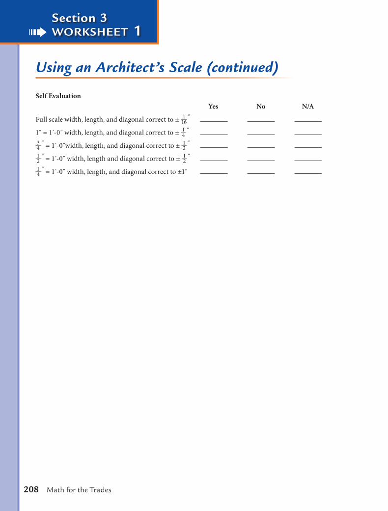
Using an Architect’s Scale (continued)
Self Evaluation Yes No N/A
Full scale width, length, and diagonal correct to ± 116
˝
1 = 1 -0˝ width, length, and diagonal correct to ± 14
˝ 34
˝ = 1 -0˝width, length, and diagonal correct to ± 12
˝ 12
˝ = 1 -0˝ width, length and diagonal correct to ± 12
˝ 14
˝ = 1 -0˝ width, length, and diagonal correct to ±1

Measurement and Measurement Tools 209
Section 3 worksheet 2
MEA
SUREM
ENT
Measuring Dimensions on a Drawing With an Architect’s Scale
Instructions Use an architect’s scale to measure and record dimensions based on the drawing on the following page. To successfully complete this task, the participant will:
• measurewiththecorrectscale • recordthescaleddimensionsonthedrawing
Materialspencilworksheet
Toolsarchitect’s scale
Procedure
1. Refer to the drawing.
2. Using an architect scale, measure the sides of the shapes drawn using the scale indicated under each shape.
3. Write the dimensions read on the line provided on the drawing.
Self Evaluation Yes No N/A
Determined the correct scale to use.
Read the lengths of the sides.
Wrote the dimensions in the spaces provided.
Dimensions correct within tolerances specified.

Section 3 worksheet 2
210 Math for the Trades
Measuring Dimensions on a Drawing With an Architect’s Scale (continued)
Scale: Full – read to nearest Scale: = 1´-0˝
Scale: 1˝ = 1´-0˝
˝116
˝18
Scale: = 1´-0˝˝14

Measurement and Measurement Tools 211
Section 3 worksheet 3
MEA
SUREM
ENT
Using a Metric Scale
Instructions Use a metric scale to measure and record dimensions based on the drawing on the following page. To complete this task successfully, the participant will:
• measurewiththecorrectscale • recordthescaleddimension
Materialspencilworksheet
Toolsmetric scales with full scale millimeters, 1mm:20mm, 1m:100m, 1m:500m
Procedure
1. Refer to the drawing.
2. Using a metric scale, measure the sides of the shapes drawn using the scale indicated under each shape.
3. Write the dimensions read on the line provided on the drawing.
Self Evaluation Yes No N/A
Determined the correct scale to use.
Read the lengths of the sides.
Wrote the dimensions in the space provided.
Dimensions correct within tolerances specified.

Section 3 worksheet 3
212 Math for the Trades
Using a Metric Scale (continued)
Scale: Full – read to nearest mm Scale: 1 mm : 20 mm
Scale: 1 m : 100 m Scale: 1 m : 500 m

Measurement and Measurement Tools 213
Section 3 worksheet 4
MEA
SUREM
ENT
Measurement Tools: Using an Architect’s Scale
Instructions Measure the length and width of the shop and prepare a rough sketch showing all doorways, stationary equipment, columns, and tool rooms to the nearest inch. Use an architect’s scale to draw the shop to a scale of 3
16˝ = 1 , inserting a 14
border around the paper, Title Block, all stationary equipment, doorways, columns, and tool rooms. Include all the dimensions within a tolerance of one inch. To complete this task success-fully, the participant will:
• squareandtapethepapertothedrawingboard • drawa 1
4 border • insertaTitleBlock • drawtheshop • drawallrelatedobjectsandequipmenttoscale • insertextensionanddimensionlines
Materialsnotebookpencil erasermasking tapedrawing paper
Toolsdrawing boardpencil sharpener 30°-60°-90° triangleT-squarearchitect’s scale
Procedure
1. Square paper to the drawing board using the T-square. Tape the four corners.
2. Draw a 14 border.
3. Using the inside of the border, draw a Title Block in the lower right corner and include your name, the date, and the drawing scale.

Section 3 worksheet 4
214 Math for the Trades
Measurement Tools: Using an Architect’s Scale (continued)
4. Find and lay out the center of the paper between the borders.
5. Use the rough sketch that has the length and width of the shop and all other relevant information for the necessary measurements. Refer to the Job Description for all items in the shop that must be included.
6. Use light pressure on the pencil so the lines are not extra dark and hard to erase when the doorways are inserted or if a mistake is made.
7. Find the center of the paper form the borders.
8. Work equally from the center of the paper using the 3 16 = 1 scale, using the T-square
and triangle to draw the outline of the shop. For example, if the shop measures 48 feet long and 24 feet wide:
a. Place the butt end of the T-square against the vertical side of the drawing board so the long end will make horizontal lines across the paper.
b. Position the architect’s scale on the T-square aligning the 24 feet mark on the centerline of the paper. c. Place dots at 0 feet and 48 feet. d. Remove the architect’s scale. Place the triangle on the T-square at the 0 feet mark and draw a light
vertical line extending to the top and bottom border. e. Repeat step d at the 48 feet mark. f. Position the architect’s scale along the triangle and T-square to lay out the width or vertical
measurement. g. Align the 12 feet mark on the centerline. h. Place dots at 0 feet and 24 feet. i. Remove the architect’s scale. Place the T-square on the 0 feet dot and draw a light line intersecting
the two vertical lines established in steps c and d. j. Repeat step i at the 24 feet dot.
9. Draw to scale the columns, benches, and stationary equipment listed on the rough sketch.
10. Add all extension and dimension lines to the length and width of the shop, doorways, columns, benches, and stationary equipment.
11. Erase any unnecessary lines.

Measurement and Measurement Tools 215
Section 3 worksheet 4
MEA
SUREM
ENT
Measurement Tools: Using an Architect’s Scale (continued)
Self Evaluation Yes No N/A
Measurements on rough sketch within one inch.
Taped paper square to the drawing board.
Drew a 14 border.
Drew the Title Block in the correct location.
Included the appropriate information in the Title Block.
Started the layout from the center of the paper.
Used the correct scale.
Marked the correct length to within one inch.
Marked the correct width to within one inch.
Doorway scaled correctly and located in the correct position.
Stationary equipment scaled correctly and located in the correct position.
Tool room scaled correctly and located in the correct position.
Columns scaled correctly and located in the correct position.
Dimension lines drawn correctly.
Extension lines drawn correctly.
All finished dimensions to the nearest one inch.
Copyright © 2022 FDOKUMEN