Contents - AWS
300
-
Upload
khangminh22 -
Category
Documents
-
view
0 -
download
0
Transcript of Contents - AWS


C1
s
h
��
�����
��
���
GX..E
GX..S
GX..R
AX..
SX..
LX..
FX..
PX..
MC..
TC..
C2-C4
C5-C26
C27-C28
C29-C44
C45-C68
C72-C90
C92-C103
C104-C119
C120-C139
C140-C148
C150-C155
C156-C163
C164-C171
C172-C177
General
C253-C259
C260-C262
C263-C267
C268-C271
C272-C277
C278-C291
C292-C296
C297
C298-C299
C180-C181
C182
C183
C184
C185
C186
C187
C188
C189
C190-C193
C196-C199
C200-C212
C213-C222
C223-C230
C231-C232
C233-C236
C237-C239
C240-C245
C246-C251
Intro
ducti
on
Applic
ation
Inser
ts
Tools Tech
nical
infor
mation
Shanks
Modules - external
Monobloc - external
Blocks, blades
Boring bars
Modules- internal
Monobloc - internal
Threading
UTS,HSK-T
Contents
Intro
duct
ion
Tool
s an
d in
serts
for p
artin
g an
d gr
oovi
ng

C2
L
K
00R25E
90R25I
00R25E
90R32I
90R32I
2.5D
1212
2525
AD
1.5D
2D
2D
90R12I
00R16E
MSS
MSS
MSS
MSS
MSS
MSS
1616
00R25E
40
40
40
UT
UT
UT
00R12E
-
-
-
-
-
-
-
-
-
--
-
-
-
-
-
-
-
-
21
KR05 1010MC - --
90L32EMSST63HSK --
TC16-
TC16
GX09-
-
GX24-1-
Syst
ems
UTS,
HSK
-T
Syst
em a
ssem
bly
size
MSS
sys
tem
E =
exte
rnal
/ I =
inte
rnal
Asse
mbl
y si
ze
Hand
Appr
oach
ang
le
Shan
k se
ctio
n, ty
pe
Shan
k le
ngth
Parti
ng a
nd g
roov
ing
dept
h
Inse
rt sy
stem
CERATIZIT designation systemIn
trodu
ctio
nTo
ols
and
inse
rts fo
r par
ting
and
groo
ving
Tool holders

C3
-
-
-
-
-
-
-
-
-
-
-
-
-
-
-
-
-
-
-
-
-
-
-
A 70-10015 GX 24 325 REMSS
GX 09 1
FX
SX
AX
3.1
3
10
LX
TC 16 2
TC 16 2
GX 16 2
25 R 06I
25
25
25
R
R
R
20
25
10
E
E
E
32 N 45E
25 RE
32 RI
25 R 12E
MSS
MSS
MSS
MSS
MSS
MSS
MSS
MSS
MSS
sys
tem
E =
exte
rnal
/ I =
inte
rnal
Asse
mbl
y si
ze
Hand
Max
. par
ting
and
groo
ving
de
pth
Inse
rt sy
stem
Inse
rt si
ze, c
uttin
g w
idth
Wid
th c
lass
Axia
ldi
amet
er ra
nge
D min
- D m
ax
CERATIZIT designation system
Intro
duct
ion
Tool
s an
d in
serts
for p
artin
g an
d gr
oovi
ng
Modules

C4
-
-
-
-
-
-
-
-
-
-
-
-
-
Code
Code
Code
Code
Code
Code
Code
Code
Code
N
N
N
N
N
R
N
N
ISO
N
0.20
0.20
0.80
0.10
0.30
0.30
1.50
1.00
3.10
2.00
8.00
3.00
4.00
1.50
1.00
3.00
2 R16
2 S
E
16
10
E
E
R
1 E16
05
2 E16
GX
GX
FX
SX
LX
AX
LX
TC
MC
GX
20-
- 5
- CodeN1.50RSX
- - CodeL 051.502 E20PX
Inse
rt sy
stem
Inse
rt si
ze
Wid
th c
lass
Inse
rt sh
ape,
app
licat
ion
Cutti
ng w
idth
, pitc
h
Hand
, thr
ead
stan
dard
Corn
er ra
dius
, ang
le
Chip
gro
ove
code
Num
ber o
f cut
ting
edge
s
Min
imum
axi
al g
roov
ing
diam
eter
CERATIZIT designation systemIn
trodu
ctio
nTo
ols
and
inse
rts fo
r par
ting
and
groo
ving
Inserts

C5
radial axial
external internal
Grooving Part-off Profile grooving
Parting, grooving and
turning
Deep grooving
Parting and grooving covers a diverse range of applications and demands, advanced technology and intel-ligent tool design.
> Radial, axial grooving> External/internal parting and
grooving> Grooving> Part-off> Profile grooving> Parting, grooving and turning> Deep grooving
> Chip formation> Chip evacuation> Parallel - flat parting and grooving surface> Surface finish> Formation of burrs when parting off tubes> Formation of pips in part-off operations> vc = 0 in the centre> Entire main cutting edge applied
> Narrow, long overhang> Insert clamping> Rigidity> Resistant against breakage> Easy handling> Economy
Diverse range of applications
Advanced technology
Intelligent tool designIn
trodu
ctio
nTo
ols
and
inse
rts fo
r par
ting
and
groo
ving
Parting and grooving

C6
> Separate shank and tool holder> Same interface for all parting, grooving and threading applications> Stable, precise connection> ( [WHQGDEOH� WKURXJK� QHZ � ¶ P RGXOHV·> Easy handling> Clamping features optimized for the various applications
In order to be able to meet all demands, up-to-date tools have a modular structure.
System features
- The modular parting, grooving and threading system
Intro
duct
ion
The solution!To
ols
and
inse
rts fo
r par
ting
and
groo
ving

C7
> Adaptable to machining task> One system only for all parting, grooving and
threading operations> Particularly well-suited for semi-standard tools
> High accuracy and repeatability when changing the module
> Reduced set-up time> High-quality work pieces
> Application security> Parting, grooving and longitudinal turning possible
> Quick module change in case of tool breakage, short downtime
> Low stock inventory provides a large variety of combination possibilities
> In case of tool breakage only change module
> Components for all work pieces and materials
Flexibility
Precision
Stability
Simplicity
Economy
Completeness
Intro
duct
ion
Tool
s an
d in
serts
for p
artin
g an
d gr
oovi
ng
0 66 � ² � EHQ HILWV

C8
�����
���
���
���
��
��
��
��
��
��
��
Parting, grooving and turning GX Parting and grooving FX
Axial grooving AX + GX
Thread turning TC
Parting, grooving and turning LX + SX
Intro
duct
ion
Tool
s an
d in
serts
for p
artin
g an
d gr
oovi
ng
MSS - system components

C9
1
1
4
3
3
2
2
3
1
2
3
4
FX SX
GX TC
LX GX
AX4
Gap
Gap
Unclamped module: Clamped module:
FX / SX:Self-clamping inserts
GX / TC:Active insert clamping
LX / GX / AX:active insert clamping
> Gap between module and location face for axial clamping
> Axial clamping with location face> Connection without clearance,
therefore highest stability
Screws 1, 2 and 3 are used to clamp the module. The insert is self-clamping.
Screws 1, 2 and 3 are used to clamp the module.Important: clamp the module with screw 1, then screw 2. Afterwards the insert is clamped by means of screw 3.
Screws 1, 2 and 3 are used to clamp the module. The insert is self-clamping.The insert is clamped through the elastic deformation of the module through the additional screw 4.
The strong connection
Clamping features
Intro
duct
ion
Tool
s an
d in
serts
for p
artin
g an
d gr
oovi
ng
The interface

C10
s
s
Tmax
Tmax
s
Tmax
s
Tmax
Axial grooving
Parting, grooving, longitudinal turning, axial grooving
Parting, grooving, longitudinal turning
Tmax = 7 - 21 mms = 2.0 - 8.0 mm
Tmax = 4 - 19 mms = 2.0 - 6.0 mm
Tmax = 20 - 35 mms = 2 - 4 mm
Tmax = 5 - 15 mms = 3 mm
Tmax = .75 - 4.0 mms = .6 - 5.25 mm
Tmax = 1.78 - 2.58 mms = 1.6 - 2.4 mm
Circlip grooves:
O-ring grooves:
AX
GX external
GX internal
SX
Intro
duct
ion
Tool
s an
d in
serts
for p
artin
g an
d gr
oovi
ng
The modulesSystems GX / AX / SX

C11
ss
Tmax
Tmax
Parting, grooving
Parting, grooving, longitudinal turning, axial grooving
Thread turning and milling
Tmax 20 = 45 mms = 2.2 - 6.5 mm
Tmax = 25 - 45 mms = 8.0 - 10.0 mm
Pitch:ISO .5 - 5.0 mmBSW 28 - 5 TPI
FX
LX
TC
> Modules made of tempered steel with high strength
> Locating surfaces for MSS interface ground with highest precision
> Ground insert seat
> Long tool life, high rigidity> Accurate repeatability> Secure and precise insert clamping
System characteristics Benefits
Intro
duct
ion
Tool
s an
d in
serts
for p
artin
g an
d gr
oovi
ng
The modulesSystems LX / FX / TC

C12
09 0,6 - 3,25 0,8 - 1,2 2,0 - 3,5 1,0 - 1,2
16 0,6 - 5,25 0,8 - 1,2 2,0 - 6,0 1,5 - 3,0
24 2,0 - 6,0 1,50 - 3,0
3,0
N
R
1,5 - 3,0 2,0 - 6,0 2,0 - 4,0
4,0 8,0 - 10,0
Axial grooving
Parting, grooving, longitudinal turning, axial grooving
Parting, grooving, longitudinal turning, axial grooving
Parting, grooving, longitudinal turning
AX
LX
SX
> According to the respective application either precision ground or sintered> Optimized geometries for all important materials> Security through ideal combination of substrate and coating> All inserts for aluminium machining are microfinished
GXInsertsize
Uponrequest
Intro
duct
ion
Tool
s an
d in
serts
for p
artin
g an
d gr
oovi
ng
The insertsSystems GX / AX / SX / LX

C13
N2,2 - 9,7 2,2 - 6,5
N1,0 - 2,0 1,0 - 2,0
N1,0 - 2,5 1,0 - 2,5
,62 � � � ƒ %6: � � � ƒ
Parting, grooving
Parting, grooving
Thread turning and milling
FX
TC
Parting, grooving, longitudinal turning
PX
MC
Full and partial profileexternal, internal
Full and partial profileexternal, internal
Pitch .5 - 5.0 mm 48 - 5 TPI
Intro
duct
ion
Tool
s an
d in
serts
for p
artin
g an
d gr
oovi
ng
The insertsSystems FX / PX / MC / TC

C14
1 2 3 4 5
MSS-E20R12-GX16-2
GX16-2E3.00N0.30
��� �������
�����������
���
�����������
���
����������� ����������� ����
����������� �����������
The parting and grooving widths of the MSS system are divided into width classes. Every width class represents a certain range of cutting widths.
1) Ideally the module and the insert have the same width class. This combination results in the best possible application security.
Width classes
Parting and grooving modules
Parting and grooving inserts
Inserts for circlip grooves
Module designation:
Insert designation:Width class 1)
Intro
duct
ion
The width classesSystem GX
Tool
s an
d in
serts
for p
artin
g an
d gr
oovi
ng

C15
� ��
MSS-E25R00-2525L
MSS-E25R25-GX16-2
GX
1 2 3 4 1 2 3 4
10121620253240
GX
10121620253240
�� �� ���� �� ��
�� �� ��
The assembly size is determined by the shank dimensions of the MSS tool holders.In this manner the correct tool holder can be assigned to the correct module size and vice versa.The following tables will give you an overview of the width classes and insert sizes for the available assembly sizes.
Tool designation:
Module designation: Assembly size (h)
Width class
external internal
Assembly size (h)
Assembly size (h)
Insert sizeIn
trodu
ctio
n
The assembly size
Tool
s an
d in
serts
for p
artin
g an
d gr
oovi
ng

C16
h1
D
h
h
1
1
h
s
h
� ����������������
�����������������������
����������������
s
s
� ����������������
����������������������
����������������
�
h
� �����������������
� ������������
����������������
�
����������������
��������������
����������������
����������������
� ��������
h2
Tool shank with GX grooving module
GX blade
Clamping block
GX module, axial
Monobloc tool
System characteristics
> Double-ended insert> Ground and directly pressed inserts
Benefits
> Good economy> Optimum solution for all situations
System GX is characterized by a double-ended insert with numerous application possibilities. It is mostly applied for radial grooving and turning. Thanks to special modules the system can easily be adapted for axial and circlip grooving. For GX inserts a range of modules and boring bars for internal grooving is available.
Intro
duct
ion
Tool
s an
d in
serts
for p
artin
g an
d gr
oovi
ng
System overviewSystem GX

C17
s
h1
h
h1
h
� ����������������
�����������
� ����������
� ����������������
�����������
� ����������
Dm
in
Tool shank with AX parting and grooving module
Monobloc tool
System characteristics
> Neutral insert
> Monobloc and modular tools
Benefits
> May be applied in left-hand and right-hand tools> Optimum solution in terms of costs for every
application
System AX is for axial grooving with small diameters. A special characteristic of the design is that the insert needs no support in the cutting area.
Intro
duct
ion
Tool
s an
d in
serts
for p
artin
g an
d gr
oovi
ng
System AXSystem overview

C18
h1
h1
hs
h
h1
h
� ����������������
����������������
����������������
�
� �����������������
� ����������������
����������������
����������������
�
� ���������
����������������
����������������
�
h2
r
Tool shank with SX parting and grooving module
SX blade
Clamping block
Monobloc tool
System characteristics
> Active clamping> Insert seat with fixed stop> Easy handling
> FEM optimized tool
Benefits
> Inserts will not pull out of the cutting blade> Exact positioning of the cutting edge> Quick insert change> Maximum stability also when longitudinal turning
In system SX the insert is self-clamping and fixed with maximum clamping force in the insert seat. Precise cutting edge positioning and easy handling are guaranteed.
Intro
duct
ion
Tool
s an
d in
serts
for p
artin
g an
d gr
oovi
ng
System overviewSystem SX

C19
Z
r
s
�������������
��������
���� �����������������
�������������
��������
�
� ��� ������ �������
�h
h1
����������������h1
h2
Parting and grooving module LX
Detail ZActive insert clamping
LX blade
Clamping block
System characteristics
> Robust construction> Active insert clamping> Insert with full radius
Benefits
> Application security, high strength and stability> Well-suited for copy turning
System LX is characterized by high strength and stability. It is most suitable for the production of wide and deep grooves as well as for parting off large bar diameters.
Application of LX modules
> Part-off> Grooving and turning> Axial grooving with D > 500 mm> Internal grooving and turning with D > 200 mm
Intro
duct
ion
Tool
s an
d in
serts
for p
artin
g an
d gr
oovi
ng
System overviewSystem LX

C20
h
h
1
1
h
hs
h1
h
� ����������������
�����������������
� �����������������
� ����������������
�����������������
����������������
� �������������
��
Tool shank with FX grooving module
FX blade
Clamping block
Monobloc tool
System characteristics
> Self-clamping insert> Adjustable blade> Single-blade insert, directly pressed
Benefits
> Easy handling, no clamping parts> Parting and grooving depth, overhang optimally
adjustable> Economic for deep parting and grooving
System FX is characterized by a self-clamping single blade insert for deep grooving of large diameters. FX is directly integrated in the MSS system by means of the respective modules. Additionally the tried and tested block/blade solutions and monobloc tools are available.
Intro
duct
ion
Tool
s an
d in
serts
for p
artin
g an
d gr
oovi
ng
System FXSystem overview

C21
h / h = 16 - 20 mm
s = 1,0 - 2,0 mm1
T = 5 - 11 mmmax
��
Tmax
�
�
Monobloc tool
System characteristics
> Maximum precision of the cutting edge when mounted
> Flexible cutting widths possible
Benefits
> Close tolerances on the work piece> Less material wastage
This system is the first choice for small parting and grooving widths when maximum flexiblity, repeatability and stability are required in high volume production.
Intro
duct
ion
Tool
s an
d in
serts
for p
artin
g an
d gr
oovi
ng
System overviewSystem PX

C22
h / h = 10 - 25 mm1
s = 1,0 - 2,5 mm
T = 5 - 10 mmmax
��
Tmax
�
�
����
����
Monobloc tool
System characteristics
> Extremely narrow part-off and grooving widths are possible
> Excellent surface quality can be achieved> Multiple part-off operations are possible
Benefits
> Less material wastage> No additional finishing work necessary> Reduction of machining costs
MaxiClick is characterized by a cutting insert consisting of 4 or 5 cutting elements. The worn cutting edge is broken off towards the side, like a snap-off knife.
Intro
duct
ion
Tool
s an
d in
serts
for p
artin
g an
d gr
oovi
ng
System overviewSystem MaxiClick

C23
h1
h
h1
h
P P
��
h1 / h = 20 - 25 mm
PitchP = .5 - 5.0 mmP = 48 - 5 TPI
h1 / h = 12 mmPitch
P = .5 - 3.0 mmP = 48 - 8 TPI
d1 = 25 - 32 mm
PitchP = .5 - 5.0 mmP = 48 - 5 TPI
Tool shank with TC threading module
Monobloc tool
Monobloc toolfor thread milling
System characteristics
> Turning and milling with the same insert> Neutral configuration of insert
Benefits
> Flexibility, reduced variety and costs> Right-hand and left-hand threads possible using
one insert only> Reduced storage
With system TC the same insert can be used to produce threads by turning or milling. TC offers numerous advantages which are of decisive importance for many threading applications.
Intro
duct
ion
Tool
s an
d in
serts
for p
artin
g an
d gr
oovi
ng
System overviewSystem TC

C24
OverhangOverhang
System TC Conventional system
System TC for thread turning is an integrated part of the MSS system. Compared to traditional systems TC offers a series of advantages which are of decisive importance for many threading applications.
> Neutral configuration of insert makes operation in both directions possible
> Only one threading insert per pitch for partial profile and Whitworth thread;
only two threading inserts (internal - external) per pitch for ISO threads
> Reduced storage> Good chip formation through chip groove with
UDNH� DQJOH� � � � ƒ
Enhanced economy through> Reduced machining time> Fewer tool changes> Improved stability, small overhang> Material saving> Thread turning between shoulders possible> Fewer tools and inserts
> Right-hand and left-hand version of insert, therefore operation only in one direction
> For every pitch 4 threading inserts are necessary (right-hand - left-hand, internal - external)
> For this machining method 2 tools are necessary
> Additional loss of stability and material caused by large overhangs
Intro
duct
ion
Tool
s an
d in
serts
for p
artin
g an
d gr
oovi
ng
6 \ VWHP � 7&� ² � WKUHDG� WXUQ LQ J

C25
R
LA
BA
B
R
L
��� ��� ��� ��� ���
+3° +2° +1° 0°
-3°
10
9
8
7
6
5
4
3
2
1
50 100 150
A A
Bp (mm)
Ø (mm)
right-hand thread left-hand thread
corrected standard
left-hand thread
left-hand thread
right-hand thread
right-hand thread
R = right-hand toolL = left-hand tool
System TC Conventional system
> Easy access to work piece therefore use of tailstock also possible with small thread diameters
> Easy to apply as the tools can be used in both directions without correcting the helix angle
> Difficult component access> Danger of collision
> Correction of helix angle necessary, therefore high degree of application know-how required
> Can only be operated in one direction
Intro
duct
ion
Tool
s an
d in
serts
for p
artin
g an
d gr
oovi
ng
6 \ VWHP � 7&� ² � WKUHDG� WXUQ LQ J

C26
ISO 60°BSW 55°ISO 60°
Internal thread
External thread
internal internal/external external
System characteristics
> Turning and milling with the same insert> Single-tooth thread milling
> Thread is cut in one pass
Benefits
> Flexibility, reduced variety and costs
> Low machining forces, large overhang possible, high cutting data (vc and f), easy programming
> No interruptions or steps in the thread
For thread milling and turning the same inserts are applied. With special tool shanks, which are characterized by compact and modular construction, external as well as internal threads can be produced on all up-to-date machining centres.
Intro
duct
ion
Tool
s an
d in
serts
for p
artin
g an
d gr
oovi
ng
6 \ VWHP � 7&� ² � WKUHDG� P LOOLQ J

C27
Machining application type
%DVHG� RQ� 9 ' ,� � � � � � & ( 5 $ 7,=,7· V�0 DVWHU* XLGH� GLYLGHV�P DWHULDOV�LQWR�six main groups (P, M, K, N, S, H).Each is given a colour, according to the system partly adopted in ISO 513.
F = fine machiningM = medium machiningR = rough machining
Yellow: stainless steelFerritic Cr-steels, austenitic CrNi-steels, martensitic Cr-steels, duplex steels
Green: non ferrous metals and non metalsAl wrought and Al cast alloys, copper, copper alloys, non metal materials
Each coloured segment is divided into three sections, and each section indicates the relevant machining application type:
Orange: heat resistant alloys / titaniumNi/Co-base alloys, Ti alloys
Red: cast ironCast iron, grey cast iron, tempered iron, spheroidal cast iron, CGI, sintered iron
Blue: steelMachining, cementation, tempered and constructional steels
Material
White: hard materialsHardened steels (≥ 45 HRC), chilled castings, hard cast irons
Intro
duct
ion
MasterGuide
Tool
s an
d in
serts
for p
artin
g an
d gr
oovi
ng

C28
The right indexable insert at a glance
Main application:Medium machining of steel and stainless steel.
Extended application:Finish machining of steel and stainless steel. Medium and finish machining of non ferrous metals and non metals, heat resistant alloys/titanium.
The ideal application area for the insert is indicated by a black circle. Extended applications are indicated by an open circle. The CERATIZIT MasterGuide provides you with an easily understandable structure for choosing a product and enables you to reduce grade and geometry stocks.
● Main application
○ Extended application
Application
Intro
duct
ion
MasterGuideTo
ols
and
inse
rts fo
r par
ting
and
groo
ving

C29
C T C P 3 3 5Manufacturer: CERATIZIT
Cutting material
W Uncoated carbideC CVD coated carbideP PVD coated carbideT Uncoated cermetE Coated cermetN Uncoated silicon nitrideM Coated silicon nitrideS Mixed ceramicI SialonD PCDB CBNL CBN coatedH Sintered HSS
ISO 513 Application range
For example:05 ISO K05/P05101525-
Main application (material)Variant 1: number
1 Steel2 Stainless steel3 Cast iron4 Light and non ferrous metals, non metals5 Heat resistant alloys, titanium6 Hard materials7 Universal grade for a variety of applications
Main application (machining method)
1 Turning2 Milling3 Parting and grooving4 Drilling5 Threading6 Others7 Universal grade for a variety of
applications
Main application (material)Variant 2: ISO letter
P SteelM Stainless steelK Cast ironN Light and non ferrous metals, non metalsS Heat resistant alloys, titaniumH Hard materialsX Universal grade for a variety of applications
Intro
duct
ion
The CERATIZIT designation systemfor new cutting materials
Tool
s an
d in
serts
for p
artin
g an
d gr
oovi
ng

C30
P M K N S H
05 15 25 35 4501 10 20 30 40 50
CTC1325HC-P25 C ●HC-M20 C ○HC-K30 C ●
CTCP335HC-P35 C ●HC-M30 C ○HC-K35 C ●
CTP1340HC-P30 P ●HC-M25 P ● ●HC-K30 P ● ○
CTPP345HC-P45 P ●HC-M40 P ●HC-S40 P ○
CTW7120HW-M20 W ○HW-K20 W ● ○
GM127HC-P30 C ●HC-M25 C ○
H216T HW-K15 W ● ●S40T
HW-P40 W ●HW-M40 W ●
SR127HC-P25 C ●HC-M20 C ○HC-K30 C ●
TSM20 HW-K15 W ● ● ●●01 10 20 30 40 50
05 15 25 35 45 ○
Gra
dede
sign
atio
n
Stan
dard
desi
gnat
ion
*Cut
ting
mat
eria
l Application range
Stee
l
Stai
nles
s
Cast
iron
Non
ferro
us
met
als
Heat
resis
tant
Hard
mat
eria
ls
Main application
Extended application
*Type of cutting materialC29
** to be discontinued
Intro
duct
ion
Tool
s an
d in
serts
for p
artin
g an
d gr
oovi
ng
Grade overview - parting and grooving

C31
P M K N S H
05 15 25 35 4501 10 20 30 40 50
GM213HC-P20 C ●HC-M15 C ●HC-K25 C ●
GM240HC-P35 C ●HC-M25 C ●
H216T HW-K15 W ● ●●01 10 20 30 40 50
05 15 25 35 45 ○
Gra
dede
sign
atio
n
Stan
dard
desi
gnat
ion
*Cut
ting
mat
eria
l Application range
Stee
l
Stai
nles
s
Cast
iron
Non
ferro
us
met
als
Heat
resis
tant
Hard
mat
eria
ls
Main application
Extended application
*Type of cutting materialC29
Intro
duct
ion
Tool
s an
d in
serts
for p
artin
g an
d gr
oovi
ng
* UDGH� RYHUYLHZ � ² � WKUHDGLQ J

C32
1� � 7KHVH� FDUELGHV�DUH� DOVR� FDOOHG� ¶ FHUP HWV·�
2) Polycrystalline diamond and polycrystalline boron nitride are also called ultra-hard cutting materials.
Carbide
Reference Carbide group
HW Uncoated carbide, consisting mainly of tungsten carbide (WC)HT1) Uncoated carbide, consisting mainly of titanium carbide (TiC) or titanium
nitride (TiN) or bothHC Carbides as above, but coated
Ceramic
Reference Ceramic group
CA Oxide ceramic, consisting mainly of aluminium oxide (Al2O3)CM Mixed ceramic, based on aluminium oxide (Al2O3), but with different oxide componentsCN Nitride ceramic, consisting mainly of silicon nitride (Si3N4)CC Ceramics as above, but uncoated
Diamond
Reference Diamond group
DP Polycrystalline diamond2)
2) Polycrystalline diamond and polycrystalline boron nitride are also called ultra-hard cutting materials.
Boron nitride
Reference Boron nitride group
BN Cubic crystalline boron nitride (polycrystalline boron nitride) 2)
Intro
duct
ion
ISO 513To
ols
and
inse
rts fo
r par
ting
and
groo
ving

C33
0 2 4 6 8 10
0 2 4 6 8 10
0 2 4 6 8 10
0 2 4 6 8 10
0 2 4 6 8 10
0 2 4 6 8 10
CTC1325 Composition:Co 7.0%; composite carbides 8.0%; WC balance
Grain size: 1 - 2 µm
Hardness: HV30 1450
Coating specification:CVDTi(C,N) + Ti(C,N) + TiN + Al2O3; 12 µm
HC-P25 .
HC-M20 .
HC-K30 .
Toughness
Wear resistance
CTCP335 Composition:Co 10.5%; mixed carbides 2.0%; WC balance
Grain size: 1 - 2 µm
Hardness: HV30 1400
Coating specification:Ti(C,N) + Al2O3; 7.5 µm
HC-P35 .
HC-M30 .
HC-K35 .
Toughness
Properties, application: • Excellent wear resistance • Good resistance to oxidation • High toughness • Good heat resistance
Wear resistance
CTP1340 Composition:Co 9.0%; WC balance
Grain size: .7 - 1 µm
Hardness: HV30 1590
Coating specification:PVDTiAlN; 4 µm
HC-P30 .
HC-M25 .
HC-K30 .
Toughness
Properties, application: • Excellent suitability for universal application• Ideal for stainless steels• High cutting edge stability
Wear resistance
Steel
Intro
duct
ion
* UDGH� GHVFULSWLRQ � ² � SDUWLQ J� DQ G� JURRYLQ J
Tool
s an
d in
serts
for p
artin
g an
d gr
oovi
ng
C34
0 2 4 6 8 10
0 2 4 6 8 10
0 2 4 6 8 10
0 2 4 6 8 10
0 2 4 6 8 10
0 2 4 6 8 10
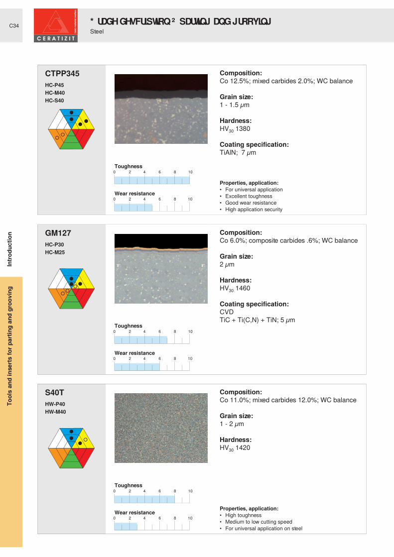
CTPP345 Composition:Co 12.5%; mixed carbides 2.0%; WC balance
Grain size: 1 - 1.5 µm
Hardness: HV30 1380
Coating specification:TiAlN; 7 µm
HC-P45 .
HC-M40 .
HC-S40 .
Toughness
Properties, application: • For universal application • Excellent toughness• Good wear resistance• High application security
Wear resistance
GM127 Composition:Co 6.0%; composite carbides .6%; WC balance
Grain size: 2 µm
Hardness: HV30 1460
Coating specification:CVDTiC + Ti(C,N) + TiN; 5 µm
HC-P30 .
HC-M25 .
.
Toughness
Wear resistance
S40T Composition:Co 11.0%; mixed carbides 12.0%; WC balance
Grain size:1 - 2 µm
Hardness:HV30 1420
HW-P40 .
HW-M40 .
.
Toughness
Properties, application: • High toughness • Medium to low cutting speed • For universal application on steel
Wear resistance
Steel
Intro
duct
ion
* UDGH� GHVFULSWLRQ � ² � SDUWLQ J� DQ G� JURRYLQ JTo
ols
and
inse
rts fo
r par
ting
and
groo
ving

C35
0 2 4 6 8 10
0 2 4 6 8 10
SR127 Composition:Co 6.0%; composite carbides .6%; WC balance
Grain size:2 µm
Hardness:HV30 1460
Coating specification:CVDTi(C,N) + TiN + Al2O3; 12 µm
HC-P25 .
HC-M20 .
HC-K30 .
Toughness
Properties, application: • Wide range of applications (steel and cast iron) • Excellent resistance to oxidation • Good toughness• High wear resistance
Wear resistance
Steel
Intro
duct
ion
* UDGH� GHVFULSWLRQ � ² � SDUWLQ J� DQ G� JURRYLQ J
Tool
s an
d in
serts
for p
artin
g an
d gr
oovi
ng

C36
0 2 4 6 8 10
0 2 4 6 8 10
0 2 4 6 8 10
0 2 4 6 8 10
0 2 4 6 8 10
0 2 4 6 8 10
CTP1340 Composition:Co 9.0%; WC balance
Grain size: .7 - 1 µm
Hardness: HV30 1590
Coating specification:PVDTiAlN; 4 µm
HC-P30 .
HC-M25 .
HC-K30 .
Toughness
Properties, application: • Excellent suitability for universal application• Ideal for stainless steels• High cutting edge stability
Wear resistance
CTPP345 Composition:Co 12.5%; mixed carbides 2.0%; WC balance
Grain size: 1 - 1.5 µm
Hardness: HV30 1380
Coating specification:TiAlN; 7 µm
HC-P45 .
HC-M40 .
HC-S40 .
Toughness
Properties, application: • For universal application • Excellent toughness• Good wear resistance• High application security
Wear resistance
S40T Composition:Co 11.0%; mixed carbides 12.0%; WC balance
Grain size:1 - 2 µm
Hardness:HV30 1420
HW-P40 .
HW-M40 .
.
Toughness
Properties, application: • High toughness • Medium to low cutting speed • For universal application on steel
Wear resistance
Stainless steel
Intro
duct
ion
* UDGH� GHVFULSWLRQ � ² � SDUWLQ J� DQ G� JURRYLQ JTo
ols
and
inse
rts fo
r par
ting
and
groo
ving

C37
0 2 4 6 8 10
0 2 4 6 8 10
0 2 4 6 8 10
0 2 4 6 8 10
0 2 4 6 8 10
0 2 4 6 8 10
CTC1325 Composition:Co 7.0%; composite carbides 8.0%; WC balance
Grain size: 1 - 2 µm
Hardness: HV30 1450
Coating specification:CVDTi(C,N) + Ti(C,N) + TiN + Al2O3; 12 µm
HC-P25 .
HC-M20 .
HC-K30 .
Toughness
Wear resistance
CTCP335 Composition:Co 10.5%; mixed carbides 2.0%; WC balance
Grain size: 1 - 2 µm
Hardness: HV30 1400
Coating specification:Ti(C,N) + Al2O3; 7.5 µm
HC-P35 .
HC-M30 .
HC-K35 .
Toughness
Properties, application: • Excellent wear resistance • Good resistance to oxidation • High toughness • Good heat resistance
Wear resistance
CTP1340 Composition:Co 9.0%; WC balance
Grain size: .7 - 1 µm
Hardness: HV30 1590
Coating specification:PVDTiAlN; 4 µm
HC-P30 .
HC-M25 .
HC-K30 .
Toughness
Properties, application: • Excellent suitability for universal application• Ideal for stainless steels• High cutting edge stability
Wear resistance
Cast iron
Intro
duct
ion
* UDGH� GHVFULSWLRQ � ² � SDUWLQ J� DQ G� JURRYLQ J
Tool
s an
d in
serts
for p
artin
g an
d gr
oovi
ng

C38
0 2 4 6 8 10
0 2 4 6 8 10
0 2 4 6 8 10
0 2 4 6 8 10
H216T Composition:Co 6.0%; WC balance
Grain size:1 µm
Hardness:HV30 1630
HW-K15 .
.
.
Toughness
Properties, application: • Optimally suitable for aluminium • High wear resistance • High heat resistance • Low tendency to adhesion
Wear resistance
SR127 Composition:Co 6.0%; composite carbides .6%; WC balance
Grain size:2 µm
Hardness:HV30 1460
Coating specification:CVDTi(C,N) + TiN + Al2O3; 12 µm
HC-P25 .
HC-M20 .
HC-K30 .
Toughness
Properties, application: • Wide range of applications (steel and cast iron) • Excellent resistance to oxidation • Good toughness• High wear resistance
Wear resistance
Cast iron
Intro
duct
ion
* UDGH� GHVFULSWLRQ � ² � SDUWLQ J� DQ G� JURRYLQ JTo
ols
and
inse
rts fo
r par
ting
and
groo
ving
C39
0 2 4 6 8 10
0 2 4 6 8 10
0 2 4 6 8 10
0 2 4 6 8 10
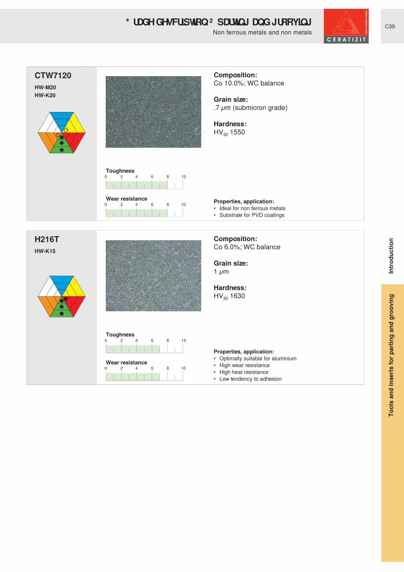
CTW7120 Composition:Co 10.0%; WC balance
Grain size: .7 µm (submicron grade)
Hardness: HV30 1550
HW-M20 .
HW-K20 .
.
Toughness
Properties, application: • Ideal for non ferrous metals• Substrate for PVD coatings
Wear resistance
H216T Composition:Co 6.0%; WC balance
Grain size:1 µm
Hardness:HV30 1630
HW-K15 .
.
.
Toughness
Properties, application: • Optimally suitable for aluminium • High wear resistance • High heat resistance • Low tendency to adhesion
Wear resistance
Non ferrous metals and non metals
Intro
duct
ion
* UDGH� GHVFULSWLRQ � ² � SDUWLQ J� DQ G� JURRYLQ J
Tool
s an
d in
serts
for p
artin
g an
d gr
oovi
ng

C40
0 2 4 6 8 10
0 2 4 6 8 10
CTP1340 Composition:Co 9.0%; WC balance
Grain size: .7 - 1 µm
Hardness: HV30 1590
Coating specification:PVDTiAlN; 4 µm
HC-P30 .
HC-M25 .
HC-K30 .
Toughness
Properties, application: • Excellent suitability for universal application• Ideal for stainless steels• High cutting edge stability
Wear resistance
Heat resistant alloys / titanium
Intro
duct
ion
* UDGH� GHVFULSWLRQ � ² � SDUWLQ J� DQ G� JURRYLQ JTo
ols
and
inse
rts fo
r par
ting
and
groo
ving

C41
0 2 4 6 8 10
0 2 4 6 8 10
0 2 4 6 8 10
0 2 4 6 8 10
GM213 Composition:Co 6.0%; WC balance
Grain size: 1 µm
Hardness: HV30 1630
Coating specification:CVDTiC + TiN; 3 µm
HC-P20 .
HC-M15 .
HC-K25 .
Toughness
Properties, application: • Suitable for high cutting speed• Good heat resistance• Good wear resistance
Wear resistance
GM240 Composition:Co 10.0%; composite carbides .6%; WC balance
Grain size: .7 µm
Hardness: HV30 1590
Coating specification:CVDTiC + Ti(C,N) + Al2O3 + Ti(N,B); 6 µm
HC-P35 .
HC-M25 .
.
Toughness
Properties, application: • For universal application • High toughness • Good wear resistance• Low tendency to adhesion
Wear resistance
Steel
Intro
duct
ion
* UDGH� GHVFULSWLRQ � ² � WKUHDGLQ J
Tool
s an
d in
serts
for p
artin
g an
d gr
oovi
ng

C42
0 2 4 6 8 10
0 2 4 6 8 10
0 2 4 6 8 10
0 2 4 6 8 10
GM213 Composition:Co 6.0%; WC balance
Grain size: 1 µm
Hardness: HV30 1630
Coating specification:CVDTiC + TiN; 3 µm
HC-P20 .
HC-M15 .
HC-K25 .
Toughness
Properties, application: • Suitable for high cutting speed• Good heat resistance• Good wear resistance
Wear resistance
GM240 Composition:Co 10.0%; composite carbides .6%; WC balance
Grain size: .7 µm
Hardness: HV30 1590
Coating specification:CVDTiC + Ti(C,N) + Al2O3 + Ti(N,B); 6 µm
HC-P35 .
HC-M25 .
.
Toughness
Properties, application: • For universal application • High toughness • Good wear resistance• Low tendency to adhesion
Wear resistance
Stainless steel
Intro
duct
ion
* UDGH� GHVFULSWLRQ � ² � WKUHDGLQ JTo
ols
and
inse
rts fo
r par
ting
and
groo
ving

C43
0 2 4 6 8 10
0 2 4 6 8 10
0 2 4 6 8 10
0 2 4 6 8 10
GM213 Composition:Co 6.0%; WC balance
Grain size: 1 µm
Hardness: HV30 1630
Coating specification:CVDTiC + TiN; 3 µm
HC-P20 .
HC-M15 .
HC-K25 .
Toughness
Properties, application: • Suitable for high cutting speed• Good heat resistance• Good wear resistance
Wear resistance
H216T Composition:Co 6.0%; WC balance
Grain size:1 µm
Hardness:HV30 1630
HW-K15 .
.
.
Toughness
Properties, application: • Optimally suitable for aluminium • High wear resistance • High heat resistance • Low tendency to adhesion
Wear resistance
Cast iron
Intro
duct
ion
* UDGH� GHVFULSWLRQ � ² � WKUHDGLQ J
Tool
s an
d in
serts
for p
artin
g an
d gr
oovi
ng

C44
0 2 4 6 8 10
0 2 4 6 8 10
H216T Composition:Co 6.0%; WC balance
Grain size:1 µm
Hardness:HV30 1630
HW-K15 .
.
.
Toughness
Properties, application: • Optimally suitable for aluminium • High wear resistance • High heat resistance • Low tendency to adhesion
Wear resistance
Non ferrous metals and non metals
Intro
duct
ion
* UDGH� GHVFULSWLRQ � ² � WKUHDGLQ JTo
ols
and
inse
rts fo
r par
ting
and
groo
ving

C45
-F2 ● CTC1325 CTC1325 / CTP1340 CTPP345● CTP1340 CTP1340 / CTPP345 CTPP345○ CTC1325 CTC1325 / CTP1340 ²
² ² ²
○ ² ² ²
● CTC1325 CTC1325 / CTP1340 CTCP335○ CTP1340 CTP1340 CTP1340● CTC1325 CTC1325 / CTP1340 CTP1340
² ² ²² ² ²
-M40 ● CTC1325 CTC1325 / CTP1340 CTP1340 / CTPP345○ CTP1340 CTP1340 / CTPP345 CTPP345● CTC1325 CTC1325 CTP1340
² ² ²○ CTP1340 CTP1340 CTP1340 / CTPP345
-M1 ● CTC1325 CTC1325 / CTP1340 CTPP345○ CTP1340 CTP1340 / CTPP345 CTPP345● CTC1325 CTC1325 / CTP1340 CTP1340
² ² ²○ CTP1340 CTP1340 CTP1340 / CTPP345
-27P ² ² ²² ² ²² ² ²
● H216T H216T H216T² ² ²
Non ferrous metals
Hard
m
ater
ials
Steel Stainless
steel
Cast
ironHeat
resistant
Consistent cutting depth
Inconsistent cutting depth Interrupted cut
Chip groove Machining type Material
Part-off, grooving, turning
Standard
The easy way to success
Intro
duct
ion
Tool
s an
d in
serts
for p
artin
g an
d gr
oovi
ng
Inserts for system GX

C46
R/L ● CTC1325 CTC1325 ²○ CTC1325 CTC1325 ²● CTC1325 CTC1325 ²
² ² ²² ² ²
● CTC1325 CTC1325 / CTP1340 CTP1340 / CTCP335○ CTC1325 / GM127 CTP1340 CTP1340● CTC1325 CTC1325 CTCP335
² ² ²² ² ²
-27P ² ² ²² ² ²² ² ²
● H216T H216T H216T² ² ²
● CTP1340 CTP1340 ²● CTP1340 CTP1340 ²○ CTP1340 CTP1340 ²○ CTP1340 CTP1340 ²○ CTP1340 CTP1340 ²
L/N/R
Non ferrous metals
Hard
m
ater
ials
Steel Stainless
steel
Cast
ironHeat
resistant
Consistent cutting depth
Inconsistent cutting depth Interrupted cut
Chip groove Machining type Material
Non ferrous metals
Hard
m
ater
ials
Steel Stainless
steel
Cast
ironHeat
resistant
Consistent cutting depth
Inconsistent cutting depth Interrupted cut
Chip groove Machining type Material
Radius grooves, copy turning
Circlip grooves
Standard/-M3
The easy way to successIn
trodu
ctio
nTo
ols
and
inse
rts fo
r par
ting
and
groo
ving
Inserts for system GX

C47
-F50 ● CTP1340 CTP1340 ²
● CTP1340 CTP1340 ²
○ CTP1340 CTP1340 ²
○ CTP1340 CTP1340 ²
○ CTP1340 CTP1340 ²
Non ferrous metals
Hard
m
ater
ials
Steel Stainless
steel
Cast
ironHeat
resistant
Consistent cutting depth
Inconsistent cutting depth Interrupted cut
Chip groove Machining type Material
Axial grooving
The easy way to success
Intro
duct
ion
Tool
s an
d in
serts
for p
artin
g an
d gr
oovi
ng
Inserts for system AX

C48
-F2 ● CTC1325 CTC1325 / CTP1340 CTPP345● CTP1340 CTP1340 / CTPP345 CTPP345○ CTC1325 CTC1325 / CTCP335 ²
² ² ²○ CTP1340 CTP1340 / CTPP345 ²
-M2 ● CTC1325 CTC1325 / CTP1340 CTCP335○ CTP1340 CTP1340 / CTPP345 CTCP335● CTC1325 CTC1325 / CTP1340 CTCP335
² ² ²○ CTP1340 CTP1340 CTP1340 / CTPP345
-M3 ● CTP1340 CTP1340 / CTCP335 CTP1340 / CTCP335● CTP1340 CTP1340 CTP1340 / CTCP335
CTP1340 CTCP335 CTCP335○ CTP1340 CTP1340 CTP1340○ CTP1340 CTP1340 CTP1340
-M1 ● CTC1325 CTP1340 / CTCP335 CTCP335 / CTPP345○ CTP1340 CTP1340 / CTPP345 CTPP345● CTC1325 CTC1325 CTCP335
² ² ²○ CTP1340 CTP1340 CTP1340 / CTPP345
-27P ² ² ²² ² ²² ² ²
● H216T H216T H216T² ² ²
Non ferrous metals
Hard
m
ater
ials
Steel Stainless
steel
Cast
ironHeat
resistant
Consistent cutting depth
Inconsistent cutting depth Interrupted cut
Chip groove Machining type Material
Part-off, grooving, turning
The easy way to successIn
trodu
ctio
nTo
ols
and
inse
rts fo
r par
ting
and
groo
ving
Inserts for system SX

C49
-M2 ● CTC1325 CTC1325 / CTCP335 CTCP335○ CTCP335 CTCP335 CTCP335● CTC1325 CTC1325 CTCP335
² ² ²² ² ²
-M3 ● CTC1325 CTC1325 / CTCP335 CTCP335○ CTCP335 CTCP335 CTCP335● CTC1325 CTC1325 CTCP335
² ² ²² ² ²
Non ferrous metals
Hard
m
ater
ials
Steel Stainless
steel
Cast
ironHeat
resistant
Consistent cutting depth
Inconsistent cutting depth Interrupted cut
Chip groove Machining type Material
Part-off, grooving, turning
The easy way to success
Intro
duct
ion
Tool
s an
d in
serts
for p
artin
g an
d gr
oovi
ng
Inserts for system LX

C50
-F1 ● CTC1325 CTC1325 / CTP1340 CTPP345● CTP1340 CTP1340 / CTPP345 CTPP345● CTC1325 CTC1325 / CTP1340 ²
² ² ²² ² ²
-M1 ● CTC1325 CTP1340 / CTCP335 CTCP335 / CTPP345○ CTP1340 CTP1340 / CTPP345 CTPP345● CTC1325 CTC1325 CTCP335
² ² ²
○ CTP1340 CTP1340 CTP1340 / CTPP345
-R2 ● CTC1325 CTC1325 / CTP1340 CTPP345● CTP1340 CTP1340 / CTPP345 CTPP345● CTC1325 CTC1325 CTP1340
² ² ²
○ CTP1340 CTP1340 CTP1340 / CTPP345
-27P ² ² ²² ² ²² ² ²
● H216T H216T H216T² ² ²
Non ferrous metals
Hard
m
ater
ials
Steel Stainless
steel
Cast
ironHeat
resistant
Consistent cutting depth
Inconsistent cutting depth Interrupted cut
Chip groove Machining type Material
Part-off, grooving
The easy way to successIn
trodu
ctio
nTo
ols
and
inse
rts fo
r par
ting
and
groo
ving
Inserts for system FX

C51
-F3 ● CTP1340 CTP1340 ²● CTP1340 CTP1340 ²○ CTP1340 CTP1340 ²
² ² ²○ CTP1340 CTP1340 ²
Non ferrous metals
Hard
m
ater
ials
Steel Stainless
steel
Cast
ironHeat
resistant
Consistent cutting depth
Inconsistent cutting depth Interrupted cut
Chip groove Machining type Material
Part-off, grooving
The easy way to success
Intro
duct
ion
Tool
s an
d in
serts
for p
artin
g an
d gr
oovi
ng
Inserts for system PX

C52
-F2 ● CTP1340 CTP1340 CTP1340● CTP1340 CTP1340 CTP1340○ CTP1340 CTP1340 CTP1340
² ² ²
○ CTP1340 CTP1340 ²
-F3 ● CTP1340 CTP1340 ²
● CTP1340 CTP1340 ²
○ CTP1340 CTP1340 ²² ² ²
○ CTP1340 CTP1340 ²
-27P ² ² ²² ² ²² ² ²
● CTW7120 CTW7120 CTW7120² ² ²
Non ferrous metals
Hard
m
ater
ials
Steel Stainless
steel
Cast
ironHeat
resistant
Consistent cutting depth
Inconsistent cutting depth Interrupted cut
Chip groove Machining type Material
Part-off, grooving
The easy way to successIn
trodu
ctio
nTo
ols
and
inse
rts fo
r par
ting
and
groo
ving
Inserts for system MC
C53
1
1,5
2
2,5
3
0,05 0,15 0,25 0,350,1 0,2 0,3 0,4 0,45
4
5
6
0,05 0,15 0,25 0,350,1 0,2 0,3 0,4
0,5
1,0
1,5
2,0
2,5
3,0
3,5
4,0
ap
[mm]
Cutti
ng w
idth
s [m
m]
Feed rate f [mm/rev]
Dept
h of
cut
ap [
mm
]
Cutting width s:
= 6 mm = 5 mm = 4 mm = 3 mm = 2 mm
Feed rate f [mm/rev]
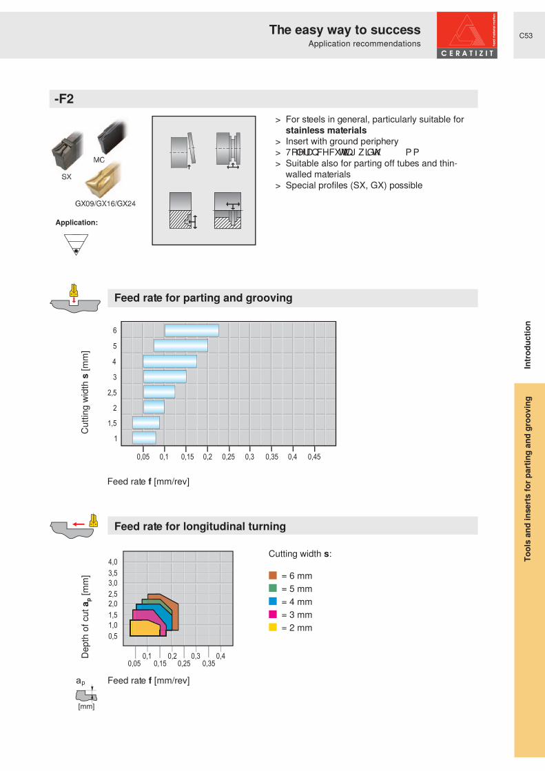
-F2
Application:
Feed rate for parting and grooving
Feed rate for longitudinal turning
> For steels in general, particularly suitable for stainless materials
> Insert with ground periphery> 7ROHUDQFH� FXWWLQJ� ZLGWK� “ � � � � � P P> Suitable also for parting off tubes and thin-
walled materials> Special profiles (SX, GX) possible
The easy way to success
Intro
duct
ion
Application recommendations
Tool
s an
d in
serts
for p
artin
g an
d gr
oovi
ng

C54
1
1,5
2
2,5
0,05 0,15 0,25 0,350,1 0,2 0,3 0,4 0,45
Cutti
ng w
idth
s [m
m]
Feed rate f [mm/rev]
-F3
Application:
Feed rate for parting and grooving
> Particularly suitable also for parting off tubes and thin-walled materials
> For steels in general, particularly suitable for stainless materials
> Special profiles (PX) possible
The easy way to successIn
trodu
ctio
n
Application recommendations
Tool
s an
d in
serts
for p
artin
g an
d gr
oovi
ng

C55
0,6-1,7
1,95-2,25
2,75-3,25
4,25
5,25
0,05 0,15 0,25 0,350,1 0,2 0,3 0,4 0,45
Cutti
ng w
idth
s [m
m]
Feed rate f [mm/rev]
Circlip grooves L/N/R
Feed rate for grooving operations
Application:
> Insert for circlip grooves according to DIN 471-472
> For internal and external machining
The easy way to success
Intro
duct
ion
Application recommendations
Tool
s an
d in
serts
for p
artin
g an
d gr
oovi
ng

C56
0,8
1,0-1,2
0,05 0,15 0,25 0,350,1 0,2 0,3 0,4 0,45Radi
us r
[mm
]
Feed rate f [mm/rev]
Radius grooves R/L
Application:
> Inserts for radius grooves and copy turning> For all steel materials> For internal and external machining
Feed rate for grooving operations
The easy way to successIn
trodu
ctio
n
Application recommendations
Tool
s an
d in
serts
for p
artin
g an
d gr
oovi
ng

C57
2
3
4
5
6
0,05 0,15 0,25 0,350,1 0,2 0,3 0,4 0,45
ap
[mm]
Cutti
ng w
idth
s [m
m]
Feed rate f [mm/rev]
Dept
h of
cut
ap [
mm
]
Cutting width s:
= 6 mm = 5 mm = 4 mm = 3 mm = 2 mm
Feed rate f [mm/rev]
Standard
Application:
Feed rate for parting and grooving
Feed rate for longitudinal turning
> For all steel materials> For universal application> Wide application range
The easy way to success
Intro
duct
ion
Application recommendations
Tool
s an
d in
serts
for p
artin
g an
d gr
oovi
ng

C58
AX05
AX10
AX15
0,05 0,15 0,25 0,350,1 0,2 0,3 0,4 0,45
0,05 0,15 0,25 0,350,1 0,2 0,3 0,4
0,5
1,0
1,5
2,0
2,5
3,0
3,5
4,0
Feed rate f [mm/rev]
Dept
h of
cut
ap [
mm
]
Cutting width s:
= AX15 = AX10 = AX05
Feed rate f [mm/rev]
-F50
... f feed rate for the first groove... feed rate range f
Application:
> Universal geometry for: - Steel - Stainless steel - Cast iron - Non ferrous metals> Insert with ground periphery> 7ROHUDQFH� FXWWLQJ� ZLGWK� “ � � � � � P P
Feed rate axial grooving
Feed rate face turning
The easy way to successIn
trodu
ctio
n
Application recommendations
Tool
s an
d in
serts
for p
artin
g an
d gr
oovi
ng

C59
10
8
6
5
4
3
2
0,05 0,15 0,25 0,350,1 0,2 0,3 0,4 0,45 0,5
0,05 0,15 0,25 0,350,1 0,2 0,3 0,4
0,450,5
0,5
1,0
1,5
2,0
2,5
3,0
3,5
4,0
ap
[mm]
Cutti
ng w
idth
s [m
m]
Feed rate f [mm/rev]
Dept
h of
cut
ap [
mm
]
Cutting width s:
= 10 mm = 8 mm = 6 mm = 5 mm = 4 mm = 3 mm = 2 mm
Feed rate f [mm/rev]
-M2
Application:
Feed rate for parting and grooving
Feed rate for longitudinal turning
> For grooving and turning> Suitable for all steel and cast iron materials> Very good chip control
The easy way to success
Intro
duct
ion
Application recommendations
Tool
s an
d in
serts
for p
artin
g an
d gr
oovi
ng

C60
0,05 0,15 0,25 0,350,1 0,2 0,3 0,4 0,45
0,05 0,15 0,25 0,350,1 0,2 0,3 0,4
0,5
1,0
1,5
2,0
2,5
3,0
3,5
4,0
ap
[mm]
Cutti
ng w
idth
s [m
m]
Feed rate f [mm/rev]
Dept
h of
cut
ap [
mm
]
Cutting width s:
= 6 mm = 5 mm = 4 mm = 3 mm = 2 mm
Feed rate f [mm/rev]
-M40
Application:
Feed rate for parting and grooving
Feed rate for longitudinal turning
> For grooving and turning> Suitable for all steel materials> Very good chip control> 7ROHUDQFH� FXWWLQJ� ZLGWK� “ � � � � � P P
The easy way to successIn
trodu
ctio
n
Application recommendations
Tool
s an
d in
serts
for p
artin
g an
d gr
oovi
ng

C61
1,5
2
2,5
3
4,0
0,05 0,15 0,25 0,350,1 0,2 0,3 0,4 0,45
0,450,5
0,550,6
0,650,7
0,75
0,5
1,0
1,5
2,0
2,5
3,0
3,5
4,0
0,80,85
ap
[mm]
Radi
us r
[mm
]
Feed rate f [mm/rev]
Dept
h of
cut
ap [
mm
]
Radius r:
= radius 4.0 mm = radius 3.0 mm = radius 2.5 mm = radius 2.0 mm = radius 1.5 mm
Feed rate f [mm/rev]
-M3
Application:
Feed rate for parting and grooving
Feed rate for longitudinal turning
> Insert for radius grooves and copy turning> For all steel materials> For internal and external machining
The easy way to success
Intro
duct
ion
Application recommendations
Tool
s an
d in
serts
for p
artin
g an
d gr
oovi
ng

C62
2
3
4
5
6
0,05 0,15 0,25 0,350,1 0,2 0,3 0,4 0,45
Cutti
ng w
idth
s [m
m]
Feed rate f [mm/rev]
-M1
Application:
Feed rate for parting and grooving
> Insert with narrow negative chamfer> Suitable for all steel materials with high
strength> Universally applicable grade> For steel and grey cast iron
The easy way to successIn
trodu
ctio
n
Application recommendations
Tool
s an
d in
serts
for p
artin
g an
d gr
oovi
ng

C63
2
3
4
5
6
0,05 0,15 0,25 0,350,1 0,2 0,3 0,4 0,45
0,05 0,15 0,25 0,350,1 0,2 0,3 0,4
0,5
1,0
1,5
2,0
2,5
3,0
3,5
4,0
ap
[mm]
Cutti
ng w
idth
s [m
m]
Feed rate f [mm/rev]
Dept
h of
cut
ap [
mm
]
Cutting width s:
= 6 mm = 5 mm = 4 mm = 3 mm = 2 mm
Feed rate f [mm/rev]
-27P> Particularly suitable for aluminium and non
ferrous metals> Insert with highly positive cutting geometry
and sharp cutting edge> Insert with ground periphery> 7ROHUDQFH� FXWWLQJ� ZLGWK� “ � � � � � P P> ( [WUD� VPRRWK� UDNH� IDFH� WKURXJK� ¶ P LFURILQLVK·
Application:
Feed rate for parting and grooving
Feed rate for longitudinal turning
The easy way to success
Intro
duct
ion
Application recommendations
Tool
s an
d in
serts
for p
artin
g an
d gr
oovi
ng

C64
1,5
2
2,5
3
4
0,05 0,15 0,25 0,350,1 0,2 0,3 0,4 0,45
0,5
1,0
1,5
2,0
2,5
3,0
3,5
4,0
0,05 0,15 0,25 0,350,1 0,2 0,3 0,4
0,450,5
0,55 0,650,6 0,7
0,750,8
ap
[mm]
Radi
us s
[mm
]
Feed rate f [mm/rev]
Dept
h of
cut
ap [
mm
]
Radius r:
= 4 mm = 3 mm = 2,5 mm = 2 mm = 1,5 mm
Feed rate f [mm/rev]
-27P
Application:
Feed rate for parting and grooving
Feed rate for longitudinal turning
> Particularly suitable for aluminium and non ferrous metals
> Insert with highly positive cutting geometry and sharp cutting edge
> Insert with ground periphery> 7ROHUDQFH� FXWWLQJ� ZLGWK� “ � � � � � P P> ( [WUD� VPRRWK� UDNH� IDFH� WKURXJK� ¶ P LFURILQLVK·
The easy way to successIn
trodu
ctio
n
Application recommendations
Tool
s an
d in
serts
for p
artin
g an
d gr
oovi
ng

C65
2.2
3.1
4.1
0,05 0,15 0,25 0,350,1 0,2 0,3 0,4 0,45
Cutti
ng w
idth
s [m
m]
Feed rate f [mm/rev]
-F1
Application:
Feed rate for parting and grooving
> Excellent cutting geometry with low cutting forces
> For low or medium strength materials> Particularly suitable for parting off tubes and
thin-walled work pieces> Excellent swarf control also with low feed> Reduced built-up edge
The easy way to success
Intro
duct
ion
Application recommendations FX
Tool
s an
d in
serts
for p
artin
g an
d gr
oovi
ng

C66
2,2
3,1
4,1
5,1
6,5
8,2
9,7
0,05 0,15 0,25 0,350,1 0,2 0,3 0,4 0,45
Cutti
ng w
idth
s [m
m]
Feed rate f [mm/rev]
-M1
Application:
Feed rate for parting and grooving
> Insert with narrow negative chamfer> Suitable for all steel materials with high
strength> Universal application> For steel and grey cast iron
The easy way to successIn
trodu
ctio
n
Application recommendations FX
Tool
s an
d in
serts
for p
artin
g an
d gr
oovi
ng

C67
3,1
4,1
0,05 0,15 0,25 0,350,1 0,2 0,3 0,4 0,45
Cutti
ng w
idth
s [m
m]
Feed rate f [mm/rev]
-R2
Application:
Feed rate for parting and grooving
> Insert with excellent chip formation for a wide feed range
> Very stable cutting edge> Particularly suitable for economic parting
when rather intensive formation of burrs and pips does not cause any problems
The easy way to success
Intro
duct
ion
Application recommendations FX
Tool
s an
d in
serts
for p
artin
g an
d gr
oovi
ng

C68
2.2
3.1
4.1
0,05 0,15 0,25 0,350,1 0,2 0,3 0,4 0,45
Cutti
ng w
idth
s [m
m]
Feed rate f [mm/rev]
-27P
Application:
Feed rate for parting and grooving
> Particularly suitable for aluminium and non ferrous metals
> Insert with highly positive cutting geometry and sharp cutting edge
> ( [WUD� VPRRWK� UDNH� IDFH� WKURXJK� ¶ P LFURILQLVK·> Reduced built-up edge
The easy way to successIn
trodu
ctio
n
Application recommendations FX
Tool
s an
d in
serts
for p
artin
g an
d gr
oovi
ng


C70
GX / SX /LX / FX
GX / SX /LX / FX
GX / SX /LX / FX
GX / SX /LX / FX
GX / SX /FX / PX
MaxiClick
GX / SX / LX
GX / SX / LX
GX / SX / LX
GX / SX
GX
GX
GX
GX
GX
GX
GX
GX / SX / LX
GX / SX / LX
GX
GX
GX / SX
GX / SX
GX
GX / AX
GX / AX
GX
AX
C76-C81
C78-C81
C80-C81
C82-C84
C86-C89
C90
C96-C100
C99-C100
C100
C101-C102
C106-C110
C109-C110
C110
C111-C112
C113-C117
C116-C117
C118-C119
C124-C129
C127-C129
C128-C129
C130-C131
C132-C136
C135-C136
C138-C139
C142-C147
C144-C147
C147
C148
OverviewAp
plic
atio
nTo
ols
and
inse
rts fo
r par
ting
and
groo
ving
C71
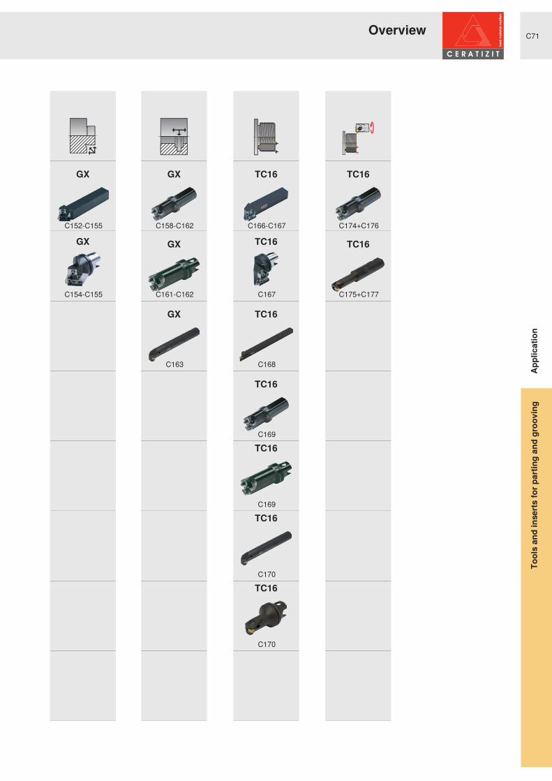
GX
GX
GX
GX
GX
TC16
TC16
TC16
TC16
TC16
TC16
TC16
TC16
TC16
C152-C155
C154-C155
C158-C162
C161-C162
C163
C166-C167
C167
C168
C169
C169
C170
C170
C174+C176
C175+C177
Overview
Appl
icat
ion
Tool
s an
d in
serts
for p
artin
g an
d gr
oovi
ng

C72
dA dA
dA dA
h
b
h2
h h
b
2
6KDQ NV� � ƒ 6KDQ NV� � � ƒ
8 76 � � ƒ 8 76 � � � ƒ
+ 6 . � 7 � � ƒ + 6 . � 7 � � � ƒ
Clamping blocks Split clamping blocks
h / b16/16 - 32/32
h / b20/20 - 32/32
dA = 40 - 63 dA = 40 - 63
dA = 63 - 100 dA = 63 - 100
h / b20/20 - 40/37
h / b20/20 - 32/29
Appl
icat
ion
Part-off2 YHUYLHZ � ² � P RGXODU� VWUXFWXUH
Tool
s an
d in
serts
for p
artin
g an
d gr
oovi
ng

C73
Tm
ax
s
T
max
s
Tm
ax
s
Tm
ax
s
Tm
ax
s
Tm
ax
s
Tm
ax
s
Tm
ax
s
GX16 GX24
SX LX
FX short FX long
GX16 GX24
SX LX
FX short FX long
GX SX LX FX
s = 2,0 - 6,5Tmax = 12
s = 2,0 - 5,0Tmax = 21
s = 2,0 - 4,0Tmax = 20 - 35
s = 2,0 - 4,0Tmax = 20 - 35
s = 8,0 - 10,0Tmax = 25 - 45
s = 8,0 - 10,0Tmax = 25 - 45
s = 2,2 - 6,5Tmax = 20 - 32
s = 2,2 - 6,5Tmax = 20 - 32
s = 3,1 - 6,5Tmax = 35 - 45
s = 2,0 - 6,5Tmax = 12
s = 2,0 - 5,0Tmax = 21
s = 3,1 - 4,5Tmax = 35 - 45
s = 2,0 - 6,5Tmax = 21
s = 2,0 - 6,0Tmax = 25 - 60
s = 8,0 - 10,0Tmax = 80
s = 2,2 - 9,7Tmax = 25 - 80
Appl
icat
ion
Part-off2 YHUYLHZ � ² � P RGXODU� VWUXFWXUH
Tool
s an
d in
serts
for p
artin
g an
d gr
oovi
ng

C74
Tm
ax
hb
s
Tm
ax
h
b
s
Tm
ax
h
b
s
Tm
ax
h
b
s
Tm
ax
h
b
s
Tm
ax
h
b
s
GX16 monobloc tool holders
GX24 monobloc tool holders
SX monobloc tool holders
FX monobloc tool holders
PX monobloc tool holders
MaxiClick
h / b12/12 - 25/25s = 2,0 - 5,0
Tmax = 12
h / b16/16 - 32/25s = 2,0 - 6,5
Tmax = 21
h / b16/16 - 25/25s = 2,0 - 6,0
Tmax = 16 - 32
h / b10/10 - 25/20s = 2,2 - 4,1
Dmax = 30 - 50
h / b16/16 - 20/20s = 1,0 - 2,0
Dmax = 52 - 62
h / b10/10 - 25/25s = 1,0 - 2,5Tmax = 5 - 10
Appl
icat
ion
Part-offOverview - monobloc tools
Tool
s an
d in
serts
for p
artin
g an
d gr
oovi
ng


C76
Tm
ax
s
RL
Tm
ax
s
RL
Tm
ax
s
RL
Type,description
smin smax Tmax[mm] [mm] [mm]
2.00 2.75
12
RMSS-E20R12-GX16-1 GX16-1..
2.76 3.75 MSS-E20R12-GX16-2 GX16-2.. 3.76 5.00 MSS-E20R12-GX16-3 GX16-3.. 2.00 2.75
LMSS-E20L12-GX16-1 GX16-1..
2.76 3.75 MSS-E20L12-GX16-2 GX16-2.. 3.76 5.00 MSS-E20L12-GX16-3 GX16-3..
C201
C180-C181
Type,description
smin smax Tmax[mm] [mm] [mm]
2.00 2.75
21
RMSS-E20R21-GX24-1 GX24-1..
2.76 3.75 MSS-E20R21-GX24-2 GX24-2.. 3.76 5.00 MSS-E20R21-GX24-3 GX24-3.. 2.00 2.75
LMSS-E20L21-GX24-1 GX24-1..
2.76 3.75 MSS-E20L21-GX24-2 GX24-2.. 3.76 5.00 MSS-E20L21-GX24-3 GX24-3..
C202
C180-C181
Type,description
b h[mm] [mm]
20
16 R MSS-E20R00-1620G20 MSS-E20R00-2020J16 L MSS-E20L00-1620G20 MSS-E20L00-2020J
C196
Type,description
b h[mm] [mm]
20 20 R MSS-E20R90-2020JL MSS-E20L90-2020J
C197
Type,description
s Tmax [mm] [mm]
2.0
20 R MSS-E20R20-SX2 SX2
3.0 MSS-E20R20-SX3 SX3 2.0 L MSS-E20L20-SX2 SX2 3.0 MSS-E20L20-SX3 SX3
C209
C185
� ƒ � � ƒ
GX16 GX24
SX
BGR E20
Appl
icat
ion
6KDQNV� ² � * ; � 6 ;Part-off
Tool
s an
d in
serts
for p
artin
g an
d gr
oovi
ng
C77
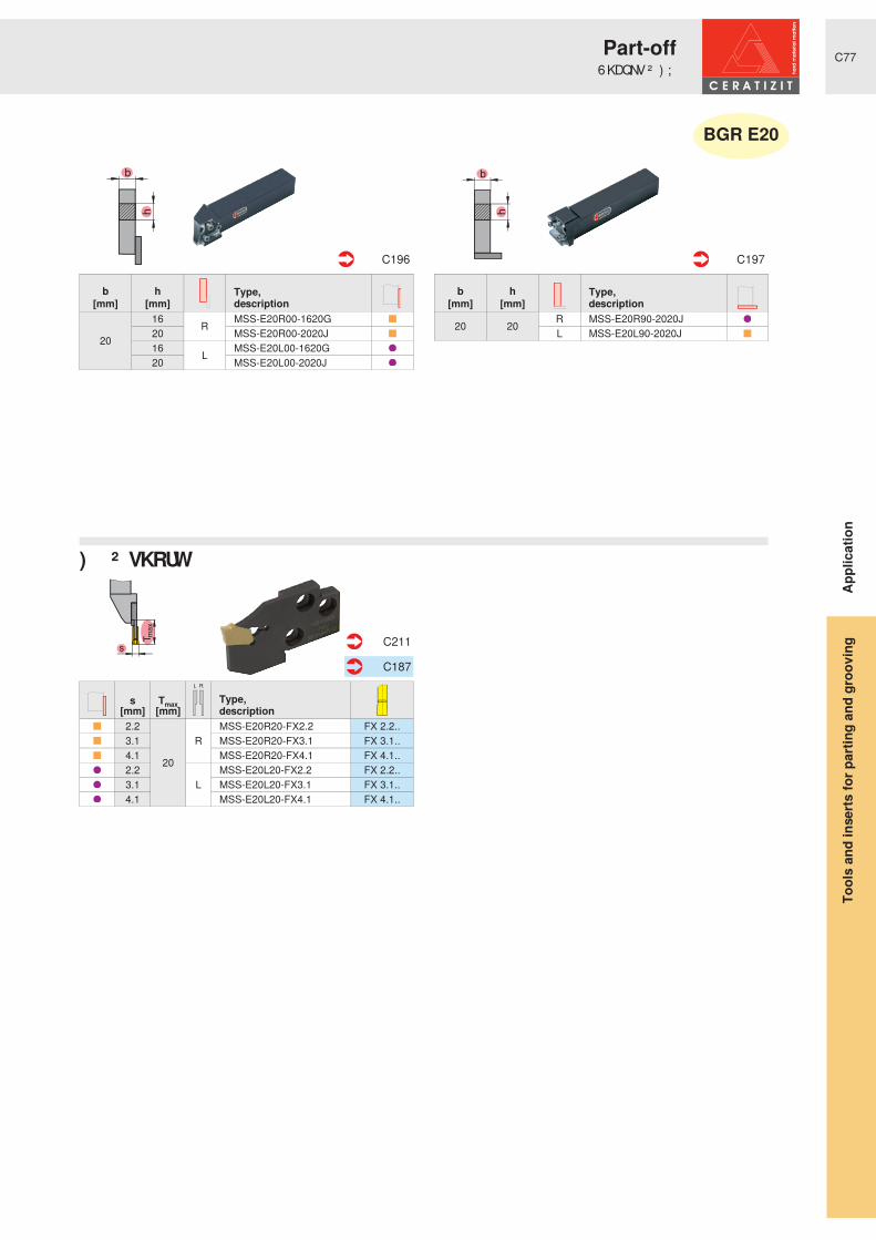
Tm
ax
s
RL
Type,description
b h[mm] [mm]
20
16 R MSS-E20R00-1620G20 MSS-E20R00-2020J16 L MSS-E20L00-1620G20 MSS-E20L00-2020J
C196
Type,description
b h[mm] [mm]
20 20 R MSS-E20R90-2020JL MSS-E20L90-2020J
C197
Type,description
s Tmax[mm] [mm]
2.2
20
RMSS-E20R20-FX2.2 FX 2.2..
3.1 MSS-E20R20-FX3.1 FX 3.1.. 4.1 MSS-E20R20-FX4.1 FX 4.1.. 2.2
LMSS-E20L20-FX2.2 FX 2.2..
3.1 MSS-E20L20-FX3.1 FX 3.1.. 4.1 MSS-E20L20-FX4.1 FX 4.1..
C211
C187
� ƒ � � ƒ
) ; � ² � VKRUW
BGR E20
Appl
icat
ion
6KDQNV� ² � ) ;Part-off
Tool
s an
d in
serts
for p
artin
g an
d gr
oovi
ng

C78
dA
dA
Tm
ax
s
RL
Tm
ax
s
RL
Tm
ax
s
RL
RL
Type,description
smin smax Tmax[mm] [mm] [mm]
2.00 2.75
12
RMSS-E25R12-GX16-1 GX16-1..
2.76 3.75 MSS-E25R12-GX16-2 GX16-2.. 3.76 5.00 MSS-E25R12-GX16-3 GX16-3.. 2.00 2.75
LMSS-E25L12-GX16-1 GX16-1..
2.76 3.75 MSS-E25L12-GX16-2 GX16-2.. 3.76 5.00 MSS-E25L12-GX16-3 GX16-3..
C201
C180-C181
Type,description
smin smax Tmax[mm] [mm] [mm]
2.00 2.75
21
RMSS-E25R21-GX24-1 GX24-1..
2.76 3.75 MSS-E25R21-GX24-2 GX24-2.. 3.76 5.00 MSS-E25R21-GX24-3 GX24-3.. 2.00 2.75
LMSS-E25L21-GX24-1 GX24-1..
2.76 3.75 MSS-E25L21-GX24-2 GX24-2.. 3.76 5.00 MSS-E25L21-GX24-3 GX24-3..
C202
C180-C181
Type,description
b h dA[mm] [mm] [mm]
25 25
R
MSS-E25R00-2525L 40 UT40-MSS-E25R00 50 UT50-MSS-E25R00 63 UT63-MSS-E25R00
25 25
L
MSS-E25L00-2525L 40 UT40-MSS-E25L00 50 UT50-MSS-E25L00 63 UT63-MSS-E25L00
C196 C246
Type,description
b h dA[mm] [mm] [mm]
25 25 R
MSS-E25R90-2525L 40 UT40-MSS-E25R90 50 UT50-MSS-E25R9025 25
LMSS-E25L90-2525L
40 UT40-MSS-E25L90 50 UT50-MSS-E25L90
C197 C247
Type,description
s Tmax [mm] [mm]
2.0 20
R
MSS-E25R20-SX2 SX2 3.0 25 MSS-E25R25-SX3 SX3 3.0 35 MSS-E25R35-SX3 SX3 4.0 25 MSS-E25R25-SX4 SX4 4.0 35 MSS-E25R35-SX4 SX4
C209
C185
Type,description
s Tmax [mm] [mm]
2.0 20
L
MSS-E25L20-SX2 SX2 3.0 25 MSS-E25L25-SX3 SX3 3.0 35 MSS-E25L35-SX3 SX3 4.0 25 MSS-E25L25-SX4 SX4 4.0 35 MSS-E25L35-SX4 SX4
� ƒ � � ƒ
GX16 GX24
6 ; � ² � ULJKW� KDQ G 6 ; � ² � OHIW� KDQ G
BGR E25
Appl
icat
ion
6KDQNV� ² � 8 76 � ² � * ; � 6 ;Part-off
Tool
s an
d in
serts
for p
artin
g an
d gr
oovi
ng

C79
dA
dA
Tm
ax
s
RL
Tm
ax
s
RL
Type,description
b h dA[mm] [mm] [mm]
25 25
R
MSS-E25R00-2525L 40 UT40-MSS-E25R00 50 UT50-MSS-E25R00 63 UT63-MSS-E25R00
25 25
L
MSS-E25L00-2525L 40 UT40-MSS-E25L00 50 UT50-MSS-E25L00 63 UT63-MSS-E25L00
C196 C246
Type,description
b h dA[mm] [mm] [mm]
25 25 R
MSS-E25R90-2525L 40 UT40-MSS-E25R90 50 UT50-MSS-E25R9025 25
LMSS-E25L90-2525L
40 UT40-MSS-E25L90 50 UT50-MSS-E25L90
C197 C247
Type,description
s Tmax[mm] [mm]
2.2 20
R
MSS-E25R20-FX2.2 FX 2.2.. 3.1
25
MSS-E25R25-FX3.1 FX 3.1.. 4.1 MSS-E25R25-FX4.1 FX 4.1.. 5.1 MSS-E25R25-FX5.1 FX 5.1.. 6.5 MSS-E25R25-FX6.5 FX 6.5.. 2.2 20
L
MSS-E25L20-FX2.2 FX 2.2.. 3.1
25
MSS-E25L25-FX3.1 FX 3.1.. 4.1 MSS-E25L25-FX4.1 FX 4.1.. 5.1 MSS-E25L25-FX5.1 FX 5.1.. 6.5 MSS-E25L25-FX6.5 FX 6.5..
C211
C187
Type,description
s Tmax[mm] [mm]
3.1
35
R
MSS-E25R35-FX3.1 FX 3.1.. 4.1 MSS-E25R35-FX4.1 FX 4.1.. 5.1 MSS-E25R35-FX5.1 FX 5.1.. 6.5 MSS-E25R35-FX6.5 FX 6.5.. 3.1
L
MSS-E25L35-FX3.1 FX 3.1.. 4.1 MSS-E25L35-FX4.1 FX 4.1.. 5.1 MSS-E25L35-FX5.1 FX 5.1.. 6.5 MSS-E25L35-FX6.5 FX 6.5..
C212
C187
� ƒ � � ƒ
) ; � ² � VKRUW ) ; � ² � ORQ J
BGR E25
Appl
icat
ion
6KDQNV� ² � 8 76 � ² � ) ;Part-off
Tool
s an
d in
serts
for p
artin
g an
d gr
oovi
ng

C80
dA
dA
Tm
ax
s
RL
Tm
ax
s
RL
Tm
ax
s
RL
Type,description
smin smax Tmax[mm] [mm] [mm]
2.76 3.75
12R MSS-E32R12-GX16-2 GX16-2..
3.76 5.00 MSS-E32R12-GX16-3 GX16-3.. 2.76 3.75 L MSS-E32L12-GX16-2 GX16-2.. 3.76 5.00 MSS-E32L12-GX16-3 GX16-3..
C201
C180-C181
Type,description
smin smax Tmax[mm] [mm] [mm]
2.76 3.75
21R MSS-E32R21-GX24-2 GX24-2..
3.76 5.00 MSS-E32R21-GX24-3 GX24-3.. 2.76 3.75 L MSS-E32L21-GX24-2 GX24-2.. 3.76 5.00 MSS-E32L21-GX24-3 GX24-3..
C202
C180-C181
Type,description
s Tmax [mm] [mm]
3.0
35 R MSS-E32R35-SX3 SX3
4.0 MSS-E32R35-SX4 SX4 3.0 L MSS-E32L35-SX3 SX3 4.0 MSS-E32L35-SX4 SX4
C209
C185
Type,description
b h dA[mm] [mm] [mm]
25 32
R
MSS-E32R00-3225N32 32 MSS-E32R00-3232Q 50 UT50-MSS-E32R00 63 UT63-MSS-E32R00 63 HSK-T63-MSS-E32R00 100 HSK-T100-MSS-E32R00
25 32
L
MSS-E32L00-3225N32 32 MSS-E32L00-3232Q 50 UT50-MSS-E32L00 63 UT63-MSS-E32L00 63 HSK-T63-MSS-E32L00 100 HSK-T100-MSS-E32L00
C196 C246+C250
Type,description
b h dA[mm] [mm] [mm]
25 32
R
MSS-E32R90-3225N32 32 MSS-E32R90-3232R 63 UT63-MSS-E32R90 63 HSK-T63-MSS-E32R90 100 HSK-T100-MSS-E32R90
25 32
L
MSS-E32L90-3225N32 32 MSS-E32L90-3232R 63 UT63-MSS-E32L90 63 HSK-T63-MSS-E32L90 100 HSK-T100-MSS-E32L90
C197 C247+C251
� ƒ � � ƒ
GX16 GX24
SX
BGR E32
Appl
icat
ion
6KDQNV� ² � 8 76 � + 6 . � 7 � ² � * ; � 6 ;Part-off
Tool
s an
d in
serts
for p
artin
g an
d gr
oovi
ng

C81
dA
dA
Tm
ax
s
RL
Tm
ax
s
RL
Tm
ax
s
RL
Type,description
b h dA[mm] [mm] [mm]
25 32
R
MSS-E32R00-3225N32 32 MSS-E32R00-3232Q 50 UT50-MSS-E32R00 63 UT63-MSS-E32R00 63 HSK-T63-MSS-E32R00 100 HSK-T100-MSS-E32R00
25 32
L
MSS-E32L00-3225N32 32 MSS-E32L00-3232Q 50 UT50-MSS-E32L00 63 UT63-MSS-E32L00 63 HSK-T63-MSS-E32L00 100 HSK-T100-MSS-E32L00
C196 C246+C250
Type,description
b h dA[mm] [mm] [mm]
25 32
R
MSS-E32R90-3225N32 32 MSS-E32R90-3232R 63 UT63-MSS-E32R90 63 HSK-T63-MSS-E32R90 100 HSK-T100-MSS-E32R90
25 32
L
MSS-E32L90-3225N32 32 MSS-E32L90-3232R 63 UT63-MSS-E32L90 63 HSK-T63-MSS-E32L90 100 HSK-T100-MSS-E32L90
C197 C247+C251
Type,description
s Tmax[mm] [mm]
3.1
32
R
MSS-E32R32-FX3.1 FX 3.1.. 4.1 MSS-E32R32-FX4.1 FX 4.1.. 5.1 MSS-E32R32-FX5.1 FX 5.1.. 6.5 MSS-E32R32-FX6.5 FX 6.5.. 3.1
L
MSS-E32L32-FX3.1 FX 3.1.. 4.1 MSS-E32L32-FX4.1 FX 4.1.. 5.1 MSS-E32L32-FX5.1 FX 5.1.. 6.5 MSS-E32L32-FX6.5 FX 6.5..
C211
C187
Type,description
s Tmax[mm] [mm]
3.1
45
R
MSS-E32R45-FX3.1 FX 3.1.. 4.1 MSS-E32R45-FX4.1 FX 4.1.. 5.1 MSS-E32R45-FX5.1 FX 5.1.. 6.5 MSS-E32R45-FX6.5 FX 6.5.. 3.1
L
MSS-E32L45-FX3.1 FX 3.1.. 4.1 MSS-E32L45-FX4.1 FX 4.1.. 5.1 MSS-E32L45-FX5.1 FX 5.1.. 6.5 MSS-E32L45-FX6.5 FX 6.5..
C212
C187
Type,description
smin smax Tmax[mm] [mm] [mm]
8.00 10.00
25N
MSS-E32N25-LX LX-.. 32 MSS-E32N32-LX LX-.. 45 MSS-E32N45-LX LX-..
C210
C186
� ƒ � � ƒ
) ; � ² � VKRUW ) ; � ² � ORQ J
LX
BGR E32
Appl
icat
ion
6KDQNV� ² � 8 76 � + 6 . � 7 � ² � / ; � ) ;Part-off
Tool
s an
d in
serts
for p
artin
g an
d gr
oovi
ng

C82
h
b
h2
h h
b
2
Tm
ax
s
L/N/R
Tm
ax
s
L/N/R
Tm
ax
s
L/N/R
Type,description
h2 b h=h1[mm] [mm] [mm]
26 20 20 SBN 2020-26 K
C229
Type,description
h2 b h=h1[mm] [mm] [mm]
26 20 20 SBN 2020-26 KS
C230
Type,description
s Tmax[mm] [mm]
2.0 25 R XLCFR 2602-SX2 SX2 3.0 35 N XLCFN 2603-SX3 SX3 4.0 40 XLCFN 2604-SX4 SX4 2.0 25 L XLCFL 2602-SX2 SX2
C224
C185
Type,description
s Tmax[mm] [mm]
2.0
22R XLCFR 2608-SX2 SX2
3.0 XLCFR 2608-SX3 SX3 2.0 L XLCFL 2608-SX2 SX2 3.0 XLCFL 2608-SX3 SX3
C225
C185
Type,description
s Tmax[mm] [mm]
2.2 25N
XLCEN 2602 J22 FX FX 2.2.. 3.1 35 XLCFN 2603 J31 FX FX 3.1.. 4.1 40 XLCFN 2604 J41 FX FX 4.1..
C228
C187
Clamping blocks Split clamping blocks
SX
FX
6 ; � ² � UHLQ IRUFHG
H26
Appl
icat
ion
& ODP SLQJ� EORFNV� � EODGHV� ² � 6 ; � ) ;Part-off
Tool
s an
d in
serts
for p
artin
g an
d gr
oovi
ng

C83
h
b
h2
h h
b
2
Tm
ax
s
L/N/R
Tm
ax
s
L/N/R
Tm
ax
s
L/N/R
Tm
ax
s
L/N/R
Type,description
h2 b h=h1[mm] [mm] [mm]
32 20 25 SBN 2520-32 K32 29 32 SBN 3229-32 K
C229
Type,description
h2 b h=h1[mm] [mm] [mm]
32 20 25 SBN 2520-32 KS32 29 32 SBN 3229-32 KS
C230
Type,description
smin smax Tmax[mm] [mm] [mm]
2.00 2.75
21 N
XLCFN 3202-GX24-1S GX24-1.. 2.76 3.75 XLCFN 3203 GX24-2S GX24-2.. 3.76 5.00 XLCFN 3204 GX24-3S GX24-3.. 5.01 6.50 XLCFN 3206 GX24-4S GX24-4..
C223
C180-C181
Type,description
s Tmax[mm] [mm]
2.0 25 R XLCFR 3202-SX2 SX2 3.0 50
N
XLCFN 3203-SX3 SX3 4.0 XLCFN 3204-SX4 SX4 5.0 55 XLCFN 3205-SX5 SX5 6.0 60 XLCFN 3206-SX6 SX6 2.0 25 L XLCFL 3202-SX2 SX2
C224
C185
Type,description
s Tmax[mm] [mm]
3.0
33R XLCFR 3208-SX3 SX3
4.0 XLCFR 3208-SX4 SX4 3.0 L XLCFL 3208-SX3 SX3 4.0 XLCFL 3208-SX4 SX4
C226
C185
Type,description
s Tmax[mm] [mm]
2.2 30
N
XLCEN 3202 M22 FX FX 2.2.. 3.1 50 XLCFN 3203 M31 FX FX 3.1.. 4.1 XLCFN 3204 M41 FX FX 4.1.. 5.1 55 XLCFN 3205 M51 FX FX 5.1.. 6.5 XLCFN 3206 M65 FX FX 6.5..
C228
C187
Clamping blocks Split clamping blocks
SXGX24
FX6 ; � ² � UHLQ IRUFHG
H32
Appl
icat
ion
& ODP SLQJ� EORFNV� � EODGHV� ² � * ; � 6 ; � ) ;Part-off
Tool
s an
d in
serts
for p
artin
g an
d gr
oovi
ng

C84
h
b
h2
Tm
ax
s
L/N/R
Tm
ax
s
L/N/R
Type,description
h2 b h=h1[mm] [mm] [mm]
46 29 32 SBN 3229-46 K37 40 SBN 4037-46 K
C229
Type,description
smin smax Tmax[mm] [mm] [mm]
8.00 10.00 80 N XLCEN 4608 LX LX-..
C227
C186
Type,description
s Tmax[mm] [mm]
8.2 80 N XLCEN 4608 S82 FX FX 8.2.. 9.7 XLCEN 4609 S97 FX FX 9.7..
C228
C187
Clamping blocks
FX LX
H46
Appl
icat
ion
& ODP SLQJ� EORFNV� � EODGHV� ² � / ; � ) ;Part-off
Tool
s an
d in
serts
for p
artin
g an
d gr
oovi
ng


C86
Tm
ax
h
b
s
RL
RL
Tm
ax
h
b
s
RL
RL
Type,description
b h smin smax Tmax[mm] [mm] [mm] [mm] [mm]
12 12 2.00 2.75
12 R
E12R0012-1212K-GX16-1 GX16-1..0.60 3.75 E12R0012-1212K-GX16-2 GX16-2..
16 162.00 2.75 E16R0012-1616K-GX16-1 GX16-1..0.60 3.75 E16R0012-1616K-GX16-2 GX16-2..3.76 5.00 E16R0012-1616K-GX16-3 GX16-3..
20 202.00 2.75 E20R0012-2020K-GX16-1 GX16-1..0.60 3.75 E20R0012-2020K-GX16-2 GX16-2..3.76 5.00 E20R0012-2020K-GX16-3 GX16-3..
25 25 0.60 3.75 E25R0012-2525M-GX16-2 GX16-2..3.76 5.00 E25R0012-2525M-GX16-3 GX16-3..
C214 C180-C181
Type,description
b h smin smax Tmax[mm] [mm] [mm] [mm] [mm]
12 12 2.00 2.75
12 L
E12L0012-1212K-GX16-1 GX16-1..0.60 3.75 E12L0012-1212K-GX16-2 GX16-2..
16 162.00 2.75 E16L0012-1616K-GX16-1 GX16-1..0.60 3.75 E16L0012-1616K-GX16-2 GX16-2..3.76 5.00 E16L0012-1616K-GX16-3 GX16-3..
20 202.00 2.75 E20L0012-2020K-GX16-1 GX16-1..0.60 3.75 E20L0012-2020K-GX16-2 GX16-2..3.76 5.00 E20L0012-2020K-GX16-3 GX16-3..
25 25 0.60 3.75 E25L0012-2525M-GX16-2 GX16-2..3.76 5.00 E25L0012-2525M-GX16-3 GX16-3..
Type,description
b h smin smax Tmax[mm] [mm] [mm] [mm] [mm]
16 16 2.00 2.75
21 R
E16R0021-1616K-GX24-1 GX24-1..2.76 3.75 E16R0021-1616K-GX24-2 GX24-2..
20 202.00 2.75 E20R0021-2020K-GX24-1 GX24-1..2.76 3.75 E20R0021-2020K-GX24-2 GX24-2..3.76 5.00 E20R0021-2020K-GX24-3 GX24-3..
2525 2.76 3.75 E25R0021-2525M-GX24-2 GX24-2..
3.76 5.00 E25R0021-2525M-GX24-3 GX24-3..
32 2.76 3.75 E32R0021-3225P-GX24-2 GX24-2..3.76 5.00 E32R0021-3225P-GX24-3 GX24-3..
C215 C180-C181
Type,description
b h smin smax Tmax[mm] [mm] [mm] [mm] [mm]
16 16 2.00 2.75
21 L
E16L0021-1616K-GX24-1 GX24-1..2.76 3.75 E16L0021-1616K-GX24-2 GX24-2..
20 202.00 2.75 E20L0021-2020K-GX24-1 GX24-1..2.76 3.75 E20L0021-2020K-GX24-2 GX24-2..3.76 5.00 E20L0021-2020K-GX24-3 GX24-3..
2525 2.76 3.75 E25L0021-2525M-GX24-2 GX24-2..
3.76 5.00 E25L0021-2525M-GX24-3 GX24-3..
32 2.76 3.75 E32L0021-3225P-GX24-2 GX24-2..3.76 5.00 E32L0021-3225P-GX24-3 GX24-3..
* ; � � � ² � ULJKW� KDQ G * ; � � � ² � OHIW� KDQ G
* ; � � � ² � ULJKW� KDQ G * ; � � � ² � OHIW� KDQ G
Appl
icat
ion
0 RQREORF� WRROV� ² � * ;Part-off
Tool
s an
d in
serts
for p
artin
g an
d gr
oovi
ng

C87
Tm
ax
h
b
s
RL
RL
Type,description
s h b Tmax[mm] [mm] [mm] [mm]
2.0 16 16 16
R
E16R0016-1616K-SX2 SX220 20 E20R0016-2020K-SX2 SX2
3.016 16
20E16R0020-1616K-SX3 SX3
20 20 E20R0020-2020K-SX3 SX325 25 E25R0020-2525M-SX3 SX3
4.0 25 2525
E25R0025-2525M-SX4 SX420 20 E20R0025-2020K-SX4 SX4
5.0 25 25 E25R0025-2525M-SX5 SX56.0 25 25 32 E25R0032-2525M-SX6 SX6
C218 C185
Type,description
s h b Tmax[mm] [mm] [mm] [mm]
2.0 16 16 16
L
E16L0016-1616K-SX2 SX220 20 E20L0016-2020K-SX2 SX2
3.016 16
20E16L0020-1616K-SX3 SX3
20 20 E20L0020-2020K-SX3 SX325 25 E25L0020-2525M-SX3 SX3
4.0 25 2525
E25L0025-2525M-SX4 SX420 20 E20L0025-2020K-SX4 SX4
5.0 25 25 E25L0025-2525M-SX5 SX56.0 25 25 32 E25L0032-2525M-SX6 SX6
6 ; � ² � ULJKW� KDQ G 6 ; � ² � OHIW� KDQ G
Appl
icat
ion
0 RQREORF� WRROV� ² � 6 ;Part-off
Tool
s an
d in
serts
for p
artin
g an
d gr
oovi
ng

C88
Tm
ax
h
b
s
RL
RL
Type,description
s h b Dmax[mm] [mm] [mm] [mm]
2.2
10 10
30
R
XLCER 1010 M22 FX FX 2.2..12 12 XLCER 1212 F22 FX FX 2.2..12 12 XLCER 1212 M22 FX FX 2.2..14 14 XLCER 1414 M22 FX FX 2.2..16 12 XLCER 1612 H22 FX FX 2.2..
3.116 12 35 XLCFR 1612 H31 FX FX 3.1..20 16 40 XLCFR 2016 K31 FX FX 3.1..25 20 50 XLCFR 2520 M31 FX FX 3.1..
4.1 20 16 40 XLCFR 2016 K41 FX FX 4.1..25 20 50 XLCFR 2520 M41 FX FX 4.1..
C219 C187
Type,description
s h b Dmax[mm] [mm] [mm] [mm]
2.2
10 10
30
L
XLCEL 1010 M22 FX FX 2.2..12 12 XLCEL 1212 F22 FX FX 2.2..12 12 XLCEL 1212 M22 FX FX 2.2..14 14 XLCEL 1414 M22 FX FX 2.2..16 12 XLCEL 1612 H22 FX FX 2.2..
3.116 12 35 XLCFL 1612 H31 FX FX 3.1..20 16 40 XLCFL 2016 K31 FX FX 3.1..25 20 50 XLCFL 2520 M31 FX FX 3.1..
4.1 20 16 40 XLCFL 2016 K41 FX FX 4.1..25 20 50 XLCFL 2520 M41 FX FX 4.1..
) ; � ² � ULJKW� KDQ G ) ; � ² � OHIW� KDQ G
Appl
icat
ion
0 RQREORF� WRROV� ² � ) ;Part-off
Tool
s an
d in
serts
for p
artin
g an
d gr
oovi
ng
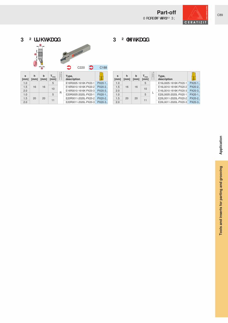
C89
Tm
ax
h
b
s
RL
RL
Type,description
s h b Tmax[mm] [mm] [mm] [mm]1.0
16 165
R
E16R0005-1616K-PX20-1 PX20-1..1.5 10 E16R0010-1616K-PX20-2 PX20-2..2.0 E16R0010-1616K-PX20-3 PX20-3..1.0
20 205 E20R0005-2020L-PX20-1 PX20-1..
1.5 11 E20R0011-2020L-PX20-2 PX20-2..2.0 E20R0011-2020L-PX20-3 PX20-3..
C220 C188
Type,description
s h b Tmax[mm] [mm] [mm] [mm]1.0
16 165
L
E16L0005-1616K-PX20-1 PX20-1..1.5 10 E16L0010-1616K-PX20-2 PX20-2..2.0 E16L0010-1616K-PX20-3 PX20-3..1.0
20 205 E20L0005-2020L-PX20-1 PX20-1..
1.5 11 E20L0011-2020L-PX20-2 PX20-2..2.0 E20L0011-2020L-PX20-3 PX20-3..
3 ; � ² � ULJKW� KDQ G 3 ; � ² � OHIW� KDQ G
Appl
icat
ion
0 RQREORF� WRROV� ² � 3 ;Part-off
Tool
s an
d in
serts
for p
artin
g an
d gr
oovi
ng

C90
Tm
ax
h
b
s
RL
RL
Type,description
b h smin smax Tmax[mm] [mm] [mm] [mm] [mm]
10 10
1.00 1.50 5
R
MC05R-1010K MC 05..12 12 MC05R-1212K MC 05..16 16 MC05R-1616K MC 05..20 20 MC05R-2020K MC 05..25 25 MC05R-2525M MC 05..10 10
1.50 2.50 10
MC10R-1010K MC 10..10 10 MC10R-1010K-S MC 10..12 12 MC10R-1212K MC 10..12 12 MC10R-1212K-S MC 10..16 16 MC10R-1616K MC 10..20 20 MC10R-2020K MC 10..25 25 MC10R-2525M MC 10..
C221-C222 C189
Type,description
b h smin smax Tmax[mm] [mm] [mm] [mm] [mm]
10 10
1.00 1.50 5
L
MC05L-1010K MC 05..12 12 MC05L-1212K MC 05..16 16 MC05L-1616K MC 05..20 20 MC05L-2020K MC 05..25 25 MC05L-2525M MC 05..10 10
1.50 2.50 10
MC10L-1010K MC 10..12 12 MC10L-1212K MC 10..16 16 MC10L-1616K MC 10..20 20 MC10L-2020K MC 10..25 25 MC10L-2525M MC 10..10 10 MC10L-1010K-S MC 10..12 12 MC10L-1212K-S MC 10..
0 &� ² � ULJKW� KDQ G 0 &� ² � OHIW� KDQ G
Appl
icat
ion
0 RQREORF� WRROV� ² � 0 D[ L& OLFNPart-off
Tool
s an
d in
serts
for p
artin
g an
d gr
oovi
ng


C92
dA dA
dA dA
6KDQ NV� � ƒ 6KDQ NV� � � ƒ
8 76 � � ƒ 8 76 � � � ƒ
+ 6 . � 7 � � ƒ + 6 . � 7 � � � ƒ
h / b20/20 - 32/32
dA = 40 - 63
h / b12/12 - 32/32
dA = 40 - 63
dA = 63 - 100 dA = 63 - 100
Appl
icat
ion
2 YHUYLHZ � ² � P RGXODU� VWUXFWXUH* URRYLQ J� DQ G� WXUQ LQ J� ² � H[ WHUQ DO
Tool
s an
d in
serts
for p
artin
g an
d gr
oovi
ng

C93
Tm
ax
s
T
max
s
Tm
ax
s
GX09 GX16 GX24
SX LX
GX16 GX24 SX LX
s = 2,0 - 3,75Tmax = 7,0
s = 2,0 - 6,5Tmax = 12
s = 2,0 - 4,0 Tmax = 20 - 35
s = 8,0 - 10,0Tmax = 25 - 45
s = 2,76 - 8,0Tmax = 21
s = 2,0 - 6,5Tmax = 12
s = 2,76 - 8,0Tmax = 21
s = 2,0 - 4,0 Tmax = 20 - 35
s = 8,0 - 10,0Tmax = 25 - 45
Appl
icat
ion
2 YHUYLHZ � ² � P RGXODU� VWUXFWXUH* URRYLQ J� DQ G� WXUQ LQ J� ² � H[ WHUQ DO
Tool
s an
d in
serts
for p
artin
g an
d gr
oovi
ng

C94
Tm
ax
h
b
s
Tm
ax
h
b
s
Tm
ax
h
b
s
Tm
ax
h
b
s
GX09 monobloc tool holders
GX16 monobloc tool holders
GX24 monobloc tool holders
SX monobloc tool holders
h / b10/10s = 2,0Tmax = 7
h / b12/12 - 25/25s = 2,0 - 5,0
Tmax = 12
h / b16/16 - 32/25s = 2,0 - 6,5
Tmax = 21
h / b16/16 - 25/25s = 2,0 - 6,0
Tmax = 16 - 32
Appl
icat
ion
2 YHUYLHZ � ² � P RGXODU� VWUXFWXUH* URRYLQ J� DQ G� WXUQ LQ J� ² � H[ WHUQ DO
Tool
s an
d in
serts
for p
artin
g an
d gr
oovi
ng


C96
Tm
ax
s
RL
Type,description
b h [mm] [mm]
12 12 R MSS-E12R00-1212EL MSS-E12L00-1212E
C196
Type,description
smin smax Tmax[mm] [mm] [mm]
2.00 2.75
7R MSS-E12R07-GX09-1 GX09-1..
2.76 3.75 MSS-E12R07-GX09-2 GX09-2.. 2.00 2.75 L MSS-E12L07-GX09-1 GX09-1.. 2.76 3.75 MSS-E12L07-GX09-2 GX09-2..
C200
C180
� ƒ
GX09
BGR E12
Appl
icat
ion
6KDQNV� ² � * ; � 6 ;* URRYLQ J� DQ G� WXUQ LQ J� ² � H[ WHUQ DO
Tool
s an
d in
serts
for p
artin
g an
d gr
oovi
ng

C97
Tm
ax
s
RL
Type,description
b h [mm] [mm]
16 16 R MSS-E16R00-1616GL MSS-E16L00-1616G
C196
Type,description
smin smax Tmax[mm] [mm] [mm]
2.00 2.75
7R MSS-E16R07-GX09-1 GX09-1..
2.76 3.75 MSS-E16R07-GX09-2 GX09-2.. 2.00 2.75 L MSS-E16L07-GX09-1 GX09-1.. 2.76 3.75 MSS-E16L07-GX09-2 GX09-2..
C200
C180
� ƒ
GX09
BGR E16
Appl
icat
ion
6KDQNV� ² � * ; � 6 ;* URRYLQ J� DQ G� WXUQ LQ J� ² � H[ WHUQ DO
Tool
s an
d in
serts
for p
artin
g an
d gr
oovi
ng

C98
Tm
ax
s
RL
Tm
ax
s
RL
Tm
ax
s
RL
Type,description
b h[mm] [mm]
20
16 R MSS-E20R00-1620G20 MSS-E20R00-2020J16 L MSS-E20L00-1620G20 MSS-E20L00-2020J
C196
Type,description
b h[mm] [mm]
20 20 R MSS-E20R90-2020JL MSS-E20L90-2020J
C197
Type,description
smin smax Tmax[mm] [mm] [mm]
2.00 2.75
12
RMSS-E20R12-GX16-1 GX16-1..
2.76 3.75 MSS-E20R12-GX16-2 GX16-2.. 3.76 5.00 MSS-E20R12-GX16-3 GX16-3.. 2.00 2.75
LMSS-E20L12-GX16-1 GX16-1..
2.76 3.75 MSS-E20L12-GX16-2 GX16-2.. 3.76 5.00 MSS-E20L12-GX16-3 GX16-3..
C201
C180-C181
Type,description
smin smax Tmax[mm] [mm] [mm]
2.76 3.75
21R MSS-E20R21-GX24-2 GX24-2..
3.76 5.00 MSS-E20R21-GX24-3 GX24-3.. 2.76 3.75 L MSS-E20L21-GX24-2 GX24-2.. 3.76 5.00 MSS-E20L21-GX24-3 GX24-3..
C202
C180-C181
Type,description
s Tmax [mm] [mm]
2.0
20 R MSS-E20R20-SX2 SX2
3.0 MSS-E20R20-SX3 SX3 2.0 L MSS-E20L20-SX2 SX2 3.0 MSS-E20L20-SX3 SX3
C209
C185
� ƒ � � ƒ
GX16 GX24
SX
BGR E20
Appl
icat
ion
6KDQNV� ² � * ; � 6 ;* URRYLQ J� DQ G� WXUQ LQ J� ² � H[ WHUQ DO
Tool
s an
d in
serts
for p
artin
g an
d gr
oovi
ng

C99
dA
dA
Tm
ax
s
RL
Tm
ax
s
RL
Tm
ax
s
RL
RL
Type,description
b h dA[mm] [mm] [mm]
25 25
R
MSS-E25R00-2525L 40 UT40-MSS-E25R00 50 UT50-MSS-E25R00 63 UT63-MSS-E25R00
25 25
L
MSS-E25L00-2525L 40 UT40-MSS-E25L00 50 UT50-MSS-E25L00 63 UT63-MSS-E25L00
C196 C246
Type,description
b h dA[mm] [mm] [mm]
25 25 R
MSS-E25R90-2525L 40 UT40-MSS-E25R90 50 UT50-MSS-E25R9025 25
LMSS-E25L90-2525L
40 UT40-MSS-E25L90 50 UT50-MSS-E25L90
C197 C247
Type,description
smin smax Tmax[mm] [mm] [mm]
2.00 2.75
12
R
MSS-E25R12-GX16-1 GX16-1.. 2.76 3.75 MSS-E25R12-GX16-2 GX16-2.. 3.76 5.00 MSS-E25R12-GX16-3 GX16-3.. 5.01 6.50 MSS-E25R12-GX16-4 GX16-4.. 2.00 2.75
L
MSS-E25L12-GX16-1 GX16-1.. 2.76 3.75 MSS-E25L12-GX16-2 GX16-2.. 3.76 5.00 MSS-E25L12-GX16-3 GX16-3.. 5.01 6.50 MSS-E25L12-GX16-4 GX16-4..
C201
C180-C181
Type,description
smin smax Tmax[mm] [mm] [mm]
2.76 3.75
21
R
MSS-E25R21-GX24-2 GX24-2.. 3.76 5.00 MSS-E25R21-GX24-3 GX24-3.. 5.01 6.50 MSS-E25R21-GX24-4 GX24-4.. 8.00 8.00 MSS-E25R21-GX24-5 GX24-5.. 2.76 3.75
L
MSS-E25L21-GX24-2 GX24-2.. 3.76 5.00 MSS-E25L21-GX24-3 GX24-3.. 5.01 6.50 MSS-E25L21-GX24-4 GX24-4.. 8.00 8.00 MSS-E25L21-GX24-5 GX24-5..
C202
C180-C181
Type,description
s Tmax [mm] [mm]
2.0 20
R
MSS-E25R20-SX2 SX2 3.0 25 MSS-E25R25-SX3 SX3 3.0 35 MSS-E25R35-SX3 SX3 4.0 25 MSS-E25R25-SX4 SX4 4.0 35 MSS-E25R35-SX4 SX4
C209
C185
Type,description
s Tmax [mm] [mm]
2.0 20
L
MSS-E25L20-SX2 SX2 3.0 25 MSS-E25L25-SX3 SX3 3.0 35 MSS-E25L35-SX3 SX3 4.0 25 MSS-E25L25-SX4 SX4 4.0 35 MSS-E25L35-SX4 SX4
� ƒ � � ƒ
GX16 GX24
6 ; � ² � ULJKW� KDQ G 6 ; � ² � OHIW� KDQ G
BGR E25
Appl
icat
ion
6KDQNV� ² � 8 76 � ² � * ; � 6 ;* URRYLQ J� DQ G� WXUQ LQ J� ² � H[ WHUQ DO
Tool
s an
d in
serts
for p
artin
g an
d gr
oovi
ng

C100
dA
dA
Tm
ax
s
RL
Tm
ax
s
RL
Tm
ax
s
RL
Tm
ax
s
RL
Type,description
b h dA[mm] [mm] [mm]
25 32
R
MSS-E32R00-3225N32 32 MSS-E32R00-3232Q 63 UT63-MSS-E32R00 63 HSK-T63-MSS-E32R00 100 HSK-T100-MSS-E32R00
25 32
L
MSS-E32L00-3225N32 32 MSS-E32L00-3232Q 63 UT63-MSS-E32L00 63 HSK-T63-MSS-E32L00 100 HSK-T100-MSS-E32L00
C196 C246+C250
Type,description
b h dA[mm] [mm] [mm]
25 32
R
MSS-E32R90-3225N32 32 MSS-E32R90-3232R 63 UT63-MSS-E32R90 63 HSK-T63-MSS-E32R90 100 HSK-T100-MSS-E32R90
25 32
L
MSS-E32L90-3225N32 32 MSS-E32L90-3232R 63 UT63-MSS-E32L90 63 HSK-T63-MSS-E32L90 100 HSK-T100-MSS-E32L90
C197 C247+C251
Type,description
smin smax Tmax[mm] [mm] [mm]
2.76 3.75
12
RMSS-E32R12-GX16-2 GX16-2..
3.76 5.00 MSS-E32R12-GX16-3 GX16-3.. 5.01 6.50 MSS-E32R12-GX16-4 GX16-4.. 2.76 3.75
LMSS-E32L12-GX16-2 GX16-2..
3.76 5.00 MSS-E32L12-GX16-3 GX16-3.. 5.01 6.50 MSS-E32L12-GX16-4 GX16-4..
C201
C180-C181
Type,description
smin smax Tmax[mm] [mm] [mm]
2.76 3.75
21
RMSS-E32R21-GX24-2 GX24-2..
3.76 5.00 MSS-E32R21-GX24-3 GX24-3.. 5.01 6.50 MSS-E32R21-GX24-4 GX24-4.. 2.76 3.75
LMSS-E32L21-GX24-2 GX24-2..
3.76 5.00 MSS-E32L21-GX24-3 GX24-3.. 5.01 6.50 MSS-E32L21-GX24-4 GX24-4..
C202
C180-C181
Type,description
s Tmax [mm] [mm]
3.0
35 R MSS-E32R35-SX3 SX3
4.0 MSS-E32R35-SX4 SX4 3.0 L MSS-E32L35-SX3 SX3 4.0 MSS-E32L35-SX4 SX4
C209
C185
Type,description
smin smax Tmax[mm] [mm] [mm]
8.00 10.00
25N
MSS-E32N25-LX LX-.. 32 MSS-E32N32-LX LX-.. 45 MSS-E32N45-LX LX-..
C210
C186
� ƒ � � ƒ
GX16 GX24
LXSX
BGR E32
Appl
icat
ion
6KDQNV� ² � 8 76 � + 6 . � 7 � ² � * ; � 6 ; � / ;* URRYLQ J� DQ G� WXUQ LQ J� ² � H[ WHUQ DO
Tool
s an
d in
serts
for p
artin
g an
d gr
oovi
ng

C101
Tm
ax
h
b
s
RL
Tm
ax
h
b
s
RL
RL
Tm
ax
h
b
s
RL
RL
Type,description
b h smin smax Tmax[mm] [mm] [mm] [mm] [mm]
10 10 0.60 3.75 7 R E10R00-1010M-GX09 GX09..L E10L00-1010M-GX09 GX09..
C213 C180
Type,description
b h smin smax Tmax[mm] [mm] [mm] [mm] [mm]
16 16 2.00 2.75
21 L
E16L0021-1616K-GX24-1 GX24-1..2.76 3.75 E16L0021-1616K-GX24-2 GX24-2..
20 202.00 2.75 E20L0021-2020K-GX24-1 GX24-1..2.76 3.75 E20L0021-2020K-GX24-2 GX24-2..3.76 5.00 E20L0021-2020K-GX24-3 GX24-3..
25
252.76 3.75 E25L0021-2525M-GX24-2 GX24-2..3.76 5.00 E25L0021-2525M-GX24-3 GX24-3..5.01 6.50 E25L0021-2525M-GX24-4 GX24-4..
322.76 3.75 E32L0021-3225P-GX24-2 GX24-2..3.76 5.00 E32L0021-3225P-GX24-3 GX24-3..5.01 6.50 E32L0021-3225P-GX24-4 GX24-4..
Type,description
b h smin smax Tmax[mm] [mm] [mm] [mm] [mm]
16 16 2.00 2.75
21 R
E16R0021-1616K-GX24-1 GX24-1..2.76 3.75 E16R0021-1616K-GX24-2 GX24-2..
20 202.00 2.75 E20R0021-2020K-GX24-1 GX24-1..2.76 3.75 E20R0021-2020K-GX24-2 GX24-2..3.76 5.00 E20R0021-2020K-GX24-3 GX24-3..
25
252.76 3.75 E25R0021-2525M-GX24-2 GX24-2..3.76 5.00 E25R0021-2525M-GX24-3 GX24-3..5.01 6.50 E25R0021-2525M-GX24-4 GX24-4..
322.76 3.75 E32R0021-3225P-GX24-2 GX24-2..3.76 5.00 E32R0021-3225P-GX24-3 GX24-3..5.01 6.50 E32R0021-3225P-GX24-4 GX24-4..
C215 C180-C181
Type,description
b h smin smax Tmax[mm] [mm] [mm] [mm] [mm]
12 12 2.00 2.75
12 L
E12L0012-1212K-GX16-1 GX16-1..0.60 3.75 E12L0012-1212K-GX16-2 GX16-2..
16 162.00 2.75 E16L0012-1616K-GX16-1 GX16-1..0.60 3.75 E16L0012-1616K-GX16-2 GX16-2..3.76 5.00 E16L0012-1616K-GX16-3 GX16-3..
20 202.00 2.75 E20L0012-2020K-GX16-1 GX16-1..0.60 3.75 E20L0012-2020K-GX16-2 GX16-2..3.76 5.00 E20L0012-2020K-GX16-3 GX16-3..
25 25 0.60 3.75 E25L0012-2525M-GX16-2 GX16-2..3.76 5.00 E25L0012-2525M-GX16-3 GX16-3..
Type,description
b h smin smax Tmax[mm] [mm] [mm] [mm] [mm]
12 12 2.00 2.75
12 R
E12R0012-1212K-GX16-1 GX16-1..0.60 3.75 E12R0012-1212K-GX16-2 GX16-2..
16 162.00 2.75 E16R0012-1616K-GX16-1 GX16-1..0.60 3.75 E16R0012-1616K-GX16-2 GX16-2..3.76 5.00 E16R0012-1616K-GX16-3 GX16-3..
20 202.00 2.75 E20R0012-2020K-GX16-1 GX16-1..0.60 3.75 E20R0012-2020K-GX16-2 GX16-2..3.76 5.00 E20R0012-2020K-GX16-3 GX16-3..
25 25 0.60 3.75 E25R0012-2525M-GX16-2 GX16-2..3.76 5.00 E25R0012-2525M-GX16-3 GX16-3..
C214 C180-C181
GX09
* ; � � � ² � ULJKW� KDQ G * ; � � � ² � OHIW� KDQ G
* ; � � � ² � ULJKW� KDQ G * ; � � � ² � OHIW� KDQ GAp
plic
atio
n
0 RQREORF� WRROV� ² � * ;* URRYLQ J� DQ G� WXUQ LQ J� ² � H[ WHUQ DO
Tool
s an
d in
serts
for p
artin
g an
d gr
oovi
ng

C102
Tm
ax
h
b
s
RL
RL
Type,description
s h b Tmax[mm] [mm] [mm] [mm]
2.0 16 16 16
R
E16R0016-1616K-SX2 SX220 20 E20R0016-2020K-SX2 SX2
3.016 16
20E16R0020-1616K-SX3 SX3
20 20 E20R0020-2020K-SX3 SX325 25 E25R0020-2525M-SX3 SX3
4.0 25 2525
E25R0025-2525M-SX4 SX420 20 E20R0025-2020K-SX4 SX4
5.0 25 25 E25R0025-2525M-SX5 SX56.0 25 25 32 E25R0032-2525M-SX6 SX6
C218 C185
Type,description
s h b Tmax[mm] [mm] [mm] [mm]
2.0 16 16 16
L
E16L0016-1616K-SX2 SX220 20 E20L0016-2020K-SX2 SX2
3.016 16
20E16L0020-1616K-SX3 SX3
20 20 E20L0020-2020K-SX3 SX325 25 E25L0020-2525M-SX3 SX3
4.0 25 2525
E25L0025-2525M-SX4 SX420 20 E20L0025-2020K-SX4 SX4
5.0 25 25 E25L0025-2525M-SX5 SX56.0 25 25 32 E25L0032-2525M-SX6 SX6
6 ; � ² � ULJKW� KDQ G 6 ; � ² � OHIW� KDQ G
Appl
icat
ion
0 RQREORF� WRROV� ² � 6 ;* URRYLQ J� DQ G� WXUQ LQ J� ² � H[ WHUQ DO
Tool
s an
d in
serts
for p
artin
g an
d gr
oovi
ng


C104
dA dA
dA dA
h
b
h
b
l 2
Ø dA
l 2
Ø dA
l 2
Ø dA
s
l 2
Tmax
Ø dA
Ø D
s
l 2
Tmax
Ø dA
Ø D
6KDQ NV� � ƒ 6KDQ NV� � � ƒ
8 76 � � ƒ 8 76 � � � ƒ
+ 6 . � 7 � � ƒ + 6 . � 7 � � � ƒ
GX09 monobloc tool holders GX16 monobloc tool holders
Boring bars 1.5D Boring bars 2.5D
UTS boring bars
GX09 monobloc boring bars GX16 monobloc boring bars
h / b12/12 - 32/32
h / b20/20 - 32/32
dA = 40 - 63
h / b10/10
s = 0,6 - 3,25Tmax = 0,75 - 7
dA = 40 - 63
dA = 63 - 100 dA = 63 - 100
h / b12/12 - 25/25s = 0,6 - 4,25
Tmax = 0,75 - 12
dA = 20 - 40l2 = 24 - 60
dA = 20 - 50l2 = 40 - 100
dA = 40 - 63l2 = 64 - 80
D = 16,0l2 = 30dA = 16
s = 0,6 - 3,25Tmax = 0,75 - 3,0
D = 20,5 - 42l2 = 32 - 64dA = 16 - 32
s = 0,6 - 4,25Tmax = 0,75 - 12
Appl
icat
ion
&LUFOLS� JURRYLQ J� ² � H[ WHUQ DO� LQ WHUQ DOOverview
Tool
s an
d in
serts
for p
artin
g an
d gr
oovi
ng

C105
s
Tmax
Ø D
s
Tmax
Ø D
GX09 GX16
GX16
GX09 GX16
GX09 GX16
s = 0,6 - 3,25Tmax = 0,75 - 7,0
s = 0,6 - 5,25Tmax = 0,75 - 12
s = 0,6 - 5,25Tmax = 0,75 - 12
s = 0,6 - 3,25Tmax = 0,75 - 7,0
D = 20 - 32
s = 0,6 - 5,25Tmax = 0,75 - 12
D = 40 - 50
s = 0,6 - 3,25Tmax = 0,75 - 7,0
D = 20 - 32
s = 0,6 - 5,25Tmax = 0,75 - 12
D = 40 - 50
Appl
icat
ion
&LUFOLS� JURRYLQ J� ² � H[ WHUQ DO� LQ WHUQ DOOverview
Tool
s an
d in
serts
for p
artin
g an
d gr
oovi
ng

C106
RL
Tm
ax
s
RL
Type,description
b h[mm] [mm]
12 12 R MSS-E12R00-1212EL MSS-E12L00-1212E
C196
Type,description
s Tmax[mm] [mm]
0.60 0.75
R
MSS-E12R02-GX09-1 GX09-1.. R/L 0.80 0.94 MSS-E12R02-GX09-1 GX09-1.. R/L 0.90 1.04 MSS-E12R02-GX09-1 GX09-1.. R/L 1.00 1.14 MSS-E12R02-GX09-1 GX09-1.. R/L 1.20 1.34 MSS-E12R02-GX09-1 GX09-1.. R/L 1.40 1.53 MSS-E12R02-GX09-1 GX09-1.. R/L 1.70 1.82 MSS-E12R02-GX09-1 GX09-1.. R/L 0.60 0.75
L
MSS-E12L02-GX09-1 GX09-1.. R/L 0.80 0.94 MSS-E12L02-GX09-1 GX09-1.. R/L 0.90 1.04 MSS-E12L02-GX09-1 GX09-1.. R/L 1.00 1.14 MSS-E12L02-GX09-1 GX09-1.. R/L 1.20 1.34 MSS-E12L02-GX09-1 GX09-1.. R/L 1.40 1.53 MSS-E12L02-GX09-1 GX09-1.. R/L 1.70 1.82 MSS-E12L02-GX09-1 GX09-1.. R/L
C203
C182
Type,description
s Tmax[mm] [mm]
1.95
7.00
R
MSS-E12R07-GX09-1 GX09-1.. 2.25 MSS-E12R07-GX09-1 GX09-1.. 2.75 MSS-E12R07-GX09-2 GX09-2.. 3.25 MSS-E12R07-GX09-2 GX09-2.. 1.95
L
MSS-E12L07-GX09-1 GX09-1.. 2.25 MSS-E12L07-GX09-1 GX09-1.. 2.75 MSS-E12L07-GX09-2 GX09-2.. 3.25 MSS-E12L07-GX09-2 GX09-2..
C200
C182
� ƒ
GX09GX09
BGR E12
Appl
icat
ion
&LUFOLS� JURRYLQ J� ² � H[ WHUQ DO6KDQNV� ² � * ; � �
Tool
s an
d in
serts
for p
artin
g an
d gr
oovi
ng
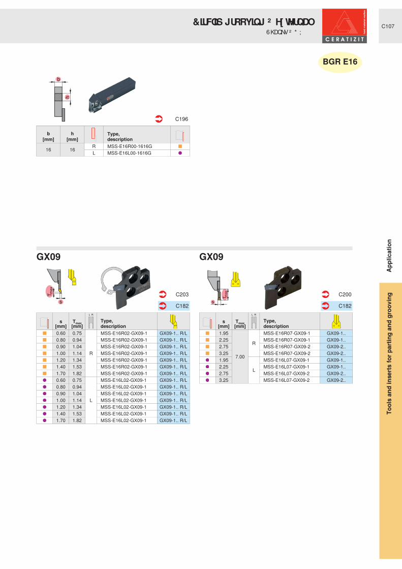
C107
RL
Tm
ax
s
RL
Type,description
b h[mm] [mm]
16 16 R MSS-E16R00-1616GL MSS-E16L00-1616G
C196
Type,description
s Tmax[mm] [mm]
0.60 0.75
R
MSS-E16R02-GX09-1 GX09-1.. R/L 0.80 0.94 MSS-E16R02-GX09-1 GX09-1.. R/L 0.90 1.04 MSS-E16R02-GX09-1 GX09-1.. R/L 1.00 1.14 MSS-E16R02-GX09-1 GX09-1.. R/L 1.20 1.34 MSS-E16R02-GX09-1 GX09-1.. R/L 1.40 1.53 MSS-E16R02-GX09-1 GX09-1.. R/L 1.70 1.82 MSS-E16R02-GX09-1 GX09-1.. R/L 0.60 0.75
L
MSS-E16L02-GX09-1 GX09-1.. R/L 0.80 0.94 MSS-E16L02-GX09-1 GX09-1.. R/L 0.90 1.04 MSS-E16L02-GX09-1 GX09-1.. R/L 1.00 1.14 MSS-E16L02-GX09-1 GX09-1.. R/L 1.20 1.34 MSS-E16L02-GX09-1 GX09-1.. R/L 1.40 1.53 MSS-E16L02-GX09-1 GX09-1.. R/L 1.70 1.82 MSS-E16L02-GX09-1 GX09-1.. R/L
C203
C182
Type,description
s Tmax[mm] [mm]
1.95
7.00
R
MSS-E16R07-GX09-1 GX09-1.. 2.25 MSS-E16R07-GX09-1 GX09-1.. 2.75 MSS-E16R07-GX09-2 GX09-2.. 3.25 MSS-E16R07-GX09-2 GX09-2.. 1.95
L
MSS-E16L07-GX09-1 GX09-1.. 2.25 MSS-E16L07-GX09-1 GX09-1.. 2.75 MSS-E16L07-GX09-2 GX09-2.. 3.25 MSS-E16L07-GX09-2 GX09-2..
C200
C182
� ƒ
GX09GX09
BGR E16
Appl
icat
ion
&LUFOLS� JURRYLQ J� ² � H[ WHUQ DO6KDQNV� ² � * ; � �
Tool
s an
d in
serts
for p
artin
g an
d gr
oovi
ng

C108
RL
Tm
ax
s
RL
Type,description
b h[mm] [mm]
20
16 R MSS-E20R00-1620G20 MSS-E20R00-2020J16 L MSS-E20L00-1620G20 MSS-E20L00-2020J
C196
Type,description
b h[mm] [mm]
20 20 R MSS-E20R90-2020JL MSS-E20L90-2020J
C197
Type,description
s Tmax[mm] [mm]
0.60 0.75
R
MSS-E20R03-GX16-2 GX16-2.. R/L 0.80 0.94 MSS-E20R03-GX16-2 GX16-2.. R/L 0.90 1.04 MSS-E20R03-GX16-2 GX16-2.. R/L 1.00 1.14 MSS-E20R03-GX16-2 GX16-2.. R/L 1.20 1.34 MSS-E20R03-GX16-2 GX16-2.. R/L 1.40 1.53 MSS-E20R03-GX16-2 GX16-2.. R/L 1.70 1.82 MSS-E20R03-GX16-2 GX16-2.. R/L 1.95 2.07 MSS-E20R03-GX16-2 GX16-2.. R/L 2.25 2.36 MSS-E20R03-GX16-2 GX16-2.. R/L 0.60 0.75
L
MSS-E20L03-GX16-2 GX16-2.. R/L 0.80 0.94 MSS-E20L03-GX16-2 GX16-2.. R/L 0.90 1.04 MSS-E20L03-GX16-2 GX16-2.. R/L 1.00 1.14 MSS-E20L03-GX16-2 GX16-2.. R/L 1.20 1.34 MSS-E20L03-GX16-2 GX16-2.. R/L 1.40 1.53 MSS-E20L03-GX16-2 GX16-2.. R/L 1.70 1.82 MSS-E20L03-GX16-2 GX16-2.. R/L 1.95 2.07 MSS-E20L03-GX16-2 GX16-2.. R/L 2.25 2.36 MSS-E20L03-GX16-2 GX16-2.. R/L
C204
C182
Type,description
s Tmax[mm] [mm]
2.75
12.00
RMSS-E20R12-GX16-2 GX16-2..
3.25 MSS-E20R12-GX16-2 GX16-2.. 4.25 MSS-E20R12-GX16-3 GX16-3.. 2.75
LMSS-E20L12-GX16-2 GX16-2..
3.25 MSS-E20L12-GX16-2 GX16-2.. 4.25 MSS-E20L12-GX16-3 GX16-3..
C201
C182
� ƒ � � ƒ
GX16GX16
BGR E20
Appl
icat
ion
&LUFOLS� JURRYLQ J� ² � H[ WHUQ DO6KDQNV� ² � * ; � �
Tool
s an
d in
serts
for p
artin
g an
d gr
oovi
ng

C109
dA
dA
RL
Tm
ax
s
RL
Type,description
b h dA[mm] [mm] [mm]
25 25
R
MSS-E25R00-2525L 40 UT40-MSS-E25R00 50 UT50-MSS-E25R00 63 UT63-MSS-E25R00
25 25
L
MSS-E25L00-2525L 40 UT40-MSS-E25L00 50 UT50-MSS-E25L00 63 UT63-MSS-E25L00
C196 C246
Type,description
b h dA[mm] [mm] [mm]
25 25 R
MSS-E25R90-2525L 40 UT40-MSS-E25R90 50 UT50-MSS-E25R9025 25
LMSS-E25L90-2525L
40 UT40-MSS-E25L90 50 UT50-MSS-E25L90
C197 C247
Type,description
s Tmax[mm] [mm]
0.60 0.75
R
MSS-E25R03-GX16-2 GX16-2.. R/L 0.80 0.94 MSS-E25R03-GX16-2 GX16-2.. R/L 0.90 1.04 MSS-E25R03-GX16-2 GX16-2.. R/L 1.00 1.14 MSS-E25R03-GX16-2 GX16-2.. R/L 1.20 1.34 MSS-E25R03-GX16-2 GX16-2.. R/L 1.40 1.53 MSS-E25R03-GX16-2 GX16-2.. R/L 1.70 1.82 MSS-E25R03-GX16-2 GX16-2.. R/L 1.95 2.07 MSS-E25R03-GX16-2 GX16-2.. R/L 2.25 2.36 MSS-E25R03-GX16-2 GX16-2.. R/L 0.60 0.75
L
MSS-E25L03-GX16-2 GX16-2.. R/L 0.80 0.94 MSS-E25L03-GX16-2 GX16-2.. R/L 0.90 1.04 MSS-E25L03-GX16-2 GX16-2.. R/L 1.00 1.14 MSS-E25L03-GX16-2 GX16-2.. R/L 1.20 1.34 MSS-E25L03-GX16-2 GX16-2.. R/L 1.40 1.53 MSS-E25L03-GX16-2 GX16-2.. R/L 1.70 1.82 MSS-E25L03-GX16-2 GX16-2.. R/L 1.95 2.07 MSS-E25L03-GX16-2 GX16-2.. R/L 2.25 2.36 MSS-E25L03-GX16-2 GX16-2.. R/L
C204
C182
Type,description
s Tmax[mm] [mm]
2.75
12.00
R
MSS-E25R12-GX16-2 GX16-2.. 3.25 MSS-E25R12-GX16-2 GX16-2.. 4.25 MSS-E25R12-GX16-3 GX16-3.. 5.25 MSS-E25R12-GX16-4 GX16-4.. 2.75
L
MSS-E25L12-GX16-2 GX16-2.. 3.25 MSS-E25L12-GX16-2 GX16-2.. 4.25 MSS-E25L12-GX16-3 GX16-3.. 5.25 MSS-E25L12-GX16-4 GX16-4..
C201
C182
� ƒ � � ƒ
GX16GX16
BGR E25
Appl
icat
ion
&LUFOLS� JURRYLQ J� ² � H[ WHUQ DO6KDQNV� ² � 8 76 � ² � * ; � �
Tool
s an
d in
serts
for p
artin
g an
d gr
oovi
ng

C110
dA
dA
RL
Tm
ax
s
RL
Type,description
b h dA[mm] [mm] [mm]
25 32
R
MSS-E32R00-3225N32 32 MSS-E32R00-3232Q 50 UT50-MSS-E32R00 63 UT63-MSS-E32R00 63 HSK-T63-MSS-E32R00 100 HSK-T100-MSS-E32R00
25 32
L
MSS-E32L00-3225N32 32 MSS-E32L00-3232Q 50 UT50-MSS-E32L00 63 UT63-MSS-E32L00 63 HSK-T63-MSS-E32L00 100 HSK-T100-MSS-E32L00
C196 C246+C250
Type,description
b h dA[mm] [mm] [mm]
25 32
R
MSS-E32R90-3225N32 32 MSS-E32R90-3232R 63 UT63-MSS-E32R90 63 HSK-T63-MSS-E32R90 100 HSK-T100-MSS-E32R90
25 32
L
MSS-E32L90-3225N32 32 MSS-E32L90-3232R 63 UT63-MSS-E32L90 63 HSK-T63-MSS-E32L90 100 HSK-T100-MSS-E32L90
C197 C247+C251
Type,description
s Tmax[mm] [mm]
0.60 0.75
R
MSS-E32R03-GX16-2 GX16-2.. R/L 0.80 0.94 MSS-E32R03-GX16-2 GX16-2.. R/L 0.90 1.04 MSS-E32R03-GX16-2 GX16-2.. R/L 1.00 1.14 MSS-E32R03-GX16-2 GX16-2.. R/L 1.20 1.34 MSS-E32R03-GX16-2 GX16-2.. R/L 1.40 1.53 MSS-E32R03-GX16-2 GX16-2.. R/L 1.70 1.82 MSS-E32R03-GX16-2 GX16-2.. R/L 1.95 2.07 MSS-E32R03-GX16-2 GX16-2.. R/L 2.25 2.36 MSS-E32R03-GX16-2 GX16-2.. R/L 0.60 0.75
L
MSS-E32L03-GX16-2 GX16-2.. R/L 0.80 0.94 MSS-E32L03-GX16-2 GX16-2.. R/L 0.90 1.04 MSS-E32L03-GX16-2 GX16-2.. R/L 1.00 1.14 MSS-E32L03-GX16-2 GX16-2.. R/L 1.20 1.34 MSS-E32L03-GX16-2 GX16-2.. R/L 1.40 1.53 MSS-E32L03-GX16-2 GX16-2.. R/L 1.70 1.82 MSS-E32L03-GX16-2 GX16-2.. R/L 1.95 2.07 MSS-E32L03-GX16-2 GX16-2.. R/L 2.25 2.36 MSS-E32L03-GX16-2 GX16-2.. R/L
C204
C182
Type,description
s Tmax[mm] [mm]
2.75
12.00
R
MSS-E32R12-GX16-2 GX16-2.. 3.25 MSS-E32R12-GX16-2 GX16-2.. 4.25 MSS-E32R12-GX16-3 GX16-3.. 5.25 MSS-E32R12-GX16-4 GX16-4.. 2.75
L
MSS-E32L12-GX16-2 GX16-2.. 3.25 MSS-E32L12-GX16-2 GX16-2.. 4.25 MSS-E32L12-GX16-3 GX16-3.. 5.25 MSS-E32L12-GX16-4 GX16-4..
C201
C182
� ƒ � � ƒ
GX16GX16
BGR E32
Appl
icat
ion
&LUFOLS� JURRYLQ J� ² � H[ WHUQ DO6KDQNV� ² � 8 76 � + 6 . � 7 � ² � * ; � �
Tool
s an
d in
serts
for p
artin
g an
d gr
oovi
ng

C111
h
b
Tm
ax
hb
s
RL
Type,description
b h s Tmax[mm] [mm] [mm] [mm]
10 10
0.60 0.75
R
E10R00-1010M-GX09 GX09..0.80 0.94 E10R00-1010M-GX09 GX09..0.90 1.04 E10R00-1010M-GX09 GX09..1.00 1.14 E10R00-1010M-GX09 GX09..1.20 1.34 E10R00-1010M-GX09 GX09..1.40 1.53 E10R00-1010M-GX09 GX09..1.70 1.82 E10R00-1010M-GX09 GX09..1.95 7.00 E10R00-1010M-GX09 GX09..2.25 7.00 E10R00-1010M-GX09 GX09..2.75 7.00 E10R00-1010M-GX09 GX09..3.25 7.00 E10R00-1010M-GX09 GX09..0.60 0.75
L
E10L00-1010M-GX09 GX09..0.80 0.94 E10L00-1010M-GX09 GX09..0.90 1.04 E10L00-1010M-GX09 GX09..1.00 1.14 E10L00-1010M-GX09 GX09..1.20 1.34 E10L00-1010M-GX09 GX09..1.40 1.53 E10L00-1010M-GX09 GX09..1.70 1.82 E10L00-1010M-GX09 GX09..1.95 7.00 E10L00-1010M-GX09 GX09..2.25 7.00 E10L00-1010M-GX09 GX09..2.75 7.00 E10L00-1010M-GX09 GX09..3.25 7.00 E10L00-1010M-GX09 GX09..
C213 C182
* ; � � � ² � ULJKW� KDQ G�
Attention:When using right-hand or left-hand inserts, the tool requires modification to prevent the insert fouling.
Appl
icat
ion
&LUFOLS� JURRYLQ J� ² � H[ WHUQ DO0 RQREORF� WRROV� ² � * ; � �
Tool
s an
d in
serts
for p
artin
g an
d gr
oovi
ng

C112
h
b
Tm
ax
h
b
s
RL
RL
Type,description
b h s Tmax[mm] [mm] [mm] [mm]
12 12
0.60 0.75
R
E12R0012-1212K-GX16-2 GX16-2..0.80 0.94 E12R0012-1212K-GX16-2 GX16-2..0.90 1.04 E12R0012-1212K-GX16-2 GX16-2..1.00 1.14 E12R0012-1212K-GX16-2 GX16-2..1.20 1.34 E12R0012-1212K-GX16-2 GX16-2..2.75 12.00 E12R0012-1212K-GX16-2 GX16-2..1.40 1.53 E12R0012-1212K-GX16-2 GX16-2..1.70 1.82 E12R0012-1212K-GX16-2 GX16-2..1.95 2.07 E12R0012-1212K-GX16-2 GX16-2..2.25 2.36 E12R0012-1212K-GX16-2 GX16-2..3.25 12.00 E12R0012-1212K-GX16-2 GX16-2..
16 16
0.60 0.75 E16R0012-1616K-GX16-2 GX16-2..0.80 0.94 E16R0012-1616K-GX16-2 GX16-2..0.90 1.04 E16R0012-1616K-GX16-2 GX16-2..1.00 1.14 E16R0012-1616K-GX16-2 GX16-2..1.20 1.34 E16R0012-1616K-GX16-2 GX16-2..1.40 1.53 E16R0012-1616K-GX16-2 GX16-2..1.70 1.82 E16R0012-1616K-GX16-2 GX16-2..1.95 2.07 E16R0012-1616K-GX16-2 GX16-2..2.25 2.36 E16R0012-1616K-GX16-2 GX16-2..2.75 12.00 E16R0012-1616K-GX16-2 GX16-2..3.25 12.00 E16R0012-1616K-GX16-2 GX16-2..4.25 12.00 E16R0012-1616K-GX16-3 GX16-3..
20 20
0.60 0.75 E20R0012-2020K-GX16-2 GX16-2..0.80 0.94 E20R0012-2020K-GX16-2 GX16-2..0.90 1.04 E20R0012-2020K-GX16-2 GX16-2..1.00 1.14 E20R0012-2020K-GX16-2 GX16-2..1.20 1.34 E20R0012-2020K-GX16-2 GX16-2..1.40 1.53 E20R0012-2020K-GX16-2 GX16-2..1.70 1.82 E20R0012-2020K-GX16-2 GX16-2..1.95 2.07 E20R0012-2020K-GX16-2 GX16-2..2.25 2.36 E20R0012-2020K-GX16-2 GX16-2..2.75 12.00 E20R0012-2020K-GX16-2 GX16-2..3.25 12.00 E20R0012-2020K-GX16-2 GX16-2..4.25 12.00 E20R0012-2020K-GX16-3 GX16-3..
25 25
0.60 0.75 E25R0012-2525M-GX16-2 GX16-2..0.80 0.94 E25R0012-2525M-GX16-2 GX16-2..0.90 1.04 E25R0012-2525M-GX16-2 GX16-2..1.00 1.14 E25R0012-2525M-GX16-2 GX16-2..1.20 1.34 E25R0012-2525M-GX16-2 GX16-2..1.40 1.53 E25R0012-2525M-GX16-2 GX16-2..1.70 1.82 E25R0012-2525M-GX16-2 GX16-2..1.95 2.07 E25R0012-2525M-GX16-2 GX16-2..2.25 2.36 E25R0012-2525M-GX16-2 GX16-2..2.75 12.00 E25R0012-2525M-GX16-2 GX16-2..3.25 12.00 E25R0012-2525M-GX16-2 GX16-2..4.25 12.00 E25R0012-2525M-GX16-3 GX16-3..
C214 C182
Type,description
b h s Tmax[mm] [mm] [mm] [mm]
12 12
0.60 0.75
L
E12L0012-1212K-GX16-2 GX16-2..0.80 0.94 E12L0012-1212K-GX16-2 GX16-2..0.90 1.04 E12L0012-1212K-GX16-2 GX16-2..1.00 1.14 E12L0012-1212K-GX16-2 GX16-2..1.20 1.34 E12L0012-1212K-GX16-2 GX16-2..1.40 1.53 E12L0012-1212K-GX16-2 GX16-2..1.70 1.82 E12L0012-1212K-GX16-2 GX16-2..1.95 2.07 E12L0012-1212K-GX16-2 GX16-2..2.25 2.36 E12L0012-1212K-GX16-2 GX16-2..2.75 12.00 E12L0012-1212K-GX16-2 GX16-2..3.25 12.00 E12L0012-1212K-GX16-2 GX16-2..
16 16
0.60 0.75 E16L0012-1616K-GX16-2 GX16-2..0.80 0.94 E16L0012-1616K-GX16-2 GX16-2..0.90 1.04 E16L0012-1616K-GX16-2 GX16-2..1.00 1.14 E16L0012-1616K-GX16-2 GX16-2..1.20 1.34 E16L0012-1616K-GX16-2 GX16-2..1.40 1.53 E16L0012-1616K-GX16-2 GX16-2..1.70 1.82 E16L0012-1616K-GX16-2 GX16-2..1.95 2.07 E16L0012-1616K-GX16-2 GX16-2..2.25 2.36 E16L0012-1616K-GX16-2 GX16-2..2.75 12.00 E16L0012-1616K-GX16-2 GX16-2..3.25 12.00 E16L0012-1616K-GX16-2 GX16-2..4.25 12.00 E16L0012-1616K-GX16-3 GX16-3..
20 20
0.60 0.75 E20L0012-2020K-GX16-2 GX16-2..0.80 0.94 E20L0012-2020K-GX16-2 GX16-2..0.90 1.04 E20L0012-2020K-GX16-2 GX16-2..1.00 1.14 E20L0012-2020K-GX16-2 GX16-2..1.20 1.34 E20L0012-2020K-GX16-2 GX16-2..1.40 1.53 E20L0012-2020K-GX16-2 GX16-2..1.70 1.82 E20L0012-2020K-GX16-2 GX16-2..1.95 2.07 E20L0012-2020K-GX16-2 GX16-2..2.25 2.36 E20L0012-2020K-GX16-2 GX16-2..2.75 12.00 E20L0012-2020K-GX16-2 GX16-2..3.25 12.00 E20L0012-2020K-GX16-2 GX16-2..4.25 12.00 E20L0012-2020K-GX16-3 GX16-3..
25 25
0.60 0.75 E25L0012-2525M-GX16-2 GX16-2..0.80 0.94 E25L0012-2525M-GX16-2 GX16-2..0.90 1.04 E25L0012-2525M-GX16-2 GX16-2..1.00 1.14 E25L0012-2525M-GX16-2 GX16-2..1.20 1.34 E25L0012-2525M-GX16-2 GX16-2..1.40 1.53 E25L0012-2525M-GX16-2 GX16-2..1.70 1.82 E25L0012-2525M-GX16-2 GX16-2..1.95 2.07 E25L0012-2525M-GX16-2 GX16-2..2.25 2.36 E25L0012-2525M-GX16-2 GX16-2..2.75 12.00 E25L0012-2525M-GX16-2 GX16-2..3.25 12.00 E25L0012-2525M-GX16-2 GX16-2..4.25 12.00 E25L0012-2525M-GX16-3 GX16-3..
* ; � � � ² � ULJKW� KDQ G * ; � � � ² � OHIW� KDQ G
Attention:When using right-hand or left-hand inserts, the tool requires modification to prevent the insert fouling.
Appl
icat
ion
&LUFOLS� JURRYLQ J� ² � H[ WHUQ DO0 RQREORF� WRROV� ² � * ; � �
Tool
s an
d in
serts
for p
artin
g an
d gr
oovi
ng

C113
l 2
Ø dA
s
Tmax
Ø D
RL
Tmax
Ø D s
RL
Type,description
l2 dA[mm] [mm]
24 20 R MSS-I16R90-1.5D-N40 20 MSS-I16R90-2.5D-N24 20 L MSS-I16L90-1.5D-N40 20 MSS-I16L90-2.5D-N
C231-C232
Type,description
Dmin s Tmax[mm] [mm] [mm]
20
0.60 0.75
R
MSS-I16R02-GX09-1 GX09-1.. R/L 0.80 0.94 MSS-I16R02-GX09-1 GX09-1.. R/L 0.90 1.04 MSS-I16R02-GX09-1 GX09-1.. R/L 1.00 1.14 MSS-I16R02-GX09-1 GX09-1.. R/L 1.20 1.34 MSS-I16R02-GX09-1 GX09-1.. R/L 1.40 1.53 MSS-I16R02-GX09-1 GX09-1.. R/L 1.70 1.82 MSS-I16R02-GX09-1 GX09-1.. R/L 0.60 0.75
L
MSS-I16L02-GX09-1 GX09-1.. R/L 0.80 0.94 MSS-I16L02-GX09-1 GX09-1.. R/L 0.90 1.04 MSS-I16L02-GX09-1 GX09-1.. R/L 1.00 1.14 MSS-I16L02-GX09-1 GX09-1.. R/L 1.20 1.34 MSS-I16L02-GX09-1 GX09-1.. R/L 1.40 1.53 MSS-I16L02-GX09-1 GX09-1.. R/L 1.70 1.82 MSS-I16L02-GX09-1 GX09-1.. R/L
C235
C182
Type,description
Dmin s Tmax[mm] [mm] [mm]
20
1.95
7.00
R
MSS-I16R04-GX09-1 GX09-1.. 2.25 MSS-I16R04-GX09-1 GX09-1.. 2.75 MSS-I16R04-GX09-2 GX09-2.. 3.25 MSS-I16R04-GX09-2 GX09-2.. 1.95
L
MSS-I16L04-GX09-1 GX09-1.. 2.25 MSS-I16L04-GX09-1 GX09-1.. 2.75 MSS-I16L04-GX09-2 GX09-2.. 3.25 MSS-I16L04-GX09-2 GX09-2..
C233
C182
GX09
GX09GX09
BGR I16
Appl
icat
ion
&LUFOLS� JURRYLQ J� ² � LQ WHUQ DO%RULQJ� EDUV� ² � * ; � �
Tool
s an
d in
serts
for p
artin
g an
d gr
oovi
ng

C114
l 2Ø dA
s
Tmax
Ø D
RL
Tmax
Ø D s
RL
Type,description
l2 dA[mm] [mm]
30 20 R MSS-I20R90-1.5D-N50 25 MSS-I20R90-2.5D-N30 20 L MSS-I20L90-1.5D-N50 25 MSS-I20L90-2.5D-N
C231-C232
Type,description
Dmin s Tmax[mm] [mm] [mm]
25
0.60 0.75
R
MSS-I20R02-GX09-1 GX09-1.. R/L 0.80 0.94 MSS-I20R02-GX09-1 GX09-1.. R/L 0.90 1.04 MSS-I20R02-GX09-1 GX09-1.. R/L 1.00 1.14 MSS-I20R02-GX09-1 GX09-1.. R/L 1.20 1.34 MSS-I20R02-GX09-1 GX09-1.. R/L 1.40 1.53 MSS-I20R02-GX09-1 GX09-1.. R/L 1.70 1.82 MSS-I20R02-GX09-1 GX09-1.. R/L 0.60 0.75
L
MSS-I20L02-GX09-1 GX09-1.. R/L 0.80 0.94 MSS-I20L02-GX09-1 GX09-1.. R/L 0.90 1.04 MSS-I20L02-GX09-1 GX09-1.. R/L 1.00 1.14 MSS-I20L02-GX09-1 GX09-1.. R/L 1.20 1.34 MSS-I20L02-GX09-1 GX09-1.. R/L 1.40 1.53 MSS-I20L02-GX09-1 GX09-1.. R/L 1.70 1.82 MSS-I20L02-GX09-1 GX09-1.. R/L
C235
C182
Type,description
Dmin s Tmax[mm] [mm] [mm]
25
1.95
7.00
R
MSS-I20R05-GX09-1 GX09-1.. 2.25 MSS-I20R05-GX09-1 GX09-1.. 2.75 MSS-I20R05-GX09-2 GX09-2.. 3.25 MSS-I20R05-GX09-2 GX09-2.. 1.95
L
MSS-I20L05-GX09-1 GX09-1.. 2.25 MSS-I20L05-GX09-1 GX09-1.. 2.75 MSS-I20L05-GX09-2 GX09-2.. 3.25 MSS-I20L05-GX09-2 GX09-2..
C233
C182
GX09
GX09GX09
BGR I20
Appl
icat
ion
&LUFOLS� JURRYLQ J� ² � LQ WHUQ DO%RULQJ� EDUV� ² � * ; � �
Tool
s an
d in
serts
for p
artin
g an
d gr
oovi
ng

C115
l 2
Ø dA
s
Tmax
Ø D
RL
Tmax
Ø D s
RL
Type,description
l2 dA[mm] [mm]
38 25 R MSS-I25R90-1.5D-N63 32 MSS-I25R90-2.5D-N38 25 L MSS-I25L90-1.5D-N63 32 MSS-I25L90-2.5D-N
C231-C232
Type,description
Dmin s Tmax[mm] [mm] [mm]
32
0.60 0.75
R
MSS-I25R02-GX09-1 GX09-1.. R/L 0.80 0.94 MSS-I25R02-GX09-1 GX09-1.. R/L 0.90 1.04 MSS-I25R02-GX09-1 GX09-1.. R/L 1.00 1.14 MSS-I25R02-GX09-1 GX09-1.. R/L 1.20 1.34 MSS-I25R02-GX09-1 GX09-1.. R/L 1.40 1.53 MSS-I25R02-GX09-1 GX09-1.. R/L 1.70 1.82 MSS-I25R02-GX09-1 GX09-1.. R/L 0.60 0.75
L
MSS-I25L02-GX09-1 GX09-1.. R/L 0.80 0.94 MSS-I25L02-GX09-1 GX09-1.. R/L 0.90 1.04 MSS-I25L02-GX09-1 GX09-1.. R/L 1.00 1.14 MSS-I25L02-GX09-1 GX09-1.. R/L 1.20 1.34 MSS-I25L02-GX09-1 GX09-1.. R/L 1.40 1.53 MSS-I25L02-GX09-1 GX09-1.. R/L 1.70 1.82 MSS-I25L02-GX09-1 GX09-1.. R/L
C235
C182
Type,description
Dmin s Tmax[mm] [mm] [mm]
32
1.95
7.00
R
MSS-I25R06-GX09-1 GX09-1.. 2.25 MSS-I25R06-GX09-1 GX09-1.. 2.75 MSS-I25R06-GX09-2 GX09-2.. 3.25 MSS-I25R06-GX09-2 GX09-2.. 1.95
L
MSS-I25L06-GX09-1 GX09-1.. 2.25 MSS-I25L06-GX09-1 GX09-1.. 2.75 MSS-I25L06-GX09-2 GX09-2.. 3.25 MSS-I25L06-GX09-2 GX09-2..
C233
C182
GX09
GX09GX09
BGR I25
Appl
icat
ion
&LUFOLS� JURRYLQ J� ² � LQ WHUQ DO%RULQJ� EDUV� ² � * ; � �
Tool
s an
d in
serts
for p
artin
g an
d gr
oovi
ng

C116
l 2
Ø dA
l 2
Ø dA
s
Tmax
Ø D
RL
Tmax
Ø D s
RL
l2 dA Type,
description[mm] [mm]48 32
RMSS-I32R90-1.5D-N
80 40 MSS-I32R90-2.5D-N64 40 UT40-MSS-I32R90-2D
C231-C232 C249
l2 dA Type,description[mm] [mm]
48 32L
MSS-I32L90-1.5D-N80 40 MSS-I32L90-2.5D-N64 50 UT50-MSS-I32L90-2D
Type,description
Dmin s Tmax[mm] [mm] [mm]
40
0.60 0.75
R
MSS-I32R03-GX16-2 GX16-2.. R/L 0.80 0.94 MSS-I32R03-GX16-2 GX16-2.. R/L 0.90 1.04 MSS-I32R03-GX16-2 GX16-2.. R/L 1.00 1.14 MSS-I32R03-GX16-2 GX16-2.. R/L 1.20 1.34 MSS-I32R03-GX16-2 GX16-2.. R/L 1.40 1.53 MSS-I32R03-GX16-2 GX16-2.. R/L 1.70 1.82 MSS-I32R03-GX16-2 GX16-2.. R/L 1.95 2.07 MSS-I32R03-GX16-2 GX16-2.. R/L 2.25 2.36 MSS-I32R03-GX16-2 GX16-2.. R/L 0.60 0.75
L
MSS-I32L03-GX16-2 GX16-2.. R/L 0.80 0.94 MSS-I32L03-GX16-2 GX16-2.. R/L 0.90 1.04 MSS-I32L03-GX16-2 GX16-2.. R/L 1.00 1.14 MSS-I32L03-GX16-2 GX16-2.. R/L 1.20 1.34 MSS-I32L03-GX16-2 GX16-2.. R/L 1.40 1.53 MSS-I32L03-GX16-2 GX16-2.. R/L 1.70 1.82 MSS-I32L03-GX16-2 GX16-2.. R/L 1.95 2.07 MSS-I32L03-GX16-2 GX16-2.. R/L 2.25 2.36 MSS-I32L03-GX16-2 GX16-2.. R/L
C236
C182
Type,description
Dmin s Tmax[mm] [mm] [mm]
40
2.75
12.00
R
MSS-I32R09-GX16-2 GX16-2.. 3.25 MSS-I32R09-GX16-2 GX16-2.. 4.25 MSS-I32R09-GX16-3 GX16-3.. 5.25 MSS-I32R09-GX16-4 GX16-4.. 2.75
L
MSS-I32L09-GX16-2 GX16-2.. 3.25 MSS-I32L09-GX16-2 GX16-2.. 4.25 MSS-I32L09-GX16-3 GX16-3.. 5.25 MSS-I32L09-GX16-4 GX16-4..
C234
C182
* ; � � � ² � ULJKW� KDQ G * ; � � � ² � OHIW� KDQ G
GX16GX16
BGR I32
Appl
icat
ion
%RULQJ� EDUV� 8 76 � ² � * ;&LUFOLS� JURRYLQ J� ² � LQ WHUQ DO
Tool
s an
d in
serts
for p
artin
g an
d gr
oovi
ng

C117
l 2
Ø dAl 2
Ø dA
s
Tmax
Ø D
RL
Tmax
Ø D s
RL
l2 dA Type,
description[mm] [mm]60 40
R
MSS-I40R90-1.5D-N100 50 MSS-I40R90-2.5D-N80 40 UT40-MSS-I40R90-2D80 63 UT63-MSS-I40R90-2D
C231-C232 C249
l2 dA Type,description[mm] [mm]
60 40L
MSS-I40L90-1.5D-N100 50 MSS-I40L90-2.5D-N80 40 UT40-MSS-I40L90-2D
Type,description
Dmin s Tmax[mm] [mm] [mm]
50
0.60 0.75
R
MSS-I40R03-GX16-2 GX16-2.. R/L 0.80 0.94 MSS-I40R03-GX16-2 GX16-2.. R/L 0.90 1.04 MSS-I40R03-GX16-2 GX16-2.. R/L 1.00 1.14 MSS-I40R03-GX16-2 GX16-2.. R/L 1.20 1.34 MSS-I40R03-GX16-2 GX16-2.. R/L 1.40 1.53 MSS-I40R03-GX16-2 GX16-2.. R/L 1.70 1.82 MSS-I40R03-GX16-2 GX16-2.. R/L 1.95 2.07 MSS-I40R03-GX16-2 GX16-2.. R/L 2.25 2.36 MSS-I40R03-GX16-2 GX16-2.. R/L 0.60 0.75
L
MSS-I40L03-GX16-2 GX16-2.. R/L 0.80 0.94 MSS-I40L03-GX16-2 GX16-2.. R/L 0.90 1.04 MSS-I40L03-GX16-2 GX16-2.. R/L 1.00 1.14 MSS-I40L03-GX16-2 GX16-2.. R/L 1.20 1.34 MSS-I40L03-GX16-2 GX16-2.. R/L 1.40 1.53 MSS-I40L03-GX16-2 GX16-2.. R/L 1.70 1.82 MSS-I40L03-GX16-2 GX16-2.. R/L 1.95 2.07 MSS-I40L03-GX16-2 GX16-2.. R/L 2.25 2.36 MSS-I40L03-GX16-2 GX16-2.. R/L
C236
C182
Type,description
Dmin s Tmax[mm] [mm] [mm]
50
2.75
12.00
R
MSS-I40R10-GX16-2 GX16-2.. 3.25 MSS-I40R10-GX16-2 GX16-2.. 4.25 MSS-I40R10-GX16-3 GX16-3.. 5.25 MSS-I40R10-GX16-4 GX16-4.. 2.75
L
MSS-I40L10-GX16-2 GX16-2.. 3.25 MSS-I40L10-GX16-2 GX16-2.. 4.25 MSS-I40L10-GX16-3 GX16-3.. 5.25 MSS-I40L10-GX16-4 GX16-4..
C234
C182
* ; � ² � ULJKW� KDQ G * ; � � � ² � OHIW� KDQ G
GX16GX16
BGR I40
Appl
icat
ion
%RULQJ� EDUV� 8 76 � ² � * ;&LUFOLS� JURRYLQ J� ² � LQ WHUQ DO
Tool
s an
d in
serts
for p
artin
g an
d gr
oovi
ng

C118
s
l 2
Tmax
Ø dA
Ø D
RL
RL
Type,description
dA l2 D s Tmax[mm] [mm] [mm] [mm] [mm]
16 30 16
0.60
3 R
I12R90-2.5D-GX09 GX09..0.80 I12R90-2.5D-GX09 GX09..0.90 I12R90-2.5D-GX09 GX09..1.00 I12R90-2.5D-GX09 GX09..1.20 I12R90-2.5D-GX09 GX09..1.40 I12R90-2.5D-GX09 GX09..1.70 I12R90-2.5D-GX09 GX09..1.95 I12R90-2.5D-GX09 GX09..2.25 I12R90-2.5D-GX09 GX09..2.75 I12R90-2.5D-GX09 GX09..3.25 I12R90-2.5D-GX09 GX09..
C237 C182
Type,description
dA l2 D s Tmax[mm] [mm] [mm] [mm] [mm]
16 30 16
0.60
3 L
I12L90-2.5D-GX09 GX09..0.80 I12L90-2.5D-GX09 GX09..0.90 I12L90-2.5D-GX09 GX09..1.00 I12L90-2.5D-GX09 GX09..1.20 I12L90-2.5D-GX09 GX09..1.40 I12L90-2.5D-GX09 GX09..1.70 I12L90-2.5D-GX09 GX09..1.95 I12L90-2.5D-GX09 GX09..2.25 I12L90-2.5D-GX09 GX09..2.75 I12L90-2.5D-GX09 GX09..3.25 I12L90-2.5D-GX09 GX09..
* ; � � � ² � ULJKW� KDQ G� * ; � � � ² � OHIW� KDQ G
Attention:When using right-hand or left-hand inserts, the tool requires modification to prevent the insert fouling.
Appl
icat
ion
&LUFOLS� JURRYLQ J� ² � LQ WHUQ DO0 RQREORF� ERULQJ� EDUV� ² � * ; � �
Tool
s an
d in
serts
for p
artin
g an
d gr
oovi
ng

C119
s
l 2
Tmax
Ø dA
Ø D
RL
RL
Type,description
dA l2 D s Tmax[mm] [mm] [mm] [mm] [mm]
16 32 20.5
0.60 0.75
R
I16R90-2.0D-GX16-2 GX16-2..0.80 0.94 I16R90-2.0D-GX16-2 GX16-2..0.90 1.04 I16R90-2.0D-GX16-2 GX16-2..1.00 1.14 I16R90-2.0D-GX16-2 GX16-2..1.20 1.34 I16R90-2.0D-GX16-2 GX16-2..1.40 1.53 I16R90-2.0D-GX16-2 GX16-2..1.70 1.82 I16R90-2.0D-GX16-2 GX16-2..1.95 2.07 I16R90-2.0D-GX16-2 GX16-2..2.25 2.36 I16R90-2.0D-GX16-2 GX16-2..2.75 12.00 I16R90-2.0D-GX16-2 GX16-2..3.25 12.00 I16R90-2.0D-GX16-2 GX16-2..
20 40 25.0
0.60 0.75 I20R90-2.0D-GX16-2 GX16-2..0.80 0.94 I20R90-2.0D-GX16-2 GX16-2..0.90 1.04 I20R90-2.0D-GX16-2 GX16-2..1.00 1.14 I20R90-2.0D-GX16-2 GX16-2..1.20 1.34 I20R90-2.0D-GX16-2 GX16-2..1.40 1.53 I20R90-2.0D-GX16-2 GX16-2..1.70 1.82 I20R90-2.0D-GX16-2 GX16-2..1.95 2.07 I20R90-2.0D-GX16-2 GX16-2..2.25 2.36 I20R90-2.0D-GX16-2 GX16-2..2.75 12.00 I20R90-2.0D-GX16-2 GX16-2..3.25 12.00 I20R90-2.0D-GX16-2 GX16-2..
25 50 32.0
0.60 0.75 I25R90-2.0D-GX16-2 GX16-2..0.80 0.94 I25R90-2.0D-GX16-2 GX16-2..0.90 1.04 I25R90-2.0D-GX16-2 GX16-2..1.00 1.14 I25R90-2.0D-GX16-2 GX16-2..1.20 1.34 I25R90-2.0D-GX16-2 GX16-2..1.40 1.53 I25R90-2.0D-GX16-2 GX16-2..1.70 1.82 I25R90-2.0D-GX16-2 GX16-2..1.95 2.07 I25R90-2.0D-GX16-2 GX16-2..2.25 2.36 I25R90-2.0D-GX16-2 GX16-2..2.75 12.00 I25R90-2.0D-GX16-2 GX16-2..3.25 12.00 I25R90-2.0D-GX16-2 GX16-2..4.25 12.00 I25R90-2.0D-GX16-3 GX16-3..
32 64 42.0
0.60 0.75 I32R90-2.0D-GX16-2 GX16-2..0.80 0.94 I32R90-2.0D-GX16-2 GX16-2..0.90 1.04 I32R90-2.0D-GX16-2 GX16-2..1.00 1.14 I32R90-2.0D-GX16-2 GX16-2..1.20 1.34 I32R90-2.0D-GX16-2 GX16-2..1.40 1.53 I32R90-2.0D-GX16-2 GX16-2..1.70 1.82 I32R90-2.0D-GX16-2 GX16-2..1.95 2.07 I32R90-2.0D-GX16-2 GX16-2..2.25 2.36 I32R90-2.0D-GX16-2 GX16-2..2.75 12.00 I32R90-2.0D-GX16-2 GX16-2..3.25 12.00 I32R90-2.0D-GX16-2 GX16-2..4.25 12.00 I32R90-2.0D-GX16-3 GX16-3..
C238 C182
Type,description
dA l2 D s Tmax[mm] [mm] [mm] [mm] [mm]
16 32 20.5
0.60 0.75
L
I16L90-2.0D-GX16-2 GX16-2..0.80 0.94 I16L90-2.0D-GX16-2 GX16-2..0.90 1.04 I16L90-2.0D-GX16-2 GX16-2..1.00 1.14 I16L90-2.0D-GX16-2 GX16-2..1.20 1.34 I16L90-2.0D-GX16-2 GX16-2..1.40 1.53 I16L90-2.0D-GX16-2 GX16-2..1.70 1.82 I16L90-2.0D-GX16-2 GX16-2..1.95 2.07 I16L90-2.0D-GX16-2 GX16-2..2.25 2.36 I16L90-2.0D-GX16-2 GX16-2..2.75 12.00 I16L90-2.0D-GX16-2 GX16-2..3.25 12.00 I16L90-2.0D-GX16-2 GX16-2..
20 40 25.0
0.60 0.75 I20L90-2.0D-GX16-2 GX16-2..0.80 0.94 I20L90-2.0D-GX16-2 GX16-2..0.90 1.04 I20L90-2.0D-GX16-2 GX16-2..1.00 1.14 I20L90-2.0D-GX16-2 GX16-2..1.20 1.34 I20L90-2.0D-GX16-2 GX16-2..1.40 1.53 I20L90-2.0D-GX16-2 GX16-2..1.70 1.82 I20L90-2.0D-GX16-2 GX16-2..1.95 2.07 I20L90-2.0D-GX16-2 GX16-2..2.25 2.36 I20L90-2.0D-GX16-2 GX16-2..2.75 12.00 I20L90-2.0D-GX16-2 GX16-2..3.25 12.00 I20L90-2.0D-GX16-2 GX16-2..
25 50 32.0
0.60 0.75 I25L90-2.0D-GX16-2 GX16-2..0.80 0.94 I25L90-2.0D-GX16-2 GX16-2..0.90 1.04 I25L90-2.0D-GX16-2 GX16-2..1.00 1.14 I25L90-2.0D-GX16-2 GX16-2..1.20 1.34 I25L90-2.0D-GX16-2 GX16-2..1.40 1.53 I25L90-2.0D-GX16-2 GX16-2..1.70 1.82 I25L90-2.0D-GX16-2 GX16-2..1.95 2.07 I25L90-2.0D-GX16-2 GX16-2..2.25 2.36 I25L90-2.0D-GX16-2 GX16-2..2.75 12.00 I25L90-2.0D-GX16-2 GX16-2..3.25 12.00 I25L90-2.0D-GX16-2 GX16-2..4.25 12.00 I25L90-2.0D-GX16-3 GX16-3..
32 64 42.0
0.60 0.75 I32L90-2.0D-GX16-2 GX16-2..0.80 0.94 I32L90-2.0D-GX16-2 GX16-2..0.90 1.04 I32L90-2.0D-GX16-2 GX16-2..1.00 1.14 I32L90-2.0D-GX16-2 GX16-2..1.20 1.34 I32L90-2.0D-GX16-2 GX16-2..1.40 1.53 I32L90-2.0D-GX16-2 GX16-2..1.70 1.82 I32L90-2.0D-GX16-2 GX16-2..1.95 2.07 I32L90-2.0D-GX16-2 GX16-2..2.25 2.36 I32L90-2.0D-GX16-2 GX16-2..2.75 12.00 I32L90-2.0D-GX16-2 GX16-2..3.25 12.00 I32L90-2.0D-GX16-2 GX16-2..4.25 12.00 I32L90-2.0D-GX16-3 GX16-3..
* ; � � � ² � ULJKW� KDQ G * ; � � � ² � OHIW� KDQ G
Attention:When using right-hand or left-hand inserts, the tool requires modification to prevent the insert fouling.
Appl
icat
ion
&LUFOLS� JURRYLQ J� ² � LQ WHUQ DO0 RQREORF� ERULQJ� EDUV� ² � * ; � �
Tool
s an
d in
serts
for p
artin
g an
d gr
oovi
ng

C120
r
dA dA
dA dA
l 2
Ø dA
l 2
Ø dA
l 2
Ø dA
6KDQ NV� � ƒ 6KDQ NV� � � ƒ
SX LX
8 76 � � ƒ 8 76 � � � ƒ
+ 6 . � 7 � � ƒ + 6 . � 7 � � � ƒ
Boring bars 1.5D Boring bars 2.5D
UTS boring bars
h / b12/12 - 32/32
h / b20/20 - 32/32
r = 1.5 - 2.0 Tmax = 20 - 35
r = 4Tmax = 25 - 45
dA = 40 - 63 dA = 40 - 63
dA = 63 - 100 dA = 63 - 100
dA = 20 - 40l2 = 24 - 60
dA = 20 - 50l2 = 40 - 100
dA = 40 - 63l2 = 64 - 80
Appl
icat
ion
5 DGLXV� JURRYHV� ² � H[ WHUQ DO� LQ WHUQ DO2 YHUYLHZ � ² � P RGXODU� VWUXFWXUH
Tool
s an
d in
serts
for p
artin
g an
d gr
oovi
ng
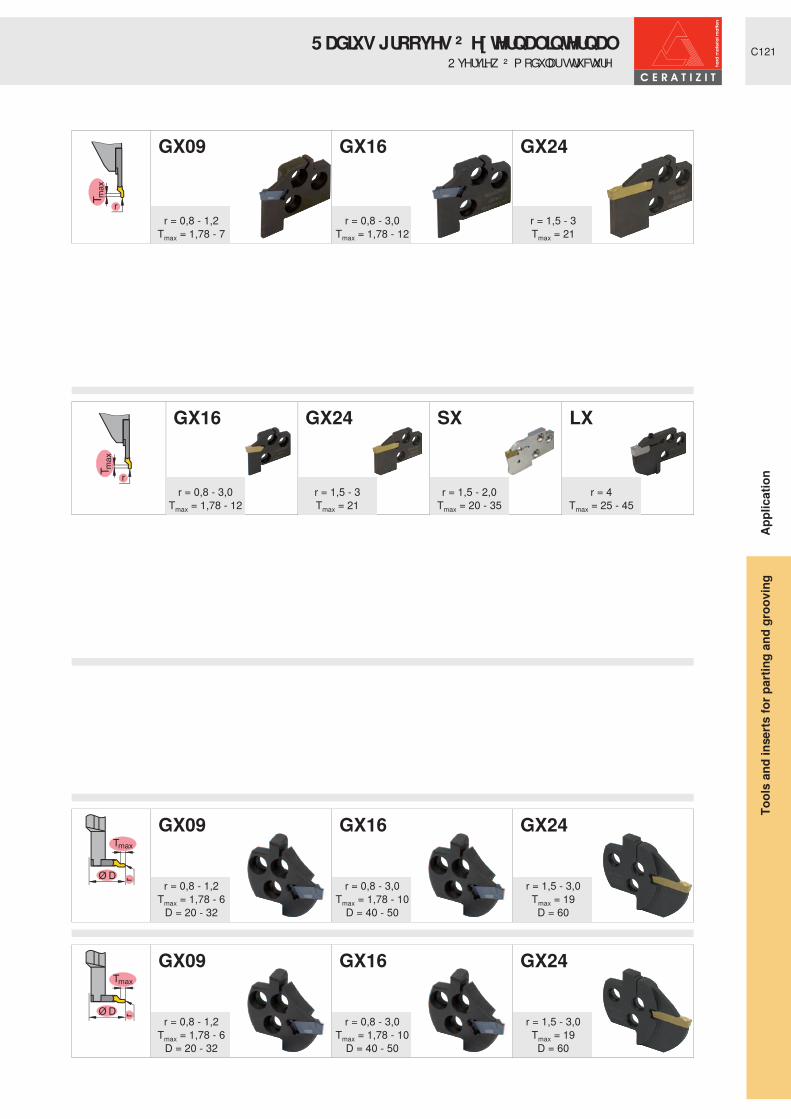
C121
r
r
Tmax
Ø D r
Tmax
Ø D r
GX09 GX16 GX24
GX16 GX24 SX LX
GX09 GX16 GX24
GX09 GX16 GX24
r = 0,8 - 1,2Tmax = 1,78 - 7
r = 0,8 - 3,0Tmax = 1,78 - 12
r = 1,5 - 3Tmax = 21
r = 0,8 - 3,0Tmax = 1,78 - 12
r = 1,5 - 3Tmax = 21
r = 1,5 - 2,0 Tmax = 20 - 35
r = 4Tmax = 25 - 45
r = 0,8 - 1,2Tmax = 1,78 - 6
D = 20 - 32
r = 0,8 - 1,2Tmax = 1,78 - 6
D = 20 - 32
r = 0,8 - 3,0Tmax = 1,78 - 10
D = 40 - 50
r = 0,8 - 3,0Tmax = 1,78 - 10
D = 40 - 50
r = 1,5 - 3,0Tmax = 19D = 60
r = 1,5 - 3,0Tmax = 19D = 60
Appl
icat
ion
5 DGLXV� JURRYHV� ² � H[ WHUQ DO� LQ WHUQ DO2 YHUYLHZ � ² � P RGXODU� VWUXFWXUH
Tool
s an
d in
serts
for p
artin
g an
d gr
oovi
ng
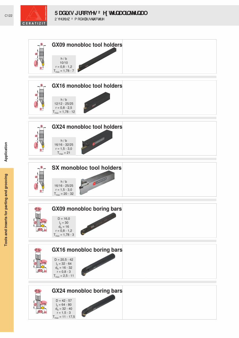
C122
Tm
ax
h
b
r
Tm
ax
h
b
r
Tm
ax
h
b
r
Tm
ax
h
b
r
Ø dA
r
l 2
Tmax
Ø D
Ø dA
r
l 2
Tmax
Ø D
Ø dA
r
l 2
Tmax
Ø D
GX09 monobloc tool holders
GX16 monobloc tool holders
GX24 monobloc tool holders
SX monobloc tool holders
GX09 monobloc boring bars
GX16 monobloc boring bars
GX24 monobloc boring bars
h / b10/10
r = 0,8 - 1,2Tmax = 1,78 - 7
h / b12/12 - 25/25r = 0,8 - 2,5
Tmax = 1,78 - 12
h / b16/16 - 32/25r = 1,5 - 3,0Tmax = 21
h / b16/16 - 25/25r = 1,5 - 3,0
Tmax = 20 - 32
D = 16,0l2 = 30dA = 16
r = 0,8 - 1,2Tmax = 1,78 - 3
D = 20,5 - 42l2 = 32 - 64dA = 16 - 32r = 0,8 - 3
Tmax = 2,5 - 11
D = 42 - 57l2 = 64 - 80dA = 32 - 40r = 1,5 - 3
Tmax = 11 - 17,5
Appl
icat
ion
5 DGLXV� JURRYHV� ² � H[ WHUQ DO� LQ WHUQ DO2 YHUYLHZ � ² � P RGXODU� VWUXFWXUH
Tool
s an
d in
serts
for p
artin
g an
d gr
oovi
ng

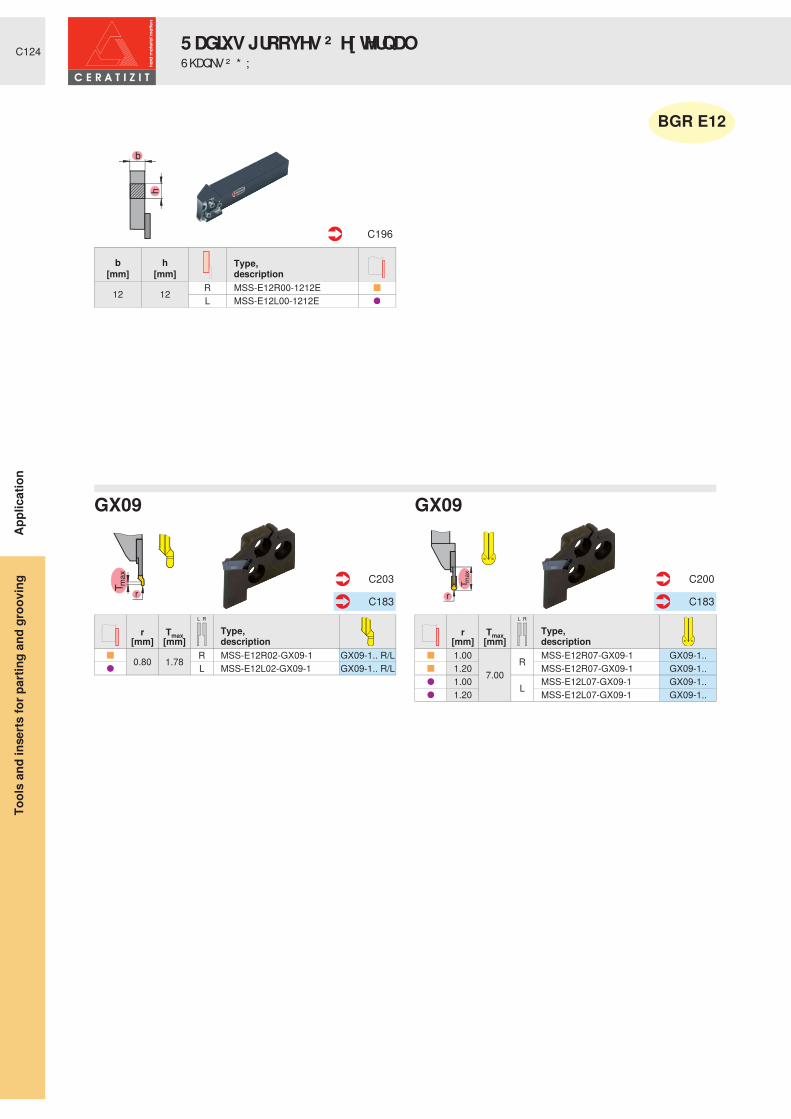
C124
r
RL
r
Tm
ax
RL
Type,description
r Tmax[mm] [mm]
0.80 1.78 R MSS-E12R02-GX09-1 GX09-1.. R/L L MSS-E12L02-GX09-1 GX09-1.. R/L
C203
C183
Type,description
r Tmax[mm] [mm]
1.00
7.00R MSS-E12R07-GX09-1 GX09-1..
1.20 MSS-E12R07-GX09-1 GX09-1.. 1.00 L MSS-E12L07-GX09-1 GX09-1.. 1.20 MSS-E12L07-GX09-1 GX09-1..
C200
C183
Type,description
b h[mm] [mm]
12 12 R MSS-E12R00-1212EL MSS-E12L00-1212E
C196
� ƒ
GX09GX09
BGR E12
Appl
icat
ion
5 DGLXV� JURRYHV� ² � H[ WHUQ DO6KDQNV� ² � * ;
Tool
s an
d in
serts
for p
artin
g an
d gr
oovi
ng

C125
r
RL
r
Tm
ax
RL
Type,description
r Tmax[mm] [mm]
0.80 1.78 R MSS-E16R02-GX09-1 GX09-1.. R/L 1.78 L MSS-E16L02-GX09-1 GX09-1.. R/L
C203
C183
Type,description
r Tmax[mm] [mm]
1.00
7.00R MSS-E16R07-GX09-1 GX09-1..
1.20 MSS-E16R07-GX09-1 GX09-1.. 1.00 L MSS-E16L07-GX09-1 GX09-1.. 1.20 MSS-E16L07-GX09-1 GX09-1..
C200
C183
Type,description
b h[mm] [mm]
16 16 R MSS-E16R00-1616GL MSS-E16L00-1616G
C196
� ƒ
GX09GX09
BGR E16
Appl
icat
ion
5 DGLXV� JURRYHV� ² � H[ WHUQ DO6KDQNV� ² � * ;
Tool
s an
d in
serts
for p
artin
g an
d gr
oovi
ng

C126
r
RL
r
Tm
ax
RL
r
Tm
ax
RL
r
Tm
ax
RL
Type,description
r Tmax[mm] [mm]
0.80 1.78R
MSS-E20R03-GX16-2 GX16-2.. R/L 1.00 2.18 MSS-E20R03-GX16-2 GX16-2.. R/L 1.20 2.58 MSS-E20R03-GX16-2 GX16-2.. R/L 0.80 1.78
LMSS-E20L03-GX16-2 GX16-2.. R/L
1.00 2.18 MSS-E20L03-GX16-2 GX16-2.. R/L 1.20 2.58 MSS-E20L03-GX16-2 GX16-2.. R/L
C204
C183
Type,description
r Tmax[mm] [mm]
1.50
12.00
RMSS-E20R12-GX16-2 GX16-2..
2.00 MSS-E20R12-GX16-3 GX16-3.. 2.50 MSS-E20R12-GX16-3 GX16-3.. 1.50
LMSS-E20L12-GX16-2 GX16-2..
2.00 MSS-E20L12-GX16-3 GX16-3.. 2.50 MSS-E20L12-GX16-3 GX16-3..
C201
C183
Type,description
r Tmax[mm] [mm]
1.50
21.00
RMSS-E20R21-GX24-2 GX24-2..
2.00 MSS-E20R21-GX24-3 GX24-3.. 2.50 MSS-E20R21-GX24-3 GX24-3.. 1.50
LMSS-E20L21-GX24-2 GX24-2..
2.00 MSS-E20L21-GX24-3 GX24-3.. 2.50 MSS-E20L21-GX24-3 GX24-3..
C202
C183
Type,description
r Tmax[mm] [mm]
1.50 20 L MSS-E20L20-SX3 SX3 R MSS-E20R20-SX3 SX3
C209
C185
Type,description
b h[mm] [mm]
20
16 R MSS-E20R00-1620G20 MSS-E20R00-2020J16 L MSS-E20L00-1620G20 MSS-E20L00-2020J
C196
Type,description
b h[mm] [mm]
20 20 R MSS-E20R90-2020JL MSS-E20L90-2020J
C197
� ƒ � � ƒ
GX16 GX16
SXGX24
BGR E20
Appl
icat
ion
5 DGLXV� JURRYHV� ² � H[ WHUQ DO6KDQNV� ² � * ; � 6 ;
Tool
s an
d in
serts
for p
artin
g an
d gr
oovi
ng

C127
dA
dA
r
RL
r
Tm
ax
RL
r
Tm
ax
RL
r
Tm
ax
RL
Type,description
r Tmax[mm] [mm]
0.80 1.78R
MSS-E25R03-GX16-2 GX16-2.. R/L 1.00 2.18 MSS-E25R03-GX16-2 GX16-2.. R/L 1.20 2.58 MSS-E25R03-GX16-2 GX16-2.. R/L 0.80 1.78
LMSS-E25L03-GX16-2 GX16-2.. R/L
1.00 2.18 MSS-E25L03-GX16-2 GX16-2.. R/L 1.20 2.58 MSS-E25L03-GX16-2 GX16-2.. R/L
C204
C183
Type,description
r Tmax[mm] [mm]
1.50
12.00
R
MSS-E25R12-GX16-2 GX16-2.. 2.00 MSS-E25R12-GX16-3 GX16-3.. 2.50 MSS-E25R12-GX16-3 GX16-3.. 3.00 MSS-E25R12-GX16-4 GX16-4.. 1.50
L
MSS-E25L12-GX16-2 GX16-2.. 2.00 MSS-E25L12-GX16-3 GX16-3.. 2.50 MSS-E25L12-GX16-3 GX16-3.. 3.00 MSS-E25L12-GX16-4 GX16-4..
C201
C183
Type,description
r Tmax[mm] [mm]
1.50
21.00
R
MSS-E25R21-GX24-2 GX24-2.. 2.00 MSS-E25R21-GX24-3 GX24-3.. 2.50 MSS-E25R21-GX24-3 GX24-3.. 3.00 MSS-E25R21-GX24-4 GX24-4.. 1.50
L
MSS-E25L21-GX24-2 GX24-2.. 2.00 MSS-E25L21-GX24-3 GX24-3.. 2.50 MSS-E25L21-GX24-3 GX24-3.. 3.00 MSS-E25L21-GX24-4 GX24-4..
C202
C183
Type,description
r Tmax[mm] [mm]
1.50 25R
MSS-E25R25-SX3 SX3 2.00 MSS-E25R25-SX4 SX4 1.50 35 MSS-E25R35-SX3 SX3 2.00 MSS-E25R35-SX4 SX4 1.50 25
L
MSS-E25L25-SX3 SX3 2.00 MSS-E25L25-SX4 SX4 1.50 35 MSS-E25L35-SX3 SX3 2.00 MSS-E25L35-SX4 SX4
C209
C185
Type,description
b h dA[mm] [mm] [mm]
25 25
R
MSS-E25R00-2525L 40 UT40-MSS-E25R00 50 UT50-MSS-E25R00 63 UT63-MSS-E25R00
25 25
L
MSS-E25L00-2525L 40 UT40-MSS-E25L00 50 UT50-MSS-E25L00 63 UT63-MSS-E25L00
C196 C246
Type,description
b h dA[mm] [mm] [mm]
25 25 R
MSS-E25R90-2525L 40 UT40-MSS-E25R90 50 UT50-MSS-E25R9025 25
LMSS-E25L90-2525L
40 UT40-MSS-E25L90 50 UT50-MSS-E25L90
C197 C247
� ƒ � � ƒ
GX16 GX16
SXGX24
BGR E25
Appl
icat
ion
5 DGLXV� JURRYHV� ² � H[ WHUQ DO6KDQNV� ² � 8 76 � ² � * ; � 6 ;
Tool
s an
d in
serts
for p
artin
g an
d gr
oovi
ng

C128
dA
dA
r
RL
r
Tm
ax
RL
r
Tm
ax
RL
Type,description
r Tmax[mm] [mm]
0.80 1.78R
MSS-E32R03-GX16-2 GX16-2.. R/L 1.00 2.18 MSS-E32R03-GX16-2 GX16-2.. R/L 1.20 2.58 MSS-E32R03-GX16-2 GX16-2.. R/L 0.80 1.78
LMSS-E32L03-GX16-2 GX16-2.. R/L
1.00 2.18 MSS-E32L03-GX16-2 GX16-2.. R/L 1.20 2.58 MSS-E32L03-GX16-2 GX16-2.. R/L
C204
C183
Type,description
r Tmax[mm] [mm]
1.50
12.00
R
MSS-E32R12-GX16-2 GX16-2.. 2.00 MSS-E32R12-GX16-3 GX16-3.. 2.50 MSS-E32R12-GX16-3 GX16-3.. 3.00 MSS-E32R12-GX16-4 GX16-4.. 1.50
L
MSS-E32L12-GX16-2 GX16-2.. 2.00 MSS-E32L12-GX16-3 GX16-3.. 2.50 MSS-E32L12-GX16-3 GX16-3.. 3.00 MSS-E32L12-GX16-4 GX16-4..
C201
C183
Type,description
r Tmax[mm] [mm]
1.50
21.00
R
MSS-E32R21-GX24-2 GX24-2.. 2.00 MSS-E32R21-GX24-3 GX24-3.. 2.50 MSS-E32R21-GX24-3 GX24-3.. 3.00 MSS-E32R21-GX24-4 GX24-4.. 1.50
L
MSS-E32L21-GX24-2 GX24-2.. 2.00 MSS-E32L21-GX24-3 GX24-3.. 2.50 MSS-E32L21-GX24-3 GX24-3.. 3.00 MSS-E32L21-GX24-4 GX24-4..
C202
C183
Type,description
b h dA[mm] [mm] [mm]
25 32
R
MSS-E32R00-3225N32 32 MSS-E32R00-3232Q 50 UT50-MSS-E32R00 63 UT63-MSS-E32R00 63 HSK-T63-MSS-E32R00 100 HSK-T100-MSS-E32R00
25 32
L
MSS-E32L00-3225N32 32 MSS-E32L00-3232Q 50 UT50-MSS-E32L00 63 UT63-MSS-E32L00 63 HSK-T63-MSS-E32L00 100 HSK-T100-MSS-E32L00
C196 C246+C250
Type,description
b h dA[mm] [mm] [mm]
25 32
R
MSS-E32R90-3225N32 32 MSS-E32R90-3232R 63 UT63-MSS-E32R90 63 HSK-T63-MSS-E32R90 100 HSK-T100-MSS-E32R90
25 32
L
MSS-E32L90-3225N32 32 MSS-E32L90-3232R 63 UT63-MSS-E32L90 63 HSK-T63-MSS-E32L90 100 HSK-T100-MSS-E32L90
C197 C247+C251
� ƒ � � ƒ
GX16 GX16
GX24
BGR E32
Appl
icat
ion
5 DGLXV� JURRYHV� ² � H[ WHUQ DO6KDQNV� ² � 8 76 � + 6 . � 7 � ² � * ;
Tool
s an
d in
serts
for p
artin
g an
d gr
oovi
ng

C129
dA
dA
r
Tm
ax
RL
r
Tm
ax
RL
Type,description
r Tmax[mm] [mm]
1.50
35R MSS-E32R35-SX3 SX3
2.00 MSS-E32R35-SX4 SX4 1.50 L MSS-E32L35-SX3 SX3 2.00 MSS-E32L35-SX4 SX4
C209
C185
Type,description
r Tmax[mm] [mm]
4.00
25N
MSS-E32N25-LX LX-.. 32 MSS-E32N32-LX LX-.. 45 MSS-E32N45-LX LX-..
C210
C186
Type,description
b h dA[mm] [mm] [mm]
25 32
R
MSS-E32R00-3225N32 32 MSS-E32R00-3232Q 50 UT50-MSS-E32R00 63 UT63-MSS-E32R00 63 HSK-T63-MSS-E32R00 100 HSK-T100-MSS-E32R00
25 32
L
MSS-E32L00-3225N32 32 MSS-E32L00-3232Q 50 UT50-MSS-E32L00 63 UT63-MSS-E32L00 63 HSK-T63-MSS-E32L00 100 HSK-T100-MSS-E32L00
C196 C246+C250
Type,description
b h dA[mm] [mm] [mm]
25 32
R
MSS-E32R90-3225N32 32 MSS-E32R90-3232R 63 UT63-MSS-E32R90 63 HSK-T63-MSS-E32R90 100 HSK-T100-MSS-E32R90
25 32
L
MSS-E32L90-3225N32 32 MSS-E32L90-3232R 63 UT63-MSS-E32L90 63 HSK-T63-MSS-E32L90 100 HSK-T100-MSS-E32L90
C197 C247+C251
� ƒ � � ƒ
SX LX
BGR E32
Appl
icat
ion
5 DGLXV� JURRYHV� ² � H[ WHUQ DO6KDQNV� ² � 8 76 � + 6 . � 7 � ² � 6 ; � / ;
Tool
s an
d in
serts
for p
artin
g an
d gr
oovi
ng

C130
h
b
r
RL
Tm
ax
h
b
r
RL
h
b
r
RL
Tm
ax
hb
r
RL
Type,description
b h r Tmax[mm] [mm] [mm] [mm]
10 10 0.80 1.78 R E10R00-1010M-GX09 GX09..L E10L00-1010M-GX09 GX09..
C213 C183
Type,description
b h r Tmax[mm] [mm] [mm] [mm]
10 10
1.00
7.00
R E10R00-1010M-GX09 GX09..1.20 R E10R00-1010M-GX09 GX09..1.00 L E10L00-1010M-GX09 GX09..1.20 L E10L00-1010M-GX09 GX09..
C213 C183
Type,description
b h r Tmax[mm] [mm] [mm] [mm]
12 12 0.80 1.78
R
E12R0012-1212K-GX16-2 GX16-2..16 16 E16R0012-1616K-GX16-2 GX16-2..16 16 1.00 2.18 E16R0012-1616K-GX16-2 GX16-2..16 16 1.20 2.58 E16R0012-1616K-GX16-2 GX16-2..20 20 0.80 1.78 E20R0012-2020K-GX16-2 GX16-2..20 20 1.00 2.18 E20R0012-2020K-GX16-2 GX16-2..20 20 1.20 2.58 E20R0012-2020K-GX16-2 GX16-2..25 25 0.80 1.78 E25R0012-2525M-GX16-2 GX16-2..25 25 1.00 2.18 E25R0012-2525M-GX16-2 GX16-2..25 25 1.20 2.58 E25R0012-2525M-GX16-2 GX16-2..12 12 0.80 1.78
L
E12L0012-1212K-GX16-2 GX16-2..16 16 E16L0012-1616K-GX16-2 GX16-2..16 16 1.00 2.18 E16L0012-1616K-GX16-2 GX16-2..16 16 1.20 2.58 E16L0012-1616K-GX16-2 GX16-2..20 20 0.80 1.78 E20L0012-2020K-GX16-2 GX16-2..20 20 1.00 2.18 E20L0012-2020K-GX16-2 GX16-2..20 20 1.20 2.58 E20L0012-2020K-GX16-2 GX16-2..25 25 0.80 1.78 E25L0012-2525M-GX16-2 GX16-2..25 25 1.20 2.58 E25L0012-2525M-GX16-2 GX16-2..
C214 C183
Type,description
b h r Tmax[mm] [mm] [mm] [mm]
16 161.50 12.00
R
E16R0012-1616K-GX16-2 GX16-2..2.00 12.00 E16R0012-1616K-GX16-3 GX16-3..2.50 12.00 E16R0012-1616K-GX16-3 GX16-3..
20 201.50 12.00 E20R0012-2020K-GX16-2 GX16-2..2.00 12.00 E20R0012-2020K-GX16-3 GX16-3..2.50 12.00 E20R0012-2020K-GX16-3 GX16-3..
25 252.50 12.00 E25R0012-2525M-GX16-3 GX16-3..2.00 12.00 E25R0012-2525M-GX16-3 GX16-3..1.50 12.00 E25R0012-2525M-GX16-2 GX16-2..
16 161.50 12.00
L
E16L0012-1616K-GX16-2 GX16-2..2.00 12.00 E16L0012-1616K-GX16-3 GX16-3..2.50 12.00 E16L0012-1616K-GX16-3 GX16-3..
20 201.50 12.00 E20L0012-2020K-GX16-2 GX16-2..2.00 12.00 E20L0012-2020K-GX16-3 GX16-3..2.50 12.00 E20L0012-2020K-GX16-3 GX16-3..
25 251.50 12.00 E25L0012-2525M-GX16-2 GX16-2..2.00 12.00 E25L0012-2525M-GX16-3 GX16-3..2.50 12.00 E25L0012-2525M-GX16-3 GX16-3..
C214 C183
* ; � � � ² � ULJKW� KDQ G�* ; � � � ² � ULJKW� KDQ G�
GX16GX16
Attention:When using right-hand or left-hand inserts, the tool requires modification to prevent the insert fouling.
Appl
icat
ion
5 DGLXV� JURRYHV� ² � H[ WHUQ DO0 RQREORF� WRROV� ² � * ;
Tool
s an
d in
serts
for p
artin
g an
d gr
oovi
ng

C131
Tm
ax
h
b
r
RL
RL
Tm
ax
h
b
r
RL
RL
Type,description
b h r Tmax[mm] [mm] [mm] [mm]
16 16 1.50
21.00 R
E16R0021-1616K-GX24-2 GX24-2..
20 201.50 E20R0021-2020K-GX24-2 GX24-2..2.00 E20R0021-2020K-GX24-3 GX24-3..2.50 E20R0021-2020K-GX24-3 GX24-3..
25
25
1.50 E25R0021-2525M-GX24-2 GX24-2..2.00 E25R0021-2525M-GX24-3 GX24-3..2.50 E25R0021-2525M-GX24-3 GX24-3..3.00 E25R0021-2525M-GX24-4 GX24-4..
32
1.50 E32R0021-3225P-GX24-2 GX24-2..2.00 E32R0021-3225P-GX24-3 GX24-3..2.50 E32R0021-3225P-GX24-3 GX24-3..3.00 E32R0021-3225P-GX24-4 GX24-4..
C215 C183
Type,description
b h r Tmax[mm] [mm] [mm] [mm]
16 16 1.50
21.00 L
E16L0021-1616K-GX24-2 GX24-2..
20 201.50 E20L0021-2020K-GX24-2 GX24-2..2.00 E20L0021-2020K-GX24-3 GX24-3..2.50 E20L0021-2020K-GX24-3 GX24-3..
25
25
1.50 E25L0021-2525M-GX24-2 GX24-2..2.00 E25L0021-2525M-GX24-3 GX24-3..2.50 E25L0021-2525M-GX24-3 GX24-3..3.00 E25L0021-2525M-GX24-4 GX24-4..
32
1.50 E32L0021-3225P-GX24-2 GX24-2..2.00 E32L0021-3225P-GX24-3 GX24-3..2.50 E32L0021-3225P-GX24-3 GX24-3..3.00 E32L0021-3225P-GX24-4 GX24-4..
Type,description
s h b Tmax[mm] [mm] [mm] [mm]
3.016 16
20
R
E16R0020-1616K-SX3 SX320 20 E20R0020-2020K-SX3 SX325 25 E25R0020-2525M-SX3 SX3
4.0 25 2525
E25R0025-2525M-SX4 SX420 20 E20R0025-2020K-SX4 SX4
5.0 25 25 E25R0025-2525M-SX5 SX56.0 25 25 32 E25R0032-2525M-SX6 SX6
C218 C185
Type,description
s h b Tmax[mm] [mm] [mm] [mm]
3.016 16
20
L
E16L0020-1616K-SX3 SX320 20 E20L0020-2020K-SX3 SX325 25 E25L0020-2525M-SX3 SX3
4.0 25 2525
E25L0025-2525M-SX4 SX420 20 E20L0025-2020K-SX4 SX4
5.0 25 25 E25L0025-2525M-SX5 SX56.0 25 25 32 E25L0032-2525M-SX6 SX6
* ; � � � ² � ULJKW� KDQ G * ; � � � ² � OHIW� KDQ G
6 ; � ² � OHIW� KDQ G6 ; � ² � ULJKW� KDQ G
Appl
icat
ion
5 DGLXV� JURRYHV� ² � H[ WHUQ DO0 RQREORF� WRROV� ² � * ; � 6 ;
Tool
s an
d in
serts
for p
artin
g an
d gr
oovi
ng

C132
l 2Ø dA
Tmax
Ø D r
RL
Tmax
Ø D r
RL
Type,description
Dmin r Tmax[mm] [mm] [mm]
20 0.80 1.78 R MSS-I16R02-GX09-1 GX09-1.. R/L L MSS-I16L02-GX09-1 GX09-1.. R/L
C235
C183
Type,description
Dmin r Tmax[mm] [mm] [mm]
20
1.00 4 R MSS-I16R04-GX09-1 GX09-1.. 1.20 4 MSS-I16R04-GX09-1 GX09-1.. 1.00 4 L MSS-I16L04-GX09-1 GX09-1.. 1.20 4 MSS-I16L04-GX09-1 GX09-1..
C233
C183
Type,description
l2 dA[mm] [mm]
24 20 R MSS-I16R90-1.5D-N40 20 MSS-I16R90-2.5D-N24 20 L MSS-I16L90-1.5D-N40 20 MSS-I16L90-2.5D-N
C231-C232
GX09
GX09GX09
BGR I16
Appl
icat
ion
5 DGLXV� JURRYHV� ² � LQ WHUQ DO%RULQJ� EDUV� ² � * ;
Tool
s an
d in
serts
for p
artin
g an
d gr
oovi
ng

C133
l 2
Ø dA
Tmax
Ø D r
RL
Tmax
Ø D r
RL
Type,description
Dmin r Tmax[mm] [mm] [mm]
25 0.80 1.78 R MSS-I20R02-GX09-1 GX09-1.. R/L L MSS-I20L02-GX09-1 GX09-1.. R/L
C235
C183
Type,description
Dmin r Tmax[mm] [mm] [mm]
25
1.00 5 R MSS-I20R05-GX09-1 GX09-1.. 1.20 5 MSS-I20R05-GX09-1 GX09-1.. 1.00 5 L MSS-I20L05-GX09-1 GX09-1.. 1.20 5 MSS-I20L05-GX09-1 GX09-1..
C233
C183
Type,description
l2 dA[mm] [mm]
30 20 R MSS-I20R90-1.5D-N50 25 MSS-I20R90-2.5D-N30 20 L MSS-I20L90-1.5D-N50 25 MSS-I20L90-2.5D-N
C231-C232
GX09
GX09GX09
BGR I20
Appl
icat
ion
5 DGLXV� JURRYHV� ² � LQ WHUQ DO%RULQJ� EDUV� ² � * ;
Tool
s an
d in
serts
for p
artin
g an
d gr
oovi
ng

C134
l 2Ø dA
Tmax
Ø D r
RL
Tmax
Ø D r
RL
Type,description
Dmin r Tmax[mm] [mm] [mm]
32 0.80 1.78 R MSS-I25R02-GX09-1 GX09-1.. R/L 1.78 L MSS-I25L02-GX09-1 GX09-1.. R/L
C235
C183
Type,description
Dmin r Tmax[mm] [mm] [mm]
32
1.00 6 R MSS-I25R06-GX09-1 GX09-1.. 1.20 6 MSS-I25R06-GX09-1 GX09-1.. 1.00 6 L MSS-I25L06-GX09-1 GX09-1.. 1.20 6 MSS-I25L06-GX09-1 GX09-1..
C233
C183
Type,description
l2 dA[mm] [mm]
38 25 R MSS-I25R90-1.5D-N63 32 MSS-I25R90-2.5D-N38 25 L MSS-I25L90-1.5D-N63 32 MSS-I25L90-2.5D-N
C231-C232
GX09
GX09GX09
BGR I25
Appl
icat
ion
5 DGLXV� JURRYHV� ² � LQ WHUQ DO%RULQJ� EDUV� ² � * ;
Tool
s an
d in
serts
for p
artin
g an
d gr
oovi
ng

C135
l 2
Ø dAl 2
Ø dA
Tmax
Ø D r
RL
Tmax
Ø D r
RL
l2 dA Type,
description[mm] [mm]48 32
RMSS-I32R90-1.5D-N
80 40 MSS-I32R90-2.5D-N64 40 UT40-MSS-I32R90-2D
C231-C232 C249
Type,description
Dmin r Tmax[mm] [mm] [mm]
40
0.80 1.78R
MSS-I32R03-GX16-2 GX16-2.. R/L 1.00 2.18 MSS-I32R03-GX16-2 GX16-2.. R/L 1.20 2.58 MSS-I32R03-GX16-2 GX16-2.. R/L 0.80 1.78
LMSS-I32L03-GX16-2 GX16-2.. R/L
1.00 2.18 MSS-I32L03-GX16-2 GX16-2.. R/L 1.20 2.58 MSS-I32L03-GX16-2 GX16-2.. R/L
C236
C183
Type,description
Dmin r Tmax[mm] [mm] [mm]
40
1.50 9
R
MSS-I32R09-GX16-2 GX16-2.. 2.00 9 MSS-I32R09-GX16-3 GX16-3.. 2.50 9 MSS-I32R09-GX16-3 GX16-3.. 3.00 9 MSS-I32R09-GX16-4 GX16-4.. 1.50 9
L
MSS-I32L09-GX16-2 GX16-2.. 2.00 9 MSS-I32L09-GX16-3 GX16-3.. 2.50 9 MSS-I32L09-GX16-3 GX16-3.. 3.00 9 MSS-I32L09-GX16-4 GX16-4..
C234
C183
l2 dA Type,
description[mm] [mm]48 32
LMSS-I32L90-1.5D-N
80 40 MSS-I32L90-2.5D-N64 50 UT50-MSS-I32L90-2D
* ; � � � ² � ULJKW� KDQ G * ; � � � ² � OHIW� KDQ G
GX16GX16
BGR I32
Appl
icat
ion
5 DGLXV� JURRYHV� ² � LQ WHUQ DO%RULQJ� EDUV� 8 76 � ² � * ;
Tool
s an
d in
serts
for p
artin
g an
d gr
oovi
ng

C136
l 2
Ø dA
l 2
Ø dA
Tmax
Ø D r
RL
Tmax
Ø D r
RL
Tmax
Ø D r
RL
l2 dA Type,
description[mm] [mm]60 40
R
MSS-I40R90-1.5D-N100 50 MSS-I40R90-2.5D-N80 40 UT40-MSS-I40R90-2D80 63 UT63-MSS-I40R90-2D
C231-C232 C249
l2 dA Type,description[mm] [mm]
60 40L
MSS-I40L90-1.5D-N100 50 MSS-I40L90-2.5D-N80 40 UT40-MSS-I40L90-2D
Type,description
Dmin r Tmax[mm] [mm] [mm]
50
0.80 1.78R
MSS-I40R03-GX16-2 GX16-2.. R/L 1.00 2.18 MSS-I40R03-GX16-2 GX16-2.. R/L 1.20 2.58 MSS-I40R03-GX16-2 GX16-2.. R/L 0.80 1.78
LMSS-I40L03-GX16-2 GX16-2.. R/L
1.00 2.18 MSS-I40L03-GX16-2 GX16-2.. R/L 1.20 2.58 MSS-I40L03-GX16-2 GX16-2.. R/L
C236
C183
Type,description
Dmin r Tmax[mm] [mm] [mm]
50
1.50 10
R
MSS-I40R10-GX16-2 GX16-2.. 2.00 10 MSS-I40R10-GX16-3 GX16-3.. 2.50 10 MSS-I40R10-GX16-3 GX16-3.. 3.00 10 MSS-I40R10-GX16-4 GX16-4.. 1.50 10
L
MSS-I40L10-GX16-2 GX16-2.. 2.00 10 MSS-I40L10-GX16-3 GX16-3.. 2.50 10 MSS-I40L10-GX16-3 GX16-3.. 3.00 10 MSS-I40L10-GX16-4 GX16-4..
C234
C183
Type,description
Dmin r Tmax[mm] [mm] [mm]
60
1.50 19
N
MSS-I40N19-GX24-2 GX24-2.. 2.00 19 MSS-I40N19-GX24-3 GX24-3.. 2.50 19 MSS-I40N19-GX24-3 GX24-3.. 3.00 19 MSS-I40N19-GX24-4 GX24-4..
C234
C183
* ; � � � � � � ² � ULJKW� KDQ G * ; � � � � � � ² � OHIW� KDQ G
GX16 GX16
GX24
BGR I40
Appl
icat
ion
5 DGLXV� JURRYHV� ² � LQ WHUQ DO%RULQJ� EDUV� 8 76 � ² � * ;
Tool
s an
d in
serts
for p
artin
g an
d gr
oovi
ng


C138
r
Tmax
Ø D
RL
r
Tmax
Ø D
RL
r
Tmax
Ø D
RL
r
Tmax
Ø D
RL
Type,description
D r Tmax[mm] [mm] [mm]
16 0.80 1.78 R I12R90-2.5D-GX09 GX09..0.80 1.78 L I12L90-2.5D-GX09 GX09..
C237 C183
Type,description
D r Tmax[mm] [mm] [mm]
20.5
0.80 1.78R
I16R90-2.0D-GX16-2 GX16-2..1.00 2.18 I16R90-2.0D-GX16-2 GX16-2..1.20 2.58 I16R90-2.0D-GX16-2 GX16-2..0.80 1.78
LI16L90-2.0D-GX16-2 GX16-2..
1.00 2.18 I16L90-2.0D-GX16-2 GX16-2..1.20 2.58 I16L90-2.0D-GX16-2 GX16-2..
25.0
0.80 1.78R
I20R90-2.0D-GX16-2 GX16-2..1.00 2.18 I20R90-2.0D-GX16-2 GX16-2..1.20 2.58 I20R90-2.0D-GX16-2 GX16-2..0.80 1.78
L
I20L90-2.0D-GX16-2 GX16-2..1.00 2.18 I20L90-2.0D-GX16-2 GX16-2..1.20 2.58 I20L90-2.0D-GX16-2 GX16-2..
32.0
0.80 1.78 I25L90-2.0D-GX16-2 GX16-2..1.00 2.18 I25L90-2.0D-GX16-2 GX16-2..1.20 2.58 I25L90-2.0D-GX16-2 GX16-2..0.80 1.78
R
I25R90-2.0D-GX16-2 GX16-2..1.00 2.18 I25R90-2.0D-GX16-2 GX16-2..1.20 2.58 I25R90-2.0D-GX16-2 GX16-2..
42.0
0.80 1.78 I32R90-2.0D-GX16-2 GX16-2..1.00 2.18 I32R90-2.0D-GX16-2 GX16-2..1.20 2.58 I32R90-2.0D-GX16-2 GX16-2..0.80 1.78
LI32L90-2.0D-GX16-2 GX16-2..
1.00 2.18 I32L90-2.0D-GX16-2 GX16-2..1.20 2.58 I32L90-2.0D-GX16-2 GX16-2..
C238 C183
Type,description
D r Tmax[mm] [mm] [mm]
20.5 1.50 5.5 R I16R90-2.0D-GX16-2 GX16-2..1.50 5.5 L I16L90-2.0D-GX16-2 GX16-2..
25.0 1.50 5.5 R I20R90-2.0D-GX16-2 GX16-2..1.50 5.5 L I20L90-2.0D-GX16-2 GX16-2..
32.0
2.50 10.0R
I25R90-2.0D-GX16-3 GX16-3..2.00 10.0 I25R90-2.0D-GX16-3 GX16-3..1.50 8.0 I25R90-2.0D-GX16-2 GX16-2..1.50 8.0
LI25L90-2.0D-GX16-2 GX16-2..
2.00 10.0 I25L90-2.0D-GX16-3 GX16-3..2.50 10.0 I25L90-2.0D-GX16-3 GX16-3..
42.0
2.50 11.0R
I32R90-2.0D-GX16-3 GX16-3..2.00 11.0 I32R90-2.0D-GX16-3 GX16-3..1.50 11.0 I32R90-2.0D-GX16-2 GX16-2..1.50 11.0
LI32L90-2.0D-GX16-2 GX16-2..
2.00 11.0 I32L90-2.0D-GX16-3 GX16-3..2.50 11.0 I32L90-2.0D-GX16-3 GX16-3..
C238 C183
Type,description
D r Tmax[mm] [mm] [mm]
16
1.00 3 R I12R90-2.5D-GX09 GX09..1.20 3 I12R90-2.5D-GX09 GX09..1.00 3 L I12L90-2.5D-GX09 GX09..1.20 3 I12L90-2.5D-GX09 GX09..
C237 C183
GX09GX09
GX16GX16
Attention:When using right-hand or left-hand inserts, the tool requires modification to prevent the insert fouling.
Appl
icat
ion
5 DGLXV� JURRYHV� ² � LQ WHUQ DO0 RQREORF� ERULQJ� EDUV� ² � * ;
Tool
s an
d in
serts
for p
artin
g an
d gr
oovi
ng

C139
r
Tmax
Ø D
RL
r
Tmax
Ø D
RL
Type,description
D r Tmax[mm] [mm] [mm]
42 1.5011.0 R
I32R90-2.0D-GX24-2 GX24-2..42 2.00 I32R90-2.0D-GX24-3 GX24-3..42 2.50 I32R90-2.0D-GX24-3 GX24-3..47 3.00 17.5 I32R90-2.0D-GX24-4 GX24-4..42 1.50
11.0 L
I32L90-2.0D-GX24-2 GX24-2..42 2.00 I32L90-2.0D-GX24-3 GX24-3..42 2.50 I32L90-2.0D-GX24-3 GX24-3..47 3.00 17.5 I32L90-2.0D-GX24-4 GX24-4..
C239 C183
Type,description
D r Tmax[mm] [mm] [mm]
53 2.00 12.0 RI40R90-2.0D-GX24-3 GX24-3..
53 2.50 I40R90-2.0D-GX24-3 GX24-3..57 3.00 17.5 I40R90-2.0D-GX24-4 GX24-4..53 2.00 12.0 L
I40L90-2.0D-GX24-3 GX24-3..53 2.50 I40L90-2.0D-GX24-3 GX24-3..57 3.00 17.5 I40L90-2.0D-GX24-4 GX24-4..
C239 C183
GX24 GX24
Appl
icat
ion
5 DGLXV� JURRYHV� ² � LQ WHUQ DO0 RQREORF� ERULQJ� EDUV� ² � * ;
Tool
s an
d in
serts
for p
artin
g an
d gr
oovi
ng

C140
dA dA
dA dA
Tm
ax
h
b
s
Tmax
h
b
s
6KDQ NV� � ƒ 6KDQ NV� � � ƒ
8 76 � � ƒ 8 76 � � � ƒ
+ 6 . � 7 � � ƒ + 6 . � 7 � � � ƒ
$ ; � � ƒ � P RQ REORF $ ; � � � ƒ � P RQ REORF
h / b16/16 - 32/32
h / b20/20 - 32/32
dA = 40 - 63 dA = 40 - 63
h / b16/16 - 25/25
s = 3Tmax = 5 - 15
h / b16/16 - 25/25
s = 3Tmax = 5 - 15
dA = 63 - 100 dA = 63 - 100
Appl
icat
ion
Axial grooving2 YHUYLHZ � ² � P RGXODU� VWUXFWXUH
Tool
s an
d in
serts
for p
artin
g an
d gr
oovi
ng

C141
Tm
ax
s
D
T
max
s
D
Tm
ax
s
D
GX axial short GX axial long AX
GX axial short GX axial long AX
GX axial short
s = 2,76 - 6,5Tmax = 14 - 15D = 50 - 900
s = 2,76 - 6,5Tmax = 14 - 15D = 50 - 900
s = 2,76 - 6,5Tmax = 14 - 15D = 50 - 900
s = 3Tmax = 5 - 15
s = 3Tmax = 5 - 15
s = 3.76 - 6.5Tmax = 21 - 25D = 50 - 300
s = 3.76 - 6.5Tmax = 21 - 25D = 50 - 300
Appl
icat
ion
Axial grooving2 YHUYLHZ � ² � P RGXODU� VWUXFWXUH
Tool
s an
d in
serts
for p
artin
g an
d gr
oovi
ng

C142
Tm
ax
s Dmin
RL
Type,description
b h[mm] [mm]
16 16 R MSS-E16R00-1616GL MSS-E16L00-1616G
C196
s Dmin Tmax Type,description[mm] [mm] [mm]
3.0 10 5 R MSS-E16R05-AX05 AX05.. L MSS-E16L05-AX05 AX05..
C208
C184
� ƒ
AX
BGR E16
Appl
icat
ion
6KDQNV� ² � $ ;Axial grooving
Tool
s an
d in
serts
for p
artin
g an
d gr
oovi
ng
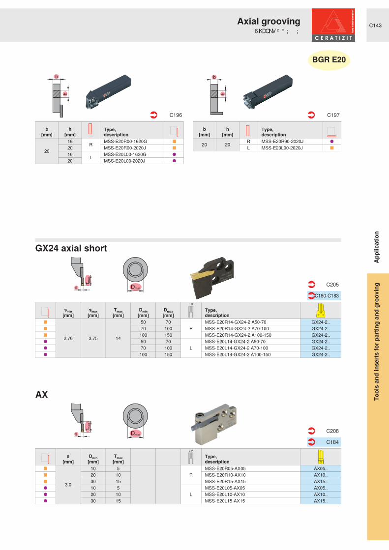
C143
Tm
ax
s Dmin
RL
Tm
ax
s Dmin
RL
smin smax Tmax Dmin Dmax Type,description[mm] [mm] [mm] [mm] [mm]
2.76 3.75 14
50 70R
MSS-E20R14-GX24-2 A50-70 GX24-2.. 70 100 MSS-E20R14-GX24-2 A70-100 GX24-2.. 100 150 MSS-E20R14-GX24-2 A100-150 GX24-2.. 50 70
LMSS-E20L14-GX24-2 A50-70 GX24-2..
70 100 MSS-E20L14-GX24-2 A70-100 GX24-2.. 100 150 MSS-E20L14-GX24-2 A100-150 GX24-2..
C205
C180-C183
s Dmin Tmax Type,description[mm] [mm] [mm]
3.0
10 5
RMSS-E20R05-AX05 AX05..
20 10 MSS-E20R10-AX10 AX10.. 30 15 MSS-E20R15-AX15 AX15.. 10 5
LMSS-E20L05-AX05 AX05..
20 10 MSS-E20L10-AX10 AX10.. 30 15 MSS-E20L15-AX15 AX15..
C208
C184
Type,description
b h[mm] [mm]
20
16 R MSS-E20R00-1620G20 MSS-E20R00-2020J16 L MSS-E20L00-1620G20 MSS-E20L00-2020J
C196
Type,description
b h[mm] [mm]
20 20 R MSS-E20R90-2020JL MSS-E20L90-2020J
C197
� ƒ � � ƒ
AX
GX24 axial short
BGR E20
Appl
icat
ion
6KDQNV� ² � * ; � $ ;Axial grooving
Tool
s an
d in
serts
for p
artin
g an
d gr
oovi
ng

C144
dA
dA
Tm
ax
s Dmin
RL
smin smax Tmax Dmin Dmax Type,description[mm] [mm] [mm] [mm] [mm]
2.76 3.75
15
50 70
R
MSS-E25R15-GX24-2 A50-70 GX24-2.. 2.76 3.75 70 100 MSS-E25R15-GX24-2 A70-100 GX24-2.. 2.76 3.75 100 150 MSS-E25R15-GX24-2 A100-150 GX24-2.. 3.76 5.00 50 70 MSS-E25R15-GX24-3 A50-70 GX24-3.. 3.76 5.00 70 100 MSS-E25R15-GX24-3 A70-100 GX24-3.. 3.76 5.00 100 150 MSS-E25R15-GX24-3 A100-150 GX24-3.. 3.76 5.00 150 300 MSS-E25R15-GX24-3 A150-300 GX24-3.. 5.01 6.50 50 70 MSS-E25R15-GX24-4 A50-70 GX24-4.. 5.01 6.50 70 100 MSS-E25R15-GX24-4 A70-100 GX24-4.. 5.01 6.50 100 150 MSS-E25R15-GX24-4 A100-150 GX24-4.. 5.01 6.50 150 300 MSS-E25R15-GX24-4 A150-300 GX24-4.. 2.76 3.75 50 70
L
MSS-E25L15-GX24-2 A50-70 GX24-2.. 2.76 3.75 70 100 MSS-E25L15-GX24-2 A70-100 GX24-2.. 2.76 3.75 100 150 MSS-E25L15-GX24-2 A100-150 GX24-2.. 3.76 5.00 50 70 MSS-E25L15-GX24-3 A50-70 GX24-3.. 3.76 5.00 70 100 MSS-E25L15-GX24-3 A70-100 GX24-3.. 3.76 5.00 100 150 MSS-E25L15-GX24-3 A100-150 GX24-3.. 3.76 5.00 150 300 MSS-E25L15-GX24-3 A150-300 GX24-3.. 5.01 6.50 50 70 MSS-E25L15-GX24-4 A50-70 GX24-4.. 5.01 6.50 70 100 MSS-E25L15-GX24-4 A70-100 GX24-4.. 5.01 6.50 100 150 MSS-E25L15-GX24-4 A100-150 GX24-4.. 5.01 6.50 150 300 MSS-E25L15-GX24-4 A150-300 GX24-4..
C205-C206
C180-C183
Type,description
b h dA[mm] [mm] [mm]
25 25
R
MSS-E25R00-2525L 40 UT40-MSS-E25R00 50 UT50-MSS-E25R00 63 UT63-MSS-E25R00
25 25
L
MSS-E25L00-2525L 40 UT40-MSS-E25L00 50 UT50-MSS-E25L00 63 UT63-MSS-E25L00
C196 C246
Type,description
b h dA[mm] [mm] [mm]
25 25 R
MSS-E25R90-2525L 40 UT40-MSS-E25R90 50 UT50-MSS-E25R9025 25
LMSS-E25L90-2525L
40 UT40-MSS-E25L90 50 UT50-MSS-E25L90
C197 C247
� ƒ � � ƒ
GX24 axial short
BGR E25
Appl
icat
ion
6KDQNV� ² � 8 76 � ² � * ;Axial grooving
Tool
s an
d in
serts
for p
artin
g an
d gr
oovi
ng

C145
dA
dA
Tm
ax
s Dmin
RL
smin smax Tmax Dmin Dmax Type,description[mm] [mm] [mm] [mm] [mm]
3.76 5.00
21
50 70
R
MSS-E25R21-GX24-3 AS50-70 GX24-3.. 3.76 5.00 70 100 MSS-E25R21-GX24-3 AS70-100 GX24-3.. 3.76 5.00 100 150 MSS-E25R21-GX24-3 AS100-150 GX24-3.. 3.76 5.00 150 300 MSS-E25R21-GX24-3 AS150-300 GX24-3.. 5.01 6.50
25
50 70 MSS-E25R25-GX24-4 AS50-70 GX24-4.. 5.01 6.50 70 100 MSS-E25R25-GX24-4 AS70-100 GX24-4.. 5.01 6.50 100 150 MSS-E25R25-GX24-4 AS100-150 GX24-4.. 5.01 6.50 150 300 MSS-E25R25-GX24-4 AS150-300 GX24-4.. 3.76 5.00
21
50 70
L
MSS-E25L21-GX24-3 AS50-70 GX24-3.. 3.76 5.00 70 100 MSS-E25L21-GX24-3 AS70-100 GX24-3.. 3.76 5.00 100 150 MSS-E25L21-GX24-3 AS100-150 GX24-3.. 3.76 5.00 150 300 MSS-E25L21-GX24-3 AS150-300 GX24-3.. 5.01 6.50
25
50 70 MSS-E25L25-GX24-4 AS50-70 GX24-4.. 5.01 6.50 70 100 MSS-E25L25-GX24-4 AS70-100 GX24-4.. 5.01 6.50 100 150 MSS-E25L25-GX24-4 AS100-150 GX24-4.. 5.01 6.50 150 300 MSS-E25L25-GX24-4 AS150-300 GX24-4..
C207
C180-C183
Type,description
b h dA[mm] [mm] [mm]
25 25
R
MSS-E25R00-2525L 40 UT40-MSS-E25R00 50 UT50-MSS-E25R00 63 UT63-MSS-E25R00
25 25
L
MSS-E25L00-2525L 40 UT40-MSS-E25L00 50 UT50-MSS-E25L00 63 UT63-MSS-E25L00
C196 C246
Type,description
b h dA[mm] [mm] [mm]
25 25 R
MSS-E25R90-2525L 40 UT40-MSS-E25R90 50 UT50-MSS-E25R9025 25
LMSS-E25L90-2525L
40 UT40-MSS-E25L90 50 UT50-MSS-E25L90
C197 C247
� ƒ � � ƒ
GX24 axial long
BGR E25
Appl
icat
ion
6KDQNV� ² � 8 76 � ² � * ;Axial grooving
Tool
s an
d in
serts
for p
artin
g an
d gr
oovi
ng

C146
dA
dA
Tm
ax
s Dmin
RL
s Dmin Tmax Type,description[mm] [mm] [mm]
3.0
10 5
RMSS-E25R05-AX05 AX05..
20 10 MSS-E25R10-AX10 AX10.. 30 15 MSS-E25R15-AX15 AX15.. 10 5
LMSS-E25L05-AX05 AX05..
20 10 MSS-E25L10-AX10 AX10.. 30 15 MSS-E25L15-AX15 AX15..
C208
C184
Type,description
b h dA[mm] [mm] [mm]
25 25
R
MSS-E25R00-2525L 40 UT40-MSS-E25R00 50 UT50-MSS-E25R00 63 UT63-MSS-E25R00
25 25
L
MSS-E25L00-2525L 40 UT40-MSS-E25L00 50 UT50-MSS-E25L00 63 UT63-MSS-E25L00
C196 C246
Type,description
b h dA[mm] [mm] [mm]
25 25 R
MSS-E25R90-2525L 40 UT40-MSS-E25R90 50 UT50-MSS-E25R9025 25
LMSS-E25L90-2525L
40 UT40-MSS-E25L90 50 UT50-MSS-E25L90
C197 C247
� ƒ � � ƒ
AX
BGR E25
Appl
icat
ion
6KDQNV� ² � 8 76 � ² � $ ;Axial grooving
Tool
s an
d in
serts
for p
artin
g an
d gr
oovi
ng

C147
dA
dA
Tm
ax
s Dmin
RL
smin smax Tmax Dmin Dmax Type,description[mm] [mm] [mm] [mm] [mm]
3.76 5.00
15
70 100
R
MSS-E32R15-GX24-3 A70-100 GX24-3.. 3.76 5.00 100 150 MSS-E32R15-GX24-3 A100-150 GX24-3.. 3.76 5.00 150 300 MSS-E32R15-GX24-3 A150-300 GX24-3.. 5.01 6.50 70 100 MSS-E32R15-GX24-4 A70-100 GX24-4.. 5.01 6.50 100 150 MSS-E32R15-GX24-4 A100-150 GX24-4.. 5.01 6.50 150 300 MSS-E32R15-GX24-4 A150-300 GX24-4.. 5.01 6.50 300 900 MSS-E32R15-GX24-4 A300-900 GX24-4.. 3.76 5.00 70 100
L
MSS-E32L15-GX24-3 A70-100 GX24-3.. 3.76 5.00 100 150 MSS-E32L15-GX24-3 A100-150 GX24-3.. 3.76 5.00 150 300 MSS-E32L15-GX24-3 A150-300 GX24-3.. 5.01 6.50 70 100 MSS-E32L15-GX24-4 A70-100 GX24-4.. 5.01 6.50 100 150 MSS-E32L15-GX24-4 A100-150 GX24-4.. 5.01 6.50 150 300 MSS-E32L15-GX24-4 A150-300 GX24-4.. 5.01 6.50 300 900 MSS-E32L15-GX24-4 A300-900 GX24-4..
C206
C180-C183
Type,description
b h dA[mm] [mm] [mm]
25 32
R
MSS-E32R00-3225N32 32 MSS-E32R00-3232Q 50 UT50-MSS-E32R00 63 UT63-MSS-E32R00 63 HSK-T63-MSS-E32R00 100 HSK-T100-MSS-E32R00
25 32
L
MSS-E32L00-3225N32 32 MSS-E32L00-3232Q 50 UT50-MSS-E32L00 63 UT63-MSS-E32L00 63 HSK-T63-MSS-E32L00 100 HSK-T100-MSS-E32L00
C196 C246+C250
Type,description
b h dA[mm] [mm] [mm]
25 32
R
MSS-E32R90-3225N32 32 MSS-E32R90-3232R 63 UT63-MSS-E32R90 63 HSK-T63-MSS-E32R90 100 HSK-T100-MSS-E32R90
25 32
L
MSS-E32L90-3225N32 32 MSS-E32L90-3232R 63 UT63-MSS-E32L90 63 HSK-T63-MSS-E32L90 100 HSK-T100-MSS-E32L90
C197 C247+C251
� ƒ � � ƒ
GX24 axial short
BGR E32
Appl
icat
ion
6KDQNV� ² � 8 76 � ² � * ; � �Axial grooving
Tool
s an
d in
serts
for p
artin
g an
d gr
oovi
ng

C148
Tm
ax
h
b
s
Dmin
RL
Tmax
h
b
s
Dmin
RL
b h s Dmin Tmax Type,description[mm] [mm] [mm] [mm] [mm]
16 16
3.0
10 5
R E16R0005-1616L-AX05 AX05..20 10 E16R0010-1616L-AX10 AX10..10 5 L E16L0005-1616L-AX05 AX05..20 10 E16L0010-1616L-AX10 AX10..
20 20
10 5R
E20R0005-2020L-AX05 AX05..20 10 E20R0010-2020L-AX10 AX10..30 15 E20R0015-2020L-AX15 AX15..10 5
LE20L0005-2020L-AX05 AX05..
20 10 E20L0010-2020L-AX10 AX10..30 15 E20L0015-2020L-AX15 AX15..
25 25
10 5R
E25R0005-2525N-AX05 AX05..20 10 E25R0010-2525N-AX10 AX10..30 15 E25R0015-2525N-AX15 AX15..10 5
LE25L0005-2525N-AX05 AX05..
20 10 E25L0010-2525N-AX10 AX10..30 15 E25L0015-2525N-AX15 AX15..
C216
C184
b h s Dmin Tmax Type,description[mm] [mm] [mm] [mm] [mm]
16 16
3.0
10 5
R E16R9005-1616J-AX05 AX05..20 10 E16R9010-1616J-AX10 AX10..10 5 L E16L9005-1616J-AX05 AX05..20 10 E16L9010-1616J-AX10 AX10..
20 20
10 5R
E20R9005-2020J-AX05 AX05..20 10 E20R9010-2020J-AX10 AX10..30 15 E20R9015-2020J-AX15 AX15..10 5
LE20L9005-2020J-AX05 AX05..
20 10 E20L9010-2020J-AX10 AX10..30 15 E20L9015-2020J-AX15 AX15..
25 25
10 5R
E25R9005-2525L-AX05 AX05..20 10 E25R9010-2525J-AX10 AX10..30 15 E25R9015-2525L-AX15 AX15..10 5
LE25L9005-2525L-AX05 AX05..
20 10 E25L9010-2525J-AX10 AX10..30 15 E25L9015-2525L-AX15 AX15..
C217
C184
$ ; � ² � � ƒ
$ ; � ² � � � ƒ
Appl
icat
ion
0 RQREORF� WRROV� ² � $ ;Axial grooving
Tool
s an
d in
serts
for p
artin
g an
d gr
oovi
ng

C150
hb
dA
Shanks 45°
UTS 45°
h / b20/20 - 25/25
dA = 40
App
licat
ion
External recessingOverview – modular structure
Tool
s an
d in
sert
s fo
r pa
rtin
g an
d gr
oovi
ng

C151
s
D = 3
5m
mm
in
T max
T max
D = 3
5m
mm
in
r
s
D = 3
5m
mm
in
T max
T max
D = 3
5m
mm
in
r
GX16
s = 1,0 - 6,0r = 0,8 - 3,0
Tmax = 1,14 - 3,0
GX16
s = 1,0 - 6,0r = 0,8 - 3,0
Tmax = 1,14 - 3,0
App
licat
ion
External recessingOverview – modular structure
Tool
s an
d in
sert
s fo
r pa
rtin
g an
d gr
oovi
ng

C152
hb
s
D = 3
5m
mm
in
Tmax
RL
s
D = 3
5m
mm
in
Tmax
RL
Type,description
b h[mm] [mm]
20 20 R MSS-E20R45-2020JL MSS-E20L45-2020J
C198
Type,description
s Tmax[mm] [mm]
1.00 1.14
R
MSS-E20R03-GX16-2 GX16-2.. R/L 1.20 1.34 MSS-E20R03-GX16-2 GX16-2.. R/L 1.40 1.53 MSS-E20R03-GX16-2 GX16-2.. R/L 1.70 1.82 MSS-E20R03-GX16-2 GX16-2.. R/L 1.95 2.07 MSS-E20R03-GX16-2 GX16-2.. R/L 2.25 2.36 MSS-E20R03-GX16-2 GX16-2.. R/L 1.00 1.14
L
MSS-E20L03-GX16-2 GX16-2.. R/L 1.20 1.34 MSS-E20L03-GX16-2 GX16-2.. R/L 1.40 1.53 MSS-E20L03-GX16-2 GX16-2.. R/L 1.70 1.82 MSS-E20L03-GX16-2 GX16-2.. R/L 1.95 2.07 MSS-E20L03-GX16-2 GX16-2.. R/L 2.25 2.36 MSS-E20L03-GX16-2 GX16-2.. R/L
C204
C182
Type,description
s Tmax[mm] [mm]
3.00
3
L
MSS-E20L03-GX16-2 GX16-2.. 3.25 MSS-E20L03-GX16-2 GX16-2.. 3.50 MSS-E20L03-GX16-2 GX16-2.. 4.00 MSS-E20L03-GX16-2 GX16-2.. 4.25 MSS-E20L03-GX16-2 GX16-2.. 4.50 MSS-E20L03-GX16-2 GX16-2.. 5.00 MSS-E20L03-GX16-2 GX16-2.. 3.00
R
MSS-E20R03-GX16-2 GX16-2.. 3.25 MSS-E20R03-GX16-2 GX16-2.. 3.50 MSS-E20R03-GX16-2 GX16-2.. 4.00 MSS-E20R03-GX16-2 GX16-2.. 4.25 MSS-E20R03-GX16-2 GX16-2.. 4.50 MSS-E20R03-GX16-2 GX16-2.. 5.00 MSS-E20R03-GX16-2 GX16-2..
C201
C182
� � ƒ
GX16GX16
BGR E20
Appl
icat
ion
6KDQNV� ² � * ; � �External recessing
Tool
s an
d in
serts
for p
artin
g an
d gr
oovi
ng

C153
h
b
r
Tmax
D = 3
5m
mm
in
RL
r
Tmax
D = 3
5m
mm
in
RL
Type,description
r Tmax[mm] [mm]
0.80 1.78R
MSS-E20R03-GX16-2 GX16-2.. R/L 1.00 2.18 MSS-E20R03-GX16-2 GX16-2.. R/L 1.20 2.58 MSS-E20R03-GX16-2 GX16-2.. R/L 0.80 1.78
LMSS-E20L03-GX16-2 GX16-2.. R/L
1.00 2.18 MSS-E20L03-GX16-2 GX16-2.. R/L 1.20 2.58 MSS-E20L03-GX16-2 GX16-2.. R/L
C204
C183
Type,description
r Tmax[mm] [mm]
1.50 12.00R
MSS-E20R03-GX16-2 GX16-2.. 2.00 12.00 MSS-E20R03-GX16-2 GX16-2.. 2.50 12.00 MSS-E20R03-GX16-2 GX16-2.. 1.50 12.00
LMSS-E20L03-GX16-2 GX16-2..
2.00 12.00 MSS-E20L03-GX16-2 GX16-2.. 2.50 12.00 MSS-E20L03-GX16-2 GX16-2..
C201
C183
Type,description
b h[mm] [mm]
20 20 R MSS-E20R45-2020JL MSS-E20L45-2020J
C198
� � ƒ
GX16GX16
BGR E20
Appl
icat
ion
6KDQNV� ² � * ; � �External recessing
Tool
s an
d in
serts
for p
artin
g an
d gr
oovi
ng

C154
h
b dA
s
D = 3
5m
mm
in
Tmax
RL
s
D = 3
5m
mm
in
Tmax
RL
Type,description
b h dA[mm] [mm] [mm]
25 25 R MSS-E25R45-2525L25 25 L MSS-E25L45-2525L 40 UT40-MSS-E25L45
C198 C248
Type,description
s Tmax[mm] [mm]
1.00 1.14
R
MSS-E25R03-GX16-2 GX16-2.. R/L 1.20 1.34 MSS-E25R03-GX16-2 GX16-2.. R/L 1.40 1.53 MSS-E25R03-GX16-2 GX16-2.. R/L 1.70 1.82 MSS-E25R03-GX16-2 GX16-2.. R/L 1.95 2.07 MSS-E25R03-GX16-2 GX16-2.. R/L 2.25 2.36 MSS-E25R03-GX16-2 GX16-2.. R/L 1.00 1.14
L
MSS-E25L03-GX16-2 GX16-2.. R/L 1.20 1.34 MSS-E25L03-GX16-2 GX16-2.. R/L 1.40 1.53 MSS-E25L03-GX16-2 GX16-2.. R/L 1.70 1.82 MSS-E25L03-GX16-2 GX16-2.. R/L 1.95 2.07 MSS-E25L03-GX16-2 GX16-2.. R/L 2.25 2.36 MSS-E25L03-GX16-2 GX16-2.. R/L
C204
C182
Type,description
s Tmax[mm] [mm]
3.00
3
R
MSS-E25R03-GX16-2 GX16-2.. 3.25 MSS-E25R03-GX16-2 GX16-2.. 3.50 MSS-E25R03-GX16-2 GX16-2.. 4.00 MSS-E25R03-GX16-2 GX16-2.. 4.25 MSS-E25R03-GX16-2 GX16-2.. 4.50 MSS-E25R03-GX16-2 GX16-2.. 5.00 MSS-E25R03-GX16-2 GX16-2.. 5.25 MSS-E25R03-GX16-2 GX16-2.. 6.00 MSS-E25R03-GX16-2 GX16-2.. 3.00
L
MSS-E25L03-GX16-2 GX16-2.. 3.25 MSS-E25L03-GX16-2 GX16-2.. 3.50 MSS-E25L03-GX16-2 GX16-2.. 4.00 MSS-E25L03-GX16-2 GX16-2.. 4.25 MSS-E25L03-GX16-2 GX16-2.. 4.50 MSS-E25L03-GX16-2 GX16-2.. 5.00 MSS-E25L03-GX16-2 GX16-2.. 5.25 MSS-E25L03-GX16-2 GX16-2.. 6.00 MSS-E25L03-GX16-2 GX16-2..
C201
C182
� � ƒ
GX16GX16
BGR E25
Appl
icat
ion
6KDQNV� ² � 8 76 � ² � * ; � �External recessing
Tool
s an
d in
serts
for p
artin
g an
d gr
oovi
ng

C155
h
b dA
r
Tmax
D = 3
5m
mm
in
RL
r
Tmax
D = 3
5m
mm
in
RL
Type,description
r Tmax[mm] [mm]
0.80 1.78R
MSS-E25R03-GX16-2 GX16-2.. R/L 1.00 2.18 MSS-E25R03-GX16-2 GX16-2.. R/L 1.20 2.58 MSS-E25R03-GX16-2 GX16-2.. R/L 0.80 1.78
LMSS-E25L03-GX16-2 GX16-2.. R/L
1.00 2.18 MSS-E25L03-GX16-2 GX16-2.. R/L 1.20 2.58 MSS-E25L03-GX16-2 GX16-2.. R/L
C204
C183
Type,description
r Tmax[mm] [mm]
1.50
3
R
MSS-E25R03-GX16-2 GX16-2.. 2.00 MSS-E25R03-GX16-2 GX16-2.. 2.50 MSS-E25R03-GX16-2 GX16-2.. 3.00 MSS-E25R03-GX16-2 GX16-2.. 1.50
L
MSS-E25L03-GX16-2 GX16-2.. 2.00 MSS-E25L03-GX16-2 GX16-2.. 2.50 MSS-E25L03-GX16-2 GX16-2.. 3.00 MSS-E25L03-GX16-2 GX16-2..
C201
C183
Type,description
b h dA[mm] [mm] [mm]
25 25 R MSS-E25R45-2525L25 25 L MSS-E25L45-2525L 40 UT40-MSS-E25L45
C198 C248
� � ƒ
GX16GX16
BGR E25
Appl
icat
ion
6KDQNV� ² � 8 76 � ² � * ; � �External recessing
Tool
s an
d in
serts
for p
artin
g an
d gr
oovi
ng

C156
l 2Ø dA
l 2
Ø dA
l 2
Ø dA
s
l 2
Tmax
Ø dA
Ø D
s
l 2
Tmax
Ø dA
Ø D
s
l 2
Tmax
Ø dA
Ø D
Boring bars 1.5D Boring bars 2.5D
UTS boring bars
GX09 monobloc boring bars
GX16 monobloc boring bars
GX24 monobloc boring bars
D = 16,0l2 = 30dA = 16
s = 2,0 - 3,75Tmax = 3,0
D = 20,5 - 42l2 = 32 - 64dA = 16 - 32s = 2,0 - 5,0
Tmax = 5,5 - 11
dA = 20 - 40l2 = 24 - 60
dA = 20 - 50l2 = 40 - 100
D = 42 - 57l2 = 64 - 80dA = 32 - 40
s = 2,76 - 6,5Tmax = 11 - 17,5
dA = 40 - 63l2 = 64 - 80
Appl
icat
ion
* URRYLQ J� DQ G� WXUQ LQ J� ² � LQ WHUQ DO2 YHUYLHZ � ² � P RGXODU� VWUXFWXUH
Tool
s an
d in
serts
for p
artin
g an
d gr
oovi
ng

C157
Tmax
Ø D s
Tmax
Ø D s
GX09 GX16 GX24
GX09 GX16 GX24
D = 20 - 32s = 2,0 - 3,75Tmax = 4 - 6
D = 40 - 50s = 2,0 - 6,5Tmax = 9 - 10
D = 60s = 3,0 - 6,0
Tmax = 19
D = 20 - 32s = 2,0 - 3,75Tmax = 4 - 6
D = 40 - 50s = 2,0 - 6,5Tmax = 9 - 10
D = 60s = 3,0 - 6,0
Tmax = 19
Appl
icat
ion
* URRYLQ J� DQ G� WXUQ LQ J� ² � LQ WHUQ DO2 YHUYLHZ � ² � P RGXODU� VWUXFWXUH
Tool
s an
d in
serts
for p
artin
g an
d gr
oovi
ng

C158
l 2Ø dA
Tmax
Ø D s
RL
Type,description
Dmin smin smax Tmax[mm] [mm] [mm] [mm]
20
2.00 2.75
4R MSS-I16R04-GX09-1 GX09-1..
2.76 3.75 MSS-I16R04-GX09-2 GX09-2.. 2.00 2.75 L MSS-I16L04-GX09-1 GX09-1.. 2.76 3.75 MSS-I16L04-GX09-2 GX09-2..
C233
C180
Type,description
l2 dA[mm] [mm]
24 20 R MSS-I16R90-1.5D-N40 20 MSS-I16R90-2.5D-N24 20 L MSS-I16L90-1.5D-N40 20 MSS-I16L90-2.5D-N
C231-C232
GX09
GX09
BGR I16
Appl
icat
ion
%RULQJ� EDUV� ² � * ;* URRYLQ J� DQ G� WXUQ LQ J� ² � LQ WHUQ DO
Tool
s an
d in
serts
for p
artin
g an
d gr
oovi
ng

C159
l 2
Ø dA
Tmax
Ø D s
RL
Type,description
Dmin smin smax Tmax[mm] [mm] [mm] [mm]
25
2.00 2.75
5R MSS-I20R05-GX09-1 GX09-1..
2.76 3.75 MSS-I20R05-GX09-2 GX09-2.. 2.00 2.75 L MSS-I20L05-GX09-1 GX09-1.. 2.76 3.75 MSS-I20L05-GX09-2 GX09-2..
C233
C180
Type,description
l2 dA[mm] [mm]
30 20 R MSS-I20R90-1.5D-N50 25 MSS-I20R90-2.5D-N30 20 L MSS-I20L90-1.5D-N50 25 MSS-I20L90-2.5D-N
C231-C232
GX09
GX09
BGR I20
Appl
icat
ion
%RULQJ� EDUV� ² � * ;* URRYLQ J� DQ G� WXUQ LQ J� ² � LQ WHUQ DO
Tool
s an
d in
serts
for p
artin
g an
d gr
oovi
ng

C160
l 2Ø dA
Tmax
Ø D s
RL
Type,description
Dmin smin smax Tmax[mm] [mm] [mm] [mm]
32
2.00 2.75
6R MSS-I25R06-GX09-1 GX09-1..
2.76 3.75 MSS-I25R06-GX09-2 GX09-2.. 2.00 2.75 L MSS-I25L06-GX09-1 GX09-1.. 2.76 3.75 MSS-I25L06-GX09-2 GX09-2..
C233
C180
Type,description
l2 dA[mm] [mm]
38 25 R MSS-I25R90-1.5D-N63 32 MSS-I25R90-2.5D-N38 25 L MSS-I25L90-1.5D-N63 32 MSS-I25L90-2.5D-N
C231-C232
GX09
GX09
BGR I25
Appl
icat
ion
%RULQJ� EDUV� ² � * ;* URRYLQ J� DQ G� WXUQ LQ J� ² � LQ WHUQ DO
Tool
s an
d in
serts
for p
artin
g an
d gr
oovi
ng

C161
l 2
Ø dAl 2
Ø dA
l 2
Ø dA
l 2
Ø dA
Tmax
Ø D s
RL
l2 dA Type,
description[mm] [mm]48 32
LMSS-I32L90-1.5D-N
80 40 MSS-I32L90-2.5D-N64 50 UT50-MSS-I32L90-2D
C231-C232 C249
Type,description
Dmin smin smax Tmax[mm] [mm] [mm] [mm]
40
2.00 2.75
9
R
MSS-I32R09-GX16-1 GX16-1.. 2.76 3.75 MSS-I32R09-GX16-2 GX16-2.. 3.76 5.00 MSS-I32R09-GX16-3 GX16-3.. 5.01 6.50 MSS-I32R09-GX16-4 GX16-4.. 2.00 2.75
L
MSS-I32L09-GX16-1 GX16-1.. 2.76 3.75 MSS-I32L09-GX16-2 GX16-2.. 3.76 5.00 MSS-I32L09-GX16-3 GX16-3.. 5.01 6.50 MSS-I32L09-GX16-4 GX16-4..
C234
C180-C181
l2 dA Type,
description[mm] [mm]48 32
RMSS-I32R90-1.5D-N
80 40 MSS-I32R90-2.5D-N64 40 UT40-MSS-I32R90-2D
C231-C232 C249
* ; � � � ² � ULJKW� KDQ G * ; � � � ² � OHIW� KDQ G
GX16
BGR I32
Appl
icat
ion
%RULQJ� EDUV� ² � * ;* URRYLQ J� DQ G� WXUQ LQ J� ² � LQ WHUQ DO
Tool
s an
d in
serts
for p
artin
g an
d gr
oovi
ng

C162
l 2
Ø dA
l 2
Ø dA
l 2
Ø dA
l 2
Ø dA
Tmax
Ø D s
RL
Tmax
Ø D s
L/N/R
l2 dA Type,
description[mm] [mm]60 40
LMSS-I40L90-1.5D-N
100 50 MSS-I40L90-2.5D-N80 40 UT40-MSS-I40L90-2D
C231-C232 C249
Type,description
Dmin smin smax Tmax[mm] [mm] [mm] [mm]
50
2.00 2.75
10
R
MSS-I40R10-GX16-1 GX16-1.. 2.76 3.75 MSS-I40R10-GX16-2 GX16-2.. 3.76 5.00 MSS-I40R10-GX16-3 GX16-3.. 5.01 6.50 MSS-I40R10-GX16-4 GX16-4.. 2.00 2.75
L
MSS-I40L10-GX16-1 GX16-1.. 2.76 3.75 MSS-I40L10-GX16-2 GX16-2.. 3.76 5.00 MSS-I40L10-GX16-3 GX16-3.. 5.01 6.50 MSS-I40L10-GX16-4 GX16-4..
C234
C180-C181
Type,description
Dmin smin smax Tmax[mm] [mm] [mm] [mm]
60
2.76 3.7519 N
MSS-I40N19-GX24-2 GX24-2.. 3.76 5.00 MSS-I40N19-GX24-3 GX24-3.. 5.01 6.50 MSS-I40N19-GX24-4 GX24-4..
C234
C180-C181
l2 dA Type,
description[mm] [mm]60 40
R
MSS-I40R90-1.5D-N100 50 MSS-I40R90-2.5D-N80 40 UT40-MSS-I40R90-2D80 63 UT63-MSS-I40R90-2D
C231-C232 C249
* ; � ² � ULJKW� KDQ G * ; � ² � OHIW� KDQ G
GX16 GX24
BGR I40
Appl
icat
ion
%RULQJ� EDUV� ² � * ;* URRYLQ J� DQ G� WXUQ LQ J� ² � LQ WHUQ DO
Tool
s an
d in
serts
for p
artin
g an
d gr
oovi
ng

C163
s
l 2Tmax
Ø dA
Ø D
RL
s
l 2
Tmax
Ø dA
Ø D
RL
s
l 2
Tmax
Ø dA
Ø D
RL
Type,description
dA l2 D smin smax Tmax [mm] [mm] [mm] [mm] [mm] [mm]
16 30 16 0.60 3.75 3 R I12R90-2.5D-GX09 GX09..L I12L90-2.5D-GX09 GX09..
C237 C180
Type,description
dA l2 D smin smax Tmax [mm] [mm] [mm] [mm] [mm] [mm]
16 32 20.5 2.00 2.75 5.5
R
I16R90-2.0D-GX16-1 GX16-1..16 32 20.5 0.60 3.75 5.5 I16R90-2.0D-GX16-2 GX16-2..20 40 25.0 0.60 3.75 5.5 I20R90-2.0D-GX16-2 GX16-2..25 50 32.0 0.60 3.75 8.0 I25R90-2.0D-GX16-2 GX16-2..25 50 32.0 3.76 5.00 10.0 I25R90-2.0D-GX16-3 GX16-3..32 64 42.0 0.60 3.75 11.0 I32R90-2.0D-GX16-2 GX16-2..32 64 42.0 3.76 5.00 11.0 I32R90-2.0D-GX16-3 GX16-3..16 32 20.5 2.00 2.75 5.5
L
I16L90-2.0D-GX16-1 GX16-1..16 32 20.5 0.60 3.75 5.5 I16L90-2.0D-GX16-2 GX16-2..20 40 25.0 0.60 3.75 5.5 I20L90-2.0D-GX16-2 GX16-2..25 50 32.0 0.60 3.75 8.0 I25L90-2.0D-GX16-2 GX16-2..25 50 32.0 3.76 5.00 10.0 I25L90-2.0D-GX16-3 GX16-3..32 64 42.0 0.60 3.75 11.0 I32L90-2.0D-GX16-2 GX16-2..32 64 42.0 3.76 5.00 11.0 I32L90-2.0D-GX16-3 GX16-3..
C238 C180-C181
Type,description
dA l2 D smin smax Tmax [mm] [mm] [mm] [mm] [mm] [mm]
32 64 42 2.76 3.75 11.0
R
I32R90-2.0D-GX24-2 GX24-2..32 64 42 3.76 5.00 11.0 I32R90-2.0D-GX24-3 GX24-3..32 64 47 5.01 6.50 17.5 I32R90-2.0D-GX24-4 GX24-4..40 80 53 3.76 5.00 12.0 I40R90-2.0D-GX24-3 GX24-3..40 80 57 5.01 6.50 17.5 I40R90-2.0D-GX24-4 GX24-4..32 64 42 2.76 3.75 11.0
L
I32L90-2.0D-GX24-2 GX24-2..32 64 42 3.76 5.00 11.0 I32L90-2.0D-GX24-3 GX24-3..32 64 47 5.01 6.50 17.5 I32L90-2.0D-GX24-4 GX24-4..40 80 53 3.76 5.00 12.0 I40L90-2.0D-GX24-3 GX24-3..40 80 57 5.01 6.50 17.5 I40L90-2.0D-GX24-4 GX24-4..
C239 C180-C181
GX09 monobloc boring bars
GX16 monobloc boring bars
GX24 monobloc boring barsAp
plic
atio
n
0 RQREORF� ERULQJ� EDUV� ² � * ;* URRYLQ J� DQ G� WXUQ LQ J� ² � LQ WHUQ DO
Tool
s an
d in
serts
for p
artin
g an
d gr
oovi
ng
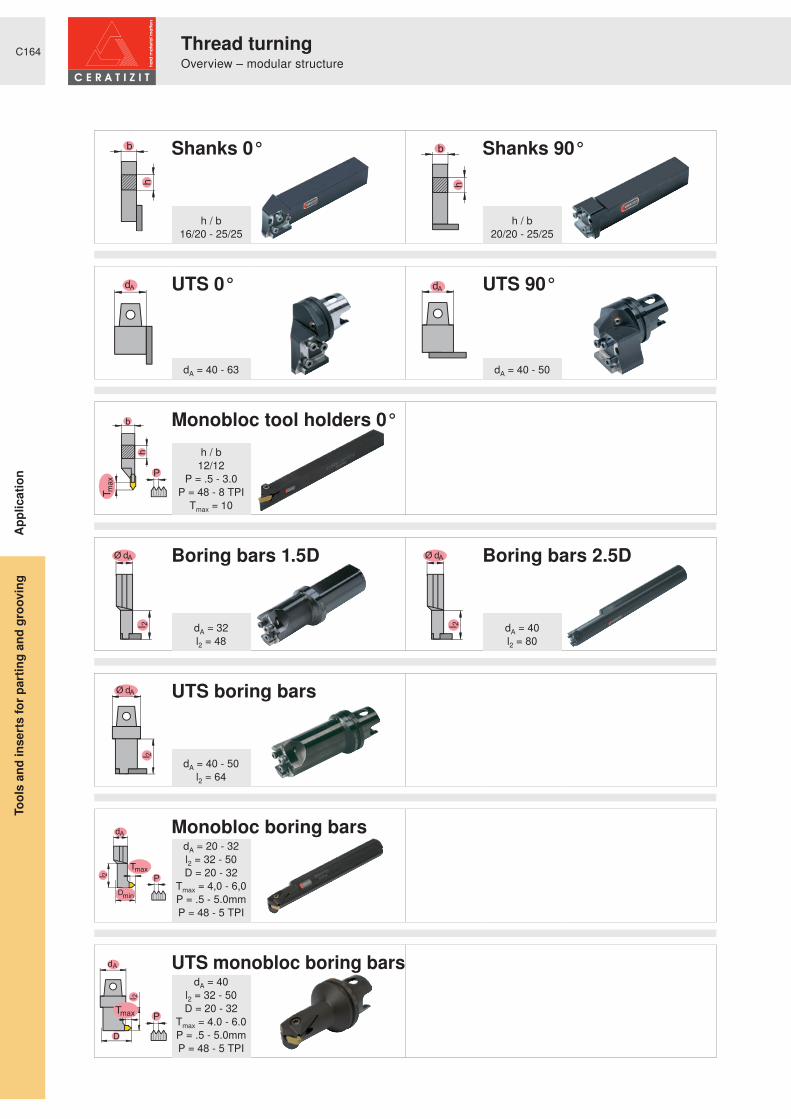
C164
dA dA
b
P
h
l 2
Ø dA
l 2
Ø dA
l 2
Ø dA
Pl 2
dA
Dmin
P
D
d
l
A
2
Shanks 0° Shanks 90°
UTS 0° UTS 90°
Monobloc tool holders 0°
Boring bars 1.5D Boring bars 2.5D
UTS boring bars
Monobloc boring bars
UTS monobloc boring bars
h / b16/20 - 25/25
h / b20/20 - 25/25
dA = 40 - 50dA = 40 - 63
dA = 20 - 32l2 = 32 - 50D = 20 - 32
Tmax = 4,0 - 6,0P = .5 - 5.0mmP = 48 - 5 TPI
dA = 32l2 = 48
dA = 40l2 = 80
dA = 40l2 = 32 - 50D = 20 - 32
Tmax = 4.0 - 6.0P = .5 - 5.0mmP = 48 - 5 TPI
dA = 40 - 50l2 = 64
h / b12/12
P = .5 - 3.0P = 48 - 8 TPI
Tmax = 10
App
licat
ion
Thread turningOverview – modular structure
Tool
s an
d in
sert
s fo
r pa
rtin
g an
d gr
oovi
ng

C165
P
P
P
Dmin
P
D
TC16
TC16
TC16
TC16
P = .5 - 5.0mmP = 48 - 5 TPITmax = 8.0 - 12
P = .5 - 5.0mmP = 48 - 5 TPITmax = 8.0 - 12
D = 40P = .5 - 5.0mmP = 48 - 5 TPI
Tmax = 7.0
D = 40P = .5 - 5.0mmP = 48 - 5 TPI
Tmax = 7.0
App
licat
ion
Thread turningOverview – modular structure
Tool
s an
d in
sert
s fo
r pa
rtin
g an
d gr
oovi
ng
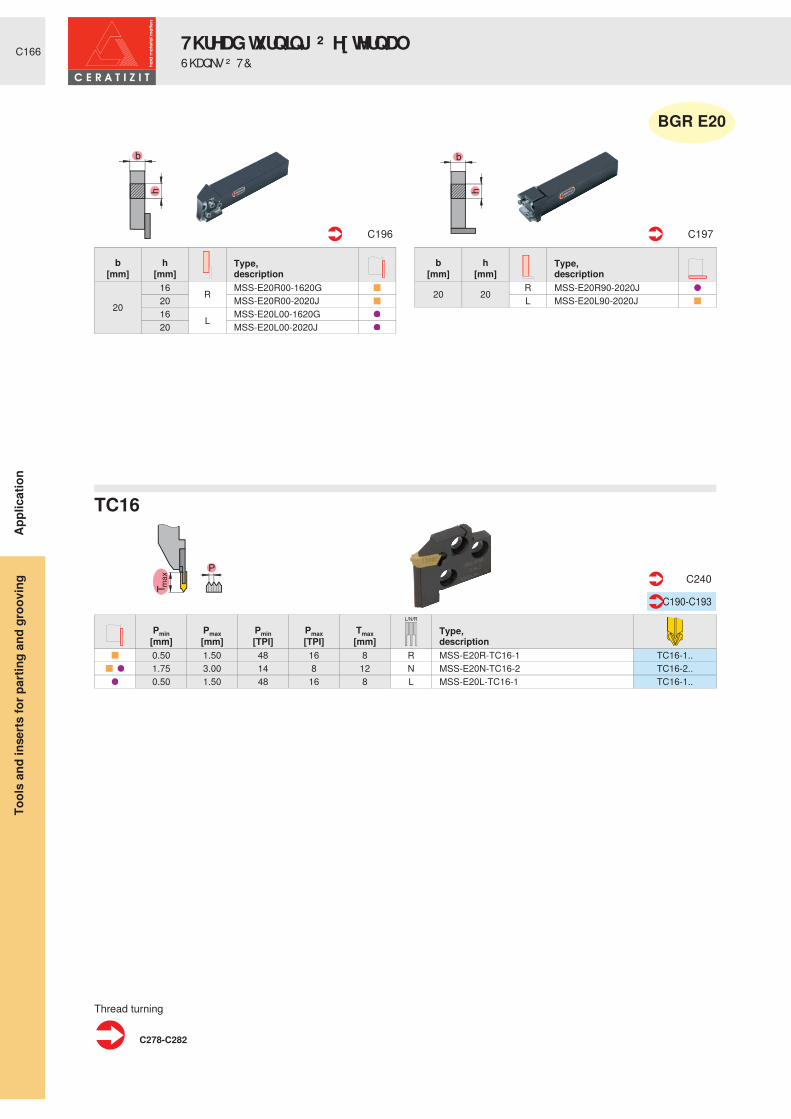
C166
P
L/N/R
Pmin Pmax Pmin Pmax Tmax Type,description[mm] [mm] [TPI] [TPI] [mm]
0.50 1.50 48 16 8 R MSS-E20R-TC16-1 TC16-1.. 1.75 3.00 14 8 12 N MSS-E20N-TC16-2 TC16-2.. 0.50 1.50 48 16 8 L MSS-E20L-TC16-1 TC16-1..
C240
C190-C193
C278-C282
Type,description
b h[mm] [mm]
20
16 R MSS-E20R00-1620G20 MSS-E20R00-2020J16 L MSS-E20L00-1620G20 MSS-E20L00-2020J
C196
Type,description
b h[mm] [mm]
20 20 R MSS-E20R90-2020JL MSS-E20L90-2020J
C197
� ƒ � � ƒ
TC16
Thread turning
BGR E20
Appl
icat
ion
7KUHDG� WXUQ LQ J� ² � H[ WHUQ DO6KDQNV� ² � 7 &
Tool
s an
d in
serts
for p
artin
g an
d gr
oovi
ng

C167
dA
dA
P
L/N/R
Pmin Pmax Pmin Pmax Tmax Type,description[mm] [mm] [TPI] [TPI] [mm]
0.50 1.50 48 16 8 R MSS-E25R-TC16-1 TC16-1.. 1.75 3.00 14 8 10 MSS-E25R-TC16-2 TC16-2.. 3.50 5.00 7 5 12 N MSS-E25N-TC16-3 TC16-3.. 0.50 1.50 48 16 8 L MSS-E25L-TC16-1 TC16-1.. 1.75 3.00 14 8 10 MSS-E25L-TC16-2 TC16-2..
C240
C190-C193
Type,description
b h dA[mm] [mm] [mm]
25 25
R
MSS-E25R00-2525L 40 UT40-MSS-E25R00 50 UT50-MSS-E25R00 63 UT63-MSS-E25R00
25 25
L
MSS-E25L00-2525L 40 UT40-MSS-E25L00 50 UT50-MSS-E25L00 63 UT63-MSS-E25L00
C196 C246
Type,description
b h dA[mm] [mm] [mm]
25 25 R
MSS-E25R90-2525L 40 UT40-MSS-E25R90 50 UT50-MSS-E25R9025 25
LMSS-E25L90-2525L
40 UT40-MSS-E25L90 50 UT50-MSS-E25L90
C197 C247
C278-C282
� ƒ � � ƒ
TC16
Thread turning
BGR E25
Appl
icat
ion
7KUHDG� WXUQ LQ J� ² � H[ WHUQ DO6KDQNV� ² � 8 76 � ² � 7 &
Tool
s an
d in
serts
for p
artin
g an
d gr
oovi
ng

C168
b
P
h
RL
Type,description
h b Tmax Pmin Pmax Pmin Pmax[mm] [mm] [mm] [mm] [mm] [TPI] [TPI]
12 12 10 0.50 3.00 48 8 R E12R00-1212-TC16 TC16-1/2..L E12L00-1212-TC16 TC16-1/2..
C241 C190-C193
C278-C282
TC16
Thread turning
Appl
icat
ion
0 RQREORF� WRROV� ² � 7 &7KUHDG� WXUQ LQ J� ² � H[ WHUQ DO
Tool
s an
d in
serts
for p
artin
g an
d gr
oovi
ng

C169
l 2
Ø dAl 2
Ø dA
P
Dmin
L/N/R
l2 dA Type,
description[mm] [mm]48 32
RMSS-I32R90-1.5D-N
80 40 MSS-I32R90-2.5D-N64 40 UT40-MSS-I32R90-2D48 32
LMSS-I32L90-1.5D-N
80 40 MSS-I32L90-2.5D-N64 50 UT50-MSS-I32L90-2D
C231-C232 C249
Type,description
Dmin Tmax Pmin Pmax Pmin Pmax[mm] [mm] [mm] [mm] [TPI] [TPI]
40 7
0.50 1.50 48 16 R MSS-I32R-TC16-1 TC16-1.. 1.75 3.00 14 8 MSS-I32R-TC16-2 TC16-2.. 3.50 5.00 7 5 N MSS-I32N-TC16-3 TC16-3.. 0.50 1.50 48 16 L MSS-I32L-TC16-1 TC16-1.. 1.75 3.00 14 8 MSS-I32L-TC16-2 TC16-2..
C242
C190-C193
C278-C282
TC16
TC16
Thread turning
BGR I32
Appl
icat
ion
6KDQNV� ² � 8 76 � ² � 7 &7KUHDG� WXUQ LQ J� ² � LQ WHUQ DO
Tool
s an
d in
serts
for p
artin
g an
d gr
oovi
ng

C170
Pl 2dA
Dmin
P
D
d
l
A
2
RL
Type,description
Dmin l2 dA Tmax Pmin Pmax Pmin Pmax[mm] [mm] [mm] [mm] [mm] [mm] [TPI] [TPI]
20 32 20 4 0.50 3.00 48 8 R I16R90-2D-TC16 TC16-1/2..32 20 4 0.50 3.00 48 8 L I16L90-2D-TC16 TC16-1/2..
25 40 25 5 0.50 5.00 48 5 R I20R90-2D-TC16 TC16-..40 25 5 0.50 5.00 48 5 L I20L90-2D-TC16 TC16-..
32 50 32 6 0.50 5.00 48 5 R I25R90-2D-TC16 TC16-..50 32 6 0.50 5.00 48 5 L I25L90-2D-TC16 TC16-..
20 32 40 4 0.50 3.50 48 8 R UT40-MSS-I16R90-2D-TC16 TC16-1/2..25 40 40 5 0.50 5.00 48 5 R UT40-MSS-I20R90-2D-TC16 TC16-..
32 50 40 6 0.50 5.00 48 5 R UT40-MSS-I25R90-2D-TC16 TC16-..50 40 6 0.50 5.00 48 5 L UT40-MSS-I25L90-2D-TC16 TC16-..
C243 C190-C193 C245 C190-C193
C278-C282
TC16
Thread turning
Appl
icat
ion
0 RQREORF� ERULQJ� EDUV� ² � 8 76 � ² � 7 &7KUHDG� WXUQ LQ J� ² � LQ WHUQ DO
Tool
s an
d in
serts
for p
artin
g an
d gr
oovi
ng


C172
l 2Ø dA
l 2
Ø dA
DN
54
/ 6
8
DG
dA
DN
DG
54
/ 6
8
dA
Boring bars 1.5D Boring bars 2.5D
TC milling cutters
TC milling cutters
dA = 32l2 = 48
dA = 25 - 32DG = M16 - M80
DG = R5/8 - R13/4
dA = 40l2 = 80
dA = 25 - 32DG = M27 - M80
DG = R11/4 - R21/2
Thread milling2 YHUYLHZ � ² � P RGXODU� VWUXFWXUH
Tool
s an
d in
serts
for p
artin
g an
d gr
oovi
ng

C173
DG
DG
TC16
DG = M82 - M300
DG = R23/4 - R6
Appl
icat
ion
Thread milling2 YHUYLHZ � ² � P RGXODU� VWUXFWXUH
Tool
s an
d in
serts
for p
artin
g an
d gr
oovi
ng

C174
l 2
Ø dA
P
Dmin
L/N/R
Type,description
dA l2 [mm] [mm]
32 48 R MSS-I32R90-1.5D-N40 80 MSS-I32R90-2.5D-N
C231-C232
Type,description
Dmin Tmax Pmin Pmax Pmin Pmax[mm] [mm] [mm] [mm] [TPI] [TPI]
447
1.75 3.00 14 8 R MSS-I32R-TC16-2 TC16-2.. 3.50 5.00 7 5 N MSS-I32N-TC16-3 TC16-3.. 59 1.75 3.00 14 8 R MSS-I32R-TC16-2 TC16-2.. 3.50 5.00 7 5 N MSS-I32N-TC16-3 TC16-3..
C242
C190-C193
C283-C289
� � ƒ
TC16
For further information on thread milling see
BGR I32
Appl
icat
ion
7KUHDG� P LOOLQ J� ² � LQ WHUQ DO%RULQJ� EDUV� ² � 7 &
Tool
s an
d in
serts
for p
artin
g an
d gr
oovi
ng

C175
Pl 2
dA
Dmin
RL
Type,description
DN l2 dA Tmax Pmin Pmax Pmin Pmax[mm] [mm] [mm] [mm] [mm] [mm] [TPI] [TPI]
25 54 25 3.0 0.50 5.00 28 5 R I25R90-2D-TC16-W TC16-..32 68 32 3.5 I32R90-2D-TC16-W TC16-..
C244 C190-C193
C283-C289
For further information on thread milling see
Appl
icat
ion
7KUHDG� P LOOLQ J� ² � LQ WHUQ DO7KUHDG� P LOOLQJ� FXWWHUV� ² � 7 &
Tool
s an
d in
serts
for p
artin
g an
d gr
oovi
ng

C176
l 2
Ø dA
P
Dmin
L/N/R
Type,description
dA l2 [mm] [mm]
32 48 R MSS-I32R90-1.5D-N40 80 MSS-I32R90-2.5D-N
C231-C232
Type,description
Dmin Tmax Pmin Pmax Pmin Pmax[mm] [mm] [mm] [mm] [TPI] [TPI]
447
1.75 3.00 14 8 R MSS-I32R-TC16-2 TC16-2.. 3.50 5.00 7 5 N MSS-I32N-TC16-3 TC16-3.. 59 1.75 3.00 14 8 R MSS-I32R-TC16-2 TC16-2.. 3.50 5.00 7 5 N MSS-I32N-TC16-3 TC16-3..
C242
C190-C193
C283-C289
� � ƒ
TC16
For further information on thread milling see
BGR E32
Appl
icat
ion
7KUHDG� P LOOLQ J� ² � H[ WHUQ DO%RULQJ� EDUV� ² � 7 &
Tool
s an
d in
serts
for p
artin
g an
d gr
oovi
ng

C177
Pl 2
dA
Dmin
RL
Type,description
DN l2 dA Tmax Pmin Pmax Pmin Pmax[mm] [mm] [mm] [mm] [mm] [mm] [TPI] [TPI]
25 54 25 3.0 0.50 5.00 28 5 R I25R90-2D-TC16-W TC16-..32 68 32 3.5 I32R90-2D-TC16-W TC16-..
C244 C190-C193
C283-C289
� � ƒ
For further information on thread milling see
Appl
icat
ion
7KUHDG� P LOOLQ J� ² � H[ WHUQ DO7KUHDG� P LOOLQJ� FXWWHUV� ² � 7 &
Tool
s an
d in
serts
for p
artin
g an
d gr
oovi
ng

C178
GX..E
V� � � � � � ² � � � �
GX..S
V� � � � � � ² � � � � �
GX..R
V� � � � � � ² � � � �
AX
s = 3,0
SX
V� � � � � � ² � � � �
C180-C181
C182
C183
C184
C185
OverviewIn
serts
Tool
s an
d in
serts
for p
artin
g an
d gr
oovi
ng

C179
LX
V� � � � � � ² � � � � �
FX
V� � � � � � ² � � � �
PX
V� � � � � � ² � � � �
MC
V� � � � � � ² � � � �
TC
C186
C187
C188
C189
Partial profile � � ƒ
C190Partial profile
� � ƒ
C191Full profile P HWU� � � � ƒ
C192Full profile : KLWZ � � � � ƒ
C193
Overview
Inse
rtsTo
ols
and
inse
rts fo
r par
ting
and
groo
ving

C180
PMKNSH
-F2
EN-M
40
VC
11000
GX GX-A GX GX GX GX
C53-C68 C70-C71 C268-C271 C255 C200-C202 C213-C215 C223 C233-C234 C237-C239C205-C207
R R R R R R R
r R r r r R r R
R R R R R
R r R r R
R r R r
H216
TTS
M20
CTW
7120
S40T
CTC1
325
SR12
7G
M12
7CT
P134
0CT
CP33
5CT
PP34
5CT
D411
0
LNR s l r amax
[mm] [mm] [mm] [mm]GX09-1E2.00N0.20-F2 R R N 2.00 9.0 0.20 2.0GX09-1E2.50N0.20-F2 R R N 2.50 9.0 0.20 2.0GX09-2E3.00N0.30-F2 R R N 3.00 9.0 0.30 2.5GX16-1E2.00N0.20-F2 R R N 2.00 16.0 0.20 2.0GX16-2E3.00N0.30-F2 R R N 3.00 16.0 0.30 2.5GX16-3E4.00N0.40-F2 R R N 4.00 16.0 0.40 3.0GX16-3E5.00N0.40-F2 R R N 5.00 16.0 0.40 3.0GX24-2E3.00N0.30-F2 R R R N 3.00 24.0 0.30 2.5GX24-2E3.50N0.30-F2 R R N 3.50 24.0 0.30 2.5GX24-3E4.00N0.40-F2 R R R R N 4.00 24.0 0.40 3.0GX24-3E5.00N0.40-F2 R R R R N 5.00 24.0 0.40 3.0GX24-4E6.00N0.50-F2 R R R R N 6.00 24.0 0.50 3.5GX09-1E2.00N0.20 R R R R N 2.00 9.0 0.20 1.5GX09-1E2.50N0.20 R R R R N 2.50 9.0 0.20 1.5GX09-2E3.00N0.30 R R R R N 3.00 9.0 0.30 2.0GX09-2E3.50N0.30 R R R N 3.50 9.0 0.30 2.0GX16-1E2.00N0.20 R R R R R N 2.00 16.0 0.20 2.0GX16-1E2.50N0.20 R R R R R N 2.50 16.0 0.20 2.0GX16-2E3.00N0.30 R R R R R N 3.00 16.0 0.30 2.5GX16-2E3.00N0.50 R R N 3.00 16.0 0.50 2.5GX16-2E3.50N0.30 R R R R R N 3.50 16.0 0.30 2.5GX16-3E4.00N0.40 R R R R R N 4.00 16.0 0.40 3.0GX16-3E4.00N0.60 R N 4.00 16.0 0.60 3.0GX16-3E4.50N0.40 R R N 4.50 16.0 0.40 3.0GX16-3E5.00N0.40 R R R R R N 5.00 16.0 0.40 3.0GX16-3E5.00N0.60 R R N 5.00 16.0 0.60 3.0GX16-4E6.00N0.50 R R R R N 6.00 16.0 0.50 3.5GX16-4E6.00N0.80 R R N 6.00 16.0 0.80 3.5GX24-2E3.00N0.30 R R R R N 3.00 24.0 0.30 2.5GX24-3E4.00N0.40 R R R R N 4.00 24.0 0.40 3.0GX24-3E5.00N0.40 R R R R N 5.00 24.0 0.40 3.0GX24-4E6.00N0.50 R R R R N 6.00 24.0 0.50 3.5GX09-1E2.00N0.20-M40 R R R R N 2.00 9.0 0.20 1.5GX09-2E3.00N0.30-M40 R R R R N 3.00 9.0 0.30 2.0GX16-1E2.00N0.20-M40 R R R R N 2.00 16.0 0.20 2.0GX16-2E3.00N0.30-M40 R R R R N 3.00 16.0 0.30 3.0GX16-3E4.00N0.40-M40 R R R R N 4.00 16.0 0.40 3.5GX16-3E5.00N0.40-M40 R R R R N 5.00 16.0 0.40 3.5GX16-4E6.00N0.50-M40 R R R R N 6.00 16.0 0.50 4.0GX24-2E3.00N0.30-M40 R R R N 3.00 24.0 0.30 3.5GX24-3E4.00N0.40-M40 R R R N 4.00 24.0 0.40 4.0GX24-3E5.00N0.40-M40 R R R N 5.00 24.0 0.40 4.0GX24-4E6.00N0.50-M40 R R R N 6.00 24.0 0.50 4.0
H216
TTS
M20
CTW
7120
S40T
CTC1
325
SR12
7G
M12
7CT
P134
0CT
CP33
5CT
PP34
5CT
D411
0
LNR s l r amax
Inse
rtsTo
ols
and
inse
rts fo
r par
ting
and
groo
ving
System GX-E

C181
PMKNSH
-M1
-27P
VC
11000
GX GX-A GX GX GX GX
C53-C68 C70-C71 C268-C271 C255 C200-C202 C213-C215 C223 C233-C234 C237-C239C205-C207
R R R R R R R
r R r r r R r R
R R R R R
R r R r R
R r R r
H216
TTS
M20
CTW
7120
S40T
CTC1
325
SR12
7G
M12
7CT
P134
0CT
CP33
5CT
PP34
5CT
D411
0
LNR s l r amax
[mm] [mm] [mm] [mm]GX16-1E2.00N0.20-M1 R R N 2.00 16.0 0.20 2.0GX16-2E3.00N0.20-M1 R R N 3.00 16.0 0.20 2.5GX16-3E4.00N0.30-M1 R R N 4.00 16.0 0.30 3.0GX24-1E2.00N0.20-M1 R R R N 2.00 24.0 0.20 2.5GX24-2E3.00N0.20-M1 R R R N 3.00 24.0 0.20 2.5GX24-3E4.00N0.30-M1 R R R N 4.00 24.0 0.30 3.0GX16-1E2.00N0.20-27P R N 2.00 16.0 0.20 2.0GX16-2E3.00N0.30-27P R N 3.00 16.0 0.30 2.5GX16-3E4.00N0.40-27P R N 4.00 16.0 0.40 3.0GX16-4E6.00N0.50-27P R N 6.00 16.0 0.50 3.5GX24-2E3.00N0.30-27P R N 3.00 24.0 0.30 2.5GX24-3E4.00N0.40-27P R N 4.00 24.0 0.40 3.0GX24-3E5.00N0.40-27P R N 5.00 24.0 0.40 3.0GX24-4E6.00N0.50-27P R N 6.00 24.0 0.50 3.5
H216
TTS
M20
CTW
7120
S40T
CTC1
325
SR12
7G
M12
7CT
P134
0CT
CP33
5CT
PP34
5CT
D411
0
LNR s l r amax
Inse
rtsTo
ols
and
inse
rts fo
r par
ting
and
groo
ving
System GX-E

C182
PMKNSH
ER-E
LEN
VC
11000
GX GX GX GX
C53-C68 C70-C71 C268-C271 C255 C203-C204 C235-C236 C237-C238C213-C214
R R R R R R R
r R r r r R r R
R R R R R
R r R r R
R r R r
H216
TTS
M20
CTW
7120
S40T
CTC1
325
SR12
7G
M12
7CT
P134
0CT
CP33
5CT
PP34
5CT
D411
0
LNR s s1 s2 l r Tmax amax
[mm] [mm] [mm] [mm] [mm] [mm] [mm]GX09-1S0.60L R R L 0.60 0.4 0.5 9.0 0.75 GX09-1S0.60R R R R 0.60 0.4 0.5 9.0 0.75 GX09-1S0.80L R R L 0.80 0.6 0.7 9.0 0.94 GX09-1S0.80R R R R 0.80 0.6 0.7 9.0 0.94 GX09-1S0.90L R R L 0.90 0.7 0.8 9.0 1.04 GX09-1S0.90R R R R 0.90 0.7 0.8 9.0 1.04 GX09-1S1.00L R R L 1.00 0.8 0.9 9.0 1.14 GX09-1S1.00R R R R 1.00 0.8 0.9 9.0 1.14 GX09-1S1.20L R R L 1.20 1.0 1.1 9.0 1.34 GX09-1S1.20R R R R 1.20 1.0 1.1 9.0 1.34 GX09-1S1.40L R R L 1.40 1.2 1.3 9.0 1.53 GX09-1S1.40R R R R 1.40 1.2 1.3 9.0 1.53 GX09-1S1.70L R R L 1.70 1.5 1.6 9.0 1.82 GX09-1S1.70R R R R 1.70 1.5 1.6 9.0 1.82 GX16-2S0.60L R R L 0.60 0.40 0.50 16.0 0.75 GX16-2S0.60R R R R 0.60 0.40 0.50 16.0 0.75 GX16-2S0.80L R R L 0.80 0.60 0.70 16.0 0.94 GX16-2S0.80R R R R 0.80 0.60 0.70 16.0 0.94 GX16-2S0.90L R R L 0.90 0.70 0.80 16.0 1.04 GX16-2S0.90R R R R 0.90 0.70 0.80 16.0 1.04 GX16-2S1.00L R R L 1.00 0.80 0.90 16.0 1.14 GX16-2S1.00R R R R 1.00 0.80 0.90 16.0 1.14 GX16-2S1.20L R R L 1.20 1.00 1.10 16.0 1.34 GX16-2S1.20R R R R 1.20 1.00 1.10 16.0 1.34 GX16-2S1.40L R R L 1.40 1.20 1.30 16.0 1.53 GX16-2S1.40R R R R 1.40 1.20 1.30 16.0 1.53 GX16-2S1.70L R R L 1.70 1.50 1.60 16.0 1.82 GX16-2S1.70R R R R 1.70 1.50 1.60 16.0 1.82 GX16-2S1.95L R R L 1.95 1.75 1.85 16.0 2.07 GX16-2S1.95R R R R 1.95 1.75 1.85 16.0 2.07 GX16-2S2.25L R R L 2.25 2.00 2.15 16.0 2.36 GX16-2S2.25R R R R 2.25 2.00 2.15 16.0 2.36 GX09-1S1.95N R R N 1.95 1.75 1.85 9.0 0.10 7.00 2.0GX09-1S2.25N R R N 2.25 2.00 2.15 9.0 0.10 7.00 2.0GX09-2S2.75N R R N 2.75 2.50 2.65 9.0 0.10 7.00 2.0GX09-2S3.25N R R N 3.25 3.00 3.15 9.0 0.10 7.00 2.0GX16-2S2.75N R R N 2.75 2.50 2.65 16.0 0.10 12.00 3.0GX16-2S3.25N R R N 3.25 3.00 3.15 16.0 0.10 12.00 3.0GX16-3S4.25N R R N 4.25 4.00 4.15 16.0 0.20 12.00 3.5GX16-4S5.25N R R N 5.25 5.00 5.15 16.0 0.20 12.00 4.0
H216
TTS
M20
CTW
7120
S40T
CTC1
325
SR12
7G
M12
7CT
P134
0CT
CP33
5CT
PP34
5CT
D411
0
LNR s s1 s2 l r Tmax amax
DIN 471 - 472: DIN standard for circlip groovess: insert widths1: circlip widths2: standard groove width H13 (+0.14/0)
Inse
rtsTo
ols
and
inse
rts fo
r par
ting
and
groo
ving
System GX-S

C183
PMKNSH
ER-E
LEN
-M3
-27P
VC
11000
GX GX-A GX GX GX GX
C53-C68 C70-C71 C268-C271 C255 C202-C204 C213-C215 C223 C234-C236 C237-C239C205-C207
R R R R R R R
r R r r r R r R
R R R R R
R r R r R
R r R r
H216
TTS
M20
CTW
7120
S40T
CTC1
325
SR12
7G
M12
7CT
P134
0CT
CP33
5CT
PP34
5CT
D411
0
LNR s l r Tmax amax
[mm] [mm] [mm] [mm] [mm]GX09-1R0.80L R R L 1.60 9.0 0.80 1.78 GX09-1R0.80R R R R 1.60 9.0 0.80 1.78 GX16-2R0.80L R R L 1.60 16.0 0.80 1.78 GX16-2R0.80R R R R 1.60 16.0 0.80 1.78 GX16-2R1.00L R R L 2.00 16.0 1.00 2.18 GX16-2R1.00R R R R 2.00 16.0 1.00 2.18 GX16-2R1.20L R R L 2.40 16.0 1.20 2.58 GX16-2R1.20R R R R 2.40 16.0 1.20 2.58 GX09-1R1.00N R R R N 2.00 9.0 1.00 7.00 1.0GX09-1R1.20N R R R N 2.40 9.0 1.20 7.00 1.2GX16-2R1.50N R R R R N 6.00 16.0 1.50 12.00 1.5GX16-3R2.00N R R R R N 6.00 16.0 2.00 12.00 2.0GX16-3R2.50N R R R R N 5.00 16.0 2.50 12.00 2.5GX16-4R3.00N R R R R N 6.00 16.0 3.00 12.00 3.0GX24-2R1.50N-M3 R R R N 3.00 24.4 1.50 21.00 1.5GX24-3R2.00N-M3 R R R N 4.00 24.4 2.00 21.00 2.5GX24-3R2.50N-M3 R R R N 5.00 24.4 2.50 21.00 3.0GX24-4R3.00N-M3 R R R N 6.00 24.4 3.00 21.00 4.0GX16-2R1.50N-27P R N 3.00 16.0 1.50 12.00 1.5GX16-3R2.00N-27P R N 4.00 16.0 2.00 12.00 2.0GX16-3R2.50N-27P R N 5.00 16.0 2.50 12.00 2.5GX24-4R3.00N-27P R N 6.00 25.3 3.00 21.00 4.0
H216
TTS
M20
CTW
7120
S40T
CTC1
325
SR12
7G
M12
7CT
P134
0CT
CP33
5CT
PP34
5CT
D411
0
LNR s l r Tmax amax
Inse
rtsTo
ols
and
inse
rts fo
r par
ting
and
groo
ving
System GX-R

C184
PMKNSH
-F50
VC
11000
AX AX
C53-C68 C70-C71 C268-C271 C255 C208 C216-C217
R R R R R R R
r R r r r R r R
R R R R R
R r R r R
R r R r
H216
TTS
M20
CTW
7120
S40T
CTC1
325
SR12
7G
M12
7CT
P134
0CT
CP33
5CT
PP34
5CT
D411
0
LNR s l r amax
[mm] [mm] [mm] [mm]AX05-E3.00N0.30-10-F50 R N 3.00 24.0 0.30 5.0AX10-E3.00N0.30-20-F50 R N 3.00 34.0 0.30 10.0AX15-E3.00N0.30-30-F50 R N 3.00 44.0 0.30 15.0
H216
TTS
M20
CTW
7120
S40T
CTC1
325
SR12
7G
M12
7CT
P134
0CT
CP33
5CT
PP34
5CT
D411
0
LNR s l r amax
Inse
rtsTo
ols
and
inse
rts fo
r par
ting
and
groo
ving
System AX

C185
PMKNSH
-F2
-M2
-M3
-M1
-27P
s s s
6°
Κ°
R N L
r r
a max
Κ°
r r
sr
a max
VC
11000
SX SX SX
C53-C68 C70-C71 C268-C271 C255 C209 C224-C226C218
R R R R R R R
r R r r r R r R
R R R R R
R r R r R
R r R r
H216
TTS
M20
CTW
7120
S40T
CTC1
325
SR12
7G
M12
7CT
P134
0CT
CP33
5CT
PP34
5CT
D411
0
LNR s r amax K
[mm] [mm] [mm] > ƒ @SX E2.00N0.20-F2 R R N 2.00 0.20 1.5 SX E3.00N0.30-F2 R R R R N 3.00 0.30 2.0 SX E4.00N0.40-F2 R R N 4.00 0.40 2.5 SX E2.00N0.20-M2 R R R R N 2.00 0.20 1.5 SX E3.00N0.30-M2 R R R R N 3.00 0.30 2.0 SX E4.00N0.40-M2 R R R R N 4.00 0.40 2.5 SX E5.00N0.40-M2 R R N 5.00 0.40 2.7 SX E6.00N0.50-M2 R R N 6.00 0.50 3.0 SX R1.50N-M3 R R N 3.00 1.50 1.5 SX R2.00N-M3 R R N 4.00 2.00 2.0 SX R2.50N-M3 R R N 5.00 2.50 2.5 SX R3.00N-M3 R N 6.00 3.00 3.0 SX E2.00L6-M1 R R L 2.00 0.20 6SX E2.00N0.20-M1 R R R N 2.00 0.20 SX E2.00R6-M1 R R R 2.00 0.20 6SX E3.00L6-M1 R R L 3.00 0.20 6SX E3.00N0.20-M1 R R R R N 3.00 0.20 SX E3.00R6-M1 R R R 3.00 0.20 6SX E4.00L6-M1 R R L 4.00 0.30 6SX E4.00N0.30-M1 R R R R N 4.00 0.30 SX E4.00R6-M1 R R R 4.00 0.30 6SX E5.00N0.30-M1 R R N 5.00 0.30 SX E6.00N0.40-M1 R R N 6.00 0.40 SX E2.00N0.20-27P R N 2.00 0.20 2.0 SX E3.00N0.30-27P R N 3.00 0.30 2.5 SX E4.00N0.40-27P R N 4.00 0.40 3.0
H216
TTS
M20
CTW
7120
S40T
CTC1
325
SR12
7G
M12
7CT
P134
0CT
CP33
5CT
PP34
5CT
D411
0
LNR s r amax K
Inse
rtsTo
ols
and
inse
rts fo
r par
ting
and
groo
ving
System SX

C186
PMKNSH
-M2
-M3
VC
11000
LX LX
C53-C68 C70-C71 C268-C271 C255 C210 C227
R R R R R R R
r R r r r R r R
R R R R R
R r R r R
R r R r
H216
TTS
M20
CTW
7120
S40T
CTC1
325
SR12
7G
M12
7CT
P134
0CT
CP33
5CT
PP34
5CT
D411
0
LNR s l r amax
[mm] [mm] [mm] [mm]LX E10.00N0.80-M2 R R R N 10.00 19.0 0.80 5.0LX E8.00N0.80-M2 R R R N 8.00 19.0 0.80 5.0 LX R4.00N-M3 R R R N 8.00 19.0 4.00 5.0
H216
TTS
M20
CTW
7120
S40T
CTC1
325
SR12
7G
M12
7CT
P134
0CT
CP33
5CT
PP34
5CT
D411
0
LNR s l r amax
Inse
rtsTo
ols
and
inse
rts fo
r par
ting
and
groo
ving
System LX

C187
PMKNSH
-F1
-M1
-R2
-27P
VC
11000
FX FX FX
C53-C68 C70-C71 C268-C271 C255 C211-C212 C228C219
R R R R R R R
r R r r r R r R
R R R R R
R r R r R
R r R r
H216
TTS
M20
CTW
7120
S40T
CTC1
325
SR12
7G
M12
7CT
P134
0CT
CP33
5CT
PP34
5CT
D411
0
LNR s r K
[mm] [mm] > ƒ @FX 2.2L5-F1 R R L 2.20 0.15 5FX 2.2N0.15-F1 R R R R N 2.20 0.15 FX 2.2R5-F1 R R R 2.20 0.15 5FX 3.1L5-F1 R R L 3.10 0.20 5FX 3.1L8-F1 R L 3.10 0.20 8FX 3.1N0.20-F1 R R R R N 3.10 0.20 FX 3.1N0.40-F1 R R R R N 3.10 0.40 FX 3.1R5-F1 R R R 3.10 0.20 5FX 3.1R8-F1 R R 3.10 0.20 8FX 4.1N0.20-F1 R R R R N 4.10 0.20 FX 4.1N0.50-F1 R R N 4.10 0.50 FX 2.2L4-M1 R R R R R L 2.20 0.10 4FX 2.2N0.10-M1 R R R R R R N 2.20 0.10 FX 2.2R4-M1 R R R R R R 2.20 0.10 4FX 3.1L6-M1 R R R R R L 3.10 0.15 6FX 3.1N0.15-M1 R R R R R R N 3.10 0.15 FX 3.1R6-M1 R R R R R R 3.10 0.15 6FX 4.1L6-M1 R R R R L 4.10 0.20 6FX 4.1N0.20-M1 R R R R R R N 4.10 0.20 FX 4.1R6-M1 R R R R R 4.10 0.20 6FX 5.1L6-M1 R R L 5.10 0.25 6FX 5.1N0.25-M1 R R R R R R N 5.10 0.25 FX 5.1R6-M1 R R 5.10 0.25 6FX 6.5L6-M1 R R L 6.50 0.30 6FX 6.5N0.30-M1 R R R R N 6.50 0.30 FX 8.2N0.40-M1 R R R R R N 8.20 0.40 FX 9.7N0.40-M1 R R R R N 9.70 0.40 FX 3.1N0.40-R2 R R R R N 3.10 0.40 FX 4.1N0.50-R2 R R R R N 4.10 0.50 FX 2.2N0.10-27P R N 2.20 0.10 FX 3.1N0.15-27P R N 3.10 0.15 FX 4.1N0.15-27P R N 4.10 0.20
H216
TTS
M20
CTW
7120
S40T
CTC1
325
SR12
7G
M12
7CT
P134
0CT
CP33
5CT
PP34
5CT
D411
0
LNR s r K
Inse
rtsTo
ols
and
inse
rts fo
r par
ting
and
groo
ving
System FX

C188
PMKNSH
-F3
r
7°
l
sR
K° K°
r rsN
sL
r
VC
11000
PX
C53-C68 C70-C71 C268-C271 C255 C220
R R R R R R R
r R r r r R r R
R R R R R
R r R r R
R r R r
H216
TTS
M20
CTW
7120
S40T
CTC1
325
SR12
7G
M12
7CT
P134
0CT
CP33
5CT
PP34
5CT
D411
0
LNR s l r K
[mm] [mm] [mm] > ƒ @PX20-1E1.00L05-F3 R L 1.00 20.0 0.08 5PX20-1E1.00N0.10-F3 R N 1.00 20.0 0.10 PX20-1E1.00R05-F3 R R 1.00 20.0 0.08 5PX20-2E1.50L05-F3 R L 1.50 20.3 0.08 5PX20-2E1.50N0.10-F3 R N 1.50 20.3 0.10 PX20-2E1.50R05-F3 R R 1.50 20.3 0.08 5PX20-3E2.00L05-F3 R L 2.00 20.3 0.08 5PX20-3E2.00N0.15-F3 R N 2.00 20.3 0.15 PX20-3E2.00R05-F3 R R 2.00 20.3 0.08 5
H216
TTS
M20
CTW
7120
S40T
CTC1
325
SR12
7G
M12
7CT
P134
0CT
CP33
5CT
PP34
5CT
D411
0
LNR s l r K
Inse
rtsTo
ols
and
inse
rts fo
r par
ting
and
groo
ving
System PX
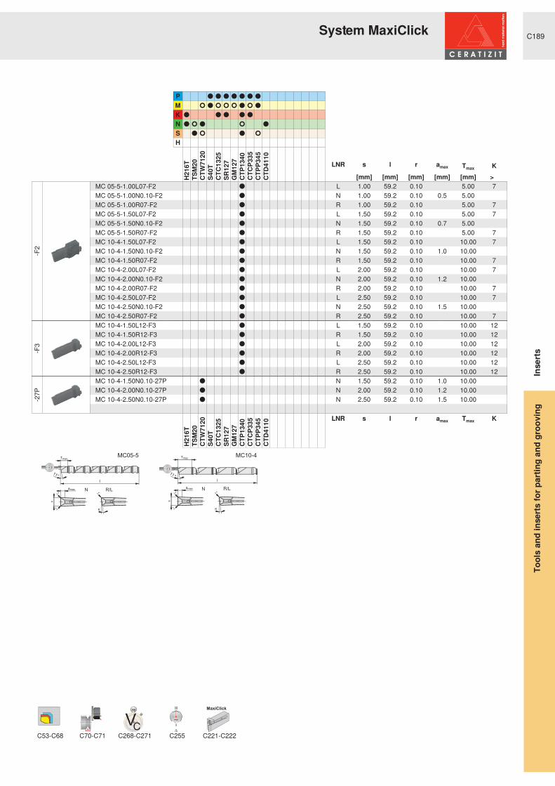
C189
PMKNSH
-F2
-F3
-27P
VC
11000
MaxiClick
C53-C68 C70-C71 C268-C271 C255 C221-C222
R R R R R R R
r R r r r R r R
R R R R R
R r R r R
R r R r
H216
TTS
M20
CTW
7120
S40T
CTC1
325
SR12
7G
M12
7CT
P134
0CT
CP33
5CT
PP34
5CT
D411
0
LNR s l r amax Tmax K [mm] [mm] [mm] [mm] [mm] > ƒ @
MC 05-5-1.00L07-F2 R L 1.00 59.2 0.10 5.00 7MC 05-5-1.00N0.10-F2 R N 1.00 59.2 0.10 0.5 5.00 MC 05-5-1.00R07-F2 R R 1.00 59.2 0.10 5.00 7MC 05-5-1.50L07-F2 R L 1.50 59.2 0.10 5.00 7MC 05-5-1.50N0.10-F2 R N 1.50 59.2 0.10 0.7 5.00 MC 05-5-1.50R07-F2 R R 1.50 59.2 0.10 5.00 7MC 10-4-1.50L07-F2 R L 1.50 59.2 0.10 10.00 7MC 10-4-1.50N0.10-F2 R N 1.50 59.2 0.10 1.0 10.00 MC 10-4-1.50R07-F2 R R 1.50 59.2 0.10 10.00 7MC 10-4-2.00L07-F2 R L 2.00 59.2 0.10 10.00 7MC 10-4-2.00N0.10-F2 R N 2.00 59.2 0.10 1.2 10.00 MC 10-4-2.00R07-F2 R R 2.00 59.2 0.10 10.00 7MC 10-4-2.50L07-F2 R L 2.50 59.2 0.10 10.00 7MC 10-4-2.50N0.10-F2 R N 2.50 59.2 0.10 1.5 10.00 MC 10-4-2.50R07-F2 R R 2.50 59.2 0.10 10.00 7MC 10-4-1.50L12-F3 R L 1.50 59.2 0.10 10.00 12MC 10-4-1.50R12-F3 R R 1.50 59.2 0.10 10.00 12MC 10-4-2.00L12-F3 R L 2.00 59.2 0.10 10.00 12MC 10-4-2.00R12-F3 R R 2.00 59.2 0.10 10.00 12MC 10-4-2.50L12-F3 R L 2.50 59.2 0.10 10.00 12MC 10-4-2.50R12-F3 R R 2.50 59.2 0.10 10.00 12MC 10-4-1.50N0.10-27P R N 1.50 59.2 0.10 1.0 10.00 MC 10-4-2.00N0.10-27P R N 2.00 59.2 0.10 1.2 10.00 MC 10-4-2.50N0.10-27P R N 2.50 59.2 0.10 1.5 10.00
H216
TTS
M20
CTW
7120
S40T
CTC1
325
SR12
7G
M12
7CT
P134
0CT
CP33
5CT
PP34
5CT
D411
0
LNR s l r amax Tmax K
Inse
rtsTo
ols
and
inse
rts fo
r par
ting
and
groo
ving
System MaxiClick

C190
PMKNSH
-27P
EN
11000
TC TC TC TC TC-F UTS-TC
C164-C177 C280-C291 C255 C240 C241 C243 C244 C245C242
R R
R R
R R
R
H216
TG
M21
3G
M24
0
Pmin Pmax Pmin Pmax l r H y[mm] [mm] [TPI] [TPI] [mm] [mm] [mm] [mm]
TC16-1 EI-A60-27P R 0.50 1.50 16 48 16.0 0.05 1.28 1.05TC16-2 EI-AG60-27P R 0.50 3.00 8 48 16.0 0.05 2.58 2.15TC16-2 EI-G60-27P R 1.75 3.00 8 14 16.0 0.15 2.49 2.15TC16-3 EI-N60-27P R 3.50 5.00 5 7 16.0 0.25 4.11 3.10TC16-1 EI-A60 R R 0.50 1.50 16 48 16.0 0.05 1.28 1.05TC16-2 EI-AG60 R R 0.50 3.00 8 48 16.0 0.05 2.58 2.15TC16-2 EI-G60 R R 1.75 3.00 8 14 16.0 0.15 2.49 2.15TC16-3 EI-N60 R R 3.50 5.00 5 7 16.0 0.25 4.11 3.10
H216
TG
M21
3G
M24
0
Pmin Pmax Pmin Pmax l r H y
Inse
rtsTo
ols
and
inse
rts fo
r par
ting
and
groo
ving
6 \ VWHP � 7&� � SDUWLDO� SURILOH� � � ƒ

C191
PMKNSH
EN
11000
TC TC TC TC TC-F UTS-TC
C164-C177 C280-C291 C255 C240 C241 C243 C244 C245C242
R R
R R
R R
R
H216
TG
M21
3G
M24
0
Pmin Pmax Pmin Pmax l r H y[mm] [mm] [TPI] [TPI] [mm] [mm] [mm] [mm]
TC16-1 EI-A55 R R 0.50 1.50 16 48 16.0 0.12 1.39 1.05TC16-2 EI-AG55 R R 0.50 3.00 8 48 16.0 0.12 2.92 2.15TC16-2 EI-G55 R R 1.75 3.00 8 14 16.0 0.23 2.78 2.15TC16-3 EI-N55 R R 3.50 5.00 5 7 16.0 0.46 4.34 3.10
H216
TG
M21
3G
M24
0
Pmin Pmax Pmin Pmax l r H y
Inse
rtsTo
ols
and
inse
rts fo
r par
ting
and
groo
ving
6 \ VWHP � 7&� � SDUWLDO� SURILOH� � � ƒ

C192
PMKNSH
-27P
EN
11000
TC TC TC TC TC-F UTS-TC
C164-C177 C280-C291 C255 C240 C241 C243 C244 C245C242
R R
R R
R R
R
H216
TG
M21
3G
M24
0
Pmin l r H y
[mm] [mm] [mm] [mm] [mm]TC16-1 E 0,5 ISO-27P R 0.50 16.0 0.05 0.33 1.05TC16-1 E 0,75 ISO-27P R 0.75 16.0 0.08 0.49 1.05TC16-1 E 1,0 ISO-27P R 1.00 16.0 0.12 0.64 1.05TC16-1 E 1,25 ISO-27P R 1.25 16.0 0.15 0.80 1.05TC16-1 E 1,5 ISO-27P R 1.50 16.0 0.18 0.96 1.05TC16-1 I 1,0 ISO-27P R 1.00 16.0 0.05 0.60 1.05TC16-1 I 1,5 ISO-27P R 1.50 16.0 0.08 0.89 1.05TC16-2 E 1,75 ISO-27P R 1.75 16.0 0.22 1.11 2.15TC16-2 E 2,0 ISO-27P R 2.00 16.0 0.25 1.27 2.15TC16-2 E 2,5 ISO-27P R 2.50 16.0 0.31 1.58 2.15TC16-2 E 3,0 ISO-27P R 3.00 16.0 0.38 1.90 2.15TC16-2 I 2,0 ISO-27P R 2.00 16.0 0.12 1.18 2.15TC16-2 I 3,0 ISO-27P R 3.00 16.0 0.19 1.76 2.15TC16-1 E 0,5 ISO R R 0.50 16.0 0.05 0.33 1.05TC16-1 E 0,75 ISO R R 0.75 16.0 0.08 0.49 1.05TC16-1 E 1,0 ISO R R 1.00 16.0 0.12 0.64 1.05TC16-1 E 1,25 ISO R R 1.25 16.0 0.15 0.80 1.05TC16-1 E 1,5 ISO R R 1.50 16.0 0.18 0.96 1.05TC16-1 I 0,5 ISO R R 0.50 16.0 0.02 0.30 1.05TC16-1 I 0,75 ISO R R 0.75 16.0 0.04 0.45 1.05TC16-1 I 1,0 ISO R R 1.00 16.0 0.05 0.60 1.05TC16-1 I 1,25 ISO R R 1.25 16.0 0.07 0.75 1.05TC16-1 I 1,5 ISO R R 1.50 16.0 0.08 0.89 1.05TC16-2 E 1,75 ISO R R 1.75 16.0 0.22 1.11 2.15TC16-2 E 2,0 ISO R R 2.00 16.0 0.25 1.27 2.15TC16-2 E 2,5 ISO R R 2.50 16.0 0.31 1.58 2.15TC16-2 E 3,0 ISO R R 3.00 16.0 0.38 1.90 2.15TC16-2 I 1,75 ISO R R 1.75 16.0 0.11 1.03 2.15TC16-2 I 2,0 ISO R R 2.00 16.0 0.12 1.18 2.15TC16-2 I 2,5 ISO R R 2.50 16.0 0.16 1.47 2.15TC16-2 I 3,0 ISO R R 3.00 16.0 0.19 1.76 2.15TC16-3 E 3,5 ISO R R 3.50 16.0 0.44 2.22 3.10TC16-3 E 4,0 ISO R R 4.00 16.0 0.50 2.53 3.10TC16-3 E 4,5 ISO R R 4.50 16.0 0.56 2.85 3.10TC16-3 E 5,0 ISO R R 5.00 16.0 0.63 3.16 3.10TC16-3 I 3,5 ISO R R 3.50 16.0 0.22 2.06 3.10TC16-3 I 4,0 ISO R R 4.00 16.0 0.25 2.35 3.10TC16-3 I 4,5 ISO R R 4.50 16.0 0.28 2.64 3.10TC16-3 I 5,0 ISO R R 5.00 16.0 0.31 2.94 3.10
H216
TG
M21
3G
M24
0
Pmin l r H y
Inse
rtsTo
ols
and
inse
rts fo
r par
ting
and
groo
ving
6 \ VWHP � 7&� � IXOO� SURILOH� � � ƒ
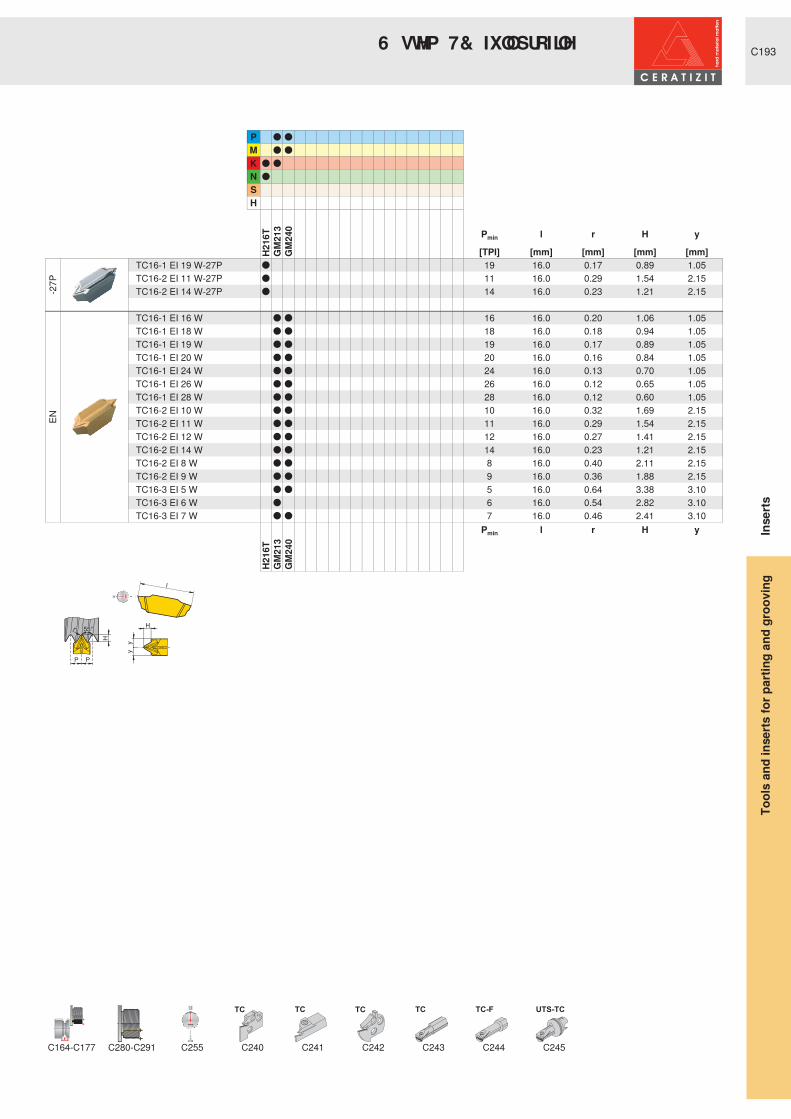
C193
PMKNSH
-27P
EN
11000
TC TC TC TC TC-F UTS-TC
C164-C177 C280-C291 C255 C240 C241 C243 C244 C245C242
R R
R R
R R
R
H216
TG
M21
3G
M24
0
Pmin l r H y
[TPI] [mm] [mm] [mm] [mm]TC16-1 EI 19 W-27P R 19 16.0 0.17 0.89 1.05TC16-2 EI 11 W-27P R 11 16.0 0.29 1.54 2.15TC16-2 EI 14 W-27P R 14 16.0 0.23 1.21 2.15 TC16-1 EI 16 W R R 16 16.0 0.20 1.06 1.05TC16-1 EI 18 W R R 18 16.0 0.18 0.94 1.05TC16-1 EI 19 W R R 19 16.0 0.17 0.89 1.05TC16-1 EI 20 W R R 20 16.0 0.16 0.84 1.05TC16-1 EI 24 W R R 24 16.0 0.13 0.70 1.05TC16-1 EI 26 W R R 26 16.0 0.12 0.65 1.05TC16-1 EI 28 W R R 28 16.0 0.12 0.60 1.05TC16-2 EI 10 W R R 10 16.0 0.32 1.69 2.15TC16-2 EI 11 W R R 11 16.0 0.29 1.54 2.15TC16-2 EI 12 W R R 12 16.0 0.27 1.41 2.15TC16-2 EI 14 W R R 14 16.0 0.23 1.21 2.15TC16-2 EI 8 W R R 8 16.0 0.40 2.11 2.15TC16-2 EI 9 W R R 9 16.0 0.36 1.88 2.15TC16-3 EI 5 W R R 5 16.0 0.64 3.38 3.10TC16-3 EI 6 W R 6 16.0 0.54 2.82 3.10TC16-3 EI 7 W R R 7 16.0 0.46 2.41 3.10
H216
TG
M21
3G
M24
0
Pmin l r H y Inse
rtsTo
ols
and
inse
rts fo
r par
ting
and
groo
ving
6 \ VWHP � 7&� � IXOO� SURILOH� � � ƒ

C194
0 66 � � ƒ
0 66 � � � ƒ
0 66 � � � ƒ
GX09
GX16
GX24
GX09
GX16
AX
SX
LX
FX
GX09
GX16
GX24
$ ; � � ƒ � � � ƒ
SX
FX
PX
MC
GX
SX
LX
FX
SBN...K
SBN...KS
Shanks
C196
C197
C198
Adapters
C199
Modules - external
C200
C201
C202
C203
C204
GX24 axial
C205-C206
GX axiallong
C207
C208
Modules - external
C209
C210
C211
FX long
C212
Monobloc - external
C213
C214
C215
C216-C217
C218
C219
C220
C221-C222
Blocks/blades
C223
C224
SXreinforced
C225-C226
C227
C228
C229
C230
Tool
s
OverviewTo
ols
and
inse
rts fo
r par
ting
and
groo
ving

C195
1,5 x D
2,5 x D
GX09
GX16
GX24
GX09
GX16
GX09
GX16
GX24
TC16
TC16
UTS/HSK-T
8 76 � � ƒ
8 76 � � � ƒ
8 76 � � � ƒ
UTS
+ 6 . � 7 � � ƒ
+ 6 . � 7 � � � ƒ
Boring bars
C231
C232
Modules- internal
C233
C234
C234
C235
C236
Monobloc- internal
C237
C238
C239
Threading
C240TC
monobloc
C241
C242
TC monobloc
C243
TC milling
C244
TC monobloc UTS
C245
C246
C247
C248
C249
C250
C251
Tool
s
Overview
Tool
s an
d in
serts
for p
artin
g an
d gr
oovi
ng
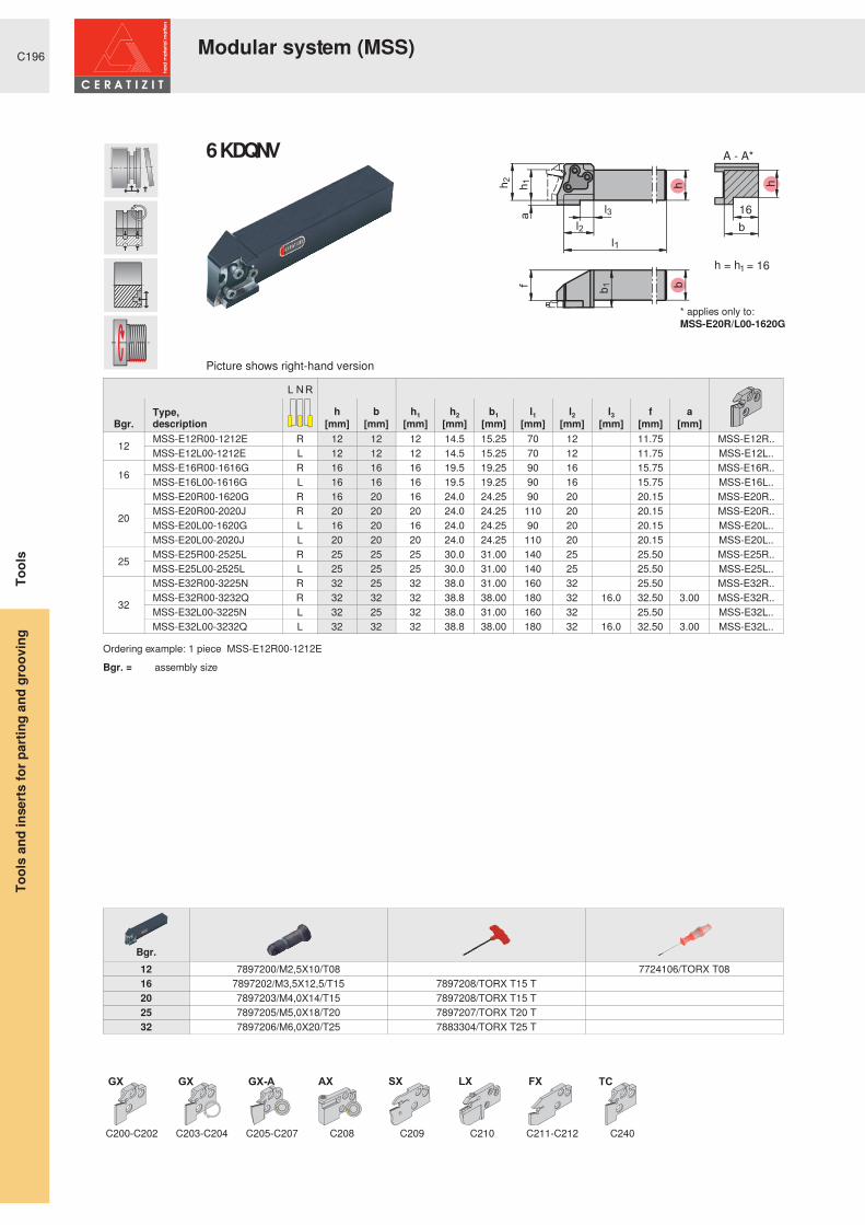
C196
������
��
�
b
����� �����
f b
b1
hh2
l2
l1
h1
a
l3
GX GX GX-A AX SX LX FX TC
Type,description
h b h1 h2 b1 l1 l2 l3 f aBgr. [mm] [mm] [mm] [mm] [mm] [mm] [mm] [mm] [mm] [mm]
12 MSS-E12R00-1212E R 12 12 12 14.5 15.25 70 12 11.75 MSS-E12R..MSS-E12L00-1212E L 12 12 12 14.5 15.25 70 12 11.75 MSS-E12L..
16 MSS-E16R00-1616G R 16 16 16 19.5 19.25 90 16 15.75 MSS-E16R..MSS-E16L00-1616G L 16 16 16 19.5 19.25 90 16 15.75 MSS-E16L..
20
MSS-E20R00-1620G R 16 20 16 24.0 24.25 90 20 20.15 MSS-E20R..MSS-E20R00-2020J R 20 20 20 24.0 24.25 110 20 20.15 MSS-E20R..MSS-E20L00-1620G L 16 20 16 24.0 24.25 90 20 20.15 MSS-E20L..MSS-E20L00-2020J L 20 20 20 24.0 24.25 110 20 20.15 MSS-E20L..
25 MSS-E25R00-2525L R 25 25 25 30.0 31.00 140 25 25.50 MSS-E25R..MSS-E25L00-2525L L 25 25 25 30.0 31.00 140 25 25.50 MSS-E25L..
32
MSS-E32R00-3225N R 32 25 32 38.0 31.00 160 32 25.50 MSS-E32R..MSS-E32R00-3232Q R 32 32 32 38.8 38.00 180 32 16.0 32.50 3.00 MSS-E32R..MSS-E32L00-3225N L 32 25 32 38.0 31.00 160 32 25.50 MSS-E32L..MSS-E32L00-3232Q L 32 32 32 38.8 38.00 180 32 16.0 32.50 3.00 MSS-E32L..
Ordering example: 1 piece MSS-E12R00-1212EBgr. = assembly size
Bgr.12 7897200/M2,5X10/T08 7724106/TORX T0816 7897202/M3,5X12,5/T15 7897208/TORX T15 T20 7897203/M4,0X14/T15 7897208/TORX T15 T25 7897205/M5,0X18/T20 7897207/TORX T20 T32 7897206/M6,0X20/T25 7883304/TORX T25 T
C200-C202 C203-C204 C205-C207 C208 C209 C210 C211-C212 C240
* applies only to:MSS-E20R/L00-1620G
Picture shows right-hand version
6KDQ NV� � ƒ
Tool
sTo
ols
and
inse
rts fo
r par
ting
and
groo
ving
Modular system (MSS)

C197
fh
1h2
90°
bh
l2
l1
a l3
h = h1
GX GX GX-A AX SX LX FX TC
Type,description
h b h2 l1 l2 l3 f a Bgr. [mm] [mm] [mm] [mm] [mm] [mm] [mm] [mm]
20 MSS-E20R90-2020J R 20 20 24.0 110 20 20.00
MSS-E20L..MSS-E20L90-2020J L 20 20 24.0 110 20 20.00 MSS-E20R..
25 MSS-E25R90-2525L R 25 25 30.0 140 28 25.00 MSS-E25L..MSS-E25L90-2525L L 25 25 30.0 140 28 25.00 MSS-E25R..
32
MSS-E32R90-3225N R 32 25 38.0 160 34 32.00 MSS-E32L..MSS-E32R90-3232R R 32 32 38.8 200 34 19.2 32.00 3.00 MSS-E32L..MSS-E32L90-3225N L 32 25 38.0 160 34 32.00 MSS-E32R..MSS-E32L90-3232R L 32 32 38.8 200 34 19.2 32.00 3.00 MSS-E32R..
Ordering example: 1 piece MSS-E20R90-2020JBgr. = assembly size
Bgr.20 7897203/M4,0X14/T15 7897208/TORX T15 T25 7897205/M5,0X18/T20 7897207/TORX T20 T32 7897206/M6,0X20/T25 7883304/TORX T25 T
C201-C202 C204 C205-C207 C208 C209 C210 C211-C212 C240
Picture shows right-hand version
In case of 90deg please note:Right-hand shank - left-hand moduleLeft-hand shank - right-hand module
6KDQ NV� � � ƒ
Tool
sTo
ols
and
inse
rts fo
r par
ting
and
groo
ving
Modular system (MSS)

C198
f b1
h1 h2
45°
hb
l1
l2
h = h1
GX
Type,description
h b h2 b1 l1 l2 f Bgr. [mm] [mm] [mm] [mm] [mm] [mm] [mm]
20 MSS-E20R45-2020J R 20 20 24.0 21.50 110 20 14.50
MSS-E20L..MSS-E20L45-2020J L 20 20 24.0 21.50 110 20 14.50 MSS-E20R..
25 MSS-E25R45-2525L R 25 25 30.0 26.00 140 25 18.00 MSS-E25L..MSS-E25L45-2525L L 25 25 30.0 26.00 140 25 18.00 MSS-E25R..
Ordering example: 1 piece MSS-E20R45-2020JBgr. = assembly size
Bgr.20 7897203/M4,0X14/T15 7897209/M4,0X11/T15 7897208/TORX T15 T25 7897205/M5,0X18/T20 7897210/M5,0X13,5/T20 7897207/TORX T20 T
C204
Picture shows right-hand version
In case of 45deg please note:Right-hand shank - left-hand moduleLeft-hand shank - right-hand module
6KDQ NV� � � ƒ
Tool
sTo
ols
and
inse
rts fo
r par
ting
and
groo
ving
Modular system (MSS)

C199
h1
f
hb
35°
l1±0,08
b1
GX GX GX-A AX SX LX FX TC
Type,description
h1 b h b1 l1 f Bgr. [mm] [mm] [mm] [mm] [mm] [mm]
20 MSS-E20R00-AD 20 10.7 24 15.3 30 11.2
MSS-E20R..MSS-E20L00-AD 20 10.7 24 15.3 30 11.2 MSS-E20L..
25 MSS-E25R00-AD 25 12.6 30 18.6 37 13.1 MSS-E25R..MSS-E25L00-AD 25 12.6 30 18.6 37 13.1 MSS-E25L..
32 MSS-E32R00-AD 32 14.6 38 20.6 46 15.1 MSS-E32R..MSS-E32L00-AD 32 14.6 38 20.6 46 15.1 MSS-E32L..
Ordering example: 1 piece MSS-E20R00-ADBgr. = assembly size
Bgr.20 7897203/M4,0X14/T15 7897211/M4X12 DIN 912 - 12.9 7897208/TORX T15 T25 7897205/M5,0X18/T20 7818319/M5,0X16,0/DIN912-12.9 7897207/TORX T20 T32 7897206/M6,0X20/T25 7897213/M6X20 12.9 DIN 912 7883304/TORX T25 T
C298-C299
C201-C202 C204 C205-C207 C208 C209 C210 C211-C212 C240
Picture shows right-hand version
For additional assembly dimensions see
Adapters
Tool
sTo
ols
and
inse
rts fo
r par
ting
and
groo
ving
Modular system (MSS)

C200
GX-E GX-S
Type,description
smin smax Tmax h1 h2 l1 f RBgr. [mm] [mm] [mm] [mm] [mm] [mm] [mm] [mm]
12
MSS-E12R07-GX09-1 R 2.00 2.75 7 12 14.5 8 3.15 18 GX09-1..MSS-E12R07-GX09-2 2.76 3.75 7 12 14.5 8 3.15 18 GX09-2..MSS-E12L07-GX09-1 L 2.00 2.75 7 12 14.5 8 3.15 18 GX09-1..MSS-E12L07-GX09-2 2.76 3.75 7 12 14.5 8 3.15 18 GX09-2..
16
MSS-E16R07-GX09-1 R 2.00 2.75 7 16 19.5 8 3.15 24 GX09-1..MSS-E16R07-GX09-2 2.76 3.75 7 16 19.5 8 3.15 24 GX09-2..MSS-E16L07-GX09-1 L 2.00 2.75 7 16 19.5 8 3.15 24 GX09-1..MSS-E16L07-GX09-2 2.76 3.75 7 16 19.5 8 3.15 24 GX09-2..
Ordering example: 1 piece MSS-E12R07-GX09-1Bgr. = assembly size
C180 C182 C183 C196
Picture shows right-hand version
GX09
Tool
sTo
ols
and
inse
rts fo
r par
ting
and
groo
ving
0 66 � P RGXOHV� ² � H[ WHUQ DO* URRYLQJ� DQG� WXUQLQJ� ² � * ; � �

C201
GX-E GX-S
Type,description
smin smax Tmax h1 h2 l1 f RBgr. [mm] [mm] [mm] [mm] [mm] [mm] [mm] [mm]
20
MSS-E20R12-GX16-1R
2.00 2.75 12 20 24 13 3.75 30 GX16-1..MSS-E20R12-GX16-2 2.76 3.75 12 20 24 13 3.40 30 GX16-2..MSS-E20R12-GX16-3 3.76 5.00 12 20 24 13 2.93 30 GX16-3..MSS-E20L12-GX16-1
L2.00 2.75 12 20 24 13 3.75 30 GX16-1..
MSS-E20L12-GX16-2 2.76 3.75 12 20 24 13 3.40 30 GX16-2..MSS-E20L12-GX16-3 3.76 5.00 12 20 24 13 2.93 30 GX16-3..
25
MSS-E25R12-GX16-1
R
2.00 2.75 12 25 30 13 5.25 37.5 GX16-1..MSS-E25R12-GX16-2 2.76 3.75 12 25 30 13 4.90 37.5 GX16-2..MSS-E25R12-GX16-3 3.76 5.00 12 25 30 13 4.43 37.5 GX16-3..MSS-E25R12-GX16-4 5.01 6.50 12 25 30 13 3.80 37.5 GX16-4..MSS-E25L12-GX16-1
L
2.00 2.75 12 25 30 13 5.25 37.5 GX16-1..MSS-E25L12-GX16-2 2.76 3.75 12 25 30 13 4.90 37.5 GX16-2..MSS-E25L12-GX16-3 3.76 5.00 12 25 30 13 4.43 37.5 GX16-3..MSS-E25L12-GX16-4 5.01 6.50 12 25 30 13 3.80 37.5 GX16-4..
32
MSS-E32R12-GX16-2R
2.76 3.75 12 32 38 13 4.90 48 GX16-2..MSS-E32R12-GX16-3 3.76 5.00 12 32 38 13 4.43 48 GX16-3..MSS-E32R12-GX16-4 5.01 6.50 12 32 38 13 3.80 48 GX16-4..MSS-E32L12-GX16-2
L2.76 3.75 12 32 38 13 4.90 48 GX16-2..
MSS-E32L12-GX16-3 3.76 5.00 12 32 38 13 4.43 48 GX16-3..MSS-E32L12-GX16-4 5.01 6.50 12 32 38 13 3.80 48 GX16-4..
Ordering example: 1 piece MSS-E20R12-GX16-1Bgr. = assembly size
C180-C181 C182 C183 C196 C197 C199 C246 C247 C250 C251
Picture shows right-hand version
GX16
Tool
sTo
ols
and
inse
rts fo
r par
ting
and
groo
ving
0 66 � P RGXOHV� ² � H[ WHUQ DO* URRYLQJ� DQG� WXUQLQJ� ² � * ; � �

C202
GX-E
Type,description
smin smax Tmax h1 h2 l1 f RBgr. [mm] [mm] [mm] [mm] [mm] [mm] [mm] [mm]
20
MSS-E20R21-GX24-1R
2.00 2.75 21 20 24 22 3.65 30 GX24-1..MSS-E20R21-GX24-2 2.76 3.75 21 20 24 22 3.40 30 GX24-2..MSS-E20R21-GX24-3 3.76 5.00 21 20 24 22 3.00 30 GX24-3..MSS-E20L21-GX24-1
L2.00 2.75 21 20 24 22 3.65 30 GX24-1..
MSS-E20L21-GX24-2 2.76 3.75 21 20 24 22 3.40 30 GX24-2..MSS-E20L21-GX24-3 3.76 5.00 21 20 24 22 3.00 30 GX24-3..
25
MSS-E25R21-GX24-1
R
2.00 2.75 21 25 30 22 5.15 37.5 GX24-1..MSS-E25R21-GX24-2 2.76 3.75 21 25 30 22 4.90 37.5 GX24-2..MSS-E25R21-GX24-3 3.76 5.00 21 25 30 22 4.43 37.5 GX24-3..MSS-E25R21-GX24-4 5.01 6.50 21 25 30 22 3.80 37.5 GX24-4..MSS-E25R21-GX24-5 8.00 8.00 21 25 30 23 2.95 37.5 GX24-5..MSS-E25L21-GX24-1
L
2.00 2.75 21 25 30 22 5.15 37.5 GX24-1..MSS-E25L21-GX24-2 2.76 3.75 21 25 30 22 4.90 37.5 GX24-2..MSS-E25L21-GX24-3 3.76 5.00 21 25 30 22 4.43 37.5 GX24-3..MSS-E25L21-GX24-4 5.01 6.50 21 25 30 22 3.80 37.5 GX24-4..MSS-E25L21-GX24-5 8.00 8.00 21 25 30 23 2.95 37.5 GX24-5..
32
MSS-E32R21-GX24-2R
2.76 3.75 21 32 38 22 4.95 48 GX24-2..MSS-E32R21-GX24-3 3.76 5.00 21 32 38 22 4.43 48 GX24-3..MSS-E32R21-GX24-4 5.01 6.50 21 32 38 22 3.80 48 GX24-4..MSS-E32L21-GX24-2
L2.76 3.75 21 32 38 22 4.95 48 GX24-2..
MSS-E32L21-GX24-3 3.76 5.00 21 32 38 22 4.43 48 GX24-3..MSS-E32L21-GX24-4 5.01 6.50 21 32 38 22 3.80 48 GX24-4..
Ordering example: 1 piece MSS-E20R21-GX24-1Bgr. = assembly size
C180-C181 C183 C196 C197 C199 C246 C247 C250 C251
Picture shows right-hand version
When using the radius insert GX24-4/GX24-5 l1 = 23 mm
GX24
Tool
sTo
ols
and
inse
rts fo
r par
ting
and
groo
ving
0 66 � P RGXOHV� ² � H[ WHUQ DO* URRYLQJ� DQG� WXUQLQJ� ² � * ; � �

C203
GX-S
Type,description
smin smax Tmax h1 h2 l1 f RBgr. [mm] [mm] [mm] [mm] [mm] [mm] [mm] [mm]
12 MSS-E12R02-GX09-1 R 0.60 1.95 2 12 14.5 8 3.15 18 GX09-1.. R/LMSS-E12L02-GX09-1 L 0.60 1.95 2 12 14.5 8 3.15 18 GX09-1.. R/L
16 MSS-E16R02-GX09-1 R 0.60 1.95 2 16 19.5 8 3.15 24 GX09-1.. R/LMSS-E16L02-GX09-1 L 0.60 1.95 2 16 19.5 8 3.15 24 GX09-1.. R/L
Ordering example: 1 piece MSS-E12R02-GX09-1Bgr. = assembly size
C182 C183 C196
Picture shows right-hand version
GX09
Tool
sTo
ols
and
inse
rts fo
r par
ting
and
groo
ving
0 66 � P RGXOHV� ² � H[ WHUQ DO& LUFOLS� DQG� UDGLXV� JURRYHV� ² � * ; � �

C204
GX-S
Type,description
smin smax Tmax h1 h2 l1 f RBgr. [mm] [mm] [mm] [mm] [mm] [mm] [mm] [mm]
20 MSS-E20R03-GX16-2 R 0.60 2.75 3 20 24 13 3.40 30 GX16-2.. R/LMSS-E20L03-GX16-2 L 0.60 2.75 3 20 24 13 3.40 30 GX16-2.. R/L
25 MSS-E25R03-GX16-2 R 0.60 2.75 3 25 30 13 4.90 37.5 GX16-2.. R/LMSS-E25L03-GX16-2 L 0.60 2.75 3 25 30 13 4.90 37.5 GX16-2.. R/L
32 MSS-E32R03-GX16-2 R 0.60 2.75 3 32 38 13 4.90 48 GX16-2.. R/LMSS-E32L03-GX16-2 L 0.60 2.75 3 32 38 13 4.90 48 GX16-2.. R/L
Ordering example: 1 piece MSS-E20R03-GX16-2Bgr. = assembly size
C182 C183 C196-C198 C199 C246 C247 C248 C250 C251
Picture shows right-hand version
GX16
Tool
sTo
ols
and
inse
rts fo
r par
ting
and
groo
ving
0 66 � P RGXOHV� ² � H[ WHUQ DO& LUFOLS� DQG� UDGLXV� JURRYHV� ² � * ; � �

C205
GX-E
Type,description
smin smax Tmax Dmin Dmax h1 h2 l1 fBgr. [mm] [mm] [mm] [mm] [mm] [mm] [mm] [mm] [mm]
20
MSS-E20R14-GX24-2 A50-70R
2.76 3.75 14 50 70 20 24 22 3.40 GX24-2..MSS-E20R14-GX24-2 A70-100 2.76 3.75 14 70 100 20 24 22 3.40 GX24-2..MSS-E20R14-GX24-2 A100-150 2.76 3.75 14 100 150 20 24 22 3.40 GX24-2..MSS-E20L14-GX24-2 A50-70
L2.76 3.75 14 50 70 20 24 22 3.40 GX24-2..
MSS-E20L14-GX24-2 A70-100 2.76 3.75 14 70 100 20 24 22 3.40 GX24-2..MSS-E20L14-GX24-2 A100-150 2.76 3.75 14 100 150 20 24 22 3.40 GX24-2..
25
MSS-E25R15-GX24-2 A50-70
R
2.76 3.75 15 50 70 25 30 22 4.90 GX24-2..MSS-E25R15-GX24-2 A70-100 2.76 3.75 15 70 100 25 30 22 4.90 GX24-2..MSS-E25R15-GX24-2 A100-150 2.76 3.75 15 100 150 25 30 22 4.90 GX24-2..MSS-E25R15-GX24-3 A50-70 3.76 5.00 15 50 70 25 30 22 4.43 GX24-3..MSS-E25R15-GX24-3 A70-100 3.76 5.00 15 70 100 25 30 22 4.43 GX24-3..MSS-E25R15-GX24-3 A100-150 3.76 5.00 15 100 150 25 30 22 4.43 GX24-3..MSS-E25R15-GX24-3 A150-300 3.76 5.00 15 150 300 25 30 22 4.43 GX24-3..MSS-E25R15-GX24-4 A50-70 5.01 6.50 15 50 70 25 30 22 3.80 GX24-4..MSS-E25R15-GX24-4 A70-100 5.01 6.50 15 70 100 25 30 22 3.80 GX24-4..MSS-E25R15-GX24-4 A100-150 5.01 6.50 15 100 150 25 30 22 3.80 GX24-4..MSS-E25R15-GX24-4 A150-300 5.01 6.50 15 150 300 25 30 22 3.80 GX24-4..MSS-E25L15-GX24-2 A50-70
L
2.76 3.75 15 50 70 25 30 22 4.90 GX24-2..MSS-E25L15-GX24-2 A70-100 2.76 3.75 15 70 100 25 30 22 4.90 GX24-2..MSS-E25L15-GX24-2 A100-150 2.76 3.75 15 100 150 25 30 22 4.90 GX24-2..MSS-E25L15-GX24-3 A50-70 3.76 5.00 15 50 70 25 30 22 4.43 GX24-3..MSS-E25L15-GX24-3 A70-100 3.76 5.00 15 70 100 25 30 22 4.43 GX24-3..MSS-E25L15-GX24-3 A100-150 3.76 5.00 15 100 150 25 30 22 4.43 GX24-3..MSS-E25L15-GX24-3 A150-300 3.76 5.00 15 150 300 25 30 22 4.43 GX24-3..MSS-E25L15-GX24-4 A50-70 5.01 6.50 15 50 70 25 30 22 3.80 GX24-4..MSS-E25L15-GX24-4 A70-100 5.01 6.50 15 70 100 25 30 22 3.80 GX24-4..MSS-E25L15-GX24-4 A100-150 5.01 6.50 15 100 150 25 30 22 3.80 GX24-4..MSS-E25L15-GX24-4 A150-300 5.01 6.50 15 150 300 25 30 22 3.80 GX24-4..
Ordering example: 1 piece MSS-E20R14-GX24-2 A50-70Bgr. = assembly size
C180-C181 C183 C196 C197 C199 C246 C247
Picture shows right-hand version
GX24 axial
Tool
sTo
ols
and
inse
rts fo
r par
ting
and
groo
ving
0 66 � P RGXOHV� ² � H[ WHUQ DO$ [ LDO� JURRYHV� ² � * ; � �

C206
GX-E
Type,description
smin smax Tmax Dmin Dmax h1 h2 l1 fBgr. [mm] [mm] [mm] [mm] [mm] [mm] [mm] [mm] [mm]
32
MSS-E32R15-GX24-3 A70-100
R
3.76 5.00 15 70 100 32 38 22 4.43 GX24-3..MSS-E32R15-GX24-3 A100-150 3.76 5.00 15 100 150 32 38 22 4.43 GX24-3..MSS-E32R15-GX24-3 A150-300 3.76 5.00 15 150 300 32 38 22 4.43 GX24-3..MSS-E32R15-GX24-4 A70-100 5.01 6.50 15 70 100 32 38 22 3.80 GX24-4..MSS-E32R15-GX24-4 A100-150 5.01 6.50 15 100 150 32 38 22 4.43 GX24-4..MSS-E32R15-GX24-4 A150-300 5.01 6.50 15 150 300 32 38 22 3.80 GX24-4..MSS-E32R15-GX24-4 A300-900 5.01 6.50 15 300 900 32 38 22 3.80 GX24-4..MSS-E32L15-GX24-3 A70-100
L
3.76 5.00 15 70 100 32 38 22 4.43 GX24-3..MSS-E32L15-GX24-3 A100-150 3.76 5.00 15 100 150 32 38 22 4.43 GX24-3..MSS-E32L15-GX24-3 A150-300 3.76 5.00 15 150 300 32 38 22 4.43 GX24-3..MSS-E32L15-GX24-4 A70-100 5.01 6.50 15 70 100 32 38 22 3.80 GX24-4..MSS-E32L15-GX24-4 A100-150 5.01 6.50 15 100 150 32 38 22 3.80 GX24-4..MSS-E32L15-GX24-4 A150-300 5.01 6.50 15 150 300 32 38 22 3.80 GX24-4..MSS-E32L15-GX24-4 A300-900 5.01 6.50 15 300 900 32 38 22 3.80 GX24-4..
Ordering example: 1 piece MSS-E32R15-GX24-3 A70-100Bgr. = assembly size
C180-C181 C183 C196 C197 C199 C246 C247 C250 C251
Picture shows right-hand version
GX24 axial
Tool
sTo
ols
and
inse
rts fo
r par
ting
and
groo
ving
0 66 � P RGXOHV� ² � H[ WHUQ DO$ [ LDO� JURRYHV� ² � * ; � �

C207
GX-E
Type,description
smin smax Tmax Dmin Dmax h1 h2 l1 fBgr. [mm] [mm] [mm] [mm] [mm] [mm] [mm] [mm] [mm]
25
MSS-E25R21-GX24-3 AS50-70
R
3.76 5.00 21 50 70 25 30 35 4.43 GX24-3..MSS-E25R21-GX24-3 AS70-100 3.76 5.00 21 70 100 25 30 35 4.43 GX24-3..MSS-E25R21-GX24-3 AS100-150 3.76 5.00 21 100 150 25 30 35 4.43 GX24-3..MSS-E25R21-GX24-3 AS150-300 3.76 5.00 21 150 300 25 30 35 4.43 GX24-3..MSS-E25R25-GX24-4 AS50-70 5.01 6.50 25 50 70 25 30 35 3.80 GX24-4..MSS-E25R25-GX24-4 AS70-100 5.01 6.50 25 70 100 25 30 35 3.80 GX24-4..MSS-E25R25-GX24-4 AS100-150 5.01 6.50 25 100 150 25 30 35 3.80 GX24-4..MSS-E25R25-GX24-4 AS150-300 5.01 6.50 25 150 300 25 30 35 3.80 GX24-4..MSS-E25L21-GX24-3 AS50-70
L
3.76 5.00 21 50 70 25 30 35 4.43 GX24-3..MSS-E25L21-GX24-3 AS70-100 3.76 5.00 21 70 100 25 30 35 4.43 GX24-3..MSS-E25L21-GX24-3 AS100-150 3.76 5.00 21 100 150 25 30 35 4.43 GX24-3..MSS-E25L21-GX24-3 AS150-300 3.76 5.00 21 150 300 25 30 35 4.43 GX24-3..MSS-E25L25-GX24-4 AS50-70 5.01 6.50 25 50 70 25 30 35 3.80 GX24-4..MSS-E25L25-GX24-4 AS70-100 5.01 6.50 25 70 100 25 30 35 3.80 GX24-4..MSS-E25L25-GX24-4 AS100-150 5.01 6.50 25 100 150 25 30 35 3.80 GX24-4..MSS-E25L25-GX24-4 AS150-300 5.01 6.50 25 150 300 25 30 35 3.80 GX24-4..
Ordering example: 1 piece MSS-E25R21-GX24-3 AS50-70Bgr. = assembly size
Bgr.25 7897221/M3,5X14,0/T15 7897208/TORX T15 T DMSD 3,2Nm/SORT T15
C272-C275
C180-C181 C183 C196 C197 C199 C246 C247
Picture shows right-hand version
Axial modules in long version can be clamped from either side.
GX24 axial long
Tool
sTo
ols
and
inse
rts fo
r par
ting
and
groo
ving
0 66 � P RGXOHV� ² � H[ WHUQ DO$ [ LDO� JURRYHV� ² � * ; � �

C208
Dm
in
s
fh
1h2
Tmax
l1
AX
Type,description
s Dmin Tmax h1 h2 l1 f Bgr. [mm] [mm] [mm] [mm] [mm] [mm] [mm]
16 MSS-E16R05-AX05 R 3.0 10 5 16 20.5 24 2.50
AX05..MSS-E16L05-AX05 L 3.0 10 5 16 20.5 24 2.50 AX05..
20
MSS-E20R05-AX05R
3.0 10 5 20 25 28 3.10 AX05..MSS-E20R10-AX10 3.0 20 10 20 25 33 3.10 AX10..MSS-E20R15-AX15 3.0 30 15 20 25 44 3.10 AX15..MSS-E20L05-AX05
L3.0 10 5 20 25 28 3.10 AX05..
MSS-E20L10-AX10 3.0 20 10 20 25 33 3.10 AX10..MSS-E20L15-AX15 3.0 30 15 20 25 44 3.10 AX15..
25
MSS-E25R05-AX05R
3.0 10 5 25 30 27.5 4.60 AX05..MSS-E25R10-AX10 3.0 20 10 25 30 32.5 4.60 AX10..MSS-E25R15-AX15 3.0 30 15 25 30 43.5 4.60 AX15..MSS-E25L05-AX05
L3.0 10 5 25 30 27.5 4.60 AX05..
MSS-E25L10-AX10 3.0 20 10 25 30 32.5 4.60 AX10..MSS-E25L15-AX15 3.0 30 15 25 30 43.5 4.60 AX15..
Ordering example: 1 piece MSS-E16R05-AX05Bgr. = assembly size
Bgr.16 7897202/M3,5X12,5/T15 7897208/TORX T15 T20 7897203/M4,0X14/T15 7897208/TORX T15 T25 7897205/M5,0X18/T20 7897207/TORX T20 T
C184 C196 C197 C199 C246 C247
Picture shows right-hand version
AX
Tool
sTo
ols
and
inse
rts fo
r par
ting
and
groo
ving
0 66 � P RGXOHV� ² � H[ WHUQ DO$ [ LDO� JURRYHV� ² � $ ;

C209
sf
a l1
R
h 2 h 1
Tmax
SX-E SX-R
Type,description
s Tmax h1 h2 l1 f a RBgr. [mm] [mm] [mm] [mm] [mm] [mm] [mm] [mm]
20
MSS-E20R20-SX2 R 2.0 20 20 24 22 3.57 3.00 30 SX2MSS-E20R20-SX3 3.0 20 20 24 22 3.20 3.00 30 SX3MSS-E20L20-SX2 L 2.0 20 20 24 22 3.57 3.00 30 SX2MSS-E20L20-SX3 3.0 20 20 24 22 3.20 3.00 30 SX3
25
MSS-E25R20-SX2
R
2.0 20 25 30 22 5.07 37.5 SX2MSS-E25R25-SX3 3.0 25 25 30 27 4.70 37.5 SX3MSS-E25R35-SX3 3.0 35 25 30 37 4.70 37.5 SX3MSS-E25R25-SX4 4.0 25 25 30 27 4.30 37.5 SX4MSS-E25R35-SX4 4.0 35 25 30 37 4.30 37.5 SX4MSS-E25L20-SX2
L
2.0 20 25 30 22 5.07 37.5 SX2MSS-E25L25-SX3 3.0 25 25 30 27 4.70 37.5 SX3MSS-E25L35-SX3 3.0 35 25 30 37 4.70 37.5 SX3MSS-E25L25-SX4 4.0 25 25 30 27 4.30 37.5 SX4MSS-E25L35-SX4 4.0 35 25 30 37 4.30 37.5 SX4
32
MSS-E32R35-SX3 R 3.0 35 32 38 37 4.70 48 SX3MSS-E32R35-SX4 4.0 35 32 38 37 4.30 48 SX4MSS-E32L35-SX3 L 3.0 35 32 38 37 4.70 48 SX3MSS-E32L35-SX4 4.0 35 32 38 37 4.30 48 SX4
Ordering example: 1 piece MSS-E20R20-SX2Bgr. = assembly size
s[mm]
SX2 2.0 10005884/S12-3SX3 3.0 10005884/S12-3SX4 4.0 10001365/S15-4
C185 C185 C196 C197 C199 C246 C247 C250 C251
Picture shows right-hand version
SX
Tool
sTo
ols
and
inse
rts fo
r par
ting
and
groo
ving
0 66 � P RGXOHV� ² � H[ WHUQ DO* URRYLQJ� DQG� WXUQLQJ� ² � 6 ;

C210
s
ff
h1h
2
Tmax
l1a
LX-E LX-R
Type,description
smin smax Tmax h1 h2 l1 f aBgr. [mm] [mm] [mm] [mm] [mm] [mm] [mm] [mm]
32MSS-E32N25-LX
N8.00 10.00 25 32 38.75 27 3.40 5.25
LX-..MSS-E32N32-LX 8.00 10.00 32 32 38.75 34 3.40 5.25MSS-E32N45-LX 8.00 10.00 45 32 38.75 47 3.40 5.25
Ordering example: 1 piece MSS-E32N25-LXBgr. = assembly size
LX-.. 7897218/M4,0X18/T20 7897207/TORX T20 T DMSD 4,0Nm/SORT T20
C186 C186 C196 C197 C199 C246 C247 C250 C251
System LX
Tool
sTo
ols
and
inse
rts fo
r par
ting
and
groo
ving
0 66 � P RGXOHV� ² � H[ WHUQ DO* URRYLQJ� DQG� WXUQLQJ� ² � / ;

C211
R
Tmax
s
f
h1
a l1
h2
FX
Type,description
s Tmax h1 h2 l1 f a RBgr. [mm] [mm] [mm] [mm] [mm] [mm] [mm] [mm]
20
MSS-E20R20-FX2.2R
2.2 20 20 24 22 3.58 3.00 30 FX 2.2..MSS-E20R20-FX3.1 3.1 20 20 24 22 3.20 3.00 30 FX 3.1..MSS-E20R20-FX4.1 4.1 20 20 24 22 2.80 3.00 30 FX 4.1..MSS-E20L20-FX2.2
L2.2 20 20 24 22 3.58 3.00 30 FX 2.2..
MSS-E20L20-FX3.1 3.1 20 20 24 22 3.20 3.00 30 FX 3.1..MSS-E20L20-FX4.1 4.1 20 20 24 22 2.80 3.00 30 FX 4.1..
25
MSS-E25R20-FX2.2
R
2.2 20 25 30 22 5.08 37.5 FX 2.2..MSS-E25R25-FX3.1 3.1 25 25 30 27 4.70 37.5 FX 3.1..MSS-E25R25-FX4.1 4.1 25 25 30 27 4.30 37.5 FX 4.1..MSS-E25R25-FX5.1 5.1 25 25 30 27 3.90 37.5 FX 5.1..MSS-E25R25-FX6.5 6.5 25 25 30 27 3.30 37.5 FX 6.5..MSS-E25L20-FX2.2
L
2.2 20 25 30 22 5.08 37.5 FX 2.2..MSS-E25L25-FX3.1 3.1 25 25 30 27 4.70 37.5 FX 3.1..MSS-E25L25-FX4.1 4.1 25 25 30 27 4.30 37.5 FX 4.1..MSS-E25L25-FX5.1 5.1 25 25 30 27 3.90 37.5 FX 5.1..MSS-E25L25-FX6.5 6.5 25 25 30 27 3.30 37.5 FX 6.5..
32
MSS-E32R32-FX3.1
R
3.1 32 32 38 34 4.70 48 FX 3.1..MSS-E32R32-FX4.1 4.1 32 32 38 34 4.30 48 FX 4.1..MSS-E32R32-FX5.1 5.1 32 32 38 34 3.90 48 FX 5.1..MSS-E32R32-FX6.5 6.5 32 32 38 34 3.30 48 FX 6.5..MSS-E32L32-FX3.1
L
3.1 32 32 38 34 4.70 48 FX 3.1..MSS-E32L32-FX4.1 4.1 32 32 38 34 4.30 48 FX 4.1..MSS-E32L32-FX5.1 5.1 32 32 38 34 3.90 48 FX 5.1..MSS-E32L32-FX6.5 6.5 32 32 38 34 3.30 48 FX 6.5..
Ordering example: 1 piece MSS-E20R20-FX2.2Bgr. = assembly size
FX 2.2.. 7802180/A 2,2FX 3.1.. 7802181/A 3,1FX 4.1.. 7802181/A 3,1FX 5.1.. 7802181/A 3,1FX 6.5.. 7802181/A 3,1
C187 C196 C197 C199 C246 C247 C250 C251
Picture shows right-hand version
FX short
Tool
sTo
ols
and
inse
rts fo
r par
ting
and
groo
ving
3DUW� RII� ² � ) ;0 66 � P RGXOHV� ² � H[ WHUQ DO

C212
FX
Type,description
s Tmax h1 h2 l1 f R Bgr. [mm] [mm] [mm] [mm] [mm] [mm] [mm]
25
MSS-E25R35-FX3.1
R
3.1 35 25 30 37 4.70 37.5
FX 3.1..MSS-E25R35-FX4.1 4.1 35 25 30 37 4.30 37.5 FX 4.1..MSS-E25R35-FX5.1 5.1 35 25 30 37 3.90 37.5 FX 5.1..MSS-E25R35-FX6.5 6.5 35 25 30 37 3.30 37.5 FX 6.5..MSS-E25L35-FX3.1
L
3.1 35 25 30 37 4.70 37.5 FX 3.1..MSS-E25L35-FX4.1 4.1 35 25 30 37 4.30 37.5 FX 4.1..MSS-E25L35-FX5.1 5.1 35 25 30 37 3.90 37.5 FX 5.1..MSS-E25L35-FX6.5 6.5 35 25 30 37 3.30 37.5 FX 6.5..
32
MSS-E32R45-FX3.1
R
3.1 45 32 38 47 4.70 48 FX 3.1..MSS-E32R45-FX4.1 4.1 45 32 38 47 4.30 48 FX 4.1..MSS-E32R45-FX5.1 5.1 45 32 38 47 3.90 48 FX 5.1..MSS-E32R45-FX6.5 6.5 45 32 38 47 3.30 48 FX 6.5..MSS-E32L45-FX3.1
L
3.1 45 32 38 47 4.70 48 FX 3.1..MSS-E32L45-FX4.1 4.1 45 32 38 47 4.30 48 FX 4.1..MSS-E32L45-FX5.1 5.1 45 32 38 47 3.90 48 FX 5.1..MSS-E32L45-FX6.5 6.5 45 32 38 47 3.30 48 FX 6.5..
Ordering example: 1 piece MSS-E25R35-FX3.1Bgr. = assembly size
FX 3.1.. 7802181/A 3,1FX 4.1.. 7802181/A 3,1FX 5.1.. 7802181/A 3,1FX 6.5.. 7802181/A 3,1
C187 C196 C197 C199 C246 C247 C250 C251
Picture shows right-hand version
FX long
Tool
sTo
ols
and
inse
rts fo
r par
ting
and
groo
ving
3DUW� RII� ² � ) ;0 66 � P RGXOHV� ² � H[ WHUQ DO
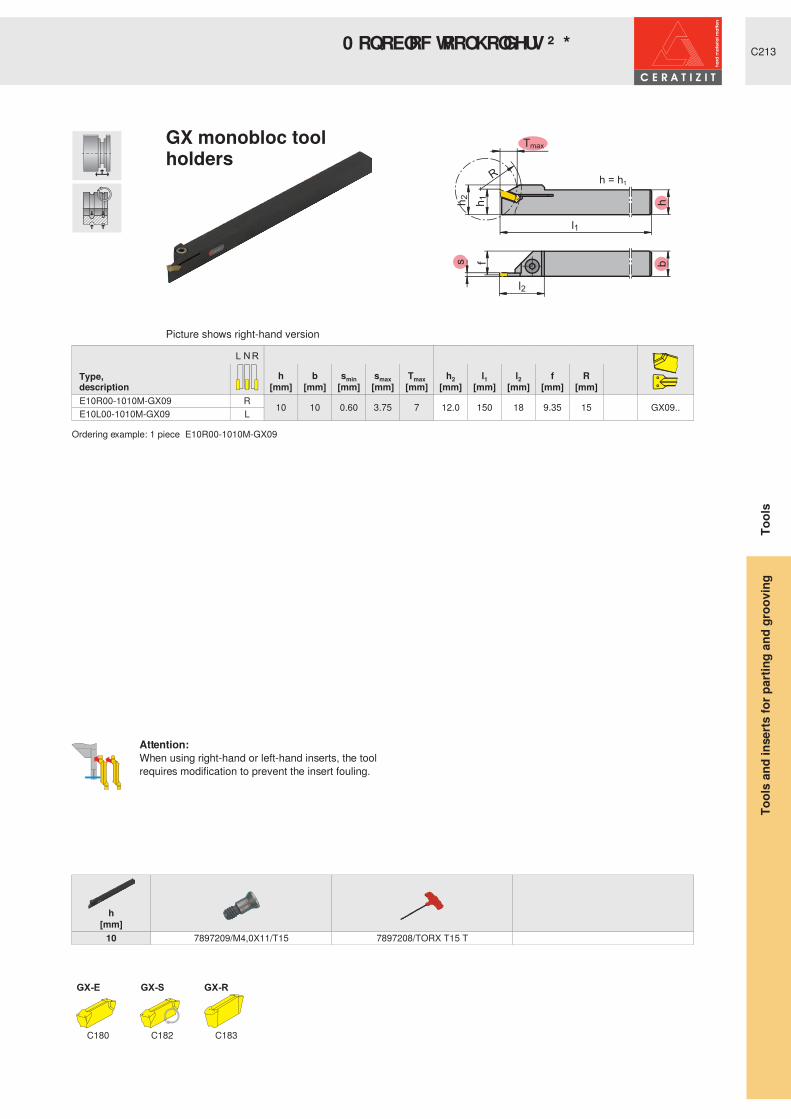
C213
Tmax
bh
s f
l2
l1
h1
h2
R h = h1
GX-E GX-S
h b smin smax Tmax h2 l1 l2 f R Type,description [mm] [mm] [mm] [mm] [mm] [mm] [mm] [mm] [mm] [mm] E10R00-1010M-GX09 R 10 10 0.60 3.75 7 12.0 150 18 9.35 15 GX09..E10L00-1010M-GX09 L
Ordering example: 1 piece E10R00-1010M-GX09
h[mm]
10 7897209/M4,0X11/T15 7897208/TORX T15 T
C180 C182 C183
Picture shows right-hand version
Attention:When using right-hand or left-hand inserts, the tool requires modification to prevent the insert fouling.
GX monobloc tool holders
Tool
sTo
ols
and
inse
rts fo
r par
ting
and
groo
ving
0 RQ REORF� WRRO� KROGHUV� ² � * ; � �

C214
l1
h = h1
b
s
hh2
Tmax
l2
fh
1
l3a
GX-E GX-S
h b smin smax Tmax h2 l1 l2 l3 f aType,description [mm] [mm] [mm] [mm] [mm] [mm] [mm] [mm] [mm] [mm] [mm]E12R0012-1212K-GX16-1 R
12
12 2.00 2.75 12 17.0 125 26 24.0 11.35 4.00 GX16-1..E12R0012-1212K-GX16-2 12 0.60 3.75 12 17.0 125 26 24.0 11.00 4.00 GX16-2..E12L0012-1212K-GX16-1 L 12 2.00 2.75 12 17.0 125 26 24.0 11.35 4.00 GX16-1..E12L0012-1212K-GX16-2 12 0.60 3.75 12 17.0 125 26 24.0 11.00 4.00 GX16-2..E16R0012-1616K-GX16-1
R
16
16 2.00 2.75 12 21.0 125 26 24.0 15.35 4.00 GX16-1..E16R0012-1616K-GX16-2 16 0.60 3.75 12 21.0 125 26 24.0 15.00 4.00 GX16-2..E16R0012-1616K-GX16-3 16 3.76 5.00 12 21.0 125 26 24.0 14.53 4.00 GX16-3..E16L0012-1616K-GX16-1
L16 2.00 2.75 12 21.0 125 26 24.0 15.35 4.00 GX16-1..
E16L0012-1616K-GX16-2 16 0.60 3.75 12 21.0 125 26 24.0 15.00 4.00 GX16-2..E16L0012-1616K-GX16-3 16 3.76 5.00 12 21.0 125 26 24.0 14.53 4.00 GX16-3..E20R0012-2020K-GX16-1
R
20
20 2.00 2.75 12 25.0 125 26 19.35 GX16-1..E20R0012-2020K-GX16-2 20 0.60 3.75 12 25.0 125 26 19.00 GX16-2..E20R0012-2020K-GX16-3 20 3.76 5.00 12 25.0 125 26 18.53 GX16-3..E20L0012-2020K-GX16-1
L20 2.00 2.75 12 25.0 125 26 19.35 GX16-1..
E20L0012-2020K-GX16-2 20 0.60 3.75 12 25.0 125 26 19.00 GX16-2..E20L0012-2020K-GX16-3 20 3.76 5.00 12 25.0 125 26 18.53 GX16-3..E25R0012-2525M-GX16-2 R
25
25 0.60 3.75 12 30.0 150 26 24.00 GX16-2..E25R0012-2525M-GX16-3 25 3.76 5.00 12 30.0 150 26 23.53 GX16-3..E25L0012-2525M-GX16-2 L 25 0.60 3.75 12 30.0 150 26 24.00 GX16-2..E25L0012-2525M-GX16-3 25 3.76 5.00 12 30.0 150 26 23.53 GX16-3..
Ordering example: 1 piece E12R0012-1212K-GX16-1
h[mm]
12 - 25 7897221/M3,5X14,0/T15 7897208/TORX T15 T
C180-C181 C182 C183
Picture shows right-hand version
Attention:When using right-hand or left-hand inserts, the tool requires modification to prevent the insert fouling.
GX monobloc tool holders
Tool
sTo
ols
and
inse
rts fo
r par
ting
and
groo
ving
0 RQ REORF� WRRO� KROGHUV� ² � * ; � �

C215
l1
h = h1
b
s
hh2
Tmax
l2
fh
1
l3a
GX-E
h b smin smax Tmax h2 l1 l2 l3 f aType,description [mm] [mm] [mm] [mm] [mm] [mm] [mm] [mm] [mm] [mm] [mm]E16R0021-1616K-GX24-1 R
16
16 2.00 2.75 21 21.0 125 35 32.0 15.20 4.00 GX24-1..E16R0021-1616K-GX24-2 16 2.76 3.75 21 21.0 125 35 32.0 15.00 4.00 GX24-2..E16L0021-1616K-GX24-1 L 16 2.00 2.75 21 21.0 125 35 32.0 15.20 4.00 GX24-1..E16L0021-1616K-GX24-2 16 2.76 3.75 21 21.0 125 35 32.0 15.00 4.00 GX24-2..E20R0021-2020K-GX24-1
R
20
20 2.00 2.75 21 25.0 125 35 19.20 GX24-1..E20R0021-2020K-GX24-2 20 2.76 3.75 21 25.0 125 35 19.00 GX24-2..E20R0021-2020K-GX24-3 20 3.76 5.00 21 25.0 125 35 18.53 GX24-3..E20L0021-2020K-GX24-1
L20 2.00 2.75 21 25.0 125 35 19.20 GX24-1..
E20L0021-2020K-GX24-2 20 2.76 3.75 21 25.0 125 35 19.00 GX24-2..E20L0021-2020K-GX24-3 20 3.76 5.00 21 25.0 125 35 18.53 GX24-3..E25R0021-2525M-GX24-2
R
25
25 2.76 3.75 21 30.0 150 35 24.00 GX24-2..E25R0021-2525M-GX24-3 25 3.76 5.00 21 30.0 150 35 23.53 GX24-3..E25R0021-2525M-GX24-4 25 5.01 6.50 21 30.0 150 35 22.90 GX24-4..E25L0021-2525M-GX24-2
L25 2.76 3.75 21 30.0 150 35 24.00 GX24-2..
E25L0021-2525M-GX24-3 25 3.76 5.00 21 30.0 150 35 23.53 GX24-3..E25L0021-2525M-GX24-4 25 5.01 6.50 21 30.0 150 35 22.90 GX24-4..E32R0021-3225P-GX24-2
R
32
25 2.76 3.75 21 37.0 170 35 24.00 GX24-2..E32R0021-3225P-GX24-3 25 3.76 5.00 21 37.0 170 35 23.53 GX24-3..E32R0021-3225P-GX24-4 25 5.01 6.50 21 37.0 170 35 22.90 GX24-4..E32L0021-3225P-GX24-2
L25 2.76 3.75 21 37.0 170 35 24.00 GX24-2..
E32L0021-3225P-GX24-3 25 3.76 5.00 21 37.0 170 35 23.53 GX24-3..E32L0021-3225P-GX24-4 25 5.01 6.50 21 37.0 170 35 22.90 GX24-4..
Ordering example: 1 piece E16R0021-1616K-GX24-1
h[mm]
16 - 32 7897218/M4,0X18/T20 7897207/TORX T20 T
C180-C181 C183
Picture shows right-hand version
GX monobloc tool holders
Tool
sTo
ols
and
inse
rts fo
r par
ting
and
groo
ving
0 RQ REORF� WRRO� KROGHUV� ² � * ; � �

C216
h1
h=h1
Tmax
bh
s f
l2
l1
h1h2
Dm
in
AX
h b s Dmin Tmax h2 l1 l2 f Type,description [mm] [mm] [mm] [mm] [mm] [mm] [mm] [mm] [mm] E16R0005-1616L-AX05 R
16
16 3.0 10 5 21.0 140 28 14.70
AX05..E16R0010-1616L-AX10 16 3.0 20 10 21.0 140 38 14.70 AX10..E16L0005-1616L-AX05 L 16 3.0 10 5 21.0 140 28 14.70 AX05..E16L0010-1616L-AX10 16 3.0 20 10 21.0 140 38 14.70 AX10..E20R0005-2020L-AX05
R
20
20 3.0 10 5 25.0 140 28 18.70 AX05..E20R0010-2020L-AX10 20 3.0 20 10 25.0 140 38 18.70 AX10..E20R0015-2020L-AX15 20 3.0 30 15 25.0 140 49 18.70 AX15..E20L0005-2020L-AX05
L20 3.0 10 5 25.0 140 28 18.70 AX05..
E20L0010-2020L-AX10 20 3.0 20 10 25.0 140 38 18.70 AX10..E20L0015-2020L-AX15 20 3.0 30 15 25.0 140 49 18.70 AX15..E25R0005-2525N-AX05
R
25
25 3.0 10 5 30.0 160 28 23.70 AX05..E25R0010-2525N-AX10 25 3.0 20 10 30.0 160 38 23.70 AX10..E25R0015-2525N-AX15 25 3.0 30 15 30.0 160 49 23.70 AX15..E25L0005-2525N-AX05
L25 3.0 10 5 30.0 160 28 23.70 AX05..
E25L0010-2525N-AX10 25 3.0 20 10 30.0 160 38 23.70 AX10..E25L0015-2525N-AX15 25 3.0 30 15 30.0 160 49 23.70 AX15..
Ordering example: 1 piece E16R0005-1616L-AX05
h[mm]
AX05.. 16 7897203/M4,0X14/T15 7897208/TORX T15 TAX05.. 20 - 25 7897205/M5,0X18/T20 7897207/TORX T20 TAX10.. 16 7897203/M4,0X14/T15 7897208/TORX T15 TAX10.. 20 - 25 7897205/M5,0X18/T20 7897207/TORX T20 TAX15.. 20 - 25 7897205/M5,0X18/T20 7897207/TORX T20 T
C184
Picture shows right-hand version
AX monobloc tool KROGHUV� � ƒ
Tool
sTo
ols
and
inse
rts fo
r par
ting
and
groo
ving
0 RQ REORF� WRRO� KROGHUV� ² � $ ;

C217
h=h1
Dm
in
Tm
ax
bh
s
l1
h1h2
f
l2
AX
h b s Dmin Tmax h2 l1 l2 f Type,description [mm] [mm] [mm] [mm] [mm] [mm] [mm] [mm] [mm] E16R9005-1616J-AX05 R
16
16 3.0 10 5 21.0 110 13.5 28.00
AX05..E16R9010-1616J-AX10 16 3.0 20 10 21.0 110 13.0 38.00 AX10..E16L9005-1616J-AX05 L 16 3.0 10 5 21.0 110 13.5 28.00 AX05..E16L9010-1616J-AX10 16 3.0 20 10 21.0 110 13.0 38.00 AX10..E20R9005-2020J-AX05
R
20
20 3.0 10 5 25.0 110 12.0 28.00 AX05..E20R9010-2020J-AX10 20 3.0 20 10 25.0 110 13.0 38.00 AX10..E20R9015-2020J-AX15 20 3.0 30 15 25.0 110 13.0 49.00 AX15..E20L9005-2020J-AX05
L20 3.0 10 5 25.0 110 12.0 28.00 AX05..
E20L9010-2020J-AX10 20 3.0 20 10 25.0 110 13.0 38.00 AX10..E20L9015-2020J-AX15 20 3.0 30 15 25.0 110 13.0 49.00 AX15..E25R9005-2525L-AX05
R
25
25 3.0 10 5 30.0 140 12.0 33.00 AX05..E25R9010-2525J-AX10 25 3.0 20 10 30.0 110 13.0 43.00 AX10..E25R9015-2525L-AX15 25 3.0 30 15 30.0 140 13.0 49.00 AX15..E25L9005-2525L-AX05
L25 3.0 10 5 30.0 140 12.0 33.00 AX05..
E25L9010-2525J-AX10 25 3.0 20 10 30.0 110 13.0 43.00 AX10..E25L9015-2525L-AX15 25 3.0 30 15 30.0 140 13.0 49.00 AX15..
Ordering example: 1 piece E16R9005-1616J-AX05
h[mm]
AX05.. 16 - 25 7897203/M4,0X14/T15 7897208/TORX T15 TAX10.. 16 7897203/M4,0X14/T15 7897208/TORX T15 TAX10.. 20 - 25 7897205/M5,0X18/T20 7897207/TORX T20 TAX15.. 20 - 25 7897205/M5,0X18/T20 7897207/TORX T20 T
C184
Picture shows right-hand version
AX monobloc tool KROGHUV� � � ƒ
Tool
sTo
ols
and
inse
rts fo
r par
ting
and
groo
ving
0 RQ REORF� WRRO� KROGHUV� ² � $ ;

C218
l2
l1
l3
Tmax
s
bh
fa
h 1h 2
h = h1
SX-E SX-R
h b s Tmax h2 l1 l2 l3 f aType,description [mm] [mm] [mm] [mm] [mm] [mm] [mm] [mm] [mm] [mm]E16R0016-1616K-SX2 R
16
16 2.0 16
21.0 125 31 26.0 15.20 7.00 SX2E16R0020-1616K-SX3 16 3.0 20 21.0 125 36 30.0 14.75 7.00 SX3E16L0016-1616K-SX2 L 16 2.0 16 21.0 125 31 26.0 15.20 7.00 SX2E16L0020-1616K-SX3 16 3.0 20 21.0 125 36 30.0 14.75 7.00 SX3E20R0016-2020K-SX2
R
20
20 2.0 16 25.0 125 31 26.0 19.20 5.00 SX2E20R0020-2020K-SX3 20 3.0 20 25.0 125 38 30.0 18.75 5.00 SX3E20R0025-2020K-SX4 20 4.0 25 27.0 125 44 35.0 18.35 5.00 SX4E20L0016-2020K-SX2
L20 2.0 16 25.0 125 31 26.0 19.20 5.00 SX2
E20L0020-2020K-SX3 20 3.0 20 25.0 125 38 30.0 18.75 5.00 SX3E20L0025-2020K-SX4 20 4.0 25 27.0 125 44 35.0 18.35 5.00 SX4E25R0020-2525M-SX3
R
25
25 3.0 20 30.0 150 40 30.0 23.75 5.00 SX3E25R0025-2525M-SX4 25 4.0 25 32.0 150 46 35.0 23.35 5.00 SX4E25R0025-2525M-SX5 25 5.0 25 32.0 150 46 35.0 22.85 5.00 SX5E25R0032-2525M-SX6 25 6.0 32 33.0 150 54 43.0 22.40 6.00 SX6E25L0020-2525M-SX3
L
25 3.0 20 30.0 150 40 30.0 23.75 5.00 SX3E25L0025-2525M-SX4 25 4.0 25 32.0 150 46 35.0 23.35 5.00 SX4E25L0025-2525M-SX5 25 5.0 25 32.0 150 46 35.0 22.85 5.00 SX5E25L0032-2525M-SX6 25 6.0 32 33.0 150 54 43.0 22.40 6.00 SX6
Ordering example: 1 piece E16R0016-1616K-SX2
h[mm]
16 - 25 7897218/M4,0X18/T20 7897207/TORX T20 T
C185 C185
Picture shows right-hand version
SX monobloc tool holders
Tool
sTo
ols
and
inse
rts fo
r par
ting
and
groo
ving
0 RQ REORF� WRRO� KROGHUV� ² � 6 ;

C219
s
f
h2
hb
l2
l1
h1
Dmax h = h1
FX
h b s Dmax h2 l1 l2 f Type,description [mm] [mm] [mm] [mm] [mm] [mm] [mm] [mm] XLCER 1010 M22 FX R 10 10 2.2 30
19.5 150 19 9.18
FX 2.2..XLCEL 1010 M22 FX L 10 2.2 30 19.5 150 19 9.18 FX 2.2..XLCER 1212 F22 FX R
12
12 2.2 30 19.5 80 19 11.18 FX 2.2..XLCER 1212 M22 FX R 12 2.2 30 19.5 150 19 11.18 FX 2.2..XLCEL 1212 F22 FX L 12 2.2 30 19.5 80 19 11.18 FX 2.2..XLCEL 1212 M22 FX L 12 2.2 30 19.5 150 19 11.18 FX 2.2..XLCER 1414 M22 FX R 14 14 2.2 30 19.5 150 19 13.18 FX 2.2..XLCEL 1414 M22 FX L 14 2.2 30 19.5 150 19 13.18 FX 2.2..XLCER 1612 H22 FX R
16
12 2.2 30 19.5 100 19 11.18 FX 2.2..XLCFR 1612 H31 FX R 12 3.1 35 22.5 100 22 10.80 FX 3.1..XLCEL 1612 H22 FX L 12 2.2 30 19.5 100 19 11.18 FX 2.2..XLCFL 1612 H31 FX L 12 3.1 35 22.5 100 22 10.80 FX 3.1..XLCFR 2016 K31 FX R
20
16 3.1 40 26.0 125 26 14.80 FX 3.1..XLCFR 2016 K41 FX R 16 4.1 40 26.0 125 26 14.40 FX 4.1..XLCFL 2016 K31 FX L 16 3.1 40 26.0 125 26 14.80 FX 3.1..XLCFL 2016 K41 FX L 16 4.1 40 26.0 125 26 14.40 FX 4.1..XLCFR 2520 M31 FX R
25
20 3.1 50 31.5 150 32 18.80 FX 3.1..XLCFR 2520 M41 FX R 20 4.1 50 31.5 150 32 18.40 FX 4.1..XLCFL 2520 M31 FX L 20 3.1 50 31.5 150 32 18.80 FX 3.1..XLCFL 2520 M41 FX L 20 4.1 50 31.5 150 32 18.40 FX 4.1..
Ordering example: 1 piece XLCER 1010 M22 FX
s[mm]2.2 7802180/A 2,23.1 7802181/A 3,14.1 7802181/A 3,1
C187
Picture shows left-hand version
FX monobloc tool holders
Tool
sTo
ols
and
inse
rts fo
r par
ting
and
groo
ving
0 RQ REORF� WRRO� KROGHUV� ² � ) ;

C220
l1
l3
s
l2
h = h1
Ø Dmax Tmax
hbf
h 1h 2a
PX
h b s Tmax Dmax h2 l1 l2 l3 f aType,description [mm] [mm] [mm] [mm] [mm] [mm] [mm] [mm] [mm] [mm] [mm]E16R0005-1616K-PX20-1
R
16
16 1.0 5 52 23.0 125 31 32.0 15.00 4.00 PX20-1..E16R0010-1616K-PX20-2 16 1.5 10 52 23.0 125 31 32.0 15.40 4.00 PX20-2..E16R0010-1616K-PX20-3 16 2.0 10 52 23.0 125 31 32.0 15.20 4.00 PX20-3..E16L0005-1616K-PX20-1
L16 1.0 5 52 23.0 125 31 32.0 15.00 4.00 PX20-1..
E16L0010-1616K-PX20-2 16 1.5 10 52 23.0 125 31 32.0 15.40 4.00 PX20-2..E16L0010-1616K-PX20-3 16 2.0 10 52 23.0 125 31 32.0 15.20 4.00 PX20-3..E20R0005-2020L-PX20-1
R
20
20 1.0 5 62 27.0 140 34 19.00 PX20-1..E20R0011-2020L-PX20-2 20 1.5 11 62 27.0 140 34 19.40 PX20-2..E20R0011-2020L-PX20-3 20 2.0 11 62 27.0 140 34 19.20 PX20-3..E20L0005-2020L-PX20-1
L20 1.0 5 62 27.0 140 34 19.00 PX20-1..
E20L0011-2020L-PX20-2 20 1.5 11 62 27.0 140 34 19.40 PX20-2..E20L0011-2020L-PX20-3 20 2.0 11 62 27.0 140 34 19.20 PX20-3..
Ordering example: 1 piece E16R0005-1616K-PX20-1
h[mm]
16 7897218/M4,0X18/T20 7897207/TORX T20 T 10008867/GS-M4.020 7897218/M4,0X18/T20 7883304/TORX T25 T 10008868/GS-M5.0
C188
Picture shows right-hand version
PX monobloc tool holders
Tool
sTo
ols
and
inse
rts fo
r par
ting
and
groo
ving
0 RQ REORF� WRRO� KROGHUV� ² � 3 ;

C221
s
l1
l2
Tmax
hbf
h2
h = h1
h1
MaxiClick
h b smin smax Tmax h2 l1 l2 f Type,description [mm] [mm] [mm] [mm] [mm] [mm] [mm] [mm] [mm] MC05R-1010K R 10 10 1.00 1.50 5 13.0 125 23 8.50
MC 05..
MC05L-1010K L 10 1.00 1.50 5 13.0 125 23 8.50MC05R-1212K R 12 12 1.00 1.50 5 15.0 125 23 10.50MC05L-1212K L 12 1.00 1.50 5 15.0 125 23 10.50MC05R-1616K R 16 16 1.00 1.50 5 19.0 125 23 14.50MC05L-1616K L 16 1.00 1.50 5 19.0 125 23 14.50MC05R-2020K R 20 20 1.00 1.50 5 23.0 125 23 18.50MC05L-2020K L 20 1.00 1.50 5 23.0 125 23 18.80MC05R-2525M R 25 25 1.00 1.50 5 28.0 150 23 23.50MC05L-2525M L 25 1.00 1.50 5 28.0 150 23 23.50
Ordering example: 1 piece MC05R-1010K
h[mm]
10 - 25 7818429/M4,0X11/T15 7897208/TORX T15 T
C189
Picture shows right-hand version
MaxiClick 05
Tool
sTo
ols
and
inse
rts fo
r par
ting
and
groo
ving
0 RQ REORF� WRRO� KROGHUV� ² � 0 &� �

C222
h = h1
3
MaxiClick
h b smin smax Tmax h2 l1 l2 l3 f aType,description [mm] [mm] [mm] [mm] [mm] [mm] [mm] [mm] [mm] [mm] [mm]MC10R-1010K R
10
10 1.50 2.50 10 13.0 125 28 8.50
MC 10..
MC10R-1010K-S R 10 1.50 2.50 10 19.0 125 28 27.0 8.50 6.00MC10L-1010K L 10 1.50 2.50 10 13.0 125 28 8.50 MC10L-1010K-S L 10 1.50 2.50 10 19.0 125 28 27.0 8.50 6.00MC10R-1212K R
12
12 1.50 2.50 10 15.0 125 28 10.50 MC10R-1212K-S R 12 1.50 2.50 10 19.0 125 28 27.0 10.50 4.00MC10L-1212K L 12 1.50 2.50 10 15.0 125 28 10.50 MC10L-1212K-S L 12 1.50 2.50 10 19.0 125 28 27.0 10.50 4.00MC10R-1616K R 16 16 1.50 2.50 10 19.0 125 28 14.50 MC10L-1616K L 16 1.50 2.50 10 19.0 125 28 14.50 MC10R-2020K R 20 20 1.50 2.50 10 23.0 125 28 18.50 MC10L-2020K L 20 1.50 2.50 10 23.0 125 28 18.50 MC10R-2525M R 25 25 1.50 2.50 10 28.0 152 28 23.50 MC10L-2525M L 25 1.50 2.50 10 28.0 152 28 23.50
Ordering example: 1 piece MC10R-1010K
h[mm]
10 - 25 7818429/M4,0X11/T15 7897208/TORX T15 T
C189
Picture shows right-hand version
MaxiClick 10
Tool
sTo
ols
and
inse
rts fo
r par
ting
and
groo
ving
0 RQ REORF� WRRO� KROGHUV� ² � 0 &� �

C223
Tm
ax
l1 150°
b1
h2
s
b
GX-E
h2 Type,description
smin smax Tmax b b1 l1[mm] [mm] [mm] [mm] [mm] [mm] [mm]
32
XLCFN 3202-GX24-1S
N
2.00 2.75 21 1.60 6.2 180 GX24-1..XLCFN 3203 GX24-2S 2.76 3.75 21 2.10 6.2 180 GX24-2..XLCFN 3204 GX24-3S 3.76 5.00 21 3.05 6.2 180 GX24-3..XLCFN 3206 GX24-4S 5.01 6.50 21 4.20 6.2 180 GX24-4..
Ordering example: 1 piece XLCFN 3202-GX24-1S
h2[mm]
32 7897221/M3,5X14,0/T15 7897208/TORX T15 T DMSD 3,2Nm/SORT T15
C180 C183 C229-C230
GX blades
Tool
sTo
ols
and
inse
rts fo
r par
ting
and
groo
ving
% ODGHV� ² � * ;

C224
SX-E SX-R
h2 Type,description
s Tmax b b1 l1[mm] [mm] [mm] [mm] [mm] [mm]
26
XLCFR 2602-SX2 R 2.0 25
1.50 2.4 110 SX2XLCFL 2602-SX2 L 2.0 25 1.50 2.4 110 SX2XLCFN 2603-SX3 N 3.0 35 2.40 110 SX3XLCFN 2604-SX4 N 4.0 40 3.20 110 SX4
32
XLCFR 3202-SX2 R 2.0 25 1.50 2.4 150 SX2XLCFL 3202-SX2 L 2.0 25 1.50 2.4 150 SX2XLCFN 3203-SX3 N 3.0 50 2.40 150 SX3XLCFN 3204-SX4 N 4.0 50 3.20 150 SX4XLCFN 3205-SX5 N 5.0 55 4.20 150 SX5XLCFN 3206-SX6 N 6.0 60 5.20 150 SX6
Ordering example: 1 piece XLCFR 2602-SX2
s[mm]
SX2 2.0 10005884/S12-3SX3 3.0 10005884/S12-3SX4 4.0 10001365/S15-4SX5 5.0 10001365/S15-4SX6 6.0 10001365/S15-4
C185 C185 C229-C230
Tool
sTo
ols
and
inse
rts fo
r par
ting
and
groo
ving
% ODGHV� ² � 6 ;

C225
l1
s b 1h 2
b
Dmax
T max
SX-E SX-R
h2 Type,description
s Tmax Dmax b b1 l1[mm] [mm] [mm] [mm] [mm] [mm] [mm]
26
XLCFR 2608-SX2 R 2.0 22 44 1.50 8.0 110 SX2XLCFR 2608-SX3 3.0 22 44 2.50 8.0 110 SX3XLCFL 2608-SX2 L 2.0 22 44 1.50 8.0 110 SX2XLCFL 2608-SX3 3.0 22 44 2.50 8.0 110 SX3
Ordering example: 1 piece XLCFR 2608-SX2
s[mm]
SX2 2.0 10005884/S12-3SX3 3.0 10005884/S12-3
C185 C185 C229-C230
Picture shows right-hand version
Tool
sTo
ols
and
inse
rts fo
r par
ting
and
groo
ving
Blades SX, reinforced blade

C226
l1
s b 1h 2
b T max
Dmax
SX-E SX-R
h2 Type,description
s Tmax Dmax b b1 l1[mm] [mm] [mm] [mm] [mm] [mm] [mm]
32
XLCFR 3208-SX3 R 3.0 33 66 2.50 8.0 110 SX3XLCFR 3208-SX4 4.0 33 66 3.40 8.0 110 SX4XLCFL 3208-SX3 L 3.0 33 66 2.50 8.0 110 SX3XLCFL 3208-SX4 4.0 33 66 3.40 8.0 110 SX4
Ordering example: 1 piece XLCFR 3208-SX3
s[mm]
SX3 3.0 10005884/S12-3SX4 4.0 10001365/S15-4
C185 C185 C229-C230
Picture shows right-hand version
Tool
sTo
ols
and
inse
rts fo
r par
ting
and
groo
ving
Blades SX, reinforced blade

C227
LX-E LX-R
h2 Type,description
smin smax Tmax b l1 [mm] [mm] [mm] [mm] [mm] [mm]
46 XLCEN 4608 LX N 8.00 10.00 80 6.80 250 LX-..
Ordering example: 1 piece XLCEN 4608 LX
h2[mm]
46 7897218/M4,0X18/T20 7897207/TORX T20 T DMSD 4,0Nm/SORT T20
C186 C186 C229
LX blades
Tool
sTo
ols
and
inse
rts fo
r par
ting
and
groo
ving
% ODGHV� ² � / ;
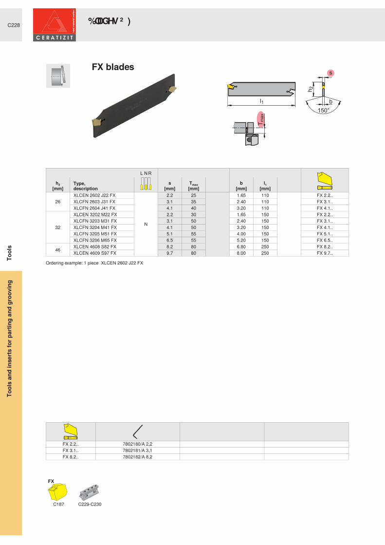
C228
FX
h2 Type,description
s Tmax b l1 [mm] [mm] [mm] [mm] [mm]
26XLCEN 2602 J22 FX
N
2.2 25
1.65 110
FX 2.2..XLCFN 2603 J31 FX 3.1 35 2.40 110 FX 3.1..XLCFN 2604 J41 FX 4.1 40 3.20 110 FX 4.1..
32
XLCEN 3202 M22 FX 2.2 30 1.65 150 FX 2.2..XLCFN 3203 M31 FX 3.1 50 2.40 150 FX 3.1..XLCFN 3204 M41 FX 4.1 50 3.20 150 FX 4.1..XLCFN 3205 M51 FX 5.1 55 4.00 150 FX 5.1..XLCFN 3206 M65 FX 6.5 55 5.20 150 FX 6.5..
46 XLCEN 4608 S82 FX 8.2 80 6.80 250 FX 8.2..XLCEN 4609 S97 FX 9.7 80 8.00 250 FX 9.7..
Ordering example: 1 piece XLCEN 2602 J22 FX
FX 2.2.. 7802180/A 2,2FX 3.1.. 7802181/A 3,1FX 8.2.. 7802182/A 8,2
C187 C229-C230
FX blades
Tool
sTo
ols
and
inse
rts fo
r par
ting
and
groo
ving
% ODGHV� ² � ) ;

C229
GX SX LX FX
Type,description
h2 h=h1 b l1 b1 h3 [mm] [mm] [mm] [mm] [mm] [mm]
26 SBN 2020-26 K 20 20
90 33.0 39
XLC.. 26..
32 SBN 2520-32 K 25 20 110 36.0 48 XLC.. 32..SBN 3229-32 K 32 29 120 44.5 48 XLC.. 32..
46 SBN 3229-46 K 32 29 150 52.0 70 XLC.. 46..SBN 4037-46 K 40 37 150 60.0 70 XLC.. 46..
Ordering example: 1 piece SBN 2020-26 K
h2[mm]
26 7802115/M6X25 DIN 912 7812301/SW 5 7802148/R1/8"/SORT32 7802115/M6X25 DIN 912 7812301/SW 5 7802148/R1/8"/SORT46 7802133/M8X35 DIN 912 7812302/SW 6 7802143/R1/4" SET
C223 C224-C226 C227 C228
The blocks are delivered without coolant set.When applying through-tool coolant, order the additional coolant set separately.
Clamping blocks
Tool
sTo
ols
and
inse
rts fo
r par
ting
and
groo
ving
Clamping blocks

C230
l1
b1
hh3
h1 h2
b
GX SX FX
Type,description
h2 h=h1 b h3 b1 l1 [mm] [mm] [mm] [mm] [mm] [mm]
26 SBN 2020-26 KS 20 20
43 37 90
XLC.. 26..32 SBN 2520-32 KS 25 20 49 38 110 XLC.. 32..32 SBN 3229-32 KS 32 29 52 47 120 XLC.. 32..
Ordering example: 1 piece SBN 2020-26 KS
h2[mm]
26 7802115/M6X25 DIN 912 7812301/SW 5 7802148/R1/8"/SORT32 7802115/M6X25 DIN 912 7812301/SW 5 7802148/R1/8"/SORT
C223 C224-C226 C228
The blocks are delivered without coolant set.When applying through-tool coolant, order the additional coolant set separately.
Split clamping blocks
Tool
sTo
ols
and
inse
rts fo
r par
ting
and
groo
ving
Split clamping blocks

C231
Tm
ax
l2
l1
l3
dA
d2 f
D
GX TC
Type,description
dA l2 Tmax D d2 l1 l3 fBgr. [mm] [mm] [mm] [mm] [mm] [mm] [mm] [mm]
16 MSS-I16R90-1.5D-N R 20 24 4 20 25 82 50 1.00 MSS-I16R..MSS-I16L90-1.5D-N L 20 24 4 20 25 82 50 1.00 MSS-I16L..
20 MSS-I20R90-1.5D-N R 20 30 5 25 25 87 50 1.00 MSS-I20R..MSS-I20L90-1.5D-N L 20 30 5 25 25 87 50 1.00 MSS-I20L..
25 MSS-I25R90-1.5D-N R 25 38 6 32 32 102 56 1.50 MSS-I25R..MSS-I25L90-1.5D-N L 25 38 6 32 32 102 56 1.50 MSS-I25L..
32 MSS-I32R90-1.5D-N R 32 48 9 40 40 119 60 2.00 MSS-I32R..MSS-I32L90-1.5D-N L 32 48 9 40 40 119 60 2.00 MSS-I32L..
40 MSS-I40R90-1.5D-N R 40 60 10 50 50 142 70 2.50 MSS-I40R..MSS-I40L90-1.5D-N L 40 60 10 50 50 142 70 2.50 MSS-I40L..
Ordering example: 1 piece MSS-I16R90-1.5D-NBgr. = assembly size
Bgr.16 7897200/M2,5X10/T08 7724106/TORX T0820 7897201/M3,0X11/T10 7883306/TORX T1025 7897202/M3,5X12,5/T15 7897208/TORX T15 T32 7897204/M4,5X17/T20 7897207/TORX T20 T40 7897205/M5,0X18/T20 7897207/TORX T20 T
C234
C233-C236 C242
GX24:Tmax = +9 mmD = +10 mm
Picture shows right-hand version
When using module MSS-I40N19-GX24.. the following applies:
Boring bars 1.5D
Tool
sTo
ols
and
inse
rts fo
r par
ting
and
groo
ving
Boring bars

C232
Tm
ax
l2
l1
h
dA f
D
h
*
GX TC
Type,description
dA l2 Tmax h l1 D f Bgr. [mm] [mm] [mm] [mm] [mm] [mm] [mm]
16 MSS-I16R90-2.5D-N R 20 40 4 19 180 20 4.50
MSS-I16R..MSS-I16L90-2.5D-N L 20 40 4 19 180 20 4.50 MSS-I16L..
20 MSS-I20R90-2.5D-N R 25 50 5 24 200 25 6.00 MSS-I20R..MSS-I20L90-2.5D-N L 25 50 5 24 200 25 6.00 MSS-I20L..
25 MSS-I25R90-2.5D-N R 32 63 6 31 250 32 7.00 MSS-I25R..MSS-I25L90-2.5D-N L 32 63 6 31 250 32 7.00 MSS-I25L..
32 MSS-I32R90-2.5D-N R 40 80 9 38 300 40 9.50 MSS-I32R..MSS-I32L90-2.5D-N L 40 80 9 38 300 40 9.50 MSS-I32L..
40 MSS-I40R90-2.5D-N R 50 100 10 48.5 350 50 11.00 MSS-I40R..MSS-I40L90-2.5D-N L 50 100 10 48.5 350 50 11.00 MSS-I40L..
Ordering example: 1 piece MSS-I16R90-2.5D-NBgr. = assembly size
Bgr.16 7897200/M2,5X10/T08 7724106/TORX T0820 7897201/M3,0X11/T10 7883306/TORX T1025 7897202/M3,5X12,5/T15 7897208/TORX T15 T32 7897204/M4,5X17/T20 7897207/TORX T20 T40 7897205/M5,0X18/T20 7897207/TORX T20 T
C233-C236 C242
* 2 clamping faces applies only for MSS-I32R/L90-2.5D-N
GX24:Tmax = +9 mmD = +10 mm
Picture shows right-hand version
When using module MSS-I40N19-GX24.. the following applies:
Boring bars 2.5D
Tool
sTo
ols
and
inse
rts fo
r par
ting
and
groo
ving
Boring bars
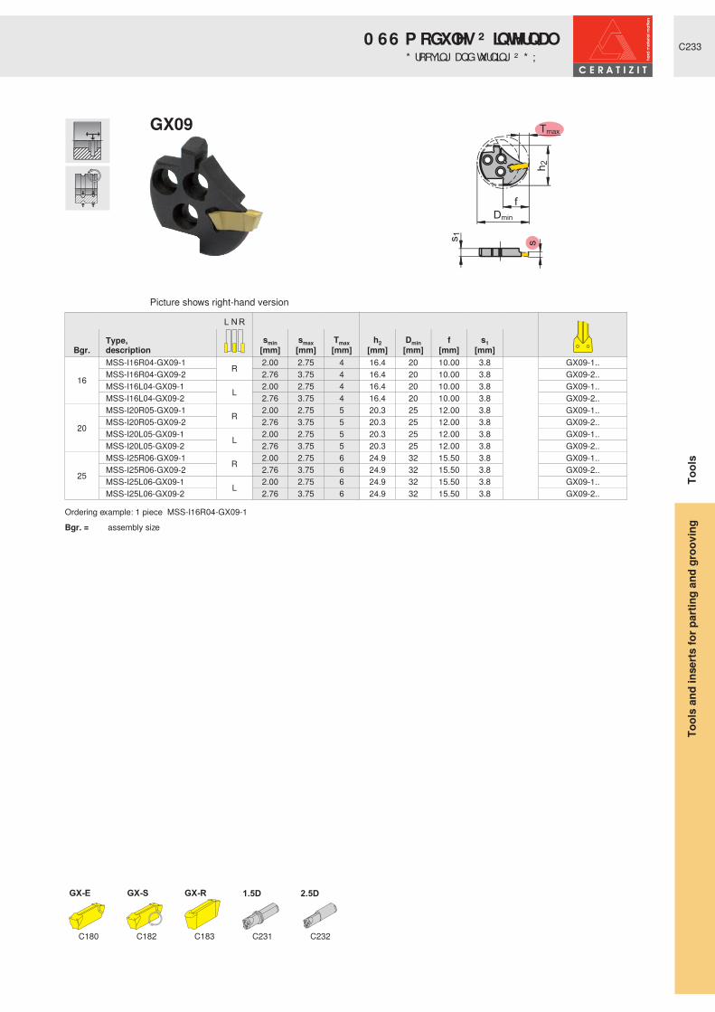
C233
GX-E GX-S 1.5D 2.5D
Type,description
smin smax Tmax h2 Dmin f s1 Bgr. [mm] [mm] [mm] [mm] [mm] [mm] [mm]
16
MSS-I16R04-GX09-1 R 2.00 2.75 4 16.4 20 10.00 3.8
GX09-1..MSS-I16R04-GX09-2 2.76 3.75 4 16.4 20 10.00 3.8 GX09-2..MSS-I16L04-GX09-1 L 2.00 2.75 4 16.4 20 10.00 3.8 GX09-1..MSS-I16L04-GX09-2 2.76 3.75 4 16.4 20 10.00 3.8 GX09-2..
20
MSS-I20R05-GX09-1 R 2.00 2.75 5 20.3 25 12.00 3.8 GX09-1..MSS-I20R05-GX09-2 2.76 3.75 5 20.3 25 12.00 3.8 GX09-2..MSS-I20L05-GX09-1 L 2.00 2.75 5 20.3 25 12.00 3.8 GX09-1..MSS-I20L05-GX09-2 2.76 3.75 5 20.3 25 12.00 3.8 GX09-2..
25
MSS-I25R06-GX09-1 R 2.00 2.75 6 24.9 32 15.50 3.8 GX09-1..MSS-I25R06-GX09-2 2.76 3.75 6 24.9 32 15.50 3.8 GX09-2..MSS-I25L06-GX09-1 L 2.00 2.75 6 24.9 32 15.50 3.8 GX09-1..MSS-I25L06-GX09-2 2.76 3.75 6 24.9 32 15.50 3.8 GX09-2..
Ordering example: 1 piece MSS-I16R04-GX09-1Bgr. = assembly size
C180 C182 C183 C231 C232
Picture shows right-hand version
GX09
Tool
sTo
ols
and
inse
rts fo
r par
ting
and
groo
ving
* URRYLQJ� DQG� WXUQLQJ� ² � * ; � �0 66 � P RGXOHV� ² � LQ WHUQ DO

C234
GX-E GX-S 1.5D 2.5D UTS
Type,description
smin smax Tmax h2 Dmin f s1 Bgr. [mm] [mm] [mm] [mm] [mm] [mm] [mm]
32
MSS-I32R09-GX16-1
R
2.00 2.75 9 32.2 40 20.00 5.9
GX16-1..MSS-I32R09-GX16-2 2.76 3.75 9 32.2 40 20.00 5.9 GX16-2..MSS-I32R09-GX16-3 3.76 5.00 9 32.2 40 20.00 5.9 GX16-3..MSS-I32R09-GX16-4 5.01 6.50 9 32.2 40 20.00 5.9 GX16-4..MSS-I32L09-GX16-1
L
2.00 2.75 9 32.2 40 20.00 5.9 GX16-1..MSS-I32L09-GX16-2 2.76 3.75 9 32.2 40 20.00 5.9 GX16-2..MSS-I32L09-GX16-3 3.76 5.00 9 32.2 40 20.00 5.9 GX16-3..MSS-I32L09-GX16-4 5.01 6.50 9 32.2 40 20.00 5.9 GX16-4..
40
MSS-I40R10-GX16-1
R
2.00 2.75 10 39.6 50 24.50 5.9 GX16-1..MSS-I40R10-GX16-2 2.76 3.75 10 39.6 50 24.50 5.9 GX16-2..MSS-I40R10-GX16-3 3.76 5.00 10 39.6 50 24.50 5.9 GX16-3..MSS-I40R10-GX16-4 5.01 6.50 10 39.6 50 24.50 5.9 GX16-4..MSS-I40L10-GX16-1
L
2.00 2.75 10 39.6 50 24.50 5.9 GX16-1..MSS-I40L10-GX16-2 2.76 3.75 10 39.6 50 24.50 5.9 GX16-2..MSS-I40L10-GX16-3 3.76 5.00 10 39.6 50 24.50 5.9 GX16-3..MSS-I40L10-GX16-4 5.01 6.50 10 39.6 50 24.50 5.9 GX16-4..MSS-I40N19-GX24-2
N2.76 3.75 19 40.7 60 33.50 6.2 GX24-2..
MSS-I40N19-GX24-3 3.76 5.00 19 40.7 60 33.50 6.2 GX24-3..MSS-I40N19-GX24-4 5.01 6.50 19 40.7 60 33.50 6.2 GX24-4..
Ordering example: 1 piece MSS-I32R09-GX16-1Bgr. = assembly size
C180-C181 C182 C183 C231 C232 C249
Picture shows right-hand version
GX16/24
Tool
sTo
ols
and
inse
rts fo
r par
ting
and
groo
ving
0 66 � P RGXOHV� ² � LQ WHUQ DO* URRYLQJ� DQG� WXUQLQJ� ² � * ; � � � � �

C235
GX-S 1.5D 2.5D
Type,description
smin smax Tmax h2 Dmin f s1 Bgr. [mm] [mm] [mm] [mm] [mm] [mm] [mm]
16 MSS-I16R02-GX09-1 R 0.60 1.95 2 16.45 20 10.00 3.8
GX09-1.. R/L
MSS-I16L02-GX09-1 L 0.60 1.95 2 16.45 20 10.00 3.8
20 MSS-I20R02-GX09-1 R 0.60 1.95 2 20.35 25 12.00 3.8MSS-I20L02-GX09-1 L 0.60 1.95 2 20.35 25 12.00 3.8
25 MSS-I25R02-GX09-1 R 0.60 1.95 2 24.95 32 15.50 3.8MSS-I25L02-GX09-1 L 0.60 1.95 2 24.95 32 15.50 3.8
Ordering example: 1 piece MSS-I16R02-GX09-1Bgr. = assembly size
C182 C183 C231 C232
Picture shows right-hand version
GX09
Tool
sTo
ols
and
inse
rts fo
r par
ting
and
groo
ving
& LUFOLS� DQG� UDGLXV� JURRYHV� ² � * ; � �0 66 � P RGXOHV� ² � LQ WHUQ DO

C236
GX-S 1.5D 2.5D UTS
Type,description
smin smax Tmax h2 Dmin f s1 Bgr. [mm] [mm] [mm] [mm] [mm] [mm] [mm]
32 MSS-I32R03-GX16-2 R 0.60 2.75 3 32.2 40 20.00 5.9
GX16-2.. R/LMSS-I32L03-GX16-2 L 0.60 2.75 3 32.2 40 20.00 5.9
40 MSS-I40R03-GX16-2 R 0.60 2.75 3 39.6 50 24.50 5.9MSS-I40L03-GX16-2 L 0.60 2.75 3 39.6 50 24.50 5.9
Ordering example: 1 piece MSS-I32R03-GX16-2Bgr. = assembly size
C182 C183 C231 C232 C249
Picture shows right-hand version
GX16
Tool
sTo
ols
and
inse
rts fo
r par
ting
and
groo
ving
& LUFOLS� DQG� UDGLXV� JURRYHV� ² � * ; � �0 66 � P RGXOHV� ² � LQ WHUQ DO
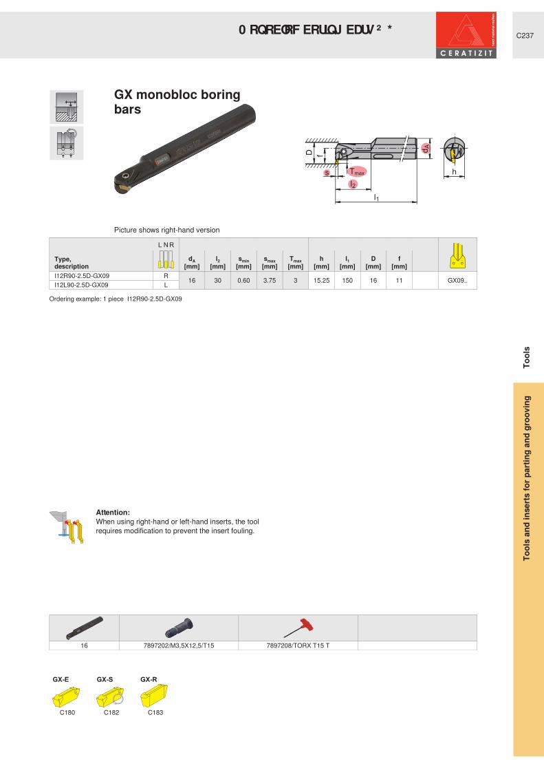
C237
Tmax
l1
l2
f
dA
hs
D
GX-E GX-S
dA l2 smin smax Tmax h l1 D f Type,description [mm] [mm] [mm] [mm] [mm] [mm] [mm] [mm] [mm] I12R90-2.5D-GX09 R 16 30 0.60 3.75 3 15.25 150 16 11 GX09..I12L90-2.5D-GX09 L
Ordering example: 1 piece I12R90-2.5D-GX09
16 7897202/M3,5X12,5/T15 7897208/TORX T15 T
C180 C182 C183
Picture shows right-hand version
Attention:When using right-hand or left-hand inserts, the tool requires modification to prevent the insert fouling.
GX monobloc boring bars
Tool
sTo
ols
and
inse
rts fo
r par
ting
and
groo
ving
0 RQ REORF� ERULQ J� EDUV� ² � * ; � �
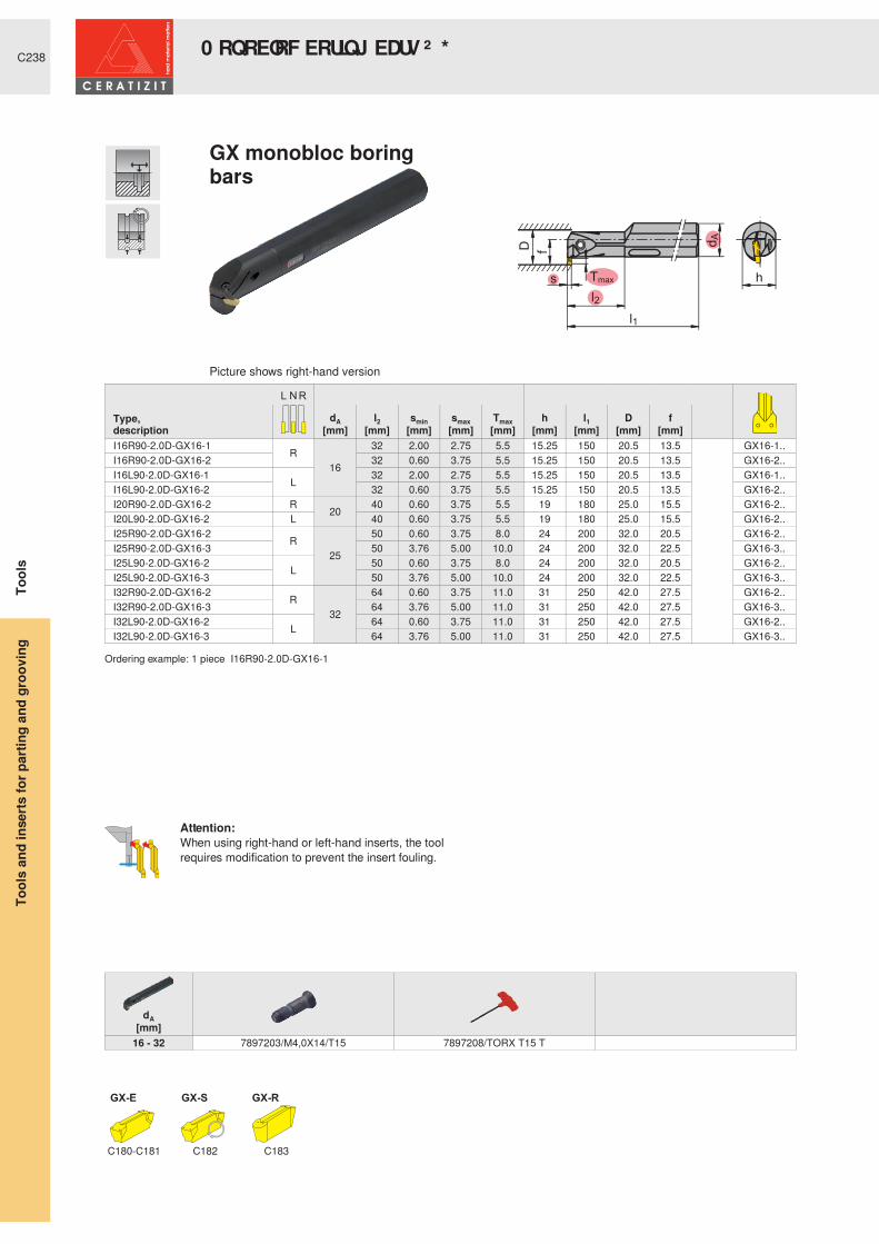
C238
Tmax
l1
l2
f
dA
hs
D
GX-E GX-S
dA l2 smin smax Tmax h l1 D f Type,description [mm] [mm] [mm] [mm] [mm] [mm] [mm] [mm] [mm] I16R90-2.0D-GX16-1 R
16
32 2.00 2.75 5.5 15.25 150 20.5 13.5
GX16-1..I16R90-2.0D-GX16-2 32 0.60 3.75 5.5 15.25 150 20.5 13.5 GX16-2..I16L90-2.0D-GX16-1 L 32 2.00 2.75 5.5 15.25 150 20.5 13.5 GX16-1..I16L90-2.0D-GX16-2 32 0.60 3.75 5.5 15.25 150 20.5 13.5 GX16-2..I20R90-2.0D-GX16-2 R 20 40 0.60 3.75 5.5 19 180 25.0 15.5 GX16-2..I20L90-2.0D-GX16-2 L 40 0.60 3.75 5.5 19 180 25.0 15.5 GX16-2..I25R90-2.0D-GX16-2 R
25
50 0.60 3.75 8.0 24 200 32.0 20.5 GX16-2..I25R90-2.0D-GX16-3 50 3.76 5.00 10.0 24 200 32.0 22.5 GX16-3..I25L90-2.0D-GX16-2 L 50 0.60 3.75 8.0 24 200 32.0 20.5 GX16-2..I25L90-2.0D-GX16-3 50 3.76 5.00 10.0 24 200 32.0 22.5 GX16-3..I32R90-2.0D-GX16-2 R
32
64 0.60 3.75 11.0 31 250 42.0 27.5 GX16-2..I32R90-2.0D-GX16-3 64 3.76 5.00 11.0 31 250 42.0 27.5 GX16-3..I32L90-2.0D-GX16-2 L 64 0.60 3.75 11.0 31 250 42.0 27.5 GX16-2..I32L90-2.0D-GX16-3 64 3.76 5.00 11.0 31 250 42.0 27.5 GX16-3..
Ordering example: 1 piece I16R90-2.0D-GX16-1
dA[mm]
16 - 32 7897203/M4,0X14/T15 7897208/TORX T15 T
C180-C181 C182 C183
Picture shows right-hand version
Attention:When using right-hand or left-hand inserts, the tool requires modification to prevent the insert fouling.
GX monobloc boring bars
Tool
sTo
ols
and
inse
rts fo
r par
ting
and
groo
ving
0 RQ REORF� ERULQ J� EDUV� ² � * ; � �

C239
D
Tmax
l1
l2
f
dA
hs
GX-E
dA l2 smin smax Tmax h l1 D f Type,description [mm] [mm] [mm] [mm] [mm] [mm] [mm] [mm] [mm] I32R90-2.0D-GX24-2
R
32
64 2.76 3.75 11.0 31.0 250 42 27.5
GX24-2..I32R90-2.0D-GX24-3 64 3.76 5.00 11.0 31.0 250 42 27.5 GX24-3..I32R90-2.0D-GX24-4 64 5.01 6.50 17.5 31.0 250 47 30.4 GX24-4..I32L90-2.0D-GX24-2
L64 2.76 3.75 11.0 31 250 42 27.5 GX24-2..
I32L90-2.0D-GX24-3 64 3.76 5.00 11.0 31.0 250 42 27.5 GX24-3..I32L90-2.0D-GX24-4 64 5.01 6.50 17.5 31.0 250 47 30.4 GX24-4..I40R90-2.0D-GX24-3 R
40
80 3.76 5.00 12.0 38.5 300 53 32.5 GX24-3..I40R90-2.0D-GX24-4 80 5.01 6.50 17.5 38.5 300 57 34.4 GX24-4..I40L90-2.0D-GX24-3 L 80 3.76 5.00 12.0 38.5 300 53 32.5 GX24-3..I40L90-2.0D-GX24-4 80 5.01 6.50 17.5 38.5 300 57 34.4 GX24-4..
Ordering example: 1 piece I32R90-2.0D-GX24-2
dA[mm]
32 - 40 7897205/M5,0X18/T20 7897207/TORX T20 T
C180-C181 C183
Picture shows right-hand version
GX monobloc boring bars
Tool
sTo
ols
and
inse
rts fo
r par
ting
and
groo
ving
0 RQ REORF� ERULQ J� EDUV� ² � * ; � �

C240
TC 60° TC 55°
Type,description
Pitch P
Pmin Pmax Pmin Pmax Tmax h1 h2 l1 f RBgr. [mm] [mm] [TPI] [TPI] [mm] [mm] [mm] [mm] [mm] [mm]
20MSS-E20R-TC16-1 R 0.50 1.50 48 16 8 20 24 20 3.45 30 TC16-1..MSS-E20N-TC16-2 N 1.75 3.00 14 8 12 20 24 20 2.20 TC16-2..MSS-E20L-TC16-1 L 0.50 1.50 48 16 8 20 24 20 3.45 30 TC16-1..
25
MSS-E25R-TC16-1 R 0.50 1.50 48 16 8 25 30 25 5.20 37.5 TC16-1..MSS-E25R-TC16-2 R 1.75 3.00 14 8 10 25 30 25 4.10 37.5 TC16-2..MSS-E25N-TC16-3 N 3.50 5.00 7 5 12 25 30 25 3.10 TC16-3..MSS-E25L-TC16-1 L 0.50 1.50 48 16 8 25 30 25 5.20 37.5 TC16-1..MSS-E25L-TC16-2 L 1.75 3.00 14 8 10 25 30 25 4.10 37.5 TC16-2..
Ordering example: 1 piece MSS-E20R-TC16-1Bgr. = assembly size
C190+C192 C191+C193 C196 C197 C199 C246 C247
Picture shows right-hand version
TC16
Tool
sTo
ols
and
inse
rts fo
r par
ting
and
groo
ving
0 66 � P RGXOHV� ² � H[ WHUQ DO7KUHDG� WXUQLQJ� ² � 7 &

C241
Tmax
R
fh
1h2
hb
l1
l2
TC 60° TC 55°
Pitch P
h b Pmin Pmax Pmin Pmax Tmax h1 h2 l1 l2 f RType,description [mm] [mm] [mm] [mm] [TPI] [TPI] [mm] [mm] [mm] [mm] [mm] [mm] [mm]E12R00-1212-TC16 R 12 12 0.50 3.00 48 8 10 12 14.5 150 20 11 15 TC16-1/2..E12L00-1212-TC16 L
Ordering example: 1 piece E12R00-1212-TC16
h[mm]
12 7897209/M4,0X11/T15 7897208/TORX T15 T
C190+C192 C191+C193
Picture shows right-hand version
TC monobloc tool holders
Tool
sTo
ols
and
inse
rts fo
r par
ting
and
groo
ving
0 RQ REORF� WRRO� KROGHUV� ² � 7&� WKUHDGLQ J

C242
TC 60° TC 55° 1.5D 2.5D UTS
Type,description
Pitch P
Pmin Pmax Pmin Pmax Tmax h2 f Dmin s1Bgr. [mm] [mm] [TPI] [TPI] [mm] [mm] [mm] [mm] [mm]
32
MSS-I32R-TC16-1 R 0.50 1.50 48 16 7 32.2 20.00 40 6.2 TC16-1..MSS-I32R-TC16-2 1.75 3.00 14 8 7 32.2 20.00 40 6.2 TC16-2..MSS-I32N-TC16-3 N 3.50 5.00 7 5 7 32.2 20.00 40 6.2 TC16-3..MSS-I32L-TC16-1 L 0.50 1.50 48 16 7 32.2 20.00 40 6.2 TC16-1..MSS-I32L-TC16-2 1.75 3.00 14 8 7 32.2 20.00 40 6.2 TC16-2..
Ordering example: 1 piece MSS-I32R-TC16-1Bgr. = assembly size
C190+C192 C191+C193 C231 C232 C249
Picture shows right-hand version
TC16
Tool
sTo
ols
and
inse
rts fo
r par
ting
and
groo
ving
7KUHDG� WXUQLQJ� ² � 7 &0 66 � P RGXOHV� ² � LQ WHUQ DO

C243
D
A - A
f
dA
Tm
ax
l1
h
l2
TC 60° TC 55°
Pitch P
dA l2 Pmin Pmax Pmin Pmax Tmax h l1 Dmin f Type,description [mm] [mm] [mm] [mm] [TPI] [TPI] [mm] [mm] [mm] [mm] [mm] I16R90-2D-TC16 R 20 32 0.50 3.00 48 8 4 18 181 20 14.00
TC16-1/2..I16L90-2D-TC16 L 32 0.50 3.00 48 8 4 18 181 20 14.00 TC16-1/2..I20R90-2D-TC16 R 25 40 0.50 5.00 48 5 5 23 200 25 17.50 TC16-..I20L90-2D-TC16 L 40 0.50 5.00 48 5 5 23 200 25 17.50 TC16-..I25R90-2D-TC16 R 32 50 0.50 5.00 48 5 6 30 250 32 22.00 TC16-..I25L90-2D-TC16 L 50 0.50 5.00 48 5 6 30 250 32 22.00 TC16-..
Ordering example: 1 piece I16R90-2D-TC16
dA[mm]
20 7897203/M4,0X14/T15 7897208/TORX T15 T25 7897205/M5,0X18/T20 7897207/TORX T20 T32 7897206/M6,0X20/T25 7883304/TORX T25 T
C190+C192 C191+C193
Picture shows right-hand version
TC monobloc boring bars
Tool
sTo
ols
and
inse
rts fo
r par
ting
and
groo
ving
0 RQ REORF� ERULQ J� EDUV� ² � 7&

C244
�
��
��
l1
l2
���� Tm
ax
TC 60° TC 55°
dA l2 Tmax l1 DN f Type,description [mm] [mm] [mm] [mm] [mm] [mm] I25R90-2D-TC16-W R 25 54 3.0 140 25 12.5 TC16-..I32R90-2D-TC16-W 32 68 3.5 166 32 16.0
Ordering example: 1 piece I25R90-2D-TC16-W
dA[mm]
25 7897207/TORX T20 T 7897204/M4,5X17/T2032 7883304/TORX T25 T 7897206/M6,0X20/T25
C190+C192 C191+C193
Picture shows right-hand version
TC milling cutters
Tool
sTo
ols
and
inse
rts fo
r par
ting
and
groo
ving
TC milling cutters

C245
f
dA
D
Tm
ax
l1
l2
TC 60° TC 55°
Type,description
dA l2 l1 Dmin f Tmax[mm] [mm] [mm] [mm] [mm] [mm]
UT40-MSS-I16R90-2D-TC16 R 40 32 50 20 14 4
TC16-1/2..UT40-MSS-I20R90-2D-TC16 R 40 40 60 25 17.5 5 TC16-..UT40-MSS-I25R90-2D-TC16 R 40 50 70 32 22 6 TC16-..UT40-MSS-I25L90-2D-TC16 L 40 50 70 32 22 6 TC16-..
Ordering example: 1 piece UT40-MSS-I16R90-2D-TC16
dA[mm] Bgr.
40 16 7897203/M4,0X14/T15 7897208/TORX T15 T 7896900/O-RING 4040 20 7897205/M5,0X18/T20 7897207/TORX T20 T 7896900/O-RING 4040 25 7897206/M6,0X20/T25 7883304/TORX T25 T 7896900/O-RING 40
C190+C192 C191+C193
Picture shows right-hand version
TC monobloc boring bars
Tool
sTo
ols
and
inse
rts fo
r par
ting
and
groo
ving
8 76 � ² � 0 66 � 7&� P RQ REORF� ERULQ J� EDUV

C246
GX GX GX-A AX SX LX FX TC
Type,description
dA h1 h2 b1 l1 fBgr. [mm] [mm] [mm] [mm] [mm] [mm]
25
UT40-MSS-E25R00R
40 25 30.0 26.40 36 20.50 MSS-E25R..UT50-MSS-E25R00 50 25 30.0 31.40 42 25.50 MSS-E25R..UT63-MSS-E25R00 63 25 30.0 37.40 50 31.50 MSS-E25R..UT40-MSS-E25L00
L40 25 30.0 26.40 36 20.50 MSS-E25L..
UT50-MSS-E25L00 50 25 30.0 31.40 42 25.50 MSS-E25L..UT63-MSS-E25L00 63 25 30.0 37.40 50 31.50 MSS-E25L..
32
UT50-MSS-E32R00 R 50 35 41.8 31.40 49 25.50 MSS-E32R..UT63-MSS-E32R00 63 35 41.8 37.40 50 31.50 MSS-E32R..UT50-MSS-E32L00 L 50 35 41.8 31.40 49 25.50 MSS-E32L..UT63-MSS-E32L00 63 35 41.8 37.40 50 31.50 MSS-E32L..
Ordering example: 1 piece UT40-MSS-E25R00Bgr. = assembly size
dA[mm] Bgr.
40 25 7897205/M5,0X18/T20 7897207/TORX T20 T 7896900/O-RING 40 7896904/SD 8X650 25 7897205/M5,0X18/T20 7897207/TORX T20 T 7896940/O-RING 50 7896904/SD 8X663 25 7897205/M5,0X18/T20 7897207/TORX T20 T 7896941/O-RING 63 7896944/SD 12X850 32 7897206/M6,0X20/T25 7883304/TORX T25 T 7896940/O-RING 50 7896904/SD 8X663 32 7897206/M6,0X20/T25 7883304/TORX T25 T 7896941/O-RING 63 7896944/SD 12X8
C201-C202 C204 C205-C207 C208 C209 C210 C211-C212 C240
Picture shows right-hand version
8 76 � � ƒ
Tool
sTo
ols
and
inse
rts fo
r par
ting
and
groo
ving
Modular system (MSS) - UTS
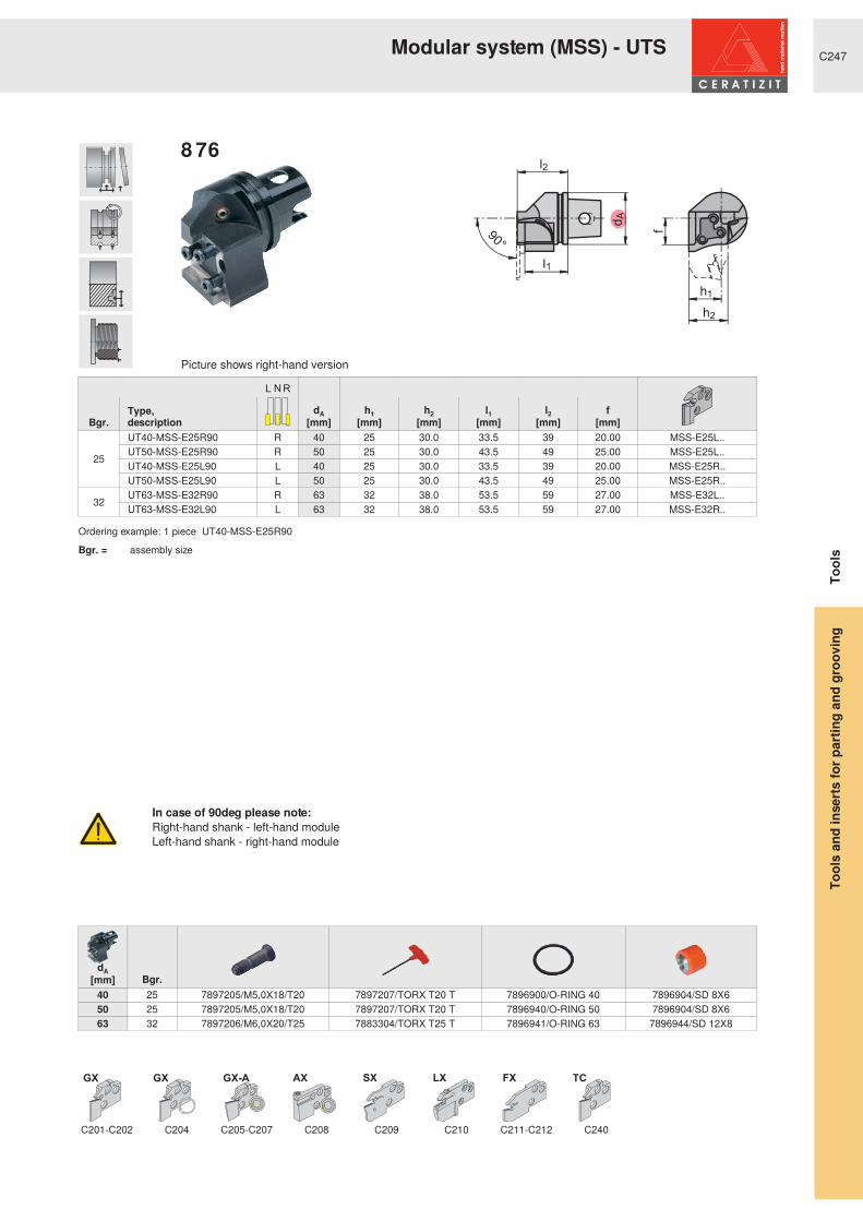
C247
GX GX GX-A AX SX LX FX TC
Type,description
dA h1 h2 l1 l2 fBgr. [mm] [mm] [mm] [mm] [mm] [mm]
25
UT40-MSS-E25R90 R 40 25 30.0 33.5 39 20.00 MSS-E25L..UT50-MSS-E25R90 R 50 25 30.0 43.5 49 25.00 MSS-E25L..UT40-MSS-E25L90 L 40 25 30.0 33.5 39 20.00 MSS-E25R..UT50-MSS-E25L90 L 50 25 30.0 43.5 49 25.00 MSS-E25R..
32 UT63-MSS-E32R90 R 63 32 38.0 53.5 59 27.00 MSS-E32L..UT63-MSS-E32L90 L 63 32 38.0 53.5 59 27.00 MSS-E32R..
Ordering example: 1 piece UT40-MSS-E25R90Bgr. = assembly size
dA[mm] Bgr.
40 25 7897205/M5,0X18/T20 7897207/TORX T20 T 7896900/O-RING 40 7896904/SD 8X650 25 7897205/M5,0X18/T20 7897207/TORX T20 T 7896940/O-RING 50 7896904/SD 8X663 32 7897206/M6,0X20/T25 7883304/TORX T25 T 7896941/O-RING 63 7896944/SD 12X8
C201-C202 C204 C205-C207 C208 C209 C210 C211-C212 C240
Picture shows right-hand version
In case of 90deg please note:Right-hand shank - left-hand moduleLeft-hand shank - right-hand module
8 76 � � � ƒ
Tool
sTo
ols
and
inse
rts fo
r par
ting
and
groo
ving
Modular system (MSS) - UTS

C248
GX
Type,description
dA h1 h2 b1 l1 l2 fBgr. [mm] [mm] [mm] [mm] [mm] [mm] [mm]25 UT40-MSS-E25L45 L 40 25 30.0 8.00 40 21 0.00 MSS-E25R..
Ordering example: 1 piece UT40-MSS-E25L45Bgr. = assembly size
Bgr.
25 7897210/M5,0X13,5/T20 7897205/M5,0X18/T20 7897207/TORX T20 T 7896904/SD 8X6
C204
Picture shows left-hand version
8 76 � � � ƒ
Tool
sTo
ols
and
inse
rts fo
r par
ting
and
groo
ving
Modular system (MSS) - UTS

C249
f
dA
D
Tm
ax
l1
l2
GX TC
Type,description
dA l2 Tmax l1 Dmin f Bgr. [mm] [mm] [mm] [mm] [mm] [mm]
32 UT40-MSS-I32R90-2D R 40 64 9 80 40 2.00
MSS-I32R..UT50-MSS-I32L90-2D L 50 64 9 90 40 2.00 MSS-I32L..
40UT40-MSS-I40R90-2D R 40 80 10 92 50 2.50 MSS-I40R..UT63-MSS-I40R90-2D R 63 80 10 110 50 2.50 MSS-I40R..UT40-MSS-I40L90-2D L 40 80 10 92 50 2.50 MSS-I40L..
Ordering example: 1 piece UT40-MSS-I32R90-2DBgr. = assembly size
Bgr.32 7897204/M4,5X17/T20 7897207/TORX T20 T40 7897205/M5,0X18/T20 7897207/TORX T20 T
C234+C236 C242
GX24:Tmax = +9 mmD = +10 mm
Picture shows right-hand version
When using module MSS-I40N19-GX24.. the following applies:
UTS boring bars
Tool
sTo
ols
and
inse
rts fo
r par
ting
and
groo
ving
8 76 � ² � 0 66 � ERULQ J� EDUV

C250
l1
h 1h 2
b1
f
GX GX GX-A SX LX FX
Type,description
dA h1 h2 l1 b1 fBgr. [mm] [mm] [mm] [mm] [mm] [mm]
32
HSK-T63-MSS-E32R00 R 63 35 41.0 74 44.20 38.70 MSS-E32R..HSK-T100-MSS-E32R00 100 43.8 49.8 77 54.20 48.70 MSS-E32R..HSK-T63-MSS-E32L00 L 63 35 41.0 74 44.20 38.70 MSS-E32L..HSK-T100-MSS-E32L00 100 43.8 49.8 77 54.20 48.70 MSS-E32L..
Ordering example: 1 piece HSK-T63-MSS-E32R00Bgr. = assembly size
dA[mm] Bgr.
63 - 100 32 7897206/M6,0X20/T25 7883304/TORX T25 T 7896944/SD 12X8
C201-C202 C204 C205-C207 C209 C210 C211-C212
Picture shows right-hand version
+ 6 . � 7 � � ƒ
Tool
sTo
ols
and
inse
rts fo
r par
ting
and
groo
ving
Modular system (MSS) - HSK-T

C251
l1l2
90°
h1
h2
f
GX GX GX-A SX LX FX
Type,description
dA h1 h2 l1 l2 fBgr. [mm] [mm] [mm] [mm] [mm] [mm]
32
HSK-T63-MSS-E32R90 R 63 34.8 40.9 63.7 69.2 31.50 MSS-E32L..HSK-T100-MSS-E32R90 100 43.8 49.8 73.7 79.2 50.00 MSS-E32L..HSK-T63-MSS-E32L90 L 63 34.8 40.9 63.7 69.2 31.50 MSS-E32R..HSK-T100-MSS-E32L90 100 43.8 49.8 73.7 79.2 50.00 MSS-E32R..
Ordering example: 1 piece HSK-T63-MSS-E32R90Bgr. = assembly size
dA[mm] Bgr.
63 - 100 32 7897206/M6,0X20/T25 7883304/TORX T25 T 7896944/SD 12X8
C201-C202 C204 C205-C207 C209 C210 C211-C212
Picture shows right-hand version
+ 6 . � 7 � � � ƒ
Tool
sTo
ols
and
inse
rts fo
r par
ting
and
groo
ving
Modular system (MSS) - HSK-T

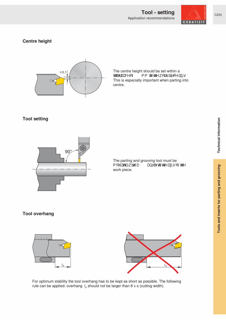
C253
0,1
90°
l l aa
The centre height should be set within a WROHUDQFH� RI� “ � � � � P P � WR� WKH� ZRUN�SLHFH� D[LV� �This is especially important when parting into centre.
The parting and grooving tool must be P RXQWHG� ZLWK� D� � � ƒ � DQJOH� WR� WKH� D[LV� RI� WKH�work piece.
For optimum stability the tool overhang has to be kept as short as possible. The following rule can be applied: overhang la should not be larger than 8 x s (cutting width).
Tool overhang
Centre height
Tool setting
Application recommendations
Tool
s an
d in
serts
for p
artin
g an
d gr
oovi
ng
Tool - setting
Tech
nica
l inf
orm
atio
n

C254
a
s
In order to avoid vibration the work piece should be clamped with the minimum overhang possible.
From dia. 5 mm on, reduce IHHG� UDWH� ¶ I· � E\� DSSUR[� � � � � �
No part-off across centre (risk of breakage).
For parting pip-free, use R or L inserts.
Because of lateral deflection UHGXFH� IHHG� UDWH� ¶ I· � E\� DSSUR[� �20% - 50%.
In order to prevent ring formation, use R or L inserts.
Because of lateral deflection UHGXFH� IHHG� UDWH� ¶ I· � E\� DSSUR[� �20% - 50%.
When grooving with an axial GLVSODFHP HQW� WKH� ZLGWK� ¶ D· � VKRXOG�be at least 70% of the cutting width ¶ V· �
When grooving inclined surfaces the feed should be reduced by approx. 20% - 50% at the beginning.
Advice for grooving operations
Work piece overhang
Advice for part-off operations
Application recommendations
Tool
s an
d in
serts
for p
artin
g an
d gr
oovi
ng
Tool - settingTe
chni
cal i
nfor
mat
ion

C255
GX09-S / GX16-S
x s rR/L “ � � � � “ � � � � ²N “ � � � �
GX09-R
x s r² “ � � � � “ � � � � “ � � � �
GX16-R
x s r-27P “ � � � � “ � � � � “ � � � �²
GX24-R
x s r-27P “ � � � � “ � � � � “ � � � �-M3 “ � � � � “ � � � � “ � � � �
GX09-E
x s r-F2 “ � � � � “ � � � � “ � � � �²
-M40 “ � � � “ � � � �
GX16-E
x s r-27P
“ � � � � “ � � � �“ � � � �
-F2²
-M1 “ � � � � “ � � � �-M40
GX24-E
x s r-27P
“ � � � � “ � � � �“ � � � �
-F2²
-M40 “ � � � � “ � � � �-M1
AX
x s r-F50 “ � � � � “ � � � � “ � � � �
FX
x s r-27P 2,2 - 4,1 “ � � � � “ � � � � “ � � � �-F1 2,2 - 4,1 “ � � � � “ � � � � “ � � � �
-M12,2 - 4,1 “ � � � � -0,1 “ � � � �5,1 - 6,5 -0,158,2 - 9,7 “ � � � � -0,2 “ � � � �
-R2 3,1 - 4,1 “ � � � � “ � � � � “ � � � �
SX
x s r-27P “ � � � � “ � � � � “ � � � �-F2-M1
“ � � � “ � � � � “ � � � �-M2-M3
LX
x s r-M2 “ � � � � “ � � � � “ � � � �-M3 “ � � � � “ � � � � “ � � � �
PX
x s r-F3 “ � � � � “ � � � � “ � � � �
MaxiClick
x s r-27P
“ � � � � � “ � � � � ²-F2-F3
TC
x s r-27P “ � � � � ² ²²
1
1000
1
1000
r
s
sr
= repeatability (x)
Tolerances (mm) Tolerances (mm)
Tolerances (mm)
Tolerances (mm)
Tolerances (mm)
Tolerances (mm)
Tolerances (mm)
Tolerances (mm)
Tolerances (mm)
Tolerances (mm) Tolerances (mm)
Tolerances (mm)
Tolerances (mm)
Tolerances (mm)
Chip grooveChip groove
Chip groove
Chip groove
Chip groove
Chip groove
Chip groove
Chip groove
Chip groove
Chip groove Chip groove
Chip groove
Chip groove
Chip groove
Width
Tool
s an
d in
serts
for p
artin
g an
d gr
oovi
ngTe
chni
cal i
nfor
mat
ion
InsertsTolerances

C256
E12 35 40 45 60 75 115 >250
E16 50 55 60 70 80 100 130 200 >420
E20 60 65 70 75 85 95 110 130 165 220 >330
E25 75 80 85 90 100 110 125 140 160 190 240 320 >500
E32 95 100 105 110 120 125 135 145 160 180 200 225 270 320 400 530 >800
0,5 1,0 1,5 2,0 2,5 3,0 3,5 4,0 4,5 5,0 5,5 6,0 6,5 7,0 7,5 8,0
Tmax
D max
at
T max
D
Tred.
a
Tred. = Tmax� ² � D
Tmax� � � � � P P � � � ‘ � � � � P P
MSS-E25R21-GX24-3
' � � ‘ � � � � � P P => Tmax - a = Tred. 21 - 2 = 19 mm
Tmax = maximum grooving depthDmax = maximum work piece diameter with full grooving depth Tmax (a = 0)a = reduction of grooving depth
Calculation example: module
Reduced parting and grooving depth:
The MSS parting and grooving modules are selected by size to suit a certain work piece diameter (Dmax). If the diameter of the work piece is bigger than Dmax of the module, then the achievable parting and grooving depth is reduced E\� GLP HQVLRQ� ¶ D· � � 7KH� H[WHQW� RI� WKH� UHGXFWLRQ� LV�HVWDEOLVKHG� E\� UHIHUHQFH� WR� WKH�following table.
Reduction of the maximum grooving depth a (mm)
Assembly size Work piece diameter (mm)
Maximum work piece diameter (Dmax)in case of full parting and grooving depth (Tmax) in mm
assembly size 25
Tool
s an
d in
serts
for p
artin
g an
d gr
oovi
ngTe
chni
cal i
nfor
mat
ion
MSS-GX, SX, LX, FXReduced parting and grooving depth

C257
Tmax
E16...PX20-1 5 52 64 74 74 88 108 144 214 428 ∞
E16...PX20-2E16...PX20-3 10 52 55 58 62 68 74 83 93 108 128 159 211 316 630 ∞
E20...PX20-1 5 62 68 77 89 106 131 174 259 518 ∞
E20...PX20-2E20...PX20-3 11 62 66 72 79 88 99 115 136 170 225 337 672 ∞
0,5 1,0 1,5 2,0 2,5 3,0 3,5 4,0 4,5 5,0 5,5 6,0 6,5 7,0 7,5 8,0
Tmax
D max
at
T max
D
Tred.
a
Tred. = Tmax� ² � D
Tmax� � � � � P P � � � ‘ � � � � P P
E20R0011-2020L-PX20-2
' � � ‘ � � � � � P P => Tmax - a = Tred. 11 - 3 = 8 mm
Tmax = maximum grooving depthDmax = maximum work piece diameter with full grooving depth Tmax (a = 0)a = reduction of grooving depth
Reduced parting and grooving depth:
The MSS parting and grooving modules are selected by size to suit a certain work piece diameter (Dmax). If the diameter of the work piece is bigger than Dmax of the module, then the achievable parting and grooving depth is reduced E\� GLP HQVLRQ� ¶ D· � � 7KH� H[WHQW� RI� WKH� UHGXFWLRQ� LV�HVWDEOLVKHG� E\� UHIHUHQFH� WR� WKH�following table.
Calculation example: system PX
Reduction of the maximum grooving depth a (mm)
Assembly size Work piece diameter (mm)
Maximum work piece diameter (Dmax)in case of full parting and grooving depth (Tmax) in mm
assembly size 20
Tool
s an
d in
serts
for p
artin
g an
d gr
oovi
ngTe
chni
cal i
nfor
mat
ion
Reduced parting and grooving depthSystem PX

C258
Nm in.lbs0 66 � ( � � « 7897200/M2,5x10/T08 T08 1,2 10,60 66 � ( � � « 7897202/M3,5x12,5/T15 T15 3,2 28,30 66 � ( � � « 7897203/M4x14/T15 T15 4 35,40 66 � ( � � « 7897205/M5x18/T20 T20 5 44,30 66 � ( � � « 7897206/M6x20/T25 T25 6 53,1
Nm in.lbs0 66 � ,� � « 7897200/M2,5x10/T08 T08 1,2 10,60 66 � ,� � « 7897201/M3x11/T10 T10 2 17,70 66 � ,� � « 7897202/M3,5x12,5/T15 T15 3,2 28,30 66 � ,� � « 7897204/M4,5x17/T20 T20 4 35,40 66 � ,� � « 7897205/M5x18/T20 T20 5 44,3
C9
C9
MSS tool shanks
MSS boring bars
MSS tool shanks Screw
Screw
Torx
Torx
Torque moments
Torque momentsMSS boring bars
Note the order in which screws must be clamped!
Note the order in which screws must be clamped!
Tool
s an
d in
serts
for p
artin
g an
d gr
oovi
ngTe
chni
cal i
nfor
mat
ion
Torque momentsMSS module clamping screws

C259
TorxNm in.lbs
7897218/M4,0X18/T20 T20 4,0 35,4
7897218/M4,0X18/T20 T20 4,0 35,4
7897202/M3,5X12,5/T157897203/M4,0X14/T157897205/M5,0X18/T20
T15T15T20
3,24,05,0
28,335,444,3
SX
PX
AX
1 + 1 + 5
DMSD 1,2Nm/SORT T08DMSD 2,0Nm/SORT T10DMSD 3,2Nm/SORT T15DMSD 4,0Nm/SORT T15DMSD 4,0Nm/SORT T20DMSD 5,0Nm/SORT T20DMSD 6,0Nm/SORT T25
1 + 1
DMSD 1-5Nm/SORT
DMSD 2-8Nm/SORT
DMSD-B T08-50MMDMSD-B T10-50MMDMSD-B T15-50MMDMSD-B T20-50MMDMSD-B T25-50MM
Recommended torque moments
Torque key (inserts/bits)
Torque moment set to:1.2 - 6.0 Nm
Torque moment can be adjusted flexibly:1.0-5.0 Nm
Torque moment can be adjusted flexibly:2.0-8.0 Nm
pcs. (incl. in delivery)
piece (incl. in delivery)
Tool ScrewTorque moments
Tool
s an
d in
serts
for p
artin
g an
d gr
oovi
ng
for insert clamping
Tech
nica
l inf
orm
atio
n
Torque moments
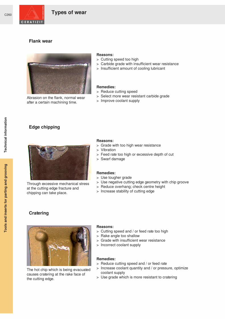
C260
Abrasion on the flank, normal wear after a certain machining time.
Reasons:> Cutting speed too high> Carbide grade with insufficient wear resistance> Insufficient amount of cooling lubricant
Remedies:> Reduce cutting speed> Select more wear resistant carbide grade> Improve coolant supply
Flank wear
The hot chip which is being evacuated causes cratering at the rake face of the cutting edge.
Reasons:> Cutting speed and / or feed rate too high> Rake angle too shallow> Grade with insufficient wear resistance> Incorrect coolant supply
Remedies:> Reduce cutting speed and / or feed rate> Increase coolant quantity and / or pressure, optimize
coolant supply> Use grade which is more resistant to cratering
Cratering
Through excessive mechanical stress at the cutting edge fracture and chipping can take place.
Reasons:> Grade with too high wear resistance> Vibration> Feed rate too high or excessive depth of cut> Swarf damage
Remedies:> Use tougher grade> Use negative cutting edge geometry with chip groove> Reduce overhang; check centre height> Increase stability of cutting edge
Edge chipping
Types of wearTo
ols
and
inse
rts fo
r par
ting
and
groo
ving
Tech
nica
l inf
orm
atio
n

C261
Built-up edge occurs when the chip is not evacuated properly due to insufficient cutting temperature.
Reasons:> Cutting speed too low> Rake angle too small> Wrong cutting material> Lack of cooling / lubrication
Remedies:> Increase cutting speed> Enlarge rake angle> Apply TiN-coating> Use emulsion with higher concentration
Built-up edge
Notch at the maximum depth of cut
Reasons:> Oxidation of the cutting edge> Excessive heat on the cutting edge
Remedies:> Use various depths of cut> Reduce cutting speed> Improve coolant supply
Notching
High machining temperature and simultaneous mechanical stress may lead to plastic deformation.
Reasons:> Too high machining temperature resulting in softening of
substrate> Wear / heat resistance of carbide grade too low> Insufficient coolant supply
Remedies:> Reduce cutting speed> Choose carbide grade with higher wear resistance> Provide cooling
Plastic deformation
Types of wear
Tool
s an
d in
serts
for p
artin
g an
d gr
oovi
ngTe
chni
cal i
nfor
mat
ion

C262
Type of problem
Corrective measures
Type of wear Work piece problems Swarf control
Edge
chi
ppin
g
Built-
up e
dge
Flan
k we
ar
Plas
tic d
efor
mat
ion
Vibr
atio
n
Form
atio
n of
pip
s an
d bu
rrs
Chat
tere
d su
rface
Surfa
ce q
uality
Chip
too
long
(tan
gled
swa
rf)
Chip
too
shor
t (fra
gmen
ted
chip
)
Cutting speed
Cutti
ng v
alue
s
Feed rate
Feed - centre area
Chip groove-R-M-F
Sele
ctio
n of
inse
rts
R / L - right-hand / left-hand version
Corner radius
larger
smaller
Cutting material
wear resistance
toughness
Cutting width
Clamping of tool
Gen
eral
crit
eriaClamping of work piece
Overhang
Tip height
Cooling lubricant
raise, increase,large influence
avoid, reducelarge influence
check,optimize
raise, increaselow influence
avoid, reducelow influence use
Tool
s an
d in
serts
for p
artin
g an
d gr
oovi
ngTe
chni
cal i
nfor
mat
ion
Measures for parting and grooving problems
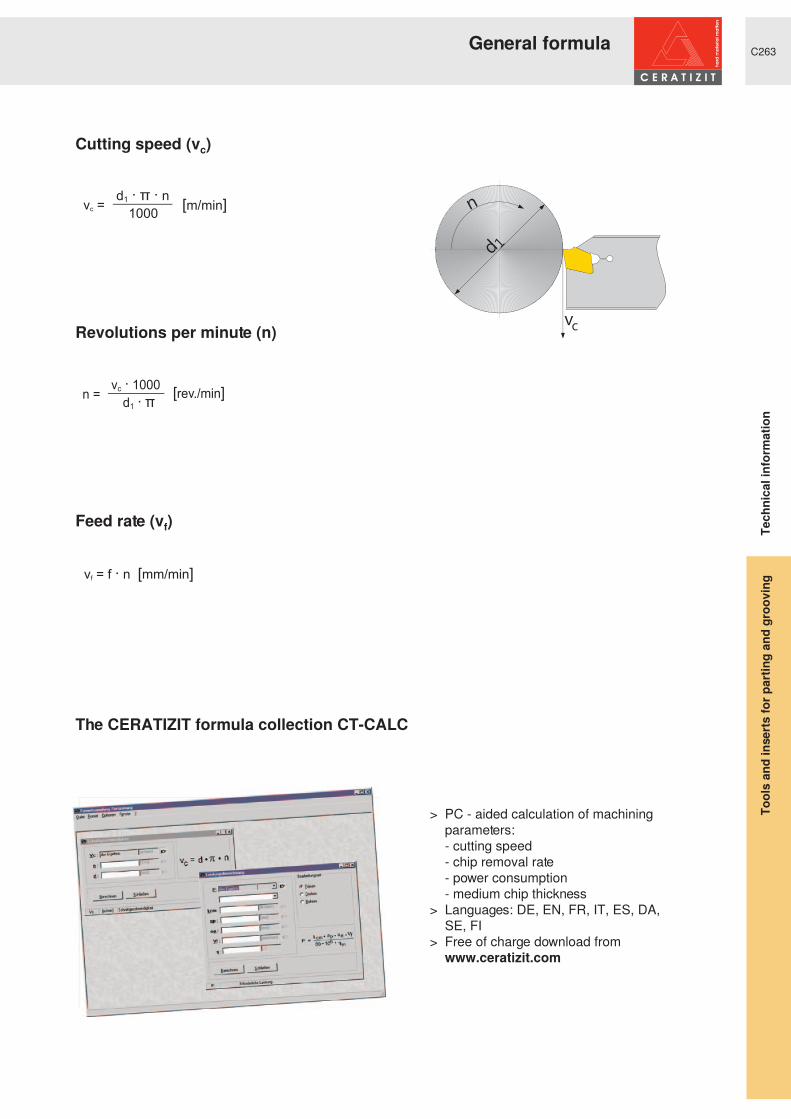
C263
d1
n
vc
> PC - aided calculation of machining parameters:
- cutting speed - chip removal rate - power consumption - medium chip thickness> Languages: DE, EN, FR, IT, ES, DA,
SE, FI> Free of charge download from www.ceratizit.com
Feed rate (vf)
The CERATIZIT formula collection CT-CALC
Cutting speed (vc)
Revolutions per minute (n)
General formula
Tool
s an
d in
serts
for p
artin
g an
d gr
oovi
ngTe
chni
cal i
nfor
mat
ion

C264
575 180 171595 185 176610 190 181625 195 185640 200 190 12,0660 205 195 13,0675 210 199 14,0690 215 204 15,0705 220 209 15,5 28720 225 214 16,0740 230 219 17,0 29755 235 223 18,0770 240 228 20,3 30785 245 233 21,3800 250 238 22,2 31820 255 242 23,1 32835 260 247 24,0 33850 265 252 24,8865 270 257 25,6880 275 261 26,4 34900 280 268 27,1915 285 271 27,8 35930 290 276 28,5950 295 280 29,2 36965 300 285 29,8 37995 310 295 31,0 381030 320 304 32,2 391060 330 314 33,3 401095 340 323 34,3 411125 350 333 35,5 421155 360 342 36,6 431190 370 352 37,7 441220 380 361 38,8 451255 390 371 39,8 461290 400 380 40,8 471320 410 390 41,8 481350 420 399 42,71385 430 409 43,6 491420 440 418 44,51455 450 428 45,3 511485 460 437 46,1 521520 470 447 46,9 531555 480 465 47,7 541595 490 466 48,41630 500 475 49,1 571665 510 485 49,8 581700 520 494 50,5 591740 530 504 51,1 60
1775 540 513 51,7 611810 550 523 52,3 621845 560 532 53,0 631880 570 542 53,6 641920 580 551 54,1 651955 590 561 54,7 661995 600 570 55,2 672030 610 580 55,7 682070 620 589 56,3 692105 630 599 56,8 702145 640 608 57,3 712180 650 618 57,8 722210 660 628 58,3 732240 665 633 58,8 742280 670 638 59,32310 675 643 59,8 752350 680 648 60,3 762380 685 653 61,1 772410 690 658 61,3 782450 695 663 61,7 792480 710 668 62,2 802520 720 678 62,6 812550 730 683 63,1 822590 740 693 63,52630 750 703 63,9 832660 760 708 64,3 842700 770 718 64,7 852730 780 723 65,12770 790 733 65,5 862800 800 738 65,92840 810 748 66,3 872870 820 753 66,7 882910 830 763 67,02940 840 768 67,4 892980 850 67,73010 860 68,1 903050 870 68,43080 880 68,7 913120 890 69,03150 900 69,3 923190 910 69,63220 920 69,93260 930 70,1
Tens
ile s
treng
th1�
PP
ò
Vick
ers
HV Brin
ell
HB Rock
wel
lHR
C
Shor
eC Te
nsile
stre
ngth
1�P
Pò
Vick
ers
HV Brin
ell
HB Rock
wel
lHR
C
Shor
eC
The figures given are approximate according to DIN EN ISO18265 (02-2004)
Hardness valuesComparison table
Tool
s an
d in
serts
for p
artin
g an
d gr
oovi
ngTe
chni
cal i
nfor
mat
ion

C265
Kc1.1N/mm2 mc
10 SPb 20 1.0722 10 PbF 2 11 L 08 1350 .21 1
100 Cr 6 1.2067 BL 3 Y 100 C 6 L 3 SUJ2 1775 .24 6/9
105 WCr 6 1.2419 105 WC 13 SKS31 1775 .24 6/9
12 CrMo 9 10 1.7380 1501-622 Gr. 31; 45 10 CD 9.10 2218 A 182-F22 SPVA,SCMV4 1675 .24 6/7
12 Ni 19 1.5680 Z 18 N 5 2515 2450 .23 10/11
13 CrMo 4 4 1.7335 1501-620 Gr. 27 15 CD 3.5 2216 A 182-F11; F12 SPVAF12 1675 .24 6/7
14 MoV 6 3 1.7715 1503-660-440 1675 .24 6/7
14 Ni 6 1.5622 16 N 6 A 350-LF 5 1675 .24 6/7
14 NiCr 10 1.5732 14 NC 11 3415 SNC415(H) 1675 .24 6/7
14 NiCr 14 1.5752 655 M 13 12 NC 15 3310; 9314 SNC815(H) 1675 .24 6/7
14 NiCrMo 13 4 1.6657 1675 .24 6/7
15 Cr 3 1.7015 523 M 15 12 C 3 5015 1675 .24 6/7
15 CrMo 5 1.7262 12 CD 4 SCM415(H) 1675 .24 6/7
15 Mo 3 1.5415 1501-240 15 D 3 2912 A 204 Gr. A 1675 .24 6/7
16 MnCr 5 1.7131 527 M 17 16 MC 5 2511 5115 SCR415 1675 .24 6/7
16 Mo 5 1.5423 1503-245-420 4520 SB450M 1675 .24 6/7
17 CrNiMo 6 1.6587 820 A 16 18 NCD 6 1675 .24 6/7
21 NiCrMo 2 1.6523 805 M 20 20 NCD 2 2506 8620 SNCM220(H) 1725 .24 6/8
25 CrMo 4 1.7218 1717 CDS 110 25 CD 4 S 2225 4130 SM420;SCM430 1725 .24 6/8
28 Mn 6 1.1170 150 M 28 20 M 5 1330 1500 .22 2
32 CrMo 12 1.7361 722 M 24 30 CD 12 2240 1775 .24 6/9
34 Cr 4 1.7033 530 A 32 32 C 4 5132 SCR430(H) 1725 .24 6/8
34 CrMo 4 1.7220 708 A 37 35 CD 4 2234 4135; 4137 SCM432;SCCRM3 1775 .24 6/9
34 CrNiMo 6 1.6582 817 M 40 35 NCD 6 2541 4340 SNCM447 1775 .24 6/9
35 S 20 1.0726 212 M 36 35 MF 4 1957 1140 1525 .22 2/3
36 CrNiMo 4 1.6511 816 M 40 40 NCD 3 9840 SNCM447 1775 .24 6/9
36 Mn 5 1.1167 1525 .22 2/3
36 NiCr 6 1.5710 640 A 35 35 NC 6 3135 SNC236 1800 .24 3/9
38 MnSi 4 1.5120 1800 .24 3/9
39 CrMoV 13 9 1.8523 897 M 39 1775 .24 6/9
40 Mn 4 1.1157 150 M 36 35 M 5 1039 1525 .22 2/3
40 NiCrMo 2 2 1.6546 311-Type 7 40 NCD 2 8740 SNCM240 1775 .24 6/9
41 Cr 4 1.7035 530 M 40 42 C 4 5140 SCR440(H) 1775 .24 6/9
41 CrAlMo 7 1.8509 905 M 39 40 CAD 6.12 2940 A 355 Cl. A SACM645 1775 .24 6/9
41 CrMo 4 1.7223 708 M 40 42 CD 4 TS 2244 4142; 4140 SCM440 1775 .24 6/9
42 Cr 4 1.7045 530 A 40 42 C 4 TS 2245 5140 SCr440 1775 .24 6/9
42 CrMo 4 1.7225 708 M 40 42 CD 4 2244 4142; 4140 SCM440(H) 1775 .24 6/9
45 WCrV 7 1.2542 BS 1 2710 S 1 1775 .24 6/9
50 CrV 4 1.8159 735 A 50 50 CV 4 2230 6150 SUP10 1775 .24 6/9
55 Cr 3 1.7176 527 A 60 55 C 3 2253 5155 SUP9(A) 1775 .24 6/9
55 NiCrMoV 6 1.2713 55 NCDV 7 L 6 SKH1;SKT4 1775 .24 6/9
55 Si 7 1.0904 250 A 53 55 S 7 2085; 2090 9255 1775 .24 6/9
58 CrV 4 1.8161 1775 .24 6/9
60 SiCr 7 1.0961 60 SC 7 9262 1775 .24 6/9
9 SMn 28 1.0715 230 M 07 S 250 1912 1213 SUM22 1350 .21 1
9 SMn 36 1.0736 240 M 07 S 300 1215 1350 .21 1
9 SMnPb 28 1.0718 S 250 Pb 1914 12 L 13 SUM22L 1350 .21 1
9 SMnPb 36 1.0737 S 300 Pb 1926 12 L 14 1350 .21 1
Al99 3.0205 700 .25 21
AlCuMg1 3.1325 700 .25 22
GermanyDIN
Mat.no.
United KingdomBS
FranceAFNOR
SwedenSS
United StatesAISI
JapanJIS
VDI3323
group
Comparison of materials
Tool
s an
d in
serts
for p
artin
g an
d gr
oovi
ngTe
chni
cal i
nfor
mat
ion

C266
Kc1.1N/mm2 mc
AlMg1 3.3315 700 .25 21
AlMgSi1 3.2315 700 .25 22
C 105 W1 1.1545 Y1 105 1880 W 110 SK3 1675 .24 3
C 125 W 1.1663 Y2 120 W 112 1675 .24 3
C 15 1.0401 080 M 15 AF3 7 C 12; XC 18 1350 1015 S15C 1350 .21 1
C 22 1.0402 050 A 20 AF 42 C 20 1450 1020 S20C, S22C 1350 .21 1
C 35 1.0501 060 A 35 AF 55 C 35 1550 1035 S35C 1525 .22 2/3
C 45 1.0503 080 M 46 AF 65 C 45 1650 1045 S45C 1525 .22 2/3
C 55 1.0535 070 M 55 1655 1055 S55C 1675 .24 3
C 60 1.0601 080 A 62 CC 55 1060 S60C 1675 .24 3
Cf 35 1.1183 S35C 1525 .22 2/3
Cf 53 1.1213 S50C 1525 .22 2/3
Ck 101 1.1274 060 A 96 1870 1095 1675 .24 3
Ck 15 1.1141 080 M 15 XC 15; XC 18 1370 1015 S15C 1350 .21 1
Ck 55 1.1203 070 M 55 XC 55 1055 S55C 1675 .24 3
Ck 60 1.1221 080 A 62 XC 60 1665; 1678 1060 S58C 1675 .24 3
CoCr20W15Ni 2.4764 3300 .24 35
CuZn15 2.0240 700 .27 27
CuZn36Pb3 2.0375 700 .27 26
E-Cu57 2.0060 700 .27 28
G-AlSi10Mg 3.2381 700 .25 24
G-AlSi12 3.2581 700 .25 23
G-AlSi9Cu3 3.2163 700 .25 23
G-CuSn5ZnPb 2.1096 700 .27 26
G-CuZn40Fe 2.0590 700 .27 28
G-X 120 Mn 12 1.3401 Z 120 M 12 Z 120 M 12 A 128 (A) 3300 .24 35
G-X 20 Cr 14 1.4027 420 C 29 Z 20 C 13 M SCS2 1875 .21 12/13
G-X 40 NiCrSi 38 18 1.4865 330 C 40 2600 .24 31
G-X 45 CrSi 9 3 1.4718 401 S 45 Z 45 CS 9 HNV 3 2450 .23 10/11
G-X 5 CrNi 13 4 1.4313 425 C 11 Z 5 CN 13.4 2385 CA 6-NM 1875 .21 12/13
G-X 5 CrNiMoNb 18 10 1.4581 318 C 17 Z 4 CNDNb 18.12 M 2150 .2 14
G-X 6 CrNi 18 9 1.4308 304 C 15 Z 6 CN 18.10 M 2333 CF-8 2150 .2 14
G-X 6 CrNiMo 18 10 1.4408 2150 .2 14
G-X 7 Cr 13 1.4001 1875 .21 12/13
GG-10 .6010 Ft 10 D 01 10-00 A48-20 B FC100 1150 .2 15
GG-15 .6015 Grade 150 Ft 15 D 01 15-00 A48-25 B FC150 1150 .2 15
GG-20 .6020 Grade 220 Ft 20 D 01 20-00 A48-30 B FC200 1150 .2 15
GG-25 .6025 Grade 260 Ft 25 D 01 25-00 A48-40 B FC250 1250 .24 15/16
GG-30 .6030 Grade 300 Ft 30 D 01 30-00 A48-45 B FC300 1350 .28 16
GG-35 .6035 Grade 350 Ft 35 D 01 35-00 A48-50 B FC350 1350 .28 16
GG-40 .6040 Grade 400 Ft 40 D 01 40-00 A48-60 B FC400 1350 .28 16
GGG-35.3 .7033 FCD350 1225 .25 17
GGG-40 .7040 SNG 420/12 FGS 400-12 0717-02 60-40-18 FCD400 1225 .25 17
GGG-40.3 .7043 SNG 370/17 FGS 370-17 0717-15 FCD400 1225 .25 17
GGG-50 .7050 SNG 500/7 FGS 500-7 0727-02 65-45-12 FCD500 1350 .28 18
GGG-60 .7060 SNG 600/3 FGS 600-3 0732-03 80-55-06 FCD600 1350 .28 18
GGG-70 .7070 SNG 700/2 FGS 700-2 0737-01 100-70-03 FCD700 1350 .28 18
GGG-NiCr 20 2 .7660 S-NiCr 20 2 S-NC 20 2 A 439 Type D-2 1350 .28 18
GGG-NiMn 13 7 .7652 S-NiMn 13 7 S-NM 13 7 1350 .28 18
GS-Ck 45 1.1191 080 M 46 XC 42 1672 1045 S45C 1525 .22 2/3
GermanyDIN
Mat.no.
United Kingdom
BSFranceAFNOR
SwedenSS
United StatesAISI
JapanJIS
VDI3323
group
Comparison of materialsTo
ols
and
inse
rts fo
r par
ting
and
groo
ving
Tech
nica
l inf
orm
atio
n

C267
Kc1.1N/mm2 mc
GTS-35-10 .8135 B 340/12 MN 35-10 1225 .25 19
GTS-45-06 .8145 P 440/7 1420 .3 20
GTS-55-04 .8155 P 510/4 MP 50-5 1420 .3 20
GTS-65-02 .8165 P 570/3 MP 60-3 1420 .3 20
GTS-70-02 .8170 P 690/2 IP 70-2 1420 .3 20
NiCr20TiAl 2.4631 HR 401; 601 Nimonic 80 A 3300 .24 33
NiCr22Mo9Nb 2.4856 Inconel 625 3300 .24 33
NiCu30Al 2.4375 Monel K 500 3300 .24 34
NiFe25Cr20NbTi 2.4955 3300 .24 34
S 18-0-1 1.3355 BT 1 Z 80 WCV 18-04-01 T 1 2450 .23 10/11
S 18-1-2-5 1.3255 BT 4 Z 80 WKCV 18-05-04-0 T 4 2450 .23 10/11
S 2-9-2 1.3348 Z 100 DCWV 09-04-02- 2782 M 7 2450 .23 10/11
S 6-5-2 1.3343 BM 2 Z 85 WDCV 06-05-04-0 2722 M 2 SKH9; SKH51 2450 .23 10/11
S 6-5-2-5 1.3243 Z 85 WDKCV 06-05-05- 2723 SKH55 2450 .23 10/11
TiAl6V4 3.7165 TA 10 bis TA 13 T-A 6 V 2110 .22 37
X 10 Cr 13 1.4006 410 S 21 Z 12 C 13 2302 410; CA-15 SUS410 1875 .21 12/13
X 10 CrNiMoNb 18 12 1.4583 318 2150 .2 14
X 10 CrNiS 18 9 1.4305 303 S 21 Z 10 CNF 18.09 2346 303 2150 .2 14
X 100 CrMoV 5 1 1.2363 BA 2 Z 100 CDV 5 2260 A 2 2450 .23 10/11
X 12 CrMoS 17 1.4104 Z 10 CF 17 2383 430 F SUS430F 1875 .21 12/13
X 12 CrNi 17 7 1.4310 301 S 21 Z 12 CN 17.07 301 2150 .2 14
X 12 CrNi 22 12 1.4829 SUS301 1350 .28 16
X 12 CrNi 25 21 1.4845 310 S24 Z 12 CN 25.20 2361 310 S SUH310; SUS310S 2150 .2 14
X 12 CrNiTi 18 9 1.4878 321 S 20 Z 6 CNT 18.12 (B) 2337 321 2150 .2 14
X 12 NiCrSi 36 16 1.4864 NA 17 Z 12 NCS 37.18 330 SUH330 2600 .24 31
X 15 CrNiSi 20 12 1.4828 309 S 24 Z 15 CNS 20.12 309 SUH309 1350 .28 16
X 165 CrMoV 12 1.2601 2310 2450 .23 10/11
X 2 CrNiMo 18 13 1.4440 2150 .2 14
X 2 CrNiMoN 17 13 3 1.4429 316 S 62 Z 2 CND 17.13 Az 2375 316 LN SUS316LN 2150 .2 14
X 2 CrNiN 18 10 1.4311 304 S 62 Z 2 CN 18 .10 2371 304 LN SUS304LN 2150 .2 14
X 20 CrNi 17 2 1.4057 431 S 29 Z 15 CN 16.02 2321 431 SUS431 1875 .21 12/13
X 210 Cr 12 1.2080 BD 3 Z 200 C 12 D 3 2450 .23 10/11
X 210 CrW 12 1.2436 2312 2450 .23 10/11
X 30 WCrV 9 3 1.2581 BH 21 Z 30 WCV 9 H 21 SKD5 2450 .23 10/11
X 40 CrMoV 5 1 1.2344 BH 13 Z 40 CDV 5 2242 H 13 SKD61 2450 .23 10/11
X 46 Cr 13 1.4034 420 S 45 Z 40 C 14 1875 .21 12/13
X 5 CrNi 18 9 1.4301 304 S 15 Z 6 CN 18.09 2332; 2333 304; 304 H SUS304 2150 .2 14
X 5 CrNiMo 17 13 3 1.4436 316 S 16 Z 6 CND 17.12 2343 316 SUS316 2150 .2 14
X 5 CrNiMo 18 10 1.4401 316 S 16 Z 6 CND 17.11 2347 316 SUS316 2150 .2 14
X 53 CrMnNiN 21 9 1.4871 349 S 54 Z 52 CMN 21.09 EV 8 1875 .21 12/13
X 6 Cr 13 1.4000 403 S 17 Z 6 C 13 2301 403 SUS403 1875 .21 12/13
X 6 Cr 17 1.4016 430 S 15 Z 8 C 17 2320 430 SUS430 1875 .21 12/13
X 6 CrMo 17 1.4113 434 S 17 Z 8 CD 17.01 2325 434 SUS434 1875 .21 12/13
X 6 CrNiMoTi 17 12 2 1.4571 320 S 31 Z 6 CNT 17.12 2350 316 Ti 2150 .2 14
X 6 CrNiNb 18 10 1.4550 347 S 17 Z 6 CNNb 18.10 2338 347 2150 .2 14
X 6 CrNiTi 18 10 1.4541 321 S 12 Z 6 CNT 18.10 2337 321 2150 .2 14
X2 CrNi 18-8 1.4317 2150 .2 14
GermanyDIN
Mat.no.
United KingdomBS
FranceAFNOR
SwedenSS
United StatesAISI
JapanJIS
VDI3323
group
kc1.1 value = specific cutting force at a cutting rake angle of 0 degrees. For positive rake angles the kc1.1 value has to be reduced (increased for negative rake angles) by 1% per degree of rake angle. The mc value is the exponent for the conversion of the kc1.1 value.
Comparison of materials
Tool
s an
d in
serts
for p
artin
g an
d gr
oovi
ngTe
chni
cal i
nfor
mat
ion

C268
HB
A
1 1252 150 - 2503 3006 180
7 / 8 250 - 3009 350
10 20011 35012 20013 325
R
14 20014 18014 230 - 26014 330
F
15 18016 26017 16018 ²19 13020 230
N
21 6022 100
< 12% Si 23 80< 12% Si 24 90> 12% Si 25 130
26 ²27 9028 10029 10029 ²29 ²30 ²
S
31 20032 28033 25034 ²35 ²36 Rm 440*37 Rm 1050*
H
38 55 HRC39 60 HRC40 40040 55 HRC
Work piecematerial Type of treatment / alloy VD
I 332
3gr
oup Ha
rd-
ness
Non alloyed steelannealed ≤ .15% Cannealed .15% - .45% Ctempered ≥ .45% C
Low alloyed steelannealedtemperedtempered
High alloyed steelannealedtempered
Corrosion resistantsteel
annealed ferritictempered martensitic
Stainless steel
annealed ferritic / martensiticquenched austeniticquenched duplexhardened martensitic / austenitic
Grey cast ironpearlitic / ferriticpearlitic / martensitic
Spheroidal cast ironferriticpearlitic
Malleable cast ironferriticpearlitic
Aluminiumwrought alloys
non hardenedhardened
Aluminiumcast alloys
non hardenedhardenednon hardened
Copper andcopper alloys (bronze,brass)
machining alloy stock (1% Pb)brass, red bronzebronzelead-free copper and electrolytic copper
Non-metallic materialsthermosetting plasticsfibre-reinforced plasticshard rubber
Heat resistantalloys
annealed Fe-basehardened Fe-baseannealed Ni or Co-basehardened Ni or Co-base 30 - 58 HRCcast 1 L� RU� & R� EDVH� � � � � � � � � � � � � 1 � P P ò
Titanium alloyspure titaniumalpha + beta alloys
Tempered steelhardened and temperedhardened and tempered
Chilled castings castTempered cast iron hardened and tempered* Rm = ultimate tensile strength, measured in MPa
Cutting dataTo
ols
and
inse
rts fo
r par
ting
and
groo
ving
Tech
nica
l inf
orm
atio
n

C269
H216Tvc
[m/min]
CTW7120vc
[m/min]
² ²² ²² ²² ²² ²² ²² ²² ²² ²² ²² ²² ²² ²² ²
120 - 160 ²90 - 140 ²
130 - 170 ²90 - 130 ²
140 - 200 ²120 - 160 ²300 - 2500 100 - 500200 - 2000 100 - 300400 - 1500 100 - 500400 - 1500 100 - 300200 - 800 100 - 300250 - 600 100 - 500200 - 600 100 - 500150 - 400 100 - 300150 - 300 100 - 30080 - 180 80 - 18060 - 150 60 - 150100 - 250 100 - 25030 - 45 ²20 - 35 ²20 - 35 ²18 - 30 ²15 - 25 ²60 - 120 50 - 12030 - 80 30 - 50
² ²² ²² ²² ²
Uncoated carbide
Cutting data
Tool
s an
d in
serts
for p
artin
g an
d gr
oovi
ngTe
chni
cal i
nfor
mat
ion

C270
HB
A
1 1252 150 - 2503 3006 180
7 / 8 250 - 3009 350
10 20011 35012 20013 325
R
14 20014 18014 230 - 26014 330
F
15 18016 26017 16018 ²19 13020 230
N
21 6022 100
< 12% Si 23 80< 12% Si 24 90> 12% Si 25 130
26 ²27 9028 10029 10029 ²29 ²30 ²
S
31 20032 28033 25034 ²35 ²36 Rm 440*37 Rm 1050*
H
38 55 HRC39 60 HRC40 40040 55 HRC
Work piecematerial Type of treatment / alloy VD
I 332
3gr
oup Ha
rd-
ness
Non alloyed steelannealed ≤ .15% Cannealed .15% - .45% Ctempered ≥ .45% C
Low alloyed steelannealedtemperedtempered
High alloyed steelannealedtempered
Corrosion resistantsteel
annealed ferritictempered martensitic
Stainless steel
annealed ferritic / martensiticquenched austeniticquenched duplexhardened martensitic / austenitic
Grey cast ironpearlitic / ferriticpearlitic / martensitic
Spheroidal cast ironferriticpearlitic
Malleable cast ironferriticpearlitic
Aluminiumwrought alloys
non hardenedhardened
Aluminiumcast alloys
non hardenedhardenednon hardened
Copper andcopper alloys (bronze,brass)
machining alloy stock (1% Pb)brass, red bronzebronzelead-free copper and electrolytic copper
Non-metallic materialsthermosetting plasticsfibre-reinforced plasticshard rubber
Heat resistantalloys
annealed Fe-basehardened Fe-baseannealed Ni or Co-basehardened Ni or Co-base 30 - 58 HRCcast 1 L� RU� & R� EDVH� � � � � � � � � � � � � 1 � P P ò
Titanium alloyspure titaniumalpha + beta alloys
Tempered steelhardened and temperedhardened and tempered
Chilled castings castTempered cast iron hardened and tempered* Rm = ultimate tensile strength, measured in MPa
Cutting dataTo
ols
and
inse
rts fo
r par
ting
and
groo
ving
Tech
nica
l inf
orm
atio
n

C271
CTC1325 vc
[m/min]
SR127vc
[m/min]
GM127vc
[m/min]
CTP1340vc
[m/min]
CTCP335vc
[m/min]
CTPP345vc
[m/min]
150 - 280 150 - 280 150 - 280 120 - 250 130 - 250 110 - 190130 - 240 130 - 240 130 - 240 80 - 180 110 - 190 80 - 150100 - 200 100 - 200 100 - 200 60 - 150 70 - 170 70 - 140140 - 220 140 - 220 140 - 220 80 - 180 120 - 200 70 - 140130 - 180 130 - 180 130 - 180 60 - 150 110 - 180 70 - 120100 - 160 100 - 160 100 - 160 60 - 120 70 - 150 60 - 120120 - 170 120 - 170 120 - 170 80 - 160 90 - 170 60 - 100100 - 150 100 - 150 100 - 150 50 - 120 70 - 160 60 - 100150 - 250 150 - 250 150 - 250 50 - 200 120 - 200 90 - 16060 -100 60 -100 60 - 100 50 - 150 60 - 100 60 - 100
140 - 220 140 - 220 140 - 220 50 - 200 120 - 200 100 - 180120 - 200 120 - 200 120 - 200 50 - 180 100 - 170 80 - 15080 - 130 80 - 130 80 - 130 50 - 100 70 - 110 70 - 11060 - 100 60 - 100 60 - 100 50 - 80 60 - 90 60 - 90120 - 220 120 - 220 ² 100 - 200 90 - 180 ²100 - 200 100 - 200 ² 90 - 160 80 - 150 ²130 - 190 130 - 190 ² 100 - 180 100 - 160 ²100 - 190 100 - 190 ² 80 - 160 70 - 140 ²140 - 280 140 - 280 ² 110 - 230 100 - 200 ²90 - 190 90 - 190 ² 80 - 160 80 - 150 ²
² ² ² 100 - 500 ² ²² ² ² 100 - 300 ² ²² ² ² 100 - 500 ² ²² ² ² 100 - 300 ² ²² ² ² 100 - 200 ² ²² ² ² 100 - 500 ² ²² ² ² 100 - 500 ² ²² ² ² 100 - 300 ² ²² ² ² 100 - 300 ² ²² ² ² 80 - 180 ² ²² ² ² 60 - 150 ² ²² ² ² 100 - 250 ² ²
25 - 45 25 - 45 25 - 45 20 - 50 ² ²20 - 40 20 - 40 20 - 40 20 - 40 ² 20 - 4015 - 25 15 - 25 15 - 25 15 - 25 ² 20 - 3010 - 20 10 - 20 10 - 20 10 - 20 ² ²10 - 20 10 - 20 10 - 20 10 - 20 ² ²
² ² ² 50 - 120 ² ²² ² ² 30 - 50 ² ²
10 - 20 10 - 20 ² ² ² ²² ² ² ² ² ²
10 - 20 10 - 20 ² ² ² ²10 - 20 10 - 20 ² ² ² ²
Coated carbide
Cutting data
Tool
s an
d in
serts
for p
artin
g an
d gr
oovi
ngTe
chni
cal i
nfor
mat
ion

C272
0 66 � WRROV� � ƒ
> Large overhang> Danger of collision> Special VDI adapter necessary
0 66 � WRROV� � � ƒ
> Short overhang> Increased stability> Normal clamping in VDI shank possible
Short axial module
> Can be clamped on one side only
> Parting and grooving depth max. 15 mm
Long axial module
> Can be clamped from either side
> Parting and grooving depth max. 21 mm
Tool configuration
Parting and grooving depth
Tool
s an
d in
serts
for p
artin
g an
d gr
oovi
ngTe
chni
cal i
nfor
mat
ion
Application possibilitiesSystem GX

C273
T = 15/25maxT = 15/21max T = 15/21max
R
R R
L
L
L L
R
T
x
21 21max
R
R
L
L
Depending on the diameter range or width class an axial GLVSODFHP HQW� � GLP HQVLRQ� ¶ [· � � P LJKW�be necessary when producing the second groove.7KH� GLP HQVLRQ� ¶ [ · � GHSHQGV�RQ� WKH�groove diameter and shank height.
Machining possibilities with short/long axial module
Machining possibilities with long axial module only
Tool
s an
d in
serts
for p
artin
g an
d gr
oovi
ngTe
chni
cal i
nfor
mat
ion
Application possibilitiesSystem GX

C274
D
D
min
max
(Dmin - Dmax)
50 - 70 mm 70 - 100 mm100 - 150 mm150 - 300 mm300 - 900 mm
20 25 32
2,76 - 3,75 2,76 -
3,75 3,76 -
5,00 5,01 -
6,50 3,76 -
5,00 5,01 -
6,50 3,76 - 5,00 5,01 - 6,50
50 - 70 R R R R
70 - 100 R R R R R R R R
100 - 150 R R R R R R R R
150 - 300 R R R R R R
300 - 900 R
14 15 21 15
Diameter range
MSS assembly size
Cutting widthCutting width
Cutting widthShort module Long module
max. grooving depth
Correct axial grooving module Incorrect axial grooving module
Please note: the diameter of face grooves must lie within the diameter range indicated on the module. Otherwise the tool may be damaged or destroyed.
Important: the indicated diameter refers to the outside diameter of the groove.
Axial grooving and face turning
Diameter range
Tool
s an
d in
serts
for p
artin
g an
d gr
oovi
ng
Application adviceTe
chni
cal i
nfor
mat
ion
System GX

C275
1
1
2
2
3
3
1 1
1
1
1
1
2
2
3
3
23
2
2
2
3
3
3
1 2 1 2 1 2
1
2
amax [mm]
GX24-2E3.00N0.30 0,05 - 0,15 2,5 0,05 - 0,20GX24-3E4.00N0.40 0,05 - 0,15 3,0 0,05 - 0,25GX24-3E5.00N0.40 0,05 - 0,15 3,0 0,10 - 0,25GX24-4E6.00N0.50 0,05 - 0,20 3,5 0,10 - 0,30GX24-2E3.00N0.30-F2 0,025 - 0,125 2,5 0,05 - 0,15GX24-2E3.50N0.30-F2 0,025 - 0,125 2,5 0,05 - 0,15GX24-3E4.00N0.40-F2 0,05 - 0,15 3,0 0,10 - 0,20GX24-3E4.50N0.40-F2 0,05 - 0,15 3,0 0,10 - 0,20GX24-3E5.00N0.40-F2 0,075 - 0,20 3,5 0,10 - 0,20GX24-4E6.00N0.50-F2 0,05 - 0,15 4,0 0,10 - 0,25
Axial grooving and face turning
Designation f [mm/rev] f [mm/rev]
Minimum grooving diameterMaximum grooving diameter
Axial grooving
is only possible within the diameter range for that module (e.g. 50 - 70 mm) - see page E24.
Please note: the indicated diameter range refers to the outside diameter of the groove.
Axial grooving - groove widening
Groove widening is possible above and below the diameter range indicated on the module.
Please note: only the first groove must lie within the diameter range of the module. The depth of the widening groove must not be larger than the depth of the original groove.
Axial grooving and face turning
When face turning it is possible to widen the groove above and below the diameter range indicated on the module.
Please note: only the first groove must lie within the diameter range of the module.
Application advice for axial grooving and face turning
Tool
s an
d in
serts
for p
artin
g an
d gr
oovi
ng
Application advice
Tech
nica
l inf
orm
atio
n
System GX
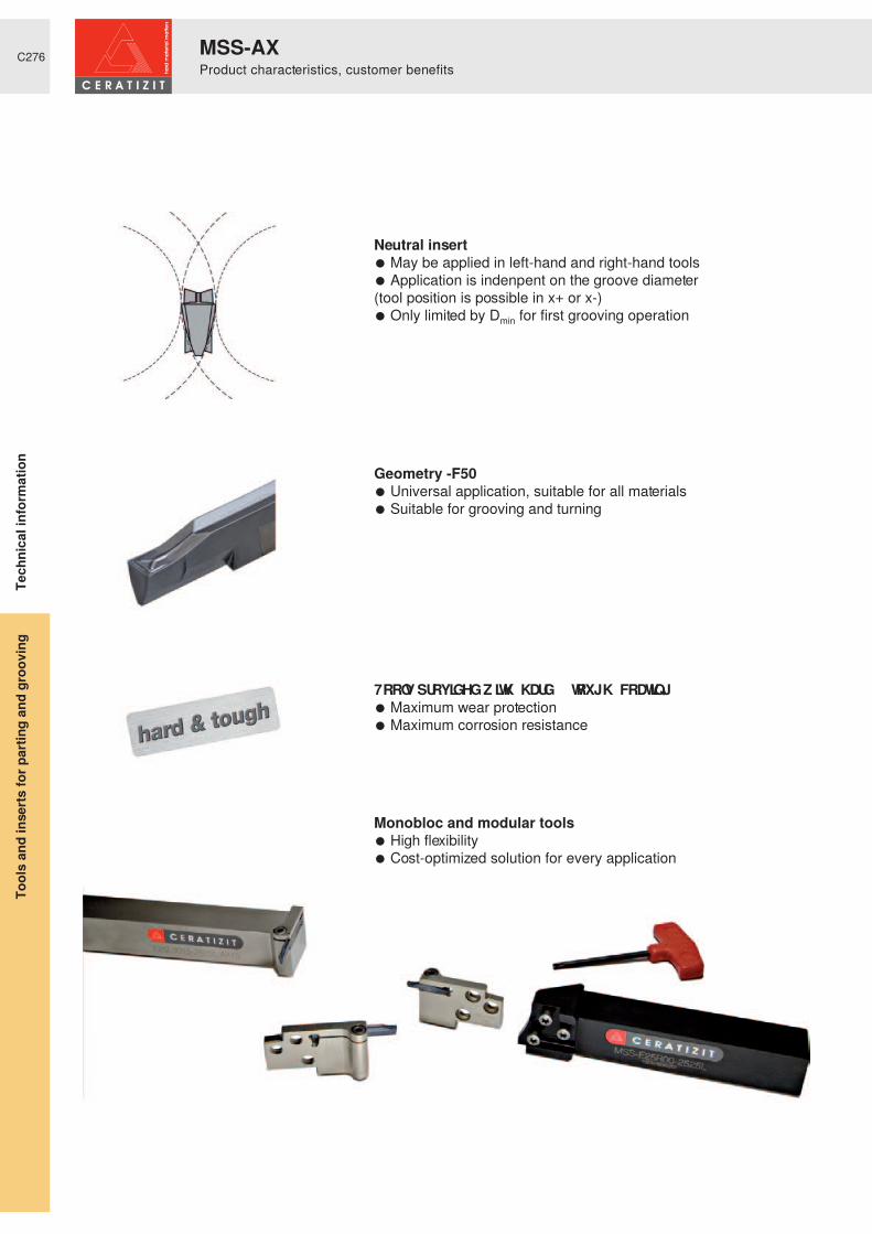
C276
Neutral insert● May be applied in left-hand and right-hand tools● Application is indenpent on the groove diameter(tool position is possible in x+ or x-)● Only limited by Dmin for first grooving operation
Geometry -F50● Universal application, suitable for all materials● Suitable for grooving and turning
7RROV� SURYLGHG� Z LWK� ¶ KDUG� � WRXJK· � FRDWLQ J● Maximum wear protection● Maximum corrosion resistance
Monobloc and modular tools● High flexibility● Cost-optimized solution for every application
Tool
s an
d in
serts
for p
artin
g an
d gr
oovi
ng
MSS-AXProduct characteristics, customer benefits
Tech
nica
l inf
orm
atio
n

C277
Tmax
AX05 AX10 AX15Dmin� ² � ' max
Dmin� ² � ' max � � � ² � ∞ � � � ² � ∞ � � � ² � ∞
Tmax 5,0 10,0 15,0
S [mm] 3,0 3,0 3,0
Tmax
E32N25 E32N32 E32N45Dmin� ² � ' max
Dmin� ² � ' max � � � � ² � ∞ � � � � ² � ∞ � � � � ² � ∞
Tmax 19 26 39
S [mm] 8 - 10 8 - 10 8 - 10
Tmax 15[mm]
21[mm]Dmin� ² � ' max
50 - 70 x x70 - 100 x x100 - 150 x x150 - 300 x x300 - 900 xS [mm] 2,76 - 6,5 3,76 - 6,5
System LX
System GX
System AX
Tool
s an
d in
serts
for p
artin
g an
d gr
oovi
ng
Axial groovingDiameter range
Tech
nica
l inf
orm
atio
n

C278
+ One insert for several pitches- Therefore the thread profile does not
exactly meet the standard- The external dia. (or the core dia. in case of
internal threads) is not machined
) LQLVKHG� WKUHDG� ‘
Partial profile insert
+ The entire thread profile including the external dia. is machined (excess material .04 - .1 mm over finished diameter) + high profile precision
+ Incresaed tool life thanks to larger point radii
+ Burr-free thread- One insert per pitch
Thread profile height Thread profile height
Total depth of cut
Excess material .04 - .1 mm
Full profile insert
+ Conventional lathes+ With pitches < 2 mm+ With short chipping materials- Reduced swarf control
Radial approach
+ Preferred approach on CNC-machines
+ With pitches from 2 to 4 mm+ Long chipping materials + Good swarf control
Flank approach
+ With pitches > 4 mm+ Long chipping materials+ Uniform insert wear+ Long tool life+ Good swarf control- More complex NC
programming
Alternating approach
Differences between full and partial profile inserts
Approach selection
Tool
s an
d in
serts
for p
artin
g an
d gr
oovi
ngTe
chni
cal i
nfor
mat
ion
TC - threadingBasics of threading

C279
a,b a,b a,b a,b a,b a,b a,b a,b
Type of problem
Corrective measures
Type of wear Work piece problems Swarf control
Flan
k we
ar
Edge
chi
ppin
g
Plas
tic d
efor
mat
ion
Built-
up e
dge
%XUU�
IRUP
DWLR
Q�DW
�H[WH
UQDO
�WKUH
DG�‘
Prof
ile p
recis
ion
Surfa
ce q
uality
Chat
ter m
arks
, vib
ratio
n
Chip
cro
ss s
ectio
n to
o la
rge
Chip
cro
ss s
ectio
n to
o sm
all
Chip
sha
pe (t
angl
ed s
warf)
Cutting speed
Cutti
ng v
alue
sFeed motion a) via the flanksb) alternating via the flanks
Approach (depth of cut)
Number of passes
Finish cut (idle cut)
Chip groove
Sele
ctio
n of
inse
rtsCutting material wear resistance
toughness
Full profile
Partial profile
Stability tool - insert
Gen
eral
crit
eriaStability - work piece
Overhang
Tip height
Cooling lubricant
raise, increase,large influence
avoid, reducelarge influence
check,optimize
raise, increaselow influence
avoid, reducelow influence use
Tool
s an
d in
serts
for p
artin
g an
d gr
oovi
ngTe
chni
cal i
nfor
mat
ion
Measures for threading problemsMSS-TC thread turning

C280
0,5 0,75 1,0 1,25 1,5 1,75 2,0 2,5 3,0 3,5 4,0 4,5 5,0
4 4 5 5 6 7 8 9 10 10 12 12 12
↓ ↓ ↓ ↓ ↓ ↓ ↓ ↓ ↓ ↓ ↓ ↓ ↓
6 7 8 9 10 11 12 14 18 18 20 20 20
0,32 0,48 0,64 0,80 0,95 1,10 1,26 1,58 1,89 2,21 2,53 2,84 3,16
0,5 0,75 1,0 1,25 1,5 1,75 2,0 2,5 3,0 3,5 4,0 4,5 5,0
4 4 5 5 6 7 8 9 10 10 12 12 12
↓ ↓ ↓ ↓ ↓ ↓ ↓ ↓ ↓ ↓ ↓ ↓ ↓
6 7 8 9 10 11 12 14 18 18 20 20 20
0,30 0,45 0,59 0,74 0,89 1,02 1,17 1,46 1,76 2,02 2,35 2,64 2,93
28 26 24 20 19 18 16 14 12 11 10 9 8 7 6 5
5 5 5 5 6 6 7 8 9 9 10 10 10 12 12 12
↓ ↓ ↓ ↓ ↓ ↓ ↓ ↓ ↓ ↓ ↓ ↓ ↓ ↓ ↓ ↓
8 8 9 9 10 10 11 12 14 14 17 18 18 20 20 20
0,60 0,65 0,70 0,84 0,88 0,93 1,05 1,20 1,40 1,53 1,68 1,87 2,11 2,41 2,81 3,37
Full profile
These are recommended values for steel machining
These are recommended values for steel machining
These are recommended values for steel machining
Pitch [mm]
Pitch [mm]
Number of cuts
Number of cuts
Number of cuts
Thread profile height
Thread profile height
Thread profile height
0 HWULF� ,62 � � � ƒ � H[ WHUQ DO� WKUHDGV
0 HWULF� ,62 � � � ƒ � LQ WHUQ DO� WKUHDGV
Pitch [passes/inch]
: KLWZ RUWK� � � ƒ � H[ WHUQ DO� DQ G� LQ WHUQ DO� WKUHDGV
Tool
s an
d in
serts
for p
artin
g an
d gr
oovi
ngTe
chni
cal i
nfor
mat
ion
TC - thread turningRecommended values for depth and number of cuts

C281
TC16-2EI-AG60
TC16-1EI-A60 TC16-2EI-G60 TC16-3EI-N60
0,5 0,75 1,0 1,25 1,5 1,75 2,0 2,5 3,0 1,75 2,0 2,5 3,0 3,5 4,0 4,5 5,0
4 4 5 6 7 8 9 10 12 8 9 10 12 12 13 14 14
↓ ↓ ↓ ↓ ↓ ↓ ↓ ↓ ↓ ↓ ↓ ↓ ↓ ↓ ↓ ↓ ↓
6 7 9 10 11 12 14 15 19 12 14 15 20 20 21 22 22
0,33 0,52 0,71 0,90 1,09 1,28 1,47 1,84 2,22 1,23 1,42 1,79 2,17 2,45 2,83 3,21 3,59
0,27 0,44 0,60 0,76 0,92 1,09 1,25 1,57 1,90 1,04 1,20 1,52 1,85 2,07 2,4 2,72 3,05
TC16-2EI-AG55
TC16-1EI-A55
28 26 24 20 19 18 16 14 12 11 10 9 8
5 5 6 6 7 7 8 9 10 10 11 12 12
↓ ↓ - ↓ ↓ ↓ ↓ ↓ ↓ ↓ ↓ ↓ ↓
8 8 9 9 12 12 14 14 16 16 18 20 20
0,66 0,72 0,79 0,95 1,01 1,07 1,21 1,39 1,63 1,79 1,97 2,20 2,48
TC16-2EI-G55 TC16-3EI-N55
14 12 11 10 9 8 7 6 5
8 9 10 11 12 12 12 12 14
↓ ↓ ↓ ↓ ↓ ↓ ↓ ↓ ↓
12 14 15 18 20 20 20 20 22
1,22 1,46 1,56 1,80 2,03 2,31 2,40 2,89 3,56
Partial profile
These are recommended values for steel machining
These are recommended values for steel machining
Pitch [mm]
Number of cuts
Number of cuts
Number of cuts
Thread profile height
Thread profile height
� � ƒ � H[ WHUQ DO� DQ G� LQ WHUQ DO� WKUHDGV
Thread profile heightexternal
Thread profile heightinternal
Threading insert
Threading insert
Threading insert
� � ƒ � H[ WHUQ DO� DQ G� LQ WHUQ DO� WKUHDGV
Pitch [passes/inch]
Pitch [passes/inch]
Tool
s an
d in
serts
for p
artin
g an
d gr
oovi
ngTe
chni
cal i
nfor
mat
ion
TC - thread turningRecommended values for depth and number of cuts

C282
Applied modules in rh / neutral version
Tools clamped in overhead position
Right-hand thread Left-hand thread
Application methods for external machining
Tools clamped in overhead position
Applied modules in lh / neutral version
Left-hand thread Right-hand thread
Applied modules in rh / neutral version
Tools clamped in overhead position
Right-hand thread Left-hand thread
Application methods for internal machining
Tools clamped in overhead position
Applied modules in lh / neutral version
Left-hand thread Right-hand thread
Tool
s an
d in
serts
for p
artin
g an
d gr
oovi
ngTe
chni
cal i
nfor
mat
ion
MSS - TCMachining method thread turning

C283
Conventional milling
Conventional milling
Climb milling
Climb milling
Right-hand thread
Right-hand thread
Left-hand thread
Left-hand thread
External thread
Internal thread
Tool
s an
d in
serts
for p
artin
g an
d gr
oovi
ngTe
chni
cal i
nfor
mat
ion
MSS - TCMachining method thread milling

C284
2xD
1xD
ø DG
ø D
1xP
L1xP
1
4
23
Through-hole thread
Drilling
Bottom hole thread
Through-hole thread
No radial plunging necessary, radial approach above or below work piece + spiral movement
Threading
Bottom hole thread
Radial approach until total profile depth + spiral movement
Radial plunging + spiral movement
I25R90-2D-TC16-WI32R90-2D-TC16W
Readjustment possible when necessary
> Same insert for thread turning and milling
> Considerably lower cost of TC inserts> Thread is cut in a single feed from
outside inwards or vice versa, so no step in the thread
> Low cutting forces possible through single-tooth thread milling
> Stable conditions> Standard reach is 2xD. Tools may be
modified up to 3xD.> Higher cutting values (vc + f) in this
manner machining times are similar to multi-tooth insert machining
> Easy programming
Advantages compared to multi-tooth threading inserts
Tool
s an
d in
serts
for p
artin
g an
d gr
oovi
ngTe
chni
cal i
nfor
mat
ion
MSS - TCMachining method thread milling


C286
DN
DN
DG
54
/ 6
8
dA
DG[mm]
DGTC
16-1
I 0,
5 IS
O
TC16
-1 I
0,75
ISO
TC16
-1 I
1,0
ISO
TC16
-1 I
1,5
ISO
TC16
-1 I
2,0
ISO
TC16
-1 I
2,5
ISO
TC16
-1 I
3,0
ISO
TC16
-1 I
3,5
ISO
TC16
-1 I
4,0
ISO
TC16
-1 I
4,5
ISO
TC16
-1 I
5,0
ISO
TC16
-2 E
I 14W
TC16
-2 E
I 12W
TC16
-2 E
I 11W
TC16
-2 E
I 10W
TC16
-2 E
I 9W
TC16
-2 E
I 8W
TC16
-3 E
I 7W
TC16
-3 E
I 6W
TC16
-3 E
I 5W
25 I25R90-2D-TC16-W M27 x x
DN
54
Ø25
M28 x x xM30 x x x xM32 x x x x x R 11/4 xM33 x x x x xM34 x x x x x xM35 x x x x x xM36 x x x x x x xM38 x x x x x x 11/2 xM39 x x x x x x xM40 x x x x x x x R 11/2 xM42 x x x x x x x x 15/8 xM45 x x x x x x x x 13/4 xM48 x x x x x x x x
32 I32R90-2D-TC16-W M36 x x x
DN
68
Ø32
M38 x x x xM39 x x x x xM40 x x x x xM42 x x x x x xM45 x x x x x xM48 x x x x x x xM50 x x x x x x x R2 xM52 x x x x x x xM55 x x x x x xM56 x x x x x xM58 x x x x x xM60 x x x x x xM62 x x x x x xM64 x x x x x xM65 x x x x x x R21/4 xM68 x x x x x xM70 x x x x x xM72 x x x x x xM75 x x x x x x R21/2 xM76 x x x x x xM78 x x x x x xM80 x x x x x x
DN =
=
Type,description
Full profileP HWULF� ,62 � � � ƒ
TC threading inserts TC threading inserts
Full profile: KLWZ RUWK� � � ƒ
QRP LQDO� P LOOLQJ� ‘
standard thread
[inch]
Tool
s an
d in
serts
for p
artin
g an
d gr
oovi
ngTe
chni
cal i
nfor
mat
ion
7KUHDG� P LOOLQ J� ² � H[ WHUQ DOMilling tool system MSS-TC

C287
Bgr.
DN
DG
54
/ 6
8dA
DG[mm]
DG
MSS-I32R-TC16-2 MSS-I32N-TC16-3 MSS-I32R-TC16-2
TC16
-2 I
2,0
ISO
TC16
-2 I
3,0
ISO
TC16
-3 I
4,0
ISO
TC16
-2 E
I 11W
32 1.5D M82 x x x R 23/4 xMSS-I32R90-1.5D M85 x x x
48
Ø32
Ø44
M90 x x x R3 xM95 x x x R31/4 x
M100 x x x R31/2 xM105 x x x R33/4 xM110 x x x R4 xM115 x x xM120 x x xM125 x x x R41/2 xM130 x x xM135 x x xM140 x x x R5 xM145 x x xM150 x x x R51/2 xM155 x xM160 x xM165 x x R6 xM170 x x
2.5D M175 x xMSS-I32R90-2.5D M180 x x
80
Ø40
Ø59
M185 x xM190 x xM195 x xM200 x xM205 x xM210 x xM215 x xM220 x xM225 x xM230 x xM235 x xM240 x xM245 x xM250 x x
↓ ↓ ↓M300 x x
Bgr. =
Type,description
Full profileP HWULF� ,62 � � � ƒ
Full profile: KLWZ RUWK� � � ƒ
[inch]
assembly size
Tool
s an
d in
serts
for p
artin
g an
d gr
oovi
ngTe
chni
cal i
nfor
mat
ion
7KUHDG� P LOOLQ J� ² � H[ WHUQ DOModular system MSS-TC

C288
DN
DG
DG[mm]
DGTC
16-1
I 0,
5 IS
O
TC16
-1 I
0,75
ISO
TC16
-1 I
1,0
ISO
TC16
-1 I
1,5
ISO
TC16
-1 I
2,0
ISO
TC16
-1 I
2,5
ISO
TC16
-1 I
3,0
ISO
TC16
-1 I
3,5
ISO
TC16
-1 I
4,0
ISO
TC16
-1 I
4,5
ISO
TC16
-1 I
5,0
ISO
TC16
-2 E
I 14W
TC16
-2 E
I 12W
TC16
-2 E
I 11W
TC16
-2 E
I 10W
TC16
-2 E
I 9W
TC16
-2 E
I 8W
TC16
-3 E
I 7W
TC16
-3 E
I 6W
TC16
-3 E
I 5W
25 I25R90-2D-TC16-W ↓ ↓
DN
54
Ø25M16 5/8 x
3/4 x7/8 x1 x
11/8 x
↓ 13/8 x11/2 x15/8 x13/4 x
32 I32R90-2D-TC16-W ↓
DN
68
Ø32
↓
M80
DN =
Type,description
Full profileP HWULF� ,62 � � � ƒ
TC threading inserts TC threading inserts
Full profile: KLWZ RUWK� � � ƒ
QRP LQDO� P LOOLQJ� ‘
[inch]
External threads in the range between M16 and
M80 can be milled with both tools, I25... or I32....Choose the adequate
threading inserts with the required pitch.
Tool
s an
d in
serts
for p
artin
g an
d gr
oovi
ngTe
chni
cal i
nfor
mat
ion
Milling tool system MSS-TC7KUHDG� P LOOLQ J� ² � H[ WHUQ DO

C289
Bgr.
DN
DG
54
/ 6
8dA
DG[mm]
MSS-I32R-TC16-2 MSS-I32N-TC16-3
TC16
-2 I
2,0
ISO
TC16
-2 I
3,0
ISO
TC16
-3 I
4,0
ISO
32 1.5D M82 x x xMSS-I32R90-1.5D M85 x x x
48
Ø32
Ø44
M90 x x xM95 x x x
M100 x x xM105 x x xM110 x x xM115 x x xM120 x x xM125 x x xM130 x x xM135 x x xM140 x x xM145 x x xM150 x x xM155 x xM160 x xM165 x xM170 x x
2.5D M175 x xMSS-I32R90-2.5D M180 x x
80
Ø40
Ø59
M185 x xM190 x xM195 x xM200 x xM205 x xM210 x xM215 x xM220 x xM225 x xM230 x xM235 x xM240 x xM245 x xM250 x x
↓ ↓ ↓M300 x x
Bgr. =
Type,description
Full profileP HWULF� ,62 � � � ƒ
assembly size
Tool
s an
d in
serts
for p
artin
g an
d gr
oovi
ngTe
chni
cal i
nfor
mat
ion
7KUHDG� P LOOLQ J� ² � H[ WHUQ DOModular system MSS-TC

C290
HB
A
1 1252 150 - 2503 3006 180
7 / 8 250 - 3009 350
10 20011 35012 20013 325
R
14 20014 18014 230 - 26014 330
F
15 18016 26017 16018 ²19 13020 230
N
21 6022 100
< 12% Si 23 80< 12% Si 24 90> 12% Si 25 130
26 ²27 9028 10029 10029 ²29 ²30 ²
S
31 20032 28033 25034 ²35 ²36 Rm 440*37 Rm 1050*
H
38 55 HRC39 60 HRC40 40040 55 HRC
Work piecematerial Type of treatment / alloy VD
I 332
3gr
oup Ha
rd-
ness
Non alloyed steelannealed ≤ .15% Cannealed .15% - .45% Ctempered ≥ .45% C
Low alloyed steelannealedtemperedtempered
High alloyed steelannealedtempered
Corrosion resistantsteel
annealed ferritictempered martensitic
Stainless steel
annealed ferritic / martensiticquenched austeniticquenched duplexhardened martensitic / austenitic
Grey cast ironpearlitic / ferriticpearlitic / martensitic
Spheroidal cast ironferriticpearlitic
Malleable cast ironferriticpearlitic
Aluminiumwrought alloys
non hardenedhardened
Aluminiumcast alloys
non hardenedhardenednon hardened
Copper andcopper alloys (bronze,brass)
machining alloy stock (1% Pb)brass, red bronzebronzelead-free copper and electrolytic copper
Non-metallic materialsthermosetting plasticsfibre-reinforced plasticshard rubber
Heat resistantalloys
annealed Fe-basehardened Fe-baseannealed Ni or Co-basehardened Ni or Co-base 30 - 58 HRCcast 1 L� RU� & R� EDVH� � � � � � � � � � � � � 1 � P P ò
Titanium alloyspure titaniumalpha + beta alloys
Tempered steelhardened and temperedhardened and tempered
Chilled castings castTempered cast iron hardened and tempered* Rm = ultimate tensile strength, measured in MPa
Tool
s an
d in
serts
for p
artin
g an
d gr
oovi
ngTe
chni
cal i
nfor
mat
ion
&XWWLQ J� GDWD� ² � WKUHDGLQ J

C291
GM213vc
[m/min]
GM240vc
[m/min]
H216Tvc
[m/min]
150 - 250 200 - 270 ²110 - 180 180 - 230 ²90 - 160 140 - 190 ²100 - 170 180 - 240 ²80 - 150 120 - 190 ²70 - 120 120 - 160 ²90 - 130 140 - 200 ²70 - 110 100 -160 ²110 - 170 170 - 230 ²90 - 140 130 - 190 ²110 - 180 150 - 200 ²80 - 140 ² ²70 - 100 ² ²70 - 120 ² ²120 - 160 130 - 200 ²100 - 130 120 - 180 ²160 - 200 120 - 170 ²90 - 140 120 - 190 ²120 - 140 150 - 230 ²90 - 130 120 - 170 ²
² ² 100 - 800² ² 100 - 800² ² 100 - 500² ² 100 - 500² ² 100 - 350² ² 80 - 300² ² 80 - 500² ² 80 - 500² ² 80 - 500² ² 80 - 500² ² 80 - 500² ² 80 - 500
30 - 50 20 - 40 ²25 - 35 20 - 30 ²15 - 25 10 - 20 ²10 - 20 10 - 20 ²10 - 25 10 - 20 ²
100 - 150 70 - 100 ²40 - 60 25 - 45 ²35 - 45 ² 30 - 40
² ² ²10 - 20 ² 5 - 1535 - 45 ² 30 - 40
Uncoated carbideCoated carbide
Tool
s an
d in
serts
for p
artin
g an
d gr
oovi
ngTe
chni
cal i
nfor
mat
ion
&XWWLQ J� GDWD� ² � WKUHDGLQ J

C292
Insert mounting key with handle towards the front into the 2 tool location points.
When moving the mounting key in the direction of the arrows the insert seat is opened.
Position the insert pressing it against the location face.
Moving the mounting key forward the insert seat locks and the insert is clamped securely.
The clamping system is designed in such a way that the mounting key can be inserted
into the blade from either side.
Tool
s an
d in
serts
for p
artin
g an
d gr
oovi
ngTe
chni
cal i
nfor
mat
ion
MSS-SXHow to use the system
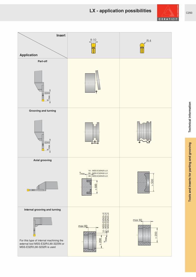
C293
T32 45
max
25
T32 45
max
25
> 50
0
26 - MSS-E32N32-LX
39 - MSS-E32N45-LX
19 - MSS-E32N25-LXTmax
21 -
MS
S-E
32N
32-L
X34
- M
SS
-E32
N45
-LX
> 2
00 T max
max 60
14 -
MS
S-E
32N
25-L
X
Insert
Application
Part-off
Grooving and turning
Axial grooving
Internal grooving and turning
For this type of internal machining the external tool MSS-E32R/L90-3225N or MSS-E32R/L90-3232R is used
Tool
s an
d in
serts
for p
artin
g an
d gr
oovi
ngTe
chni
cal i
nfor
mat
ion
LX - application possibilities

C294
Can be clamped from either above or below
Change of threaded bush
Threaded bush on topThreaded bush on bottom
Loosen the clamping screw and remove the insert ...
... fully unscrew the clamping screw and remove it ...
... draw out the threaded bush using the clamping screw ...
...press the threaded bush onto the milled recess on the opposite side ...
... push the insert onto the contact faces to the stop and fix it in place with the clamping screw.
Tool
s an
d in
serts
for p
artin
g an
d gr
oovi
ngTe
chni
cal i
nfor
mat
ion
MSS-PXHow to use the system

C295
Important: ensure insert is correctly located on pin.
To change to the next cutting edge draw the insert forward.
Worn cutting edge must be broken off to left or right
Information: during the positioning procedure, the magnets prevent the cutting inserts from falling out of the tool holder
Tool
s an
d in
serts
for p
artin
g an
d gr
oovi
ngTe
chni
cal i
nfor
mat
ion
MaxiClickHow to use the system

C296
Reinforced tool head for additional stability
Microfinish -27P to avoid the formation of built-up edge
� � ƒ � DQJOH� IRU� SDUW� RII� RSHUDWLRQV�without burrs
¶ %UHDN�RII� QRWFK· � IRU� D� FOHDQ� EUHDNDJH�line
Carbide positioning pin for accurate repeatability
Tool
s an
d in
serts
for p
artin
g an
d gr
oovi
ngTe
chni
cal i
nfor
mat
ion
MaxiClickProduct characteristics

C297
You can download the form below at our website www.ceratizit.com ->Download ->Forms or using
the QR code.
Tool
s an
d in
serts
for p
artin
g an
d gr
oovi
ngTe
chni
cal i
nfor
mat
ion
Special tools

C298
Assembly example:Adapters in combination with VDI shank
For example in case of:> Special solutions of all kinds> Special tools and shanks> Rotating tools for circular milling> Special machines> Limited space
MSS adapters offer the possibility to apply the modular parting and grooving system where conven-tional tool shanks or Maxiflex UTS tool heads cannot be used.
Application possibilities for MSS adapters:
Tool
s an
d in
serts
for p
artin
g an
d gr
oovi
ng
Application possibilitiesTe
chni
cal i
nfor
mat
ion

C299
20°
b
M..
h2
l3
h3
l2
l1
l4
l 6 min
h1
hm
in
bmin
20°
b
M..
h2
l3
h3
l2
l5
l1
l4
l 6 min
h1
h5
h4
hm
in
bmin
h1 h2 h3“ � � � h4 h5 hmin. b bmin. l1 l2 l3 l4 l5 l6 min. M..
MSS-E20R00-ADMSS-E20L00-AD 20 24 6,0 13 16 10 10,7 19 30 29,0 14,25 5,0 3 8 M4
MSS-E25R00-ADMSS-E25L00-AD 25 30 8,5 16 20 12 12,6 25 37 36,0 18,00 6,5 4 12 M5
MSS-E32R00-ADMSS-E32L00-AD 32 38 13,5 22 26 16 14,6 30 46 44,5 23,50 7,5 4 15 M6
> For low or medium loads> Adjustable adapter
> For heavy machining (large parting and grooving depths)> Adapter not adjustable
Assembly type A:
Assembly type B:
Adapters for:
Dimensions in mm
Tool
s an
d in
serts
for p
artin
g an
d gr
oovi
ng
Assembly dimensions for MSS adapters
Tech
nica
l inf
orm
atio
n