
Failure of Teton Dam : a report of findings
808
^o2 71- y^! BOSTON PUBLIC LIBRARY 3 9999 06317 343 7 GOVDOC ^ i.'^'.n'ili. FRILURE OF TETON Dflm fl REPORT OF FINDINGS X' by U.S. DEPARTMENT OF THE INTERIOR TETON DAM FAILURE REVIEW GROUP April 1977 ^<iov[RNM[NT DEP^^ stfQgiwef-tfjtrraN"" MAINE MARiTiA^E AOft^ —D-5^fr-A
-
Upload
khangminh22 -
Category
Documents
-
view
1 -
download
0
Transcript of Failure of Teton Dam : a report of findings

^o2
71- y^!
BOSTON PUBLIC LIBRARY
3 9999 06317 343 7
GOVDOC
^ i.'^'.n'ili.
FRILURE OFTETON Dflm fl REPORT OF FINDINGS
X'
byU.S. DEPARTMENT OF THE INTERIORTETON DAM FAILURE REVIEW GROUPApril 1977
^<iov[RNM[NT DEP^^stfQgiwef-tfjtrraN""MAINE MARiTiA^E AOft^—D-5^fr-A

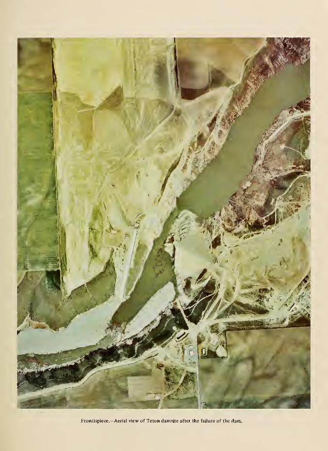
Frontispiece. -Aerial view of Teton damsite after the failure of the dam.

FAILURE OF TETON DfifTl
fl REPORT OF FINDINGS
by
U.S. Department of the Interior
Teton Dam Failure Review Group
F. WILLIAM EIKENBERRY, CHAIRMANHAROLD G. ARTHURNEIL F. BOGNERFLOYD P. LACY. JR.ROBERT L. SCHUSTERHOMER B. WILLIS
April 1977
For sale by the Superintendent oJ Documents, U.S. Government Printing OHice, Washington, D.C. 20402,
ond the Bureau of Reclamation, Engineering and Research Center, Attention: 922, P.O. Box 25007,
Denver Federal Center, Denver, Colorado 80225.
Superintendent of Documents Stock No.
024^034)0112-1

Transmittal Document
In compliance with the request of the Under Secretary of the Interior, dated June 8, 1976, the
Department of the Interior Teton Dam Failure Review Group submits this report on the TetonDam failure.
Respectfully submitted by:
^i*W^F. William Eikenberry, Chairman,
Office of the Assistant Secretary-
Land and Water Resources, Departmentof the Interior
Harold G. Arthur, Director of
Design and Construction,
Bureau of Reclamation
;ctor.
Engineering Division, Soil
Conservation Service, Departmentof Agriculture
Floyd PyQacy, Jr.,
Director of Division
Design, Tennessee Va
Robert L. Schuster, Chief, ffomer B. Willis, Chief ofEngineering Geology Branch,
Geological Survey
omerB. Willis, Chief of
Engineering Division, Directorate
of Civil Works, Corps of Engineers
April 1977

Abstract
This report is the result of a study by the
Department of the Interior Teton Dam Failure
Review Group to examine the causes of failure
of the Teton Dam and make recommendations
to prevent the recurrence of such failure. The
study included site inspections, interviews, and
examination of design and construction data.
Specific questions were directed to the Bureau
of Reclamation on design processes anddecisions. Postfailure field, laboratory, and office
investigations were also conducted. Three task
groups were formed to make indepth reviews of
geology, foundation grouting, and embankmentconstruction. A continuing portion of the study,
not reported herein, is a review of the Bureau of
Reclamation's technical decisionmaking process
and further field investigations.
Teton Dam is located in a steep-walled canyon
carved into a gently rolling silt covered volcanic
upland. The rock that forms the canyon walls
and which constitutes the major bedrockformation throughout the damsite and reservoir
area is a rhyolite welded ash-flow tuff. The rock
is characterized by the presence of prominent
and abundant open joints and fissures.
Considering all site selection factors, the site
selected for the dam was the best of the available
alternate sites for the purposes of the project.
The preconstruction geologic investigations were
sufficient to identify the important geologic
features that needed to be considered for design.
The dam was constructed in accordance with the
intent of the designers and in agreement with the
plans and specifications. The dam was a
305-foot-high zoned eartbfill embankment with
a thick central silt core. A gated spillway was
located at the top of the right abutment; a
powerhouse was located in the base of the left
abutment. The main river outlet works was
located in a tunnel in the left abutment; an
auxiliary outlet works was located in a tunnel in
the right abutment. A cutoff trench to rock was
excavated in the valley section. Deep key
trenches were provided in both abutments. Adeep grout curtain was constructed under the
entire length of the dam.
The dam failed as a result of inadequateprotection of the impervious core material from
internal erosion. The most probable physical
mode of failure was cracking of the impervious
core material either due to hydraulic fracturing
or differential settlement within theembankment that allowed the initiation of
erosion. Somewhat less probable is the concept
that damaging seepage started at the contact of
the zone 1 (impervious core) material and the
rock surface. The open fractures in the abutment
foundation rock allowed direct access byreservoir water to the impervious core on the
upstream side of the key trench. Any water
flowing through the impervious core could exit
into open fractures on the downstream side of
the key trench. The design failed to provide a
defense against flow through embankmentcracks or against erosion of the impervious core
at rock surfaces. The rock surface was not
adequately sealed under the impervious core
upstream and downstream from the key trench.
Defensive measures were within thestate-of-the-art of dam design at the time Teton
Dam was designed, and should have been used.
The major recommendations to minimize the
possibility of recurrence of a failure such as that
m
at Teton Dam are; (1) an independent board of
review should be convened for each major damproject to review both design and construction
at frequent intervals, (2) design decisions should
be formally documented, and (3) design
personnel should remain involved with a project
during construction, including frequent
scheduled site visits.
IV
Preface
This report presents the results of the
Department of the Interior Teton Dam Failure
Review Group's investigation. This failure was
a major disaster in terms of damage caused and
loss of life. The lessons learned from this and
other investigations will be of immeasurable
value if they prevent the occurrence of other
such disasters.
The Interior Review Group (IRG) was assisted
during the investigation by members of the
participants' staffs. Alternate members of the
IRG were Donald Giampaoli, Bureau of
Reclamation; Ernest Dodson, Corps of
Engineers; David Ralston, Soil Conservation
Service; and J. T. McGill, Geological Survey. C.
J. Monahan (Corps of Engineers, Retired),
served as the IRG field representative.
Much of the investigation was performed by the
Geology, Grouting, and EmbankmentConstruction Task Groups. The members are:
Geology Task Group: Robert Schuster,
Chairman, J. T. McGill and D. J. Varnes,
Geological Survey; and Lloyd Underwood,
Corps of Engineers. Assisting in the geologic
investigations were E. G. Crosthwaite, M. S.
Bedinger, S. S. Oriel, H. J. Prostka, D. M.
Perkins, and D. A. Swanson, Geological
Survey; Brent Carter, Dan Magleby, and
Daniel Hubbs, Bureau of Reclamation; and
Paul Huebschman, John Stanton, Millard
Stone, and Walter Wickbolt, Corps of
Engineers.
Grouting Task Group: Paul Fisher, Chairman,
Corps of Engineers; James Coulson,
Tennessee Valley Authority; and Ray Cope,
Soil Conservation Service.
Embankment Construction Task Group:David Ralston, Chairman, Soil Conservation
Service; Neil Parrett, Corps of Engineers; and
Samuel Stone, Tennessee Valley Authority.
Assisting in investigations of the design and
construction of the embankment were Ralph
Beene, Stanley Johnson, and John Palmerton,
Corps of Engineers.
Bureau of Reclamation Personnel makingmajor contributions: Robert Robison, Project
Construction Engineer; Peter Aberle, Field
Engineer; Ralph Mulliner, MaterialsEngineer; and the rest of the Teton Project
staff were very helpful, as were LloydGebhart, Construction Liaison Engineer;
Robert Farina, Geologist; Richard Kramerand Luther Davidson, Soil Engineers,Engineering and Research Center (E&RCenter) staff. Sam Guy, also of the E&RCenter, served as investigation coordinator.
His services are greatly appreciated.
Assisting in the completion of this report were
Brenda Tremper and Irene Murphy, Office of
the Assistant Secretary for Land and WaterResources, Department of the Interior. Paul
Fisher, Corps of Engineers, and James Coulson,
Tennessee Valley Authority, made a majorcontribution by their overall coordination and
technical editing of this report.
The Interior Review Group wishes to express its
appreciation to Dennis N. Sachs, former Deputy
Assistant Secretary, Land and Water Resources
who provided strong leadership during his
service as Chairman of the IRG from its
formation until February 25, 1977.

Contents
Frontispiece
Transmittal DocumentAbstract
Preface
Glossary
Chapter 1 -Introduction
Formation and charge of the
Interior Review GroupOther investigations of TetonDam Failure
Previous reports
Status of the IRG review
Chapter 2-General ProjectDescription
Description of facilities
Project siting
Geology
Design
Construction
Reservoir filling and releases ....
Chapter 3-Chronology andConsequences of Failure
Chronology of failure events ....Description of damages and
losses
Chapter 4-Scope of
the IRG Review
Site investigations by the IRGInterviews with Professors
Robert Curry and Marshall
Corbett
Page
i
iii
V
xi
2
2
3
3
9
19
20
32
35
42
49
49
Page
Review of postfailure investi-
gations 50
Data supplied by the Bureau
of Reclamation 50
Task Group reviews 50
Questions and answers regarding
design and construction 51
Procedures review 51
Chapter 5-PossibleCauses of Failure
Introduction 53Cracking of zone 1 material
from differential settlement
or hydraulic fracturing 53Piping along the interface
between the zone 1 material
and the rock foundation ..... 53Flow through the grout curtain ... 53Flow bypassing the grout
curtain 54Cracking due to foundation
settlement 54Cracking due to hydraulic
uplift 54
Chapter 6-Discussion andEvaluation of Investigations
Introduction 55Geologic studies 55Adequacy of geologic investi-
gations 55Postfailure geologic studies .... 56Foundation treatment 62Analysis of postfailure embank-ment remnants 78
Foundation deformation 86
Rate of reservoir filling 86
vu
Contents - continued
Chapter 7-Adequacy of Designand Construction
Design 87Construction 91
Chapter 8-Physical Causeof Failure
Unsupportable causes of failure ... 95Probable causes of failure 95
Chapter 9-Consideration of
Bureau Procedures
Consideration of Bureau
Procedures 101
Chapter 10-Conclusions
Primary conclusions 103Other conclusions 103
Chapter 1 1 -AdditionalInvestigations
Grout curtain investigations .... 105
Left abutment and embankmentinvestigations 105
Finite element studies 105
Chapter 12-Recommendations
IRG Recommendations 107
Appendix
APPENDIXES
Charge and Directions
to the IRG . . . A-1
Appendix Page
B Geology Task GroupReport B-1
B-1 Joints, fissures, and
voids in rhyolite welded
ash-flow tuff at Tetondamsite, Idaho . . . B-55
B-2 Analyses of ground-water
levels in the right
abutment B-67
C Grouting Task GroupReport C-1
C-1 Summary of interviews . . C-1
3
C-2 Recommended field explor-
ations to investigate
the integrity of the
grout curtain. .... C-25
C-3 Testing program for high
CaCl 2 grout mixes . . C-31
CA Summary of design for
foundation pressure
grouting C-3 7
C-5 Boring logs and joint
transmissibihty and
water pressure test
data C-41
D Embankment Construction
Task GroupReport D-1
D-1 Earthwork construction
inspection D-23D-2 Construction photo-
graphs D-39D-3 Construction specifi-
cations for embank-ment earthwork
and related founda-
tion treatment . . . D-61
D-4 Gravity grout place-
ment D-95
D-5 Embankment material
properties D-1 05
rui
Contents - continued
Appendix Page Table Page
F
G
H
Table
1.
List of the Teton DamFailure Exhibits Fur-
nished to the IRGby the Bureau of
Reclamation E-1
Summary of Eyewitness
Accounts P-lDesign Questions andAnswers q.]
Design questions asked
by the Independent
Panel of the Bureau
of Reclamation andthe Morrison-Knudson
Co., Inc. and their
response ....Bureau of Reclama-
tion's response
to the IRG's
24 questions . . .
4.
Postfailure Investiga-
tion of Right AbutmentEmbankment Remnant
In Situ Stress Investi-
gations
G-1
G-60
H-1
I-l
TABLES
Chronology of signifi-
cant happenings andobservable events
related to TetonDam Failure . .
Summary of precon-
struction and
construction core
drilHng-Teton DamSummary of triaxial
shear tests for
zone 1 materials .
47
57
83
Figure
1.
2.
3.
4.
5.
6.
7.
8.
9.
10.
11.
12.
13.
14.
15.
16.
Summary of classifi-
cation test data,
samples fromremnant of key-
trench fill, right
abutment . . 84
FIGURES
Teton Dam location
map 4General project map ... 5
Location of alternate
dam sites 7
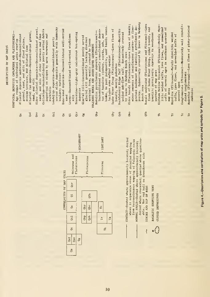
Description and correla-
tion of map units andsymbols for Figure 5 . . . iQ
Geologic map of the
region of RexburgBench and the canyonof Teton River 11
Seismic risk map for
the United States .... 13Earthquake occurrencenear the eastern SnakeRiver Plain ]4
Location of seismic
stations 15Teton Dam—geologic
profile on dam axis ... 17Teton Dam—general
plan and sections .... 2ITeton Dam-embank-ment details 23
Teton Dam—spillway ... 25Teton Dam—auxiliary
outlet works 27Teton Dam—river
outlet works 29Teton reservoir inflow,
outflow, and contents. . 33
Teton Dam -location
of visual events
associated with
the failure 37
IX

fault
flume
foundation
grouting
fumaroles
grout
grout curtain
high-angle
hydraulic
fracturing
hydraulic
gradients
hydraulic
uplift
in situ
stress
joint
key trench
lacustrine
leveling
A surface or zone of rock fracture along which there has beendisplacement, from a few inches to many miles in scale.
An artificial channel, commonly an inclined chute or trough, for
carrying water.
The practice of injecting a water-cement grout mixture into the
foundation of an engineered structure for the purpose of reducing
water seepage and/or strengthening the foundation.
A vent, usually volcanic, from which gases and vapors are emitted; it
is characteristic of a late stage of volcanic activity.
A cementitious material of high water content, fluid enough to bepoured or injected into spaces and thereby fill or seal them.
A curtain-shaped zone or rock or soil treated by grout injection
holes in order to reduce the amount of water seepage through the
rock or soil.
Indicates that the inclination of the feature being discussed is
greater than 45° from the horizontal.
The fracturing of a material, such as the material composing an
embankment, by excess fluid pressure between the constituent
particles of the material.
The rate of change of hydrostatic pressure per unit of distance of
flow at a given point and in a given direction.
The upward force exerted on a material by fluid within the material.
The stress present within a soil or rock mass.
A surface of actual or potential fracture or parting in a rock
without displacement.
A deep, narrow trench cut into a dam foundation for the purpose of
cutting off waterflow.
Pertaining to, produced by, or formed in a lake or lakes.
The operation of determining the comparative altitude of different
points on the earth's surface.
XU
low-angle
ModifiedMercalli
Scale
monument
ogee
perchedgroundwater
percolation
permeability
piezometric
surface
piping
Pliocene
Proctor
pyroclastic
rhyolite
Richter scale
seepage
Indicates that the inclination of the feature being discussed is
less than 45° from the horizontal.
One of the earthquake intensity scales, having twelve divisions
ranging from I (not felt by people) to XII (damage nearly total).
A natural or artificial (but permanent) physical structure that marks
the location on the ground of a survey point.
An S-shaped curve, for example, the curved crest of a spillway
structure.
Unconfined groundwater separated from an underlying main body of
groundwater by an unsaturated zone.
Flow of water, usually downward, through small openings in a porous
material.
The property of a porous rock or soil medium for transmitting a fluid
without impairment of the structure of the medium.
An imaginary surface representing the static head of groundwater
and defined by the level to which water will rise in a well.
Erosion by percolating water in a soil resulting in caving and the
formation of narrow conduits, tunnels, or pipes through the soil.
An epoch of the Tertiary period, ranging in time from about 2 to 6 million
years ago.
A method developed by R. R. Proctor for measuring the degree of
compaction of a soil.
Pertaining to particulate rock material formed by volcanic explosion
or aerial expulsion from a volcanic vent.
An extrusive igneous (volcanic) rock having essentially the same
composition as granite.
The range of numerical values of earthquake magnitude devised in 1935
by seismologist C. F. Richter. The scale is logarithmic and is
arranged so that very small earthquakes can have negative magnitude
values. The strength of earth materials imposes an upper limit for
possible magnitude of slightly less than 9.
The act or process involving the slow movement of water or other
fluid through a porous material such as soil or rock.
xiu

seismicity
Shelby tube
siltstone
sinkhole
slopewash
slurry
tectonics
triaxial
strength
text
trilateration
turbid
upstreamcofferdam
void
volcanism
welded tuff
The phenomenon of earth movements (earthquakes or earth vibrations).
A soil sampUng device consisting of thin-wall tubing which is
driven into a soil to obtain a sample.
A rock composed largely of silt.
A closed depression formed by solution of caving of a rock or soil
material.
Soil and rock material that is or has been transported down a slope
by gravity assisted by running water not confined to channels.
A very wet, highly mobile, semiviscous mixture or suspension of
finely divided, insoluble material.
A branch of geology dealing with the broad architecture of the upper
part of the earth's crust; that is, the regional assembling of
structural and deformational features.
A text of the strength of a soil or rock in which a cylindrical sample
is subjected to an all-around confining pressure and then subjected
to an increasing axial load until it breaks. The test may be drained
(internal sample fluid allowed to drain away).
A method of surveying in which the lengths of the three sides of a
series of touching or overlapping triangles are measured (usually by
electronic methods) and the angles are computed from the measured
lengths.
Stirred up or disturbed, such as by sediment; not clear or
translucent, being opaque with suspended matter.
A temporary dam placed upstream from the location of the permanent
dam for the purpose of allowing construction of the main dam in
dry conditions.
An opening in a rock or soil not occupied by solid matter.
The processes by which magma (mobile rock material) and its associated
gases rise into the crust and are extruded onto the earth's surface
and into the atmosphere.
A pyroclastic rock which has been made rocklike by the combinedaction of the heat retained by particles, the weight of the
overlying materials, and hot gases.
XIV
«Chapter 1
Introduction
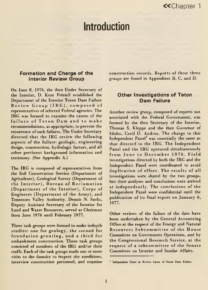
Formation and Charge of theInterior Review Group
On June 8, 1976, the then Under Secretary of
the Interior, D. Kent Frizzell established the
Department of the Interior Teton Dam Failure
Review Group (IRG), composed of
representatives of selected Federal agencies. The
IRG was formed to examine the causes of the
failure of Teton Dam and to makerecommendations, as appropriate, to prevent the
recurrence of such failures. The Under Secretary
directed that the IRG review the following
aspects of the failure: geologic, engineering
design, construction, hydrologic factors, and all
other pertinent background information and
testimony. (See Appendix A.)
The IRG is composed of representatives from
the Soil Conservation Service (Department of
Agriculture), Geological Survey (Department of
the Interior), Bureau of Reclamation(Department of the Interior), Corps of
Engineers (Department of the Army), and
Tennessee Valley Authority. Dennis N. Sachs,
Deputy Assistant Secretary of the Interior for
Land and Water Resources, served as Chairman
from June 1976 until February 1977.
Three task groups were formed to make indepth
studies: one for geology, the second for
foundation grouting, and a third for
embankment construction. These task groups
consisted of members of the IRG and/or their
staffs. Each of the task groups made one or more
visits to the damsite to inspect site conditions,
interview construction personnel, and examine
construction records. Reports of these three
groups are found in Appendixes B, C, and D.
Other investigations of TetonDam Failure
Another review group, composed of experts not
associated with the Federal Government, was
formed by the then Secretary of the Interior,
Thomas S. Kleppe and the then Governor of
Idaho, Cecil D. Andrus. The charge to this
Independent Panel was essentially the same as
that directed to the IRG. The Independent
Panel and the IRG operated simultaneously
from June to December 1976. Field
investigations directed by both the IRG and the
Independent Panel were coordinated to avoid
duplication of effort. The results of all
investigations were shared by the two groups,
but their analyses and conclusions were arrived
at independently. The conclusions of the
Independent Panel were confidential until the
publication of its final report on January 6,
1977.
Other reviews of the failure of the dam have
been undertaken by the General Accounting
Office at the request of the Energy and Natural
Resources Subcommittee of the HouseCommittee on Government Operations, and by
the Congressional Research Service, at the
request of a subcommittee of the Senate
Committee on Interior and Insular Affairs.
Independent Panel to Review Cause of Teton Dam Failure
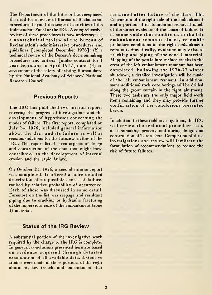
The Department of the Interior has recognized
the need for a review of Bureau of Reclamation
procedures beyond the scope of activities of the
Independent Panel or the IRG. A comprehensive
review of these procedures is now underway: (1)
a nontechnical review of the Bureau of
Reclamation's administrative procedures andguidelines [completed December 1976] ; (2) a
technical review of the Bureau's decisionmaking
procedures and criteria [under contract for 1
year beginning in April 1977] ; and (3) an
assessment of the safety of existing Bureau damsby the National Academy of Sciences' National
Research Council.
Previous Reports
The IRG has published two interim reports
covering the progress of investigations and the
development of hypotheses concerning the
modes of failure. The first report, completed on
July 14, 1976, included general information
about the dam and its failure as well as
recommendations for the future activities of the
IRG. This report listed seven aspects of design
and construction of the dam that might have
contributed to the development of internal
erosion and the rapid failure.
On October 21, 1976, a second interim report
was completed. It offered a more detailed
description of six possible causes of failure,
ranked by relative probability of occurrence.
Each of these was discussed in some detail.
Foremost on the list was seepage and resultant
piping due to cracking or hydraulic fracturing
of the impervious core of the embankment (zone
1) material.
remained after failure of the dam. Thedestruction of the right side of the embankmentand a portion of its foundation removed muchof the direct evidence of the cause of failure. It
is conceivable that conditions in the left
embankment remnant closely resembleprefailure conditions in the right embankmentremnant. Specifically, evidence may exist of
cracking and piping of the zone 1 material.
Mapping of the postfailure surface cracks in the
crest of the left embankment remnant has been
completed. Following the 1976-77 wintershutdown, a detailed investigation will be madeof the left embankment remnant. In addition,
some additional rock core borings will be drilled
along the grout curtain in the right abutment.
These two tasks are the only major field workitems remaining and they may provide further
confirmation of the conclusions presentedherein.
In addition to these field investigations, the IRGwill review the technical procedures anddecisionmaking process used during design and
construction of Teton Dam. Completion of these
investigations and review will facilitate the
formulation of recommendations to reduce the
risk of future failures.
Status of the IRG Review
A substantial portion of the investigative work
required by the charge to the IRG is complete.
In general, conclusions presented here are based
on evidence acquired through detailed
examination of all available data. Extensive
studies were made of those portions of the right
abutment, key trench, and embankment that
« Chapter 2
General Project Description
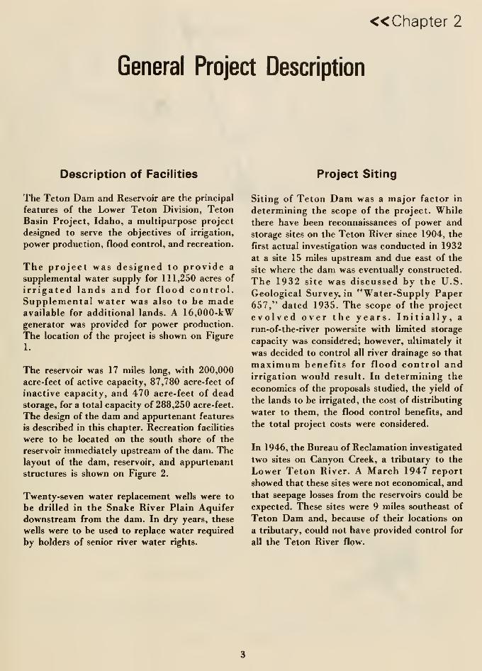
Description of Facilities
The Teton Dam and Reservoir are the principal
features of the Lower Teton Division, Teton
Basin Project, Idaho, a multipurpose project
designed to serve the objectives of irrigation,
power production, flood control, and recreation.
The project was designed to provide a
supplemental water supply for 111,250 acres of
irrigated lands and for flood control.Supplemental water was also to be madeavailable for additional lands. A 16,000-kWgenerator was provided for power production.
The location of the project is shown on Figure
1.
The reservoir was 17 miles long, with 200,000
acre-feet of active capacity, 87,780 acre-feet of
inactive capacity, and 470 acre-feet of deadstorage, for a total capacity of 288,250 acre-feet.
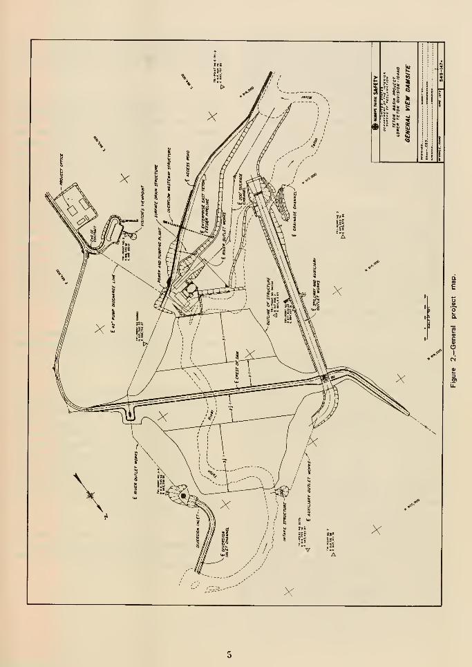
The design of the dam and appurtenant features
is described in this chapter. Recreation facilities
were to be located on the south shore of the
reservoir immediately upstream of the dam. Thelayout of the dam, reservoir, and appurtenant
structures is shown on Figure 2.
Twenty-seven water replacement wells were to
be drilled in the Snake River Plain Aquifer
downstream from the dam. In dry years, these
wells were to be used to replace water required
by holders of senior river water rights.
Project Siting
Siting of Teton Dam was a major factor in
determining the scope of the project. While
there have been reconnaissances of power and
storage sites on the Teton River since 1904, the
first actual investigation was conducted in 1932
at a site 15 miles upstream and due east of the
site where the dam was eventually constructed.
The 1932 site was discussed by the U.S.
Geological Survey, in "Water-Supply Paper657," dated 1935. The scope of the project
evolved over the years. Initially, a
run-of-the-river powersite with limited storage
capacity was considered; however, ultimately it
was decided to control all river drainage so that
maximum benefits for flood control andirrigation would result. In determining the
economics of the proposals studied, the yield of
the lands to be irrigated, the cost of distributing
water to them, the flood control benefits, and
the total project costs were considered.
In 1946, the Bureau of Reclamation investigated
two sites on Canyon Creek, a tributary to the
Lower Teton River. A March 1947 report
showed that these sites were not economical, and
that seepage losses from the reservoirs could be
expected. These sites were 9 miles southeast of
Teton Dam and, because of their locations on
a tributary, could not have provided control for
all the Teton River flow.
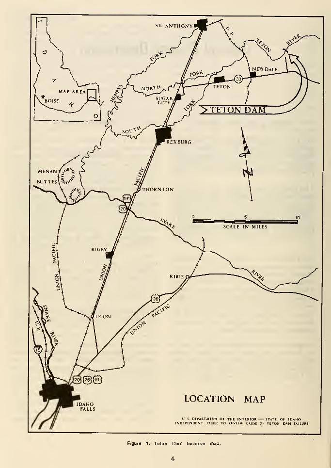
LOCATION MAP
U. S DEPARTMENT OF THE INTERIOR STATE OF IDAHOINDEPENDENT PANEL TO RFV|EW CAUSE OF TETON DAM FAILURE
Figure 1.—Teton Dam location map.
4
In 1956, the Bureau investigated a scheme for
diverting water from the Teton River to provide
flood control and other benefits. The schemeincluded a 46-foot-high dam at the mouth of the
Teton River Canyon and a canal trendingnorthwest to the Snake River Plain. The schemedid not provide irrigation storage or water for
irrigation of additional lands. Flood control for
lands along the lower reach of the Teton River
was the primary benefit. Secondary benefits
included recharge of groundwater aquifers under
the Snake River Plain. In March 1957, the
Bureau reported that the scheme was notgeologically feasible.
The Corps of Engineers selected a site for
investigation at the location of Teton Dam anddrilled two holes in July 1957. One of these holes
was drilled through the alluvium underlying the
valley floor; the other hole was drilled in the left
abutment. The quality of rock encountered by
this drilling was considered to be structurally
adequate for a dam. It was recognized that
seepage from the reservoir would occur. Further
studies to determine the impact of seepage on the
economics of the site were considered necessary.
In the fall of 1956, a joint Bureau ofReclamation and Corps of Engineers committee
was formed to assign responsibilities for
investigations in the Upper Snake River Basin to
one of these agencies. This committee agreed to
assign investigations of the Teton Project to the
Bureau of Reclamation. In 1961, the Corp of
Engineers and the Bureau of Reclamation issued
a joint report on the Upper Snake River Basin.
The Teton Project was included in this report.
The Bureau of Reclamation prepared a
reconnaissance-type geologic report for TetonDam (Fremont Site) in January 1961 and started
core drilling at the site in July 1961. A second
report describing a dam and ancillary works,
with a layout similar to that which waseventually built, was issued in March 1962. Bythis time, the Bureau had completed Hve holes
for a total of seven core holes at the site. In
March 1962, the Corps issued Interim Report R,
"Review Report on Columbia River andTributaries," covering the Lower Teton Project,
and the Bureau issued a report entitled "Teton
Basin Project, Lower Teton Division." TheBureau report recommended construction of the
Teton Project, including Teton Dam (FremontSite).
Additional siting studies were conducted by the
Bureau in late 1961 and early 1962, and geologic
studies were made at five sites along the river
between the mouth of Linderman Draw and the
mouth of the Little North Fork. The apparent
advantage of a site in this reach of the river was
that a greater amount of land could be irrigated.
The disadvantages were found to be some loss of
floodflow regulation and economicconsiderations, such as increased cost of
distribution and reduced climatic suitability of
land to be irrigated. The sites were found to be
as geologically feasible as the Teton (Fremont)
site, without benefits to be gained with respect
to the quality of foundation rock or seepage
losses from the reservoir. A report describing site
conditions and their influence on the selection
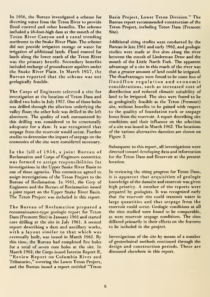
of a site was issued in March 1962. The locations
of the various alternative damsites are shown on
Figure 3.
Subsequent to this report, all investigations were
directed toward developing data and information
for the Teton Dam and Reservoir at the present
location.
In reviewing the siting progress for Teton Dam,it is apparent that acquisition of geologic
knowledge of the damsite and reservoir was given
high priority. A number of the reports wereprepared by geologists. It was recognized early
that the reservoir rim could transmit water in
large quantities and that seepage from the
reservoir could occur. Geologic conditions at all
the sites studied were found to be comparable,
as were reservoir seepage conditions. The sites
differed primarily in their effects on the features
to be included in the project.
Investigations of the site by means of a numberof geotechnical methods continued through the
design and construction periods. These are
discussed elsewhere in this report.
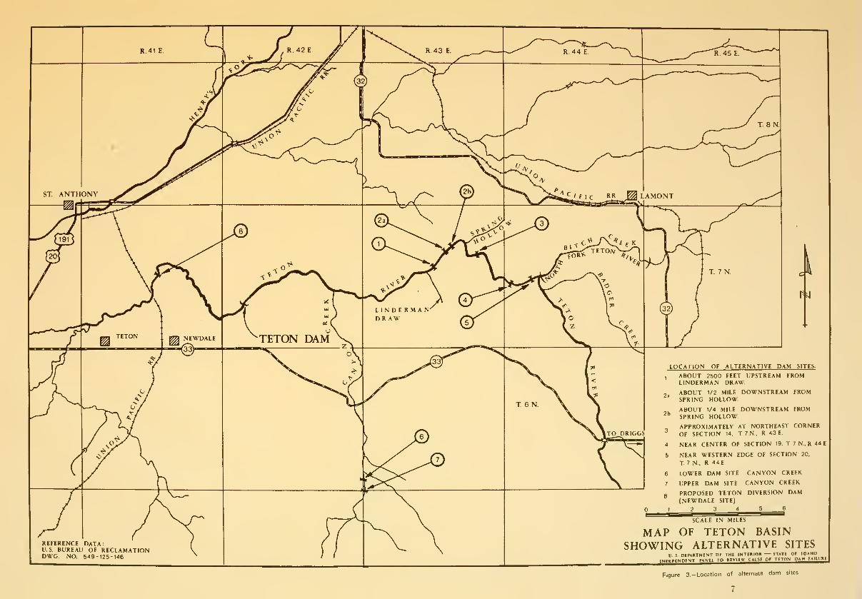
Figure 3.-Location of alternate dam sites

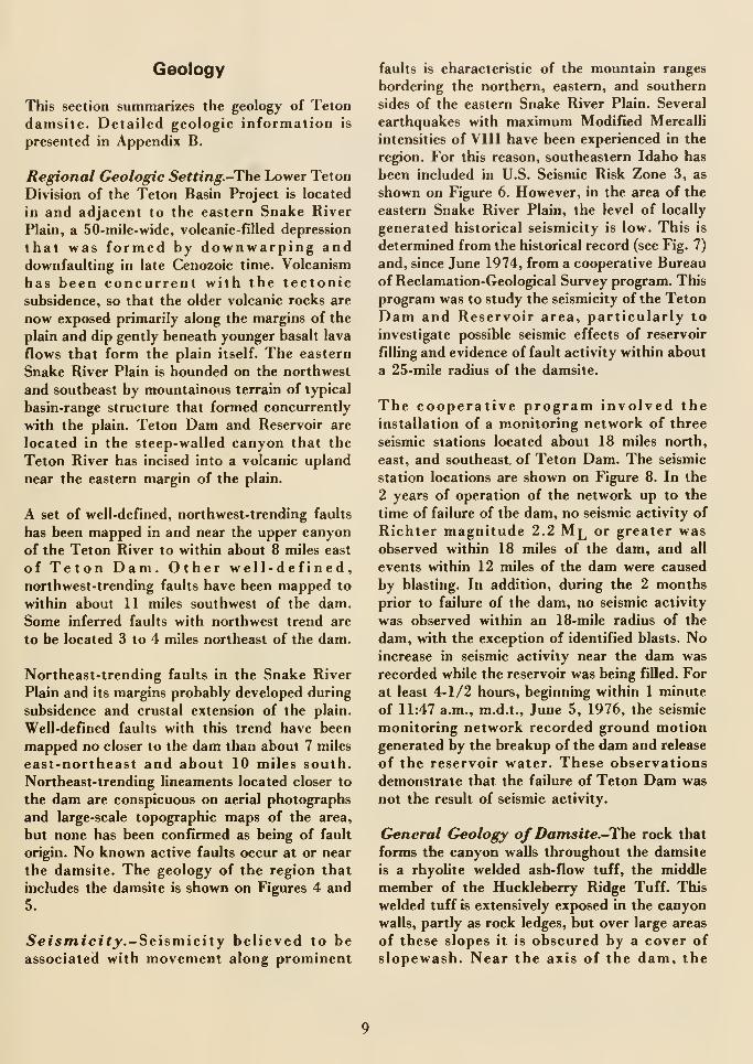
Geology
This section summarizes the geology of Teton
damsite. Detailed geologic information is
presented in Appendix B.
Regional Geologic Setting.-The Lower Teton
Division of the Teton Basin Project is located
in and adjacent to the eastern Snake River
Plain, a 50-mile-wide, volcanic-filled depression
that was formed by downwarping anddownfaulting in late Cenozoic time. Volcanism
has been concurrent with the tectonicsubsidence, so that the older volcanic rocks are
now exposed primarily along the margins of the
plain and dip gently beneath younger basalt lava
flows that form the plain itself. The eastern
Snake River Plain is bounded on the northwest
and southeast by mountainous terrain of typical
basin-range structure that formed concurrently
with the plain. Teton Dam and Reservoir are
located in the steep-walled canyon that the
Teton River has incised into a volcanic upland
near the eastern margin of the plain.
A set of well-defined, northwest-trending faults
has been mapped in and near the upper canyon
of the Teton River to within about 8 miles east
of Teton Dam. Other well-defined,northwest-trending faults have been mapped to
within about 11 miles southwest of the dam.
Some inferred faults with northwest trend are
to be located 3 to 4 miles northeast of the dam.
Northeast-trending faults in the Snake River
Plain and its margins probably developed during
subsidence and crustal extension of the plain.
Well-defined faults with this trend have been
mapped no closer to the dam than about 7 miles
east-northeast and about 10 miles south.
Northeast-trending lineaments located closer to
the dam are conspicuous on aerial photographs
and large-scale topographic maps of the area,
but none has been confirmed as being of fault
origin. No known active faults occur at or near
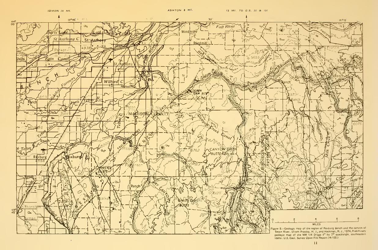
the damsite. The geology of the region that
includes the damsite is shown on Figiires 4 and
5.
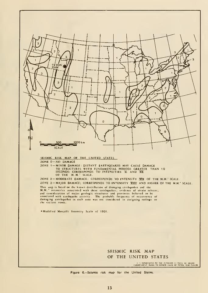
5cts/nicit_y.-Seismicity believed to beassociated with movement along prominent
faults is characteristic of the mountain ranges
bordering the northern, eastern, and southern
sides of the eastern Snake River Plain. Several
earthquakes with maximum Modified Mercalli
intensities of VIII have been experienced in the
region. For this reason, southeastern Idaho has
been included in U.S. Seismic Risk Zone 3, as
shown on Figure 6. However, in the area of the
eastern Snake River Plain, the level of locally
generated historical seismicity is low. This is
determined from the historical record (see Fig. 7)
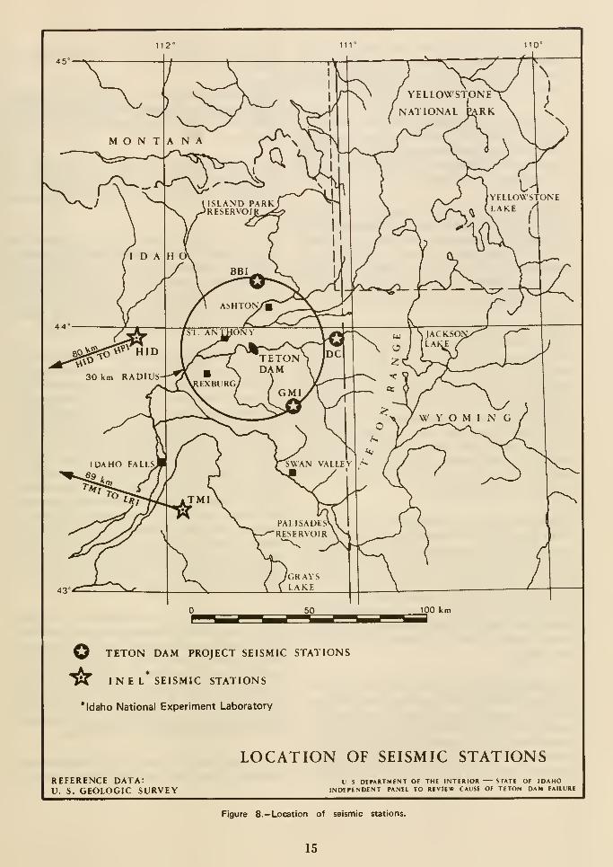
and, since June 1974, from a cooperative Bureau
of Reclamation-Geological Survey program. This
program was to study the seismicity of the Teton
Dam and Reservoir area, particularly to
investigate possible seismic effects of reservoir
filling and evidence of fault activity within about
a 25-mile radius of the damsite.
The cooperative program involved theinstallation of a monitoring network of three
seismic stations located about 18 miles north,
east, and southeast of Teton Dam. The seismic
station locations are shown on Figure 8. In the
2 years of operation of the network up to the
time of failure of the dam, no seismic activity of
Richter magnitude 2.2 Ml or greater wasobserved within 18 miles of the dam, and all
events within 12 miles of the dam were caused
by blasting. In addition, during the 2 months
prior to failure of the dam, no seismic activity
was observed within an 18-mile radius of the
dam, with the exception of identified blasts. Noincrease in seismic activity near the dam was
recorded while the reservoir was being filled. For
at least 4-1/2 hours, beginning within 1 minute
of 11:47 a.m., m.d.t., June 5, 1976, the seismic
monitoring network recorded ground motiongenerated by the breakup of the dam and release
of the reservoir water. These observations
demonstrate that the failure of Teton Dam was
not the result of seismic activity.
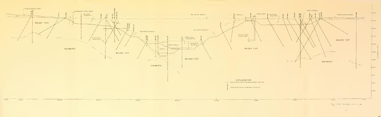
General Geology ofDamsite.-The rock that
forms the canyon walls throughout the damsite
is a rhyolite welded ash-flow tuff, the middle
member of the Huckleberry Ridge Tuff. This
welded tuff is extensively exposed in the canyonwalls, partly as rock ledges, but over large areas
of these slopes it is obscured by a cover of
slopewasb. Near the axis of the dam. the
z 4J -
> m D. c *-•
O -O iw T3U O -^
13 Ml. TO O.S. 20 & 191
MILES
Figure 5.-Geologic map of the region of Rexburg Bench and the canyon of
Teton River. (Fronn Prostka, H. J., and Hackman, R. J., 1974, Preliminar/
geologic map of the NW 1/4 Driggs 1° by 2° quadrangle, southeastern
Idaho: U.S. Geol. Survey Open-File Report 74-105.)
11

500 1000 k
SCALE
SEISMIC RISK MAP OF THE UNITED STATESZONE 0-NO DAMAGEZONE 1 — MINOR DAMAGE: DISTANT EARTHQUAKES MAY CAUSE DAMAGE
TO STRUCTURES WITH FUNDAMENTAL PERIODS GREATER THAN 10SECONDS; CORRESPONDS TO INTENSITIES I AND 31OF THE M M SCALE
ZONE 2 — MODERATE DAMAGE; CORRESPONDS TO INTENSITY HI OF THE MM." SCALE.
ZONE 3 — MAJOR DAMAGE, CORRESPONDS TO INTENSITY '^rrT AND HIGHER OF THE MM.' SCALE.
This map is based on ihc known distribution of datnaging earthquakes and thc
M.M.* inlcnstiics associated with these earthquakes: evidence of strain release;
and consideration of major geologic structures and provinces believed to beassociated with earthquake activity. The probable frequency of occurrence ofdamaging earthquakes in each zone was not considered in assigning ratings to
the various zones.
*Modificd Mercalli Intensity Scale of 1931.
SEISMIC RISK MAPOF THE UNITED STATES
Figure 6.-Seismic risk map for the United States.
13
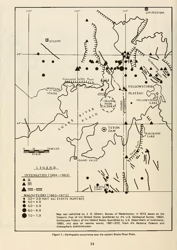
^LIVINGSTON
LEGEND
INTENSITIES (1904-1963)
A :si
^^ 'vrr -vnT
MAGNITUDES (1963-1972)• 3.0- 3.9 (NOT ALL EVENTS PLOTTED)• 4.0-4.9
• 5.0-5.9
\ '^'^'^ C4^
6.0-6.9
7.0- 7.9Map mas compiled by J. D. Gilbert, Bureau of Reclamation, In 1973, based on the
Tectonic map of the United States (published by the U.S. Geological Survey, 1962),
Earthquake history of the United States (published by U.S. Department of Commerce,
1965), and data on seismic events, 1961-1972, from the National Oceanic and
Atmospheric Administration.
Figure 7.— Earthquake occurrence near the eastern Snake River Plain.
14
112° 111° 110°
50 100 km
O TETON DAM PROJECT SEISMIC STATIONS
"^^ INEL* SEISMIC STATIONS
* Idaho National Experiment Laboratory
LOCATION OF SEISMIC STATIONSREFERENCE DATA:V. S. GEOLOGIC SURVEY
U S DEPARTMENT Of THE INTERIOK STATE OF IDAHOINDEPENDENT PANEL TO REVIEW CAUSE Of TETON DAM FAILURE
Figure 8.— Location of seismic stations.
15
thickness of the welded tuff ranges from a
minimum of about 50 feet to a maximum of at
least 575 feet. The relationship of welded tuff to
other formations is shown on Figure 9.
The welded tuff generally exhibits foliation,
which is a result of processes of accumulation,
compaction, and welding of the ash-flow
deposits. The foliation is generally flat-lying or
gently dipping, but locally it is steeply inclined.
The welded tuff at the damsite and along the
canyon of the Teton River is characterized by
the presence of prominent and abundant joints.
Most of the joints probably resulted fromtensional stresses caused by cooling of the rock
after it solidified. The joint system consists of
intersecting high-angle and low-angle joints.
Most of the high-angle joints are nearly vertical
and strike northwest. The major set, whichstrikes about N. 25° W. to N. 30° W., is well
developed on both abutments and in the rock
intersected by both outlet tunnels. A second set
strikes about N. 60° W. to N. 70° W.; it is well
developed in the lower upstream part of the right
abutment, throughout the river outlet works
tunnel, and in the downstream part of the
auxiliary outlet works tunnel. A minor set of
northeast-trending, high-angle joints is also
present in the welded tuff.
High-angle joints in the right abutment have
been traced for continuous lengths of as muchas 200 feet, but most are between 20 and 100 feet
in length. Spacing between high-angle joints
generally ranges from a few feet to about 10 feet,
but locally is from less than 1 foot to as muchas 60 feet. The width of most high-angle joints
is less than one-half inch, but many joints are as
much as several inches wide and some are several
feet wide.
Low-angle joints parallel the flat-lying or gently
dipping foliation. The lengths of the low-angle
joints are generally less than 50 feet. However,
several low-angle joints in the upper part of the
middle unit of the welded tuff have been traced
for about 200 feet, and a jointlike discontinuity
between the middle and lower units has been
traced for at least 400 feet upstream from the
dam centerline.
The spacing between low-angle joints is generally
wide except in the upper 70 feet of the welded
tuff, where closer spacing results in a platy
structure.
Many joints are open; others are partially or
wholly filled with clay, silt, silty ash, soil, or
rubble, especially near the natural groundsurface.
The permeability of the welded tuff, which has
been by far the most important geologic problem
in the development of the damsite, is due almost
entirely to the presence of open joints. The joints
are more abundant and open, and rock-mass
permeability accordingly is much higher above
about El. 5100 than below that elevation.
Underlying the welded tuff are materials of
lacustrine, alluvial, and pyroclastic origin,
probably of Pliocene Age. These materials
generally have been referred to as "sediments"
or "lakebed sediments." Information about these
materials has come mainly from drill holes,
commonly with poor or no core recovery, and to
some extent from deep grout holes, and thus is
rather fragmentary. Little is known about the
distribution and interrelations of the various
units, but sand and gravel and variably cemented
sandstone and conglomerate are commonlypresent, and thick claystone and siltstone are
present under at least part of the left abutment
and channel section. Thin ash-fall tuff and other
pyroclastic materials were found below the
welded tuff in some core holes.
The contact between the sedimentary materials
and the welded tuff is an irregular erosion surface
with a local relief of at least 440 feet and some
slopes steeper than 30°. The sedimentarymaterials are at least 390 feet thick, as explored
by postfailure drillhole 651-B in the right
abutment which bottomed in gravel. Thecharacteristics of, and depth to, the materials
underlying these sediments are unknown.
The permeability of most of the sedimentary
materials is less than that of the highly fractured
16
i ?° r

welded tuff. However, the permeability varies
considerably with the texture, apparently being
very high in some of the gravels and very low in
the thick claystone bodies.
Basalt is present in the bottom of the Teton
River Canyon as erosional remnants of a lava
flow that filled the canyon to about El. 5005. It
is buried at shallow depths under recent alluvium
in the river flood plain. In the dam foundation,
the basalt is restricted to the left side of the river
channel section, where it has a maximumthickness of about 124 feet. It is separated from
the underlying welded tuff by a deposit of
alluvial material consisting of silt, sand, and
gravel from 4 to 22 feet thick. The basalt is dense
to moderately vesicular and contains closely
spaced, randomly oriented joints and other
fractures. In spite of its fractured character, it
is an adequate foundation rock for the dam.
Water pressure tests showed the basalt to be
tight and the thin alluvial fill between the basalt
and the welded tuff to be permeable.
On the uplands bordering the canyon the welded
tuff is overlain by windblown silt, or loess, which
ranges in thickness from less than 1 foot near the
canyon edge to more than 50 feet. These deposits
served as the source of the zone 1 material of the
embankment.
The flood plain of the Teton River is underlain
by alluvial deposits having a maximum thickness
of about 100 feet at the damsite. This alluvium
consists of an upper unit about 80 feet thick
composed of sand and gravel with some cobbles
and boulders, and a lower unit about 20 feet
thick composed of silt and clay.
Large areas of the canyon walls are obscured by
a blanket of slopewash generally less than 10 feet
thick. The slopewash consists of a mixture of
silty soil and fragments of welded tuff. A small
area of landslide debris occupies a topographic
recess just upstream from the river outlet works
intake tower.
Groundwater.-ln general, the regional
groundwater table in the vicinity of Teton Damand Reservoir lies from 200 to 500 feet below the
ground surface. It shows an annual low about
May-June and an annual high in
September-November. The regional slope of the
groundwater gradient is westward, with manyirregularities.
In the immediate vicinity of Teton Dam and
Reservoir, there is also a perched water table
which, prior to reservoir filling, was 100 feet or
more above the regional water table. This
perched water table was somewhat above river
level in the area immediately southeast of the
river and as much as 50 feet below river level
northwest of the river.
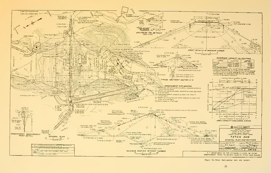
Design
Genera/.-Teton Dam was designed by the
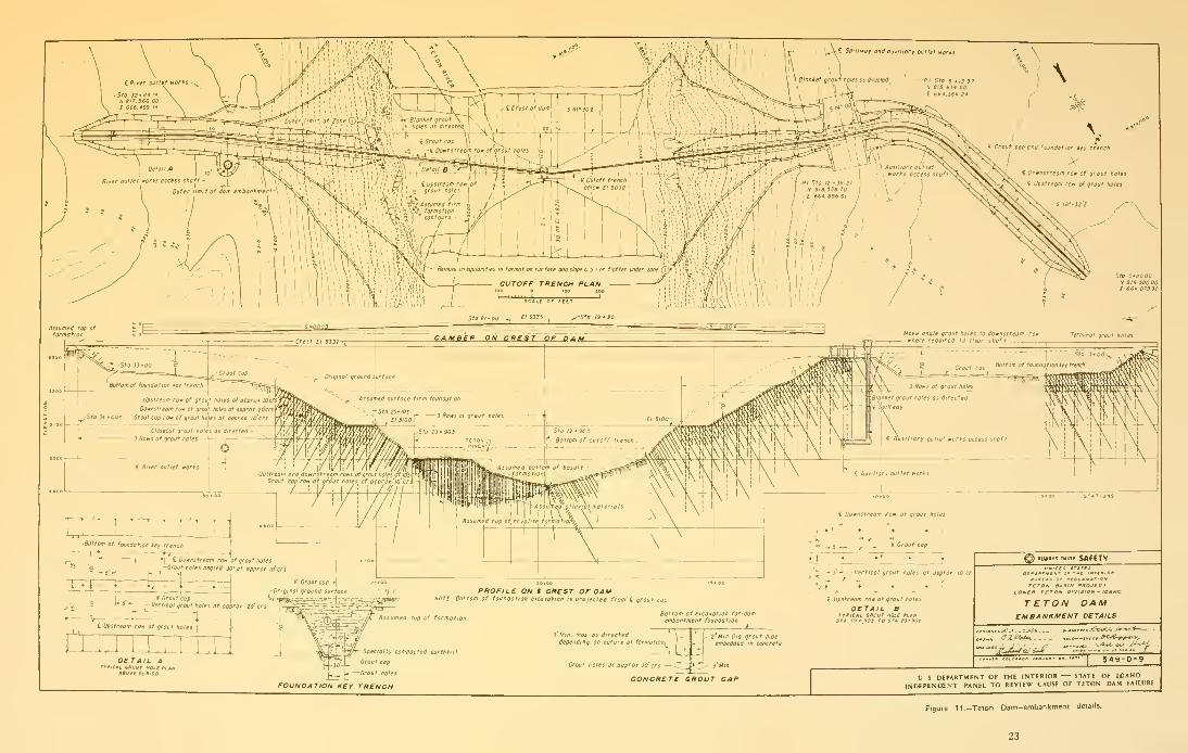
Division of Design, Bureau of Reclamation E&RCenter, Denver. Figures 10 and 11 show the
general plan and sections of the dam. The damwas designed as a zoned earthfill embankment
with crest El. 5332 and with a maximum height
of 305 feet above the valley floor and 405 feet
above the lowest point excavated in the
foundation. The crest length was about 3,100
feet, including the spillway. Appurtenant
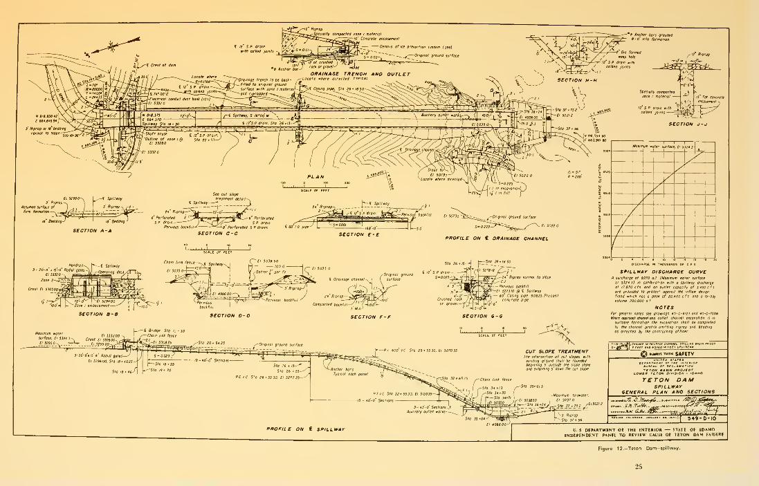
features are: (1) a three-gated, chute-type
spillway on the right abutment. Figure 12, (2) an
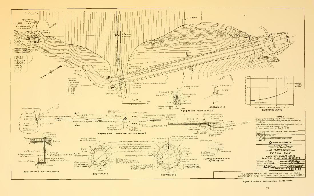
auxiliary outlet works and access shaft in the
right abutment. Figure 13, and (3) a 16,000-kW
power generating and pumping plant at the base
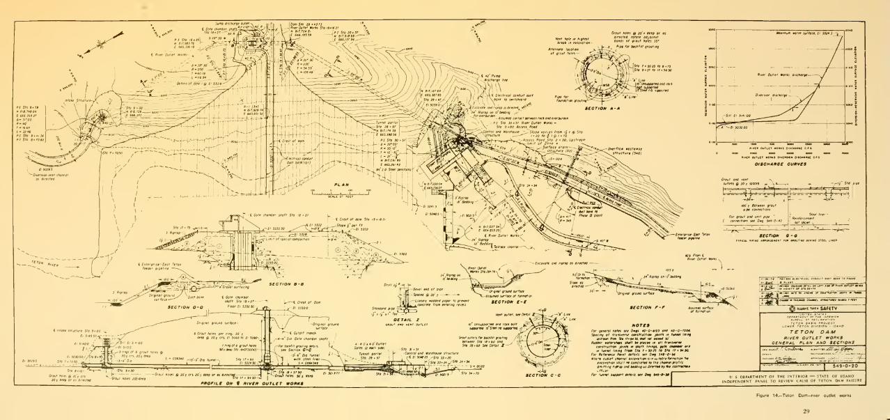
of the left abutment, (4) a river outlet works
with gate chamber and access shaft. Figure 14,
and (5) the Enterprise-East Teton Feeder
Pipeline and Canal Outlet Works Control
Structure. Because the IRG has determined that
none of the appurtenant features were involved
in the failure, they will not be discussed further
in this report.
Embankment.-The embankment is a zoned
earthnil with a thick central core. Figure 10
presents cross sections that show the dimensions
of the embankment and the relative positions of
zones 1 through 5. The location of each zone is
outlined briefly below:
Zone 1-Central core
19
Zone 2—Upstream and downstream material
adjacent to zone 1. Blanket under zone 3 in
river valley and on abutments
Zone 3—Random fill downstream of zone 2
Zone 4-Upstream cofferdam, later
incorporated into upstream toe of dam
Zone 5—Protective exterior upstream anddownstream rockfill
Zone 1 material was obtained from the deposits
of windblown silts covering most of the
immediate area outside of the Teton River
Canyon. These silts of low plasticity were
compacted to at least an average density of 98
percent of Bureau of Reclamation Standard
Proctor Density, at an average moisture content
between 0.5 and 1.5 percent dry of optimummoisture content. The permeability of zone 1
core material averaged 0.5 feet per year.
Zone 2 was composed of selected sands andgravels from the Teton River flood plain. Zone
2 was to be compacted to a relative density of
at least 70 percent.
Further details of the materials found in the
embankment are presented in Appendix D.
Foundation T'reaf/nent.-Foundationtreatment consisted of four major components:
• a cutoff trench through the flood plain
alluvium
• a key trench excavated into the rock
abutments above El. 5100 except under
the spillway
• a grout curtain that extended the full
length of the dam
• rock surface treatment on the abutments
under zone 1 material
The four components of foundation treatment
are shown on Figures 10 and 11.
The cutoff trench was to be excavated through
alluvial material to a maximum depth of 100 feet
so that zone 1 material could be placed upon a
rock foundation. The design width of the cutoff
trench in this area was 30 feet at El. 4920.
The use of the key trench was a direct result of
a pilot grouting program which showed that
above El. 5100, the upper 70 feet of rock was so
permeable that grouting was not practical. Thekey trenches extended from El. 5100 on each
abutment to the outer extremities of the
embankment, except under the spillway. Theywere excavated to a depth of 70 feet with bottom
widths of 30 feet.
As shown on Figure 11, a grout curtain was to
be constructed under the entire length of the
dam. The curtain was to be constructed with one
to three rows of grout holes generally extending
as deep as 260 feet below the bottom of the
cutoff and key trenches.
Above El. 5030, excavation was to be extended
the full width of zone 1, to cut through thin
slopewash and rubble to the firm in-place
foundation rock. Within this area, provision was
made for special treatment of large surface
joints. Further design details for foundation
treatment are presented in Appendixes C and D.
Construction
Construction ^eqrucnce.—Construction of
Teton Dam began in February 1972 with
clearing and construction of access roads. Theriver outlet tunnel was started in March 1972.
During tunnel construction, the river wasdiverted into a channel constructed along the
right abutment. During the 1972 construction
season, the original river channel adjacent to the
left abutment was cleared and materials from
required excavations were placed in the
cofferdam and at selected locations outside the
cutoff trench. Also during 1972, excavation was
in progress in the key trenches and in the
spillway.
20
i Open dram 6 baUom width
C Open drain Kj'boHom imftti .
oQ91
SC«L£ Of fEETV S DEPARTMENT Of THE rNTERIOB STATE OF IDAHO
INDEPENDENT PANEL TO REVIEW CAUSE OF TETON DAM FAILURE
Figure 10.—Teton Dam—general plan and sections.
21

i Upstream row of grout holes I
i Grout cop-
4
-Original ground surface
£ Grout cap '- . . ..
Vertical grout tioles at ap'prot so' crs \ T!^tvEzL~~ ^^^^^ t^'-^-
DETAIL ATt^icti. enouT HOLt ^i,»M
ABOVl EL HOC
-Speciolly compacted eorlhfill
vJJ 'J™"' ^op
L J^ L--
—
Grout holes
FOUNDATION KEY TRENCH
Grout tioles at approi lo crs—-d^VT^ ^'Min
CONCRETE GROUT CAP
- IDA no
TETON DAMEMBANKMENT DETAILS
«__(?ji-^6A4 ^^^f^i-^fr-^.
U S DEPARTMENT OF THE INTERIOR STATE Of IDAHO
INDEPENDENT PANEl TO REVIEW CAUSE OF TETON DAM FAILURE
Figure 1 1 .-Teton Dam-embankmeni details.
23

li For concrete
SECTION J-
J
18 BeMinq
SECTION A-
A
SECTION C-C
BC»Le OF FtET
Hgndroi
3- lO-a' tii'S' ffoami gates
CI ssx
Zone 2
Crest £i 530500
"I-. [~ -C SpillmoyChain lint fence El 5038 SO
100 -
I embonkmenl -
SECTION B-B
SECTION E-E
i Droinoge channel-
ei 502!
PROFILE ON € DRAINAGE CHANNEL
Sto 26 '18 SO
14 Riprap
-
Compoctea backfill
i il' S P dram
S-0O23<X^
SECTION D-D3 Mm-^
SECTION F-F

U S DEPARTMENT OF THE INTERIOR STATE OF IDAHO
INDEPENDENT PANEL TO REVIEW CAUSE OF TETON DAM FAllLiRE
Figure 13.-Teton Dam-auxiliary outlet works.
27

ehoniber ttioft'
P 1 Sto 16
H fir.9B3
f €S6.3J€I9

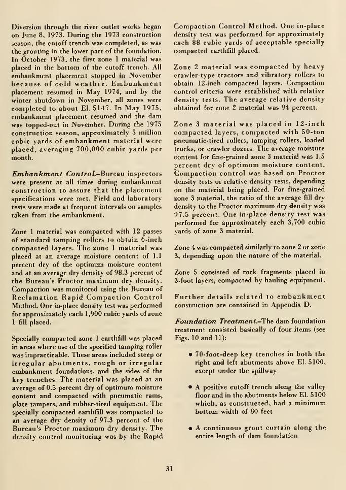
Diversion through the river outlet works began
on June 8, 1973. During the 1973 construction
season, the cutoff trench was completed, as was
the grouting in the lower part of the foundation.
In October 1973, the first zone 1 material was
placed in the bottom of the cutoff trench. All
embankment placement stopped in Novemberbecause of cold weather. Embankmentplacement resumed in May 1974, and by the
winter shutdown in November, all zones were
completed to about El. 5147. In May 1975,
embankment placement resumed and the damwas topped-out in November. During the 1975
construction season, approximately 5 million
cubic yards of embankment material were
placed, averaging 700,000 cubic yards per
month.
Embankment Control.-Bureau inspectors
were present at all times during embankmentconstruction to assure that the placement
specifications were met. Field and laboratory
tests were made at frequent intervals on samples
talcen from the embankment.
Zone 1 material was compacted with 12 passes
of standard tamping rollers to obtain 6-inch
compacted layers. The zone 1 material was
placed at an average moisture content of 1.1
percent dry of the optimum moisture content
and at an average dry density of 98.3 percent of
the Bureau's Proctor maximum dry density.
Compaction was monitored using the Bureau of
Reclamation Rapid Compaction ControlMethod. One in-place density test was performed
for approximately each 1,900 cubic yards of zone
1 fill placed.
Specially compacted zone 1 earthfill was placed
in areas where use of the specified tamping roller
was impracticable. These areas included steep or
irregular abutments, rough or irregular
embankment foundations, and the sides of the
key trenches. The material was placed at an
average of 0.5 percent dry of optimum moisture
content and compacted with pneumatic rams,
plate tampers, and rubber-tired equipment. Thespecially compacted earthfill was compacted to
an average dry density of 97.3 percent of the
Bureau's Proctor maximum dry density. Thedensity control monitoring was by the Rapid
Compaction Control Method. One in-place
density test was performed for approximately
each 88 cubic yards of acceptable specially
compacted earthfill placed.
Zone 2 material was compacted by heavycrawler-type tractors and vibratory rollers to
obtain 12-inch compacted layers. Compaction
control criteria were established with relative
density tests. The average relative density
obtained for zone 2 material was 94 percent.
Zone 3 material was placed in 12-inchcompacted layers, compacted with 50-ton
pneumatic-tired rollers, tamping rollers, loaded
trucks, or crawler dozers. The average moisture
content for fine-grained zone 3 material was 1.5
percent dry of optimum moisture content.
Compaction control was based on Proctor
density tests or relative density tests, depending
on the material being placed. For fine-grained
zone 3 material, the ratio of the average fill dry
density to the Proctor maximum dry density was
97.5 percent. One in-place density test was
performed for approximately each 3,700 cubic
yards of zone 3 material.
Zone 4 was compacted similarly to zone 2 or zone
3, depending upon the nature of the material.
Zone 5 consisted of rock fragments placed in
3-foot layers, compacted by hauling equipment.
Further details related to embankmentconstruction are contained in Appendix D.
Foundation Treatment.-The dam foundation
treatment consisted basically of four items (see
Figs. 10 and 11):
• 70-foot-deep key trenches in both the
right and left abutments above El. 5100,
except under the spillway
• A positive cutoff trench along the valley
floor and in the abutments below El. 5100
which, as constructed, had a minimumbottom width of 80 feet
• A continuous grout curtain along the
entire length of dam foundation
31
• Rock surface treatnlent under portions of
zone 1
The entire embankment foundation was stripped
of all material considered unsuitable.
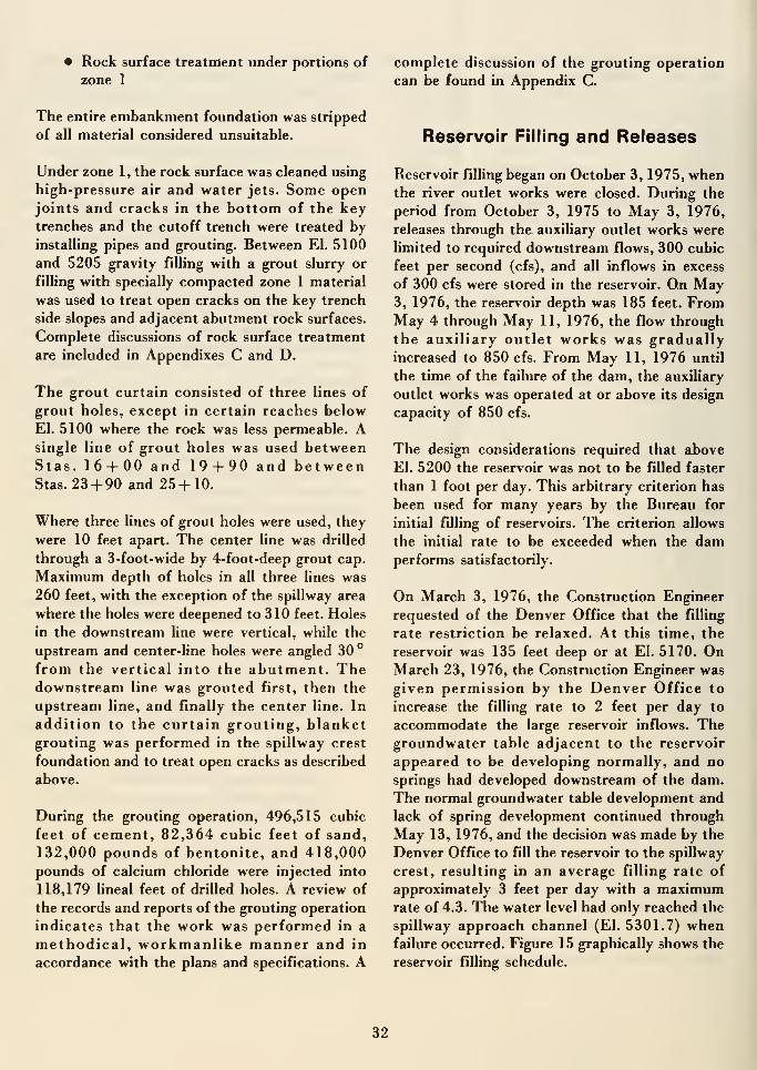
Under zone 1, the rock surface was cleaned using
high-pressure air and water jets. Some openjoints and cracks in the bottom of the keytrenches and the cutoff trench were treated by
installing pipes and grouting. Between El. 5100
and 5205 gravity filling with a grout slurry or
filling with specially compacted zone 1 material
was used to treat open cracks on the key trench
side slopes and adjacent abutment rock surfaces.
Complete discussions of rock surface treatment
are included in Appendixes C and D.
The grout curtain consisted of three lines of
grout holes, except in certain reaches below
El. 5100 where the rock was less permeable. Asingle line of grout holes was used betweenStas. 16 + 00 and 19-f 90 and betweenStas. 23 + 90 and 25 + 10.
Where three lines of grout holes were used, they
were 10 feet apart. The center line was drilled
through a 3-foot-wide by 4-foot-deep grout cap.
Maximum depth of holes in all three lines was
260 feet, with the exception of the spillway area
where the holes were deepened to 310 feet. Holes
in the downstream line were vertical, while the
upstream and center-line holes were angled 30°
from the vertical into the abutment. Thedownstream line was grouted first, then the
upstream line, and finally the center line. In
addition to the curtain grouting, blanketgrouting was performed in the spillway crest
foundation and to treat open cracks as described
above.
During the grouting operation, 496,515 cubic
feet of cement, 82,364 cubic feet of sand,
132,000 pounds of bentonite, and 418,000pounds of calcium chloride were injected into
118,179 lineal feet of drilled holes. A review of
the records and reports of the grouting operation
indicates that the work was performed in a
methodical, workmanlike manner and in
accordance with the plans and specifications. A
complete discussion of the grouting operation
can be found in Appendix C.
Reservoir Filling and Releases
Reservoir filling began on October 3, 1975, whenthe river outlet works were closed. During the
period from October 3, 1975 to May 3, 1976,
releases through the auxiliary outlet works were
limited to required downstream flows, 300 cubic
feet per second (cfs), and all inflows in excess
of 300 cfs were stored in the reservoir. On May3, 1976, the reservoir depth was 185 feet. FromMay 4 through May 11, 1976, the flow through
the auxiliary outlet works was graduallyincreased to 850 cfs. From May 11, 1976 until
the time of the failure of the dam, the auxiliary
outlet works was operated at or above its design
capacity of 850 cfs.
The design considerations required that above
El. 5200 the reservoir was not to be filled faster
than 1 foot per day. This arbitrary criterion has
been used for many years by the Bureau for
initial filling of reservoirs. The criterion allows
the initial rate to be exceeded when the damperforms satisfactorily.
On March 3, 1976, the Construction Engineer
requested of the Denver Office that the filling
rate restriction be relaxed. At this time, the
reservoir was 135 feet deep or at El. 5170. OnMarch 23, 1976, the Construction Engineer was
given permission by the Denver Office to
increase the filling rate to 2 feet per day to
accommodate the large reservoir inflows. Thegroundwater table adjacent to the reservoir
appeared to be developing normally, and no
springs had developed downstream of the dam.
The normal groundwater table development and
lack of spring development continued through
May 13, 1976, and the decision was made by the
Denver Office to fill the reservoir to the spillway
crest, resulting in an average filling rate of
approximately 3 feet per day with a maximumrate of 4.3. The water level had only reached the
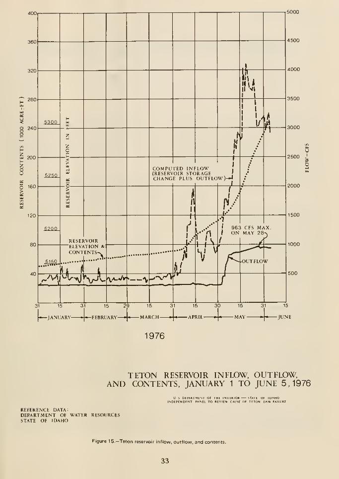
spillway approach channel (El. 5301.7) whenfailure occurred. Figure 15 graphically shows the
reservoir filling schedule.
32
400 5000
4500
- 4000
3500
3000
2500
2000
1500
1000
500
UI
1976
TETON RESERVOIR INFLOW, OUTFLOW,AND CONTENTS, JANUARY 1 TO JUNE 5.1976
U S DEPARTMENT OF THE INTERIOR STATE OF IDAHOINDEPENDENT PANEL TO REVIEW CAUSE OF TETON DAM FAILURE
REFERENCE DATA:DEPARTMENT OF WATER RESOURCESSTATE OF IDAHO
Figure 1 5.—Teton reservoir inflow, outflow, and contents.
33

«Chapter 3
Chronology and Consequences of Failure
Chronology of Failure Events
Introduction.-The Teton Dam failure
sequence has been reconstructed by the IRGfrom:
• Interviews of 41 persons and sworntestimony from 36 of them. Interviews
were conducted by special agents. Office
of Audit and Investigation, Office of the
Secretary. Eyewitness accounts of the
failure are contained in Appendix F
• Photographs taken by Bureau ofReclamation project personnel,contractor employees, and on-site visitors
• 8- and 16-mm movies taken by Bureau of
Reclamation project personnel
• Verbal discussions with project personnel
who witnessed the failure
• Statements given by Messrs. Robison,Aberle, Ringel, Parks, Isaacson, andRogers before staff members of the
Independent Panel on October 29, 1976
The exact timing of the events, excepting the
final collapse of the dam crest, are not knownbut sufficient information is available to
estimate approximate times. The failure
chronology as determined by the IRG is
substantially the same as that reported by the
Independent Panel.
Events and Observations Prior to June 5,
1976.-0n October 3, 1975, reservoir filling
began; the reservoir was then at El. 5060. Filling
continued at a relatively slow rate until April 10,
1976, when the reservoir level reached El. 5180.
No problems of any type with the embankmentwere reported, nor were there any seeps or
leakage reported. From April 10, 1976 until June
5, 1976, the reservoir filled at a faster rate
because of high runoff of snowmelt. Prior to June
3, 1976, no problems of any type with the
embankment were reported, and no seeps were
reported.
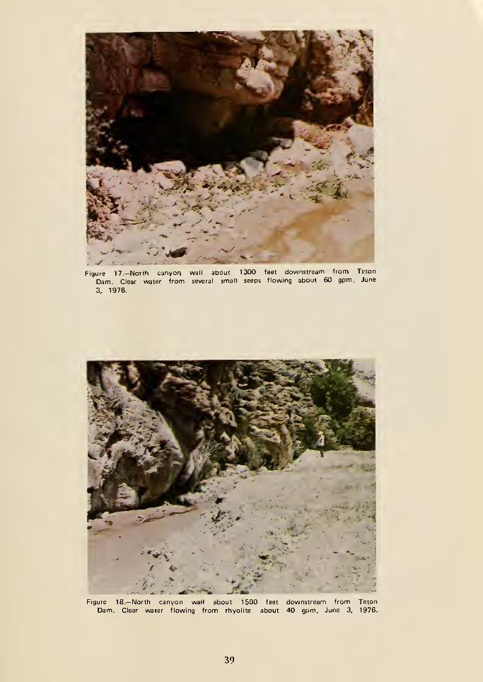
On June 3, 1976, project personnel inspecting
the right abutment found two small seeps located
1,300 and 1,500 feet downstream from the toe
of the dam. These seeps were flowing clear water
at approximately 60 and 40 gallons per minute
(gpm), respectively. Photographs of these seeps
are shown in Figures 17 and 18, and their
location relative to the dam is shown on Figure
16. The reservoir elevation at this time was 5300.
On June 4, 1976, a small clear seep was found
flowing approximately 20 gpm from the right
abutment 150 to 200 feet downstream from the
toe of the dam. This small seepage was noted bya number of individuals; its location is shown onFigure 16. No photographs of this seep exist.
No additional seepage locations were found as of
9:00 p.m. on June 4. Thus, it is established that
as of 9:00 p.m. on June 4, 1976, no serious
seepage or leaks were observed on theembankment or from the abutments of TetonDam. A Bureau employee was at the damsite
until 12:30 a.m. on June 5, 1976.
Events and Observations On June 5,
1976.—Among the first persons to arrive at the
site on June 5 were Bureau of Reclamation
35
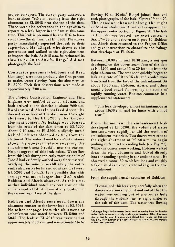
project surveyors. The survey party observed a
leak, at about 7:45 a.m., coming from the right
abutment at El. 5045 near the toe of the dam.There were also references in the eyewitness
reports to a leak higher in the dam at this sametime. This leak is presumed by the IRG to have
come from the abutment at El. 5200. The survey
party immediately reported the leak to their
supervisor, Mr. Ringel, who drove to the
powerhouse and walked to the right abutment
to inspect the leak. At 8:15 a.m. he estimated its
flow to be 20 to 30 cfs. Ringel did notphotograph the leak.
Contractor personnel (Gibbons and ReedCompany) were most probably the first persons
to notice water flowing from the abutment at
El. 5200. Their first observations were made at
approximately 7:00 a.m.
The Project Construction Engineer and Field
Engineer were notified at about 8:20 a.m. and
both arrived at the damsite at about 9:00 a.m.
Robison and Aberle walked down thedownstream face of the dam near the right
abutment to the El. 5200 embankment-abutment contact. No leakage was observed
from the crest of the dam down to El. 5200.
About 9:10 a.m., at El. 5200, a sKghtly turbid
leak of 2 cfs was observed exiting from the
abutment. The water flowed for a short distance
along the contact before entering theembankment's zone 5 rockfill near the contact.
No photograph of this leak exists. Waterflowfrom this leak during the early morning hours of
June 5 had evidently washed away finer material
overlying the zone 5 rockfill along the entire
embankment-abutment contact betweenEl. 5200 and 5041.5. It is possible that this
seepage was much larger than 2 cfs whichRobison and Aberle observed. At this time,
neither individual noted any wet spot on the
embankment at El. 5200 nor at any location onthe downstream face of the dam.
Robison and Aberle continued down the
abutment contact to the lower leak at El. 5045.
No other seepage from the abutment or
embankment was noted between El. 5200 and
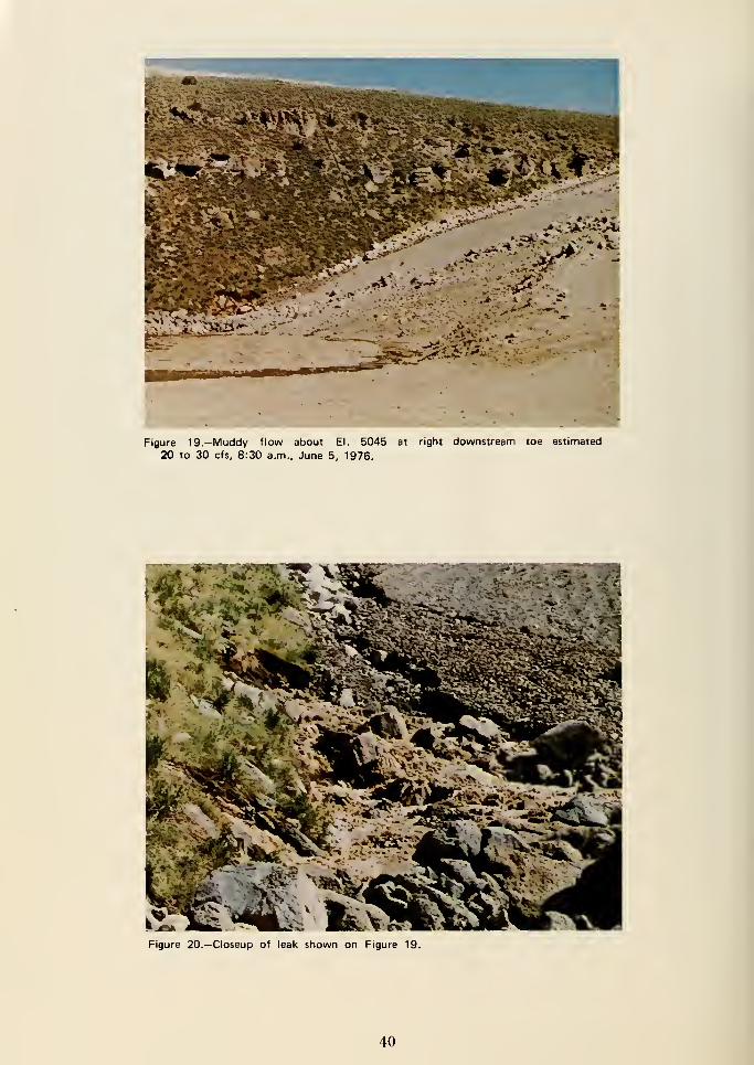
5045. The leak at El. 5045 was examined at
approximately 9:30 a.m. and was estimated to be
flowing 40 to 50 cfs. Ringel joined then andtook photographs of the leak. Figures 19 and 20.
The erosion channel along the rightembankment-abutment contact is apparent in
the upper center portion of Figure 20. The leak
at El. 5045 was located near crest centerline
Sta. 17 + 25 and is shown on Figure 16. Robison
and Aberle then returned to the Project Office
and gave instructions to channelize the leakage
that developed at El. 5045.
Between 10:00 a.m. and 10:30 a.m., a wet spot
developed on the downstream face of the damat El. 5200, and about 15 to 20 feet out from the
right abutment. The wet spot quickly began to
leak at a rate of 10 to 15 cfs, and eroded zone
5 material from the face of the embankment. Atabout 10:30 a.m., Robison, Aberle, and others
noted a loud sound followed by the sound of
rapidly running water. Robison comments in a
supplemental statement:
"This leak developed almost instantaneous at
about 10:30 a.m. and let loose with a loud
roar."
From the moment the embankment leak
developed at El. 5200, the volume of water
increased very rapidly, as did the erosion of
embankment materials. Two dozers were sent to
the right abutment at 10:40 a.m. to begin
pushing rock into the eroding hole (see Fig. 21).
While the dozers were working, Robison walked
down the right abutment and looked directly
into the eroding opening in the embankment. Heobserved a tunnel 30 to 40 feet long and roughly
6 feet in diameter extending into theembankment.
From the supplemental statement of Robison:
"I examined this leak very carefully when the
dozers were working on it and noted that the
water was coming out of a circular hole
through the embankment at right angles to
the axis of the dam. The water was flowing
' Although Ringel had estimated 20 to 30 cfs as coming from this location
earlier, both estimates are only crude approximations. What does seem
clear is that between 8:15 a.m., when Ringel first viewed the leak and
9:30 ajn., when Robison and Aberle viewed the leak no massive increase
in flow had occurred.
36
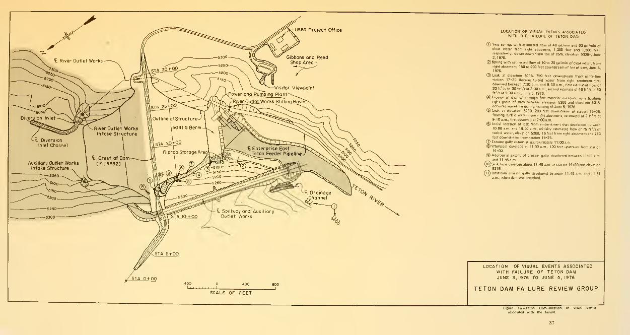
US8R Project Office LOCATION OF VISUAL EVENTS ASSOCIATEDWITH THE FAILURE OF TETON DAM
©Two springs with estimated flow of 40 gal/min and 60 gal/min ofclear water from right abutment, 1,300 feet and 1,500 feet,
respectively, downstream from toe of dam, elevation 5030+ June3,1976.
® Spring with estimated flow of 10 to 20 gal/min of clear water, fromright abutment. 1 50 to 200 feet downstream of toe of dam June 41976.
(3) Leak at elevation 5045. 750 feet downstream from ceoterlinestation 17+25 flowing turbid water from right abutment first
observed between 7:30 a.m. and 8:00 a.m., first estimated flow of20ftVs to 30 ftVs at 8:30 a.m., second estimate of 40 ftVs to 50ftVs at 9:30 a.m., June 5, 1976.
(3) Erosion of channel through fine material overlying zone 5, alongright groin of dam between elevation 5200 and elevation 5045,occurred sometime during morning of June 5, 1976.
©Leak at elevation 5200, 283 feet downstream of station 15+05.flowing turbid water from n^t abutment, estimated at 2 ft*/s at
9: 10 a.m., first observed at 7:00 a.m.
(D Initial location of leak from embankment that developed between10:00 a.m. and 1030 a.m., initially estimated flow of 15 ftVs of
turbid water, elevation 5200, 1 5 feet from right abutment and 283feet downstream from station 15+25,
(J) Erosion gully extent at approximately 1 1 :00 a.m.
(§) Whirlpool develops at 1 1 :00 a.m., 1 30 feet upstream from station
14+00.
©Additional extent of erosion gully developed between 11:00 a.m.
^..^ and 11:45 a.m.
(lO)Sink hole develops about 1 1 46 a.m. at station 14+00 and elevation
5315.
Qj) Upstream erosion gully developed between 1 1 45 a.m. and 11 57a.m.. when dam was breached.
SCALE OF FEET
LOCATION OF VISUAL EVENTS ASSOCIATEDWITH FAILURE OF TETON DAMJUNE 3,1976 TO JUNE 5, 1976
TETON DAM FAILURE REVIEW GROUP
Figure 16.-Teton Oam-locaiion of visual events
associated with the failure.
37

-. ^il^
Figure 17.-North canyon wall about 1300 feet downstream from Teton
Dam. Clear water from several small seeps flowing about 60 gpm, June
3, 1976.
.-•/ :"^ ^ • -•
Figure 18.— Nortfi canyon wall about 1500 feet downstream from Teton
Dam. Clear water flowing from rhyolite about 40 gpm, June 3, 1976.
39
,^,/ — V>«'r^"^rh&a*^C)?=*-'r
Figure 19.-Muddy flow about El. 5045 at right downstream toe estimated
20 to 30 cfs, 8:30 a.m., June 5, 1976.
Figure 20.—Closeup of leak shown on Figure 19.
40
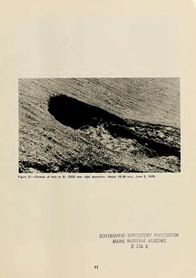
Figure 21.—Closeup of leak at El. 5200 near right abutment. About 10:30 a.m., June 5, 1976.
GOVERNMENT DEPOSITORY PU8UCATI0N
MAINE MARITIME ACADEMY
C 236 A
41
extremely muddy and exiting from the hole in
the embankment about 15 to 20 feet from the
abutment."
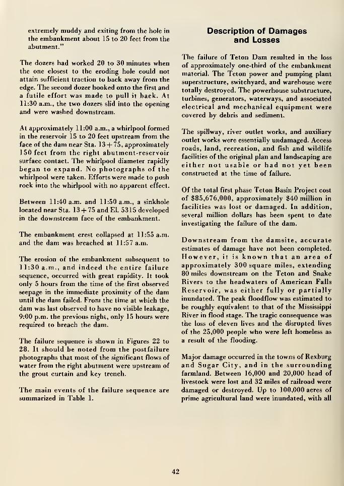
The dozers had worked 20 to 30 minutes whenthe one closest to the eroding hole could not
attain sufficient traction to back away from the
edge. The second dozer hooked onto the first and
a futile effort was made to pull it back. At11:30 a.m., the two dozers slid into the opening
and were washed downstream.
At approximately 11:00 a.m., a whirlpool formed
in the reservoir 15 to 20 feet upstream from the
face of the dam near Sta. 13 + 75, approximately
150 feet from the right abutment-reservoirsurface contact. The whirlpool diameter rapidly
began to expand. No photographs of the
whirlpool were taken. Efforts were made to push
rock into the whirlpool with no apparent effect.
Between 11:40 a.m. and 11:50 a.m., a sinkhole
located near Sta. 13+ 75 and El. 5315 developed
in the downstream face of the embankment.
The embankment crest collapsed at 11:55 a.m.
and the dam was breached at 11:57 a.m.
The erosion of the embankment subsequent to
11:30 a.m., and indeed the entire failure
sequence, occurred with great rapidity. It took
only 5 hours from the time of the first observed
seepage in the immediate proximity of the damuntil the dam failed. From the time at which the
dam was last observed to have no visible leakage,
9:00 p.m. the previous night, only 15 hours were
required to breach the dam.
The failure sequence is shown in Figures 22 to
28. It should be noted from the postfailure
photographs that most of the significant flows of
water from the right abutment were upstream of
the grout curtain and key trench.
The main events of the failure sequence are
summarized in Table 1.
Description of Damagesand Losses
The failure of Teton Dam resulted in the loss
of approximately one-third of the embankmentmaterial. The Teton power and pumping plant
superstructure, switchyard, and warehouse were
totally destroyed. The powerhouse substructure,
turbines, generators, waterways, and associated
electrical and mechanical equipment werecovered by debris and sediment.
The spillway, river outlet works, and auxiliary
outlet works were essentially undamaged. Access
roads, land, recreation, and fish and wildlife
facilities of the original plan and landscaping are
either not usable or had not yet beenconstructed at the time of failure.
Of the total first phase Teton Basin Project cost
of $85,676,000, approximately $40 million in
facilities was lost or damaged. In addition,
several million dollars has been spent to date
investigating the failure of the dam.
Downstream from the damsite, accurateestimates of damage have not been completed.
However, it is known that an area of
approximately 300 square miles, extending
80 miles downstream on the Teton and Snake
Rivers to the headwaters of American Falls
Reservoir, was either fully or partially
inundated. The peak floodflow was estimated to
be roughly equivalent to that of the Mississippi
River in flood stage. The tragic consequence was
the loss of eleven lives and the disrupted lives
of the 25,000 people who were left homeless as
a result of the flooding.
Major damage occurred in the towns of Rexburg
and Sugar City, and in the surroundingfarmland. Between 16,000 and 20,000 head of
livestock were lost and 32 miles of railroad were
damaged or destroyed. Up to 100,000 acres of
prime agricultural land were inundated, with all
42
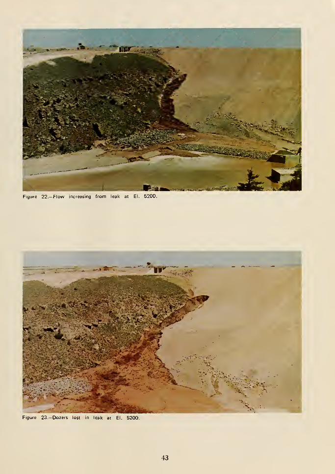
.-^J
Figure 22.—Flow increasing from leak at El. 5200.
.,-JFigure 23. -Dozers lost in leak at El. 5200.
43
Figure 24.-Approximately 11:30 a.m., June 5, 1976.
Figure 25.-Second hole in downstream slope of dam just after 11:30 a.m., June 5, 1976.
44
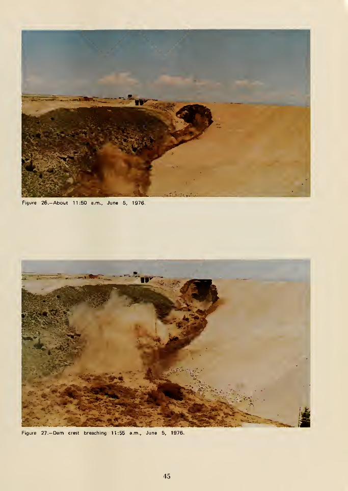
Figure 26.-About 11:50 a.m., June 5, 1976.
iFigure 27.-Dam crest breaching 11:55 a.m., June 5, 1976.
45
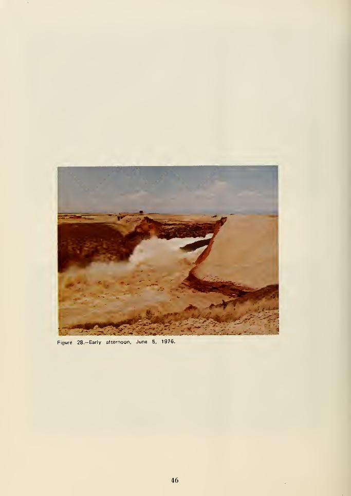
Figure 28.— Early afternoon, June 5, 1976.
46
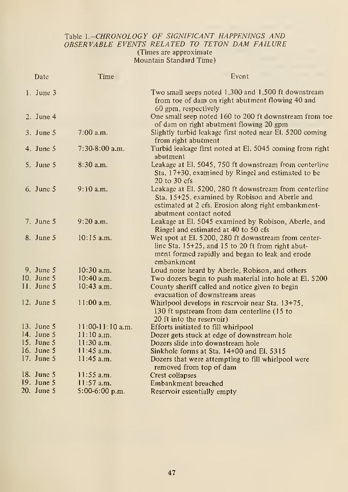
Table I.-CHRONOLOGY OF SIGNIFICANT HAPPENINGS ANDOBSERVABLE EVENTS RELATED TO TETON DAM FAILURE
(Times are approximate
Mountain Standard Time)
Event
Two small seeps noted 1,300 and 1,500 ft downstream
from toe of dam on right abutment flowing 40 and
60 gpm, respectively
One small seep noted 1 60 to 200 ft downstream from toe
of dam on right abutment flowing 20 gpmSlightly turbid leakage first noted near El. 5200 comingfrom right abutment
Turbid leakage first noted at El. 5045 coming from right
abutmentLeakage at El. 5045, 750 ft downstream from centerline
Sta. 17+30, examined by Ringel and estimated to be
20 to 30 cfs
Leakage at El. 5200, 280 ft downstream from centerline
Sta. 15+25, examined by Robison and Aberle and
estimated at 2 cfs. Erosion along right embankment-abutment contact noted
Leakage at El. 5045 examined by Robison, Aberle, andRingel and estimated at 40 to 50 cfs
Wet spot at El. 5200, 280 ft downstream from center-
Une Sta. 1 5+25, and 1 5 to 20 ft from right abut-
ment formed rapidly and began to leak and erode
embankmentLoud noise heard by Aberle, Robison, and others
Two dozers begin to push material into hole at El. 5200County sheriff called and notice given to begin
evacuation of downstream areas
Whirlpool develops in reservoir near Sta. 13+75,
130 ft upstream from dam centerline (15 to
20 ft into the reservoir)
Efforts initiated to fill whirlpool
Dozer gets stuck at edge of downstream hole
Dozers slide into downstream hole
Sinkhole forms at Sta. 14+00 and El. 5315Dozers that were attempting to fill whirlpool wereremoved from top of dam
Crest collapses
Embankment breached
Reservoir essentially empty
but 3,000 acres capable of being restored to full
productivity.
Damage to private and public property wasextensive. As of March 16, 1977, the Bureau of
Reclamation had received 5,616 claims totaling
more than $250 million. The Bureau has paid
over $138 million on 4,938 claims. It is nowestimated that the total claims to be paid by the
Bureau of Reclamation will approach$400 million. This does not include damages to
the dam and appurtenant structures nordamages paid from other sources. A total cost of
damages is not yet available.
48
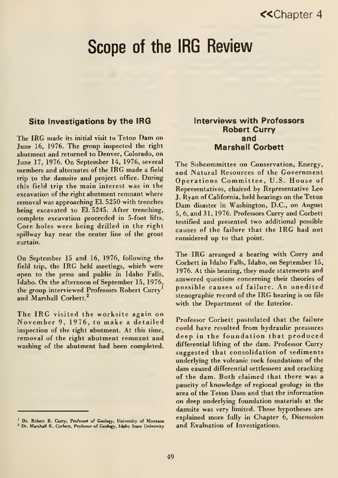
«Chapter 4
Scope of the IRG Review
Site Investigations by the IRG
The IRG made its initial visit to Teton Dam on
June 16, 1976. The group inspected the right
abutment and returned to Denver, Colorado, on
June 17, 1976. On September 14, 1976, several
members and alternates of the IRG made a field
trip to the damsite and project office. During
this field trip the main interest was in the
excavation of the right abutment remnant where
removal was approaching El. 5250 with trenches
being excavated to El. 5245. After trenching,
complete excavation proceeded in 5-foot lifts.
Core holes were being drilled in the right
spillway bay near the center line of the grout
curtain.
On September 15 and 16, 1976, following the
field trip, the IRG held meetings, which were
open to the press and public in Idaho Falls,
Idaho. On the afternoon of September 15, 1976,
the group interviewed Professors Robert Curry
and Marshall Corbett.
The IRG visited the worksite again onNovember 9, 1976, to make a detailedinspection of the right abutment. At this time,
removal of the right abutment remnant andwashing of the abutment had been completed.
Dr. Robert R. Curry. Professor of Geology. UiiiTersity of Montana* Dr. Marshall K. Corbett, Professor of Geology. Idaho State University
Interviews with ProfessorsRobert Curry
andMarshall Corbett
The Subcommittee on Conservation, Energy,
and Natural Resources of the GovernmentOperations Committee, U.S. House of
Representatives, chaired by Representative Leo
J. Ryan of California, held hearings on the Teton
Dam disaster in Washington, D.C., on August
5, 6, and 31, 1976. Professors Curry and Corbett
testified and presented two additional possible
causes of the failure that the IRG had not
considered up to that point.
The IRG arranged a hearing with Curry and
Corbett in Idaho Falls, Idaho, on September 15,
1976. At this hearing, they made statements and
answered questions concerning their theories of
possible causes of failure. An uneditedstenographic record of the IRG hearing is on file
with the Department of the Interior.
Professor Corbett postulated that the failure
could have resulted from hydraulic pressures
deep in the foundation that produceddifferential lifting of the dam. Professor Curry
suggested that consolidation of sediments
underlying the volcanic rock foundations of the
dam caused differential settlement and cracking
of the dam. Both claimed that there was a
paucity of knowledge of regional geology in the
area of the Teton Dam and that the information
on deep underlying foundation materials at the
damsite was very limited. These hypotheses are
explained more fully in Chapter 6, Discussion
and Evaluation of Investigations.
49
Review of Postfailure
Investigations
The IRG has had the opportunity to review data
from all postfailure field investigations of the
Teton Dam. These investigations included
resurveys of monuments in the area, a program
of drilling and water testing in the damfoundation to check the adequacy of the
grouting program, and a program of hydraulic
fracturing tests of the embankment remaining
on the left abutment. In addition to this, that
part of the embankment remaining on the valley
slope of the right abutment was carefully
removed, its conditions observed, and samples
taken for laboratory testing. After removal of
the embankment, the entire area of the keytrench and adjacent areas were cleaned anddetailed geologic maps and sections wereprepared. In addition, topographic mapping and
cross-sectioning of the right abutment, borehole
camera photography of selected holes, andtesting of transmissibility of selected rock joints
were carried out. Postfailure laboratory testing
was done to confirm the embankment design
parameters, and to determine the nonlinear
parameters needed for finite element analyses of
the embankment. Finite element stress analyses
were performed for transverse and longitudinal
sections through the dam and for sections in the
foundation. Arrangements for work in the field,
laboratories, and offices were made in close
cooperation with the staff of the Independent
Panel to eliminate duplication of effort.
Data Supplied by theBureau of Reclamation
The IRG received a detailed briefing at
Reclamation's E&R Center on June 15, 1976.
Basic background data such as the plans and
specifications were distributed at this briefing.
Subsequently, the remaining exhibits listed in
Appendix E were given to all members of the
IRG, their alternates, and members of the task
groups as appropriate. Many of these documents
were supplemented and expanded at the request
of both the IRG and the Independent Panel.
Also, the field data generated during the
investigation were given to the IRG. Thesedocuments are compiled and maintained in tworepositories: (1) the Bureau of Reclamation in
Denver, Colorado, and (2) the Department of
the Interior in Washington, D.C.
At the request of the Independent Panel and the
IRG, two physical models of Teton Dam were
prepared for the failure investigations: (1) a
model of the entire dam and appurtenances, at
a scale of 1:1000, showing both the foundation
and the dam, and (2) a model of the right
abutment and dam at a scale of 1:400, showing
pre- and postfailure conditions.
Task Group Reviews
Three task groups were organized with staff
members from the Federal agencies represented
on the IRG. The responsibility of the groups was
to obtain information that would assist the IRGin carrying out its charges. The scope of their
activities are given below:
Geology.-The geology group made several
visits to the damsite to examine the geologic
conditions, held discussions with Bureau of
Reclamation project and regional geologists,
and reviewed project records. To obtain
additional expertise, they consulted with
Federal specialists concerning the regional
geology of the Snake River Plain, volcanic
geology, engineering geology of damsites in
volcanic rocks, groundwater geology, andseismology.
They reviewed Bureau of Reclamationprefailure investigations of the site geology
and recommended to the Bureau ofReclamation that further geologic studies be
conducted.
They reviewed and evaluated the results of
the recommended postfailure studies.
Appendix B is the report of this task group.
Grouting.—The grouting group evaluated the
adequacy of the grout curtain to perform its
SO
design function, evaluated the adequacy of
the rock surface treatment program, anddetermined the probable contribution, or lack
thereof, of the rock treatment to the failure.
During the course of its activities, the
Grouting Task Group made two visits to
Teton Dam to interview Bureau construction
personnel, interview the grouting contractor,
study Bureau photographs and inspection
documents, and inspect the dam andabutments. One visit was also made to Denver
to interview Bureau design personnel.
Appendix C is the report of this task group.
Embankment Construction Review.-The
embankment construction group reviewed the
construction aspects regarding theembankment and foundation, exclusive of the
foundation pressure grouting. During the
review made by the task group, a visit was
made to the damsite, a number ofconstruction inspectors were interviewed, and
construction records and reports werereviewed. Analysis of soil tests was made to
determine if design requirements were metand if construction control was obtained.
Procedures Review
The original charge to IRG directed that the
cause of the failure be determined and that
recommendations, if warranted by its Hndings,
be provided to prevent recurrence of such
failures. To respond appropriately to this charge,
the IRG believes it is necessary to review
documentation of the Bureau of Reclamation
technical decisionmaking process and to conduct
interviews with appropriate Bureau personnel.
These reviews and interviews will be conducted
so that the design procedures and design review
and technical decisionmaking processes will be
identiHed. Recommendations will be based on
the review and interviews.
Appendix D is the report of this task group.
Questions and AnswersRegarding
Design and Construction
The IRG developed and sent to theCommissioner, Bureau of Reclamation, a
number of questions concerning the design of
the dam and the function and responsibilities of
the Division of Design during the construction
of the dam.
Appendix G contains these questions and the
answers supplied by the Bureau. Also, in
Appendix G, is a second set of questions posed
by the Independent Panel and answers supplied
by the Bureau of Reclamation and theconstruction contractor.
51

«Chapter 5
Possible Causes of Failure
Introduction
In the IRG Second Interim Report, October 21,
1976, six possible causes of the failure were
presented in the order of their relative
probability of occurrence. These six possible
causes of failure are described below. Theinvestigations and evaluations carried out to
determine the most probable cause of failure and
to explore the adequacy of design andconstruction of Teton Dam are discussed in
subsequent chapters.
Piping Along the Interface
Between the Zone 1 Materialand the Rock Foundation
The zone 1 material, an erodible silt, was in
direct contact with the open-jointed rock
foundation in the right abutment. Thedifferential head across the key trench wasconducive to seepage along paths of any poorly
compacted material and/or poorly treated
surface joints. Water seeping along the contact
could have caused erosion of zone 1 material.
Cracking of Zone 1 Material
from Differential Settlementor Hydraulic Fracturing
The steep abutment slope and key trench in
contact with brittle zone 1 material may have
led to cracking of this material because of
differential settlement. Also, there is a possibility
that hydraulic fracturing may have occurred
because of the stresses introduced in zone 1 by
the unusual abutment geometry. Arching in or
above the key trench could pevent the full
weight of overlying embankment material from
bearing on the underlying material. This could
permit hydraulic fracturing and provide a path
for seepage through the zone 1 material. Water
seeping through these cracks in an otherwise
impervious zone may have led to piping through
the embankment.
Flow Through the Grout Curtain
The foundation rock in the right abutment is so
open jointed that there was a possibility of major
leakage through the grout curtain. If large flows
passed through the grout curtain and came into
contact with zone 1 material throughdownstream joints, the zone 1 material could
have been sufficiently eroded to create a void
which would have gradually enlarged through
collapse of the adjacent material. This process
eventually could have reached the upstream face
of zone 1, resulting in failure of theembankment.
53
Flow Bypassing the Grout Curtain
Flow could have bypassed the grout curtain in
either of two ways:
(1) Flow around the end of the groutcurtain.—Water level measurements in
observation wells during reservoir filling
indicated high piezometric levels in the
open-jointed rock of the right abutment at
the end of the grout curtain prior to failure
of the dam. Water from this area could have
flowed along the downstream side of the grout
curtain to zone 1 of the embankment through
high-angle joints having suitable orientation.
This flow eventually could have led to failure
in somewhat the same manner as discussed in
the section. Flow Through the Grout Curtain.
(2) Flow under the grout curtain.—Theopen-jointed rock in the right abutmentprovides possible entrances and exits for
water to pass under the grout curtain. This
flow could have entered the embankment,resulting in failure in somewhat the samemanner as described in the section. FlowThrough the Grout Curtain.
Cracking Due to FoundationSettlement'
The open-jointed rhyolitic tuff and the basalt
flow upon which the dam is founded are
underlain, at a depth as little as 170 feet beneath
the rock floor of the canyon, by an unknownthickness of poorly to moderately indurated
alluvial and/or lake sediments that are relatively
weak compared to the overlying rock. Little is
known about the thickness or properties of these
sediments at the damsite. It has been postulated
that they consolidated under the weight of the
dam and reservoir, thus leading to settlement of
the bedrock foundation and of the dam itself.
With considerable local variation in
thickness of the sediments, the amount of
settlement due to their consolidation could
differ from one part of the foundation to
another. Such differential settlement could
have opened cracks in the right abutmentand through the grout curtain within the
right abutment, at the contact between the
right abutment and the embankment and/or
within the embankment. Seepage through
these cracks could have led to failure of the
embankment by piping.
Cracking Due to Hydraulic Uplift^
This possible cause has been suggested byCorbett who summarized the hypothesis as
follows:
" * * *, that the dam could have floated. This
in a sense is a simplification. But, what I meanis that the ground water pressures in the
sediments and the loose unconsolidated
material below the rhyolite flow, andtherefore, the dam itself, may have beensubject to quick loading or some sort of stress
which would cause other pressures to build up
in the ground water system. This would be a
hydraulic system; therefore, the pressures
would be hydrostatic and equal in all
directions. And certainly a certain degree of
lifting might take place."
' lliis poafliUc cause of failure and ita description have been developed
hj tbe group based on its interpretation of statements made by Professor
Currj before the Conservation, Energy and Natural ResoiH'ces
Subcommittee of the Committee on Government Operations. VJS. House
of Represenutives, Washington, D.C, August 5, 1976, and before the
VS. Department of the Interior Teton Dam Failure Review Croup
in Idaho Falls, Idaho, September 15, 1976.
' Quoution from Professor Corbett's sutement before the Conservation,
Energy and Natural Resources Subcommittee of the GovernmentOperations Committee, VS. House of Represenutives, Washington, D.C,August 5, 1976.
54
«Chapter 6
Discussion and Evaluation of Investigations
Introduction
This chapter describes the postfailure
investigations undertaken to determine the
cause of the failure of Teton Dam and evaluates
their results. Many of these investigations were
monitored by the IRG Task Groups. Detailed
descriptions of the investigations and the results
therefrom are contained in the task group
reports (Appendixes B, C, and D).
Geologic Studies
As stated in Chapter 4, Scope of the IRGReview, the Geology Task Group performed
studies to determine the adequacy of geologic
investigations of the Teton damsite prior to and
during construction, and to review the geologic
conditions extant at Teton Dam and their
possible influence on the failure. The regional
and site geologic conditions have beensummarized in Chapter 2, General Project
Description. The detailed description of geologic
studies, presentation of the results of the studies,
and discussion of their significance is contained
in Appendix B. The following discussion
summarizes the investigations and their results
concerning the adequacy of the Bureau of
Reclamation geologic investigations and the
relationship of existing geologic conditions to the
failure.
Adequacy of GeologicInvestigations
This study was performed by examiningavailable reports, drawings, boring logs, andother geologic records of the Bureau of
Reclamation. The descriptions of prefailure
geologic investigations and of parts of the site
geology were mainly obtained from the
unpublished report, "Teton Dam Geology,"
June 1976, by the Geology and Geotechnology
Branch, Bureau of Reclamation. The evaluation
of construction geologic investigations wasdeveloped mainly from examination of the
construction geologic maps. Observation well
readings were examined to determine the type
of groundwater flow pattern that could have
developed.
Preconstruction Investigations.-Consider-
able geologic investigations of alternate sites
were performed during the site selection for
Teton Dam (see Chapter 2, General Project
Description). The acquisition of geologic
information was given high priority.
Subsurface explorations at the site eventually
selected were started in 1957 with the drilling
of two core borings by the Corp of Engineers.
In all, 102 core borings, totaling 17,824 lineal
feet, were drilled prior to construction to
develop foundation and potential seepage loss
55
information. This included 10 borings to
evaluate a pilot grouting program conducted in
the canyon and on the left abutment. A summaryof preconstruction core drilling is included in
Table 2.
Some of the foundation borings were surveyed
with a downhole TV camera to developinformation on joint patterns. Index tests (such
as specific gravity, unconfined compressive
strength, and absorption) were performed on
selected core samples from the welded tuff and
basalt.
Areal geologic maps of the damsite andlarge-scale detailed outcrop maps of the
abutments were prepared.
All the information relating to thepreconstruction geologic investigations program
through early 1971, including logs, maps,sections, etc., is in the Preconstruction Geologic
Report.
The preconstruction geologic investigations were
sufficient to identify the important geologic
features that needed to be considered for design.
The IRG is concerned that the geologic data maynot have been documented in a manner which
effectively displayed the critical features to the
designers. This subject will be studied in further
investigations of Bureau procedures.
Construction Investigations.-\n\esUgAXxons
and additional explorations during construction
consisted of the development of as-built geologic
foundation and tunnel maps, core borings, auger
borings, and test trenches.
As-built geologic maps were made of the cutoff
and key trenches and of the spillway excavation.
The maps of the cutoff and key trenches also
depict the adjacent parts of the canyon walls
that were to be covered by zone 1 material.
Geologic materials were identified and joints
were mapped and partially described. Much of
the bottom of the left key trench and the
extreme right part of the right key trench were
not mapped.
Inclined core borings were drilled in the upper
portion of the right abutment to explore an area
where fissures and cavities had been discovered
in the key trench excavation. A similar deep,
inclined core boring was drilled for the samereason in the upper portion of the left abutment.
Some core borings in the right abutment were
kept open for use as observation wells.
Additional borings were drilled for use as
groundwater observation wells, one on each
abutment and one near the outlet of the river
outlet works tunnel. Table 2 summarizes the
construction core drilling.
During excavation of the cutoff trench in the
canyon section, auger holes were bored and test
trenches were excavated to define the limit and
extent of silt and clay layers encountered near
the bottom of the excavation.
In general, the construction geologicinvestigations in the right abutment andassociated appurtenant works were adequate to
verify the basic geologic conditions determined
by the preconstruction investigations. However,
in the area of the failure, the construction
geologic mapping was deficient. The significant
open brecciated contact between the middle and
lower units of the welded tuff was not mapped.
The postfailure mapping of the key trench
recorded the presence of several throughgoing
high-angle joints that were not mapped during
construction; one of these joints is as much as
2-1/2 inches in width. Numerous low-angle
joints were not recorded on the construction
geologic map. The information on joint openings
was inadequate; information was not provided on
joint openness unless the opening was at least
0.1 foot (more than 1 inch).
Postfailure Geologic Studies
Geologic conditions that have been hypothesized
as being important to the failure are active
faults, rock foundation cracking due to
consolidaton of deep-seated sedimentarymaterials, and the permeability characteristics
of the right abutment rock foundation. TheGeology Task Group's postfailure geologic
56
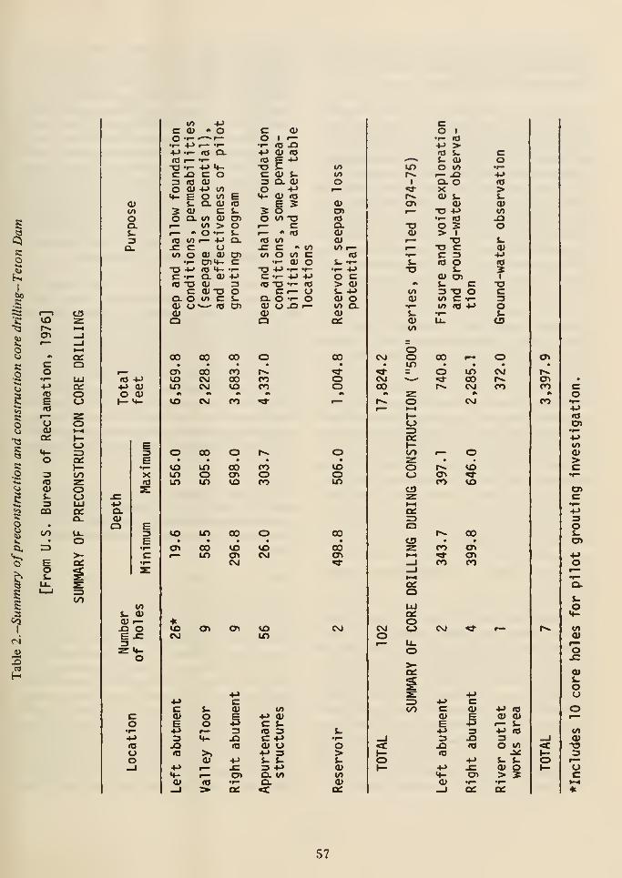
s
a
o
c.o
to
Co
caco
toKO
CI,
S<^
0)
oQ.&.=3a.
co•I—+->
toE<0
u
3
CO
to
o
CJ
a:o
oo+-) cuO 0)(- «*-
oa:
>-
</>
Q.(UO
OJ —^ o3o
uo
c <u •> o
<o •—T3 •-c n3 ITS
O OJ*^ E
s-
5 s;O Q.
n 10^ cin o
C -1-
CQ. O0) Uo
rT3
•r—4J <-C O(U4J toO l/l
Q. (Uc .
10 <U CT>W > Oo •- s-f— !-> Ol
<J0) <1> OlC7m- Cre <4- -^Q. <U +J
(U "O oto c s-
ro CT
(U <oE •->
0) s.Q. (U
+J<u <aE Soto "o
00 00 00
CT» 00 roto CM 00IT) CVJ to
co
<o-oc:3o
oI— • (O(O to.C C "intn O t/) c
•r- (U O•T3 +J •!- •>-
C •!-+-> +J<0 T3 '^^ *0C I— tJ
Q. O •!- O<u o ^ >—
o
00CO
too
<uC7>lOQ.0)<uto »—
«oJ- -r-•I- 4Jo c> <us- •<->
(U oto o.(Ua:
00
ooto cvj
CO
to min o\n in
to in
a\ 00i— m
toCVJ
o^
CO
00
to
00
to
CVJ
o>
COoCO
toCVJ
to
tooto
00
00at
csj
•u
studies were aimed mainly at determining the
relationship between these geologic conditions
and the failure of the dam.
If a dam were located on or in the immediate
vicinity of an active fault, its safety would be
jeopardized for two reasons. The first is the
shaking that could result from an earthquake
originating on the fault, and the second is the
actual physical displacement of the foundation
and the dam due to the fault movement. Thesubject of faulting is addressed in Chapter 2,
General Project Description and, in detail, in
Appendix B. Some inferred northwest-trending
faults have been mapped 3 to 4 milesnorth-northeast of the damsite. If these faults
exist, they may be part of a collapse structure
along the margin of a caldera. A well-defined
lineament was observed on aerial photos to
parallel the Teton River about 500 to 800 feet
west of the right abutment. This lineament was
tentatively considered by the U.S. Geological
Survey to be an extension of an inferred
northeast-trending fault. Reexamination of
available data led to relocating this inferred fault
to a position as much as 3 miles northwest of the
lineament observed on the aerial photos.
Well-defined, northwest-trending faults have
been observed within 1 1 miles southwest of the
dam and to within 8 miles east of the dam.Well-defined, northeast-trending faults have
been mapped no closer than 7 miles northeast of
the dam and 10 miles south of the dam.
No active faults were identified at or near the
dam.
Professor Curry hypothesized that the sediments
underlying the welded tuff at the damconsolidated under the weight of the dam and
reservoir. Because the thickness of these
sediments varies, the amount of settlement due
to consolidation would vary from point to point.
This differential settlement could have opened
cracks in the right abutment and in the grout
curtain. Seepage through these cracks could
have led to piping. The geologic history of the
damsite area provides an insight into the
likelihood of occurrence of these events.
After deposition of the welded tuff and before
the canyon of Teton River was eroded into the
tuff, the weight of these volcanic rocks on the
underlying sediments was considerably greater
than the more recently applied load of the damand reservoir. The underlying sediments were
consolidated under this heavy load of rock over
a period of hundreds of thousands of years. Suchpreconsolidated materials will not further
consolidate any signiHcant amount unless the
original load is exceeded. Thus, there is little
likelihood that the sediments consolidated under
the weight of the dam and reservoir. This subject
is treated further in Chapter 6, under Analysis
of Postfailure Embankment Remnants.
The permeability of the rock mass comprising
the right abutment is considered to be the mostimportant geologic condition associated with the
failure of Teton Dam. As a consequence,extensive postfailure investigations of rock mass
permeability and associated subjects wereperformed. These investigations included:
(1) postfailure geologic mapping of the right
abutment, (2) evaluation of the information
obtained from postfailure core borings,
(3) evaluation of groundwater observations madeon the right abutment, and (4) study of the cause
of rock jointing in the welded tuff.
The geologic mapping of the right abutment rock
surface was performed to locate and describe all
visible geologic features (joints, foliation, breccia
zones, etc.) that could have been involved in the
failure.
With the key trench and adjacent areas cleaned,
the entire abutment was photographed, using
oblique views. Enlargements of thesephotographs were used as a base on whichpostfailure geologic mapping of the abutmentwas performed. Also, a strip map of the bottomof the key trench was prepared. This map differs
from the abutment maps in that features were
projected into a horizontal plane. The strip mapaccurately portrays feature locations in plan
view; the abutment maps do not. All mappedjoints (fractures) were assigned identifying
numbers and located on the photo overlays. Atabulation was made describing, for each joint,
the attitude, width of opening, extent of filling.
58
nature of the filling, and other properties.
Geologic sections were prepared along the
upstream and downstream lines of grout holes
and' 150 feet upstream and 100 feet downstream
of the centerline of the dam.
The rock core drilling and water pressure testing
were performed to check the effectiveness of the
grout curtain and to determine the physical
characteristics of the sediments underlying the
welded tuff. The first area investigated was the
spillway channel upstream of the ogee, where
both blanket and curtain grouting under the
structure had been performed and where the key
trench was omitted. Eleven holes were drilled
and water pressure tests were performed in each.
The second area of the right abutment that was
investigated was beneath the embankment north
of the spillway structure. Large open fissures had
been encountered during construction in this
area, and remedial work had included placing of
concrete, as well as establishing a deep grout
curtain. Three holes were drilled and pressure
tested to a depth of several hundred feet. One
of these holes, drill hole 651B, was extended
vertically to a depth of 890 feet to develop
information about the underlying sediments.
Initially, drill hole 651, an NX diamond drill
hole, went to a depth of 622 feet; at this depth
it was decided that a large-size hole would better
develop information on the strata. Due to
drilling difficulties in drill hole 651A, it was
replaced by drill hole 651B, which was rock
bitted to 622 feet and core drilled to the final
depth.
The third area of the right abutment that was
investigated by core drilling and water pressure
testing was the key trench riverward of the
spillway structure. In all, 24 holes werecompleted in this area to check the adequacy of
the grout curtain.
The locations of all borings, all postfailure boring
logs that have been prepared, and the results of
the water pressure testing are included in
Appendix C-5 of the Grouting Task GroupReport. The rock cores from all borings have
been photographed for record purposes. In
addition, five holes have been photographed in
color, using a borehole camera developed by the
Corps of Engineers. Ten additional holes have
been left open to permit borehole photography
in the spring of 1977.
The principal data concerning hydrologic
conditions in the right abutment lie in the
observations of water levels in drill holes that
were monitored for this purpose. The Geology
Task Group analyzed the water level
measurements made in right abutment drill holes
5, 6, 504, 501, and 506(2). The locations of these
holes are shown on Figure 29. Analyses were
performed on variations of water levels with
time, variation of rates of water level change
with time, and variation of differences in water
level between selected locations with time.
The permeability of the right abutmentfoundation rock (welded tuff) is almost wholly
controlled by spacing, openness, and continuity
of fractures. The preconstruction foundation
core drilling and water testing indicated high
fracture permeabilities near the surface, which
decreased somewhat with depth. Thepreconstruction pilot grouting program showed
that the near-surface rock in the abutment was
so permeable that curtain grouting could not be
effectively accomplished. This condition resulted
in a decision to use the 70-foot-deep key trenches
in the abutments.
An attempt was made to analyze behavior of the
groundwater in the area of the right abutment
during the filling of the reservoir. This analysis
was made difficult by the low number of
groundwater observation wells, the absence of
wells in locations critical to the analysis, and the
lack of frequent readings. However, the analyses
that were performed tend to confirm the
permeability of the welded tuff. The rates at
which the water levels in the observation wells
followed the rise of reservoir water varied over
the filling period. This may be interpreted to
mean that zones of relatively higher permeability
were being encountered by the rising water.
Figure 30 shows the relative positions of the
water levels in the observation wells and in the
reservoir with time.
59
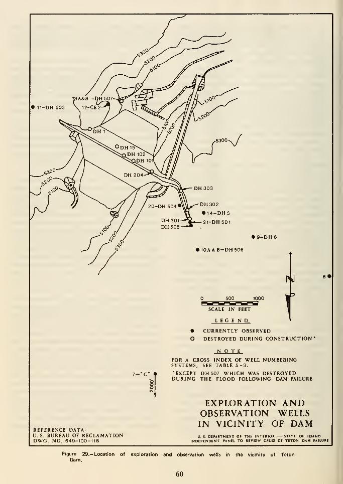
DH302
• 14-DH5
21-DH 501
9-DH6
10A&B-DH506
REFERENCE DATA:U. S. BUREAU OF RECLAMATIONDWG. NO. 549-100-116
500 100
SCALE IN FEET
LEGE N D
• CURRENTLY OBSERVED
O DESTROYED DURING CONSTRUCTION'
NOTEFOR A CROSS INDEX OF WELL NUMBERINGSYSTEMS. SEE TABLE 5-3
•EXCEPT DH507 WHICH WAS DESTROYEDDURING THE FLOOD FOLLOWING DAM FAILURE.
EXPLORATION ANDOBSERVATION WELLSIN VICINITY OF DAMV. S DEPARTMENT OF THE INTEKIOIt STATE OF IDAHO
INDEPENDENT PANEL TO REVIEW CAUSE OF TETON DAM FAILURE
Figure 29.— Location of exploration and observation wells in the vicinity of TetonDam.
60
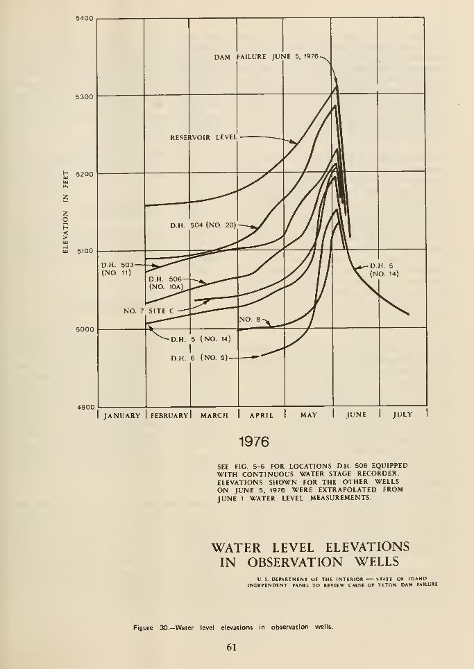
5400
5300
t 5200
zop
wu! 5100
5000
4900JANUARY FEBRUARY MARCH
1976
SEE FIG 5-6 FOR LOCATIONS D.H. 506 EQUIPPEDWITH CONTINUOUS WATER STAGE RECORDER.ELEVATIONS SHOWN FOR THE OTHER WELLSON JUNE 5, 1976 WERE EXTRAPOLATED FROMJUNE 1 WATER LEVEL MEASUREMENTS.
WATER LEVEL ELEVATIONSIN OBSERVATION WELLS
U S DEPARTMENT OF THE INTERIOR iTATE OF IDAHOINDEPENDENT PANEL TO REVIEW CAUSE OF TETON DAM FAILURE
Figure 30.-Water level elevations In observation wells.
61
Contours of the groundwater surface at various
times were drawn from water levels in three
observation wells, drill holes 5, 6, and 506. Asequence of selected contour maps, covering the
period of time from reservoir filling to just after
failure is presented on Figure 3 1 . These contours
indicate apparently normal behavior of reservoir
water flowing through permeable abutmentrocks along and around a less permeable curtain
of grouted rock.
The postfailure geologic mapping confirmed the
presence of open fractures in the welded tuff,
along which considerable quantities of water
could have flowed. Some high-angle open joints
were traced for distances up to 280 feet.
Upstream from the key trench the contact
between the middle and lower units of the welded
tuff was characterized by an open brecciated
zone. Many throughgoing low-angle joints, or
zones of joints were recorded, paralleling the
foliation. A coincidence of major, throughgoing
joints occurs along the key trench between grout
cap centerline Stas. 13 + 00 and 14 + 00, the
interval that includes the whirlpool that
developed in the reservoir about an hour before
the dam was breached.
Although the main purpose of the postfailure
core drilling program was to check the adequacy
of the grout curtain, much valuable information
was obtained on the condition of the abutmentrock. The locations of these borings are shownon Figure 32. The boring logs and water pressure
data are contained in Appendix C. Thepostfailure drilling indicated zones of high
permeability in the vicinity of Sta. 13 + 50, even
though curtain grouting had been performed.
However, it is not known if this permeable zone
occurred as a result of loosening of jointed rock
during the failure. One of the postfailure borings
in the vicinity of Stas. 3 + 00 to 5 + 00 (drill hole
650) was oriented so that it penetrated rock
outside from the grout curtain. Water pressure
tests in this boring confirmed the highpermeabilities observed during thepreconstruction investigations.
As stated in Chapter 2, General ProjectDescription, the foliation and associated
low-angle joints in the welded tuff appear to be
the result of accumulation, compaction, andwelding of the ash-flow deposits. The high-angle
joints probably resulted from tensional stresses
caused by cooling of the rock after it solidified.
The high-angle joints appear to have openedfurther after the rock mass cooled, thusincreasing its permeability. Three mainpossibilities have been advanced for this further
opening of high-angle joints:
• horizontal tectonic extension
• gravitational creep toward the present
canyon
• relief of horizontal stresses
Of these possibilities, horizontal tectonic
extension appears to be the most likely. The logic
supporting this conclusion is presented in
Appendix B-1.
Foundation Treatment
Condition of Foundation.-During the
investigation of the damsite and thedevelopment of the design, considerable
evidence was compiled which demonstrated that
the dam was to be placed on a foundation of
highly fractured and permeable rock.Groundwater studies generally showed the water
table to be at or below river elevation; return
water was uncommon during exploratory
drilling; water tests during exploratory drilling
showed high permeabilities, and rock outcrops
in the side walls of the canyon containedwell-developed patterns of numerous openjoints.
Curtain Grouting.—A pilot grouting program
was instituted in 1969 to determine the
groutability of the basalt in the canyon floor, the
alluvial material below the basalt, and the
welded tuff in the abutments. Bids were let for
the injection of an estimated 260,000 cubic feet
of grout in the testing program. More than twice
that amount was pumped during the course of
the pilot grouting program.
62

Sept. 24, 1975 Jan. 7, 1976
DM4 Q
May 13,1976 May 25, 1976
Figure 31 .—Contours on groundwater surface adjacent to Teton Dam. (Sheet 1 of 2)
63
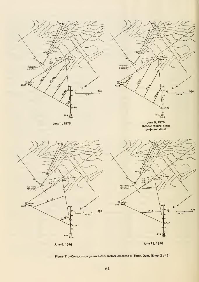
June 5, 1976
(before failure, from
projected data)
June 9, 1976 June 13, 1976
Figure 31 .—Contours on groundwater surface adjacent to Teton Dann. (Sheet 2 of 2)
64

Figure 32.— Locations of postfailure core borings
(sheet 1 of 21.
65

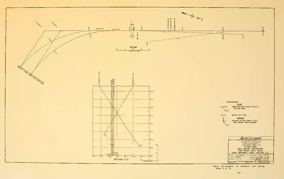
Figure 32.— Locations of posttaiiure core borings
(sheet 2 of 2).
67


High grout takes were common in the abutment
holes. The combined takes of just two of the pilot
holes were almost 16,000 sacks of cement and
18,000 cubic feet of sand. Several holes could not
be grouted to refusal at depths of less than
70 feet. Grout travel greater than 300 feet was
observed. In the canyon floor, the basalt was so
fractured that drilling of angled holes was
difficult, but the basalt was found to be easily
grouted. The alluvial material under the basalt
was found to be groutable using three lines of
holes, with the two outer lines grouted first.
In 1970, 10 exploratory holes were drilled to
observe the condition of areas grouted during the
pilot grouting tests. The results of the pilot
grouting and subsequent exploration showed
that in the abutments above El. 5100, the upper
70 feet of tuff was so permeable that a
satisfactory grout curtain could not be
economically constructed. As a consequence, a
decision was made to excavate a 70-foot-deep
key trench into each abutment above El. 5100.
Blanket grouting was called for to locally replace
the key trench under the spillway. A grout
curtain would then be constructed with three
rows of holes to a depth of 260 feet below the
bottom of the key trench. Below El. 5100, where
the rock was tighter, a single-line grout curtain
was called for, except through the basalt and
lower alluvium in the left half of the canyon
floor. Here, three rows of holes were again used.
The details of the curtain grouting program are
shown on Figure 11. Where a three-line curtain
was used, the upstream and downstream lines
were not grouted to closure, but were considered
complete with holes grouted on 20-foot centers.
The outer two rows were grouted first to act as
backups for the center row. The center row was
then grouted to refusal, using required split
spacings occasionally closer than 5 feet. Thereason for this technique was to limit grout travel
and to concentrate refusal grouting to within the
confines of the upstream and downstream rows.
In reviewing the records for grout takes, it
appears that this method of construction for a
three-row grout curtain served the intended
purpose of limiting grout travel.
With the upstream and downstream rowscontaining holes on 20-foot centers, the
three-line grout curtain below the key trench at
Teton Dam should be considered to function as
a single-line curtain. It has been the practice of
other Government agencies to install multi-line
curtains in permeable rock. This lessens the
possibility of windows in the grout curtain. Moreimportantly, closing all lines increases the
effective width of the grout curtain anddecreases the hydraulic gradient across the
curtain, thus decreasing the possibility of erosion
and/or leaching of the grout over long periods
of time.
In the areas where one row of holes was used, the
rock was thought to be tight enough that
excessive grout travel would not occur from
closure grouting with one row of holes. The grout
records generally substantiated this approach.
For the entire length of the grout curtain, the
single row and center row holes were drilled
through a concrete grout cap. The grout cap was
installed in a 3-foot-wide by 4-foot-deep trench
excavated in the rock foundation.
Where three rows of grout holes were used,
CaCl2 (calcium chloride) was added to the grout
mix used in the upstream and downstream rows
for two purposes: (1) to quicken the set time of
the grout mix and inhibit long distance grout
travel, and (2) to raise the temperature of the
grout mix in cold weather. The CaCl2 was not
used in single-row grouting or in the center row
of the three-line curtains. Between Stas. 1 1 + 50
and 16+ 00, including the area where the failure
occurred, grouting was done during the summer
months and CaCl2 was not used in significant
amounts. Elsewhere, the two outer rows of holes
were injected with grout mixes containing up to
8 percent CaCl2 (by weight of cement). Theindustry normally specifies 2 to 3 percent CaCl2
as the maximum amount that can be used.
Whether or not the use of CaCl2 in excess of 2
to 3 percent CaCl2 would cause adverse effects
is unknown. The use of CaCl2 in smaller amounts
is common for hastening set time, but its use for
controlling grout temperature is unknown to the
other Government agencies involved in this
investigation. The Bureau is currently
69
conducting tests at the request of the IRG to
determine if the use of CaClg in unprecedented
amounts could have affected the integrity of the
grout curtain over either the short or long term.
After removal of the embankment remnant from
the right abutment key trench, the condition of
the grout cap was observed. The cap had been
badly battered and partially removed in the area
of the failure, but it appeared tight and well
constructed where it had been exhumed in the
key trench.
A number of postfailure core holes was drilled for
water testing within the center line of the grout
curtain. Figure 33 shows the arrays of holes
drilled between Stas. 12 + 50 and 14 + 25. Onthis figure, postfailure grout curtainpermeabilities are indicated by water takes in the
core holes. Construction grout takes during
construction for the center row of grout holes are
also shown on the figure. To evaluate grout
curtain permeability, the Grouting Task Groupidentified water takes ranging from 0.1 gpm/ft
to 0.5 gpm/ft as being marginally significant and
takes greater than 0.5 gpm/ft as significant. As
shown on the figure, several significant takes
were recorded near the top of rock.
In addition to the core drilling, 19 joint
transmissibility tests were conducted in the
bottom of the key trench in the area of the
failure between Stas. 12 + 93 and 13 + 50. Water
was ponded over exposed joints which ranged
from 1.2 to 8.0 feet in length, with maximumponded water depths of from 0.4 to 1.0 foot.
Water losses ranged from to 1.1 gpm. Water
communication to the surface occurred within a
few minutes along fissures outside the ponded
areas. These tests should be consideredqualitative.
Postfailure testing indicates a shallow zone of
moderate permeability in the vicinity of the
failure between Stas. 13 + 00 and 14+ 00. It is
likely that this zone was disturbed during the
failure and that observed permeabilities were
greater that those which existed before the
failure. The IRG considers the seepage quantities
observed after the failure to be within tolerable
limits and that they should be considered normalfor a grout curtain in a permeable rock mass.
Treatment of Rock Foundation Surfacesunder Zone 1 MateriaL-DttaxXeA analyses of
foundation preparation under the zone 1
embankment area are presented in Appendixes
C and D. Appendix D also discusses foundation
preparation under the remaining zones. Because
foundation preparation was generally adequate
outside the area where zone 1 contacted the
foundation, only those portions of thefoundation associated with zone 1 are discussed
here. The entire question of foundationpreparation ties closely with the design concepts
and assumptions discussed later in Chapter 7,
Adequacy of Design and Construction.
No formal written procedures detailing the
surface treatment were developed within either
the Bureau's design or field constructionorganizations. Information concerning surface
treatment has been obtained from field records
and from task group interviews with design and
construction personnel.
Concerns for the protection of pipable zone 1 fill
material placed on a highly fractured foundation
were expressed by the principal designer in a
collection of design notes and draft material
dated from March 1967 to January 16, 1970.
These concerns were not, however, expressed in
the document, "Design Considerations for Teton
Dam, October 1971." This document, which was
prepared by design personnel to familiarize field
construction personnel with important design
considerations and to further describe the
construction specifications, does not address
itself to the details of a surface treatmentprogram outside the area of the bottom of the
cutoff and key trenches. In fact, the statement
"Erosive seepage under the embankment will be
eliminated by injecting the foundation with a
grout mix" seems to imply that the "tight grout
curtain" was the major defense relied upon by
Design to assure that piping was under control.
No provision was made in the contractspecifications for general surface treatment of
open joints except for blanket grouting which
was to be used on "an individual or small area
70
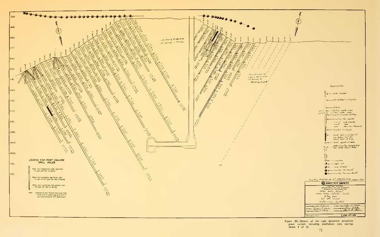
-•a » ^ 99 9 9 9 9 **'» *f ^3L *i >«*»•»
LEGEND FOR POST FAILUREDRILL HOLES
mtv mt-ltnignltlconl fot* (*u tfiott
01 gpm ptr tool of bating
Wuttf tnt-marglnalir lignlficanl (ot«1 gpm to 5 gpm pm tool of beting
Nol§: Leeotlon at pott fallun halt* vary frometnl§rlln» of grovt cap up to /J.5 ft
upttmm'ond up to II ft downslrtam
\%
?V^ — *,rf ry^^ C^^*- >ft4^*
o5
Cr«./'*/ >'"r'''
IMiiMvs mintt SAfCTV
of^amrMeir or rue inremiommwctnj or mecL»t»*Tioit
r.o.oii^.AA^
Sf9-/¥^/fi'
Figure 33.-Details of the right abutment centerline
grout curtain including postfailure core borings
{sheet 1 of 3).
71

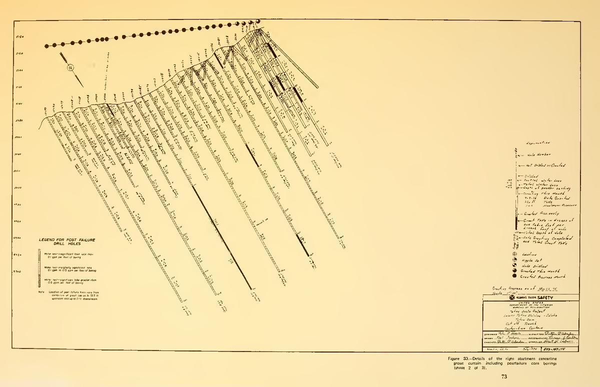
LeOEND FOR POST FAILUREDRILL HOLES
t»tof«f mr-.nsigniricanf lokt itu "ton
1 gpm 0*' tool of boring
Nol» Locallon of peal tollure holai tory fromctnlerline e* groul cap up la I3S It
upiliaam and up to II li doanlraam
- OrUlat/
_ r-,fMi ^»/., ^,„ifJ^Jaf '.' o £ pmalit,' sa ^4-*/^
f-1-73 O.fc C^.^Jwico el Tii^c
: Odff
-^
""' r-.i,i ^^/ ^^^
^ nujwvs rmtiic SAf€TV
Ltcuar Ti^oM Ofatt/ojn -J'a/t^a
_^(^jl -Itft^i'.'j »
f-.rf '. X^. . j»/3 ">vI ^o-/yr-/>»"
Figure 33.— Details of the right abutment centerline
grout curtain including postfailure core borings
(sheet 2 of 31.
73

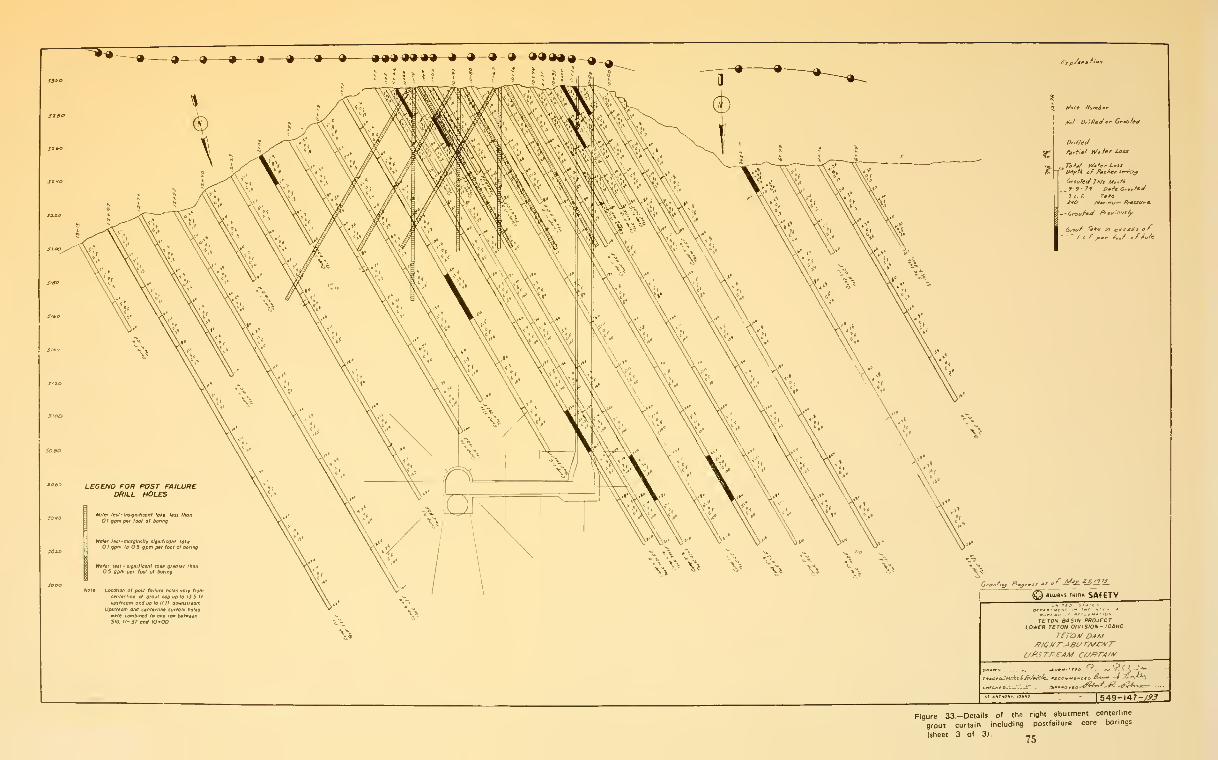
LEGEND FOR POST FAILUREDRILL HOLES
/fo^ Dr'.Het^o'' Grouted
Dr.//ed
Crouted nit Mo^tl-
_ 9-9- ?y Dm^c G'»v^<J3 c.f. TaAe.
Qrouf' Take i/t i^jteess o*
.*^, /„/ a/^o/e
No\t Location of post toilurt hoiti roty from
; al grout cop up to 13 5 ft
and up 10 II fr aotmslreomUpsiteam ami ctnttrhne cuitaln holtf
mere combirtea to one row betretnSto II-S7 ana l0*0O
\*
TETON BASIN PROJECTLOWER TETON DIVISION- IDAHO
VETO A/ DAM
.ecntO.\^7.S: -*'«
,.„„ &. 1 Av^ -
l549-l47-/<'.7
Figure 33.-Details of the right abutment centerline
grout curtain including postfailure core borings
(sheet 3 of 3). _^

basis." It was the feeling of the designers that
surface grouting should be treated as a field
problem to be negotiated with the contractor.
In late 1973 and early 1974, design, geology, and
construction liaison personnel visited the site, at
the Project Construction Engineer's request, to
look at the cutoff and key trench excavations
prior to placement of fill. The trip reports, which
are presented in Appendix G, are not directed
toward the full scope of a surface treatment
program. Interviews with Messrs. Bock, Harber,
Aberle, and Gebhart (see Appendix C) indicate
that during these site visits surface treatment
was discussed. After deciding jointly at that time
that surface treatment would be done by
"bucket grouting," field construction personnel
developed a surface treatment procedure,
apparently without further detailed design and
geological assistance. At one time, a
memorandum was prepared by the principal
designer stating that consideration was being
given to a surface treatment program using
shotcrete. However, after telephoneconversations with the Teton ProjectConstruction Engineer, it was felt that the
studies necessary for the development of a
shotcrete program were premature at that time.
These communications are apparently the last
time shotcreting was considered for surface
treatment.
Field construction personnel developed surface
treatment procedures to allay their concerns for
compaction of zone 1 embankment material over
large open joints. The embankment and surface
grouting inspectors would designate whichcracks were to be filled. The cracks were then
filled by surface grouting using a 0.7:1 neat
cement grout or a sand-cement grout, depending
upon the size of the opening. The surface
treatment was performed in a narrow cleaned-up
strip of rock just ahead of the advancing fill.
Because of the stiff grout mixes used, andbecause the concerns of construction personnel
were generally for compaction control and not
the percolation of water next to the pipable zone
I material, joints and cracks less than 1/4 to
1/2 inch in width were ignored. In the right
abutment, surface grouting was performed under
zone 1 material from El. 5075 to 5205.
Figure 34 shows the location of features which
were surface-grouted and the amount of grout
poured into each. This information is
superimposed on the geologic map of the
abutment drawn during construction. The total
surface treatment operation on both abutments
used somewhat over 1,800 cubic yards of poured
grout, 1,325 cubic yards of which were used in
the right abutment.
It was also the intent of design personnel that
surface grouting be done in the side walls of the
key trench. The field construction inspectors
have indicated that very little surface gro^lting
was done in the side walls of the key trench.
However, inspection of Figure 34 shows that
there was some surface grouting in the side walls.
Postfailure inspection of the key trench revealed
a number of ungrouted joints and cracks, some
open as much as 6 inches. Most of the area
outside the key trench, where surface treatment
was done on the right abutment, was affected by
the failure. In situ rock up to 70 feet in depth
was stripped by the flood. As a result, postfailure
observations of as-built conditions were not
possible.
Surface grouting stopped at El. 5205. Neither
the designers nor the liaison engineer were aware
of the decision to stop surface grouting until
after the failure of Teton Dam. According to
field personnel, the field geologists also played no
part in the decision to stop surface grouting.
Conflicting reports as to the openness of the rock
surface above EI. 5205 have been presented to
the IRG. According to the field engineer, above
El. 5205 the rock was more slabby. While there
were no large fissures riverward of the spillway,
there were "hundreds" of 1/4- to 1/2-inch-wide
fissures which were left "untreated." One of the
shift supervisors stated that there did not appear
to be a change in the fracturing characteristics
above El. 5205, and that above that elevation no
attempt was made to remove native soil from
cracks to replace it with zone 1 material. He also
said the native crack filling material appeared
moist and was probably a silt of low plasticity
similar to zone 1 material.
77

Analysis of Postfailure
Embankment Remnants
The portion of the embankment of primeinterest was destroyed by the failure of the dam.
The remaining embankment remnants outside
the breach area were investigated after the
failure because they were representative of the
failure area.
Investigation of Right Abutment/?em/uint.—Exploratory work was performed to
determine the physical characteristics of the
remnant embankment and to allow examination
of the embankment and rock surfaces for
evidence of unusual conditions. This work was
done under the direction of representatives of
the Independent Panel. Pertinent descriptions
of the conditions encountered, along with
illustrations, are extracted from theIndependent Panel Report and are included as
Appendix H. The IRG and/or task groupmembers observed conditions at several stages
of the work.
The embankment remnant was carefully
removed, using hand excavaton, supplemented
by small mechanical equipment. As removal
took place, notes, supplemented byphotographs, were made of the embankmentconditions, such as fracturing, unusual moisture
conditions, and contact of the core and filters
with bedrock. Undisturbed cube samples of the
core material were taken for laboratory testing.
Numerous in-place density tests were made, as
were tests for in situ moisture. When all
embankment material had been removed, the
entire key trench was washed clean with water.
Areas on the lower slope adjacent to andunderneath the key trench that had been deeply
eroded during failure were also washed clean.
Laboratory tests on samples from the right
abutment embankment remnant were made to
confirm material properties used in the design,
to determine variability of as-constructed
physical properties, and to determinestress-deformation properties for in situ stress
analyses. Ninety-two undisturbed, hand-cut
9-inch cube samples, and 47 Shelby tube drive
samples, 3 inches in diameter by 36 inches long,
together with 10-pound bag samples wereobtained at locations shown on Figure 35.
Selected block samples were sent to various
laboratories for testing.
The dispersive characteristics of zone 1 material
were investigated by pinhole dispersion tests at
the U.S. Army Engineer Waterways Experiment
Station. The erodibility characteristics wereinvestigated by flume tests and rotating cylinder
tests at the University of California at Davis.
The stress-strain properties of the zone 1
material were investigated by drained triaxial
compression tests at both placement andsaturated moisture contents by NorthernTesting Laboratories, Billings, Montana, and bythe Bureau of Reclamation laboratories in
Denver. The results are summarized in Table 3.
Unconfined compression tests at varyingmoisture contents were also made by the Bureau
of Reclamation.
Special horizontal permeability tests were madeby the University of California at Berkeley.
Gradation analysis and Atterberg limit
determinations were made on all samples by the
Teton Project Laboratory, including those
samples shipped to the other laboratories for
testing. These results are summarized in Table
4.
The excavation and examination of zone 1
material on the right abutment showed nothing
that could definitely be interpreted as a clue to
the failure. In general, the fill in the key trench
appeared to be well constructed.
At El. 5265, near-vertical cracks roughlyparalleling the breach face were encountered in
the fill approximately 12 feet from the breach
face. The cracks were as much as 2 inches wide
and some were filled with water-borne sediment.
A crack and sheared zone adjacent to the breach
face extended to the bottom of the key trench
as the excavation progressed. It was concluded
that this disturbance was the result of postfailure
movement; however, it did demonstrate the
cracking potential of the fill.
78
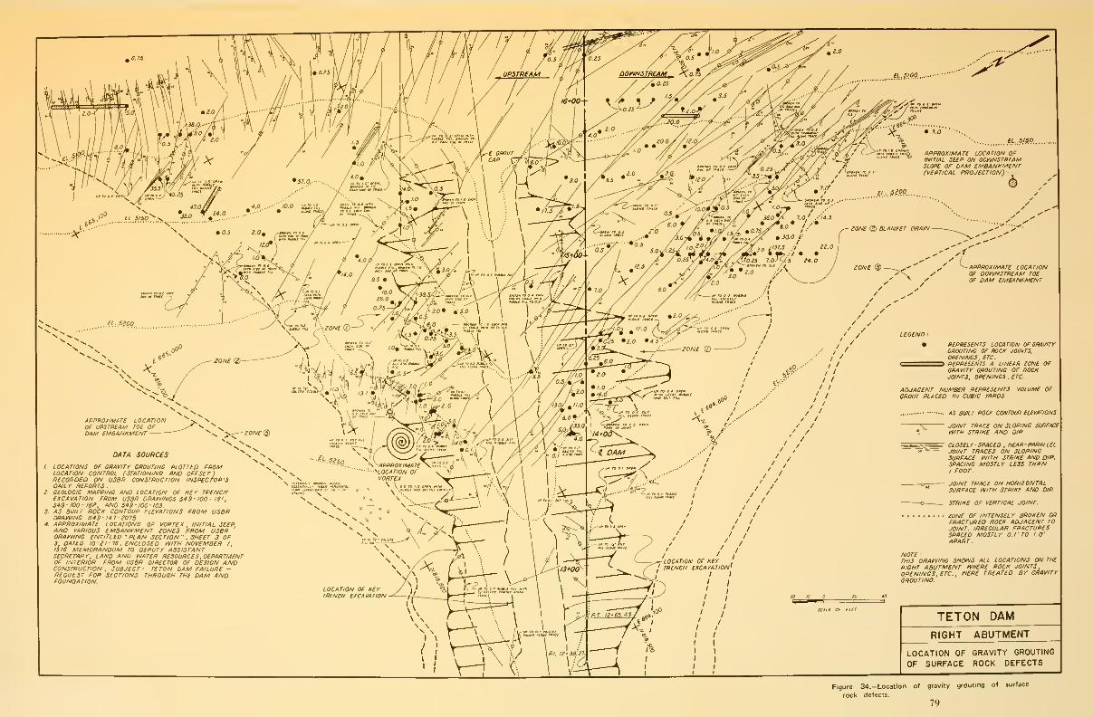
APPROXIMATe LOCATIONOF UPSTREAM T0£ OFDAM EMBANKMENT
DATA sounces
1. LOCATIONS OF OUAVITT BMUTINO PLOTTED FROMLOCATION CONTROL (STATIONINO AND OFFSET)RECOFiOED ON U3BR CONSTRUCTION INSPECTOR'SDAIL Y REPORTS .
2. OEOLOeiC MAPPING AND LOCATION OF KEY TRENCHEXCAVATION FROM USdR ORAIVINOS 54$- 100- LSI
,
54S-l00-ISe, AND 549 -mo- 163.
3. AS BUILT ROCK CONTOUR ELEVATIONS FROM US8RORAniNC 549-I4T-107S
4. APPROXIMATE LOCATIONS OF VORTEX, INITIAL SEEPAND VARIOUS EMBANKMENT iONE3 FROM U3BRDRAniNG ENTITLED 'PLAN SECTION" , SHEET 3 OF3, DATED 10-21-16, ENCLOSED rVITH NOVEMBER I,
1376 MEMORANDUM TO DEPUTY ASSISTANTSECRETARY, LAND AND IVATER RESOURCES, DEPARTMENTOF INTERIOR FROM USBR DIRECTOR OF DESIGN ANDCONSTRUCTION , SUBJECT TETON DAM FAILURE -REQUEST FOR SECTIONS THROUGH THE DAM ANDFOUNDATION.
LOCATION OF GRAVITY GROUTING
OF SURFACE ROCK DEFECTS
Figure 34.-Location of gravity grouting of surface
rock defects.
79

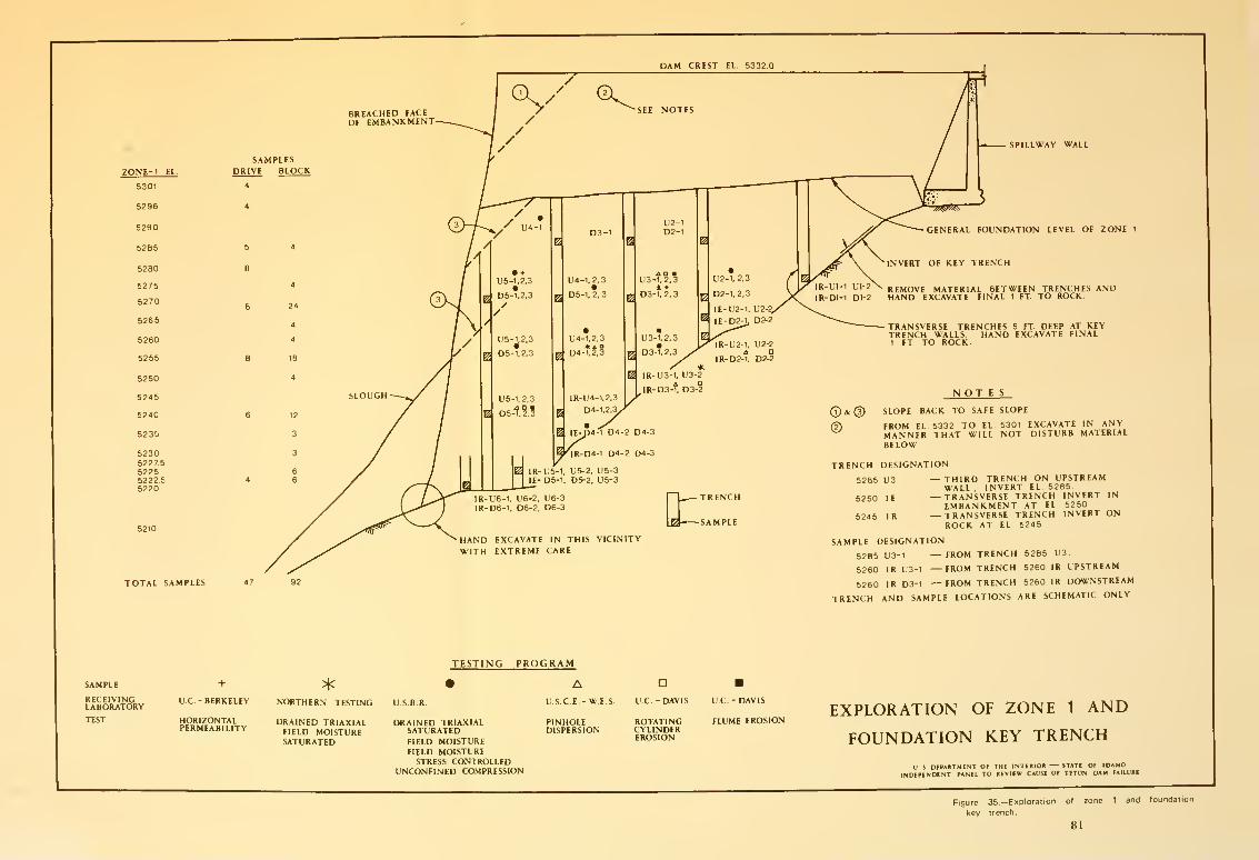
DAM CREST EL 5332
REMOVE MATERIAL BETWEEN TRENCHES ANDDl-1 DI-2 HAND EXCAVATE FINAL 1 FT TO ROCK
TOTAL SAMPLES

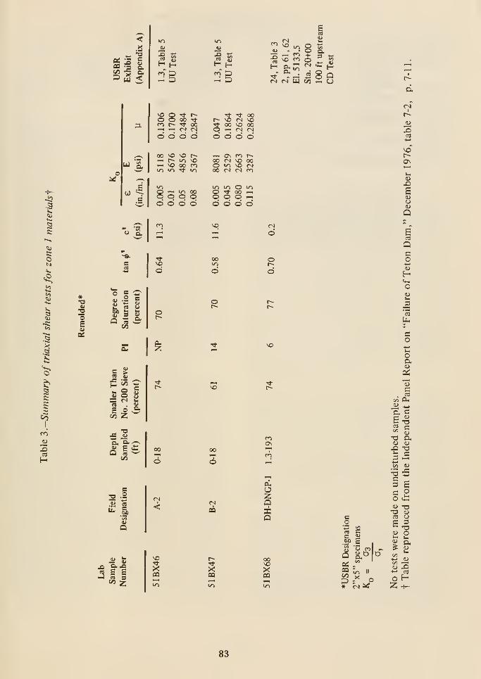
.a
is«
^ a,
3 [5 <05 5u
u'/^ g tS
-2 \o <^ o !?
^ §:^ ^^ ^^' "i: - 2 8 QOl tN W 00 —. U
a.
<N
U
OJ
o

Table A.-Summary of classification test data, samples from remnantof key-trench fill right abutment^
Zone 1 compaction at the contact withfoundation rock surfaces was generallyequivalent to that within the body of the fill.
Joints and fractures in the key trench walls were
numerous, with openings up to 6 inches wide.
There was little evidence of surface grouting in
joints exposed in the key trench walls.
The laboratory tests, in addition to providing
input parameters for the finite element analysis,
confirmed the highly erodible nature of the zone
1 material and its brittle characteristics whencompacted dry of optimum moisture content.
Investigation of Left Abutment andEmbankment Remnant.-There is muchsimilarity between conditions on the right and
left abutments. Each had a key trench having
the same configuration and dimension, andembankment zoning was identical. The bedrock
on the left abutment is reported to be somewhatless jointed and fractured than on the right
abutment. Thus, conditions in the left abutment
can be considered nearly the same as those in the
right abutment. After failure of the dam, it was
noted that a number of transverse cracks were
present in the crest of the remaining left
embankment. These cracks were mapped.Limited investigations have been made andextensive future examination is planned.
Because of the similarity of the two abutments,
in situ stress measurements were considered
desirable to evaluate the role of cracking and/or
hydraulic fracturing in the zone 1 material
during failure. An attempt was made to makedirect measurements of the in situ state of stress
by using an experimental self-boring pressure
meter, PAFSOR, being evaluated by the
California Department of Transportation under
a contract with the Federal HighwayAdministration. The PAFSOR (Pressiometre
Auto Foreur Sols Sous on Raide) is a Frenchdevice designed to be used in medium stiff to stiff
soils. The technique of self-boring consists of
inserting a thin-walled metallic cylinder with an
expandable membrane into the ground with
minimal disturbance of the soil surrounding the
hole. The investigation at the site was conducted
by the California Department of Transportation
under arrangements with the Bureau of
Reclamation. The results were furnished in a
report to the Bureau, dated January 21, 1977,
titled "In Situ Stress Measurement at TetonDam, Idaho, Using the French Probe PAFSOR."
The investigation was not successful in providing
meaningful data on in situ stresses at the
locations of interest. Equipment difficulties
limited the depth of probe penetration to 34 feet
below the crest of the dam. Tests were made at
24 and 34 feet, but the results at these shallow
depths are considered insignificant in evaluating
stress conditions near the base of theembankment.
At the request of the Independent Panel,
hydraulic fracturing tests were performed at
Stas. 26+ 00, 26+ 25, and 27 + 00 to determine
the hydraulic head that would cause fracturing
of zone 1 materials within the key trench. Eachtest consisted of drilling a large-diameter hole to
the depth to be tested, setting a small-diameter
casing at this depth and casting a concrete seal
around its base. Then, the test section was drilled
as a 3-inch hole through the casing below the
concrete seal. Testing consisted of applying
various heads of water and measuring the
seepage rate at each head. Before fracturing, the
seepage rates were approximately proportional
to applied head; after fracture, the rate of
seepage increased rapidly.
The details of the tests and the results are given
in Appendix I. Results were somewhat erratic,
partly because of installation difficulties. AtSta. 26+ 00, fracturing occurred during drilling
at a depth and head of 101.3 feet. AtSta. 26+ 25, the installation was unsuccessful
and a test was not made. A test run at
Sta. 27+ 00 did not indicate hydraulic fracturing
under an average head at 119 feet (to the top of
the hole).
Another test was run at Sta. 26+ 00. The results
indicated hydraulic fracture at a head ot
approximately 145 feet (see Appendix I).
Finite Element Analysis of theEmbankment.—The IRG felt it was necessary
to investigate in situ stress conditions in the
embankment. In the first IRG interim report
85
dated July 14, 1976, investigations wererequested to evaluate in situ stress conditions
with finite element analysis, to perform water
pressure testing in the remaining left
embankment, and to make in situ pressure
measurements in the left embankment. In
accordance with agreements to avoid duplication
of investigations being carried on by the
Independent Panel, the IRG deferred work on
the finite element analysis of the embankmentand water pressure tests in the left embankmentuntil results of the Independent Panel's
investigations were available. The results of the
Independent Panel finite element investigation
are included as Appendix D in its report. This
information is included herein as a portion of
Appendix I.
The finite element studies clearly show the
possibility of hydraulic fracturing in the key
trench. These studies cannot be considered
conclusive since the input data are subject to
considerable variation. Further, the results are
based on a two-dimensional analysis, while the
complex geometry of the abutment and key
trench suggests considerable influence by the
stress distribution along the dam axis.
Foundation Deformation
The hypothesis of failure advanced by Curry
involved differential settlement of the bedrock
foundation, with resultant cracking in the dam.
This hypothesis has been discussed previously in
the Geologic Studies portion of this chapter. Toobtain qualitative insight into the magnitude of
foundation deformations, a finite elementanalysis was made to model the effect of the load
of the dam and reservoir on the rock foundation.
These studies indicate a maximum settlement at
the base of the dam of about 1/4 foot, with a
uniformly distributed differential settlement
between the base and top of the abutmentsranging from 0.10 to 0.15 foot. No large local
differential settlements were found. Rebound on
the order of 0.1 foot is indicated for the
postfailure condition. These studies wereconsistent with earlier opinions that the
magnitude of settlement in the rock foundation
was well within that experienced by manyprojects, and that foundation deformation wasnot responsible for cracking within theembankment.
To further investigate the foundation movementhypothesis, a study was made of permanentmovement that might have taken place in the
dam area. This study constituted a resurvey of
all available points that could be compared with
known prefailure locations, both at the damsite
and in the immediate area. Excavation of the
right abutment remnant provided access to
bench marks set on the grout cap. Of six
readings, the maximum vertical movement was0.021 foot downward and the average was0.008 foot downward.
The investigation of area movement involved
remeasurement and releveling of monumentsadjacent to the dam, referencing them to anestablished bench mark several miles away. Bothtrilateration and leveling showed no systematic
movement. Within instrument accuracy, only
two monuments showed movement—oneattributable to construction disturbance and the
other attributable to local sliding of the reservoir
bank during rapid drawdown.
These studies of foundation movement indicate
nothing that can be interpreted as lending
credence to the theory that at-depth bedrock
behavior was instrumental in the failure.
Rate of Reservoir Filling
The impact of the rate of filling on the failure
cannot be analyzed. It is conceivable that a morerapid increase in load from the reservoir could
induce cracking in a core which might deform
without cracking under slower application of
stress. The difference in rate between 1 foot per
day and the maximum of 4.3 feet per day is not
believed to have affected Teton Dam.
86
«Chapter 7
Adequacy of Design and Construction
Design
Early in its investigation, the IRG noted some
design features that were judged to be pertinent
to the failure. An investigation was made to
determine the design concepts that led to those
design features. The Bureau of Reclamation was
provided with a list of questions relating to manyof the design features. The Independent Panel
also submitted questions concerning the design
of the project. Both sets of questions and the
responses are included in Appendix G. Other
information on some of the design considerations
is included in the task group findings appended
to this report. The IRG has also gained insight
into some of the design concepts fromdiscussions with Bureau of Reclamationpersonnel during the working sessions.
Design notes, developed early in the design
process, identify and report a variety of
potential design problems and possible design
alternatives. However, there are no records,
documents, or reports that show: (1) the logical
resolution of each of the identified design
problems, (2) why a particular design alternative
was considered satisfactory and selected in
preference to others, and (3) why an identified
design problem was subsequently judgedimportant or not important and omitted from,
or included for, further consideration.
Obviously, the plans and specifications issued for
construction received the concurrence of
technical, supervisory, and managementpersonnel. However, because of the lack of
documented rationale to bridge the gap between
early design notes and the final design, it is not
clear to what extent these personnel were
involved during the design process.
Most of the problems related to the failure can
be associated with basic design assumptions and
procedures. Design procedures will be the focus
of a forthcoming IRG investigation.
General Design of Embankment.-Design of
the embankment relied heavily on past Bureau
experience at other dams. At Teton Dam, the
development of new information to establish
design parameters for embankment materials
was minimal. For example, during the design
only two laboratory shear strength tests were
performed on zone 1 embankment material and
no permeability tests were performed on zone 2
material.
Even with this minimum amount of test
information, the IRG agrees that a safe dam was
designed from the point of view of its structural
stability. As discussed below, the problems that
led to the failure were not associated with the
structural stability of the dam.
The impervious core was constructed of a
wind-blown silt of fairly uniform grain size. Ofparamount importance was the protection of this
silt from piping and erosion. This protection had
to be provided to prevent migration of silt
particles as water percolated through it (piping)
and next to it (erosion). Safe dams have been
constructed using this material, and the basic
concepts for a defensive design were well within
the state-of-the-art during the design of Teton
Dam.
87
The protection of cohesionless, or nearly
cohesionless, core material is usually provided by
means of impermeable barriers and/or filters.
Rock surfaces are sealed by treating them with
concrete, blanket grouting, dental concrete,
surface grouting, etc. Filters allow free drainage
of seepage but prevent migration of the material
to be protected as water seeps through it.
Specific guidelines have been developed by the
industry for the design of filters based ontheoretical analyses, laboratory tests, andexperience.
At Teton Dam a defensive design for adequate
protection of zone 1 embankment material was
not provided. This is perhaps the single most
important finding of the IRG investigation.
The designers appear to have recognized from
the beginning that zone 1 must be protected
from erosive seepage through the permeable rock
foundation. However, except for the cutoff and
key trench bottoms, adequate sealing of rock
surfaces under zone 1 was not provided. The only
rock treatment specified was blanket grouting to
be used in the bottom of the cutoff and key
trenches and in small localized areas identified
during construction. The designer assumed that
specified compaction of zone 1 material would
achieve a degree of resistance that could prevent
its migration into openings in the foundation as
seepage passed through it. The IRG disagrees
with these design concepts.
It is doubtful that special compaction of any
kind could substantially inhibit migration of silt
particles into open foundation cracks. In
addition, the basic function of a grout curtain is
to reduce seepage under a dam to tolerable
limits. This serves to enhance embankmentstability and to inhibit the loss of valuable
reservoir water through the foundation. A grout
curtain should never be considered capable of
eliminating seepage through the foundation.
Seepage in varying quantities will exist along the
entire length of a grout curtain, especially in a
highly jointed foundation such as that at Teton
Dam. Whether or not a grout curtain is used, the
embankment must be protected from this
seepage to the degree dictated by the properties
of the embankment materials and thefoundation.
The details of the rock surface treatmentprogram, beyond local blanket grouting, were
handled informally after construction began.
The responsibility for developing the scope and
details of the surface treatment program was left
to the field construction personnel, with nowritten instructions from design personnelconcerning basic design concepts. Such written
instructions would have been necessary to ensure
a full understanding that surface treatment was
fundamental to the ultimate integrity of the
dam.
Surface treatment was discontinuous. Wheretreatment was used, it did not tie into the grout
curtain, and it was not applied to a significant
abutment area above El. 5205.
Without a proper defensive design, the integrity
of zone 1 was in jeopardy from percolation of
water through it and along its contact with the
rock foundation. The design and construction of
the defensive measures necessary to protect zone
1 were well within the state-of-the-art at the time
Teton Dam was constructed.
Zone 2.—The zone 2 was included to protect
zone 1 from the effects of throughgoing seepage.
No laboratory permeability tests were performed
on zone 2 material during design. The designers
assumed that this material would have sufficient
water-carrying capacity to handle all normal
seepage passing through zone 1 and also prevent
zone 3 from becoming saturated. Zone 2 was not
designed for, and could not handle, the large
flows that were associated with the initiation of
the failure. The designers judged that because of
the grain size of the material and the width of
zone 2, adequate drainage capacity and filtration
for normal seepage quantities would be provided.
Tests performed on zone 2 material after
completion of the design are presented onFigures 36 and 37. Figure 36 shows the range of
gradation curves for zone 1 material; limits of
gradation for zone 2 as required by Corps of
Engineers, Soil Conservation Service, andBureau of Reclamation design standards; and the
88
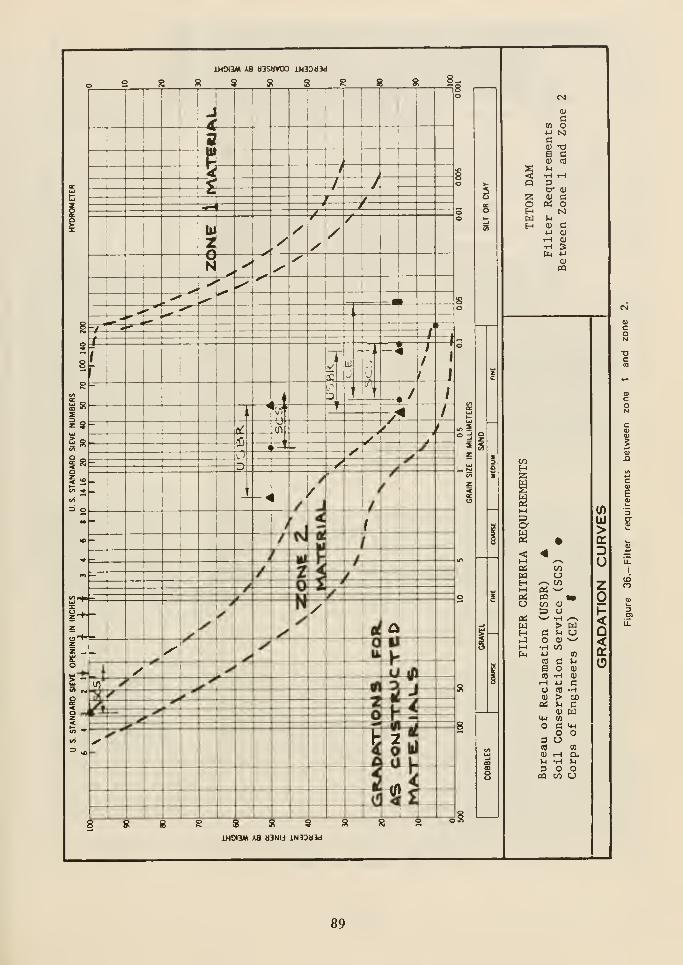
c
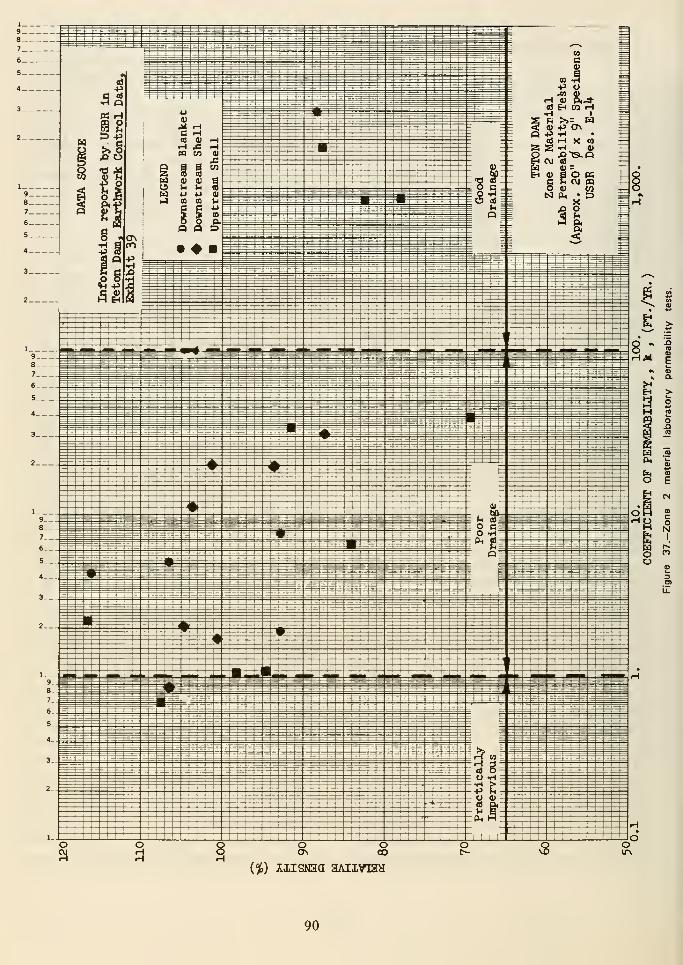
{%) AIISN3a aAIIVI3H
90
range of as-constructed gradation curves for
zone 2 material. Figure 37 shows the results of
permeability tests on zone 2 material.Permeabilities are grouped into three categories
ranging from "practically impervious" to "gooddrainage."
Test results generally indicate (1) that zone 2
was too coarse to meet design standards for
filtration of zone 1, and (2) that zone 2 did not
provide free drainage. Zone 2 was probablycapable of functioning according to the intent of
the designers, but only marginally so.
Design of Key Trenches.—It was recognized
early in the design that the silty core material
had a high potential for cracking. It was also
recognized that cracking would be aggravated by
the geometry of the foundation. The following
are direct quotes from design notes by the
principal designer:
March 1967-'k wide flat sloped cutoff trench
should be provided across the valley to
minimize cracking of the core fromdifferential settlement."
"... it undoubtedly also has the negative
characteristics of a silt, namely low resistance
to erosion, susceptibility to cracking ..."
The design of the key trench came later, during
the period for which no design documentation is
available. A profile of the right key trench is
shown on Figure 38.
Four observations can be made:
(1) Sufficient information was available
within the Bureau to understand, at least
quantitatively, the impact of abutmentgeometry on stress distribution and cracking
potential within the core. Technicalinformation on the general subject was also
readily available in the literature.
(2) The abutments and key trenchesincluded steep side slopes.
(3) The deep, narrow key trenches andabutment slope changes tended to aggravate
the cracking problem. The design of the key
trench did not take this into consideration.
The ability to minimize the impact of the
foundation geometry on cracking in the core
was within the state-of-the-art at the time of
the design.
(4) That the narrow key trench created a
steep hydraulic gradient that was notadequately provided for in the design.
Design Review.-^\ie design was not subjected
to an independent review. The IRG feels that
such reviews are warranted.
Instrumentation.-The designers judged that
their experiences at other dams were sufficient
to adequately predict the performance of TetonDam and that installation of instruments to
measure foundation and embankmentsettlement, lateral movements, and piezometric
pressures was unnecessary.
In the opinion of the IRG, if state-of-the-art
instrumentation had been installed it would not
have been capable of predicting this failure.
Construction
Investigations by the IRG and the task groups
have found that in all respects, with the possible
exception of inconsequential schedulingproblems, Teton Dam was constructed in
accordance with the intent of the designers andin agreement with the plans and specifications.
The field organization, under the direction of the
Project Construction Engineer, was well staffed,
well organized, and functionally efficient. Thefield laboratory was adequately equipped andthe scope and quality of tests performed were
within industry standards.
Of major concern to the IRG is the level of
active participation by designers during the
construction phase of the project. The designers
visited the site at two critical construction
stages. They were satisfied that field conditions
were compatible with design assumptions.Considerable written information, including
91
weekly and monthly progress reports, wastransmitted from Construction to Design.
However, there is Httle documentation of the
flow of information from Design to Construction
during the construction period.
A liaison engineer acted to some degree as a line
of communication between Design andConstruction. However, from early in 1972 until
the failure in 1976, he made only six visits to the
site. The last documented visit was in March1974. During the same period, only two visits
were made by the design engineers.
The IRG believes that designers should makefrequent field visits to prove to their satisfaction
that the assumptions made during design
sufficiently portray actual field conditions. Such
trips also give the designer the valuableexperience necessary to make his next design and
specification technically and economically morecompetent than the last.
92
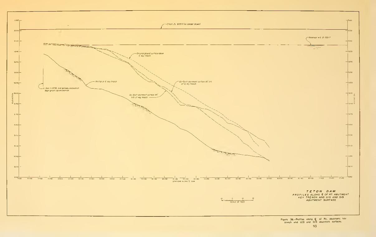
- Crest. EL 53320 (no camber shown!
-Original ground surface above
£ key trench
As-Built abutment surface 80 D/S
of i. key trench
J I 1 I 1 I I L J I L J L
Reservoir WS El 5301 7
I I\ L
^20 IO40 llf-fiO IZrtJO 12 +20 12+ flO 12 +60 12 + 90 13+00 13 + 20 13 +M 13+ 60 13 + 14 + 00 14 + 20 14 + 40 14+ 60 14 + 80
STATIONS 6L0NG t DAM
15+00 15 + 20 15 + 40 15+ 60 15+SO 16+00 16 + 20 16+40 16+60 tS + BO 17+00 17+20 17+40
SCALE OF FEET
TETON DAMPROFILES ALONG £ OF RT ABUTMENT
KEY TRENCH AND U/S AND D/SABUTMENT SURFACE
Figure 38.-Profiles along(J.
of Bt. abutment key
trench and U/S and D/S abutment surfaces.
93


«Chapter 8
Physical Cause of Failure
Unsupportable Causes of Failure
After evaluating all available information, the
IRG judges that the hypotheses of Curry and
Corbett, foundation cracking due to foundation
settlement and cracking due to hydraulic uplift,
are not supported by the physical conditions
that existed prior to and during the failure.
The hypotheses dealing with flow bypassing the
grout curtain are unlikely. There is no evidence
available to indicate flows under or around the
grout curtain would have been enough to cause
the rapid erosion of large amounts of zone 1
materials needed to result in the rapid breaching
of the dam.
The Independent Panel has concluded that the
initial seepage that led to eventual failure could
well have occurred through the grout curtain.
The bases for their conclusion are the results of
the joint ponding tests and the results of water
pressure tests in the postfailure borings. TheIRG recognizes the possibility that these
measured permeabilities may have been caused
by the failure-induced loosening of the rock
mass. As a consequence, the IRG believes that
failure due to initial seepage through the grout
curtain is much less probable than failure due
to initial seepage through cracks in the zone 1
material or to initial seepage along the contact
between the zone 1 material and the rock
foundation.
Probable Causes of Failure
The IRG concludes that the geometry of the
abutment and key trench, coupled with the
physical properties of the constructed zone 1,
were conducive to cracking because of
differential settlement or because of hydraulic
fracturing. The IRG believes that one, or both,
of these modes of cracking occurred, allowing
the initial seepage to pass through the zone 1
material. Water under full reservoir head had
access to the upstream end of these fractures
through open joints in the rock mass. These
joints had a sufficient volume of voids so that
the initially eroded zone 1 material could have
been carried downstream.
Somewhat less probable is the concept that the
damaging seepage started at the contact
between the zone 1 (impervious core) material
and the rock surface. The IRG believes that if
zone 1 cracking had not occurred, failure would
have been initiated by seepage between zone 1
and the foundation.
"Hydraulic Fracturing and Its Possible Role in
the Teton Dam Failure," included in Appendix
I, provides an excellent discussion of hydraulic
fracturing and its possible role in the failure of
the dam. After demonstrating that fracturing
could have occurred in the zone 1 key trench
fill, the authors of this paper developed a
95
scenario of the progression of piping leading to
the failure. This scenario follows:
"Several days before the final failure, leakage
through the key trench fed water at a slowly
increasing rate into a number of diagonal joint
systems; a portion of this flow entered the
joints directly, and a portion entered via the
overlying highly fractured rhyolite and talus
above El. 5200. As the joint systems began to
fill with water, aided by water flow around the
end of the right abutment key trench fill,
quiet discharges of water occurred several
days before the actual failure. Some of the
discharges emerged along the base of the
canyon wall downstream from the dam (see
locations 1 and 2 in Fig. 39 and some movedas subsurface flows into the contact zone of
talus and heavily jointed rock beneath the
zone 2 and zone 5 portions of downstreampart of the embankment (Fig. 40).
"Thus the critical escape route for leakage was
the multitude of partially filled void spaces in
the loose slabby rock just beneath the zone 1
fill downstream from the key trench.Significantly, materials partially filling void
spaces in this zone of rock would beunaffected by overburden pressures from the
overlying fill because of the sheltering action
of the loose rock structure. Accordingly, the
leakage conveyed to this medium by flow
across the key trench at Sta. 14 + 00 andthence flowing downward and to the left
towards Sta. 15 + 00, found not only an
almost free exit in the near-surface rock but
also escaped in channels that were of such size
that they could easily convey soil particles
eroded from the core of the dam. Thus of
paramount importance was the possibility for
leakage flows occurring immediately along the
core-to-rock interface to loosen and erode the
compacted silt from zone 1. Although the fill
was probably well-compacted, those parts of
the fill beneath minor overhangs wouldinevitably be sheltered from overburdenpressures and thus locally vulnerable to
erosion.
"In this way the initial seepage probablyeroded a small channel along the base of the
dam, both upstream and downstream as
shown in Figure 41(a), with the seepageflowing under zone 2 material, down the talus
on the upper part of the right abutment andfinally emerging as the leak at the toe of the
dam on the morning of the failure.
"As the flow continued, further erosion along
the base of the dam and a resultingconcentration of flow in this area, led to a
rapid increase in the size of the eroded channel
as shown in Figure 41(b). At this stage water
probably began to emerge at the contact of
the embankment with the underlying rock at
about El. 5190 to 5200.
"Progressive erosion led to continued increase
in the size of the channel along the base of the
dam, and perhaps some erosion of the soil
above zone 2 as shown in Figure 41(c), until
finally the water pressure was sufficiently
great to break suddenly and violently through
the zone 2 fill and erupt on the face of the damas shown in Figure 41(d).
"Beyond this point the progressive formation
of sinkholes, both upstream and downstream,
as illustrated in Figure 41(e), provided anever-accelerating mechanism for internal
erosion, finally leading to complete breaching
of the dam as illustrated in Figure 41(f)."
The IRG believes that the scenario of the
development of failure is logical andconsistent with all of the available information
and photographs of the failure.
' lUustratioDS are identical to those appearing in the Independent Panel
Report; however, the figure numherB have been changed.
96
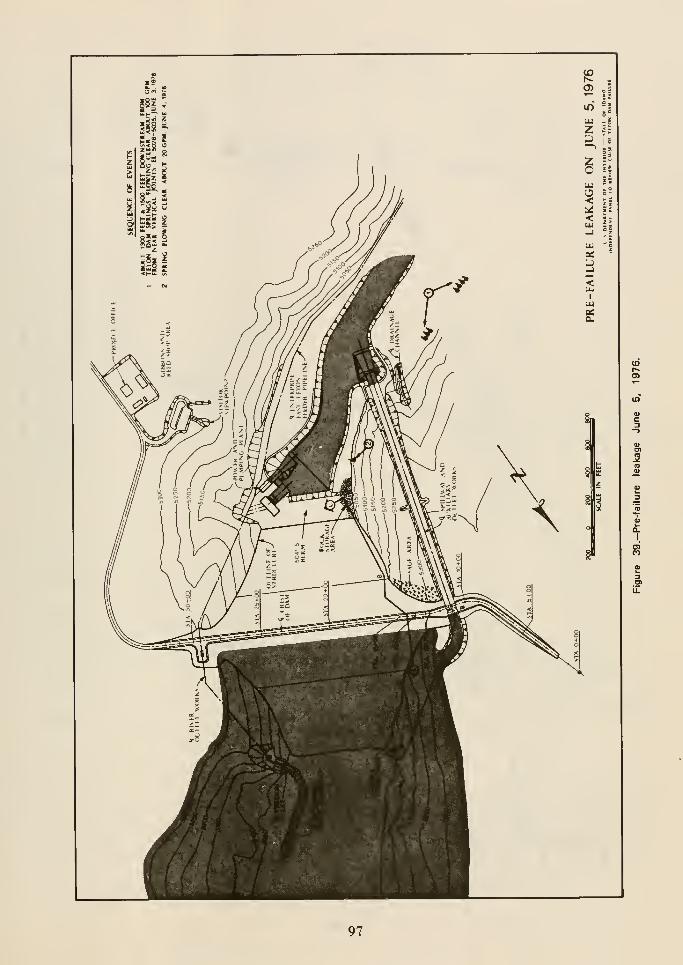
CO
Q.
I
97
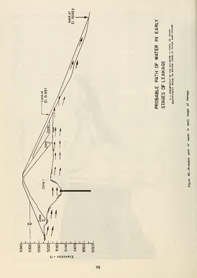
<UJ
<u. aoz
5
< UJQ. _l
UJ fe
DO (/i< UJm o<
01 HQ_ en
z z
Q Q
5
Ul
O
8
o o o _CM OO <^ Oin if> in in
O O
in mii - uo!(OAa|3
98
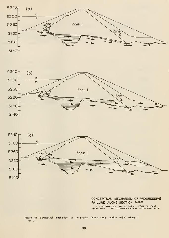
5340
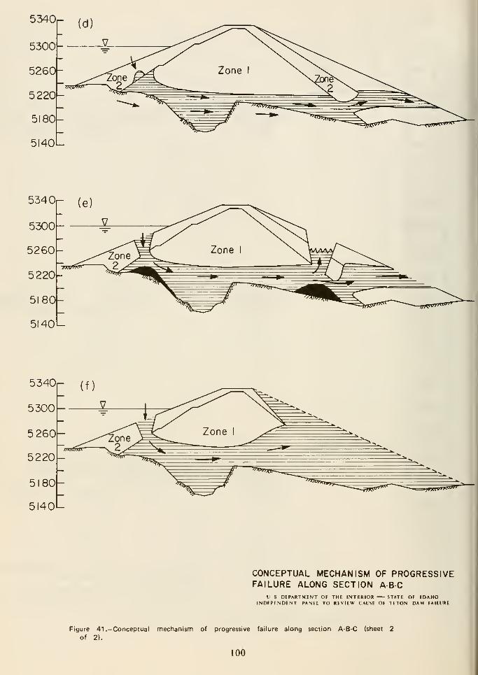
5340
5300
5 260
5220
5180
5140
CONCEPTUAL MECHANISM OF PROGRESSIVEFAILURE ALONG SECTION A-B-C
V S DEPARTMENT OF THE INTERIOR 5TATE OF IDAHOINDEPENDENT PANEL TO REVIEW CAUSE OF TETON DAM FAILURE
Figure 41 .—Conceptual mechanism of progressive failure along section A-B-C (sheet 2
of 2).
100
«Chapter 9
Consideration of Bureau Procedures
Consideration of
Bureau Procedures
The original charge to the IRG directed that the
cause of the failure be determined and that
recommendations, if warranted by its findings, be
provided to prevent a recurrence of such failures.
(See Appendix A.)
During its study of the cause of failure, the IRGidentified areas where it appears that procedures
and documentation, or a lack of them, may have
played a part in decisions that ultimately led to
the failure of Teton Dam. The IRG has
determined that a study of the specific
procedures followed in the design andconstruction is needed to identify deficient or
ahsent procedures and appropriatedocumentation. The study made by the Interior
Department's Office of Administrative and
Management Policy, "Review of Bureau of
Reclamation's Dam Building Procedures"
(December 1976), outlines general Bureau
procedures. The report does not include the
specific procedures followed during the design
and construction of Teton Dam.
• key trench design
• analysis of abutment and key trenchgeometry
• considerations of cracking potential
• treatment of rock surface in contact with
zone 1
• development of specifications
• design involvement in construction
• technical specialists' role in design andconstruction
• role of construction liaison personnel
• evaluation of instrumentation
• consideration of the need for a review
board
The recommendations or suggestions developed
by the IRG following the interviews will be
incorporated in a report that will be submitted
no later than June 1977.
The Bureau has prepared an annotated index of
documents related to important geologic, design,
and construction aspects of Teton Dam. Key
personnel involved in the decisionmaking
process will be interviewed so that anyprocedures in need of correction may be
determined and improved proceduresrecommended. Some areas of concern of the
IRG are:
101
«Chapter 10
Conclusions
Two classes of conclusions are presented: (1) the
primary conclusions concerning the failure of
Teton Dam, and (2) other conclusionsconcerning site selection, design, construction,
and operation of the dam.
Primary Conclusions
Teton Dam was constructed as specified and
failed as the result of inadequate protection of
the zone 1 impervious core material from
internal erosion. The most probable physical
mode of failure was cracking of zone 1 material
that allowed the initiation of erosion; however,
the erosion could have been initiated by piping
at the contact of the zone 1 and the rock surface.
The Bureau had the necessary information
available to develop an adequate defensive
design. A safe dam could have been built at the
site utilizing design concepts that were knownat that time.
Other Conclusions
Site Selection.Site selection procedures were
adequate; the site selected was the best of the
available alternative sites for the desired
purposes of the project.
Design.—Knough geologic data were obtained
for a proper design of the dam.
Reliance on the grout curtain for total control
of damaging seepage inhibited adoption of other
design features that could have prevented the
failure.
The design failed to provide a defense against
both flow through embankment cracks and
erosion of the zone 1 impervious core at rock
surfaces. Defensive measures, such as rock
surface sealing and adequate filters, were well
within the state-of-the-art at the time Teton
Dam was designed and should have been used.
The design incorporated a feature, key trenches
in the abutments, that significantly departed
from past Bureau of Reclamation practices.
The geometry of the abutment key trenches was
conducive to developing stress patterns that
could have allowed cracking of the impervious
core.
The narrow width of the sealed foundation rock
at the bottom of the key trench, combined with
the high permeability of the rock foundation on
either side of the key trench, produced steep
hydraulic gradients across the trench.
Recognition of the potential for occurrence of
hydraulic fracturing was not in the general
state-of-the-art of dam design at the time Teton
Dam was designed. However, the potential for
cracking from differential settlement near the
steep abutments and key trenches within the
abutments has been recognized by dam designers
in the past.
An independent review of the design might have
identified the design deficiencies.
103
Structural instability of the embankment was
not a factor in the failure.
Instrumentation of the embankment andfoundation would have been desirable to monitor
the performance of the dam; however, there is
no indication that such instrumentation would
have furnished information that could have been
used to prevent this failure.
Construction.—The grout curtain wassatisfactory to control seepage within normal
limits.
The foundation preparation for the embankmentplacement was in accordance with the contract
plans and specifications.
The placement methods used to construct the
embankment were in agreement with the general
practices and procedures followed in earth damconstruction. Construction control testing was
adequate and followed generally acceptedprocedures.
Operation.-The relation of the high rate of
filling of the reservoir to the failure is
indeterminate. The fact that the main river
outlet works was not available to assist in
controlling rate of storage is judged to have had
no significant effect on the ultimate failure of
Teton Dam.
104

«Chapter 1
1
Additional Investigations
Further investigations are desirable to assure
that all possible factors that might have
influenced the failure have been considered.
Appropriate reports will be issued. Theinvestigations are as follows.
Grout Curtain Investigations
The original program for drilling and testing of
the effectiveness of the grout curtain was not
completed because of winter shutdown.Additional holes will be drilled in the right
abutment to complete the program that was
interrupted by shutdown. This will extend the
present investigation both laterally and in depth.
Finite Element Studies
Additional finite element studies are planned.
These will include studies of the left
embankment, in addition to some parametric
studies, to determine the influence of key trench
shape on stress distribution within the
embankment. Conditions encountered in the left
embankment may suggest further analyses.
Left Abutment andEmbankment Investigations
Physical conditions on the left abutment are
very similar to those of the right abutment. Aninvestigation of the embankment andembankment foundation contact surface will be
made by a means that will permit visual
inspection.
The investigation will be primarily to search for
cracks in the remaining left embankment and to
find evidences of erosion channels through the
core or at the contact of the zone 1 and the rock
surface. The area of concern, in the vicinity of
the key trench, is far enough from the failure
breach to be influenced only slightly, if at all,
by postfailure stress release. Further in situ
stress investigations are planned.
105
«Chapter 12
Recommendations
IRG Recommendations
In the charge to the IRG, the Under Secretary
of the Interior directed that the group makerecommendations to prevent the recurrence of
failures such as that at Teton Dam. Therefore,
it is recommended that:
• An independent board of review be
convened for each major dam project.
This board should review both design and
construction at appropriate intervals
• Design decisions be formally documented
• Design personnel remain activelyinvolved with a project duringconstruction including frequent scheduled
site visits
• Major dams and their foundations include
an instrumentation program to monitor
construction and postconstructionbehavior. Instrumentation data should be
promptly interpreted and evaluated
These recommendations may be supplementedwhen all IRG investigations are completed.
107

« Appendix A
Charge and Directions to the IRG

United States Department of the Interior
OFFICE OF THE SECRETARYWASHINGTON, D.C. 20240
June 8, 1976
Memorandum
TO : /''^Cssistant Secretary—Land & Water Resources
Assistant Secretary—Energy & MineralsDirector—Geological Survey
Commissioner—Bureau of Reclamation
FROM : Under Secretary .-, / • r- v -.
SUBJECT: Teton Dam Failure Review Group
I am establishing today a review group to examine the causes of
the Teton Dam failure. The review group should examine, among
other matters relevant to the causes of the failure, the
following:
o Geologic aspectso Engineering design factoro Construction detailso Hydrologic factorso Pertinent background information and testimony
If the findings warrant, the group should also make recommendations,
as appropriate, designed to prevent recurrence of failures.
The review group will be chaired by Deputy Assistant SecretaryDennis Sachs. The Federal subject matter experts of the groupwill be drawn from:
o Department of the Interior- Bureau of Reclamation- U.S. Geological Survey
o Tennessee Valley Authorityo Corps of Engineers (Department of the Army)
o Soil Conservation Service (Department of Agriculture)
' '
! \ /•-. -^ >>.,— ,-,'5
Save Energy and You Serve America!
A-1
-2-
The review group should provide to me an interim report by
July 12 and a final report by July 30. This review effort
is not a substitute for the "Blue Ribbon" panel that will
conduct an investigation of the failure independent of the
Department. Information developed by the review group will
be made available to the panel.
Bill Lyons, for the Under Secretary's Office, will be the
focal point for coordination with the Blue Ribbon panel.
Dennis Sachs will serve as the contact point for all matters
related to the Department-led review.
cc: SolicitorAssistant Secretary/Program
Development & Budget
A-2
^/'^'^'Tzj^^s Unltea States Department of the Interior
OFFICE or THE SECRETARYWASHI.NGTOX, D.C. 20210
Memorandum " ''^' ^ ^ /'••'/
To: Chairman, Teton Dam Failure Interior Review Group
From: Secretary of the Interior
Subject: Review of Procedures Used in Specific Features of Teton Dam
To fulfill completely the original charge nade to your group, you arerequested to study the relationship of those physical aspects of TetonDam that may have contributed to its failure to the specific proceduresfollowed in the Bureau of Reclamation that gave rise to those aspects.This will provide the Interior Review Group v.'ith more complete informationupon v;hich to base recor.-endations designed to prevent recurrence of suchfailures.
The investigation will involve those specific features of Teton Dam whicheither the Interior Review Group or the Independent Panel have identifiiid
as being related to the failure. It will center on the evolution anddevelopment of each feature with the identification and documentation of
decision points and the delineation of any divergence from "normal" pro-cedures. Examples (not an inclusive list) of aspects of the dam and itsfailure that especially warrant this type of investigation are: the designof the key trench; the surface grouting program; the rate of filling of the
reservoir; the selection of embankment materials; and the instrumentationdeficiencies of the surveillance program.
The Interior Review Group will administer this program with assistance frcm
the Assistant Secretary—Adm.inistration and Management and the Bureau of
Reclamation. In response to a set of specific requests to be preparedimmediately by the Interior Review Group, Administration and Managementwill gather detailed information on the procedures follov/ed. The Bureau
of Reclamation will provide related docum.entation, with particular emphasis
on those points where critical decisions were made.
The Interior Review Group will be responsible for the synthesis and inter-
pretation of as much of this information as possible for inclusion in the
Group's report to the Secretary currently scheduled for February 1977. An
addenduTii to that report, reporting all further information gathered from this
special procedures review, should be submitted no later than June 1977.
^OVUT/O.v
^ /T\ -o Thomas S. Kleppc

« Appendix B
Report of the Geology Task Group
U.S. Department of the Interior
Teton Dam Failure Review Group

CONTENTS
Page
Abstract B-1
Introduction B-1
Purpose and scope B-1
Participants B-1
Activities B-1
Sources of information B-2
Regional geologic setting B-2
Seismicity B-4
Geologic investigations by tlie Bureau of Reclamation B-4
Preconstruction investigations B-4
Construction investigations B-5
Post-failure investigations B-7
General geology of the damsite B-8
Welded tuff B-9
Sedimentary deposits underlying the welded tuff B-11
Intracanyon basalt B-11
Surficial deposits B-12
Wind-deposited silt B-12
Alluvium B-12
Slope deposits > B-12
Ground water B-1
3
Regional B-13
Damsite • B-13
Pre-reservoir filling B-13
General ground-water conditions during filling of the reservoir B-13
Geology of the right abutment and associated appurtenant works B-14
Right canyon side B-14
Subdivisions of the welded tuff B-1
5
Coincidence of geologic features between grout cap centerline
station 13-^00and 14-K)0 B-1
6
Slope stability B-16
Major fissures along haul road upstream of abutment B-1
7
Spillway crest and auxiliary outlet works access shaft B-17
Right wing of dam B-17
Auxiliary outlet works tunnel B-18
Permeability of the welded tuff in the right abutment B-18
Discussion of adequacy of pre-failure geologic investigations B-20
Preconstruction investigations B-20
Construction investigations B-20
Investigations of geologic features not related to damfailure B-21
Comments on adequacy of investigation of permeability and ground-water levels . . . B-22
Conclusions B-22
References cited B-23
TABLE
Table
B1 Summary of preconstruction and construction core
drilling B-6
B-i
CONTENTS-Continued
FIGURES
Figure Page
B1 Generalized geologic map of southeastern Idaho and vicinity, and
generalized cross section of eastern Snake River Plain B-26
B2 Geologic map of the region of Rexburg Bench and the canyon of
Teton River B-28
B3 Surface geologic map of Teton damsite showing locations of
exploration B-31
B4 Geologic section along upstream row of holes of grout curtain,
station -5+00 to station 49+00 B-35
B5 Aerial view of Teton damsite prior to construction B-43
B6 Geologic section across lower end of Teton Reservoir showing water
levels in wells during reservoir filling B-45
B7 Teton Dam and Reservoir water table contour map for 6/1/76 B-47
88 Right abutment of Teton Dam showing location of structures and
selected exploratory drill holes B-48
B9 Aerial view of right abutment in November 1976, after embankment
material removed from key trench B-49
BIO Grout take and permeability in two parts of section along key
trench, right abutment, Teton Dam B-50
APPENDIXES
B-1 Joints, fissures, and voids in rhyolite welded ash-flow tuff at
Teton damsite, Idaho, by Harold J. Prostka, 1977 (U.S.
Geological Survey Open-File Report 77-211) B-53
B-2 Analyses of ground-water levels in the right abutment B-65
B-ii
ABSTRACT
The mission of the Geology Task Group was to review
the geologic aspects of the Teton damsite and evaluate
their possible significance in failure of the dam. This
investigation was conducted through review of Bureau
of Reclamation pre-failure and post-failure geologic
investigations, site observations, and interviews of
Bureau of Reclamation geologists. In order to avail
itself of additional expertise, as needed, the Task
Group has consulted from time to time with Federal
specialists in regional geology of the Snake River Plain,
volcanic geology, engineering geology of damsites in
volcanic rocks, ground-water geology, and seismology.
works weri; generally adequate to verify the basic
geologic conditions determined by the preconstruction
investigations. However, the Geology Task Group feels
that the development of a more complete and better
integrated three-dimensional picture of the geology of
the right abutment would have helped to focus even
greater engineering attention on the critical problem of
open joints that would be in contact with the
embankment materials.
An adequate system was not provided for monitoring
ground-water levels to evaluate the performance of the
key trench£:s and grout curtain during filling of the
reservoir.
Teton Dam is located in a steep-walled canyon that was
eroded by the Teton River into a gently rolling, eolian
silt-covered volcanic upland adjoining the eastern
Snake River Plain. The rock that forms the canyon
walls and which constitutes the major bedrock
formation throughout the damsite and reservoir area is
a rhyolite welded ash-flow tuff. At the damsite, as well
as elsewhere along the Teton River, this welded tuff is
characterized by the presence of prominent and
abundant open joints and fissures. The high natural
permeability of the rock in the right abutment
resulting from the presence of these interconnected
joints and fissures, especially in the upper part of the
abutment, was a major factor in the dam failure. Of
particular importance was the contact of open-jointed
rock with zone 1 materials both upstream and
downstream of the grout curtain.
INTRODUCTION
Purpose and Scope
In establishing the Teton Dam Failure Review Group,the Under Secretary of the Interior emphasized several
factors that should be examined in determining the
cause or causes of failure of the dam. Listed first
among these factors was the geologic aspects. In order
to facilitate this part of the review, the Geology Task
Group was formed. The specific mission of this task
group is to review the geologic aspects and evaluate
their possible significance in the failure.
Participants
The members of the Geology Task Group are:
A coincidence of major, throughgoing joints and other
rock defects occurs along the right key trench between
grout cap centerline stations approximately 13-HDO and
14-K)0, an interval that includes the whirlpool that
developed about 80 feet upstream in the reservoir
shortly before the breaching of the dam. These
geologic features may have contributed to the failure.
The closest positively identified faults are about 7 to 8
miles east of the damsite and they are not known to be
active. The records of the seismic monitoring network
centered on Teton Dam and Reservoir demonstrate
that failure of the dam was not the result of seismic
activity.
Surface and subsurface preconstruction geologic
investigations generally appear to have been well
conceived and executed and the data obtained to have
been adequate to establish the basic geologic features
that should have been considered in the design of the
dam. In addition, construction geologic investigations
in the right abutment and associated appurtenant
Robert L. Schuster, Chief, Engineering Geology
Branch, U.S. Geological Survey
John T. McGill, Geologist, Engineering Geology
Branch, U.S. Geological Survey
David J. Varnes, Geologist, Engineering Geology
Branch, U.S. Geological Survey
Lloyd B. Underwood, Chief, Geology Section,
Engineering Division, U.S. Army, Office Chief of
Engineers
In order to avail itself of additional expertise, as
needed, the Task Group has consulted from time to
time with Federal specialists in regional geology of the
Snake River Plain, volcanic geology, engineering
geology of damsites in volcanic rocks, ground-water
geology, and seismology.
Activities
Members of the Geology Task Group have performed
the following principal functions as related to the
activities of the Review Group:
B-1
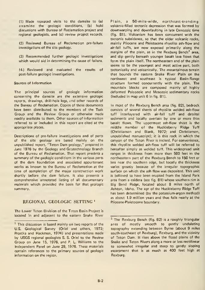
(1) Made repeated visits to the damsite to (a)
examine the geologic conditions, (b) hold
discussions with Bureau of Reclamation project and
regional geologists, and (c) review project records.
(2) Reviewed Bureau of Reclamation pre-failure
investigations of the site geology.
(3) Recommended further geologic investigations
which would aid in determining the cause of failure.
(4) Reviewed and evaluated the results of
post-failure geologic investigations.
Sources of Information
The principal sources of geologic information
concerning the damsite are the extensive geologic
reports, drawings, drill-hole logs, jnd other records of
the Bureau of Reclamation. Copies of these documents
have been distributed to the members of the Task
Group and the Review Group or otherwise madereadily available to them. Other sources of information
referred to or included in this report are cited at the
appropriate places.
Descriptions of pre-failure investigations and of parts
of the site geology are based mainly on the
unpublished report, "Teton Dam geology," prepared in
June 1976 by the Geology and Geotechnology Branch
of the Bureau of Reclamation. That report presents a
summary of the geologic condition; in the various parts
of the dam foundation and associated appurtenant
works as known to the Bureau of Reclamation at the
time of completion of the major construction work
shortly before the dam failure. It also presents a
comprehensive annotated listing of all documentary
materials which provided the basis for that geologic
summary.
REGIONAL GEOLOGIC SETTING '
Plain, a 50-mile-wide, northeast-trendingvolcanic-filled tectonic depression that was formed by
downwarping and downfaulting in late Cenozoic time
(fig. B1). Volcanism has been concurrent with the
tectonic subsidence, so that the older volcanic rocks,
mainly Pliocene and Pleistocene rhyolite ash-flow and
air-fall tuffs, are now exposed primarily along the
margins of the plain, as in the Rexburg Bench^ area,
and dip gently beneath younger basalt lava flows that
form the plain itself. The northeastern end of the plain
seems to be the youngest and most active part, both
tectonically and volcanically. The mountainous terrain
that bounds the eastern Snake River Plain on the
northwest and southeast is typical Basin-Range
structure formed concurrently with the plain. The
mountain blocks are composed mainly of highly
deformed Paleozoic and Mesozoic sedimentary rocks
(included in map unit 6 in fig. B1 ).
In most of the Rexburg Bench area (fig. B2), bedrock
consists of several sheets of rhyolite welded ash-flow
tuff interlayered with air-fall tuff and detrital
sediments and locally overlain by one or more thin
basalt flows. The uppermost ash-flow sheet is the
middle member of the Huckleberry Ridge Tuff
(Christiansen and Blank, 1972; and Christiansen,
unpublished manuscript); it is this rock in which the
canyon of the Teton River is incised. For convenience,
this rhyolite welded ash-flow tuff will be referred to
hereafter simply as welded tuff. This widespread unit
ranges in thickness from more than 500 feet in the
northeastern part of the Rexburg Bench to 150 feet or
less near the southern edge, but locally the thickness
varies greatly because of the irregular topographic
surface on which the ash flow was deposited. This unit
is believed to have been erupted from the Island Park
area from a caldera (see fig. B1) whose southern rim is
Big Bend Ridge, located about 8 miles north of
Ashton, Idaho. The age of the Huckleberry Ridge Tuff
has been determined (by the potassium-argon method)
as about 1.9 million years and thus falls nearly at the
Pliocene-Pleistocene boundary.
The Lower Teton Division of the Tnon Basin Project is
located in and adjacent to the eastern Snake River
' This discussion is based mainly on two reports of the
U.S. Geological Survey (Oriel and others, 1973;
Prostka and Hackman, 1974) and presentations made
by USGS regional geologists S. S. Oriel to the Review
Group on June 15, 1976, and P. L. Williams to the
Independent Panel on June 29, 1976. These materials
contain references to the primary sources of geologic
information on the region.
^ The Rexburg Bench (fig. B2) is a roughly triangular
area of mostly smooth to gently undulating
topography extending between Byrne (about 9 miles
south-southeast of Rexburg), Rexburg, and the vicinity
of Teton Dam. It rises above the flood plains of the
Snake and Teton Rivers along a more or less rectilinear
to somewhat irregular and steep to gently sloping
escarpment that is as much as 400 feet high at
Rexburg.
B-2

The basalt flows that overlie the welded tuff were
erupted from local sources, such as several small lava
domes on the Rexburg Bench. A sample of basalt
collected by G. M. Richmond, U.S. Geological Survey
(oral communication, December 1976), from an
outcrop near the bridge where Idaho State Highway 33
crosses Canyon Creek, about 6 miles southeast of
Teton Dam, has been dated by IVIinze Stuiver, Univ. of
Washington; it is interpreted to be between 225,000
and 500,000 years old. This basalt is probably
equivalent to or younger than the basalt exposed along
the rims of the canyons of Teton River and Canyon
Creek near their confluence and probably equivalent to
or older than the remnants of intracanyon basalt in the
bottom of the canyon of Teton River at and
downstream from the dam.
Wind-deposited silt, or loess, mantles much of the
northern Rexburg Bench and adjacent volcanic upland
near the canyon of Teton River. Its source area was the
river flood plains on the adjacent Snake River Plain.
The loess is of Pleistocene age and may be less than
70,000 years old.
Most of the faults in the region tend to be roughly
parallel and perpendicular to the northeast trend of the
eastern Snake River Plain. Northwest-trending normal
faults are common along the southeastern margin of
the plain, where some of them boundnorthwest-trending mountain ranges and intervening
valleys or basins that were blocked out principally by
displacements during middle and late Cenozoic
northeast-southwest crustal extension of the region. Aset of well-defined faults with northwest trend has
been mapped in and near the upper canyon of the
Teton River to within about 8 miles east of Teton Dam(fig. B2; IVlagleby and Sweeney, 1963). These faults
probably are related to late Pliocene and Quaternary
uplift of the Big Hole Mountains (see fig. B1 for
location); they offset the welded tuff and overlying
basalt as much as 80 feet vertically. The loess does not
appear to be displaced by these faults, but suitable
exposures are lacking for a definitive determination.
Other well-defined northwest-trending faults have been
mapped to within about 11 miles southwest of the
dam, where they cut basalt flows at the ground surface
(fig. B2). These faults and a line of basaltic vents
adjacent to them lie along the northwest projection of
the Grand Valley fault (fig. B1). Some inferred faults
with northwest trend in Huckleberry Ridge Tuff, 3 to
4 miles north-northeast of the dam in the area labeled
Hog Hollow on published topographic maps, may be
part of a collapse structure along the southwest margin
of a caldera (H. J. Prostka, oral communication,
August 1976).
Northeast-trending high-angle faults in the Snake River
Plain and its margins presumably developed during
subsidence of the plain accompanying general
northwest-southeast crustal extension but they have
been largely buried by lavas and sediments.
Well-defined faults with northeast trend have been
mapped cutting the welded tuff no closer than about 7
miles east-northeast (fig. B2) and about 10 miles south
(Haskett, 1972) of the dam.
Northeast-trending lineaments located closer than the
well-defined faults to the dam are conspicuous on
aerial photographs and large-scale topographic maps of
the area. Structural control seems likely for those
lineaments having considerable length or topographic
relief, but none has been confirmed as of fault origin.
One such prominent lineament was noted on the
upland about 500 to 800 feet west of and roughly
parallel to the segment of the canyon in which the damis located. On the basis of this lineament and
interpretation of geologic cross sections in a Bureau of
Reclamation report by Haskett (1972) on
ground-water geology of the Rexburg Bench, regional
geologists of the U.S. Geological Survey inferred the
existence of a northeast-trending fault extending about
18 miles from south of Rexburg to and beyond the
immediate vicinity of the right abutment of the dam.
This was communicated to the Bureau of Reclamation
in a meeting in March 1973 and then in a draft
preliminary report (Oriel and others, 1973).
Subsequent fieldwork by the USGS revealed no
evidence of faulting of welded tuff or other surface
rocks along the trace of the inferred fault; therefore,
on a preliminary geologic map of the region (see fig.
B2) the feature is shown as a concealed subsurface
fault, inferred from well data, that is of
pre-Huckleberry Ridge Tuff age. After the Teton Damfailure, a replotting of map locations of the fault
interpreted from Haskett's geologic sections in the
southern part of the Rexburg Bench indicates that the
corrected map trace of the inferred fault, projected
northeast, would fall as much as 3 miles northwest of
the prominent, northeast-trending topographic
lineament adjacent to the right end of the dam.
In a Bureau of Reclamation memorandum dated April
1, 1976, prepared by Haskett, the geologic conditions
downstream from the dam are briefly described and
the possibility is suggested of a fault along a line
trending northeast from the town of Newdale. The
production of wells per foot of penetration of welded
tuff increases manyfold about at this line (Haskett,
1972, p. 9, 11), which also coincides with a narrow
zone of hot water wells. This line probably would cross
the northwest-trending segment of the canyon of
B-3
Teton River approximately 2 miles downstream from
the dam, possibly within one-half mile of the replotted
pxDsition of the inferred subsurface fault beneath the
Rexburg Bench and about on the projection of twoshort, northeast-trending topographic lineaments
located between Newdale and the canyon. These
lineaments are shown on the USGS preliminary
geologic map (see fig. B2) as concealed normal faults;
they also are inferred faults.
The closest positively identified faults are about 7 to 8
miles east of the damsite, and they are not known to
be active.
(3) No increase in seismic activity near the dam was
recorded while the reservoir was being filled.
(4) For at least 4-1/2 hours, beginning within 1
minute of 11:47 MDT, June 5, 1976, the seismic
monitoring network recorded ground motion
generated by the breakup of the dam and release of
the reservoir water. Maximum amplitude of the
ground motion was reached within half an hour and
continued for about an hour.
These observations demonstrate that the failure of
Teton Dam was not the result of seismic activity.
SEISMICITY
Selsmicity believed to be associated with prominent
faults is characteristic of the mountain ranges
bordering the northern, eastern, and southern sides of
the eastern Snake River Plain. Several earthquakes with
maximum Modified Mercalli intensities of VIII have
been experienced in the region. For this reason,
southeastern Idaho has been included in U.S. Seismic
Risk Zone 3 (Algermissen, 1969). However, in the area
of the Snake River Plain and its margins, although
youthful and active deformation is indicated by
geologic, geodetic, and geothermal conditions, the level
of locally generated historic seismicity is low. This is
known from the historical record of 1915 to 1974 and,
since June 1974, from a cooperative Bureau of
Reclamation-Geological Survey program to study the
seismicity of the Teton Dam and Reservoir area, in
particular to investigate any seismic effects of reservoir
filling and evidence of fault activity within about a
25-mile radius. The cooperative program involved the
installation of a monitoring network of three seismic
stations located about 18 miles north, east, and
southeast of Teton Dam. The following conclusions
have been drawn from this short-term monitoring of
the seismicity (Navarro and others, 1976):
(1) During the period June 16, 1974, to March 31,
1976, no seismic event of Richter magnitude 2.2
M|_ or greater was observed within an 18-mile radius
of Teton Dam. In addition, all events within 12
miles of the dam have been confirmed as having
been caused by blasting.
(2) During the period April 1, 1976, to June 9,
1976, no seismic event was observed within an
18-mile radius of the dam, with the exception of
identified blasts. The closest and largest earthquake,
which had a magnitude of 1.7 M|_, was located
southwest of Victor, Idaho, about 37 miles
southeast of the dam.
GEOLOGIC INVESTIGATIONS BY THEBUREAU OF RECLAMATION'
PreconstructJon Investigations
Prior to selection of the site of Teton Dam in 1964,
various potential sites were investigated along the
Teton River and its tributaries. In 1946 two sites on
Canyon Creek, a tributary of the lower Teton River,
were studied. In 1956, a low diversion damsite was
investigated 5 miles downstream from the present site.
In early 1 961 , five alternate sites were studied upstream
of Teton Dam in the stretch of the river from
Linderman Draw to the mouth of North Fork. (For
information on the results of these investigations and
selection of the site, see the section titled "Project
Siting" in the IRG report.)
At the Teton damsite the initial geologic investigations
consisted of two core holes by the Corps of Engineers
in 1957. Subsequent planning and preconstruction
drilling programs were undertaken by the Bureau of
Reclamation in 1961, 1962, and 1967 through 1970.
These programs consisted of a total of 102 core drill
holes, ranging in depth from 20 to 698 feet. Manyholes, most on the order of 300 feet deep, were drilled
along the sites of the proposed cutoff and key
trenches. Nearly all of these holes were drilled at an
angle of 30° to the vertical and directed to intersect
high-angle joints. The core from all the drill holes was
' The summary descriptions of preconstruction and
construction investigations are based mainly on an
unpublished report prepared in June 1976 by the
Geology and Geotechnology Branch of the Bureau of
Reclamation (U.S. Bureau of Reclamation, 1976). The
locations of preconstruction and construction core drill
holes are shown on the geologic map of the damsite
(fig. B3) and those near the axis of the dam are shown
on the geologic section through the damsite (fig. B4) in
this Task Group report.
B-4

logged, and a down-hole television camera was used to
examine some of the holes. A summary of
preconstruction core drilling is presented in table B1.
Twenty-six of the holes were drilled in the left
abutment, 9 in the valley floor, 9 In the right
abutment, and 56 at sites of appurtenant structures. Aspecial drilling program of 10 holes was included to
evaluate the effectiveness of the pilot grouting program
that was conducted in a blanket grouting zone in the
valley floor and a curtain grouting area In the left
abutment. Long-term pump-in permeability tests were
conducted In five holes in the right abutment. Twelve
holes (six in each abutment) were examined with a
down-hole television camera t^^ analyze the joint
system. Two holes also were dt lied about 10 miles
upstream from the site as part of the evaluation of the
reservoir water-holding capability.
Cores from five drill holes in the welded tuff and three
holes In the Intracanyon basalt were tested to
determine the following physical and mechanical
properties: modulus of elasticity, Poisson's ratio,
compressive strength, absorption, and specific gravity.
In addition, the same cores were subjected to
F>etrographic examination both before and after the
physical and mechanical tests were conducted. The
"before" examinations determined the lithology,
veslcularity, and degree of weathering of the rock In
the cores. The "after" descriptions and measurements
were made on the specimens tested to failure to
determine their mode and angle of failure, and the
nature of the materials associated with the failure.
Complementing the drilling programs was a geologic
field-mapping program which produced maps at scales
of r'=100' and 1"=50' of the areal geology of the
damsite and maps at a scale of 1"=20' of the joints In
the outcrops of welded tuff on both abutments.
Information obtained from the drilling and geologic
field-mapping programs was used to compile geologic
cross sections at various scales and degree of detail. Apreliminary geologic report in 1963 included a
reconnaissance geologic map of the reservoir area at a
scale of 1 "=1,000'.
An outcrop of intracanyon basalt on the left canyon
side about 1 miles downstream from the damsite was
explored as a possible source of riprap for the dam (see
fig. B5). Three core holes were drilled and a sample
geologic map was made of the left canyon side between
the outcrop and the damsite.
Magnetometer surveys were made in the canyon
bottom in the area of the proposed cutoff trench In
1967 and in the power plant area in 1969 to
supplement drilling information regarding the extent
and configuration of the buried intracanyon basalt.
All of the Information relating to the preconstruction
geologic investigations program at the damsite through
early 1971, including logs, maps, sections, etc., is
Included In the Preconstruction Geologic Report (U.S.
Bureau of Reclamation, 1971).
Construction Investigations
During the course of construction, which began in
1972, the various site excavations were examined in
detail and "as built" drawings prepared showing the
geologic features exposed at the final excavated
surfaces. Major emphasis was placed on the mapping of
joints in the welded tuff.
The geologic map of the cutoff trench and key
trenches includes adjacent parts of the canyon walls
that also were subsequently covered with zone 1
material. The map, at a scale of 1"=20', identifies the
geologic materials in a very general way and shows
joint traces and attitudes in the welded tuff ; notations
are provided as to widths, fillings, and coatings only for
joints more than 0.1 foot In width. As Indicated on the
map, much of the bottom of the left key trench and
the extreme right part of the right key trench were not
mapped. Rose diagrams of the joints In selected areas
of the right abutment recently were added to the map.
Supplementing the geologic map is a series of
panoramic color photographs with geologic overlays
showing prominent joint traces In construction
exposures of the walls of the key trenches and adjacent
parts of the right and left abutments. As of early
February 1977, two of four volumes of photographs
with overlays had been completed. They cover most of
the right abutment and key trench above elevation
approximately 51 50. The scale of the overlays is about
1"=10'to1"=15'.
The geologic map of the spillway excavation, at a scale
of 1"=10', also Is mainly a map of joints in welded
tuff. A geologic cross section along the spillway site, at
a scale of 1"=50', shows the several geologic units
present from the original ground surface to an average
depth of about 60 feet. A final report has been drafted.
Joint maps, at a scale of 1"=10', and brief geologic
reports were prepared for the river outlet works tunnel,
gate chamber access shaft, and Intake shaft, and for the
auxiliary outlet works tunnel, gate chamber access
shaft, and adit. These engineering structures are located
entirely within the welded tuff.
B-5
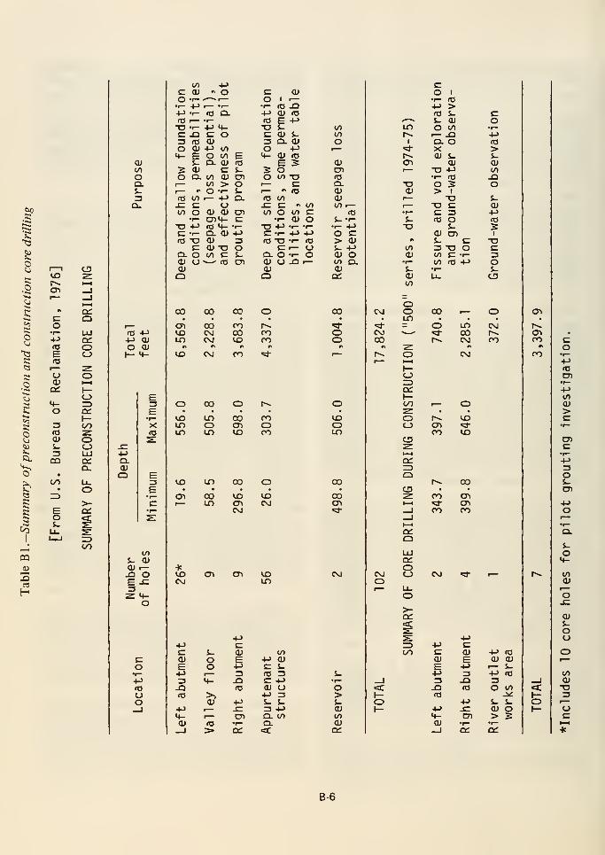
.^
o
.o
to
8
KO
toKO
=1.
<3
tooQ.S-
+->
ro
BCO
ucua:
3re
s-
CQ
tn
OO
OrDq:I—I/)
ooLlJ
o.
,
—
In October 1975 a map was made which locates and
briefly described a series of major fissures discovered
along the haul road on the upper part of the right
canyon wall 650 to 1,450 feet upstream from the
centerline of the dam.
In addition to the geologic mapping, three deep
exploratory core holes were slant-drilled in the outer
portion of the right abutment and one in the outer
portion of the left abutment to investigate at depth the
areas where fissures and cavities had been discovered in
the key trench excavations. Two of these holes in the
right abutment were kept open for use as ground-water
observation wells. Also, one deep vertical core hole was
drilled farther out on each abutment to service as an
observation well in the ground-water monitoring
program. An additional core hole for ground-water
observation was drilled near the outlet of the river
outlet works tunnel, adjacent to the power plant. Table
B1 summarizes the core drilling during the
construction stage.
During the excavation of the cutoff trench, six auger
holes were bored to help define the limit and extent of
silt and clay layers that were present in the alluvium
near the bottom of the excavation, and three auger
holes were bored to define the surface of the welded
tuff adjacent to and below an overhang that had been
encountered. As the cutoff trench was deepened and
completed, 14 test trenches were excavated to further
investigate the silt and clay layers.
In 1972 an electromagnetic subsurface profiling survey
of a research experimental nature was conducted by
Geophysical Survey Systems, Inc., in an effort to
delineate possible near-surface voids in bedrock
beneath the eolian silt just beyond the end of the left
abutment.
In 1973 a cooperative program was initiated between
the Bureau of Reclamation and the Geological Survey
to monitor the seismicity of the Teton project area and
to provide evidence for evaluation of the activity of the
known and inferred faults (see Seismicity).
Post-failure Investigations
Post-failure geologic investigations and related studies
have been conducted or supervised by the Bureau of
Reclamation to help determine the cause of failure.
These investigations and studies through January 1977
can be summarized as follows:
(1 ) Initial geologic mapping of the right abutment
post-failure rock surface (preliminary maps and
tabulations completed in August 1976).
This first-phase mapping was accomplished on a
three-sheet contoured orthophotomap of the
canyon wall at a scale of 1"=20'. At the time this
work was done, the remnant of the key trench and
much of the rock surface directly downslope were
covered by zone 1 material that was in place or had
sloughed from the escarpment formed during the
failure of the dam. The map shows traces of major
joints, contacts between units of the welded tuff,
and locations of post-failure waterflows from the
abutment. Included with the map are an
explanation of the geologic units and tabulated
descriptions of the individual joints and waterflows.
(2) Geologic mapping of the bottom of the right
abutment key trench and downslope strip along
centerline of grout cap (completed in November
1976; station numbering revised in December
1976).
Following excavation of the zone 1 material from
the key trench and downslope area, a 20- to
30-foot-wide strip of the newly exposed rock
surface was mapped in great detail between grout
cap stations 11-^40 and 16-1-20. The graphic results
of this survey consist of (a) geologic overlays for
strip topographic maps at a scale of 1"=5', and (b)
geologic sections along the upstream and
downstream drill holes of the grout curtain at a
scale of 1"=5', as well as (c) geologic sections 100
feet downstream (at a scale of 1"=10') and 150 feet
upstream (at a scale of 1"=5') of the centerline of
the dam. These maps and sections, which mainly
show details of the jointing, are accompanied by an
expanded explanation of the geologic units and
tabulations of descriptions of the individual joints.
(3) Detailed geologic mapping of the right
abutment post-failure rock surface (completed in
January 1977).
The results of this survey consist of 24 geologic
overlays for very large scale (approximately 1"=5'
to 1"=11') oblique helicopter photographs of the
right abutment and tabulations of descriptions of
the individual joints. The explanation of the
geologic units and symbols is essentially the same as
that for the key trench maps. The photographs, all
but three of which were taken October 12 or
October 29, 1976, after most of the loose debris
had been removed, consist of an overlapping series
directed into the abutment. They show most of the
exposed rock surface on the right canyon wall from
about 1,250 feet downstream to about 1,000 feet
upstream of the centerline of the dam with the
exception of the upper part of the key trench.
B-7
(4) Geologic logging and pressure-testing of
post-failure (600 series) core drill holes located
along tiie right abutment grout curtain (37 holes
were drilled, logged, and pressure-tested in 1976).
Although the main purpose of this drilling program
was to check the perviousness of the grout curtain,
information on joints, lithology, and presence of
grout was obtained by geologic logging of the cores.
The locations and logs of the post-failure drill holes
are provided in the report of the Grouting Task
Group, Appendix C of the IRG report. Thirty-four
relatively shallow holes were drilled to check the
grout curtain under the spillway and upstation to
station 14-1-27.8 to appraise the grout curtain in the
key trench; these holes ranged from 21 to 145 feet
deep. Ten of these holes were vertical, 14 were
angled away from the river, 8 were angled toward
the river, and 2 were angled through the grout
curtain, one each upstream and downstream. Three
deeper holes were drilled in the vicinity of stations
3-1-00 to 5+00; this stationing was selected for
proximity to the two large vertical fissures
intersecting the key trench at approximately
stations 3-1-50 and 4-1-35. The first of these holes
(DH-650), located at station 3-K)0, was directed
upstation at an angle of 59° from the horizontal
and reached a depth of 351.5 feet. The second deep
hole (DH-651) was a vertical hole at station 4-1-34
which was intended to pass through the welded tuff
into underlying sediments to a total depth of 1,000
feet. Due to technical difficulties encountered in
coring through the sediments, this hole was drilled
three times (DH-651 , 651 A, and 651 B) to depths of
622, 495, and 890 feet with sediments being
sampled at depths below approximately 500 feet.
The third deep hole (DH-652), which was located at
station 5-1-11, was directed downstation at an angle
of 56° from the horizontal to a total depth of 450
feet.
limit tests, and triaxial and unconfined compression
tests were run, as appropriate, on these samples
from drill holes 501, 503, 506, and 507. One sample
was from the basal part of the welded tuff and the
other four samples were from underlying volcanic
ash, tuff, and tuffaceous sediments.
(6) Finite element study of dam foundation.
Stress analyses were made by the Bureau of
Reclamation of the natural foundation at Teton
Dam to estimate the magnitudes of stresses and
deformations induced in the foundation by the
imposed loadings of the dam, reservoir, and bank
storage. The analyses were performed by the finite
element method using two-dimensional plane strain
concepts. Preliminary analyses based on estimated
deformation properties of the foundation materials
were completed in September 1976.
(7) Releveling to investigate possible foundation
elevation changes.
In order to detect foundation deformations which
could have occurred due to the imposed loadings of
the dam, reservoir, and bank storage, all recoverable
foundation reference points under the embankmentfor which pre-embankment construction elevations
were available were resurveyed to determine
elevation changes. These reference points are on the
right abutment grout cap. Post-failure elevations
were obtained in early November 1976. In addition,
all existing bench marks within the site area were
releveled and tied to monuments several miles from
the dam.
GENERAL GEOLOGY OFTHE DAMSITE
in addition to the coring, logging, and
pressure-testing of the 37 holes along the grout
curtain, 6 of the holes were photographed with a
Corps of Engineers borehole camera. The U.S. ArmyEngineer Waterways Experiment Station is
analyzing and interpreting the borehole
photography.
(5) Laboratory testing of deep core samples from
500-series drill holes.
Physical and mechanical tests were conducted in
1976 on five samples from cores which had been
obtained when the 500 series of holes was drilled in
1974 and 1975. Size gradation analyses, Atterberg
Teton Dam is located in a steep-walled canyon that was
eroded by Teton River into a gently rolling,
loess-covered volcanic upland adjoining the
northeastern part of the Rexburg Bench. Prior to
construction of the dam, the river flowed through the
damsite area in broad meanders on a 750-foot-wide,
flat-bottomed flood plain and the rocky canyon walls
rose about 280 feet above the canyon floor (fig. B5).
The rock that forms the canyon walls aid which
constitutes the major bedrock formation throughout
the damsite and reservoir area is a rhyolite welded
ash-flow tuff. It overlies poorly to moderately
indurated sediments and is overlain by thin surficial
deposits of eolian silt, alluvium, and slope debris.
B-8
Remnants of intracanyon basalt are locally present at
and downstream from the damsite.
WELDED TUFF
The rhyolite welded ash-flow tuff is the middle
member of the Huckleberry Ridge Tuff (Christiansen
and Blank, 1972; and Christiansen, unpublished
manuscript). This welded tuff is extensively exposed in
the canyon walls, partly as rock ledges, but over large
areas of these slopes it is obscured by a thin cover of
slopewash. Some of the outcrops have a crude but
distinct pinnacle and pillar appearance, reflecting the
locally more or less columnar pattern of high-angle
joints.
The thickness of the welded tuff and the elevation of
its base vary greatly within the damsite, as shown by
prefailure exploratory borings and deep grout holes.
Near the axis of the dam (fig. B4), the thickness of the
welded tuff ranges from a minimum of about 50 feet in
the left side of the channel section, where the ancestral
Teton River had eroded a canyon in the ash-flow sheet,
to a maximum of at least 573 feet in drill hole 506
about 500 feet beyond the right end of the key trench,
where a very complete section is preserved. Near the
axis of the dam, the base of the welded tuff ranges in
elevation from less than 4,710 feet, at least 328 feet
below the preconstruction canyon floor of Teton
River, to about 5,150 feet (or about 110 feet above the
level of the canyon floor) in two widely separated drill
holes beyond the end of the left wing and key trench.
About 1 ,200 feet upstream from the dam centerline, in
the horseshoe-shaped topographic recess adjacent to
the intake tower of the river outlet works, the base of
the welded tuff is at an elevation of at least 5,1 17 feet
and possibly about 5,150 feet, and would daylight
were it not covered with about 10 feet of slopewash
(U.S. Bureau of Reclamation, 1971, drawing
549-125-263). About 420 feet downstream from the
dam centerline the apparent base of the welded tuff
was exposed at an elevation of about 5,015 feet in the
floor of the river outlet works tunnel during
construction; and about 450 feet farther downstream
from the dam centerline the base of the welded tuff is
at an elevation of 4,697 feet in a vertical drill hole near
the end of the tunnel.
The welded tuff is densely to partially welded and
generally is fairly hard; hand-size fragments break with
a moderate hammer blow. It is relatively lightweight,
by comparison with the local basalt, for example. The
texture generally is porphyritic with moderate to
abundant phenocrysts mainly of light-colored alkali
feldspar up to about 1/4 inch in size within a matrix of
devitrified, flattened and welded glass shards. The rock
contains scattered lapilli of pumice and volcanic rock
fragments and zones of flattened vesicles and vugs. The
welded tuff is devitrified except for a thickness of a
few feet at the base of the sheet. The color of the
devitrified tuff ranges from light gray to medium gray,
with shades of red, brown, and purple. Locally the
rock has been stained reddish brown to brick red by
ground water and possibly hydrothermal alteration.
The top and bottom parts of the welded tuff sheet
differ appreciably from the rest of the formation. The
uppermost 20 feet or so is generally more pink than
gray, softer, less densely welded and therefore of
lighter weight, more vesicular, and the pumice
fragments are less flattened. Except where emphasized
by platy joints, foliation is less distinct or absent.
Locally the ash-flow tuff contains thin partings of
air-fall tuff. The basal part of the welded tuff, as
revealed by some of the deeper drill holes, is
commonly a black, densely welded, glassy porphyritic
rock known as vitrophyre. The vitrophyre consists of
small light-colored phenocrysts of feldspar and quartz
in an obsidian-like matrix. Its observed range in
thickness in the various drill holes is about 2 feet to
more than 25 feet.
Most of the welded tuff exhibits faint to distinct
foliation, which is the nearly parallel alinement of
planar textural and structural elements in the rock,
especially flattened vesicles and vugs and, to some
extent, collapsed pumice fragments. The foliation is a
result of processes of accumulation, compaction, and
welding of the ash-flow deposits. The foliation is
generally flat lying or gently dipping, but locally it is
steeply inclined, as on the flanks of the topographic
recess adjacent to the intake tower, where the steep
dips probably resulted from ash-flow deposition on a
sloping surface or differential compaction during
welding. Steep dips in the upper middle part of the
right canyon side upstream from the key trench may
have resulted from secondary flowage during cooling.
Lineation commonly is associated with foliation, but is
much less prominent. It is the nearly parallel alinement
of linear features in the rock, especially elongate
phenocrysts, pumice and rock fragments, and vesicles,
and probably resulted from processes of accumulation
or secondary flowage.
The welded tuff at the damsite as well as elsewhere
along the canyon is characterized by the presence of
prominent and abundant joints, which are more or less
planar fractures that occur individually and in sets that
are roughly parallel. Most of the joints probably
resulted from tensional stresses caused by cooling and
thermal contraction of the rock after it solidified. The
joint system consists mainly of intersecting high-angle
B-9
(steeply dipping to vertical) joints and low-angle (gently
dipping or relatively flat lying) joints. The attitude, or
orientation, of individual joints and of joint sets mayvary somewhat both laterally and vertically (see
fig. B9).
Most of the high-angle joints are nearly vertical and
trend northwest. The dominant set strikes about
N. 25° W. to N. 30° W. and is well developed in the
canyon-side portions of both abutments and in the
rocks intersected by both outlet tunnels. A second
major set that strikes about N. 60° W. to N. 70° W. is
well developed in the lower upstream part of the right
abutment, throughout the river outlet works tunnel,
and in the downstream part of the auxiliary outlet
works tunnel. Major joints and fissures encountered in
the far-right segment of the key trench strike about
N. 75°W. to N. 80°W. In most of the spillway
excavation the principal joints strike about N. 40° W.
Northeast-trending high-angle joints are also present in
the welded tuff; at the damsite they are generally
subordinate to the northwest-trending sets, but in
canyon-wall exposures 1 to 2 miles downstream they
are the most prominent joints. The patterns of
high-angle joints are particularly complex in the
channel section (cutoff trench) and very irregular in
the upper part of the spillway excavation.
Individual high-angle joints have been traced on
construction exposures and on the post-failure rock
surface of the right abutment for as much as 280 feet,
but most mapped joints are between 20 and 100 feet in
length. Many joints are offset several inches or more on
intersecting joints. Spacing between high-angle joints
generally ranges from a few feet to about 10 feet, but
locally is less than 1 foot and may be as much as 60
feet. The width or openness of most high-angle joints is
less than one-half inch, but many joints or fissures are
as much as several inches wide and some are several
feet wide. Preconstruction mapping of rock outcrops in
the canyon walls recorded joint widths of as much as 5
feet in the right abutment, and 3 feet in the left
abutment. During construction, major high-angle
fissures were discovered in the distal parts of the right
key trench (max. width about 5 feet) and left key
trench (max. width 3 feet) and along the upper haul
road on the right side of the canyon upstream from the
dam (max. width 3 feet). The additional widening of
joints since their original formation during cooling of
the welded tuff probably was caused mainly byhorizontal tectonic extension and gravitational creep,
perhaps aided by lateral stress relief (see AppendixB-1).
Low-angle joints are arbitrarily defined here as joints
that dip less than about 15°. They tend to parallel the
generally flat lying or gently dipping foliation and
locally may superficially resemble the bedding of
sedimentary rocks. The direction of dip of the mappedjoints is mainly in the northern quadrants; on the right
canyon side the predominant direction is west to
northwest, into the abutment. The lengths of most of
the mapped joint traces are relatively short, less than
50 feet. On the post-failure rock surface of the right
abutment several low-angle joints in the upper part of
the middle unit of the welded tuff have been traced for
about 200 feet, and the jointlike discontinuity
(contact) between the middle and lower units has been
traced for at least 400 feet upstream of the damcenterline. On the left abutment, the locations of somegrout seeps during the pilot curtain grouting suggested
the presence of a low-angle joint extending from
elevation about 5130 feet 100 feet upstream of the
grout curtain to elevation about 5060 feet 300 feet
downstream, but its presence was not confirmed by
geologic mapping during construction.
Spacing between low-angle joints generally ranges from
about 5 to 15 feet except in the upper 70 feet or so of
the welded tuff, where a much closer spacing results in
a platy structure. The joints in the platy unit are
mostly discontinuous and spaced from a few inches to
about 1 foot apart; joint widths generally range from
about one-fourth inch to 2 inches. In the more massive
rock beneath the platy unit, the spacing of low-angle
joints locally is more than 30 feet, whereas in zones of
closely spaced joints associated with prominent
foliation, it may be less than 1 foot. Most of the joints
in the more massive rock either are tight or are less
than one-half inch in width, but some are as much as
several inches in width.
In their natural condition, some joints are open and
unfilled and others are partially or wholly filled with
clay, silt, silty ash, soil, or rubble, especially near the
natural ground surface. Many joint surfaces are stained
or coated with iron oxides and manganese oxide, and
deposits of calcium carbonate line the surfaces or
completely fill some joints. As a result of grouting,
many joints were partially or completely filled with
cement or cement and sand mixtures, and some
especially large voids in the far-right part of the right
key trench were largely filled with concrete.
The high permeability of the welded tuff, which has
been by far the most important geologic problem in
the development of the damsite, apparently is due
almost entirely to the presence of open joints or
fissures. Information on permeability and its relation
to jointing comes mainly from results of water-pressure
and pump-in tests on the core drill holes, geologic logs
of those holes, joint surveys using a borehole television
B-10
camera, records of water losses during drilling, and
records of grout takes. These data show that joints are
more abundant and open, and rock-mass permeability
accordingly much higher, above elevation about 5100
than below that elevation. Furthermore, the pilot
curtain grouting carried out on the upper part of the
sloping left abutment showed that conventional
grouting procedures were inadequate to close out the
intensely jointed upper 70 feet or so of the welded
tuff.
Laboratory tests of rock properties were performed in
1970 on a total of 20 representative core specimens of
welded tuff from five drill holes. All of the specimens
were from below elevation 5040. Specimens from two
of the holes were from the approximate alinement of
the river outlet works tunnel, two of the holes were
located at the power plant site, and specimens from a
hole on the right abutment were from the approximate
alinement of the auxiliary outlet works tunnel. Average
values from the tests were as follows: modulus of
elasticity, 1.8 million Ib/in^; Poisson's ratio, 0.16;
unconfined compressive strength, 6,168 Ib/in^;
absorption, 4.13 percent by weight; and specific
gravity, 2.32 (range 2.24 to 2.40). No in situ values
were obtained.
SEDIMENTARY DEPOSITS UNDERLYINGTHE WELDED TUFF
Unconformably underlying the welded tuff at the
damsite are various sedimentary deposits of lacustrine,
alluvial, and pyroclastic origin and of probable Pliocene
age. In reports and drawings by the Bureau of
Reclamation these deposits generally are referred to
collectively as "sediments" (as shown in fig. B4) or
"lakebed sediments." For convenience, in this report
the deposits also will be referred to as sediments,
although some of them are moderately indurated.
Fragmentary information about these poorly knowndeposits has come mainly from drill holes, commonlywitn poor or no core recovery, and to some extent
from I eep grout holes. The sediments are not exposed
at the damsite except very locally in the topographic
recess just upstream from the river outlet works intake
tower. In all of the construction excavations of the
project they were found only at one place, in the invert
of the river outlet works tunnel between stations
23+89 and 23+93 (i.e., about 420 feet downstream of
the dam centerline), where claystone was exposed
beneath welded tuff. Geologic logs of drill holes record
a considerable range of lithology and degree of
induration of the sedimentary materials. Little is
known about the distribution and interrelations of the
various lithologies, but sand and gravel and variably
cemented sandstone and conglomerate are commonly
present, and thick sequences of lacustrine claystone
and siltstone are present beneath welded tuff under at
least part of the left abutment and channel section.
Thin beds of airfall tuff and other pyroclastic
materials were found below the glassy base of the
welded tuff in some drill holes.
The contact between the sediments and the overlying
welded tuff is an irregular erosion surface which has a
local relief of at least 440 feet and slopes locally
steeper than 30° (fig. B4). The highest elevations of
the contact were encountered in the left abutment and
the lowest elevations in what may have been a
paleo-canyon well below the bottom of the present
canyon. The thickness of the sediments and the depth
and nature of their lower contact at the damsite are
not known. The maximum recorded thickness is about
390 feet in post-failure drill hole 651 -B, which
bottomed in gravel. Drill hole 102, in the canyon
bottom, penetrated 230 feet of sediments and
bottomed in thick claystone. Drill hole G, in the recess
adjacent to the intake tower, penetrated 242 feet of
claystone.
The permeability of most of the sedimentary materials
is less than that of the highly fractured welded tuff
above elevation 5100, but it varies considerably with
grain size and texture, apparently being very high in
some of the gravels and very low in thick claystone
bodies. Data on pressure tests and grout takes are quite
limited both in number of determinations and depth of
coverage, and generally are difficult to correlate with
specific lithologic units. There was no return of drilling
water during the drilling of much of these materials.
High grout takes occurred in sediments in the
downstream row of grout holes at depths somewhat
greater than 200 feet between stations 31 -KX) and
34-HDO. This was thought to be due to hydrofracturing
or displacement of material around the holes at the
contact of tbe sediments with the overlying welded
tuff (see summaries of interviews with Bock and Aberle
in Appendix C, the Grouting Task Group report). This
led to a decision to grout only the upper 10 feet of the
sedimentary materials, at least in that area, even
though it meant a reduction in the depth criteria for
the grout curtain. Grout takes were very low in the left
side of the channel section, where the top of the
sedimentary materials is topographically high and the
grout holes penetrated 10 to 85 feet of sediments.
INTRACANYON BASALT
Basalt is discontinuously present in the bottom of the
canyon of Teton River as erosional remnants of a lava
flow that filled the canyon to about elevation 5005. It
is mostly buried at shallow depths under recent
B-11
alluvium of the river flood plain. In the damfoundation the basalt is restricted to the left side of the
channel section (fig. B4), where it has a maximumthickness of about 124 feet. There it is separated from
the underlying w/elded tuff by a thin deposit, about 4
to 22 feet thick, of older alluvial silt, sand, and gravel.
The intracanyon basalt also is present in the power and
pumping plant foundation on the left side of the
canyon and farther downstream in the spillway stilling
basin on the right side. The erosion surface on the
basalt exposed in the cutoff trench during construction
was remarkably smooth, without local channels, slots,
or potholes.
The basalt is dark gray to black, hard, very fine
grained, and dense to moderately vesicular. It contains
closely spaced, randomly oriented, hackly joints and
other fractures which were not mapped because of
their ubiquitous nature, complexity, and lack of
apparent pattern. Many of the fractures are stained
with iron oxides and manganese oxide and coated or
filled with clayey material. Although highly fractured,
the basalt is a competent foundation rock. Laboratory
tests of rock properties of the basalt were performed in
1970 on a total of seven representative core specimens
from two drill holes at the power and pumping plant
site and one drill hole at the spillway stilling basin site.
These specimens were comparable to the basalt in the
channel section of the dam foundation. Average test
values were as follows: modulus of elasticity, 7.7
million Ib/in^; unconfined compressive strength,
13,270 Ib/in^; and specific gravity, 2.72 (range 2.50 to
2.86). No in situ values were obtained.
Water-pressure tests in the exploratory core drill holes
In the channel section showed the basalt there to be
tight and the thin alluvial fill between the basalt and
the welded tuff to be permeable.
Surficial Deposits
Surficial deposits in the damsite area consist of
wind-deposited silt on the uplands, alluvium in the
canyon bottom, and various slope deposits on the
canyon sides.
Wind-deposited silt
On the uplands bordering the canyon of Teton River
the welded tuff is overlain by windblown silt, or loess,
which ranges in thickness from 1 foot or less near the
canyon edge to more than 50 feet. The deposits consist
predominantly of silt of low plasticity (ML in the
Unified Soil Classification system) with small amounts
of fine sand and clay. The silt is loose to moderately
cemented by calcareous material, which also is present
as discrete particles. Borrow area A, on the upland
northwest of the canyon, served as the source of the
zone 1 material of the embankment.
Alluvium
The flood plain of the Teton River is underlain by
young alluvial deposits which have a maximumthickness of about 100 feet at the damsite. During
construction of the cutoff trench, these deposits were
excavated down to the surface of the underlying
wrelded tuff and basalt bedrock (fig. B4). The all ivium
that was exposed in the excavation is composed of twodistinct units. The upper unit, about 80 fjet in
maximum thickness, consists mainly of sand and gravel
with come cobbles and boulders, and contains somelenses of silt and clay as much as 2 feet thick. The
lower unit, about 20 feet thick, consists of impervious
layers of silt and clay with some lenses of sand and
gravel as much as 1 foot thick. It is about 330 feet
wide as measured parallel to the axis of the dam.
Borrow area C, located in the flood plain upstream of
the dam, and the excavation for the cutoff trench
served as the sources of the zone 2 material of the
embankment. This material is a mixture of sand and
gravel with few fines (GW or GP).
Slope Deposits
Large areas of welded tuff in the canyon walls are
obscured by a thin blanket of surficial materials that
were deposited on the slopes. In the preconstruction
geologic mapping (U.S. Bureau of Reclamation, 1971)
three categories of slope deposits were differentiated,
but it was recognized that they grade complexly into
one another and that boundaries between them are
approximate or indefinite.
Slopewash is by far the most extensive unit, especially
on the upper part of the canyon walls. It consists of a
mixture of silty soil and gravel- to boulder-size
fragments of welded tuff that has been transported
slowly downslope by the action of gravity and running
water. The slopewash deposits generally range in
thickness from a few inches to possibly 10 feet, but
they are more than 30 feet thick along the alinement
of tha pump discharge line south of the power and
pumping plant. Thin silt locally covers slopewash on
the upper part of the left abutment.
Several patches of talus were mapped in the middle and
lower parts of the right abutment area. These deposits,
part of which were removed during construction.
B-12
probably were no more than 5 or 10 feet thick. The
talus consists of loose, platy, and angular fragments of
welded tuff as much as 2 feet in maximum dimension.
An area of landslide debris and associated slopewash
was mapped on the left side of the canyon in the lower
part of the topographic recess just upstream of the
river outlet works intake tower. The deposit,
apparently more than 40 feet thick, consisted of a
mixture of silty soil and fragments of welded tuff as
much as about 6 feet in maximum dimension. These
surficial deposits and the underlying claystone were
thought to be unstable. During rapid drawdown of the
reservoir at the time of dam failure, a small part of the
material in the recess area slid into the canyon. On the
right abutment, geologic mapping and exploration
prior to and during construction did not indicate any
evidence of landslides or instability there.
GROUND WATER
Regional
The report "Ground-water geology of the Rexburg
Bench," by Gordon Haskett (1972) of the Bureau of
Reclamation, shows contours on the regional water
table in the general area lying between the Henrys Fork
and the Snake River and including the Teton damsite.
In general, the regional water table lies 200-500 feet
beneath the ground surface, within complexly
interlayered welded tuff, detrital sediments, and basalt
flows. The regional slope of the ground-water gradient
is westward with many irregularities. In the vicinity of
the Teton Dam and Reservoir there is also a perched
water table, which prior to reservoir filling was 100
feet or more above the regional water table and also
had a general westward gradient. Haskett (1972, p. 12)
reported that the Teton River "has no loss in the 8- or
10-mile reach above the damsite, but loses up to 50 cfs
in the 5-mile reach downstream." According to Haskett
in a memorandum from the Regional Planning Officer
to the Regional Engineer, April 1, 1976, flow data
from gages on the Teton River showed that during the
period November 1974 through September 1975 (just
prior to filling) the river possibly had a small net
average gain in the 17-mile stretch above the damsite.
Damsite
Pre-reservoir Filling
The ground-water conditions in the vicinity of the
damsite prior to filling of the reservoir were
determined by the Bureau of Reclamation through a
several-year-long program of monitoring selected wells
that included periodic water-level measurements,
water-quality sampling, and temperature logging. Prior
to reservoir filling the perched water table in the
vicinity of the damsite was somewhat above river level
in the area immediately southeast of the river and as
much as 50 feet below river level northwest of the
river, as shown in figure 6, reproduced from a
memorandum of April 7, 1976, from the Regional
Director, Boise, to the Director of Design and
Construction, on the subject "Monitoring Ground
Water Conditions—Teton Project, Idaho." No seeps or
springs were observed along the canyon walls in the
vicinity of the proposed dam.
Possible variations in the regional water table, which
lies about 100 feet beneath the perched water table, as
observed in wells 2 miles west of the damsite, are of
interest in connection with the hydraulic uplift
hypothesis of failure advanced by Marshall Corbett. He
suggested the possibility that the abnormally high
runoff in the spring of 1976 could have led to a large
recharge in the regional aquifer and created
"overpressure" in the water in the sediments beneath
the welded tuff in the vicinity of the reservoir and
dam, and thus caused disturbance of the dam. The
possibility of abnormally high pore pressures being
created in the period January-June 1976, was
examined by E. G. Crosthwaite, Water Resources
Division, U.S. Geological Survey (written
communication, September 1976). He has found that
by using annual records, including those for 1971,
another high runoff year, the regional water table near
the dam shows an annual low about May-June and an
annual high in September-November. In his opinion,
ground-water recharge by an annual snowmelt-runoff
event does not cause a rise in ground-water levels at the
damsite during the period January-June.
General Ground-water Conditions During
Filling of the Reservoir
Pertinent data concerning the general rise of
ground-water levels in wells in the region of the
damsite are shown in figure B6. Additional information
is contained in a memorandum of April 1, 1976, from
the Regional Planning Officer to the Regional
Engineer, on the subject "Water Table Behavior During
Early Stage of Filling Teton Reservoir" (prepared by
Gordon Haskett), some of which is quoted below.
1. "Aquifer testing of Teton Dam was confined to
an area near the right abutment, plus numerous
conventional packer tests in scattered exploratory
drill holes. Transmissivity, permeability, and storage
were calculated to be about 0.5 ft^/min., 1,500
feet/year, and 0.02. The low yield of irrigation wells
B-13
north of the dam is conformable with these
calculated values."
2. "On the north side of the reservoir where there is
most control, the rise of the water table and arrival
times form a pattern which indicates a uniform
advance. This favors a belief that at least to the
present pool elevation, we are dealing with a fairly
uniform rock mass, not cut by continuous open
channels."
3. "On the south side of the reservoir, the geology
is more complicated. The underlying sediments
show considerable relief as apparent on the cross
section [figure B6] .... The sediments appear to
have retarded the reservoir effect. ... In DH 503,
the rate of rise may change when the water table
tops the sedimentary ridge and is in welded tuff."
A memorandum of June 2, 1976, on the subject
"Water Table Response to Initial Filling of Teton
Reservoir" to Chief, Drainage and Groundwater
Branch, Bureau of Reclamation, from R. W. Ribbens,
contains an analysis of changing water levels in
observation wells between October 6, 1975, wrtien
reservoir filling began, and March 15, 1976. The
analysis was made to determine the mathematical
models appropriate for estimating ground-water table
rises at various distances from the rising reservoir and
losses into the region northwest of the reservoir by
ground-water flow. Contours on the water table as of
June 1, 1976, in the vicinity of the Teton Dam are
shown in figure B7, which is reproduced from Bureau
of Reclamation drawings 549-100-1168.
Some analyses of behavior of ground water in the area
of the right abutment during the period subsequent to
that of Mr. Ribben's study, from March 15, 1976,
through failure to June 20, 1976, are contained in
Appendix B-2 of this report of the Geology Task
Group. These analyses are derived from all available
basic data. Although the data are inadequate to
determine changes in ground-water levels downstream
from the grout curtain near the area of failure in the
final stages of filling, they do indicate: (a) abrupt
changes in the rates of rise of water levels in
observation wells located upstream from, just beyond
the end of, and just downstream from the end of the
grout curtain; and (b) abrupt changes in the differences
in water levels among pairs of these wells during the
periods April 5-15 and, more importantly. May 13-19,
1976. These departures from a steadily changing state
can be interpreted as responses to (a) increased filling
rates of the reservoir, which occurred during these
periods; (b) influx from the rising reservoir reaching
more permeable zones in the fractured welded tuff; or
(c) changes in hydraulic characteristics of the welded
tuff as the ground-water level rose. Each of these
interpretations is subject to largely unanalyzed effects
of possible variation in hydraulic characteristics of the
rock, such as transmissivity, saturated thickness, and
storage coefficient.
GEOLOGY OF THE RIGHTABUTMENT AND ASSOCIATED
APPURTENANT WORKS
The following description of the geology of the right
abutment and associated appurtenant works is limited
mainly to pertinent local details that supplement the
description of general conditions covered in General
Geology of the Damsite. It deals almost exclusively
with one geologic formation, the welded tuff.
Appended to this report is a brief report (Appendix
B-1) by Prostka (1977) that describes some aspects of
the joints, fissures, and irregularly shaped voids in the
welded tuff of the right abutment and discusses the
origin of these features.
The areas described here are the abutment area of the
right canyon side, the spillway crest area, the right
wing of the dam that extends for about 900 feet on the
nearly flat upland beyond the spillway, and the
auxiliary outlet works tunnel and access shaft.
Right Canyon Side
The canyon side, prior to construction, extended from
the flat, alluviated canyon floor at about elevation
5035 to the edge of the upland at about elevation
5300, and had a slope of about 30° to 35° (fig. B5).
Welded tuff was exposed in scattered, bold outcrops
from near river level up to about elevation 5200, but
over most of the canyon side it was covered by
deposits of slopewash a few feet thick and a few local
thin patches of talus (fig. B3). The 100-foot-deep
cutoff trench in the alluvium disclosed that the
bedrock profile on the right canyon side below
elevation 5035 was very irregular with several benches
and intervening steep slopes (fig. 84).
The principal source of information on the geology of
the welded tuff in the right canyon side is the detailed
geologic mapping by the Bureau of Reclamation of the
post-failure rock surface of the right abutment (see
Geologic Investigations by the Bureau of Reclamation).
The following description is based mainly on the
results of that investigation.
8-14
Subdivisions of the Welded Tuff
The welded tuff in the right abutment has been
subdivided into three informal units, primarily on the
basis of differences in jointing and associated foliation
(fig. B9). These units are (1) an upper platy unit with
mostly low-angle joints, (2) a middle unit with mostly
moderately to steeply dipping joints, and (3) a lower
blocky, massive unit with near-vertical and low-angle
joints. Unit 2 appears to terminate abruptly
downstream of the key trench.
Unit 1 is about 55 feet thick. It is characterized by
abundant subhorizontal platy joints, which are
approximately parallel to the foliation, and much less
common near-vertical joints. The platy joints are
spaced mostly 2 to 6 inches apart, but some are as
much as 2 feet apart. The more closely spaced joints
occur in several zones that are each about 5 feet thick
in the key trench. The platy joints generally range in
width from about 1/4 inch to 2 inches. Some are
coated with calcite, and caliche and silt fill many of the
joints in the upper 6 feet or so of the unit.
Near-vertical joints in unit 1 in the abutment are best
documented by the mapping of the bottom of the key
trench. The dominant joint set strikes about N. to
N. 20° W. Other near-vertical joints strike about
N. 60°-90° E., including a throughgoing joint as muchas 2-1/2 Inches wide that crosses the key trench at
grout cap centerline station 11-1-85. Most of the
near-vertical joints are spaced about 2 to 5 feet apart
and are tight or less than 1/2 Inch wide, but some are
as much as 4 inches wide. Most of these joints are
planar and smooth, and about half are stained with
iron oxides and manganese oxide and coated with
calcite. The rock in unit 1 is light to medium pinkish or
brownish gray in the upper part and grades to light to
medium gray In the lower part. The basal contact with
unit 2 is gradational over a few inches; it is at about
elevation 5242 in the key trench and at elevation 5245about 100 feet upstream of the grout cap.
Unit 2, which occurs mainly upstream of the key
trench, is about 66 feet thick at the key trench. It is
characterized by a complex, blocky pattern of closely
to widely spaced joints resulting from a combination of
dominant, moderately dipping joints with low-angle
joints in the upper part of the unit and with high-angle
joints in the lower part. The moderately dipping joints
define a broad archlike structure (fig. B1-9 and
Appendix B-1); near the key trench they have an
average strike of about N. 15°W. and range in dip
from about 16° to 38° SW., whereas farther upstream
they strike about N. 30° W. and dip about 45° NE.The spacing of these joints is mostly about 2 to 5 feet.
but it ranges from less than 1 foot to as much as 8 feet.
Unit 2 is medium to dark gray.
Unit 2 can be further subdivided, on the basis of
jointing. Into two parts, or subunits. The upper subunit
is about 17 feet thick just upstream of the key trench.
It contains several near-horizontal joints that are
parallel to the foliation, are spaced 3 to 8 feet apart,
and can be traced for several hundred feet. Thelowermost and most prominent of these joints forms
the contact with the lower subunit at about elevation
5225, and for about 100 feet upstream of the key
trench It Is between 1/2 inch and 2 inches in width. In
the lower subunit, which is about 49 feet thick, the
foliation and joints parallel to it strike about N. 38° to
50° W. and range in dip from about 60° to 85° NE.
The spacing of these joints is mostly from 2 to 5 feet,
but it ranges from about 1 foot to 10 feet. At least twonortheast-trending vertical joints make up part of the
face of the post-failure cliff formed by the lower
subunit. Most of the joints in unit 2 are tight or less
than 1/2 Inch wide, but some are as much as 4 inches
wide. Calcite coats many of the joints and fills somejoints which are as much as 1/2 inch wide. Iron oxides
and manganese oxide stain many of the joints.
Unit 2 apparently does not extend more than about 50
feet downstream of the grout cap. At that location, the
lower 15 feet or so of unit 2 seems to be abruptly
terminated against unit 3 rocks along a prominent
near-vertical joint that strikes about N. 20°-30° W. and
which has been traced riverward at least 40 feet in unit
3. The extent of unit 2 upstream is not known beyond
approximately 400 feet from the grout cap.
The prominent, nearly horizontal contact betweenunits 2 and 3 is an abrupt discontinuity betweenhigh-angle foliation above and near-horizontal foliation
below as well as between strongly contrasting joint
patterns (fig. B9). Even more significant, upstream of
the key trench the rock along the contact is brecciated
and forms a single irregular zone that varies In
thickness from about 2 inches to about 3 feet, or
several zones in a vertical interval of as much as 10
feet. The upper and lower boundaries of the contact
zone are locally planar, but in general they are wavyand irregular (Appendix B-1, fig. B1-10). In the thicker
segments of the zone the most highly brecciated rock is
in the lower part. The highly brecciated rock consists
of angular fragments that range in maximum dimension
from less than 1/2 inch to 2 feet. Numerous openings
are present in the breccia zone. They are mostly
Irregularly shaped and vary in width from 1/4 Inch to
as much as 8 Inches. The rock fragments are cementedtogether by coatings of calcite as much as 1-1/2 Inches
B-15

thick. The contact between units 2 and 3 has been
traced for at least 400 feet upstream of the damcenteriine, well into the reservoir area. It is at elevation
5176 in the key trench and at elevation 5184 about
100 feet upstream of the grout cap. Through the
bottom of the key trench the contact is a nearly
horizontal joint filled with calcite as much as 1-1/2
inches thick.
Unit 3 is characterized by blocky, massive outcrops
and widely spaced high-angle and low-angle joints. The
dominant set of high-angle joints strikes about
N. 20°-25°W. and dips mostly about 80°-90° SW.
These joints are very prominent in the downstream
part of the abutment (fig. B9), where some of them have
been traced more than 200 feet. Several have been
traced through the bottom of the key trench between
grout cap centeriine stations 13-1-30 and 14-H23,
including one or more joints that cut the lower part of
unit 2. A second major set of high-angle joints strikes
about N. 60°-70° W. and dips mostly about75°-90° NE. It is well developed in the upstream part
of the abutment. Spacing between the
northwest-trending high-angle joints generally ranges
from a few feet to about 10 feet, but locally is less
than 1 foot. These joints are mostly tight or less than
1/2 inch in width, but many are between 1/2 inch and
2 inches in width, and several are as much as 4 inches
wide. A subordinate, widely spaced set of near-vertical
joints strikes about N. 40° E., approximately parallel
to the canyon. These joints apparently control the
location of some of the low cliffs which are
conspicuous in the upstream part of the abutment
(fig. B9) and probably also control the nearly linear cliff
in which the breccia zone along the contact between
units 2 and 3 is exposed. Many of these
northeast-trending joints are tight or less than 1/2 inch
wide, but a few short, grout-filled joints near the outer
edge of the broad bench in the upstream part of the
abutment are as much as 8 inches wide. Most of the
high-angle joints are smooth and stained with iron
oxides and manganese oxide and some are coated with
calcite. The color of the rock is mostly medium gray.
The low-angle joints in unit 3 are subparallel to the
well-developed foliation. They dip mostly 10° or less
and generally are inclined in a westerly direction more
or less into the abutment. In the upstream part of the
abutment these joints form prominent benches
(fig. B9). The spacing between the joints generally
ranges from about 5 to 15 feet, but locally is more
than 30 feet, and in several zones of closely spaced
joints associated with prominent foliation it is less than
1 foot. Most of the low-angle joints are tight or are less
than 1/2 inch in width.
Coincidence of Geologic Features
Between Grout Cap Centeriine
Stations 13+00 and 14H)0
A coincidence of major throughgoing joints and other
rock defects occurs along the right key trench between
grout cap centeriine stations approximately 13-K)0 and
14-K)0, an interval that includes the whirlpool that
developed about 80 feet upstream in the reservoir
shortly before the breaching of the dam. These
geologic features, which may have contributed to the
failure, are as follows:
(1) A group of prominent, nearly vertical joints
that intersects the bottom of the key trench
between grout cap centeriine stations 13-1-30 (el.
5198±) and 14-1-23 (el. 5142±) and trends about
S. 20°-25° E., diagonally through the downstream
part of the abutment and toward the canyon.
Individual joints have been traced continuously as
much as 280 feet. Several of these joints are 1/2
inch to 2 inches in width and one is as much as 3
inches in width. This group of joints may include
the joint that apparently terminates the lower part
of unit 2 of the welded tuff jyst downstream of the
key trench.
(2) -The prominent, nearly horizontal contact
between units 2 and 3, which is brecciated and
contains numerous openings upstream of the key
trench for a distance of at least several hundred feet.
The contact intersects the bottom of the key trench
at about station 13-H65 (el. 5176).
(3) A thick, throughgoing zone of low-angle closely
spaced joints and prominent foliation that intersects
the bottom of the key trench between about
stations 12-1-84 (el. 5220±) and 13-t-30 (el. 5195+).
(4) A vertical joint that strikes N. 45° E. and
intersects the bottom of the key trench at station
13-f48 (el. 5191±), in line with the cliff in which the
breccia zone along the contact between units 2 and
3 is exposed upstream of the key trench. The
reported location of the whirlpool is on this same
line.
Slope Stability
Geologic mapping and explorations of the right
abutment prior to and during construction did not
indicate any evidence of landslides or instability. After
the dam failure, an area of slightly slumped rock was
mapped between 400 and 550 feet upstream of the
dam centeriine and extending up the slope about 250
B-16
feet from elevation 5060 to about elevation 5210.
Many of the high-angle joints in the slumped area
widened, some to an opening of as much as 2 feet. This
slope movement probably was caused by seepage forces
from bank storage return flow during the dam failure
and possibly by erosive action by the escaping reservoir
water.
Major Fissures Along Haul RoadUpstream of Abutment
During construction, a group of 16 large debris-filled
fissures was exposed along a haul road on the right
canyon side between 650 and 1,450 feet upstream of
the dam centerline and within a vertical interval
between about elevations 5217 and 5284. These
fissures are vertical to near vertical and strike between
about N. 40° W. and N. 90° W., with an average strike
of about N. 70° W. They range in width from about 1
inch to 3 feet. The debris is composed of loosely to
moderately compact silt and angular fragments and
blocks of welded tuff. Voids as much as about 3 inches
in width are present locally.
Spillway Crest and Auxiliary Outlet
Works Access Shaft
In the spillway crest area the upper 15 feet or so of the
welded tuff that was exposed during construction is
pink to gray, slightly to moderately welded, and
contains scattered, angular fragments of pumice as
much as 6 inches in size. Near the bottom of the
shallow excavation this material grades downward to
about elevation 5282 into a moderately to densely
welded tuff, part of which is platy. The high-angle
jointing as mapped in the excavation appears to be
generally random in orientation, but some fairly long,
continuous joints trend about N. 20° W. and a minor
set trends about N. 80°-85° E. Silty volcanic ash filling
is common in the high-angle joints, several of which are
more than 2 inches wide and one of which is as muchas about 10 inches wide.
In the auxiliary outlet works access shaft, a
northwest-trending nearly vertical fissure as much as 1
foot wide was exposed at elevations about 5270 to
5280. Calcite deposits as much as 2-1/2 inches thick
line the walls of the fissure and some ash filling is also
present. In addition, several other open or partially to
completely filled joints as much as 3 inches wide
were encountered at lower elevations in the shaft.
Right Wing of Dam
The right wing and key trench extend for about 900feet beyond the spillway. During preconstruction
investigations in this area, borehole television camera
observations disclosed many cracks and joints of
apparent random orientation in the upper several
hundred feet of the welded tuff. Most of the cracks
that were recorded range from 1/10 inch to 1/2 inch in
width and the widest is less than 2 inches in width. The
construction geologic map of the key trench shows
that the high-angle joints in the bottom of the trench
mainly trend nearly north-south or east-west. Most of
them are less than 1 inch wide, but some are as muchas 1 foot wide and are coated with calcite deposits and
filled or partially filled with silt and rubble.
During excavation of the right end of the key trench,
unusually large open fissures were found crossing the
trench near station 4-K)0. The two main fissures are
essentially vertical and have an average strike of about
N. 80° W. They are shown on figure 84 of this report,
on the construction geologic map of the key trench,
and in greater detail on Bureau of Reclamation
drawings 549-147-133 and 134 dated April 2, 1974.
The following description of these and some nearby
fissures is taken from an attachment to a memorandumdated March 14, 1974, from the Project Construction
Engineer to the Director of Design and Construction:
"The excavation for the right abutment keyway
trench has disclosed two unusually large fissures
that cross the floor and extend into the walls of the
keyway near the toe of the walls. On the floor of
the keyway, the fissures are filled with rubble; but
at both locations, the contractor has excavated a
trench about three to four feet wide and about five
feet deep. Both fissures apparently were developed
along joints that strike about N. 80° W. and are
vertical to steeply inclined. The largest fissure
crosses the keyway from station 4-^44 of the
upstream face to station 4-t-21 at the downstream
face. The other crosses from station 3-^66 on the
upstream face to station 3+45 on the downstream
face. A small fissure strikes about N. 75° W. and
crosses the keyway trench from station 5+33 of the
upstream face to station 5+11 at the downstream
face.
"The largest and most extensive open zone extends
into the upstream wall from the toe of the keyway
wall near station 4-(44. The opening at the toe is
about five feet wide and three feet high. There is a
rubble-filled floor about four feet below the lip of
the opening. A few feet in from the wall the fissure
is about seven feet wide, but a very large block of
welded tuff detached from the roof and/or the
north wall rests in the middle. Beyond the large
block about 20 feet in from the opening the fissure
narrows to about 2-1/2 feet wide. The rubble floor
B-17
slopes gently away from the opening and the
vertical clearance is about ten feet. About 35 feet
in, the rubble floor slopes rather steeply and the
roof swings sharply upward. About 50 feet in from
the opening, the vertical clearance is about 40 feet
and the fissure curves out of view at the top. About
75 feet back the fissure curves slightly southward
out of view. The smaller fissure is mostly rubble
filled and is open only at the upstream face. The
opening is about one foot square at the face and the
fissure appears to be rubble filled about five feet
back from the face.
"The continuation of this fissure intersects the
downstream wall of the keyway near station 4+21.
The opening is about four feet wide and four feet
high. A rubble-filled floor lies about four feet below
the lip of the opening. The large opening only
extends about five feet back from the face then a
foot-wide fissure at the north edge continues about
ten feet back and about ten feet upward before
going out of view.
"The other large open zone extends into the
upstream wail from the toe of the wall near station
3-1-66. The opening at the toe of the wall is about
1-1/2 feet wide and 1-1/2 feet high. From the
opening, the fissure extends about 10 feet down to a
rubble floor and about 15 feet back before going
out of view. The continuation of this fissure
intersects the downstream wall of the keyway at
about station 3+45. There is no open fissure at the
downstream wall but there is a 3.5-foot-wide zone
of very broken rock with open spaces up to 0.8 foot
wide. About 2.5 feet north, there is an open joint
about 10 feet long and 0.2 foot wide that dips
about 78 degrees south.
"At both the upstream and downstream locations of
the fissure zones, broken rock extends to about
midway up the keyway walls. Above the broken
zones there appears to be filled fissures about 0.5
foot wide that extend vertically to the top of the
keyway cut.
"Other open joints or holes were observed on the
floor of the keyway near centerline at stations
5+03, 5+68, and 6+18 and about five feet left of
centerline between stations 6-K)3 and 6-K)8. The
holes were rubble filled at shallow depths and their
lateral extent, if any, was covered by rubble. Heavy
calcareous deposits were associated with all of the
open zones except for a sharp, 0.2-foot-wide open
joint between stations 6-K)3 and 6-K)8."
Holes drilled to explore the extent of the large vertical
fissures encountered a possibly continuous
subhorizontal zone of voids, soft material, and broken
rock about 1 to 5 feet thick approximately 15 to 20
feet beneath the floor of the key trench between
stations 3-H45 and 4+55.
Auxiliary Outlet Works Tunnel
The auxiliary outlet works tunnel was driven in densely
welded tuff of unit 3 for its entire length. The twoprominent, well-developed sets of high-angle joints
have average strikes of about N. 30° W. and N. 60° W.The N. 30° W. set is dominant except between tunnel
stations 21+40 and 27+80 (i.e., about 300 to 950 feet
downstream of the dam centerline), where joints of the
IM. 60° W. set are very strongly developed, generally
closely spaced, and are virtually the only joints present.
A minor joint set that strikes about N. 30° W. and dips
about 10° to 35° SW. was observed in local areas of
the tunnel. Spacing between joints generally ranges
from about 3 to 10 feet, but in some sections it ranges
from 1/2 foot to 5 feet, and locally it is as much as 40feet. Most joints are tight or less than 1/2 inch in
width, but locally some joints are as much as 3 inches
wide. Many joints are stained with iron oxides and
manganese oxide and filled with clay.
PERMEABILITY OF THE WELDEDTUFF IN THE RIGHT
ABUTMENT
The permeability of the welded tuff is controlled
almost wholly by the spacing, openness, and continuity
of fractures rather than by connections between small
pores within the rock itself. The welded tuff is thus
very inhomogeneous with regard to permeability and
also anisotropic, depending on the orientation of the
fractures.
During preconstruction studies of the damsite,
permeability was estimated by injecting water under
pressure, at least two pressures, into sealed-off
segments of the exploratory drill holes. The location of
drill holes in the right abutment is shown in figure B8.
Permeability was further indicated by records of
depths at which drilling water was lost during
deepening of the drill holes, and by measurements of
wrater take during pump-in tests on completed holes.
The spacing, width, and filling, if any, in fractures as
recorded in the geologic logs provided additional
evidence of potential permeability; also, TV camera
survey logs of some of the drill holes gave more precise
B-18

information on the location, openness, orientation, and
filling of the fractures. Grout takes during the pilot
grouting program and later during construction of the
grout curtain provided supplementary information on
the original permeability of the welded tuff before
grouting.
Permeabilities in the welded tuff as calculated from
pressure tests and reported quantitatively in feet per
minute should be regarded only as comparative rather
than absolute values. Equipment calibration, except for
flow and pressure meters, was not done. Where large
rates of flow are measured, lack of calibration can
introduce considerable error. The formula used for
calculation of permeability is valid only for a
homogeneous medium in which injected water spreads
uniformly around the drill hole rather than through
fractures. Thus, the figures reported grossly
misrepresent the actual velocity of flow through
fractures; nevertheless, they offer comparative
measures and are corrected for expected greater flow
for tests made under higher static heads at greater
depths.
As might be expected, permeabilities as determined
from exploratory drill holes, and also as indicated
during grouting, varied widely both from place to place
and with depth at any one place. As indicated in the
description of the general geology of the damsite,
joints and fractures are more prevalent in the upper
parts of the welded tuff. This is reflected by a general
and significant increase in measured permeabilities at
shallower depths in drill holes in the right abutment.
In figure BIO some of the various measures and
indications of permeability are brought together and
presented for two representative sections of welded
tuff along the key trench in the right abutment. Figure
BIOA is a section between stations 12+00 and 15+00
and figure B10B is a section at the right end of the key
trench between stations 0+00 and 5+00.
Pre-grouting permeabilities measured in drill holes 203
and 204 in the vicinity of section A were generally low,
although there was total loss of drilling water at
shallow depths in both drill holes. Grout takes in the
area of section A were generally significantly greater
nearer the surface of the key trench. Measured
permeabilities in drill holes shown in section B were
much greater than in section A and quite variable.
They were significantly greater above elevation 5100than below. Grout takes similarly increased upward
from about that elevation, although with exceptions
and reversals. The very high grout and concrete
consumption close to the base of the key trench
resulted mostly from treatment of large open fissures
in the general vicinity of stations 3+50 and 4+35.
Post-grouting permeabilities in the area of section A, as
determined by pressure-testing in the short post-failure
600-series drill holes, were in general greater than
recorded before grouting in drill holes 203 and 204.
This could be attributed to loosening of the jointed
rock and damage to the grout cap during the erosion of
the right abutment at the time of failure. Deeper
testing of the grout curtain in this vicinity has not yet
been completed. Drill hole 633, whose collar is 13.5
feet upstream from the grout curtain centerline, is
inclined 70° from the horizontal in a downstream
direction and extends to a depth of 90 feet (to about
elevation 5106). High permeability was measured in
depth intervals 50-55 feet and 55-60 feet, where the
hole would have been only 4 to 7 feet downstream
from the grout cap centerline. There was total loss of
drilling water below a depth of 77 feet and leakage of
water carrying silt from a vertical joint a few feet
downstream from the grout cap.
Post-grouting permeable zones in short segments and
total loss of drilling water were recorded at drill holes
501 and 504 located upstream from the grout curtain.
Some grout-filled joints as much as 3/8 inch in width
were encountered in drill hole 504; grout from
grouting operations in the key trench entered drill hole
501 while it was being drilled. In drill hole 505,
oriented N. 20° W. and inclined 30° from the
horizontal, all drilling water was lost below a depth of
70 feet; an open seam at 171.3 feet allowed rods to
drop 0.6 foot after loosening the chuck, and no
percolation tests were taken because of caving and
raveling conditions in the hole. A pump-in test at depth
199.8 consumed 2,300 gallons in 40 minutes without
the water level rising to the surface. Similar tests at
hole depth 399.8, when the water level stood at 395.0,
consumed 5,705 gallons in a 90-minute test and 7,970
gallons in a 105-minute test. The water level was still at
depth 395.0 feet after the tests. Drill hole 505penetrated rock that lies wholly beyond the end of the
grout curtain and no grout was encountered during
drilling.
Post-grouting post-failure drill hole 650 showed high
permeability in a zone beneath the bottom of the key
trench near the fissure exposed at about station 3+50
during excavation of the key trench. If this fissure were
vertical it would line up approximately with a zone of
permeability and total water loss in drill hole 652 at
about elevation 5160-80 and with permeable zones
noted in drill hole 501 somewhat lower.
B-19
In summary, the rock in the right abutment is very
permeable, especially above elevation 5100, except
where grouting was effective. Post-grouting tests, while
showing the curtain to be generally effective, reveal
also local areas, as shown in both figures BIOAand B,
where leakage through the curtain might have
occurred. Ample opportunity for large flows around
the end of the curtain is apparent.
DISCUSSION OF ADEQUACYOF PRE-FAILURE GEOLOGIC
INVESTIGATIONS
The geologic investigations for Teton Dam and
Reservoir were conducted over a period of at least 20
years in several phases from early reconnaissance
studies through detailed mapping of construction
excavations (see Geologic investigations by the Bureau
of Reclamation). The investigations quickly and
properly focused on the major engineering geologic
problem associated with the site—the high natural
permeability of the foundation and reservoir rock
resulting from the presence of abundant open joints or
fissures. In general, the surface and subsurface
investigations appear to have been well conceived and
executed and the data obtained to have been adequate
to establish the basic geologic features that should be
considered in the design. However, in our opinion, the
development of a more complete and better integrated
three-dimensional picture of the geology of the
abutments would have been desirable to better define
and presumably focus even greater engineering
attention on the critical problem of open joints that
would be in contact with the embankment.
Preconstruction Investigations
An examination of the preconstruction geologic mapof the damsite (fig. B3) shows that along the dam axis
on the left abutment a continuous section of welded
tuff was exposed from about river level to about
elevation 5285, and numerous core holes were drilled
in the canyon side in the vicinity, mostly in connection
with the pilot grouting program. On the right
abutment, by contrast, exposures of welded tuff along
the dam axis were extremely limited because of a thin
cover of slopewash and talus, and only three
exploratory core holes were drilled in the canyon side
riverward from the spillway.
Additional exploratory core holes and a cleanup
operation in the right abutment well before
construction would have been desirable to develop
more information on the spatial distribution.
continuity, and interrelations of rock defects. This
information could have been used to construct detailed
geologic sections similar to those prepared for the
power plant area and river outlet works intake area but
including data on rock properties, geologic structures,
and drilling and testing records that would aid in
subsurface correlation of defects within the welded
tuff. For example, by the use of such methods it is
likely that the most impressive and possibly mostimportant low-angle discontinuity in the abutment, the
geologic contact <with breccia zone) between the
middle and lower units of the welded tuff, would have
been detected.
Construction Investigations
The principal indication of the adequacy of geologic
investigations during construction is the documentary
record of construction geologic drawings and reports,
annotated panoramic photographs of the steep slopes
of surface excavations, and travel report memoranda.
As judged from this record, the monitoring of geologic
conditions during construction was generally adequate
to verify basic geologic conditions determined by the
preconstruction investigations. Geologists' field notes
and planetable sheets have not been examined in this
review.
During the construction investigations the final
excavated surfaces were mapped in detail except for
the intracanyon basalt exposed in the cutoff trench,
several areas of welded tuff along the key trenches, and
a small area of welded tuff in the lower upstream part
of the right abutment which was covered by a haul
road. The joints in the intracanyon basalt were
intentionally not mapped because of their ubiquitous
nature, complexity, and lack of apparent pattern.
According to the construction geologic maps of the
key trenches, almost three-fourths of the bottom of
the left key trench was not mapped, including the
riverward-sloping lower portion between grout cap
centerline stations 25-^30 and 27-^30 (i.e., between
elevations approximately 5100 and 5190). The right
key trench was not mapped between the major fissure
at about station 3^50 and the right end of the trench,
but the downstream wall of the trench in this interval
is shown on annotated panoramic photographs. While
construction mapping in itself does not assure a safe
structure, it normally provides the last opportunity to
verify geologic conditions and discover geologic
defects. Post-failure mapping of the reexcavated
remnant of the bottom of the right key trench
upstation from the spillway recorded the presence of
several throughgoing high-angle joints that were not
mapped during construction; one of these joints is as
much as 2-1 /2 inches in width.
B-20
No low-angle joints are shown on the construction
geologic map of the right key trench, presunnably
because of difficulty in distinguishing such joints from
the foliation. However, a Bureau of Reclamation
compilation of panoramic photographs taken during
construction with geologic overlays of exposures of the
right abutment and key trench upstation from the
spillway shows numerous prominent though very short
traces of mostly closely spaced near-horizontal to
low-dipping joints in the trench walls and adjacent
abutment. Furthermore, post-failure mapping of the
reexcavated remnant of the bottom of this segment of
the key trench recorded (on geologic sections) the
presence of many low-angle joints, including several
zones of closely spaced joints associated with
prominent foliation. In our opinion, a special effort
should have been made during construction to map and
portray low-angle joints on plan views of the sloping
surfaces.
More cortiplete information on the openness of
individual joints exposed at the ground surface is
desirable than appears on the construction geologic
maps of the damsite. For example, on most of the
construction geologic map of the abutments, notations
about the openness of specific joints were not provided
unless the widths of the joints were at least 0.1 foot;
and although many joints were described as open, it is
not clear in each case whether they actually had voids
along them or were partially or wholly filled. Much of
the uncertainty probably stems from ambiguities
associated with the geological profession's
nomenclature of joints. To the layman, an open joint is
literally open, with a void space between the rock walls
of the fracture. To many geologists, however, openness
refers to the width of a joint, which may actually be
filled, rather than to the presence of void space along
the joint. Data on joint openness would be clearer, as
well as more complete and explicit, if a given joint or
segment of a joint were described as to its total width,
presence and thickness of filling or coating within that
width, and width of void.
The foliation of the welded tuff was duly noted in
drill-hole logs and various reports and maps of the
damsite and reservoir area. However, in the detailed
investigations of the abutments, especially in the
vicinity of the key trenches, a greater effort should
have been made to map and record the attitude of the
foliation where it departs appreciably from the general
near-horizontal orientation. Such anomalous
orientations may be important clues to the presence of
other geologic structures of engineering significance.
An example is the association of an abrupt change in
attitude of foliation with an equally abrupt change in
character of jointing at the horizontal, brecciated
contact between the middle and lower units of the
welded tuff in the right abutment, mainly upstream
from the grout curtain. Neither the high-angle foliation
nor this significant low-angle discontinuity was mappedprior to failure of the dam.
Investigations of Geologic Features
Not Related to Dam Failure
Many aspects of the local and regional geology were
reviewed by the task group as was necessary in the
process of identifying those geologic features of
significance in the failure of the dam. We feel that
some of the features not directly related to the actual
failure nevertheless pertain to the safety and efficiency
of the dam and reservoir. Hence, they deserved greater
attention in the investigations, and it is appropriate to
note them here as a matter of record and for their
possible value to the planning and conduct of
investigations for other dam projects. In saying this, wealso recognize that the state-of-the-art of geologic
investigations for engineering projects is constantly
changing and that the Bureau of Reclamation is one of
the leaders in this field.
The configuration of the irregular buried surface of the
pre-welded-tuff sedimentary materials (including
pyroclastic deposits) and the physical properties of
those materials are important because of their possible
influence on reservoir seepage loss and ground-water
behavior during reservoir filling and operation,
especially in the vicinity of the left abutment. In
addition, the topography of the buried surface is at
least locally reflected in geologic structures within the
welded tuff as in the apparent arching of foliation over
the claystone "high" in the topographic recess just
upstream from the river outlet works intake tower. It is
likely that some local and possibly significant
variations in the character of jointing may also be
related to the configuration of the ground surface on
which the ash flow was deposited. A Bureau of
Reclamation memorandum dated April 1, 1976,
prepared by Gordon Haskett noted that the
configuration of the buried surface is poorly defined
away from the dam-axis exploration. Even along the
dam axis, however, there are sizable gaps in knowledge
about the position of this geologic contact; for
example, beneath the spillway crest and most of the
right key trench and beneath the sloping lower part of
the left key trench. In addition, the physical properties
and distribution of the various sedimentary materials
below the contact also are not well known. More
information on both the configuration of the contact
and the character of the sedimentary materials would
B-21
have permitted a more comprehensive evaluation of the
dam foundation and of ground-water changes in the
vicinity of the dam.
A set of northwest-trending high-angle faults was
mapped in the upper part of the reservoir area, to
within 9 miles east of the damsite, during preliminary
geologic investigations by the Bureau of Reclamation
(Magleby and Sweeney, 1963). Beyond the exposures
in the canyon walls, these faults appear as low linear
escarpments on the silt-covered upland. Other
lineaments, reported but not mapped, are faint
escarpments and linear drainageways on the upland
near the reservoir area which show up prominently on
aerial photographs. These northeast- and
northwest-trending lineaments also were thought
mainly to reflect underlying rock structures.
Apparently no studies were made of these lineaments
to determine if they are of fault origin except for a
limited investigation of the northeast-trending
lineament adjacent to the right end of tha dam; and no
investigation was made of a suggested
northeast-trending fault only 2 miles downstream from
the dam (see Regional Geologic Setting). We are also
unaware of specific investigations of faults to
determine their recency of movement and potential for
future activity other than the cooperative Bureau of
Reclamation—Geological Survey seismic monitoring
program. However, geologic data on recency of faulting
may be much more significant than the historic record
of seismicity in evaluating fault activity and probable
earthquake risk. Some investigations would have been
desirable to determine if the eolian silt and surface soil
are displaced along faults and lineaments in the vicinity
of the reservoir.
The slope stability of the canyon walls of the reservoir
area is a potentially important factor in the operation
and safety of the project, but we have found no
reference to a study or evaluation of slope stability
having been made prior to reservoir filling except for
the investigation of the landslide in the topographic
recess adjacent to the river outlet works intake tower.
COMMENTS ON ADEQUACY OFINVESTIGATION OF PERMEABILITYAND GROUNDWATER LEVELS
Pressure and pump-in tests in the cored drill holes
appear generally to have been conducted in a thorough
and conscientious manner and to have yielded
information on permeability of the rocks in the
vicinity of the damsite adequate to indicate that (a) the
rocks are highly permeable, (b) the permeability is
controlled by joints and fissures, and (c) permeability
varies greatly from place to place, and with depth in
any one drill hole.
Pre-failure analyses of ground-water movements during
reservoir filling were directed toward estimation of
water losses by ground-water flow from the reservoir,
particularly into the region northwest of the reservoir.
These investigations, which included the readings of
water levels in some exploratory drill holes near the
dam, did not address the problem of dam performance.
For the purpose of evaluating both performance and
safety, the design of the dam should have incorporated
more observation wells, and they should have been
positioned so that an adequate number could register
ground-water levels downstream from the grout
curtain. Effective monitoring would have required
wells to be located, constructed, and observed
especially for this purpose; in our opinion, the use of
existing exploration drill holes to monitor water levels
is rarely satisfactory.
At Teton Dam, no observation wells were emplaced
downstream from the grout curtain after completion of
grouting in the right abutment. The only exploratory
drill hole close to the right abutment downstream from
the grout curtain (DH-204) was, in fact, covered by the
embankment and made unavailable for water-level
monitoring. During the later stages of reservoir filling,
when water levels were rising rapidly in the wells that
were observed, readings were taken on May 10, 13, 18,
20, 25, and June 1. In our opinion, daily readings
should have been made and the data analyzed
promptly as acquired. Had this been done, possibly it
would have been apparent that changes in the
hydrologic conditions of the right abutment during the
period May 13-19 warranted special and prompt
attention.
CONCLUSIONS
1. The high natural permeability of the rock in the
right abutment resulting from the presence of
abundant and interconnected open joints or fissures,
especially in the upper part of the abutment, was a
major factor in the dam failure. Of particular
importance was the contact of open-jointed rock with
the highly erodible zone 1 materials both upstream and
downstream of the grout curtain.
2. A coincidence of major, throughgoing joints and
other rock defects occurs alpng the right key trench
between grout cap centerline stations approximately
13-fOO and 14-K)0, an interval that includes the
w/hirlpool that developed about 80 feet upstream in the
B-22
reservoir shortly before the breaching of the dam.
These geologic features may have contributed to the
failure.
3. The closest positively identified faults are about 7
to 8 miles east of the damsite, and they are not known
to be active.
4. The records of the seismic monitoring network
centered on Teton Dam and Reservoir demonstrate
that the failure of the dam was not the result of seismic
activity.
5. The surface and subsurface preconstruction geologic
investigations generally appear to have been well
conceived and executed and the data obtained to have
been adequate to establish the basic geologic features
that should be considered in the design of the dam.
6. Comprehensive and detailed analyses and
interpretations apparently were not made of the spatial
distribution, continuity, and interrelations of rock
defects within the right abutment. In our opinion, the
development of a more complete and better integrated
three-dimensional picture of the geology of the right
abutment would have helped to better define and
presumably focus even greater engineering attention on
the critical problem of open joints that would be in
contact with the embankment materials.
7. Construction geologic investigations in the right
abutment and associated appurtenant works, as
evidenced by the available documentary record, were
generally adequate to verify the basic geologic
conditions determined by the preconstruction
investigations.
8. An adequate system was not provided for
monitoring ground-water levels to evaluate the
performance of the key trenches and grout curtain
during filling of the reservoir.
REFERENCES CITED
Algermissen, S. T., 1969, Seismic risk studies in the
United States: World Conf. Earthquake
Engineering, 4th, Santiago, Chile, Proc, v. 1,
p. 14-27.
Christiansen, R. L., 1977 (in process), Quaternary and
Pliocene volcanism of the Yellowstone rhyolite
plateau region of Wyoming, Idaho, and Montana:
U.S. Geol. Survey unpub. manuscript, 344 p.,
pis.
Christiansen, R. L., and Blank, H. R., Jr., 1972,
Volcanic stratigraphy of the Quaternary rhyolite
plateau in Yellowstone National Park: U.S. Geol.
Survey Prof. Paper 729-B, 18 p.
Haskett, G. I., 1972, Ground-water geology of Rexburg
Bench: U.S. Bur. Reclamation, Region 1, Boise,
Idaho, 21 p., maps.
King, P. B., and Beikman, H. M., compilers, 1974,
Geologic map of the United States (exclusive of
Alaska and Hawaii): U.S. Geol. Survey, 3 sheets
[1975].
Magleby, D. N., and Sweeney, G. L., 1963, Preliminary
geologic report, Fremont dam and reservoir site,
Lovi'er Teton Division, Teton Basin Project,
Idaho: U.S. Bur. Reclamation, Snake River
Development Office, Feb. 1963, v. I, 26 p. plus
attachments (photos, geol. maps of dam and
reservoir sites); v. II, geologic logs and core
photos.
Navarro, R., Wuollet, G., West, J., King, K., and
Perkins, D., 1976, Seismicity of the Teton Damarea, June 16, 1974-June 9, 1976: U.S. Geol.
Survey Open-File Report 76-555, 23 p.
Oriel, S. S., Prostka, H. J., Schleicher, D., and
Hackman, R. J., 1973, Draft preliminary report
on geologic investigations, eastern Snake River
Plain and adjoining mountains: U.S. Geol. Survey
unpub. report transmitted to U.S. Bur.
Reclamation July 1973, 6 p., enclosures.
Prostka, H. J., 1977, Joints, fissures, and voids in
rhyolite welded ash-flow tuff at Teton damsite,
Idaho: U.S. Geol. Survey Open-File Report
77-211.
Prostka, H. J., and Hackman, R. J., 1974, Preliminary
geologic map of the NW 1/4 Driggs 1° by 2°
quadrangle, southeastern Idaho: U.S. Geol.
Survey Open-File Report 74-105.
U.S. Bureau of Reclamation, 1971, Preconstruction
geologic report, Teton damsite. Lower Teton
Division, Teton Basin Project, Idaho: U.S. Bur.
Reclamation, Snake River Planning Office, Boise,
Idaho, April 1971, 13 -i- 232 p., plus additional
tables, drawings.
-1976, Teton Dam geology: U.S. Bur.
Reclamation, Geology and Geotechnology Br.,
unpub. rept., 44 p., extensive lists and index of
documents.
B-23

Zohdy, A. A. R., and Stanley, W. D., 1973, Preliminary
interpretation of electrical sounding curves
obtained across the Snake River Plain fromBlackfoot to Arco, Idaho: U.S. Geol. SurveyOpen-File report, 5 p., 16 figs., 2 pis.
I
B-24
FIGURES
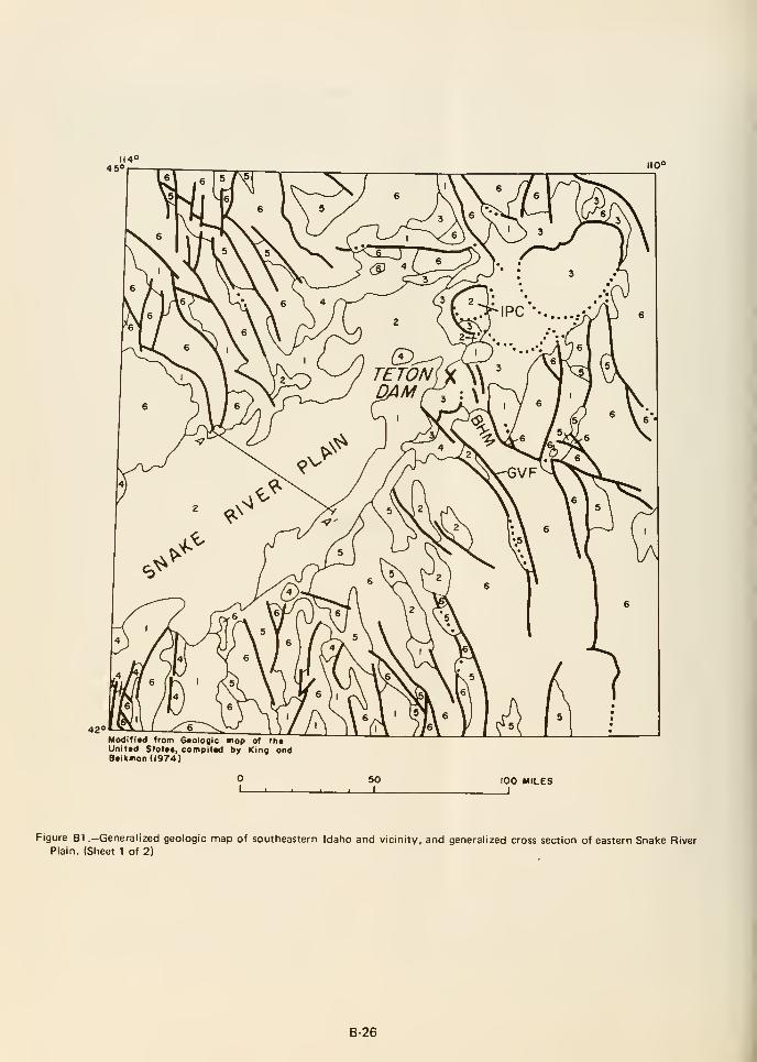
Modifitd from Geologic mop of fh«Unjitd Stolct, compilad by King ondB«ikmon(l974)
SO_i 1 L_
100 MILESI
Figure B1 .—Generalized geologic map of southeastern Idaho and vicinity, and generalized cross section of eastern Snake RiverPlain. (Sheet 1 of 2)
B-26
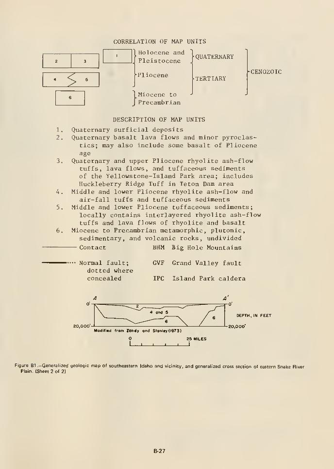
2 3
^
CORRELATION OF MAP UNITS
QUATERNARYsne J
-Pliocene
Holocene and
Pleistocene
}Miocene to
Precambrian
TERTIARYCENOZOIC
4.
5,
DESCRIPTION OF MAP UNITS
Quaternary surficial depositsQuaternary basalt lava flows and minor pyroclas-
tics; may also include some basalt of Plioceneage
Quaternary and upper Pliocene rhyolite ash-flowtuffs, lava flows, and tuffaceous sedimentsof the Yellowstone-Island Park area; includesHuckleberry Ridge Tuff in Teton Dam area
Middle and lower Pliocene rhyolite ash-flow and
air-fall tuffs and tuffaceous sedimentsMiddle and lower Pliocene tuffaceous sediments;
locally contains interlayered rhyolite ash-flowtuffs and lava flows of rhyolite and basalt
Miocene to Precambrian metamorphic, plutonic,sedimentary, and volcanic rocks, undivided
— Contact BHM Big Hole Mountains
Normal fault;dotted whereconcealed
GVF Grand Valley fault
IPC Island Park caldera
20,000Modifiad from Zotidy ond Stonl«y(l973)
25 MILES
-J 1- _!_
DEPTH, IN FEET
20,000'
Figure B1 .-Generalized geologic map of southeastern Idaho and vicinity, and generalized cross section of eastern Snake RiverPlain. (Sheet 2 of 2)
B-27
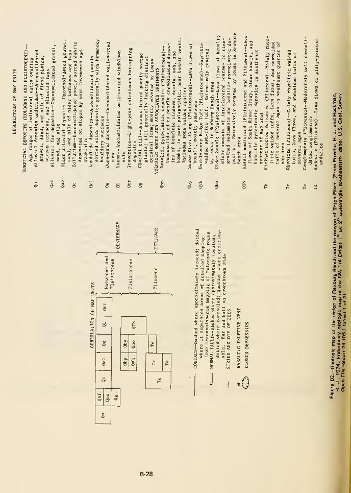
u c <u c 01 <u c
O rH
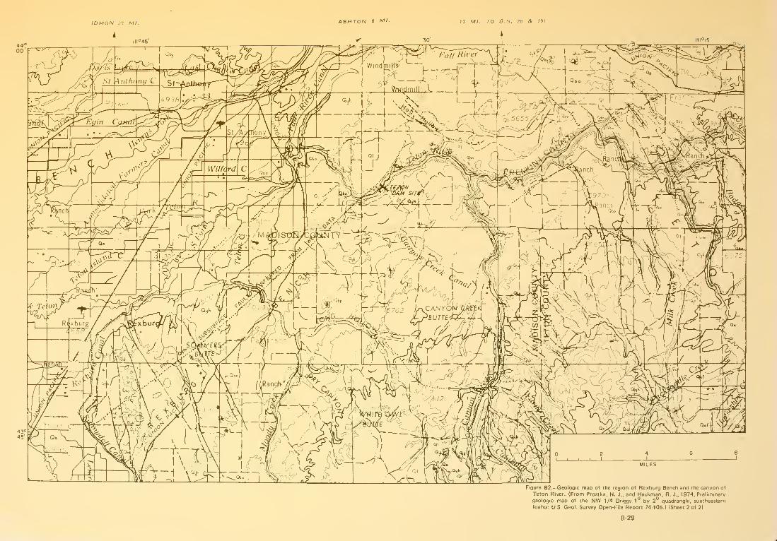
ASHTON 8 Ml 13 Ml. TO O.S. 20 & 191
Figure B2.—Geologic map of the region of Rexburg Bench and the canyon of
Teton River. (From Prostka, H. J., and Hackman, R, J., 1974. Preliminary
Idaho: U.S. Geol. Survey Open-File Report 74-105.) (Sheet 2 of 2)
B-29

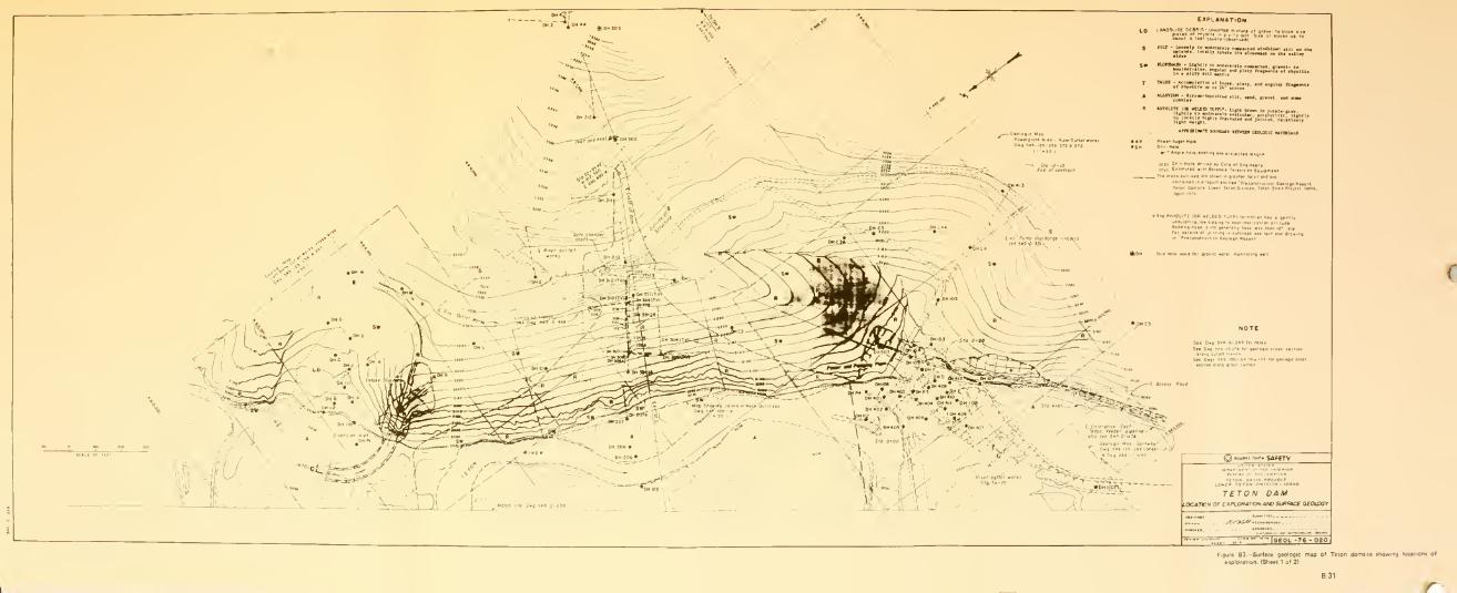
EWPLAN4TI0N
TETON DAMLOCATION OF e»PLOffATK)N Aft) SUf/aC£ GEOLOGY
^.u.. .. ....|qeo(_ -76 - 02o'
Figure B3.—Surface geologic map o( Teton damiite thoMirig locaiiont of
enploiation. [Sheet 1 at 21

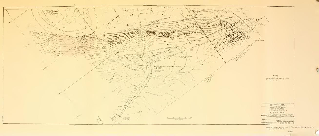
^ aunavj lyinit SAfETV
TETON DAMLOCATION or EXPLORATION AfO) SURFACE GEOLOGY
|GE0L-76-02l
Figure 83 -Surface geologic map of Teion damiite ihowing locations ot
exploration (Sheet 2 of 21


Figure B4.—Geologic section along upstream row of holes of grout curtain,
station -5+00 to station 49-K)0. (Sfieet 1 of 4)
B-35

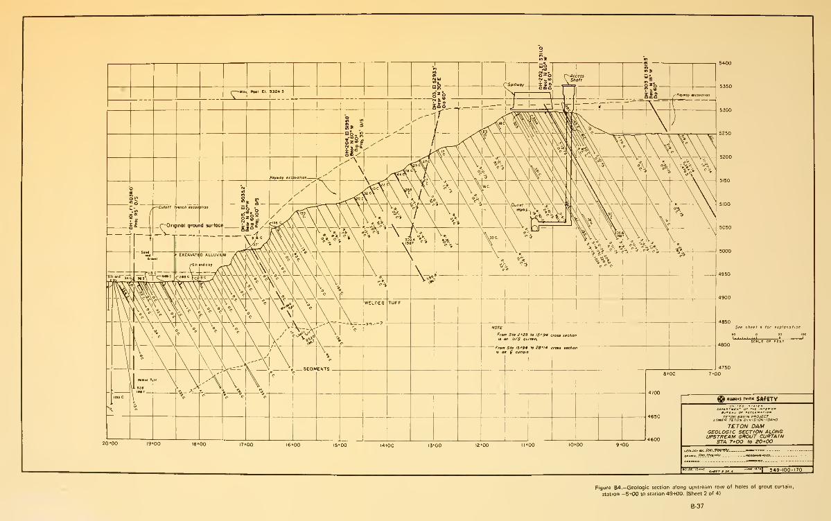
Figure B4.—Geologic section along upstream row of holes of grout curtain,
station -5-K)0 to station 49+00. (Sfieet 2 of 4)
B-37

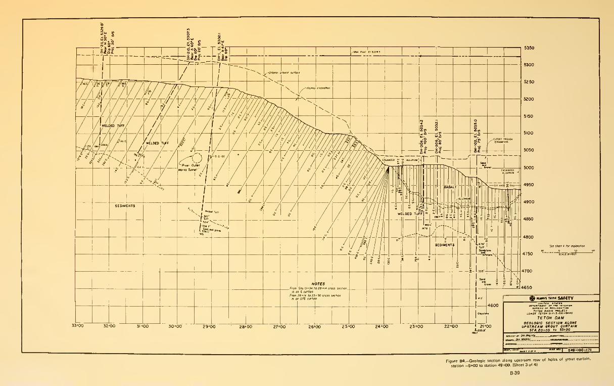
Figure B4.-Geologic section along upstream row of holes of grout curtain,
station -5+00 to station 49+00. (Sheet 3 of 4)
B-39

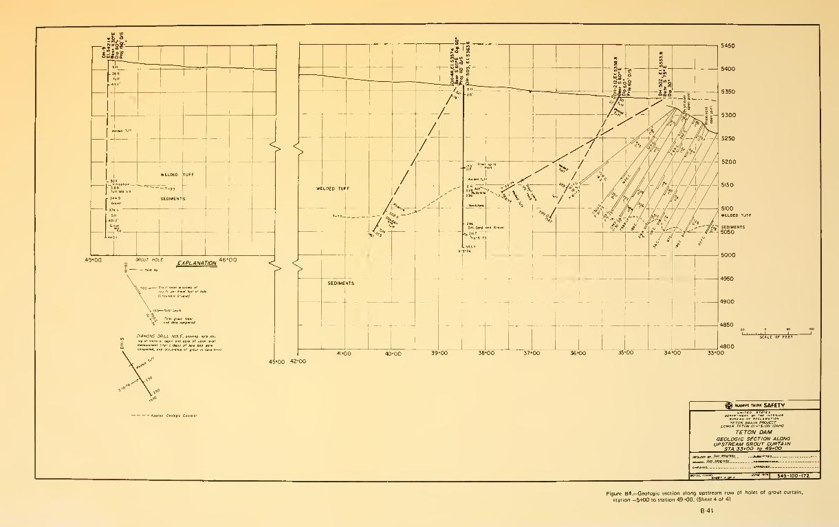
r^J7?^9

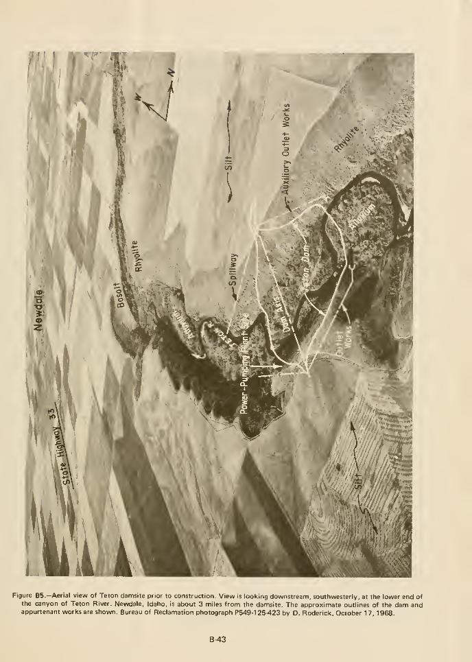
Figure B5.—Aerial view of Teton damsite prior to construction. View is looking downstream, southwesterly, at the lower end ofthe canyon of Teton River. Newdale, Idaho, is about 3 nniles from the damsite. The approximate outlines of the dam andappurtenant works are shown. Bureau of Reclamation photograph P549-125-423 by D. Roderick, October 17, 1968.
B-43


ki

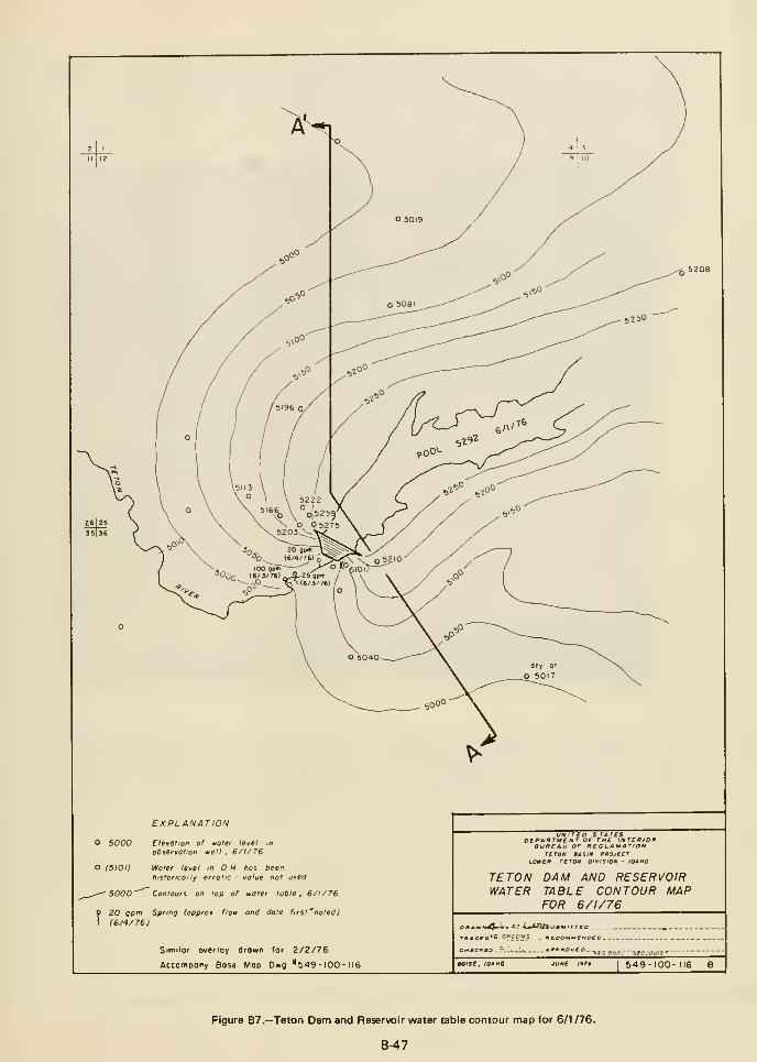
EXPLANATION
O 5000 Elevation of water le^el mobservation well, 6/1/76
o (5101) Water level m D h has beenhistorically erratic - value not used
^.-^ 5000"'^ Contours on top of water table, 6/1/76
9 20 gpm Spring (approx flow arid date firsf^noted)
1 (6/4/76)
Similor overlay drown for 2/2/76
Accompony Bose Mop Dwg *549 - lOO - 116
urvirtD sraresDEPAffTVENT OF THE INTERIORBUREAU OF RECLAMATION
TETON BASIN PROJECTLOWER TETON DIVISION - IDAHO
TETON DAM AND RESERVOIRWATER TABLE CONTOUR MAP
FOR 6/1/76
CnECitEO .
aoise. IDAHO JUN£ I9?t 549-100-116 B
Figure B7.—Teton Dam and Reservoir water table contour map for 6/1 /76.
B-47
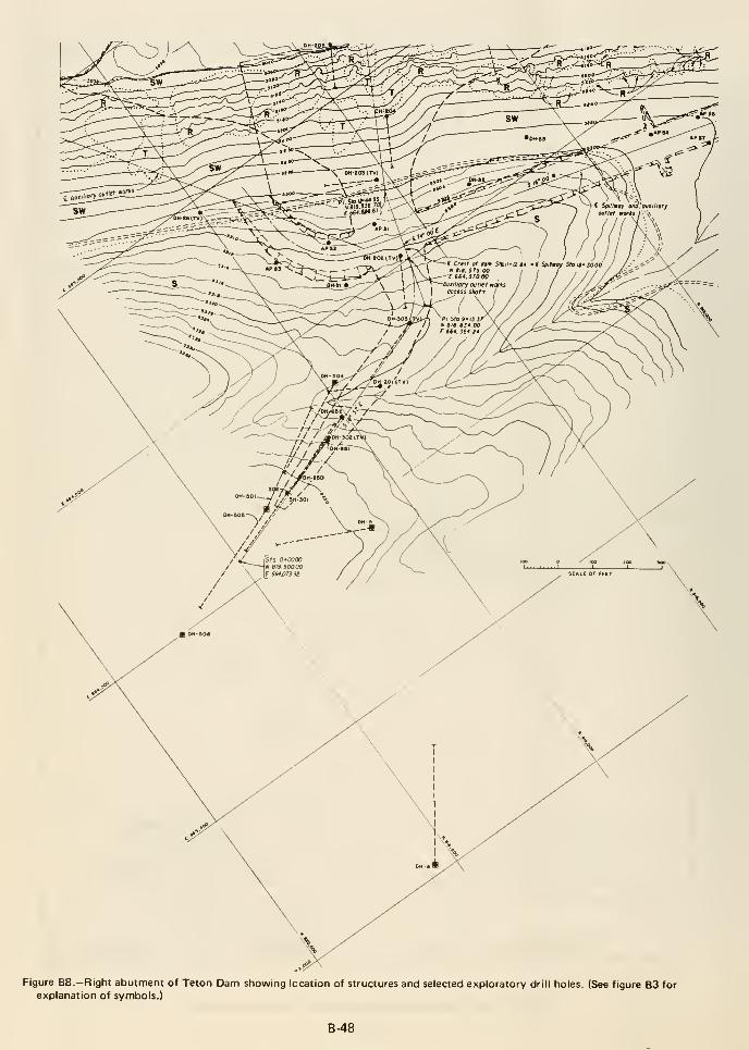
Figure B8.—Right abutment of Teton Dam showing location of structures and selected exploratory drill holes. (See figure B3 forexplanation of symbols.)
B-48
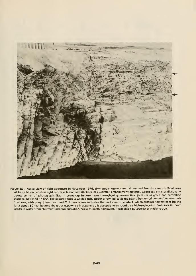
- -- Vl_ «
% f^ -MAW . K.< -'9^' -^ ^"i, . "-^
Figure B9.—Aerial view of right abutment in November 1976, after embanl<ment material removed from key trench. Small area
of loose fill on bench in right center is temporary stockpile of excavated embankment material. Grout cap extends diagonally
across center of photograph. Gap in grout cap between two throughgoing near-vertical joints is at grout cap centerline
stations 13+98 to 14+22. The exposed rock is welded tuff. Upper arrow indicates the nearly horizontal contact between unit
1 (above, with platy joints) and unit 2. Lower arrow indicates the unit 2-unit 3 contact, which extends downstream (to the
left) about 50 feet beyond the grout cap, where it apparently is abruptly terminated by a high-angle joint. Dark area in lower
center is water from abutment cleanup operation. View to north-northwest. Photograph by Bureau of Reclamation.
B-49
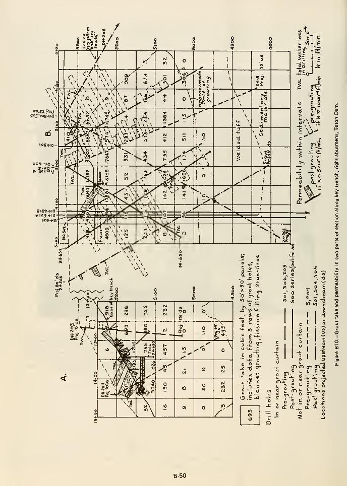
o(A
t(0ao
oo
I.
d
B-50

APPENDIXES
B-51

APPENDIX B 1
Joints, Fissures, and Voidsin Rhyolite Welded Ash-flow Tuff
at Teton Damsite, Idaho
by
Harold J. Prostka

UNITED STATES DEPARTMENT OF THE INTERIOR
GEOLOGICAL SURVEY
Joints, Fissures, and Voids
in Rhyolite Welded Ash-flow Tuff
at Teton Damsite, Idaho
By
Harold J. Prostka
Open-File Report 77-211
1977
This report is preliminary and has not
been edited or reviewed for conformity
with U.S. Geological Survey standards
or nomenclature.
B-55

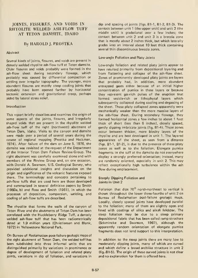
JOINTS, FISSURES, AND VOIDS IN
RHYOLITE WELDED ASH FLOW TUFFAT TETON DAMSITE, IDAHO
By HAROLD J. PROSTKA
Abstract
Several kinds of joints, fissures, and voids are present in
densely welded rhyolite ash-flow tuff at Teton damsite.
Older fissures and voids probably were formed in the
ash-flow sheet during secondary flowage, which
probably was caused by differential compaction or
settling over irregular topography. The younger, more
abundant fissures are mostly steep cooling joints that
probably have been opened farther by horizontal
tectonic extension and gravitational creep, perhaps
aided by lateral stress relief.
Introduction
This report briefly describes and examines the origin of
some aspects of the joints, fissures, and irregularly
shaped voids that are present in the rhyolite welded
ash-flow tuff of the right (northwest) abutment of
Teton Dam, Idaho. Visits to the canyon and damsite
were made over a period of several years during the
course of regional mapping (Prostka and Hackman,
1974). After failure of the dam on June 5, 1976, the
damsite was revisited at the request of the Department
of the Interior Teton Dam Failure Review Group. The
right abutment was carefully examined alone and with
members of the Review Group and, on one occasion,
with Donald A. Swanson, U.S. Geological Survey, vuho
provided additional insights and discussion on the
origin and significance of the volcanic features exposed
there. The terminology and concepts pertaining to
ash-flow tuffs that are used here are those developied
and summarized in several definitive papers by Smith
(1960a, b) and Ross and Smith (1961), in which the
processes of deposition, compaction, welding, and
cooling of ash-flow tuffs are described.
The rhyolite that forms the walls of the canyon of
Teton River and the abutments of Teton Dam has been
correlated with the Huckleberry Ridge Tuff, a densely
welded ash-flow tuff that has been radiometrically
dated at 1.9 million years (Christiansen and Blank,
1972) in Yellowstone National Park.
On Bureau of Reclamation post-failure geologic maps of
the right abutment of Teton Dam, the welded tuff has
been subdivided into three informal units that are
distinguished primarily by variations in prominence or
degree of development of foliation and related platy
joints, variations in dip of foliation, and variations in
dip and spacing of joints (figs. B1-1, B1-2, Bl-3). Thecontact between unit 1 (the upper unit) and unit 2 (the
middle unit) is gradational over a few inches; the
contact between unit 2 and unit 3 is a breccia zone
that is mostly about 2 inches thick, but which laterally
grades into an interval about 10 feet thick containing
several thin discontinuous breccia zones.
Low-angle Foliation and Platy Joints
Low-angle foliation and related platy joints appear to
have resulted primarily from depositional layering and
from flattening and collapse of the ash-flow sheet.
Zones of prominently developed platy joints are layers
that probably had, in addition, more abundant
entrapped gases either because of an initial higher
concentration of pumice in these layers or because
they represent gas-rich pulses of the eruption that
formed vesicle-rich or lithophysal layers which
subsequently collapsed during cooling and degassing of
the sheet. These platy collapsed zones apparently were
mechanically weaker than the more massive layers of
the ash-flow sheet. During secondary flowage, they
formed horizontal zones a few inches to about 1 foot
thick of short (less than 6 inches), closely spaced,
gently dipping imbricate joints (fig. B1-4). These zones
occur between thicker, more blocky layers of the
rhyolite and are best developed in unit 1. The layered
appearance of the sheet, as seen from a distance
(figs. B1-1, B1-2), is due to the presence of these platy
zones as well as to the foliation. Elongate pumice
fragments in the tuff at the dgmsite do not everywhere
display a strongly preferred orientation; instead, manyare randomly oriented, especially in unit 2. This mayreflect exceptionally high turbulence within the ash
flow during emplacement.
Steeply Dipping Foliation and
Joints in Unit 2
Foliation that dips 70° north-northeast to vertical is
shown throughout the lower three-fourths of unit 2 on
Bureau of Reclamation post-failure geologic maps.
Locally, closely spaced joints have developed parallel
to the foliation; many of them are slightly open and
lined with coatings of silica and alkali feldspar. The
steep foliation may be due to a steep primary
depositional fabric that has been called ramp structure
(Schmincke and Swanson, 1967), although the
apparently random orientation of elongate pumice
fragments does not lend support to this interpretation.
In addition to the steep joints there are many low to
moderately dipping joints, many of which are curved
and which define a broad archlike structure in unit 2
(fig.-B1-5). The origin of these curved joints is not clear
and no explanation for them is offered here.
B-57
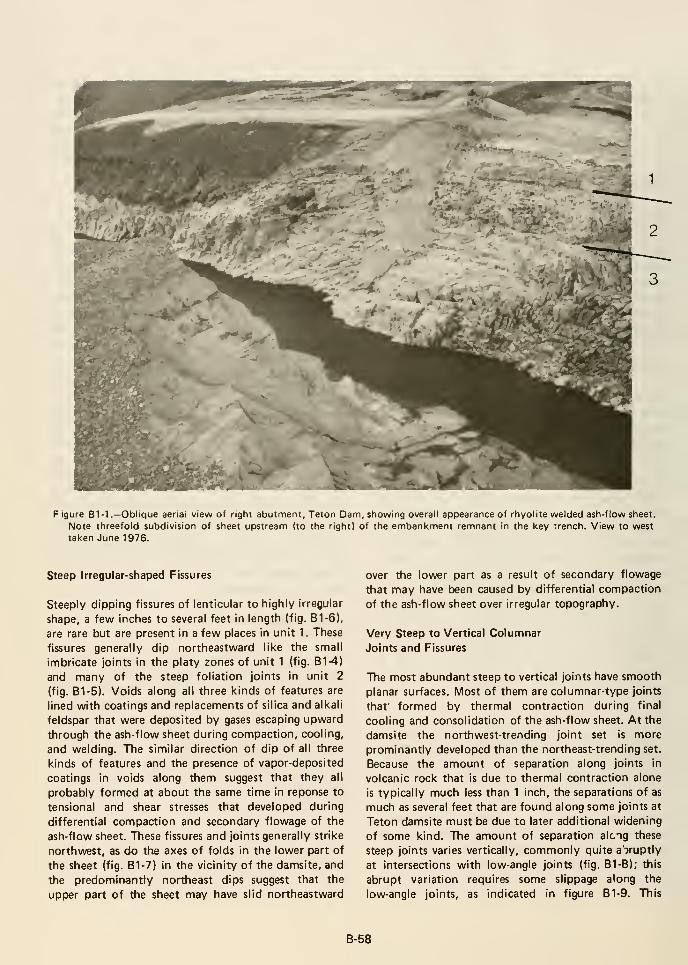
F igure B1-1 .—Oblique aerial view of right abutment, Teton Dam, showing overall appearance of rhyolite welded ash-flow sheet.
Note threefold subdivision of sheet upstream (to the right) of the embankment remnant in the key trench. View to west
taken June 1976.
Steep Irregular-shaped Fissures
Steeply dipping fissures of lenticular to highly irregular
shape, a few inches to several feet in length (fig. B1-6),
are rare but are present in a few places in unit 1. These
fissures generally dip northeastward like the small
imbricate joints in the platy zones of unit 1 (fig. B1-4)
and many of the steep foliation joints in unit 2
(fig. B1-5). Voids along all three kinds of features are
lined with coatings and replacements of silica and alkali
feldspar that were deposited by gases escaping upward
through the ash-flow sheet during compaction, cooling,
and welding. The similar direction of dip of all three
kinds of features and the presence of vapor-deposited
coatings in voids along them suggest that they all
probably formed at about the same time in reponse to
tensional and shear stresses that developed during
differential compaction and secondary flowage of the
ash-flow sheet. These fissures and joints generally strike
northwest, as do the axes of folds in the lower part of
the sheet (fig. B1-7) in the vicinity of the damsite, and
the predominantly northeast dips suggest that the
upper part of the sheet may have slid northeastward
over the lower part as a result of secondary flowage
that may have been caused by differential compaction
of the ash-flow sheet over irregular topography.
Very Steep to Vertical Columnar
Joints and Fissures
The most abundant steep to vertical joints have smooth
planar surfaces. Most of them are columnar-type joints
that' formed by thermal contraction during final
cooling and consolidation of the ash-flow sheet. At the
damsite the northwest-trending joint set is more
prominantly developed than the northeast-trending set.
Because the amount of separation along joints in
volcanic rock that is due to thermal contraction alone
is typically much less than 1 inch, the separations of as
much as several feet that are found along some joints at
Teton damsite must be due to later additional widening
of some kind. The amount of separation along these
steep joints varies vertically, commonly quite aVuptly
at intersections with low-angle joints (fig. B1-8); this
abrupt variation requires some slippage along the
low-angle joints, as indicated in figure B1-9. This
B-58
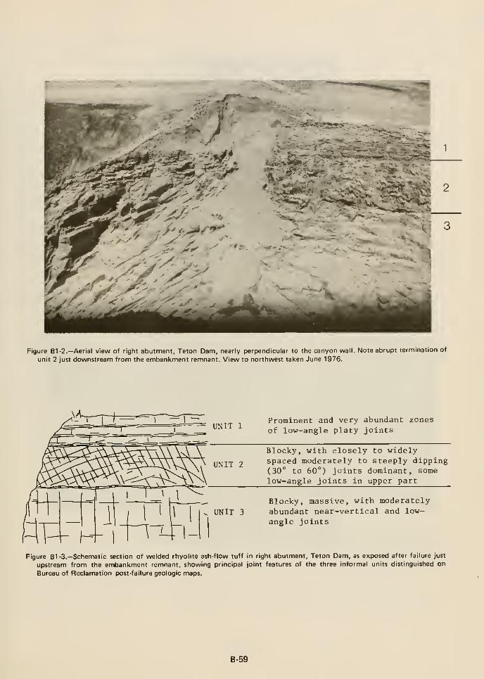
Figure B1-2.-Aerial view of right abutment, Teton Dam, nearly perpendicular to the canyon wall. Note abrupt termination of
unit 2 just downstream from the embankment remnant. View to northwest taken June 1976.
= UNIT 1Prominent and very abundant zones
of low-angle platy joints
Blocky, with closely to widelyspaced moderately to steeply dipping(30° to 60°) joints dominant, some
low-angle joints in upper part
UNIT 2
Blocky, massive, with moderatelyabundant near-vertical and low-
angle joints^ UNIT 3
Figure B1 -3.—Schematic section of welded rhyolite ash-flow tuff in right abutment, Teton Dam, as exposed after failure just
upstream from the embankment remnant, showing principal joint features of the three informal units distinguished on
Bureau of Reclamation post-failure geologic maps.
B-59
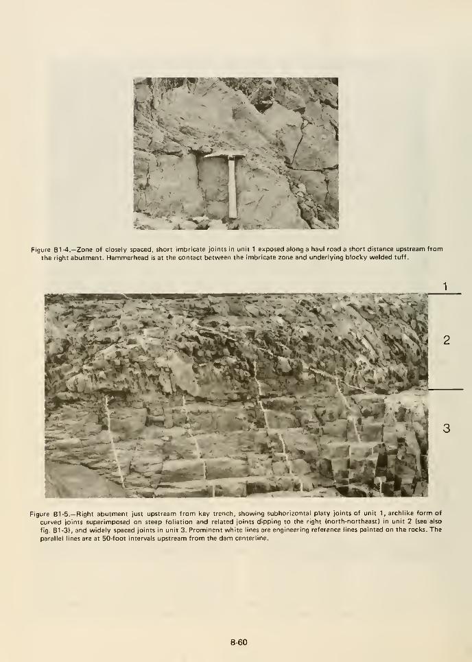
^"flBFf
'*!%*^
Figure B1-4.—Zone of closely spaced, short imbricate joints in unit 1 exposed along a haul road a short distance upstream from
the right abutment. Hammerhead is at the contact between the imbricate zone and underlying blocky welded tuff.
Figure B1 -5.—Right abutment just upstream from key trench, showing subhorizontal platy joints of unit 1, archlike form of
curved joints superimposed on steep foliation and related joints dipping to the right (north-northeast) in unit 2 (see also
fig. B1-3), and widely spaced joints in unit 3. Prominent white lines are engineering reference lines painted on the rocks. The
parallel lines are at 50-foot intervals upstream from the dam centerline.
B-60
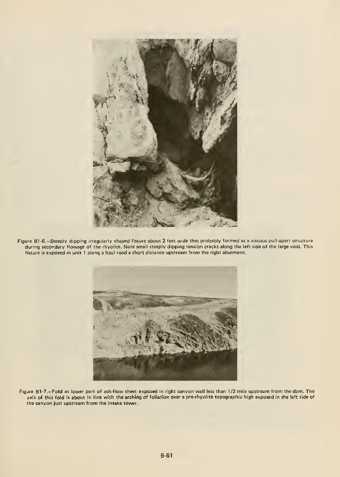
Figure B1 -6.—Steeply dipping irregularly shaped fissure about 2 feet wide that probably formed as a viscous pull-apart structure
during secondary f lowage of the rhyolite. Note small steeply dipping tension cracks along the left side of the large void. This
fissure Is exposed in unit 1 along a haul road a short distance upstream from the right abutment.
Figure B1-7.—Fold in lower part of ash-flow sheet exposed in right canyon wall less than 1/2 mile upstream from the dam. Theaxis of this fold is about in line with the arching of foliation over a pre-rhyolite topographic high exposed in the left side of
the canyon just upstream from the intake tower.
B-61
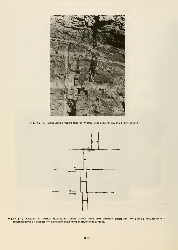
Figure B1 -8.—Large vertical fissure apF>arently offset along several low-angle joints in unit 1
.
Figure B1 -9.—Diagram of vertical fissure; horizontal offsets show how different separation (>) along a vertical joint is
accommodated by slippage (^ along low-angle joints in rhyolite at damsite.
B-62
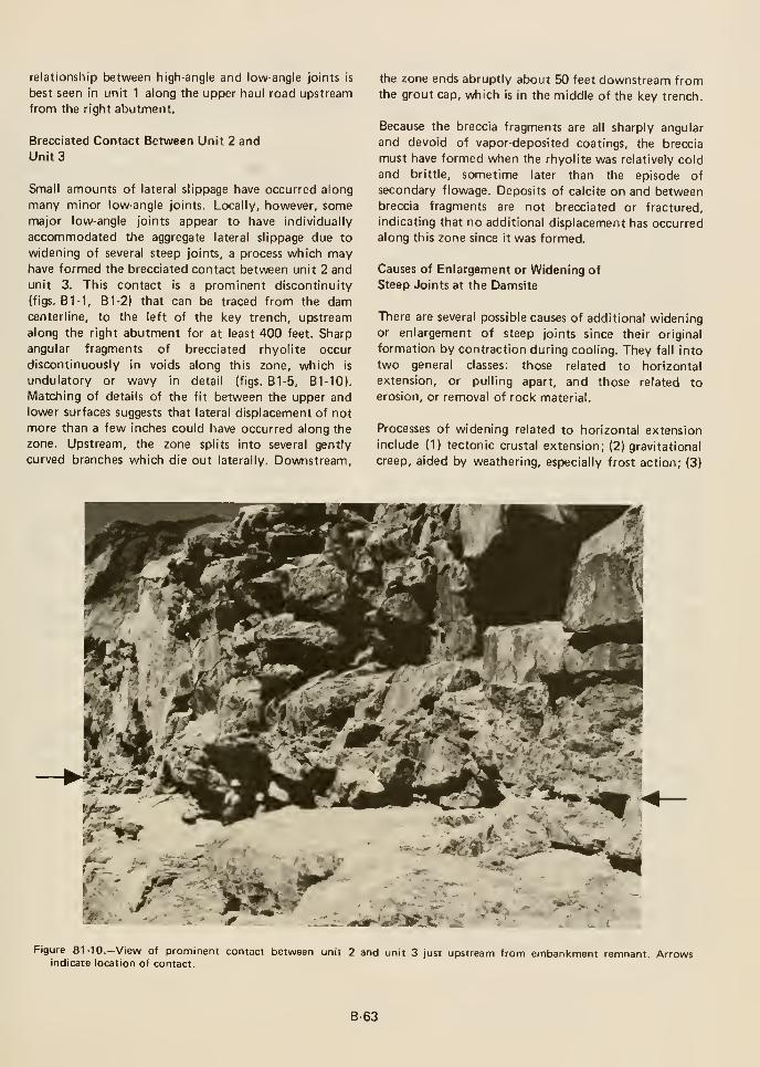
relationship between high-angle and low-angle joints is
best seen in unit 1 along the upper haul road upstream
from the right abutment.
Brecciated Contact Between Unit 2 and
Units
Small amounts of lateral slippage have occurred along
many minor low-angle joints. Locally, however, somemajor low-angle joints appear to have individually
accommodated the aggregate lateral slippage due to
widening of several steep joints, a process which mayhave formed the brecciated contact between unit 2 and
unit 3. This contact is a prominent discontinuity
(figs. B1-1, B1-2) that can be traced from the damcenterline, to the left of the key trench, upstream
along the right abutment for at least 400 feet. Sharp
angular fragments of brecciated rhyolite occur
discontinuously in voids along this zone, which is
undulatory or wavy in detail (figs. B1-5, 81-10).
Matching of details of the fit between the upper andlower surfaces suggests that lateral displacement of not
more than a few inches could have occurred along the
zone. Upstream, the zone splits into several gently
curved branches which die out laterally. Downstream,
the zone ends abruptly about 50 feet downstream fromthe grout cap, which is in the middle of the key trench.
Because the breccia fragments are all sharply angular
and devoid of vapor-deposited coatings, the breccia
must have formed when the rhyolite was relatively cold
and brittle, sometime later than the episode of
secondary flowage. Deposits of calcite on and betweenbreccia fragments are not brecciated or fractured,
indicating that no additional displacement has occurredalong this zone since it was formed.
Causes of Enlargement or Widening of
Steep Joints at the Damsite
There are several possible causes of additional wideningor enlargement of steep joints since their original
formation by contraction during cooling. They fall into
two general classes: those related to horizontal
extension, or pulling apart, and those related to
erosion, or removal of rock material.
Processes of widening related to horizontal extension
include (1) tectonic crustal extension; (2) gravitational
creep, aided by weathering, especially frost action; (3)
Figure Bl-IO.-View of prominent contact between unit 2 and unit 3 just upstream from embankment remnant. Arrowsindicate location of contact.
B-63
movement of rock toward the canyon because of
lateral stress relief, or unloading; and (4) movement
caused by differential settlement due to subsurface
erosional sapping of fine-grained sediments beneath the
rhyolite.
Evidence for (1) tectonic crustal extension includes the
following: (a) the Snake River Plain and surrounding
Basin-Range provinces of eastern Idaho have been
undergoing regional tectonic extension from at least
late Miocene time to the present; (b) tectonic
extension in the Teton-Rexburg Bench area, in
particular, has been most active since late Pliocene
time, or since emplacement of the Huckleberry Ridge
Tuff less than 2 million years ago; and (c) the
predominant northwest trend of fissures at the damsite
is consistent with the predominant northwest trend of
Quaternary fissure zones, such as the Great Rift on the
Snake River Plain, and with the dominant trend of late
Cenozoic, possibly active, normal faults adjacent to the
plain.
(2) Gravitational creep has been the demonstrable
cause of block movement with attendant joint
widening at a number of places along the canyon, but
because most of the prominent wide fissures at the
damsite trend at high angles to the canyon walls it does
not seem likely that creep could have been the
principal cause of joint widening. Intersecting joints
conceivably might have blocked out large rock masses
that migrated canyonward, perhaps influenced by the
character of the underlying sediments, especially
claystone; however, the relative sparsity of wide
fissures oriented parallel to the canyon walls argues
against this process being the most important one.
(3) Stress relief due to erosion of the present canyon
may account for some widening of joints, particularly
in the lower part of the canyon; it probably is not an
especially important cause, however, and its effects
would be difficult to distinguish from widening due to
gravitational creep.
Little evidence supports (4) differential settlement
caused by subsurface erosional sapping. However,
because the rhyolite is underlain by variably inducated
fine-grained sediments interlayered with gravels, someof which may be ground-water aquifers, this process
cannot be entirely discounted.
Erosional processes include spalling or slabbing of
fractured rock along joints and enlargement by
hydrothermal leaching. Spalling has contributed to the
further enlargement of already opened joints, but it
cannot be the primary process of widening because
there is no effective way of removing the coarse rubble
from the fissure. Hydrothermal leaching probably is
not important except very locally, because nearly all of
the exposed fissures have surfaces that are smooth and
planar, not irregular and corroded.
On the basis of the available evidence, most of the
high-angle fissures at Teton damsite seem to be cooling
joints that subsequently have been further openedmainly by horizontal tectonic extension and locally bygravitational creep, perhaps aided to some extent by
lateral stress relief. Other fissures, formed earlier during
differential compaction and secondary flowage of the
ash-flow sheet, are not as numerous or as extensive as
the later ones. The rate of extension and its recency
have not adequately been established.
References Cited
Christiansen, R. L, and Blank, H. R., Jr., 1972,
Volcanic stratigraphy of the Quaternary rhyolite
plateau in Yellowstone National Park: U.S. Geol.
Survey Prof. Paper 729-B, 18 p.
Prostka, H. J., and Hackman, R. J., 1974, Preliminary
geologic map of the NW 1/4 Driggs 1° by 2°
quadrangle, southeastern Idaho: U.S. Geol.
Survey Open-File Report 74-105.
Ross, C. S., and Smith, R. L., 1961, Ash-flow tuffs;
their origin, geologic relations, and
identification: U.S. Geol. Survey Prof. Paper
366, 81 p.
Schmincke, Hans-Ulrich, and Swanson, D. A., 1967,
Laminar viscous flowage structures in ash-flow
tuffs from Gran Canaria, Canary Islands: Jour.
Geology, v. 75, no. 6, p. 641-664.
Smith, R. L. 1960a, Ash flows: Geol. Soc. America
Bull., V. 71, no. 6, p. 795-841.
-1960b, Zones and zonal variations in welded ash
flows,//? Shorter contributions to general
geology, 1959: U.S. Geol. Survey Prof. Paper
354-F,p. 149-159.
B-64
APPENDIX B-2
ANALYSES OF GROUNDWATER LEVELS IN
THE RIGHT ABUTMENT

FIGURES
Figure Page
B2-1 A, Water levels; B, Rate of water-level rise. Reservoir and
selected drill holes near right abutment, Teton Dam, Idaho B-74
B2-2 Variation of differences in water levels with time B-75
B2-3 Contours on an assumed plane water table defined by water levels
in drill holes 5, 6, and 506; shown at various time before
and during reservoir filling and after failure B-76
B-67

ANALYSES OF GROUND-WATERLEVELS IN THE RIGHT
ABUTMENT
The following analyses of ground-water levels in
observation wells in and near the right abutment were
made to determine, from the available data, the
changes that occurred during reservoir filling and after
failure and their possible significance.
Hydrologic Conditions in the Right
Abutment During Filling of the Reservoir
The data concerning hydrologic conditions in the right
abutment during filling of the reservoir were derived
from observations of water levels in previously drilled
exploration holes that were monitored for this purpose
during reservoir filling. Of the drill holes that were
monitored only those close to the grout curtain in the
right abutment were selected for analysis by the
Geology Task Group. The analyses, we believe, provide
pertinent information concerning ground-water levels
in the region downstation (northwest) of the spillway.
However, they also bear indirectly on hydrologic
conditions in the area of greater interest in the vicinity
of the grout curtain upstation (toward the river) from
the spillway.
The analyses are derived from observations reported in
the memorandum of June 14, 1976, from Regional
Director, Bureau of Reclamation, Boise, to Director of
Design and Construction on the subject "Reservoir
Seepage Loss Study—Teton Dam and Reservoir," with
attachments, which pertains to water levels in the
reservoir and in drill holes 5, 6, 501, 504, and 506(2)
(2 refers to the upper piezometer in that hole), and
from Records of Subsurface Investigations for Teton
Dam and Power and Pumping Plant, Bureau of
Reclamation, June, 1971, reprinted June 1976. The
location of these drill holes is shown in figure 88 of
Appendix B. The analyses consist of three bodies of
data: I, the variation of water levels with time shown in
figure B2-1A; II, variation of rates of water-level rise
with time, shown in figure B2-1B; and III, variation of
differences in water levels between selected locations
with time, shown in figure B2-2. The interpretation of
these data is in section IV.
I. Variation of water levels with time-
Figure B2-1A.
1. Filling of the reservoir continued at a fairly
steady rate through the months of
January, February, March, and early April
1976.
2. In early April the filling rate increased
markedly.
3. The behaviors of water levels in drill holes
501 and 504, both upstream from the
grout curtain, are similar. Drill hole 504,
being nearer to the reservoir, generally
showed water-level elevations about 3
days earlier than drill hole 501 during the
later stages of filling from April 10 until
the middle of May; later the delay was
greater, because these two inclined drill
holes are separated farther at higher
elevations.
4. The behaviors of water levels in drill hole 5,
downstream from the right end of the
grout curtain, and drill hole 506(2),
beyond the end of the grout curtain, are
similar. The extreme northwestern limit of
grouting is probably at about station 0-K)0
at elevation 5100, but the effective grout
curtain probably did not extend
downstation beyond station 1-K)0 (see
fig. BIO, Appendix B). The behavior of
water levels in drill holes 5 and 506(2)
appears somewhat different from that of
the 501-504 pair. Water levels in both drill
holes 5 and 506(2) were always at
considerably lower elevations than in drill
holes 501 and 504, as was to be expected.
II. Variation of rates of water-level rise with
time-Figure B2-1B.
1. The filling rate curve for the reservoir (2-day
averages) shows a fairly constant rate until
about April 3, when a marked increase in
rate occurred, peaking at about April 13
at about 3 ft/day (peak 1 ) and falling
back, with an intervening minor rise, to
about 1 ft/day on April 28.
2. After April 28 the rate of reservoir filling
increased steadily to a peak of about
4 ft/day on May 19 (peak 2), then
dropped off to a rate of about 2.3 ft/day
at the time approaching dam failure.
3. Comparison of rate curves:
a. Comparison of drill hole 501 (just
upstream from the curtain, a slant hole
60P from horizontal directed
S. 3CP E.) with the reservoir.-The rate
of rise in drill hole 501 generally
followed that of the reservoir but
exceeded it slightly during much of
March, in mid-April, and in mid-May.
B-69
It appears to have lagged about 1 day
behind the April 13 peak of reservoir
filling rate and 3-1/2 days behind the
May 19 peak of reservoir filling rate.
The time spacing of readings in the
drill holes was not daily, as at the
reservoir, which makes all such
correlations subject to some error.
Based on a water-level reading on June
1, the rate of rise of water in drill hole
501 in late May became less than the
rate of rise in the reservoir.
b. Comparison of drill hole 506(2) with the
reservoir.—Dt\\\ hole 506 is vertical,
about 300 feet beyond the end of and
on line with the grout curtain. The
upper piezometer, 506(2), was erratic
until early April, its rate of rise being
sometimes above and sometimes below
that of the rate of the reservoir.
Between April 3 and 4, essentially at
the same time as the beginning of the
rise of reservoir rate to peak 1, drill
hole 506(2) also began a distinct
increase in rate. The peak rate of the
reservoir on about April 13 and
minimum rate on about April 28 were
not reflected in the record of drill hole
506(2) because of lack of readings. The
rate increased after May 5 and
exceeded that of the reservoir rise rate
on about May 12, finally peaking at a
rate of about 10.55 ft/day on May 19,
at the same time that the reservoir rate
peaked. This rate is 2.7 times the peak
maximum rate of rise of the reservoir.
As the rate of reservoir filling declined
late in May, so also did the rate of rise
of water in drill hole 506(2), although
it remained at a faster rate than that of
the reservoir.
c. Comparison of drill hole 5 with the
reservoir.— Dr\\\ hole 5 is located just
barely behind and downstream from
the grout curtain (see fig. BIO,
Appendix B). It is angled 60° from
horizontal and directed N. 25° E. Its
record is perhaps the most important
of all, as it is the only drill hole in the
right abutment behind the grout
curtain (a short distance) that was
monitored during filling of the
reservior. Figure B2-1B shows that its
rate of rise approximately followed that
of the reservoir until early April.
Between April 3 and 4, essentially at the
same time as the reservoir filling rate
accelerated toward peak 1, drill hole 5
showed an increase in rate of water-level
rise. The rate of rise in drill hole 5
reflected either (a) the April 13 peak
(peak 1 ) of the reservoir rate on about
April 1 8, a delay of 5 days, (b) increased
permeability at about elevation 5180,
which was the reservoir level on about
April 10, or (c) a change in other
hydraulic properties of the welded tuff.
The minimum rate of rise in drill hole 5
between April 27 and 28 apparently
reflected the April 28 minimum rate of
rise of the reservoir, but the spacings of
readings on drill hole 5 and averaging
rates over long times probably accounts
for this minor "anticipation." After
that, the rate of rise of water in drill
hole 5 accelerated, surpassing the rate
of rise of the reservoir around May 1 7 or
1 8 and peaking between May 22 and 23
at a rate of 1 1.64 ft/day, or 2.95 times
the peak rate of rise of the reservoir that
was attained on May 1 9. The rate of rise
of water in drill hole 5 then declined
abruptly, although remaining higher
than the rate of rise of the reservoir. Therate of rise of the reservoir also
declined, although the decline in the
rate of rise of the reservoir was muchless abrupt.
III. Variation of differences in water levels
between the reservoir and drill holes and
among drill holes with time.
Differences in water levels between the
reservoir and selected drill holes, and between
selected drill holes, were examined, as they
varied with time, because pressure differential
is one of the principal factors determining the
velocity of water moving from place to place
and for removing debris that might be
clogging fissures.
In figure B2-2, curve A shows the variation of
the pressure differential between the reservoir
and drill hole 506(2). A rise in early April
apparently reflects the increase in reservoir
filling rate, and the slight decline in mid-April
apparently reflects the decline in filling rate
during that period. The rise in early May
B-70
appears also to be a response to the increase
in filling rate of the reservoir. The pressure
differential on May 13, distributed in some
unknown manner over the approximately
1,300 feet to the reservoir edge, was about
133 feet of water. On or about May 13 a very
rapid decline in pressure differential began
that continued until the last observation
preceding the dam failure.
Curve B, showing the variation of the
difference in water level between the
reservoir and drill hole 5, shows a sharper
increase in level differences than curve A in
late April and early May, reflecting perhaps
the effect of the grout curtain in retarding
the rise of water in drill hole 5 compared
with drill hole 506(2). The sharp drop occurs
on about May 18, about 5 days later than at
drill hole 506(2).
Curves C and D show, respectively, the
variations in pressure differential between
drill hole 501 and drill hole 506(2) and
between drill hole 501 and drill hole 5, the
latter drill hole being on the other side
(downstream) of the grout curtain from drill
hole 501. These curves are similar in that
both show a steady state in the latter part of
March, in equilibrium with the then steady
rate of reservoir filling, and both record a rise
reflecting the increased filling rate in early
April. However, curve C, the pressure
differential between drill hole 501 and drill
hole 506(2), shows a rapid decline beginning
on May 13, or between May 13 and 14,
whereas the similar rapid decline in pressure
differential between drill hole 501 and drill
hole 5 was delayed. The delay period was 6
days, if only the data points are used to
compare the peaks, and about 5 1/2 days if
water levels are interpolated between times of
observation (dotted line).
Curves E and F show, respectively, the
variations in pressure differential between the
reservoir and drill holes 501 and 504. Their
traces are similar to each other and very
different from curves A and B. Curves E and
F show a general decline indicating a
tendency for water levels in drill holes 501
and 504 to come to equilibrium with the
reservoir. This trend is disturbed briefly in
early April, apparently by the accelerated
filling rate of the reservoir. Curve E shows a
minor loss of pressure differential beginning
about May 13, which was recovered by June
1, back to the declining trend of late April
and early May.
Water-level observations in drill holes 5, 6,
and 506(2) permit drawing contours on an
assumed plane surface representing the water
table passing through the three drill holes
(fig. B2-3). This surface was gently inclined
toward N. 70° W. during early stages of
filling, dipped steeply directly westward
about May 13, swung to about S. 70° W. on
June 1, and to S. 65° W. on June 5 (using
projected values for water levels). These
changes appear to be those that might be
expected as the water table, formerly
adjusted to the northeast-trending Teton
River, was affected by the rise of water in the
reservoir, and by the grout curtain. During
filling of the reservoir the direction of slope
of the water table between drill hole 5 and
the river is not known from observation, but
it was probably toward the south, or even
southeast as indicated in figure B7 of
Appendix B.
IV. Interpretation of data
The curves presented in figures B2-1, B2-2,
and B2-3 are derived from the available data
and arithmetic operations on these data. It is
probable that more information could be
extracted from a computer-supported
analysis of transient conditions with
consideration of the moving reservoir
boundary and the variation in space and time
of the hydraulic characteristics of the rock,
such as saturated thickness, transmissivity,
and storage coefficient. However, the lack of
data on water levels at critical times and
places would make the value of more
elaborate analysis questionable. The
interpretation of the simple curves in the
figures is attended with considerable
uncertainty; the curves do, however, bring
out some relations that bear on ground-water
conditions preceding failure:
1. There were two periods of departure from
steady rates of rise of water levels in
observation wells in the vicinity of the
right end of the grout curtain; one in
B-71
the period April 5-10 and a much moreImportant one in the period May13-19.
2. These periods of change may reflect (a)
change in filling rate of the reservoir,
(b) water levels reaching zones of
different permeability, or (c) variation
with water-level elevation of other
hydraulic characteristics of the welded
tuff.
3. The difference in water levels between the
reservoir and the drill holes, and amongsome of the drill holes, varied abruptly
in mid-May. As the hydraulic head is
one of the principal factors
determining the velocity of water
moving from place to place and for
removing the fillings of joints and open
fissures, it should be considered in
analysis.
4. The data in figures B2-1, B2-2, and B2-3
indicate an expectable flow to the end
of and around the grout curtain and
the possibility of a very strong pressure
pulse that reached drill hole 5 on or
before May 19. It would take a longer
time for this pulse to progress from
drill hole 5 to the canyon wall of the
Teton River and the dam embankmentitself than it took to go from drill hole
506(2) to drill hole 5. The distances of
travel are uncertain, owing to the
unknown path from drill hole 506 to
drill hole 5, the 60° inclination and
northeast orientation of drill hole 5,
the unknown pattern of joints between
drill hole 5 and the dam, and unknowndirection and magnitude of gradients
of the water table between drill hole 5
and the river. Using crude estimates of
distance, a delay time between drill
hole 506(2) and drill hole 5 of 6 days,
and a uniform rate of travel, the
water-level rise recorded at drill hole 5
would have reached the vicinity of the
canyon wall-dam embankmentinterface downstream from the grout
curtain about 16 days later, on June 4.
On June 3 two small springs developed in
the right abutment 600 and 900 feet
downstream of the spillway stilling
basin, flowing about 40 and 60 gallons
per minute, respectively. On June 4 a
spring flowing about 20 gallons per
minute developed on the right
abutment about 150 feet downstreamfrom the toe of the dam. Early in the
morning of June 5, the day of failure,
the first major seepage, 20 to 30 cubic
feet per second, developed in the right
abutment at about elevation 5045 near
to and above the toe of the
embankment. These springs of June
3-5 may record the arrival of the rise in
water levels discussed above, and
indicate progressive wall-rock
saturation that may have augmented
other possible processes that led to
failure higher in the embankment.
5. The drop in pressure differential between
drill hole 501 upstream from the grout
curtain and drill hole 5, downstream,
beginning on about May 19 could have
been caused by the establishment of a
direct hydraulic connection through
the grout curtain, rather than around
it. Perhaps both processes operated.
Flow over the curtain and grout cap on
about May 19 near the right end of the
key trench seems unlikely (a) because
the key trench was filled with
impermeable zone 1 material, and (b)
because the key trench bottom in that
vicinity is about at altitude 5250 and
the water level in drill hole 501 did not
reach 5250 until around May 25.
However, post-failure permeability tests
in drill hole 650 indicate that flow
under the trench at stations 3-t-50 to
3+70 could have begun before water
levels reached 5250 (see fig. BIO in
Appendix B).
6. The observed changes in (a) water levels in
the drill holes, (b) their rates, and (c)
the differences in levels among them,
and between them and the reservoir,
indicate hydrologic events in the
period May 13-19 that are worthy of
consideration. The significance of these
events is not clear because the available
data are inadequate. What is clear is
that more observation wells to measure
water levels during reservoir filling
were needed in the right abutment
closer to the reservoir on both sides of
the grout curtain near the damembankment. Although failure
occurred in the right abutment, the
same comment applies to the left
abutment.
B-72
Hydrologic Conditions in the Right
Abutment After Failure
The failure of the dam lowered the reservoir level to
about elevation 5055. Water stored in the banks of the
reservoir returned to the canyon walls, producing large
springs and seeps in the right abutment that were
observed from the air and ground. Their positions were
plotted and their flows were measured. Post-failure
water-level readings were recorded at the observation
drill holes shown in figure B2-1, as well as at other
wells. Water levels in drill holes close to the damdropped rapidly after the reservoir emptied. The rocks
intersected by drill hole 5 have very high permeability
above elevation 5100 (see fig. BIO in Appendix B).
When the reservoir emptied, the level in drill hole 5
dropped as fast as did the levels in wells on the
upstream side of the grout curtain (drill holes 501,
504) (see fig. B2-1). It is of interest to note in figure
B2-2 that the rapid declines in curves C and D that
begin in mid-May continue on the same trend through
the time of dam failure to the next reading, on June 9.
They then begin to level out. As shown in figure B2-3,
the direction of inclination of the water table, and its
gradient, within the triangle defined by water levels in
drill holes 5, 6, and 506, rapidly returned to conditions
approximating those before reservoir filling, although
the level on June 13, 1976, was about 120 feet higher
than on September 24, 1975 (fig. B2-3).
B-73
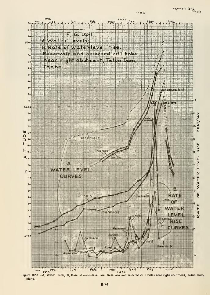
Nov. DecI9T6
Jan- Fab, May JuneMar AprilI 9Tt>
Figure B2-1.—A, Water levels; B, Rate of water-level rise. Reservoir and selected drill holes near right abutment, Teton Dam,Idaho.
B-74
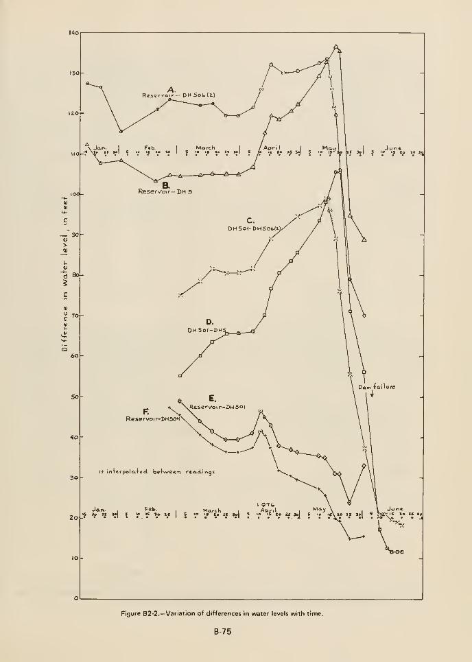
tMOr
Reservoir-DHSOH'
iTtrpolo-TecL between reaoLinqs
Jar\.,
?cb., MarchMarch
I
AprilI
'^'^^ \ I = V -*""•IS Ze t« ao 5 lo tf 20 £S Ja 5 lo ir\ xo tc 3o 9 ?<^<^ IS ID U lo• • • •< • • • • • A • 'V* * *^' ar** N^, - . J
Figure B2-2.—Variation of differences in water levels with time.
B-75
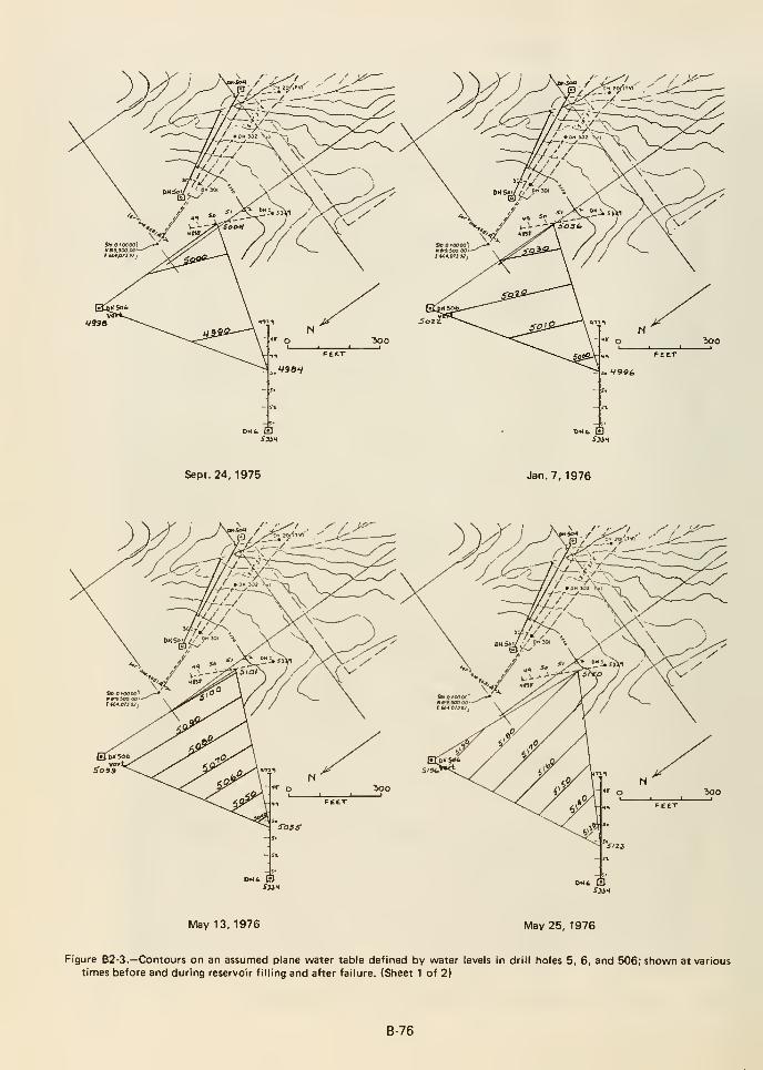
Sept. 24, 1975 Jan. 7, 1976
May 13,1976 May 25, 1976
Figure B2-3.—Contours on an assumed plane water table defined by water levels in drill holes 5, 6, and 506; shown at varioustimes before and during reservoir filling and after failure. (Sheet 1 of 2)
B-76
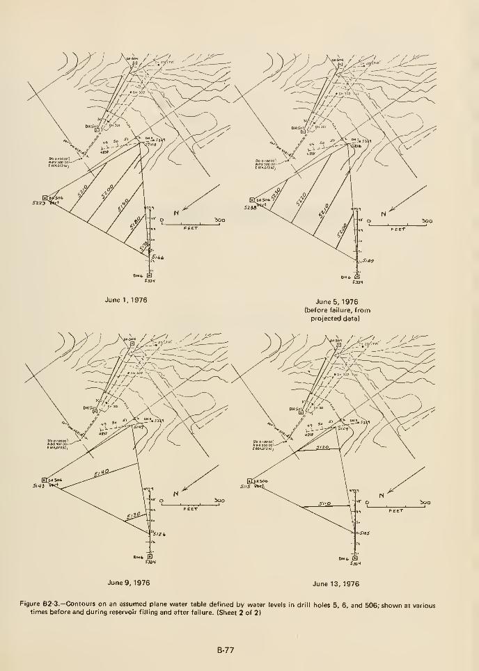
June 1, 1976 June 5, 1976(before failure, fromprojected data)
June 9, 1976 June 13, 1976
Figure B2-3.—Contours on an assumed plane water table defined by water levels in drill holes 5, 6, and 506; shown at varioustimes before and during reservoir filling and after failure. (Sheet 2 of 2)
B-77

«Appendix C
REPORT OF FINDINGS
Grouting Task Group
U.S. Department of the Interior
Teton Dam Failure Review Group
December 10, 1976

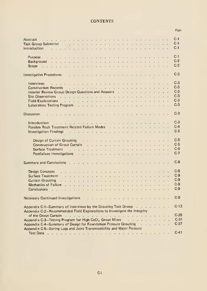
CONTENTS
Page
Abstract C-1
Task Group Submittal C-1
Introduction C-1
Purpose C-1
Background C-2
Scope C-2
Investigative Procedures C-3
Interviews C-3
Construction Records C-3
Interior Review Group Design Questions and Answers C-3
Site Observations C-3
Field Explorations C-3
Laboratory Testing Program C-3
Discussion C-3
Introduction C-3
Possible Rock Treatment Related Failure Modes C-4
Investigation Findings C-5
Design of Curtain Grouting C-5
Construction of Grout Curtain C-5
Surface Treatment C-6
Postfailure Investigations C-7
Summary and Conclusions C-8
Design Concepts C-8
Surface Treatment C-9
Curtain Grouting C-9
Mechanics of Failure C-9
Conclusions C-9
Necessary Continued Investigations C-9
Appendix C-1 -Summary of Interviews by the Grouting Task Group C-13
Appendix C-2-Recommended Field Explorations to Investigate the Integrity
of the Grout Curtain C-25
Appendix C-3—Testing Program for High CaCl2 Grout Mixes C-31
Appendix C-4—Summary of Design for Foundation Pressure Grouting C-37
Appendix C-5-Borlng Logs and Joint Transmissibillty and Water Pressure
Test Data C-41
C-i


ABSTRACT TFtANSMITTAL DOCUMENT
This report is the result of a study to evaluate the
adequacy of the Teton Dam grout curtain and surface
grouting to perform their design functions and to
determine, so far as possible, the contribution, or lack
thereof, of the rock treatment to the June 5, 1976,
dam failure. The study was conducted through
interviews of involved Bureau of Reclamation and
contractor fjersonnel, examination of construction
records, written design questions to the Bureau of
Reclamation, site observations, field explorations, and
laboratory tests (not yet completed).
The curtain grouting was performed in general
accordance with the contract specifications. Though
the grout curtain has been termed a multiline curtain
on the abutments, it is, in reality, a single line curtain
with grouting in rows up and downstream from the
centerline row to inhibit grout travel from the
centerline row. Only the centerline row was
split-spaced to closure. The potential performance of
the grout curtain should have been normal in terms of
limiting but not completely blocking seepage. During
the postfailure drilling and water pressure testing, a
permeable zone was discovered at shallow depths in the
grout curtain in the vicinity of station 13+50.
An attempt was made to seal open joints in the rock
surface outside the key trench between elevations 5075
and 5205. Although the need for a rock surface
treatment program was considered in the early stages
of design, such a program was apparently not included
in the final design. This treatment was not included in
the construction specifications. It was discontinuous
where treatment was used; it was not tied into the
grout curtain; and it was not applied to a significant
abutment area above elevation 5205.
In compliance with the assignment made by the
Chairman, Department of the Interior Teton DamFailure Review Group, the Grouting Task Group
submits this Report of Findings on the aspects of rock
treatment involved in the Teton Dam failure.
Paul R. Fisher, Chairman,Stjff Geologist,Engineering Division,Directorate of Civil Works,
Office, Chief of Engineers
Corps of Engineers
Ray Cope//^Ci^l Engineer, Grouting Specialist
Midwest Technical Service Center
USDA Soil Conservation Service
^'M<^X^^^es H. Coulson,Principal Civil Engineer,Geotechnical EngineeringDivision of Engineering Design,
Tennessee Valley Authority
There is a significant coincidence of features in the area
between stations 13+00 and 14+00. These features
occur along a line between the locations of leaks
observed downstream prior to and during failure and
the upstream whirlpool.
The only discovered grout curtain permeabilities are
not considered high enough to have been significant of
themselves to the failure development. Available
evidence leads the Grouting Task Group to conclude
that design reliance on curtain grouting to eliminate
erosive seepage and resultant poor rock surface
treatment contributed to a failure between stations
13+00 and 14+00.
INTRODUCTION
Purpose
The purposes of the study reported herein are
threefold:
1. To evaluate the adequacy of the grout curtain to
perform its design function
2. To evaluate the adequacy of complementary
surface treatment operations
3. To determine the probable contribution, or lack
thereof, of the rock treatment to the failure
C-1
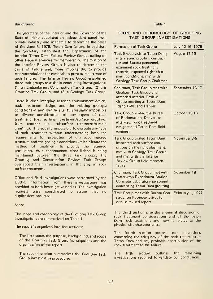
Background Table 1
The Secretary of the Interior and the Governor of the
State of Idaho appointed an independent panel from
private industry and acadamia to determine the cause
of the June 5, 1976, Teton Dam failure. In addition,
the Secretary established the Department of the
Interior Teton Dam Failure Review Group, calling on
other Federal agencies for membership. The mission of
the Interior Review Group is also to determine the
cause of failure and, more importantly, to provide
recommendations for methods to prevent recurrence of
such failures. The Interior Review G'oup established
three task groups to assist in conducting investigations:
(1 ) an Embankment Construction Task Group, (2) this
Grouting Task Group, and (3) a Geology Task Group.
There is close interplay between embankment design,
rock treatment design, and the e<isting geologic
conditions at any specific site. It is virtually impossible
to divorce consideration of one aspect of rock
treatment (i.e., surficial treatment/surface grouting)
from another (i.e., subsurface tieatment/curtain
grouting). It is equally impossible to evaluate any type
of rock treatment without understanding both the
requirements for protection of thj superimposed
structure and the geologic conditions v/hich dictate the
method of treatment to provide the required
protection. As a consequence, close liaison is being
maintained between the three task groups. The
Grouting and Construction Review Task Groups
overlapped their investigations in the area of rock
surface treatment.
Office and field investigations were performed by the
USBR. Information from these investigations was
provided to both investigative bodies. The investigation
requests were coordinated to assure that no
duplications occurred.
Scope
The scope and chronology of the Grouting Task Group
investigations are summarized on Table 1.
The report is organized into five sections:
The first states the purpose, background, and scopeof the Grouting Task Group investigations and the
organization of the report.
SCOPE AND CHRONOLOGY OF GROUTINGTASK GROUP INVESTIGATIONS
Formation of Task Group
INVESTIGATIVE PROCEDURES
Interviews
Interviews with USBR and contractor personnel were
conduLted during the August 17-19 Task Group visit to
Teton Dam and the October 15-16 visit to the Bureau
in Denver. Individuals interviewed were Richard Bock,
Head, Earth Dams Section; William Harber, retired
principal Teton Dam designer; Lloyd Gebhart,
Construction Liaison; Robert Robison, Project
Construction Engineer; Peter Aberle, Project Field
Engineer; Jan Ringel, Douglas Jarvie, and Kenneth
Hoyt, embankment inspectors; Claude Daniels,
grouting inspector; Brent Carter, Chief, Geology
Branch, Pacific Northwest Region; William and Ed
McCabe, McCabe Brothers Drilling Co.; and V. M.
Poxleintner, Morrison Knudsen Co.
Summaries of the Grouting Task Group interviews are
contained in Appendix C-1.
The Construction Review Task Group has also
conducted an extensive investigation into the "surface
grouting." Results of its interviews on that subject are
contained in that Task Group report.
Construction Records
Those Bureau construction records which were
examined consisted of the field inspectors' drilling and
grouting reports, the L-10 monthly grouting
summaries, the prefailure and postfailure geologic
maps, and construction photographs of the rock
conditions on both abutments.
The Grouting Task Group examination of the detailed
records was limited to the right abutment betweenstations 11+00 and 17-K)0.
Records which the Grouting Task Group did not
examine were the Bureau grouting inspectors' log
lx)oks and records kept by McCabe Brothers Drilling,
Inc.
Interior Review Group Design Questions
and Bureau Answers
The Interior Review Group presented a series of
questions to the Bureau dealing with the design
considerations for Teton Dam. In addition, the
Independent Panel presented questions to the Bureau.
The questions and answers dealing with rock treatment
comprise a considerable portion of the basis for the
Grouting Task Group's analysis, discussion, and
conclusions. Those questions and answers are presented
in appendix G of the main report.
Site Observations
During the August 17-19 visit to Teton Dam, the
Grouting Task Group examined the surface of the right
abutment by viewing it from the visitor overlook, the
top of the embankment, the river level at the riverside
edge of the breached embankment, and by walking
over the upstream surface of the abutment.
During the November 3-5 visit, we examined in detail
the cleaned rock surface in the key trench and
downstream portion of the right abutment, and
reexamined the upstream rock surface.
Field Explorations
Both the Independent Panel and the Grouting Task
Group requested subsurface explorations on the right
abutment to check the effectiveness of the grouting
program. The requested explorations are detailed in
Appendix C-2.
The Independent Panel exploration requests were given
first priority. The status of exploration drilling, mapsshowing location of postfailure borings, and boring logs
are presented in Appendix C-5.
Laboratory Testing Program
Because of the unprecedented high proportions of
calcium chloride used in the curtain grouting, the
Grouting Task Group requested that the Bureau
perform a testing program to determine grout behavior,
durability, and resistance to erosion for the various
mixes containing calcium chloride. The Bureau
conceived and proposed a program which was approved
by the Grouting Task Group. Results of this testing
program should be available during March 1977. The
grout testing program is outlined in Appendix C-3.
DISCUSSION
Introduction
Certain of the Bureau grouting procedures are different
from those practiced by the agencies represented on
the Group. In order to set the stage for our evaluation,
the following discussion on general rock treatment
considerations summarizes the experiences of the
members of the Grouting Task Group.
C-3
The safety of an engineering structure and the
reduction of permeability in the foundation are usually
the objectives of a grouting effort.
Though a single or multiline grout curtain is not 100percent effective, it is quite often the only economical
or feasible means of reducing the flow through rock
foundations and abutments of dams.
Grouting measures should extend from the rock
surface to the maximum design depth. The difficulty
inherent in the application of pressure grout near the
rock surface requires that methods of grouting vary
with depth and objectives.
To prevent water from flowing through the foundation
near the rock-earth fill interface, and thus endangering
the fill, slush-or-slurry grout is applied to the
thoroughly cleaned rock surface to backfill the
cleaned-out open voids with cement grout. Blanket
grouting reduces high permeability immediately belowthe rock surface. An acceptable blanket grouting design
consists of a grid of shallow holes for the injection of
grout under low pressures. Commonly the area treated
extends laterally rather than in depth and the holes are
closely spaced to facilitate complete grout filling of
voids at low pressures. Curtain grouting extends the
treatment to design depth. It consists of rows of grout
holes which are grouted under pressures which increase
with depth.
In curtain grouting, primary holes are drilled and
grouted at a preselected spacing in the row. If one of
these primary holes takes grout, two new holes are
drilled to design depth or past the elevation of take.
These two secondary holes are located at each side of
the primary hole and thus split the spacing in half
between primary holes. This procedure is called split
spacing. It is carried out until the distance betweengrout holes becomes too close, 2-1/2 to 3 feet, to be
effective. Additional holes are located outside the rowrather than within.
Special features, such as fault zones, wide joints, andknown large cavities require special design
considerations with respect to hole patterns, grouting
materials, and pressures. It is the consensus of the
Grouting Task Group that a three-row curtain, in
which each row is grouted to closure, is commonlyconsidered when high permeabilities are a majorproblem. This constitutes a realistic compromisebetween economy and the obtainable efficiency.
Standard rock treatment specifications usually include
detailed instructions for the preparation of rock
surfaces prior to treatment, and for the treatment of
known special features as well as provisions for
grouting in freezing temperatures. Specifications based
on actual experience from pilot grouting programs are
usually more specific than standard specifications. As
at Teton Dam, pilot programs generally result in better
estimates of quantities, grout pressures, mix ratios, and
grouting sequences.
Possible Rock Treatment Related
Failure Modes
The six possible causes of failure listed by the Interior
Review Group in its second Interim Report are:
1. Cracking or hydraulic fracturing of zone 1
material
2. Piping along the interface between the zone 1
material and the rock foundation
3. Flow through the grout curtain
4. Flow bypassing the grout curtain
5. Cracking due to foundation settlement
6. Cracking due to hydraulic uplift
Failure modes involving the rock foundation would (1
)
include water movement into the zone 1 material from
the rock and vice versa (e.g., water entering zone 1
upstream from the grout curtain and leaving it
downstream from the grout curtain), or (2) involve the
movement of high-velocity water through the rock
immediately adjacent to the zone 1 material. The
former could result in removal of zone 1 material by
piping; the latter by scour erosion.
The first possible cause listed above could have
involved the rock foundation if the hydraulic fracture
or crack occurred in a location such that the reservoir
water could enter and leave the embankment through
rock fractures. The second through the fourth possible
causes are obviously rock foundation related. The fifth
and sixth possible causes were not given much credence
by the Interior Review Group.
Piping failures of embankments and emijankment
foundations usually begin in the vicinity of the
downstream toe and progress headward (upstream).
Subsurface scour erosion requires continuous channels
downstream from the location of scour to allow
continued movement of material from the point of
erosion.
C-4
The observed mode of failure indicates that the piping
at the downstream toe was not the primary cause of
failure. Piping may have occurred from the
embankment into the abutment rock mass because
there are sufficient voids in the form of open fractures
in the upper portions of the abutment to accept
embankment zone 1 material either being piped or
scoured from the key trench.
The preconstruction explorations do not provide
sufficient data to make conclusive quantitative analysis
of the effective (or fracture) porosity of the rock mass.
The bore hole TV logs of right abutment borings
indicate a probable effective porosity of about 1
percent in the upper 100 feet of rock. Analysis of core
loss in the same borings indica js from 1 to 3 percent
between 30 and 100 feet and around 10 percent above.
We can assume that these percentages, which are
derived from boring and bore hole TV log information,
without regard to hole and joint orientation, are
substantially lower than the true rock mass porosity.
The low water table, rapid infiltration of rain water,
consistent lack of drill water return, high and rapid
grout takes during pilot and curtain grouting, and
observation of the surface of the rock mass all indicate
that the Teton foundation is of moderate to high
porosity. Also, both the boring logs and TV logs
indicated the presence of individual fracture openings
up to 2 feet wide.
Investigation Findings
Design of Curtain Grouting
A detailed description of the pressure grouting
design is attached as Appendix C-5. The following is
a short abstract.
The principal design feature consisted of a one-row
curtain to be grouted to closure (refusal). Primary
holes were spaced at 80 feet and ranged from 260
feet to 310 feet in depth. Secondary holes on
40-foot centers were 160 feet deep; tertiary holes
on 20-foot centers were 110 feet deep; and
quaternary holes on 10-foot centers were 60 feet
deep. There were provisions to drill closure holes to
5-foot centers, or closer if necessary.
In the abutments only, two outer rows were
designed to control lateral grout travel from the
center row. Primary holes were at 80 feet,
secondary holes at 40 feet, and tertiary holes at 20
feet. Depths ranged from 60 feet to 260 feet. Closer
spacing between holes was not specified for closure.
The grouting specification permitted both packer
and stage grouting procedures.
With the exception of the spillway gate structure
area, the need and choice of locations for blanket
grouting were left to the Project Construction
Engineer. Blanket holes were "to be ordered on an
individual or small area basis to treat specific
defects."
Grout mixes were specified to vary from 10:1 to
0.8:1 (water to cement ratio by volume), allowing
for sand bulkfiller, for bentonite as a pumping aid
for sanded grouts, and calcium chloride as required
in the field, for the control of grout travel.
All grouting stages or packer settings were to be
water-pressure tested prior to the injection of grout.
The decision to grout and the starting mix ratio
(either 8:1 or 6:1) were to be determined by these
water pressure tests.
Pressures at the collar of the hole were not to
exceed 0.75 Ib/in^ per foot of depth measured
perpendicular to the closest surface, but not less
than 10 Ib/in^
Bench marks were to be established prior to
grouting for the detection of "movements of the
formation" or uplift due to grouting, specifically on
steep abutments.
Construction of Grout Curtain
The construction field staff made every effort to
comply with the contract specifications. They
appear to have been interested in the quality of
work performed and to have been determined to
achieve, or exceed, the desired results.
There were some variations in the methods of grout
injection. For example, under comparable
conditions some inspectors would change from a
neat cement and water grout mix to a sand, cement,
and water mix; others would not. The rate at which
grout mixes were thickened on rapidly taking grout
holes varied somewhat. These variations occurred as
the result of authorized exercise of judgment by
individual inspectors and are not inconsistent with
practice by other agencies on other projects.
A few exceptions to the specified split-spacing
criteria were noted on the grouting records. These
involved the lack of drilling of centerline fifth order
C-5
grout holes where takes in scheduled quaternary
holes were in excess of a specified amount. Three of
these exceptions occurred in the right abutment
grout curtain. A valid reason was provided for each
exception.
Functionally, the abutment grouting at Teton Damshould not be considered as a three-row curtain. Theouter rows were grouted to 20-foot centers and to
depths of from 60 feet to 260 feet. The intent was
not to install three rows grouted to closure but to
facilitate more effective center row grouting. It is
our understanding from our interview with Mr.
Gebhart that the Bureau has normally closed all
rows in a multiline grout curtain.
As part of the Bureau packer grouting procedures,
water-pressure tests were routinely performed in
holes, the lower section of which had just been
grouted. Although this has been employed as a
standard procedure by the Bureau, the Grouting
Task Group believes that this procedure can result
in washing freshly placed grout from rock fractures.
The starting grout mixes (usually 8 water to 1
cement) were much thinner than those used by the
other agencies (5:1 or 3:1) and were used longer
before changing to thicker mixes. Again, this
constitutes normal Bureau practice.
Calcium chloride was used to accelerate the setting
of grout in the outer two rows, with the intent of
limiting grout travel. Three percent of the weight of
cement is considered to be the maximum amount of
CaCl2 without having an adverse effect on the grout
properties. Amounts above 4 percent are considered
to adversely affect the permeability and permanence
of the grout. The Bureau used up to 8 percent
CaCl2 in rapidly taking grout holes. In cold weather,
CaCl2 was added until the grout mix reached 90°Fdue to chemical reaction. The Grouting Task Groupfeels that the practice of heating the mixing water
or the cement is a more common practice to obtain
warm grout. The lower temperature of the rock at
depth cooled the grout mix upon injection and
reduced the rate of hydration. This, in turn,
probably slowed the setting time in the rock
sufficiently to allow the grout to flow freely away
from the grout hole. Injection rates as high as 7
ft^/min were used by the Bureau on taking holes in
order to maintain design injection pressures. A moreconventional means to restrict grout travel away
from a grout hole (where subsurface flowing water
is not present) is to use thick grout mixes, reduced
pumping rates, and low pressures. The high
percentages of CaCl2 were not used during the
grouting operations on the right abutment in area of
the failure between stations 1 HBO and 16-1-00.
Surface Treatment
No formal written procedures were developed
within either the design or field construction
organizations which detailed the surface treatment
program.
Concerns for the protection of fill material
susceptible to piping placed on a highly fractured
foundation were expressed by Mr. Harber in a
collection of design notes and draft material dated
March 1967, November 20, 1969, November 12,
1969, November 13, 1969, May 1970, March 10,
1969, March 1967, October 20, 1970, and January
16, 1970. These concerns were not, however,
expressed in the document "Design Considerations
for Teton Dam, October 1971." This document,
which was prepared by Design to familiarize
Construction with important design considerations
and to further describe the construction
specifications, does not address itself to the details
of a surface treatment program. In fact, the
statement "Erosive seepage under the embankmentwill be eliminated by injecting the foundation with
a grout mix" seems to infer that the "tight grout
curtain" referred to in the next sentence was the
major defense relied upon by Design to assure that
piping was under control.
No provision was made in the contract
specifications for general surface treatment of open
joints except for blanket grouting to be used on "an
individual or small area basis." It was the feeling of
the designers that surface grouting should be treated
as a field problem to be negotiated with the
contractor. The Gr >uting Task Group feels that in
order for Constru>jtion to make adequate field
decisions, the theoretical reasons for surface
treatment must be fully understood. None of the
available design documents provided sufficient
background information to make valid field
decisions.
In late 1973 and early 1974, design, geology, and
liaison personnel visited the site at Construction's
request to look at the cut-off and key trench
excavations prior to placement of fill. The trip
reports do not direct themselves to the full scope of
a surface treatment program. Interviews with
C-6
Messrs. Bock, Harber, Aberle, and Gebhart indicate
that during these site visits surface treatment was
discussed. After deciding jointly at this time that
surface treatment would be done by "bucket
grouting," Construction developed a surface
treatment procedure, apparently without further
detailed design and geological assistance. According
to Mr. Gebhart, at one time a memorandum was
prepared by Mr. Harber stating that consideration
was being given to a surface treatment program
using shotcrete. Mr. Arthur has explained that after
telephone conversations with the Construction
Engineer, it was felt that the studies necessary for
the development of a shotcrete program were
premature at that time. These communications are
apparently the last time shotcreting was considered
for surface treatment.
Mr. Aberle stated in the Denver interview that he
felt that Construction knew the designers were
aware of the open nature of the abutment surface
rock because they specified the key trench
excavation. Further, he assumed that Design was
not particularly concerned about surface treatment
because there was nothing in the specifications for
surface treatment. Mr. Ringel of the Teton
Construction Office Staff independently stated that
no Denver Office people were noted as being around
during surface grouting operations.
The field construction personnel developed surface
treatment procedures to allay their concerns for
compaction of zone 1 embankment material over
large voids. The embankment and surface grouting
inspectors, without the assistance of the project
geologist, would designate which cracks were to be
filled. The cracks were then filled by grouting with a
0.7:1 neat cement grout or a sanded cement grout
depending upon the size of the opening. The surface
treatment was performed in a narrow cleaned-up
strip of rock just ahead of the advancing fill.
Because of the stiffness of the grout mixes used, and
because the concerns of Construction were generally
for larger cracks, features less than 1/4 to 1/2 inch
in width were ignored. In the right abutment,
surface grouting was done under zone 1 material
from elevation 5075 to 5205. Mr. Gebhart indicated
that it was Design's intent,on for surface grouting
also to be done in the side walls of the key trench.
The inspectors have indicated that very little surface
grouting was done in the side walls of the key
trench. However, inspection of records shows that
there was some surface grouting in the side walls.
Postfailure inspection of the key trench revealed a
number of untreated open features.
Surface grouting stopped at elevation 5205. Neither
Mr. Bock from Design nor the Liaison Officer,
Mr. Gebhart, was aware of the decision to stop
surface grouting until after the Teton Dam failure.
According to field personnel, the geologists also
played no part in the decision to stop surface
grouting.
Conflicting reports as to the openness of the rock
surface above 5205 have been presented to this
Group. According to Mr. Aberle, above 5205 the
rock was more slabby and large fissures were
replaced by "hundreds" of 1/4- to 1/2-inch-wide
fissures which were left "untreated." Mr. Ringel
stated that there did not appear to be a change in
the fracturing characteristics which indicated no
further need for surface grouting. Above elevation
5205, no attempt was made to remove native soil
from cracks in order to replace it with design fill.
The native crack filling material appeared moist and
was probably ML, similar to zone 1 material.
During discussions with Mr. Aberle, he expressed his
theory for the origin of the large fissures between
elevations 5075 and 5205. He felt that many of the
near-vertical fissures were behind large detached
blocks that had moved toward the river. He was not
sure if the designers knew of the possible displaced
condition of these blocks. Removal of these blocks
would have involved large excavation quantities.
Postfailure Investigations
Boring logs, joint transmissibility test results, and
water pressure test results are presented in
Appendix C-5.
The joint transmissibility tests were conducted in
the bottom of the key trench in the area of the
failure between stations 12+93 and 13+50. Water
was ponded over exposed joint lengths of from 1.2
to 8.0 feet with maximum ponded water depths of
from 0.4 to 1.0 foot. Water losses ranged from to
1.1 gal/min. Water communication to the surface
occurred along fissures outside the ponded areas.
The amount of water transmitted along these joints
would have been considerably greater under the
heads imposed by the reservoir. However, the
condition of these joints prior to failure is
unknown.
For the purpose of examining the water pressure
test data, we adopted evaluation criteria for water
loss as follows:
C-7
Insignificant: less than 0.1 gal/min per foot of
boring
Marginally significant: 0.1 gal/min to 0.5
gal/min per foot of boring
Significant: greater than 0.5 gal/min per foot of
boring
Water losses during pressure tests in the spillway
borings were generally insignificant. Marginally
significant losses occurred in the upper portion of
one boring in the right spillway bay. At station
3+00, significant water losses occurred in the upper
portion of one of the deep angle borings.
A considerable number of shallow borings have been
drilled in clusters along the right abutment between
stations 12+75 and 14+26. Water losses were
insignificant in the boring clusters at stations 12+75
and 13+15. Beginning with station 13+30 and going
riverward, marginally significant and significant
water losses occurred. The greatest number of
significant takes occurred in the boring cluster at
station 13+45. Water from some of the pressure
tests leaked to the rock surface and also connected
to the boring in the station 13+30 cluster which was
inclined toward the river. During pressure testing,
this riverward-inclined boring at station 13+30
leaked to the surface both up and downstream from
the grout cap. However, the seepage quantities
measured during these tests were probably not large
enough to be considered abnormal for a typical
grout curtain. The only concentration of grout takes
during the construction of the right abutment
centerline grout curtain occurred in the grout holes
between stations 13+38 and 13+72.
A review of all geological and grouting information
available to date reveals a coincidence of features
between stations 13+00 and 14+00. A nearly
straight line can be drawn between leaks observed
downstream prior to and during failure and the
upstream whirlpool. This line crosses the key trench
near station 13+75. The following prefailure and
postfailure features fall approximately along this
line and in the key trench between stations 13+00
and 14+00:
1. Many significant, continuous joints running
along and parallel to the line are shown on the
as-built geologic drawings. Postfailure
exploration of the area also shows well
developed, continuous, open or partially filled
joints trending parallel to this line. Because of
the violent nature of the failure, the postfailure
openness of joints observed at the elevation at
the bottom of the key trench may not be
entirely representative of that which existed
during construction.
(It should be noted that postconstruction
mapping refers to joints less than 1/2 inch open
as being tight. We feel that those joints less than
1/2 inch wide which are capable of passing water
should be considered open.)
2. Several significant grout takes in the auxiliary
outlet works tunnel are in the area where this
line crosses the tunnel.
3. Grout takes occurred in grout holes between
stations 13+28 and 13+62 along the centerline
curtain.
4. Scour of abutment rock upstream and
downstream of the key trench was quite severe
landward to station 13+20 where a set of
prominent steeply dipping joints cross the key
trench.
5. Water loss in postfailure core holes is
concentrated in this general area.
These data from prefailure records, records of the
failure itself, and postfailure mapping and testing
seem to indicate that the failure could have been
associated with more significant jointing in the area
of the failure and greater difficulty in achieving
adequate surface treatment and grouting for
necessary protection of the fill. Unfortunately the
key trench has been scoured away by the failure, so
the condition of the key trench walls is not visible.
SUMMARY AND CONCLUSIONS
Design Concepts
The basic function of a grout curtain is to reduce
seepage under a dam to tolerable limits. This serves to
enhance embankment stability and to inhibit the loss
of valuable reservoir water through the foundation. Agrout curtain should never be considered capable of
eliminating seepage through the foundation. Seepage in
varying quantities will exist along the entire length of a
grout curtain, especially in a highly jointed foundation
such as that at Teton Dam. Whether or not a grout
curtain is used, the embankment must be orotected
from this seepage to the degree dictated by the
properties of the embankment materials and the
foundation.
C-8
These basic design concepts were correctly addressed at
an early date, but ensuing decisions within the design
organization, were successful in shifting the emphasis
toward creating a "tight" grout curtain which would
then "eliminate" erosive seepage at the
rock/embankment contacts. Great pains were taken to
describe and specify an elaborate key trench and grout
curtain, while embankment protection through the
proper use of rock surface treatment and appropriately
placed filters at embankment/rock interfaces were all
but eliminated.
Surface Treatment
Rock surface treatment for embankment protection
was not a specified item. It was handled informally
after construction began. The responsibility for
developing the scope and details of the program were
left to the field construction office with no written
instructions from Design concerning basic design
concepts. Such written instructions would have been
necessary to insure a full understanding that surface
treatment was fundamental to the ultimate integrity of
the dam. As a result, surface treatment was developed
in a nonsystematic fashion. It was discontinuous.
Where treatment was used, it did not tie into the grout
curtain, and it was not applied to a significant
abutment area above elevation 5205.
Curtain Grouting
The grout curtain was constructed by a methodology
somewhat inconsistent with the experiences of the
members of the Grouting Task Group. The
performance of the abutment grout curtain is
considered by the Group to be that of a single line
rather than a multiline curtain. As is normal for most
grout curtains, the effective depth was less than the
depth of primary holes.
Grouting between stations 11+50 and 16+00 was done
with less than 3 percent CaCl2 and should not be
considered abnormal in the location of the failure.
Elsewhere the quality of injected grout in the outer
rows may have been degraded by the excessive use of
CaCl2. The effects of high percentages of CaCl2 are the
subject of a laboratory testing program being
conducted by the Bureau of Reclamation.
Our opinion is that the postfailure testing indicates
that seepage through the grout curtain prior to failure
was within tolerable limits. Testing does, however,
indicate a possible shallow permeable zone in the grout
curtain in the vicinity of station 13+50.
Mechanics of Failure
Evidence points to a significant concentration of
features along a line between the failure leaks and the
whirlpool. This line crosses the key trench between
stations 13+00 and 14+00. Because of the
concentration of joints and the ineffectiveness of the
rock surface treatment, minor seepage in this area mayhave been a major factor in the development of the
failure. Seepage moving along geologic features had
direct access to zone 1 material immediately upstream
of the key trench and grout curtain. This water then
had egress into the fractured permeable rock
immediately downstream of the grout curtain thus
establishing a seepage path with a high hydraulic
gradient.
Conclusions
1. A basic error was made by the Bureau of
Reclamation, Division of Design, in assuming that a
grout curtain tight enough to eliminate erosive seepage
could be constructed.
2. Because of the error cited in item 1, Design failed to
recognize the importance of protecting zone 1 material
from the inevitable percolation of water through and
along the surface of the foundation. Rock surface
treatment was not a designed item, and it was
inadequate for the protection of zone 1 material on the
highly jointed rock foundation.
3. The grout curtain, as constructed, can be considered
normal in terms of its ability to limit seepage. Like any
grout curtain, it cannot be considered tight.
4. The well-developed set of open joints, which
controlled the linearity of the significant features
discussed previously, played an important role in the
early development of adverse seepage paths.
NECESSARY CONTINUEDINVESTIGATIONS
As of this writing, field investigations are still
incomplete and laboratory tests of the various grout
mixes are underway. It is anticipated that all
information will be available for review by mid-1977.
At that time, a supplement to this Report of Findings
should be prepared to summarize and evaluate the
results of those findings pertinent to the charge of the
Grouting Task Group.
C-9

APPENDIX CI
SUMMARY OF INTERVIEWS
by the
GROUTING SUBCOMMITTEE
TASK GROUP
TETON DAM
August 17-19, 1976, at Teton Dam
October 15-16, 1976, USBR, Denver
Revised February 4, 1977

INTRODUCTION
The following statements have been compiled from
notes taken by the Grouting Task Group during
informal interviews with the indicated persons at the
damsite August 17-19, 1976, and at the USBR in
Denver on October 15-16, 1976. Notes included in
parentheses are provided as explanatory information.
Included is a memorandum by Mr. Peter Aberle, TetonProject Field Engineer, commenting on some of the
statements made by Messrs. McCabe and the USBRfield inspection staff.
continued to completion through shift changes or
weekends, when necessary.
Grout holes were located by Government inspectors.
The inclination of the grout nipples were checked by
Government inspectors after the nipples were set. The
nipple inclination controlled hole inclination. The
nipples were "Schedule 45" 2-inch black pipe and were
2 feet 8 inches long. Occasionally 4 to 5-foot nipples
were required.
McCabe Brothers Drilling Company
Mr. Ed McCabe of McCabe Brothers, Drilling and
Grouting Contractors
Mr. Bill McCabe of McCabe Brothers
Mr. Howard McCabe of McCabe Brothers (not able to
attend)
Mr. V. M. Poxleintner of Morrison Knudsen,
Construction Company
(Nearly all comments are from Ed and Bill McCabe.Mr. Poxleintner was present generally only as an
observer.)
All drilling and grouting work was done under specific
direction of the contracting officer. If there was anydifference of opinion between the contractor and
inspector, the contractor would advise the inspector
but would abide by the inspector's decision. Grouting
was done during all three shifts with one of the three
McCabe brothers present nearly all the time.
Drilling was done with 1-7/8-inch-diameter diamondplug bits on 5-foot barrels. Grout hole drilling wasrapid in the welded tuff; 200 feet per shift per drill was
achieved. Drilling was slower in the basalt. McCabe wascapable of drilling angle holes parallel (more or less) to
the slope of the abutments.
There were generally three or four holes 80 feet O.C.
open ahead of one being grouted. There was very little
hole-to-hole communication, maybe in a half dozenholes.
Surface leaks were estimated as occurring on less than
5 percent of the holes grouted. If leaks occurred during
grouting of a staged hole, the leaks generally recurred
during grouting of successive stages.
More rock fracturing was noted on the right abutmentthan the left and fractures on the right abutmentappeared to be going every which way.
Grout was transferred up to 2,000 feet through
insulated pipes from the grout batch plant to the
holding tanks and pumps adjacent to the header.
The grout cap was constructed by excavating a narrowslot in the bottom of the key trench or cutoff trench.
The slot was 3 feet wide by 3 feet deep with vertical
sidewalls. The sidewalls were line drilled by drilling
3-inch holes on 6-inch centers. The blast holes were a
single line on 18-inch centers, drilled to grade. Thepowder factor was recollected as averaging 1/4 Ib/yd^.
It was hard to hold the sidewalls and bottom. However,
overbreak and rock fracturing beyond the sidewalls andbottom did not appear to be severe. There were very
little grout surface leakage along the edges of the grout
cap.
No blasting was recalled as having occurred close to the
completed grout curtain lines.
There was no interference with the grouting activities.
The grouting of a particular stage in a hole was
Mixes ranged from 8:1 to 0.8:1 (water to cementratio). Intermittent grouting was used on high taking
holes. Five hundred sacks of progressively thicker mix(usually pumped for one-half hour for each
successively thicker mix) would be pumped and then
the hole would be flushed with water. After a specified
period of time (4 hours if CaCIa was used and 6 hours
otherwise), grouting would be resumed starting with a
3:1 or 2:1 neat cement mix for another 500 sacks or
until refusal. Sanded mixes were also used at a ratio of
6 parts sand, 5 parts water, and 5 parts cement. All
sanded mixes contained bentonite. CaCl2 was used in
amounts up to 8 percent of the cement content (by
weight). Government forces sampled the grout for
testing.
When using CaCl2, grout temperature was checked to
control the amount of CaCl2 added. In the beginning.
C-13
the USBR requsted CaCl2 percentages as high as 10
percent. Because of severe problems with plugged lines,
a maximum of 8 percent was used at McCabe's request.
Concern was expressed for the quality of the grout
when high percentages of CaCl2 were used. Flash sets
with no further gain of strength were observed. Several
instances were recalled where the grout arched in a
hole. Redrilling found an open hole behind the arch.
With high percentages of CaClj, the grout was in the
hole within 1 minute after leaving the batch plant.
CaCl2 was used in a few large takers on the centerline
curtain and for all larger takers on the upstream and
downstream curtains.
These cases were not for fracture filling. They were for
filling behind overhangs after the fill was brought up to
the top of the overhang.
No blasting was recalled near a grouted area.
The reason for not carrying the surface grouting above
elevation 5200 was that the field forces were instructed
to stop at that point. There did not appear to be a
change in the fracturing characteristics which indicated
no further need for surface grouting. Above elevation
5200, no attempt was made to remove native soil from
cracks in order to replace it with design fill. The native
crack filling material appeared moist and probably ML,
similar to zone 1 material.
The final hole spacing of 10 feet on the centerline
curtain was considered adequate. It appeared that
"closure" was obtained.
Grouting was done with 100 and 300 Ib/in^ gages
isolated by diaphragm gage savers.
The grout quantities ran over the estimate but not
critically. The grouting operations did not significantly
impede other construction activities.
The grouting contractor was not involved in the
"surface grouting" of rock fractures intersecting the
foundation surface. As a matter of observation, the
grouting contractor noticed that there was very little
"slush grouting" performed.
Jan Ringel, USBR Embankment and
Surface Grouting Inspector
Worked on the "surface grouting" activities,
previous experience in dam construction.
No
All "surface grouting" was gravity grouting. Often,
grout was placed in the same crack on several
successive applications. Most of the cracks grouted
were vertical. Both through going and localized cracks
were present. The majority were localized.
The bottom of the key trench was relatively tight.
There was some but very little surface grouting in the
key trench. Most of the surface grouting was in the
surface of the cutoff trench above the key trench.
Both a 0.7:1 neat cement and sand/cement grout were
used. The decision on which to use was based on the
size of the crack.
There were only a couple of cases where the grout was
poured through pipes after the fill was brought up.
No Denver office people were noted as being around
during surface grouting operations.
Doug Jarvie, USBR Embankment and
Surface Grouting Inspector
Mr. Jarvie has had previous dam construction
experience.
When the surface grouting was first started, the
"office" decided what was wanted and field forces
took it from there. Surface grouting began when the
fill was at approximately elevation 5075. No surface
grouting was done in the bottom or sides of the key
trench. When cracks were found, the inspector would
call the batch plant for grout and determine the mix.
Usually 0.8:1 neat cement grout. Sanded grout was
used on the biggest cracks. No CaCl2 was used.
An attempt was made to keep rock surface preparation
work 5 feet ahead of embankment placement.
Sometimes this distance dropped to 2 feet.
The final rock cleanup was usually done with air jets.
Sometimes air/water jets were required. The rock
surface was moistened before fill was placed. The
natural fracture filling was silt and other debris. There
were both long and short cracks. Most cracks seemed
to run at angle with the centerline. There was no
consultation with the geologists during the surface
grouting operation.
There was no recollection of grouting through pipes
after the embankment was brought up. Grout was
placed under some big overhangs.
More surface grouting was done on the right abutment
than the left.
Surface grouting was stopped because of orders "from
above." At that time, the operation was getting to
C-14
where there were fewer fractures. Jarvie would have
continued the surface grouting further.
Ken Hoyt, USBR Embankment and
Surface Grouting Inspector
The criterion was to grout those cracks in which fill
material could not be compacted. The grout mixes and
procedures were set by "policy." The first 15 cubic
yards were to be neat cement. After that a sanded mix
was used.
There were hardly any holes in the key trench that
needed grouting. The only one recollected was on the
high part of the left abutment; lean mix concrete was
put in it.
There were more cracks on the right abutment than on
the left.
There did not appear to be any preferred orientation to
the cracks.
Sometimes a 4-inch (or so) hole would be found that
would take 20 cubic yards of grout. One could hold
one's hand over such a hole and feel cold air. Holes or
cracks needing grout were marked with spray paint.
Generally cracks less than one-fourth inch open were
not grouted. All cracks were dry, even after a rain. As
many as 10 voids per shift were grouted. Often more
than one shift was required to complete a crack.
There was not any grouting through a pipe after fill
had been placed.
Some grout leakage from the pressure grouting was
observed on the sides of the key trench.
There was a geologist present on the day shift but he
provided no input to the grouting operations.
The field personnel were told to stop surface grouting
in the vicinity of elevation 5200. At that time, they
were starting to run out of cracks but more could have
been grouted. A few "tubes" were observed above
5200 which went back several feet and bent out of
sight. One reason which appeared to be "floating
around" was that the "stresses" would be low enough
to allow quitting.
aaude Daniels, USBR Curtain
Grouting Inspector
Has previous grouting experience.
The original grouting records consist of inspectors'
reports, inspectors' drilling reports, and inspectors'
grouting reports.
Grout placement criteria were developed by the
supervisor of grouting after consultation with the grout
inspectors. Thore was still plenty of room for exercise
of individual judgment.
If a hole took 100 cubic feet per hour or more,
grouting was stopped after 500 cubic feet had been
placed (hole was stalled) and the hole was flushed with
20 cubic feet of water. After 4 to 6 hours, grouting was
resumed. If CcCl2 was used, the waiting time was only
3 hours. Occasionally a big taker would refuse after
being "stalled." Reaming the grout hole would
generally open things up again. When restarting a hole
previously taking a sanded mix, a 5:1 neat cement
grout was first used.
Tight grout holes were started with an 8:1
water/cement ratio mix. Wide open holes were
generally started with a 5:1 mix and then thickened
progressively (4:1, 3:1, 2:1, 1:1,0.8:1) at about 15- to
30-minute increments. CaCl2 was used when a sanded
mix was used. Occasionally CaCl2 was used without
sand in thick (0.8: 1 ) neat cement mixes. When the rate
of grout take dropped to 50 sacks per hour, CaCl2
would be discontinued. On the centerline, CaCl2 was
used only at stations 2+60 and 6-^40.
Initial testing to determine acceptable percentages of
CaCl2 concentrated on set time. No strength tests were
recalled. No test cylinders were taken during grouting
with CaCl2 mixes.
The criterion for drilling a centerline "closure" hole
was a take over greater than 25 to 30 sacks at any one
packer setting n the final scheduled holes (resulting in
10-foot spacing). It usually took two adjacent taking
holes before s "closure" hole was drilled between
them. Generally, no splitting was done around a single
taker unless surface leakage was observed. With surface
leakage, splitting was done by "feel." These criteria
were developed by the field inspectors.
The grout holes appear to have been drilled rather
straight. A number of vertical holes drilled around the
auxiliary outlet works access shaft had been surveyed
with a gyrocompass. These holes drifted less than 1
degree in 200 feet. No inclined holes were surveyed for
straightness. The equipment was capable of operating
in an inclined hole.
The rock which was excavated for the grout cap was
highly fractured in the river section and "seamy" on
C-15
both abutments. The difference between the right and
left abutments was that the right abutment "seams"
were open. These open seams got pipe for blanl<et
grouting. Most of the time the line drill holes were
preserved on the grout cap excavation side walls. There
was very little surface leakage around the sides of the
grout cap while grouting at depth. Some leakage was
observed around the grout cap when grouting at the
nipple.
There was blasting close to completed grout lines on
the left abutment (25 to 50 feet away). There was no
recollection of close blasting on the right abutment.
There was no formal grout sampling and testing
program. Some samples were taken to determine the
best amount of CaCl2 additive.
The basalt in the valley section was responsible for
quite a bit of packer leakage. Pneumatic packers were
used in the basalt to help alleviate leakage. Artesian
flow was encountered at the basalt/lake sediment
contact. The alluvial materials penetrated appeared to
be fine sand. The grout did not travel well in this
material. The grout mix used was 10:1. Spacing
between grout holes was 10 feet.
Voids were Infrequently encountered in grout holes.
The rock appeared more massive with depth in the
valley (one row) section of the grout curtain.
Brent Carter, USBR Geologist
(This interview was in the form of a discussion between
Messrs. Carter, Coulson, and Fisher while on the right
abutment. The following is a combination of
information provided by Mr. Carter and observations
by Messrs. Coulson and Fisher.)
There are three visible members of the welded ash flow
rhyolite exposed on the right abutment.
The uppermost member is a fine-grained pinkish platy
tuff. Subhorizontal flow jointing is very apparent; the
average joint spacing is less than 1 foot. Second and
third near vertical joint sets divide this rock into
cuboids. This member appears to be about 30 feet
thick.
An intermediate member is a highly jointed gray
porphyritic tuff. This rock is cut by lots of steeply
dipping and flat dipping joints. These joints appear to
strike into and parallel to the canyon walls. Joint
surfaces are coated with oxidation weathering products
and, frequently, with calcium carbonates. The flow
banding changes orientation rapidly. This member is
about 60 feet thick. Two very prominent parallel
vertical joints were observed in this member striking
across the dam centerline. It appeared that the trace of
one of these open joints could be seen both up and
downstream of the key trench location. This memberhas been described as a transition between the upper
and lower members. However, a breccia zone occurs at
its base at about elevation 5160. This zone is a series of
subparallel open planes with abundant carbonate
deposition.
The intermediate member contained several prominent
horizontal joints open from 1/4 inch to 6 inches. These
were generally sinusoidal planes covered with calcite.
Several delicate stalactites and stalagmites were
observed, indicating that the rock mass, at least in the
local area, had not been disturbed by the dam failure.
The planes were open over large areas. Small, local
pillars were in a state of failure, showing that the
planes were either open over very large areas or that
there had been superincumbent loads greater than the
present overlying rock thickness would indicate.
The lower member is a gray prophyritic tuff which is
considerably more massive than the overlying
intermediate member. It is cut by widely spaced joints
but many of these joints are open. While many joints
sets were present, three could be easily identified. Aprominent low-angle set dips slightly into the
abutment. A near vertical joint set strikes nearly
parallel to the canyon wall. A third high-angle joint set
strikes (variably) diagonally upstream into the
abutment and dips downstream. A number of joints
were partially filled with neat cement and sand cement
grout. No joint was observed to be completely filled.
Both tops and bottoms of grout flow surfaces were
observed. Open joints were observed next to
grout-filled joints. One case was observed where grout
flowed along a joint to a cross joint and flowed one
way along the cross joint but not the other. The
maximum observed width of a grout-filled joint was
about 1 foot.
The intermediate tuff appears to warp down in an
upstream direction around the more massive lower
tuff.
There is a rock slump area In the upstream portion of
the abutment.
C-16
Richard Bock. Head, Earth Dams Section,
and William G. Harber, Head,
Design Unit No. 2, retired January 1975
(Both involved with the design of Teton Dam as far
back as 1964 when it was known as Fremont Dam.
Nearly all questions answered by Mr. Bock. Mr. Harber
generally seemed to agree with Mr. Bock's answers, but
had little to contribute on his own.)
A grout curtain was included in the design for design
safety to prevent high pressures at the downstream toe,
to eliminate piping, and to control water loss through
seepage under and around the embankment. A piping
problem was anticipated and it was necessary to
control seepage. Use of the word "eliminated" in the
sentence "Erosion seepage under the embankment will
be eliminated by injecting the foundaton with a grout
mixture," from "Design Considerations for Teton
Dam" was probably a poor choice of words.
Watdf testing during test grouting was the chief source
of data to determine the depth of the grout curtain.
From this it was assumed that a 310-foot-deep curtain
in the abutments and a curtain extending below the
alluvial material in the river bottom would be
adequate. It was assumed that the effective depth of
the curtain was the depth of the primary holes. Actual
required depths were determined by construction.
High takes in lake sediments between stations 31+00
and 34+00 and at depths of 200 + were not thought
important because (1) grout loss was thought to be
concentrated at rock/sediment contact, and (2) back
pressures experienced during grouting indicated that
grout travel was limited to a bulb area around the hole.
The decision to grout only the upper 10 feet of the
lake sediments, even though this meant a shallower
than normal curtain, was made jointly by Design and
Construction personnel and was made in the interest of
economy.
The responsibility for determining the potential for
and consequences of reservoir rim leakage was given to
the geologists.
The Bureau's experience has shown that seepage could
always be controlled by grouting. No piezometers have
ever been installed in dam foundations by the Bureau
to look at the performance of a grout curtain.
Historically, the Bureau has used pregrouting testing
and installation experiences to assess the performance
of a curtain and no direct observations of curtain
performance have been made.
High takes in the upper 70 feet led to the decision to
use a key trench. Estimates of takes calculated by
geologists using void information from drill logs were
thought by the designers to be wrong.
The performance of the curtain is that of a one-line
curtain backed up by two outer lines installed for
construction expediency. The Bureau seldom uses a
multiline curtain with all lines closing. In general,
blanket grouting is used rather than multiline grouting.
The role of the geologists during the design stage was
to supply logs of holes, document water testing
information, and construction profiles and sections to
provide a general description and interpretation of the
foundation geology. Geology does not become
involved with foundation treatment design other than
to have a look at it after its completion. There was
nobody with formal geological training in the DamDesign Branch.
During construction, the project geologist, Mr.
Sweeney (now retired) prepared as-built drawings of
foundation geology. The cutoff trench below elevation
5100 was cleaned up and mapped at one time. Above
5100, cleanup and mapping was done progressively just
ahead of fill construction. The Construction Engineer
was responsible for approving the foundation for
placement of fill. When the project geologist found a
problem area, he was supposed to bring it to the
attention of the Field or Construction Engineer who in
turn notified Design. (When asked if the project
geologist did this, there was no answer.)
The use of CaCl2 to control the flow of grout is a
standard technique as far as Design is concerned.
Design knows of no previous experience with the high
percentages of CaCl2 used at Teton Dam and was not
involved in the discussion to use CaCl2 in
unprecedented quantities.
Prior to the issuance of specifications, Design worked
closely with Construction so all were in agreement on
the details of the specifications. After bids were in,
Construction was running the job with designers not
involved unless a serious design problem occurred. All
communications between Design and Construction
were then through Mr. Gebhart, the liaison officer
since 1973. The designers made few visits to the
project during construction. Federal travel restrictions
during the energy crisis had no impact on
communications between Design and Construction.
During the course of construction, the designer was
supplied with the L-29 progress reports. If these
C-17

reports indicated that a visit by Design was warranted,
one was made. Designers generally like the current
system and saw no access problem to Construction
information during construction.
Messrs. Bock and Robison looked at left abutment key
trenches in 1973 when the cut slopes of the key
trenches were visible but before abutment areas under
zone 1 had been stripped. It was concluded that open
cracks should be bucket filled with ready-mix concrete
as the fill progressed. No criteria were established for
the size of crack to be filled, except that those which
would readily accept ready-mix would be treated.
Design understood that ready-mix from Rexburg was
to be used.
The bottom of the key trench was to be treated
through pipes set in significant cracks. The sides of the
key trench were to be treated as the fill progressed by
building a fill dike around the fissure and bucket
grouting within the dike. (This appears to contradict
the understanding of Construction; there was
apparently no sidewall treatment.) No Design or
Construction memorandums were sent to the field to
detail the surface treatment program.
Design was not involved in the decision to terminate
the surface treatment at elevation 5205. Mr. Bock did
not know of the decision until after the failure. To Mr.
Bock's knowledge, the geologists had no input into the
problem. Mr. Harber thought Mr. Sweeney may have
been participating with Mr. Robison in decisionmaking.
Mr. Bock is satisfied with surface treatment. Mr.
Harber does not know what he would have done.
Surface treatment was not Included In specifications.
This is in agreement with standard USBR practice.
Design does not think a better job would have been
done had the specifications included surface treatment.
Mr. L. Gebhart— (Liaison officer between USBR design
and construction organizations. Reports to Chief of
Construction Division. Visits Teton routinely every 6
months and when needed. Liaison responsibility for
USBR southwest region containing about six damsunder construction plus all grouting USBR wide.
Operates independently with no immediate staff. Main
background in grouting. Came up through USBRgrouting section.)
Mr. Pete Aberle, USBR Field Engineer
(Interviewed simultaneously with Gebhart. To the
extent possible, the individual is identified in the text.)
Mr. Aberle was not involved in pilot grouting. Pilot
grouting handled by Messrs. Bob Pittard and Ralph
Mulliner in the field and Mr. Wayne Hermes. Chief
values of pilot grouting:
1. Indicated need for 70-foot-deep key trenches to
get to easily groutable material
2. Showed that the alluvial material under basalt is
groutable
3. Showed that the basalt could remain
Mr. Gebhart reviewed grout curtain design. Tried to
arrange for closing outer two rows, but Design wanted
to limit drilling for economic reasons. General practice
to close all lines where multiline curtains used.
Recalled six to eight dams where this was the case. Alist was supplied to the Task Group showing 12 USBRdams with two or four closed lines built from 1938 to
1971. Grout curtain depths are generally a function of
water tables in abutment exploratory holes. A rule of
thumb is H/3 + (25 feet to 75 feet), source
unknown.
A key trench was not provided under the spillway
because:
1. A trench filled with compacted fill would cause
differential settlement, and
2. It was not economically feasible to fill a trench
with concrete. While grouting spillway, one or two
holes connected to tunnel below.
Mr. P. Aberle
Lake sediments between stations 32-^80 and 34-1-00 had
high takes. Construction assumed that because of the
back pressures associated with these takes that
hydrofracturing or displacement of material was
occurring to allow the takes. Sediments and associated
takes were encountered at approximately 200 feet,
above the 260 to 310 depth criterion for the curtain.
Construction thought that grouting could be stopped
10 feet into the sediments without Impairing the depth
criterion of the curtain enough to matter. This then
became the standard practice. The design
considerations gave instructions to limit travel of grout
to within 100 feet of the curtain. In order to
accommodate this. Construction used CaCl2 and sand
where, and in the quantities, they thought to be
appropriate. Mixes with up to 4 percent CaClj were
tested in the laboratory. When the contractor started
using river water at temperatures as low as 34°F, more
C-18
CaCl2 was added for temperature control. At 10
percent CaCl2, the mix froze solid. Mixes with 8
percent were hard to control, so the normal maximumwas approximately 6-1/2 percent.
Mr. L. Gebhart
Normal USBR practice is to limit CaClj to 2-1/2
percent. The percentages used at Teton were
unprecedented.
Mr. P. Aberle
The temperature of the grout at the pump was the
criterion used for adding CaCl2.
Mr. L Gebhart
When large voids were discovered in the left abutment
key trench, Liaison made a visit to the project to
investigate. At that time, the key trench excavation
was completed down to elevation 5200. The slabby
and broken nature of the side walls of the upper part
of the trench were observed. Discussion followed
between Design and Construction, Geology not
included, concerning the treatment of the features. Mr.
Harber of Design wrote a memorandum asking for
surface treatment by shotcreting. This memorandumdid not go anywhere. The preference of Construction,
slurry grouting, was decided upon. The specifics of the
procedure were left up to Construction, and most were
handled verbally. Liaison was not aware that surface
treatment stopped at elevation 5205.
Mr. P. Aberle
Construction knew the designers were aware of the
open nature of the abutment surface rock because they
specified the key trench excavation. Further,
Construction assumed that Design was not particularly
concerned about surface treatment because there was
nothing in the specifications for surface treatment.
(Mr. Aberle's evaluation of the geologic explanation for
the large open fissures follows. These ideas appear to
be his own, not necessarily those of the project
geologist.)
Many of the large, nearly vertical, open or filled
fissures below 5200 were behind large detached surface
blocks which had moved toward the river. Most of
these large detached blocks were left in place because
the specifications called only for surface cleanup under
zone 1 material. The surface grouting program was
tailored to treat these large features. Construction
generally concurred with leaving abutment rock in
place because of the large excavation quantities
required for removal. Not sure if the designers knew of
the displaced condition of these large blocks.
Above 5205, the rock was more slabby and the large
fissures were replaced with hundreds of 1/4- to
1/2-inch-wide fractures which were left untreated.
C-19
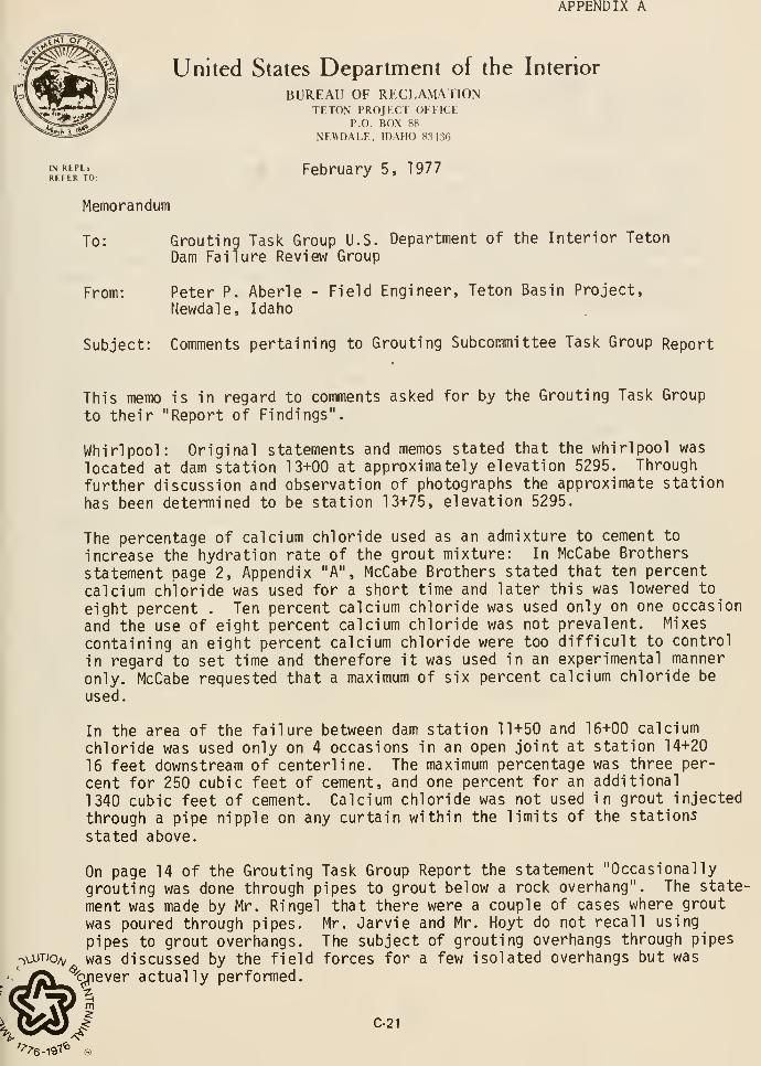
APPENDIX A
United States Department of the Interior
BUREAU OF RECLAMATIONTETON PROJECT OFFICE
P.O. BOX 88
NEWDALE, IDAHO 83436
'NREPL. February 5, 1977REFER TO; -^
Memorandum
To: Grouting Task Group U.S. Department of the Interior Teton
Dam Failure Review Group
From: Peter P. Aberle - Field Engineer, Teton Basin Project,
Newdale, Idaho
Subject: Comments pertaining to Grouting Subcommittee Task Group Report
This memo is in regard to comments asked for by the Grouting Task Group
to their "Report of Findings".
Whirlpool: Original statements and memos stated that the whirlpool was
located at dam station 13+00 at approximately elevation 5295. Through
further discussion and observation of photographs the approximate station
has been determined to be station 13+75, elevation 5295.
The percentage of calcium chloride used as an admixture to cement to
increase the hydration rate of the grout mixture: In McCabe Brothers
statement page 2, Appendix "A", McCabe Brothers stated that ten percent
calcium chloride was used for a short time and later this was lowered to
eight percent . Ten percent calcium chloride was used only on one occasion
and the use of eight percent calcium chloride was not prevalent. Mixes
containing an eight percent calcium chloride were too difficult to control
in regard to set time and therefore it was used in an experimental manner
only. McCabe requested that a maximum of six percent calcium chloride be
used.
In the area of the failure between dam station 11+50 and 16+00 calcium
chloride was used only on 4 occasions in an open joint at station 14+20
16 feet downstream of centerline. The maximum percentage was three per-
cent for 250 cubic feet of cement, and one percent for an additional
1340 cubic feet of cement. Calcium chloride was not used in grout injected
through a pipe nipple on any curtain within the limits of the stations
stated above.
On page 14 of the Grouting Task Group Report the statement "Occasionally
grouting was done through pipes to grout below a rock overhang". The state-
ment was made by Mr. Ringel that there were a couple of cases where grout
was poured through pipes. Mr. Jarvie and Mr. Hoyt do not recall using
pipes to grout overhangs. The subject of grouting overhangs through pipes
-,\.uTio/v was discussed by the field forces for a few isolated overhangs but was
-^ever actually performed.%.
C-21
On page 1 of Appendix "A" it stated, "There was very little grout surface
leakage along the edges of grout cap". There was so little leakage along
the grout cap that it can be termed insignificant. Only two occasions
can be recalled.
On page 2, paragraph 2, Appendix "A", "If leaks occurred during grouting of
a staged hole, the leaks generally reoccurred during grouting of successive
stages". This situation did not exist. If surface leaks occurred from
any stage of a hole the leaks were caulked and sealed. Grouting was then
suspended for at least eight hours to give the sealed leaks sufficient
time to heal before grouting was resumed. It is possible that leaks at
new locations from successive stages could occur, however, this is a normal
occurrence. Very few surface leaks occurred from stages at depth. Most
leaks occurred when hooked to the nipple.
On page 2, paragraph 7, Appendix "A", "With high percentage of CaClp the
grout was in the hole within one minute after leaving the batch plant".
At a maximum pumping rate of 250 cubic feet of cement per hour, the maximum
pumping rate was 5.4 cubic feet of grout mixture per minute. With the time
required to move the grout through the distribution lines and the time re-
quired to pump empty a 25 cubic foot capacity tub located at the pump site
it was impossible to inject grout any sooner than six mimutes after it was
mixed.
On page 2, paragraph 10, "Grouting was done with 100 and 300 PSI gauges
isolated by diaphram gauge savers". The gauges were also internally filled
with glycerine which dampened the pulsations from the duplex piston type
pumps. This made the life expectancy of the gauges up to 20 times longer
and much easier to read. Viscosity of the oil in the diaphram was adjusted
to coincide with weather temperature.
On page 6, paragraph 1, "There was blasting close to the completed grout
line on the left abutment (25 to 50 feet away)". This blasting was controlled
blasting in the grout cap and occurred in the vicinity of station 19+50.
Another blast in the vicinity of station 24+75 was made upstream of the grout
cap where a small overhang was removed also under a controlled blast situation.
C-22
APPENDIX C 2
RECOMMENDED FIELD EXPLORATIONS TO INVESTIGATETHE INTEGRITY OF THE GROUT CURTAIN
TETON DAM

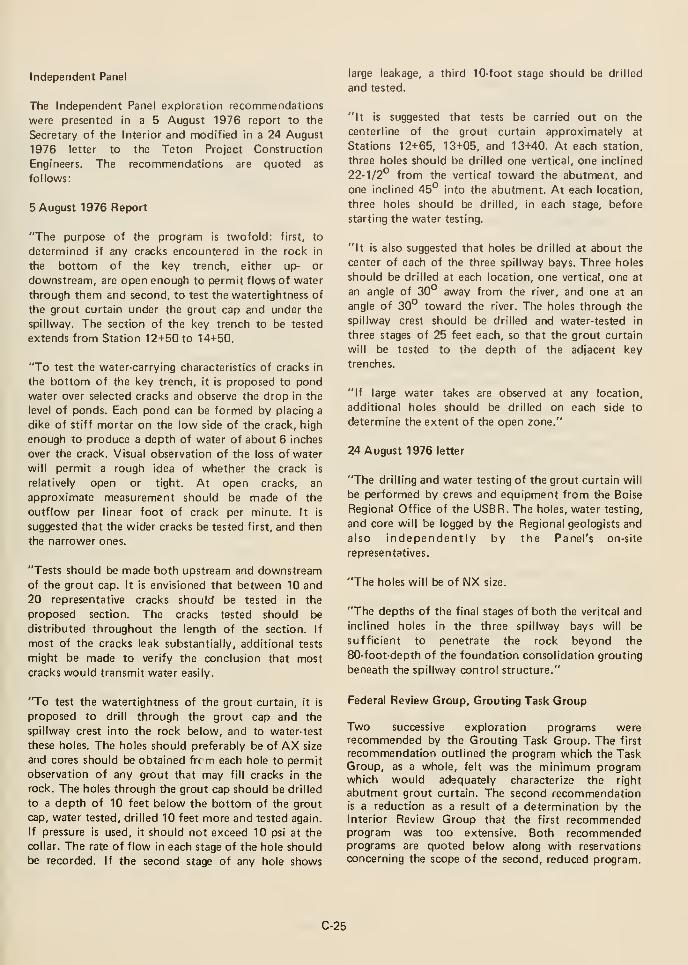
Independent Panel
The Independent Panel exploration recommendations
were presented in a 5 August 1976 report to the
Secretary of the Interior and modified in a 24 August
1976 letter to the Teton Project Construction
Engineers. The recommendations are quoted as
follows:
5 August 1976 Report
"The purpose of the program is twofold: first, to
determined if any cracks encountered in the rock in
the bottom of the key trench, either up- or
downstream, are open enough to permit flows of water
through them and second, to test the watertightness of
the grout curtain under the grout cap and under the
spillway. The section of the key trench to be tested
extends from Station 12+50 to 14+50.
"To test the water-carrying characteristics of cracks in
the bottom of the key trench, it is proposed to pond
water over selected cracks and observe the drop in the
level of ponds. Each pond can be formed by placing a
dike of stiff mortar on the low side of the crack, high
enough to produce a depth of water of about 6 inches
over the crack. Visual observation of the loss of water
will permit a rough idea of whether the crack is
relatively open or tight. At open cracks, an
approximate measurement should be made of the
outflow per linear foot of crack per minute. It is
suggested that the wider cracks be tested first, and then
the narrower ones.
"Tests should be made both upstream and downstream
of the grout cap. It is envisioned that between 10 and
20 representative cracks should be tested in the
proposed section. The cracks tested should be
distributed throughout the length of the section. If
most of the cracks leak substantially, additional tests
might be made to verify the conclusion that most
cracks would transmit water easily.
"To test the watertightness of the grout curtain, it is
proposed to drill through the grout cap and the
spillway crest into the rock below, and to water-test
these holes. The holes should preferably be of AX size
and cores should be obtained frc m each hole to permit
observation of any grout that may fill cracks in the
rock. The holes through the grout cap should be drilled
to a depth of 10 feet below the bottom of the grout
cap, water tested, drilled 10 feet more and tested again.
If pressure is used, it should not exceed 10 psi at the
collar. The rate of flow in each stage of the hole should
be recorded. If the second stage of any hole shows
large leakage,
and tested.
a third 10-foot stage should be drilled
"It is suggested that tests be carried out on the
centerline of the grout curtain approximately at
Stations 12+65, 13+05, and 13+40. At each station,
three holes should be drilled one vertical, one inclined
22-1/2° from the vertical toward the abutment, and
one inclined 45° into the abutment. At each location,
three holes should be drilled, in each stage, before
starting the water testing.
"It is also suggested that holes be drilled at about the
center of each of the three spillway bays. Three holes
should be drilled at each location, one vertical, one at
an angle of 30° away from the river, and one at an
angle of 30° toward the river. The holes through the
spillway crest should be drilled and water-tested in
three stages of 25 feet each, so that the grout curtain
will be tested to the depth of the adjacent key
trenches.
"If large water takes are observed at any location,
additional holes should be drilled on each side to
determine the extent of the open zone."
24 August 1976 letter
"The drilling and water testing of the grout curtain will
be performed by crews and equipment from the Boise
Regional Office of the USBR. The holes, water testing,
and core will be logged by the Regional geologists and
also independently by the Panel's on-site
representatives.
"The holes will be of NX size.
"The depths of the final stages of both the veritcal and
inclined holes in the three spillway bays will be
sufficient to penetrate the rock beyond the
80-foot-depth of the foundation consolidation grouting
beneath the spillway control structure."
Federal Review Group, Grouting Task Group
Two successive exploration programs wererecommended by the Grouting Task Group. The first
recommendation outlined the program which the TaskGroup, as a whole, felt was the minimum programwhich would adequately characterize the right
abutment grout curtain. The second recommendationis a reduction as a result of a determination by the
Interior Review Group that the first recommendedprogram was too extensive. Both recommendedprograms are quoted below along with reservations
concerning the scope of the second, reduced program.
C-25
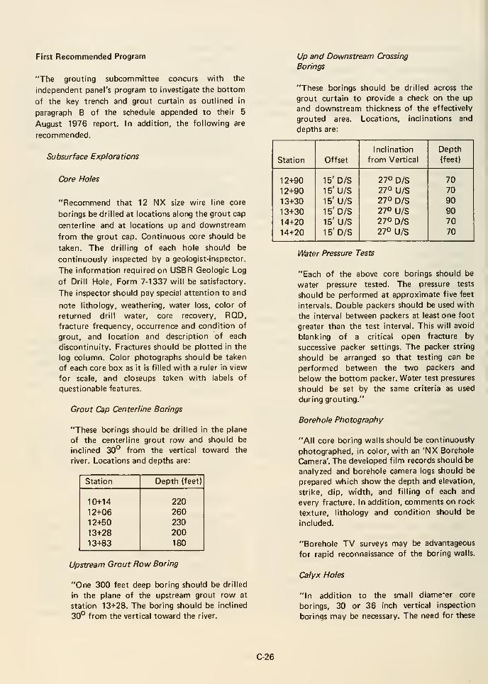
First Recommended Program
"The grouting subcommittee concurs with the
independent panel's program to investigate the bottom
of the tcey trench and grout curtain as outlined in
paragraph B of the schedule appended to their 5
August 1976 report, in addition, the following are
recommended.
Subsurface Explorations
Core Holes
"Recommend that 12 NX size wire line core
borings be drilled at locations along the grout cap
centerline and at locations up and downstream
from the grout cap. Continuous core should be
taken. The drilling of each hole should be
continuously inspected by a geologist-inspector.
The information required on USER Geologic Log
of Drill Hole, Form 7-1337 will be satisfactory.
The inspector should pay special attention to and
note lithology, weathering, water loss, color of
returned drill water, core recovery, RQD,fracture frequency, occurrence and condition of
grout, and location and description of each
discontinuity. Fractures should be plotted in the
log column. Color photographs should be taken
of each core box as it is filled with a ruler in view
for scale, and closeups taken with labels of
questionable features.
Grout Cap Centerline Borings
"These borings should be drilled in the plane
of the centerline grout row and should be
inclined 30° from the vertical toward the
river. Locations and depths are:
Station
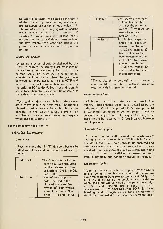
borings will be established based on the results
of the core boring, water testing, and a core
drilling apparatus such as a shot or calyx drill.
The use of a rotary drilling rig with air and/or
water circulation should be avoided. If
significant through going vertical features are
observed in the up and downstream walls of
the key trench, their condition below the
grout cap can be checked with inspection
borings.
Laboratory Testing
"A testing program should be designed by the
USBR to analyze the strength characteristics of
the various grout mixes using from two to ten
percent CaCl2. The tests should be set up to
emulate field conditions where the grout was
delivered at temperatures as high as 90°F and
injected into a rock mass with temperatures on
the order of 50° to 60°F. Set times and strength
versus t'ime characteristics should be observed at
the ambient rock temperatures.
"Tests to determine the erodibility of the weaker
grout mixes should be performed. The pinhole
dispersion test appears to be applicable for this
purpose. If the weaker mixes prove to be
erodible, a more comprehensive testing program
would need to be devised."
Second Recommended Program
Subsurface Explorations
Core Holes
"Recommended that 14 NX size core borings be
drilled as follows and in the order of priority
shovm:
Priority 1
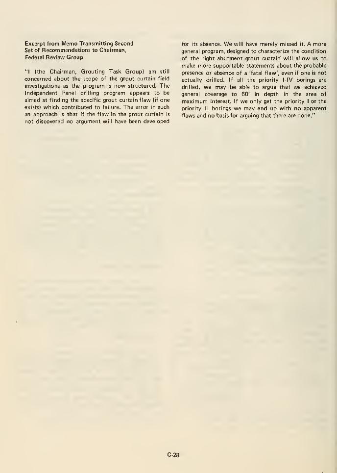
Excerpt from Memo Transmitting SecondSet of Recommendations to Chairman,
Federal Review Group
"I (the Chairman, Grouting Task Group) am still
concerned about the scope of the grout curtain field
investigations as the program is now structured. The
Independent Panel drilling program appears to be
aimed at finding the specific grout curtain flaw (if one
exists) which contributed to failure. The error in such
an approach is that if the flaw in the grout curtain is
not discovered no argument will have been developed
for its absence. We will have merely missed it. A more
general program, designed to characterize the condition
of the right abutment grout curtain will allow us to
make more supportable statements about the probable
presence or absence of a 'fatal flaw', even if one is not
actually drilled. If all the priority l-IV borings are
drilled, we may be able to argue that we achieved
general coverage to 60' in depth in the area of
maximum interest. If we only get the priority I or the
priority II borings we may end up with no apparent
flaws and no basis for arguing that there are none."
C-28
APPENDIX C 3
TESTING PROGRAM FOR HIGH CaCl, GROUT MIXES
TETON DAM

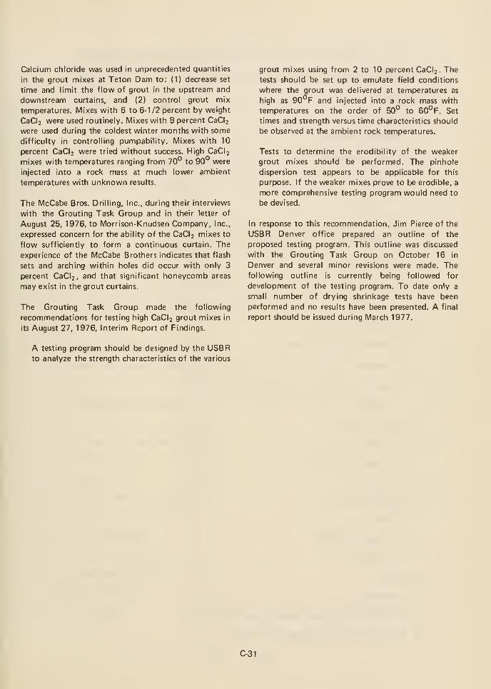
Calcium chloride was used in unprecedented quantities
in the grout mixes at Teton Dam to: (1) decrease set
time and limit the flow of grout in the upstream and
downstream curtains, and (2) control grout mix
temperatures. Mixes with 6 to 6-1/2 percent by weight
CaCl2 were used routinely. Mixes with 8 percent CaCl2
were used during the coldest winter months with some
difficulty in controlling pumpability. Mixes with 10
percent CaCl2 were tried without success. High CaCli
mixes with temperatures ranging from 70° to 90° were
injected into a rock mass at much lower ambient
temperatures with unknown results.
The McCabe Bros. Drilling, Inc., during their interviews
with the Grouting Task Group and in their letter of
August 25, 1976, to Morrison-Knudsen Company, Inc.,
expressed concern for the ability of the CaClj mixes to
flow sufficiently to form a continuous curtain. The
experience of the McCabe Brothers indicates that flash
sets and arching within holes did occur with only 3
percent CaCl2, and that significant honeycomb areas
may exist in the grout curtains.
The Grouting Task Group made the following
recommendations for testing high CaCl2 grout mixes in
its August 27, 1976, Interim Report of Findings.
grout mixes using from 2 to 10 percent CaCl2. Thetests should be set up to emulate field conditions
where the grout was delivered at temperatures as
high as 90°F and injected into a rock mass with
temperatures on the order of 50° to 60°F. Set
times and strength versus time characteristics should
be observed at the ambient rock temperatures.
Tests to determine the erodibility of the weaker
grout mixes should be performed. The pinhole
dispersion test appears to be applicable for this
purpose. If the weaker mixes prove to be erodible, a
more comprehensive testing program would need to
be devised.
In response to this recommendation, Jim Pierce of the
USBR Denver office prepared an outline of the
proposed testing program. This outline was discussed
with the Grouting Task Group on October 16 in
Denver and several minor revisions were made. Thefollowing outline is currently being followed for
development of the testing program. To date only a
small number of drying shrinkage tests have been
performed and no results have been presented. A final
report should be issued during March 1977.
A testing program should be designed by the USBRto analyze the strength characteristics of the various
C-31
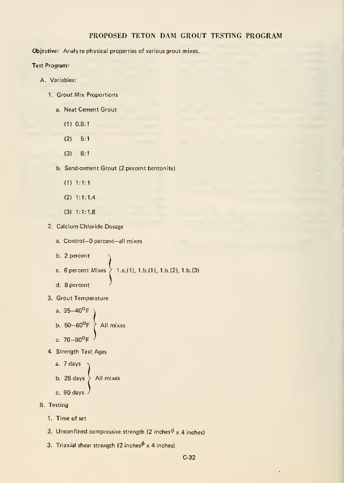
PROPOSED TETON DAM GROUT TESTING PROGRAM
Objective: Analyze physical properties of various grout mixes.
Test Program:
A. Variables:
1. Grout Mix Proportions
a. Neat Cement Grout
(1) 0.8:1
(2) 5:1
(3) 8:1
b. Sand-cement Grout (2 percent bentonite)
(1) 1:1:1
(2) 1:1:1.4
(3) 1:1:1.8
2. Calcium Chloride Dosage
a. Control— percent— all mixes
b. 2 percent \
c. 6 percent Mixes > l.a.(l), 1.b.(1 ), 1.b.(2), 1.b.(3)
d. 8 percent ^
3. Grout Temperature
a. 35-40°F \
b. 50-60°F ? All mixes
c. 70-90° F ^
4. Strength Test Ages
a. 7 days \
b. 28 days > All mixes
c. 90 days /
B. Testing
1. Time of set
2. Unconfined compressive strength (2 inches'/" x 4 inches)
3. Triaxial shear strength (2 inches'^ x 4 inches)
C-32
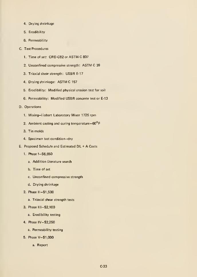
4. Drying shrinkage
5. Erodibility
6. Permeability
C. Test Procedures
1. Time of set: CRD-C82 or ASTM C 807
2. Unconfined compressive strength: ASTM C 39
3. Triaxial shear strength: USBR E-17
4. Drying shrinl<age: ASTIVICIB?
5. Erodibility: Modified physical erosion test for soil
6. Permeability: Modified USBR concrete test or E-13
D. Operations
1. Mixing— I lobart Laboratory Mixer 1725 rpm
2. Ambient casting and curing temperature—60°F
3. Tin molds
4. Specimen test condition—dry
E. Proposed Schedule and Estimated DL + A Costs
1. Phase l-$6,650
a. Addition literature search
b. Time of set
c. Unconfined compressive strength
d. Drying shrinkage
2. Phase 11 -$1,500
a. Triaxial shear strength tests
3. Phase lll-$2,100
a. Erodibility testing
4. Phase IV-$2,250
a. Permeability testing
5. Phase V-$ 1,000
a. Report
C-33

APPENDIX C 4
SUMMARY OF DESIGN
FOR
FOUNDATION PRESSURE GROUTING
TETON DAM

The information on the design of the Teton Dampressure grouting program was obtained from: (1)
USBR Design Considerations for Teton Dam, October
1971; (2) ASCE Specialty Conference Paper by Peter
P. Aberle, "Pressure Grouting Foundation on Teton
Dam," 1976; and (3) Teton Dam Contract
Specifications DC-6910.
The design purpose of the Teton Dam pressure
grouting program can be summarized by the following
two quotations:
1. "Erosive seepage under the embankment will be
eliminated by injecting the foundation with a grout
mixture." (Design Considerations, page 9.)
2. "... to construct an impermeable curtain for
the foundation of Teton Dam ..." (Aberle's 1976
ASCE paper, first page).
It was anticipated that large grout quantities would be
required to produce a tight curtain and that special
procedures would be required to prevent travel of the
grout beyond the limits of the impervious barrier.
Grout more than approximately 100 feet from a
vertical plane through the grout cap would serve no
useful purpose. The grouting operation was designed
to, in part, limit travel of grout.
To obviate massive grout takes on the abutments,
70-foot-deep key tranches were to be excavated in each
abutment above elevation 5100 except under the
spillway. The key trench was not extended under the
spillway because of fear of differential settlement.
Critical areas in the foundation were to be treated by
drilling and grouting three staggered rows of grout
holes. The outer rows of holes were to be drilled at a
specified spacing and injected with a limited volume of
grout based on the probable volume of voids in the
zone being grouted. No attempt would be made to
completely seal the planes defined by the outer rows of
holes by continuing to drill and grout intermediate
(closeout) holes until they refused to take grout. After
the outer rows were drilled and grouted, the centerline
grout cap row was to be drilled and grouted by split
spacing techniques until it was closed out.
In addition to the grout curtain, blanket grouting was
to be provided to reinforce the curtain in areas where
the bottom of the key trench or cutoff trench contains
open fractures or other defects.
The critical areas requiring a three-row grout curtain
were the abutments above elevation 5100 and an
intracanyon basalt-rhyolite contact zone occurring
under the valley floor between approximate dam
stations 20+00 and 24+00. Areas which were
anticipated to need blanket grouting were in the
vicinity of the spillway where the key trench was
omitted and basalt-rhyolite contact zones in the
bottom of the cut-off trench.
The curtain grouting method was split spacing, packer
grouting with provision for stage grouting where
significant drill water loss (greater than 50 percent) or
caving occurred during grout hole drilling. If a grout
hole could be drilled to its planned depth, the hole
would be successively water tested and grouted in
sections, under a packer, from the bottom up. Each
section would only be grouted if water losses during
water pressure testing exceeded 1 cubic foot in 5
minutes.
The final hole spacing in the outer grout rows on the
abutments was to be 20 feet to a depth of 60 feet, 40
feet to 160 feet deep, and 80 feet to 260 feet deep.
Closure holes would not be drilled. The initial spacing
for centerline grout cap holes on the abutment was to
be 10 feet to a depth of 60 feet, 20 feet to 110 feet
deep, 40 feet to 160 feet deep, and 80 feet to 260 feet
deep. Closure holes would be drilled where grout takes
in the last sequence of planned borings indicated that
further grouting was necessary. In the areas where
holes on 5-foot centers would fail to close out at
depths exceeding 60 feet, additional closure holes were
to be drilled 5 to 10 feet upstream from the centerline.
On the right abutment, the 80-foot spaced primary
holes would be extended from 260 to 310 feet in
depth.
The holes in the upstream and dowstream rows were to
be drilled vertically. The holes in the centerline row
were to be inclined into each abutment at 30° from
vertical.
Below elevation 5100, the hole spacings and depths in
the single-line grout curtain were to be the same as
those in the centerline row on the abutments. Closure
holes would be drilled as needed.
The outer rows of grout holes in the intracanyon basalt
area were to be drilled on 10-foot centers to a depth of
15 feet into the rhyolite underlying the basalt. No
closure holes were to be drilled. The centerline row
grout cap holes were to be drilled on the same initial
pattern as the centerline row on the abutments, except
that the 10-foot spacing was to extend 15 feet into the
rhyolite. Closure holes would be drilled as needed.
C-37
The blanket grouting was provided to allow special
treatment of open cracks, jointed areas, high grout
takes, and other defects uncovered in the bottom of
the cutoff trench or disclosed by the curtain grouting.
The blanket grouting was to have been performed by
low-pressure grouting through shallow drill holes.
The sequence of grouting where three grout rows wereused was (for any section of the curtain) thedownstream row first, the upstream row second, andthe centerline row third. Where required, blanket
grouting would be performed prior to curtain grouting.
It was anticipated that the grout water-cement ratio
would vary from 10:1 to 0.8:1 by volume. Thegrouting maximum injection pressure, with certain
exceptions, would be 10 psi or 0.75 psi per foot of
depth measured normal to the ground surface from thepacker to the ground surface, whichever was thegreater.
In order to minimize grout travel up and downstreamfrom the planned grout curtain, the use of calcium
chloride (CaClz), sand-cement grout mixes, and
intermittent grout pumping was planned for grout
holes which took large amounts of grout at less than
normal pressures. The grout mix was to be
progressively thickened and then sand and/or CaCI^
added if the rate of grout take remained high. If the
hole continued to take, consideration was to be given
to intermittent pumping when a take of more than 500
sacks occurred in a 20-foot stage. Intermittent
pumping would include flushing the hole with not
more than 25 cubic feet of water, allowing the grout to
set for up to 8 hours, and then continuing pumping.
Closeout holes were required on each side of a
centerline hole where intermittent pumping was
performed.
The criterion for discontinuing grouting was a pumping
rate of less than two sacks of cement per hour, a rate
of less than 1 cubic foot of mix in 10 minutes at
injection pressures up to 50 psi, in 8 minutes from 50
to 100 psi, and in 5 minutes if the injection pressure
was greater than 100 psi.
C-38
APPENDIX C 5
BORING LOGS AND
JOINT TRANSMISSIBILITY AND WATER PRESSURE TEST
DATA
TETON DAM

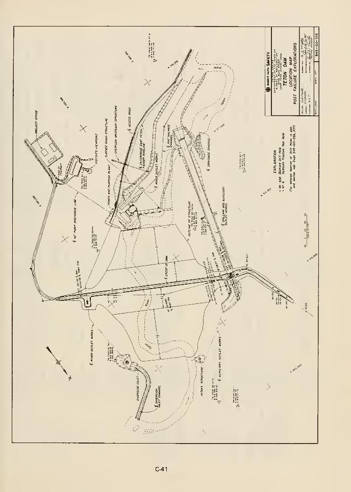
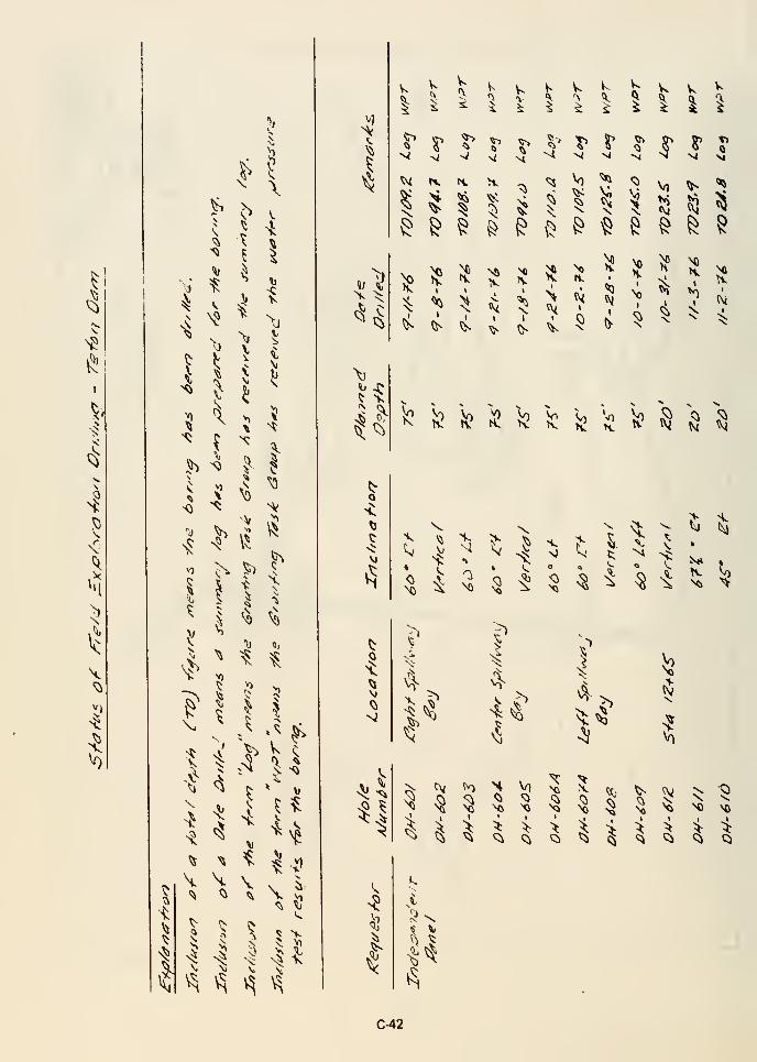
I
I
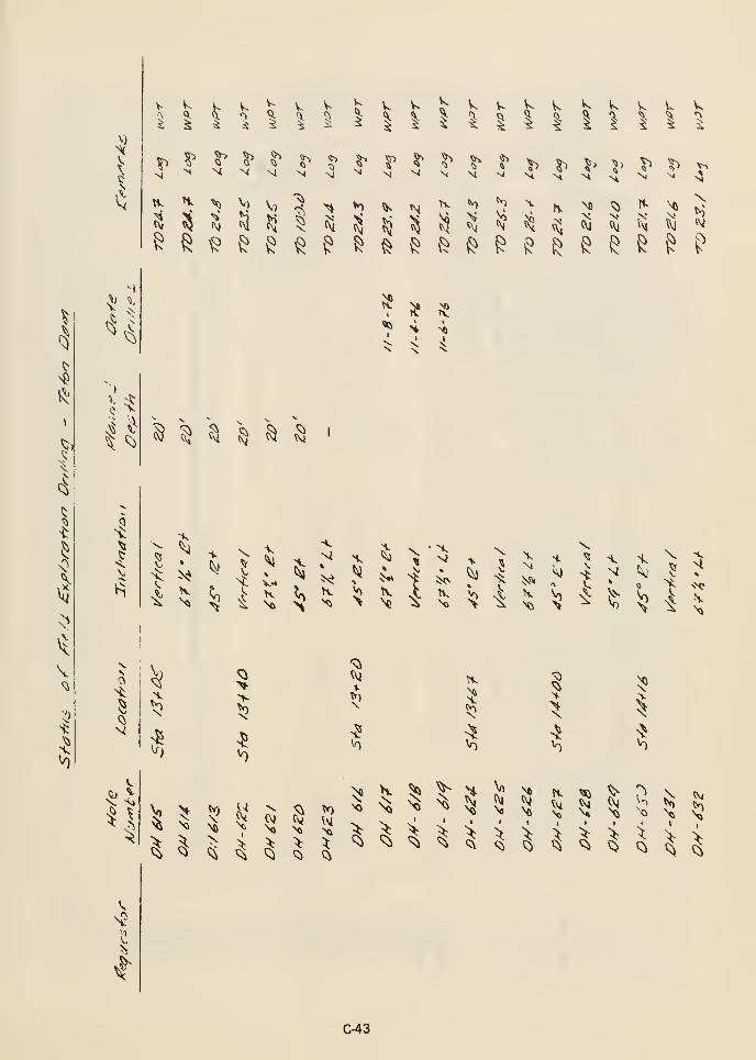
y^
Ci
V-
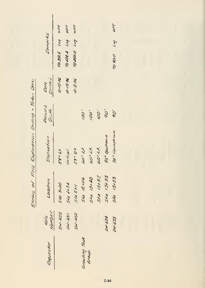
I
^ '^ ^III5^ '^l ^5^ Q <1
N Vi M
^ ^ I^ ^ \^
I
^
^
^
I
V
I
<5
^
5;
^
1
S S S ^ ^« ^ ^ ^ 'i-
\ \ ^
H Qc, ^
^ 5 ^VT) ^ \0
^ ^
^^
Mi NO
I 1
» »
!i.' Ji! ^^ *^ tv^
X X >,
^ ^ ^5
^ ;?^
IQ V) V/)
^1\0 W)
^ ^Q ^
V) Ml
S
I" I
C-44
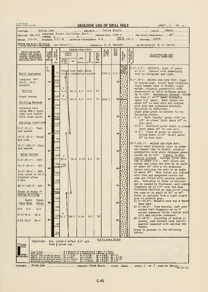
GEOLOGIC LOG OF DRILL HOLE SHEET. . .1 .
FEATURE Tp.t.O.n . P»R . PROJECT Te.tQI). P^.S.iO STATE I4»h.O..
GROUND ELEV, 5299-0. ........ DIP (ANGLE FROM HORIZ ) . . ..60* .
COORDS. N E TOTALBEGUN . .?-?-.76 . . . FINISHED. .9.-.I.I.-.7.6.
. . . DEPTH OF OVERBURDEN ..".-.O DEPTH. JP9,2. . . . BEARING. . .N74TW
''LEVEL*I!No^bATE°M'E«u7E'o. See .Notes.- logged by. P-. N... M«Jeby log reviewed by. .8. .H. .Carter
NOTES ON WATERLOSSES AND LEVELS.CASING. CEMENTING.CAVING, AND OTHERDRILLING CONDITIONS
CLASSIFICATION ANDPHYSICAL CONDITION
Drill Equipment
Longyear "34
"
drill, skidmounted.
Driller
Frank Martin
Drilling Methods
Advanced holeusing NWD-3 splittube core barrelwith clear water.
Drilling Conditior
5281.7
0.0'-20.3': Fastand smooth.
20.3'-25.I': Roughand slow.
25.r-109.2': Fastand smooth
.
Water Return
0.0'-20.3': 100%
20.3'-40.D': 95%
40.0'-80.4': 90%,
lost water at 80.4regained after4 min.
80.4'-109.2': 85%
Depth to Water **
r h
4. ^ -4
» *'
-4 A
During Dril ing
Depth DepthDate Hole Water
70-. . ' -
9-9 4.0 3.0
9-10 49.6 35.6
9-11 93.8 80.4
*» f* w »
0.0'-5.4': CONCRETE; hard, 1" rebarat 4.4'. Contact with underlyingrock Is irregular and tight.
5.4'-20'+: WELDED ASH-FLOW TUFF; lightto medium gray, fairly hard (requireslight hammer blow to break), lightweight, slightly porphyritic withphenocrysts of white feldspar mostlyup to 1/8". Moderately Jointed . Joindsare from 1" to 1' apart averagingabout 0.8' apart. Most joints areabout 60* to core axis and stainedwith iron and carbonate minerals.Foliation is indistinct.Light gray grout is present in thefollowing joints:9.3': Soft "chalky" grout 1/16" to
1/8" in planar joint about 60* tocore axis,
10,8': Scattered grout stain in plani*joint about 60* to core axis.
16.4': Trace of grout in calcitefilled joint (1/32" thick) about30" to core axis.
20't-109.2': WELDED ASH-FLOW TUFF;fairly hard (requires light to moder-ate hammer blow to break), slightlyporphyritic with white feldspar phenocrysts up to 1/4". Lightly to Mod-erately Jointed . Average joint spac-ing is about 0.8' . Most joints areplanar and cross the core at an angleof about 60° with a few prominentjoints crossing the core at an angleof about 30*. Many joints are stainedwith iron and manganese oxides andsome are filled with calcium carbon-ate. Foliation Is faint to distinctand Is caused by flattened, wavy pumicfefragments up to 1/4" wide and someflattened cavities or vugs which crossthe core at an angle of 60* to 80*.
Color is variable from a light purplegray to pinkish gray.67.9'-69»9': Breccia zone and » inter
flow . zone
.
67.9'-68.8': Flow breccia, dark graywelded tuff fragments up to 2"
across cemented fairly tightly withsilt and calcium carbonate.
69.3'-69.9': Interflow of medium to
coarse, semi-rounded sand (mostly
quartz) cemented with calcium carbonate.
Grout is present in the followingjoints:
i;CORERECOVERY
Sta. 10-»60.4 offset 8.5'
from £ grout cap
.
u/sEXPLANATION
Typ. of hoi. Dm Diamond, H Hojr.t.ilit., S a Shot, C • ChwmHel. fa\»4 P " Pock.r, Cm m Cwn.nl.d, C. BoHom of cosing
Appro., fiio of hoi. (X->o>ioi) . .E> • 1-1/2", A« = 1.7/8", B« - 2-3/«", N. - 3"
Appioio •is. of cor. (X-iori.a) . . Ei c 7/e", A. « 1.1/8", B« - LS/I", H« - 2-1/r'Ouliidodlo. of co>ing(X.>.ri.>).E> IE 1-13/l«", A. > 2-1/4", Bi • 2-7/1", Ni • 3-1/2"
In.ld. Jlo. of co.ing (X.»»i«i|. E. . 1-1/2 ', A» - 1-29/32", B. - 2-3/1", N« - 3"
.Teton Dam. project .Teton .Basin . . . state . .Idaho . SHEET .1. . OF . 3. . HOLE HO. .DH- ^o^;
C-45
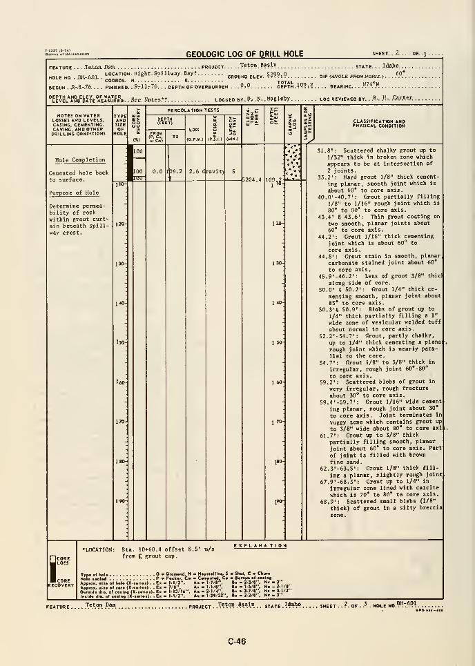
GEOLOGIC LOG OF DRILL HOLE SHEET. . A. . . . OF. .3 .
.TetjOTL Dam, project T??™. ???!"? state. .. Jd^P. .
.
jj^ni LOCATION. Right. Spillway. Bay*ground elev. ????-.? oip c"'--' - "'™ "">" - ^''*
FEATURE
HOLE NO. . ,„„=„,COORDS.
BEGUN . .9.-.a-.7.6. . . . FINISHED.
DEPTH AND ELEV. OF WATER
» (ANGLE FROUHORIZ.} .
9rllr7f>. . . DEPTH OF OVERBURDEN . . .9.9. N74'W
'LEJEL*AND^bATE'irEls*URED. . See. NOteS" LOGGED BY . P, . N, . MasleW LOG REVIEWED BY. ..B... .H-. .Qarter.
NOTES ON WATERLOSSES AND LEVELS,CASING. CEMENTING,CAVING, AND OTHERDRILLING CONDITIONS
TYPEANDSIZE
GO
PERCOLATION TESTS
FROM
'It)
LOSS
(CP-I*.)
Hi-u-^J CLASSIFICATION AND
PHYSICAL CONDITION
Hole Completion
Cemented hole back
to surface.
Purpose of Hole
2.6 Gravit)
110-
Determine permea-bility of rock
within grout curt-
ain beneath spill-
way crest.
130-
140
ISO
l60-
170-
5204.4°^>l
120-
130-
140-
1 60-
170
ISO-
i*®:
31.8': Scattered chalky grout up to
1/32" thick in broken zone which
appears to be at intersection of
2 joints.33.2'; Hard grout 1/8" thick cement-
ing planar, smooth joint which is
about 60* to core axis.40.0'-40.7': Grout partially filling
1/8" to 1/16" rough joint which is
80* to 90* to core axis.
43.4' 6 43.6': Thin grout coating on
two smooth, planar joints about60* to core axis.
44.2': Grout 1/16" thick cementing
joint which is about 60° to
core axis.44.8': Grout stain in smooth, planar
carbonate stained joint about 60*
to core axis.
45. 9' -46.2': Lens of grout 3/8" thic)
along side of core.
50.0' S 50.2': Grout 1/4" thick ce-
menting smooth, planar joint about85* to core axis.
50.3'S 50.9': Blobs of grout up to
1/4" thick partially filling a 1"
wide zone of vesicular welded tuff
about normal to core axis.
52.2'-54.7': Grout, partly chalky,
up to 1/4" thick cementing a plana:
rough joint which is nearly para-
llel to the core,
54.7": Grout 1/8" to 3/8" thick in
irregular, rough joint 60*-80''
to core axis.59.2': Scattered blobs of grout in
very irregular, rough fracture
about 30* to core axis.
59.4'-59.7': Grout 1/16" wide cement
Ing planar, rough joint about 30*
to core axis. Joint terminates in
vuggy rone which contains grout up
to 3/8" wide about 80* to core axl
61.7': Grout up to 3/8" thick
partially filling smooth, planar
joint about 60* to core axis. Part
of joint is filled with brown
fine sand.62.3'-63.5': Grout 1/8" thick fill
ing a planar, slightly rough joint67.9'-68.3': Grout up to 1/4" in
irregular zone lined with calcitc
which is 70* to 80* to core axis.
68.9': Scattered small blebs (1/8"
thick) of grout in a silty breccia
zone.
COREJ LOSS
I CORERECOVERY
•LOCATION: Sta. 10->6D.4 offset 8,5
from £ grout cap.
u/s
Typ« e
Hoi*m Dlomond, H Haytt«lllt«. S
Pa Pocksr, Cm « CMn«nt*rf, CaAppnix. III. si boU (X-»iUi| . . E« - M/J ", A» - l-'/*".
Approx. alt* o( cora (X.aarlaa) . . Ea 7/8", Ax • I.1/8' ,
Oulalrfa dio. of eaalna <X-aaflaa). Ea 1-13/16", Aa - 2-1/4
Inaida dio. o« coataq (X-aa>laa). . Ea 1-1/2" . 1-29/32"
EXPLANA TION
Sh«l, C m ChumB«tto<ii af coalnf
Ba .2-3/J", Ma -3"Ba -l-5/«", Ma-2-1/i"Ba • 2-7/t", Na - 3-1/2"Ba 2.3/>" . 3"
Teton Dm project Teton Basin STATE .?4*')° SHEET ,
, DH-6019P0 aaa-aii
C-46
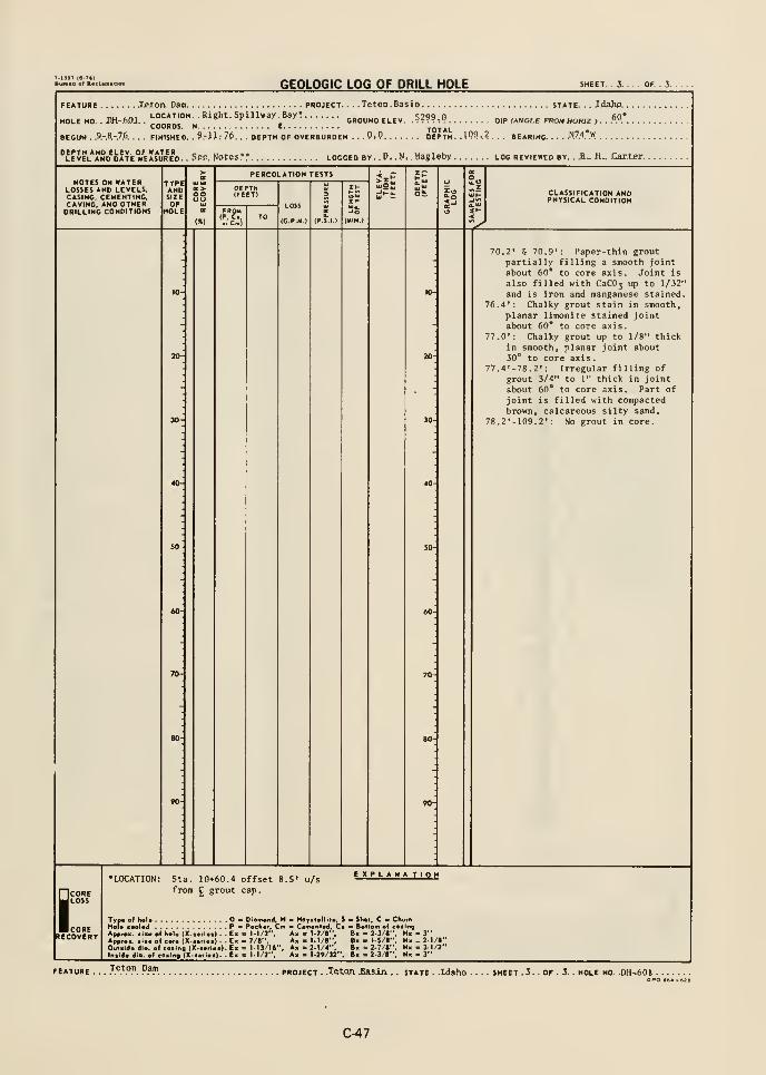
7.1S8T (fl-T*)
Bur**u ot R*ol
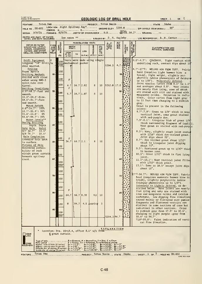
GEOLOGIC LOG OF DRILL HOLE
FEATURE
.
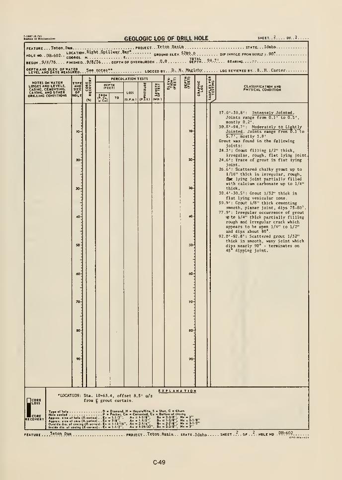
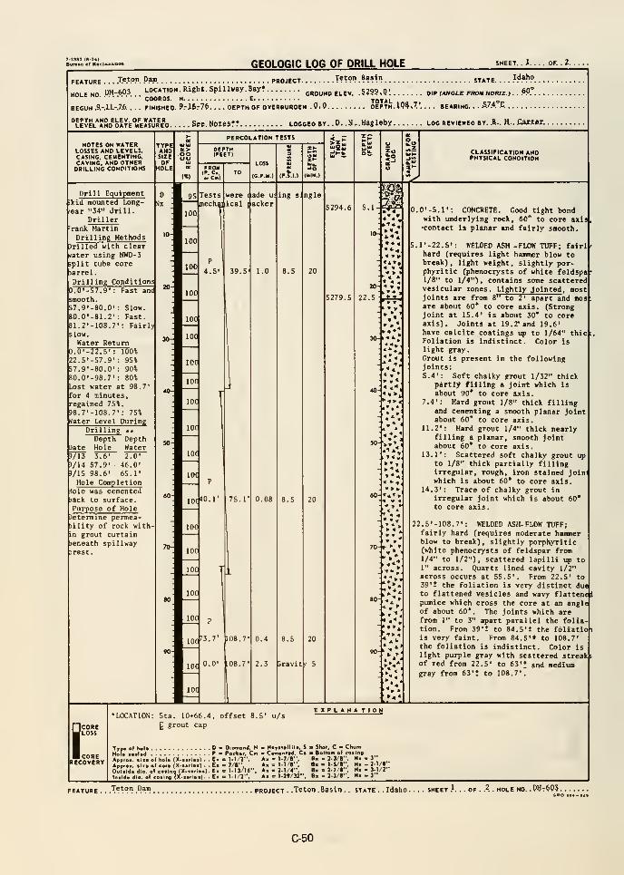
GEOLOGIC LOG OF DRILL HOLE SHEET. . X. OF. . 2.
IdahoFEATURE . . .
.T.e.tO.n. P.am. PROJECT T?^?"? .??»!') STATE.
LOCATION. Right. Spillway. Bayrground elev. .5?99.Q'. wp (angle f^m horiz, . f><>.NO. .W-.*.".'.HOLE ,«r,o«.COORDS, n
BEGUN .9.-.I.I.-.7.6. . . . FINISHED. 9rl5r7f>.
DEPTH AND ELEV. OF WATER
. DEPTH OF OVERBURDEN .QiQ. DEPTH. 109 »7'.. . . BEARING. • •
.S.'.^.'E..
level*and^oate°meIs*Jred Sre. Notes?? logged by. .0. .N,.M3gleby log reviewed by. A.. H.. Caxtei.
NOTES ON WATERLOSSES AND LEVELS,CASING, CEMENTING,CAVING, AND OTHERDRILLING CONDITIONS
TYPEANCTSIZEOF
XOLE
OO
PERCOLATION TESTS
FROMIP, C.e> Cm)
LOSS
(C.P.M.)
-O(HIN.)
CLASSIFICATION ANDPHYSICAL CONDITION
Drill Equipment(kid mounted Long- kjx
'ear "34" drill.Driller
rank MartinDrilling Methods
drilled with clearrfater using NWD-3jplit tube corejarrel.
Drilling Condition;0.0'-57.9
smooth,57,9'-80,0'80,0'-81,2'
81.2'-108.7slow.Water Return
D,0'-22,5'22,5'-57,9
Fast anc
SlowFastFairl>
100%
95%57.9'-80.0' : 90%B0.0'-98,7': 80%
Lost water at 98,7'
for 4 minutes,regained 75%,
38,7'-lD8,7' : 75%^ater Level During
DrillingDepth Depth
)ate Hole Water13 3.6' 2,0'
)/14 57,9' 46,0'
)/15 98,6' 65,1'
Hole Completionlole was cementedjack to surface.Purpose of Hole)etermine permea-Jility of rock withLn grout curtain>eneath spillwayrest.
Testsmech:
were i :ade u<
icalIacker
ing s: ngle ms?3?5294,6 5.1
100
100
100
100
100
100
100
100
p
4.S' 39.
S
1,0
5279.
S
20
22.5
»•».
« *
' » »'I* «
r±-Vl¥ T
- ^1 *
IOC
IOC
10(
50- .
,0(10,1'
IOC
IOC
20C
1loc'
IOC
p
3,7'
0,0'
75,1 0,08
70- , fr
/ 5
0.0'-5.1': CONCRETE. Good tight bondwith underlying rock, 60° to core axis•contact is planar and fairly smooth,
5.1'-22.5': WELDED ASH -FLOW TUFF; falrlhard (requires light haimier blow tobreak), light weight, slightly por-phyritic (phenocrysts of white feldspa-1/8" to 1/4"), contains some scatteredvesicular lones. Lightly Jointed , mostjoints are from 8" to 2
' apart and mosare about 60* to core axis. (Strongjoint at 15.4' is about 30' to coreaxis). Joints at 19.2' and 19.6'have calcite coatings up to 1/64" thic ;
Foliation is indistinct. Color islight gray.C^rout is present in the followingjoints:5.4": Soft chalky grout 1/32" thick
partly filling joint which is
about 90* to core axis.7.4': Hard grout 1/8" thick filling
and cementing a smooth planar jointabout 60* to core axis.
11.2': Hard grout 1/4" thick nearlyfilling a planar, smooth jointabout 60* to core axis.
13.1': Scattered soft chalky grout upto 1/8" thick partially fillingirregular, rough, iron stained jolni
which is about 60* to core axis.14.3': Trace of chalky grout in
irregular joint which is about 60"
to core axis.
22.5'-108.7' : WELDED ASH- FLOW TUFF;fairly hard (requires moderate hammerblow to break), slightly porphyritlc(white phenocrysts of feldspar from1/4" to 1/2"), scattered lapilli up to1" across. Quartz lined cavity 1/2"across occurs at 55.5'. From 22,5' to39't the foliation is very distinct du«to flattened vesicles and wavy flattenc
1
pumice which cross the core at an angleof about 60". The joints which arefrom 1" to 3" apart parallel the foliation. From 39 'i to 84.5 't the follatiohis very faint. From 84.5'* to 108.7'
the foliation is indistinct. Color islight purple gray with scattered streak,of red from 22.5' to 63't and mediumgray from 63't to 108.7'.
iCORELOSS
CORERECOVERI
Sta. 10*66.4
£ grout cap
offset 8.5' u/sEXPLANATION
Trp« of KoU Da Diamond, HHoU aoolod P - Pockor, CmApproM. alio of holo (X.iarloi) . . E> • ''<<?"'Approa. til* of cofo (X.aorioi) . . Em 7/8",Oulttd* dio. of eating (X-ioriot). Ex = 1.13/16".
Intldo dig, of co«ln9 (X-tf Igi). E» a T-1/2",
- Hoyatalhlo, S - SKot, C - ChumComonlod, C« - Bottom of eating
Ai = 1-7/8", B. . 2-3/8", H. .3"A. = 1-1/8", B« - 1-5/8", H.- 2-1/8"A. a 2-1/4", B. « 2-7/8", H. - 3-1/2"
Am = 1-29/32", Bm - 2-3/8". N« - 3"
,T^'-9'! ,Pa"! PROJECT . T^ton Basin, , state, , Idaho sheet .1... of . .? hole no .PHt603.spo •84-aaB
C-50

GEOLOGIC LOG OF DRILL HOLE .2... OF. ..2 ,
ecjLTiipc T«ton Dam PROJECT Tftt,OJX BASAJX
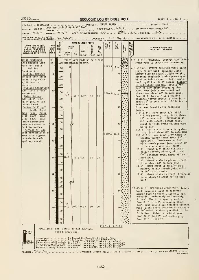
GEOLOGIC LOG OF DRILL HOLE SHEET. .1 . OF. .2 .
FEATURE
.
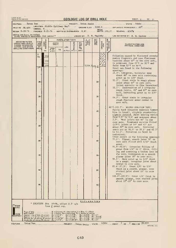
7-1337 (6-7*)Bureiu of RvcUmkllon
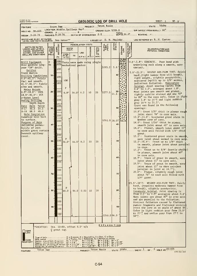
GEOLOGIC LOG OF DRILL HOLE
HOLE NO. . DH.-6D5. .
^^^^^j ^
BEGUN . 3.-16.-7&. . . F1NISHE0.9tI?t7&.
. . . . Teton. Dam project. ..Teton .Basin state. . .
Idah9.
LOCATION. Middle. Spillway .Bay*ground elev. 529a..Q dip (angle frou horiz >. 90'
.
^„ . TOTAL _, .,
DEPTH OF OVERBURDEN .Q,0 DEPTH .yo.-.U BEARING. ..-."
DEPTH AND ELEV OF WATERLEVEL AND DATE MEASURED. S^f ,l:l(jt«s** LOGGED BY. .0. .N, .Maglfihy. log reviewed by. B-.H.. Carter.
NOTES ON WATERLOSSES AND LEVELS,CASING, CEMENTING,CAVING, AND OTHERDRILLING CONDITIONS
TYPEANDSIZE oo
PERCOLATION TESTS
FROMLOSS
(C.P.M.)
CLASSIFICATION ANDPHYSICAL CONDITION
Drill EquipmentSkid mounted Long-
year "34" drill.Driller
Frank MartinDrilling Conditions0.0'-45.3' : Fairlyfast and smooth.45.3'-96.0' ; Fairlyslow and smooth.
Water Return0.0'-18.0': 100%18.0'-96.0': 95».
** Water Level
During DrillingDepth Depth
Date Hole Water9-17 4S.3 30.39-18 88.9 48.6Hole Completion
Cemented hole back
to surface.Purpose of HoleDetermine permea-bility of rock
within grout curtail
beneath spillway
crest.
100
mechai.ical
100
I lade w.
1 acker.
ing s: ngle
5293,2
P
6,0' 10 5277,5 20
21.5
P
36.0'
•A38.0
40-
66.0 0.2
P
66.0 10
5203.0
0.0 '-5,8': CONCRETE. Poor bond with
underlying rock along a smooth, wavycontact
.
5.8'-21.S': WELDED ASH-FLOW TUFF: fairl)
hard, (light hammer blow will break),
light weight, slightly porphyritic,
scattered lapilli up to 3/8" across,
indistinct foliation. Moderately
Jointed . Joint spacing varies from
0.4' to 2.2', averages about 1.0'.
Most joints are smooth and planar,
lightly calcite stained and are 70*
to 80" to the core axis. Color is ligl
gray 5.8' to 16't and light reddish
gray 16'* to 21.5'
.
Grout was found in the following
openings
:
10.8': Grout 1/8" thick in planar rou^joint about 70° to core axis.
13.8'-13.9': Scattered grout stain inbroken zone of core.
14.0': Grout 1/16" thick in planar,smooth joint about 40° to core axi;
14.8': Planar, smooth joint about 15'
to core axis filled with 1/4" thicJgrout
.
15.2': Scattered grout stain in smootjh
wavy joint about normal to core ax15.2'-15.4': Grout up to 1/8" thick
in smooth, planar joint about paral|lel
to core.17.2'; Grout UP to 1/4" fnartly chalk^)
in planar, smooth joint about 40*^
to core axis.18,7': Trace of grout in smooth, wavy
joint about 15° to core axis.19.9': Trace of grout in smooth, wavy
joint about 15° to core axis(notparallel to joint at 18.7').
20.8': Planar, slightly rough jointabout 75* to core axis filled with1/4" grout
.
21.5'-38'*: WELDED ASH-FLOW TUFF; fairlyhard, (requires moderate hammer blowto break), slightly porphyritic.Intensely Jointed . Joint spacing is
from 0.1' to 1.0' averaging about 0.4Most joints are about 80* to core axisand are parallel to the foliation.Distinct foliation caused by flattenedpumice fragments and flattened vesiclecross the core at an angle of about 80
Color is light reddish gray from 21.5'
to 27'* and medium gray from 27't to
38't.
SCORELOSS
CORERECOVERY
Sta. 10+89, offset 8.5'
C grout cap.
u/sEXPLANA TION
Type of Kol«HoU taal«dApproR, liie al hole (X-scriei) .
Approx. liie a( cor* (X-seriat) -
Oulild« dio. o( cosing (X-t«n«sImida dio. of co«ing (X-«»fie»).
. ' Diamond. H
. P = Packer. Cm
.E> = 1-I/2",
. E> = 7/8*-.
. E> = 1.13/16*',
. E. = 1-1 '2",
Hoyslellile, S b Shot, C « ChvrnCemented. Ci e Bottom «f cosing
^x = ).7/8'-, B. = 2-3/8", N« - 3"
i« = 1.1/8'. Bx = 1.5/8". Nh- 2-1/8'
fcx = 2-1/4", B» =2-7/8", Nx = 3.1/2"
fc, = 1-29/32". Bk = 2-3/8", Nx - 3"
Teton Uam Teton BasinPROJECT .'.^.^.^-". .''*^.V'. . . . STATE .
CPO •B4-«3B
C-54
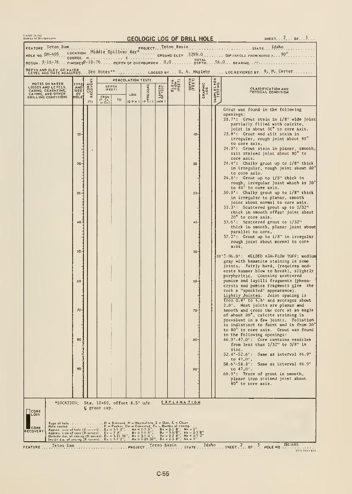
T.1S37 («-7«l
GEOLOGIC LOG OF DRILL HOLE SHEET. . . ^. . . OF.
Teton BasinFEATURE . T??Pn. P?"" PROJECT.
nH-605 LOCATION. Middle. Spillway Bay*HOLE NO. MP. Pyp. . .« „ , r GROUND ELEV .^f^^-.M DIP (ANGLE FROM HORIZ )
COORDS. N E TOTALBEGUN .
9-16- 76,. , FINISHED?? 1 87 76 DEPTH OF OVERBURDEN . .QtQ DEPTH. . .
.9.6 -.Q . . BEARING. .."."
Idaho
90°
See. Notes** logged by. . . ,D^ .^l^ M^gUtiy . LOG reviewed by. ..^.* . H.- .
Carter.
NOTES ON WATERLOSSES AND LEVELS.CASING. CEMENTING,CAVING. AND OTHERDRILLING CONDITIONS
TYPEANDSIZE
q: >00
PERCOLATION TESTS
LOSS
(C.P.M.)
CLASSIFICATION ANDPHYSICAL CONDITION
Grout was found in the followingopenings:21.7': Grout stain in 1/8" wide joint
partially filled with calcite,joint is about 80* to core axis.
23.8': Grout and silt stain in
irregular, rough joint about 45°
to core axis.24.0': Grout stain in planar, smooth
silt stained joint about 80* to
core axis.24.4': Chalky grout up to 1/8" thick
in irregular, rough joint about 80
to core axis.24.8': Grout up to 1/8" thick in
rough, irregular joint which is 30
to 40° to core axis.30.0': Chalky grout up to 1/8" thick
in irregular to planar, smoothjoint about normal to core axis.
33.3': Scattered grout up to 1/32"
thick in smooth offset joint about20* to core axis.
33.6': Scattered grout to 1/32"
thick in smooth, planar joint aboutparallel to core.
37.2': Grout up to 1/8" in irregularrough joint about normal to core
axis.
•t-96.0': WELDED ASH-FLOW TUFF; mediuir
gray with hematite staining in somejoints. Fairly hard, [requires mod-erate hammer blow to break), slightlyporphyritic. Contains scatteredpumice and lapilli fragments (pheno-
crysts and pumice fragments give therock a "speckled" appearance).Lightly Jointed . Joint spacing is
from 0.4' to 4.8' and averages about2.0'. Most joints are planar andsmooth and cross the core at an angleof about 80*, calcite staining is
prevalent in a few joints. Foliation.
is indistinct to faint and is from 30
to 80° to core axis. Grout was found
in the following openings:46.9'-47.0': Core contains vesicles
from less than 1/32" to 3/8" in
size.52.4'-52.6': Same as interval 46.9'
to 47.0'.
S8.6'-58.8': Same as interval 46.9'
to 47.0'.60.9': Trace of grout in smooth,
planar iron stained joint about80° to core axis.
1;
•LOCATION; Sta. 10+89, offset 8.S'
6 grout cap.u/s EXPLANATION
Type of hole D = Diamond. H = Hoystellile, S = Shot, C = ChurnHofe leoled P = Pocker, Cm = Cemented, Cs = Bottom of coding
App.o. i.ieolhole (X.enesl E. = 1-1 2", A, = 1.7B". B« = 2-3 8". N, . 3"
Appro.. ...eof co.e (X-se.ies) - , E< = 7-8", Ax = 1-1 8". B, = 1.5/8". N»-2-l.'8"OoH.de dio. of co..n9 (X-ieries) E. = 1-13 16". A, .2-1 4", B. = 2-7 8". N. =3-1 2"Inside dio of loiing IX-ier.ei)- E. = 11 2". A, = 1-29 32". B. = 2-3 8". N» - 3"
Teton Dam Idaho
C-55
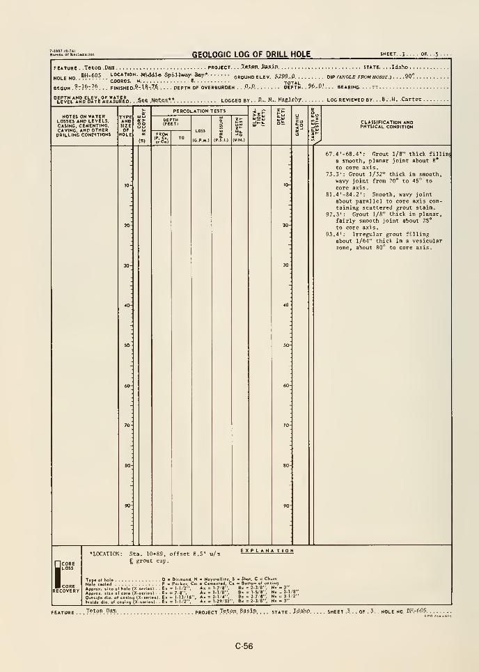
GEOLOGIC LOG OF DRILL HOLE
FEATURE . .Teton .Dam project. . . .Te.ton. £a5in state. . . .Idaho .
DH-605 location. .Mi<Jdl.6 Spillway Bay*- GROUND ELEV. S299-D DIP (ANCLE FROMHOR1Z-) ..90°
.9:16:76. . . FINISHED.9-.l,8.-.7.6. .... depth of overburden . ..O.-.O DEPTH. 96..0.', BEARING.
LEVEL AND DATE MeIsJr ED. . .Ss? .NQtSS.". LOGGED BY. . D... N... MaglCby LOG REVIEWED BY. .B. .H. .Carter
NOTES ON WATERLOSSES AND LEVELS.CASING. CEMENTING,CAVING. AND OTHERDRILLING CONDITIONS
TYPEANDSIZEOF
HOLE
UJUiq:>oo
PERCOLATION TESTS
FROM(P. C,..Cm)
LOSS
(G.P-M.)
l-m
St CLASSIFICATION ANDPHYSICAL CONDITION
67.4'-68.4': Hrout 1/8" thick fillini
a smooth, planar joint about 8*
to core axis.73.3': Grout 1/32" thick in smooth,
wavy joint from 20" to 45° to
core axis.81.4'-84.2': Smooth, wavy joint
about parallel to core axis con-taining scattered grout stain.
92.3': Grout 1/8" thick in planar,fairly smooth joint about 25*
to core axis.93.4': Irregular grout filling
about 1/64" thick in a vesicularzone, about 80° to core axis.
SCORELOSS
CORERECOVERY
•LOCATION: Sta. 10*89, offset 8.5' u/s
g grout cap.
EXPLANA TION
Type ol hole D D.cmond. H - HoyiteH.ie. S = Shot, C = Chi
HoU tooled P = Po.ke,. Cm - Cemenled. C. =_Boiiom_ o^ co.
Appro,
Outside di
In.lde
( hole (X-seri
I core (X.>eri
(eo.ing(X.l,eo.ir,9 (X...r
. E> = 1-1, 2".
.)..£«= 7 8",
ie.).E. = I.n/I6"n). . E» = 1-1/2".
A< = 1-7 1
= 1-1 e". B.- 2-1 4". B.= 1-29 32". B>
ng2-3 B". N« . 3"1-5/8". N> - 2-1/8"2-7 •". N. = 3-1/2"
2-3'a". N. - 3"
Teton Dam project .T.e.t.on. .Basin. STATE . .Id.ahp. SHEET .3 . . OF . 3. . hole NO. 0H-.6.O5,
C-56
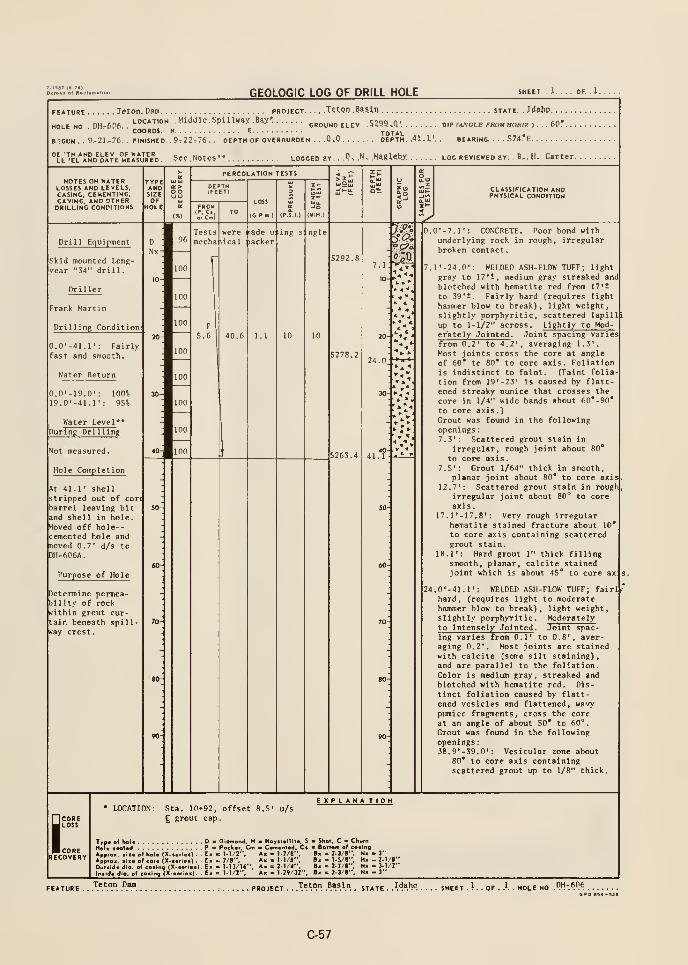
GEOLOGIC LOG OF DRILL HOLE SHEET. . J. . . . OF. . J.
FEATURE
HOLE NO. . DH.-6D6.
B TCUN
Teton. Dam project Teton .Basin state. . Jdahp. . . .
LOCATION. Middle. Spillway. Bax* „„„„„.,.„ j^gg^Q. dip m/vcle from howz , . . .60*
.
COORDS. N
9.-21.-76. . finished. . 9^22,76 .
CROUNO ELEVt
. DEPTH OF OVERBURDEN . . .0*0 . S7l)*E.
.See. Notes** locoed by. .P'. .N-. .Magleby. loo reviewed by. . E.. H,. Carter.
NOTES on waterLOSSES AND LEVELS.CASINO. CEMENTING,CAVING, AND OTHERDRILLING CONDITIONS
TYPEANDSIZEOF
HOLE
q:>oo
PERCOLATION TESTS
FROMIP. C.o. C~l
LOSS
(C P M )
J
CLASSIFICATION ANDPHYSICAL CONDITION
jd.
Drill Equipment
Skid mounted Long-
year "34" dri 1 1
.
Driller
Frank Martin
Drilling Condition
D a 96
Nx
100
0.0'-41.1': Fairlyfast and smooth.
Water Return
0.0'-19.0': 100*19.0'-41.1': 95%
Water Level*
During Drilling
Not measured.
Hole Completion
100
Testsmecha:iical
r
p
S.6
nade u:
acker; ing s ngle
5292.87.i:
-^.V
10
* ¥ 4
5278.224.0
100 »*4
100
<0- 100
At 41.1' shellstripped out of cort
barrel leaving bitand shell in hole.Moved off hole--cemented hole andTioved 0.7' d/s toDH-606A.
Purpose of Hole
Determine permea-bility of rockwithin grout cur-tain beneath spill-K*ay crest.
5263.440-
41.1
0.0'-7.1': CONCRETE. Poor bond withunderlying rock in rough, irregularbroken contact.
.l'-24.0': WELDED ASH-FLOW TUFF; light
gray to 17' t, medium gray streaked and
blotched with hematite red from 17't
to 39't. Fairly hard (requires light
hammer blow to break), light weight,slightly porphyritic, scattered lapilli
up to 1-1/2" across. Lightly to Moder'ately Jointed . Joint spacing variesfrom 0.2' to 4.2', averaging 1.3'.
Most joints cross the core at angleof 60* to 80" to core axis. Foliationis indistinct to faint. (Faint folia-
tion from 19'-23' is caused by flatt-ened streaky pumice that crosses the
core in 1/4" wide bands about 60*-90*
to core axis.)Grout was found in the followingopenings
:
7.3': Scattered grout stain In
irregular, rough joint about 80*
to core axis.7.5': Grout 1/64" thick in smooth,
planar joint about 80* to core axis12.7': Scattered grout stain in rough
irregular joint about 80^ to core
axis.17.1 '-17. 8': Very rough irregular
hematite stained fracture about 10*
to core axis containing scatteredgrout stain.
18.1': Hard grout 1" thick fillingsmooth, planar, calcite stainedjoint which is about 45* to core ax
24.0'-41.1': WELDED ASH-FLOW TUFF; fairl^'
hard, (requires light to moderatehammer blow to break), light weight,slightly porphyritic. Moderatelyto Intensely Jointed . Joint spac-ing varies from 0.1' to 0.8', aver-aging 0.2*. Most joints are stainedwith calcite (some silt staining),and are parallel to the foliation.Color is medium gray, streaked »ndblotched with hematite red. Dis-tinct foliation caused by flatt-ened vesicles and flattened, wavypumice fragments, cross the coreat an angle of about 50* to 60".
Grout was found in the followingopenings:38.9'-39.0': Vesicular zone about
80* to core axis containingscattered grout up to 1/B" thick.
SCORELOSS
CORERECOVERY
LOCATION: Sta. 10+92. offset 8.5'
£ grout cap
.
u/sEXPLANA TION
Typ* of hoi* D •
" MC •»al«d P :
AppiApprox. till
Outside didIntid* dia. .
:• of hole (X-serlea) -
:o.in, (X-.
'«'"g (X-.e
DiOffiond, HPack.!. Cm
1 = 1-1/2",
= 7/8".: 1. 13/16".. 1.1/2",
m Haytt.Ult.. S > Shot. C Chwfn* C.«n.nl.d, C. Bottom o( coaingA. = 1.7/B". fl« = 2-3/8", Nx - 3"A. • 1.1/8". B. » 1 5/«". M. -2-I/8"A. • 2-1/4", B. = 2-7/8", N« - 3-1/2"
A. = 1-29/32". B< . 2-3/8". N. . 3"
Teton Basin Idaho SHEET . ? . . OF . -•- . HOLE NO -PI-STO
C-57
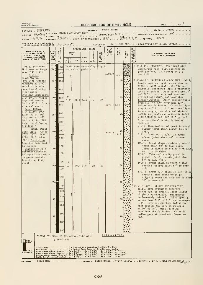
7-1137 {fl-74:
GEOLOGIC LOG OF DRILL HOLE
FEATURE . ..'^?^9^.°^ PROJECT. . . J.«^°?. Aasi.n STATE
HOLE NO DH- 606-A LOCATION. .MWdle .S.pAUw.W .B.^.*^^^^^^ ELEV, 5.2.9.9, p; B,p f^„0LE FRO«HOR,Z.) .
COORDS. N E TOTAL o
BEGUN . .?/??/76. . FINISHED. .VMOA . . . DEPTH OF OVERBURDEN . ..Q-.O' DEPTH. .1.1.1. P.'. . . BEARING S74.E. .
See notes** LOGGED by . . . V>.-. N-. Hagieby log reviewed by. .B. .H. .Carter
notes on waterlosses and levels,casing. CEMENTING,CAVING, AND OTHERDRILLING CONDITIONS
CLASSIFICATION ANDPHYSICAL CONDITION
^Drill Equipment
Skid mounted Long-
year "34" dril 1
.
DrillerFrank MartinDrilling Methods
7.1
Advanced hole with
NWD-3 split tube
core barrel usingclear water.Drilling Conditions0.0'-69.2' : Fairlyfast and smooth.69.2'-111.0'; Fairl)
slow and smooth.
Water Return0.0'-13.0' : 100°^
13.0'-43.3' : 95%43.3'-69.2': 85%69.2'-111.0' : 90%
Water Level During
» * *
^ -* T. -4
5278.0 24.2 -
r
Drilling **
Depth Depth
Date Hole Water23 13.0 0.0
9/24 69.2 40.6
Hole CompletionCemented hole back
to surface.Purpose of Hole
Determine permea-
bility of rock with
in grout curtainbeneath spi 1 Iway
crest.
5262.840
41.8 rV-
70-. »^',
•4 I ^
•4 »
.0'-7.1': CONCRETE. Poor bond withunderlying rock, silt staining onrock surface. 1/2" rebar at 1.3'
and 4.2'.
.l'-24.2': WELDED ASH-FLOW TUFF; fairlhard (requires light hammer blow tobreak), light weight, slightly por-phyritic, scattered lapilli fragmentsup tD 3" across. Most joints are 30*
and 60* to core axis and some arestained with CaCO-i and hematite.Lightly Jointed . Joint spacing varie:
from 0.3' to 3.0' averaging 1.5'.
Indistinct foliation. Color is lightgray from 7.1' to 16't and then light
to medium gray streaked and stainedmostly in joints and vesicular zoneswith hematite red from 16't to 40'-
Hrout was found in the followingopenings
:
7.5': Thin coating of grout in roughplanar joint about normal to coreaxis.
8.2': Grout up to 1/32'' in roughplanar joint about 60" to coreaxis.
10.2': Grout stain in planar, smoothjoint about 60'^ to core axis.Joint is partially filled with CaCf
up to 1/16" thick.12.6': Thin soft chalky grout in
planar, fairly smooth joint about60* to core axis.
16.0': Grout stain in rough planarcalcite stained joint 60* to coreaxis
.
17.7':, Grout 3/4" thick in 1/4" thicicalcite lined joint which is
slightly rough and wavy and is aboijt35* to core axis.
1.2'-41.8't: WELDED AvSH-FLOW TUFF;fairly hard (requires moderatehammer blow to break), light weight,slightly porphyritic. Moderatelyto Intensely Jointed . Joint spacingvaries from 0.1' to 1.0' and averages0,3'. Core has distinct foliationthat crosses the core at an angleof 50* to 60*. Most jointingparallels the foliation. Color is
medium gray streaked with hematitered.
iCORELOSS
CORERECOVERY
LOCATION: Sta. 10+92, offset 7.8' u/ s
£ grout cap.
Typ« of hoU D - Diamond. HMole tooled P » Poclief, CmApprox. liieof hole (X-teries) . . Ex = 1-1 '2".
ApproH. tiie of core (X-series) . . Ex = 7 B",
Oulltde dio. of eosina (X-.erie«)- Ex = 1-13 16*',
lni.de dig, of cQ»infl (X-«efie«) Ex = 1-1 2''.
EXPLAHA TtON
- Hoytt.llite, S
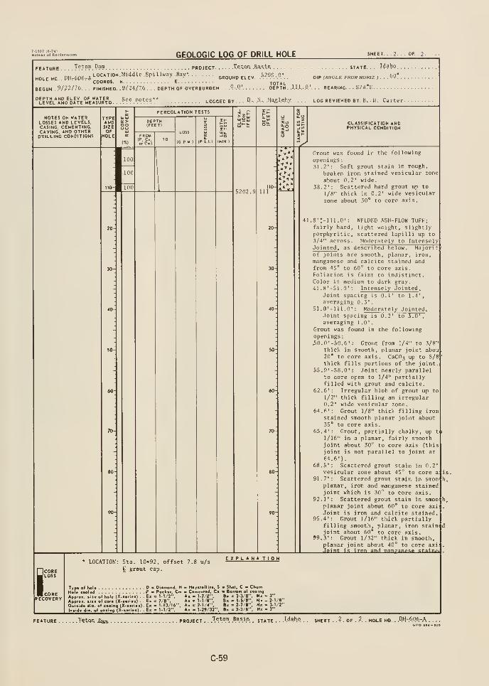
GEOLOGIC LOG OF DRILL HOLE SHEET,
Teton Dam PROJECT.
HOLE NO, , PH.-606rALOCATION, Middle .Spillway .Bay*.
,
COORDS. N
FINISHED. .9/24/76.
.Xet.Qr\ .aaiin . . . .
5299.0'GROUND ELEV.•
'r, n< TOTAL ,,, „
PTH OF OVERBURDEN .,"-.4 DEPTH ,1,U,.,0,BEGUN , ?/^^/7t>.
''Ul^r.5^'^or.,°uVJi^iio. ,
See .notes- logged by, , , .P- ,N.. ,M^l,e,b,y.
STATE. . . . W^bP.
DIP (ANOLE FROM HORIZ J ... ^0 .
. . . BEARING. . S7(l*E
LOG REVIEWED BY. B. . H. -Carter-
NOTES ON WATERLOSSES AND LEVELS.CASING, CEMENTING,CAVING, AND OTHERDRILLING CONDITIONS
TYPEANDSIZEOF
HOLE
oo
PERCOLATION TESTS
LOSS
(C.PM.)
CLASSIFICATION ANDPHYSICAL CONDITION
^
110-
111
Grout was found in the following
openings
:
31.2': Soft grout stain in rough,
broken iron stained vesicular zone
about 0. 2' wide.
38.2': Scattered hard grout up to
1/8" thick in 0.2' wide vesicular
zone about 3(1" to core axis.
WELDED ASH- FLOW TUFF;light weight, slightlyscattered lapilli up toModerately to Intensely
.8'!-ni.0' :
fairly hard,porphyrit ic
,
3/4" across.Jointed , as described below. Majorit '
of joints are smooth, planar, iron,
manganese and calcite stained andfrom 45' to 60° to core axis.Foliation is faint to indistinct.Color is medium to dark gray.41.8'-51.0' : Intensely Jointed .
Joint spacing is 0.1' to 1.4',averaging 0.3'.
Sl.O'-lll.O': Moderately Jointed .
Joint spacing is 0.2' to 5.0',averaging 1.0'.
Grout was found in the followingopenings
:
30.0'-50.6': Grout from 1/4" to 3/8thick in smooth, planar joint abou20* to core axis. CaCflj up to 5/8thick fills portions of the joint
55.9'-58.0': Joint nearly parallelto core open to 1/4" partiallyfilled with grout and calcite.
62.6': Irregular blob of grout up to1/2" thick filling an irregular0.2' wide vesicular zone.
64.6': Grout 1/8" thick filling ironstained smooth planar joint about35' to core axis.
65.4': Grout, partially chalky, up t
1/16" in a planar, fairly smoothjoint about 30° to core axis fthisjoint is not parallel to joint at
64.6')
.
68.5': Scattered grout stain in 0.2vesicular zone about 45° to core a:
91.7': Scattered grout stain in smooplanar, iron and manganese stainedjoint which is 30^ to core axis
92.1': Scattered grout stain in smooplanar joint about 60* to core axi
Joint is iron and calcite stained.95.4': Grout 1/16" thick partially
filling smooth, planar, iron stainedjoint about 60* to core axis.
99.3': Grout 1/32" thick in smooth,planar joint about 40° to core axi:
Jflint is iron anH manganptip fitainft
: as.
h.
COREJloss
IcORERECOVERY
LOCATION: Sta. 10*92, offset 7.8 u/s
^ grout cap.
explana tign
Typ« of hol« -
Hol« feoled
Approx. (ii*Cuisida dio. oInside 6,0 of (
D - Diamond, H - Hoyslallilo, S - Shal. C b ChurnPa Pockar, Cm C«fn»ntad, C* > Bottom of coting
ol« (X..«n..) . . E« = 1-1/2", Ax = t-7/8'*, B« = 2-3/8*', N» - 3"
or. (X.(«ri«i) . . Ex = 7/8", A» = M/8", Bx « 1-5/8", Mm - 2-1/8"
oiino (X-.oriei). E< = 1-13/16", A. = 2-1/4", B« = 2-7/8", N. - 3.1/2"
ting (X-«>..e»). - E. = 1-1/2", A« = 1-29/32". Bm = 2-3/8". N» - 3"
FEATURE T^ton .Dam PROJECT . ..T^ton Basin ^^^^^ .Idaho
. ,.2. . HOLE NO. . .PH-.606-A .
C-59
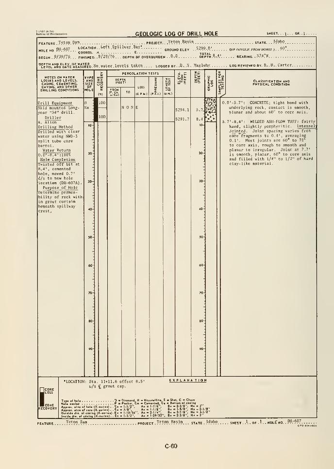
GEOLOGIC LOG OF DRILL HOLE SHEET 1-
FEATURE . T?f PP. P?n> PROJECT. . .VAP". .B^sin STATE. . .I^ahO
HOLENO DH-607 LOCATION. Uft.SpiUwax.B4X* GROUNOELEV. ..5.2.99.0' DIPM<VGLEFRO«HOR,2,..69°COORDS. N E TOTAL o
BEGUN . 9/29/76. . . FINISHED. .9/19/76. . . DEPTH OF OVERBURDEN . .Q-.Q DEPTH .8. ..4' BEARING. . N7.4. W
EPTH AND ELEV OF »ATEK „ „„tpT levels takenLEVEL AND DATE MEASURED. NQ . water . t?V?lS .taUCT LOGGED BY .Di .N.. Maglehx log reviewed by. B-. H. Carter.
NOTES ON WATERLOSSES AND LEVELS.CASING. CEMENTING,CAVING. AND OTHERDRILLING CONDITIONS
TYPEANDSIZEOF
HOLE
UJIUCOoo
fllOO
fllOO
PERCOLATION TESTS
FROMIP. Ci.o, Cm)
LOSS
(G.P.M-) (MIN.)
3^
CLASSIFICATION ANDPHYSICAL CONDITION
Drill EquipmentSkid mounted Long-
year "34" drill
.
DrillerA. AllenDrilling Method
5294.1
5291.7
Drilled with clearwater using NWD-5split tube corebarrel
.
Water Return0.0'-8.4' :100%
Hole CompletionTwisted off bit at
4'
, cementedhole, moved 0.7'
d/s to new holelocation (DH-607A)
.
Purpose of HoleDetermine permea-bility of rock within grout curtainbeneath spillwaycrest.
5.7.
8.4
10-
0.0' -5.7': CONCRETE; tight bond withunderlying rock, contact is smooth,planar and about 60^ to core axis.
5.7'-8.4': WELDED ASH- FLOW TUFF: fairly
hard, slightly porphyritic. Intensel
Jointed. Joint spacing varies from
core fragments to 0.4', averaging0,1'. Most joints are 60° to 70°
to core axis, rough to smooth and
planar to irregular. Joint at 7,7'
is smooth, planar, 60° to core axis
and filled with 1/4" to 1/2" of hardclay-like material
,
SCORELOSS
CORERECOVERY
•LOCATION: Sta. 11*11.6 offset 8.5'
u/s £ grout cap.
EXPLANA TION
Typ« of hoU D • Diomond, H - Hoyitcllit*. S • Shot, C Ch
HoU taaUd P " Poeli«r, Cm m Cvmcntad, C» - Bottom of cot
Apptoti. .1.. o( hoi. (X...rl..) . . E. = 1.1,'2". A. = 1.7/8". B. = 2.3/8".
Apjtom. . I.. o( CO.. |X....i. .)..£. = 7/8", A. = 1.1/8", g. - l-S/S ,
oE°.ld.t)l.,o(coiln,CX-...l..).E. = 1-13/16", A. = 2-1/4" B. = 2-7/; ,N. - 3- /2
In.ld. dio, of co.log'x-.«.l..l. . Ex •= 1-1/2", .--i-'O/tV B. . 5.1/«" N. . V: 1-29/32", B. . 2-3/8"
. 3"1 - 2-1/8"
. 3"
FEATURE '!'fT?^.9?? PROJECT .T?.t?r. Basin state .
.'^?h9 sheet .
pH-6p76PO •S4-a3B
C-60
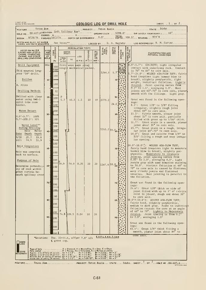
7-IS37 {6-74)
GEOLOGIC LOG OF DRILL HOLE SHEET. .1.. OF..?.
FEATURE T6.t.°.". P.^!^. PROJECT.
HOLE HO . '^-^07,^'^;C^>'J^^^^PWJ"?)'- ^^y
COORDS. N. . . . . .
BEGUN . . 9/.29/76. FINISHEDlP/2/7.6.
. . . JPtpn. Basin state. . .\'\^h°
GROUND ELEV. . . . 5299.01 DIP (ANCLE FROM HORIZ ) 60 ,
N74°W. DEPTH OF OVERBURDEN . . P.'P.' DEPTH- . 109.5! BEARING.
,
See. Notes** logged by D, . N. , Magleby log reviewed by. .^.. .H-. Carter.
NOTES ON WATERLOSSES AND LEVELS.CASING, CEMENTING,CAVING. AND OTHERDRILLING CONDITIONS
CLASSIFICATION ANDPHYSICAL CONDITION
Dri 1 1 Equipment
Skid mounted Long-
year "34" drill.
Driller
A. Allen
Drilling Methods
Drilled with clearwater using NWD-3split tube corebarrel
.
Water Return
0.0'-9.7': 100%9.7'-109.5' : 95%
Water Level**
; O ,m
» 4 '
During DrillingHole Water
Date Depth Depth
9/30 25.7 19.810/1 74.9 35.9
Hole Completion
Hole was cementedback to surface.
Purpose of Hole
Determine permeability of rock withingrout curtain be-neath spillway crest
' * -.
0.0'-5.7': CONCRETE; tight irregularcontact with underlying rock. Contactis 70* to 80* to core axis.
5.7'-24.0': WELDED ASH-FLOW TUFF; fairlyhard (requires light hammer blow tobreak), slightly porphyritic, lightweight, indistinct foliation. LightlyJointed . Joint spacing varies from0.1' to 1.6', averaging 1.0'. Mostjoints are 60*-70* to core axis, planarsmooth with few fillings. Light gray
Grout was found in the following openings:8.4': Grout 1/8" to 3/8" filling
irregular, slightly rough jointabout 60* to core axis.
11.3': Fairly smooth, planar jointabout 55* to core axis, partiallyfilled with grout up to 1/16" thick
11.7': Grout stain in a smooth, planarjoint about 35* to core axis.
13.7': Grout stain in a rough, irregu-lar joint 60*-70* to core axis.
14.0': Grout and calcite from 1/4" to3/8" filling a rough and very irregu-lar opening.
M.0'-39.0'*: WELDED ASH-FLOW TUFF;fairly hard (requires light to moderatehammer blow to break), slightly por-phyritic. Moderately to IntenselyJointed
, joint spacing varies from0.05' to 1.0', averaging 0.3', lightpurple gray with some hematite staininp.
to 30.0'. Distinct foliation at 60", to70* to core axis is caused by flattenedwavy streaky pumice and flattenedvesicles. Most jointing is parallel tothe foliation.
Grout was found in the following open-ings:24.6': Grout 1/8" thick on side of
joint filled with up to 1" of calciteJoint is planar, rough and about 30'^
to core axis.59.0't-59.0't: WELDED ASH-FLOW TUFF;fairly hard, slightly porphyritic,medium to dark gray. Faint to indistin4tfoliation crosses the core at an angleof 60* to 70*. Lightly to ModeratelyJointed . Joint spacing is from 0.2'
to 2.0', averaging 1.0'
Grout was found in the following open-ings:43.4': Grout 1/8" thick filling a
smooth, planar joint about 80 to
i:CORERECOVERY
* Location: Sta. 11+11.6,
C grout cap.
offset 7.8' u/s
Type of hoU D s Diomond, H Haystellile, S
Hole seal«d P = Pocker, Cm - Cemented, CsApprox. (Ji« of hole (X-seriei) . . Ek = M/2", Ax = 1-7/8",
Approx. *<ie of cof« (X-series) . E> = 7/8", Ax = 1-1 /B",Outside dio. of cosing (X-*eries). Ex = 1-13/16". Ax = M /4".
Inside dig, of cosing (X-serie»). Ex = 1-1/2". Ax = 1-29/3Z".
EXPLANATION
. Shot. C " Churn= Bottom of cosingBx = 2-3/8", Nx - 3"8x = 1-5/8", N> - 2-1/8"Bx = 2-7/«", Nx - 3-1/2"Bx = 2-3/8", Nx - 3"
core axis.
.Tevon .Dam project . Teton. Basin. . Idaho. . SHEET
C-61
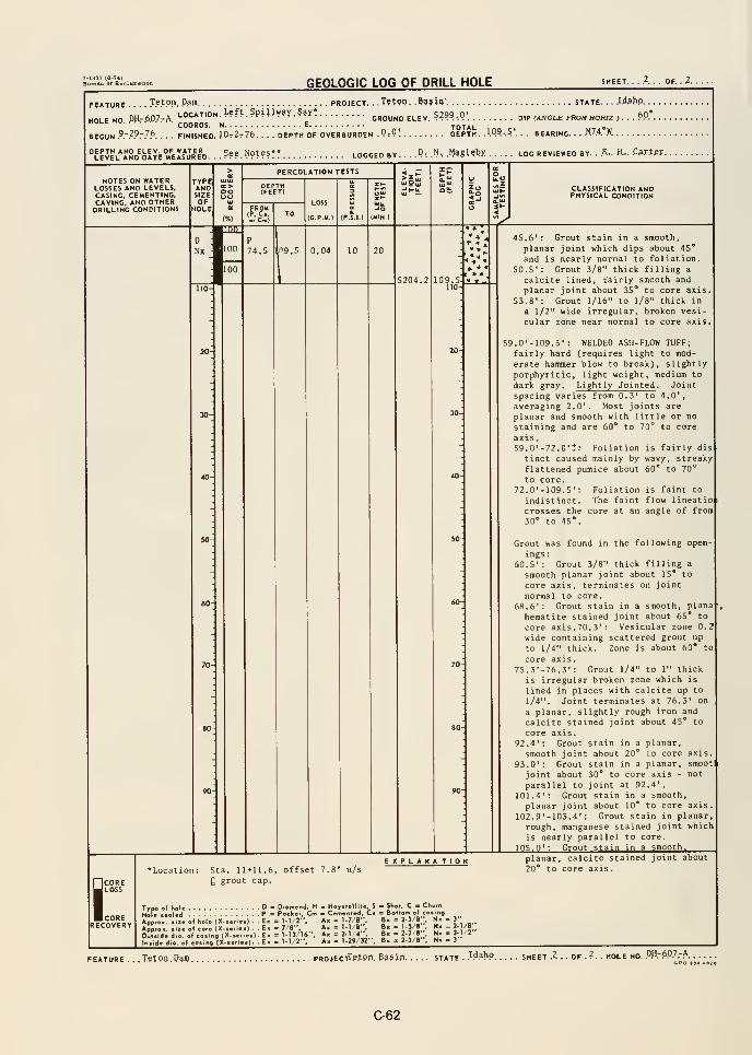
M937 <e-74)Biueftu o( ReclunftUon
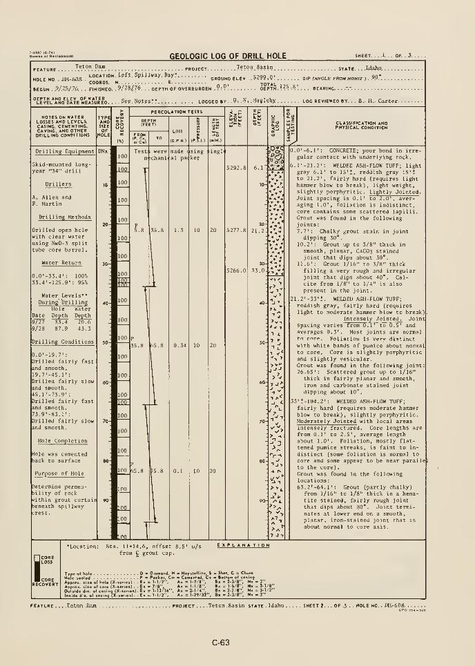
GEOLOGIC LOG OF DRILL HOLE SHEET. . . .1. . . OF. . 3.
FEATURE
HOLE NO . BH-^Oa
Teton Dam
LOCATION. J-sft. Spillway. Bay?
COORDS.
. PROJECT T???n. Basin state UAh.o.
GROUND ELEV .5?99.0'. OiP (ANCLE FROM HOKIZ ). ?P'.
BEGUN ..9/.-.5y.76. . . FINISHED. .?/?8/7^. . . DEPTH OF OVERBURDEN .9:9 DEPTH. ^?5 •.?
'. BEARING -.-
''LEVEL*AND^bATE'MEA*UR"D....S?P.HPteS** LOGGED BY .. P. .N,
. tfl?gUbX LOG REVIEWED BY. .. A.. H.. Carter.
NOTES ON WATERLOSSES AND LEVELS.CASING. CEMENTING,CAVING, AND OTHERDRILLING CONDITIONS
CLASSIFICATION ANDPHYSICAL CONDITION
Drilling Equipment
Skid-mounted Long-year "34" drill
A. Allen andF. Martin
Drilling Methodsni
Drilled open holewith clear waterusing NwD-3 splittube core barrel
.
Water Return
0.0'-33.4': 100°!,
SS.-t'-ns.g": 95%
Water Levels**During bril ling
Hole WaterDate Depth Depth9/27 33.4 20.69/28 87.9 43.3
Drilling Conditions
20-
21.2
> ^
30
33.0
7 A"
>v-.'w 1
"> L
7 "
0.0'-19.7'
:
Drilled fairly fast
and smooth.i9.7'-45.1':Drilled fairly slowand smooth.45.1'-73.9'
:
Drilled fairly fast
and smooth.
73.9'-83.l':Drilled fairly slowand smooth.
Hole Completion
rlole was cementedjack to surface
Purpose of Hole
Determine permea-bility of rocki^ithin grout curtaibeneath spillwaycrest
.
^-'
* -I
-4 r*
7 J 7
0.0'-6.1': CONCRETE; poor bond in irre-gular contact with underlying rock.
6.1' -21.2': WELDED ASH-FLOW TUFF; lightgray 6.1' to 15'*, reddish gray 15'*
to 21.2', fairly hard (requires lighthammer blow to break), light weight,slightly porphyritic. Lightly Jointed .
Joint spacing is 0.1' to 2.0', aver-aging 1.0', foliation is indistinct,core contains some scattered lapilli.Grout was found in the followingjoints:7.7': Chalky grout stain in jointdipping 30".
10.2': Grout up to 3/8" thick in
smooth, planar, CaC03 stainedjoint that dips about 30*.
11.6': Grout 1/16" to 3/8" thickfilling a very rough and irregularjoint that dips about 40". Cal-cite from 1/8" to 1/4" is alsopresent in the joint.
21.2'-33'!. WELDED ASH-FLOW TUFF;reddish gray, fairly hard (requireslight to moderate hammer blow to break)
Intensely Jointed. Jointspacing varies from 0.1' to 0.5' andaverages 0.3'. Most joints are normalto core. Foliation Is verv distinctwith white bands of pumice about normalto core. Core is slightly porphyriticand slightly vesicular.Grout was found in the following joint26.65': Scattered grout up to 1/16"
thick in fairly planar and smooth,iron and carbonate stained jointdipping about 10°.
53'*-104.2': WELDED ASH-FLOW TUFF;fairly hard (requires moderate hammerblow to break), slightly porphyritic.Moderately Jointed with local areasintensely fractured. Core lengths arefrom 0.1' to 2.5', average lengthabout 1.0'. Foliation, mostly flat-tened pumice streaks, is faint to in-
distinct (some foliation is normal to
core and some appear to be near parallelto the core)
.
Grout was found in the followinglocations
:
63.2'-64.r: Grout (partly chalky)from 1/16" to 1/8" thick in a hema-
tite stained, fairly rough jointthat dips about 80*. Joint termi-nates at lower end on a smooth,planar, iron-stained joint that is
about normal to core axis.
iCORELOSS
CORERECOVERY
Sta. 11+14.6, offset 8.5' u/sfrom ^ grout cap.
EXPLANATION
9 Ds: Diomond, H - Hoystcllile. S <
J P = Pockor. Cm m Cemenlcd. Ci =
e of hole (X-.ef.ei) . - E« = 1-1/2*', Ax = 1-7/8".
e of core (X-s.r.e.) . . E« = 7/8", A» = i-1/8".1. of cojing {X-«er.e»). E« = 1-13/16". Ax = 2-1/4",
of cos.ng (X-«erie«). Ex = 1-1/2", Ak = 1-29/32".
Shot, C .
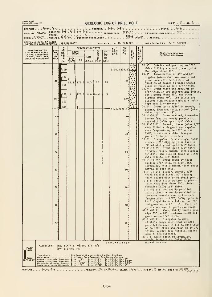
7-1337 (0-74)BuMAU of Racl
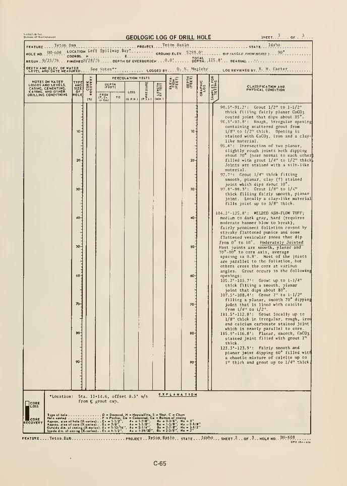
T-nST 18-74)
GEOLOGIC LOG OF DRILL HOLE SHEET. ...... OF.
FEATURE
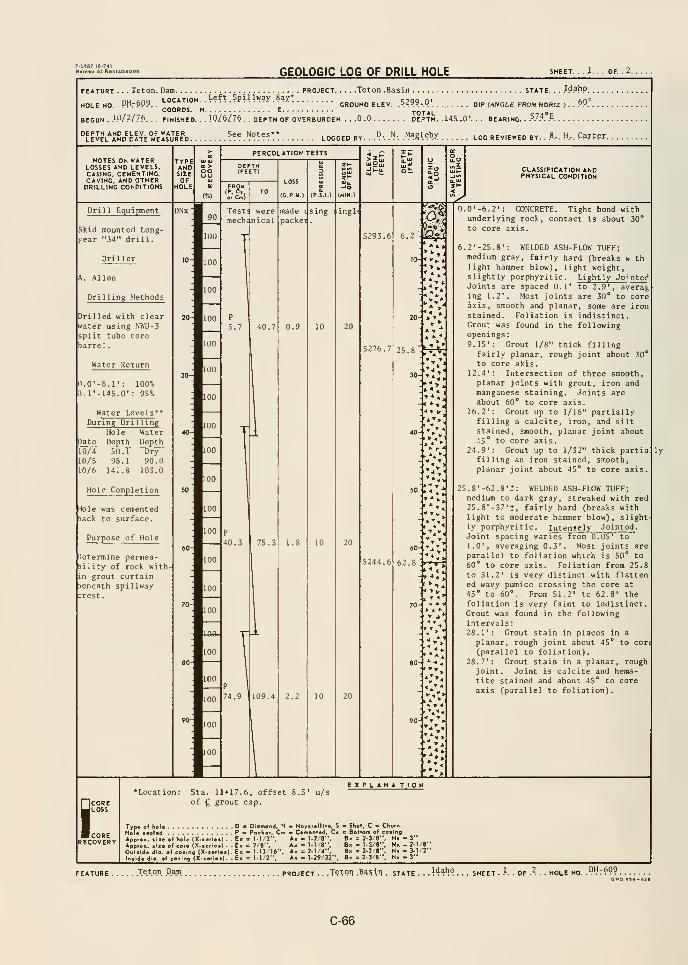
GEOLOGIC LOG OF DRILL HOLE SHEET. .1. OF. . 2. .
FEATURE
HOLE NO. .PHrSP?
Teton. Dam PROJECT Teton .Basin STATE. . . }^?^°.
LOCATION. .Left. Spillway. Baxt qjoo n' fin°
COORDS. N E.GROUND ELEV. .5299.0' oip (jutOLE FROM HORIZ >
BEGUN . .1P/.2/76. . . FINISHED. . . lO/.^/jA . . DEPTH OF OVERBURDEN . . .0.0 DEPTH. .14S„Q'. . . BEARING. ?7-'*- ^. - .
.?-. .^. .Magl.ebX LOG REVIEWED BY. ..B.-. H... C.arfPF.
NOTES ON WATERLOSSES AND LEVELS.CASING, CEMENTING.CAVING, AND OTHERDRILLING CONDITIONS
St CLASSIFICATION ANDPHYSICAL CONDITION
^Drill Equipment
Skid mounted Long-year "34" drill
.
5293.6
Drilling Methods
Drilled with clearwater using NWD-3split tube corebarrel
.
Water Return
0.0'-8.1': 100%3. 1 '-145.0' : 95°*
Water Levels **
During DrillingHole Water
Date Depth Depth10/4 50.1 Dry10/5 98.1 90.010/6 141.8 103.0
Hole Completion
^ole was cementedaack to surface.
Purpose of Hole
Determine permea-Dility of rock within grout curtainDeneath spillway:rest
.
t>:i
";.
> «
0.0'-6.2': CONCRETE. Tight bond withunderlying rock, contact is about 30''
to core axis.
6.2'-25.8': WELDED ASH-FLOW TUFF;medium gray, fairly hard (breaks w thlight hammer blow), light weight,slightly porphyritic. Lightly Jo ^ ntet*
Joints are spaced 0.1' to 2.9', averaging 1.2'. Most joints are 30** to coreaxis, smooth and planar, some are ironstained. Foliation is indistinct.Grout was found in the followingopenings
:
9.15': Grout 1/8" thick fillingfairly planar, rough joint about 30"
to core ajcis.
12.4': Intersection of three smooth,planar joints with grout, iron andmanganese staining. Joints areabout 60" to core axis.
16.2': Grout up to 1/16" partiallyfilling a calcite, iron, and siltstained, smooth, planar joint about45° to core axis.
24.9': Grout up to 1/32" thick partiafilling an iron stained, smooth,planar joint about 45" to core axis.
25.8'-62.8'?: WELDED ASH-FLOW TUFF;medium to dark gray, streaked with red25.8'-37'+, fairly hard (breaks withlight to moderate hammer blow), slightly porphyritic. intensely Jointed .
Joint spacing varies from 0.05' to1.0', averaging 0.3'. Most joints areparallel to foliation which is 50" to60° to core axis. Foliation from 25.8to 51.2' is very distinct with flattened wavy pumice crossing the core at45" to 60". From 51.2' to 62.8' thefoliation is very faint to indistinct.Grout was found in the followingintervals
:
28.1': Grout stain in places in a
planar, rough joint about 45" to cort
(parallel to foliation).28.7': Grout stain in a planar, rough
joint. Joint is calcite and hema-tite stained and about 45° to coreaxis (parallel to foliation).
ly
iCORELOSS
CORERECOVERY
* Location: Sta. 11+17.6, offsetof 6 grout cap.
.5' u/sEXPLANATION
yp* of hol« D I
lole «eal«d P =
Diamond. H - Hoystsllit*, S a Shot, C « ChumPacker, Cm - C«m«ni*d, C* b Bottom of eating
ofhot, (X-..ri..) . . Ex = 1.I/2", Ak = 1-7/8". Bx = 2-3/8", N« - 3"
of cor« (X-««ri..) . - E« .= 7/8", A« = M/8", B» = 1-5/8", Hk - 2-1/8"
of coijng (X-.erie»). E« = M306". A« = 2-1/4", B« = 2-78", N- - 3-1/2"
coiing (X-.arie»). E« = 1-1/2", A. = 1-29/32". B. = 2-3/8". N. » 3"
FEATURE Teton Dam. project . . .I^XQT) M^\n . state . . .^^^9 . . . sheet . ). . of ^. . . hole no. .9*^:^9?.spo ee4-«2e
C-66
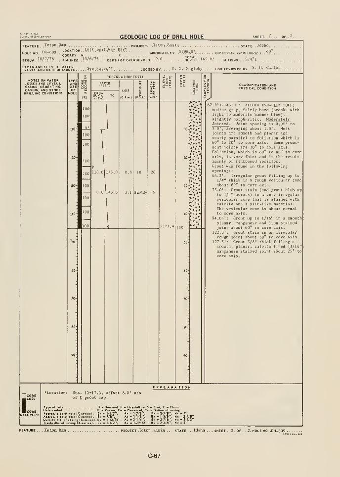
7-1337 16-74)Bureau of Reel

GEOLOGIC LOG OF DRILL HOLE SHEET. ..J.
. . . OF. . .1.
FEATURE Teton. Dam project. . ..Teton .Basin state. . . Idaho. .
LOCATION. Bight .Atiutment, .Keyxw* c^tt i 48°GROUND ELEV. >AA^.-.^ DIP f/UVGLE FROM HOR/Z I ... T?
.
COORDS. N E^0^K\. o
. . DEPTH. . ..2.'».-.8.'.
. BEARING. . . N^?. ^
HOLENO. .PHr&JC
BEGUN . Jlrlr76. . FINISHED. .W-.Z-.Xd . . . DEPTH OF OVERBURDEN . .Q..Q'.
.Not .Measured
.
LOGGED BY. . . .R-. .N .. .M^le.by LOG REVIEWED BY. . P. .H,. Carter.
NOTES ON WATERLOSSES AND LEVELS.CASING, CEMENTING,CAVING, AND OTHERDRILLING CONDITIONS
PERCOLATION TESTS
CLASSIFICATION ANDPHYSICAL CONDITION
Drill Equipment
Mark IX portabledrill.
Drilling Methods
Drilled with NxD-3split tube corebarrel, usingclear water.
Water Return
0.0'-24.8' - 100%
Hole Completion
Hole was cementedback to surface.
Purpose of Hole
Test effectivenessof grout curtain.
3V
< ^ •
0.0' -4.7': CONCRETE; hard, tight,irregular contact with underlyingrock. (Grout Cap)
4.7'-24.8': WELDEP ASH-FLOW TUFF;
dark gray, hard (core breaks with
moderate hammer blow andscratches with heavy knife pressure).Slightly porphyritic, non vesicular,indistinct foliation. Intensely to
Moderately Jointed . Joint spacingis from 0.2' to 1.4', averaging 0.7'.
Most joints are planar and smooth
and are about 35* to 45° to coreaxis. Many joints are hematite and
manganese stained. No grout was
observed in core.
Prominent joints
:
5.6'-7.5': Smooth, planar, ironand manganese stained joint about10* to core axis.
17.0': Intersection of 2 planar and
rough joints, one about 70* to
the core axis, the other one about25* to the core axis.
17.2': Smooth, planar, iron and
manganese stained joint about 15**
to core axis.19.3': Planar, rough, iron stained
joint about 40° to core axis.
SCORELOSS
CORERECOVERY
Sta. 12*73
£ grout cap.
^yo• of hel* - Diamond, H - Haysialtit*, S
Hor* icoUd P > Packer, Cm C«fn«nl«J. CbApptos. •>>• of hoU (X-i«ri«a) . . E> ° M/2", Ax = l-7/ti",
ApproH. ail* of e.at% (X-i*(i«*) . . Ex « 7/8", A> = 1-1/8",
Outiida dla. of cosing (X-*«ri«*). Ex « M3/>6". Ax = 2-1/4",
ln»ld« dia. of co»ina (X-«f >««)- Ex = M/2", Ax = T-29/32".
EXPLANA TIOH
Shol, C ChurnB Bottom of casingB> - 2-3/8", N» -3"B> - 1-5/8", N« -2.1/r'Bx = 2-7/r", Nx - 3-1/2"Bx - 2-3/8", Nx - 3"
Teton Dam PROJECT 7??^?". ??sir.. . . STATE .
Jdaho. .?..H0LEN0..PH-6.1P.spo aod-eia
C-68
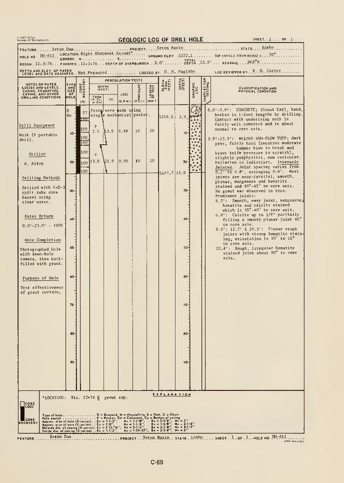
GEOLOGIC LOG OF DRILL HOLE OF. . 1 .
FEATURE leton. Dam project Tetpn .Basi". state. . ..JdabP.
.
HOLENO DH-611 LOCATION. Blgbt .Abutment .K^XXW*ground ELEV .5222.1 DIP fANOLE FROM HO(«Z,...7P'.
COORDS. N e total tif.o»wBEGUN ii.- 3.-76. . . FINISHED. .11-1,76. . DEPTH OF OVERBURDEN .0.0'. DEPTH. .?3...9' BEARING W-^. !*
.P, .N, MagUby LOO reviewed by. . .8.-. h.-. F?rter
NOTES ON WATERLOSSES AND LEVELS.CASING. CEMENTING,CAVING. AND OTHERDRILLING CONDITIONS
TYPEANDSIZE
PERCOLATION TESTS
FROMLOSS
(C.P.M )
-Jo
(MIN )
CLASSIFICATION ANDPHYSICAL CONDITION
^
Drill Equipment
Mark IX portabledrill.
97
rmr
nade ui.ing
hmical packe:
IP
u5216.5 ^
10
Drilling Methods
Drilled with NxD-3split tube core
barrel usingclear water.
Water Return
0.0'-23.9' - 100*0
Hole Completion
Photographed holewith down-holecamera, then back-filled with grout.
Purpose of Hole
Test effectivenessof grout curtain.
5197.7
20
23.9
^ <
0.0' -3. 9': CONCRETE; (Grout Cap], hard,
broken in 1-foot lengths by drilling.
Contact with underlying rock is
fairly well cemented and is about
normal to core axis.
3.9»-23.9': WELDED ASH-FLOW TUFF; dark
gray, fairly hard (requires moderate
hammer blow to break and
heavy knife pressure to scratch),
slightly porphyritic, non vesicular.
Foliation is indistinct. Intensely
Jointed . Joint spacing varies from
0.2' to 0.8', averaging 0.4'. Most
joints are near-parallel, smooth,
planar, manganese and hematite
stained and 40'-45° to core axis.
No grout was observed in core.
Prominent joints
:
6.3': Smooth, wavy joint, manganese
hematite and calcite stained
which is 35*-40'' to core axis.
6.8': Calcite up to 1/8" partially
filling a smooth planar joint 40"
to core axis
.
9.0'; 12.7' fi 20.3': Planar rough
joints with strong hematite stain
ing, orientation is 10*^ to 15°
to core axis
.
22.4': Rough, irregular hematite
stained joint about 80° to core
axis
.
ICORE
J LOSS
IcORERECOVERY
Sta. 12+74 ^ grout cap.EXPLANA TION
Type of hoU D » DiamHole sealed P = Pock.
ApprOK. liie of hole (X-serieO . . Ex = 1-1/2".
Apptox. (lie of core (X-serles) . . Ex = 7/6",Outside dio. of casing (X-ser.e>)- Ex = M3/t6Inside dio. of casing (X-ser.e*)- - Ex = M/2".
d, H - Hoyslellite, S = Shol, C •= Churn. Cm B Cemenled, Cs = Bolfom of casing
Ax = 1-7/8", B« = 2-3/8", N» - 3"
Ax =1-1/8", B« = 1-5/8", Nx-2-t/8"Ax =2-1/4", B. =2-7/8", Nx = 3-l/2'Ax = 1-29/32", B. = 2-3/8", Nx-3"
. T^^°". ^^f" PROJECT . ..T.etpp. 3??in. . STATE -
lAa.hp. .l..H0LEN0..DH-6ncpo Bs* - e2fl
C-69
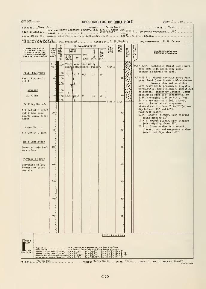
GEOLOGIC LOG OF DRILL HOLE SHEET. . 1. . . . OF. .1 .
FEATURE . . . .TetQn Xlam project Teton. Basin state. . . .Idaho .
LOCATION RAght Abutment Y.eyv^y, Sta* 12+75 C Grout Cap.^^^., , „„-HOLE NO QH..612 . . 2 CROUNd'SLEV '^.5222.1... BIF (ANGLE FROM HORIZ ).. .9.Q°.
COORDS. N E.jOTAL
BEGUN .1Q-.26-.76 , . FINISHED. lX.-l.-7(>. . . . DEI'TH OF OVERBURDEN . D, D.' DEPTH. . 23.5! . . BEARING
. Hot. Measured. LOGGED BY. . P.-. N.- . Magleby log reviewed by. . .B. .H. .Carter .
NOTES ON WATERLOSSES AND LEVELS.CASING, CEMENTING,CAVING, AND OTHERDRILLING CONDITIONS
TYPEANDSIZEOF
HOLE
oo
PEFCOLATION TESTS
LOSS
(G.P-M.)
CLASSIFICATION ANDPHYSICAL CONDITION
Drill Equipment
Mark IX portabledrill.
Drilling Methods
Drilled with NxD-3split tube corebarrel using clearwater.
Water Return
0.0'-23.5' 100%
Hole Completion
Cemented hole backto surface.
Purpose of Hole
Determine effect-iveness of groutcurtain.
100
13.5
,23.5
nade uical
0.5
mgPacket. 5218.6
10 20 4 <
' 1.
t 4
5198.6
20
23.5
0.0' -3.5': CONCRETE; (Grout Cap); hard,good bond with underlying rock,contact is normal to core.
.5'-23.S': WELDED ASH-FLOW TUFF; darkgray, hard (core breaks with moderate
hammer blow and scratcheswith heavy knife pressure), slightlyporphyritic, non vesicular, indistinctfoliation. Intensely Jointed . Jointspacing is from 1/2" (fragments) to1.3', averaging 0.3' to 0.4*. Mostjoints are near parallel, planar,smooth, hematite and manganesestained and dip from 0* to 20'^(others
dip between 45* and 60")
.
Prominent joints:6.2': Smooth, planar, iron stained
joint dipping 35".
19.4': Smooth planar, iron stainedjoint dipping about 35*.
22.9': Grout stains in a smooth,planar, iron and manganese stainedjoint that dips about 45".
j;CORERECOVERY
Type of Kol« D !
Hole sealed P =
Appro., size of hole (X-series) . . ExApprox. size of core (X-senes) . - ExOutside d-o. of cosing (X-ser<es). ExInside dip- of cosing (X-series) Ex
EXPLANA TION
Diomond. H - Hoystellile, S o SKol, C " ChurnPocker, Cm - Cemented, Cs = Bottom of costng
: 1-1/2". Ax = 1-7/B", B» = 2-3/8", N» - 3": 7/8", Ak = 1-1/8". Bx = 1-5/8", N> - 2-1/8"= 1-13/16" Ax =2-1/4", B- = 2-7/8"', N. =3-1/2"= 1.12". Ax = 1-29/32", Bx = 2-3/8". Nx - 3"
Teton Dam project .Tctpn Basin.. . . state . .W^Ko. . SHEET . 1 . . OF . J. . HOLE NO. .QH-.6L2 . .
SPO •
C-70
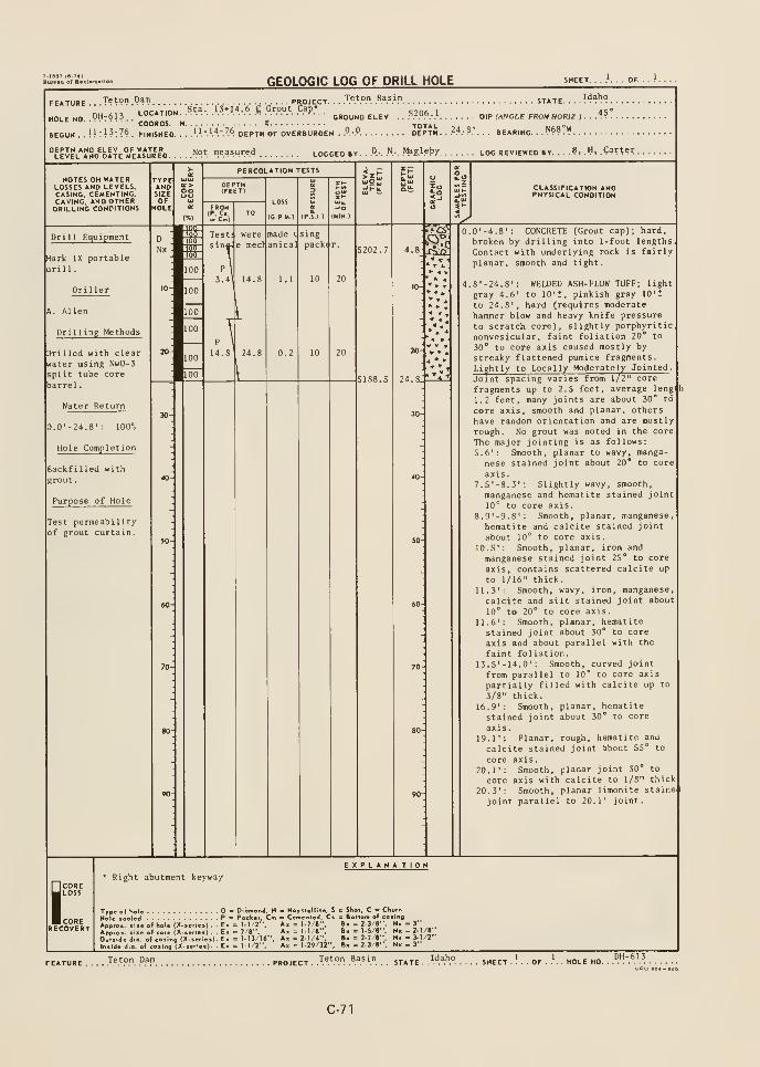
GEOLOGIC LOG OF DRILL HOLE SHEET. ...'... OF.
aojECT. . .T^.'."."..B.^.s.!."
inriTinu S'tsi. 13*I4.6 C Grout Cap* r->n<;iHOLENO .PH:6!3..
LOCATION^.. ...... ......>!^... ....*-...oROUND ELEV .. .5.2.06- .1 .. .
BEOUN..!!:!?:?*. finished. ...'^l-.'.'''-.'A depth of overburden .
.".•.". depth. ..2;t.-8.'.
. . bearing...?*^?"'!'
STATE
DIP (ANGLE FROM HORJZ )
Idaho
45°
''LEVEL*I!NO^b!TfE°M'kIs*jRE'o ^9'^. .'»=35".«d LOGGED BY. ..».. .".-. .Ma&l.eby LOG REVIEWED BY. . .
.?, .H, ,gar??r.
NOTES ON WATERLOSSES AND LEVELS.CASING, CEMENTING.CAVING, AND OTHERDRILLING CONDITIONS
CLASSIFICATION ANDPHYSICAL CONDITION
Drill Equipment
Mark IX portable
drill.
Driller
A. Allen
Drilling Methods
Drilled with clear
water using NwD-3split tube core
barrel.
Water Return
D.0'-24.8': 100%
Hole Completion
Backfilled with
grout
.
Purpose of Hole
Test permeabilityof grout curtain.
0.0'-4.8': CONCRETE (Grout cap); hard,
broken by drilling into 1-foot lengthsContact with underlying rock is fairly
planar, smooth and tight.
4.8'-24.8': WELDED ASH- FLOW TUFF; light
gray 4.6' to 10'?, pinkish gray lO't
to 24.8', hard (requires moderatehammer blow and heavy knife pressure
to scratch core), slightly porphyriticnonvesicular, faint foliation 20* to
30° to core axis caused mostly by
streaky flattened pumice fragments.
Lightly to Locally Moderately Jointed .
Joint spacing varies from 1/2" core
fragments up to 2.5 feet, average leng'
h
1.2 feet, many joints are about 30° to
core axis, smooth and planar, othershave random orientation and are mostlyrough. No grout was noted in the core
The major jointing is as follows:5.6': Smooth, planar to wavy, manga-
nese stained joint about 20* to core
axis.7.5'-8.3': Slightly wavy, smooth,
manganese and hematite stained joint10'^ to core axis.
8.9'-9.8': Smooth, planar, manganese,
hematite and calcite stained joint
about 10^ to core axis.
10.5'; Smooth, planar, iron and
manganese stained joint 25" to core
axis, contains scattered calcite up
to 1/16" thick.11.3': Smooth, wavy, iron, manganese,
calcite and silt stained joint about10° to 20° to core axis.
11.6': Smooth, planar, hematitestained joint about 30° to core
axis and about parallel with the
faint fol iation.13.5'-14.0': Smooth, curved joint
from parallel to 10° to core axis
partially filled with calcite up to
3/8" thick.16.9': Smooth, planar, hematite
stained joint about 30" to core
axis.19.1': Planar, rough, hematite and
calcite stained joint about 55" to
core axis.20.1': Smooth, planar joint 30° to
core axis with calcite to l/S" thick
20.3': Smooth, planar limonite staine
joint parallel to 20.1' joint.
COREJloss
corerecovery
Right abutment keyway
le of hole (X-se o(core(X>sI. of casing (Xof coi.nq (X-i
F.
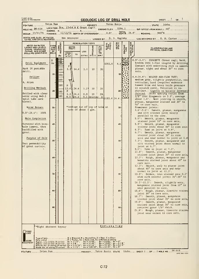
7-iaS7 (0-74)Bura.u of R.clua.aoD
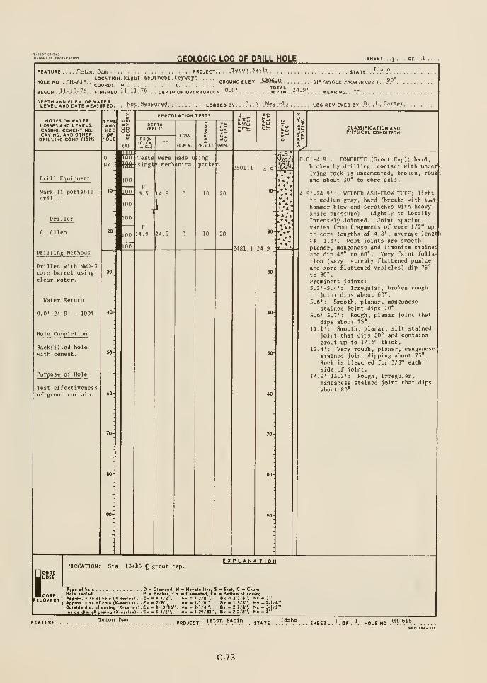
7-1987 (8-74)
GEOLOGIC LOG OF DRILL HOLE OF. . .1. . .
FEATURE .... .Teton. Dam. .
LOCATION. Bigh t. Abutment .Keywsy* .
. PROJECT T?tpn Basin j^y^ Idaho
GROUND ELEV 52Q$,.0. DIP (ANCLE FROM HORIZ ). . ?9.HOLE NO . 0H-6JS. . ,-.„„, „ .COORDS. N E TOTAL
BEGUN ..I.I.-.I.O.-.7.6.
. FINISHED. llr!!r?*.. . DEPTH OF OVERBURDEN .P:P! DEPTH. .^A:V. . . . BEARING. . .V
''LEJEL^JSD^bATE'iirElsVRE'D. .Npt Measured LOGGED BY .P, .N, .Magletjy log reviewed by .B.-. .H-. .Carter
NOTES ON WATERLOSSES AND LEVELS.CASING, CEMENTING.caving, and OTHERDRILLING CONDITIONS
TYPEANDSIZE
oo
PERCOLATION TESTS
FROMIP. c.0. C»l
LOSS
(G.P M )
CLASSIFICATION ANDPHYSICAL CONDITION
^
Drill Equipment
Mark IX portabledrill.
Drilling Methods
Drilled with NwD-3core barrel usingclear water.
Water Return
100%
Hole Completion
Backfilled holewith cement.
Purpose of Hole
Test effectivenessof grout curtain
.
NX : tflt
Tests weresingS * mech
P
3.5
lade u
inical
ling
packet".
P
14.9 24.9
4.9.
10 20
0.0' -4.9': CONCRETE (Crout Cap); hard,
broken by drilling; contact with underlying rock is uncemented, broken, roug i
and about 30* to core axis.
4.9'-24.9': WELDED ASH-FLOW TUFF; light
to medium gray, hard (breaks with McmJ,
hammer blow and scratches with heavy
knife prfssure). Lightly to Locally -
Intensel^' Jointed . Joint spacing
varies from fragments of core 1/2" up
to core lengths of 4.8', average lengt^
iJ 1.3'. Most joints are smooth,
planar, manganese and limonite stained
and dip 45* to 60*. Very faint folia-
tion (wavy, streaky flattened pumiceand some flattened vesicles) dip 75°
to 80",
Prominent joints
:
5.2'-5.4': Irregular, broken rough
joint dips about 60*.
5.6*: Smooth, planar, manganesestained joint dips 10'.
5.6'-5.7': Rough, planar joint that
dips about 75*.
11.1': Smooth, planar, silt stained
joint that dips 50° and contains
grout up to 1/16" thick.
12.4': Very rough, planar, manganesestained joint dipping about 75*.
Rock is bleached for 3/8" each
side of joint.14.9'-15.2': Rough, irregular,
manganese stained joint that dips
about 80*.
I
CORELOSS
CORERECOVERY
LOCATION: Sta. 13+15 £ grout cap.EXPLANA TIOH
Trp. of hel* D .
Hol« ••al«d Pock*.ApproK. ail* of hola (X-aafUi) . . E> - 1-1/2",Approi. Ill* of cora (X-ioflal) . En c 7/8",Outlld* dlo. e( coiing (X-««ri«t) - E« = t-13/16'lo»ld« dia. of CO«lng (X. «>!««). . E« c l-l/Z",
I - HoyalalMla, S - Shot, C - Churn~ Camanlad, Ca Bottom of coatngAk = 1-7/8", Bh 1 2-3/8", Nx - 3"A« = I-1/8", Bx - 1-5/8", Nx- 2-1/8"Ax = 2-1/4", B« = 27/8", Nx - 3-1/2"Ax = I-29/32", B« - 2-3/8", Nx - 3"
Teton Dam
C-73
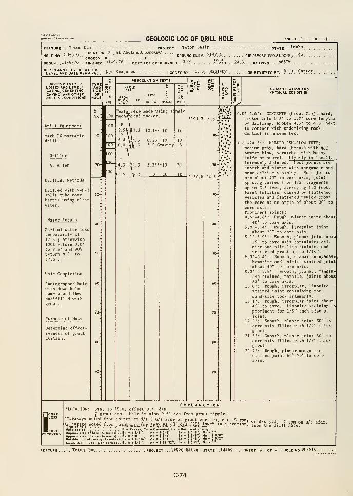
GEOLOGIC LOG OF DRILL HOLE SHEET, . 1 .
FEATURE . . .Teton .Dam project. . ..Teton Basin state. . .
^4^t?o.
nH fiift LOCATION. -Right Ahutmeat KieyyiBy* e-io-t a a-i°HOLE NO. .PH7C>lfe. .
» ^^ '^ GROUND ELEV. .^iP/.-f* V\P (ANGLE FROM HORIZ) . .^^ .
COORDS. H E TOTALBEGUN . . Ut8t76. , FINISHED. .11. ".^.-Z^ . . . DEPTH OF OVERBURDEN . P.-P' DEPTH. . . ?^.-?. . . BEARING. . .
.N^S.W
LEVEL^AND^DATE m'e1!s*ured. ..Npt Measured logged by. .
D., N, Ma£.leby log reviewed by. .B, .H, .Carter
.
PERCOLATION TESTSNOTES ON WATER
LOSSES AND LEVELS.CASING, CEMENTING,CAVING, AND OTHERDRILLING CONPITIONS
CLASSIFICATION ANDPHYSICAL CONDITION
Drill Equipment
Mark IX portabledrill.
Drilling Methods
Drilled with NwD-3
split tube core
barrel using clearwater
.
Water Return
Partial water loss
temporarily at
17.5'; otherwise100% return 0.0'
to 8.5' and 90"p
return 8.5' to24.3'.
Hole Completion
Photographed holewith down-holecamera and thenbackfilled withgrout
.
Purpose of Hole
Determine effect-iveness of groutcurtain.
5194.3 4.6
5180.9
0.0'-4.6': CONCRETE CGrout Cap); hardbroken into 0.3' to 1.0' core lengthsby drilling, broken 4.5' to 4.6' nextto contact with underlying rock.
Contact is uncemented.
4.6' -24. 3': WELDED ASH-FLOW TUFF;medium gray, hard fbreaks with Mod.hammer blow, scratches with heavyknife pressure). Lightly to Locally -
Intensely Jointed . Most joints are
smooth and planar with manganese and
some calcite staining. Most joints
are about 40* to core axis, joint
spacing varies from 1/2" fragmentsup to 3.5 feet, averaging 1.2 feet.
Faint foliation caused by flattenedvesicles and flattened pumice cross
the core at an angle of about 20* to
core axis.Prominent joints
;
4.6'-440* to
5.0'-5.4'
Rough, planar joint aboutcore axis.
Rough, irregular jointabout 25* to core axis.
5.1'-5.9': Smooth, planar joint abou15* to core axis containing cal
cite and silt-like staining and
scattered grout up to 1/16".
6.0'-6.4': Smooth, planar, manganesehematite and calcite stained joint
about 40* to core axis.9.3' 5 9.8': Smooth, planar, mangan
ese stained, parallel joints about35* to core axis
.
13.6': Rough, irregular, limonite
stained joint containing some
sand-size rock fragments.15.1': Rough, irregular joint about
45* to core. Limonite staining is
prominent for 1/8" each side of
joint.17.5': Smooth, planar joint 30* to
core axis filled with 1/4" thick
grout
.
21.5': Smooth, planar joint 30° to
core axis filled with 1/8" thickgrout
.
22.4': Rough, planar manganesestained joint 60°-70* to coreaxis
.
iCORELOSS
CORERECOVERY
EXPLANA TION*LOCATION: Sta. 13+28.8, offset 0.4' d/s
C grout cap. Hcle is also 0.6' d/s from grout nipple.**Leakage noted from joints an d/s S u/s side of grout curtain, est. 5 gpm* „„ j/c ci^<. 7 ,tt,™ «« . /. .-a
*j%^t^J^m%.^.'^.^^'^..^.''.'^^.X°^i^.^.^^ ^" elevation! ??om^?hrd?{lf KTe°""'^' ''^^'
Approx. tile of hal« (X-ieApproK. lite of cere (X-i«Ouolije dia. of casing (X-i
In. id. dip, of co.ing (>«.
. .P = Pccket
<il . . E« = 1. 1/2",
• 1 . . E. .= 7/8".i.i). E> = 1-13/16".I.). . E. = 11/2".
' Cemenfod. Ci b Boiiomk« = 1-7/8". B. . 2-3/8", N. - 3"l« = 1.1/8". B« . 1-5/8", N« - 2-1/8"k. = 2-1/4". B. = 2-7/8", Nx. 3-1/2"
\x = 1-29/32", Bx . 2-3/8", Nx - 3"
FEATURE Teton P.^PI. PROJECT . ..T?tpn .Basin
. STATE ..Idaho ... SHEET . J. . OF .1. . . HOLE NO P^T^l^ .
CPO BB.-S3B
C-74
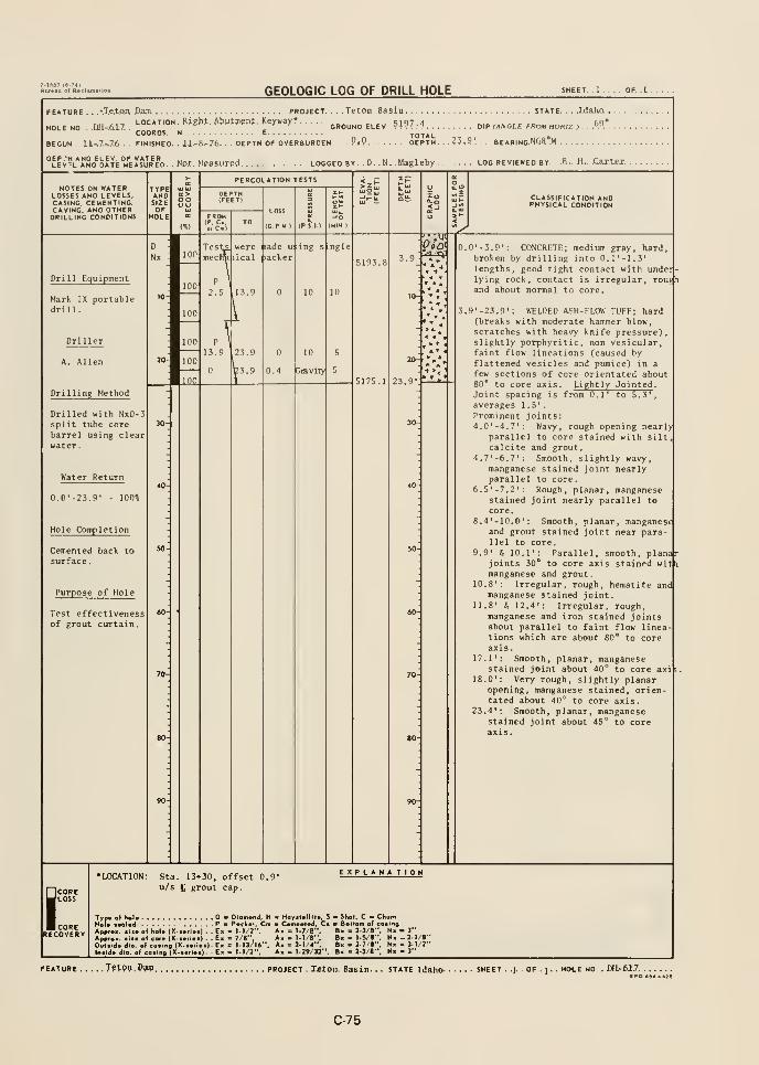
GEOLOGIC LOG OF DRILL HOLE
FEATURE . . .vTeXoA Dajn.
LOCATION.
COORDS. I
BEGUN . .ll,7-.7.5 . FINISHED. .
HOLE NO . .DH-.6L7. .
PROJECT.
Right. Abutment. Keyinay*
. Teton. Basin STATE.
I ELEV 5197.4 o,p rANGLE FROM HORIZ ) .
JJ^8,76. . DEPTH OF OVERBURDEN . . . PiP DEPTH. .?3.S'. , BEARING.N68°.W .
, Not. Measured logged by . D. . M. Magleby log reviewed by. . .6-. H.. .Car.tex.
PERCOLATION TESTSNOTES ON WATER
LOSSES AND LEVELS,CASING, CEMENTING,CAVING, AND OTHERDRILLING CONDITIONS
TYPEANDSIZEOF
HOLE
CLASSIFICATION ANDPHYSICAL CONDITION
Dril 1 Equipment
Mark IX portabledrill.
A. Allen
Drilling Method
Drilled with NxD-3split tube corebarrel using clearwater.
Water Return
0.0'-23.9' 100%
Hole Completion
Cemented back tosurface.
Purpose of Hole
Test effectivenessof grout curtain.
20
23.9'
< <
0.0' -3.9': CONCRETE; medium gray, hard,broken by drilling into 0.1'-1.3'
lengths, good tight contact with undei
-
lying rock, contact is irregular, rouj ^i
and about normal to core.
3.9'-23.9': WELDED ASH-FLOW TUFF; hard(breaks with moderate hammer blow,scratches with heavy knife pressure),slightly porphyritic, non vesicular,faint flow lineations (caused byflattened vesicles and pumice) in a
few sections of core orientated about80* to core axis. Lightly Jointed .
Joint spacing is from 0.1' to 5.3',averages 1.5'.
Prominent joints:4.0' -4. 7': Wavy, rough opening nearly
parallel to core stained with siltcalcite and grout.
4.7'-6.7': Smooth, slightly wavy,manganese stained joint nearlyparallel to core.
6.5'-7.2': Rough, planar, manganesestained joint nearly parallel to
core.8.4 ' - 10. 0'
: Smooth, planar, manganeseand grout stained joint near para-1 lei to core.
9.9' 5 10.1': Parallel, smooth, planarjoints 30" to core axis stained wit i
manganese and grout
.
10.8': Irregular, rough, hematite andmanganese stained joint.
11.8' G 12.4': Irregular, rough,manganese and iron stained jointsabout parallel to faint flow lineations which are about 80* to coreaxis.
17.1': Smooth, planar, manganesestained joint about 40*^ to core axi
18.0': Very rough, slightly planaropening, manganese stained, orientated about 40*^ to core axis.
23.4': Smooth, planar, manganese
stained joint about 45° to coreaxis.
ICOREJloss
corerecovery
Sta. 13*30, offset 0.9'
u/s £ grout cap.
EXPLANATION
Ouitld. di
o( h.U (X...ti..| , . Ex = M/J", A, = 1-7/8",
o( cor. (X.i.rc.l) . . Ex = 7/6", A. = M/B",osing (X-i.t^.i|.Ex = 1-I3/I6". A. c 2.1/4"
• Hayit.llit., S - Shot, C •
C.m.nl.ll, C. Bollom of coalng
In.id. dip, of co.in, (X-«.f i.t) . . Ex Ax = 1.29/32"
. 2-3/8", Nx . 3"= 1-5/8", Nx -2.1/8". 2-7/i". Nx - 3-1/2". 2-3/8". N. - 3"
,Tetpn.p?m project . Teton. Basi STATE Idaho- SHEET ..J.
. OF . 1 . . MOLE NO . DH,-M7SPO aS4-.2B
C-75
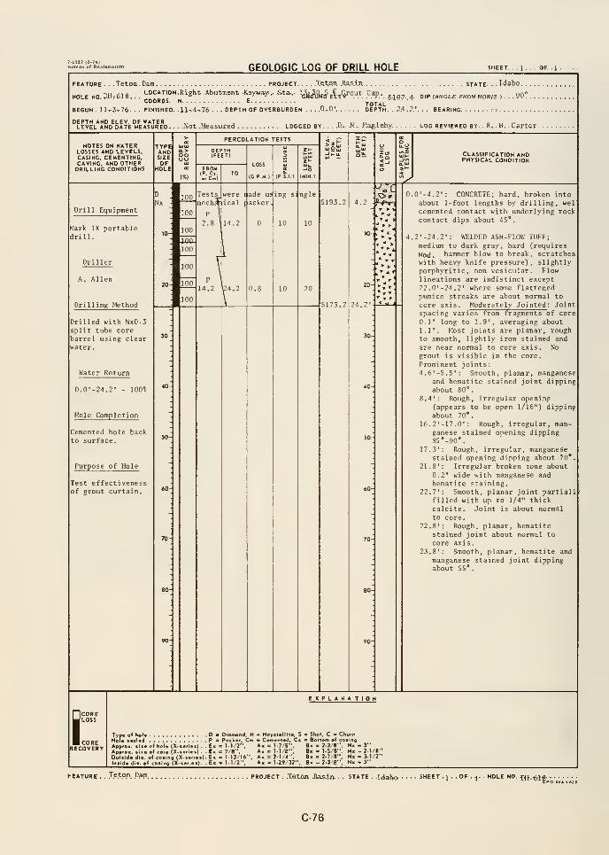
GEOLOGIC LOG OF DRILL HOLE OF. 1
FEATURE . . . Teton . Dam
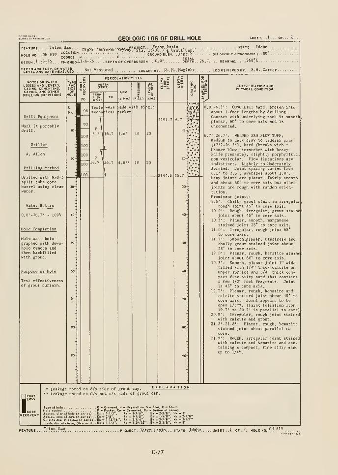
GEOLOGIC LOG OF DRILL HOLE
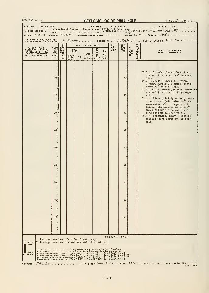
7-1887 (8-74)Bunau of Racl
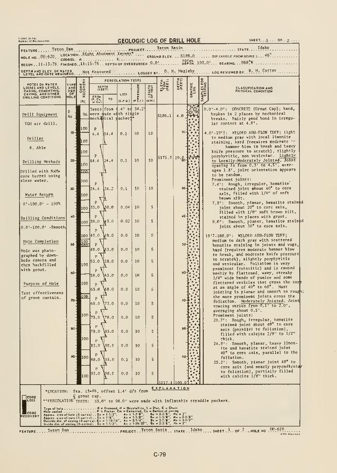
GEOLOGIC LOG OF DRILL HOLE SHEET. . .1. . . . OF. . .2-
FEATURE T??™ .P^ PROJECT
nu fi7n LOCATION. .Rtgnt. .Abutment .Keyyay.*
HOLE NO .PHrOjy. .
^pijljjlj ^ J
BEGUN . . Url3776. FINISHED. .11^15-7^ . . DEPTH OF OVERBURDEN .P-.Q' DEPTH. .1.0P..0.'. BEARING. . . WS'C
Teton Basin
GROUND ELEV
STATE. . . . ?^?''? .
5185.. .0. DIP (ANGLE FKOM HOKIZ ) . . . 4^ .
''LEJEL*!!HD^bATE°M^E"jRE'D . .
"^Ot Measured LOGGED BY "• ^.- M*?!'''/ LOG REVIEWED BY.B. H. Carter
NOTES ON WATERLOSSES AND LEVELS.CASING. CEMENTING.CAVING. AND OTHERDRILLING CONPITIONS
CLASSIFICATION ANDPHYSICAL CONDITION
Drill Equipment
S6H air drill.
Driller
R. Able
Drilling Methods
Drilled with NxHw
core barrel usingclear water.
Water Return
O'-IOO.O' - 100%
Drilling Conditions
O.O'-IOO.O' -Smooth.
Hole Completion
Hole was photo-graphed by down-
hole camera and
then backfilledwith grout.
Purpose of Hole
Test effectivenessof grout curtain.
5186.1
5175.3 « » T[ » «t r 4
i *
..•'4
70- I ^ »> «
ICORELOSS
CORERECOVERY
inn.n1
0.0'-4.0': CONCRETE (Grout Cap); hard,
broken in 2 places by mechanical
breaks. Fairly good bond in irregu-
lar contact at 4.0'.
».0'-19't: WELDED ASH-FLOW TUFF; light
to medium gray with local limonlte
staining, hard (requires moderate '-
hammer blow to break and heavy
knife pressure to scratch), slightly
porphyritic, non vesicular. Lightly
to Local ly-Moderately Jointed . Joint
spacing Is from 0.3' to 4.5', aver-
ages 1.8', joint orientation appears
to be random.Prominent joints:7.4': Rough, irregular, hematite
stained joint about 40* to core
axis, filled with 1/4" of soft
brown silt.7.8': Smooth, planar, hematite stained
joint about 20* to core axis,
filled with 1/8" soft brown silt,
stained in places with grout.
9.0': Smooth, planar, hematite stained
joint about 30* to core axis.
19't-100.0': WELDED ASH-FLOW TUFF;
medium to dark gray with scattered
hematite staining in joints and vugs
hard (requires moderate hammer blow
to break, and moderate knife pressure
to scratch), slightly porphyritic
and vesicular. Foliation is very
prominent (eutaxitic) and is caused
mostly by flattened, wavy, streaky
1/4" wide bands of pumice and some
flattened vesicles that cross the cor^
at an angle of 40* to 60*. Most
jointing is planar and smooth to roug i
the more prominent joints cross the
foliation. Moderately Jointed . Joint
spacing varies from 0.1' to 2.0'
,
averaging about 0.5'.
Prominent joints:20.7': Rough, irregular, hematite
stained joint about 40* to core
axis (parallel to foliation),
filled with calcite 1/8" to 1/2"
thick.24.9': Smooth, planar, heavy limon-
ite and hematite stained joint40* to core axis, parallel to the
foliation
.
25.2': Smooth, planar joint 40* to
core axis (and nearly perpendicul
to foliation), partially filled
with calcite 1/8" thick.
E X P L A NATION•LOCATION: Sta. 13-t46, offset 1.4' d/s from
^ grout cap
.
"PERCOLATION TESTS: 33.0' to 98.0' were made with inflatable straddle packers.
Type of hola D k Dtamond, H - HoySlellita, S
HoU leoUd P 3 Packer. Cm - C^mcntod, C*Appr0>. sii« of hole (X. series) . . E> = 1-1/2". Ax = 1-7/6",
.1 tore (X-.eri..) .. E« = 7/8". A< = 1-1/8"
Ounide dio. of CO. Ino (X-.eries).E» = 1-13/16". A, = 2-1/4", B;
lr..ide die, of co.ing (X-.etre.). E. = 1-1/2". A. = 1-29/32", B;
. SSoi, C - Churns Bottom of cosingBx = 2-3/8". Nx • 3"
Bx = 15/8". Nx -2-1/8"Bx = 2-;/8". Nx . 3-1/2""x = 2-3/8", Nx - 3"
ATURE Teton Dam project ..T??on Basin 5-r^-rE . .
Id?!}? sheet . }.DH-620
CPO tS4-e2B
C-79
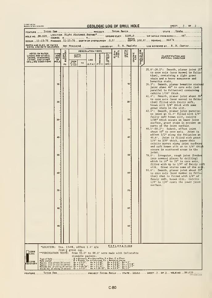
GEOLOGIC LOG OF DRILL HOLE SHEET. OF. . .2.
FEATURE T?tOT .PW PROJECT
nil i.-,n LOCATION. .Right Abutment Xayxa./.*HOLE NO. .DHtOJO. .
" '
COORDS. N E^o^^.\.
11713t76. finished. .H-.15-.76 . . depth of overburden . .Q..a' depth. JDD.O.BEGUN .
. . . ..Te.t.OA. .B.a.sjp STATE. . . . I<J»ho . . .
GROUND ELEV, . 5XS9..0 DIP (ANGLE FROM HOFUZ J . . . .46° .
BEARING. ...N68?iy
Not Measure^ logged by. . . .".-. .H-. M.ag.leby log reviewed by. . .B. .H. .Carter .
NOTES ON WATERLOSSES AND LEVELS,CASING. CEMENTING.CAVING, AND OTHERDRILLING CONDITIONS
TYPEANDSIZEOF
HOLE
oo
PERCOLATION TESTS
..C.l
LOSS
(C.P-U.)
CLASSIFICATION ANDPHYSICAL CONDITION
^
26
41
25.6'-26.5': Smooth, planar joint 25
to core axis fnear normal to foliation) , containing a light groutstain and a heavy manganese andhematite stain.3': Smooth, planar hematite stalnddjoint about 40* to core axis Csub
parallel to foliation) containingcalcite 1/16" thick.4': Smooth, planar joint about 35
to core axis (near normal to foliation) filled with fairly soft,
brown silt 3/8" thick with somegrout stain in the silt.
42.0': Smooth, planar joint parallelto joint at 41.4' filled with 1/4"
fairly soft brown silt, calcite1/16" thick occurs on lower jointsurface, grout stain is present onparts of the joint surface.
48.6'-S0.2': Smooth, offset jointabout 10* to core axis. Joint is
offset 1/2" along the foliation at49.6'. Joint is filled with grout1/4" to 3/8" thick, paper-thincalcite occurs along joint surfaceand soft brown silt up to 1/4" thi(
occurs in scattered areas in thejoint
.
79.0': Irregular, rough joint (broker
into several pieces by drilling)which is 10* to 20* to core axis,filled with up to 1/4" of fairly sc f
t
silt. Grout stains some of the silt.91.6': Smooth, planar joint about 35*
to core axis (near normal to folia-
tion) that is filled with 1/4" offairly soft, brown silt. Calcite1/8" to 1/4" coats the lower jointsurface.
COREJ LOSS
I CORERECOVERY
Sta. 13+46, offset 1.4' d/sexpl ana tion
from C grout cap
.
PERCOLATION TESTS: From 33.0' to 98.0' were made with inflatablestraddle packers.D Diomond, H - Hoyslellili., _
Pa Pocliet, Cm m Cemented, Ci>f hole (X-«erie«) . . E< = I-I/2". A- = 1-7/1
>( core (X-sefiei) . - E« = 7/8", A« :
•LOCATION:
ing
ApprOK, 1
Approx. *
Outiide d
Iniide dio. ol coting (X(X- : 1-13/16"
: 1-1/2".
= 1-1/8= 2-1/4'
Ax = 1-29/32'
, S B SKoi. C B Churn__llom of C
e- = 2-3/8',
B« = 1-5/8".
< = 2 7 8B. = 2-3'8". Nx
.3"
.2.1/8": 3-1/2".3"
FEATURE Te.tpA .Dajm. project .Teton .Basin . STATE . Idaho - SHEET . 2. . OF .2 . . HOLE NO, . .DH-620 .
C-80
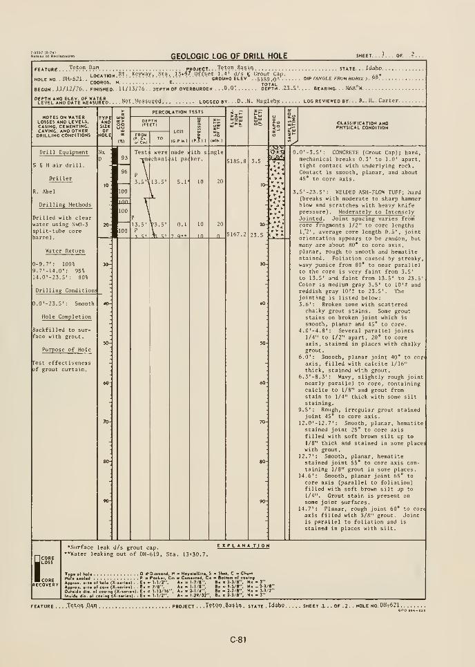
GEOLOGIC LOG OF DRILL HOLE SHEET. ...'... OF.
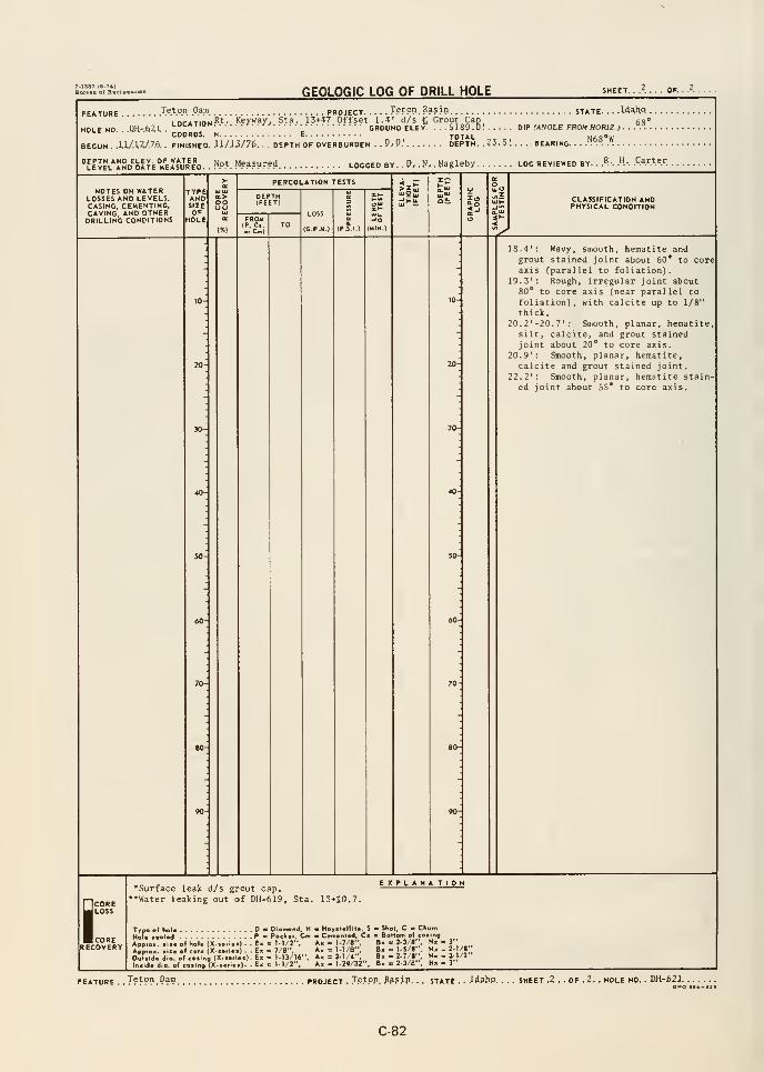
GEOLOGIC LOG OF DRILL HOLE SHEET. ./.... OF. .
FEATURE Teton Dam PROJECT J?tPO. pasin STATE. . ..W^i\o. .
inriTiftijRt. Keyway, Sta. 13+47 Offset 1.4' d/s £ Grout Cap ^q*LU^* liun I . . t r GROUNDELEV S1S9 0' two rATiit-.r c contM u/iDr7 i ""
COORDS. N E
BEGUN ..l.Ul.^.7.6. . FINISHED. JLa/a3/76,
DIP (ANCLE FROM HORIZ ) .
Nes'wHOLE NO. . .QH-.6Z1. . ^™p5 „ '.'."b.
]'.'.'.'. GROUND ELEV
DEPTH OF OVERBURDEN . . P^P.' DEPTH. .4-^,^'.. . . BEARING.
^LEVEL^AND^DATe'irE^jRE^D. . ^9^- Measured LOGGED BY. . D, - N, .Magleby LOG REVIEWED BY. .
.B-. .H.. .Carter
NOTES ON WATERLOSSES AND LEVELS,CASING. CEMENTING,CAVING, AND OTHERDRILLING CONDITIONS
TYPEANDSIZEOF
HOLE
oo
PERCOLATION TESTS
LOSS
(G,P-M.)
-JO
(MIN )
w»5 CLASSIFICATION ANDPHYSICAL CONDITION
18.4': Wavy, smooth, hematite andgrout stained joint about 60* to coreaxis (paral lei to foliation).
19.3': Rough, irregular joint about80* to core axis (near parallel to
foliation), with calcite up to 1/8"
thick.20. 2
' -20. 7': Smooth, planar, hematite,
silt, calcite, and grout stainedjoint about 20* to core axis.
20.9' : Smooth, planar, hematite,calcite and grout stained joint.
22.2*: Smooth, planar, hematite stain-ed joint about 5S* to core axis.
SCORELOSS
CORERECOVERY
•Surface leak d/s grout cap.'•Water leaking out of DH-619. Sta.
EXPLANA TION
13*30.7.
Typ« of hol* D • Diamond, H - Hoyitollil*, S - Shol, C = Churn
Hofo ceaUd P » Poehor, Cm - C*m.nl«d. C. - Bottom of coiinfl
Appro«. .110 of hol. (X-»ri«s) . . Ex = l.t/2", A» = 1-7/8", B. » 2-3/8", N, - 3'
AppOutsld* dIn.lde dio
cor* (X-B«ri«a) . . Ecosing (X-toftai)- Exosing (X-(«rioB). - Ex
= 7/8",= I-I3/14"= I-1/2",
Ax = t.1/8"Ax = 2-1/4",
Ak = 1-29/32'
„. J 1-5/8", N» - 2.1/8"
Bx = 2.7/8", N« - 3-1/2"" = 2-3/8", N« - 3"
FEATURE. .T?^??.?^? PROJECT. .T.e.tpp. pp^j-P. . . STATE. . Jd^hP. SHEET .^ . . OF . 2. . HOLE NO.
C-82
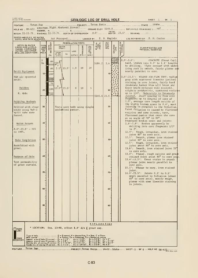
GEOLOGIC LOG OF DRILL HOLE
FEATURE
HOLE NO
TQto.n Dajn PROJECT. . ,Tptpn. Basin jj^ TE. Idaho
DH-.622.'-°"^'°''"^«^''"'^""^''-""^'>'*
OROUNOELEV. 5J89.0 dip m,vgle «o« ho«z , . ..?Q°
COORDS. N E.fO^^l^
BEGUN .U-U-.76 . . FINISHED. .1.1- .1.2." .76. . . DEPTH OF OVERBURDEN ..O.-.O.' DEPTH. . ??.5.' . BEARING.
. D,. N,. MagJeby log reviewed by. . .8. .H. .Carter .
NOTES ON WATERLOSSES AND LEVELS.CASING. CEMENTING.CAVING. AND OTHERDRILLING CONDITIONS
TYPEANDSIZEOF
HOLE
oo
^
PERCOLATION TESTS
FROM(P. C,o. Cm)
LOSS
(C.P M )
EP
CLASSIFICATION ANDPHYSICAL CONDITION
Dri 1 1 Equipment
S6H air operateddrill.
Driller
R. Able
Drilling Methods
Drilled with clearwater using NwD-3split tube corebarrel
.
Water Return
0.0'-23.5' - 95%
to 100%.
Hole Completion
Backfilled withgrout
.
Purpose of Hole
Test permeabilityof grout curtain.
89
100
79
1.9
23.5'
S165.5
20-
23.5
Tests were nade using singli
mechanical packer.
0.n'-3.6': CONCRETE (Grout Cap);hard, broken into 0.3* to 1.1' lengthsby drilling. Tight contact with undei
-
lying rock is smooth, fairly planar an
i
nearly parallel to core.
3.6'-23.5': WELDED ASH-FLOW TUFF; mediungray with scattered limonite (yellow)
staining in some joints, fairly hard(moderate hammer blow will break andheavy knife pressure will scratch),slightly porphyritic, scattered vesiclJes
up to 1/4". Moderately to IntenselyJointed . Joint spacing is from corefragments up to lengths of core of1.0', average core length outside ofthe highly broken areas is 0.4', mostjointing is parallel to the foliation.Faint foliation is caused by flattenecvesicles and some streaky, wavy,flattened pumice that cross the coreat an angle of 70* to 80*.
Prominent broken zones and joints:3.4 '-7.4': Broken apparently by
drilling into core fragments 1/2"
to 2".
12.4': Rough, irregular, iron stainecjoint 80* to core axis.
12.5': Smooth, planar iron stainedjoint 30* to core axis.
12.6': Rough, irregular, iron stainecjoint about 80* to core axis.
13.0': Smooth, iron stained joint 35°
to core axis.13.4': Planar, rough calcite and groiit
stained joint about 80* to core axis.13.4'-13.5': Grout stains in smooth
planar joint nearly parallel to
core axis.15.1': Planar to wavy, iron stained
joint.16.0'-23.5': Joints 0.3' to 0.5'
apart parallel to foliation (about80* to core axis), mostly rough,planar with some limonite stainingin joints.
ICOREdLOSS
corerecovery
EXPLANATIONSta. 13+48, offset 1.4' d/s g grout cap.
TyfM of hel* Da Diamond, H Harst«llil«. S Shot, C •> Churnflolo •olsd P > Pockar, Cm - C«ni«nlod, Cs » Bottom of coclngApprox. lix* of hoU (X-sarias) . . E« = M/2", Ax = 1-7/8". B« = 2-3/8", N> - 3"ApproK. Ill* of cofo (X-sari**) . . Em = 7/8". Ax = M/S". Bx = )-S/8", Nx - 2-1/8"Outi.da d>a. of easing (X-.ofio.). E« = 1-13/16", Ax = 2-1/4", Bx = 2-7/8". Nx - 3-1/2"
Iniido dio. of ca.infl (X-if io«). Ex = 1-1/2". Ax = 1-29/32", Bx = 2-3/8", N« - 3"
FEATURE . ..te.tpn Dam project .Teton .Basin . STATE . .Idaho . . . SHEET . 1 . . OF -1- - . HOLE NO- 011-622
po se* -oie
C-83
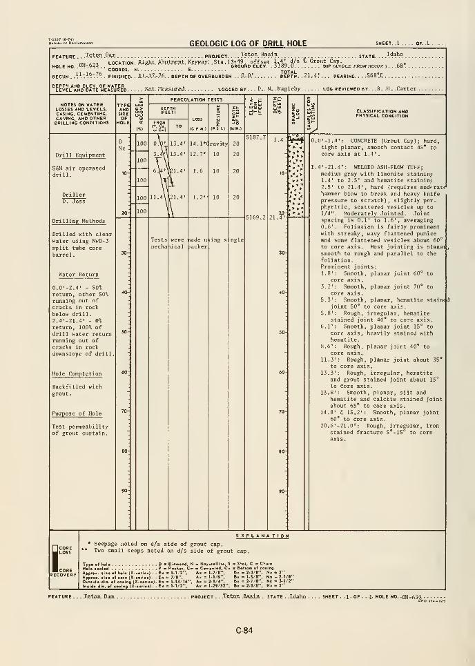
GEOLOGIC LOG OF DRILL HOLE
FEATURE .. Teton Dam pr
HOLE HO. .PH-^?5 .
OJECT. . . .J?t?". B?5in , STATE.• rnwjc^i ^
L0CATI0H.JUfiht.A.bu.tiii.erJ:.K.eyv?y..St3. 13+49 offset }.4!i ^^ '' "^""Li-^P.-GROUND ELEV .5189.0 DIP M/VGLE FROM HOR/Z ).. .68°.COORDS. H E TOTAL
JEGUH . .\\'.\^.~.l^. . FIHISHED. . .1.1.-.1.7.-.7I5. . DEPTH OF OVERBURDEH . . CD.' DEPTH. . 21.4.' . . . BEARING. .S68°E
. No.t. Measuxfid logged by. . . D.. N.. Magleby log reviewed by. . .B. .H. .Carter
NOTES on waterLOSSES and levels,CASING. CEMENTING.CAVING. AND OTHERDRILLING COHDITIONS
TYPEANDSIZEOF
HOLE
oo
PERCOLATION TESTS
LOSS
(G.P.M.)
CLASSIFICATION ANDPHYSICAL CONDITION
y^
Drill Equipment
S6H air operateddrill.
DrillerD. Jess
Drilling Methods
Drilled with clearwater using NwD-3
split tube corebarrel
.
Water Return
0.0'-2.4' - 50%
return, other 50%running out of
cracks in rockbelow drill
.
2.4'-21.4' - 0%
return, 100% of
drill water returnrunning out ofcracks in rockdownslope of drill
Hole Completion
Backfilled withgrout.
Purpose of Hole
Test permeabilityof grout curtain.
5187.714.1-
12.7"
( ravity 20 m10 20
20
5169.220-,
21.4-'^
< k
^ -4
> ^*
were lade using singlemechaiical lacker
0.0' -1.4': CONCRETE (Grout Cap); hard,tight planar, smooth contact 45* tocore axis at 1.4'.
1.4'-21.4': WELDED ASH-FLOW TUFF;medium gray with limonite staining1.4' to 2.5' and hematite staininf2,5' to 21.4', hard (requires mod' racHhammer blow to break and heavy knifepressure to scratch), slightly por-phyritic, scattered vesicles up to1/4" . Moderately Jointed . Jointspacing is 0.1' to 1.6', averaging0.6'. Foliation is fairly prominentwith streaky, wavy flattened pumiceand some flattened vesicles about 60*^
to core axis. Most jointing is planai
,
smooth to rough and parallel to thefoliation.Prominent joints:1.8': Smooth, planar joint 60** to
core axis.3.2': Smooth, planar joint 70* to
core axis.S.3': Smooth, planar, hematite stained
joint 50° to core axis.5.8' : Rough, irregular, hematite
stained joint 40* to core axis.6.1': Smooth, planar joint 15'^ to
core axis, heavily stained withhematite.
8.6': Rough, planar joint 40* to
core axis.11.3': Rough, planar joint about 35"
to core axis
.
13.3': Rough, irregular, hematiteand grout stained joint about 15'^
to core axis
.
13.8': Smooth, planar, silt andhematite and calcite stained jointabout 65* to core axis.
14.8' 6 15.2': Smooth, planar joint60° to core axis.
20.6*-21.0' : Rough, irregular, ironstained fracture 5*-15*^ to coreaxis
.
SCORELOSS
CORERECOVERY
EXPLANA TION* Seepage noted on d/s side of grout cap.
** Two small seeps noted on d/s side of grout cap.
Type o( hola D « Diamond, H - Hoystalliie, 5 m Shot, C « ChurnHoi* s«al«<l Pa Pockar, Cm m Cementad. Ci > Boriom of coaing
Appro., lii* of hoi* (X-wrl«0 . . E« = M/2", A, = 1-7 /8", B« = 2-3/8", H« - 3"
Approx. •<!• ol cor. (X-a«ri*a) . . E» = 7/8", A« = 1-1/8", Bk = 1-5/8", Nk - 2-1/8"
Oulald* dio. of coiing (X-«.ri..) . E« = 1-13/16". Ax = 2-1/4". Bx = 2-7/«", Nx - 3-1/2"
Intldo dio. of coiing <X.i>..>«). Ex = 1-1/2". Ax = 1-29/32", Bx = 2-3/8". Wx - 3"
TjRtxja Dam. project . . .Teton .Ba^JLn . state . .Idaho . SHEET . . 1 . OF . . .1- HOLE NO. DH-623
C-84
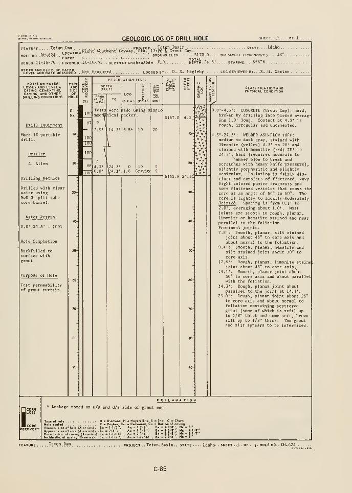
T-133T (6-74)
GEOLOGIC LOG OF DRILL HOLE OF. .1 .
Tetqn .Dam ,. ^ project.,^. J.etpn Wfjn.
.
, n^.T.n.j Rignt Abutment Keyway. Sta. 13+76 I. Grout Cap.'-°"^""'
GROUND ELEV 5170.0COORDS. N E TOTAL
BEGUN . U- 16-76 . . FINISHED. .I.I.-.I.6.-.7.6.. . DEPTH OF OVERBURDEH , D.D DEPTH. 24.3!. .. . BEARING. . . .N68*W
FEATURE
HOLE NO. W-.dZ^
T.e.tpn._to5Jn^ STATE. ...Idaho .
.
DIP (ANGLE FROMHORIZ ). . . .45".
.Not Me.a3.ur.ed. LOGGED BY. . . D-. N. . Hagleby log reviewed by B. H. .Cartel .
NOTES ON WATERLOSSES AND LEVELS.CASING, CEMENTING.CAVING. AND OTHERDRILLING CONDITIONS
TYPEANDSIZE
oo
PERCOLATION TESTS
FROM
':,c^;i
LOSS
tC.P M)
CLASSIFICATION ANDPHYSICAL CONDITION
Drill Equipment
Mark IX portabledrill.
Drilling Methods
Drilled with clearwater usingNwD-3 split tubecore barrel.
Water Return
0.0'-24.3' - lOO'o
Hole Completion
Backfilled tosurface withgrout
.
Purpose of Hole
Test permeabilityof grout curtain.
wereTestsmecIEnical
nade uking singlepacker
5167.0 4.3_
2.9' 14.3 3.5* 10
TTTO
—100
4.3' \24.3'0.0' b4.3'
" >,
10Tavi^
0.0' -4. 3': CONCRETE CGrout Cap); hard,broken by drilling into pieces averaging 1.0' long. Contact at 4.3' is
rough, irregular and uncemented.
4.3'-24.3': WELDED ASH-FLOW TUFF:medium to dark gray, stained withlimonite (yellow) 4.3' to 20' andstained with hematite Cred) 20' to24.3', hard (requires moderate to
hajiuner blow to break andscratches with heavy knife pressure),slightly porphyritic and slightlyvesicular. Foliation is fairly dis-tinct and consists of flattened, wavylight colored pumice fragments andsome flattened vesicles that cross the
core at an angle of 50"^ to 60'*. Thecore is Lightly to Local ly-ModeratelyJointed . Spacing is from 0.1' to"
2.0', averaging about 1.0'. Mostjoints are smooth to rough, planar,limonite or hematite stained and nearparallel to the foliation.Prominent joints:7,8': Smooth, planar, silt stained
joint about 45* to core axis andabout normal to the foliation.
9.4': Smooth, planar, hematite andsilt stained joint about 30'^ tocore axis.
12.6': Rough, planar, limonite staineji
joint about 45* to core axis.14.1': Smooth, planar joint about
50° to core axis and about parallelwith the foliation.
14,3': Rough, planar joint aboutparallel to the joint at 14.1',
23.0': Rough, planar joint about 25*
to core axis and about normal tofoliation containing scatteredgrout (some of which is soft) upto 1/8" thick and some soft, brownsilt up to 1/8" thick. The groutand silt appears to be intermixed.
ICORELOSS
CORERECOVERY
E_
X PLANA TION* Leakage noted on u/s and d/s side of grout cap.
Typ«
Appr
of holeleaUd
r hole (X. series). . E:
>«. (lie of core (X. series) . . E:
de dia. of cosing (X-serles). E:
e dio- of cosir^g (X-series). E;
: Pocki'. 1-1/2'
7/8",: 1-13/16*
: 1-I/2",
nd, H Hoystellite, S c
Cm — Cemented, Cs a
A. = 1-7/8",
Ax = t-1/8",A« = 2-1/4",Ax = 1-29/32",
Shoi. C •= ChurnBollorn of cosingU = 2-3/8". Nk - 3"U = 1-5/8", Nx - 2-1/8"Ix = 2-7/8", Nx = 3-1/2"
Ix = 2-3/8", Nx - 3"
FEATURE Tetpn Dam project . . Teton. Basin. . state . . Idaho- SHEET . .1. . OF . . 1 . hole no, . DH.-624.
C-85
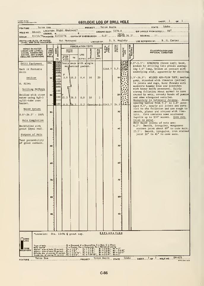
GEOLOGIC LOG OF DRILL HOLE SHEET. . .1. . . . OF.
FEATURE .Teton Dam. PROJECT. . . . TetPn. Basin
nu ,,, LOCATION. Righ.t. AbPfwnt.* ground elev 5170.0HOLE NO. .
.QH-.62S . ^g„^„5 „ E"°"'"' "'''
• •
TOTALBEGUN 1.1./.1.V.7.6fiN1SHEO. .'.1/.1.5/.7.6. . . DEPTH OF OVERBURDEN . .
.0,0.' DEPTH. 26. 3'.
DEPTH AND ELEV. OF WATER NotMeaSureJi nrrcn BV
LEVEL AND DATE MEASURED LOGGED BYD. N. Magleby
STATE Wa.hq
DIP (ANGLE FROM HORJZ J . . .30
. . . BEARING. ...".".
LOG REVIEWED BY ? . .1-. .Qart.e.r.
NOTES ON WATERLOSSES AND LEVELS.CASING. CEMENTING.CAVING, AND OTHERDRILLING CONDITIONS
Drill Equipment
Mark IX PortableDrill
A. Allen
Drilling Methods
Drilled with clearwater using NwD-3split-tube corebarrel.
Water Return
0.0'-26.3' - 100%
Hole Completion
Backfilled withgrout Cdyed red)
.
Purpose of Hole
Test permeabilityof grout curtain.
COREJ LOSS
corerecovery
5.3.^
26.3
30-
IT I- I
• -• «
> 4^ r- 4.
CLASSIFICATION ANDPHYSICAL CONDITION
.0'-5.3': CONCRETE (Grout Cap); hard,
broken by drilling into pieces averag
ing 1.0' long, broken at contact withunderlying rock, apparently by drilling
.3' -26. 3': WELDED ASH- FLOW TUFF; mediumgray, streaked with limonite (yellow)
in joints and vugs, hard (breaks with
moderate hammer blow and scratcheswith heavy knife pressure) , fairlystrong foliation about normal to core
caused by wavy, streaky bands of pumice
and some elongated vesicles.Moderately to Intensely Jointed . Joint
spacing varies from 0.2' to 1.0' aver-
ages 0.4', nearly all joints are para-
llel to the foliation and are rough to
smooth, planar and stained with limo-
nite. Core contains some scatteredlapilli up to 3/4" across. Core con-
tains no grout .
Only major joints of note are:6.2': Smooth, irregular, manganese
stained joint about 80* to core axis.23.5': Smooth, irregular, iron stained
joint 30* to 45" to core axis.
*Location: Sta. 13+7^ C grout cap. EXPLANA TIOM
Type o( heU - Diomond, H - Haytt.llit., S - Shot, C - Chofn
Hofe (colad P - Packer. Cm - Cm.nl.d, C« - Bottom ol co.lng
A^p'o- .i« ol hoi. (X-...i..) . . E- = M/2". A. = 1-7/8;:, »» "?-^i ' 2" " ^ /,.-
ApJ.ox. .i>« of cor. (X—ri..) . . E- = 7/8-. Ax = 1- /8 , B« = l-S/r ,Nx - 2-1/1.
Oui.ld. dio. ol co.ing (X...n..). E« = 1-13/1«-. A« = 2-1/4",_
In.id. dio. of co.ing (X-t.rl.i). E» = 1-1/2". Ak ^ l-2»/32"= 2-7'r',
. - 2-3/8",. . 3-1/2"
Teton Dam Idaho pH-625OPO .04-
C-86
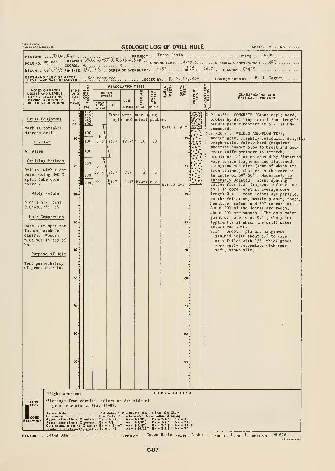
GEOLOGIC LOG OF DRILL HOLE SHEET. ..'.... OF.
FEATURE Teton Darn PROJECT T?.'?". Basln ST^TE .
nu A^^ LOCATION ^ta. 13*77. 3 C Grout Cap*HOLE NO. ."n".'!''.''. .
,' GROUND ELEV ..?>>>?. ^ DIP (ANCLE FROM HOfUZ >
Idaho_
68*
BEGUN . . .\\(\V7P. FINISHED. k^/?^/7P. . . DEPTH OF OVERBURDEN . . 9:9! DEPTH. . . ?^ : 7 ! . . BEARING. 5^? -5
''LElEL"5D'olTE°»rEMUR"D. . .."." !".".'".>-.<'<l LOGGED BY . . . P.. . N.. .
Magjeby LOO REVIEWED BY. . . .».: ."-. .Carter.
NOTES ON WATERLOSSES AND LEVELS.CASING, CEMENTING.CAVING, AND OTHERDRILLING CONDITIONS
Drill Ec^^u ipment
Mark IX portablediamond dril 1
.
Driller
A. Allen
Drilling Methods
Drilled with clearwater using NwD-5split tube corebarrel
.
Water Return
0.0'-9.0': 100%9.0'-26.7*: 5%
Hole Completion
HOl e 1 eft open for
future boreholecamera. Woodenplug put in top ofhole.
Purpose of Hole
Test permeabilityof grout curtain.
TYPEANDSIZEOF
HOLE
oo
PERCOLATION TESTS
; mech inical
12.5-
LOSS
(CPM.)
were iiade u >ing
7.5
4.5^ Gravi :y 5
pack -r
6.7
10-
26.7
30
< V »
CLASSIFICATION ANDPHYSICAL CONDITION
C.0'-6.7': CONCRETE (Grout cap); hard,broken by drilling into 1-foot lengthsSmooth planar contact at 6.7' is un-cemented.7'-26.7': WELDED ASH-FLOW TUFF;medium gray, slightly vesicular, slight[lyporphyritic, fairly hard (requiresmoderate hammer blow to break and moderate knife pressure to scratch),prominent foliation caused by flattenedwavy pumice fragments and flattened,elongated vesicles (some of which areiron stained) that cross the core atan angle of 50*-60°. Moderately toIntensely Jointed . Joint spacingvaries from 1/2" fragments of core upto 1.4' core lengths, average corelength 0.4'. Most joints are parallelto the foliation, mostly planar, roughhematite stained and 60" to core axis.About 80% of the joints are rough,about 20% are smooth. The only majorjoint of note is at 9.2', the jointapparently at which the drill waterreturn was lost
.
9.2': Smooth,planar, manganese
stained joint about 35* to coreaxis filled with 1/8" thick groutapparently intermixed with somesoft, brown silt.
I
*Right abutment EXPlana tion
•Leakage from vertical joints on d/s side ofgrout curtain at Sta. 13+97.
Trp« of hoU D > Diamond, H - Hoysiallite. S « Shot. C - ChurnHoU ••oUd - P B Packer, Cm « Cemenl«d, Cs ^ Bottom o( cotingApproK. <iie o( hol« (X-ien«s) . . E« = M/2", Ax = 1-7/B", B« = 2-3/8", N« - 3"
ApproK. siie of core (X->er>«s) - . Ek <= 7/8", Ax = M/S", B> = l-S/8", Nx - 2-1/8"Outside dio. of cosirto (X-.erie.) . Ex = t-t3/I«*', Ax = 2-1/4", Bk = 2-7/8", Nx - 3-1/2"
Iniide d.a. of coiing (X.»«r.e«). Ex = 1-1/2". Ax = 1-29/32", 8« = 2-3/8", Nx » 3"
Tetpp. P^lp PROJECT . . . J^^9P. .^.3,S.iP. STATE - .^A^^P. K - HOLE NO. . P.H-.6.2.6 ,
CPO
C-87
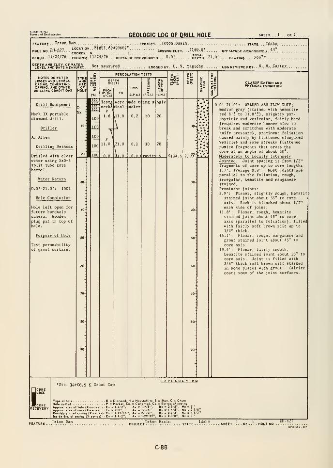
GEOLOGIC LOG OF DRILL HOLE SHEET. . ,1. . OF. i.
FEATURE . .J.e.tpn PW PROJECT.
HOLE NO. PH.-.6.2.7.LOCATION. .
Wght.
Abutment •
COORDS. N E.
. .T?t9o.?^5in STATE. . . JrffihP.
GROUND ELEV . A\^.^,-M\ \>\? (ANGLE FROM HORIZ ). ^^ . .
BEGUN . }-}-I?N7P. . FINISHED. Wl^^ll^ . . . DEPTH OF OVERBURDEN . . .PtP! DEPTH. .21-.Q'.. . . BEARING- • X6.8*W
^level*and^date°meI*ur"d. . .Not.measiired logged by. .P. .N, MggUbx log reviewed by. .
.B.-. .H-. CarteT
NOTES ON WATERLOSSES AND LEVELS,CASING, CEMENTING,CAVING, AND OTHERDRILLING CONDITIONS
TYPEANDSIZEOF
HOLE
oouu
PERCOLATION TESTS
FROM(P. C,or Cm)
LOSS
(C.P.M.) (MIN }
CLASSIFICATION ANDPHYSICAL CONDITION
Drill Equipment
Mark IX portablediamond drill.
Driller
A. Allen
Drilling Methods
Drilled with clearwater using NxD-3split tube corebarnel.
Water Return
0.0'-21.0': 100"^
Hole Completion
Hole left open for
future boreholecamera. Wooden
plug put in top of
hole.
Purpose of Hole
Test permeabilityof grout curtain.
Tests, weremechiiical
Made u:
jiacker
0.2 10
ngle
20
20
n.O (trflvit;- ^ S134.5 21.^:
.0'-21.0': WELDED ASH- FLOW TUFF;medium gray (stained with hematitered 8'1 to 11.8'*), slightly por-phyritic and vesicular, fairly hard(requires moderate hammer blow to
break and scratches with moderateknife pressure), prominent foliationcaused mainly by flattened elongatedvesicles and some streaky flattenedpumice fragments that cross thecore at an angle of about 50°.
Moderately to Locally IntenselyJointed . Joint spacing is from 1/2"
fragments of core up to core lengths1.7', average 0.8'. Most joints areparallel to the foliation, rough,
irregular, hematite and manganesestained.Prominent joints
:
8.9': Planar, slightly rough, hematitstained joint about 35* to coreaxis. Rock is bleached about 1/2'
each side of joint.11.8'; Planar, rough, hematitestained joint about 45" to coreaxis (parallel to foliation), filledwith fairly soft brown silt up to
1/4" thick.15.1': Planar, rough, manganese and
grout stained joint about 45° to
core axis,19.4': Planar, fairly smooth,hematite stained joint about 25° to
core axis. Joint is filled with3/8" thick soft brown silt stainedin some places with grout. Calcitecoats some of the joint surfaces.
iCORELOSS
CORERECOVERY
•Sta. 14+08,5 £ Grout CapEXPLANA TION
Type o( hole D - D.omond. H - Hoyitell.le, S = Shot, C = ChurnHole teoted P = Poeker. Cm - Cemented, C. = Bottom of eo.ing
Appfo». sue of hole (X-ieriei) . . E- = 1-1 2", A« = 1-7 8", B« = 2-3 8", N« - 3"
Approx. «iie of core (X-.efie.) . . E. = 78", A« = 1-1 8", Bx = 1-5/8", N> - 2-1 8"Outi.de dio. of coting (X-.er.ei) . Ex = 1-13 '16". A. = 2-1 4", B> = 2-7 8", N. = 3-1 2"In.ide dio. of co«ing (X-ieriet). - Ex = 1-1 2", A. = l-29 32". B. = 2-3'8", Nx - 3"
Teton Dam 1 i DH-627SHEET .... OF . HOLE NO
C-88
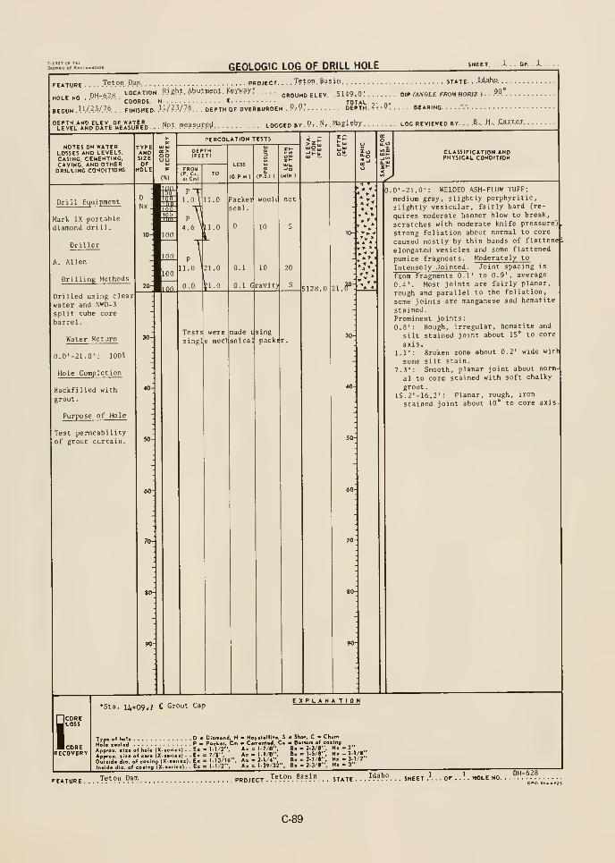
7-l«a7 (6-7*1
GEOLOGIC LOG OF DRILL HOLE SHEET. . . .1. . . OF. . 1.
FEATURE
.
HOLE NO. .
.'.H.-.6.2.8.
Teton Da.m
LOCATION.
COORDS.
BEGUN W/.-.yyP. . . FINISHED.
DEPTH AND ELEV. OF WATERLEVEL AND DATE MEASURED.
ROJECT. . ..Teton, Pii5;n STATE. . .lA^ho.
Right. ^t)utin?pt. Kfyv*y*.GROUND ELEV. .5149.0'. DIP fXJVGLE FROM HOR/Z ) .
TOTAL1.1/23/76, ., oEpTH OF OVERBURDEN .P.- P.' DEPTH. ?i-.P BEARING.
Not measured LOGGED by . P- . N/ MaElfby LOG reviewed by ?.. M.. .Car.t.ej.
NOTES ON WATERLOSSES AND LEVELS,CASING. CEMENTING.CAVING, AND OTHERDRILLING CONPITIONS
TYPEANDSIZE
Drill Equipment
Mark IX portablediamond drill.
Driller
A. Allen
DrillinR Methods
Drilled using clear
water and NWD-3
split tube core
barrel
.
Water Return
0.0'-21.0': 100%
Hole Completion
Backfilled with
grout
.
Purpose of Hole
Test permeabilityof grout curtain.
QE>oo
ICO
SCORELOSS
CORERECOVERY
PERCOLATION TESTS
FROM(P, Ci, TOo. Cm)
LOSS
(C.P.M-)
Packerseal
.
Tests
sing
weree mecri;
0.1 10
0.1 Gravity
made usinganical
woulc
packer.
5128.0 l.^'
> •
CLASSIFICATION ANDPHYSICAL CONDITION
.0'-21.0': WELDED ASH-FLOW TUFF;
medium gray, slightly porphyritic,
slightly vesicular, fairly hard (re-
quires moderate hammer blow to break
scratches with moderate knife pressure)
strong foliation about normal to core
caused mostly by thin bands of flattened
elongated vesicles and some flattened
pumice fragments. Moderately to
Intensely Jointed . Joint spacing is
from fragments 0.1' to 0.9', average
0.4'. Most joints are fairly planar,
rough and parallel to the foliation,
some joints are manganese and hematite
stained.Prominent joints:0.8': Rough, irregular, hematite and
silt stained joint about 15* to core
axis
.
1.1': Broken zone about 0.2' wide with
some silt stain.7.3': Smooth, planar joint about norm-
al to core stained with soft chalky
grout
.
15.2'-16.2': Planar, rough, iron
stained joint about 10° to core axis
*Sta. LI,+09</ C Grout CapEXPLANA TIOH
AppfOK.
Ouiild. di
Inside d
. . . D Diamond, H - Hayit»ltiie, S - Shpf, C - Churn
P a Packet, Cm Cemented, Ca Bottom of caiing
.)! :E« = 1-1/2", A. = 1. ?/«, B. =2-3/8", N. -3;•. .Ex=7/8". Ax = 1-1/8", B. = 1-5/8", N. -2-1/»::
"ol'cVi'na'lXrie'rie.l.E. = 1-13/16". A. = 2.1/<", B« - 2-7/8"
ol =a.ina(X..e,i..). E. ^ M/2", A« = l-2?/32"
le of hole (X-t
B> -2-3/8". 3-1/2". 3"
Teton Dam pROJECTTeton Basin DH-628
cpo e84-e2e
C-89
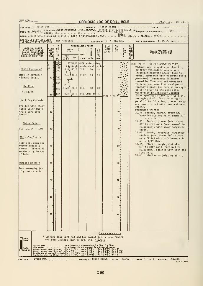
GEOLOGIC LOG OF DRILL HOLE SHEET. . .1. . . . OF.
FEATURE .'^l-V'.'.':'^'!' PROJECT. . ..Teton Basi.n STATE. - . Idaho
IIP (ANGLE FROM HORIZ J . . . . 5&? . .
LOCATION. Bight .AtJWi;ii)^nt;> .Sta...l4-K)7*5 ^offset 1.1' d/s e Grout ChdGROUND ELEV. 5149.. .Q . ^HOLE NO, .DHr629.. ^„„„^, „COORDS. N
BEGUN ..I.lr?0r76. . FINISHED- U -:2^-:7^
DEPTH AND ELEV. OF WATERleJel AND DATE MEASURED- .^l^ot .Measured LOGGED BY.. P-. .N- .M^U.by. log reviewed by. .B..H.. Carter.
. DEPTH OF overburden . .Q-Q' DEPTH. . 21.. jO.'. . . BEARING. - SfeSJ'E.
PERCOLATION TESTSNOTES ON WATER
LOSSES AND LEVELS,CASING. CEMENTING,CAVING, AND OTHERDRILLING CONDITIONS
CLASSIFICATION ANDPHYSICAL CONDITION
Drill Equipment
Mark IX portablediamond drill
.
Drilling Methods
Drilled with clearrfater using NwD-3split tube corebarrel
.
Water Return
D.0'-21.0' - 100%
Hole Completion
lole left open forfuture borehole:amera. Instal ledrfooden plug in top3f hole.
'urpose of Hole
Pest permeability)f grout curtain
.
< L.
,1 T,
5131.6
.0'-21.0': WELDED ASH-FLOW TUFF;medium gray, slightly porphyritic,slightly vesicular, fairly hard(requires moderate hammer blow tobreak, scratches with moderate knifepressure). Prominent foliationcaused by flattened and elongatedvesicles and some flattened pumicefragments cross the core at an angleof 50" to 60"* to the core axis.Moderately to Intensely Jointed .
Joint spacing is from 0.1' to 1.2',
averaging 0.4'. Most jointing is
parallel to foliation, planar, roughand some stained with iron and man-ganese.Prominent joints
:
2,3': Smooth, planar, grout andhematite stained joint about 30°
to core axis.15.8': Smooth, planar joint about
30** to core axis (near normal tofoliation), with heavy manganesestain.
17.6': Rough, irregular, manganesestained joint about 30" to coreaxis filled with soft brown siltup to 1/4" thick.
18.4': Planar, rough joint about60* to core axis (parallel tofoliation), stained with iron andsome silt.
20.8': Similar to joint at 18.4'.
SCORELOSS
CORERECOVERY
EXPLANATIONLeakage from vertical and horizontal joints near DH-629and some leakage from DH-628, Sta. l4+09-,7 •
Typ* of hoi* DHoU iMlett P
Appro >.
Diamond, I
Packer, Ci
>«of hoU (X.»ri«>) . .E. - M/2".!• of core (X-iorieO . . E- « 7/8",
o. of catirtg (X-t«rie*). E. c )-l3/16". of co»ir»fl (X-»erie.). - E» = 1-1/2",
I - Hoydellito, S - Shot. C - CKurrt
I Cotnenled, C> Betlem of coiingA> = 1-7/8", B« - 2-3/B". Nx - 3"
Am =1-1/8", fin « 1-5/8", M«-2-1/«"A» = 2-1/4", B» = 2.7/8", N«- 3-1/2"
A« = 1-29/32", 8.-2-3/8", N« - 3"
Teton Dam. project . .T^^.PH .^asin. . state . .Id^ho . SHEET . 1. . OF .L . HOLE NO .DH.629
CPO B4-S2B
C-90
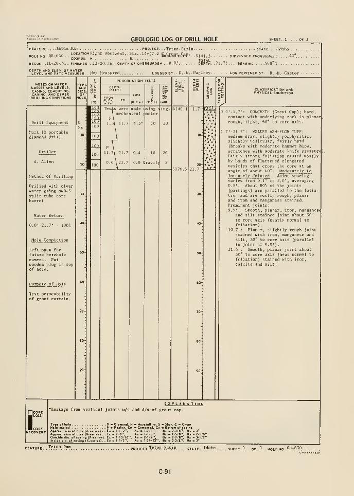
GEOLOGIC LOG OF DRILL HOLE SHEET. ,1 ,
.T.etoa Dim project.
HOLE NO .DH-.63Q.'-ocATiONRight. Abutment,. St»,. 14*27.0 6„gf;BHt^,C^COORDS. N. . . C
BEGUN . ll-.2n-7.h . FINISHED. . JJ^20.-76. DEPTH OF OVERBURDEN . . 0-0.'. . . .
Teton Basin state. . . .I<laho .
5141.3 DIP (ANCLE FROM HORIZ ) 4,3.*
DEPTH. .21.7'.. BEARING N68°.K
. No.t. Measured locoed by P. N. . Magleby log reviewed by. B, .H. Carter
NOTES on WATERLOSSES AND LEVELS,CASING, CEMENTING.CAVING, AND OTHERDRILLING CONDITIONS
TYPEANDSIZEOF
HOLE
oo
mi
PERCOLATION TESTS
FROM(P. C.o-Cm)
LOSS
(C.P M )
mL
CLASSIFICATION ANDPHYSICAL CONDITION
Dri 11 Equipment
Mark IX portablediamond dri 1 1
.
Driller
Method of Drilling
Drilled with clearwater using NwD-3split tube corebarrel
.
Water Return
0.0'-21.7'
Hole Completion
Left open for
future boreholecamera. Putwooden plug in topof hole.
Purpose of Hole
Test permeabilityof grout curtain.
madeical
singpacker
: ingl
0.4
0.9 dravitjf 5
I:CORERECOVERY
20
21.7
0.0' -1.7': CONCRETE fC.rout Cap"); hard
contact with underlying rock is planairough, tight, 60* to core axis.
;.7'-21.7': WELDED ASH-FLOW TUFF;medium gray, slightly porphyritic,slightly vesicular, fairly hard(breaks with moderate hammer blow,
scratches with moderate knife pressure)Fairly strong foliation caused mostlyby bands of flattened elongatedvesicles that cross the core at an
angle of about 60°. Moderately to
Intensely Jointed . Joint spacingvaries from 0.1' to 2.0', averaging0.8'. About B0% of the jointsCpartings) are parallel to the folia-tion and are mostly rough, planarand iron and manganese stained.Prominent joints
:
9.9': Smooth, planar, iron, manganestand silt stained joint about 30"
to core axis (nearly normal to
foliation)
.
10.7': Planar, slightly rough jointstained with iron, manganese and
silt, 30° to core axis (parallel
to joint at 9.9')
.
21.6': Smooth, planar joint about30* to core axis (near normal to
foliation) stained with iron,calcite and silt
.
^Leakage from vertical joints u/s and d/s of grout cap.
EXPLANATION
Typ« o( hoi* D Diamond, H •
HeU ••ol»d pa Pock«r. CmApproo. iii« of hoi* (X.t*ri«s) . . Ex <= 1-1/2". '
Apprex. it* of cor* (X-i«(<*s) . . E> c 7/8". t
Ouliid* dJo. of coiing (X.a«ri*>). Ex = 1-13/16",Insid* dio »i"fl (X-< ,.)- .E< : 1.1/2"
Hoyitclllt*, S - Shot. C » ChurnC*(n*nt*d, Ci a BoMom of casingX = 1-7/8 *. B« « 2-3/8", N> - 3"X » 1-1/8", B> c 1-5/8", Nx - 2-1/8"= 2-1/4", B« = 2-7/8", Nx- 3-1/2"
A. = 1-29/32", fix - 2-3/8"
. J9'^°V. P?? PROJECT J^^PP. .S.as.in state -.IAa.^o. SHEET .\ . . OF . ?. . HOLE NO. P.H-A^P.
GPO •e4-02B
C-91
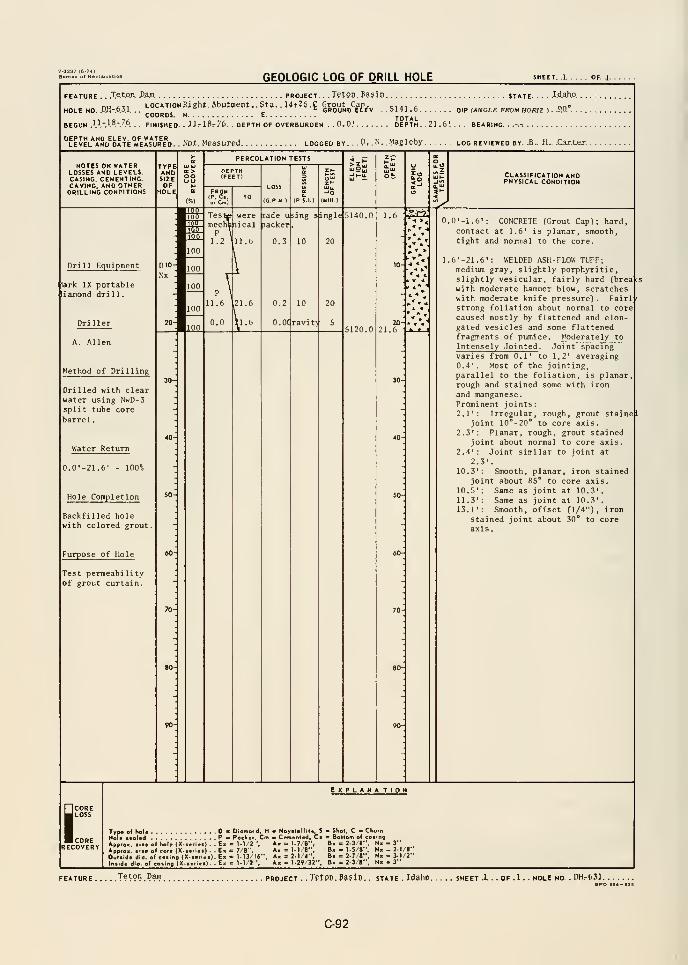
GEOLOGIC LOG OF DRILL HOLE SHEET .1 OF. J.
FEATURE . . .T.et.OA P.aR PROJECT. . . Tstpn .Pajin STATE I.d.a.ho.
nu <Lii LOCATiONRight. Abutment, .Sta. . 14t26.f Grout Can „MOLE NO. .RH-.6.3.1. , .
" • K GROUND EtEV ..5141.6 DIP (ANGLE FROM HORIZ ) . .M. . .
""""S- " ^ „ „, TOTAL ,.0.0; DEPTH. .21.6', ., - BEARING...-.-.
COORDS. N E.
BEGUN .1.1.-.1.8.-.7.6 FINISHED. . JJrl8r76. . DEPTH OF OVERBURDEN
. ND.t. Measured logged by. . P. C. .Magleby log reviewed by. .8.. a.. .Car.t.er
NOTES on waterLOSSES and levels,CASING, CEMENTING,CAVING, AND OTHERDRILLING CONDITIONS
TYPEANDSIZEOF
HOLE
ooLID
tm:
PERCOLATION TESTS
FROMIP, C,or Cm)
LOSS
(G P M )
CLASSIFICATION ANDPHYSICAL CONDITION
Drill Equipment
lark IX portabletiajnond dri 11
.
Method of Drilling
Drilled with clearwater using NwD-3split tube corebarrel
.
Water Return
100%
Hole Completion
Backfilled holewith colored grout.
Purpose of Hole
Test permeabilityof grout curtain.
Teste weremechanical
P \
1.2 1 1 . (>
,21.6
nade ufeing s|ingle|5140.0
packer
lii
* 4 *k « 4
. 4." "l
0.2
O.Odravit) 2021.6
0.0'-1.6': CONCRETE (Grout Cap); hard,contact at 1.6' is planar, smooth,tight and nomial to the core.
1.6'-21.6': WELDED ASH-FLOW TUFF;medium gray, slightly porphyritic,slightly vesicular, fairly hard (breawith moderate hammer blow, scratcheswith moderate knife pressure). Fairlstrong foliation about normal to corecaused mostly by flattened and elon-gated vesicles and some flattenedfragments of pumice, htoderately to
Intensely Jointed . Joint spacingvaries from 0.1' to 1.2' averaging0.4'. Most of the jointing,parallel to the foliation, is planarrough and stained some with iron
and manganese.Prominent joints:2.1': Irregular, rough
,grout staine I
joint 10°-20*' to core axis.2.3' : Planar, rough, grout stained
joint about normal to core axis.2,4': Joint similar to joint at
2.3'.
10.3': Smooth, planar, iron stainedjoint about 85** to core axis.
10.5': Same as joint at 10.3'.11.3': Same as joint at 10.3'.13.1': Smooth, offset (1/4"), iron
stained joint about 30" to coreaxis.
SCORELOSS
CORERECOVERY
EXPLANA TIOM
Typ« of hol« D > Diomord, H - Haral*lllt«, S e SKol, C * ChurnHole tvoled P * Packer. Cm * Cemented, Ct Bottom of casing
App,o«. >iie ol Kole (X-ierie.) . . E« = 1-1/2 ', A« = 1.7/8", B> = 2-3/8", N« - 3"
Approx. iJie of core (X-,erie.) . . E» - 7/B", A» = l-l/B", Bx = 1-5/8", N« - 2.1/8-
Owt.lde dio. olcoiing (X.«er(.«).E» = 1-13/I6-, A, = 2-1/4", B« = 2-7/«", N« - 3-1/2"
ln«ide dio. of co.Ing (X-.erte.). E« = 1-1/2 '. A« = 1-29/32", B- = 2-3/8". N- - 3"
.T?^90.P^ PROJECT . .Tptpn.395ip. . state . Idaho sheet .1. . OF .1 . . HOLE NO. . DH.-631
C-92
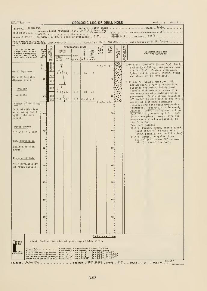
GEOLOGIC LOG OF DRILL HOLE SHEET.
FEATURE . . .T?tpn Dani PROJECT. . .TctQn Basia STATE. - - }^^^9.
LOCATION Biebt AbutiO^Ot. 5^^% 1^4+27.8 C Grout Cap. o
HOLE NO, DH^632. ..
»-°"TI0N.ttlKm,.OWV«.iW', JS. .HWR^ .^(JftOUHO ELEV . . .S1-41-.-3' Dip (ANGLE FROM HORIZ ) . ^^ . .
BEGUN ii-19-76. . . FINISHED. - . Ut19t7^ . DEPTH OF OVERBURDEN . .Q.P'- DEPTH.23..I ' BEARING. ?.^?. ?
Not. Measured logged by. .D^ .N» .MggUbx log reviewed by. P.-.H.-. Carter.
NOTES ON WATERLOSSES AND LEVELS.CASING, CEMENTING.CAVING, AND OTHERDRILLING CONDITIONS
TYPEANDSIZEOF
HOLE
oo
PERCOLATION TESTS
LOSS
(C.P.M )
CLASSIFICATION ANDPHYSICAL CONDITION
Drill Equipment
Mark IX Portablediajnond dri 1 1
.
Method of Drilling
Drilled with clear
water using NwD-3
split tube core
barrel
.
Water Return
0.0'-23.r - lOO'o
Hole Completion
backtilled with
grout
.
Purpose of Hole
Test permeabilityof grout curtain.
5138.7 m
1.6
0.7
10
Gravi
20
5122.2
20
23.1
0.0' -3.1': CONCRETE (Grout Cap); hard,
broken by drilling into pieces from
0.1' to 0.9'. Contact with under-
lying rock is planar, smooth, tight
and about 45' to core axis.
3.1'-23.r; WELDED ASH-FLOW TUFF;
medium gray, slightly porphyritic,
slightly vesicular, fairly hard
(breaks with moderate hammer blow
and scratches with moderate knife
pressure). Fairly strong foliation45° to 50° to core axis is the result
mostly of flattened elongated
vesicles and some flattened pumice
fragments. Moderately to Intensely
Jointed . Joint spacing varies from
0,1' to 1.4', averaging 0.6'. Host
joints are planar, rough, iron and
manganese stained and parallel to
the foliation.Prominent joints:13.6': Planar, rough, iron stained
joint about 40° to core axis
(about parallel to the foliation)
14.4': Rough, irregular, iron
stained joint about 20° to core
axis (crosses foliation).
iCORELOSS
CORERECOVERY
EXPLANA TIOH
•Small leak on u/s side of grout cap at Sta. 14*41.
Typ« ol holaHole ieol«dApproK. liieofholc (X-sei
Approx. siie of core (X-iei
Owltide dio. of cosing (X-i
ln»ide dio. of cosing {X-«e
. P = Pocker,Em = 1.1/2'
- E. = 7/8'
t.e.).E. = 1-13/16", A«
J, H - Hoyttelhte. S •
Cm a Cemented, Ca :
A. = 1.7/B",A« = 1.1/8",
. 2-1/4"i 1.29/32"
Shoi, C = ChurnBoiiom of coiing\m = 2-3/8", Nx . 3"
Ix I 1-5/8", N« -2-1/li = 2-7/8", N. = 3-1/
li = 2-3/8", Nx . 3"
FEATURE . .
.Teton Dam PROJECT . .T?^9" .^a^in j^^^EIdaho DH-632
C-93
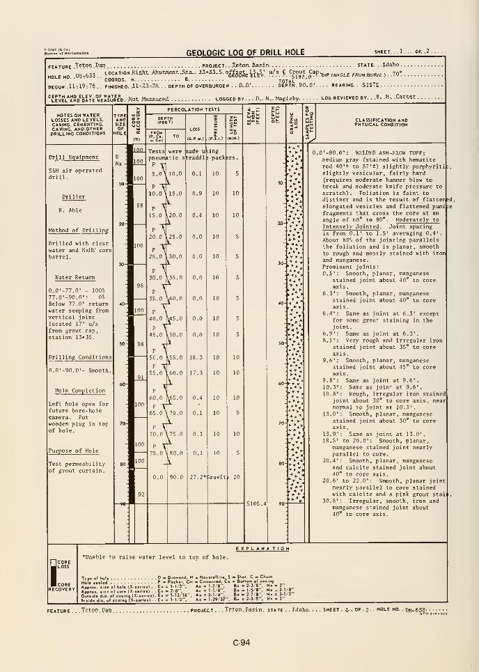
GEOLOGIC LOG OF DRILL HOLE SHEET. . .1. . . OF. .2 .
FEATURE "T^tPn .P^ PROJECT- . JStOn. BasilX STATE. . .Idaho .
HOLE HO.m-.m..^°o* Jj""
-^^^ Ahutja«it.S.ta... 13.*43. S. o^^gg^^ ^^^^ u/s J Grout Cap^,^ ^^^^^ ^^^^ ^^^^ ^
ygo
BEGUN .U-I9r7e . . FINISHED. XI-Z3-7.6. DEPTH OF OVERBURDEN . . CD.' DEPTH. 90.0.'. . . . BEARING. . -SIS-E
''leJel*I!nd^date°«'eJ!s*Jred. Xot Mea5.ar.ad. logged by. . . D... N... Magleby log reviewed by. . -B. .H. .Carter .
NOTES ON WATERLOSSES AND LEVELS,CASING. CEMENTING,CAVING, AND OTHERDRILLING CONDITIONS
TYPEANDSIZEOF
HOLE
COoo
PERCOLATION TESTS
FROM(P. C.or Cm)
LOSS
(G.P.M.)
CLASSIFICATION ANDPHYSICAL CONDITION
Drill Equipment
SfiH air operateddrill.
Driller
R. Able
Method of Drilling
Drilled with clearwater and NxHV,' corebarrel.
Water Return
0.0'-77.0' - 100%77.0'-90.0': 0%
Below 77.0' returnwater seeping fromvertical jointlocated 17' u/s
from grout cap,
station 13+35.
Drilling Conditions
0.0'-90.0'- Smooth
Hole Completion
Left hole open for
future bore-holecamera . Putwooden plug in topof hole.
Purpose of Hole
Test permeabilityof grout curtain.
Testspneumitic s t
P
5
nade uraddl
ingpack
.0^
p
10.0
p
15.0
P
20.0
100P
25.0
P
30.0
98P
35.0
P
40.0
P
45.0
P
50.0
P
55.0
1
2
I'.3
\'W
10.0 0.1
10
20.0
25.0
10
35.0
.40.0
45.0
50.0
55.0
60.0
P
60.0
P
65.0
P
70.0
P
75.0
\^
l' 75.0
n 80.0
.65.0
70.0
100
:
A90.0
0.0
0.0
0.0
0.0
18.3
17.3
0.4
0.1
0.1
27.2*;ravit' 20
10
10
10
10
10
10
* » A' ' .
:»!".
• *
5105.4
> ^
.0'-90.0': WELDED ASH-FLOW TUFF;medium gray (stained with hematitered 4C'± to 57'+) slightly porphyTiti|:
slightly vesicular, fairly hard(requires moderate hammer blow tobreak and moderate knife pressure to
scratch). Foliation is faint todistinct and is the result of flattened,elongated vesicles and flattened pumi :
fragments that cross the core at an
angle of 60* to 80*. Moderately to
Intensely Jointed . Joint spacingis from 0.1' to 1.5' averaging 0.4'.
About 80-6 of the jointing parallelsthe foliation and is planar, smoothto rough and mostly stained with iron
and manganese.Prominent joints
:
0.5': Smooth, planar, manganesestained joint about 40* to coreaxis.
6.3': Smooth, planar, manganesestained joint about 40* to coreaxis.
6.4': Same as joint at 6.3' exceptfor some grout staining in thejoint
.
6.9': Same as joint at 6.3'.
8.1': Very rough and irregular ironstained joint about 35* to coreaxis.
9.6': Smooth, planar, manganesestained joint about 45* to coreaxis
.
9.8': Same as joint at 9.6'.
10.3': Same as joint at 9.6'.
10.8': Rough, irregular iron stainedjoint about 30* to core axis, nearnormal to joint at 10.3'.
13.0': Smooth, planar, manganesestained joint about 30* to coreaxis.
13.9': Same as joint at 13.0'.18.5' to 20.0': Smooth, planar,
manganese stained joint nearlyparallel to core.
20.4' : Smooth, planar, manganeseand calcite stained joint about40* to core axis.
20.6' to 22.0': Smooth, planar jointnearly parallel to core stainedwith calcite and a pink grout stai i
30.8': Irregular, smooth, iron andmanganese stained joint about40* to core axis.
SCORELOSS
CORERECOVERY
EXPLANA TION*Unable to raise water level to top of hole.
ApprcApprcOulti
D K Diamond. H Hoyilellite, S e Shot, C = Churn
p « Packer Cm - Cem«r«l»d, Cs > Bottom of coiing
ofhol. (X-..r.,.). E. = 1-1 2-'. A. = 1.7'8". B- = 2.3/8;;. N> -3"of cor. X...r...) . . E, = 7 8-. A, = 1.1/8". B« = 1-5/8 .
Nx - 2-/8o(co.in9(X...r...)-E- = 1-13/16--, A. = 2-1 4'*, B. = 2-7 •', N. - 3-1/2
.w _-i C 11 -»•of cQi'ng (X-1 : M/J" A. = l-29'32" . • 2-3 B", N. • 3"
.Teton. Pot PROJECT . TeJon. Basin, state . . Idaho-
C-94
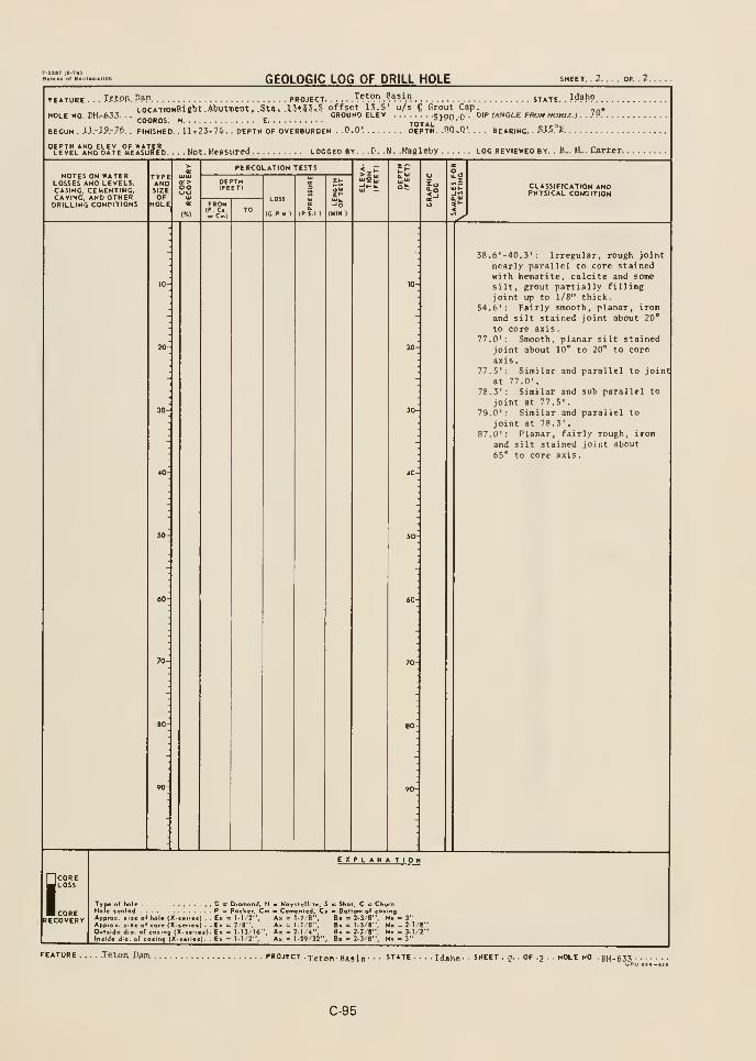
7-I98T (a-74>Buraftu or Rao
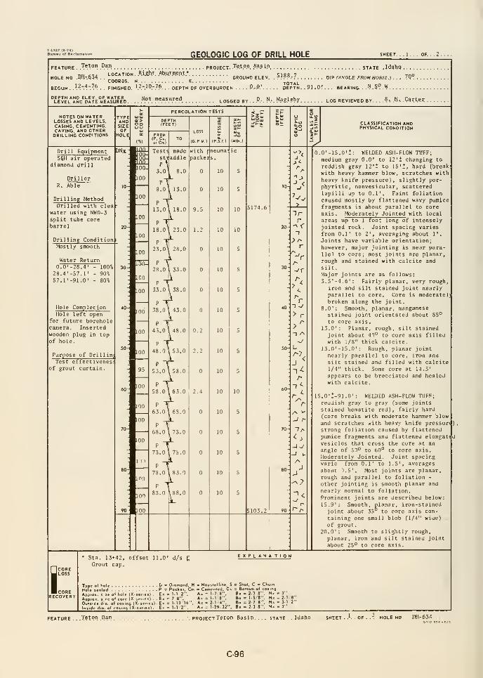
GEOLOGIC LOG OF DRILL HOLE SHEET.
FEATURE ..Tst™ .P™ PROJECT. .T.e.t.O.n. .Bas.ip STATE, .IdshQ .
n„ ,,. LOCATION. .R.i&h.t. .Ab.ut.m.e.nt.*
HOLE NO .0H-.Q34 . . ,COORDS. N E TOTALBEGUN . .\^.~A~P.^. . . FINISHED, ^.^r^9-7^. . DEPTH OF OVERBURDEN .... P.. 0.' DEPTH . . 9 J . *
. BEARING. . ."^ .5"^ .W
.
GROUND ELEV. . ?.^??.'7 DIP (ANGLE FROM HORtZ ) . . ..7Q°
LeIeL^^ND dItE MeIsURED. . . .
.N.°^. .»««."".<' LOGGED BY. .°.-
. N.-. Mag.Uby LOG REVIEWED BY- , ,
B, .H, Carter.
NOTES ON WATERLOSSES AND LEVELS.CASING. CEMENTING.CAVING, AND OTHERDRILLING CONDITIONS
TYPEANDSIZE OOuu
PERCOLATION TESTS
TO
LOSS
(G P M) (P.S.I )
CLASSIFICATION ANDPHYSICAL CONDITION
Drill EquipmentSfiH air operated
diamond drill
DrillerR. Able
Drilling MethodDrilled with clea
water using NWD-3split tube corebarrel
Drilling ConditionMostly smooth
Water Return
DNx- ^^
: m
0.0'-28.428.4'-57.1'
57.1'-91.0
- 100%- 90%- 80%
Hole CompletionHole left open
for future boreholecamera. Insertedwooden plug in topof hole.
Purpose of DrillinTest effect ivenes
of grout curtain.
LOO
00
Testi madesti addle
3.0 8.0
3.0 I 13.0
13.0 , 18.0
18.0 23.0
^ T23.0' 28.0
28.0 I 33.0
33.0 L 38.0
M38,0 43.0
p-f43.0, 48.0
48.0 53.0
53.0 ,53.0
M58.0
,63.0
withpacke
1.2
f neumal ic
10
10
I
.O' 6
8
2.2
10
P
83.0 I 88.0
-> <
r
r-I ~y
>r>^-I -^
~y
u
:'<
r
-I r-
-If
AJ
r
0.0'-15.0'!: WELDED ASH-FLOW TUFF;medium gray 0.0' to 12'i changing to
reddish gray 12'- to 15**, hard (break:
with heavy hammer blow, scratches withheavy knife pressure), slightly por-phyritic, nonvesicular, scatteredlapilli up to 0.1'. Faint foliationcaused mostly by flattened wavy pumicefragments is about parallel to coreaxis. Moderately Jointed with local
areas up to 1 foot long of intenselyjointed rock. Joint spacing variesfrom 0.1' to 2', averaging about 1'.
Joints have variable orientation;however, major jointing is near para-llel to core; most joints are planar,rough and stained with calcite and
silt.
Major joints are as follows:3.5'-4.6': Fairly planar, very rough,
iron and silt stained joint nearlyparallel to core. Core is moderatel)broken along the joint.
8.0' : Smooth, planar, manganesestained joint orientated about 85^
to core axis.13.0' : Planar, rough, silt stained
joint about 40° to core axis filledwith 1/8" thick calcite.
13.0'-15.0': Rough, planar jointnearly parallel to core, iron and
silt stained and filled with calcite1/4" thick. Some core at 14.5'
appears to be brecciated and healedwith calcite.
15.0':-91.0': WtLDED ASH-FLOW TUFF;reddish gray to gray (some jointsstained hematite red), fairly hard(core breaks with moderate hammer blowand scratches with heavy knife pressure),strong foliation caused by flattenedpumice fragments and flattened elongatfuvesicles that cross the core at an
angle of 5D° to 60*^ to core axis.Moderately Jointed . Joint spacingvarie from 0.1' to 1.5', averagesabout ).5', Most joints are planar,rough and parallel to foliation -
otiior jointinf. is smooth planar and
nearly normal to foliation.
Prominent joints are described below:15.9': Smooth, planar, iron-stained
joint about 35 to core axis con-
taining one small blob (1/4" wide)
of grout.20.0': Smooth to slightly rough,
planar, iron and silt stained joint
about 25° to core axis.
iCORELOSS
CORERECOVERY
Sta. 13+42,Grout cap.
offset 11.0' d/s CEXPLANA TION
Type
Approi le (X-je
*.ng(X.!
. D = Diamond, H - HoyilcU'te. S <
. P = Packer, Cm o Cemenled. C» =
E. = 1-1 2". A. = 1-7 B".. E. t= 7 8", A« = l-l 8'',
. E. = l-n'16". A« = 21 4*-.
. E« = M/2-', A» = 1-29 32-'.
l>om of c
: 2-3 S"r tS 8""
: 2-7 8"-. 2 3 8"
.3"
- 2-1'
= 3-13"
.Tetpn .Pam pROJECTTeton. Basin. STATE . . Idaho .T HOLE NO , DH.-654
C-96
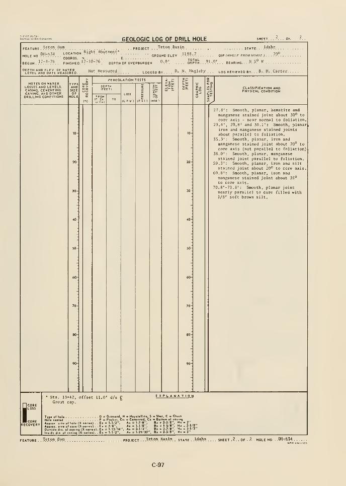
GEOLOGIC LOG OF DRILL HOLE
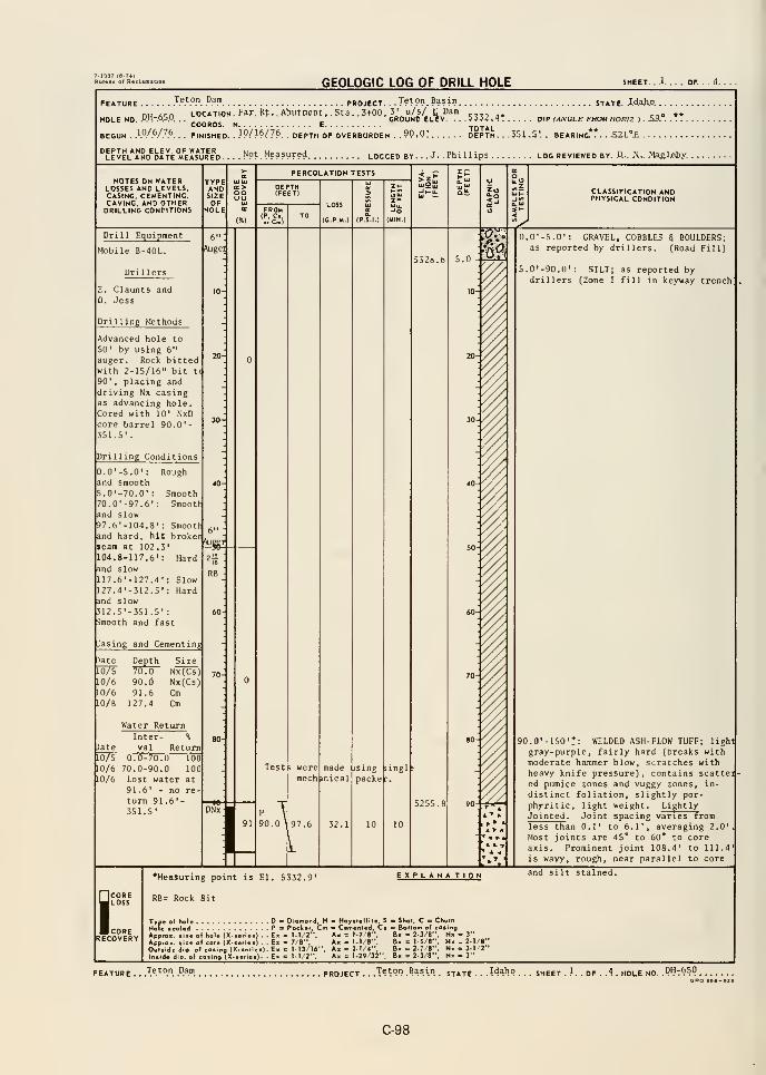
GEOLOGIC LOG OF DRILL HOLE SHEET. . .1 OF.
FEATURE .T.^V™. .".3!" PROJECT. . . 1??°?. Basin STATE. .W.aho.. .
nu ten LOCATION. F?r.Bt,. AbuttlCTt..St3. .3t00, 3' u/s/ £ Dam .,,,.,HOLE NO. .D.".-.o5.0.
. .
' GROUND ELEV. ...5332. 4* DIP M/VGLE FROM BOWZ ). A9..COORDS. N E
BEGUN . }9/P/?P. . . FINISHED. . .IP/J*/?*. . DEPTH OF OVERBURDEN .90,0! DEPTH... 351. 5'.. BEARING**. . .S2L°£ .
.J. .Phillips LOG REVIEWED BY. R-. H... jMagJjsb.y.
NOTES ON WATERLOSSES AND LEVELS,CASING, CEMENTING,CAVING, AND OTHERDRILLING CONDITIONS
TYPEANDSIZEOF
HOLE
OOOL>
PERCOLATION TESTS
LOSS
(G P.M )
CLASSIFICATION ANDPHYSICAL CONDITION
Drill Equipment
Mobile B-40L.
Drillers
6"
Augq
E. Claunts andD. Jess
Drilling Methods
Advanced hole to50' by using 6"
auger. Rock bittedwith 2-1S/16" bit ti
90', placing and
driving Nx casingas advancing hole.Cored with 10' NxDcore barrel 90.0'-351.5'
.
Drilling Conditions
Rough
Smooth: Smooth
Smooth
0.0'-5.0':
and smooth5.0'-70.0' :
70.0'-97.6'
and slow97.6'-104.8and hard, hit brokerseam at 102.3104.8-117.6':
nd slow117.6'-127.4'127.4'-312.5'and slow312.5'-351.5' :
Smooth and fast
basing and Cementing
6"
Hard
SlowHard
Water Return
Inter- %
)ate val ReturnLOTs 0.0-70.0 100
10/6 70.0-90.0 100
10/6 Lost water at91.6' - no re
turn 91.6'-351.5'
0.0'-5.0': GRAVEL, COBBLES S BOULDERS;as reported by drillers. (Road Fill)
S.0'-90,0': SILT; as reported bydrillers [Zone I fill in keyway trench
Testp weremech mlcal
made ising
packe -.
ingl
"I .ol
i.
90.0'-150't: WELDED ASH-FLOW TUFF; light
gray-purple, fairly hard (breaks withmoderate hammer blow, scratches withheavy knife pressure), contains scatteied pumice zones and vuggy zones, in-
distinct foliation, slightly por-
phyritic, light weight . Light lyJointed . Joint spacing varies fromless than 0.1' to 6.1', averaging 2.0'
Most joints are 45* to 60* to coreaxis . Prominent joint 108.4' to 111.4
is wavy, rough, near parallel to core
SCORELOSS
CORERECOVERY
•Measuring point is El. 5332.9'
RB= Rock Bit
Type of hol« D - Diofnond, HHole isaUd P - Poek.r. CmApprox. tits of hole (X-ierioc) . . Ex ^ M/2".ApprOK. liio of cora (X-aoriei) . . Ex ^ 7/8",OuOide dio. of cosing (X-««rie«) . Ex = )-I3/16",ln«id«t dio. of cosing (X-i«ri«.). - Em e M/2".
EXPLANA TION
m Hoyslollil*, S o Shot. C *> Churn— C«men(od, Cs Bottom of cosingAx = 1-7/8", Bx = 2-3/8", N« - 3"
Ax = 1-1/8", Bx= 1-5/8", Nx- 2-1/8"Ax = 2-1/4", B«>=2-7/«", Nx- 3-1/2"
Ax = 129/32", B» - 2-3/8", N» - 3
"
and silt stained.
FEATURE . . .T«^.9". P.^P. PROJECT. ..Teton Basin
. st^je ...Idaho. .. s„eet .
I.. of . .4. hole no. .P^^t^SO
C-98
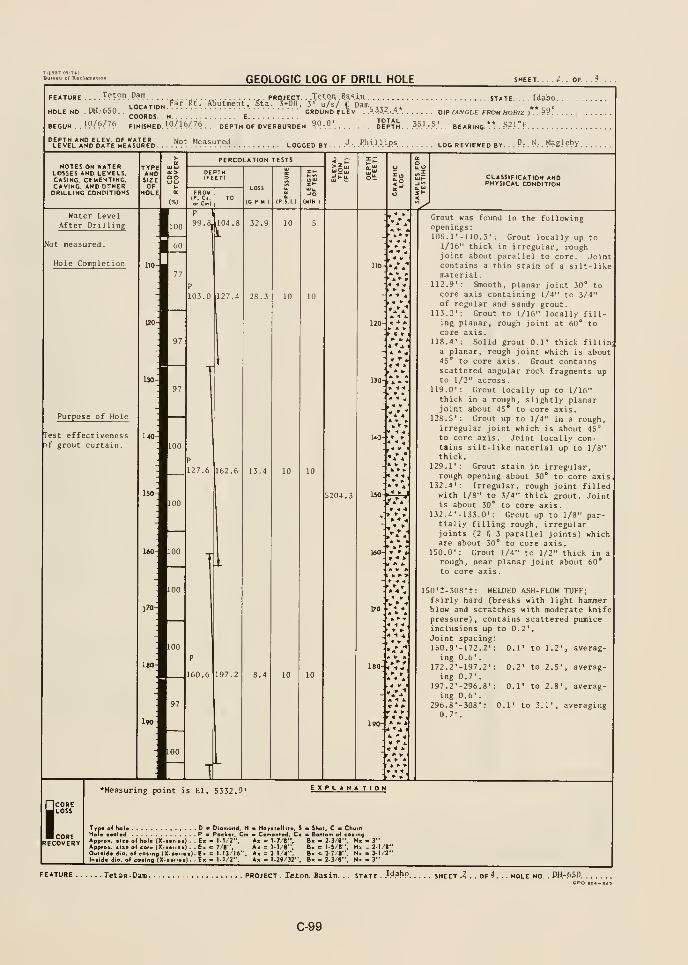
-'•""«•'-'•'" GEOLOGIC LOG OF DRILL HOLE sheet 2 of 4
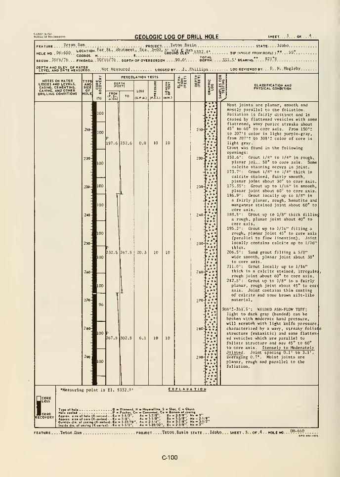
-1337 («-74)
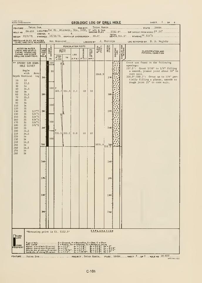
T-18ST (B-74)Burwku ot RacluDftUon
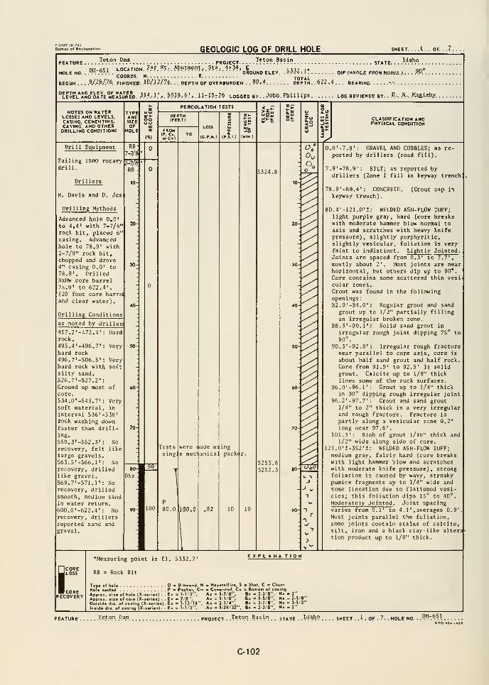
GEOLOGIC LOG OF DRILL HOLE .A.. OF. ..7.
Teton BasinFEATURE .... .'^.^.^.°". .°.^. PROJECT. . .
nH f.c:^ LOCATION ^^^ ^^ • Abutment, Sta. 4+34, £ p. .
HOLE NO. . .R^.-^.^A .
'-°"T'*"* '
GROUND ELEV. ,
5332. 1*
COORDS. N E TOTALBEGUN . . .
.9/28/76. FINISHED. .iP/.l?/76. . . DEPTH OF OVERBURDEN . .80,4 DEPTH. .^22.4 . . . BEARING.
STATE. . . ...... . ,
DIP (ANGLE FROM HORIZ.) . . . .^A ,
NOTES ON WATERLOSSES AND LEVELS.CASING, CEMENTING,CAVING, AND OTHERDRILLING CONDITIONS
TYPEANDSIZEOF
HOLE
oo
PERCOLATION TESTS
FROM(P, C,or Cm)
LOSS
(C.P.M.)
CLASSIFICATION ANDPHYSICAL CONDITION
Drill Equipment
Failing 1500 rotarydrill.
RB
7-7/8
2-^RB
H. Davis and D. Jes
Drilling Methods
Advanced hole 0,0'
to 4,4' with 7-7/8"roqk bit, placed 6"
casing. Advancedhole to 78.9' with2-7/8" rock bit,chopped and drove4" casing 0,0* to78.9'. DrilledNxHw core barrel78.9' to 622.4'.(20 foot core barrdand clear water)
.
Drilling Conditions
as noted by drillen
-472.4': Hard
Very
Verysoft
457.2rock,495.4'-496.7':hard rock
496,7'-506.S'
:
hard rock withsilty sand,526.7'-527.2':Ground up most ofcore,534.0'-543,7': Verysoft material, in
interval 536'-538'rock washing downfaster than drill-ing.
550.3'-552,3': Norecovery, felt likelarge gravels,563.5'-566.1' : Norecovery, drilledlike gravel,569.7'-571.1': Norecovery, dril led
smooth, medium sandin water return,600.0'-622,4': No
recovery, dril lersreported sand andgravel.
Testssing:
were nade u;
e mecl anica]
ing
packer.
5253.85252.3
P
80.0 ilGG.G ,02
0.0'-7.9': GRAVEL AND COBBLES; as re-ported by drillers (road fill).
7.9'-78.9': SILT; as reported bydrillers (Zone I fill in keyway trench
78.9'-80.4' : CONCRETE,keyway trench)
.
(Grout cap in
80.4'-121.0'i: WELDED ASH-FLOW TUFF;light purple gray, hard (core breakswith moderate hammer blow normal toaxis and scratches with heavy knifepressure), slightly porphyritic,slightly vesicular, foliation is veryfaint to indistinct. Lightly Jointed .
Joints are spaced from 0.3' to 7.7',
mostly about 2'. Most joints are nearhorizontal, but others dip up to 90*.
Core contains some scattered thin vesicular zones.Grout was found in the followingopenings
:
82.9'-84.0': Regular grout and sandgrout up to 1/2" partially fillingan irregular broken zone.
88.3'-90.1': Solid sand grout in
irregular rough joint dipping 75° to80°.
90.3'-92.8' : Irregular rough fracturenear parallel to core axis, core is
about half sand grout and half rock.
Core from 91.9' to 92.5' is solidgrout. Calcite up to 1/8" thicklines some of the rock surfaces.
96.0'-96.r: Grout up to 1/4" thickin 30° dipping rough irregular joint,
96.2'-97.7': Grout and sand grout1/4" to 2" thick in a very irregularand rough fracture. Fracture is
partly along a vesicular zone 0.2'
long near 97 .6'
.
101.3': Blob of grout 1/16" thick and1/2" wide along side of core.
121.0'J-352'+: WELDED ASH-FLOW TUFF;medium gray, fairly hard (core breakswith light hammer blow and scratcheswith moderate knife pressure), strongfoliation is caused by wavy, streakypumice fragments up to 1/4" wide andsome lineation due to flattened vesi-cles; this foliation dips 15° to 40°.
Moderately Jointed . Joint spacingvaries from 0.1' to 4 .
1', averages 0.9'.
Most joints parallel the foliation,some joints contain stains of calcitesilt, iron and a black clay-like altera-tion product up to 1/8" thick.
ICOREJ LOSS
corerecovery
*Measuring point is El. 5332.7'
RB = Rock Bit
EXPLAN* TION
Typ.Ho I. ,
Appro
if hoi. D ' Diomond, H * Hoyst.lliie. S . Shot. C e C
Ml.d Pa Packer, Cm CeirrentwJ, C. = Bollom o( c
E< = M /2", A. = 1-7/8", B. = 2.3/8"
Ex = 7/8". A. = 1-1/8", 8« = 1-S/l",
Em = 1-13/16", A. =2-1/4", B. = 2-7/1"
E> = 1-1 2". A, = 1-29/32". B. . 2-3/8"
olhol. (X-iolcor. (X-i.r^.of co.ing (X-sei
io..oa(X-..,[,
.1)..2-1/8". 3-1/2". 3"
FEATURE Teton Dam project .Tetqn Basin stjt DH-651
C-102

GEOLOGIC LOG OF DRILL HOLE
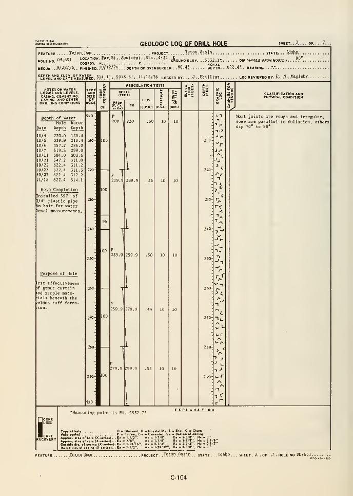
7-1837 (6-74)Bureau of R*ol
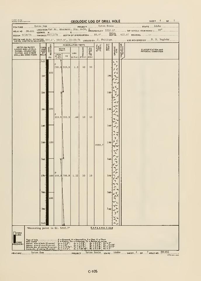
7.Ifl9T (6-74)
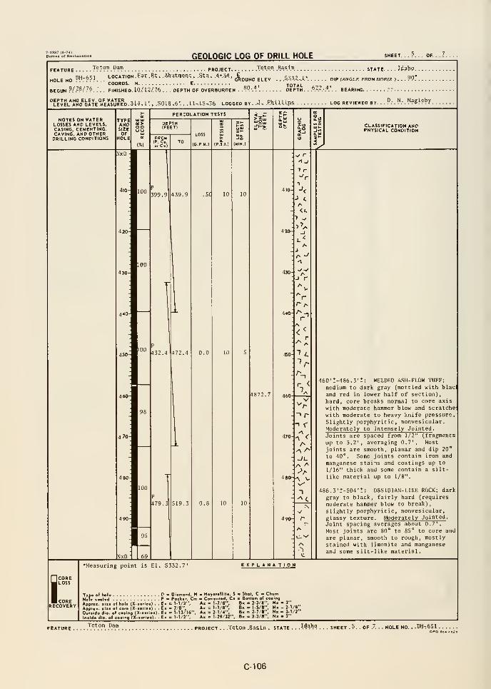
GEOLOGIC LOG OF DRILL HOLE SHEET. ..?... OF.
FEATURE ^???^.9^'? PROJECT T^.ton .Basin. _ .
HOLE NO DH-eSl'.
.LOCATION, f«T. Bt. .AbUt^QHt. .Sta . .4*34. ^^^^^ ^^^^ 555^ ^.COORDS. N
BEGUN P/??/??. .. . FINI5HED.10/U/76 .
'Sn 4' TOTAL
. DEPTH OF OVERBURDEN . ."V'.^ DEPTH.
.5018.6'. . .11-.1.S,7.6 LOGGED BY. .J- .RhiJ-Ups .
STATE. . . . W?h9
DIP (ANGLE FROM HORIZ ) . . . ?P
.6.2.2.-.<,'.. BEARING r-
LOG REVIEWED BY. ..°:. <^ : .
"^gleby
NOTES ON WATERLOSSES AND LEVELS.CASING. CEMENTING,CAVING, AND OTHERDRILLING CONDITIONS
TYPEANDSIZEOF
HOLE
PERCOLATION TESTS
LOSS
(G.P M.)
Jo(MIN )
EF
CLASSIFICATION ANDPHYSICAL CONDITION
440-
450-
470
P
399.9 .5C
P
432.4
4872.7
P
479.3
NxDIn
T r
^<L
1
AJ r
r
/^ _
/%
r <7
- -> r
^470-
-^ <-
' A
->A
480-J^ V
: T
4 90
: 1-^
460't-486.3'?: WELDED ASH-FLOW TUFF;
medium to dark gray (mottled with blacl
and red in lower half of section),hard, core breaks normal to core axis
with moderate hammer blow and scratchewith moderate to heavy knife pressure.
Slightly porphyritic, nonvesicular.
Moderately to Intensely Jointed .
Joints are spaced from 1/2" (fragments
up to 3.2', averaging 0.7', Most
joints are smooth, planar and dip 20**
to 40°. Some joints contain iron and
manganese stains and coatings up to
1/16" thick and some contain a silt-
like material up to 1/8".
486.3't-504'!: OBSIDIAN-LIKE ROCK; dark
gray to black, fairly hard (requires
moderate hammer blow to break!
,
slightly porphyritic, nonvesicular,
glassy texture. Moderately Jointed .
Joint spacing averages about 0.7*.
Most joints are 80" to 85" to core and
are planar, smooth to rough, mostlystained with limonite and manganeseand some silt-like material.
ICOREJ LOSS
BcORERECOVERY
•Measuring point is El. 5332.7' EXPLANA TION
TyM <
oledApproK. ilse of hol« (X-i«rla*) . . EaApprOH. tlia of cor« (X-a«rJ«t) . . EkOulilde dlo. of coilng (X-ierias). Exln«ld« dig, ot coiing {X-»Brta») . . E«
Diamond, H - Hoyitollilo, S " Shot, C - ChurnPockor, Cm Comonlod, Ci > Bottom of coiing= 1.1/2", A, = 1-7/8". B. . 2-3/6", N« - 3"= 7/8", A. = 1-1/8". B. • 1-5/8", H. - 2-1/8"= 1-13/16". A, = 2-1/4", B. = 2-7/8", N. . 3-1/2"
= 11/2", Ax = 1-29/32". B. = 2-3/8". N. . 3"
FEATURE . , . ,
.^^.^°.". °!^. PROJECT . .Teton .Basin . state . . .H^h"? . . - sheet . 5. . of .7. . . hole no. - .DH-651 -
GPO •04-020
C-106
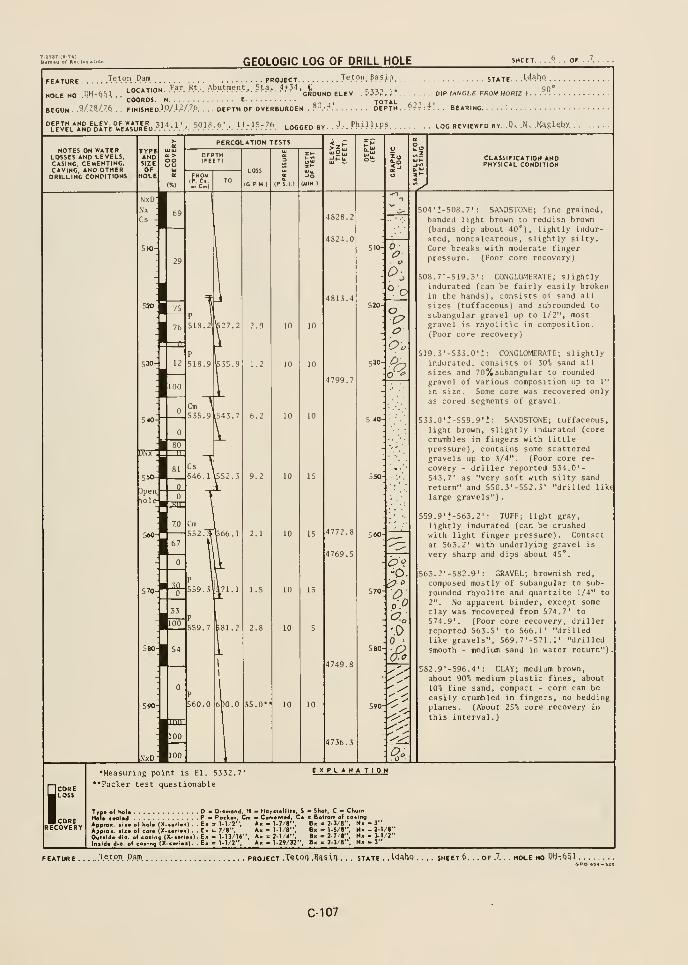
GEOLOGIC LOG OF DRILL HOLE SHEET, ...... OF.
FEATURE TetO". P.^!". PROJECT JftpP. Basin STATE. ..Idaho
. . .
I nrATinN Far Rt . Abutment. Sta. 4+54, £ tttt i* 90"HOLE NO Pl)-fl51.
'-">-«"'"' GROUND EUEV, .S33J.) OW (ANGLE FROM HOKIZ >...... .
COORDS. N E^ TOTAL , i . ,
BEGUN . .V.-A/JA . . FINISHED.l.<'y'.1.2/.7.6 DEPTH OF OVERBURDEN .?°:^ DEPTH- -P-r-.-*. . . BEARING. .--
''LEVEL*lND^blTE°M''EMURED.51.''.-.'.'.'. ^?^^-P!.'. .'.'.-.1 5" 76. LOCOED BY . .
J.-. Ph.l.l.l.'P? LOG REVIEWED BY. .Q..N- .MaglShX .
NOTES ON WATERLOSSES AND LEVELS,CASING. CEMENTING,CAVING. AND OTHERDRILLING CONDITIONS
CLASSIFICATION ANDPHYSICAL CONDITION
oo
530
O
o
550
'O.
?P
-
Wo
^.
504'!-508.7' : SANDSTONE; fine grained,banded light brown to reddish brown(bands dip about 40*), lightly indur-ated, noncalcareous , slightly silty.Core breaks with moderate fingerpressure. (Poor core recovery)
508.7'-519.3' : CONGLOMERATE; slightlyindurated (can be fairly easily brokenin the hands), consists of sand all
sizes (tuffaceous) and subrounded to
subangular gravel up to 1/2", mostgravel is rhyolitic in composition.(Poor core recovery)
519.3'-533.0't: CONGLOMERATE; slightlyindurated, consists of 50^ sand all
sizes and 70%subangular to roundedgravel of various composition up to 1"
in size. Some core was recovered onlyas cored segments of gravel.
553.0'!-559.9'*: SANDSTONE; tuffaceous
,
light brown, slightly indurated (core
crumbles in fingers with littlepressure), contains some scatteredgravels up to 3/4". (Poor core re-
covery - driller reported 534.0'-543.7' as "very soft with silty sand
return" and S50. 3' -552. 3' "drilled like
large gravels") .
559.9'!-563.2' : TUFF; light gray,
lightly indurated (can be crushedwith light finger pressure). Contactat 563.2' with underlying gravel is
very sharp and dips about 45°.
565.2'-S82.9' : GRAVEL; brownish red,
composed mostly of subangular to sub-
rounded rhyolite and quartzite 1/4" to2". No apparent binder, except someclay was recovered from 574.7' to574.9'. (Poor core recovery, drillerreported 563.5' to 566.1' "drilledlike gravels", 569.7'-S71.r "drilledsmooth - medium sand in water return")
582.9'-596.4' : CLAY; medium brown,
about 90^0 medium plastic fines, about
\d% fine sand, compact - core can be
easily crumbled in fingers, no beddingplanes. (About 25% core recovery in
this interval.
)
iCORELOSS
CORERECOVER!
•Measuring point is El. 5332.7'
"Packer test questionable
EXPLANA TION
Typ* of hoU D B Diamond, H - Hoyttellite, S - Shot, C b C
HoU *«al*<l P ' Pack«r, Cm CvmenlMJ. Ci > Bottom ol c
Appro.. *ii« of hoi* (X-«ofi«i) . . Ex = 1-1/2", A« = I-7/B", B« - 2-3/8",
Appro-, aixo of coro (X.»«ri.i) . . Ek « 7/8-, A« = 1-1/8", B« - 1-5/8",
Oulildo dio. of casing (X-iori..). Ex = 1.13/I6". Ax = 2-1/4", B> = 2-7/e",
Iniido dio. of co»ing (X-«ofi»«). - Ex = 1-1/2", Ax = 1-29/32". B. = 2-3/8"
Nx -3"Nx -2-1/8"Nx - 3-1/2"
FEATURE .Xe.tO.n Dam PROJECT .T^;Q0 M^X^ . . . STATE . .I44hq SHEETS. . . OF .7. . . HOLE NO, 04-^5 I .
C-107
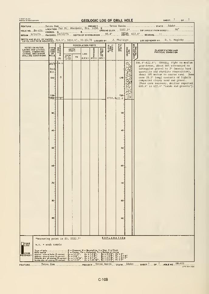
GEOLOGIC LOG OF DRIlL HOLE SHEET. .,'.... OF.
FEATURE .Teton. Dam^. ..._...._. ^. PROJECT. . ^ TetOD.Basio STATE. . ..I.da.h.0.
HOLE NO. . JBH-J^SJLOCATION. F?r.?t.-.Ab^'?i!i?n?i.???:.'?t5'?. C c,„ ,.uui.»iiv/r.
GROUND ELEV. ..?-?J4-.^
.
COORDS, t. .. . EDIP {ANGLE FROM HORIZ ) .
BEGUN . ?/W7P. . . FINISHED. .'P/.^?/7?. . . DEPTH OF OVERBURDEN . . . ?9 :
^' DEPTH. .^^.^.'A'. . . BEAR
LEVEL AND DAT
NOTES ON WATERLOSSES AND LEVELS,CASING, CEMENTING,CAVING, AND OTHERDRILLING CONDITIONS
TYPEANDSIZEOF
HOLE
PERCOLATION TESTS
LOSS
(CPU )
CLASSIFICATION ANDPHYSICAL CONDITION
^J.5/8
Roc
Bit
610
620-
31622.4
596.4'-522.4' : GRAVEL; light to mediumgray-brown, about 90^ subrounded to
subangular gravel to 2" (mostly hardquartzite and rhyolite composition),about 10^ medium to coarse sand. Somecore (0.3' long) consists of lightlycompacted clayey sand and gravel.
(Poor core recovery, driller reported600.4' to 622.4' "sands and gravels").
iCORELOSS
CORERECOVERY
•Measuring point is El. S332.7' explanation
w.s. = wash sample
Typ* of hoU D • Diomond, H - Hay«t«llil«, S - 5h«I, C - CHurnHoi* t*al«d P Pockvr, Cm * C*(Ttenl«d, C» Bollom of coaing
App,o«. .n.olhoU (X....I.1). .E. « 1.I/2", A, = 1.7/8". B« . 2-3/8", N. - 3"
App.o.. ,1,. oltor. (X...ri.i). .E. = 7/8", A. = 1.1/8", B. =1.5/8", H« -2.1/8'
Oul.ld.dio. ofcoiino (X....i. .I.E. = 1.13/16". A, .2-1/4", B. - 2.7/»"
lo.ld. dio. o( ca.lrn (X...cl..l. . E. = 11/2". A. = 1-29/32". B. - 2-3/8'N. - 3-1/2"N> -3"
Teton Dam PROJECT . .T???"} .??sin state . .
!daho sheet .'
DH-651oPo .B.-sia
C-108
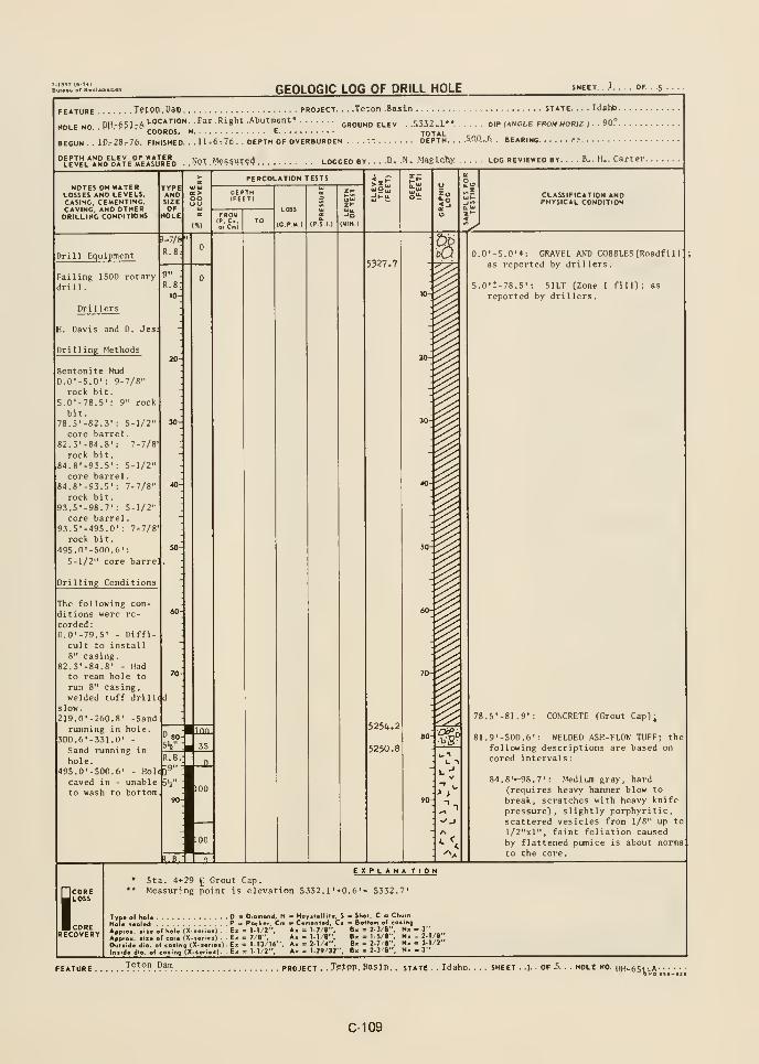
GEOLOGIC LOG OF DRILL HOLE SHEET. . .1. , . . OF. . 5 ... .
FEATURE Tftop. Dam PROJECT. . . .Teton .Basin state. ..
. Idaho
MniF-o nH-651-A'-°"^'°'' f" "'S'''*''"'"^"'-* GROUND ELEV. ..5332.1**. OIKANOLE FROM HORIZ ).. 90?HOLE NO.K.
. . . * . . joo^oj ^ E TOTALBEGUN . . iD.-28r76. FINISHED. . .Ut6,76. . DEPTH OF OVERBURDEN ....-•: DEPTH. .5.0.0...6. BEARING -.-
''LEVEL*lND^blTE°»rElsJR"D. . Npt M?a5UT?d LOGGED BY. , . ,D. .N. .Maglehy. LOG REVIEWED BY. . . . B-. H.. Carter.
NOTES ON WATERLOSSES AND LEVELS.CASING. CEMENTING.CAVING. AND OTHERDRILLING CONflTIONS
TYPEANDSIZEOF
HOLE
oouu
PERCOLATION TESTS
FROMIP. c.o. C»)
LOSS
(C P M )
-SSCLASSIFICATION ANDPHYSICAL CONDITION
Drill Equipment
)-7/a
R.B-
Failing 1500 rotarydrill.
Drillers
H. Davis and D. Jes:
Drilling Methods
Bentonite Mud0.0'-5.0': 9-7/8"
rock bit.5.0'-78.5' :
9" rock
bit.78.5'-82.3': 5-1/2"
core barrel
.
82.3'-84.8': 7-7/8'
rock bit.84.8'-93.5': 5-1/2"
core barrel
.
84.8'-93.5': 7-7/8"
rock bit.93.5'-98.7' : 5-1/2"
core barrel
.
93.5'-495.0' : 7-7/8
rock bit.
495.n'-500.6'
:
5-1/2" core barre]
Drilling Conditions
The following con-
ditions were re-
corded :
0.0'-79.5' - Diffi
cult to install8" casing.
82.3'-84.8' - Hadto ream hole to
run 8" casing,welded tuff drilled
slow.219.0'-260.8' -Sand
running in hole.300.6'-331.0' -
Sand running in
hole.495.0'-500.6' - Hol^J
caved in - unableto wash to bottom
R.B9"
«B.1 I n
5327.7
5254.2
5250.8
I
I-
I1
8
> >
0.0'-5.0'*: GRAVEL AND COBBLES (Roadfill
as reported by drillers.
5.0't-78.5': SILT (Zone I fill); as
reported by drillers.
78.S'-81.9': CONCRETE (Rrout Capl
;
81.9'-500.6' : WELDED ASH-FLOW TUFF; thefollowing descriptions are based oncored intervals
:
84.8'«-98.7' : Medium gray, hard{requires heavy hammer blow to
break, scratches with heavy knifepressure), slightly porphyritic,scattered vesicles from 1/8" up to
l/2"xl", faint foliation caused
by flattened pumice is about normato the core.
ICOREJloss
jcorerecovery
EXPLANATION* Sta. 4*29 5 Grout Cap.
** Measuring point is elevation 5332 .
1' +0.6 '= 5332.7'
Typ. ol hol. « Diomond. H - Hoysi.llit., S « Shot, C " Chutn
Hole seoled P = Pock.r. Cm • C.m.nted, Ci = Bollom ol casing
Appro.. .,.. ol hoi. (X-...i..). E. = 1-I/2--, A, = 1.7/8", B. = 2.3/«", N. - 3"
A„,o.. .... of CO,. (X-..,,..) . - E, = 7/8". Ax = 1.1/8", B. = l-S/J , N. - 2- /8
Ooi.id. dio. olco.ino(X...ri..).E. = I-13/16", A. = 2.1/4", B. . 2-7 8", N. . 3-1/2"
loiid. dio. ol co.lna |X...ri.i). - E. = 1-1/2", A. = 1-29/32", B. = 2-3/8" .3"
EATURE TfT?".?™ PROJECT . . Tefpn, Basin. . STATE ..Idaho. SHEET . 1 . OF 5. HOLE NO. DH-65VpA-.
C-109
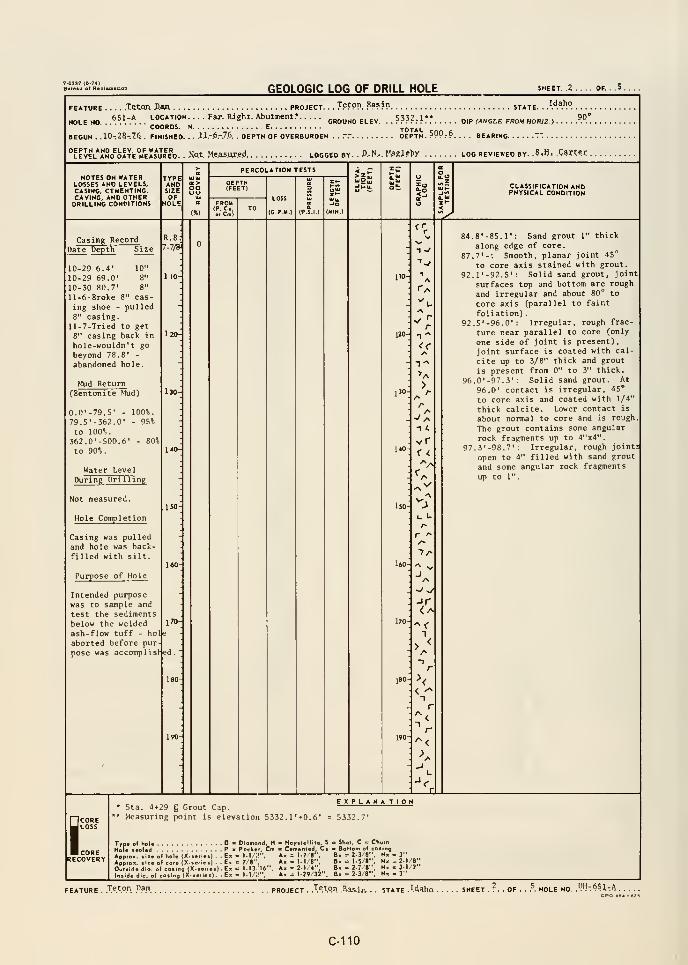
GEOLOGIC LOG OF DRILL HOLE
FEATURE
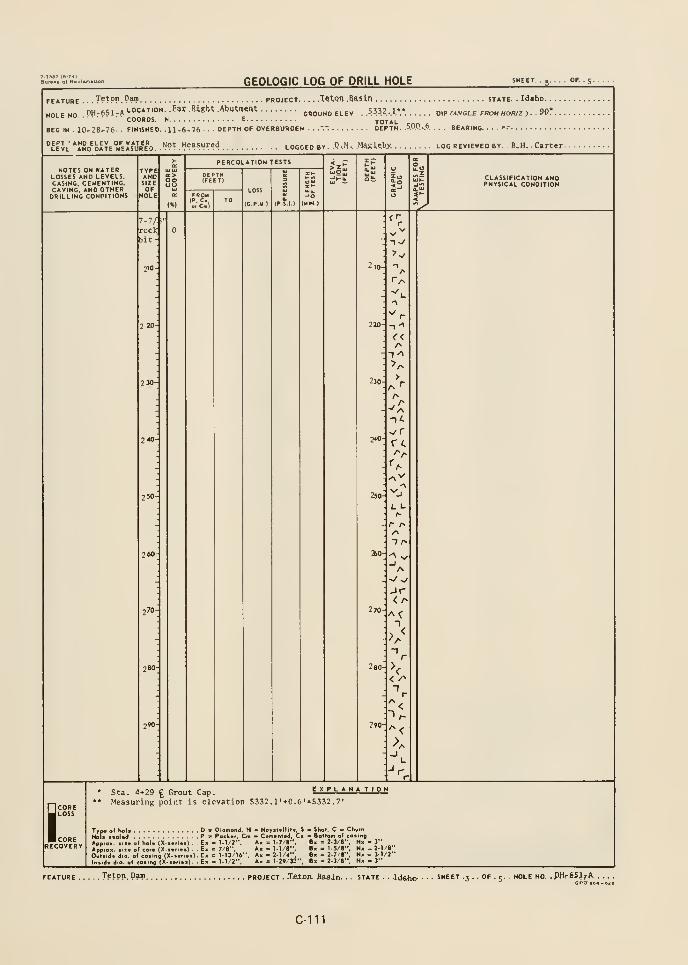
GEOLOGIC LOG OF DRILL HOLE
FEATURE
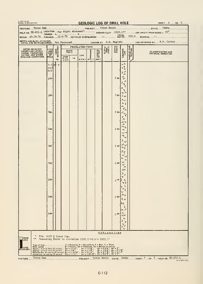
GEOLOGIC LOG OF DRILL HOLE SHEET. . .4. . . . OF. . 5.
FEATURE . .-Te.t.o.n. .D.am project T???" .
???in state. . . }A?^°.
DH-6S1-A LOCATION. . paj.. Right. Abutment?.COORDS. N E.
GROUND ELEV. .533?il" DIP (ANGLE FKOM HOFUZlTOTAL
90°HOLE NO.
BEGUN ..1.0.-.2.8-76 FINISHED. . .
.Ijr^r7*. . DEPTH OF OVERBURDEN . . . rr DEPTH. ..^O?'.^ BEARING.
''LEVEL*J!ND^DATE°M'kIs*URED. . NOt. MeajUred LOGGED BY. . P,N, .MsglrtV LOG REVIEWED BY. . .
.B.-.H-. .Carter
NOTES ON WATERLOSSES AND LEVELS,CASING. CEMENTING,CAVING, AND OTHERDRILLING CONDITIONS
TYPEANDSIZEOF
HOLE
oo
PERCOLATION TESTS
;c»i
LOSS
(G P.M.)
CLASSIFICATION ANDPHYSICAL CONDITION
7-7) 8
roci
bit
310
320-
330
3«>-
360
370
3 10-
3 20
<
1-> ^7 v
_l L
1
•>
3 80-
SCORELOSS
CORERECOVERY
EXPLANATIONSta. 4+29 C Grout Cap.Measuring point is elevation 5332.1'+0.6'
Inirde dia. ol
of ho
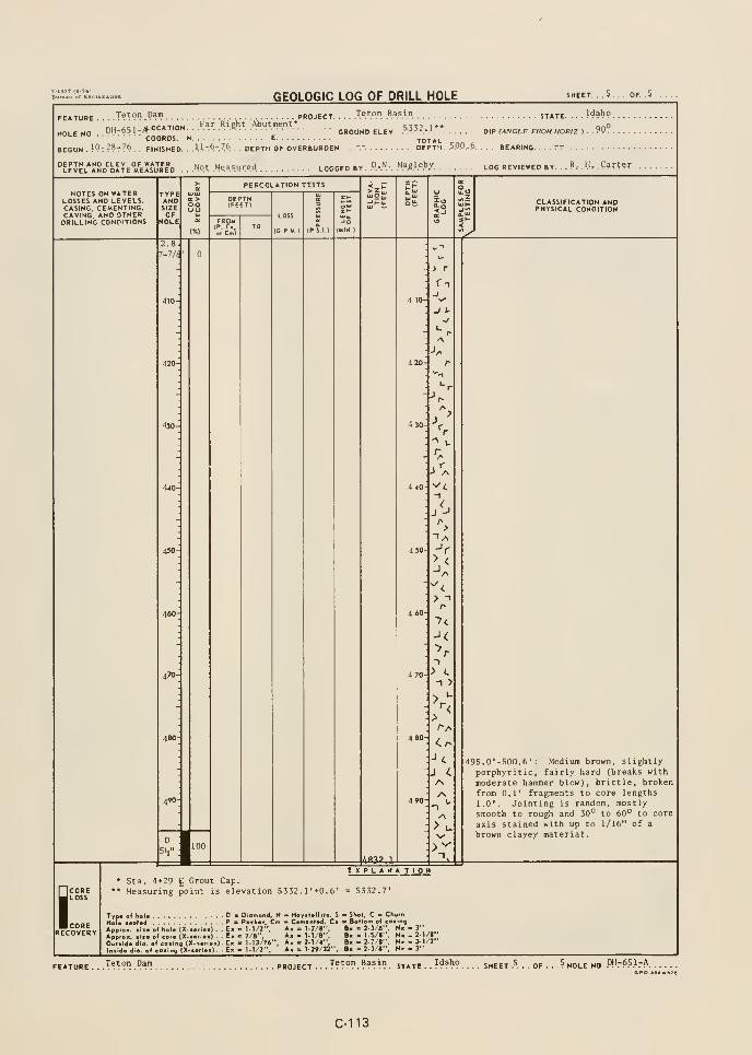
7-lM7<e.74)Buraku of RscluDfttlon
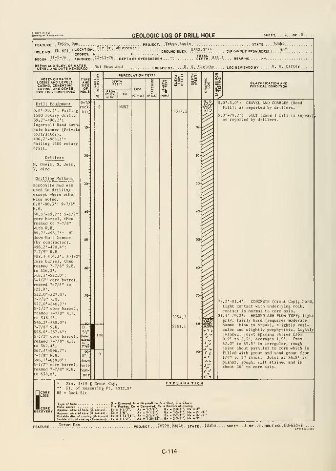
GEOLOGIC LOG OF DRILL HOLE .1.. OF. .9.
FEATURE
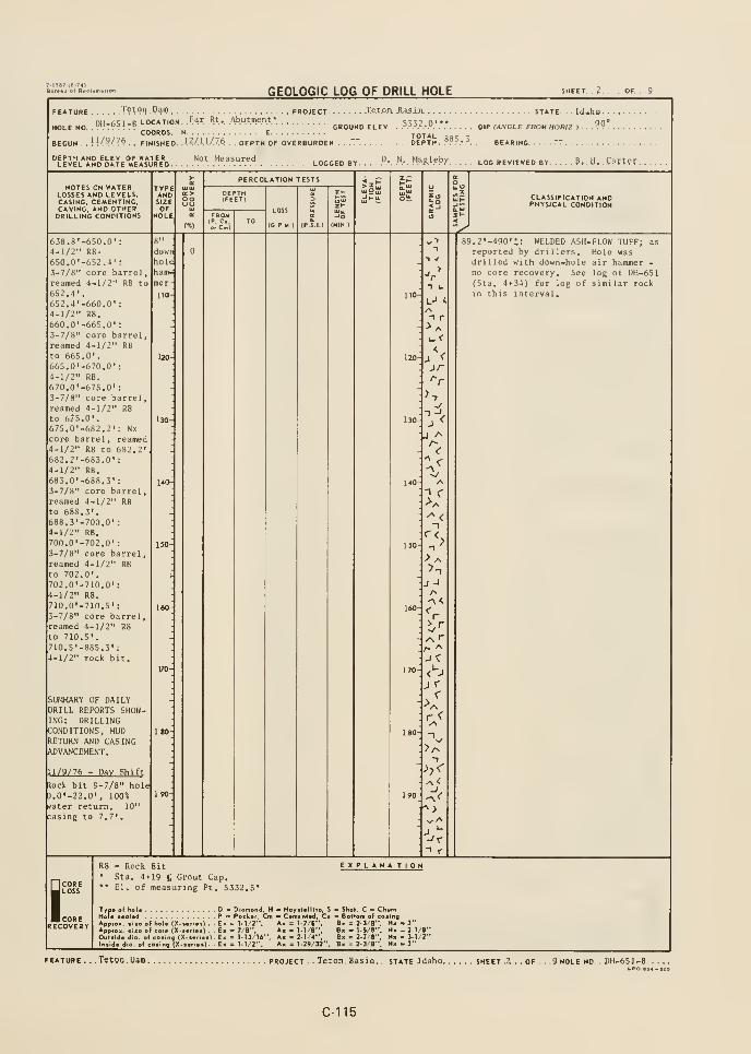
7-n37 16-74)Buratu or Racl
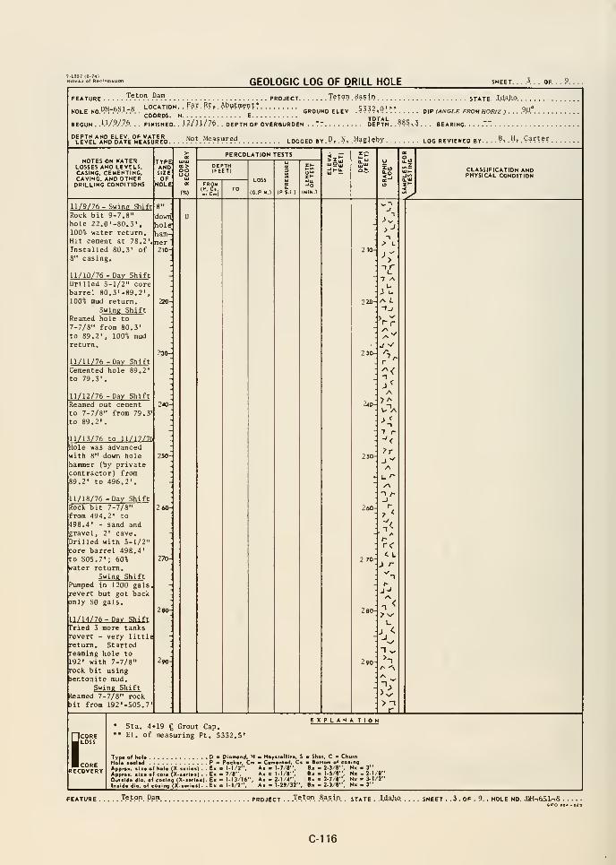
7-1337 (6-74)Bureau of RbC
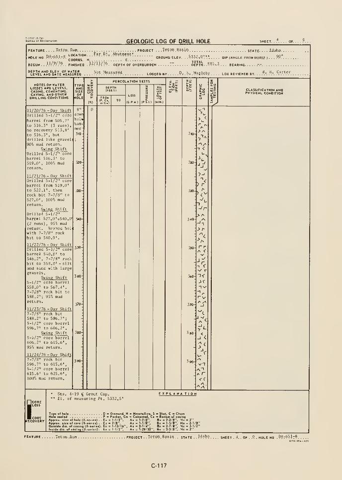
Burvftu of R»c
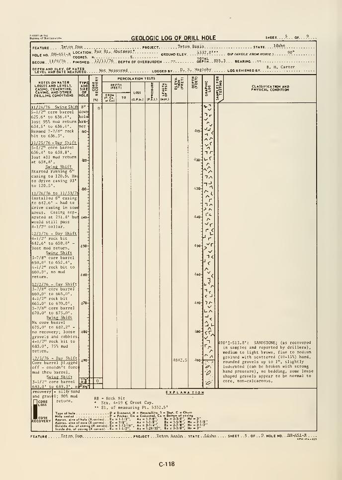
-1337 (6-74)Bureau or Rflclunatlon
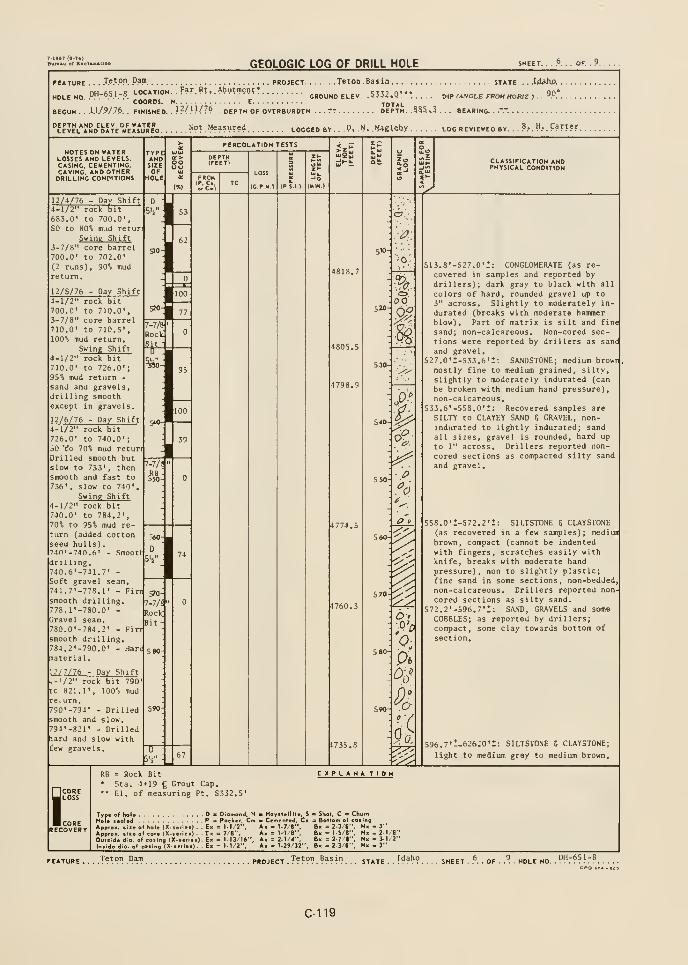
GEOLOGIC LOG OF DRILL HOLE SHEET. . . P. . . OF.
.
.Te.t.o.n. .Dapi project Tetoo. Basin state. . . .I44hp.
DH-651-B LOCATION. . F?r. W. .Abutmen;*
.
HOLE HO ."".".".-'.'.".". GROUND ELEV. .5?5?,Q'.V. DtKANOLE FROM HORIZ ) .
COORDS. H E TOTALBEGUN . . .U/.9/.7.6. . FINISHED. . \^(\U.l'^ . . DEPTH OF OVERBURDEN . . . TT DEPTH. .335.3 . . . BEARING. .
.""
90°
"ElEL*JSD'k"E ««ur"o Not. Measured logged by. . ,P. .N. .HagUbx log reviewed by. . .
B... H... Carter.
NOTES ON WATERLOSSES AND LEVELS,CASING, CEMENTING,CAVING, AND OTHERDRILLING CONDITIONS
CLASSIFICATION ANDPHYSICAL CONDITION
12/4/76 - Day Shift4-1/2" rock bit683.0' to 700.0SO to iO% mud returi
Swing Shift3-7/8" core barrel700.0' to 702.0'
(2 runs), 90% mudreturn.
12/5/76 - Day Shift4-1/2" rock bit700.0' to 710.0',3-7/8" core barrel710.0' to 710.5',100% mud return.
Swing Shift4-1/2" rock bit710.0' to 726.0';95% mud return -
sand and gravels,drilling smoothexcept in gravels.
12/6/76 - Day Sh i ft
4-1/2" rock bit726.0' to 740.0
50 *t'o 70% mud returi
Drilled smooth butslow to 733' , thensmooth and fast to
736', slow to 740'
Swine Shift4-1/2" rock bit740.0' to 784.2',70% to 95% mud re-
turn (added cottonseed hulls)
.
740' -740. 6' - .Smooth
dm 1 ing.740.6'-741.7' -
Soft gravel seam.741.7'-778.1' - Fiosmooth drilling.778.1'-780.0' -
Gravel seam.780.0'-784.2' - Firn
smooth drilling784.2'-790.0' - Hare
material
12/ 7/76 - Day Shift/2" rock bit 790
tc 821.1' , 100% mudre I urn.790'-794' - Drilledsmooth and slow.794'-821' - Drilledfiard and slow withfew gravels.
4805.5
4774.5
4760.3
:.^:
510-
0.
520.mu
h
<*
P V
5 70
513.8'-527.0'!: CONGLOMERATE (as re-covered in samples and reported bydrillers); dark gray to black with all
colors of hard, rounded gravel up to3" across. Slightly to moderately in-
durated (breaks with moderate hammerblow). Part of matrix is silt and fine
sand; non-calcareous. Non-cored sec-
tions were reported by drillers as sane
and gravel.527.0'i-533.6'l: SA;JDST0NE; medium browr
mostly fine to medium grained, silty,
slightly to moderately indurated (can
be broken with medium hand pressure),non-calcareous.
533,6'-558,0' t: Recovered samples are
SILTY to CLAYEY SAND 5 GRAVEL, non-indurated to lightly indurated; sandall sizes, gravel is rounded, hard up
to 1" across. Drillers reported non-
cored sections as compacted silty sand
and gravel.
558.0'i-572.2'l: SILTSTONE 6 CLAYSTONE(as recovered in a few samples) ; mediun
brown, compact (cannot be indented
with fingers, scratches easily withknife, breaks with moderate handpressure), non to slightly plastic;fine sand in some sections, non-bedded,non-calcareous, Dril lers reported non-
cored sections as silty sand.572.2'-596,7'!: SAND, GRAVELS and some
COBBLES; as reported by drillers;compact, some clay towards bottom of
section.
596.7't-626;0'i: SILTSTONE 5 CLAYSTONE;
light to medium gray to medium brown.
SCORELOSS
CORERECOVERY
RB = Rock Bit EXPLANA TION• Sta. 4+19 g Grout Cap,•* El, of measuring Pt. 5532, S'
Type of hole D Diamond, H - Hoyslellite, S = Shot, C o ChurnHole lealed P = Pack«r. Cm - Cemented, Ci a Bottom of eating
Appro-. »i«e o( hol« (X-seriet) . - E- = 1-1 /2", A« = 1.7'8", B« = 3-3/e", N» - J"Appfox. size of core (X-.eneO . - E. = 7'8", A« = M/fl-', B« = 1-5/8", H» - 2-1/8"
Out.ide dio. of coiing <X-.«rie.) - E» = 1-13 U'", Ax = 2.1/4", 8» = 2-7 8'*, N» = J-I/2"In.ide dia. of cosing (X-terie.)- Ex = 11/2", Ax = 1-29/32". B. = 2-3/8". N« - 3"
Teton Dam PROJECT.T?!^??.Basin___ state. SHEET . y. . OF .
C-119

GEOLOGIC LOG OF DRILL HOLE SHEET. . .7 . . . OF. . .9. .
.T.et.o.n, flan PROJECT. . . . Xe.tpn. Basin state. . . .Idaho .
LOCATION. . f.^T. ^P.*. .AbMtment.*HOLE NO. .QH-;^5l-.B
\.wnua. i^ c totalBEGUN . . .WWJA. . FINISHED. .1.2/.1.1/.7.6. . . DEPTH OF OVERBURDEN . . .
" DEPTH. . ???!?. . BEARII
p. N, Magleby log reviewed by. . . ?.-. H.v ??????.
NOTES ON WATERLOSSES AND LEVELS,CASING, CEMENTING,CAVING, AND OTHERDRILLING CONDITIONS
TYPEANDSIZEOF
HOLE
OO
PERCOLATION TESTS
LOSS
(C P M )
CLASSIFICATION ANDPHYSICAL CONDITION
12/7/76 -Swing Shifl D :
4-1/2" rock bit821.1' to 841.1'
90% mud return.821.1'-825.6': Firmmaterial
.
825.6'-826.0':Gravels, lost 480gals. mud.826.0'-833.8' : Firmmaterial with somegravels.833.8'-834.9' :
Cobbles, gravelsand sand.8}4.9'-841.1' : Firmmaterial with somegravels.
2/8/76 - Day Shift4-1/2" rock bit841.1' to 866.6';100% mud return.Drilled slow exceptin infrequent grave
.
areas.Swing Shift
4-1/2" rock bit866.6' to 883.8';95% mud return to
882.2' - firm,
smooth drilling and
then no mud return882.2' to 883.0'
in gravel andcobbles. Lost 980gals, mud using 2
sack mix and 1/3sack cotton seedhulls.
620-
640-
*oct3it
4>-/:
Roct
Bit
660
D
3-7/!
I
12/9/76 - Day Shift4-1/2" rock bit883.8' to 885, 3\no mud return.Mixed 12 tanks mudwith no return.
Swing ShiftMixed 4 tanks ofheavy mud, still noreturn,
12/10/76 -Day ShiftPumped 3 tanks mud,still no return.
4HRod
D
5-7/:
^1D
Nx
680-
D :
3-7/f
690
4V':Roc!
Bit
4697.
S
<<
630-
670-
6 80-
i
5
slight to medium pasticity, highly compacted (cannot be imprinted with fingerpressure, scratches easily with knife,breaking with moderate hand pressure).No bedding planes apparent. Some sec-tions contain some fine sand; inter> al
from 622,5' to 622.8' contains scat z^
ed hard, rounded gravels up to 1",
Core contains prominent joints orpartings as follows:604,6' : Smooth, planar, manganese
stained, slickensided joint thatdips 45*.
607,0' : Smooth, planar, slickensidedjoint dipping 40°
608,0', 609,0' and 610,2': Parallel,planar, slickensided joints dipping45°,
611,0', 613,3' and 614,8': Smooth,planar, slickensided joints that dipabout 45° and are near normal toeach other,
618.7' : Smooth, planar, slickensidedjoint that dips 40°.
619.7': Smooth, fairly planar, slickers-
sided, manganese stained joint thatdips 45' (not parallel to joint at
619.7').
626 , • 1-635 , ' i : CONGLOMERATE ; mediumbrown, moderately indurated (can bebroken with heavy hand pressure), consists of 60-70% hard, rounded gravelup to 2" across in a silty fine sandmatrix, no apparent bedding,
635.0'!-671.0'!: SILTSTONE and CUYSTONE(as recovered in samples and reportedby drillers), light gray to mediumbrown, medium plasticity, compact (can
not be indented with finger pressure,breaks with moderate hand pressure),unbedded. A smooth, planar, manganesestained joint at 635' has prominentslickensides and dips 45*. Drillersreported uncored sections as firm clay
671,0'i-699.0'l: SAND, GRAVEL, COBBLESwith some SILT; as reported by drillers
iCORELOSS
CORERECOVERY
* Sta, 4+19 C Grout Cap,** El. of measuring Pt. 5332, 5»
RB = Rock Bit
EXPLANA TION
Type of hole DHole *eal«d PApproK. »iie of hole (X-
MX-tei,mfl<X-.o9(X-ie
> Diamond, H - Koyslellite, S « Shof, C ^ Churna Pocker, Cm m Cemented, C* a Bottom of casing= 1-1/2-'. Ak = 1-7 8", B« = 2-3/8"', N. - 3"
= 7 8". A« = 1-1/8", B» = 1-5/B", Nx - 2-1
= l-U/16". Ax = 2-1 4-*. B< = 2-7 I", N. = 3-1
= l.l/2'*, A« = I-29/32". B« = 2-3'8", N« - 3"
FEATURE Teton Damproject . . T?^?l' . ^^^>^) . . state . . ]^^^9 . . . . sheet . 7. . of -
.9. hole no. .
PHr^Sl-BCPO iS4-029
C-120
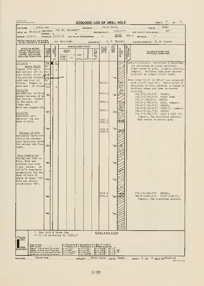
GEOLOGIC LOG OF DRILL HOLE SHEET. ...... OF.
FEATURE Teton Dam PROJECT .T.".°.". .".'S.^'"STATE. . . .
LOCATION ^^^ '^t. Abutment* c:tt7 n'**HOLE NO -PM-651-B GROUND ELEV. . . f^i'^.'r DIP (ANGLE FROM HOmz )
COORDS. N E TOTALBEGUN ,11/9/76. . FINISHED. .U./.U./.76. . . DEPTH OF OVERBURDEN .....".- DEPTH. . . ???.•?. . BEARING "7
. . .
Idaho
90°
leIel*Jnd^oate°m'eJs*iJre'd, . .
-Not .Measured ^„^^^g ^^ D. N. Magleby ^00 reviewed by. .
.B... H... Carter.
NOTES ON WATERLOSSES AND LEVELS,CASING. CEMENTING.CAVING. AND OTHERDRILLING CONDITIONS
TYPANDSIZE
oo
PERCOLATION TESTS
LOSS
(G.P.M.I
CLASSIFICATION ANDPHYSICAL CONDITION
^12/10/76
gwing Shift
Pumped 1500 gals,
mud and got 10« re-
turn before drill- ,
ing -Started turningrods and lost all
return. Pumped in
more mud - no return
12/11/76
44"
Rocklit
'3%
E.710;
RocKBit
Decided not to drill
deeper because of n(
mud return. Pumpedin 300 gals, ofclean mud.Hole was capped off,
2/15/76
50
Down-hole geo-physical log was
made of hole.
Purpose of HoleDetermine character-
istics of sedimentary materials belov
the welded ash- flow
tuff.
Hole CompletionCasing was left in
hole, hole wascovered over with
gal. bucket. On
12/15/76 down-holegeophysical log wasmade of hole to
depth of about 750'
hole was partlycaved below 750'
.
JSL
4597.54596.
S
4591.94590.8
4554.44552.5
7l0-
760-
780-
790-
699.0'1-712.8'1: SILTSTONE 6 CLAYSTONE(as recovered in cored sections):light brown to gray, slightly plasticcompact. Drillers indicated uncoredsections as compact SILTY SANDS.
Hole from 712.8' to 885,3' was advancedwith 4-1/2" rock bit. Description ofmaterials in this interval is based ondrillers notes and some recoveredcuttings.
712.8'i-719.2'i719.2'i-724.1'i724,l'-729,0'*:729.0'1-735,0't
735.0':-736.0'l736.0'i-740.6'l740.6'I-741.7'i741.7'i-778.1'l
GRAVEL,SILTY SAND.
GRAVELCLAY, compact.GRAVEL.SAND(?), compactGRAVELSILT 5 CLAY (?),
compact, few scattered gravels.Mud return is mostly gray.
778,l't-780.0':: GRAVEL,780,0't-825,6'i: SILTY CLAY(?)
,
compact, few scattered gravels.
iCORELOSS
CORERECOVERY
Sta. 4*19 g Grout Cap.El. of measuring Pt. 5332,5'
EXPLANA TION
Typo of hoNolo t«ol«<ApprOK. fii
Approx. t>i
Ouisido die
Inside dio.
DP » Pockoi
ilo (X-ioiloi) . . Ei = 1-1/2",
,r« (X-»of.o.) . . E. = 7/8",ling (X-io>ie.).E« = 113/16na (X....io.i. .E. » \-\/r-.
Diamond, H Hoyitallilo, !
Comontod, Ci
X = 1-7/8".X = 1-1/8".X = 2-1/4".I = 1.29/32"
> Shot, C • ChuiBottom o( cati
B. = 2-3/8", NBx = l-S/8", NBx = 2-;/«", HBx . 2-3/8". N
-2-1/8". 3-1/2". 3"
FEATURE T?t?n Dam project , . .T?.t?n. P?^}'}. state .
.I^.^h?. .?.H0LEN0AH.-6.S.1.-.B
C-121
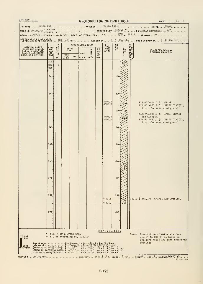
GEOLOGIC LOG OF DRILL HOLE SHEET. . y. . . . OF. .
= EATURE .T.e.t.o.n. Dam project T?ton Basin ijAj^.
HOLE MO. .DH-.6.5.1.-ALOCATION
COORDS. N
FINISHED, lillim.
GROUND ELEV .????!?'. DIP (ANGLE FROM HORIZ ) .
TOTAL o„n ,. DEPTH OF OVERBURDEN . . DEPTH. .°»^-.-? . . . BEARING.BEGUN .
.1.1/97.7.6.
''leJel*I!Eo^dIte°m'ea*ur"d. . . .Not. Measured logged by P- .N. .Maglebx .... log reviewed by B, .H, .CgrteT.
NOTES on waterLOSSES and levels,casing, cementing,caving, and otherdrilling conditions
TYPEANDSIZEOF
HOLE
PERCOLATION TESTS
LOSS
IC-P.M.) (MIN I
<^l-
CLASSIFICATION ANDPHYSICAL CONDITION
^4!-,"
Roc)
Bit
810
820
840-
8»0-
8l0-
4506.94506.5
4498.84497.6
850-
4450.3
4447.2
890-
825.6'i-826.0'l: GRAVEL826.0'l-853.7ii: SILTY CLAY(?)
;
firm, few scattered gravel,
833.7'i-834.9'l: SAND, GRAVELand COBBLES.
834.9'i-882.2':: SILTY CLAYC?),firm, few scattered gravel.
B2.2'i-885.3' GRAVEL AND COBBLES.
iCORELOSS
CORERECOVERY
EXPL A N A T I N
App,o,. .^>. .1
Approx. til* ofOuliid* d\o. of
Inild* rfia. of c(
Sta, 4+19 £ Grout Cap.El. of measuring Pt. 5332.5'
D « Diamond, H Hayitallil*. S m Shot, C « ChurnPa Pockar. Cm m C«ment<*d, Ca • BoHom of coaing
lola (X-t.fi.a) . .E« o I-1/2". Am = l-)/a", B« - 2-3/B", Mx - 3"
or* (X-iofiot) . . E. o 7/8", A« = 1-1/8", B» - 1-5/8", N« - 2-1/8"o.ina{X-««ri.a). E« = M3/16", A« = 2-l/<", Bm = 2-7^1", N« - 3-1/2"
ling (X-aeri^a). . E« g 1-1/2". Aw » 1-29/32". B« - 2-3/8". N» - 3"
Description of materials from712.8' to 885.3* is based on
drillers notes and some recoveredcuttings.
Tetqr\ Dam project . ..T^tpn .Basin state . . I4^h9 . SHEE-^ OF . .9. . HOLE NO, P^^T^^l-B
C-122
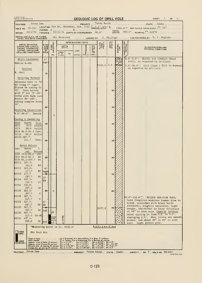
7.1.137 (6-74)Buntu of R*cUmation
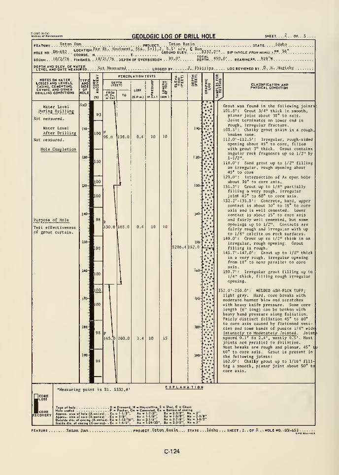
GEOLOGIC LOG OF DRILL HOLE SHEET. ...<.. OF. .
FEATURE Teton Dam PROJECT

GEOLOGIC LOG OF DRILL HOLE SHEET. . . .r , . OF.
JP}PP. .B«.ir STATE. . . U^bQ .
nu t.c^ LOCATION '^^'" ^^ Abutment, Sta. 5*11.2, 5.5' u/s, C Dam «»HOLE NO .
.'1':'°^/.. GROUND ELEV 5332.0.'. DIP (ANCLE FROM HORIZ ). .?9.COORDS. N E TOTAL
BEGUN . .10/2/76. . FINISHED. .IQ/2U7.& . . DEPTH OF OVERBURDEN . .?0.0,' DEPTH, . .
450.. 0.'. BEARING.** ..i!119°W
DEPTH AND ELEV OF WATERLEVEL AND DATE MEASURED Not Measured. LOGGED BV. . . .
.J.-. PhjJJipS LOG REVIEWED BY, . .D. .N. .Magleby
NOTES ON WATERLOSSES AND LEVELS.CASING. CEMENTING.CAVING, AND OTHERDRILLING CONDITIONS
PERCOLATION TESTS
(MIN )
CLASSIFICATION ANDPHYSICAL CONDITION
^
220- //
^ A *
-4 *
260- ••^^
2 70-
10
NxD -
2 90-
5086.2 297. 0:7^^
166.0': Sand grout up to 3/8" thickfilling a smooth, planar joint about45** to core axis (nearly normal tofol iation)
.
169.6': Sand grout 1/8" to 1/2" thickfilling a rough, slightly planaropening about 30** to core axis.
194.2': Chalky grout up to 1/16"thick, in a rough, planar to wavyjoint about 50° to core axis. Someare parallel to the foliation.
208.1': Sand grout 3/8" thick in a
smooth, planar joint about 30° to
core axis which is about normal tothe foliation.
250.0'-297.0' : WELDED ASH-FLOW TUFF;light gray. Core breaks with moderatehand pressure and scratches with lightknife pressure; lightly vesicular.Fairly distinct foliation between 45°
to 60° to core axis caused by flattenecvesicles and some wavy pumice bandingup to 1/4" wide. Intensely Jointed .
Joints spaced from less than 1/2" to1.3', mostly between 0.3' to 0.8'.
Most joints are parallel to the folia-tion which is 45° to 60* to core axis.268. 7
' -270. 7' : Two high angle, rough
to smooth joints about 20* to core ajjis.
Grout is present in the followingjoints
:
253.4': Grout to 1/8" in a rough,planar joint 30° to 40° to coreaxis. Joint is parallel to thefoliation.
2S7.3': Grout stains on irregular,rough joint 40° to core axis.
260.2': Grout 1/16" thick filling a
smooth, planar joint 50° to coreaxis.
260.6': Grout stains in smooth,planar joint 50° to core axis.
272.3'-272.8' : Grout up to 1" thickin an irregular joint intersectingsome near parallel, smooth planarjoints which contain 1/2" grout.Smooth joints are 30° to 35° to coreaxis and normal to foliation.
273.1': Grout to 1/8" thick in a
planar, rough joint that is 50° tocore axis and near normal to folia-tion.
273.3'; Grout to 1/4" thick in a
smooth, planar joint that is 45° tocore axis and near normal to folia-tion.
tCORERECOVERY
•Measuring point is El. 5332.4'
Typ. of hoi. DHoi.AppreApprcOuiic
Diamond, HP < Pock.,, Cm
I ol hoi. (X.i.rl.t) . . E> = M/2",i ol cor. (X-i.ri.t) . . E> = 7/8",of coaiog (X.i.,1.1). Ex <= M3/1«",
.( loiing (X-i.rl..). . E. = 1-1/2".
EXPLANATION
Hoyft.llit., S Shot. C 1 Churna Cmonlod, C. — Bottom ol co.irtg
Ax I 1.7/8", B. = 2-3/8", H« - 3"Ax = 1-1/8", B»= 1-5/8", Nx- 2-1/8"Ax I 2-1/4", B« = 2-7/8", Nx . 3-1/2"
Ax = 1-29/32", Bx . 2-3/8", Nx . 3"
Teton _Dam PROJECT --T^t^n .Basin
_ _ state H^9 . 3.. OF . .5 . HOLE NO. ,
.PH:*52 . .
SPQ SB.
C-125
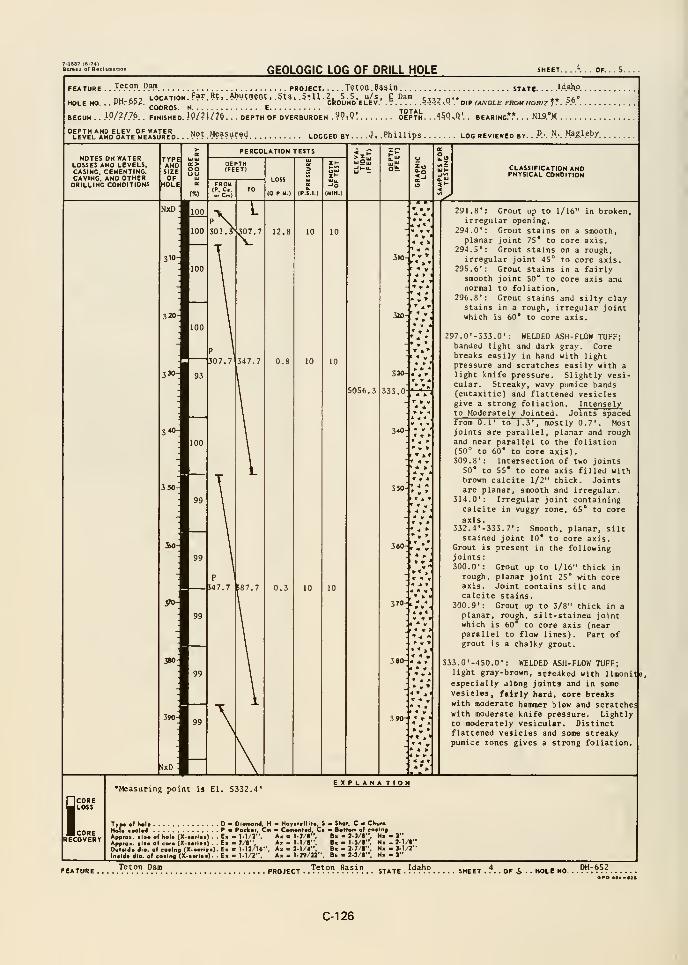
GEOLOGIC LOG OF DRILL HOLE SHEET. ..."•... OF. .
FEATURE . ..T.e.t.o.n. .Dam project T«t9D .e«sin state Waho.
,
nu ft<;9 LOCATION. Far. Rt,. Abutment, .Sta,.5*U. 2 5.5, u/s, £ Dam c,„n'« * 5fi°HOLE HO. . ..Dp.-.Of?. ,.„„„„, „ ^ GROUND ELEV ^ iJ^'i-.O
. DIP (ANGLE FROUHORIzJ*. PP.
BEGUN.
COORDS..1.0/.2/.7.6. . FINISHED. !9/?J/7l5. . DEPTH OF OVERBURDEN . ?9 : 9
!
DEPTH. . .45.Q^Q'. . BEARING**. . tiiS.'H .
"level^and^date "eIsVIe'd. .
.Not. Measured logged by. . . .-I. .PhiXUps log reviewed by. . P.: .N.-. .Ma&l.e.by.
NOTES on waterLOSSES and levels.CASING, cementing,CAVING. AND OTHERDRILLING CONDITIONS
TYPEANDSIZE
CLASSIFICATION ANDPHYSICAL CONDITION
nxd:
5056.3
330-
333.0
« « »'< Ar- V »
+ ' »•t ^ ,A > I
* V *•• f '
* >
< .* »» J
340-
* « «y « «
« » »
»fc. »
» »* w '
* T *
380-
• t» * V
. ' « T
* * »
« A >
291.8irregul
294.0'
:
planar294.5'
:
irregul295.6'
:
smoothnormal
296.8'
:
stainswhich i
Grout up to 1/16"ar opening.Grout stains on a
joint 75* to coreGrout stains on a
ar joint 45° to coGrout stains in a
joint 50° to coreto foliation.Grout stains and s
in a rough, irregu60* to core axis
in broken,
smooth,axis.
rough,
re axis,
fairlyaxis and
ilty claylar joint
297.0'-333.0' : WELDED ASH-FLOW TUFF;banded light and dark gray. Corebreaks easily in hand with lightpressure and scratches easily with a
light knife pressure. Slightly vesi-cular. Streaky, wavy pumice bands(eutaxitic) and flattened vesiclesgive a strong foliation. Intenselyto Moderately Jointed . Joints spacedfrom 0.1' to 1.3', mostly 0.7'. Mostjoints are parallel, planar and roughand near parallel to the foliation(50° to 60* to core axis).309.8': Intersection of two joints
50* to 55* to core axis filled withbrown calcite 1/2" thick. Jointsare planar, smooth and irregular.
314.0': Irregular joint containingcalcite in vuggy zone, 65* to core
axis.332 .4 ' -353. 7
' : Smooth, planar, siltstained joint 10* to core axis.
Grout is present in the followingjoints:300.0': Grout up to 1/16" thick in
rough, planar joint 25* with coreaxis. Joint contains silt andcalcite stains.
300.9*: Grout up to 3/8" thick in a
planar, rough, silt-stained jointwhich is 60* to core axis (nearparallel to flow lines). Part ofgrout is a chalky grout.
333.0'-450.D' : WELDED ASH-FLOW TUFF;light gray-brown, stteAked with liraonitje
especially along joints and in somevesicles, fairly hard, core breakswith moderate hammer blow and scratcheswith moderate knife pressure. Lightlyto moderately vesicular. Distinctflattened vesicles and some streakypumice r,ones gives a strong foliation.
iCORELOSS
CORERECOVERY
•Measuring point is El. 5332.4'EXPLANA TION
Trp« of heU D « Dlomond, H > Hoyii.r. aMlttd P<~ "
_____ . S - SKoi, C • ChwmPacker, Cm * Camanlvd, Ca &oHo«n o( eating
Appfox. !>• of hoi* (X-»rl«B) . . E« - 1.1/2", A« i I-?/*". B« - 2-3/«', H- - 3**
Appro., siio of Goro (X-.«rlo>} . - E« - 7/8", A« - M/8". B. - 1-5/8", N« - 2-1/8"
Ouiald* dto. of caiina (X-aofloa} . Ek - M3/I6", Am > 2-1/4", Bx - 2-7/8". Na - 3-1/2"
Ir^.ldo dio. of co«lr>9 jX—^l*')- E- " M/2", A« - 1-29/32". Bk - 2-3/8". N. - 3"
Teton Dam. OF S HOLE NO.
DH-652OPO •B4-«]|
C-126
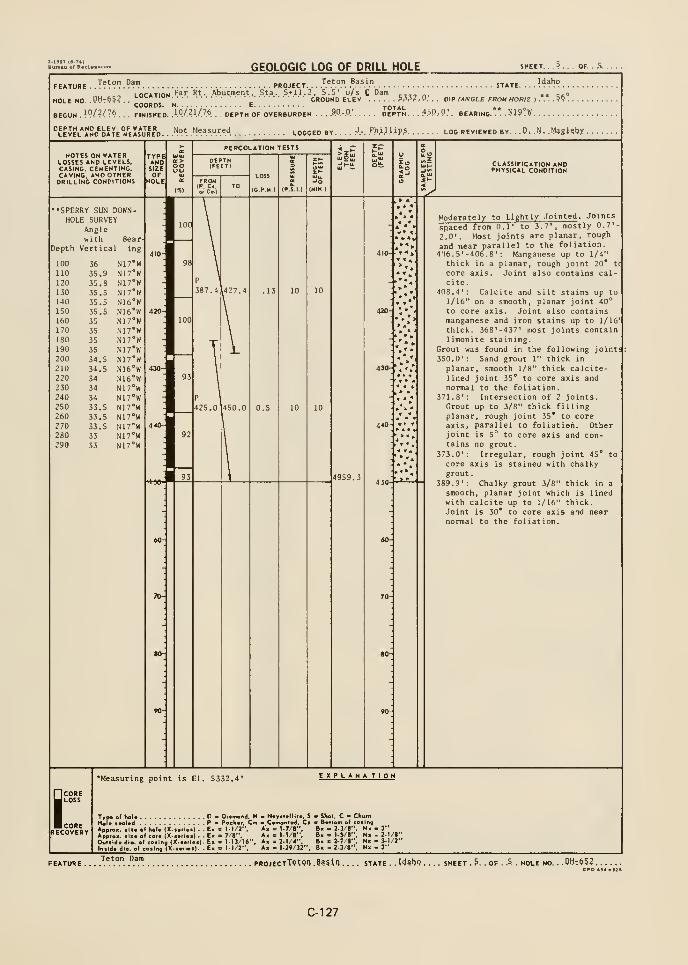
GEOLOGIC LOG OF DRILL HOLE OF. .5. .
FEATURE. -T^^°".°^") PROJECT
HOLE HO. . PMt^^
Teton Basin
1 nriTiOM Far Rt . Abutment, Sta. 5«11.2, 5.5' u/s C Dam ^,,, „,GROUND ELEV Piil, V.
COORDS.
STATE. . . . .."
. . .
DIP fANGLE FROM HORIZ ) .*.*.. 5^ .
BEGUN .19/'/76.
. . FINISHED, .'."./.^l/.Z*. . DEPTH OF OVERBURDEN . . . ?P.-0' DEPTH. . . :'5P..P.'. BEARING. . . .NIS^W.
"leJel'JSd^oate^emJrVd. ..'^.".y ."^".^.u.r^.'i. LOGGED BY . . , .
.J.-. .P.h.i.l.l.ip.s LOG REVIEWED BY, .D, .N. .Maglebx .
NOTES ON WATERLOSSES AND LEVELS.CASING, CEMENTING.CAVING. AND OTHERDRILLING CONDITIONS
CLASSIFICATION ANDPHYSICAL CONDITION
^••SPERRY SUN
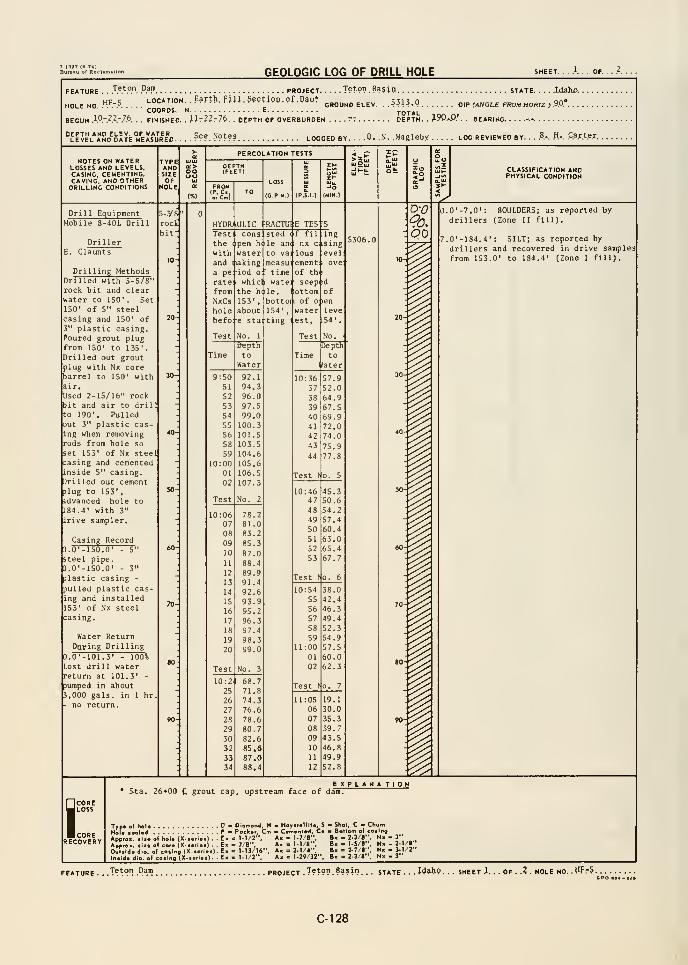
GEOLOGIC LOG OF DRILL HOLE SHEET. ...'.. OF. .
Teton DamFEATURE . ..'."'.".". .".'•!". PROJECT
up c LOCATION. . Earth. FUJ. Section. of. OaiorHOLE NO ."^ .' ,„„„„, u cCOORDS. N E TOTALBEGUN 1.0.-.".- .7,6 . . FINISHED. . Mrilrli. . DEPTH OF OVERBURDEN . . . . 77 DEPTH. . .19P.'P.' . . BEARING.
. . ..Tf?on.Ba5io state LdaJu). .
GROUND ELEV. ..^313,0 Q|p (ANGLE FROM HORIZ ) .9.0.*. . . .
. ???.^9??? LOGGED BY D. .N. .Maglebx log reviewed by. . .
.B.-. .H-. .Qa.rt.e.r.
NOTES ON WATERLOSSES AND LEVELS.CASING. CEMENTING.CAVING, AND OTHERDRILLING CONDITIONS
TYPEANDSIZE oo
PERCOLATION TESTS
LOSS
(CP.M,)
CLASSIFICATION ANDPHYSICAL CONDITION
Drill EquipmentMobile B-40L Drill rod
bit'
E. Claunts
Drilling MethodsDrilled with 5-S/8"rock bit and clearwater to 150' . SetISO' of 5" steelcasing and 150' of
plastic casing.Poured grout plugfrom ISO' to 135'
.
Drilled out groutplug with Nx corebarrel to 150' withair.
Used 2-15/16" rockbit and air to drilto 190'. Pulledout 3" plastic cas-ing when removingrods from hole so
set 153' of Nx steecasing and cementedinside 5" casing.Drilled out cement3lug to 153'
,
idvanced hole to
184.4' with 3"
Irive sampler.
Casing Record3.0'-150.0' - 5"
steel pipe.D.O'-ISO.O' - 3"
plastic casing -
pulled plastic cas-ing and installed153' of Nx steelcasing.
Water ReturnDaifing Drilling
0.0'-101.3' - 100%Lost drill waterreturn at 101.3' -
pumped in about3,000 gals, in 1 hrno return.
HYDR;lUL1C i'RACTUIE TES'
Testthewithanda pe:
rate;
fromNxCsholebefo:
Test
hi I
conspenwater
nakingiod o
whicl
the hi
153',
aboute sta:
No. 1
a:
stedle an
to
measutime
i wat'le.
bott154'
ting
(f fil
( nx c
e:'
lOUS
ementof th
seeottomof
waterest.
Test
ing'Sing
evelove
P' 'd
' len
leve54'.
No.
•Bepth
to
Water
Depth
Hater
9:5051
52
53
54
55
56
58
59
10:0001
02
Test
92.1
94.396.097.599.0100.3101.5103.5104.6
105.6106.
S
107.3
No. 2
10:3637
38
39
40
41
42
43
44
57.952.064.967.569.972.074.0
75.977.8
Test to. 5
10:0607
08
09
10
11
12
13
14
15
16
17
18
19
20
Test
2
2
3
88.489.991.492.693.995.296.397.4
98.399.0
No. 3
10:4647
48
49
50
51
52
53
45.350.654.257.460.4
63.065.467.7
Test (o. 6
10:54
55
56
57
58
59
11:0001
02
38.042.446.349.452.354.957.5
50.062.3
10:2. 68.771.874.376.678.680.7
82.685.687.088.4
Test to, 7
11:0506
07
08
09
10
11
12
19.130.0
35.339.743.546.849.9
52.8
D-0
oo
I
1111II
0.0'-7.0': BOULDERS; as reported by
drillers (Zone II fill).
7.0'-184.4': SILT; as reported by
drillers and recovered in drive samples
from 153.0' to 184.4' (Zone I fill).
COREJ LOSS
BcORERECOVERY
Sta. 26*00 £ grout cap, upstream face of dam.EXPLANATION
Typ« ol hoi
Hal« t»ala<ApprOK. Ill
Ovililda dio
Intida dio.
D Diamond, H - Hoyttolliio. S - Shol. C Chwrn
P B Pochor, Cm a Comonlod, Ca Bottom ol eating
ol hoi. (X...,i..) . . E. . 1.1/2", Ax = 1.7/8". B. - 2-3/8", N. - 3"
ol CO,. X...,i..) . . E. . 7/8", A. .1.1/8", B, -IS/l", N. -2- /;olooiin, IX-..,i..).E. = 1-13/16". A, = 2-1/4", B. - 2-7/1", H. . 3-1/2"
I toilna(X-...l..), E. = 1-1/2", A. .1-29/32", B. - 2-3/8", N. - 3"
FEATURE . . .T^^™ .Pam PROJECT .Tefpn .
Basil). . . state ,. , 14^9. . sheet .1. . . OF . .? . hole no .tlF75,
opo iga-e^fl
C-128
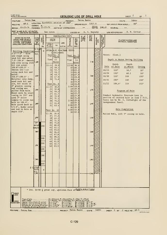
GEOLOGIC LOG OF DRILL HOLE
FEATURE . . . J.".*.".". .".»! PROJECT. . . . T??"?. B??'"? STATE WhP.up c LOCATION. Earthf ill section of (Jam* c,,, „ on*
HOLE NO. . . ."."V. . . , GROUND ELEV .^^\^:^ OIP (ANGLE FROM HORIZ) /'f. . .
COORDS. H E TOTALBEGUN . }Pr??r7^. . FINISHED. .'.'."??r?*. . . DEPTH OF OVERBURDEN rr DEPTH. .
190«Q'. BEARING --.
''LEvSL*JSD^DATE°>rEA*UR"D See nptes LOGGED BY . P. N. .M^gUby LOO REVIEWED BY . ..B.-. H... .Carter
NOTES ON WATERLOSSES AND LEVELS,CASING. CEMENTING,CAVING, AND OTHERDRILLING CONDITIONS
TYPEANlTSIZEOF
HOLE
oo
PERCOLATION TESTS
FROUIF, C.
LOSS
(G P.M )
Jo(MtN )
CLASSIFICATION ANDPHYSICAL CONDITION
^Drilling Condition
O.D'-7.0' - Slowand rough usingrock bit and water7.0'-100,0' -Smoothand slow using rockbit and water.
lOO.O'-lSO.O' -
Smooth and fast
using rock bit andwater.
1S0.0'-190.0' -
Material very damp,
used rock bit andair, bit stuck in
3" plastic casingand casing was
pulled from hole.
Reset with Nx steelcasing to 153' and
used 3" drivesample to clean outhole to 184.4' .
Hole caved back to
172.0' , muddy waterand mud in hole at
depth 154'.
S-3,if
rocS
bit
UO
120
130-
140-
150-
HYDRAVLICont ii
F|IACTUR :
)
test;
Depth
Water
11:14
15
16
17
18
19
20
24.044.252.758.753.767.971.4
No, 9
11:2425
26
27
28
29
30
31
32
30.050.059.1
65.770.975,2
78.581.483.4
Test llo. 10
3"
drivT
mpl(
160
170-
11:3637
38
39
40
41
42
43
44
45
46
47
48
49
50
26.647.364.271.375.980.082.184.686.487.989.491.091.992.793.5
2 l>/lfrrockbit-190
lo. 1
Depth
to
later
12:0005
10
IS
20
25
30
40
50
1:00
10
20
30
40
502:00
30
3:0030
4:0030
96.6100
103.2
105.8107.9
109.8111.4114.0
116.0118.0
120.0
121.3
122.7124.0
125
128
123
129
130
132.0132.6
Notes:
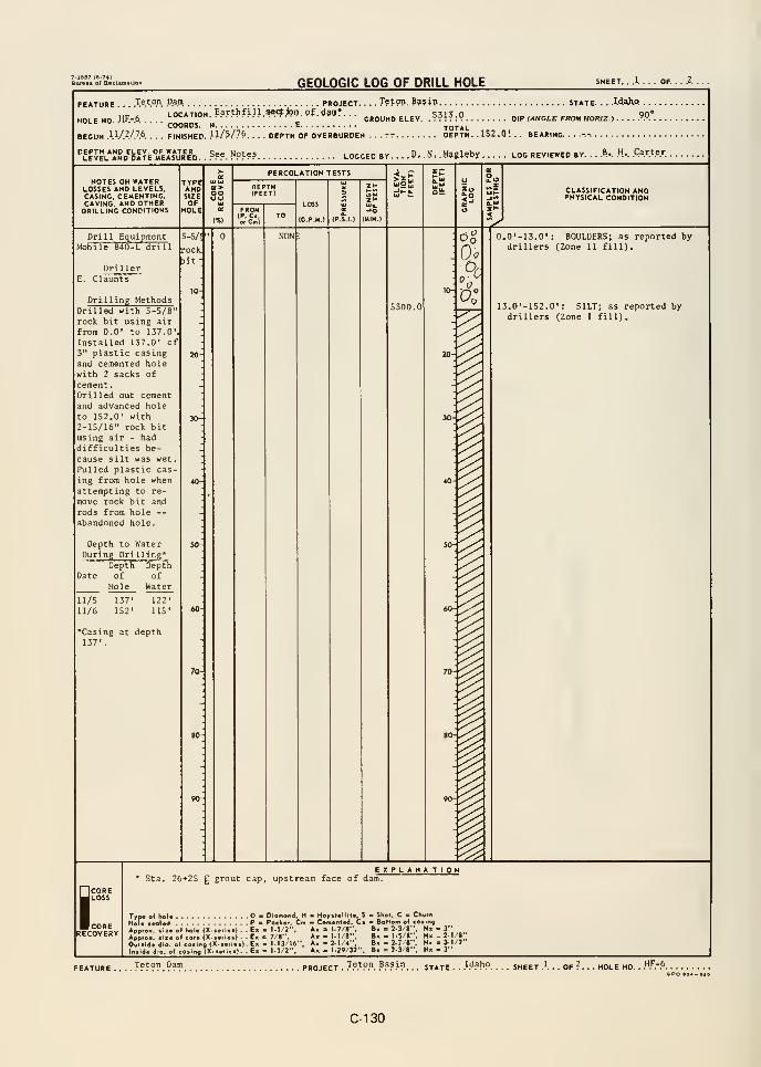
GEOLOGIC LOG OF DRILL HOLE SHEET.
FEATURE .
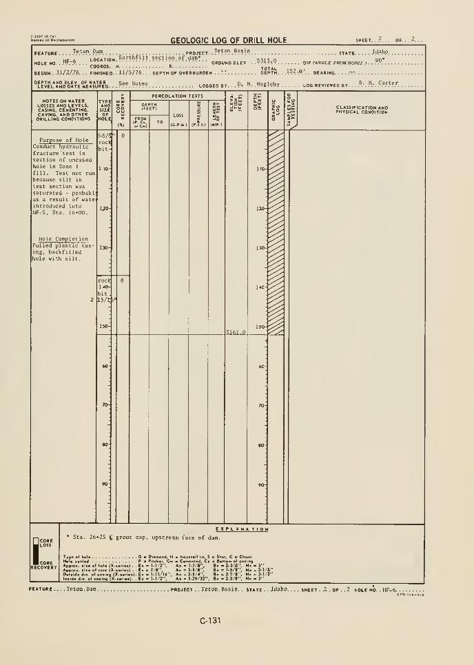
GEOLOGIC LOG OF DRILL HOLE SHEET. ..'.... OF.
FEATURE .... .T.*.'.°P. .".*? PROJECT. . T???? .???^'} STATE Waho
Hc A LOCATION. ??ri(>?iii.????i9n.9f.^am*.. 53130 90*HOLE NO . VfrP. . . . _ GROUND ELEV . .?-;H-.V DIP tANOLE FROM HOfUZ > . .
.".. .
COORDS. N E TOTALBEGUN . \XJZJ?f>. . . FINISHED. . J J/5/76. . . DEPTH OF OVERBURDEN . .TT DEPTH. .
.152.0'.. BEARING. ....-.-.
BY. . .Pt .N: .Magleby log reviewed by. . .,^.-. .".-. 9?T^^T.
NOTES ON WATERLOSSES AND LEVELS,CASING. CEMENTING.CAVING. AND OTHERDRILLING CONDITIONS
TYPANDSIZE
ooUL>
PERCOLATION TESTS
LOSS
(C P M.)
CLASSIFICATION ANDPHYSICAL CONDITION
^Purpose of Hole
Conduct hydraulicfracture test in
section of uncasedhole in Zone I
fill. Test not runbecause silt in
test section wassaturated - probablas a result of wateintroduced intoHF-5, Sta. 16*00.
Hole CompletionPulled plastic cas-
ing, backfilledhole with silt.
5-5 /S
roc
bit
1^
rock140-
bit ;
15/1.
5161.0
iCORELOSS
CORERECOVERY
EXPLANATION* Sta. 26+25 fc grout cap, upstream face of dam.
Typ« of hole D > Diomond. H - Hoyflellite. S e Shot, C e ChurnHol« sealed P > Packer, Cm - Cemenled. C* » Bottom of caiingApp,<,». site of hole (X-iefie.) . , Ex = 1-1/2", Ax = 1-7/8", Bx = 2-3/8", Nx - 3"Appro*, size of core (X-.er.e.) - . Ex = 7/8", Ax = 1-1/8", Bx = I-5/8", Nx - 2-I/8"Outside dio. of cosing (X-series). Ex = 1-13/16", A. = 2-1/4", Bx = 2-7 1". Nx <= 3-1/2"Inside dig, of cosing (X. series). - Ex = 1-1/2", Ax = 1-29/32", B« = 2-3/8", Nx - 3"
FEATURE . . . .TetOD.DaiD PROJECT . . TetPD. Basin. . state . . JdahP. SHEET . .2 . OF - . 2 . HOLE NO. . HF-6.
C-131
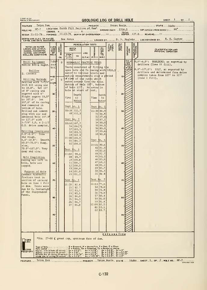
7-1387 (8-74)Bureau of RacluDaUoD
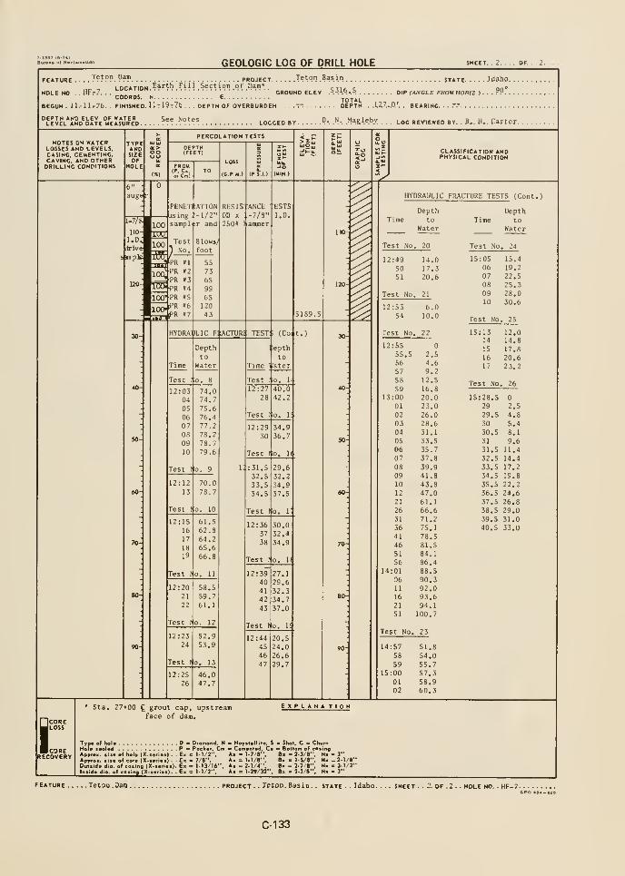
GEOLOGIC LOG OF DRILL HOLETeton Dam PROJECT T^^PH .Basin STATE
LOCATION Earth Fill Section of Dam* cth; c7. . . ;.
, GROUND ELEV. .= ->l°-.=. DIP f/lWOLE FROM HORU >.
1,Z7...0.'. , BEARING. .""
FEATURE . .
HOLE NO . . HF; . . . . ,-„_„,COORDS, n
BEGUN . iJ.-Jir76. . FINISHED. 11t19t76
90°
' TOTAL. DEPTH OF OVERBURDEN ....--. DEPTH.
LEVEL AND DATE MEASURE LOG REVIEWED BY
PERCOLATION TESTSNOTES ON WATER
LOSSES AND LEVELS,CASING, CEMENTING.CAVING. AND OTHERDRILLING CONDITIONS
TYPEANDSIZEOF
HOLE
CLASSIFICATION ANDPHYSICAL CONDITION
HYDRAULIC F!J\CTUR1 TEST:; (Coi t.)
Depth
to
Water
ipepth
tollater
Test lo. 8 Test Mo. 1"
12:0304
05
0607
08
09
10
74.074.7
75.
6
76.477.278.278.7
12:2728
40.042.2
Test llo. 1!
12:29
30
34.9
36.7
79.6 Test llo. II
Test lo. 9
12:1213
31.532.533.534.5
29.632.234.937.5
Test (o. 10 Test lo. 1
12:15
16
17
1819
61.562.864.265.656.8
12:3657
38
30.032.4
34.9
Test lo. II
Test lo. 11
12:2021
22
58.559.761.1
12:3940
41
42
43
Test (o. 12 Test lo. 1<
12:2324
52.9
53.9
Test lo. 13
12:4445
46
47
20.524.026.6
29.7
12:2526
46.047.7
HYDRAULIC FRACTURE TESTS (Cont.)
Depth
Test No
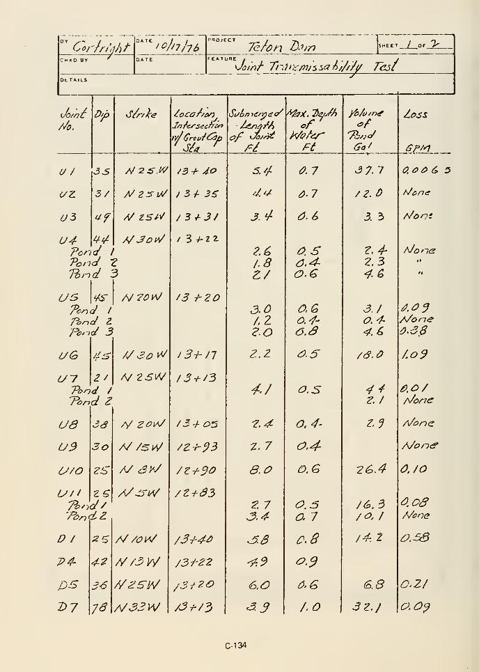
"^Co/-/ri'tjJ)t
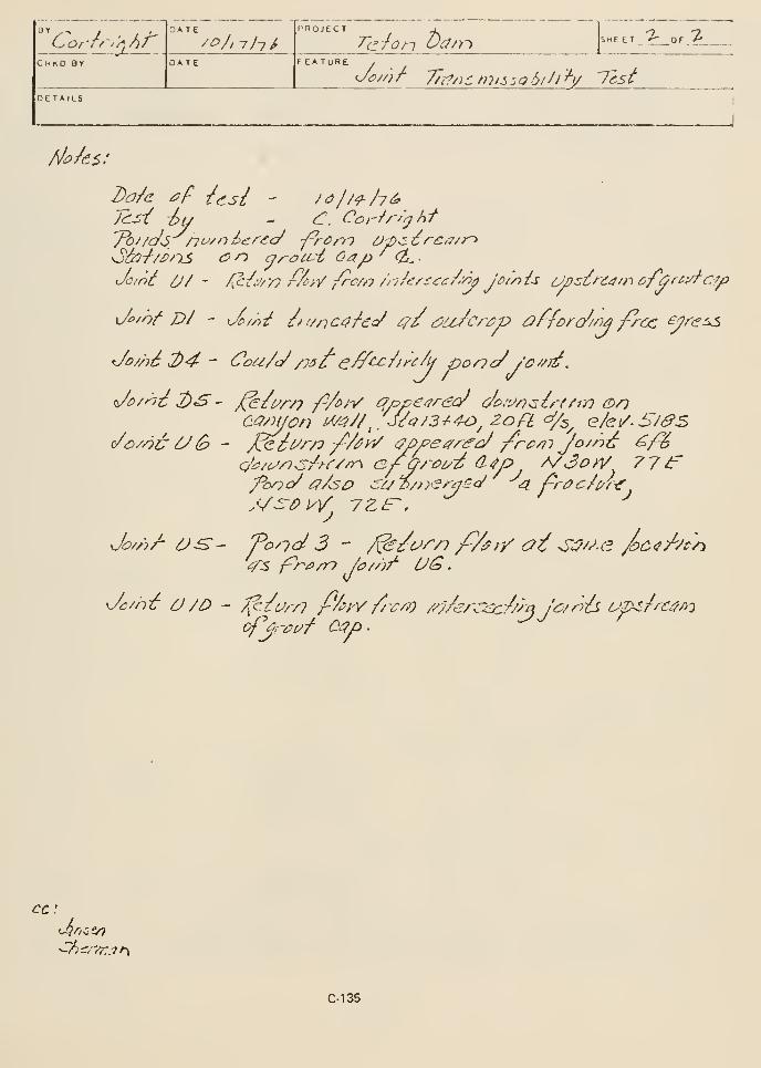
Cor-r/'//)A/
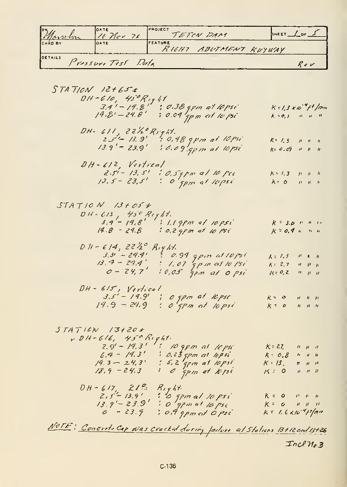
1// /
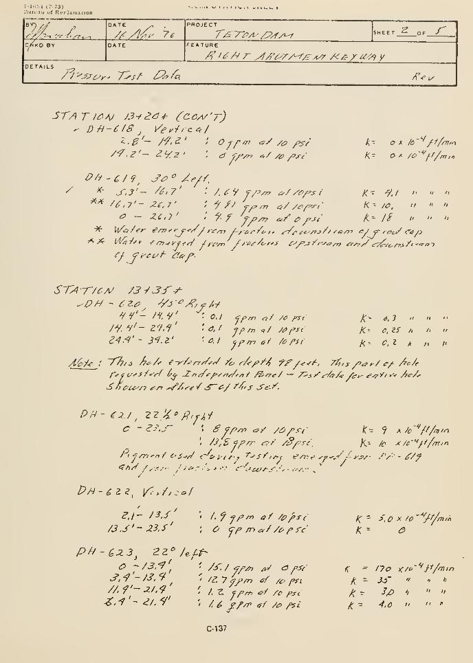
7-U;M (7-73)llurciu of Rcrlaiii:iiion
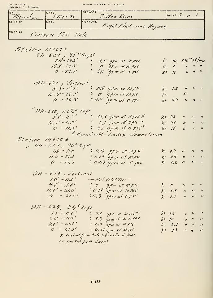
7-lGOJ (7-73)Hureau of Rt'claiiiation
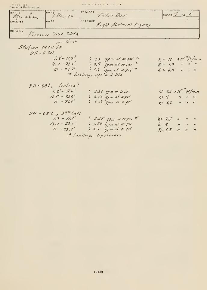
Bureau of R iT laniallon
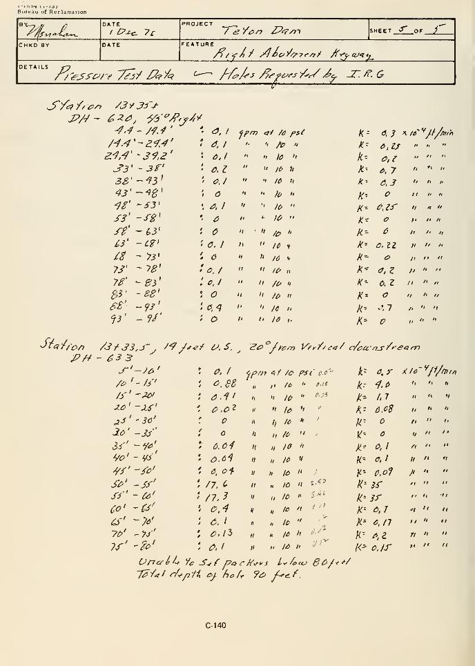
t -tool 1 1 -/j;Bureau of Reclamation
^/ffl^ aA^^X^„^
DATE/ eVcn JP^yjt SHEET ^ or j
DATE FEATURE
/i/ f A / yjoo)^/^7f^/ /fy^^cu-^t^
//^l^-T^/V 7^}/ /i^.>^ ^—• //^A--^ y^^^^-y/^^x^^ JT./^.G
DETAILS
^.^

///is->^^^1 ef^
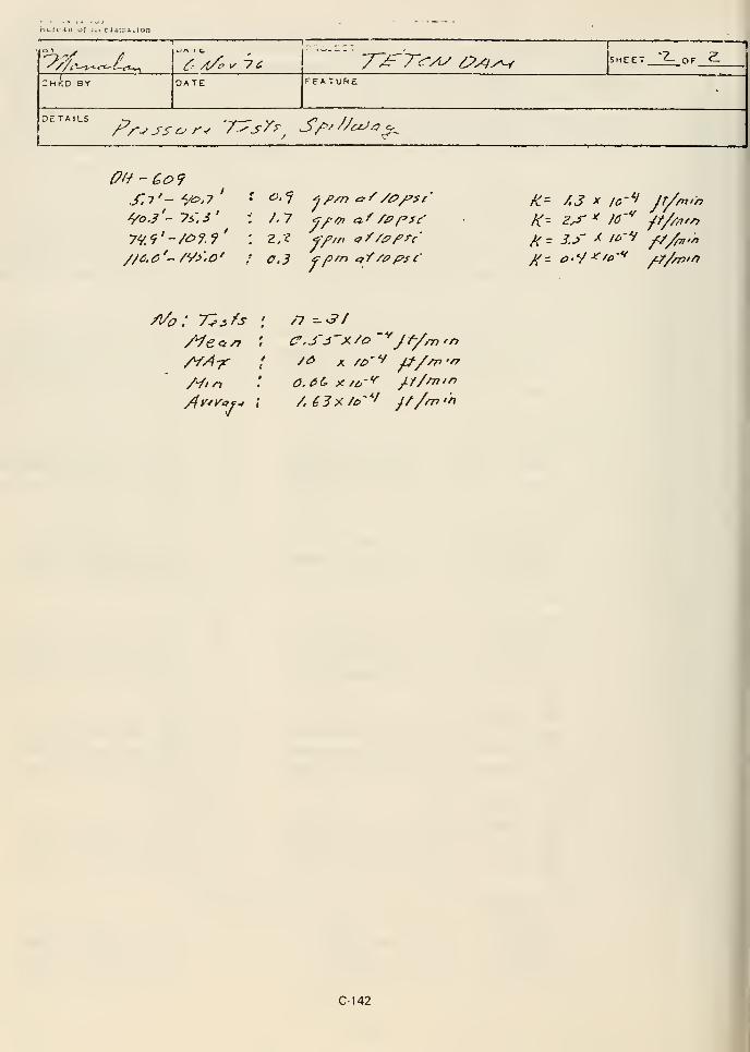
huri-;iu of JL
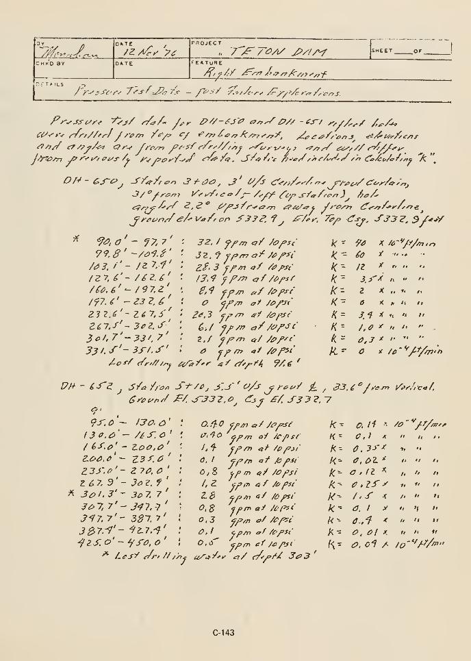
« f'-x.l^^7"^ /^/i/ y^/Z/V
OS TAILS
FEATURE£
i:K^^j'C'r-r Ti's/^JP^Ys _ />^/ r.^//c,r,/^^^'^^rr^,
^^S;^Z^ ^.^ ^A'j/r^ayri ^/^^f //'iez-n (ir^/y/C»^/C -^t*
^rec^n^e/^V'a/ron ^3^F.i^ j£'/fi^. 7?/p (fj^, SS3Z. S/-e^V
/f7.£' - Z3 7.^'
ZlZ.d' - 1^7,5''^
3o/.7'~J3f.7'
7e^^ (/r'Z/ //^j
32, / f/'m er/ /o^sc
ZS- 3 j/'/n af /t!>/>st
£</a/*
k-
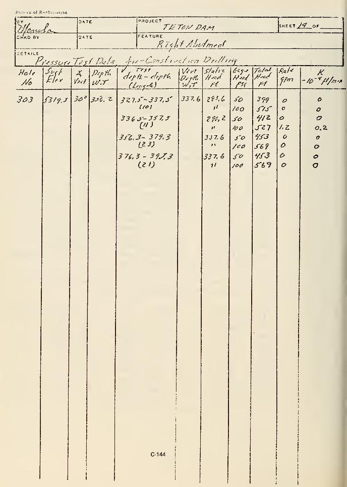
i^i;:. hu of R-rl ti.i^iion
K^^ i2>^_
P.TOJECT
T/y T^ry P/^A1 SHEET J'f OF
EATURE
CETAILS
/^. '-fsSi^r-t yl^ff Pc^f'^, ^j-iy -'C-':^"sf t -'C,'-' fcn tPy/^/r-if
%iAY
A'
.?<^J fS/f.J 3a' ^^6. ^I/O I
3 7^.3 - 3f^j
33 7. 6
C-144
ll
ll
337. G1 1
337.67/
/OO
SO
3'0
/CO
3'o
3 99
3'/S
sn
SB?vf3^6?
o
o
o
ooo
o
ooO.2.
ooo
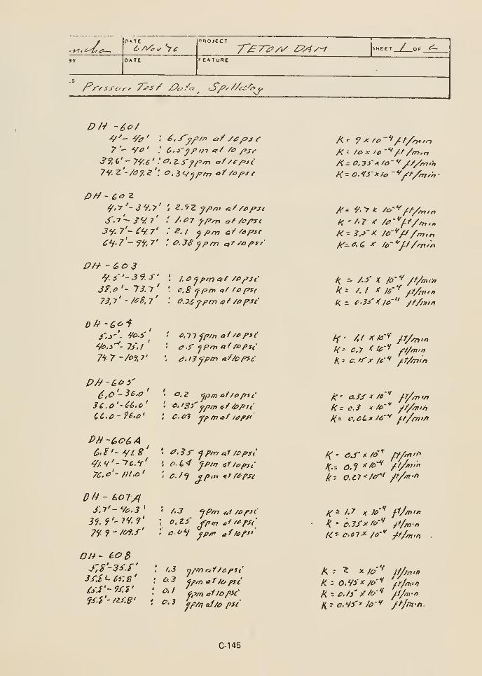
li^ttf^
OATE
y^TlP/i/ £?,4y-r
/^r^s^-o,' 7^^/ /Pc/c^ ^ S/'y/Zc'<^-'&v/
/ or ^
DH -60/
7'- Vi?
39, (,' - 79-6 ' .' ^- a i'fj'm a:f /e/>st'•7^ '•'- ''"= ''' o.iCf^/7ni of /af>x{79.z'-/a?.e
Jy- 7'- ^y 7' ; .?. / ^ pm ay ^aptr
PH - (>0 3Y i '- 39.S'
3?.P'- 13.1'
7ll' -MS.l'
'^.j'<- 7/.
I
7^7 ~/o%J'
c.B fprn of ro pS(
ff .f jprn a-f fopsi
C'-^'-'^f.S' ' ^.3r 'ipm e,1 /£>ps;
7C.C-JII.O' ; ^_/^ SP'" ^^7£r^(
Dh - Lo7/iJ.T'-^c.3' ' f.3 'ip/n etl /opsi
Jf. 9'- 7V' ?': O. Zi' jrp,„ ^i/^fSi
7i.')-7of.f' :' CO ''I ^^^ ^//tf/'J''
OH- (>^
8
3',S'-35J'3i:S'~6i'.s'
Ci.i'-'/f.i'
fi.i'-uy.e'
'i3 nffn ciY/cpii^- ^ W/75 af /o pre'^'
'
fpm affopicO, 3 ^^v/J af/O pSC
/C : /OX 'o -**/^f/m.n
H -/-r f /^-*'//'/^,„
/("= /.-»'^ /0-'^/7/m,n
^ ^ /.y K /O'^ /f/min
k- /.I X J6-'^ ff/nt^n
K - c.3i''( /a" /f/jjiin
ff- Af X/a"^ /T//n,n
H^ c.y < ic'"' /i/^.f,
/;; c.ffx /i'' /.T/nrin
^; 0.11 "/er"' /f/'-n-fi
K- 1-^ K IP"' fj/nifi
fl/m>n
C-145
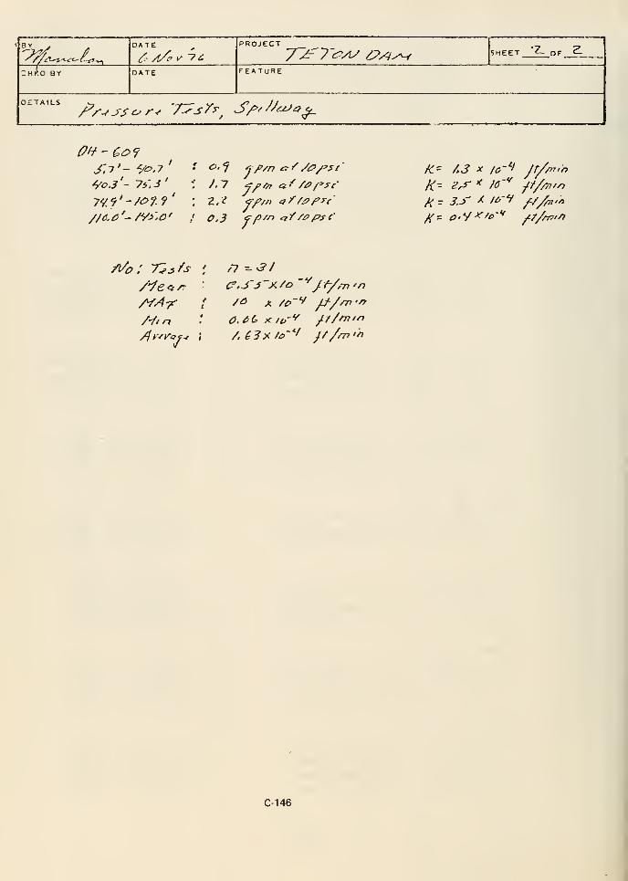
; H K D BY
DATE
yc y^T^Ay ^?^y^ JHEET 'Z- OF 2.
DATE FEATURE
DETAILSPr-^ssc^r-r 'T^s^^^ S/^/^/^czJo^
'/ninfC- /,3 X lo-'-i jr//
K-- ^^ ^ /^'^ ///^/-^
/•///7 (51, ^^X/^-^ y///77//7
A ^3 >i/&'"'' /A/rrr'n
C-146

or «
CHKO BYr^-^
7^^ /a/i/ ^///v'
Q/^ /// /^/^ ^^17/7 A"/-/? ''A'/' •
-f
/r-^5^c-r-f T^'sr JZrTT - p^s/ 7^/y^r-,' /^^/'^ ''^ /yens.DETAILS
^/^// err /p^Ari C7 f-f /rc/n P^'ff <'/ry///y7^ ^-^c^f ly" e. j tfjy/V^ tu^/ // e^/y^i^
9a, a' - i7,7
'
99,8' ~/o^.e'
/Z7. £' ~ /6Z.S'/^a.s' - /97.z'/</7.4' -13 2,^'
ZC~7,y' - 3^2.'^'
3o/.7'~33'.7'3,} /.J''- 3J-/.J"
3Z, / f/'fn <^/ /O/'sc
ZS. 3 r/'/w <?/ /a pst
k^
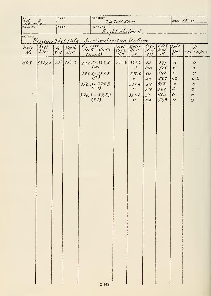
7//fl^,a ,.
KKO;ib^_
r/.' r^ry P/jAi L^ M_or
DETAILS
303 f3/f.J
£7.^
3a
'
3^1!'. ^
33(,J'-3f2j
JJ'C.J- 37'^.
3
L^3)
3 7L3 - 3f^S
Vfyt
u/,-r
33 7. 6
/'
J J 7. 6«•
JJ7, ,S
11
J'o
J7f
"/J'J
J-s?
Vf3^6^
oo
o
ooo
•/o"^////.i'/i
o
oo
o
ooO
C-148
« Appendix D
REVIEW REPORT
by the
Embankment Construction Task Group
for the
U.S. Department of the Interior
Teton Dam Failure Review Group
February 1977

ABSTRACT
This task group was originally charged to determine if
the dam embankment was constructed in accordance
with the contract plans and specifications. Added later
was a second task to evaluate the embankment design
concepts.
A generalization of the task group's critical conclusions
would suggest the USBR (1) did not make proper
assessments during design as to the potential for
migration of zone 1 into the rock foundation, (2) did
not choose and specify proper foundation preparation,
and (3) did not make proper adjustments for critical
embankment and foundation conditions encountered
during construction. Assurance against the occurrence
of the above events is provided by good organizational
relationships and by having design and construction
performed by experienced people with competent
technical knowledge.
Detailed conclusions of the Embankment Construction
Task Group are presented at the end of Appendix D.

INTRODUCTION
Purpose and Scope
This task group was originally charged to review the
construction of Teton Dam embankment and
foundation treatment exclusive of foundation pressure
grouting for compliance with the plans and
specifications. Added later was a second task to
evaluate the embankment design concepts.
Participants
David C. Ralston, Soil Engineer, Soil Conservation
Service, Washington, D.C., Chairman
Neil F. Parrett, Soil Engineer, Corps of Engineers,
Washington, D.C.
Samuel D. Stone, Jr., Soil Engineer, Tennessee Valley
Authority, Knoxville, Tennessee
Activities
The task group members first met at the damsite from
August 3-6, 1976. The task group (1) interviewed
USBR construction inspectors, (2) reviewed inspection
records and reports, and (3) inspected the damsite and
project laboratory. Following the site visit, members of
the task group analyzed a variety of earthwork data.
The members met again in Washington, D.C, on
September 27-29, 1976, to coordinate report activities.
The task group met in Knoxville, Tennessee, on
January 19-21, 1977. The task group conclusions and
associated discussions, charts, tables, and construction
photographs are contained in this report.
Documentation
The documents reviewed include the followingr
1. Specifications No. DC-6910, Volumes 1-4. The
applicable specifications and drawings for Teton
Dam.
2. Design Considerations for Teton Dam, October
1971, prepared by the USBR.
3. Construction Materials Test Data for Teton Dam,January 28, 1971, prepared by the USBR, E&RCenter.
4. Teton Dam and Power and Pumping Plant,
a. Soil Sample Index Sheets.
b. Memorandums of Laboratory Test Results,
Denver Laboratory.
c. Undisturbed Embankment Samples Testing.
5. Earthwork Information extracted from Weekly
Progress Reports.
6. Part C-Earthwork Construction Data from L-29
Reports.
7. Compilation of Earthwork Control Data,
Summary of Field and Laboratory Tests of
Compacted Fill, Zones 1, 2, 3, and 4.
8. Earthwork Control Statistics, Zones 1 and 3.
9. Design Engineer Notes, Design Considerations,
March 1967 through October 1970.
10. Project Construction Office Photograph file.
11. As-Built Cross Sections of the EmbankmentFoundation.
12. Special Reports by Embankment Inspectors.
13. Daily Reports by Embankment Inspectors.
DESIGN REVIEW
Scope of Review
This task group's review of design was generally
restricted to an overview of the design development,
design philosophy, and major design criteria. No study
was made of the detail design computations or
analytical analyses.
Significant Design Assumptions
The following quotations have been extracted from
USBR design notes to show the sequential
development of significant decisions during the design
of Teton Dam:
From Teton (Fremont) Dam Design Considerations
(March 1967):
"1. General considerations: ...cheapest and
most abundant material is a silt . . . relatively
good tan <p values and low permeability . . . low
D-1
resistance to erosion, susceptibility to cracking,
and liquefaction tendency ... Third, the
formation' at the damsite is thought to contain
open joints. It is possible that sonne connbination
of open joints may extend from the reservoir to
the downstream toe that will not be intercepted
by grouting.
"2. Basic design criteria . .
.
"(a) The upstream and downstream sides of
the core should be blanketed by semipervious
zones of sandy gravel . . .
"(b) A wide flat sloped cutoff trench should
be provided across the valley to minimize
cracking . . .
"(c) A relatively heavy upstream shell should
be provided to compensate for possible
strength loss in the saturated core due to
seismic activity.
"(d) Under the core, open joints should be
filled with grout or concrete so that piping
through the formation will be impossible.
Under the shells, piping should be controlled
by removing overburden of the ML soil
classification and replacing it with sand and
gravel."
From Teton Dam Gradation Test Curves (June
1969). Zone 1 Material:
"Seepage velocities may be too low to move
particles."
From Teton Dam (no date):
From USBR Design and Construction BookTeton Dam— Design Considerations, Crest Details
(13 November 1969):
"1.
"2. The silt core should be surrounded by sand
and gravel . .
."
From Teton Dam— Design Considerations Abutment
Section Above El 5300± (18 November 1969):
"1. Stripping . . .
"2. Riprap toe trench . . .
"3. Toe drains—pervious blanket d.s. side of cutoff
(key) trench.
"a. All appreciable volume of seepage through
the embankment could only result from cracks
thru the core. Since the core is less than 50 feet
high and is founded on formation in this
elevation range, settlement cracks thru the core
are unlikely.
"b. Considerable seepage may occur thru
formation . . . and seepage will probably outcrop
on the lower abutment.
"c. Conclusion: Toe drains or pervious blankets
on the downstream side of the cutoff trench
would serve no useful purpose.
"4. Extended grout curtain beyond limits of
embankment
"Justification for sand filter blanket—heavy
gravel rock zones.
"a. . . . could be accomplished after the reservoir
is placed in operation . . .
"1. To prevent piping failure due to cracks in
the core . . .
"2. To prevent piping failure due to seeps at
rock contact . . .
"3. To prevent major spring from developing
due to erosion of fines from open joints in the
rock."
' The word "formation" is defined in specifications
paragraph 66.c. as follows: "Formation—Anysedimentary, igneous or metamorphic material
represented as a unit in geology, generally called
rock . .."
'5. Cutoff Trench
"a. Depth . . .
"b. Width . . .
"c. Cutoff trench side slopes.
"d. Special treatment of cracks in formation in
the bottom of the cutoff trench.
"a. Alternate treatment methods include . . .
"b. Purpose of treatment
D-2
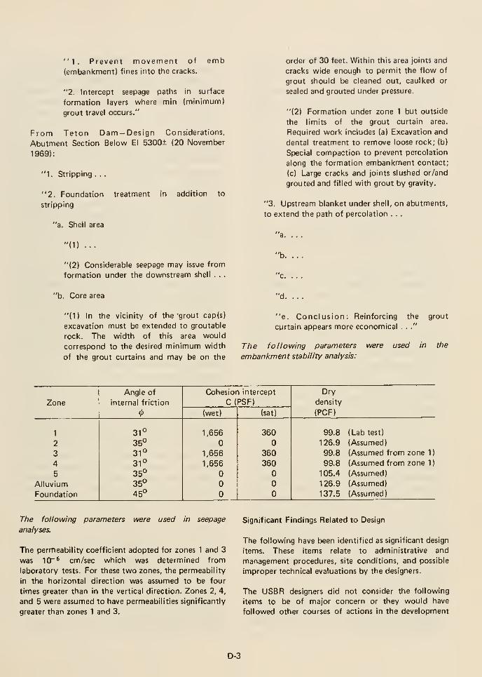
"1. Prevent movement of
(embankment) fines into the cracks.
emb
"2. Intercept seepage paths in surface
formation layers where min (minimum)
grout travel occurs."
From Teton Dam — Design Considerations,
Abutment Section Below El 5300± (20 November
1969):
"1. Stripping . . .
"2. Foundation treatment in addition to
stripping
"a. Shell area
order of 30 feet. Within this area joints and
cracks wide enough to permit the flow of
grout should be cleaned out, caulked or
sealed and grouted under pressure.
"(2) Formation under zone 1 but outside
the limits of the grout curtain area.
Required work includes (a) Excavation and
dental treatment to remove loose rock; (b)
Special compaction to prevent percolation
along the formation embankment contact;
(c) Large cracks and joints slushed or/and
grouted and filled with grout by gravity.
"3. Upstream blanket under shell, on abutments,
to extend the path of percolation . . .
"(1) ...
"(2) Considerable seepage may issue from
formation under the downstream shell . . .
"b.
•c. . . .
"b. Core area "d.
"(1) In the vicinity of the "grout cap(s)
excavation must be extended to groutable
rock. The width of this area would
correspond to the desired minimum width
of the grout curtains and may be on the
"e. Conclusion: Reinforcing the grout
curtain appears more economical . .."
The following parameters were used in the
embankment stability analysis:
of the design. The plans and specifications issued for
construction reflect the USBR's judgment of what
constituted a properly designed dam for the Teton site.
Some of the following items may not have contributed
to failure of the dam but reflect this task group's
opinion that they were significant factors in the design
of Teton Dam.
5. The designers judged that there was not
sufficient precedence to use hydraulic gradient
concepts to establish the minimum width of the
abutment key trenches. The designers, therefore,
judged that a theoretical maximum seepage gradient
of 7.3 at the floor of the key trench at elevation
5100 was tolerable.
1. Design notes developed early in the design
process identify and report a variety of potential
design problems and possible design alternatives.
There are no records, documents, or reports which
show:
a. The logical resolution of each of the identified
design problems.
b. Why a particular design alternative was
considered satisfactory and selected in preference
to others.
c. Why an identified design problem was
subsequently judged not to be serious and
omitted from further consideration.
Obviously, the plans and specifications issued for
construction received the concurrence of technical
supervisory and management personnel. Because of
the lack of documented rationale, it is not clear to
what extent technical supervisory and management
were involved during the design process.
2. Laboratory testing of embankment construction
materials during design was minimal because the
designers believed they possessed adequate
knowledge of the materials due to past experiences
with comparable materials at other damsites.
3. No laboratory permeability tests were performed
on zone 2 material during design; however, the
designers judged that this material would have
sufficient water-carrying capacity to handle all
normal seepage passing through zone 1 and also
prevent zone 3 from becoming saturated. The
designers did not envision zone 2 being required to
convey large volumes of seepage. It was assumed
that the zone 1 core would remain intact and not
develop cracks due to differential settlement,
hydraulic fracturing, or seismic activity. The
designers also judged that adequate filter action
could be provided by making zone 2 relatively wide
(thick).
4. The designers judged that seepage exiting from
the abutment rock downstream of the grout curtain
would be minimal and could adequately enter the
zone 2 blanket drain.
6. The designers judged that a treatment programfor known defects in the surface rock beneath the
dam could be best established after construction
excavation exposed the rock.
7. The designers judged that the potential for
migration of zone 1 fill into underlying or adjacent
rock was insufficient to warrant the use of filter
material between zone 1 and rock or to warrant
sealing small openings in the rock with concrete or
shotcrete.
8. The designers judged that their experiences at
other dams were sufficient to adequately predict the
performance of Teton Dam and that installation of
instruments to measure foundation and
embankment settlement, lateral movements, and to
monitor piezometric pressures were unnecessary.
CONSTRUCTION REVIEW
Summary Of Information Obtained
During Visit To Damsite
Inspection Organization
The embankment construction organization for
inspection was excellent. An organization chart and
staff names are shown in Appendix D1. The experience
of the inspection staff was varied. Only a few of the
embankment inspectors had prior experience in damconstruction. Several had prior experience in
earthwork construction, surveying, or laboratory
construction control testing. Resumes of the project
staff are included in Appendix D1.
Interviews of Embankment Inspectors
Inspectors were privately interviewed by the task
group. The initial six interviews were conducted on
August 3, 1976. The seventh interview and the second
interview of Mr. Ringel and Mr. Hoyt, to confirm some
of the task group findings while reviewing construction
records, were conducted on August 5th. The persons
interviewed, in order of first appearances, were
Kenneth Hoyt, Jan Ringel, Glen Harris, Lyman Rogers,
Richard McClung, Douglas Jarvie, and Stephan
Johnson. Each person interviewed was very cooperative
D-4
and judged to be responsive to the questions. The
infornnation obtained during the interviews is
summarized by subject matter. The answers by
different individuals were generally in agreement.
Where conflicts in testimony were noted, all the
different answers are reported.
Technical Qualifications of Personnel; The task group
was impressed by the sincerity and conscientiousness
of all the persons interviewed. Both principal
inspectors (shift supervisors) were interviewed. One
had no previous earth dam or earthwork experience.
However, the most experienced supervisory
embankment inspector was assigned to his shift. The
other principal inspector had a career experience in
inspection of earthwork construction. He had previous
assignments at several earth dam projects. The three
supervisory embankment inspectors interviewed had
previous experience as earthwork inspectors. One had
previous experience in earth dam construction. The
second had previous earth dam experience as a
laboratory technician. The third had no previous
experience in earth dam construction. The earth
placement inspectors interviewed had little previous
earthwork experience and none had past experience in
earth dam construction. Many of the earth placement
inspectors were young persons learning construction
inspection. At the time of these interviews, all were
judged to be capable as first level inspectors in earth
dam construction.
Controls to Obtain Quality Construction: All said that
they believed they had inspected the construction of a
good dam. The contractor had been cooperative with
the inspector's requests. While some conflicts between
contractor and inspectors had occurred, the
contractor's performance and willingness to perform to
USBR standards had been better than previously
experienced on similar contracts. The inspectors
complimented the Materials Engineering Branch
(Project Laboratory) for its cooperation in obtaining
field control tests when and where requested. The
inspectors were authorized to work overtime so that
inspection would be provided whenever the contractor
was working. All inspectors interviewed confirmed that
a personnel time overlap occurred between day and
swing shifts for the purpose of verbal briefing
concerning the status of work being performed. The
earth placement inspectors, three per shift, spent all
their work shift on the embankment. The supervisory
embankment inspector, one per shift, would spend his
total shift on earthwork features with approximately
half his time in the borrow area and the other half on
the embankment.
Excavation and Backfill of the Cut-Off Trench: The
cutoff trench was specified to be excavated in the dry.
Deep wells (to bedrock) were installed to dewater the
excavation. The cutoff trench contained a deep silt
stratum that complicated efforts to dewater ahead of
excavation. The lower elevations of the cutoff trench
were excavated from under water with a dragline. Once
excavated, the area was dewatered by augmenting the
established well system with ditches along the sides of
the excavation and sump pumps. Gravel was placed at
the toe of the excavated side slopes to provide
continuous interception of seepage. The rock surface
cleanup and backfilling was accomplished in the dry.
At the base of the left abutment near the upstream side
of the cutoff trench, a persistent spring was treated by
providing gravel-covered drains and standpipes that
were grouted when the backfilling reached sufficient
height (elev. 5112). After operation of the dewatering
system was discontinued, one seep penetrated to the
surface of the backfill. Special dewatering and
reconstruction of the area was provided. The cleanup
of rock surfaces in the bottom of the cutoff trench
removed all loose slabby and undesirable rock. In the
basalt area at the base of the left abutment, washing
was stopped as soon as the surface was clean because
the 2-inch-diameter pressure water hose jet used would
continue to loosen pieces of the closely jointed but
otherwise sound basalt.
Excavation of the Key Trenches: The key trenches
were excavated by alternate blasting and mucking
activities. The blasting technique was to drill presplit
holes along the boundary of the excavation on 2' to 3'
centers. Production holes were drilled on patterns of 6'
X 8' inside the presplit holes. The blasting used delay
sequence. The sequence was to first shoot presplit
holes, followed by center row holes, and then
remaining production holes. The constructed depth of
the key trench was approximately 68 feet. The
excavation proceeded in lifts of 24 feet, 24 feet, and
20 feet. Due to the highly jointed nature of the rock,
there was significant overbreak which resulted in an
irregular rock surface particularly in the upper portions
of the key trenches. No unusual weathering of the
excavated rock surfaces occurred during the three-year
exposure of the key trench rock. Some ravelling due to
freeze-thaw action did occur.
Foundation Preparation and Treatment, Zone 1 : The
abutments under zone 1 were cleaned of all loose
materials to firm sound rock. Two exceptions were
noted. The first was an area of silt and rock on the
right abutment approximately 200 feet upstream of
the key trench and below approximate elevation 5050.
This area extended under part of zone 1, zone 2, and
zone 4. The decision not to remove this material was
apparently made at a supervisory level above the
embankment supervisor. The second area mentioned
was on the right abutment downstream of the key
D-5
trench somewhere between elevations 5200 to 5250
where a lot of loose rock was encountered. The
procedure for general foundation preparation on the
abutments was to remove as much material as possible
with dozers working down the slope within the zone 1
contact area. Much of this work was performed during
the 1974 construction season. When the canyon wall
was too steep for dozers to operate, the contact area
was cleaned with a backhoe working from the
embankment surface as construction progressed. This
cleaning removed all large loose rock and most of the
overburden. Where firm intact rock formed overhangs,
they were removed by machine excavation if possible
or by blasting. Most of the overhangs that required
removal by blasting were on the left abutment. One
large right abutment overhang below a bench at
elevation 5006 was removed from the dam centerline
to 266 feet upstream. Prior to placing fill against the
zone 1 abutment contact, the area was given final
cleanup by air jets. Enough water to control dust was
sometimes used in the air jet. The air-jet cleanup
removed all unsound, undesirable materials that
remained on the contact surface. Jackhammers were
used to remove grout which had leaked to the surface
of the key trench during curtain grouting activity.
The same contractor crew performed final cleanup
work on both abutments. The cleanup was maintained
one to five feet ahead of the fill placement elevation.
After cleanup the inspector would mark the acceptable
area of cleanup with a spray paint and mark the surface
cracks and holes to be filled by gravity grouting. Most
of the cracks that were grouted were oriented
vertically. Drafts of cool air movement could be felt
exiting from the rock at many of the holes marked for
filling with gravity grout. There are some discrepancies
concerning the extent of the gravity grouting
performed. Gravity grout was placed on the right
abutment under the zone 1 contact between elevation
5075± and 5205. The methods used to place gravity
grout varied. Some gravity grout was placed directly
from the chute on the truck. Other times gravity grout
was placed through a short length of pipe inserted into
the crack or hole to be filled. The openings selected to
receive gravity were those too narrow or too deep to be
backfilled with zone 1 material compacted with
"pogo" sticks. Sometimes a small earth dike would be
built around the opening to serve as a small retaining
reservoir to facilitate the placement of gravity grout.
Placement of specially compacted earthfill was not
delayed if gravity grouting had not been completed;
therefore, it was sometimes necessary to set a pipe so
that the opening could be grouted from a higher
elevation after a few lifts of fill were placed. No
inspector recalled any opening marked for gravity
grouting that was not grouted by one of these
methods. No written criteria were available on which
openings were to receive gravity grout or how gravity
grout would be placed. The holes that received gravity
grout were usually: (a) extensive in opening, (b) had air
drainage or (c) had no limited depth when probed with
a lath. Each hole was evaluated individually. Gravity
grout placement was accomplished on the swing shift
only; therefor, most cracks were seen by several
inspectors. Generally any cracks too narrow to be
backfilled with zone 1 material using "pogo" sticks and
wider than 1/2 inch received gravity grout. The
water-cement ratio by volume of the gravity grout was
usually 0.7 to 0.8. Some inspectors, but not all, added
sand and used a 1/1/1 mix if the gravity grout takes
became large (usually greater than 4-1/2 to 10 cubic
yards). Most gravity grouting under the zone 1 contact
was done upstream or downstream of the key trench.
The bottom of the key trench was described as sound
rock with cracks adequately filled by the curtain
grouting activity. The side slopes of the key trench
excavation were described as blocky rock. Several
inspectors said the cracks and holes in the side slopes
of the key trench required little to no gravity grout.
One inspector stated that the side slopes of the key
trench required about the same amount of treatment as
other areas under the zone 1 contact area. The filling
of cracks and holes with gravity grout was not a
separate contract pay item. The work was paid under
the unit price for backfill concrete. The inspectors
believed the price to be favorable for the contractor.
The gravity grouting on the right abutment began at
approximate elevation 5075. The inspectors generally
agreed that there was no need for gravity grout
treatment at lower elevations. According to Special
Reports prepared by the inspectors, gravity grout
treatment on the right abutment ended at elevation
5205. None of the inspectors interviewed remembered
this elevation. Two did remember the month and year,
August 1975. The decision to stop the gravity grout
treatment was made by personnel above the level of
principal inspectors. One inspector thought the
decision was made by the Project Construction
Engineer, Mr. Robison. No inspector knew of any
USBR Denver office participation in the decisions to
provide or to terminate the gravity grout treatment.
The reasons the inspectors gave for the decision to stop
the gravity grout treatment varied. Inspector's opinions
varied as to whether the rock above elevation 5205 had
more or fewer cracks and holes than the rock that
received gravity grout at lower elevations.
All inspectors who discussed this subject gave a
reduced reservoir head above this elevation as one of
the reasons given to them for discontinuation of the
gravity grout treatment. All inspectors agreed gravity
grout placement was expensive work. One said the
D-6
contractor complained about gravity grout treatment
because it interfered with his schedule for topping out
the embankment in 1975. Others said the contractor
liked the gravity grout treatment because of his
"dollars mark-up" in the item.
Foundation Preparation and Treatment for Zone
2: The foundation preparation for zone 2 removed all
material with vegetation and all loose or soft material.
Material that contained small roots was removed. The
remaining overburden material was firm and
impervious and hard to dig with a hand shovel. All
inspectors who discussed this said that as best they
could remember the downstream zone 2 contact
surface on the right abutment was about 50% rock and
50% overburden. The Project Construction Engineer,
Mr. Robison, indicated to the IRG and two members
of this task group on February 8, 1977, that he
disagreed with the above reported amount of
impervious overburden remaining on the right
abutment. He indicated that very little impervious
overburden remained and that most of the overburden
was pervious accumulations of rock.
Specially Compacted Earthfill: Specially compacted
earthfill on the abutments was required only for zone 1
materials. Specially compacted earthfill was usually
placed in the following manner. Zone 1 material would
be dumped adjacent to the placement area. When
necessary, the material would have water added and be
mixed by means of a motor patrol. An effort was made
to maintain the special earthfill material near optimum
moisture content. After mixing the material and
wetting the adjacent rock surface, the fill material was
spread into 9-inch loose lifts. The lift height was
controlled by using a lath to penetrate the lift and
painting elevation marks on the rock surface. The lift
would then be compacted with a sheepsfoot roller if
possible. When a lift was the first to be placed on rock,
it was spread to a 6-inch thickness and rolled with
rubber-tired equipment. Where a sheepsfoot roller
could not roll next to a steep rock slope, the
compaction was accomplished with a loaded
rubber-tired hauling truck. The boundary areas that
could not be compacted by this equipment were
compacted with a hydrohammer, wacker, or "pogo
stick." Large holes and small rock overhangs were
backfilled with zone 1 material compacted with "pogo
sticks" or wacker power tampers. A hydrohammer
plate mounted on a 3/4-ton chassis was said to be the
best of the small size compactors. The surface area of a
compacted lift would be scarified and the placement
and compaction procedure repeated. A hand shovel
was used to scarify the boundary areas that could not
be scarified with disc, dozer mounted drag teeth, or
dozer tracking. The inspectors selected the areas for
the laboratory to perform control tests. Inspectors
used the following criteria for selecting the locations
for earthwork control testing: (1) areas where the
compactive effort was suspected to be less than
adequate, and (2) areas that would locate tests
representatively over the material zone. Several
inspectors said the construction sequence maintained
the specially compacted earthfill at the rock surface
boundary slightly above the adjacent fill and provided
a gentle slope from the specially compacted earthfill
areas downward toward the main embankment areas.
One inspector agreed that this was the intent, but
because of the slow nature of the work required at the
abutments, the specially compacted earthfill was often
2 feet lower than the adjacent main embankment zone
1 fill. Zone 1 placement was temporarily halted when
it was 3 feet higher than the specially compacted
earthfill.
Specially compacted earthfill was placed around the
four column legs of the material handling tower which
were permitted to remain in the fill. The tower was
located at the base of the right abutment immediately
downstream of the key trench. (Station 16-1-75, 60±
feet upstream of the dam centerline with footings at
approximate elevation 5006.) This tower was used for
filling of zone 1 hauling trucks throughout the 1974
construction season. Approximately one-half of the
zone 1 material was transported to the embankment
through the tower. At the end of the 1974
construction season, the exposed portion of the tower
was disassembled. The column legs were cut off at the
embankment fill height.
Placement Procedure, Zone 1: The routine placement
procedure for zone 1 was to follow scarifying the
dumping, spreading, sprinkling and mixing if necessary,
scarifying, and compaction with a sheepsfoot roller.
The compacted area was then scarified and the above
procedure repeated. Scarifying was accomplished with
a disc (12"± dia) or with drag teeth mounted on the
back of a dozer. When mixing was required, a larger
disc (14"± dia) that was weighted to increase the depth
of penetration was employed. Mr. Aberle said, at a
later date, that the diameters of the discs were 18 and
24 inches, respectively. The sheepsfoot rollers used
were self-propelled four wheel drum Caterpillar 825-B,
and single drum Ferguson SP-120-D. The inspectors
concentrated their attention on moisture control and
number of roller passes. The zone 1 material was of
uniform appearance, but varied greatly in natural water
content and optimum moisture content. The material
arriving from the borrow area was extremely difficult
to judge for water content. The inspectors requested
many water content tests. The project laboratory used
a microwave oven to rapidly determine water contents.
D-7
The contractor also made water content tests with a
speedy moisture teller. Water content tests for final
acceptance testing were made in standard drying ovens
in the project laboratory. The inspectors selected the
locations for field control tests (in-place density and
water content). The same test location criteria
described for specially compacted earthfill were used
for determining the location for the control tests. The
sand cone density test and USBR Rapid Compaction
Control procedures were employed in the field control
tests. When a control test indicated a fill area did not
conform with the specification requirements, the
material in the area was scarified and reworked or
removed to zone 3. After recompaction the area was
retested. When anticipating a rain storm or at the end
of a construction season, the fill surface was sealed
using rubber-tired equipment. Preparation for fill
placement after a period of sealing included the
removal to zone 3 of all excessively wet material and
scarifying of the underlying surface until it became
satisfactory for fill placement. The material removed to
zone 3 would be spread and aerated and returned to
zone 1 when it was satisfactory for placement into
zone 1.
Placement Procedure, Zone 2: The routine placement
procedure for zone 2 was to dump and spread the
material in 12" thick loose lifts and to compact by
dozer tracking or vibratory roller. The dozer tracking
and vibratory roller were used intermittently. The
vibratory rollers were often down for maintenance.
Zone 2 material was extended up the downstream
abutments to form a blanket drain under zone 3. The
zone 2 material was placed one scraper dumping width
and compacted with dozer tracking in a direction
parallel to the abutment. A dozer was used for all
compaction against the abutments because the tracks
could get next to the surface of the prepared
foundation. The inspectors concentrated on preventing
contamination of zone 2 with zone 1 material and on
controlling lift thickness. Construction traffic tracked
adjacent to the zone 2 abutment blanket drain
throughout most of the contract.
Inspection and Interviews of
Project Laboratory
On August 4, 1976, an inspection was made of the
project laboratory. Ralph Mulliner, Chief, Materials
Engineering Branch, guided our inspection and
discussed the laboratory's capabilities and methods of
testing.
The laboratory has soil testing capability which
includes the following:
Classification
Moisture content
Gradation (Sieve and Hydrometer analyses)
Specific gravity
Atterberg limits
Compaction (including mechanical tamper)
Relative Density (vibratory table)
Settlement-Permeability (constant head)
In-Place density (sand cone)
Testing of Zone 1 Fill Material: The laboratory
monitored zone 1 fill placement by routine control
testing which included: (a) in-place density tests by use
of the sand cone method (USBR Designation E-24) and
(b) rapid compaction control (USBR Designation
E-25). During construction of the dam, these tests were
performed at a frequency of approximately one set of
tests per 1 ,900 cubic yards of compacted fill placed. At
less frequent intervals, approximately once for every
34,000 cubic yards of compacted fill placed, the
laboratory performed record tests which included; (a)
in-place density, (b) rapid campaction control, and (c)
combined laboratory permeability and settlement tests
(USBR Designation E-13). Undisturbed block (cube)
samples of compacted zone 1 fill were not obtained
during construction of the dam.
Testing of Zone 2 Fill Material; Zone 2 fill
compaction was monitored by in-place density tests
(USBR Designation E-24). Laboratory relative density
tests, by vibratory table procedures (USBR Designation
E-12), were performed by the project laboratory to
establish control criteria for acceptance testing. In
addition, combined laboratory permeability and
settlement tests (USBR Designation E-14) were made
on laboratory compacted samples of zone 2 fill
materials by the project laboratory. Approximately
one combined permeability and settlement test was
made for every 97,000 cubic yards of zone 2 fill
material placed.
Testing of Zone 3 Fill Material; Zone 3 fill
compaction was monitored by in-place density tests
(USBR Designation E-24). Compaction control criteria
were established by the rapid compaction control
method or relative density, depending upon the nature
of the material being placed.
The USBR Earth Manual, Second Edition, describes
each of the above tests in significant detail. Therefore,
the test procedures will not be repeated here.
The project laboratory appeared to be well equipped
and staffed with qualified personnel. Project personnel
associated with construction of the dam embankment
were complimentary of the laboratory staff.
D-8
Stripping, Foundation Preparation, and
Rocl< Surface Treatment
Within this section an attempt has been made to
summarize all written information (exclusive of
contract drawings and logs of subsurface investigations)
that was available to the constructors in published
documents and that would have direct influence on the
stripping or foundation treatment to be performed.
The documents that are quoted are DESIGNCONSIDERATIONS FOR TETON DAM, OCTOBER1971 and SPECIFICATIONS NO. DC-6910, TETONDAM AND POWER AND PUMPING PLANT,
VOLUME 1, as amended. Many of the details of actual
foundation treatment not specified to be performed
are not repeated from the section titled Interviews of
Embankment Inspectors. Familiarity with that section
will help in review of this section.
Design Considerations: The applicable quotes from the
DESIGN CONSIDERATIONS FOR TETON DAM,OCTOBER 1971, are summarized at the end of this
text in Exhibit A, pages 1 and 2. This exhibit is a
tabular display that relates foundation design intent to
the appropriate area of the foundation.
Specification Requirements: The applicable quotes
from SPECIFICATIONS No. DC-6910, VOLUME 1,
are summarized at the end of this text in Exhibit B,
pages 1, 2, and 3. This exhibit is a tabular display that
relates specification requirements for foundation work
to the foundation area of application.
Construction Practices:
1. Stripping.— Because the results of stripping
operations were not suspect or directly contributory
to failure in any of the postulated causes for failure,
the interview questions and review of construction
data concerning stripping were rather general.
Foundation stripping was accomplished using
bulldozers. When abutment slopes were too steep
for bulldozer operations, stripping was performed
with a backhoe after the embankment construction
progressed to an elevation that would provide a
working platform. No available information
indicates any areas where large or deep zones of soft
or weak surface materials were permitted to remain.
At the failure location, the zone 1 contact area was
excavated to formation. The zone 2 and 5 contact
areas were stripped and the overburden that
remained was described as firm, impervious, and
difficult to dig with a hand shovel. All stripping was
measured by the cubic yards excavated for payment
as "Excavation for dam embankment
foundation ..."
2. Foundation preparation and rock surface
treatment. — Except where the zone 1 contact area
was on formation, the foundation preparation for
all areas was accomplished by stripping and initial
fill placement. The stripping work provided some
shaping and the initial fill placement backfill
confined irregularities. Some zone 2 backfill
materials were placed into confined areas by
sluicing. Foundation preparation complied to
specification requirements for zones 2, 4, and 5
(zone 3 did not contact bedrock). Specified
foundation preparation work under the damembankment was accomplished as a subsidiary
obligation of embankment construction and was not
measured for separate payment.
a. Zone 1, cutoff trench. The construction
practice, except for excavation of the lower
portion of the trench in the wet, was in
accordance with specifications. After excavation,
the dewatering system was able to control
seepage. One persistent spring required special
treatment. The rock surface treatment was
performed on contact surfaces that were free of
standing water. The zone 1 contact surface was
cleaned using a 2-inch-diameter pressure water
hose jet.
Less erosive surface cleaning was performed on
the closely jointed basalt contact area. Holes,
depressions, and irregularities were filled with
specially compacted earthfill using hand-operated
power tampers. No special sealing treatment of
rock surfaces was specified or performed. All
rock surface treatment was accomplished as a
subsidiary obligation of embankment
construction and was not measured for payment.
b. Zone 1, abutments. Trimming of contact area
slopes to 1 H on 2V or flatter was required only
for zone 1. Photographs taken during
construction show local areas where final
formation slopes were steeper. There were on the
right abutment two areas reported by inspectors
where "shall be cleaned of all loose, soft,
and ..." [Specifications, paragraph 68. a. (2)]
was not accomplished. These two areas were a
silt and rock mixture approximately 200 feet
upstream of the key trench below elevation
5100, and a jointed loose rock material
downstream of the key trench between elevation
5200± to 5250±. Other than these exceptions,
construction was in general accordance with
specifications. The final cleanup of formation
under the zone 1 contact area was performed
with air jets. Holes, cracks, depressions, and
D-9
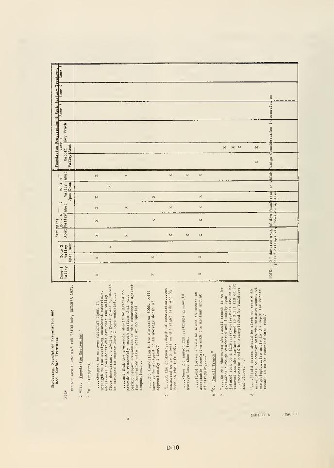
2 g
i O OT3
J X ^J •-' D
C «O O)
-la.,^
•a 5
SB
^ p n oj oj
« ^ x: c o.-H C W O >^
lU n 41
W g 14 I
M 3 C9I
O r-l U T3 4)
u u rt d mC 41 H 3 O3 > a> a
O -O - Xo -H e 3
-O 4J O h U
1-1 4J
o ^ <u c
Bi
C5 tJ iJ O O
C T)O4J bO
C 4J
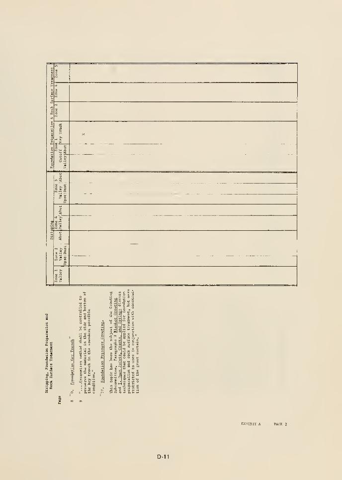
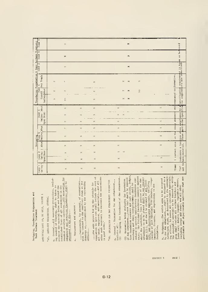
4J
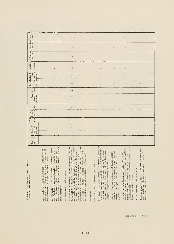
u
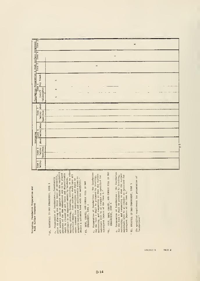
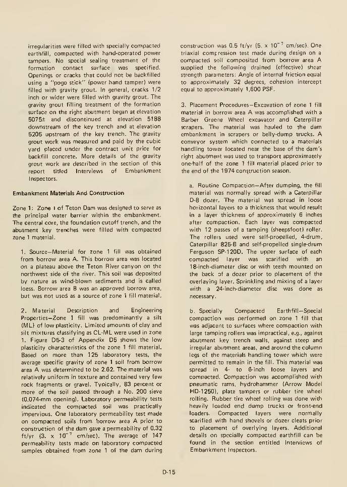
irregularities were filled with specially compacted
earthfill, compacted with hand-operated power
tampers. No special sealing treatment of the
formation contact surface was specified.
Openings or cracks that could not be backfilled
using a "pogo stick" (power hand tamper) were
filled with gravity grout. In general, cracks 1/2
inch or wider were filled with gravity grout. The
gravity grout filling treatment of the formation
surface on the right abutment began at elevation
5075± and discontinued at elevation 5188
downstream of the key trench and at elevation
5205 upstream of the key trench. The gravity
grout work was measured and paid by the cubic
yard placed under the contract unit price for
backfill concrete. More details of the gravity
grout work are described in the section of this
report titled Interviews of Embankment
Inspectors.
Embankment Materials And Construction
Zone 1 : Zone I of Teton Dam was designed to serve as
the principal water barrier within the embankment.
The central core, the foundation cutoff trench, and the
abutment key trenches were filled with compacted
zone 1 material.
1. Source— Material for zone 1 fill was obtained
from borrow area A. This borrow area was located
on a plateau above the Teton River canyon on the
northwest side of the river. This soil was deposited
by nature as wind-blown sediments and is called
loess. Borrow area B was an approved borrow area,
but was not used as a source of zone 1 fill material.
2. Material Description and Engineering
Properties—Zone 1 fill was predominantly a silt
(ML) of low plasticity. Limited amounts of clay and
silt mixtures classifying as CL-ML were used in zone
1. Figure D5-3 of Appendix D5 shows the low
plasticity characteristics of the zone 1 fill material.
Based on more than 125 laboratory tests, the
average specific gravity of zone 1 soil from borrow
area A was determined to be 2.62. The material was
relatively uniform in texture and contained very few
rock fragments or gravel. Typically, 83 percent or
more of the soil passed through a No. 200 sieve
(0.074-mm opening). Laboratory permeability tests
indicated the compacted soil was practically
impervious. One laboratory permeability test made
on compacted soils from borrow area A prior to
construction of the dam gave a permeability of 0.32
ft/yr (3. X 10~^ cm/sec). The average of 147
permeability tests made on laboratory compacted
samples obtained from zone 1 of the dam during
construction was 0.5 ft/yr (5. x 10"^ cm/sec). Onetriaxial compression test made during design on a
compacted soil composited from borrow area Asupplied the following drained (effective) shear
strength parameters: Angle of internal friction equal
to approximately 32 degrees, cohesion intercept
equal to approximately 1,600 PSF.
3. Placement Procedures— Excavation of zone 1 fill
material in borrow area A was accomplished with a
Barber Greene Wheel excavator and Caterpillar
scrapers. Tho material was hauled to the damembankment in scrapers or belly-dump trucks. Aconveyor system which connected to a materials
handling tower located near the base of the dam's
right abutment was used to transport approximately
one-half of the zone 1 fill material placed prior to
the end of the 1974 cons.truction season.
a. Routine Compaction—After dumping, the fill
material was normally spread with a Caterpillar
D-8 dozer. The material was spread in loose
horizontal layers to a thickness that would result
in a layer thickness of approximately 6 inches
after compaction. Each layer was compacted
with 12 passes of a tamping (sheepsfoot) roller.
The rolleis used were self-propelled, 4-drum,
Caterpillar 825-B and self-propelled single-drum
Ferguson SP-120D. The upper surface of each
compacted layer was scarified with an
18-inch-diameter disc or with teeth mounted on
the back of a dozer prior to placement of the
overlaying layer. Sprinkling and mixing of a layer
with a 24-inch-diameter disc was done as
necessary.
b. Specially Compacted Earthfill—Special
compaction was performed on zone 1 fill that
was adjacent to surfaces where compaction with
large tamping rollers was impractical, e.g., against
abutment key trench walls, against steep and
irregular abutment areas, and around the column
legs of the materials handling tower which were
permitted to remain in the fill. This material was
spread in 4- to 6-inch loose layers and
compacted. Compaction was accomplished with
pneumatic rams, hydrohammer (Arrow Model
HD-1250), plate tampers or rubber tire wheel
rolling. Rubber tire wheel rolling was done with
heavily loaded end dump trucks or front-end
loaders. Compacted layers were normally
scarified with hand shovels or dozer cleats prior
to placement of overlying layers. Additional
details on specially compacted earthfill can be
found in the section entitled Interviews of
Embankment Inspectors.
D-15
4. Construction Control
a. Moisture Control—The specifications required
that all acceptable zone 1 fill have a moisture
content between 3.5 percent dry of and 1
percent wet of standard optimum moisture
content. In addition, no more than 20 percent of
the material could be drier than 3 percent dry of
standard optimum moisture content. Likewise,
no more than 20 percent of the material could be
wetter than 0.5 percent wet of standard
optimum moisture content. The average moisture
content of all accepted fill was required to be
between 0.5 and 1.5 percent dry of standard
optimum moisture content.
b. Density Control—The specifications required
that all acceptable zone 1 fill be compacted to at
least 94 percent of standard maximum dry
density. In addition, no more than 20 percent of
the fill could have dry densities less than 95
percent of standard maximum dry density. The
average dry density of all accepted fill was to be
not less than 98 percent of standard maximumdry density.
c. Control Testing—Zone 1 fill placement was
monitored by routine control testing which
included: (a) in-place density tests by the sand
cone method (USBR Designation E-24) and (b)
rapid compaction control (USBR Designation
E-25). In addition to the above two routine tests,
the laboratory occasionally performed combined
laboratory permeability and settlement tests
(USBR Designation E-13) on record samples.
Figures D5-4 and D5-5 of Appendix D5 are
statistical plots of density control and moisture
control for all acceptable zone 1 fill placed in the
dam embankment. (These two statistical plots do
not contain test results on unacceptably placed
fill which was subsequently reworked to meet
specification requirements.) The USBR Earth
Manual requires at least one in-place density test
for every 2,000 cubic yards of compacted
earthfill placed. During construction of the dam,
in-place density tests were performed at a
frequency of approximately one test per 1,900
cubic yards of acceptable compacted zone 1
earthfill placed.
(1) Routine Compaction—Approximately
2,167 in-place density tests were made on
routine zone 1 fill, which represents a testing
frequency of one test per 2,370 cubic yards of
acceptable material placed. The average degree
of compaction obtained was approximately
98.6 percent of standard maximum dry
density, and the average placement moisture
content was approximately 1.2 percent dry of
standard optimum moisture content.
(2) Specially CompactedEarthfill—Approximately 568 in-place density
tests were made on special compacted zone 1
fill, which represents a testing frequency of
one test per 88.5 cubic yards of acceptable
material placed. The average degree of
compaction obtained was approximately 97.3
percent of standard maximum dry density,
and the average placement moisture content
was approximately 0.5 percent dry of
standard optimum moisture content.
Zone 2: The major portion of Teton Dam immediately
upstream of the impervious core was designated as
zone 2. In addition, zone 2 formed a blanket and
chimney drain in the downstream portion of the dam.
1. Source— Material for zone 2 fill was obtained
from borrow area C and from required excavation
for the cutoff trench for the dam. Borrow area Cwas located upstream of the dam in the Teton River
flood plain. Material in borrow area C was
geologically young alluvial deposits. Since borrow
area C was subject to flooding during periods of
high flow in the river and during diversion through
the river outlet works, the excavated material not
placed directly into the embankment was stockpiled
on the plateau above the left abutment.
2. Material Description and Engineering
Properties—Zone 2 fill was a mixture of sand and
gravel with little fines. The material classified as GWor GP. Based upon approximately 232 laboratory
dry sieve analyses, the average percent passing
through a No. 200 sieve (0.074-mm opening) was
approximately 4 percent. Figure D5-21 of Appendix
D5 shows the grain size distribution of zone 2
material in the right abutment area. The average
specific gravity of zone 2 material passing a 3-inch
sieve was determined by 231 laboratory tests to be
2.63. Figure D5-25 of Appendix D5 shows the
results of 22 laboratory permeability tests on
compacted zone 2 material. The majority of these
laboratory permeability tests indicated compacted
zone 2 material to be poor draining.
3. Placement Procedures—Zone 2 material was
transported to the dam embankment in Caterpillar
scrapers or by a conveyor system. The material was
spread with Caterpillar D-9 dozers in loose
horizontal layers to a thickness that resulted in a
D-16
maximum layer thickness of approximately 12
inches after compaction. Compaction was achieved
with Caterpillar D-8 and D-9 crawler-type dozers, an
Ingersoll-Rand L-60 vibratory roller, or a Rascal
700A self-propelled vibratory roller. Four complete
passes of the treads of the crawler-type equipment
was used for each layer. The number of vibratory
roller passes used is unknown. Sluicing was used to
place some zone 2 material in areas of limited
access.
4. Construction Control
a. Moisture Control—There were no specific
requirements for moisture content control for
zone 2 fill. The specifications required that the
moisture content be sufficient to attain the
maximum relative density.
b. Density Control—The specifications required
that all acceptable zone 2 fill be compacted to at
least 65 percent relative density. In addition, no
more than 20 percent of the fill could have
relative densities less than 70 percent.
1. Source— Material for zone 3 fill was obtained
from a wide variety of sources: dam cutoff trench
excavation, tailrace channel excavation, tunnel
excavation, road excavation, dam abutment
excavation, dam key trench excavation, zone 5
stockpile, and borrow area A. Material from borrow
area A included soil meeting zone 1 criteria and
other soil unsuitable for zone 1 dlie to the presence
of caliche and calcareous materials.
2. Material Description-Zone 3 fill was highly
variable due to the variety of sources. The material
varied from silt, to sand and gravel, to caliche, to
rock. Boulders and rock fragments larger than 12
inches were not permitted in zone 3. Fragments of
caliche and hard calcareous material larger than 12
inches were permitted in zone 3 provided the
fragments broke down to less than 12 inches during
compaction. Most of the material sources fromrequired excavations were depleted by September
1974, at which time zone 3 fill was at approximate
elevation 5100. Therefore, almost all zone 3 fill
above this elevation was composed of silty soils
from borrow area A.
c. Control Testing—Zone 2 fill placement was
monitored by in-place density tests by the sand
cone method (USBR Designation E-24).
Laboratory relative density tests, by vibratory
table procedures (USBR Designation E-12), were
performed by the project laboratory to establish
control criteria for acceptance testing. In
addition, combined laboratory permeability and
settlement tests (USBR Designation E-14) were
made on laboratory compacted samples. The
USBR Earth Manual does not specify a
frequency for in-place density tests for
compacted pervious fill. Approximately 232
in-place density tests were made on zone 2 fill,
which represents a testing frequency of
approximately one test per 9,200 cubic yards of
fill placed. The 232 tests indicated an average
relative density of approximately 94 percent and
an average moisture content of approximately 7
percent. The tests showed almost identical
compaction results were achieved for the blanket
drain and all other zone 2 areas above the
foundation.
Zone 3: Zone 3 of Teton Dam was essentially a
miscellaneous or random fill zone and was located in
the downstream portion of the dam. The purpose of
this zone was to provide a useful fill area for much of
the material from required excavations and for material
from the borrow areas unsuitable for other
embankment zones.
3. Placement Procedures—Zone 3 fill was normally
hauled to the embankment in Euclid or Caterpillar
end-dump trucks and spread with D-8 dozers. The
material was spread in loose horizontal layers to a
thickness that would result in a maximum layer
thickness of approximately 12 inches after
compaction. Depending upon the type of material
being placed and availability of equipment, the
following compaction equipment was used: 50-ton
pneumatic-tired rollers pulled with Caterpillar D-8
or D-9 dozers. Caterpillar 825-B self-propelled
tamping rollers, Euclid end-dump trucks, and
dozers.
4. Construction Control
a. Moisture Control—There were no specific
requirements for moisture content control for
zone 3 fill. The specifications required that the
fill material have the most practicable moisture
content required for compaction purposes.
b. Density Control—There were no specific
requirements on the percent of compaction for
zone 3 fill. For a 50-ton pneumatic-tired roller in
particular, the specifications contained a
procedural requirement of 6 complete passes for
each layer of fill. The specifications did not give
procedural requirements for other compaction
equipment.
D-17
c. Control Testing—Zone 3 fill connpaction was
monitored by one in-place density test (USBRDesignation E-24) for approximately every 3,700
cubic yards of acceptable fill placed. The USBREarth Manual does not specify a frequency for
in-place density tests for compactedmiscellaneous fills. Compaction control criteria
were established by the rapid compaction control
method or relative density, depending upon the
nature of the material being placed. Seven
in-place density tests on granular zone 3 fill
indicated an average relative density of
approximately 91 percent. Based upon 202in-place density tests on materials controlled by
the rapid method, the average degree of
compaction was approximately 97.5 percent of
standard maximum dry density.
Zone 4: Zone 4 of Teton Dam was an upstream
diversion cofferdam which remained in place to
become a permanent part of the dam embankment.
1. Source— Fill material for zone 4 was obtained
from borrow area C, tail race channel excavation,
and excavations for the dam's cutoff and key
trenches.
2. Material Description—Zone 4 fill materials were
variable, but primarily granular in nature. This fill
was composed of sand, gravel, small cobbles, somerock, and some silt.
3. Placement Procedures—Zone 4 material obtained
from borrow area C was excavated with Caterpillar
641-B scrapers and D-9 dozers. Zone 4 material was
hauled to the fill area in Caterpillar scrapers and
Euclid end-dump trucks and spread with Caterpillar
D-8 and D-9 dozers. The material was spread in
loose horizontal layers to a thickness that would
result in a maximum layer thickness of
approximately 12 inches after compaction.
Compaction was achieved with hauling equipment
travel, tracking with Caterpillar D-9 dozers, and
with 50-ton pneumatic-tired rollers pulled with
Caterpillar D-8 and D-9 dozers.
4. Construction Control
a. Moisture Control—There were no specific
requirements for moisture control for zone 4 fill.
The specifications required the placement
moisture content to be the optimum amountrequired to obtain the maximum dry unit weight
of the material in place when compacted.
zone 4 fill. For a 50-ton pneumatic-tired roller in
particular, the specifications contained a
procedural requirement of 6 complete passes for
each layer of fill. This specification did not give
procedural requirements for other compaction
equipment.
c. Control Testing—Zone 4 fill compaction was
monitored by in-place density tests (USBRDesignation E-24). One in-place density test was
made for approximately every 6,800 cubic yards
of zone 4 fill placed. Laboratory relative density
tests, by vibratory table procedures (USBRDesignation E-12), were made by the project
laboratory to establish control criteria for
acceptance testing. The results of 87 in-place
density tests on the zone 4 cofferdam revealed an
average relative density of approximately 93
percent.
Zone 5: The thin outer shells of rockfill of Teton Damwere designated as zone 5.
1. Source— Rock for zone 5 rockfill was obtained
from required tunnel excavation, spillway
excavation, and excavation for the dam's key
trenches. In addition, oversize rock dumped in zone
3 was removed to zone 5.
2. Material Description — Rock for zone 5 consisted
of rhyolite tuffs which were native to the damsite.
These materials are described in the appendix of this
report prepared by the geology task group.
3. Placement Procedures—Zone 5 material was
hauled to the fill area in Euclid and Caterpillar
end-dump trucks. After dumping, the rock was
spread in 3-foot layers with a Caterpillar D-8 dozer.
Compaction of this zone was accomplished by
hauling equipment travel evenly distributed over the
fill area.
4. Construction Control—No control tests were
made on zone 5 fill.
Verification of Design
The design of a dam is based upon a number of
assumed conditions during analysis of the embankmentand its foundation. Verification of these assumptions
during construction is of extreme importance. The
designers of Teton Dam used the following reports and
procedures to monitor construction and verify design
assumptions.
b. Density Control—There were no specific
requirements on the percent of compaction for
a. Reviewed weekly progress reports prepared by
the Project Construction Engineer.
D-18
b. Reviewed the applicable portions of monthly
progress reports (L-29) prepared by the Project
Construction Engineer. This report described the
work progress and contained current and cumulative
construction control test results on moisture and
density control. The report also contained some
photographs.'
c. Telephone conversations with construction
personnel.
d. Visits to the construction site by the designated
Construction Liaison representative. The visits were
at the following times and purpose:^
Date Purpose
June 12-23, 1972 General Construction
Inspection
August 23-24, 1972 Inspection of major rock
joints (left abutment)
November 14-17, 1972 General Construction
Inspection
June 18-20, 1973 Foundation Grouting
Inspection
October 8-11, 1973 General Construction
Inspection
March 20-21, 1974 Inspection of right abut-
ment key trench.
e. Visits to the construction site by designers. The
visits were at the following times and purpose:^
Date Purpose
October 16-17, 1973
March 20-21, 1974
Inspection of Foundation
Inspection of right abut-
ment key trench.
CONCLUSIONS
1. Past experiences at other dam sites may have given
the USBR designers an unwarranted sense of
confidence to the extent that:
a. Their design testing of foundation and
construction materials for gradation, permeability,
and shear strength was insufficient to define the
range of material properties that could be
reasonably expected to be encountered during
construction.
' Some of the photographs are in Appendix D-2 of
Appendix D.
^ Trip reports are contained in Appendix G of the IRG
report.
b. They thought that installation of
instrumental ion to monitor foundation and
embankment settlements, lateral movements, and
piezometric pressures to be unnecessary.
2. The designers were overly optimistic when they
assumed that compacted low plasticity zone 1 silt
would remain intact; therefore, they failed to provide
adequate defensive measures to protect against the
materials high potential for cracking and erosion.
Special provisions—such as concrete sealing of the rock
openings and/or placement of filter material between
zone 1 and the downstream rock—should have been
provided to prevent the migration of zone 1 material
into rock.
3. The design choices and subsequent construction in
the badly jointed abutment area are believed to be the
significant contribution to failure. The adverse physical
aspects of foundation preparation were: (a) the rock
geometry in the abutments that resulted in steep rock
faces, deep tranches, and extremely high seepage
gradients across the impervious barrier, and (b) rock
surface treatment that permitted vertical faces, small
overhangs, and cracks to be in contact with the
erodible zone 1 material. The severe abutment
geometry was conducive to the development of stress
conditions that could encourage cracking due to
differential settlement and hydraulic fracturing of zone
1.
This group may have selected design alternatives
different than key trenches; however, if key trenches
were specified, the following should have been
provided: (a) abutment key trenches with minimum
bottom (floor) widths of 0.25 of the maximumreservoir head that could act at that zone 1 rock
contact elevation, (b) sealing of all openings in rock,
with concrete or shotcrete, in the floor of the key
trench, in the upstream wall of the key trench, and
beneath zone 1 upstream of the key trench, (c) a
continuous blanket of filter and drain material between
zone 1 and the rock on the downstream wall of the key
trench, beneath zone 1 downstream of the key trench,
and that connected to the specified zone 2 blanket
drain.
4. The designers did not adequately recognize: (a) the
severity of the jointed rock foundation conditions
upon the dam's performance and (b) the need for more
extensive rock surface treatment. For the rock
D-19
conditions at Teton, the specially compacted earthfill
was inadequate to prevent migration of zone 1 fill into
the joints. Designs to protect against migration of
erodible material need to provide several
complimentary treatments.
Contract work to provide extensive foundation cleanup
and treatment should not be performed as subsidiary
obligation to excavation or embankment placement.
5. Although the DESIGN CONSIDERATIONS FORTETON DAM did not in all cases relay adequate
information to the project construction staff, (e.g.,
surface sealing of rock joints) the designers are to be
commended on their intent to supply to construction
personnel information beyond that contained in the
plans and specifications.
6. The gravity grouting of openings in the rock surface
was inadequate for sealing the rock in that:
a. Construction personnel executed gravity grouting
solely to create a firm surface against which zone 1
fill could be compacted or to fill voids that existed
behind previously compacted zone 1 fill when rate
of fill placement exceeded gravity grout placement.
b. Large openings that could be backfilled with silt
using hand-operated power tampers and openings
less than approximately one-half inch were normally
not filled or sealed by gravity grouting.
c. Gravity grouting on the right abutment was
terminated above elevation 5205.
7. The foundation preparation for the embankment
was performed in accordance with the significant
aspects of the contract plans and specifications.
8. The dam embankment was constructed in
accordance with all applicable significant aspects of the
contract plans and specifications. The fill placement
methods used to construct the dam embankment were
in accordance with the general practices and
procedures followed in dam construction.
9. USBR personnel inspecting the earthwork
construction were qualified to perform their
responsibility. The embankment construction
organization for inspection was excellent.
10. The project laboratory was properly equipped and
staffed with qualified personnel to adequately perform
embankment construction control testing.
11. Construction control testing was adequate and
followed generally accepted procedures. During
construction, the designers should have required somelaboratory tests on undisturbed block samples of
compacted zone 1 fill to confirm design shear strength
parameters so that adjustments could have been madeto the dam embankment if necessary.
12. The monitoring of construction by designers was
less than adequate. Visits by designers to the site
during construction were too infrequent for them to be
knowledgeable of the construction conditions. Visual
examination by designers is especially important in
those areas, such as rock surface conditions, that
cannot be adequately described in written reports. The
effectiveness of the few site visits made by designers is
questionable since they failed to adequately assess the
foundation conditions and make suitable adjustments.
In addition, the timeliness in which the designers
received test results on materials used in the dam from
the field is uncertain, e.g., permeability tests on zone 2
materials were still being made at the project
laboratory nine months after the dam embankmentwas completed.
13. The ability of zone 2 to function as an effective
drain is questionable. The majority of laboratory
permeability tests conducted during construction
indicate that the material would be unable to convey
any seepage quantities beyond routine percolation
through intact zone 1 fill.
14. There is no evidence that the failure was related to
inadequate structural shear strength of the materials
composing the dam and its foundation.
D-20
APPENDIX D 1
EARTHWORK CONSTRUCTION INSPECTION
1. Teton Dam Project Organization
of Earthwork Construction
Inspection
2. Resume's of Project Staff

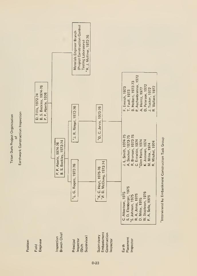

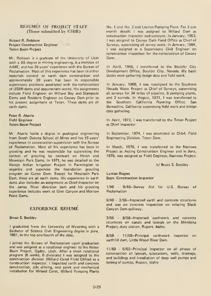
RESUMES OF PROJECT STAFF(Those submitted by USBR)
Robert R. Robison
Project Construction Engineer
Teton Basin Project
Mr. Robison is a graduate of the University of Utah
with a BS degree In nnining engineering, is a member of
AIME, and has 25 years' experience with the Bureau of
Reclamation. Most of this experience has been in either
materials control or earth dam construction and
approximately 20 years has been in responsible
supervisory positions associated with the construction
of USBR dams and appurtenant works. His assignments
include Field Engineer on Willard Bay and Stampede
Dams and Resident Engineer on Causey Dam prior to
his present assignment at Teton. These dams are all
earth dams.
Peter R. Aberle
Field Engineer
Teton Basin Project
Mr. Aberle holds a degree in geological engineering
from South Dakota School of Mines and has 15 years'
experience in construction supervision with the Bureau
of Reclamation. Most of his experience has been in
grouting and he was responsible for supervising the
control of grouting by contract on Heron and
Mountain Park Dams. In 1971, he was detailed to the
Navajo Indian Irrigation Project in Farmington to
organize and supervise the foundation grouting
program on Cutter Dam. Except for Mountain Park
Dam, these are all earth dams. His experience in earth
dams also includes an assignment as Chief Inspector on
the James River diversion dam and his grouting
experience includes work at Glen Canyon and MorrowPoint Dams.
EXPERIENCE RESUME
Bruce S. Beckley
I graduated from the University of Wyoming with a
Bachelor of Science Civil Engineering degree In June,
1961 , In the top one-fourth of the class.
I joined the Bureau of Reclamation upon graduationand was assigned as a rotational engineer to the WeberBasin Project, Ogden, Utah. After a short rotational
program (6 weeks, 6 divisions) I was assigned to the
construction division (Willard Canal Field Office) as a
construction inspector. I Inspected earth and concreteconstruction, pile driving, and paint and mechanicalinstallation for Willard Canal, Willard Pumping Plants
No. 1 and No. 2 and Layton Pumping Plant. For 2 one
month details I was assigned to Willard Dam as
construction Inspector and surveyor. In January, 1963,
I was assigned to Causey Dam Field Office as Chief of
Surveys, supervising all survey work. In January, 1964,
I was assigned as a Supervisory Civil Engineer on
construction inspection for the construction of Causey
Dam.
In April, 1965, I transferred to the Boulder City
Development Office, Boulder City, Nevada. My basic
duties were gathering design data and field work.
In January, 1968, I was reassigned to the Southern
Nevada Water Project as Chief of Surveys, supervising
all surveys for 34 miles of pipeline, 8 pumping plants,
and 2 tunnels. In August, 1971, I was transferred to
the Southern California Planning Office, San
Bernadino, California supervising field work and design
data gathering.
In April, 1972, I was transferred to the Teton Project
as Chief Inspector.
In September, 1974, I was promoted to Chief, Field
Engineering Division, Teton Dam.
In March, 1976, I was transferred to the Narrows
Project as Acting Construction Engineer and in June,
1976, was assigned as Field Engineer, Narrows Project.
/s/ Bruce S. Beckley
Lyman Rogers
Supv. Construction Inspector
1/46 - 9/49-Survey Aid for U.S. Bureau of
Reclamation
9/49 - 3/55— Inspected earth and concrete structures
and was on concrete inspection on refacing Black
Canyon Dam spillway.
3/55 - 8/58— Inspected earthwork and concrete
structures on canals and laterals on the Minidoka
Project, duty station. Rupert, Idaho.
8/58 - 11/59-Principal earthwork
earthfill dam. Little Wood River Dam.
inspector on
11/59 - 6/62—Principal inspector on all phases of
construction of laterals, substations, wells, drainage,
and buildings and installation of deep well pumps and
testing of pumps, Rupert, Idaho
D-25
6/62 - 8/63— Principal inspector on all phases of
pipeline rehabilitation of Dalton Gardens, Hayden
Lake, and Avondale (Coeur d'Alene, Idaho) Districts.
In charge of laboratory and materials.
8/63 - 5/67— Principal inspector on Spokane Valley
Project—approxinnately 100 miles of transit pipeline
(6" to 36" diameter, 34 pumping wells, water tanks
and appurtenant structures.
5/67 - 8/71— Principal inspector to resident engineer in
preconstruction activities—inspected contract drilling
of exploration wells for geologic and hydrologic data.
Established and maintained a water level observation
program with area ground water geologists. Inspected
drilling and testing of test wells for Teton Dam Project.
Snake River Development Office, Boise.
8/71 - 6/76— Principal inspector on a shift on all phases
of construction by contract of the Teton Dam, Power
and Pumping Plant appurtenant structures. Workedunder general supervision of Chief, Inspection Branch.
Jan Ringel,
Supv. Civil Engineer
Graduate Civil Engineer, BBS, 1970
7/67 - 4/71— Engineer Trainee Rotational Program for
the Utah Dept. of Highways which included training in
the following divisions: materials and testing, road-way
design, right-of-way design, hydraulics, transportation
and planning, structure, traffic, construction and
location.
USBR
5/71 - 8/72-Civil Engineer in Regional Office, USBR,Great Falls, Montana. Worked on reports and designed
hydraulic structures, canals and drainage systems in the
design branch. Wrote a set of specifications on a small
drainage project. Worked on Canyon Ferry Dikes
which includes setting alignments of dikes, designing
dikes, and calculating quantities and cost estimates.
Also worked on many smaller routine projects which
required engineering skills.
9/62 - 4/75— Inspected excavation of the damfoundation and structure foundation excavation,
excavation of tunnel portals; shift inspector on the
driving and excavation of the 6-foot diameter tunnel
and a 26-foot diameter shaft 300-feet deep. Also has
been assigned to the earthwork operation in charge of
different zones of earthwork on one shift. Worked with
zones 1, 2, 3, 4, & 5 materials in excavation and placed
zones 1, 2, 3, 4, & 5 in the dam embankment.
Controlled material to obtain material suited for
various zones. Worked in close conjunction with soils
laboratory to obtain a number of density tests required
in relation to yardage placed in the different zones and
through test results varied the methods of placement to
fit material conditions as to suitability on
embankment.
Later assigned to the pumping plant, powerhouse, and
canal inlet and outlet structures setting forms,
miscellaneous metal work, piping, and the installation
of reinforcing steel. Worked closely with surveys in
preparing tack sheets for each placement in these areas
and issued these tack sheets to the contractor.
Discussed with supervisor the progress and problems as
well as relations with the contractor. Also inspected
concrete placements in the past and worked closely
with the laboratory for concrete cylinders, air
entrainment, and slump.
During the early winter months of 1974, supervised
and participated in the planning and formulation of a
comprehensive zoning report to determine the proper
distribution of materials to be placed into Teton Dam.Responsible for coordinating several subordinates to
complete this report on the given deadline. After
completing this report, reassigned to set up and
organize a field office in the power and pumping plant,
and to confer with the contractor's representatives on
the power and pumping plant design.
When the construction started again, assigned to the
spillway as a shift inspector on the drainage trenches
excavation; checked out concrete placement for the
floor and walls to insure that the contractor had
included all embedded materials in the proper location;
conferred with the contractor's representatives on the
interpretation of specifications or standards to the
attention of the contractor and saw that these
conditions were corrected; always advised supervisors
of daily construction progress, daily problems, and
contractor's relations; and attended weekly contractor
safety meetings and worked with the contractor to
keep a safe working condition in the work area.
During the winter months of 1975, again supervised
the planning and formulation of a comprehensive
zoning report to determine the materials distribution
to be placed in the Teton Dam.
Richard McClung
4/25- 12/55-Surveys, U.S.B.R.
D-26
1/58 - 5/58-Worked on canals at U.S.B.R., McCook,
Nebraska. Duties consisted of field density tests,
penetration resistance and moisture test of compacted
embankment and structures backfill to determine the
percent of compaction. Made Atterburg limits tests on
soils samples and operated compression testing
machine for testing the strength of concrete control
cylinders.
4/68 4/70—Supervisory Inspector over the
construction of the Sinlehiken Siphon and Toats
Coulee Diversion Dam which are both a portion of the
White Stone Coulee Unit of the Chief Joseph DamProject. The Sinlehiken Siphon is a 6-mile pipeline
ranging in size from IB-inches to 45-inches in diameter.
Toats Coulee Diversion Dam is a reinforced concrete
structure.
5/58 - 4/60-Worked on an earth filled dam and
pipeline at U.S.B.R., Anadarko, Oklahoma. Duties
consisted of soil classification tests, mechanical
analysis, specific gravity, permeability, compaction,
and penetration of soil. Concrete work consisted of
slump tests and air entrainment tests.
4/60 - 3/61—Construction Inspector at Weslow, Texas,
rebuilding old canals. Checked contractors work on
removing mud and fill of the old canals down to
suitable subgrade. Compacted embankment checking
the material used for moisture content, compaction,
line, and grade. In placing concrete -lining, checked
slump, finish, curing, line, and grade.
3/61 - 2/62-Construction Inspector at St. Paul,
Nebraska, working on structures. Checked subgrade,
placing of concrete in structures, reinforcement steel
for spacing, grade and quantity, stripping of forms, and
finish of concrete and cure. Compacted backfill around
structures, checking for moisture content, degree of
compaction, line and grade. Inspected laying of precast
concrete pipe for drainage and structures, checking
line, grade, and compacted backfill. Worked in tunnel
portion of the time.
2/62 - 4/63— Inspected work on a 230-kV transmission
line at Lewiston, California. Consisted of placing
concrete footings for reinforcement steel and
compacting backfill.
4/63 - 5/65— Principal concrete inspector on Yellowtail
Dam and Powerplant at Forth Smith, Montana.
Inspected embedded items, contractor's concrete
operations, concrete placing in spillway and spillway
tunnel lining.
5/64 - 8/66- Inspector at U.S.B.R. Project at Yuma,Arizona, inspecting the contractor's operations or
constructing pump discharge canal and pipelines.
8/66 4/68— Inspector on the Oraville-Tonasket Unit
of the Chief Joseph Dam Project, Oraville, Washington.
Work consisted of construction of reinforced concrete
pipe cross-strings, concrete lined canals, elevated and
bench flumes, and county road relocations.
4/70 - 10/71—Supervisory Inspector on the pipeline
laterals of the Southern Nevada Water Project.
Principal responsibility was to supervise the
contractor's operations in constructing the pipelines.
10/71 - Present—Shift Inspector at Teton Dam.Supervised inspection of the contractor's operations on
excavation, foundation preparation and placement of
embankment materials, and checking for compaction,
lift thickness, and moisture. Inspected the contractor's
operations in constructing the power and pumping
plant and appurtenant structures for excavation,
foundation preparation, forms, re-steel placing, and
concrete placing.
Kenneth Hoyt
11/64- 5/68-Surveys for U.S.B.R.
5/68 - 9/70-(Missouri Oahe Project, O'Niell, Nebraska)
Construction Inspector on steel tower assembly and
erection, and alinement and location of structures,
including bolting, filling, and bracing of towers.
Inspected forms, reinforcing steel, placement of
concrete, clearing of right-of-way, and construction of
gates.
9/70 - 3/72-(Missouri-Souris Project, Garrison, North
Dakota) Performed inspection duties on installation of
machinery, electrical equipment, metal work, and
piping as required for installation and embedding in
concrete.
3/72 - 7/72-(Missouri-Souris Project, Garrison, North
Dakota) Performed inspection duties on earthwork
including excavation, embankment, backfill, and
compaction, earthlining, concrete construction,
erection of forms, installation of reinforcing steel, and
concrete placing.
7/72 - 3/75— (Navajo Indian Irrigation Project,
Farmington, New Mexico) Inspected installation of
precast concrete pipe for canal siphon and concrete
pipe for canals, drains, siphons, and structures.
Determined suitability of material from excavation for
D-27
use in embankment, backfill, compacted embankment,
and consolidated backfill.
3/75 - Present— (Teton Project, Idaho) Supervised three
to five inspectors in the placing of zones 1, 2, 3, 4, and
5 material and riprap in main dam fill. See that
material is suitable for use in respective zones.
Douglas Jarvie
10/56- 10/59-Surveyor, U.S.B.R.
10/59 • 9/66—Supervisory Surveying Technician,
U.S.B.R.
9/66 - 6/69-Construction Inspector at Meeks Cabin
Dam, Mountain View, Wyoming. Inspected earth
materials at both the borrow area and construction
site. Inspected for suitability of earth materials of the
foundations, dam embankments, road dykes. Checked
for outlet works, spillways, and dykes. Checked
embedded materials, placing procedures, curing and
forming, and grouting operations.
6/69 - 4/71— Supervisory Construction Inspector (Same
as above) Assigned to supervisory and inspecting the
construction of the Lyman Project, which included
Meeks Cabin Dam (earth filled), reservoir, and access
road and other appurtenant structures.
4/71 - 6/72-(Upper Green River Project Office) Served
as principal inspector of the contractor's operation on
the Farson, Eden Irrigation Project. This consisted of
reconstruction or modification of existing canals and
laterals; construction of new canals, laterals, turnouts,
measuring devices, and farm bridges; the remodeling
and updating of the little Sandy Dam outlet work.
6/72 - 6/73— Principal inspector on a shift of the
contractor's operations on Meeks Cabin Dam (earth
filled). This included inspection on the final work on
the dam, reservoir, access roads, and appurtenant
structures.
6/73 - Present— Inspection shift of Teton Dam.
Supervised and inspected the contractor's operations
on excavation of keyway foundation, dewatering and
foundation preparation, placement of embankmentmaterial, and checking for compaction, lift thickness
and moisture. Inspected the contractor's operations in
constructing the power and pumping plant and
appurtenant structures for excavation, foundation
preparation, and forms, re-steel placing, and concrete
placing.
Glen M. Harris
Civil Engineering Technician
5/11/75 - Present— Responsible for administering
construction contracts; coordinating construction
operations; preparing construction cost estimates;
collection of design data; and all related activities.
Assigned specific duties which may include all
functions in developing such progress payments to
contractors, and is responsible for correct
interpretation of the contract specifications in doing
so. Based on knowledge of contract specifications,
computes the computation of quantities including
excavation and backfill for pipelines and pumping
plants, concrete in structures, weights of metal parts,
and weights of reinforcing steel for concrete structures.
Assists in the assembling of data for calculation of
earthwork quantities in borrow areas using aerial
photogrammetric methods. Prepares various drawing or
sketches needed to substantiate computed pay
quantities.
Reviews contractor's drawings for bending and
planning steel reinforcing bars and for forming and
placing concrete in structures to assure conformance
with specification requirements. These drawings and
data are also used for monthly progress estimates and
final payments. Collecting survey information in order
to compute stake-out information for survey crews
working on various boat ramps, recreation areas, access
roads, and pipelines. Also checking computations
before stake-out is performed.
5/10/75 - 7/2/73-Construction Inspector. Performs
inspection duties on contractor's drilling and grouting
operation which include: low pressure blanket holes,
high pressure curtain holes, tunnel and shaft radial
holes, and tunnel backfill grouting.
Carries out a defined grouting schedule in determining
direction, depth and spacing of grout holes, grouting
mixtures and pumping pressures. Keeps daily records
of drilling and grouting operations, refers to supervisor
conditions different from those indicated by previous
instructions, and advises supervisor of foundation
conditions encountered during drilling and grouting
operations.
Working with contract administration during winter
months. This included plotting cross sections, running
end areas and compute columes for payment of access
roads, service roads and earthfill dam.
D-28
Performs inspection duties and prepares daily
inspection reports of earthfill dam. Daily progress and
inspection of zones 1, 2, 3, 4, 5, and other related
features of Teton Dam.
6/30/71 - 5/10/73-Supervisory Survey Technician.
Horizontal and vertical surveys for preconstruction
work. Responsible for keeping daily recordings of
water gaging stations, water storage and release from
reservoir to meet state and local water users allotment.
Responsible for operations of high pressure gate in gate
chambers and control gates in control house.
Due to the nature of Meeks Cabin Dam the various
points were checked twice weekly. Alignment and
settlement points on dam and stilling basin walls. Slope
Indicator drill holes, piezometer wells, slip joints on 62
inch steel liner were checked three times weekly.
6-6-66 - 6-30-68—Working from specific instructions.
Bureau survey manuals. Survey Trade Publications, and
construction specifications and drawings, incumbent
performs the following day to day duties. Served as
party chief to take and record cross sections, establish
horizontal and vertical controls on borrow areas, river
outlets, spillway, reservoir clearing lines, dam axis and
other related features. Records and notes taken and
used from cross sections, horizontal control, vertical
control. Construction progress and monthly estimates
used for payment.
Conducts and submits minutes of planned tool box
safety meetings as required.
3-14-64 - 6-6-66—Accomplishes a varied program of
surveys. Serves as journeyman instrumentman
operating survey instruments.
6/30/68 - 6/30/71—Working from general instructions.
Bureau Survey Manuals, Survey Trade Publications,
and Construction specifications and drawings.
Organizes and assigns work to survey party to
accomplish preconstruction and construction field
surveys on a day to day basis as follows: Horizontal
and vertical surveys, cross section surveys, final
location surveys, and personally supervised work in
progress to insure accuracy. Assembled and reviewed
field noted and sketches, and supervised the
preparation of maps, charts, graphs, etc.
Trained surveymen in general survey activities.
Detail Duties: Detail to Upper Green River Project
Office, Rocks Springs, Wyoming. To perform
construction surveys in connection with canal
enlargements and rehabilitation on the Eden Project.
8-24-70- 11-21-70
Worked as Chief of a sub-party which is usually madeof an instrumentman and one or two helpers. Served as
party chief from 6-2-65 to 1 1 -2-65 with 3 to 5 men.
3-18-62 - 3-14-64— Received general assignments in the
execution of final location and construction surveys on
the Flaming Gorge Dam. Powerplant, and appurtenant
features, requiring the operation of all survey
instruments.
Served as journeyman instrumentman operating survey
instruments, including precision types such as the Wild
T-2 theodilite and precise level, on construction
surveys performing the following work:
Establising precise controls for the alignment of the
dam, powerplant, and spillway, layout of penstocks,
gate frames and guides, turbines, scrollcases, and other
mechanical and electrical equipment.
Detail to the Engineering Division to assist in Office
Engineering functions. Reducing and checking field
notes, plotting cross sections of dam area, borrow
areas, and access roads, computing end areas and
earthwork volumes from cross sections, miscellaneous
computation and drafting as required. 1-3-69 to
4-18-69.
Detail to Office Engineering Division, same as above.
3-3-68 to 5-4-68
Detail to Stampede Dam, for the Lahontan Basin
Project, Carson City, Nevada. To perform survey work
on location of access road to Stampede Dam.Horizontal control, vertical control, original cross
sections and controls for diversion tunnel. 11-7-66 to
12-17-66
Line and grade for excavation of structures. Checks
and adjusts instruments for accuracy. Performs related
duties as assigned.
12-11-60 3-18-62—Served as journeyman levelman,
instrument man for final location and construction
surveys for the Flaming Gorge Dam, power plant,
diversion tunnel, spillway, and access roads.
6-14-59 - 12-1 1-60-Perform responsible duties of a
transitman on pre-construction and preliminary surveys
and duties as a levelman on construction surveys.
Perform duties of rodman on precise controls necessary
to establish and maintain the main control systems
involving the carrying of controls through coordinates,
triangulation, etc. into the working areas of the dam
and related structures.
D-29
2-10-59 - 6-14-59-Engineering Aid. Holds rod for
levelman when precise lines, grades and elevations of
structures are being established for the setting of
concrete forms for foundations of structures. The
laying of water and sewer lines, the location and
grading of roads, and construction features of diversion
works. Sets slope stakes, cross sections, sketches and
records target readings.
4-20-58 • 2-10-59— Engineering Aid. Take samples of
concrete aggregate from field test areas being explored
for potential sources of aggregate as used in
construction. Take regular and special samples of earth
materials, operates simple testing equipment such as
rotap, screens compactors, and related equipment,
make laboratory tests such as standard mechanical
analysis, moisture and specific gravity tests. Field
density, compaction, and penetration analysis. Makesimple computations, compile records data resulting
from tests. Perform related duties as assigned.
12-3-56 - 4-20-58— Laborer. Running gravel gradations
and screening rotap samples for aggregate
investigations. Screening analysis for concrete
aggregate. In charge of weighing and computation for
aggregate investigations for Flaming Gorge Dam and
Diversion tunnel. Various laboratory experience.
Slump test, making cylinders, etc.
10-19-56- 12-3-56-Unemployed
3-56 - 10- 18- 56—Cement Finisher Apprentice.
Construction of compressor station which consisted of
cement finishing of colored cement floors, finishing
sidewalls and foundations. Finishing and pre-pack on
piers and foundations for high pressure tanks and large
stationary motors. Plastering and stuccoing basement
walls. Placing foundations for 6 permanent homes.
Work was performed with vibrators, hand finishing
trowels, markers and edgers. Operation of large mixer
and batching plants, preparing and caring of newly
finished cement floors and driveways.
6-53 - 3-56—Second-class Carpenter. Building and
repairing permanent type houses and garages. Laying
out and constructing foundations for water tanks,
houses, garages. Construction of built-in cabinets,
closets, dressers, redecorating homes, plastering of
walls, wall papering, laying of various types of
linoleum. Operating power equipment such as cross-cut
saw, rip saw, planers, jointers, shapers, band saw, datto
blades, and sanders. Repairs on Railroad bridges, snowfences and stock yards.
3-17-53 - 6-9-53—Private— U.S. Army. Doing various
detail jobs, entered service as a "Medical Hold" and
stayed such until received an Honorable Medical
Discharge.
10-52 - 10-17-53-Second-class
experience as in 6-53 - 3-56.
Carpenter. Same
5-50 - 10-52— Ranch hand. Operating farm machinery,
tractors, mowers, rakes, push rakes, seeding drills,
planting and harvesting of crops such as barley, oats,
and alfalfa, preparing and caring of ground for crops.
Handling and taking care of horses, cattle and sheep.
Construction and repairs of fences. Operating trucks
for marketing of crops and livestock.
Jerry L. Smith
12-1-75 - Present—Compute simple end areas and
volumes. Reduce survey notes. Plotting "X" section of
construction excavation, dam embankment and roads.
Other office work as assigned.
6-1-73 - 12-1-75—Construction inspector for zone #1
dam embankment fill. Contractor time and equipment
and inspection daily reports. Location of compaction
tests. Insepction of contractors equipment.
1-27-69 - 5-31-73—Supervisory survey technician. 20%control, organizes, plans and applies best survey
techniques and procedures in the field in order to
establish horizontal and vertical control for the
accurate layout of the various facilities. 40% field
layout. 15% survey notes. 10% miscellaneous jobs and
15% estimates. Is responsible for taking cross-sections
and other field data for monthly estimates.
9-8-68 1-27-69—Surveying Technician. Operates: Wild
T-2 theodolite on triangulation control and operates
precise leveling instrument. Make field notes of
observations taken from triangulation points. I amresponsible for instructing and informing subordinate
personnel in arc operation and safety requirements.
Have acquired knowledge in the use of life lines and
safety belts.
3-24-68 9-8-68—Surveying Technician. As
instrumentman established triangulation points, bench
marks, reference points, and other necessary control
points for the excavation and construction of
multi-arch dam. Also operate all instruments for
obtaining "X" section, establishing level circuits,
producing lines for construction and taking topog.
D-30
5-7-67 • 3-24-68 — Surveying Technician
Instrumentman. Helped determine fills zones in dam,
around intake structure, stilling basin and spillway. At
the pumping and relift plants, pipe drop and siphon
staked the layout, checked forms, station, grade and
distances, slope stake approximately five miles of
canal.
7-17-65 - 5-7-67 — Survey ing Technician
Instrumentman; establish clearing lines around Phillips
Reservoir. "X" section spillway, dam site, borrow area
and roads. Determined cut lines; dam site, grout
trench, spillway, stilling basin and Black Mountain
road. Spillway, stilling basin and outlet works.
Established and checked joint lines, grades and
stations.
10-1 1-64 - 2-27-65—Surveying Technician. "X" section
construction sites, canals, wasteway, dikes along Sun
River for riprap. On Tiber Dam downstream from
stilling basin for riprap along banks and bridge at
Gibson Dam. Location of 1000' siphon and siphons.
5-54 - 12-54-Station attendant
8-53 - 2-54— Rodman and rear chainman, mostly cross
section roads. Helped run levels.
Stephen D. Elenberger
6-9-74 - Present—Construction Inspector. Drilling,
shooting, excavation, re-bar installation and concrete
forming and placement of the spillway stilling basin.
Also included in this is a sub-terrainian water pressure
relief system. Inspected some of the main fill and key
trench excavation and clean-up for the Dam. When that
was complete, inspected the Dam fill placement and
compaction which consisted of five different types of
fill material which were put in by differing methods
and lifts. Mechanical Installation and painting of
stoplogs, radial bulkhead, radial gates, river outlet
gates, outlet works, shafts metal work, etc. Also
inspected coal-tar enamel application to a steel-lined
tunnel and all painting in power house, pumping plant,
and warehouse.
10-11-64 - 2-27-65—Surveying Technician. As transit
man, helped locate and make section ties to
transmission lines, turn and check accuracy angles,
establish structure sites, "X" section structure legs,
stake steel tower, concrete footing for excavation,
check concrete footing for vertical and horizontal
errors, inspect wood pole transmission lines, excavation
of anchors and hardware on the poles.
10-22-63 - 10-1 1-64—Surveying Technician. As
instrument man, directed head chainman to center line,
turn and check angles for accuracy on Oahe to Eagle
Butte transmission line and Mission, S.D. to Martin,
South Dakota. Profile: transmission lines from Sioux
Falls, S.D. to Ft. Thompson.
5-14-61 - 10-22-63— Engineering aid. Aided in locating
transmission lines, topog. on possible substation sites,
head chainman from Hinton Substation to Spencer,
Iowa and from Denison, Iowa to Creston, Iowa.
Performed inspection on the following: Power house
super structure, roofing plumbing & piping, sewage
system, emergency water and fire system. Penstock
piezometer systems, crane installations, discharge
pipeline, duct bank and canal outlet portion. After the
failure of Teton Dam assisted in some investigation
research and inspection of emergency canal
reconstruction. Also 3 emergency pumping systems
were built and put into service, and had to serve as
water master making sure pumps were kept running to
suit irrigation demands.
3-72 6-9-74—Surveying Technician. Preliminary
surveying of 5 different borrow areas, the various
structures, access roads, recreation areas, and Damproper. Served as Instrumentman and helped organize
work in concurrence with specifications and
contractors needs for survey party chief. Used several
different surveying transites, levels, distance meters,
compasses, etc.
9-60 - 5-14-61-Surveying Aid. Rodman doing "X"sections on creeks; mapping section to be used for
possible irrigation study. Second and third order levels.
2-25-57 - 9-60—Survey aid. Rodman doing topog. 200'
to the inch, on several stretches of creek bottoms. Aschainman I chained out blocks, established control
points approximately every half mile to be used later
for mapping.
2-4-55- 2-1-57-Fireman
6-68 - 3-72—Member of survey crew, progressed to
Instrumentman. Preliminary and construction
surveying were done on the wide base canal with its
many bridges, siphons, box culverts, freeway
relocation, public and private road relocations, railroad
detour and relocation, and a canal inlet headworksstructure. Work with the survey crew was running "P"lines for access roads and determining cut and fill
balances for location for construction.
5-67 - 6-68—Surveying Aid. Assigned to a survey party
which was involved in construction, reconstruction and
D-31
maintenance of Department of Transportation Roads
and Mountain passes. Primary duties were that of any
other rodman-chainman on a survey crew bit was also
assigned as inspector at times. Inspector of paving
operation on the Kingsbury Grade between Lake
Tahoe and Carson Valley, Nevada. Ran Sieve analysis
to make sure the bituminus Plant Mix was within the
limits of mix design and at times served as
weigh-master.
Frank Emrich
9/55- 3/60-Surveying, U.S.B.R.
3/60 - 8/61-(Willard and Ogden, Utah) Performed
standard field and lab tests on construction materials as
required, which included test for investigation and
control for earth and concrete materials.
8/61 - 6/63-(Willard, Utah) Construction Inspector.
Inspected construction work performed by
contractor's forces on Willard Canal, Willard pumpplant, and related works (1) earthwork—canal
embankments and backfills (2) concrete construction
of pumping plants and C.H.O.'s (3) driving of piling
below both pumping plants (4) laying of
pipe—discharge and C.H.O.'s.
6/63 - 10/63— (Yuma, Arizona) Construction
Inspector. Inspected the drilling of 33 drainage wells
located in Wellton Mohawk and South Gila areas.
4/65 - 8/65— (Yuma, Arizona) Construction Inspector.
Inspected quarrying of rock from Pilot Knob rock
quarry.
8/65 - 11/65— (Yuma, Arizona) Construction
Inspector. Inspected installation and erection of
2563.95 foot of 12-foot diameter flume.
11/65 - 5/69— (Corning, California) Construction
Inspector. Inspected construction of Tehama-Colusa
Canal, which included inspection of excavation and
construction of prism and embankments, concrete
placements, and laying of irrigation pipelines.
5/69 - 1/70— (Carson City, Nevada) Civil Engineering
Technician. Performed required tests on earth
materials, concrete, and aggregates. Performed
mechanical inspection duties on swing shift.
1/70 - 5/70— (Carson City, Nevada) Surveying,
U.S.B.R. Detailed to Soils Laboratory (performed lab
tests).
5/70 - 6/72-(McClusky, North Dakota) Construction
Inspector. Inspected construction of McClusky Canal,
Reach 3A. Excavated and constructed canal prism and
embankments; laid CMP road crossing drains. Inspected
fabrication of trashracks and inspected and kept
records on drilling test wells.
6/72 - 3/75-(Teton Dam, Idaho) Construction
Inspector. Inspected construction of all office facilities.
10/63 3/64— (Yuma, Arizona) Construction
Inspector. Inspected 8,000 acres of tile drains in
Wellton Mohawk area and 6 miles of tile drains in
Yuma area.
3/64 - 6/64— (Yuma, Arizona) Construction Inspector.
Inspected and acted as part-time geologist on drilling of
three deep supply or production wells in South Gila
Valley.
6/64 - 4/65— (Yuma, Arizona) Construction Inspector.
Inspected group cap curtain trench excavation,
installation of grout pipe in trench, placing grout cap
concrete and all steps in drilling and grouting of grout
holes. Inspected hauling and placing of materials used
for reservoir blanket, hauling, weighing, and placing of
riprap material, checking slopes while excavating rock
for service roads. Inspected structure subgrade, placing
of structural steel anchor bars while being grouted into
formation, placing of large and small concrete
placements and structural welding on penstock
installation.
Worked on grouting dam's grout curtain, lining outlet
works tunnel, and gate chamber. Worked as checkout
and placing inspector as concrete was placed in
constructing powerhouse and pumping plant.
Occasionally did mechanical inspection. Classified zone
1 material. Inspected contractor's zone 2 excavation
and stockpiling operation. Inspected rock excavation
of dam's cutoff trenches, spillway, and riprap rock
quarry.
Inspected installation of mechanical equipment in
power and pumping plant.
3/75 Present— (Teton Dam, Idaho) Mechanical
Engineer. Inspected contractor's mechanical
installation operations. Inspected materials and
supplies delivered to jobsite. Tested mechanical
equipment.
D-32
Roger P. Michel
Civil Engineer
6/73 9/73
6/72 - 9/72
6/71 - 9/71 -Summer help at the Dakota Utilities Co.,
Montana. Main responsibility was reading gas meters,
however, also worked a small amount of gas pipeline
construction.
6/74 - 2/76—Civil engineer at Teton Dam Project.
Inspection activities include rock excavation, grouting,
drilling, concrete, earthwork, and surveying.
2/76 - Present— Civil Engineer at Teton Project.
Analyze contractors' claims for work changed from the
specifications. This involves reviewing of the
specifications, drawings, and records of labor,
equipment and materials. Such information is used to
establish authenticity of data provided by the
contractor in his change orders. Either a denial of such
claims or a monetary figure of adjustment is derived
from the analysis. Review subcontracts for compliance
to the specifications of the prime contract. Compose
and send letters to the prime contractor indicating
whether or not all requirements have been met and
what additions are necessary for approval.
Corporation. Scheduled production and delivery of
parts to assenribly and shipping. Coordinated between
management and union labor representatives.
5/70 - 6/70-Clerk-Elliott Feed and Farm Supply.
6/70 - 5/71 -Assigned to Yuma Projects Office.
Established location lines, elevation controls, cross
sections of proposed and built structures, topographic
maps and cadastral surveys that pertained to
construction of irrigation and drainage systems and
appurtenant structures. Acted as a rodman and head
and rear chainman. Carried marked and set stakes.
Recorded and reduced field survey notes.
5/71 - 3/72—Rodman and chainman for Mountain Park
Dam Project. Instrumentman on highway relocation
and railroad relocation, established reference points for
construction of complex concrete structures. Promoted
to position of Surveying Technician GS-4.
3/72 - 3/73-Assigned to the Teton Dam Project as
head and rear chainman, rodman and sometimes
instrumentman. In May of 1972, assigned as full time
instrumentman operating electronic measuring devices,
transits, levels precise level, theodolite and alidade.
Performed duties as a surveying technician.
David Miller
Construction Inspector
3/68 - 5/69— Engineering Aid I I/Inspector for the State
Highway Commission of Indiana. Worked in bridge
construction, inspecting embankment placement and
testing of earthwork on bridge approaches and off
ramps of the Interstate Highway system. On bridge
construction, acted as rodman and chainman, checking
layout and grade. Checked reinforcing steel according
to drawings and specifications, set and checked screed
elevations. Performed soil compaction and moisture
tests, concrete Air Entrainment, Yield and Slump test,
Flexural strength tests. Attended the Indiana State
Highway Concrete and Earth School at Purdue
University in West Lafayette, Indiana. Kept records
and made weekly and monthly reports to send to the
regional office.
5/69 - 10/69—Self-employed selling and installing chain
link fences, privacy fences and split rail fences.
Sub-contracted fence installation for the Central
Hardware Chain of St. Louis, Mo. and for the Sears
Corporation.
10/69 - 4/70— Kept records of parts and parts shortages
for the Peerless Pump Division of the FMC
3/73 - 5/74—Assigned to the Lab as a materials
engineering technician. Took samples of earth materials
and performed tests of earth materials. Tested concrete
as it was being manufactured. Performed tests for
slump water-cement ratio, etc.
6/74 - Present—Assigned to the Inspection Rranch of
the Teton Dam. Inspection of contractors drilling and
grouting operations. In June 1974 assigned duties of
inspecting the placement and compaction of the DamEmbankment consisting of Zone 1, Zone 2, Zone 3,
and Zone 5 materials and continued in this until
November 1974 when again assigned duties of grouting
inspector.
Stephen C. Johnson
9/69 - 12/74-Highway Engineer I & II for Washington
State Highway Department. Analyzed roadway design
to determine operational level of service and required
improvement; designed signals, highway signing, and
illumination; surveying (with two months pipe
inspection).
5/75 —Teton Project, Idaho, inspected
placement of dam embankment zones 1 through 5, and
riprap & installation of mechanical equipment in the
D-33

powerhouse; aided in writing final construction report
for Teton Dam.
Richard Jones
Civil Engineer
I. EDUCATIONA. College
1. B.S. Civil Engineering from California State
University @ Fresno, California.
B. 1. Planning and estimating school
2. Builder school— Building techniques
3. Instructor's school
II. EXPERIENCEA. U.S. Navy (SEABEES 4 years)
1. Planning and estimating
a. Manual Network Analysis
1) Originate and complete C.P.M.'s
b. Estimate materials
c. Manpower estimates and updates
2. Quality Assurance
a. Assisted in drafting Q.A. Program
b. Jobsite Inspector
1) Road construction; including
bituminous surfacing
2) Cone, and cone, masonry building
construction
3) Soils and cone, lab
4) Built-up roofing
5) Painting (including texcote)
6) Cone, pre-cast yard
7) Re-bar pre-fab yard
8) Cone, masonry unit fabrication plant
9) Mechanical in buildings
10) Electrical in buildings
3. Minor Design Work
B. Bureau of Reclamation
1. Teton Dam, Newdale, Idaho
a. Jobsite Inspector
1) Left and right abutment fill
2) Left and right key trench fill
3) Placement of rip-rap
4) Placement zones 1, 2, 3, and 5 fill
5) Cone, repair ROW intake structure
6) Painting ROW tunnel
b. Snow Removal
gravel
units,
supply
2. Riverside Park, Palisades, Idaho
a. Jobsite Inspector (90% of Project)
1) Road construction; including
surfacing
2) Cone, and cone, block buildings
3) Mechanical—Chrysler crapper
sprinkler system, and water
(culinary)
4) Electrical-service and bidg. elee.
5) Responsible for field changes,
interpreting bureau specs, etc.
Alvin Heintz
8/55 - 5/60—Surveys for various projects, U.S.B.R.
5/60 - 12/60—Served as concrete batch plant inspector,
Prosser Creek Construction Field Office
12/60- 5/61 -Surveys, U.S.B.R.
5/61 12/61—Performed inspector's duties on Prosser
Creek Dam in borrow pits observing excavation
operations at two separation plants located in zone 1
and zone 2 areas. Worked in coordination with the
different zone inspectors in regard to moisture,
mixture, and compaction of the different materials in
the fill of the embankment area.
12/61 - 5/62-Surveys, U.S.B.R.
5/62 - 1 1/62—Performed inspection duties on Prosser
Creek Dam on the zone 1 and zone 2 embankments
coordinating with the Chief Inspector in regard to
suitable material to be placed and compacted to
specifications. Inspected upstream and downstream
zone 2 embankment, boulder blankets, and the
upstream riprap blanket; excavation on both
abutments; placing of reinforcing steel, embedded
materials, formwork, and cleanup of stilling basin,
control building shaft, installation of drain pipes,
fitters and construction of open drains; Government
and contractor furnished materials to assure
compliance with specification requirements.
11/62- 9/63-Surveys, U.S.B.R.
9/63 - 9/67—As Construction Inspector, assigned to
San Luis Project, worked on the following phases of
D-34
construction: spillway, piezometer, terminal wells, San
Luis Pumping and Generating Plant, including service
yard and switchyard and intake structure.
9/67 - 12/67-At Stampede Dam, Truckee, California,
when was principal inspector over full inspection
operations of the concrete spillway and outlet works
tunnel. Consisted of 1) excavation for spillway and
outlet works stilling basins, wheer footings, and
trenches for perforated drain pipe; 2) drilling and
grouting of anchor bars; installation of perforated drain
pipe; 3) placing of reinforcement steel, concrete, and
finish work; 4) formwork, including embedded
materials.
12/67 • 5/68-Surveys, U.S.B.R.
5/68 • 12/68-Resumed construction work at
Stampede Dam.
12/68- 5/69-Surveys, U.S.B.R.
5/69 - 4/70—Principal inspector on above plus riprap:
placing riprap material adjacent to spillway; chainlink
fence; backfill; second stage concrete intake (pressure
grouting); gate chamber, and stage (pressure grouting).
4/70 - 10/71— Principal inspector at South Nevada
Water Project with responsibilities over all inspection
operations of concrete structures, including electrical,
mechanical, and tunnel operations.
Chama, New Mexico. Informed the tunnel chief of any
changes that occurred in excavated material and
assisted in determining the protection needed on shale
surfaces. Took gas tests and kept complete and
accurate records of gas. Inspected concrete placement
for consolidation, finishing, repair, and curing.
Inspected gunite protective coating installation. From1/66 to 4/67 of this time also inspected conventional
tunnel operations through glacial till and reported
changes of material, installation of steel tunnel liner
plates and backfill behind liner plates.
5/70 - 12/70— Inspected drilling and grouting operation
on U.S.B.R. San Juan-Chama Project. Inspected
placement of dirt fill in dam for moisture content,
required compaction, unsuitable materials in fill,
proper slopes, placement of proper zone materials in
right places, and that fill materials did not freeze.
12/70 - 10/72— Inspected contractor operations at the
Grand Coulee Third Powerplant in Washington.
Inspected various operations of concrete, dirt, and
blasting.
10/72 • —Teton Dam. Chief shift inspector for
grouting work directly under the Chief of Grouting.
Drilling and grouting was done on three curtain
grouting on left and right abutments in welded tuff and
basalt area of cutoff trench, backfill grouting of
diversion tunnel and one curtain grouting on left
abutment and cutoff trench.
10/71 Present—Principal inspector covering
excavation, installation of materials and equipment,
backfill and embankment. This includes placement of
earth, concrete, metalwork, and technical equipment.
Charles Entwisle
5/62 - 11/63-Construction Inspector on U.S.B.R.
Flaming Gorge Unit. Inspected pressure grouting of
contraction joints and inspected and directed grouting
of rock foundation. Included inspection of concrete
cooling, testing, assembling, and embedding stress,
strain, and joint meters.
11/63 - 11/64-Construction Inspector on U.S.B.R.
project at Sanford, Texas. Checked forms for line,
grade, bracing in compliance with the specifications.
Checked reinforcing for size, spacing, position,
clearance, quantities, laps, and shapes. During
placement of concrete, checked mix, vibration,
finishes, protection.
11/64 - 5/70— Inspected tunnel excavation as it
progressed on the U.S.B.R. San Juan-Chama Project,
Karl S. Justesen
9/62- 6/65-Surveys, U.S.B.R.
College
3/66 - 9/66-Surveys, U.S.B.R.
College
6/67 - 11/67— Began work on Starvation Dam,
U.S.B.R. Project at Duchesne, Utah, as Construction
Inspector. Inspected dam foundation excavation,
cutoff trenches, stripping and pre-watering of borrow,
placement of embankment material, proper thickness
of lifts, moisture control, and rolling of embankment.
Inspected final cleanup of foundations and abutments,
and special compaction along abutment.
1 1/67 - 1/68— In charge of shift on grouting operations
on Starvation Dam. Inspected and instructed the
layout of holes to be drilled and grouted. Inspected
water testing of holes, depth of stage drilled, pressure
D-35
to be used. Inspected the grouting of holes, various
mixes to be used, and when to use.
1/68 - 5/68-Assigned to Starvation Dam outlet v\/orks
tunnel. Inspected final cleanup, setting reinforcement
steel, checking the cleanup oiling, setting of steel
forms, ordering concrete and actual placement and
finishing of concrete.
5/68 - 10/68-Shift inspector on Starvation Dam(earthfill dam). Inspected excavation for dam
foundation, cutoff trenches, borrow areas, and
embankment operations. Inspected final cleanup of
abutments and specially compacted zone 1
embankment, and placing of riprap around inlet and
outlet of Starvation Tunnel.
10/68 - 3/70-Shift inspector on Strawberry Aqueduct,
Water Hollow Tunnel and Channel No. 2 Tunnel.
Inspected tunnel excavation, setting of support steel,
centers to be set on, and use of logging.
3/70 - 5/71-Shift inspector on concrete operations of
Water Hollow Tunnel.
5/71 - 11/71 -Shift inspector on the placing of
concrete in both the upper and lower tunnels, both
upper and lower gate chambers, the chute from the
upper tunnel to the outlet works and the outlet works
for both tunnels of the Soldier Creek Dam.
11/71 - 6/73-Construction inspector at U.S.B.R.
office in Provo, Utah. Served as shift inspector on the
Jordan Aqueduct. Inspected trench excavation, the
slope of banks, and subbase that pipe was to be laid on.
Inspected the laying of pipe, checking of joints after
pipe was laid and inspected the placing and compacting
of pipe bedding after bedding was placed and
compacted. Inspected tunnel excavation on three small
tunnels under D&RG Railroad, and the State Highway.
Inspected installing of liner plate, line and grade after
completion of tunnel, and inspected the grouting of
tunnel. Inspected the installation of reinforcement
steel, preparing and actual placing of concrete for
turnout and manholes along aqueduct; after placement
inspected the finishing and repairs of concrete.
Inspected the final cleanup of right-of-way, restoring of
forms ditches, replacing of top rail, and the reseeding
of right-of-way through nonagricultural land.
11/71 - -Teton Dam. Inspection on all phases of
foundation grouting, blanket grouting, backfill
grouting and tunnel radial hole grouting, grouting of
trench drain under zone 1 embankment and in the
powerhouse. Instructed inspector as to holes to be
drilled, depth of hole, stage pressure, and mix to use.
D-36
APPENDIX D 2
CONSTRUCTION PHOTOGRAPHS

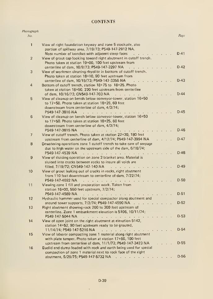
CONTENTS
Photograph
No. Page
1 View of right foundation keyway and zone 5 stockpile, also
portion of spillway area, 7/19/73; P549-147-291 2 NA.
Note number of benches with adjacent steep faces D-41
2 View of grout cap looking toward right abutment in cutoff trench.
Photo taken at station 19+00, 100 feet upstream from
centerline of dam, 10/9/73; P549-147-3297 NA D-42
3 View of workmen cleaning rhyolite in bottom of cutoff trench.
Photo taken at station 18+10, 90 feet upstream from
centerline of dam, 10/15/73; P549-147-3356NA D-43
4 Bottom of cutoff trench, station 18+75 to 18+25. Photo
taken at station 18+50, 220 feet upstream from centerline
of dam, 10/16/73; CN549-147-703NA D-44
5 View of cleanup on bench below conveyor-tower, station 16+50
to 17+50. Photo taken at station 18+25, 60 feet
downstream from centerline of dam, 4/3/74;
P549-147-3816NA D-45
6 View of cleanup on bench below conveyor-tower, station 16+50
to 17+50. Photo taken at station 18+25, 60 feet
downstream from centerline of dam, 4/3/74;
P549-1 47-381 5 NA D-46
7 View of cutoff trench. Photo taken at station 22+30, 180 feet
upstreamfromcenterlineof dam, 4/12/74; P549-147-3994 NA .... D-47
8 Dewatering operations zone 1 cutoff trench to take care of seepage
due to high water on the upstream side of the dam, 6/18/74;
P549-147-4539 NA D-48
9 View of sluicing operation on zone 2 blanket area. Material is
sluiced into cracks between rocks to insure all voids are
filled, 7/19/72; CN549-147-140NA D-49
10 View of grout leaking out of cracks in rocks, right abutment
from 1 10 feet downstream to centerline of dam, 7/22/74;
P549- 1 47-4692 NA D-50
11 Viewing zone 1 fill and preparation work. Taken from
station 16+00, 550 feet upstream, 7/2/74;
P549-1 47-4589 NA D-51
12 Hydraulic hammer used for special compactor along abutment and
around tower supports, 7/2/74; P549-1 47-4590 NA D-52
13 Right abutment showing rock 260 to 300 feet upstream of
centerline. Zone 1 embankment elevation is 5106, 10/11/74;
P549-1 47-5044 NA D-53
14 View of open joint on the right abutment at elevation 5142,
station 14+52, 90 feet upstream ready to be grouted,
1 1/14/74; P549-147-5216NA D-54
15 View of laborer compacting zone 1 material along right abutment
with plate tamper. Photo taken at station 17+60, 100 feet
upstream from centerline of dam, 11/1/73; P549-147-3423NA .... D-55
16 Euclid end dump loaded with rock and earth being used for special
compaction of zone 1 material next to rock face of the right
abutment, 5/29/75; P549-147-5732NA D-56
D-39
CONTENTS-Continued
Photograph
No. Page
17 Left abutment zone 1 . Laborer using a hand held air driven
compactor to compact zone 1 material up to rock face of
downstream left abutment, 5/27/75; P549-147-5731 NA D-57
18 Right key trench showing workmen cleaning up rock face,
station 9+25, prior to the placement of zone 1 in the
key trench, 6/26/75; P549-1 47-6241 NA D-58
D-40
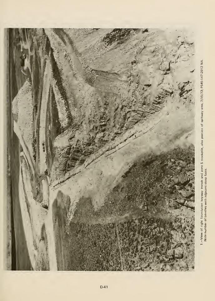
<
O wN g
C "^
CO Q.r- <"
5 2C ">
0) ^
> "^iCD .2,
> CO
l!*- CDCD ^a oc cD 03
o n
>- EO 35
=
^1
D-41
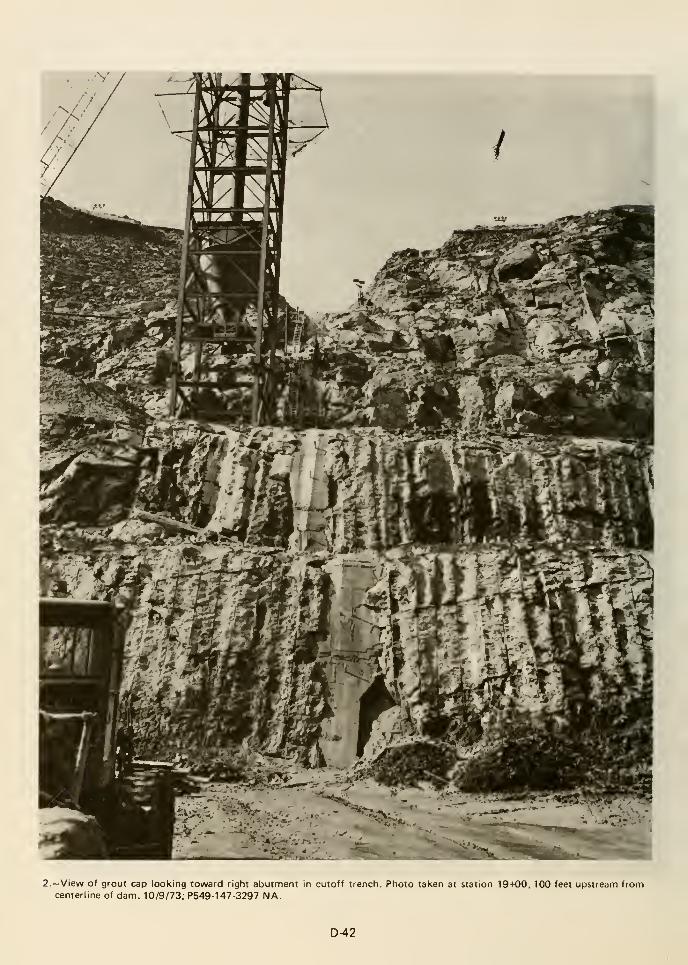
2.—View of grout cap looking toward right abutment in cutoff trench. Photo tal<en at station 19+00, 100 feet upstreann fromcenterline of dam. 10/9/73; P549-1 47-3297 NA.
D-42
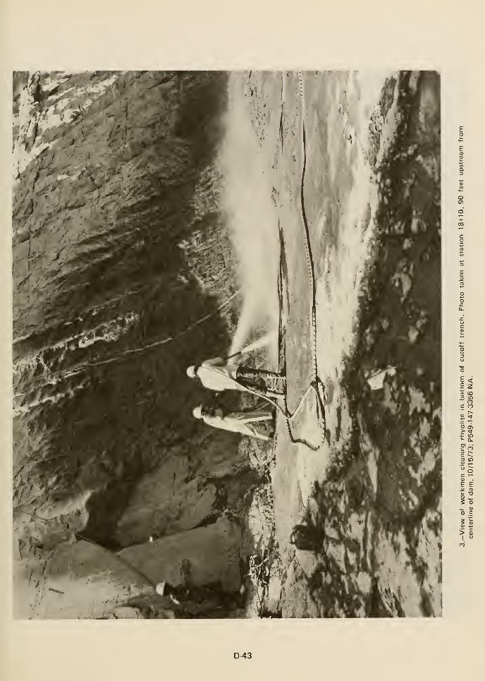
o
O+CO
O 05
E E
g o
5 5;0) 4-
>I
D-43
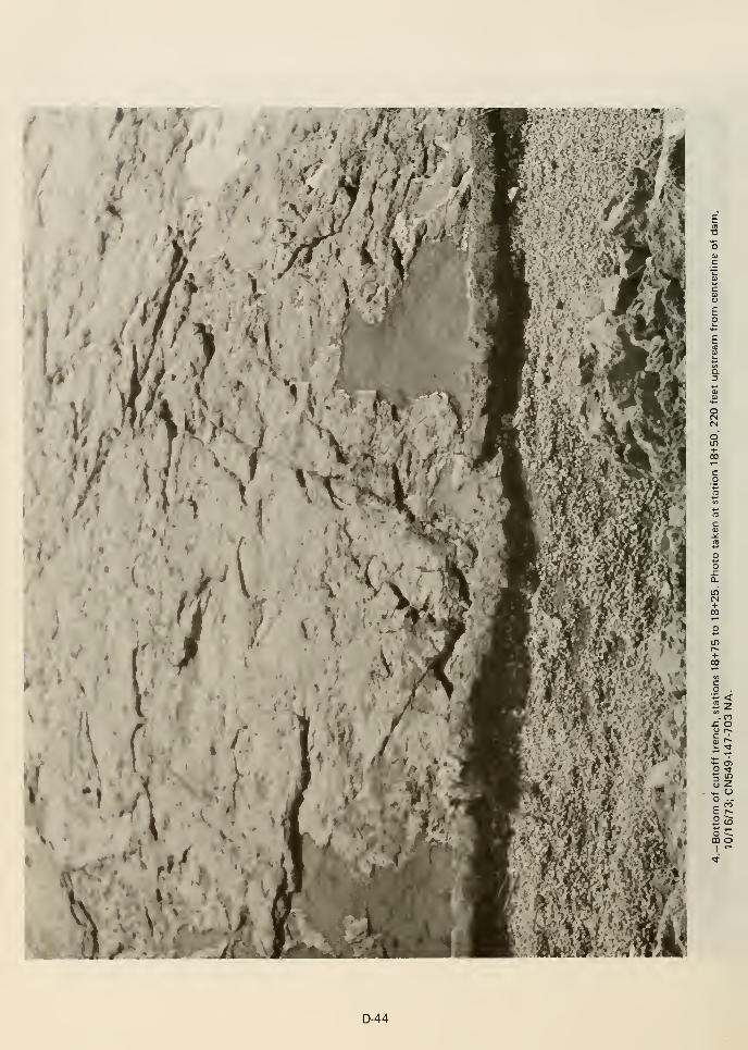
ECD
•D
OO
a.
+00
o
P" CO-C Oo r^
O Tt
o Z^ Uo ..
c "
o ^00 o
D-44
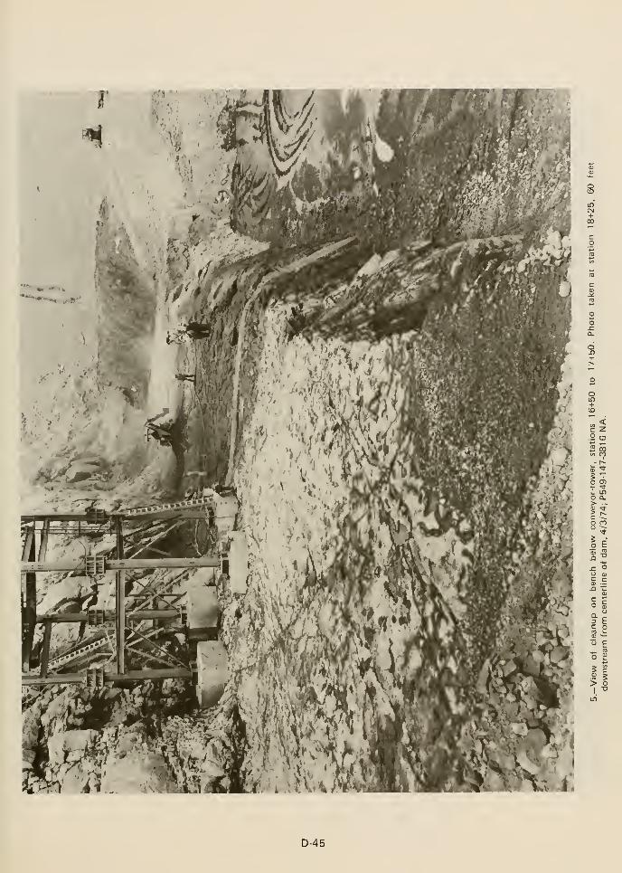
inCM+00
^ <c Z
s^
o o^*:' "^^ IDO Q-
O CI
Ie
> o
D-45
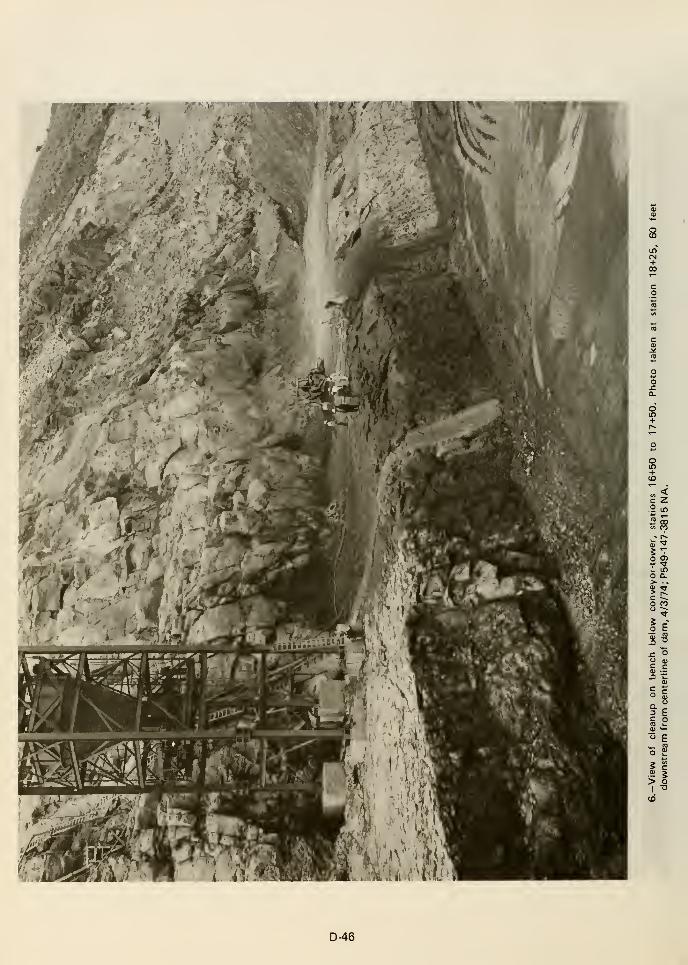
sin
+00
2 00in M- p^
o o^
L inO Q.
O CO
Ie
^ o
= E5 °
" E
>
D-46
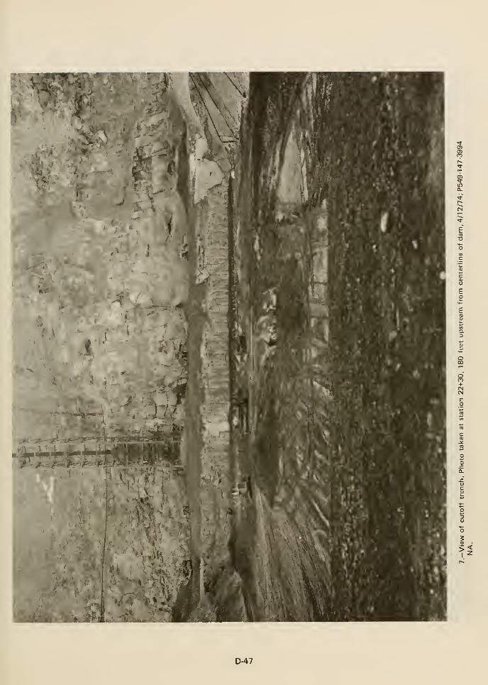
i
1^ «awe'-
f.
f
R?
in0.
ECO
T3
'o
oCO
8
U
D-47

Eto
c <P 2
.9^ro (^
o O)
D-48
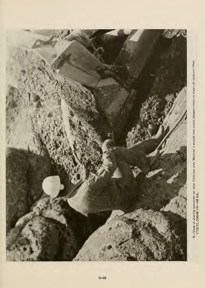
r
(N
:• o
O CN
0) G)
D-49
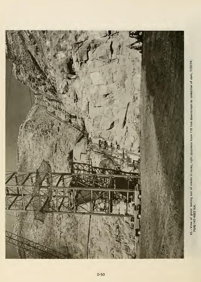
^<
o r~
D-50
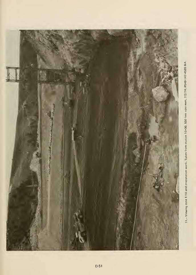
05COin
05
If)
oIT)
in
>I
D-51
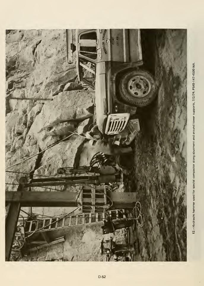
<2.
oo
>I
I
D-52
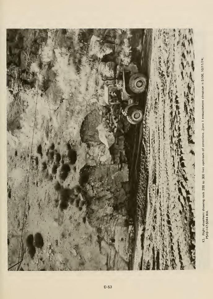
IDO
e
Oo
s
^ <c 2
E ^
JO 1-
D-53
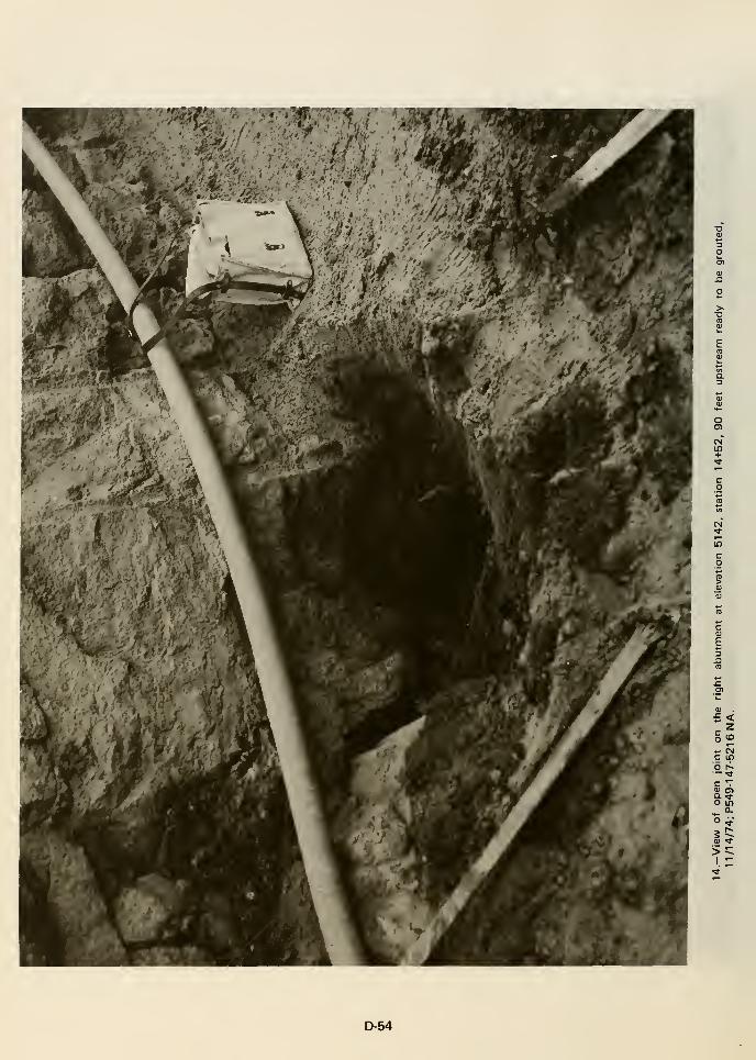
oO)
cm"in+
o r~— 'C
c "7
o in0.
>I
:
D-54

oo
8
CD <J
XI CMCD ^»- n
1$
Isra Q.
ra CO
E -
o -°
N M-
ai °C 0)- c
is
£io ^
5 a
>I
D-55
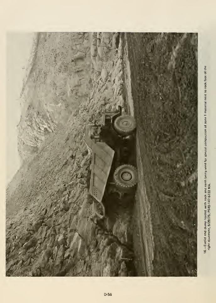
aeo
P r^
; cn
o C;
a (N
X) .-
£ E
D-56
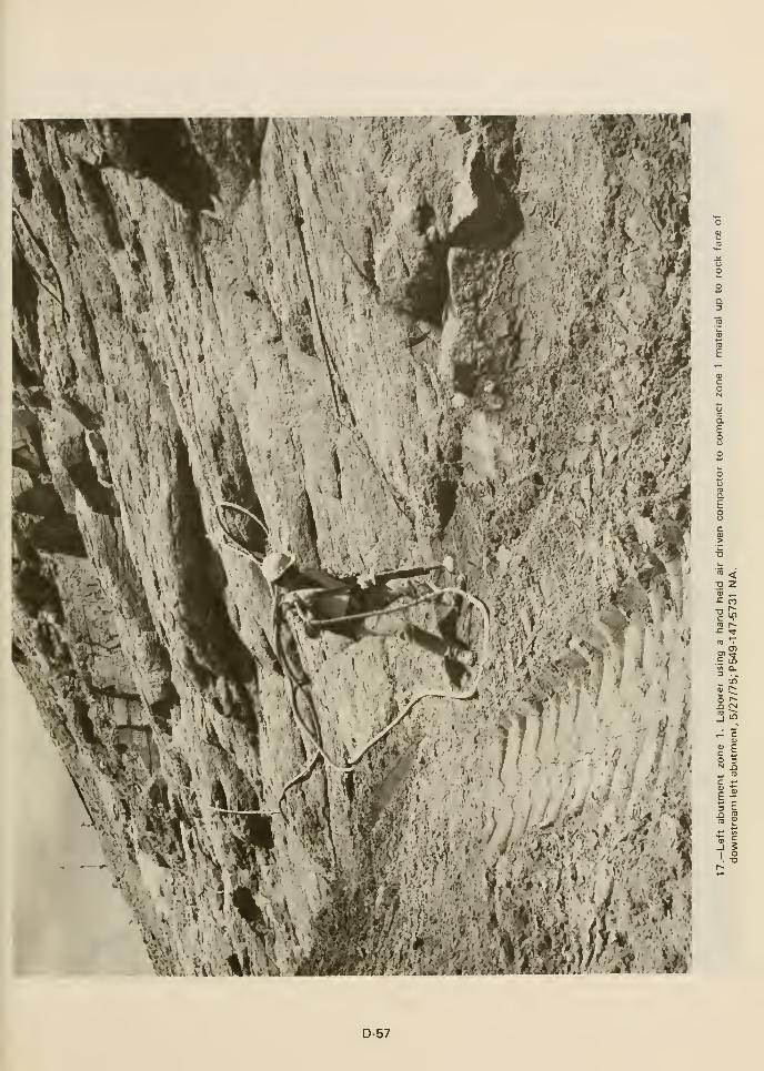
1.. '^W. :i&^t-„^v::'
i '• v:'-V/,'.'1; *ig|, JJ
o
a.
o Z= n
CD r^= •*
E inu> a.
^ in
o r^J3 CN]
0}
O 3N ^
if
^ I
''^M^iim'^M
D-57
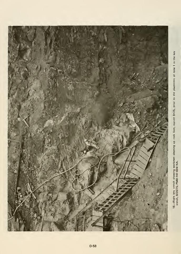
i
>-(0
to
00
D-58

APPENDIX D 3
CONSTRUCTION SPECIFICATIONS
FOR
EMBANKMENT EARTHWORK
AND
RELATED FOUNDATION TREATMENT

Specifications No. DC-6910Volume 1 of 4
(Schedule and Paragraphs 1 to 203, inclusive)
VOLUME 1
UNITED STATES
DEPARTMENT OF THE INTERIOR
BUREAU OF RECLAMATION
Schedule, General Provisions, and Specifications
TETON DAM
AND
POWER AND PUMPING PLANT
Lower Teton Division
Teton Basin Project, Idaho
Bids will be received by the Bureau of Reclamation, at the Council Chambers in City Hall, Idaho Falls, Idaho,
until 10 a.m. (local time at the place of bid opening), September 9, 1971. Bids submitted by mail should be
addressed to the Bureau of Reclamation, c/o U.S. Geological Survey, Post Office Box 697, Idaho Falls, Idaho
83401.
(PRICE-VOLUMES 1, 2, 3, and 4-$17.00)
REPRINT
D-61

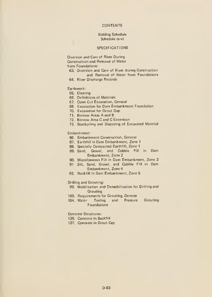
CONTENTS
Bidding Schedule
Schedule (a-v)
SPECIFICATIONS
Diversion and Care of River During
Construction and Removal of Water
from Foundations:
63. Diversion and Care of River during Construction
and Removal of Water from Foundations
64. River Discharge Records
Earthwork:
65. Clearing
66. Definitions of Materials
67. Open Cut Excavation, General
68. Excavation for Dam Embankment Foundation
70. Excavation for Grout Gap
71. Borrow Areas A and B
72. Borrow Area C and C Extension
73. Stockpiling and Disposing of Excavated Material
Embankment:
86. Embankment Construction, General
87. Earthfill in Dam Embankment, Zone 1
88. Specially Compacted Earthfill, Zone 1
89. Sand, Gravel, and Cobble Fill in DamEmbankment, Zone 2
90. Miscellaneous Fill in Dam Embankment, Zone 3
91 Silt, Sand, Gravel, and Cobble Fill in DamEmbankment, Zone 4
92. Rockfill in Dam Embankment, Zone 5
Drilling and Grouting:
99. Mobilization and Demobilization for Drilling and
Grouting
100. Requirements for Grouting, General
104. Water Testing and Pressure Grouting
Foundations
Concrete Structures:
136. Concrete in Backfill
137. Concrete in Grout Cap
D-63

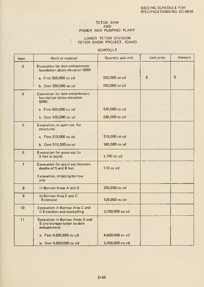
BIDDING SCHEDULE FORSPECIFICATIONS NO. DC-6910
TETON DAMAND
POWER AND PUMPING PLANT
LOWER TETON DIVISIONTETON BASIN PROJECT, IDAHO
SCHEDULE
Item
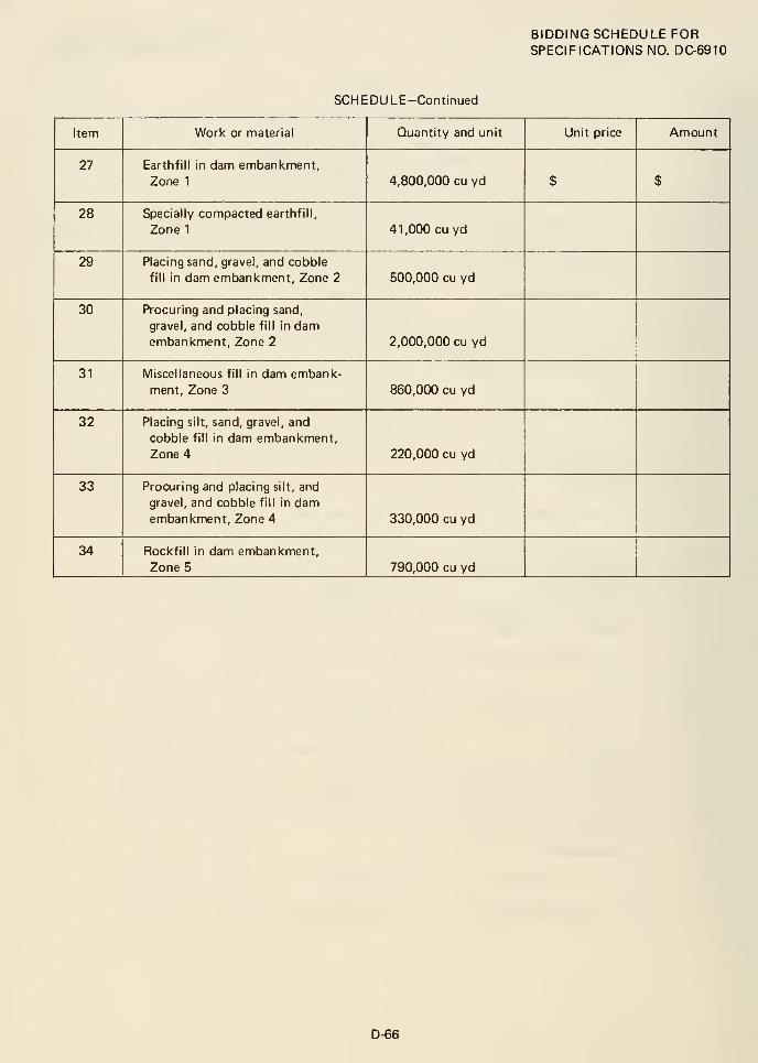
BIDDING SCHEDULE FORSPECIFICATIONS NO. DC-6910
SCHEDULE-Continued
Item
Par. 63
DIVERSION AND CARE OF RIVER DURINGCONSTRUCTION AND REMOVAL OF WATER
FROM FOUNDATIONS
63. DIVERSION AND CARE OFRIVER DURING CONSTRUC-TION AND REMOVAL OFWATER FROM FOUNDATIONS
a. General.—The contractor shall construct and
maintain all necessary cofferdams, channels, flumes,
drains, sumps, and/or other temporary diversion and
protective works and temporary stream crossings;
shall furnish all materials required therefor; shall
furnish, install, maintain, and operate all necessary
pumping and other equipment for removal of water
from the various parts of the work and for
maintaining the foundations and other parts of the
work free from water as required for constructing
each part of the work. The downstream cofferdams
shall be located so as to minimize silting of the
tailrace channel from underwater excavation of
cofferdams and wet placement of bedding for riprap
and riprap.
All cofferdams or other temporary diversion and
protective works constructed upstream from the
dam and not a part of the permanent damembankment shall be removed or leveled and graded
to the extent required to prevent obstruction in any
degree whatever of the flow of water to the spillway
or outlet works.
The contractor shall be responsible for and shall
repair at his expense any damage to the
foundations, structures, or any other part of the
work caused by floods, water, or failure of any part
of the diversion or protective works.
All contractor operations shall be such as to prevent
pollution of the river in accordance with Paragraph
60.
b. Plan.—Prior to beginning any work on diversion
and care of river and removal of water from
foundations, the contractor shall submit to the
Construction Engineer for approval, a water control
plan showing his proposed method for the diversion
and care of the river during construction and
removal of water from foundations. For paymentpurposes, the plan shall be in not more than 12
major divisions as provided in Subparagraph f. Theplan may be placed in opwration upon approval, but
nothing in this paragraph shall relieve the contractor
from full responsibility for the adequacy of the
diversion and protective works.
c. Diversion and care of river.—Because of fish
requirements, and because of downstream irrigation
requirements between May 1 and September 30, the
contractor shall not interrupt the natural flow of
the Teton River through the damsite except that the
contractor will be permitted to reduce such flow in
the amount of water available for construction
purposes as provided in Paragraph 52 and during the
period of closure of the river outlet works the
contractor will be permitted to reduce the flow past
the dam as provided in Subparagraph (6) below.
For the purpose of diverting the flow past the
damsite the contractor will be permitted to:
(1) Pass the flow over the dam embankmentcompleted to the top of the cutoff trench:
Provided, That flow through the damsite shall
not be raised higher than the elevation of the
present channel.
(2) Use temporary pipe, flume, or other
approved facilities for conveying flow through
the damsite. Drop structures shall be constructed
as required to minimize erosion. No pipe, flume,
or other facility will be permitted to be
embedded in the dam embankment.
(3) Leave a temporary gap in the damembankment in accordance with Paragraph 86:
Provided, That flow through the damsite shall
not be raised higher than the elevation of the
present channel.
(4) Use the river outlet works for diversion
purposes after completion of the following
construction, both temporary and permanent:
(a) River outlet works diversion inlet channel.
(b) Open-cut excavation
structure and gate chamber.
above intake
(c) Open-cut excavation for the canal outlet
works structure, and for the river outlet works
structures and outlet channel upstream from
Station 34-H70.
(d) Open-cut excavation for the power and
pumping plant, tailrace retaining walls, and
80-foot-wide tailrace channel immediately
D-67
Par. 63
downstream from the powerplant.
(e) All other required open-cut excavation
which requires blasting within 50 feet of
completed portions of the structures.
(f ) All first-stage concrete in the river outlet
works structures, except concrete in intake
structure above elevation 5141 .00 and in shaft
house and shaft above the construction joint
at elevation 5295.
(g) Bypass in diversion inlet consisting of
36-inch slide gate, trashrack, lift, and pipe.
(h) Diversion inlet stoplog seats and blockout
concrete at upstream end of diversion inlet
structure.
(i) Pressure grouting of foundation
surrounding river outlet works intake
structure, tunnel, gate chamber, and shaft.
(j) Embedded 36-inch pipe in channel lining
for canal outlet branch.
(k) Reservoir level gage piping which is
embedded in concrete.
(5) Use the auxiliary outlet works for diversion
purposes in conjunction with use of the river
outlet works for diversion purposes in
accordance with (4) above, after completion of
the following:
(a) Auxiliary outlet works complete below
elevation 5295.00, including a reliable
temporary power source for gate operation
and temporary controls for gate operation,
furnished by and at the expense of the
contractor and as approved by the contracting
officer.
(b) Spillway complete downstream from the
contraction joint at Station 33-^84, including
completion of riprap in the outlet channel.
(6) The auxiliary outlet works shall be used as
the only method of diversion during the period
of closure of the river outlet works as provided
below. The period of closure of the river outlet
works shall begin on October 1 and shall be
completed by the following April 30. Prior to use
of the auxiliary outlet works as the only method
of diversion and prior to initiating closure of the
river outlet works the following construction
shall be completed:
(I) Embedded 13.5-foot inside-diameter steel
penstock between gate chamber and
downstream portal.
(m) Upstream embedded penstock transition
leading to the 10-foot 6-inch by 13-foot
6-inch wheel-mounted gate chamber.
(n) Approved temporary protection of
first-stage concrete, reinforcing, waterstops,
recesses for second-stage concrete, grout
outlets and vents, covers for wall openings in
channel lining, recess for canal outlet branch,
and upstream edge of stilling basin dividing
wall.
(o) Pervious backfill and riprap for stilling
basin as directed.
(p) Minimum size outlet channel downstream
from stilling basin.
The upstream Zone 4 portion of the damembankment may be incorporated into the
cofferdam during the fjeriod of diversion through
the outlet works.
(a) Dam embankment complete to elevation
5332.0.
(b) All first-stage concrete in river outlet
works intake structure and installation of
intake bulkhead seat and gate and trashracks.
(c) All first-stage concrete in river
works shaft house and shaft.
outlet
(d) Complete spillway, including completion
of riprap in the outlet channel.
(e) Complete auxiliary outlet works,
including a reliable temporary or permanent
power source for gate operation. This power
shall be available for the remainder of the
contract period.
(f) Canal outlet works and control structure
and Enterprise-East Teton feeder pipeline
complete to access road Station 19-KX).
Prior to diversion through the auxiliary outlet
works, all sediment, rocks, and debris shall be
D-68
Par. 63
removed from the auxiliary outlet works and the
spillway stilling basin.
During the period of diversion through the axuiliary
outlet works and prior to April 30, the contractor
shall: close the river outlet works and place the
second-stage concrete in the intake structure and
gate chamber; install the outlet works gates,
penstock manifold, outlet pipe and other
appurtenant metalwork and equipment; and
complete the tailrace channel.
The contractor shall complete the closure and
perform all construction required to complete the
river outlet works and the powerplant tailrace,
during the specified closure period to the extent
that the full release of available water maycommence through the river outlet works by May 1.
Prior to May 1, the contractor shall provide reliable
temporary or [wrmanent power source for testing
and operating all gates in the spillway and river
outlet works. The power source shall be available
for the remainder of the contract period.
d. Removal of water from foundations.—The
contractor's method of removal of water from
foundation excavations shall be subject to the
approval of the contracting officer. The use of a
sufficient number of properly screened wells or
other equivalent methods will be approved for
dewatering.
Where excavation for the cutoff trench and for the
foundation key trenches in embankmentfoundations, and excavation for the spillway, outlet
works, power and pumping plant structures, and for
the pipelines, extends below the water table in
common material, the portion below the water table
shall be dewatered in advance of excavation. The
dewatering shall be accomplished in a manner that
will prevent loss of fines from the foundation, will
maintain stability of the excavated slopes and
bottom of the excavation, and will result in all
construction operations being performed in the dry.
The contractor shall be responsible for and shall
repair at his expense any unstable slopes and
structural damage that may occur during the
dewatering operations.
The contractor will also be required to control
seepage along the bottom of the dam embankmentcutoff trench and the foundation key trenches,
which may require supplementing the approved
dewatering systems by pipe drains leading to sumps
from which the water shall be pumped. Such pipe
drains shall be of uniform diameter for each run,
shall be provided with grout connections and
returns at 50-foot intervals, and shall be embedded
in reasonably well-graded gravel or like material.
During the placing and compacting of the
embankment material in the dam embankmentcutoff trench, the water level at every point in the
cutoff trench shall be maintained below the bottom
of the embankment until the compacted
embankment in the cutoff trench at that point has
reached a depth of 10 feet, after which the water
level shall be maintained at least 5 feet below the
top of the compacted embankment. When the
embankment has been constructed to an elevation
which will permit the dewatering systems to
maintain the water level at or below the designated
elevations, as determined by the contracting officer,
the pipe drains and sumps including surrounding
gravel, shall be filled with grout composed of water
and cement or clay.
EARTHWORK
66. DEFINITIONS OF MATERIALS
Materials excavated will not be classified for payment.
For purposes of these specifications, other than for
payment, materials of earthwork and embankment
construction are defined in detail as follows:
a. Rock.—A sound and solid mass, layer, or ledge of
mineral matter in place and of such hardness and
texture that it:
(1) Cannot be effectively loosened or broken
down by ripping in a single pass with a late
model tractor-mounted hydraulic ripper
equipped with one digging point of standard
manufacturer's design adequately sized for use
with and propelled by a crawler-type tractor
rated between 210- and 240-net flywheel
horsepower, operating in low gear, or
(2) In areas where the use of the ripper
described above is impracticable, rock is defined
as sound material of such hardness and texture
that it cannot be loosened or broken down by a
6-pound drifting pick. The drifting pick shall be
Class D, Federal Specification GGG-H-506d, with
handle not less than 34 inches in length.
b. Common material.—All earth materials which do
D-69
Par. 66
not meet the requirements of rock as defined in a.
above.
c. Formation.—Any sedimentary, igneous, or
metamorphic material represented as a unit in
geology, generally called rock but not necessarily
meeting the classification requirements for rock in
a. above.
d. Cobbles.— Rounded pieces of rock which are not
greater than 12 inches, but are larger than 3 inches
in maximum dimension.
e. Boulders.— Detached pieces of rock, generally
rounded but may be subrounded to angular, which
are larger than 12 inches in maximum dimension.
f. Rock fragments,
are not rounded.
-Pieces of rock which generally
g. Soil components.—NOTE: Soils in nature usually
consist of a number of soil components. They are
identified by the predominance of one of the
components and other criteria given in the Unified
Soil Classification System. See notes on drawings of
logs of explorations.
(1) Clay. -Plastic soil which
States Standard No. 200 sieve.
passes a United
(2) Silt.—Nonplastic soil which passes a United
States Standard No. 200 sieve.
(3) Sand.—Mineral grains which pass a United
States Standard No. 4 sieve and are retained on a
United States Standard No. 200 sieve.
(4) Gravel.—Pieces of rock which are not greater
than 3 inches in maximum dimension, and are
retained on a United States Standard No. 4 sieve.
h. Other materials.—
(1) Slopewash.—Pebble- to boulder-size angular
fragments of rhyolite or tuff In a silty soil
matrix.
(2) Talus.—Pebble- to boulder-size angular
fragments of rhyolite or tuff.
(3) Alluvium.—Silt, sand, gravel, and somecobbles.
(4) Sandstone.—Sand that has been cemented to
some degree.
(5) Siltstone.—Silt that has been cemented to
some degree.
(6) Claystone.—Clay that has been cemented to
some degree.
(7) Rhyolite.— Fine-grained mass of natural
minerals, hard and coherent except along
fractures and where locally weathered.
(8) Tuff.—A material of relatively light weight
formed by consolidation of volcanic ash and
dust.
(9) Lapilii tuff.—Tuff with numerous volcanic
fragments that are larger (generally 4 to 32
millimeter) than fragments comprising matrix.
(10) Welded tuff.-Used
rhyolite in this case.
synonymously with
67.
(11) Basalt.—Very fine-grained mass of natural
minerals, hard and coherent except along
fractures and where locally weathered.
OPEN-CUT EXCAVATION,GENERAL
a. General.—All open-cut excavation required for
the dam, power and pumping plant, tailrace
channel, and appurtenant works shall be performed
in accordance with this paragraph and Paragraphs 68to 70, inclusive. Open-cut excavation in borrow
areas shall be in accordance with Paragraphs 71 and
72. Excavation for pipe trenches and structures for
the Enterprise-East Teton Feeder Pipeline between
Stations 0-KX) and 58-1-50, and for the pumpdischarge line between Stations 3-1-60.93 and
12-1-03.50, shall be in accordance with Paragraphs
291 and 294. Excavation for roadway shall be in
accordance with Paragraph 312.
Excavation shall be made to the lines, grades, and
dimensions shown on the drawings or established by
the contracting officer.
During the progress of the work. It may be found
necessary or desirable to vary the slopes, grades, or
the dimensions of the excavations from those
specified herein. Any increase or decrease of
quantities excavated as a result of such variations
will be Included in the estimates. However, if the
contracting officer determines that the contractor's
costs of performing the work will be increased by
reason of such variations, an equitable adjustment
D-70
Par. 67
will be made to cover such increased costs.
Otherwise, the work will be paid for at the unit
prices bid therefor in the schedule regardless of such
variations.
Where ripping is used for excavation the ripper
tooth shall not be operated closer than 4 feet to the
final excavation line and the excavation shall be
completed by light blasting, wedging, barring,
channeling, line drilling and broaching, or other
suitable methods approved by the contracting
officer.
All blasting for excavation shall be subject to the
provisions of this paragraph and to the provisions of
Paragraph 53. All necessary precautions, including
control of blasting, shall be taken to preserve the
material below and beyond the established lines of
all excavation in the soundest possible condition.
Whenever, in the opinion of the contracting officer,
further blasting might injure the material upon or
against which concrete is to be placed, the use of
explosives shall be limited to light loads, and the
excavation shall be completed by light blasting,
wedging, barring, channeling, line drilling and
broaching, or other suitable methods approved by
the contracting officer. Any damage to the work
due to the contractor's operations, including
shattering of the material beyond the required
excavation lines, shall be repaired at the expense of
and by the contractor. Slopes shattered or loosened
by blasting shall be taken down at the expense of
and by the contractor.
Blasting shall be done using lift (or bench) heights
not greater than 24 feet and using blast holes having
diameters not greater than 3 and 1/2 inches:
Provided, That as the excavation for structure
foundations approaches the final excavation lines,
the depths of the blast holes shall not exceed
one-half of the depth of the rock remaining above
the final grade: Provided further. That the final 5
feet of rock to be excavated for structure
foundations shall be blasted and excavated as a
separate operation.
Any and all excess excavation for the convenience
of the contractor or overexcavation performed by
the contractor for any purpose or reason, except as
may be ordered in writing by the contracting
officer, and whether or not due to the fault of the
contractor, shall be at the expense of the
contractor. Where required to complete the work,
all such excess excavation and overexcavation shall
be refilled with materials furnished and placed at
the expense of and by the contractor: Provided,
That payment will be made for cement used in
concrete placed to refill such excess excavation or
overexcavation unless such excess excavation or
overexcavation is caused by careless excavation or is
intentionally performed for the convenience of the
contractor to facilitate his operations, as determined
by the contracting officer.
All excavation for embankment and structure
foundations shall be performed in the dry. Noexcavation shall be made in frozen materials
without written approval. No additional allowance
above the unit prices per cubic yard bid in the
schedule for excavation will be made on account of
any of the materials being wet or frozen.
Excavations shall be made to the full dimensions
required and shall be finished to the prescribed lines
and grades except that individual sharp points of
undisturbed formation material will be permitted to
extend within the prescribed lines not more than 6
inches where the excavation surfaces are not to be
covered with concrete or are not required as a
foundation for pipe.
d. Excavated materials.—So far as practicable, as
determined by the contracting officer, all suitable
materials from excavations for specified permanent
construction shall be used in the permanent
construction required under these specifications.
Materials shall be selected as follows:
(1) Mixtures of clay, silt, sand, gravel, and
cobbles less than 5 inches in maximumdimensions shall be used in Zone 1 of the dam
embankment.
(2) Reasonably well-graded pervious mixtures of
sand, gravel, and cobbles less than 12 inches in
maximum dimension shall be used in Zone 2 of
the dam embankment.
(3) Miscellaneous mixtures of clay, silt, sand,
gravel, cobbles, and rock fragments less than 12
inches in maximum dimension shall be used in
the Zone 3 of the dam embankment.
(4) Mixtures of silt, sand, gravel, and cobbles less
than 12 inches in maximum dimensions shall be
used in the Zone 4 of the dam embankment and
for Zone 4 to the left of the tailrace channel.
D-71
Par. 67
(5) Cobbles, boulders, and rock fragments less
than 1 cubic yard in volume shall be used in the
Zone 5 of the dam embankment.
Any roots larger than one-fourth inch in diameter
excavated with otherwise suitable material shall be
removed prior to compaction on the embankment.
Excavated materials which are unsuitable for or are
in excess of dam embankment or other earthwork
requirements, as determined by the contracting
officer, shall be wasted as provided in Paragraph 73.
The contractor's blasting and other operations in
excavations shall be such that the excavations will
yield as much suitable material for such
construction as practicable, and shall be subject to
the approval of the contracting officer. Where
practicable, as determined by the contracting
officer, suitable materials shall be excavated
separately from the materials to be wasted and the
suitable materials shall be segregated by loads during
the excavation operations. The suitable materials
shall be placed in the designated final locations
directly from the excavation, or shall be placed in
temporary stockpiles and later placed in the
designated locations as directed by the contracting
officer. In excavating materials which are suitable
for use in embankment, the contracting officer will
designate the depths of cut which will result in the
best gradation of materials, and the cuts shall be
made to such designated depths.
If, after excavation, sand, gravel, and cobble fill.
Zone 2 material, or silt, sand, gravel, and cobble fill.
Zone 4 material has a moisture content greater than
that required for placement and compaction in
embankment, the material shall not be placed on
the embankment, but shall be placed temporarily in
stockpiles and allowed to drain or dry until the
moisture content is reduced sufficiently to permit it
to be placed in the embankment.
e. Measurement and payment.— Excavated material
will be measured, for payment, in excavation to the
lines shown on the drawings or described in these
specifications, or when lines are not shown on the
drawings or described in these specifications, then as
prescribed by the contracting officer, and will
include only material that is actually removed
within the prescribed pay lines.
Where concrete is to be placed directly upon or
against the excavations, such excavations shall be
sufficient at all points to provide for the minimumdimensions of concrete. Where dimensions of a
concrete structure are shown on the drawings or if
the elevation of the foundation is indicated, such
dimensions shall be considered as the minimumdimensions and such elevation shall be considered as
the elevation determining the minimum dimensions
of the structure. Where a dimension or an elevation
is not indicated on the drawings, minimumdimensions will be established by the contracting
officer.
Where concrete is to be placed directly upon or
against the excavations and the character of the
material cut into is such that the material can be
trimmed efficiently to accurate dimensions by
oridinary excavation finishing methods to the
required lines of the concrete structure, as
determined by the contracting officer, measurement
for payment will be made only of the excavation
within the neatlines of the concrete structure.
Where concrete is to be placed directly upon or
against the excavations and the character of the
material cut into is such that the material cannot be
trimmed efficiently to accurate dimensions by
ordinary excavation finishing methods, as
determined by the contracting officer, measurement
for payment thereof will be made to the prescribed
average dimension lines. The prescribed average
dimension lines shall be considered as 3 inches
outside the neatlines of the concrete for the
purposes of measurement, for payment, of
excavation.
Measurement, for payment, of excavations upon or
against which concrete is not required to be placed
will be limited to the neatlines shown on the
drawings or, where not shown on the drawings, to
the most practicable lines, grades, and dimensions as
established by the contracting officer.
Except as otherwise provided in Paragraph 63 for
diversion and care of river during construction and
removal of water from foundations, the unit prices
bid in the schedule for excavation in open-cut shall
include the cost of all labor, equipment, and
materials for cofferdams and other temporary
construction and of all pumping, bailing, draining,
and all other work necessary to maintain the
excavations in good order during construction and
of removing such temporary construction where
required.
D-72
Par. 67
The unit prices bid in the schedule for excavation in
open-cut shall also include the entire cost of:
(1
)
Excavating to designated depths.
(2) Segregating materials by loads.
(3) Draining or drying otherwise suitable
materials.
(4) Transportation of materials from the
excavation to points of final use, to disposal
areas, to temporary stockpiles, and from
temporary stockpiles to points of final use.
(5) Rehandling excavated materials which have
been deposited temporarily in stockpiles.
(6) Disposal of excavated waste materials.
(7) Preparation of concrete structure
foundations.
All excavated materials actually placed in complete
embankment construction will again be included for
fjayment under appropriate items of the schedule
covering such construction.
Except as provided in Subparagraph b. above, no
payment will be made for excavation performed in
previously placed embankment, refill, or backfill.
68. EXCAVATION FOR DAM EMBANKMENTFOUNDATION
a. General.—Excavation for dam embankment
foundation shall be in accordance with this
paragraph and Paragraph 67, and includes all:
(1) Stripping for foundation of damembankment.
(2) Excavation below stripping for foundation
of dam embankment, including cutoff trench,
foundation key trench, and other areas if
required, but not including excavation for grout
cap.
(3) Excavation for the river outlet works shaft
and shaft house above elevation 5295.00.
(4) Excavation for the open drain shown on
Drawing No. 4 (549-D-8).
The alinements and excavation lines shown on the
drawings are subject to such changes as may be
found necessary by the contracting officer to adapt
the dam foundation excavation to the conditions
disclosed by the excavation.
Accurate trimming of the slopes of the excavation
will not be required, but the excavation shall
conform as closely as practicable to the established
lines and grades. Loose rock shall be removed from
foundation contacts and rock cliffs, ledges,
overhangs and sharp irregularities shall be reduced
to provide satisfactory foundation contours. The
finished foundation controus against which the
earthfill. Zone 1 portion of the dam embankment is
to be placed shall be not steeper than 1/2:1, and
shall be cleaned of all loose, soft, and disintegrated
materials, including removal of such materials from
pockets, irregularities, fissures, and depressions in
the foundation.
b. Stripping.—The entire area to be occupied by the
dam embankment, except the area beyond the toe
of the downstream Zone 2. 1 and 1/2:1 slope,
which is to be covered by Zone 4, shall be stripped
to a sufficient depth, as determined by the
contracting officer, to remove all unsuitable
materials. The unsuitable materials to be removed
by stripping shall include all surface boulders and
loose rock; debris; topsoil; vegetable matter,
including stumps and roots; and all other perishable
and objectionable materials that are unsuitable for
use in permanent construction required under these
specifications or that might interfere with the
proper bonding of the embankment with the
foundation, or the proper compaction of the
materials in the embankment, or that may be
otherwise objectionable as determined by the
contracting officer. Materials from stripping
operations shall be wasted in areas upstream from
the dam embankment and as provided in Paragraph
73.
c. Excavation below stripping for cutoff trench and
foundation key trench.—The cutoff trench shall be
excavated to firm formation, and the foundation
key trench shall be excavated into the firm
formation, as shown on Drawings No. 4 (549-D-8)
and 5 (549-D-9).
d. Measurement and payment-Measurement, -for
payment, of excavation for dam embankment
foundation will be made as provided in Paragraph
67.
D-73
Par. 68
The dividing surfaces for measurement for paymentbetween excavation for dam embanl<ment
foundation and:
(1) Excavation for roadway will be a vertical
plane normal to the centerline of the roadway at
roadway Station 1+50.00.
(2) Excavation, in open-cut, for structures will
be those surfaces described in Paragraph 69.
(3) Excavation for grout cap will be the bottom
of the excavation for dam embankmentfoundation as shown on the concrete grout cap
detail on Drawing No. 5 (549-D-9).
Payment for excavation for dam embankmentfoundation will be made at the applicable unit price
per cubic yard bid in the schedule for excavation for
dam embankment foundation above elevation 5040,
and for excavation for dam embankmentfoundation below elevation 5040, and shall include
all costs as provided in Paragraph 67 and all costs of
cleanup of foundation surfaces as provided in
Subparagraph a. above.
70. EXCAVATION FOR GROUT CAP
Excavation for grout cap shall be in accordance with
this paragraph and Paragraph 67.
Excavation for grout cap shall be performed by the use
of handtools and approved mechanical equipment, in
such a manner as to prevent shattering of the sides and
bottom of the excavation. At the option of the
contractor and with the approval of the contracting
officer, line drilling and light blasting, or other similar
methods may be employed. If line drilling and light
blasting are employed, the diameter, spacing, and
depth of the holes shall be subject to the approval of
the contracting officer, and the spacing shall be such as
to insure that the material w\\\ break along the desired
lines. The light blasting shall be limited to approved
methods which provide for successive fracturing of the
worked face as the work is advanced by use of power
tools and handwork. Whenever, in the opinion of the
contracting officer, further blasting might injure the
surfaces upon or against which concrete is to be placed,
the use of explosives shall be discontinued.
When an excavation for grout cap crosses a fault or
seam, the excavation shall be carried to depths shown
on the drawings or as may be directed and shall be
keyed into the formation on the sides of the fault or
seam as directed: Provided, That if excavation is
required to a greater depth than 8 feet measured
normal to the finished surface of excavation for damembankment foundation, such excavation will be
ordered in writing in accordance with Clause No. 3 of
the General Provisions.
The contractor shall furnish all materials to support the
sides of the excavation where necessary, and all
supports shall be removed before or during the placing
of concrete.
Measurement, for payment, of excavation for grout cap
will be made to the prescribed average dimension in
width, and to the designated depth measured normal to
the finished surfaces of excavation.
The measurement will not include excavation for the
trench under the spillway inlet structure between
vertical planes 50.5 feet left and right of the spillway
centerline. Excavation for the trench in this reach will
be included in the measurement for payment for
excavation, in open cut, for structures.
Payment for excavation for grout cap will be made at
the applicable unit price per cubic yard bid in the
schedule for excavation for grout cap to 5 feet in
depth, and for excavation for grout cap between
depths of 5 and 8 feet, which unit prices shall include
all costs as provided in Paragraph 67, and the cost of
line drilling and light blasting if employed, the cost of
furnishing, installing, and removing supports, and the
cost of all other work described by this paragraph.
The requirement for excavation for grout cap between
depths of 5 and 8 feet is uncertain and will be governed
by conditions encountered as the work progresses, as
determined by the contracting officer. The contractor
will be entitled to no additional allowance above the
unit price bid therefor in the schedule by reason of any
amount or none of the work for this item being
required.
71. BORROW AREAS A AND B
a. General.—All materials required for construction
of dam embankment Zones 1 and 3, and of specially
compacted earthfill. Zone 1, which are not available
from excavations required for permanent
construction under these specifications, shall be
obtained from Borrow Areas A and B. The locations
of the borrow areas are shown on Drawings No. 442
(549-D-165) and 443 (549-D-166).
Explorations in the borrow areas indicate that the
materials are variable in nature and texture and
D-74
Par. 71
contain variable amounts of moisture and oversize
materials, and of hard calcareous layers and caliche
areas. Approximate percentages of oversize
materials and the location of hard strata are
indicated on the logs. The absence of percentages of
oversize or hard strata on any log of explorations
within the area does not, however, imply that
oversize materials or hard layers will not be
encountered in the vicinity of such explorations.
Ground-water level encountered in the explorations,
as shown on the logs, is for the indicated dates. The
absence of a ground-water level or moisture content
on any log of explorations within the areas does
not, however, imply that ground water or variable
moisture content will not be encountered in the
vicinity of such explorations.
Bidders are cautioned that wide variation from the
nature, texture, moisture content, and the
percentage of oversize material as indicated by the
explorations, is to be anticipated. Bidders and the
contractor must assume all responsibility for
deductions and conclusions concerning the nature,
moisture content, and texture of materials, the
percentages of oversize materials and hard
calcareous layers, the total yield of suitable
materials, the difficulties of making excavations, of
breaking down or removing the oversize materials,
of obtaining a satisfactory moisture content, and of
obtaining a uniform mixture of materials.
Some exploratory test pits and test embankments in
the borrow areas will be open for inspection and
bidders should inspect the borrow areas and
examine the test pits, and bidders are urged to
sample and test materials from borrow areas prior to
submitting bids.
The type of equipment used and the contractor's
operations in the excavation of materials in borrow
pits shall be such as will produce the required
uniformity of mixture of each of the types of
materials at the borrow pits.
The location and extent of all borrow pits within
borrow areas shall be as directed, and the
Government reserves the right to change the limits
or location of borrow pits within the limits of the
borrow areas in order to obtain the most suitable
material, to minimize stripping, or for other reasons.
Borrow Areas A and B shall not excavated below
elevation 5325 on the reservoir side of the borrow
area, and a berm tying into the crest of the dam,
with a minimum width of 200 feet shall not be
excavated below elevation 5332.
To avoid the formation of pools in borrow pits
during the excavation operations, and after the
excavation operations are completed, drainage
ditches from borrow pits to the nearest outlets shall
be excavated by the contractor where, in the
opinion of the contracting officer, such drainage
ditches are necessary. The borrow areas shall be
excavated so that the drainage pattern is away from
the dam structures.
Final excavated surfaces of borrow pits shall be
graded to slopes not steeper than 2:1. Other than as
specified above, the contractor will not be required
to excavate surfaces of borrow pits to any specified
lines and grades, but such surfaces shall be left in a
reasonably smooth and even condition and may
require trimming, as directed by the contracting
officer to provide a neat appearance or to provide
suitable surfaces for seeding. Borrow pits shall be
operated and left in a condition so as not to impair
the usefulness nor mar the appearance of any part
of the work or any other property of the
Government, and shall be left in a condition as
required in Paragraph 58. The surfaces of wasted
material shall be left in a reasonably smooth and
even condition.
b. Moisture and drainage.—The moisture content of
the earthfill. Zone 1 material prior to and during
compaction shall be in accordance with Paragraph
87. As far as practicable, the material shall be
conditioned in the borrow pits before excavation. If
required, moisture shall be introduced into the
borrow pits for the earthfill material by irrigation,
at least 45 days in advance of excavation operations.
When moisture is introduced into the borrow pits
for earthfill material prior to excavation, care shall
be exercised to moisten the material uniformly to
produce the required moisture content during
compaction, avoiding both excessive runoff and
accumulation of water in depressions. The
contractor is cautioned to control carefully the
application of water and check on the depth and
amount of water penetration during application so
as to avoid overirrigation.
Ponding and sprinkling tests were conducted in
Borrow Areas A and B. The results of these tests are
shown on Drawing No. 445 (549-D-323).
D-75
Par. 71
If at any location in the borrow pits for earthfill
material, before or during excavation operations,
there is excessive moisture, as determined by the
contracting officer, steps shall be taken to reduce
the moisture by selective excavation to secure the
drier materials; by mixing the wet material with dry
material in the excavation; by excavating and
placing in temporary stockpiles material containing
excessive moisture; by excavating drainage ditches;
by allowing adequate additional time for curing or
drying; or by any other approved means.
In any event, the contractor will be required to
excavate sufficient suitable mterial in portions of
Borrow Areas A and B to complete the work under
these specifications, regardless of whether overly
wet conditions encountered are due to ground
water, precipitation, difficulty of draining, or for
any other reason.
The contractor shall be entitled to no additional
allowance above the unit prices bid in the schedule
on account of the requirement for excavating
drainage ditches; for allowing additional time for
curing or drying; for stockpiling and rehandiing
excavated materials which have been deposited
temporarily in stockpiles; delays or increased costs
due to stockpiling; poor trafficability in the borrow
areas on the haul roads, or the embankment;
reduced efficiency of the equipment the contractor
elects to use; or on account of any other operations
or difficulties caused by overly wet materials. Noadditional allowance above the unit prices bid in the
schedule will be made because of variation in the
proportion between wet and dry materials which are
required to be excavated in order to obtain
adequate suitable material.
c. Stripping and waste.—Borrow pit sites shall be
cleared as provided in Paragraph 65. Borrow pits
will be designated by the contracting officer as the
work progresses, and stripping operations shall be
limited only to designated borrow pits. The
contractor shall carefully strip the sites of
designated borrow pits of boulders, topsoils, sod,
loam, and other matter which is unsuited for the
purposes for which the borrow pit is to be
excavated. The contractor shall maintain the
stripped surfaces free of vegetation until excavation
operations in the borrow pit are completed and the
contractor shall be entitled to no additional
allowance above the unit prices bid in the schedule
because of this requirement. Materials from
stripping from Borrow Areas A and B which are
suitable for topsoil shall be selected during stripping
operations, temporarily stockpiled adjacent to
borrow pits if necessary, and spread over exhausted
portions of the borrow pits as directed by the
contracting officer. Materials from stripping which
are not suited for topsoil shall be disposed of in
exhausted borrow pits, or in approved areas
adjacent to borrow pits, or as provided in Paragraph
73.
If materials unsuitable, or not required, for
permanent construction purposes are found in any
borrow pit, such materials shall be left in place or
excavated and wasted, as directed. Where excavation
of such materials is directed, payment for such
excavation and disposal of unsuitable or excess
materials will be made at the unit price per cubic
yard bid in the schedule for excavation, stripping
borrow pits in Borrow Areas A and B.
d. Excavation and transportation.—The contracting
officer will designate the depths of cut in all parts of
the borrow pits, and the cuts shall be made to such
designated depths. The earthfill materials delivered
on the dam embankment shall be equivalent to a
mixture of materials obtained from an
approximately uniform cutting from the full height
of the designated face of the borrow pit excavation.
Shallow cuts will be permitted in the borrow areas if
unstratified materials with uniform moisture
content are encountered.
The contractor shall transport the materials to the
dam embankment location designated by the
contracting officer.
The contractor shall be entitled to no additional
allowance above the unit prices bid in the schedule
on account of the designation by the contracting
officer of the various portions of the borrow areas
from which materials are to be obtained, on account
of the depths of cut which are required to be made,
or on account of the zone or location on
embankment where materials are hauled.
Haul roads on the sides of the canyon, from Borrow
Areas A and B to the dam embankment shall be
located upstream in the reservoir area, in locations
approved by the contracting officer.
e. Measurement and payment.—Measurement, for
payment, of excavation, stripping borrow pits will
be made in excavation and will include only the
stripping in locations and to the depths as directed
by the contracting officer. Payment for excavation,
D-76
Par. 71
stripping borrow pits in Borrow Areas A and B will
be made at the unit price per cubic yard bid
therefor in the schedule, which unit price shall
include the costs of selecting, stockpiling, and
spreading the topsoil over exhausted portions of the
borrow pits, or otherwise disposing of materials
from stripping.
Measurement, for payment, of excavation in Borrow
Areas A and B will be made in excavation only and
to the excavation lines prescribed by the contracting
officer. Payment for excavation in Borrow Areas Aand B and transportation to dam embankment will
be made at the unit price per cubic yard bid
therefor in the schedule, which unit price shall
include all costs of irrigation and unwatering of
borrow pits, of conditioning the material properly,
and all work other than stripping required by this
paragraph. Ail materials from borrow pits in Borrow
Areas A and B placed in dam embankment. Zones 1
and 3, and in specially compacted earthfull, Zone 1
will again be included for payment under the
applicable items of the schedule for placing such
earthwork.
If the contractor elects to obtain other material
from Borrow Area A or B for which the cost of
furnishing is included in other items of work, no
payment will be for stripping or excavation of such
materials obtained from borrow areas. The
contractor shall keep his operations for the
production of these materials separate and distinct
from his other borrow area operations.
72. BORROW AREA C AND CEXTENSION
a. General.— All materials required for construction
of dam embankment Zones 2 and 4, which are not
available from excavations required for permanent
construction under these specifications, shall be
obtained from materials excavated from Borrow
Area C and C extension. All materials required for
bedding for riprap and for previous backfill shall be
selected from materials excavated from BorrowArea C and C extension and stockpiled as provided
below. Materials required for gravel surfacing in
accordance with Paragraph 318 may be obtained
from materials excavated from Borrow Area C and
C extension and stockpiled as provided below. Thelocation of the borrow area is shown on Drawings
No. 442 (549-D-165), 443 (549-D-166), and 443A(549-D-503).
Borrow Area C and C extension will be subject to
flooding during periods of high flow in the river and
during diversion through the outlet works. The
required materials from Borrow Area C and Cextension shall be excavated and stockpiled in the
location shown on Drawing No. 442 (549-D-165).
Prior to initiating excavation in Borrow Area C or Cextension, the contractor shall submit to the
Construction Engineer, for approval, an excavation
and disposal plan for the borrow area, which shall
include plans for control of turbidity as required by
Paragraph 60. The plan shall reflect the
requirements of this paragraph and shall relate these
requirements to the construction program, and to
the anticipated riverflows and the diversion
discharge curves. Drawings included with the plan
shall indicate haul road locations, river crossings,
temporary dike locations and dimensions, methods
of diverting the river through the operations, and
turbidity control structures.
The flow of the river shall be diverted away from
excavation operations whenever possible, so that
underwater excavation will be performed in still
water.
The type of equipment used and the contractor's
operations in the excavation of materials in borrow
pits shall be such as to permit selection of the
proper mixture of each of the types of the materials
at the borrow pits, shall be capable of underwater
excavation, and shall be subject to the approval of
the contracting officer.
The location and extent of all borrow pits within
the borrow area shall be as directed, and the
contracting officer reserves the right to change the
limits or location of borrow pits within the limits of
the borrow area in order to obtain the most suitable
material, to minimize stripping, or for other reasons.
b. Explorations.— Logs of additional explorations in
the extended portion of Borrow Area C will be
furnished by additions to the "Records of
Subsurface Investigations," referred to in Paragraph
54.
Explorations in the borrow area indicate that the
materials are variable in nature and texture and
contain variable amounts of moisture and oversize
materials. Approximate percentages of oversize
material encountered in the explorations within the
borrow area are shown on the logs. The absence of
percentages of oversize on any log of explorations
within the area does not, however, imply that
D-77
Par. 72
oversize materials will not be encountered in the
vicinity of such explorations.
Ground-water level encountered in the explorations,
as shown on the logs, is for the indicated dates. The
absence of a ground-water level or moisture content
on any log of explorations within the area does not,
however, imply the ground-water or variable
moisture content will not be encountered in the
vicinity of such explorations.
Bidders are cautioned that wide variation from the
nature, texture, moisture content, and the
percentage of oversize material as indicated by the
explorations is to be anticipated. Bidders and the
contractor must assume all responsibility for
deductions and conclusions concerning the nature,
moisture content and texture of material, the
percentages of oversize materials, the total yield of
suitable materials, the difficulties of making
excavations, of removing the oversize materials, and
of selecting the proper mixture of materials for the
various items of work.
Some exploratory test pits in the borrow area will
be open for inspection and bidders should inspect
the borrow area and examine the test pits, and
bidders are urged to sample and test material from
the borrow area prior to submitting bids.
c. Stripping and waste.—Borrow pit sites shall be
cleared as provided in Paragraph 65. Borrow pits
will be designated by the contracting officer as the
work progresses, and stripping operations shall be
limited only to designated borrow pits. The
contractor shall carefully strip the sites of
designated borrow pits of boulders, topsoil, sod,
loam, and other matter which is unsuited for the
purposes for which the borrow pit is to be
excavated, as directed by the contracting officer.
The stripping depth shall not exceed 12 inches for
the removal of roots. Any roots larger than
one-fourth inch in diameter excavated with
otherwise suitable material shall be removed prior to
compaction on the embankment.
The contractor shall maintain the stripped surfaces
free of vegetation until excavation operations in the
borrow pit are completed and the contractor shall
be entitled to no additional allowance above the
unit prices bid in the schedule because of this
requirement. Materials from stripping shall be
disposed of in dikes as provided in Paragraph 60, in
exhausted borrow pits, or in approved areas
adjacent to borrow pits, as required in Paragraph 73.
If materials unsuitable or not required for
permanent construction purposes are found in any
borrow pit, such materials shall be left in place or
excavated and wasted, as directed. Where excavation
of such materials is directed, payment for such
excavation and disposal of unsuitable or excess
materials will be made at the unit price per cubic
yard bid in the schedule for excavation, stripping
borrow pits in Borrow Area C and C extension.
d. Excavation, transportation, andstockpiling.—The contracting officer will designate
the depths of cut in all parts of the borrow pits, and
the cuts shall be made to such designated depths.
A berm not less than 150 feet wide shall be left
between the upstream toe of the dam embankment
and the edge of the borrow pit, with a slope not
steeper than 4:1 to the bottom of the borrow pit.
In other areas the contractor will not be required to
excavate surfaces of borrow pits to any specified
lines and grades, but such surfaces and surfaces of
wasted material shall be left in a reasonably smooth
and even condition.
Excavation in Borrow Area C and C extension shall
be scheduled taking into account the flow of the
Teton River and the diversion capacities of the
outlet works so that work is not delayed.
Where suitable material is available, excavation in
Borrow Area C and C extension shall be at least 25
feet deep in order to minimize stripping.
It is anticipated that the most of the material
excavated from Borrow Area C and C extension will
be from below the water table. The contractor shall
be entitled to no additional allowance above the
prices bid in the schedule on account of poor
trafficability in the borrow area or on the haul
roads, reduced efficiency of the equipment the
contractor elects to use, or on account of any other
operations or difficulties caused by overly wet
materials.
The contractor shall transport the materials to the
stockpile.
Haul roads from Borrow Area C and C extension to
the stockpile shall be in locations approved by the
contracting officer. Haul roads which will not be
inundated by the reservoir shall be obliterated and
left in a condition which will facilitate natural
revegetation prior to completion of the contract.
D-78
Par. 72
Materials for the various embankment items shall be
selected and placed in separate areas of the stockpile
as directed. The material shall be placed in the
stockpile to dimensions as directed by the
contracting officer.
73. STOCKPILING AND DISPOSINGOF EXCAVATED MATERIAL
So far as practicable, as determined by the contracting
officer, all suitable materials from excavation required
under these specifications shall be used in the
permanent construction. Excavated materials that are
unsuitable for, or are in excess of permanent
construction requirements shall be wasted.
Materials excavated from Borrow Area C and Cextension shall be stockpiled in accordance with
Paragraph 72.
Suitable materials excavated for permanent
construction and which cannot be placed in the
designated final locations directly from the excavation
shall be placed in stockpiles and shall later be placed in
the embankment. The locations of these stockpiles
shall be subject to approval. Care shall be taken not to
cover or contaminate materials which are required for
use in the permanent construction. Materials in these
stockpiles not used in construction shall be disposed of
In approved disposal areas prior to completion of workunder these specifications.
The disposal of all excavated materials that are to be
wasted shall be subject to the approval of the
contracting officer, but the contractor will not be
required to haul materials to be wasted more than
3,000 feet along the most practicable routes to the
designated disposal areas. Areas designated for disposal
of waste material from excavation are shown on
Drawing No. 4 (599-0-8). Additional disposal areas will
be designated by the contracting officer as needed.
Waste piles shall be located where they will not
interfere harmfully with the natural flow of the stream
and drainage channels, with construction operations in
the borrow areas, with the operation of the reservoir,
or with the flow of water to or from the spillway,
outlet works, or powerplant, and where they will
neither detract from the appearance of the completed
project nor interfere with the accessibility of the
structures for operation. Waste piles shall be leveled
and trimmed to reasonably regular lines.
Except as otherwise provided in Paragraph 72, no
separate payment will be made for stockpiling and
disposing of excavated materials, and all costs of
transporting excavated materials from excavations to
disposal areas or to points of final use, including
stockpiling and rehandling, if required, and of
disposing of all excavated materials that are wasted, as
provided in this paragraph, shall be as provided in
Paragraphs 67, 71, and 72.
EMBANKMENT
86. EMBANKMENT CONSTRUCTION,GENERAL
a. General.— For the purpose of these specifications,
the term "dam embankment" includes all portions
of the dam embankment as follows:
(1) The earthfill. Zone 1 portions designated on
the drawings by the figure 1 encircled, including
specially compacted earthfill.
(2) The sand, gravel, and cobble fill, Zone 2
portions designated on the drawings by the figure
2 encircled.
(3) The miscellaneous fill. Zone 3 portions
designated on the drawings by the figure 3
encircled.
(4) The silt, sand, gravel, and cobble fill. Zone 4
portions designated on the drawings by the figure
4 encircled.
(5) The rockfill. Zone 5 portions designated on
the Drawings by the figure 5 encircled.
(6) The riprap on the upstream slope of Zone 2
dam embankment.
The surfacing on the crest of the dam shall be gravel
surfacing in accordance with Paragraph 318.
Other items of embankment, which are not
necessarily a part of the dam embankment, include
bedding for riprap, riprap, pervious backfill and that
portion of Zone 4 to the left of the tailrace channel.
Earthwork for the Enterprise-East Teton Feeder
Pipeline, the pump discharge line, and appurtenant
structures shall be in accordance with Paragraphs
286 through 297.
D-79
Par. 86
Roadway embankment shall be in accordance with
Paragraph 314.
The embankment shall be constructed in accordance
with this paragraph and Paragraphs 87 through 95.
The completed embankment shall be to the lines
and grades shown on the drawings: Provided, That
the thickness of the downstream Zone 5
embankment and of the adjoining Zone 3
embankment shall vary as directed by the
contracting officer so as to accommodate the
volume of rockfill available; Provided further. That
the upper portion of the Zone 1 and of the
adjoining Zone 2 embankment shall vary as directed
by the contracting officer so as to accommodate the
volume of Zone 2 material in the stockpile.
b. Foundation preparation.—No material shall be
placed in any portion of the dam embankment until
the foundation for each section has been unwatered,
stripped, suitably prepared, and has been approved
by the contracting officer. Stripping shall be in
accordance with Paragraph 68.
All cavities, depressions, and irregularities, either
existing or resulting from removal of rock fragments
found within the area to be covered by
embankment, and which extend below or beyond
the established lines of excavation for damembankment foundations, shall be filled with
embankment materials and compacted as specified
for the overlying embankment.
c. Placing embankment materials.—The suitability
of each part of the foundation for placing
embankment materials thereon, and of all materials
for use in embankment construction will be
determined by the contracting officer. Noembankment material shall be placed in the
embankment when either the material or the
foundation or embankment on which it would be
placed is frozen.
No brush, roots over one-fourth inch in diameter,
sod, or other perishable or unsuitable materials shall
be placed in the completed embankment.
Each load of the material placed in the
embankment, whether from excavation for other
parts of the work or from borrow pits, shall be
placed in the location designated by the contracting
officer and the contractor shall be entitled to no
additional allowance above the unit prices bid in the
schedule on account of this requirement.
In any separate portion of dam embankment being
constructed, each layer of each zone shall be
constructed continuously and approximately
horizontal for the width and length of such portion
at the elevation of the layer.
The contractor shall maintain the embankment in
an approved manner, including maintaining surfaces
free of weeds or other vegetation, until final
completion and acceptance of all the work under
the contract.
The contractor will be permitted to construct
separate portions of the embankment below original
ground surface, subject to the approval of the
contracting officer.
Above original ground surface, construction of the
dam embankment shall be subject to the following
conditions:
(1) Longitudinal bonding surfaces (surfaces
parallel to the centerline crest of embankment)
will not be permitted in Zone 1. Within other
zones of dam embankment, longitudinal surfaces
between previously constructed embankment
and embankment to be constructed shall be
subject to approval and shall be not steeper than
1 and 1/2:1.
(2) A temporary gap through the damembankment, for diversion purposes as described
in Paragraph 63 will be permitted: Provided,
That the slopes of transverse bonding surfaces
(surfaces normal to the centerline crest of
embankment) in Zone 1 shall be not steeper than
4:1, and in other zones of dam embankment,
transverse bonding surfaces between previously
completed portions of embankment and
embankment to be constructed shall be not
steeper than 2:1. No other transverse bonding
surfaces will be permitted in the damembankment.
During construction of earthfill. Zone 1,
embankment in the openings at the gap, the
contractor shall construct a keyway trench in
each 4:1 transverse bonding surface in the
previously placed earthfill. Zone 1. The keyway
trenches shall be excavated in the bonding
surfaces to a minimum depth of 5 feet, shall have
4:1 side slopes, and shall have a minimum
bottom width of 20 feet. The centerline of the
trenches shall be located approximately midway
D-80

Par. 86
between the upstream and downstream slopes of
the Zone 1. The treanches shall be refilled with
earthfill. Zone 1, material subject to the
provisions of Paragraph 87.
(3) At any cross section, the elevation of the
Zone 1 portion of the dam embankment shall
not exceed the elevation of the immediately
adjacent Zone 2 by more than 5 feet.
Placing shall be performed in a manner to prevent
damage to structures.
d. Measurement and payment.— Measurement, for
payment, of the various items of embankment
construction will be made of the material in place in
the completed embankment to the lines, grades,
slopes, and thicknesses shown on the drawings
including crest camber, or established by the
contracting officer. The cross sections obtained by
surveys made after completion of excavation for
dam embankment foundation and the lines and
dimensions shown on the drawings and as directed
will be used in computing the quantity of
embankment placed. No allowance will be made in
measurement for payment for settlement, shrinkage,
and consolidation of the foundation or of the
material in the embankment. In measuring
embankment for payment, the volume of structures,
of specially compacted earthfill, and of other work
for which items for payment are provided in the
schedule, will be deducted.
compacted pervious backfill will be made in
accordance with Paragraph 95.
Payment for the embankment items will be in
addition to payment made for excavation and
transportation of the materials: Provided, That
materials obtained from the stockpile of materials
from Borrow Area C and C extension will not be
measured in excavation, and the costs of excavating
from stockpile and transportation to points of final
use of these materials shall be included in the
appropriate items of embankment, as provided in
the embankment paragraphs: Provided further. That
materials obtained directly from Borrow Area C and
C extension, without stockpiling, will be measured
only in place in the embankment and the costs of
excavating and transporting to points of final use of
these materials shall be included in the appropriate
items of the schedule for which payment includes
procuring.
It may be feasible to transport some of the materials
which are excavated for other parts of the work and
which are suitable for embankment construction
directly to the embankments at the time of making
the excavations, but the contractor shall be entitled
to no additional compensation above the unit prices
bid in the schedule by reason of it being necessary,
or required by the contracting officer, that such
excavated materials be deposited temporarily in
stockpiles and rehandled prior to being placed in the
embankment.
The dividing surfaces for measurement, for
payment, between embankment items and roadway
embankment for the left abutment county road
connection, will be a vertical plane normal to the
centerline of the roadway, at roadway Station
1+50.00, and between Zone 4 embankment and
roadway embankment for the access road will be a
vertical plane normal to the centerline of the road at
roadway Station 19+00.
Payment under all items of embankmentconstruction shall include the costs of preparing the
embankment foundations; of placing; of
supplementary wetting on the fill, if necessary, and
any additional work required on the embankment
to accomplish uniform moisture application; of
compacting where compaction is required, except
for compacting pervious backfill; of preparing
bonding surfaces; and all other operations required
to secure adequate bond between embankment in
place and embankment to be placed. Payment for
No measurement or payment will be made for
excavating keyway trenches in embankment or for
refilling the trenches and the cost of preparing
bonding surfaces, including excavating keyway
trenches and refilling such trenches in transverse
bonding slopes and all other operations required to
secure adequate bond between embankment in
place and embankment to be placed shall be
included in unit prices bid for items of constructing
embankments.
87. EARTHFILL IN DAM EMBANK-MENT, ZONE 1
a. Genera!.—The earthfill. Zone 1 portion of the
dam embankment shall be constructed in
accordance with this paragraph and Paragraph 86.
b. Materials.—Zone 1 of the earthfill portion of the
dam embankment shall consist of a mixture of clay,
silt, sand, gravel, and cobbles, available from
D-81
Par. 87
excavations required for permanent construction
under these specifications and from borrow pits in
Borrow Areas A and B.
The contractor's operations in the excavation of the
materials for the earthfill shall be in accordance
with Paragraphs 67 and 71.
Cobbles and rock fragments having maximumdimensions of more than 5 inches shall not be
placed in the earthfill. Should cobbles and rock
fragments of such size be found in otherwise
approved earthfill materials, they shall be removed
by the contractor either at the site of excavation or
after being transported to the earthfill but before
the materials in the earthfill are rolled and
compacted. Such cobbles and rock fragments shall
be placed in the Zone 3 portion of the damembankment or wasted as approved by the
contracting officer.
Fragments of caliche and hard calcareous materials
larger than 5 inches in maximum dimensions may be
placed on the embankment, provided that the
fragments are broken down to less than 5 inches
during compaction, or the fragments may be
removed and placed in Zone 3.
c. Preparation of foundations.—The foundation for
the earthfill. Zone 1, except surfaces of formation
materials, shall be prepared by leveling, moistening,
and rolling so that the surface materials of the
foundation will be as compact and will provide as
satisfactory a bonding surface with the first layer of
the earthfill as specified for the subsequent layers of
the earthfill.
Immediately prior to placing the first layer of
earthfill, all surfaces upon or against which the
earthfill portions of the dam embankment are to be
placed shall be cleaned of all loose and
objectionable materials in an approved manner by
handwork, barring, picking, brooming, sluicing, or
by other effective means. Such surfaces shall have
all water removed from depressions and shall be
properly moistened and sufficiently clean to obtain
a suitable bond with the earthfill.
d. Moisture and density control.—
(1) General.— Each layer of the material on the
embankment shall be compacted by 12 passes of
the tamping roller as provided in Subparagraph g.
below, which shall be the minimum compacting
effort to be performed by the contractor. During
compaction, the placement moisture content and
dry density of the earthfill shall be maintained
within the control limits specified below.
To determine that the moisture content and dry
density requirements of the compacted earthfill
are being met, field and laboratory tests will be
made at frequent intervals on samples taken at
embankment locations determined by the
contracting officer. Field and laboratory tests
will be made by the contracting officer in
accordance with Designations E-11, E-24, and
E-25 of the Bureau of Reclamation Earth
Manual. The results of all completed earthwork
tests will be available to the contractor at the
Government laboratory.
Materials not meeting the specified moisture
content and dry density requirements, as
determined by the tests, shall be reworked until
approved results are obtained. Reworking may
include removal, rehandling, reconditioning,
rerolling or combinations of these procedures.
The contractor shall be entitled to no additional
allowance above the prices bid in the schedule by
reason of any work required to achieve the
placement moisture content and density
specified in this paragraph.
(2) Moisture control.-The standard optimummoisture content is defined as, "That moisture
content which will result in a maximum dry unit
weight of the soil when subjected to the Bureau
of Reclamation Proctor Compaction Test." The
maximum dry weight, in pounds per cubic foot,
obtained by the above procedure is the Proctor
maximum dry density. The Bureau of
Reclamation Proctor Compaction Test
(Designation E-11 of Earth Manual) is the same
as ASTM Designation: D 698, Method A, except
that a 1/20-cubic foot compaction mold is used
and the rammer is dropped from a height of 18
inches.
The moisture content of the earthfill material
prior to and during compaction shall be
distributed uniformly throughout each layer of
the material. The allowable ranges of placement
moisture content are based on design
considerations. The moisture control shall be
such that the moisture content of compacted
earthfill, as determined by tests performed by
D-82
Par. 87
the contracting officer, shall
following linnits:
be within the
(a) Material represented by the samples tested
having a placement moisture content more
than 3.5 percent dry of the standard optimum
condition, or more than 1.0 percent wet of
the standard optimum condition will be
rejected and shall be removed or reworked
until the moisture content is between these
limits.
(b) Within the above limits, and based on a
continuous record of tests made by the
Government on previously placed and
accepted material, the uniformity of
placement moisture content shall be such
that:
(aa) No more than 20 percent of the
samples of accepted embankment material
will be drier than 3.0 percent dry of the
standard optimum moisture content, and
no more than 20 percent will be wetter
than 0.5 percent wet of the standard
optimum moisture content.
(bb) The average moisture content of all
accepted embankment material shall be
between 0.5 and 1.5 percent dry of the
standard optimum moisture content.
The Government will inform the contractor and
when the placement moisture content is near or
exceeds the limits of uniformity specified above,
and the contractor shall immediately make
adjustments in procedures as necessary to
maintain the placement moisture content within
the specified limits.
As far as practicable, the material shall be
brought to the proper moisture content in the
borrow pit before excavation, as provided in
Paragraph 71. Supplementary water, if required,
shall be added to the material by sprinkling on
the earthfill and each layer of earthfill shall be
conditioned so that the moisture is uniform
throughout the layer.
(3) Density control.—Density control of
compacted earthfill shall be such that the dry
density of the compacted material, as determined
by tests performed by the contracting officer,
shall conform to the following limits:
(a) Material represented by samples having a
dry density less than 94 percent of its Proctor
maximum dry density will be rejected. Such
rejected material shall be rerolled until a dry
density equal to or greater than 94 percent of
its Proctor maximum dry density is obtained.
(b) Within the above limit and based on a
continuous record of tests made by the
Government on previously placed and
accepted embankment, the uniformity of dry
density shall be such that:
(aa) No more than 20 percent of the
material represented by the samples tested
shall be at dry densities less than 95
percent of Proctor maximum dry density.
(bb) The average dry density of all
accepted embankment material shall be not
less than 98 percent of the average Proctor
maximum dry density.
The Government will inform the contractor
when the dry density is near or exceeds the limits
of uniformity specified above, and the contractor
shall immediately make adjustments in
procedures as necessary to maintain the dry
density within the specified limits.
e. Placing.—The distribution and gradation of the
materials throughout the earthfill shall be such that
the fills will be free from lenses, pockets, streaks, or
layers of material differing substantially in texture,
gradation, or moisture from the surrounding
material. The combined excavation and placing
operations shall be such that the materials when
compacted In the earthfill will be blended
sufficiently to secure the best practicable degree of
compaction and stability. Successive loads of
material shall be dumped on the earthfill so as to
produce the best practicable distribution of the
material, subject to the approval of the contracting
officer, and for this purpose the contracting officer
may designate the locations in the earthfill where
the individual loads shall be deposited, to the end
that the most impervious materials shall be placed in
the central portion of the earthfill and the more
pervious materials shall be placed so that the
permeability of the fill will be gradually increased
toward the upstream and downstream slopes of the
earthfill.
The material shall be placed in the earthfill In
D-83
Par. 87
continuous, approximately horizontal layers not
more than 6 inches in thickness after being
compacted. If, in the opinion of the contracting
officer, the surface of the prepared foundation or
the compacted surface of any layer of earthfill is
too dry or smooth to bond properly with the layer
of material to be placed thereon, it shall be
moistened and/or worked with harrow, scarifier, or
other suitable equipment, in an approved manner to
a sufficient depth to provide a satisfactory bonding
surface before the next succeeding layer of earthfill
material is placed. If, in the opinion of the
contracting officer, the compacted surface of any
layer of the earthfill in place is too wet for proper
compaction of the layer of earthfill material to be
placed thereon, it shall be removed; allowed to dry;
or be worked with harrow, scarifier, or other
suitable equipment to reduce the moisture content
to the required amount; and then it shall be
recompacted before the next succeeding layer of
earthfill material is placed.
The earthfill on each side of the structures and at
the abutments shall be kept at approximately the
same level as the placing of the earthfill progresses,
and the structures shall be protected against
displacement or other damage.
f. Rollers.—Tamping rollers shall be used for
compacting the earthfill. The rollers shall meet the
following requirements:
(1) Roller drums.—Tamping rollers shall consist
of two or more roller drums mounted side by
side in a suitable frame. Each drum of a roller
shall have an outside diameter of not less than 5
feet and shall be not less than 5 feet nor more
than 6 feet in length. The space between twoadjacent drums, when on a level surface, shall be
not less than 12 inches nor more than 15 inches.
Each drum shall be free to pivot about an axis
parallel to the direction of travel. Each drumballasted with fluid shall be equipped with at
least one pressure-relief valve and with at least
one safety head as shown on Drawing No. 375
(40-D-6001) or with approved equivalent types.
The safety head shall be equal to union type
safety heads as manufactured by Black, Sivals,
and Bryson, Inc., Kansas City, Missouri, with
rupture disks suitable for between 50- and 75-psi
rupturing pressure.
The pressure-relief valve shown is a manually
operated valve and shall be opened periodically.
Personnel responsible for opening pressure-relief
valves shall be instructed to ascertain that valve
openings are free from plugging to assure that
any pressure developed in roller drums is released
at each inspection.
(2) Tamping feet.—At least one tamping foot
shall be provided for each 100 square inches of
drum surface. The space measured on the surface
of the drum, between the centers of any two
adjacent tamping feet, shall be not less than 9
inches. The length of each tamping foot from the
outside surface of the drum shall be not more
than 1 1 inches and shall be maintained at not less
than 9 inches. The cross-sectional area of each
tamping foot shall be not more than 10 square
inches at a plane normal to the axis of the shank
6 inches from the drum surface, and shall be
maintained at not less than 7 square inches nor
more than 10 square inches at a plane normal to
the axis of the shank 8 inches from the drum
surface.
(3) Roller weight.—The weight of a roller when
fully loaded shall be not less than 4,000 pounds
per foot of length of drum.
Drawings No. 374 (40-D-6000) and 375
(40-D-6001) are detailed drawings of a tamping
roller meeting the above requirements.
The loading used in the roller drums and operation
of the rollers shall be as required to obtain the
specified compaction. If more than one roller is
used on any one layer of fill, all rollers so used shall
be of the same type and essentially of the same
dimensions. Rollers operated in tandem sets shall be
towed in a manner such that the prints of the
tamping feet produced by the tandem units do not
overlap. The design and operation of the tamping
roller shall be subject to the approval of the
contracting officer who shall have the right at any
time during the prosecution of the work to direct
such repairs to the tamping feet, minor alterations
in the roller, and variations in the weight as may be
found necessary to secure optimum compaction of
the earthfill materials. Rollers shall be drawn by
crawler-type or rubber-tired tractors. The use of
rubber-tired tractors shall be discontinued if the
tires leave ruts that prevent uniform compaction by
the tamping roller. Tractors used for pulling rollers
shall have sufficient power to pull the rollers
satisfactorily when drums are fully loaded with sand
and water.
D-84
Par. 87
At the option of the contractor, self-propelled
tamping rollers conforming with the above
requirements may be used in lieu of tractor-drawn
tamping rollers. For self-propelled rollers, in which
steering is accomplished through the use of
rubber-tired wheels, the tire pressure shall not
exceed 40 psi. During the operation of rolling, the
spaces between the tamping feet shall be maintained
clear of materials which would impair the
effectiveness of the tamping rollers.
g. Compaction.—When each layer of material has
been conditioned to have the specified moisture, as
provided in Subparagraph d., it shall be compacted
by passing the tamping roller over it 12 times, and
when compacted the density shall be essentially
uniform throughout the layer. If the uncompacted
earthfill material is too wet for proper compaction,
the earthfill material shall be worked with harrow,
scarifier, or other suitable equipment to reduce the
moisture content to the amount specified; shall be
allowed to dry until such time as the material has
dried so that it contains only the specified moisture
content; or the material shall be removed from the
embankment. Compacted earth material having a
moisture content or dry density that do not meet
the criteria specified in Subparagraph d. above shall
be reworked and rerolled as directed by the
contracting officer, to obtain the specified moisture
content and dry density of embankment in place.
h. Measurement and payment.— Measurement, for
payment, of earthfill in dam embankment, Zone 1,
will be made of all earthfill compacted in place by
rollers specified in Subparagraph f. and as provided
in Paragraph 86.
Payment for earthfill in dam embankment. Zone 1,
will be made at the unit price per cubic yard bid
therefor in the schedule, which price shall include
all costs of work required under this paragraph and
as provided in Paragraph 86.
Where portions of the earthfill in dam embankment.
Zone 1, require special compaction, payment
therefor will be made as provided in Paragraph 88.
88. SPECIALLY COMPACTED EARTH-FILL, ZONE 1
Where compaction of earthfill, material by means of
roller specified for use on the dam embankment is
impracticable or undesirable, the earthfill shall be
specially compacted as specified herein at the following
locations:
(1) Portions of the earthfill in dam embankment.
Zone 1, where designated by the contracting officer,
at steep and irregular abutments and on rough and
irregular embankment foundations.
(2) Earthfill material placed to refill additional
excavation, ordered in writing by the contracting
officer, in common excavation for structure
foundations.
(3) Portions of the earthfill, in dam embankment
adjacent to structures and structure foundations
shown on the drawings as specially compacted
earthfill.
(4) Earthfill material at locations outside the limits
of the dam embankment as shown on the drawings
or where designated by the contracting officer.
Material used in specially compacted earthfill shall
conform to materials required for earthfill in dam
embankment: Provided, that gravel, cobbles, and rock
fragments having maximum dimensions of more than 1
inch shall not be placed in the specially compacted
earthfill. The material shall be obtained from
excavation required for permanent construction under
those specifications and from excavation in Borrow
Areas A and B.
All specially compacted earthfill material shall be
placed in accordance with the applicable provisions of
Subparagraph 88e: Provided, That earthfill material to
be specially compacted may require placement in
layers thinner than those specified for roller
compaction of earthfill material to obtain the desired
compaction with the equipment used.
Where the foundation or compacted surface of any
layer is too smooth to bond properly with the
succeeding layer, it shall be scarified or otherwise
roughened to provide a satisfactory bonding surface
before the next layer of earthfill material is placed.
When each layer or material has been conditioned to
have the required moisture content, it shall be
compacted by special rollers, mechanical tampers, or
by other approved methods. All equipment and
methods used shall be subject to approval. The
moisture and density shall be equivalent to that
obtained in the earthfill placed in the dam
embankment in accordance with Subparagraph 88d.
Measurement, for payment, of specially compacted
earthfill. Zone 1, will be made of the material specially
compacted, as provided in this paragraph, and as
D-85
Par. 88
provided in Paragraph 86. Under (1) above,
measurement, for payment, of specially compacted
earthfill at steep and irregular dam abutments will be
limited to a thickness of 2 feet measured horizontally
from the average contacts where practicable, or as
otherwise determined by the contracting officer, and
measurement, for payment, of specially compacted
earthfill on rough and irregular embankment
foundations will be made in the most practicable
manner as determined by the contracting officer.
Payment for specially compacted earthfill. Zone 1, will
be made at the unit price per cubic yard bid therefor in
the schedule, which unit price shall include all costs as
provided in Paragraph 86.
compacted by the specified compaction procedure
as provided in Subparagraph e. In general, the
material shall be thoroughly wetted to obtain the
maximum practicable compaction but shall not
contain moisture to the extent which will interfere
with trafficability of the contractor's hauling,
placing, or compacting equipment.
Moisture, as required, may be applied by sprinkling
on the fill, or by other approved methods.
e. Placing and compacting.—The contractor's
operations shall be such and he shall handle and
place the material in such a manner as to prevent
segregation.
89. SAND, GRAVEL, AND COBBLEFILL IN DAM EMBANKMENTZONE 2
a. General.—The sand, gravel, and cobble fill in damembankment. Zone 2, shall be constructed in
accordance with this paragraph and Paragraph 86.
b. Materials.—The materials shall consist of a
reasonably well-graded pervious mixture of sand,
gravel, and cobbles less than 12 inches in maximumdimension selected from excavations required for
permanent construction under these specifications
and from the stockpile of materials from borrow
pits In Borrow Area C and C extension in
accordance with Paragraph 72.
Boulders and rock fragments larger than 12 inches
in maximum dimensions, delivered to the
embankment with otherwise approved Zone 2
materials, shall be removed before the Zone 2
material is compacted. Such oversize boulders and
rock fragments shall be placed in Zone 5, or on the
outer slopes of the upstream embankment, or shall
be wasted as directed.
c. Preparation of foundations.—The foundation for
the Zone 2 shall be prepared by leveling,
moistening, and compacting so that the surface
materials will be as compact as specified for
subsequent layers of the Zone 2.
d. Moisture control.—The moisture content of the
sand, gravel, and cobble fill material, prior to and
during compaction, shall be distributed uniformly
throughout each layer of the material. The moisture
content shall be sufficient to attain the maximumrelative density of the material in place, when
The materials obtained from excavations for
permanent construction shall be placed separately
from the materials obtained from Borrow Area Cand C extension, to facilitate measurement for
payment.
The sand, gravel, and cobble material shall be placed
in the dam embankment in continuous,
approximately horizontal layers not more than 12
inches in compacted thickness. When each layer of
material has been conditioned to have the required
moisture, as provided in Subparagraph d., it shall be
compacted by four passes of the treads of the
crawler-type tractor weighing approximately 40,000
pounds, or as provided below. One pass of the
treads is defined as the required number of
successive tractor trips which, by means of
sufficient overlap, will insure complete coverage of
the entire surface of the layer by the tractor treads.
Second and subsequent passes of the treads shall not
be made until each pass, as defined above, is
completed.
If the contractor elects to use methods of
compaction other than the one specified above, the
weight of the compactor, the number of fjasses,
inflation pressures of tires (if rubber-tired
compactors are used), and thickness of lift not to
exceed 12 inches compacted, shall be such as to
result in sand, gravel, and cobble fill in damembankment compacted within the following
limits:
(1) Material represented by samples having a
relative density less than 65 percent will be
rejected. Such rejected material shall be
recompacted until a relative density equal to or
greater than 65 percent is obtained.
D-86
Par. 89
(2) Within the above limit and based on a
continuous record of tests made by the
contracting officer on previously placed and
accepted embankment, the uniformity of relative
density shall be such that no more than 20
percent of the material represented by the
samples tested shall be at relative densities less
than 70 percent.
The contracting officer will inform the contractor
when the relative density of the compacted material
is close to or outside the limits specified above and
the contractor shall immediately make adjustments
in procedures as necessary to maintain the relative
density of the compacted embankment within the
specified limits.
The relative density of the compacted sand, gravel,
and cobble fill material will be determined by the
contracting officer for the full depth of each
compacted layer in accordance with Part B of
Designation E-12 of the Bureau of Reclamation's
Earth Manual. Zone 2 material surrounding the
shaft of the river outlet works and the auxiliary
outlet works near the surface shall be consolidated
by other approved methods which give equivalent
relative densities.
f. Measurement and payment.— Measurement and
payment, of" sand, gravel, and cobble fill in damembankment, Zone 2, will be made as provided in
this paragraph and in Paragraph 86.
Embankment constructed of materials from
excavations for permanent construction required
under these specifications and placed In sand, gravel,
and cobble fill in dam embankment. Zone 2, will be
measured separately from embankment constructed
of materials obtained from the stockpile of
materials from Borrow Area C and C extension and
placed in the dam embankment. Zone 2.
Measurement, for payment, of placing sand, gravel,
and cobble fill in dam embankment. Zone 2, will be
made of the embankment constructed of materials
from excavations for permanent construction
required under these specifications. Payment for
placing sand, gravel, and cobble fill in damembankment, Zone 2, will be made at the unit price
per cubic yard bid therefor in the schedule which
unit price shall include all costs as provided in
Paragraph 86.
Measurement, for payment, of procuring and
placing sand, gravel, and cobble fill in damembankment. Zone 2, will be made of the
embankment constructed of materials obtained
from the stockpile of materials from Borrow Area Cand C extension and of materials obtained directly
from Borrow Area C and C extension. Payment for
procuring and placing sand, gravel, and cobble fill in
dam embankment. Zone 2, will be made at the unit
price per cubic yard bid therefor in the schedule,
which unit price shall include all costs as provided in
Paragraph 86.
90. MISCELLANEOUS FILL IN
EMBANKMENT, ZONE 3
DAM
a. General.—The miscellaneous fill. Zone 3 [wrtion
of the dam embankment shall be in accordance with
this paragraph and Paragraph 86.
b. Materials.—The miscellaneous fill. Zone 3
portion of the dam embankment shall consist of
miscellaneous mixtures of clay, silt, sand, gravel,
cobbles, rock fragments, or fragments of caliche and
calcareous materials to 12 inches in maximumdimensions. The materials shall be obtained from
excavations required for permanent construction
under these specifications and from Borrow Areas Aand B.
Boulders and rock fragments larger than 12 Inches
in maximum dimensions shall be removed from
otherwise approved miscellaneous fill material,
either at the site of excavation or after the material
has been placed on the embankment, but before the
Zone 3 material is compacted. Such oversize
boulders and rock fragements shall be placed in
Zone 5 or wasted as directed.
Fragments of caliche and hard calcareous material
larger than 12 inches In maximum dimensions maybe placed on the embankment, provided that the
fragments are broken down to less than 12 inches
during compaction, or the fragments may be
removed and wasted in approved disposal areas.
c. Moisture control.— Prior to and during
compaction, the material in each layer of the Zone
3 fill material shall have the most practicable
moisture content required for compaction purposes
as determined by the contracting offficer.
Additional moisture as required may be applied by
D-87
Par. 90
sprinkling on the dam embanl<ment.
d. Placing and compacting.—The material shall be
placed in the miscellaneous fill in continuous and
approximately horizontal layers, not more than 12
inches in thickness after being compacted as herein
specified. The combined excavation and placing
operations shall be such that the materials, when
compacted in the miscellaneous fill, will be
sufficiently blended to secure the best practicable
degree of compaction and stability.
When each layer of the material has been
conditioned to have the proper moisture content, it
shall be compacted by six trips of a 50-ton
pneumatic-tired roller over each 15-foot horizontal
width of the layer, as herein provided. Each trip of
the roller shall be offset from the path of the
previous trip so that the total compactive effort
shall be distributed evenly over the entire horizontal
layer of Zone 3 embankment.
The pneumatic-tired roller used for compaction
shall have a maximum total capacity of 50 tons and
shall have a minimum of four wheels equipped with
pneumatic tires. The tires shall be of such size and
ply as can be maintained at tire pressures between
80 and 100 psi for a 25,000-pound wheel load
during roller operations. The roller wheels shall be
located abreast, and be so designed that each wheel
will carry approximately equal loads in traversing
uneven ground. The spacing of the wheels shall be
such that the distance between the nearest edges of
adjacent tires will not be greater than 50 percent of
the tire width of a single tire at the operating
pressure for a 25,000-pound wheel load. The roller
shall have a rigid steel frame provided with a body
suitable for balanced loading such that the load per
wheel may be maintained at 25,000 pounds.
Tractors used for pulling pneumatic-tired rollers
shall have sufficient power to pull the fully loaded
roller satisfactorily under normal conditions of
compaction.
e. Measurement and payment.—Measurement, for
payment, of miscellaneous fill in dam embankment.
Zone 3, will be made as provided in Paragraph 86.
Payment for miscellaneous fill in dam embankment.
Zone 3, will be made at the unit price per cubic
yard bid therefor in the schedule, which unit price
shall include all costs as provided in Paragraph 86.
91. SILT, SAND, GRAVEL, ANDCOBBLE FILL IN DAMEMBANKMENT, ZONE 4
a. General.—The silt, sand, gravel, and cobble fill.
Zone 4 portion of the dam embankment shall be in
accordace with this paragraph and Paragraph 86.
Zone 4 material shall also be placed between the
tailrace channel and the left abutment, between
access road Stations 2-^30 and 19-K)0 to bring this
area up to the design grade.
b. Materials.—The Zone 4 portion of the
embankment shall consist of a mixture of silt, sand,
gravel, and cobbles selected from excavation
required for permanent construction under these
specifications and from the stockpile of materials
from borrow pits in Borrow Area C and Cextension. Boulders and rock fragments larger than
12 inches in maximum dimensions, delivered to the
embankment with otherwise approved Zone 4
materials, shall be removed and placed on the outer
slope of the Zone 4 embankment before the Zone 4
is compacted.
c. Preparation of foundations.—The foundation for
the Zone 4 shall be prepared by leveling,
moistening, and compacting so that the surface
materials will be as compact as specified for
subsequent layers of the Zone 4.
d. Moisture control.—The moisture in the silt, sand,
gravel, and cobble fill material, prior to and during
compaction, shall be distributed uniformly
throughout each layer of the material. The
placement moisture content shall be the optimum
amount required, as determined by the contracting
officer, to obtain the maximum dry unit weight of
the material in place, when compacted by the
specified compaction procedure. Additional
moisture, as required, may be applied by sprinkling
on the fill.
e. Placing and compacting.—The materials obtained
from excavations for permanent construction shall
be placed separately from the materials obtained
from the stockpile of materials from Borrow Area C
and C extension to facilitate measurement for
payment.
The silt, sand, gravel, and cobble fill material shall
be placed in the Zone 4 portion of the embankment
D-88
Par. 91
in continuous, approximately horizontal layers not
more than 12 inches in compacted thickness. When
each layer of material has been conditioned to have
the required moisture, as provided in Subparagraph
d., it shall be compacted by six trips of a 50-ton,
pneumatic-tired roller over each 15-foot horizontal
width of the layer, as herein provided. Each trip of
the roller shall be offset from the path of the
previous trip so that the total compactive effort
shall be distributed evenly over the entire horizontal
layer of Zone 4 embankment.
The pneumatic-tired roller shall
requirements of Subparagraph 90d.
meet the
Tractors used for pulling pneumatic-tired rollers
shall have sufficient power to pull the fully loaded
roller satisfactorily under normal conditions of
compaction.
f. Measurement and payment.—Measurement and
payment of silt, sand, gravel, and cobble fill in damembankment. Zone 4, will be made as provided in
this paragraph and in Paragraph 86.
Embankment constructed of materials from
excavations for permanent construction required
under these specifications and placed in silt, sand,
gravel, and cobble fill in dam embankment. Zone 4,
will be measured separately from embankment
constructed of materials obtained from the
stockpile of materials from Borrow Area C and Cextension and placed in the dam embankment. Zone
4.
Measurement, for payment, of placing silt, sand,
gravel, and cobble fill in dam embankment. Zone 4,
will be made of the embankment constructed of
materials from excavations for permanent
construction required under these specifications.
Payment for placing silt, sand, gravel, and cobble fill
in dam embankment. Zone 4, will be made at the
unit price per cubic yard bid therefor in the
schedule, which unit price shall include all costs as
provided in Paragraph 86.
Measurement, for payment, of procuring and
placing silt, sand, gravel, and cobble fill in damembankment. Zone 4, will be made of the
embankment constructed of materials obtained
from the stockpile of materials from Borrow Area Cand C extension, and of materials obtained directly
from Borrow Area C and C extension. Payment for
procuring and placing silt, sand, gravel, and cobble
fill in dam embankment. Zone 4, will be made at
the unit price per cubic yard bid therefor in the
schedule, which unit price shall include all costs as
provided in Paragraph 86.
92. ROCKFILL IN DAM EMBANK-MENT, ZONE 5
The rockfill. Zone 5, portions of the dam embankment
shall be in accordance with this paragraph and
Paragraph 86.
Materials for rockfill. Zone 5, shall consist of cobbles,
boulders, and rock fragments reasonably well graded
up to 1 cubic yard in volume, selected from excavation
required for permanent construction under these
specifications. Rock fragments larger than 1 cubic yard
in volume may be embedded in the rockfill. Zone 5, or
may be placed on the outer slope of the upstream Zone
5 embankment, or may be wasted as approved by the
contracting officer.
The rockfill. Zone 5 portions of the dam embankment
shall be placed in approximately horizontal layers not
exceeding 3 feet in thickness. Equipment shall be
routed over the layers already in place and traffic shall
be distributed evenly over the entire width of fill so as
to obtain the maximum amount of compaction
possible. Successive loads of the material shall be
dumped so as to secure the best practicable
distribution of the material, as determined by the
contracting officer, with the larger pieces placed
toward the outer slopes. The material shall be dumpedand roughly leveled off in an approved manner so as to
maintain reasonably uniform surfaces on the fill and on
the outer slopes of the embankment, and to insure that
the completed fill will be stable and that there will be
no large unfilled spaces within the fill.
Measurement, for
embankment. Zone
Paragraph 86.
payment, of rockfill in dam
5, will be made as provided in
Payment for rockfill in dam embankment. Zone 5, will
be made at the unit price per cubic yard bid therefor in
the schedule, which unit price shall include all costs as
provided in Paragraph 86.
DRILLING AND GROUTING
99. MOBILIZATION AND DEMOBILI-ZATION FOR DRILLING AN^D
GROUTING
Payment for assembling the drilling and grouting plant
and all equipment at the site preparatory to initiating
D-89
Par. 99
the pressure grouting, and for removing it tlierefrom
when the drilling and grouting program has been
completed will be made at the lump-sum price bid in
the schedule for mobilization and demobilization for
drilling and grouting. Mobilization and demobilization
for drilling and grouting shall include moving onto the
site, complete assembly in working condition, and
removing from the site all equipment and supplies
necessary to perform the required drilling and pressure
grouting operations.
The lump-sum price bid in the schedule will be paid
only once and shall include complete mobilization and
demobilization regardless of the amount of any
additional equipment which may be required during
the progress of the work, and regardless of the number
of times the equipment is moved and reassembled.
Sixty percent of the lump-sum price bid will be
included in the monthly estimate for progress
payments for the month during which pressure
grouting has commenced. The remaining 40 percent
will be included in the estimate for progress payments
for the month during which the equipment is
demobilized and removed from the site after
completion of all drilling and pressure grouting.
100. REQUIREMENTS FOR GROUTINGGENERAL
The contractor shall drill and grout under pressure:
(1) The rock foundation of the dam embankment,
including blanket grouting of rock foundation in
cutoff trench and foundation key trench as may be
required, upstream and downstream rows of curtain
grout holes as shown on the drawings, and the grout
cap row of curtain grout holes with closeout holes
as shown on the drawings or as directed;
(2) The rock surrounding portions of the tunnels,
gate chambers, adit, and shafts as shown on the
drawings;
(3) The rock formation and structures at other
locations as shown on the drawings, or as directed;
and
(4) Any faults, joints, shear zones, springs, and
other foundation defects that may require grouting
as determined by the contracting officer.
The amount of drilling and pressure grouting that will
be required is uncertain and the contractor shall be
entitled to no additional compensation above the unit
prices bid in the schedule by reason of increase or
decrease of the schedule quantities except as provided
in Paragraph 104.
It is anticipated that grouting the foundation of Teton
Dam will require more than average time and grout
quantities and that considerable experimentation will
be required to develop satisfactory procedures for
drilling and grouting. The contractor shall schedule his
operations to allow for these contingenies and provide
ample time for drilling and grouting. The contractor
shall be entitled to no additional allowance above the
price bid in the schedule by reason of interference or
delay to other phases of the work caused by drilling
and grouting operations, including any necessary
experimentation which is required to develop
satisfactory procedures.
Dam embankment foundation grouting from hole
collars above elevation 5090 shall be performed prior
to placing adjoining Zone 1 embankment within 50
feet in elevation measured from the collar of the hole
being grouted.
104. WATER TESTING AND PRES-
SURE GROUTING FOUNDATIONS
When connections are made to grout holes, cracks,
crevices, seams, or where other foundation defects are
evident, the defects shall first be washed with water
and/or air under pressure to remove as much washable
materials as possible.
CONCRETE STRUCTURES
136. CONCRETE IN BACKFILL
The item of the schedule for concrete in backfill
includes all lean concrete in backfill beneath the
concrete structures placed in additional excavation
where directed as provided in Paragraph 67. The
concrete backfill shall be placed where directed, to
completely refill excavation made to remove unsuitable
material from structure foundations. Concrete in
backfill shall be lean concrete conforming to the
applicable provisions of Paragraph 113 for backfill
concrete. The quantity of concrete in backfill is
uncertain and the contractor shall be entitled to no
additional allowance above the prices bid in the
schedule by reason of increased or decreased quantities
of concrete in backfill being reCjuired.
D-go
Par. 137
137. CONCRETE IN GROUT CAP
The item of the schedule for concrete In grout cap
includes all concrete placed in excavation for grout cap
as provided in Paragraph 70.
The contractor may, at his option, finish or form the
top of the grout cap to provide a stair step surface on
the abutments: Provided, That any additional costs of
labor or materials therefor shall be at the contractor's
expense.
D-91

APPENDIX D4
GRAVITY GROUT PLACEMENT
1. Summary of Gravity Grout Placement In Foundation Rock Surface Joints
2. Location of Gravity Grouting Of Surface Rock Defects

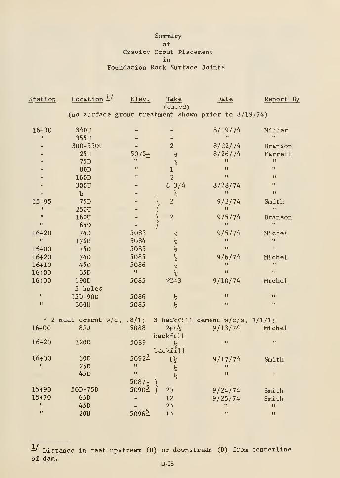
Station
Summary
ofGravity Grout Placement
in
Foundation Rock Surface Joints
Location 1/ Elev. Take Date Report By
Ccu.yd)(no surface grout treatment shown prior to 8/19/74)
16+30
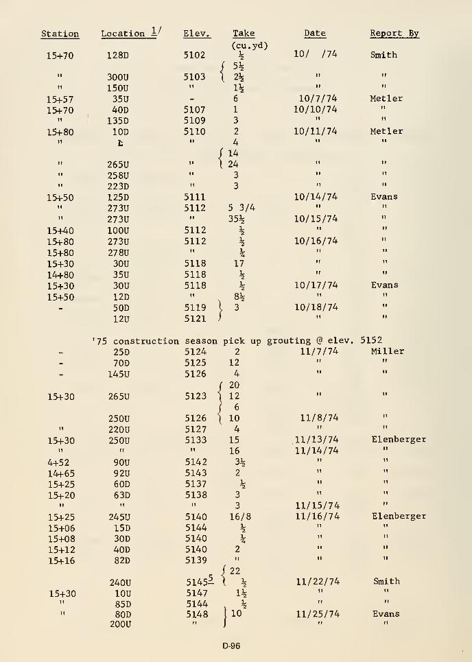
Station
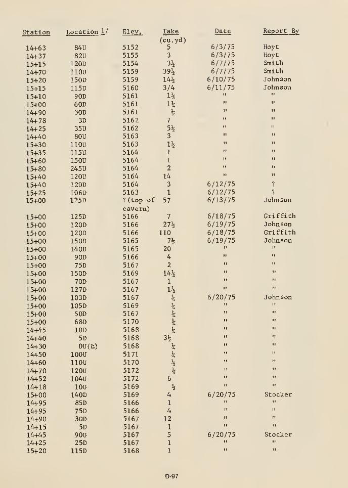
Station
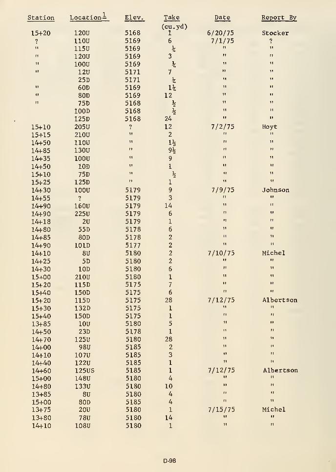
Station

Station

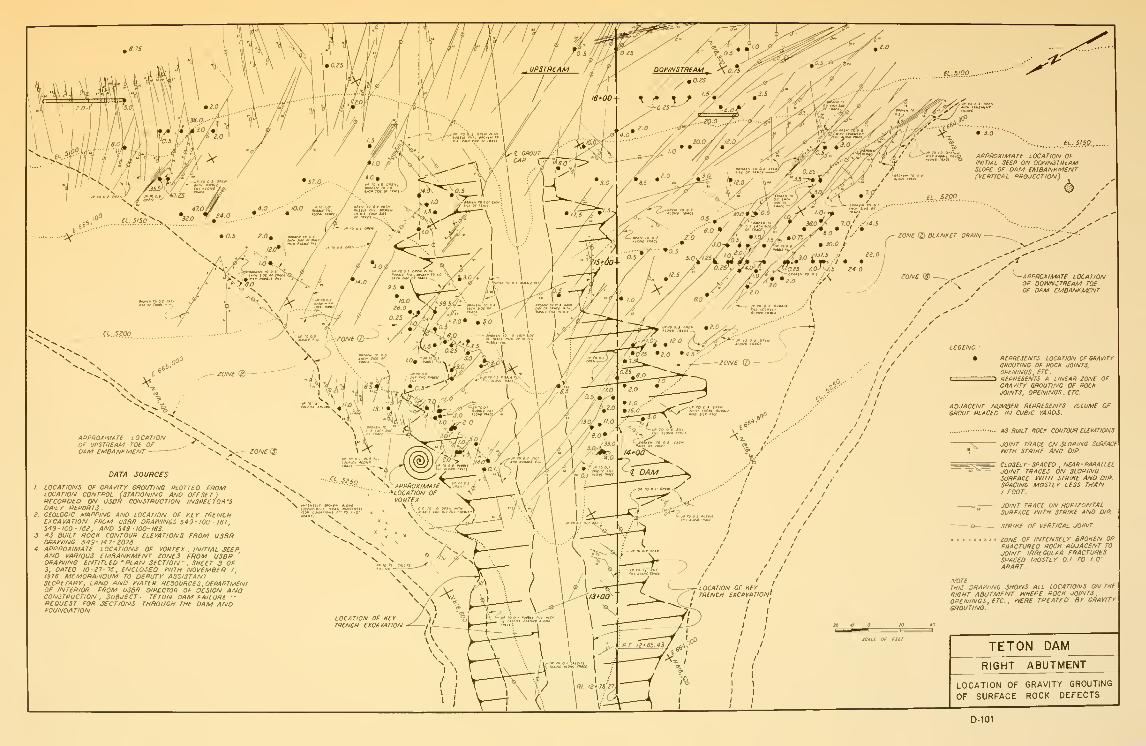
APPmxiMATe LOCATIONOf DOV^NSTRtAM T0£OF DAM EMBANKM£NT
REPRESENTS LOCATION OF GRAV/TYGROUTING OF ROCfC JOINTS.OPENINGS. ETC.
ZD REPRESENTS A LINEAR ZONE OFGRAVirr GROUTING OF ROCKJOINTS, OPENINGS . ETC-
APPROXIMATE LOCATIONOF UPSTREAM TOE OFDAM EMBANHMENT
DATA SOURCES
I. LOCATIONS OF GRAVITY GROUTING PLOTTED FROMLOCATION CONTROL (STATIONING AND OFFS£T
)
RECORDED ON USOfi CONSTRUCTION INSPECTOR'SDAILY REPORTS .
Z GEOLOGIC MAPPING AND LOCATION OF KEY TRENCHEXCAVATION FROM USBR DRAi^'lNGS 543 - 100- 161
,
549-100- ISe, AND 549 -100- 163.
3. AS BUILT ROCK CONTOUR ELEVATIONS FROM USBRDRAINING 549- 147- 3076
4 APPROXIMATE LOCATIONS OF VQRTEX , INITIAL SEEPAND VARIOUS EMBANKMENT ZONES FROM USBR '
DRAtVING ENTITLED "PLAN SECTION- . SHEET 3 OF3, DATED 10-27-76. ENCLOSED ^ITH NOVEMBER I
1976 MEMORANDUM TO DEPUTY ASSISTANTSECRETARY, LAND AND INATER RESOURCES , DEPARTMENTOF INTERIOR FRQM USSR DIRECTOR OF DESIGN ANDCONSTRUCTION, SUBJECT- TETON DAM FAILURE ~REQUEST FOR SECTIONS THROUGH THE DAM ANDFOUNDA TION.
ADJACENT NUMBER REPRESENTS VOLUME OfGROUT PLACED IN CUBIC YARDS-
AS BUILT ROCK CONTOUR ELEVATIONS
JOINT TRACE ON SLOPING SURFACEINITH STRIKE AND DlP-
CLOSELY - SPACED , NEAR PARALLELJOINT TRACES ON SLOPINGSURFACE tVl7H STRIKE AND DIP-
SPACING MOSTLY LESS THANI FOOT.
JOINT TRACE ON HORIZONTALSURFACE I^ITH STRIKE AND DIP.
STRIKE OF VERTICAL JOINT.
ZONE OF INTENSEL Y BROKEN ORFRACTURED ROCK ADJACENT TOJOINT IRREGULAR FRACTURESSPACED MOSTLY 0.1' TO f.O'
APART.
NOTETHIS ORAtVING SHOfVS ALL LOCATIONS ON THE
RIGHT ABUTMENT tVHERE ROCK JOINTSOPENINGS, ETC.. t^ERE TREATED BY GRAVITYGROUTING.
SCALE OF Ftir
TETON DAM
RIGHT ABUTMENT
LOCATION OF GRAVITY GROUTING
OF SURFACE ROCK DEFECTS
D-101

APPENDIX D-5
EMBANKMENT MATERIAL PROPERTIES

CONTENTS
Figure Page
D5-1 Progress of Zone 1 Fill Placement D-107
D5-2 Range of Gradation, Zone 1 Material D-108
D5-3 Plasticity Chart, Zone 1 Material D-109
D5-4 Statistical Analysis of Test Results for Density Control of
Fill, Zone 1 D-110
D5-5 Statistical Analysis of Test Results for Moisture Control of
Fill, Zone 1 D-111
D5-6 Statistical Analysis of Construction Moisture Tests Monthly,
through Zone 1 D-112
D5-19
D5-20 Summary of Zone 1 Embankment Control Data D-126
D5-21 Range of Gradation, Zone 2 Material, Right Abutment Area D-127
D5-22 Range of Gradation, Zone 2 Material, Downstream Right
Abutment Shell D-128
D5-23 Range of Gradation, Zone 2 Material, Downstream Right
Abutment Blanket D-129
D5-24 Filter Requirements, Between Zone 1 and Zone 2 D-130
D5-25 Lab Permeability Tests, Zone 2 Material D-131
D-105


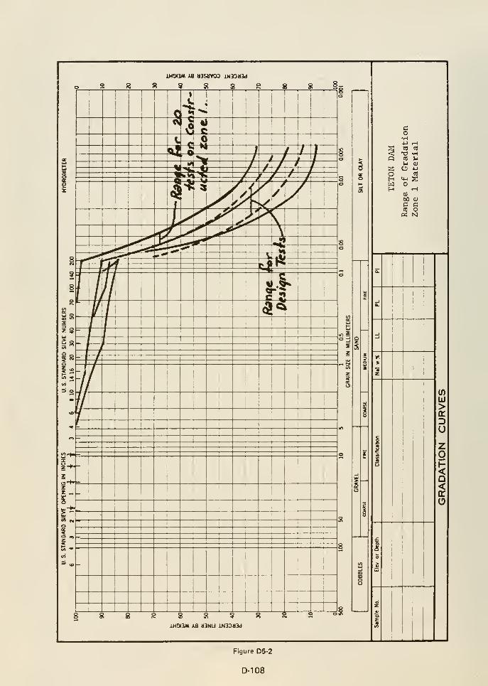
iHOIBM xa tl3StlV03 iN33IJ3d
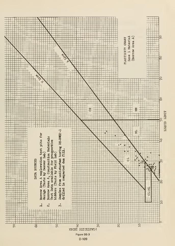
XHOMI XXIOIISVI-I
Figure D5-3
D-109

STATISTICAL ANALYSIS OF TEST RESULTS FOR DENSITY CONTROL OF FILL
Project Tgt.r.n Dam Feature Zone 1 fill
Period Oct. 197^ Tn Oct. ^1. IQTq
Fill Quantity: Approx. 5.^00.000
§X
>5+^•H0]
c<L)
O
Co•HPUa
to-pB0)
O^H
4)
.yd-
O
Kl
1
o
o
i
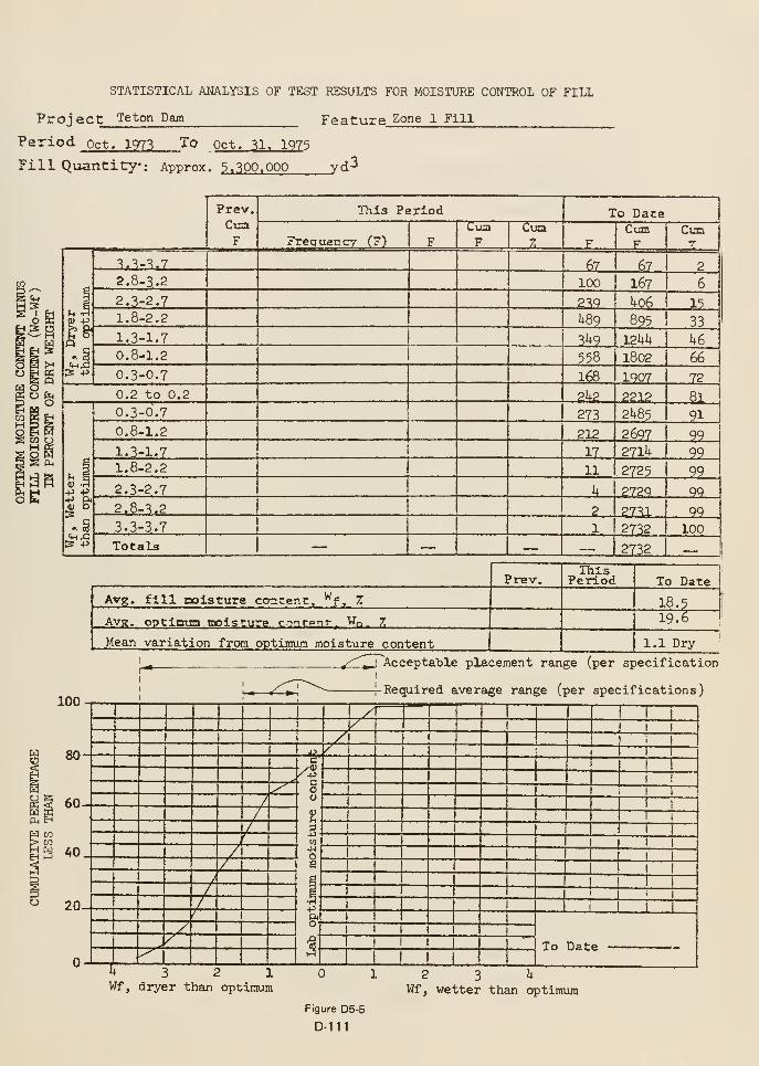
STATISTICAL ANALYSIS OF TEST RESULTS FOR MOISTURE CONTROL OF FILL
Project Teton Dam Feature Zone 1 Fill
Period pct. 1973 To Oct. 31. 1973
Fill Quantity: Approx. 3 » 300. 000 _yd-
CO
2
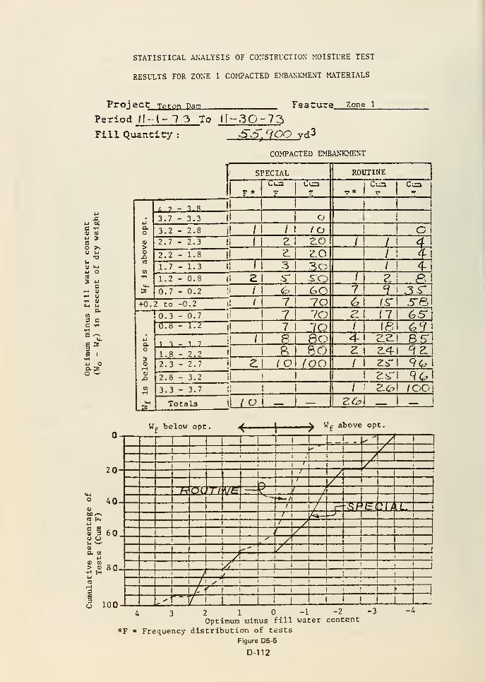
STATISTICAL ANALYSIS OF CONSTRUCTION MOISTURE TEST
RESULTS FOR ZONE 1 COMPACTED EMBANKMENT MATERIALS
Proj ac t Tpton Da!?. FgaCure Zone 1
Period II- I- "? 3 To II-3Q-73FilL Quantity
U DC
CO
3 CC -H•H6 ^1^S I
•Hw oaso '—
20
AO0)
60 --NCD Cb4J
<U 3O OM ^0)
a 0)
u> o•H H
60
80
3eao 100
>5 S. 'lOO vd3
COMPACTED EMBANTCMENT
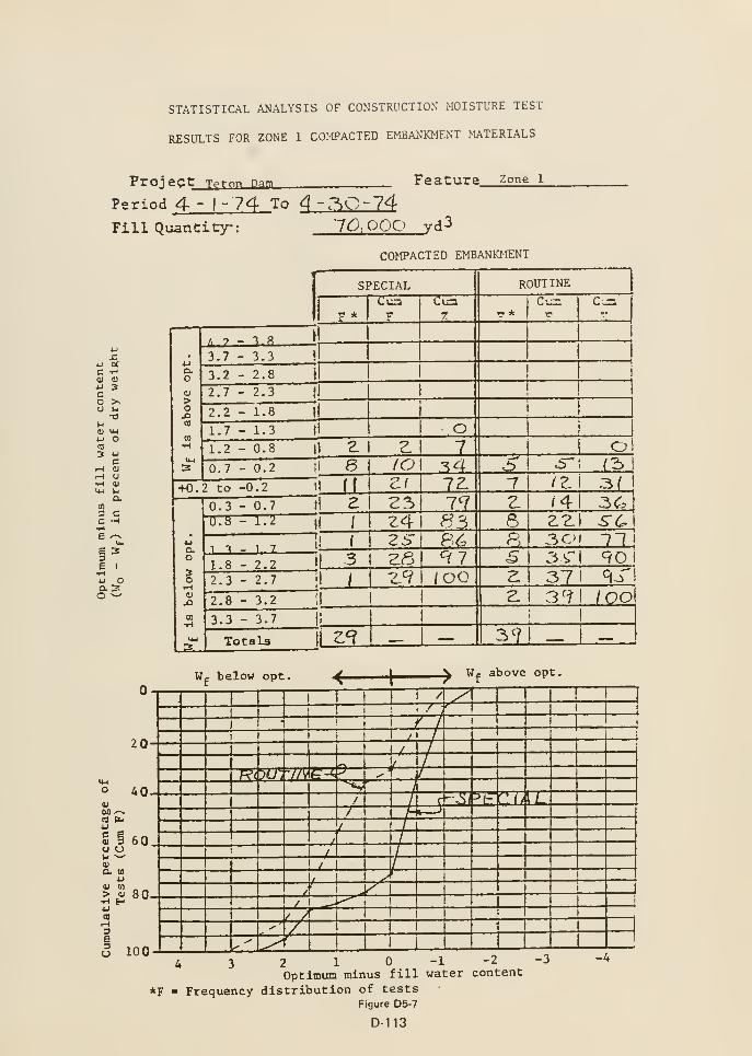
STATISTICAL ANALYSIS OF CONSTRUCTION MOISTURE TEST
RESULTS FOR ZONE 1 COMPACTED E^BANKMENT MATERIALS
Proj ect Tpton Dam Feature zone 1
Period 4 - 1-74 To 4 -.'^0-74
FillQuanCicy: 10-. OOP vd^
COMPACTED EMBANKMENT
4 3 2 1 0-1-2-3Optimum minus fill water content
*F = Frequency distribution of testsFigure D5-7
D-113
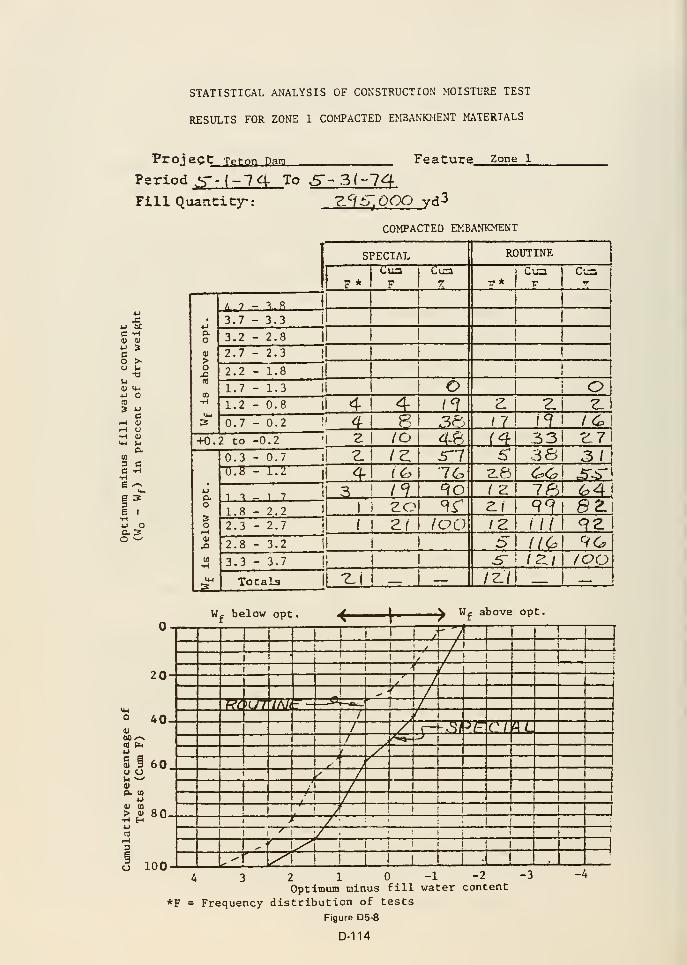
STATISTICAL ANALYSIS OF CONSTRUCTION MOISTLTIE TEST
RESULTS FOR ZONE 1 COMPACTED EMBANKMENT MATERIALS
Proj eCt Teton Dam Fe ature Zone l
Period ,^-(-7 4- To 5'' 3 (-74Fill Quantity: -Z:^.S^Ogg_yd.'^
c01
ucou
u(U
u(0
»
•5•H(1)
»>^l-<
t3
M-l
o
CO
3C
C(U
u01
ua
ao
3r
o3:
20-
o
0)
(0 (
4J
c0)
O (
1-1^
01
o.
>
40-
60.
^^ 80-
100
COMPACTED EMBANKMENT
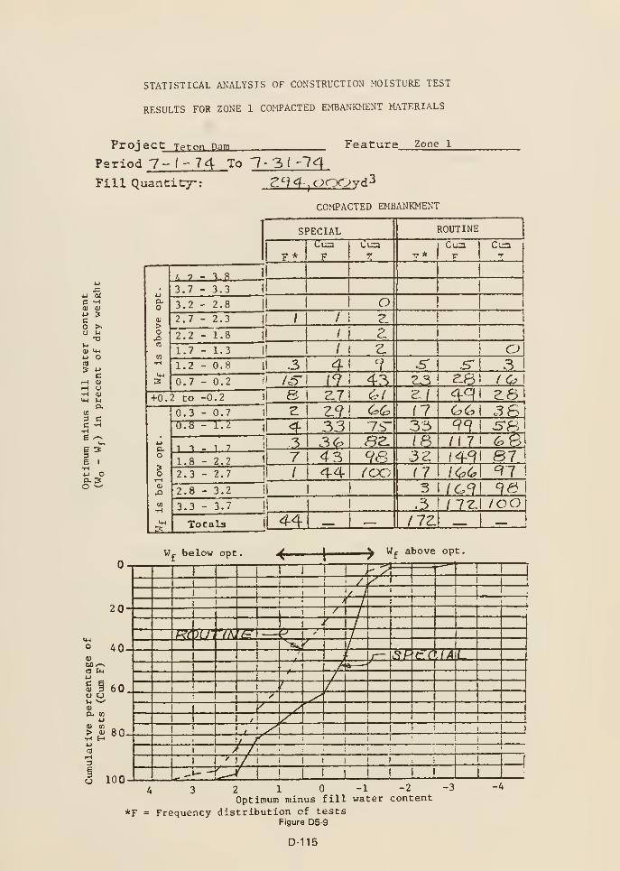
STATISTICAL ANALYSIS OF CONSTRUCTION MOISTURE TEST
RESULTS FOR ZONE 1 COMPACTED EMBANKMENT MATERIALS
Proj ec t Tpfon Dam Feature Zone l
Period 7-1-74 To 1-31 '"?4
Fill Quancicy: Z'-M-jOnCjyd^
COMPACTED EMBANKMENT
u ct
C -H01 <ll
w 3CO >sU 1^
T3
U OCO
B
1-1 OTt a)U-l 1.1
13.
to
3 CC -H
6 I
u o
o11
to-'CO (
iJ
ct>
o <
I- ^
0)
ex
>
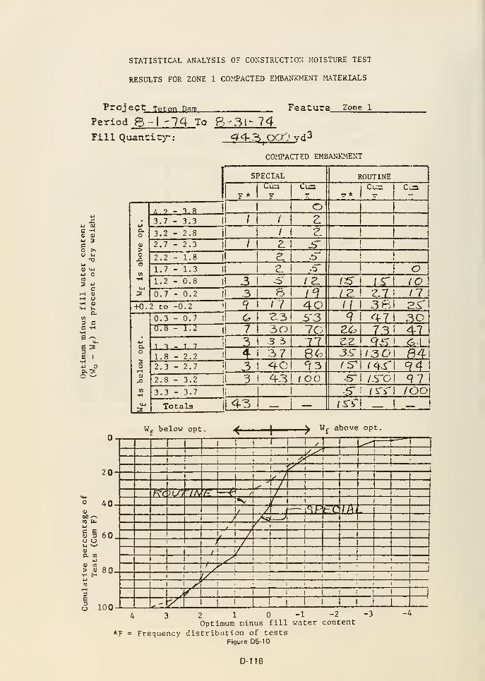
STATISTICAL ANALYSIS OF CONSTRUCTION MOISTLTIE TEST
RESULTS FOR ZONE 1 COMPACTED EMBANKMENT MATERIALS
Proj ec t Teton Dam Featura Zone 1
Period 6-1-74 To B-3l- 74Fill Quantity: <f4-.tS OaO vd^
COMPACTED EMBANKMENT
U MC -H<U lU*-> 3cO J-.
U l-i
73
U Ofl)
5 4J
c.-I aj
rH O•H V<4-l »^
am3 cC -H•H6 ^e 33e I
4-1 Oa3o ^
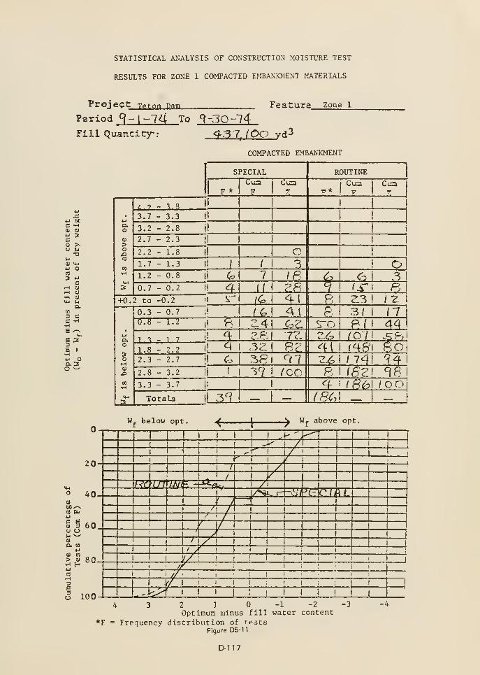
STATISTICAL ANALYSIS OF CONSTRUCTION MOISTURE TEST
RESULTS FOR ZONE 1 COMPACTED EMBANKMENT MATERIALS
Proj ect Teton Dam Feature zone 1
Period 9-1-74 To 9-30~?4Fill Quancicy-: 43 7^ (OO vd^
COMPACTED EMBANKMENT
uu exC -H01 <uu 3co ><U M
T3
11 U-i
u O
3 4J
cfH HJ
iH O•H (U
6 33e I
iJ Oaso ^
M-l
o
lU
at I
4J
c
u (
<u
a
>•H HCD1-1
S
20
40
60
en
.1) 8
100
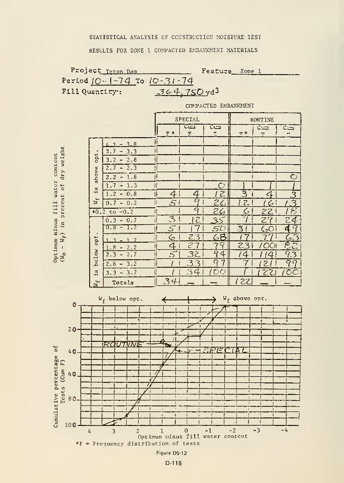
STATISTICAL ANALYSIS OF CO:;STRUCT I CM MOISTURE TEST
RESULTS FOR ZONE 1 COMPACTED EMBANKMENT MATERIALS
Projec t Teton Dam Feature Zone l
Period 10-1-74 To IO-3I -14Fill Quantity: .3 <^ <^j 7SD vd^
COtO'ACTED EMBANKMENT
4J ocC -H(U (U
o >^o u
•ol-l
0) V-l
u O«*^
.-I <u
I-l (J
•H 0)
MH Id
O.0)
3 CC -H•He /-^
1^B I
•H4J OD. 3O ^
20
° AO
<fl ft,
B<u
U (
u -
il
o.
>
60
•H H.oj 8(
3e3o 100
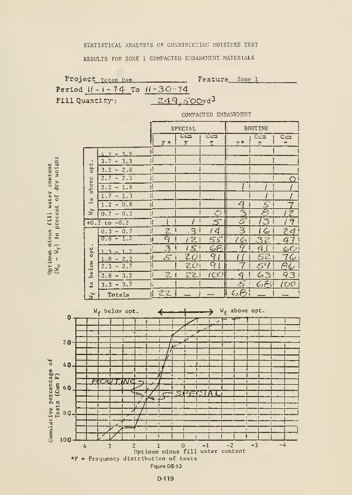
STATISTICAL ANALYSIS OF CONSTRUCTION MOISTURE TEST
RESULTS FOR ZONE 1 COMPACTED EMBANKMENT MATERIALS
Proj ec t Teton Dam Feature Zone 1
Period (/ - i - 74 To l(~30-l4
_S£t£L,j£QOyd3Fill QuanCity-:
4-1 OCC -Hdl <U
u 3Co >O M
T3)<
0) u-i
4-1 OCO
3 4J
c
rH O•H D>4-l M
am3 CC -H
e 33e I
•HtJ oa. 3o ^
COMPACTED EMBANKMENT
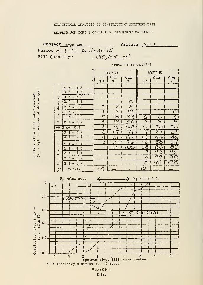
STATISTICAL ANALYSIS OF CONSTRUCTION MOISTURE TEST
RESULTS FOR ZONE 1 COMPACTED EMBANKMENT MATERIALS
Proj eg t Teton Dam
Period o -(-7^' To 6"- 31 -7.5'
Fill Quantity :
Feature Zone l
CD
3
>-ua
c01
o
ua.
C
ao
o2
/90/,'00 _yd3
COMPACTED EMBANKMENT
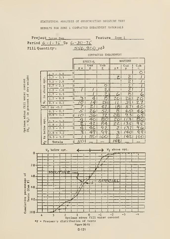
STATISTICAL ANALYSIS OF CONSTRUCTION' MOISTURE TEST
RESULTS FOR ZONE 1 COMPACTED EMBANKMENT MATERIALS
Project_
Period 6 -
Tp.r.on Dam
f' li' To 6 -JO -7^
Feature Zone 1
Fill Quancity-
DCH<U
3
u•o
cHI
o01
l-l
o.
o
COMPACTED EMBANTCMENT

STATISTICAL ANALYSIS OF CONSTRUCTION >;OISTURE TEST
RESULTS FOR ZONE 1 COMPACTED EMBANKMENT MATERIALS
Froj ec t Teton Datn Feature Zone l
Period 7-(-7.S To 7-3 I -7S"
Fill Quantity: o"fe.3 7CC yd^
COMPACTED EMBANKMENT
4-1 tit
C -H
3
c<u
u
ua
e 33e I
•Hu oa 2o ^
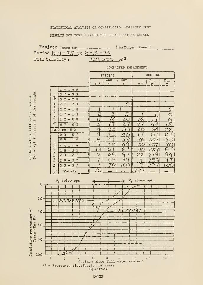
STATISTICAL ANALYSIS OF CONSTRUCTION MOISTURE TEST
RESULTS FOR ZONE 1 COMPACTED EMBANKMENT MATERIALS
Proj ect Teton Dam Feature Zone 1
Period 8--/- IS To Fj-31-lSFillQuanCicy: l^'i. <^00 rd3
x:u uC -H0) 01
u scO P>-
u uT3
UU O«
cr-t 0)
r-l O•H 0)
M-l UC
10
3 CC -H
E 33E I
*HU Oa 3o ^
20
° 40<u
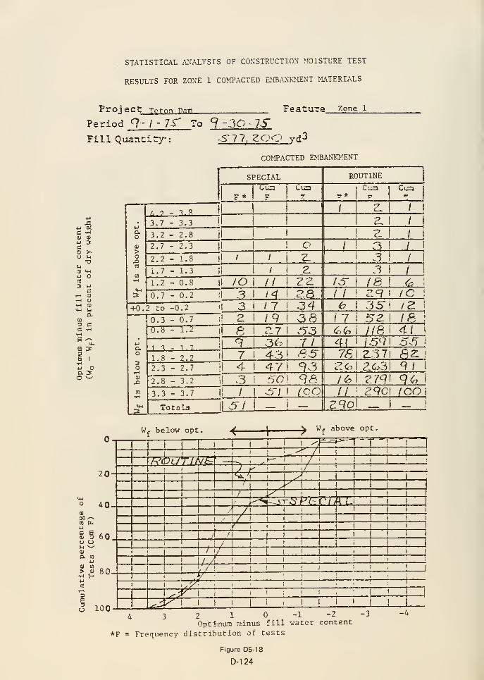
STATISTICAL ANALYSIS OF CONSTRUCTION MOISTURE TEST
RESULTS FOR ZONE 1 COMPACTED EJffiANKMENT MATERIALS
Proj ac t Tprnn Dam Feature Zone 1
Period 9 - \-7S' To 9 --30 - 75"
-5-77, za^D yd3
COMPACTED EMBANKMENT
Fill Quancicy-:
C -H(U <1J
jj 3Co >•O M
•Ol-i
U O«3 4J
cf-l
^ o•H OJ
en
3 CC -H
1^g IHU OasO ^
20
0)60 /-^
CD bu4) 3 60o u
I* tn « _> D 8-H E-H
4-1
niH3E
o 100
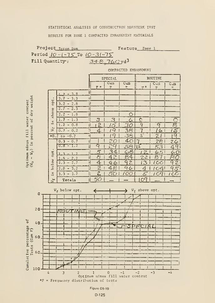
STATISTICAL ANALYSIS OF CONSTRUCTION MOISTURE TEST
RESULTS FOR ZONE 1 COMPACTED EMBANKMENT MATERIALS
Projec t Teton Dam Feature Zone l
Period lO -(-TS" To (O -3(~1S'Fill Quancity: 3<t S^l^^avd^
4J at.
C -HV <u
u 3co >-o u
T3U(U '*-'
u O
3 4J
ci-H (U
H aj
D.m3 CC -H
6 33E I
•Hu OQ. 3O ^
o 100
COIffACTED EMBANKMENT
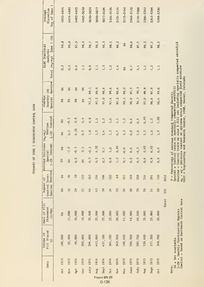
<5
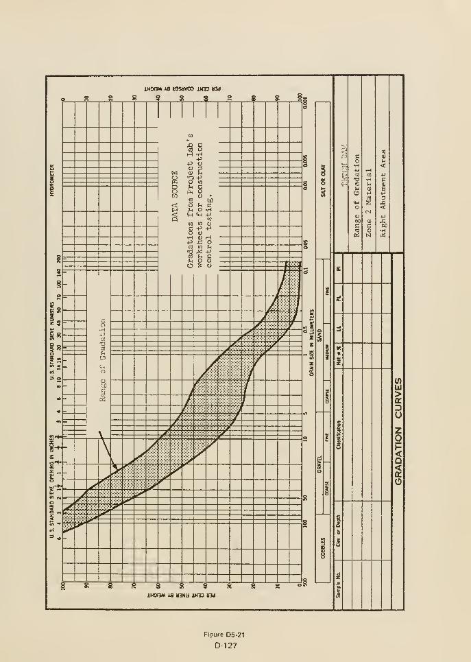
<
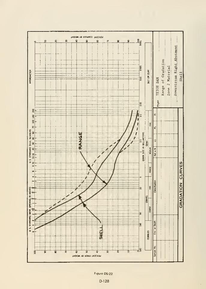
S S -
52-
31 „_
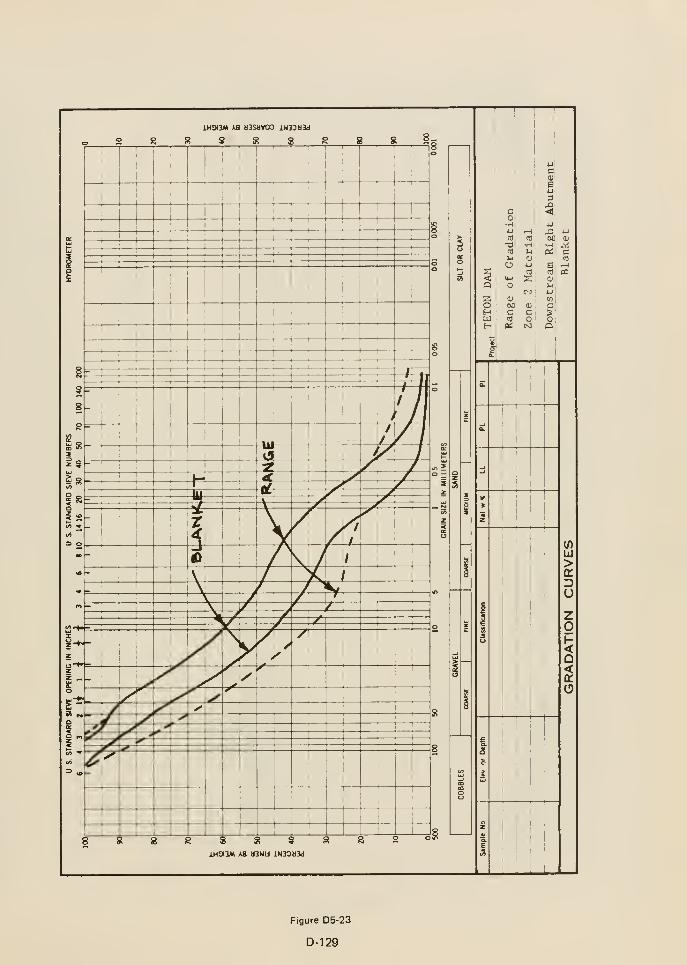
S 8 S
iHOI3M AS dSNli iN33tl3d
o
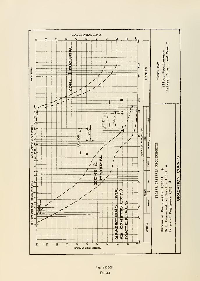
c
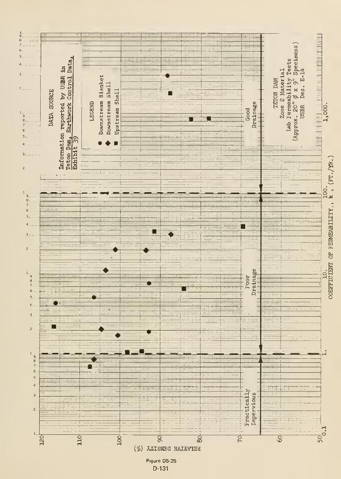
1
9

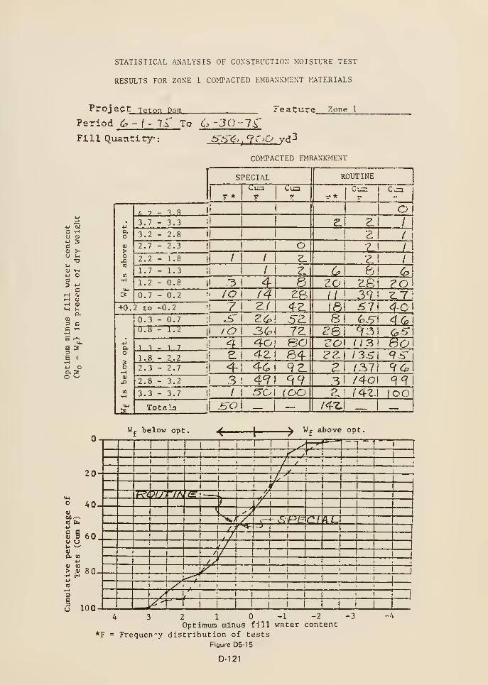
STATISTICAL ANALYSIS OF CONSTRUCTION MOISTURE TEST
RESULTS FOR ZONE 1 COMPACTED EMBAN!a>tENT MATERIALS
Project
Period 6 -
(
Teton Dam
li' To 6 -30 -7^Feature Zone I
Fill Quantity:
•H(U
3
>•a
o
COMPACTED EMBANKMENT
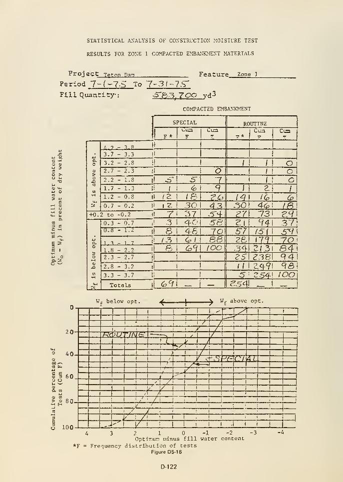
STATISTICAL ANALYSIS OF CONSTRLXTION MOISTURE TEST
RESULTS FOR ZONE 1 COMPACTED EMBAJJKMENT MATERIALS
Project Teton Dam Feature Zone 1
Period 7-(-7-SFill QuanCitry-:
To 7-3/-7.b'
x:
•H
»
U•O
U-l
o
c•-( a
iM ua.
CO
3 CC -HHe '-^
I^
ao ^
o fi3j 7CO vd3
COMPACTED EMBANKMENT
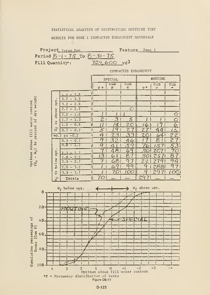
STATISTICAL ANALYSIS OF CONSTRUCTION MOISTURE TEST
RESULTS FOR ZONE 1 COMPACTED EMBANKMENT MATERIALS
Proj ec t Teton Para
Period 8 -/- 7.S" To Fj-31
Feature Zone 1
Fill Quantity-: 72 'V, <^00 rd3
COMPACTED EMBANKMENT
4-1 ocC -H01 <u
3
c
aH 01
c(0
3 CC 1-1
•HE '-^
6 33E I
•H4-1 Oaso ^
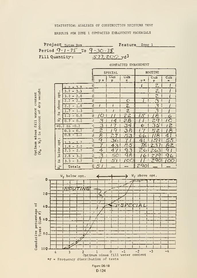
STATISTICAL ANALYSIS OF CONSTRUCTION MOISTURE TEST
RESULTS FOR ZONE 1 CO>!PACTED EMBANKMENT MATERIALS
Proj act Teton Dam Feature Zone l
Period 9- I -IS' To 9 - 30 - 75"
FillQuauCitry-: Sll, ZOC^ yd^
COMPACTED EMBANKMENT
4J DCC -H(U (U
u 3Co >•o u
•ol-l
0) M-l
4J O
5 4J
crH at
-H O•w 0)
U-l ua.
II)
3 CC -H
E 33e IH4J Oa 3o •^
20
40
1-1
S § 60
(U u)
> tu
•H Hto
80
o 100
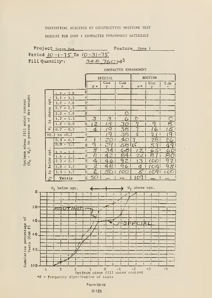
STATISTICAL ANALYSIS OF CONSTRUCTION MOISTURE TEST
RESULTS FOR ZONE 1 COMPACTED EMBANKMENT MATERIALS
Proj ec t Teton Dam Feature Zone l
Period to -i -IS' To (O -3l~l^Fill Quancitry: 3<t S 'iC^avd^
u4J OCC -H(U 9)
u
c
a<u
i-i
am3C
S I
•H4J Oas:o ^
COMPACTED EMBANKJfENT
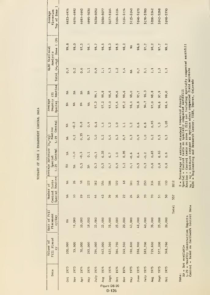
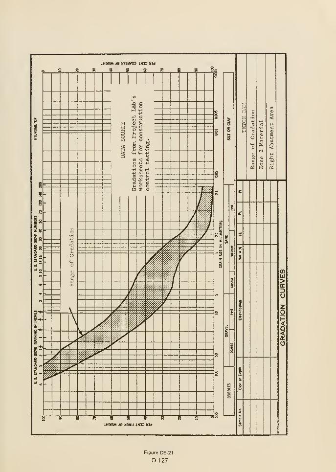
e
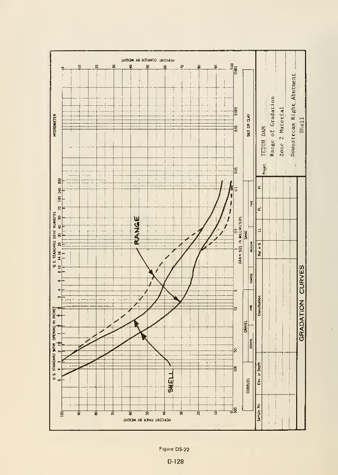
2
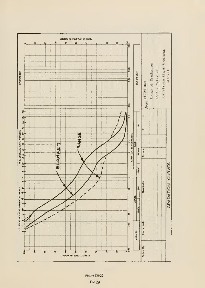
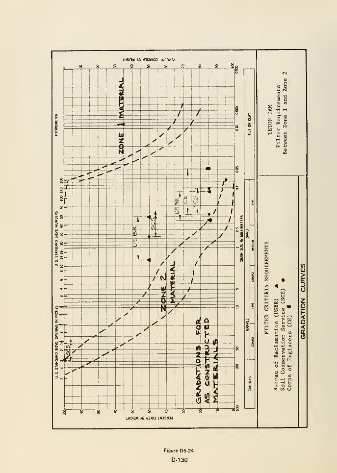
« 3 S S^
S S 3 S!
JLH0I3M iB )I3NU iN33il3d
CM
<U
c(0 o
c<U T3B C<u nj
l-i
•H .H3a" Q)
<u CBtf OM1^
0) C4J dl
iH I)
•H S
(U«
COH
D
MwH
COuCOM
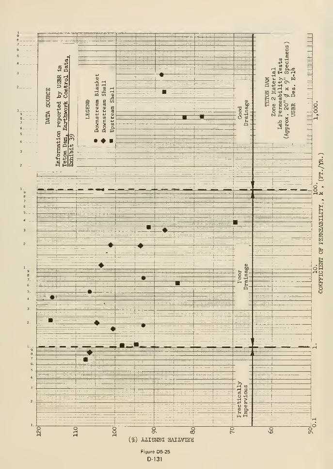
{$) AiisNaa aAiiviaa
Figure D5-25
D-131

« Appendix E
List of the Teton DamFailure Exiiibits Fumislied to
tlie IRG by tlie
Bureau of Reciamation
(Updated to December 12, 1976)
Asof July 8, 1976
(Items 1 through 35)
(Updated to December 12,
1976 - through 57)
TETON DAM FAILURE EXHIBITS
No.
1. Panellnformation Packet
1.1 Brochure on Lower Teton Division, Idaho, dated 1974
1.2 Comparison—Specifications vs. Final Quantities (DC-6766) Teton Dam, Pilot Grouting (Table)
1.3 Construction Materials Test Data
1.4 Design Considerations
1.5 Drawing of Teton Dam Left Abutment Cut-off Trench, Station ±33+20 to Station 34+00, dated
8/17/72
1.6 Drawing—Teton Dam— Location of Explorations for Borrow Areas "A," "B," and "C"
1.7 Earthwork Construction Data, dated June 1975
1.8 Earthwork Control Analysis (2 printouts—Zone Number Dam 1, Run No. 14, and Zone NumberDam 3, Run No. 7)
1.9 Final Environmental Statement (including pertinent letters)
1.10 Geological Survey letter regarding Teton Dam (Memo from Commissioner Stamm transmitting letter
dated June 11, 1976 from V. E. McKelvey of the Survey to Senator Henry M. Jackson)
1.11 Geological Survey Questions and Answers Regarding Teton Dam (Wire message dated June 18, 1976—Questions and Answers dated June 15, 1976)
1.12 Key Events and Key Personnel—Teton Dam, Design and Construction, Denver Office, from 1/1/69 to
present (June 28, 1976)
1.13 L-10— Final Report on Foundation Pilot Grouting
1.14 List of Teton Dam Material in Central Files, Library, etc., at E&R Center
1.15 List of Teton Original Drawings on file in PN 700 asof 6/15/76
1.16 Listing of correspondence and reports on Teton Dam Project on file in the Regional Geology Office
1.17 Listing of Key Personnel—Teton Project Office— 1967 to present
1.18 Morrison-Knudsen wire message dated June 1 1, 1976, regarding their part in building Teton Dam1.19 News Release—Teton Dam Failure— Department of the Interior, dated 6/9/76
1.20 News Release— Panel Named to Review Cause of Teton Dam Failure— Department of Interior, dated
6/10/76
1.21 Preliminary Geologic Map of the NW 1/4 Driggs 1° by 2° Quadrangle, Southeastern Idaho
(USGS)
1.22 Progress Chart—DC-6910 (showing maximum section, with dates of construction)
1.23 Records available at Teton Project Office (Faxogram from Project Construction Engineer, Newdale,
Idaho to Regional Director, Boise)
1.24 Resume of Facts and Findings—Teton Dam, Idaho
1.25 Seismic monitoring program—Teton Dam and Reservoir (including memorandum from Acting Chief
Geologist Robert C. Davis to D. J. Duck, dated early July 20, 1973 and Preliminary Reporton Geologic Investigations, Eastern Snake River Plain and Adjoining Mountains, a draft report
by Steven S. Oriel, Harold J. Prostka, David Schleicher, and Robert J. Hackman, USGS, June 1973)
1.26 Testimony, Vol II, Vol V, Civil Case No. 1-71-88, Trout Unlimited et al vs. Rogers C. B. Mortonet al
1.27 Water Surface Elevations—March, April, May, and June 19761.28 Wire Message from R. R. Robison to Commissioner of Reclamation, Director of Design and
Construction, and Regional Director, Boise, subject, "Failure of Teton Dam, Teton Project,
Idaho," dated June 6, 1976
2. Teton Dam Book
3. Plans and Specifications Packet
3.1 Plans and Specifications—DC-6910—with supplemental notices (Four volumes— 10 supplemental notices)
3.2 Abstract of Bids
E-1
TETON DAM FAILURE EXHIBITS-Continued
No.
3.3 Record of Subsurface Investigations
3.4 Specifications No. DC-6766—Teton Dam, Pilot Grouting—with one supplemental notice
4. General Plan Sketch
5. Maximum Section Sketch
6. Profile Sketch
7. Prints of slides— Location of Damsite—Construction through Failure
8. Photographs of Failure
9. 8mm Film of Dam Failure
10. 16mm Film of Dam Failure
11. Record of Filling of Teton Reservoir (2-page memorandum with the following)
1 1.1 Memorandum of March 3, 1976 from Project Construction Engineer to Director of Design and
Construction, subject, "Monitoring Ground Water Conditions—Teton Project, Idaho"
1 1.2 Memorandum of March 23, 1976 from Director of Design and Construction to Project Construction
Engineer, subject, "Reservoir Operating Criteria—Teton Dam—Teton Basin Project, Idaho,"
1 1.3 Faxogram from Project Construction Engineer to Director of Design and Construction dated May 14,
1976, subject, "Status of Construction of Teton Dam and Filling of Reservoir—Teton
Project, Idaho"
1 1.4 Daily Records of Reservoir Filling (Same as Exhibit 1.27)
1 1.5 Record of observation well from October 1975 to June 1976 (6 sheets)
12. Geology Handout
12.1 Introduction
12.2 Parti
12.3 Part II
12.4 Index
12.5 Letter of June 14, 1976 to Director of Design and Construction from Regional Director with
attachments, as follows:
12.5.1 Maps of the reservoir seepage loss study, including isopachs, water table contour for
2/2/76 and 6/1/76, and cross sections
12.5.2 "500 series" geologic drill logs DH-501 through -507
12.5.3 Water level data from observation wells
12.5.4 Hydrographs of Teton Reservoir and observation wells
12.6 Seismicity reports including four sent to the Bureau by U.S. Geological Survey in letters dated:
12.6.1 April 26, 1976
12.6.2 February 19, 1976
12.6.3 September 19, 1975
12.6.4 September 4, 1975
12.6.5 Memorandum on the geologic and seismic factors of Island Park and Jackson Lake Damsdated March 30, 1973
E-2
TETON DAM FAILURE EXHIBITS-Continued
No.
12.7 Two reports
12.7.1 "Preliminary Report on Geologic Investigations, Eastern Snake River Plain and
Adjoining Mountains" by the USGS, sent by cover letter dated July 20, 1973
12.7.2 "Groundwater Investigations of the Rexburg Bench," by the Bureau of Reclamation,
February 1972
12.8 Laboratory test data of foundation rock core specimens covered by memorandums dated:
12.8.1 November 24, 1970
12.8.2 December 1, 1970
12.8.3 December 2, 1970
12.9 Final Construction Geology Report for the Spillway (Draft)
12.10 Drawings
12.10.1 Teton Dam-Plan View of Fissures Exposed in Haul Road Cut-Drawing No. 549-100-176-
July 1976
12.10.2 Profiles of Right Abutment 200 and 250 Feet Upstream of Dam Axis, Unnumbered—postJune 5, 1976
12.10.3 Construction Geology of Spillway-Drawings No. 549-100-124 to -132-December 197512.10.4 Generalized Geologic Section A-A' Drawing No. 549-100-1 52-M arch 1976
12.10.5 Geologic Map of Cutoff Trench, Stations 2-1-60 to 34-(-20-Drawings No. 549-100-158 to
-168-June 1976
12.10.6 Geologic Section Along Upstream Grout Curtain, Stations -5+10 to 49-^00— Drawings
No. 549-100-169 to -172-June 1976
12.10.7 River Outlet Works Tunnel Geology, Stations 7-1-72.5 to 28-^97.0-Drawings No.
549-147-100 to -11 5-April 1973
12.10.8 River Outlet Works Tunnel Gate Shaft Geology-Drawings No. 549-147-1 17 to -118-
April 1973
12.10.9 River Outlet Works Tunnel Gate Chamber Geology-Drawing No. 549-147-1 19-April 197312.10.10 River Outlet Works Tunnel Intake Shaft Geology-Drawing No. 549-147-120-April 1973
12.10.11 Geology and Explorations in Right Abutment Keyway Trench—Drawing No. 549-147-133—
April 1974
12.10.12 Geologic Sections Across Fissures in Right Abutment Keyway Trench—DrawingNo. 549-147-134-April 1974
12.10.13 Auxiliary Outlet Works Geology, Stations 6+63 to 34+1 1.33-Drawings No. 549-147-400 to
419-October 1974
12.10.14 Auxiliary OutletWorks Shaft and Adit Geology-Drawing No. 549-147-420-October 1974
12.10.15 Auxiliary OutletWorks Access Shaft Geology, el 5080 to el 5290-DrawingNo. 549-147-121-October 1974
12.10.16 Location of Exploration and Surface Geology—Drawings No. GEOL-76-020 and -021—June
1976
12.10.17 Geologic Section Along Downstream Grout Curtain—Right Abutment Drawing
No. GEOL-76-022-June 1976
13. Prints of Slides (Geology)
14. Seismicity
14.1 Epicenters with Modified Mercalli Epicentral Intensity V or Greater through 1970
E-3
TETON DAM FAILURE EXHIBITS-Continued
No.
14.2 Maximum Epicentral Intensity (Modified Mercalli) per 10,000 sq. km. through 1970
14.3 Horizontal Acceleration in Rock with 10% Probability of Being Exceeded in 50 Years (2 sheets, one
redrawn from the other)
14.4 Figure 2.—Location of seismic stations near Teton Dam14.5 Figure 6.—Portion of seismogram showing ground motion induced by flooding waters
15. Regional Environmental Geology of Southeastern Idaho, by Steven S. Oriel (Unedited remarks prepared for
presentation to Review Group June 15, 1976)
16. Composite Drawing of Grouting Profile (Same as 12.10.6)
17. Photographs of Key Trenches (Grouting)
18. Grout Profile of Right Abutment (This is included in Exhibit 32.)
19. Handouts on Embankment
19.1 Teton Dam Earthwork Control Data-"Part C-Earthwork Construction Data" from L-29 Reports-May
1972 to November 1975
19.2 Teton Dam—Earthwork Information from Weekly Progress Reports—June 1973 to December 1975
19.3 Sequence of Earthfill Placement from L-29 Reports-June 1972 to October 1975
19.4 Maximum Sections and Earthwork Control Statistics of Earth-fill Dams Built by the Bureau of
Reclamation—June 1973
19.5 Measurement Points (with observation dates) (seven sheets)
19.6 Right Abutment Cross-Sections Before and After June 5, 1976-Stations 100 through 400 Upstream of
the Dam Axis (seven sheets)
19.7 Memorandum dated June 4, 1976 from Project Construction Engineer to Director of Design and
Construction, subject, "Filling of Teton Reservoir, Teton Project, Idaho," with drawing
showing location of springs.
19.8 Teton Flood Data
19.9 Memorandum dated June 4, 1976 to Project Construction Engineer from Director of Design and
Construction, subject, "Status of Construction of Teton Dam and Filling of Reservoir— Specifica-
tions No. DC-6900—Morrison-Knudsen-Kiewit, Contractor—Teton Dam, Power and Pumping Plant—
Teton Basin Project, Idaho"
20. Photographs of Key Trenches (Embankment)
21. Letter from R. Keith Higginson, State of Idaho Department of Water Resources, to Wallace L. Chadwick, dated
June 21, 1976, requesting additional information for the Panel
21.1 Draft of Reply, dated 6/24/76
21.2 Corrected Reply, dated 7/8/76
22. Chart— Bureau of Reclamation Organizations at Engineering and Research Center—March 1976
23. Eye Witness Accounts— Interrogatories by Division of Investigation Special Agents, Office of Audit and Investi-
gation, Office of the Secretary, on Behalf of the Teton Dam Project Review Committee, dated June 25, 1976
23.1 Analysis of Eye Witnesses to Teton Dam Failure, June 5, 1976, dated July 2, 1 976 plus three more
accounts
E-4
TETON DAM FAILURE EXHIBITS-Continued
No.
24. Denver Laboratory Test Data entitled "Sample Index Sheets"
25. Observation Well Maps (Readings through June 20, 1976)
26. Slurry and Grout Used to Fill Cracks and Fissures in Abutment (Six pages)
27. Drawings
27.1 549-D-5 Location Map27.2 549-D-6 Vicinity Map27.3 549-D-8 General Plan and Sections
27.4 549-D-9 Embankment Details
28. Set of Six Grout Summary Sheets-Main Dam-Final Quantities (taken from October 25, 1975 L-10 Report)
29. Preliminary Report on Failure of Teton Dam, by Harold G. Arthur
30. Pressure Grouting Foundation on Teton Dam, by Peter P. Aberle
31
.
Questions and Answers Concerning the Failure of Teton Dam—prepared by the Bureau of Reclamation
32. Foundation Grouting Profile and Plan Drawings-Drawings No. 549-147-150 through -195 (with index)
33. Preconstruction Geologic Report, Teton Damsite, April 1971
34. Photographs of Teton Dam construction and prefailure (from project files)
35. Volume of material washed away by failure of Teton Dam—dated 6/18/76
(Added Subsequent to July 8, 1976)
36. Sequence of Failure Photographs (taken by Gibbons and Reed employee)
37. Chronology of Failure (from Interim Report of Interior Teton Dam Failure Review Group)
38. Atrial Photographs (Only one set available. Furnished to Mr. Jansen for panel use, 7/27/76)
39. Teton Dam Earthwork Control Data Book
40. Teton Dam Earthwork Control Statistics, Zones 1 and 3
41. Map showing Observation Wells located near Teton Dam
(Exhibits added subsequent to July 30, 1976)
42. Transcript of Hearings before Conservation, Energy, and Natural Resources Subcommittee of the Committeeon Government Operations, House of Representatives, Congress of the United States, August 5, 1976
43. Transcript of Hearings before Conservation, Energy, and Natural Resources Subcommittee of the Committee
on Government Operations, House of Representatives, Congress of the United States, August 6, 1976
E-5
TETON DAM FAILURE EXHIBITS-Continued
No.
44. Transcript of Hearings before Conservation, Energy, and Natural Resources Subcommittee of the Committee
on Government Operations, House of Representatives, Congress of the United States, August 31 , 1976
45. Prepared Statement of Robert R. Curry Presented to Conservation, Energy, and Natural Resources Subcom-
mittee Hearing, August 5, 1976
46. Prepared Statement of Marshall K. Corbett Presented to Conservation, Energy, and Natural Resources Subcom-
mittee Hearing, August 5, 1976
47. Prepared Statement of H. Anthony Ruckel Presented to Conservation, Energy, and Natural Resources Subcom-mittee Hearing, August 5, 1976
48. Prepared Statement of Robert W. James Presented to Conservation, Energy, and Natural Resources Subcom-
mittee Hearing, August 5, 1976
49. Prepared Statement of R. R. Robison Presented to Conservation, Energy, and Natural Resources Subcommittee
Hearing, August 6, 1976
50. Prepared Statement of H. G. Arthur Presented to Conservation, Energy, and Natural Resources Subcommittee
Hearing, August 6, 1976
51. Prepared Statement of Gilbert G. Stamm Presented to Conservation, Energy, and Natural Resources Subcom-mittee Hearing, August 31, 1976
52. Teton Dam Disaster—Thirtieth Report by the Committee on Government Operations to the 94th Congress,
Based on a Study Made by its Conservation, Energy, and Natural Resources Subcommittee, September 23,
1976 (House Report No. 94-1667)
53. Summary of Bureau of Reclamation Comments on Testimony Presented to Conservation, Energy, and Natural
Resources Subcommittee of the House Committee on Government Operations
54. Seismicity of the Teton Dam Area, June 16, 1974-June 9, 1976, by R. Navarro, G. Wuolet, J. West, K. King,
and D Perkins (Open File Report 76-555)
55. Drawing No. 549-125-268, Geologic Cross Section Along Spillway Site, Revised April 1976
56. Transcript of Meeting of Teton Dam Failure Review Group, Idaho Falls, Idaho, September 15, 1976
57. Teton Dam Project Organization for Earthwork Construction Inspection (with resume of work experience of
most of the individuals listed)
E-6
« Appendix F
Summary of Eyewitness Accounts
Reproduced from Appendix C of the Independent Panel Report "Teton Dam Failure," December 1976

APPENDIX C
WITNESS ACCOUNTS OF FAILURE
U S DEPARTMENT OF THE INTERIOR STATE OF IDAHOINDEPENDENT PANEL TO REVIEVf CAUSE OF TETON DAM FAILURE
INTERROGATORIES BY DIVISIGN OF INVESTIGATION SPECIAL AGENTS, OFFICE
OF AUDIT AND INVESTIGATION, OFFICE OF THE SECRETARY, ON BEHALF OFTHE TETON DAM PROJECT REVIEW COMMITTEE
June 25, 1976
F-1

INTERVIEW GUIDELINE QUESTIONS
Name:Address:Employer: USBR ContractorTitle of Position:How Long Employed:All of Teton Project?
Whered-id you observe events of failure? (Exact location if possible)
Why were you there?
What time did you arrive at scene?
Who alerted you of possible problem? What Time?
How long did you stay?
Did you change locations?
State your description of what you saw from each site .
Did you see:
1. The lower water seepage? Where was it? What time noted? Whatcolor was the water? Estimated volume? How fast did it increase?
2. The upper water seepage? Where was it? What time noted? Whatcolor was the water? Estimated volume? How fast did in increase?When were you aware that the dam was in eminent danger? When did
you realize that it would collapse?
3. The whirlpool upstream? Was there more than one? Estimate its
circumference when first seen. Describe its activity - enlarging?moving? Did you realize the significance? Where was it? What time
observed? How long was it visable?
Any tremors earlier?
Check inspection route on previous shifts.
F-3
BUREAU OF RECLAMATION WITNESS STATEMENTS TO TETON DAM FAILURE
Peter P. Aberle, Field Engineer 356-7631Fifth West SouthRexburg, Idaho 83440
Andrew L. Anderson, Electrical Engineer 356-392453 S. Third E.
Rexbiirg, Idaho 83440
Wilbum H. Andrew, Mechanical EngineerVirginia H. Perkins Dormitory #32, 356-2579Ricks College, Rm 59Rexburg, Idaho 83440
Richard Berry, Surveyor275 So. First EastRexburg, Idaho 83440
Stephen Elenberger, Construction InspectorVictor, Idaho
Charles L. Entwisle, Inspector 624-3012440 N. 7th W.
St. Anthony, Idaho 83445
Clifford W. Felkins, Surveyor 745-7922430 N. 3 W.
Rigby, Idaho 83442
Myra Ferber, Surveyor 624-4106Box 124St. Anthony, Idaho 83445
Alvin J. Heintz, Inspector 624-7982151 N. 2nd E.
St. Anthony, Idaho 83445
Kenneth C. Hoyt, Inspector 624-3228Rt. 1, Box 202-12St. Anthony, Idaho 83445
Harry A. Parks, Surveyor (Chief of Crew) 624-4273Kit Circle Trl. Ct. #5St. Anthony, Idaho 83445
Jan R. Ringel, Engineer (Supr.) 624-3873520 Targhee St.
St. Anthony, Idaho 83445
Robert R. Robison, Pro j . Constr. Engineer 356-7218581 Taurus DriveRexburg, Idaho 83440
Alfred D. Stites, Inspector 624-3885P.O. Box 155St. Anthony, Idaho 83445
F-4
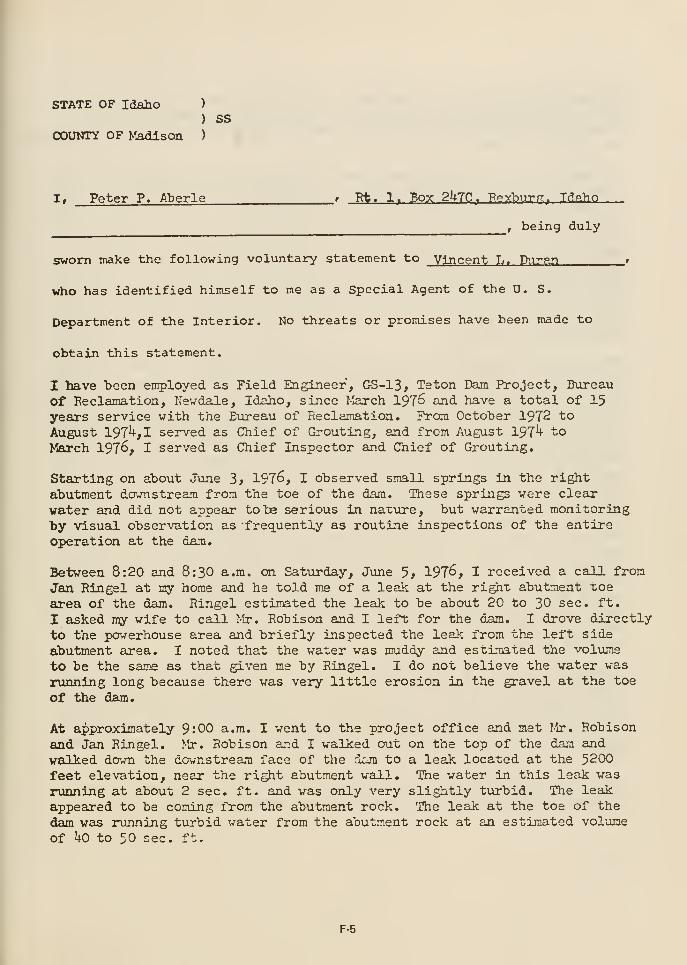
STATE OF Idaho )
) SS
COUNTY OF Madison )
I, Peter P. Aberle , Rt. 1. Box 2hlCf Peybi^rrr, Idaho
, being duly
sworn make the following voluntary statement to Vincent L. Piiran »
who has identified himself to me as a Special Agent of the 0. S.
Department of the Interior. No threats or promises have been made to
obtain this statement.
I have been employed as Field Engineer, GS-13, Teton Dam Project, Bureau
of Reclamation, Newdale, Idaho, since I-larch 197^ and have a total of 15years service with the Bureau of Reclamation. From October 1972 to
August 197U,I served as Chief of Grouting, and from August 197^ to
March 197^, I served as Chief Inspector and Chief of Grouting.
Starting on about June 3> 1976, I observed small springs in the rightabutment downstream from the toe of the dam. These springs were clear
water and did not appear to be serious in nature, but warranted monitoringby visual observation as frequently as routine inspections of the entireoperation at the dam.
Between 8:20 and 8:30 a.m. on Saturday, June 5, 1976, I received a call from
Jan Ringel at my home and he told me of a leak at the right abutment toe
area of the dam. Ringel estimated the leak to be about 20 to 30 sec. ft.
I asked ray wife to call Mr. Robison and I left for the dam. I drove directly
to the powerhouse area and briefly inspected the leak from the left side
abutment area. I noted that the water was muddy and estinated the volume
to be the same as that given me by Ringel. I do not believe the water was
running long because there was very little erosion in the gravel at the toe
of the dam.
At approximately 9:00 a.m. I went to the project office and met Mr. Robisonand Jan Ringel. Mr. Robison and I walked out on the top of the dam andwalked down the downstream face of the d::jn to a leak located at the 5200feet elevation, near the right abutment wall. The water in this leak was
running at about 2 sec. ft. and was only very slightly turbid. The leak
appeared to be coming from the abutment rock. The leak at the toe of the
dam was running turbid water from the abutment rock at an estimated volume
of ho to 50 sec. ft.
F-5
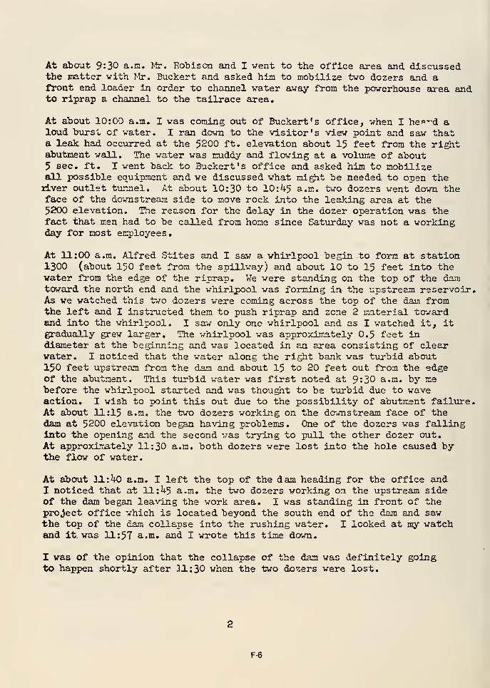
At about 9:30 a. in. >ir. Boblson and I went to the office area and discussedthe matter vith ^^r. Buckert and asked him to mobilize two dozers emd afront end loader in order to channel water away from the powerhouse area andto riprap a channel to the tailrace area.
At about 10:00 a.m. I was coming out of Buckert 's office, when I he^'^d aloud burst of water. I ran down to the visitor's view point and saw thata leak had. occurred at the 5200 ft. elevation about 15 feet from the rightabutment wall. The water was muddy and flowing at a volume of about5 sec. ft. I went back to Buckert 's office and asked him to mobilizeall possible equipment and we discussed what mi^t be needed to open theliver outlet tunnel. At about 10:30 to 10:^4-5 a.m. two dozers went down theface of the downstream side to move rock into the leaking area at the5200 elevation. The reason for the delay in the dozer operation was thefact that men had to be called from home since Saturday was not a workingday for most eniployees.
At 11:00 a.m. Alfred Stites and I saw a whirlpool begin to form at station1300 (about 150 feet from the spillway) and about 10 to 15 feet into thevater from the edge of the riprap. We were standing on the top of the damtoward the north end and the whirlpool was forming in the upstream reservoir.As we watched this tr^o dozers were coming across the top of the dam fromthe left and I instructed them to push riprap and zone 2 material torf-ard
and into the whirlpool. I saw only one whirlpool and as I watched it, itgradually grew larger. The whirlpool was approximately O.5 feet indiameter at the beginning and was located in an area consisting of clearvater. I noticed that the water along the right bank was turbid about150 feet upstream from the dam and about 15 to 20 feet out from the edgeof the abutment. This turbid water was first noted at 9:30 a.m. by mebefore the whirlpool started and was thought to be turbid due to waveaction. I wish to point this out due to the possibility of abutment failure.At about 11:15 a.m. the two dozers working on the do->vnstream face of thedam at 5200 elevation began having problems. One of the dozers was fallinginto the opening and the second was trying to pull the other dozer out.At approxi.Ta.tely 11:30 a.m. both dozers were lost into the hole caused bythe flow of water.
At about 11:^40 a.m. I left the top of the dam heading for the office andI noticed that at 11:^5 a.m. the two dozers working on the upstream sideof the dam began leaving the work area. I was standing in front of theproject office which is located beyond the south end of the dam and sawthe top of the dam collapse into the rushing water. I looked at my watchand it. was 11:57 a.m. and I wrote this time down.
I was of the opinion that the collapse of the dam was definitely goingto happen shortly after 3J.:30 when the two dozers were lost.
F-6
A nunber of the Bureau of Reclamation employees vere involved in controlling
crowds of onlookers on both sides of the dam, from the time of the collapse
tmtil late in the afternoon. I cannot at this time estimate the nimber of
onlookers
.
I have carefully read the foregoing sta-ucment consistjjig of two and
one-quarter pages and declare it to be true and correct.
Ort, . Q.aUs^Peter P. Aberle
Subscribed and si^om to before
me this ;^3--^ day of June 1976
Vincent L. I>aran, Special Agent(J
U. S. Department of the Interior
F-7
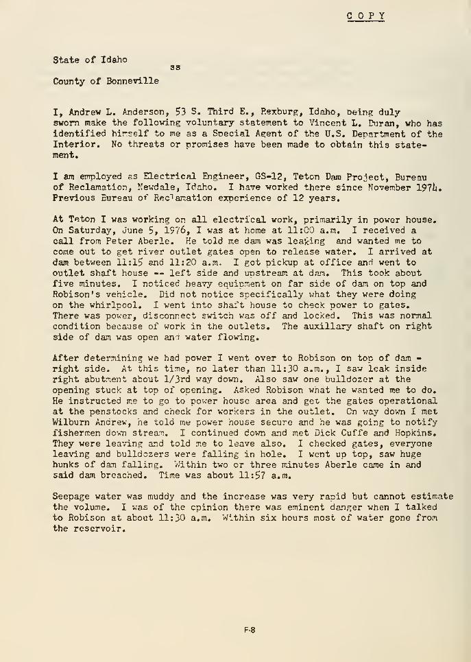
COPY
State of Idahoss
County of Bonneville
I, Andrew L. /jiderson, 53 S. Third E. , Rexburg, Idaho, being duly-
sworn make the following voluntary statement to Vincent L. Drjran, who hasidentified hir^elf to me as a Snecial Agent of the U.S. Department of theInterior, No threats or promises have been made to obtain this state-ment*
I am employed £S Electrical Engineer, GS-12, Teton Dam Project, Bureauof Reclamation, Nevdale, Idaho. I have worked there since November 197lj.
Previous Bureau of Reclamation experience of 12 years.
At Teton I was working on all electrical work, primarily in power house.On Saturday, June 5, 19?6, I was at home at 11:00 a.m. I received acall from Peter Aberle. He told m^e dam was leaking and wanted me to
come out to get river outlet gates open to release water. I arrived atdam between li:l5 and 11:20 a.m. I got pickup at office and went to
outlet shaft house — left side and unstream at dam. This took aboutfive minutes. I noticed heavy equipment on far side of dam on top andRobison's vehicle. Did not notice specifically v;hat they were doingon the whirlpool, I vent into shaft house to check power to gates.
There was power, disconnect switch was off and locked. This was normalcondition because of work in the outlets. The auxiliary shaft on rightside of dam was open and water flowing.
After determining we had power I went over to Robison on top of dam -
right side. At this time, no later than 11:30 a.m., I saw leak insideright abutment about l/3rd way down. Also saw one bulldozer at the
opening stuck at top of opening. Asked Robison what he wanted m.e to do.
He instructed m.e to go to power house area and get the gates operationalat the penstocks and check for workers in the outlet. On v/ay down I metWilbum Andrew, he ^old me power house secure and he was going to notifyfishermen do'-v-n stream, I continued down and met Dick Cuffe and Hopkins,They were lea\-ing and told me to leave also, I checked gates, everyoneleaving and bulldozers were falling in hole, I went up top, saw hugehunks of dam falling. V/ithin two or three minutes Aberle came in andsaid dam breached. Time was about 11:57 a,m.
Seepage water was muddy and the increase was very raoid but cannot estimatethe volume. I was of the opinion there was eminent danger when I talkedto Robison at about 11:30 a.m. Within six hours most of water gone fromthe reservoir.
F-8
I have carefully read the foregoing statement, consisting of 2 pagesand declare it to be true and correct.
/s/ A, L, Anderson
Andrew L. Anderson
Subscribed and sworn to before me onthis 18th day of June, 1976.
/s/ Vincent L. Duran, Special Agent
Vincent L, Duran, iipecial AgentU.S. Department of thr Interior
F-9
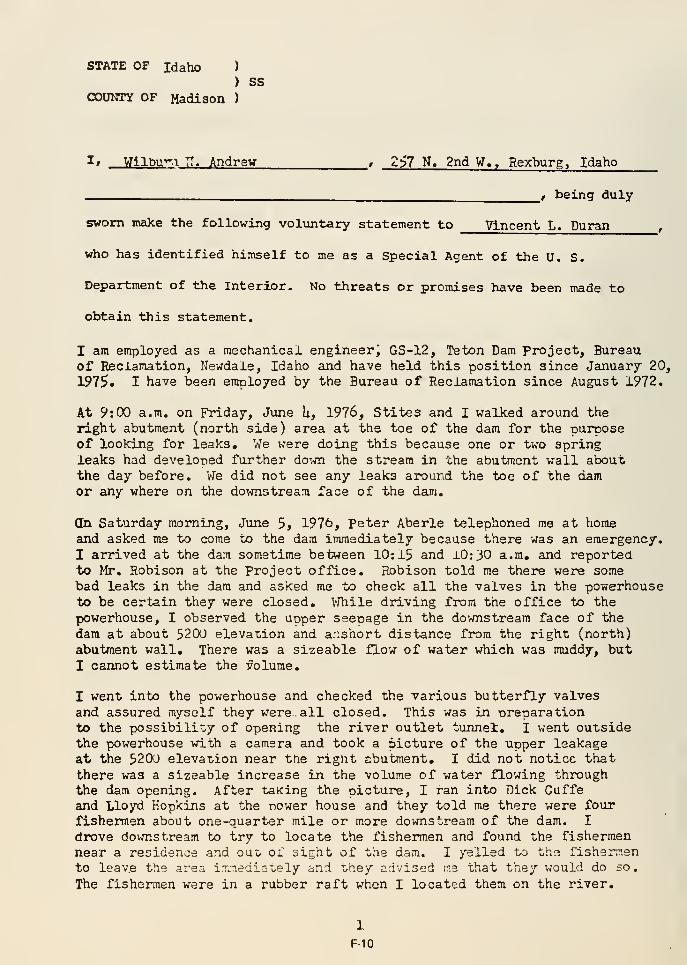
STATE OF Idaho )
) ssCOUNTY OF Madison )
I» Wilbu-^.i IT. Andrew , 257 N. 2nd W., Rexburg, Idaho
^__ , being duly
sworn make the following voliintary statement to Vincent L. Duran
who has identified himself to me as a Special Agent of the U. S.
Department of the Interior. No threats or promises have been made to
obtain this statement.
I am employed as a mechanical engineerj GS-12, Teton Dam Project, Bureauof Reclamation, Newdale, Idaho and have held this position since January 20,
1975. I have been employed by the Bureau of Reclamation since August 1972.
At 9: CO a.m. on Friday, June U, 1976, Stites and I walked around theright abutment (north side) area at the toe of the dam for the purposeof looking for leaks. We were doing this because one or two springleaks had developed further down the stream in the abutment wall aboutthe day before. We did not see any leaks around the toe of the damor any where on the downstream face of the dam.
Qn Saturday morning, June 5, 197t>, Peter Aberle telephoned me at homeand asked me to come to the dam immediately because there was an emergency.I arrived at the dam sometime between 10:15 and iO:30 a.m. and reportedto Mr. Robison at the Project office. Robison told me there were somebad leaks in the dam and asked me to check all the valves in the powerhouseto be certain they were closed, V/hile driving from the office to the
powerhouse, I observed the uoper seepage in the downstream face of the
dam at about 5200 elevation and anshort distance from the right (north)abutment wall. There was a sizeable flow of water which was muddy, butI cannot estimate the volume.
I went into the powerhouse and checked the various butterfly valvesand assured myself they were all closed. This was in ureparationto the possibility of opening the river outlet tunnel, I went outsidethe powerhouse with a camera and took a picture of the uoper leakageat the 5200 elevation near the right abutment, I did not notice thatthere was a sizeable increase in the volume of water flowing throughthe dam opening. After talcing the picture, I ran into Dick Guffeand Lloyd Hopkins at the nower house and they told me there were fourfishermen about one-quarter mile or more downstream of the dam. I
drove downstream to try to locate the fishermen and found the fishermennear a residence and ouo of sight of the dam. I >'elled to the fishermento leave the area ixnediately and T/hey advised ne that they would do so.
The fishermen were in a rubber raft when I located them on the river.
1
F-10
I drove back upstream 4»' the powerhouse and saw a crane evacuating
the area and Barry Roberts advised me that I should leave the
powerhouse area and go to higher ground, I would estimate the time
to be about 11: Uu a.m. I drove up to the south rim road and observedthe top of the dam collapse. I would estima"b the collapse of the damto have been at about 11: U5 avm. but this is not an exact time,
I was not checking the time in the face of all the turmoil.
The river outlet tunnel was never opened because it had to be=evacuatedbefore it was completely cleared of equinraent,
I had no l\ill realization that the dam was actually going to collapseuntil I saw the top fall. I never saw the activity at the top ofthe dam, including the whirlpool, because all of ray activities werein the powerhouse and the downstream area.
I remained at the dam site until about 8:30 p.m. Much of this time
was spent working on crowd contrt)l, but I cannot estimate the numberof people who came to the dam. At about 7:U0 or 8:LXD p.m. I observedseveral springlike flows of water on the face of the rock wall upstreamof the grout curtain on the north or right side. I made this
observation from the south side of the dam, I noticed one flowwas approximately 25 feet upstream from the grout curtain and about100 to 125 feet down from what had been the top of the dam. I wouldestimate this flow at about 200 gallons per minute. There were no
observable leaks or flows of water from the rock face within 2U0 feetdownstream of the grout curtain,
I have careftiily read the foregoing statement consisting of one andthree-quarter pages and declare it to be true and correct.
Wilbum H. Andrew
Subscribed and sworn to beforeme this ^^- day of June 1976
Vincent L. Duran, Special AgentU. S. Department of the Interior
2
F-11
STATE OF IDAHOss
COUNTY OF MADISON
I, Dick R. Berry , 269 S. First E., Rexburg . Idaho^ , being duly sworn make the
following voluntary statement to Vincent L. Duran, who has identified himself
to me as a Special Agent of the U.S. Department of the Interior. No threats
or promises have been made to obtain this statement.
I am employed as Survey Technician, GS-5, Teton Dam Project, Bureauof Reclamation, NewdeLle, Idaho and have held this position sinceSeptember 1975. I had previously been employed with the Soil ConservationService, U. S. Department of Agriculture since May 197^.
On June k, 1976 I recall seeing seepage near the right abutment walltelow the toe of the dam. The water was clear and not really running—Jiist settlement. There were no leakages or seeps at the dam.
On Saturday, June 5, 1976, I arrived at the Project Office a littlebefore 7:00 a.m. Hairry Park's Volkswagen was in the parking lot.Clifford Felkins and I arrived in a white Chevrolet pickup truck. Thesewere the only two vehicles in the parking lot at the time. I hadno watch with me at work on that date.
At 7:20 a.m. on June 5, I left the Project Office and drove down theupper south rim road to check three site rods on the south rim acrossfrom the spillway. I was checking the site rods for the purposeof going to the spillway and doing siirvey work on its welIIs. Whilechecking the site rods I saw a small seepage on the north sidedownstream face of the dam, ri^t at the abutment and dam joint.This was approximately one-third of the way up the dam, but notas hi^ as the change in slope. There was slight erosion, slow flowof water, but I do not recall, it being muddy. The seepage appearedto be almost new. I retiirned to the office and Haxry Parks, who wasIn the crew, reported the seepage to Jan Ringel about 7:35 a.m.We then drove across the dam and parked just south of the spillway.I checked the water level in the reservoir on the upstream side, butdo not recall the level. Tne water was very calm and there wasno discoloration and no evidence of a whirlpool.
F-12
We then started work on the spillway at about 8:30 a.m. Justbefore we went into the spillway I saw a wet area at the endof the sage area just off the abutment on the dCTvmstream faceof the dam. I do not recall this being rvinning water, just awet area. We went into the spillway and s\irveyed the left wall. 1^view of the leak was blocked. At about 10:15 a.m. I heard noisefrom a lot of equipment. At 10:30 a.m. I went to the top of thespillway to start the right wall and noted that the upper holehad expanded to 35 feet ±a diameter with a flow of muddy water 3 to 4feet wide and six inches deept. There was a dozer trying to fill inthe hole.
At 11:00 a.m. I was back at the top of the spillway and saw the holehad expanded towaj-d the top of the dam and had elongated to 100 feetand took more of the face of the dam. There was a lot of activityon the dam. I recall saying ,5 0171°thigg about sounding like a waterfallsometime about 11:15 a.m. sjs^ 11:30 a.m. We continued to surveyuntil about ll:ii-0 a.m.at which time Aberle called us out of thespillway because of danger. I arrived at the top of the spillwayat about 11:45 a.m. and saw that there was a little bridge of dammaterial across the top. I thought at this time that the dam wasgone. At about 12:60 noon I saw the top of the dam break through.
At 11:45 a.m. I saw ±i*«- dozer^ leaving the upstream face just beforethe top collapsed. I also believe there was a pickup truck goingacross the top. I evacuated to the north side. I observed the damuntil about 12:15 p.m. and then head for St. Anthony, Idaho. I wasnot involved in crowd control.
I was not aware of any earthquake or tremors.
I have carefully read the foregoing statement, consisting of oneand three-qxiarter pages and declare it to be true and correct.
Ra4ADick R. Berry ^
Subscribed and sworn to beforeme this 22nd day of June I976.
Vincent L. I>aran, STscial A-"^2nt <yVincent L. I>aran,
U. S. Department of the Interior
2
F-13
STATE OF Idaho )
) SSCOUNTY OF Kadison
)
I, Charles L. Entwisle , '»40 N. Seventh W. ,
< . Anthony, Idaho , being duly
sworn make the following voluntary statement to Vincent L. Duran ,
who has identified himself to me as a Special Agent of the U. S.
Department of the Interior. No threats or promises have been made to
obtain this statement.For three and one-half years I have been employed as Construction Inspector,GS-9, Teton Dam Project, Bureau of Reclamation, Newdale, Idaho. I havebeen employed by the Bureau since May 7» 1962.
On Saturday, June 5, 1976, at about 900 a.m., I received a telephonecall from Jan ^ingel who asked me to come to the dam because there wasan emergency. I arrived at the dam at about 10:30 a.m. Upon my arrivalat the office I answered the telephone and was told by Wilburn Andrewthat the butterfly valves at the power house were secured. I then proceededto the top of the dam to relay the information to Robert Hobison. As I
approached the top of the dam I saw a washout area about ^0 feet sq^uare inthe downstream face of the dam near the north or right abutment and aboutone-third the way up the face. There were two dozers pushing materialinto the openings. The water was muddy, but I cannot estimate the volume.
I proceeded out across the top of the dam to see Robison. As I approachedthe north or right side a small whirlpool about 10 feet from the upstreamface of the dam just off the right abutment was forming in the reservoir.The time of this was about 10:50 a.m. The whirlpool was about two feetin diameter and the \iS£s^^ was^ about six inches. It appeared to bestationjfry, but grew in size as I watched it. Two dozers were activatedand began pushing rip rap into the whirlpool.
The downstream leakage and the whirlpool grew in size and the two dozersworking on the downstream side were washed away by the water. I wouldestimate the time of this to be about 11:30 a.m., but this is strictly aguess. Shortly after this the downstream face washed out to within 10 feetfrom the top of the dam. At this point I felt the dam was going to washaway.
The two dozers working on the whirlpool were told to evacuate and asthey moved across the top of the dam to the south side the top of the damcollapsed. To my recollection the collapse occurred at about 12 noon.
F-14
I immediately after the collapse drove down the north side of the river
warning people of the collapse and returned to the project office about
12:30 p.m. Throughout the afternoon we were working on safety precautions
for on-lookers coming by, but I cannot estimate how many people vjere there.
I have carefully read the foregoing sta.tement, consisting of 2 pages ^ and
declare it to be true and correct.
/AJ, i/ Q.7t.£Charles L. Entwisle
Subscribed and sworn to beforeme on this ^(^day of June I976.
Vincent L. Duran, Special AgentU.S. Department of the Interior
F-15
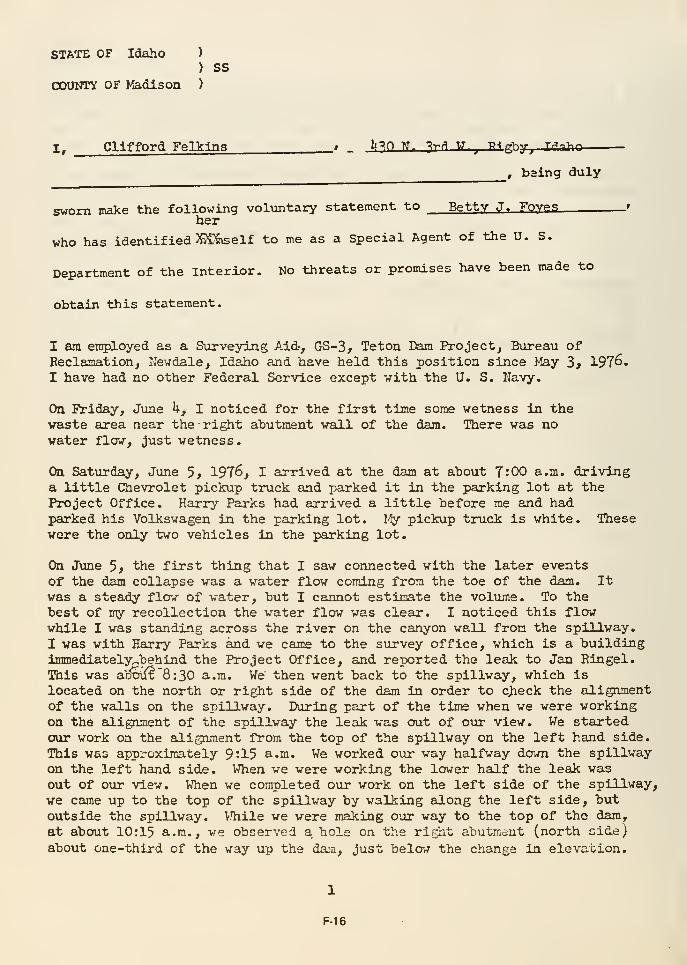
STATE OF Idaho )
) SS
COUNTY OF Madison )
Z, Clifford FelklnS __f _ l»^n W. ^r f\ W._, T?^gr^hy^ Trf-^-hn
, baing duly
svrom make the following voliintary statement to Betty J. Foves '
her
who has identified SC^elf to me as a Special Agent of the U. S.
Department of the Interior. Ko threats or promises have been made to
obtain this statement.
I am employed as a Surveying Aid-, GS-3, Teton Dam Project, Bureau ofBeclamation, Newdale, Idaho and have held this position since May 3* 1976.I have had no other Federal Service except with the U. S. Navy.
On Friday, June h, I noticed for the first time some wetness in thewaste area near the right abutment wall of the dam. There was nowater flow, Just wetness.
On Saturday, Jtme 5* 1976, I arrived at the dam at about 7:00 a.m. drivinga little Chevrolet pickup truck and parked it in the parking lot at theProject Office. Harry Parks had arrived a little before me and hadparked his Volkswagen in the parking lot. 1-^ pickup truck is white. Thesewere the only two vehicles in the parking lot.
On J\me 5> the first thing that I saw connected with the later eventsof the dam collapse was a water flow coming from the toe of the dam. Itwas a steady flow of water, but I cannot estimate the volume. To thebest of my recollection the water flow was clear. I noticed this flowwhile I was standing across the river on the canyon wall from the spillway.
I was with Harry Parks and we came to the survey office, which is a buildingimmediately^behind the Project Office, and reported the leak to Jan Eingel.This was a^5oiJ(t '8 : 30 a.m. We then went back to the spillway, which is
located on the north or right side of the dam in order to cjfieck the alignmentof the walls on the spillway. During part of the time when we were workingon the alignment of the spillway the leak was out of our view. We startedour work on the alignment from the top of the spillway on the left hand side.
This was approximately 9:15 a.m. We worked o\ir way halfway down the spillwayon the left hand side. When we were working the lower half the leak wasout of our view. When we completed o\ir work on the left side of the spillway,
we came up to the top of the spillway by waUking along the left side, butoutside the spillway. While we were making our way to the top of the dam,
at about 10:15 a.m., we observed a. hole on the rif^ht abutment (north side;
about one-third of the way up the da:n, just below the change in elevation.
1
F-16
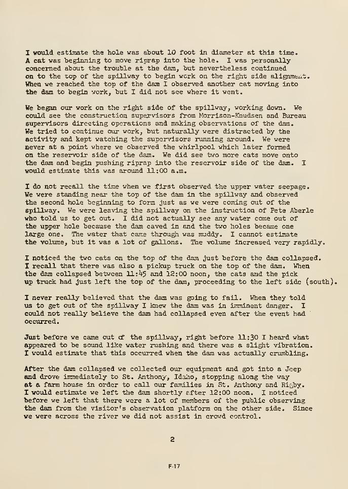
I would estimate the hole was about 10 foot In diameter at this time.
A cat was beginning to move riprap into the hole. I was personally-
concerned about the trouble at the dam, but nevertheless continuedon to the top of the spillway to begin work on the right side aligrnneiit.
When we reached the top of the dam I observed another cat moving intothe dam to begin work, but I did not see where it went.
We be^m our work on the right side of the spillway, working down. Wecould see the construction supervisors from Morrison-Khudsen and Bureausupervisors directing operations and making observations of the dam.
We tried to continue our work, but naturally were distracted by theactivity and kept watching the supervisors running ajround. We werenever at a point where we observed the whirlpool which later formedon the reservoir side of the dam. We did see two more cats move ontothe dam and begin pushing riprap into the reservoir side of the dam. Iwovild estimate this was around 11:00 a.m.
I do not recall the time when we first observed the upper water seepage.We were standing near the top of the dam in the spillway and observedthe second hole beginning to form just as we were coming out of thespillway. We were leaving the spillway on the instruction of Pete Aberlewho told us to get out. I did not actually see any water come out ofthe upper hole because the dam caved in and the two holes became onelarge one. The water that came through was muddy. I cannot estimatethe volume, but it was a lot of gallons. The volume increased very rapidly.
I noticed the two cats on the top of the dam just before the dam collapsed.I recall that there was also a pickup truck on the top of the dam. Whenthe dam collapsed between ll:i|-5 and 12:00 noon, the cats and the pickup truck had just left the top of the dam, proceeding to the left side (south),
I never really believed that the dam was going to fail. When they told\is to get out of the spillway I knew the dam was in imminent danger. Icould not really believe the dam had collapsed even after the event hadoccurred.
Just before we came out cf the spillway, right before 11:30 I heard whatappeared to be sound like water rushing and there was a slight vibration.I would estimate that this occurred when the dam was actually crumbling.
After the dam collapsed we collected our equipment and got into a Jeepand drove immediately to St. Anthon;/', Idalio, stopping along the wayat a farm house in order to call oiir families in St. Anthony and Riijby.
I woiild estimate we left the dam shortly efter 12:00 noon. I noticedbefore we left that there were a lot of members of the public observingthe dam from the visitor's observation platform on the other side. Sincewe were across the river we did not assist in crowd control.
F-17
I have carefully read the foregoing statement consisting of two and afraction pages and declare it to be true and correct.
Subscribed and sworn to before methis 22nd day of June I976.
K!>ji^- ^^^Betty J, f'iff^i} SpecjLal AgentU. S. Depkftment of the Interior
F-18
STATE OF
Again while we were surveying the spillway I was unahle to observethe leak. At about 11:^5 a.m. Peter Aberle called us out of thespillway and we started toward the top. Just before Aberle calledus I heard a loud r.oise, which sounded like water forcing through thelecik area.
At a,bout 11:50 a.m. I arrived at the. top. of the spMLlway and eeM- two- iMt/v/^al
^f^^roGc ur.c'^5U) 6-^r^5~^:2.r. irag. the nai~lh' 3ii.e--t.oifG.i-!l - LIic ocuth
:tf;i-c . Shortly thereafter the remaining portion of the top of thedam on the north side collapsed, I v;ould estimate the time to havebeen 11:57 a-m. I went hone at about 12:15 a-.m.
I have carefully read the foregoing statement consisting of oneand one-third pages and declare it to be true and correct.
<^^^^ yf ^^^y. ^M^a A, Ferber
Subscribed an(h sworn to before methis ^_^2J5.^i.day of June 1976.
Vincent L. Duran, Spe^icLl Agent "^U, S. Department of the Interior
F-20
STATE OF Idaho)
) SS
COUNTY OF I'adison )
I, Alvin .T. Heintz _, 105 N. Second E. , St. Anthony,
Idaho ^ , being duly
sworn make the following voluntary statement to Vincent L. Puran,
who has identified himself to me as a Special Agent of the U. S.
Department of the Interior. No threats or promises have been made to
obtain this statement.
Since OctolDer 1971, I have teen employed as Construction Inspector,
CS-9, Teton Dam Project, Bureau of Reclamation, Newdale, Idaho. I have
been employed by the Bureau since 1955«
At about 10:30 a.m. on Saturday, June 5, 1976, Pete Aberle telephoned
me at my home and asked me to come to the dam because there were some
leakage problems. I arrived at the office at about 10:55 a.m. and after
finding no one in the office drove across the top of the dam and found
Aberle on the north or right end of the dam near the spillway. I would
estimate the time to be 11:00 a.m.
As I drove across the dam I could see water spewing from the downstream
face of the dam near the north or right side abutment. I cannot estimate
the elevation of the leak. The vjater was flowing rapidly and vras eroding
fill materials thereby making it muddy. There were two dozers on the
face of the dam pushing rock into the hole.
As I was talking to Aberle we noticed a small whirlpool forming in the
reservoir on the upstream side of the dam. The whirlpool was about two
feet in diameter, close to the north or right abutment and about 10 to
15 feet out from thfe dam. This was the only whirlpool I saw and to myknowledge it stayed in the same location.
I remained on the top of the dam near the north end and helped direct
two .dozers pushing riprap into the whirlpool. V/hile 'ro:'i:i;'g I saw the
downstream flow of water increase in volume and the whirlpool increas.e in
size. I cannot give estimates of the volume of water or the si:t.e of
the whirlpool or times of any significant increases.
At about 11:^5 a.m. , we instructed the two dozers on the top of the dam
to leave and I went off the north or right side of dam. The top of the
dam collapsed at about 11:50 a.m. This time estimate is not specific.
I never really considered that the dam would fail until the last minute.
To my knowledge there was no earthquake before the problems began.
Shortly after the collapse I left the north side and proceeded down-
stream to i.'^:yn. residents, I returned to" the offices on the south side
of the dajiTSat assisV'^ in crowd control. I cannot estimate the numberof people who cane to the dan after the failure , but we had problemskeeping people off the rim edges and the dam itself.
I have carefully read the foregoing statement, consisting of 1 and l/8thpages, and declare it to be true and coirect.
Alvin J. Heintz
SubscD?lbed and sworn to before me on this^:?-<^ day of June I976.
Vincent L. Duran, Special AgentU.S. Department of the Interior
F-22
STATE OF IDAHO
COUNTY OF MADISONss
If Ksnneta C. Hoyt > Rt. Ij^ Box 202-12^ St. Anthony
^
Idaho , being duly sworn make the
following voluntary statement to Vincent L. Duran, who has identified himself
to me as a Special Agent of the U.S. Department of the Interior. No threats
or promises have been made to obtain this statement.
I have heen employed as Construction Inspector, GS-9, Teton Dam Project,Bureau of Reclamation, Newdale, Idaho since March 30, 1975/ and I havea total of l6 years service with the Bureau of Reclamation,
Before Jime 5, I saw seepage in the bottom beyond the toe of the dam.This seepage was visible for about two or three days prior to Jime 5>and was 150 feet downstream of the toe of the dam. I never saw theseepage clearly, do not know the condition or volume. It was a slightflow and was of no great concern to me as it appeared rather natural.
On Friday, June k, I saw nothing \inusual at the dam. There were noleaks or no whirlpools up to 4:30 p.m. when I quit work.
On Saturday, June 5, 1976, at about 10:30 a.m., Pete Aberle called myhome and left a message with my wife that I should be on standby tocome to work on the midnight shift that ni^t. I called Aberle backabout 10:40 a.m. and he told me to come to the dam immediately. Idrove to the dam and arrived on top of the dam at about 11:15 a.m. Isaw a large stream of water running off the downstream side of the damat about 5^200 slope and about 20 to 30 feet from the right abutment.(The elevation for the water level was 5^324 feet elevation.The- elevation of the opening to the spill water was 5^306.) Thestream of water was at about the change in slope elevation. The waterwas muddy. I also saw two dozers pushing rock into the hole createdon the downstream face.
I also saw a whirlpool on the upstream face of the dam in reservoirwater. The whirlpool was about 150 feet across the top of the dam fromthe spillway and about 15 feet out from the face of the dam into thewater. It was rather close to the rock and abutment wall. Thewhirlpool was about 10 feet in diameter. There were two bulldozerspushing riprap into the pool. The water was clear. The dozers werecreating discoloration in the water. When I saw the whirlpool I feltthe dam vas £;one. Zihe vhirlpcol gradually grew and was visiblevmtil I left the dan.
F-23
Someone said the dozers on the downstream face were gone. I looked and
saw them tumbling down stream. Shortly thereafter the dozers on the
top of the dam pulled hack and headed to the south side of the dam. I
followed the dozers in a pickup truck. When I got to the river outlet
shaft house on top of the dam I tiorned around and saw the top of the dam
collapse. I looked at my watch and noted the time to be 11:58 a.m.
Thereafter, I spend time controlling crowds. There were a number of
people wandering aroiind. I cainnot estimate the number at this time.
It was a very dangerous situation.
At ahout 2:00 p.m., Andrew Anderson and I went one mile upstream to
check the water elevation, which at the time was 5,217 feet. At
2:30 p.m. the water level was 5,170 feet. There was no one around the
area. At the time I could see a lot of water running out of rock on
the right abutment across from the boat ramp. This was water in the
rocks from the reservoir. There was no such water prior to the filling
of the dam.
I am not aware of any earthquake tremors in the area.
I have carefully read the foregoing statement, consisting of 2 pages,
and declare it to be true and correct.
Kenneth C. Hoyt ^
Subscribed and sworn to before me
on this ^;?:=4^ay of June 1976.
Vincent 1j. Duran, Special Agent (i/
U.S. Department of the Interior
F-24
STATE OF IDAHOss
COUNTY OF MADISON
I, Harry Parks . Kit Circle Trailer Court,
Space 5, St. Anthony, Idaho, being duly sworn make the
Betty J, Foyes .—^--^following voluntary statement to Vincent L. Duran,/who ha^se identified r«-fev
theraselves
to me as ^ Special Agentsof the. U.S. Department of the Interior. No threat
or promises have been made to obtain this statement.
I am employed as Supervisory Surveying Technician (Party Chief), GS-8,Teton Dam Project, Bureau of Eeclamation, Newdale, Idaho, and I haveheld this position since April 1975 • I previously vorked for theBureau of Reclamation at Forest Grove, Oregon from November I968 to April
1975 • I have been employed by the Bureau of Reclamation since November 19d1»
About June 3, 1976, I observed a small stream of water appearingalong the bottom of the vaste area about l^iOO feet downstream fromthe toe of the dam. I was on the top of the south rim when I observedthis water and so I coiild not say at this tine whether the water wasclear, muddy, etc. I was aware that Robison and Aberle were watchingthe flow on at least one occasion.
On Saturday, June ^, 1976, I arrived at the project office a coupleminutes before 7:00 a.m. I was driving a green Volkswageh. I parkedthe Volkswagen in the Reclamation parking lot. I was the first personto park a vehicle in the lot and Chris Felkins arrived shortly thereafterdriving his white Chevrolet pickup truck. We left the office about
7:35 a.m. in a survey truck and traveled down the south rim roaddownstream for the pm-pose of checking the survey si^ts in order toperform a survey on the spillway on the north side of the dam. At about7:50 a member of the survey party noticed water seepage. I thenobserved the water which was running out of the toe of the dam at about50 feet from the north abutment wall. I cannot estimate the volvune
but it was barely what could be called a stream at all. The waterappeared muddy, but this may have been caused by the material overv/hich it was flowing. We drove back to the office and I reportedthe water leakage about 8:00 a.m. to Jan Ringel.
After reporting the water, we departed the project office and droveacross the top of the dam and parked our vehicle near the spillwaybridge on the dam. At about 8:20 a.m. I checked the water elevationon the reservoir or upstream side of the dam, near the spillway inlet,and it w?.s f>3'-1.7 clc/aticn. This v.s ?.bout thjree fr-^t of the p?.te levelof the spillway. At this time I noted nothing unusual on thereservoir side of one os-jn so x'ar as the water was concerned, i'here
was no whirlpool and in fact the water was unusually calm. Thejre was no
1
F-25
discoloration of the vater. There vere no fishermen or any otherpersons on the reservoir side at this time. This area is postedagainst fishing.
I went down into the spillway and made no observation of thedownstreajn face of the dam at this time. I was working in thespillway and my view was hlocked of the downstream face of the dam,and it was not until about 9:30 a.m. that I could see a dozercoming off the top of the dam to work on the downstream side.At about 10:30 a.m. I came up to the top of the spillira-y. I walkedonto the sage area and observed a leakage about 50 feet from thenorth abutment and somewhere above the 5200 elevation. I cannotestimate the vol\ime of the water but it was a running stream.I would estimate the hole was about five feet in diameter and thewater was muddy. We watched the water about five minutes andtherhpleamay have increased as much as a foot during this time.He does not recall seeing any dozers working at the hole at thistime.
We then went back down the spillway to continue our s\irvey work.I was aware of a lot of activity at the top of the dam in thatthere were a lot of people moving about and tiio dozers moved acrossthe dam. Between 11:15 a.m. and 11:30 a.m. I could hear water flowingand made the assumption that it was coming out of the hole, but Icould not see it from where I was working. At about 11:45 a.m. PeteAberle called to the survey crew and told us to leave the area.I did not have the feeling at that time that the dam was in imminentdanger of collapse and if I had, I would have left the spillway earlier.I would estimate that it was close to 11:50 when I reached thetop of the dam. At this time the hole on the downstream face ofthe dam had eroded almost to the top and muddy water was rushingout of it. There was a pickup truck on the top of the dam and twodozers. Tne dozers were pushing riprap into the water on the upstreamside.
I did not see the whirlpool which developed on the upstream sideof the dam. I did not see the water on the upstream side of thedam at all until the dam broke. I was standing a few feet fromthe spillway bridge in the middle of the road. I saw half of thetop of the dam go and shortly thereafter the other half (upstream)went. I was weaaring a watch but did not note the time, but it wasclose to noon.
The first time that I became aware that there '-ra.s imminent dangerof the dam collapsing was when edge of the hole came close to thebottom of the road. This was shortly after 11:50 a.m.
F-26
I am not aware of any earthquake tremors. The only tremors I amaware of was vhen the spillway tremored a little bit about 11:^5and I bel^'eve this was caused by the rush of the water.
I dejiarted from the north side of the dam at about 12:05 p.m.I did not participate in any crowd control operation, since therewere no members of the public on the north side at that time.
I have read the above statement consisting of two and one-quarterpages and declare it to be true and correct.
l/fTZ^^^^-T^-''^ jC-z^^Harry J^ks
Subscribed and sworn to before roe
this 22nd day of June I976
Vincent L. Duran, Special? AgentU. S. Department of the Interior
Betty J.Foyes, Spacial Agent \/
U. S. DOTarlaaent or the Interior
F-27
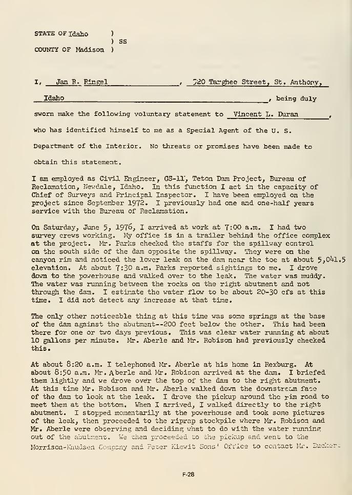
STATE OFiaahO )
) SSCOUNTY OF Madison )
I, Jan p. Pingel , >20 Tar^ee Street, St. Anthony,
Idaho , being duly
sworn make the following voliintary statement to Vincent L. Duran,
who has identified himself to me as a Special Agent of the U. S.
Department of the Interior. No threats or promises have been made to
obtain this statement.
I am employed as Civil Engineer, GS-11', Teton Dam Project, Bureau ofReclamation, Nevdale, Idaho. In this function I act in the capacity ofChief of Surveys and Principal Inspector. I have been employed on theproject since September 1972. I previously had one and one-half yearsservice with the Bureau of Reclamation.
On Saturday, June 3} 1976, I arrived at work at 7:00 a.m. I had twosurvey crews working, I-!y office is in a trailer behind the office complexat the project. 1^. Parks checked the staffs for the spillway controlon the south side of the dam opposite the spillway. They were on thecanyon rim and noticed the lower leak on the dam near the toe at about 5^0^+1.5
elevation. At about 7:30 a.m. Parks reported sightings to me. I drovedovm to the powerhouse and walked over to the leak. The water was muddy.The water was running between the rocks on the right abutment and notthrough the dam. I estimate the water flow to be about 20-30 cfs at thistime. I did not detect any increase at that time.
The only other noticeable thing at this time was some springs at the baseof the dam against the abutment—200 feet below the other. This had beenthere for one or two days previous. This was clear water running at about10 gallons per minute. >5r. Aberle and Mr. Robison had previously checkedthis.
At about 8:20 a.m. I telephoned Mr. Aberle at his home in Rexburg. Atabout 8:50 a.m. >tr. Aherle and Mr. Robison arrived at the dam. I briefedthem lightly and we drove over the top of the dam to the right abutment.At this time Mr. Robison and Mr. Aberle walked da^n the downstrccjn faceof the dam to look at the leak. I drove the pickup around the rim road tomeet them at the bottom. V/hen I arrived, I walked directly to the rightabutment. I stopped momentarily at the powerhouse and took some pict-ures
of the leak, then proceeded to the riprap stockpile ^/here Mr. Robison andMr. Aberle were observing and deciding what to do with the water runningout of the abutr.-.en-c . We "chen proceeded to the pickup and wen'G to the
Morrison-rvnudsen Company and Fe^er JrCiewit Sons' Ofi'ice to contact Mx'. iiuciCL-r^^
F-28
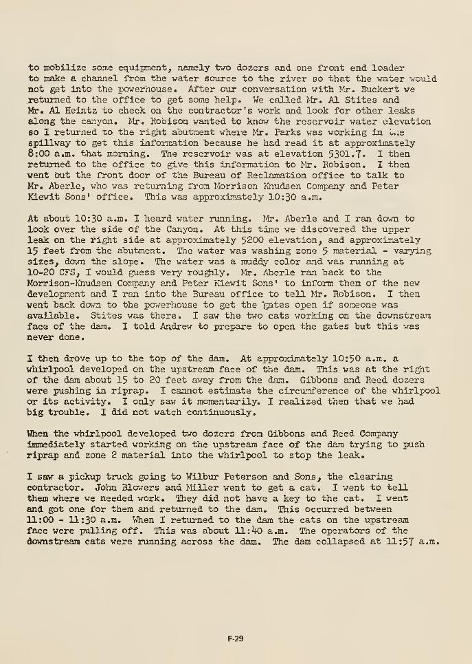
to mobilize some equipment, namely two dozers and one front end loaderto make a channel from the water so\irce to the river so that the water wouldnot get into the powerhouse. After our conversation with Mr. Buckert wereturned to the office to get some help. We called Mr. Al Stites andMr. Al Heintz to check on the contractor's work and look for other leaksalong the canyon. Mr. Bobison wanted to know the reservoir water elevationso I returned to the right abutment wheie Mr. Parks was working in l,.e
spillway to get this information because he had read it at approximately8:00 a.m. that morning. The reservoir was at elevation 5301.7. I thenreturned to the office to give this information to Mr. Robison. I thenvent Out the front door of the Bureau of Reclamation office to talk toKr. Aberle, who was returning from Morrison Khudsen Company and PeterKiewit Sons' office. This was approximately 10:30 a.m.
At about 10:30 a.m. I heard water running. !&•. Aberle and I ran down tolook over the side of the Canyon. At this time we discovered the upperleak on the right side at approximately 5200 elevation, and approximately15 feet from the abutment. The water was washing zone 5 material - varyingsizes, down the slope. The water was a muddy color and was running at10-20 CFS, I would guess very rou^ily. Mr. Aberle ran back to theMorrison-Knudsen Company and Peter Kiewit Sons ' to inform them of the newdevelopment and I ran into the Bureau office to tell Mr. Robison. I thenvent back down to the pawerhouse to get the gates open if someone wasavailable. Stites was there. I saw the two cats working on the downstreamface of the dam. I told Andrew to prepare to open the gates but this wasnever done.
I then drove up to the top of the dam. At approximately 10:50 a.m. avhirlpool developed on the upstream face of the dam. This was at the rightof the dam about 15 to 20 feet away from the dam. Gibbons and Reed dozerswere pushing in riprap. I cannot estimate the circumference of the whirlpoolor its activity. I only saw it momentarily. I realized then that we had"big trouble. I did not watch continuously.
When the whirlpool developed two dozers from Gibbons and Reed Companyimmediately started working on the upstream face of the dam trying to pushriprap and zone 2 material into the whirlpool to stop the leak.
I saw a pickup truck going to Wilbur Peterson and Sons, the clearingcontractor. John Blowers and Miller went to get a cat. I went to tellthem where we needed work. They did not have a key to the cat. I wentand got one for them and returned to the dam. This occurred between11:00 - 11:30 a.m. When I returned to the dam the cats on the upstreamface were pulling off. This was about 11:^ a.m. The operators of thedownstream cats were running across the dam. The dam collapsed at 11:57 a.m.
F-29
I recall that there vas a fanner In a green pickup truck at the dam onthe north side sometime between 9:00 and 11:00 a.m. The man said "whatis going on here?", "Is it seriovis? " I told him yes, the dam is breaking.The roan said "I am going to get out of here. I have a farm down below,"I do not know the name of the man and cannot identify him.
Within two ho\ars of the collapse of the dam, there were at least 15 peopleon the north side of the dam around the spillway and on the edge of thecollapsed area. There was considerable problems with crowd controlthroughout the afternoon.
I am not aware of any earthqiiake tremors.
I have carefully read the foregoing statement consisting of two andone-half pages and declare it to be true and correct.
n3axi R. Ringei
Subscribed and sworn to beforeme this p^-^ day of June 1976
/ tO^*<I^/
Vincent L. Duran, Special AgentU» S. Department of the Interior
F-30
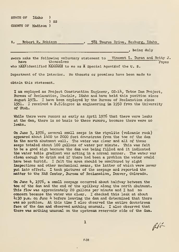
STATE OF Idaho )
) ssCOUNTY OF Madison )
I, Robert P» Robison , 58I Taurus Drive. Eexburg, Idaho
, being duly
sworn make the following voluntary statement to Vincent L. Duran and Betty J.
have themselves Foyes
who hXSCidentified KXKSSO to me as X Special Agentgof the U. S.
Department of the Interior. No threats or promises have been made to
obtain this statement,
I am employed as Project Construction Engineer, GS-1^, Teton Dam Project,Bureau of Reclamation, Newdale, Idaho and have held, this position sinceAugust 1971. I have been employed by the Bureau of Reclamation since
1951* I received a B.S«degree in engineering in 195D from the Universityof Utah.
While there vere rumors as early as April 197^ that there vere leaksat the dam, there is no basis to these rumors, because there were noleaks.
On June 3> 1976, several small seeps in the rhyolite (volcanic rock)api)eared about 1^0 to 2000 feet dovmstream from the toe of the damin the north abutment vail. The vater was clear and all of theseseeps totaled about 100 gallons of water per minute. This was feltto be a good sign because the dam was being filled and it indicatedthe water table gradient was acting in a normal manner. The water wasclean enough to drink and if there had been a problem the water wouldhave been turbid. I felt the area should, be monitored by sightinspections and other mechanical means, the latter of which were neverput into effect. I took pictures of the seepage and reported thematter to the E&R Center, Bureau of Reclamation, Denver, Colorado,
On June h, 1976, a small seepage occurred about halfway between thetoe of the dam and the end of the spillway along the north abutment.This flow was approximately 20 gallons per minute and I had noconcern becau.se the water was clear. I checked this leak at aboutU:30 p.m. on June h before leaving the dam and determined that therevas no problem. At this time I also observed the entire downstreamface of the dam and observed nothing vinusual. I also observed thatthere was nothing unusual on the upstream reservoir side of the dam.
^y-
F-31
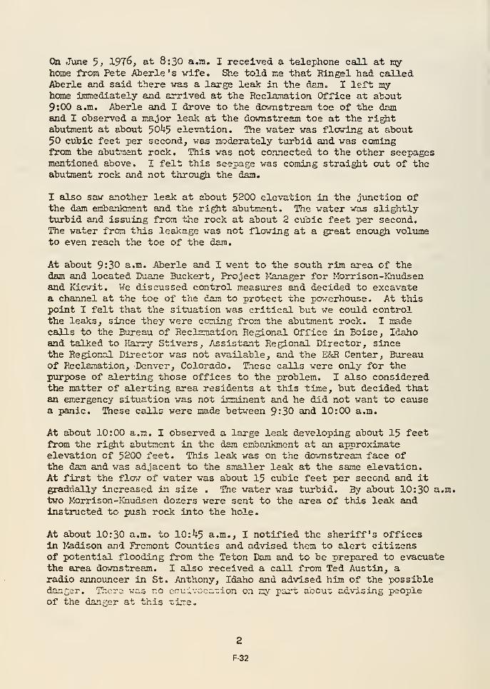
On June 5* 1976, at 8:30 a.m. I received a telephone call at myhome from Pete Aberle's vife. She told me that Rlngel had calledAberle and said there was a large leak in the dam. I left myhome immediately and arrived at the Reclamation Office at about9:00 a.m. Aherle and I drove to the dovmstreara toe of the damand I observed a major leak at the downstream toe at the rightabutment at about 50^5 elevation. The water was flavTing at about50 cuiic feet per second, was moderately turbid and was comingfrom the abutment rock. This was not connected to the other seepagesmentioned above. I felt this seepage was coming straight out of theabutment rock and not through the dam.
I also saw another leak at about 5200 elevation in the junction ofthe dam einbankment and the right abutment. The water was slightlyturbid and issuing from the rock at about 2 cubic feet per second.The water from this leakage was not flowing at a great enough volumeto even reach the toe of the dam.
At about 9:30 a.m. Aberle and I went to the south rim area of thedam and located Duane Buckert, Project Manager for Morrison-Khudsenand Kiewit. We discussed control measures and decided to excavatea channel at the toe of the dam to protect the powerhouse. At thispoint I felt that the situation was critical but we could controlthe leaks, since they were coming from the abutment rock. I madecalls to the Bureau of Reclamation Regional Office in Boise, Idahoand talked to Harry Stivers, Assistant Regional Director, sincethe Regional Director was not available, and the E&R Center, Bureauof Reclamation, Denver, Colorado. These calls were only for thepurpose of alerting those offices to the problem. I also consideredthe matter of alerting area residents at this time, but decided thatan emergency situation was not imminent and he did not want to causea panic. These calls were made between 9^30 and 10:00 a.m.
At about 10:00 a.m. I observed a large leak developing about 15 feetfrom the rigtit abutment in the dam embankment at an approximateelevation of 5200 feet. This leak was on the downstream face ofthe dam and was adjacent to the smaller leak at the same elevation.At first the flow of water was about 15 cubic feet per second and itgradually increased in size . The water was tvirbid. By about 10:30 a.m.two Morrison-Khudsen dozers were sent to the area of this leak andinstructed to push rock into the hole.
At about 10:30 a.m. to 10:^+5 a.m., I notified the sheriff's officesin l-iadison and FVemont Counties and advised them to alert citizensof potential flooding from the Teton Dam and to be prepared to evacuatethe area da^nstream. I also received a call from Ted Austin, aradio announcer in St. Anthony, Idaho and advised him of the possibledanger. There was no eauivoca-ion on my part about; advising peopleof the danger at this time.
2
F-32
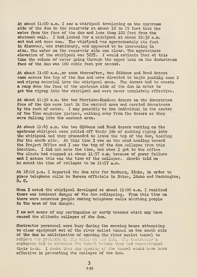
At about 11:00 a.m. I saw a whirlpool developing on the upstreamside of the dam in the reservoir at about 10 to 15 feet into thewater from the face of the dam and less than 100 feet from theabutment wall. I had looked for a whirlpool at about 10; 30 a.m.and had not seen one. The whirlpool ttis approximately six feetin diameter, was stationary, and appeared to be increasing insize. The water on the reservoir side was clear. The approximateelevation of the whirlpool was 5295* I vould estimate that at thistime the voliuns of water going through the upper leak on the downstreamface of the dam was 100 cubic feet per second.
At about 11:00 a.m.,or soon thereafter, two Gibbons and Reed dozerscame across the top of the dam and were directed to begin pushing zone 2and riprap material into the whirlpool area. The dozers had to createa rarap dovm the face of the upstream side of the dam in order toget the riprap into the whirlpool and were never completely effective.
At about 11:30 a.m. the two Morrison-Rmdsen dozers on the downstreamface of the dam were lost in the washout area and carried downstreamby the rush of water. I may possibly be the individual in the centerof the Time magazine pictiore, walking away from the dozers as theywere falling into the washout area.
At about ll:i)-5 a.m. the two Gibbons and Reed dozers working on theupstream whirlpool were p\illed off their job of pushing riprap intothe whirlpool and they proceeded to leave the top of the dam, headingfor the south side. At this time I was on the road heading tcrjBxd.
the Project Office and I saw the top of the dam collapse, from thislocation. I did not note the time, but when I got to the officethe clocks had stopped at about 11:57 a.m. because of power failureand I assume this was the time of the collapse. Aberle told mehe noted the time of collapse to be 11:57 a.m.
At 12:10 p.m. I departed the dam site for Rexbvirg, Idaho, in order toplace telephone calls to Bureau officials in Boise, Idaho and Washington,D. C.
When I noted the whirlpool developed at about 11:00 a.m. I realizedthere was imminent danger of the dam collapsing. From this time onthere were numerous people making telephone calls alerting peoplein the area of the danger.
I am not aware of any earthquakes or eartjr tremors which may havecaused the ultimate collapse of the dam.
Contractor personnel were busy during the morning hours attemptingto clear equipment out of the river aatlet tunnel on the south sideof the dam in anticipation of opening the river outlet tunnel torelieve v.i pr;3^ure ci t;;.j vct^r <::\ ^a3 dz". rie ccn-,raczor 's
employes;: hs,d to e\T,c"ate t'l.-} tiininl "c-.Trore they "-.ad accOTrrplished
their task. I uoubo tiiar, the or^^nin;^ of Lhe tunnel woxild have beeneffective in preventing the collapse of the dam.
3
F-33

At the time of the dam collapse there was no schedule of work shifts
for Bureau of Reclajnation employees that would have required personsat the dam 2k hours a day. On Saturday June 5> 1976, the onlyscheduled Bureau of Beclamation workers were the survey crews. Theicwere scheduled quality control inspections according to the workbeing done, but there were no scheduled physical plant inspectionsof the dam on a routine basis by the inspectors.
I have carefully read the foregoing statement, consisting of threeand one-qusrter pages and declare it to be true and correct to thebest of my knowledge and belief.
Robert K. Robison
Subscribed and sworn to beforeme this 23rd day of June 1976
Vincent L. Duran, Special Agent(
U. S. Department of the Interior
Betty J/ Foyes, ^Special Agent (/
U. S. Dppdii-tment of the Interior
F-34
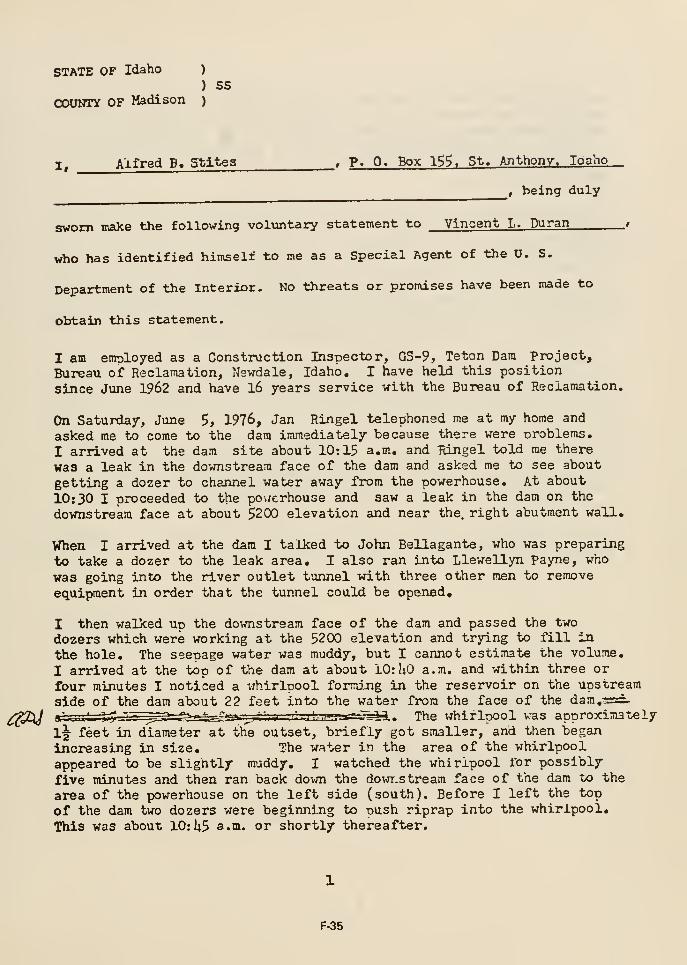
STATE OF Idaho )
) SS
couvm OF Madison )
I^ Alfred B. Stltes _, P» 0. Box 1^^. St. Anthony, loaho
, being duly
sworn make the following voluntary statement to Vincent L. Duran i
who has identified himself to me as a Special Agent of the U. S.
Department of the Interior. No threats or promises have been made to
obtain this statement.
I am emolojed as a Construction Inspector, GS-9, Teton Dam Project,
Bureau of Reclamation, Newdale, Idaho, I have held this position
since June 1962 and have l6 years service with the Bureau of Reclamation.
On Saturday, June 5, 1976, Jan Ringel telephoned me at my home and
asked me to come to the dara immediately because there were oroblems.
I arrived at the dam site about 10:15 a.m. and Ringel told me there
was a leak in the downstream face of the dam and asked me to see about
getting a dozer to channel water away from the powerhouse. At about
10:30 I proceeded to the po\/crhouse and saw a leak in the dam on the
downstream face at about 5200 elevation and near the, right abutment wall.
When I arrived at the dara I talked to John Bellagante, who was preparing
to take a dozer to the leak area, I also ran into Llewellyn Payne, who
was going into the river outlet tunnel with three other men to remove
equipment in order that the tunnel could be opened,
I then walked un the downstream face of the dam and passed the two
dozers which were working at the 5200 elevation and trying to fill in
the hole. The seenage water was muddy, but I cannot estimate the volume,
I arrived at the top of the dam at about 10: UO a.m. and within three or
four minutes I noticed a whirloool forming in the reservoir on the upstream
side of the dam about 22 feet into the water from the face of the dam.-rsd.
g"- -. L_ L jT!?— ^^~7r"^-^^^^^=-£-^ ^— • .-H : -g» ^p-f^.^s^ ^A
, The whirlpool was approximately
1^ feet in diameter at the outset, briefly got smaller, and then began
increasing in size. The water in the area of the whirlpool
appeared to be slightly muddy. I watched the whirlpool for possibly
five minutes and then ran back dovm the dowi.stream face of the dam to the
area of the powerhouse on the left side (south). Before I left the top
of the dam two dozers were beginning to push riprap into the whirlpool.
This was about 10: U5 s.m. or shortly thereafter.
F-35

When I arrived at the powerhouse area I noted that one of the dozersworking on the downstream face was falling into the washed out areaand the other dozer was attem5ting to pull it out. A very short timethereafter both dozers were washed awa/ in the stream of water. Thevolume of water at this point had increai>ci tremendously and the waterwas very muddy.
Shortly after 11:00 a.m. Payne and his fellow workers evacuated theriver outlet tunnel and three other persons in the powerhouse areawere evacuating motorized equipment to higher ground near the dam.
I drove to the upper south rim oposite the spillway and observedthe washout area on the downstream face continually increase and portionsof the dam falling into the vacuum. This was during the period11:30 a.m. until almost 12:00 noon when the top of the dam finallycollapsed, I felt that the dam was definitely going to collapse shortlyafter 11: Ou a.m. when the two dozers were washed away.
I remained at the dam until about 10:30 p.m. and much of this timewas spent trying to keep spectators behind the visitors pointon the south rim. I cannot estimate the number of spectators thatwere there during the day.
During the afternoon, after the water had receded, it appeared to methat the grout cap was still in place, I noticed some water wasrunning out of the right abutment, upstream of the gix)ut cap, but Idid not observe any water iMnning out of the abutment downstream ofthe grout cap.
I have carefulljr read the foregoing statement consisting of one and one-halfpages and declare it to be true and correct.
/;^f^_ ^jf^'^^>''
Alfred D. Stites
Subscribed and sworn to beforeme this y^^-^d day of June 1976
yiL..U;J./^^jrVincent L, Buran, Special Agen,1^
U. S. Department of the Interior
F-36
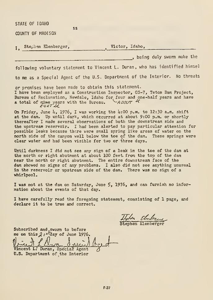
STATE OF IDAHOss
COUNTY OF MADISON
T Stephen Elenberger, ^Victor, Idaho,
, being duly sworn make the
following voluntary statement to Vincent L. Duran , who has identified himsel
to me as a Special Agent of the U.S. Department of the Interior. No threats
or promises have been made to obtain this statement.
I have been employed as a Construction Inspector, GS-7, Teton Dam Project,Bureau of Reclamation, Newdale, Idaho for, four and one-half years and have
a total of -r^EFfe years with the Bureau. ^^A POUT "^
On Friday, June I4, 1976, I was working the 1:00 p.m. to 12:30 a.m. shiftat the dam. Up until dark, which occurred at about 9:00 p.m. or shortlythereafter I made several observations of both the downstream side and
the upstream reservoir. I had been alerted to pay particular attention forpossible leaks because there were small spring like areas of water on thenorth side of the canyon well below the toe of the dam. These springs wereclear water and had been visible for two or three days.
Until darkness I did not see any sign of a leak in the toe of the dam at
the north or right abutment at about 100 feet, from the top of the damnear the north or right abutment. The entire downstream face of thedam showed no signs of any problems. I also did not see anything unusualin the reservoir or upstream side of the dam. There was no sign of awhirlpool.
I was not at the dam on Saturday, June 5, 1976, and can furnish no infor-mation about the events of that day.
I have carefully read the foregoing statement, consisting of 1 page, anddeclare it to be true and correct.
Subscribed andjSwom to beforeme on this^/*^ay of June 1976.
Siephen Elenberger
^Vincent L. Duran, Special AgentU.S. Department of the Interior
F-37
GIBBONS & REED-CONTRACTOR WITNESS STATEMENTS
Harold F. AdamsRoute 3, Box 259Rigby, Idaho
Dave Burch, MechanicP.O. Box 384Ashton , Idaho
Jerry Dursteler, Master Mechanic 524-1396280 Wilson DriveIdaho Falls, Idaho
Perry Ogden, Mechanic 356-7920Rexburg, Idaho
Lynn Walker, Superintendent 458-4304Behind June's BarTeton
F-38
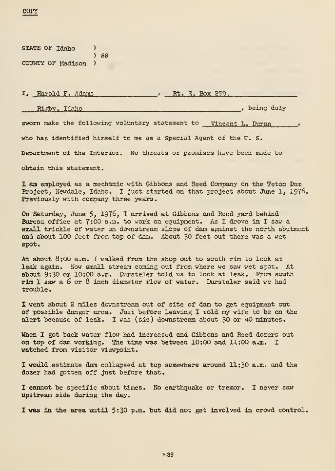
COPY
STATE OF Idaho )
) SSCOUNTY OF Madison )
1, Harold F. Adams , Rt. 3. Box 259.
Rl^y. Idaho , being duly
sworn make the following voliintary statement to Vincent L« Duran »
who has identified himself to me as a Special Agent of the U. S.
Department of the Interior. No threats or promises have been made to
obtain this statement.
I am employed as a mechanic with Gibbons and Reed Company on the Teton DamProject, Newdale, Idaho. I just started on that project about June 1, 1976.Previously with company three years.
On Saturday, June 3} 197^, I ajrived at Gibbons and Reed yard behindBureau office at 7:00 a.m. to work on equipment. As I drove in I saw asmall trickle of water on downstream slope of dam against the north abutmentand about 100 feet from top of dam. About 30 feet out there was a wetspot.
At about 8:00 a.m. I walked from the shop out to south rim to look at
leak again. Now small stream coning out from where we saw wet spot. Atabout 9:30 or 10:00 a.m. Dursteler told us to look at leak. From southrim I saw a 6 or 8 Inch diameter flow of water. Dursteler said we hadtrouble
.
I went about 2 miles downstream out of site of dam to get equipment outof possible danger area. Just before leaving I told my wife to be on theELlert because of leak. I was (sic) downstream about 30 or kO minutes.
When I got back water flow had increased and Gibbons and Reed dozers outon top of dan working. The time was between 10:00 and 11:00 a.m. I
watched from visitor viewpoint.
I wovild estimate dam collapsed at top somewhere around 11:30 a.m. and thedozer had gotten off just before that.
I cannot be specific about times. No earthquake or tremor. I never saw-
upstream side during the day.
I was in the area \uitil 5:30 p.m. but did not get Involved in crowd control.
F-39
I thou^t dam voiild go at about 9^30 a.m. when the flow of water had increased.
I did take note of Morrison and Khudsen tractor activity and saw them getwashed away. I do not know the time.
I have carefully read the foregoing statement, consisting of 3
pages and declare it to be true and correct.
/s/ Harold F. Adams
Subscribed and sworn to before methis 22nd day of June 197^
/s/ VincentL. Duran, Snecial Agtent
Vincent L. Duran, Special AgentU.S. Department of the Interior
F-40
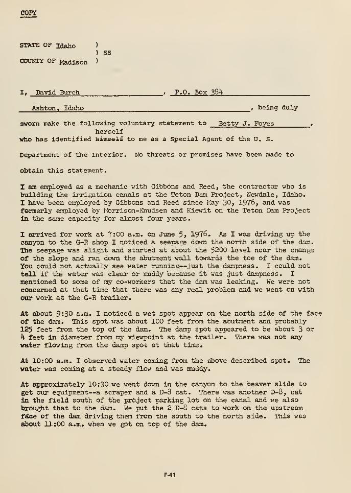
COPY
STATE OF Idaho )
) SSOOONTY OF Madison >
I, David Burch , P.O. Box ^Sk
Ashton, Idaho , being duly
sworn make the following voluntary statement to Betty J. Foyes ,
herselfwho has identified bins«X£ to me as a Special Agent of the U. S.
Department of the Interior. Ko threats or promises have been made to
obtain this statement.
I am employed as a mechanic with Gibbons and Reed, the contractor who is
building the irrigation canals at the Teton Dam Project, Newdale, Idaho.
I have been employed by Gibbons and Reed since May 30, 1976, and wasformerly employed by Morris on-iGiudsen and Kiewit on the Teton Dam Projectin the same capacity for almost four years.
I arrived for work at 7:00 a.m. on Jwae 3) 1976. As I was driving up thecanyon to the G-R shop I noticed a seepage down the north side of the dam.
The seepage was slif^mt and started at about the 5200 level near the change
of the slope and ran down the abutment wall towards the toe of the dam.
You could not actually see water running—just the dampness. I covild nottell if the water was clear or muddy because it was just dampness. I
mentioned to some of my co-workers that the dam was leaking. We were notconcerned at that time that there was any real problem and we went on withour work at the G-R trailer.
At about 9:30 a.m. I noticed a wet spot appear on the north side of the face
of the dam. This spot was about 100 feet from the abutment and probably125 feet from the top of the dam. The damp spot appeared to be about 3 or
k feet in diameter from my viewpoint at the trailer. There was not anyvater flowing from the damp spot at that time.
At 10:00 a.m. I observed water coming from the above described spot. Thevater was coming at a steady flow and was muddy.
At approximately 10:30 we went down in the canyon to the beaver slide toget OTJir equipment—a scraper and a D-3 cat. There was another D-8, cat
in the field south of the project parking lot on the canal and we alsobrou^t that to the dam. We put the 2 D-8 cats to work on the upstreamfdce of the dam driving them from the south to the north side. This wasabout 11:00 a.m. when we got on top of the dam.
F-41
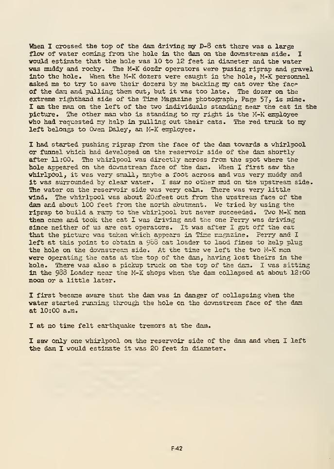
When I crossed the top of the dam driving my D-8 cat there vas a largeflow of vater coming fron the hole in the dam on the downstream side. Ivould. estimate that the hole was 10 to 12 feet in diameter and the waterwas muddy and rocky. The M-K dozdr operators were pusing riprap and gravelInto the hole. When the M-K dozers were cau^t in the hole, M-K personnelasked me to try to save their dozers by me backing my cat over the facpof the dam and pulling them out, but it was too late. The dozer on theextreme righthand side of the Time Magazine photograph. Page 57, is mine.I am the man on the left of the two individuals standing near the cat in thepicture. The other man who is standing to my ri^t is the M-K employeewho had requested my help in pulling out their cats. The red truck to myleft belongs to Owen Daley, an M-K employee.
I had started pushing riprap from the face of the dam towards a whirlpoolor funnel which had developed on the reservoir side of the dam shortlyafter 11:00. The whirlpool was directly across from the spot where thehole appeared on the downstream face of the dan. When I first saw thewhirlpool, it was very small, maybe a foot across and was very muddy andIt was surrounded by clear water. I saw no other mud on the upstream side.The water on the reservoir side was very calm. There was very littlewind. The whirlpool was about 20iifeet out from the uDStream face of thedam and about 100 feet fron the north abutmem:. We tried by using theriprap to build a ramp to the whirlpool but never succeeded. Two M-K menthen came and took the cat I was driving and the one Perry was drivingsince neither of us are cat operators. It was after I got off the cat
that the picture vas taken which appears in Time magazine. Perry and I
left at this point to obtain a S'oo cat loader to laod fines to help plugthe hole on the downstream side. At the time we left the two M-K menwere operating the cats at the top of the dam, having lost theirs in the
hole. There vas also a pickup truck on the top of the dam. I was sittingla the 983 Loader neeir the M-K shops when the dam collapsed at about 12:00noon or a little later.
I first became aware that the dam was in danger of collapsing when thewater started running through the hole on the downstream face of the damat 10:00 a.m.
I at no time felt earthquake tremors at the dam.
I saw only one whirlpool on the reservoir side of the dam and when I leftthe dam I would estimate it was 20 feet in diameter.
F-42
I have read the above statement consisting of four and one-half handwritten
pages and declare it to be true and correct.
/a/ David L. BurchDavid L. Burch
Subscribed and sworn to before
me this 22nd day of J\me 1976
/s/ Betty J. FoyesBetty J. Foyes, bpecial Agent
U« S. Department of the Interior
F-43
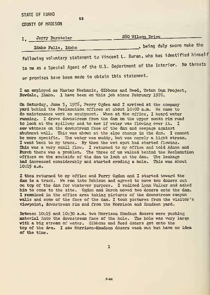
STATE OF IDAHOss
COUNTY OF MADISON
l^ Jerry Dursteler 280 Wilson Drive
Idaho Falls, Idaho .» being duly sworn make the
following voluntary statement to Vincent L. Duran, who has identified himself
to me as a Special Agent of the U.S. Def5artment of the Interior. No threats
or promises have been made to obtain this statement.
I am employed as Master Mechanic, Gibbons and Eeed, Teton Dam Project,Hewdale, Idaho. I have been on -this job since February 197d.
On Saturday, June 5> 1976, Perry Ogden and I arrived at the companyyard behind the Eeclamation offices at about 10:00 a.m. We came todo maintenance work on eqviipnient. When at the office, I heard waterrunning. I drove downstream from the dam on the upper south rim roadto look at the spillway and to see if water was flowing over it. Isaw witness on the downstream face of the dam and seepage againstabutment wall. This was about at the slpe change in the dam. I cannotbe more specific. The water was muddy, but was merely a light stream.I went back to my truck. By then the wet spot had started flowing.This was a very small flav?-. I returned to my office and told Adams andBurch there was a problem. The three of us walked behind the Reclamationoffices on the souxside of the dam to look at the dam. The leakagehad increased considerably and started eroding a hole. This was about10:15 a.m.
I then rettirned to my office and Perry Ogden and I started toward thedam in a truck. We ran into Robison and agreed to move two dozers outon top of the dam for whatever purpose. I radioed Lynn Walker and askedhim to come to the site. Ogden and Burch moved two dozers onto the dam.
I remained in the office area taking pictures of the downstream canyonwalls and some of the face of the dam. I took pictures from the visitor'sviewpoint, downstream rim and from the Morrison and Khudsen yard.
Between 10:15 and 10:30 a.m. two Morrison Khudsen dozers were pushingmaterial into the downstream face of the hole. The hole was very largewith a big stream of water. Gibbons and Reed dozers got onto thetop of the dpm. I saw Morrison-Kaudsen dozers wash out but have no ideaof the time.
i
F-44
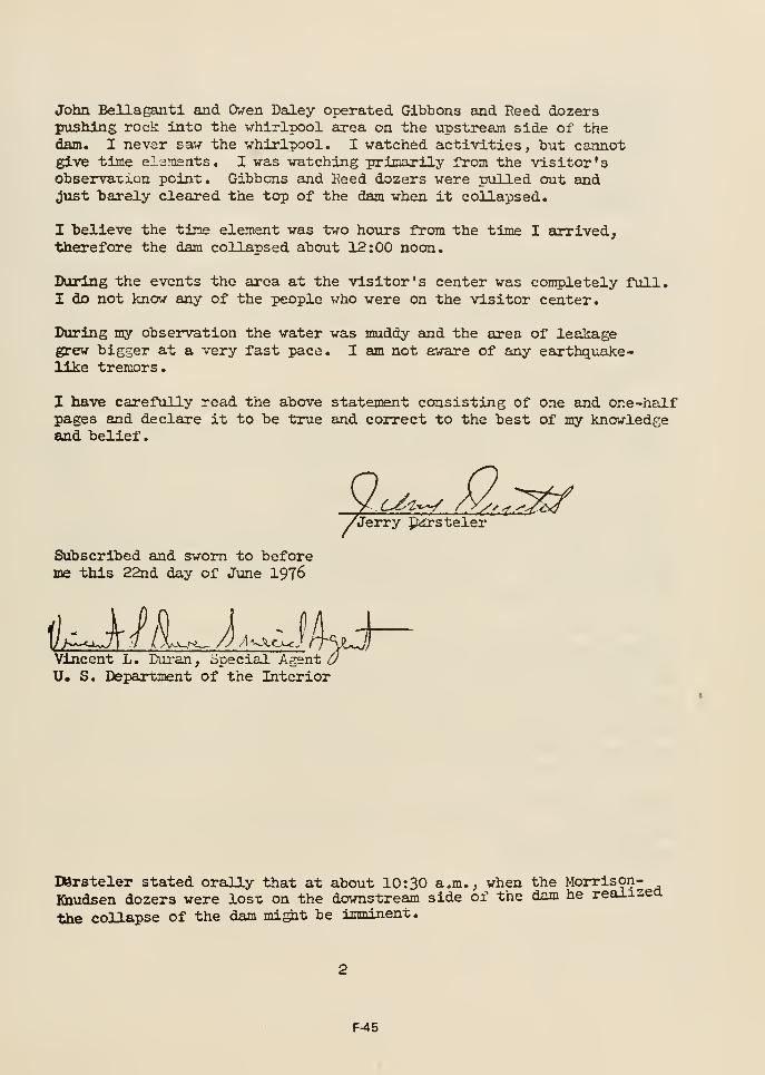
John Bellagantl and Owen Daley operated Gibbons and Reed dozerspushing rock into the whirlpool area on the upstream side of thedam, I never saw the whirlpool, I watched activities, but cannotgive time elements, I was watching prinarily from the visitor'sobservaxion point. Gibbons and Keed dozers were pxiLLed out andjvist barely cleared the top of the dam when it collapsed.
I believe the time element was two hotirs fl-om the time I arrived,"therefore the dam collapsed about 12:00 noon.
During the events the area at the visitor's center was completely full,I do not know any of the people who were on the visitor center.
During my observation the water was muddy and the area of leakagegrew bigger at a very fast pace. I am not aware of any eeirthquake-like tremors.
I have carefully read the above statement consisting of one and one-halfpages and declare it to be true and correct to the best of my knowledgeand belief.
Va^^ M..^^/Jerry p<lrsteler
Subscribed and sworn to beforeme this 22nd day of June I976
Vincent L. Duran, special Agent aU. S. Department of the Interior
DJrsteler stated orally that at about 10:30 a,m,, when the Morrison-Khudsen dozers were los-c on the downstream side of the dam he realizea
the collapse of the dam mi^t be imminent.
F-45
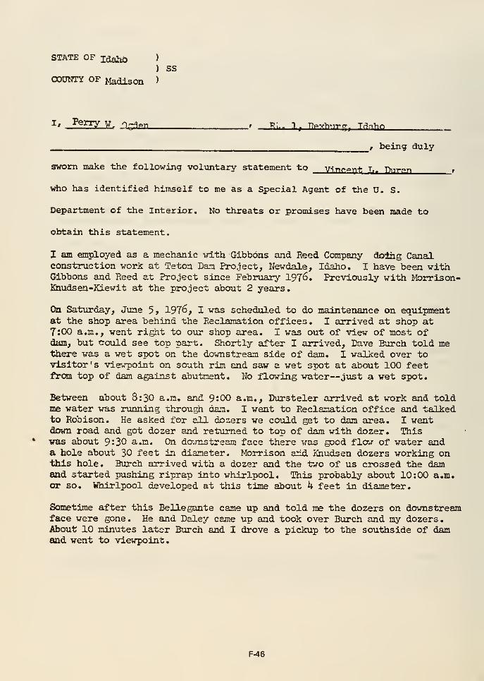
STATE OF Idahi) )
) SSCOUNTY OF Madison )
____^ r being duly
sworn make the following voluntary statement to v.;y,f,o^.[. t__ -Dnrpn ,
vrtio has identified himself to me as a Special Agent of the D. S.
Department of the Interior. No threats or promises have been made to
obtain this statement.
I am employed as a mechanic •^d.th Gibbons and Eeed Company doing Canalconstruction work at Teton Dam Project, Newdale, Idaho. I have been withGibbons and Reed at Project since February I976. Previously with Morris on-Khtidsen-Kiewit at the project about 2 years.
On Saturday, June 5> 1976, I wais scheduled to do maintenance on equipmentat the shop aurea behind the Eeclamation offices. I arrived at shop at7:00 a.m., went right to our shop area. I was out of view of most ofdam, but could see top pairt. Shortly after I arrived, Dave Burch told methere was a wet spot on the downstream side of dam. I walked over tovisitor's viewpoint on south rim and saw a wet spot at about 100 feetftom top of dam against abutment. No flowing water—just a wet spot.
Between about 8:30 a.m. and 9;00 a.m., Dursteler arrived at work and toldme water was running -chrough dam. I went to Reclamation office and talkedto Robison. He asked for all dozers we could get to dam area. I wentdovm road and got dozer and returned to top of dam with dozer. Thiswas about 9:30 a.m. On damstream face there was good flow of water anda hole about 30 feet in diameter. Morrison arid Knudsen dozers working onthis hole. Burch arrived with a dozer and the two of us crossed the damand started pushing riprap into whirlpool. This probably about 10:00 a.m.ox* so. Whirlpool developed at this time about 4 feet in diameter.
Sometime after this Belle gante came up and told me the dozers on downstreamface were gone. He and Daley came up and took over Burch and my dozers.About 10 minutes later Burch and I drove a pickup to the southside of damand went to viewpoint.
F-46
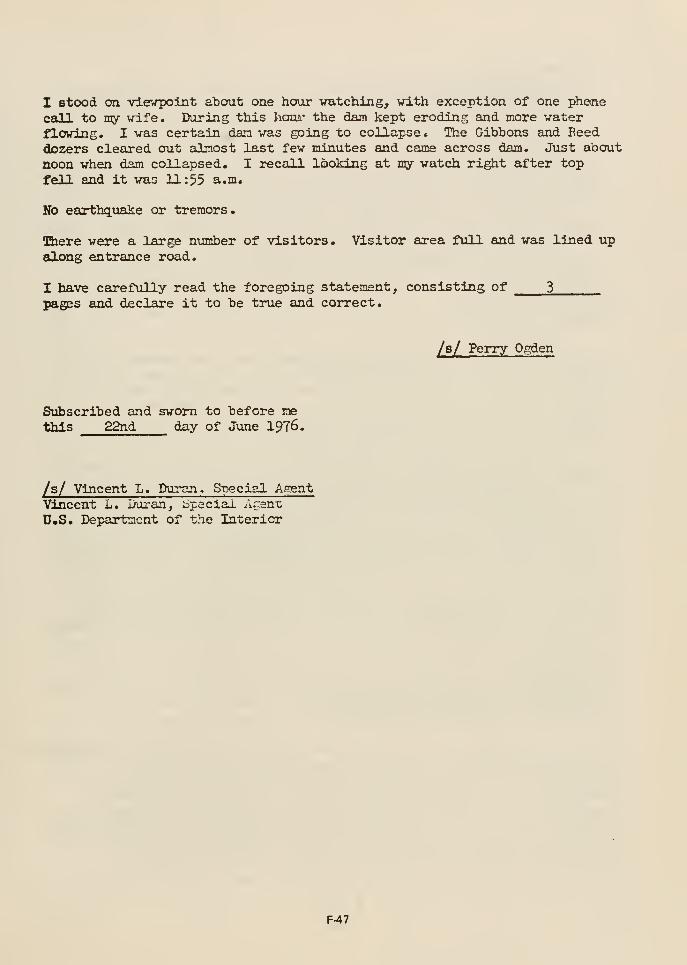
I stood on viewpoint about one hour vatching, vith exception of one phene
call to my vrife. During this houi' the dam kept eroding and more waterflowing. I was certain dan was going to collapse. The Gibbons and Reeddozers cleared out almost last few minutes and came across dam. Just about
noon when dam collapsed. I recall looking at my vatch right after top
fell and it was 11:55 a.m.
Hb earthq^uake or tremors.
dere vere a large number of visitors. Visitor area full and was lined upalong entrance road.
I have carefully read the foregoing statement, consisting of 3
pages and declare it to be true and correct.
/s/ Perry Ogden
Subscribed and sworn to before methis 22nd day of June 1976.
/s/ Vincent L. Duran, Special AgentVincent L. iXiran, bpeciai Acent;
U.S. Department of the Interior
F47
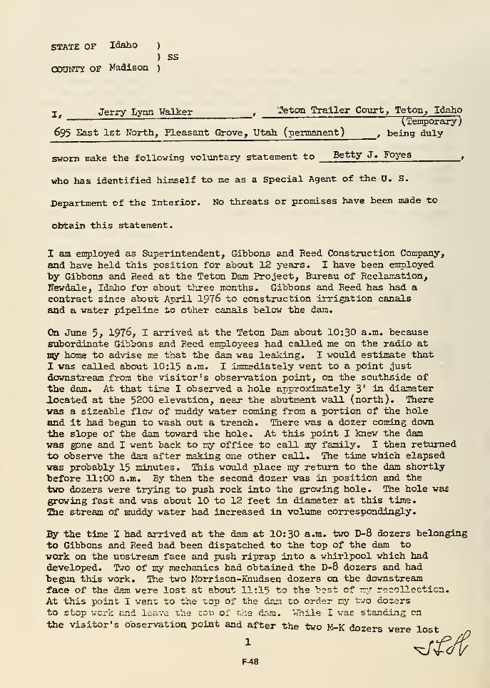
STATE OF Idaho )
) SS
OOUNTY OF Madison )
I Jerry Lynn Walker , 'Jeton Trailer Cotirt, Teton ^ Idaho" ~~~ ~~~~ (Temporary)
695 East Ist North, Pleasant Grove, Vtah (permanent) , being duly
sworn make the following voluntary statement to Betty J« Foyes,
who has identified himself to me as a Special Agent of the U. S.
Department of the Interior. No threats or promises have heen made to
obtain this statement.
I am employed as Superintendent, Gibbons and Reed Construction Company,
and have held this position for about 12 years. I have been employedby Gibbons and Reed at the Teton Dam Project, Bureau of Reclamation,Rewdale, Idaho for about three months. Gibbons and Reed has had acontract since about April 1976 to construction irrigation canalsand a water pipeline to other canals below the dam.
On Jime 5, 1976, I arrived at the Teton Dam about 10:30 a.m. becausesubordinate Gibbons and Reed employees had called me on the radio at
ny home to advise me that the dam vas leaking. I would estimate that
I vas called about 10:15 a.m. I immediately went to a point justdownstream from the visitor's observation point, on the southside ofthe dam. At that time I observed a hole approximately 3' in diameteriocated at the 5200 elevation, near the abutment wall (north). Therevas a sizeable flow of muddy water coming from a portion of the holeand it had begun to wash out a trench. There was a dozer coming down
the slope of the dam toward the hole. At this point I knew the damvas gone and I went back to my office to call my family. I then reinimedto observe the flam after making one other call. The time which elapsedvas probably 15 minutes. This would place my return to the dam shortlytefore 11:00 a.m. By then the second dozer was in position and the
two dozers were trying to push rock into the growing hole. The hole vas
growing fast and was about 10 to 12 feet in diameter at this time.
Bie stream of muddy water had increased in volume correspondingly.
By the time I had arrived at the dam at 10:30 a.m. two D-8 dozers belongingto Gibbons and Reed had been dispatched to the top of the dam to
vork on the unstream face and push riprap into a whirlpool which haddeveloped. T*ro of my mechanics had obtained the D-8 dozers and hadbegun this work. The two Morrison-Knudsen dozers on the downstreamface of the dam were lost at about 11:15 to the "b^st of rrr recollection.
At this point I went to the ^op of the darn to order ny t--/o dozersto stop work and leave "che cou of t/:e dam. While I vas standing on
the visitor's observation point and after the two M-K dozers were lost
F48
* crack developed above the hole, ^e crack veis In the shape ofa setnl-ctrcl^ with the arc at the top; was about 30 feet abovethe h>le; snd I would estimate that it may have been as much as 100feet ia total length. The earth starting Bluffing down frcan thecrack totmrds the hole and caused an offset in the earth on the faceof the dam as it sank. As this earth fell in a small hole ddv&ippedabove the crack. I would estimate this was about 10 to 15 feetabove the crack and was initially six or seven feet in diameter.I then left the visitor's observation point emd drove to the topof the dam. I wovild estimate that I reached the top of the damat about 11:40 a.m. >ty cats were already coming across the top ofthe dam towards the south side. As soon as I saw that my cats weregetting off the dam, I drove back to the visitor's observation pointand observed that while my cats were about one-third of the way acrossthe top of the dam sliiffed dovm about 100 feet. About 11:55 a.m. the dam
I at no time was in a location where I could observe the whirlpoolwhich had formed on the upstream side of the dam.
I at no time felt earthqtiake tremors at the dam site either before June 5or on June 5, 1976.
^out 7:30 plm. on Jime 5> 1976, after the water was down to the lowestlevel it wotild reach at that point, I was at the upper curve of the M-Kaccess road on the south rim of the dam and I observed a six inchstream of water coming out of theaborthside abutment rock. The waterwas clear as a bell. The water was coming from a spot about ICX)
feet down from where I would estimate the crest of the dam had been.We took some photographs and I may be able to furnish a picture ofthis occurrence. We have some other photographs of the collapse ofthe dam and I will make arrangements to have a set of the photographsfurnished to the Department of the Interior.
I have carefully read the foregoing statement consisting of one andone-half pages and declare it to be true and correct.
5*^^ Lyo^ Wal ker
Siibscribed and sworn to beforeme this 23rd day of June I976
Betty J. Foyea-, 332cial/A£.3nt
U. S. Departointhfaf the Interior
F-49
MORRISON-KNUDSEN, KIEWITT EMPLOYEE WITNESS STATEMENTS
John P. BelleganteTeton Villa Apts.Rexburg, Idaho
Duane E. BucVartKit Circle #14St. Anthony, Idaho
Jay M. CalderwoodVictor , Idaho
Roy C. ClineKit Circle #22St, Anthony, Idaho
David O. Daley330 W. 8th St., Space 6
St. Anthony, Idaho
Llewellyn L. PayneP. O. Box 37Ashton , Idaho
Vincent M. Poxleitner, Jr.P.O. Box 22
Teton City, Idaho
Barry W. RobertsKit Circle No. 1
St. Anthony, Idaho
Donald D. TruppP.O. Box 3
Newdale, Idaho
F-50
copy
STATE OF Idaho )
) SSOOOOTY OF Madison )
1, John P. Bellegante , 262 N. Second H.
,
RexTaurg, Idaho , being duly
sworn make the following voluntary statement to Vincent L. Duran,
%»ho has identified himself to me as a Special Agent of the O. S.
Department of the interior. No threats or promises have been made to
obtain this statement.
I £un employed as excavation superintendent, Morrison-Knudsen and Kiewit
at Teton Dam Project, Newdale, Idaho. I have worked there since March
1975.
On Satuiday, June 5, 1976, at ahout 10:00 a.m., Duane Buckert telephoned
me and told me the dam was leaking and to come to project. I arrived
at the project at 10:30 a.m. emd went directly downstream of the dam
in the area of the powerhouse. Buckert told me by radio he wanted to
try and fill in hole. I saw a leak near north abutment side at about
5250 feet elevation. There was a fast flow of water down slope and
there were several gallons per minute coming dovm. VJater was muddy.
Prior to Saturday, there were leaks on north side at toe elevation of
dam. These were on north side. There were tliree that I know of. Gleax
water on these leaks. This was about Tuesday or Wednesday.
On Saturday, I went on top of dajn, got a dozer and Instructed Owen Daley
to- get another dozer. The tvro of us went do^-m and started pushing
rock into face of leaJc on the downstream face. This was about 10:i(-0 a.m.
To my knowledge there was no increase in the leakage.
My dozer settled into hole created by leak. I got a cable at top of
dam and hooked the tvro dozers together, tie were unsuccessful and both
dozers went with the water. I would estimate this to be about 10:55 a.m.
to 11:00 a.m. I looked down into the hole, 'i.'hite water was gushing
out of the north abutment through the rocks and creating the muddy water.
I then went to top of dam. Others had found whirlpool on upstream face
and were directing dozers to push riprap into whirlpool area. 'Whirlpool
was about 18 inches in diameter near the north abutment wall about I5 feet
from upstream face of the dam. I did not notice it getting bigger. I
could feci the driTi area scttlin^ and. pulled the dozers out. Lozers wentto southside and I vrent to northside. I cannot i?ive tine elements of this.
F-51
Shortly afterwards, the dam collapsed. I do not know the time. At
no point did I think the dam vras going to collapse. These were the
last thoughts I had until immediately before it went.
I proceeded down the northside rim with others notifying people andeventually returned to office on southside. I was in the area untilabout 5^00 f'^'
I have carefully read the foregoing statement, consisting of 3pages and declare it to be true and correct.
/s/ John P. Bellegante
Subscribed and sworn to before me
this 19th day of June 1976.
/s/ Vincent L. Duran, ST;ecial ArpntVincent L. Duran, Special ArentU.S. Department of the Interior
F-52
COPY
STATE OP Idaho )
) SSOODNTY OF Kadison )
I, Duance i:. Buckert , Kit Circle #1^
St. Anthony, Idaho , being duly
sworn maXe the following volvmtary statement to Vincent L. Duran^
who has identified himself to me as a Special Agent of the U. S.
Department of the interior. No threats or promises have been made to
obtain this statement.
I am Project Manager, KorTlson-Knudswn-Klewit on Teton Dam Project, Newdale,
Idaho. I have been on the project for two yeaurs.
On Satiurday, June 5, 1976, I arrived on job at approximately 8:30 a.m.
jmd drove out on top of dam. As I drove out I saw water coming out of
side at abutment below toe of dam. The water was clear. I was told
Robison had been notified. P.obison, Aberle, Hii;gel and I met regardingthis leak and decided to chauinel this water to reduce erosion and keep
aw&y from power house. I agreed to get people and went to the office to
make telephone calls to employees. While doing this, Aberle came in about
10:00 a.m. ajid told me another leak had appeared.
At about 10:20 a.m. I went out and saw leak on downstream face of dam. Thisleak at about elevation 5200 smd about 10 or 12 feet out from abutment. The
area eroded out was about six feet by six feet. The flow, I cannot estimate,
but it was muddy and erosion was occurring. I senl two dozers in to
push rock into the hole. I then went down into tunnel area at power-house to get it cleaned out for possible opening. The erosion was increasingat the leak airea.
I went hack up on top of the dam and ran into Robison. He told me twodozers had been lost on the downstream face. V/e talked about opening the
river outlet tunnel. This was about 11:00 to 11:20 a.m. A whirlpool had
developed on the upstream reservoir of dam. I did not actueilly see the
whirlpool, but saw dozerspushing materials in.
I proceeded to office when Poxleltner told me he did not believe the
dam would hold. This was sometime around 11:20 a.m. I then went to the
office and made telephone calls to notify area residents of the danger.
Daring this time I observed the Increasing turbulence of water, but didnot actually see the final collapse. I saw the dozers on top of damleaving and collarolng earth behind them. The tine of 11:57 a.m is close
to the actual time of failure.
F-53
I realized the loss of dam when I heard ^bout the whirlpool at about
11:30 a.m. This was the first tine the facts really dawned on me.
I was not involved in crowd control. This was handled by the Bureauof Reclar.ation.
I have carefully read the foregoing statement, consisting of 3 pageseind declare it to be true and correct to the best of my knowledge.
/s/ Duane E. Buckert
Subscribed and sworn to before me this19th day of June 1976.
/s/ Vincent L. Duran, S-pecial ArcntVincent L. Duran, Special AgentU.S. Department of the Interior
F-54
COPY
STATE OF Idaho )
) SSOOONTY OF Kadison )
I Jay M. Calderwood Victor, Idaho
, being duly
sworn mcike the following voluntary statement to Vincent L. Duran^
%»ho has identified himself to me as a Special Agent of the U. S.
Department of the Interior. No threats or promises have been made to
obtain this statement.
I am general excavation foreman for Morrison-Knudsen and Kiewit on TetonDeim Project. I worked on the project at Newdale, Idaho, from March 1972to present.
On Saturday, June 5, 1976, Ray Short , timekeeper, telephoned me at
home and told me there was a leak in the dam. I arrived at the dam at
11:30 a.m. I went directly on top of dam. I saw a hole about 20 feet
in circumference, about 15 feet from right abutment and about 2/3rdsway up from bottom.
There was a large anount of v/ater, muddy and washing the hole bigger all
the time. I thought then we could not stop the water ajid the dan wouldgo. I jumped on a dozer on top of dam, worked on pushing riprap into
the whirlpool, which was on the upstream side about 12 feet to 1^ feetin water near the right abutment, not far out. The whirlpool was about
20 feet to 30 feet in circunference and 5 feet to 6 feet in depth. It
continued to get larger.
I pulled the dozer back to southside and within two minutes the top fellIn. This was about 11:50 a.m. or thereabouts. VJhen I looked at my watch,
it was 12:00 noon ani the dam had collapsed about 5 to 10 minutes before.
I have carefully read the foregoing statement, consisting of 1-1/2
pages and declare it to be true and correct.
/s/ Jay Calderwood
Subscribed and sworn to before me*l^ls 19th day of June 1976.
/s/ Vincent L. Duran, Snecial A-rent
Vincent L. iJui-an, Special A^jcnt
U.S. Department of the Interior
F-55
WaOB Ot Idaho )
) SSQOOHTY OF Kadlson )
I, Roy C. Cllne , Kit Circle #22
St. Anthony, Idaho, being duly
worn nake the following volxintary statement to Vincent L. Duran^
who has identified himself to me as a Special Agent of the U. S.
Department of the Interior. No threats or promises have been made to
obtain this statement.
I am employed as master mechanic at Morrison-Knudsen-Kle-wit on the TetonDam Project. I have been on the project since January 1972.
On Saturday, June 5» 1972, at atout 10:30 a.m., Duane Buckert telephonedme and told me there was a leak. I arrived at 11:00 a.m. and wentdirectly to the powerhouse. I saw a stream of water from right abutmentabout 3Ath way up the dam. Volume was equivalent to what would run outof a 10- inch pipe. It appeared clear at the time. I proceeded to makea roadway behind power in preparation to opening the river outlet. I
did this and then moved a truck. At about 11:30 a.m. , I looked at thedam from powerhouse and saw the two dozers had disappeared, the hole wasbig, and a iJirge volume of muddy water. I cannot estimate the size ofhole or volume of water. I moved crane and other equipment to top onBouthside. When I reaw:hed the top I saw the final collapse of the damtop. I would estimate I girrived at top and saw collapse at about 11:55 a.m.I proceeded to office and arrived at noon.
I felt the collapse was imminent at about 11:30 a.m. when dozers weregone, and I began leaving the powerhouse hole.
I left the area shortly after 12:00 noon.
I have carefully read the foregoing statement, consisting of 2 pagesand declare it to be true and correct.
A/ Roy C. Cline
Subscribed and sworn to before me
this 19th day of June 1976.
/s/ Vincent L. Duran, Supcial Atent
Vincent L. iuran, Special A2en^U.S. Department of the Interior __.
r-oo
CPPY
STATE OF Idaho )
) SS
COUNTY OF I'edison )
I David 0. Daley , J'JO W. 8th St. , Space 6,
St. Anthony, Idaho, being duly
sworn make the following voluntary statement to Vincent L. Juran,
who has identified himself to me as a Special Agent of the U. S.
Department of the Interior. No threats or promises have been made to
obtain this statement.
I ajn employed as equipment operator vfith Horrison-Knudsen-Kiewit on
Teton Dam Project, Newdale, Idaho. I have worked there since March 15
i
1972.
On Saturday, June 5, 1976, at 10:10 a.m., I got a call asking me to
come to the dam. The timekeeper called and did not give r.c details.
I arrived at 10:25 a. p.. I stopped at office briefly and then vjent on to
dam. I savr leaJc on north side within 15 to 20 feet of abutment and
about 100 to 150 feet from top of dam. A snail stream of water was
flowing, but could not see if vr.ter muddy, pj-on that point on the hole
got bigger and more T;ater flowed. Water definitely muddy.
I would guess Eellegante and I lost our dozers in the flow of water on
the downstream face at about 11:15 3..ui. The two of us went up to the
top of dam and I operated a Gibbons and itecd dozer trying to fill in
the whirlpool on the upstream reservoir side of the dam.
The whirlpool was about 30 feet out into water and about 20 feet in
circumference. The pool was rather close to the north wall. I operated
one dozer about one-half hour before we pulled them out. We got dozers
on top of dan and headed toward southside of the dam. This was about
11:^5 a.m. or possibly a little later. As we were driving off the dam the
top caved in.
I never believed the dam was going to collapse until the l£,3t minutewhen we pulled the dozers off. I cannot give specific or estimated time
of collapse. I have heard it was 11:57 a.m.
After the collapse I vratched the water go down the river a short while
and then left for home. I did not get involved with onlookers.
F-57
I have carefully read the foregoing statement, consisting ofpages and declare it to be true ajid correct.
/s/ David Orven Daley
Suhscrited and sworn to "before methis 19th day of June 1976.
/s/ Vincent L. Dura.n, Special A-eni
Vincent L. Duran, Special AgentU.S. Department of the Interior
F-58
COPY
STATE OF Idaho )
) SSCOUNTY OF Kadlson )
I, Llewellyn L. Fayne , P.O. Box 37,
Ashton , Idaho , being duly
sworn make the following volxmtary statement to Vincent L. Duran
who has identified himself to me as a Special Agent of the U. S.
Department of the Interior. No threats or promises have been made to
obtain this statement.
I am employed as concrete superintendent with Korrison-Knudsen andKiewlt, on the Tetan Dan Project, Newdale, IdaJio. I have worked therefor three years and one month.
On Saturday, June 5i 1976, Duane Buckert called my house and left amessage for rae to come to the dam. I got the message about 10:00 a.m.
euid arrived at 10:20 a.m. I travelled by the lovier road ajid arrivedat the powerhouse. As I approached I could see muddy water in river butnot the actual leak. As I got closer, I could see the leak, which wasabout 75 - 100 feet from top of the dam on north side against abutmentand zone material. I cannot estimate volume and at this time I
did not see actual hole.
After my arrival I got Archie J. Zuern, Claude Rhodes, Michael Powelland Charles Powell and went into the river outlet tunnel. The purposewas to get painting equipment out in order to let water through. We
went into the tunnel about 10:30 a.m. At the time, one dozer was
working on downface of the dam and another was on its way. I was in
and out of the tunnel and v/atching leaJc so could pull men if dangerbecame too great.
The leak grew larger - water was muddy, ajid at about 11:20 or 11:30 a.m.
the two dozers were washed out. Ve went into the tunnel one more timeto move anything. We left for the top of the dam shortly thereafteron foot. The water was flowing heavily ajid began coming around thepowerhouse. ^*.'hen I vras about half-way up, I could see dozers workingon top. I could see the dam washing out and radioed to move the catsbecause the daua was going. I saw the dan go, but csmnot make a guess.I did not look at a watch and just never gave the tine factor a thought.
At about the time the dozers were lost - 11:30 a.m., I was scared ajid
had the feeling the dam vras going to cpllapse.
F-59
We worked on crowd control as much as we could. Also number of carsthat cane .to' the dan.
I have carefully read the foresoing statement, consisting of Z^pages and declare it to be true and correct,
/s/ L. L. Payne
Subscribed and sworn to before me"this 19th day of June I976.
/s/ Vincent L. Duran, S-^ecial A^entVincent L. Duran, cpecial AgentU.S. Department of the Interior
F-60
COPY
STATE OF Idaho )
) SSOOUNTY OF Madison )
I, Vincent M. Poxleltner, Jr. , P.O. Box 211
Tetftn, Idaho , being duly
sworn make the following voluntary statement to Vincent L. Duran^
who has identified himself to me as a Special Agent of the O. S.
Department of the Interior. No threats or promises have been made to
obtain this statement.
I am employed by Korrison-Knudsen, Kievrit, at the Teton Dam Project. I
have been employed here since June 22, 1973. I am the Project Engineer.
On Saturday, June 5, 1976, Duane Buckert, Project Manager, telephoned
me at home shortly after 9:00 a.m. He asked that I come to the dam
immediately because there was a leak. I arrived within 15 minutes at the
office. As I came through gate saw water running out of downstream face
of dam. The leak was on right-hand side of dam just off the abutment at
about 5150 to 5200 elevation. The water was turbid from what I could
see. The volume was the equivalent of what you see coming out of 12"
pipe.
Buckert was moving a traictor across top of dam and I followed him out
on top of deim. This was about 10:00 a.m. The flow had not changed
much and was turbid. Vie h£xl another dozer on its way to work on downface.
Talked to Robison at his office, then Buckert at powerhouse, then back
up to top of dcim.
By the time I got to top of dam, whirlpool had developed on upstream side
of dam. I cannot give times. The whirlpool about 25 feet from upstream
face of dam and 75 feet from right abutment. About 3-|- feet to ^ feet
in diameter. Stayed constant for awhile. There were two Gibbons and
Reed dozers pushing riprap into hole. I. did not feel the dam was going
to callapse. I thought everything was salvageable. I was working to
chajige operation of the dozers on upper side to build a ramp in orderthat trucks could bring in material.
The dozers on downface were having trouble. The TD 15 was tied to the
eight, which was nosed into the hole, I went to get another dozer to
help them and by the time I got turned around they were gone.
I would estinate it wai3 about 11: CO a.m. shortly after dozers were gone.
I was on top of dam. Tvjo dozers still uorking on upstream face. Bid not
pay attention to whirlpool.
F-61

Shortly thereafter I moved tvfo pickup trucks off the dam. At about11:30 a.m., I would estimate, I called Euckert and told him dam goingpretty fast and to have Bureau of Reclamation get people out downstream.
About 10 or 15 r.inutes later we pulled the dozers off the upstream fcLce
of dam. ThL-j went to southside and I went to northside of dam. V/ithir
one minute or one and a half minutes the dam collapsed. At 11:55 a.m.the dam collapsed. I looked at my watch when this happened. I went downstream within tv.'o or three minutes to help people. I did not returnuntil about 1:00 p.m.
I have carefully read the foregoing statement, consisting of 3 pages anddeclare it to be true and correct.
/s/ V. M. Poxleitner, Jr.
Subscribed and sworn to before methis 19th day of June, I976.
/s/ Vincent L. Duran, S-necial A.-ent
Vincent L. Duran, Special Agen^U.S. Department of the Interior
F-62
COPY
STATE OF Idaho )
) ssC»UNTY OF Madison )
I, Barry W. Roberts , Klx Circle No. 1,
St. Anth^)ny, Idaho , being duly
sworn make the following voluntary statement to Vincent L. Duran,
who has identified himself to me as a Special Agent of the U. S.
Department of the Interior. No threats or promises have been made to
obtain this statement.
I am employed as office engineer- of Horrison-Knudwen , Kiewit Teton DamProject, Neifdale , Idaho. I have been on the project since December 1973'
On June 5» 1976, I came to the office shortly after 95 00 a.m. on personalbusiness. Ringel, Robison and Aberle follovfed me through the gate andproceeded across the dam. As I Ccime in I noticed the downstream rightside of dara was wet. This was at the slope change and against theright abutment. I cannot estimate the volume.
Shortly before 10:00 a.m. , Robison requested of Buckert assistance ingetting river outlet operational and dozers to work on the dovmstreamslope. For the next half hour I was in the warehouse.
At about 10:45 a.m. I was in the povrerhouse ocx^ to get opening ofriver outlet operational. At this time there was considerable watercoming through the dam. I cannot estimate the volume. There was nochasm. The leakage area wa.s considerably larger than when I ?.rrived.
I did some work in the power house area and at about 11:30 a.m. everyoneat the powerhouse decided to evacuate. I thought at this time the damwas going to breaJ-:.
,
On the way up several people stopped on the south ridge. '/later flowing.
ajid there was a small bridge on the top of the dam on right side. I
proceeded to visitors overlook and by the time I arrived the dam hadcollapsed. I estimated the collapse at ll:^5 a.m. This was estimatedbecause I had no watch with me.
I did not see anything on the upstream face of dam. Everything I did wason downstreani side.
F-63
I do not recall seeing the dozers working on downstreajn face or theirloss.
I have carefully read the foregoing statement, consisting of 2-l/fJ-
pages and declare it to be true and correct.
/s/ Barry W. Roherts
Subscribed and sworn to before me this19th day of June, 1976.
/s/ Vincent L. Suran, Special ArentVincent L, Duran, 3pocial A^xntU.S. Department of the Interior
F-64
COPY
STATE OF Idciho )
) SSOOUNTY OF I'adison
)
I, Donald D. Trupp ,P.O. Box 3.
Newdale, Idaho , being duly
sworn make the following voluntary statement to Vincent L. Duran,
who has identified himself to me as a Special Agent of the U. S.
Department of the Interior. No threats or promises have been made to
obtain this statement.
I ajn employed as medical supervisor with Horrison-Knudsen and Kiewit,
Teton Dam Project, Neudale, Idaho. I began working on the project
April 19, 1972.
On Saturday, June 5, 1976, at about 10:30 a.m. I was approaching the
dam on the upper south rim road, and saw water leaJcing through the
dam on the downstream side, north side and approximately l/^v to l/3 down
from top and close to the side. The hole was four to six feet in
diameter with muddy water flowing. I vfent to the first aid office on
the project and at about 10:35 a.m. telephoned my wife. I stayed in
trailer and Morrison-Knudsen office the rest of the time. I saw the
flow gradually increase and saw the dozers working on downstream side
of dam. I saw them having problems.
I did not see the whirlpool activity on the upstream side of the dam.
I saw the dam collapse, but cannot estimate the time, I only saw the
progressive increasing of the leakage.
At about 11:30 a.m., I telephoned relatives in Wilford, Idaho, and told
them they had better be ready for danger, because I thought the dam might
collapse
.
I recall at eight minutes to 12:00 noon, by my watch, several of ufi put
out the alarm and the dam collapsed veiy shortly after this.
I have cajrefully read the foregoing statement, consisting of 2 I)jlg@8
and declare It to be true cuid correct.
/b/ Donald lililtoipi^
Subscribed and sworn to before me
this 19th day of June 1976.
/s/ Vincent L. TDuran, "fecial A'-rent
Vincent L. Duran, Special Agent
U.S. Department of the Interior f^5
WITNESS STATEMENTS BY OTHERS
Henry L. BauerBox 173Teton City, Idaho
Dave Christensen1420 Benton St., Apt. 1
Idaho Falls, Idaho
Ted V. Gould455 N. South W.,St. Anthony, Idaho
Richard B. HoweRexburg, Idaho
John F. Lee276 N. First E.
Rexburg , Idaho
Eunice J. Olson223 North 4th EastSt. Anthony, Idaho
Mr. Lynn SchwendimanMrs. Lee Ann SchwendemanRt. 1, Box 122St. Anthony, Idaho
F-66
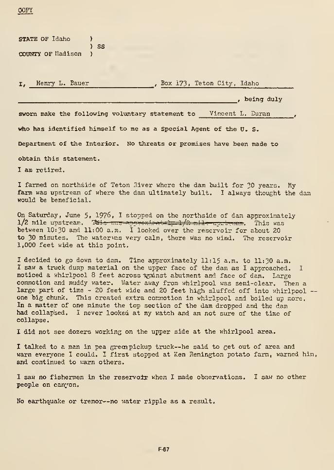
(X)PY
STATE OF Idaho )
) SSCOUNTY OF Madison )
I, Henry L. Bauer , Box 173 1 Teton City, Idaho
, being duly
sworn make the following voluntary statement to Vincent L. Duran,
who has identified himself to me as a Special Agent of the U. S.
Department of the Interior. No threats or promises have been made to
obtain this statement.
I am retired.
I fanned on northside of Teton River where the dam built for 30 years. Kyfarm was upstream of where the dam ultimately built. I always thought the damwould be beneficial.
On Saturday, June 5. 1976, I stopped on the northside of dam approximately1/2 mile upstream. Iki-r .-i ..j-l 'ujii ' UJtlin iiju 1 ^, l/.n ..Jli. lj^^^i.li,.,. . This wasbetween 10:30 and 11:00 a.m. I looked over the reservoir for about 20to 30 minutes. The watervas very calm, there was no wind. The reservoir1,000 feet wide at this point,
I decided to £0 dovm to dam. Time approximately 11:15 a.m. to 11:30 a.m.I saw a truck dump material on the upper face of the dam as I approached. I
noticed a whirlpool 8 feet across agsinst abutment and face of dam. Largecommotion and muddy v.'ater. Water away from whirlpool was semi-clear. Then alarge part of time - 20 feet wide and 20 feet high sluffed off into whirlpool ~one big chunk. This created extra comm.otion in whirlpool and boiled up more.In a matter of one minute the top section of the dam dropped and the damhad collapsed. I never looked at my watch and am not sure of the time ofcollapse
.
I did not see dozers working on the upper side at the vfhirlpool area.
I talked to a man in pea greai pickup truck—he said to get out of area andwarn ever^/'one I could. I first stopped at Ken Remington potato farm, warned him,
and continued to i:arn others.
I saw no fishermen in the reservoir when I made observations. I saw no otherpeople on canyon.
No earthquake or tremor—no water ripple as a result.
F-67
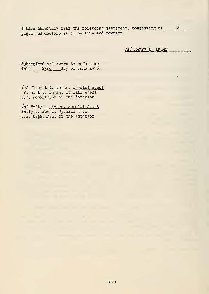
I have carefully read the foregoing statement, consisting of
pages and declare it to be true and correct.
/s/ Henry L. Bauer
Subscribed and svrorn to before me
this 2?rd day of June 1976.
/s/ Vincent L. Duran, Special A;:;ent
Vincent L. Duran, Special ArentU.S. Department of the Interior
/s/ Petty J. FoyRr., cv.ncla.l Arent
Betty J. Foyes, Special AzentU.S. Department of the Interior
F-68
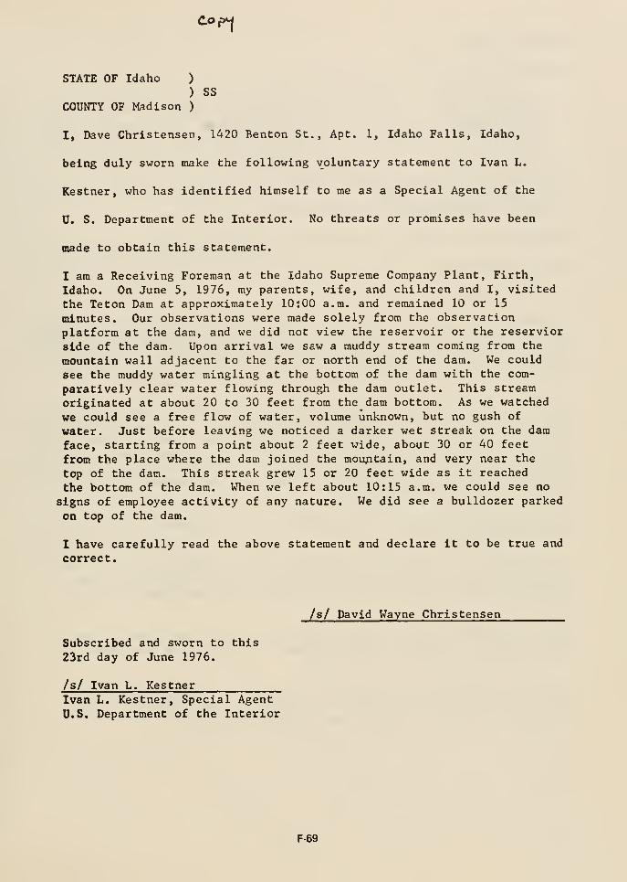
don
STATE OF Idaho )
) SS
COUNTY OF Madison )
I, Dave Christensen, 1420 Benton St., Apt. 1, Idaho Falls, Idaho,
being duly sworn make the following voluntary statement to Ivan L.
Restner, who has identified himself to me as a Special Agent of the
U. S. Department of the Interior. No threats or promises have been
made to obtain this statement.
Z am a Receiving Foreman at the Idaho Supreme Company Plant, Firth,
Idaho. On June 5, 1976, my parents, wife, and children and I, visited
the Teton Dam at approximately lOsOO a.m. and remained 10 or 15
minutes. Our observations were made solely from the observationplatform at the dam, and we did not view the reservoir or the reservior
side of the dam. Upon arrival we saw a muddy stream coming from the
mountain wall adjacent to the far or north end of the dam. We could
see the muddy water mingling at the bottom of the dam with the com-
paratively clear water flowing through the dam outlet. This stream
originated at about 20 to 30 feet from the dam bottom. As we watched
we could see a fvee flow of water, volume unknown, but no gush of
water. Just before leaving we noticed a darker wet streak on the damface, starting from a point about 2 feet wide, about 30 or 40 feet
from the place where the dam joined the mountain, and very near the
top of the dam. This streak grew 15 or 20 feet wide as it reached
the bottom of the dam. When we left about 10:15 a.m. we could see no
signs of employee activity of any nature. We did see a bulldozer parked
on top of the dam.
I have carefully read the above statement and declare it to be true and
correct.
/s/ David Wayne Christensen
Subscribed and sworn to this
23rd day of June 1976.
/s/ Ivan L. KestnerIvan L. Kestner, Special Agent
U.S. Department of the Interior
F-69
STATE OF Idaho )
) SSCOUNTY OF lladison
)
I, Ted V. Gould ^4-5^) N. South W. , St. Anthony, Idaho
.
^ r being duly
sworn make the following voluntary statement to Vincent L. Duran
who has identified himself to me as a Special Agent of the u. S.
Department of the Interior. No threats or promises have been made to
obtain this statement.
I an self employed.
Saturday, June 5. 1976, I was going to Teton, Idaho, to work on my trucks.This was about 8:30 a.n. I bad two-way radios on se.T.e frequency as Gibbinsand Reed and others and heard talk about leak being at dan. I thought littleof this, but continued to harw; talk regarding equipment movement and theleakage. Then I heard someone say there was a hole in the dam.
I arrived about 9=30 a.n. and went to visitor viewpoint. Gnall hole abouthalf-v;ay up about 20 feet into dam on downstream side. The water vjashing awaymaterial and this made it muddy. The dozers were just heading toward area tofill in rock at the hole area. The hole gradually got bigger and more waterflowing as I watched. More and more volune. One dozer, D-0, started slippinginto washed out area and D-I5 tried to pull out. Unsuccessful and about10:00 am. the dozers washed away.
Then big chunks of dirt fell out of hole and water appeared to be running outof side abutment rock.
I was back in my truck about this tine and heard someone on the radio mentionVfhirlpool on upstream face and I heard the person talking l%at there wasbig trouble and probably not be able to stop. This was possibly about10:30 a.m.
I left shortly thercnfter and went to Teton to check on my parents. Atabout 11:00 a.n. , I heard a radio message over Gibbons and read about top ofdam going pusing riprap into whirlpool.
I called my wife and told her about the incident. I talked Gibbons andReed over the radio and he told me top vfaahing out and dam going. Thiswas about 11:30 a.m. I did not see the actual collapse.
F-70
I was "back at the dam at s.bout 5O0 p.m. and saw water runnirc out ofabutment on the south side right where the dan abutted against canyon wall.
I have carefully read the foregoing statement, consisting of 2^ pages anddeclare it to be true and correct.
/s/ Ted '..'. Gould
Subscribed and sv:orn to before methis 23rd day of June 1976.
/s/ Vincent L. Duran, Snoclal Af:cni
Vincent L. Duran, Epecial AgentU.S. Depaxtraent of the Interior
F-71
IXoyd Hopkins, 56 N. Second W. , Rexbnrg, Idaho
Einployed as Supervisor;'- Electrician by Wismer and Becker at Teton DamProject, Newdale, Idaho,
Hopkins said during the period 6:00 p.m. to 7:30 p.m. on Friday, June h,
1976, he WIS at the da-n aroijnd the powtr house area, which is located on
the south or left side at the downstrenm foot of the dam. He said he
observed the entire do'.sTistream face of the dan more than once durine^ thisperiod and saw no evidence of any leaks or water running anywhere onthe face of the dam.
Hopkins said at about 10:00 a.m. on Saturday, June 5, 1976, Dick Cuffe,his supervisor, asked him to go to the dam because there were problems.He said he went directly to th power house and arrived at about 10:30 a.m.
He said upon his arrival he saw a leak in the downstream face of the
dam near the north or rir-ht abutment and below the ton of the dcm. Hesaid he could not be mere specific about the location nor could he estimatethe volume of water. He said the water was muddy. He said he saw onedozer falling in the hole created by the leak end another dozer tryingto pull it out. He said shortly after this the two dozers were washedaway by the water, but he cannot estimate the time.
Hopkins aid he checked the availability of electricity at the power housein order to possibly coen the river outlet tunnel. He said while he wasdoing his work several nen were in the tunnel moving equipment out in
order that the tunnel could be opened,
Hopkins said that at about 11:00 he and the several other workers in thetunnel and powerhouse area decided f^ere vras eminent danger and evacuatedthe area. He s=id he went to the Bureau of Reclamation offices onthesouth or left side of the dam. He said when he got to the offices hesaw two dozers, which were working at the ton of the dam, preparing towithdraw from the top of the dam. He said he does not know whit time thiswas, but he knows the top of the dam callapsed shortly thereafter. Hesaid he did not see the collanse, because he was nreparing to leave forRexburg, Idaho, and do what he could to protect his home from the flood.
This is not a signed statement because Mr. Hopkins was departing forCalifornia.
F-72
COPY
STATE OF )Idaho
) SSCOUNTY OF ) Fronont
J Elizabeth A. Howard ^ P.O. Box 342, St. Anthony, Id. 83445
, being duly
sworn nake the following voluntary statement to Ivan L. Kestner^
who has identified himself to me as a Special Agent of the U. S.
Department of the Interior. No threats or promises have been made to
obtain this statement.
F-73
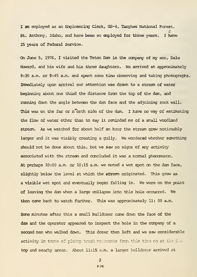
I BBL enplcyed as an Engineering Clerk, GS-4, Targhee National Forest.
St. Anthony, Idaho, and have been so enployed for three years. I have
25 years of Federal Service.
C3n June 5, 1976, I visited the Teton Dam in the ootpany of n^ son. Dale
Howard, and his wife and his three daughters. We arrived at approximately
9:30 a.m. or 9:45 a.m. and spent sane time observing and taJdiig photographs,
lnmediately upai arrival our attention was drawn to a stream of water
beginning about one third the distance frcm the top of the dam, and
running down the angle between the dam face and the adjoining rock wall.
This was on the far or n orth side of the dam. I have no way of estimating
the flow of water other than to say it roninded me of a snail woodland
stream. As we watched for about half an hour the stream grew noticeably
larger and it was visibly creating a gully. We wondered whether sanething
should not be done about this, but we saw no signs of any activity
associated with the strean and ccncluded it was a normal j^ienanencsi.
At perhaps 10:00 a.m. or 10:15 a.m. we noted a wet spot on the dam face,
slightly below the level at v^iich the strewn originated. This grew as
a visible wet spot and eventually began falling in. We were on the point
of leaving the dam v^en a large collapse into this hole occurred. We
then came back to watch further. This was approximately 11: 00 a.m.
Sore minutes after this a small bulldozer came down the face of the
dam and the operator appeared to inspect the hole in the coipany of a
second man v^o walked down. This dozer then left and we saw considerable
activity in terns of pia-orp tr-vic'; rcvcr'T-OTits frcn; tiiis tirf.3 on at il~.a c'r.';
top and nearby areas. About 11:15 a.m. a larger bulldozer arrived at
2
F-74
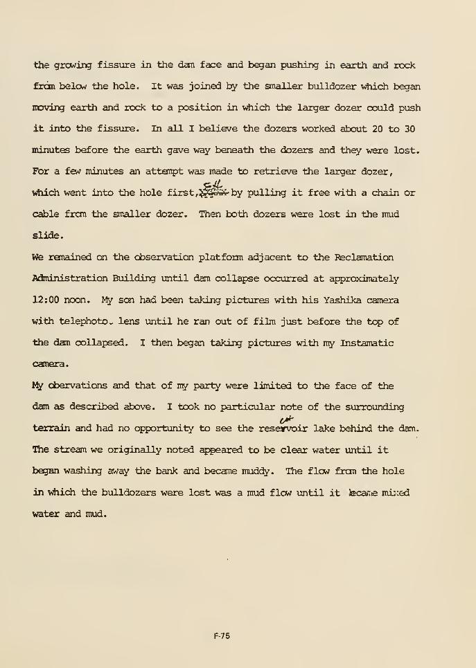
the growing fissure in the dcm face and began pushing in earth and rock
frdn below the hole. It was joined by the smaller bulldozer v*iich began
iiDving earth and rock to a position in vrfiich the larger dozer oould push
it into the fissure. In all I believe the dozers worked about 20 to 30
minutes before the earth gave way beneath the dozers and they were lost.
For a few minutes an attaipt was made to retrieve the larger dozer,
vrfiich went into the hole first ,^^S4- by pulling it free with a chain or
cable fron the smaller dozer. Then both dozers were lost in the mud
slide.
We ranained on the cbservation platform adjacent to the Reclamation
Administration Building until dam collapse occurred at approximately
12:00 noon. My son had been taking pictures with his Yashlka camera
with telephoto- lens until he ran out of film just before the tc^ of
the dam oollapsed. I then began taking pictures with my Instamatic
camera.
My cbervations and that of ny party were limited to the face of the
dam as described above. I took no particular note of the surrounding
terrain and had no opportunity to see the reservoir lake behind the dam.
Wie stream we originally noted aj^eared to be clear water until it
began washing away the bank and became mudcfy. The flow fron the hole
in vdiich the bulldozers were lost was a mud flow until it tecarie mij;ed
water and mud.
F-75
I have read the above statanent cxxisisting in all of four typed pages,
including this page, and I declare thct. it is true and correct.
Subscribed and sworn to before methis 22nd day of June, 1976.
Ivan L. Kestner, Special AgentU.S. D^jartment of the Interior
-Q^
F-76
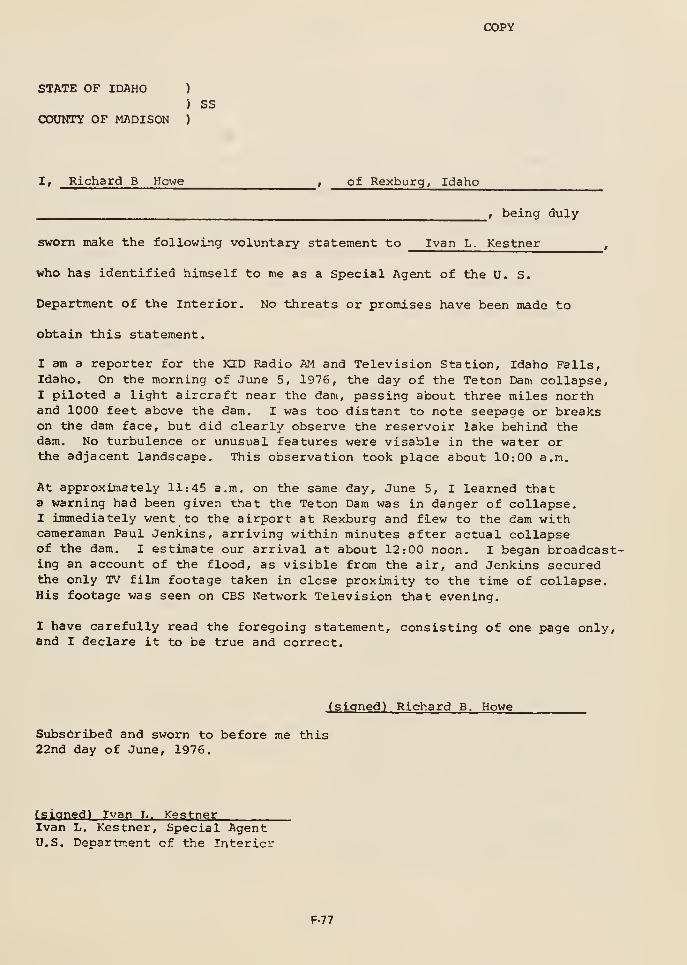
COPY
STATE OP IDAHO )
} SSCOUNTY OF MADISON )
I, Richard B Howe , of Rexburg, Idaho
_, being duly
sworn make the following voluntary statement to Ivan L. Kestner,
who has identified himself to me as a Special Agent of the U. S.
Department of the Interior. No threats or promises have been made to
obtain this statement.
I am a reporter for the KID Radio AM and Television Station, Idaho Falls,Idaho. On the morning of June 5, 1976, the day of the Teton Dam collapse,I piloted a light aircraft near the dam, passing about three miles northand 1000 feet above the dam. I was too distant to note seepage or breakson the dam face, but did clearly observe the reservoir lake behind thedam. No turbulence or unusual features were visable in the water orthe adjacent landscape. This observation took place about 10:00 a.m.
At approximately 11:45 a.m. on the same day, June 5, I learned thata warning had been given that the Teton Dam was in danger of collapse.I immediately went to the airport at Rexburg and flew to the dam withcameraman Paul Jenkins, arriving within minutes after actual collapseof the dam. I estimate our arrival at about 12:00 noon. I began broadcast-ing an account of the flood, as visible from the air, and Jenkins securedthe only TV film footage taken in close proximity to the time of collapse.His footage was seen on CBS Network Television that evening.
I have carefully read the foregoing statement, consisting of one page only,and I declare it to be true and correct.
(signed) Richard B. Howe
Subscribed and sworn to before me this22nd day of June, 1976.
(sianedl Ivan L. KestnerIvan L. Kestner, Special AgentU.S. Department of the Interior
F-77
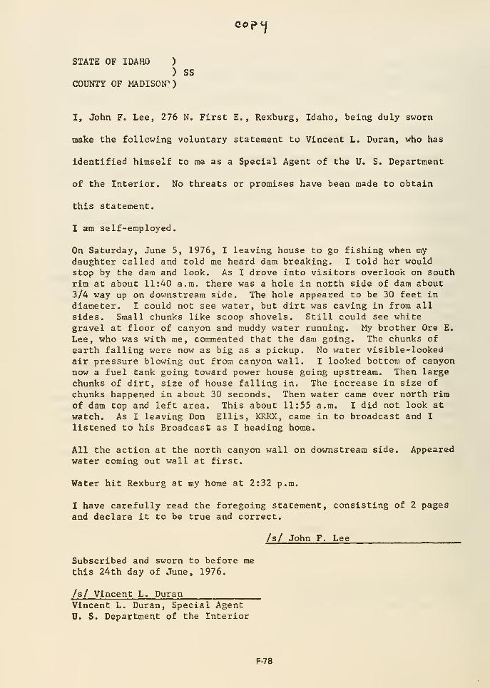
STATE OF IDAHO )
) ssCOUNTY OF MADISON"*)
ceptj
I, John F. Lee, 276 N. First E. , Rexburg, Idaho, being duly sworn
make the following voluntary statement to Vincent L. Duran, who has
identified himself to me as a Special Agent of the U. S. Department
of the Interior. No threats or promises have been made to obtain
this statement.
I am self-employed.
On Saturday, June 5, 1976, I leaving house to go fishing when mydaughter called and told me heard dam breaking. I told her wouldstop by the dam and look. As I drove into visitors overlook on south
rim at about 11:40 a.m. there was a hole in notth side of dam about
3/4 way up on do^-rastream side. The hole appeared to be 30 feet in
diameter. I could not see water, but dirt was caving in from all
sides. Small chunks like scoop shovels. Still could see whitegravel at floor of canyon and muddy water running. My brother Ore E.
Lee, who was with me, commented that the dam going. The chunks of
earth falling were now as big as a pickup. No water visible-lookedair pressure blowing out from canyon wall. I looked bottom of canyonnow a fuel tank going toward power house going upstream. Then large
chunks of dirt, size of house falling in. The increase in size of
chunks happened in about 30 seconds. Then water came over north rim
of dam top and left area. This about 11:55 a.m. I did not look at
watch. As I leaving Don Ellis, KRKX, came in to broadcast and I
listened to his Broadcast as I heading home.
All the action at the north canyon wall on downstream side. Appearedwater coming out wall at first.
Water hit Rexburg at my home at 2:32 p.m.
I have carefully read the foregoing statement, consisting of 2 pages
and declare it to be true and correct.
/s/ John F. Lee
Subscribed and sworn to before me
this 24th day of June, 1976.
/s/ Vincent L. DuranVincent L. Duran, Special Agent
U. S. Department of the Interior
F-78

STATE OF IDAHO )
) SSCXJUNTY OF FREMONT )
I' Funicc '^- Q^^"" ' 22? North itth Ea-;t-
St. Anthony, Idaho, being duly
sworn make the following voluntary statement to Ivan L. Kestner,
who has identified himself to me as a Special Agent of the 0. S.
Department of the Interior. No threats or promises have been made to
obtain this statement.
I am the Resource Clerk, GS-5, Targhee National Forest, St. Anthony, Idaho
(U.S. Forest Service) and reside at St. Anthony, Idaho.
On the morning of June 5, 1976 I visited the Teton Dam with two guests,Ms. Myrtle Worfolk and Miss Heather Chapman, both residents of GriffithAustralia. We arrived at the dam at approximately 10:30 a.m. and upon reachingthe observation platform found that two bulldozers were beginning workon the visible face of the dam at a point where a mud leak appeared to havedeveloped. At that time the flow from the fissure had a lava-like appearanceand seemed to consist solely of mud. It was absorbed into the dam face toa large degree. We watched as the bulldozer operators attempted to scrapeearth and rocks into the fissure. At approximately 11:00 a.m. I became awarethat the hole was growing in an accelerated way and the two bulldozers werein danger. Within a very short time the dozers were lost and the operatorsscrambled to safety. We continued to watch until approximately 12:00 noonwhen total collapse occurred. I never had opportunity to look at the reservoirlake and I did not observe any other leaks or fissures other than that dealtwith by the two bulldozers. Just prior to actual collapse Project EngineerRob! son caused us to move back from the observation platform for safety.
Ms. Worfolk and Miss Chapman each had cameras and took pictures of the collapsebut to date I have been unable to retrieve these pictures.
I have carefully read the above statement apd;:^eclare it true and correct.
Subscribed and sworn to
before me this 22nd day of
June, 1976. ^^_^
Ivan L. Kestnr.r, Special AgentU.S. Department of the Interior
u
F-79
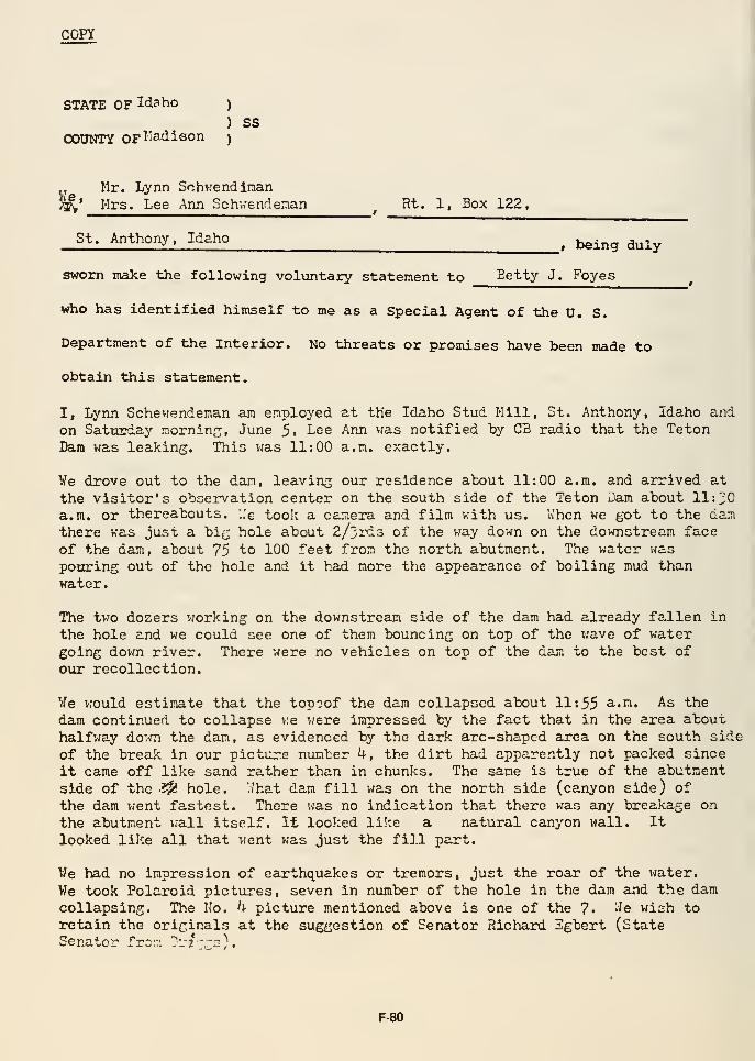
COPY
STATE OF Idaho )
) SSCOUNTY OF^'s^isoil )
y Mr. Lynn Schv.'endinan
M,' Mrs. Lee Ann Schv.-endeman ^ Ht. 1, Box 122,
St. Anthony. Idaho^ ^^^^^ ^^^^
sworn make the following voluntary statement to Setty J. Foyes
who has identified himself to me as a Special Agent of the U. S.
Department of the Interior. No threats or promises have been made to
obtain this statement.
I, Lynn Schevrendenan am employed at the Idaho Stud Hill, St. Anthony, Idaho and
on Sattirday morninsi June 5i L^e Ann vjas notified by C3 radio that the TetonDam was leaking. This was 11:00 a.m. exactly.
We drove out to the dan, leaving our residence atout 11:00 a.m. and arrived at
the visitor's observation center on the south side of the Teton Z)am about 11:^0a.m. or thereabouts, '..'e took a camera and film with us. a hen we got to the damthere was just a bi^ hole about 2/3i"d3 of the way down on the downstream face
of the dam, about 75 to 100 feet from the north abutment. The water waspouring out of the hole and it had more the appearance of boiling mud thanwater.
The two dozers working on the downstreajn side of the dam had already fallen in
the hole and we could see one of them bouncing on top of the wave of watergoing dovrn river. There were no vehicles on top of the dam to the best of
our recollection.
We would estimate that the top^of the dam collapsed about 11:55 ^'^' As the
dam continued to collapse v;e were impressed by the fact that in the area abouthalfway down the dam, as evidenced by the dark arc-shs.ped area on the south side
of the breaJc in our picture number k, the dirt had apparently not packed since
it came off like sand rather than in chunks. The same is true of the abutmentside of the ?^ hole, './hat dam fill was on the north side (canyon side) of
the dam went fastest. There was no indication that there was any breakage on
the abutment '.rail itself. It loo!:ed like a natural canyon wall. It
looked like all that went was just the fi].l part.
We had no impression of earthquakes or tremors » just the roar of the water.
Vfe took Polaroid pictures, seven in number of the hole in the dam and the damcollapsing. The No. U picture mentioned above is one of the 7« '^e wish toretain the originals at the suggestion of Senator Richard Egbert (StateSenator fron ystz"-^)-
F-80
Ve have real t!:c above statement consisting of two anJ one-quarter pagesand declare it to be true and correct to the best of our knowledge andbelief.
/s/ Lynn Sch'.rendiii'.an
Lynn Dchv.'endiman
/s/ Lee Ann L'ch".:endir'an
Lee Ann Lichwendiuian
Subscribed and sworn to beforeme this 23rd day of June 19?6.
/s/ Eetty J. Fo:"-8G
Betty J. Foyes, Cpecial AjentU.S. Derartnent of the Interior
F-81
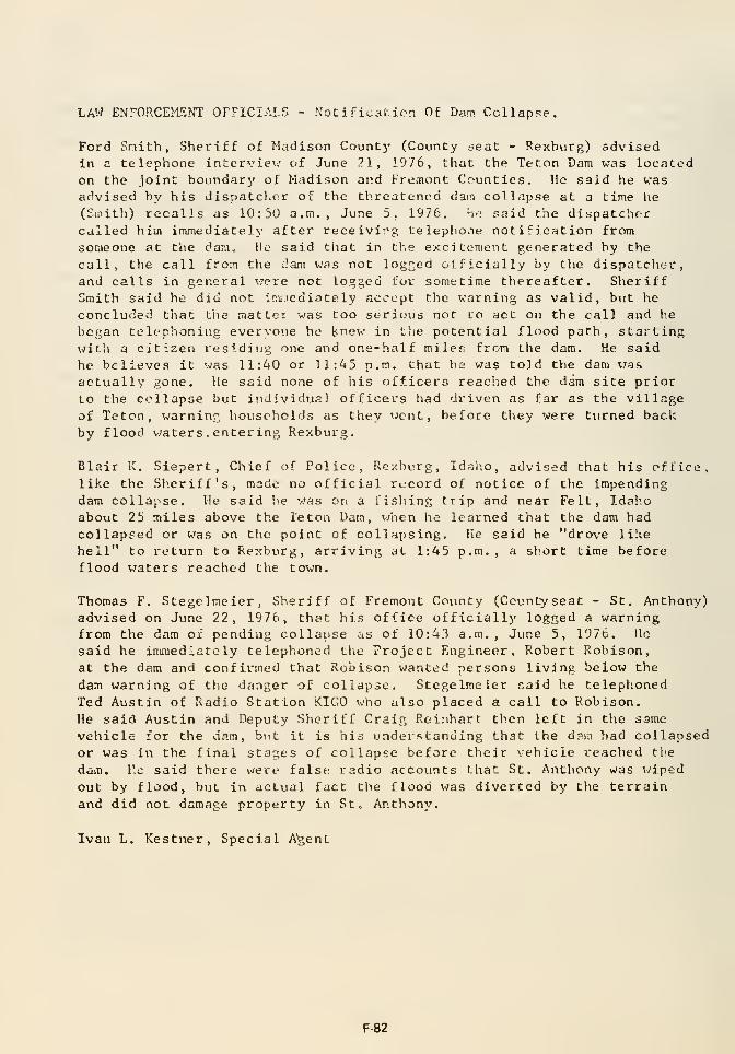
LAW ENrORCEMENT OFFICIALS - Notification Of Darn. Collapse.
Ford Snith, Sheriff of Madison County (County jeat - Rexburg) advisedIn a telephone interview of June 21, 1976, that the Teton Dam was locatedon Che joint boundary of Madison and Tremont Counties. He said he wasadvised by his dispatcher of the threatened dam collnpse at a time he
(Smith) recalls as 10:50 a.m., June 5. 1976. h<i said the dispatchercalled hirn immediately after receivirg telephoiie notification fromsomeone at the dam. He said that in the excitement generated by the
call, the call from the c.'aiu was not logfted olficially by the dispatcher,and calls in general were not logged for sometime thereafter. SheriffSmith said he did not immediately accept the warning as valid, but he
concluded that the matter was too serious not co act on the call and he
began telephoning everyone he l^ncw in the potential flood path, startingwith a citizen residing one and one-half miler; from the dam. He said
he believes it was 11:40 or 11:45 p.m. that he was told the dam was
actually gone. He said none of his officers reached the dam site prior
to the collapse but individual officers had driven as far as the villageof Teton, warninr;, households as they went, before they were turned backby flood waters . enter ing Rexburg,
Blair K. Siepert, Chief of Police, Rexburg, Id^^ho, advised that his office,like the Sheriff's, made no official record of notice of the impendingdam collayse. He said he was on a fishing trip and near Felt, Idah.o
about 25 miles above the leton Uain, v;hen he learned that the dam hadcollapsed or was on the point of collapsing. He said he "drove li!ie
hell" to return to Rexburg, arriving at 1:45 p.m., a short time beforeflood waters reached the town.
Thomas F. Stegelmeier, Sheriff of Fremont County (Ccuntyseat - St. Anthony)advised on June 22, 1976, that his office officially logged a warningfrom the dam of pending collause as of 10:43 a.m., June 5, 1976. He
said he imi;iediately telephoned tlio Project Engineer, Robert Robison,at the dam and confirmed that Robison wanted persons living below the
dam warning of the danger of collapse. Stegelmeier said he telephoned
Ted Austin of Radio Station KIGO who also placed a call to Robison,
He said Austin and Deputy Sheriff Craig Rtinhart then left in the same
vehicle for the dam, but it is his underf-tanding that the dam had collapsedor was in the final stages of collapse before their vehicle reached the
dam. V.c said there were false radio accounts that St. Anthony was wiped
out by flood, b\jt in actual fact the flood v;as diverted by the terrain
and did not damage property in St. Anthony.
Ivan L. Kestner, Special A'gent
F-82
« Appendix G
Design Questions and Answers
• Design questions asked by the Independent Panel
of the Bureau of Reclamation and the
Morrison-Knudson Co., Inc. and their response.
• Bureau of Reclamation's response to the IRG's
24 questions.

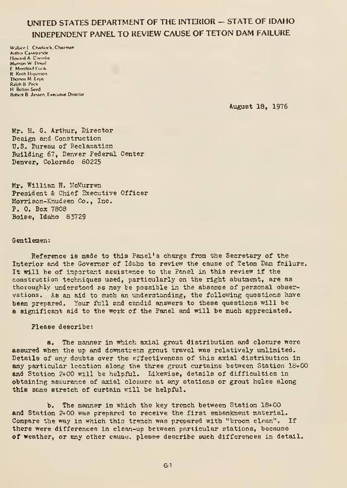
UNITED STATES DEPARTMENT OF THE INTERIOR - STATE OF IDAHO
INDEPENDENT PANEL TO REVIEW CAUSE OF TETON DAM FAILURE
Atigust 18, 1976
WjlLvp I CrvwJurk. Ch»irnMn
Arthur CawiTi^-vV
Mowixd A CnomhsMunson W Onwrf
E Mrwllord J'ucik
R Knlh H^^^lnso^l
Thonvis M le\n
Rilph B Prck
H Bolton Seed
Rob«n B Janscn. Execuiive D:r«clor
Mr. H. G. Arthur, DirectorDesign ar.d ConstructionU.S. Bureau of ReclamationBuilding 67, Denver Federal CenterDenver, Colorado 60225
Mr. Williaa H. Md^urrenPresident & Chief Executive OfficerMorxison-Knudsen Co., Inc.
?. 0. Box 7808Boise, Idaho 83729
Gentlemen:
Reference is made to this Panel's charge from the Secretsiry of theInterior and the Governor of Idaho to review the cause of Teton Dam failure.
It will be of important assistance to the Panel in this review if theconstruction techniques used, particularly on the right abutment, are asthoroughly vinderetood as may be possible in the absence of personal obser-vations. As an aid to such an understanding, the follovring questions have
been prepared. Your full and candid answers to these questions v/lll be
a significant aid to the woi-k of the Panel and will be much appreciated.
Please describe:
a. The manner in which axial grout distribution and clocure wereassured when the up and downstresm grout travel was relatively lonlimited.
Details of any doubts over the crfectivenosa of this axial distribution in
any particular location along the three grout curtains between Station 18+00and Station 2+00 will be helpful. LikeTrise, details of difficulties in
obtaining assurance of axial clofc^ire at any stations or grout holes alongthis same stretch of curtain will be helpful.
b. The manner in which the key trench between Station 18+00and Station 2^ 00 was prepared to receive the first embankment material.Compare the way in which thlo trench was prepared with "broom clean". Ifthere were differences in clean-up bexv/een particular stations, becauseof weather, or any other cause, please describe such differences in detail.
G-1
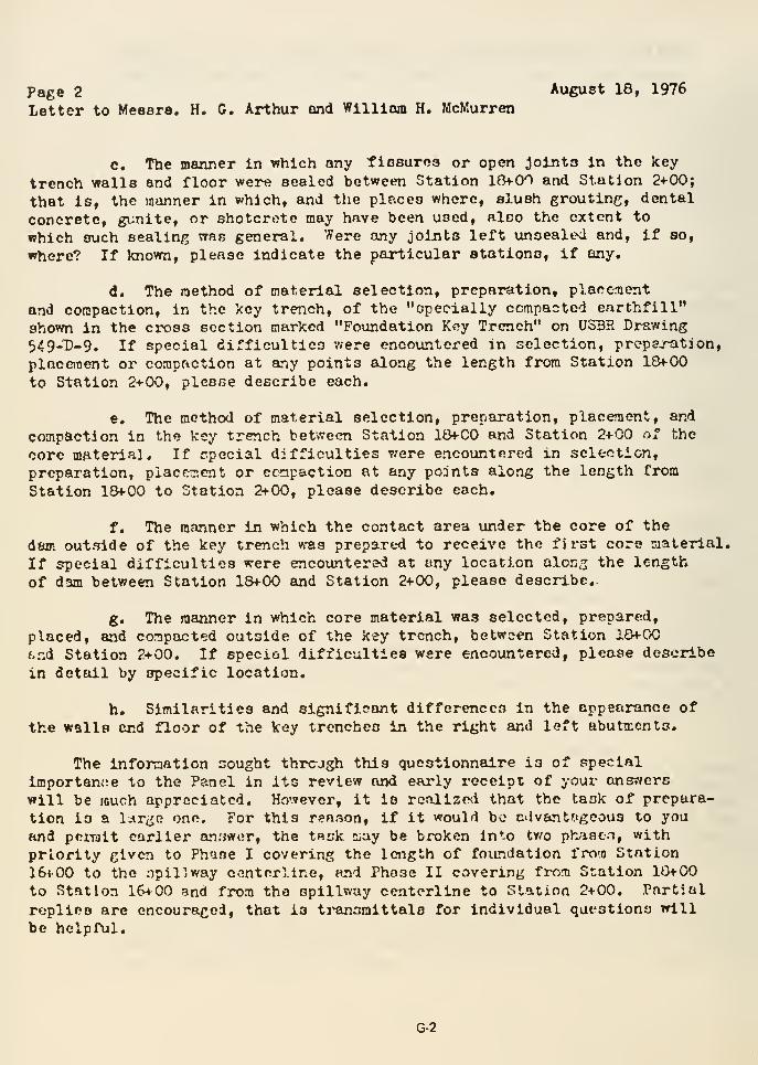
Page 2 Aixgust 18, 1976
Letter to Meesra. H. C. Arthur and Williom H. McMurren
c. The manner in which any tioaures or open joints in the key
trench walls and floor were sealed between Station 184-00 and Station 2+00;
that is, the manner in which, and the placea where, slush grouting, dental
concrete, gunite, or shotcrote may have been used, also the extent to
which such sealing was general. Were any joints left unsealed and, if so,
where? If known, please indicate the particular stations, if any,
d. The method of material selection, preparation, placement
and compaction, in the key trench, of the "opecially ccmpacted earchfill"
shown in the cross section marked "Foundation Key Trench" on USBR Drawing
549_D_g. If special difficulties v.-ere encountered in selection, prcpaj-ation,
placement or corapr-iction at any points along the length from Station ISfOO
to Station 2+00, please describe each.
e. The method of material selection, preparation, placement, and
compaction in the key trench between Station 18+00 and Station 2+00 of the
core material. If r.pecial difficulties 7/ere encountered in selection,
preparation, placement or cc^npaction at any points along the length from
Station 18+00 to Station 2+00, please describe each.
f. The manner in which the contact area under the core of the
dam outside of the key trench was prepared to receive the first core material.
If special difficulties were encoxmtersd at any location alon^ the length
of dam between Station 18+00 and Station 2+00, please describe.
g. The manner in which core material was selected, prepared,
placed, and compacted outside of the key trench, between Station 18+00
i.rA Station 2+00. If epecitil difficulties were encountered, please describe
in detail by specific location.
h. Similarities and significant differences in the appearance of
the walls end floor of the key trenches in the right and left abutments.
The information sought thrcjgh this questionnaire is of special
importar.iie to the Panel in its review and early receipt of your onsr/ers
will be much appreciated. Ho'.vever, it is rcolize^i that the task of prepara-
tion is a l-^rtjo one. For this renaon, if it would be cdvant^geous to you
and pniult earlier anriwer, the tB^-k Ciay be broken in*.o tv/o ph/iacM, withpriority given to Phase I covering the length of foundation from Station
16«00 to the opillway centerllne, and Phose II covering from Station 10+00
to Station 16+00 and from the spillway centerline to Station 2+00. Partial
replies are encouraged, that is ti^ansmittala for individual questions will
be helpful.
G-2
Patje 3Auguot 16, 1976
Letter to Messrs. H. G. Arthur and William H. McMurren
Please accept our appreciation in advance for your cooperation in
supplying this important supplementing infonnation.
Very truly yours,
t 7/allace L. Chvf^ick
G-3
#CC'NTRACTORSENGINEERSDEVELOPERS
b MORRISON-KNUDSEN COMPANY, 'NC.
EXFOJTIVF OFFICEONC MORRISON KKnjDSEN PLAZA / PO 60X7808 / BOISE. IDAHO 83729 / USATEir.X 3fifl4J9
PHONE (2061345 MOO
K W. SmithASSISTANT GENERAL COUNSEL
October 7, 1976
Mr. Harold G. Arthur, DirectorDesign and Construction Bureau of ReclamationBuilding 67
Denver Federal CenterDenver, Colorado 80225
Re: Teton Dam
Dear Mr. Arthur;
Pursuant to the request of Mr. E. M. Armstrong, enclosedfor your information is a copy of the joint venture'sresponse of this date to Mr. Wallace L. Chadwick, represent-ing the Independent Panel to Review the Cause of the TetonDam Failure.
Sincere
G-4
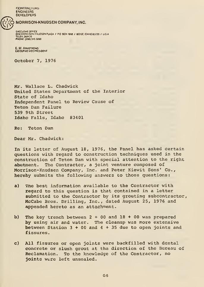
nONTRACIUHbENGlNEtnSDEVELOPERS
VVO MORRISON-KNUDSEN COMPANY, INC.iV
EXECUTIVE OTfICEONE MOHHiSONKNUOSEN PLAZA / PO BOX 7806 / BOiSE. IDAHO 83779 /USATELEX: 368439PHONE: (206) 345-5000
E. M. ArmstrongEXECUTIVE VICE PRESIDENT
October 7, 1976
Mr. Wallace L. ChadwickUnited States Department of the InteriorState of IdahoIndependent Panel to Review Cause ofTeton Dcun Failure539 9th StreetIdaho Falls, Idaho 83401
Re: Teton Dam
Dear Mr. Chadwick:
In its letter of August 18, 1976, the Panel has asked certainquestions with regard to construction techniques used in theconstruction of Teton Dam with special attention to the rightabutment. The Contractor, a joint venture composed ofMorrison-Knudsen Company, Inc. and Peter Kiewit Sons' Co.,
hereby submits the following answers to those questions
:
a) Tne best information available to the Contractor withregard to this question is that contained in a lettersubmitted to the Contractor by its grouting subcontractor,McCabe Bros. Drilling, Inc., dated August 25, 1976 andappended hereto as an attachnient.
b) The key trench between 2+00 and 18 + 00 was preparedby using air and water. The cleanup was more extensivebetween Station 3+00 and 4+35 due to open joints andfissures.
c) All fissures or open joints were backfilled with dentalconcrete or slush grout at the direction of the Bureau ofReclamation. To the knowledge of the Contractor, nojoints were left unsealed.
G-5
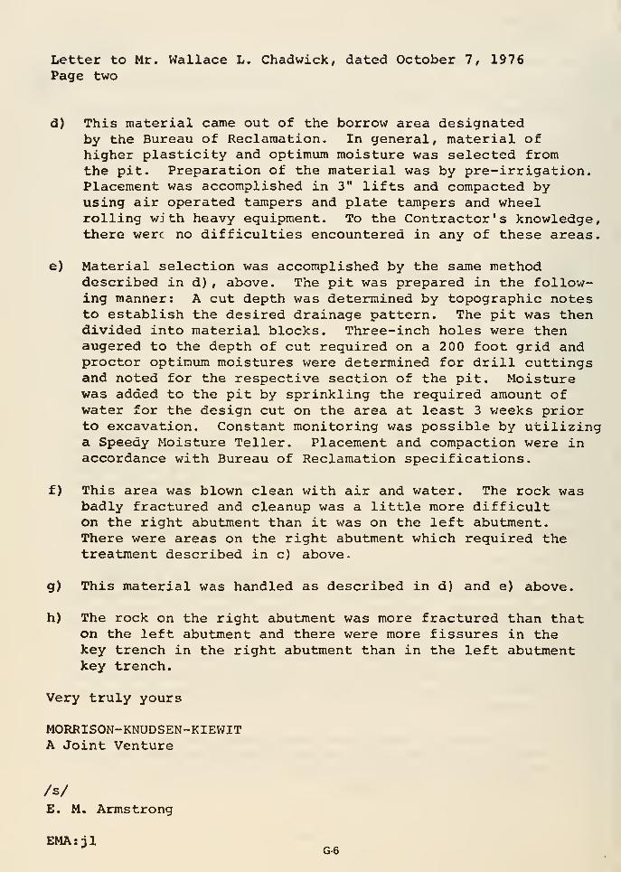
Letter to Mr. Wallace L. Chadwick, dated October 7, 1976Page two
d) This material came out of the borrow area designatedby the Bureau of Reclamation. In general, material ofhigher plasticity and optimum moisture was selected fromthe pit. Preparation of the material was by pre-irrigation.Placement was accomplished in 3" lifts and compacted byusing air operated tampers and plate tampers and wheelrolling with heavy equipment. To the Contractor's knowledge,there were no difficulties encountered in any of these areas.
e) Material selection was accomplished by the same methoddescribed in d) , above. The pit was prepared in the follow-ing manner: A cut depth was determined by topographic notesto establish the desired drainage pattern. The pit was thendivided into material blocks. Three-inch holes were thenaugered to the depth of cut required on a 200 foot grid andproctor optimum moistures were determined for drill cuttingsand noted for the respective section of the pit. Moisturewas added to the pit by sprinkling the required amount ofwater for the design cut on the area at least 3 v;eeks priorto excavation. Constant monitoring was possible by utilizinga Speedy Moisture Teller. Placement and compaction were inaccordance with Bureau of Reclamation specifications.
f) This area was blown clean with air and water. The rock wasbadly fractured and cleanup was a little more difficulton the right abutment than it was on the left abutment.There were areas on the right abutment which required thetreatment described in c) above-
g) This material was handled as described in d) and e) above.
h) The rock on the right abutment was more fractured than thaton the left abutment and there were more fissures in thekey trench in the right abutment than in the left abutmentkey trench.
Very truly yours
MORRISON-KNUDSEN-KIEWITA Joint Venture
/s/
E. M. Armstrong
EMA: jl•'
G-6
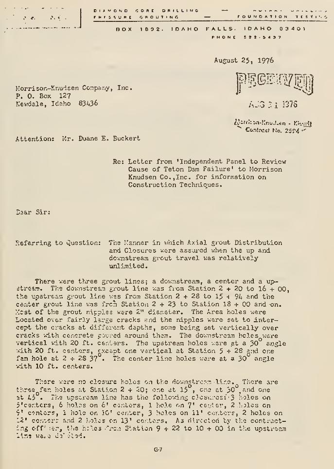
. c.
OI^WONO CORC 0RIILM4CrUti^VPt OHOUTINC rOUNOATION TtST
nOX 1692. IDAHO FALLS. IDAHO 03401
August 25, 1976
Korrison-Knudsen Co.Tip&ny, Inc.
P. 0. Box 127
Kevjdale, Idaho 83A36 AJ3 : 1 i375
^ Contfccl No. 25r4 •''
Attention: Mr. Duane E. Buckert
D3ar Sir:
Re: Letter from 'Independent Panel to ReviewCause of Teton Dam Failure' to MorrisonKnudsen Co., Inc. for information onConstruction Techiiioues.
5:eferring to Question:
There v.ere thiree gi
strs^T?. The dov.-nstresjn
the upstroa'T. grout linecenter grout lijie v.as fi
"est of the grout nippleLocated over fairly largcept the cracks at diffecracks -.vith concrete poovertical with 20 ft. ce.-.
vith 20 ft. centers, e.xc
The Manner in which Axial grout Distributionand Closures were assui'cd when the up anddovmstream gi^out travel vas relativelyvinli.'nited.
L'out lines; a dovmstream, a center and a up-grout line v.as fiom Station 2 + 20 to 16 + 00,v.as from Station 2 + 28 to 15 h 94 and thec^ Station 2 + 23 to Station 13 + 00 and on.£ vere 2" dia.T.eter. The Area holes v.ere
c cracks <ind the nipples v;ere set to inter-6:;t depths, soine being set vertically over
red aromid thenfi. The dov.-pstream holes v;ere
-ers. The upstree.m holes v.ore at a JO aogle
"an hole at 2 + 2S 37 •
vith 10 I*t. centers.
ept one vertical at Station 5+28 and oneThe center line holes v.ere at a 30 angle
There .-.ere no clcs'jre holes on the do-.vn=tr.;':". lir.o. There arethree far. ::oles r-.t Station 2 + 20; one at 15 i
one at 30 .aiid onest i,5 • The iipsoroam line has the follo-.sdng clcsi...'cs: -5 holes onp'cer.tcr.s, 6 holrs on c' cu.-ilors, 1 hole on 7' ce::-tor, 2 holes on9' onterf, 1 hole on iC center, 3 holes on 11' c<i'.tov5, 2 holes on12* co.'.vcrr and 2 !:Ol>;s on 13' ce/.tors. As rilroclen by tl.e contract-ing off'
\<Gi
J
lJ5
t'.e h:\e3 -Vc:;! Station 9 + 22 to 10 + 00 in the upstrc:?jn
G-7
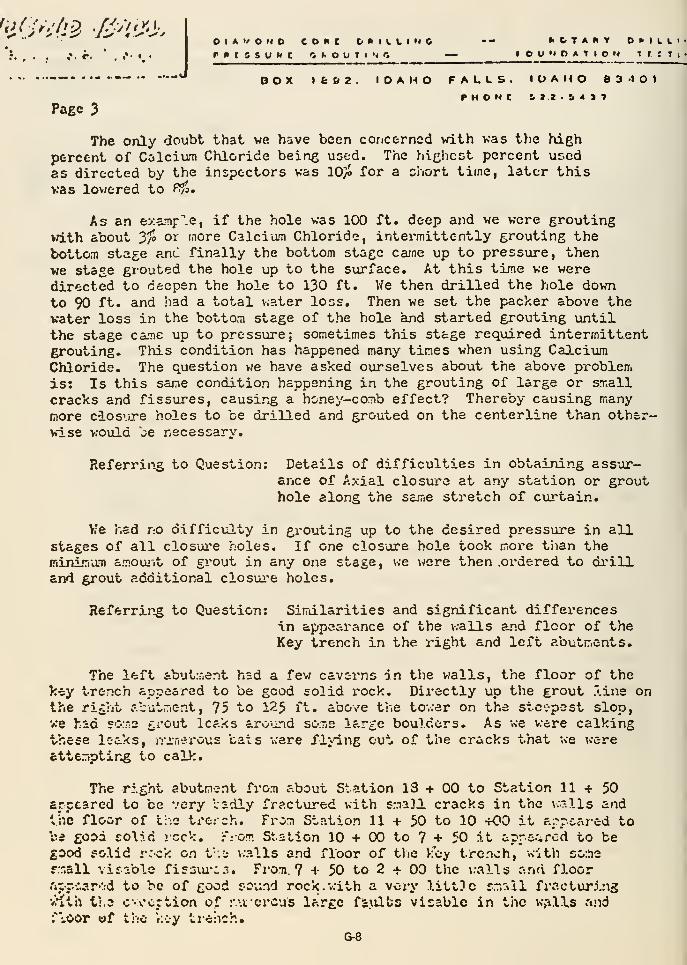
^^OV'^f^ •^>^^'>OIAVOND cone bMILLINC -- tiCTAWV D^ILLir*tssuxc <if.ouTiN*; — »ou»»oation TrtTi
BOX 1&&2. IDAHO FALLS. IDAHO SS'IOI
Page 3
The only doubt that we have been concerned vdth vas the high
percent of Calcium Chloride being used. The hi^licst percent usedas directed by the inspectors was 10/J for a chort time, later this
vas lovJtred to P^fo,
As an examf'.e, if the hole was 100 ft. deep and we were groutingwith about 3/» or more Calcium Chloride, intermittently grouting the
bottom stage ?jr\C finally the bottom stage ca-ne up to pressure, thenwe stage grouted the hole up to the surface. At this time we weredirected to deepen the hole to 130 ft. We then drilled the hole downto 90 ft. and load a total v.ater loss. Then we set the packer above thewater loss in the bottom stage of the hole and started grouting untilthe stage came up to pressure; sometimes this stage required intermittentgrouting. This condition has happened many times when using CalciumChloride. The question we have asked ourselves about the above problemis: Is this same condition happening in the grouting of large or smallcracks and fissures, causing a honey-comb effect? Thereby causing manymore ciosure holes to be drilled and grouted on the centerline than other-wiss would be necessary.
Referring to Question: Details of difficxolties in obtaining assur-ance of Axial closui'e at any station or grouthole along the sa^ne stretch of cuj'tain.
>?e had no difficulty in grouting up to the desired pressure in allstages of all closui'e holes. If one closure hole took more tlian theminimam amoujit of grout in any one stage , we were then .ordered to di'ill
and grout additional closui'e holes,
Referrir^g to Question: Sirrdlarities and significant differencesin appearance of the walls and floor of theKey trench in the right and left abutr.ents.
The left abutment had a few caverns in the v/alls, the floor of thekey trench appeared to be good solid rock. Directly up the grout .'.ine onthe rifcht c-.cutr.ent, 75 to 12$ ft. above the tov.er on the steepest slop,we had so.ne gi-out leaks aro'irid so;r,e large boulders. As we were calkingthese leaks, nMn^rous tats were flv-ing ou".. of the cracks that we werefetteriptir4g to calk.
The right abutment from about Station 13 + 00 to Station 11+50arccarcd to be very ladly fractured with small cracks in the walls andthe floor of t;:o trcich. From Station 11 + 50 to 10 +00 it a:\rcared tobe good solid !cck, :-:om Station 10 + 00 to 7 + 50 it apre%rcd to begood folid rC'Ck en V.u v.-alls and floor of tlie k"oy tronoh, with somerr.all visr:ble fi£3i.u*^3. From 7 + 50 to 2 + 00 tlic v:alls and floor.'ipr.:.?.rv:d to be of good round rock.vrith a vory little s.-r»ll fracturingviith ti.3 c-ocrtion of r.\i crcus large faxilts visablc in tiie w>^lls andfvoor of the kvy trchch,
G-8
I CtlAMOND CCOC t>niLLtM6 -— • NOTart xr..w....:.> ••<-. >*•£
I'KtltUHC CKOtlTlfVC — rOU'<OATICI4 ICt^ll'l
••-•"** BOX 1662. IDAHO FALLS. IDAHO 034O1^HbMI £12 .54)7
Pa/je It
The li-y.o bed sc-riimsnts that underlay the riolitc formation alongthe extro.-i2 length and vddth of the dam at depth were drilled andgrouted to the desired pressures for a short distance on the outer endof the left abutnent.
AH work do cribed above was co.r.pleted as directed by thecontractLng offi or, The Bureau of Rc-clan-.ation.
Very truly yoiirs,
^5cCAEE BROS. DRILLING, INC.
ELM:RJH
Edwin L. l-5cCabe
President
G-9
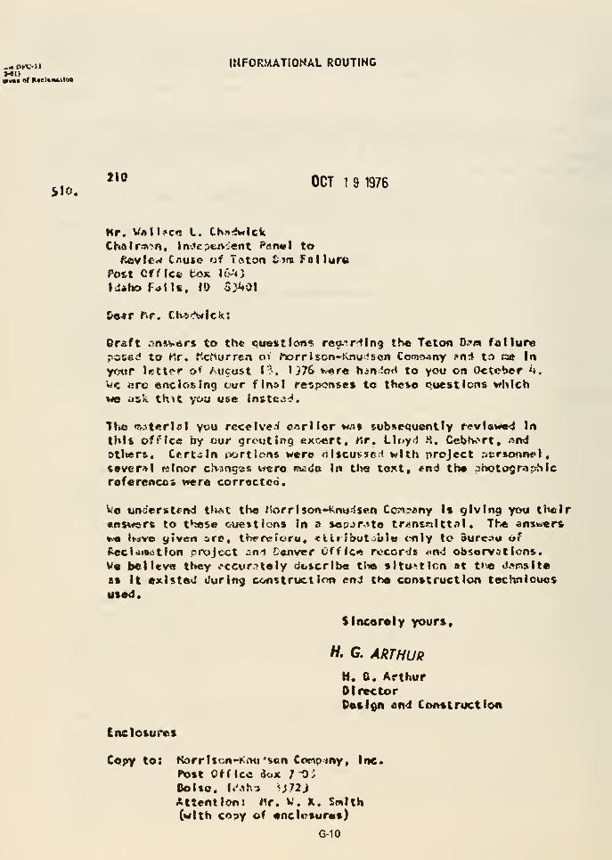
J-61)«»• nf Rteliimttlaa
INFORMATIONAL ROUTING
<^iO.
**° OCT 1 9 1976
Kr. VaII?cc L. Ch3»4wlck
CKalr^fMit In-.^cpwvrient farutl to/^vf«w C/iutc of Teton &7ni Folluna
Poit Cf f Ic<! box \{y*y
Idaho Ftflls. ID S:j^Q|
&e«r f>r. Ctvi-^lck:
Or-aft .-snsv^rs to the <ji«xtlcirn«i rea."!rdlr»9 the Tclon tufm failure
r-ccsd to t*.r, Kcf^urren ot f»rr I scn-Knuf son ComcjAny ?ntl to ce In
yotir letti>r o* Aucost I"?, U76 »v«r« hiriio<< to you on October «>,
Wc BTc enclosing cur final reip<:nstt% to these eocstlcns whichwe ask th^t yoit use instea-:>.
Tti« «^3tcrlal Y'->w receive^ eArllor wflt subsequently revl«we4 In
thlfc office by uur grouting excert, Mr. Llf»ytl K. Cebhort, An<i
otiierft. Ctrtiln jvjrtlons wer© r, Itcusscrl with project r»Er»onnel,
(evcr^l Kinor ciV3ng«« wi^ro mads in tt>« toKt, «nd the photo9raphicreference* were corrected.
Wo underiitend t>v?>t the t'lorrlson-^Cnu-^sen Conjany Is giving you their«RS%^rs to these oue»tlcns In a sepjrtte trj<ntwlttal . The anxi«er*
»>« Imvo yiven ire, thfTtrfora, «iir!but :'uIb <-nly to Sufc;»u of{^ecidiB-Jtion project ^ni Denver Offlc«« records «>n«i observations,Ve believe they occur^tely ck.»crlbe tSie sltu^tlcn at t»'e «.t»nslte
aft It existed c'uring construction end the conttructlon techniouos
used.
SIneorety yours,
H, G. ARTHUR
M. G. ArthurDirectorOetion ami Construction
Enclosures
Copy to: Korrltcn-KrHj'son Conpmy, Inc.
»^)»t Office iuK 7 OJSolto. l<Mh-> i;72J
Attention: ^r. W. K. Smith(with cosy of encliTSures)
G-10
QUESTIONS ASKED BY INDEPENDENT PANELof H. G. Arthur and Morr i son-Knudson
August 18, 1976
and
THE BUREAU RESPONSEOctober 19, 1976
(Note: Most of the information in our answerswas furnished by the Project Construction Engineer.)
G-11
I'j.ease describe
:
A. The manner in which axial grout distribution and closure wereassured when the up and downstream grout travel was relativelyunlimited. Details of any doubts over the effectiveness of thisaxial distribution in any particular location along the three groutcurtains between Station 18+00 and Station 2+00 will be helpful .
Likewise, details of difficulties in obtaining assurance of axialclosure at any stations or grout holes along this same stretch ofcurtain will be helpful
.
GROUTING REQUIREMENTS
Grouting requirements between Station 2+00 and Station 18+00 consistedof a triple curtain between Station 2+00 and 16+00 and a single curtainbetween 16+00 and 18+00. Blanket holes were located in areas wherejoints and fissures were exposed in the curtain area and also a blanketgrouting program was performed under the spillway weir section. Theminimum depth requirements for the curtain holes were 260-60-160-60-260feet for 80-foot patterns on the centerline curtain on 10-foot centers.In the spillway area, the maximum depths were increased to 310 feet.
Specifications drawings required that both the upstream curtain anddownstream curtain be drilled on 20-foot centers with no provisions forspaced closure. However, these curtains were split spaced and closed to
depth. Specifications drawings also required that both the upstream anddownstream curtain consist of vertical holes. After excavation of thekey trenches was completed, it was determined that angle holes on oneof the two outer curtains would readily intercept more Joints and,
therefore, the upstream curtain holes were drilled on angles 30 degreesfrom vertical. Specifications required AX (1-7/8-inch) diameter size holesbe drilled and that holes be down staged if water losses larger than50 percent occurred. When partial water losses occurred, the percentageamount was determined by the onsite inspector and grouting of these
partial water loss stages consisting of 50 percent or larger was strictlyadhered to
.
In the vicinity of the spillway section, an exception was made in regardto the centerline curtain insofar that between Station 10+00 and Station11+37, the centerline curtain was eliminated and incorporated with the
upstream curtain. This was done because the alinement of the centerlinecurtain was in the same alinement as the AOW gate chamber shaft andbecause a positive curtain was better protection for the shaft whenlocated upstream of the shaft. This was accomplished for two reasons.First , double coverage could be given to the adit and shaft by envelopingthe curtain between the shaft and the reservoir, and secondly , curtainholes could be extended to their full design depth rather than having to
be shortened to prevent intersection with the shaft and adit concrete.Curtain holes enveloping the AOW tunnel had to be shortened to preventintersecting the tunnel concrete . However, radial holes from within the
tunnel in the curtain area were deepened to overlap the curtain holes by
30 feet.
G-12
GROUTING ORGANIZATION
U.S. Bureau of Reclamation
The grouting organization for the Bureau of Reclamation consisted of
one Supervisory Civil Engineer and primarily, three ConstructionInspectors . The Supervisor had approximately 12 years of inspectionand supervisory experience in the field of grouting. Three primaryConstruction Inspectors had grouting experience varying from 2 to 5
years prior to arriving on Teton Dam.
Each of the three primary inspectors was responsible for one shift on a
three-shift basis and supervised additional inspectors when groutingoperations were separated and additional inspectors were required. Whengrouting operations were separated, the primary inspector was able to
contact subordinate inspectors through the contractor's communicationssystem to discuss any problems.
Contractor (McCabe Brothers Drilling Company)
The contractor usually had a work force which varied from 18 to 27 men.
The Company is owned by three brothers and each brother was a shiftforeman. A mechanic was on duty on day shift to make necessary repairs.Other workmen consisted of pump operators and drillers.
CONTROL OF GROUTING OPERATIONS
Order of Grouting
When the contractor determined the area that he wanted to grout in,
grout holes on the upstream and downstream curtain were located by BureauInspectors. These locations were previously determined from profiledrawings from which the proper spacings were determined. Blanket holes
were located in the field to fit the rock foundation conditions exceptthose required beneath the spillway weir which were located on a pattern
basis. Location of grout holes for the centerline curtain was also
determined from a profile drawing prepared prior to concrete placement in
the grout cap. Pipe nipples were embedded in the concrete as the concrete
was placed. Angles for the pipe were accurately determined with a
machinist's protractor and the pipe nipples were set above the concrete-rock contact at all times so that this contact would be drilled and
grouted if a bond did not occur.
When grouting was initiated within a specific area, the blanket holes were
drilled and grouted prior to any grouting performance or curtain holes.
The contractor usually worked in an area 400 to 500 feet long. Therefore,
initial curtain grouting consisted of drilling on five to six pattern
holes. As drilling and grouting progressed on the original pattern holes
to depth, it was sometimes necessary to initiate drilling and grouting on
G-13
intermediate and final closure holes simultaneously to facilitate thecontractor's operations. However, a lag of 40 feet in vertical distancewas always adhered to with respect to adjacent related holes .
The upstream curtain was grouted in similar fashion to the downstreamcurtain; however, no holes were drilled on the upstrenm curtain untilthose patterns on the downstream curtain in vicinity of the holes on theupstream curtain to be drilled were completed.
Grouting on the centerline curtain was initiated after all other groutingin the vicinity was completed. As previously mentioned, the centerlinecurtain was grouted on 10-foot centers with the 10-foot center holessplit to 5-foot centers or less if a grout take of 20 cubic feet or moreper stage occurred. This criterion was adhered to, with two exceptions.At Station 10+25 stage 0-20 feet, a grout take of 28 cubic feet was notsplit as most of the grout injected leaked to the surface within a fewfeet of the holes. Also, a grout take of 1,003 cubic feet at Station11+37 stage 220 to 245 was only split on one side. However, this takeis near the gate chamber adit, and the area was super-saturated withgrout holes from within the adit and access shaft.
Five-foot-closure holes were drilled and grouted at Stations 11+09, 8+19,6+34, 6+46, 6+22, and 15+28 to check areas of doubt. However, these holeswere not required as the adjacent 10-foot-closure holes previously groutedwere tight.
DAILY DIRECTION BY THE BUREAU SUPERVISION
As grouting was initiated in each area, a drilling and grouting instructionsheet was made by the Bureau supervisor. On this sheet were listed holesthat were available for drilling and grouting by the contractor as
determined by the Bureau supervisor. This sheet was made on a daily basisand was updated taking into consideration the work that had been previ-ously completed, and the work that was expected to be completed duringthat particular day. Special instructions and safety notes were alsoadded to these sheets from time to time . On rare occasions, it would benecessary for the field inspector to make additions to the sheet if fieldoperations made it necessary. This daily sheet was made for the purposeof keeping unity by having a single organized program within the Bureauinspection forces and it was also available to the contractor so he couldplan his operations accordingly. Examples of these sheets are attachedat the suggestion of Cliff Cortright, Panel Representative.
G-14
LOG BOOK KEPT BY INSPECTORS
From the plan and profile drawings kept in the Bureau Office, log books
were made which contained a profile of grout holes as located in the
field. In these log books, the onsite grouting inspector kept a runningrecord of all drilling ar i grouting that was performed. The log books
were passed from inspector to inspector (shift to shift) . This record
contained the history of each hole and was available to the inspector at
all times at the pump site for the purposes of back-checking for related
grout takes, water losses, water test information, surface leaks, and
performance dates of adjacent holes. Copies of pages from several log
books are attached to show the types of information contained.
DAILY WRITTEN REPORTS
In addition to the log books, each field inspector was required to write
a daily report which gave a brief description of the holes drilled and
grouted as to location, depth, water tests, grout takes, equipment
problems, conversations with the contractor's representative, and
instructions to the contractor. Also, a drill sheet was made for each
hole drilled and a grout sheet for each hole grouted. The drill sheet
was passed on from shift to shift until that particular hole was completed
or the hole was stopped for grouting at which time it was turned in to
the Bureau supervisor at the end of the graveyard shift. The drill sheet
contained drilling information such as rock hardness, color of waterreturn, time of drilling, and water losses. The grout sheet was also
passed on from shift to shift until that particular hole was completed or
the hole was ready to be redrilled to a deeper depth at which time it
was turned in to the Bureau supervisor at the end of the graveyard shift.
The grouting sheet gives a complete history of a grout hole. This
history may be very complex; however, all information relating to the
hole is recorded in minute detail in relation to time. The grout sheet
primarily contains information relating to water tests, packer settings,
initial grout mixes, final grout mixes, pressures, surface leaks, amount
of grout take per hour, total grout take, holding pressures, back pres-
sures, suction, etc. A copy of a drill and a grout report (see attached
examples) are appended to the daily written report.
After the daily reports in conjunction with the drill and grout reports
were turned over to the Bureau supervisor by tfae field inspector at
8:30 a.m. each morning, they were reviewed and checked for accuracy.
The results from the drill and grout reports were then immediatelyplotted on a plan and profile drawing. These nesults were plotted each
day on the same drawing and thoroughly studied by the supervisor to
correlate grout takes from hole to hole and curtain to curtain.
Profile drawings from each curtain were usually overlain for a positive
check so that no gaps in the overall curtain ar>ea would occur. From
each days' information as it was plotted, deptfci of holes could be changed
and additional holes added as required. The daily drilling and grouting
G-15
instruction sheet discussed above was determined from the plan andprofile drawing.
RECORDS BY THE CONTRACTOR
The records made by McCabe Brothers Drilling Company are extensive andwere kept diligently by the employees of the contractor. Drill logs weremade by each driller of each hole drilled on each shift . Grout pumpoperators kept a running record of all grout injected which containedthe time, number of batches, cubic feet per batch, and the grout mix.A record of all water tests was also made which stated the hole numberstage and amount of take
.
Drillers recorded drill bit serial numbers used each shift with corres-ponding drilling depths.
A profile of each curtain in the vicinity of the work area was keptcurrent daily and given to each foreman. This profile was reviewedwith the inspector and correlated with the Bureau Daily Drilling andGrouting Sheet. A time log on each grout pump was kept by pump operators.
GROUT MIXES, CALCIUM CHLORIDE, SAND, PRESSURES, WATER TESTS
Grout mixes were designed to fulfill the scope of the specificationsand design criteria. It was desirous that grout travel be limited to
within 100 feet of the curtain area and that the upstream and downstreamcurtains be constructed as barrier curtains for the centerline curtainwhich was the final closure curtain. ^Vhen large grout takes on theupstream and downstream curtain were encountered, grout mixes werereadily thickened . Calcium chloride was used to increase hydration anddecrease the initial set time and was rarely used when a hole was beingpumped under pressure
.
When a hole was relatively wide open and the grout mix used was an 0.8:1W-C ratio (by volume), the hole would accept grout at the rate of 250 cubicfeet of cement per hour (maximum pump rate) and the pressure on the holegage would be zero and the hole would have extreme suction. Thisindicated that the grout was traveling away from the hole area and, in
order to restrict travel, the hole was pumped intermittently (500 cubicfeet with delays ranging from 3-8 hours) by using calcium chloride. Whenpressures began to register on the hole gage during a pumping sequence,
the calcium chloride was discontinued and pumping would then usuallycontinue to refusal. Precautions were taken to prevent slugging a holeprematurely
.
Sand was used when evidence showed that a large void had been encounteredand that the sanded mix would be readily accepted. For instance, the
blanket holes in the spillway area accepted large amounts of grout; however,
G-16
sand was used in only one hole as no large voids were encountered
during drilling of these holes. Although other holes accepted grout
quite readily, no voids of consequence were detected by the drillers
when water losses occurred and, therefore, a sanded grout mix was not
used in this area.
Calcium chloride was added to accelerate hydration of the grout mix
and control travel within the curtain area. Laboratory and field experi-
ments were performed to determine the optimum amount of calcium chloride
to be used to achieve setting after the grout reached the area to be
grouted. Numerous variables, such as mix water temperature, sand tem-
perature, cement temperature, air temperature, rate of take of the hole,
and distance of hole from the mix plant, affected the set-up time and
the injection time. A hole that was wide open would usually accept
grout at the rate of 250 cubic feet of sand and cement or cement per
hour. The lapsed time between mixing and injecting the grout at this
rate varied bet\veen 6 and 8 minutes. An initial set-time of 12 to 16
minutes was therefore desirable, so that the grout could adequately reach
its destination before prematurely setting.
Due to these temperature variances of the grout ingredients, it was
impossible to develop a usable criteria to accurately predetermine amount
of calcium chloride required to attain the desired set time. A more
feasible set of criteria was used based on grout temperatures at the
grout pump. From 2 to 3 percent by weight of cement of calcium chloride
was added when the mix water temperature ranged between 75 and 80 degrees
F. and up to 6j percent of calcium chloride was required when the mix
water temperature was in the 35 to 40 degrees F, range. Eight percent
calcium chloride was used for a short interval when near freezing waterwas used by the contractor, however, set times were uncontrollable and
the percentage was ultimately lowered. Grout would reach the critical
temperature of 90 degrees F. when using the warmer mix water and near70 degrees F. when using the colder mix water. Grout temperatures weremonitored constantly at the pump by the pump operator and the inspector
so that the proper amount of calcium chloride required could be constantlyadjusted. Water was added to the grout mix at the pump on rare occasions
when the grout began its initial set in the tub before it could be
injected. It was of utmost importance that, when calcium chloride was
being used in a grout mix, the temperature of the grout mix be kept as
high as possible without prematurely setting in the tub before it could
be injected. Adding lesser amounts of calcium chloride only prolonged
the set time and increased grout travel distances which was undesirable
in holes which were determined to be wide open. The use of calciumchloride on the centerline curtain holes was very limited.
Pressures used during grouting and water testing consisted of 10 psi at
the hole collar and were increased by 0.75 psi per foot of depth of the
packer setting normal to the rock surface at the hole collar. Pumping
pressures were kept at the design pressure at all times unless surface
leaks occurred or when the hole acceptance rate was greater than the
capacity of the pump.
G-17
For grouting of the downstream and upstream curtains and blanket holes,a maximum of 5:1 water-cement ratio by volume was used. An 8:1 maximumratio was used on the centerline (final closure) curtain. All packersettings were water tested prior to grouting and the starting grout mixwas determined by the amount of water accepted in the 5-minute watertest period. On the upstream and downstream curtain and blanket holes,the following criteria were used:
Water accepted in 5 minutes Starting Grout Mixture
30 c.f . or more 3:1 w/c ratio20 - 30 c.f
.
4:1 w/c ratio20 c.f. or less 5:1 w/c ratio
For the centerline curtain, these criteria were modified to:
Water accepted in 5 minutes Starting Grout Mixture
30 c.f. or more 5:1 w/c ratio20 - 30 c.f
.
6:1 w/c ratio20 c.f. or less 8:1 w/c ratio
Grout mixes were changed when it was felt that a thicker mix would bereadily accepted by the hole . When to change mixes was a judgmentdecision made by the onsite inspector and was based on rate of take,drilling characteristics, pumping pressure, and intuition or so called"feel of the hole" by the inspector. Only basic criteria were specifiedas mix changes could be based on hole behavior and this was quitevariable even within different stages within the same hole
.
When large grout takes were encountered in any portion of any hole atlower than normal pressures, the grout mix was progressively thickened.Sand or calcium chloride was used only after it was definitely determinedthat a hole would accept thick mixes . Once it was determined that a
hole was wide open, intermittent grouting was performed by injecting500 cubic feet of cement or cement and sand and then washing the holewith just enough water to clear the hole . Grouting was resumed aftera 4-hour interval . Two percent of bentonite by weight of the cementin a batch was added to all mixes containing sand to facilitate keepingthe sand in suspension during pumping.
EQUIPMENT
Grout pumps used by the contractor consisted of Gardner-Denver 6"x3"x6"and 5 x22"x5" air operated duplex piston type in conjunction with a
25-cubic-foot agitator tube and circulating system grout lines. Pumpswere usually located within 50 feet of the hole being pumped whichfacilitated the pumping of thick mixes. Pumps were identified by
G-18
number and operating logs wei'e kept. Pumps were cleaned after eachpumping interval and were dismantled every 110 hours at which timepiston swabs were replaced and liners checked. This maintenanceschedule was strictly adhered to by the contractor and throughout theduration of the grouting program a pump breakdown occurred only oncewhile a hole was being pumped.
Pressure gages consisted of Ashcroft 0-100 lbs. for low pressure and0-300 lbs. for higher pressure. The gages were internally filled withglycerin for dampening purposes from pump surges which made themextremely long lasting. The gages were activated by an oil filleddiaphram in contact with the grout mixture .
Communications between persons at the grout pumps at the grout hole andthe mixing plant were achieved by the use of waterproof mine telephones,These telephones were also equipped with signal lights for use inordering batches. Three separate light systems, one for each mixer,were incorporated to facilitate operations between a grout pump and itsdesignated mixer at the plant. This system was used to call personnelto the telephone who may have been at some distance from the telephone .
Telephones were located at the office, repair shop, mixing plant, andat each grout pump located at the grout hole. The main telephone linehad numerous outlets and the telephones were equipped with extensionsso they could be readily moved.
REPORTS
Monthly Reports (L-lO's) were submitted for construction and designreview. These reports contained plan and profile drawings of all thework performed during the month and a summary of holes grouted. Thehole summary sheet contained all information pertinent to each holesuch as stages, pressures, mixes, water tests, surface leaks, andholding pressures. A summary sheet is attached. A general narrativewas also included which stated the amount of drilling accomplished,the total amount of cement and sand injected, and also the number ofwater tests performed.
SUMMARY
The upstream-downstream curtains were not intended to be closed beyond20-foot centers . The purpose of these two curtains was to act as barriersfor the centerline curtain which was the intended main-line of finalclosure. Final closure of the centerline curtain was rather easilyattained. The number of 5-foot closure holes was negligible and 2|-footclosures were required only twice (Stations 2+60 and 3+10). To eliminatedoubts during the time of grouting, holes were extended or extra holesadded. Full confidence in the effectiveness of the grout curtain as a
barrier was obtained by the meticulous drilling and grouting operationsand method of closures.
G-19
In regard to the attached letter submitted by McCabe Brothers toMorrison-Knudsen Company, dated August 25, 1976, we generally agreewith all statements except for Paragraphs No. 1 and No. 2 on page 3.High percentages of calcium chloride were seldom used and the situationof water losses occurring higher in the hole after grouting than whenthe water loss had originally occurred did not exist . Water lossesdid however occur at times at the same location or immediately belowthe original water loss, which is a normal occurrence.
G-20
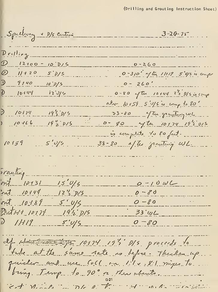
(Drilling and Grouting Instruction Sheet)
' .^Pil-^-y'^ :L_^^P±^^^_
T'r.///^^,
^. t^-tc o - I0'l>/S>
3 Zt '^.^ 'OS.P/>
?) / ^_v V 'j_*ty>. ._
3-1Q-7^-
o -^ 2.(^0
_o~3/o^ -yj^ ///// ^'tyi ^ ON-y2x
o- ZCo*
_ o-y o y tL.. / ^^ivy^ 2
J- .p/s Jo /i--^^
^}>_Z^.9_ V.^. S^.'f-t^^rfrl ySr-
:_^_Z__ fj? V ?^ .<<? /_7.y ^J.'y.j>A ^.
r^ • - - - (^ - -
/ois^l. s^'.'V^. 3i- So ^/-^ iT^-^Y
uJL
I
— •
—
-^- /
/-iv^. IP_-(3L ^:> - J d iaJ L^
h^. . JodAf.. \j^y..pK
/) /.H/i f:.Y$_._..
r.IA.
o -~^o
I/-I-^^^
.. /->'--v»-/'. . ./c? ^^ ^r^ . ^
7^/- /5?.
G-21
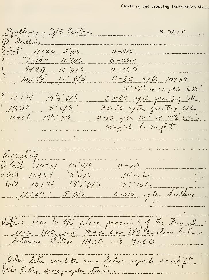
(Drilling and Grouting Instruction Sheet
Sf^-^tf^-^-^j - D/S Cu^^A>^^ l:.ptjA_ .
Q)^.^"<A^-^-
^_42:-/r_ i/j.^j?^^.^.^y/^ Q.z.^/.9- -
> _.^yjC/? fpjp./..^. ^.::^^_'^.„
^ /o^t il^..__.../?_' 0^6 9.230 v.^... /07_SJ_
_ _ _^'}^/f.^^ S^'.^rfA^-skJ^l.-
[
__/^4-^f ^/.^A_ 3.?:_^._ VSc^ _&^l^^'7._^:^__^ _ :_
2 &,'Ci ./oi3 / f^'U/^ o ^lO
{^4.... .jo.tiL !l''j'j?Z'?. 33:ujj^^,
:
///•?J?__; ^.^PA> Q.rJl^ /y h^ d^uM^-^:^
y '.' "
'. "~ " "g-22 " *^ "/
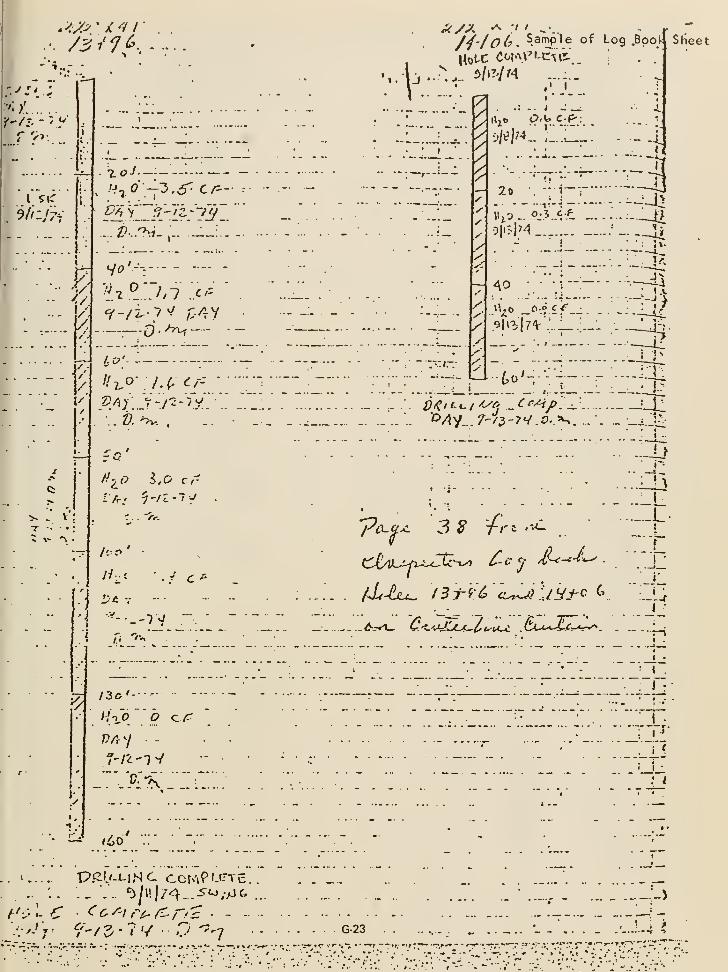
••.."
/4-/0(0. Sample of Log .Bpol-
./ '<
•'l/^
1
n«^»- ^-' • -•'-..
f
X
V
:
^p;. ; ._ ..
ho-
PI
yA
/
:T:rv ^
|Ko t>.V. C-^
.
'/»?l74„
,.. ....
20 - T
Sheet
0.3..<:-.P
40 - -|—
.^|i3|7'V'...i_.'-
. 1 _. .-
to'-;
1^
• Jv
"pc^-^^ 3 ^ tn '--^
1 ..
-rv
tc-Ly) Cc ^ rV'-e-c-i'-
. .. J_'
f^/3c'-
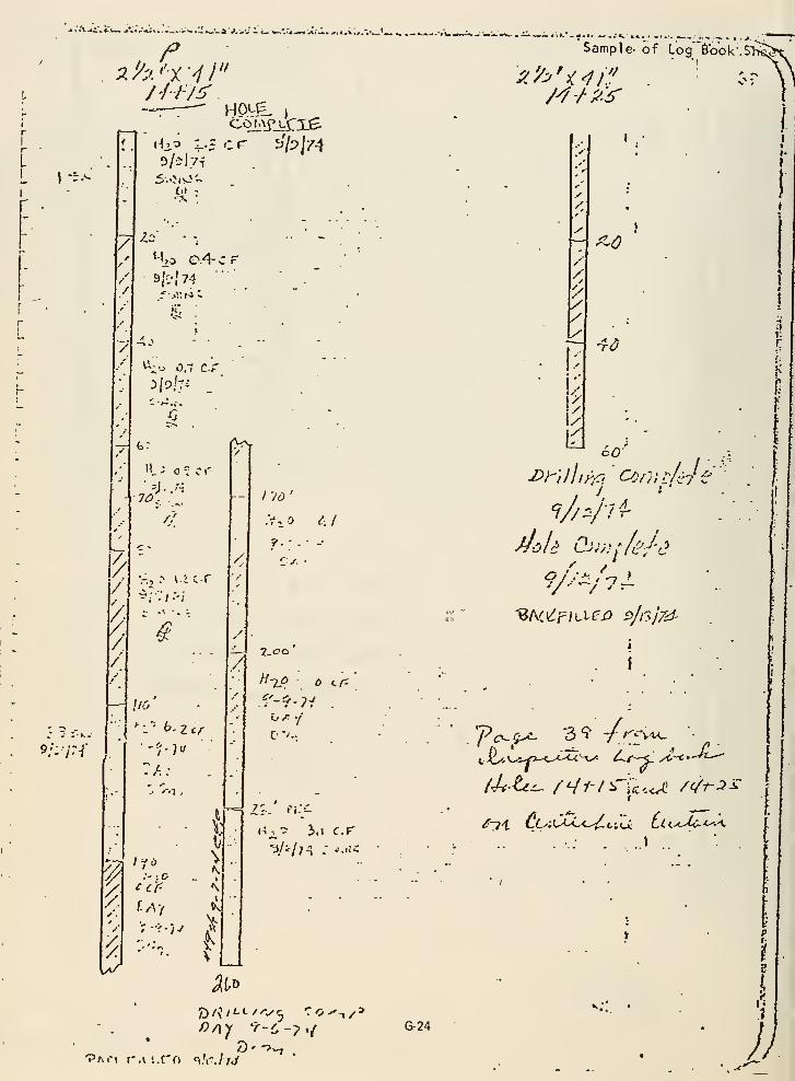
- ^^ .*-»» Al'-••^*^ «-.\ .. tK. .-^.t, tj ,.*j[
f-
/
/
/
^://
s/:/:-/'
^j*
- >- .r-
/
V:, ^ v.icr
^
/
//6
.• '''1
,
/l
Z-co
IJ
I
g
\I
N
My (ill
ij A'I
i-i;^-3 3,,i c.r
u
"Pmm r.v i.rn q.'r,/7<y
G-24
Sample- of Log"6o'ok-.
/
^^0
-rd
60'.
"BACe^f/LLfj3 o/l'lj/:d-
I
f
...» .
1
^..'i
y;
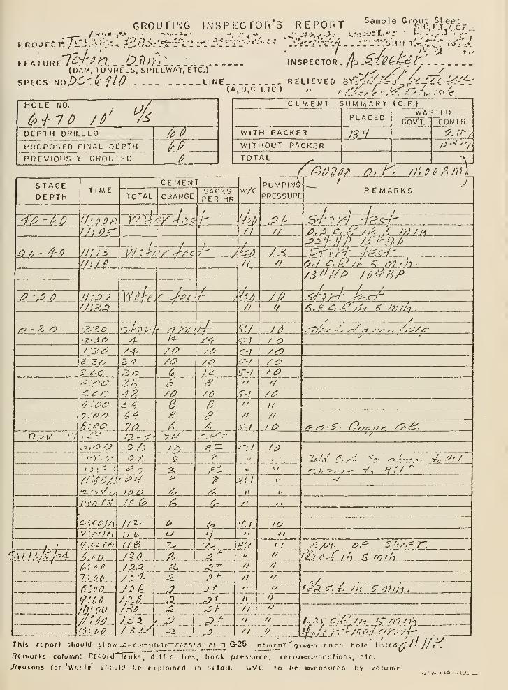
GROUTING INSPECTOR'S RIZPORT ^^"^^^^^'SV^vi-rf-^of..
(0AM, 1 UNNfLS, SPILLWAY, ETC.)INSPECTOR
SPECS UoDC''^(e'llO LINE RELIEVED ^il'2<'/^^C/_i-^.l-L<.''^<^-''S^(A.B,C ETC.) ,. 'C'/-,^'!j^'i'^:'w^^<_
HOLE NO. 1/
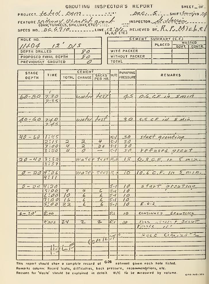
GROUllNy INSPECTPirS KEPOin" SHtET_"oF..
PROJECT. :^^^J:0-C/. . .Q^]i:^t1 _ :^L* ' .J?^-Qj..-^... _ ..shift.^.'<>i'^i9^^-
FEATURE ,^/'//A<^''^>/ /ir'/-/7^2/<v4 9^^? r-^- INSPECTOR -.,^-^:.'<r4r?<:^fV(DAM.-TUNhJELS, SPILLWAY, ETCO-.:.-.:. '"' '•'
[7 l^' \'a"' I IjyC 0_'^ /a LINE_/2.'/yy_. RELIEVED ^'i.K i. J-f.M Ji^M -^ I
(A.B.C^ETC.)SPECS NO..
HOLE NO.
/U04 /^ ' .o/s
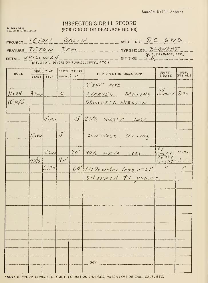
Sample Dri 1 1 Report
»-l7<4 (?-7l)Duicwu ol KfClHmadon
INSPECTOR'S DRILL RECORD(FOR GROUT OR DRAIfMGE HOLES)
TSyoA^ 6A5//~^PROJECT_ U-^'—lrL ^d^i/— . SPECS. NO. VC G7/D-
PEATURE_ T^ /_ ^'j^_ J^i_r^ TYPE HOLES_ ^bA/^Jf.^Z„K. B^DRA/NAGE. ETC.)
DETAIL :IC^J:L-'d^j^^ BITSIZE_(RT. AHUT.. D/VCRS/ON TUNNEL, SPV/Y.. ETC.;
HOLE
Please describe:
B. The manner in which the key trench between Station 18+00 andStation 2+00 was prepared to receive the first embankment material .
Compare the way in which this trench was prepared with "broom clean."If there were differences in clean-up between particular stations, becauseof weather, or any other cause, please describe such differences in
detail .
(B) The key trench between Station 2+00 and 18+00 was all cleaned in
basically the same manner. Laborers using hand shovels and bars wouldfirst remove any loose rock or earth materials from the rock foundation.An air jet was then used to clean any remaining finer material down toa clean rock condition. Any grout which had been spilled in key trenchareas was loosened by paving breaker and cleaned by air jet . Cleanupof key trenches and all abutment areas generally progressed to 2 to 10feet above the elevation of the zone 1 fill . Material accumulated duringcleanup was removed by a rubber-tired backhoe .
Prior to placement of each lift of specially compacted zone 1 material,the abutment rock which had been cleaned by shovels and air jets wasalways sprayed with water to assure a proper bond with the fill material .
No particular areas in the foundation key trench I'^ceived a differenttype of treatment from the rest of the key trench. The air jet andwater treatment method of cleaning the abutment rock was consideredsuperior to broom clean because the use of air jets and water resultedin a more thorough cleaning of cracks and irregularities in the rocksurface then with the broom method .
G-28
Please describe:
C. The manner in which any fissures or open joints in the key trench wallsand floor were sealed between Station 18+00 and Station 2+00; that is, themanner in which, and the places where, slush grouting, dental concrete, gunite,or shotcrete may have been used, also the extent to which such sealing wasgeneral. Were any joints left unsealed and, if so, where? If known, pleaseindicate the particular stations, if any.
The excavation for the right abutment keyway trench disclosed two unusuallylarge fissures that cross the floor and extend into the walls of the keywaynear the toe of the walls. On the floor of the keyway, the fissures werefilled with rubble; but at both locations, the contractor excavated a trenchabout 3 to 4 feet wide and about 5 feet deep. Both fissures apparentlywere developed along joints that strike about N80 V/ and are vertical to
steeply inclined. The largest fissure crossed the keyway from station k+kkof the upstream face to station 3+^+5 on the downstream face. The strikeof a smaller fissure was about N75 W and crossed the keyway trench fromstation 5+33 of the upstream face to station 5+11 of the downstream face.
The largest and most extensive open zone extended into the upstream wallfrom the toe of the keyway wall near station k-'-kk. The opening at the toewas about 5 feet wide and 3 feet high. There was a rubble-filled floor about4 feet below the lip of the opening. A few feet in from the wall the fissurewas about 7 feet wide, but a very large block of welded tuff detached fromthe roof and/or the north wall rested in the middle. Beyond the large blockabout 20 feet in from the opening the fissure narrowed to about 2-1/2 feetwide. The rubble floor sloped gently away from the opening and the verticalclearance was about 10 feet. About 35 feet in, the rubble floor slopedrather steeply and the roof tilted sharply upward. About 50 feet in from theopening, the vertical clearance was about kO feet and the fissure curved outof sight at the top. About 75 feet back, the fissure curved slightly south-ward out of view. The smaller fissure was mostly rubble-filled and was openonly at the upstream face. The opening was about 1 foot square at the faceand the fissure appeared to be rubble-filled about 5 feet back from the face.
The continuation of this fissure intersected the cJownstream wall of thekeyway near station 4^-21, The opening was about h feet wide and k feet high,A rubble-filled floor lay about k feet below the lip of the opening. Thelarge opening extended only about 5 feet back frocn the face and then a footwide fissure at the north edge continued about 10 feet back and about 10 feetupward before going out of view.
The other large open zone extended into the upstream wall from the toe of the
wall near station 3+66. The opening at the toe of the wall was about 1-1/2 feet
wide and 1-1/2 feet high. From the opening, the fissure extended about 10 feet
down to a rubble floor and about 15 feet back before going out of view. Thecontinuation of this fissure intersected the downstream wall of the keyway at
about station 3+^5. There was no open fissure at the downstream wall but
G-29
there was a 3-1/2-foot-wide zone of very broken rock with open spaces upto 0.8 foot wide. About 2-1/2 feet north, there was an open joint about10 feet long and 0.2 feet wide that dipped about 78 degrees south.
At both the upstream and downstream locations of the fissure zones, brokenrock extended to about midway up the keyway walls. Above the broken zonesthere appeared to be filled fissures about 0.5 foot wide that extendedvertically to the top of the keyway cut.
Two 9-5/8- inch-d iameter holes were bored to intersect the open fissure thatextended into the upstream and downstream walls of the keyway trench. Onehole was located 72 feet upstream from dam axis station k+6k and the otherwas located 75 feet downstream from dam axis station U+02. The upstreamextension of the fissure was encountered at a depth of 68 feet and thedownstream extension was encountered at a depth of 58 feet. The holes werecased with 8-5/8- inch-d iameter steel casing. High-slump concrete was pouredthrough these casings into the fissures. Ninety-five cubic yards of concretewas placed in the upstream hole and 233 cubic yards was placed in the down-stream hole in April 197^.
Three 3- inch-d Iameter vertical drill holes were bored 77 feet downstream fromdam axis station 3+30 to explore for a possible open fissure indicated byearlier horizontal drill holes bored from the floor of the keyway trench.The vertical holes encountered some voids and some soft, broken, or looserock; however, these voids did not appear to be of sufficient volume towarrant drilling large diameter holes for backfilling with concrete.
In May 197^, an additional 18 cubic yards of high-slump concrete was placedin the 8-5/8- inch-d iameter-cased hole wh Pch intercepts the open fissure75 feet dov/nstream from station ^02. A total of 251 cubic yards of high-slump concrete was placed in this hole. Drawings No. 5^9-1^7-133 and -13^(Exhibits 12,10.11 and 12.10.12) show the location of the holes, the esti-mated outline of the fissures, and the concrete that was placed into thefissures.
Other open joints or holes were observed on the floor of the kyeway nearcenterline at stations 5+03, 5+68, and 6+18 and about 5 feet left ofcenterl ine between stations 6+03 and 6+08. The roles v^ere rubble filled atshallow depths and their lateral extent, if any, was covered by rubble.Heavy calcareous deposits were associated with all of the open zones exceptfor a 0,2-foot-wide open joint between stations 6+03 and 6+08.
The joints between station 5+03 and 6+08 were filled with grout during thegrouting operation.
Dental concrete was placed in an open jointed area on the spillway floor at
approximate station 9+00 where the 1-1/2:1 slope of the key trench meets
the spi 1 Iway floor.
G-30
The surface grouting on the abutments began because of the numerous joints
in the rocks. This grouting was started on July 29, 197^ and was completedabout August 6, 1975.
The joints in the rock between elevation 5055 and 5205 were grouted to
refusal by mixing grout in the mix trucks and placing it in the crack or
joint by making a funnel out of the zone 1 material around the cracks and
dumping it in out of the trucks. The smaller cracks, approximately 1/2 inch
to 2 inches wide, were grouted witha 0.7 to 1 mix by volume. For gravityfilling the larger cracks, approximately 3 to 4 inches wide, a sand-cement
grout was used. These cracks were marked and filled by inspectors for zone 1
special compaction placing.
Occasionally, the batch plant could not place grout in these cracks daily.
Therefore, the zone I special compaction was held up until the cracks could
be grouted. At times, the fill would get ahead of the special compaction a
foot or 2, but this was not a problem because the batch plant operated on
two shifts and grout could be placed during the graveyard shift when the
fill was shut down
.
The foundation keyway and abutment rock above elevation 5205 had fewer openjoints than below this elevation. Generally the rock in the keyway was more
massive and the joints and cracks very small; hence, the slurry grouting aboveelevation 5205 became impracticable. It was noted also that the fewer large
joints above elevation 5205 were usually filled with rubble or silt which alsoadded to the difficulty of treating these joints.
Please refer to the detailed geologic maps of the abutment and key trenchareas for a description of the joints and fissures. The panoramic photos
of key trenches and zone 1 foundation rock will also reveal the more massivenature of the rock in the key trenches.
No fissures or large joints were knowingly left untreated. A tabulated list
of the locations where slurry grout was used is attached.
The fissures crossing the key trench at stations 3+55 and k "ik wereexcavated similar to the grout cap trench and filled with concrete.
G-31
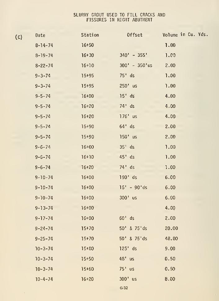
SLURRY GROUT USED TO FILL CRACKS ANDFISSURES IN RIGHT ABUTMENT
(C)Date
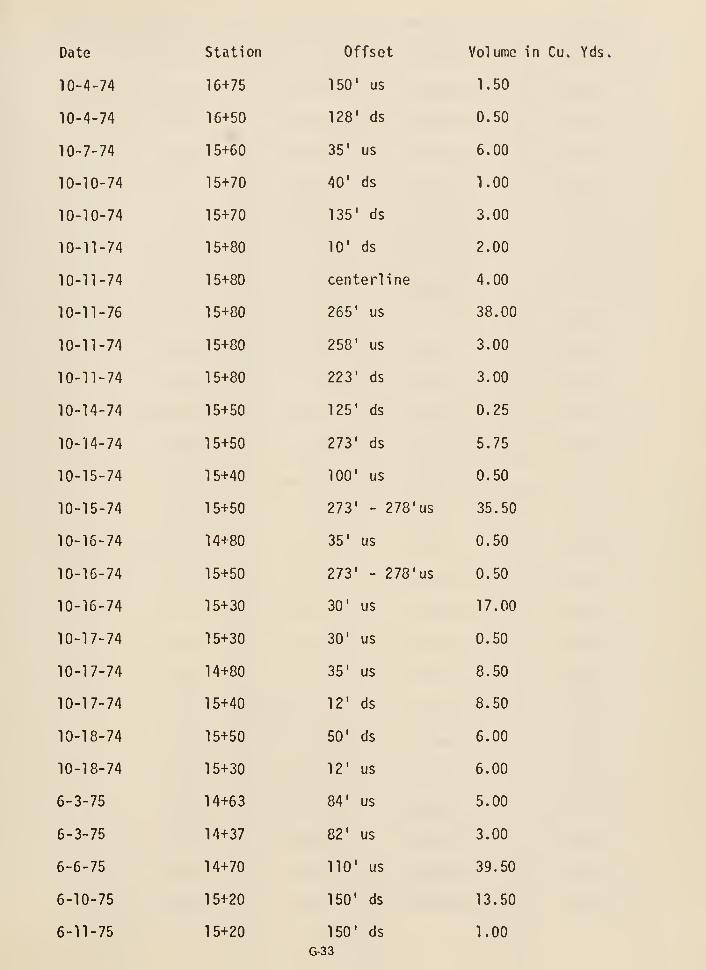
Date

Date
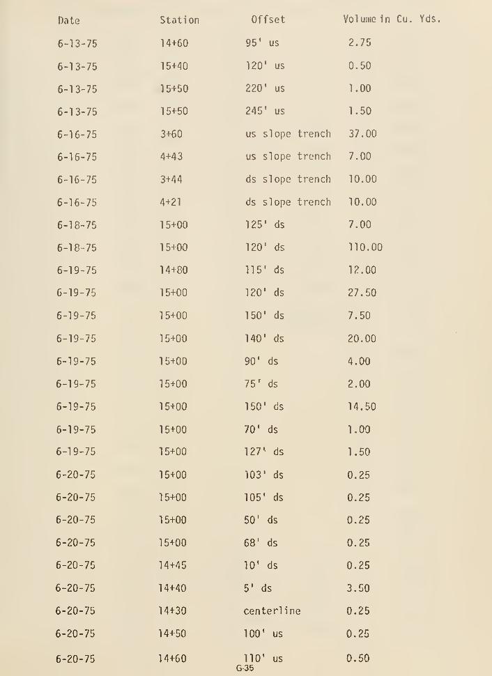
Date
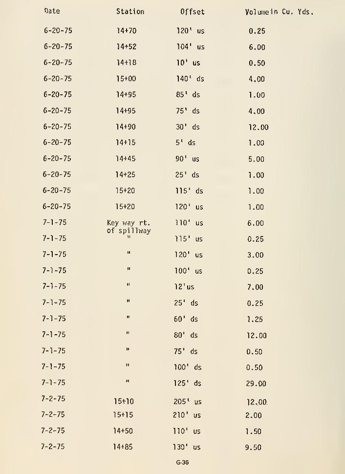
Oate Station Offset Volumein Cu. Yds.
6-20-75 14+70 120" us 0.25
6-20-75 14+52 104' us 6.00
6-20-75 14+18 10' us 0.50
6-20-75 15+00 140' ds 4.00
6-20-75 14+95 85* ds 1.00
6-20-75 14+95 75' ds 4.00
6-20-75 14+90 30' ds 12.00
6-20-75 14+15 5' ds 1.00
6-20-75 14+45 90' us 5.00
6-20-75 14+25 25' ds 1.00
6-20-75 15+20 115' ds 1.00
6-20-75 15+20 120' us 1.00
7-1-75 Key way rt. 110' us 6.00of spillway
'-1-75 " 115' us 0.25
-1-75 " 120' us 3.00
1-75 " 100' us 0.25
-1-75 " 12'us 7.00
1-75 " 25' ds 0.25
'-1-75 " 60' ds 1.25
1-75 " 80' ds 12.00
'-1-75 " 75' ds 0.50
'-1-75 •• 100' ds 0.50
-1-75 " 125' ds 29.00
2~7^ 15+10 205* us 12,00
^2-75 15+15 210' us 2.00
2-75 14+50 110' us 1.50
^2-75 14+85 130' us 9.50
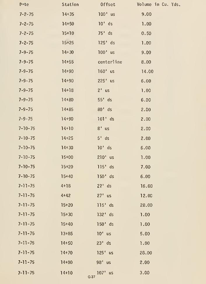
pne
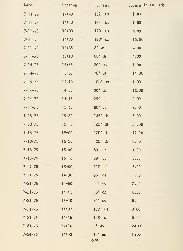
D^te
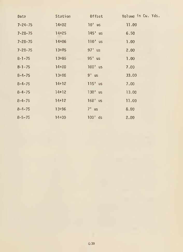
Date
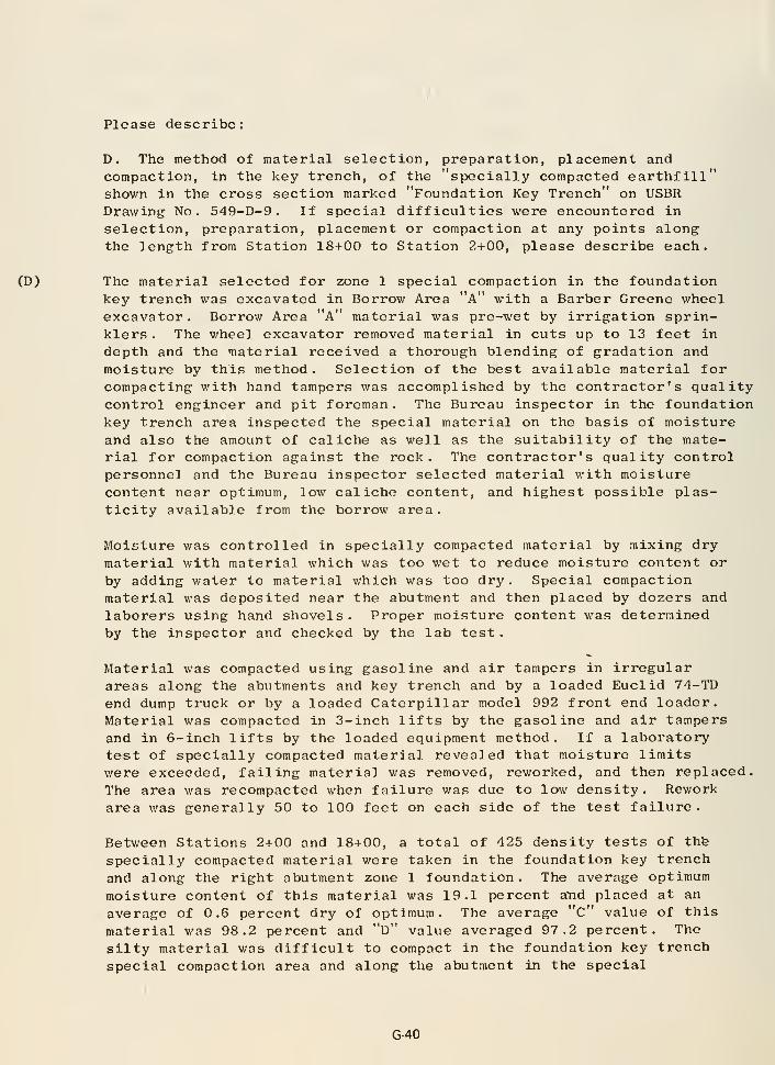
Please describe:
D. The method of material selection, preparation, placement andcompaction, in the key trench, of the "specially compacted earthfill"shown in the cross section marked "Foundation Key Trench" on USERDrawing No. 549-D-9 . If special difficulties were encountered in
selection, preparation, placement or compaction at any points alongthe length from Station 18+00 to Station 2+00, please describe each.
(D) The material selected for zone 1 special compaction in the foundationkey trench was excavated in Borrow Area "a" with a Barber Greene wheelexcavator. Borrow Area "A" material was pre-wet by irrigation sprin-klers . The wheel excavator removed material in cuts up to 13 feet in
depth and the material received a thorough blending of gradation and
moisture by this method. Selection of the best available material forcompacting with hand tampers was accomplished by the contractor's qualitycontrol engineer and pit foreman. The Bureau inspector in the foundationkey trench area inspected the special material on the basis of moistureand also the amount of caliche as well as the suitability of the mate-rial for compaction against the rock. The contractor's quality controlpersonnel and the Bureau inspector selected material with moisturecontent near optimum, low caliche content, and highest possible plas-ticity available from the borrow area.
Moisture was controlled in specially compacted material by mixing dry
material with material which was too wet to reduce moisture content or
by adding water to material which was too dry . Special compactionmaterial was deposited near the abutment and then placed by dozers andlaborers using hand shovels . Proper moisture content was determinedby the inspector and checked by the lab test
.
Material was compacted using gasoline and air tampers in irregularareas along the abutments and key trench and by a loaded Euclid 74-TD
end dump truck or by a loaded Caterpillar model 992 front end loader.Material was compacted in 3-inch lifts by the gasoline and air tampersand in 6-inch lifts by the loaded equipment method. If a laboratorytest of specially compacted material revealed that moisture limitswere exceeded, failing material was removed, reworked, and then replaced.
The area was recompacted when failure was due to low density. Reworkarea was generally 50 to 100 feet on each side of the test failure
.
Between Stations 2+00 and 18+00, a total of 425 density tests of thfe
specially compacted material were taken in the foundation key trench
and along the right abutment zone 1 foundation. The average optimum
moisture content of this material was 19.1 percent aYid placed at an
average of 0.6 percent dry of optimum. The average "c" value of this
material was 98.2 percent and "d" value averaged 97.2 percent. The
silty material was difficult to compact in the foundation key trench
special compaction area and along the abutment in the special
G-40
compaction areas. This is illustrated by the fact that of the 425tests taken between Stations 2+00 and 18+00, 114 tests failed either formoisture or density deficiencies and required reworking or additionalcompaction; however, these areas were retested after being reworked andbrought up to specifications requirements.
Field experience with this silty material demonstrated that theinherent nature of the material, particularly its low plasticity, madecompaction by hand tampers difficult and a very concentrated effort wasrequired to obtain a good job. However, there were no areas not placedto specifications requirements and particular attention was given to
obtaining both moisture and density uniformity along the abutment rockcontact in these special compaction areas
.
Please refer to our reply to Question F., "Cleanup and Special Compac-tion - General" for additional information.
G-41
Please describe:
E. The method of material selection, preparation, placement, andcompaction in the key trench between Station 18+00 and Station 2+00of the core material . If special difficulties were encountered inselection, preparation, placement or compaction at any points alongthe length from Station 18+00 to Station 2+00, please describe each.
(E) Material in the key trench core area was selected by the same methodas in paragraph (D) . The borrow area was prepared in the followingmanner: A cut depth was determined from topographic notes to estab-lish the desired drainage pattern. The borrow pit was then dividedinto material blocks . Three-inch holes were augered to the depth ofcut required on a 200-foot grid and proctor optimum moistures wererun on the drill cuttings and noted on the borrow pit drawings.Moisture was added to the pit by sprinkling the required water forthe design cut on the area at least 3 weeks prior to excavation .
Constant monitoring was possible by utilizing a speedy moistureteller. Material on the zone 1 fill received extra water from watertrucks if required. The material was spread in about 8- to 9- inch-thick
uncompacted lifts and rolled with two Caterpillar 825B self-propelledsheepsfoot rollers with caron wheels and two Ferguson SP-120-Pself-propelled sheepsfoot rollers. Two Caterpillar motor graderswith scarifier attachments provided supplemental scarifying onembankment as moisture was being added.
The method of excavation in the borrow pit by the Barber Greene wheelexcavator resulted in a very homogeneous mixture of zone 1 material
.
Moisture and gradation reached a high degree of uniformity by the
mixing action of the wheel excavator and the subsequent loading intothe trucks by the belt. Further uniformity was attained by spreadingand working of the material on the fill . The average density of all
zone 1 fill placed was 98.3 percent of laboratory maximum with an
average optimum moisture of 19.6 percent and placed at an averageof 1.0 percent dry of optimum.
No special difficulties were encountered in placing the core materialto the required density.
G-42
Please describe:
F. The manner in which the contact area under the core of the dam outsideof the i<ey trench was prepared to receive the first core material. If
special difficulties were encountered at any location along the length
of dam between Station 18+00 and Station 2+00, please describe.
CLEANUP AND SPECIAL COMPACTION - GENERAL
Placement of zone 1 embankment at Teton Dam began in the cutoff trench on
October 18, 1973 with zone 1 material being transported by beltline conveyorfrom the left abutment to the trench bottom. Special compaction of the
zone 1 material began on October 19, 1973, initiated by two laborers
operating pneumatic tamping hammers and gas powered wackers along the
perimeter of the embankment area from station 17+75 on the dam axis to
station 19+50, 200 feet upstream.
While the zone 1 dam embankment material consisting of clay, silt, and sandcould have rocks with dimensions of 5 inches or less, the zone 1 embankmentmaterial placed in locations requiring special compaction consisted of clay,
silt, and sand with rock fragments having maximum dimensions of no more than1 inch. Any portion of the dam embankment where zone 1 material was placedand could not be adequately compacted by sheepsfoot roller was speciallycompacted. These areas include zone 1 material adjacent to rock abutments,concrete structures, and any steel pipe or 5.tee! structures which would be
embedded in the zone I embankment. Special compaction was accomplished foran average horizontal distance of 2 feet from any surface contacted by thezone 1 embankment. Standard procedure for placing a lift of zone 1 fill
consisted of dumping the material from belly dumps and placing the lift withdozers to a depth which would equal 6 inches when compacted. An uncompactedlift of 9 inches generally compacted to a depth of 6 inches. Areas of fillwhich could not be placed by dozer were placed by laborers with hand shovels.Equipment such as dozers and sheepsfoot rollers were not allowed to contactthe abutment or any other surface requiring special compaction of adjacentembankment material to assure that no damage would occur to the surfaceand that no rock would be loosened or dislodged from the abutment.
Abutment cleanup along the zone 1 embankment consisted of removal of allvegetation, including roots, larger than one-fourth inch in diameter, leavingclean rock. Any earth attached to the rock was removed by a i r jet or handshovel. Any grout which had been spilled in key trench areas was chipped out
by jack hammer and cleaned by air jet. Cleanup of abutments generally prog-
ressed 2 to 10 feet above the elevation of the zone 1 fill. Material accumu-lated during cleanup was removed by rubber-tired backhoe.
Prior to placement of each lift of specially compacted zone 1 material, the
abutment or other surface which had been cleaned by handwork and air jets
was always sprayed with water to assure a proper bond of the fill material
to this surface. A minimum of eight passes was made by a loaded Euclid Jk-TD
G-43
end dump or other approved piece of rubber-tired equipment over speciallycompacted areas forcing the clay material into the wetted cracks in therock abutment. (See photo P5^9-1^7-5732 , Exhibit 3^.) All surfaces wereclean prior to placement. Areas not reached by wheel rolling were power-tamped by gasoline or air tampers to such a degree that the compaction anddensity requirements were met. (See photo P5^9- 1^7-573^ Exhibit 3^.)
Before placing a new lift of specially compacted zone 1 material, theprevious lift was scarified by discing the surface. Any areas which couldnot be reached by the disc were scarified by hand with shovels to assurea good bond with the following lift and to prevent a smooth bonding surfacewhich could possibly allow movement of water along this boundary in thefuture. Moisture was controlled in specially compacted material by mixingdry material with material which was too wet, to reduce moisture content,or by adding water to material which was too dry. Material was workedto the proper moisture content near the abutment and then placed. It wasdifficult to adjust the moisture content of material already in place alongthe abutment. Proper moisture content was determined by the inspector andchecked by the lab test. Following a test, failing material was removed,reworked and then replaced to correct a failure in moisture content. Thearea v^as recompacted when failure was due to low density. Rework area wasgenerally 50 to 100 feet on each side of the test failure.
Material was specially compacted around 36-inch pipe encasing dewateringpumps station 18-1-85, 75 feet upstream and at station 19+70, 175 feetupstream, (See photo P5'+9- 1^7-325^ NA , Exhibit 3^+.) Plastic dewateringpipes at the bottom of the trench were also embedded in specially com-pacted earthfill. Saturated material along the upstream and downstreamtoe of the embankment was removed with a Case 58OB backhoe. The areaswere then backfilled with gravel to prevent water from pooling or saturatingplaced embankment material. Zone 1 material was then specially compactedover the gravel beds, or French drains, using a rubber-tired 992 frontloader with its bucket filled with zone 1 material.
Special compaction of zone I fill continued from station l8-i-50 tostation 18-h75, I90 feet upstream to 200 feet upstream, elevation ^937 to504l
, using gas-powered plate wackers around the pump encasement and drains.Rock abutments were cleaned of all vegetation and loose material by hand-work and air jets as construction of the embankment progressed.
By October 29, 1973, the pipe from the dewatering pump at station 18-t-85
was embedded in specially compacted material to eJevation ^961. An area6 feet wide for a depth of k feet above the pipe was compacted with gas-powered plate wackers, from the pump to the downstream toe of the embank-ment. With a 4-foot depth of material over the pipe, it was possible fora sheepsfoot roller to compact the fill in this area. On November 7, 1973,the two 50-hp dewatering pumps were removed from the embankment and the36-inch pipe encasements were filled with concrete. Special compactionwith wackers began around the zone 1 belt tower footings on this date at
G-44
station 16+65 on the right abutment. This was the last day of fill place-ment as snow closed the embankment for the season. ,
The contractor resumed embankment operations on April h, 197^, with zone 1
material being placed and compacted at the toe of the right abutment andaround the base of the bel'.line tower. After dropping through the tower,the material was loaded and spread by a Cat. 966 loader. The fill wascompacted adjacent to the abutment by wheel rolling with the Cat. 966 loaderand around the tower legs with gas-powered plate wackers. An access rampwas constructed for scrapers at the base of the tower during this operation.Elevation of the fill around the tower legs on April 11, 197^ was 5015.5 feet.
Laborers continued to clean the basalt formation at station 21+55 on theleft abutment. Mud and grout along the grout cap on both abutments andloose debris were removed to a waste area on the downstream slope of theembankment by a Cat. 988 loader. Fill was compacted along the rhyolitewall of the right abutment with pneumatic tamping hammers. The abutmentwas wetted by a Cat. 63IB water wagon to assure proper bond with theembankment
.
On April 29, 197^, a 6,000 gallon Cat. 63IB water wagon compacted fillmaterial adjacent to the abutment making eight passes of the wheel at eachlocat ion
.
By May 29, 197^, areas of special compaction of zone 1 included materialaround the legs of zone 1 beltline tower station 16+58, 50 feet upstreamfrom the dam axis, the right zone 1 abutment station 16+50 to sta-tion 17+50, 100 feet downstream to 3^0 feet upstream from centerline,and the left abutment from station 22+50 to station 24+00, 100 feet downstreamto 300 feet upstream. Average elevation of embankment was 5022 feet.
On July 8, 197^, the contractor began using a Pierce Arrow pavement breakeror Hydra Hammer, with shoe area of the hammer approximately 1 square foot,for special compaction along the abutment and the materials handling towersupports. (See photo P549- 1^7-4590 NA, Exhibit 34.)
On July 11, 1974, special compaction was interrupted to blast overhangingrock on the left abutment. Blasting, scaling, and cleanup continued forseveral days and special compaction resumed following this operation.Grout leaks from construction of the grout curtain in the right cutofftrench appeared along the right abutment special compaction area. Wetmaterial was removed by motor patrol and new material was placed andcompacted
.
A "Ho-pac" compactor arrived for use on July 17, 1974 and a Case 58OB back-hoe with special vibrator attached to the end of the backhoe to be used forcompaction arrived on July 22, 1974. Use of the "Ho-pac" was discontinuedbecause of the high number of passes required to get adequate compaction.When it was not possible to compact zone 1 fill in very deep voids on theirregular abutments, it was necessary to fill these voids with backfill
G-45
grout to form an impervious rock foundation sealing off voids so eartlifill
material could not penetrate the foundation and cause an unstable embankment.
A standard grout mix of 0.7:1 water-to-cement ratio was used for most backfill
grouting operations.
On November 27, 197^, the contractor terminated operations for the season,
resuming work on April 18, 1975, with cleanup on rock abutments. Standingwater along the abutment on May 19, 1975, was drained toward the center of
the fill and pumped downstream and fill material was scarified with an
International TD15C dozer pulling discs and allowed to dry. Any materialconsidered too wet along the abutments was removed by a Cat. l^E patrol,
picked up by scrapers, and hauled to the zone 3 embankment to dry.
When construction of the right cutoff trench embankment began on June 10,
1965, a Cat. 966 rubber-tired loader was used for special compaction.
After all concrete repair was complete at the Auxiliary Outlet Works gate
shaft and right spillway counterforted wall station 10+55, elevation 5295special compaction began on July 22, 1975. Gasoline-powered plate wackerswere used there.
On October 20, 1975, cleanup of grout and debris began around the River
Outlet Works gate shaft. Hand shovels and air jets were again used to clean
the foundation. Placement of zone 1 material around the shaft began on
October 2k, 1975 with same special compaction procedures used as at previous
concrete structures. By November 1, 1975, special compaction around the
shaft was finished completing zone 1 special compaction on the dam
embankment
.
G-46
Please describe:
G. The manner in which core material was selected, prepared, placed, and
compacted outside of the key trench, between Station 18+00 and Station 2+00.
If special difficulties were encountered, please describe in detail by
specific location.
There is no significant difference between this operation and the operation
described in the answer to (E) previously given. The key trenches, except
for special compaction areas, were a continuation of the zone 1 fill opera-
tion. The key trenches were wide enough to permit the spreading and rolling
equipment to place the key trench areas in a concurrent operation with the
main body of zone 1 fill. The method of selection, preparation, placement,
and compaction was the same outside of the key trench areas as Inside them.
We do not know of any particular difficulties associated with this operation.
The following description of the training procedures used for construction
personnel and quality control efforts will provide an insight into efforts
made to select and prepare the zone 1 material for placement in the
embankment
:
Prior to the start of zone 1 placement in the fall of 1973, the Bureau
of Reclamation supervisory personnel met with those from Mor r I son-Knudsen-
Klev/it to determine how to precondition and excavate material from Borrow
Area "A." it was decided that, for the short construction season left, Bureaumaterials technicians would work In the pit directly with M-K-K personnel
and that the Bureau would provide laboratory facilities for preplacement
testing. This would help train M-K-K personnel for control of the pit
during the following construction season.
During the winter shutdown following the 1973 construction season, the
Bureau conducted a training session covering testing procedures for
earthwork and concrete. Bureau laboratory personnel conducted the session
in the project laboratory.
M-K-K requested that their supervisory personnel be allowed to attendthese sessions. After completion of the Initial training session, M-K-K
requested that the Bureau have an additional day's training coveringearthwork testing so that they could have additional personnel receivethis training. This was done.
Prior to and during the early part of the 197^ construction season, M-K-Khad three people work In the Bureau project laboratory to receive trainingbefore they were allowed to work In M-K-K's mobile laboratory, which was
set up in Borrow Area "A" specifically for preplacement testing of the
material for specifications compliance prior to placement In the dam.
From the start of the 197^ construction season and through completion of
the dam, M-K-K handled the preconditioning and testing of the borrow area
prior to placing. The Bureau of Reclamation tested the material as
G-47
delivered to the dam for specifications compliance. The Bureau providedteciinical assistance and provided special testing whenever requested by
M-K-K to maintain adequate control of the borrow area. Considerablecontrol testing was needed in Borrow Area "A" due to the wide range ofoptimum moisture contents. The optimum moistures ranged from approxi-mately 16 percent to 2k percent. It was difficult to d-^termine visuallyor by hand tests whether the material from the pit was within the speci-fications limits from placement moisture.
G-48
Please describe:
H. Similarities and significant differences in the appearance of the
walls and floor of the key trenches in the right and left abutments.
The walls and floor of the key trench in the right abutment generaMyappeared to have more cracks in the rock than the walls and floor of
the key trench in the left abutment.
Both abutments, however, have a highly fractured zone in the top of
the canyon wall in the rhyolite.
Profiles through the key trenches are, of course, quite different becau;of the 1-1/2:1 slope adjacent to the spillway on the right abutment key
It is recommended that similarities and differences of the key trenchescan best be understood by inspecting the panoramic color photos withgeologic overlays and the detailed geologic maps made of the key trenchesduring construction.
G-49

UNHID statl:s Di:i'Ainr>u-NT or the inichior - stati! or idaho
iNHUT.' •i^r.Nr PANi-x 1 o i;i:viiAv causi: or tieton dam failure
LOV^il-l 'icSxOn
Kr. H. G. Arthur, Director
Deninn ct:^^ Constraction
U.S. Bureau of KeclaT.ation
Building 67, Denver Federal Center
Denver, Colorado 80225
V.T. V-'illi8iE H. MaVurren
President & Chief Executive Officer
V.orrison-Knudsen Co., Inc.
?. 0. Box 7803Boise, Idaho 83729
Gentlcraen!
AuguEt _16r^976_
:.'AL
cirY /'^UG 24 1976
f;';VTn: /^^0(G:'v\
' I r< >
I
tj
Reference is made to this Pp-nel's charge from the Secretary of the
Interior ai:id the Governor of Idaho to revie'.v the cause of Teton Dam failure.
It will be of ijTjportant assistance to the Panel in this review if the
construction techniques used, particularly on the right abutaent, are as
thoroughly understood as nay be possible in the absence of personal obser-
vations. As an aid to such an understanding, the following questions have
Vi-en prcnared. Your full and candid answers to these questions will be
a significant aid to the work of the Panel and will be much appreciated.
Please describe:
a. The manner in which axial gixjut distribution and closure were
Qssxired when the up and doT-Tistream grout travel was relatively unlimited.
Details of any doubts over the effectiveness of this axial distribution in
any particular location along the three grout curtains between Station 18+00
and Station 2+00 will be helpful. Likewise, details of difficulties in
obtaining assurance of axial closure at any stations or grout holes along
this same stretch of curtain will be helpful.
b. The manner in wMch the key trench between Station 18+00
and Station 2+00 wao prepared to receive the flrot esibankinent material.
Compare the way in which tiiis trench was prepared with "broom clean". If
there were diffcrcncea in clcan-up between particular ntutiono, becauoo
of weather, or any other cauoe, plcuoe describe ouch differences in detail.
G-50
mce 2 AuGUEt 18, 1976
Leltor to '.'cr.nrn. H. G. Arthur and VrilHtcn II. McWurrcn
c. The mnnnor In which nny Ticnuroa or open jointa in the key
tron'-h walls a.nd floor were ocal cd between Station 10i-0O and Station 2+00;
thn*- Is, the ir,'inncr in whlcli, nnd t))c plr-.cco where, oluah groutlnc, dcntol
co;urotc, t'''"'^'^^* °^ .':holcroto ir.ay have been uriod, bIro the extt.nt to
v.hich iujch ne«linc v.ni.- (general. 'iVore any jointa left unsealed and, if so,
where? If knovrn, plcaae indicate the partjcular atationo, if any.
d. The racthod of material celectlon, pi-eparatJon, placcuent
nnd co::!r'^'^*^ "^"f ^^i the key treiioh, of the "cpecially ccinpaoted earthfill"
sho'".7i in the c3\->rs section marked "Foundation Key Trench" on USBR Drtiv/tngi,/9_r>_9. If r^pocial difficultierj v.ere onc-.nuntered in aelcctlon, prc-p?jation,
placc;nc'nt or co.T.paction at any points along the lencth from Station 18+-00
io Station 2-f-OO, plcace def;cribe each.
e. The method of msterial eelcction, preparation, placement, andcompaction in the key trench bet.veen Station 10+00 and Station 2+00 of the
core material. If cpecial difficulties r.'ere encoLintored in selection,preparation, placcuient or ccnnpaction at any points along the length froaStation 18+00 to Station 2+00, pleaae describe each.
f. The manner in which the contact area under the core of thed&JT; outside of the key trench v;as prepai-cd to receive the first core naterial.If special difficulties were encou.ntero-d at any location clcng the lengthof daai between Station IS+CO end Station 2+00, plcace describe.
g. The nanner in which core material was eelectcd, prepared,placed, and co-jpactfrd outside of ihe key trench, be tureen Station 18+00and Station 2+00, If cpecial difj'iculties were encountered, plcaoe describein detail by cpeoific location.
h. Simil'aritics and significant differencen in the appearance ofthe walls and floor of the key trcncheo in the right aiid left ubulmcnts.
The inforaatton sought thrcjgh this questionnaire is of specialiipportGn;:e to the Panel in its reviev/ rind c°rly receipt of your ansTrer£
jiriorixy given \o i r.^iiie x coverins ine icngin oi loanaa^lon liX)va ijtai.xcn
D6fOO to the ."pillway centorline, tini Phase II covering fix^m Station 10+00to Station 16-(00 ?ind from the njiillv.ay conterline to Station 2+00. Partialreplica are cnrouip.ged, that ia tran^niittalo for individual questiono willbe helpful
.
G-51
Tnao 3
Loiter I'o I'.casra. H. G. Arthur and WiHin.Ti H. KcXurrcnAufiUQt 18, 1976
Plcrico accept our ftpprcclatjon in advance for your cooperation in"^^Pplyii^G ^^^'^ ircportfint cupplcracnting infonr.ntion.
Very truly youro,
aVZ^ n'allnce L. Ch-'^'f^ick
G-52
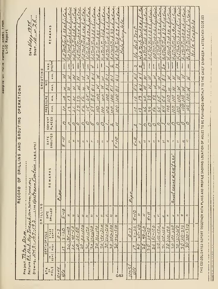
yy _. ^.,.. I
1
1
5^ o A^.Jiil
1.
INFORMATIONAL ROUTIMG ^'-^-^^-^-^
I
r
I
I
I
200 r - -
I
i
August 26 p 197G I
1
I
I
To: Project ConacrucEloa Enstnear, K£i?dalo» Id«ho
Frcm; Dti'ectov oJ3 D^algo ond CcaotructLoa
Subject r Tctoa Df^a Fctluirc
Er.cloaGd £o a copy of o lohtcr dated Ai'S'uot IB, I976» i:5:r.:r3 the
Indopr^nc'cnt Panel ad^ires&eil joiotly to fx. Kcl :ux:i;£ii r.ad iry^slf
tJ^iJ.ch c^Gkff tor tcfciVatlOQ tejisi^tiing tho ccnstiructx-Cfi ct Totoa
Also encloncd Is c copy of ry ('L'rry cnS;r5' rfr;ai:»ilri3 tUa eclcrhcvaa
coavcrsanion held v-lr.U r.r. ALri.-af.):^n2 of i;-K ca Au^viat 24, 1976-
to \;'if.ch ^;e (lLzzv.uzs.iL tho pRXictturu to ba follov-od iu rcplyior; to
Chic IcttfeC.
Please prepare a cJrcft reply ol»talnlri2 Irtrorcatlon frca th®
coatraetof'o f:J.olc3 pjrccnncl cs fippropfft:;Lo, Tho cIraCt f.liould
be Con*35*ccci tc r..G Cor conjiJeeatioQ. I MiW hnixllo tlic coorcIi»
nattca icith Ks:. i:;Kuin.-cin,
Koto tiici pRasl'n Ktatecvav^t thnt pa:3rttal ircpUeo ore encoDrrtr.cd
and tUfit tt^incmlttalo for Indivlduyl queationa vlU bo hclpC^tl.
TlitOp oC couroo, GhoiiTLd be given Ul&h priority.
H a /iirj'iJUH
nneloftii?:«a
Copy to: W. n. Hcl'urrca
(with coj./ difii-y catrj)
blind to:\ Conintr.fii.oncr, Attcmtlor.: 10:5 (Clue Knvalopc)
2001300 (Guy)
G-54
4rCI*0> l«74- tTn-NM
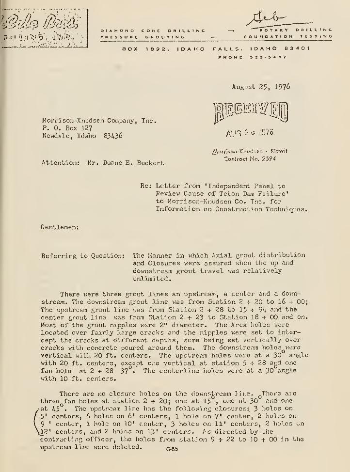
/d^-^DIAMOND COMC DRILLINCPRCSSUn-C CROUTINC
ROTARY DRILLINGrOUNDATION TtSTINC
BOX 1892. IDAHO FALLS. IDAHO 83401PHONC S22.S437
Korrison-Knudsen Company, Inc.P. 0. Box 127Newdale, Idaho 83436
August 25, 1976
A'.-'^.:r7o
Attention; Mr. Duane E. Buckert
/Ipofflssn-Knud-^en - KJewil
ZonUaiA No. 5594
Gentlemen:
Re: Letter from 'Independent Panel toReview Cause of Teton Dam Failure'to Morrison-Knudsen Co. Inc. forInformation on Construction Teclmioues.
Referring to Question: The Kanner in which Axial grout dist)-ibution
and Closures were assured v.'hen the up and
downstream giout travel was relativelyunlimited.
There were tliree gi^out lines an upstream, a center and a qoa-.tt-
stream. The dovrnstream grout line was from Station 2 ^ 20 to I6 + 00;The upstream grout line was from Station 2 -i- 28 to 15 + % and the
center grout line was from Station 2 + 23 to Station 18 + 00 and on.
>5ost of the grout nipples were 2" diameter. The Aiea holes vjere
located over fairly large cracks ajid the nipples were set to inter-cept the cracks at different depths, some being set verticalJ.y overcracks with concrete poured around them. The downstream holes were
vertical with 20 ft. centers. The upstream holes were at a 30 anglewith 20 ft. centers, except one vertical at station 5 + 28 agd one
fan hole at 2 + 28 37 • The centerline holes were at a 30 angle
witlj 10 ft. centers.
There are no closure holes on the downstrecun line Thej-e ar-c
three fan liolcs at station 2 + 20; one at 15"' i one at 30 and one
-at 45 • The upstj'^^am line has the following closures: 3 holes on5' centcr.s, 6 holes on 6' centers, 1 hole on 7' center, 2 holes on
9 ' center, 1 hole on 10' center, 3 holes on 11' centers, 2 holes on^12' centers, and 2 holes on 13' ccotors. As directed by the
contracting officer, the liolcs from .-itaLion 9-1- 22 to 10 + 00 in tlie
\ipstrcajn line v;ere deleted. Q.55
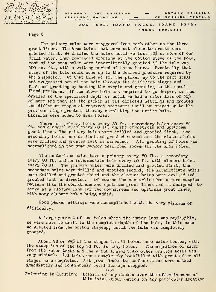
DIAMOND CORE DRILLING — ROTARY DRILLINGPRCSSURC GROUTING rOUNDATION TESTING
BOX 1892. IDAHO FALLS. IDAHO 83401PHONC 522-S437
Page 2
The primary holes were staggered from each other on the threegrout lines. The Area holes that were set close to cracks weregrouted first. We drilled the holes until we lost ^Ufo or more of ourdrill v;ater. Then commenced grouting at the bottom stage of t))e hole,most of the area holes were intermittently grouted if the take was^CX) cu. ft., with a waiting period of thiree hours. Eventually thatstage of the hole would come up to the desired pressure required bythe inspector. At that time, we set the packer up to the next stageand progressed out of the hole thi-ough the different stages andfinished grouting by hooking the nipple and grouting to the speci-ficed pressiore. If the above hole v;as reqiiired to go deeper, we thendrilled to the specificed depth or until we had a v;ater loss of ^ofo
of more and then set the packer at the directed settings and groutedthe different stages at required pressures umtil v;e staged up to theprevious stage grouted, thereby completing the entire ?iole.
Closures were added to area holes.
There are primary holes every SO ft., secondary holes every 80ft. and closure lioles every L^ ft. on. t.he Qownstreajn and upstreamgi^out lines. The primary holes were drilled and grouted first, thesecondai'y holes were drilled and grouted second and the closiu^e holeswere drilled and grouted last as directed. All grouting of holes wasaccomplished in the same mariner described above for the area holes.-
The centerline holes have a primary every 80 ft., a secondaryevery 80 ft. and an intermediate hole every L^ ft. with closure holesevery 20 ft. The primary holes were drilled and grouted first, thesecondary holes were drilled ar.'d grouted second, the intermediate holeswere di'illed and grouted third and the closure holes vere drilled andgrouted last as directed. Of course the centerline has a more complexpattern than the downstream and upstream grout lines and is designed toserve as a closure line for the downstream and upstream grout lines,with many closure holes being added.
Good packer settings were accomplished with the very minimum ofdifficulty.
A large pei'cent of the holes where the water loss v;as negligible,vie were able to drill to the complete depth of the hole, in this casewe grouted from the bottom stageup, until the hole was compl(-;teD.y
grouted.
About 98 or ^Jfo of the stages in all liolcs were water tested, withthe exception of the top 20 ft. in many )iolcs. The migration of waterfrom the water tests and the grout travel into other drilled holes wasvei-y minijnal. All holes were completely backfilled with grout after allstages were completed. All t;,rout leaks to surface areas were calkedimmediately and continously until leakage stopped.
G-56Referring to Question: Details of any doubts over the effectiveness of
Uiis Axial distribution in any particular location
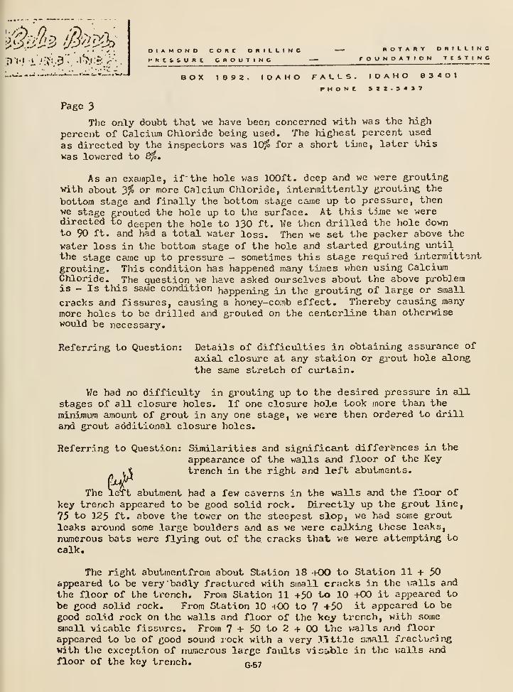
. f - ^ . DIAMOND cone DRILLING — HOTARY DRILLINGPRCSSURC GROUTING rOONDATION TtSTING
BOX 1892. IDAHO FALLS. IDAHO 83401PHONC S22-34»7
Page 3
The o.nly doubt that we have been concerned vrith was the high
percent of Calcium Chloride being used. The highest percent used
as directed by the inspectors was 10^ for a short time, later this
was lowered to 8/5,
As an exajnple, if" the hole vias 100ft. deep and we were groutingwith about 3% or more Calcium Chloride, intermittently grouting the
bottom stage and finally the bottom stage came up to pressure, thenwe stage grouted the hole up to the surface. At this tjjne we weredirected to deepen the hole to 130 ft. We then drilled the hole downto 90 ft. and had a total water loss. Then we set the pacl<er above the
water loss in the bottom stage of the hole and started grouting untilthe stage came up to pressure - sometimes this stage required intermittent
grouting. This condition has happened many times when using CalciumChloride. The question we have asked ourselves about the above pi^oblemis - Is this same condition happenin^g in the grouting of large or small
cracks and fissures, causing a honey-comb effect. Thereby causing many
more holes to be drilled and grouted on the centerline than otherwisewould be necessary.
Referring to Question: Details of difficulties in obtaining assurance of
axial closure at any station or grout hole along
the same stretch of curtain.
Me had no difficulty in grouting up to the desired pressure in allstages of all closure holes. If one closure hole took more than the
minimum amount of grout in any one stage, we were then ordered to drilland grout additional closure holes.
Referring to Question: Sijnilarities and significant differences in the
appearance of the walls and floor of the Key. t trench in the right and left abutments.
The left abutment had a few caverns in the walls and the floor of
key trench appeared to be good solid rock. Directly up the grout line,
75 to 125 ft. above the tower on the steepest slop, we had some grout
leaks around some large boulders and as we were calking these leaks,
numerous bats were flying out of the cracks that -we were attempting tocalk.
The right abutmentfrom about Station 18 -hOO to Station 11+50appeared to be very badly fxactured with small cracks in the v.-alls and
the floor of the trench. From Station 11 +50 to 10 +00 it appeared to
be good solid rock. From Station 10 hOO to 7 +50 it appeared to begood solid rock on the walls and floor of the key trench, with some
small viewable fissures. From 7 + 50 to 2 + 00 the v.aJls .-uid floorappeared to be of good sound lock with a very i:^ttle small fracturingwith tlic exception of numerous large faxilts vicible in the v.alls andfloor of the key trench, Q.57
Page k
DIAMOND CORE DRILLINGPRISSURC CROOTINC
ROTARY DRILLINGrOUNOATION IC&TINC
BOX 1892 IDAHO FALLS. IDAHO 03401PHONE 122.5437
The la]<e bed sedimenis that vmderlay the riolite formation alongthe extreme length and width of the dam at depth vere drilled andgrouted to the desired pressures for a short distance on the outer endof the left abutment.
All work described above was completed as directed by thecontracting officer, Bureau of Reclamation.
Very truly yovir,
McCABE BROS. DRILLING, INC.
Edwin L. HcCabePresident
' ;: / ':—
ELM:rjn
G-58
H. G. Arrlnir, Dlrpctor of Dcflif-n .nnd Conn true trton
Tucn c1 n y, Aup;u3t 26, 1976
Cnll from Ccno Ai'mntronp, , Morrlson-Knuclr.cn, Boise,
re Jnvcstif'aLion oT TcLon Dnm Knilurc
Armstrong read to me a letter Just received by M-Kwhich was addressed jointly to McMurren and to myself.
The date of the letter v;as August 20, 1976. I told
Armstrong that I had not yet received my copy.
The letter was from Chadwick v;ho was asking for
Information regarding the grouting of the damfoundation and the construction of the embankment.He asked a number of detailed questions relatingthe construction to specific stations of the dam.
I suggested to Armstrong that the Bureau take the
lead in preparing a response to this letter since
I felt that our Project office probably had betterrecords than the contractor. I said that anyInformation available in the M-K field office whichwould be helpful in preparing the response should befurnished to our Construction Engineer. I furthersuggested that a draft of the proposed reply bereviewed by M-K and that the reply be made jointlyby Mr. McMurren and myself.
Armstrong agreed with this procedure saying thathe had already discussed it v;ith key personnel in
M-K and he felt this would be an appropriate meansof being responsive to Chadvjick's request. He saidthat he had advised his staff that all factualinformation available should be furnished but he felt
that speculation not founded on th-a fact should beavoided as it would not be helpful. .1 agreed withthio concept.
Copy of this diary entry vjas furnished to Code 1300and to the Project Construction Engineer by blueenvelope.
G-59
USER RESPONSE
TO
INTERIOR REVIEW GROUP'S
24 QUESTIONS
February 1, 1977
G-60
Question No. 1
What was the organizational structure of the Division of Designduring the design and construction of Teton Dam?
ANSWER
From January 1, 1969, to September 1, 1970 , the following structureexisted for the segments concerned with Teton Dam:
The Division of Design and all other divisions at the Engineeringand Research Center reported to:
Chief EngineerAssociate Chief Engineer
Division of Design
Chief Designing EngineerAssistant to Chief Designing Engineer - Civil and StructuralAssistant to Chief Designing Engineer - Electrical and Mechanical
Chief, Dams BranchHead, Concrete Dams SectionHead, Earth Dams SectionHead, Spillways and Outlets SectionHead, Highway and Structural Behavior Section
Division of Engineering Geology
ChiefAssociate Chief
Chief, Geophysics BranchChief, Construction and OSM Geology BranchChief, Geology Branch No. 1
Chief, Geology Branch No. 2
Chief, Cartographic and Geologic Specifications Branch
From September 1, 1970 to August 20. 1972
The Division of Design absorbed the Division of Engineering Geologyand reported to the Office of Design and Construction
Director of Design and ConstructionDeputy Director of Design and Construction
G-61
Division of Design
Chief, Division of DesignAssistant Chief, Division of Design
Chief, Hydraulic Structures BranchHead, Concrete Dams SectionHead, Earth Dams SectionHead, Structural Behavior and Analysis SectionHead, Tunnels and Pipelines SectionHead, Canal Structures and Bridges Section
Chief, Geology and Geotechnology BranchHead, Geotechnical SectionHead, Engineering Geology Section No. 1
Head, Engineering Geology Section No. 2
Head, Cartographic and Specifications Section
On August 20, 1972, the structure of the Hydraulics Structures Branchwas changed to:
Chief, Hydraulics Structures BranchHead, Concrete Dams SectionHead, Earth Dams SectionHead, Spillways, Outlets, and Experimental Analysis SectionHead, Tunnels and Pipelines SectionHead, Canal Structures and Bridges Section
All other pertinent organizational segments remained the same.
On December 2, 1974, the structure of the Geology and GeotechnologyBranch was changed to:
Chief, Geology and Geotechnology BranchHead, Geotechnology SectionHead, Engineering Geology and Specifications SectionHead, Engineering Geology and Special Studies Section
All other pertinent organizational segments remained the same.
On August 18, 1975, the Washington Office approved dividing the HydraulicStructures Branch into two branches. Branch chief positions were filledOctober 26, 1975, for the Dams Branch and the Water Conveyance Branch.
Chief, Dams BranchHead, Concrete Dams SectionHead, Earth Dams SectionHead, Spillways and Outlets SectionHead, Technical Analysis Section
G-62
Chief, Water Conveyance BranchHead, Tunnels SectionHead, Pipelines SectionHead, Canals and Bridges SectionHead, Canals and Diversion Structures Section
All other pertinent organizational segments remained the same,is the structure in effect on June 5, 1976, and at the presenttime (2/1/77).
This
G-63

Question No. 2
Explain the functions of the various levels of the organization in thedesign phase.
ANSWER
The Office of Design and Construction (formerly Chief Engineer'sOffice) has primary responsibility for supervision and coordinationof activities relating to the Bureau's design and construction ofwater resources developments and for providing technical supportservices for resource planning and management through the appropriatedivisions under its jurisdiction. These divisions are Design,Construction, and Engineering Support.
The Division of Design is the principal office of the Bureau fordesign activities. It supervises and coordinates the Bureaudesign program, including development of policies, guidelines,standards, and procedures relating to design work. Appropriatebranches under its supervision:
Prepare final designs and technical specifications
Prepare appraisal and feasibility designs and quantity estimatesas requested by Regional Directors
Prepare and issue design action schedules
Apply theory and mathematical analysis to highly technical engineeringproblems in the solution and development of design practices
The Division Office staff supervises design and geological activitiesthroughout the Bureau, including guidance and review of such activitiesto assure conformance to policies and standards, and consideration of
water quality control and environmental compatibility of structures.It also originates, coordinates, and participates in a Bureau-wideprogram of technical investigations and studies of a developmentaland research nature directed toward new approaches and potentialsolutions of unresolved design problems or improvement in existingand accepted design methods and criteria both as to cost and technical
excellence with particular emphasis on civil, mechanical, structural,
hydraulic, and electrical power engineering applications.
The Earth Dams Section of the Dams Branch prepares appraisal and
feasibility designs, estimates, and layouts; develops new approaches
and methods of structural and stability analysis for earth dams and
other earth structures; prepares specifications designs and quantity
estimates, including general plan and section drawings; prepares
layouts and final designs and drawings for construction of access
G-64
roads and appurtenant structures, railroads, and highways; designsand develops instrumentation for earth dams; collects, processes andanalyzes performance data and determines structural behavior, directsand analyzes soils testing programs for earth dams; reviews earth damdesigns submitted for the Small Loans Program; analyzes and assessesearth dams in the Safety of Dams Program; develops and maintains ADPprograms; coordinates design data with the field offices and inspectsconstruction sites; prepares and coordinates various reports andinstructions such as design considerations, designers' operatingcriteria, and final design reports; consults with other Federalagencies and foreign governments on soils problems; and reviews andcomments on planning reports for proposed projects.
The Spillways and Outlets Section of this branch prepares appraisal,feasibility, and specifications designs and quantity estimates forspillways, outlets, diversion works, and migratory fish control works;prepares construction drawings including concrete outlines and reinforce-ment design; evaluates and designs structures for control of waterquality; coordinates the structural and hydraulic designs with otherdesign sections and branches; reviews hydraulic and structural designsof existing structures under the Safety of Dams Program and preparesdesigns for modifying structures as required; reviews designs andspecifications prepared by regional offices; reviews designs andspecifications prepared by consulting engineering firms underPublic Law 984 (Small Projects Program); prepares design considerationsreports for use by construction engineers; provides technical assistanceto other agencies and to foreign governments; performs research anddevelopment related to structures for which the section is responsible;participates in examination of new structure sites and structures underconstruction; prepares designers' operating criteria; prepares finaldesign reports and other technical reports, reviews definite planreports and environmental impact statements; assists in evaluatingresults of hydraulic model testing; evaluates structural and hydraulicperformance data; coordinates materials testing with Division of
General Research; and develops and maintains ADP programs.
The Geology and Geotechnology Branch provides technical supervision ofBureau engineering geology and geophysics functions and the rockmechanics and soil mechanics aspects of natural slopes and foundations,except for associated laboratory investigations, testing, and analysis.
It develops and recommends related Bureau technical standards and
procedures; advises on the geological features of investigations,including geothermal, and projects at all stages from inception throughoperation and maintenance; collaborates with the Division of GeneralResearch and the Division of Planning Coordination in the development of
plans for geologic study and exploration of engineering structures and
reservoir sites, project areas, and sources of natural constructionmaterials, including necessary field and laboratory tests to secure
geologic data for Bureau program purposes; reviews and evaluates
G-65
geologic data and reports; conducts geophysical investigations; preparesgeologic data for use in specifications for bidding and constructionpurposes; interprets geologic conditions from aerial photographs, preparesaerial mosaics, and makes studies utilizing photogrammetric methods; andconducts and advises on research relating to engineering geology matters.
The functions of the various organizational segments have been relativelyunchanged by internal reorganization since the start of work on Teton Dam.
G-66

Question No. 3
Explain how the geologists and designers reached agreement on depthof excavation, foundation treatment, etc.
ANSWER
The geologists and designers reached an agreement on the depth ofexcavation by examining the following information:
1. Preconstruction Geology Report
2. Pilot Grouting Study3. Pump-in test data4. Core taken from drill holes prior to and after grouting
and by verbal discussions. The items which were most influentialin determining the excavation depth were the grout takes from thepilot grouting program, water loss results from the pump-in tests,
and openness of fractures at depth. Decisions on foundation treat-ment and other items were made by examination of the PreconstructionGeology Report, and other available written information, and verbaldiscussion between the concerned parties. Design Considerations wereprepared and issued in October 1971. This volume was available toand reviewed by geologists, designers, and construction personnel.
G-67
Question No. 4
During construction of the dam, what was the policy for site visitsby key designers to verify design assumptions and conditions and/ordetermine necessity for any redesign or design modifications? Wereinspections made by the dam designers or by liaison personnel actingas interface between design and construction with no direct designor construction responsibility. Furnish information concerninginspection visits with dates, names, and responsibilities of allindividuals from design and geology who visited the dam during con-struction and give specific reason for visits.
ANSWER
Construction liaison personnel visited the damsite to ensure con-formance with specifications. These visits were initiated byeither the project personnel or by the Denver Office. Designersvisited the site when the foundation excavation was complete andprior to the placement of any zone 1 material. Designers andgeologists also visited the site when specific problems arose orwhen requested to do so by project personnel. Attached is a listof travel reports covering trips made by designers and geologistsduring construction which were pertinent to the dam and its
foundation.
G-68
TETON DAM
Travel Reports of Designers and GeologistsPertinent to the Dam and its Foundation
September 1, 1972
Traveler:
Dates of visit:
Subject:
J. D. Gilbert, Geologist, and Ed Webb, ADP
August 14-17, 1972
Collection of Teton Dam Joint Data in a FormSuitable for Computer Processing
(a) Discusses examination of river outlet workstunnel, (b) left abutment foundation key trench,and (c) joint data to be computerized. (Visitsuggested by July 18, 1972 letter for Directorof Design and Construction to Regional Director.)
October 25, 1972
Traveler:
Dates of visit;
Subj ect
:
M. A. Jabara, Head, Spillways and Outlets andExperimental Analysis Section, and former Head,Earth Dams Section, and Donald Colgate, HydraulicsEngineer
September 13-14, 1972
To examine excavated key trench on left abutment,partially excavated key trench on right abutment,river outlet works shaft, and the downstream por-tion of the river outlet works tunnel. (Letterfor Director, Design and Construction, to RegionalDirector dated August 15, 1972, and reply datedAugust 23, 1972.)
G-eg
October 10, 1972
Traveler: Andris Viksne, Geophysicist
Dates of visit: September 20-23,1972
Subject: Electromagnetic Subsurface Profiling
To monitor the performance of the contract withGeophysical Survey Systems, Inc., for delineatingalluvium-covered, near-surface fractures in thebedrock - left abutment. (Internal memorandum forChief, Geology and Technology Branch, to Directorof Design and Construction, September 6, 1972.)
November 23, 1973
Visitor: Ira Klein, Supervisory Geologist, and Richard Bock,Head, Earth Dams Section
Dates of visit: October 16-17, 1973
Subject: Review of Construction
Review of cutoff trench excavation prior to place-ment of zone 1 embankment and other constructionwork and observations regarding evidence of possiblefaults in damsite vicinity. (Telephone call fromProject Construction Engineer, October 12, 1973.)
March 29, 1974
Visitor: L. R. Gebhart, Construction Liason, W. G. Harber,Design Engineer, J. D. Gilbert, Geologist
Dates of visit: March 20-21, 1974
Subject: Examination of Right Abutment Key Trench
To examine voids exposed in right abutment keytrench between stations 3+45 and 4+44. (ProjectConstruction Engineer letter dated March 14, 1974.)
G-70
April 16, 1975
Visitor: A. Viksne, Geophysicist, and D. Route, EngineeringTechnician, Geotechnology Section
Dates of visit: March 24-27, 1975
Subject: Shear Wave Velocity Measurements
Performed in situ shear wave velocity measurementsfor zone 1 and zone 2 and compressional wavevelocity in zone 1, utilizing down hole, crosshole, and up hole methods. (Memorandum to ProjectConstruction Engineer, October 7, 1974, and replyto Director of Design and Construction, November 1,
1974.)
June 12, 1975
Visitor: H. Ham, Groundwater Geologist, and R. Farina,Head, Engineering Geology and Special StudiesSection
Subject: Field Review of Geologic Investigations for Fissuresand Ground-water Observation and Monitoring Program
Reviews the monitoring system to be set up to
measure anticipated reservoir seepage losses,discusses large fissures exposed by new haulroad. (Memorandum from Assistant Regional Director,May 9, 1975, and Acting Director, Design andConstruction's reply. May 22, 1975.)
G-71
Question No. 5
Within the design organization, was there a particular individual ora particular position, knowledgeable on all aspects of the TetonProject, that had the responsibility of monitoring construction toensure that the dam and all appurtenant structures were being con-structed as designed? Who was the "key designer?" Who was thesupervisor of the coordinating unit? How was the constructionmonitored?
ANSWER
Design and construction of a Bureau of Reclamation earth dam projectis a joint effort among many sections in the Division of Design suchas the Earth Dams Section, the Spillways and Outlet Works Section,the Engineering Geology Section, and the Special Studies Section, etc.
Specific individuals within these sections are responsible for beingknowledgeable about the project for their specific discipline. Thisis a team effort and no one individual in the design organizationhas an in-depth knowledge of all aspects of a project. Responsibilityfor monitoring the construction of the various portions of the total
design of a project is assigned to the section that prepared that
specific portion of the design. The supervisor of the coordinatingunit of the coordinating section coordinates the design effort and
closely follows construction activity. Teton Dam Monthly Construc-tion Progress Reports (which included earthwork control data) and
earthwork information in Weekly Progress Reports were carefully and
continuously reviewed.
For Teton Dam, the Earth Dams Section was the coordinating section.
During the major portion of the design of Teton Dam, the key
designer was Mr. W. G. Harber; Mr. R. W. Bock was his unit supervisor,
and Mr. P. C. Walker was Head of the Earth Dams Section.
G-72
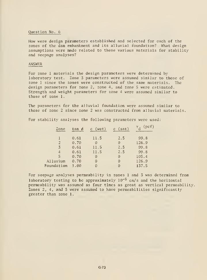
Question No. 6
How were design parameters established and selected for each of the
zones of the dam embankment and its alluvial foundation? What designassumptions were made related to these various materials for stabilityand seepage analyses?
ANSWER
For zone 1 materials the design parameters were determined bylaboratory test. Zone 3 parameters were assumed similar to those ofzone 1 since the zones were constructed of the same materials. Thedesign parameters for zone 2, zone 4, and zone 5 were estimated.Strength and weight parameters for zone 4 were assumed similar to
those of zone 1.
The parameters for the alluvial foundation were assumed similar to
those of zone 2 since zone 2 was constructed from alluvial materials.
For stability analyses the following parameters were used:
Y fpcf)Zone tan c (wet) c (sat) d ^
1
Question No. 7
Zone 2 material does not meet the generally accepted criteria for a
filter against zone 1. What is Bureau criteria for use of filters
and what was the rationale on the need for designed filters at Teton?
ANSWER
The grain-size curves that were available for design are included in
exhibit 24 which has been distributed to the Independent Panel and
the Review Group. The interpolated average Dg^ size of the zone 1
curves from 21 preconstruction borrow area A samples is approximately0.122 mm as shown in the attached figure 1. Using the average Dg^
size of the zone 1 as 0.122 mm, the most generally used filtercriteria (Terzaghi filter criteria) states that the D]^5 size of the
filter must not be greater than five times the Dg5 size of the
protected soil (base) (reference 1, p. 175) and this requires that
Di5 < 0.61 mm. Plotting this diameter on the attached preconstruc-tion grain-size curves for the zone 2 material from test pits C2,
figure 2, and C8, figure 3, shows that the zone 2 curves do in fact
satisfy this filter criteria.
USER filter criteria are as follows for subrounded particles and
reasonably well-graded filter materials (Earth Manual, 2nd edition,
p. 307).
R
R
50 percent size P.M. n ^ ro jr/^ = rr.
1 = „ w = 12 to 58, and50 50 percent size B.M.
15 percent size P.M. ,_ ^ .„,n = r 1 ^
D w = 12 to 4015 15 percent size B.M.
The average D]^5 and D^q sizes of zone 1 from figure 1 are approximately
0.006 mm and 0.03 mm, respectively. Using these values, the USBR range
of gradations for a filter is shown on the grain size curves for
TP-C2 and TP-C8 . It can be readily seen that the zone 2 curves lie
to the right of the implied range. These requirements are, as
stated in the Earth Manual, "given as a guide for filters used in
canal structures or other hydraulic structures involving high-water
heads where rapid dissipation of uplift pressure is desired" (Earth
Manual, 2nd edition, p. 306).
In addition, concerning filter width, the Earth Manual states as a
guideline (p. 309):
"(4) The filter layers for coarse filter material (3-inch maximum
size) are usually not less than 8 inches in thickness, and layers
of finer filter material are often of 6-inch minimum thickness.
However, for severe field conditions such as high head, variations
G-74
in base material, or filter gradations which are near the extremecoarse limit, the minimum thickness of 8 inches may be specified.For zoned filters these minimiom thicknesses may be specified andare maintained for each layer."
Clearly, the filter criteria given in the Earth Manual are developedfor the extreme conditions of rapid dissipation of high hydraulicgradients with relatively thin layers of filter material with theimplied possibility of filter surging.
The "* * * rationale on the need for designed filters at Teton" is
that filters were definitely needed and that a thick zone of siltygravel which was close to USER criteria and which did in fact meetthe Terzaghi filter requirements would be used rather than a processedfilter whose expense was unjustified. In addition, excessive exitgradients were not expected to be involved.
Cedergren, a generally accepted authority on seepage, states thefollowing in his text (reference 1, p. 178):
"If a protected soil is a plastic clay, the piping ratiooften can be much higher than 5 or 10, as indicated by U.S.Army Corps of Engineers practice previously noted. But ifcohesionless silts, fine sands, or similar soils are in directcontact with filter materials which have piping ratios muchabove 5 or 10, erosion is very likely to occur."
In this statement Cedergren' s reference to "much above 5 or 10" is
essentially allowing that the Terzaghi filter criteria may be relaxed.If the upper filter limit criteria of D2^5/Dg5 < 10 are used for theTeton material, the D^;. size of the filter may be as large as 1.22 mm.
The range of D filter limits for these criteria (D]^5/Dgr < 5 to 10) is
shown on the grain size curve of TP-C2 and TP-C8.
The following quotations (Justin, Greager, and Hinds, ref. 2, p. 690)demonstrate that it has been generally accepted by authorities in
embankment dam design that bank run material may serve very adequatelyas a filter and a drain:
"There are many cases where a single layer of run of banksand gravel is all that is required to serve both as filterand drain. One should be sure that the sizing of the materialwill be such that impregnation will be insignificant."
They continue
"In many cases a run of bank sand gravel may be used success-
fully, as in fig. 21. So long as the run of bank materialcontains the necessary range of sizes, it will make its own
G-75
filter if thick enough. Fine sand or gravel when placednext to stone will perhaps run right through the intersticesin the stone, but the larger gravel will stick and a filterwill thus be gradually built up. The first thing to be sure
of is that the previous run of bank materials contains someparticles that are of greater diameter than the biggest voidsin the stone."
Reference 1 - "Seepage, Drainage, and Flownets," H. R. Cedergren,John Wiley and Sons, 1967
Reference 2 - Justin, Creager, and Hinds, "Engineering for Dams,"John Wiley and Sons, 1945
G-76

(3.SJ)Kurtau of Kcclarvatlon
OHISSVd IN
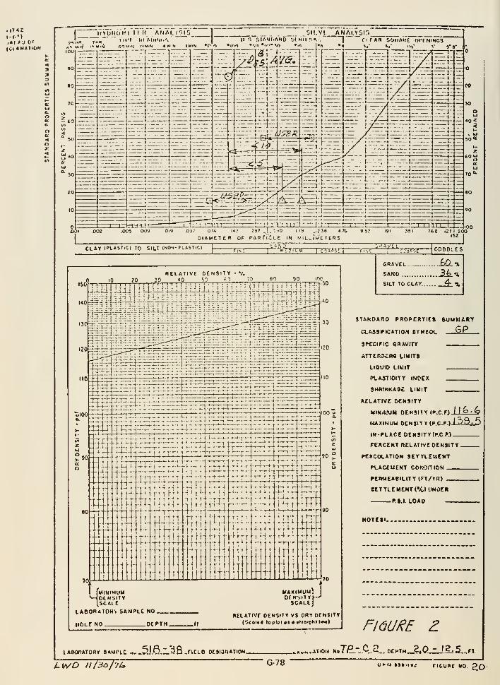
I f.M,•( /J Of
[ijVijHoMriirfi " AMALfr-iG"
]'_ "'_"
. __.. . 6i(.yi_ ANALTsir.^]"'
\~ ,„„ " liMI III AOINI.'."
I
~II •. r.lAsi.AHO ifllll'-.".,
I' ClfAR SOllAMt OrfNIHOSA'- *AltJ 1'^ M.«J f.lMiN PJMIN Att'H IMIW •f'O •l'»0 •vi*-»"*<0 • "« ]»B "4 %# t,' IV," V
COl .002 Oi9 X)37 OM l«? 25*'. '..->0 I '^ .IJi9 • tDIAMETER OF PARfl'CLE IN MIL^'wETERS
CO
JO
oUJ
•0?
so*
76£ 121 200152 I
CLAr (fLASTiCI TO SILT (NON-PL«SIlClIcoi'?r
---!:-::-''^f
ISO
140
REIATIVE DENSITY30 40 'jO f.->
5100
.90
10 ?0 30 40 'jO f) 7? 90 90 iOO. .
jm^ iiiijiiiUJIii' i;;iii:iilJ-LLLL jJjiilLliJ^i^ B-i]'
-•-fc-r-rv.::.-
—i-T- <—+1-'-
JU-p r^-~j£:2Jl—-.: .r4 J^'-riIL"^4xrrr:lrrrr ,.:.--i,.t-rrz:
;:..-!.;
,
J3
m
-» r-4-i 4-'—f-r - -^ I— r-T •! • • -•t i
l-rr''"'"'"*'!"'" '
—
'— 1"^—' ^~""I~
_i.i4 .i.|-,-fUi._.-r. ..,.i..,4J_-^-_l.^-r—^— ^ J—t--,^ -,•-
—
•^t4- --4—t-ir-'-T^-r" v-.-H-i--^- i-U-^- —
—
-f—,-^--r— -
-f-^-l- -h'-riI
''—'-'-'
—
'—f-
—
-^—-~-^—~H—' H H——'-T-
,t n .
,, ,.;. -(.,1-1,. }i -i....i-,.-ti.. .i-i.-- ^J^.
LABORATOH^ SAMPLE NO
HOLf NO OCPTH.RtLATIVr DENSITY VS DRY DENSITY
(Scoi«4 topioi at • ttfo'c'^i ii*^)
CRaVEL 60 gSANO .36.1SILT TO CLAY 4- t.
STANDARD PROPEKTieS SUMMARY
CLASSriCATION 8TKf-0«. 6Ps^tciric eRAvrrr
ATTtRKfW LIMITS
LIQUID LIMIT
PUA5T10ITY INPCX
SH«H««(A9£ LIKIT
RELATIVE DENJITT
KmrfiSJKI nFn<nv<>r r) 11 b • fo
HAdNuu r>rM^iTY(pr t) I 59, 5
IN-PLACE DENSITY (P.C.r.)
rCMCENT nELATIVE DENSITY .
PERCOLATION SETTLEMENT
PLACEMENT COMOmON
PEWMEABILITY 1?T/1R)
eETTL£MENT(%) UHDEB
P.S.I LOAO —
NOTCti.
n6(//e/^ £lABOnATORY SAMPLE ..w .Sj.Q.I.^8 -TICLO OESIOMATION. _i.>v»>ATlOU NsIfL-.^.?... ot^r»_^.Q.zJ^ 5„M.
G-78 Uf> (J •!• ttti ncitm MO ^(^
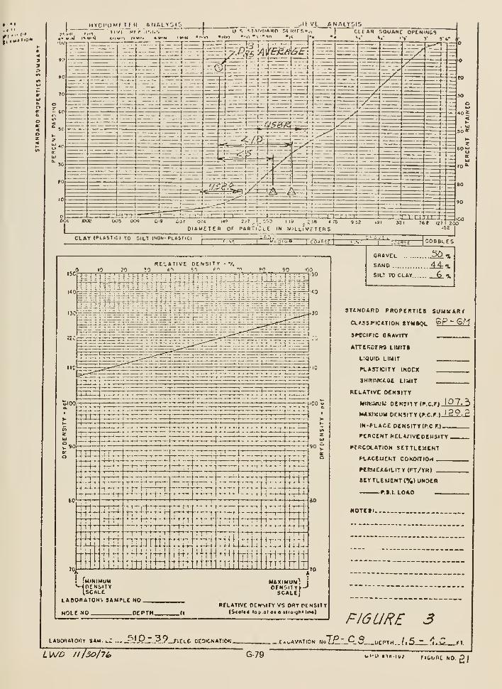
I IITCI'QMI/I rH aflALrDK-..,11 ti.n il'/T Ml >
JO
--44Jj_L
TlHF4 1 ; .-,-1
TT1n]trr T
! fuiNIMUM
LABORATOHV SAMPLE NO.
HOL£ NO . .DEPTH.
MAXIMUM!I
orNr.iTYt-'SCALtJ
R£LATIVC OCNSIIV VS ORT PCNSITT(S<ol«tf fot-.ot 0« o ilroight lin«)
LAUORAIOlr SAM. ,.C -.- fil P ~ 39 fin r CC5lCNAT:0^•.
F16LIRE 3C»v,AVATpON UalJzJ'_C5 tiCPTH.
G-79 bi-o tmiu; ribijnc Mo£l
Question No. 8
Since much of zone 3 material is the same as zone 1 silt, why wasn'ta filter layer included between zone 3 and the zone 5 rockfill?
ANSWER
The zone 2 pervious material upstream from the zone 3 would controlthe phreatic line and prevent- saturation of the zone 3. No water,other than precipitation, was available to carry zone 3 material intozone 5; therefore, a filter was not required.
G-80
Question No. 9
Surface treatment, by concreting or nonpressure grouting of joints,fissures, and openings in the rock beneath zone 1 was not a require-ment in the construction specifications. Was surface treatment ofsuch rock defects considered unnecessary or were the defects unknownto the designers? Explain the following statements from the DesignConsiderations for Teton Dam :
a. Page 9, paragraph IV. A. "Erosive seepage under the embankmentwill be eliminated by injecting the foundation with a groutmixture."
b. Page 10, paragraph IV. A. "To cover exceptional conditions,the specifications also provide for blanket grouting so that thecurtain can be reinforced in areas where the near surface rockin the bottom of the cutoff trench or key trench contains openjoints or cracks -or other foundation defects."
Considering the condition of the near surface rock, it does notseem credible that required treatment not be included in the specifi-cations .
Submit evidence that the design considered use of gravity grouting offractured rock. Also, forward instructions provided to the projectengineer on the type, extent, location, and other information aboutthe purpose and determination of need. List the types, methods,etc., of rock treatment from which selection was to be made. Whatbasis was to be used for selection of one method over another?Submit evidence of the guidance provided by design to the constructionoffice.
ANSWER
Answer to First Part of Question in Sentence No. 2 "Was the surfacetreatment of such rock defects considered unnecessary * * *":
The surface treatment of any rock defects was considered necessary.This is made clear by the Design Considerations, paragraph IV. I,
page 16 which is quoted below:
"I. Open Joints, Cracks, and Springs
Open joints or cracks found in the bottom of the foundationkey trench and cutoff trench are to be treated by (1) cleaningout the crack with air and/or water jets, (2) setting groutpipe nipples in the crack, (3) sealing the surface by caulkingand/or grout, (4) drilling, if required, and (5) low-pressure
G-81
grouting through the nipples. Springs may be treated in asimilar manner. However, if considerable water is involved,it may be necessary to extend grout pipe or dewatering pipesthrough the fill from gravel drains until the embankment levelpermits sufficient grouting pressure to seal the spring.This would usually be part of the contractor's dewateringobligation."
Answer to Second Part of Question in Sentence No. 2 "* * * or werethe defects unknown to the designers?":
The above quote from the Design Considerations in conjunctionwith the facts that (1) 17,824 feet of core in 102 preconstructiondrill holes were obtained, (2) a test grouting program was performedin 1969, and (3) extensive pump- in tests on the right abutment wereconducted in 1970 make it clear that the Bureau was well aware thatthere were defects in the foundation which would require treatment.
Answer to Third Sentence, Part a and Part b
The statement in the Design Considerations, page 9, paragraph IV. A.
"Erosive seepage under the embankment will be eliminated byinjecting the foundation with a grout mixture." is under theheading entitled "Foundation Pressure Grouting" and is in itsfirst section entitled "General ." This statement is the firstsentence in the first paragraph of this section and is simplytrying to give the field personnel a general feeling as to thefunction and rationale of the grout curtain. The term "erosiveseepage" was meant to be a general concept and could just as wellhave meant that a high flow of water under the foundation woulderode the downstream alluvial foundation or would erode the zone 4
berm at the downstream toe. It was not the intent of the designersto imply that the grout curtain was substituting for surfacetreatment.
The statement on page 10, paragraph IV. A. "To cover exceptionalconditions, the specifications also provide for blanket groutingso that the curtain can be reinforced in areas where the near sur-
face rock in the bottom of the cutoff trench or key trench containsopen joints or cracks or other foundation defects," is again under
the heading entitled "Foundation Pressure Grouting" and under the
section entitled "General ." Here the reference is to a specific
area, namely, "the near surface rock in the bottom of the cutoff
trench or key trench." This was to provide a vehicle for ensuring
that the grout curtain was effective.
G-82
Question No. 9 continues with "Considering the condition of the nearsurface rock, it does not seem credible that required treatment wouldnot be included in the specifications."
ANSWER
The Bureau considers it difficult and many times impracticableto specify the exact treatment of a foundation without examining thefoundation firsthand. The Bureau's general policy is to have design,construction, and field personnel examine the foundation prior toplacement of zone 1 material and to decide at that time the method ofsurface treatment. Whether the surface treatment should be specifiedat the time of the cutoff trench inspection or whether it should beincluded at the time the specifications are written is debatable.
Question No. 9 continues : "Submit evidence that the design considereduse of gravity grouting of fractured rock."
ANSWER
To the best of our knowledge there are no travel reportsor design notes that specifically say the designers consideredgravity g^out . However, the Bureau considers the fact that it diduse gravity grout as prima facie evidence that it did considergravity grouting in the design.
Question No. 9 continues : "Also forward instructions provided tothe project engineer on the type, extent, location, and otherinformation about the purpose and determination of need for surfacegrouting.
ANSWER
In October of 1973 when the left abutment key trench wasopened for inspection, a meeting between the designers, the geologists,and the construction personnel was held in the field to discuss howkey trench walls would be treated. Discussions between the designers,the geologists, the construction liaison personnel, and the fieldpersonnel resulted in a verbal agreement that gravity slush groutingwould be the most reasonable and economical method of treatingthe surface of the key trenches.
To illustrate the fact that group decisions involving design,construction liaison, geology, and field personnel were standardpolicy and that instructions, albeit many times verbal, weregiven to field personnel, a memorandum dated March 14 from the fieldand a travel report of March 29, 1974, concerning examination andtreatment of the voids encountered in the right abutment key trenchare appended.
G-83
Question No. 9 continues : "List the types, methods, etc.
of rock treatment from which selection was to be made."
ANSWER
The following types of surface rock treatment were considered:
1. Sealing and guniting as the embankment was raised2. Shotcreting3. Concrete wall facing4. Slush or gravity grouting5. Blanket grouting upstream and downstream from the key trench
faces6. Filter construction along the downstream face of the key
trench
Question No. 9 continues : "What basis was to be used for selectionof one method over another?"
ANSWER
The basis for the method of selection was verbal discussion of thepros and cons of each method by experienced personnel from design,construction liaison, geology, and the field.
Question No. 9 continues : "Submit evidence of guidance providedby design to the construction office."
ANSWER
Guidance provided by design came in three forms: (1) by verbaldiscussion with the field personnel when design personnel visitedthe site, (2) by telephone contact with the field personnel, and
(3) by travel reports written after visiting the damsite.
As an example of "guidance provided by design personnel to theconstruction office" a travel report dated November 23, 1973, whichwas written after a review of the cutoff trench excavation priorto placement of the zone 1 embankment, is attached.
Paragraph 4, page 2 of this report specifically gives guidance inhow to treat "the large mass of loosely jointed, blocky rock on thedownstream side of the left abutment trench."
The report gives guidance (which was later revised) by stating "Thefirst condition can be treated by sealing and guniting in selectedareas as the fill is placed."
G-84
ir'.- 1 /-/
It:
IN REPLYREFER TO:
BUREAU OF RECLAMATION
TETON PROJECT OFFICEP.O. BOX 88
NEWDALE. IDAHO 83436
March 14, 1974
Memorandum
To: Director of Design and Construction, Denver, ColoradoAttn: 1300 and 220/
From: Project Construction Engineer, Newdale, Idaho
Subject: Proposed Treatrent of Fissures and Cavities in RightAbutrrent Key Trench - Specifications No. DC-6910 -
Morrison-Knudsen-Kiewi t, Teton Dam, Pov/er and PumpingPlant, Teton Project, Idaho
The geology of the fissures and cavities which have recently beenexposed in the excavation for the right abutment key trench isdescribed ill tiic oLLai-iieu lepurl. F re] iiiii fictry drdv/ings nu.Toers549-147-131 and 549-147-132, and photographs of the fissure zonesand cavities are also included.
The follov/ing proposed treatrr-ent of the fissure zones and relatedcavities as discussed with meiri>ers of your staff is summarized as
fol 1 ows
:
Locate t.hp ravit.ipe: with Pilot ?.P'^l9 holes u'^strear? 2nd dC'-Ti-
stream from the foundation key trench using an air-trac drillset up on the original ground surface. The estimated pilothole footage is about 500 lin. ft.
Drill 10-inch diameter holes (8" casing) to intersect cavitiesat locations determined by the pilot drilling and approxi-mately as shown on Drawing No. 549-147-131. Ten-inch diameterholes as follows:
a. One l0-1nch diameter hole to intersect cavity In fissurezone at Station 4+44 upstream. The estimated depth ofthis hole is 60 feet.
b. One 10-inch diameter hole to Intersect cavity in continua-tion of above fissure zone at Station 4+21 davnstream. Theestimated depth of this hole is 70 feet.
CONSERVE\AWERiCA'3
ENELROV
Save Energy and You Serve America!G-85
c. One 10-1 nch diameter hole to intersect cavity In fissurezone at Station 3+66 upstream. The estimated depth ofthis hole is 70 feet.
d. The need for a 10-inch diameter hole 1n the continuationof the above fissure zone davnstream at Station 3+45 is
questionnable; however, the final determination of theneed for a larger hole in this area should be based onthe results of the pilot hole drilling.
3. Fin the cavities vn'th high slump backfill concrete dischargedInto the 10-inch diameter holes (8" cased) described above.Discussions with the prime contractor indicate that backfillconcrete using a 4-bag mix will be the most economical fillermaterial for these cavities. It is anticipated that a local
ready mix concrete supplier will furnish the concrete to the
prime contractor at a substantially lower price than can bebatched on the job with the contractor's batching facilities.
4. Place nipples in the voids along fissure zones in the bottora
of foundation key trench and embed in concrete during place-iTKnt of grout cap. Trenches 3 to 5 feet deep and about 3 feetwide have been excavated along the strike of the two mainfissure zones as shown on drawing ^;o. 549-147-132. Nippleswill be placed in open joints or holes in the floor of the keytrench near centerline at Stations 5+03, 5+68, and 6+18; andabout five feet left of centerline between Stations 6+03 and
6+08.
5. Intersect fissure zones at vcirtuus u'euuis in Llie uOutOiTi of kdy
trench with grout holes, then grout voids using grout mixesand procedures previously established on the project for grout-
ing similar areas.
G-86

The estimated cost for accomplishing this proposed work is as
follows:
Work or Material Quanti ty Unit Price Amount
1. Mobilization and demobilizationof drill equipment For the lump sum of 1 ,000.00
2. Alr-trac pilot holes 300 11n.ft.,5.00 1,500.00
3. Ten-inch diameter holes with8-inch casing 200 Tin.ft., 35. 00 7.000.00
4. Backfill concrete 350 cu.yds..30.00 10,500.00
5. Block cavern entrances For the lump sura of 1,000.00
Total estimated cost $ 21 ,000.00
G-87
It Is critical that this work begin as soon as possible to avoiddelaying the contractor In his scheduled grouting program on the
right abutment. Backfilling of the cavern areas with concreteshould precede grouting to prevent leakage of more costly groutInto the large voids. The contractor has indicated that pilotdrilling could begin during the week of March 18 and begin fillingthe cavities in early April.
I suggest that representatives from your office visit the projectduring the v/eek of March 18 for an examination of the fissure and
cavity zones and discuss v/ith our staff the proposed treatn:ent of
these areas. To expedite the early commencement of the treatmentwork. It is requested that authority be granted this office to
proceed with price negotiations with the contractor.
Your early reply would be appreciated.
Enclosures
cc: Regional Director, Boise, Idaho
Attn: 200 w/Enc.
Note to Regional Engineer ;
We would appreciate having a member of your staff present during
tbe visit of the Denver Office representatives to the Teton Project,
G-88
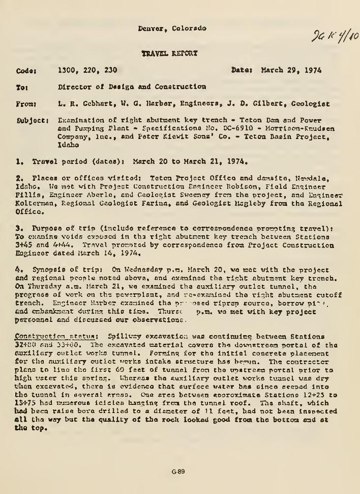
Pcaver, Colorado _, ,,
TIUIVSL ILETORT
Codai 1300, 220, 230 ttttat March 29, 1974
Tot Director of D««lga and Construction
FroBii L. R. Ccbhart, W. 0. lUrbor, Enslneors, J, 0. Gilbert, Gcolosiet
Subject t Exaninatlon oC rljjht obutnent k«y trench - Teton Dam and Powerfind Pu3T)in3 Plant - fpeclflcatiooo Ho, DC-6910 - Morriaon-Kr.udaenCompany, lac. And Peter Klowlt Sons* Co. * Teton Basin Project,Idaho
1, Trarol period (dates)! March 20 to March 21, 1974,
2« Places or offlcoo visited: Teton Project Offtco and daiMlto, Kavxlala,
Idaho. Uo ra«tt with Project Conotruction Er.ttinGcr Poblcon, Field EngineerFillls, Znginaer Aborlo, and Ceoloqtat Sweeney frcra the project, and Iln'^inear
Koltcnoan, Rogional Ccologist Farina, and Geologict ll^glcby fma tha Re&ionalOffice,
3* Purpose o? trip (include reference to coTro2T>ondeneQ vroCTtln? trarel):To exftraina voldn cvpoacd in tha rlsht abutncnt key trench bctvcen Stctiona3+45 and UryhU, Travel pror.otod by correapondenco froa Project ConctructioaEQfilneor dated llsrch 14, 1974.
^, Synopsis of tripj On Wednasday p.n, March 20, va tact vith the projectand rcRional pconle noted above, and mt^nained the rirrht abutTaent key trench.On Yhursd.iy a.m. March 21, va csanincd the auxiliary outlet tunnel, theprosrosa of vork on the pcw»rplant, and VG-cy.aralocd tha rirjht abutaent cutofftrench. Engineer r.-irbcr cannined tha pr need riprap eourco, borrov pi~<,find crbanfcacnt during this ti2«, Thurrt p.n. wo aet with key projectpGrconnel end diccusficd our observatlonc.
ponnfctnictioTi ntptum Spillvrsy ©xcavatloa wan continuicc between Stations32+i50 end 33-rOO. The excavated cateriol covers tha dovnetreaa portal of thoftartllary outlet vorlto turmol, Forsilni:? for the initial concrete plaeonentfor tho ftuj'.iliarf outlet »-n:rk8 intake structure hs« ber»ja. The contractorplfino to line tho first 60 feet of tunnel fron the itpstrcaa portal prior tohtch t'ater this cnrlnjt. l<"hcrnas tha fiuxlllnry outlet vorks tunnel uas drytshon oxcevated, thcro ia cvldcnco that eurface V4ter bus cinco eccped Intotho tunnel in aoveral ernas. One area betvaen tonrorimate Stations 12+23 tolS-S-75 had numerous Iclclcc hjn?;in<? froa tha tunnel roof. The alLnft, vbichbad been raioe bore drilled to a dlssetcr of )1 feet, had not b^en Insooctedell tha way but tha quality of tho rock looked good froa tho bottoca end attho top.
G-89
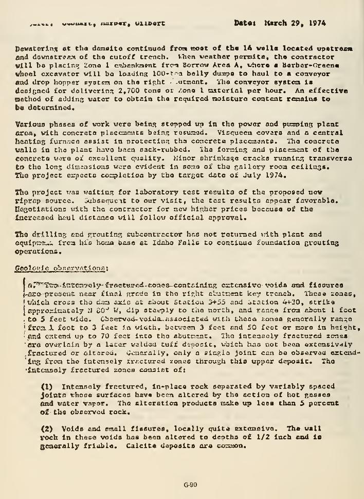
y.i.«i.« vwwtMui., 4ittrp«T» uxiPQrc Datoi March 29» 1974
Dfivatorln,<s at tho doraaito continuod froa coat of th« Ih veils located upstrftcn
end dovmstrffJtn of tho cutoff trench. V.Ticn weather pomltu, tho contrnctorVlll bo placlr.i? Zona 1 cn:U>cnlcaffnt tra Borrov Area A, vhoro a Barbcr-Gracnavhool cxcttVrttor will bo loading 100- f -a bally duni;>a to haul to a coavoyorand drop hopper pyotcia on tho rip;ht -ticmont, 'i'ho conveyor syBtcia la
<leol(;ncd for dollvcrln:? 2,700 tono ot /-ono I taatcrinl per hour. An effective(aodiod of adding vator to obtain tha required noietura content rexaaina to
bo dotemlnod.
Vorlouo phsocs of work vera belnj^ ctopped up In the power and punipln^ plantcr&a» vith concrcto ploccaoncB bain?; rocu^aod. Vic<ruccn covaro nnd n c«uitral
heottns fumnca nsaist in protcctlurt tha concrete placcaanto. Iho concretavallo in tho plant havo baca Dack-rubbed. Iha foraim; and placement of theconcrete u.rra oi! c^callant qiiaiity. Minor ohrinlcaga cracka ruanin;; transvcrsoto fcho Ions diminaioua were evident in soma of tha ^^nlloTy rooa ceilings.TliO project cxpectc cospietion by tho tarfiot data of July 1974,
Tho project vaa waitinst for laboratory test reeulto of tha proposed novplprnp source. oubsnnucTt to our visit, the teat resulto appear favorable,Ecgotinttonc vd.th tha contractor for new hlohcr prices beccuea of thatncreaocd b£:ul diotnaca will follow official approval.
Tho drilling end jrroutin?i; srubcontrcctor has not returned xrtth plant andequlpt^c::^'. frca his hcoa baao at Idaho Falls to coutiuua foundation grouting0|»eratlons.
pcoloi'ic obnervrtt<onfi t
Iar^Tts^'lntrers-sely-froettsjfcd-cones-contiilnlnR cstcnalvo voida aod flooures
f-ero- proiseiifc iieor final jrrcdc in tho rlr.ht cL-jtnent kerf crcach. llicae zonae,•vj'atch croia tha daa Axlo at about fitatiou >*-iJ5 and Jtaclon <V+-30, strlko
Icpproxiuatoly 21 oO"^ V/, dip otceply to cno north, and rcnqa frca about I foot
. to 5 feet wide. Cbserwed-voida^iisaociated trtth thcc<s zonaa Rencraiiy raniio
Ifrca, X foot to 3 fviet in «.d.ciCh, bctvatrn 3 feet and 50 foot or coro in hal^ht,
•end cntcnd up to 70 feet into tho abutinEnt, Tho Intenocly fractured lonsa
' ex& ovarlcin by a later weldou tuff d2nocic, vbich ha^o not been oxccaslvaiy.frnctured or aitcrGd, »;cnerally, only a flln,c!;lQ joint can ba obaarvou crtcnd-
'iRg frotn tho intensely frjictured zoneo throujjh thio upper deposit. Xho'l&tcasely fractured aonca conaiat ofi
(1) Intcaifloly frnct\n:ed, In-placa rock aeparated by variably spacedJoints ^rhooo Burfacoo havo been altered by tha a^itloa of hot {•asaos
end t^atcr T.'^por. Tha alteration products caake up Icoa than 5 percentoi tho obcorvcd rock.
(2) Voidis and email fiesuraa, locally quitd cxtanoivo. Tha wall
roch In theco voida has bean altered to deptha o£ 1/2 Inch and is
QQaerally friablo. Calcita dapoaita nra corsaon.
G-go
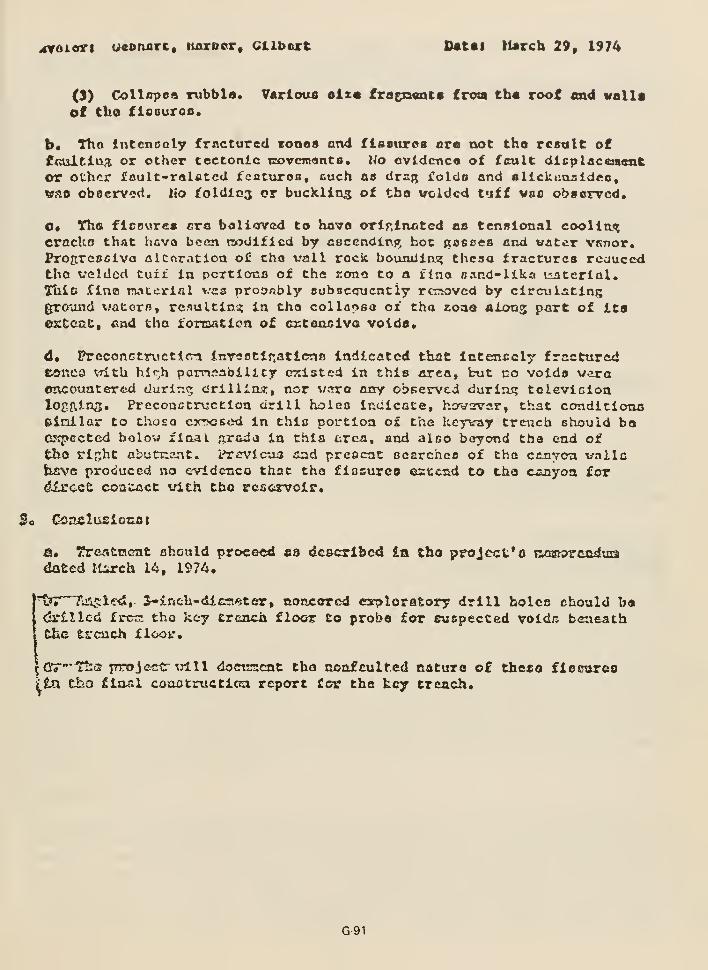
^iTOiori u«oruirc» luirber, Cllbart ])«t«l March 29, 1974
(3) Collapaa rubbla. Varlouo elztt txa^pmxf froa th« roof «n4 vallaof tho flcourofl.
b* Tho Intencoly frnctured cones and flsstirea ore not tho rcatilt offcialtin^ or other tectonic tcovemantB, Wo cvldcnca of fault dlsplacensntor other fault-ralAtcd tcaturoo, cuch as dra;; iolda and sllckcosidfto,
vso obacrvcd. lio ioldicz ^^ buckling of tbo voided tuff wae observed.
C* Tha flceurca era boliorvcd to have orirlixated as tensional eoolltx<?
cracko that hava been ttodlficd by aocendtng hot (tasces and water VKnor.Progrcsoivo alcoration of cho vail rock boiiiuliai? theso fractures rcauccdtho welded turf la pcxtlono of this rona to a flno Band-ilka tuiterial,
TUio flna roaterial vcs proDnbly aubscqucntly rcrioved by circulatingground vatorB, rc.iultln^ in tho collaosa oi tho zoaa aixmz part of ItsexCcati end tho forcaaticn of crtonaiva voids.
d* PreconGtrvctlcn inirsatlr.aticna Indicated that Intencely fracturedE«nc3 \,Tith hif:h pamsability existed in this area, but no voida veraencountered duriui; drillinj!:, nor varo any obt:ervcd during tolevlGionlogftins. Preconctructlon drill holeo indicate, hoftrsrwar, that conditionseinilar to thoso cyycstid in thic portion of the keyvay trtnicb should baexpected bolow final .T^rada in this erca, and alco boyond tha end oftho rifjht abutx:c!nt. I^rcvlcas and pretJcat oearchca of tha cflnvoTn vailoSurve produced no evldcnco that tha fiosurco cstcfid to tho canyon fordixcct contact vith tbo reservoir.
e» Tr&atrjcnt ohonld proceed as described In tho project'© ooaKJrandatadated llirch 14, 1974,
^^r~Tin5:l'r<*, S-inch-dicaieter, nonccred csrploratory drill holes chonld b«,drilled frca tho key trench floor to probe for cucpecced voids beneaththe trench floor.
^Orr"'^'? rrrojectr nxlll doctcscnt tho nonfculfed caturo o£ the«o flccureoitn tho flaal coactructicsa report ienc tha key trcach.
G-91
»»•.«««'«». I uoun«r»f naroer^ Giiocrt Datot March 29. 1974
6* R«eo3Bm«nUAtloa«i tl<m««
L. B. Gebharx
Copy tot Ccglooal Director, BoIbo, IdahoProject Conacruccion hlis^iacer, Nevdale, Idsbo
Blind toi 210222
^23013001305
LaCcbhxart/WCUarbftr/JDGi lbort : cad
NOTED: _.
— -E-<3; Arlh'ur —DIRlCTCRDESIGN AND COrJSTRUCTION
G-92
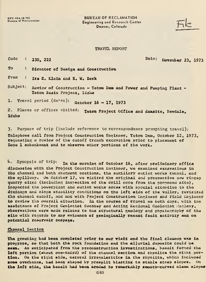
DFC.40A (8-70) BUREAU OF RECLAMATIONDU...U .f P.cUm.ilon
Engineering ond Rcscorch Center
Denver, Colorado Kt
TRAVEL REPORT
Code: 230, 222 ^^^' Jioveaber 23, 1973
Director of Dofliga and Constraction
Ira S. Ueln £a<l &• V« Sock
To
From
Subject Ecvlcv of Cozuitructlon — Tatoo Da» aad Pover and Puapias Flaxit -
Toton B&aia Project, Idziho
1. Travel period (dates):^^^^^^^ ^^ ^ ^^^ ^^3
2. Places or offices visited: ^^^^ Project Office and d«aite, Hcvdiao,Idaho
3. Purpose of trip (include reference to correspondence pronipting travel):
lolephone coll froa Project Coaatructlon Eni^lnQer, Teton Daa, October 12, 1973,requastinf^ a review of tho cuCoff trench excavation prior to plsceiacnt of2oQO 1 eabankuont end to observe other portions of tho work.
k. Synopsis of trip: j^ ^j^^ is>nilni? of October 16, after prellalaary officediscussion with the Project Construction tn^laoer, ve oxsinincd ftxcavatioua intho channel sad both abucic^nt oectlona, the auxiliary outlet borks timnel. andthe opillvay. On October 17, vo isited the orlr;laal and proonoctlva n«w rlpra?quarry oltes (Includin?; Inspection of the drill coro froa tlie proposed fiito) ,
Inspected the powerpi^nC end outlet vorica areas with apoclal attention to thodralnago and olopa staollity conditions on tho left aide of the valley, revisitedtho channel cutoff, «nd oat with Project Conatrvrctlon Lnrxlneor and Field tlaglucer
to review tass overall oltuatlon. In the course of travel on both days, vith tnoftdslotanca of Project Geologist Swcen«y and Acting Ketilonal Geologist /larieoy,observations wero uusda related to too structural f^eology and physio ,-rraphy of thi»
0lto with rci^arda to any avlucnco of gcoloslca 1 ],y recant fault activity anU onpK>tgntidl reaorvolr eeepaga,
Channal Soctica
Tho grouting had been conpletad prior to oar rlslt end tho final cleanup vaa laprof.reos, so that both the rock foundation and tha &lluvlal daposlts could ba•an. Aa anticipated froa tlie preconstructlon Investif^atlons, basalt forr^cd tho
left portion (about one-tiiird) of the channel section and rhyollta tha rl~nt por-tion* On the rl^ht aide, natural irroo'.ularltica In tha rhyollta, vhlcii incluaadsoaa overbani:;a, hod been shaped by presplit blaatlnjc to stable steep slopea. On
tha loft aide, tha basalt had baca arodod to reaarkably apooth-curved clooa alopea
G-93
of hBr4 frooh dcnsa rock vhlch re-yulrad mlntmil c}caTiu»», Th« flatness oftb« clinnnel bottoni ovur « 30«)-fcot lencth la both the hard basxlc ocad ooftarrhyollto Man outatandint;. Tlmro wnr« no oroalonnl elota. crovlcea, or pot-holcR* Tiio bottom olcvatlon rnn^'.cd frora elevation 4931 to 4934 feat. Yi\*
phyolcal coadition of tuo rhyollto, aa veil nsi tha bcsalt, waa r;ood. 'D\era
Mata no faulta or aiioar zor.nn* lioth tha low-utcpin'x, f lov-bod<lin,t jointsand Btoop tcnolcmrvi coolir.;^ jointo were prctloniiiiintiy tl-.:lit, so Llukt gtouclxtg
and rcuujveJL of Ioogq joinc blockii vor« rcndlly acco!upllahed.
Drainfige of vatcr not olrcodr Intercepted by v«ll points in tho Af'ivelly
cUnnncl nll*ivlun wno boinsj offcctivoly Itandled by punpinrt froa ahallovr to«
drains. Tba loworuost cut olop>ifi, v/ilch vera excavated in a i3-t'ooc-t.\iclc
Ijxyav of f lncr-tcxturr<l allvivlviri, vor« variably Cioist to wot and locally
eacplnR. /JvthouRU a littlo rock jxad uocjj placed on t:ic iipstrtuia rlgat comerbocau3Ci of nor>f5 fit^ns o! Inci;>i.:iiat iiU)taI>iliLy in t\:Ls Ilacr-tuxturcJ ailuviurii,
olopo stGbility wao p.ood at t'n« tti-ia of this iiispectioa nnd. t'aa outlook, favor—cblc. In tiiQ nrccoii.itructlon inve5ti<:;a.tior.s t!>e occurrc-Ace. of 001.1.3 clayey andullty oo.dlraants in tha lowcnwst part of tl\o cliancal fill 'uaJ be^n indicated
by Dil-101 and Li'd-102. VTaea tUa c^uionoi excavation had pouo Chrou;7.a about (;3
feat o£ f:raval» tho f iao-tti:!iturcJ Las<&l uicnntr of th^ aliavial fill was rtsacliod.
Kine aunor liolea vcro than drilled to depth of 15 to 23 feet to dotcrnine ita
ConflRuratica and caarActcrictica eorc conplutely than vds practicable ia tho
prcconELructlon inviestiracloac. Tna basal fins-teiituxcd cnancel fill licnoaic
lo prodoTjlnnntly a boracirliac iDL-CL eoil witi: s.a avprcciablo content of fiaaOtmd. r>trinp,cr3 pjid leiicto of sandy and rrovally coil ure preaeaic tfirou^hout
tho deposit, ae Indtcacad in tha cutoff fclopea by local eccpaces. 'i'hesc strins*-
OJTS and Icn.ses arc r.uD&t obvious toward tas top and bottoti of tho unit. The
COnfcGct with tha ovorlyli.K rrav&i way irrcitulnr vith ccvoral feet of relief.
Tha diBtribuLion of tha variouc alluvial uciio vao recorded as the cicr.vatioa
proprnsncd by GyntE^iatlc fe:t.olo?ic aappinz t5U{.portfcd by laboratory clsi.uifica-
feion of caapioa. XhcGO data will bo coupiitd in cetailcil t.apo a-vA occtiona.
teft Abutnant Area
EEoavatloa :ind Rroutlo?; In tho cutoff trench &ra nearly conpleted. Tha vork
la tha diver:;ion tunnel and outleC workc facllitiea ia in an advanced stata.
Tho f5j;outin/» hca bcjea reccotlv reported on by Hr. Gi'.hlmxt baaed on hJLc Uvcnec-
felon on October t!-ll. Tlio follovtng resiarke pcsrtAtQ to 60w>* localiztd condi-
tions xrequixina furthur attcntioa.
Theao eiroj (1) Tho larrc taaea of loooely jointed, blocky rock on tha dounatr«£aa
elde of tha loft nbutnont trench, (2) hli:h Rrout takoe and Inconplota closure ._,
la tha fan holoo «t tha ond of tho abutstent, and (3) cavitioa in tJia upponsoat)
part of tho left nbutt=cnt trench between StAtioo 33-J-lO and Station 3'i-K50, Tha i
first condicloTi can b« treated by sea.linp; ffjid r;unltln:» in oelocted areaa ae tha I
fill la plnccd. Tha second and third oro bolievod to b« treolop.ically related.
Tha cavltlca nra believed to bo f00a 11 fuoorolo vonto «loni? which ateam rooa
through tho rhyoLltc tuff froa vator trappod on tha croaional eurtaca burled by
thai volcanic aah flew. In thio part of tha fotindation, irrc7.ular chlianey-lika
pattomu of cavema foilovins tha attiep coollnj Joints appear to extend froa tha
G-94
baoc to tho top of tliQ tuff. Fortunatttly this la the only part of tha donvhare thio r.color.lc phenomenon haa hacn found* Plo«rrlnj» of thcaa voids froatba ourfacn and tioro pifoutlni* In Intormadlate holaa to obtain closura alon^tho coatorllno curtain Is plannedt sona Invcsclratlona to dotannlno if thaCavamous rondlclon poroiats to a slr.nlficanc c^ktont beyond tha ond of thadaa lo ncodcd* Anoclior notcuorthv anpact of tha foundation p^coiory vas locallarge srout takmi, nacociated with ntroni? bnck. presourea. In tha "lakebod"fomation jnnt bcnrattj tho xhyolito. Uhera thla formation vaa cncountorod intlto initial rrouclntr. thcua conditions appeared to represent a problea cspa^clally if tliQ condition \saa a rc^ioral oua. Tortunataly it has proved to bohighly locall^nd in tho loft abutnent and channel section* Typically thaburled oedincntnry fon^iation and tho contact Eone vith the rhyolito, conlins-inj; tho preconotructlon inveatlRatiooo, have bean fairly tight In tho erontholea that bavo f^ona thla deep*
Rlr,ht Abutrctgnt Area
Esxavatlon in the cutoff trench and auxiliary outlot vorka tunnel was epiita
edvftnced ciiid consid^rr.bie work had bcon dono on tna apillway, Scallnjr, vna iaprogress on tho doimctrca.-a eida of the upper part of tha cutoff trench (northoS tho opillvny). In thla area, wiilch waa near tlio natural top of the rhyolite,the rock l3 notobly diffcTcnt than in the lower pnrt of tha ahutnant. ficneath
tha ooft aoiiy top layer, which waa treated ce overburdon, thoro is a li'^htvolpht"cliuJicry" layor about 10 foot thick. Thlu ia underlain by a diotinctlva thin-bedded £one. Both conco aTjpoar fairly loose jointed and ostcnd into tha ucpcrpart of tha cpillu-ay chuto» vhich vaa rouphly excavated to a fcv tect abovegrado* Thts occurrenco of thesa natt-rials could affect the placeaant of anchorbolts in parts of tlio chuta bottca and poaaibly increaaa jrrout takoa in Cneerect nrca. J'.ovcvcr» ecnce.mirj?i tno latter, a pilot core hoia for t'ne iiuxiiltiry
cmclot XTOTTha abaft Indicated prcniicinnly favorable cocdltions frotj tha curiacoCaaa* Larno vater Ioeecs vera only found ia a fcv pointa and thoy were balovdepth of cibout 140 feet*
Reck czposnd in tha aaxiliary outlet tunnel vaa inspected at both portal* amiIn the tunnol dcvntstrer.n of the qato chaiaber vi-iare er:cavation of tha adit toth^ chaft vr-a in pro^rcoa* Tlie portals vera in stable 1/4:1 presplit cuts,es:cQvatcid iu ccund, videlv jointed rhyolito ouoported trlth eorea rocli bolts*Tha tunaal, which vaa dry and rjcill unlined, vea r.cncraily unsupported exceptfor ctcal fiota for ahcrt intervala at each portal and rocft boita ia selectedplaces Kucli as iatcrvalo where tha flow beddin?^-typQ of jointa were presentia tho erch. The rwst proniinont jotnca vare in a nc^r-vertlcal oat thattrended obliquely serosa tha tunnel. Tbcao joints f»enerally had 1/o-iach toX./4-5.Rch brcr.miah clay filling, but occaaioasily had open unfilled portions.Detailed data on thcso and other Gtn:ctural features are belnsj recorded iattio coologic tunnai lor.a, Tnia sort of partially cl-ay~fillcd jointln;? la
evidently r^oro frequent in thia tunnai and proBUToabi-y alao alacwhero at depthin tha ri^ht abutr:ient, than i^cnorally waa found in th« diveraion tunnel andloft abutrtant aroa. Ihia cc^ild b« a si^ificzmt factor in th« rolativa aieounta
ot £;routiQS that trill ba -raqulrad.
G-95
««.uv%>Au»»4 M.m B,, tuLoxa nna k. w. HOCK ixatet Noronber 23» 1973
Ho CAVcmcnin-tTp<t voldo nach as occur In f:ho end of chn left nbutaent cutoffvera cncoimCorrd. It In nlno nocr^'orthT thnr. no fnnlr.o, or ovca oridenco offelnor ollpon^a on &rvf of tha wronlnant hl*;!*-**!,^!^ joints* (vfalch spparontlyhad a tonsionol coollnf; orlt^ln) wer4 8o«n*
PoBBtblo Faulto and Potcmttal Hegervolr T.cakAy.*
Spoclal attention vns clv€?n <!arJn» t^« •fnaT»«ition of tha da^ and tha surrovind—injx Ccrrano to evidence of posoiblo fculto no.nr tho dnt^altQ and rotentlalsrcsorvoir icakaro. Wo found that tho catororlcally reratlvc y^lcturo onfeultinn. pointed oMt In the rer^arJca on tb« niirlli?ir7r outlet tuixntvl, a^ralicsequally to the Bcvfrnl thousand r'ftp.t ot vr.ll-oynoBrd rock la tho ciiannel spx—tlou mid cbutrjant cutoff tronchca, epilluay cut, snd portal cuts whlcli uaInspected, end also tha dlvcroion timnol, pov<?rt)lcnC foundation, etc., arcaavlilch hnd been napped in detail by Cco.loclct Sw<»onev. l'\irthen2orG, cvidcmcao£ jjcolo;;ic structures and nlnor dlscontinuitiea (o.s. shear zonoa or shearedJoints iind tectonic flerurci) arc also rot seen. Thl«j confircs our extensiveprecoaatruction inventlr-ationn bv cora holeo ard ctirfncc nnnnlnsx. The fore-BOlnj; la ijaportant brecauoa onrroin<? ref'ional cmvlronnantal ntudlea br the USGSbAVO led parties ij that a»encv to trxprffsc oplntonn bacod on prellatnary©tudlGOi (na.d& availiblo to L'?B5 br lottor of July ?0, 1373, trans'^ittinp: a4raft - PrallEilniry KororC on Grtoloeric Invcstlrntlono. Fastem Snaicc RivorPlain end /»djolninp, Moantnlna - Juno 1973) that t'eolc^'ically recent faultir.s;
vith current coioriic lETfillcatlcns arc ccTxr<on la tho SsT.burjT Bench, and further-apro a fault vlth posatbin larca Lateral crccmt le rio«tu3atcd to llo on thonorth cido of tha r&ftor^oir within a ie-r hurdrad feet of th<j end of the rlrhtabutnent cutoff trench. Evidently, thia fault is Inferred In tho da-e vicinityfroa a norcneact-trcndin?, Ic-j, sraooth cacarrcaent in tha afrollan, sllt-covoredplAccau. This tono?n:rinhic fcaturo lifss bctvecn nrcconatructlon cor« holj?.'j
DH-S end DH-6, at tho north end of tho araa covered bv subfjurface inventlTa-tiona for potential recerveir Icakaro. iloither of thoca deco inclined coreholo6» vliich aro now part o)i tha porriAnEnt rrotmd-waeer obnervation veil net,found evldcxvca of faultin*?. An additional intemsdlately located cora hol«Si& proposed to resolve tho nucstlon of this infarred fault. It vould also btt
tjseful to ciieck on proutlng at tlila end of tha dan.
Cocceroinj? tha roLated tnjjttor of solcnlcltv, tha USf:s ±t\ the prellrslaarr rcT>ort
deferred to obova. in our oolnicn, plaices too wjch frrphasla on r:emer <inta. TheCurciiu's nlcrooeicraic survey ef tha entire ro'^wrvnJr vicinity. In coot>eration
with the hntional Center of VLartheuaiCO Renrwrch (USOCI) and the CooIott r>0T>art-
vsiuxt of Ricka Collen;Q, wiiicb ehould be in oncr.itIon in 1974, will nrovlda basindata that can b<a used la conrdljvatlon vlth jr>cal and ro<Tlonal pcolotric rwrrning
in roflceaumt of our ovftlu&tiou of efirthqucko rloka related to th« project.
Tha npocificationa riprap eo«rc« vaa otrlnred and nuarry opftratlona started bythe coutra.ctor in liay il>73. Thoro »«ire 15,000 cubic yards produced to provide
riprap for tha rlvor outlet vorka. Dua to the hlnh perccntafje of vnnta pro-duced oiui inodequALa ep«c« betvesa tha river And th« Access rood altorDdte aites
G-96
gxo hoinfi Invootlr^atod. Tha nost favorabla 1« tha Mobbo Slt« No. 2 locatedObout 3-1/2 nllcn north of tha Toton Rlvar. Six cor« drill holoa Indtcata20 to ^43 fcot of rood, caanlvQ, locally allr.htly fractured vesicular todanoa basalt in ono flow. 'lh<a Project Conatruction tn^lnoor una authorlxadto tie^otlato with tho contractor to pcrfom a blast teat ot this elte todotcnniaa tha olzo and quality of tho rock which can ba produced*
5« Conclusions
t
O* Tho foundation r,colo<ry In tho bottoa of the channal section cutoffvao hlnhly favorablo for efficient earthfill placenont. TTiq pround-vator drainuj^G and slopo etaliility conditlona wcres «lco eatlsfactory.
b> Th« docp cutoff tr'sr.ch dealrn in tha abutmenta la proving Bucceacfultn olltnlnatlni: tho bulk of tbo opeii-joiiited rock caoa in which firoutlnjuould hava been very difficult.
e« In tho li^pfr part of tho left cbutJccnt cutoff trench plu5»r.lnfl; ofexposed cavities an-i additional ".routing la the fan holo psttcm at thaend of tho cbutrse.at aro reiuired. Tlie curfcice cavities arid perviouscondltioua at dooCh in this part of tha foundation appear to b<s t^colo-^i—
colly relatod. To b«ttjr underfltarui tUa ;r5olo=?,ic conditions for bothfinal coa^tr^JCtioa and futuro operational cecda, one or fro dc^o coreholes vhich czn bo iiado part of tlis penaaruint project nround-vatsr obser-vation ufjt, Gliould be plaancd a shore distenca p>asc tha present end of6ho cutofC trench.
d* In tho rlf^ht abtttracnt Jtirea cr^oloiJile featurcts vhich ^nsre observed thatere oC scrae ni^^niticanca to conatruction are th© ioocc~1oinced, thin-bedded structurn of tho rhyollto la the uoper part of the partiallyexcavated cpillvay chuto and tha open character of part of the steepJoints at depth ao indicated in thi? ouxillary catlet voris tunnal.
e« Tla?ra la no evidenro of foulte In the ecveral tliousand feet of exca-vaclooa in any part of the d;un and appurtenant vi-v>rVi, Tie eiclitonco ofa fault, Inferred fron prelindr.iry cnvlronncnc.il jjcolo^.y studl-jj of thouses to bfl lec-.tcf! a short diit.-^nccj north c? t^io dst», io qnnotionabl.::.
^O resolve thi"? it Is pro'70.T?d ch-jt a coro bole, vfclch can hi Incorporatsid
isi the p'^m'Tnen!: n;round-^/atcr cbacrvation net, b-j located n^sar tijo vishtend of Che d.w.
S, Tho altcmsto Hobbo So. 2 basalt rlptan quarry cite ia b^jln^^ tnvpsti-Cnfcod. The pccplrted ^eolorle exnlnrattou ir.dlcatas tyu:t uad-jr the localteVTuin ccndiclona* wUtch arcs confiuclvo to efficient cuarryln«; o'^erstlona,oufficlont rock is av^iilablo for the dan conatrtjstion. A blaat toot to^ffitcnalnQ the olao and TU'^Hty of tlxa reck la being performed.
G-97
6; RfiCotescudatlofxai Kontt
Os^^,-. c. A^l-V:^
n. ly./^^^'
Project Conatrucclon En{;^naor, nevdcJLo, Idaho
Blind tot 210222
*-230
1300
lERldn/raiEock ; jda
HOTEIX,DEC 3 1973
D. J. ^^- -^
PESIGW /tlitJ ^""
G-98

Question No. 10
Did Design participate in deciding to treat the rock defects underzone 1? Did they take part in the decision not to treat the rockabove approximately el 5200?
Because there were construction photographs which show cracks aboveelevation 5200 which would appear to accept gravity grout and becausesome of the field personnel thought that surface grouting of somevoids might have been continued above the point where the groutingwas terminated, why did the Bureau not grout these cracks?
Furnish copies of trip reports, memorandums, or other documentaryevidence that is available on design visits and/or design modifica-tions during construction based on field conditions which justify notgrouting specific cracks.
What is considered minimal voids and open cracks in rock? Does theBureau consider any open crack beneath a highly erosive silty fillmaterial acceptable?
Provide the purpose, reasoning, and criteria used in determining theneed for surface grouting as a part of abutment surface preparationprior to placement of the earth fill.
a. What was the purpose intended during the design considerationof need?
b. What purpose was intended by the project construction staff?By the inspectors?
c. Did the designers concur in the methods, procedures, and criteriaused in placing the gravity grout as determined by the project staff?Were they aware in detail of the procedures used?
d. What was the specific criteria on determining when a crack wouldbe grouted? Who made the decision on which crack to grout or notto grout?
G-99
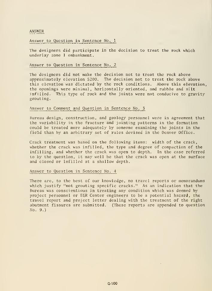
ANSWER
Answer to Question in Sentence No. 1
The designers did participate in the decision to treat the rock whichunderlay zone 1 embankment.
Answer to Question in Sentence No. 2
The designers did not make the decision not to treat the rock aboveapproximately elevation 5200. The decision not to treat the rock abovethis elevation was dictated by the rock conditions. Above this elevation,the openings were minimal, horizontally oriented, and rubble and siltinfilled. This type of rock and the joints were not conducive to gravitygrouting.
Answer to Comment and Question in Sentence No. 5
Bureau design, construction, and geology personnel were in agreement thatthe variability in the fracture and jointing patterns in the formationcould be treated more adequately by someone examining the joints in thefield than by an arbitrary set of rules devised in the Denver Office.
Crack treatment was based on the following items: width of the crack,whether the crack was infilled, the type and degree of compaction of theinfilling, and whether the crack was open to depth. In the case referredto by the question, it may well be that the crack was open at the surfaceand closed or infilled at a shallow depth.
Answer to Question in Sentence No. 4
There are, to the best of our knowledge, no travel reports or memorandumswhich justify "not grouting specific cracks." As an indication that the
Bureau was conscientious in treating any condition which was deemed byproject personnel or E§R Center engineers to be a potential hazard, the
travel report and project letter dealing with the treatment of the rightabutment fissures are submitted. (These reports are appended to questionNo. 9.)
G-100
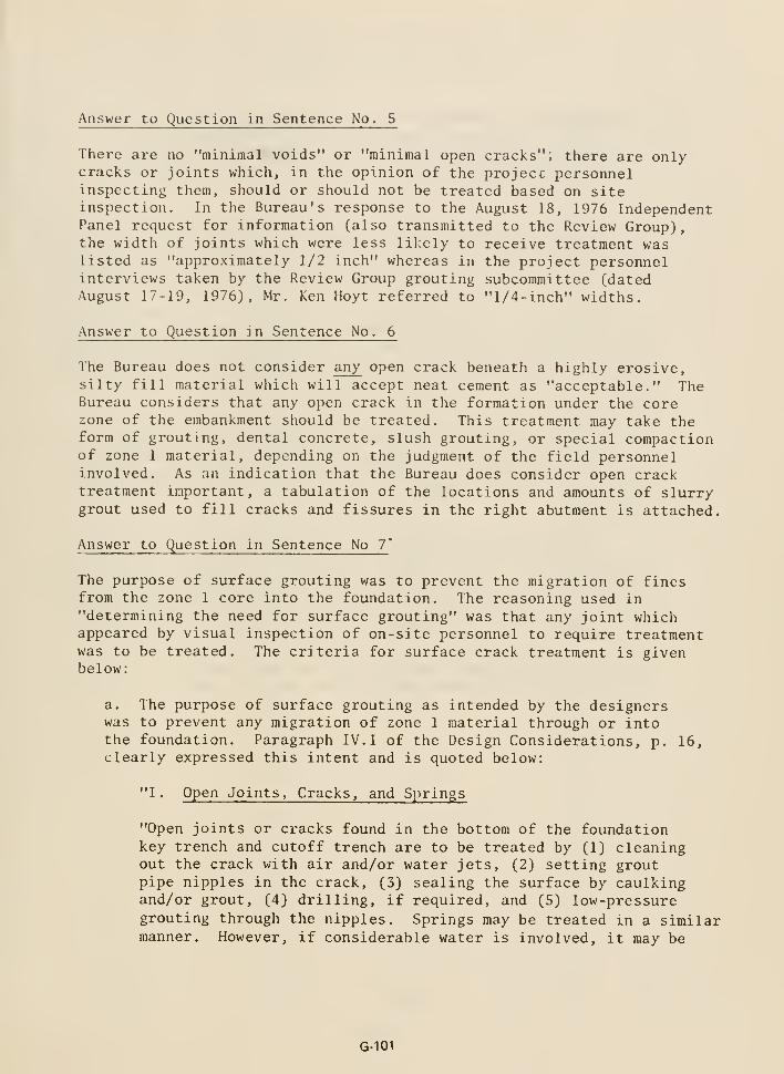
Answer to Question in Sentence No. 5
There are no "minimal voids" or "minimal open cracks"; there are only-cracks or joints which, in the opinion of the project personnelinspecting them, should or should not be treated based on siteinspection. In the Bureau's response to the August 18, 1976 IndependentPanel request for information (also transmitted to the Review Group),the width of joints which were less likely to receive treatment waslisted as "approximately 1/2 inch" whereas in the project personnelinterviews taken by the Review Group grouting subcommittee (datedAugust 17-19, 1976), Mr. Ken Hoyt referred to "1/4-inch" widths.
Answer to Question in Sentence No. 6
The Bureau does not consider any open crack beneath a highly erosive,silty fill material which will accept neat cement as "acceptable." TheBureau considers that any open crack in the formation under the corezone of the embankment should be treated. This treatment may take theform of grouting, dental concrete, slush grouting, or special compactionof zone 1 material, depending on the judgment of the field personnelinvolved. As an indication that the Bureau does consider open cracktreatment important, a tabulation of the locations and amounts of slurrygrout used to fill cracks and fissures in the right abutment is attached.
Answer to Question in Sentence No 7'
The purpose of surface grouting was to prevent the migration of finesfrom the zone 1 core into the foundation. The reasoning used in"determining the need for surface grouting" was that any joint whichappeared by visual inspection of on-site personnel to require treatmentwas to be treated. The criteria for surface crack treatment is givenbelow:
a. The purpose of surface grouting as intended by the designerswas to prevent any migration of zone 1 material through or intothe foundation. Paragraph IV. I of the Design Considerations, p. 16,clearly expressed this intent and is quoted below:
"1. Open Joints, Cracks, and Springs
"Open joints or cracks found in the bottom of the foundationkey trench and cutoff trench are to be treated by (1) cleaningout the crack with air and/or water jets, (2) setting groutpipe nipples in the crack, (3) sealing the surface by caulkingand/or grout, (4) drilling, if required, and (5) low-pressuregrouting through the nipples. Springs may be treated in a similarmanner. However, if considerable water is involved, it may be
G-101
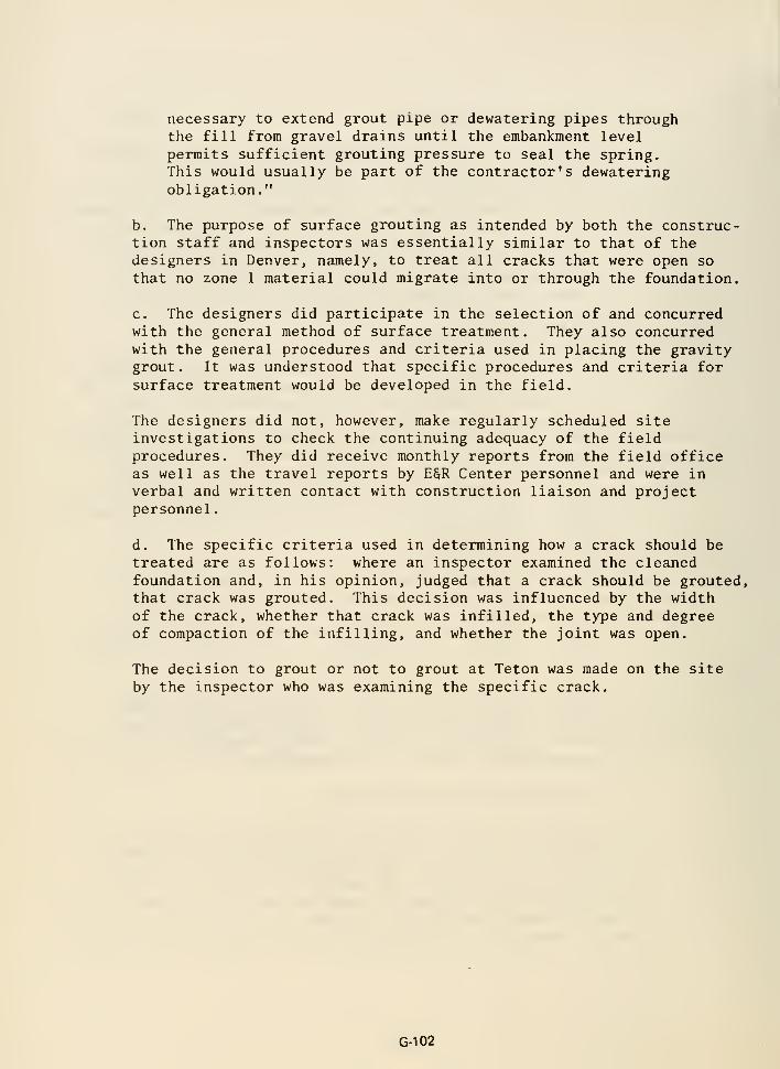
necessary to extend grout pipe or dewatering pipes throughthe fill from gravel drains until the embankment levelpermits sufficient grouting pressure to seal the spring.This would usually be part of the contractor's dewateringobligation."
b. The purpose of surface grouting as intended by both the construc-tion staff and inspectors was essentially similar to that of thedesigners in Denver, namely, to treat all cracks that were open so
that no zone 1 material could migrate into or through the foundation.
c. The designers did participate in the selection of and concurredwith the general method of surface treatment. They also concurredwith the general procedures and criteria used in placing the gravitygrout. It was understood that specific procedures and criteria forsurface treatment would be developed in the field.
The designers did not, however, make regularly scheduled siteinvestigations to check the continuing adequacy of the fieldprocedures. They did receive monthly reports from the field officeas well as the travel reports by E§R Center personnel and were inverbal and written contact with construction liaison and projectpersonnel.
d. The specific criteria used in determining how a crack should betreated are as follows: where an inspector examined the cleanedfoundation and, in his opinion, judged that a crack should be grouted,that crack was grouted. This decision was influenced by the widthof the crack, whether that crack was infilled, the type and degreeof compaction of the infilling, and whether the joint was open.
The decision to grout or not to grout at Teton was made on the site
by the inspector who was examining the specific crack.
G-102
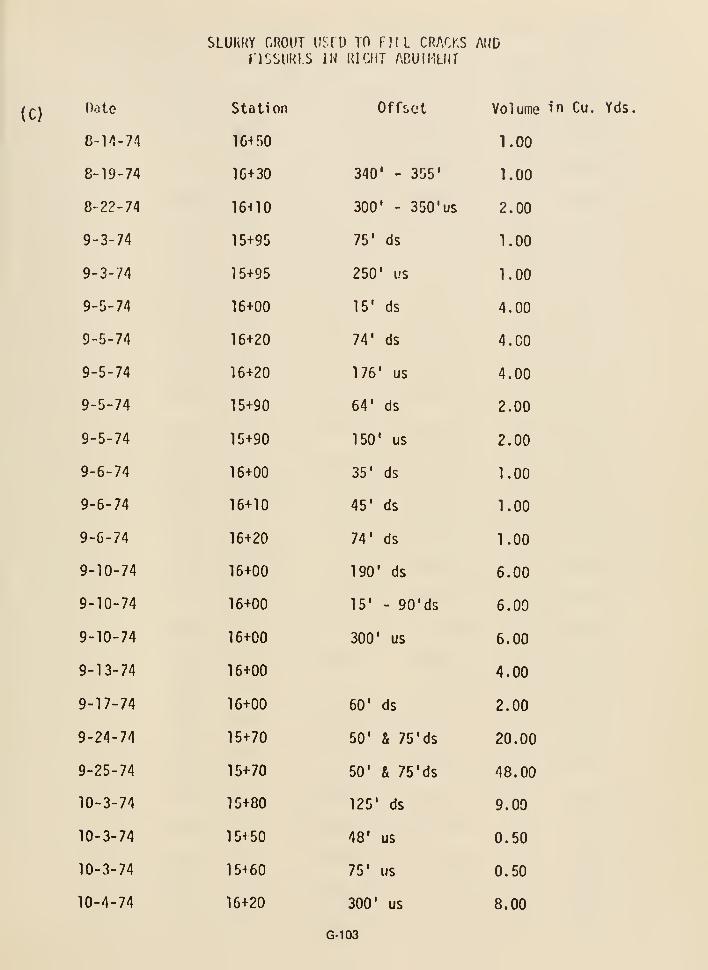
SLUKKY GROUT USfD TO FJIL CRACKS ANDnSSURLS IN lUCliT ABUIHLUT
(C)Date
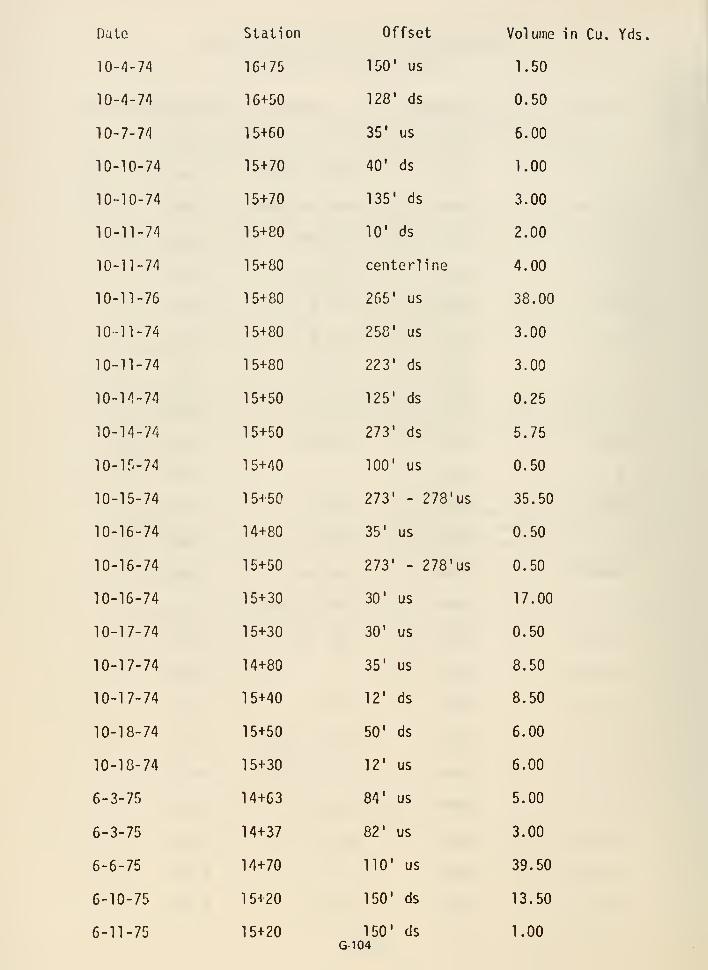
Date
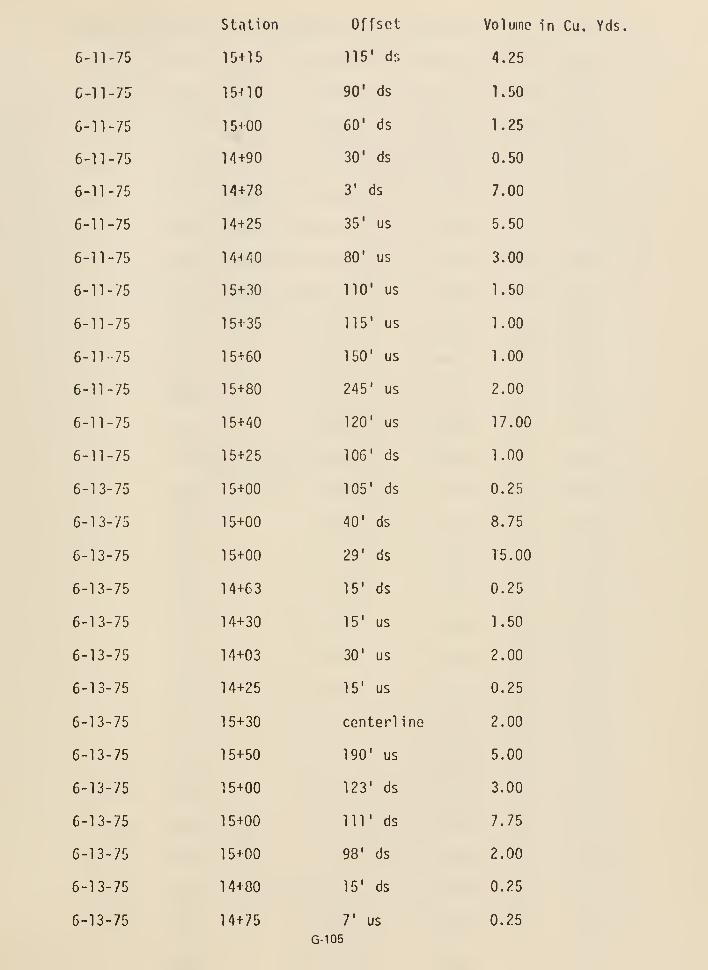

.c
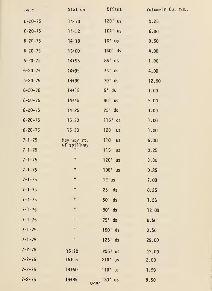
w.itc station Offset Vol wine in Cu. Yds.
6-^0-75 ^4^70 120' us 0.25
6-20-75 14+52 104' us 6.00
6-20-75 14+18 10* us 0.50
6-20-75 15+00 140' ds 4.00
6-20-75 14+95 85' ds 1.00
6-20-75 14+95 75' ds 4.00
6-20-75 14+90 30' ds 12.00
6-20-75 14+15 5' ds 1.00
6-20-75 14+45 90' us 5.00
6-20-75 14+25 25' ds 1.00
6-20-75 15+20 115' ds 1.00
6-20-75 15+20 120' us 1.00
7-1-75 Key way rt. 110' us 6.00of spi llway
7-1-75 " 115' us 0.25
7-1-75 " 120' us 3.00
7-1-75 " 100' us 0.25
7-1-75 " 12'us 7.00
7-1-75 " 25' ds 0.25
7-1-75 " 60' ds 1.25
7-1-75 " 80' ds 12.00
7-1-75 " 75' ds 0.50
7-1-75 " 100' ds 0.50
7-1-75 •• 125' ds 29.00
T-'^-'^^ 15+10 205^ us 12.00
7-2-75 15+15 210' us 2.00
7-2-75 14+50 110' us 1.50
7-2-75 14+85 130' us 9.50G-107
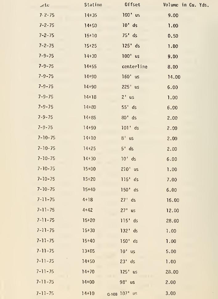
^c.iv station Offset Volume in Cu. Yds.
7/^-75 l/HSf) 100' us 9.00
7-2-75 1/H50 10' ds 1.00
7-2-75 15^^0 75' ds 0.50
7-2-75 15125 125' ds 1.00
7-9-75 14+30 100' us 9.00
7-9-75 14+55 center! ine 8.00
7-9-75 14+90 160' us 14.00
7-9-75 14+90 225' us 6.00
7-9-75 14+18 2' us 1.00
7-9-75 14+80 55' ds 6.00
7-9-75 14+85 80' ds 2.00
7-9-75 14+90 lOT ds 2.00
7-10-75 14+10 8' us 2.00
7-10-75 14+25 5' ds 2.00
7-10-75 14+30 10' ds 6.00
7-10-75 15+00 210' us 1.00
7-10-75 15+20 115' ds 7.00
7-10-75 15+40 150' ds 6.00
7-11-75 4+18 27' ds 16.00
7-11-75 4+42 27' us 12.00
7-11-75 15+20 115' ds 28.00
7-11-75 15+30 132' ds 1.00
7-11-75 15+40 150' ds 1.00
7-11-75 13+C5 10' us 5.00
7-11-75 14+50 23' ds 1.00
7-11-75 14+70 125' us 28.00
7-11-75 14+00 98' us 2.00
7-11-75 14+10 G-108 107' OS 3.00
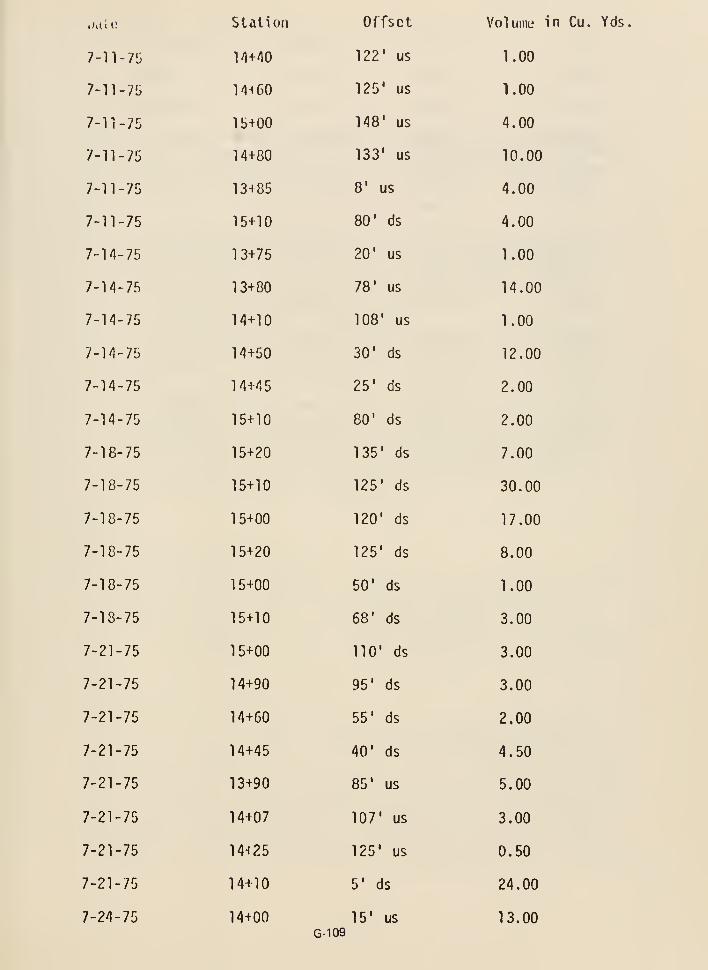
wall?

n.ite

Question No. 11
Stripping specifications for the abutments did not require removalof any in situ impervious soils prior to placement of zone 2 blanketdrain. Roughly 50 percent of the rock in the abutments was coveredby silt when the blanket drain material was placed. What designconsiderations were given to:
a. Partially blocked access to blanket drain for seepageexiting from the rock abutments? Isn't there a good possibilitythat these impervious silts could have been eroded by flow fromjoints? At places where open joints come in contact with thesilts it seems unlikely that all of the joint flow would haveto be confined to the joints themselves.
b. Partial blockage creating concentrations of seepage flows toimpinge directly onto the blanket drain materials in localizedareas?
c. Localized and channelized flow of seepage exiting from therock abutments which might result in washout of the silt beneaththe blanket drain or migrating of the silt into rock openings?In this very pervious abutment, flows large enough to result in
washing of silt beneath the gravel blanket into rock openingsprobably should have been expected.
ANSWER
Answer to Part a. Sentence No. 1
The Bureau designers considered it possible that a partially blockedaccess to the blanket drain might occur for seepage exiting fromthe abutment rock; however, it was assumed the large surface areacontact of the downstream zone 2 blanket and the rock jointing wouldresult in redistribution of this seepage to other parts of the blanketwith no harmful pressure buildup in the abutments.
Answer to Part a. Sentence No. 2
There is a possibility that the silt along the abutments could havebeen eroded into the blanket. However, it is extremely difficult tovisualize the erosion of the silt into the zone 2 material since, as
noted in the response to question No. 7, zone 2 satisfied the Terzaghifilter criteria. As the Review Group has pointed out, the abutmentswere fractured and jointed and this would have made it difficult for
pressure to have built up within the abutments other than by massiveseepage losses. Additionally, even if the silts beneath the zone 2
had eroded it should only have led to a localized problem of slumping.
G-111
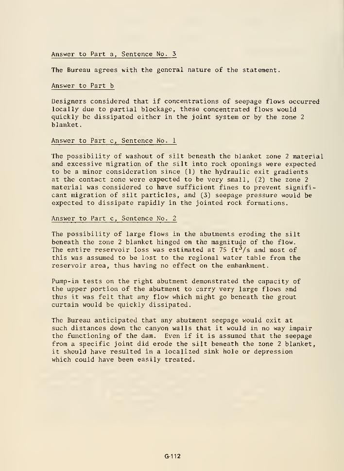
Answer to Part a. Sentence No. 3
The Bureau agrees with the general nature of the statement.
Answer to Part b
Designers considered that if concentrations of seepage flows occurredlocally due to partial blockage, these concentrated flows wouldquickly be dissipated either in the joint system or by the zone 2
blanket.
Answer to Part c. Sentence No. 1
The possibility of washout of silt beneath the blanket zone 2 materialand excessive migration of the silt into rock openings were expectedto be a minor consideration since (1) the hydraulic exit gradientsat the contact zone were expected to be very small, (2) the zone 2
material was considered to have sufficient fines to prevent signifi-cant migration of silt particles, and (3) seepage pressure would beexpected to dissipate rapidly in the jointed rock formations.
Answer to Part c. Sentence No. 2
The possibility of large flows in the abutments eroding the siltbeneath the zone 2 blanket hinged on the magnitude of the flow.
The entire reservoir loss was estimated at 75 ft^/s and most ofthis was assumed to be lost to the regional water table from thereservoir area, thus having no effect on the embankment.
Pump-in tests on the right abutment demonstrated the capacity ofthe upper portion of the abutment to carry very large flows andthus it was felt that any flow which might go beneath the groutcurtain would be quickly dissipated.
The Bureau anticipated that any abutment seepage would exit at
such distances down the canyon walls that it would in no way impairthe functioning of the dam. Even if it is assumed that the seepagefrom a specific joint did erode the silt beneath the zone 2 blanket,it should have resulted in a localized sink hole or depressionwhich could have been easily treated.
G-112
Question No. 12
During construction of the dam, why were undisturbed block (cube)
samples of compacted zone 1 fill and of fine-grained zone 3 fill
not obtained for laboratory testing to verify design parameters?
ANSWER
Undisturbed block samples of an embankment are usually not required toverify design parameters for zone 1 when laboratory data on soil froma uniform borrow area are available as was the case at Teton. Denisonsamples were taken in the zone 1 fill at Teton in conjunction withpreparations for the dynamic analysis of the dam. The parametersdetermined from testing these samples did verify design parameters.In addition, construction control tests were also available to verifyzone 1, zone 2, and zone 3 design parameters.
G-113
Question No. 15
What investigations and studies were made during design to determine
the significance of the older alluvium beneath the intracanyon
basalt as related to the integrity of the dam?
ANSWER
The older alluvium beneath the intracanyon basalt was investigated by
water testing and grouting drill holes in the alluvium during the 1969
test grouting program.
The foundation investigation in the area of the intracanyon basalt
indicated that the underlying alluvium consisted of silt, sand, and
gravel. Core recovery was minimal in the drill holes which indicateda possibility of some minor settlement under loading of the embank-
ment. The test grouting in the area indicated that the alluviumcould be consolidated by grout, and since it was confined between the
basalt and rhyolite, settlement was not considered a problem.Analytical studies were not made during the design phase to examine
the magnitude of possible settlement. After failure of the dam, a
stress analysis of the foundation, including the deep lake bed
sediments, was made using the finite element method. The results
indicated a uniform compressive stress pattern and a smoothlyvarying deformation pattern of small magnitude.
G-114
Question No. 14
Why were embankment and foundation instruments, such as piezometers,deflectometers, and devices for measuring internal movements consideredunnecessary? In other USBR dams of similar material is there informa-tion from instrumentation programs that indicates cracking of thecore material may be a matter of concern? There are no two founda-tions similar in all respects. It is highly doubtful that grout
curtain performance, movement of water through the foundation, etc.,would be predictable at Teton Dam from observations at other dams.
Explain the justification for not installing foundation piezometersat Teton Dam.
ANSWER
Answer to Question in Sentence No. 1
Instrumentation is not always used for sti'uctures constructed ofmaterials previously instrumented at other dams and which havesatisfactory performance records or in structures in which no prob-lems are anticipated.
Answer to Question in Sentence No. 2
No. At the time of the design of Teton Dam (and to the present) reviewof the instrumentation data and past safety inspections in other Bureaudams with similar material did not indicate that cracking of the corematerial would be a matter of concern.
Answer to Question in Sentence No. 5
The justification for not installing foundation piezometers is as
follows:
The upper portions of the abutments consisted of highly fracturedrock and it was felt that insufficient pressure would be developedin this region to warrant the placement of foundation piezometers.In the lower portion of the foundations the major high-angle jointset would provide a directional flow that would make the detectionof any specific pore pressure buildup improbable.
G-115
Question No. 15
What design criteria were used to establish the width of theabutment key trenches as related to reservoir head? What was the
gradient considered across the key trench and what is the Bureaunormal standard?
ANSWER
Answer to Question in Sentence No. 1
The bottom width of 30 feet was selected to allow room for constructionequipment and the three grout curtains. The width of the key trenchselected was not related to the hydraulic gradient.
Answer to Question in Sentence No. 2
The gradient across the key trench will vary with the assumedhead and the thickness of zone 1 material. The Bureau consideredthat at a normal water surface elevation of 4320.0, the maximumhydraulic gradient across the 30-foot-wide trench bottom at ele-
vation 5100 would be 220/30 = 7.3. This gradient would have occurredin massive rock.
There is no written Bureau criteria for a limiting gradient acrossa zone 1 foundation contact. More generally, a gradient of 1:1 betweenthe toe points of the zone 1 material is considered desirable.
G-116
Question No. 16
What design considerations were given to possible differentialsettlements and subsequent cracking of the low plasticity zone 1
fill due to geometric configuration of the supporting steep rockabutments and deep key trenches? What projects are similar toTeton in the use of ML materials and geometric configuration ofabutments and key trenches?
ANSWER
Answer to Question in Sentence No. 1
The main design considerations given to possible differential settle-ments and subsequent cracking were based on an examination of pastexperience and the fact that no previous problems of this type hadbeen known to occur. It was also assumed that the close constructioncontrol of zone 1 and zone 2 and the Bureau's conservative method ofzone 1 placement would eliminate any potential settlement or crackingproblems. At the time of the design of Teton Dam, the state-of-the-art had not developed so that a practicable mathematical solutioncould be performed to determine tension zones in the embankment dueto differential settlement.
Answer to Question in Sentence No. 2
The Bureau has constructed the following dams which used an ML material:
Height aboveName streambed
Medicine Creek 102Enders 100Tiber 196Palisades 260Glendo 170Red Willow 126Bully Creek 104North Coulee 90Soldier Creek 251
Teton 305
The Bureau had not previously constructed a dam with deep keytrenches such as were used at Teton Dam; however. Palisades Damhad abutment slopes which were approximately 60 percent for theleft abutment and 50 percent for the right abutment and theseslopes approximate closely those at Teton Dam. No significantproblems have been observed in the 20-year history of PalisadesDam.
G-117
Question No. 17
Considering the degree of fracturing and permeability of thefoundation rock, explain why the upstream and downstream groutcurtains were not split-spaced to "closure." Regarding splitspacing of upstream and downstream grout curtains, information is
needed on how the probable volume of rock voids was estimated andhow the probable direction of grout travel was estimated in orderto determine the final 20-foot spacing in the upstream and down-stream grout rows. Since the purpose of the other rows was to
limit grout travel and provide an upstream and downstream barrierto allow the centerline holes to be grouted effectively, it appearsthat the term "3-row grout curtain" is somewhat misleading.
ANSWER
Answer to Question in Sentence No. 1
The rationale for not closing out the upstream and downstream rowsof grout holes is given on pp. 9-10 of the Design Considerations ForTeton Dam and is quoted below:
"* * * Foundation investigations at the Teton damsite indicatethat large grout quantities will be required to produce a
tight curtain, and that special procedures will be required to
prevent travel of the grout beyond the limits of the imperviousbarrier. In this connection, it is believed that even in the
most pervious parts of the formation a barrier a few hundredfeet wide will be ample for our design; consequently, when it
appears that grout is traveling beyond these limits, stepsshould be taken to restrict its flow. To facilitate controlof the grout, our design has adopted some of the methods and
philosophies associated with overburden grouting. Briefly,these include drilling and grouting three staggered rows of
grout holes through the critical areas. The outer rows ofholes are drilled at a specified spacing and injected with a
limited volume of grout based on the probable volume of voidsin the zone being grouted. When this quantity has been pumped,
grouting in the stage should be discontinued. Intermediatecloseout holes at a spacing less than that shown on the draw-
ings are not required in the outer rows.
"After grouting at the outer rows is complete, the centergrout cap row is drilled and closed out in the conventional
manner."
Answer to Question in Sentence No. 2
There was no theoretical method used to estimate either the probable
volume of rock voids or the probable direction of grout travel. The
spacing of 20 feet was selected by the designers. The 3-row grid pattern
G-118
shown in Detail A of specifications drawing No. 549-D-9 illustratesthat a minimum spacing at 5 feet occurs between the holes of the threerows when they are projected onto a single plane passing through thecenterline curtain. This concept as well as the fact that the 20-footspacing of the downstream holes is offset 10 feet from the upstreamholes and" 5 feet from the centerline holes influenced the selectedhole spacing and locations.
Answer to Comment in Sentence No. 5
The comments in response to the question in sentence No. 1 make itclear that the designers considered that a single barrier wasbeing created. In creating the barrier, three individual sets ofdrill holes were being used. Thus, it was felt that the term "3-
row grout curtain" would more clearly relate to others the realityof what was being done.
G-119
Question No. 18
Examination of the grouting records indicates that on the centerline
curtain often only one closure hole was drilled between two scheduled
taking holes rather than bracketing each scheduled taking hole with
two closure holes. In a number of areas, no splitting appears to
have been done when only one scheduled hole was a taker. Explain.
Specific questionable locations with respect to the splittingare:
a. Secondary hole at station 9+17 took 20 cf in a stage from170-200 feet. The adjacent tertiary holes were not drilledbelow 150 and 160 feet.
b. There seems to be some confusion in the changing of the
"closure" curtain from the centerline to the upstream row under
the spillway. An upstream tertiary hole at station 11+37 took
1003 cf in a stage from 220 to 245 feet. Quanternary and fifth
order holes were drilled in the upstream row at stations 11+26
and 11+31. When transitioning to the centerline row, no hole
was drilled below 180 feet until station 11+66.
c. There seems to be some confusion between sheet 186 and sheet 175.
The last primary hole on sheet 186 appears to be at station 13+10.
The first primary on sheet 175 appears to be at station 13+46 but
is too shallow (160 feet)
.
d. The secondary hole at station 17+03 is short with respect to the
adjacent taking primary hole at station 13+46 (49 cf in a stage
from 200 to 260 feet)
.
e. Quanternary holes 24+83 and 25+01 took 28 and 23 cf from to
20 feet. There should be fifth order holes at 24+79, 24+87, 24+96,
and 25+07.
f. Quanternary hole 33+86 took 360 cf in a stage from 230 to
250 feet. Fifth order bracketing holes were not drilled.
g. High takes were experienced in the last two fan holes at
the end of the left abutment centerline row. Extraordinary,
continued grouting at this location was probably not necessary.
ANSWER
Answer to Question in Sentence No. 1
An answer to this question is not required as a result of the following
statement received from the Review Group. (Letter dated October 6, 1976.)
G-120
"Regarding centerline row closure holes, reexamination of thegrouting drawings indicates that bracketing of the final scheduledtaking hole was performed."
Answer to Question in Sentence No. 2
Normally all grout takes larger than 20 cubic feet of cement perstage on 10-foot spacing closure holes were drilled to 5-foot centerson both sides of the stages tliat took grout. In several areas,5-foot center holes were drilled adjacent to 10-foot center holeseven though the 10-foot center holes were tight. We are aware ofno cases where splitting was not done when only one scheduled holeswas a taker other than where additional grouting was used as in
part "b" below:
Answer to Part "a"
Take for the primary hole at station 9+17 on the centerlinecurtain was checked on the right by the secondary hole 8+70 drilledto a depth of 220 feet. As the take was a marginal 20 cubic feet in
a 30-foot stage and at depth (170' -200'), the stage was not checkedby a secondary hole on the left.
Answer to Part "b"
Grout hole 11+37, stage 220 to 245, accepted 1,003 cubic feet andwas split on one side as noted. However, the take was near the gatechamber adit and the area was well checked with grout holes fromwithin the adit and access shaft.
Answer to part "c"
The first primary hole on sheet 175 is at station 13+78, 260 feetdeep, some 68 feet down station from station 13+10. The hole at
station 13+46, which was indicated as primary, is a secondary hole.
Answer to part "d"
The secondary hole at station 17+03 was short with respect to
the adjacent primary hole at station 13+46 due to a drillingproblem at depth at Station 17+03.
Answer to part "e"
At station 24+83, a large amount of the 28 cubic feet leaked at
the surface. (See plan view on drawing No. 549-147-162.) Therefore,closures to 5 -foot centers were not made. The details of why
G-121

closure holes adjacent to station 25+01 were omitted for a take of23 cubic feet for stage to 20 feet are not known. It was probablydue to loss from surface leaks or some other judgment factor.
Answer to part "f"
Station 33+86 was a tight hole; however, station 33+77 acceptedgrout at depth and was not closed to 5-foot centers. Most of thegrout injected in the lake sediment area on the left abutmentindicated back pressure and splitting to 5-foot centers at suchdepths was not deemed necessary.
Answer to part "g"
At the extreme ends of grout curtains on abutments, where thecurtains could easily be extended in the future if necessary,strict closure was not deemed necessary.
G-122
Question No. 19
Why was water pressure testing routinely performed above andimmediately after grouting a lower part of a grout hole?
Regarding water pressure testing on a freshly grouted interval ofa rock, examination of field inspector's grouting reports indicatesthat a stage in a hole would be grouted and then successively higherstages in the hole would be water tested before the grout had a
chance to set. What is the desirability of this procedure?
ANSWER
Answer to Question in Sentence No. 1
Water testing each stage prior to grouting was done to assure thepacker was seated. Also, a water test gives an inspector a feelfor the quantity of take and the starting water-cement ratio is oftendetermined by the water test. Pressures for stages decrease as thepacker is raised and a water test should not interfere with thegrouted stages below. Stages with negligible water takes are notgrouted.
Answer to Comments in Sentence No. 2 and Question in Sentence No. 3
In grouting ascending stages of a hole in firm rock, it is normalBureau of Reclamation practice to water test each stage prior togrouting for the reasons given previously. As pressures decreasefor higher stages, the grouted stages below should not be affectedunless the grouted stages leaked to the surface in which case thegrout should be allowed to attain its initial set prior to watertesting the stage above. If the grouted stage be disturbed belowthe stage being water tested, grouting of the stage above willrepair the disturbed area.
G-123
Question No. 20
Why was CaCl2 used to restrict grout travel in the curtain area ratherthan using low pressure, heavy grout, and close hole spacing? Wereattempts made to achieve design injection pressures regardless of rateof take?
ANSWER
Answer to Question in Sentence No. 1
CaCl? was only used where it was clearly evident that verylarge grout takes would be required and very little CaCl2 was
used in the centerline grout holes. CaCl2 was used in lieu
of close hole, low pressure heavy grout for three reasons.
1. Using CaCl2 and standard grouting pressures would spread
the grout sufficiently to achieve the sealing effect desiredby the designers in the outer rows of holes.
2. CaCl2 would require smaller grout quantities.
3. The center row of grout holes would be closed out with
closely spaced holes using standard grouting pressures.
Answer to Question in Sentence No. 2
No.
G-124
Question No. 21
What grout quality laboratory tests were performed to verify the useof CaCl„ percentages as high as 8 percent?
Laboratory tests of grout mixes were limited and did not emulate fieldconditions. What knowledge was available to verify the use of CaCl2percentages as high as 8 percent (the grouting contractor says 10 percentwas used in the beginning)? Grout with 90° temperature was injectedinto a rock mass with temperatures as low as 50° at depth and perhapsmuch lower near the surface during the winter. What knowledge ofgrout behavior was available to justify the high percentages of CaCl2under these conditions?
ANSWER
Answer to Question in Sentence No. 1
No laboratory tests of the grout using CaCl2 percentages as high as8 percent were performed. CaCl was used based on its generallyaccepted characteristic of accelerating the set of concrete.
Extensive tests of grout mixes containing varied quantities ofwater, cement, sand, bentonite, and CaCl2 were performed in 1974 to
determine yield, cost per cubic foot, and strength. However,maximum percentages of CaCl2 by weight of cement were approximately4.5 percent. Results of the tests, included in the report titled"Teton Basin Project Foundation Grouting Report - DC-6910," datedMay 1974, are as follows:
"YIELD AND C0^4PRESS1VE STRENGTHS OF GROUT MIXES
"Laboratory tests to determine yield for various grout mixesused on the Teton Project were performed during the past months.Figure No. 1 shows the yield and strengths achieved from thevarious mixes tested.
"The ingredients for the individual mixes were predeterminedto fill a standard 6" X 12" concrete cylinder mold and werewet-cured for 6 days prior to breaking.
"A cost per cubic foot of yield was calculated using the bidprice for cost of cement and cost of injection and also includesthe cost of calcium chloride in those mixes where calcium chloridewas used. The cost of bentonite was not included as the addi-tion of bentonite to a sanded mix is included in the cost ofthe sand.
G-125
"It can be noted from Figure No. 2 (attached) that the compres-sive strength and yield are related for mixes not containingcalcium chloride. Mix No. 1 shows a high yield and low com-
pressive strength while Mix No. 2 and 14 show a higher compres-sive strength and lower yield.
"Calcium chloride was added to Mixes No. 3, 4, and 5 using mixwater at a temperature of 67° F. A higher compressive strengthwith lower yield was attained in Mix No. 3 by using a higherconcentration of calcium chloride than was used in Mix No. 4 and5.
"Calcium chloride was also added to mixes 10 through 13. A con-stant yield with increase in compressive strength was attainedby increasing the mix water temperature. For Mixes No. 10, 11,
and 12, water temperatures used were 44°, 54°, and 60° F respec-tively. Initial set time was 34, 23, and 16 minutes at tempera-tures of 70°, 75°, and 76° F respectively.
"Mix Nos. 6 through 9 are grout mixes containing various amountsof sand per bag of cement. Compressive strengths for those mixescontaining no calcium chloride varied between 2,292 psi and2,502 psi."
Answer to Question in Sentence No. 3
There are, to the best of our knowledge, no studies available concerningthe specific effect of using CaCl2 percentages as high as 8 percentin grouting operations.
Very little research has been done by others in this field. In
regard to tests by others, Traetteberg and Sereda in their paperentitled, "Strength of C3A Paste Containing Gypsum and CaCl2 (Cement
and Concrete Research, Vol 6, 1976)" noted that when using 8 and16 percent CaCl2 with C3A, the early strength producer of portlandcement, produced a microstructure expected to result in improvedinterparticle bonding. If so, one might hypothesize that thiswould improve resistance to erosion or dissolution by water.
Following are two references regarding erosion of concrete containingCaCl2:
a. Proceedings of the American Concrete Institute, Vol 60, 1963,
page 1489. Report of ACI Committee 212, Admixtures for Concrete,
"It (calcium chloride) significantly increases the resistanceof concrete to erosive and abrasive action especially at earlyages." (1-2 percent additions of CaCl„)
G-126

b. Shideler, J. J., "Calcium Chloride in Concrete" Proceedingsof the American Concrete Institute, Vol 48, 1952, pp 557.
"Data obtained in abrasion and cavitation tests conducted inthe Bureau laboratories strongly indicate that concretescontaining 2 percent CaCl_ are more resistive to erosiveforces than plain concrete under either moist curing ordrying conditions."
Although these references are of limited applicability they do implythat no serious defects occur as the percentage of CACl increases.
Answer to the Comment in Sentence No. 4 and the Question in SentenceNo. 5
No specific test results were performed concerning the effect of usingCaCl^ percentages up to 8 percent in a grout that was to be injectedinto rock with temperatures as low as 50 degrees. However, the corerecovered from the drill holes used to examine the results of the testgrouting program indicated good bond between the grout and thefoundation rock.
G-127
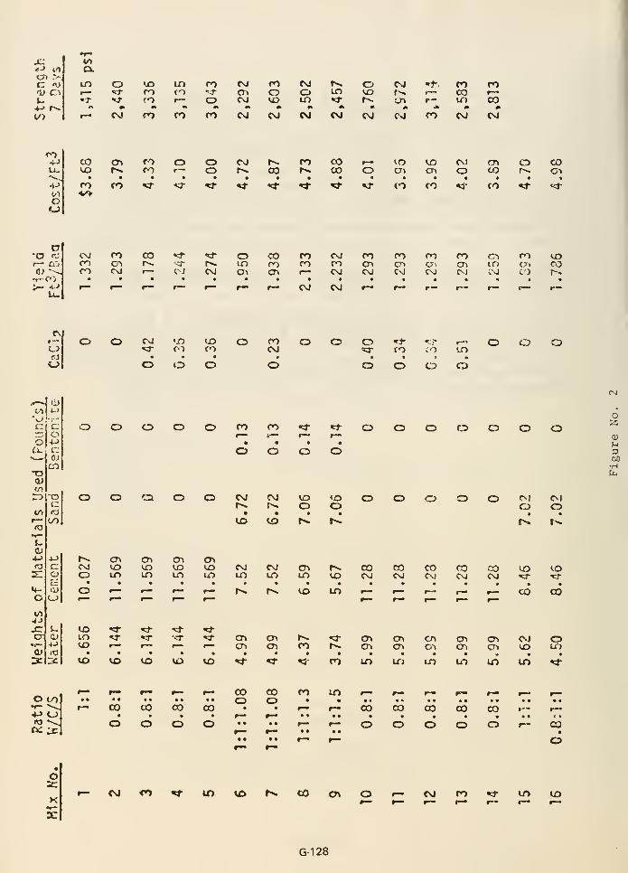
JC
Question No. 22
In a rock mass where the orientation of joint sets varies unpredictably,the grout holes in each grout line are often oriented in a differentdirection. Please explain why the upstream and ceterline holes wereoriented in the same direction.
ANSWER
Initially, the grout curtain design required that the upstreamand downstream holes were to be vertical and the centerline holeswere to be angled at 30° into the abutments. After exposure ofthe right abutment key trench, it was decided that the upstreamrow of holes should also be angled into the abutment in order tointersect more joint sets. Both the upstream and centerline holeswere oriented in the same direction. To the best of our knowledgethere is no greater probability of ensuring complete grouting byorienting the holes of one row at say 45 degrees and the otherrow at 30 degrees. The important concept is simply that the holesare angled.
G-129
Question No. 23
Was the alluvium below the basalt sampled, and were appropriate testsperformed to determine the relative merits of cement vs. chemicalgrouting for this material?
ANSWER
The results of the pilot grouting program of Teton damsite in1969 conclusively demonstrated that the 5- to 20-foot thick zoneof alluvium between the basalt and rhyolite was groutable with acement grout. Thus, for economic reasons, a chemical grout was nottested or considered.
G-130

Question No. 24
Was the decision not to continue the key trench under the spillwaymade only on economics?
ANSWER
The decision not to continue the key trench under the spillway wasnot based on economics. The decision was based on the need to avoiddifferential settlement of the spillway crest structure in orderto prevent cracking of the crest structure and possible malfunctionof the radial gates. The formation under the spillway crest wasconsidered to be much superior to compacted embankment for carryingthe design loadings.
G-131

« Appendix H
Postfailure Investigation of
Right Abutment Embanlcment Remnant
Reproduced from pages 3-10 through 3-16 and Figure F-42 of Independent Panel Report "Failure of Teton
Dam," December 1976

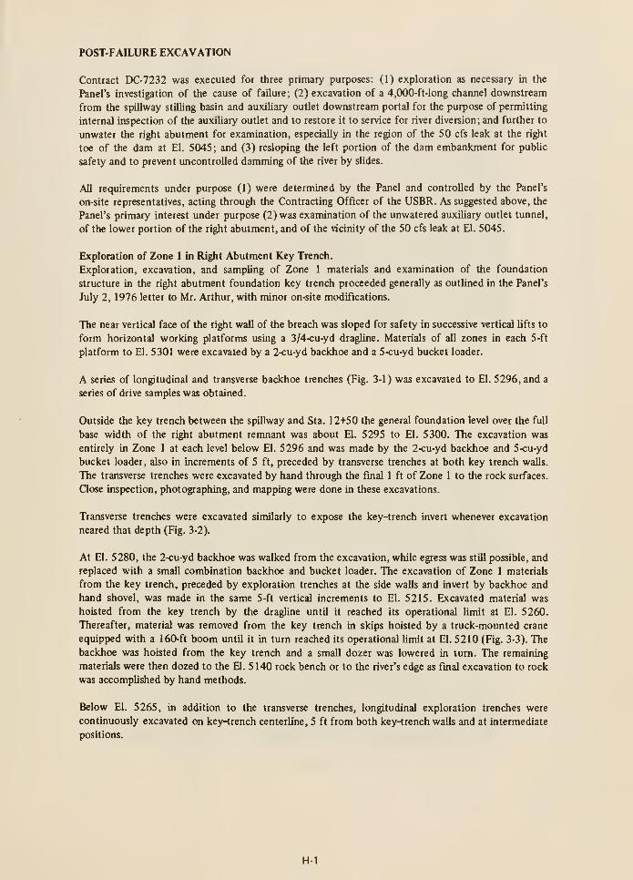
POST-FAILURE EXCAVATION
Contract DC-7232 was executed for three primary purposes: (1) exploration as necessary in the
Panel's investigation of the cause of failure; (2) excavation of a 4,000-ft-long channel downstream
from the spillway stilling basin and auxiliary outlet downstream portal for the purpose of permitting
internal inspection of the auxiliary outlet and to restore it to service for river diversion; and further to
unwater the right abutment for examination, especially in the region of the 50 cfs leak at the right
toe of the dam at El. 5045; and (3) resloping the left portion of the dam embankment for public
safety and to prevent uncontrolled damming of the river by slides.
All requirements under purpose (1) were determined by the Panel and controlled by the Panel's
on-site representatives, acting through the Contracting Officer of the USER. As suggested above, the
Panel's primary interest under purpose (2) was examination of the unwatered auxihary outlet tunnel,
of the lower portion of the right abutment, and of the vicinity of the 50 cfs leak at El. 5045.
Exploration of Zone 1 in Right Abutment Key Trench.
Exploration, excavation, and sampling of Zone 1 materials and examination of the foundation
structure in the right abutment foundation key trench proceeded generally as outlined in the Panel's
July 2, 1976 letter to Mr. Arthur, with minor on-site modifications.
The near vertical face of the right wall of the breach was sloped for safety in successive vertical lifts to
form horizontal working platforms using a 3/4-cu-yd dragUne. Materials of all zones in each 5 -ft
platform to El. 5301 were excavated by a 2-cu-yd backhoe and a 5-cu-yd bucket loader.
A series of longitudinal and transverse backhoe trenches (Fig. 3-1) was excavated to El. 5296, and a
series of drive samples was obtained.
Outside the key trench between the spillway and Sta. 12+50 the general foundation level over the full
base width of the right abutment remnant was about El. 5295 to El. 5300. The excavation was
entirely in Zone 1 at each level below El. 5296 and was made by the 2-cu-yd backhoe and 5-cu-yd
bucket loader, also in increments of 5 ft, preceded by transverse trenches at both key trench walls.
The transverse trenches were excavated by hand through the final 1 ft of Zone 1 to the rock surfaces.
Close inspection, photographing, and mapping were done in these excavations.
Transverse trenches were excavated similarly to expose the key-trench invert whenever excavation
neared that depth (Fig. 3-2).
At El. 5280, the 2-cu-yd backhoe was walked from the excavation, while egress was still possible, and
replaced with a small combination backhoe and bucket loader. The excavation of Zone 1 materials
from the key trench, preceded by exploration trenches at the side walls and invert by backhoe and
hand shovel, was made in the same 5-ft vertical increments to El. 5215. Excavated material was
hoisted from the key trench by the dragline until it reached its operational limit at El. 5260.
Thereafter, material was removed from the key trench in skips hoisted by a truck-mounted crane
equipped with a 160-ft boom until it in turn reached its operational limit at El. 5210 (Fig. 3-3). The
backhoe was hoisted from the key trench and a small dozer was lowered in turn. The remaining
materials were then dozed to the El. 5140 rock bench or to the river's edge as final excavation to rock
was accomplished by hand methods.
Below El. 5265, in addition to the transverse trenches, longitudinal exploration trenches were
continuously excavated on key-trench centerline, 5 ft from both key-trench walls and at intermediate
positions.
H-1

Fig. 3-1 Exploration trenches
Fig. 3-2 Transverse trenches exposing key-trench invert and grout cap
H-3
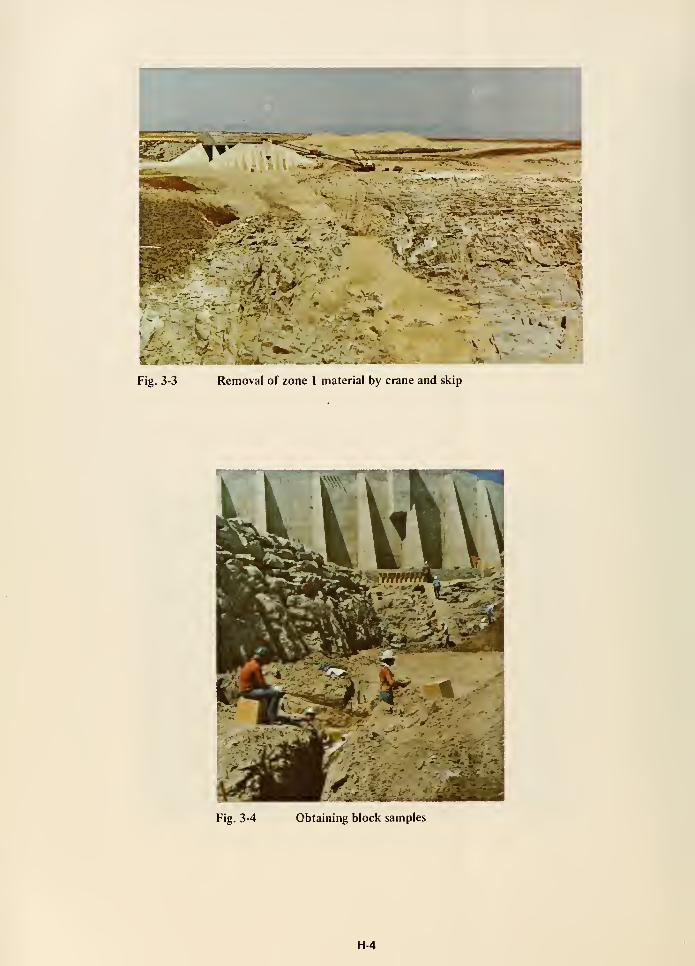
Fig. 3-3
V*!.-
.^^L^
4--.-.-"i.
.^-v:---: .v-3» ~>^—
;
^^-: I
Removal of zone 1 material by crane and skip
\..
>: «
Fig. 3-4 Obtaining block samples
H-4
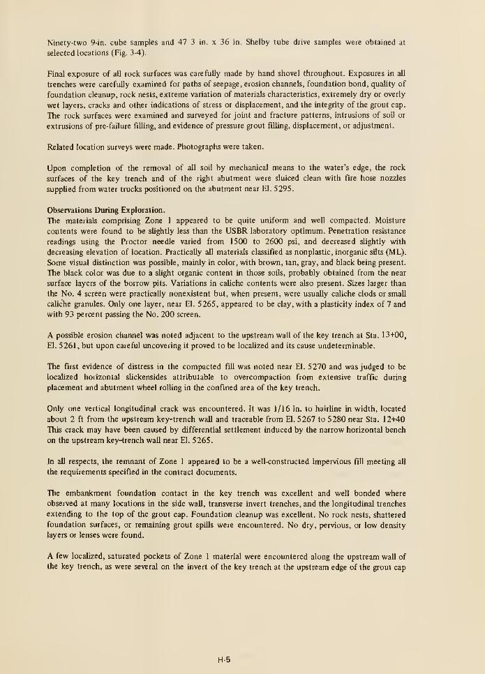
Ninety-two 9-in. cube samples and 47 3 in. x 36 in. Shelby tube drive samples were obtained at
selected locations (Fig. 3-4).
Final exposure of all rock surfaces was carefully made by hand shovel throughout. Exposures in all
trenches were carefully examined for paths of seepage, erosion channels, foundation bond, quality of
foundation cleanup, rock nests, extreme variation of materials characteristics, extremely dry or overly
wet layers, cracks and other indications of stress or displacement, and the integrity of the grout cap.
The rock surfaces were examined and surveyed for joint and fracture patterns, intrusions of soil or
extrusions of pre-failure filling, and evidence of pressure grout filling, displacement, or adjustment.
Related location surveys were made. Photographs were taken.
Upon completion of the removal of all soil by mechanical means to the water's edge, the rock
surfaces of the key trench and of the right abutment were sluiced clean with fire hose nozzles
supplied from water trucks positioned on the abutment near El. 5295.
Observations During Exploration.
The materials comprising Zone 1 appeared to be quite uniform and well compacted. Moisture
contents were found to be slightly less than the USER laboratory optimum. Penetration resistance
readings using the Proctor needle varied from 1500 to 2600 psi, and decreased sUghtly with
decreasing elevation of location. Practically all materials classified as nonplastic, inorganic silts (ML).
Some visual distinction was possible, mainly in color, with brown, tan, gray, and black being present.
The black color was due to a slight organic content in those soUs, probably obtained from the near
surface layers of the borrow pits. Variations in caliche contents were also present. Sizes larger than
the No. 4 screen were practically nonexistent but, when present, were usually caliche clods or small
caliche granules. Only one layer, near El. 5265, appeared to be clay, with a plasticity index of 7 and
with 93 percent passing the No. 200 screen.
A possible erosion channel was noted adjacent to the upstream wall of the key trench at Sta. 13+00,
El. 5261, but upon careful uncovering it proved to be localized and its cause undeterminable.
The first evidence of distress in the compacted fill was noted near El. 5270 and was judged to be
localized horizontal slickensides attributable to overcompaction from extensive traffic during
placement and abutment wheel rolling in the confined area of the key trench.
Only one vertical longitudinal crack was encountered. It was 1/16 in. to hairline in width, located
about 2 ft from the upstream key-trench wall and traceable from El. 5267 to 5280 near Sta. 12-H40
This crack may have been caused by differential settlement induced by the narrow horizontal bench
on the upstream key-4rench wall near El. 5265.
In all respects, the remnant of Zone 1 appeared to be a well-constructed impervious fill meeting all
the requirements specified in the contract documents.
The embankment foundation contact in the key trench was excellent and well bonded where
observed at many locations in the side wall, transverse invert trenches, and the longitudinal trenches
extending to the top of the grout cap. Foundafion cleanup was excellent. No rock nests, shattered
foundation surfaces, or remaining grout spills were encountered. No dry, pervious, or low density
layers or lenses were found.
A few localized, saturated pockets of Zone 1 material were encountered along the upstream wall of
the key trench, as were several on the invert of the key trench at the upstream edge of the grout cap
H-5
where direct access of reservoir water was afforded by the interconnected joint and fracture
structure.
The rock surfaces at the Icey-trench walls and invert are highly jointed and fractured, but the rhyolite
rock is hard, dense, and strong. On the walls the joints and fractures are numerous and closely spaced.
The openings are frequent and range up to 1 in., especially above El. 5280.
There was no evidence of the joints and fractures having been surface treated by slush grouting. The
Zone 1 fill where placed against the open joints was found to bridge across them. Some local
overhangs of limited extent were present under which the Zone 1 material was found in an
uncompacted and saturated state.
As the Zone 1 fill was progressively and alternatively explored by trenches and excavated full width,
it was found intact and undisturbed from El. 5332 to 5265. At El. 5265, the embankment was found
to be cracked transversely at vertical and steeply dipping angles. Well-defined shear zones appeared.
Hydraulically transported filling was found in some of the cracks. Wet clay coatings were also present.
It was concluded that these cracks were associated with incipient sliding of the remnant of fill toward
the face being eroded by the flood waters and that the filling was due to the flow of bank storage into
the cracks as the failure progressed. Hence, the cracks were judged to be due to the consequences of
the failure.
Finally, at the lower elevations, near El. 5225 and the rock bench at El. 5220, the well-defined,
concentrated cracks disappeared, but the shear pattern became more intense and extensive until the
embankment everywhere exhibited distress for horizontal distances in excess of 20 ft from the face of
the breach. The shearing pattern was diamond-shaped, and the general configuration formed cupped
or bowl-shaped surfaces concave toward the river, with the surfaces gradually becoming subtangent to
the key-trench walls.
The longitudinal exploration trenches exposed the bench at 5220 and extended to the deeper key-
trench invert beyond. Here the sheared zones were found concentrated at the key-trench profile
break and appeared to be controlled by that break.
Near Sta. 13-H5, at El. 5215, the embankment for the first time was found extremely wet
continuously across the width of the key trench. Some free water was encountered. The fill was
extremely muddy over the surface of the grout cap. Between the grout cap and the upstream key-
trench wall, the backhoe sank up to the axle. Even under the lighter ground pressure of the small
dozer, the fill was spongy and quick. The in-place embankment remaining at this elevation was very
limited in axial extent, being about 15 ft. A transverse vertical face was cut by hand 3 to 4 ft to the
key-trench invert rock. By probing over this vertical surface, a softer, wetter horizon was detected.
Penetration resistance readings were in the 170-psi range while readings above were in the 400-psi
range and those below averaged 330 psi. Because this horizon was everywhere within 15 in. of the
rock, and in such close proximity to the face of the breach it was not possible to determine if this
wetter horizon existed pre-failure or was created during the failure.
At Sta. 13+25 and El. 5206 on centerline of grout cap, the in-place embankment terminated, and all
of the soil then remaining on the abutment foundation was identified as disturbed material which had
sloughed down from the steep face of the breach.
Beyond that location, all the remaining soil on the abutment was gradually removed by the small
dozer pushing the soil either to a stockpile on the bench at El. 5140 or completely down to the edge
H-6
of the river. By hand shovel, the grout cap was exposed ahead of the dozer operation to avoid any
possible damage or displacement of the grout cap.
Care was also used in removing the soil immediately adjacent to the rock by hand, initially without
water, so that any existing clues to the cause of failure might not be accidently destroyed. The rock
surfaces were then sluiced clean as previously described.
Channel Excavation.
Following the failure, the river flow stabilized with the reservoir at about El. 5056 and an
intermediate pool in the breach at approximately El. 5053. The level of the intermediate pool was
controlled by an extensive bar of large rocks. The auxiliary outlet portal was blocked by debris
deposited in the stilling basin; consequently, a trapezoidal channel bypassing the bar was excavated,
commencing 4,000 ft downstream from the stilling basin, and was completed sufficiently by
September 27 to attempt a controlled lowering of the intermediate pool by gradual removal of the
portion of the bar near the stUhng basin which had been partially reinforced as a cofferdam at the
head end of the bypass channel. Unfortunately, the cofferdam eroded very rapidly, lowering the
intermediate pool to El. 5036 with consequent rapid erosion of Zone 1 of the left remnant in the
river channel. To avert uncontrolled releases of the remaining reservoir storage, the cofferdam was
quickly reestabUshed, again raising the intermediate pool to El. 5053 and arresting the erosion of
Zone 1
.
A temporary gated, double-barrelled culvert control structure of 1,000-cfs capacity was then
constructed in the river bypass channel. After testing it by closing the gates and filling the lower pool
thus formed at the spillway stilling basin, the cofferdam was removed and the river channel at the
dam was slowly excavated to permit controlled draining of the reservoir through the bypass control
structure. In this marmer, the residual reservoir and intermediate pool were reduced to a negligible
capacity by lowering the river channel invert, and the remaining abutment and the vicinity of the leak
at El. 5045 were unwatered for inspection (Figs. 2-5 and 2-6).
SOIL SAMPLING AND TESTING
Undisturbed, hand-cut block samples, 9 in. x 9 in. x 9 in. in dimension, and 3 in. x 36 in. Shelby tube
drive samples together with 10-lb bag samples taken nearby were obtained at the locations shown in
Fig. 3-5.
Selected block samples, representative of the range of materials and densities found, and spanning the
mass of the embankment remnant on the right abutment, were sent to various laboratories for
identification tests and tests of designated engineering properties. To the extent practicable, two
laboratories were sent similar samples for comparative purposes.
The dispersive characteristics of Zone 1 material were investigated by pinhole tests at the Waterways
Experiment Station and the erodibiUty by flume tests and rotating cylinder tests by the University of
California at Davis.
The stress-strain properties were investigated by drained triaxial compression tests at both placement
moisture and saturated moisture contents by Northern Testing Laboratories, Billings, Montana, andby the Earth Sciences Branch, USBR, Denver, Colorado. Unconfmed compression tests at varying
moisture contents were also made by the latter.
Special horizontal permeability tests were made by the University of California at Berkeley.
H-7

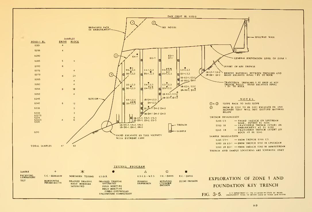
DAM CREST EL 5332
TOTAL SAMPLES

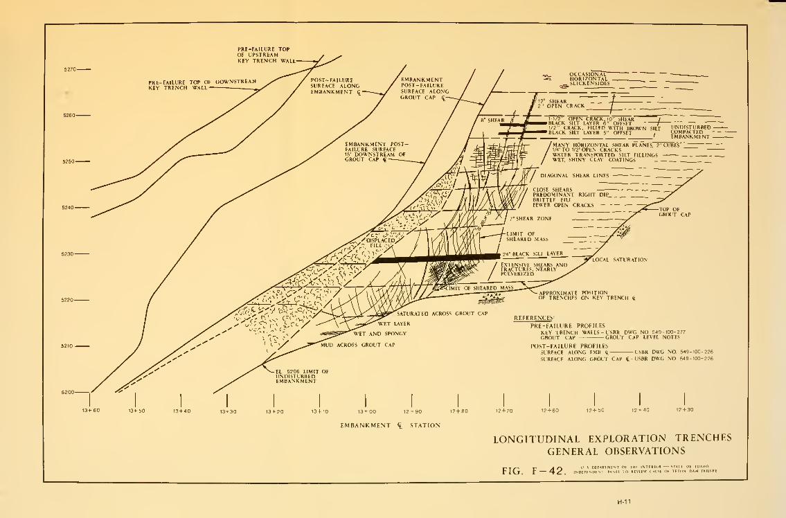
PRI-FAILURE TOPOF UPSTREAMKEY TRENCH WALL
PRE-FAILUREKEY TRENCH
TOP OF DOWNWALL
5210-USBR DWG NO 549-100-226
USBR DWG NO, 549-100-226
t3-t-50 13 + 40 13+30 13 + 20 13 + 10 13 + 00 12 + 90 12+80 12+70 12 + 60 12 + 50 12+40 12 + 30
EMBANKMENT <t STATION
LONGITUDINAL EXPLORATION TRENCHESGENERAL OBSERVATIONS
-,_^^ ^ y| O l> ^ DiPARIMENTOf IIIF INTERIOH M*lt ur lu^tn.
r Hj, r H- ^ . INDEPhNllENT PANEl lO REVtEW ( ALISE OF TETON DAM FAIIIRE
H-11


«Appendix
In Situ Stress Investigations
Reproduced from Appendix D, "Hydraulic Fracturing and Its Possible Role in the Teton Dam Failure," and pages
3-17 through 3-21 of the Independent Panel Report on "Failure of Teton Dam," December 1976.


APPENDIX DFINITE ELEMENT ANALYSES
U. S. DEPARTMENT OF THE INTERIOR STATE OF IDAHOINDEPENDENT PANEL TO REVIEW CAUSE OF TETON DAM FAILURE
1-1


APPENDIX DHYDRAULIC FRACTURING AND ITS POSSIBLE ROLE
IN THE TETON DAM FAILURE
by
H. Bolton Seed, T.M. Leps, J.M. Duncan and R.E. Bieber
INTRODUCTION
In recent years, cracking leading to excessive loss of drill water in the cores of a number of
embankment dams has been attributed to the phenomenon of hydraulic fracturing; that is, a
condition leading to the creation and propagation of a thin physical separation in a soil whenever the
hydraulic pressure exerted on a surface of the soil exceeds the sum of the total normal stress on that
surface and the tensile strength of the soil. A similar condition has also been suspected of occurring in
the cores of several embankment dams due to reservoir water pressures. This has usually been the case
in compressible cores of dams with more rigid outer shells, where the tendency for the core to settle
or compress more than the shells results in a major reduction in stresses within the core. As a result,
water pressures may exceed the sum of the normal stresses and tensile strength of the soil on certain
planes within such zones of reduced stress, and cracking may develop along these planes.
To date there does not seem to have been any case reported where similar hydraulic fracturing has
occurred as a result of construction of a steep-walled key trench although the conditions required to
produce hydraulic fracturing are as well-developed for this type of construction (compressible fill
adjacent to relatively rigid rock) as they are for the cores of rockfill dams (compressible impervious
soil adjacent to relatively stiffer rockfill). Accordingly the possibility of hydraulic fracturing
developing in the key trench of Teton Dam was considered to merit serious consideration, and
detailed studies have been conducted to investigate this possibiUty.
The general hypothesis whereby failure could have occurred as a result of internal erosion due to
leakage through cracks in the key-trench fill caused by hydraulic fracturing is illustrated schematically
in Fig. 1. If the grout curtain were fully or highly effective, the highly pervious nature of the
upstream rock along vertical and horizontal joints would lead to a condition of essentially fuU
hydrostatic pressures developing along some zones of the upstream face of the key trench. Even if the
cutoff allowed some seepage under the key trench, high water pressures might still develop against the
upstream face of the key-trench fill. As shown in Fig. 1 , step 1 , these pressures could cause fracturing
of the fill whete it came in contact with the joints. The resulting cracks would tend to be along the
rrtinor principal planes and would propagate longitudinally along the wall of the trench, permitting
water to have access to the wall over a considerable length of the key trench.
In a coincident or second step (step 2 in Fig. 1) the water pressures thus developed would tend to
produce multiple fractures along transverse planes with low normal stresses acting on them due to the
arching action of the fill over the soil in the key trench. This would provide access for the water to
the downstream face of the key trench.
Once this stage was reached, further fracturing could occur along minor principal planes for soil
elements adjacent to the downstream wall of the key trench, again permitting the water to flow
longitudinally until it found a convenient egress through open joints in the downstream rock. Erosion
along the resulting flow path would ultimately lead to a piping failure of the embankment as
discussed in a later section.
1-3
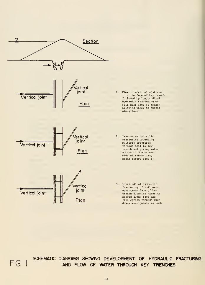
Section
Vertical joint
Vertical
joint Flow in vertical upstrecun
ioint to fage of key trenchfollowed by longitudinalhydraulic fracturing offill near face of trenchallowing water to spreadalong face
Analysis for Predicting the Possibility of Hydraulic Fracturing.
In many cases where hydraulic fracturing is bebeved to have occurred, its development resulted by
accident during drilling or monitoring operations. In recent years experimental and analytical studies
have been developed for investigating the possibility of its occurrence. Experimental studies include
laboratory tests on large models, which clearly showed that high water pressures induced in vertical
holes could produce observable extensive fracturing in earth materials, and field bore hole tests where
high pressures induced by filling the hole with water led to fracturing at the bottom of the hole and
an initially rapid loss of water from the hole. Analytical studies have involved studies of the stress
conditions causing fracturing at the bottom of drill holes and the stress conditions in the shell and
core materials in embankment dams. These latter studies, accomplished by means of the finite
element method of analysis, have shown that this procedure has the capability to show where zones
of low pressure will occur in the cores of embankment dams and thus where hydrauhc fracturing
might be anticipated. It has been used in design studies of such dams in the past few years.
It should be recognized that the use of finite element analyses to predict stress conditions in cores
and key trench materials in this way requires the use of the most sophisticated analysis techniques
and even then they should desirably be used in conjunction with some types of field test program to
provide some check on the validity of the calculations. Furthermore, potential errors in the results
would suggest that they are more useful as a guide to judgment than as an absolute indication of
stress conditions.
The best method of stress analysis of this type is one which determines the stresses on the basis of a
reasonable representation of the non-linear stress-strain relationships for the construction materials
and follows a step-by-step sequence representative of the construction sequence for the embankment
under consideration. Such features are embodied in the finite element computer program ISBILD
which was developed at the University of California, Berkeley (Ozawa and Duncan, 1973). For some
of the analyses described in this appendix, Bieber (1976) developed a computer program which
employs the same analysis procedures and stress-strain relationships as ISBILD. Results from Bieber's
program were compared with results from ISBILD for a simple problem to insure that the newprogram would produce results which conform to those from ISBILD in all essential respects.
The computer program ISBILD employs hyperbolic stress-strain relationships which model several
important aspects of the stress-strain behavior of soils, including (1) nonlinearity, or decreasing
modulus with increasing strain, (2) stress-dependency, or increasing stiffness and strength with
increasing confining pressure, and (3) realistic variations of Poisson's ratio with strain and confining
pressure. The parameters employed in the hyperboUc stress-strain relationships are listed in Table 1,
together with descriptions of their physical significance and explanations of their roles in finite
element analyses; a more complete description of these parameters is contained in a recent report by
Wong and Duncan (1974).
Using this procedure, two types of analyses may be performed — a total stress analysis using
undrained stress-strain parameters, or an effective stress analysis using drained stress-strain
parameters. Both approaches have limitations. For example, an effective stress analysis may be used,
incorporating drained stress-strain parameters, to evaluate the effective stress acting on any plane
within the soil mass. Gradually increasing water pressures may be introduced by means of nodal point
loads, representing buoyancy and seepage forces, and the resulting changes in effective stress may be
calculated. If this type of analysis is performed using hyperboUc stress-strain and strength parameters
determined from conventional laboratory tests conducted with positive (compressive) values of 03,which are often used to represent the non-linear stress-strain properties of soils, the modulus of the
soil will approach zero as the calculated value of 03 approaches zero simply due to the method of
1-5
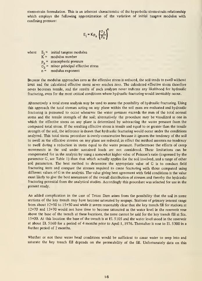
stress-strain formulation. This is an inherent characteristic of the hyperbolic stress-strain relationship
which employs the following approximation of the variation of initial tangent modulus with
confining pressure:
Ei = KPa (^
where E: = initial tangent modulus
K = modulus number
p = atmospheric pressure
Oo = minor principal effective stress
n = modulus exponent
Because the modulus approaches zero as the effective stress is reduced, the soil tends to swell without
limit and the calculated effective stress never reaches zero. The calculated effective stress therefore
never becomes tensile, and the results of such analyses never indicate any likelihood for hydraulic
fracturing, even for the most critical conditions where hydraulic fracturing would inevitably occur.
Alternatively a total stress analysis may be used to assess the possibility of hydraulic fracturing. Using
this approach the total stresses acting on any plane within the soil mass are evaluated and hydraulic
fracturing is presumed to occur whenever the water pressure exceeds the sum of the total normal
stress and the tensile strength of the soil; alternatively the procedure may be visualized as one in
which the effective stress on any plane is determined by subtracting the water pressure from the
computed total stress. If the resulting effective stress is tensile and equal to or greater than the tensile
strength of the soil, the inference is drawn that hydraulic fracturing would occur under the conditions
analyzed. This total stress procedure is overly-conservative because it ignores the tendency of the soil
to swell as the effective stresses on any plane are reduced; in effect the method assumes no tendency
to swell during a reduction in stress equal to the water pressure. Furthermore the effects of creep
movements in the soil under sustained loads are not considered. These limitations can be
compensated for in the analysis by using a somewhat higher value of Poisson's ratio (expressed by the
parameter G, see Table 1) than that which actually applies for the soil involved, and a range of other
soil parameters. The best method to determine the appropriate value of G is to conduct field
fracturing tests and compare the stresses required to cause fracturing with those computed using
different values of G in the analysis. The value giving best agreement with field conditions is the value
most Ukely to give the best assessment of the overall distribution of stresses and thereby the hydraulic
fracturing potential from the analytical studies. Accordingly this procedure was selected for use in the
present study.
An added compUcation in the case of Teton Dam arises from the possibility that the soil in somesections of the key trench may have become saturated by seepage. Stations of primary interest range
from about 12+50 to 15+50 and while it seems reasonably clear that the key trench fill for stations at
12+70 and 13+70 would not have time to become saturated as the water level in the reservoir rose
above the base of the trench at these locations, the same cannot be said for the key trench fill at Sta.
15+00. At this location the base of the trench is at El. 5105 and the water level stood in the reservoir
at about El. 5160 for a period of 4 months prior to April 1, 1976. Thereafter it rose to El. 5300 in a
further period of 2 months.
Whether or not these water head conditions would be sufficient to cause water to seep into and
saturate the key trench fill depends on the permeability of the fill. Unfortunately data on this
1-6
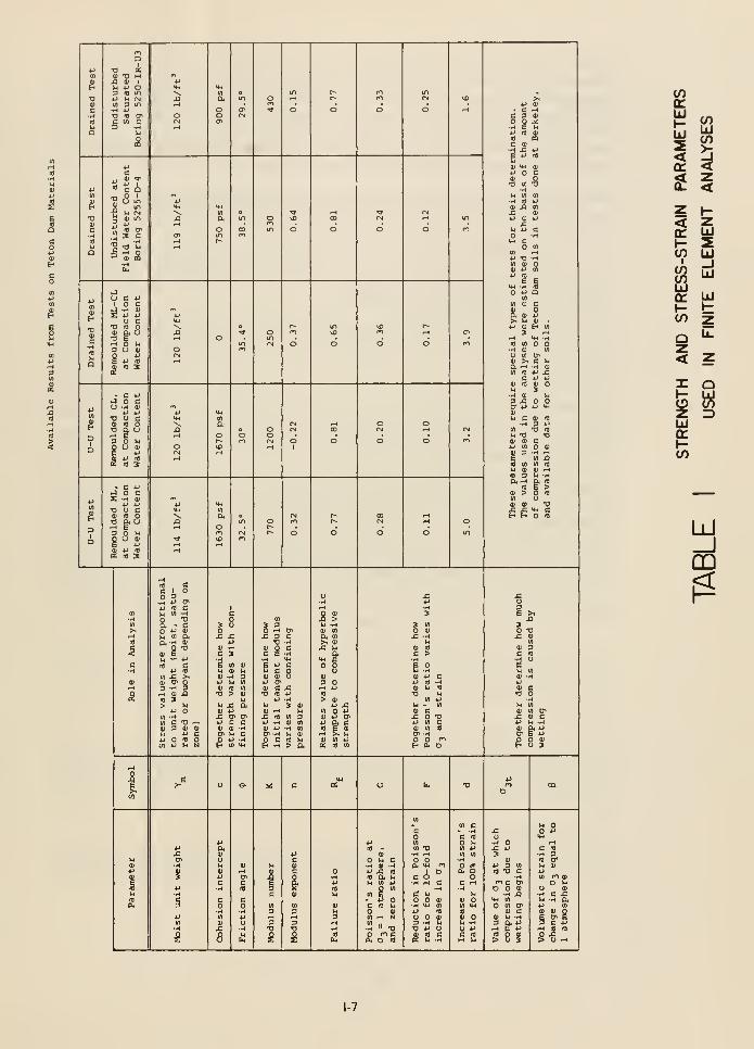

property of the Zone 1 fill are highly variable. Preconstruction values determined by the Bureau of
Reclamation show an average value of 0.25 x 10'" cm/sec and 146 tests on record samples taken
during construction tend to confirm this result, showing values ranging from 0.02 x 10"" to
3.6 X 10'° cm/sec. On the other hand, horizontal permeability tests on 3 undisturbed samples taken
during construction gave permeability coefficients ranging from 3 x 10"" to 13 x 10"" cm/sec while
four similar tests at the University of California on samples taken from one block of soil from the key
trench fill gave values ranging from 0.3 x 10'" to 4.3 x 10'" cm/sec.
It seems reasonable to conclude from these data that the coefficient of permeabiUty of the in-situ
Zone 1 fill varies mainly from about 0.1 x 10"" to 5 x 10'" cm/sec.
If the average permeabihty were 1 x 10'" then a simple computation would show that for ahead of
55 ft, such as would exist near the bottom of the trench at Sta. 15+00 from Jan. 1 to April 1, 1976,
the water would flow horizontally into the fill for a distance of only about 6 or 7 ft. At higher
elevations the water penetration would be even less.
On the other hand, if the coefficient of permeabihty of the fill were of the order of 5 x 10"" cm/sec,
as indicated by the undisturbed sample tests, the water would penetrate into the bottom of the fill a
distance of 30 to 40 ft prior to April 1 , suggesting, that by June 1 , the major part of the key trench
fill at Sta. 15+00 could have increased in degree of saturation. This raises the possibiUty that in this
vicinity, arching of the soil over the key trench would occur not only due to the original differential
compressibihty of the soU and rock at the key trench elevation, but also due to some additional
tendency of the fill in the key trench to settle sUghtly as a result of the wetUng action. Although
settlement due to wetting may be very small, it can never-the-less have a pronounced effect on the
stress distribution in the key trench.
Because of the uncertainty regarding the extent of wetting in the key trenches at the deeper sections,
analyses of stress distribution were made for both conditions and a determination of the most likely
condition was made by comparing the computed stress distribution with the results of field tests to
measure the in-situ stresses at which hydraulic fracturing developed. The secondary effect of
settlement due to wetting can be taken into account in a fmite element analysis of stress distribution
using a computer program written by Nobari and Duncan (1972) and this program was used, together
with measured values of compression of the Teton Dam Zone 1 material due to wetting, to compute
the stress distribution at Sta. 15+00 for the wetted key trench condition, in addition to the stress
distribution for the normal fill placement condition.
The purpose of the field test program was thus two-fold: (1) to investigate whether the soils in the
vicinity of Station 15+00 showed any indication of having been saturated prior to the failure and (2)
to investigate the appropriate value of Poisson's ratio or G, as used in the computations, to provide
computed stresses in agreement with in-situ conditions.
The value of G determined by the field tests corresponds to a sudden or short-term appUcation of the
water pressure. In a dam, the rate of appUcation of the water pressure by a rising reservoir is muchslower. The effect of the difference in rate of loading, with respect to the value of G, has not been
systematically investigated, and thus represents an element of uncertainty in predictions of the
potential for fracturing.
Selection of Significant Soil Characteristics.
As previously noted, the computation of the stress distribution in an embankment using the program
ISBILD requires the determination of nine different soil parameters. These parameters are readily
1-8
determined from triaxial compression tests and a number of such tests were conducted for this
purpose. Since the primary interest in Teton Dam centers on the Zone 1 material, testing programs
were limited to this material.
Tests were performed on both laboratory-compacted samples and on undisturbed samples cut from
the key trench fill after the failure occurred. The results of these tests are summarized in Table 1.
As may be seen from the data presented in this table, the test data show considerable scatter for some
of the parameters involved. However, in determining the stress distribution within the Zone 1
material, the most significant of the highly variable parameters are K (the modulus number), n (the
modulus exponent) and G, the factor determining the relationship between major, minor, and
intermediate principal stresses.
Because of the wide scatter in these values shown by the test data, it was decided to perform a
parameter study to determine the effect of the values of K and n, within the range indicated by the
data, on the values of the stresses computed to develop in the Zone 1 fill. Accordingly stress analyses
were made for the conditions at Stations 15+00 for the following conditions
(1) K = 250; n = 0.07
(2) K= 1000, n = 0.07
(3) K = 250 n = 0.50
Other parameters were maintained constant at their most likely values (e.g. G = 0.35; Y = 1 17 Ib/ft^;
c= 1650 psf, 0= 31°; etc.). The results of these studies are shown in Figs. 2 and 3. Fig. 2 shows
computed values of the major principal stress and Fig. 3 shows computed values of the minor
principal stress at a number of representative points both in the key trench and throughout the Zone
1 fiU. It may be seen that, in spite of the wide variations in K and n, the values of the computed
stresses do not change appreciably, indicating that the stress analysis procedure is insensitive to
reasonable variations in these parameters. In view of this it was considered appropriate to use
representative values, based on the test data and on experience with determinations of parameters for
other soils. On this basis, the following parameters were selected for use in all further analyses:
Y
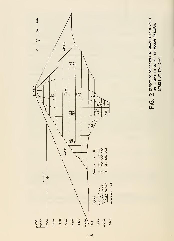
cOz<
CO(£UJ
<
Ozen
q:o<
^ o
Q 3oO+If)
LU CO
3
O2 COO COO UJ
UJ O CO
CVJ
1-10
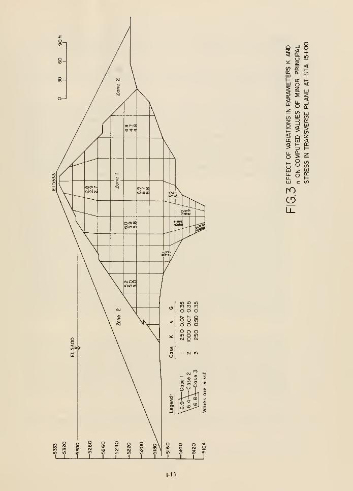
9 s! oZ <t 4-< 5= S^ ^ <cn ir p"^ Q- CO
•- a: btiJ o <
— CO uj
^ 3 ^? ^>5 Q Zcr uj << I- q:> 3 HO 2 ^\- P-,
^5 U COLlI ^ LlI
t o^LU c CO
ro
1-11
hydraulic fracturing. Previous studies have shown that this water pressure should be closely equal to
the sum of the minor principal stress at the point in question and the tensUe strength of the soil at
that point.
Sections chosen for study were Station 26+00, where the stress conditions were considered to be
somewhat similar to those at Station 15+00 on the right abutment and Station 27+00, where
conditions were similar to those at Station 1 3+70 on the right abutment.
Test No. I - Station 26+00
The first test was performed at Station 26+00 where fracturing was induced at El. 5210 under a water
head of 101 ft, corresponding to a pressure of 6.3 ksf. The location of the test, superimposed on the
cross-section at Station 15+00, is shown by point A in Figs. 4 and 5. Also shown in the figures are the
computed stress conditions required to cause hydraulic fracturing in the vicinity of A for three
different values of the parameter G and for the case where the key-trench fill is assumed to be
unwetted (Fig. 4) and wetted (Fig. 5). It was estimated that the tensile strength of the Zone 1 fill was
about 0.4 ksf for this purpose. It wiU be seen that, in Fig. 4 the computed stress required to induce
fracturing at point A is about 6.5 ksf for G = 0.35, while in Fig. 5, the computed fracturing pressure
is about 6.3 ksf for G = 0.35. Both of these computed results are in excellent agreement with the
measured pressure causing fracturing in the field, but results for other values of G are significantly less
favorable.
Test No. 2
The second test was performed at Station 26+00 in a depth range between Els. 5133 and 5161, and
fracturing developed when the head of water acting on the soil reached an average elevation of 5293.
As described in Chapter 3, it seems reasonable to bebeve that fracturing occurred at about El. 5147 so
that the corresponding head causing fracturing would be 146 ft of water or a pressure of 9.1 ksf. The
location of such a test position superimposed on the cross-section at Station 15+00 is shown by point
B in Figs. 4 and 5. Also shown in the figures are the computed stress-conditions required to cause
hydraulic fracturing in the vicinity of B for three different values of the parameter G and for the case
where the key-trench fill is assumed to be unwetted (Fig. 4) and wetted (Fig. 5). It may be seen that,
in this case also, reasonably good agreement is obtained between the measured pressure required to
cause hydrauhc fracturing (9.1 ksf) and the computed pressure for the case where G = 0.35 and the
key-trench fill is assumed to be unwetted (8.8 ksf). Poorer agreement is obtained for higher and lower
values of G. However the much lower values indicated for all values of G by an analysis performed for
a wetted key-trench fill suggests that this type of analysis would not provide realistic results for the
section under investigation, and indicates that the key-trench fill was probably not wetted before the
failure. It might also be noted that the results of this test indicate the tensile strength of the fill to be
of the order of 0.4 ksf (see Chapter 3).
Test No. 3
The third test was performed at Sta. 27+00 in a hole drilled to El. 5190. The hole was then fiUed with
water to El. 5315 but no evidence of hydrauhc fracturing was observed. The pressure at the bottom
of the hole under this head was 7.8 ksf. The location of this test point superimposed on the
cross-section at Station 13+70 is shown in Fig. 6. It may be noted that for G = 0.35, the
corresponding value of the computed pressure required to cause hydraulic fracturing at this location
is only 6.4 ksf. It seems likely, based on the results shown in Figs. 5 and 6, that a computed pressure
in good agreement with the field test result might have been obtained if the analysis had been made
for G = 0.4.
However in view of the good results obtained for Station 15+00 using G = 0.35 and an unwetted key-
trench fill condition, together with the uncertainties necessarily introduced by other aspects of the
1-12
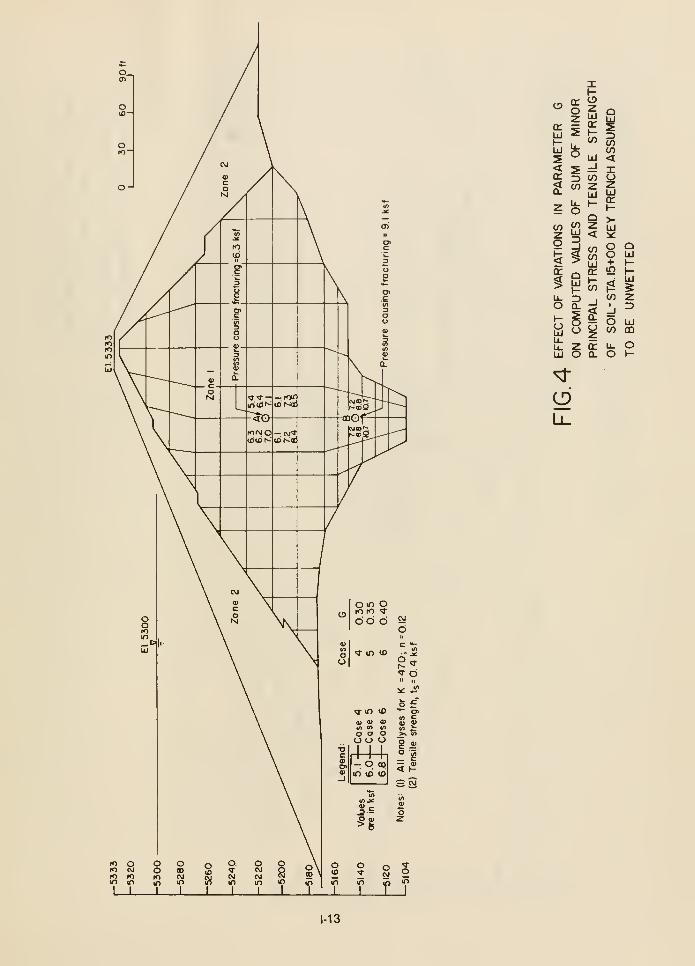
q: I ^
I 5 =J
5 3 CO
^ CO z
aUJ
toCO<XozllJ
cr
£ oCO CO
z UJ <
r: 9- fn<
3
liJ
oo+in
COJ^ i3 $
oUJu.
& c
Ll
CJ
crQ.
O UJCO ca
u. oo h-
1-13
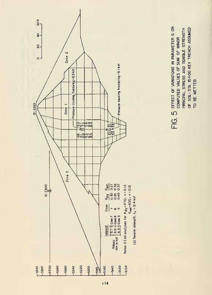
1^ Cvj
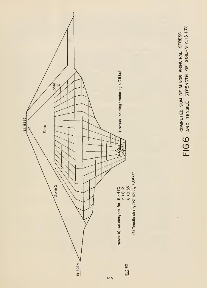
CO +CO fOUJ —
CO C;
^5
q: Xo I-
S UJ
3 UJ(O -J
(OoUJ UJ
Q.
o zo <
CD
1-15
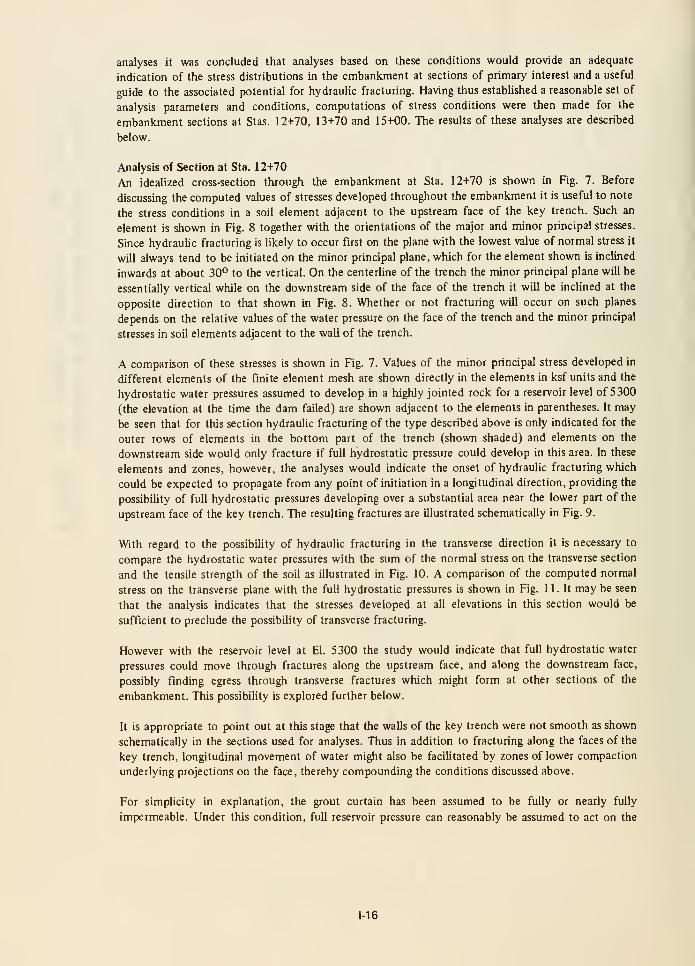
analyses it was concluded that analyses based on these conditions would provide an adequate
indication of the stress distributions in the embankment at sections of primary interest and a useful
guide to the associated potential for hydraulic fracturing. Having thus established a reasonable set of
analysis parameters and conditions, computations of stress conditions were then made for the
embankment sections at Stas. 12+70, 13+70 and 15+00. The results of these analyses are described
below.
Analysis of Section at Sta. 12+70
An idealized cross-section through the embankment at Sta. 12+70 is shown in Fig. 7. Before
discussing the computed values of stresses developed throughout the embankment it is useful to note
the stress conditions in a soil element adjacent to the upstream face of the key trench. Such an
element is shown in Fig. 8 together with the orientations of the major and minor principal stresses.
Since hydraulic fracturing is Ukely to occur first on the plane with the lowest value of normal stress it
will always tend to be initiated on the minor principal plane, which for the element shown is inclined
inwards at about 30*^ to the vertical. On the centerUne of the trench the minor principal plane will be
essentially vertical while on the downstream side of the face of the trench it will be inclined at the
opposite direction to that shown in Fig. 8. Whether or not fracturing will occur on such planes
depends on the relative values of the water pressure on the face of the trench and the minor principal
stresses in soil elements adjacent to the waU of the trench.
A comparison of these stresses is shown in Fig. 7. Values of the minor principal stress developed in
different elements of the finite element mesh are shown directly in the elements in ksf units and the
hydrostatic water pressures assumed to develop in a highly jointed rock for a reservoir level of 5300
(the elevation at the time the dam failed) are shown adjacent to the elements in parentheses. It may
be seen that for this section hydrauhc fracturing of the type described above is only indicated for the
outer rows of elements in the bottom part of the trench (shown shaded) and elements on the
downstream side would only fracture if full hydrostatic pressure could develop in this area. In these
elements and zones, however, the analyses would indicate the onset of hydrauhc fracturing which
could be expected to propagate from any point of initiation in a longitudinal direction, providing the
possibility of full hydrostaric pressures developing over a substantial area near the lower part of the
upstream face of the key trench. The resulting fractures are illustrated schematically in Fig. 9.
With regard to the possibility of hydraulic fracturing in the transverse direction it is necessary to
compare the hydrostatic water pressures with the sum of the normal stress on the transverse section
and the tensile strength of the soil as illustrated in Fig. 10. A comparison of the computed normal
stress on the transverse plane with the full hydrostatic pressures is shown in Fig. 1 1. It may be seen
that the analysis indicates that the stresses developed at all elevations in this section would be
sufficient to preclude the possibihty of transverse fracturing.
However with the reservoir level at El. 5300 the study would indicate that full hydrostatic water
pressures could move through fractures along the upstream face, and along the downstream face,
possibly finding egress through transverse fractures which might form at other sections of the
embankment. This possibihty is explored further below.
It is appropriate to point out at this stage that the walls of the key trench were not smooth as shown
schematically in the sections used for analyses. Thus in addition to fracturing along the faces of the
key trench, longitudinal movement of water might also be facilitated by zones of lower compaction
underlying projections on the face, thereby compounding the conditions discussed above.
For simphcity in explanation, the grout curtain has been assumed to be fully or nearly fully
impermeable. Under this condition, full reservoir pressure can reasonably be assumed to act on the
1-16
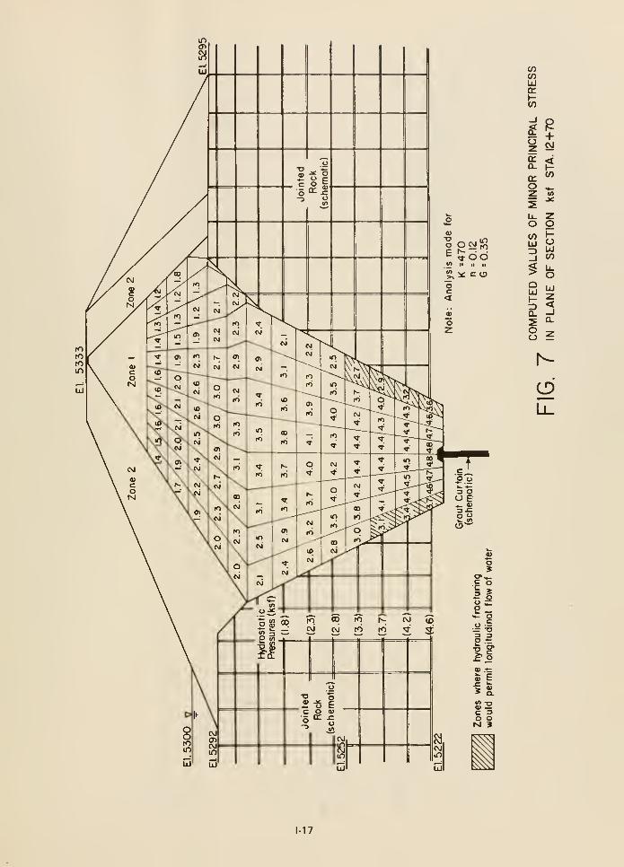
0)
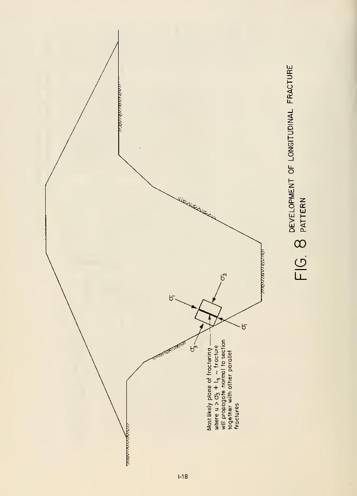
UJonZ)I-o<en
<Q
Oo
UJ
Q.
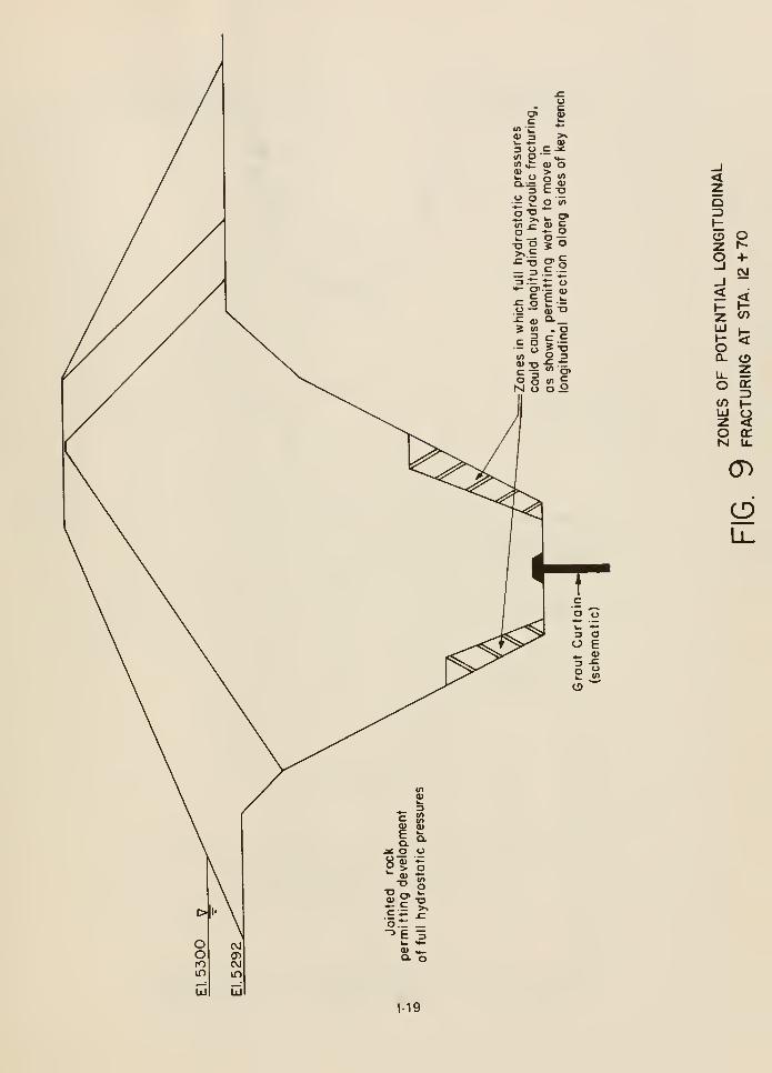
o
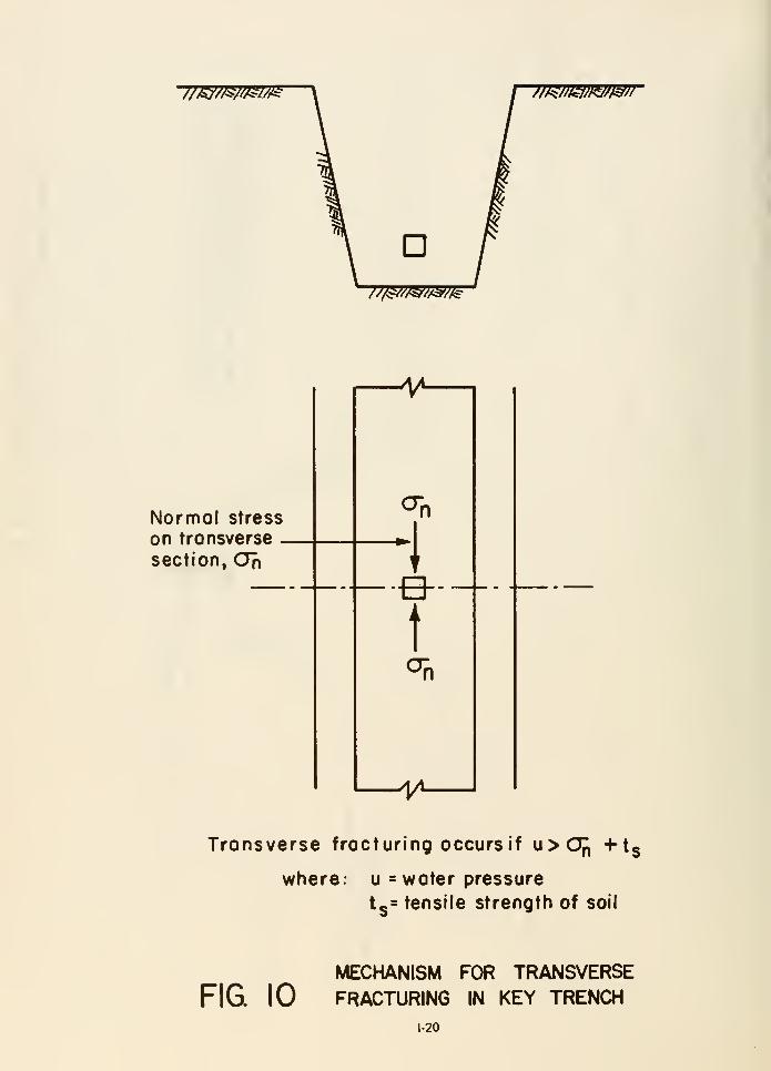
//^//^Ml^ mmw/m
D///^/v<s'//3'//e-
Normal stress
on tronsverse
section, CJn
Transverse fracturing occurs if u>Of, +ts
where- u = water pressure
13= tensile strength of soil
MECHANISM FOR TRANSVERSE
FIG 10 FRACTURING IN KEY TRENCH1-20
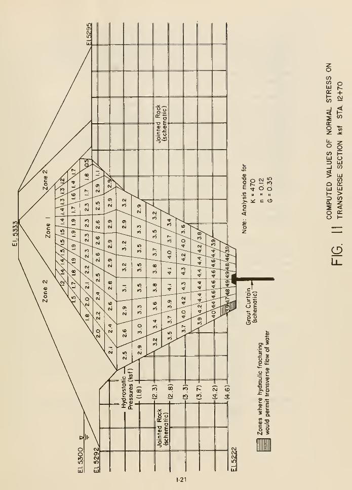
COenUJoc
tn
<!
ITO
O+CVJ
CO
CO
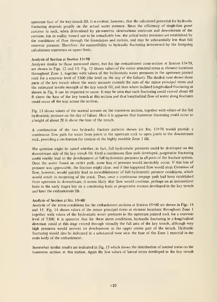
upstream face of the key-trench fill. It is evident, however, that the calculated potential for hydrauhc
fracturing depends greatly on the actual water pressure. Since the efficiency of single-line grout
curtains in rock, when determined by oiezometric observations upstream and downstream of the
curtains, has in reality turned out to be remarkably low, the actual water pressures are established by
the conditions of flow through the foundation and curtain, and may be substantially less than full
reservoir pressure. Therefore, the susceptibiUty to hydraulic fracturing determined by the foregoing
calculations represents an upper limit.
Analysis of Section at Station 13+70
Analyses similar to those presented above, but for the embankment cross-section at Station 13+70,
are shown in Figs. 12 and 13. Fig. 12 shows values of the minor Drincioal stress at element locations
throughout Zone 1, together with values of the hydrostatic water pressures in the upstream jointed
rock for a reservoir level of 5300 (the level on the day of the failure). The shaded zone shows those
parts of the key trench where the water pressure exceeds the sum of the minor principal stress and
the estimated tensile strength of the key trench fill, and thus where inchned longitudinal fracturing as
shown in Fig. 8 can be expected to occur. It may be seen that such fracturing could extend about 40
ft above the base of the key trench at this section and that longitudinal flow of water along fractures
could occur all the way across the section.
Fig. 13 shows values of the normal stresses on the transverse section, together with values of the full
hydrostatic pressure on the day of failure. Here it is apparent that transverse fracturing could occur to
a height of about 20 ft above the base of the trench.
A combination of the two hydrauhc fracture patterns shown for Sta. 13+70 would provide a
continuous flow path for water from joints in the upstream rock to open joints in the downstream
rock, providing a mechanism for erosion of the highly erodible Zone 1 fiU.
The question might be raised whether, in fact, full hydrostatic pressures could be developed on the
downstream side of the key trench fill. Until a continuous flow path developed, progressive fracturing
could readily lead to the development of full hydrostatic pressures in all parts of the fracture system.
Once the water found an outlet path, some loss of pressure would inevitably occur. If this loss of
pressure was appreciable, the fracture might close, and if this happened flow would stop. Cessation of
flow, however, would quickly lead to reestabUshment of full hydrostatic pressure conditions, which
would result in reopening of the crack. Thus, once a continuous seepage path had been established
from upstream to downstream, it seems likely that flow would continue, perhaps on an intermittent
basis in the early stages but on a continuing basis as progressive erosion developed in the key trench
and later the embankment fill.
Analysis of Section at Sta. 15+00
Analysis of the stress conditions for the embankment sections at Station 15+00 are shown in Figs. 14
and 15. Fig. 14 shows values of the minor principal stress at element locations throughout Zone 1
together with values of the hydrostatic water pressures in the upstream jointed rock for a reservoir
level of 5300. It is apparent that for these stress conditions, hydrauhc fracturing in a longitudinal
direction could at this stage extend through virtually the full area of the key trench, although very
high pressures would prevent its development in the upper center part of the trench. Hydrauhc
fracturing would also be indicated in a substantial zone near the base of the Zone 1 material in the
main body of the embankment.
Somewhat similar results are indicated in Fig. 15 which shows the distribution of normal stress on the
transverse section at this station. Again the low values of lateral stress developed in the key trench
1-22
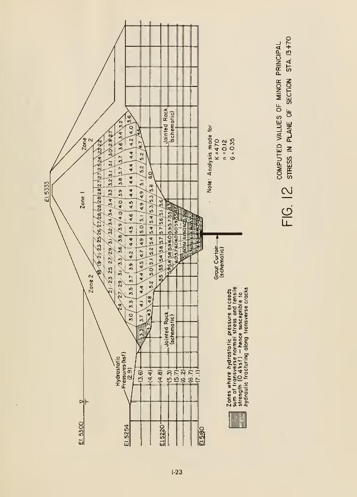
0)
inro
d«> :^ c u>
c—2 -
= 1o 6
O(S-
u>
OPJIf)
«» jgOS o oa> a) M, h.
"^ c — «
3 in o iitf> « m "!
irt a> 3 5Q) k. en o
^ fl> E"D « "*" 'w>.»- <n 3
0) W T o
<n"o C3>Q
INl in <A -C
T)
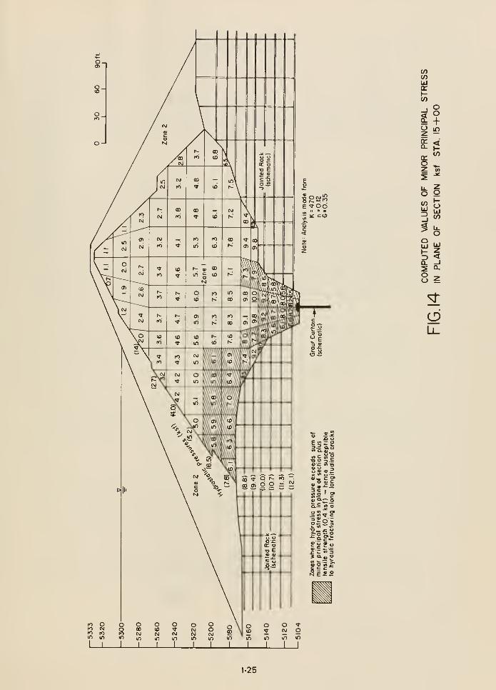
o o
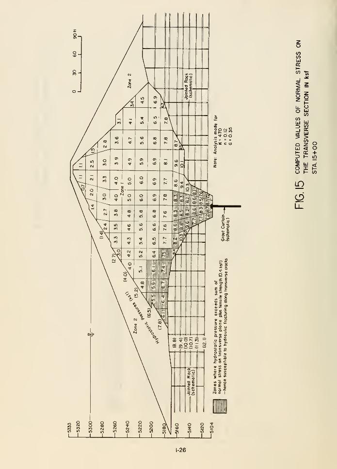
V)CO
(-CO
_J<
o
</)
QLlI
I-
ou
llJ
CO(£UJ>z<H
Oo+in
^\?>
Li_
I L
s
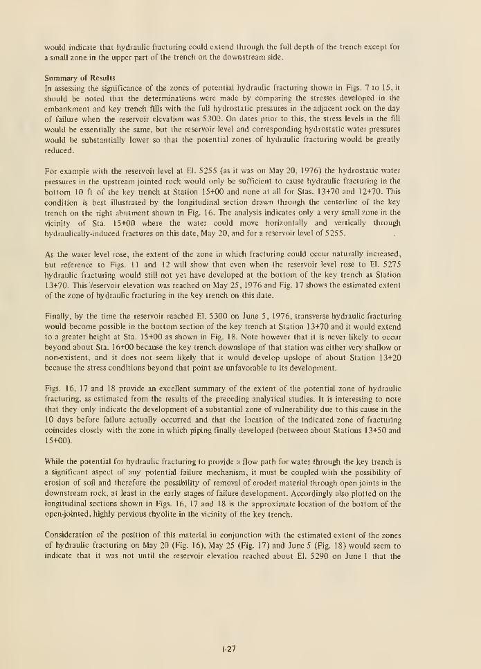
would indicate that hydraulic fracturing could extend through the full depth of the trench except for
a small zone in the upper part of the trench on the downstream side.
Summary of Results
In assessing the significance of the zones of potential hydraulic fracturing shown in Figs. 7 to 15, it
should be noted that the determinations were made by comparing the stresses developed in the
embankment and key trench fills with the full hydrostatic pressures in the adjacent rock on the day
of failure when the reservoir elevation was 5300. On dates prior to this, the stress levels in the fiU
would be essentially the same, but the reservoir level and corresponding hydrostatic water pressures
would be substantially lower so that the potential zones of hydraulic fracturing would be greatly
reduced.
For example with the reservoir level at El. 5255 (as it was on May 20, 1976) the hydrostatic water
pressures in the upstream jointed rock would only be sufficient to cause hydrauhc fracturing in the
bottom 10 ft of the key trench at Station 15+00 and none at all for Stas. 13+70 and 12+70. This
condition is best illustrated by the longitudinal section drawn through the centerline of the key
trench on the right abutment shown in Fig. 16. The analysis indicates only a very small zone in the
vicinity of Sta. 15+00 where the water could move horizontally and vertically through
hydraulically-induced fractures on this date. May 20, and for a reservoir level of 5255.
As the water level rose, the extent of the zone in which fracturing could occur naturally increased,
but reference to Figs. 11 and 12 will show that even when the reservoir level rose to El. 5275
hydraulic fracturing would still not yet have developed at the bottom of the key trench at Station
13+70. This reservoir elevation was reached on May 25, 1976 and Fig. 17 shows the estimated extent
of the zone of hydraulic fracturing in the key trench on this date.
Finally, by the time the reservoir reached El. 5300 on June 5, 1976, transverse hydraulic fracturing
would become possible in the bottom section of the key trench at Station 13+70 and it would extend
to a greater height at Sta. 15+00 as shown in Fig. 18. Note however that it is never likely to occur
beyond about Sta. 16+00 because the key trench downslope of that station was either very shallow or
non-existent, and it does not seem likely that it would develop upslope of about Station 13+20
because the stress conditions beyond that point are unfavorable to its development.
Figs. 16, 17 and 18 provide an excellent summary of the extent of the potential zone of hydraulic
fracturing, as estimated from the results of the preceding analytical studies. It is interesting to note
that they only indicate the development of a substantial zone of vulnerability due to this cause in the
10 days before failure actually occurred and that the location of the indicated zone of fracturing
coincides closely with the zone in which piping finally developed (between about Stations 13+50 and
15+00).
While the potential for hydrauhc fracturing to provide a flow path for water through the key trench is
a significant aspect of any potential failure mechanism, it must be coupled with the possibihty of
erosion of soil and therefore the possibility of removal of eroded material through open joints in the
downstream rock, at least in the early stages of failure development. Accordingly also plotted on the
longitudinal sections shown in Figs. 16, 17 and 18 is the approximate location of the bottom of the
open-jointed, highly pervious rhyolite in the vicinity of the key trench.
Consideration of the position of this material in conjunction with the estimated extent of the zones
of hydraulic fracturing on May 20 (Fig. 16), May 25 (Fig. 17) and June 5 (Fig. 18) would seem to
indicate that it was not until the reservoir elevation reached about El. 5290 on June 1 that the
1-27
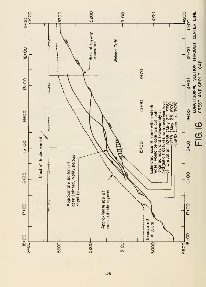
1-28

oo
OS+
oo+
oo
oo+
oo+1^
8+QOO~o
in
o
in
ooCVJ
in
T"
ooin
>^c
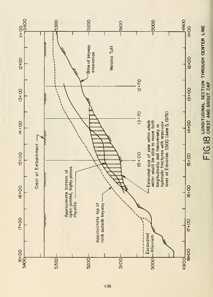
oo
+
oo+CVJ
+
oo+
oo+in
OO+ID
OO+
'<
r-ica>
e
co
f=
IJJ
o
^
oo2> o
+
UJ
oo+
oo+to
oo+
+in
8+ID
OO+
OO
"o92O<n'it
1-30
complete flow path through highly pervious rock, through extensively fractured key trench fill and
again into highly pervious rock would exist to permit the initiation of internal erosion and the
mechanism which finally could lead to failure of the dam.
The remarkable coincidence of the critical zones for hydrauUc fracturing, and the time at which it
could develop, with the zone of failure and the time of failure would seem to lend considerable
support to the hypothesis that hydrauUc fracturing of the soil in the key trench may well have been a
contributory cause to the failure of Teton Dam. However it should be noted that the potential zones
of hydrauUc fracturing would tend to be reduced if water pressures on the upstream face of the
trench were substantially lowered as a result of leakage through the grout curtain. Thus the analysis
presented above indicates an upper bound on the extent of hydraulic fracturing which might have
occurred.
The hydraulic fracturing hypothesis presented above necessarily raises other questions concerning the
dam failure. Foremost among these would have to be the question of why failure was initiated on the
right abutment rather than the left. The key trench sections were remarkably similar on both sides
and an analysis similar to that described in the preceding pages for stations on the left abutment of
the dam would undoubtedly lead to somewhat similar results with regard to the potential for
hydraulic fracturing.
In the final analysis therefore it must be considered that if hydraulic fracturing were responsible for
the leakage through the key trench fill, initiation of failure on one side of the damsite rather than the
other would be related to the question of minor geologic details and the fact that the joint system in
the rhyoUte was more extensively developed and adversely aligned to facilitate seepage and internal
erosion on the right abutment than on the left. However the hypothesis would seem to indicate that
if this mechanism of failure developed, given similar rock conditions in the left abutment, it would
only have been a matter of time before seepage and internal erosion occurred on that side also.
Finally, it is worthy of note that, although it is assumed that hydraulic fracturing will occur in a
fine-grained soil whenever the water pressure exceeds the sum of the minimum compressive stress and
the tensile strength of the soil at a given point, the phenomenon is not yet fully understood and
deserves research on a variety of materials under different boundary conditions and under controlled
laboratory conditions. When a better physical understanding of the creation and propagation of
cracks by water pressure has been acliieved, the criteria for initiation of hydrauUc fracturing utilized
herein may require modification.
Significance of Key Trenches
The preceding discussion necessarUy attaches considerable significance to the role of the key trenches
in reducing the stresses in the key trench fill and thereby faciUtating hydrauUc fracturing and
accompanying erosion. In order to further investigate the effects of the key trenches on the stress
distribution and to provide a qualitative rather than a quantitative assessment of their significance, a
series of studies was conducted for the conditions at Sta. 1 5+00 in wliich the vertical stresses
developed in the embankment were expressed as a proportion of the total weight of overburden, for
aU points in the embankment. The results are expressed as contours showing the developed vertical
stress as a fraction of the direct overburden pressure. Analyses were made for four conditions.
1. For the actual section at Sta 15+00 with no allowance for wetting of the Zone 1 fill in the
key trench or the embankment.
2. For the section at Sta 15+00 if the key trench had not been constructed and with no
allowance for wetting of the Zone 1 material.
31
3. For the actual section at Sta 15+00 with allowance for wetting of the Zone 1 fill to the
extent indicated in Fig. 13.
4. For the sections at Sta. 15+00 if the key trench had not been constructed but the Zone 1
fill had been wetted to the extent indicated in Fig. 13.
The comparative results for analyses 1 and 2 above are shown in Fig. 19 and for analyses 3 and 4
above in Fig. 20. The effects of arching over the key trench and the considerable reduction in stresses
in the key trench fill resulting from the presence of the key trench is readily apparent from these
figures, confirming the fact that the use of key trenches on the sides of the abutments invited the
development of arching, stress reduction and the accompanying onset of hydraulic fracturing and
internal erosion.
Mechanism of Failure by Hydraulic Fracturing
The discussion presented in the preceding pages has shown clearly how the phenomenon of hydraulic
fracturing could provide a continuous flow path through the key-trench fill in critical locations, if all
features of the grout curtain had functioned adequately. The flow path in the early stages of its
development would necessarily start in highly pervious rock, pass through fractures in the key-trench
fill and then continue through highly pervious rock.
Whether the initial flow started by hydrauhc fracturing or leakage in the rock just below the grout
cap, the flow path would have to develop into a continuous pipe through the embankment in order to
lead to the massive seepage which developed in the one or two hours just prior to complete failure
and which through accompanying erosion led to the breaching of the embankment. It is of interest to
speculate therefore on the manner in which this transition might have developed.
Playing a key role in this aspect of faOure was undoubtedly the specific character of the joint systems
in the rock in the vicinity of Station 14+00 and the highly erodible nature of the Zone 1 fill. As
observed in the field, there were a number of open joints in the rock plunging down to and below the
base of the key trench on the upstream side of the key trench between Stas. 13+90 and 14+10.
Similar but narrower joints could readily be identified at locations 10 to 20 ft on both sides of this
zone.
Readily identifiable exit paths for water on the downstream side of the key trench in this vicinity
could similarly be noted as foUows:
(a) a limited number of open vertical joints in the relatively sound rhyolite below about EI.
5200
(b) a maze of open horizontal and vertical joints in the highly fractured and jointed rhyolite
between about Els. 5200 and 5240.
and (c) a 25 ft thick layer of highly pervious talus and slope wash between Els. 5240 and 5265.
Characteristically the primary open vertical joints in the downstream pervious rock angled in plan at
about 45° from the dam axis towards the river, so that water entering this joint system would be
expected to flow primarily in this direction untU it encountered a more accessible outlet path near
the face of the abutment rock, where joints were abundant in all directions.
Thus the general path of seepage and erosion, both as evidenced by the field and analytical studies
and by the observed backward path of erosion towards the whirlpool during the failure itself would
1-32
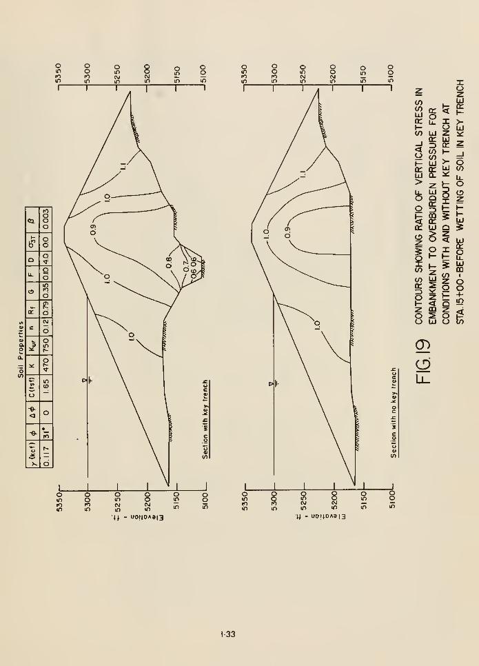
o
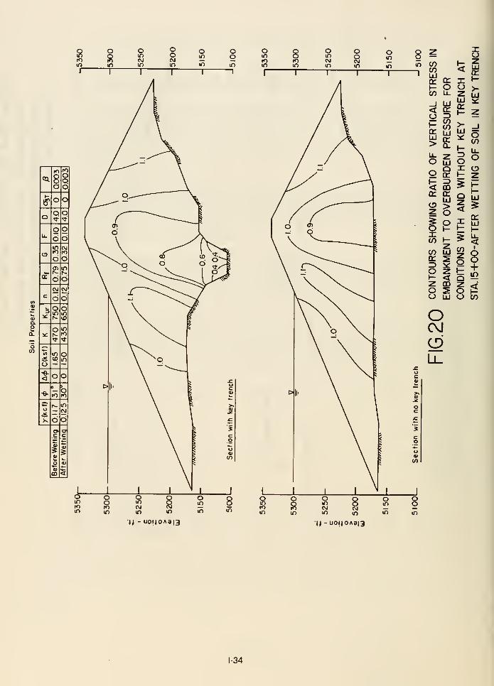
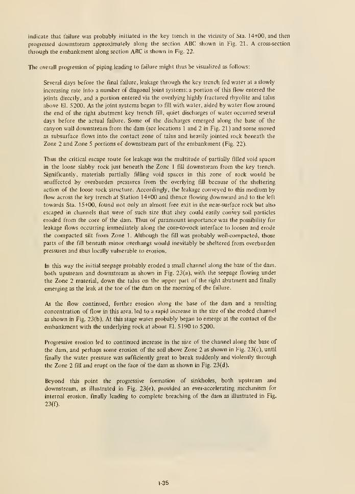
indicate that failure was probably initiated in the key trench in the vicinity of Sta. 14+00, and then
progressed downstream approximately along the section ABC shown in Fig. 21. A cross-section
through the embankment along section ABC is shown in Fig. 22.
The overall progression of piping leading to failure might thus be visualized as follows:
Several days before the final failure, leakage through the key trench fed water at a slowly
increasing rate into a number of diagonal joint systems; a portion of this flow entered the
joints directly, and a portion entered via the overlying highly fractured rhyolite and talus
above El. 5200. As the joint systems began to fill with water, aided by water flow around
the end of the right abutment key trench fill, quiet discharges of water occurred several
days before the actual failure. Some of the discharges emerged along the base of the
canyon wall downstream from the dam (see locations 1 and 2 in Fig. 21 ) and some moved
as subsurface flows into the contact zone of talus and heavily jointed rock beneath the
Zone 2 and Zone 5 portions of downstream part of the embankment (Fig. 22).
Thus the critical escape route for leakage was the multitude of partially filled void spaces
in the loose slabby rock just beneath the Zone 1 fill downstream from the key trench.
Significantly, materials partially filling void spaces in this zone of rock would be
unaffected by overburden pressures from the overlying fill because of the sheltering
action of the loose rock structure. Accordingly, the leakage conveyed to this medium by
flow across the key trench at Station 14+00 and thence flowing downward and to the left
towards Sta. 15+00, found not only an almost free exit in the near-surface rock but also
escaped in channels that were of such size that they could easily convey soil particles
eroded from the core of the dam. Thus of paramount importance was the possibility for
leakage flows occurring immediately along the core-to-rock interface to loosen and erode
the compacted sUt from Zone 1 . Although the fill was probably well-compacted, those
parts of the fill beneath minor overhangs would inevitably be sheltered from overburden
pressures and thus locally vulnerable to erosion.
In this way the initial seepage probably eroded a small channel along the base of the dam,
both upstream and downstream as shown in Fig. 23(a). with the seepage flowing under
the Zone 2 material, down the talus on the upper part of the right abutment and finally
emerging as the leak at the toe of the dam on the morning of the failure.
As the flow continued, further erosion along the base of the dam and a resulting
concentration of flow in this area, led to a rapid increase in the size of the eroded channel
as shown in Fig. 23(b). At this stage water probably began to emerge at the contact of the
embankment with the underlying rock at about El. 5190 to 5200.
Progressive erosion led to continued increase in the size of the channel along the base of
the dam, and perhaps some erosion of the soil above Zone 2 as shown in Fig. 23(c), until
finally the water pressure was sufficiently great to break suddenly and violently through
the Zone 2 fill and erupt on the face of the dam as shown in Fig. 23(d).
Beyond this point the progressive formation of sinkholes, both upstream and
downstream, as illustrated in Fig. 23(e), provided an ever-accelerating mechanism for
internal erosion, finally leading to complete breaching of the dam as illustrated in Fig.
23(0-
1-35
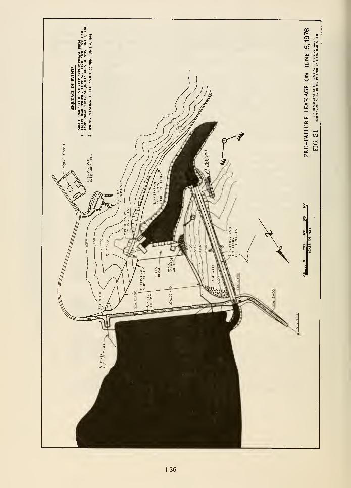
-36
oc
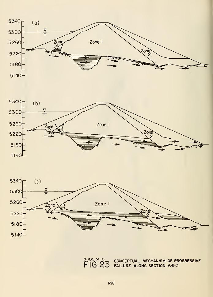
5340r
5300-
5 260-
5220-
5180-
5140-
^r-^l^r^nZi CONCEPTUAL MECHANISM OF PROGRESSIVE
r \\J.C.O FAILURE ALONG SECTION ABC
1-38
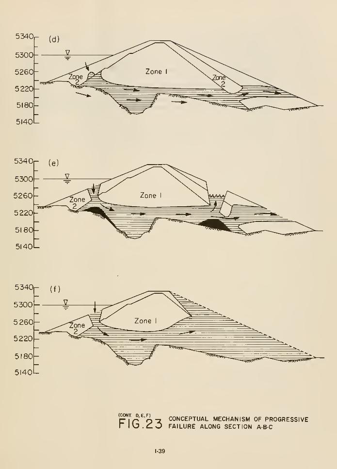
(CONT D, E,F)CONCEPTUAL MECHANISM OF PROGRESSIVE
lO.^O FAILURE ALONG SECTION A-B-C
1-39
This general concept of the mechanism appears to be consistent with the photographic
record of the development of the failure.
It should be noted that even this rather detailed description of the faOure mechanism does not
provide a final answer to the specific cause of failure of Teton Dam. Clearly many aspects of the site
and the embankment design were contributory to the failure, but because the failed section was
carried away by the flood waters, it will probably never be possible to resolve whether the primary
cause of leakage in the vicinity of Station 14+00 was due to imperfect grouting of the rock just below
the grout cap, or to hydraulic fracturing in the key trench fill, or possibly both. There is evidence to
support both points of view. Nevertheless, while the specific cause may be impossible to estabUsh,
the narrowing of the possibUities to these two aspects of design and construction is likely to serve as
an important lesson in the design and construction of future projects of this type.
1-40
REFERENCES
Bieber, Ray E. (1976) "TETON DAM; Finite Element Stress Analysis Study," Report DAC/1222 to
Independent Panel to Review Cause of Teton Dam Failure, October 15, 1976.
Nobari, E.S. and Duncan, J.M. (1972) "Effect of Reservoir Filling on Stresses and Movements in
Earth and Rockfill Dams," Geotechnical Engineering Report No. TE 72-1 to the Office, Chief of
Engineers, U.S. Army Waterways Experiment Station, University of California, Berkeley, January.
Ozawa, Y. and Duncan, J.M. (1973) "ISBILD: A Computer Program for Analysis of Static Stresses
and Movements in Embankments," Geotechnical Engineering, Report No. TE 73-4, University of
California, Berkeley, December.
Wong, Kai S. and Duncan, J.M. (1974) "Hyperbolic Stress-Strain Parameters for Nonlinear Finite
Element Analyses of Stresses and Movements in Soil Masses," Report No. TE 74-3 to National
Science Foundation, Office of Research Services, University of California, Berkeley, July.
1-41
Gradation analysis and Atterberg limit determinations were made on all samples by the Teton Project
Laboratory, including those samples shipped to the other laboratories for testing.
The results of aU tests are discussed in Chapter 7, and the complete reports have been placed in the
Panel's records. Samples not tested are stored at the USER laboratories in Denver.
EMBANKMENT STRESS ANALYSIS
Interest developed early within the Panel as to the possibility of tension cracking of Zone I
transversely within the key trench due to arching between the steep side walls of the narrow trench or
due to differential settlement at any abrupt changes in the longitudinal slope of the key-trench invert,
or due to the tendency of the embankment mass to pull away from the abutments as the dam settled.
The Panel recognized that the state of stress within the embankment due to these factors would be
intimately associated with and influenced by the tntergranular forces imposed as the reservoir filled
and saturation gradually spread through the embankment volume. A two-dimensional pUot study of
the state of stress within Zone 1 at Sta. 14+00 was made at the Panel's request by Dynamic Analysis
Corporation, Saratoga, California. The finite element analytical methods for soils developed in recent
years primarily by the University of California at Berkeley were employed.
The results of these pilot studies, available to the Panel at its August meeting, were considered
sufficiently revealing to warrant expanding the studies to three transverse sections at Stas. 12+70,
13+20, and 13+70 and to a longitudinal section along the key trench from Sta. 12+00 to Sta. 20+00.
The University of California at Berkeley also undertook a two-dimensional finite element stress
analysis of the embankment at Sta. 15+00. The results of these analyses are included in Appendix Dand reviewed in Chapter 12.
HYDRAULIC FRACTURING TESTS IN BOREHOLES
Hydraulic fracturing tests were made in boreholes in the left portion of the remaining embankment at
stations where the geometry of the key trench and the height of the overlying embankment were
similar to those at the stations where the initial breach of the right key-trench fill occurred. The
principal purpose was to determine, by comparing the results of the field tests with those of
calculations, appropriate in-situ values of soil properties needed for finite-element analyses of stress
conditions in the right key trench.
Three tests were performed. Sta. 26+00 was selected for the first test upon determining that the key
trench and embankment-foundation geometry were analogous to that of Sta. 15+00.
The test procedure involved drilling a vertical hole directly over the key-trench centerUne to a
predetermined depth and subjecting an exposure of Zone 1 over a selected length of the hole near the
bottom to a gradually increasing head of water. The length of hole so pressured was restricted bysealing an internal standpipe in the drill hole with a cement plug at the top of the length selected for
testing and introducing water into the standpipe.
By observing the recession rate of the imposed head, a normal rate of seepage for the conditions
established was determined. The head was then increased by increments and the recession rates
observed. If an increment was reached for which the recession rate suddenly increased by a larger
magnitude , the fill in the region of the hole was deemed to have been fractured by the hydrostatic
pressures created by the head then imposed.
1-42
At Sta. 26+00 it was believed that the hole could be safely wash-bored to 150 ft and the plug set at
that depth (Fig. 3-6). However, at 101.3 ft (El. 5211.7) a sudden loss of drill water occurred.
Fracturing is believed to have occurred at that elevation and head. Through a misunderstanding,
drilling of the hole continued to a depth of 150 ft with continued loss of drilling water and the
injection of several thousand gallons of water into the adjacent soil. A 3-in. plastic pipe was sealed in
the hole with the cement plug and the hole was extended for 39 ft beyond by drilling with air. Soil
wetted by the previous drill water loss became lodged behind the drill bit and in forcefully freeing the
drill string the plastic pipe was pulled from the plug. The hole was temporarily abandoned.
A second attempt was made at Sta. 26+25 by drilling a 4-in. hole with air to a depth of 150 ft, sealing
a 3-in. plastic pipe in the hole with a cement plug at El. 5163, and extending the length of hole to be
pressured 20 ft to El. 5143 by using air to facilitate drilling. Again wet drill cuttings lodged behind
the drill bit, this time causing a momentary increase in air pressure, apparently sufficient to fracture
the hole as evidenced by the sudden entry of water into the hole, most likely from the adjacent hole
at Sta. 26+00.
Because Sta. 13+70 had also been analyzed and because Sta. 27+00 was analogous, a third test hole
was located at that station and augered 109 ft to El. 5210. Nx casing was sealed in the hole at that
elevation, and the hole was extended 20 ft with a split spoon drive sampler. The hole was then
incrementally pressured as previously described. The test results are shown on Fig. 3-7.
As revealed by the water level recession rates, no fracturing occurred even with the water level raised
to the top of the hole at El. 5317.
The hole at Sta. 26+00 which had been originally cased to 150 ft with 6-in. casing was restored by
sealing Nx casing with a new plug at 152 ft and by cleaning out the original 39-ft-long hole extension
with the split spoon drive sampler for 28 ft. The hole was then tested. Although some sloughing of
the hole may have taken place during the test, the average head was assumed measured to the
midheight of the restored hole, or El. 5147. The results are shown on Fig. 3-8 and indicate that the
Zone 1 fill was fractured when the water surface was 20 ft below the top of the hole, or El. 5293.
POST-FAILURE FOUNDATION INVESTIGATION
Early in its investigation the Panel recognized the desirability of identifying the most probable path
or paths of the leakage that led to failure of the dam. Efforts were directed to determine whether
critical leakage had passed through, around, or under the dam, or had followed a combination of
routes; also to establish the precise path or paths insofar as possible from the evidence remaining at
the site.
A geologic program was developed to investigate the following possible avenues of leakage through
the foundation:
1. Around the right end of the dam.
2. Through the grout curtain.
3. Through large cavities discovered near the right end of the dam during its construction.
4. Through sedimentary deposits underlying the volcanic rock foundation.
1-43


CEMENT PLLX;-EL5161
-3" UNCASED HOIE
BOTTOM OF HOLE-EL 5133
KEY TRENCH INVERT-EL. 5114
SCALE IN FEET
BORE HOLE STA. 26-1-00
_-.^ ~ — us DEPAHTMtNT OF THE INT[«IO« — STATE OF JDAHO
FIG. 3— 6. INOiPENDENT PANEL TO «EVIEW CAUSE Of TETON DAM FAILUHE
1-45

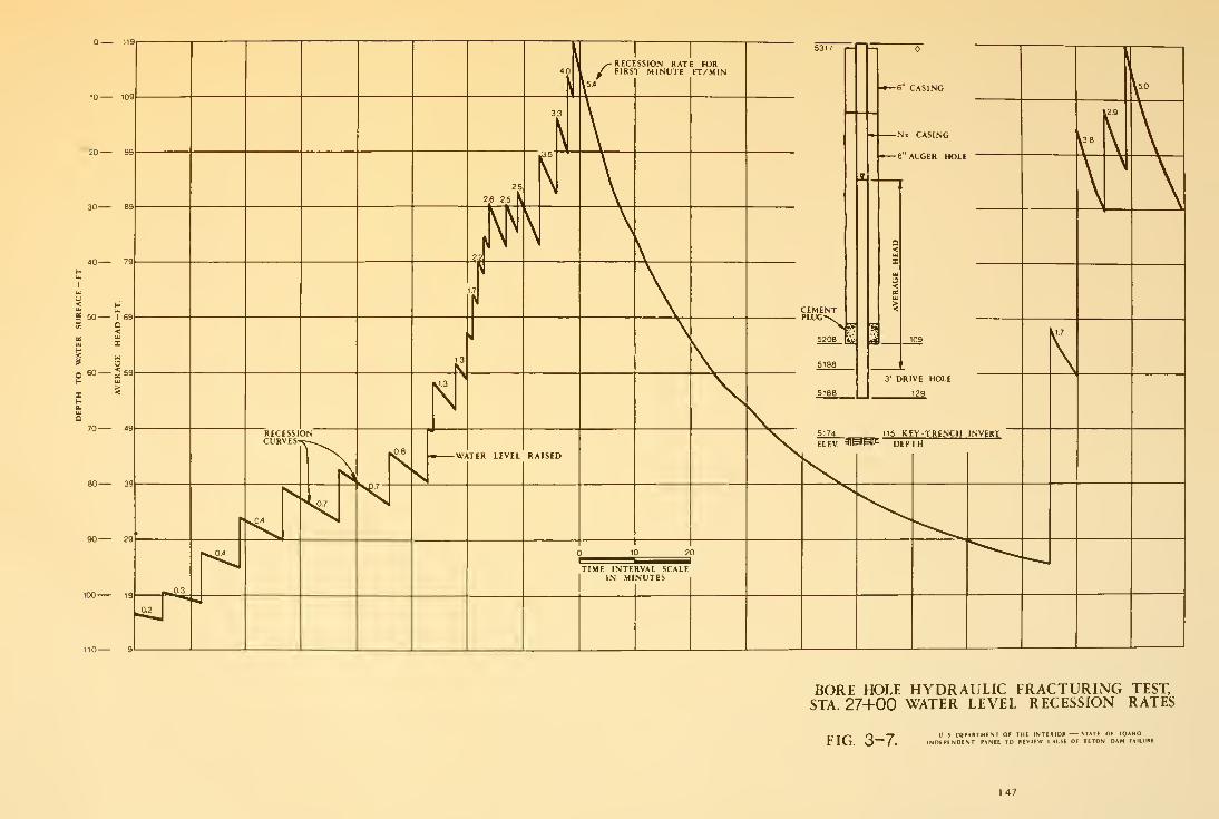
BORE HOLE HYDRAULIC FRACTURING TEST.STA. 27+00 WATER LEVEL RECESSION RATES
rw^^ r^ ~7 us DEPARTMENT OF THE INTERIOR ^TATl OF lOAMU
r Id. O ( INDEPENDENT PANEL TO REVIEW CAUSE OF TETON DAM FAILURE
1-47

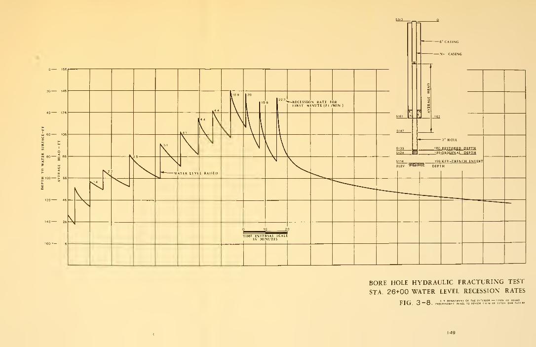
BORE HOLE HYDRAULIC FRACTURING TEST
STA. 26+00 WATER LEVEL RECESSION RATES
r. , /— O O "J S DEPAHTMINT OF THI INTIRIOll *TATi Or IDAHO
r Itj. O ~0. INDtPENDfWT PANIL TO HIVIIW CAUSE Of TITON DAM FAIU
«
1-49