Operational and Maintenance Manual for Harangi Dam ...
156
Page 1 of 156 Operational and Maintenance Manual for Harangi Dam KA06HH0139 (Version 2.0) Water Resources Department State of Karnataka.
-
Upload
khangminh22 -
Category
Documents
-
view
0 -
download
0
Transcript of Operational and Maintenance Manual for Harangi Dam ...
Page 1 of 156
Operational and Maintenance Manual for Harangi Dam KA06HH0139 (Version 2.0)
Water Resources Department State of Karnataka.
O&M Manual for Harangi Dam(Version 2.0) January 2020
Page 2 of 156
Front Cover Photograph: Downstream view of Harangi Dam during flood release. The scope of rehabilitation works carried out under the Dam Rehabilitation & Improvement Project (DRIP) entailed works carried out to reduce seepage and leakage within the concrete /masonry structure, special treatments to the glacis surfaces to reduce erosion, upgrade of canal gates, Reaming of porous hole and foundation hole, Improvement and Repairs of ornamental parapet.
Chief Engineer CNNL, Irrigation South Zone, Mysore. Ph No: 0821-2443900 Email: [email protected] [email protected]
O&M Manual for Harangi Dam(Version 2.0) January 2020
Page 3 of 156
Operation and Maintenance Manual for Harangi Dam
Prepared by the Dam Safety Rehabilitation Directorate
with Assistance from
CAUVERY NEERAVARI NIGAM LIMITED
(A Government of Karnataka undertaking)
January 2020
O&M Manual for Harangi Dam(Version 2.0) January 2020
Page 4 of 156
MESSAGE
India has more than 5200 large dams. Their health and safety are of paramount importance for sustainable use of the valuable assets, besides providing protection to the people and property in the downstream areas. The Ministry of Water Resources, River Development & Ganga Rejuvenation through the Central Water Commission (CWC), with financial assistance from the World Bank, started the Dam Rehabilitation and Improvement Project (DRIP) to rehabilitate 198 large dam projects in seven states. For managing a dam in a sustainable and scientific manner, it is very crucial for each dam owner to have dam specific Operation and Maintenance Manual that lays down procedures for the daily upkeep of the dam. An Operation and Maintenance Manual for a dam is essential for ensuring its safe functioning and for deriving continued benefits. This Operation and Maintenance Manual for Harangi Dam has been prepared following the Guideline for Preparation Operation and Maintenance Manuals published in January 2018 under DRIP and covers requirements for project Operation, Inspection, Maintenance, Instrumentation and Monitoring the health of Harangi Dam both during monsoon and non-monsoon periods. This manual will also be of great value to all dam owners of Karnataka and operators to achieve the desired objectives.
I recommend the dam officials to use this manual for the efficient and safe Operation and Maintenance of the Harangi Dam on regular basis.
I appreciate the initiative taken by CPMU, DRIP and CWC for developing this comprehensive document for implementation by the engineers and administrators of the Harangi Dam, Harangi Rehabilitation Division Kushalanagar, Cauvery Neeravari Nigam, Karnataka.
I also compliment all the experts who have contributed to the development of this manual and congratulate the Ministry of Water Resources, River Development & Ganga Rejuvenation, CWC for the initiation of such important policy protocol to address dam safety management in India.
Sri. Rakesh Singh, IAS Principal Secretary
Water Resources Department, Karnataka

O&M Manual for Harangi Dam(Version 2.0) January 2020
Page 5 of 156
Foreword This Operation and Maintenance (O&M) Manual developed exclusively for Harangi Dam is a detailed set of written descriptions with step-by-step procedures for ensuring that the dam is safely operated, frequently inspected and properly maintained. In this era of shrinking budgets, timely inspection and preventative maintenance is necessary for the safe functioning of the dam and continued productive use of the dam and reservoir.
The format of this manual was prepared following the principles published 2018 CWC guidelines for operation and maintenance of dam for the use by all Dam Owners in developing their own site-specific manuals. Each section of the document provides the necessary instructions to operate inspect and maintain their dam.
It is recommended that all dam officials charged with the operation of their dams to use this manual to ensure their dam is operated and maintained in a sustainable manner and will continue to derive benefits.
O&M Manual for Harangi Dam(Version 2.0) January 2020
Page 6 of 156
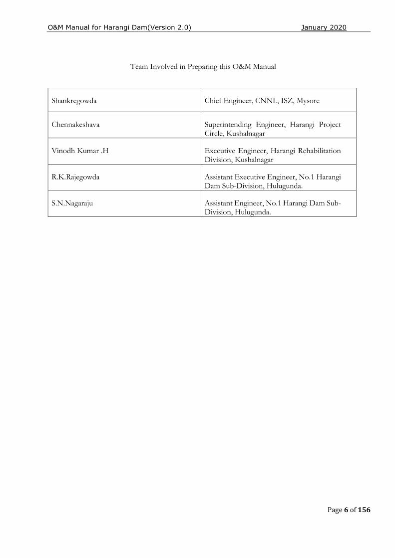
Team Involved in Preparing this O&M Manual
Shankregowda Chief Engineer, CNNL, ISZ, Mysore
Chennakeshava Superintending Engineer, Harangi Project Circle, Kushalnagar
Vinodh Kumar .H Executive Engineer, Harangi Rehabilitation Division, Kushalnagar
R.K.Rajegowda Assistant Executive Engineer, No.1 Harangi Dam Sub-Division, Hulugunda.
S.N.Nagaraju Assistant Engineer, No.1 Harangi Dam Sub-Division, Hulugunda.
O&M Manual for Harangi Dam(Version 2.0) January 2020
Page 7 of 156
TABLE OF CONTENTS
Message 4
Chapter 1 - General Information 13
1.1 Introduction 13
1.2 Purpose, Location & Description of Harangi Dam 13
1.3 Background Details of the Project 14
1.3.1 Dam site Location: 14
1.3.2 Harangi Reservoir Planning: 14
1.3.3 Main Design Features and Components of Harangi Dam: 17
1.4 Salient Features of Harangi Dam 19
1.5 Assignment of Responsibility 21
1.5.1 Roles and Responsibilities of the AEE and AE during Monsoon 22
1.5.2 Roles and Responsibilities of the SE and EE during Monsoon 23
1.5.3 Roles and Responsibilities of the Chief Engineer during Monsoon 23
1.6 Collection & Reporting of Dam and Reservoir Data 24
1.7 Public and Project Staff - Health and Safety 26
1.7.1 Restricted Areas 26
1.7.2 Details of the Security arrangements at Harangi Dam Site. 26
1.8 Staff Position, Communication & Warning System 28
1.8.1 Schedule of General Duties for Project Engineers 31
1.8.2 Hydro-Mechanical Inspections / Checks 34
1.9 Distribution of Operation & Maintenance Manuals 36
1.10 Supporting Documents & Reference Material 37
Chapter 2.Project Operation 38
2.1 Basic Data 38
2.1.1 Area Capacity curves. 38
2.1.2 Design Flood and Features Related to Safety 38
2.2 Flood Management at Harangi Reservoir: 42
2.2.1 Gate Normal operation Rule curve 42
2.2.2 Sequence of Opening or Closing of Gates 43
2.2.3 Reservoir Operation during floods 43
2.3 Operation of Radial Crest Gates of Harangi Dam 48
2.3.1 Brief Description 48
2.3.2 Radial Crest gates 48
2.3.3 Salient Features 49
2.3.4Material Specification 49

O&M Manual for Harangi Dam(Version 2.0) January 2020
Page 8 of 156
2.4 Operating Instructions 50
2.4.1Checklist before Operation 50
2.5 Material Specifications 50
2.6 Handling Equipment 52
2.6.1 35-T Gantry Crane – Brief Description 52
2.6.2 Technical Data 53
2.6.3 Technical Data 59
2.7 Operational Instructions 65
2.7.1 TROUBLE SHOOTING 66
2.8 Electrical Connections: 67
2.9 RIVER OUTLET WORKS. 68
2.9.1 Description: 68
2.9.1.1 RIVER SLUICE GATES: 68
2.9.1.2 Irrigation Sluice gates & hoists 68
2.9.1.3 HEAD WORKS: 69
2.9.2.1 General: 71
2.9.3 Historical Events. 71
2.9.3.1 General 71
2.9.3.2 Mechanical: 71
2.10 ACCESS ROADS 73
2.10.1 Record Keeping 74
Chapter 3 - Project Inspections
3.1 Types of Inspections 77
3.1.1 Comprehensive Evaluation Inspection 77
3.1.2 Scheduled Inspections 78
3.1.3 Special (Unscheduled) Inspections 78
3.1.4 Informal Inspections 79
3.1.5 Pre-and Post-Monsoon Checklist and Example of Report Proforma 79
Chapter 4 Project Maintenance
4.1 Maintenance Priorities 88 4.1.1 Immediate Maintenance 88
4.1.2 Preventive Maintenance 88 4.1.2.1 Condition Based Maintenance 88 4.1.2.2 Routine Maintenance 89 4.2 Procedures for Routine Maintenance 89 4.2.1 Earthwork 90 4.2.2 Masonry /Concrete Dams & Spillways 94 4.2.3 River Sluices 94

O&M Manual for Harangi Dam(Version 2.0) January 2020
Page 9 of 156
4.2.4 Gates & Hoisting Equipment 94
4.2.5 Electrically operated fixed hoists 97
4.3 Maintenance of Electrical components of Fixed Rope Drum Hoists 99 4.4 Surface Preparation and Painting of HM Works 104
4.5 Electrical System 108
4.6 Maintenance of Metal Gate Components 108
4.7 Access Roads 108
4.8 General Cleaning 109
4.9 Materials and Establishment Requirements during Monsoon Period 109
4.10 General List of Maintenance Records 109
4.11 Preparation of O&M budget 109
4.12 Maintenance Records 113
Chapter 5 - Instrumentation and Monitoring
5.1 Dam Instrumentation 113
5.1.1 General Information 113
5.1.2 Embedded Instruments – Concrete/Masonry 113
5.1.3 Instruments Embedded in the Harangi Earthen Dam 114
5.1.4 Seismological Observations 114
5.1.5 Telemetric Weather station 114
Chapter 6 - Previous Rehabilitation Efforts 114
List of Tables Table 1 - Details of Distributed Water to Karnataka 14
Table 2 – Overall Responsibilities for Harangi Dam 21
Table 3 – Roles & Responsibilities of AEE & AE 22
Table 4 – Roles & Responsibilities of SE & EE 23
Table 5 – Roles & Responsibilities of the Chief Engineer 23
Table 6 - Distribution of O&M Manual and Revisions 36
Table 7 – Gate opening discharge table 45
Table 8 - Material Specifications 50
Table 9 - Harangi Dam 35-Ton Gantry Crane Design Data 53
Table 10 – Harangi Dam 20-Ton Gantry Crane Design Data 59
Table 11 – Materials for 35-Ton Gantry Crane 65
Table 12 – Materials for 20-Ton Gantry Crane 65
Table 13 – Troubleshooting Chart 66
Table 14 – O&M Budget Costs (Annual) 111
Table 15 –Locations and Extents of Structural Members 113
O&M Manual for Harangi Dam(Version 2.0) January 2020
Page 10 of 156
Table 16 – Embedded Instruments 114
Table 17 - Embankment Instruments 114
List of Figures
Figure 1 - Harangi Basin Map
Figure 2 – General layout of Harangi Dam
Figure 3 – Engineering organizational chart
List of Appendix
Appendix 1 - Performance of Dam Instruments 87
Appendix 2 - Basic Drawings of HARANGI Dam 116
Appendix 3- Key elements of the EAP 119
Appendix 4- Material Required for Maintenance during Monsoon 133
Appendix 5- Scheduled or Unscheduled Dam Safety Inspection Form 134
Appendix 6 – CCTV Camera System Specification 146
Appendix 7 – Glossary 148
O&M Manual for Harangi Dam(Version 2.0) January 2020
Page 11 of 156
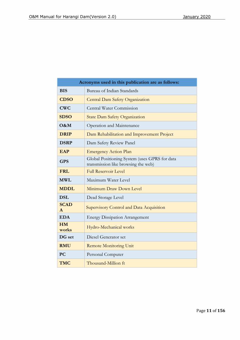
Acronyms used in this publication are as follows:
BIS Bureau of Indian Standards
CDSO Central Dam Safety Organization
CWC Central Water Commission
SDSO State Dam Safety Organization
O&M Operation and Maintenance
DRIP Dam Rehabilitation and Improvement Project
DSRP Dam Safety Review Panel
EAP Emergency Action Plan
GPS Global Positioning System (uses GPRS for data transmission like browsing the web)
FRL Full Reservoir Level
MWL Maximum Water Level
MDDL Minimum Draw Down Level
DSL Dead Storage Level
SCADA Supervisory Control and Data Acquisition
EDA Energy Dissipation Arrangement
HM works Hydro-Mechanical works
DG set Diesel Generator set
RMU Remote Monitoring Unit
PC Personal Computer
TMC Thousand-Million ft

O&M Manual for Harangi Dam(Version 2.0) January 2020
Page 12 of 156
THIS PAGE LEFT BLANK INTENTIONALLY
O&M Manual for Harangi Dam(Version 2.0) January 2020
Page 13 of 156
CHAPTER 1 - GENERAL INFORMATION
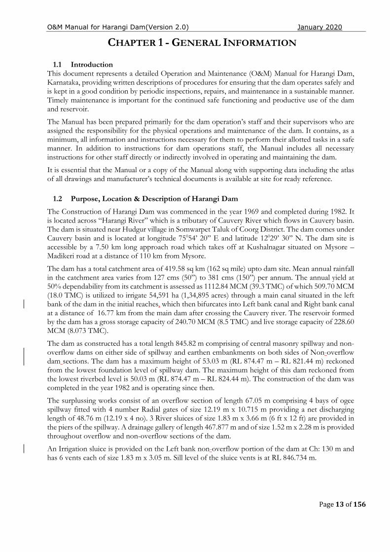
1.1 Introduction This document represents a detailed Operation and Maintenance (O&M) Manual for Harangi Dam, Karnataka, providing written descriptions of procedures for ensuring that the dam operates safely and is kept in a good condition by periodic inspections, repairs, and maintenance in a sustainable manner. Timely maintenance is important for the continued safe functioning and productive use of the dam and reservoir.
The Manual has been prepared primarily for the dam operation’s staff and their supervisors who are assigned the responsibility for the physical operations and maintenance of the dam. It contains, as a minimum, all information and instructions necessary for them to perform their allotted tasks in a safe manner. In addition to instructions for dam operations staff, the Manual includes all necessary instructions for other staff directly or indirectly involved in operating and maintaining the dam.
It is essential that the Manual or a copy of the Manual along with supporting data including the atlas of all drawings and manufacturer’s technical documents is available at site for ready reference.
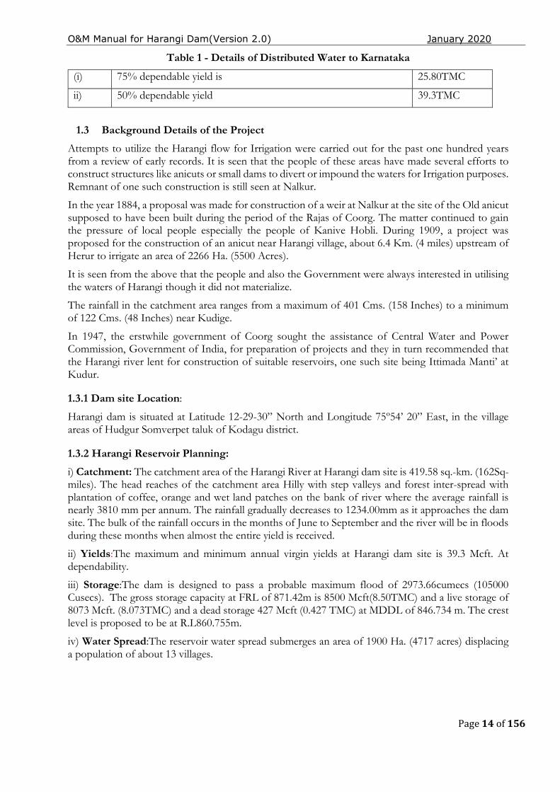
1.2 Purpose, Location & Description of Harangi Dam
The Construction of Harangi Dam was commenced in the year 1969 and completed during 1982. It is located across “Harangi River” which is a tributary of Cauvery River which flows in Cauvery basin. The dam is situated near Hudgur village in Somwarpet Taluk of Coorg District. The dam comes under Cauvery basin and is located at longitude 75054’ 20’’ E and latitude 12029’ 30’’ N. The dam site is accessible by a 7.50 km long approach road which takes off at Kushalnagar situated on Mysore – Madikeri road at a distance of 110 km from Mysore.
The dam has a total catchment area of 419.58 sq km (162 sq mile) upto dam site. Mean annual rainfall in the catchment area varies from 127 cms (50”) to 381 cms (150”) per annum. The annual yield at 50% dependability from its catchment is assessed as 1112.84 MCM (39.3 TMC) of which 509.70 MCM (18.0 TMC) is utilized to irrigate 54,591 ha (1,34,895 acres) through a main canal situated in the left bank of the dam in the initial reaches, which then bifurcates into Left bank canal and Right bank canal at a distance of 16.77 km from the main dam after crossing the Cauvery river. The reservoir formed by the dam has a gross storage capacity of 240.70 MCM (8.5 TMC) and live storage capacity of 228.60 MCM (8.073 TMC).
The dam as constructed has a total length 845.82 m comprising of central masonry spillway and non-overflow dams on either side of spillway and earthen embankments on both sides of Non-overflow dam sections. The dam has a maximum height of 53.03 m (RL 874.47 m – RL 821.44 m) reckoned from the lowest foundation level of spillway dam. The maximum height of this dam reckoned from the lowest riverbed level is 50.03 m (RL 874.47 m – RL 824.44 m). The construction of the dam was completed in the year 1982 and is operating since then.
The surplussing works consist of an overflow section of length 67.05 m comprising 4 bays of ogee spillway fitted with 4 number Radial gates of size 12.19 m x 10.715 m providing a net discharging length of 48.76 m (12.19 x 4 no). 3 River sluices of size 1.83 m x 3.66 m (6 ft x 12 ft) are provided in the piers of the spillway. A drainage gallery of length 467.877 m and of size 1.52 m x 2.28 m is provided throughout overflow and non-overflow sections of the dam.
An Irrigation sluice is provided on the Left bank non-overflow portion of the dam at Ch: 130 m and has 6 vents each of size 1.83 m x 3.05 m. Sill level of the sluice vents is at RL 846.734 m.
O&M Manual for Harangi Dam(Version 2.0) January 2020
Page 14 of 156
Table 1 - Details of Distributed Water to Karnataka
(i) 75% dependable yield is 25.80TMC
ii) 50% dependable yield 39.3TMC
1.3 Background Details of the Project
Attempts to utilize the Harangi flow for Irrigation were carried out for the past one hundred years from a review of early records. It is seen that the people of these areas have made several efforts to construct structures like anicuts or small dams to divert or impound the waters for Irrigation purposes. Remnant of one such construction is still seen at Nalkur.
In the year 1884, a proposal was made for construction of a weir at Nalkur at the site of the Old anicut supposed to have been built during the period of the Rajas of Coorg. The matter continued to gain the pressure of local people especially the people of Kanive Hobli. During 1909, a project was proposed for the construction of an anicut near Harangi village, about 6.4 Km. (4 miles) upstream of Herur to irrigate an area of 2266 Ha. (5500 Acres).
It is seen from the above that the people and also the Government were always interested in utilising the waters of Harangi though it did not materialize.
The rainfall in the catchment area ranges from a maximum of 401 Cms. (158 Inches) to a minimum of 122 Cms. (48 Inches) near Kudige.
In 1947, the erstwhile government of Coorg sought the assistance of Central Water and Power Commission, Government of India, for preparation of projects and they in turn recommended that the Harangi river lent for construction of suitable reservoirs, one such site being Ittimada Manti’ at Kudur.
1.3.1 Dam site Location: Harangi dam is situated at Latitude 12-29-30” North and Longitude 75º54’ 20” East, in the village areas of Hudgur Somverpet taluk of Kodagu district.
1.3.2 Harangi Reservoir Planning:
i) Catchment: The catchment area of the Harangi River at Harangi dam site is 419.58 sq.-km. (162Sq-miles). The head reaches of the catchment area Hilly with step valleys and forest inter-spread with plantation of coffee, orange and wet land patches on the bank of river where the average rainfall is nearly 3810 mm per annum. The rainfall gradually decreases to 1234.00mm as it approaches the dam site. The bulk of the rainfall occurs in the months of June to September and the river will be in floods during these months when almost the entire yield is received.
ii) Yields:The maximum and minimum annual virgin yields at Harangi dam site is 39.3 Mcft. At dependability.
iii) Storage:The dam is designed to pass a probable maximum flood of 2973.66cumecs (105000 Cusecs). The gross storage capacity at FRL of 871.42m is 8500 Mcft(8.50TMC) and a live storage of 8073 Mcft. (8.073TMC) and a dead storage 427 Mcft (0.427 TMC) at MDDL of 846.734 m. The crest level is proposed to be at R.L860.755m.
iv) Water Spread:The reservoir water spread submerges an area of 1900 Ha. (4717 acres) displacing a population of about 13 villages.
O&M Manual for Harangi Dam(Version 2.0) January 2020
Page 15 of 156
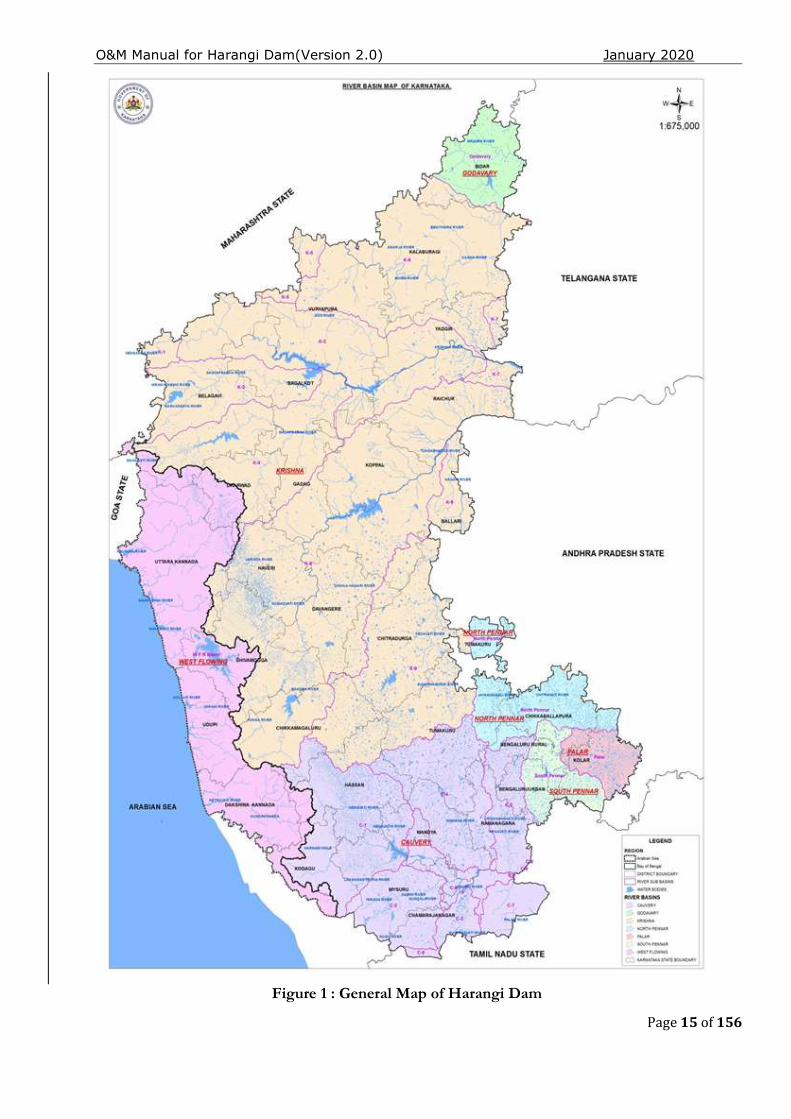
Figure 1 : General Map of Harangi Dam
O&M Manual for Harangi Dam(Version 2.0) January 2020
Page 16 of 156
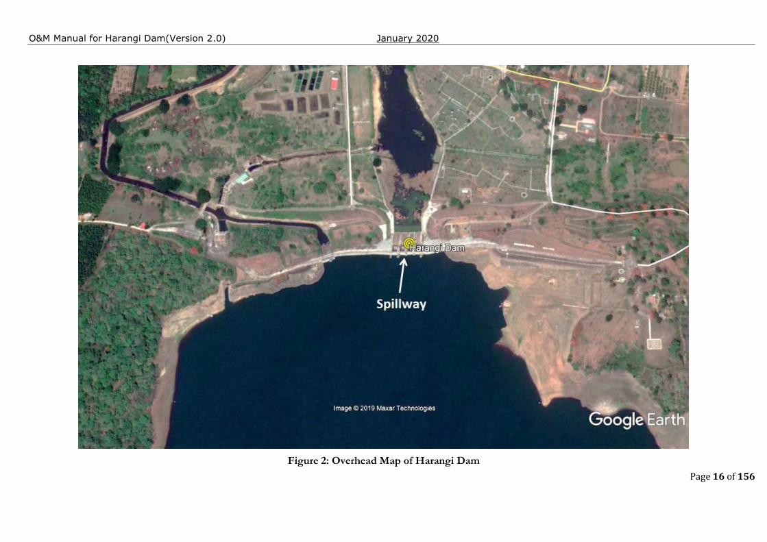
Figure 2: Overhead Map of Harangi Dam
O&M Manual for Harangi Dam(Version 2.0) January 2020
Page 17 of 156
1.3.3 Main Design Features and Components of Harangi Dam:
i) Earthen Dams: Earthen dams have been constructed on both left and right flanks as mentioned above and have the following features indicated.
1. Length of Left bank earthen dam is 85.34 m (Ch 0 to 85.34 m)
2. Length of Right bank earthen dam is 277.37m (Ch 568.45 m to 845.82 m)
3. Top width of dam is 5.48 m
4. Upstream slope of the dam is 3 H:1V uniformly
5. Downstream slope is 2 H:1V throughout with 1.50 m wide intervening berm at RL 864.718 m
6. Central heating zone with 5.40 m wide top kept at RL 872.947 m and having ½ H:1V side slopes.
7. Cut off trench taken upto hard strata or 10 m below stripped level having ½ H:1V side slopes and bottom width 3.50 m.
8. The internal drainage for the dam consists of 1.40 m thick inclined filter with cross drains at regular intervals connected to Toe drain below Rock toe.
9. The upstream slope is protected by rough stone revetment of 0.60 m thick rough stones laid on 0.45 m thick graded filter placed over casing material.
The dam site lies in Zone II of the revised seismic map of the country as per IS 1893:2002. As such to confirm the adequacy of the section provided, the SPMU needs to carryout fresh stability analysis for different conditions of loadings including seismic loadings stipulated in IS 1893:2002 and other relevant IS codes by adopting seismic coefficients applicable to the dam site as per the revised seismic map of the country and in-situ properties of the materials forming the dam and foundation determined by carrying out tests on representative undisturbed samples extracted in accordance with the prevailing standards. Strengthening measures may be initiated if stability requirements so warrant.
The cross section of the earth dam indicates provision of 1.50 m thick impervious blanket all along the base of the earth fill on the upstream portion at the stripped level and the same is connected to impervious hearting of the dam.
Upstream revetment at the Left bank earth dam junction with Non overflow dam was inspected. It was found that revetment was intact, free from bulges or settlements.
Turfing is provided on the downstream slope of right bank earthen dam and is well maintained.
ii) Left bank and right bank Non overflow dams: Masonry non-overflow dams have been constructed on both left and right flanks as mentioned above and have the following features.
1. Length of Left non overflow dam is 219.46 m (Ch: 85.34 m to 304.80 m).
2. Length of Right bank Non overflow dam is 196.60 m (Ch 371.85 m to 568.45m)
3. Top width of dam is 5.48 m
4. Upstream slope kept vertical from top upto RL 865.60 m (RL 2840 ft) and 1 in 10 batters below up to foundation.
5. Downstream slope kept vertical from top upto RL 865.60 m (RL 2840 ft), 0.65 H:1V up to RL 853.40 m (RL 2800 ft), 0.75:1 up to RL 839.70 m (RL 2755 ft) and then 0.85:1 up to bottom.
6. Body wall of the NOF dam is constructed in UCR masonry in CM 1:4 with face stone masonry 2.25 ft thick in CM 1:3 for upstream face and in CM 1:4 for downstream face.
7. The upstream face of drainage gallery is provided at a distance of 10ft from the axis of the dam.
O&M Manual for Harangi Dam(Version 2.0) January 2020
Page 18 of 156
The head works of the left bank canal consists of six sluices each of size 1.83 m x 3.08 m (6’ x 10’) having sill at RL 844.30 m (RL 2771 ft) and is located in the left bank non overflow dam at Ch 130 m.
The upstream face of the left non-overflow dam was inspected and the joints in the masonry above the water level at the time of inspection RL 853.68 m (RL 2800.93 ft) are in good condition and free from openings.
iii)Central Spillway Dam: Masonry overflow dam has been constructed in the Central gorge portion as mentioned above and has the following features as indicated.
1. Length of overflow dam is 67.05 m (Ch: 304.80 to 371.85 m)
2. Top width of Dam is 5.48 m
3. Upstream slope has a batter of 1 H:1V from crest RL 860.755 m (RL 2824 ft) up RL 856.15 m (RL 2809 ft) and 1 in 20 batter below up to foundation.
4. Downstream slope is provided with WES profile up to tangent point at RL 851.55 m (RL 2793.88 ft) and then 0.8 H:1V batter up to bottom.
5. Body wall of the overflow dam is constructed in UCR masonry CM 1:4 with face stone masonry 2.25 ft thick in CM 1:3 for upstream face and 5 ft thick CC 1:2:4 for downstream face.
6. The upstream face of drainage gallery is provided at a distance of 10 ft from the axis of the dam.
The spillway has a total length of 67.05 m consisting of 4 radial type crest gates each of size 12.19m x 10.67 m providing a net discharging length of 48.76 m. The crest of the spillway is kept at RL 860.755 m (RL 2824 ft)
The spillway has an ogee crest with WES profile designed to pass a maximum flood discharge of 3493 cumec (120163 cusecs) under a spillage depth of 10.665 m. The spillway discharge is carried over the downstream glacis negotiating a fall of 32.92 m from its crest level before entering the energy dissipater consisting of a ski jump bucket, the details of which are given in para below.
Energy dissipation arrangements
The dissipation provided below the spillway is Ski-jump bucket action as finalized by model studies at KERS, KRS. The bucket has an invert level at RL 2706 ft and has a radius of 50 ft terminating at its lip level RL 828.30 m (RL 2717.70 ft). This spillway is in operation since first filling in the year 1982.
A maximum discharge of 77464 cusecs has passed over the spillway during monsoon season of the year Aug-2018.
Underwater inspection report of Stilling Basin.
Enzen global solutions Pvt.Ltd, Bengaluru survey conducted during month of June-2019. In this report briefs the results from the preliminary inspection of the health condition of the stilling basin of the Harangi Da. Inspection carried out during June 2019 aimed at identifying damages or anomalies on the wall of the stilling basin has been done using the semi-autonomous Remotely operated vehicle (ROV).
Major observation from the inspection was categorized into cavities, cracks and debonding on the walls. It is suggested to take up appropriate repair works based on the preliminary findings of this report to restore the structural integrity of the wall. Details of the inspection site,
O&M Manual for Harangi Dam(Version 2.0) January 2020
Page 19 of 156
equipment used and methodology are explained in the following sections, following by observations and conclusions.
1. Four major defects were found on the left side wall of the stilling basin. Defect observed were of debonding in nature with the size ranging from 90 mm to 130 mm in length and 9 to 11 mm in width. All were found between MSL 2710.32 to 2716.40 ft. These defects need immediate attention for grouting or injecting high grade concrete.
2. Three moderate sized cavities and cracks were observed at Gate 4, left and right side of the wall of MSL 2711.15, 2712.02 and 2708.88 ft respectively. These defects need grouting as immediate measure and continuous watch.
3. 37 numbers of minor anomalies in terms of small sized cavities, minor cracks, surface deformations and minor honeycomb formation were found.
4. In addition, debris in the form of iron bars observed below Gate 3-B at a depth of 2711.15 ft. Which requires further inspection on the source.
5. From the Bathymetry survey, it can be concluded thet a maximum depth of 10 ft is observed at the centre of the basin with gradually reduces to 2ft as we move towards the wall.
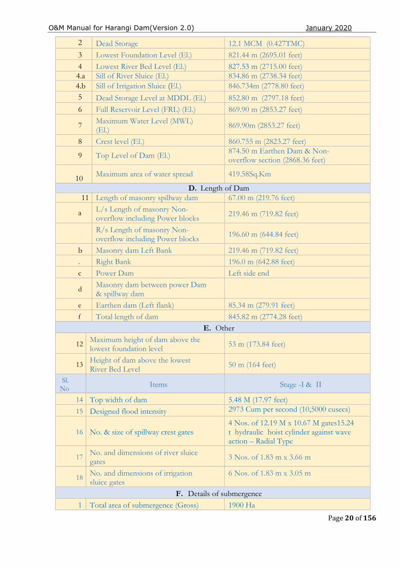
1.4 Salient Features of HarangiDam
Sl No Items Stage -I& II
A. General
1 Location of Dam
Hudgur village of Somaverpet taluk of Kodagu district at: Latitude12°29'30”N Longitude75°54’20’’E
2 Means of Access 8.00 Km from Kushlanagara
B. Geophysical Features
1 Catchment area 419.58 Sq.km (162Sq.miles)
2 Nature of catchment
Hilly with steep valleys and thick forest inter spread with plantation of coffee, orange and wet land patches on the bank of river.
3 Climate Moderate
4 Annual mean temperature
5 Mean annual precipitation Varying from 127 ems (50") to 381cm (159”)
6 Net yield Dam site at 75 % dependability 25.80 TMC
7 Silt charge per year 1.00 Acre ft/sq.mile
8 Geological features at dam site Hard quartzite rock (Coarse-grained) exposed at bed and quartzite's in the flanks
C. Technical Details of Dam 1 Gross Storage 240.7 MCM (8.50TMC)
O&M Manual for Harangi Dam(Version 2.0) January 2020
Page 20 of 156
2 Dead Storage 12.1 MCM (0.427TMC)
3 Lowest Foundation Level (El.) 821.44 m (2695.01 feet)
4 Lowest River Bed Level (El.) 827.53 m (2715.00 feet) 4.a Sill of River Sluice (El.) 834.86 m (2738.34 feet)
4.b Sill of Irrigation Sluice (El.) 846.734m (2778.80 feet) 5 Dead Storage Level at MDDL (El.) 852.80 m (2797.18 feet)
6 Full Reservoir Level (FRL) (El.) 869.90 m (2853.27 feet)
7 Maximum Water Level (MWL) (El.) 869.90m (2853.27 feet)
8 Crest level (El.) 860.755 m (2823.27 feet)
9 Top Level of Dam (El.) 874.50 m Earthen Dam & Non-overflow section (2868.36 feet)
10 Maximum area of water spread 419.58Sq.Km
D. Length of Dam 11 Length of masonry spillway dam 67.00 m (219.76 feet)
a L/s Length of masonry Non-overflow including Power blocks 219.46 m (719.82 feet)
R/s Length of masonry Non-overflow including Power blocks 196.60 m (644.84 feet)
b Masonry dam Left Bank 219.46 m (719.82 feet) . Right Bank 196.0 m (642.88 feet) c Power Dam Left side end
d Masonry dam between power Dam & spillway dam
e Earthen dam (Left flank) 85.34 m (279.91 feet) f Total length of dam 845.82 m (2774.28 feet)
E. Other
12 Maximum height of dam above the lowest foundation level 53 m (173.84 feet)
13 Height of dam above the lowest River Bed Level
50 m (164 feet)
Sl. No Items Stage -I & II
14 Top width of dam 5.48 M (17.97 feet) 15 Designed flood intensity 2973 Cum per second (10,5000 cusecs)
16 No. & size of spillway crest gates 4 Nos. of 12.19 M x 10.67 M gates15.24 t hydraulic hoist cylinder against wave action – Radial Type
17 No. and dimensions of river sluice gates 3 Nos. of 1.83 m x 3.66 m
18 No. and dimensions of irrigation sluice gates
6 Nos. of 1.83 m x 3.05 m
F. Details of submergence
1 Total area of submergence (Gross) 1900 Ha
O&M Manual for Harangi Dam(Version 2.0) January 2020
Page 21 of 156
2 Villages submerge 13 Nos
3 Population affected 700 Person above
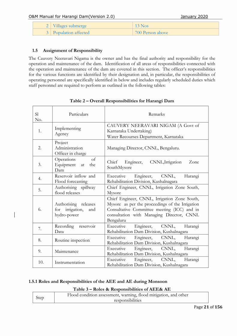
1.5 Assignment of Responsibility
The Cauvery Neeravari Nigama is the owner and has the final authority and responsibility for the operation and maintenance of the dam. Identification of all areas of responsibilities connected with the operation and maintenance of the dam are covered in this section. The officer’s responsibilities for the various functions are identified by their designation and, in particular, the responsibilities of operating personnel are specifically identified in below and includes regularly scheduled duties which staff personnel are required to perform as outlined in the following tables:
Table 2 – Overall Responsibilities for Harangi Dam
Sl No.
Particulars Remarks
1. Implementing Agency
CAUVERY NEERAVARI NIGAM (A Govt of Karnataka Undertaking)
Water Recourses Department, Karnataka
2. Project
Administration Officer in charge
Managing Director, CNNL, Bengaluru.
3. Operations of
Equipment at the Dam
Chief Engineer, CNNL,Irrigation Zone SouthMysore
4. Reservoir inflow and Flood forecasting
Executive Engineer, CNNL, Harangi Rehabilitation Division, Kushalnagara
5. Authorising spillway flood releases
Chief Engineer, CNNL, Irrigation Zone South, Mysore
6. Authorising releases
for irrigation, and hydro-power
Chief Engineer, CNNL, Irrigation Zone South, Mysore as per the proceedings of the Irrigation Consultative Committee meeting (ICC) and in consultation with Managing Director, CNNL Bengaluru
7. Recording reservoir Data
Executive Engineer, CNNL, Harangi Rehabilitation Dam Division, Kushalnagara
8. Routine inspection Executive Engineer, CNNL, Harangi
Rehabilitation Dam Division, Kushalnagara
9. Maintenance Executive Engineer, CNNL, Harangi Rehabilitation Dam Division, Kushalnagara
10. Instrumentation Executive Engineer, CNNL, Harangi Rehabilitation Dam Division, Kushalnagara
1.5.1 Roles and Responsibilities of the AEE and AE during Monsoon
Table 3 – Roles & Responsibilities of AEE& AE
Step Flood condition assessment, warning, flood mitigation, and other responsibilities

O&M Manual for Harangi Dam(Version 2.0) January 2020
Page 22 of 156
1. Coordinate with the Project Engineers to get the information in email on the rainfall in the catchment and inflow status at the state boundary and to bring it to the notice of the EE/SE/CE
2. Assist the EE/SE/CE to issue notification to the villagers downstream in Newspapers, Radio, TV News channel to be alert regarding the flood situation
3. Assist the EE/SE/CE to coordinate with the Revenue authorities (District Administration) to alert the downstream villagers to evacuate the flood zone to prevent loss of life and live stock
4. Assist the EE/SE/CE to coordinate with the CWC flood monitoring authorities on the flood condition
5. Maintain the reservoir water level gauge register and to update on hourly basis during floods and to bring to the notice of EE/SE/CE
6.
Assess the inflows in the reservoir as per the approved reservoir operation and to prepare proforma consisting of the status of the reservoir capacity and releases from the reservoir as per the standard Performa and to submit to the EE/SE/CE
7. Submit to the EE/SE/CE on the inflows and releases from the reservoir and status of the reservoir twice in the day
8. Maintain the spillway crest gate operation log book
9. Operate the Spillway crest gates for flood mitigation as per the instructions of the EE/SE/CE and to update the Gate operation Log book
10.
Observe the seepages in the drainage Gallery with respect to the reservoir head and record the seepages in the infiltration gallery and to immediately bring to the notice of the EE/SE/CE in case of excessive seepage ,leakage in any specific blocks and porous drains
11. Maintain the pump operation log books for the dewatering pumps in the drainage gallery and to submit to EE/SE/CE
12. Observe the gates and to see that the drain holes are not clogged and floating debris is not deposited in the gate components
13. Monitor the condition of the Welding transformers, gas cutting sets, umbrellas, tool kits torches chain blocks ropes balliesetc on daily basis and to see that things are in place to handle any emergency situation
14. Observe the Gates ,hoists and handling equipment during operation for the smooth movements and to immediately report any untoward excessive sounds in the motors, pumps or vibrations in the gate
15. Observe the dam top, embankment, catwalk, approach roads are well maintained by housekeeping personnel
16.
Observe the performance of the Dam and its appurtenant structures / Gates and Hoists during flood water releases and to report to the EE/SE/CE in case of any untoward incidents or malfunctioning of the gates of excessive seepages, leakages etc
17. Assist EE/SE/CE to coordinate with the downstream Krishnarajasagar Dam Project Engineers and getting the flow data
18. Assist EE/SE/CE to share the flow data and the reservoir storage details to the Media on day to day basis
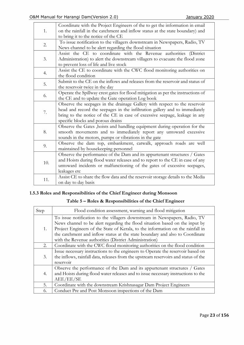
1.5.2 Roles and Responsibilities of the SE and EE during Monsoon
Table 4 – Roles & Responsibilities of SE & EE
Step Flood condition assessment, warning, flood mitigation and other responsibilities
O&M Manual for Harangi Dam(Version 2.0) January 2020
Page 23 of 156
1. Coordinate with the Project Engineers of the to get the information in email on the rainfall in the catchment and inflow status at the state boundary) and to bring it to the notice of the CE
2. To issue notification to the villagers downstream in Newspapers, Radio, TV News channel to be alert regarding the flood situation
3. Assist the CE to coordinate with the Revenue authorities (District Administration) to alert the downstream villagers to evacuate the flood zone to prevent loss of life and live stock
4. Assist the CE to coordinate with the CWC flood monitoring authorities on the flood condition
5. Submit to the CE on the inflows and releases from the reservoir and status of the reservoir twice in the day
6. Operate the Spillway crest gates for flood mitigation as per the instructions of the CE and to update the Gate operation Log book
7.
Observe the seepages in the drainage Gallery with respect to the reservoir head and record the seepages in the infiltration gallery and to immediately bring to the notice of the CE in case of excessive seepage, leakage in any specific blocks and porous drains
8. Observe the Gates ,hoists and handling equipment during operation for the smooth movements and to immediately report any untoward excessive sounds in the motors, pumps or vibrations in the gate
9. Observe the dam top, embankment, catwalk, approach roads are well maintained by housekeeping personnel
10.
Observe the performance of the Dam and its appurtenant structures / Gates and Hoists during flood water releases and to report to the CE in case of any untoward incidents or malfunctioning of the gates of excessive seepages, leakages etc
11. Assist CE to share the flow data and the reservoir storage details to the Media on day to day basis
1.5.3 Roles and Responsibilities of the Chief Engineer during Monsoon
Table 5 – Roles & Responsibilities of the Chief Engineer
Step Flood condition assessment, warning and flood mitigation
1.
To issue notification to the villagers downstream in Newspapers, Radio, TV News channel to be alert regarding the flood situation based on the input by Project Engineers of the State of Kerala, to the information on the rainfall in the catchment and inflow status at the state boundary and also to Coordinate with the Revenue authorities (District Administration)
2. Coordinate with the CWC flood monitoring authorities on the flood condition
3. Issue necessary instructions to the engineers to Operate the reservoir based on the inflows, rainfall data, releases from the upstream reservoirs and status of the reservoir
4. Observe the performance of the Dam and its appurtenant structures / Gates and Hoists during flood water releases and to issue necessary instructions to the AEE/EE/SE
5. Coordinate with the downstream Krishnasagar Dam Project Engineers 6. Conduct Pre and Post Monsoon inspections of the Dam
O&M Manual for Harangi Dam(Version 2.0) January 2020
Page 24 of 156
1.6 Collection & Reporting of Dam and Reservoir Data
A proforma table is provided below to ensure that dates and times for the collection and reporting of vital information is recorded and documented for the record.
● Reservoir water surface elevation.
● Reservoir inflow.
● Spillway outflow.
● River releases.
● Irrigation, water supply and hydropower releases.
● Weather related data
● Instrumentation data
● Water quality Instructions and a standard proforma for collection and reporting of inflow and outflow data,
Records [Logbooks] of the following operations at Harangi Dam are to be maintained in a chronological manner for reference. These records are helpful for identifying preventative maintenance measures that may need to be taken up, troubleshooting the cause of potential equipment failure and documenting development of any unusual conditions.
● Date and Time ● Attendance statement during normal operations – both during monsoon and non-monsoon
periods. ● Operations of the spillway gates and outlet works. ● Operating hours of mechanical equipment. ● Testing /Operation of spillway gates, stop-logs and associated controls. ● Testing/operation of Outlet gates, valves and associated controls. ● Maintenance activities carried out. ● Reservoir and dam inspections. ● Unusual conditions or occurrences, including acts of vandalism. ● Attendance statement at the dam during emergency operations. ● Changes to normal operating procedures. ● Communication network checks. ● Safety and special instructions. ● Names of officers and staff carrying out inspections and maintenance. ● Any other item pertaining to the operation and maintenance of the dam.

O&M Manual for Harangi Dam(Version 2.0) January 2020
Page 25 of 156
Legend
● EDCL: Energy Development Corporation Limited ● HLBC: HarangiLeft Bank Canal
Date Time Water level in
Mtr.
Inflow in Cusecs1
Out Flow in Cusecs
EDCL
Spillway Gates
HLBC
Escape
Total O/F
Reservoir Capacity in TMC
O&M Manual for Harangi Dam(Version 2.0) January 2020
Page 26 of 156
1.7 Public and Project Staff - Health and Safety
As safety of Project Staff is of prime concern, safety instructions & protection measures at the dam are carried out by all staff / project personnel. Electronic kiosks located on the left and right abutment provide public notices of events and status of security of the dam and downstream river conditions.
1.7.1 Restricted Areas
Certain areas of the dam and reservoir are restricted for entry of the general public. The purpose of restrictions is for security of the dam, public safety and uninterrupted safe operation of the dam.
Restricted areas will include the following:
● Upstream and downstream faces/ slopes of dam
● Gallery
● Spillway approach areas, chutes and stilling basins.
● Control buildings.
● Intake and outlet channels 1.7.2 Details of the Security arrangements at Harangi Dam Site.
The security arrangements of Harangi Dam are entrusted to the Karnataka State Police since 1998, (A unit of Karnataka State Police.) with a total strength of 8 Security personnel.
1. Security Officer One Security Officer of the rank of police inspector is in charge of the overall security arrangements.
2. Security personnel Security personnel Police constables (Both armed and unarmed), Head constable and Assistant sub Inspectors are deployed 24/7 at the critical location viz., dam main entrances, control room, gallery audits, check posts head works etc. Assistant sub Inspectors – 2 Nos
Head constable – 3 Nos
Police constables -3 Nos
O&M Manual for Harangi Dam(Version 2.0) January 2020
Page 27 of 156
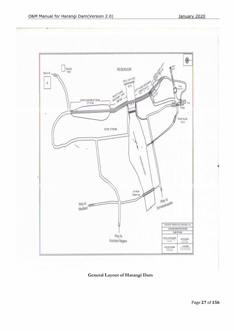
General Layout of Harangi Dam
O&M Manual for Harangi Dam(Version 2.0) January 2020
Page 28 of 156
1.8 Staff Position, Communication & Warning System
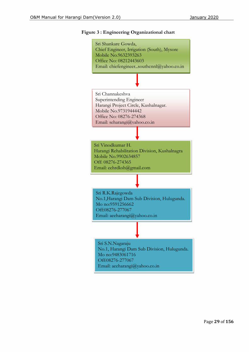
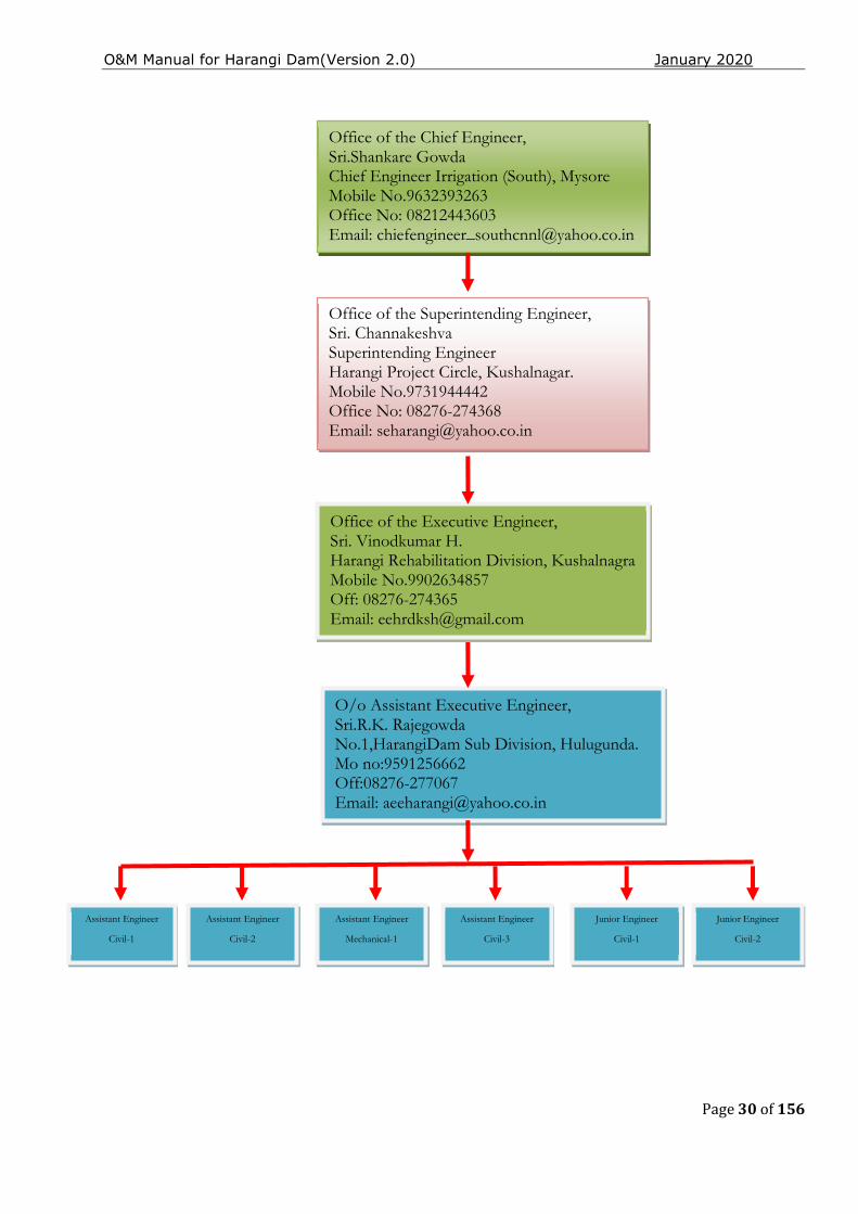
The number & description of operating unit personnel posted/placed at different locations of the dam are noted and referenced in this Manual. Staff positions vary according to requirement during monsoon /non-monsoon periods. An engineering organizational chart is shown in Figure 3 below.
The means of communications both in normal and emergency situations are identified in the Communication Directory found below. Available communication means including landline, mobile phones, wireless sets, & radio (10 Nos. Walkytakies available) at different locations on the dam. Security staffs are provided with door frame and hand-held metal detectors and binoculars to maintain security of the dam.
A utility room located on the downstream of Dam has an equipment room with all essential small tools, welders, gas cutter sets, chain blocks and ropes, space for the hydraulic hoist, dewatering pumps, weather gear, and consumables to facilitate O&M requirements.
A brief description of the warning systems including alarms at the dam is mentioned in the Manual. This includes information on downstream inundation areas during scheduled or unscheduled release of flood outflows from the spillway. Basic facilities like communication facilities, sirens, hooters etc. are provided.
O&M Manual for Harangi Dam(Version 2.0) January 2020
Page 29 of 156
Figure 3 : Engineering Organizational chart
Sri Shankare Gowda, Chief Engineer, Irrigation (South), Mysore Mobile No.9632393263 Office No: 08212443603 Email: [email protected]
Sri Channakeshva Superintending Engineer Harangi Project Circle, Kushalnagar. Mobile No.9731944442 Office No: 08276-274368 Email: [email protected]
Sri Vinodkumar H. Harangi Rehabilitation Division, Kushalnagra Mobile No.9902634857 Off: 08276-274365 Email: [email protected]
Sri R.K.Rajegowda No.1,Harangi Dam Sub Division, Hulugunda. Mo no:9591256662 Off:08276-277067 Email: [email protected]
Sri S.N.Nagaraju No.1, Harangi Dam Sub Division, Hulugunda. Mo no:9483061716 Off:08276-277067 Email: [email protected]
O&M Manual for Harangi Dam(Version 2.0) January 2020
Page 30 of 156
Office of the Chief Engineer, Sri.Shankare Gowda Chief Engineer Irrigation (South), Mysore Mobile No.9632393263 Office No: 08212443603 Email: [email protected]
Office of the Superintending Engineer, Sri. Channakeshva Superintending Engineer Harangi Project Circle, Kushalnagar. Mobile No.9731944442 Office No: 08276-274368 Email: [email protected]
Office of the Executive Engineer, Sri. Vinodkumar H. Harangi Rehabilitation Division, Kushalnagra Mobile No.9902634857 Off: 08276-274365 Email: [email protected]
O/o Assistant Executive Engineer, Sri.R.K. Rajegowda No.1,HarangiDam Sub Division, Hulugunda. Mo no:9591256662 Off:08276-277067 Email: [email protected]
Assistant Engineer
Civil-1
Assistant Engineer
Civil-2
Assistant Engineer
Mechanical-1
Assistant Engineer
Civil-3
Junior Engineer
Civil-1
Junior Engineer
Civil-2
O&M Manual for Harangi Dam(Version 2.0) January 2020
Page 31 of 156
1.8.1 Schedule of General Duties for Project Engineers
Schedules of duties being performed by the staff assigned to various locations and components of Harangi Dam are provided in this section. All activities are to be recorded daily in the Logbook and site registers.
DAILY
✓ Visual inspection of dam
➢ Crest of dam (Dam top)
➢ Upstream and downstream faces
➢ Visible portions of foundation and abutments contacts
➢ Galleries
✓ Record water surface elevation. (during monsoon on hourly basis)
✓ Record reservoir inflow and spillway discharge. (during monsoon on hourly basis)
✓ Record releases from outlets /sluices.
✓ Record seepage from drainage systems-Toe drains, Gallery drains etc. on daily basis Record meteorological data.
✓ Check security and safety devices.
✓ Complete logbook /site registers which should include the above information
WEEKLY
Electrical System
✓ Standby generator (DG Sets)
➢ Run for 15-30 min to achieve recommended operating temperature
➢ Check status of batteries and keep them charged.
➢ Check Fuel Supply
✓ Drainage systems - Toe drains, Gallery drains etc., and, during any reservoir filling operations
MONTHLY
Check condition of:
Dam and Reservoir
✓ Reservoir periphery (During Monsoon)
✓ Drainage systems - Toe Drains, Gallery drains etc. (on regular basis)
✓ Measuring devices/Instruments
✓ Security and safety devices – rectification, if needed.
✓ Communication Devices
✓ Status of Vegetation growth
O&M Manual for Harangi Dam(Version 2.0) January 2020
Page 32 of 156
✓ Check Sign/Warning display boards near vulnerable locations are in place and updated as necessary
Mechanical/Electrical System
✓ Replace fuses/light bulbs, as necessary
✓ Inspect and maintain ventilation system; check for and remove any obstructions
✓ Cleaning of control panel boards
QUARTERLY
Outlet Works
✓ Availability of updated operating instruction
✓ Check gate air vents
✓ Clean gate control switchboxes
✓ Check operation of gates and valves
✓ Grease gate hanger / dogging arrangements
Check
✓ Check condition of trash rack of intake structure
✓ Check condition of Outlet works &the Energy Dissipation Arrangement (EDA)
Spillway
✓ Check for debris in inlet channel
✓ Check operation of gates
✓ Check for damages in spillway glacis, EDA, d/s area, etc.
✓ Check and clear spillway bridge drains
✓ Clean inside of motor control cabinet and remove debris, insect (bee nests), nests, rodents and bird nests
Other works
✓ Check for adherence to instrumentation schedule
✓ Record pertinent information in Operation Log
✓ Check conditions of V-notch weirs/other seepage measuring devices
BI-ANNUAL
Spillway & outlet works
✓ Check paint on gates and other areas of corrosion
✓ Check lubrication of wire ropes and application of cardium compound.
✓ Check mechanical hoist bearings and flexible coupling bearings. Greasing as required
✓ Check gear systems. Check oil condition and replace / top up as per requirement
✓ Exercise gate and valves for operational efficiency
O&M Manual for Harangi Dam(Version 2.0) January 2020
Page 33 of 156
✓ Check oil reservoir level in hydraulic system and top up as necessary
✓ Check pressure release valve and clean any debris, dirt, other foreign objects as necessary
✓ Lubricate gate rollers
✓ Check rubber seals and seal clamp bar
✓ Check motor, brake system and Electrical controls replace the parts as required
Electrical System and Equipment
✓ Change oil in stand by generator Top Up or Replace if required
✓ Check healthiness of batteries of DG and replace if required
✓ Check exposed electrical wiring of :
➢ Operating equipment of gates/valves/hoists of Outlet works.
➢ Operating equipment of gates and hoists of Spillway
➢ Operating equipment of any other gates and hoists in dam
➢ Spillway catwalk / bridge
➢ Dam Gallery
✓ Check Gate limit switches and adjust
ANNUAL
Spillway & Outlet works
✓ Paint
➢ Metalwork, Gate, Hoists and all exposed metal parts for corrosion
➢ Valves / Control valves
✓ Exercise Gates and Valves
✓ Examine stilling basin / energy dissipation arrangement and d/s channel & carry out rectification works, as necessary.
✓ Check metal welds for damages/cracks in Gates, Hoist platform, Radial Gate Tie flats, Trunnion Girders/supports etc.
Electrical
✓ Check electrical conduits, pull-boxes and switches for:
➢ Outlet works valve house
➢ Gates & hoists
➢ Spillway bridge
➢ Gallery
FIVE YEAR (PERIODIC)
O&M Manual for Harangi Dam(Version 2.0) January 2020
Page 34 of 156
✓ Inspect intake structures, trash racks and stilling basin / energy dissipation arrangement, which normally are underwater; less frequent if experience indicates. This may need to be done by carrying out dewatering or by divers/remote operated vehicle (ROV) as necessary.
✓ Review Dam operation procedures and EAP and update as necessary.
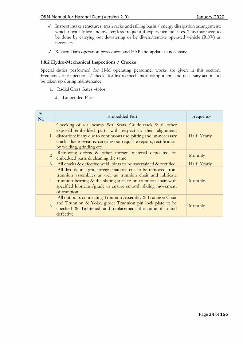
1.8.2 Hydro-Mechanical Inspections / Checks
Special duties performed for H-M operating personnel works are given in this section. Frequency of inspections / checks for hydro-mechanical components and necessary actions to be taken up during maintenance
1. Radial Crest Gates -4Nos.
a. Embedded Parts
Sl. No
Embedded Part Frequency
1
Checking of seal beams. Seal Seats, Guide track & all other exposed embedded parts with respect to their alignment, distortion: if any due to continuous use, pitting and un-necessary cracks due to wear & carrying out requisite repairs, rectification by welding, grinding etc.
Half Yearly
2 Removing debris & other foreign material deposited on embedded parts & cleaning the same Monthly
3 All cracks & defective weld joints to be ascertained & rectified. Half Yearly
4
All dirt, debris, grit, foreign material etc. to be removed from trunnion assemblies as well as trunnion chair and lubricate trunnion bearing & the sliding surface on trunnion chair with specified lubricant/grade to ensure smooth sliding movement of trunnion.
Monthly
5
All nut bolts connecting Trunnion Assembly & Trunnion Chair and Trunnion & Yoke, girder Trunnion pin lock plate to be checked & Tightened and replacement the same if found defective.
Monthly
O&M Manual for Harangi Dam(Version 2.0) January 2020
Page 35 of 156
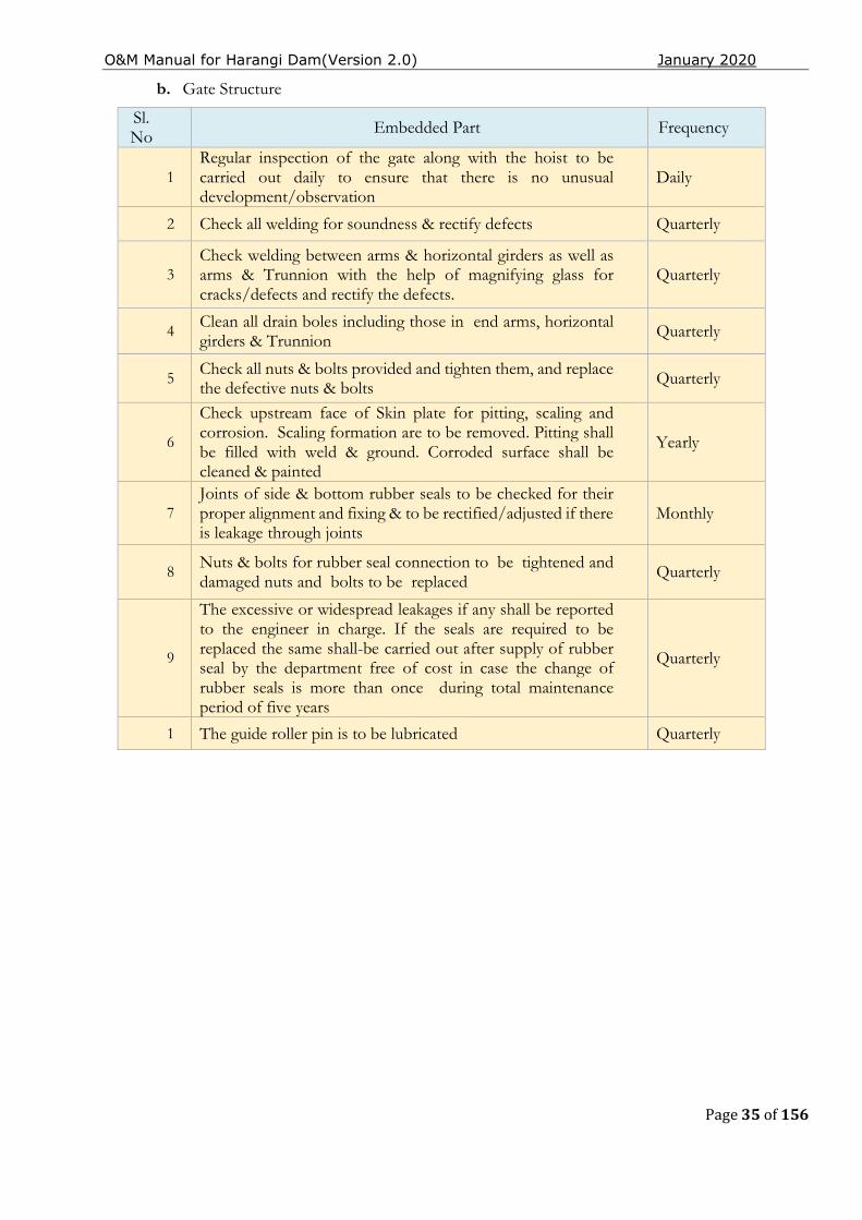
b. Gate Structure
Sl. No Embedded Part Frequency
1 Regular inspection of the gate along with the hoist to be carried out daily to ensure that there is no unusual development/observation
Daily
2 Check all welding for soundness & rectify defects Quarterly
3 Check welding between arms & horizontal girders as well as arms & Trunnion with the help of magnifying glass for cracks/defects and rectify the defects.
Quarterly
4 Clean all drain boles including those in end arms, horizontal girders & Trunnion Quarterly
5 Check all nuts & bolts provided and tighten them, and replace the defective nuts & bolts Quarterly
6
Check upstream face of Skin plate for pitting, scaling and corrosion. Scaling formation are to be removed. Pitting shall be filled with weld & ground. Corroded surface shall be cleaned & painted
Yearly
7 Joints of side & bottom rubber seals to be checked for their proper alignment and fixing & to be rectified/adjusted if there is leakage through joints
Monthly
8 Nuts & bolts for rubber seal connection to be tightened and damaged nuts and bolts to be replaced
Quarterly
9
The excessive or widespread leakages if any shall be reported to the engineer in charge. If the seals are required to be replaced the same shall-be carried out after supply of rubber seal by the department free of cost in case the change of rubber seals is more than once during total maintenance period of five years
Quarterly
1 The guide roller pin is to be lubricated Quarterly
O&M Manual for Harangi Dam(Version 2.0) January 2020
Page 36 of 156
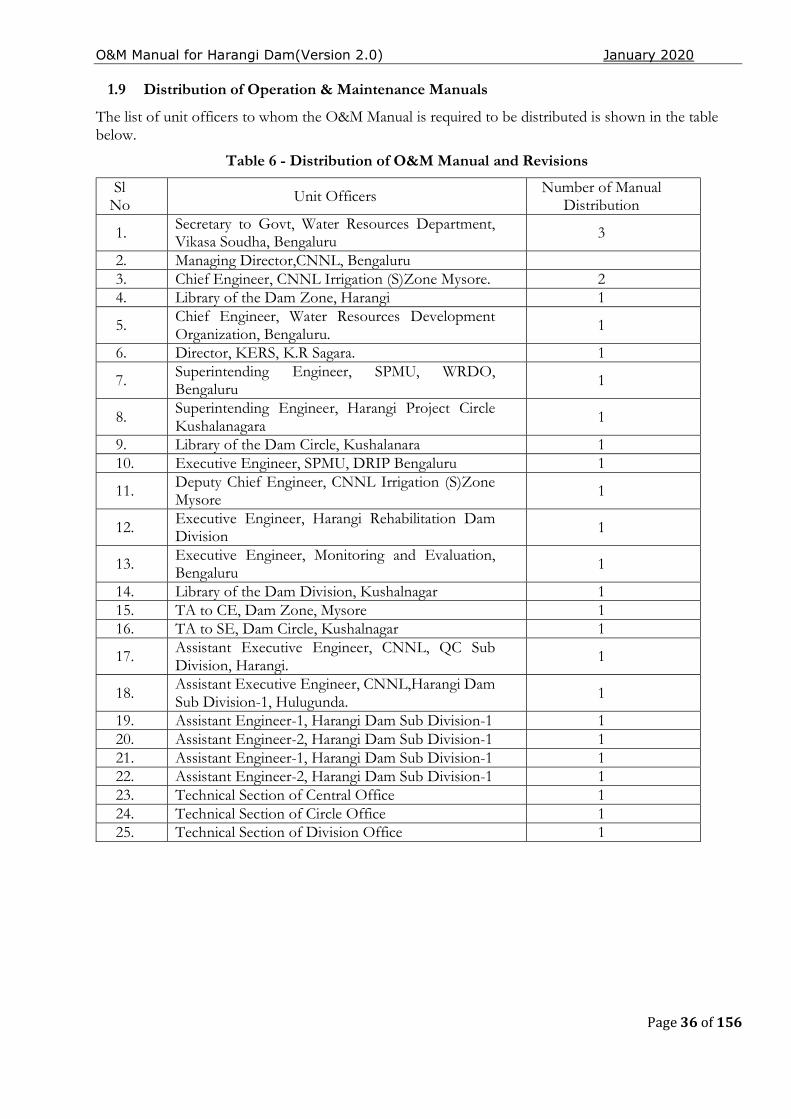
1.9 Distribution of Operation & Maintenance Manuals
The list of unit officers to whom the O&M Manual is required to be distributed is shown in the table below.
Table 6 - Distribution of O&M Manual and Revisions
Sl No Unit Officers Number of Manual
Distribution
1. Secretary to Govt, Water Resources Department, Vikasa Soudha, Bengaluru 3
2. Managing Director,CNNL, Bengaluru 3. Chief Engineer, CNNL Irrigation (S)Zone Mysore. 2 4. Library of the Dam Zone, Harangi 1
5. Chief Engineer, Water Resources Development Organization, Bengaluru.
1
6. Director, KERS, K.R Sagara. 1
7. Superintending Engineer, SPMU, WRDO, Bengaluru 1
8. Superintending Engineer, Harangi Project Circle Kushalanagara
1
9. Library of the Dam Circle, Kushalanara 1 10. Executive Engineer, SPMU, DRIP Bengaluru 1
11. Deputy Chief Engineer, CNNL Irrigation (S)Zone Mysore 1
12. Executive Engineer, Harangi Rehabilitation Dam Division 1
13. Executive Engineer, Monitoring and Evaluation, Bengaluru 1
14. Library of the Dam Division, Kushalnagar 1 15. TA to CE, Dam Zone, Mysore 1 16. TA to SE, Dam Circle, Kushalnagar 1
17. Assistant Executive Engineer, CNNL, QC Sub Division, Harangi.
1
18. Assistant Executive Engineer, CNNL,Harangi Dam Sub Division-1, Hulugunda. 1
19. Assistant Engineer-1, Harangi Dam Sub Division-1 1 20. Assistant Engineer-2, Harangi Dam Sub Division-1 1 21. Assistant Engineer-1, Harangi Dam Sub Division-1 1 22. Assistant Engineer-2, Harangi Dam Sub Division-1 1 23. Technical Section of Central Office 1 24. Technical Section of Circle Office 1 25. Technical Section of Division Office 1
O&M Manual for Harangi Dam(Version 2.0) January 2020
Page 37 of 156
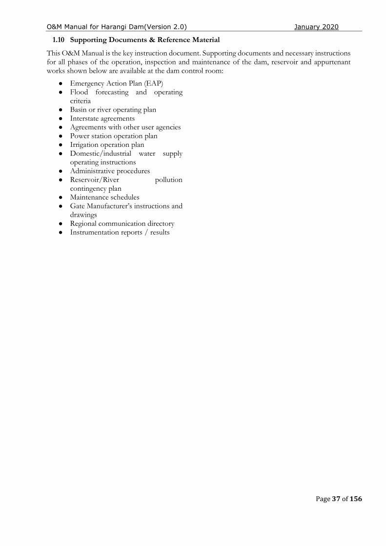
1.10 Supporting Documents & Reference Material
This O&M Manual is the key instruction document. Supporting documents and necessary instructions for all phases of the operation, inspection and maintenance of the dam, reservoir and appurtenant works shown below are available at the dam control room:
● Emergency Action Plan (EAP) ● Flood forecasting and operating
criteria ● Basin or river operating plan ● Interstate agreements ● Agreements with other user agencies ● Power station operation plan ● Irrigation operation plan ● Domestic/industrial water supply
operating instructions ● Administrative procedures ● Reservoir/River pollution
contingency plan ● Maintenance schedules ● Gate Manufacturer’s instructions and
drawings ● Regional communication directory ● Instrumentation reports / results
O&M Manual for Harangi Dam(Version 2.0) January 2020
Page 38 of 156
CHAPTER 2. PROJECT OPERATION
2.1 Basic Data
The Harangi operation plan consists of step-by-step instructions for operating the dam and reservoir during routine (normal) and emergency conditions. The operating procedures for normal operations are discussed in in this chapter including operating criteria for the reservoir, spillway & outlets. The operation of a dam involves regulation of its reservoir as per project specific requirements. This includes the use of area capacity curves and design flood; both are described below.
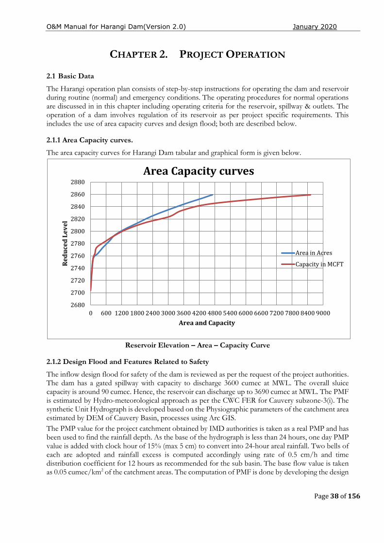
2.1.1 Area Capacity curves.
The area capacity curves for Harangi Dam tabular and graphical form is given below.
Reservoir Elevation – Area – Capacity Curve
2.1.2 Design Flood and Features Related to Safety
The inflow design flood for safety of the dam is reviewed as per the request of the project authorities. The dam has a gated spillway with capacity to discharge 3600 cumec at MWL. The overall sluice capacity is around 90 cumec. Hence, the reservoir can discharge up to 3690 cumec at MWL. The PMF is estimated by Hydro-meteorological approach as per the CWC FER for Cauvery subzone-3(i). The synthetic Unit Hydrograph is developed based on the Physiographic parameters of the catchment area estimated by DEM of Cauvery Basin, processes using Arc GIS. The PMP value for the project catchment obtained by IMD authorities is taken as a real PMP and has been used to find the rainfall depth. As the base of the hydrograph is less than 24 hours, one day PMP value is added with clock hour of 15% (max 5 cm) to convert into 24-hour areal rainfall. Two bells of each are adopted and rainfall excess is computed accordingly using rate of 0.5 cm/h and time distribution coefficient for 12 hours as recommended for the sub basin. The base flow value is taken as 0.05 cumec/km2 of the catchment areas. The computation of PMF is done by developing the design
2680
2700
2720
2740
2760
2780
2800
2820
2840
2860
2880
0 600 1200 1800 2400 3000 3600 4200 4800 5400 6000 6600 7200 7800 8400 9000
Red
uce
d L
evel
Area and Capacity
Area Capacity curves
Area in Acres
Capacity in MCFT
O&M Manual for Harangi Dam(Version 2.0) January 2020
Page 39 of 156
flood hydrograph considering critical sequencing of rainfall excess and Principles. The revised design flood (PMF) under DRIP worked out to be 5,456 m3/sec. Flood routing study carried out by the SPMU indicates that the revised MWL is at EL 870.3 m, which is below the original FRL/MWL of 871.42. The TBL is at EL 874.471 m and the available freeboard above the original MWL of EL 871.42 is 3.05 m, which is more than the minimum recommended 1.50 m as per IS 10635. Development of Synthetic Unit Hydrograph
Estimation of Physiographic parameters, all the Physiographic parameters of the catchment area required for deriving the Synthetic Unit Hydrograph have been estimated by GIS processing DEM of Cauvery Basin which is tabulated below.
Physiographic parameters of Harangi catchment
Catchment area (A) 420.00 Sq.km Longest Length from the outlet (L) 44.25 Km Centroidal River length from the outlet (Lc) 24.75 Km Equivaient stream slope along eth river (S) 3.58 M/Km L*Lc/√(s) 578.82
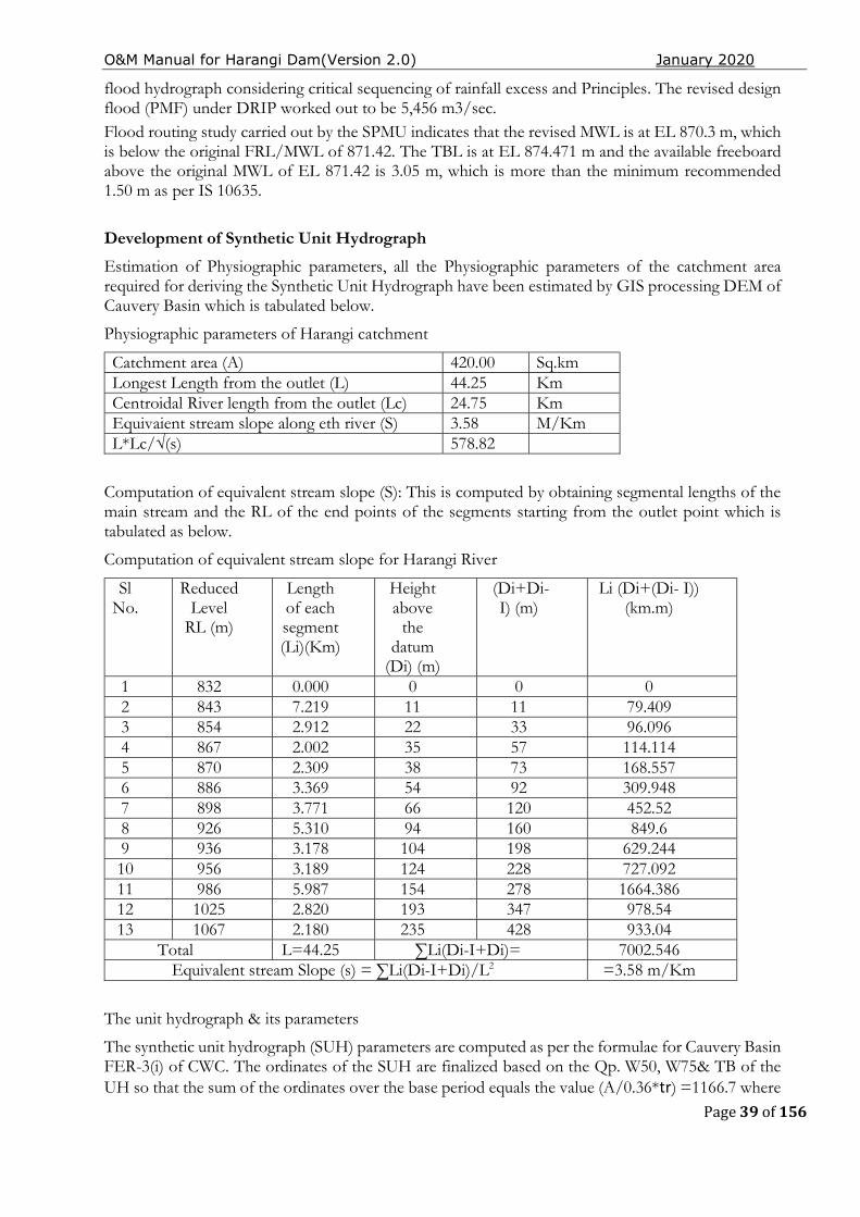
Computation of equivalent stream slope (S): This is computed by obtaining segmental lengths of the main stream and the RL of the end points of the segments starting from the outlet point which is tabulated as below.
Computation of equivalent stream slope for Harangi River
Sl No.
Reduced Level
RL (m)
Length of each segment (Li)(Km)
Height above
the datum
(Di) (m)
(Di+Di-I) (m)
Li (Di+(Di- I)) (km.m)
1 832 0.000 0 0 0 2 843 7.219 11 11 79.409 3 854 2.912 22 33 96.096 4 867 2.002 35 57 114.114 5 870 2.309 38 73 168.557 6 886 3.369 54 92 309.948 7 898 3.771 66 120 452.52 8 926 5.310 94 160 849.6 9 936 3.178 104 198 629.244 10 956 3.189 124 228 727.092 11 986 5.987 154 278 1664.386 12 1025 2.820 193 347 978.54 13 1067 2.180 235 428 933.04
Total L=44.25 ∑Li(Di-I+Di)= 7002.546 Equivalent stream Slope (s) = ∑Li(Di-I+Di)/L2 =3.58 m/Km
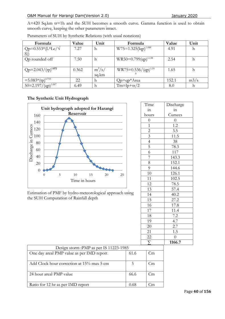
The unit hydrograph & its parameters
The synthetic unit hydrograph (SUH) parameters are computed as per the formulae for Cauvery Basin FER-3(i) of CWC. The ordinates of the SUH are finalized based on the Qp. W50, W75& TB of the UH so that the sum of the ordinates over the base period equals the value (A/0.36*tr) =1166.7 where
O&M Manual for Harangi Dam(Version 2.0) January 2020
Page 40 of 156
A=420 Sq.km tr=1h and the SUH becomes a smooth curve. Gamma function is used to obtain smooth curve, keeping the other parameters intact.
Parameters of SUH by Synthetic Relations (with usual notations)
Formula Value Unit Formula Value Unit Qp=0.553*(L*Lc/√S))
7.27 h W75=1.325(lqp)1.088 4.91 h
Qp rounded off 7.50 h WR50=0.799(qp)1.138 2.54 h
Qp=2.043/(tp)0.872 0.362 m3/s/ sq.km
WR75=0.536/(qp)1.10
9 1.65 h
=5.083*(tp)0.733 22 h Qp=qp*Area 152.1 m3/s 50=2.197/(qp)1.067 6.49 h Tm=lp+tr/2 8.0 h
The Synthetic Unit Hydrograph
Estimation of PMF by hydro-meteorological approach using the SUH Computation of Rainfall depth
Design storm :PMP as per IS 11223-1985 One day areal PMP value as per IMD report 61.6 Cm
Add Clock hour correction at 15% max 5 cm 5 Cm
24 hour areal PMP value 66.6 Cm
Ratio for 12 hr as per IMD report 0.68 Cm
0
20
40
60
80
100
120
140
160
0 5 10 15 20 25
Dis
char
ge in
Cum
ecs
Time in hours
Unit hydrograph adopted for Harangi Reservoir
Time in
hours
Discharge in
Cumecs 0 0 1 1.2 2 3.5 3 11.5 4 38 5 78.3 6 117 7 143.3 8 152.1 9 144.6 10 126.1 11 102.5 12 78.5 13 57.4 14 40.2 15 27.2 16 17.8 17 11.4 18 7.2 19 4.7 20 2.7 21 1.5 22 0 ∑ 1166.7
O&M Manual for Harangi Dam(Version 2.0) January 2020
Page 41 of 156
Areal PMP depth for 1st 12 hr bell 45.29 Cm
Areal PMP depth for 2nd12hr bell 21.31 Cm
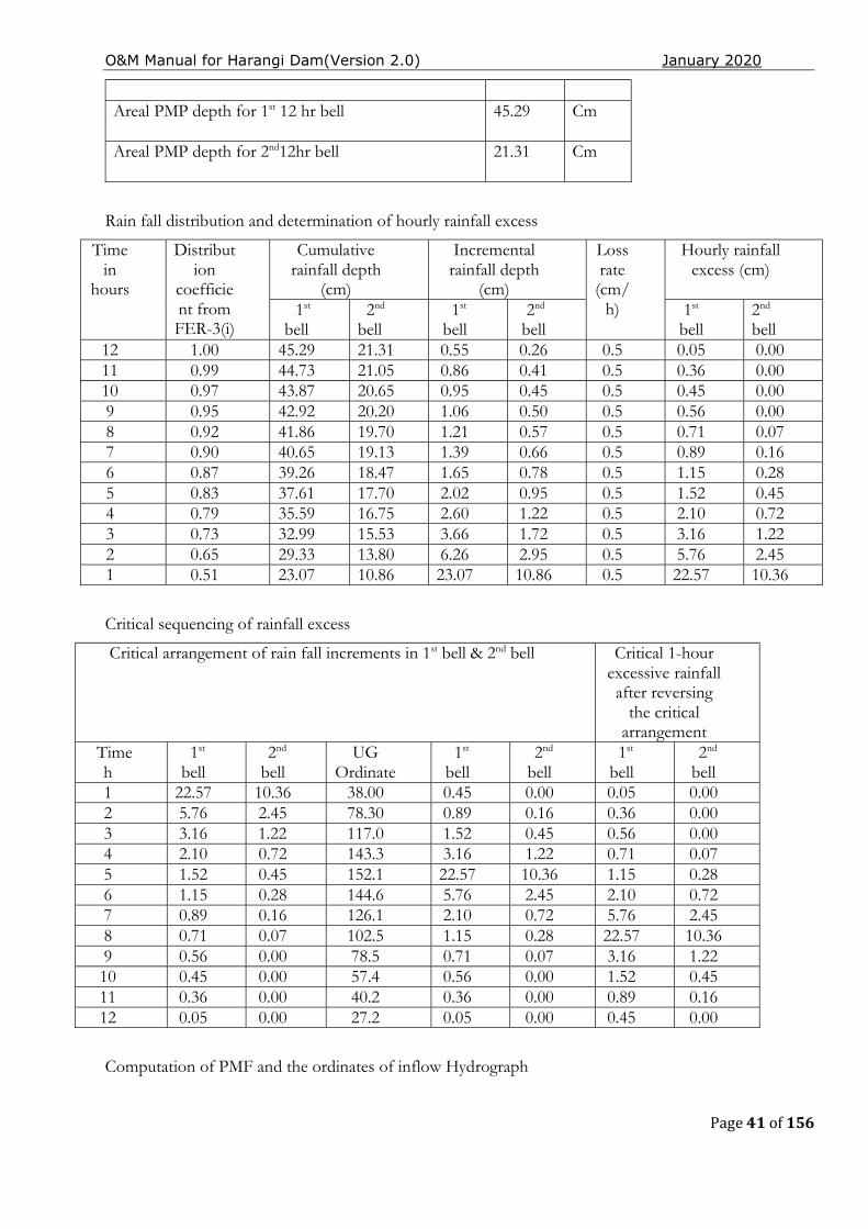
Rain fall distribution and determination of hourly rainfall excess
Time in
hours
Distribution
coefficient from FER-3(i)
Cumulative rainfall depth
(cm)
Incremental rainfall depth
(cm)
Loss rate
(cm/h)
Hourly rainfall excess (cm)
1st bell
2nd
bell 1st
bell 2nd bell
1st bell
2nd bell
12 1.00 45.29 21.31 0.55 0.26 0.5 0.05 0.00 11 0.99 44.73 21.05 0.86 0.41 0.5 0.36 0.00 10 0.97 43.87 20.65 0.95 0.45 0.5 0.45 0.00 9 0.95 42.92 20.20 1.06 0.50 0.5 0.56 0.00 8 0.92 41.86 19.70 1.21 0.57 0.5 0.71 0.07 7 0.90 40.65 19.13 1.39 0.66 0.5 0.89 0.16 6 0.87 39.26 18.47 1.65 0.78 0.5 1.15 0.28 5 0.83 37.61 17.70 2.02 0.95 0.5 1.52 0.45 4 0.79 35.59 16.75 2.60 1.22 0.5 2.10 0.72 3 0.73 32.99 15.53 3.66 1.72 0.5 3.16 1.22 2 0.65 29.33 13.80 6.26 2.95 0.5 5.76 2.45 1 0.51 23.07 10.86 23.07 10.86 0.5 22.57 10.36
Critical sequencing of rainfall excess
Computation of PMF and the ordinates of inflow Hydrograph
Critical arrangement of rain fall increments in 1st bell & 2nd bell Critical 1-hour excessive rainfall after reversing
the critical arrangement
Time h
1st
bell 2nd bell
UG Ordinate
1st bell
2nd bell
1st bell
2nd bell
1 22.57 10.36 38.00 0.45 0.00 0.05 0.00 2 5.76 2.45 78.30 0.89 0.16 0.36 0.00 3 3.16 1.22 117.0 1.52 0.45 0.56 0.00 4 2.10 0.72 143.3 3.16 1.22 0.71 0.07 5 1.52 0.45 152.1 22.57 10.36 1.15 0.28 6 1.15 0.28 144.6 5.76 2.45 2.10 0.72 7 0.89 0.16 126.1 2.10 0.72 5.76 2.45 8 0.71 0.07 102.5 1.15 0.28 22.57 10.36 9 0.56 0.00 78.5 0.71 0.07 3.16 1.22 10 0.45 0.00 57.4 0.56 0.00 1.52 0.45 11 0.36 0.00 40.2 0.36 0.00 0.89 0.16 12 0.05 0.00 27.2 0.05 0.00 0.45 0.00
O&M Manual for Harangi Dam(Version 2.0) January 2020
Page 42 of 156
The direct run off hydrograph ordinates are computed by considering the critical sequencing of hourly rainfall excess and convolution principles. Base flow recommended @ 0.05 m3/s per sq.km of the catchment area is added to the direct runoff ordinates to get the final ordinates of the PMF inflow hydrograph. The peak value of the PMF works out to 5456 m3/s.
2.2 Flood Management at Harangi Reservoir
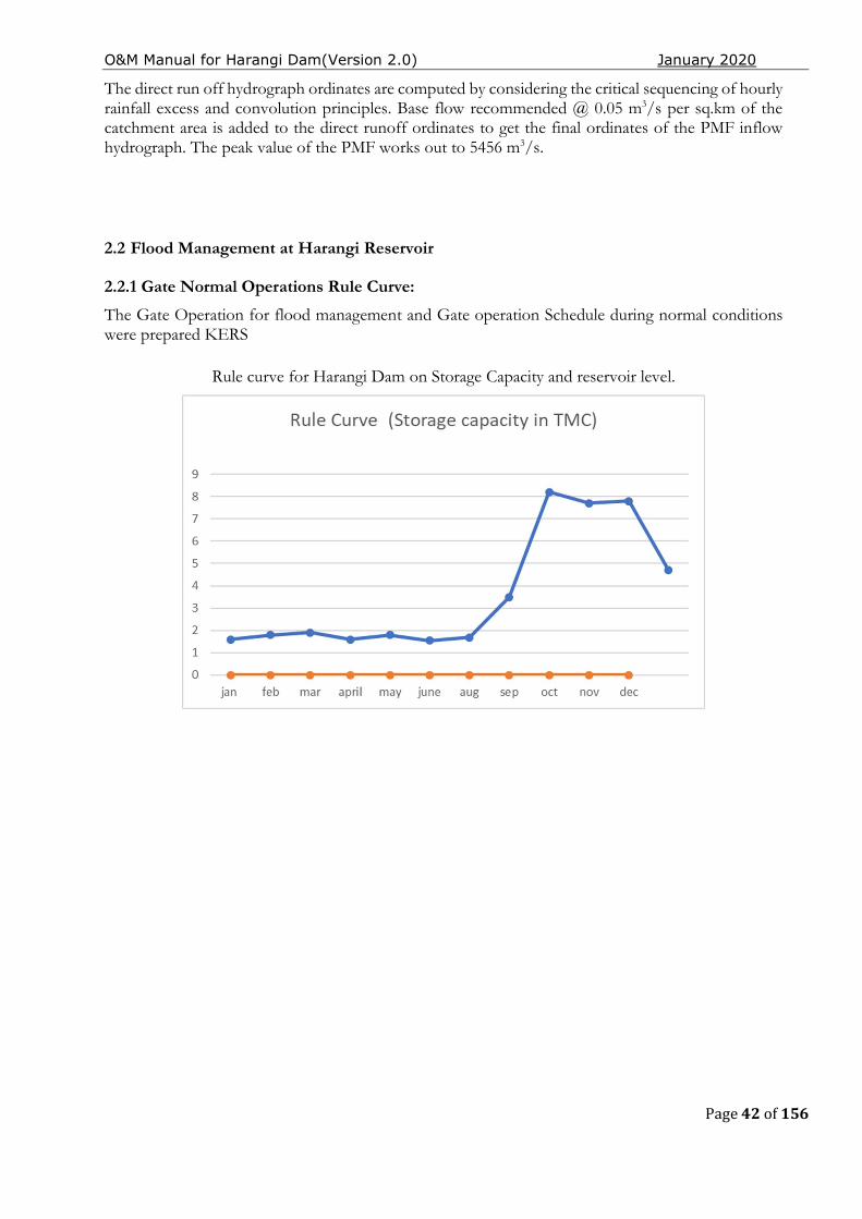
2.2.1 Gate Normal Operations Rule Curve:
The Gate Operation for flood management and Gate operation Schedule during normal conditions were prepared KERS
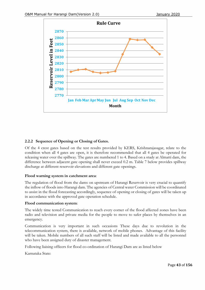
Rule curve for Harangi Dam on Storage Capacity and reservoir level.
O&M Manual for Harangi Dam(Version 2.0) January 2020
Page 43 of 156
2.2.2 Sequence of Opening or Closing of Gates.
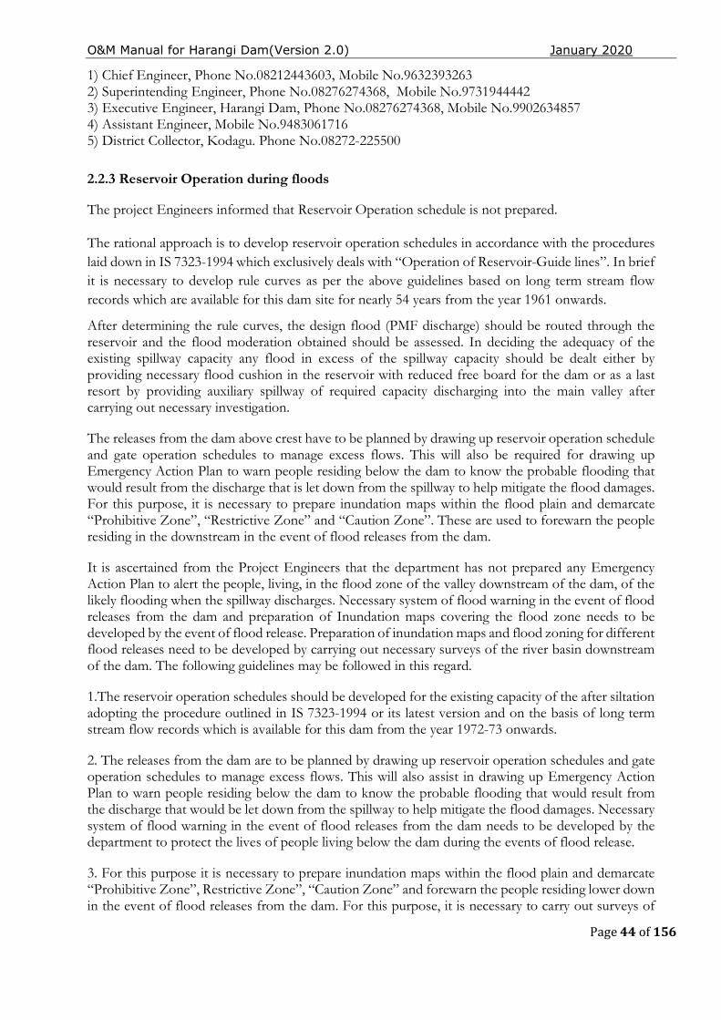
Of the 4 crest gates based on the test results provided by KERS, Krishnarajasagar, relate to the condition when all 4 gates are open, it is therefore recommended that all 4 gates be operated for releasing water over the spillway. The gates are numbered 1 to 4. Based on a study at Almatti dam, the difference between adjacent gate opening shall never exceed 0.2 m. Table 7 below provides spillway discharge at different reservoir elevations and different gate openings. Flood warning system in catchment area:
The regulation of flood from the dams on upstream of Harangi Reservoir is very crucial to quantify the inflow of floods into Harangi dam. The agencies of Central water Commission will be coordinated to assist in the flood forecasting accordingly, sequence of opening or closing of gates will be taken up in accordance with the approved gate operation schedule.
Flood communication system:
The widely time tested Communication to reach every corner of the flood affected zones have been radio and television and private media for the people to move to safer places by themselves in an emergency.
Communication is very important in such occasions These days due to revolution in the telecommunication system, there is available, network of mobile phones. Advantage of this facility will be taken. Mobile numbers of all such staff will be listed and made available to all the personnel who have been assigned duty of disaster management.
Following liaising officers for flood co-ordination of Harangi Dam are as listed below
Karnataka State:
2770
2780
2790
2800
2810
2820
2830
2840
2850
2860
2870
Jan Feb Mar Apr May Jun Jul Aug Sep Oct Nov Dec
Res
ervo
ir L
evel
in F
eet
Month
Rule Curve
O&M Manual for Harangi Dam(Version 2.0) January 2020
Page 44 of 156
1) Chief Engineer, Phone No.08212443603, Mobile No.9632393263 2) Superintending Engineer, Phone No.08276274368, Mobile No.9731944442 3) Executive Engineer, Harangi Dam, Phone No.08276274368, Mobile No.9902634857 4) Assistant Engineer, Mobile No.9483061716 5) District Collector, Kodagu. Phone No.08272-225500 2.2.3 Reservoir Operation during floods
The project Engineers informed that Reservoir Operation schedule is not prepared.
The rational approach is to develop reservoir operation schedules in accordance with the procedures laid down in IS 7323-1994 which exclusively deals with “Operation of Reservoir-Guide lines”. In brief it is necessary to develop rule curves as per the above guidelines based on long term stream flow records which are available for this dam site for nearly 54 years from the year 1961 onwards.
After determining the rule curves, the design flood (PMF discharge) should be routed through the reservoir and the flood moderation obtained should be assessed. In deciding the adequacy of the existing spillway capacity any flood in excess of the spillway capacity should be dealt either by providing necessary flood cushion in the reservoir with reduced free board for the dam or as a last resort by providing auxiliary spillway of required capacity discharging into the main valley after carrying out necessary investigation.
The releases from the dam above crest have to be planned by drawing up reservoir operation schedule and gate operation schedules to manage excess flows. This will also be required for drawing up Emergency Action Plan to warn people residing below the dam to know the probable flooding that would result from the discharge that is let down from the spillway to help mitigate the flood damages. For this purpose, it is necessary to prepare inundation maps within the flood plain and demarcate “Prohibitive Zone”, “Restrictive Zone” and “Caution Zone”. These are used to forewarn the people residing in the downstream in the event of flood releases from the dam.
It is ascertained from the Project Engineers that the department has not prepared any Emergency Action Plan to alert the people, living, in the flood zone of the valley downstream of the dam, of the likely flooding when the spillway discharges. Necessary system of flood warning in the event of flood releases from the dam and preparation of Inundation maps covering the flood zone needs to be developed by the event of flood release. Preparation of inundation maps and flood zoning for different flood releases need to be developed by carrying out necessary surveys of the river basin downstream of the dam. The following guidelines may be followed in this regard.
1.The reservoir operation schedules should be developed for the existing capacity of the after siltation adopting the procedure outlined in IS 7323-1994 or its latest version and on the basis of long term stream flow records which is available for this dam from the year 1972-73 onwards.
2. The releases from the dam are to be planned by drawing up reservoir operation schedules and gate operation schedules to manage excess flows. This will also assist in drawing up Emergency Action Plan to warn people residing below the dam to know the probable flooding that would result from the discharge that would be let down from the spillway to help mitigate the flood damages. Necessary system of flood warning in the event of flood releases from the dam needs to be developed by the department to protect the lives of people living below the dam during the events of flood release.
3. For this purpose it is necessary to prepare inundation maps within the flood plain and demarcate “Prohibitive Zone”, Restrictive Zone”, “Caution Zone” and forewarn the people residing lower down in the event of flood releases from the dam. For this purpose, it is necessary to carry out surveys of

O&M Manual for Harangi Dam(Version 2.0) January 2020
Page 45 of 156
river valley on the downstream of the dam and mark contours of different elevations to enable to demarcate the flood zones for flood 25-year return period, Spillway design flood and dam break flood.
Table 7 - Gate Opening Discharge table
Tape Readin
g
EL in ft
Gate Opening (discharge mentioned is for 4 gates) Discharge from one gate = the value written / 4
3'' 6" 9" 12" 1'3" 1'6" 1'9'' 2' 2'6'' 3' 3'6'' 4' 4'6''
79' 2857.0
0 1218.3
9 2427.7
4 3469.1
4 4501.9
8 5561.4
8 6620.1
7 7680.4
8 8739.4
8 11122.4
5 12933.2
2 14963.2
17082.19
19420.91
79'0.6'' 2857.0
5 1219.4
3 2430.3
4 3472.7
7 4507.2
1 5566.6
9 6626.2
1 7685.6
8 8744.6
8 11132.9 12941.0
8 14976.2
4 17095.2
4 19441.8
79'1.2'' 2857.10
1220.46
2432.95
3476.41
4512.45
5571.89
6631.25
7690.89
8749.9 11143.34
12948.84
14989.29
17108.29
19462.7
79'1.8'' 2857.1
5 1221.5
0 2435.5
5 3480.0
5 4517.6
8 5577.1
0 6636.3
8 7696.1 8755.1
0 11153.8 12956.6
5 15002.3
3 17121.3
4 19483.6
79'2.4'' 2857.20
1222.53
2438.15
3483.69
4522.92
5582.31
6641.92
7701.31
8760.31
11164.23
12964.46
15015.32
17134.38
19504.50
79'3'' 2857.2
5 1223.5
7 2440.7
6 3487.3
3 4528.1
6 5587.5
1 6647.2
6 7706.5
1 8765.5
1 11174.6
7 12972.2
7 15028.4
3 17147.4
3 19525.2
3
79'3.6'' 2857.30
1224.61
2443.36
3490.97
4533.39
5592.72
6652.49
7711.72
8770.72
11185.11
12980.08
15041.47
17160.48
19546.24
79'4.2'' 2857.3
5 1225.6
4 2445.9
6 3494.6
4538.63
5597.29
6657.63
7716.93
8775.93
11195.56
12987.9 15054.5
3 17173.5
3 19567.1
2
79'4.8'' 2857.4
0 1226.6
8 2448.5
7 3498.2
4 4543.8
7 5603.1
4 6662.3
7 7722.1
4 8781.1
4 11206 12995.7 15067.5
7 17186.5
7 19588.0
1
79'5.4'' 2857.45
1227.71
2451.17
3501.88
4549.1 5608.34
6668.4 7727.34
8786.34
11216.89
13003.51
15080.62
17199.62
19608.90
79'6.6'' 2857.5
5 1229.7
8 2453.3
6 3509.1
6 4559.5
8 5618.7
6 6678.5
8 7737.7
5 8796.7
5 11247.7
8 13019.1
4 15106.7
1 17225.7
2 19650.6
7
79'7.2'' 2857.60
1230.82
2458.98
3512.8 4564.81
5623.96
6683.82
7742.96
8801.96
11258.22
13026.95
15119.76
17238.76
19671.56
79'7.8'' 2857.6
5 1231.8
5 2461.5
8 3516.4
4 4570.0
5 5629.1
7 6689.8
5 7748.1
7 8807.1
7 11268.6
7 13034.7
6 15132.3
1 17251.8
1 19692.4
5
79'8.4'' 2857.7
0 1232.8
9 2464.1
9 3520.0
8 4575.2
9 5634.3
8 6694.2
9 7753.3
8 8812.3
8 11279.1
1 13042.6 15145.8
6 17264.8
6 19713.3
4
79'9'' 2857.75
1233.93
2466.79
3523.72
4580.53
5639.58
6699.53
7758.58
8817.58
11289.55
13050.4 15158.9 17277.9 19734.22
79'9.6'' 2857.8
0 1234.9
6 2469.3
9 3527.3
6 4585.7
6 5644.7
9 6704.7
6 7763.7
9 8822.7
9 11300 13058.1
9 15171.8
2 17220.9
5 19755.1
1
79,10.2'' 2857.85
1236.00
2472 3531 4591 5650 6710 7769 8828 11306.86
13066 15185 17304 19776
79'10.8'' 2857.9
0 1240.1
1 2478.8
6 3537.8
6 4597.8
2 5656.8
6 6716.3
2 7775.8
6 8834.8
6 11313.7
2 13079.7
2 15198.6
8 17317.6
8 19782.8
6
79'11.4'' 2857.95
1244.22
2485.72
3544.72
4604.64
5663.72
6732.64
7782.72
8841.72
11320.58
13093.44
15212.36
17331.36
19789.72
80' 2858.0
0 1248.3
2 2492.5
8 3551.5
8 4611.4
6 5670.5
8 6730.4
6 7769.5
8 8846.5
8 11327.4
4 13107.1
6 15226.0
5 17345.0
5 19796.5
6
80'0.6'' 2858.0
5 1252.4
3 2499.4
4 3558.4
4 4618.2
8 5677.4
4 6737.2
9 7796.4
4 8855.4
4 11334.3 13120.8
8 15239.7
3 17358.7
3 19803.4
4
80'1.2'' 2858.10
1256.54
2506.3 3565.3 4685.11
5684.3 6744.41
7803.3 8862.3 11341.16
13134.6 15253.41
17372.44
19810.3
80'1.8'' 2858.1
5 1260.6
5 2513.1
6 3572.1
6 4631.9
3 5691.1
6 6750.9
3 7810.1
6 8869.1
6 11346.6
5 13148.3
3 15267.0
9 17386.0
9 19817.1
8
80'2.28'' 2858.19
1263.93
2518.65
3577.65
4637.39
5696.65
6756.39
7815.65
8874.65
11349.39
13159.31
15278.03
17397.03
19822.65
80'2.52'' 2858.2
1 1265.5
8 2521.3
9 3580.3
9 4640.1
1 5699.3
9 6759.1
1 7818.3
9 8877.4
11354.88
13164.79
15283.51
17402.5 19825.3
9
80'3'' 2858.2
5 1268.8
7 2526.8
8 3585.8
8 4645.5
7 5704.8
8 6764.5
7 7823.8
8 8882.8
8 11354.8
8 13175.7
7 15294.4
6 17413.4
6 19830.8
8
80'3.6'' 2858.30
1272.97
2533.74
3592.74
4652.39
5711.74
6771.39
7830.74
8889.74
11361.74
13189.49
15308.14
17427.14
19837.74
80'4.2'' 2858.3
5 1277.0
8 2540.6 3596.6 4659.2
2 5718.6 6778.2
2 7837.6 8890.6 11368.6 13203.2
1 15321.8
2 17440.8
2 19844.6
80'4.8'' 2858.40
1281.18
2547.45
3606.46
4666.04
5725.46
6785.04
7844.46
8903.46
11375.46
13216.93
15335.5 17454.50
19851.40
80'5.4'' 2858.4
5 1285.2
8 2554.3
2 3613.3
2 4672.8
6 5732.3
2 6791.8
6 7851.3
2 8910.3
2 11382.3
3 13230.6
5 15349.1
9 17468.1
8 19858.3
3
80'6'' 2858.50
1289.41
2561.18
3620.18
4679.88
5739.18
6788.68
7858.63
8917.18
11389.18
13244.37
15362.87
17481.87
19865.18
80'6.6'' 2858.5
5 1293.5
3 2568.0
4 3627.0
4 4686.5
5746.05
6805.5 7865.0
5 8924.0
4 11396.0
5 13258
15376.55
17485.55
19872.03
80'7.2'' 2858.6
0 1297.6
3 2574.9
1 3633.9
1 4693.3
2 5752.9
1 6812.3
2 7871.9
1 8930.9
1 11402.9
1 13271.8
1 15390.2
3 17509.2
3 19878.9
1
80'7.8'' 2858.65
1301.74
2581.77
3640.77
4700.15
5759.77
6819.15
7878.75
8937.77
11408.77
13285.53
15403.91
17522.81
19885.77
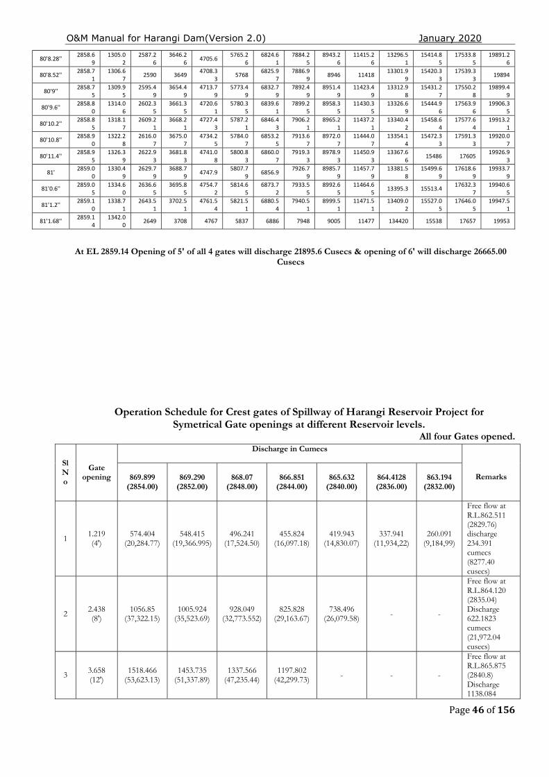
O&M Manual for Harangi Dam(Version 2.0) January 2020
Page 46 of 156
80'8.28'' 2858.6
9 1305.0
2 2587.2
6 3646.2
6 4705.6 5765.2
6 6824.6
1 7884.2
5 8943.2
6 11415.2
6 13296.5
1 15414.8
5 17533.8
5 19891.2
6
80'8.52'' 2858.71
1306.67
2590 3649 4708.33
5768 6825.97
7886.99
8946 11418 13301.99
15420.33
17539.33
19894
80'9'' 2858.7
5 1309.9
5 2595.4
9 3654.4
9 4713.7
9 5773.4
9 6832.7
9 7892.4
9 8951.4
9 11423.4
9 13312.9
8 15431.2
7 17550.2
8 19899.4
9
80'9.6'' 2858.80
1314.06
2602.35
3661.35
4720.61
5780.35
6839.61
7899.25
8958.35
11430.35
13326.69
15444.96
17563.96
19906.35
80'10.2'' 2858.8
5 1318.1
7 2609.2
1 3668.2
1 4727.4
3 5787.2
1 6846.4
3 7906.2
1 8965.2
1 11437.2
1 13340.4
2 15458.6
4 17577.6
4 19913.2
1
80'10.8'' 2858.90
1322.28
2616.07
3675.07
4734.25
5784.07
6853.25
7913.67
8972.07
11444.07
13354.14
15472.33
17591.33
19920.07
80'11.4'' 2858.9
5 1326.3
9 2622.9
3 3681.8
3 4741.0
8 5800.8
3 6860.0
7 7919.3
3 8978.9
3 11450.9
3 13367.6
6 15486 17605
19926.93
81' 2859.0
0 1330.4
9 2629.7
9 3688.7
9 4747.9 5807.7
9 6856.9 7926.7
9 8985.7
9 11457.7
9 13381.5
8 15499.6
9 17618.6
9 19933.7
9
81'0.6'' 2859.05
1334.60
2636.65
3695.85
4754.72
5814.65
6873.72
7933.55
8992.65
11464.65
13395.3 15513.4 17632.37
19940.65
81'1.2'' 2859.1
0 1338.7
1 2643.5
1 3702.5
1 4761.5
4 5821.5
1 6880.5
4 7940.5
1 8999.5
1 11471.5
1 13409.0
2 15527.0
5 17646.0
5 19947.5
1
81'1.68'' 2859.14
1342.00
2649 3708 4767 5837 6886 7948 9005 11477 134420 15538 17657 19953
At EL 2859.14 Opening of 5' of all 4 gates will discharge 21895.6 Cusecs & opening of 6' will discharge 26665.00 Cusecs
Operation Schedule for Crest gates of Spillway of Harangi Reservoir Project for Symetrical Gate openings at different Reservoir levels.
All four Gates opened.
Sl No
Gate opening
Discharge in Cumecs
Remarks 869.899 (2854.00)
869.290 (2852.00)
868.07 (2848.00)
866.851 (2844.00)
865.632 (2840.00)
864.4128 (2836.00)
863.194
(2832.00)
1 1.219 (4')
574.404 (20,284.77)
548.415 (19,366.995)
496.241 (17,524.50)
455.824 (16,097.18)
419.943 (14,830.07)
337.941 (11,934,22)
260.091 (9,184,99)
Free flow at R.L.862.511 (2829.76) discharge 234.391 cumecs (8277.40 cusecs)
2 2.438 (8')
1056.85 (37,322.15)
1005.924 (35,523.69)
928.049 (32,773.552)
825.828 (29,163.67)
738.496 (26,079.58) - -
Free flow at R.L.864.120 (2835.04) Discharge 622.1823 cumecs (21,972.04 cusecs)
3 3.658 (12')
1518.466 (53,623.13)
1453.735 (51,337.89)
1337.566 (47,235.44)
1197.802 (42,299.73)
- - -
Free flow at R.L.865.875 (2840.8) Discharge 1138.084
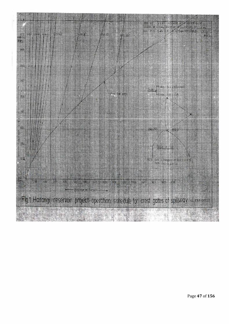
O&M Manual for Harangi Dam(Version 2.0) January 2020
Page 47 of 156
cumecs (40,190.85 cusecs)
4 4.877 (16')
1953.362 (68,981.97)
1961.22 (66,906.37)
1836.415 (64,852.021) - - - -
Free flow at R.L. 867.705 (2841.80) Discharge 1817.158 cumecs (64,171.997 cusecs)
Statement showing the Free Flow discharge for various heads over the Crest of the Spillway Harangi Reservoir Project
Crest R.L.860.755 m (2824.00 ft.)
Head in meters over the Crest of Spillway Reservoir levels in meters Discharge over Spillway incumecs
0.6096 (2' ) 861.365 (2826.00 ft.) 55.169 (1,948.27 cusecs)
1.2191 (4' ) 861.974 (2828.00 ft.) 132.909 (4,693.63 cusecs)
2.4384 (6' ) 863.194 (2832.00 ft.) 373.654 (13,195.41 cusecs)
3.6586 (12' ) 864.413 (2836.00 ft.) 693.406 (24,487.25 cusecs)
4.877 (16' ) 865.632 (2840.00 ft.) 1069.714 (37,776.30 cusecs)
6.096 (20' ) 866.851 (2844.00 ft.) 1500.380 (52,985.14 cusecs)
7.315 (24' ) 868.070 (2848.00 ft.) 1973.088 (69,678.56 cusecs)
8.534 (28' ) 869.29 (2852.00 ft.) 2482.821 (87,679.52 cusecs)
9.144 (30' ) 869.899 (2854.00 ft.) 2858.591 (1,00,949.63 cusecs)
10.688 (35' ) 871.423 (2859.00 ft.) 3598.202 (1,27,068.61 cusecs)
O&M Manual for Harangi Dam(Version 2.0) January 2020
Page 48 of 156
2.3 Operation of Radial Crest Gates of Harangi Dam
2.3.1 Brief Description.
Crest Gates of Harangi Dam have been designed with spillway crest of 860.755 m and FRL of 871.42 m. The basic principal of the design is that. the water pressure is transferred to piers and abutments through skin plates, stiffeners horizontal girders, arms, trunion, tie flats and anchor girders. The skin plates between bottom and top horizontal girders is designed as supported on the girders. The portion below the bottom horizontal girder up to sill beam and above top horizontal girder and up to FRL is designed as cantilever.
2.3.2 Radial Crest Gates – Technical Data
1. The spillway Radial Gate consist of an upstream curved skin plate of varying thickness from 14 mm to 10 mm, stiffened by suitably spaced vertical 500 ISMB (1/2 cut) stiffeners.
2. The sill beam, wall plates are provided with suitable anchorage for a rigid connection to the spillway crest and the piers Suitable stainless-steel plates are welded on the wall plate to match with the rubber seals. The sill beam embedded in the spillway crest are provided sealing surfaces of stainless steel to match with the rubber seal on the bottom of the gates
3. The gate consists of structural steel frame formed by three (3) main horizontal girders supported by radial arms at each end. These inclined radial arms in turn transmit the load to trunnion brackets installed on trunnion girder spanning between the piers. The water load is transferred through girders to end arms, trunnion brackets, to concrete beam and is finally transferred to pier concrete.
4. Gate Assembly: The skin plate of the gate consists of a 10 to 14-mm-thick stainless steel on the u/s side. The skin plate is stiffened by radial shaped vertical stiffeners. Which rests on horizontal girders. The vertical stiffeners rest on horizontal girders. Which are mounted on suitably braced inclined arms fixed to the trunnion assembly. The skin plate is supported on 3 main horizontal girders which are in turn, supported on a frame of inclined arms. The end arms pivot on trunnion pins mounted on trunnion brackets fixed to the Yoke girder and resting on rest beam (chair) plate. The water load is transferred to pier concrete through Anchor bars welded to anchor girder embedded in pier concrete. The horizontal force due to arm inclination is taken by stiffened D/s flange of horizontal girder at the junction level. This force is taken by the trunnion tie connecting the two trunnion hub limbs.
5. Guide Roller Assembly: Each gate has been provided with 3 guide rollers of size dia 130-mm O.D. x 76 mm I.D. x 90 mm width on each side, to check side sway. In fully open position of the gate, two no. guide rollers on each side rests on the wall plate. The rollers are provided with plain bronze bushings turning on fixed pins. The roller pin is 60-mm-dia and is hard chromium-plated with thickness of 40 microns the rollers are adjustable and removable type.
6. Trunnion Assembly: The trunnion assembly consists of a single piece cast steel trunn1o: hub having 10 680 mmand 00 I 030 mm, to which the arms of the gates are rigidly connected to ensure full transfer of load. 580-dia. Stainless steel trunnion pins with bush bearings of size 580 I.D. x 680 O.D. are used. The trunnion pins are hard chromium plated to 40 microns. The trunnion pins connect trunnion hub to radial arms.
7. Seal Arrangement: The radial gate is seated at the bottom by contact of bottom edge of skin plate and wedge type bottom seal of 16-mm-thickness and side seals of thickness 16 mm (Z- Type).
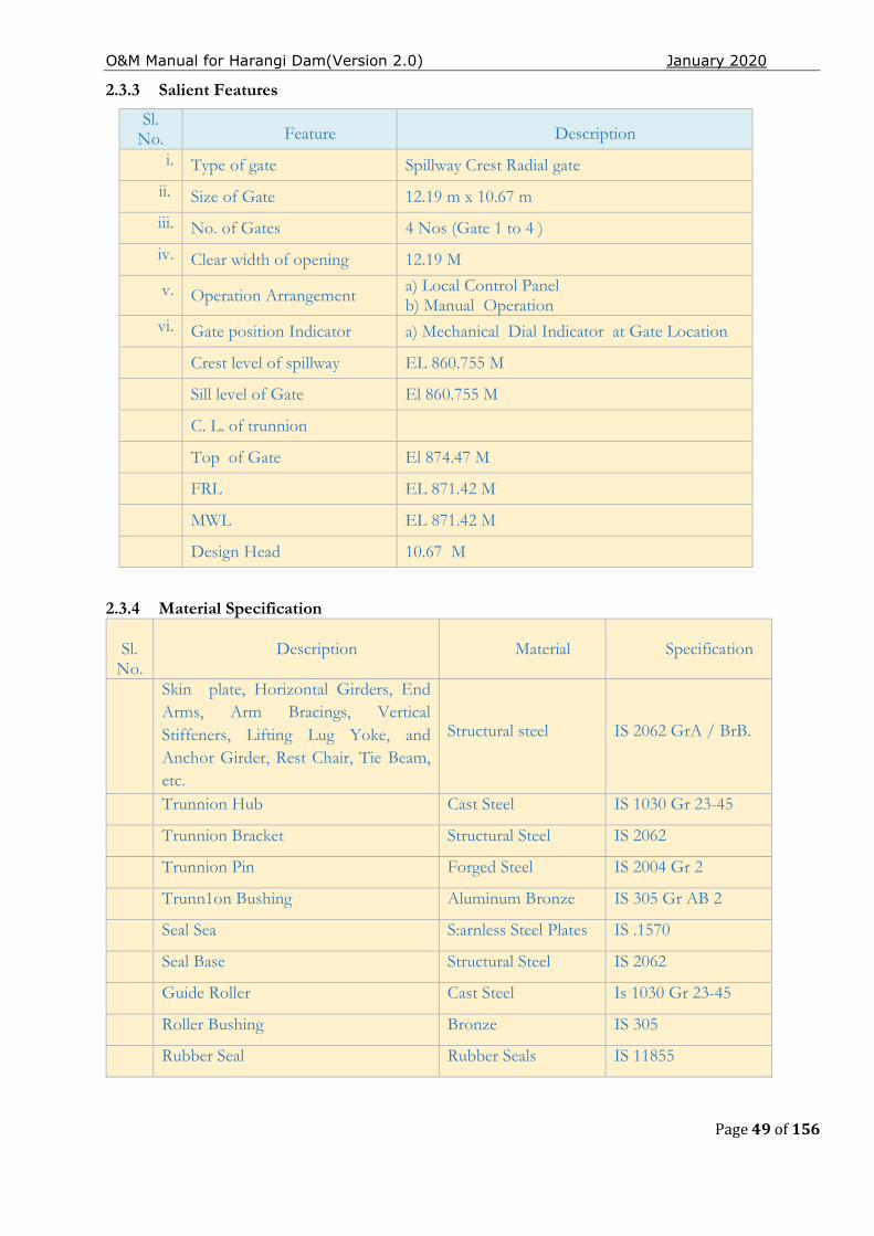
O&M Manual for Harangi Dam(Version 2.0) January 2020
Page 49 of 156
2.3.3 Salient Features
Sl. No. Feature Description
i. Type of gate Spillway Crest Radial gate
ii. Size of Gate 12.19 m x 10.67 m
iii. No. of Gates 4 Nos (Gate 1 to 4 )
iv. Clear width of opening 12.19 M
v. Operation Arrangement a) Local Control Panel b) Manual Operation
vi. Gate position Indicator a) Mechanical Dial Indicator at Gate Location
Crest level of spillway EL 860.755 M
Sill level of Gate El 860.755 M
C. L. of trunnion
Top of Gate El 874.47 M
FRL EL 871.42 M
MWL EL 871.42 M
Design Head 10.67 M
2.3.4 Material Specification
Sl. No.
Description Material Specification
Skin plate, Horizontal Girders, End Arms, Arm Bracings, Vertical Stiffeners, Lifting Lug Yoke, and Anchor Girder, Rest Chair, Tie Beam, etc.
Structural steel IS 2062 GrA / BrB.
Trunnion Hub Cast Steel IS 1030 Gr 23-45
Trunnion Bracket Structural Steel IS 2062
Trunnion Pin Forged Steel IS 2004 Gr 2
Trunn1on Bushing Aluminum Bronze IS 305 Gr AB 2
Seal Sea S:arnless Steel Plates IS .1570
Seal Base Structural Steel IS 2062
Guide Roller Cast Steel Is 1030 Gr 23-45
Roller Bushing Bronze IS 305
Rubber Seal Rubber Seals IS 11855
O&M Manual for Harangi Dam(Version 2.0) January 2020
Page 50 of 156
2.4 Operating Instructions
The gates are operated by electric motor and wire rope winch system. Hoists are capable of fully opening and closing the gates and holding the gates any position i.e. fully open and partially opened. The full closing time and opening time of the gate is 15mins. The limit switches are mounted on each hoist unit to set automatic off of hoist operation at fully close and open.
Each hoist can be operated from the unit control cabinet located in the hoist operating chamber. Each control panel contains the necessary main line fuse and switch. Reversing contacts and relay. Overload relays, WRC-Fuses, indicating lamps, etc. Necessary inter-locking arrangement is provided to disengage the hoist machinery from electric circuit when manual operation is in progress.
2.4.1 Checklist before Operation
The following steps are to be taken before operation of the gates to ensure these eight critical functions are in good working condition.
Sequence Description Actions to be carried out
Step 1 Seal Clamp The seal clamp fixing should be such as to ensure that the side seals are flexible enough
Step 2 Guide Roller The location and alignment of guide rollers should be checked.
Step 3 Limit Switch Limit Switches shall. be checked for satisfactory operation (function) to stop the hoist automatically when the gate. reaches the fully opened or fully closed position
Step 4 Nut & Bolts All nuts, bolts and screws shall be checked for wear, tear and tightness
Step 5 Pins Gate pin, connecting pin and all other pins should be in proper position and ensure that the nuts and split pins are tight and proper
Step 6 Trunnion Lubrication
To check and apply the high pressure lubricating grease in trunnion bushing from the hole provided in trunnion hub
Step 7 Control Panel
Control Panel shall be checked for its suitability for the purpose envisaged. The check may include items such as weather proofing, conducting wires, etc. In case of any contact chatter, clean the magnet surface and try again. If the chattering continues, check the coil voltage and replace the contact / coil, if necessary
2.5 Material Specifications (Radial Gate Skin plate assembly)
Table 8 - Material Specifications
Components Particulars Nos
required material
Materials
Skin plate, stiffeners, Horizontal girders, tracks, Base, seal seat bases, Sill beam, seal clamp, Guide and guide shoes
Structural steel IS 226
14thSkin R 4500 x 2481 2 STD Bolts 12thSkin R 3000 x 2481 2 STD Bolts
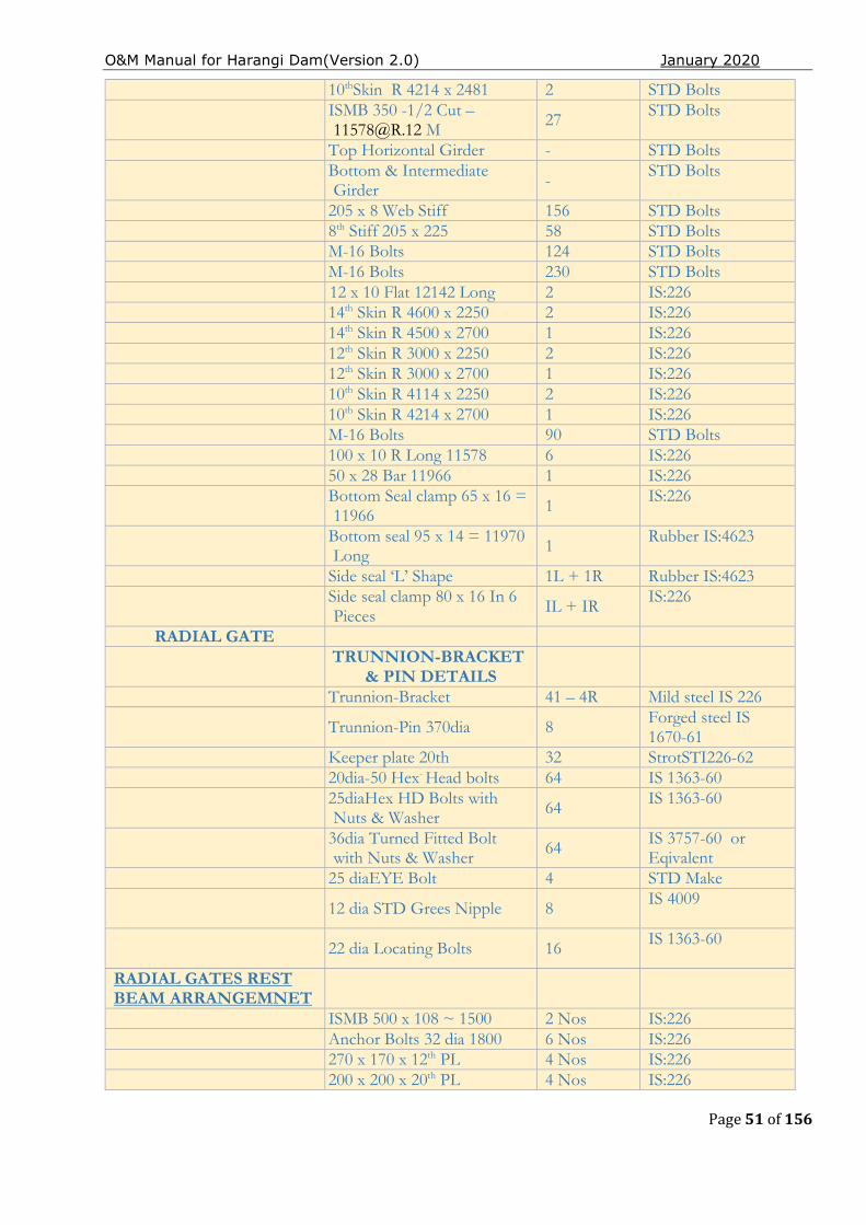
O&M Manual for Harangi Dam(Version 2.0) January 2020
Page 51 of 156
10thSkin R 4214 x 2481 2 STD Bolts
ISMB 350 -1/2 Cut – [email protected] M
27 STD Bolts
Top Horizontal Girder - STD Bolts
Bottom & Intermediate Girder - STD Bolts
205 x 8 Web Stiff 156 STD Bolts 8th Stiff 205 x 225 58 STD Bolts M-16 Bolts 124 STD Bolts M-16 Bolts 230 STD Bolts 12 x 10 Flat 12142 Long 2 IS:226 14th Skin R 4600 x 2250 2 IS:226 14th Skin R 4500 x 2700 1 IS:226 12th Skin R 3000 x 2250 2 IS:226 12th Skin R 3000 x 2700 1 IS:226 10th Skin R 4114 x 2250 2 IS:226 10th Skin R 4214 x 2700 1 IS:226 M-16 Bolts 90 STD Bolts 100 x 10 R Long 11578 6 IS:226 50 x 28 Bar 11966 1 IS:226
Bottom Seal clamp 65 x 16 = 11966 1
IS:226
Bottom seal 95 x 14 = 11970 Long 1 Rubber IS:4623
Side seal ‘L’ Shape 1L + 1R Rubber IS:4623
Side seal clamp 80 x 16 In 6 Pieces IL + IR
IS:226
RADIAL GATE
TRUNNION-BRACKET
& PIN DETAILS
Trunnion-Bracket 41 – 4R Mild steel IS 226
Trunnion-Pin 370dia 8 Forged steel IS 1670-61
Keeper plate 20th 32 StrotSTI226-62 20dia-50 Hex- Head bolts 64 IS 1363-60
25diaHex HD Bolts with Nuts & Washer 64 IS 1363-60
36dia Turned Fitted Bolt with Nuts & Washer 64 IS 3757-60 or
Eqivalent 25 diaEYE Bolt 4 STD Make
12 dia STD Grees Nipple 8 IS 4009
22 dia Locating Bolts 16 IS 1363-60
RADIAL GATES REST BEAM ARRANGEMNET
ISMB 500 x 108 ~ 1500 2 Nos IS:226 Anchor Bolts 32 dia 1800 6 Nos IS:226 270 x 170 x 12th PL 4 Nos IS:226 200 x 200 x 20th PL 4 Nos IS:226
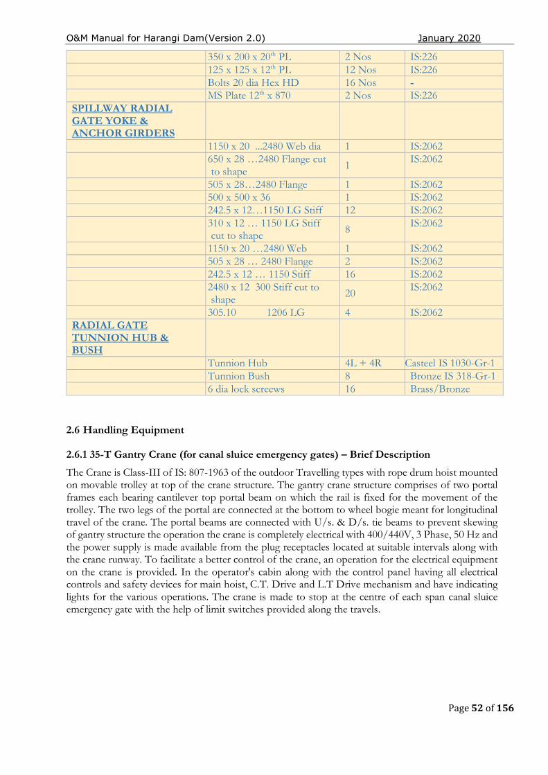
O&M Manual for Harangi Dam(Version 2.0) January 2020
Page 52 of 156
2.6 Handling Equipment
2.6.1 35-T Gantry Crane (for canal sluice emergency gates) – Brief Description
The Crane is Class-III of IS: 807-1963 of the outdoor Travelling types with rope drum hoist mounted on movable trolley at top of the crane structure. The gantry crane structure comprises of two portal frames each bearing cantilever top portal beam on which the rail is fixed for the movement of the trolley. The two legs of the portal are connected at the bottom to wheel bogie meant for longitudinal travel of the crane. The portal beams are connected with U/s. & D/s. tie beams to prevent skewing of gantry structure the operation the crane is completely electrical with 400/440V, 3 Phase, 50 Hz and the power supply is made available from the plug receptacles located at suitable intervals along with the crane runway. To facilitate a better control of the crane, an operation for the electrical equipment on the crane is provided. In the operator's cabin along with the control panel having all electrical controls and safety devices for main hoist, C.T. Drive and L.T Drive mechanism and have indicating lights for the various operations. The crane is made to stop at the centre of each span canal sluice emergency gate with the help of limit switches provided along the travels.
350 x 200 x 20th PL 2 Nos IS:226 125 x 125 x 12th PL 12 Nos IS:226 Bolts 20 dia Hex HD 16 Nos - MS Plate 12th x 870 2 Nos IS:226
SPILLWAY RADIAL GATE YOKE & ANCHOR GIRDERS
1150 x 20 ...2480 Web dia 1 IS:2062
650 x 28 …2480 Flange cut to shape 1
IS:2062
505 x 28…2480 Flange 1 IS:2062 500 x 500 x 36 1 IS:2062 242.5 x 12…1150 LG Stiff 12 IS:2062
310 x 12 … 1150 LG Stiff cut to shape 8 IS:2062
1150 x 20 …2480 Web 1 IS:2062 505 x 28 … 2480 Flange 2 IS:2062 242.5 x 12 … 1150 Stiff 16 IS:2062
2480 x 12 300 Stiff cut to shape 20 IS:2062
305.10 1206 LG 4 IS:2062 RADIAL GATE TUNNION HUB & BUSH
Tunnion Hub 4L + 4R Casteel IS 1030-Gr-1 Tunnion Bush 8 Bronze IS 318-Gr-1 6 dia lock screews 16 Brass/Bronze
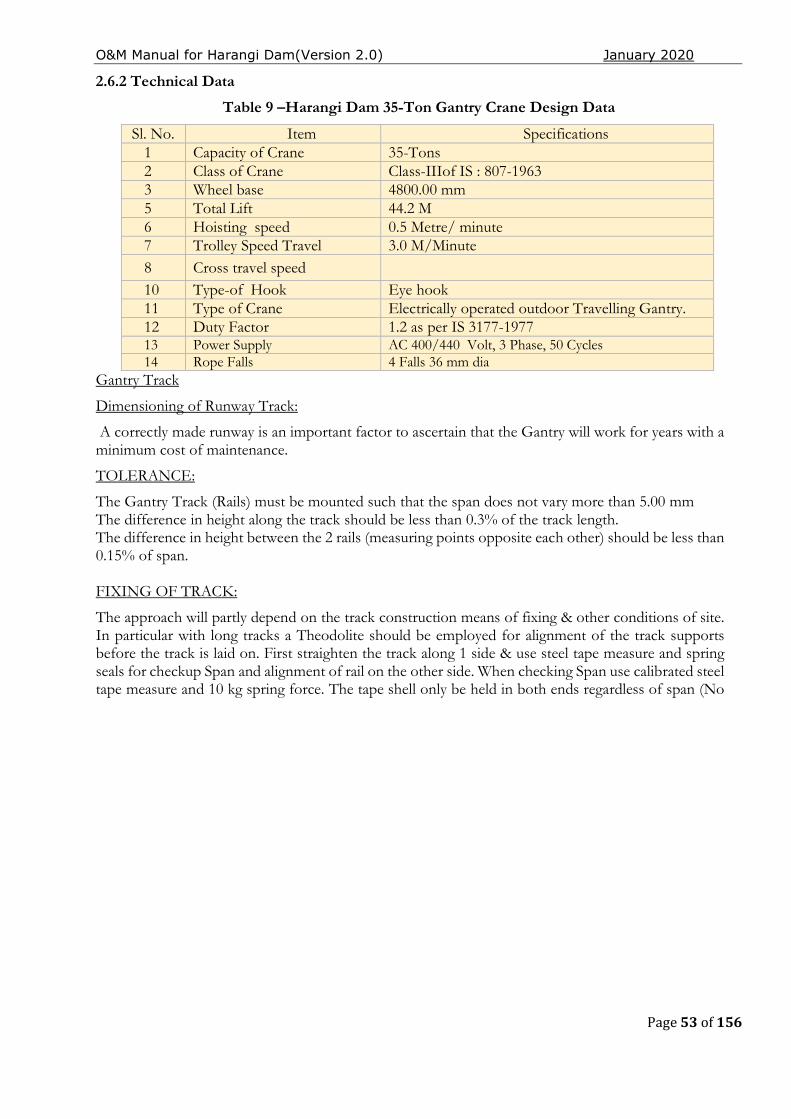
O&M Manual for Harangi Dam(Version 2.0) January 2020
Page 53 of 156
2.6.2 Technical Data
Table 9 –Harangi Dam 35-Ton Gantry Crane Design Data
Sl. No. Item Specifications 1 Capacity of Crane 35-Tons 2 Class of Crane Class-IIIof IS : 807-1963 3 Wheel base 4800.00 mm 5 Total Lift 44.2 M 6 Hoisting speed 0.5 Metre/ minute 7 Trolley Speed Travel 3.0 M/Minute 8 Cross travel speed 10 Type-of Hook Eye hook 11 Type of Crane Electrically operated outdoor Travelling Gantry. 12 Duty Factor 1.2 as per IS 3177-1977 13 Power Supply AC 400/440 Volt, 3 Phase, 50 Cycles 14 Rope Falls 4 Falls 36 mm dia
Gantry Track
Dimensioning of Runway Track:
A correctly made runway is an important factor to ascertain that the Gantry will work for years with a minimum cost of maintenance.
TOLERANCE:
The Gantry Track (Rails) must be mounted such that the span does not vary more than 5.00 mm The difference in height along the track should be less than 0.3% of the track length. The difference in height between the 2 rails (measuring points opposite each other) should be less than 0.15% of span. FIXING OF TRACK:
The approach will partly depend on the track construction means of fixing & other conditions of site. In particular with long tracks a Theodolite should be employed for alignment of the track supports before the track is laid on. First straighten the track along 1 side & use steel tape measure and spring seals for checkup Span and alignment of rail on the other side. When checking Span use calibrated steel tape measure and 10 kg spring force. The tape shell only be held in both ends regardless of span (No
O&M Manual for Harangi Dam(Version 2.0) January 2020
Page 54 of 156
other supports). Check span for each 3 mtr rail joints should be spliced with a maximum of gap of 3 mm in between rails.
ASSEMBLY AND TEST RUN OFGRANTY CRANE
MAIN PARTS:
During transport of Granty crane is usually made up by the following main parts.
a) Gantry portal columns
b) End carriage with wheels
c) Hoist with frame
d) Long travel machinery
e) Cabin and electrical equipments
ELECTRICAL WIRING:
During transport a number of electric cables have to be disconnected and these have to be re-connected. For this work, the electrician will require.
i) Wiring diagram
ii) Electrical layout diagram
POWER SUPPLY:
The power supply is through slip rings and a cable reeling drum driven from L.T drive.
EARTHING OF ELECTRICAL SYSTEM:
The crane structure, motor frames and metal cases of electrical equipment are earthed. The crane wheels are considered to make an effective earth with the rails.
PROTECTION OF ELECTRICAL EQUIPMENTS:
The electrical layout of the crane is protected by fuses in the Crane control panels.
TEST RUN OF GANTRY CRANE:
Make sure that phasing of Gantry power supply is correct. Controller marked down. If hook moves upwards interchange the connection of two phase in the relevant contractor panel of the Hoist. Test limit switches for hoisting machinery and limit switches for Gantry drive. If provided. Drive the Gantry carefully along the whole length of the Track for check of clearance. Be alert and stop immediately if excessive noice occurs.
ADJUSTMENT OF LIMIT SWITCHES:
Limit switches for hoisting motions. The limit switch is of shunt type, operating the contactor circuit. The actuating nuts are easily adjustable to suit the limits of hook lifts required by disengaging the driving chain. Adjust also limit switches for long travelling movements.
GANTRY CRANE PREVENTIVE MAINTENANCE:
General:
The adjust of maintenance on any type of equipment – Gantry Crane – brings to mind adjustments and repairs in the event of breakdown. This type of thinking prevailed in Industry for many years when equipment was allowed to operate irrespective of efficiency until a breakdown accured. Then repairs were carried out as fast as possible. However, realization of the folly of this attitude in regard to major equipments and Gantry in particular, has brought about a complete revision in managements approach to the programming of maintenance. Maintenance departments now have master Electrician and
O&M Manual for Harangi Dam(Version 2.0) January 2020
Page 55 of 156
Fitters, each specialist in his own right who are responsible for the performance of the various aspects of equipment. Due to their complex nature. These Gantry Cranes resent special problems in that they are a combination of three branches of Engineering Electrical, Mechanical and Structural. Each can immobilize the equipment due to the equipment due to poor maintenance. The economic upkeep of Gantry can only be attained through a rigidly enforced preventive maintenance programme. Repairs can be carried out without having to pay for over time. Additionally, the life span of Gantry Crane will be extended and the sequence of a defective part contributing to major breakdowns can be prevented.
GANTRY TRACK:
A good track is essential for proper performance of the Gantry Crane. Keep the Track groove clean and tidy and remove any possible physical obstructions. Joints should be free from vide gaps and work out edges causing wear to the wheel surfaces and bearings. In aligning Track Rails, Rails should be checked for span in increments of not more than 3 meters of Track length. Track Rail alignment should never be allowed to deviate more than 6 mm, as the danger of wheel flanges scrubbing the Rail head can do irreparable damage to the wheels and place undue strain on mechanical and structural components. Rugged Gantry bumpers are provided are provided at each end of the Track. These are of steel and should engage with the bumpers on the Gantry. It is essential that the bumpers are set square with the track, otherwise the Gantry may be thrown askew it when it comes into contact with them.
IMPORTANT NOTE:
Span of Gantry Rails should be within ± 5 mm when you first start the Gantry Crane. Before the Gantry Crane is placed in service there are three very important things that should be done. First, check the direction of rotation of each controller handle to effect movement of each of the Gantry Cranes motion. Next, check the operation of the hoist motor brake and finally set the upper limit stop so that the current is shut off when the Gantry hook reaches its uppermost safe limit of travel. Slight adjustment of each of the above points may be necessary so that each of these units operate as they should.
DAILY MAINTENANCE CHECK LIST:
This being a Gantry Crane for the operation of draft tube gates not sequently used a thorough check is to be made before the Gantry Crane is put in to actual operation when required. The ideal man to put forward a report on the operation of Gantry day by day is the operator. At the commencement and at the end of his shift, he should cross the walkway of the Gantry looking for loose bolts,
O&M Manual for Harangi Dam(Version 2.0) January 2020
Page 56 of 156
excessive grease or oil leaks, or any other un usual signs that would indicate potential trouble. Regular periodic checks to be performed by the maintenance department are given in the detailed check lists.
STANDARD REGULAR GANTRY CRANE MAINTENANCE CHECKS:
Weekly maintenance check list.
Electromagnetic Brakes - Check brake liners for wear. Check linkages and adjustment to ensure brake is not dragging. Grease linkage piece when Crane is first put into operation adjust brakes every first day of the week.
Lubrication - See chart at conclusion of check lists. Monthly maintenance check list.
Hoist wire rope - Check for wear and broken strands.
Resistor connections - Check for broken or worn out connection.
Controllers - Check contacts, clean and replace, where necessary.
Control Cabinets - Clean out control cabinets.
Lubrication - See chart at conclusion of check lists.
- Quarterly maintenance check list.
Controllers - Check connection and clean contacts.
Electrical connections - Check throughout Gantry Crane.
Flexible couplings - Check pins and bushes foe wear.
Gross Shaft Plummer blocks - Take two pieces, clean out grease, check seals and pack with grease.
- Semi Annual maintenance Check list
Gantry Crane Track - Inspection for wear flat spots and cracks in flange. Ensure drive wheels are of the same diameter.
Track - Check alignment and elevation.
Lubrication - See chart at conclusion of check lists.
- Annual maintenance check list
Master switches - Check contacts
Main & Secondary switches - Check contacts
Gear boxes - Drain & Refill
Motors - Check brushes on would rotor motors.
Oil seals - Check in leaks
Machinery and hold down bolts - Check for tightness. They should also be checked after first month of operation.
Rope Sheaves - Inspect for wear and cracks in flanges
Lubrication - See chart.
The type of lubrication are given on lubrication chart and the frequency is given below.
Gantry Lubrication chart
Description Frequency
O&M Manual for Harangi Dam(Version 2.0) January 2020
Page 57 of 156
Gantry drive motor - 6 Months
Gantry drive gear box - Check monthly, Change yearly.
LT-Shaft Plummer blocks - 6 Months
Truck Wheel Bearings - 6 Months
Open gear and Pinion teeth - Monthly
Hoist Assembly – all motors - 6 Months
Wire Ropes - Monthly
Hoist drive gear box - Check monthly, Change yearly
Hoist Gear box - Check monthly, Change yearly
Drum Pinion and Gear teeth - Monthly
Top and equalizer sheave bearings - Monthly
Hoist hook block and all sheave bearings - Monthly
The foundation of good preventive maintenance is an educational program for both operators and maintenance personnel. A few simple ideas supplied in this respect can reply the effort involved many times over. It is suggested that a card be installed in the cab stipulating the following regulations.
OPERATING DO’S AND DON’TS
DO: Clean walkway, control cabin etc., regularly, take up slack in slings and cables gradually provide good acess to Gantry from the floor, secure all covers after maintenance, turn off main switch when operator leaves cab. Remove main fuses when maintenance has to be carried out on Gantry Crane.
DON’T: Use limit switches as regular stops. Run Gantry Crane up against the stops. Ease it along gently.
Pick up a load at an angle or pull loads sideways. Let the block swing excessively. Brake too hard and stop crane suddenly. Over load the crane. Jerk a load off the floor. Leave tools etc., loose on Crane or runway after maintenance. Try to do maintenance on the Gantry Crane with power on. Step on LT Shafts or couplings, when Gantry is in motion. Let hook block lie on the ground, so that Hoist cables become loose. This will cause cables to jump the sheaves and may result in broken cables. The subject of education can be supplied by the Engineer responsible for maintenance to his own personnel by the application of a little fore thought.
ELECTRIC EQUIPMENT – MAINTENANCE
Equipment for Power supply: Current collection is through the slipring on the cable reeling drum. Ensure that the slip rings are clean and brushes are intact with Springs.
CONTACTORS:
The contactors are designed with adequate margin for Gantry Crane operation. After some time of operation, however, small creatures will appear on the contact surface which will cause increased resistance and accelerate the process of wear on the contacts. The contactor contacts should there be inspected at regular intervals and worked plane with a file. For all types of contactors, new contacts can be bought and it is not necessary to buy a new contactor.
SEQUENCE OF FAULTS CHECKING:
If any faults should arise in the electric system, one should consult the wiring diagram when investigating the matter. Suspect items are all cables exposed to movement’s i.e cable for controls and eventual cables for hoist and Gantry power supply. It is advisable to investigate these first. Occasionally, after some time of operation terminals in the contactor panels may come loose and
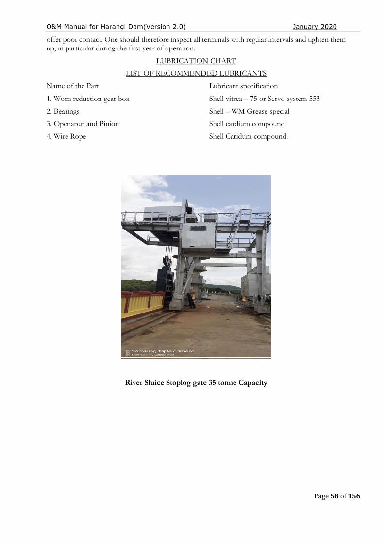
O&M Manual for Harangi Dam(Version 2.0) January 2020
Page 58 of 156
offer poor contact. One should therefore inspect all terminals with regular intervals and tighten them up, in particular during the first year of operation.
LUBRICATION CHART
LIST OF RECOMMENDED LUBRICANTS
Name of the Part Lubricant specification
1. Worn reduction gear box Shell vitrea – 75 or Servo system 553
2. Bearings Shell – WM Grease special
3. Openapur and Pinion Shell cardium compound
4. Wire Rope Shell Caridum compound.
River Sluice Stoplog gate 35 tonne Capacity
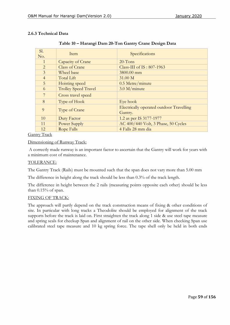
O&M Manual for Harangi Dam(Version 2.0) January 2020
Page 59 of 156
2.6.3 Technical Data
Table 10 – Harangi Dam 20-Ton Gantry Crane Design Data
Sl. No. Item Specifications
1 Capacity of Crane 20-Tons 2 Class of Crane Class-III of IS : 807-1963 3 Wheel base 3800.00 mm 4 Total Lift 31.00 M 5 Hoisting speed 0.5 Metre/minute 6 Trolley Speed Travel 3.0 M/minute 7 Cross travel speed
8 Type-of Hook Eye hook
9 Type of Crane Electrically operated outdoor Travelling Gantry.
10 Duty Factor 1.2 as per IS 3177-1977 11 Power Supply AC 400/440 Volt, 3 Phase, 50 Cycles 12 Rope Falls 4 Falls 28 mm dia
Gantry Track
Dimensioning of Runway Track:
A correctly made runway is an important factor to ascertain that the Gantry will work for years with a minimum cost of maintenance.
TOLERANCE:
The Gantry Track (Rails) must be mounted such that the span does not vary more than 5.00 mm
The difference in height along the track should be less than 0.3% of the track length.
The difference in height between the 2 rails (measuring points opposite each other) should be less than 0.15% of span.
FIXING OF TRACK:
The approach will partly depend on the track construction means of fixing & other conditions of site. In particular with long tracks a Theodolite should be employed for alignment of the track supports before the track is laid on. First straighten the track along 1 side & use steel tape measure and spring seals for checkup Span and alignment of rail on the other side. When checking Span use calibrated steel tape measure and 10 kg spring force. The tape shell only be held in both ends
O&M Manual for Harangi Dam(Version 2.0) January 2020
Page 60 of 156
regardless of span (No other supports). Check span for each 3 mtr rail joints should be spliced with a maximum of gap of 3 mm in between rails.
ASSEMBLY AND TEST RUN OFGRANTY CRANE
MAIN PARTS:
During transport of Granty crane is usually made up by the following main parts.
f) Gantry portal columns
g) End carriage with wheels
h) Hoist with frame
i) Long travel machinery
j) Cabin and electrical equipments
ELECTRICAL WIRING:
During transport a number of electric cables have to be disconnected and these have to be re-connected. For this work, the electrician will require.
iii) Wiring diagram
iv) Electrical layout diagram
POWER SUPPLY:
The power supply is through sliprings and a cable reeling drum driven from L.T drive.
EARTHING OF ELECTRICAL SYSTEM:
The crane structure, motor frames and metal cases of electrical equipment are earthed. The crane wheels are considered to make an effective earth with the rails.
PROTECTION OF ELECTRICAL EQUIPMENTS:
The electrical layout of the crane is protected by fuses in the Crane control panels.
TEST RUN OF GANTRY CRANE:
Make sure that phasing of Gantry power supply is correct. Controller marked down. If hook moves upwards interchange the connection of two phase in the relevant contractor panel of the Hoist. Test limit switches for hoisting machinery and limit switches for Gantry drive. If provided. Drive the Gantry carefully along the whole length of the Track for check of clearance. Be alert and stop immediately if excessive noice occurs.
ADJUSTMENT OF LIMIT SWITCHES:
Limit switches for hoisting motions. The limit switch is of shunt type, operating the contactor circuit. The actuating nuts are easily adjustable to suit the limits of hook lifts required by disengaging the driving chain. Adjust also limit switches for long travelling movements.
GANTRY CRANE PREVENTIVE MAINTENANCE:
General:
The adjust of maintenance on any type of equipment – Gantry Crane – brings to mind adjustments and repairs in the event of breakdown. This type of thinking prevailed in Industry for many years when equipment was allowed to operate irrespective of efficiency until a breakdown accured. Then
O&M Manual for Harangi Dam(Version 2.0) January 2020
Page 61 of 156
repairs were carried out as last as possible. However, realization of the folly of this attitude in regard to major equipments and Gantry in particular, has brought about a complete revision in managements approach to the programming of maintenance. Maintenance departments now have master Electrician and Fitters, each specialist in his own right who are responsible for the performance of the various aspects of equipment. Due to their complex nature. These Gantry Cranes resent special problems in that they are a combination of three branches of Engineering Electrical, Mechanical and Structural. Each can immobilize the equipment due to the equipment due to poor maintenance. The economic upkeep of Gantry can only be attained through a rigidly enforced preventive maintenance programme. Repairs can be carried out without having to pay for over time. Additionally, the life span of Gantry Crane will be extended and the sequence of a defective part contributing to major breakdowns can be prevented.
GANTRY TRACK:
A good track is essential for proper performance of the Gantry Crane. Keep the Track groove clean and tidy and remove any possible physical obstructions. Joints should be free from vide gaps and work out edges causing wear to the wheel surfaces and bearings. In aligning Track Rails, Rails should be checked for span in increments of not more than 3 meters of Track length. Track Rail alignment should never be allowed to deviate more than 6 mm, as the danger of wheel flanges scrubbing the Rail head can do irreparable damage to the wheels and place undue strain on mechanical and structural components. Rugged Gantry bumpers are provided are provided at each end of the Track. These are of steel and should engage with the bumpers on the Gantry. It is essential that the bumpers are set square with the track, otherwise the Gantry may be thrown askew it when it comes into contact with them.
IMPORTANT NOTE:
Span of Gantry Rails should be within ± 5 mm when you first start the Gantry Crane. Before the Gantry Crane is placed in service there are three very important things that should be done. First, check the direction of rotation of each controller handle to effect movement of each of the Gantry Cranes motion. Next, check the operation of the hoist motor brake and finally set the upper limit stop so that the current is shut off when the Gantry hook reaches its uppermost safe limit of travel. Slight adjustment of each of the above points may be necessary so that each of these units operate as they should.
DAILY MAINTENANCE CHECK LIST:
This being a Gantry Crane for the operation of draft tube gates not sequently used a thorough check is to be made before the Gantry Crane is put in to actual operation when required. The ideal man to put forward a report on the operation of Gantry day by day is the operator. At the commencement and at the end of his shift, he should cross the walkway of the Gantry looking for loose bolts, excessive
O&M Manual for Harangi Dam(Version 2.0) January 2020
Page 62 of 156
grease or oil leaks, or any other un usual signs that would indicate potential trouble. Regular periodic checks to be performed by the maintenance department are given in the detailed check lists.
STANDARD REGULAR GANTRY CRANE MAINTENANCE CHECKS:
Weekly maintenance check list.
Electromagnetic Brakes - Check brake liners for wear. Check linkages and adjustment to ensure brake is not dragging. Grease linkage piece when Crane is first put into operation adjust brakes every first day of the week. Lubrication - See chart at conclusion of check lists. Monthly maintenance check list.
Hoist wire rope - Check for wear and broken strands.
Resistor connections - Check for broken or worn out connection.
Controllers - Check contacts, clean and replace, where necessary.
Control Cabinets - Clean out control cabinets.
Lubrication - See chart at conclusion of check lists.
- Quarterly maintenance check list.
Controllers - Check connection and clean contacts.
Electrical connections - Check throughout Gantry Crane.
Flexible couplings - Check pins and bushes foe wear.
Gross Shaft Plummer blocks - Take two pieces, clean out grease, check seals and pack with grease. - Semi Annual maintenance Check list
Gantry Crane Track - Inspection for wear flat spots and cracks in flange. Ensure drive wheels are of the same diameter. Track - Check alignment and elevation.
Lubrication - See chart at conclusion of check lists.
- Annual maintenance check list
Master switches - Check contacts
Main & Secondary switches - Check contacts
Gear boxes - Drain & Refill
Motors - Check brushes on would rotor motors.
Oil seals - Check in leaks
Machinery and hold down bolts - Check for tightness. They should also be checked after first month of operation.
Rope Sheaves - Inspect for wear and cracks in flanges
Lubrication - See chart.
The type of lubrication is given on lubrication chart and the frequency is given below.
Gantry Lubrication chart
DescriptionFrequency
Gantry drive motor - 6 Months
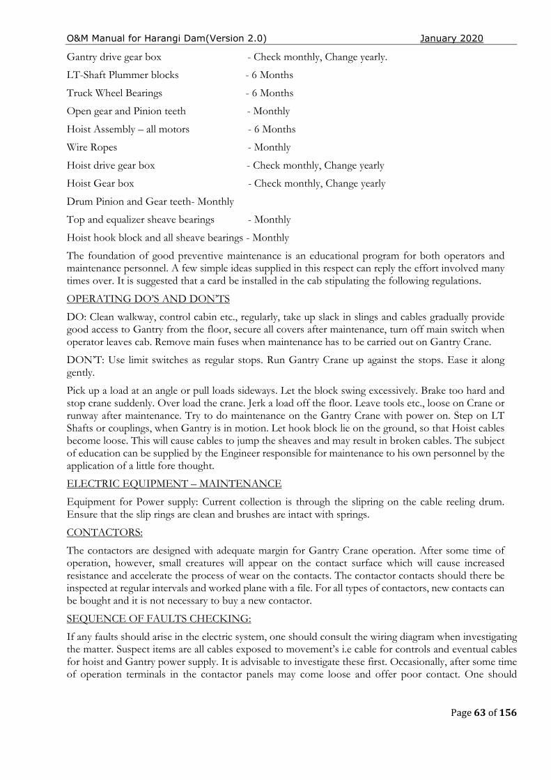
O&M Manual for Harangi Dam(Version 2.0) January 2020
Page 63 of 156
Gantry drive gear box - Check monthly, Change yearly.
LT-Shaft Plummer blocks - 6 Months
Truck Wheel Bearings - 6 Months
Open gear and Pinion teeth - Monthly
Hoist Assembly – all motors - 6 Months
Wire Ropes - Monthly
Hoist drive gear box - Check monthly, Change yearly
Hoist Gear box - Check monthly, Change yearly
Drum Pinion and Gear teeth- Monthly
Top and equalizer sheave bearings - Monthly
Hoist hook block and all sheave bearings - Monthly
The foundation of good preventive maintenance is an educational program for both operators and maintenance personnel. A few simple ideas supplied in this respect can reply the effort involved many times over. It is suggested that a card be installed in the cab stipulating the following regulations.
OPERATING DO’S AND DON’TS
DO: Clean walkway, control cabin etc., regularly, take up slack in slings and cables gradually provide good access to Gantry from the floor, secure all covers after maintenance, turn off main switch when operator leaves cab. Remove main fuses when maintenance has to be carried out on Gantry Crane.
DON’T: Use limit switches as regular stops. Run Gantry Crane up against the stops. Ease it along gently.
Pick up a load at an angle or pull loads sideways. Let the block swing excessively. Brake too hard and stop crane suddenly. Over load the crane. Jerk a load off the floor. Leave tools etc., loose on Crane or runway after maintenance. Try to do maintenance on the Gantry Crane with power on. Step on LT Shafts or couplings, when Gantry is in motion. Let hook block lie on the ground, so that Hoist cables become loose. This will cause cables to jump the sheaves and may result in broken cables. The subject of education can be supplied by the Engineer responsible for maintenance to his own personnel by the application of a little fore thought.
ELECTRIC EQUIPMENT – MAINTENANCE
Equipment for Power supply: Current collection is through the slipring on the cable reeling drum. Ensure that the slip rings are clean and brushes are intact with springs.
CONTACTORS:
The contactors are designed with adequate margin for Gantry Crane operation. After some time of operation, however, small creatures will appear on the contact surface which will cause increased resistance and accelerate the process of wear on the contacts. The contactor contacts should there be inspected at regular intervals and worked plane with a file. For all types of contactors, new contacts can be bought and it is not necessary to buy a new contactor.
SEQUENCE OF FAULTS CHECKING:
If any faults should arise in the electric system, one should consult the wiring diagram when investigating the matter. Suspect items are all cables exposed to movement’s i.e cable for controls and eventual cables for hoist and Gantry power supply. It is advisable to investigate these first. Occasionally, after some time of operation terminals in the contactor panels may come loose and offer poor contact. One should
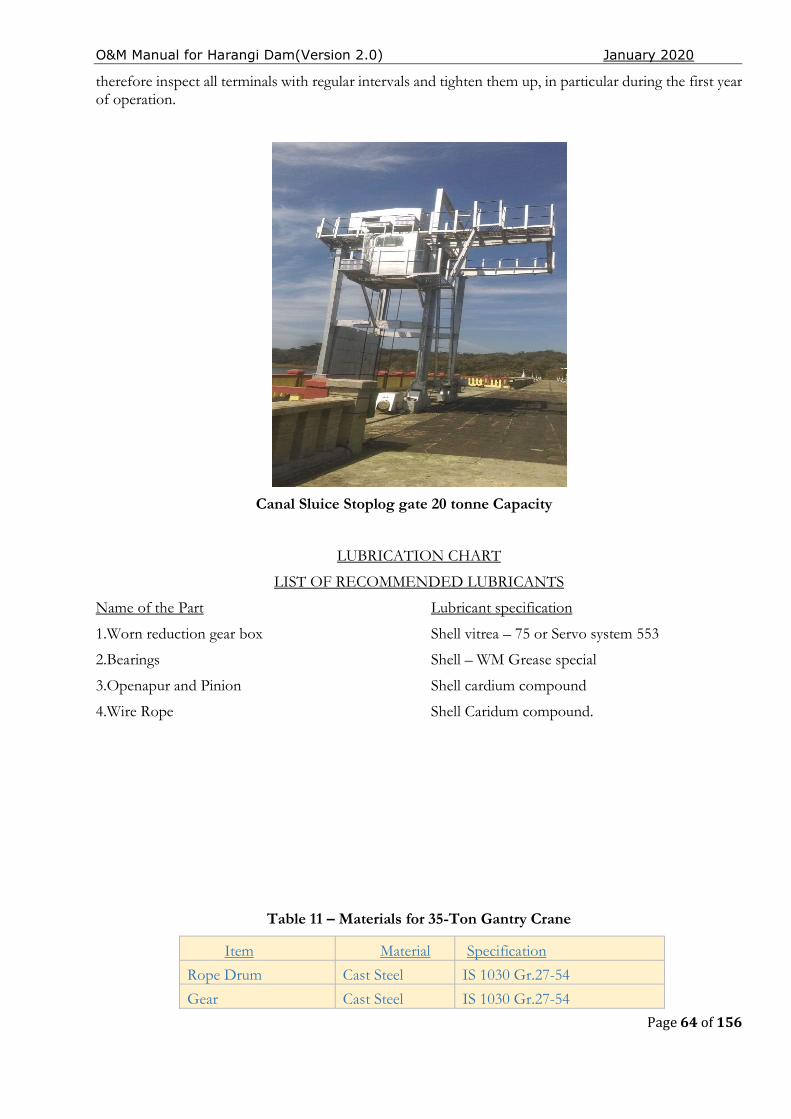
O&M Manual for Harangi Dam(Version 2.0) January 2020
Page 64 of 156
therefore inspect all terminals with regular intervals and tighten them up, in particular during the first year of operation.
Canal Sluice Stoplog gate 20 tonne Capacity
LUBRICATION CHART
LIST OF RECOMMENDED LUBRICANTS
Name of the Part Lubricant specification
1.Worn reduction gear box Shell vitrea – 75 or Servo system 553
2.Bearings Shell – WM Grease special
3.Openapur and Pinion Shell cardium compound
4.Wire Rope Shell Caridum compound.
Table 11 – Materials for 35-Ton Gantry Crane
Item Material Specification
Rope Drum Cast Steel IS 1030 Gr.27-54
Gear Cast Steel IS 1030 Gr.27-54
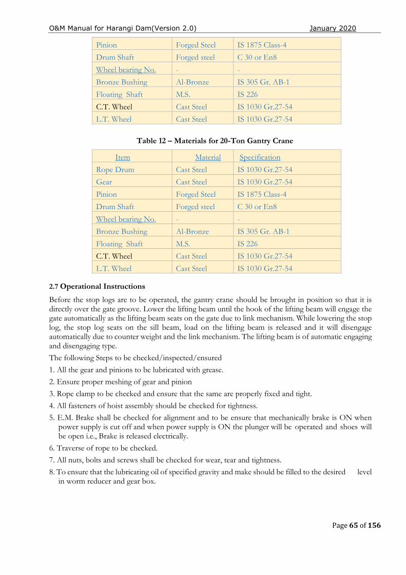
O&M Manual for Harangi Dam(Version 2.0) January 2020
Page 65 of 156
Pinion Forged Steel IS 1875 Class-4
Drum Shaft Forged steel C 30 or En8
Wheel bearing No. - -
Bronze Bushing Al-Bronze IS 305 Gr. AB-1
Floating Shaft M.S. IS 226
C.T. Wheel Cast Steel IS 1030 Gr.27-54
L.T. Wheel Cast Steel IS 1030 Gr.27-54
Table 12 – Materials for 20-Ton Gantry Crane
Item Material Specification
Rope Drum Cast Steel IS 1030 Gr.27-54
Gear Cast Steel IS 1030 Gr.27-54
Pinion Forged Steel IS 1875 Class-4
Drum Shaft Forged steel C 30 or En8
Wheel bearing No. - -
Bronze Bushing Al-Bronze IS 305 Gr. AB-1
Floating Shaft M.S. IS 226
C.T. Wheel Cast Steel IS 1030 Gr.27-54
L.T. Wheel Cast Steel IS 1030 Gr.27-54
2.7 Operational Instructions
Before the stop logs are to be operated, the gantry crane should be brought in position so that it is directly over the gate groove. Lower the lifting beam until the hook of the lifting beam will engage the gate automatically as the lifting beam seats on the gate due to link mechanism. While lowering the stop log, the stop log seats on the sill beam, load on the lifting beam is released and it will disengage automatically due to counter weight and the link mechanism. The lifting beam is of automatic engaging and disengaging type.
The following Steps to be checked/inspected/ensured
1. All the gear and pinions to be lubricated with grease.
2. Ensure proper meshing of gear and pinion
3. Rope clamp to be checked and ensure that the same are properly fixed and tight.
4. All fasteners of hoist assembly should be checked for tightness.
5. E.M. Brake shall be checked for alignment and to be ensure that mechanically brake is ON when power supply is cut off and when power supply is ON the plunger will be operated and shoes will be open i.e., Brake is released electrically.
6. Traverse of rope to be checked.
7. All nuts, bolts and screws shall be checked for wear, tear and tightness.
8. To ensure that the lubricating oil of specified gravity and make should be filled to the desired level in worm reducer and gear box.
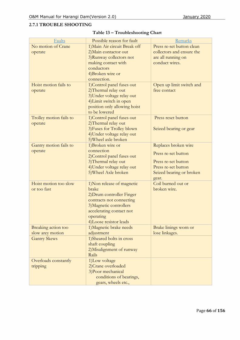
O&M Manual for Harangi Dam(Version 2.0) January 2020
Page 66 of 156
2.7.1 TROUBLE SHOOTING
Table 13 – Troubleshooting Chart
Faults Possible reason for fault Remarks No motion of Crane operate
1)Main Air circuit Break off 2)Main contactor out 3)Runway collectors not making contact with conductors 4)Broken wire or connection.
Press re-set button clean collectors and ensure the are all running on conduct wires.
Hoist motion fails to operate
1)Control panel fuses out 2)Thermal relay out 3)Under voltage relay out 4)Limit switch in open position only allowing hoist to be lowered
Open up limit switch and free contact
Trolley motion fails to operate
1)Control panel fuses out 2)Thermal relay out 3)Fuses for Trolley blown 4)Under voltage relay out 5)Wheel axle broken
Press reset button Seized bearing or gear
Gantry motion fails to operate
1)Broken wire or connection 2)Control panel fuses out 3)Thermal relay out 4)Under voltage relay out 5)Wheel Axle broken
Replaces broken wire
Press re-set button
Press re-set button Press re-set button Seized bearing or broken gear.
Hoist motion too slow or too fast
1)Non release of magnetic brake 2)Drum controller Finger contracts not connecting 3)Magnetic controllers accelerating contact not operating 4)Loose resistor leads
Coil burned out or broken wire.
Breaking action too slow arey motion
1)Magnetic brake needs adjustment
Brake linings worn or lose linkages.
Gantry Skews 1)Sheared bolts in cross shaft coupling 2)Misalignment of runway Rails
Overloads constantly tripping
1)Low voltage 2)Crane overloaded 3)Poor mechanical
conditions of bearings, gears, wheels etc.,

O&M Manual for Harangi Dam(Version 2.0) January 2020
Page 67 of 156
2.8 Electrical Connections:
The Electrical power connections for the Gates and the Switches.
The PLCs /Gates were already wired. It is shown here as a continuity and relevance to the current project.
The switches are connected in the following manner with the Group of three switches connected to each DB through an MCB
O&M Manual for Harangi Dam(Version 2.0) January 2020
Page 68 of 156
2.9 RIVER OUTLET WORKS.
Monthly Water Releases for Irrigation purpose
Month Canal withdrawal (Mcft)
June-2019 78.52 July-2019 899.53 August-2019 3133.21 September-2019 3079.01 October-2019 1873.36 November-2019 3575.97 December-2019 2110.12
2.9.1 Description:
Intake channel, intake structure, trash racks, closure method, upstream conveyance structure, gate chamber, downstream conveyance structure, control structure, stilling basin, exit channel, power sources, diversion during construction, bypass system).
2.9.1.1 River Sluice Gates & hoists:
There River sluice are provided in the body of 3 piers in the spillway. Vent size of these river sluices is 1.83 x 3.66 m (6 x 12 ft) and sills of all the three vents are at RL 832.06 m (RL 2730 ft). The discharging capacity of theses sluices is 333.24 cumec (11770 cusecs) at MDDL RL 2790 ft.
An emergency gate is provided for the river sluice. One gate is provided to use whenever in whichever of the three service gates provided in the piers go out of order. A gantry crane of 35 tonnes capacity is provided for handling and operation of the gate of river sluice. The gantry is provided with hoisting arrangements, hoist travelling and gantry travelling arrangements. The hoist is situated at the top of the gantry and moves on rails fixed on the top beams in the gantry structure.
2.9.1.2 Irrigation Sluice Gates & hoists:
An Irrigation Sluice is provided on the Left bank no over flow section of the dam at Ch: 130 m having 6 vents each of size 1.83 x 3.05 m. Sill level of the sluice vents are at RL 846.734 m (RL 2778.80 ft). These sluices have controls inside the well formed in the body of the dam and flow is regulated by vertical lift MS gates. Operation is done from the top of the hoist platform created below the top of dam which can be accessed from dam top by means of a ladder fixed along the downstream face.
The gates are operated by screw hoists with rod attached to the gate at its lower end and a worm wheel at the top. The sluice are fitted with both service and emergency gates and are being operated in electrical mode.
The sluice vents are provided with 6 numbers of service gates with provision of one emergency gate. A 20 tonnes capacity Gantry crane is provided with hoist for handling and operating the stoplog element. The gantry is provided with hoisting arrangements, hoist is situated at the
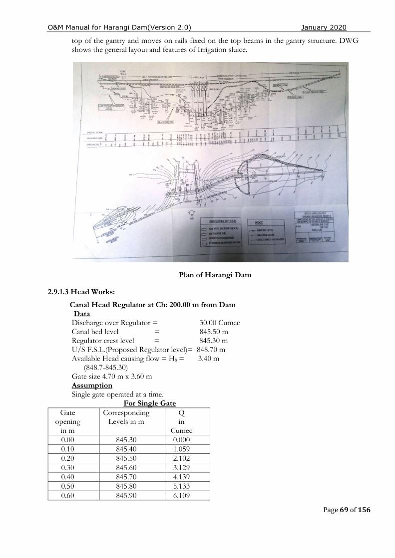
O&M Manual for Harangi Dam(Version 2.0) January 2020
Page 69 of 156
top of the gantry and moves on rails fixed on the top beams in the gantry structure. DWG shows the general layout and features of Irrigation sluice.
Plan of Harangi Dam
2.9.1.3 Head Works:
Canal Head Regulator at Ch: 200.00 m from Dam Data Discharge over Regulator = 30.00 Cumec Canal bed level = 845.50 m Regulator crest level = 845.30 m U/S F.S.L.(Proposed Regulator level)= 848.70 m Available Head causing flow = H8 = 3.40 m (848.7-845.30) Gate size 4.70 m x 3.60 m Assumption Single gate operated at a time. For Single Gate
Gate opening
in m
Corresponding Levels in m
Q in
Cumec 0.00 845.30 0.000 0.10 845.40 1.059 0.20 845.50 2.102 0.30 845.60 3.129 0.40 845.70 4.139 0.50 845.80 5.133 0.60 845.90 6.109
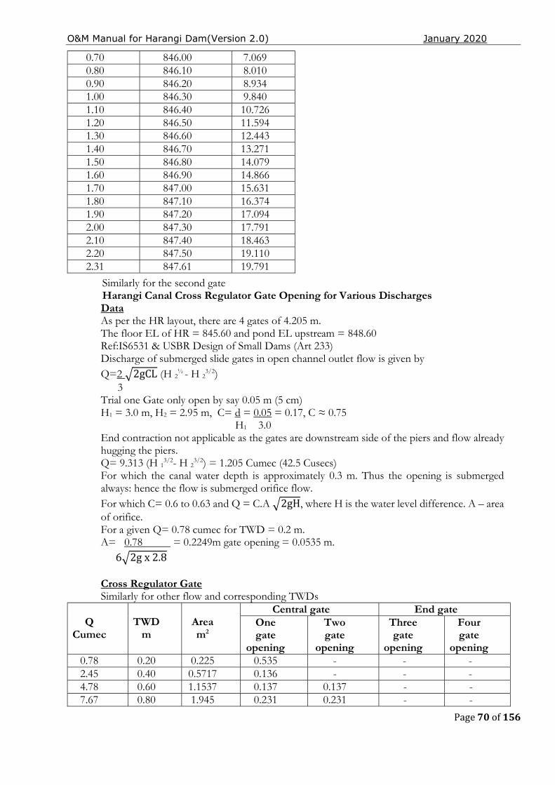
O&M Manual for Harangi Dam(Version 2.0) January 2020
Page 70 of 156
Similarly for the second gate Harangi Canal Cross Regulator Gate Opening for Various Discharges
Data As per the HR layout, there are 4 gates of 4.205 m. The floor EL of HR = 845.60 and pond EL upstream = 848.60 Ref:IS6531 & USBR Design of Small Dams (Art 233) Discharge of submerged slide gates in open channel outlet flow is given by Q=2 2gCL (H 2
½ - H 23/2)
3 Trial one Gate only open by say 0.05 m (5 cm) H1 = 3.0 m, H2 = 2.95 m, C= d = 0.05 = 0.17, C ≈ 0.75 H1 3.0 End contraction not applicable as the gates are downstream side of the piers and flow already hugging the piers. Q= 9.313 (H 1
3/2- H 23/2) = 1.205 Cumec (42.5 Cusecs)
For which the canal water depth is approximately 0.3 m. Thus the opening is submerged always: hence the flow is submerged orifice flow. For which C= 0.6 to 0.63 and Q = C.A 2gH, where H is the water level difference. A – area of orifice. For a given Q= 0.78 cumec for TWD = 0.2 m. A= 0.78 = 0.2249m gate opening = 0.0535 m. 6 2g x 2.8
Cross Regulator Gate Similarly for other flow and corresponding TWDs
Q
Cumec
TWD
m
Area m2
Central gate End gate One gate
opening
Two gate
opening
Three gate
opening
Four gate
opening 0.78 0.20 0.225 0.535 - - - 2.45 0.40 0.5717 0.136 - - - 4.78 0.60 1.1537 0.137 0.137 - - 7.67 0.80 1.945 0.231 0.231 - -
0.70 846.00 7.069 0.80 846.10 8.010 0.90 846.20 8.934 1.00 846.30 9.840 1.10 846.40 10.726 1.20 846.50 11.594 1.30 846.60 12.443 1.40 846.70 13.271 1.50 846.80 14.079 1.60 846.90 14.866 1.70 847.00 15.631 1.80 847.10 16.374 1.90 847.20 17.094 2.00 847.30 17.791 2.10 847.40 18.463 2.20 847.50 19.110 2.31 847.61 19.791
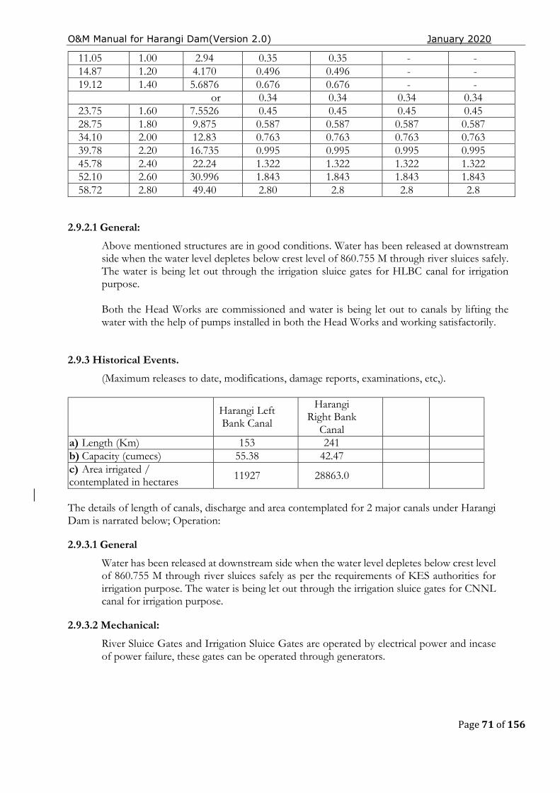
O&M Manual for Harangi Dam(Version 2.0) January 2020
Page 71 of 156
11.05 1.00 2.94 0.35 0.35 - - 14.87 1.20 4.170 0.496 0.496 - - 19.12 1.40 5.6876 0.676 0.676 - -
or 0.34 0.34 0.34 0.34 23.75 1.60 7.5526 0.45 0.45 0.45 0.45 28.75 1.80 9.875 0.587 0.587 0.587 0.587 34.10 2.00 12.83 0.763 0.763 0.763 0.763 39.78 2.20 16.735 0.995 0.995 0.995 0.995 45.78 2.40 22.24 1.322 1.322 1.322 1.322 52.10 2.60 30.996 1.843 1.843 1.843 1.843 58.72 2.80 49.40 2.80 2.8 2.8 2.8
2.9.2.1 General:
Above mentioned structures are in good conditions. Water has been released at downstream side when the water level depletes below crest level of 860.755 M through river sluices safely. The water is being let out through the irrigation sluice gates for HLBC canal for irrigation purpose. Both the Head Works are commissioned and water is being let out to canals by lifting the water with the help of pumps installed in both the Head Works and working satisfactorily.
2.9.3 Historical Events.
(Maximum releases to date, modifications, damage reports, examinations, etc,).
Harangi Left Bank Canal
Harangi Right Bank
Canal
a) Length (Km) 153 241 b) Capacity (cumecs) 55.38 42.47 c) Area irrigated / contemplated in hectares 11927 28863.0
The details of length of canals, discharge and area contemplated for 2 major canals under Harangi Dam is narrated below; Operation:
2.9.3.1 General
Water has been released at downstream side when the water level depletes below crest level of 860.755 M through river sluices safely as per the requirements of KES authorities for irrigation purpose. The water is being let out through the irrigation sluice gates for CNNL canal for irrigation purpose.
2.9.3.2 Mechanical:
River Sluice Gates and Irrigation Sluice Gates are operated by electrical power and incase of power failure, these gates can be operated through generators.
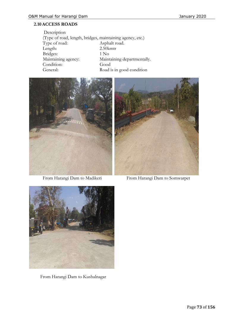
O&M Manual for Harangi Dam January 2020
Page 73 of 156
2.10 ACCESS ROADS
Description (Type of road, length, bridges, maintaining agency, etc.) Type of road: Asphalt road. Length: 2.50kmtr Bridges: 1 No Maintaining agency: Maintaining departmentally.
Condition: Good General: Road is in good condition
From Harangi Dam to Madikeri From Harangi Dam to Somwarpet
From Harangi Dam to Kushalnagar

O&M Manual for Harangi Dam January 2020
Page 74 of 156
2.10.1 Record Keeping
Operating a dam includes keeping accurate records of items pertaining to project operation. These include but not limited to the following: -
1. Rainfall and Reservoir Levels – On daily basis during non-monsoon and on hourly basis during monsoon.
2. Release through outlet/sluices on daily basis for irrigation, hydropower etc.
3. Outflows through spillway during monsoon on hourly basis.
4. Records of drawdown with reservoir levels, quantity of water released, drawdown rates, reason for drawdown.
5. Other Procedures – Maintain a complete record of all operating procedures for gates, sluices and Mechanical & Manual operating system.
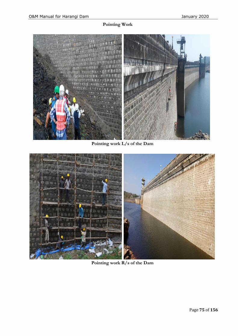
O&M Manual for Harangi Dam January 2020
Page 75 of 156
Pointing Work
Pointing work L/s of the Dam
Pointing work R/s of the Dam
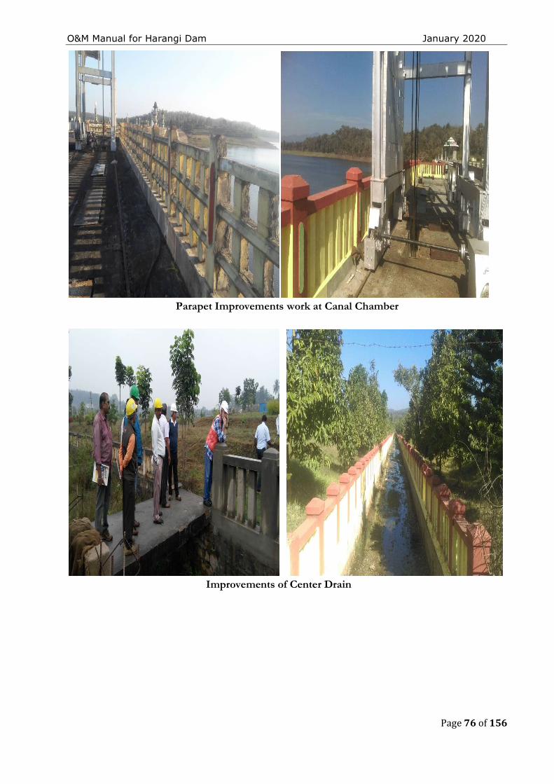
O&M Manual for Harangi Dam January 2020
Page 76 of 156
Parapet Improvements work at Canal Chamber
Improvements of Center Drain
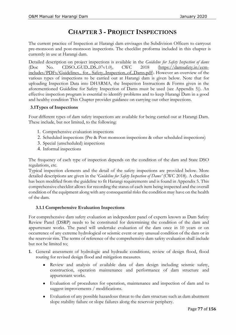
O&M Manual for Harangi Dam January 2020
Page 77 of 156
CHAPTER 3 - PROJECT INSPECTIONS
The current practice of Inspection at Harangi dam envisages the Subdivision Officers to carryout pre-monsoon and post-monsoon inspections. The checklist proforma included in this chapter is currently in use at Harangi dam.
Detailed description on project inspections is available in the Guideline for Safety Inspection of dams (Doc No. CDSO_GUD_DS_07v1.0), CWC 2018 (https://damsafety.in/ecm-includes/PDFs/Guidelines_ for_ Safety_Inspection_of_Dams.pdf). However an overview of the various types of inspections to be carried out at Harangi dam is given below. Note that for uploading Inspection Data into DHARMA, the Inspection Instructions & Forms given in the aforementioned Guideline for Safety Inspection of Dams must be used (see Appendix 5)). An effective inspection program is essential to identify problems and to keep Harangi Dam in a good and healthy condition This Chapter provides guidance on carrying out other inspections.
3.1Types of Inspections
Four different types of dam safety inspections are available for being carried out at Harangi Dam. These include, but not limited, to the following:
1. Comprehensive evaluation inspections 2. Scheduled inspections (Pre & Post monsoon inspections & other scheduled inspections) 3. Special (unscheduled) inspections 4. Informal inspections
The frequency of each type of inspection depends on the condition of the dam and State DSO regulations, etc. Typical inspection elements and the detail of the safety inspections are provided below. More detailed descriptions are given in the ‘Guideline for Safety Inspection of Dams’ (CWC 2018). A checklist has been modified from the guideline to fit Harangi requirements and is found in Appendix 5. This comprehensive checklist allows for recording the status of each item being inspected and the overall condition of the equipment along with any consequential risks the condition may have on the health of the dam.
3.1.1 Comprehensive Evaluation Inspections
For comprehensive dam safety evaluation an independent panel of experts known as Dam Safety Review Panel (DSRP) needs to be constituted for determining the condition of the dam and appurtenant works. The panel will undertake evaluation of the dam once in 10 years or on occurrence of any extreme hydrological or seismic event or any unusual condition of the dam or in the reservoir rim. The terms of reference of the comprehensive dam safety evaluation shall include but not be limited to;
1. General assessment of hydrologic and hydraulic conditions, review of design flood, flood routing for revised design flood and mitigation measures.
● Review and analysis of available data of dam design including seismic safety, construction, operation maintenance and performance of dam structure and appurtenant works.
● Evaluation of procedures for operation, maintenance and inspection of dam and to suggest improvements / modifications.
● Evaluation of any possible hazardous threat to the dam structure such as dam abutment slope stability failure or slope failures along the reservoir periphery.
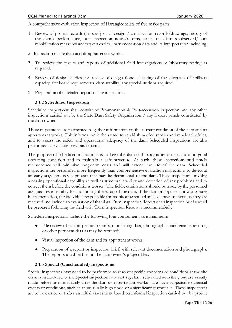
O&M Manual for Harangi Dam January 2020
Page 78 of 156
A comprehensive evaluation inspection of Harangiconsists of five major parts:
1. Review of project records (i.e. study of all design / construction records/drawings, history of the dam’s performance, past inspection notes/reports, notes on distress observed/ any rehabilitation measures undertaken earlier, instrumentation data and its interpretation including.
2. Inspection of the dam and its appurtenant works.
3. To review the results and reports of additional field investigations & laboratory testing as required.
4. Review of design studies e.g. review of design flood, checking of the adequacy of spillway capacity, freeboard requirements, dam stability, any special study as required.
5. Preparation of a detailed report of the inspection.
3.1.2 Scheduled Inspections
Scheduled inspections shall consist of Pre-monsoon & Post-monsoon inspection and any other inspections carried out by the State Dam Safety Organization / any Expert panels constituted by the dam owner.
These inspections are performed to gather information on the current condition of the dam and its appurtenant works. This information is then used to establish needed repairs and repair schedules, and to assess the safety and operational adequacy of the dam. Scheduled inspections are also performed to evaluate previous repairs.
The purpose of scheduled inspections is to keep the dam and its appurtenant structures in good operating condition and to maintain a safe structure. As such, these inspections and timely maintenance will minimize long-term costs and will extend the life of the dam. Scheduled inspections are performed more frequently than comprehensive evaluation inspections to detect at an early stage any developments that may be detrimental to the dam. These inspections involve assessing operational capability as well as structural stability and detection of any problems and to correct them before the conditions worsen. The field examinations should be made by the personnel assigned responsibility for monitoring the safety of the dam. If the dam or appurtenant works have instrumentation, the individual responsible for monitoring should analyze measurements as they are received and include an evaluation of that data. Dam Inspection Report or an inspection brief should be prepared following the field visit (Dam Inspection Report is recommended).
Scheduled inspections include the following four components as a minimum:
● File review of past inspection reports, monitoring data, photographs, maintenance records, or other pertinent data as may be required;
● Visual inspection of the dam and its appurtenant works;
● Preparation of a report or inspection brief, with relevant documentation and photographs. The report should be filed in the dam owner’s project files.
3.1.3 Special (Unscheduled) Inspections
Special inspections may need to be performed to resolve specific concerns or conditions at the site on an unscheduled basis. Special inspections are not regularly scheduled activities, but are usually made before or immediately after the dam or appurtenant works have been subjected to unusual events or conditions, such as an unusually high flood or a significant earthquake. These inspections are to be carried out after an initial assessment based on informal inspection carried out by project
O&M Manual for Harangi Dam January 2020
Page 79 of 156
personnel reveal dam safety related concerns like cracking in the dam, damages, erosion/ scour, undermining/ piping/ sink holes/ liquefaction or any such undesirable feature. A special inspection may also be performed during an emergency, such as an impending dam breach, to evaluate specific areas or concerns. They are also made when the ongoing surveillance program identifies a condition or a trend that appears to warrant a special evaluation. Special inspections should focus on those dam components that are affected by the unusual event and should include at least three elements: 1) review of relevant files or data, 2) visual inspection, and 3) report preparation.
More detailed site investigations / studies may be required (such as drilling, surveys, or seepage flow estimates) if the special inspection reveals the need for the same. Photographic documentation is to be included as part of the inspection.
Japan Water Agency (JWA) has developed a system of carrying out inspections after an earthquake Even for Ichari Dam, Uttarakhand. For details refer “Inspections Manual for Dam Field Engineers after Seismic Events, Ichari Dam, Uttarakhand (CDSO GUD DS 0 v1.0, September 2017). The manual is available at the following link: https://damsafety.in/ecm-includes/PDFs/Inspection Manual for Dam Field Engineers after Seismic Events.pdf.
3.1.4 Informal Inspections
The last type of inspection, an informal inspection, is a continuing effort by on-site personnel (dam owners/operators and maintenance personnel) performed during their routine duties. Informal inspections are critical to the proper operation and maintenance of the dam. They consist of frequent observations of the general appearance and functioning of the dam and appurtenant structures.
Operators, maintenance crews, or other staffs who are posted at Harangi dam site conduct informal inspections. These people are the “first-line of defense” in assuring safe dam conditions, and it is their responsibility to be familiar with all aspects of the dam. Their vigilance in walking the dam, checking the operating equipment, and noting changes in conditions may prevent serious mishaps or even dam failures.
Informal inspections are important and are performed at every available opportunity. These inspections may only cover one or two dam components as the occasion presents itself, or they may cover the entire dam and its appurtenant structures. The informal inspections are not as detailed as comprehensive evaluation, scheduled, and special inspections and will only require that a formal report is submitted to the dam owner’s project files if a condition is detected that might endanger the dam. Report is to be submitted detailing the condition discovered along with photographs, time, reservoir water level (RWL), etc.
3.1.5 Pre- and Post-Monsoon Checklist and Example of Report Proformas
Detailed checklists are required to ensure the health of the dam continues to operate in satisfactory and safe condition.
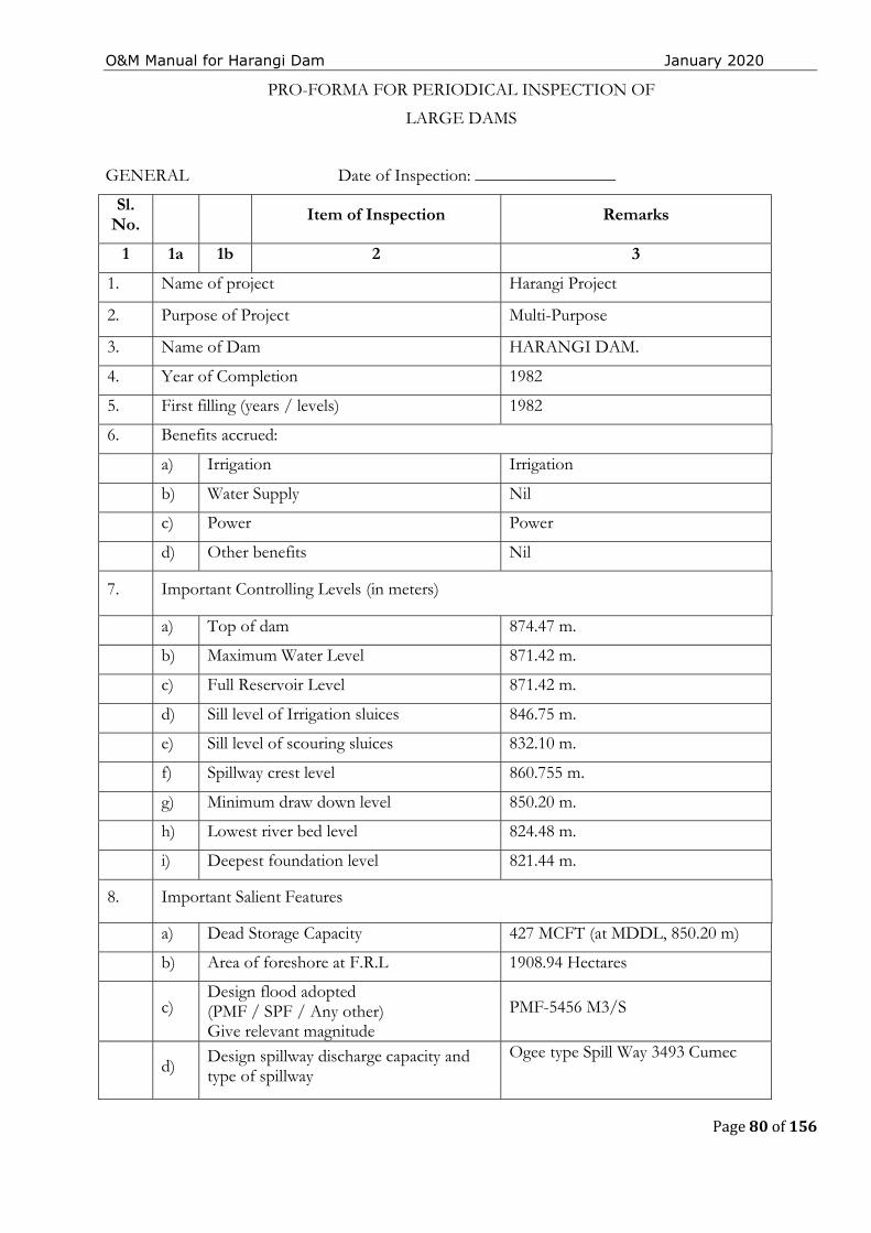
O&M Manual for Harangi Dam January 2020
Page 80 of 156
PRO-FORMA FOR PERIODICAL INSPECTION OF
LARGE DAMS
GENERAL Date of Inspection: ________________
Sl. No. Item of Inspection Remarks
1 1a 1b 2 3
1. Name of project Harangi Project
2. Purpose of Project Multi-Purpose
3. Name of Dam HARANGI DAM.
4. Year of Completion 1982
5. First filling (years / levels) 1982
6. Benefits accrued:
a) Irrigation Irrigation
b) Water Supply Nil
c) Power Power
d) Other benefits Nil
7. Important Controlling Levels (in meters)
a) Top of dam 874.47 m.
b) Maximum Water Level 871.42 m.
c) Full Reservoir Level 871.42 m.
d) Sill level of Irrigation sluices 846.75 m.
e) Sill level of scouring sluices 832.10 m.
f) Spillway crest level 860.755 m.
g) Minimum draw down level 850.20 m.
h) Lowest river bed level 824.48 m.
i) Deepest foundation level 821.44 m.
8. Important Salient Features
a) Dead Storage Capacity 427 MCFT (at MDDL, 850.20 m)
b) Area of foreshore at F.R.L 1908.94 Hectares
c) Design flood adopted (PMF / SPF / Any other) Give relevant magnitude
PMF-5456 M3/S
d) Design spillway discharge capacity and type of spillway
Ogee type Spill Way 3493 Cumec
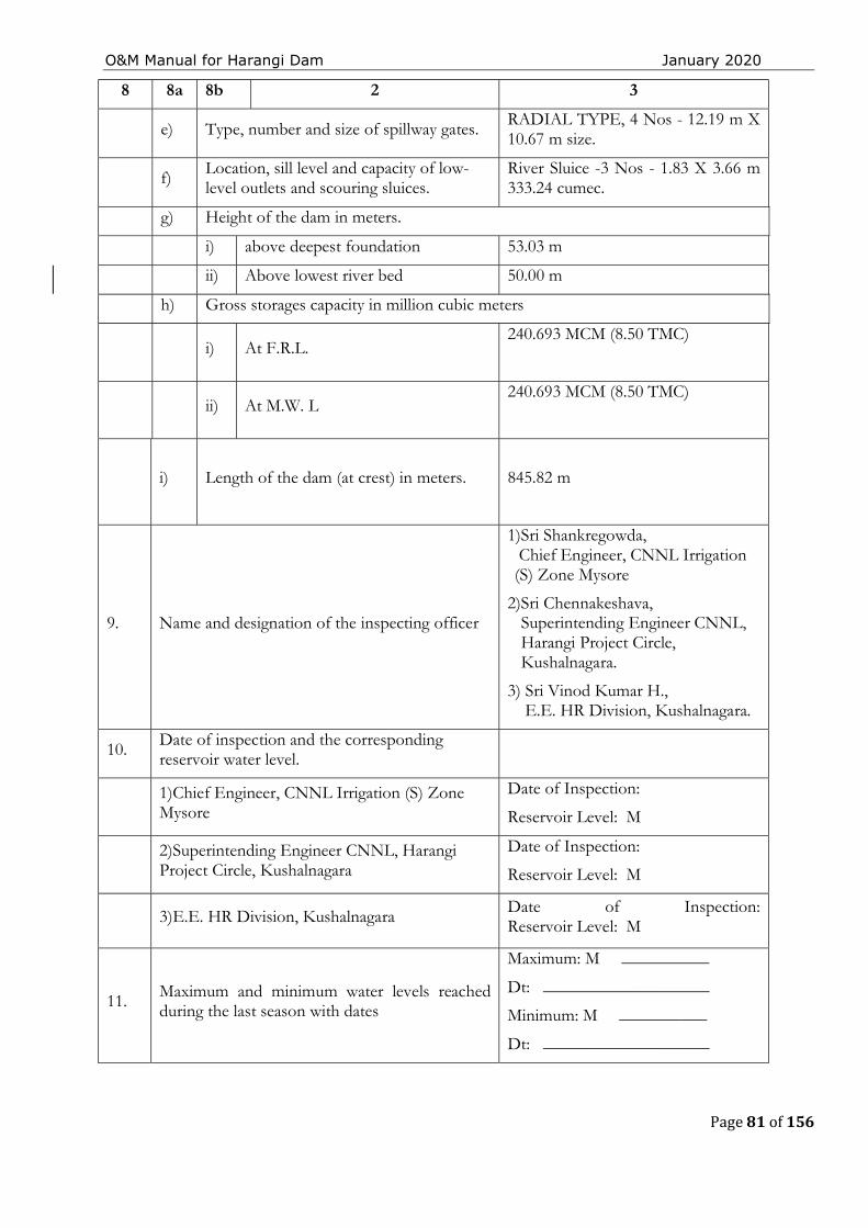
O&M Manual for Harangi Dam January 2020
Page 81 of 156
8 8a 8b 2 3
e) Type, number and size of spillway gates. RADIAL TYPE, 4 Nos - 12.19 m X 10.67 m size.
f) Location, sill level and capacity of low-level outlets and scouring sluices.
River Sluice -3 Nos - 1.83 X 3.66 m 333.24 cumec.
g) Height of the dam in meters.
i) above deepest foundation 53.03 m
ii) Above lowest river bed 50.00 m
h) Gross storages capacity in million cubic meters
i) At F.R.L. 240.693 MCM (8.50 TMC)
ii) At M.W. L 240.693 MCM (8.50 TMC)
i) Length of the dam (at crest) in meters.
845.82 m
9. Name and designation of the inspecting officer
1)Sri Shankregowda, Chief Engineer, CNNL Irrigation (S) Zone Mysore
2)Sri Chennakeshava, Superintending Engineer CNNL, Harangi Project Circle, Kushalnagara.
3) Sri Vinod Kumar H., E.E. HR Division, Kushalnagara.
10. Date of inspection and the corresponding reservoir water level.
1)Chief Engineer, CNNL Irrigation (S) Zone Mysore
Date of Inspection:
Reservoir Level: M
2)Superintending Engineer CNNL, Harangi Project Circle, Kushalnagara
Date of Inspection:
Reservoir Level: M
3)E.E. HR Division, Kushalnagara Date of Inspection: Reservoir Level: M
11. Maximum and minimum water levels reached during the last season with dates
Maximum: M __________
Dt: ___________________
Minimum: M __________
Dt: ___________________
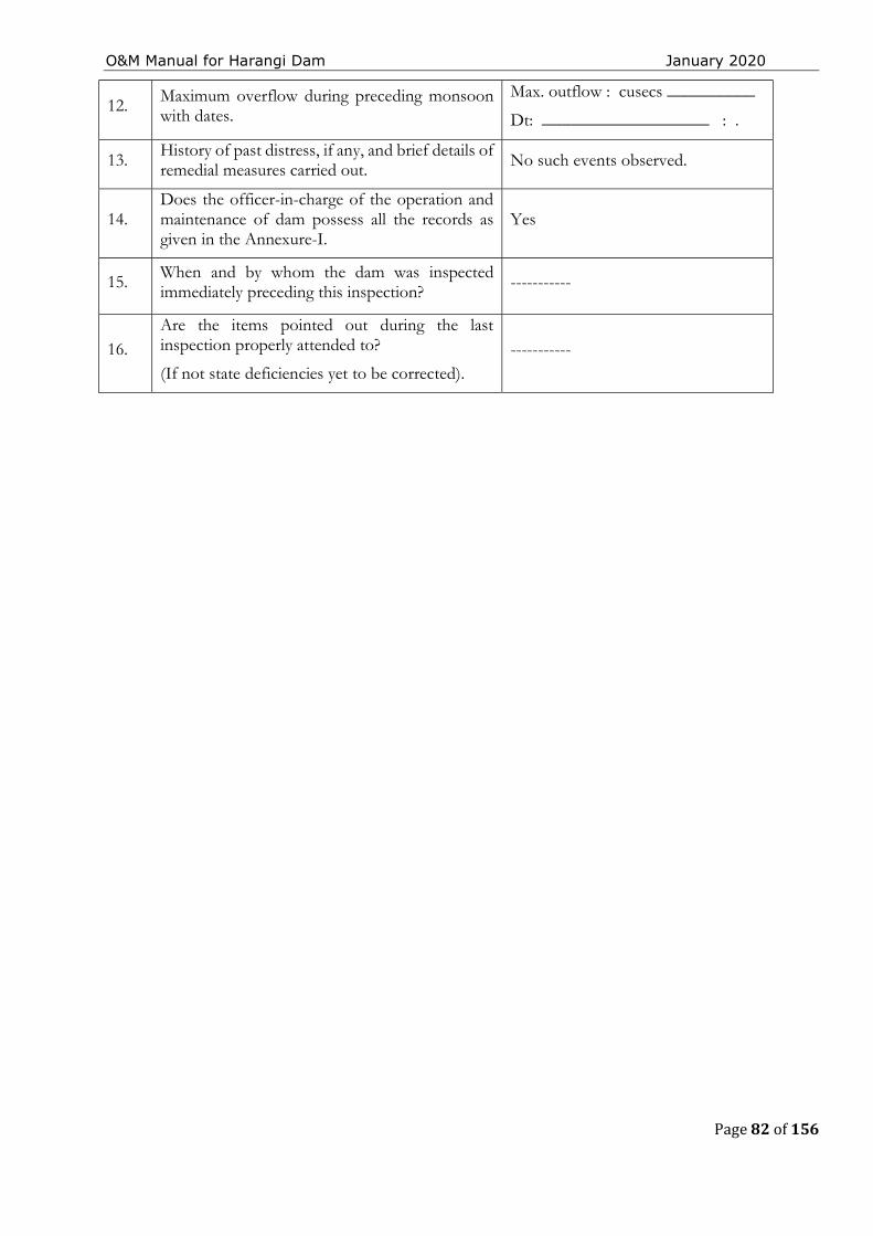
O&M Manual for Harangi Dam January 2020
Page 82 of 156
12. Maximum overflow during preceding monsoon with dates.
Max. outflow : cusecs __________
Dt: ___________________ : .
13. History of past distress, if any, and brief details of remedial measures carried out. No such events observed.
14. Does the officer-in-charge of the operation and maintenance of dam possess all the records as given in the Annexure-I.
Yes
15. When and by whom the dam was inspected immediately preceding this inspection?
-----------
16. Are the items pointed out during the last inspection properly attended to?
(If not state deficiencies yet to be corrected). -----------
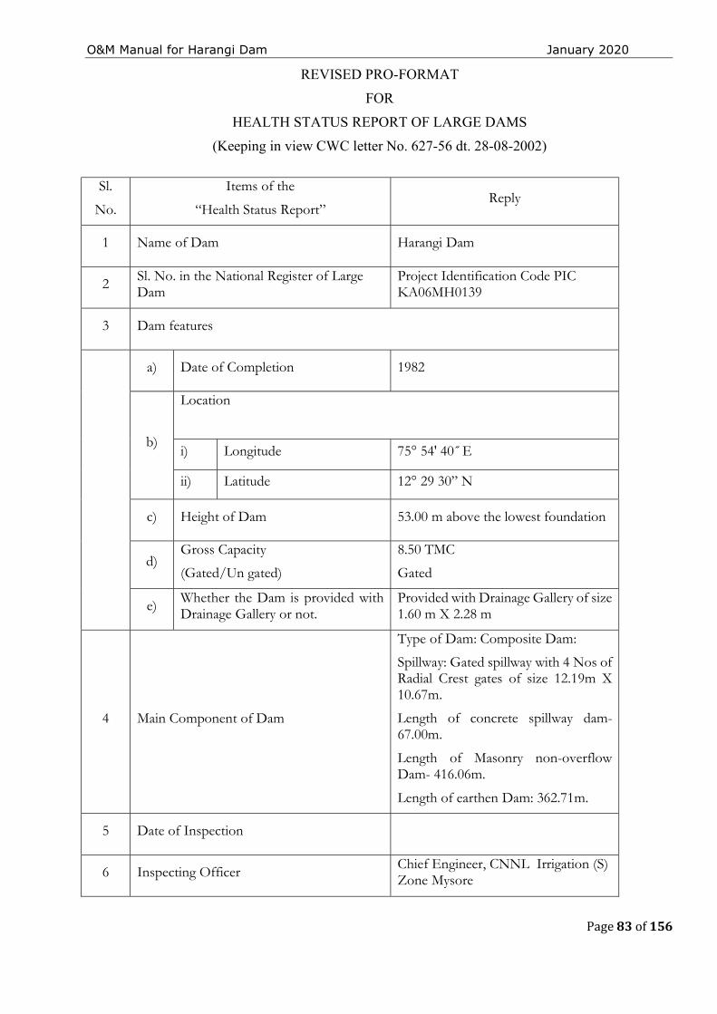
O&M Manual for Harangi Dam January 2020
Page 83 of 156
REVISED PRO-FORMAT
FOR
HEALTH STATUS REPORT OF LARGE DAMS
(Keeping in view CWC letter No. 627-56 dt. 28-08-2002)
Sl.
No.
Items of the
“Health Status Report” Reply
1 Name of Dam Harangi Dam
2 Sl. No. in the National Register of Large Dam
Project Identification Code PIC KA06MH0139
3 Dam features
a) Date of Completion 1982
b)
Location
i) Longitude 75° 54' 40˝ E
ii) Latitude 12° 29 30” N
c) Height of Dam 53.00 m above the lowest foundation
d) Gross Capacity
(Gated/Un gated)
8.50 TMC
Gated
e) Whether the Dam is provided with Drainage Gallery or not.
Provided with Drainage Gallery of size 1.60 m X 2.28 m
4 Main Component of Dam
Type of Dam: Composite Dam:
Spillway: Gated spillway with 4 Nos of Radial Crest gates of size 12.19m X 10.67m.
Length of concrete spillway dam-67.00m.
Length of Masonry non-overflow Dam- 416.06m.
Length of earthen Dam: 362.71m.
5 Date of Inspection
6 Inspecting Officer Chief Engineer, CNNL Irrigation (S) Zone Mysore
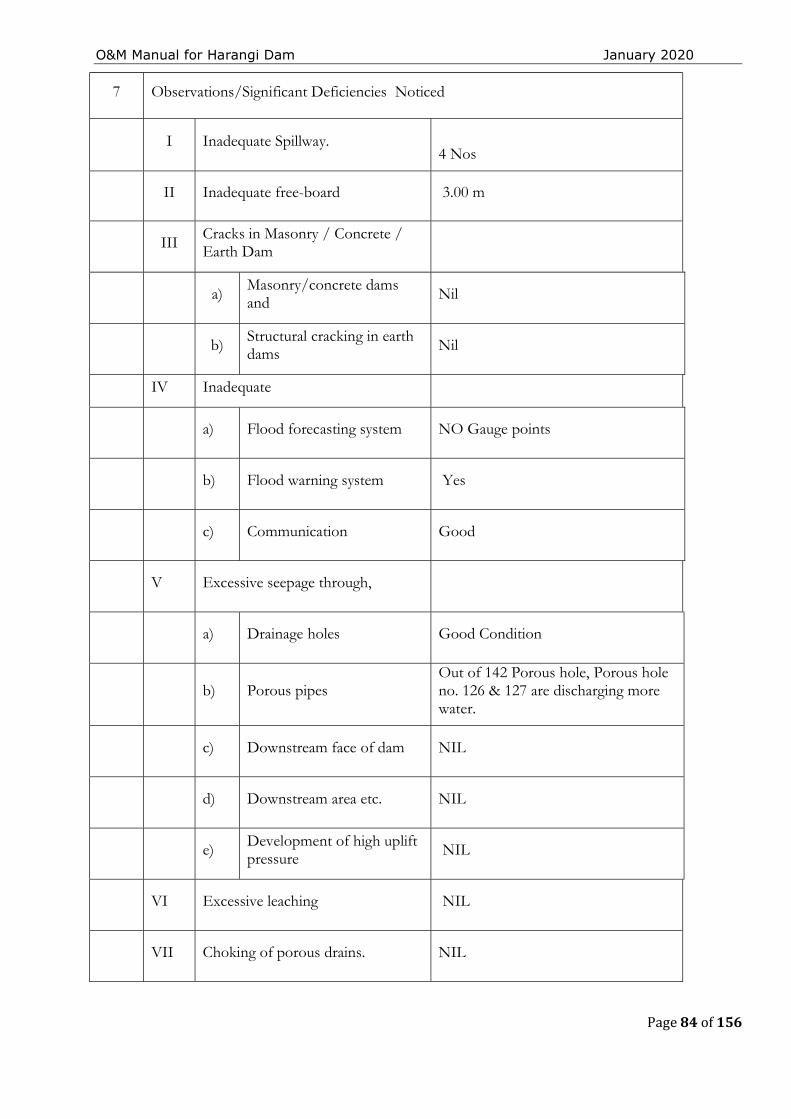
O&M Manual for Harangi Dam January 2020
Page 84 of 156
7 Observations/Significant Deficiencies Noticed
I Inadequate Spillway.
4 Nos
II Inadequate free-board 3.00 m
III Cracks in Masonry / Concrete / Earth Dam
a) Masonry/concrete dams and Nil
b) Structural cracking in earth dams Nil
IV Inadequate
a) Flood forecasting system NO Gauge points
b) Flood warning system Yes
c) Communication Good
V Excessive seepage through,
a) Drainage holes Good Condition
b) Porous pipes Out of 142 Porous hole, Porous hole no. 126 & 127 are discharging more water.
c) Downstream face of dam NIL
d) Downstream area etc. NIL
e) Development of high uplift pressure
NIL
VI Excessive leaching NIL
VII Choking of porous drains. NIL
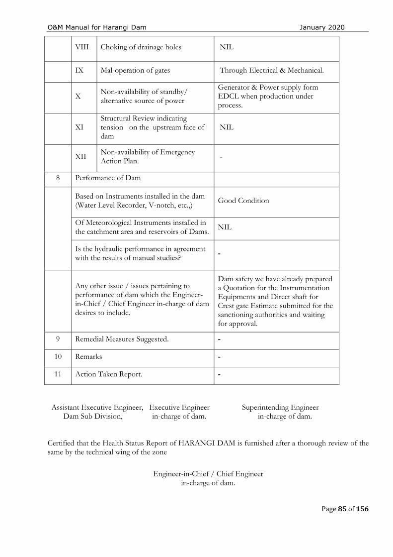
O&M Manual for Harangi Dam January 2020
Page 85 of 156
VIII Choking of drainage holes NIL
IX Mal-operation of gates Through Electrical & Mechanical.
X Non-availability of standby/ alternative source of power
Generator & Power supply form EDCL when production under process.
XI Structural Review indicating tension on the upstream face of dam
NIL
XII Non-availability of Emergency Action Plan. -
8 Performance of Dam
Based on Instruments installed in the dam (Water Level Recorder, V-notch, etc.,)
Good Condition
Of Meteorological Instruments installed in the catchment area and reservoirs of Dams. NIL
Is the hydraulic performance in agreement with the results of manual studies? -
Any other issue / issues pertaining to performance of dam which the Engineer-in-Chief / Chief Engineer in-charge of dam desires to include.
Dam safety we have already prepared a Quotation for the Instrumentation Equipments and Direct shaft for Crest gate Estimate submitted for the sanctioning authorities and waiting for approval.
9 Remedial Measures Suggested. -
10 Remarks -
11 Action Taken Report. -
Assistant Executive Engineer, Executive Engineer Dam Sub Division, in-charge of dam.
Superintending Engineer in-charge of dam.
Certified that the Health Status Report of HARANGI DAM is furnished after a thorough review of the same by the technical wing of the zone
Engineer-in-Chief / Chief Engineer in-charge of dam.

O&M Manual for Harangi Dam January 2020
Page 86 of 156
THIS PAGE LEFT BLANK INTENTIONALLY
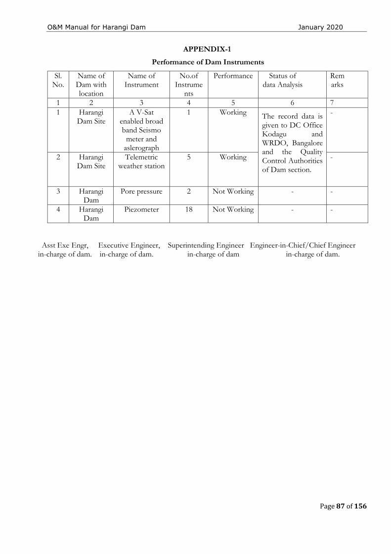
O&M Manual for Harangi Dam January 2020
Page 87 of 156
APPENDIX-1
Performance of Dam Instruments
Asst Exe Engr, Executive Engineer, Superintending Engineer Engineer-in-Chief/Chief Engineer in-charge of dam. in-charge of dam. in-charge of dam in-charge of dam.
Sl. No.
Name of Dam with location
Name of Instrument
No.of Instrume
nts
Performance Status of data Analysis
Remarks
1 2 3 4 5 6 7 1 Harangi
Dam Site
A V-Sat enabled broad band Seismo
meter and aslerograph
1 Working The record data is given to DC Office Kodagu and WRDO, Bangalore and the Quality Control Authorities of Dam section.
-
2 Harangi Dam Site
Telemetric weather station
5 Working -
3 Harangi Dam
Pore pressure 2 Not Working - -
4 Harangi Dam
Piezometer 18 Not Working - -
O&M Manual for Harangi Dam January 2020
Page 88 of 156
CHAPTER 4 - PROJECT MAINTENANCE A good maintenance program protects Harangi Dam against accelerating deterioration, prolongs its life, and greatly reduce the chance of failure. Nearly all the components of Harangi Dam and its materials are susceptible to damage and deterioration if not well maintained. Moreover, the cost of a proper maintenance program is small compared to the costs of major repairs, loss of life and property and litigation. Preventative maintenance not only protects the dam and its owner but the public as well. If maintenance of a dam is neglected the consequences and costs will multiply.
Preventive maintenance assures that a dam and reservoir are in good working condition and prevents more harmful conditions from developing. Individual maintenance tasks are noted, with a description of the area where the maintenance is to be performed, the schedule for performing the tasks, and reporting procedures. Typical routine maintenance tasks performed includes mowing grass, removing vegetation, bushes and trees, removing litter and other debris, re-grading the crest and/or access roads, repairing fencing to keep livestock off the dam, etc. Other maintenance works that need to be performed on the embankment includes restoration of embankment to its design section, seepage problems, erosion, displaced riprap, cracking in embankment etc. In concrete / masonry dams there may be issues like cracking and disintegration in concrete, choking of drainage holes in dam body/ foundation, damages to spillway glacis/piers/energy dissipaters due to abrasion/ cavitation/unsymmetrical flows, damages to pointing on upstream & downstream faces of masonry dams, heavy seepages through some drains in foundation/inspection galleries etc.
A basic maintenance program has been developed primarily based on systematic and frequent inspections.
4.1 Maintenance Priorities
For Harangi Dam, maintenance activities require to be prioritized as immediate maintenance or preventative maintenance.
4.1.1 Immediate Maintenance
The following conditions are critical and call for immediate attention & reservoir lowering, if warranted. These conditions may include, but are not limited to:
The dam is about to be overtopped or being overtopped during high flood.
The dam is about to be breached by erosion, slope failure etc.
The dam showing signs of piping or internal erosion indicated by increasingly cloudy seepage or other symptoms.
The spillway being blocked or with some inoperable gates.
Evidence of excessive seepage appearing anywhere on the dam site, e.g., the Embankment becomes saturated, defective water stops, etc., and seepage exiting on the downstream face is increasing in volume.
Although the remedy for some critical problems may be obvious (such as clearing a blocked spillway or repairing the spillway gates so that they are in working condition), the problems listed above generally demand the services of experienced engineers/expert panels familiar with the
O&M Manual for Harangi Dam January 2020
Page 89 of 156
design, construction and maintenance of dams. The emergency action plan (EAP) should be activated when any of the above conditions are noted.Note also that the “blue” conditions of the EAP are also applicable during con-trolled release of floods through the spillway
4.1.2 Preventive Maintenance
This can be further classified as Condition based Maintenance and Routine Maintenance.
4.1.2.1 Condition Based Maintenance
The following maintenance should be completed as soon as possible after the defective condition is noted. These include but are not limited to: ✓ Remove all vegetation and bushes from the dam and restoring any eroded areas and
to establish a good grass cover. ✓ Fill animal burrows. ✓ Restore and reseed eroded areas and gullies on embankment. ✓ Repair of defective gates, valves, and other hydro-mechanical equipment. ✓ Repair any concrete or metal components that have deteriorated. ✓ Cleaning of the choked drainage holes in the dam body/ foundations in concrete /
masonry dams. ✓ Repair any damages on spillway glacis, piers, energy dissipaters, training/divide walls,
downstream areas etc. ✓ Repairs on the upstream face of masonry dams, in case the pointing is damaged, due
to which there is increased seepage. ✓ Controlling any heavy seepage in the foundation/ inspection galleries in
Concrete/Masonry dams from drainage holes. ✓ Repairs of any cracks/cavities/joints in concrete/masonry dams/structures.
However, many of these works will require the services of experienced engineers/expert panels.
4.1.2.2 Routine Maintenance
Several tasks should be performed on a continuous basis. These include but are not limited to the following:
✓ Routine mowing, restore and reseed eroded areas and gullies on downstream face of the left flank embankment and general maintenance including repairs/cleaning of surface drains on downstream face and in the downstream area.
✓ Maintenance and treatment of any cracks/joints/ cavities in Concrete/Masonry dams and spillways based on the recommendations of experienced engineers / expert panels.
✓ Observation of any springs or seepage areas, comparing quantity and quality (clarity) with prior observations in the embankment.
✓ Monitoring of downstream development which could have an impact on the dam and its hazard category.
✓ Maintenance of Electrical & Hydro-Mechanical equipment and systems e. g. Servicing of spillway gates & stop logs, hoisting arrangements, gantry crane, gates/hoist of outlet works/sluices & stand by generator.
✓ Maintaining proper lighting at dam top, galleries, etc. ✓ Monitoring of seepage in galleries. ✓ Monitoring/ cleaning & removal of leached deposits in porous concrete / formed
drains in dam body and foundation drainage holes.
O&M Manual for Harangi Dam January 2020
Page 90 of 156
✓ Maintenance of all dam roads & access roads. ✓ Operation of electrical and mechanical equipment and systems including exercising
gates & valves. ✓ To keep the gate slots, clear of silt/debris. ✓ Maintenance/testing of monitoring equipment (instruments) and safety alarms. ✓ Testing of security equipment. ✓ Testing of communication equipment. ✓ Any other maintenance considered necessary.
4.2 Procedures for Routine Maintenance
The O&M Manual includes detailed instructions and schedules for performing periodic maintenance works at the site. This include maintenance of the dam, the appurtenant works, and the reservoir areas. Methodology / Specifications for carrying out maintenance works of general & recurring nature should be included in the Manual.
Dam repairs are scheduled based on severity of the problem, available resources, and weather conditions. For example, if a severe settlement problem (more than envisaged in designs) or cracking is detected on the crest of the dam, it should have a high priority since further degradation could lead to dam breaching. The causes of all major issues / problems should be identified and evaluated by experienced engineers/ Expert Panels so that appropriate remedial measures can be finalized. Correcting minor rill erosion on the downstream slope could be assigned a low priority since it is not a dam safety concern. This type of repair will also be weather dependent, since grass can only be planted during specific times of the year, and the embankment should be dry so that more damage is not inflicted to the embankment slopes.
4.2.1 Earthwork
The surfaces of an earthen dam may deteriorate due to several reasons. For example, wave action may cut into the upstream slope, vehicles may cause ruts in the crest or slopes, trails left by livestock can result in erosion, or runoff waters may leave erosion gullies on the downstream slope. Other special problems, such as shrinkage cracks or rodent damage, may also occur. Damage of this nature must be repaired constantly.
The maintenance procedures described here are effective in repairing minor earthwork problems. However, this section is not intended to be a technical guide, and the methods discussed should not be used to solve serious problems. Conditions such as embankment slides, structural cracking, and sinkholes threaten the immediate safety of a dam and require immediate repair under the directions of experienced engineers/Expert panels.
The material selected for repairing embankments should be free from vegetation, organic materials, trash, and large rocks.
If flow-resistant portions such as the core of an embankment dam are being repaired, materials that are high in clay or silt content should be used. If the area is to be free draining or highly permeable (such as pervious shell of an embankment dam) the material should have a higher percentage of sand and gravel. It is usually satisfactory to replace or repair damaged areas with soils like those originally in place.
An important soil property affecting compaction is moisture content. Soils that are too dry or too wet do not compact well. One may test repair material by squeezing it into a tight ball. If the sample keeps its shape without cracking and falling apart (which means it is too dry), and without depositing excess water onto the hand (which means it is too wet), the moisture content is near the proper level.
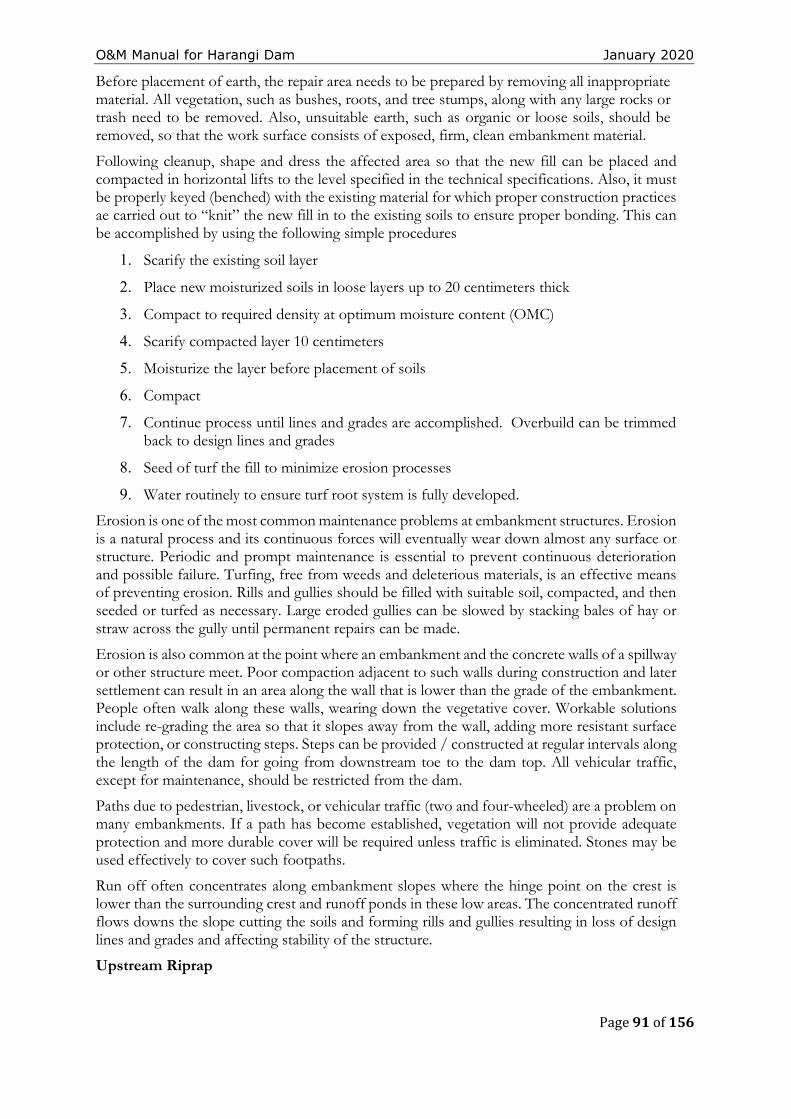
O&M Manual for Harangi Dam January 2020
Page 91 of 156
Before placement of earth, the repair area needs to be prepared by removing all inappropriate material. All vegetation, such as bushes, roots, and tree stumps, along with any large rocks or trash need to be removed. Also, unsuitable earth, such as organic or loose soils, should be removed, so that the work surface consists of exposed, firm, clean embankment material.
Following cleanup, shape and dress the affected area so that the new fill can be placed and compacted in horizontal lifts to the level specified in the technical specifications. Also, it must be properly keyed (benched) with the existing material for which proper construction practices ae carried out to “knit” the new fill in to the existing soils to ensure proper bonding. This can be accomplished by using the following simple procedures
1. Scarify the existing soil layer
2. Place new moisturized soils in loose layers up to 20 centimeters thick
3. Compact to required density at optimum moisture content (OMC)
4. Scarify compacted layer 10 centimeters
5. Moisturize the layer before placement of soils
6. Compact
7. Continue process until lines and grades are accomplished. Overbuild can be trimmed back to design lines and grades
8. Seed of turf the fill to minimize erosion processes
9. Water routinely to ensure turf root system is fully developed.
Erosion is one of the most common maintenance problems at embankment structures. Erosion is a natural process and its continuous forces will eventually wear down almost any surface or structure. Periodic and prompt maintenance is essential to prevent continuous deterioration and possible failure. Turfing, free from weeds and deleterious materials, is an effective means of preventing erosion. Rills and gullies should be filled with suitable soil, compacted, and then seeded or turfed as necessary. Large eroded gullies can be slowed by stacking bales of hay or straw across the gully until permanent repairs can be made.
Erosion is also common at the point where an embankment and the concrete walls of a spillway or other structure meet. Poor compaction adjacent to such walls during construction and later settlement can result in an area along the wall that is lower than the grade of the embankment. People often walk along these walls, wearing down the vegetative cover. Workable solutions include re-grading the area so that it slopes away from the wall, adding more resistant surface protection, or constructing steps. Steps can be provided / constructed at regular intervals along the length of the dam for going from downstream toe to the dam top. All vehicular traffic, except for maintenance, should be restricted from the dam.
Paths due to pedestrian, livestock, or vehicular traffic (two and four-wheeled) are a problem on many embankments. If a path has become established, vegetation will not provide adequate protection and more durable cover will be required unless traffic is eliminated. Stones may be used effectively to cover such footpaths.
Run off often concentrates along embankment slopes where the hinge point on the crest is lower than the surrounding crest and runoff ponds in these low areas. The concentrated runoff flows downs the slope cutting the soils and forming rills and gullies resulting in loss of design lines and grades and affecting stability of the structure.
Upstream Riprap
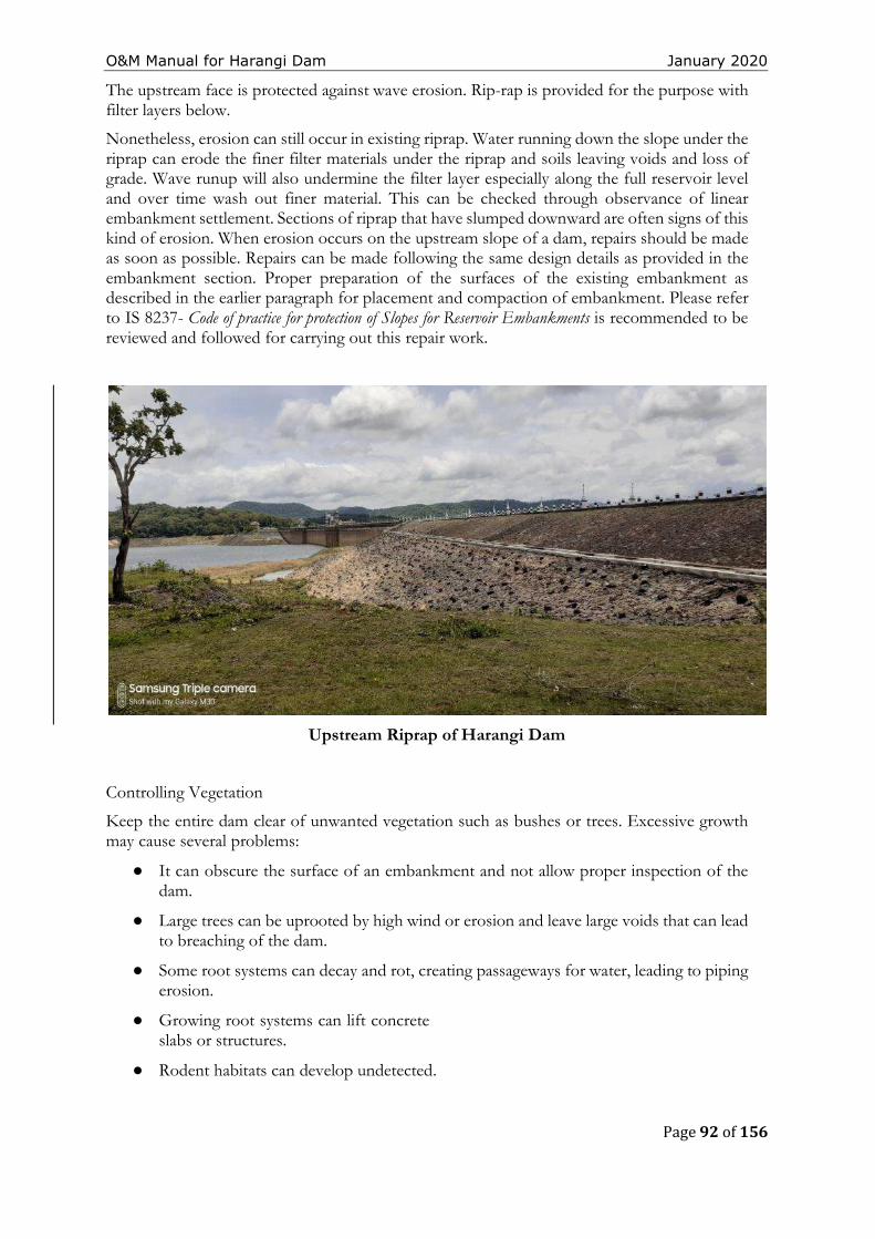
O&M Manual for Harangi Dam January 2020
Page 92 of 156
The upstream face is protected against wave erosion. Rip-rap is provided for the purpose with filter layers below.
Nonetheless, erosion can still occur in existing riprap. Water running down the slope under the riprap can erode the finer filter materials under the riprap and soils leaving voids and loss of grade. Wave runup will also undermine the filter layer especially along the full reservoir level and over time wash out finer material. This can be checked through observance of linear embankment settlement. Sections of riprap that have slumped downward are often signs of this kind of erosion. When erosion occurs on the upstream slope of a dam, repairs should be made as soon as possible. Repairs can be made following the same design details as provided in the embankment section. Proper preparation of the surfaces of the existing embankment as described in the earlier paragraph for placement and compaction of embankment. Please refer to IS 8237- Code of practice for protection of Slopes for Reservoir Embankments is recommended to be reviewed and followed for carrying out this repair work.
Upstream Riprap of Harangi Dam
Controlling Vegetation
Keep the entire dam clear of unwanted vegetation such as bushes or trees. Excessive growth may cause several problems:
● It can obscure the surface of an embankment and not allow proper inspection of the dam.
● Large trees can be uprooted by high wind or erosion and leave large voids that can lead to breaching of the dam.
● Some root systems can decay and rot, creating passageways for water, leading to piping erosion.
● Growing root systems can lift concrete slabs or structures.
● Rodent habitats can develop undetected.
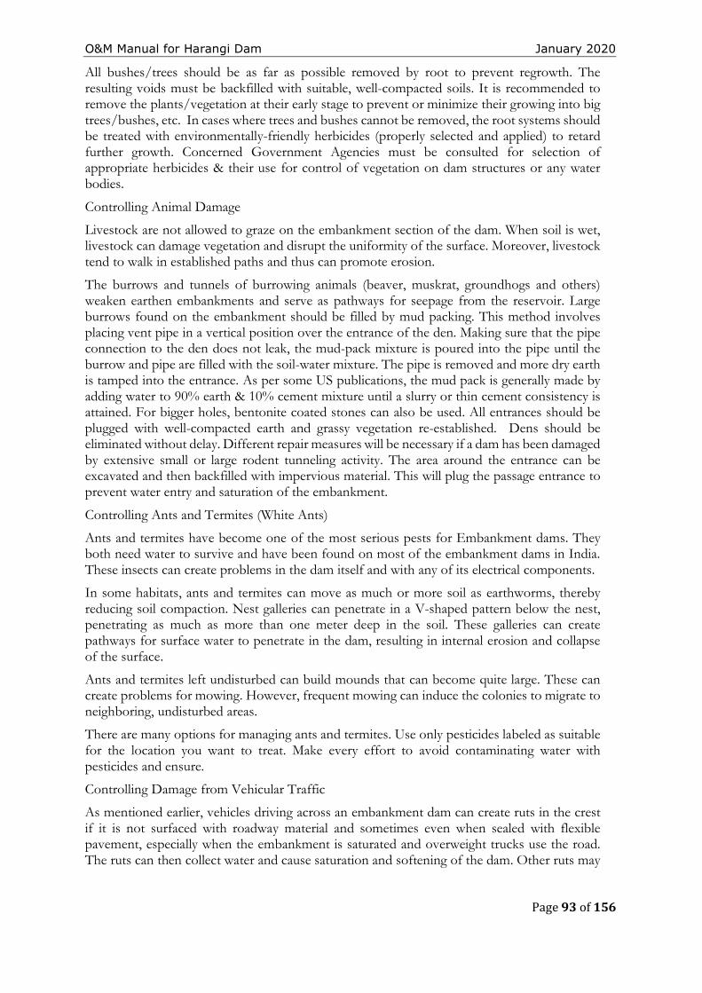
O&M Manual for Harangi Dam January 2020
Page 93 of 156
All bushes/trees should be as far as possible removed by root to prevent regrowth. The resulting voids must be backfilled with suitable, well-compacted soils. It is recommended to remove the plants/vegetation at their early stage to prevent or minimize their growing into big trees/bushes, etc. In cases where trees and bushes cannot be removed, the root systems should be treated with environmentally-friendly herbicides (properly selected and applied) to retard further growth. Concerned Government Agencies must be consulted for selection of appropriate herbicides & their use for control of vegetation on dam structures or any water bodies.
Controlling Animal Damage
Livestock are not allowed to graze on the embankment section of the dam. When soil is wet, livestock can damage vegetation and disrupt the uniformity of the surface. Moreover, livestock tend to walk in established paths and thus can promote erosion.
The burrows and tunnels of burrowing animals (beaver, muskrat, groundhogs and others) weaken earthen embankments and serve as pathways for seepage from the reservoir. Large burrows found on the embankment should be filled by mud packing. This method involves placing vent pipe in a vertical position over the entrance of the den. Making sure that the pipe connection to the den does not leak, the mud-pack mixture is poured into the pipe until the burrow and pipe are filled with the soil-water mixture. The pipe is removed and more dry earth is tamped into the entrance. As per some US publications, the mud pack is generally made by adding water to 90% earth & 10% cement mixture until a slurry or thin cement consistency is attained. For bigger holes, bentonite coated stones can also be used. All entrances should be plugged with well-compacted earth and grassy vegetation re-established. Dens should be eliminated without delay. Different repair measures will be necessary if a dam has been damaged by extensive small or large rodent tunneling activity. The area around the entrance can be excavated and then backfilled with impervious material. This will plug the passage entrance to prevent water entry and saturation of the embankment.
Controlling Ants and Termites (White Ants)
Ants and termites have become one of the most serious pests for Embankment dams. They both need water to survive and have been found on most of the embankment dams in India. These insects can create problems in the dam itself and with any of its electrical components.
In some habitats, ants and termites can move as much or more soil as earthworms, thereby reducing soil compaction. Nest galleries can penetrate in a V-shaped pattern below the nest, penetrating as much as more than one meter deep in the soil. These galleries can create pathways for surface water to penetrate in the dam, resulting in internal erosion and collapse of the surface.
Ants and termites left undisturbed can build mounds that can become quite large. These can create problems for mowing. However, frequent mowing can induce the colonies to migrate to neighboring, undisturbed areas.
There are many options for managing ants and termites. Use only pesticides labeled as suitable for the location you want to treat. Make every effort to avoid contaminating water with pesticides and ensure.
Controlling Damage from Vehicular Traffic
As mentioned earlier, vehicles driving across an embankment dam can create ruts in the crest if it is not surfaced with roadway material and sometimes even when sealed with flexible pavement, especially when the embankment is saturated and overweight trucks use the road. The ruts can then collect water and cause saturation and softening of the dam. Other ruts may
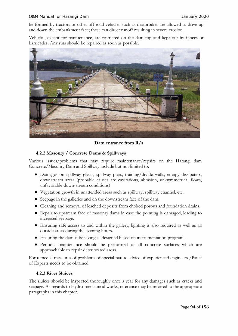
O&M Manual for Harangi Dam January 2020
Page 94 of 156
be formed by tractors or other off-road vehicles such as motorbikes are allowed to drive up and down the embankment face; these can direct runoff resulting in severe erosion.
Vehicles, except for maintenance, are restricted on the dam top and kept out by fences or barricades. Any ruts should be repaired as soon as possible.
Dam entrance from R/s
4.2.2 Masonry / Concrete Dams & Spillways
Various issues/problems that may require maintenance/repairs on the Harangi dam Concrete/Masonry Dam and Spillway include but not limited to:
● Damages on spillway glacis, spillway piers, training/divide walls, energy dissipaters, downstream areas (probable causes are cavitations, abrasion, un-symmetrical flows, unfavorable down-stream conditions)
● Vegetation growth in unattended areas such as spillway, spillway channel, etc.
● Seepage in the galleries and on the downstream face of the dam.
● Cleaning and removal of leached deposits from choked porous and foundation drains.
● Repair to upstream face of masonry dams in case the pointing is damaged, leading to increased seepage.
● Ensuring safe access to and within the gallery, lighting is also required as well as all outside areas during the evening hours.
● Ensuring the dam is behaving as designed based on instrumentation programs.
● Periodic maintenance should be performed of all concrete surfaces which are approachable to repair deteriorated areas.
For remedial measures of problems of special nature advice of experienced engineers /Panel of Experts needs to be obtained
4.2.3 River Sluices
The sluices should be inspected thoroughly once a year for any damages such as cracks and seepage. As regards to Hydro-mechanical works, reference may be referred to the appropriate paragraphs in this chapter.
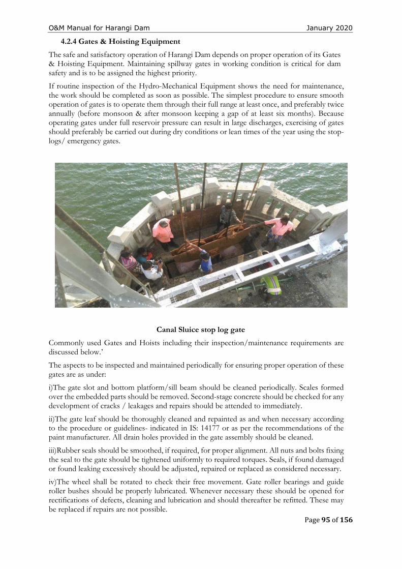
O&M Manual for Harangi Dam January 2020
Page 95 of 156
4.2.4 Gates & Hoisting Equipment
The safe and satisfactory operation of Harangi Dam depends on proper operation of its Gates & Hoisting Equipment. Maintaining spillway gates in working condition is critical for dam safety and is to be assigned the highest priority.
If routine inspection of the Hydro-Mechanical Equipment shows the need for maintenance, the work should be completed as soon as possible. The simplest procedure to ensure smooth operation of gates is to operate them through their full range at least once, and preferably twice annually (before monsoon & after monsoon keeping a gap of at least six months). Because operating gates under full reservoir pressure can result in large discharges, exercising of gates should preferably be carried out during dry conditions or lean times of the year using the stop-logs/ emergency gates.
Canal Sluice stop log gate
Commonly used Gates and Hoists including their inspection/maintenance requirements are discussed below.’
The aspects to be inspected and maintained periodically for ensuring proper operation of these gates are as under:
i)The gate slot and bottom platform/sill beam should be cleaned periodically. Scales formed over the embedded parts should be removed. Second-stage concrete should be checked for any development of cracks / leakages and repairs should be attended to immediately.
ii)The gate leaf should be thoroughly cleaned and repainted as and when necessary according to the procedure or guidelines- indicated in IS: 14177 or as per the recommendations of the paint manufacturer. All drain holes provided in the gate assembly should be cleaned.
iii)Rubber seals should be smoothed, if required, for proper alignment. All nuts and bolts fixing the seal to the gate should be tightened uniformly to required torques. Seals, if found damaged or found leaking excessively should be adjusted, repaired or replaced as considered necessary.
iv)The wheel shall be rotated to check their free movement. Gate roller bearings and guide roller bushes should be properly lubricated. Whenever necessary these should be opened for rectifications of defects, cleaning and lubrication and should thereafter be refitted. These may be replaced if repairs are not possible.
O&M Manual for Harangi Dam January 2020
Page 96 of 156
v)Hoisting connection of the gate leaf should be lubricated where necessary and defects if any should be rectified.
vi)All nuts, bolts, check nuts and cotter pins of the lifting devices should be checked periodically.
vii)All components should be greased and lubricated. Recommended and approved oils and grease only should be used.
viii)Roller assembly should be adjusted by the eccentricity arrangement to ensure all rollers rest uniformly on the track plates particularly in the closed position of the gate
ix)Where filling valves are provided as part of the gate structure, all the nuts, bolts, check nuts etc. should be tightened.
x)All welds shall be checked for cracks/ damages. Any weld that might have become defective shuld be chipped out and redone following the relevant codal provisions. Damaged nuts, bolts, rivets, screws etc. should be replaced without delay.
xi)The filling-in valves allow passage of water when it is lifted by lifting beam & crane due to creation of space between stem seat and exit passage liner. The springs and associated components should be checked periodically for damages and replaced if necessary.
xii)The guide-assemblies, wheel-assemblies and sealing-assemblies shall be cleared off grit, sand or any other foreign material.
xiii)The wheel pin shall be coated with corrosion resistant compound.
xiv)All nuts and bolts shall be tightened.
The aspects to be inspected and maintained periodically for ensuring proper operation of these gates are as under:
a) Rubber Seals:
i)Seals shall be inspected for leakages. Locations of excessive leakages shall be recorded for taking remedial measures. Weeping or slight flow in localized area will not require immediate remedial measures. However, measures like tightening of bolts are carried out. Further adjustment is carried out during annual maintenance.
ii)If leakage is excessive & immediate repair is considered necessary, the stop log gates shall be dropped and seals repaired or replaced.
NOTE: - During monsoon period, stop log gates shall NEVER be lowered in spite of heavy leakage through seals.
b)Trunnion block assembly and anchorages:
(i)All the nuts and bolts of Trunnion block assembly and its anchorages shall be checked for tightness.
(ii)Check all the welds for soundness and rectify defects.
(iii)Check whether the Yoke girder and thrust block is covered on not. If not, cover it with mild steel plates.
(iv)Cover the trunnion pin with anti- corrosive jelly.
(v)Remove all dirt, grit etc. from trunnion assembly and lubricate trunnion bearings of the gate with suitable water resisting grease as recommended by bearing manufacturers.
c)Gate structures:
i)Check all the welds for soundness and rectify defects.
O&M Manual for Harangi Dam January 2020
Page 97 of 156
ii)Check welds between arms and horizontal girders as well as between latching bracket and skin plate with the help of magnifying glass for cracks/defects and rectify the defects.
iii)Clean all drain holes including those in end arms and horizontal girders.
iv)Check all the nuts and bolts and tighten them. Replace damaged ones.
v)Check upstream face of skin plate for pitting, scaling and corrosion. Scaling may be filled with weld and grinded. Corroded surface shall be cleaned and painted.
d)Embedded Parts:
i)All the sill beams and wall plates shall be inspected for crack, pitting etc. and defects shall be rectified.
ii)The guide roller pins shall be lubricated.
e)General Maintenance:
i)Defective welding should be chipped out and it should be re-welded duly following the relevant codal provision (IS: 10096).
ii)Damaged nuts, bolts, rivets, screws etc. should be replaced.
iii)Any pitting should be filled up by welding and finished by grinding if necessary.
iv)The gate leaf, exposed embedded metal parts, hoists and hoist supporting structure etc., should be thoroughly cleaned and repainted when required keeping in view the original painting system adopted and as per the guidelines contained in IS: 14177.
v)Trunnion bearing should be greased as and when required. Keeping trunnion bearings in perfect working condition is very important. All other bolted connections should also be checked up for proper tightness.
vi)Bolts and trunnion bearing housing should be tightened wherever required.
vii)The seals of the gate should be checked for wear and tear and deterioration. These should be adjusted/replaced as and when necessary.
viii)The wall plates, sill beams shall be checked and repaired if necessary.
ix)Wire ropes should be properly lubricated.
x)Oil level in the worm reduction unit should be maintained by suitable replenishment. Oil seals should also be replaced if required. Lubrication of other parts of hoists such as chains, position indicators and limit switches should also be done.
xi)The stroke of the brake should be reset to compensate for lining wear. Worn out brake linings should be replaced in time.
xii)Flexible couplings should be adjusted if required.
xiii)Repairs and replacements of all electrical relays and controls should be attended to.
xiv) Maintenance of alternative sources of Power such as Diesel Generating sets and alternative drives wherever provided should be carried out.
xv)The list of essential spare parts to be kept available should be reviewed and updated periodically. The condition of spares should be checked periodically and protective coating given for use.
4.2.5 Electrically operated fixed hoists
1.General Instructions:
O&M Manual for Harangi Dam January 2020
Page 98 of 156
a) Operation of fixed hoist without lifting the gate is not possible and need not therefore be attempted. It will be possible to operate the unit and observe operation of load carrying hoist component when gate is being lifted or lowered.
b) Never open any bolt or nut on motor, gear boxes, rope drums and other load carrying hoist components when the gate is in raised position. The gate should be fully closed or rested on the gate latches before carrying out any work on hoist components including motor brake and other electrical equipment.
c) The aspects to be inspected and maintained periodically for ensuring proper operation of Rope drum hoists are as under;
i. Entrance to all hoist platforms shall be kept locked. All keys shall remain with the shift supervisor.
ii. A cursory daily inspection shall be made of hoist and gate to ensure that there is no unusual happening.
iii. Clean all hoisting equipment and hoist platform.
iv. Check oil level in gearboxes and replenish as and when required with oil of proper grade.
v. Apply grease of suitable grade by grease gun.
vi. Lubricate all bearings, bushings, pins, linkages etc.
vii. Check all the fuses on the power lines.
viii. All bolts and nuts on gear boxes, hoist drum and shaft couplings should be checked for tightness.
ix. Check the supply voltage.
x. Drain sample gear oil from each of the gear boxes. If excessive foreign particles or sludge is found, the gear box shall be drained, flushed and filled with new oil.
xi. All the geared couplings shall be greased.
xiii. Raise and lower the gate by hoist motor and check for smooth, and trouble-free operation of gate without excessive vibration.
xiv. Observe current drawn by motor at the time of lifting and check if it is more than normal. If so, stop the hoist and investigate the cause and rectify.
xv. Check the condition of painting of various components and remove rust wherever noticed and repaint the portion after proper cleaning as per painting schedule.
xvi. All trash, sediments and any other foreign material shall be cleared off the lifting rope and lifting attachment.
xvii. All ropes shall be checked for wear and tear and if broken wires are noticed, the rope shall be replaced.
O&M Manual for Harangi Dam January 2020
Page 99 of 156
xviii. All the wire ropes shall be checked and all visible oxidation shall be removed.
xix. All wire ropes shall be greased with cardium compound.
xx. Check the overload relays for proper functioning.
xxi. Check all the nuts, bolts, rivets, welds and structural components for hoisting platform and its supporting structure for wear, tear and damage. All damages shall be rectified. All bolts shall be tightened. The portion with damaged painting shall be touched up.
xxii. Check the pulleys, sheaves and turn-buckles.
xxiii. Raise and lower the gate for its full lift several time (at least three to four) and observe the following:
a) Check the limit switches and adjust for design limits.
b) The effectiveness and slip of the breaks shall be checked by stopping the gate in raising and lowering operations. The brakes shall be adjusted if needed.
c) When the gate is operated, there should not be any noise or chatter in the gears.
xxiv. Adjust the rope tension of wires if unequal.
xxv. Check for all gears and pinions for uneven wear and adjust for proper contact. Grease the gears.
xxvi. Repaint the hoist components, hoisting platform and its supporting structures as per requirement.
xxvii. The periodic maintenance of commercial equipment like motors, brakes, thrusts etc. shall be carried out as per manufacturers operation and maintenance manual.
4.3. Maintenance of Electrical components of Fixed Rope Drum Hoists:
a) The electrical components to be inspected and maintained periodically are as under;
i) Starters should be cleaned free of moisture and dust.
ii) Each individual contactor should be tried by hand to make sure that it operates freely.
iii) All wearing parts should be examined in order to take note of any wear which may have occurred during operation.
iv) If the contactor hums, the contact faces should be cleaned.
(v)Examine all connections to see that no wires are broken and no connections are loose.
vi) Clean the surface of the moving armature and magnet core which comes together when the contactor closes, free of dust or grease of any kind.
vii)Examine the mechanical interlocks between the reversing contactor and see when the contact tips of one of the contactor units are touching, it is impossible to get the contact tips of the other unit to touch.
O&M Manual for Harangi Dam January 2020
Page 100 of 156
viii)The contact tips should be kept free from burns or pits by smoothening with fine sand paper or emery paper.
ix)Replace the contact tips which have worn away half-way.
x)Do not lubricate the contacts.
xi)Blow out windings thoroughly by clean and dry air to clear air passage in the stator and the rotor of any accumulated dirt. The air pressure shall not be too high to damage the insulation.
xii)Examine earth connections and motor leads.
xiii)Examine motor windings for overheating
xiv)Examine control equipment’s
xv)Examine starting equipment for burnt contacts
xvi)Check and tighten all nuts and bolts
xvii)Clean and tighten all terminals and screw connections all contact surfaces shall be made clean and smooth.
xviii)Lubricate the bearings
xix) Overhaul the controllers
xx)Inspect and clean circuit breakers.
xxi)Wipe brush holders and check bedding of brushes.
xxii)Blow out windings thoroughly by clean and dry air. The pressure shall not be so high that insulation may get damaged.
xxiii)Check the insulation resistance of the motor between any terminal and the frame. If the measured resistance is less than the prescribed value, then steps shall be taken to dry- out the motors either by passing a low voltage current through the windings or by placing the stator and rotor only in a warm dry place for a day or so.
WARNING: The complete motor shall never be put in an oven for drying as that may melt the grease out of bearings.
xxiv) Coat the windings with an approved high temperature resisting insulation enamel or varnish.
xxv) Over haul the motor, if required.
xxvi) Check the switch fuse units and renew, if required.
xxvii) Check resistance or earth connections.
xxviii) Check air gap.
b) Solenoid Operated Brakes
i) All fixing bolts shall be checked and tightened at least once in three months.
ii) The magnet stroke should be reset to compensate for wear.
iii) Re-adjust the brake when the magnet stroke reaches the value given on the instruction plate.
iv) Brake lining should be checked and replaced when required.
O&M Manual for Harangi Dam January 2020
Page 101 of 156
v) Examine all electrical leads and connections.
vi) Rubber bushes or couplings should be checked and replaced if defective.
vii) The pins should be tightened.
viii) Brake drum shall be cleaned to remove any dust or grease.
Stop logs, lifting beam & gantry crane
A. MAINTENANCE OF GANTRY CRANE
Hoisting trolley of the Gantry cranes is built on top of a wheeled mobile gantry structure travelling over fixed rails and is used to straddle an object or load over a workspace. Following aspects need to be considered and attended to during maintenance;
1. Oil level in the gear boxes. It is very important to ensure that the correct oil level is maintained. Over filling causes overheating and leakage, therefore, care should be taken that the breather holes are not clogged by any foreign material like dust, paint etc.
2. The insulation resistance of motor windings. In case it is found to have dropped below a prescribed value, the motor should be dried prior to putting back in service. If weak insulation becomes a regular feature, the winding should be given a good coat of insulating varnish after the motor has been dried.
3. Checking of all the electrical connections. 4. Lubrication of each part of crane 5. Removal of any loose/foreign material along the rail track 6. Actuating tests of limit switches 7. Actuating tests of brakes. 8. All fuses in the control panel should be checked and if necessary, it should be
replaced. 9. Necessary terminal connections of motors, brakes etc. is to be checked. 10. Overload relay should be checked. 11. Visual inspection of wire ropes for any snapped loose wire and its proper
lubrication. 12. Checking of rope clamps on the drum and tightening of bolts if required. 13. Gearbox assembly should not have any leakage of oil. 14. Unusual noise/vibration if any should be checked and rectified before operation.
B. MAINTENANCE OF MOTOR
Motors shall be blown out at regularly intervals to keep its ventilating passage clear, particularly when operating in dirty atmosphere.
Moisture, oil, dirt, grease and carbon or metallic dust are the principal causes of break down. The motor therefore be kept clean and dry and must be kept free from oil and greases, damp and dirt, periodical cleaning with dry compressed air with a brush is necessary.
The motor required be examining and dismantling from time to time and frequency of service cleaning will depend upon the conditions under which the motor operates. During periodical cleaning care shall be taken to clean air passage in the starter and motor of any accumulated dirt.
O&M Manual for Harangi Dam January 2020
Page 102 of 156
Terminals and screw connections shall be kept clean and tight. If they become dirty or corroded, they shall be disconnected and all contact surfaces made clean and smooth. Bad contact leads to sparking and ultimate breakdown.
C. LUBRICATION AND MAINTENANCE OF REDUCTION GEAR UNIT
1. Satisfactory performance of grease required that the lubricating oil kept be clean, and free from dirt, grit, moisture and sludge. Depending upon operating conditions the oil eventually becomes contaminated and should be drained periodically. During operation the oil level should be periodically checked, too high-level results loss of power and oil leakage, too low oil results in friction in bearings and on gear teeth causing overheating. Use proper graded oil.
2. Oil level should be checked with the help of dipstick or the oil indicator and should be topped up, if necessary.
3. Where the bearings of the unit are greases lubricated, the same should be filled with the top of grease gun.
4. Care should be taken that the breather holes are not clogged by any foreign materials, like dust, paint etc.
5. During cleaning gear casing should be flushed with the same sort oil that is used under working Conditions. If encasing is opened for cleaning all sealing compound must be removed.
O&M Manual for Harangi Dam January 2020
Page 103 of 156
D. LUBRICATION CHART
PART LUBRICATION FOR FREQUENCY
1. Hoist Brake Hand oiled points One in a month
Fulcrum pins
2.Long travel Hand oiled points One in a month
Brake fulcrum
Pins
3.Motors:
Hoist Long travel End Bearing Replace once in six
Months Once in a year.
4.Long travel Grease Nipples Repack once in Six
Shaft Plummer Blocks Months and renew
Once in a year.
5.Gear Boxes Gear Boxes Check oil level once
A month and top up
As necessary.
6.Pinion & Gear Gears & Pinions Every 3 Months.
Wheels
7.Wire Rope Full Wire (CardiumCompound) Every year preferably
before onset of Monsoon
E. MAINTENANCE OF BEARING
Like all other important machine components ball and roller bearings must occasionally be cleaned and examined.
In many cases it is permissible to let the bearing run for considerable / longer time before carrying out inspections, especially the conditions of the bearings can be ascertained, during service for example, by listening to the sound produced during running, checking the temperature of noting the colour of the lubricant.
While spirit good quality paraffin, petrol or benzene may be recommended as suitable for cleaning roller bearings.
Bearing should not be allowed to stand dry for any length of time after they have cleaned out, should be oiled and greased immediately when this is done, the bearings should be rotated several times to that oil or grease can reach all vital parts and thereby protect the bearings from rust.
For sheaves, oiling the bearing at frequent interval and checking that they rotate freely must be done. A seized-up sheave may ruin a rope very speedily. Care should be taken to see that the rope does not foul in flat against any obstacle in its way.
F. MAINTENANCE OF WIRE ROPE
O&M Manual for Harangi Dam January 2020
Page 104 of 156
Frequently the inspection of the entire length of rope is necessary. Watch constantly for broken wires, excessive wear and lubrication, see that the number of broken wires does not exceed as laid down in different regulation.
Prompt attention must be given to a broken wire in a rope otherwise damage to other wires and serious accidents may results.
Cleaning wire rope with brush or compressed air and giving it a light coating of special wire rope dressing is essential. This lubricant puts a protective film on each individual wire, repels water and stops corrosion.
G. CHECK FOR THE TIGHTNESS OF THE BOLTS
1. Fixing bolts of motor and reduction gears.
2. Plummer Block base Bolts.
3. Bolts of all Coupling.
4. Inspect the keys in the Couplings for its correct position once in every six months.
5. The wire Rope and is fixed over the winding drum by weans of clamps and bolts. These are to be checked for its tightness periodically.
4.4 Surface Preparation and Painting of HM Works
i) Protection of painted surfaces is considered essential for protection & enhancement of service life. Gates, their embedded parts, gate leaf, hoists and its supporting structures need to be protected against corrosion due to climatic condition, weathering, biochemical reaction and abrasion etc. This equipment is likely to deteriorate or get damaged to any extent that the replacement of parts may become necessary and such replacement may become difficult and costly.
ii) Surface preparation & Painting requirements:
Painting for hydro-mechanical works is to be carried out as prescribed in IS 14177 for both newly manufactured as well as old & used gates, hoists and associated works after proper surface preparation. The preparation includes thorough cleaning, smoothing irregular surfaces, rusted surfaces, weld spatters, oil, grease, dirt, earlier applied damaged layers of primers/ paint by use of mechanical tools, by use of solvents, wire brush etc. The sand / grit blasting process is used for surface preparation to a level of Sa 2½ of the Swedish standard.
iii) Surfaces not requiring painting & their protection during surface preparation, painting & transportation process:
a) The following surfaces are not to be painted unless or otherwise specified:
• Machine finished or similar surface
• Surfaces which will be in contact with concrete
• Stainless steel overlay surfaces.
• Surfaces in sliding or rolling contact
• Galvanized surfaces, brass and bronze surfaces.
• Aluminum alloy surfaces
O&M Manual for Harangi Dam January 2020
Page 105 of 156
b) The Surfaces of stainless steel, nickel, bronze and machined surface adjacent to metal work being cleaned or painted shall be protected by using sticky protective tape or by other suitable means over the surfaces not to be painted.
c) All embedded parts which come in contact with concrete shall be cleaned as detailed above and given two coats of cement latex to prevent rusting during the shipment while awaiting installation.
iv) Application of primer &finish coats on embedded parts and gates:
a) EMBEDDED PARTS:
• The prescribed primer shall be applied as soon as the surface preparation is complete and prior to the development of surface rusting and within the specified time prescribed by Indian Standards or the Paint Manufacturer. In case there is lapse of considerable time beyond the prescribed time limit, the surfaces shall be again cleaned prior to priming.
• Two coats of zinc rich primer with epoxy resin shall be applied to all embedded parts surfaces which are not in contact with concrete and shall remain exposed to atmosphere or submerged in water to obtain a dry film thickness of 75 microns.
• This shall be followed by three coats at an interval of 24hours of coal-tar blend epoxy resin so as to get a dry film thickness of 80 microns in each coat. Total dry film thickness of paint shall not be less than 300 microns.
b) GATES:
Primer Coat:
• Over the prepared surface one coat of inorganic zinc silicate primer giving a dry film thickness of 70 ± 5 microns should be applied. Alternatively, two coats of zinc rich primer, which should contain not less than 85% zinc on dry film should be applied to give a total dry film thickness of 75 ± 5 microns.
Finished paint:
• Two coats of solvent less coal tar epoxy paints. These shall be applied at an interval of about 24 hours. Each coat shall give a dry film thickness of 150±5 microns. The total dry film thickness of all the coats including primer coating shall not be less than 350 microns.
v) Hoist and supporting structure:
a) Structural components:
Primer coats of zinc phosphate primer shall be applied to give a dry film thickness of 40±5 microns.
Final Coats: One coat of alkalized based micaceous iron oxide paint to give a dry film thickness of 65 ± 5 microns followed by two coats of synthetic enamel paint confirming to IS 2932 – 1974 to give a dry film thickness of 25 ± 5 microns per coat. The interval between each coat shall be 24hours. The total dry thickness of all coats of paint including the primer coat shall not be less than 175 microns.
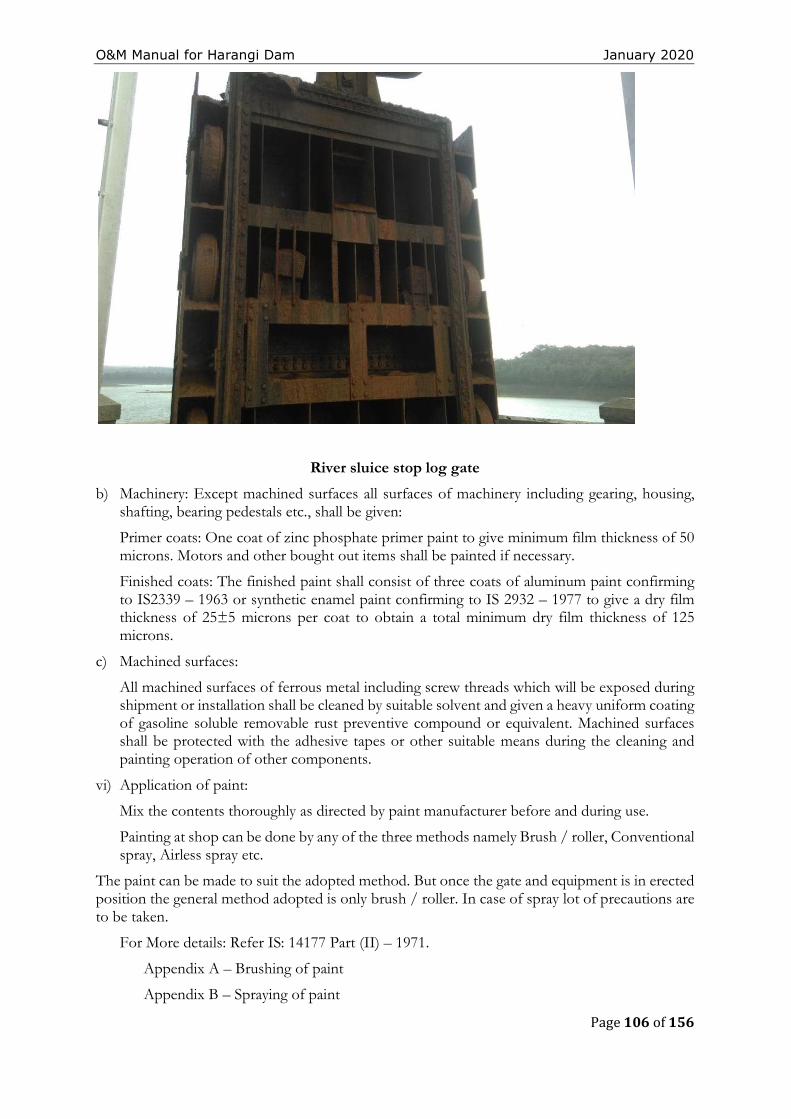
O&M Manual for Harangi Dam January 2020
Page 106 of 156
River sluice stop log gate
b) Machinery: Except machined surfaces all surfaces of machinery including gearing, housing, shafting, bearing pedestals etc., shall be given:
Primer coats: One coat of zinc phosphate primer paint to give minimum film thickness of 50 microns. Motors and other bought out items shall be painted if necessary.
Finished coats: The finished paint shall consist of three coats of aluminum paint confirming to IS2339 – 1963 or synthetic enamel paint confirming to IS 2932 – 1977 to give a dry film thickness of 25±5 microns per coat to obtain a total minimum dry film thickness of 125 microns.
c) Machined surfaces:
All machined surfaces of ferrous metal including screw threads which will be exposed during shipment or installation shall be cleaned by suitable solvent and given a heavy uniform coating of gasoline soluble removable rust preventive compound or equivalent. Machined surfaces shall be protected with the adhesive tapes or other suitable means during the cleaning and painting operation of other components.
vi) Application of paint:
Mix the contents thoroughly as directed by paint manufacturer before and during use.
Painting at shop can be done by any of the three methods namely Brush / roller, Conventional spray, Airless spray etc.
The paint can be made to suit the adopted method. But once the gate and equipment is in erected position the general method adopted is only brush / roller. In case of spray lot of precautions are to be taken.
For More details: Refer IS: 14177 Part (II) – 1971.
Appendix A – Brushing of paint
Appendix B – Spraying of paint
O&M Manual for Harangi Dam January 2020
Page 107 of 156
Appendix C – Spray painting defects: Causes and remedies.
Removal of old paint / rust and carrying out fresh painting:
The carrying out of fresh painting is to be considered under the following conditions:
• The rusting is noticed all over the surface or
• Rusting is severe or
• Cracking and blistering has damaged the primer coat exposing the metal and is noticed all over the surface or
• The paint film has eroded badly, the scrap of entire paint film to the base metal and carry out fresh painting.
Note: In case of maintenance and renovation: Refer IS 14177 (Part II) – 1971 for checking and repainting.
vii) Removal of old paint for repainting:
Caution should be exercised while removing the old paint. The surfaces shall be de-rusted and descaled by either mechanically by one or more of the methods, namely:
a) Wire brushing, Scraping, and chipping. Sand papering or cleaning with steel wool or abrasive paper
b) Power tool cleaning
c) Flame cleaning
d) Sand blasting or shot blasting and
e) Chemical rust removal.
Note: The method of application shall be decided based on conditions existing. After cleaning painting is to be carried out as originally proposed.
Some are painted without removal of old paint and rusting this will amounts to no painting and deteriorate faster than the original one.
viii)Inspection and testing of painting of H. M works:
a) The following steps are involved in inspection of painting:
● General inspection before and during painting
● Viscosity test of paints
● Paint thickness test – using Elco-meter.
● Inspection of general appearance of finished work.
b) General:
The aim of inspection and testing is to ascertain whether the recommended practice is being employed correctly during every stage of application and whether the final results fulfill the object of painting. Any test carried out should be of non – destructive nature or, if it is of destructive nature, it should be either restricted to areas which can be restored without marring the general appearances or be such that it is possible to restore easily without necessitating a complete repetition of the work.
c) Inspection of surfaces prior to painting:
Inspection methods will depend on whether it is to be painted for the first time or is to be repainted.
O&M Manual for Harangi Dam January 2020
Page 108 of 156
d) New Works (Not previously painted): The following shall be decided by inspection:
● The method of pre cleaning feasible or recommended;
● The intermediate protective treatments to be applied, if found necessary;
● The final painting schedule and the specifications for the paint for ensuring the particular performance;
● The method of application, whether by brush, roller or spray.
e) Old Work (Which requires repainting):
The following shall be decided by inspection:
● Whether the entire existing paint requires removal; and/or
● Whether repainting without paint removal would be adequate.
4.5 Electrical System
Electricity is typically used at a dam for lighting and to operate the gates, hoists, recording equipment, and other miscellaneous equipment. It is important that the Electrical system be well maintained, including a thorough check of fuses and a test of the system to ensure that all parts are properly functioning. The system should be free from moisture and dirt, and wiring should be checked for corrosion and mineral deposits.
All necessary repairs should be carried out immediately and records of the works kept. Maintain generators used for auxiliary emergency power -- change the oil, check the batteries and antifreeze and make sure fuel is readily available.
Monitoring devices usually do not need routine maintenance. Open areas are particularly susceptible to vandalism. As such all electrical fittings like bulbs, lights, loose wires etc. in open areas should be checked routinely and replaced / repaired where needed. The recommendations of the manufacturer should also be referred to.
4.6 Maintenance of Metal Gate Components
All exposed, bare ferrous metal of an outlet installation, whether submerged or exposed to air, will tend to rust. To prevent corrosion, exposed ferrous metals must be either appropriately painted (following the paint manufacturer’s directions) or heavily greased in respect of moving parts & on surfaces like guides & track seats on which there is movement of gates. When areas are repainted, it should be ensured that paint is not applied to gate seats, wedges, or stems (where they pass through the stem guides), or on other friction surfaces where paint could cause binding. Heavy grease should be applied on friction surfaces to avoid binding. As rust is especially damaging to contact surfaces, existing rust is to be removed before periodic application of grease.
4.7 Access Roads
For a dam to be operated and maintained there must be a safe means of access to it at all times. Access road surfaces must be maintained to allow safe passage of automobiles and any required equipment for servicing the dam in any weather conditions. Routine observations of any cut and fill slopes along the sides of the road should be made. If unstable conditions develop assistance of experienced Engineers/Expert Panels should be obtained and remedial measures initiated.
Drains are required to be provided and maintained along roads to remove surface and subsurface drainage. This will prolong the life of the road and help reduce deterioration from rutting. Road surfacing should be repaired or replaced as necessary to maintain the required
O&M Manual for Harangi Dam January 2020
Page 109 of 156
traffic loadings. In most cases, specialized contractors will be required to perform this maintenance.
4.8 General Cleaning
As already suggested, for proper operation of spillways, sluiceways, approach channels, inlet and outlet structures, stilling basin /energy dissipation arrangements, discharge conduit, dam slopes, trash racks, debris control devices etc., regular and thorough cleaning and removal of debris is necessary. Cleaning is especially important after large floods, which tend to send more debris into the reservoir.
4.9 Materials and Establishment Requirements during Monsoon Period
Materials required during monsoon period for both immediate maintenance and preventive maintenance must be stocked in adequate quantities for emergency situations that may arise. Needful instructions in this regard is enclosed in the O&M Manual. At Harangi Dam, a 24/7-hour patrol schedule is carried out during monsoon period. At the same time the additional management requirements during monsoon period are enhanced.
4.10 General List of Maintenance Records
Maintenance records are of utmost importance. Records are kept of all maintenance activities, both immediate and preventive maintenance works. Essential information to be recorded include the following:
● Date and time of maintenance, ● Weather conditions, ● Type of maintenance, ● Name of person, title and / or contractor performing maintenance, ● Description of work performed, ● Length of time it took to complete the work with dates, ● Equipment and materials used, and ● Before and after dated photographs.
The data is recorded by the person responsible for maintenance.
4.11 Preparation of O&M budget
In order to prepare O&M budget for a dam project all possible costs associated with implementation of O&M Program need to be identified and considered. Typical O&M budget for a project should essentially include but not limited to the following items:
O&M Manual for Harangi Dam January 2020
Page 110 of 156
i) Establishment Cost of Regular Staff - Salaries and allowances, Bonus, Medical Reimbursement, LTC, Leave Encashment, pension benefits, etc. (as applicable).
ii) Establishment Cost of Work charged Staff - Salaries and allowances, Bonus, Medical Reimbursement, LTC, Leave Encashment, Pension benefits, TA and DA, etc. (as applicable).
iii) Establishment Cost of Daily wage Staff - Salaries and allowances, TA and DA etc. (as applicable).
iv) Office Expenses – Rent for office, Telephone/Mobile/any other Telecommunication bills, Electricity bills, water bills, Office stationery, Day to day office requirements.
v) Motor Vehicles - Running and Maintenance cost of inspection vehicles, Cost of hiring of vehicles as required
vi) Maintenance of Colony - Maintenance of staff quarters, colony roads, Electricity, Sanitary and Water supply systems etc.
vii) T&P - T&P requirements for offices, colony, works etc. as applicable.
viii) Works -Painting, oiling, greasing, overhauling of HM equipment’s, Repair/replacement of gates seals & wire ropes, POL for pumps & generator sets, Electricity charges and maintenance of Electric systems of dam site, specific requirements for all Civil, H.M& Electrical maintenance works, vegetation removal and mowing of turfing on earth dams, maintenance/cleaning of drains in dam, maintenance of lift/elevators in dam (as applicable), maintenance of access roads & basic facilities, provision for flood contingency works during monsoon, unforeseen events/items (about 10% of the cost of works) etc.
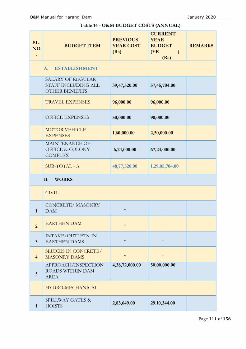
O&M Manual for Harangi Dam January 2020
Page 111 of 156
Table 14 - O&M BUDGET COSTS (ANNUAL)
SL. NO
.
BUDGET ITEM PREVIOUS YEAR COST (Rs)
CURRENT YEAR BUDGET (YR _______)
(Rs)
REMARKS
A. ESTABLISHMENT
SALARY OF REGULAR STAFF INCLUDING ALL OTHER BENEFITS
39,47,520.00 57,45,704.00
TRAVEL EXPENSES 96,000.00 96,000.00
OFFICE EXPENSES 50,000.00 90,000.00
MOTOR VEHICLE EXPENSES 1,60,000.00 2,50,000.00
MAINTENANCE OF OFFICE & COLONY COMPLEX
6,24,000.00 67,24,000.00
SUB-TOTAL - A 48,77,520.00 1,29,05,704.00
B. WORKS
CIVIL
1 CONCRETE/ MASONRY DAM
-
-
2 EARTHEN DAM
-
-
3 INTAKE/OUTLETS IN EARTHEN DAMS
-
-
4 SLUICES IN CONCRETE/ MASONRY DAMS
-
-
5
APPROACH/INSPECTION ROADS WITHIN DAM AREA
4,38,72,000.00 50,00,000.00 -
HYDRO-MECHANICAL
1 SPILLWAY GATES & HOISTS
2,83,649.00 29,10,344.00
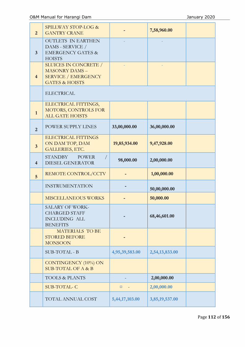
O&M Manual for Harangi Dam January 2020
Page 112 of 156
2 SPILLWAY STOP-LOG & GANTRY CRANE
- 7,58,960.00
3
OUTLETS IN EARTHEN DAMS - SERVICE / EMERGENCY GATES & HOISTS
- -
4
SLUICES IN CONCRETE / MASONRY DAMS – SERVICE / EMERGENCY GATES & HOISTS
- -
ELECTRICAL
1
ELECTRICAL FITTINGS, MOTORS, CONTROLS FOR ALL GATE HOISTS
2 POWER SUPPLY LINES 33,00,000.00 36,00,000.00
3
ELECTRICAL FITTINGS ON DAM TOP, DAM GALLERIES, ETC.
19,85,934.00 9,47,928.00
4 STANDBY POWER / DIESEL GENERATOR
98,000.00 2,00,000.00
5 REMOTE CONTROL/CCTV - 1,00,000.00
INSTRUMENTATION -
50,00,000.00
MISCELLANEOUS WORKS - 50,000.00
SALARY OF WORK- CHARGED STAFF INCLUDING ALL BENEFITS
- 68,46,601.00
MATERIALS TO BE STORED BEFORE MONSOON
-
SUB-TOTAL - B 4,95,39,583.00 2,54,13,833.00
CONTINGENCY (10%) ON SUB-TOTAL OF A & B
TOOLS & PLANTS - 2,00,000.00
SUB-TOTAL- C ¤ - 2,00,000.00
TOTAL ANNUAL COST 5,44,17,103.00 3,85,19,537.00
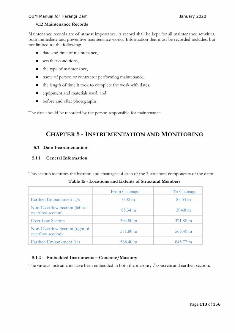
O&M Manual for Harangi Dam January 2020
Page 113 of 156
4.12 Maintenance Records
Maintenance records are of utmost importance. A record shall be kept for all maintenance activities, both immediate and preventive maintenance works. Information that must be recorded includes, but not limited to, the following:
● date and time of maintenance,
● weather conditions,
● the type of maintenance,
● name of person or contractor performing maintenance,
● the length of time it took to complete the work with dates,
● equipment and materials used, and
● before and after photographs.
The data should be recorded by the person responsible for maintenance
CHAPTER 5 - INSTRUMENTATION AND MONITORING
5.1 Dam Instrumentation·
5.1.1 General Information
This section identifies the location and chainages of each of the 3 structural components of the dam:
Table 15 - Locations and Extents of Structural Members
From Chainage To Chainage
Earthen Embankment L/s 0.00 m 85.34 m
Non-Overflow Section (left of overflow section) 85.34 m 304.8 m
Over-flow Section 304.80 m 371.80 m
Non-Overflow Section (right of overflow section) 371.80 m 568.40 m
Earthen Embankment R/s 568.40 m 845.77 m
5.1.2 Embedded Instruments – Concrete/Masonry The various instruments have been embedded in both the masonry / concrete and earthen section.
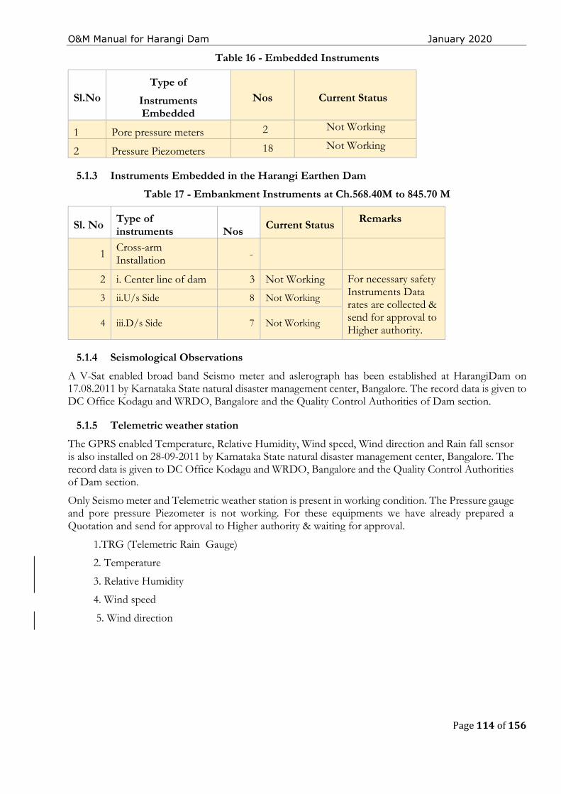
O&M Manual for Harangi Dam January 2020
Page 114 of 156
Table 16 - Embedded Instruments
Sl.No Type of
Instruments Embedded
Nos Current Status
1 Pore pressure meters 2 Not Working
2 Pressure Piezometers 18 Not Working
5.1.3 Instruments Embedded in the Harangi Earthen Dam Table 17 - Embankment Instruments at Ch.568.40M to 845.70 M
Sl. No Type of instruments
Nos
Current Status Remarks
1 Cross-arm Installation -
2 i. Center line of dam 3 Not Working For necessary safety Instruments Data rates are collected & send for approval to Higher authority.
3 ii.U/s Side 8 Not Working
4 iii.D/s Side 7 Not Working
5.1.4 Seismological Observations A V-Sat enabled broad band Seismo meter and aslerograph has been established at HarangiDam on 17.08.2011 by Karnataka State natural disaster management center, Bangalore. The record data is given to DC Office Kodagu and WRDO, Bangalore and the Quality Control Authorities of Dam section.
5.1.5 Telemetric weather station
The GPRS enabled Temperature, Relative Humidity, Wind speed, Wind direction and Rain fall sensor is also installed on 28-09-2011 by Karnataka State natural disaster management center, Bangalore. The record data is given to DC Office Kodagu and WRDO, Bangalore and the Quality Control Authorities of Dam section.
Only Seismo meter and Telemetric weather station is present in working condition. The Pressure gauge and pore pressure Piezometer is not working. For these equipments we have already prepared a Quotation and send for approval to Higher authority & waiting for approval.
1.TRG (Telemetric Rain Gauge)
2. Temperature
3. Relative Humidity
4. Wind speed
5. Wind direction
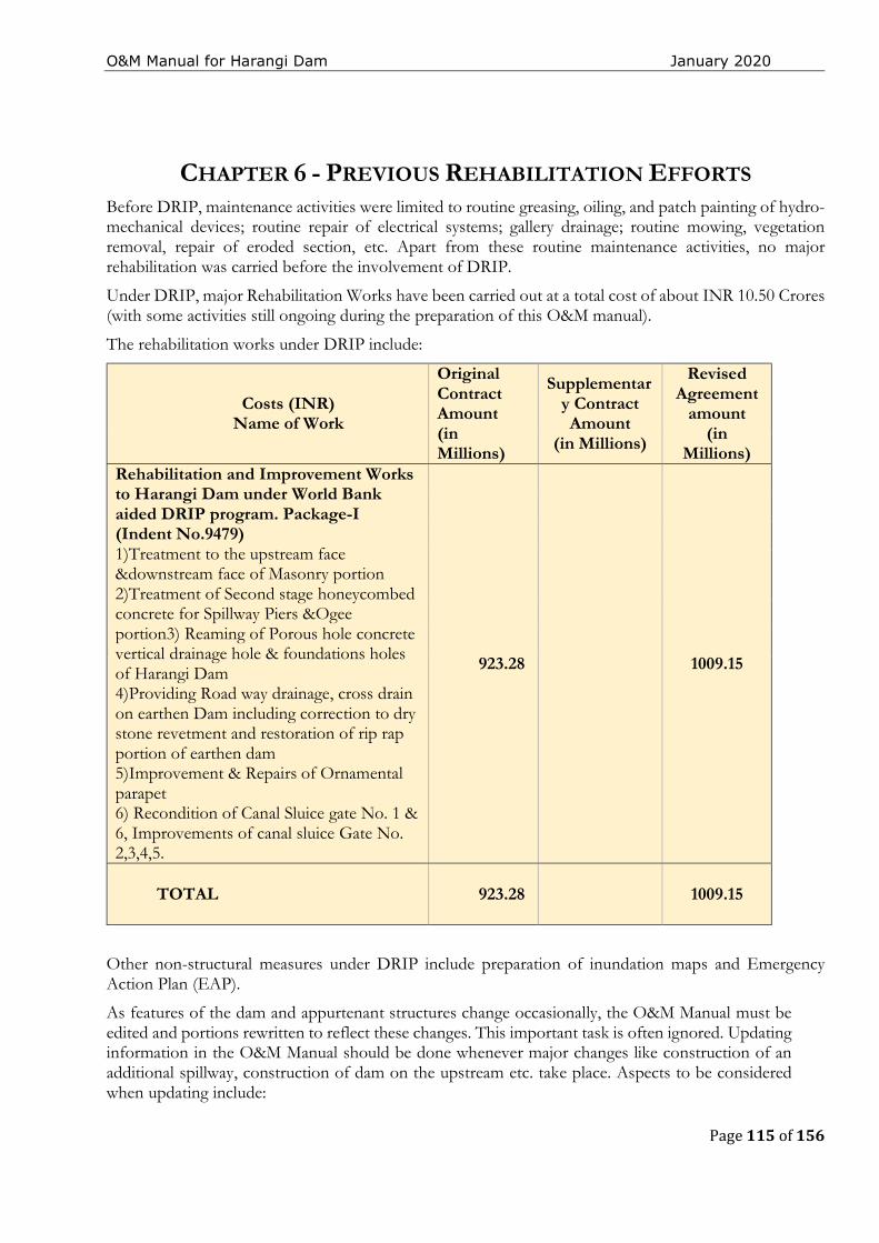
O&M Manual for Harangi Dam January 2020
Page 115 of 156
CHAPTER 6 - PREVIOUS REHABILITATION EFFORTS Before DRIP, maintenance activities were limited to routine greasing, oiling, and patch painting of hydro-mechanical devices; routine repair of electrical systems; gallery drainage; routine mowing, vegetation removal, repair of eroded section, etc. Apart from these routine maintenance activities, no major rehabilitation was carried before the involvement of DRIP.
Under DRIP, major Rehabilitation Works have been carried out at a total cost of about INR 10.50 Crores (with some activities still ongoing during the preparation of this O&M manual).
The rehabilitation works under DRIP include:
Costs (INR) Name of Work
Original Contract Amount (in Millions)
Supplementary Contract Amount
(in Millions)
Revised Agreement
amount (in
Millions) Rehabilitation and Improvement Works to Harangi Dam under World Bank aided DRIP program. Package-I (Indent No.9479) 1)Treatment to the upstream face &downstream face of Masonry portion 2)Treatment of Second stage honeycombed concrete for Spillway Piers &Ogee portion3) Reaming of Porous hole concrete vertical drainage hole & foundations holes of Harangi Dam 4)Providing Road way drainage, cross drain on earthen Dam including correction to dry stone revetment and restoration of rip rap portion of earthen dam 5)Improvement & Repairs of Ornamental parapet 6) Recondition of Canal Sluice gate No. 1 & 6, Improvements of canal sluice Gate No. 2,3,4,5.
923.28 1009.15
TOTAL 923.28 1009.15
Other non-structural measures under DRIP include preparation of inundation maps and Emergency Action Plan (EAP).
As features of the dam and appurtenant structures change occasionally, the O&M Manual must be edited and portions rewritten to reflect these changes. This important task is often ignored. Updating information in the O&M Manual should be done whenever major changes like construction of an additional spillway, construction of dam on the upstream etc. take place. Aspects to be considered when updating include:
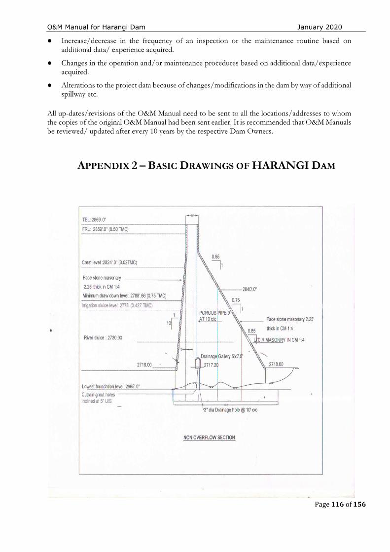
O&M Manual for Harangi Dam January 2020
Page 116 of 156
● Increase/decrease in the frequency of an inspection or the maintenance routine based on additional data/ experience acquired.
● Changes in the operation and/or maintenance procedures based on additional data/experience acquired.
● Alterations to the project data because of changes/modifications in the dam by way of additional spillway etc.
All up-dates/revisions of the O&M Manual need to be sent to all the locations/addresses to whom the copies of the original O&M Manual had been sent earlier. It is recommended that O&M Manuals be reviewed/ updated after every 10 years by the respective Dam Owners.
APPENDIX 2 – BASIC DRAWINGS OF HARANGI DAM

O&M Manual for Harangi Dam January 2020
Page 117 of 156

O&M Manual for Harangi Dam January 2020
Page 118 of 156

O&M Manual for Harangi Dam January 2020
Page 119 of 156
THIS PAGE LEFT BLANK INTENTIONALLY
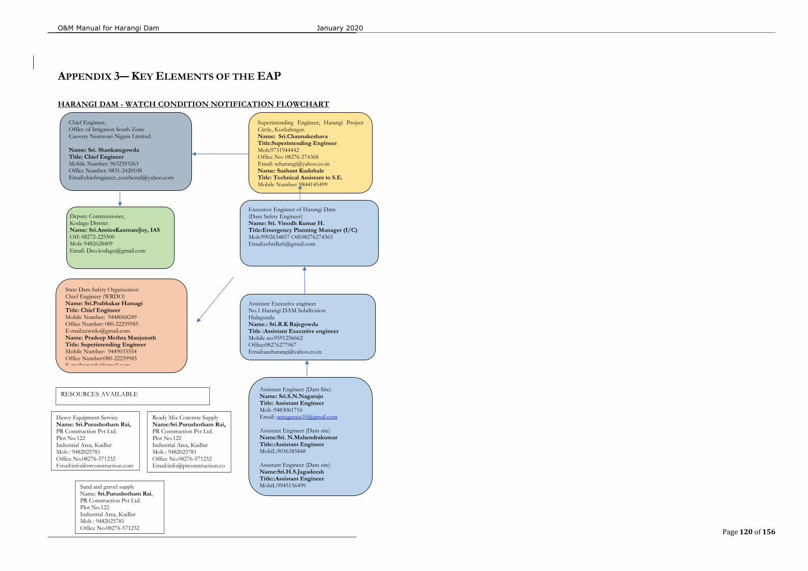
O&M Manual for Harangi Dam January 2020
Page 120 of 156
APPENDIX 3― KEY ELEMENTS OF THE EAP
HARANGI DAM - WATCH CONDITION NOTIFICATION FLOWCHART
Chief Engineer, Office of Irrigation South Zone Cauvery Neeravari Nigam Limited. Name: Sri. Shankaregowda Title: Chief Engineer Mobile Number: 9632393263 Office Number: 0831-2420108 Email:[email protected]
Superintending Engineer, Harangi Project Circle, Kushalnagar. Name: Sri.Channakeshava Title:Superintending Engineer Mob:9731944442 Office No: 08276-274368 Email: [email protected] Name: Sushant Kudubale Title: Technical Assistant to S.E. Mobile Number: 9844145499
Executive Engineer of Harangi Dam (Dam Safety Engineer) Name: Sri. Vinodh Kumar H. Title:Emergency Planning Manager (I/C) Mob:9902634857 Off:08276274365 Email:[email protected]
Assistant Executive engineer No.1 Harangi DAM Subdivision Hulagunda Name.: Sri.R.K Rajegowda Title :Assistant Executive engineer Mobile no:9591256662 Office:08276277067 Email:[email protected]
Deputy Commissioner, Kodagu District Name: Sri.AnniesKanmaniJoy, IAS Off: 08272-225500 Mob: 9482628409 Email: [email protected]
State Dam Safety Organization Chief Engineer (WRDO) Name: Sri.Prabhakar Hamagi Title: Chief Engineer Mobile Number: 9448068249 Office Number: 080-22259985 E-mail:[email protected] Name: Pradeep Methra Manjunath Title: Superintending Engineer Mobile Number: 9449033554 Office Number:080-22259985 E-mail:[email protected]
Assistant Engineer (Dam Site) Name: Sri.S.N.Nagaraju Title: Assistant Engineer Mob :9483061716 Email: [email protected] Assistant Engineer (Dam site) Name:Sri. N.Mahendrakumar Title::Assistant Engineer MobiL:9036385848 Assistant Engineer (Dam site) Name:Sri.H.S.Jagadeesh Title::Assistant Engineer MobiL:9945156499
Heavy Equipment Service Name: Sri.Purushotham Rai, PR Construction Pvt Ltd. Plot No.122 Industrial Area, Kudlur Mob : 9482025781 Office No.08276-571232 Email:[email protected]
Ready Mix Concrete Supply Name:Sri.Purushotham Rai, PR Construction Pvt Ltd. Plot No.122 Industrial Area, Kudlur Mob : 9482025781 Office No.08276-571232 Email:[email protected]
Sand and gravel supply Name: Sri.Purushotham Rai, PR Construction Pvt Ltd. Plot No.122 Industrial Area, Kudlur Mob : 9482025781 Office No.08276-571232
RESOURCES AVAILABLE
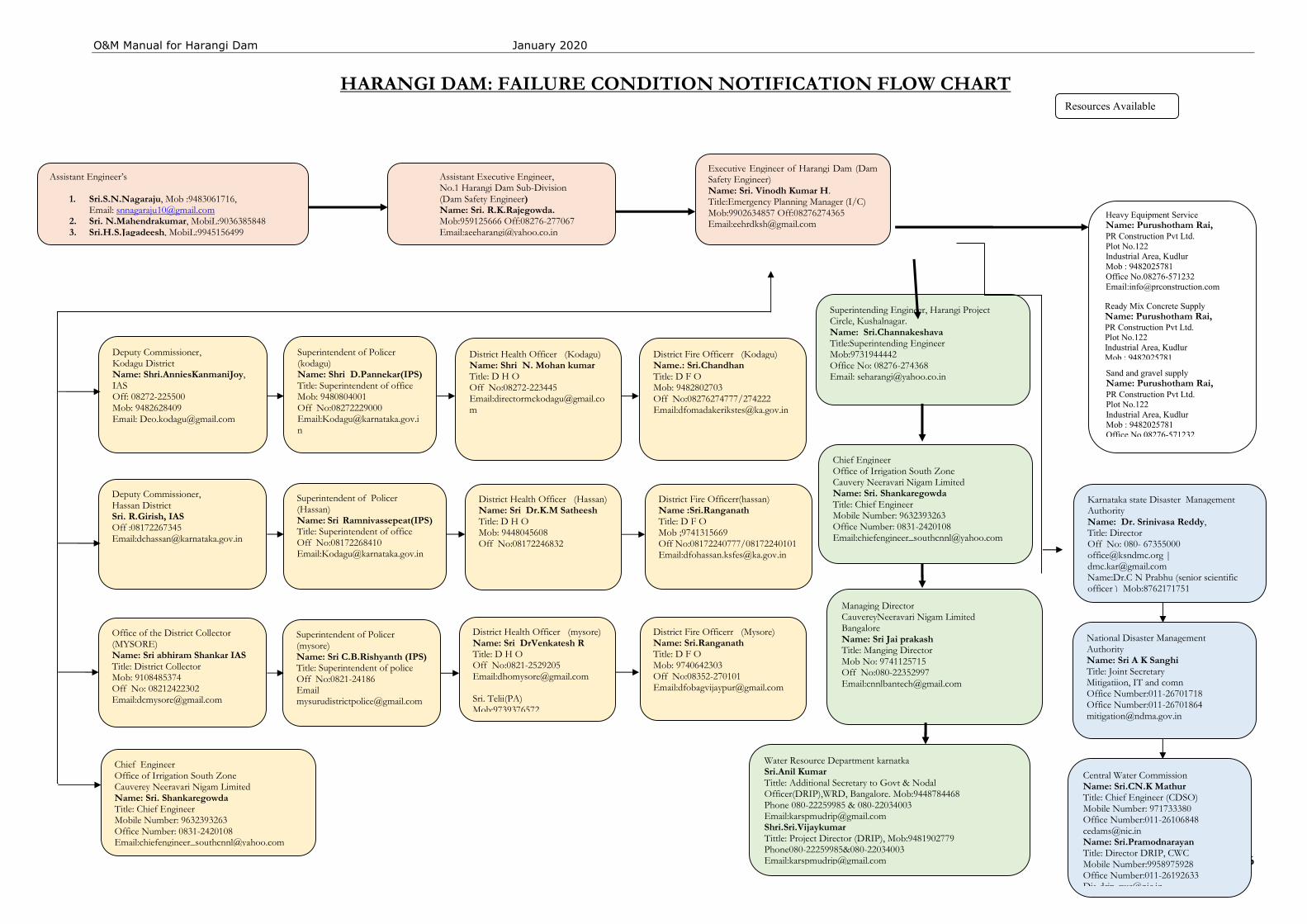
O&M Manual for Harangi Dam January 2020
Page 121 of 156
HARANGI DAM: FAILURE CONDITION NOTIFICATION FLOW CHART
Executive Engineer of Harangi Dam (Dam Safety Engineer) Name: Sri. Vinodh Kumar H. Title:Emergency Planning Manager (I/C) Mob:9902634857 Off:08276274365 Email:[email protected]
Superintending Engineer, Harangi Project Circle, Kushalnagar. Name: Sri.Channakeshava Title:Superintending Engineer Mob:9731944442 Office No: 08276-274368 Email: [email protected]
Chief Engineer Office of Irrigation South Zone Cauvery Neeravari Nigam Limited Name: Sri. Shankaregowda Title: Chief Engineer Mobile Number: 9632393263 Office Number: 0831-2420108 Email:[email protected]
Water Resource Department karnatka Sri.Anil Kumar Tittle: Additional Secretary to Govt & Nodal Officer(DRIP),WRD, Bangalore. Mob:9448784468 Phone 080-22259985 & 080-22034003 Email:[email protected] Shri.Sri.Vijaykumar Tittle: Project Director (DRIP), Mob:9481902779 Phone080-22259985&080-22034003 Email:[email protected]
Central Water Commission Name: Sri.CN.K Mathur Title: Chief Engineer (CDSO) Mobile Number: 971733380 Office Number:011-26106848 [email protected] Name: Sri.Pramodnarayan Title: Director DRIP, CWC Mobile Number:9958975928 Office Number:011-26192633 [email protected]
Deputy Commissioner, Kodagu District Name: Shri.AnniesKanmaniJoy, IAS Off: 08272-225500 Mob: 9482628409 Email: [email protected]
Deputy Commissioner, Hassan District Sri. R.Girish, IAS Off :08172267345 Email:[email protected]
Office of the District Collector (MYSORE) Name: Sri abhiram Shankar IAS Title: District Collector Mob: 9108485374 Off No: 08212422302 Email:[email protected]
Heavy Equipment Service Name: Purushotham Rai, PR Construction Pvt Ltd. Plot No.122 Industrial Area, Kudlur Mob : 9482025781 Office No.08276-571232 Email:[email protected]
Ready Mix Concrete Supply Name: Purushotham Rai, PR Construction Pvt Ltd. Plot No.122 Industrial Area, Kudlur Mob : 9482025781 Office No.08276-571232 Email:info@prconstruction.
National Disaster Management Authority Name: Sri A K Sanghi Title: Joint Secretary Mitigatiion, IT and comn Office Number:011-26701718 Office Number:011-26701864 [email protected]
Karnataka state Disaster Management Authority Name: Dr. Srinivasa Reddy, Title: Director Off No: 080- 67355000 [email protected] | [email protected] Name:Dr.C N Prabhu (senior scientific officer ) Mob:8762171751
Managing Director CauvereyNeeravari Nigam Limited Bangalore Name: Sri Jai prakash Title: Manging Director Mob No: 9741125715 Off No:080-22352997 Email:[email protected]
Chief Engineer Office of Irrigation South Zone Cauverey Neeravari Nigam Limited Name: Sri. Shankaregowda Title: Chief Engineer Mobile Number: 9632393263 Office Number: 0831-2420108 Email:[email protected]
Resources Available
Superintendent of Policer (kodagu) Name: Shri D.Pannekar(IPS) Title: Superintendent of office Mob: 9480804001 Off No:08272229000 Email:[email protected]
District Health Officer (Kodagu) Name: Shri N. Mohan kumar Title: D H O Off No:08272-223445 Email:[email protected]
District Fire Officerr (Kodagu) Name.: Sri.Chandhan Title: D F O Mob: 9482802703 Off No:08276274777/274222 Email:[email protected]
District Health Officer (Hassan) Name: Sri Dr.K.M Satheesh Title: D H O Mob: 9448045608 Off No:08172246832
District Fire Officerr(hassan) Name :Sri.Ranganath Title: D F O Mob ;9741315669 Off No:08172240777/08172240101 Email:[email protected]
Superintendent of Policer (Hassan) Name: Sri Ramnivassepeat(IPS) Title: Superintendent of office Off No:08172268410 Email:[email protected]
Superintendent of Policer (mysore) Name: Sri C.B.Rishyanth (IPS) Title: Superintendent of police Off No:0821-24186 Email [email protected]
District Health Officer (mysore) Name: Sri DrVenkatesh R Title: D H O Off No:0821-2529205 Email:[email protected] Sri. Telii(PA) Mob:9739376572
District Fire Officerr (Mysore) Name: Sri.Ranganath Title: D F O Mob: 9740642303 Off No:08352-270101 Email:[email protected]
Sand and gravel supply Name: Purushotham Rai, PR Construction Pvt Ltd. Plot No.122 Industrial Area, Kudlur Mob : 9482025781 Office No.08276-571232
Assistant Engineer’s
1. Sri.S.N.Nagaraju, Mob :9483061716, Email: [email protected]
2. Sri. N.Mahendrakumar, MobiL:9036385848 3. Sri.H.S.Jagadeesh, MobiL:9945156499
Assistant Executive Engineer, No.1 Harangi Dam Sub-Division (Dam Safety Engineer) Name: Sri. R.K.Rajegowda. Mob:959125666 Off:08276-277067 Email:[email protected]
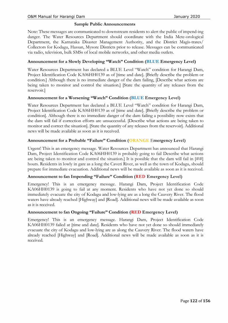
O&M Manual for Harangi Dam January 2020
Page 122 of 156
Sample Public Announcements
Note: These messages are communicated to downstream residents to alert the public of impend-ing danger. The Water Resources Department should coordinate with the India Mete-orological Department, the Karnataka Disaster Management Authority, and the District Magis-trates/ Collectors for Kodagu, Hassan, Mysore Districts prior to release. Messages can be communicated via radio, television, bulk SMSs of local mobile networks, and other media outlets.
Announcement for a Slowly Developing “Watch” Condition (BLUE Emergency Level)
Water Resources Department has declared a BLUE Level “Watch” condition for Harangi Dam, Project Identification Code KA06HH0139 as of [time and date]. [Briefly describe the problem or condition.] Although there is no immediate danger of the dam failing, [Describe what actions are being taken to monitor and control the situation.] [State the quantity of any releases from the reservoir.]
Announcement for a Worsening “Watch” Condition (BLUE Emergency Level)
Water Resources Department has declared a BLUE Level “Watch” condition for Harangi Dam, Project Identification Code KA06HH0139 as of [time and date]. [Briefly describe the problem or condition]. Although there is no immediate danger of the dam failing a possibility now exists that the dam will fail if correction efforts are unsuccessful. [Describe what actions are being taken to monitor and correct the situation]. [State the quantity of any releases from the reservoir]. Additional news will be made available as soon as it is received.
Announcement for a Probable “Failure” Condition (ORANGE Emergency Level)
Urgent! This is an emergency message. Water Resources Department has announced that Harangi Dam, Project Identification Code KA06HH0139 is probably going to fail Describe what actions are being taken to monitor and control the situation.] It is possible that the dam will fail in [##] hours. Residents in lowly in gare as a long the Caveri River, as well as the town of Kodagu, should prepare for immediate evacuation. Additional news will be made available as soon as it is received.
Announcement to fan Impending “Failure” Condition (RED Emergency Level)
Emergency! This is an emergency message. Harangi Dam, Project Identification Code KA06HH0139 is going to fail at any moment. Residents who have not yet done so should immediately evacuate the city of Kodagu and low-lying are as a long the Cauvery River. The flood waters have already reached [Highway] and [Road]. Additional news will be made available as soon as it is received.
Announcement to fan Ongoing “Failure” Condition (RED Emergency Level)
Emergency! This is an emergency message. Harangi Dam, Project Identification Code KA06HH0139 failed at [time and date]. Residents who have not yet done so should immediately evacuate the city of Kodagu and low-lying are as along the Cauvery River. The flood waters have already reached [Highway] and [Road]. Additional news will be made available as soon as it is received.
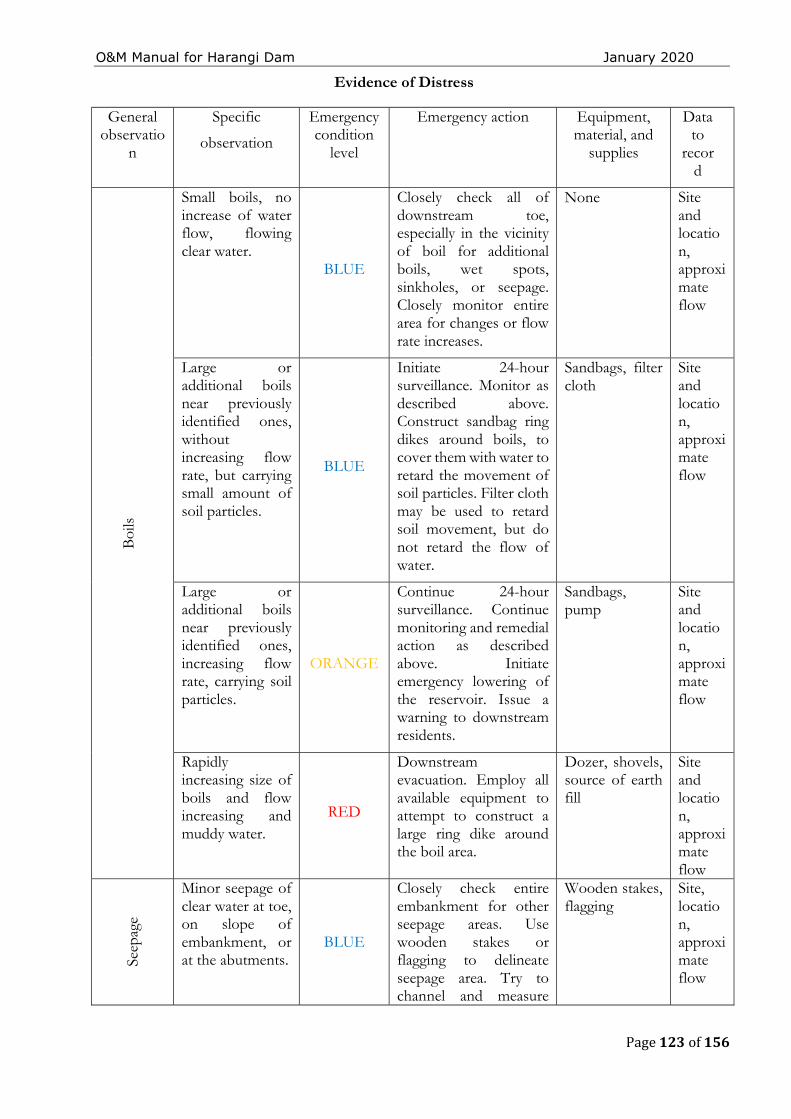
O&M Manual for Harangi Dam January 2020
Page 123 of 156
Evidence of Distress
General observatio
n
Specific
observation
Emergency condition
level
Emergency action Equipment, material, and
supplies
Data to
record
Boi
ls
Small boils, no increase of water flow, flowing clear water.
BLUE
Closely check all of downstream toe, especially in the vicinity of boil for additional boils, wet spots, sinkholes, or seepage. Closely monitor entire area for changes or flow rate increases.
None Site and location, approximate flow
Large or additional boils near previously identified ones, without increasing flow rate, but carrying small amount of soil particles.
BLUE
Initiate 24-hour surveillance. Monitor as described above. Construct sandbag ring dikes around boils, to cover them with water to retard the movement of soil particles. Filter cloth may be used to retard soil movement, but do not retard the flow of water.
Sandbags, filter cloth
Site and location, approximate flow
Large or additional boils near previously identified ones, increasing flow rate, carrying soil particles.
ORANGE
Continue 24-hour surveillance. Continue monitoring and remedial action as described above. Initiate emergency lowering of the reservoir. Issue a warning to downstream residents.
Sandbags, pump
Site and location, approximate flow
Rapidly increasing size of boils and flow increasing and muddy water.
RED
Downstream evacuation. Employ all available equipment to attempt to construct a large ring dike around the boil area.
Dozer, shovels, source of earth fill
Site and location, approximate flow
Seep
age
Minor seepage of clear water at toe, on slope of embankment, or at the abutments.
BLUE
Closely check entire embankment for other seepage areas. Use wooden stakes or flagging to delineate seepage area. Try to channel and measure
Wooden stakes, flagging
Site, location, approximate flow
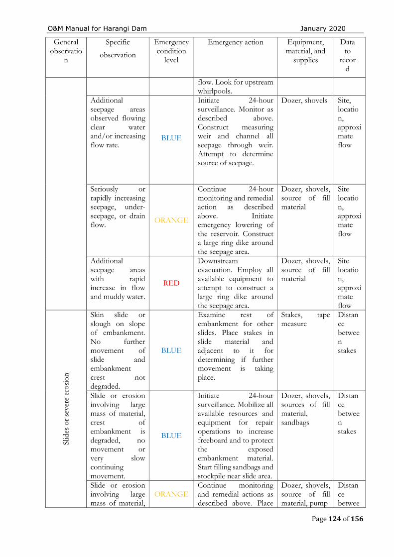
O&M Manual for Harangi Dam January 2020
Page 124 of 156
General observatio
n
Specific
observation
Emergency condition
level
Emergency action Equipment, material, and
supplies
Data to
record
flow. Look for upstream whirlpools.
Additional seepage areas observed flowing clear water and/or increasing flow rate.
BLUE
Initiate 24-hour surveillance. Monitor as described above. Construct measuring weir and channel all seepage through weir. Attempt to determine source of seepage.
Dozer, shovels Site, location, approximate flow
Seriously or rapidly increasing seepage, under-seepage, or drain flow. ORANGE
Continue 24-hour monitoring and remedial action as described above. Initiate emergency lowering of the reservoir. Construct a large ring dike around the seepage area.
Dozer, shovels, source of fill material
Site location, approximate flow
Additional seepage areas with rapid increase in flow and muddy water.
RED
Downstream evacuation. Employ all available equipment to attempt to construct a large ring dike around the seepage area.
Dozer, shovels, source of fill material
Site location, approximate flow
Slid
es o
r se
vere
ero
sion
Skin slide or slough on slope of embankment. No further movement of slide and embankment crest not degraded.
BLUE
Examine rest of embankment for other slides. Place stakes in slide material and adjacent to it for determining if further movement is taking place.
Stakes, tape measure
Distance between stakes
Slide or erosion involving large mass of material, crest of embankment is degraded, no movement or very slow continuing movement.
BLUE
Initiate 24-hour surveillance. Mobilize all available resources and equipment for repair operations to increase freeboard and to protect the exposed embankment material. Start filling sandbags and stockpile near slide area.
Dozer, shovels, sources of fill material, sandbags
Distance between stakes
Slide or erosion involving large mass of material,
ORANGE Continue monitoring and remedial actions as described above. Place
Dozer, shovels, source of fill material, pump
Distance betwee
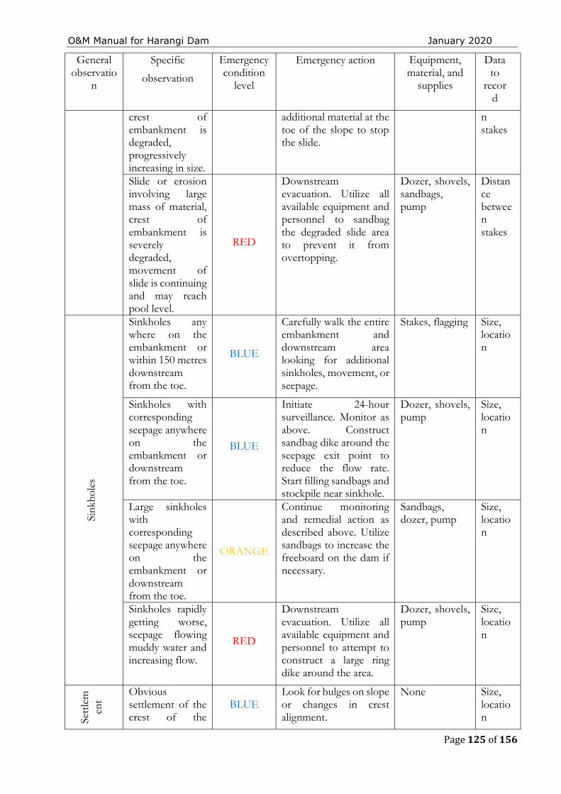
O&M Manual for Harangi Dam January 2020
Page 125 of 156
General observatio
n
Specific
observation
Emergency condition
level
Emergency action Equipment, material, and
supplies
Data to
record
crest of embankment is degraded, progressively increasing in size.
additional material at the toe of the slope to stop the slide.
n stakes
Slide or erosion involving large mass of material, crest of embankment is severely degraded, movement of slide is continuing and may reach pool level.
RED
Downstream evacuation. Utilize all available equipment and personnel to sandbag the degraded slide area to prevent it from overtopping.
Dozer, shovels, sandbags, pump
Distance between stakes
Sink
hole
s
Sinkholes any where on the embankment or within 150 metres downstream from the toe.
BLUE
Carefully walk the entire embankment and downstream area looking for additional sinkholes, movement, or seepage.
Stakes, flagging Size, location
Sinkholes with corresponding seepage anywhere on the embankment or downstream from the toe.
BLUE
Initiate 24-hour surveillance. Monitor as above. Construct sandbag dike around the seepage exit point to reduce the flow rate. Start filling sandbags and stockpile near sinkhole.
Dozer, shovels, pump
Size, location
Large sinkholes with corresponding seepage anywhere on the embankment or downstream from the toe.
ORANGE
Continue monitoring and remedial action as described above. Utilize sandbags to increase the freeboard on the dam if necessary.
Sandbags, dozer, pump
Size, location
Sinkholes rapidly getting worse, seepage flowing muddy water and increasing flow.
RED
Downstream evacuation. Utilize all available equipment and personnel to attempt to construct a large ring dike around the area.
Dozer, shovels, pump
Size, location
Sett
lem
ent
Obvious settlement of the crest of the
BLUE Look for bulges on slope or changes in crest alignment.
None Size, location
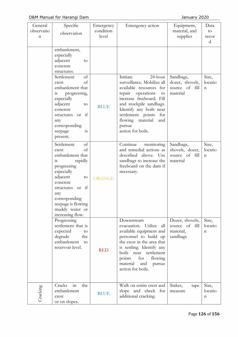
O&M Manual for Harangi Dam January 2020
Page 126 of 156
General observatio
n
Specific
observation
Emergency condition
level
Emergency action Equipment, material, and
supplies
Data to
record
embankment, especially adjacent to concrete structures. Settlement of crest of embankment that is progressing, especially adjacent to concrete structures or if any corresponding seepage is present.
BLUE
Initiate 24-hour surveillance. Mobilize all available resources for repair operations to increase freeboard. Fill and stockpile sandbags. Identify any boils near settlement points for flowing material and pursue action for boils.
Sandbags, dozer, shovels, source of fill material
Size, location
Settlement of crest of embankment that is rapidly progressing especially adjacent to concrete structures or if any corresponding seepage is flowing muddy water or increasing flow.
ORANGE
Continue monitoring and remedial actions as described above. Use sandbags to increase the freeboard on the dam if necessary.
Sandbags, shovels, dozer, source of fill material
Size, location
Progressing settlement that is expected to degrade the embankment to reservoir level. RED
Downstream evacuation. Utilize all available equipment and personnel to build up the crest in the area that is settling. Identify any boils near settlement points for flowing material and pursue action for boils.
Dozer, shovels, source of fill material, sandbags
Size, location
Cra
ckin
g Cracks in the embankment crest or on slopes.
BLUE
Walk on entire crest and slope and check for additional cracking.
Stakes, tape measure
Size, location
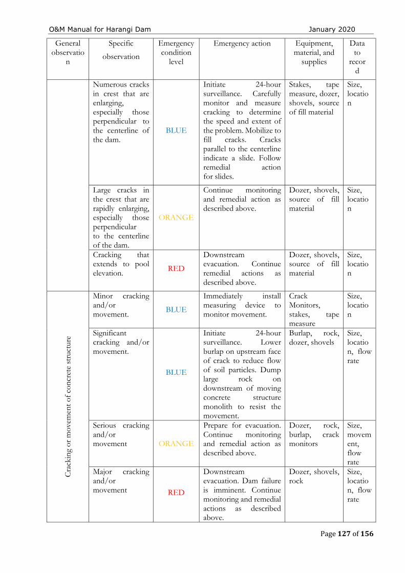
O&M Manual for Harangi Dam January 2020
Page 127 of 156
General observatio
n
Specific
observation
Emergency condition
level
Emergency action Equipment, material, and
supplies
Data to
record
Numerous cracks in crest that are enlarging, especially those perpendicular to the centerline of the dam.
BLUE
Initiate 24-hour surveillance. Carefully monitor and measure cracking to determine the speed and extent of the problem. Mobilize to fill cracks. Cracks parallel to the centerline indicate a slide. Follow remedial action for slides.
Stakes, tape measure, dozer, shovels, source of fill material
Size, location
Large cracks in the crest that are rapidly enlarging, especially those perpendicular to the centerline of the dam.
ORANGE
Continue monitoring and remedial action as described above.
Dozer, shovels, source of fill material
Size, location
Cracking that extends to pool elevation. RED
Downstream evacuation. Continue remedial actions as described above.
Dozer, shovels, source of fill material
Size, location
Cra
ckin
g or
mov
emen
t of c
oncr
ete
stru
ctur
e
Minor cracking and/or movement.
BLUE
Immediately install measuring device to monitor movement.
Crack Monitors, stakes, tape measure
Size, location
Significant cracking and/or movement.
BLUE
Initiate 24-hour surveillance. Lower burlap on upstream face of crack to reduce flow of soil particles. Dump large rock on downstream of moving concrete structure monolith to resist the movement.
Burlap, rock, dozer, shovels
Size, location, flow rate
Serious cracking and/or movement ORANGE
Prepare for evacuation. Continue monitoring and remedial action as described above.
Dozer, rock, burlap, crack monitors
Size, movement, flow rate
Major cracking and/or movement RED
Downstream evacuation. Dam failure is imminent. Continue monitoring and remedial actions as described above.
Dozer, shovels, rock
Size, location, flow rate
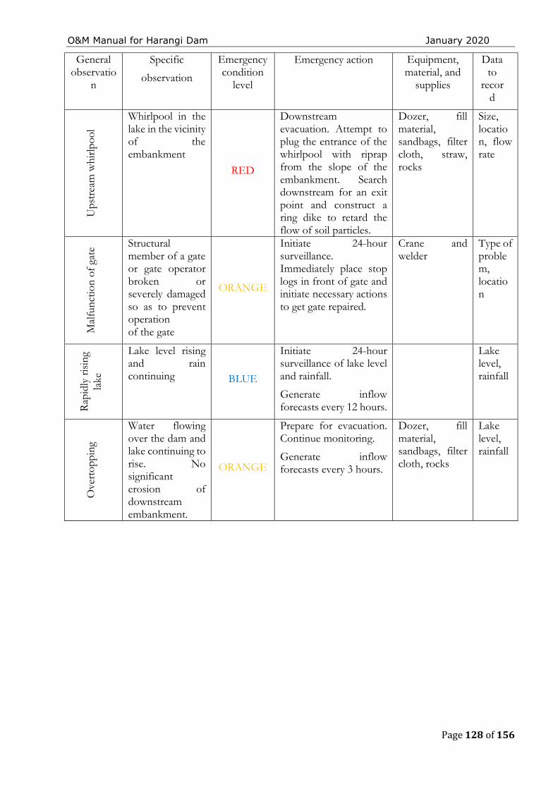
O&M Manual for Harangi Dam January 2020
Page 128 of 156
General observatio
n
Specific
observation
Emergency condition
level
Emergency action Equipment, material, and
supplies
Data to
record
Ups
trea
m w
hirlp
ool
Whirlpool in the lake in the vicinity of the embankment
RED
Downstream evacuation. Attempt to plug the entrance of the whirlpool with riprap from the slope of the embankment. Search downstream for an exit point and construct a ring dike to retard the flow of soil particles.
Dozer, fill material, sandbags, filter cloth, straw, rocks
Size, location, flow rate
Mal
func
tion
of g
ate Structural
member of a gate or gate operator broken or severely damaged so as to prevent operation of the gate
ORANGE
Initiate 24-hour surveillance. Immediately place stop logs in front of gate and initiate necessary actions to get gate repaired.
Crane and welder
Type of problem, location
Rap
idly
ris
ing
lake
Lake level rising and rain continuing BLUE
Initiate 24-hour surveillance of lake level and rainfall.
Generate inflow forecasts every 12 hours.
Lake level, rainfall
Ove
rtop
ping
Water flowing over the dam and lake continuing to rise. No significant erosion of downstream embankment.
ORANGE
Prepare for evacuation. Continue monitoring.
Generate inflow forecasts every 3 hours.
Dozer, fill material, sandbags, filter cloth, rocks
Lake level, rainfall
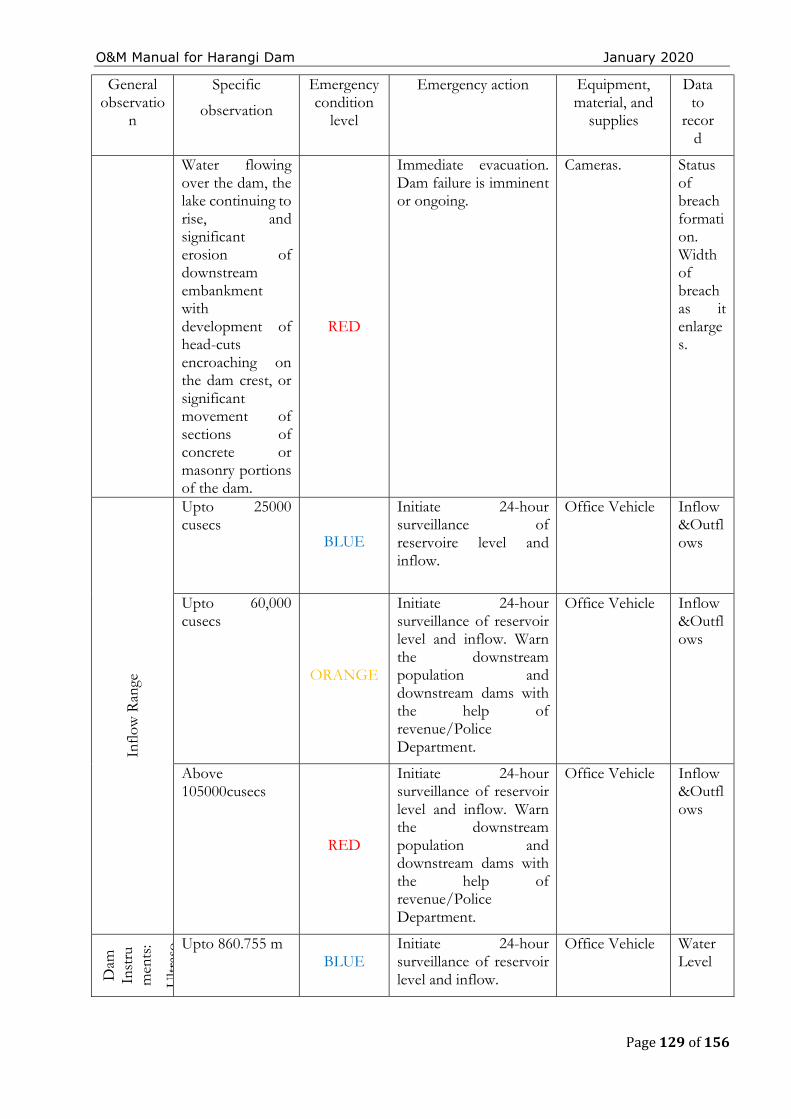
O&M Manual for Harangi Dam January 2020
Page 129 of 156
General observatio
n
Specific
observation
Emergency condition
level
Emergency action Equipment, material, and
supplies
Data to
record
Water flowing over the dam, the lake continuing to rise, and significant erosion of downstream embankment with development of head-cuts encroaching on the dam crest, or significant movement of sections of concrete or masonry portions of the dam.
RED
Immediate evacuation. Dam failure is imminent or ongoing.
Cameras. Status of breach formation. Width of breach as it enlarges.
Inflo
w R
ange
Upto 25000 cusecs
BLUE
Initiate 24-hour surveillance of reservoire level and inflow.
Office Vehicle Inflow &Outflows
Upto 60,000 cusecs
ORANGE
Initiate 24-hour surveillance of reservoir level and inflow. Warn the downstream population and downstream dams with the help of revenue/Police Department.
Office Vehicle Inflow &Outflows
Above 105000cusecs
RED
Initiate 24-hour surveillance of reservoir level and inflow. Warn the downstream population and downstream dams with the help of revenue/Police Department.
Office Vehicle Inflow &Outflows
Dam
In
stru
men
ts:
Ultr
aso Upto 860.755 m
BLUE Initiate 24-hour surveillance of reservoir level and inflow.
Office Vehicle Water Level
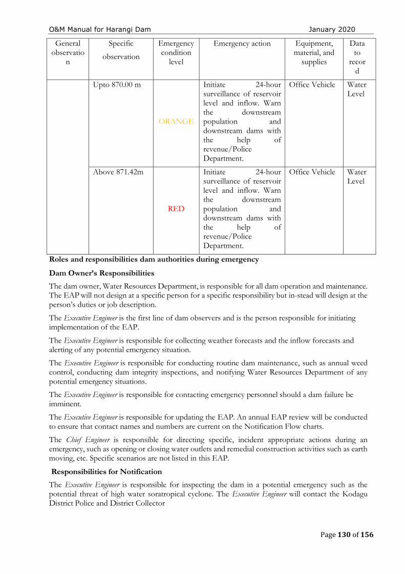
O&M Manual for Harangi Dam January 2020
Page 130 of 156
General observatio
n
Specific
observation
Emergency condition
level
Emergency action Equipment, material, and
supplies
Data to
record
Upto 870.00 m
ORANGE
Initiate 24-hour surveillance of reservoir level and inflow. Warn the downstream population and downstream dams with the help of revenue/Police Department.
Office Vehicle Water Level
Above 871.42m
RED
Initiate 24-hour surveillance of reservoir level and inflow. Warn the downstream population and downstream dams with the help of revenue/Police Department.
Office Vehicle Water Level
Roles and responsibilities dam authorities during emergency
Dam Owner’s Responsibilities
The dam owner, Water Resources Department, is responsible for all dam operation and maintenance. The EAP will not design at a specific person for a specific responsibility but in-stead will design at the person’s duties or job description.
The Executive Engineer is the first line of dam observers and is the person responsible for initiating implementation of the EAP.
The Executive Engineer is responsible for collecting weather forecasts and the inflow forecasts and alerting of any potential emergency situation.
The Executive Engineer is responsible for conducting routine dam maintenance, such as annual weed control, conducting dam integrity inspections, and notifying Water Resources Department of any potential emergency situations.
The Executive Engineer is responsible for contacting emergency personnel should a dam failure be imminent.
The Executive Engineer is responsible for updating the EAP. An annual EAP review will be conducted to ensure that contact names and numbers are current on the Notification Flow charts.
The Chief Engineer is responsible for directing specific, incident appropriate actions during an emergency, such as opening or closing water outlets and remedial construction activities such as earth moving, etc. Specific scenarios are not listed in this EAP.
Responsibilities for Notification
The Executive Engineer is responsible for inspecting the dam in a potential emergency such as the potential threat of high water soratropical cyclone. The Executive Engineer will contact the Kodagu District Police and District Collector
O&M Manual for Harangi Dam January 2020
Page 131 of 156
If warranted, the Executive Engineer will notify the State and District Disaster Management Authori-ties. The Kodagu District Police will notify downstream residents. The Kodagu District Collector will implement the Notification Flow chart for regional and state disaster management contacts.
Emergency Operations Center
In the even to failure condition, the Executive Engineer will activate the Emergency Operations Center to serve as the main distribution center for warning and evacuation activities. The Emergency Operations Center will be established at the Office of Executive Engineer, Harangi dam division, kushalnagar. The Executive Engineer will be responsible for initiating actions from this location.
Responsibilities for Evacuation
The Kodagu District Disaster Management Authority or Kodagu City Police are responsible for initiating evacuations on receipt of the Emergency notification. The brief duties are as described below.
a). Warn the public under emergency condition at the dam along with the help of Division and sub-Division level officers (Assistant Commissioner’s and Tahsildar’s) .
b). Assist and Monitor with the Disaster management authorities during the evacuation operations.
c). Install barricades at all affected bridges.
d). As a part of evacuation responsibilities form small groups of volunteers in the localities along the path of possible inundation who can assist immediately or guide the affected area public to move to the nearest safe zone.
e). The District Police officers can train the local youths, Scouts & Guides, NCC students /candidates regarding the evacuation procedures, which will be helpful during emergency conditions.
f). To educate the people likely to be affected about the nearest safe zone, mode of evacuation etc.
Responsibilities for Duration, Security, Termination and Follow-up
The Executive Engineer is responsible for monitoring of emergency situations at the dam and keeping authorities in formed, based on the Notification Flowcharts.
The Executive Engineer of Dam and the Kodagu District Collector are responsible for declaring that an emergency at the dam is terminated. Applicable authorities will be notified based on the Notification Flowcharts.
The Chief Engineer will ensure that a follow-up evaluation is completed by all participants after the emergency. The results of the evaluation should be documented in a written report and filed with the EAP.
Communications
Local officials and downstream residents will be notified by landline telephone, if available ; otherwise via cell phones or emergency personnel (inpersonorusing their radios). The various networks for emergency use include the networks of the following:
The Hassan/Mysore/Kodagu District Police. The Hassan/Mysore/Kodagu District Commissioner. The Hassan/Mysore/Kodagu The Karnataka State Disaster Management Authority.
Verification or authentication of the situation can be made by contacting the Chief Engineer and the Kodagu, Hassan, Mysore District disaster management officials. Television, Radio and bulk SMS facilities of the local Mobile Network Operators can be used as much as possible to notify area residents of the possible dangers. Public announcements are to be issued by the concerned District Disaster Management officials or the Water Resources Department public affairs officer
O&M Manual for Harangi Dam January 2020
Page 132 of 156
Emergency Detection, Evaluation and Classification
Emergency Detection
A. Situations
Many dam conditions can lead to emergency situations, not all of which will necessitate the implementation of the EAP. However, if any of them occur, the appropriate actions must be taken.
Severe Storms/Inclement Weather: Although generally not in themselves a threat to the dam, severe storms and other inclement weather conditions can contribute to an existing problem and hinder any remediation efforts. Severe storms also cause the uncontrolled release of floodwater, and increase flow in already rain-swollen areas.
Tropical cyclones: Tropical cyclones do occur in the area, with the potential for structural damage to the dam, possibly resulting in its failure. If a tropical cyclone has struck in the area, an inspection of the dam for any signs of damage will be appropriate.
Earthquakes: Harangi dam is located in the seismic zone III. An earthquake is a possibility, and appropriate post-earthquake inspections should be performed.
Sabotage: A threat to damage the dam has been made. Appropriate actions must be taken to protect the dam.
Signs of Failure
The Executive Engineer is responsible for conducting routine inspections and identifying conditions that could indicate the onset of problems leading to a dam failure. The early identification of potentially dangerous conditions can allow time for the implementation of EAPs. It is important to understand how distress scan develop into failure. With appropriate action, distress need not lead to acat as trophic failure of the dam. The following sections describe some of the different types of failure which could lead to a dam failure.
Seepage Failure: Although all earthen embankments allow some minor seepage through the dam or the foundation, excessive, uncontrolled seepage can result in piping (the movement of embankment material in the seepage flow) and lead to failure. Piping can occur for years at a slow rate. If the piping has progressed to a dangerous level, it will be evident by increased flow or the discharge of muddy water (or both). At that stage, immediate action to stop the piping is needed. Fully developed piping is difficult to control and is very likely to result in failure. A whirlpool in the reservoir is a sign of uncontrollable piping and necessitates immediate emergency action.
Embankment or Foundation Sliding: Sliding is usually first apparent when cracks or bulges in the embankment appear. Slides with progressive movement can cause failure of the embankment.
Structural Failure: The structural failure or collapse of any non-overflow portion of the dam, spillway or spillway gates could result in loss of the reservoir. A structural failure of a portion of the spillway could cause piping and possibly embankment failure
Overtopping Failure: Overtopping of the embankment results in erosion of the dam crest. Once erosion begins, it is very difficult to stop.
Emergency Evaluation and Classification
O&M Manual for Harangi Dam January 2020
Page 133 of 156
This section lists the conditions and actions which may be used to classify the level of emergency response, as a guide for the Executive Engineer. Specific dam observations and corresponding emergency classification levels can be found in the Evidence of Distress.
Internal Alert Condition BLUE–A “watch” condition. A problem has been detected at the dam that requires constant monitoring. At this time, the distress condition is manageable by dam personnel. The Executive Engineer of dam will be responsible for monitoring and repair as soon as possible and implementing the appropriate Notification Flowchart. The following is a list of conditions that would initiate this condition:
Cloudy or dirty seepage or seepage with an increase inflow, boils, piping, or bogs
Seepage around conduits
Large sinkholes with corresponding seepage any where on the embankment or down-stream from the toe
Any slide that degrades the crest of the embankment or that is progressively increasing in size
Cracking or movement of any concrete structure
An increase in the reservoir level leading to engagement of the emergency spillway.
Exceptionally heavy rain falling the catchment of the dam reservoir External Alert Condition ORANGE– This is indicative of a dam condition that is progressively getting worse; and there is a high probability of dam failure. Although there is no immediate danger, the dam could fail if conditions continue to deteriorate. The Executive Engineer of dam will be responsible for initiating immediate repairs, including lowering the reservoir if appropriate and implementing the appropriate Notification Flowchart. The following is a list of conditions that would initiate this condition:
Large boils, increasing in size and flow rate, especially if there is flowing muddy water
Significantly increasing seepage, especially flowing muddy water
Slides involving a large mass of material that impairs the crest of the dam and is continuing to move
Sinkholes with seepage flowing muddy water
Large cracks, movement or failure of a portion of any major concrete structure that forms an integral part of the dam
An increase in the reservoir level to near the top of the dam
Overtopping of a dam that is not designed for overtopping
Near to ‘Design Flood’ inflow forecast
External Alert Conditions RED–These are “failure” conditions. Either the dam is in immediate danger of failing or has already failed. No time remains to implement measures to prevent failure. Evacuate immediately. Evacuation efforts will continue until the situation is stabilized. The Executive Engineer of dam is responsible for implementing the appropriate Notification Flowchart. The following is a list of conditions that would initiate “imminent dam failure” or “dam failure” conditions:
O&M Manual for Harangi Dam January 2020
Page 134 of 156
Rapidly increasing boils or the presence of new, significantly flowing boils, particularly muddy ones near previously identified ones
Rapidly increasing seepage, especially flowing muddy water
Slides involving a large mass of material or which have degraded the crest of the embankment to a level that approaches the water surface level, or if significant seepage is observed through the slide area
Settlement that is predicted to degrade to the reservoir level
Cracks that extend to the reservoir level
Significant movement or failure of any structure that forms an integral part of the dam
Overtopping of an earthen dam.
Uncontrollable release of the reservoir.
APPENDIX 4 ― MATERIAL REQUIRED FOR MAINTENANCE DURING MONSOON
Materials during monsoon period should be stocked in adequate quantity as experience shows them to be necessary. Particular care should be taken that the required materials are distributed with careful fore-thought so as to be readily available everywhere, particularly at dangerous sites. The quantity of materials required depends on importance or dangerousness of the dam and the distances of the dam from the nearest stations at which these can be purchased. This will need to be worked out by the respective dam owners / state govt. as per their experience & documented in the O & M Manual for the dams. The following norms have been prescribed by the Govt. of Madhya Pradesh for their projects during monsoon period.
1. Patrolling
i. Torches: 1 for each Executive Engineer, Assistant Engineer, Sub-Engineer and 2 in spare.
ii. Cells: 1 fill and 2 spare sets
iii. Binoculars 2
iv. Search Lights 4
v. Communication Systems (local walkie-talkie) 10
vi. Rain coat: 10
vii. Gum boots: 10
viii. Danger Zone Light: Strips 10
APPENDIX 5 ― SCHEDULED OR UNSCHEDULED DAM SAFETY
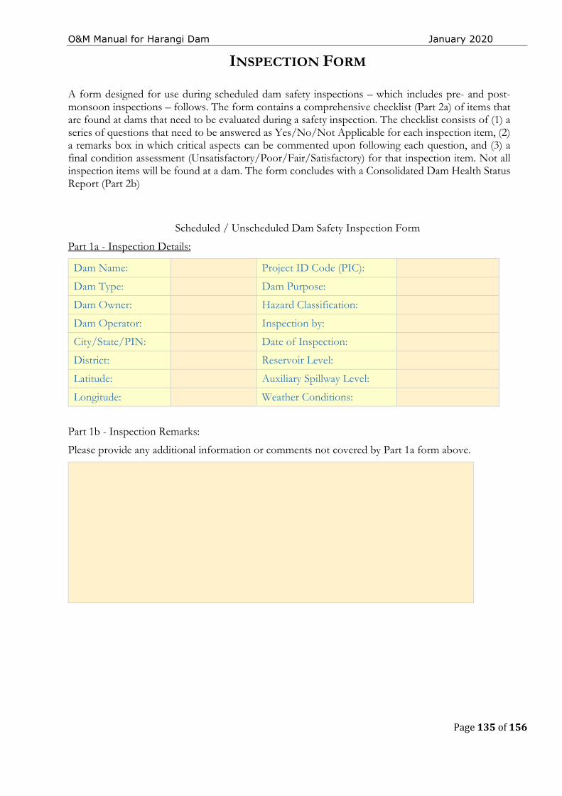
O&M Manual for Harangi Dam January 2020
Page 135 of 156
INSPECTION FORM
A form designed for use during scheduled dam safety inspections – which includes pre- and post-monsoon inspections – follows. The form contains a comprehensive checklist (Part 2a) of items that are found at dams that need to be evaluated during a safety inspection. The checklist consists of (1) a series of questions that need to be answered as Yes/No/Not Applicable for each inspection item, (2) a remarks box in which critical aspects can be commented upon following each question, and (3) a final condition assessment (Unsatisfactory/Poor/Fair/Satisfactory) for that inspection item. Not all inspection items will be found at a dam. The form concludes with a Consolidated Dam Health Status Report (Part 2b)
Scheduled / Unscheduled Dam Safety Inspection Form
Part 1a - Inspection Details:
Dam Name: Project ID Code (PIC):
Dam Type: Dam Purpose:
Dam Owner: Hazard Classification:
Dam Operator: Inspection by:
City/State/PIN: Date of Inspection:
District: Reservoir Level:
Latitude: Auxiliary Spillway Level:
Longitude: Weather Conditions:
Part 1b - Inspection Remarks:
Please provide any additional information or comments not covered by Part 1a form above.
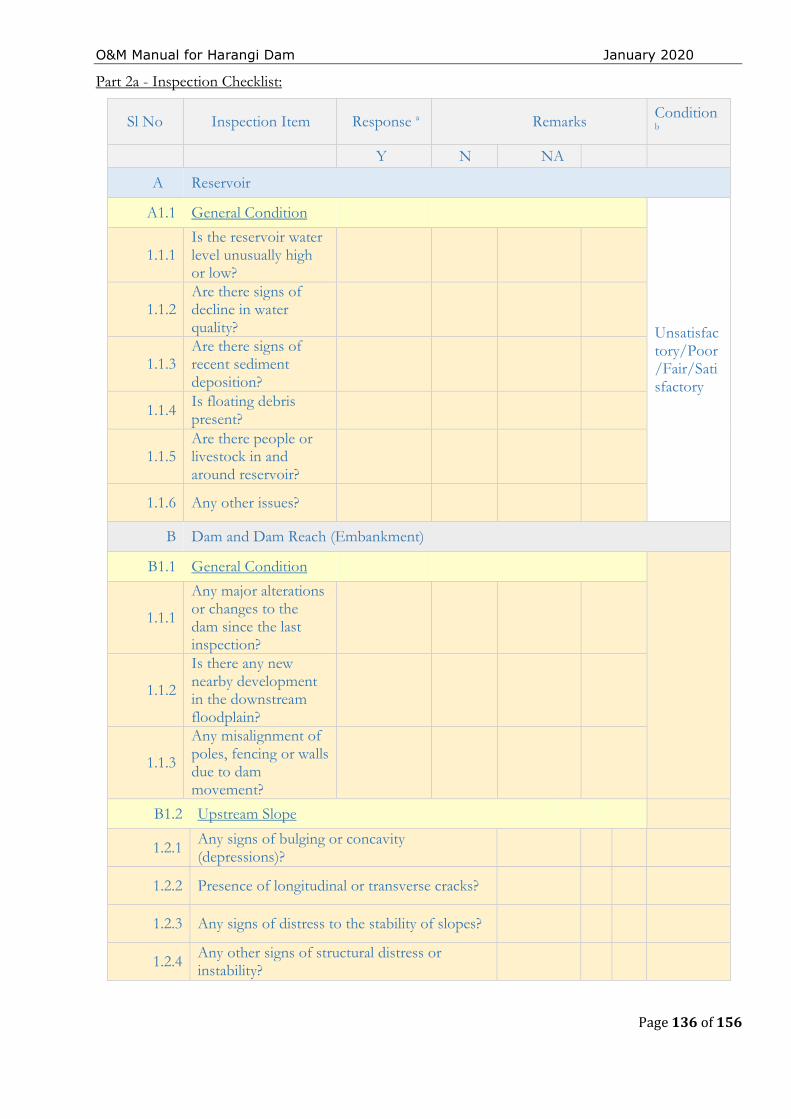
O&M Manual for Harangi Dam January 2020
Page 136 of 156
Part 2a - Inspection Checklist:
Sl No Inspection Item Response a Remarks Condition b
Y N NA
A Reservoir
A1.1 General Condition
Unsatisfactory/Poor/Fair/Satisfactory
1.1.1 Is the reservoir water level unusually high or low?
1.1.2 Are there signs of decline in water quality?
1.1.3 Are there signs of recent sediment deposition?
1.1.4 Is floating debris present?
1.1.5 Are there people or livestock in and around reservoir?
1.1.6 Any other issues?
B Dam and Dam Reach (Embankment)
B1.1 General Condition
1.1.1
Any major alterations or changes to the dam since the last inspection?
1.1.2
Is there any new nearby development in the downstream floodplain?
1.1.3
Any misalignment of poles, fencing or walls due to dam movement?
B1.2 Upstream Slope
1.2.1 Any signs of bulging or concavity (depressions)?
1.2.2 Presence of longitudinal or transverse cracks?
1.2.3 Any signs of distress to the stability of slopes?
1.2.4 Any other signs of structural distress or instability?
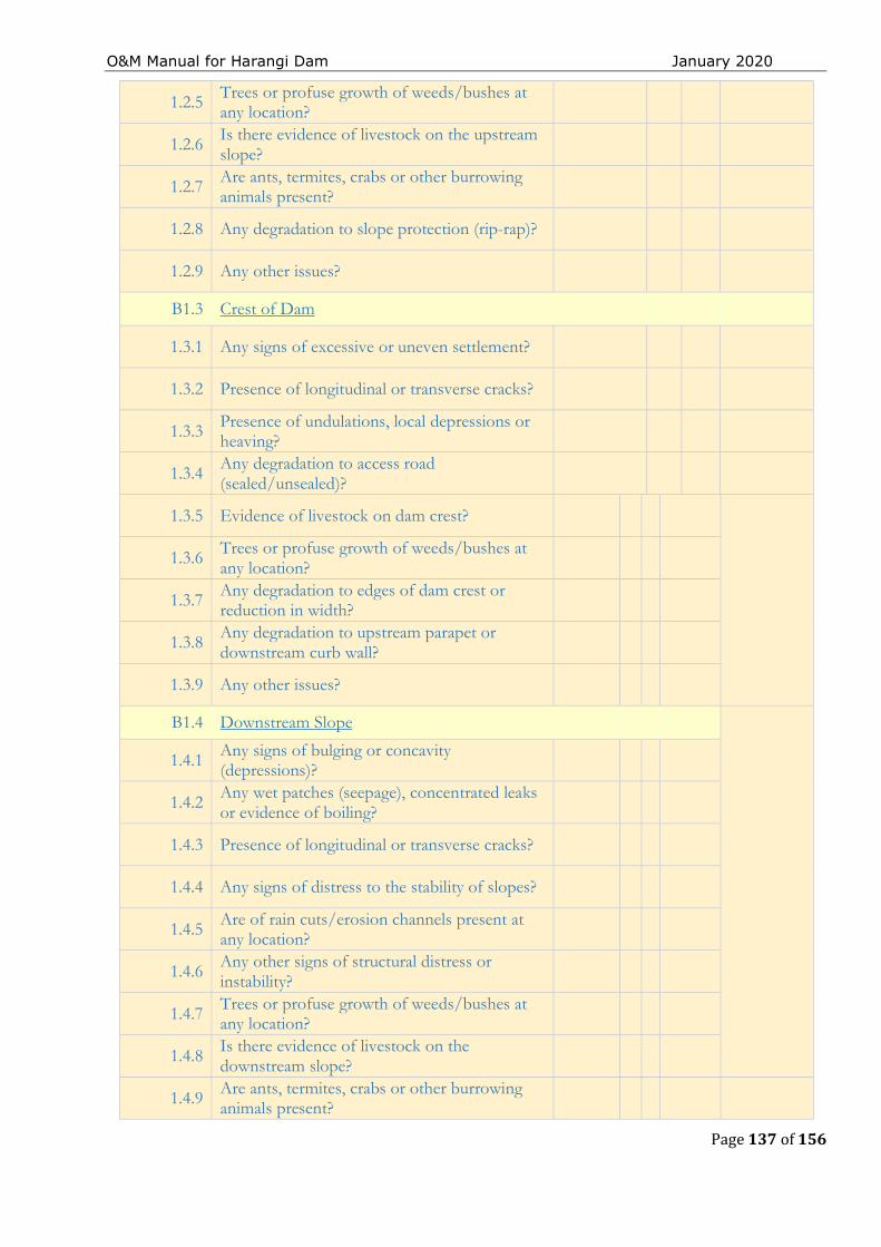
O&M Manual for Harangi Dam January 2020
Page 137 of 156
1.2.5 Trees or profuse growth of weeds/bushes at any location?
1.2.6 Is there evidence of livestock on the upstream slope?
1.2.7 Are ants, termites, crabs or other burrowing animals present?
1.2.8 Any degradation to slope protection (rip-rap)?
1.2.9 Any other issues?
B1.3 Crest of Dam
1.3.1 Any signs of excessive or uneven settlement?
1.3.2 Presence of longitudinal or transverse cracks?
1.3.3 Presence of undulations, local depressions or heaving?
1.3.4 Any degradation to access road (sealed/unsealed)?
1.3.5 Evidence of livestock on dam crest?
1.3.6 Trees or profuse growth of weeds/bushes at any location?
1.3.7 Any degradation to edges of dam crest or reduction in width?
1.3.8 Any degradation to upstream parapet or downstream curb wall?
1.3.9 Any other issues?
B1.4 Downstream Slope
1.4.1 Any signs of bulging or concavity (depressions)?
1.4.2 Any wet patches (seepage), concentrated leaks or evidence of boiling?
1.4.3 Presence of longitudinal or transverse cracks?
1.4.4 Any signs of distress to the stability of slopes?
1.4.5 Are of rain cuts/erosion channels present at any location?
1.4.6 Any other signs of structural distress or instability?
1.4.7 Trees or profuse growth of weeds/bushes at any location?
1.4.8 Is there evidence of livestock on the downstream slope?
1.4.9 Are ants, termites, crabs or other burrowing animals present?
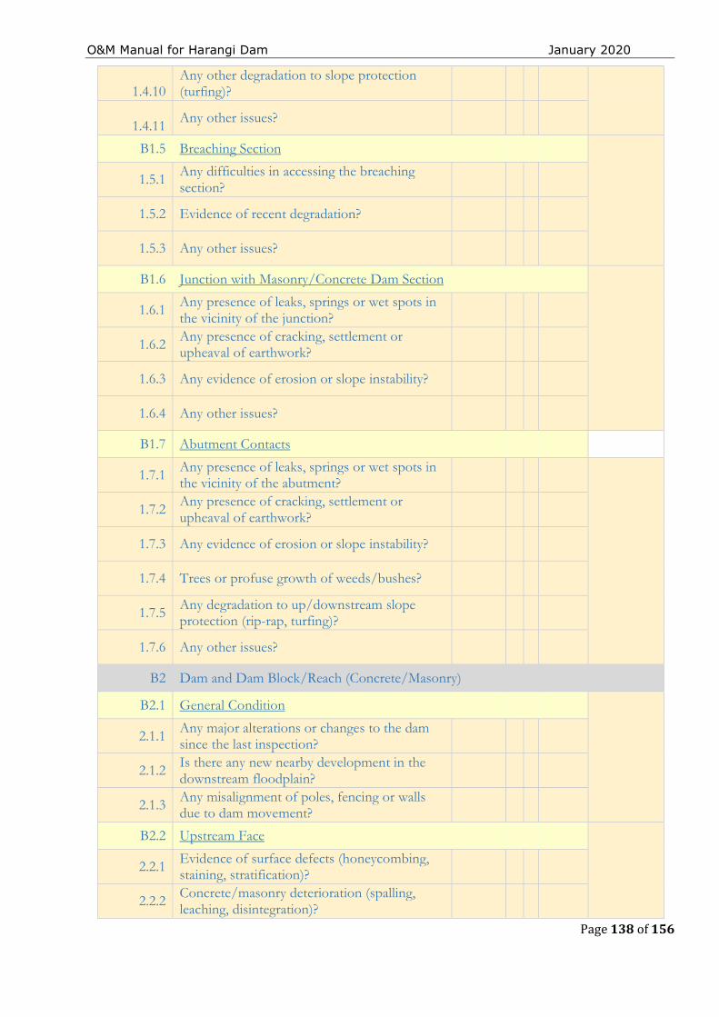
O&M Manual for Harangi Dam January 2020
Page 138 of 156
1.4.10
Any other degradation to slope protection (turfing)?
1.4.11
Any other issues?
B1.5 Breaching Section
1.5.1 Any difficulties in accessing the breaching section?
1.5.2 Evidence of recent degradation?
1.5.3 Any other issues?
B1.6 Junction with Masonry/Concrete Dam Section
1.6.1 Any presence of leaks, springs or wet spots in the vicinity of the junction?
1.6.2 Any presence of cracking, settlement or upheaval of earthwork?
1.6.3 Any evidence of erosion or slope instability?
1.6.4 Any other issues?
B1.7 Abutment Contacts
1.7.1 Any presence of leaks, springs or wet spots in the vicinity of the abutment?
1.7.2 Any presence of cracking, settlement or upheaval of earthwork?
1.7.3 Any evidence of erosion or slope instability?
1.7.4 Trees or profuse growth of weeds/bushes?
1.7.5 Any degradation to up/downstream slope protection (rip-rap, turfing)?
1.7.6 Any other issues?
B2 Dam and Dam Block/Reach (Concrete/Masonry)
B2.1 General Condition
2.1.1 Any major alterations or changes to the dam since the last inspection?
2.1.2 Is there any new nearby development in the downstream floodplain?
2.1.3 Any misalignment of poles, fencing or walls due to dam movement?
B2.2 Upstream Face
2.2.1 Evidence of surface defects (honeycombing, staining, stratification)?
2.2.2 Concrete/masonry deterioration (spalling, leaching, disintegration)?
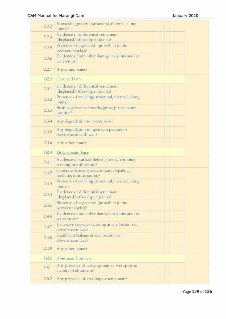
O&M Manual for Harangi Dam January 2020
Page 139 of 156
2.2.3 Is cracking present (structural, thermal, along joints)?
2.2.4 Evidence of differential settlement (displaced/offset/open joints)?
2.2.5 Presence of vegetation (growth in joints between blocks)?
2.2.6 Evidence of any other damage to joints and/or waterstops?
2.2.7 Any other issues?
B2.3 Crest of Dam
2.3.1 Evidence of differential settlement (displaced/offset/open joints)?
2.3.2 Presence of cracking (structural, thermal, along joints)?
2.3.3 Profuse growth of weeds/grass/plants at any location?
2.3.4 Any degradation to access road?
2.3.5 Any degradation to upstream parapet or downstream curb wall?
2.3.6 Any other issues?
B2.4 Downstream Face
2.4.1 Evidence of surface defects (honey-combing, staining, stratification)?
2.4.2 Concrete/masonry deterioration (spalling, leaching, disintegration)?
2.4.3 Presence of cracking (structural, thermal, along joints)?
2.4.4 Evidence of differential settlement (displaced/offset/open joints)?
2.4.5 Presence of vegetation (growth in joints between blocks)?
2.4.6 Evidence of any other damage to joints and/or water stops?
2.4.7 Excessive seepage/sweating at any location on downstream face?
2.4.8 Significant leakage at any location on downstream face?
2.4.9 Any other issues?
B2.5 Abutment Contacts
2.5.1 Any presence of leaks, springs or wet spots in vicinity of abutment?
2.5.2 Any presence of cracking or settlement?
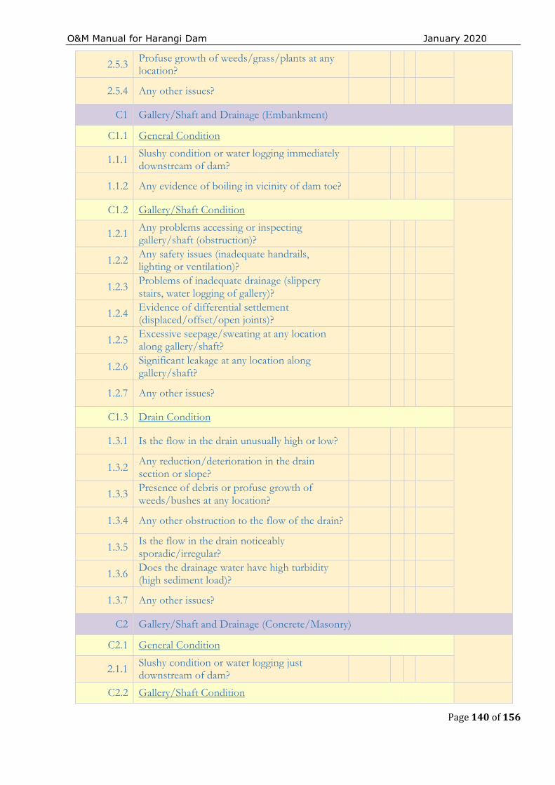
O&M Manual for Harangi Dam January 2020
Page 140 of 156
2.5.3 Profuse growth of weeds/grass/plants at any location?
2.5.4 Any other issues?
C1 Gallery/Shaft and Drainage (Embankment)
C1.1 General Condition
1.1.1 Slushy condition or water logging immediately downstream of dam?
1.1.2 Any evidence of boiling in vicinity of dam toe?
C1.2 Gallery/Shaft Condition
1.2.1 Any problems accessing or inspecting gallery/shaft (obstruction)?
1.2.2 Any safety issues (inadequate handrails, lighting or ventilation)?
1.2.3 Problems of inadequate drainage (slippery stairs, water logging of gallery)?
1.2.4 Evidence of differential settlement (displaced/offset/open joints)?
1.2.5 Excessive seepage/sweating at any location along gallery/shaft?
1.2.6 Significant leakage at any location along gallery/shaft?
1.2.7 Any other issues?
C1.3 Drain Condition
1.3.1 Is the flow in the drain unusually high or low?
1.3.2 Any reduction/deterioration in the drain section or slope?
1.3.3 Presence of debris or profuse growth of weeds/bushes at any location?
1.3.4 Any other obstruction to the flow of the drain?
1.3.5 Is the flow in the drain noticeably sporadic/irregular?
1.3.6 Does the drainage water have high turbidity (high sediment load)?
1.3.7 Any other issues?
C2 Gallery/Shaft and Drainage (Concrete/Masonry)
C2.1 General Condition
2.1.1 Slushy condition or water logging just downstream of dam?
C2.2 Gallery/Shaft Condition
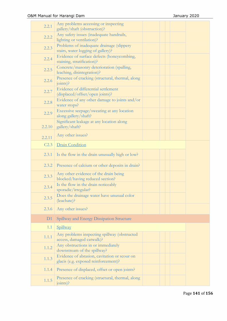
O&M Manual for Harangi Dam January 2020
Page 141 of 156
2.2.1 Any problems accessing or inspecting gallery/shaft (obstruction)?
2.2.2 Any safety issues (inadequate handrails, lighting or ventilation)?
2.2.3 Problems of inadequate drainage (slippery stairs, water logging of gallery)?
2.2.4 Evidence of surface defects (honeycombing, staining, stratification)?
2.2.5 Concrete/masonry deterioration (spalling, leaching, disintegration)?
2.2.6 Presence of cracking (structural, thermal, along joints)?
2.2.7 Evidence of differential settlement (displaced/offset/open joints)?
2.2.8 Evidence of any other damage to joints and/or water stops?
2.2.9 Excessive seepage/sweating at any location along gallery/shaft?
2.2.10
Significant leakage at any location along gallery/shaft?
2.2.11 Any other issues?
C2.3 Drain Condition
2.3.1 Is the flow in the drain unusually high or low?
2.3.2 Presence of calcium or other deposits in drain?
2.3.3 Any other evidence of the drain being blocked/having reduced section?
2.3.4 Is the flow in the drain noticeably sporadic/irregular?
2.3.5 Does the drainage water have unusual color (leachate)?
2.3.6 Any other issues?
D1 Spillway and Energy Dissipation Structure
1.1 Spillway
1.1.1 Any problems inspecting spillway (obstructed access, damaged catwalk)?
1.1.2 Any obstructions in or immediately downstream of the spillway?
1.1.3 Evidence of abrasion, cavitation or scour on glacis (e.g. exposed reinforcement)?
1.1.4 Presence of displaced, offset or open joints?
1.1.5 Presence of cracking (structural, thermal, along joints)?
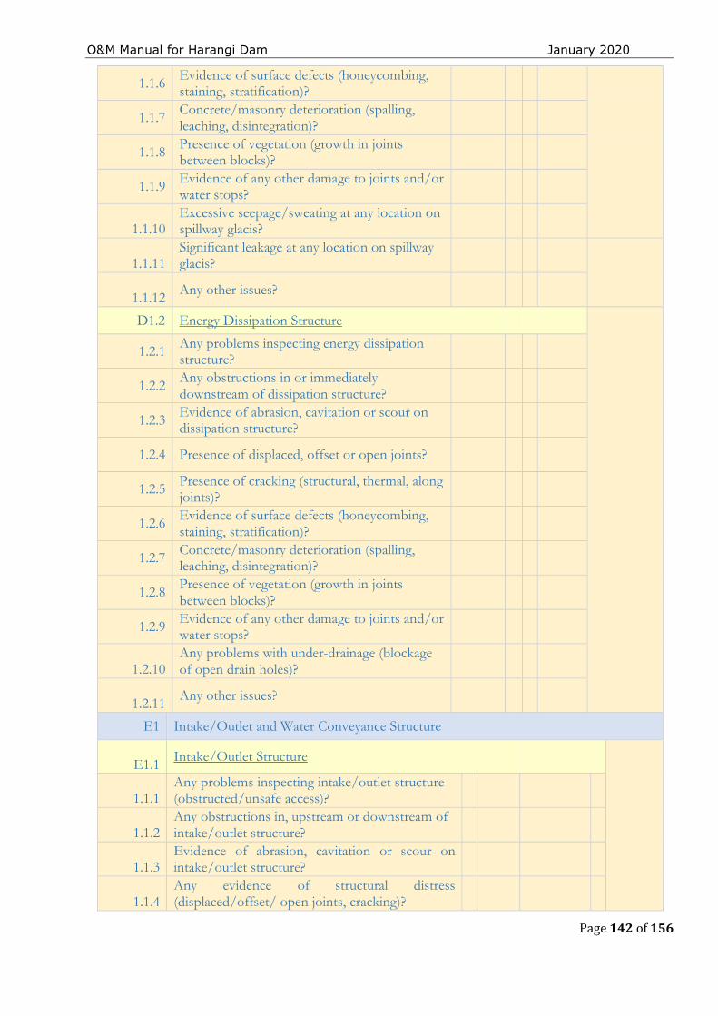
O&M Manual for Harangi Dam January 2020
Page 142 of 156
1.1.6 Evidence of surface defects (honeycombing, staining, stratification)?
1.1.7 Concrete/masonry deterioration (spalling, leaching, disintegration)?
1.1.8 Presence of vegetation (growth in joints between blocks)?
1.1.9 Evidence of any other damage to joints and/or water stops?
1.1.10
Excessive seepage/sweating at any location on spillway glacis?
1.1.11
Significant leakage at any location on spillway glacis?
1.1.12 Any other issues?
D1.2 Energy Dissipation Structure
1.2.1 Any problems inspecting energy dissipation structure?
1.2.2 Any obstructions in or immediately downstream of dissipation structure?
1.2.3 Evidence of abrasion, cavitation or scour on dissipation structure?
1.2.4 Presence of displaced, offset or open joints?
1.2.5 Presence of cracking (structural, thermal, along joints)?
1.2.6 Evidence of surface defects (honeycombing, staining, stratification)?
1.2.7 Concrete/masonry deterioration (spalling, leaching, disintegration)?
1.2.8 Presence of vegetation (growth in joints between blocks)?
1.2.9 Evidence of any other damage to joints and/or water stops?
1.2.10
Any problems with under-drainage (blockage of open drain holes)?
1.2.11 Any other issues?
E1 Intake/Outlet and Water Conveyance Structure
E1.1 Intake/Outlet Structure
1.1.1
Any problems inspecting intake/outlet structure (obstructed/unsafe access)?
1.1.2
Any obstructions in, upstream or downstream of intake/outlet structure?
1.1.3
Evidence of abrasion, cavitation or scour on intake/outlet structure?
1.1.4
Any evidence of structural distress (displaced/offset/ open joints, cracking)?
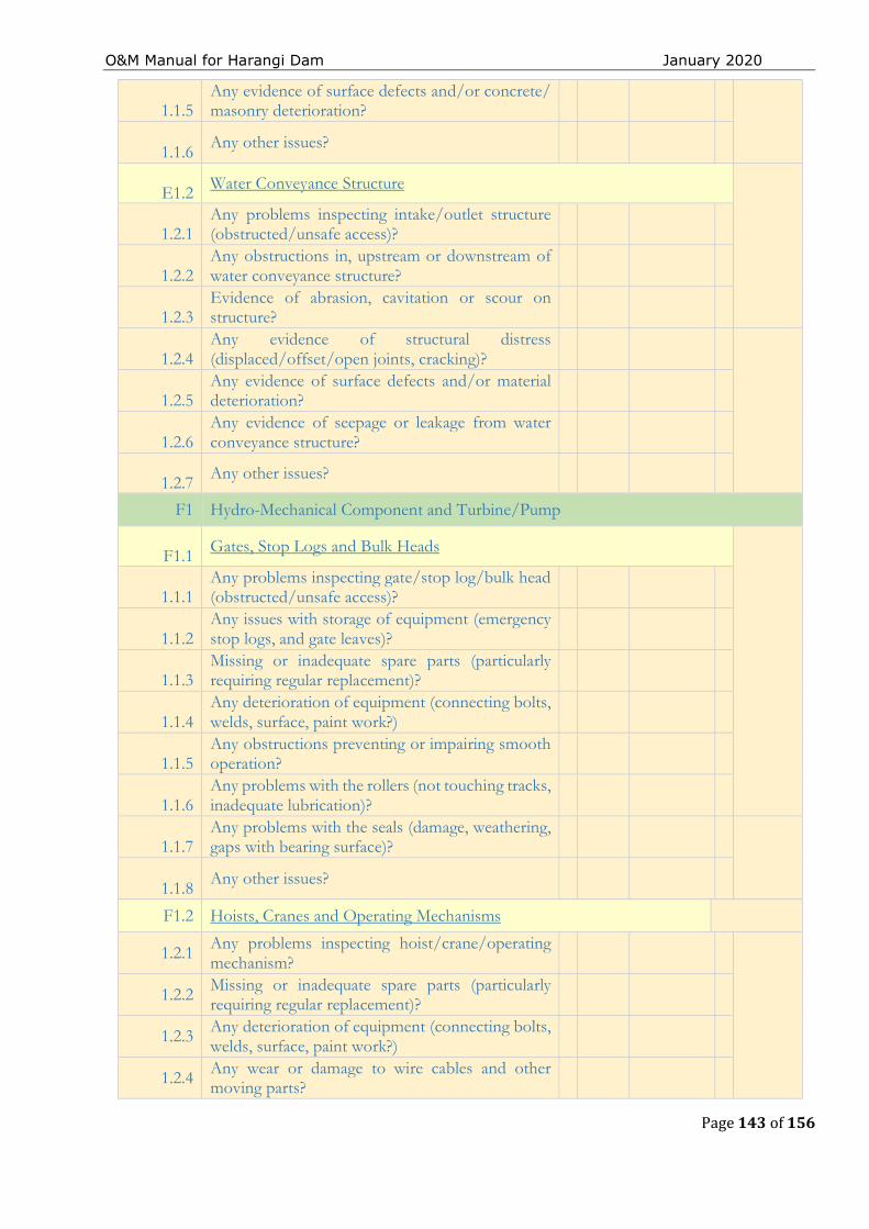
O&M Manual for Harangi Dam January 2020
Page 143 of 156
1.1.5
Any evidence of surface defects and/or concrete/ masonry deterioration?
1.1.6
Any other issues?
E1.2 Water Conveyance Structure
1.2.1
Any problems inspecting intake/outlet structure (obstructed/unsafe access)?
1.2.2
Any obstructions in, upstream or downstream of water conveyance structure?
1.2.3
Evidence of abrasion, cavitation or scour on structure?
1.2.4
Any evidence of structural distress (displaced/offset/open joints, cracking)?
1.2.5
Any evidence of surface defects and/or material deterioration?
1.2.6
Any evidence of seepage or leakage from water conveyance structure?
1.2.7 Any other issues?
F1 Hydro-Mechanical Component and Turbine/Pump
F1.1 Gates, Stop Logs and Bulk Heads
1.1.1
Any problems inspecting gate/stop log/bulk head (obstructed/unsafe access)?
1.1.2
Any issues with storage of equipment (emergency stop logs, and gate leaves)?
1.1.3
Missing or inadequate spare parts (particularly requiring regular replacement)?
1.1.4
Any deterioration of equipment (connecting bolts, welds, surface, paint work?)
1.1.5
Any obstructions preventing or impairing smooth operation?
1.1.6
Any problems with the rollers (not touching tracks, inadequate lubrication)?
1.1.7
Any problems with the seals (damage, weathering, gaps with bearing surface)?
1.1.8 Any other issues?
F1.2 Hoists, Cranes and Operating Mechanisms
1.2.1 Any problems inspecting hoist/crane/operating mechanism?
1.2.2 Missing or inadequate spare parts (particularly
requiring regular replacement)?
1.2.3 Any deterioration of equipment (connecting bolts, welds, surface, paint work?)
1.2.4 Any wear or damage to wire cables and other moving parts?
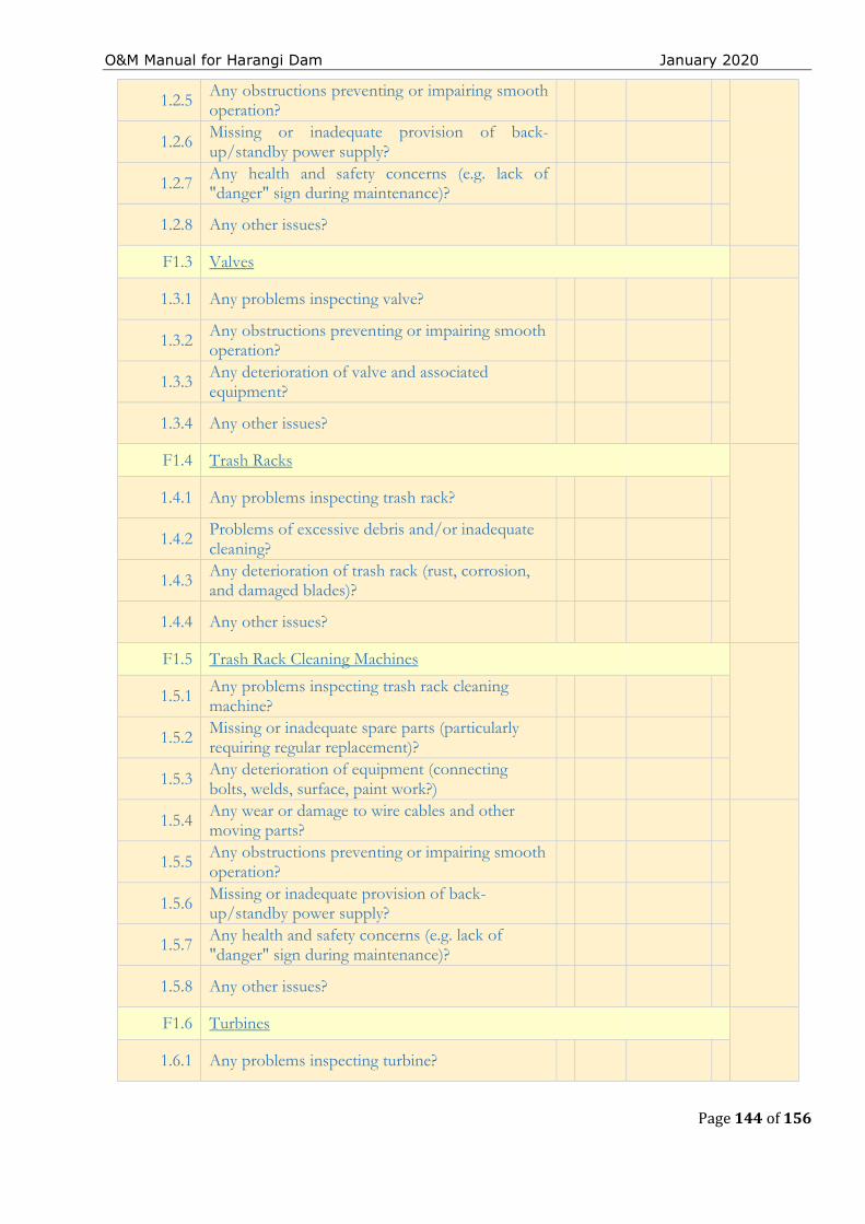
O&M Manual for Harangi Dam January 2020
Page 144 of 156
1.2.5 Any obstructions preventing or impairing smooth operation?
1.2.6 Missing or inadequate provision of back-up/standby power supply?
1.2.7 Any health and safety concerns (e.g. lack of "danger" sign during maintenance)?
1.2.8 Any other issues?
F1.3 Valves
1.3.1 Any problems inspecting valve?
1.3.2 Any obstructions preventing or impairing smooth
operation?
1.3.3 Any deterioration of valve and associated equipment?
1.3.4 Any other issues?
F1.4 Trash Racks
1.4.1 Any problems inspecting trash rack?
1.4.2 Problems of excessive debris and/or inadequate cleaning?
1.4.3 Any deterioration of trash rack (rust, corrosion, and damaged blades)?
1.4.4 Any other issues?
F1.5 Trash Rack Cleaning Machines
1.5.1 Any problems inspecting trash rack cleaning machine?
1.5.2 Missing or inadequate spare parts (particularly requiring regular replacement)?
1.5.3 Any deterioration of equipment (connecting bolts, welds, surface, paint work?)
1.5.4 Any wear or damage to wire cables and other moving parts?
1.5.5 Any obstructions preventing or impairing smooth operation?
1.5.6 Missing or inadequate provision of back-up/standby power supply?
1.5.7 Any health and safety concerns (e.g. lack of "danger" sign during maintenance)?
1.5.8 Any other issues?
F1.6 Turbines
1.6.1 Any problems inspecting turbine?
O&M Manual for Harangi Dam January 2020
Page 145 of 156
1.6.2 Any obstructions preventing or impairing smooth operation?
1.6.3 Any deterioration of turbine, blades and associated equipment?
1.6.4 Any other issues?
F1.7 Pumps
1.7.1 Any problems inspecting pump?
1.7.2 Any obstructions preventing or impairing smooth operation?
1.7.3 Any deterioration of pump and associated equipment?
1.7.4 Any other issues?
G1 Access Road
G1.1 General Condition
1.1.1 Any problems ensuring security of dam site (including gates and fencing)?
1.1.2 Any obstructions along or at entrance to access road (temporary or long-term)?
1.1.3 Any slope stability issues (road embankment or adjacent slopes)?
1.1.4 Profuse growth of weeds/grass on or in vicinity of access road?
1.1.5 Any drainage problems (standing water on or adjacent to road)?
1.1.6 Any other degradation to road surface (ruts, potholes, cavities, cracking)?
1.1.7 Any other issues?
H1 Instrumentation
H1.1 General Condition
1.1.1 Any problems inspecting instrument (obstructed/unsafe access)?
1.1.2 Is the instrument vulnerable to damage or theft (inadequate protection)?
1.1.3 Any problems ensuring correct functioning of instrument (lighting, ventilation)?
1.1.4 Any evidence of degradation to condition of instrument (rusting, vandalism)?
1.1.5 Any evidence of instrument not working (decommissioned, broken)?
1.1.6 Any other issues?
I1 Other Appurtenant Structures (Flexi-Component)
I1. Bridges and Catwalks
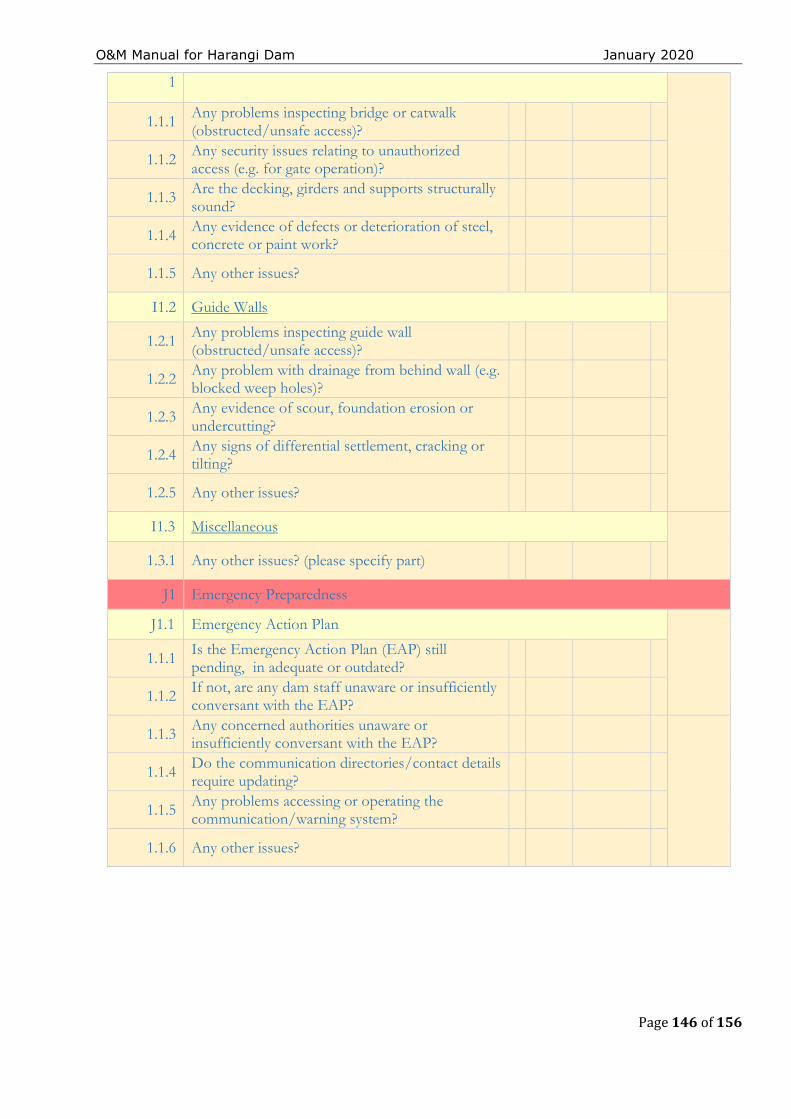
O&M Manual for Harangi Dam January 2020
Page 146 of 156
1
1.1.1 Any problems inspecting bridge or catwalk (obstructed/unsafe access)?
1.1.2 Any security issues relating to unauthorized access (e.g. for gate operation)?
1.1.3 Are the decking, girders and supports structurally sound?
1.1.4 Any evidence of defects or deterioration of steel, concrete or paint work?
1.1.5 Any other issues?
I1.2 Guide Walls
1.2.1 Any problems inspecting guide wall (obstructed/unsafe access)?
1.2.2 Any problem with drainage from behind wall (e.g. blocked weep holes)?
1.2.3 Any evidence of scour, foundation erosion or undercutting?
1.2.4 Any signs of differential settlement, cracking or tilting?
1.2.5 Any other issues?
I1.3 Miscellaneous
1.3.1 Any other issues? (please specify part)
J1 Emergency Preparedness
J1.1 Emergency Action Plan
1.1.1 Is the Emergency Action Plan (EAP) still pending, in adequate or outdated?
1.1.2 If not, are any dam staff unaware or insufficiently conversant with the EAP?
1.1.3 Any concerned authorities unaware or insufficiently conversant with the EAP?
1.1.4 Do the communication directories/contact details
require updating?
1.1.5 Any problems accessing or operating the communication/warning system?
1.1.6 Any other issues?
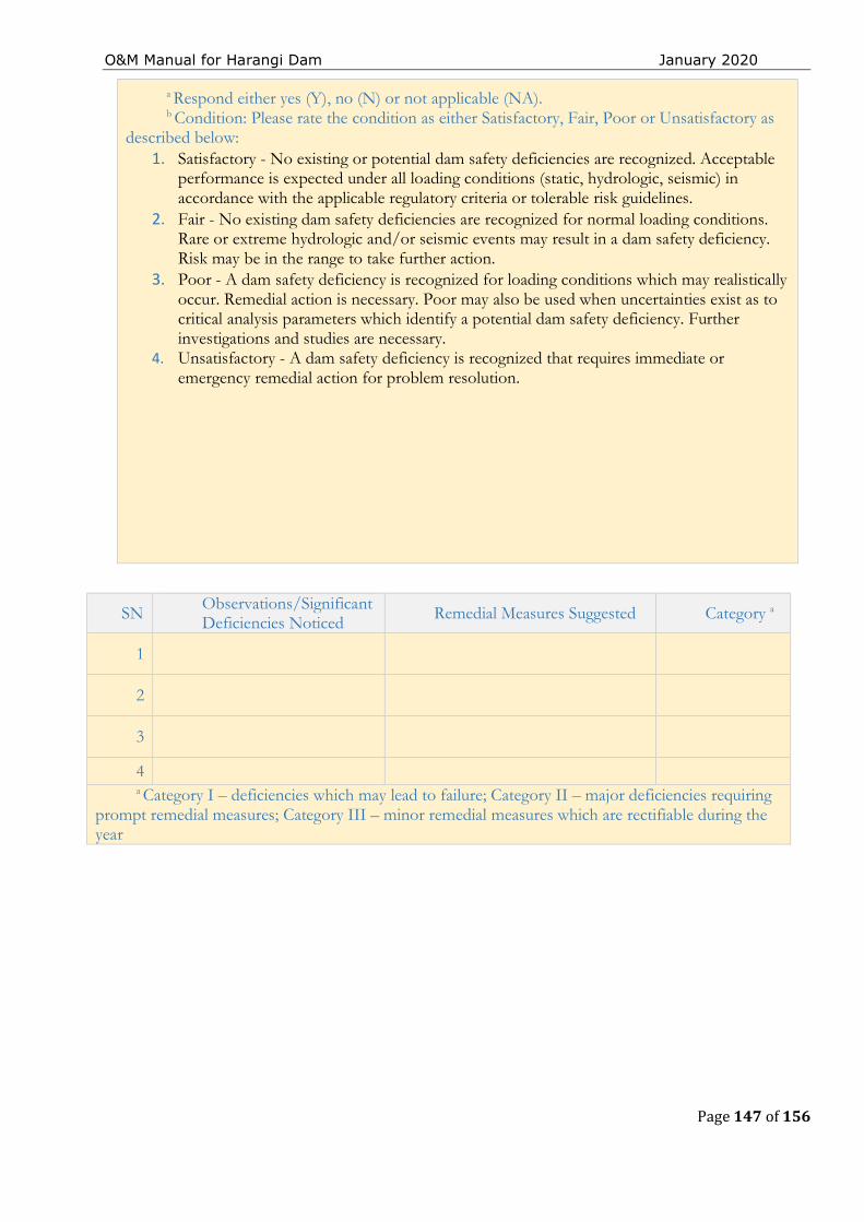
O&M Manual for Harangi Dam January 2020
Page 147 of 156
a Respond either yes (Y), no (N) or not applicable (NA). b Condition: Please rate the condition as either Satisfactory, Fair, Poor or Unsatisfactory as
described below: 1. Satisfactory - No existing or potential dam safety deficiencies are recognized. Acceptable
performance is expected under all loading conditions (static, hydrologic, seismic) in accordance with the applicable regulatory criteria or tolerable risk guidelines.
2. Fair - No existing dam safety deficiencies are recognized for normal loading conditions. Rare or extreme hydrologic and/or seismic events may result in a dam safety deficiency. Risk may be in the range to take further action.
3. Poor - A dam safety deficiency is recognized for loading conditions which may realistically occur. Remedial action is necessary. Poor may also be used when uncertainties exist as to critical analysis parameters which identify a potential dam safety deficiency. Further investigations and studies are necessary.
4. Unsatisfactory - A dam safety deficiency is recognized that requires immediate or emergency remedial action for problem resolution.
SN Observations/Significant Deficiencies Noticed Remedial Measures Suggested Category a
1
2
3
4 a Category I – deficiencies which may lead to failure; Category II – major deficiencies requiring
prompt remedial measures; Category III – minor remedial measures which are rectifiable during the year
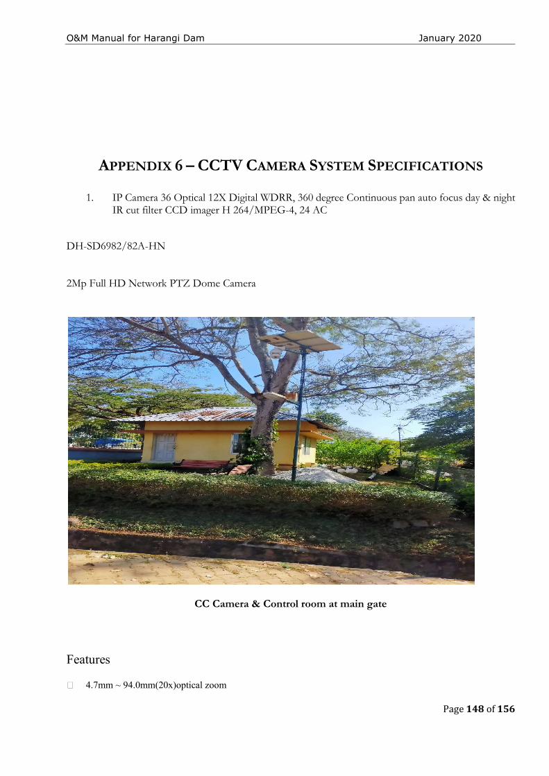
O&M Manual for Harangi Dam January 2020
Page 148 of 156
APPENDIX 6 – CCTV CAMERA SYSTEM SPECIFICATIONS
1. IP Camera 36 Optical 12X Digital WDRR, 360 degree Continuous pan auto focus day & night IR cut filter CCD imager H 264/MPEG-4, 24 AC
DH-SD6982/82A-HN
2Mp Full HD Network PTZ Dome Camera
CC Camera & Control room at main gate
Features 4.7mm ~ 94.0mm(20x)optical zoom

O&M Manual for Harangi Dam January 2020
Page 149 of 156
H.264&MJPEGdual-stream encoding and JPEG image capture Max 25/30fps@1080p resolution WDR(DWDR), Day/Night(ICR), DNR (2D&3D),Auto iris, Auto focus, AWB, AGC,BLC Multiple network monitoring: Web viewer, CMS(DSS/PSS) &DMSS Max 240°/s pan speed, 360° endless pan rotation Up to 255 presets, 5 auto scan, 8 tour, 5 pattern Built-in 7/2 alarm in/out Support intelligent 3D positioning with DH-SD protocol Micro SD memory, IP66 IR LEDs up to 100m
O&M Manual for Harangi Dam January 2020
Page 150 of 156
APPENDIX 7 - GLOSSARY
Dam – any artificial barrier including appurtenant works constructed across rivers or tributaries thereof with a view to impound or divert water; includes barrage, weir and similar water impounding structures but does not include water conveyance structures such as canal, aqueduct and navigation channel and flow regulation structures such as flood embankments, dikes, and guide bunds.
Dam failure – failures in the structures or operation of a dam which may lead to the uncontrolled release of impounded water resulting in downstream flooding affecting the life and property of the people.
Dam incident – all problems occurring to a dam that has not degraded into ‘dam failure’ and including the following:
a) Structural damage to the dam and appurtenant works;
b) Unusual readings of instruments in the dam; c) Unusual seepage or leakage through the
dam body; d) Change in the seepage or leakage regime; e) Boiling or artesian conditions noticed below
an earth dam; f) Stoppage or reduction in seepage or leakage
from the foundation or body of the dam into any of the galleries, for dams with such galleries;
g) Malfunctioning or inappropriate operation of gates;
h) Occurrence of any flood, the peak of which exceeds the available flood discharge capacity or 70% of the approved design flood;
i) Occurrence of a flood, which resulted in encroachment on the available freeboard, or the adopted design freeboard;
j) Erosion in the near vicinity, up to five hundred meters, downstream of the spillway, waste weir, etc.; and
k) Any other event that prudence suggests would have a significant unfavorable impact on dam safety.
Dam inspection – on-site visual examination of all components of dam and its appurtenances by one or more persons trained in this respect and includes investigation of the non-overflow portion, spillways, abutments, stilling basin, piers, bridge, downstream toe, drainage galleries, operation of mechanical systems (including gates and its components, drive units, cranes), interior of outlet conduits, instrumentation records, and record-keeping arrangements.
Dam owner – the Central Government or a State Government or public sector undertaking or local authority or company and any or all of such persons or organizations, who own, control, operate or maintain a specified dam.
Dam safety – the practice of ensuring the integrity and viability of dams such that they do not present unacceptable risks to the public, property, and the environment. It requires the collective application of engineering principles and experience, and a philosophy of risk management that recognizes that a dam is a structure whose safe function is not explicitly determined by its original design and construction. It also includes all actions taken to identify or predict deficiencies and consequences related to failure, and to document, publicize, and reduce, eliminate, or remediate to the extent reasonably possible, any unacceptable risks.
Decommission― Taking a dam out of service in an environmentally sound and safe manner or converting it to another purpose.
Design life― the intended period that the dam will function successfully with only routine maintenance; determined during design phase.
Distress condition – the occurrence or potential development of such conditions in the dam or appurtenance or its reservoir or reservoir rim, which if left unattended to, may impede the safe operation of dam for its intended benefits or may pose unacceptable risks to the life and property of people downstream.
O&M Manual for Harangi Dam January 2020
Page 151 of 156
Documentation – all permanent records concerning investigation, design, construction, operation, performance, maintenance and safety of dams and includes design memorandum, construction drawings, geological reports, reports of specialized studies simulating structural and hydraulic response of the dam, changes made in design and drawings, quality control records, emergency action plan, operation and maintenance manual, instrumentation readings, inspection and testing reports, operational reports, and dam safety review reports;
Emergency Action Plan (EAP)― a plan of action to be taken to reduce the potential for damage to property and loss of life in the area affected by failure of a dam or other potentially hazardous practice.
Hazard Classification― a system that categorizes dams according to the degree of adverse incremental consequences of a failure or improper operation of the dam. CWC classifies dam hazards as “low”, “significant”, or “high”.
Maintenance―the recurring activities necessary to retain or restore a dam in a safe and functioning condition, including the management of vegetation, the repair or replacement of failed components, the prevention or treatment of deterioration, and the repair of damages caused by flooding or vandalism.
Operation― the administration, management, and performance of maintenance activities necessary to keep a dam safe and functioning as planned.
Program ― any authorized activity used to implement and carry out goals, actions, and objectives contained within the authorizing legislation.
Program Life― the period in a contract, conservation plan, or plan during which the conservation practice or conservation system shall be maintained and used for the intended purpose; determined by program requirements.
Rehabilitation― the completion of all work necessary to extend the service life of the practice or component and meet applicable safety and performance standards.
Repair― actions to restore deteriorated, damaged, or failed dam or its component to an acceptable by meeting functional condition.
Replacement― the removal of a structure or component and installation of a similar, functional structure or component.
Service Life― the actual period after construction of a dam, during which the practice functions adequately and safely with only routine maintenance; determined by on-site review.
Abutment―that part of a valley side against which a dam is constructed. Right and left abutments are those on respective sides of the of an observer looking downstream.
Air-Vent Pipe―a pipe designed to provide air to the outlet conduit to reduce turbulence during release of water and safeguard against damages due to cavitation.
Appurtenant Structures―ancillary features of a dam, such as the outlet, spillway, energy dissipation arrangement powerhouse, tunnels, etc.
Arch Dam―a concrete or masonry dam that is curved to transmit the major part of the water pressure to the abutments.
Backwater Curve―the longitudinal profile of the water surface in an open channel where the depth of flow has been increased by an obstruction, an increase in channel roughness, a decrease in channel width, or a flattening of the bed slope.
Base Width (Base Thickness) ―the maximum width or thickness of a dam measured horizontally between upstream and downstream faces and normal (perpendicular) to the axis of the dam but excluding projections for outlets, etc.
Berm―a horizontal step or bench in the sloping profile of an embankment dam.
Upstream Blanket―an impervious layer placed on the reservoir floor upstream of a dam. In case of an embankment dam, the blanket may be connected to the impermeable element in a dam.
Buttress dam―a dam consisting of a watertight upstream face supported at intervals on the downstream side by a series of buttresses.
O&M Manual for Harangi Dam January 2020
Page 152 of 156
Cofferdam―a temporary structure enclosing all or part of a construction area so that construction can proceed in a dry area.
Concrete Lift―in concrete works the vertical distance between successive horizontal construction joints.
Conduit Outlet Works―a closed conduit for conveying discharge through or under a dam for different project purposes.
Consolidation Grouting (Blanket Grouting) ― the injection of grout to consolidate a layer of the foundation, resulting in greater impermeability, strength, or both.
Construction Joint―the interface between two successive placings or pours of concrete where a bond, not permanent separation, is intended.
Core Wall―a wall built of impervious material, usually concrete or asphaltic concrete, in the body of an embankment dam to prevent leakage.
Crest Length―the length of the dam at its crest (dam top) top of a dam, including the length of the spillway, powerhouse, navigation lock, fish pass, etc., where these structures form part of the length of a dam. If detached from a dam, these structures should not be included.
Crest of dam―Used to indicate the “top of dam”. To avoid confusion to indicate the crest of spillway and top of dam may be used.
Culvert―a drain or waterway built under a road, railway, or embankment, usually consisting of a pipe or covered conduits
Cutoff―an impervious construction or material which reduces seepage through the foundation material.
Cutoff trench―an excavation later to be filled with impervious material to form a cutoff.
Cutoff wall―a wall of impervious material (e.g., concrete, asphaltic concrete, steel-sheet piling) built into the foundation to reduce seepage under the dam.
Dead storage―the storage that lies below the invert of the lowest outlet and that, therefore, cannot be withdrawn from the reservoir.
Design flood―see spillway design flood.
Diaphragm―see membrane.
Dike (Levee)―a long low embankment whose height is usually less than 5 m and whose length is more than 10 times the maximum height. Usually applied to embankments or structures built to protect land from flooding. If built of concrete or masonry, the structure is usually referred to as a flood wall. Also, used to describe embankments that block areas on a reservoir rim that are lower than the top of the main dam and that are quite long. In the Mississippi River basin, where the old French word levee has survived, the term now applies to flood-protecting embankments whose height can average up to 15 m.
Diversion channel, canal, or tunnel―a waterway used to divert water from its natural course. These terms are generally applied to temporary structures such as those designed to bypass water around a dam site during construction. “Channel’ is normally used instead of “canal” when the waterway is short. Occasionally these terms are applied to permanent structures.
Drainage area―an area that drains naturally to a point on a river.
Drainage layer or blanket―a layer of permeable material in a dam to relieve pore pressure or to facilitate drainage of fill.
Relief well―vertical wells or boreholes, constructed downstream of an embankment dam to relieve the pressure from confined pervious layers in foundation overlaid by an impervious layer to arrest boiling.
Drawdown―the lowering of water surface level due to release of water from a reservoir.
Earthen dam or earth filled dam―see embankment dam.
Embankment dam (Fill dam) ― any dam constructed of excavated natural materials.
Earth dam (Earth fill dam) ―An embankment dam in which more than 50 percent of the total volume is formed of compacted fine-grained material obtained from a borrow area.
Homogeneous earth fill dam― an embankment dam constructed of similar earth material throughout, except internal drains or drainage blankets; distinguished from a zoned earth fill dam.
O&M Manual for Harangi Dam January 2020
Page 153 of 156
Hydraulic fill dam―an embankment dam constructed of materials, often dredged, that are conveyed and placed by suspension in flowing water.
Rock fill dam―an embankment dam in which more than 50 percent of the total volume comprises compacted or dumped pervious natural or crushed rock.
Rolled fill dam―an embankment dam of earth or rock in which the material is placed in layers and compacted using rollers or rolling equipment.
Zoned embankment dam―an embankment dam composed of zones of materials selected for different degrees of porosity, permeability and density.
Emergency spillway―see spillway.
Face―the external surface of a structure, e.g., the surface of a wall of a dam.
Failure―the uncontrolled release of water from a dam.
Filter (filter zone) ―A band or zone of granular material that is incorporated into a dam and is graded (either naturally or by selection) to allow seepage to flow across or down the filter without causing the migration of material from zones adjacent to it.
Flashboards―a length of timber, concrete, or steel placed on the crest of a spillway to raise the retention water level but that may be quickly removed in the event of a flood, either by a tripping device or by deliberately designed failure of the flashboard or its supports.
Floodplain―an area adjoining a body of water or natural stream that has been, or may be, covered by flood water.
Floodplain management―a management program to reduce the consequences of flooding, either by natural runoff or by dam failure, to existing and future properties in a floodplain.
Flood routing―the determination of the attenuating effect of storage on a flood passing through a valley, channel, or reservoir.
Flood surcharge―the volume or space in a reservoir between the controlled retention water level (Full Reservoir Level) and the maximum water level. Flood surcharge cannot be retained in the reservoir but will flow over the spillway
until the controlled retention water level is reached.
Flood wall―a concrete wall constructed adjacent to a stream to prevent flooding of property on the landward side of the wall, normally constructed in lieu of or to supplement a levee where the land required for levee construction is expensive or not available.
Foundation of dam―the natural material on which the dam structure is placed.
Freeboard―the vertical distance between a stated reservoir level and the top of a dam. Normal freeboard is the vertical distance between Full Reservoir Level (FRL) and the top of the dam. Minimum freeboard is the vertical distance between the Maximum Water Level (MWL) and the top of the dam.
Gallery―(a) a passageway within the body of a dam or abutment, hence the terms grouting gallery, inspection gallery and drainage gallery (b) a long and rather narrow hall, hence the following terms for a power plant viz. valve gallery, transformer gallery and bus bar gallery.
Gate―a device in which a leaf or member is moved across the waterway from an external position to control or stop the flow.
Bulkhead gate―a gate used either for temporary closure of a channel or conduit to empty it for inspection or maintenance or for closure against flowing water when the head difference is small, e.g., for diversion tunnel closure. Although a bulkhead gate is usually opened and closed under nearly balanced pressures, it nevertheless may be capable of withstanding a high-pressure differential when in the closed position.
Crest gate (spillway gate) ―a gate on the crest of a spillway to control overflow or reservoir water level.
Emergency gate―a standby or reserve gate which is lowers only for repairing / servicing of the service gate.
Fixed wheel gate (fixed-roller gate, fixed-axle gate) ―a gate having wheels or rollers mounted on the end posts of the gate. The wheels move against rails fixed in side grooves or gate guides.
Flap gate―a gate hinged along one edge, usually either the top or bottom edge. Examples of
O&M Manual for Harangi Dam January 2020
Page 154 of 156
bottom-hinged flap gates are tilting gates and belly gates, so called due to their shape in cross-section.
Flood gate―a gate to control flood release from a reservoir.
Guard gate (guard valve) ―a gate or valve that operates fully open or closed. It may function as a secondary device for shutting off the flow of water in case the primary closure device becomes inoperable but is usually operated under conditions of balanced pressure and no flow.
Outlet gate―a gate controlling the outflow of water from a reservoir.
Radial gate (Taintergate) ―a gate with a curved upstream plate and radial arms hinged to piers or other supporting structures.
Service/Regulating gate (regulating valve) ―a gate or valve that operates under full pressure and flow to throttle and vary the rate of discharge.
Slide gate (sluice gate) ―a gate that can be opened or closed by sliding it in supporting guides.
Gravity dam―a dam constructed of concrete, masonry, or both that relies on its weight for stability.
Grout cap―a pad or wall constructed to facilitate pressure grouting of the grout curtain beneath it.
Grout curtain (grout cutoff) ―a barrier produced by injecting grout into a vertical zone, usually narrow horizontally, in the foundation to reduce seepage under a dam.
Height above lowest foundation―the maximum height from the lowest point of the general foundation to the top of the dam.
Hydraulic height―the height to which water rises behind a dam and the difference between the lowest point in the original streambed at the axis of the dam and the maximum controllable water surface.
Hydrograph―a graphic representation of discharge, stage, or other hydraulic property with respect to time for a point on a stream. (At times the term is applied to the phenomenon the graphic representation describes; hence a flood hydrograph is the passage of a flood discharge past the observation point.)
Inclinometer―an instrument, usually consisting of a metal or plastic tube inserted in a drill hole and a sensitized monitor either lowered into the tube or fixed within it. The monitor measures at different points the tube’s inclination to the vertical. By integration, the lateral position at various levels of the tube may be found relative to a point, usually the top or bottom of the tube, assumed to be fixed. The system may be used to measure settlement.
Intake―any structure in a reservoir, dam, or river through which water can be drawn into an aqueduct.
Internal Erosion―see piping.
Inundation map―a map delineating the area that would be inundated in case of a failure.
Leakage―Uncontrolled loss of water by flow through a hole or crack.
Lining― a coating of asphaltic concrete, reinforced or unreinforced concrete, shotcrete, rubber or plastic on a canal, tunnel etc. to provide water tightness, prevent erosion, reduce friction, or support the periphery of structure. May also refer to lining, such as steel or concrete, of outlet pipe or conduit.
Low-level outlet (bottom outlet) ―an opening at a low level from a reservoir generally used for emptying or for scouring sediment and sometimes for irrigation releases.
Masonry dam―a dam constructed mainly of stone, brick, or concrete blocks that may or may not be joined with mortar. A dam having only a masonry facing should not be referred to as a masonry dam.
Maximum cross-section of dam―a cross-section of a dam at the point of its maximum height.
Maximum water level―the maximum water level, including flood surcharge, the dam is designed to withstand.
Membrane (Diaphragm)―a sheet or thin zone or facing made of a flexible material, sometimes referred to as a diaphragm wall or diaphragm.
Minimum operating level―the lowest level to which the reservoir is drawn down under normal operating conditions.
Morning glory spillway―see spillway.
O&M Manual for Harangi Dam January 2020
Page 155 of 156
Full Reservoir Level (FRL)/Normal water level―for a reservoir with un-gated spillway it is the spillway crest level. For a reservoir, whose outflow is controlled wholly or partly by movable gates, siphons or other means, it is the maximum level to which water can be stored under normal operating conditions, exclusive of any provision for flood surcharge.
One-Hundred Year (100-Year) Exceedance Interval― the flood magnitude expected to be equaled or exceeded on the average of once in 100 years. It may also be expressed as an exceedance frequency, i.e. a percent chance of being exceeded in any given year.
Outlet―an opening through which water can be freely discharged from a reservoir.
Overflow dam―a dam designed to be overtopped.
Parapet Wall―a solid wall built along the top of a dam for ornament, for the safety of vehicles and pedestrians, or to prevent overtopping.
Peak Flow―the maximum instantaneous discharge that occurs during a flood. It coincides with the peak of a flood hydrograph.
Pervious Zone―a part of the cross-section of an embankment dam comprising material of high permeability.
Phreatic Surface―the top most flow line in an embankment dam.
Piezometer―an instrument for measuring pore water pressure within soil, rock, or concrete.
Piping―the progressive development of internal erosion by seepage, appearing downstream as a hole or seam discharging water that contains soil particles.
Pore Pressure―the interstitial pressure of water within a mass of soil, rock, or concrete.
Pressure Cell―an instrument for measuring pressure within a mass of soil, rock, or concrete or at an interface between one and the other.
Pressure Relief Pipes―Pipes used to relieve uplift or pore water pressure in a dam’s foundation or structure.
Probable Maximum Flood (PMF)―a flood that would result from the most severe combination
of critical meteorologic and hydrologic conditions possible in the region.
Probable Maximum Precipitation (PMP)―the maximum amount and duration of precipitation that can be expected to occur on a drainage basin.
Pumped storage reservoir―a reservoir filled entirely or mainly with water pumped from outside its natural drainage area.
Regulating dam―a dam impounding a reservoir from which water is released to regulate
Reservoir area―the surface area of a reservoir when filled to controlled retention level.
Reservoir routing―the computation by which the interrelated effects of the inflow hydrograph, reservoir storage, and discharge from the reservoir are evaluated.
Reservoir surface―the surface of a reservoir at any level.
Riprap―a layer of large stones, broken rock, or precast blocks placed randomly on the upstream slope of an embankment dam, on a reservoir shore, or on the sides of a channel as a protection against wave action. Large riprap is sometimes referred to as armoring.
Risk assessment―as applied to dam safety, the process of identifying the likelihood and consequences of dam failure to provide the basis for informed decisions on a course of action.
Rock fill Dam―see embankment dam.
Roll Crete or Roller-Compacted Concrete A no-slump concrete that can be hauled in dump trucks, spread with a bulldozer or grader, and compacted with a vibratory roller.
Seepage―the interstitial movement of water that may take place through a dam, its foundation, or its abutments.
Sill―(a) A submerged structure across a river to control the water level upstream. (b) The crest of a spillway. (c) A horizontal gate seating, made of wood, stone, concrete or metal at the invert of any opening or gap in a structure, hence the expressions gate sill and stop log sill.
Slope―(a) the side of a hill or mountain. (b) The inclined face of a cutting or canal or embankment. (c) Inclination from the
O&M Manual for Harangi Dam January 2020
Page 156 of 156
horizontal. In the United States, it is measured as the ratio of the number of units of horizontal distance to the number of corresponding units of vertical distance. The term is used in English for any inclination and is expressed as a percentage when the slope is gentle, in which case the term gradient is also used.
Slope Protection―the protection of a slope against wave action or erosion.
Sluiceway―see low-level outlet.
Spillway―a structure over or through which flood flows are discharged. If the flow is controlled by gates, it is a controlled spillway; if the elevation of the spillway crest is the only control, it is an uncontrolled spillway.
Auxiliary Spillway (Emergency Spillway) ―a secondary spillway designed to operate only during exceptionally large floods.
Fuse-Plug Spillway―an auxiliary or emergency spillway comprising a low embankment or a natural saddle designed to be overtopped and eroded away during a rare and exceptionally large flood.
Primary Spillway (Principal Spillway) ―the principal or first-used spillway during flood flows.
Shaft Spillway (Morning Glory Spillway) ―a vertical or inclined shaft into which flood water spills and then is conducted through, under, or around a dam by means of a conduit or tunnel. If the upper part of the shaft is splayed out and terminates in a circular horizontal weir, it is termed a “bell mouth” or “morning glory” spillway.
Side Channel Spillway―a spillway whose crest is roughly parallel to the channel immediately downstream of the spillway.
Siphon Spillway―a spillway with one or more siphons built at crest level. This type of spillway is sometimes used for providing automatic surface-level regulation within narrow limits or when considerable discharge capacity is necessary within a short period.
Spillway Channel (Spillway Tunnel) ―a channel or tunnel conveying water from the spillway to the river downstream.
Stilling Basin―a basin constructed to dissipate the energy of fast-flowing water, e.g., from a spillway or bottom outlet, and to protect the riverbed from erosion.
Stop logs―large logs or timber or steel beams placed on top of each other with their ends held in guides on each side of a channel or conduit providing a cheaper or easily handled temporary closure than a bulkhead gate.
Storage―the retention of water or delay of runoff either by planned operation, as in a reservoir, or by temporary filling of overflow areas, as in the progression of a flood crest through a natural stream channel.
Tailrace―the tunnel, channel or conduit that conveys the discharge from the turbine to the river, hence the terms tailrace tunnel and tailrace canal.
Tail water Level―the level of water in the tailrace at the nearest free surface to the turbine or in the discharge channel immediately downstream of the dam.
Toe of Dam―the junction of the downstream face of a dam with the ground surface, referred to as the downstream toe. For an embankment dam the junction of upstream face with ground surface is called the upstream toe.
Top of Dam―the elevation of the uppermost surface of a dam, usually a road or walkway, excluding any parapet wall, railings, etc.
Top Thickness (Top Width) ―the thickness or width of a dam at the level of the top of the dam. In general, “thickness” is used for gravity and arch dams, “width” for other dams.
Transition Zone (Semi-pervious Zone)―a part of the cross-section of a zoned embankment dam comprising material of intermediate size between that of an impervious zone and that of a permeable zone.
Trash rack―a screen located at an intake to prevent the ingress of debris.
Tunnel―a long underground excavation usually having a uniform cross-section. Types of tunnel include: headrace tunnel, pressure tunnel, collecting tunnel, diversion tunnel, power tunnel, tailrace tunnel, navigation tunnel, access tunnel,
O&M Manual for Harangi Dam January 2020
Page 157 of 156
scour tunnel, draw-off tunnel, and spillway tunnel.
Under seepage―the interstitial movement of water through a foundation.
Uplift―the upward pressure in the pores of a material (interstitial pressure) or on the base of a structure.
Upstream Blanket―see blanket.
Valve―a device fitted to a pipeline or orifice in which the closure member is either rotated or moved transversely or longitudinally in the waterway to control or stop the flow.
Water stop―a strip of metal, rubber or other material used to prevent leakage through joints between adjacent sections of concrete.
Weir―(a) a low dam or wall built across a stream to raise the upstream water level, called fixed-crest weir when uncontrolled. (b) A structure built across a stream or channel for measuring flow, sometimes called a measuring weir or gauging weir. Types of weir include broad-crested weir, sharp-crested weir, drowned weir, and submerged weir.