Failure modes characterization of impacted carbon fibre reinforced plastics laminates under...
13
XML Template (2013) [17.10.2013–2:26pm] [1–13] //blrnas3/cenpro/ApplicationFiles/Journals/SAGE/3B2/JCMJ/Vol00000/130519/APPFile/SG-JCMJ130519.3d (JCM) [PREPRINTER stage] Author Query Form Journal Title: Journal of Composite Materials (JCM) Article Number: 509504 Dear Author/Editor, Greetings, and thank you for publishing with SAGE. Your article has been copyedited and typeset, and if we have any queries for you they are listed below. Please address these queries when you return your proof corrections. Thank you for your time and effort. Please ensure that you have obtained and enclosed all necessary permissions for the reproduction of artistic works, (e.g. illustrations, photographs, charts, maps, other visual material, etc.) not owned by yourself, and ensure that the Contribution contains no unlawful statements and does not infringe any rights of others, and agree to indemnify the Publisher, SAGE Publications Ltd, against any claims in respect of the above warranties and that you agree that the Conditions of Publication form part of the Publishing Agreement. Any colour figures have been incorporated for the on-line version only. Colour printing in the journal must be arranged with the Production Editor, please refer to the figure colour policy outlined in the e-mail. Please assist us by clarifying the following queries: 1. Kindly approve insertion of citation for figure 9. 2. Kindly provide complete details for ref 19. 3. Kindly provide article title for ref 25. 4. Kindly provide year and publisher details for ref 26 5. 5. Please provide page range for ref 29. 6. Please provide better quality artwork for figure 13.
Transcript of Failure modes characterization of impacted carbon fibre reinforced plastics laminates under...

XML Template (2013) [17102013ndash226pm] [1ndash13]blrnas3cenproApplicationFilesJournalsSAGE3B2JCMJVol00000130519APPFileSG-JCMJ1305193d (JCM) [PREPRINTER stage]
Author Query Form
Journal Title Journal of Composite Materials (JCM)
Article Number 509504
Dear AuthorEditor
Greetings and thank you for publishing with SAGE Your article has been copyedited and typeset and if we haveany queries for you they are listed below Please address these queries when you return your proof correctionsThank you for your time and effort
Please ensure that you have obtained and enclosed all necessary permissions for the reproduction of artistic works(eg illustrations photographs charts maps other visual material etc) not owned by yourself and ensure thatthe Contribution contains no unlawful statements and does not infringe any rights of others and agree toindemnify the Publisher SAGE Publications Ltd against any claims in respect of the above warranties and thatyou agree that the Conditions of Publication form part of the Publishing Agreement
Any colour figures have been incorporated for the on-line version only Colour printing in the journal must bearranged with the Production Editor please refer to the figure colour policy outlined in the e-mail
Please assist us by clarifying the following queries
1 Kindly approve insertion of citation for figure 92 Kindly provide complete details for ref 193 Kindly provide article title for ref 254 Kindly provide year and publisher details for ref 265 5 Please provide page range for ref 296 Please provide better quality artwork for figure 13
XML Template (2013) [17102013ndash226pm] [1ndash13]blrnas3cenproApplicationFilesJournalsSAGE3B2JCMJVol00000130519APPFileSG-JCMJ1305193d (JCM) [PREPRINTER stage]
JOURNAL OFC O M P O S I T EM AT E R I A L SArticle
Failure modes characterization ofimpacted carbon fibre reinforced plasticslaminates under compression loadingusing acoustic emission
V Arumugam1 A Adhithya Plato Sidharth1 and C Santulli2
Abstract
Composite laminates have low resistance under dynamic loading particularly impact loading A low-velocity impact on
laminated composites causes various types of damage such as delamination fibre breakage matrix cracking and fibre
matrix interfacial debonding Post-impact compressive strength is one of the greatest weaknesses in carbon fibre
reinforced plastics laminates After impact due to the delaminations present in the laminates local instability is triggered
which ultimately reduces considerably their residual strength In this work symmetric cross ply carbon fibre reinforced
plastics laminates [(090)2]12 were subjected to falling weight impact at two different velocities 25 and 35 ms
Compression after impact studies showed substantial differences in failure mode between the two cases passing
from end crushing to crack propagation with higher impact energy Acoustic emission technique was able to confirm
this result and characterize the different types of failure modes during compression after impact test in particular by
frequency distribution
Keywords
Carbon fibre reinforced plastics impact compression after impact acoustic emission
Introduction
Carbon fibre reinforced plastics (CFRP) laminates arebeing increasingly used in a wide range of engineeringapplications because of their strength-to-weight andstiffness-to-weight ratios and superior corrosion resist-ance compared to conventional engineering materialssuch as steel and aluminium CFRP laminates how-ever do possess serious limitations which include sus-ceptibility to internal damage when they are subjectedto low-velocity impact1ndash5 For example the dropping ofa hand-held tool onto composite aircraft parts duringmaintenance can generate low-velocity impact damagewhich may not appear visually significant but can haveobtrusive effects Low-velocity impact damage in ametallic structure always starts from the surfacewhereby the structure absorbs energy through elasticand plastic deformation which can be detected by rou-tine visual inspection In contrast on CFRP the abilityto undergo plastic deformation is limited As a conse-quence damage occurs in the form of internal damagesuch as sub-surface matrix cracking delamination
andor fibre breakage with imperceptible visible surfacedamage Such damage can cause significant reductionin the strength and stiffness of the component
Compression after impact (CAI) performanceremains an important design criterion in the use ofcomposite structures particularly in aerospace indus-try mainly because of their susceptibility to impactdamage and huge reduction in post-impact compressivestrength of composite materials6 Ghelli and Minak7
studied the effect of geometry by using rectangularand circular quasi-isotropic specimens for CAI testingThe outcome of their investigation was that delamin-ation produced by impact could change the bucklingmode andor decrease both critical load and ultimate
1Department of Aerospace Engineering Anna University Chennai India2Department of Chemical Engineering Materials and Environment
Universita La Sapienza Rome Italy
Corresponding author
Carlo Santulli Universita di Roma via Eudossiana 18 Roma 00184 Italy
Email carlosantulli141gmailcom
Journal of Composite Materials
0(0) 1ndash12
The Author(s) 2013
Reprints and permissions
sagepubcoukjournalsPermissionsnav
DOI 1011770021998313509504
jcmsagepubcom
XML Template (2013) [17102013ndash226pm] [1ndash13]blrnas3cenproApplicationFilesJournalsSAGE3B2JCMJVol00000130519APPFileSG-JCMJ1305193d (JCM) [PREPRINTER stage]
strength (up to 25) This study concluded thatimpact-induced damage did not influence the compres-sive failure in all the specimens whereas orientationand dimension of the specimen plays a key role in theresidual compression strength of the CFRP specimens
Naik et al8 have carried out the CAI tests forimpacted specimens using NASA fixture and pro-posed that damage tolerance was higher for low massand high velocity combination as compared to highmass and low velocity combination The effect ofhybrid laminates on CAI was studied by Gustinet al9 on carbon fibre and Kevlar combination to deter-mine the reduction in compressive strength The experi-mental tests have shown that the addition of Kevlarminimized the reduction in CAI strength De Freitasand Reis10 studied the low-energy impact and CAItests on CFRP laminate composite panels concludingnot only that the delaminated area due to impact load-ing is a function of the absorbed energy but also thatthe residual strength during compression has a relationwith the delaminated area Mehmet Aktas et al11 inves-tigated the effect of the impact test temperature on CAIstrength For this purpose CAI tests were carried outon the glassepoxy composite plates subjected to vari-ous impact energies at room temperature (20C) and atelevated temperatures Two stacking sequences namely[090090]S and [0904545]S were tested toinvestigate the laminate orientation effects on CAIstrength and damage mechanism Results show thatthe impact test temperature has significant effect onthe CAI strength of the laminates in particular themaximum reduction in CAI strength is obtained at100C while the minimum one is measured at 20C
During the post-impact test the damage present inthe laminate will lead to different failure modesHowever damage characterisation in CFRP is by nomeans easy in particular because the mode of failuredepends on the material and geometry so that differentcompressive failure modes such as microbucklingkinking delamination debonding and fibre failuremay occur in the composite laminates12ndash14 Someresearchers considered the kinking mode as a conse-quence of micro buckling while others considered itas a separate failure mode1516
Acoustic emission (AE) is a non-destructive tech-nique frequently used for real-time structural healthmonitoring of the damage development in materialsthe source-generated stress waves can be described interms of AE signal characteristics such as energycounts rise time amplitude and spectral frequency dis-tribution17 Caneva et al18 performed damage evalu-ation analysis on post-impacted stitched specimensusing a digitalised image technique and AE techniquewhile conducting CAI test The damaged area was mea-sured and different zone shape was evaluated by image
technique on the other hand the AE technique is cap-able of evidencing the effect of the stitching wiredepending on the size of the mesh created with themMany researchers have attempted to identify the failuremodes using two different approaches namely para-metric-based approach and signal-based approach19
Bussiba et al20 adopted AE to evaluate threshold par-ameters during loading of CC composites under vari-ous states of stress (uniform and multi-axial in presenceof a notch) Tomeasure the sensitivity of the AEmethodin characterizing precisely and reliably their mechanicalproperties three CC composites with different densitieswere designed and their mechanical response was moni-tored simultaneously by AE Most studies involvingparametric-based approach have been performed usingAE parameters such as energy counts amplitude dur-ation and rise time21ndash23 Berthelot et al24 used AE par-ameters to discriminate the failure modes from differentstacking sequences (0 cross-ply 045 9045)
In signal-based approach AE waveforms and thedetermination of their frequency content using FastFourier Transform (FFT) are used This leads to indi-cate the dominant frequencies of the signal those whichare directly related to main failure mechanism The FFTpower spectrum can be used as the fingerprint of eachevent and therefore used as means of distinguishingthem The event primary frequency alone was enoughto characterize each acoustic event because of the sug-gestion that signals having similar frequency contentmay have also a similar source mechanism thereforeimplying the occurrence of a similar damage mode25
In this paper the falling weight impact performanceand compressive strength after impact (CAI) of CFRPcross-ply laminates at two different impact velocitieshave been measured and described Damage was char-acterised by investigating damage modes by means ofAE based in particular on AE events location and fre-quency distribution in order to characterize their differ-ent modes of failure
Experimental
Materials
Laminates were fabricated by hand layup technique Alayer of epoxy Araldite resin (LY556) with hardener(HY951) and a layer of stitch-bonded unidirectionalcarbon fibre reinforcement UD 200 with areal weight224 gm2 by Zoltek were stacked together while theresin was allowed to better impregnating the reinforce-ment with the aid of rollers The stacking sequenceconsists of 12 layers Specimens of dimension 100150-mm were cut from the 53-mm thick cross ply[(090)2]12 laminate using water jet cutting machinecomplying with the ASTM D7137M-12 CAI standard
2 Journal of Composite Materials 0(0)
XML Template (2013) [17102013ndash226pm] [1ndash13]blrnas3cenproApplicationFilesJournalsSAGE3B2JCMJVol00000130519APPFileSG-JCMJ1305193d (JCM) [PREPRINTER stage]
Falling weight impact The specimens fabricated wereimpacted at two different impact velocities 25 and35ms with impact energies of 603 and 1183 J respect-ively using a CEAST Fractovis Falling Weight impacttower The mass of the impactor was 1926 kg while thediameter of the indenter was 127mm with a clampingforce of 1000N The parameters such as impact energydeformation contact force and velocity were recordedFigure 1 shows the photograph of the falling weightimpact tower used for conducting the tests The impac-tor was dropped at the centre of the specimen from aselected height and was captured after the first reboundusing an electromagnetic braking system fitted in theimpact tower to avoid multiple impacts which can gen-erate additional damage to laminates In these tests theimpact velocity of the striker is measured using a pair oflaser emitters and light-sensitive diodes The accelerom-eter mounted on the impactor yields data from whichthe impact force is calculated The software provided onthe computer allows the collection parameters of thedata capture unit to be varied as well as viewing andstoring the test data
CAI tests The CAI tests are conducted at room tem-perature using an ASTM D7137M-12 fixture in aTinius Olsen UTM with 100 kN load capacity asshown in Figure 2 Stable support of the coupon wasprovided by two pairs of 8-mm-thick plates on its upperand lower ends and by two pairs of plates with knifeedges on its left and right sides leaving a central rect-angular 94 134mm exposed zone In this way con-straints were provided against rotation and lateraltranslation for the upper and lower specimen edgesand simply supporting the two vertical sides (free rota-tion but no lateral translation) arresting global buck-ling The four supporting plates could be adjustedbefore testing so that the laminate fitted exactly in thefacility without any clearance between its faces and thesurfaces supporting them A 1-mm clearance was leftaccording to the standard between the lateral sides ofthe specimen and the angles of the fixture holding theknife plates in order not to hinder the lateral expansionof the specimen under compression
Compressive load is applied under stroke control ata displacement rate of 1mmmin During the CAI testa data acquisition system recorded the force versus dis-placement history The failure load is obtained from theforce-displacement curve
The CAI strength (sC) of the specimen is calculatedusing equation (1)
c frac14 Fmax= b deth THORN eth1THORN
where Fmax b and d denote the maximum failure loadthe width and the thickness of the CAI specimenrespectively
CAI test was performed in the universal testingmachine with online AE monitoring AE can be definedas a transient elastic wave generated by the rapidrelease of strain energy within the material An eightchannel AE setup supplied by Physical AcousticsCorporation was used for AE studies AE was continu-ously monitored by using a SAMOS E310 data acqui-sition system from Physical Acoustics Corporation(PAC) with a sampling rate of 3MSPS and a 40 dBpre-amplification Ambient noise was filtered using athreshold of 45 dB AE measurements were achievedby using two Wide Band PAC sensors which have aquasi-flat response in the 100ndash900 kHz interval Theamplitude distribution covers the range of 0ndash100 dB(0 dB corresponds to 1mV at the transducer output)The signal definition times used for AE monitoring areas follows peak definition time (PDT)mdash13 ms hit
Figure 1 Falling weight impact testing tower
Figure 2 Experimental Setup of CAI Test
Arumugam et al 3
XML Template (2013) [17102013ndash226pm] [1ndash13]blrnas3cenproApplicationFilesJournalsSAGE3B2JCMJVol00000130519APPFileSG-JCMJ1305193d (JCM) [PREPRINTER stage]
definition time (HDT)mdash300 ms hit lock-out time(HLT)mdash600 ms Some indications on the function ofthese time intervals on composites monitoring aregiven in Ref [26] though in this case an even shorterPDT has been selected to avoid false measurements onhigh-velocity low-amplitude precursor signals which isvery likely given the abrupt nature of failure in CAItests Hsu-Nielsen pencil break test in accordancewith ASTM E976-10 was carried out to calculate thewave velocity and fed to the AE software AE wavevelocity for the specimen was found to be in the orderof 4500ms AE parameters like counts amplitudeenergy events duration rise time etc were recordedfor all the specimens Figure 3 shows the specimenwith three sensors positioned and the attenuation asso-ciated with them 2D planar location was used as rect-angular specimen is being tested and to get the eventslocation in (x y) coordinates The three sensors areplaced to form an equilateral triangle of side 60 mm
Results and discussion
Impact test
Impact tests were performed on CAI specimens at twodifferent velocities namely 25 and 35ms five for eachimpact velocity These two impact velocities wereselected after a number of preliminary tests increasingimpact velocity by steps of 05ms according to thecriterion of the appearance of damage to the backside of the laminate This appearance was dubious inthe case of impact at 3ms which was selected as alsquolsquothreshold valuersquorsquo for this phenomenon Accordinglythe two above velocities were selected with the idea to
see how the appearance of backside damage influencesCAI properties and the consequent mode of failure
As a matter of fact in the case of 25ms impactedspecimens only barely visible impact damage (BVID)was detected on the impacted surface (Figure 4(a)) anda virtually non-existent damage on the rear side of theimpacted surface (not shown) In contrast for 35msimpacted specimens external damage was revealedboth on the tension side and compression side(impacted surface) as shown in Figure 4(b) and (c)In particular in these latter figures the whitish colourof damage revealed on the two surfaces does indicatethe significant presence of matrix cracking owed to thebrittleness of epoxy matrix
Figure 5 shows the contact force and energy withrespect to time It is noteworthy that the duration ofthe impact event remains virtually the same whichimplies that also the damping mode in the laminatedoes not substantially change since delaminations incarbon fibre reinforced laminates have a well-knownconnection with vibration damping27 In contrast thepeak force is much higher for specimens impacted at35ms in particular being 5602 170N against4604 134N for specimens impacted at 25msAbsorbed energy is 429 021 J and 181 015 Jrespectively Figure 6 depicts typical force vs deform-ation hysteresis cycles From it the slope of the elasticpart of impact curve often referred to as linear stiff-ness which tends to decrease with an increasingamount of damage being present in the laminate28
was measured The values obtained for laminatesimpacted at the two different velocities were1785 200Nmm and 1680 160Nmm for specimensimpacted at 25ms and 35ms respectively
Figure 3 Attenuation studies on CAI test specimen
4 Journal of Composite Materials 0(0)
XML Template (2013) [17102013ndash227pm] [1ndash13]blrnas3cenproApplicationFilesJournalsSAGE3B2JCMJVol00000130519APPFileSG-JCMJ1305193d (JCM) [PREPRINTER stage]
Figure 4 (a) Impacted side of specimen subjected to impact at 25 ms (b) Impacted side of specimen subjected to impact at 35 ms
(c) Rear side of the specimen impacted at 35 ms
Figure 5 Contact force (N) energy (J) vs time (ms) for 25 ms and 35 ms
Figure 6 Contact force (N) vs deformation (mm) for impact at 25 and 35 J
Arumugam et al 5
XML Template (2013) [17102013ndash227pm] [1ndash13]blrnas3cenproApplicationFilesJournalsSAGE3B2JCMJVol00000130519APPFileSG-JCMJ1305193d (JCM) [PREPRINTER stage]
Although the difference can be considered limited itcan be noticed that some reduction of the elastic por-tion of energy absorbed over the time of impact eventas indicated by linear stiffness takes place
CAI results
The specimens subjected to two different impact velo-cities were mounted in CAI fixture and tested Duringthe test global buckling of the specimens did not occurdue to the fixture supports
Specimens subjected to an impact velocity of 25mswere tested in CAI test fixture leading to failure in theway shown in Figure 7 From Figure 8 it was evident
that most damage during CAI test is initiated only fromthe bottom side of the laminate and not at the region ofimpact so that in practice the laminates failed byend crushing as shown by the highlighted portion ofFigure 7 Moreover during the initial stages of loadingup to 700 seconds most events are found to occur onlyat the bottommost region and are therefore correlatedto end crushing damage At the time of failure signifi-cant bursts of AE were observed involving basically allfailure modes as a matter of fact events with frequencypeaks in the whole range between around 50ndash350 kHzwere detected More details about frequency analysiswill be given later on
During the CAI test on 35ms impacted specimensas the applied load is increased damage in the form oflocal buckling leading to crack propagation grows lat-erally from the impact damage region In additiondelaminated regions continued to propagate first inshort discrete increments and then rapidly at the failureload Examination of the failed specimens removedfrom the test fixture confirmed that the local delamin-ations extended completely across the specimen width
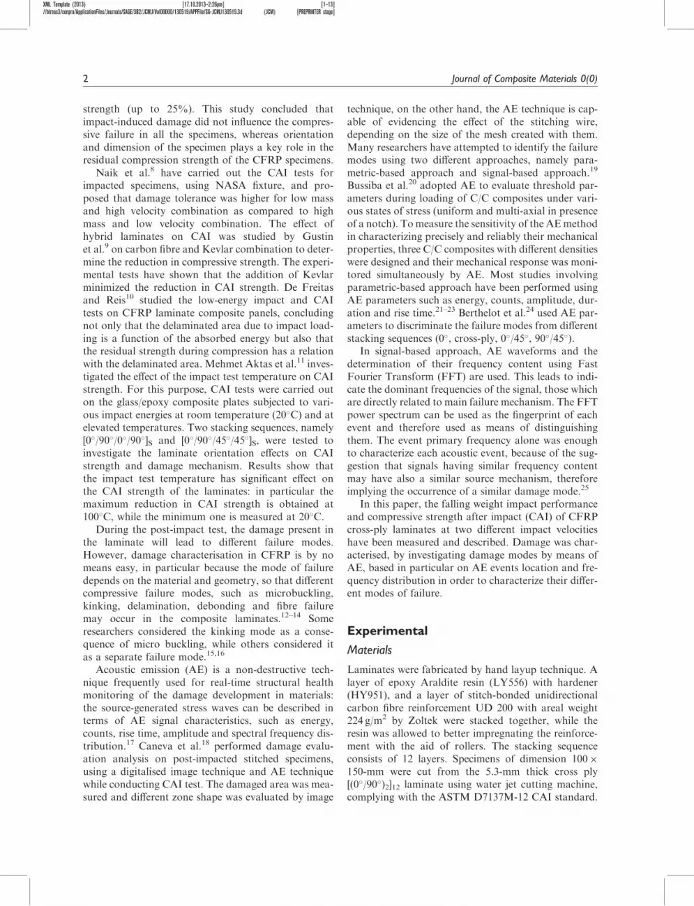
Figures 9 and 10 1show the AE events location vstime for a laminate impacted at 35ms from the figureit is evident that most of the events are concentratedonly at the impact site an evidence revealing that theprevious damage has a larger effect on CAI failure Thepeak load for 25ms and 35ms impacted specimenswere 946 43 kN and 909 33 kN respectivelyFigure 11 shows load vs time plot for 25ms and35ms impacted specimens obtained during CAItests It can be seen that after an initial time character-ized by very small load in which the clearances in thetest fixture were eliminated the applied force increased
Figure 8 Location vs time for specimen subjected to an impact velocity of 25 ms
Figure 7 Specimen after CAI test
6 Journal of Composite Materials 0(0)
XML Template (2013) [17102013ndash227pm] [1ndash13]blrnas3cenproApplicationFilesJournalsSAGE3B2JCMJVol00000130519APPFileSG-JCMJ1305193d (JCM) [PREPRINTER stage]
linearly with the displacement till the failure point TheCAI strength for 25ms and 35ms impacted speci-mens was estimated to be 1785 83MPa and171523 77MPa respectively From these data thedecrease of CAI performance does appear much morelimited than the appearance of damage on the rear sur-face for the higher impact velocity would suggest
AE results
Frequency and parametric analysis are performed onthe AE data obtained during the CAI testing ofCFRP specimens impacted at two different velocitiesFrequency analysis is based on the principle that each
Figure 11 Load vs displacement for CAI test (mm)
Figure 10 Location vs time for specimen subjected to an impact velocity of 35 ms
Figure 9 Specimen subjected to 35 ms after CAI test
Arumugam et al 7
XML Template (2013) [17102013ndash227pm] [1ndash13]blrnas3cenproApplicationFilesJournalsSAGE3B2JCMJVol00000130519APPFileSG-JCMJ1305193d (JCM) [PREPRINTER stage]
failure mode generates an AE signal which is related tothe amount of strain energy released Therefore eachAE waveform has a unique feature in the sense thatits amplitude duration and frequency content arerelated to the damage mechanisms such as matrixcracking debonding and delamination and fibre failure
In particular peak frequency can allow a fairly easydiscrimination of the signals according to the failuremode that generates them as discussed already inRef [29] In Figure 12 this kind of partition as appliedto CAI test on a laminate impacted at 35ms isreported Four ranges of peak frequency namely 80ndash120 kHz 120ndash170 kHz 170ndash200 kHz and 200ndash300 kHzare identified which may be possibly related to the dif-ferent damage modes The lowest frequency range of80ndash120 kHz corresponds to matrix cracking whose fre-quency range has been often revealed to be centredaround 100 kHz2930 The second range of frequencycontent 120ndash170 kHz may be possibly related to delam-ination failure mode found to be predominant in CAItesting31 The next frequency range of 170ndash200 kHzmay be possibly affiliated to fibre-matrix debondingThese two frequency ranges are somehow overlappingas reported already in Ref [29] which may be due tothe fact that both delamination and fibre-matrixdebonding are associated failure modes The fourthand last frequency range is pertaining to fibre-relatedphenomena including fibre failure and microbucklingThe events are considerably denser in a narrow rangearound 250 kHz To attempt a first partition betweenfibre failure and fibre microbuckling events it has beententatively considered that whenever amplitude washigher than 65 dB the event was pertaining to fibrefailure while otherwise it was an event generated byfibre microbuckling the association of high amplitudeAE events with fibre failure has been widely reported inliterature32
Along the lines of the frequency discriminationreported above in Figure 13 duration vs energy plotsfor events attributed to the five different failure modesare reported Matrix cracking events were found to pos-sess low energy and short duration Delaminationevents which appear even during initial stages of CAIloading have typically long duration Fibre-matrixdebonding events are more likely to be associatedwith the second part of loading where an abruptincrease in AE activities is detected which is evidentfrom the cumulative count vs time plot shown inFigure 12 just before 600 seconds Discrimination ofdelamination and debonding in spite of some overlap-ping shown around 170 kHz could be obtained fromduration vs energy plots considering that hits pertain-ing to fibre-matrix debonding are found to possessmedium duration and medium energy in comparisonwith delamination failure mode Both fibre microbuck-ling and fibre failure events are low-duration events theformer is seen to bring to failure the laminate impactedat the higher velocity during CAI test in Figure 14where microbuckling events tend to concentratearound the impacted region as it is depicted inFigure 15 The AE classification of different failuremodes has been summed up in Table 1
Results of FFT analysis of further frequency peaksdetected in events associated to the different failuremodes which has been already reported to be ofsome interest for additional material characterisation25
is reported in Figure 16 Figure 16 shows the differentfailure modes for the FFT magnitude representation ofthe different failure modes obtained during CAI testingof specimen impacted at 35ms This suggests that inall cases a second peak around 140ndash180 kHz is alwaysrevealed which implies that some degree of develop-ment of delaminationdebonding is present in allcircumstances whichever other mechanism of failure
Figure 12 Peak frequency and cumulative counts vs time for specimen impacted at 35 ms
8 Journal of Composite Materials 0(0)
XML Template (2013) [17102013ndash227pm] [1ndash13]blrnas3cenproApplicationFilesJournalsSAGE3B2JCMJVol00000130519APPFileSG-JCMJ1305193d (JCM) [PREPRINTER stage]
is predominant This is typical of the leading characterof impact damage in the CAI failure event
Conclusion
In this study CAI of carbon epoxy composite lamin-ates was investigated with the assistance of AE moni-toring In particular impact tests of the compositelaminates were performed at 25ms and 35mswhich resulted in two different modes of failurethe former being based on end crushing of the com-posite laminate whilst the latter is linked to the devel-opment of the impacted area in terms of lateral
Figure 13 Energy-duration distribution (a) matrix cracking (b) delamination (c) debonding (d) fibre6 microbuckling and (e) fibre
failure
Figure 14 Peak frequency corresponding to fibre microbuck-
ling vs XY location for specimen impacted at 35 ms
Arumugam et al 9
XML Template (2013) [17102013ndash227pm] [1ndash13]blrnas3cenproApplicationFilesJournalsSAGE3B2JCMJVol00000130519APPFileSG-JCMJ1305193d (JCM) [PREPRINTER stage]
Figure 16 Different types of AE signal in CAI test on a laminate impacted at a velocity of 35 ms related to (a) matrix cracking
(b) delamination (c) fibre-matrix debonding (d) fibre microbuckling and (e) fibre failure
Figure 15 Photographic view of a failed 35 ms impacted specimen during CAI test
Table 1 Classification of damage modes according to acoustic emission (AE) signal frequency
Damage mode AE frequency range (kHz) Duration (microseconds) Energy (energy units)
Matrix cracking 80ndash120 0ndash600 0ndash50
Delamination 120ndash170 0ndash8000 0ndash3000
Fibrendashmatrix debonding 170ndash200 0ndash3000 0ndash1000 (ca)
Fibre failure 200ndash300 (AE amplitudegt 65 dB) 0ndash2000 0ndash500
Fibre microbuckling 200ndash300 (AE amplitudegt 65 dB) 0ndash1000 0ndash100
10 Journal of Composite Materials 0(0)
XML Template (2013) [17102013ndash227pm] [1ndash13]blrnas3cenproApplicationFilesJournalsSAGE3B2JCMJVol00000130519APPFileSG-JCMJ1305193d (JCM) [PREPRINTER stage]
crack propagation AE monitoring including fre-quency analysis was able to suggest the different char-acteristics of the two failure modes in particularindicating that the effect of delamination and debond-ing is predominant in the higher energy one based oncrack propagation Moreover microbuckling was iden-tified with AE events of a characteristic frequencysomehow overlapping with that of fibre fracture
This study suggests that an integrated strategy onanalysis based on study of impact hysteresis cyclesfailure characterization and AE monitoring is able tooffer a wealth of information about damage evolutiondue to CAI loading as related to impact energyFurther studies would concern the application of theabove concepts to CAI tests on other laminates suchas glass fibre reinforced laminates and natural fibrereinforced laminates on which the knowledge of resi-dual properties following an impact event is still quitelimited
Funding
This research received no specific grant from any fundingagency in the public commercial or not-for-profit sectors
Conflict of Interest
None declared
References
1 Siow YP and Shim VPW An experimental study of low
velocity impact damage in woven fibre composites J
Compos Mater 1998 32 1178ndash12022 Abrate S Impact on laminated composites recent
advances Appl Mech Rev 1994 47 517ndash5443 Abrate S Impact on composite structures Cambridge UK
Cambridge University Press 19984 Cantwell WJ and Morton J The impact resistance of com-
posite materials - a review Composites 1991 22 347ndash3625 Ishikawa T Sugimoto S Matsushima M et al Some
experimental findings in compression-after-impact (CAI)
tests of CFPEEK (APC-2) and conventional CFepoxy
flat plates Compos Sci Technol 1995 55 349ndash3636 Zhang X Davies GAO and Hitchings D Impact damage
with compressive preload and post-impact compression of
carbon composite plates Int J Impact Eng 1999 22
485ndash509
7 Ghelli D and Minak G Low velocity impact and compres-
sion after impact tests on thin carbonepoxy laminates
Compos Part B 2011 42 2067ndash20798 Naik NK Borade SV Arya H et al Experimental studies
on impact behaviour of woven fabric composites effect of
impact parameters J Reinf Plast Compos 2002 21
1347ndash13629 Gustin J Joneson A and Matinfalah M Low velocity
impact of combination kevlarcarbon epoxy fibre sand-
wich composites Compos Struct 2005 69 396ndash406
10 de Freitas M and Reis L Failure mechanisms on com-
posite specimens subjected compression after impact
Compos Struct 1998 42 365ndash37311 Mehmet Aktas Ramazan Karakuzu and Yusuf Arman
Compression-after impact behavior of laminated com-
posite plates subjected to low velocity impact in high tem-
peratures Compos Struct 2009 89 77ndash82
12 Aoki Y Yamada K and Ishikawa T Effect of hygrother-
mal condition on compression after impact strength of
CFRP laminates Compos Sci Technol 2008 68
1376ndash138313 Fleck NA Sivashanker S and Sutcliffe MPF
Compressive failure of composites due to microbuckle
growth Eur J Mech ASolids 1997 16 65ndash8214 Ochola RO Marcus K Nurick GN et al Mechanical
behaviour of glass and carbon fibre reinforced compos-
ites at varying strain rates Compos Struct 2004 63
455ndash46715 Budianky B and Fleck NA Compressive kinking of fibre
composites a topical review Appl Mech Rev 1994 47
S246ndashS25016 Pavana Prabhakar and Anthony M Waas Interaction
between kinking and splitting in the compressive failure
of unidirectional fibre reinforced laminated composites
Compos Struct 2013 98 85ndash9217 Esposito C Lizza A Giordano M et al IEEE
Ultrasonics Symp Proc 5ndash8 October pp64918 Caneva C Olivieri S Santulli C et al Impact damage
evaluation on advanced stitched composites by means of
acoustic emission and image analysis Compos Struct
1993 25 121ndash128
19 Grosse CU and Linzer LM Signal-based AE analysis in
acoustic emission testing CU Grosse 2
20 Bussiba A Kupiec M Piat R et al Fracture character-
ization of CC composites under various stress modes by
monitoring both mechanical and acoustic responses
Carbon 2008 46 618ndash63021 Barre S and Beneggagh ML On the use of acoustic emis-
sion to investigate damage mechanism in glass-fibre-
reinforced polypropylene Compos Sci Technol 1994 52
369ndash376
22 Dzenis Y and Qian J Hybrid transient-parametric AE
analysis of histories of damage micro mechanisms in
composites In T Kundu (ed) Advanced nondestructive
evaluation for structural and biological health monitoring
Vol 4335 of Proceedings of SPIE International Society
for Optical Engineering 200123 Bar HN Bhat MR and Murthy CRL Identification of
failure modes in GFRP using PVDF sensors ANN
approach Compos Struct 2003 65 231ndash23724 Berthelot JM and Rhazi J Acoustic emission in carbon
fibre Compos Sci Technol 1990 37 411ndash42825 Ramirez-Jimenez CR Papadakis N Reynolds N et al
Compos Sci Technol 2004 64 1819 326 Unnthorsson R Hit detection and determination in AE
bursts In Wojciech Sikorski (ed) Acoustic emission -
research and applications 4ISBN 978-953-51-1015-627 Hou JP and Jeronimidis G Vibration of delaminated thin
composite plates Compos Part A 1999 30 989ndash995
Arumugam et al 11
XML Template (2013) [17102013ndash227pm] [1ndash13]blrnas3cenproApplicationFilesJournalsSAGE3B2JCMJVol00000130519APPFileSG-JCMJ1305193d (JCM) [PREPRINTER stage]
28 Santulli C Janssen M and Jeronimidis G Partial replace-ment of E-glass fibres with flax fibres in composites andeffect on falling weight impact performance J Mater Sci
2005 40 3581ndash358529 Santulli C Matrix cracking detection5 by acoustic emis-
sion in polymer composites and countsduration ratioE-J Non-Destruct Test 2012 15(11) 2
30 Arumugam V Barath Kumar S Santulli C et al Effectof fibre orientation in uni-directional glass epoxy lamin-ate using acoustic emission monitoring Acta Metall Sin
(Engl Lett) 2011 24 351ndash364
31 Amin Salehi-Khojin Reza Bashirzadeh MohammadMahinfalah et al The role of temperature on impactproperties of Kevlarfibreglass composite laminates
Compos Part B 2006 37 593ndash60232 Huguet S Godin N Gaertner R et al Use of acoustic
emission to identify damage modes in glass fibre rein-forced polyester Compos Sci Technol 2002 62
1433ndash1444
12 Journal of Composite Materials 0(0)

XML Template (2013) [17102013ndash226pm] [1ndash13]blrnas3cenproApplicationFilesJournalsSAGE3B2JCMJVol00000130519APPFileSG-JCMJ1305193d (JCM) [PREPRINTER stage]
JOURNAL OFC O M P O S I T EM AT E R I A L SArticle
Failure modes characterization ofimpacted carbon fibre reinforced plasticslaminates under compression loadingusing acoustic emission
V Arumugam1 A Adhithya Plato Sidharth1 and C Santulli2
Abstract
Composite laminates have low resistance under dynamic loading particularly impact loading A low-velocity impact on
laminated composites causes various types of damage such as delamination fibre breakage matrix cracking and fibre
matrix interfacial debonding Post-impact compressive strength is one of the greatest weaknesses in carbon fibre
reinforced plastics laminates After impact due to the delaminations present in the laminates local instability is triggered
which ultimately reduces considerably their residual strength In this work symmetric cross ply carbon fibre reinforced
plastics laminates [(090)2]12 were subjected to falling weight impact at two different velocities 25 and 35 ms
Compression after impact studies showed substantial differences in failure mode between the two cases passing
from end crushing to crack propagation with higher impact energy Acoustic emission technique was able to confirm
this result and characterize the different types of failure modes during compression after impact test in particular by
frequency distribution
Keywords
Carbon fibre reinforced plastics impact compression after impact acoustic emission
Introduction
Carbon fibre reinforced plastics (CFRP) laminates arebeing increasingly used in a wide range of engineeringapplications because of their strength-to-weight andstiffness-to-weight ratios and superior corrosion resist-ance compared to conventional engineering materialssuch as steel and aluminium CFRP laminates how-ever do possess serious limitations which include sus-ceptibility to internal damage when they are subjectedto low-velocity impact1ndash5 For example the dropping ofa hand-held tool onto composite aircraft parts duringmaintenance can generate low-velocity impact damagewhich may not appear visually significant but can haveobtrusive effects Low-velocity impact damage in ametallic structure always starts from the surfacewhereby the structure absorbs energy through elasticand plastic deformation which can be detected by rou-tine visual inspection In contrast on CFRP the abilityto undergo plastic deformation is limited As a conse-quence damage occurs in the form of internal damagesuch as sub-surface matrix cracking delamination
andor fibre breakage with imperceptible visible surfacedamage Such damage can cause significant reductionin the strength and stiffness of the component
Compression after impact (CAI) performanceremains an important design criterion in the use ofcomposite structures particularly in aerospace indus-try mainly because of their susceptibility to impactdamage and huge reduction in post-impact compressivestrength of composite materials6 Ghelli and Minak7
studied the effect of geometry by using rectangularand circular quasi-isotropic specimens for CAI testingThe outcome of their investigation was that delamin-ation produced by impact could change the bucklingmode andor decrease both critical load and ultimate
1Department of Aerospace Engineering Anna University Chennai India2Department of Chemical Engineering Materials and Environment
Universita La Sapienza Rome Italy
Corresponding author
Carlo Santulli Universita di Roma via Eudossiana 18 Roma 00184 Italy
Email carlosantulli141gmailcom
Journal of Composite Materials
0(0) 1ndash12
The Author(s) 2013
Reprints and permissions
sagepubcoukjournalsPermissionsnav
DOI 1011770021998313509504
jcmsagepubcom
XML Template (2013) [17102013ndash226pm] [1ndash13]blrnas3cenproApplicationFilesJournalsSAGE3B2JCMJVol00000130519APPFileSG-JCMJ1305193d (JCM) [PREPRINTER stage]
strength (up to 25) This study concluded thatimpact-induced damage did not influence the compres-sive failure in all the specimens whereas orientationand dimension of the specimen plays a key role in theresidual compression strength of the CFRP specimens
Naik et al8 have carried out the CAI tests forimpacted specimens using NASA fixture and pro-posed that damage tolerance was higher for low massand high velocity combination as compared to highmass and low velocity combination The effect ofhybrid laminates on CAI was studied by Gustinet al9 on carbon fibre and Kevlar combination to deter-mine the reduction in compressive strength The experi-mental tests have shown that the addition of Kevlarminimized the reduction in CAI strength De Freitasand Reis10 studied the low-energy impact and CAItests on CFRP laminate composite panels concludingnot only that the delaminated area due to impact load-ing is a function of the absorbed energy but also thatthe residual strength during compression has a relationwith the delaminated area Mehmet Aktas et al11 inves-tigated the effect of the impact test temperature on CAIstrength For this purpose CAI tests were carried outon the glassepoxy composite plates subjected to vari-ous impact energies at room temperature (20C) and atelevated temperatures Two stacking sequences namely[090090]S and [0904545]S were tested toinvestigate the laminate orientation effects on CAIstrength and damage mechanism Results show thatthe impact test temperature has significant effect onthe CAI strength of the laminates in particular themaximum reduction in CAI strength is obtained at100C while the minimum one is measured at 20C
During the post-impact test the damage present inthe laminate will lead to different failure modesHowever damage characterisation in CFRP is by nomeans easy in particular because the mode of failuredepends on the material and geometry so that differentcompressive failure modes such as microbucklingkinking delamination debonding and fibre failuremay occur in the composite laminates12ndash14 Someresearchers considered the kinking mode as a conse-quence of micro buckling while others considered itas a separate failure mode1516
Acoustic emission (AE) is a non-destructive tech-nique frequently used for real-time structural healthmonitoring of the damage development in materialsthe source-generated stress waves can be described interms of AE signal characteristics such as energycounts rise time amplitude and spectral frequency dis-tribution17 Caneva et al18 performed damage evalu-ation analysis on post-impacted stitched specimensusing a digitalised image technique and AE techniquewhile conducting CAI test The damaged area was mea-sured and different zone shape was evaluated by image
technique on the other hand the AE technique is cap-able of evidencing the effect of the stitching wiredepending on the size of the mesh created with themMany researchers have attempted to identify the failuremodes using two different approaches namely para-metric-based approach and signal-based approach19
Bussiba et al20 adopted AE to evaluate threshold par-ameters during loading of CC composites under vari-ous states of stress (uniform and multi-axial in presenceof a notch) Tomeasure the sensitivity of the AEmethodin characterizing precisely and reliably their mechanicalproperties three CC composites with different densitieswere designed and their mechanical response was moni-tored simultaneously by AE Most studies involvingparametric-based approach have been performed usingAE parameters such as energy counts amplitude dur-ation and rise time21ndash23 Berthelot et al24 used AE par-ameters to discriminate the failure modes from differentstacking sequences (0 cross-ply 045 9045)
In signal-based approach AE waveforms and thedetermination of their frequency content using FastFourier Transform (FFT) are used This leads to indi-cate the dominant frequencies of the signal those whichare directly related to main failure mechanism The FFTpower spectrum can be used as the fingerprint of eachevent and therefore used as means of distinguishingthem The event primary frequency alone was enoughto characterize each acoustic event because of the sug-gestion that signals having similar frequency contentmay have also a similar source mechanism thereforeimplying the occurrence of a similar damage mode25
In this paper the falling weight impact performanceand compressive strength after impact (CAI) of CFRPcross-ply laminates at two different impact velocitieshave been measured and described Damage was char-acterised by investigating damage modes by means ofAE based in particular on AE events location and fre-quency distribution in order to characterize their differ-ent modes of failure
Experimental
Materials
Laminates were fabricated by hand layup technique Alayer of epoxy Araldite resin (LY556) with hardener(HY951) and a layer of stitch-bonded unidirectionalcarbon fibre reinforcement UD 200 with areal weight224 gm2 by Zoltek were stacked together while theresin was allowed to better impregnating the reinforce-ment with the aid of rollers The stacking sequenceconsists of 12 layers Specimens of dimension 100150-mm were cut from the 53-mm thick cross ply[(090)2]12 laminate using water jet cutting machinecomplying with the ASTM D7137M-12 CAI standard
2 Journal of Composite Materials 0(0)
XML Template (2013) [17102013ndash226pm] [1ndash13]blrnas3cenproApplicationFilesJournalsSAGE3B2JCMJVol00000130519APPFileSG-JCMJ1305193d (JCM) [PREPRINTER stage]
Falling weight impact The specimens fabricated wereimpacted at two different impact velocities 25 and35ms with impact energies of 603 and 1183 J respect-ively using a CEAST Fractovis Falling Weight impacttower The mass of the impactor was 1926 kg while thediameter of the indenter was 127mm with a clampingforce of 1000N The parameters such as impact energydeformation contact force and velocity were recordedFigure 1 shows the photograph of the falling weightimpact tower used for conducting the tests The impac-tor was dropped at the centre of the specimen from aselected height and was captured after the first reboundusing an electromagnetic braking system fitted in theimpact tower to avoid multiple impacts which can gen-erate additional damage to laminates In these tests theimpact velocity of the striker is measured using a pair oflaser emitters and light-sensitive diodes The accelerom-eter mounted on the impactor yields data from whichthe impact force is calculated The software provided onthe computer allows the collection parameters of thedata capture unit to be varied as well as viewing andstoring the test data
CAI tests The CAI tests are conducted at room tem-perature using an ASTM D7137M-12 fixture in aTinius Olsen UTM with 100 kN load capacity asshown in Figure 2 Stable support of the coupon wasprovided by two pairs of 8-mm-thick plates on its upperand lower ends and by two pairs of plates with knifeedges on its left and right sides leaving a central rect-angular 94 134mm exposed zone In this way con-straints were provided against rotation and lateraltranslation for the upper and lower specimen edgesand simply supporting the two vertical sides (free rota-tion but no lateral translation) arresting global buck-ling The four supporting plates could be adjustedbefore testing so that the laminate fitted exactly in thefacility without any clearance between its faces and thesurfaces supporting them A 1-mm clearance was leftaccording to the standard between the lateral sides ofthe specimen and the angles of the fixture holding theknife plates in order not to hinder the lateral expansionof the specimen under compression
Compressive load is applied under stroke control ata displacement rate of 1mmmin During the CAI testa data acquisition system recorded the force versus dis-placement history The failure load is obtained from theforce-displacement curve
The CAI strength (sC) of the specimen is calculatedusing equation (1)
c frac14 Fmax= b deth THORN eth1THORN
where Fmax b and d denote the maximum failure loadthe width and the thickness of the CAI specimenrespectively
CAI test was performed in the universal testingmachine with online AE monitoring AE can be definedas a transient elastic wave generated by the rapidrelease of strain energy within the material An eightchannel AE setup supplied by Physical AcousticsCorporation was used for AE studies AE was continu-ously monitored by using a SAMOS E310 data acqui-sition system from Physical Acoustics Corporation(PAC) with a sampling rate of 3MSPS and a 40 dBpre-amplification Ambient noise was filtered using athreshold of 45 dB AE measurements were achievedby using two Wide Band PAC sensors which have aquasi-flat response in the 100ndash900 kHz interval Theamplitude distribution covers the range of 0ndash100 dB(0 dB corresponds to 1mV at the transducer output)The signal definition times used for AE monitoring areas follows peak definition time (PDT)mdash13 ms hit
Figure 1 Falling weight impact testing tower
Figure 2 Experimental Setup of CAI Test
Arumugam et al 3
XML Template (2013) [17102013ndash226pm] [1ndash13]blrnas3cenproApplicationFilesJournalsSAGE3B2JCMJVol00000130519APPFileSG-JCMJ1305193d (JCM) [PREPRINTER stage]
definition time (HDT)mdash300 ms hit lock-out time(HLT)mdash600 ms Some indications on the function ofthese time intervals on composites monitoring aregiven in Ref [26] though in this case an even shorterPDT has been selected to avoid false measurements onhigh-velocity low-amplitude precursor signals which isvery likely given the abrupt nature of failure in CAItests Hsu-Nielsen pencil break test in accordancewith ASTM E976-10 was carried out to calculate thewave velocity and fed to the AE software AE wavevelocity for the specimen was found to be in the orderof 4500ms AE parameters like counts amplitudeenergy events duration rise time etc were recordedfor all the specimens Figure 3 shows the specimenwith three sensors positioned and the attenuation asso-ciated with them 2D planar location was used as rect-angular specimen is being tested and to get the eventslocation in (x y) coordinates The three sensors areplaced to form an equilateral triangle of side 60 mm
Results and discussion
Impact test
Impact tests were performed on CAI specimens at twodifferent velocities namely 25 and 35ms five for eachimpact velocity These two impact velocities wereselected after a number of preliminary tests increasingimpact velocity by steps of 05ms according to thecriterion of the appearance of damage to the backside of the laminate This appearance was dubious inthe case of impact at 3ms which was selected as alsquolsquothreshold valuersquorsquo for this phenomenon Accordinglythe two above velocities were selected with the idea to
see how the appearance of backside damage influencesCAI properties and the consequent mode of failure
As a matter of fact in the case of 25ms impactedspecimens only barely visible impact damage (BVID)was detected on the impacted surface (Figure 4(a)) anda virtually non-existent damage on the rear side of theimpacted surface (not shown) In contrast for 35msimpacted specimens external damage was revealedboth on the tension side and compression side(impacted surface) as shown in Figure 4(b) and (c)In particular in these latter figures the whitish colourof damage revealed on the two surfaces does indicatethe significant presence of matrix cracking owed to thebrittleness of epoxy matrix
Figure 5 shows the contact force and energy withrespect to time It is noteworthy that the duration ofthe impact event remains virtually the same whichimplies that also the damping mode in the laminatedoes not substantially change since delaminations incarbon fibre reinforced laminates have a well-knownconnection with vibration damping27 In contrast thepeak force is much higher for specimens impacted at35ms in particular being 5602 170N against4604 134N for specimens impacted at 25msAbsorbed energy is 429 021 J and 181 015 Jrespectively Figure 6 depicts typical force vs deform-ation hysteresis cycles From it the slope of the elasticpart of impact curve often referred to as linear stiff-ness which tends to decrease with an increasingamount of damage being present in the laminate28
was measured The values obtained for laminatesimpacted at the two different velocities were1785 200Nmm and 1680 160Nmm for specimensimpacted at 25ms and 35ms respectively
Figure 3 Attenuation studies on CAI test specimen
4 Journal of Composite Materials 0(0)
XML Template (2013) [17102013ndash227pm] [1ndash13]blrnas3cenproApplicationFilesJournalsSAGE3B2JCMJVol00000130519APPFileSG-JCMJ1305193d (JCM) [PREPRINTER stage]
Figure 4 (a) Impacted side of specimen subjected to impact at 25 ms (b) Impacted side of specimen subjected to impact at 35 ms
(c) Rear side of the specimen impacted at 35 ms
Figure 5 Contact force (N) energy (J) vs time (ms) for 25 ms and 35 ms
Figure 6 Contact force (N) vs deformation (mm) for impact at 25 and 35 J
Arumugam et al 5
XML Template (2013) [17102013ndash227pm] [1ndash13]blrnas3cenproApplicationFilesJournalsSAGE3B2JCMJVol00000130519APPFileSG-JCMJ1305193d (JCM) [PREPRINTER stage]
Although the difference can be considered limited itcan be noticed that some reduction of the elastic por-tion of energy absorbed over the time of impact eventas indicated by linear stiffness takes place
CAI results
The specimens subjected to two different impact velo-cities were mounted in CAI fixture and tested Duringthe test global buckling of the specimens did not occurdue to the fixture supports
Specimens subjected to an impact velocity of 25mswere tested in CAI test fixture leading to failure in theway shown in Figure 7 From Figure 8 it was evident
that most damage during CAI test is initiated only fromthe bottom side of the laminate and not at the region ofimpact so that in practice the laminates failed byend crushing as shown by the highlighted portion ofFigure 7 Moreover during the initial stages of loadingup to 700 seconds most events are found to occur onlyat the bottommost region and are therefore correlatedto end crushing damage At the time of failure signifi-cant bursts of AE were observed involving basically allfailure modes as a matter of fact events with frequencypeaks in the whole range between around 50ndash350 kHzwere detected More details about frequency analysiswill be given later on
During the CAI test on 35ms impacted specimensas the applied load is increased damage in the form oflocal buckling leading to crack propagation grows lat-erally from the impact damage region In additiondelaminated regions continued to propagate first inshort discrete increments and then rapidly at the failureload Examination of the failed specimens removedfrom the test fixture confirmed that the local delamin-ations extended completely across the specimen width
Figures 9 and 10 1show the AE events location vstime for a laminate impacted at 35ms from the figureit is evident that most of the events are concentratedonly at the impact site an evidence revealing that theprevious damage has a larger effect on CAI failure Thepeak load for 25ms and 35ms impacted specimenswere 946 43 kN and 909 33 kN respectivelyFigure 11 shows load vs time plot for 25ms and35ms impacted specimens obtained during CAItests It can be seen that after an initial time character-ized by very small load in which the clearances in thetest fixture were eliminated the applied force increased
Figure 8 Location vs time for specimen subjected to an impact velocity of 25 ms
Figure 7 Specimen after CAI test
6 Journal of Composite Materials 0(0)
XML Template (2013) [17102013ndash227pm] [1ndash13]blrnas3cenproApplicationFilesJournalsSAGE3B2JCMJVol00000130519APPFileSG-JCMJ1305193d (JCM) [PREPRINTER stage]
linearly with the displacement till the failure point TheCAI strength for 25ms and 35ms impacted speci-mens was estimated to be 1785 83MPa and171523 77MPa respectively From these data thedecrease of CAI performance does appear much morelimited than the appearance of damage on the rear sur-face for the higher impact velocity would suggest
AE results
Frequency and parametric analysis are performed onthe AE data obtained during the CAI testing ofCFRP specimens impacted at two different velocitiesFrequency analysis is based on the principle that each
Figure 11 Load vs displacement for CAI test (mm)
Figure 10 Location vs time for specimen subjected to an impact velocity of 35 ms
Figure 9 Specimen subjected to 35 ms after CAI test
Arumugam et al 7
XML Template (2013) [17102013ndash227pm] [1ndash13]blrnas3cenproApplicationFilesJournalsSAGE3B2JCMJVol00000130519APPFileSG-JCMJ1305193d (JCM) [PREPRINTER stage]
failure mode generates an AE signal which is related tothe amount of strain energy released Therefore eachAE waveform has a unique feature in the sense thatits amplitude duration and frequency content arerelated to the damage mechanisms such as matrixcracking debonding and delamination and fibre failure
In particular peak frequency can allow a fairly easydiscrimination of the signals according to the failuremode that generates them as discussed already inRef [29] In Figure 12 this kind of partition as appliedto CAI test on a laminate impacted at 35ms isreported Four ranges of peak frequency namely 80ndash120 kHz 120ndash170 kHz 170ndash200 kHz and 200ndash300 kHzare identified which may be possibly related to the dif-ferent damage modes The lowest frequency range of80ndash120 kHz corresponds to matrix cracking whose fre-quency range has been often revealed to be centredaround 100 kHz2930 The second range of frequencycontent 120ndash170 kHz may be possibly related to delam-ination failure mode found to be predominant in CAItesting31 The next frequency range of 170ndash200 kHzmay be possibly affiliated to fibre-matrix debondingThese two frequency ranges are somehow overlappingas reported already in Ref [29] which may be due tothe fact that both delamination and fibre-matrixdebonding are associated failure modes The fourthand last frequency range is pertaining to fibre-relatedphenomena including fibre failure and microbucklingThe events are considerably denser in a narrow rangearound 250 kHz To attempt a first partition betweenfibre failure and fibre microbuckling events it has beententatively considered that whenever amplitude washigher than 65 dB the event was pertaining to fibrefailure while otherwise it was an event generated byfibre microbuckling the association of high amplitudeAE events with fibre failure has been widely reported inliterature32
Along the lines of the frequency discriminationreported above in Figure 13 duration vs energy plotsfor events attributed to the five different failure modesare reported Matrix cracking events were found to pos-sess low energy and short duration Delaminationevents which appear even during initial stages of CAIloading have typically long duration Fibre-matrixdebonding events are more likely to be associatedwith the second part of loading where an abruptincrease in AE activities is detected which is evidentfrom the cumulative count vs time plot shown inFigure 12 just before 600 seconds Discrimination ofdelamination and debonding in spite of some overlap-ping shown around 170 kHz could be obtained fromduration vs energy plots considering that hits pertain-ing to fibre-matrix debonding are found to possessmedium duration and medium energy in comparisonwith delamination failure mode Both fibre microbuck-ling and fibre failure events are low-duration events theformer is seen to bring to failure the laminate impactedat the higher velocity during CAI test in Figure 14where microbuckling events tend to concentratearound the impacted region as it is depicted inFigure 15 The AE classification of different failuremodes has been summed up in Table 1
Results of FFT analysis of further frequency peaksdetected in events associated to the different failuremodes which has been already reported to be ofsome interest for additional material characterisation25
is reported in Figure 16 Figure 16 shows the differentfailure modes for the FFT magnitude representation ofthe different failure modes obtained during CAI testingof specimen impacted at 35ms This suggests that inall cases a second peak around 140ndash180 kHz is alwaysrevealed which implies that some degree of develop-ment of delaminationdebonding is present in allcircumstances whichever other mechanism of failure
Figure 12 Peak frequency and cumulative counts vs time for specimen impacted at 35 ms
8 Journal of Composite Materials 0(0)
XML Template (2013) [17102013ndash227pm] [1ndash13]blrnas3cenproApplicationFilesJournalsSAGE3B2JCMJVol00000130519APPFileSG-JCMJ1305193d (JCM) [PREPRINTER stage]
is predominant This is typical of the leading characterof impact damage in the CAI failure event
Conclusion
In this study CAI of carbon epoxy composite lamin-ates was investigated with the assistance of AE moni-toring In particular impact tests of the compositelaminates were performed at 25ms and 35mswhich resulted in two different modes of failurethe former being based on end crushing of the com-posite laminate whilst the latter is linked to the devel-opment of the impacted area in terms of lateral
Figure 13 Energy-duration distribution (a) matrix cracking (b) delamination (c) debonding (d) fibre6 microbuckling and (e) fibre
failure
Figure 14 Peak frequency corresponding to fibre microbuck-
ling vs XY location for specimen impacted at 35 ms
Arumugam et al 9
XML Template (2013) [17102013ndash227pm] [1ndash13]blrnas3cenproApplicationFilesJournalsSAGE3B2JCMJVol00000130519APPFileSG-JCMJ1305193d (JCM) [PREPRINTER stage]
Figure 16 Different types of AE signal in CAI test on a laminate impacted at a velocity of 35 ms related to (a) matrix cracking
(b) delamination (c) fibre-matrix debonding (d) fibre microbuckling and (e) fibre failure
Figure 15 Photographic view of a failed 35 ms impacted specimen during CAI test
Table 1 Classification of damage modes according to acoustic emission (AE) signal frequency
Damage mode AE frequency range (kHz) Duration (microseconds) Energy (energy units)
Matrix cracking 80ndash120 0ndash600 0ndash50
Delamination 120ndash170 0ndash8000 0ndash3000
Fibrendashmatrix debonding 170ndash200 0ndash3000 0ndash1000 (ca)
Fibre failure 200ndash300 (AE amplitudegt 65 dB) 0ndash2000 0ndash500
Fibre microbuckling 200ndash300 (AE amplitudegt 65 dB) 0ndash1000 0ndash100
10 Journal of Composite Materials 0(0)
XML Template (2013) [17102013ndash227pm] [1ndash13]blrnas3cenproApplicationFilesJournalsSAGE3B2JCMJVol00000130519APPFileSG-JCMJ1305193d (JCM) [PREPRINTER stage]
crack propagation AE monitoring including fre-quency analysis was able to suggest the different char-acteristics of the two failure modes in particularindicating that the effect of delamination and debond-ing is predominant in the higher energy one based oncrack propagation Moreover microbuckling was iden-tified with AE events of a characteristic frequencysomehow overlapping with that of fibre fracture
This study suggests that an integrated strategy onanalysis based on study of impact hysteresis cyclesfailure characterization and AE monitoring is able tooffer a wealth of information about damage evolutiondue to CAI loading as related to impact energyFurther studies would concern the application of theabove concepts to CAI tests on other laminates suchas glass fibre reinforced laminates and natural fibrereinforced laminates on which the knowledge of resi-dual properties following an impact event is still quitelimited
Funding
This research received no specific grant from any fundingagency in the public commercial or not-for-profit sectors
Conflict of Interest
None declared
References
1 Siow YP and Shim VPW An experimental study of low
velocity impact damage in woven fibre composites J
Compos Mater 1998 32 1178ndash12022 Abrate S Impact on laminated composites recent
advances Appl Mech Rev 1994 47 517ndash5443 Abrate S Impact on composite structures Cambridge UK
Cambridge University Press 19984 Cantwell WJ and Morton J The impact resistance of com-
posite materials - a review Composites 1991 22 347ndash3625 Ishikawa T Sugimoto S Matsushima M et al Some
experimental findings in compression-after-impact (CAI)
tests of CFPEEK (APC-2) and conventional CFepoxy
flat plates Compos Sci Technol 1995 55 349ndash3636 Zhang X Davies GAO and Hitchings D Impact damage
with compressive preload and post-impact compression of
carbon composite plates Int J Impact Eng 1999 22
485ndash509
7 Ghelli D and Minak G Low velocity impact and compres-
sion after impact tests on thin carbonepoxy laminates
Compos Part B 2011 42 2067ndash20798 Naik NK Borade SV Arya H et al Experimental studies
on impact behaviour of woven fabric composites effect of
impact parameters J Reinf Plast Compos 2002 21
1347ndash13629 Gustin J Joneson A and Matinfalah M Low velocity
impact of combination kevlarcarbon epoxy fibre sand-
wich composites Compos Struct 2005 69 396ndash406
10 de Freitas M and Reis L Failure mechanisms on com-
posite specimens subjected compression after impact
Compos Struct 1998 42 365ndash37311 Mehmet Aktas Ramazan Karakuzu and Yusuf Arman
Compression-after impact behavior of laminated com-
posite plates subjected to low velocity impact in high tem-
peratures Compos Struct 2009 89 77ndash82
12 Aoki Y Yamada K and Ishikawa T Effect of hygrother-
mal condition on compression after impact strength of
CFRP laminates Compos Sci Technol 2008 68
1376ndash138313 Fleck NA Sivashanker S and Sutcliffe MPF
Compressive failure of composites due to microbuckle
growth Eur J Mech ASolids 1997 16 65ndash8214 Ochola RO Marcus K Nurick GN et al Mechanical
behaviour of glass and carbon fibre reinforced compos-
ites at varying strain rates Compos Struct 2004 63
455ndash46715 Budianky B and Fleck NA Compressive kinking of fibre
composites a topical review Appl Mech Rev 1994 47
S246ndashS25016 Pavana Prabhakar and Anthony M Waas Interaction
between kinking and splitting in the compressive failure
of unidirectional fibre reinforced laminated composites
Compos Struct 2013 98 85ndash9217 Esposito C Lizza A Giordano M et al IEEE
Ultrasonics Symp Proc 5ndash8 October pp64918 Caneva C Olivieri S Santulli C et al Impact damage
evaluation on advanced stitched composites by means of
acoustic emission and image analysis Compos Struct
1993 25 121ndash128
19 Grosse CU and Linzer LM Signal-based AE analysis in
acoustic emission testing CU Grosse 2
20 Bussiba A Kupiec M Piat R et al Fracture character-
ization of CC composites under various stress modes by
monitoring both mechanical and acoustic responses
Carbon 2008 46 618ndash63021 Barre S and Beneggagh ML On the use of acoustic emis-
sion to investigate damage mechanism in glass-fibre-
reinforced polypropylene Compos Sci Technol 1994 52
369ndash376
22 Dzenis Y and Qian J Hybrid transient-parametric AE
analysis of histories of damage micro mechanisms in
composites In T Kundu (ed) Advanced nondestructive
evaluation for structural and biological health monitoring
Vol 4335 of Proceedings of SPIE International Society
for Optical Engineering 200123 Bar HN Bhat MR and Murthy CRL Identification of
failure modes in GFRP using PVDF sensors ANN
approach Compos Struct 2003 65 231ndash23724 Berthelot JM and Rhazi J Acoustic emission in carbon
fibre Compos Sci Technol 1990 37 411ndash42825 Ramirez-Jimenez CR Papadakis N Reynolds N et al
Compos Sci Technol 2004 64 1819 326 Unnthorsson R Hit detection and determination in AE
bursts In Wojciech Sikorski (ed) Acoustic emission -
research and applications 4ISBN 978-953-51-1015-627 Hou JP and Jeronimidis G Vibration of delaminated thin
composite plates Compos Part A 1999 30 989ndash995
Arumugam et al 11
XML Template (2013) [17102013ndash227pm] [1ndash13]blrnas3cenproApplicationFilesJournalsSAGE3B2JCMJVol00000130519APPFileSG-JCMJ1305193d (JCM) [PREPRINTER stage]
28 Santulli C Janssen M and Jeronimidis G Partial replace-ment of E-glass fibres with flax fibres in composites andeffect on falling weight impact performance J Mater Sci
2005 40 3581ndash358529 Santulli C Matrix cracking detection5 by acoustic emis-
sion in polymer composites and countsduration ratioE-J Non-Destruct Test 2012 15(11) 2
30 Arumugam V Barath Kumar S Santulli C et al Effectof fibre orientation in uni-directional glass epoxy lamin-ate using acoustic emission monitoring Acta Metall Sin
(Engl Lett) 2011 24 351ndash364
31 Amin Salehi-Khojin Reza Bashirzadeh MohammadMahinfalah et al The role of temperature on impactproperties of Kevlarfibreglass composite laminates
Compos Part B 2006 37 593ndash60232 Huguet S Godin N Gaertner R et al Use of acoustic
emission to identify damage modes in glass fibre rein-forced polyester Compos Sci Technol 2002 62
1433ndash1444
12 Journal of Composite Materials 0(0)
XML Template (2013) [17102013ndash226pm] [1ndash13]blrnas3cenproApplicationFilesJournalsSAGE3B2JCMJVol00000130519APPFileSG-JCMJ1305193d (JCM) [PREPRINTER stage]
strength (up to 25) This study concluded thatimpact-induced damage did not influence the compres-sive failure in all the specimens whereas orientationand dimension of the specimen plays a key role in theresidual compression strength of the CFRP specimens
Naik et al8 have carried out the CAI tests forimpacted specimens using NASA fixture and pro-posed that damage tolerance was higher for low massand high velocity combination as compared to highmass and low velocity combination The effect ofhybrid laminates on CAI was studied by Gustinet al9 on carbon fibre and Kevlar combination to deter-mine the reduction in compressive strength The experi-mental tests have shown that the addition of Kevlarminimized the reduction in CAI strength De Freitasand Reis10 studied the low-energy impact and CAItests on CFRP laminate composite panels concludingnot only that the delaminated area due to impact load-ing is a function of the absorbed energy but also thatthe residual strength during compression has a relationwith the delaminated area Mehmet Aktas et al11 inves-tigated the effect of the impact test temperature on CAIstrength For this purpose CAI tests were carried outon the glassepoxy composite plates subjected to vari-ous impact energies at room temperature (20C) and atelevated temperatures Two stacking sequences namely[090090]S and [0904545]S were tested toinvestigate the laminate orientation effects on CAIstrength and damage mechanism Results show thatthe impact test temperature has significant effect onthe CAI strength of the laminates in particular themaximum reduction in CAI strength is obtained at100C while the minimum one is measured at 20C
During the post-impact test the damage present inthe laminate will lead to different failure modesHowever damage characterisation in CFRP is by nomeans easy in particular because the mode of failuredepends on the material and geometry so that differentcompressive failure modes such as microbucklingkinking delamination debonding and fibre failuremay occur in the composite laminates12ndash14 Someresearchers considered the kinking mode as a conse-quence of micro buckling while others considered itas a separate failure mode1516
Acoustic emission (AE) is a non-destructive tech-nique frequently used for real-time structural healthmonitoring of the damage development in materialsthe source-generated stress waves can be described interms of AE signal characteristics such as energycounts rise time amplitude and spectral frequency dis-tribution17 Caneva et al18 performed damage evalu-ation analysis on post-impacted stitched specimensusing a digitalised image technique and AE techniquewhile conducting CAI test The damaged area was mea-sured and different zone shape was evaluated by image
technique on the other hand the AE technique is cap-able of evidencing the effect of the stitching wiredepending on the size of the mesh created with themMany researchers have attempted to identify the failuremodes using two different approaches namely para-metric-based approach and signal-based approach19
Bussiba et al20 adopted AE to evaluate threshold par-ameters during loading of CC composites under vari-ous states of stress (uniform and multi-axial in presenceof a notch) Tomeasure the sensitivity of the AEmethodin characterizing precisely and reliably their mechanicalproperties three CC composites with different densitieswere designed and their mechanical response was moni-tored simultaneously by AE Most studies involvingparametric-based approach have been performed usingAE parameters such as energy counts amplitude dur-ation and rise time21ndash23 Berthelot et al24 used AE par-ameters to discriminate the failure modes from differentstacking sequences (0 cross-ply 045 9045)
In signal-based approach AE waveforms and thedetermination of their frequency content using FastFourier Transform (FFT) are used This leads to indi-cate the dominant frequencies of the signal those whichare directly related to main failure mechanism The FFTpower spectrum can be used as the fingerprint of eachevent and therefore used as means of distinguishingthem The event primary frequency alone was enoughto characterize each acoustic event because of the sug-gestion that signals having similar frequency contentmay have also a similar source mechanism thereforeimplying the occurrence of a similar damage mode25
In this paper the falling weight impact performanceand compressive strength after impact (CAI) of CFRPcross-ply laminates at two different impact velocitieshave been measured and described Damage was char-acterised by investigating damage modes by means ofAE based in particular on AE events location and fre-quency distribution in order to characterize their differ-ent modes of failure
Experimental
Materials
Laminates were fabricated by hand layup technique Alayer of epoxy Araldite resin (LY556) with hardener(HY951) and a layer of stitch-bonded unidirectionalcarbon fibre reinforcement UD 200 with areal weight224 gm2 by Zoltek were stacked together while theresin was allowed to better impregnating the reinforce-ment with the aid of rollers The stacking sequenceconsists of 12 layers Specimens of dimension 100150-mm were cut from the 53-mm thick cross ply[(090)2]12 laminate using water jet cutting machinecomplying with the ASTM D7137M-12 CAI standard
2 Journal of Composite Materials 0(0)
XML Template (2013) [17102013ndash226pm] [1ndash13]blrnas3cenproApplicationFilesJournalsSAGE3B2JCMJVol00000130519APPFileSG-JCMJ1305193d (JCM) [PREPRINTER stage]
Falling weight impact The specimens fabricated wereimpacted at two different impact velocities 25 and35ms with impact energies of 603 and 1183 J respect-ively using a CEAST Fractovis Falling Weight impacttower The mass of the impactor was 1926 kg while thediameter of the indenter was 127mm with a clampingforce of 1000N The parameters such as impact energydeformation contact force and velocity were recordedFigure 1 shows the photograph of the falling weightimpact tower used for conducting the tests The impac-tor was dropped at the centre of the specimen from aselected height and was captured after the first reboundusing an electromagnetic braking system fitted in theimpact tower to avoid multiple impacts which can gen-erate additional damage to laminates In these tests theimpact velocity of the striker is measured using a pair oflaser emitters and light-sensitive diodes The accelerom-eter mounted on the impactor yields data from whichthe impact force is calculated The software provided onthe computer allows the collection parameters of thedata capture unit to be varied as well as viewing andstoring the test data
CAI tests The CAI tests are conducted at room tem-perature using an ASTM D7137M-12 fixture in aTinius Olsen UTM with 100 kN load capacity asshown in Figure 2 Stable support of the coupon wasprovided by two pairs of 8-mm-thick plates on its upperand lower ends and by two pairs of plates with knifeedges on its left and right sides leaving a central rect-angular 94 134mm exposed zone In this way con-straints were provided against rotation and lateraltranslation for the upper and lower specimen edgesand simply supporting the two vertical sides (free rota-tion but no lateral translation) arresting global buck-ling The four supporting plates could be adjustedbefore testing so that the laminate fitted exactly in thefacility without any clearance between its faces and thesurfaces supporting them A 1-mm clearance was leftaccording to the standard between the lateral sides ofthe specimen and the angles of the fixture holding theknife plates in order not to hinder the lateral expansionof the specimen under compression
Compressive load is applied under stroke control ata displacement rate of 1mmmin During the CAI testa data acquisition system recorded the force versus dis-placement history The failure load is obtained from theforce-displacement curve
The CAI strength (sC) of the specimen is calculatedusing equation (1)
c frac14 Fmax= b deth THORN eth1THORN
where Fmax b and d denote the maximum failure loadthe width and the thickness of the CAI specimenrespectively
CAI test was performed in the universal testingmachine with online AE monitoring AE can be definedas a transient elastic wave generated by the rapidrelease of strain energy within the material An eightchannel AE setup supplied by Physical AcousticsCorporation was used for AE studies AE was continu-ously monitored by using a SAMOS E310 data acqui-sition system from Physical Acoustics Corporation(PAC) with a sampling rate of 3MSPS and a 40 dBpre-amplification Ambient noise was filtered using athreshold of 45 dB AE measurements were achievedby using two Wide Band PAC sensors which have aquasi-flat response in the 100ndash900 kHz interval Theamplitude distribution covers the range of 0ndash100 dB(0 dB corresponds to 1mV at the transducer output)The signal definition times used for AE monitoring areas follows peak definition time (PDT)mdash13 ms hit
Figure 1 Falling weight impact testing tower
Figure 2 Experimental Setup of CAI Test
Arumugam et al 3
XML Template (2013) [17102013ndash226pm] [1ndash13]blrnas3cenproApplicationFilesJournalsSAGE3B2JCMJVol00000130519APPFileSG-JCMJ1305193d (JCM) [PREPRINTER stage]
definition time (HDT)mdash300 ms hit lock-out time(HLT)mdash600 ms Some indications on the function ofthese time intervals on composites monitoring aregiven in Ref [26] though in this case an even shorterPDT has been selected to avoid false measurements onhigh-velocity low-amplitude precursor signals which isvery likely given the abrupt nature of failure in CAItests Hsu-Nielsen pencil break test in accordancewith ASTM E976-10 was carried out to calculate thewave velocity and fed to the AE software AE wavevelocity for the specimen was found to be in the orderof 4500ms AE parameters like counts amplitudeenergy events duration rise time etc were recordedfor all the specimens Figure 3 shows the specimenwith three sensors positioned and the attenuation asso-ciated with them 2D planar location was used as rect-angular specimen is being tested and to get the eventslocation in (x y) coordinates The three sensors areplaced to form an equilateral triangle of side 60 mm
Results and discussion
Impact test
Impact tests were performed on CAI specimens at twodifferent velocities namely 25 and 35ms five for eachimpact velocity These two impact velocities wereselected after a number of preliminary tests increasingimpact velocity by steps of 05ms according to thecriterion of the appearance of damage to the backside of the laminate This appearance was dubious inthe case of impact at 3ms which was selected as alsquolsquothreshold valuersquorsquo for this phenomenon Accordinglythe two above velocities were selected with the idea to
see how the appearance of backside damage influencesCAI properties and the consequent mode of failure
As a matter of fact in the case of 25ms impactedspecimens only barely visible impact damage (BVID)was detected on the impacted surface (Figure 4(a)) anda virtually non-existent damage on the rear side of theimpacted surface (not shown) In contrast for 35msimpacted specimens external damage was revealedboth on the tension side and compression side(impacted surface) as shown in Figure 4(b) and (c)In particular in these latter figures the whitish colourof damage revealed on the two surfaces does indicatethe significant presence of matrix cracking owed to thebrittleness of epoxy matrix
Figure 5 shows the contact force and energy withrespect to time It is noteworthy that the duration ofthe impact event remains virtually the same whichimplies that also the damping mode in the laminatedoes not substantially change since delaminations incarbon fibre reinforced laminates have a well-knownconnection with vibration damping27 In contrast thepeak force is much higher for specimens impacted at35ms in particular being 5602 170N against4604 134N for specimens impacted at 25msAbsorbed energy is 429 021 J and 181 015 Jrespectively Figure 6 depicts typical force vs deform-ation hysteresis cycles From it the slope of the elasticpart of impact curve often referred to as linear stiff-ness which tends to decrease with an increasingamount of damage being present in the laminate28
was measured The values obtained for laminatesimpacted at the two different velocities were1785 200Nmm and 1680 160Nmm for specimensimpacted at 25ms and 35ms respectively
Figure 3 Attenuation studies on CAI test specimen
4 Journal of Composite Materials 0(0)
XML Template (2013) [17102013ndash227pm] [1ndash13]blrnas3cenproApplicationFilesJournalsSAGE3B2JCMJVol00000130519APPFileSG-JCMJ1305193d (JCM) [PREPRINTER stage]
Figure 4 (a) Impacted side of specimen subjected to impact at 25 ms (b) Impacted side of specimen subjected to impact at 35 ms
(c) Rear side of the specimen impacted at 35 ms
Figure 5 Contact force (N) energy (J) vs time (ms) for 25 ms and 35 ms
Figure 6 Contact force (N) vs deformation (mm) for impact at 25 and 35 J
Arumugam et al 5
XML Template (2013) [17102013ndash227pm] [1ndash13]blrnas3cenproApplicationFilesJournalsSAGE3B2JCMJVol00000130519APPFileSG-JCMJ1305193d (JCM) [PREPRINTER stage]
Although the difference can be considered limited itcan be noticed that some reduction of the elastic por-tion of energy absorbed over the time of impact eventas indicated by linear stiffness takes place
CAI results
The specimens subjected to two different impact velo-cities were mounted in CAI fixture and tested Duringthe test global buckling of the specimens did not occurdue to the fixture supports
Specimens subjected to an impact velocity of 25mswere tested in CAI test fixture leading to failure in theway shown in Figure 7 From Figure 8 it was evident
that most damage during CAI test is initiated only fromthe bottom side of the laminate and not at the region ofimpact so that in practice the laminates failed byend crushing as shown by the highlighted portion ofFigure 7 Moreover during the initial stages of loadingup to 700 seconds most events are found to occur onlyat the bottommost region and are therefore correlatedto end crushing damage At the time of failure signifi-cant bursts of AE were observed involving basically allfailure modes as a matter of fact events with frequencypeaks in the whole range between around 50ndash350 kHzwere detected More details about frequency analysiswill be given later on
During the CAI test on 35ms impacted specimensas the applied load is increased damage in the form oflocal buckling leading to crack propagation grows lat-erally from the impact damage region In additiondelaminated regions continued to propagate first inshort discrete increments and then rapidly at the failureload Examination of the failed specimens removedfrom the test fixture confirmed that the local delamin-ations extended completely across the specimen width
Figures 9 and 10 1show the AE events location vstime for a laminate impacted at 35ms from the figureit is evident that most of the events are concentratedonly at the impact site an evidence revealing that theprevious damage has a larger effect on CAI failure Thepeak load for 25ms and 35ms impacted specimenswere 946 43 kN and 909 33 kN respectivelyFigure 11 shows load vs time plot for 25ms and35ms impacted specimens obtained during CAItests It can be seen that after an initial time character-ized by very small load in which the clearances in thetest fixture were eliminated the applied force increased
Figure 8 Location vs time for specimen subjected to an impact velocity of 25 ms
Figure 7 Specimen after CAI test
6 Journal of Composite Materials 0(0)
XML Template (2013) [17102013ndash227pm] [1ndash13]blrnas3cenproApplicationFilesJournalsSAGE3B2JCMJVol00000130519APPFileSG-JCMJ1305193d (JCM) [PREPRINTER stage]
linearly with the displacement till the failure point TheCAI strength for 25ms and 35ms impacted speci-mens was estimated to be 1785 83MPa and171523 77MPa respectively From these data thedecrease of CAI performance does appear much morelimited than the appearance of damage on the rear sur-face for the higher impact velocity would suggest
AE results
Frequency and parametric analysis are performed onthe AE data obtained during the CAI testing ofCFRP specimens impacted at two different velocitiesFrequency analysis is based on the principle that each
Figure 11 Load vs displacement for CAI test (mm)
Figure 10 Location vs time for specimen subjected to an impact velocity of 35 ms
Figure 9 Specimen subjected to 35 ms after CAI test
Arumugam et al 7
XML Template (2013) [17102013ndash227pm] [1ndash13]blrnas3cenproApplicationFilesJournalsSAGE3B2JCMJVol00000130519APPFileSG-JCMJ1305193d (JCM) [PREPRINTER stage]
failure mode generates an AE signal which is related tothe amount of strain energy released Therefore eachAE waveform has a unique feature in the sense thatits amplitude duration and frequency content arerelated to the damage mechanisms such as matrixcracking debonding and delamination and fibre failure
In particular peak frequency can allow a fairly easydiscrimination of the signals according to the failuremode that generates them as discussed already inRef [29] In Figure 12 this kind of partition as appliedto CAI test on a laminate impacted at 35ms isreported Four ranges of peak frequency namely 80ndash120 kHz 120ndash170 kHz 170ndash200 kHz and 200ndash300 kHzare identified which may be possibly related to the dif-ferent damage modes The lowest frequency range of80ndash120 kHz corresponds to matrix cracking whose fre-quency range has been often revealed to be centredaround 100 kHz2930 The second range of frequencycontent 120ndash170 kHz may be possibly related to delam-ination failure mode found to be predominant in CAItesting31 The next frequency range of 170ndash200 kHzmay be possibly affiliated to fibre-matrix debondingThese two frequency ranges are somehow overlappingas reported already in Ref [29] which may be due tothe fact that both delamination and fibre-matrixdebonding are associated failure modes The fourthand last frequency range is pertaining to fibre-relatedphenomena including fibre failure and microbucklingThe events are considerably denser in a narrow rangearound 250 kHz To attempt a first partition betweenfibre failure and fibre microbuckling events it has beententatively considered that whenever amplitude washigher than 65 dB the event was pertaining to fibrefailure while otherwise it was an event generated byfibre microbuckling the association of high amplitudeAE events with fibre failure has been widely reported inliterature32
Along the lines of the frequency discriminationreported above in Figure 13 duration vs energy plotsfor events attributed to the five different failure modesare reported Matrix cracking events were found to pos-sess low energy and short duration Delaminationevents which appear even during initial stages of CAIloading have typically long duration Fibre-matrixdebonding events are more likely to be associatedwith the second part of loading where an abruptincrease in AE activities is detected which is evidentfrom the cumulative count vs time plot shown inFigure 12 just before 600 seconds Discrimination ofdelamination and debonding in spite of some overlap-ping shown around 170 kHz could be obtained fromduration vs energy plots considering that hits pertain-ing to fibre-matrix debonding are found to possessmedium duration and medium energy in comparisonwith delamination failure mode Both fibre microbuck-ling and fibre failure events are low-duration events theformer is seen to bring to failure the laminate impactedat the higher velocity during CAI test in Figure 14where microbuckling events tend to concentratearound the impacted region as it is depicted inFigure 15 The AE classification of different failuremodes has been summed up in Table 1
Results of FFT analysis of further frequency peaksdetected in events associated to the different failuremodes which has been already reported to be ofsome interest for additional material characterisation25
is reported in Figure 16 Figure 16 shows the differentfailure modes for the FFT magnitude representation ofthe different failure modes obtained during CAI testingof specimen impacted at 35ms This suggests that inall cases a second peak around 140ndash180 kHz is alwaysrevealed which implies that some degree of develop-ment of delaminationdebonding is present in allcircumstances whichever other mechanism of failure
Figure 12 Peak frequency and cumulative counts vs time for specimen impacted at 35 ms
8 Journal of Composite Materials 0(0)
XML Template (2013) [17102013ndash227pm] [1ndash13]blrnas3cenproApplicationFilesJournalsSAGE3B2JCMJVol00000130519APPFileSG-JCMJ1305193d (JCM) [PREPRINTER stage]
is predominant This is typical of the leading characterof impact damage in the CAI failure event
Conclusion
In this study CAI of carbon epoxy composite lamin-ates was investigated with the assistance of AE moni-toring In particular impact tests of the compositelaminates were performed at 25ms and 35mswhich resulted in two different modes of failurethe former being based on end crushing of the com-posite laminate whilst the latter is linked to the devel-opment of the impacted area in terms of lateral
Figure 13 Energy-duration distribution (a) matrix cracking (b) delamination (c) debonding (d) fibre6 microbuckling and (e) fibre
failure
Figure 14 Peak frequency corresponding to fibre microbuck-
ling vs XY location for specimen impacted at 35 ms
Arumugam et al 9
XML Template (2013) [17102013ndash227pm] [1ndash13]blrnas3cenproApplicationFilesJournalsSAGE3B2JCMJVol00000130519APPFileSG-JCMJ1305193d (JCM) [PREPRINTER stage]
Figure 16 Different types of AE signal in CAI test on a laminate impacted at a velocity of 35 ms related to (a) matrix cracking
(b) delamination (c) fibre-matrix debonding (d) fibre microbuckling and (e) fibre failure
Figure 15 Photographic view of a failed 35 ms impacted specimen during CAI test
Table 1 Classification of damage modes according to acoustic emission (AE) signal frequency
Damage mode AE frequency range (kHz) Duration (microseconds) Energy (energy units)
Matrix cracking 80ndash120 0ndash600 0ndash50
Delamination 120ndash170 0ndash8000 0ndash3000
Fibrendashmatrix debonding 170ndash200 0ndash3000 0ndash1000 (ca)
Fibre failure 200ndash300 (AE amplitudegt 65 dB) 0ndash2000 0ndash500
Fibre microbuckling 200ndash300 (AE amplitudegt 65 dB) 0ndash1000 0ndash100
10 Journal of Composite Materials 0(0)
XML Template (2013) [17102013ndash227pm] [1ndash13]blrnas3cenproApplicationFilesJournalsSAGE3B2JCMJVol00000130519APPFileSG-JCMJ1305193d (JCM) [PREPRINTER stage]
crack propagation AE monitoring including fre-quency analysis was able to suggest the different char-acteristics of the two failure modes in particularindicating that the effect of delamination and debond-ing is predominant in the higher energy one based oncrack propagation Moreover microbuckling was iden-tified with AE events of a characteristic frequencysomehow overlapping with that of fibre fracture
This study suggests that an integrated strategy onanalysis based on study of impact hysteresis cyclesfailure characterization and AE monitoring is able tooffer a wealth of information about damage evolutiondue to CAI loading as related to impact energyFurther studies would concern the application of theabove concepts to CAI tests on other laminates suchas glass fibre reinforced laminates and natural fibrereinforced laminates on which the knowledge of resi-dual properties following an impact event is still quitelimited
Funding
This research received no specific grant from any fundingagency in the public commercial or not-for-profit sectors
Conflict of Interest
None declared
References
1 Siow YP and Shim VPW An experimental study of low
velocity impact damage in woven fibre composites J
Compos Mater 1998 32 1178ndash12022 Abrate S Impact on laminated composites recent
advances Appl Mech Rev 1994 47 517ndash5443 Abrate S Impact on composite structures Cambridge UK
Cambridge University Press 19984 Cantwell WJ and Morton J The impact resistance of com-
posite materials - a review Composites 1991 22 347ndash3625 Ishikawa T Sugimoto S Matsushima M et al Some
experimental findings in compression-after-impact (CAI)
tests of CFPEEK (APC-2) and conventional CFepoxy
flat plates Compos Sci Technol 1995 55 349ndash3636 Zhang X Davies GAO and Hitchings D Impact damage
with compressive preload and post-impact compression of
carbon composite plates Int J Impact Eng 1999 22
485ndash509
7 Ghelli D and Minak G Low velocity impact and compres-
sion after impact tests on thin carbonepoxy laminates
Compos Part B 2011 42 2067ndash20798 Naik NK Borade SV Arya H et al Experimental studies
on impact behaviour of woven fabric composites effect of
impact parameters J Reinf Plast Compos 2002 21
1347ndash13629 Gustin J Joneson A and Matinfalah M Low velocity
impact of combination kevlarcarbon epoxy fibre sand-
wich composites Compos Struct 2005 69 396ndash406
10 de Freitas M and Reis L Failure mechanisms on com-
posite specimens subjected compression after impact
Compos Struct 1998 42 365ndash37311 Mehmet Aktas Ramazan Karakuzu and Yusuf Arman
Compression-after impact behavior of laminated com-
posite plates subjected to low velocity impact in high tem-
peratures Compos Struct 2009 89 77ndash82
12 Aoki Y Yamada K and Ishikawa T Effect of hygrother-
mal condition on compression after impact strength of
CFRP laminates Compos Sci Technol 2008 68
1376ndash138313 Fleck NA Sivashanker S and Sutcliffe MPF
Compressive failure of composites due to microbuckle
growth Eur J Mech ASolids 1997 16 65ndash8214 Ochola RO Marcus K Nurick GN et al Mechanical
behaviour of glass and carbon fibre reinforced compos-
ites at varying strain rates Compos Struct 2004 63
455ndash46715 Budianky B and Fleck NA Compressive kinking of fibre
composites a topical review Appl Mech Rev 1994 47
S246ndashS25016 Pavana Prabhakar and Anthony M Waas Interaction
between kinking and splitting in the compressive failure
of unidirectional fibre reinforced laminated composites
Compos Struct 2013 98 85ndash9217 Esposito C Lizza A Giordano M et al IEEE
Ultrasonics Symp Proc 5ndash8 October pp64918 Caneva C Olivieri S Santulli C et al Impact damage
evaluation on advanced stitched composites by means of
acoustic emission and image analysis Compos Struct
1993 25 121ndash128
19 Grosse CU and Linzer LM Signal-based AE analysis in
acoustic emission testing CU Grosse 2
20 Bussiba A Kupiec M Piat R et al Fracture character-
ization of CC composites under various stress modes by
monitoring both mechanical and acoustic responses
Carbon 2008 46 618ndash63021 Barre S and Beneggagh ML On the use of acoustic emis-
sion to investigate damage mechanism in glass-fibre-
reinforced polypropylene Compos Sci Technol 1994 52
369ndash376
22 Dzenis Y and Qian J Hybrid transient-parametric AE
analysis of histories of damage micro mechanisms in
composites In T Kundu (ed) Advanced nondestructive
evaluation for structural and biological health monitoring
Vol 4335 of Proceedings of SPIE International Society
for Optical Engineering 200123 Bar HN Bhat MR and Murthy CRL Identification of
failure modes in GFRP using PVDF sensors ANN
approach Compos Struct 2003 65 231ndash23724 Berthelot JM and Rhazi J Acoustic emission in carbon
fibre Compos Sci Technol 1990 37 411ndash42825 Ramirez-Jimenez CR Papadakis N Reynolds N et al
Compos Sci Technol 2004 64 1819 326 Unnthorsson R Hit detection and determination in AE
bursts In Wojciech Sikorski (ed) Acoustic emission -
research and applications 4ISBN 978-953-51-1015-627 Hou JP and Jeronimidis G Vibration of delaminated thin
composite plates Compos Part A 1999 30 989ndash995
Arumugam et al 11
XML Template (2013) [17102013ndash227pm] [1ndash13]blrnas3cenproApplicationFilesJournalsSAGE3B2JCMJVol00000130519APPFileSG-JCMJ1305193d (JCM) [PREPRINTER stage]
28 Santulli C Janssen M and Jeronimidis G Partial replace-ment of E-glass fibres with flax fibres in composites andeffect on falling weight impact performance J Mater Sci
2005 40 3581ndash358529 Santulli C Matrix cracking detection5 by acoustic emis-
sion in polymer composites and countsduration ratioE-J Non-Destruct Test 2012 15(11) 2
30 Arumugam V Barath Kumar S Santulli C et al Effectof fibre orientation in uni-directional glass epoxy lamin-ate using acoustic emission monitoring Acta Metall Sin
(Engl Lett) 2011 24 351ndash364
31 Amin Salehi-Khojin Reza Bashirzadeh MohammadMahinfalah et al The role of temperature on impactproperties of Kevlarfibreglass composite laminates
Compos Part B 2006 37 593ndash60232 Huguet S Godin N Gaertner R et al Use of acoustic
emission to identify damage modes in glass fibre rein-forced polyester Compos Sci Technol 2002 62
1433ndash1444
12 Journal of Composite Materials 0(0)

XML Template (2013) [17102013ndash226pm] [1ndash13]blrnas3cenproApplicationFilesJournalsSAGE3B2JCMJVol00000130519APPFileSG-JCMJ1305193d (JCM) [PREPRINTER stage]
definition time (HDT)mdash300 ms hit lock-out time(HLT)mdash600 ms Some indications on the function ofthese time intervals on composites monitoring aregiven in Ref [26] though in this case an even shorterPDT has been selected to avoid false measurements onhigh-velocity low-amplitude precursor signals which isvery likely given the abrupt nature of failure in CAItests Hsu-Nielsen pencil break test in accordancewith ASTM E976-10 was carried out to calculate thewave velocity and fed to the AE software AE wavevelocity for the specimen was found to be in the orderof 4500ms AE parameters like counts amplitudeenergy events duration rise time etc were recordedfor all the specimens Figure 3 shows the specimenwith three sensors positioned and the attenuation asso-ciated with them 2D planar location was used as rect-angular specimen is being tested and to get the eventslocation in (x y) coordinates The three sensors areplaced to form an equilateral triangle of side 60 mm
Results and discussion
Impact test
Impact tests were performed on CAI specimens at twodifferent velocities namely 25 and 35ms five for eachimpact velocity These two impact velocities wereselected after a number of preliminary tests increasingimpact velocity by steps of 05ms according to thecriterion of the appearance of damage to the backside of the laminate This appearance was dubious inthe case of impact at 3ms which was selected as alsquolsquothreshold valuersquorsquo for this phenomenon Accordinglythe two above velocities were selected with the idea to
see how the appearance of backside damage influencesCAI properties and the consequent mode of failure
As a matter of fact in the case of 25ms impactedspecimens only barely visible impact damage (BVID)was detected on the impacted surface (Figure 4(a)) anda virtually non-existent damage on the rear side of theimpacted surface (not shown) In contrast for 35msimpacted specimens external damage was revealedboth on the tension side and compression side(impacted surface) as shown in Figure 4(b) and (c)In particular in these latter figures the whitish colourof damage revealed on the two surfaces does indicatethe significant presence of matrix cracking owed to thebrittleness of epoxy matrix
Figure 5 shows the contact force and energy withrespect to time It is noteworthy that the duration ofthe impact event remains virtually the same whichimplies that also the damping mode in the laminatedoes not substantially change since delaminations incarbon fibre reinforced laminates have a well-knownconnection with vibration damping27 In contrast thepeak force is much higher for specimens impacted at35ms in particular being 5602 170N against4604 134N for specimens impacted at 25msAbsorbed energy is 429 021 J and 181 015 Jrespectively Figure 6 depicts typical force vs deform-ation hysteresis cycles From it the slope of the elasticpart of impact curve often referred to as linear stiff-ness which tends to decrease with an increasingamount of damage being present in the laminate28
was measured The values obtained for laminatesimpacted at the two different velocities were1785 200Nmm and 1680 160Nmm for specimensimpacted at 25ms and 35ms respectively
Figure 3 Attenuation studies on CAI test specimen
4 Journal of Composite Materials 0(0)
XML Template (2013) [17102013ndash227pm] [1ndash13]blrnas3cenproApplicationFilesJournalsSAGE3B2JCMJVol00000130519APPFileSG-JCMJ1305193d (JCM) [PREPRINTER stage]
Figure 4 (a) Impacted side of specimen subjected to impact at 25 ms (b) Impacted side of specimen subjected to impact at 35 ms
(c) Rear side of the specimen impacted at 35 ms
Figure 5 Contact force (N) energy (J) vs time (ms) for 25 ms and 35 ms
Figure 6 Contact force (N) vs deformation (mm) for impact at 25 and 35 J
Arumugam et al 5
XML Template (2013) [17102013ndash227pm] [1ndash13]blrnas3cenproApplicationFilesJournalsSAGE3B2JCMJVol00000130519APPFileSG-JCMJ1305193d (JCM) [PREPRINTER stage]
Although the difference can be considered limited itcan be noticed that some reduction of the elastic por-tion of energy absorbed over the time of impact eventas indicated by linear stiffness takes place
CAI results
The specimens subjected to two different impact velo-cities were mounted in CAI fixture and tested Duringthe test global buckling of the specimens did not occurdue to the fixture supports
Specimens subjected to an impact velocity of 25mswere tested in CAI test fixture leading to failure in theway shown in Figure 7 From Figure 8 it was evident
that most damage during CAI test is initiated only fromthe bottom side of the laminate and not at the region ofimpact so that in practice the laminates failed byend crushing as shown by the highlighted portion ofFigure 7 Moreover during the initial stages of loadingup to 700 seconds most events are found to occur onlyat the bottommost region and are therefore correlatedto end crushing damage At the time of failure signifi-cant bursts of AE were observed involving basically allfailure modes as a matter of fact events with frequencypeaks in the whole range between around 50ndash350 kHzwere detected More details about frequency analysiswill be given later on
During the CAI test on 35ms impacted specimensas the applied load is increased damage in the form oflocal buckling leading to crack propagation grows lat-erally from the impact damage region In additiondelaminated regions continued to propagate first inshort discrete increments and then rapidly at the failureload Examination of the failed specimens removedfrom the test fixture confirmed that the local delamin-ations extended completely across the specimen width
Figures 9 and 10 1show the AE events location vstime for a laminate impacted at 35ms from the figureit is evident that most of the events are concentratedonly at the impact site an evidence revealing that theprevious damage has a larger effect on CAI failure Thepeak load for 25ms and 35ms impacted specimenswere 946 43 kN and 909 33 kN respectivelyFigure 11 shows load vs time plot for 25ms and35ms impacted specimens obtained during CAItests It can be seen that after an initial time character-ized by very small load in which the clearances in thetest fixture were eliminated the applied force increased
Figure 8 Location vs time for specimen subjected to an impact velocity of 25 ms
Figure 7 Specimen after CAI test
6 Journal of Composite Materials 0(0)
XML Template (2013) [17102013ndash227pm] [1ndash13]blrnas3cenproApplicationFilesJournalsSAGE3B2JCMJVol00000130519APPFileSG-JCMJ1305193d (JCM) [PREPRINTER stage]
linearly with the displacement till the failure point TheCAI strength for 25ms and 35ms impacted speci-mens was estimated to be 1785 83MPa and171523 77MPa respectively From these data thedecrease of CAI performance does appear much morelimited than the appearance of damage on the rear sur-face for the higher impact velocity would suggest
AE results
Frequency and parametric analysis are performed onthe AE data obtained during the CAI testing ofCFRP specimens impacted at two different velocitiesFrequency analysis is based on the principle that each
Figure 11 Load vs displacement for CAI test (mm)
Figure 10 Location vs time for specimen subjected to an impact velocity of 35 ms
Figure 9 Specimen subjected to 35 ms after CAI test
Arumugam et al 7
XML Template (2013) [17102013ndash227pm] [1ndash13]blrnas3cenproApplicationFilesJournalsSAGE3B2JCMJVol00000130519APPFileSG-JCMJ1305193d (JCM) [PREPRINTER stage]
failure mode generates an AE signal which is related tothe amount of strain energy released Therefore eachAE waveform has a unique feature in the sense thatits amplitude duration and frequency content arerelated to the damage mechanisms such as matrixcracking debonding and delamination and fibre failure
In particular peak frequency can allow a fairly easydiscrimination of the signals according to the failuremode that generates them as discussed already inRef [29] In Figure 12 this kind of partition as appliedto CAI test on a laminate impacted at 35ms isreported Four ranges of peak frequency namely 80ndash120 kHz 120ndash170 kHz 170ndash200 kHz and 200ndash300 kHzare identified which may be possibly related to the dif-ferent damage modes The lowest frequency range of80ndash120 kHz corresponds to matrix cracking whose fre-quency range has been often revealed to be centredaround 100 kHz2930 The second range of frequencycontent 120ndash170 kHz may be possibly related to delam-ination failure mode found to be predominant in CAItesting31 The next frequency range of 170ndash200 kHzmay be possibly affiliated to fibre-matrix debondingThese two frequency ranges are somehow overlappingas reported already in Ref [29] which may be due tothe fact that both delamination and fibre-matrixdebonding are associated failure modes The fourthand last frequency range is pertaining to fibre-relatedphenomena including fibre failure and microbucklingThe events are considerably denser in a narrow rangearound 250 kHz To attempt a first partition betweenfibre failure and fibre microbuckling events it has beententatively considered that whenever amplitude washigher than 65 dB the event was pertaining to fibrefailure while otherwise it was an event generated byfibre microbuckling the association of high amplitudeAE events with fibre failure has been widely reported inliterature32
Along the lines of the frequency discriminationreported above in Figure 13 duration vs energy plotsfor events attributed to the five different failure modesare reported Matrix cracking events were found to pos-sess low energy and short duration Delaminationevents which appear even during initial stages of CAIloading have typically long duration Fibre-matrixdebonding events are more likely to be associatedwith the second part of loading where an abruptincrease in AE activities is detected which is evidentfrom the cumulative count vs time plot shown inFigure 12 just before 600 seconds Discrimination ofdelamination and debonding in spite of some overlap-ping shown around 170 kHz could be obtained fromduration vs energy plots considering that hits pertain-ing to fibre-matrix debonding are found to possessmedium duration and medium energy in comparisonwith delamination failure mode Both fibre microbuck-ling and fibre failure events are low-duration events theformer is seen to bring to failure the laminate impactedat the higher velocity during CAI test in Figure 14where microbuckling events tend to concentratearound the impacted region as it is depicted inFigure 15 The AE classification of different failuremodes has been summed up in Table 1
Results of FFT analysis of further frequency peaksdetected in events associated to the different failuremodes which has been already reported to be ofsome interest for additional material characterisation25
is reported in Figure 16 Figure 16 shows the differentfailure modes for the FFT magnitude representation ofthe different failure modes obtained during CAI testingof specimen impacted at 35ms This suggests that inall cases a second peak around 140ndash180 kHz is alwaysrevealed which implies that some degree of develop-ment of delaminationdebonding is present in allcircumstances whichever other mechanism of failure
Figure 12 Peak frequency and cumulative counts vs time for specimen impacted at 35 ms
8 Journal of Composite Materials 0(0)
XML Template (2013) [17102013ndash227pm] [1ndash13]blrnas3cenproApplicationFilesJournalsSAGE3B2JCMJVol00000130519APPFileSG-JCMJ1305193d (JCM) [PREPRINTER stage]
is predominant This is typical of the leading characterof impact damage in the CAI failure event
Conclusion
In this study CAI of carbon epoxy composite lamin-ates was investigated with the assistance of AE moni-toring In particular impact tests of the compositelaminates were performed at 25ms and 35mswhich resulted in two different modes of failurethe former being based on end crushing of the com-posite laminate whilst the latter is linked to the devel-opment of the impacted area in terms of lateral
Figure 13 Energy-duration distribution (a) matrix cracking (b) delamination (c) debonding (d) fibre6 microbuckling and (e) fibre
failure
Figure 14 Peak frequency corresponding to fibre microbuck-
ling vs XY location for specimen impacted at 35 ms
Arumugam et al 9
XML Template (2013) [17102013ndash227pm] [1ndash13]blrnas3cenproApplicationFilesJournalsSAGE3B2JCMJVol00000130519APPFileSG-JCMJ1305193d (JCM) [PREPRINTER stage]
Figure 16 Different types of AE signal in CAI test on a laminate impacted at a velocity of 35 ms related to (a) matrix cracking
(b) delamination (c) fibre-matrix debonding (d) fibre microbuckling and (e) fibre failure
Figure 15 Photographic view of a failed 35 ms impacted specimen during CAI test
Table 1 Classification of damage modes according to acoustic emission (AE) signal frequency
Damage mode AE frequency range (kHz) Duration (microseconds) Energy (energy units)
Matrix cracking 80ndash120 0ndash600 0ndash50
Delamination 120ndash170 0ndash8000 0ndash3000
Fibrendashmatrix debonding 170ndash200 0ndash3000 0ndash1000 (ca)
Fibre failure 200ndash300 (AE amplitudegt 65 dB) 0ndash2000 0ndash500
Fibre microbuckling 200ndash300 (AE amplitudegt 65 dB) 0ndash1000 0ndash100
10 Journal of Composite Materials 0(0)
XML Template (2013) [17102013ndash227pm] [1ndash13]blrnas3cenproApplicationFilesJournalsSAGE3B2JCMJVol00000130519APPFileSG-JCMJ1305193d (JCM) [PREPRINTER stage]
crack propagation AE monitoring including fre-quency analysis was able to suggest the different char-acteristics of the two failure modes in particularindicating that the effect of delamination and debond-ing is predominant in the higher energy one based oncrack propagation Moreover microbuckling was iden-tified with AE events of a characteristic frequencysomehow overlapping with that of fibre fracture
This study suggests that an integrated strategy onanalysis based on study of impact hysteresis cyclesfailure characterization and AE monitoring is able tooffer a wealth of information about damage evolutiondue to CAI loading as related to impact energyFurther studies would concern the application of theabove concepts to CAI tests on other laminates suchas glass fibre reinforced laminates and natural fibrereinforced laminates on which the knowledge of resi-dual properties following an impact event is still quitelimited
Funding
This research received no specific grant from any fundingagency in the public commercial or not-for-profit sectors
Conflict of Interest
None declared
References
1 Siow YP and Shim VPW An experimental study of low
velocity impact damage in woven fibre composites J
Compos Mater 1998 32 1178ndash12022 Abrate S Impact on laminated composites recent
advances Appl Mech Rev 1994 47 517ndash5443 Abrate S Impact on composite structures Cambridge UK
Cambridge University Press 19984 Cantwell WJ and Morton J The impact resistance of com-
posite materials - a review Composites 1991 22 347ndash3625 Ishikawa T Sugimoto S Matsushima M et al Some
experimental findings in compression-after-impact (CAI)
tests of CFPEEK (APC-2) and conventional CFepoxy
flat plates Compos Sci Technol 1995 55 349ndash3636 Zhang X Davies GAO and Hitchings D Impact damage
with compressive preload and post-impact compression of
carbon composite plates Int J Impact Eng 1999 22
485ndash509
7 Ghelli D and Minak G Low velocity impact and compres-
sion after impact tests on thin carbonepoxy laminates
Compos Part B 2011 42 2067ndash20798 Naik NK Borade SV Arya H et al Experimental studies
on impact behaviour of woven fabric composites effect of
impact parameters J Reinf Plast Compos 2002 21
1347ndash13629 Gustin J Joneson A and Matinfalah M Low velocity
impact of combination kevlarcarbon epoxy fibre sand-
wich composites Compos Struct 2005 69 396ndash406
10 de Freitas M and Reis L Failure mechanisms on com-
posite specimens subjected compression after impact
Compos Struct 1998 42 365ndash37311 Mehmet Aktas Ramazan Karakuzu and Yusuf Arman
Compression-after impact behavior of laminated com-
posite plates subjected to low velocity impact in high tem-
peratures Compos Struct 2009 89 77ndash82
12 Aoki Y Yamada K and Ishikawa T Effect of hygrother-
mal condition on compression after impact strength of
CFRP laminates Compos Sci Technol 2008 68
1376ndash138313 Fleck NA Sivashanker S and Sutcliffe MPF
Compressive failure of composites due to microbuckle
growth Eur J Mech ASolids 1997 16 65ndash8214 Ochola RO Marcus K Nurick GN et al Mechanical
behaviour of glass and carbon fibre reinforced compos-
ites at varying strain rates Compos Struct 2004 63
455ndash46715 Budianky B and Fleck NA Compressive kinking of fibre
composites a topical review Appl Mech Rev 1994 47
S246ndashS25016 Pavana Prabhakar and Anthony M Waas Interaction
between kinking and splitting in the compressive failure
of unidirectional fibre reinforced laminated composites
Compos Struct 2013 98 85ndash9217 Esposito C Lizza A Giordano M et al IEEE
Ultrasonics Symp Proc 5ndash8 October pp64918 Caneva C Olivieri S Santulli C et al Impact damage
evaluation on advanced stitched composites by means of
acoustic emission and image analysis Compos Struct
1993 25 121ndash128
19 Grosse CU and Linzer LM Signal-based AE analysis in
acoustic emission testing CU Grosse 2
20 Bussiba A Kupiec M Piat R et al Fracture character-
ization of CC composites under various stress modes by
monitoring both mechanical and acoustic responses
Carbon 2008 46 618ndash63021 Barre S and Beneggagh ML On the use of acoustic emis-
sion to investigate damage mechanism in glass-fibre-
reinforced polypropylene Compos Sci Technol 1994 52
369ndash376
22 Dzenis Y and Qian J Hybrid transient-parametric AE
analysis of histories of damage micro mechanisms in
composites In T Kundu (ed) Advanced nondestructive
evaluation for structural and biological health monitoring
Vol 4335 of Proceedings of SPIE International Society
for Optical Engineering 200123 Bar HN Bhat MR and Murthy CRL Identification of
failure modes in GFRP using PVDF sensors ANN
approach Compos Struct 2003 65 231ndash23724 Berthelot JM and Rhazi J Acoustic emission in carbon
fibre Compos Sci Technol 1990 37 411ndash42825 Ramirez-Jimenez CR Papadakis N Reynolds N et al
Compos Sci Technol 2004 64 1819 326 Unnthorsson R Hit detection and determination in AE
bursts In Wojciech Sikorski (ed) Acoustic emission -
research and applications 4ISBN 978-953-51-1015-627 Hou JP and Jeronimidis G Vibration of delaminated thin
composite plates Compos Part A 1999 30 989ndash995
Arumugam et al 11
XML Template (2013) [17102013ndash227pm] [1ndash13]blrnas3cenproApplicationFilesJournalsSAGE3B2JCMJVol00000130519APPFileSG-JCMJ1305193d (JCM) [PREPRINTER stage]
28 Santulli C Janssen M and Jeronimidis G Partial replace-ment of E-glass fibres with flax fibres in composites andeffect on falling weight impact performance J Mater Sci
2005 40 3581ndash358529 Santulli C Matrix cracking detection5 by acoustic emis-
sion in polymer composites and countsduration ratioE-J Non-Destruct Test 2012 15(11) 2
30 Arumugam V Barath Kumar S Santulli C et al Effectof fibre orientation in uni-directional glass epoxy lamin-ate using acoustic emission monitoring Acta Metall Sin
(Engl Lett) 2011 24 351ndash364
31 Amin Salehi-Khojin Reza Bashirzadeh MohammadMahinfalah et al The role of temperature on impactproperties of Kevlarfibreglass composite laminates
Compos Part B 2006 37 593ndash60232 Huguet S Godin N Gaertner R et al Use of acoustic
emission to identify damage modes in glass fibre rein-forced polyester Compos Sci Technol 2002 62
1433ndash1444
12 Journal of Composite Materials 0(0)

XML Template (2013) [17102013ndash227pm] [1ndash13]blrnas3cenproApplicationFilesJournalsSAGE3B2JCMJVol00000130519APPFileSG-JCMJ1305193d (JCM) [PREPRINTER stage]
Although the difference can be considered limited itcan be noticed that some reduction of the elastic por-tion of energy absorbed over the time of impact eventas indicated by linear stiffness takes place
CAI results
The specimens subjected to two different impact velo-cities were mounted in CAI fixture and tested Duringthe test global buckling of the specimens did not occurdue to the fixture supports
Specimens subjected to an impact velocity of 25mswere tested in CAI test fixture leading to failure in theway shown in Figure 7 From Figure 8 it was evident
that most damage during CAI test is initiated only fromthe bottom side of the laminate and not at the region ofimpact so that in practice the laminates failed byend crushing as shown by the highlighted portion ofFigure 7 Moreover during the initial stages of loadingup to 700 seconds most events are found to occur onlyat the bottommost region and are therefore correlatedto end crushing damage At the time of failure signifi-cant bursts of AE were observed involving basically allfailure modes as a matter of fact events with frequencypeaks in the whole range between around 50ndash350 kHzwere detected More details about frequency analysiswill be given later on
During the CAI test on 35ms impacted specimensas the applied load is increased damage in the form oflocal buckling leading to crack propagation grows lat-erally from the impact damage region In additiondelaminated regions continued to propagate first inshort discrete increments and then rapidly at the failureload Examination of the failed specimens removedfrom the test fixture confirmed that the local delamin-ations extended completely across the specimen width
Figures 9 and 10 1show the AE events location vstime for a laminate impacted at 35ms from the figureit is evident that most of the events are concentratedonly at the impact site an evidence revealing that theprevious damage has a larger effect on CAI failure Thepeak load for 25ms and 35ms impacted specimenswere 946 43 kN and 909 33 kN respectivelyFigure 11 shows load vs time plot for 25ms and35ms impacted specimens obtained during CAItests It can be seen that after an initial time character-ized by very small load in which the clearances in thetest fixture were eliminated the applied force increased
Figure 8 Location vs time for specimen subjected to an impact velocity of 25 ms
Figure 7 Specimen after CAI test
6 Journal of Composite Materials 0(0)
XML Template (2013) [17102013ndash227pm] [1ndash13]blrnas3cenproApplicationFilesJournalsSAGE3B2JCMJVol00000130519APPFileSG-JCMJ1305193d (JCM) [PREPRINTER stage]
linearly with the displacement till the failure point TheCAI strength for 25ms and 35ms impacted speci-mens was estimated to be 1785 83MPa and171523 77MPa respectively From these data thedecrease of CAI performance does appear much morelimited than the appearance of damage on the rear sur-face for the higher impact velocity would suggest
AE results
Frequency and parametric analysis are performed onthe AE data obtained during the CAI testing ofCFRP specimens impacted at two different velocitiesFrequency analysis is based on the principle that each
Figure 11 Load vs displacement for CAI test (mm)
Figure 10 Location vs time for specimen subjected to an impact velocity of 35 ms
Figure 9 Specimen subjected to 35 ms after CAI test
Arumugam et al 7
XML Template (2013) [17102013ndash227pm] [1ndash13]blrnas3cenproApplicationFilesJournalsSAGE3B2JCMJVol00000130519APPFileSG-JCMJ1305193d (JCM) [PREPRINTER stage]
failure mode generates an AE signal which is related tothe amount of strain energy released Therefore eachAE waveform has a unique feature in the sense thatits amplitude duration and frequency content arerelated to the damage mechanisms such as matrixcracking debonding and delamination and fibre failure
In particular peak frequency can allow a fairly easydiscrimination of the signals according to the failuremode that generates them as discussed already inRef [29] In Figure 12 this kind of partition as appliedto CAI test on a laminate impacted at 35ms isreported Four ranges of peak frequency namely 80ndash120 kHz 120ndash170 kHz 170ndash200 kHz and 200ndash300 kHzare identified which may be possibly related to the dif-ferent damage modes The lowest frequency range of80ndash120 kHz corresponds to matrix cracking whose fre-quency range has been often revealed to be centredaround 100 kHz2930 The second range of frequencycontent 120ndash170 kHz may be possibly related to delam-ination failure mode found to be predominant in CAItesting31 The next frequency range of 170ndash200 kHzmay be possibly affiliated to fibre-matrix debondingThese two frequency ranges are somehow overlappingas reported already in Ref [29] which may be due tothe fact that both delamination and fibre-matrixdebonding are associated failure modes The fourthand last frequency range is pertaining to fibre-relatedphenomena including fibre failure and microbucklingThe events are considerably denser in a narrow rangearound 250 kHz To attempt a first partition betweenfibre failure and fibre microbuckling events it has beententatively considered that whenever amplitude washigher than 65 dB the event was pertaining to fibrefailure while otherwise it was an event generated byfibre microbuckling the association of high amplitudeAE events with fibre failure has been widely reported inliterature32
Along the lines of the frequency discriminationreported above in Figure 13 duration vs energy plotsfor events attributed to the five different failure modesare reported Matrix cracking events were found to pos-sess low energy and short duration Delaminationevents which appear even during initial stages of CAIloading have typically long duration Fibre-matrixdebonding events are more likely to be associatedwith the second part of loading where an abruptincrease in AE activities is detected which is evidentfrom the cumulative count vs time plot shown inFigure 12 just before 600 seconds Discrimination ofdelamination and debonding in spite of some overlap-ping shown around 170 kHz could be obtained fromduration vs energy plots considering that hits pertain-ing to fibre-matrix debonding are found to possessmedium duration and medium energy in comparisonwith delamination failure mode Both fibre microbuck-ling and fibre failure events are low-duration events theformer is seen to bring to failure the laminate impactedat the higher velocity during CAI test in Figure 14where microbuckling events tend to concentratearound the impacted region as it is depicted inFigure 15 The AE classification of different failuremodes has been summed up in Table 1
Results of FFT analysis of further frequency peaksdetected in events associated to the different failuremodes which has been already reported to be ofsome interest for additional material characterisation25
is reported in Figure 16 Figure 16 shows the differentfailure modes for the FFT magnitude representation ofthe different failure modes obtained during CAI testingof specimen impacted at 35ms This suggests that inall cases a second peak around 140ndash180 kHz is alwaysrevealed which implies that some degree of develop-ment of delaminationdebonding is present in allcircumstances whichever other mechanism of failure
Figure 12 Peak frequency and cumulative counts vs time for specimen impacted at 35 ms
8 Journal of Composite Materials 0(0)
XML Template (2013) [17102013ndash227pm] [1ndash13]blrnas3cenproApplicationFilesJournalsSAGE3B2JCMJVol00000130519APPFileSG-JCMJ1305193d (JCM) [PREPRINTER stage]
is predominant This is typical of the leading characterof impact damage in the CAI failure event
Conclusion
In this study CAI of carbon epoxy composite lamin-ates was investigated with the assistance of AE moni-toring In particular impact tests of the compositelaminates were performed at 25ms and 35mswhich resulted in two different modes of failurethe former being based on end crushing of the com-posite laminate whilst the latter is linked to the devel-opment of the impacted area in terms of lateral
Figure 13 Energy-duration distribution (a) matrix cracking (b) delamination (c) debonding (d) fibre6 microbuckling and (e) fibre
failure
Figure 14 Peak frequency corresponding to fibre microbuck-
ling vs XY location for specimen impacted at 35 ms
Arumugam et al 9
XML Template (2013) [17102013ndash227pm] [1ndash13]blrnas3cenproApplicationFilesJournalsSAGE3B2JCMJVol00000130519APPFileSG-JCMJ1305193d (JCM) [PREPRINTER stage]
Figure 16 Different types of AE signal in CAI test on a laminate impacted at a velocity of 35 ms related to (a) matrix cracking
(b) delamination (c) fibre-matrix debonding (d) fibre microbuckling and (e) fibre failure
Figure 15 Photographic view of a failed 35 ms impacted specimen during CAI test
Table 1 Classification of damage modes according to acoustic emission (AE) signal frequency
Damage mode AE frequency range (kHz) Duration (microseconds) Energy (energy units)
Matrix cracking 80ndash120 0ndash600 0ndash50
Delamination 120ndash170 0ndash8000 0ndash3000
Fibrendashmatrix debonding 170ndash200 0ndash3000 0ndash1000 (ca)
Fibre failure 200ndash300 (AE amplitudegt 65 dB) 0ndash2000 0ndash500
Fibre microbuckling 200ndash300 (AE amplitudegt 65 dB) 0ndash1000 0ndash100
10 Journal of Composite Materials 0(0)
XML Template (2013) [17102013ndash227pm] [1ndash13]blrnas3cenproApplicationFilesJournalsSAGE3B2JCMJVol00000130519APPFileSG-JCMJ1305193d (JCM) [PREPRINTER stage]
crack propagation AE monitoring including fre-quency analysis was able to suggest the different char-acteristics of the two failure modes in particularindicating that the effect of delamination and debond-ing is predominant in the higher energy one based oncrack propagation Moreover microbuckling was iden-tified with AE events of a characteristic frequencysomehow overlapping with that of fibre fracture
This study suggests that an integrated strategy onanalysis based on study of impact hysteresis cyclesfailure characterization and AE monitoring is able tooffer a wealth of information about damage evolutiondue to CAI loading as related to impact energyFurther studies would concern the application of theabove concepts to CAI tests on other laminates suchas glass fibre reinforced laminates and natural fibrereinforced laminates on which the knowledge of resi-dual properties following an impact event is still quitelimited
Funding
This research received no specific grant from any fundingagency in the public commercial or not-for-profit sectors
Conflict of Interest
None declared
References
1 Siow YP and Shim VPW An experimental study of low
velocity impact damage in woven fibre composites J
Compos Mater 1998 32 1178ndash12022 Abrate S Impact on laminated composites recent
advances Appl Mech Rev 1994 47 517ndash5443 Abrate S Impact on composite structures Cambridge UK
Cambridge University Press 19984 Cantwell WJ and Morton J The impact resistance of com-
posite materials - a review Composites 1991 22 347ndash3625 Ishikawa T Sugimoto S Matsushima M et al Some
experimental findings in compression-after-impact (CAI)
tests of CFPEEK (APC-2) and conventional CFepoxy
flat plates Compos Sci Technol 1995 55 349ndash3636 Zhang X Davies GAO and Hitchings D Impact damage
with compressive preload and post-impact compression of
carbon composite plates Int J Impact Eng 1999 22
485ndash509
7 Ghelli D and Minak G Low velocity impact and compres-
sion after impact tests on thin carbonepoxy laminates
Compos Part B 2011 42 2067ndash20798 Naik NK Borade SV Arya H et al Experimental studies
on impact behaviour of woven fabric composites effect of
impact parameters J Reinf Plast Compos 2002 21
1347ndash13629 Gustin J Joneson A and Matinfalah M Low velocity
impact of combination kevlarcarbon epoxy fibre sand-
wich composites Compos Struct 2005 69 396ndash406
10 de Freitas M and Reis L Failure mechanisms on com-
posite specimens subjected compression after impact
Compos Struct 1998 42 365ndash37311 Mehmet Aktas Ramazan Karakuzu and Yusuf Arman
Compression-after impact behavior of laminated com-
posite plates subjected to low velocity impact in high tem-
peratures Compos Struct 2009 89 77ndash82
12 Aoki Y Yamada K and Ishikawa T Effect of hygrother-
mal condition on compression after impact strength of
CFRP laminates Compos Sci Technol 2008 68
1376ndash138313 Fleck NA Sivashanker S and Sutcliffe MPF
Compressive failure of composites due to microbuckle
growth Eur J Mech ASolids 1997 16 65ndash8214 Ochola RO Marcus K Nurick GN et al Mechanical
behaviour of glass and carbon fibre reinforced compos-
ites at varying strain rates Compos Struct 2004 63
455ndash46715 Budianky B and Fleck NA Compressive kinking of fibre
composites a topical review Appl Mech Rev 1994 47
S246ndashS25016 Pavana Prabhakar and Anthony M Waas Interaction
between kinking and splitting in the compressive failure
of unidirectional fibre reinforced laminated composites
Compos Struct 2013 98 85ndash9217 Esposito C Lizza A Giordano M et al IEEE
Ultrasonics Symp Proc 5ndash8 October pp64918 Caneva C Olivieri S Santulli C et al Impact damage
evaluation on advanced stitched composites by means of
acoustic emission and image analysis Compos Struct
1993 25 121ndash128
19 Grosse CU and Linzer LM Signal-based AE analysis in
acoustic emission testing CU Grosse 2
20 Bussiba A Kupiec M Piat R et al Fracture character-
ization of CC composites under various stress modes by
monitoring both mechanical and acoustic responses
Carbon 2008 46 618ndash63021 Barre S and Beneggagh ML On the use of acoustic emis-
sion to investigate damage mechanism in glass-fibre-
reinforced polypropylene Compos Sci Technol 1994 52
369ndash376
22 Dzenis Y and Qian J Hybrid transient-parametric AE
analysis of histories of damage micro mechanisms in
composites In T Kundu (ed) Advanced nondestructive
evaluation for structural and biological health monitoring
Vol 4335 of Proceedings of SPIE International Society
for Optical Engineering 200123 Bar HN Bhat MR and Murthy CRL Identification of
failure modes in GFRP using PVDF sensors ANN
approach Compos Struct 2003 65 231ndash23724 Berthelot JM and Rhazi J Acoustic emission in carbon
fibre Compos Sci Technol 1990 37 411ndash42825 Ramirez-Jimenez CR Papadakis N Reynolds N et al
Compos Sci Technol 2004 64 1819 326 Unnthorsson R Hit detection and determination in AE
bursts In Wojciech Sikorski (ed) Acoustic emission -
research and applications 4ISBN 978-953-51-1015-627 Hou JP and Jeronimidis G Vibration of delaminated thin
composite plates Compos Part A 1999 30 989ndash995
Arumugam et al 11
XML Template (2013) [17102013ndash227pm] [1ndash13]blrnas3cenproApplicationFilesJournalsSAGE3B2JCMJVol00000130519APPFileSG-JCMJ1305193d (JCM) [PREPRINTER stage]
28 Santulli C Janssen M and Jeronimidis G Partial replace-ment of E-glass fibres with flax fibres in composites andeffect on falling weight impact performance J Mater Sci
2005 40 3581ndash358529 Santulli C Matrix cracking detection5 by acoustic emis-
sion in polymer composites and countsduration ratioE-J Non-Destruct Test 2012 15(11) 2
30 Arumugam V Barath Kumar S Santulli C et al Effectof fibre orientation in uni-directional glass epoxy lamin-ate using acoustic emission monitoring Acta Metall Sin
(Engl Lett) 2011 24 351ndash364
31 Amin Salehi-Khojin Reza Bashirzadeh MohammadMahinfalah et al The role of temperature on impactproperties of Kevlarfibreglass composite laminates
Compos Part B 2006 37 593ndash60232 Huguet S Godin N Gaertner R et al Use of acoustic
emission to identify damage modes in glass fibre rein-forced polyester Compos Sci Technol 2002 62
1433ndash1444
12 Journal of Composite Materials 0(0)
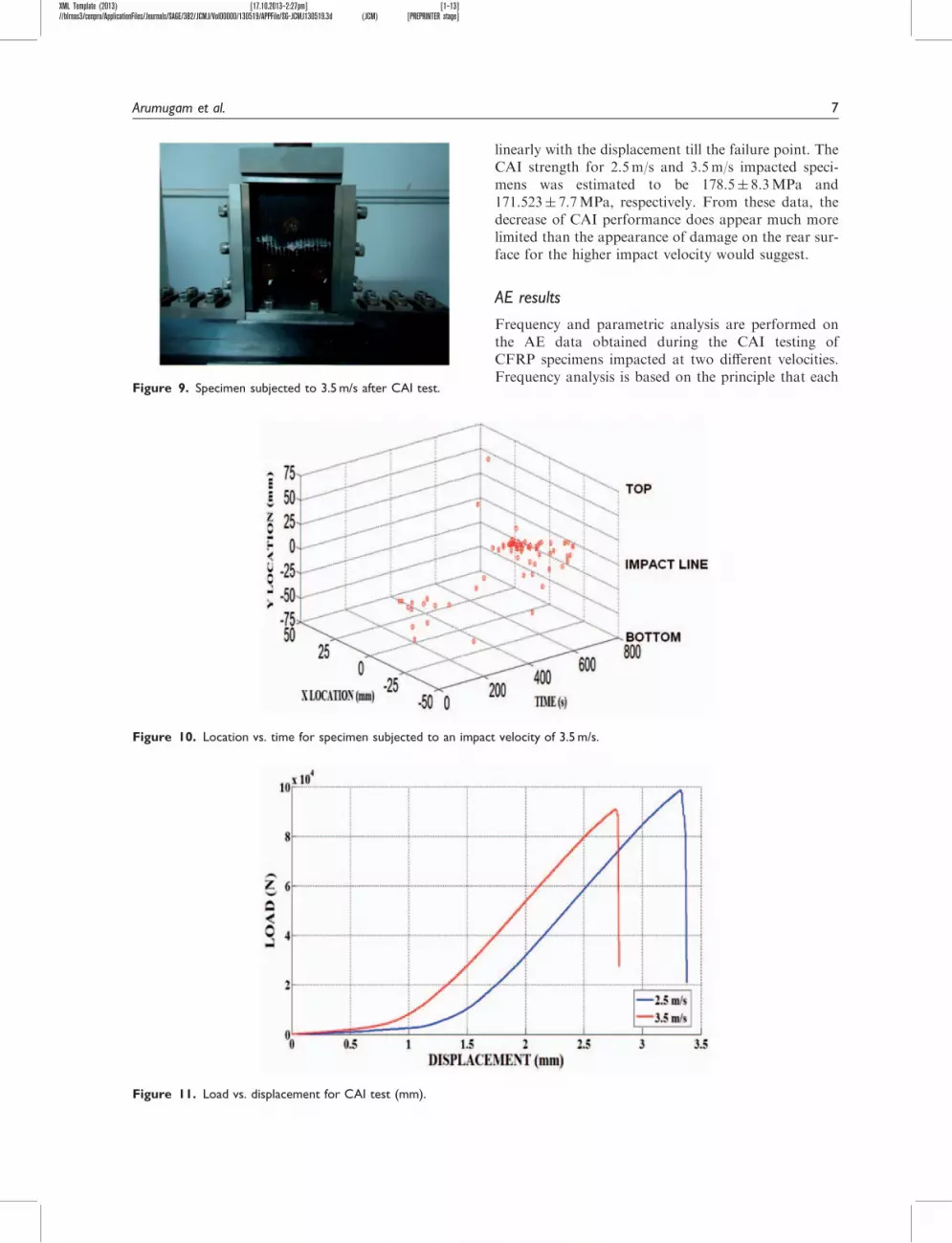
XML Template (2013) [17102013ndash227pm] [1ndash13]blrnas3cenproApplicationFilesJournalsSAGE3B2JCMJVol00000130519APPFileSG-JCMJ1305193d (JCM) [PREPRINTER stage]
28 Santulli C Janssen M and Jeronimidis G Partial replace-ment of E-glass fibres with flax fibres in composites andeffect on falling weight impact performance J Mater Sci
2005 40 3581ndash358529 Santulli C Matrix cracking detection5 by acoustic emis-
sion in polymer composites and countsduration ratioE-J Non-Destruct Test 2012 15(11) 2
30 Arumugam V Barath Kumar S Santulli C et al Effectof fibre orientation in uni-directional glass epoxy lamin-ate using acoustic emission monitoring Acta Metall Sin
(Engl Lett) 2011 24 351ndash364
31 Amin Salehi-Khojin Reza Bashirzadeh MohammadMahinfalah et al The role of temperature on impactproperties of Kevlarfibreglass composite laminates
Compos Part B 2006 37 593ndash60232 Huguet S Godin N Gaertner R et al Use of acoustic
emission to identify damage modes in glass fibre rein-forced polyester Compos Sci Technol 2002 62
1433ndash1444
12 Journal of Composite Materials 0(0)