
Calcium Carbonate Production on the Central - USF Digital ...
Upload
khangminh22Category
view
3download
0
Facies and sequence architecture of mixed carbonate-siliciclastic depositional systems during transforming sag to foreland basin
geometries − “Sundance Basin”, Middle and Late Jurassic, western United States
Dissertation
zur
Erlangung des Doktorgrades (Dr. rer. nat.)
der
Mathematisch-Naturwissenschaftlichen Fakultät
der
Rheinischen Friedrich-Wilhelms-Universität Bonn
vorgelegt von
Olaf Büscher
aus
Bünde/Westfalen
Bonn 2003

Angefertigt mit Genehmigung der Mathematisch-Naturwissenschaftlichen Fakultät der Rheinischen Friedrich-Wilhelms-Universität Bonn

Contents
Abstract ..............................................................................................................................6
Zusammenfassung............................................................................................................8
1 Introduction...............................................................................................................10
1.1 Study objectives....................................................................................................10
1.2 Research methods................................................................................................13
2 Geologic framework.................................................................................................17
2.1 Location and geologic setting of the study area ...................................................17
2.2 Paleogeography....................................................................................................18
2.3 Lithostratigraphy ...................................................................................................22
2.4 Allostratigraphy .....................................................................................................42
2.4.1 Hierarchical concept of allostratigraphic boundaries.....................................43
2.4.2 Allostratigraphic boundaries in the “Sundance Basin”...................................44
2.5 Cyclostratigraphy ..................................................................................................62
3 Facies analysis .........................................................................................................65
3.1 Carbonates ...........................................................................................................65
3.2 Siliciclastics...........................................................................................................90
3.3 Evaporites and collapse breccias .......................................................................109
3.4 Diagenesis ..........................................................................................................111
3.5 Ichnofacies..........................................................................................................112
3.6 Supplementary facies types................................................................................120
4 Facies modelling ....................................................................................................123
4.1 Existing facies models for the “Sundance Basin” ...............................................124
4.2 Facies model for a carbonate depositional system in the „Sundance Basin“ .....125
4.3 Facies model for a siliciclastic depositional system in the „Sundance Basin“ ....130
4.4 Facies model for a mixed carbonate-siliciclastic depositional system in the “Sundance Basin” .........................................................................................134
4.5 Ramp models for differing basin configurations in the “Sundance Basin” ..........135
4.5.1 Homoclinal ramp model...............................................................................136
4.5.2 Distally steepened ramp model ...................................................................136
4.6 Basinwide facies context ....................................................................................137
4.7 Facies analysis and modelling characteristics....................................................139

4
5 Facies and allostratigraphic correlation in the “Sundance Basin” ...................141
5.1 2-dimensional facies correlation .........................................................................141
5.2 Spatial facies distribution within sedimentary cycles: facies maps .....................157
5.3 Spatial and temporal facies characteristics: 3-dimensional facies correlation....166
6 Stratigraphic concepts for the “Sundance Basin”..............................................171
6.1 Cyclostratigraphic concept for the “Sundance Basin”.........................................171
6.2 Sequence stratigraphic concepts for the “Sundance Basin”: depositional, genetic and transgressive-regressive .................................................................174
7 Sequence stratigraphic correlation in the “Sundance Basin” ...........................180
7.1 Correlation and hierarchy of third-order sequences within second-order sedimentary cycles .............................................................................................180
7.1.1 First Marine Cycle (C I) ...............................................................................180
7.1.2 Second Marine Cycle (C II) .........................................................................184
7.1.3 Third Marine Cycle (C III) ............................................................................191
7.1.4 The “unnamed cycle”...................................................................................198
7.1.5 Fourth Marine Cycle (C IV)..........................................................................199
7.2 Sequence characteristics....................................................................................206
7.3 Sedimentary cycle and sequence hierarchy in the “Sundance Basin”................208
8 Facies and sequence architecture........................................................................210
8.1 Facies and sequence architecture of the First Marine Cycle (C I)......................210
8.2 Facies and sequence architecture of the Second Marine Cycle (C II)................211
8.3 Facies and sequence architecture of the Third Marine Cycle (C III)...................213
8.4 The “unnamed cycle” ..........................................................................................215
8.5 Facies and sequence architecture of the Fourth Marine Cycle (C IV) ................215
8.6 Appearance and internal organization of sequences and sequence types ........216
9 Identification and influence of controlling mechanisms ....................................221
9.1 Relative sea-level changes in the “Sundance Basin” .........................................221
9.1.1 Interpretation of relative sea-level changes in terms of global eustasy.......222
9.1.2 Comparison of transgressive events and relative sea-level curves in the “Sundance Basin”..................................................................................224

5
9.2 Quantitative subsidence analysis .......................................................................227
9.2.1 Overburden .................................................................................................227
9.2.2 Decompaction .............................................................................................228
9.2.3 Compaction parameters and porosity-depth relations.................................229
9.2.4 Decompacted thickness profiles..................................................................232
9.2.5 Subsidence and sediment accumulation curves .........................................235
9.3 Influence of tectonism on sedimentation in the “Sundance Basin” .....................238
9.3.1 Subsidence pattern .....................................................................................238
9.3.2 Basin geometry ...........................................................................................239
9.3.3 Depositional environments and facies evolution .........................................240
10 Geologic modelling of the “Sundance Basin” evolution....................................242
10.1 Existing geologic models for the “Utah-Idaho trough”.........................................243
10.2 Discussion and evaluation of existing theories ...................................................246
10.3 Geologic scenario: 3-dimensional modelling ......................................................249
11 Influence of allogenetic factors on facies evolution and sequence architecture in the “Sundance Basin”..................................................................256
12 Identification of potential reservoir-seal facies types and stratigraphic traps in the “Sundance Basin”..............................................................................264
12.1 Existing reservoir rocks in the “Sundance Basin” ...............................................264
12.2 Potential reservoir and seal facies types in the “Sundance Basin”.....................265
12.2.1 Theoretical framework.................................................................................265
12.2.2 Basin configurations and prediction of potential reservoir rocks .................266
12.2.3 Basin configurations and prediction of potential seals ................................270
12.2.4 Basin configurations and potential reservoir rocks and seals .....................271
13 Comparison with other basin studies ..................................................................273
14 Summary of results and conclusions...................................................................277
Acknowledgements .......................................................................................................285
References .....................................................................................................................286
Appendix ........................................................................................................................305

6
Abstract
During the Middle Jurassic, the symmetric intracratonic “Sundance Basin” in the western portion of the North American continent was overridden by the approaching tectono-orogenic front of an early Cordilleran orogeny and transformed into an asymmetric foreland basin. In the Late Jurassic, the orogenic activity ceased and the basin reflexively regained its symmetric geometry. The basin transformation comprises three evolutionary stages and fundamentally influenced the facies evolution as well as the sequence architecture. The reorganization had a tremendous impact on distribution, character and geometry of economically significant sediment bodies in the carbonate-siliciclastic basinfill.
These stratigraphic-sedimentologic relationships were investigated in an original case study. Furthermore, this investigation provides the first analysis of the entire “Sundance Basin”. The study is based on a grid of 35 outcrop sections in Wyoming, Montana, Utah, Idaho, and South Dakota. This data set was supplemented by stratigraphic sections, well data and research results from the present regional-geologic literature.
More than 20 carbonate, siliciclastic and evaporitic facies types indicate basinwide depositional models describing homoclinal and distally steepening ramps. Basinwide discontinuities define five allostratigraphic units. Each unit represents the remnant of a transgressive-regressive second-order sedimentary cycle: First Marine Cycle (C I), Second Marine Cycle (C II), Third Marine Cycle (C III), “unnamed cycle” and Fourth Marine Cycle (C IV). Internally, the second-order sedimentary cycles are composed of third-order sequences. The sequence boundaries are recorded by transgressive deposits and/or erosional surfaces. The second-order sedimentary cycles and third-order sequences consist of transgressive and regressive systems tracts of differing hierarchy. The architecture of the sequences varies along the time axis.
The different sequence types and stacking patterns correlate with the three stages of basin evolution. During the initial basin stage (“sag basin stage”) tabular sequences with a layer cake stacking developed. Wedge-shaped sequences with an aggradational to progradational stacking pattern evolved during the asymmetric basin stage (“foreland basin-style stage”). In the final evolutionary stage (“rebound stage”) simple stacked, tabular and truncated sequences were generated.
Sea-level changes as a major controlling mechanisms are not eustatic, but regional and are controlled by regional-tectonic and climatic parameters. Moreover, the formation of sequence boundaries corresponds to tectono-orogenic phases of the early Cordilleran orogeny. The temporarily asymmetric subsidence behavior generated additional accommodation space, while the increasing input of clastic material from orogenic sources primarily regulated the sediment supply. This interplay influenced the carbonate factory in the subsiding, asymmetric portion of the basin. Low sediment supply, sufficient subsidence rates and a warm climate promoted the formation of thick, distal carbonate

Abstract 7
successions, while the increasing input of siliciclastics caused the termination of the carbonate factory. Ceasing orogenic activities and erosion of the evolved orogen produced low subsidence rates and initiated partial overfilling of the basin during the final evolutionary stage.
The geometric transformation significantly influences the generation of potential reservoirs and seals. In a symmetric basin geometry (“sag basin stage”) these associations are developed as thin but widespread carbonate reservoir facies types. During an asymmetric basin geometry (“foreland basin-style stage”) potential reservoirs and seals occur either in shoreline-detached carbonate facies belts that fringe areas of increased subsidence or in continuous siliciclastic shoreface-foreshore successions of tectonically stable areas. For symmetric basin settings that undergo partial overfilling by increasing siliciclastic input (“rebound stage”) no significant reservoir and seal facies types were found due to the high degree of erosion and redistribution within the sedimentary system.

8
Zusammenfassung
Im Westen von Nordamerika wurde im Mittleren Jura das symmetrische intrakratonale „Sundance Basin“ an seinem westlichen Rand von der vorrückenden tektono-orogenen Front einer frühen Kordilleren-Orogenese überfahren und in ein asymmetrisches Vorlandbecken umgeformt. Bereits im Oberjura ließ die orogene Aktivität nach und das Becken fiel reflexartig in eine symmetrische Konfiguration zurück. Die Beckentransformation umfasst drei Entwicklungsstadien und hat fundamentale Auswirkungen auf die Faziesevolution und die Sequenzarchitektur. Die Reorganisation beeinflusst entscheidend die Verbreitung, den Charakter und die Geometrie von ökonomisch relevanten Sedimentkörpern in der karbonatisch-siliziklastischen Beckenfüllung.
Diese prinzipiellen stratigraphisch-sedimentologischen Zusammenhänge wurden in einer Fallstudie untersucht und führten dabei auch zu einer ersten beckenweiten Analyse des „Sundance Basin“. Dafür wurden 35 Geländeprofile in Wyoming, Montana, Utah, Idaho und South Dakota sedimentologisch untersucht. Die Datenbasis wurde durch Auswertung von stratigraphischen Profilen, Bohrungsdaten und Untersuchungsergebnissen der regional-geologischen Literatur ergänzt.
Mehr als 20 karbonatische, siliziklastische und evaporitische Faziestypen belegen beckenweite Ablagerungsmodelle, die homoklinale und distal versteilende Rampen beschreiben. Diskontinuitätsflächen in der Schichtenfolge begrenzen fünf allostratigraphische Einheiten. Diese Gesteinskörper repräsentieren die erhaltene Teile von transgressiv-regressiven Ablagerungszyklen zweiter Ordnung: First Marine Cycle (C I), Second Marine Cycle (C II), Third Marine Cycle (C III), “unnamed cycle” und Fourth Marine Cycle (C IV). Innerhalb der sedimentären Zyklen lassen sich Sequenzen dritter Ordnung unterscheiden. Die Sequenzgrenzen sind durch transgressive Sedimente und/oder Erosionsflächen dokumentiert. Intern sind die sedimentären Zyklen und Sequenzen von transgressiven und regressiven „systems tracts“ unterschiedlicher Hierarchie aufgebaut. Die Sequenzarchitektur verändert sich entlang der Zeitachse.
Die unterschiedlichen Sequenztypen und Stapelungsmuster korrelieren zeitlich mit den drei Stadien der Beckenevolution. Im initialen, symmetrischen Beckenstadium („sag basin stage“) bildeten sich tafelförmige Sequenzen mit einfachem Stapelungsmuster. Keilförmige, aggradierende und progradierende Sequenzen entstanden während der asymmetrischen Geometrie des Beckens („foreland basin-style stage“). Ein erosiv gekappter, tafelförmiger Sequenztyp tritt während des finalen, symmetrischen Beckenstadiums („rebound stage“) auf.
Meeresspiegelschwankungen als wichtiger Steuerungsmechanismen sind nur untergeordnet eustatisch, sondern regional und von tektonischen und klimatischen Parametern kontrolliert. Die Entstehung von Sequenzgrenzen korreliert mit tektono-orogenen Phasen der frühen Kordillerenorogenese. Das temporär asymmetrische

Zusammenfassung 9
Subsidenzverhalten führte zur Schaffung von zusätzlichem „accommodation space“, während der zunehmende Eintrag von klastischem Material aus orogenen Liefergebieten den „sediment supply“ steuerte. Dieses Zusammenspiel beeinflusste die „carbonate factory“ im asymmetrischen Teil des Beckens. Geringer Sedimenteintrag, hohe Subsidenzraten und warmes Klima begünstigten die Entstehung mächtiger distaler Karbonatabfolgen, während zunehmender Eintrag von Siliziklastika zum Abschalten der „carbonate factory“ führte. Die abnehmende orogene Aktivität und die Abtragung des Orogens bedingte geringe Subsidenzraten und „partial overfilling“ des Beckens im finalen Entwicklungsstadium.
Die geometrischen Umformungsprozesse bedingen signifikante Veränderungen in der Bildung von „Reservoirs“ und „Seals“. In symmetrischen Beckenkonfigurationen („sag basin stage“) sind geringmächtige, aber räumlich weitaushaltende Karbonatfaziestypen als potentielle Reservoirs ausgebildet. In asymmetrischen Beckengeometrien („foreland basin-style stage“) sind „Reservoirs“ und „Seals“ in hoch-energetischen Karbonatfaziesgürteln entwickelt, welche Gebiete erhöhter Subsidenz eingrenzen. Zusätzlich kommen „Reservoirs“ und „Seals“ in progradierenden, siliziklastischen Vorstrand-Strand-Abfolgen in tektonisch stabilen Gebieten vor. Für symmetrische Beckenkonfigurationen mit „partial overfilling“ durch zunehmenden Sedimenteintrag konnten keine „Reservoirs“ und „Seals“ nachgewiesen werden, was auf intensive Erosions- und Umlagerungsprozesse im Ablagerungssystem zurückgeführt werden kann.
10
1 Introduction
1.1 Study objectives
Geologic setting
During the Nevadian orogeny in the Middle and Late Jurassic, an active margin system developed at the western edge of the North American continent. In the Middle Jurassic, the continuously eastward shifting Nevadian tectono-orogenic front reached a pre-existing intracratonic basin that is referred to in this study as “Sundance Basin”. This initiated a reorganization of the paleotectonic setting. With the progressive orogenic process, the spatial subsidence behavior changed and the evolution of the “Sundance Basin” became dominated by varying geometric basin configurations. The initially symmetric, intracratonic basin geometry was temporarily modified into an asymmetric foreland basin. The paleogeographic setting initiated carbonate production as well as a permanent influx of siliciclastics from external and internal uplifts. The resulting sedimentary suite comprises sediment bodies of shale, sandstone, evaporite, and carbonate. In the Late Jurassic, the orogenic activity ceased and terminated the marine development. The Late Jurassic lacustrine and fluvial sediments of the Morrison Formation represent a molasse stage of an unfinished foreland basin before Cretaceous orogenies.
General problems
This geologic setting yields several fascinating aspects and unanswered geologic problems. Five principal geologic questions can be tied into the geologic history of the “Sundance Basin”:
1. In which way changed the geometry and the subsidence pattern within the transformed basin? The geometric history of the basin should be locked in the facies distribution and in the decompacted thickness pattern.
2. Is the changing basin geometry triggering characteristic facies evolutionary and sequence architectural styles? The changing geometry should affect the environmental parameters controlling the sequence stratigraphic architecture in a typical relationship.
3. Can the dynamics of a carbonate-siliciclastic depositional system be explained by sequence stratigraphic models? These aspects are poorly understood. Furthermore, facies models for mixed carbonate-siliciclastic systems do rarely exist.
4. Is the generation and distribution of resource sediments responding to the changing basin geometry? The progressive basin transformation should alter the occurrence, geometry and stratal position of potential sedimentary resource bodies.

1. Introduction 11
5. Are the research results contributing insights into the principal origin and subsequent evolution of intracratonic basins? Tectonic overprinting and transformation into other basin types is not investigated so far. This includes exemplary investigations of the depositional systems within the basin during the transformational process and the documentation of the subsidence history.
The geologic setting, good outcrop conditions and a solid framework of basic lithostratigraphic work makes the Jurassic “Sundance Basin” a priority research target for a case study. The facies resolution is excellent within the study area. Facies types and facies changes can be identified in the commonly well exposed stratigraphic sections. Major erosional surfaces within the stratal record are well known. Consequently, the “Sundance Basin” gives insight into the facies evolution and sequence architectural styles during major transformational stages of an extraordinary basin evolution.
Regional problems
A basinwide facies model and a sequence stratigraphic concept are essential elements that provide the basic framework for this case study. Their establishment for the “Sundance Basin” was restricted by pre-existing regional geologic problems in the study area:
1. Basinwide facies models do not exist for the “Sundance Basin”. The regionally varying status of sedimentologic research made the development of a basinwide facies model problematic. Some portions of the “Sundance Basin” were subject to sedimentologic research, while other areas were neglected.
2. The biostratigraphic resolution within the basinfill is poor. The sediments are commonly fossiliferous. However, fauna and flora of biostratigraphic value is very limited. Poor biostratigraphic control impedes basinwide stratigraphic correlation in the “Sundance Basin”.
Data & methods
The data set that was used for this study is based on two sources:
• Field and lab work on outcrop and rock sample material.
• Additional literature data from MSc, PhD and Diploma theses from the Universities of Wyoming, Michigan, Wisconsin, and the University of Bonn/Germany, respectively, and results from previous workers, published in numerous scientific papers. The latter will be mentioned where they are used in the course of this study.
In order to establish a comprehensive depositional model and a sequence stratigraphic concept it turned out to be necessary to correlate basinwide major facies types and bounding surfaces 2- and 3-dimensionally for the first time in the “Sundance Basin”.
The applied research methods include sedimentologic field work that was conducted on 35 outcrop sections in Wyoming, Montana, northeastern Utah, western South Dakota, and

1. Introduction 12
eastern Idaho. Special attention was drawn to bounding surfaces and unconformities like sudden facies changes and erosional surfaces. Samples were taken from carbonate successions and from chosen siliciclastics. The subsequent sedimentologic interpretation of the carbonate samples is based on the microfacies analysis methods of thin sections introduced by FLÜGEL (1982). The facies analysis of siliciclastic rocks comprises the interpretation of sediment structures, sediment petrography and grain size as the main criteria. The sedimentological data provided paleoenvironmental information and, in the vertical compilation, a cyclostratigraphic profile of every measured section. The basinwide 2- and 3-dimensional facies correlation produced both, a basinwide depositional model and a sequence stratigraphic framework.
Facies maps displaying the main depositional intervals were produced to represent the corresponding time slice during basin evolution. Finally, decompacted thickness profiles were produced and provided the required data for a quantifying subsidence analysis for the entire the “Sundance Basin”. This manifold data set was finally integrated to compile a geologic model for the “Sundance Basin”.
Stratigraphically, the “Sundance Basin” fill includes the Gypsum Spring Formation and Sundance Formation in South Dakota and Wyoming, the Ellis Group (Sawtooth Formation, Rierdon Formation and Swift Formation) and Piper Formation in Montana, the Twin Creek Limestone, Carmel Formation, Preuss Formation, Entrada Sandstone, and Stump Formation in northeastern Utah, western Wyoming and eastern Idaho.
Focus
The unsolved principal and regional geologic problems define the main objectives for this study. It is primary aim of this study to determine the impact of a changing basin geometry on the facies evolution and sequence architecture of a mixed carbonate-siliciclastic basinfill. It will be further essential to identify the parameters that played an important role for the sedimentation within transforming basin configurations. Consequently, a number of methodical steps were necessary to assure progress for this case study. Those steps were:
• Confirmation of established and identification of new bounding unconformities to identify allostratigraphic units in the basinfill.
• Analysis and interpretation of carbonate microfacies, siliciclastic lithofacies and ichnofacies types as well as their spatial arrangement in a basinwide facies model for the “Sundance Basin”.
• 2 and 3-dimensional basinwide correlation of facies types and bounding surfaces.
• Compilation of basinwide facies maps for defined stratigraphic intervals.
• Erection of a basinwide sequence stratigraphic concept.
• Basinwide sequence stratigraphic correlation.
1. Introduction 13
• Determination of the sequence stratigraphic pattern expressed in the internal organization (facies distribution, lithology and bounding surfaces) and physical appearance (isopach pattern, sequence geometry, stacking pattern) of sequences with time.
• Identification of controlling factors on the facies evolution and sequence architectural styles in the in the transforming basin. Evaluation of the interplay between the allogenetic factors eustasy, tectonism and climate.
• Reconstruction of the spatial and temporal basin evolution, basin geometry and the subsidence pattern.
• Development of a geologic model for the entire “Sundance Basin”, that represent distinct basin evolutionary stages.
• The combination of these results lead to the identification of potential economic sediment bodies in the depositional systems and transforming basin configurations.
1.2 Research methods
1.2.1 Field work and facies interpretation
The primary data source is derived from:
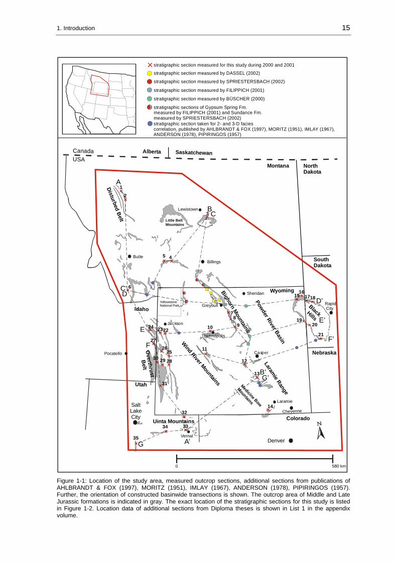
1. Field work performed during the summers of 2000 and 2001 in the central Rocky Mountains area. 35 outcrop sections, shown in Figure 1-1 and listed in Figure 1-2, were chosen for sedimentological and stratigraphic analyses. The exact location of the investigated sections are listed in the appendix volume. Overall 363 rock samples were collected from which 244 carbonate rock samples were used to produce thin-sections. To assure correspondence to the present stratigraphic context, sections were selected, which were measured for other stratigraphic investigations by previous workers. Lithologic sections from each studied location are illustrated in the appendix volume. The outcrop work included:
• Measuring of detailed stratigraphic sections of the 70 m to about 1100 m thick stratal packages using the 1,5 m profiling stick of WURSTER & STETS (1979).
• Documentation of sediment structures and on-site grain size analysis using a grain size scale and 16x hand lenses.
• Photo-documentation.
• Tracing of bounding surfaces and stratal geometries.
• Sampling after detectable lithofacies changes in carbonates and of selected siliciclastics.
• Pre-analysing the carbonate rocks using hand lenses and 10% HCL.

1. Introduction 14
2. The sedimentologic interpretation of 244 carbonate thin-sections applying the microfacies analysis methods of thin-sections introduced by FLÜGEL (1982). The hand samples were prepared for transportation in the rock lab of the Department of Geology & Geophysics of the University of Wyoming in Laramie. The thin-sections were produced by the author in the rock lab of the University of Bonn. The facies analysis of siliciclastic rocks comprises thin-section petrographic analysis, interpretation of sediment structures, and grain size as the main criteria.
1.2.2 Literature data
To enhance a spatial resolution of the primary data set, sedimentologic information, isopach data and outcrop descriptions were used from MSc theses of ANDERSON (1978), WEST (1985) and CAPARCO (1989) submitted to the University of Wyoming, PhD theses from RAUTMANN (1976) and HILEMAN (1973) submitted to the Universities of Wisconsin and Michigan, respectively, and four Diploma theses of BÜSCHER (2000), FILIPPICH (2001), DASSEL (2002), and SPRIESTERSBACH (2002) prepared at the University of Bonn. The exact location of used additional stratigraphic sections from those Diploma theses are listed in List 1 in the appendix volume. Further, detailed stratigraphic sections, isopach data and facies interpretations published in various papers by previous workers were used to bridge gaps in the established outcrop section grit. The biostratigraphic data set is derived from IMLAY (1967; 1980).
1. Introduction 15
Denver
Laramie
Cheyenne
Casper
Rapid City
Salt Lake City
Pocatello
Sheridan
Greybull
BillingsButte
Jackson
Montana
Utah
Idaho
Bighorn Mountains
Laramie Range
Wind River Mountains
Little BeltMountains
Disturbed Belt
YellowstoneNational Park
SaskatchewanAlberta
Uinta Mountains
Medicine Bow
Mountains
Lewistown
Wyoming
Vernal
Thermopolis
1
2
45
6
78
910
1516
1718
21
2019
12
13
14
24
25 11
CanadaUSA
NorthDakota
SouthDakota
Nebraska26
27
28
2223
2930
31
32
3334
35
Colorado
3
Overthrust
Belt
0 580 km
Powder River Basin
Black Hills
A
stratigraphic section measured by DASSEL (2002)
stratigraphic section measured for this study during 2000 and 2001
stratigraphic section measured by SPRIESTERSBACH (2002)
stratigraphic section measured by FILIPPICH (2001)
stratigraphic section measured by BÜSCHER (2000)
stratigraphic section taken for 2- and 3-D faciescorrelation, published by AHLBRANDT & FOX (1997), MORITZ (1951), IMLAY (1967),ANDERSON (1978), PIPIRINGOS (1957)
stratigraphic sections of Gypsum Spring Fm. measured by FILIPPICH (2001) and Sundance Fm. measured by SPRIESTERSBACH (2002)
A’G
G’B’
F’
E’
D’DC’
BC
E
F
Figure 1-1: Location of the study area, measured outcrop sections, additional sections from publications of AHLBRANDT & FOX (1997), MORITZ (1951), IMLAY (1967), ANDERSON (1978), PIPIRINGOS (1957). Further, the orientation of constructed basinwide transections is shown. The outcrop area of Middle and Late Jurassic formations is indicated in gray. The exact location of the stratigraphic sections for this study is listed in Figure 1-2. Location data of additional sections from Diploma theses is shown in List 1 in the appendix volume.

1. Introduction 16
No. Name of section & abbreviation
State Township/Range
1 Swift Reservoir (SR) MT T 28 N., R 10 W., Sec. 26 & 27
2 Sun River Canyon (SRC) MT T 22 N., R 9 W., Sec. 25
3 Heath (HE) MT T 14 N., R 19 E., Sec. 12
4 Rocky Creek Canyon (RC) MT T 2 S., R 7 E., Sec. 19
5 Sappington (SAP) MT T 1 N., R 2 W., Sec. 25
6 Little Water Creek (LW) MT T 13 S., R 31 E., Sec. 10
7 Hyattville (HY) WY T 49 N., R 89 W., Sec. 16
8 Red Rim Ranch (RR) WY T 46 N., R 87 W., Sec. 16
9 Hampton Ranch(HR) WY T 43 N., R 88 W., Sec. 24
10 Red Lane (RL) WY T 43 N., R 6 E., Sec. 18
11 Squaw Women Creek (SWC) WY T 33 N., R 1 E., Sec. 22
12 Alcova Reservoir (AR) WY T 30 N, R 84 W, Sec. 30
13 Freezeout Hills (FH) WY T 26 N., R 79 W., Sec. 33
14 Jelm Mountain (J) WY T 13 N., R 77 W., Sec. 35
15 Hulett (HU) WY T 54 N., R 65 W., Sec. 12 & 2
16 T cross T Ranch (T-T) WY T 55 N., R 64 W., Sec. 1
17 Thompson Ranch (TR) SD T 7 N., R 1 E., Sec. 2
18 Spearfish (SF) SD T 52 N., R 2 E., Sec. 11
19 Stockade Beaver Creek (SBC) WY T 45 N., R 60 W., Sec. 18
20 Elk Mountain (EM) SD T 6 S., R 1 E., Sec. 10
21 Minnekatha (MIN) SD T 7 S., R 4 E., Sec., 21
22 Hoback Canyon (HC) WY T 38 N., R 114 W., Sec. 6
23 Cabin Creek (CC) WY T 38 N., R 116 W., N ½, Sec. 17
24 Big Elk Mountain (BE) ID T 2 S., R 45 E., SW ¼, Sec. 6
25 South Piney Creek (SPC) WY T 29 N., R 115 W., Sec. 10 ; 11 ; 12
26 Poker Flat (PF) WY T 29 N., R 117 W., Sec. 3 & 10
27 Stump Creek (SC) ID T 6 S., R 45 E., SW ¼, Sec. 27 & SE ¼, Sec. 28
28 La Barge Creek (LB) WY T 27 N., R. 115 W., Sec. 16 & 17
29 Devils Hole Creek (DH) WY T 27 N., R 117 W., Sec. 22 & 23
3o Thomas Fork Canyon (TF) WY T 28 N., R 119 W., Sec.19 & 20
31 Twin Creek (TC) WY T 21 N., R 119 W., NE ¼, Sec. 1
32 Flaming Gorge (FG) WY T 2 N., R 20 E. Sec. 6 & 31
33 Vernal (V) UT T 3 S., R 22 E., Sec. 5
34 Whiterocks Canyon (W) UT T 2 N., R 1 E., SE ¼, sec. 18 & NW ¼, Sec. 19
35 Thistle (THI) UT T 8 S., R 4 E., Sec. 28
Figure 1-2: Abbreviations and exact locations of stratigraphic sections investigated during field work for this study. The section numbers are corresponding to the numbers in Figure 1-1.
17
2 Geologic framework
2.1 Location and geologic setting of the study area
Geographically, the study area is located in the central Rocky Mountain states of the USA: Wyoming, Montana, western South Dakota, eastern Idaho, and northeastern Utah. The study area is shown in Figure 1-1. The southernmost outcrop section is near Thistle/Utah (section 35, Figure 1-1), while the northernmost section is located at the Swift Reservoir/Montana (section 1, Figure 1-1) close to the southern border of Glacier National Park. In east-west direction the field area stretches from the Black Hills into the “Overthrust Belt” at the Wyoming-Idaho border.
The outcrop area of Jurassic strata is also shown in Figure 1-1. In general, outcrops and stratigraphic sections of Jurassic rocks are available:
• on the flanks of uplifted structural elements as for instance the Bighorn Mountains in Wyoming and the Black Hills in western Wyoming and eastern South Dakota,
• in thrust sheets as for instance in the “Disturbed Belt” in Montana and the “Overthrust Belt” in western Wyoming.
In between these outcrops areas Jurassic strata occur only in the subsurface, e.g. in the Powder River Basin. The thickness of the investigated stratal column increases from approximately 70 m in the Black Hills of South Dakota to about 1100 m in the “Overthrust Belt” of western Wyoming and eastern Idaho.
The geologic setting of the study area is characterized by the twofold structural style of Laramide tectonics of the Rocky Mountain foreland in the east and the Cordilleran thrust belt in the west (Figure 2-1). Despite the structural differences the contrasting tectonic styles are intimately related in time and space (DICKINSON et al. 1988, BROWN 1993). The Cordilleran thrust belt, also referred to as “foreland fold-and-thrust belt” (EISBACHER 1988), “Sevier orogenic belt” (SNOKE 1993), “Sevier fold-and-thrust belt” or “Overthrust belt” (LAGESON & SPEARING 1991), is a classic example of an intraplate, retroarc fold-thrust belt (SNOKE 1993). The contractile deformation of the Sevier orogeny, initiated by multiphase metamorphic-magmatic deformation and synchronous foreland thrusting, started during the Early Cretaceous (HELLER et al. 1986) and is known as “thin-skinned tectonic style” (DICKINSON et al. 1988). Along the Wyoming-Idaho border, in northern Utah and western Montana, the imbricated overthrust sheets are well exposed. Eastward of the Cordilleran thrust belt begins the tectonically contrasting domain of the Rocky Mountain foreland. This part of the study area is characterized by the Laramide orogeny. Deep-rooted, reverse and thrust faults fractured the North American craton during the Late Cretaceous through the early Eocene and formed basement-cored uplifts separated by deep, actively subsiding basins (DICKINSON et al. 1988, SNOKE 1993). This distinct Laramide-style is known as “thick-skinned tectonics”. Characteristic elements of this tectonic style in the study area are for instance the basement-cored uplifts of the

2. Geologic framework 18
Black Hills, Bighorn Mountains, Wind River Mountains, and Owl Creek Mountains, while intervening basins are the Bighorn Basin, Powder River Basin and Wind River Basin (see Figure 1-1). The best exposures of sedimentary rocks are commonly found in the Rocky Mountain foreland, where Mesozoic rocks are exhumed on the flanks of uplifted basement-cored elements. Outcrop conditions in the Cordilleran thrust belt are excellent as well, but potential problems arise when thick, monotonous stratal packages are thrusted. HILEMAN (1973) assumed that some extreme thickness values measured of the Preuss Formation may be the result of repeated sections due to imbrication within thrust plates. The investigated stratigraphic interval is overlain by the fluvio-lacustrine Late Jurassic to Lower Cretaceous Morrison Formation in the entire study area.
Figure 2-1: Simple cross section sketch displaying contrasting “thin-skinned” and “thick-skinned” deformational styles in the western Cordilleran thrust belt and the eastern Rocky Mountain foreland (from LAGESON & SPEARING 1991).
2.2 Paleogeography
The paleogeographic situation and the position of various paleotectonic elements is displayed in Figure 2-2. The study area covers the central and northern portions of the “Sundance Basin”. As shown in the paleogeographic map numerous local paleotectonic elements named “arches”, “trends” and “troughs” are known from the Jurassic period at the western margin of the North American continent. For simplicity the whole structure displayed in Figure 2-2 is referred to as the “Sundance Basin” in this study, in respect to the term “Sundance Sea”. Although “Sundance Basin” is not established in the Jurassic paleogeographic nomenclature, it will be helpful to use a comprehensive term to describe and discuss aspects that apply for the complete, so far unnamed structure. Otherwise, if particular elements or areas within the “Sundance Basin” will be subject to the present study the local nomenclature will be used. It is further important to note that the term proximal will be applied differently from other basin studies, because large stratal portions on the orogenward side of the basin structure in western states are physically removed. The term proximal applies in this study for the eastern, cratonward side of the basin instead of the areas adjacent to a thrust belt as in other studies.

2. Geologic framework 19
0 300 km100 200
WY
MT ND
SD
CO
NB
ID
UT
TXOK
NV
AZ NM
CA
SaltLakeCity
Denver
Albuquerque
LasVegas
Phoenix
Laramie
RapidCity
Sheridan
Lewistown
Pocatello
Wes
tern
E
lko
H
ighl
ands
CANADAUSA
MEXICO
AncestralRockyMtns. ?
Magm
atic Arc Mogollon Slope
Graben Depression
BELT
ISLAND
COMPLEX
POW
DE
RR
IVER
EM
BAYM
ENT
WILLISTONBASIN
HARDIN
TROUGH
SWEETGRASSTROUGH
ALBERTA
TROUG
H
SW
EETG
RA
SSAR
CH
BOULDER HIGHUT
AH-ID
AHO
TRO
UGH
CIRCLE
CLIFFS
TROUGH
HIGH P
LATE
AUS
TREN
D
COLORAD
O TREN
D
MONUM
ENT
ARCH
BLAN
DING
BASI
N
UNCOMPAHGRE POSITIVE AREA
SHERIDAN ARCH
BLACK MTN.
HIGH
SAN JUAN
BASIN
Z U N I T R E N D
BLACK MESA ARCH
?
?
?“WYOMING
SHELF”
area with negative reliefarea with positive relief
approximateshape of
“Sundance Basin”
?
Figure 2-2: Paleogeographic map of the “Sundance Basin” structure with individual paleotectonic elements for the Middle and Late Jurassic. Compiled from PETERSON (1954; 1957a and b; 1958), KOCUREK & DOTT (1983), BLAKEY et al. (1983), BLAKEY (1988), PETERSON, F. (1986; 1994), BRENNER (1983), IMLAY (1980), SCHMUDE (2000).

2. Geologic framework 20
Since the Eocambrian, the western portion of the North American craton was flooded by the ocean. With the beginning terrane accretion in the Middle Paleozoic the access to the open ocean was progressively blocked until in the Triassic/Jurassic the westerly passage was replaced by arctic seaways. The history of the Middle and Late Jurassic of the western North American continent “is a variation of the theme made familiar by preceding subsequences; that is, persistent seaways occupied the more rapidly subsiding areas of the cratonic border, spreading inland to form carbonate and evaporitic tongues intercalated with continental deposits.” (SLOSS 1988: 43). The Middle and Late Jurassic stratal packages were deposited during the late breakup of the supercontinent Pangea (FRAZIER & SCHWIMMER 1987) that was further accompanied by a period of transition in the Rocky Mountains region (LAGESON & SPEARING 1991). A major tectonic reorganization took place at the western margin of the North American continent. During the Middle and Late Jurassic an Andean-type magmatic arc formed in the southern Cordilleran region as a result of deformation, magmatism and uplift, known as the Nevadan orogeny (SCHWEICHERT & COWAN 1975, FRAZIER & SCHWIMMER 1987, EISBACHER 1988). Additionally, the North American plate drifted northward in a counterclockwise rotation and moved through latitudes 22° to 42° N (PARRISH & PETERSON 1988, PETERSON, F. 1988, PARRISH 1993).
During the Triassic, the western margin of the North American continent was occupied by a featureless, muddy coastal plain on which the sediments of the Chugwater Group and their stratigraphic equivalents were deposited (PICARD 1993). The overlying, eolian Lower Jurassic Nugget Sandstone and the equivalent Navajo Sandstone were formed by an enormous coastal to inland dune field that extended from central Wyoming to southern Arizona (KOCUREK & DOTT 1983). A major unconformity separates the Triassic and Early Jurassic from the Middle and Late Jurassic. The unconformity can be traced across the entire craton, where it truncates the Navajo and Nugget Sandstone, the Popo Agie Formation of the Chugwater Group, the Chinle Formation, and the Spearfish Formation (PIPIRINGOS & O’ SULLIVAN 1978, FRAZIER & SCHWIMMER 1987). During the Middle Jurassic, marine conditions returned to the western craton. The craton was flooded and the first “Sundance Sea” stretched from northern Arizona to the Canadian border (KOCUREK & DOTT 1983, FRAZIER & SCHWIMMER 1987). At least seven major and minor marine transgressions are recorded in the Middle Jurassic and Late Jurassic strata (PETERSON, F. 1994). Each successive transgression spread farther southward than the preceding one (IMLAY 1980, FRAZIER & SCHWIMMER 1987). The distribution of Jurassic sediments was mostly influenced by intrabasinal tectonic features within the “Sundance Basin” (IMLAY 1980). In the southern “Sundance Basin” several paleotectonic trends are known. Some of these minor intrabasinal elements had a strong influence on eolian deposition, in that most erg centres lay within paleobasins (BLAKEY 1988, BLAKEY et al. 1988).
The global Jurassic climate was warm and moist. Greenhouse conditions prevailed (GOLONKA & FORD 2000). The paleoclimate at the western edge of the North American continent was warm and dry during the Jurassic (KOCUREK & DOTT 1983, PETERSON,

2. Geologic framework 21
F. 1994). Especially the southern portion of the “Sundance Basin” was under the influence of an arid paleoclimate, as recorded by extensive eolian deposits and evaporites (KOCUREK & DOTT 1983, PARRISH 1993). In contrast, the central parts of the “Sundance Basin” show evidence for temporary humid conditions for the Middle Jurassic (JOHNSON 1992). With the northward movement of the North American continent, the topographic deflection at the western edge of the continent and the global changes toward a more humid paleoclimate, conditions in the “Sundance Basin” shifted finally from dry subtropical domains into a more humid temperate paleoclimate during the Late Jurassic. This paleoclimatic change, from arid to temperate climatic conditions, is expressed by a significant faunal change during the late Middle Jurassic (PETERSON 1957a). A marked decline in the warm-water indicating oyster population (Gryphea sp.) was accompanied by a southward migration of cool-water preferring belemnites. PETERSON, F. (1988) recognized modifications of the paleowind direction, probably due to the northward continent drift and contemporaneous topographic deflections, initiated by the Nevadan orogeny (KOCUREK & DOTT 1983). Southward directed paleowinds during the Early and Middle Jurassic shifted to winds from the northwest and west during the late Middle Jurassic and Late Jurassic.
Various paleotectonic elements served as source areas for the Middle and Late Jurassic sediments. According to HILEMAN (1973), BRENNER & DAVIES (1974) and JORDAN (1985), the primary source was the slowly evolving magmatic arc and orogenic belt that extended from west-central Montana into northern Utah. A volumetrically less important source of siliciclastic sediments were intrabasinal positive elements like the “Sheridan Arch” and “Belt Island Complex” (HILEMAN 1973). As proposed by JORDAN (1985) the paleogeographic setting suggests further that mature sand was transported from the north and southeast into the “Sundance Basin”.
The marine Middle and Late Jurassic successions are succeeded by non-marine sediments of the spatially restricted Windy Hill Member of the Sundance Formation and the widespread Morrison Formation. The Windy Hill Sandstone Member of the Sundance Formation in southeastern Wyoming and the Black Hills grades laterally into the Morrison Formation (BRENNER & PETERSON 1994). Other workers like IMLAY (1980) and JOHNSON (1992) interpreted the Windy Hill Sandstone Member as sediments of a final short-time readvance of marine conditions into Wyoming.
However, the Morrison Formation was deposited in a wide range of environments that include fluvial, lacustrine and eolian settings (IMLAY 1980, JOHNSON 1992, PETERSON, F. 1994). The former “Sundance Basin” was filled with varicolored mud, sand, gravel, lacustrine limestones, and volcanic ash deposits. Despite the global rising sea-level during the Jurassic (HAQ et al. 1987, VAIL et al. 1984, HALLAM 1988) a significant pulse of siliciclastics probably related to increasing orogenic activity to the west (ALLMENDINGER & JORDAN 1984, THORMAN et al. 1990) caused a progressive filling of the Jurassic seaways (BRENNER 1983). In basin evolutionary terms the Morrison Formation resembles a molasse stage.

2. Geologic framework 22
2.3 Lithostratigraphy
The most important information about the investigated Middle and Late Jurassic formations in the “Sundance Basin”, concerning lithostratigraphic relations, geographic distribution, nomenclatorial history, thickness, lithology, biostratigraphic range, and stratigraphic contacts, are compiled in this chapter. The compilation is necessary to avoid stratigraphic ambiguities, due to different standards from state to state and within the various literature sources. The formations are introduced in alphabetical order. A chronostratigraphic correlation chart for the Middle and Late Jurassic formations in Montana, Wyoming, South Dakota, Idaho, Utah, Arizona, and New Mexico is illustrated in Figure 2-3. In this study, the Middle and Late Jurassic biostratigraphic framework established by IMLAY (1980) is followed. For additional information about paleontology and paleobiogeography the reader is referred to the publications of IMLAY (1967; 1980).
2.3.1 Carmel Formation
Members: In northeastern and east-central Utah: undivided. In southwestern Utah to northern Arizona (in ascending order): Judd Hollow Member, Crystal Creek Member, Paria River Member, Winsor Member (BLAKEY et al. 1983).
Chronostratigraphic age: Middle or early Late Bajocian to Middle Callovian (IMLAY 1980, BLAKEY et al. 1983).
Geographic distribution: Northern, northeastern, east-central, southwestern Utah, northwestern New Mexico and northern Arizona.
Nomenclatorial history: The Carmel Formation was named for exposures near Mount Carmel in southern Utah by REESIDE & GILULY (1928). Along the Uinta Mountains the Carmel Formation is considered to be equivalent to the Twin Creek Limestone (IMLAY 1953; 1967; 1980). Since the Twin Creek Limestone was divided by IMLAY (1953) into seven members, A to G, this subdivision was also applied for the Carmel Formation in the Uinta Mountains by HANSEN (1965).
Measured sections: Flaming Gorge (FG), Vernal (V).
Thickness: 76, 5 m at section Vernal (V) to 110 m at section Flaming Gorge (FG).
Lithology: In general, the Carmel Formation is composed of a red mudstone and sandstone succession in its eastern and a tan limestone and siltstone succession in its western distribution area (BLAKEY et al. 1996). The stratal package thickens westward. The lithology in the western succession comprises gray to tan limestones, siliciclastic mudstones and siltstones of shallow marine origin (BLAKEY et al. 1996). The limestones are commonly fossiliferous or oolitic (BLAKEY et al. 1983). Between the two investigated locations in northeastern Utah the Carmel Formation differs remarkably in respect to outcrop conditions and lithology. Along Highway 191, near Vernal/Utah the Carmel Formation is poorly exposed. Large portions of section Vernal (V) are either soil-covered

2. Geologic framework 23
Mor
rison
Fm.
Sundance Fm. Hul
ett S
st. M
br.
Stoc
kade
Bea
ver
Shal
e M
br.
Gyp
sum
Sp
ring
Fm.
Redw
ater
Shal
e M
br.
Cany
on S
prin
gsSs
t. M
br.
Lak
Mbr
.
Pine
But
te M
br.
NW
New
Mex
ico
SE U
tah
(Fou
r Cor
ners
)N
E U
tah
Unc
onfo
rmiti
es&
C
ycle
s
SW U
tah
San
Raf
ael
Swel
l/UT
W W
yom
ing/
E Id
aho
Mon
tana
&
Will
isto
n B
asin
Car
mel
Fm
.un
divi
ded
Wan
akah
Fm
.
Entra
da S
st.
Todi
lto L
s. M
br.
J-2c
J-2b
Carm
el F
m.
undi
vide
d
Entra
da S
st.
Wan
akah
Fm
.
S a n R a f a e l G r o u p
Co-
opCr
eek
Mbr
.Pa
geSs
t.Carmel Fm.
Win
sor
Mbr
.Pa
ria R
iver
Mbr
.
Entra
da S
st.
Tem
ple
Cap
Sst.
Page
Sst
.Glen Canyon
Group
Nav
ajo
Sst
.
Carmel Fm.
gyps
um
limes
tone
Entra
da S
st.
Sum
mer
ville
Fm
.
Cur
tis F
m.
Mor
rison
Fm.
J-2
J-1
Low
erC
ontin
enta
l
Firs
tM
arin
e
Seco
ndM
arin
e
Thir
dM
arin
e
Mor
rison
Fm.
Mor
rison
Fm.
Mor
rison
Fm.
Entra
da S
st.
Cur
tis F
m.
Carm
el F
m.
undi
vide
d
Glen CanyonGroup
uppe
rm
embe
r
Twin Creek Limestone Gyp
sum
Spr
ing
Mbr
.
Cur
tis M
br.
Preu
ss F
m.
Stump Fm.
Slid
eroc
k M
br.
Rich
Mbr
.
Bou
ndar
y R
idge
Mbr
.
Leed
s Cre
ekM
br.
Wat
ton
Can
yon
Mbr
.
Gira
ffe
Cre
ek M
br.
NuggetSst.
uppe
rm
embe
rN
avaj
o S
st.
Nav
ajo
Sst
.
Redw
ater
Shal
e M
br.
K-1
Low
erC
reta
ceou
sLo
wer
Cre
tace
ous
Low
erC
reta
ceou
sLo
wer
Cre
tace
ous
J-3
J-4
J-5
Four
thM
arin
e
Upp
erC
ontin
enta
l
“unn
amed
cy
cle”
Low
erC
reta
ceou
s
176,
5
4,0
169,
2
4,0
164,
4
3,8
159,
4
3,6
154,
1
3,2
150,
7
3,0
144,
2
2,6
180,
1
4,0
189,
6
4,0
cent
ral
Wyo
min
gB
lack
Hill
s/So
uth
Dak
ota
Sundance Fm. Hul
ett S
st. M
br.
Stoc
kade
Bea
ver
Shal
e M
br.
Gyp
sum
Sp
ring
Fm.
Red
wat
erSh
ale
Mbr
.
Cany
on S
prin
gsSs
t. M
br.
Mor
rison
Fm.
Lak
Mbr
.
Pine
But
te M
br.
Win
dy H
ill S
st. M
br.
?
Low
erC
reta
ceou
sLo
wer
Cret
aceo
us
?
Rier
don
Fm
.
Saw
toot
h F
m.
Pipe
r Fm
.
E l l i s G r o u p
Swift
Fm
.
Mor
rison
Fm. ?
Low
erC
reta
ceou
s
NuggetSst.
uppe
rm
embe
r
Figure 2-3: Chronostratigraphic correlation chart for Middle and Late Jurassic rocks in the northern, central and southern Rocky Mountain states (compiled after IMLAY 1980, PETERSON, F. 1994, BRENNER & PETERSON 1994, BLAKEY et al. 1983). Further, major depositional cycles as defined by BRENNER & PETERSON (1994) and the position of Jurassic unconformities as proposed by PIPIRINGOS & O`SULLIVAN (1978) are indicated. Hiatuses are shaded in gray. Time scale after GRADSTEIN et al. (1995).

2. Geologic framework 24
or concealed by the paved road that cuts through the outcrop. The formation consists of thin- to thick-bedded, reddish-brown or yellowish-brown siltstones and sandstones that lack apparent sediment structures except for some plane bedding. In Sheep Creek Gap, at section Flaming Gorge (FG), the outcrop conditions are excellent. According to HANSEN (1965), the lower two members A and B of the Carmel Formation are not present in this area. The member C, as defined by HANSEN (1965), rests directly on the Navajo Sandstone (see Figure 2-4). The members D and E of the Carmel Formation consist here of brownish, gray or reddish-brown silty shales and siltstones with interstratified gray, medium- to thick-bedded, partly cross-bedded fossiliferous, non-fossiliferous or oolitic carbonates. The overlying members F and G consist of varicolored shale, siltstone and gypsum. Carbonate beds are replaced by thin, weathered gypsum beds in these members.
Biostratigraphic range: Based on the paleontological content the Carmel Formation was correlated by IMLAY (1967; 1980) with the Twin Creek Limestone. An overview of the fossil content derived from the Carmel Formation in the Uinta Mountains was given by HANSEN (1965).
Stratigraphic contacts: The lower contact of the Carmel Formation with the underlying Middle or Lower Jurassic formations is unconformable and represented by the J-2 unconformity. The contact with the overlying Entrada Sandstone is sharp as found at section Flaming Gorge (FG).
Figure 2-4: Carmel Formation at section Flaming Gorge (FG). At this location the member C, equivalent to the Rich Member of the Twin Creek Limestone, rests on the Navajo Sandstone. Field assistant (above base of member C) is 1,70 m tall. The members C, D and E are overlain by the varicolored rocks of the members F and G.
2. Geologic framework 25
2.3.2 Curtis Formation
Members: The Curtis Formation is not further subdivided.
Chronostratigraphic age: Middle Callovian (IMLAY 1980).
Geographic distribution: Utah.
Nomenclatorial history: The Curtis Formation was first described in the Uinta Mountains by BAKER et al. (1936). These authors assigned the type section to exposures near Curtis Point in Emery County in the San Rafael Swell area of east-central Utah.
Measured sections: Vernal (V).
Thickness: 57 m at section Vernal (V).
Lithology: Generally, the Curtis Formation in Utah consists of grayish-green, glauconitic, fine- to very-fine-grained sandstones with interbedded shale, limestone or gypsum. The formation contains a broad spectrum of sediment structures. The most prominent ones are planar bedding, large-scale cross-bedding, ripple lamination, lenticular bedding, wavy bedding, and sigmoidal-shaped tidal bundles (KREISA & MOIOLA 1986).
Along Highway 191, near Vernal the Curtis Formation is a fining-upward unit of grayish-green sandstones, siltstones and shale. Limestone pebbles were found in cross-bedded sandstone beds. At Sheep Creek Gap, near Flaming Gorge HANSEN (1965) described the strata exposed at this location entirely as the Curtis Formation. This correlation was revised by IMLAY (1980) who assigned these sediments to the Redwater Shale Member of the Stump Formation.
Biostratigraphic range: Based on the paleontological content the Curtis Formation is correlated by PIPIRINGOS & IMLAY (1979) and IMLAY (1980) with the Curtis Member of the Stump Formation and the Pine Butte Member of the Sundance Formation.
Stratigraphic contacts: The Curtis Formation is unconformably bound at its base by the J-3 unconformity and at the top by the J-4 unconformity.
2.3.3 Ellis Group
PEALE (1893) applied the term Ellis Formation for Jurassic rocks in the Three Forks area in Montana between the Triassic Quadrant Formation and Cretaceous rocks, but he did not describe the unit in detail. The unit was named after Fort Ellis in Montana, north of Yellowstone National Park. COBBAN (1945) raised the formation to group rank and divided it into the Sawtooth Formation, Rierdon Formation and Swift Formation (from bottom to top, as shown in Figure 2-5).

2. Geologic framework 26
Figure 2-5: Outcrop of the Ellis Group at the section Sun River Canyon (SRC). The Ellis Group is exposed in an open saddle. The cliff on top of the saddle is the “sandstone unit” of the Swift Formation. On the right side of the photo the Madison Limestone forms the base of a thrust. On the left side the Madison Limestone is thrusted over Cretaceous shales along the Home Thrust.
2.3.3.1 Sawtooth Formation
Members: In ascending order: Lower Sandstone Member, Middle Shale Member and Upper Sandstone Member (IMLAY 1980).
Chronostratigraphic age: Late Middle Bajocian to Middle Bathonian (IMLAY 1980).
Geographic distribution: Western Montana.
Nomenclatorial history: The Sawtooth Formation was named by COBBAN (1945) after exposures in the Sawtooth Range of northwestern Montana and the reference section is located in Rierdon Gulch west of the town of Choteau in Teton County/Montana. The nomenclatorial “border” to the equivalent Piper Formation is drawn northward from Yellowstone National Park (IMLAY 1980).
Measured sections: Little Water Creek (LW), Sun River Canyon (SRC), Swift Reservoir (SR), Rocky Creek Canyon (RC), Sappington (SAP).
Thickness: 25 m at section Little Water Creek (LW) to 60 m at section Swift Reservoir (SR).
Lithology: In northwestern Montana, the Sawtooth Formation consists of a 2,4 to 9 m thick, gray, grayish-brown, or greenish-gray Lower Sandstone Member, a gray to greenish-gray, 5 to 52 m thick Middle Shale Member and a gray to greenish-gray, 7 to

2. Geologic framework 27
20 m thick Upper Sandstone Member. The Lower Sandstone Member locally contains a basal conglomerate, which is reported by IMLAY (1980), but was not recognized during field work.
In southwestern Montana, the Sawtooth Formation is dividable into three informal lithologic units (IMLAY et al. 1948, IMLAY 1980). The lower member is up to 24 m thick and consists of gray to grayish-brown siltstone, the middle member is up to 21 m thick and consists of gray limestone interbedded with gray shale or siltstone. MORITZ (1951) reported specimen of Gryphea and Camptonectes in this member. The upper member is up to 25 m thick and consists of shaly siltstone, sandstone and sandy or oolitic limestone.
Biostratigraphic range: The biostratigraphy of the Sawtooth Formation was subject to investigations by IMLAY et al. (1948) and PETERSON (1957a).
Additional stratigraphic investigations are published by MORITZ (1951) and SCHMITT (1953). The dating of the formation is based on the presence of the ammonites: Chondroceras and Stemmatoceras near the base of the Sawtooth Formation, Sohlites and Parachondroceras in the middle member in southwestern Montana, Paracephalites in the upper member in northwestern Montana (IMLAY 1980).
Stratigraphic contacts: The Sawtooth Formation rests on older Mississippian, Pennsylvanian, Permian, and Triassic rocks - separated by the J-2 unconformity (PIPIRINGOS & O’ SULLIVAN 1978). The contact to the overlying Rierdon Formation is conformable.
2.3.3.2 Rierdon Formation
Members: The Rierdon Formation is not divided into stratigraphic members. PETERSON (1957a) stated that three “lithogenetic units” named informally Rierdon “A”, “B” and “C” from bottom to top are distinguishable in the Williston Basin area and Montana.
Chronostratigraphic age: Late Middle or early Late Bathonian to Early Callovian (IMLAY 1980).
Geographic distribution: Montana, North Dakota, Saskatchewan.
Nomenclatorial history: The Rierdon Formation was named by COBBAN (1945) for calcareous shales and limestones at the reference section in Rierdon Gulch west of the town of Choteau in Teton County/Montana.
Measured sections: Heath (HE), Sun River Canyon (SRC), Swift Reservoir (SR), Little Water Creek (LW), Rocky Creek Canyon (RC), Sappington (SAP).
Thickness: 30 m at section Heath (HE) to 50 m at section Little Water Creek (LW). 0 m in west-central Montana (IMLAY 1980).
Lithology: West of the Pryor Mountains in southern Montana the lower member consists of oolitic limestone (MORITZ 1951, SCHMITT 1953, IMLAY 1980). This member is sometimes called the “Rierdon shoulder” because of the characteristic appearance on the
2. Geologic framework 28
electric log (PETERSON 1957a). The middle member consists of gray, silty shale with thin interbedded siltstone and sandstone layers. The upper member is a sandy, oolitic limestone.
In thickness the Rierdon Formation ranges from 0 m in west-central Montana (where it is absent in the “Belt Island” area) to 107 m in the subsurface of northeastern Montana and northwestern North Dakota (IMLAY 1980).
Biostratigraphic range: The Rierdon Formation is dateable by the presence of ammonites. IMLAY (1980) dated the base of the formation to late Middle Bathonian or early Late Bathonian.
Stratigraphic contacts: The contact of the Rierdon Formation with the underlying Sawtooth/Piper interval is conformable. The upper contact to the overlying Swift Formation is marked by the J-4 unconformity.
2.3.3.3 Swift Formation
Members: The Swift Formation in northwestern Montana is divided informally into two members. The lower member is referred to as the “shale unit”, the upper member is called “ribbon sandstone” (HAYES 1984, MOLGAT & ARNOTT 2001) or the “upper sandstone body” (MEYERS & SCHWARTZ 1994).
Chronostratigraphic age: Late Callovian to Early Kimmeridgian (IMLAY 1980).
Geographic distribution: Montana, North Dakota, Saskatchewan, and Manitoba. The Swift Formation is the thinnest and most widespread unit of the Ellis Group (MORITZ 1951).
Nomenclatorial history: The Swift Formation was named by COBBAN (1945) after the type section at the Swift Reservoir in Teton County/Montana. At the type section, the formation comprises the two informal members: “shale unit” and “upper sandstone body”.
Measured sections: Swift Reservoir (SR), Sun River Canyon (SRC), Heath (HE), Little Water Creek (LW), Rocky Creek Canyon (RC), Sappington (SAP).
Thickness: 34 m at section Rocky Creek Canyon (RC) to 59 m at the type section Swift Reservoir (SR).
Lithology: The lithology of the Swift Formation is dominated by glauconitic shales, siltstones and sandstones. In west-central Montana, a locally developed basal conglomerate occurs (PORTER 1989, MEYERS & SCHWARTZ 1994, IMLAY 1980). This basal conglomerate is absent where the thick “shale unit” underlies the “upper sandstone body” and vice versa (MEYERS & SCHWARTZ 1994). Commonly, shale appears in the lower part of the formation, while silt- and sandstones make up the upper part. The most prominent sediment structures in the upper unit are ripple marks, various types of cross-bedding, herring-bone structures, climbing ripples, and bioturbation.

2. Geologic framework 29
Biostratigraphic range: The age of the upper part of the Swift Formation is uncertain since no diagnostic fossils have been found. It should be of Late Oxfordian to Early Kimmeridgian age (IMLAY 1980).
Stratigraphic contacts: The Swift Formation is bound at its base and top by unconformable stratigraphic contacts. The lower contact is marked by the J-4 unconformity. PIPIRINGOS & O’ SULLIVAN (1978) considered the upper contact to be marked by the J-5 unconformity.
2.3.4 Entrada Sandstone
Members (in ascending order): In northern Arizona: Lower Sandy Member, Cow Springs Member. In Utah: lower, middle and upper member (PETERSON, F. 1988).
Chronostratigraphic age: Early to Middle Callovian (IMLAY 1980).
Geographic distribution: Utah, Arizona, New Mexico.
Nomenclatorial history: The Entrada Sandstone was named by REESIDE & GILULY (1928) for outcrops at Entrada Point in the northeastern part of the San Rafael Swell. BAKER et al. (1936) extended the term into northern Utah. PETERSON, F. (1988) reassigned the type section to be at Pine Creek, north of Escalante in Garfield County/Utah.
Measured sections: Flaming Gorge (FG), Vernal (V).
Thickness: 71 m at section Flaming Gorge (FG) to 109 m at section Vernal (V).
Lithology: In general, the lower and the upper member of the Entrada Sandstone are composed of cliff-forming sandstone. The middle member is characterized by reddish-brown, silty sandstone and called sometimes “earthy facies” (PETERSON, F. 1988).
The Entrada Sandstone at the investigated locations consists of large-scale cross-bedded, yellowish-brown, fine-grained sandstone. At section Vernal (V), the whole suite shows this lithologic character. At section Flaming Gorge (FG), reddish-brown siltstone, probably belonging to the “earthy facies” is intercalated between two thick, cross-bedded sandstone cliffs. In the upper 25 m of the Entrada Sandstone reddish-brown siltstone and sandstone mark the top of the formation (see Figure 2-6). Because of this twofold character HANSEN (1965) divided the Entrada Sandstone in the Flaming Gorge area into a lower and an upper unit.
Biostratigraphic range: No body fossils have ever been found in the Entrada Sandstone. In eastern Utah eolian beds contain three types of trace fossils (Entradichnus meniscus, Pustulichnus gregarious, Digitichnus laminatus) that were described by EKDALE & PICARD (1985). Dating of the Entrada Sandstone is based on the correlation of under- and overlying formations.
2. Geologic framework 30
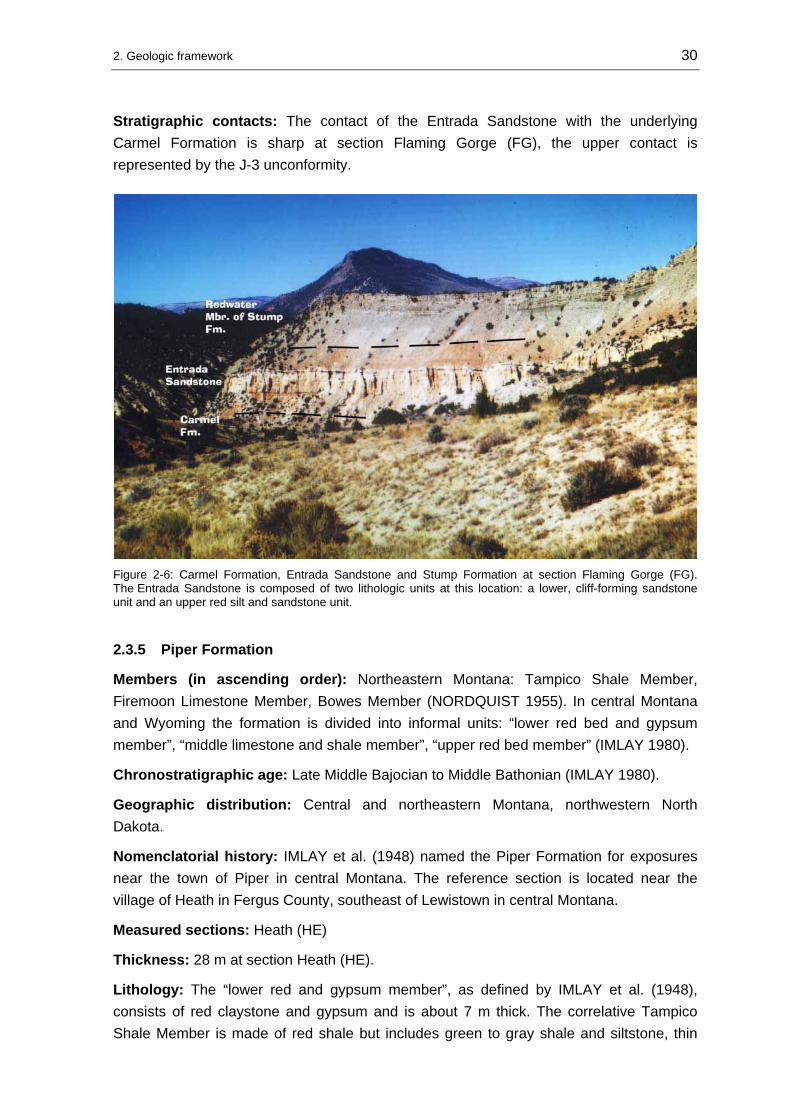
Stratigraphic contacts: The contact of the Entrada Sandstone with the underlying Carmel Formation is sharp at section Flaming Gorge (FG), the upper contact is represented by the J-3 unconformity.
Figure 2-6: Carmel Formation, Entrada Sandstone and Stump Formation at section Flaming Gorge (FG). The Entrada Sandstone is composed of two lithologic units at this location: a lower, cliff-forming sandstone unit and an upper red silt and sandstone unit.
2.3.5 Piper Formation
Members (in ascending order): Northeastern Montana: Tampico Shale Member, Firemoon Limestone Member, Bowes Member (NORDQUIST 1955). In central Montana and Wyoming the formation is divided into informal units: “lower red bed and gypsum member”, “middle limestone and shale member”, “upper red bed member” (IMLAY 1980).
Chronostratigraphic age: Late Middle Bajocian to Middle Bathonian (IMLAY 1980).
Geographic distribution: Central and northeastern Montana, northwestern North Dakota.
Nomenclatorial history: IMLAY et al. (1948) named the Piper Formation for exposures near the town of Piper in central Montana. The reference section is located near the village of Heath in Fergus County, southeast of Lewistown in central Montana.
Measured sections: Heath (HE)
Thickness: 28 m at section Heath (HE).
Lithology: The “lower red and gypsum member”, as defined by IMLAY et al. (1948), consists of red claystone and gypsum and is about 7 m thick. The correlative Tampico Shale Member is made of red shale but includes green to gray shale and siltstone, thin

2. Geologic framework 31
beds of white to red sandstone and gray to brown dolomite and dolomitic limestone (IMLAY 1980). The thickness in the subsurface is about 26 m and about 30 m in surface sections (NORDQUIST 1955).
The overlying “middle limestone member” is about 18 m thick and the Firemoon Limestone Member ranges between 4,5 and 30 m. The members consist of interbedded gray shale and oolitic or dolomitic limestone. The “upper red bed member” in central Montana and the Bowes Member in northeastern Montana are both characterized by red shale and siltstone followed by varicolored shale and siltstone (IMLAY 1980). In thickness, the “upper red bed member” ranges between 0 and 23 m, while the Bowes Member ranges between 6 and 40 m (IMLAY 1980). At the type section near Heath, the lower 5 m of the Piper Formation are not exposed (see Figure 2-7).
Figure 2-7: Piper Formation at section Heath (HE). The basal portion of the Piper Formation is not exposed. The picture shows the “middle limestone and shale member”.
Biostratigraphic range: The dating of the “middle limestone member” of the Piper Formation as Latest Bajocian is based on the presence of the ammonites Sohlites and Parachondroceras, the pelecypods Gryphea planoconvexa Whitfield and the coral Actinastrea cf. hyatti. That means the upper member must be of Early Bathonian age and the lower member must be at least partly of Late Bajocian age (IMLAY 1980).
Stratigraphic contacts: The Piper Formation rests on older Mississippian, Pennsylvanian, Permian, or Triassic rocks - separated by the J-2 unconformity (PIPIRINGOS & O’ SULLIVAN 1978). The contact to the overlying Rierdon Formation is conformable.

2. Geologic framework 32
2.3.6 Preuss Formation
Members: Undivided, in eastern Idaho: Wolverine Canyon Member (near Idaho Falls).
Chronostratigraphic age: Early to Middle Callovian (IMLAY 1980).
Geographic distribution: Western Wyoming and eastern Idaho.
Nomenclatorial history: MANSFIELD & ROUNDY (1916) named the Preuss Formation for outcrops of red sandstone, siltstone and shale at Preuss Creek in the vicinity of Montpelier/Idaho.
Measured sections: South Piney Creek (SPC), Poker Flat (PF), Stump Creek (SC), Big Elk Mountain (BE), Cabin Creek (CC), Hoback Canyon (HC), Devils Hole Creek (DH), La Barge Creek (LB).
Thickness: 22 m at section Hoback Canyon (HC) to 395 m in the Salt River Range after HILEMAN (1973).
Lithology: The Preuss Formation consists of thin- to medium-bedded, pale red to maroon sandstones, siltstones and shale. Sediment structures are rare parallel bedding, oscillation and current ripples. The parallel laminated beds show upward-fining sand-silt-shale intervals. Further, flaser bedding, convolute bedding and mudcracks occur. Salt crystal casts were found at section Big Elk Mountain (BE). HILEMAN (1973) reported the presence of chert-calcite nodules and layers, scarce trace fossils (worm burrows) and small channels. Near Idaho Falls, the Preuss Formation contains a suite of sandstones, oolitic and fossiliferous limestones, named the Wolverine Canyon Member by IMLAY (1952).
The field work revealed that good exposures of the Preuss red beds are very rare. HILEMAN (1973: 15) noted: “ A typical exposure is a sparsely vegetated slope with grass and sagebrush on a dull red soil containing a few widely separated exposed ribs of fine-grained sandstone.” The best outcrop was found at section La Barge Creek (LB) (see Figure 2-8).
Biostratigraphic range: In general, the Preuss Formation is uniformly non-fossiliferous. The only fossils known from the Preuss Formation were found in the Wolverine Canyon near Idaho Falls/Idaho by IMLAY (1952). At this location, approximately 70 m of sandstones and limestones crop out and contain bivalves, crinoids, gastropods, and small coral fragments.
Stratigraphic contacts: The contact of the Preuss Formation with the underlying Giraffe Creek Member of the Twin Creek Limestone is conformable, but at the sections Cabin Creek (CC) and La Barge Creek (LB) the two units intertongue. The transitional nature of this contact was observed also by HILEMAN (1973). The upper contact to the Curtis Member of the Stump Sandstone Formation was found to be sharp. Commonly the change in color and lithology is easy to recognize. Evidence of erosion was not found

2. Geologic framework 33
during field work or by previous workers. Southward in the Uinta Mountains of northeastern Utah, where the J-3 unconformity is developed, the contact becomes unconformable (PIPIRINGOS & O’ SULLIVAN 1978).
Figure 2-8: Preuss Formation at section La Barge Creek (LB). Below the hatched line is the Giraffe Creek Member of the Twin Creek Limestone. The best outcrop of the Preuss Formation was found at this location.
2.3.7 Stump Formation
Members: In ascending order: Curtis Member, Redwater Shale Member (PIPIRINGOS & IMLAY 1979).
Chronostratigraphic age: Curtis Member: Middle to early Late Callovian, Redwater Shale Member: Early to Middle Oxfordian (IMLAY 1980).
Geographic distribution: Wyoming-Idaho border area and adjoining parts of northeastern Utah.
Nomenclatorial history: The Stump Formation was named by MANSFIELD & ROUNDY (1916) for glauconitic sandstone beds near Stump Peak at the head of Stump Creek in Caribou County/Idaho. PIPIRINGOS & IMLAY (1979) proposed that the lithological, stratigraphic and faunal character of the Stump Formation is identical to the Curtis Formation in Utah and the Redwater Shale Member of the Sundance Formation in Wyoming. Consequently they divided the formation into a lower Curtis Member and an upper Redwater Shale Member.
Measured sections: South Piney Creek (SPC), Poker Flat (PF), Stump Creek (SC), Big Elk Mountain (BE), Cabin Creek (CC), Hoback Canyon (HC), La Barge Creek (LB), Flaming Gorge (FG).

2. Geologic framework 34
Thickness: 35 m at section South Piney Creek (SPC) to 90 m at section Stump Creek (SC).
Lithology: Generally, the Stump Formation consists of glauconitic sandstones and shales. The shales are mostly covered by a veneer of debris and/or vegetation, while the sandstone units are cliff-forming.
The Curtis Member is composed of two lithological units, a “lower sandstone unit” and an “upper shale unit” (PIPIRINGOS & IMLAY 1979). The lower unit is made of glauconitic, thin- to thick-bedded, fine-grained sandstones with interbeds of shale and/or siltstone and thins north- and eastward. The most prominent sediment structures are cross-bedding, ripple marks and bioturbation. The “upper shale unit” of the Curtis Member varies irregularly in thickness and thins east and northward. This unit is absent where the overlying Redwater Shale Member is thickest (PIPIRINGOS & IMLAY 1979).
The Redwater Shale Member thins southward along the Wyoming-Idaho border and consists of two lithological units, a “lower shale unit” and an “upper sandstone unit” (PIPIRINGOS & IMLAY 1979). Outcrop conditions of the member are usually poor. The lower unit is a calcareous, glauconitic shale that contains belemnite or oyster fragments and silty interbeds. The upper unit is characterized by a glauconitic, thin- to thick-bedded, fine-grained sandstone with shale and/or siltstone interbeds. The most prominent sediment structures are cross-bedding, ripple marks and bioturbation. At the sections Vernal (V) and Flaming Gorge (FG), in northeastern Utah the unit is represented by a thick, massive, cliff-forming suite of oolitic limestone.
Biostratigraphic range: The Stump Formation is fossiliferous, especially within the Redwater Shale Member. The macro- and microfossil spectrum was studied by PIPIRINGOS & IMLAY (1979) and CAPARCO (1989).
Stratigraphic contacts: The contact of the Curtis Member with the underlying Preuss Formation in western Wyoming is sharp. In northeastern and central Utah the contact with the underlying Entrada Sandstone is the J-3 unconformity. The contact between the Curtis Member and the Redwater Shale Member is the J-4 unconformity and the upper contact to the Morrison Formation is the J-5 unconformity.
2.3.8 Sundance Formation
Members: In ascending order: Canyon Springs Sandstone, Stockade Beaver Shale, Hulett Sandstone, Lak, Pine Butte, Redwater Shale, and Windy Hill Sandstone (IMLAY 1980).
Chronostratigraphic age: Middle Bathonian to Middle Oxfordian (IMLAY 1980).
Geographic distribution: Western South Dakota, southeastern, central and northwestern Wyoming.
Nomenclatorial history: The Sundance Formation was named by DARTON (1899) after outcrops in the vicinity of the town Sundance in Crook County in northeastern Wyoming.

2. Geologic framework 35
He assigned all of the marine strata between the red beds of the Triassic Spearfish Formation and Late Jurassic continental deposits to the Sundance Formation. Since DARTON (1899) did not assign a type section for the formation, IMLAY (1947) defined a reference section north of the town of Spearfish/Lawrence County in South Dakota. He further defined the five formal members: Canyon Springs Sandstone, Stockade Beaver Shale, Hulett Sandstone, Lak, and Redwater Shale. PIPIRINGOS (1968) described the formation in southeastern Wyoming and added two members: the Pine Butte between the Lak and Redwater Shale and the Windy Hill Sandstone between the Redwater Shale and the Morrison Formation (see Figure 2-3).
Westward from the Black Hills the members lose their distinct character. In the subsurface of the Powder River Basin the members are not recognizable. In the Bighorn Basin the informal stratigraphic subdivision by NEELY (1937) into the “lower” and the “upper” Sundance Formation is still in use by geologists. IMLAY (1956) divided the “lower” Sundance into three lithologic units: a basal, a middle and an upper member, coeval with the stratigraphic units in the Black Hills area.
Measured sections: Black Hills: Minnekatha (MIN), Elk Mountain (EM), Spearfish (SF), Thompson Ranch (TR), Hulett (HU), T cross T Ranch (T-T), Stockade Beaver Creek (SBC). Bighorn Basin: Red Lane (RL), Red Rim Ranch (RR), Hampton Ranch (HR), Hyattville (HY). Central and southeastern Wyoming: Alcova Reservoir (AR), Freezeout Hills (FH), Squaw Women Creek (SWC).
Thickness: 63 m at section Squaw Women Creek (SWC) to 101 m at section Red Lane (RL).
Lithology: The Canyon Springs Sandstone Member extends as a lithologic unit westward from the Black Hills/South Dakota into the Bighorn Basin/Wyoming and from north-central Colorado to the Sheep Mountain southeast of Lander/Wyoming. The member ranges in thickness from 0 to 28 m. It consists mainly of large-scale cross-bedded, ripple marked, yellowish-brown to white or salmon colored, partly oolitic, fine- to medium-grained sandstones (IMLAY 1980). In the Bighorn Basin, the member is 0,5 to 8,0 m thick and consists of fine- to medium-grained sandstones intercalated with occasional limestone beds. Near the top of the Canyon Springs Sandstone Member a previously unknown dinosaur tracksite was discovered in 1997 along the west flank of the Bighorn Mountains. The presence of dinosaur tracks in this stratigraphic interval can be traced in outcrops from 25 km north of Greybull/Wyoming approximately 100 km southward, toward the town of Ten Sleep/Wyoming (KVALE et al. 2001). According to KVALE et al. (2001), this tracksite is one of two most extensive Middle Jurassic dinosaur tracksites currently known in the United States. The member was named after an outcrop northwest of Horton in the Black Hills area of Wyoming.
The Stockade Beaver Shale Member in the Black Hills consists of greenish-gray, olive-green and gray, calcareous, fissile, silty shales. At the sections Stockade Beaver Creek (SBC), Elk Mountain (EM) and Minnekatha (MIN), limestone nodules were found
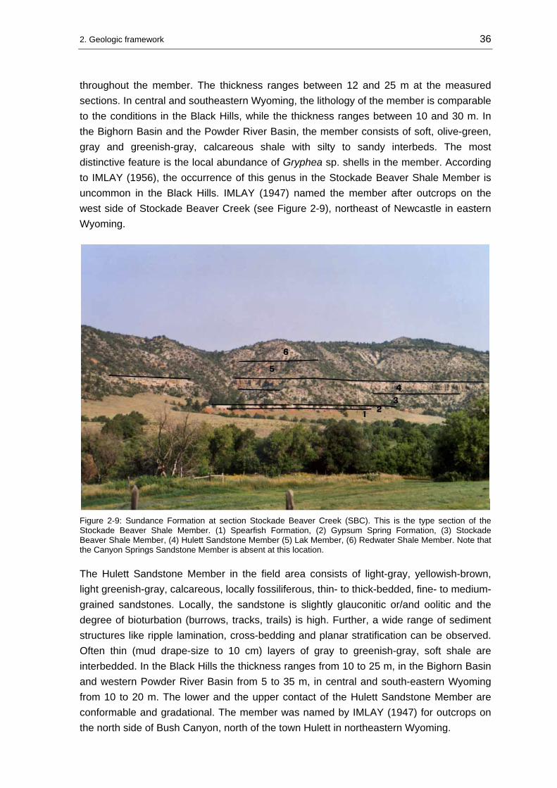
2. Geologic framework 36
throughout the member. The thickness ranges between 12 and 25 m at the measured sections. In central and southeastern Wyoming, the lithology of the member is comparable to the conditions in the Black Hills, while the thickness ranges between 10 and 30 m. In the Bighorn Basin and the Powder River Basin, the member consists of soft, olive-green, gray and greenish-gray, calcareous shale with silty to sandy interbeds. The most distinctive feature is the local abundance of Gryphea sp. shells in the member. According to IMLAY (1956), the occurrence of this genus in the Stockade Beaver Shale Member is uncommon in the Black Hills. IMLAY (1947) named the member after outcrops on the west side of Stockade Beaver Creek (see Figure 2-9), northeast of Newcastle in eastern Wyoming.
Figure 2-9: Sundance Formation at section Stockade Beaver Creek (SBC). This is the type section of the Stockade Beaver Shale Member. (1) Spearfish Formation, (2) Gypsum Spring Formation, (3) Stockade Beaver Shale Member, (4) Hulett Sandstone Member (5) Lak Member, (6) Redwater Shale Member. Note that the Canyon Springs Sandstone Member is absent at this location.
The Hulett Sandstone Member in the field area consists of light-gray, yellowish-brown, light greenish-gray, calcareous, locally fossiliferous, thin- to thick-bedded, fine- to medium-grained sandstones. Locally, the sandstone is slightly glauconitic or/and oolitic and the degree of bioturbation (burrows, tracks, trails) is high. Further, a wide range of sediment structures like ripple lamination, cross-bedding and planar stratification can be observed. Often thin (mud drape-size to 10 cm) layers of gray to greenish-gray, soft shale are interbedded. In the Black Hills the thickness ranges from 10 to 25 m, in the Bighorn Basin and western Powder River Basin from 5 to 35 m, in central and south-eastern Wyoming from 10 to 20 m. The lower and the upper contact of the Hulett Sandstone Member are conformable and gradational. The member was named by IMLAY (1947) for outcrops on the north side of Bush Canyon, north of the town Hulett in northeastern Wyoming.

2. Geologic framework 37
The Lak Member is composed of orange-red or maroon, massive siltstone or fine-grained sandstone. Locally, gypsum beds near the base of the unit are present as at section Alcova Reservoir (AR) (see Figure 2-10). Fossils are not known from this unit. Sediment structures, if observable, are very poorly developed. The thickness ranges between 10 and 28 m. The member occurs in the Black Hills and in central southeastern Wyoming. According to IMLAY (1980), the member pinches out in the Powder River Basin and north of Lander in the Wind River Basin. It is absent in the Bighorn Basin, Bighorn Mountains, northern Wind River Basin, and northwestern Wind River Mountains. If the absence of the member in parts of Wyoming is related to erosion during origin of the J-4 unconformity or to non-deposition can not be answered. PETERSON (1954) reported a lateral gradation into the oolitic sandstones and limestones in the upper part of the “lower” Sundance Formation in the western Powder River Basin/southeastern Bighorn Mountains near the town of Kaycee/Wyoming. The member, also known as “Sundance red”, was named by IMLAY (1947) after the Lak reservoir, close to the L.A.K. Ranch northeast of Newcastle/Wyoming.
Figure 2-10: Lak Member at section Alcova Reservoir (AR). At this location a gypsum bed is exposed at the base of the Lak Member and overlies the greenish-gray beds of the Hulett Sandstone Member. Length of Jacob stick 1,5 m.
The Pine Butte Member consists of greenish-gray, light-green to gray, thin-bedded, calcareous, glauconitic, fine-grained sandstone interbedded with thin shale and siltstone layers. Sediment structures are faint planar bedding and ripple lamination. Otherwise the member lacks primary sediment structures and bioturbation. JOHNSON (1992) reported the occurrence of furrowed trails. Often bivalve fragments and crinoids are found. The
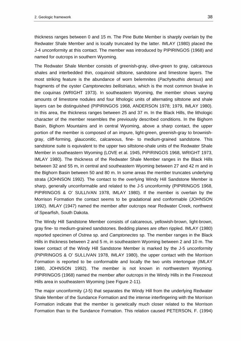
2. Geologic framework 38
thickness ranges between 0 and 15 m. The Pine Butte Member is sharply overlain by the Redwater Shale Member and is locally truncated by the latter. IMLAY (1980) placed the J-4 unconformity at this contact. The member was introduced by PIPIRINGOS (1968) and named for outcrops in southern Wyoming.
The Redwater Shale Member consists of greenish-gray, olive-green to gray, calcareous shales and interbedded thin, coquinoid siltstone, sandstone and limestone layers. The most striking feature is the abundance of worn belemnites (Pachyteuthis densus) and fragments of the oyster Camptonectes bellistriatus, which is the most common bivalve in the coquinas (WRIGHT 1973). In southeastern Wyoming, the member shows varying amounts of limestone nodules and four lithologic units of alternating siltstone and shale layers can be distinguished (PIPIRINGOS 1968, ANDERSON 1978; 1979, IMLAY 1980). In this area, the thickness ranges between 25 and 37 m. In the Black Hills, the lithologic character of the member resembles the previously described conditions. In the Bighorn Basin, Bighorn Mountains and in central Wyoming, above a sharp contact, the upper portion of the member is composed of an impure, light-green, greenish-gray to brownish-gray, cliff-forming, glauconitic, calcareous, fine- to medium-grained sandstone. This sandstone suite is equivalent to the upper two siltstone-shale units of the Redwater Shale Member in southeastern Wyoming (LOVE et al. 1945, PIPIRINGOS 1968, WRIGHT 1973, IMLAY 1980). The thickness of the Redwater Shale Member ranges in the Black Hills between 32 and 55 m, in central and southeastern Wyoming between 27 and 42 m and in the Bighorn Basin between 50 and 80 m. In some areas the member truncates underlying strata (JOHNSON 1992). The contact to the overlying Windy Hill Sandstone Member is sharp, generally unconformable and related to the J-5 unconformity (PIPIRINGOS 1968, PIPIRINGOS & O’ SULLIVAN 1978, IMLAY 1980). If the member is overlain by the Morrison Formation the contact seems to be gradational and conformable (JOHNSON 1992). IMLAY (1947) named the member after outcrops near Redwater Creek, northwest of Spearfish, South Dakota.
The Windy Hill Sandstone Member consists of calcareous, yellowish-brown, light-brown, gray fine- to medium-grained sandstones. Bedding planes are often rippled. IMLAY (1980) reported specimen of Ostrea sp. and Camptonectes sp. The member ranges in the Black Hills in thickness between 2 and 5 m, in southeastern Wyoming between 2 and 10 m. The lower contact of the Windy Hill Sandstone Member is marked by the J-5 unconformity (PIPIRINGOS & O’ SULLIVAN 1978, IMLAY 1980), the upper contact with the Morrison Formation is reported to be conformable and locally the two units intertongue (IMLAY 1980, JOHNSON 1992). The member is not known in northwestern Wyoming. PIPIRINGOS (1968) named the member after outcrops in the Windy Hills in the Freezeout Hills area in southeastern Wyoming (see Figure 2-11).
The major unconformity (J-5) that separates the Windy Hill from the underlying Redwater Shale Member of the Sundance Formation and the intense interfingering with the Morrison Formation indicate that the member is genetically much closer related to the Morrison Formation than to the Sundance Formation. This relation caused PETERSON, F. (1994)

2. Geologic framework 39
and CURRIE (1998; 2002) to include the Windy Hill interval as lower member into the Morrison Formation. Under genetic aspects this approach is logic and comprehensive. However, a formal Jurassic standard stratigraphy comparable to the European standard stratigraphy is lacking for the western United States. A widely accepted standard is published by IMLAY (1980). To avoid further irritations in the already confusing stratigraphic Jurassic nomenclature the stratigraphic standard of IMLAY (1980) is followed in this study and the Windy Hill interval for formal reasons is included as member in the Sundance Formation.
Figure 2-11: Sundance Formation at section Freezeout Hills (FH). (1) Nugget Sandstone, (2) Canyon Springs Member, (3) Stockade Beaver Shale Member, (3) Hulett Sandstone, (4) Pine Butte Member, (5) Lak Member, (6) Redwater Shale Member, (7) Windy Hill Sandstone Member.
Biostratigraphic range: Comprehensive investigations of the paleontology and stratigraphy providing biostratigraphic information of the Sundance Formation are published by WRIGHT (1973; 1974), IMLAY (1947; 1954; 1956; 1957; 1980), PETERSON (1954; 1957a; 1958), CAPARCO (1989), KVALE et al. (2001).
Stratigraphic contacts: The contact of the Sundance Formation with the underlying formations is unconformable and is represented by the J-2 and J-2a unconformities. The upper contact with the Morrison Formation is considered to be the erosional surface of the J-5 unconformity. This locally occurring surface lies at the base of the Windy Hill Sandstone Member (PIPIRINGOS & O’ SULLIVAN 1978). In the Bighorn Basin and Powder River Basin, where the Windy Hill Sandstone Member is absent (IMLAY 1980), evidence for the unconformity is weak (JOHNSON 1992). According to PIPIRINGOS & O’ SULLIVAN (1978), thickness variations of the Swift Formation between 1 to 75 m might indicate the development of an erosional relief. Other workers like IMLAY (1980) and UHLIR et al. (1988) doubt the existence of an unconformable contact at this stratigraphic level. Therefore, the nature of this upper contact is still discussed.

2. Geologic framework 40
2.3.9 Twin Creek Limestone
Members (in ascending order): Gypsum Spring, Sliderock, Rich, Boundary Ridge, Watton Canyon, Leeds Creek, Giraffe Creek (IMLAY 1967; 1980).
Chronostratigraphic age: Middle Bajocian to lower Early Callovian (IMLAY 1980).
Geographic distribution: Western Wyoming (Wyoming-Idaho border area), northeastern Utah.
Nomenclatorial history: The Twin Creek Limestone was named by VEATCH (1907) after outcrops of limestones, shales and sandstones along the Twin Creek between Sage and Kemmerer in Lincoln County, Wyoming. Surprisingly, at the type location the formation is incomplete and only the lower five members are present (see Figure 2-12). IMLAY (1953) primarily divided the formation into seven members named A to G. Later IMLAY (1967) renamed the members A to G and assigned the formal member names.
Figure 2-12: Twin Creek Limestone at its type section at Twin Creek. The formation is incomplete at this location. The Rich Member forms the slope and is overlain by red sediments of the Boundary Ridge Member. The uppermost stratigraphic unit exposed is the Watton Canyon Member.
Measured sections: Hoback Canyon (HC), Cabin Creek (CC), Big Elk Mountain (BE), South Piney Creek (SPC), Poker Flat (PF), Stump Creek (SC), La Barge Creek (LB), Devils Hole Creek (DH), Twin Creek (TC), Whiterocks Canyon (WC).
Thickness: 190 m at section Hoback Canyon (HC) to 805 m at section Thomas Fork Canyon (TF).

2. Geologic framework 41
Lithology: In general, the members of the Twin Creek Limestone thicken in a westerly direction. The Gypsum Spring Member ranges in thickness between 3 and 120 m and is the stratigraphic equivalent to the Gypsum Spring Formation in northwestern and eastern Wyoming. The member comprises red beds and brecciated or chert-bearing limestones. Usually, the member is covered and therefore poorly exposed. The Sliderock Member ranges between 7 and 100 m. It consists of grayish, thin- to medium-bedded, partly fossiliferous or oolitic carbonates that grade upward into the grayish, shaly, thin-bedded, partly fossiliferous, soft limestone of the Rich Member. This unit ranges in thickness between 10 and 150 m. Further upsection, the Rich Member grades into the Boundary Ridge Member, which is red or grayish siltstone and/or shale interbedded with thin layers of oolitic carbonates. The thickness varies between 10 and 100 m.
The Boundary Ridge Member is overlain by the Watton Canyon Member. This member consists of grayish, thin- to thick-bedded, partly oolitic carbonates and ranges in thickness between 20 and 120 m. The succeeding Leeds Creek Member is composed of monotonous medium- to light-gray limestone with few oolitic and/or sandy interbeds. The member is between 80 and 490 m thick. The uppermost unit, the Giraffe Creek Member, reveals gray to grayish-green, ripple marked sandstones or sandy limestones. Oolitic beds, bioturbation and a high glauconite content are common. The thickness varies between 7 and 120 m.
Biostratigraphic range: The biostratigraphic framework and the paleontology of the Twin Creek Limestone are described in a very comprehensive publication by IMLAY (1967).
Stratigraphic contacts: The contact of the Twin Creek Limestone with the underlying Nugget or Navajo Sandstone is unconformable and correlates with the J-1 unconformity. The Gypsum Spring Member is separated from the succeeding members by the J-2 unconformity. The upper contact with the Preuss Formation is either intertonguing and conformable as at section La Barge Creek (LB) or sharp as at section Devils Hole Creek (DH) (see Figure 2-13).
Figure 2-13: The Twin Creek Limestone is sharply overlain by the Preuss Formation at section Devils Hole Creek (DH). The uncovered, gray slopes are the Leeds Creek Member and the Giraffe Creek Member.

2. Geologic framework 42
2.4 Allostratigraphy
Allostratigraphic units are of special importance for the study of the stratal record in cratonic areas with poor biostratigraphic resolution. In addition, the allostratigraphic system offers a useful approach to establish a genetic stratigraphic nomenclature. In 1983 the NORTH AMERICAN COMMISSION ON STRATIGRAPHIC NOMENCLATURE published a code of recommended procedures for the classification and naming of stratigraphic units. In this code allostratigraphic units are defined as: “An allostratigraphic unit is a mappable stratiform body of sedimentary rock that is defined and identified on the basis of its bounding discontinuities”.
The Phanerozoic history of the North American craton is characterized by periods of sedimentation and erosion. The cratonic sedimentary cover bears a number of interregional erosional interfaces that provide the opportunity to subdivide the Phanerozoic history into rational units (SLOSS 1988). SLOSS (1963) was the first worker who recognized “interregional surfaces marking interruptions in the continuity of sedimentation across the entire (North American) craton”. These sequence bounding unconformities were used by SLOSS (1963) to establish a framework of six major sequences: Sauk, Tippecanoe, Kaskaskia, Absaroka, Zuni, and Tejas (see Figure 2-14).
PERIODS
TERTIARY
CRETACEOUS
JURASSIC
TRIASSIC
PERMIAN
PENNSYLVANIAN
MISSISSIPPIAN
DEVONIAN
SILURIAN
ORDOVICIAN
CAMBRIAN SAUK
TIPPECANOE
KASKASKIA
ABSAROKA
ZUNI
TEJASQUATERNARY
CORDILLERANMARGIN
CRATONINTERIOR
APPALACHIANMARGIN
CRATONICSEQUENCES
Figure 2-14: Sloss sequences. The studied Middle and Late Jurassic stratigraphic column is assigned to the Zuni sequence (modified from SLOSS 1963). Gray shaded areas indicate sedimentation, while the white color marks hiatuses.

2. Geologic framework 43
These major unconformity bound successions were later subdivided by SLOSS (1988) into subsequences that are identified by Roman numerals. According to this approach, the studied Middle and Late Jurassic stratigraphic column is assigned to the Zuni subsequence I that extends in time from the Early Jurassic (Aalenian) to the Early Cretaceous (Berriasian).
Allostratigraphic units and their boundaries can be ranked in a hierarchical system. A hierarchical concept for sequences and sequence boundaries was initially established and successfully applied for the sedimentary fill of the Jurassic Sverdrup Basin in northern Canada by EMBRY (1993). This concept reflects the unconformable nature of the transgressive-regressive sequence boundaries and resulted in a five-fold classification of first- to fifth-order sequences and their boundaries.
2.4.1 Hierarchical concept of allostratigraphic boundaries
EMBRY (1993) formulated five orders of sequences that are defined by subaerial unconformities and correlative transgressive surfaces. The resulting first- to fifth-order sequence boundaries are displayed in Figure 2-15. Figure 2-15a shows the schematic classification of stratigraphic sequences based on the nature of their contact. The principles for determination of a sequence order is shown in Figure 2-15b.
Figure 2-15: (a) Schematic classification of stratigraphic sequences based on the nature of their contact. (b) Principles for the determination of a sequence order. Sequences can not contain a sequence boundary with the same or lower order than its highest order boundary. Further, the order of a sequence is equal to the order of its highest order boundary (from EMBRY 1993).

2. Geologic framework 44
The main character of the allostratigraphic boundaries as defined by EMBRY (1993) can be described as follows.
First-order: This boundary is characterized by a widespread subaerial unconformity. The correlative transgressive surface is traceable into the basin center. Strata below the unconformity is deformed by faulting, tilting or folding.
Second-order: A subaerial unconformity that can be recognized at the basin margins associated with a prominent transgressive surface characterizes this sequence boundary. The transgressive surface reflects a major deepening period and the sedimentary regime (sometimes also subsidence pattern and source area) represents a marked change across the boundary.
Third-order: This boundary consists mostly of a prominent transgressive surface. The subaerial unconformity is restricted to the basin edge. Detection of this boundary is difficult or impossible in shale-dominated portions of the basin. Subsidence pattern and sedimentary regime show only minor changes.
Fourth-order: This boundary consists of a transgressive surface and the correlative unconformity is very difficult to identify. The boundary can not be correlated throughout the basin, especially not in the shaly central parts of a basin. This boundary is best recognized in shallow shelf-like deposits.
Fifth-order: This boundary is represented by a transgressive surface of local extent. Correlating this boundary beyond a few tens of kilometers is impossible. These boundaries are common in coarsening-up units, equivalent to the parasequence as defined by Van WAGONER et al. (1990).
2.4.2 Allostratigraphic boundaries in the “Sundance Basin”
PIPIRINGOS & O’ SULLIVAN (1978) noted that the Triassic and Jurassic formations of the Western Interior region were deposited on a westward sloping, stable shelf. Deposition on this shelf was interrupted several times by epeiric uplift and subsequent erosion in the context of sea-level changes. Each erosional surface was preserved by burial beneath the deposits of the subsequent transgressive phase or beneath a continental fill of a subsiding basin. The Jurassic strata in the Western Interior contains six unconformities labeled J-0, J-1, J-2, J-3, J-4, and J-5 from bottom to top (PIPIRINGOS & O’ SULLIVAN 1978). The arrangement and relationship of the unconformities is illustrated in Figure 2-16, the spatial extent is shown in Figure 2-17. Some unconformities were partly destroyed during the origin of subsequent erosional surfaces while others were preserved completely.

2. Geologic framework 45
J-2a
J-2bJ-2c
J-4a
Figure 2-16: Arrangement and relationship of Jurassic unconformities J-0 to J-5 as proposed by PIPIRINGOS & O’ SULLIVAN (1978). Additional unconformities (J-2a, J-2b, J-2c, and J-4a) discussed in this chapter are indicated by red lines. Triangles denote the occurrence of chert pebbles (modified from PIPIRINGOS & O’ SULLIVAN 1978).
The recognition of the Jurassic unconformities by PIPIRINGOS & O’ SULLIVAN (1978) and their allostratigraphic application by BRENNER & PETERSON (1994) offers the opportunity to establish a hierarchical system of sequences and sequence boundaries within the “Sundance Basin”, based on the concept of EMBRY (1993). Moreover, the unconformable contacts within the Jurassic successions are helpful interfaces that offer the opportunity to assign poorly dateable stratigraphic successions to distinct, correlative alloformations. This provides the basis for a reliable correlation of stratigraphic units. For instance, the monotonous carbonate successions of the Twin Creek Limestone can be correlated over great distances and facies boundaries. The unconformities were identifiable in the investigated sections. The unconformities identified by PIPIRINGOS & O’ SULLIVAN (1978) were recognized at their proposed stratigraphic positions and additional unconformable contacts were noticed during field work.
The characteristics, regional extent and duration of the Jurassic unconformities are briefly discussed in this chapter. The J-0 unconformity is below the investigated stratal package and consequently not addressed in this study. Further, a number of additional unconformities are introduced that were discovered and described by various authors (PETERSON, F. 1994, RIGGS & BLAKEY 1993, MAXWELL 1982, PORTER 1989, MOLGAT & ARNOT 2001, ANDERSON 1978; 1979, BÜSCHER 2000, KVALE et al. 2001) after the preliminary publication of PIPIRINGOS & O’ SULLIVAN (1978). Finally, evidence for the existence of a previously unknown unconformity in the Oxfordian stratal record is presented and discussed.

2. Geologic framework 46
0 300 km100 200
ZU: Zuni Uplift
approximate edge of Jurassic formations
J-4aconfirmedinferred
J-4
J-3, confirmedinferred/ under discussion
J-1, J-2, J-5basinwide unconformities
J-2a = J-2b, PETERSON, F. (1994), J-s-up, RIGGS & BLAKEY (1993)
J-2c, MAXWELL (1982)
J-2b
ZU
CANADAUSA MT ND
SD
IDWY
CO
UTNV
NB
NMAZ
confirmed
Figure 2-17: Spatial distribution of the regional and local Jurassic unconformities J-0, J-1, J-2, J-2a, J-2b, J-2c, J-3, J-4, J-4a, and J-5 according to results from this study and previous publications from other authors (PIPIRINGOS & O’ SULLIVAN 1978, MAXWELL 1982, RIGGS & BLAKEY 1993, KVALE et al. 2001, PETERSON, F. 1994, BRENNER & PETERSON 1994).
2.4.2.1 J-1 unconformity
The J-1 unconformity was recognized by PIPIRINGOS & O’ SULLIVAN (1978) mainly in Wyoming and adjacent parts of Idaho and Utah. The unconformity marks the contact between the Gypsum Spring interval (formation or member) and the underlying Nugget Sandstone in Wyoming. This surface is correlated with an erosion surface proposed by NORDQUIST (1955) at the base of the Nesson Formation in the subsurface of the Williston Basin and with an erosion surface at the base of the Temple Cap Sandstone in southwestern Utah. PIPIRINGOS & O’ SULLIVAN (1978) estimated the time interval between uplift and erosion of the Nugget Sandstone and deposition of overlying strata at 2-3 Ma. In application of the hierarchical concept of EMBRY (1993) the J-1 unconformity represents a second-order sequence boundary. During field work the unconformity was found and easily identified in the “Overthrust Belt”. It is exposed at the sections of the Twin Creek Limestone where it separates the Navajo Sandstone from the brecciated beds of the Gypsum Spring Member. In this area the surface displays a slight relief.

2. Geologic framework 47
2.4.2.2 J-2 unconformity
The J-2 unconformity is the best preserved and most extensive erosion surface in the Western Interior region (PIPIRINGOS & O’ SULLIVAN 1978). It is mostly associated with chert pebbles that occur immediately at or a few centimeters above the erosion surface. The stratigraphic position of the J-2 unconformity is illustrated in the chronostratigraphic correlation chart in Figure 2-3. PIPIRINGOS & O’ SULLIVAN (1978) estimated the time between uplift and erosion of the Gypsum Spring Formation and initial deposits of the overlying formations at about 1 Ma. In the western parts of the field area in the Black Hills, the erosion surface incised deep valleys into the Triassic Spearfish Formation (AHLBRANDT & FOX 1997). The distribution of the strata above the J-2 surface indicates that the unconformity was overlapped from west to east and from north to south (PIPIRINGOS & O’ SULLIVAN 1978). In application of the hierarchical concept of EMBRY (1993) the J-2 unconformity represents a second-order sequence boundary. The stratigraphic position of the J-2 unconformity is shown in Figure 2-3. At the investigated sections the J-2 unconformity was identifiable. In the Black Hills, the proposed chert pebble layer was either found in poorly lithified sediments as at section Thompson Ranch (TR) or as chert pebbles on top of a bored dolomitic carbonate bed at section T cross T Ranch (T-T) (see Figure 2-18). Westward the erosional relief of the J-2 surface becomes slight.
Figure 2-18: Chert pebbles on top of an intensively bored dolomitic carbonate bed mark the J-2 unconformity at the base of the Sundance Formation at section T cross T Ranch (T-T). Lense cap is 6 cm in diameter.

2. Geologic framework 48
2.4.2.3 J-2a unconformity
The presence of a regional and primarily unnamed unconformity above the J-2 surface was reported by various workers. In the Bighorn Basin in Wyoming, IMLAY (1956) noted an erosional surface marked by chert clasts at the contact between the Gypsum Spring Formation and the base of the “lower” Sundance Formation. In the original publication IMLAY (1956) considered the Gypsum Spring Formation to be equivalent with the Piper Formation. PIPIRINGOS & O’ SULLIVAN (1978) demonstrated that those two units are not equivalent, because they are divided by the J-2 unconformity (see Figure 2-3 and Figure 2-16). The Gypsum Spring Formation is bound by the J-1 and J-2 unconformities. The J-2 unconformity separates the Gypsum Spring Formation from the overlying lithological very similar “upper red bed member” of the Piper Formation. Recent investigations by SCHMUDE (2000) confirmed the original correlation of PIPIRINGOS & O`SULLIVAN (1978). In other words, IMLAY (1956) described an unconformable contact between the “upper red bed member” of the Piper Formation and the “lower” Sundance Formation in the Bighorn Basin. In consequence, an additional unconformity must exist above the J-2 surface. In a recent publication KVALE et al. (2001) referred to this unconformity and introduced the term J-2a.
The J-2a unconformity was recognized during field work in the “Utah-Idaho trough” area. Apparent lithological changes and abrupt facies shifts from red beds of the Boundary Ridge Member to marine carbonates of the Watton Canyon Member within the Twin Creek Limestone were observed at section Poker Flat (PF), South Piney Creek (SPC), Big Elk Mountain (BE), Cabin Creek (CC), La Barge Creek (LB), and Devils Hole Creek (DH). For IMLAY (1967), this change from red beds to marine limestone (oolitic grainstones, mudstones and biomudstones) proves an environmental change, but is no evidence for an unconformity at the contact. However, it seems appropriate to relate the sudden facies shift to an unconformable stratigraphic contact.
In addition, at a correlative stratigraphic position at the base of the Sundance Formation a disconformable facies shift is reported from the Black Hills by AHLBRANDT & FOX (1997). These authors detected paleovalleys incised into the surface of the underlying Triassic Spearfish Formation during generation of the J-2 unconformity. The paleovalleys are filled with a suite of eolian, estuarine and marine sediments of the Middle Jurassic Canyon Springs Sandstone Member, have locally a relief of more than 100 m and can be several kilometers wide. The paleovalleys slope and deepen in a western direction.
A schematic sketch of the paleovalley fill, depositional environments and the stratigraphic nomenclature is shown in Figure 2-19. The nomenclature includes the informal stratigraphic units “limestone marker”, “brown shale” and “siltstone marker” derived from subsurface seismic stratigraphy. According to AHLBRANDT & FOX (1997), a complete valley fill consists of the lower part of the Canyon Springs Member (eolian, LCS in Figure 2-19), overlain by the marine “limestone marker”, the marine/estuarine “brown shale” and the upper part of the Canyon Springs Member (marine). The eolian portion of the valley fill is separated by an disconformable facies shift (PS 1 surface) from the

2. Geologic framework 49
estuarine/marine portion of the upper Canyon Springs Member (UCS in Figure 2-19). The PS 1 surface described by AHLBRANDT & FOX (1997) is interpreted to be equivalent to the facies shift that marks the J-2a unconformity, because both interfaces mark marine transgressions over a regressive sedimentary suite that is either a red bed suite in the western “Sundance Basin” (Boundary Ridge Member of the Twin Creek Limestone) or an eolian lowstand succession (lower Canyon Springs Member of the Sundance Formation) in the east.
Figure 2-19: Schematic sketch of the paleovalley fill, depositional environments and the sequence stratigraphic nomenclature. Positions of identified T-R sequence bounding unconformities J-2a, J-2b, paleosol/ weathering zone, estuarine valley fill, and transgressive surface (TS) are added (modified from AHLBRANDT & FOX 1997).
The concept of paleovalleys, highlighted by AHLBRANDT & FOX (1997), offers a useful approach to correlate previously unidentified unconformities above the J-2 and – as will be demonstrated in the facies correlation – to evaluate and interpret the outcrop situation at stratigraphic sections in the northern Black Hills.
In south-central Utah and adjacent Arizona, RIGGS & BLAKEY (1993) identified an “important unconformity at or near the top of the Page Sandstone” and termed it J-s-up. PETERSON, F. (1994) renamed this surface J-2b. This surface appears at the stratigraphic level as the J-2a in the study area.

2. Geologic framework 50
According to EMBRY (1993), changes in a sedimentary regime play an important role in the identification of transgressive-regressive sequence boundaries. Therefore, since a correlative unconformity is identified in the eastern and western portions of the “Sundance Basin”, a third-order sequence boundary in the hierarchical system of EMBRY (1993) can be proposed.
2.4.2.4 J-2b unconformity
At the investigated section Freezeout Hills (FH), an unconformable contact is expressed by locally developed algal structures that overlie oolitic sandstone beds in the upper portion of the Canyon Springs Sandstone Member (see Figure 2-20). The algal structure is indicative for supratidal conditions and consists of mm-thick wavy lamination, stony casts and bioturbation. This structure was also described from central Wyoming by JOHNSON (1992). At section Alcova Reservoir (AR), a shallowing upward succession in the Canyon Springs Sandstone is composed of large-scale cross-bedded sandstone that grades upward into wave rippled sandstone. This suite is abruptly succeeded by shales of the Stockade Beaver Shale Member.
Figure 2-20: Algal lamination that indicates shallowing conditions in the upper portion of the Canyon Springs Member at section Freezeout Hills (FH). Hammer is 32 cm long.
From a correlative stratigraphic position unconformable contacts are reported from the Black Hills by AHLBRANDT & FOX (1997) and from the Bighorn Basin by KVALE et al. (2001). In the Black Hills, the estuarine/marine portion in the upper Canyon Springs Sandstone (UCS, in Figure 2-19) is separated from overlying marine sediments of the Stockade Beaver Shale Member by a paleosol/weathering zone. The development of this

2. Geologic framework 51
paleosol/weathering zone is related to shallowing conditions and subaerial exposure (AHLBRANDT & FOX 1997). In the Bighorn Basin, a recently discovered dinosaur tracksite near the top of the Canyon Springs Sandstone Member of the Sundance Formation reflects a subaerial exposure surface. This surface is referred to as J-2b unconformity by KVALE et al. (2001). The occurrence of a traceable shallowing upward and partly subaerial exposed interval in southeastern, eastern and northwestern Wyoming near the top of the Canyon Springs Sandstone Member was used in this study to correlate these contacts regionally as J-2b unconformity.
2.4.2.5 J-2c unconformity
Evidence for local uplift and erosion was found by MAXWELL (1982) (in PETERSON, F. 1994) along the north side of the Zuni Uplift in northwestern New Mexico at the base of the Wanakah Formation. The origin of this angular unconformity was related to tectonic activity in the Colorado Plateau region. It was named J-2c by PETERSON, F. (1994). There is no evidence of the J-2c unconformity in the study area. The J-2c represents a fourth-order sequence boundary as defined by EMBRY (1993).
2.4.2.6 J-3 unconformity
In their original publication PIPIRINGOS & O’ SULLIVAN (1978) stated that the erosional J-3 surface is recognizable in central, southern and northeastern Utah, northwestern Colorado and northern Arizona. The extent farther northwest or northeast is uncertain. On the northern and southern side of the Uinta Mountains the J-3 is truncated by the J-4 surface. PIPIRINGOS & O’ SULLIVAN (1978) calculated the elapsed time represented by the J-3 unconformity to be less than 1 Ma.
The J-3 unconformity is probably the most debated and uncertain of all Jurassic erosional surfaces. PETERSON, F. (1994) stated: “Understanding the J-3 unconformity is a challenge because some aspects of it appear to be relatively minor and other aspects appear to be highly important”. Minor aspects would be the fact that the surface fades out eastward and could not be traced by O’ SULLIVAN (1980) as far as the town of Moab/Utah. The surface seems to be a transgressive erosion surface that formed when the Curtis sea flooded the Entrada inland dune field (PETERSON, F. 1994).
Important facts are that the J-3 surface marks significant changes in the structural setting on the west side of the Colorado Plateau and in sedimentary source areas farther west (PETERSON, F. 1994). Former sedimentation areas were uplifted. In consequence, the Curtis Formation is absent in the southwestern parts of the former “Utah-Idaho trough”. PETERSON, F. (1994) illustrated the transformed areas as shown in Figure 2-21. The absence of the Curtis Formation implies that the erosional event that resulted in the J-3 unconformity was mostly, if not entirely, related to local tectonics and not originated by

2. Geologic framework 52
eustatic sea-level fall. PETERSON, F. (1994) related the tectonic processes that caused the erosional surface to isostatic rebound in the proximal parts of the basin, as is suggested in the two-phase stratigraphic model for foreland basins by HELLER et al. (1988).
Figure 2-21: Paleogeographic setting in the southern part of the Western Interior during latest Callovian. Encircled areas are several uplifts that developed in the former “Utah-Idaho trough” due to flexural rebound within the proximal part of foreland basin. In the southern “Sundance Basin” in Colorado, Utah, Arizona, and New Mexico the J-3 unconformity is developed and confirmed (from PETERSON, F. 1994).
In eastern Wyoming, equivocal field evidence caused some workers to postulate an unconformable contact - correlative to the J-3 surface - between the Lak Member and the Pine Butte Member of the Sundance Formation (RAUTMANN 1976). Other workers doubt this unconformable nature (SPECHT & BRENNER 1979, IMLAY 1980). At some locations in eastern Wyoming and adjacent areas the contact is gradational and intertonguing, at other locations the contact is sharp (JOHNSON 1992).
During the investigation of outcrops in the Black Hills and central Wyoming the discussed stratigraphic interval of the Pine Butte Member was recognized at the sections Spearfish (SF), Stockade Beaver Creek (SBC), Elk Mountain (EM), Minnekatha (MIN), Thompson Ranch (TR), Freezeout Hills (FH), and Alcova Reservoir (AR). Evidence for erosion between the Lak Member and the Pine Butte Member was not found at these locations, but the contact clearly represents an abrupt facies shift from red beds to glauconitic sandstones and shales.

2. Geologic framework 53
KILIBARDA & LOOPE (1997) considered the J-3 unconformity to be present within the “lower” Sundance Formation in the Bighorn Basin in northwestern Wyoming. These authors emphasized the correlation between the J-3 surface and an eustatic sea-level fall as proposed in sea-level curves by HALLAM (1988) and VAIL et al. (1984), in contrast to PETERSON, F (1994). They argued that during sea-level fall a topographic element, named “Sheridan Arch”, became subaerially exposed and ooids that were primarily developed in shoals on the windward side of the arch were deflated and accumulated in dunes on the down-wind side of the arch. Major problems in this theory come from contradictions between the paleowind directions that were assumed by KILIBARDA & LOOPE (1997) and directions proposed in paleoclimate models. An important aspect in the theory of KILIBARDA & LOOPE (1997) is that ooid particles were deflated and transported over a relief element by northwestward directed winds during the Callovian. As demonstrated by PARRISH & PETERSON (1988) and PETERSON, F. (1994), the paleowinds shifted in a counterclockwise direction to blow toward the east in the late Middle Jurassic. Hence, in the investigated outcrops in the southern Bighorn Basin the existence of an additional unconformity equivalent to the J-3 was not recognized. Northward, in Montana, evidence for the J-3 unconformity is also lacking and neither reflected by erosion nor by obvious facies changes at the investigated sections.
2.4.2.7 J-4 unconformity
The J-4 unconformity occurs in South Dakota, Wyoming, Montana, northeastern Utah, and northwestern Colorado (PIPIRINGOS & O’ SULLIVAN 1978). In these areas the surface underlies the Redwater Shale Member of the Sundance Formation, the Redwater Member of the Stump Formation and the “shale unit” of the Swift Formation. PIPIRINGOS & O’ SULLIVAN (1978) found only a sharp change in lithology and the abrupt appearance of belemnites above the surface. An often observed feature of the J-4 surface is the truncation of underlying strata. In the vicinity of the “Belt Island Complex” in Montana, underlying strata of the Rierdon Formation and the Sawtooth Formation are truncated or eroded completely, so that the Swift Formation rests on Paleozoic rocks. Truncation of the Curtis Formation occurs in the Uinta Mountains (PIPIRINGOS & O’ SULLIVAN 1978). Southward into central Utah, Arizona and New Mexico the extent of the J-4 unconformity is unknown prior to non-deposition or erosion before deposition of the Morrison Formation. PIPIRINGOS & O’ SULLIVAN (1978) estimated the time elapsed between deposition of the Summerville Formation and the Swift Formation at about 1 Ma. In application of the hierarchical concept of EMBRY (1993) the J-4 unconformity represents a second-order sequence boundary. In the investigated sections the J-4 is expressed by sharp lithological contacts. For instance in the Bighorn Basin glauconitic belemnite-bearing shales abruptly overlie shallow marine sandstones. However, as emphasized by PIPIRINGOS &

2. Geologic framework 54
O’ SULLIVAN (1978) the topographic relief of the J-4 is generally slight and locally not conspicuous. At western locations where outcrop conditions become poor the surface was difficult or impossible to identify. In this case the stratigraphic position was adopted from the correlation of PIPIRINGOS & IMLAY (1979).
2.4.2.8 J-4a unconformity
The J-4a unconformity represents a third-order boundary according to the hierarchical system of EMBRY (1993). This unconformity within the Oxfordian strata is defined and correlated on a regional scale for the first time in this study.
2.4.2.8.1 Field observations
An unconformable contact within the Redwater Shale Member of the Sundance Formation was recognized by BÜSCHER (2000) in outcrops in the western and southwestern Powder River Basin. This unconformable contact was traced during field work into the southern Bighorn Basin at sections Red Rim Ranch (RR), Red Lane (RL), Hampton Ranch (HR), Hyattville (HR) (see Figure 2-22 to Figure 2-26) and into central and southeastern Wyoming at sections Alcova Reservoir (AR) and Freezeout Hills (FH).
In outcrop the lithologic contact at the unconformity is sharp and the erosional relief seems to be slight. A lag of well rounded carbonate pebbles ranging in diameter between 5 and 30 cm marks the surface. These pebbles are bedded in a matrix-supported, glauconitic to non-glauconitic, fine- to medium-grained, 5 to 50 cm thick sandstone layer with shell fragments, rip up clasts, belemnites, and bone fragments. A preferred clast orientation is observable along the long axis of the oval shaped pebbles. The carbonate pebbles comprise mudstones, detritic mudstones, calcareous fine-grained sandstones with serpulid plaster, various kinds of skeletal biograinstones, biopackstones, and biowackestones.
Another unconformable contact was observed at the sections Swift Reservoir (SR), Sun River Canyon (SRC) and Rocky Creek Canyon (RC) in Montana. At the first two locations, the outcrop occurrence of the unconformity fits very well with the description of an erosional surface of PORTER (1989) (see discussion below). At Rocky Creek Canyon (RC), the unconformity is marked by pebbly, well-rounded lithoclasts up to 1,5 cm in diameter in a trough cross-bedded, coarse- to medium-grained, glauconitic sandstone.

2. Geologic framework 55
Figure 2-22: Unconformable contact between shale lithofacies of Redwater Shale Member and glauconitic lithofacies at section Hampton Ranch (HR). Note the oval carbonate cobbles and concretions marked by red arrows at the contact. Pencile is 15 cm long.
Figure 2-23: Unconformable contact within the Redwater Shale Member at section Red Lane (RL). Hammerhead is 17 cm long.

2. Geologic framework 56
Figure 2-24: Unconformable contact between shale lithofacies of Redwater Shale Member and glauconitic lithofacies at section Red Rim Ranch (RR). Note the oval carbonate cobbles and concretions marked by red arrows at the contact. Hammer is 32 cm long.
Figure 2-25: Boulder with densely packed, large, oval carbonate cobbles and concretions from the stratigraphic position between the shale and the glauconitic lithofacies within the Redwater Shale Member at section Red Rim Ranch (RR). Hammer is 32 cm long.
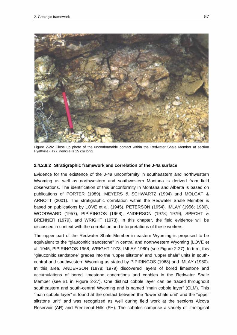
2. Geologic framework 57
Figure 2-26: Close up photo of the unconformable contact within the Redwater Shale Member at section Hyattville (HY). Pencile is 15 cm long.
2.4.2.8.2 Stratigraphic framework and correlation of the J-4a surface
Evidence for the existence of the J-4a unconformity in southeastern and northwestern Wyoming as well as northwestern and southwestern Montana is derived from field observations. The identification of this unconformity in Montana and Alberta is based on publications of PORTER (1989), MEYERS & SCHWARTZ (1994) and MOLGAT & ARNOTT (2001). The stratigraphic correlation within the Redwater Shale Member is based on publications by LOVE et al. (1945), PETERSON (1954), IMLAY (1956; 1980), WOODWARD (1957), PIPIRINGOS (1968), ANDERSON (1978; 1979), SPECHT & BRENNER (1979), and WRIGHT (1973). In this chapter, the field evidence will be discussed in context with the correlation and interpretations of these workers.
The upper part of the Redwater Shale Member in eastern Wyoming is proposed to be equivalent to the “glauconitic sandstone” in central and northwestern Wyoming (LOVE et al. 1945, PIPIRINGOS 1968, WRIGHT 1973, IMLAY 1980) (see Figure 2-27). In turn, this “glauconitic sandstone” grades into the “upper siltstone” and “upper shale” units in south-central and southwestern Wyoming as stated by PIPIRINGOS (1968) and IMLAY (1980). In this area, ANDERSON (1978; 1979) discovered layers of bored limestone and accumulations of bored limestone concretions and cobbles in the Redwater Shale Member (see #1 in Figure 2-27). One distinct cobble layer can be traced throughout southeastern and south-central Wyoming and is named “main cobble layer” (CLM). This “main cobble layer” is found at the contact between the “lower shale unit” and the “upper siltstone unit” and was recognized as well during field work at the sections Alcova Reservoir (AR) and Freezeout Hills (FH). The cobbles comprise a variety of lithological

2. Geologic framework 58
groups. ANDERSON (1978; 1979) reported skeletal carbonates (echinoderm debris with quartz), silty to sandy biosparite, parallel laminated silt and clay cobbles, and clay and silt cobbles without fabric. He interpreted the cobbles to have formed as hardground clasts derived from reworking of nearby lithified strata or as calcareous concretions in layers of sand, silt, mud, clay, and coquina. This interpretation was confirmed by investigations of WILKINSON et al. (1985). Further, ANDERSON (1978; 1979) reported the cobble layers to be consistent in thickness of 5 to 10 cm. Each layer is overlain by 5 to 20 cm thick calcareous fine sandstone, which bears shell fragments. At section Alcova Reservoir (AR), carbonate beds (samples AR 3 and AR 4) were noted to follow above the cobble layers. The “main cobble layer” is about 10 cm thick and very similar between locations in respect to cobble types, borings, taxa of epizoans, and matrix. It shows a greater geographic distribution, is thicker and the cobbles are more extensively bored than in other layers (ANDERSON 1978; 1979). Further, the cobbles of the main layer were colonized by polychaetes. Based on those facts ANDERSON (1978; 1979) concluded that the main layer was exposed on the sea-floor for a longer period. Similar layers of reworked concretions are described by VOIGT (1968) and BAIRD & FÜRSICH (1975) from the Jurassic in Germany, by HALLAM (1969) from the Jurassic in Great Britain, by KENNEDY & KLINGER (1972) from the Cretaceous of Zululand, and by KENNEDY et al. (1977) from the Cretaceous of Texas and Mexico. Calcareous concretions were interpreted by these authors as lag deposits that were left from winnowed strata. Therefore, the cobble layers in the “lower shale unit” of the Redwater Shale were interpreted by ANDERSON (1978; 1979) as a lag deposit. He related the exhumation of the concretions to falls in relative sea-level.
Red
wat
er S
hale
Mem
ber
shale
&
intercalated carbonate
and sandstone beds
Red
wat
er S
hale
Mem
ber
Swift
For
mat
ion
Swift
For
mat
ion
lowersiltunit
lower shaleunit
uppershaleunit
uppersiltunit
?glauconitic,coquinoid sandstone
glauconitic,coquinoid sandstone
glauconitic,coquinoid sandstone
glauconitic,coquinoid sandstone
ribbonsandstone
shale shale shale
lowersiltunit
lowershaleunit
lowershaleunit
lowersiltunit
lowershaleunit
lowersiltunit
lowershaleunit
#1 #2 #3 #4
#1
#2
#3
#4
cobble layer and unconformity identified in the Bighorn Basin/WY
cobble layer and unconformity identified in the southern Bighorn Mtns.and western Powder River Basin by BÜSCHER (2000)
“main cobble layer” and unconformity identified in southeastern and south-central Wyoming by ANDERSON (1978)
chert pebble lag and unconformity identified in northwestern Montana and Albertaby MOLGAT & ARNOTT (2001)
unconformity inferred
unconformity confirmed
J-4
J-5
NW Wyoming,Bighorn Basin
centralWyoming
W Powder River Basin
south-centralMontana
Black Hillssoutheastern, south-central
Wyoming
northwestern Montana &
Alberta
Figure 2-27: Regional stratigraphic correlation chart of the Redwater Shale and equivalents in the “Sundance Basin” compiled after LOVE et al. (1945), PETERSON (1954), IMLAY (1956; 1980), WOODWARD (1957), PIPIRINGOS (1968), ANDERSON (1978; 1979), SPECHT & BRENNER (1979), and WRIGHT (1973). Further, the stratigraphic position and evidence for a previously unknown unconformity within the allounit is shown. Hiatus of the J-5 unconformity is shaded in gray.
2. Geologic framework 59
SPECHT & BRENNER (1979) described almost similar concentrations of encrusted and bored carbonate nodules from the “upper silt unit” of the Redwater Shale Member in east-central Wyoming. They related the cobble accumulation to wave-caused winnowing effects during storm events.
At the same stratigraphic level, as the “main cobble layer” occurs, at the contact between calcareous shales and the glauconitic sandstone, BÜSCHER (2000) found a correlative layer of carbonate nodules in sections of the southeastern Bighorn Mountains and the western Powder River Basin (see # 3 in Figure 2-27). During field work, it was possible to trace this layer into the southern Bighorn Basin (see # 2 in Figure 2-27). There the layer was found at the sections Red Lane (RL), Hampton Ranch (HR), Red Rim Ranch (RR), and Hyattville (HY). Northward along the Bighorn Mountains front at the sections Sheep Mountain, Crystal Creek Road, Little Sheep Mountain, and Horseshoe Bend, investigated by DASSEL (2002), the unconformity can only be inferred by sharp lithological contacts between shale and overlying glauconitic sandstone. At section Buffalo Bill Dam, measured by SPRIESTERSBACH (2002), a coquinoid channel marks the shale–sandstone contact in the Redwater Shale Member. Northward from this location at Trail Creek IMLAY (1956) reported a pebbly conglomerate that appears at the same stratigraphic level.
In context with the interpretations of ANDERSON (1978; 1979), the stratigraphic framework shown in Figure 2-27 and observations that were made during field work, it seems likely to correlate the “main cobble layer” between sections in southeastern, central, north-central, and northwestern Wyoming. As a consequence, the “main cobble layer” represents a regional diastem and is generated during a major fall in relative sea-level.
In northwestern Montana and Alberta, the correlation of the J-4a unconformity is based on observations during field work and investigations by PORTER (1989), MOLGAT & ARNOTT (2001) and MEYERS & SCHWARTZ (1994). In southeastern Alberta and adjacent Montana, another previously unknown unconformity was reported by MOLGAT & ARNOTT (2001) within the Swift Formation. In this area, the Swift Formation consists of two unconformity-bound units (see #4 in Figure 2-27). The lower interval is composed of the “shale unit”, the upper interval is named the “ribbon sandstone” (HAYES 1984, MOLGAT & ARNOTT 2001). Between both units a thin chert pebble lag was discovered recently by MOLGAT & ARNOTT (2001). In their interpretation the deposition of the “shale unit” was terminated by a fall in relative sea-level. During lowstand a network of northeast to southwestward trending channels incised the top of the “shale unit”. The surface of the “shale unit” shows a highly irregular paleotopography of narrow (1,5 km), interconnected scours that are up to 15 m deep. Lowstand deposits were reworked thoroughly by ravinement processes during subsequent transgression and preserved as a thin chert pebble lag at the base of the paleovalleys. A thick suite of flaser- to wavy-bedded, interstratified mudstones, siltstones and sandstones of tidal origin overlies the transgressive lag/reworked lowstand deposits.

2. Geologic framework 60
PORTER (1989) reported the existence of a transgressive surface of erosion (TSE) within the Swift Formation in western and northwestern Montana. In this area, the Swift Formation consists of a “shale unit”, which grades into a flaser- to wavy-bedded, fine-grained sandstone. This unit is succeeded by a sharp-based, medium-grained, cross-bedded sandstone (PORTER 1989). The two units are separated by an unconformity, named transgressive surface of erosion (TSE) (PORTER 1989). This surface was recognized by PORTER (1989) first in the Sun River Canyon and also found during field work at this location (see Figure 2-28).
Figure 2-28: Transgressive surface of erosion (TSE) just below hammerhead. This surface was identified by PORTER (1989) at the Sun River Canyon (SRC) and confirmed during field work. A facies shift from lenticular-bedded shale and sandstone to glauconitic sandstone is marked by this surface. Length of hammer 32 cm.
In west and central Montana, the Swift Formation comprises three informal stratigraphic units (MEYERS & SCHWARTZ 1994). In the Great Falls area and the Three Forks area the formation includes a laterally restricted, 0 – 4 m thick “basal conglomerate unit” and a widespread, upward-fining “upper sandstone body” (MEYERS & SCHWARTZ 1994). The authors reported the lower surface of the basal conglomerate to be a scour surface developed upon various underlying Mississippian to Middle Jurassic rocks. Where the basal unit is absent a thick “lower shale unit” with thin sandstone and siltstone beds in the upper part underlies the “upper sandstone body” southwest and west of Great Falls (MEYERS & SCHWARTZ 1994). The “shale unit” is sharply capped by the “upper sandstone body” which is of tidal origin (MEYERS & SCHWARTZ 1994). Due to the

2. Geologic framework 61
widespread twofold lithologic character of the Swift Formation in Montana this “upper sandstone body” must be equivalent to the sharp-based, medium-grained, cross-bedded sandstone reported by PORTER (1989). This means that the “upper sandstone body” must be separated from the underlying shales by an unconformable contact.
Taking into account the discussed interpretations of ANDERSON (1978; 1979), MOLGAT & ARNOT (2001), PORTER (1989), and MEYERS & SCHWARTZ (1994) in combination with the observations made during field work the following conclusion can be drawn: In the Oxfordian stratal record of the study area two unconformity-bound, lithologically contrasting units are present. The lower unit consists of shale and was deposited under low-energetic, marine conditions below wave base. Diastemic accumulation was dominant, but frequently sedimentation took place under higher energetic conditions during storm events. In the vicinity of paleotopographic elements the marine shale grades into tidal-influenced, flaser- to wavy-bedded siltstone-sandstone beds. Sedimentation of this lower unit was terminated by a major regressive event that can be traced from southeastern Alberta over northwestern Montana via northwestern and central into southeastern Wyoming. During ensuing transgression, lowstand deposits and remaining lag deposits were reworked and accumulated as a chert pebble lag or a carbonate cobble lag at the base of the overlying upper, tide-, wave- and storm-influenced glauconitic sandstone suite. This situation is illustrated in a generalized cross section in Figure 2-29.
Sawtooth Fm.Rierdon Fm.
Swift Fm. axisof
Belt Island
Complex
Alberta Montana Wyoming
ARRRCD
PCCSRCSR#1 #2
sub-basin
paleovalleyincised
on J-4 surfacechannelsincised
on top of “shale unit” surface
#1: generalized section of Swift Formation in Alberta after MOLGAT & ARNOTT (2001)#2: generalized section of Swift Formation in west and central Montana after MEYERS & SCHWARTZ (1994)C: section Craig/MT after PORTER (1989)PC: section Porcupine Creek/MT after PORTER (1989)SR: section Swift Reservoir (SR) this studySRC: section Sun River Canyon (SRC) this studyCD: Chugwater Dome section after SPRIESTERSBACH (2002)RR: section Red Rim Ranch (RR) this studyAR: section Alcova Reservoir (AR) this study
#1
33 m
J-5
J-4
J-4a
“shale unit”
“upper sandstone body”
Belt Island Complex
#2
AR
RR
CD
SRCSR
PCC
N S
Figure 2-29: Schematic cross-section from the Alberta-Montana border into southeastern Wyoming showing thickness trends of the “lower shale” and “upper sandstone body” over paleotopographic highs. Basal conglomerates are locally developed in incised paleovalley on top of the J-4 surface (see location PC). Distances between state borders are not to scale. As datum the J-4a unconformity was chosen.

2. Geologic framework 62
2.4.2.9 J-5 unconformity
PIPIRINGOS & O’ SULLIVAN (1978) found the J-5 unconformity in most parts of the Western Interior, although the continuation into Montana, northwestern Wyoming and Idaho is not known. Commonly, the surface marks the base of the Morrison Formation or the Windy Hill Sandstone Member of the Sundance Formation. Where the Windy Hill Member is absent physical evidence for an unconformable contact to the succeeding Morrison Formation is weak as for instance in the Bighorn Basin (JOHNSON 1992). PIPIRINGOS & O’ SULLIVAN (1978) considered thickness variations of the Swift Formation in Montana between 0 and 70 m as possible evidence for pre-Morrison erosion. However, IMLAY (1980), UHLIR et al. (1988), MEYERS & SCHWARTZ (1994) doubted the presence of the J-5 unconformity in these areas. In central Wyoming all strata below the J-5 surface progressively truncated (PIPIRINGOS 1957, PIPIRINGOS 1968, PIPIRINGOS 1972, PIPIRINGOS & O’ SULLIVAN 1978). The hiatus represented by the J-5 unconformity is estimated by PIPIRINGOS & O’ SULLIVAN (1978) at less than 2 Ma. The J-5 represents a second-order boundary according to the hierarchical system of EMBRY (1993).
2.5 Cyclostratigraphy
Based on lithofacies and biofacies distribution BRENNER & PETERSON (1994) identified six transgressive-regressive sedimentary cycles in the Jurassic stratal record. The stratigraphic position of the sedimentary cycles and their bounding unconformities is indicated in the correlation chart in Figure 2-3.
The cycles are termed, in ascending order: Lower Continental, First Marine, Second Marine, Third Marine, Fourth Marine, and Upper Continental. As recognized by BRENNER & PETERSON (1994) the transgressive-regressive cycles are bound by the unconformable stratigraphic contacts J-0 to K-1 proposed by PIPIRINGOS & O’ SULLIVAN (1978). The First Marine cycle is bordered by the J-1 and J-2 unconformities. The Second and Third Marine cycles occur within an interval that is bound by the J-2 and J-3 unconformities. The Fourth Marine cycle appears between the J-4 and J-5 unconformities. Between the J-3 and J-4 unconformities an isolated and undefined interval (“unnamed cycle”), stratigraphically equivalent to the Pine Butte Member of the Sundance Formation and the Curtis Member of the Stump Formation, is present.
The examined Middle and Late Jurassic outcrop sections in the study area are stratigraphically equivalent to the four marine sedimentary cycles of BRENNER & PETERSON (1994). The cyclic nature within the “Sundance Basin” fill is expressed in the stratigraphic successions and can be recognized basinwide in outcrop. Moreover, the cyclostratigraphic approach to the partly unfossiliferous basin fill allows a correlation of sedimentary successions over great distances within the study area. In addition to the cyclostratigraphic subdivision of BRENNER & PETERSON (1994) subordinate
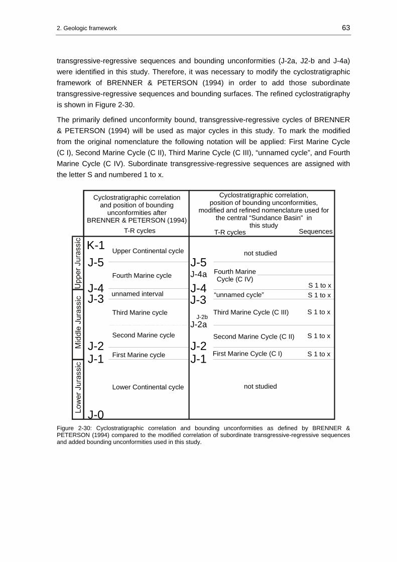
2. Geologic framework 63
transgressive-regressive sequences and bounding unconformities (J-2a, J2-b and J-4a) were identified in this study. Therefore, it was necessary to modify the cyclostratigraphic framework of BRENNER & PETERSON (1994) in order to add those subordinate transgressive-regressive sequences and bounding surfaces. The refined cyclostratigraphy is shown in Figure 2-30.
The primarily defined unconformity bound, transgressive-regressive cycles of BRENNER & PETERSON (1994) will be used as major cycles in this study. To mark the modified from the original nomenclature the following notation will be applied: First Marine Cycle (C I), Second Marine Cycle (C II), Third Marine Cycle (C III), “unnamed cycle”, and Fourth Marine Cycle (C IV). Subordinate transgressive-regressive sequences are assigned with the letter S and numbered 1 to x.
Cyclostratigraphic correlation and position of bounding
unconformities after BRENNER & PETERSON (1994)
Upper Continental cycle
Fourth Marine cycle
Third Marine cycle
unnamed interval
Second Marine cycle
First Marine cycle
Lower Continental cycle
J-1J-2
J-3J-4
J-5K-1
J-0
J-1J-2
First Marine Cycle (C I)
Second Marine Cycle (C II)
T-R cycles Sequences
J-2a
J-4
J-5J-4a
Third Marine Cycle (C III)
Fourth Marine Cycle (C IV)
S 1 to x
S 1 to x
S 1 to x
S 1 to x
Cyclostratigraphic correlation, position of bounding unconformities,
modified and refined nomenclature used forthe central “Sundance Basin” in
this studyT-R cycles
not studied
not studied
J-2b
“unnamed cycle”J-3 S 1 to x
Figure 2-30: Cyclostratigraphic correlation and bounding unconformities as defined by BRENNER & PETERSON (1994) compared to the modified correlation of subordinate transgressive-regressive sequences and added bounding unconformities used in this study.
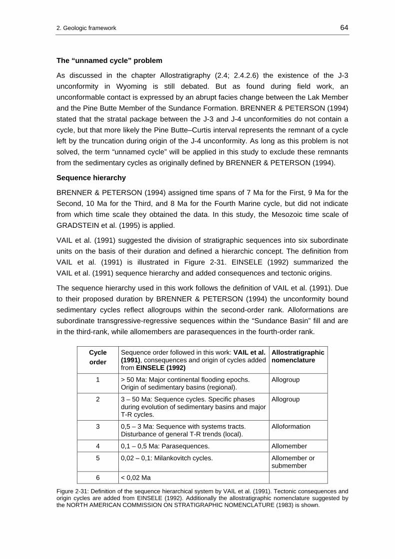
2. Geologic framework 64
The “unnamed cycle” problem
As discussed in the chapter Allostratigraphy (2.4; 2.4.2.6) the existence of the J-3 unconformity in Wyoming is still debated. But as found during field work, an unconformable contact is expressed by an abrupt facies change between the Lak Member and the Pine Butte Member of the Sundance Formation. BRENNER & PETERSON (1994) stated that the stratal package between the J-3 and J-4 unconformities do not contain a cycle, but that more likely the Pine Butte–Curtis interval represents the remnant of a cycle left by the truncation during origin of the J-4 unconformity. As long as this problem is not solved, the term “unnamed cycle” will be applied in this study to exclude these remnants from the sedimentary cycles as originally defined by BRENNER & PETERSON (1994).
Sequence hierarchy
BRENNER & PETERSON (1994) assigned time spans of 7 Ma for the First, 9 Ma for the Second, 10 Ma for the Third, and 8 Ma for the Fourth Marine cycle, but did not indicate from which time scale they obtained the data. In this study, the Mesozoic time scale of GRADSTEIN et al. (1995) is applied.
VAIL et al. (1991) suggested the division of stratigraphic sequences into six subordinate units on the basis of their duration and defined a hierarchic concept. The definition from VAIL et al. (1991) is illustrated in Figure 2-31. EINSELE (1992) summarized the VAIL et al. (1991) sequence hierarchy and added consequences and tectonic origins.
The sequence hierarchy used in this work follows the definition of VAIL et al. (1991). Due to their proposed duration by BRENNER & PETERSON (1994) the unconformity bound sedimentary cycles reflect allogroups within the second-order rank. Alloformations are subordinate transgressive-regressive sequences within the “Sundance Basin” fill and are in the third-rank, while allomembers are parasequences in the fourth-order rank.
Cycle order
Sequence order followed in this work: VAIL et al. (1991), consequences and origin of cycles added from EINSELE (1992)
Allostratigraphic nomenclature
1 > 50 Ma: Major continental flooding epochs. Origin of sedimentary basins (regional).
Allogroup
2 3 – 50 Ma: Sequence cycles. Specific phases during evolution of sedimentary basins and major T-R cycles.
Allogroup
3 0,5 – 3 Ma: Sequence with systems tracts. Disturbance of general T-R trends (local).
Alloformation
4 0,1 – 0,5 Ma: Parasequences. Allomember
5 0,02 – 0,1: Milankovitch cycles. Allomember or submember
6 < 0,02 Ma
Figure 2-31: Definition of the sequence hierarchical system by VAIL et al. (1991). Tectonic consequences and origin cycles are added from EINSELE (1992). Additionally the allostratigraphic nomenclature suggested by the NORTH AMERICAN COMMISSION ON STRATIGRAPHIC NOMENCLATURE (1983) is shown.

65
3 Facies analysis
The paleoenvironmental and sequence stratigraphic reconstruction requires more detailed sedimentological data in addition to the lithostratigraphic, cyclostratigraphic and allostratigraphic analysis. The required additional sedimentological data is provided by a facies analysis of the carbonate and siliciclastic rocks.
3.1 Carbonates
The method of carbonate microfacies analysis that was applied to study the carbonate samples from the investigated outcrop sections was introduced by FLÜGEL (1982). The nomenclature for carbonate rocks used in this work is a combination of the terminology introduced by DUNHAM (1962), which is focused on textural aspects, and the particle-related notation of FOLK (1962). The interpretation of carbonate depositional environments includes macroscopic sedimentary structures, outcrop observations and the occurrence of diagnostic facies fossils in the stratigraphic column.
3.1.1 Carbonate microfacies analysis
3.1.1.1 Bioclast spectrum
The bioclast spectrum of the studied samples is primarily composed of pelecypods and crinoids. Additionally, varying trace amounts are contributed by foraminifers, gastropods, ostracods, and fragmented bioclastic debris from fennestrate bryozoans and codiacean algae.
Pelecypods: The diversity of pelecypods in the Middle and Late Jurassic formations is enormous. Comprehensive paleontological surveys and systematic descriptions are published by IMLAY (1947; 1956; 1967; 1980). According to IMLAY (1967), in the Twin Creek Limestone Jurassic pelecypods account for about 1580 specimen and include 43 genera and subgenera and 50 species and subspecies. The most abundant genera are by far Gryphea, followed by Camptonectes, Ostrea, Pronella, and Pleuromya (IMLAY 1967).
Crinoids: Echinoderm particles are primarily disarticulated crinoidal columns. Crinoids from marine Jurassic formations are identified by IMLAY (1967) as Pentacrinus asteriscus Meek & Hayden. In southwestern Utah, TANG et al. (2000) described the recently discovered partially articulated crinoid columns from Isocrinus nicoletti.

3. Facies analysis 66
Foraminifers: A comprehensive survey of Middle and Late Jurassic foraminiferans was conducted by CAPARCO (1989). 72 species of benthic foraminifera and seven species of arenaceous benthic foraminifera were identified from the Middle Jurassic “lower” Sundance Formation. The species belong to seven foraminifera families, represented in descending order by: Nodosariidae, Lituolidae, Polymorphinidae, Hormosinidae, Trochaminidae, Spirillinidae, and Ceratubuliminidae (CAPARCO 1989). Further, thirty-six species of calcareous benthic foraminifera and seven species of arenaceous benthic foraminifera were identified in Late Jurassic sediments. The species belong to eight foraminifera families, represented in descending order by: Nodosariidae, Lituolidae, Polymorphinidae, Hormosinidae, Trochaminidae, Miliolidae, Glandulinidae, Spirillinidae, and Ceratubuliminidae.
Gastropods: Gastropod specimen are strongly fragmented in the studied samples. IMLAY (1967) reported the nacticiform gastropods species Cossmannea sp. and otherwise unidentifiable specimen from Middle Jurassic strata.
Ostracods: Middle Jurassic ostracod faunas in central and eastern Wyoming belong to the Aparchitocythere compressa biofacies, while the Procytherida exempla biofacies is dominant in north Wyoming and central Montana (PETERSON 1954). Late Jurassic ostracods are assigned to the Aparchitocythere typica zone that include the Progonocythere subzone and the Leptocythere imlayi-Cytherura lanceolata subzone (PETERSON 1954). In the analyzed samples ostracods contribute trace amounts and are sometimes difficult to distinguish from juvenile bivalves.
Microschill: this term will be applied for strongly fragmented bioclasts.
3.1.1.2 Non-biogen components
Ooids: Ooids are the major non-biogen component in the studied samples. The calcareous, elongated to spherical ooids range between 0,3-0,7 mm in diameter and are present in various states of micritization. Normal ooids with a quartz or bioclast nuclei are common, while subordinate amounts of superficial ooids are commonly associated with bioclastic nuclei.
Peloids: Peloids are either products of reworking or of faecal origin (FLÜGEL 1985). Peloids in the studied samples are interpreted as reworked carbonate particles or small intraclasts since they are always associated and mixed with ooids. A faecal origin would rather be suggested by a separation of ooids and peloids in combination with bioturbation, the occurrence of pellets in clusters associated with bindstone-like textures. A faecal origin of laminated, spherical pellets is proposed for peloidal grainstones in Montana by MEYERS (1981).

3. Facies analysis 67
Intraclasts: Intraclasts are the reworked product of partly lithified material (FLÜGEL 1982). They are generated by dehydration (mud pebbles), storm or wave influence in intertidal to supratidal environments. They are the large-sized, poorly reworked counterparts of peloids and are a prominent component in the studied samples.
Lithoclasts: Lithoclasts are >2 mm in diameter and consist of rounded to unrounded clasts of sandstone, chert or carbonate (FLÜGEL 1985). Chert and sandstone lithoclasts are common in samples from the “Sundance Basin”.
Detritus: A detritic component is considered here as quartzose, fine-grained detritus (silt to fine sand). Many samples contain up to 5 Vol. % of siliciclastic detritus.
3.1.2 Carbonate microfacies types
3.1.2.1 Grainstone facies types
Oograinstone facies
Samples: DH 1, CC 3, CC 5, PF 5, RC 5, RL 3, RL 5, SPC 17, SPC 18, TF 2, TF 3, TF 6, TC 7, TC 8, TF 9, TC 4, THI 4, THI 7.
Matrix/particle ratio (Vol.-%)
matrix30%
particle70%
Carbonate particle spectrum (Vol.-%)
ooids75%
peloids5%
intraclasts4%
biogen16%
Matrix: Sparite, columnar to palisade-like or isopachous cement A, blocky cement B. Crinoid fragments are replaced by syntaxial cement.
Components: The major non-biogen components of the oograinstone microfacies are densely packed, spherical to elongated, brownish, normal ooids, 0,45-0,7 mm in diameter, partly micritized with quartzose or bioclastic nuclei and multiple concentric layers (see Plate 1, A and B). Further, oval to spherical, well sorted, dark brown to opaque peloids, <0,25 mm in diameter and intraclasts, 0,5-2 mm in diameter, composed of abraded and broken ooids embedded in brownish micritic material are present. Biogen particles are

3. Facies analysis 68
abraded crinoidal columns, 0,4-1 mm in diameter with thick micritic envelopes and well rounded, moderate to good sorted pelecypod fragments, 0,3-0,8 mm in length (oysters and unidentified bivalves). Variations in this microfacies are expressed in the relative proportions of skeletal fragments and detritus. The degree of detritus content varies between 1 and 10 Vol. %.
Texture: Grain-supported with well to moderate sorted and rounded particles. In densely packed layers ooids are deformed.
Bedding and sedimentary structures: Thin-sections of the oograinstone microfacies display either 5 mm thick planar stratification or lack internal bedding features. At some outcrop locations faint large-scale cross-bedding is preserved, for example at section Hoback Canyon (HC). At section Red Lane (RL), the oograinstone microfacies is exposed in massive beds of cross-bedded, quartzose oolitic grainstone (see Figure 3-1). The lower contacts of the massive- to thick-bedded oolitic grainstone suites are sharp. The sediment bodies show tabular persisting thickness and are traceable in outcrop sections.
Figure 3-1: Massive, cross-bedded quartzose oograinstone beds that form the base of the Sundance Formation at section Red Lane (RL) north of Thermopolis/WY in the southern Bighorn Basin.
Interpretation: The high degree of winnowing, reworking and sorting of the particles in combination with the preserved sedimentary structures indicate deposition under permanent high-energetic conditions. In recent environments ooids are generated on shoals and bars on the Bahama platform in water depths between 2 and 5 m (TUCKER 1985, TUCKER & WRIGHT 1990, FLÜGEL 1982). This suggests that the oograinstone microfacies was deposited in high-energy shoals and bars in the vicinity of paleotopographic elements or in high-energetic facies belts. This interpretation is
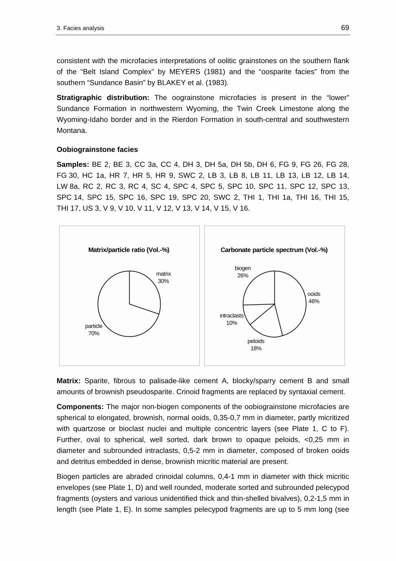
3. Facies analysis 69
consistent with the microfacies interpretations of oolitic grainstones on the southern flank of the “Belt Island Complex” by MEYERS (1981) and the “oosparite facies” from the southern “Sundance Basin” by BLAKEY et al. (1983).
Stratigraphic distribution: The oograinstone microfacies is present in the “lower” Sundance Formation in northwestern Wyoming, the Twin Creek Limestone along the Wyoming-Idaho border and in the Rierdon Formation in south-central and southwestern Montana.
Oobiograinstone facies
Samples: BE 2, BE 3, CC 3a, CC 4, DH 3, DH 5a, DH 5b, DH 6, FG 9, FG 26, FG 28, FG 30, HC 1a, HR 7, HR 5, HR 9, SWC 2, LB 3, LB 8, LB 11, LB 13, LB 12, LB 14, LW 8a, RC 2, RC 3, RC 4, SC 4, SPC 4, SPC 5, SPC 10, SPC 11, SPC 12, SPC 13, SPC 14, SPC 15, SPC 16, SPC 19, SPC 20, SWC 2, THI 1, THI 1a, THI 16, THI 15, THI 17, US 3, V 9, V 10, V 11, V 12, V 13, V 14, V 15, V 16.
Matrix/particle ratio (Vol.-%)
matrix30%
particle70%
Carbonate particle spectrum (Vol.-%)
ooids46%
peloids18%
intraclasts10%
biogen26%
Matrix: Sparite, fibrous to palisade-like cement A, blocky/sparry cement B and small amounts of brownish pseudosparite. Crinoid fragments are replaced by syntaxial cement.
Components: The major non-biogen components of the oobiograinstone microfacies are spherical to elongated, brownish, normal ooids, 0,35-0,7 mm in diameter, partly micritized with quartzose or bioclast nuclei and multiple concentric layers (see Plate 1, C to F). Further, oval to spherical, well sorted, dark brown to opaque peloids, <0,25 mm in diameter and subrounded intraclasts, 0,5-2 mm in diameter, composed of broken ooids and detritus embedded in dense, brownish micritic material are present.
Biogen particles are abraded crinoidal columns, 0,4-1 mm in diameter with thick micritic envelopes (see Plate 1, D) and well rounded, moderate sorted and subrounded pelecypod fragments (oysters and various unidentified thick and thin-shelled bivalves), 0,2-1,5 mm in length (see Plate 1, E). In some samples pelecypod fragments are up to 5 mm long (see

3. Facies analysis 70
Plate 1, F). Trace amounts of bioclasts are contributed by foraminifers, ostracods, gastropods, and bryozoans (samples FG 15, LB 11, LB 13). Variations in this microfacies are in the relative proportions of peloids and detritus. The degree of detritus content is composed of quartzose and/or allochthonous glauconitic grains in silt to fine sand-size and varies between 1 and 8 Vol. %. The glauconite is either fresh medium-green or yellowish-brown due to alteration.
Texture: Grain-supported with moderate to poorly sorted and rounded particles. In densely packed layers ooids are deformed. The up to 5 mm long pelecypod fragments superimpose rudstone-like textures in some samples (see Plate 1, F).
Bedding and sedimentary structures: The majority of studied samples lack stratification in the microscopic thin-section as well as the macroscopic outcrop scale. A sediment structure in outcrop is cross-bedding with sigmoidal-shaped forests as at section Vernal (V) (see Figure 3-2). Microscopic structures are planar stratification of 3-5 mm thick bands of ooid-rich and crinoid-rich layers as well as cross-bedding with imbricated crinoidal columns that grade upward into ooid-rich bands. Sample FG 15 shows dehydration fabrics. In densely packed clusters of pelecypod fragments micritic material is occasionally preserved. In samples DH 5a, SPC 10, SPC 4, SPC 5, SWC 2, HR 5, HR 7, THI 1a, US 3 the degree of bioerosion is high. Echinoderm and pelecypod fragments are intensively bored and micritic envelopes are developed. Some samples show graded bedding and micritic material is sheltered by large, planar oriented convex shell fragments.
In outcrop the lower contacts of the massive to thick-bedded grainstone suites are sharp (see Figure 3-3). The sediment bodies show tabular persisting thickness and are traceable at the examined locations.
Interpretation: The high degree of winnowing, reworking and sorting of particles in combination with the preserved sedimentary structures indicate deposition under dominantly high-energy hydrodynamic conditions. The oobiograinstone microfacies occurs in close genetic and spatial relation with the oograinstone facies. According to MEYERS (1981), this relation suggests deposition of the oobiograinstones in the vicinity of and among oolite shoals and bars. This relation between a pure oolitic facies and a slightly “impure”, intermediate oolite-bioclastic facies was also suggested for carbonate microfacies types of the Sundance Formation in Wyoming by BÜSCHER (2000), SPRIESTERSBACH (2002) and DASSEL (2002).
Stratigraphic distribution: The oobiograinstone microfacies occurs in the Sundance Formation in northwestern Wyoming, the Twin Creek Limestone along the Wyoming-Idaho border, the Carmel Formation, and Stump Formation in northeastern Utah, and in the Rierdon Formation in south-central and southwestern Montana.

3. Facies analysis 71
Figure 3-2: Sharp-based, cross-bedded oobiograinstones intercalated into shales of the Curtis Formation at section Vernal (V). The foresets are sigmoidal shaped. Samples V 11 and V 12 were taken from this bed. Portion of Jacob stick is approximately 50 cm long.
Figure 3-3: Oograinstone and oobiograinstone facies in the upper part of the Watton Canyon Member of the Twin Creek Limestone at section South Piney Creek (SPC).

3. Facies analysis 72
Biograinstone facies
Samples: AR 5, DH 5, HE 2, HE 3, HE 4, HU 10, HU 11, HU 13, HU 14, HY 9, HY 10, HY 11, LW 1, LW 10, LW 10a, MIN 12, RC 8, RL 8, RR 8, SC 2, SC 7, SC 8, SPC 7.
Matrix/particle ratio (Vol.-%)
matrix30%
particle70%
Carbonate particle spectrum (Vol.-%)
gastropods2%
foraminifera2%
ooids5%
peloids5%
intraclasts6%
crinoids40%
pelecypods40%
Matrix: Sparite, palisade-like cement A, blocky/sparry cement B and small amounts of brownish pseudosparite. Crinoid fragments are replaced by syntaxial cement.
Components: The major components of this microfacies type are pelecypods and crinoids (see Plate 2, A and B). The crinoids are 0,5-2 mm in diameter, abraded, bored, and display micritic envelopes. The pelecypods are moderately sorted, well rounded and range between 0,3-12 mm in size. Oyster fragments can be distinguished from thin- to thick-shelled unidentifiable bivalves. Trace amounts (up to 2 Vol. %) of foraminifers (samples H 10, SC 2, MIN 12, SPC 17) and 0,4 mm sized gastropod fragments (SPC 7) are present. Ooids are only superficially developed with bioclastic nuclei and range between 0,2-0,5 mm in diameter. Peloids are oval to spherical, well sorted, dark brown to opaque, and <0,25 mm in diameter. Variations in this microfacies are in the relative proportions of major components. The detritus is composed of quartzose and/or allochthonous glauconitic grains (samples MIN 12, SC 2, RC 8, HU 10, HU 14, HY 9) in silt to fine sand-size and varies between 1 and 10 Vol. %. The glauconite is either fresh medium-green or yellowish-brown due to alteration. Further, rounded intraclasts, 0,3-0,5 mm in diameter, composed of a detritic, dense, brownish micritic material, are present.
Texture: Grain-supported with well to moderate sorted and rounded particles. The up to 5 mm long pelecypod fragments superimpose rudstone-like textures in some samples (see Plate 2, A).

3. Facies analysis 73
Bedding and sedimentary structures: Some samples display graded bedding, sheltering of micritic material, intense bioturbation, planar stratification of 5 mm thick pelecypod-rich and detritic layers, and a rudstone-character (more than 10 Vol. % of pelecypod fragments are >2 mm).
In outcrop the biograinstone microfacies beds are sharp-based and interbedded into fine-clastic suites of glauconitic shales, siltstones or mudstones and display hummocky cross- lamination as found at section Alcova Reservoir (AR). Additional macroscopic sediment structures are cross-bedded, tidal channel lags as observed at sections Heath (HE) (see Figure 3-4), Alcova Reservoir (AR) and Hyattville (HY). Alternatively as at sections Little Water Creek (LW) and Thomas Fork Canyon (TF) (see Figure 3-5) the biograinstone microfacies display lenticular, 5 m thick sediment body geometries with “rudstone-like character” that are traceable in outcrop.
Figure 3-4: Biograinstones intercalated as lenticular tidal channel lags (red arrows) into glauconitic sandstones of the “ribbon sandstone unit” of the Swift Formation at section Heath (HE) in central Montana. Note that in the upper part of the sandstone cliff the biograinstone facies grades into cross-bedded glauconitic sandstones. Length of Jacob stick 1,5 m.
Interpretation: The poor to moderate sorting, the well winnowed, grain-supported texture, and the strong abrasion of biogenic particles indicate deposition under high-energetic hydrodynamic conditions. The abundance of oysters in some samples suggests a close spatial relation to oyster banks. Additional diagnostic sediment structures like graded bedding, sheltering of micrite, sharp based contacts, and poor sorting are indicative for storm-influenced deposits (FLÜGEL 1982, AIGNER 1985). Accordingly, samples that contain these sediment structures are interpreted as storm beds. This interpretation is

3. Facies analysis 74
supported by the discontinuous facies relations that are expressed at locations where the biograinstone microfacies is intercalated into glauconitic shales of the Redwater Shale Member (Sundance Formation) or mudstones of the Leeds Creek Member (Twin Creek Limestone) as at sections Red Lane (RL), Alcova Reservoir (AR) and Devils Hole Creek (DH). The process of storm-related winnowing of grainstone beds is also described by SPECHT & BRENNER (1979) from examples within the “upper” Sundance Formation in central Wyoming.
Figure 3-5: Biograinstones, with a strong rudstone character, exposed as a densely packed oyster coquina in the Watton Canyon Member of the Twin Creek Limestone at section Thomas Fork Canyon (TF). Hammerhead is 17 cm long.
Samples that lack these diagnostic structures are interpreted on the basis of their macroscopic structures (lenticular geometries, cross-bedding) in context with the interpretations of MEYERS (1981) and UHLIR et al. (1988) as tidal channel lag accumulations. Those are found at various locations in Montana at section Heath (HE) or in northwestern Wyoming at sections Hyattville (HY), Hampton Ranch (HR), Red Rim Ranch (RR) or as bioclastic bars as found at Little Water Creek (LW).
Stratigraphic distribution: The biograinstone microfacies is represented in the Sundance Formation, in the Twin Creek Limestone, in the Sawtooth and Rierdon Formation in south-central and southwestern Montana, and in the Swift Formation in central Montana.

3. Facies analysis 75
3.1.2.2 Packstone facies types
Oobiopackstone facies
Samples: FG 11, FG 12, FG 14, FG 15, FG 16, FG 17, FG 29, HC 3, LB 10, LW 3, THI 29, W 5.
Matrix/particle ratio (Vol.-%)
matrix50%
particle50%
Carbonate particle spectrum (Vol.-%)
ooids39%
peloids18%
intraclasts8%
biogen35%
Matrix: Brownish pseudosparite. Crinoid fragments with massive syntaxial overgrowth.
Components: Spherical to elongated, brownish, normal ooids, 0,35-0,55 mm in diameter, partly micritized with quartzose or bioclastic nuclei, and multiple concentric layers, are the major non-biogen component. Further, oval to spherical, well sorted, dark brown to opaque peloids, <0,3 mm in diameter, and subrounded intraclasts composed of dark brown micritic material with embedded detritus, microschill and ooids are common.
Bioclasts are abraded, well rounded, thin- to thick-bedded pelecypods that range between 0,5-12 mm in length (oysters and various unidentified bivalves). Oyster fragments and thick-bedded shell fragments display micritic envelopes. Further, poorly sorted crinoidal columns, 0,4-1,5 mm (maximum 3 mm) in diameter with thick micritic envelopes are present. Trace amounts of bioclasts are varying proportions of foraminifers, gastropods or bryozoans (samples FG 12). The detritus content is composed of silt to fine sand and contributes up to 5 Vol. %.
Texture: Grain-supported, moderately winnowed and sorted.
Bedding and sedimentary structures: The majority of studied samples lack stratification. If present, sedimentary structures are 3 mm thick, flaser stratification of peloid-rich and detritus-rich layers. Further, dehydration features occur. Some samples display graded bedding and an imbrication fabric of pelecypod fragments. Macroscopic aspects of the oobiopackstone microfacies are a sheet-like geometry, up to 1,3 m

3. Facies analysis 76
thickness and sharp-based contacts. The rocks are interbedded with glauconitic shales at section Hampton Ranch (HR), mudstones in the Twin Creek Limestone area or massive oograinstone facies types at sections Flaming Gorge (FG) and Red Lane (RL).
Interpretation: The majority of studied thin-sections show a high degree of winnowing, reworking and sorting that indicate high-energetic hydrodynamic conditions. The spatial association with the oograinstone and oobiograinstone microfacies suggests as well a genetic relation to these facies types. Deposition took place under conditions that allowed carbonate mud to settle into the intergranular space in protected settings among oolite shoals and bars. This interpretation corresponds to the microfacies interpretations of oolites on the southern flank of the “Belt Island Complex” by MEYERS (1981) and the “oosparite facies” from the southern “Sundance Basin” by BLAKEY et al. (1983). Alternatively, it is possible that the oobiopackstones represent drowned shoals and bars.
Stratigraphic distribution: The oobiopackstone microfacies is represented in the Sundance Formation, the Twin Creek Limestone, the Carmel Formation, and the Stump Formation in northeastern Utah as well as in the Rierdon Formation in south-central and southwestern Montana.
Biopackstone to biorudstone facies
Samples: AR 7, FG 8, FG 13, FG 25, HY 8, LB 4, LB 5, LB 6, LW 5, MIN 10, PF 4, RL 9, RR 6, SC 1, SC 3, SPC 8, SR 3, SR 4, SWC 5, SWC 6, SWC 10, SWC 11, THI 19, US 1, US 2, US 5, W 5a.
Matrix/particle ratio (Vol.-%)
matrix50%
particle50%
Carbonate particle spectrum (Vol.-%)
crinoids16%
gastropods25%
pelecypods34%
bryozoa5%
peloids10%
ooids8%
intraclasts2%
Matrix: Brownish pseudosparite or microsparite is dominant, while in some samples sparite (palisade-like cement A and blocky to sparry cement B) is present in well winnowed intergranular areas. Syntaxial overgrowth cements are developed around echinoderm fragments.

3. Facies analysis 77
Components: The main biogen components of the biopackstone microfacies are crinoids, pelecypods and gastropods in varying amounts (see Plate 2, C and D). The pelecypods are subangular and rounded, thick- to thin-shelled, poorly sorted (0,2-10 mm), and display micritic envelopes (see Plate 2, D). The crinoids are poorly sorted (0,5-2 mm), abraded, bored, and display thick micritic envelopes. The gastropods are thin walled, strongly fragmented and poorly sorted (0,4-15 mm). Additional bioclasts are fragmented bryozoans (FG 13, THI 19, SC 3), 0,4-2 mm in size.
Non-biogen components are spherical to elongated, brownish, normal ooids, 0,2-0,5 mm in diameter, partly micritized with quartzose or bioclastic nuclei, and multiple concentric layers. A subordinate amount of oolites is developed as superficial ooids, 0,4 mm in diameter (LW 5, THI 19). The microfacies contains spherical, well sorted, dark brown to opaque peloids, <0,25 mm in diameter, and subrounded intraclasts composed of dark brown micritic material with silt to fine sand-sized detritus. The detritus content comprises quartzose and/or allochthonous glauconitic grains (samples THI 19, SC 3) in silt to fine sand-size. The degree varies between 1 and 3 Vol. %. The glauconite is either fresh medium-green or yellowish-brown due to alteration.
Texture: Grain-supported, moderately winnowed and poorly sorted. Up to 35 mm long bioclast fragments that make up more than 10 Vol. % in some samples superimpose a rudstone-like character (see Plate 2, C and D).
Bedding and sedimentary structures: The biopackstone microfacies either lacks stratification due to intense bioturbation or displays bedding parallel oriented particles. The degree of bioturbation is high in some samples (LW 5, FG 13) and expressed as S- or J-shaped burrows filled with dark brown micritic material. In some samples (FG 25, PF 4, US 1, US 2, US 5) the degree of sorting and fragmentation decreases upward.
In outcrop, the biopackstone microfacies types are exposed as 0,2-1 m thick interbeds within massive oograinstone facies types at sections Flaming Gorge (FG) and Little Water Creek (LW), within mudstones (section Poker Flat) or within red siltstones (section Whiterocks Canyon).
Interpretation: The biopackstone microfacies is very similar to the biograinstone microfacies in respect to the rudstone character and the degree of particle sorting and reworking. The main contrast is an increased diversity of the particle spectrum that is composed of biogen and non-biogen components. The varying degree of bioclast fragmentation reflects a multiple redepositional history of the bioclast accumulation. The development of micritic envelopes and borings indicates accumulation within the photic zone. A continuous facies relation with underlying and overlying beds is not evident in outcrop which rather suggests an infrequent deposition of the biopackstone microfacies probably during storm events. A particle input from high-energetic facies zones (shoals and bars) is suggested by the occurrence of ooids, intraclasts and peloids in the biopackstone microfacies and the interstratification with massive oolite facies types.

3. Facies analysis 78
Stratigraphic distribution: The biopackstone microfacies is present in the Twin Creek Limestone, the Sundance Formation in Wyoming, the Carmel Formation and the Stump Formation in northeastern Utah and in the Ellis Group in Montana.
3.1.2.3 Wackestone facies types
Pelbiowackestone facies
Samples: LW 4, TF 1, W 6.
Matrix/particle ratio: 70/30-80/20 Vol. %. The matrix/particle ratio in this wackestone microfacies type varies due to the degree of particle fragmentation and compaction.
Matrix: Brownish micrite or microsparite. Syntaxial overgrowth cements are developed around echinoderm fragments.
Components: The major non-biogen components of the pelbiowackestone microfacies are spherical, well sorted, dark brown to opaque peloids, <0,25 mm in diameter. Additional non-biogen particles are spherical to elongated, brownish, normal ooids, 0,2-0,5 mm in diameter, partly micritized with quartzose or bioclastic nuclei, and multiple concentric layers (TF 1, LW 4). A minor amount of oolites is developed superficially and 0,4 mm in diameter. Further, subrounded to rounded intraclasts composed of dark brown micritic material with embedded fine sand-sized detritus and broken ooids are present. The main biogen components of this microfacies are in descending order: pelecypods, crinoids and gastropods. The pelecypods are usually 0,4-2 mm, but in some samples up to 4 mm long, moderately sorted and fragmented, subrounded, thick- to thin-shelled, and display thick micritic envelopes, especially around oyster shells. The crinoids are 0,5-10 mm in length, abraded, poorly sorted, and display micritic envelopes and borings. The gastropods are thin walled, strongly fragmented and well sorted (0,5 mm). The degree of detritus content (not included in the particle spectrum graphic) varies between 1 and 3 Vol. %.
Carbonate particle spectrum (Vol.-%)
pelecypods12%
crinoids8%
gastropods5%
peloids45%
ooids8%
intraclasts22%

3. Facies analysis 79
Texture: Matrix-supported. Primarily poor sorting and fragmentation.
Bedding and sedimentary structures: The pelbiowackestone microfacies displays either homogenous or stratified fabrics. Homogenous fabrics are probably due to intense bioturbation. In particle free, mud-dominated areas pseudomorphism of authigene evaporite crystals occur (TF 1). In outcrop, the pelbiowackestone microfacies displays symmetric ripple marks and is exposed in association with red or greenish-gray siltstones.
Interpretation: The matrix-supported texture indicates deposition under low-energetic hydrodynamic conditions. The occurrence of authigene evaporite crystals suggests deposition in a restricted environment where conditions where favorable for precipitation. As concluded by MEYERS (1981), some of the peloidal wackestones and packstones within the Rierdon Formation where deposited in relatively protected settings in shelf lagoons. The pelbiowackestone facies is further equivalent to the “pelmicrite” facies of BLAKEY et al. (1983) in respect to particle spectrum and bedding structures. BLAKEY et al. (1983) interpreted this microfacies as deposits of a tidal flat environment where sedimentation was influenced by nearshore processes on a protected shelf.
Stratigraphic distribution: The pelbiowackestone microfacies is represented in the Twin Creek Limestone and in the Rierdon Formation in southwestern Montana.
Biowackestone to biofloatstone facies
Samples: AR 3, AR 4, AR, 6, AR 9, AR 10, BE 1, CC 4a, FG 5, FG 7, FH 7, HC 2, HU 6, PF 3, RC 7, SC 4, SPC 9, SPC 21, THI 5, THI 6, THI 8, THI 9, TF 4, TF 5, W 3.
Carbonate particle spectrum (Vol.-%)
pelecypods67%
intraclasts11%
peloids1%
ooids2%
foraminifera3%
crinoids16%

3. Facies analysis 80
Matrix/particle ratio: 70/30–80/20 Vol. %. The matrix/particle ratio in this wackestone microfacies type varies due to the degree of particle fragmentation and compaction.
Matrix: Brownish micrite or microsparite. Syntaxial overgrowth cements are developed around echinoderm fragments.
Components: The main components of the biowackestone microfacies are in descending order: pelecypods, crinoids and foraminifers (see Plate 2, E and F; Plate 3, A). The pelecypods are 0,4-2 mm, in some samples up to 5 mm long, moderately to poorly sorted and fragmented, subrounded, thick- to thin-shelled, and display thick micritic envelopes (see Plate 3, A). The crinoids are 0,5-10 mm in length, abraded, poorly sorted, and display micritic envelopes. Foraminifers occur in samples AR 3 and RC 7. In sample SPC 21 fragments of an unidentified scaphopod, 0,7 mm in diameter, were found.
Non-biogen components are spherical to elongated, brownish, normal ooids, 0,5-0,7 mm in diameter, partly micritized with quartzose or bioclastic nuclei, and multiple concentric layers. A minor amount of oolites is developed superficially and 0,4 mm diameter (sample THI 19). The biowackestone microfacies contains rounded intraclasts composed of dark brown micritic material with silt to fine sand-sized detritus, microschill and broken ooids. The detritus content is composed of quartzose and/or allochthonous glauconitic grains (samples AR 6, AR 9, AR 10, THI 5) in silt to fine sand-size. The degree varies between 1 and 4 Vol. %. The glauconite is either fresh medium-green or yellowish-brown due to alteration.
Texture: Matrix-supported. Poor sorting and fragmentation. Up to 25 mm long bioclast fragments that make up more than 10 Vol. % in some samples superimpose a floatstone-like character (see Plate 3, A).
Bedding and sedimentary structures: The biowackestone microfacies displays wavy to flaser-like or chaotic fabrics (see Plate 2, E). Samples AR 6 and AR 9 show graded bedding (see Plate 2, F).
In outcrop the biowackestone beds are discontinuously interbedded with glauconitic siltstones and shales of the Redwater Shale Member (Sundance Formation) or are interbedded with oograinstones, biograinstones and biomudstones of the Twin Creek Limestone. The biowackestone microfacies is equivalent to the “biomicrite facies” as described from the southern “Sundance Basin” by BLAKEY et al. (1983) in respect to particle spectrum.
Interpretation: The matrix-supported texture indicates deposition under low-energetic hydrodynamic conditions below effective wave base. BLAKEY et al. (1983) proposed an origin on a low-energy basin slope which is suggested by the abundance of micritic material and open marine faunas. This interpretation of BLAKEY et al. (1983) can be considered as suitable for the majority of studied samples of the biowackestone microfacies. In central Wyoming, where biowackestones are discontinuously intercalated

3. Facies analysis 81
into glauconitic sediments erosive, graded beds indicate a storm-influenced deposition. This storm-influenced origin of bioclastic carbonates in the Redwater Shale Member (Sundance Formation) was also concluded by SPECHT & BRENNER (1979).
Stratigraphic distribution: The biowackestone microfacies is represented in the Twin Creek Limestone, the Carmel Formation and Stump Formation in western Wyoming, eastern Idaho and northeastern Utah. Furthermore, in the Sundance Formation in central Wyoming and in the Rierdon Formation in south-central Montana.
3.1.2.4 Mudstone facies types
Mudstone facies
Samples: DH 2, DH 4, EM 2, FH 6, MIN 9, T-T 1, TC 5, THI 33, US 4.
Components: The mudstone microfacies contains less than 10 % particles. In some samples very small trace amounts of microschill, abraded echinoderm fragments and detritus are present.
Matrix: Light-brown to dark-brown micrite or pseudosparite.
Texture: Matrix-supported. The mudstones are commonly unfossiliferous (see Plate 3, B).
Bedding and sedimentary structures: The mudstone microfacies is structureless (see Plate 3, B). In outcrop the mudstone microfacies forms massive, monotonous, stratal packages up to 70 m thick as at sections Devils Hole Creek (DH) or Twin Creek (TC). Alternatively, the microfacies occurs as bored, oval concretions, 3-50 cm in diameter (see Figure 3-6), embedded in glauconitic shales of the Redwater Member of the Sundance Formation as at sections Minnekatha (MIN) and Freezeout Hills (FH) or as hardgrounds at section T cross T Ranch (T-T).
Interpretation: A subtidal origin as calcareous mud is suggested for the thick mudstone packages in the Twin Creek Limestone and corresponds to the interpretation of IMLAY (1967). A chemical origin for most of the limestones is indicated by their fine texture and scarcity of fossils (IMLAY 1967). In addition, the occurrence of the mudstone microfacies as concretions in the Sundance Formation in Wyoming indicate a deposition under low-energetic conditions below storm wave base.
Stratigraphic distribution: The mudstone microfacies is represented in the Redwater Shale Member (Sundance Formation and Stump Formation) in Wyoming and South Dakota. Further in the Rich and Leeds Creek Member of the Twin Creek Limestone and the Piper Formation in south-central Montana.
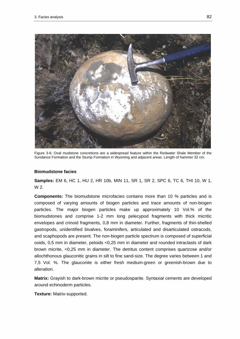
3. Facies analysis 82
Figure 3-6: Oval mudstone concretions are a widespread feature within the Redwater Shale Member of the Sundance Formation and the Stump Formation in Wyoming and adjacent areas. Length of hammer 32 cm.
Biomudstone facies
Samples: EM 6, HC 1, HU 2, HR 10b, MIN 11, SR 1, SR 2, SPC 6, TC 6, THI 10, W 1, W 2.
Components: The biomudstone microfacies contains more than 10 % particles and is composed of varying amounts of biogen particles and trace amounts of non-biogen particles. The major biogen particles make up approximately 10 Vol.% of the biomudstones and comprise 1-2 mm long pelecypod fragments with thick micritic envelopes and crinoid fragments, 0,8 mm in diameter. Further, fragments of thin-shelled gastropods, unidentified bivalves, foraminifers, articulated and disarticulated ostracods, and scaphopods are present. The non-biogen particle spectrum is composed of superficial ooids, 0,5 mm in diameter, peloids <0,25 mm in diameter and rounded intraclasts of dark brown micrite, <0,25 mm in diameter. The detritus content comprises quartzose and/or allochthonous glauconitic grains in silt to fine sand-size. The degree varies between 1 and 7,5 Vol. %. The glauconite is either fresh medium-green or greenish-brown due to alteration.
Matrix: Grayish to dark-brown micrite or pseudosparite. Syntaxial cements are developed around echinoderm particles.
Texture: Matrix-supported.

3. Facies analysis 83
Bedding and sedimentary structures: The biomudstone microfacies displays in outcrop thin-bedded, wavy lamination as shown in Figure 3-7. It forms massive, up to 50 m thick stratal packages, interbedded with mudstone facies types as at sections Thistle (THI) and Twin Creek (TC). Further, the microfacies is exposed as bored, oval concretions (see Figure 3-8), 3-40 cm in diameter, embedded in glauconitic shales of the Redwater Member of the Sundance Formation as at sections Minnekatha (MIN), Hulett (HU), Elk Mountain (EM), Alcova Reservoir (AR), within the Sawtooth Formation in northeastern Montana as found at section Swift Reservoir (SR) and within the Carmel Formation as at section Whiterocks Canyon (W).
Interpretation: The biomudstones are genetically and spatially related to the mudstone microfacies. A subtidal origin as calcareous mud is also suggested for the thick, distal mudstone packages in the Twin Creek Limestone in correspondence with the interpretation of IMLAY (1967). The occurrence of the biomudstone microfacies as oval concretion indicates a deposition under low-energetic conditions below storm wave base.
Stratigraphic distribution: The biomudstone microfacies is represented in the Sundance Formation in Wyoming and South Dakota. Further in the Twin Creek Limestone along the Wyoming-Idaho border, the Sawtooth Formation in northwestern Montana and the Carmel Formation in northeastern Utah.
Figure 3-7: Thin-bedded biomudstones in the Sliderock Member of the Twin Creek Limestone at section South Piney Creek (SPC). The lense cap is 6 cm in diameter.

3. Facies analysis 84
Figure 3-8: Oval biomudstone concretion at the base of a storm-deposited sandstone bed in the Redwater Shale Member of the Sundance Formation at section Hampton Ranch (HR), Bighorn Basin/WY. Head of Jacob stick is approximately 15 cm long.
Detritusmudstone facies
Samples: BE 4, BE 5, FG 4, FG 10, FG 18, FG 19, FG 20, FG 21, FG 24, FH 5, HE 1, HR 1, HR 10a, HU 4, HU 12, LB 2, LW 2, LW 8, MIN 8, PF 2, SR 5, SBC 1, THI 31, THI 24, THI 23, THI 25, THI 26, THI 27, THI 20, THI 21, THI 11, THI 12, THI 13, THI 14, TR 10, V 7, W 4, W 8.
Components: The detritusmudstone microfacies contains trace amounts of biogen particles and trace amounts of non-biogen particles. The detritus content comprises quartzose and/or allochthonous glauconitic grains (THI 24, FH 5, HU 12, FG 24) in silt to fine sand-size. The degree of quartzose grains varies between 1 and 10 Vol. % and of glauconitic grains between 1 and 4,5 Vol. %. The glauconite is either fresh medium-green or greenish-brown due to alteration. The major biogen particles make up approximately 5 Vol.% of the detritusmudstones and comprise 1-2 mm long pelecypod fragments with thick micritic envelopes and crinoid fragments, 0,7-1 mm in diameter. Further, fragments of thin-shelled gastropods and microschill are present. The non-biogen particle spectrum is composed of peloids, <0,25 mm in diameter.
Matrix: Grayish to dark-brown micrite or pseudosparite.
Texture: Matrix-supported.
3. Facies analysis 85
Bedding and sedimentary structures: The detritusmudstones are commonly structureless. In some samples poorly preserved, tube-like structures, up to 4 mm in diameter are present and probably document bioturbation. The detritusmudstone microfacies forms massive stratal packages up to 35 m thick interbedded with various mudstone facies types at sections Big Elk Mountain (BE), Little Water Creek (LW), Thistle (THI). Alternatively, the microfacies occurs as 0,2-0,4 m thick layers intercalated into glauconitic shales as at sections Hampton Ranch (HR), Hulett (HU) or Stockade Beaver Creek (SBC). The microfacies corresponds to the “terrigenous mudstone facies” as described from the southern “Sundance Basin” by BLAKEY et al. (1983) in respect to particle spectrum and absence of bedding structures.
The microfacies is exposed as bored, oval diastemic cobbles, 3-40 cm in diameter, embedded in glauconitic shales of the Sundance Formation as at sections Thompson Ranch (TR), Minnekatha (MIN), Hulett (HU), Hampton Ranch (HR), Stockade Beaver Creek (SBC), within the Sawtooth Formation in southwestern Montana as at section Little Water Creek (LW), in northeastern Montana as at section Swift Reservoir (SR), within the Stump Formation as near Vernal (V) and in the Twin Creek Limestone.
Interpretation: The “terrigenous mudstone facies” was deposited in a variety of low-energetic settings in restricted to normal marine environments as proposed by BLAKEY et al. (1983). In the southern “Sundance Basin”, the origin of this microfacies is non-specific and can only be determined in context with adjacent facies types (BLAKEY et al. 1983). This is also true for other areas of the basin. The detritusmudstones in the study area are genetically and spatially related to the mudstone and the biomudstone microfacies of subtidal origin.
Stratigraphic distribution: The detritusmudstone microfacies is represented in the Sundance Formation in Wyoming and South Dakota. Further in the Twin Creek Limestone, in the Sawtooth Formation in southwestern Montana, the Rierdon Formation in northwestern Montana, and the Carmel Formation in northeastern Utah.
Laminated mudstone facies
Samples: LW 9, RC 6, TC 1, TC 2, TC 3, THI 28, THI 32, T-T 2.
Particles: The major grain constituents of the laminated mudstone microfacies are trace amounts of microschill and silt to fine sand-sized arenaceous detritus.
Matrix: Inhomogenous light-brown to grayish-brown micrite and pseudosparite.
Bedding and sedimentary structures: The laminated mudstones display mm-thick, flaser to convolute layers in wavy lamination. Further, cracked mudflakes and salt crystal casts are present. In outcrop the microfacies is associated with red shales and siltstones as at sections Twin Creek (TC) and Thistle (THI). In respect to sediment structures the laminated mudstone microfacies is equivalent to the “algal-laminated dolomicrite facies” as described from the southern “Sundance Basin” by BLAKEY et al. (1983) and an algal limestone facies described by JOHNSON (1992) from southern Wyoming.

3. Facies analysis 86
Interpretation: The sediment structures and red bed facies types associated with the laminated mudstones suggest deposition in low-energetic environment in the vicinity of a carbonate-dominated shoreline.
Stratigraphic distribution: The laminated mudstone microfacies is represented in the Sundance Formation in northeastern Wyoming and South Dakota. Further in the Twin Creek Limestone along the Wyoming-Idaho border and the Rierdon Formation in southwestern Montana.

3. Facies analysis 87
A: Oograinstone microfacies. Sample DH 1 from the Twin Creek Limestone at section Devils Hole Creek (scale is 2 cm for the lower side of the photo, bright field).
B: Oograinstone microfacies. Sample TF 3 from the Twin Creek Limestone at section Thomas Fork Canyon. (scale is 1,2 cm for the lower side of the photo, bright field).
C: Oobiograinstone microfacies. Sample HR 5 from the Sundance Formation at section Hampton Ranch (scale is 6,3 mm for the long side of the photo, bright field). Planar stratification of ooid-rich and sand-rich layers. The ooid-rich layers contain pelecypod and crinoid fragments.
D: Oobiograinstone microfacies. Sample SPC 4 from the Twin Creek Limestone at section South Piney Creek (scale is 6 cm for the long side of the photo, bright field). Ooids are mixed with crinoid fragments.
E: Oobiograinstone microfacies. Sample V 10 from the Stump Formation at section Vernal (scale is 6,3 cm for the long side of the photo, bright field). Ooids are mixed with pelecypod fragments.
F: Oobiograinstone microfacies. Sample FG 28 from the Stump Formation at section Flaming Gorge (scale is 2,1 cm for the long side of the photo, bright field). Ooids are mixed with poorly sorted pelecypod fragments, intraclasts and gastropod fragments. The pelecypods are rounded and display thick micritic envelopes.
Plate 1: Photographs from thin-sections of oolitic grainstone microfacies types.
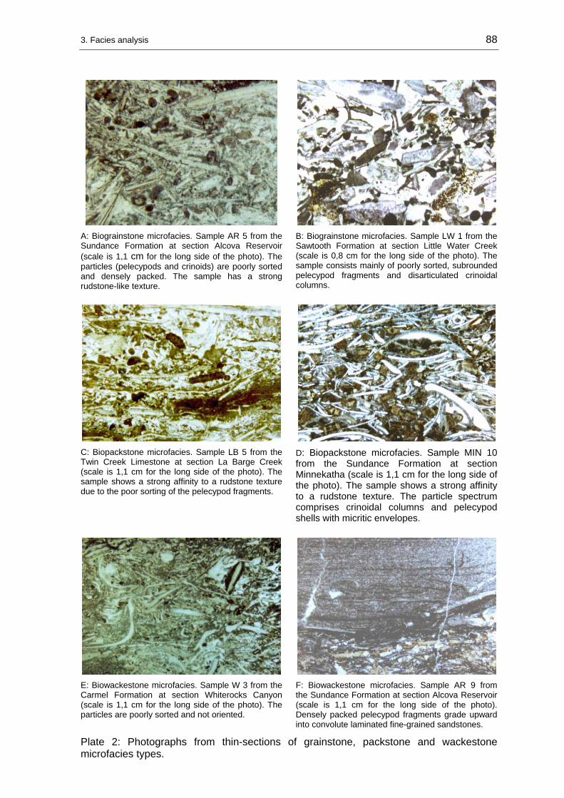
3. Facies analysis 88
A: Biograinstone microfacies. Sample AR 5 from the Sundance Formation at section Alcova Reservoir (scale is 1,1 cm for the long side of the photo). The particles (pelecypods and crinoids) are poorly sorted and densely packed. The sample has a strong rudstone-like texture.
B: Biograinstone microfacies. Sample LW 1 from the Sawtooth Formation at section Little Water Creek (scale is 0,8 cm for the long side of the photo). The sample consists mainly of poorly sorted, subrounded pelecypod fragments and disarticulated crinoidal columns.
C: Biopackstone microfacies. Sample LB 5 from the Twin Creek Limestone at section La Barge Creek (scale is 1,1 cm for the long side of the photo). The sample shows a strong affinity to a rudstone texture due to the poor sorting of the pelecypod fragments.
D: Biopackstone microfacies. Sample MIN 10 from the Sundance Formation at section Minnekatha (scale is 1,1 cm for the long side of the photo). The sample shows a strong affinity to a rudstone texture. The particle spectrum comprises crinoidal columns and pelecypod shells with micritic envelopes.
E: Biowackestone microfacies. Sample W 3 from the Carmel Formation at section Whiterocks Canyon (scale is 1,1 cm for the long side of the photo). The particles are poorly sorted and not oriented.
F: Biowackestone microfacies. Sample AR 9 from the Sundance Formation at section Alcova Reservoir (scale is 1,1 cm for the long side of the photo). Densely packed pelecypod fragments grade upward into convolute laminated fine-grained sandstones.
Plate 2: Photographs from thin-sections of grainstone, packstone and wackestone microfacies types.

3. Facies analysis 89
A: Biowackestone microfacies. Sample HU 6 from the Sundance Formation at section Hulett (scale is 1,2 cm for the long side of the photo). The particles are poorly sorted and not oriented. Note the large, well rounded oyster fragment in lower half of photo. In some samples up to 25 mm long particles make up more than < 10 Vol. % and superimpose a floatstone-like texture.
B: Mudstone microfacies. Sample FH 6 from the Sundance Formation at section Freezeout Hills (scale is 1,2 cm for the long side of the photo). This sample stems from a mudstone concretion in the Redwater Shale Member.
Plate 3: Photographs from thin-sections of wackestone and mudstone microfacies types.

3. Facies analysis 90
3.2 Siliciclastics
The siliciclastic sediments are interpreted on the basis of petrography, sediment structures and grain-size. Some beds were sampled during field work. Thin-sections were produced from chosen siliciclastics to get additional petrographic information.
3.2.1 Large-scale cross-bedded lithofacies (LX lithofacies)
Studied samples: TR 4.
Description: Fine to medium-grained sandstone, massive, subangular to subrounded, white to yellowish-brown, calcareous cements, well-sorted.
Sedimentary structures: The LX lithofacies is characterized by large-scale, trough-shaped cross-bedding. The cross-bed sets range from 0,5-2,2 m, while the average thickness is 1,2 m. Cross-bed angles are between 20 to 30 °. Further, 1-10 cm thick, planar lamination is present.
Interpretation: AHLBRANDT & FOX (1997) interpreted this facies as eolian because of inversely graded wind-ripple lamination and avalanche toes in the basal Canyon Springs Sandstone Member in the Black Hills area (see chapter: 2.4, Allostratigraphy; 2.4.2.3, J-2a unconformity and Figure 2-19).
RAUTMANN (1976) and BRENNER & PETERSON (1994) suggested a tidal origin for the large-scale cross-bedded lithofacies, because of bimodal paleocurrent patterns and deformational structures like convolute lamination, overturned and oversteepened cross-bedding.
In this study, the interpretation of the LX lithofacies as either marine or eolian derives from the stratal context with adjacent facies types. Therefore, unequivocal interpretations exist for particular successions in the Sundance Formation in eastern Wyoming. For instance, when marine waters of the early “Sundance Sea” entered the area of eolian accumulation the dunes were partly reworked. Consequently, marine and eolian deposits are included in the Canyon Springs Sandstone Member (JOHNSON 1992).
Stratigraphic distribution: The large-scale cross-bedded lithofacies is represented in the Sundance Formation in the Black Hills and central Wyoming and in the Entrada Sandstone in northeastern Utah.

3. Facies analysis 91
3.2.2 Wave-rippled lithofacies (WR lithofacies)
Studied samples: AR 1, FH 4, HR 4, RR 2.
Description: Fine- to medium-grained sandstone, yellowish-brown, greenish-gray, platy to medium-bedded (2-30 cm), well-sorted, subangular to subrounded, calcareously cemented. Partly arcosic or glauconitic, with opaque peloids (<0,2 mm) and black heavy mineral grains. Often with gray or grayish-green mud partings.
Sedimentary structures: The WR lithofacies (shown in Figure 3-9) is characterized by various kinds of ripples such as: interference ripples, rhomboid ripples, flattened ripples, symmetric, straight-crested, longitudinal, or bifurcated wave ripples, asymmetric wave ripples, and undulatory, asymmetric ripples. In the Black Hills, at section Stockade Beaver Creek (SBC), the rippled bedding planes show wrinkle marks. The WR lithofacies is commonly associated with bioturbation: Skolithos-like burrows, Planolites, Diplocraterion, Rhizocorallium. Additional sediment structures are herring-bone cross-bedding and small-scale cross-bedding. The lithofacies includes the “small-scale cross-bedded facies” identified by RAUTMANN (1976) in the Black Hills area.
Figure 3-9: Wave-rippled lithofacies in the Hulett Sandstone Member at section Alcova Reservoir (AR). Handle of Jacob stick is 1,5 cm in diameter.
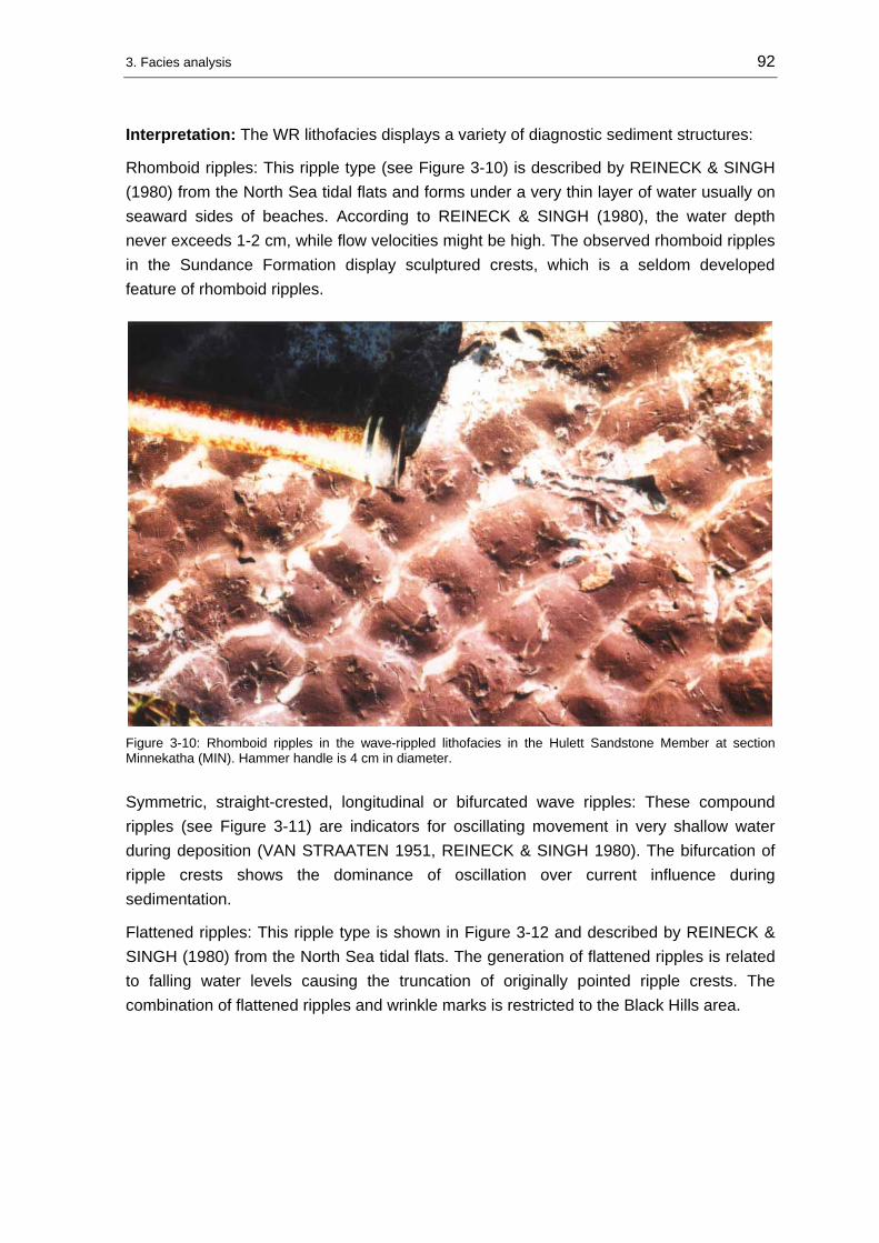
3. Facies analysis 92
Interpretation: The WR lithofacies displays a variety of diagnostic sediment structures:
Rhomboid ripples: This ripple type (see Figure 3-10) is described by REINECK & SINGH (1980) from the North Sea tidal flats and forms under a very thin layer of water usually on seaward sides of beaches. According to REINECK & SINGH (1980), the water depth never exceeds 1-2 cm, while flow velocities might be high. The observed rhomboid ripples in the Sundance Formation display sculptured crests, which is a seldom developed feature of rhomboid ripples.
Figure 3-10: Rhomboid ripples in the wave-rippled lithofacies in the Hulett Sandstone Member at section Minnekatha (MIN). Hammer handle is 4 cm in diameter.
Symmetric, straight-crested, longitudinal or bifurcated wave ripples: These compound ripples (see Figure 3-11) are indicators for oscillating movement in very shallow water during deposition (VAN STRAATEN 1951, REINECK & SINGH 1980). The bifurcation of ripple crests shows the dominance of oscillation over current influence during sedimentation.
Flattened ripples: This ripple type is shown in Figure 3-12 and described by REINECK & SINGH (1980) from the North Sea tidal flats. The generation of flattened ripples is related to falling water levels causing the truncation of originally pointed ripple crests. The combination of flattened ripples and wrinkle marks is restricted to the Black Hills area.

3. Facies analysis 93
Figure 3-11: Compound ripples in the wave-rippled lithofacies with transition between linguoid and curved forms in the Hulett Sandstone Member at section Stockade Beaver Creek (SBC). Hammerhead is 17 cm long.
Figure 3-12: Flattened, straight-crested ripples in the wave-rippled lithofacies in the Hulett Sandstone Member at section Stockade Beaver Creek (SBC). Hammerhead is 17 cm long.

3. Facies analysis 94
Interference ripples: Interfering ripple systems (see Figure 3-13) are prominent features in the Black Hills, Powder River Basin and Bighorn Basin sections. This ripple type occurs in wave-dominated, tidal influenced environments. They are produced in a hierarchical system when varying hydrodynamic directions operate in the depositional environment. REINECK & SINGH (1980) described interfering ripple systems formed on the North Sea tidal flats by the interaction of wave activity and currents.
Figure 3-13: Interference ripples in the wave-rippled lithofacies in the Hulett Sandstone Member at section Minnekatha (MIN). Lense cap is 6 cm in diameter.
Herring-bone cross-bedding and climbing ripples: These sediment structures (see Figure 3-14) show bipolar oriented foreset laminae and are often associated with symmetric, low-relief ripples. According to REINECK & SINGH (1980), real herring-bone cross-bedding can be confirmed only in 3-dimensional sections. Often herring-bone structures are treated as indicator for tidal origin (TUCKER 1985, PRATT & JAMES 1986). However, herring-bones are not exclusively a feature of tidal environments, if not accompanied by other diagnostic features such as mud drapes, reactivation surfaces, flaser and lenticular bedding, mudcracks or algal mats. A different origin for herring-bones is discussed by JOHNSON & BALDWIN (1986). Multidirectional sediment structures can also be related to alternating currents generated during bad weather periods and storm events.

3. Facies analysis 95
Figure 3-14: Climbing ripple and planar lamination in the wave-rippled lithofacies in the Hulett Sandstone Member at section Hampton Ranch (HR). Pencil is 15 cm long.
Wrinkle marks: Small ridges with an amplitude of 1-2 mm and a wave length of 2-5 mm, are produced by wind blowing over sediment surfaces covered by a thin film (up to 1 cm) of water (REINECK & SINGH 1980). They are good indicators of intermittent emergence of sedimentary surfaces. These structures are often related to wave ripples with flattened or truncated crests (flattened ripples). This observation was also mentioned by RAUTMANN (1976).
Asymmetric ripples: These ripples have mostly undulatory, occasionally straight crests with small tongue-like projections, showing a wave length of 4-4,5 cm and a height of 1-2,5 cm. They are formed at low velocities and therefore can be called low-energy ripples (HARMS 1969). Transitions to asymmetric wave ripples might be present, since it is sometimes difficult to distinguish them from current generated ripples with straight crests.
The described sedimentary structures support the interpretation of a mainly wave influenced depositional environment of the WR lithofacies between the foreshore and the upper shoreface. Storm and bad weather periods affected the sedimentation process and generated temporarily high-energetic hydrodynamic conditions.
Distribution: The WR lithofacies is represented in the Sundance Formation in central and northwestern Wyoming, in the Giraffe Creek Member of the Twin Creek Limestone and in the Stump Formation along the Wyoming-Idaho border.

3. Facies analysis 96
3.2.3 Lenticular to flaser bedded lithofacies (L-Fb lithofacies)
Description: Shale, silt, fine- to medium-grained sandstone, light-brown or greenish-gray. In the Black Hills area mostly subarcosic. Commonly, moderately to highly glauconitic. Well-sorted, subangular to subrounded and calcareously cemented. Intercalated with gray to greenish-gray shale partings (0,2-7 cm thick). Discontinuous, sharp-based, 1,5-10 cm thick sandstone layers, usually thickening upward (see Figure 3-15).
Figure 3-15: L-Fb lithofacies in the Stockade Beaver Shale of the Sundance Formation at section Red Rim Ranch (RR) in the Bighorn Basin. Note the upward increasing bed thickness. The red arrow marks the position of the J-2 unconformity and the contact to the underlying Gypsum Spring Formation. In contrast to conditions at adjacent locations the Stockade Beaver Shale is reduced in thickness to about 4 m and developed as L-Fb lithofacies at this location.
Sedimentary structures: Lenticular and/or flaser bedding is the most prominent sediment structure from which the nomenclature of this lithofacies is derived. Mostly it is transitional to wavy bedding. The degree of bioturbation is high. Abundant bioturbation is represented by Planolites, Cruziana and unidentified traces. The upper bedding planes are covered with various wave ripple types. Sometimes coarser sand grains and fine shell hash accumulation are observable in ripple troughs. Coarse, poorly sorted shell accumulations were found at numerous sections in all parts of the “Sundance Basin” such as Flaming Gorge (FG), Swift Reservoir (SR), Elk Mountain (EM), and Hyattville (HY).

3. Facies analysis 97
Some layers occasionally exhibit small-scale cross-bedding. AHLBRANDT & FOX (1997) reported desiccation cracks and root zones in a similar facies association from locations in the southern Black Hills.
Interpretation: According to REINECK & SINGH (1980), the origin of wavy, lenticular and flaser bedding is caused by current or wave action depositing sand, alternating with low-energetic water conditions when mud is deposited. Such conditions are found in lower shoreface, tidal influenced settings. These environments are characterized by sufficient sediment supply and alternating hydrodynamic conditions in the subtidal zone (REINECK 1963) and/or the intertidal zone (VAN STRAATEN 1954). In the “Sundance Basin”, lenticular and flaser bedding occur in two possible settings: in the Hulett Sandstone as lower shoreface deposit and in the “upper” Sundance Formation and the Swift Formation as tidal influenced sediment. The environmental interpretation derives in the context with under- and overlying sedimentary environments. Discontinuously interbedded shell accumulations indicate deposition under frequently high-energetic conditions.
Distribution: The L-Fb lithofacies is represented in the Sundance Formation in Wyoming and western South Dakota, the Swift Formation in western Montana and the Stump Formation in northeastern Utah.
3.2.4 Glauconitic lithofacies (Gl lithofacies)
Samples: HR 11, SWC 7, SWC 8, SWC 9, RL 11, RL 12, SR 8.
Description: Shale, silt, fine- to medium-grained sandstone, partly thin interbeds and partings of shale, locally thin or massive interbeds of oolitic limestone, moderately to highly glauconitic (0-15 Vol. %). Transitions to quartzarenitic or sublitharenitic rock types are common. Calcareously cemented, moderately sorted, thin-bedded to massive, light-green, greenish-gray, brownish-green, olive, often with abundant bioclastic debris (oyster shells, coquinas). Described by MEYERS & SCHWARTZ (1994) as “coquinoid sandstone”, often with plant debris. PORTER (1989) reported coarse-grained lags of worn belemnite fragments and chert pebbles. HAYES (1984) and MOLGAT & ARNOTT (2001) reported coalified wood fragments. The sandstone intervals are cliff-forming (see Figure 3-16).
Sedimentary structures: The glauconitic lithofacies encompasses many sediment structures. For instance, wavy, lenticular and flaser bedding occur frequently in the investigated sections. In the “Sundance Basin”, those are the most common sediment structures in the glauconitic lithofacies. Other sedimentary structures include herring-bone cross-bedding, sigmoidal reactivation surfaces and climbing ripples. Internally trough-shaped cross-bedded layers show wave rippled bedding planes (see Figure 3-17). A prominent feature is planar to wavy bedding in 0,5-4 cm thick parallel laminated layers. In rare cases the thickness of individual layers can reach 15 cm. The basal contacts of individual layers are planar and sometimes truncating underlying strata. These low-angled discordances can be followed in outcrop of a few tens of meters. At the section Squaw

3. Facies analysis 98
Women Creek (SWC), toward the top of the succession shallow channels are scoured into the parallel laminated sand sheets. The representative sediment structures observed in the glauconitic lithofacies are summarized in Figure 3-18.
Figure 3-16: Glauconitic lithofacies in the upper part of the Redwater Shale Member at section Hampton Ranch (HR). The red arrows mark lenticular bioclastic layers equivalent to the “coquina facies” interpreted by UHLIR et al. (1989) as tidal inlet deposits.
Figure 3-17: Close up photo of the glauconitic lithofacies in the “upper sandstone unit” of the Swift Formation at section Sun River Canyon (SRC). The dominant sediment structures are wave ripple lamination and trough-shaped cross-bedding. Hammer is 32 cm long.
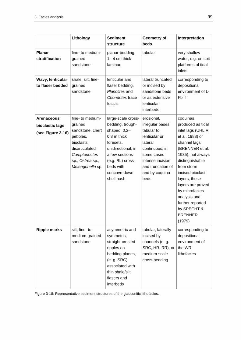
3. Facies analysis 99
Lithology Sediment structure
Geometry of beds
Interpretation
Planar stratification
fine- to medium-grained sandstone
planar-bedding, 1– 4 cm thick laminae
tabular very shallow water, e.g. on spit platforms of tidal inlets
Wavy, lenticular to flaser bedded
shale, silt, fine-grained sandstone
lenticular and flaser bedding, Planolites and Chondrites trace fossils
lateral truncated or incised by sandstone beds or as extensive lenticular interbeds
corresponding to depositional environment of L-Fb lf
Arenaceous
bioclastic lags
(see Figure 3-16)
fine- to medium-grained sandstone, chert pebbles, bioclasts: disarticulated Camptonectes sp., Ostrea sp., Meleagrinella sp.
large-scale cross-bedding, trough-shaped, 0,2–0,8 m thick foresets, unidirectional, in a few sections (e.g. RL) cross-beds with concave-down shell hash
erosional, irregular bases, tabular to lenticular or lateral continuous, in some cases intense incision and truncation of and by coquina beds
coquinas produced as tidal inlet lags (UHLIR et al. 1988) or channel lags (BRENNER et al. 1985), not always distinguishable from storm incised bioclast layers, these layers are proved by microfacies analysis and further reported by SPECHT & BRENNER (1979)
Ripple marks silt, fine- to medium-grained sandstone
asymmetric and symmetric, straight-crested ripples on bedding planes, (e .g. SRC), associated with thin shale/silt flasers and interbeds
tabular, laterally incised by channels (e. g. SRC, HR, RR), or medium-scale cross-bedding
corresponding to depositional environment of the WR lithofacies
Figure 3-18: Representative sediment structures of the glauconitic lithofacies.

3. Facies analysis 100
Interpretation: A variety of sediment structures was observed in the studied outcrop sections in the glauconitic lithofacies (see above). The bulk of these diagnostic sediment structures is already comprehensively and precisely described and interpreted by many workers (HILEMAN 1973, PIPIRINGOS & IMLAY 1979, LANGTRY 1983, HAYES 1984, UHLIR et al. 1988, PORTER 1989, MEYERS & SCHWARTZ 1994, MOLGAT & ARNOTT 2001). The observations made during field work confirmed the interpretations of previous workers. In a stratigraphic context the glauconitic lithofacies represents the sandstone suite in the upper part of the Redwater Shale Member of the Sundance Formation and the Stump Formation and the upper part of the Swift Formation and Curtis Formation. This stratigraphic interval in the upper Redwater Shale Member and equivalents was also named “ribbon sandstone” by HAYES (1984) and MOLGAT & ARNOTT (2001), the “upper sandstone body” by MEYERS & SCHWARTZ (1994), the “coquina sandstone” by UHLIR et al. (1988), and the “coquinoid sandstone” by BRENNER & DAVIES (1973) and BRENNER et al. (1985). Considering all observed diagnostic sediment structures it seems likely to assume a tidal influence on the sedimentation of the glauconitic lithofacies. Moreover, studies by KREISA & MOIOLA (1986) and ELLIOT (1984) described tidal successions and even neap tide-spring tide cycles (UHLIR et al. 1988) from the marine Jurassic formations. In contrast, BRENNER et al. (1985) stated that they were unable to positively identify tidal influence in outcrops of the Sundance Formation in the Bighorn Basin. The intensity of the tidal influence is still uncertain, but the depositional environments can be expected in shoreface to foreshore environments.
Distribution: The glauconitic lithofacies occurs in the Redwater Shale Member of the Sundance Formation in Wyoming, the Stump Formation in the Wyoming-Idaho area, the Swift Formation in Montana, and the Curtis Formation in Utah.
3.2.5 Low-angle laminated lithofacies (LL lithofacies)
Description: Fine-grained sandstone, light-brown to yellowish-brown, subrounded, calcareously cemented, well sorted, medium- to thick-bedded (0,15-0,5 m), black heavy minerals (~2 %), arcosic to subarcosic.
Sedimentary structures: The dominant sediment structure in the LL lithofacies is low-angle cross-bedding. The cross-beds show low-angle trough-shaped foresets, a few meters in length and dipping in an angle of 5 – 7°. Further, symmetric, flattened ripples can be observed.
Interpretation: Shoaling waves produce planar, seaward dipping sediment structures in foreshore and/or upper shoreface environments (JOHNSON & BALDWIN 1986). In recent sediments these structures are reported by McCUBBIN (1982) on the foreshore of Plum Island at the coast of Massachusetts. Caused by the intensity of physical processes the biological activity in these environments is very limited and supports suspension feeding. The low-angle-laminated lithofacies corresponds to the facies described and interpreted by RAUTMANN (1976) as a beach/foreshore deposit.

3. Facies analysis 101
Distribution: The low-angle laminated lithofacies is present in the Hulett Sandstone Member of the Sundance Formation in the northern Black Hills and western Powder River Basin.
3.2.6 Oolite lithofacies (Oo lithofacies)
Samples: HR 3, HR 6, HY 2, HY 3, RL 7.
Description: Silt and fine-grained, partly weathered, friable sandstone, calcareously cemented, yellowish-brown, light-brown, massive, subrounded, well sorted, interbeds of oolitic calcarenite with echinoderm and pelecypod fragments in discontinuous layers.
Sediment structures: The oolite lithofacies shows medium-scaled cross-bedding with 15 cm thick, trough-shaped, low-angle sets. Further, parallel lamination in cm thick layers, current ripples, symmetric, straight-crested wave ripples, and mud drapes are present. Infrequently interbedded layers display Planolites traces. In some beds fining up cycles are represented by sandy layers with high relief ripple marks, overlain by laminated siltstones that grade into greenish-gray shale partings. The fining up cycles are capped by intercalated 0,1-0,4 m thick, lenticular oolitic layers with abundant echinoderm and pelecypod fragments. The oolitic beds grade laterally into sandstone. Internally the oolitic beds show cross-bedding and on the upper bedding planes current ripples (see Figure 3-19).
Figure 3-19: Cross-bedded oolite lithofacies (marked by red arrow) associated with the WR lithofacies in the Hulett Sandstone Member at section Red Lane (RL). Hammer is 32 cm long.

3. Facies analysis 102
Interpretation: The abundance of wave ripples in the oolite lithofacies indicates oscillating wave action. Further, grain size variations between sand-silt-shale and oolite/bioclast-rich sediments indicate alternating hydrodynamic conditions. The occurrence of Planolites traces give evidence for low- to moderate-energetic conditions in a subtidal setting. It seems likely to assign a high-energetic setting to the incised oolitic-bioclast-rich interbeds, while the sand-silt-shale suite marks a transition from high- to low- energetic conditions.
The described sediment structures and trace fossils show strong similarities to upper shoreface-lower foreshore sediments as found by REINECK & SINGH (1980). The parallel and medium-scale cross-bedded sandstones are supposed to be deposited as sand ridges incised infrequently by runnels or very shallow channels. A significant influence of tides to the sedimentation of the oolite lithofacies is not evident, although some diagnostic tidal sediment structures are present in the oolite lithofacies (mud drapes, fining upward cycles). The latter occurs only infrequently and not in a rhythmic pattern. Generally, the oolite lithofacies is characterized by a high degree of erosion and reworking, caused by the erosional potential of the interbedded oolitic-bioclast layers. The oolite lithofacies corresponds to the “trough cross-stratified oolitic calcarenite” described by WEST (1985) from the Bighorn Basin.
Distribution: The oolite lithofacies is represented in the Hulett Sandstone Member and Redwater Shale Member of the Sundance Formation in northwestern Wyoming.
3.2.7 Calcareous shale (shale lithofacies)
Description: Olive-gray, olive-green, greenish-gray, medium-gray, black, soft, fissile, silty, in parts sandy, calcareous shale. The thickness ranges from thin mud drapes to few tens of meters. In some sections with abundance of oysters (Gryphea sp. and Ostrea sp.) and belemnites (Pachitheutis densus). Further, pelecypod shells, gastropods, foraminifers, ostracods, and crinoids are present. In some areas, the lithofacies is unfossilferous.
Sediment structures: The shale lithofacies contains the following sediment structures:
Sandy-silty layers: Thin, lenticular silt and fine-grained sandstone layers (see Figure 3-20). Often with densely packed bioclastic debris (see Figure 3-21: belemnites and oysters). The sandy beds may display graded bedding and are commonly composed of bioclastic accumulations that fine upward into sandstone (see Figure 3-22). Sometimes the bedding planes are covered with symmetric or asymmetric ripple lamination. Sediment structures can be completely obliterated by bioturbation or display hummocky cross-lamination (see Figure 3-23). The lower bedding planes often display a variety of scour, rill or prod marks. The basal contacts are often sharp and erosive. Coarse-grained storm beds were found only as well rounded pebble lags in the Black Hills (Figure 3-24).

3. Facies analysis 103
Coquinoid carbonate layers: Thin, lenticular, discontinuous coquinoid beds of biograinstone or biorudstone and/or biowacke- to packstone. These coquina beds display graded bedding, erosional base, sheltering of fine material in the studied thin-sections.
Figure 3-20: Glauconitic shale (shale lithofacies) with lenticular sandy storm beds and oval mudstone cobbles in the Redwater Shale Member at section Flaming Gorge (FG). Hammer is 32 cm long.
Figure 3-21: Bedding plane of a bioclastic coquina composed of oyster and belemnite fragments in the Redwater Shale Member at section Red Rim Ranch (RR). Scale is 7,5 cm long.
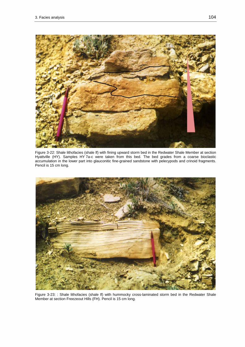
3. Facies analysis 104
Figure 3-22: Shale lithofacies (shale lf) with fining upward storm bed in the Redwater Shale Member at section Hyattville (HY). Samples HY 7a-c were taken from this bed. The bed grades from a coarse bioclastic accumulation in the lower part into glauconitic fine-grained sandstone with pelecypods and crinoid fragments. Pencil is 15 cm long.
Figure 3-23: : Shale lithofacies (shale lf) with hummocky cross-laminated storm bed in the Redwater Shale Member at section Freezeout Hills (FH). Pencil is 15 cm long.

3. Facies analysis 105
Figure 3-24: Storm bed composed of well rounded pebbles in the shale lithofacies in the Redwater Shale Member at section Hulett (HU). The pebble lithology comprise mudstone and sandstone. This sample was found as float. Lense cap is 6 cm in diameter.
Interpretation: Shales are described by WALKER & PLINT (1992), JOHNSON & BALDWIN (1986), and REINECK & SINGH (1980) as offshore or shelf deposits. The shales of the Sundance Formation and the stratigraphic equivalents in Montana (Ellis Group) are interpreted by IMLAY (1947; 1980), WRIGHT (1973), BRENNER & DAVIES (1974), MEYERS & SCHWARTZ (1994), RAUTMANN (1976), HAYES (1984), MOLGAT & ARNOTT (2001) as offshore to lower shoreface sediments. The ichnofossil assemblage comprises grazing and deposit-feeding structures, which are characteristic for low-energy marine settings. The siltstone and coquina intercalations are considered to be related to frequent high-energetic conditions during storms within the depositional environment. The macroscopic features graded bedding, hummocky cross-lamination, lenticular geometry of beds, erosive basal contacts, the abundance of rill, scour, and prod marks on lower bedding planes, and an abundance of chaotic bedded and poorly sorted bioclastic debris allow an interpretation of the interstratified carbonate and siliciclastic layers as storm beds. This interpretation is supported by the observed microscopic features in thin-sections: sheltering of fine-grained material, chaotic fabric and rapid material changes.
Distribution: The shale lithofacies occurs in various stratigraphic intervals within the Sundance Formation in Wyoming, the Stump Formation in western Wyoming and eastern Idaho, and the Ellis Group in Montana.

3. Facies analysis 106
3.2.8 Silty lithofacies (silt lithofacies)
Description: Silt, silty sandstone, minor amounts of silty shale, greenish-gray, light-gray, glauconitic. Often poorly exposed.
Sediment structures: Physical sedimentary structures are wavy or flaser bedding and climbing ripple lamination with in-phase laminae (see Figure 3-25). Fluid escape structures are reported from a silt facies in the Black Hills by RAUTMANN (1976). Sediment structures are scarce due to bioturbation. The degree of bioturbation in the silty lithofacies increases, while the content of sediment structures decreases away from the Black Hills (RAUTMANN 1976).
Figure 3-25: Silty lithofacies with climbing ripple lamination composed of in-phase laminae in lower half of picture. This lamination grades upward into flaser bedding in Hulett Sandstone Member at section Elk Mountain (EM). Scale is 7,5 cm long.
Interpretation: The silty lithofacies in the eastern parts of the field area is interpreted by RAUTMANN (1976) as a lagoonal sediment deposited behind a barrier island complex, very close to the margin of the “Sundance Sea”. This interpretation can be confirmed in comparison with the observed sediment structures and bioturbation in examined outcrops. The in-phase ripple lamination indicates rapid sedimentation in a standing body of water, probably during high-energetic events like storms or bad weather periods. This environment with a periodic rapid accumulation of sediment is favorable for the origin of climbing ripple lamination (REINECK & SINGH 1980).

3. Facies analysis 107
As already mentioned, in the western portions of the “Sundance Basin” sediment structures in the silty lithofacies become less abundant. Toward the offshore direction in the more central parts of the “Sundance Basin” the depositional environment is more debatable. Certainly, the silty lithofacies represents an interval of low-energy and low sediment influx. JOHNSON & LEVELL (1995) described very similar silty sediments from the Lower Cretaceous Woburn Sands (Lower Greensands) in southern England. Despite the lack of any tidal channel or marsh deposits these silty beds in the Lower Greensands are interpreted to be either of tidal or shallow marine origin. Since tidal signatures are lacking completely from the silt lithofacies in the “Sundance Basin”, a shallow marine origin is more likely. The depositional environment can be placed in the lower shoreface zone. This interpretation is also supported by the facies model for coastal profiles published by REINECK & SINGH (1980). In this model, silty sediments (sandy silt to silty sands) are interpreted as deposits of the transition zone between shoreface and offshore.
Distribution: The silty lithofacies is distributed in the Sundance Formation in the Black Hills and central Wyoming and the Stump Formation in northeastern Utah.
3.2.9 Sabkha red beds (Lak Member)
In the Jurassic formations two red bed successions can be distinguished that were deposited during the same time, but in different environments. Each red bed formation is discussed and treated separately.
Description: Silt, fine-grained sandstone, reddish-brown, maroon to light-red, very poorly developed or preserved sediment structures. RAUTMANN (1976) described mottling and whispy, swirled lamination at irregular intervals from slabbed Lak Member specimen (Sundance Formation). No fossils have been found in the red bed facies (IMLAY 1947, RAUTMANN 1976). At section Minnekatha (MIN), evaporite pseudomorphs after halite were found at the base of the Lak Member.
Interpretation: In stratigraphic terms the red beds represent the Lak Member of the Sundance Formation in eastern Wyoming. Until today the red bed succession of the Sundance Formation remains enigmatic and almost every imaginable origin for the red beds was discussed since the 1950’s. Discussed depositional settings ranged from loess-type deposits to paleosols. A comprehensive overview is given by JOHNSON (1992). Due to the grain size, the absence of trace and body fossils, poorly developed sediment structures, and the presence of gypsum and salt the interpretation of JOHNSON (1992) that the Lak red beds are sabkha deposits is followed in this study. The lithofacies is named “sabhka red bed” lithofacies to distinguish it from the “marine red bed” lithofacies.
Distribution: The “sabkha red beds” are represented in the Lak Member of the Sundance Formation in southeastern Wyoming and the Black Hills at sections Hulett (HU), Stockade Beaver Creek (SBC), Minnekatha (MIN), Spearfish (SF), Thompson Ranch (TR), Elk Mountain (EM), Alcova Reservoir (AR), Freezeout Hills (FH), Squaw Women Creek (SWC).

3. Facies analysis 108
3.2.10 Marine red beds (Preuss red beds)
Description: Silt and fine- to medium-grained sandstone, reddish-brown, maroon, pale red, some grayish. Platy (2 cm) to thick-bedded (40 cm). Poorly preserved sediment structures are planar bedding with 1-3 cm thick layers, oscillation and current ripple lamination on bedding planes or small-scale cross-bedding. At section Big Elk Mountain (BE), halite pseudomorphs are present. IMLAY (1952) reported salt beds in the lower part of the Preuss Formation along the Idaho-Wyoming border. HILEMAN (1973) noticed channels in some outcrops. Generally, the outcrops are partly soil covered, especially on fine-grained, soft sediments. A good outcrop can be studied at section La Barge Creek (LB).
Interpretation: In stratigraphic terms the marine red beds represent the Preuss Formation. IMLAY (1952) interpreted the Preuss red beds as marine in origin. Evidence for this interpretation derives from the sediment structures (ripple marks, cross-bedding) displayed in the red beds. Further, the Wolverine Canyon Limestone Member, composed of corals, nerineid gastropods and oolitic beds at outcrops near Idaho Falls, Idaho, can be assigned to the Preuss Formation. According to IMLAY (1952), the Preuss red beds were deposited in lagoons connected with an open marine sea, bordering an extensive island in the area of Montana. In contrast, HILEMAN (1973) distinguished intertidal to supratidal facies types representing prodeltaic, sabkha and tidal flat environments within the Preuss red beds. These facies types are spatially oriented in eastward prograding facies belts. Despite the relative scarcity and poor preservation of diagnostic sediment structures the marine depositional environments of the Preuss red beds are much better supported than the interpretation of the origin of the Lak Member.
The sediment structures and halite pseudomorphs observed during outcrop studies in this work confirm a sabkha, tidal flat to shallow subtidal origin of the Preuss red beds as proposed by HILEMAN (1973). Further, the context with the time equivalent, regressive offshore-nearshore-sabkha succession of the Hulett Sandstone and the Lak Member in eastern and central Wyoming confirms the progradational nature of the Preuss red beds, as concluded by HILEMAN (1973).
Distribution: The marine red beds of the Preuss Formation occur in the “Overthrust Belt” along the Idaho-Wyoming border and in northeastern Utah at sections Hoback Canyon (HC), South Piney Creek (SPC), La Barge Creek (LB), Cabin Creek (CC), Stump Creek (SC), Devils Hole Creek (DH), Poker Flat (PF), Big Elk Mountain (BE).

3. Facies analysis 109
3.3 Evaporites and collapse breccias
3.3.1 Evaporites
Description: Gypsum, white, sucrosic, porous, weathers filthy gray, massive (1-1,5 m) to very thin-bedded (1-5 cm). Sometimes a nodular mosaic texture (chicken wire fabric) can be observed, for example, at the section Alcova Reservoir (AR).
Interpretation: The evaporitic deposits are not associated with diagnostic carbonates from which a clear facies development might be obtained. Such diagnostic facies associations would consist of a vertical sequence of shallow subtidal oolitic, bioclastic carbonates, intertidal carbonates with fenestral fabrics, stromatolites, and supratidal evaporites (TUCKER 1985). Instead, the evaporites are interbedded with red beds or shales and mudstones of the Piper Formation in Montana or overlain by red bed intervals of the Lak Member in Wyoming. The nodular gypsum beds and halite pseudomorphs reported from Wyoming by DRESSER (1959) indicate temporary hypersaline conditions in the “Sundance Basin”.
MEYER (1984) and FILIPPICH (2001) proposed a depositional environment for the red bed-gypsum associations comparable to the “coastal sabkha” model (BUTLER et al. 1982) of the Trucial Coast in the Persian Gulf. The interpretation of these facies associations as shallow subtidal, intertidal and supratidal, sabkha-like deposits seems well constrained and was accepted in this study.
Distribution: Isolated gypsum beds occur in the basal part of the Lak Member of the Sundance Formation in southeastern Wyoming at section Alcova Reservoir (AR). Red bed-gypsum successions occur in the Piper Formation and Sawtooth Formation of the Ellis Group in Montana at section Heath (HE) and in members of the Twin Creek Limestone at section Whiterocks Canyon (WC).
3.3.2 Collapse breccias
Description: The yellowish-gray breccia ranges in thickness between 2-15 m. The rock consists of an accumulation of small (1,5 cm) and/or large (50-100 cm) angular limestone clasts and blocks. In some sections chert nodules and siliceous limestone blocks are present. The fabric of the breccia varies between outcrops. At section Poker Flat (PF), the breccia is moderately sorted, matrix-supported and occurs honeycombed (see Figure 3-26), while in the section South Piney Creek (SPC) poor sorting and clast-supporting is dominant (see Figure 3-27). The silty to sandy, calcareous matrix is yellowish-brown to yellowish-gray. Laterally, the breccia grades into a thick gypsum bed (IMLAY 1953; 1967).

3. Facies analysis 110
Figure 3-26: Honeycombed, well-sorted collapse breccia in the Gypsum Spring Member of the Twin Creek Limestone at section Poker Flat section (PF). Lense cap is 6 cm in diameter.
Figure 3-27: Poorly-sorted collapse breccia, sharply overlying the Nugget Sandstone (red arrow) at the base of section South Piney Creek (SPC). Note the poor sorting documented by the presence of large blocks (above head of Jacob stick). The Jacob stick is 1,5 m.

3. Facies analysis 111
Interpretation: IMLAY (1967) interpreted the breccia as the result of the solution of gypsum and the subsequent collapsing of limestone beds because of the lateral substitution of the breccia by massive gypsum. Therefore, the honeycombed and/or brecciated beds represent the stratigraphic position of former thin beds of gypsum. Evidence for an alternative interpretation of the breccia was not observed during field work.
Distribution: The collapse breccia is represented at the base of the Gypsum Spring Member of the Twin Creek Limestone at sections Poker Flat (PF), South Piney Creek (SPC), Stump Creek (SC), La Barge Creek (LB), Hoback Canyon (HC), Cabin Creek (CC).
3.4 Diagenesis
Carbonates
Diagenetic structures in investigated carbonates indicate synsedimentary to burial diagenetic overprint. The degree of dolomitization was not investigated in this study.
Cements: Particle cements and intergranular cements in the studied samples are affected by neomorphism. Primary aragonitic pelecypod shells are transformed into calcite. The particle shape is outlined by thin or well developed micritic envelopes and filled with blocky to sparry cements. A well developed particle cement A is not present. Syntaxial cements occur around crinoid fragments. In densely packed layers echinoderm particles form a closed fabric and no matrix is preserved. In winnowed fabrics intergranular cements are calcite that comprise a thin, fibrous cement A and a blocky to sparry cement B. Commonly, the intergranular cements are intensively affected by neomorphism and then termed pseudosparite, following the nomenclature of FOLK (1962).
Particles: Ooids in the studied samples display concentric laminations and diagenetic radial structures. The biogenetic components commonly display micritic envelopes. These rims are either thin or well developed. Echinoderm fragments are often bored.
A common phenomenon in the studied carbonate samples are either deformed or broken particles. Especially pelecypods and ooids are often broken. Further, ooids are frequently pitted and squeezed together. These normal ooids can be distinguished from composite ooids in the studied samples. The abundance of broken and deformed particles is high in samples from the Twin Creek Limestone in the “Overthrust Belt” and was found to be increasing in samples from the Ellis Group in Montana. Coquinoid carbonate beds in the Redwater Shale Member of the Sundance Formation at section Squaw Women Creek (SWC) in the Wind River Basin display stylolites.

3. Facies analysis 112
Siliciclastics
In the Canyon Springs Sandstone Member of the Sundance Formation in the Black Hills dish structures that formed by fluid escape during compaction and dewatering were reported by RAUTMANN & DOTT (1977). These structures were not found during field work. Indications for abnormal high pressure in deep burial regimes – as grain-penetrations caused by pressure solution – were neither found in thin-section analysis of the investigated siliciclastic sediments nor reported from petrographical studies by previous authors like RAUTMANN (1976), WEST (1985), HILEMAN (1973), JORDAN (1985), and AHLBRANDT & FOX (1997).
Evaporites
Gypsum is the only calcium sulfate mineral in the investigated sedimentary column. It converts into anhydrite syndepositionally or in burial environments under the influence of temperature, pressure and salinity (WARREN 1989; 1991). This process is reversed during erosion and exposure. Additionally, gypsum commonly develops enterolithic folds during burial as it is converted into the dehydrated anhydrite phase (WARREN 1989; 1991). This texture accompanied by mosaic-nodular bedding in the secondary gypsum beds of the Gypsum Springs Formation is reported as a prominent feature by FILIPPICH (2001) and was observed during field work in the Lak Member of the Sundance Formation at section Alcova Reservoir (AR). Collapse breccias occur in the Gypsum Spring Member of the Twin Creek Limestone. The formation of collapse breccias is supported by the compaction of early, partly cemented calcium sulfate sediments (EINSELE 1992). In the Gypsum Spring Formation in the Bighorn Basin evaporitic sediments are dissolved by groundwater.
3.5 Ichnofacies
In the siliciclastic successions in the “Sundance Basin” bioturbation is an abundant feature. Often primary bedding structures are completely obliterated. The most prominent biogenic structures are tracks, trails and burrows of suspension and deposit feeding organisms. In the carbonate successions bioturbation and associated trace fossils are mostly found in suites with an increasing siliciclastic content, as in the Giraffe Creek Member at section Thomas Fork Canyon (TF). Otherwise bioturbation was observed in thin-sections.
The trace fossil assemblages of the investigated sedimentary successions were interpreted and grouped in accordance to the ichnofacies concept of PEMBERTON et al. (1992). An ichnofacies is considered to be the preserved record of an ichnocoenose, an association of contemporaneous, environmentally related traces, comparable to a community of organisms. Therefore, the ichnofacies reflects the adaptation of organisms to environmental factors such as substrate consistency, food supply, hydrodynamic energy, salinity, oxygen supply (PEMBERTON et al. 1992).

3. Facies analysis 113
PEMBERTON et al. (1992) defined nine recurring ichnofacies types, comprising nonmarine, marine softground, nearshore marine as well as open marine and deep marine ichnofacies (see Figure 3-28). In the investigated Jurassic formations at least three types, the Cruziana, Skolithos and Glossifungites ichnofacies can be recognized and indicate offshore-shoreface-foreshore environments as can be obtained from the shoreface model of FREY et al. (1990) in Figure 3-29.
Before the individual trace fossils and the comparative ichnofacies are described in detail, it is important to note that ichnofacies models are more abstract than lithofacies models (PEMBERTON et al. 1992). Representative biogenic structures of any particular ichnofacies can occur in other settings. In the aftermath of storms opportunistic, high- energy Skolithos-type tracemakers may move into a low-energy environment, inhabited primarily by Cruziana-type tracemakers.
Figure 3-28: Recurring marine ichnofacies and representative, but not exclusive, arrangement of environmental settings (modified from PEMBERTON et al. 1992).

3. Facies analysis 114
LowerOffshore
UpperOffshore
Transition LowerShoreface
MiddleShoreface
UpperShoreface
Fore-shore
Backshore
Low Tide
High Tide
Minim
umw
ave base
Maxim
umw
ave base
SkolithosIchnofacies
CruzianaIchnofacies
PsiloichnusIchnofaciesgrazing &
foraging
deposit feeding
suspension feeding
Figure 3-29: Idealized shoreface model for ichnofacies occurrence (modified from FREY et al. 1990).
3.5.1 Cruziana ichnofacies
Sediment: The Cruziana ichnofacies is exclusively preserved in siliciclastic successions.
Ichnogenera: The following ichnogenera were observed during field work.
Gryochorte: Horizontal oriented trails. Braid-like structure, 2-5 mm in diameter. The producer is unknown (HÄNTZSCHEL 1975).
Thalassinoides: 3-dimensional, cylindrical burrows building a horizontal network. This ichnogenus is interpreted as a combined dwelling and feeding burrow of an arthropod. In a few cases Thalassinoides has been noticed as a boring.
Arenicolites: Perpendicular to bedding oriented simple U-shaped tubes without spreite (see Figure 3-30). Size may vary between 2 mm in diameter to very large examples in the Powder River Basin area, where diameters up to 2,5 cm were observed. Length ranges between 2 and 5 cm and a maximum of 12 cm in the Powder River Basin area. Arenicolites is interpreted as a dwelling burrow made by worms or worm-like organisms (HÄNTZSCHEL 1975).
Planolites: Horizontal or oblique to bedding oriented cylindrical to subcylindrical burrows (see Figure 3-31). The burrows are unbranched and straight to curved. The diameter is 2-10 mm, length is up to 15 cm. Mostly no distinct internal or external structure is visible. In rare occurrences “infilling structures” form rippled external surfaces as at section Hulett (HU) in the Black Hills area in South Dakota. According to HÄNTZSCHEL (1975), this feature also known as “Stopftunnel” is not uncommon for Planolites traces. Planolites is interpreted as a feeding burrow of a worm-like organism (HÄNTZSCHEL 1975).

3. Facies analysis 115
Figure 3-30: Arenicolites trace in the upper portion of the Canyon Springs Member at section Freezeout Hills (FH). The pencil is 15 cm long.
Figure 3-31: Planolites traces in the wave rippled lithofacies (WR lf) of the Hulett Sandstone Member at section Stockade Beaver Creek (SBC). Pencile is 15 cm long.

3. Facies analysis 116
Cruziana: Horizontal oriented, band-like furrows with herringbone shaped ridges or with outer longitudinal striations. Diameter 5-15 mm, maximum length up to 1 m, common length 15-35 cm. This ichnogenus is interpreted as a locomotion trail caused by the product of furrowing, burrowing or shoveling arthropods (HÄNTZSCHEL 1975).
Chondrites: Dendritic, branching tunnels (see Figure 3-32). The branching tunnels are dipping downward, then smoothly bending back to a horizontal orientation. The size varies between 1-5 mm in diameter. The producers of Chondrites traces are probably worms (HÄNTZSCHEL 1975).
Figure 3-32: Chondrites traces in glauconitic fine-grained sandstone beds (storm-related) of the Redwater Shale Member of the Sundance Formation at section Freezeout Hills (FH). Lense cap is 6 cm in diameter.
Rhizocorallium: Horizontal or oblique to bedding oriented, U-shaped tubes with spreite (see Figure 3-33). Diameter of tubes 1-2,5 cm. The length of Rhizocorallium is up to 50 cm. The trace fossil is interpreted as burrow of a deposit feeding organism or dwelling burrow of a plankton feeding organism. The producer moved horizontally through the sediment in a systematic feeding pattern (HÄNTZSCHEL 1975).
Interpretation of the Cruziana ichnofacies: According to SEILACHER (1967), HÄNTZSCHEL (1975) and PEMBERTON et al. (1992), the Cruziana ichnofacies is an indicator for subtidal environments with poorly sorted, unconsolidated substrates. Hydrodynamic conditions range from moderate energy in shallow water settings, between fairweather wave base and storm wave base, to low-energy conditions in deeper, quieter waters (PEMBERTON et al. 1992). Depositional settings include tidal flats, estuaries, bays, lagoons, continental shelves, and epeiric seas. Dominant physical sediment structures range from parallel bedding, trough-shaped cross-bedding, ripple lamination to

3. Facies analysis 117
megarippled sediments if bedding is not destroyed by a high degree of bioturbation. Landward the Cruziana ichnofacies grades into the Skolithos ichnofacies (PEMBERTON et al. 1992). Indicative trace fossils of deeper water environments (Zoophycos ichnofacies) were not observed in the investigated formations and are not reported from previous workers.
Figure 3-33: Well preserved Rhizocorallium traces in glauconitic fine-grained sandstone beds of the Redwater Shale Member of the Sundance Formation at section Thirtythree Mile Reservoir (from BÜSCHER 2000). Scale is 7,5 cm long.
3.5.2 Skolithos ichnofacies
Sediment: The Skolithos ichnofacies is exclusively preserved in siliciclastic successions.
Ichnogenera: The following ichnogenera were observed during field work.
Skolithos: Perpendicular to bedding oriented, straight tubes or pipes (see Figure 3-34 and Figure 3-35). Cylindrical and unbranched, 2-10 mm in diameter. The length reaches a maximum of 25 cm in the Black Hills area in South Dakota. The producer of Skolithos is not known with certainty, but assumed among annelids, brachiopods or phoronids (HÄNTZSCHEL 1975).
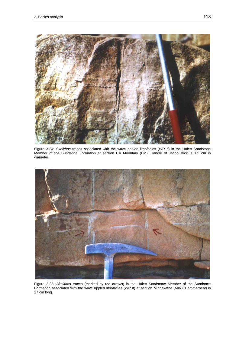
3. Facies analysis 118
Figure 3-34: Skolithos traces associated with the wave rippled lithofacies (WR lf) in the Hulett Sandstone Member of the Sundance Formation at section Elk Mountain (EM). Handle of Jacob stick is 1,5 cm in diameter.
Figure 3-35: Skolithos traces (marked by red arrows) in the Hulett Sandstone Member of the Sundance Formation associated with the wave rippled lithofacies (WR lf) at section Minnekatha (MIN). Hammerhead is 17 cm long.

3. Facies analysis 119
Diplocraterion: Perpendicular to bedding oriented, U-shaped burrows with spreite. The tube limbs are parallel and range in diameter between 5 and 10 mm. Distances between limbs reach usually 5-7 cm. Length or depth of the burrow can reach a maximum of 20 cm, but is commonly 12 cm. Entrances/exits of the burrows are usually scoured due to permanent erosion and sediment shift in the inhabited environment. The ichnologic interpretation of Diplocraterion considers the traces as a dwelling burrow of a suspension feeding organism, living probably in high-energetic environments (HÄNTZSCHEL 1975).
Monocraterion: Perpendicular to bedding oriented, straight, sometimes slightly curved tubes with funnel. Diameter 1cm, depth 2 cm. According to HÄNTZSCHEL (1975), also known as “Trumpet pipes” and produced as a dwelling burrow of a suspension feeding worm-like organism. The occurrence of these traces is limited to eastern Wyoming and the Black Hills area in South Dakota (RAUTMANN 1976).
Interpretation of the Skolithos ichnofacies: The Skolithos ichnofacies is indicative for relatively high-energetic environments and typically develops in well-sorted, loose and shifting sediments (PEMBERTON et al. 1992). The rate of erosion, deposition and reworking is fairly high and characterizes beach, shoreface and foreshore environments. Physical sedimentary structures are subparallel to parallel bedded, large- to small-scale trough-shaped cross-bedding and ripple lamination. Commonly, sedimentary structures are much more abundant in these environments than biogenic structures due to the permanent reworking and shifting of sediment. Seaward the Skolithos ichnofacies grades into the Cruziana ichnofacies, landward into the Glossifungites or Trypanites ichnofacies.
3.5.3 Glossifungites ichnofacies
Sediment: The Glossifungites ichnofacies is preserved in hardground carbonates as at section T cross T Ranch (T-T) or in well sorted, fine-grained, calcareously cemented, non-glauconitic sandstone pebbles in the Black Hills area in South Dakota (see Figure 3-36).
The observed trace fossils (borings) can not be assigned to the Glossifungites ichnofacies with certainty. A close relation to the Trypanites ichnofacies exists, but as PEMBERTON et al. (1992) pointed out, the two ichnofacies are intergradational and the nomenclature for hardground versus firmground associations is in a developing stage. The Glossifungites ichnofacies in the investigated formations is characterized by vertical oriented cylindrical, tear-shaped and U-shaped borings or boring-like structures. Descriptions of borings and encrustings identified in Jurassic sediments in the “Sundance Basin” are published by ANDERSON (1978; 1979), WILSON et al. (1998) and CONROY & TANG (2002).
Interpretation of the Glossifungites ichnofacies: The Glossifungites ichnofacies develops landward of the Skolithos ichnofacies on firm but unlithified substrates on marine littoral to sublittoral omission surfaces or in low to moderate hydrodynamic settings (PEMBERTON et al.1992).
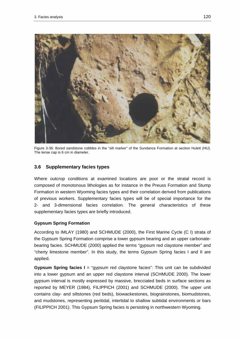
3. Facies analysis 120
Figure 3-36: Bored sandstone cobbles in the “silt marker” of the Sundance Formation at section Hulett (HU). The lense cap is 6 cm in diameter.
3.6 Supplementary facies types
Where outcrop conditions at examined locations are poor or the stratal record is composed of monotonous lithologies as for instance in the Preuss Formation and Stump Formation in western Wyoming facies types and their correlation derived from publications of previous workers. Supplementary facies types will be of special importance for the 2- and 3-dimensional facies correlation. The general characteristics of these supplementary facies types are briefly introduced.
Gypsum Spring Formation
According to IMLAY (1980) and SCHMUDE (2000), the First Marine Cycle (C I) strata of the Gypsum Spring Formation comprise a lower gypsum bearing and an upper carbonate-bearing facies. SCHMUDE (2000) applied the terms “gypsum red claystone member” and “cherty limestone member”. In this study, the terms Gypsum Spring facies I and II are applied.
Gypsum Spring facies I = “gypsum red claystone facies”: This unit can be subdivided into a lower gypsum and an upper red claystone interval (SCHMUDE 2000). The lower gypsum interval is mostly expressed by massive, brecciated beds in surface sections as reported by MEYER (1984), FILIPPICH (2001) and SCHMUDE (2000). The upper unit contains clay- and siltstones (red beds), biowackestones, biograinstones, biomudstones, and mudstones, representing peritidal, intertidal to shallow subtidal environments or bars (FILIPPICH 2001). This Gypsum Spring facies is persisting in northwestern Wyoming.

3. Facies analysis 121
Gypsum Spring facies II = “cherty limestone facies”: This facies consists of chert bearing limestones as well as red, green and gray claystones. Three subunits are distinguished by SCHMUDE (2000). This Gypsum Spring facies is persisting in northwestern Wyoming.
Where no additional stratigraphic or lithologic data from the First Marine Cycle (C I) is available, the Gypsum Spring facies is labeled “undivided” in the facies correlation. Such conditions were found in the Wyoming Range and in the Black Hills where the Gypsum Spring unit is only partly exposed.
Piper Formation
The Piper Formation is composed of three stratigraphic members (IMLAY et al. 1948, PETERSON 1957a, IMLAY 1956; 1980) (see chapter: 2.3, Lithostratigraphy; 2.3.5, Piper Formation). These members are termed “lower red bed and gypsum member”, “middle limestone member” and “upper red bed member” (PETERSON 1957a) and reflect characteristic correlative facies types. These members are the stratigraphic equivalents of the Sliderock, Rich and Boundary Ridge Member of the Twin Creek Limestone (IMLAY 1967; 1980). In this study, the terms Piper facies I, II and III from bottom to top are applied.
Preuss Formation
A detailed study of Middle and Upper Jurassic depositional environments including the Preuss Formation, based on outcrop sections in western Wyoming and eastern Idaho, was conducted by HILEMAN (1973). She proposed four facies types within the thick red bed successions of the Preuss Formation. This facies interpretation of the Preuss Formation by HILEMAN (1973) offers the opportunity to further subdivide the marine red bed facies introduced in chapter 3.2.10. The Preuss Formation was examined during field work in the Wyoming Range and two of the four facies types were recognized in the outcrop sections. In this study, the terms Preuss facies I and II are applied.
Preuss facies I = Facies I of HILEMAN (1973): A thin succession of shales and siltstones that contain evaporite pseudomorphs, some rippled bedding planes and white sandstone beds with abraded oolites. The facies I is interpreted by HILEMAN (1973) as prodeltaic.
Preuss facies II = Facies II of HILEMAN (1973): Characterized by an upward increasing content of sandstone. Mudcracks, rip-up clasts, evaporite pseudomorphs, and collapse breccias occur. Facies II is interpreted by HILEMAN (1973) as evaporitic sabkha and supratidal flat deposits.
The facies III and IV of HILEMAN (1973) were not identified in the outcrop sections. Facies III is composed of siltstones and shales that contain a middle sandstone unit. Further, cherts are replacing evaporites. According to HILEMAN (1973), the sandstone unit formed only locally as tidal channels in intertidal environments. Facies IV is equivalent to the Wolverine Canyon Member of the Preuss Formation and restricted to the vicinity of the Wolverine Creek in Idaho.

3. Facies analysis 122
Stump Formation
The lithology and stratigraphy of the Stump Formation is introduced in the chapter Lithostratigraphy (see chapter 2.3; 2.3.7, Stump Fm.). The Stump Formation consists of the Curtis Member and the Redwater Member, that are separated by the J-4 unconformity (PIPIRINGOS & O’ SULLIVAN 1978, PIPIRINGOS & IMLAY 1979, PETERSON, F. 1994). The Curtis Member consists of a “lower sandstone unit” and an “upper shale unit” (PIPIRINGOS & IMLAY 1979) that can both be recognized in outcrop. Based on the glauconitic appearance, ripple marks and cross-bedding the “upper sandstone unit” can be interpreted as representative for the glauconitic lithofacies. The “lower shale unit” is glauconitic and documents the shale lithofacies. The overlying Redwater Member contains a “lower shale unit” and an “upper sandstone unit” that are representative for the shale and the glauconitic lithofacies, respectively. Both lithologic units were found in outcrop. The “lower shale unit” of the Redwater Member is greenish-gray and glauconitic. The “upper sandstone unit” is greenish-gray, glauconitic, cross-bedded, and ripple marked. Further, some oolitic layers are present.
A problem with the identification of an unconformable contact between the very similar members derives from the lack of indicative features like marked lithological changes, accompanied by facies shifts or erosional surfaces in western Wyoming. The J-4 unconformity that is proposed to be existent in the Stump Formation was not definitely recognized during field work, although PIPIRINGOS & IMLAY (1979) proposed a sharp contact and a lithological change. The contact seems to be best documented biostratigraphically. The unconformable contact is expressed by the sudden appearance of belemnites and Gryphea nebrascensis Meek & Hayden specimen that mark the lower boundary of the Redwater Member. In consequence, the position was chosen in context with the original stratigraphic correlation of PIPIRINGOS & IMLAY (1979). To distinguish the glauconitic sandstones and shales of the Curtis Member from lithologically similar beds of the Redwater Member in the facies correlation the position of the lower lithologic units will be marked as “Curtis sandstone facies” and “Curtis shale facies”.

123
4 Facies modelling
The stratigraphic fill of the “Sundance Basin” is composed of numerous facies types that reflect a wide range of depositional settings. After facies analysis it is the next step to display the spatial arrangement of facies types and facies associations in a schematic, 3-dimensional model. Based on the microfacies, lithofacies and ichnofacies analysis a terrigenous and shallow to open marine origin of the “Sundance Basin” fill is evident. Further, the facies types reflect high-energetic and low-energetic hydrodynamic conditions that are either related to gradually increasing water depths or are produced by superimposed high-energy events, for instance, during storms. The facies types and their partly unequivocal interpretation of depositional environments are listed in Figure 4-1 and Figure 4-2. The facies interpretation of the unequivocal facies types derives from the stratal context with related facies successions.
A 3-dimensional facies model for the complete “Sundance Basin” structure does presently not exist, but it will be important for the course of this study to establish such a basinwide facies context. Therefore, it is an aim of this study to combine the results from the facies analysis with already published “Sundance Basin” facies models to compile for the first time a comprehensive basinwide facies model.
Carbonate microfacies Interpretation of depositional process & environment : continuous
Interpretation of depositional process & environment : superimposed
Oograinstone microfacies High-energetic facies
Oobiograinstone microfacies High-energetic facies
Biograinstone microfacies Peritidal: Tidal inlet deposits, nearshore bioclast accumulations
Storm, shallow and deeper water
Oobiopackstone microfacies High-energetic facies
Biopackstone microfacies Subtidal Storm, shallow and deeper water
Pelbiowackestone microfacies Lagoonal
Biowackestone microfacies Peritdal to subtidal, basin slope, deeper water
Storm, shallow and deeper water
Mudstone microfacies (various types)
Peritidal to subtidal: lagoonal to shallow or deeper water
Figure 4-1: Carbonate microfacies types and their depositional environments.

4. Facies modelling 124
Siliciclastic & evaporite facies
Interpretation of depositional process & environment: continuous
Interpretation of depositional process & environment: superimposed
Large-scale cross-bedded lithofacies
Terrigenous: eolian Marine: nearshore, estuarine
Wave-rippled lithofacies Upper foreshore – upper shoreface
Storm
Lenticular to flaser bedded lithofacies
Lower shoreface, tidal environments
Storm
Low-angle laminated lithofacies
Beach – foreshore
Oolite lithofacies Lower shoreface – upper shoreface
Shale lithofacies Offshore Storm
Silty lithofacies Lower shoreface Storm
Glauconitic lithofacies Middle – upper shoreface Storm
Sabkha red beds Sabkha
Marine red beds Upper shoreface – foreshore (intertidal, prodeltaic)
Evaporites Sabkha
Figure 4-2: Siliciclastic lithofacies types and their depositional environments.
The central portions of the “Sundance Basin” lack a schematic, large-scale 3-dimensional model that displays the arrangement of depositional environments. The mixed lithologic character of the basin fill suggests an approach to facies modelling from pure carbonate and siliciclastic lithologies. Consequently, individual facies models will be introduced and discussed for carbonate and siliciclastic depositional systems.
4.1 Existing facies models for the “Sundance Basin”
Facies models and depositional settings for various stratigraphic intervals of parts of the “Sundance Basin” fill have been proposed by previous workers (HILEMAN 1973, RAUTMANN 1976, MEYER 1984, MEYERS 1981, DeJARNETTE & UTGAARD 1986, MOLGAT & ANOTT 2001) for siliciclastic and carbonate suites in the Black Hills, Wyoming and Montana. A 3-dimensional, regional facies model that combines carbonate and siliciclastic environments is developed by BLAKEY et al. (1983) for the southern “Sundance Basin”.

4. Facies modelling 125
Semantic problems
As pointed out by YANCEY (1991) and BURCHETTE & WRIGHT (1992), some semantic and conceptual problems occur with the usage of the terms “shelf” and “ramp”. Both terms describe a gently sloping depositional surface which passes gradually offshore, from shallow water depths into deeper, low-energetic water. In analogy to modern settings the shelf is defined by BATES & JACKSON (1987) to stretch between the continental margin and the continental slope. As noted by VAN WAGONER et al. (1990), ramp morphologies are important in pure siliciclastic regimes. Carbonate ramp settings are analogous to siliciclastic shelves in respect to hydrodynamics and morphology (TUCKER & WRIGHT 1990, BURCHETTE & WRIGHT 1992). In the “Sundance Basin”, inclined depositional gradients for the stratal package of the Sundance Formation have been recognized long ago. The informal term “Wyoming shelf” reflects those settings. Nevertheless, shelf settings analogous to modern shelves are not evident and this terminology does not describe depositional settings in the “Sundance Basin” correctly. Consequently, the term “ramp” will be used in the course of this study if referred to inclined depositional slopes, regardless to the lithologic character of the deposited sedimentary succession.
4.2 Facies model for a carbonate depositional system in the „Sundance Basin“
MEYERS (1981) described a facies mosaic in the massive peloidal and oolitic grainstone successions in the Rierdon Formation in Montana that suggests the existence of a shallow peritidal “shelf”. According to MEYERS (1981), peloidal grainstones reflect deposition in inner shelf settings, while oolite shoals developed near the outer edge of the shelf and migrated over inner shelf deposits. This depositional setting proposed by MEYERS (1981) is displayed in Figure 4-3. Considering the semantic problems discussed above MEYERS (1981) applied the term “shelf” to describe a ramp morphology.
Figure 4-3: Peritidal “shelf” carbonate depositional model developed by MEYERS (1981) for peloidal, oolitic and skeletal grainstones, micrites, wackestones and packstones of the Rierdon Formation on the southern flank of the Belt Island Complex.

4. Facies modelling 126
According to READ (1982; 1985), carbonate ramps are defined as a gently sloping surface on which a high-energy facies of a wave-dominated nearshore zone gradually passes into deeper water and low-energetic conditions. READ (1982; 1985) divided carbonate ramps into homoclinal and distally steepened ramps. Homoclinal ramps are defined by a slope gradient that continuously persist from the shoreline into deeper water, while distally steepened ramps are characterized by an offshore break between the shallow ramp and an adjacent basin. On distally steepened ramps the slope break is located in a position around the mid- or outer ramp. Carbonate ramps are common in epicontinental and/or interior cratonic basins (EINSELE 1992, BURCHETTE & WRIGHT 1992) or as elements adjacent to a subsiding foreland to back-arc basinal configuration (BURCHETTE & WRIGHT 1992).
Moreover, carbonate ramps display an unique energy zonation that was already described by IRWIN (1965). The low morphological gradient, characteristic for shallow marine epeiric or intracratonic ramp settings, causes a specific energy zonation in the area above the storm wave base (SWB). The most important aspect of this energy zonation is the development of broad and extremely wide facies belts with the occurrence of shoreline-detached high-energy zones. This model – commonly known as “Irwin model” – was developed to describe shallow marine carbonate sedimentation in epeiric settings. The “Irwin model” consists of three marine hydrodynamic energy zones and is shown in Figure 4-4.
Y-ZONEtens of km
sea-level
SupratidalIntertidal
SubtidalFWWB
TideLow
High
Z-ZONEup to hundreds of km
X-ZONE hundreds of km
energy zonation
migratingskeletal build ups
IRWIN model
Figure 4-4: “Irwin model” for hydrodynamic zonation and shallow marine carbonate sedimentation developed by IRWIN (1965). FWWB = fairweather wave base (modified from FLÜGEL 1985).
Zone X: The Zone X can reach a width of hundreds of miles. It is a low-energy zone in the open sea below wave base and effected only by marine currents.
Zone Y: The Zone Y is an intermediate high-energy zone with a wide of tens of miles. The zone begins where wave action impinge on the sea floor and extends landward to the area of tidal action.

4. Facies modelling 127
Zone Z: The Zone Z can reach a width of hundreds of miles and is a zone of extreme shallow water depth. The Zone Z occurs landward of Zone Y. Water circulation is often weak, tides are essentially wanting and wave action is generated by occasional high-energy events during storms or bad weather conditions.
As pointed out by BURCHETTE & WRIGHT (1992), the best recognizable interfaces in ramp successions are the fairweather wave base (FWWB) and the storm wave base (SWB). These interfaces can as well be identified in siliciclastic systems, because of the morphological and hydrodynamic similarity between siliciclastic shelves and carbonate ramps. BURCHETTE & WRIGHT (1992) specified carbonate ramp models on the basis of their hydrodynamic and morphological aspects. The basic model is displayed in Figure 4-5. It results in a general compatibility between homoclinal or distally steepened carbonate ramps and siliciclastic shelves.
OUTERRAMP
MID-RAMP
INNERRAMP
BASINA
B
CDE
F
sea-levelFWWB
SWBPC
Homoclinal ramp model
10’s to 100’s km
Figure 4-5: Homoclinal ramp model proposed by BURCHETTE & WRIGHT (1992). The model shows the main sedimentary facies types. Inner ramp: (A) peritidal and sabkha facies with evaporites and stromatolitic algae, (B) bioturbated and variably bedded lagoonal mudstone, packstone, wackestone, (C) shoreface to shoal oolitic or bioclastic grainstones and packstones; Mid-ramp: (D) graded tempestites, with hummocky cross-lamination; Outer ramp: (E) fine-grained tempestites interbedded with bioturbated mudstones, (F) laminated siliceous mudstones. All these boundaries are gradational. FWWB = fairweather wave base, SWB = storm wave base, PC = pycnocline.
Carbonate ramp facies generally reflect offshore-directed, gradually increasing water depths that are associated with decreasing hydrodynamic energy gradients. Some indicative compositional and textural sedimentological aspects of inner, mid- and outer ramp deposits can be summarized from BURCHETTE & WRIGHT (1992), TUCKER & WRIGHT (1990) and EINSELE (1992). According to BURCHETTE & WRIGHT (1992), the following environmental subdivisons and sedimentological aspects characterize carbonate ramps depozones:

4. Facies modelling 128
Inner ramp: The inner ramp comprises the zone above the fairweather wave base (FWWB). Depositional environments and morphologic elements are sand shoals, organic barriers, shoreface deposits, and back-barrier peritidal areas. Inner ramp successions are commonly composed of oolitic or bioclastic shoals, bars, build ups, and back-bar sediments. Inner ramp lagoonal and sabkha deposits comprise evaporites and a wide range of mud-, wacke- and packstones with a restricted faunal spectrum.
Mid-ramp: The mid-ramp is the area between the fairweather wave base (FWWB) and the storm wave base (SWB). Here the sea floor is frequently affected during bad weather periods. Sedimentary structures as graded beds and hummocky cross-lamination are diagnostic for storm-related sedimentation. Mid-ramp successions consist of sediments that indicate environments below the fairweather wave base (FWWB) and the influence of storm events. Typical storm deposits are associated with partly winnowed fabrics, hummocky cross-lamination, graded bedding, sheltering of mud, climbing ripple lamination as described by KREISA (1981), FLÜGEL (1982) and AIGNER (1985). During fairweather periods, sedimentation is dominated by suspension fall out and mud-dominated, intensively bioturbated deposits are produced.
Outer ramp: In the outer ramp, the sedimentation of mud with varying amounts of terrigenous input takes place. This depozone is effected only by storms and distal tempestites may occur. The outer ramp extends from the depth limit of effective storm influence to the basin plain (if a basin is developed). Sedimentation is derived only from suspension.
Basin: In this distal part of the ramp the sedimentation is affected very infrequently during heavy storm events (tsunamis). Mostly hemipelagic sedimentation is dominant. In rapidly subsiding basins the sediment fill may be siliceous. In shallow marine basins sediments may be composed of bioturbated limy mudstones.
These diagnostic compositional and textural sedimentological aspects of inner, middle and outer ramp deposits and their bounding interfaces are documented in the analyzed carbonate microfacies types and compiled in Figure 4-6
OUTERRAMP
MID-RAMP
INNERRAMP
sea-level 10’s to 100’s km
Carbonatemicrofacies types andevaporites
Peritidal low-energetic inner ramp (P):
High-energetic inner ramp (H):
pelbiopackstones, biowackestones to biofloatstones, laminated mudstones, detritus
oograinstones, oobiograinstones,oopackstones, biograinstones
mudstones, evaporites
biowackestones to biofloatstonesbiopackstones to biorudstones,biograinstones
biomudstones, detritusmudstones, mudstones
FWWB
SWB(P) (P)(H)
Figure 4-6: The arrangement of carbonate microfacies types and evaporites in inner, middle and outer ramp settings in the “Sundance Basin”. FWWB = fairweather wave base, SWB = storm wave base.

4. Facies modelling 129
The inner ramp facies in the calcareous successions of the “Sundance Basin” fill is represented by peritidal sediments associated with shoreline-detached high-energy facies types. As shown in Figure 4-6 peritidal low-energetic microfacies types from lagoonal or sabkha, inner ramp settings are pelbiopackstones, biowackestones, laminated mudstones, and detritusmudstones. High-energy, inner ramp deposits are oograinstones, oopackstones, oobiograinstones, and biograinstones. These facies types display textural and structural aspects (cross-bedding, winnowing, high degree of reworking and sorting) that suggest depositional settings as shoals or migrating bars.
The mid-ramp in the “Sundance Basin” is characterized by storm influenced sedimentation. The biowackestone to biofloatstone, biopackstone to biorudstone and biograinstone microfacies are interpreted as storm deposits on the basis of their wide range of microscopic and macroscopic sedimentological structures. Besides hummocky cross-stratification and graded bedding as claimed by BURCHETTE & WRIGHT (1992), TUCKER & WRIGHT (1990) and EINSELE (1992) the mid-ramp sediments display sheltering of mud, sharp, erosive contacts, and discontinuous facies relations. Moreover, these microfacies types contain all features of typical storm deposits as described by KREISA (1981), FLÜGEL (1982) and AIGNER (1985). The poor sorting and reworking of the microfacies types indicate multiple depositional events in varying states of recycling.
Outer ramp deposits are the mudstone microfacies types that comprise the biomudstone, detritusmudstone and mudstone microfacies. These microfacies types lack apparent sediment structures. The frequency of storm related deposits in these successions becomes scarce as was found in outcrop sections during field work.
The important fairweather wave base (FWWB) is distinctively represented by carbonate facies types that were deposited under wave agitated conditions on the inner ramp. Sedimentation below this interface is dominated by suspension and the occasional influence of storms above the storm wave base (SWB). Based on these intimate relations the carbonate microfacies types were placed in context with the basic ramp model of BURCHETTE & WRIGHT (1992). The resulting schematic, 3-dimensional facies model is illustrated in Figure 4-9 A. It is evident from the carbonate microfacies analysis that hemipelagic deposits do not exist in the “Sundance Basin”. These deposits are not reported by other workers. Consequently, this depozone is not displayed in the carbonate ramp model in Figure 4-9 A.

4. Facies modelling 130
4.3 Facies model for a siliciclastic depositional system in the „Sundance Basin“
RAUTMANN (1976) was the first worker who defined a distinct, prograding “offshore-shoreface-foreshore-beach-sabkha” succession in the eastern portions of the “Sundance Basin”. DeJARNETTE & UTGAARD (1986) were able to extend this terminology into northwestern Wyoming and adjacent Montana. AHLBRANDT & FOX (1997: 107) confirmed the existence of shoreface-foreshore sequences in the Black Hills area and stated that the facies units and parasequences within the Hulett Sandstone Member of the Sundance Formation represent “….textbook examples of prograding shoreface to foreshore deposits”. Comparable deposits were found during field work at the sections Hulett (HU), T cross T Ranch (T-T), Thompson Ranch (TR), Spearfish (SF), Stockade Beaver Creek (SBC), Elk Mountain (EM), and Minnekatha (MIN) and interpreted as lenticular to flaser bedded lithofacies (L-Fb lf), wave-rippled lithofacies (WR lf) and low-angle laminated lithofacies (LL lf). Therefore, it seems appropriate to place the siliciclastic facies types in a model that includes depositional environments from beach over shoreface into outer marine settings. To describe the arrangement of siliciclastic depositional environments the “foreshore-shoreface-offshore” facies model of WALKER & PLINT (1992) was chosen, because:
• The operating hydrodynamic processes, the depositional gradient and applied terminology include wave,- tide- and storm action that is indicated by the lithofacies analysis.
• The zonation of ichnofacies types in the “Sundance Basin” corresponds to the shoreface model of FREY et al. (1990) introduced in Figure 3-29.
• The depozones are described by increasing water depths in continuously interacting environments and low depositional gradients.
• The model can be applied independently from the tectonic setting.
The model comprehensively provides a suitable hydrodynamic and morphological framework to describe the wide range of siliciclastic sediments and trace fossil assemblages in the “Sundance Basin”. The model of WALKER & PLINT (1992) is shown in Figure 4-7 and describes a shoreline to shallow marine profile. The important morphological elements are the offshore depozone, the shoreface depozone – divided into the lower, middle and upper zone – and the foreshore depozone. Hydrodynamic processes within the foreshore and upper shoreface zones are mostly generated by wind and wave action. Tides can play an important role in the foreshore zone. In the deeper parts of the shoreface zone and the mud-dominated offshore zone deposition is effected only during sporadic bad weather conditions and storm events.

4. Facies modelling 131
SHOREFACEOFFSHORE
FORESHORE
SkolithosCruziana
Zoophycos
LOWER MIDDLE UPPER
Ichnofacies
TideLow
High
WAVES BEGIN TO BUILD UPSPILLING BREAKERS
SHOALING WAVES
SURF ZONE
SANDY SUBSTRATEMUDDY SUBSTRATE
FAIRWEATHER WAVE BASE (FWWB)
STORM WAVE BASE (SWB)
VERTICAL SCALE GREATLY EXAGGERATED
5 - 15mLONGSHORE BARS
Figure 4-7: Spatial arrangement of foreshore, shoreface and offshore areas, fairweather wave base (FWWB), storm wave base (SWB), and ichnofacies (modified from WALKER & PLINT 1992).
The depozones of the “foreshore-shoreface-offshore” model of WALKER & PLINT (1992) can be filled with various depositional elements that were identified by the lithofacies and ichnofacies analysis. The differing facies types represent a continuum of laterally adjacent high- to low-energetic depozones with characteristic hydrodynamic conditions. These depozones are – like depozones in the carbonate model – delineated by the distinct interfaces of the fairweather (FWWB) and storm wave base (SWB). The continuous hydrodynamic conditions are interrupted by discontinuous, superimposed processes.
These diagnostic compositional and textural sedimentological aspects of foreshore, shoreface and offshore environments are documented in the analyzed siliciclastic lithofacies types and compiled in Figure 4-8.
SHOREFACEOFFSHORE
FORESHORE
LOWER MIDDLE UPPER
Tide
5 - 15m
sea-level
Siliciclasticlithofacies types andevaporites
low-angle laminated lf,silty lf, glauconitic lf,sabkha red bed lf, marine red bed lf, wave-rippled lf, evaporites
shale lf, lenticular to flaser bedded lf large-scale cross-bedded lf,wave-rippled lf, silty lf, marine redbed lf, lenticular to flaser bedded lf,marine red bed lf, oolite lf, glauconitic lf
FWWB
Figure 4-8: The arrangement of siliciclastic lithofacies types and evaporites in foreshore-shoreface-offshore settings in the “Sundance Basin”. lf = lithofacies, FWWB = fairweather wave base.
The foreshore depozone in the model of WALKER & PLINT (1992) is equivalent to a beach and lies in the zone between low and high tide. Deposition is dominated by tides, swash and backwash of breaking waves as well as onshore, longshore and rip currents. In the model for the “Sundance Basin” in Figure 4-9 B, the foreshore and associated

4. Facies modelling 132
deposits are reflected by the low-angle laminated lithofacies (LL lf), the sabkha red bed lithofacies (sabkha red bed lf), the glauconitic lithofacies (gl lf), and the silty lithofacies (silt lf). Shoaling and breaking waves produce swash that in turn produces planar to low-angle laminated stratification (LL lf). The semi-terrigenous red beds reflect depozones landward of the foreshore. The silty lithofacies in the eastern parts of the field area is interpreted by RAUTMANN (1976) and in this work as a lagoonal sediment deposited behind and between protected areas in a barrier island complex. The glauconitic lithofacies comprise a number of diagnostic tidal sedimentary structures and reflect deposition in foreshore to middle shoreface environments. Laterally, the glauconitic lithofacies grades into the silty and shale lithofacies. Farther landward and not included in the facies model of WALKER & PLINT (1992) continental sedimentation is dominant. In the “Sundance Basin” extensive terrigenous suites are represented by the eolian Entrada Sandstone.
According to WALKER & PLINT (1992), the physical processes within the shoreface depozone are dominated by onshore, longshore and rip currents, while mass transport is driven by waves. The shoreface depozone ranges between the fairweather wave base (FWWB) and the low tide line, while the morphological gradient decreases offshore. Prominent sediment structures in the “Sundance Basin” model are straight-crested and symmetric oscillation ripples, sand dunes, hummocky cross-stratification, and a variety of small bedforms, bars and runnels. These sediment structures and bodies are found in a number of siliciclastic lithofacies types from corresponding upper and middle shoreface settings such as: wave-rippled lithofacies (WR lf), large-scale cross-bedded lithofacies (LX lf) and the silty lithofacies (silt lf). In the eastern parts of the study area the trace fossil assemblages are Skolithos-dominated. The lower shoreface is transitional between the middle shoreface and the offshore zone. It is characterized by an ichnofacies transition to Cruziana-dominated assemblages and interbedded shale-sandstone suites of the lenticular to flaser bedded lithofacies (L-Fb lf). Currents and wave action fades out seaward. The base of the shoreface zone delineates the fairweather wave base (FWWB). According to WALKER & PLINT (1992), this boundary is defined by the point where sandstone-mudstone suites grade upward into sandstone lithologies. High-energetic processes are generated by storm events. In the “Sundance Basin”, the lower shoreface depozone is characterized by Cruziana ichnofacies traces in the lenticular to flaser bedded lithofacies (L-Fb lf) and the silty lithofacies (silt lf). These lithofacies types display intercalated hummocky cross-lamination and partly in-phase climbing ripples that indicate temporary high-energetic events. The oolite lithofacies (Oo lf) is typical for the middle and upper shoreface zone, but may occur in the lower shoreface as incised oolitic-bioclast-rich interbeds. The offshore zone is characterized by fine clastic sedimentation under low-energetic hydrodynamic conditions below the fairweather wave base (FWWB). The shale lithofacies (shale lf) is representative for this depozone and effected by high-energetic conditions only during storms.

4. Facies modelling 133
A
B
Arenicolites-Ichnofacies
Skolithos-Ichnofacies
Cruziana-Ichnofacies
current direction,storm transport
crinoids
ooids & biogenetic debris
pelecypodpatches
biogenticdebris
Carbonate environments
peritidal
lagoonal
subtidal
storm influenced
Siliciclastic environments
shallow marine/peritidal
terrigenous
normal marine/subtidal
sabkha
terrigenous
storm influenced
Figure 4-9: A: Facies model for the carbonate depositional system, B: Facies model for the siliciclastic depositional system.

4. Facies modelling 134
4.4 Facies model for a mixed carbonate-siliciclastic depositional system in the “Sundance Basin”
Facies models for lithologic end members have been described above. To display the 3-dimensional distribution of mixed depositional environments it will be necessary to combine these facies models. It will further be important to pay attention to the changing basin configuration during evolution of the “Sundance Basin”.
As demonstrated above, the best identifiable interfaces in carbonate and siliciclastic ramp depositional systems are the fairweather wave base (FWWB) and the storm wave base (SWB). These interfaces delineate the boundaries between differing ramp depozones in the facies models and control the distribution of high- and low-energetic facies types. Consequently, it seems appropriate to use these interfaces as distinct markers to describe depozones within carbonate-siliciclastic depositional systems. More precisely, the fairweather wave base (FWWB) delineates the transition from the offshore to the shoreface zone in siliciclastic environments (WALKER & PLINT 1992) (see Figure 4-7) and the mid- to inner ramp transition in carbonate systems (BURCHETTE & WRIGHT 1992) (see Figure 4-5). The storm wave base (SWB) is located within the siliciclastic offshore zone, while it marks the transition from mid-ramp to outer ramp settings in carbonate systems. The water depth in which these boundaries are developed varies with time and depends on the hydrodynamic and climatic conditions (BURCHETTE & WRIGHT 1992).
Thus, both interfaces are identifiable and documented in the analyzed siliciclastic and carbonate facies types. The depozones above fairweather wave base (FWWB) are characterized by wave or/and current agitated hydrodynamic processes and their diagnostic sediment structures. Diagnostic sediment structures in these depozones are various ripple types, cross-bedding and small-scale sediment bodies. Storm deposits that indicate deposition above storm wave base (SWB) are abundantly preserved in the “Sundance Basin” fill. These deposits are easy to identify by their discontinuous facies contacts and diagnostic sediment structures in outcrop and thin-section.
Similarities between siliciclastic and carbonate facies models comprise further the morphological gradient that causes the development of a specific hydrodynamic energy zonation with an offshore-ward protracted decrease of energy gradients in the area above storm wave base (SWB). This zonation is reflected in the ichnofacies spectrum, micro- and macroscopic sedimentary structures and continuous facies relations. Therefore, the combination of criteria from the siliciclastic “foreshore-shoreface-offshore” model of WALKER & PLINT (1992) and the carbonate ramp model of BURCHETTE & WRIGHT (1992) leads to three carbonate-siliciclastic depozones in the “Sundance Basin”. The depozones are termed Zone 0 to II and are characterized by broad and extremely wide facies belts and associated shoreline-detached high-energy zones.

4. Facies modelling 135
Zone 0: The Zone 0 is dominantly a terrigenous depozone that include sabkha settings. A typical lithofacies is the large-scale cross-bedded lithofacies (LX lf). Pure terrigenous deposition is extremely rare in the central and northern portions of the “Sundance Basin”. However, this zone is represented by stratigraphic outliers of the eolian Entrada Sandstone that were examined at southernmost sections Flaming Gorge (FG) and Vernal (V).
Zone I: The zone I is a marine depozone and comprises depositional environments above the fairweather wave base (FWWB). This includes “foreshore-shoreface” environments from the model of WALKER & PLINT (1992) and the inner ramp from the carbonate facies model of BURCHETTE & WRIGHT (1992). The hydrodynamic processes are dominated by shoaling and breaking waves. Moderate to low-energy environments are associated with protected foreshore settings and include marine red beds and lagoons. Siliciclastic facies types are low-angle laminated lithofacies (LL lf), silty lithofacies (silt lf), wave-rippled lithofacies (WR lf), glauconitic lithofacies (gl lf), and marine red beds. Lagoonal and/or low-energetic carbonates are recorded by the detritusmudstone, laminated mudstone and pelbiowackestone microfacies. Seaward the low-energy depozone grades into high-energetic depozones where the ichnofacies assemblage is Skolithos-dominated. The high-energy depozone is equivalent to the shoreface in siliciclastic facies models and the peritidal inner ramp in carbonate facies models. Typical mid-ramp deposits as claimed by BURCHETTE & WRIGHT (1992) are excluded from the Zone I, because sedimentation does not occur below the fairweather wave base (FWWB).
Zone II: This zone combines carbonate mid- to outer ramp settings with siliciclastic offshore settings and is characterized by a low-energetic hydrodynamic regime in deeper water below fairweather wave base (FWWB). The low-energetic sedimentation is frequently effected by storm events and bad weather periods. The ichnofacies assemblage becomes Cruziana-dominated. The sediment facies is mud-dominated and represented by the shale lithofacies (shale lf) and various mudstone microfacies types (biomudstone, detritusmudstone, mudstone). Further, storm-deposited biowackestones and sandy beds are interbedded. In context with the definition of BURCHETTE & WRIGHT (1992) the mid-ramp is reflected by the biowackestone microfacies types, while mudstone microfacies types typify the outer ramp.
4.5 Ramp models for differing basin configurations in the “Sundance Basin”
Ramp configurations occur in a variety of sedimentary basins, but are “best developed where subsidence is flexural and gradients are slight over large areas, as in foreland, cratonic-interior and along passive margins” (BURCHETTE & WRIGHT 1992: 3). This implies that besides the hydrodynamic regime the tectonic configuration and the influence of subsidence are of special importance for the development of ramp systems (HANFORD & LOUCKS 1993). As pointed out by READ (1982; 1985), a common phenomenon in the

4. Facies modelling 136
geologic history is the evolution of a homoclinal ramp toward a distally steepened configuration. In consequence, it would be necessary to progressively modify ramp models in relation to particular evolutionary tectonic stages of a sedimentary basin. The distal steepening of ramp systems might be either tectonically driven (differential subsidence), inherited or occur due to intrinsic processes (differential sedimentation). The ramp classification of READ (1982; 1985) offers the opportunity to modify homoclinal ramp models during transformation toward distally steepened models.
This relation will be of special significance for the present study. As will be demonstrated, two major geometric settings can be distinguished during evolution of the “Sundance Basin” that require two ramp models:
• A homoclinal ramp model for symmetric basin configurations, characterized by lithologic mixed deposystems, low morphological gradients, limited accomodation space, and a specific energy zonation that is typified by a shoreline-detached high-energy facies.
• A distally steepened ramp model characterized by an asymmetric geometry. This model is composed of a proximal, siliciclastic-dominated domain that grades laterally into distal, carbonate-dominated domains. The morphological gradient steepens distally toward the developing basin slope.
In both ramp models the energy zonation is caused by gradually decreasing hydrodynamic energy toward the offshore/outer ramp zone. The most significant contrasts between the two ramp configurations are confined to the spatial distribution of siliciclastic and carbonate sediments.
4.5.1 Homoclinal ramp model
The homoclinal ramp model describes a prominent configuration during the evolution of the “Sundance Basin”. Homoclinal ramp settings were dominant during deposition of the First (C I) and Fourth Marine Cycle (C IV). In contrast to a distally steepened ramp configuration the offshore/outer ramp zone II deposits are thin and storm interbeds occur with a much higher frequency in the stratal record. Further, siliciclastic and carbonate sediments are spatially associated and occur in all depozones of the ramp. The carbonate-siliciclastic homoclinal ramp model is illustrated in Figure 4-10 A.
4.5.2 Distally steepened ramp model
The distally steepened ramp model is corresponding to the homoclinal ramp model in respect to the principal facies and energy zonation. In contrast to the homoclinal ramp model the distal deposits in the offshore/outer ramp zone II are much thicker. Moreover, the distal portion of the ramp is differentiated and mid-ramp sediments (biowackestones) can be distinguished from outer ramp mudstones. The fairweather wave base (FWWB) is

4. Facies modelling 137
delineated by the massive build up of oolite facies types. A very strong contrast to the homoclinal ramp model is expressed in the pronounced spatial separation of siliciclastics and carbonates. The distally steepened ramp model is characterized by siliciclastic sedimentation in the proximal part with low depositional gradients and carbonate sedimentation in the distal part on the mid- and outer ramp. The carbonate-siliciclastic distally steepened ramp model is illustrated in Figure 4-10 B. This configuration is favored by the asymmetric spatial subsidence behavior within the “Sundance Basin” and expressed in the Second (C II) and Third Marine Cycle (C III). More precisely, a distally steepened ramp configuration can be proposed for the developing stage of the “Utah-Idaho trough”.
4.6 Basinwide facies context
Facies models for siliciclastic and carbonate depositional settings as shown in Figure 4-11 are developed for the Carmel Formation by BLAKEY et al. (1983). The existence of a southward adjacent facies model provides the opportunity to control the proposed facies mosaic of homoclinal to distally steepened ramp models and place them in a basinwide context. According to BLAKEY et al. (1983), the narrow, confined nature of the “Carmel seaway”, that occupied the “Utah-Idaho trough” and the gentle slope of the adjacent coastal plain resulted in extremely wide facies belts. As noticed by BLAKEY et al. (1983), TUCKER & WRIGHT (1990) and EINSELE (1992), no modern analogues for such configurations are known. Basinwide, the facies models introduced by BLAKEY et al. (1983), for the southern “Sundance Basin” and the facies zonation proposed for the central and northern portions in this study are corresponding in respect to their morphological gradients, hydrodynamic conditions, facies zonation (lithofacies and ichnofacies), resemblance of analyzed carbonate microfacies types (see chapter: 3.1.1, Carbonate microfacies analysis) and distally increasing water depths.
According to BURCHETTE & WRIGHT (1992) and SARG (1988), the basinward slope zone in distally steepened ramps may display a slope apron and slump structures. Such structures that indicate rapid mass transport were neither observed during field work nor reported by previous workers. There are two possible explanations: Either the basin slope was gentle, as shown in the carbonate facies model A of BLAKEY et al. (1983), so that mass transport was not induced or potential slump deposits were subsequently reworked by storms.

4. Facies modelling 138
Arenicolites-Ichnofacies
Skolithos-Ichnofacies
Cruziana-Ichnofacies
Color code for depositional environments
cont
inuo
us
disc
ontin
uous
storm deposits
subtidal
high-energy facies belt
shallow marine/peritidal
peritidal
lagoonal
sabkhaterrigenous
Abbreviations for lithofacies types(lf = lithofacies)
LX-lf: large-scale cross-bedded lfLL-lf: low-angle laminated lfGl-lf: glauconitic lf,Oo-lf: oolite lf,WR-lf: wave-rippled lf,L-Fb-lf: lenticular to flaser bedded lfsilt lf: silty lf,shale lf: shale lf
B (not to scale, no paleogeographic implications)
(not to scale, no paleogeographic implications)A
Figure 4-10: A: Homoclinal ramp model for the mixed carbonate-siliciclastic depositional system within the “Sundance Basin” and arrangement of depositional zones 0, I and II; B: Distally steepened ramp model for the mixed carbonate-siliciclastic depositional system within the “Sundance Basin” and arrangement of depositional zones 0, I and II.

4. Facies modelling 139
Figure 4-11: General facies model, proposed by BLAKEY et al. (1983) to display the depositional settings during the Middle Jurassic in the southern “Sundance Basin”. A: for the carbonate-dominated facies, B: for the terrigenous-dominated facies (from BLAKEY et al. 1983).
4.7 Facies analysis and modelling characteristics
Based on the facies analysis, 11 carbonate microfacies, 10 siliciclastic lithofacies and an evaporitic facies can be distinguished in the “Sundance Basin” fill. The depositional environments of these facies types are characterized by high-energetic to low-energetic hydrodynamic conditions. The sedimentary facies interpretation is supported by the observed ichnofacies that describe hydrodynamic high-energetic versus low-energetic environmental conditions. The facies zonation describes spatially adjacent depozones with a specific offshore protracted decrease of energy gradients. This offshore-directed decrease of energy gradients is associated with increasing water depths. The continuous hydrodynamic zonation is temporarily interrupted by storm events. Morphological gradients within the “Sundance Basin” primarily controlled this continuous hydrodynamic zonation. Facies models for the “Sundance Basin” are best described by homoclinal and distally steepened ramp settings. Well expressed interfaces in the sedimentary facies spectrum on these ramps are the fairweather wave base (FWWB) and the storm wave base (SWB) that mark boundaries between differing depozones and are expressed by diagnostic sediment structures like large-scale cross-bedding, hummocky cross-

4. Facies modelling 140
lamination, herring-bone cross-bedding, various wave ripple laminations, planar bedding, and coquinoid beds in the investigated stratigraphic column. Due to the moderate morphological gradient the resulting depozones 0, I and II are broad and extremely wide. In depozone 0 terrigenous and sabkha sedimentation is dominant. Zone I includes shoreface-foreshore environments above fairweather wave base (FWWB), while zone II is typified by offshore-mid- to outer ramp settings above storm wave base (SWB). Temporary modifications in the geometric basin configuration of the “Sundance Basin” by tectonic activity on the western edge of the North American craton suggests temporarily alternating ramp models (homoclinal and distally steepened) to comprehensively describe the spatial arrangement of carbonate-siliciclastic depositional environments.

141
5 Facies and allostratigraphic correlation in the “Sundance Basin”
To display the distribution and correspondence of facies types and bounding surfaces within the “Sundance Basin” seven transections through the outcrop area of Jurassic formations were constructed. These 2-dimensional projections provide the basis for the compilation of facies maps and 3-dimensional fence diagrams of the entire study area. Figure 1-1 shows the position of the seven transections. Identified facies types were grouped as facies associations in respect to the ramp environments of depozone 0, I and II (see chapter: 4, Facies models). The facies types and associations were assigned with a color code and correlated between measured outcrop sections under consideration of (a) the allostratigraphic framework provided by the identified Jurassic unconformities of PIPIRINGOS & O’ SULLIVAN (1978) and additional subordinate interfaces and (b) the biostratigraphic framework defined by IMLAY (1980) within the major sedimentary cycles. The color code and facies associations are listed in the explanation chart in Figure 5-1.
If necessary the outcrop grid was extended with additional data and supplementary facies types from previous publications to maintain control on thickness trends, facies correspondence, spatial extent, and stratigraphic position of bounding unconformities (see chapter: 3.6, Supplementary facies types). For this purpose, outcrop sections described by IMLAY (1967; 1980), MORITZ (1951), PIPIRINGOS (1957), AHLBRANDT & FOX (1997), BÜSCHER (2000), SCHMUDE (2000), FILIPPICH (2001), SPRIESTERSBACH (2002), and DASSEL (2002), were compared and placed in context with the examined outcrop sections.
5.1 2-dimensional facies correlation
North-south oriented transections A – A’ to C – C’
The transections A – A‘ to C – C‘ are north-south oriented. Due to their individual 2-dimensional facies distribution the three transections are discussed separately.
Transection A – A’
The transection A – A’ in Figure 5-2 extends from the northernmost outcrop at section Swift Reservoir (SR) in Montana through the Sawtooth Range of southwestern Montana (section LW) into the “Overthrust Belt” and runs along the Wyoming-Idaho border (section BE – TC) southward to the southern flank of the Uinta Mountains in northeastern Utah.

5. Facies and allostratigraphic correlation in the “Sundance Basin” 142
Explanation chartCarbonates Siliciclastics
diverse mudstone facies(biomudstones, detritusmudstones, mudstones): outer ramp to basin, zone II
oolitic grainstones and packstones: inner ramp, zone I
biowackestones:mid to outer ramp, zone II
biograinstones stones:discontinuously intercalated storm deposits, zone I & II
and -pack
detritusmudstones,pelbiowackestones:lagoonal, zone I
biograinstones: tidal channel lags, bioclastic bars on inner ramp,zone I
shale lithofacies:outer ramp to offshore, zone II
silty lithofacies:shoreface or lagoonal, zone I
red beds & gypsum: sabkha deposits, zone 0red beds: marine or tidal deposits, zone I
wave-rippled lithofacies:foreshore to shoreface, zone I
glauconitic lithofacies:foreshore to shoreface, zone I
low-angle laminated lithofacies:foreshore, zone I
large-scale cross-bedded lithofacies: shoreface, zone I or eolian, zone 0
lenticular to flaser-bedded lithofacies: shoreface, zone I
Preuss facies I: Preuss Formation prodeltaic facies (HILEMAN 1973)Preuss facies II: Preuss Formation supra and intertidal facies (HILEMAN 1973)Curtis sandstone facies: Curtis Member of Stump Formation “sandstone unit “ (PIPIRINGOS & 1979)IMLAY
Gypsum Spring facies I: “gypsum red claystone facies”
Supplementary facies types
Gypsum Spring facies II: “cherty limestone facies”
Curtis shale facies: Curtis Member of Stump Formation “shale unit “ (PIPIRINGOS & 1979)IMLAY zone II
zone I
zone I to IIzone I
zone I
Piper facies III: “upper red bed facies”zone IPiper facies II: “limestone facies”
Piper facies I: “lower red bed and gypsum facies”
Figure 5-1: Explanation chart for color code of facies types.
The First Marine Cycle (C I) strata is represented by monotonous red siltstones and brecciated limestones that are the stratigraphic equivalent of the Gypsum Springs Formation in Wyoming as demonstrated by IMLAY (1967; 1980). The allounit thins from the “Utah-Idaho trough” northward and southward. The maximum thickness was measured at section Stump Creek with 62 m. According to SCHMUDE (2000), the spatial extent of the Gypsum Spring Formation is delineated by the bounding J-2 unconformity in central and northwestern Wyoming. This relation can be extended into southwestern Montana and northeastern Utah where the First Marine Cycle (C I) allounit is unconformably bound by the J-2. The allounit is absent in Montana northward of section Little Water Creek (LW). In northeastern Utah the allounit is absent at section Flaming Gorge (FG).
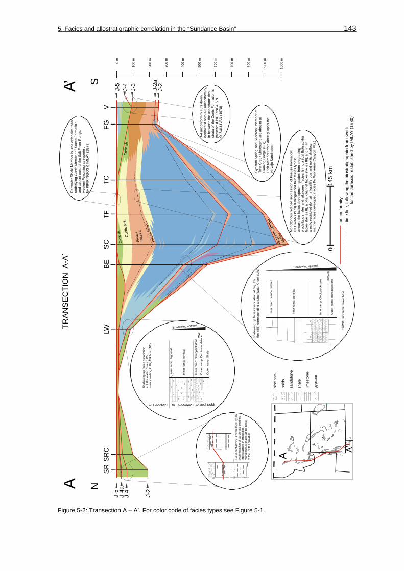
5. Facies and allostratigraphic correlation in the “Sundance Basin” 143
A’A
SN
0 m
100
m
200
m
300
m
400
m
500
m
600
m
700
m
800
m
900
m
1000
m
TRA
NS
EC
TIO
N A
-A`
SRSR
CLW
BES
CTF
TCFG
V
Preu
ss
faci
es II
Preu
ss fa
cies
I
Cur
tis s
h.
Cur
tis s
st.
Cu r
tis s
h .
Gyp
sum
Spr
ing
facie
s
014
5 km
A A’
J-5
J-2
J-4a
J-4
J-5
J-2
J-2a
J-4
J-3
J-4
unco
nfor
mity
is e
xpre
ssed
by
an
accu
mul
atio
n of
car
bona
te c
obbl
esin
ters
tratif
ied
in li
thol
ogic
al
mon
oton
ous
shal
es a
t the
bas
e of
the
Swift
For
mat
ion
Gyp
sum
Spr
ing
and
Slid
eroc
k M
embe
r of
Twin
Cre
ek L
imes
tone
are
abs
ent a
t Fl
amin
g G
orge
(FG
), R
ich
Mem
ber r
ests
dire
ctly
upo
n th
e N
avaj
o Sa
ndst
one
Out
er r
amp:
Det
ritus
mud
ston
e
Inne
r ram
p: O
obio
pack
ston
e
Inne
r ram
p: p
eriti
dal
Inne
r ram
p: la
goon
al
Out
er r
amp:
Sha
le
Shallowing upward
FWW
B
Shal
low
ing
up fa
cies
ass
ocia
tion
at L
ittle
Wat
er C
reek
(LW
)co
rres
pond
ing
to B
ig E
llk M
tn. (
BE)
Shallowing upward
Shal
low
ing
up fa
cies
ass
ocia
tion
at B
ig E
lkM
tn. (
BE) c
orre
spon
ding
to L
itte
Wat
er C
reek
(LW
)
FWW
B
Inne
r ram
p: O
obio
pack
ston
e
Inne
r ram
p: p
eriti
dal
Inne
r ram
p: m
arin
e re
d be
d
Out
er r
amp:
Bio
wac
kest
one
Red
wat
er S
hale
Mem
ber i
s le
ss e
xten
sive
than
un
derly
ing
Cur
tis M
embe
r of S
tum
p Fo
rmat
ion
and
abse
nt w
est o
f the
Sal
t Riv
er R
ange
,w
este
rn W
yom
ing
as re
porte
d by
PIP
IRIN
GO
S &
IMLA
Y (1
979)
Mon
oton
ous
red
bed
succ
essi
on o
f Pre
uss
Form
atio
n:H
ILE
MA
N (1
973)
dis
tingu
ishe
d fo
ur fa
cies
type
s:
upw
ard
the
faci
es d
evel
opm
ent g
rade
s fro
m p
rogr
adin
gpr
odel
taic
sha
les
and
silts
tone
s in
to a
tida
l fla
t/sab
kha
faci
es (f
acie
s II)
, a ti
dal c
hann
el fa
cies
(fac
ies
III),
and
in a
n ar
eally
rest
ricte
d do
mai
n a
foss
ilife
rous
and
ool
itic
shal
low
m
arin
e fa
cies
dev
elop
ed (f
acie
s IV
/ Wol
verin
e C
anyo
n M
br.)
(faci
es I)
upper part of Sawtooth Fm.Rierdon Fm.
J-4
unco
nfor
mity
cut
s do
wn
north
war
d on
to J
-3 u
ncon
form
ity,
in b
etw
een
the
unco
nfor
miti
es
stra
ta o
f the
Cur
tis F
orm
atio
n is
pres
erve
d PI
PIR
ING
OS
&
O’ S
ULL
IVAN
(197
8)
sand
ston
e
shal
e
limes
tone
gyps
um
ooid
s
bioc
last
s
unco
nfor
mity
time
line,
follo
win
g th
e bi
ostra
tigra
phic
fram
ewor
k
for t
he J
uras
sic
est
ablis
hed
by IM
LAY
(198
0)
FWW
B: f
airw
eath
er w
ave
base
Figure 5-2: Transection A – A’. For color code of facies types see Figure 5-1.

5. Facies and allostratigraphic correlation in the “Sundance Basin” 144
The Second Marine Cycle (C II) is bound by the J-2 and J-2a unconformities. The lithology of the represented Sliderock Member is composed of basal oolitic to skeletal grainstones interbedded with various mudstone facies types that overlie the bounding J-2. This association is vertically succeeded by outer ramp to basinal mudstones and biomudstones of the Rich Member. Finally, the succession of red beds, carbonates and gypsum that make up the Boundary Ridge Member progrades from the marginal areas into the “Utah-Idaho trough”. The prograding is accompanied by a correlative shallowing upward succession in the equivalent Sawtooth Formation. Outer to inner ramp deposits are identified at section Big Elk Mountain (BE) and Little Water Creek (LW). The Second Marine Cycle (CII) thickens from 14 m at section Flaming Gorge (FG) and 24 m at section Little Water Creek (LW) to 244 m at section Stump Creek (SC) in the “Utah-Idaho trough”. At sections Swift Reservoir (SR) and Sun River Canyon (SRC), the Second Marine Cycle (C II) is represented by the Sawtooth Formation (BRENNER & PETERSON 1994) and is composed of the shale lithofacies.
The Third Marine Cycle (C III) contains dominantly siliciclastic deposits of the Giraffe Creek Member, the Carmel Formation, Preuss Formation, Entrada Sandstone, and Stump Formation. Carbonate facies types are confined to the “Utah-Idaho trough” and the Watton Canyon and Leeds Creek Member of the Twin Creek Limestone. The carbonate facies types comprise basinward thickening shallow to normal marine facies types that range between 50 m at section Little Water Creek (LW) to approximately 570 m at section Thomas Fork Canyon (TF). Various mudstone facies types (biomudstones, detritusmudstones, mudstones) interbedded with oolitic/skeletal facies associations are followed by marine mudstones and biomudstones that overlie the J-2a unconformity. In contrast to the underlying allounit, the progradational siliciclastic wedge is much thicker and contains a variety of facies types that range from shoreface-foreshore successions to prodeltaic and eolian. The progradation is heralded by a shift from calcareous offshore sediments (mudstones, biomudstones) to siliciclastic nearshore deposits (WR lf) (see Figure 5-3). Sedimentation in the southern portions is dominated by siliciclastics of the Carmel Formation. In northwestern Montana, siliciclastic sedimentation of shales of the Rierdon Formation occurs continuously as is evident at section Sun River Canyon (SRC) and Swift Reservoir (SR).
The Fourth Marine Cycle (C IV) strata of the Stump and Swift Formation between the J-4 and the J-5 unconformity shows an irregular thickness pattern. Along the Wyoming-Idaho border the Redwater Shale Member is absent and only the Curtis Member of the Stump Formation is present (PIPIRINGOS & IMLAY 1979). Laterally, the facies grades from the shale lithofacies into the glauconitic lithofacies north of the section Big Elk Mountain (BE). North of the “Belt Island Complex” the Fourth Marine Cycle (C IV) consists of the “shale unit” and the “upper sandstone body” of the Swift Formation.

5. Facies and allostratigraphic correlation in the “Sundance Basin” 145
Figure 5-3: The transition from massive carbonate sedimentation of the Leeds Creek Member to siliciclastic sedimentation at the type section of the Giraffe Creek Member exposed along US Highway 89, south of Smoot, WY. Monotonous, gray Leeds Creek mudstones are sharply overlain by glauconitic limestones and sandstones in wave-rippled lithofacies (WR lf). Toward the right the Giraffe Creek grades into the red beds of the Preuss Formation. The contact is covered. The Preuss Formation is exposed in its typical appearance as reddish, sagebrush covered hills as shown in the background.
A problematic matter is the spatial distribution of the J-3 unconformity, which is proposed to separate the Entrada Sandstone from the Stump and/or Curtis Formation. As discussed in the chapter Allostratigraphy (chapter 2.4; 2.4.2.6, J-3 unconformity), the extension of this unconformity from the Uinta Mountains northward into Wyoming is uncertain as primarily defined by PIPIRINGOS & O’ SULLIVAN (1978) and the J-3 is truncated by the J-4 unconformity. PETERSON, F. (1994) doubted the northward extension of this unconformity as well and related the generation of the unconformity to local tectonics in the southern “Sundance Basin”. These interpretations are confirmed by the fact that at the sections South Piney Creek (SPC), La Barge Creek (LB) and Devils Hole Creek (DH) the contact was found to be rather conformable. HILEMAN (1973) reported the stratigraphic contact between the Preuss Formation and the overlying Stump Formation to be gradational at locations that contain the facies II of the Preuss Formation.
Transection B – B’
The transection B – B’ in Figure 5-4 is located approximately 300 km east of transection A – A’ and extends from the section Heath (HE) in the Big Snowy Mountains in central Montana along the west flank of the Bighorn Mountains (#CD – HR) via central Wyoming (#33, AR) and the Freezeout Hills (section FH) into the Laramie Basin.

5. Facies and allostratigraphic correlation in the “Sundance Basin” 146
14B
B’
0 m
100
m
200
m
TRA
NS
EC
TIO
N B
-B`
B
N
B’
S#C
D#H
B#S
MH
Y#C
CR
RR
HR
#33
ARFH
#CB
HE
3rd
and
4th
Mar
ine
Cyc
le s
trata
at s
ectio
n#C
D m
easu
red
by S
PRIE
STE
RS
BAC
H (2
002)
,#H
B, #
SM
, #C
CR
mea
sure
d by
D
AS
SEL
(200
2), #
33 m
easu
red
by B
ÜSC
HER
(200
0), #
CB
mea
sure
d by
PIP
IRIN
GO
S (1
957)
Gyp
sum
2nd3rd4th
1st
2nd
3rd4th
Spr
ing
faci
es I
Gyp
sum
Sp r
ing
faci
es II
Pipe
r fac
ies
IPipe
r fac
ies
II
Pipe
r fac
ies
III
014
5 km
1st a
nd 2
nd M
arin
e C
ycle
stra
ta a
t sec
tion
#CD
= R
ed D
ome
#HB
= G
ypsu
m C
reek
#SM
= S
hell
RR
=
Ten
Slee
pH
R =
Big
Tra
ilsm
easu
red
by F
ILIP
PIC
H (2
001)
(for e
xact
loca
tion
of s
ectio
ns s
ee L
ist 1
in a
ppen
dix
vol
ume)
HY
mea
sure
d by
BÜ
SC
HE
R (2
000 )
no
data
J-4
J-5
J-2
J-2a
J-4a
J-2b
J-1
J-2a
Lak
Mem
ber r
ests
unc
onfo
rmab
lyon
Can
yon
Sprin
gs M
embe
r at
addi
tiona
l sec
tion
Com
o B
luff,
repo
rted
by P
IPIR
ING
OS
(195
7)
Can
yon
Sprin
gs M
embe
r gra
des
into
sha
le li
thof
acie
s;bo
und
by J
-2b
unco
nfor
mity
as re
sult
of s
hallo
win
g up
north
war
d
J-4
unco
nfor
mity
, exp
ress
ed a
sun
conf
orm
able
con
tact
that
sep
arat
es
the
silty
faci
es o
f the
Pin
e Bu
tteM
embe
r fro
m th
e “lo
wer
silt
ston
e un
it”of
the
Red
wat
er S
hale
Mem
ber
intro
duce
d by
PIP
IRIN
GO
S (1
968)
J-4a
unc
onfo
rmity
Prog
radi
ng “o
ffsho
re-s
hore
face
-fore
shor
e”
sequ
ence
gra
des
into
offs
hore
sha
le fa
cies
Pip
er fa
cies
III =
“upp
er re
d be
d m
embe
r”of
Pip
er F
m.
sepa
rate
din
the
Bigh
orn
Basi
n by
the
J-2
unco
nfor
mity
from
the
unde
rlyin
g G
ypsu
m S
prin
g Fm
.
exte
nds
sout
hwar
d in
to B
igho
rn B
asin
and
is
Stra
tal r
ecor
d tru
ncat
ed b
y J-
4 un
conf
orm
ity o
ver
“Bel
t Isl
and
Com
plex
”
Late
ral c
onta
ct o
f Lak
Mem
ber
unkn
own;
PE
TER
SO
N (1
954)
,D
RES
SER
(195
9), R
AUTA
NN
(197
6)
repo
rted
a gr
adin
g of
Lak
red
beds
into
ool
itic
beds
of t
he H
ulet
t Mem
ber
in th
e w
este
rn P
owde
r Riv
er B
asin
Pro
noun
ced
thin
ning
of o
ffsho
re li
thof
acie
sov
er to
pogr
aphi
c re
lief e
lem
ent o
f “Sh
erid
an A
rch”
;pr
ogra
ding
“offs
hore
-sho
refa
ce-fo
resh
ore”
seq
uenc
e
pale
otop
ogra
phic
el
emen
t
offs
hore
offs
hore
low
er
shor
efac
e
low
er
shor
efac
e
low
er
shor
efac
e
low
er
shor
efac
e
mid
dle
shor
efac
e
mid
dle
shor
efac
e
mid
dle
shor
efac
e
mid
dle
shor
efac
e
uppe
rsh
oref
ace
uppe
rsh
oref
ace
Hya
ttville
(HY)
Red
Rim
Ran
ch (R
R)
Ham
pton
Ran
ch (H
R)
J-4
“silt
ston
e m
arke
r” in
form
al s
tratig
raph
ic u
nit
iden
tifie
d by
AH
BR
AN
DT
& F
OX
(199
7),
prev
ious
ly d
escr
ibed
by
RA
UTM
ANN
(197
6)as
“wes
tern
silt
y fa
cies
” gra
des
into
sh
ale
litho
faci
es o
f Sto
ckad
e Be
aver
Sha
leM
embe
r at s
ectio
n FH
,
sand
ston
e
shal
e
limes
tone
gyps
um
ooid
s
bioc
last
s
unco
nfor
mity
time
line,
follo
win
g th
e bi
ostra
tigra
phic
fram
ewor
k
for t
he J
uras
sic
est
ablis
hed
by IM
LAY
(198
0)
Figure 5-4: Transection B – B’. For color code of facies types see Figure 5-1.

5. Facies and allostratigraphic correlation in the “Sundance Basin” 147
The First Marine Cycle (C I) strata is bound by the J-1 and J-2 unconformities and separated from the overlying lithological very similar “upper red bed member” of the Piper Formation.
The Second Marine Cycle (C II), represented by the Piper Formation, can not be grouped with the lithological similar Gypsum Spring Formation, because the latter is evidently truncated by the J-2 and the Piper Formation is observable only above the J-2 unconformity (SCHMUDE 2000). However, both allounits pinch out southward, below the bounding unconformities J-2 and J-2a. The Second Marine Cycle (C II) extends into central Montana and was investigated at section Heath (HE). The “upper red bed member” (Piper facies III) of the Piper Formation spreads into the Bighorn Basin in northwestern Wyoming (IMLAY 1980, SCHMUDE 2000). The member is 28,5 m thick at section #CD (FILIPPICH 2001) and is absent at section Red Rim Ranch (RR).
The Third Marine Cycle (C III) is dominantly composed of shale in Montana (Rierdon Formation) and northern Wyoming (Stockade Beaver Shale Member) between section Heath (HE) and section Crystal Creek Road (#CCR). Between the sections Crystal Creek Road (#CCR) and Como Bluff (#CB) a northward oriented progradational wedge of offshore-shoreface-foreshore successions within the Hulett Sandstone Member becomes dominating. The offshore portion of the Stockade Beaver Shale, commonly recorded by monotonous shales (shale lf), thins remarkable between sections Hyattville (HY) and Hampton Ranch (HR) and grades into a lenticular to flaser bedded shale-sandstone suite (L-Fb lf) at section Red Rim Ranch (RR) (see chapter: 3.2, Siliciclastics and Figure 3-15). The stratal package thins from 19 m at section Alcova Reservoir (AR) to 4 m at section Red Rim Ranch (RR) and 11 m at section Hyattville (HY). This irregular thickness trend was also recognized by PETERSON (1954), IMLAY (1956), WEST (1985), and SCHMUDE (2000). Based on the isopach pattern of the Sundance Formation in the Bighorn Basin PETERSON (1954) proposed the existence of a major paleotopographic element that caused stratal thinning over the “Sheridan Arch”. SCHMUDE (2000) was able to confine the existence of this element to the depositional period of the Third Marine Cycle (C III). Consequently, it seems appropriate to attribute the facies change and thickness pattern in the southern Bighorn Basin to the influence of the “Sheridan Arch”. In central and southeastern Wyoming, at sections Alcova Reservoir (AR) and Freezeout Hills (FH), the shoreface-foreshore succession of the Hulett Sandstone Member is succeeded by the red beds of the Lak Member. The spatial extent of this red bed unit can be traced from the northern Black Hills into the Wind River Basin of central Wyoming (IMLAY 1980). PETERSON (1954), DRESSER (1959), and RAUTMANN (1976) reported the contact between Lak red beds and strata of the underlying Hulett Sandstone Member in the Powder River Basin to be gradational.

5. Facies and allostratigraphic correlation in the “Sundance Basin” 148
The Fourth Marine Cycle (C IV) strata of the Redwater Shale Member in Wyoming and the Swift Formation in Montana is almost completely siliciclastic, with some intercalations of calcareous beds. The thickness of this allounit ranges between 32 m at section Freezeout Hills (FH) and about 70 m at section Hyattville (HY). Thinning of the strata above the “Belt Island Complex” was reported by MORITZ (1951), SCHMITT (1953), PETERSON (1958; 1972), MEYERS (1981), and MEYERS & SCHWARTZ (1994). Vertically, the allounit is developed as a succession that unconformably grades upward from the shale lithofacies into the glauconitic lithofacies. The lithofacies types are separated by the J-4a unconformity. Lateral facies variations occur in central Wyoming between sections Thirtythree Mile Reservoir (#33) and Alcova Reservoir (AR).
Transection C – C’
The transection C – C’ in Figure 5-5 extends from section Heath (HE) in the Big Snowy Mountains in central Montana to section Little Water Creek (LW) in the Sawtooth Range in southwestern Montana.
The First Marine Cycle (C I) is not present in this area. The Second Marine Cycle (C II) is represented by the Sawtooth Formation in southwestern Montana and the Piper Formation in central Montana. In this allounit, contrasting facies realms are expressed in the stratigraphic record between section Heath (HE) in central Montana and sections Rocky Creek Canyon (RC), Sappington (SA), Indian Creek (#IC), and Little Water Creek (LW) in southwestern Montana. At section Heath (HE), the facies associations of the Piper Formation are greenish or gray shales with varying amounts of gypsum and/or limestone beds. The uppermost part is a 4,5 m thick poorly exposed red bed suite. Southwestward the facies of the Sawtooth Formation is dominated by gray shales and carbonate beds. As concluded by PETERSON (1957a) the sedimentary development in Montana was intensively influenced by the “Belt Island Complex”. The Sawtooth facies represents normal marine, dominantly clastic sedimentation in the vicinity of the “Belt Island Complex”, while eastward restricted marine deposition of the Piper Formation occurred in the marginal portions of the Williston Basin (PETERSON 1957a).
The Third Marine Cycle (C III) in Montana is assigned to the Rierdon Formation. Differing facies realms are recorded in the Rierdon Formation in southwestern and central Montana. In southwestern Montana, massive carbonate successions are dominant, while in northwestern and central Montana monotonous shales are present. However, the differing facies realms can be correlated between southwestern and central Montana as demonstrated in Figure 5-5. The best correlation results are obtained when inclined ramp environments are assumed that grade away from the positive element northward and southward into deeper water environments. Unanswered is the question whether the shale-dominated, outer ramp facies associations are correlative over the relief element and document a period of drowning. Uncertain is further the northward extension of the shallowing upward succession that was identified at section Little Water Creek (LW). The Second Marine Cycle (C II) strata of the Sawtooth Formation is mostly covered by float at

5. Facies and allostratigraphic correlation in the “Sundance Basin” 149
2nd3rd4th
2nd3rd4th
Pipe
r fa
cies
I
Pipe
r fa
cies
I II
014
5 km
0 m
100
m
LW#I
CS
AR
CH
E
“Bel
t Isl
and
Com
plex
”
TRA
NS
EC
TIO
N C
-C`
NE
SW
CC
’
J-2
J-4
J-5
J-2aJ-4a
2nd,
3rd
and
4th
Mar
ine
Cyc
le s
trata
at s
ectio
n#I
C fr
om M
OR
ITZ
(195
1)
Poor
out
crop
con
ditio
ns a
t se
ctio
ns S
A an
d R
C, c
over
ed b
y flo
at o
r veg
etat
ion
Con
trast
ing
faci
es in
2nd
and
3rd
Mar
ine
Cyc
le
stra
ta s
outh
war
d an
d no
rthw
ard
of “B
elt I
slan
d C
ompl
ex”
“basal gypsum unit”
“shale, gypsum & limestone unit”
Sawtooth FormationRierdon Formation
faci
es s
outh
of B
IC
J-4
inner
to mid
ramp
ooliti
c-pelo
idal
grains
tone f
acies
oute
r ram
p
mud
ston
es a
nd
wack
esto
nes
inne
r to
mid
ram
p
oolit
ic-pe
loid
al
grai
nsto
ne fa
cies
carbonate inner to outer ramp facies
Rierdon Formation Piper Formation
corre
spon
denc
e be
twee
n sh
allo
win
g
upwa
rd s
eque
nce
at L
W a
nd p
rogr
adat
iona
l
(?) r
ed b
eds
at H
E ?
J-2
J-2a
J-2a
“Bel
t Isl
and
Com
plex
” (B
IC)
LWR
CH
E
outer to inner ra
mp shallowing
up sequence
?
red beds
faci
es c
orre
spon
denc
e ov
er B
IC ?
outer ramp
shale facies
inne
r ram
p sk
elet
al
grai
nsto
ne fa
cies
J-2
mid
to o
uter
ram
p sh
ale
facie
s
red
bed
faci
es
oute
r ram
psh
ale
faci
es
inne
r ram
pre
stric
ted
mar
ine
facie
s
J-4
faci
es n
orth
of B
IC
“Bel
t Isl
and
Com
plex
” (B
IC)
57,5
m54
,5 m
74 m
2nd Marine Cycle (C II)3rd Marine Cycle (C III)
unco
nfor
mity
time
line,
follo
win
g th
e bi
ostra
tigra
phic
fram
ewor
k
for t
he J
uras
sic
est
ablis
hed
by IM
LAY
(198
0)
sand
ston
e
shal
e
limes
tone
gyps
um
bioc
last
s
Figure 5-5: Transection C – C’. For color code of facies types see Figure 5-1.

5. Facies and allostratigraphic correlation in the “Sundance Basin” 150
the sections Sappington (SA) and Rocky Creek Canyon (RC) and the shallowing up succession can therefore not be traced northward. Since the shallowing up succession is correlative with the more distal section Big Elk Mountain (see BE in transection A – A’) it seems likely that this shallowing outer to inner ramp suite is developed northward but covered.
The Fourth Marine Cycle (C IV) thins over the “Belt Island Complex” as reported by MORITZ (1951), SCHMITT (1953), PETERSON (1958; 1972), MEYERS (1981), and MEYERS & SCHWARTZ (1994). The lithologic character is dominated by the shale lithofacies, unconformably overlain by the glauconitic lithofacies. The lower J-4 bounding unconformity is expressed by a discontinuous facies shift from carbonates of the Rierdon Formation to glauconitic shales of the Swift Formation and local removal of Rierdon strata northward of the transection C – C’. The upper J-5 bounding unconformity is reported by MEYERS & SCHWARTZ (1994) to be gradational in Montana with the overlying sediments of the Morrison Formation.
East-west oriented transections D – D’ to G – G’
The transections D – D‘ to G – G‘ shown in Figure 5-6 to Figure 5-9 are east-west oriented. Because these transections reveal similarities in their 2-dimensional facies distribution they are described together.
The First Marine Cycle (C I) is present in the transections D – D‘ to G – G‘. The allounit is bound by the J-1 and J-2 unconformities and can be traced from the Bighorn Basin into the northern Black Hills and central Wyoming. Westward the unit extends into the “Overthrust Belt”. The allounit thickens from 7 m at section Hulett (HU) to 62 m west of Thermopolis measured by FILIPPICH (2001). The First Marine Cycle (C I) is facies and lithology equivalent to the conditions in transection A – A’ and B – B’. The cycle contains persisting red bed-carbonate-gypsum successions of the Gypsum Spring facies I and II in Wyoming. The First Marine Cycle (C I) strata is brecciated in the “Overthrust Belt”.
The Second Marine Cycle (C II) is bound by the J-2 and J-2a unconformities. The stratal record can be traced from Montana into northwestern (Bighorn Basin) and west-central Wyoming (Wind River Basin). In northwestern Wyoming, the allounit is lithologically very similar to the underlying First Marine Cycle (C I) (see transection B – B’). According to SCHMUDE (2000), the eastern limit of the Piper Formation, that represents the Second Marine Cycle (C II) in the Bighorn Basin, is located along a line that runs northeastward from Thermopolis to Big Trails. This pattern is confirmed in transection E – E’ where the Second Marine Cycle (C II) pinches out eastward of section Red Lane (RL) and is absent at sections Hampton Ranch (HR) and Squaw Women Creek (SWC). In Wyoming, the Second Marine Cycle (C II) is composed of the red bed-limestone-gypsum facies of the Piper Formation and grades into the shale-dominated facies of the Sawtooth Formation in southwestern Montana (see transection D – D’). Westward the red bed-limestone-gypsum facies of the Piper Formation and the shale-dominated facies of the Sawtooth Formation grade into the shallow marine to normal marine carbonates (oolitic grainstone/packstone

5. Facies and allostratigraphic correlation in the “Sundance Basin” 151
1st2nd
3rd4th
Pipe
r fac
i es
I
Pipe
r fac
ies
I I
Pipe
r fac
ies
IIIG
ypsu
m S
prin
g fa
cies
IG
ypsu
m S
prin
g fa
cies
IIG
ypsu
m S
prin
g fa
cies
und
ivid
ed
0 m
100
m
200
m
300
m
LW#B
BDH
Y#G
RH
UTR
SF
TRA
NS
EC
TIO
N D
- D
`D
’D
WE J-
1J-
2
J-4
J-5
J-2
J-4
J-5
J-4a
J-2a
J-3
1st a
nd 2
nd M
arin
e C
ycle
stra
ta a
t sec
tion
#BB
D =
Sho
shon
e R
iver
mea
sure
d by
FIL
IPP
ICH
(200
1),
#GR
= s
ectio
n 18
in M
uddy
Cre
ek a
rea
from
IMLA
Y (1
980)
(for e
xact
loca
tion
of s
ectio
ns s
ee L
ist 1
in
app
endi
x vo
lum
e)
3rd
and
4th
Mar
ine
Cyc
le s
trata
at s
ectio
n#B
BD
mea
sure
d by
SP
RIE
STE
RS
BA
CH
(200
2),
#GR
mea
sure
d by
BÜ
SC
HE
R (2
000)
,(fo
r exa
ct lo
catio
n of
sec
tions
see
Lis
t 1
in a
ppen
dix
volu
me)
Rem
nant
s of
“unn
amed
cyc
le” p
rese
rved
betw
een
J-3
and
J-4
unco
nfor
miti
es a
t sec
tions
Hul
ett (
HU
), Sp
earfi
sh (S
F), E
lk M
tn (E
M)
and
Min
neka
tha
(MIN
) “silt
mar
ker”,
info
rmal
uni
t bet
wee
n up
per
Can
yon
Sprin
gs M
br. a
nd S
tock
ade
Beav
er
Sha
le M
br.,
intro
duce
d Hul
ett (
HU
) and
T
cros
s T
Ran
ch (T
-T),
boun
d at
bas
e by
lo
cal J
-2b
unco
nfor
mity
by
AH
LBR
AND
T &
FOX
(199
7),
iden
tifie
d at
sec
tion
“silt
mar
ker”
: mar
ine
“lim
est o
ne m
a rke
r”&
“bro
wn
shal
e”
mar
ine
faci
es e
q uiv
alen
tsg r
ade
late
rally
into
u p
per C
a nyo
n S p
rings
Mbr
.
lago
onal
near
shor
e/es
tuar
ine
J-2,
form
s ba
se o
f inc
ised
valle
ys o
n w
est s
ide
o fB
lac k
Hill
s
J-2 a
J-2 b
floo d
ing
surfa
ceSt
ock a
de B
eave
r Sha
le: o
ffsho
re m
arin
e20
,5 m
0 m
3 m
Hul
ett (
HU
)
Out
er r
amp:
Det
ritus
mud
ston
e
Inne
r ram
p: O
obio
pack
ston
e
Inne
r ram
p: p
eriti
dal
Inne
r ram
p: la
goon
al
Out
er r
amp:
Sha
le
Shallowing upward
FWW
B
Shal
low
ing
up fa
cies
ass
ocia
tion
at L
ittle
Wat
er C
reek
(LW
)
wes
twar
d ex
tent
of J
-4a
unco
nfor
mity
unk
now
n
Pro
grad
ing
“fore
shor
e-sh
oref
ace-
offs
hore
”se
quen
ce, c
orre
lativ
e fro
m th
e B
lack
Hill
svi
a P
owde
r Riv
er B
asin
into
Big
horn
Bas
in
offs
hore
low
er
shor
efac
e
lower
shore
face
middle
shore
face
mid
dle
shor
efac
eup
per
shor
efac
e
Hya
ttville
(HY
)G
reub
Roa
d (G
R)
Hul
ett (
HU
)
mid
d le
shor
efa c
e
lower
shoref
ace
mid
dle
s hor
efac
e
offs
hore
mid
dle
s hor
efac
e
low
e r s
h ore
face
uppe
r sho
refa
cefo
resh
ore
J-4
014
5 km
sand
ston
e
shal
e
limes
tone
gyps
um
ooid
s
bioc
last
s
unco
nfor
mity
time
line,
follo
win
g th
e bi
ostra
tigra
phic
fram
ewor
k
for t
he J
uras
sic
est
ablis
hed
by IM
LAY
(198
0)
Figure 5-6: Transection D – D’. For color code of facies types see Figure 5-1.

5. Facies and allostratigraphic correlation in the “Sundance Basin” 152
and various mudstone facies types) of the Sliderock and Rich Member of the Twin Creek Limestone in the “Utah-Idaho trough”. Passing upward the Twin Creek Limestone carbonates are followed by a red bed suite that can be recognized and correlated between section Red Lane (RL) and Big Elk Mountain (BE). In general, the allounit and the included facies types thicken westward. The allounit and their facies successions thicken from 9 m at section Red Lane (RL) to 130 m at section Big Elk Mountain (BE). Individual facies types follow this pattern. The oolitic grainstones and associated facies types in transection E – E’ thicken from approximately 0,6 m at section #GRL to 18 m at section Hoback Canyon (HC), while the mudstone facies increases in thickness from about 40 m at section Hoback Canyon (HC) to approximately 120 m at section Big Elk Mountain (BE).
It is uncertain if the Second Marine Cycle (C II) is exposed at section Vernal (V) in transection G –G’. The stratal packages of the Carmel Formation are partly concealed red beds at this location. According to IMLAY (1967), the Second Marine Cycle (C II) and the basal stratigraphic unit of the Watton Canyon Member of the overlying allounit are not present at Steinaker Draw, northeast of Vernal/Utah. Further, between Whiterocks Canyon (W) and Duchesne River (#DR) the Twin Creek Limestone grades into the Carmel Formation (IMLAY 1967). This stratigraphic correlation is accompanied by an interfingering of marine carbonates and red bed facies types, as found at section Whiterocks Canyon (W). Further upsection, the marine carbonates are followed by a red bed suite that can be recognized between the sections Whiterocks Canyon (W) and Thistle (THI). The allounit thickens westward from 18 m at section Whiterocks Canyon (W) to 79 m at section Thistle (THI).
The Third Marine Cycle (C III) is present in transection D – D’ to G – G’. The allounit is bound at its base by the J-2a. The upper boundary is the J-3 unconformity as in the Black Hills or in the Uinta Mountains in northeastern Utah. In other portions of the study area the J-4 cuts down onto the J-3 and marks the bounding unconformity.
The facies distribution of the Third Marine Cycle (C III) is characterized by carbonate-dominated lithologies and marine facies types in the “Utah-Idaho trough” and siliciclastic or mixed carbonate-siliciclastic successions in adjacent areas. The carbonates of the “Utah-Idaho trough” comprise westward thickening shallow to normal marine facies types (mudstone, biomudstone, detritusmudstone, oograinstone, oobiograinstone, and oopackstone facies) that range between 115 m at section Hoback Canyon (HC) and 211 m at section Big Elk Mountain (BE). These carbonates grade into oolitic and skeletal carbonates of the Rierdon Formation in southwestern Montana and the siliciclastic deposits of the Stockade Beaver Shale and the Hulett Sandstone Member of the Sundance Formation.

5. Facies and allostratigraphic correlation in the “Sundance Basin” 153
E’E W
E
TRA
NS
ECTI
ON
E-E
`
014
5 km
0 m
100
m
200
m
300
m
400
m
500
m
Gyp
sum
Spr
ing
faci
es u
ndiv
ided
Gyp
sum
Spr
ing
faci
es I
prod
elta
ic
Pre
uss
faci
es I
inte
rtida
l &
supr
atid
al
Preu
ss
faci
es II
Cur
tis s
h.
1st a
nd 2
nd M
arin
e C
ycle
stra
ta a
t sec
tion
RL
= W
’ The
rmop
olis
HR
= B
ig T
rails
m
easu
red
by F
ILIP
PIC
H (2
001)
,(fo
r exa
ct lo
catio
n of
sec
tions
see
Lis
t 1 in
app
endi
x vo
lum
e)#G
RL
mea
sure
d by
RIC
HM
ON
D (1
945)
from
IMLA
Y (1
967)
, #B
AR =
sec
tion
18 in
Mud
dy C
reek
are
afro
m IM
LAY
(198
0)
3rd
and
4th
Mar
ine
Cyc
le s
trata
at s
ectio
n#
mea
sure
d by
B
ÜSC
HE
R (2
000)
, (
GR
L m
easu
red
by R
ICH
MO
ND
(194
5)fro
m IM
LAY
(196
7),
#BAR
fo
r exa
ct lo
catio
n of
sec
tion
#BAR
see
Lis
t 1 in
app
endi
x vo
lum
e)
2nd3rd4th
Gyp
s um
Spr
ing
fac i
e s II
??
Gyp
sum
Spr
i ng
faci
es u
ndiv
ided
SBC
#BA
RH
RR
L#G
RL
HC
CC
BE
J-4
J-5
J-2a J-1
J-2
J-4
J-5
J-1
J-2/
J-2a
J-4a
J-3
J-3
1st
Rem
nant
s of
Pin
e Bu
tte M
embe
r pre
serv
edbe
twee
n J-
3and
J-4
unc
onfo
rmiti
es a
t sec
tion
Hul
ett (
HU
), Sp
earfi
sh (S
F), E
lk M
tn (E
M)
and
Min
neka
tha
(MIN
)
Pro
grad
ing
“offs
hore
-”
sequ
ence
, cor
rela
tive
from
the
Bla
ck H
ills
(sec
tion
SBC
) via
Pow
der R
iver
Bas
in (s
ectio
n #B
AR) i
nto
the
sout
hern
Big
horn
Bas
in (s
ectio
ns R
L an
d H
R)
shor
efac
e-fo
resh
ore
pron
ounc
ed th
inni
ng o
f offs
hore
lith
ofac
ies
over
topo
grap
hic
relie
f ele
men
t of “
Sher
idan
Arc
h”
offs
hore
low
er
shor
efac
e
low
er
shor
efac
e
mid
dle
shor
efac
em
iddl
esh
oref
ace
uppe
rsh
oref
ace
Ham
pton
Ran
ch (H
R)
Barn
um (#
BAR
)R
ed L
ane
(RL)
offs
hore
low
er
shor
efac
e
uppe
rsh
oref
ace
mid
dle
shor
efac
e
low
er
shor
efac
e
pale
otop
ogra
phic
ele
men
t
Mon
oton
ous
red
bed
succ
essi
on o
f Pre
uss
Form
atio
n:H
ILEM
AN
(197
3) d
istin
guis
hed
four
faci
es ty
pes:
up
war
d th
e fa
cies
dev
elop
men
t gra
des
from
pro
grad
ing
prod
elta
ic s
hale
s an
d si
ltsto
nes
into
a ti
dal f
lat/s
abkh
a fa
cies
(fac
ies
II), a
tida
l cha
nnel
faci
es (f
acie
s III
), an
d in
an
area
lly re
stric
ted
dom
ain
a fo
ssili
fero
us a
nd o
oliti
c sh
allo
w
mar
ine
faci
es d
evel
oped
(fac
ies
IV/ W
olve
rine
Can
yon
Mbr
.)
(faci
es I)
Pro
grad
ing
“offs
hore
-”
sequ
ence
, com
pare
with
tran
sect
ion
D-D
’sh
oref
ace-
fore
shor
e
Stra
ta o
f Cur
tis M
br. (
Stu
mp
Fm.)
grad
es la
tera
lly in
toeq
uiva
lent
Pin
e B
utte
Mbr
. (S
unda
nce
Fm.)
and
pinc
hes
out e
astw
ard
belo
w J
-4 u
ncon
form
ity,
at s
ectio
n no
equ
ival
ents
of s
ilici
clas
tic H
ulet
t Sst
. Mbr
.or
Gira
ffe C
reek
Mbr
. rep
orte
d by
pre
viou
s w
orke
rsG
RL
Cur
tis s
st.
Spa
tial e
xten
t of G
ypsu
m S
prin
g fa
cies
as
soci
atio
n fro
m F
ILIP
PIC
H (2
001)
into
“U
tah-
Idah
o tro
ugh”
unk
now
n du
e to
poo
r out
crop
san
d lim
ited
corre
latio
n po
tent
ial o
f mon
oton
ous
red
beds
J-4
i nne
r ram
p-sh
oref
ace
inne
r ram
p-sh
oref
ace
sand
ston
e
shal
e
limes
tone
gyps
um
ooid
s
bioc
last
s
unco
nfor
mity
time
line,
follo
win
g th
e bi
ostra
tigra
phic
fram
ewor
k
for t
he J
uras
sic
est
ablis
hed
by IM
LAY
(198
0)
no d
ata
avai
labl
e
“uc”
= u
nnam
ed c
ycle
“uc”
Figure 5-7: Transection E – E’. For color code of facies types see Figure 5-1.

5. Facies and allostratigraphic correlation in the “Sundance Basin” 154
A westward prograding offshore-shoreface-foreshore succession within the Hulett Sandstone Member is present from section Stockade Beaver Creek (SBC) westward to section Red Lane (RL) in transection E – E’. This succession develops from the offshore shale lithofacies (shale lf) upward into the shoreface lenticular to flaser bedded (L-Fb lf) and wave-rippled (WR lf), the foreshore low-angle laminated (LL lf) and the sabkha-like red bed lithofacies (red bed lf). This characteristic siliciclastic succession can be traced in transections D – D’ to G – G’. A siliciclastic wedge of wave-rippled lithofacies types represents the stratigraphic equivalent Giraffe Creek Member and was observed between section Big Elk Mountain (BE) and Hoback Canyon (HC) in transection E – E’. The progradational successions of the Hulett Sandstone and Giraffe Creek Member are oriented toward each other. Thus, at section #GRL, that was taken from RICHMOND (1945), the Third Marine Cycle (C III) strata is documented by shales. Therefore, the prograding Giraffe Creek and Hulett Sandstone successions obviously grade into shale lithologies in an area between the southern Bighorn Basin and the Hoback Range. The same relation exists for the Preuss and Lak red bed suites that prograde eastward and westward, respectively. According to IMLAY (1967), these deposits are absent at the section #GRL in transection E – E’ and the Third Marine Cycle (C III) is directly overlain by the Stump Formation of the Fourth Marine Cycle (C IV). If the red bed successions are interconnected in the subsurface between the Wind River Mountains and the “Overthrust Belt” with the stratigraphic equivalents of the Preuss Formation can not be evaluated with the available data and a relation is not reported by other workers. In transections D – D’ to G – G’, remnants of the “unnamed cycle” are present between the J-3 unconformity on top of the Preuss and Lak red beds and the bounding J-4 unconformity. In detail, the Curtis Member of the Stump Formation is composed of the “Curtis sandstone facies” overlain by the “Curtis shale facies”. The latter is absent eastward of the section Big Elk Mountain (BE). This observation was already made by PIPIRINGOS & IMLAY (1979).
In transection G – G’, in Figure 5-9 the allounit is composed of the eolian Entrada Sandstone, measured at sections Vernal (V) and Whiterocks Canyon (W). This prominent stratal package is stratigraphically and genetically related to the shallow marine Giraffe Creek Member and the Preuss red beds west and northward and the Hulett and Lak Member of the Sundance Formation to the east and northeast (IMLAY 1980, PETERSON, F. 1994). According to PIPIRINGOS & O’ SULLIVAN (1978), the J-3 unconformity is developed in the Uinta Mountains and separates the Entrada Sandstone from the overlying Curtis Formation. Chert pebbles that should document the unconformity according to PIPIRINGOS & O’ SULLIVAN (1978) were not found during field work. Instead, the major facies shift from eolian Entrada to marine Curtis sandstone deposits can be considered as an unconformable contact. The J-3 unconformity is shown as a hatched line in the transection G – G’, but the extent of this unconformity into Wyoming is uncertain (see chapter: 2.4.2.6, J-3 unconformity).

5. Facies and allostratigraphic correlation in the “Sundance Basin” 155
F’F
0 m
100
m
200
m
300
m
400
m
500
m
600
m
700
m
800
m
900
m
1000
m
FF’
Cur
tis s
st.
faci
es?
Gypsu
m Spri
ng
facie
s und
ivide
d
prod
elta
ic
Preu
ss
faci
es I
1st2nd3rd4th
inte
rtida
l &
supr
atid
al
Preu
ss
faci
es II
no d
ata
avai
labl
e
Cur
tis s
hale
faci
es
no d
ata
avai
labl
e
AR
TRA
NS
EC
TIO
N F
-F`
ELa
nce
Cre
ek
oil f
ield
MIN
Red
Can
yon
SWC
SPC
PF
SC
J-2
J-4
J-5
J-2a
J-2b
J-4a
J-1
J-4
J-5
J-2a J-2
J-3
J-3
014
5 km
Lak
Mem
ber r
ed b
eds
exte
nd in
toce
ntra
l Wyo
min
g, m
easu
red
at s
ectio
n S
WC
,eq
uiva
lent
Pre
uss
red
beds
ext
end
into
the
“Ove
rthru
st B
elt”
fore
land
as
repo
rted
by
HIL
EM
AN (1
973)
and
mea
sure
d at
sec
tion
SPC
,la
tera
l con
tact
bet
wee
n bo
th re
d be
d un
its u
nkno
wn
Gyp
sum
Spr
ing
Fm. a
nd e
quiv
alen
tsbo
und
by J
-2 u
ncon
form
ity
1st a
nd 2
nd M
arin
e C
ycle
stra
ta a
t sec
tion
SW
C is
bas
ed o
n se
ctio
n S
quaw
Cre
ek,
publ
ishe
d by
PE
TER
SO
N (1
957)
3rd
and
4th
Mar
ine
Cyc
le s
trata
at s
ectio
nR
ed C
anyo
n m
easu
red
by A
HLB
RA
ND
T &
FO
X(1
997)
, Lan
ce o
il fie
ld s
eism
ic im
age
is fr
om w
ell
Con
t’l N
o. B
-2 D
ielm
an p
ublis
hed
byA
HLB
RA
ND
T &
FOX
(199
7)
J-4
unco
nfor
mity
, exp
ress
ed a
s un
conf
orm
able
con
tact
that
sep
arat
es
the
silty
faci
es o
f the
Pin
e Bu
tte M
embe
r fro
m th
e “ l
ower
silt
ston
e un
it”of
the
Red
wat
er S
hale
Mem
ber i
ntro
duce
d by
PIP
IRIN
GO
S (1
968)
Sand
y w
ave
rippl
ed fa
cies
of G
iraffe
Cre
ek M
br.
inte
rbed
ded
with
ool
ite b
eds,
gra
des
late
rally
into
dis
tal
sand
y lim
esto
ne, a
t nor
ther
n lo
catio
ns H
C, C
C, B
E, S
C(c
ompa
re to
tran
sect
ion
A - A
’ and
E -
E’)
the
faci
es is
mor
e sa
ndy,
gla
ucon
itic
and
oolit
ic
Pro
grad
ing
“offs
hore
-”
sequ
ence
, cor
rela
tive
betw
een
sect
ion
Red
Can
yon,
m
easu
red
by A
HLB
RA
ND
T &
FOX
(199
7) a
nd
sect
ion
Min
neka
tha
shor
efac
e-fo
resh
ore
sect
ion
R
ed C
anyo
n in
com
plet
e,Su
ndan
ce F
m. a
bove
H
ulet
t Sst
. Mbr
. abs
ent
mid
dle
to u
pper
sho
refa
ce
Min
neka
tha
(MIN
)R
ed C
anyo
n,fro
m A
HLB
RA
ND
T &
FO
X (1
997)
offs
hore
low
e r s
hore
face
Can
yon
Sprin
gs
Sst
. Mbr
not e
xpos
ed a
tM
inne
kath
a(M
IN)
near
shor
e
pale
osol
J-2b
J-2a
=PS
1 o
fAH
LBR
AND
T &
FOX
(199
7)
J-2
eolia
nlo
wst
and
inci
sed
paeo
valle
y fil
l
low
er s
hore
face
mid
dle
to u
pper
sho
refa
ce
l ow
e r s
h or e
f ac e
fore
shor
es a
bkha
faci
essh
iftca
used
by
appr
oach
ing
sabk
ha-
p rog
rada
tiona
lse
q uen
ce
Late
rally
the
near
shor
e fa
cies
of
the
uppe
r Can
yon
Sprin
gs S
st. M
br.
(UC
S) p
asse
s in
to e
stua
rine
beds
of
the
“bro
wn
shal
e m
arke
r”, la
goon
al
limes
tone
of “
limes
tone
mar
ker”
no
t exp
osed
(com
pare
to s
ectio
n H
U in
tran
sect
ion
D -D
‘)
Late
rally
the
shor
efac
e-fo
resh
ore
sequ
ence
s of
the
Hul
ett S
st. M
br.
are
trace
able
into
the
Big
horn
Bas
in(c
ompa
re to
tran
sect
ions
D -
D’
and
E -
E’)
Late
rally
the
offs
hore
faci
esis
trac
eabl
e in
to w
este
rn W
yom
ing
J-4
Hulett Sst. Mbr.
shoreface to foreshore
Stockade Beaver Sh. Mbr.
VVIVIIforeshore marineIV III
Canyon Springs Sst. Mbr.lower Canyon Springs (LCS)
(UCS)
unco
nfor
mity
time
line,
follo
win
g th
e bi
ostra
tigra
phic
fram
ewor
k
for t
he J
uras
sic
est
ablis
hed
by IM
LAY
(198
0)
sand
ston
e
shal
e
limes
tone
gyps
um
ooid
s
bioc
last
s
“uc”
= u
nnam
ed c
ycle
“uc”
Figure 5-8: Transection F – F’. For color code of facies types see Figure 5-1.
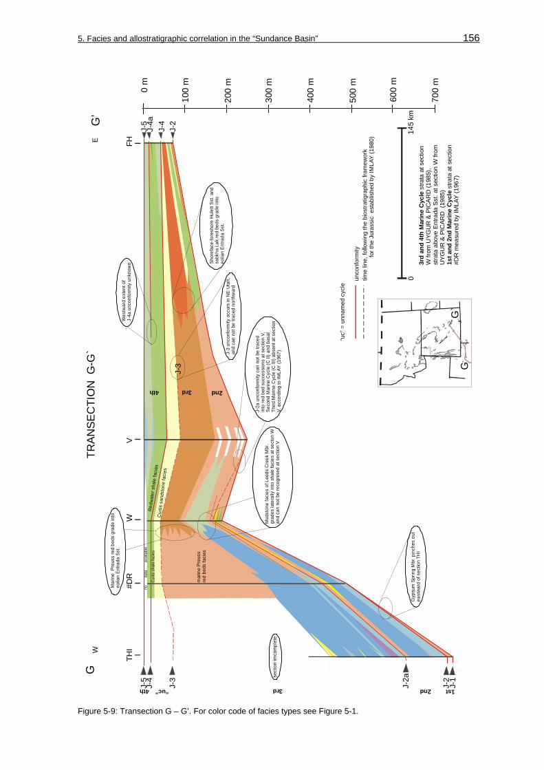
5. Facies and allostratigraphic correlation in the “Sundance Basin” 156
mar
ine
Preu
ssre
d be
ds fa
cies
Cu r
tis s
ands
tone
fac i
es
Cur
tis s
hale
faci
esR
edw
ater
sha
le fa
cies
1st2nd3rd4th
2nd3rd4th
no
d
ata
avai
labl
e0
m
100
m
200
m
300
m
400
m
500
m
600
m
700
m
G’
GE
WTR
AN
SE
CTI
ON
G-G
`
G`
G
VW
#DR
THI
FH
J-2
J-3
J-5
J-4
J-3
J-2a
J-2
J-1
J-4
J-4a
J-5
014
5 km
1st a
nd 2
nd M
arin
e C
ycle
stra
ta a
t sec
tion
#DR
mea
sure
d by
IMLA
Y (1
967)
3rd
and
4th
Mar
ine
Cyc
le s
trata
at s
ectio
nW
from
UYG
UR
&
(198
5),
stra
ta a
bove
Ent
rada
Sst
. at s
ectio
n W
from
U
YGU
R &
(1
985)
PIC
AR
D
PIC
ARD
sect
ion
imco
mpl
ete
Gyp
sum
Spr
ing
Mbr
. pin
ches
out
east
war
d of
sec
tion
THI
Mud
ston
e fa
cies
of L
eeds
Cre
ek M
br.
grad
es la
tera
lly in
to s
hale
faci
es a
t sec
ton
Wan
d ca
n no
t be
reco
gnis
ed a
t sec
tion
V
Mar
ine
Pre
uss
red
beds
gra
de in
to
eolia
n En
trada
Sst
.
Shor
efac
e-fo
resh
ore
Hul
ett S
st. a
nd
sabk
ha L
ak re
d be
ds g
rade
into
eo
lian
Entra
da S
st.
J-3
unco
nfor
mity
occ
urs
in N
E U
tah,
and
can
not b
e tra
ced
north
war
d
Wes
twar
d ex
tent
of
J-4a
unc
onfo
rmity
unk
now
n
J-2a
unc
onfo
rmity
can
not
be
trace
d in
to re
d be
d su
cces
sion
s at
sec
tion
V,Se
cond
Mar
ine
Cyc
le (C
II) a
nd b
asal
Third
Mar
ine
Cyc
le (C
III)
abse
nt a
t sec
tion
V, a
ccor
ding
to IM
LAY
(196
7)
unco
nfor
mity
time
line,
follo
win
g th
e bi
ostra
tigra
phic
fram
ewor
k
f
or th
e Ju
rass
ic e
stab
lishe
d by
IMLA
Y (1
980)
“uc”
= u
nnam
ed c
ycle
“uc”
Figure 5-9: Transection G – G’. For color code of facies types see Figure 5-1.

5. Facies and allostratigraphic correlation in the “Sundance Basin” 157
The Fourth Marine Cycle (C IV) is almost entirely siliciclastic, with some thin interbeds of bioclastic carbonates within the Redwater Shale Member of the Sundance Formation at sections Hulett (HU), Hyattville (HY) and Greub Road (#GR) in transection D – D’. The thickness pattern is continuous and paleotopographic elements were eroded during origin of the J-4 unconformity (SCHMUDE 2000). The Fourth Marine Cycle (C IV) shows strong similarities in the transections D – D’, E – E’ and F – F’ in respect to allostratigraphy, thickness and facies pattern. The lithology of the Redwater Shale Member that is reflected in this unit is composed by the shale lithofacies and the silt lithofacies. At section Vernal (V), in transection G – G’ 0,5-5 m thick oolitic beds are discontinuously intercalated into the shale lithofacies. The allounit is truncated by the J-5 unconformity. In this part of the southern “Sundance Basin” many workers reported the contact to the overlying Morrison Formation to be conformable. UYGUR & PICARD (1985) reported a transition from glauconitic marine sediments into stream and flood plain deposits of the succeeding Late Jurassic Morrison Formation.
5.2 Spatial facies distribution within sedimentary cycles: facies maps
To display the spatial distribution of facies types and facies domains within the sedimentary cycles basinwide facies maps were compiled for certain time intervals.
Based on the chronostratigraphic framework (see chapter: 2.3, Lithostratigraphy and Figure 2-3) established by IMLAY (1980) the facies maps were compiled for defined stratigraphic members and correlative formations. For instance, facies maps can be produced for the correlative stratigraphic interval of the Hulett Sandstone Member of the Sundance Formation, the Giraffe Creek Member of the Twin Creek Limestone, the Winsor Member of the Carmel Formation and the upper portion of the Rierdon Formation of the Third Marine Cycle (C III). If the stratigraphic relation between intervals is poorly documented, like for the Gypsum Spring Formation and Nesson Formation of the First Marine Cycle (C I), a map of the average facies distribution was produced. Due to the limited stratal preservation and distribution no facies maps were compiled for the “unnamed cycle”.
The basic paleogeographic map that was used for the facies maps corresponds to the paleogeographic map of the “Sundance Basin” structure with individual paleotectonic elements compiled from PETERSON (1954; 1957a and b; 1958), KOCUREK & DOTT (1983), BLAKEY et al. (1983), BLAKEY (1988), PETERSON, F. (1986; 1994), BRENNER (1983), IMLAY (1980), SCHMUDE (2000) (see chapter 2.2, Paleogeography and Figure 2-2). Additional information about paleotectonic elements, contemporaneous igneous rocks and paleowind directions derived from PETERSON, F. (1994). The color code for the displayed facies types is shown in the explanation chart in Figure 5-1.

5. Facies and allostratigraphic correlation in the “Sundance Basin” 158
Facies map for the First Marine Cycle (C I) (Aalenium to Lower Bajocian)
Stratigraphically, the Nesson Formation in the Williston Basin area, the Gypsum Spring Formation in northwestern Wyoming, the Gypsum Spring Member of the Twin Creek Limestone in western Wyoming and eastern Idaho, and the Sinawava and White Throne Member of the Temple Cap Sandstone in the southwestern corner of Utah are presented in Figure 5-10. Comprehensive facies maps for this interval are rare. Additional data for this map was obtained from RIGGS & BLAKEY (1993), PETERSON, F. (1994), PETERSON (1972), PETERSON (1994), PETERSON et al. (1987), BRENNER & PETERSON (1994), FILIPPICH (2001), and IMLAY (1980). As reported by BRENNER & PETERSON (1994) and SCHMUDE (2000), the occurrence of post-J-2 deposits of the
sandy limestone & red shale
anhydrite&
limestoneof
Nesson Formation
red shale & siltstone
evap
orite
s,
red s
hale
& sil
tston
e,
limes
tone
eolianites
AncestralRockyMtns. ?
red beds, limestone
and local evaporitic
deposits
Facies map for the First Marine Cycle (C I)(Aalenium to lower Bajocian: Gypsum Spring-Nesson-Temple Cap interval)
0 300 km100 200
?
Magmatic Arc Mogollon Slope
Graben Depression
Williston Basin
?
Wind directionContemporaneous igneous rocks
MT NDUSACANADA
SD
WY
CO
NB
KA
TX
OKNMAZ
NV UT
ID
CA
MEXICO
position of study area
Area with positive relief
Figure 5-10: Facies map for the First Marine Cycle (C I). For color code of facies types see Figure 5-1. The basic paleogeographic map was compiled from PETERSON (1954; 1957a and b; 1958), KOCUREK & DOTT (1983), PETERSON, F. (1986; 1994), IMLAY (1980).

5. Facies and allostratigraphic correlation in the “Sundance Basin” 159
Second Marine Cycle (C II) in direct stratigraphic contact with sub-J-1 rocks of the Navajo Sandstone indicate that the depositional area of the First Marine Cycle (C I) was much more extensive and large portions were obviously removed during formation of the J-2 unconformity (JOHNSON 1992).
The stratal record of the First Marine Cycle (C I) comprise peritidal red beds and evaporites as well as shallow subtidal carbonates. Two characteristic sedimentation and facies domains are illustrated in the facies map:
• The Williston Basin where the carbonates and evaporites of the Nesson Formation formed.
• Northwestern Wyoming and northern Utah where the red bed-carbonate-gypsum successions of the Gypsum Spring Formation are deposited.
Facies map for the Second Marine Cycle (C II)
A facies map for the time interval from the Middle Bajocian to the earliest Bathonian is illustrated in Figure 5-11 for the Second Marine Cycle (C II). Stratigraphically, the Harris Wash Tongue of the Page Sandstone, the Judd Hollow Member of the Carmel Formation, the Sliderock and Rich Member of the Twin Creek Limestone, the lower parts of the Sawtooth Formation and the Piper Formation are displayed. In the southern part of the “Sundance Basin”, facies changes have been noticed and described by BLAKEY et al. (1983) in east–west oriented facies belts ranging from supratidal, intertidal to subtidal environments. These facies belts can be traced continuously over a few 100 kilometers into northeastern Utah and are found at sections Thistle (THI), Whiterocks Canyon (W) and Flaming Gorge (FG). In the northern projection the continuous facies belts grade transitionally into more isolated oolite facies types along the Idaho-Wyoming border. In Wyoming, the “Black Mountain High” represents a large platform with numerous anticlinal and synclinal features (SCHMUDE 2000). The edge between this platform and the adjacent “Utah-Idaho trough” displays contrasting depositional realms. Deposition on the “Black Mountain High” platform is characterized by clay- and siltstones (red beds), thin-bedded evaporites and carbonates (bindstones, biograinstones, mudstones) representing peritidal, intertidal to shallow subtidal environments. To the north siliciclastic sedimentation of green to grayish-green shales, detritic mudstones and nodular gypsum beds in normal marine shallow subtidal environments prevailed.
Three characteristic sedimentation and facies domains are present in the facies map:
• The “Utah-Idaho trough” in the southern and western portions of the “Sundance Basin” is characterized by marine carbonate sedimentation.
• The “Belt Island Complex” area comprises marine sedimentation of fine-grained siliciclastics.
• The greater Williston Basin area that includes the Bighorn Basin in northwestern Wyoming is characterized by red bed-carbonate-gypsum sedimentation.

5. Facies and allostratigraphic correlation in the “Sundance Basin” 160
red b
eds, l im
estone
&
gypsum
oopa
cksto
nepe
lmicr
itegy
psife
rous
mud
ston
e
dolo
micr
itecr
oss-
bedd
ed
sand
ston
e
shale & limestone
shale &
silty limestone
shale
mud
ston
e &
biom
icr it
ebi
omud
-
ston
esh
ale &
silty
limes
tone
?
?
?
Facies map for the Second Marine Cycle (C II)(Midde Bajocian to Early Bathonian: Sliderock/Rich-Sawtooth-Piper-Judd Hollow interval)
MT ND
ID
UT
CA
Wes
tern
E
lko
H
ighl
ands
AncestralRockyMtns. ?
Magm
atic Arc Mogollon Slope
Graben Depression
Belt Isla
nd
Complex
Williston Basin
?
?
ID“Black Mtn.
High”
Area with positive relief
0 300 km100 200
Wind direction
Contemporaneous igneous rocks
USACANADA
SD
WY
TXOKNM
AZ
NV
NB
CO
KA
MEXICO
position of study area
Figure 5-11: Facies map for the Second Marine Cycle (C II). For color code of facies types see Figure 5-1. The basic paleogeographic map was compiled from PETERSON (1954; 1957a and b; 1958), KOCUREK & DOTT (1983), BLAKEY et al. (1983), BLAKEY (1988), PETERSON, F. (1986; 1994), IMLAY (1980), SCHMUDE (2000).
Facies maps for the Third Marine Cycle (C III)
Additional data for areas adjacent to the study area was obtained from the following sources: (a) southern “Sundance Basin”: BLAKEY et al. (1983) and KOCUREK & DOTT (1983), (b) western and northern “Sundance Basin”: IMLAY (1957; 1967), PETERSON (1957a; 1972), HILEMAN (1973). Because the correspondence between stratigraphic intervals is reliable within the Third Marine Cycle (C III), two facies maps can be compiled for the Middle and the Late Bathonian to illustrate the increasing influence of siliciclastic sedimentation and the development of facies domains.
Facies map C III-A in Figure 5-12 covers the time interval from the early to the late Middle Bathonian. In a stratigraphic context the unit represents the Paria River Member of the Carmel Formation, Watton Canyon Member of the Twin Creek Limestone, the basal part of the Twelvemile Canyon Member, and the “limestone” Member of the Arapien Shale, the

5. Facies and allostratigraphic correlation in the “Sundance Basin” 161
basal parts of the Rierdon Formation, and the Canyon Springs Sandstone Member of the Sundance Formation. In the southern “Sundance Basin”, facies types are trending 90° different and are east-west oriented as shown in facies maps published by BLAKEY et al. (1983). This configuration differs from the facies orientation in the facies map for the Second Marine Cycle (C II) in Figure 5-11. As concluded by BLAKEY et al. (1983), this stratigraphic interval is characterized by the shift from stagnant/regressive conditions to readvancing marine environments. Obviously, the southward directed marine advance is reflected by the facies orientation. Siliciclastic sedimentation dominated in most parts of Montana, North Dakota, eastern Wyoming, and Canada, while carbonates were deposited in the “Utah-Idaho Trough” and on the south flank of the “Belt Island Complex”.
?
?
gyps
um
mudsto
ne
& gy
psum
dolomicrite
LX-lf
LX-lf
LX-lf
large
-scale
cross-
bedde
d lf
“Brown Shale
”
lenticular to
flaser b
edded lf
mudstone
oolit ic &
peloidal
grains tone
limy shale
shale
oo li t ic
oolit i
coo
l iti coo lit ic
?
?
?
shale lf
MT ND
ID
UT
CA
Wes
tern
E
lko
H
ighl
ands
AncestralRockyMtns. ?
Magm
atic Arc Mogollon Slope
Graben Depression
Belt I
sland
Com
plex
Williston Basin
ID
CO
NB
TXOK
AR
NV
MEXICO
0 300 km100 200
Wind directionContemporaneous igneous rocks
NM
SD
WY
USACANADA
KA
C III-A: Facies map for the Third Marine Cycle (C III)(early to late Middle Bathonian: Watton Canyon-Canyon Springs-
Rierdon-Paria River interval)
position of study area
red
beds
shale
Area with positive relief Figure 5-12: Facies map C III-A for the Third Marine Cycle (C III). For color code of facies types see Figure 5-1. The basic paleogeographic map was compiled from PETERSON (1954; 1957a and b; 1958), KOCUREK & DOTT (1983), BLAKEY et al. (1983), BLAKEY (1988), PETERSON, F. (1986; 1994), IMLAY (1980).

5. Facies and allostratigraphic correlation in the “Sundance Basin” 162
Facies map C III-B in Figure 5-13 shows the time interval from the Late Bathonian to the Early Callovian. In stratigraphic terms the Twistgulch Member and the “sandstone” Member of the Arapien Shale, the upper part of the Rierdon Formation, the Hulett and Lak Members of the Sundance Formation, the upper part of the Winsor Member of the Carmel Formation, the Giraffe Creek Member of the Twin Creek Limestone, the Entrada and Preuss Formations are displayed. In contrast to the previous facies pattern it is obvious that the carbonate sedimentation in the “Utah-Idaho Trough” is completely obliterated and replaced by siliciclastic sedimentation. The eastern and western marginal portions of the “Sundance Basin” are occupied by siliciclastic lithofacies types that represent shoreface-foreshore-sabkha facies types. In eastern Utah, western and southern Colorado, northern New Mexico, and northern Arizona, the extensive eolian sand sheet of the Entrada inland dune field is dominating.
Belt I
sland
Com
plex
red be
ds,
silty s
andsto
ne
and m
udsto
ne
large
-scale
cross
bedde
d
sand
stone
(LX lf)
Wind directionContemporaneous igneous rocks
shale & sa
ndstone
shale
red b
eds
gypsum
Preuss facies I
Preuss facies I I
WR &
Oo
lf
L-Fb
lfW
R & O
o lfL-Fb l f
oolitic
& pe
loida
l
?
shale
lf
LL lf
nearshore sandy facies
?
?
?
MT ND
ID
UT
Wes
tern
E
lko
H
ighl
ands
AncestralRockyMtns. ?
Blanding
Basin
Williston Basin
Mogollon Slope
Graben Depression
Magm
atic Arc
position of study area
Area with positive relief
Figure 5-13: Facies map C III-B for the Third Marine Cycle (C III). For color code of facies types see Figure 5-1. The basic paleogeographic map was compiled from PETERSON (1954; 1957a and b; 1958), KOCUREK & DOTT (1983), BLAKEY et al. (1983), BLAKEY (1988), PETERSON, F. (1986; 1994), IMLAY (1980).

5. Facies and allostratigraphic correlation in the “Sundance Basin” 163
Four characteristic sedimentation and facies domains occur in the facies maps:
• The “Utah-Idaho trough” in the southern and western portions of the “Sundance Basin” is characterized by marine carbonate sedimentation and is progressively occupied by siliciclastic sedimentation.
• In the “Belt Island Complex” area marine sedimentation of carbonates on its southern flank existed, while fine-grained siliciclastics were continuously deposited on the eastern and northern flanks.
• The Williston Basin is characterized by continuous sedimentation of fine-grained siliciclastics.
• In eastern South Dakota and Wyoming shallow marine siliciclastic sediments and mixed clastic-carbonate successions were deposited.
Facies maps for the Fourth Marine Cycle (C IV)
Additional information to supplement the data from the 2-dimensional facies transections within the Fourth Marine Cycle (C IV) was obtained from PETERSON, F. (1994), PETERSON (1972), BRENNER & PETERSON (1994), SCHMITT (1953), IMLAY (1980), LANGTRY (1983), HAYES (1984), KREIS (1991), BRENNER & DAVIES (1974), and JORDAN (1985). Since the correspondence between stratigraphic intervals is reliable within the Fourth Marine Cycle (C IV) two facies maps can be produced for the Early and the Middle Oxfordian to illustrate the increasing influence of siliciclastic sedimentation and the development of facies domains.
Facies map C IV-A in Figure 5-14 covers the time interval of the Early Oxfordian. In stratigraphic terms, the Redwater Shale Member of the Stump Formation and Sundance Formation, the “shale” unit of the Swift Formation and the lower part of the Masefield Shale Formation are represented. Sedimentation in the “Sundance Basin” is entirely dominated by fine-grained siliciclastics, while coarse-grained sands are transported into the basin from marginal areas. Carbonates are limited to minor occurrences of skeletal grainstones as identified by LANGTRY (1982) in the Williston Basin or bioclast-rich storm deposits (biowackestones and biopackstones) as found at sections Hyattville (HY), Red Rim Ranch (RR), Red Lane (RL), Squaw Women Creek (SWC), and Hulett (HU).
Facies map C IV-B in Figure 5-15 represents the time interval of the Middle Oxfordian. In stratigraphic terms, the upper part of the Redwater Shale Member of the Stump Formation (“sandstone unit”) and Sundance Formation, the “ribbon sandstone” unit of the Swift Formation and the upper part of the Masefield Shale Formation are illustrated. The lithofacies is composed of glauconitic sandstones, siltstones and minor amounts of shale. The dominant clastic input derived from western surrounding areas (JORDAN 1985, HILEMAN 1973, BRENNER & PETERSON 1994).

5. Facies and allostratigraphic correlation in the “Sundance Basin” 164
silt
dark mud
shale
biocla
stic o
ffsho
re ba
rs
shale lf
?
?
glau
coni
tic lf
clastic transport
glauconitic nearshore sands ?
MT ND
ID
UT
Alberta
Trough
Easter
n Elko
High
lands
Erosion - Nondeposition ?
Powde
r Rive
r Emba
ymen
t
BeltIsl
and
Comple
x
Saskatchewan ShelfAlberta Shelf
Mogollon Slope
Graben Depression
Magm
atic Arc
Williston Basin
C IV-A: Facies map for the Fourth Marine Cycle (C IV)(Early Oxfordian: Redwater Shale-Swift interval)
CO
NB
TXOKAR
NV
MEXICO
0 300 km100 200
NM
SD
WY
USACANADA
KA
position of study area
Contemporaneous igneous rocksArea with positive relief
Figure 5-14: Facies map C IV-A for the Fourth Marine Cycle (C IV). For color code of facies types see Figure 5-1. The basic paleogeographic map was compiled from PETERSON (1954; 1957a and b; 1958), PETERSON, F. (1986; 1994), BRENNER (1983), IMLAY (1980).
Three characteristic sedimentation and facies domains occur in the facies maps:
• A major western source area that includes the “Belt Island Complex” provided coarse-grained clastic material. From these source areas impure, glauconitic sediments were transported progressively southeast and eastward. As pointed out by BRENNER (1983), this dispersal of sand-size detritus from an active western source area is representative for the final progradational phase in the “Sundance Basin”. Facies patterns investigated by PETERSON (1957a; 1972) and HILEMAN (1973) and sediment petrographic data from JORDAN (1985) and BRENNER (1983) indicate that the primary source of clastic sediments that represent the Fourth Marine Cycle (C IV) was a slowly rising western magmatic arc or orogenic belt which extended from northern Utah into southeastern Idaho.
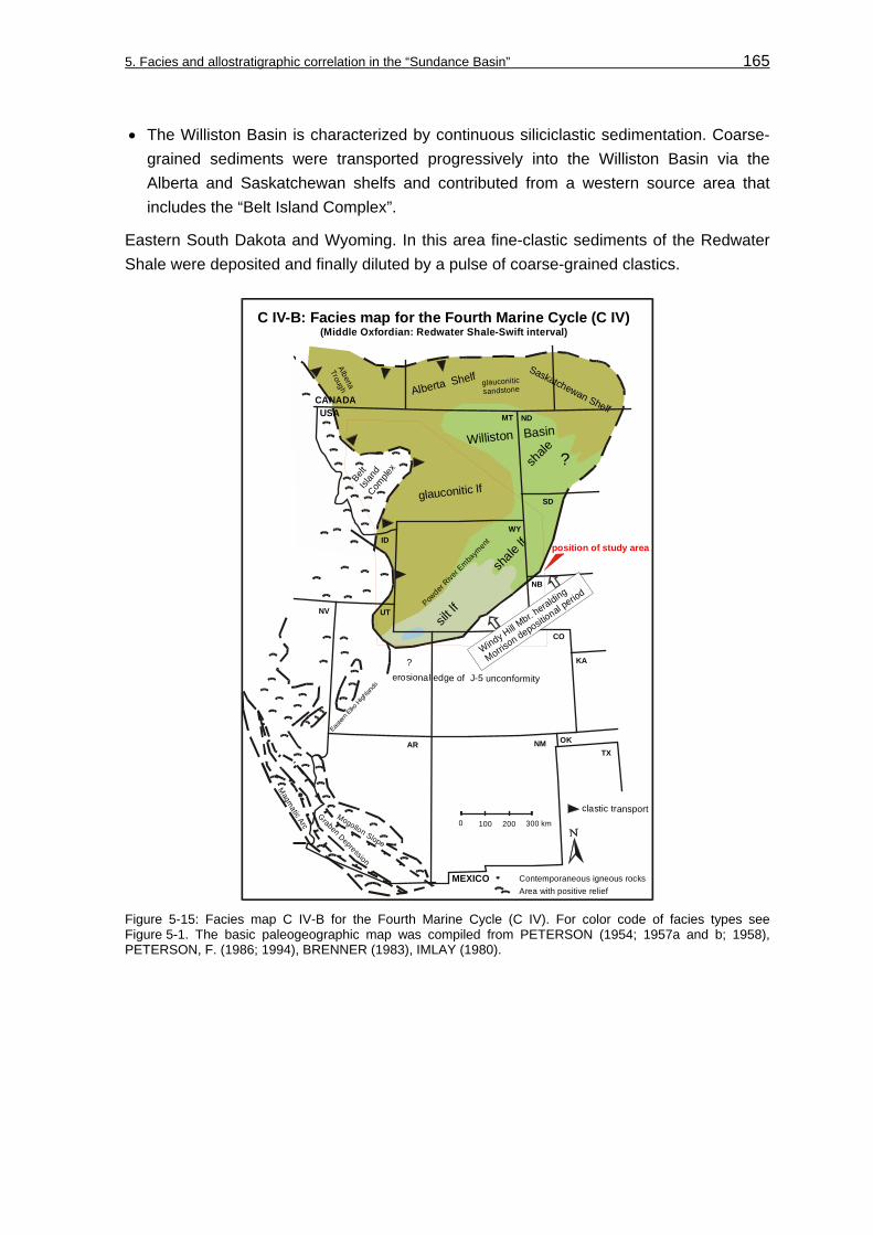
5. Facies and allostratigraphic correlation in the “Sundance Basin” 165
• The Williston Basin is characterized by continuous siliciclastic sedimentation. Coarse-grained sediments were transported progressively into the Williston Basin via the Alberta and Saskatchewan shelfs and contributed from a western source area that includes the “Belt Island Complex”.
Eastern South Dakota and Wyoming. In this area fine-clastic sediments of the Redwater Shale were deposited and finally diluted by a pulse of coarse-grained clastics.
silt lf
shale
lf
?glauconitic lf
clastic transport
glauconitic sandstone
shale ?
MT ND
ID
UT
Alberta
Trough
Easter
n Elko
High
lands
?
Powder
River E
mbaym
ent
Saskatchewan Shelf
Alberta Shelf
erosional edge of J-5 unconformity
Magm
atic Arc
Mogollon Slope
Graben Depression
Williston Basin
BeltIsl
and
Comple
x
CO
NB
TXOKAR
NV
MEXICO
0 300 km100 200
NM
SD
WY
USACANADA
KA
C IV-B: Facies map for the Fourth Marine Cycle (C IV)(Middle Oxfordian: Redwater Shale-Swift interval)
Windy Hill M
br. heralding
Morrison depositi
onal period
position of study area
Contemporaneous igneous rocksArea with positive relief
Figure 5-15: Facies map C IV-B for the Fourth Marine Cycle (C IV). For color code of facies types see Figure 5-1. The basic paleogeographic map was compiled from PETERSON (1954; 1957a and b; 1958), PETERSON, F. (1986; 1994), BRENNER (1983), IMLAY (1980).

5. Facies and allostratigraphic correlation in the “Sundance Basin” 166
5.3 Spatial and temporal facies characteristics: 3-dimensional facies correlation
The 2-dimensional facies correlation provides information about the spatial and temporary facies evolution within the “Sundance Basin”. This information will be used in the further course of this study to identify depositional sequences and their boundaries within the stratigraphic record of the major sedimentary cycles. The results of the 2-dimensional facies correlation will be summarized in this chapter and displayed in 3-dimensional facies diagrams in Figure 5-16 to Figure 5-19. Due to the limited stratal preservation and distribution no fence diagram was constructed for the “unnamed cycle”. The color code is shown in the explanation chart in Figure 5-1.
THI
TC
TF
SE-HY HU
BESBC
LAN
SC
~25m
WILLISTON BASINanhydrite
&limestone
ofNesson Formation
red beds, limestone
and local evaporitic
deposits
Gyp
sum S
pring
facie
s und
ivide
d
undivided
undivided
undivided
homoclinal ramphomoclinal rampRampmorphology
position of transections
emerged area
emerg
ed ar
ea
position of transections
Approximate extend of “Sundance Basin” accordingto paleogeographic maps of IMLAY (1980)
Figure 5-16: 3-dimensional facies correlation for the First Marine Cycle (C I). For color code of facies types see Figure 5-1. For full names and position of sections see Figures 1-1 and 1-2.

5. Facies and allostratigraphic correlation in the “Sundance Basin” 167
It is obvious, from the 2-dimensional transections and facies maps that each sedimentary cycle is characterized by an individual distribution of facies types, lithology and thickness pattern. A persisting facies domain and paleotectonic element is the Williston Basin in all sedimentary cycles.
The sedimentary cycle C I is basinwide traceable and correlative (see Figure 5-16). The spatial extent and stratal preservation are strongly controlled by the bounding J-2 unconformity. The facies distribution and facies models for the sedimentary cycle C I describe shallow subtidal to peritidal depositional environments. A homogenous supratidal to peritidal red bed facies is unconformably interrupted by thin, but widespread peritidal to shallow subtidal carbonate beds that indicate repeated advance of marine conditions into the depositional settings. Depositional settings are described by toward each other oriented homoclinal ramps as schematically shown in Figure 5-16. In marginal and poorly exposed portions of the “Sundance Basin” the facies of the First Marine Cycle (C I) is labeled as undivided.
The facies distribution and facies model for the sedimentary cycle C II reveal sedimentation of peritidal red beds and shallow subtidal carbonate beds of the Piper Formation in the Williston Basin and northwestern Wyoming. The spatial extent and stratal preservation of the sedimentary cycle are strongly controlled by the J-2a unconformity and the stratal onlap onto paleotopographic elements like the “Black Mountain High” in Wyoming (see Figure 5-17). Like in the preceding cycle C I a homogenous supratidal to peritidal red bed facies in northwestern Wyoming is unconformably interrupted by thin, but widespread peritidal to shallow subtidal carbonate beds that indicate repeated advance of marine conditions into the depositional settings. These facies shifts occur frequently in the Piper Formation, while facies contrasts in the Sawtooth Formation are slight in Montana. Depositional settings of the sedimentary cycle C II in southwestern Wyoming and eastern Idaho are described by a ramp morphology with distally steepened gradients toward the “Utah-Idaho trough” as schematically shown in Figure 5-17. With onset of the Second Marine Cycle (C II) the facies domain of the “Utah-Idaho trough” evolved and shallow to normal marine carbonates of the Twin Creek Limestone were deposited. The spatial facies relations are recorded by wide, more or less east-west oriented and north-south trending facies belts that range from supratidal distally into subtidal environments.
During deposition of the sedimentary cycle C III (see Figure 5-18), particular facies domains like the carbonate facies realm of the “Utah-Idaho trough”, the mixed carbonate-siliciclastic facies of the “Belt Island Complex”, the fine clastic sediments of the Williston Basin, and the mixed carbonate-siliciclastic facies realm of the “Wyoming shelf” were constituted. The facies distribution and facies model for the cycle C III reveal a differentiation between shallow and normal marine siliciclastic and mixed carbonate-siliciclastic facies types of the Sundance Formation in the eastern “Sundance Basin” and marine carbonate facies types of the Twin Creek Limestone in the “Utah-Idaho trough” and the Rierdon Formation on the south flank of the “Belt Island Complex” (see Figure 5-18). In the distal portion of a steepened ramp shallow to normal marine

5. Facies and allostratigraphic correlation in the “Sundance Basin” 168
carbonates of the Twin Creek Limestone were deposited. Carbonate sedimentation in the “Utah-Idaho trough” was finally surpressed with the progradation of thick red bed successions of the Preuss Formation during the Third Marine Cycle (C III). Deposition of the siliciclastic dominated Sundance Formation occurred in the proximal portion.
cross-bedded, eolian
Page Sandstone
~ 50m
distally steepened ramp Rampmorphology
Approximate extend of “Sundance Basin” accordingto paleogeographic maps of IMLAY (1980)
emerged area
emerged area
position of transections
emerged area
bounding J-2 unconformity
Figure 5-17: 3-dimensional facies correlation for the Second Marine Cycle (C II). For color code of facies types see Figure 5-1. For full names and position of sections see Figures 1-1 and 1-2.
The facies distribution and the facies model for the cycle C IV describe depositional environments of a homoclinal ramp and normal marine to intertidal sedimentation of glauconitic fine- to coarse-grained successions (see Figure 5-19). The stratal preservation is strongly controlled by the bounding unconformities J-4a and J-5. The spatial distribution

5. Facies and allostratigraphic correlation in the “Sundance Basin” 169
and the evolution of facies types is monotonous. Facies shifts are very minor. Distinct facies domains like the “Utah-Idaho trough” can no longer be identified in contrast to conditions found in the preceding sedimentary cycles. In addition, the “Sundance Basin” regained its symmetric geometry. As also shown in the facies maps for this interval only the Williston Basin presents a facies domain in which fine siliciclastic material was
~50 m
AR
MINSPC
SWC
HU TR
SBC#BAR
HR
FH
HY
#CD
HE
RL
LW
BE
FG
SR
SC
TF
LB
V
THI
?
intertidal &supratidalPreuss facies II
prodeltaic Preuss facies I
prode
ltaic
Preus
s fac
ies I
intertidal &supratidalPreuss facies II
distally steepened ramp Rampmorphology
position of transectionsposition of transections
emerged area
Approximate extend of “Sundance Basin” accordingto paleogeographic maps of IMLAY (1980)
emerged area
position of bounding unconformities
SRC
SAP
RC
W
Figure 5-18: 3-dimensional facies correlation for the Third Marine Cycle (C III). The “unnamed cycle” is not displayed. For color code of facies types see Figure 5-1. For full names and position of sections see Figures 1-1 and 1-2.

5. Facies and allostratigraphic correlation in the “Sundance Basin” 170
deposited. The most obvious facies shifts are recorded where coarse-grained sandstones are transported via the bordering Alberta and Saskatchewan shelfs into the basin. The glauconitic sandstones grade toward the Williston Basin into glauconitic siltstones and shales.
RC
AR
MINSPC SWC
HUGRHY#BBD
HR
FH
CD
HE
V
#DR
homoclinal ramphomoclinal rampRampmorphology
emerged area
Approximate extend of “Sundance Basin” accordingto paleogeographic maps of IMLAY (1980)emerged area
position of transectionsposition of transectionsposition of bounding unconformitiesclastic transport
SRSRC
LW
SAP
BE
FG
~50 m
Figure 5-19: 3-dimensional facies correlation for the Fourth Marine Cycle (C IV). For color code of facies types see Figure 5-1. For full names and position of sections see Figures 1-1 and 1-2.

171
6 Stratigraphic concepts for the “Sundance Basin”
6.1 Cyclostratigraphic concept for the “Sundance Basin”
On the basis of lithofacies, biofacies, and bounding unconformities BRENNER & PETERSON (1994) defined major sedimentary cycles within the “Sundance Basin” fill. This cyclostratigraphic subdivision was modified for the purpose of this study as explained in chapter Cyclostratigraphy (2.5. and Figure 2-30). The basinwide identification of major cycles by BRENNER & PETERSON (1994) is confirmed in this study, but additional subordinate transgressive-regressive sequences are evident in the stratigraphic record.
Before the basinwide correlation of the major sedimentary cycles and their associated sequences are discussed some theoretical considerations about cyclostratigraphic concepts are made.
6.1.1 Theoretical considerations
Transgressive-regressive sedimentary cycles are controlled by the interplay between subsidence, sediment supply, submarine erosion, and sediment bypassing at different locations within a basin. Strictly symmetric cycles develop only under very special conditions (EINSELE & BAYER 1991). The development of asymmetric cycles is much more common in the geological record and displayed in Figure 6-1. The sediment accumulation and submarine erosion at proximal and distal locations within a basin are illustrated after EINSELE & BAYER (1991). Location I and II are located in a proximal position, while location III represents a distal position. The conceptual model of EINSELE & BAYER (1991) is based on the following assumptions:
• The sea-level oscillation is sinusoidal and the storm wave base varies parallel to the sea-level.
• The rate of subsidence and sediment supply is constant throughout time.
In consequence the situation at certain distinct locations within a basin can be described as follows:
Locations I & II: Sedimentation rate > subsidence rate. Highstand deposits are partly eroded during sea-level fall. Resulting unconformities are marked by lag deposits and/or incised channels. At location I repeated deepening upward sequences developed during sea-level rise, while at location II deepening-upward trends are followed by shallowing upward sequences (EINSELE & BAYER 1991).
Location III: Sedimentation rate = subsidence rate. No long-term trend in sediment characteristics, but cyclic patterns are recorded as deepening and shallowing upward sections (EINSELE & BAYER 1991).

6. Stratigraphic concepts for the “Sundance Basin” 172
SEA-LEVEL
STORM WAVE BASE
EROSIONALUNCONFORMITY
WINNOWING
SHA
LLO
WIN
G&
PR
OG
RA
DIN
G
DEE
PEN
ING
PROXIMAL DISTAL
HIATUS
SUBSIDENCE>
SEA-LEVEL FALL
SUBSIDENCE<
SEA-LEVEL FALL
CHRONOSTRATIGRAPHICSEQUENCES
SEA-LEVELHIGH LOW
?
T I M
E
SH
ALL
OW
ING
&PR
OG
RAD
ING
DEE
PEN
ING
CYCLE
CYCLE
CYCLE
HIATUS
EROSIONALUNCONFORMITY
LOCATION I II III
?
DEE
PEN
ING
Figure 6-1: Model for the interplay between periodic sea-level fluctuation, storm wave base, constant subsidence, and sediment supply and resulting chronostratigraphic sequences (modified from EINSELE & BAYER 1991).
Of course it is unrealistic to assume factors like the subsidence rate and sediment supply as constant through the time of basin evolution. Instead, the sediment supply of terrigenous material from marginal areas will decrease during transgression, while during sea-level fall sediment will be eroded and bypassed from shallow into deeper basinal areas. According to EINSELE & BAYER (1991), the resulting chronostratigraphic sequences will not differ much from the discussed model with constant subsidence and sediment supply. The main differences would effect the time span of the stratigraphic gap and the resulting sequences with their “field water-depth curve” in the distal portions of the basin. These considerations will be of importance when water depth curves are constructed for the “Sundance Basin”.
6.1.2 Transgressive-regressive cycle and sequence identification within the “Sundance Basin”
In the relatively shallow “Sundance Basin”, sea-level changes should effect the depositional environments basinwide. Consequently, distinct subordinate transgressive-regressive signatures should be documented and are detectable in the examined stratigraphic sections. To display the correlation of subordinate transgressive-regressive signatures within the major sedimentary cycles the investigated sections were generalized

6. Stratigraphic concepts for the “Sundance Basin” 173
and a water depth column was attached to the stratigraphic column. The water depth column corresponds to the homoclinal and distally steepened ramp depozones 0, I and II (see chapter: 4, Facies modelling). In a next step, the depositional environment (zone 0, I and II) of a facies types was entered into the water depth column. In this way, relative water depth curves for every investigated section were constructed. The transgressive-regressive signatures of the resulting relative water depth curves were used for the identification and correlation of sedimentary cycles and subordinate sequences. The uppermost bounding unconformity of every allounit was chosen as datum for the correlation by graphical means. In a later step, the water depth curves are plotted against a Jurassic time scale and a relative sea-level curve for the “Sundance Basin” will be compiled from this data.
6.1.3 Resolution potential and precision of the relative water depth curves
Transgressive and regressive cycles and their bounding unconformities within the sedimentary fill of the “Sundance Basin” are evident and traceable over great distances. The identification of subordinate sequences is based on the integration of facies distribution (two and three-dimensional), allostratigraphic interfaces (see chapter: 5, Facies correlation) and the existing biostratigraphic framework for the study area. The common stratigraphic resolution is on the second-order (3-50 Ma) and third-order level (0,5-3 Ma), if the hierarchical definition of VAIL et al. (1991) is followed. More restricted is the detection of subordinate fourth-order cycles (0,1-0,5 Ma). Parasequences as defined by VAN WAGONER et al. (1990) belong to this category. They can be identified more easily in the siliciclastic basin fill than in carbonate lithologies, because the bounding marine flooding surfaces of the parasequences are recognizable by abrupt intercalations of shale beds in sandstone successions in proximal areas of the basin. Those parasequences are not traceable basinwide, but are of local extent. For instance, well developed parasequences in the Hulett Sandstone Member of the Sundance Formation are exposed in the Black Hills area. These parasequences were identified by AHLBRANDT & FOX (1997) and found during field work at the sections Minnekatha (MIN), Elk Mountain (EM), Stockade Beaver Creek (SBC), Hulett (HU), Thompson Ranch (TR), T cross T Ranch (T-T), and Spearfish (SF). The typical exposure of a parasequence is shown in Figure 6-2. This parasequence is considered to be equivalent to the shoreface-foreshore facies defined by AHLBRANDT & FOX (1997) at Red Canyon in respect to sediment structures (ripple lamination, flaser bedding), ichnofacies, coarsening upward, and shale-sandstone interbedding. Westward from the Black Hills the parasequences are not recognizable and the units appear laterally discontinuous.
A relatively high resolution in the scale of fifth-order cycles (0.01-0.2 Ma) can not be established in the stratigraphic record of the “Sundance Basin” with the applied facies analysis methods and the Middle and Late Jurassic biostratigraphy.

6. Stratigraphic concepts for the “Sundance Basin” 174
Figure 6-2: Coarsening upward shoreface-foreshore parasequence in the Hulett Sandstone Member at section Minnekatha (MIN). The parasequence starts in the low portion of the photo with light gray shale beds that are interpreted as lower shore deposits. Upward the shale grades transitionally into middle and upper shorefaces sandstones. Above the cliff this suite is bound on top by shale. The position of the hammer marks the transition from shoreface to foreshore deposition of wave rippled sandstones with Skolithos traces. This suite is considered to be equivalent to the shoreface-foreshore facies of AHLBRANDT & FOX (1997) at Red Canyon. Lower red arrow marks a rippled bedding plane, upper arrow a Skolithos trace. The hammer is 32 cm long.
6.2 Sequence stratigraphic concepts for the “Sundance Basin”: depositional, genetic and transgressive-regressive
Sequences are regional genetic stratigraphic units, bound by unconformities or corresponding correlative conformities (VAN WAGONER et al. 1990). A sequence can commonly be divided into distinct systems tracts that are deposited during a specific stage of a transgressive-regressive cycle. Additionally, sequences may consist of parasequences, equivalent to small-scale transgressive-regressive cycles. If parasequences are developed the corresponding systems tracts are defined by the stacking pattern of these building blocks. The recognition of a sequence depends mainly upon the delineation of significant breaks, markers and/or facies changes in the stratal record that document a bounding unconformity. A number of significant sequence boundaries is discussed and introduced in the chapter Allostratigraphy (see chapter: 2.4).

6. Stratigraphic concepts for the “Sundance Basin” 175
Additional boundaries are expressed as facies changes within the investigated sections. Consequently, the integration of facies analysis, allostratigraphy and biostratigraphy provides the basis to identify subordinate sequences and parasequences within the major sedimentary cycles.
In general, three types of sequences named depositional, genetic and transgressive-regressive have been defined and developed by various workers (VAN WAGONER et al. 1990, GALLOWAY 1989, EMBRY 1993). These different approaches to the stratigraphic analysis of basinfills are briefly introduced and the choice of a suitable concept for the “Sundance Basin” will be discussed.
6.2.1 Depositional sequence model
A sequence stratigraphic concept was invented and promoted by geologists from the EXXON Corporation in the late 1970’s and 1980’s. Influential publications concerning methods and application of this concept are from VAIL et al. (1977), POSAMENTIER et al. (1988a and b) and VAN WAGONER et al. (1990). SARG (1988) applied the depositional sequence concept and its definitions for carbonate depositional systems. In this concept the depositional sequence is defined by subaerial unconformities. Deposition in coastal and shallow marine environments and the deeper basin is affected by relative sea-level changes (EINSELE 1992). Usually, the unconformities are modified by shoreface erosion during ensuing transgression and then named ravinement surface. The stratigraphic surface that correlates with the maximum basinward extent of this unconformity is the correlative conformity. Theoretically, this depositional surface defines the phase of the maximum rate of relative sea-level fall. The bounding surfaces are commonly traced by seismic reflection profiling. Therefore, depositional sequences are treated as basic stratigraphic units in seismic stratigraphy.
AHLBRANDT & FOX (1997) applied this concept successfully in a local context to the Middle Jurassic stratigraphic interval of the Sundance Formation in the southern Black Hills area. In this area the lithologic contrasts within the Canyon Springs Sandstone and Hulett Sandstone are pronounced. Parasequences are locally developed and unconformable stratigraphic contacts are well expressed in this marginal part of the “Sundance Basin”.
In this study, the depositional sequence model was not used for a basinwide stratigraphic analysis of the “Sundance Basin” fill. The concept of depositional sequences was particularly invented for siliciclastic sediments in continental margin settings that comprise a shelf break, slope, and a deeper basin. EMBRY (1993: 302) stated that: “The main problem with the use of a depositional sequence for basin analysis is that the correlative conformity has little or no lithologic expression and cannot be objectively determined in most sections”. An important aspects, that restricts the basinwide application of the

6. Stratigraphic concepts for the “Sundance Basin” 176
depositional sequence concept is the primarily eustatic generation of sequences that is assumed by this concept. The “Sundance Basin” depositional configuration is strongly influenced by tectonic activities of the early Cordilleran orogeny.
6.2.2 Genetic sequence model
An alternative sequence stratigraphic unit is defined by the genetic stratigraphic sequence concept of GALLOWAY (1989). The bounding surface of a genetic sequence is the maximum flooding surface (GALLOWAY 1989) and reflected by low sedimentation rates and widespread submarine erosion that separates transgressive from regressive deposits (EMBRY & PODRUSKI 1988, THORNE & SWIFT 1991). In consequence, major sequence boundaries are shifted in phase by 180° from the depositional sequence concept of the EXXON Group (GALLOWAY 1989). Genetic sequence boundaries are commonly easy and objectively to recognize because of their distinctive lithologic change.
In detailed studies, BLAKEY et al. (1996), RIGGS & BLAKEY (1993), HAVHOLM et al. (1993), BLAKEY et al. (1988), and BLAKEY & JONES (1993) applied the concept to investigate eolian and marine–coastal plain interactions in the Page Sandstone – Carmel Formation interval in south-central Utah and northern Arizona. In this stratigraphic interval marine flooding surfaces can be identified and correlated between marine and eolian depositional systems. Thin marine marker beds of the marine Carmel sediments intertongue with the eolian Page Sandstone and continue as super-bounding surfaces (BLAKEY et al. 1996). In stratigraphic intervals, where contrasting depositional systems are expressed, the genetic sequence stratigraphy of GALLOWAY (1989) is a useful tool and produces good results. In parts of the study area monotonous sedimentary successions, as the Twin Creek Limestone, are exposed. The depositional environments range between shallow marine and normal marine. In settings where contrasts between depositional environment, lithology and associated facies types are low the bounding maximum flooding surface of a sequence is only poorly developed and can not be identified. Another problem with the basinwide application of the genetic sequence stratigraphy derives from the expression of the bounding unconformities. EMBRY (1993: 302) noted: “A major problem with a genetic stratigraphic sequence is that it contains a subaerial unconformity within it. Major depositional and tectonic changes often occur across such an unconformity, and thus a genetic stratigraphic sequence consists of two disparate stratigraphic units and is not a suitable genetic unit”.
Therefore, since maximum flooding surfaces as sequence boundaries are difficult to recognize in the study area the genetic stratigraphic sequence concept of GALLOWAY (1989) was not used for a basinwide stratigraphic analysis.

6. Stratigraphic concepts for the “Sundance Basin” 177
6.2.3 Transgressive-regressive sequence model
A transgressive-regressive sequence is identical to a T-R cycle as defined by (EMBRY 1993). This type of sequence is bound by subaerial (or ravinement) unconformities in marginal portions of a basin. In the basinward position sequences are bound by transgressive surfaces (EMBRY 1993). The transgressive surface marks the change from regression to transgression. The surface is lithologically distinctive and in most cases can be objectively defined. In other words, the transgressive-regressive sequence model is an integrated approach based on the identification of allostratigraphic units, transgressive surfaces and a hierarchical system of sequence boundaries as proposed by EMBRY (1993).
In general, the three discussed sequence models (depositional, genetic and transgressive-regressive) are applicable for siliciclastic and carbonate depositional systems. It became obvious from the application of the depositional sequence model by AHLBRANDT & FOX (1997) and the genetic sequence model by BLAKEY et al. (1996) that these concepts offer the opportunity to establish a sequence stratigraphic framework for the “Sundance Basin” only on local to regional scale. For a basinwide sequence stratigraphic concept the integrated transgressive-regressive sequence model of EMBRY (1993) was chosen in this study because:
• The transgressive-regressive sequence model is an appropriate concept for progressively evolving tectonic settings. Moreover, it is of special importance that the concept implies exclusively tectonic control on the generation of sequences.
• The alternative models are applicable only where lithologic and facies contrasts are pronounced.
• Transgressive surfaces and deposits can be identified in calcareous and siliciclastic successions in the “Sundance Basin”.
• The depositional sequence model and the genetic sequence model are applicable only locally or regionally in the “Sundance Basin”. The transgressive-regressive sequence model is not as closely focused on siliciclastic systems, but serves carbonate and mixed carbonate-siliciclastic systems as well.
• The required allostratigraphic framework for the transgressive-regressive sequence model is already provided in the “Sundance Basin” by the Jurassic bounding unconformities (J-0 to K-1) as defined by PIPIRINGOS & O’ SULLIVAN (1978).

6. Stratigraphic concepts for the “Sundance Basin” 178
In distal successions and even in relatively monotonous lithologies transgressive surfaces are recognizable in the basin fill. The author agrees with EMBRY (1993) who stated: “The T-R sequence is judged to be the best type of sequence for regional basin analysis because subaerial unconformities form its boundaries and do not occur within it and the designated correlative conformity, the transgressive surface, can be recognized in most cases.”
The differences in the definition of bounding surfaces between the discussed depositional, genetic and transgressive-regressive stratigraphic sequences are shown in Figure 6-3. Sequence boundaries in the genetic sequence model are related to maximum flooding surfaces. The boundaries in the depositional sequence model are equivalent to the T-R sequence model, but basinward the correlative boundaries are poorly expressed in the lithology. In the T-R model unconformable contacts are best developed in marginal portions of the basin. Basinward these unconformities are represented by transgressive surfaces (TS) and their associated deposits.
Figure 6-3: Schematic cross-section showing the definition of sequence boundaries in siliciclastic deposystems for the discussed depositional, genetic and transgressive-regressive stratigraphic sequences. The boundaries for the T-R and the depositional sequence are identical on the basin margin (subaerial unconformities/ravinements) and diverge basinward (from EMBRY 1993).

6. Stratigraphic concepts for the “Sundance Basin” 179
A sequence can be subdivided into systems tracts that are defined as a linkage of contemporary depositional sequence (VAN WAGONER et al. 1990). The definition of systems tracts was initially developed for siliciclastic systems, but the definition can be also used for carbonate depositional systems as demonstrated by SARG (1988) and POSAMENTIER & JAMES (1993).
Systems tracts for the transgressive-regressive sequence model reflect contemporaneous depositional environments that existed during the origin of a particular sequence. In the transgressive-regressive sequence model two systems tracts are defined:
• Transgressive systems tract (TST) that includes the stratal record between the basal bounding unconformity and the maximum flooding surface.
• Regressive systems tract (RST), which comprises strata between the maximum flooding surface and the upper bounding unconformity (EMBRY 1993). The regressive systems tract (RST) includes highstand systems tracts and lowstand systems tracts or shelf-margin systems tracts of the succeeding depositional sequence as defined in the depositional sequence model.

180
7 Sequence stratigraphic correlation in the “Sundance Basin”
As demonstrated in the previous chapter, the transgressive-regressive sequence concept highlighted by EMBRY (1993) was considered to offer the most suitable approach for a sequence stratigraphic analysis of the entire “Sundance Basin”. This decision is supported by the basinwide applicability of the concept, the independence from lithologic expressions, the recognition of transgressive surfaces and deposits by the facies analysis, and an established allostratigraphic framework for the “Sundance Basin”.
As further demonstrated in the chapter Cyclostratigraphy (see chapter: 2.5, Figure 2-31), the hierarchical sequence definition of VAIL et al. (1991) is followed in this study. Consequently, the sedimentary cycles are assigned with a second-order rank on the basis of their duration. In turn, subordinate sequences are in the third-order or fourth-order rank. In the major sedimentary cycles subordinate sequences can be correlated for large portions of the “Sundance Basin”. Despite the stratal incompleteness the internal architecture can be reconstructed. Internally, the sedimentary cycles and their sequences are composed of facies successions that represent contemporaneous depositional systems. In the sequence stratigraphic nomenclature these facies successions are equivalent to systems tracts. Transgressive (TST) and regressive (RST) systems tracts for second-order sedimentary cycles will be indicated in the sequence correlation graphics in this chapter. Thus, within the third-order sequences genetically related and contemporaneous facies successions in transgressive and regressive systems tracts can be identified as well. These successions will be termed transgressive (TC) and regressive (RC) complexes in the further course of this study. With this modified nomenclature the third-order systems tracts TC and RC are distinguished from the second-order systems tracts TST and RST of the sedimentary cycles.
In this chapter, the basinwide correlation of the second-order sedimentary cycles and their second-order systems tracts, subordinate third-order sequences, sequence boundaries, and transgressive (TC) – regressive (RC) complexes are explained.
7.1 Correlation and hierarchy of third-order sequences within second-order sedimentary cycles
7.1.1 First Marine Cycle (C I)
The First Marine Cycle (C I) represents the Gypsum Spring Formation in most parts of Wyoming and South Dakota. In the “Overthrust Belt” area, in western Wyoming and the Uinta Mountains of Utah the Gypsum Spring Formation is included as the basal member into the Twin Creek Limestone. The sequence correlation is shown in Figure 7-1.

7. Sequence stratigraphic correlation in the “Sundance Basin” 181
RCRC
TCRCRC
TC
RCRC TC
RC TCRC
RC RC TC
RCRC TC
RST TST
Dat
um
J-2
3rd order
3rd order
3rd order
3rd order
3rd order
3rd order
2nd ordersequence
regr
essi
ve s
yste
ms
tract
s se
nsu
EMBR
Y (1
993)
trans
gres
sive
sys
tem
s tra
cts
sens
u EM
BR
Y (1
993)
2nd-
orde
rsy
stem
s tra
cts
regr
essi
ve c
ompl
ex
trans
gres
sive
com
plex
3rd-
orde
rco
mpl
exes
RC
RC
Num
erou
s, lo
cal
shal
low
ing-
upw
ard
cycl
es
GC
: Gyp
sum
Cre
ekS:
She
llTS
: Ten
Sle
epBT
: Big
Tra
ilsW
-Th:
W’ T
herm
opol
isSE
-Th:
SE’
The
rmop
olis
CC
: Cab
in C
reek
SPC
: Sou
th P
iney
Cre
ek
mea
sure
d by
FIL
IPPI
CH
(200
1),
(for e
xact
loca
tion
of a
dditi
onal
sec
tions
see
Lis
t 1 in
app
endi
x vo
lum
e)
Gre
ybul
l
Jac
kso
n
Uta
h
I dah
o
Wind Rive
r Mou
ntains
Uin
ta M
ount
ains
Wyo
min
g
Ther
mop
olis
GC
S TSB
TSE
-TW
-TC
C
SPC
Bighorn Mountains
First Marine Cycle (C I)
J-1
0 m
10 m5 m
20 m
15 m
25 m
30 m
35 m
40 m
50 m
60 m
55 m
45 m
Ten
Sle
ep/W
Y(T
S)
She
ll/W
Y(S
)G
ypsu
m C
reek
/WY
(GC
)
0I
II0
III
0II
I
Big
Tra
ils/W
Y(B
T)
0I
SE
’ Th
erm
opol
is/
WY
(SE
-Th)
0II
Cab
in
Cre
ek /W
Y(C
C)
0I
II ?
?
0I
II
Sou
th P
iney
C
reek
/WY
(SP
C) ?
C I-
S 1
C I-
S 2
C I-
S 3
Dep
ositi
onal
zon
es O
, I a
nd II
,0:
terr
igen
ous
I: p
eriti
dal
II: s
ubtid
al
Rel
ativ
e w
ater
dep
th c
urve
(cor
resp
ondi
ng to
the
mix
ed c
arbo
nate
-silic
icla
stic
faci
es m
odel
for t
he “S
unda
nce
Basi
n”)
evap
orite
brec
cia
(com
pose
d of
che
rt an
d ca
rbon
ate
clas
ts)
sand
ston
e
silts
tone
clay
ston
e
carb
onat
e
TC
Figure 7-1: Water depth curves, transgressive-regressive sequences C I-S 1, C I-S 2, C I-S 3 and sequence boundaries in the First Marine Cycle (C I).

7. Sequence stratigraphic correlation in the “Sundance Basin” 182
Sequence hierarchy: According to BRENNER & PETERSON (1994), this cycle covers a time interval of approximately 7 Ma from the Aalenian to the Middle Bajocian. Following the sequence hierarchy definition of VAIL et al. (1991) this sedimentary cycle is in the second-order cycle rank. The identification and correlation of transgressive-regressive sequences and boundaries within the First Marine Cycle (C I) is based derived on results from the Diploma thesis of FILIPPICH (2001). Three transgressive-regressive sequences exist in the Gypsum Spring Formation in the Bighorn Basin. These sequences are labeled C I-S 1, C I-S 2 and C I-S 3 in this study.
Sequence boundaries: Major sequence boundaries are the J-1 and J-2 unconformities. Southward along the Bighorn Mountains front the stratigraphic record of the First Marine Cycle (C I) is truncated by the J-2 surface between sections Gypsum Creek and W’ Thermopolis (see Figure 7-1). Deposition was followed by uplift, regression and significant erosion creating the J-2 surface (SCHMUDE 2000). The resulting unconformity removed larger portions of the stratal record of the sequences C I-S 2 and C I-S 3 from top to base. Complete truncation to the zero edge of the Gypsum Spring Formation occurs in the southeastern parts of the Bighorn Mountains and southern Powder River Basin (JOHNSON 1992, SCHMUDE 2000). Internal sequence boundaries are correlative transgressive carbonates. These carbonates form transgressive complexes (TC).
Third-order transgressive complexes (TC): The transgressive complexes (TC) of the third-order sequences are characterized either by mudstone-biowackestone or bindstone-biowackestone marker beds. The thickness of individual transgressive complexes (TC) ranges between 1 and 5 m. The mudstone-biowackestone and bindstone-biowackestone limestone successions reflect marine conditions and renewed productivity of the carbonate factory in the epeiric basin. At some locations (sections Gypsum Creek and Shell in Figure 7-1), small-scale, shallowing upward cycles documented by red bed – bindstone intercalations are preserved. In the lower sequence C I-S 1 the transgressive complex (TC) is developed as a basal red bed – evaporite succession.
Third-order regressive complexes (RC): The regressive complexes (RC) of the third-order sequences are composed of red bed – carbonate successions. The regressive complexes (RC) range between 10 and 15 m in thickness. The lithology comprises isolated gypsum beds (section Ten Sleep) and marginal developed bindstones (sections Big Trails and Gypsum Creek).
Second-order systems tracts (TST) and (RST): Transgressive systems tracts (TST) include the stratal record between the basal bounding unconformity and the flooding surface. Since a major flooding surface can not be identified in the truncated stratal record of the First Marine Cycle (C I) the TST was defined tentatively and assigned to the base of the sequence C I-S 2. The RST comprises the strata between the base of the sequence C I-S 2 and the upper bounding J-2 unconformity.

7. Sequence stratigraphic correlation in the “Sundance Basin” 183
Sequence correlation: FILIPPICH (2001) measured sections of the Gypsum Spring Formation in the Bighorn Basin (sections Gypsum Creek, Shell, Ten Sleep, Big Trails, SE Thermopolis, and W Thermopolis) and established a cyclostratigraphic correlation for this area. Stratigraphic sections of the First Marine Cycle (C I) were investigated in the “Overthrust Belt” in this study. At most investigated locations, the strata is poorly exposed. Often a thick veneer of Nugget Sandstone boulders covers the lower part of the Twin Creek Limestone. Fairly exposed outcrops were found at sections Cabin Creek (CC), Poker Flat (PF), South Piney Creek (SPC), La Barge Creek (LB), and Twin Creek (TC). Due to these limited conditions transgressive-regressive sequences were not identified in the “Overthrust Belt”.
Isopach maps for the sedimentary cycle C I are shown in Figure 7-2 and for the individual sequences in Figure 7-3. It becomes obvious from the thickness pattern that the preserved stratal packages of the Gypsum Spring Formation thicken symmetrically toward a northeast-southwest oriented basin axis.
this study
from IMLAY (1967), PETERSON (1957b)
from FILIPPICH (2001)
Early Bajocian
Figure 7-2: Isopach map for compacted stratal thickness of the First Marine Cycle (C I).

7. Sequence stratigraphic correlation in the “Sundance Basin” 184
CanadaUSA
C I-S 3C I-S 2C I-S 1
CI-S 1 to C I-S 3
MT ND
SD
WY
NB
ID
UT CO
Figure 7-3: Isopach map for compacted stratal thickness of sequences C I-S 1, C I-S 2 and C I-S 3 of the First Marine Cycle (C I).
7.1.2 Second Marine Cycle (C II)
Stratigraphically, the sedimentary cycle C II comprises:
• NW Wyoming and Montana: The Piper and Sawtooth Formation.
• “Overthrust Belt”: The Sliderock, Rich and Boundary Ridge Members of the Twin Creek Limestone.
• Utah: The lower portion of the Carmel Formation and the Page Sandstone.
Stratigraphic intervals of the Second Marine Cycle (C II) are not represented in central Wyoming and South Dakota (IMLAY 1980, BRENNER & PETERSON 1994).
Sequence hierarchy: According to BRENNER & PETERSON (1994), the sedimentary cycle C II covers a time interval of approximately 9 Ma from the Late Bajocian to the Early Bathonian. Following the sequence hierarchy definition of VAIL et al. (1991) this sedimentary cycle is in the second-order cycle rank. The sequence correlation of the Second Marine Cycle (C II) is displayed in Figure 7-4, Figure 7-5 and Figure 7-6 together with the Third Marine Cycle (C III) and the “unnamed cycle” by graphical means.
The Second Marine Cycle (C II) is composed of four third-order sequences C II-S 1, C II-S 2, C II-S 3, and C II-S 4. Sequences in the Second Marine Cycle (C II) can be found in the Bighorn Basin, Montana and the “Overthrust Belt”. The identification and correlation of transgressive-regressive sequences in the northern Bighorn Basin is based on the results from the Diploma thesis of FILIPPICH (2001).
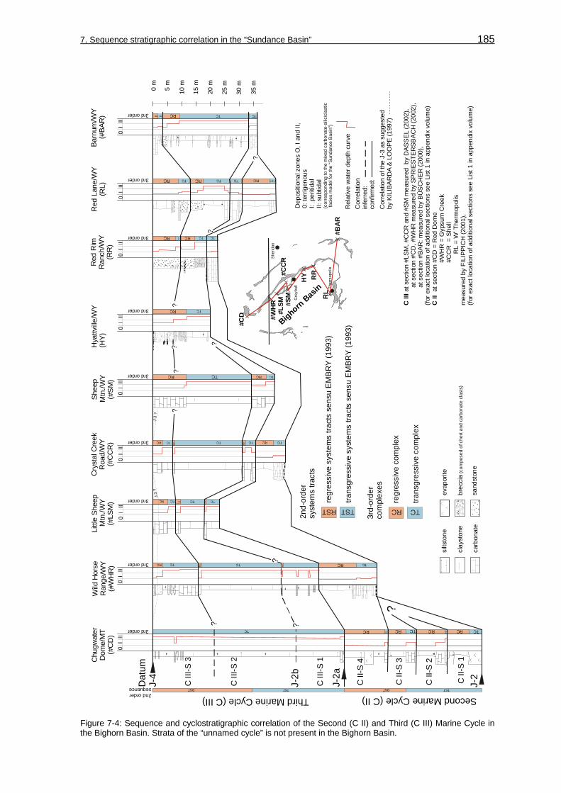
7. Sequence stratigraphic correlation in the “Sundance Basin” 185
TC
TC TCRCRCTC RCRC
TC
?
TCTCTCRC RC
RCTCTC ?
C II
I
C II
at s
ectio
n #L
SM, #
CC
R a
nd #
SM m
easu
red
by
DA
SSEL
(200
2),
a
t sec
tion
#CD
, #W
HR
mea
sure
d by
SP
RIE
STE
RSB
ACH
(200
2),
a
t sec
tion
#BAR
: mea
sure
d by
BÜ
SC
HER
(200
0),
(for e
xact
loca
tion
of a
dditi
onal
sec
tions
see
Lis
t 1 in
app
endi
x vo
lum
e)at
sec
tion
#CD
= R
ed D
ome
#WH
R =
Gyp
sum
Cre
ek
#C
CR
= S
hell
R
L =
W’ T
herm
opol
ism
easu
red
by F
ILIP
PIC
H (2
001)
, (fo
r exa
ct lo
catio
n of
add
ition
al s
ectio
ns s
ee L
ist 1
in a
ppen
dix
volu
me)
RST TST2nd ordersequence
3rd order
3rd order
3rd order
3rd order
3rd order
3rd order
3rd order
3rd order
3rd order
RST TST
regr
essi
ve s
yste
ms
tract
s se
nsu
EM
BR
Y (1
993)
trans
gres
sive
sys
tem
s tra
cts
sens
u EM
BRY
(199
3)
2nd-
orde
rsy
stem
s tra
cts
regr
essi
ve c
ompl
ex
trans
gres
sive
com
plex
3rd-
orde
rco
mpl
exes
TC
Sher
idan
Gre
ybul
l
Bighorn Basin Th
erm
opol
is
#CD #W
HR
HY
#BA
R
RL
RR
#LSM #S
M#C
CR
??
?? ?
Second Marine Cycle (C II)Third Marine Cycle (C III)
0 m
10 m5 m
20 m
15 m
25 m
30 m
35 m
J-2a
J-2
Dat
um
J-4
C II
I-S 1
C II
I-S 2
C II
I-S 3
C II
-S 4
C II
-S 3
C II
-S 2
C II
-S 1
Hya
ttville
/WY
(HY)
Red
Rim
Ran
ch/W
Y(R
R)
Wild
Hor
seR
ange
/WY
(#W
HR
)
Barn
um/W
Y
(#BA
R)
Shee
p M
tn./W
Y(#
SM
)
Cry
stal
Cre
ekR
oad/
WY
(#C
CR
)
Littl
e Sh
eep
Mtn
./WY
(#LS
M)
Chu
gwat
erD
ome/
MT
(#C
D)
Red
Lan
e/W
Y(R
L)
?
J-3
?J-
3 ?
J-2b
RC
?
0I
II
Dep
ositi
onal
zon
es O
, I a
nd II
,0:
terr
igen
ous
I: p
eriti
dal
II: s
ubtid
al
Rel
ativ
e w
ater
dep
th c
urve
(cor
resp
ondi
ng to
the
mix
ed c
arbo
nate
-sili
cicl
astic
faci
es m
odel
for t
he “S
unda
nce
Bas
in”)
?
?
Cor
rela
tion
infe
rred:
conf
irmed
:C
orre
latio
n of
the
J-3
as s
ugge
sted
by
KIL
IBA
RD
A &
LO
OP
E (1
997)
evap
orite
brec
cia
(com
pose
d of
che
rt an
d ca
rbon
ate
clas
ts)
sand
ston
e
silts
tone
clay
ston
e
carb
onat
e
Figure 7-4: Sequence and cyclostratigraphic correlation of the Second (C II) and Third (C III) Marine Cycle in the Bighorn Basin. Strata of the “unnamed cycle” is not present in the Bighorn Basin.

7. Sequence stratigraphic correlation in the “Sundance Basin” 186
TC
TCTC
RC
RC
TCR
CR
C
TC
TCR
CTC
RC
RC
RC
TC
TC
TC
?
TCTC
RC
RST
TST
2nd
orde
rse
quen
ce
3rd
orde
r
3rd
orde
r
3rd
orde
r
3rd
orde
r
RST
TST
C III C II
at section #CD, measured by SPRIESTERSBACH (2002),at section #CD = Red Dome
measured by FILIPPICH (2001), (for exact location of additional sections see List 1 in appendix volume)
Sun RiverCanyon/MT
(SRC)
SwiftReservoir/MT
(SR)
Heath/MT(HE)
ChugwaterDome/MT
(#CD)
?
?
?
105 m
100m
110 m
115 m
120 m
0 m
10 m
5 m
20 m
15 m
25 m
30 m
35 m
40 m
50 m
60 m
55 m
65 m
70 m
75 m
80 m
45 m
90 m
85 m
95 m
BillingsButte
Big SnowyMtns.
Little BeltMountains
Disturbed Bel t
Lewistown
SR
SRC
HE
RCSAP
LW
CD
?
Sec
ond
Mar
ine
Cyc
le (C
II)
Third
Mar
ine
Cyc
le (C
III)
J-2
Datum J-4
J-2a
J-2
C III-S 1
C III-S 2
C III-S 3
C II-S 4
C II-S 3
C II-S 2
C II-S 1
regressive systems tracts sensu EMBRY (1993)transgressive systems tracts sensu EMBRY (1993)
2nd-ordersystems tracts
sequence stratigraphic definition of stratalimited by lithologic expression?
regressive complex
transgressive complex3rd-ordercomplexes
Relative water depth curve
Depositional zones O, I and II,0: terrigenousI: peritidalII: subtidal(corresponding to the mixed carbonate-siliciclastic facies model for the “Sundance Basin”)
Correlationinferred:confirmed:
Figure 7-5: Sequence and cyclostratigraphic correlation of the Second (C II) and Third (C III) Marine Cycle in Montana. For explanation of lithologic signatures see Figure 7-4. Strata of the “unnamed cycle” is absent in Montana.
Sequence boundaries: Major sequence boundaries of the sedimentary cycle C II are the J-2 and J-2a unconformities. Internal sequence boundaries are placed at the base of transgressive carbonate beds that reflect transgressive complexes (TC). These boundaries correlate with the occurrence of the transgressive complexes (TC).

7. Sequence stratigraphic correlation in the “Sundance Basin” 187
Seco
nd M
arin
e
Cyc
le (C
II)
Third
Mar
ine
Cyc
le (C
III)
HCCCBE
J-4
J-2a
J-2
J-3
SPCPFSC“u
nnam
ed c
ycle
”
Third
Mar
ine
Cyc
le (C
III)
Seco
nd M
arin
e
Cyc
le (C
II)
J-2
SC
SPCDC
TF LB
TC
DuboisJackson
La Barge
KemmererUtah
BE CCHC
?
2nd
orde
r
2nd
orde
r
2nd
orde
r
2nd
orde
r
2nd
orde
r
2nd
orde
r
RS
TTS
TTS
TR
ST
TST
RS
TTS
TR
ST
TST
TST
RST
TST
TST
TST
“unn
amed
cyc
le”
J-4
J-3
J-2a
RST
TST
TST
RS
TTS
T
RS
T
RS
T
TST
TST
TST
TST
TST
TST
RS
T
regressive systems tracts sensu EMBRY (1993)transgressive systems tracts sensu EMBRY (1993)
2nd-ordersystems tracts
Depositional zones O, I and II,0: terrigenousI: peritidalII: subtidal(corresponding to the mixed carbonate-siliciclastic facies model for the “Sundance Basin”)
Relative water depth curve
Correlationinferred:confirmed:
evaporite
breccia (composed of chert and carbonate clasts)
sandstone
siltstone
claystone
carbonate
?
Figure 7-6: Sequence and cyclostratigraphic correlation of the Second Marine Cycle (C II), the Third Marine Cycle (C III) and the “unnamed cycle” in the “Utah-Idaho trough” area.
Third-order transgressive complexes (TC): Transgressive complexes (TC) are in the Second Marine Cycle (C II) well expressed only in the Piper Formation and characterized by inter- and supratidal wackestones, bindstones and laminated red siltstones. Additionally, the lateral facies successions include oolitic grainstone facies (oograinstones, oobiograinstones, oopackstones), biograinstones, and rare transitions to biopackstones. In the sequence C II-S 1, the basal transgressive complex contains up to 5 m thick gypsum beds.

7. Sequence stratigraphic correlation in the “Sundance Basin” 188
Toward the evolving “Utah-Idaho trough” the transgressive complexes of the sequences C II-S1 to C II-S 4 consist either of oolitic grainstones overlain by or interbedded with marine mudstones, biomudstones, biowackestones, or detritic mudstones with preserved bioturbation and ripple lamination. In general, the thickness of the transgressive complex (TC) increases westward. This trend is evident in all investigated sections. In the Sliderock Member and the Rich Member of the Twin Creek Limestone the distinct lateral facies successions within third-order scaled systems tracts can not be recognized.
Third-order regressive complexes (RC): The regressive complexes (RC) of the Piper Formation are characterized solely by monotonous, partly laminated, red siltstones. In the uppermost sequence C II-S 4, a regressive complex (RC) is preserved at sections like Poker Flat (PF) and Stump Creek (SC) and composed of thin, isolated oolitic sheets or thin biowackestone beds intercalated in unstratified red shales and siltstones. As demonstrated in the corresponding fence diagram for the Second Marine Cycle (C II), the uppermost regressive complex (RC) of sequence C II-S 4 is marked by an basinward shift of prograding red siltstone sediments and bound by the J-2a unconformity (see chapter: 5.3, 3-dimensional facies correlation; Figure 5-17). This complex represents in stratigraphic terms the Boundary Ridge Member of the Twin Creek Limestone and the “upper red bed member” of the Piper Formation.
Second-order systems tracts (TST) and (RST): The TST of the Second Marine Cycle (C II) in Wyoming is composed of detritic mudstones, biomudstones, intercalated oolitic-skeletal grainstones and in Montana of shales. These transgressive successions create a characteristic trend in the resulting relative water depth curve.
The RST of the Second Marine Cycle (C II) is dominantly composed of red beds. Additionally, thin oolitic grain- and wackestone beds may occur as at section Poker Flat (PF). IMLAY (1967) reported local collapse breccias and gypsum beds from this unit. This distinct red bed interval of the RST occurs in all sections in the “Utah-Idaho trough”. The RST is equivalent to the Boundary Ridge Member of the Twin Creek Limestone, which in turn is equivalent to the “upper red bed and gypsum member” of the Piper Formation (IMLAY 1980).
Sequence correlation: Isopach maps for the sedimentary cycle C II are shown in Figure 7-7 and for the individual sequences in Figure 7-8. The isopach pattern shows a remarkable thickening toward the “Utah-Idaho trough”.
In the Bighorn Basin, the Piper Formation represents the Second Marine Cycle (C II) and is bound by the J-2 and J-2a unconformities (Figure 7-4). As discussed in the chapter Facies correlation (see chapter: 5.2), SCHMUDE (2000) demonstrated that only the “upper red bed member” of the Piper Formation, persists along the flank of the Bighorn Mountains to its southern limit near Big Trails. The Piper Formation is composed of four transgressive-regressive sequences, if the unit is completely preserved as at section Chugwater Dome (#CD). Where the lower three sequences C II-S-1 to C II-S-3 are absent, chert pebbles and erosional contacts are reported by FILIPPICH (2001) at the

7. Sequence stratigraphic correlation in the “Sundance Basin” 189
sections Shell (#CCR) and Gypsum Creek (#WHR). SCHMUDE (2000) concluded that the persistence of the “upper red bed member” is related to a transgressive event that exceeded the spatial pattern of previous transgressions. In the Bighorn Basin, the sequences C II-S 1 to C II-S 4 are composed of basal gypsum and/or carbonate beds, overlain by siliciclastic red bed sediments.
FILIPPICH (2001)IMLAY(1967)
this study
Figure 7-7: Isopach map for compacted stratal thickness of the Second Marine Cycle (C II).
The sequence correlation in Montana is shown in Figure 7-5 for sections Chugwater Dome (#CD), Heath (HE), Sun River Canyon (SRC), and Swift Reservoir (SR). The Second Marine Cycle (C II) is represented by the Sawtooth Formation and the stratigraphic equivalent Piper Formation. The third-order sequences and their boundaries are difficult to distinguish in the stratigraphic sections in Montana. This is primarily due to the monotonous shale and silt dominated lithology. Therefore, the boundaries of the sequences C II-S 1 to C II-S 4 of the Second Marine Cycle (C II) are displayed as inferred lines in Figure 7-5 and fade out from the section Chugwater Dome (#CD) in a

7. Sequence stratigraphic correlation in the “Sundance Basin” 190
northwestern direction. From the section Chugwater Dome (#CD) the four sequences of the Second Marine Cycle (C II) can be traced into central Montana to section Heath (HE).
In the “Utah-Idaho trough”, the Second Marine Cycle (C II) is bound by the J-2 and the J-2a unconformities as shown in Figure 7-6. Third-order sequences can not be identified in the stratal record due to the monotonous facies successions. Thus, second-order transgressive (TST) and regressive (RST) systems tracts can be addressed for the sedimentary cycle.
C II-S 1CanadaUSA
CanadaUSA
CanadaUSA
CanadaUSA
C II-S 2
C II-S 3 C II-S 4
MT ND
SD
WY
NB
ID
UT CO
MT ND
SD
WY
NB
ID
UT CO
MT ND
SD
WY
NB
ID
UT CO
MT ND
SD
WY
NB
ID
UT CO
Figure 7-8: Isopach maps compiled for individual transgressive-regressive sequences S 1 to S 4 of the Second Marine Cycle (C II).

7. Sequence stratigraphic correlation in the “Sundance Basin” 191
7.1.3 Third Marine Cycle (C III)
The Third Marine Cycle (C III) is much more widespread than the underlying sedimentary cycles (IMLAY 1980, BRENNER & PETERSON 1994). The cycle is displayed in the correlation charts together with the underlying Second Marine Cycle (C II) and the overlying “unnamed cycle” by graphical means. It represents stratigraphically:
• Wyoming: The Canyon Springs Sandstone, Stockade Beaver Shale, Hulett Sandstone, and Lak Member of the Sundance Formation.
• “Overthrust Belt”: The Watton Canyon, Leeds Creek, Giraffe Creek Member of the Twin Creek Limestone, Preuss Formation, and Entrada Sandstone.
• Montana: The Rierdon Formation.
Sequence hierarchy: According to BRENNER & PETERSON (1994), this sedimentary cycle covers a time interval of approximately 10 Ma from the Middle Bathonian to the early Middle Callovian. Following the sequence hierarchy definition of VAIL et al. (1991) this sedimentary cycle is in the second-order cycle rank. The sequence correlation graphics are displayed in Figure 7-4, Figure 7-5, Figure 7-6. Figure 7-9, and Figure 7-10.
Sequence boundaries: Major sequence boundaries of the sedimentary cycle C III are the J-2a and J-3 unconformities in Wyoming. In other parts of the study area the J-4 cuts down the J-3 and is the upper boundary. Internal sequence boundaries are the J-2b unconformity and transgressive siliciclastic beds of transgressive complexes (TC).
Third-order transgressive complexes (TC): The transgressive complexes (TC) of the sequences C III-S 1, C III-S 2 and C III-S 3 are dominantly composed of siliciclastic and mixed siliciclastic-carbonate suites. The facies successions are dominated by siliciclastic shallow marine facies types (large-scale cross-bedded lithofacies) that grade into mixed siliciclastic-carbonate successions, typically consisting of thick quartzose, oolitic grain- and packstones interbedded with mud- and wackestones and calcareous shale. This expression is characteristic for the Canyon Springs Sandstone – Watton Canyon interval in sequence C III-S 1. Further, transgressive complexes (TC) contain monotonous mudstones that grade proximally into shales as in the Stockade Beaver Shale – Leeds Creek interval in the sequence C III-S 2 (TC-C III-S 2) and Hulett Sandstone – Giraffe Creek interval in sequence C III-S 3 (TC-C III-S 2).

7. Sequence stratigraphic correlation in the “Sundance Basin” 192
00
00
00
0
TCRC
TC TCRCRCTC
TC TCRC RCTC
TCTCRC RC
RC
TCTCRC ?
?
RST TST2nd ordersequence
3rd order
3rd order
3rd order
3rd order
3rd order
RCTC TC3rd order
regr
essi
ve s
yste
ms
tract
s se
nsu
EM
BRY
(199
3)
trans
gres
sive
sys
tem
s tra
cts
sens
u E
MBR
Y (1
993)
2nd-
orde
rsy
stem
s tra
cts
regr
essi
ve c
ompl
ex
trans
gres
sive
com
plex
3rd-
orde
rco
mpl
exes
RCTC TC3rd order RC
Dep
ositi
onal
zon
es O
, I a
nd II
,0:
terr
igen
ous
I: p
eriti
dal
II: s
ubtid
al(c
orre
spon
ding
to th
e m
ixed
car
bona
te-s
ilici
clas
tic fa
cies
mod
el fo
r the
“Sun
danc
e B
asin
”)
Hul
ett/W
YTh
omps
onR
anch
/SD
T cr
oss
T R
anch
/WY
Elk
Mou
ntai
n/SD
Stoc
kade
Bea
ver C
reek
/WY
Min
neka
tha/
SDSp
earfi
sh/S
DThird Marine Cycle (C III)
J-2b
Dat
um
J-4
100m0 m
10 m5 m
20 m
15 m
25 m
30 m
35 m
40 m
50 m
60 m
55 m
65 m
70 m
75 m
80 m
45 m
90 m
85 m
95 m
“silt
mar
ker”
(info
rmal
uni
t)
?
?
??
C II
I-S 1
Black H
ills
T-T
HU
SF
TR
SBC
EM M
IN
J-2/
J-2a
“lim
esto
ne m
arke
r” &
“bro
wn
shal
e”(in
form
al u
nits
)
C II
I-S 2
C II
I-S 3
“unnamed cycle”
(HU
)(T
-T)
(TR
)(S
F)(S
BC)
(EM
)(M
IN)
J-3
evap
orite
brec
cia
(com
pose
d of
che
rt an
d ca
rbon
ate
clas
ts)
sand
ston
e
silts
tone
clay
ston
e
carb
onat
e
TS
Rel
ativ
e w
ater
dep
th c
urve
Cor
rela
tion
infe
rred:
conf
irmed
:
Figure 7-9: Sequence and cyclostratigraphic correlation of the Third Marine Cycle (C III) and the “unnamed cycle” in the Black Hills. The remnants of the uppermost Pine Butte-Curtis interval are termed “unnamed cycle”. Strata of the Second Marine Cycle (C II) is not present in the Black Hills.
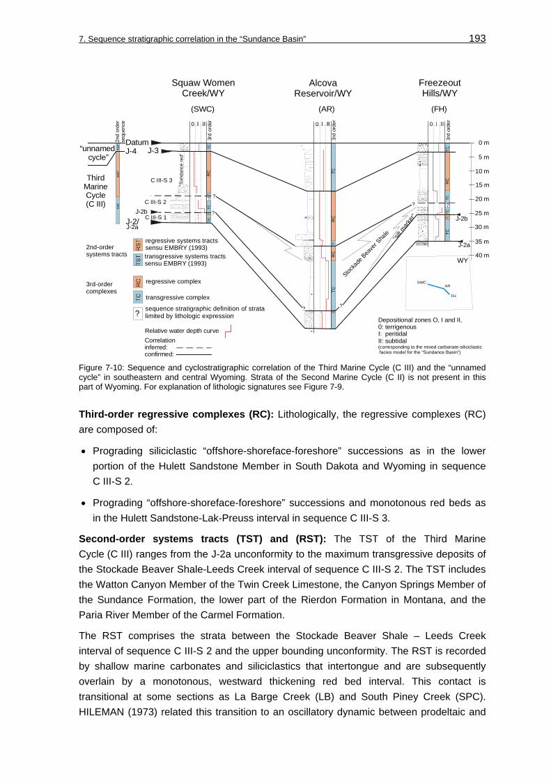
7. Sequence stratigraphic correlation in the “Sundance Basin” 193
AlcovaReservoir/WY
Squaw WomenCreek/WY
FreezeoutHills/WY
0 m
10 m
5 m
20 m
15 m
25 m
30 m
35 m
40 m
ThirdMarineCycle(C III)
“Sun
danc
e r e
d”
?
?
(SWC) (AR) (FH)
?sequence stratigraphic definition of stratalimited by lithologic expression?
RST
2nd
orde
rse
quen
ce
RC
TCTC
3rd
orde
r
TCR
CR
CTC
3rd
orde
r
TCTC
RC
RC
TC3r
d or
der
TST
TST
regressive systems tracts sensu EMBRY (1993)transgressive systems tracts sensu EMBRY (1993)
2nd-ordersystems tracts
regressive complex
transgressive complex
3rd-ordercomplexes
“silt m
arke
r”
Stocka
de B
eave
r Sha
le
Datum J-4“unnamed
cycle”
C III-S 3
J-2b
J-2aJ-2/ J-2b
J-2a
J-3
C III-S 2
C III-S 1
??
??
0 0 0
Relative water depth curve
Depositional zones O, I and II,0: terrigenousI: peritidalII: subtidal(corresponding to the mixed carbonate-siliciclastic facies model for the “Sundance Basin”)
SWCAR
FH
WY
Correlationinferred:confirmed:
Figure 7-10: Sequence and cyclostratigraphic correlation of the Third Marine Cycle (C III) and the “unnamed cycle” in southeastern and central Wyoming. Strata of the Second Marine Cycle (C II) is not present in this part of Wyoming. For explanation of lithologic signatures see Figure 7-9.
Third-order regressive complexes (RC): Lithologically, the regressive complexes (RC) are composed of:
• Prograding siliciclastic “offshore-shoreface-foreshore” successions as in the lower portion of the Hulett Sandstone Member in South Dakota and Wyoming in sequence C III-S 2.
• Prograding “offshore-shoreface-foreshore” successions and monotonous red beds as in the Hulett Sandstone-Lak-Preuss interval in sequence C III-S 3.
Second-order systems tracts (TST) and (RST): The TST of the Third Marine Cycle (C III) ranges from the J-2a unconformity to the maximum transgressive deposits of the Stockade Beaver Shale-Leeds Creek interval of sequence C III-S 2. The TST includes the Watton Canyon Member of the Twin Creek Limestone, the Canyon Springs Member of the Sundance Formation, the lower part of the Rierdon Formation in Montana, and the Paria River Member of the Carmel Formation.
The RST comprises the strata between the Stockade Beaver Shale – Leeds Creek interval of sequence C III-S 2 and the upper bounding unconformity. The RST is recorded by shallow marine carbonates and siliciclastics that intertongue and are subsequently overlain by a monotonous, westward thickening red bed interval. This contact is transitional at some sections as La Barge Creek (LB) and South Piney Creek (SPC). HILEMAN (1973) related this transition to an oscillatory dynamic between prodeltaic and

7. Sequence stratigraphic correlation in the “Sundance Basin” 194
shallow marine bar environments along the “Utah-Idaho trough” margin. The RST is equivalent to the Giraffe Creek Member of the Twin Creek Limestone, the Hulett Sandstone Member, the upper part of the Rierdon Formation, the Entrada Sandstone. The red bed interval corresponds to the Preuss Formation and the Lak Member.
The locally occurring fossiliferous carbonate beds of the Wolverine Canyon Member of the Preuss Formation in Idaho were considered by IMLAY (1952) as a transgressive-regressive cycle. In contrast, HILEMAN (1973) interpreted the depositional setting of the Wolverine Member in context with barrier environments in an eastward prograding prodeltaic, subtidal, intertidal, and supratidal setting. On the other hand, the Wolverine Canyon Member might correlate with the informal “middle member” of the Entrada Sandstone as suggested by PETERSON, F. (1988; 1994). This member is interbedded with eolian Entrada sandstones and thought to be deposited in tidal flat and coastal sabkha settings (PETERSON, F. 1988; 1994). With the data available in this study the interpretation of HILEMAN (1973) is followed, because:
• On the basis of the field observations made in outcrops of the Preuss Formation progradation is confirmed by the prodeltaic and peritidal Preuss Formation facies types I and II (see chapters: 3.6, Supplementary facies types and 5, Facies correlation).
• Progradational successions are identified within the stratigraphically equivalent sediments of the Hulett Sandstone and Lak Member in Wyoming and South Dakota.
Sequence correlation: The Third Marine Cycle (C III) is composed of three third-order sequences C III-S 1, C III-S 2 and C III-S 3. Isopach maps for the sedimentary cycle C III are shown in Figure 7-11 and for the individual sequences in Figure 7-12. The thickness pattern for sedimentary cycle C III and subordinate sequences reveals a close similarity to the underlying units. The stratal packages show a pronounced thickening toward the “Utah-Idaho trough”.
For the Black Hills area the correlation of third-order sequences C III-S 1, C III-S 2, C III-S 3, and their associated boundaries in the Third Marine Cycle (C III) is shown in Figure 7-9. The “unnamed cycle” of the Pine Butte – Curtis interval is included in the graphics. Sequence C III-S 1 is considered as equivalent to the “limestone marker” and “brown shale” as originally defined by AHLBRANDT (1996a and b). These informal units reflect a transition from marine to estuarine environments and are introduced in the chapter Facies correlation (see chapter: 5, transection F - F’). The sequence C III-S 1 is bordered by the J-2a and J-2b unconformities. The succeeding C III-S 2 sequence is bound by a transgressive surface (TS) at the base of the “silt marker”, which occurs as abrupt onset of shale beds. The C III-S 2 sequence contains the Stockade Beaver Shale Member and portions of the Hulett Sandstone. Upward the sequence coarsens from shales into flaser-bedded shales and sandstones. On top the C III-S 2 sequence is capped by abrupt shale interbeds that mark the transgressive surface of the overlying sequence C III-S 3. The uppermost C III-S 3 sequence contains the Hulett Sandstone and the Lak Member. This sequence is truncated on top by the unconformable J-3 contact that

7. Sequence stratigraphic correlation in the “Sundance Basin” 195
delineates the facies change to the “unnamed cycle”. The thick red bed-gypsum sequence of the Lak Member is overlain by glauconitic fine- to medium-grained sandstones of the Pine Butte Member. The lithologic and facies change that mark the J-3 unconformity are sharp at this contact.
CanadaUSA
from HILEMAN (1973)
from PETERSON(1957a; 1957b;1958),SCHMITT (1953), MORITZ (1951)
0-15m
15-45m
45-61m
61-122m
>122m
well surfacesection
this studyfrom BÜSCHER (2000), SPRIESTERSBACH (2002) and DASSEL (2002)
Figure 7-11: Isopach map for compacted stratal thickness of the Third Marine Cycle (C III). Thickness data from the “unnamed cycle” is not included in the isopach map.
In the Bighorn Basin and western Powder River Basin, the third-order sequences are equivalent to sequences in the Black Hills (see Figure 7-4). The sequence C III-S 1 in the Bighorn Basin represents parts of the Canyon Springs Sandstone Member and forms a shallowing upward mixed siliciclastic-carbonate succession, typically consisting of thick quartzose oograinstones, oobiograinstones and oopackstones interbedded with mud- and wackestones and calcareous shale. The sequence is bound by the J-2a and J-2b unconformities. The J-2b unconformity can not be traced into pure shale lithologies and fades out between sections Wild Horse Range (#WHR) and Chugwater Dome (#CD) that were measured by SPRIESTERSBACH (2002). Sequence C III-S 2 comprises the Stockade Beaver Shale Member and portions of the Hulett Sandstone Member. In context with the evidence for a renewed transgressive trend in the lower part of the Hulett Sandstone Member in the Black Hills (see Figure 7-9), the boundary between the sequences C III-S 2 and C III-S 3 is not tied to the stratigraphic Stockade Beaver Shale –

7. Sequence stratigraphic correlation in the “Sundance Basin” 196
Hulett Sandstone boundary. Instead, the initial marine flooding event of the sequence C III-S 3 is documented by a intercalated shale bed within the Hulett Sandstone Member in the Bighorn Basin and the Black Hills. The sequence C III-S 2 thins in the vicinity of the sections Hyattville (HY) and Red Rim Ranch (RR) (see chapter: 5.1, 2-dimensional facies correlation; Figure 5-4) and the lowermost sequence C III-S 1 can not be recognized. As suggested by the 3-dimensional facies correlation in Figure 5-18 (see chapter: 5.3, Spatial and temporal facies characteristics), this pattern can be explained by the existence of a
CanadaUSA
“unnamed cycle”
CanadaUSA
CanadaUSA
C III-S 3
C III-S 1CanadaUSA
C III-S 2
MT ND
SD
WY
NB
ID
UT CO
MT ND
SD
WY
NB
ID
UT
CO
MT ND
SD
WY
NB
ID
UT
CO
MT ND
SD
WY
NB
ID
UT
CO
Figure 7-12: Isopach maps compiled for individual transgressive-regressive sequences C III-S 1 to C III-S 3 of the Third Marine Cycle (C III) and the “unnamed cycle”. The sequences thicken northward. Westward the sequences show a pronounced thickening toward the rapidly subsiding “Utah-Idaho trough”. Note that the stratigraphic record of the “unnamed cycle” is only poorly preserved below the J-4 unconformity.

7. Sequence stratigraphic correlation in the “Sundance Basin” 197
positive relief element, the “Sheridan Arch”, that was already identified by PETERSON (1954) and SCHMUDE (2000). Therefore, the incomplete preservation of the sequence C III-S 1 and the thinning of sequence C III-S 2 between Hyattville (HY) and Red Rim Ranch (RR) can be explained by the influence of this relief element. The sequence C III-S 3 contains the upper portion of the Hulett Sandstone Member in the Bighorn Basin. On top the sequence C III-S 3 is capped by the J-4 unconformity.
Finally, it is important to note that the sequences C III-S 1, C III-S 2 and C III-S 3 lose their distinctive character in a northwesterly direction where the lithology becomes dominated by shales. As discussed in the chapter Allostratigraphy (see chapter: 2.4), the J-3 unconformity is considered to be absent in the Bighorn Basin and the original definition of PIPIRINGOS & O’ SULLIVAN (1978) is followed in this study as long as this problem remains unsolved. SCHMUDE (2000) did not report this surface from the Bighorn Basin as well. However, following the interpretation of KILIBARDA & LOOPE (1997) the J-3 is developed as a deflation surface and would diverge from the J-4 unconformity north of Greybull/Wyoming. This possible interpretation is shown as a thin hatched line in the correlation.
In southeastern and central Wyoming, strata of the Third Marine Cycle (C III) is represented in Figure 7-10. Here, the sequences CIII-S 1 to C III-S 3 can be recognized at the investigated sections Alcova Reservoir (AR), Freezeout Hills (FH) and Squaw Women Creek (SWC). The lithologic expression of the sequences and their boundaries is almost similar to conditions found in the Bighorn Basin and the Black Hills. Problematic is the identification of the sequence boundaries J-2a and J-2b at section Squaw Women Creek (SWC). The lower portion of the Sundance Formation is poorly exposed as oolitic beds and intercalated shales. Some parts of the outcrop are covered. The sequence boundaries are therefore shown with a question mark. Further, the bounding J-2b unconformity can not be identified with certainty in the Canyon Springs Sandstone Member at section Alcova Reservoir (AR). As shown in Figure 7-13, at this location massive sandstones of the large-scale lithofacies (LX lithofacies) are overlain by a 1 m thick bed of wave-rippled sandstone (WR lithofacies). This suite is interpreted as a shallowing up succession. The J-2b is placed on top of this succession.
The sequence correlation in Montana is shown for sections Chugwater Dome (#CD), Heath (HE), Sun River Canyon (SRC), and Swift Reservoir (SR) in Figure 7-5. The Third Marine Cycle (C III) strata belongs entirely to the Rierdon Formation. The third-order sequences and their boundaries are difficult to distinguish in the stratigraphic sections in Montana. This is primarily due to the monotonous shale and silt dominated lithology and outcrop conditions as, for instance, at section Heath (HE). Therefore, the boundaries of the sequences C III-S 1 to C III-S 3 of the Third Marine Cycle (C III) are displayed as inferred lines and fade out from the section Chugwater Dome (#CD) in a northwestern direction.

7. Sequence stratigraphic correlation in the “Sundance Basin” 198
Figure 7-13: Canyon Springs Sandstone Member at section Alcova Reservoir (AR). A massive sandstone (LX lithofacies) is abruptly overlain by sandstones of the wave-rippled lithofacies (WR lf) separated by the J-2b unconformity. This suite is interpreted as a shallowing upward succession. The white line marks the contact between the lithofacies types. Only the lower portion of the approximately 1 m thick wave-rippled sandstone beds is shown. Jacob stick in left corner of picture is 1,5 m long.
The cyclostratigraphic and sequence stratigraphic correlation of the Third Marine Cycle (C III) in the “Utah-Idaho trough” is displayed for representative sections in Figure 7-6. In the “Utah-Idaho trough” and adjacent areas third-order sequences within the Third Marine Cycle (C III) can not be identified in the stratal record with the methods of facies analysis applied in this study nor by the available biostratigraphy. A successful identification of third-order sequences within the Twin Creek Limestone would require the integration of a detailed biostratigraphic analysis of the micro- and macrofaunal spectrum. The relative water depth curves of investigated sections reflect the major sedimentary Second (C II) and Third (C III) Marine Cycle as defined by BRENNER & PETERSON (1994).
7.1.4 The “unnamed cycle”
The “unnamed cycle” represents stratigraphically the Pine Putter Member of the Sundance Formation in Wyoming, the Curtis Member of the Stump Formation in the “Overthrust Belt” and the Curtis Formation in Utah. The sequence stratigraphic correlation is displayed together with the underlying sedimentary cycles by graphical means in Figure 7-6, Figure 7-9 and Figure 7-10. The “unnamed cycle” is incompletely preserved and the sequence boundaries are the J-3 and J-4 unconformities. Due to the limited stratal record no third-order systems tracts can be recognized. The “unnamed cycle” – if preserved in outcrop sections – above the Third Marine Cycle (C III) represents remnants

7. Sequence stratigraphic correlation in the “Sundance Basin” 199
of a transgressive interval. Deposits of the cycle are not present in the Bighorn Basin and Montana. The second-order rank of the sequence boundaries (J-3 and J-4) place the sedimentary remnants of the “unnamed cycle” formally in the rank of a second-order cycle, if the hierarchical sequence boundary concept of EMBRY (1993) is applied. As can be obtained from the thickness map in Figure 7-12, the “unnamed cycle” thickens from central Wyoming toward the “Utah-Idaho trough” and follows the thickness pattern of the underlying cycles.
7.1.5 Fourth Marine Cycle (C IV)
The Fourth Marine Cycle (C IV) represents the Redwater Shale Member of the Sundance Formation and Stump Formation in Wyoming, eastern Idaho and northeastern Utah and the Swift Formation in Montana.
Sequence hierarchy: According to BRENNER & PETERSON (1994), this cycle covers a time interval of approximately 8 Ma from the Early to the Middle Oxfordian. Following the sequence hierarchy definition of VAIL et al. (1991) this sedimentary cycle is in the second-order cycle rank. The sedimentary cycles are composed of two sequences C IV-S 1 and C IV-S 2. The sequence correlation graphics are displayed in Figure 7-14 to Figure 7-18.
Rapid CityBlack Hills
HU TR SF
MIN
EMSBC
10 m
5 m
20 m
15 m
25 m
30 m
35 m
40 m
60 m
55 m
65 m
70 m
45 m
50 m
TST TS
T
TST
TST
TST
RST
RS
TTS
T
RS
TTS
T2n
d or
der
sequ
ence
3rd
orde
r
3rd
orde
r
3rd
orde
r
3rd
orde
r
3rd
orde
r
3rd
orde
r
Datum J-5
J-4
Four
th M
arin
e C
ycle
(C IV
)
Minnekatha/SD (MIN)
ThompsonRanch/SD
(TR)
Hulett/WY (HU)
Stockade Beaver
Creek/WY(SBC)
Elk Mountain/SD(EM)
Spearfish/SD(SF)
regressive systems tracts sensu EMBRY (1993)
transgressive systems tracts sensu EMBRY (1993)
2nd-ordersystems tracts
Depositional zones O, I and II,0: terrigenousI: peritidalII: subtidal(corresponding to the mixed carbonate-siliciclastic facies model for the “Sundance Basin”)
Correlationinferred:confirmed:Relative water depth curve
Figure 7-14: Sequence and cyclostratigraphic correlation of the Fourth Marine Cycle (C IV) in the Black Hills. For explanation of lithologic signatures see Figure 7-9.

7. Sequence stratigraphic correlation in the “Sundance Basin” 200
TC
TCR
C
TC
TCTC
RC
RC
?
??
TC
RS
TTS
T2n
d or
der
sequ
ence
3rd
orde
r
3rd
orde
r
3rd
orde
r
3rd
orde
r
3rd
orde
r
3rd
orde
r
sequence stratigraphic definition of stratalimited by lithologic expression?
regressive systems tracts sensu EMBRY (1993)
transgressive systems tracts sensu EMBRY (1993)
2nd-ordersystems tracts
regressive complex
transgressive complex
3rd-ordercomplexes
TC TCR
C
Vernal/UT(V)
FlamingGorge/UT
(FG)
Jackson
Utah
Idaho
Uinta Mountains
Vernal
BE
SPC
HCCC
45
FG
V
Overt hrust Be lt
0 m
10 m
5 m
20 m
15 m
25 m
30 m
35 m
40 m
55 m
45 m
50 m
Cabin Creek/WY(CC)
Hoback Canyon/WY
(HC)
South PineyCreek/WY
(SPC)
Big ElkMountain/ID
(BE)
J-4a
Datum J-5
Four
th M
arin
e C
ycle
(C IV
)
J-4
?
C IV-S 2
C IV-S 1? ??
Depositional zones O, I and II,0: terrigenousI: peritidalII: subtidal(corresponding to the mixed carbonate-siliciclastic facies model for the “Sundance Basin”)
Correlationinferred:confirmed:
Relative water depth curve
Figure 7-15: Sequence and cyclostratigraphic correlation of the Fourth Marine Cycle (C IV) in the “Overthrust Belt”. For explanation of lithologic signatures see Figure 7-9.
Sequence boundaries: Major sequence boundaries of the sedimentary cycle C IV are the J-4 and J-5 unconformities. Internally, the sequences C IV-S 1 and C IV-S 2 are separated by the J-4a unconformity.
Third-order transgressive complexes (TC): The stratigraphic record of the Fourth Marine Cycle (C IV) is dominantly composed of siliciclastic sediments. In contrast to the underlying Second (C II) and Third (C III) Marine Cycle the recognition of distinctive lateral facies successions is very limited in the third-order sequences C IV-S 1 and C IV-S 2 of the Fourth Marine Cycle (C IV) due to:
• The relatively monotonous lithology of the Redwater Shale Member.
• The incomplete preservation of sequences and their systems tracts below the bounding unconformities J-4a and J-5.
The facies types that represent the transgressive-regressive sequences C IV-S 1 and C IV-S 2 allow an identification of two facies successions. These facies successions combine genetically related sediments of transgressive (TC) and regressive (RC) complexes.
The lithology of the transgressive complexes (TC) is dominated by calcareous, glauconitic shales and siltstones. Characteristic lateral facies variations can not be recognized, with an exception in northwestern Montana. In this area the shale lithology grades laterally into flaser- and lenticular-bedded lithofacies types. The transgressive complexes (TC) are representative for the sequence C IV-S 1 and the basal portion of the overlying sequence C IV-S 2.

7. Sequence stratigraphic correlation in the “Sundance Basin” 201
She
ridan
Gre
ybul
l
Bighorn Basin Th
erm
opol
is
HB
HY
BA
R
GR
RR
LSM SM
CC
R
?
TC TC?
RC
RC TCTCRC
TCRC
TCRC
?
RST TST2nd ordersequence
3rd order
3rd order
3rd order
3rd order
3rd order
3rd order
C IV
-S 2
regr
essi
ve s
yste
ms
tract
s se
nsu
EM
BRY
(199
3)
trans
gres
sive
sys
tem
s tra
cts
sens
u EM
BRY
(199
3)
2nd-
orde
rsy
stem
s tra
cts
regr
essi
ve c
ompl
ex
trans
gres
sive
com
plex
3rd-
orde
rco
mpl
exes
TC
TC
sequ
ence
stra
tigra
phic
def
initi
on o
f stra
talim
ited
by li
thol
ogic
exp
ress
ion
or p
rese
rvat
ion
of s
trata
?
Dep
ositi
onal
zon
es O
, I a
nd II
,0:
terri
geno
usI:
per
itida
lII:
sub
tidal
(cor
resp
ondi
ng to
the
mix
ed c
arbo
nate
-sili
cicl
astic
faci
es m
odel
for t
he “S
unda
nce
Bas
in”)
Cor
rela
tion
infe
rred
:co
nfirm
ed:
Rel
ativ
e w
ater
dep
th c
urve
evap
orite
brec
cia
(com
pose
d of
che
rt
and
car
bona
te c
last
s)
sand
ston
e
silts
tone
clay
ston
e
carb
onat
e
0 m
10 m5 m
20 m
15 m
25 m
30 m
35 m
40 m
60 m
55 m
65 m
70 m
45 m
50 m
Hya
ttville
/WY
(
HY)
Red
Rim
Ran
ch/W
Y(R
R)
Hor
sesh
oe B
end/
WY
(#H
B)
Bar
num
/WY
(#B
AR
)
Fourth Marine Cycle (C IV)
Dat
um
J-5 J-
4
C IV
-S 1
J-4a
Cla
rks
Fork
Can
yon/
WY
(#C
FC)
Buffa
loBi
ll D
am/W
Y(#
BB
D)
Trai
l Cre
ek(fr
om IM
LAY
195
6)
C IV
at s
ectio
n #H
B m
easu
red
by D
ASS
EL
(200
2),
#CFC
, #BB
D m
easu
red
by S
PRIE
STE
RS
BAC
H (2
002)
,#B
AR m
easu
red
by B
ÜSC
HER
(200
0),
(for e
xact
loca
tion
of a
dditi
onal
sec
tions
see
Lis
t 1 in
a
ppen
dix
volu
me)
pebb
ly c
ongl
omer
ate,
cher
t and
lim
esto
ne p
ebbl
es,
repo
rted
by IM
LAY
(195
6) a
ndBR
EN
NER
& D
AVIE
S (1
974)
,ca
n be
trac
ed 1
2 km
nor
thw
ard
to th
e Tr
ail C
reek
sec
tion
Figure 7-16: Sequence and cyclostratigraphic correlation of the Fourth Marine Cycle (C IV) in the Bighorn Basin.

7. Sequence stratigraphic correlation in the “Sundance Basin” 202
TCR
C
RST
TC
RC
TCTC
TCTC
TCTC
TCTC
RST
TST
2nd
orde
rse
quen
ce
3rd
orde
r
3rd
orde
r
3rd
orde
r
sequence boundary sensu EMBRY (1993) expressed aserosional surface or facies shift
sequence stratigraphic definition of stratalimited by lithologic expression?
regressive systems tracts sensu EMBRY (1993)
transgressive systems tracts sensu EMBRY (1993)
2nd-ordersystems tracts
regressive complex
transgressive complex
3rd-ordercomplexes
Datum J-5 0 m
10 m
5 m
20 m
15 m
25 m
30 m
FreezeoutHills/WY
(FH)
Squaw Women Creek/WY
(SWC)
RobbersRoost/WY
(from ANDERSON 1979)
DyerSpring/WY
(from ANDERSON 1979)
BattleMtn./WY
(from ANDERSON 1979)
PineHill/WY
(from ANDERSON 1979)
AlcovaReservoir/WY
(AR)
LaramieCheyenne
Casper
Laramie Range
Wind River Mountains
Medicine Bow
Mountains
33 MIN
AR
FH
SWC
Black Hills
J-4a
J-4CL: Cobble layerCLM: Main cobble layer
Four
th M
arin
e C
ycle
(C IV
)
C IV-S 1
? ?
? ?
C IV-S 2
stratigraphic correlation of informalunits in the Redwater Shale Memberafter ANDERSON (1978; 1979)D: “upper shale unit”C: “upper siltstone unit”B: “lower shale unit”A: “lower siltstone unit”
?
?
Depositional zones O, I and II,0: terrigenousI: peritidalII: subtidal(corresponding to the mixed carbonate-siliciclastic facies model for the “Sundance Basin”)
Correlationinferred:confirmed:
Relative water depth curve
Figure 7-17: Sequence and cyclostratigraphic correlation of the Fourth Marine Cycle (C IV) in southeastern and central Wyoming. For explanation of lithologic signatures see Figure 7-16.
TC
?
TC
TC
RC
TC TCR
CTC
TC
RC
RC
?RC
RC
TC2n
d or
der
sequ
ence
3rd
orde
r
3rd
orde
r
3rd
orde
r
3rd
orde
r
3rd
orde
r
sequence stratigraphic definition of stratalimited by lithologic expression?
regressive systems tracts sensu EMBRY (1993)
transgressive systems tracts sensu EMBRY (1993)
2nd-ordersystems tracts
regressive complex
transgressive complex
3rd-ordercomplexes
TC
Little Water Creek/MT
(LW)
J-4a
BillingsButte
Little BeltMountains
Disturbed Belt
Lewistown
SR
SRC
LW
Datum J-5
Four
th M
arin
e C
ycle
(C IV
)
C IV-S 1J-4
0 m
10 m
5 m
20 m
15 m
25 m
30 m
35 m
40 m
Rocky CreekCanyon/MT
(RC)
Sun RiverCanyon/MT
(SRC)
SwiftReservoir/MT
(SR)
C IV-S 2
Depositional zones O, I and II,0: terrigenousI: peritidalII: subtidal(corresponding to the mixed carbonate-siliciclastic facies model for the “Sundance Basin”)
Correlationinferred:confirmed:
Relative water depth curve
Figure 7-18: Sequence and cyclostratigraphic correlation of the Fourth Marine Cycle (C IV) in Montana. For explanation of lithologic signatures see Figure 7-16.

7. Sequence stratigraphic correlation in the “Sundance Basin” 203
Third-order regressive complexes (RC): The regressive complexes (RC) are only partly preserved in the third-order sequences. The lithology comprises dominantly glauconitic, fine to medium-grained sandstones with minor amounts of shales and siltstones. The regressive complex of sequence C IV-S 1 is only recognized where shales grade transitionally into flaser and lenticular bedded lithofacies as, for instance, in the Redwater Shale Member in the Bighorn Basin and the Swift Formation in northwestern Montana.
The regressive complex of sequence C IV-S 2 is identical with the glauconitic lithofacies which, in turn, is the stratigraphic counterpart of the “upper sandstone body” of MEYERS & SCHWARTZ (1994), the “ribbon sandstone” of HAYES (1984) and MOLGAT & ARNOTT (2001) as well as the “coquina facies” and “sandstone facies” of UHLIR et al. (1988) (see chapters: 2.4, Allostratigraphy and 2.4.2.8, J-4a unconformity). The regressive complex of sequence C IV-S 2 represents a variety of depositional environments that range from tidal to deltaic. From west to east the succession grades from glauconitic sandstones into siltstones and storm influenced carbonates in central Wyoming and finally into glauconitic shales in South Dakota.
Second-order systems tracts (TST) and (RST): The second-order TST and RST can not be identified in all portions of the study area due to the limited preservation of regressive successions. Transgressive systems tracts (TST) are best identified by the shale facies of the Redwater Shale Member. The RST comprises the strata above the J-4a unconformity, which reflects the regressive nature of the sedimentary cycle by prograding siliciclastics.
Sequence correlation: Isopach maps for the sedimentary cycle C IV are shown in Figure 7-19 and for the individual sequences in Figure 7-20. The strong asymmetry in spatial thickness pattern that characterized the Second (C II) and Third (C III) Marine Cycle can not longer be recognized in the Fourth Marine Cycle (C IV). The sequences are bound by the J-4, J-4a and J-5 unconformities.
The correlation of the Fourth Marine Cycle (C IV) in the Black Hills is shown in Figure 7-14. The unit is represented solely by glauconitic, calcareous shales and intercalated thin carbonate or sandstone beds. Since the stratigraphic record is progressively truncated toward central and northwestern Wyoming by the J-5 surface it seems unlikely that the stratal record is completely preserved in the Black Hills. As a consequence from the uniform lithology and partly covered outcrops the third-order sequences of the Fourth Marine Cycle (C IV) can not be identified in the Black Hills.

7. Sequence stratigraphic correlation in the “Sundance Basin” 204
well surfacesection
from PETERSON(1957a; 1957b;1958),SCHMITT (1953), MORITZ (1951),IMLAY (1956),PIPIRINGOS & IMLAY (1979)
30-61m
>61m
<30m
0m
this studyfrom BÜSCHER (2000), SPRIESTERSBACH (2002) and DASSEL (2002)
CanadaUSA
Figure 7-19: Isopach map for compacted stratal thickness of the Fourth Marine Cycle (C IV).
CanadaUSA
C IV-S 1CanadaUSA
C IV-S 2
MT ND
SD
WY
NB
ID
UT CO
MT ND
SD
WY
NB
ID
UT CO
Figure 7-20: Isopach maps compiled for the two individual transgressive-regressive sequences C IV-S 1 and C IV-S 2 of the Fourth Marine Cycle (C IV). Note that the subsiding “Utah-Idaho trough” can not longer be identified as a major tectonic element in the thickness pattern.

7. Sequence stratigraphic correlation in the “Sundance Basin” 205
In northeastern Utah, eastern Idaho and western Wyoming, the Fourth Marine Cycle (C IV) is represented by the Redwater Member of the Stump Formation. The correlation is shown in Figure 7-15. Like in Wyoming and Montana this unit is a coarsening upward succession. Two lithologic units: a “glauconitic shale unit” sharply overlain by an “upper glauconitic sandstone unit” are considered to rest conformably upon each other (PIPIRINGOS & IMLAY 1979). Problematic is the identification of the J-4 bounding unconformity in outcrops since the surface lacks an erosional nature. The lower boundary is either concealed or difficult to locate within lithologically similar glauconitic sandstones and shales. The unconformable J-4 surface was placed in context with the correlation of PIPIRINGOS & IMLAY (1979). The J-4a unconformity was not identified during field work in western Wyoming. However, the coarsening upward and the sharp facies development from the shale lithofacies into the glauconitic lithofacies resembles conditions described previously in this study from the correlation of sequences in Wyoming and Montana. In northeastern Utah, at section Vernal (V) a cobble layer was noticed within the Redwater Member. If this layer corresponds to cobble layers or the J-4a surface in Wyoming is questionable. The fragmented stratigraphic record, lithologic similarities of siliciclastic facies types combined with the limited identification of sequence bounding unconformities in the “Overthrust Belt” make the extension of the sequences C IV-S 1 and C IV-S 2 into western Wyoming uncertain. Therefore, the correlation is shown with question marks.
The Bighorn Basin correlation is illustrated in Figure 7-16. In the Bighorn Basin, the sequence C IV-S 1 is composed of fine-grained siliciclastics and intercalated coquinoid storm beds. Transgressive signatures are reflected by glauconitic shales (shale lithofacies). At sections Red Rim Ranch (RR) and Hyattville (HY), the regression can be identified by a coarsening from shales into glauconitic silt and very fine-grained sandstones (silty lithofacies). The sequence C IV-S 1 is bound by the J-4 and the J-4a unconformities. The upper sequence C IV-S 2 is dominated by sediments of the glauconitic lithofacies. Transgression is documented by the reworked lag of accumulated cobbles at the base of the sequence C IV-S 2. Regression is expressed by coarsening upward and a shift from transgressive toward tidally influenced environments of the glauconitic lithofacies.
The correlation for southeastern and central Wyoming is illustrated in Figure 7-17. In southeastern and central Wyoming, the Redwater Shale Member contains four informal lithologic units (PIPIRINGOS 1968). ANDERSON (1978; 1979) correlated these units on the basis of carbonate cobble layers within the stratal record. Further, the “upper shale unit” and “upper siltstone unit” are equivalent to the upper sandstone body of the Redwater Shale Member. As demonstrated in this study, the “main cobble layer” (CLM) in southeastern Wyoming – originally identified by ANDERSON (1978; 1979) – is considered to be equivalent to the J-4a unconformity. Between the sections Freezeout Hills (FH) and Alcova Reservoir (AR) two to three cobble layers occur in the sequence C IV-S1 within the Redwater Shale Member. The cobbles formed as a result of diastemic sedimentation, accumulated during sea-level fall and were reworked during subsequent transgressions.

7. Sequence stratigraphic correlation in the “Sundance Basin” 206
The Fourth Marine Cycle (C IV) strata is truncated progressively from southeast to northwest by the J-5 unconformity. The truncation affected both sequences C IV-S 1 and C IV-S 2 as can be obtained from sections Robbers Roost and Battle Mountain, measured by ANDERSON (1978; 1979).
The Fourth Marine Cycle (C IV) is represented by the Swift Formation in Montana. The correlation is shown in Figure 7-18. The informal “shale unit” and “upper sandstone unit” are considered as equivalent to the sequences C IV-S 1 and C IV-S 2. In the examined outcrop sections in Montana parasequences were not identified. Lithologically, the sequences are entirely composed of siliciclastics. The coarsening upward successions grade from glauconitic shales (shale lithofacies) transitionally into flaser-bedded shale-sandstone beds (L-Fb lithofacies) in sequence C IV-S 1. In the upper sequence glauconitic sandstones (glauconitic lithofacies) directly overlie the sequence bounding unconformable contact.
7.2 Sequence characteristics
The second-order sedimentary cycles C I, C II, C III, “unnamed cycle”, and C IV and their third-order sequences show remarkable differences in facies distribution, lithology, isopach pattern, sequence correlation potential, and stratal preservation. These differences will be summarized here. The internal organization of the sedimentary cycles and sequences is listed in Figure 7-21.
Sequence correlation potential: The second-order sedimentary cycles C I, C II, C III, and C IV are basinwide traceable and correlative. In contrast, the “unnamed cycle” is poorly preserved and restricted to the Black Hills, southeastern Wyoming, the “Overthrust Belt” and adjacent Utah. The subordinate third-order sequences are documented differently in the sedimentary cycles. While in the cycles C I and C IV third-order sequences are basinwide correlative, the sequences occur in the cycles C II and C III only in the eastern portions of the “Sundance Basin” that describe the proximal portion of a distally steepened ramp. The sequences can not be identified in areas with low facies contrasts, monotonous lithologies and limited biostratigraphic resolution as in the Twin Creek Limestone in the “Utah-Idaho trough” as well as in the Sawtooth Formation and Rierdon Formation in Montana. In the cycles C II and C III the third-order sequences and bounding surfaces are developed where distinct facies and lithologic contrasts between shallow and normal marine sediments are traceable by the facies analysis. The sequence boundaries are expressed by transgressive, shallow to normal marine deposits that overlie unconformable stratigraphic contacts (erosional surfaces or discontinuous facies shifts).
Internal organization and stratal preservation: Internally, the third-order sequences are composed of transgressive (TC) and regressive (RC) complexes. The preservation of these complexes is strongly controlled by the unconformities within the stratal record. For instance, the sequences and complexes of the Gypsum Spring Formation in cycle C I are

7. Sequence stratigraphic correlation in the “Sundance Basin” 207
truncated by the J-2 unconformity. Regressive complexes in the Redwater Shale Member of the Sundance Formation in cycle C IV are almost completely removed below the bounding unconformities J-4a and J-5. An extreme example for stratal removal is the “unnamed cycle” between the J-3 and J-4 unconformities.
Facies distribution: The facies distribution and facies models for the sedimentary cycle C I characterize shallow subtidal to peritidal depositional environments with sedimentation of red bed-carbonate-gypsum successions on a homoclinal ramp. In contrast, the facies distribution and facies model for the sedimentary cycles C II and C III reveal a differentiation between proximal and distal portions of a steepened ramp. Shallow and normal marine facies types of the Sundance Formation in the eastern “Sundance Basin” and the Rierdon Formation on the southern flank of the “Belt Island Complex” were deposited in the proximal portions of the ramp. The marine carbonate facies types of the Twin Creek Limestone were deposited in the distal steepened parts, the “Utah-Idaho trough”. The facies distribution and facies model for the cycle C IV characterize depositional environments of a homoclinal ramp and normal marine to intertidal sedimentation of glauconitic fine- to coarse-grained successions of the Redwater Shale interval.
Isopach pattern: The isopach maps for the sedimentary cycles C I and C IV and their subordinate sequences display a symmetric thickness pattern. In contrast, the isopach pattern for the cycles C II and C III reveal an asymmetric spatial distribution of thickness trends. Westward and southwestward the isopach pattern for the sedimentary cycles and their sequences show a pronounced thickening toward the “Utah-Idaho trough”. Based on these contrasts in lithology, facies, isopach pattern, and sequence correlation potential two representative areas of sequence correlation within the study area can be distinguished for the sedimentary cycles C II and C III.
• A siliciclastic-carbonate-evaporite realm in the eastern and northern parts of the “Sundance Basin”. Deposition occurred in shallow subtidal to supratidal environments in the proximal portion of a distally steepening ramp. This area comprises locations in western South Dakota, eastern, southeastern, central and northwestern Wyoming, central and southwestern Montana where third-order sequences are traceable due to pronounced lithological contrasts, facies changes and unconformities. In Wyoming this area is equivalent to the “Wyoming Shelf”. To emphasize the more realistic ramp model in the study area the term “Sundance ramp” will be used as a working title in following discussions. The “Sundance ramp” becomes a recognizable facies and structural element during deposition of the sequence C II-S 1 as can be obtained from Figure 7-8.
• A carbonate domain in the “Utah-Idaho trough”. Deposition occurred in shallow to normal marine environments in the distal portion of a steepening ramp. This area covers western Wyoming, eastern Idaho and northeastern Utah where third-order sequences can not be identified.

7. Sequence stratigraphic correlation in the “Sundance Basin” 208
7.3 Sedimentary cycle and sequence hierarchy in the “Sundance Basin”
It can be summarized that sedimentary cycles and their subordinate transgressive-regressive sequences are correlative in most parts of the “Sundance Basin”. For the further course of this study it will be helpful to establish a basinwide sequence hierarchical system that provides the opportunity to address individual sequences.
The concept of sequence boundary hierarchies highlighted by EMBRY (1993) allows the erection of a basinwide sequence hierarchical system (see discussion in chapters: 2.4, Allostratigraphy and 2.4.1, Hierarchical concept of allostratigraphic boundaries). If this concept is applied to the correlated sedimentary cycles, subordinate sequences and their boundaries within the “Sundance Basin” fill, a hierarchical system can be established (see Figure 7-21). Moreover, this hierarchical system corresponds as well to the sequence hierarchy definition of VAIL et al. (1991). The sequence hierarchy proposed by VAIL et al. (1991) is established on the basis of sequence duration (see discussion in chapter: 2.5, Cyclostratigraphy and Figure 2-31) and supports the definition of second-order and third-order sequences within the “Sundance Basin” fill.
Second-order cycles are assigned with time spans of 3 to 50 Ma by VAIL et al. (1991). The major sedimentary cycles (First to Fourth Marine Cycle) as primarily defined by BRENNER & PETERSON (1994) are assigned with time spans over 3 Ma. Accordingly, subordinate sequences within these cycles must be in the third-order or fourth-order rank.
The major Jurassic unconformities J-1 to J-5, first recognized by PIPIRINGOS & O’ SULLIVAN (1978), are second-order unconformities and enclose the second-order sedimentary cycles First (C I), Second (C II), Third (C III), “unnamed cycle”, and Fourth (C IV) Marine Cycle. Those five second-order cycles are composed of thirteen third-order transgressive-regressive sequences, termed C I-S 1 to C IV-S 2. The sequences are bound by third-order boundaries expressed in the stratigraphic record either by transgressive surfaces that overlie discontinuous facies changes and/or erosional surfaces. Distinct unconformities like the J-2a, J-2b and J-4a are for the first time correlated regionally in this study.

7. Sequence stratigraphic correlation in the “Sundance Basin” 209
2nd-ordercycle andboundary expression
FirstMarineCycle(C I)
SecondMarineCycle(C II)
ThirdMarineCycle(C III)
Fourth MarineCycle (C IV)
3rd- ordersequence& boundary
Internal organization of sequences& systems tractsSystems tracts
RC-C IV-S 2
Lithology Facies
C IV-S 2TC-C IV-S 2
RC-C I-S 1C I-S 1
TC-C I-S 1
C I-S 2
C I-S 3peritidalto shallow subtidalon ahomoclinalramp
carbonatered bedsred beds &gypsum
RC-C I-S 2
TC-C I-S 2
red bedscarbonate
RC-C I-S 3
TC-C I-S 3
red beds
RC-C II-S 1C II-S 1
TC-C II-S 1
C II-S 2
C II-S 3
carbonatered bedsred beds &gypsum
RC-C II-S 2
TC-C II-S 2
red bedscarbonate
RC-C II-S 3
TC-C II-S 3
red beds
C II-S 4RC-C II-S 4
TC-C II-S 4 peritidalon “SR”to subtidalon adistallysteepenedramp“UT-ID-TR”
“foreshore- shoreface- offshore” on “SR”,
shallow to normal marine in “UT-ID-TR”
“SR” “UT-ID TR”
2nd
orde
r car
bona
teke
ep-u
p sy
stem
carbonate
red beds
RC-C III-S 1C III-S 1
TC-C III-S 1
C III-S 2
C III-S 3
RC-C III-S 2
TC-C III-S 2
RC-C III-S 3
TC-C III-S 3
2nd
orde
r car
bona
teke
ep-u
p sy
stem
red beds
mixed
mixed
siliciclastic
siliciclastic
siliciclastic
siliciclastic
RC-C IV-S 1C IV-S 1 TC-C IV-S 1 siliciclastic
siliciclasticsiliciclasticsiliciclastic
“foreshore- shoreface- offshore”
“unnamed cycle”
facies change
erosional
erosional
erosional/facies change
erosional ?
TS
J-4
J-3
J-5J-4a
J-2b
J-2a
TS
TS
TS
TS
TS
TS
TS
TS
TS
TS
TS
TS
J-1
J-2
TC-unnamed
erosional/
shallowmarine
Figure 7-21: Hierarchical system and internal organization of sedimentary cycles (C I to C IV), subordinate transgressive-regressive sequences (S 1 to x), their boundaries, and transgressive (TC) – regressive (RC) complexes in the “Sundance Basin” fill. “SR” = “Sundance ramp”, “UT-ID TR” = “Utah-Idaho trough”; TS = transgressive surface.

210
8 Facies and sequence architecture
In the preceding chapter third-order sequences within the second-order sedimentary cycles were correlated for large portions of the “Sundance Basin”. Internally, the cycles and their sequences are composed of transgressive and regressive complexes that combine genetically related and contemporaneous linked depositional systems. It follows from the sequence correlation that the second-order sedimentary cycles C I, C II, C III, and C IV are basinwide traceable and correlative, while the subordinate third-order sequences are documented differently in the basinfill. The “unnamed cycle” is for graphical means illustrated together with the cycle C III. Differences in internal sequence stratigraphy, lithology and facies organization of the cycles and sequences were recognized (see Figure 7-21). In this chapter, the vertical facies architecture and the sequence geometry, thickness and stacking pattern will be discussed.
8.1 Facies and sequence architecture of the First Marine Cycle (C I)
The facies and sequence architecture of the First Marine Cycle (C I) is displayed in Figure 8-1 in a Wheeler diagram.
8.1.1 Vertical facies architecture
The vertical facies architecture of the First Marine Cycle (C I) is closely related to the third-order transgressive-regressive sequences C I-S 1 to C I-S 3 and their correlative boundaries. Moreover, the vertical architecture is characterized by a repeated stacking of the transgressive (TC) and regressive (RC) complexes. This vertical, layer cake-like stacking pattern of the transgressive (TC) and regressive (RC) complexes makes up the sequences C I-S 1 to C I-S 3 and plays an important role for the sequence architecture.
red beds
gypsum
skeletal carbonates
bio-wackestones
NW SE
J-1
3rd ordersystems tracts
3rd ordersequences2nd order
cycle
C I-S 1
C I-S 2
C I-S 3
GY
PSU
M S
PR
I NG
FO
RM
ATI O
N
RC-C I-S 1
TC-C I-S 1
southern Bighorn Basinsouth-central Montana
C I
RS
TTS
T
RC-C I-S 2TC-C I-S 2
RC-C I-S 3TC-C I-S 3
boundary of TC or RC complex
bounding unconformityerosionalfacies shift
J-2
RS
TTS
T
Figure 8-1: Wheeler diagram for the First Marine Cycle (C I).
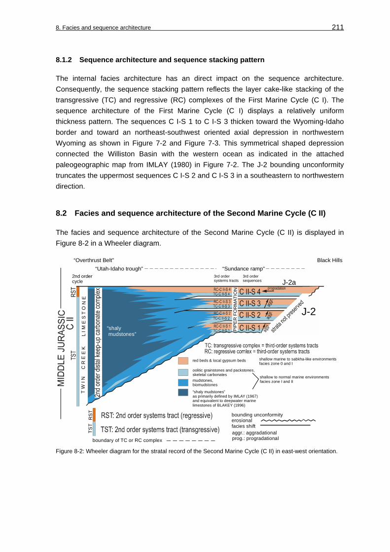
8. Facies and sequence architecture 211
8.1.2 Sequence architecture and sequence stacking pattern
The internal facies architecture has an direct impact on the sequence architecture. Consequently, the sequence stacking pattern reflects the layer cake-like stacking of the transgressive (TC) and regressive (RC) complexes of the First Marine Cycle (C I). The sequence architecture of the First Marine Cycle (C I) displays a relatively uniform thickness pattern. The sequences C I-S 1 to C I-S 3 thicken toward the Wyoming-Idaho border and toward an northeast-southwest oriented axial depression in northwestern Wyoming as shown in Figure 7-2 and Figure 7-3. This symmetrical shaped depression connected the Williston Basin with the western ocean as indicated in the attached paleogeographic map from IMLAY (1980) in Figure 7-2. The J-2 bounding unconformity truncates the uppermost sequences C I-S 2 and C I-S 3 in a southeastern to northwestern direction.
8.2 Facies and sequence architecture of the Second Marine Cycle (C II)
The facies and sequence architecture of the Second Marine Cycle (C II) is displayed in Figure 8-2 in a Wheeler diagram.
3rd ordersequences
3rd ordersystems tracts
2nd ordercycle
“Sundance ramp”“Utah-Idaho trough”“Overthrust Belt” Black Hills
T W
I N
C
R E
E K
L I
M E
S T
O N
E
shallow to normal marine environmentsfacies zone I and II
shallow marine to sabkha-like environmentsfacies zone 0 and I
red beds & local gypsum beds
oolitic grainstones and packstones,skeletal carbonatesmudstones, biomudstones
“shaly mudstones”as primarily defined by IMLAY (1967) and equivalent to deepwater marinelimestones of BLAKEY (1996)
boundary of TC or RC complex
bounding unconformityerosionalfacies shift
RS
TTS
T
aggr.: aggradationalprog.: progradational
PIP
ER
FO
RM
ATIO
N
J-2a
J-2“shaly mudstones”
Figure 8-2: Wheeler diagram for the stratal record of the Second Marine Cycle (C II) in east-west orientation.

8. Facies and sequence architecture 212
8.2.1 Vertical facies architecture
The building blocks that reflect the vertical facies architecture of the Second Marine Cycle (CII) in the “Sundance Basin” are stacked third-order sequences C II-S 1 to C II-S 4 on the “Sundance ramp” and the second-order sedimentary cycle C II in the “Utah-Idaho trough”. With the applied methods of facies analysis and the available biostratigraphic framework rhythmic bedded, small-scale cycles and sequences as described by CECIL (1990) from the Carboniferous of the Appalachian basin and AIGNER & PÖPPELREITER (2003) from the Lower Keuper Formation in the Triassic German Basin can not be identified in the sedimentary record of the Second Marine Cycle (C II) in the “Sundance Basin”.
In the subsiding “Utah-Idaho trough”, local, non-correlative shallowing upward cycles are exposed in the Sliderock Member of the Twin Creek Limestone at sections Cabin Creek (CC), Stump Creek (SC) and South Piney Creek (SPC). Therefore, the lack of rhythmic bedded, regional small-scale cycles indicates that the carbonate depositional system of the “Utah-Idaho trough” represents a keep-up system sensu SARG (1988). A catch-up system would be documented in regionally identifiable and correlative small-scale cycles.
8.2.2 Sequence architecture and sequence stacking pattern
The sequence architecture of the Second Marine Cycle (C II) is characterized by the aggradational transgressive-regressive sequences C II-S 1 to C II-S 3 and the progradational regressive complex (RC) of sequence C II-S 4. The sequences C II-S 1 to C II-S 3 are built internally by stacked transgressive (TC) and regressive (RC) complexes that thicken in a western and northern direction and form wedge-shaped sequences. Sequences and systems tracts lose their distinct character from the “Sundance ramp” toward the actively subsiding “Utah-Idaho trough” in the west and the Williston Basin in the north. Their aggradational nature is indicated by a gradual overstepping of shallow marine facies types by normal marine sediments. The progradational trend of the regressive complex (RC) of sequence C II-S 4 is documented by a pronounced basinward shift of red beds. In general, the third-order sequences show a northward and westward thickening as demonstrated in the isopach maps in Figure 7-7 and Figure 7-8.
The facies and sequence architecture of the Second Marine Cycle (C II) as previously described is coherent with investigations of BLAKEY et al. (1996) in the southern parts of the “Sundance Basin”. The situation in Utah, as proposed by BLAKEY et al. (1996), is displayed in the cross-section in Figure 8-3. In contrast to the central parts of the “Sundance Basin” marine – continental transitions are well expressed in the Twin Creek Limestone – Carmel Formation – Page Sandstone stratigraphy. The sequences C II-S 1 to C II-S 3 are added to the sketch and reveal as well progressive aggradation, accompanied by marine deepening in the “Utah-Idaho trough”. Sequence C II-S 4, termed “shelf margin

8. Facies and sequence architecture 213
system tract” by BLAKEY et al. (1996) progrades into the “Utah-Idaho trough”. The area marked A and A’ represents approximately the normal to shallow marine transition in the central parts of the “Sundance Basin” that is investigated in this work. Indicative marine – terrigenous intertongues, as preserved in the southern parts of the “Sundance Basin”, are lacking in the study area. Therefore, the sedimentary record in the southern “Sundance Basin” supports the application of the genetic sequence stratigraphic concept of GALLOWAY (1989) as demonstrated by BLAKEY et al. (1996) (see discussion in chapter: 6.2, Sequence stratigraphic concepts).
deepwater marine
SE Idaho - NC Utah SW Utah SC Utah - NC Arizona
Monument bench
Utah-Idaho troughJ-1
Navajo
Sst.
Temple Cap Sst.
Gypsum Spring Mbr.
SWW W ENNE
Twin
Cre
ek L
imes
tone
Page Sst.
1-10: accumulation sequences, bounded by MFS sensu GALLOWAY (1989)
Crystal CreekMbr.
Judd
Hollow
Mbr.
2345
67
9
8
10
HST
TST
TST
Car
mel
Form
atio
n
Slid
eroc
kM
br.
Ric
hM
br.
Bou
ndar
yR
idge
M
br.
Wat
ton
Can
yon
Mbr
.
deepening upward
SHELF MARGIN SYSTEM TRACT
eolian facies
mixed coastal plain facies shallow marine
fluvial
deepening upward
coastal marine
restricted marine
Type I unconformity
2nd
Mar
ine
Cyc
le (C
II)
Mon
umen
t b
ench
Utah
Arizona
Uta
h-Id
aho
trou
gh
J-2
J-s-up
1
A
A´A´´
A A´ A´´
C II-S 1
C II-S 2
C II-S 3
C II-S 4
C III-S 1
3rd
Mar
ine
Cyc
le (C
III)
marine
deepwater marine
marine
Figure 8-3: Regional genetic sequence stratigraphy sensu GALLOWAY (1989), stratigraphy and facies distribution of Bajocian and Bathonian rocks in the southern parts of the “Sundance Basin”, modified from BLAKEY et al. (1996). C II and C III and subordinate sequences are added from investigations in this work.
8.3 Facies and sequence architecture of the Third Marine Cycle (C III)
The facies and sequence architecture of the Third Marine Cycle (C III) is displayed in Figure 8-4 in a Wheeler diagram. The “unnamed cycle” is illustrated in Figure 8-4 together with the Third Marine Cycle (C III) by graphical means.
8.3.1 Vertical facies architecture
Similar to the conditions described from the underlying Second Marine Cycle (C II) no rhythmic bedded, small-scale cycles and sequences can be identified in the Third Marine Cycle (C III). Distally, in the “Utah-Idaho trough” no individual sequences can be distinguished and indications for the sequence architecture are limited. The distal sedimentary succession grades from shallow into normal marine carbonates that indicate marine deepening. Upward the distal calcareous suite is succeeded by siliciclastic

8. Facies and sequence architecture 214
successions of the regressive complex RC-C III-S 3. As in the Second Marine Cycle (C II), the lack of characteristic small-scale cycles indicates that the distal carbonate depositional system of the “Utah-Idaho trough” represents a keep-up system sensu SARG (1988). Accordingly, a vertical facies succession that comprises a second-order distal keep-up carbonate succession can be proposed to be representative for the Third Marine Cycle (C III) in the “Utah-Idaho trough”.
“Overthrust Belt” Black Hills
boundary of TC or RC complex
bounding unconformityerosionalfacies shift
RS
TTS
T
“uc” = “unnamed cycle”
“shaly mudstones”
Figure 8-4: Wheeler diagram for the stratal record of the Third Marine Cycle (C III).
8.3.2 Sequence architecture and sequence stacking pattern
The sequence architectural elements of the Third Marine Cycle (C III) are the third-order sequences C III-S 1 to C III-S 3. As shown in the isopach maps in Figure 7-11 and Figure 7-12, a general thickening from the “Sundance ramp” toward the “Utah-Idaho trough” and the Williston Basin can be detected.
The correlated third-order sequences of the Third Marine Cycle (C III) are wedge-shaped. Sequences C III-S 1 and C III-S 2 are stacked aggradational, while sequence C III-S 3 is progradational. As can be obtained from the Wheeler diagram in Figure 8-4, the basal sequence C III-S 1 is overstepped by the shale/mudstone deposits of the Stockade Beaver Shale-Leeds Creek interval of the subsequent sequence C III-S 2. Both sequences are characterized by an aggradational nature. The overlying transgressive-regressive sequence C III-S 3 displays a progradational nature. Internally, stacked and laterally corresponding progradational facies successions of the regressive complex (RC-III-S 3) are dominated by a pronounced increase of siliciclastic influx.
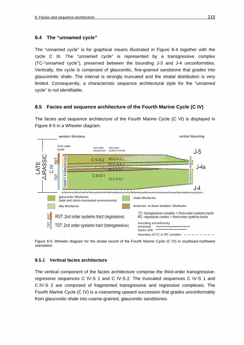
8. Facies and sequence architecture 215
8.4 The “unnamed cycle”
The “unnamed cycle” is for graphical means illustrated in Figure 8-4 together with the cycle C III. The “unnamed cycle” is represented by a transgressive complex (TC-“unnamed cycle”), preserved between the bounding J-3 and J-4 unconformities. Vertically, the cycle is composed of glauconitic, fine-grained sandstone that grades into glauconintic shale. The interval is strongly truncated and the stratal distribution is very limited. Consequently, a characteristic sequence architectural style for the “unnamed cycle” is not identifiable.
8.5 Facies and sequence architecture of the Fourth Marine Cycle (C IV)
The facies and sequence architecture of the Fourth Marine Cycle (C VI) is displayed in Figure 8-5 in a Wheeler diagram.
western Montana central Wyoming
SWIF
T FO
RM
ATIO
N
SUN
DA
NC
E F
OR
MAT
ION
silty lithofacies
shale lithofaciesglauconitic lithofacies (tidal and storm-dominated environments)
lenticular- to flaser-bedded lithofacies
boundary of TC or RC complex
bounding unconformityerosionalfacies shift
RST
TST
Figure 8-5: Wheeler diagram for the stratal record of the Fourth Marine Cycle (C IV) in southeast-northwest orientation.
8.5.1 Vertical facies architecture
The vertical component of the facies architecture comprise the third-order transgressive-regressive sequences C IV-S 1 and C IV-S 2. The truncated sequences C IV-S 1 and C IV-S 2 are composed of fragmented transgressive and regressive complexes. The Fourth Marine Cycle (C IV) is a coarsening upward succession that grades unconformably from glauconitic shale into coarse-grained, glauconitic sandstones.

8. Facies and sequence architecture 216
8.5.2 Sequence architecture and sequence stacking pattern
The sequence architectural building elements of the Fourth Marine Cycle (C IV) are the third-order sequences C IV-S 1 and C IV-S 2. As demonstrated by the facies correlation (see chapters: 5.1, 2-dimensional facies correlation; 5.2, facies maps and 5.3, 3-dimensional facies correlation) and the sequence stratigraphic correlation (see chapter: 7.1, Sequence stratigraphic correlation) the stratal record of the Fourth Marine Cycle (C IV) is limited below the bounding unconformities.
As shown in the isopach maps (see Figure 7-19 and Figure 7-20), the spatial thickness pattern for the Fourth Marine Cycle (C IV) differs remarkably from the underlying Second (C II) and Third (C III) Marine Cycle. The strong asymmetric thickness pattern in the former “Utah-Idaho trough” can not be recognized anymore and the isopach pattern is symmetric instead. The sequences C IV-S 1 and C IV-S 2 are physically tabular and bound by unconformable contacts. A distinguished stacking pattern was not found.
8.6 Appearance and internal organization of sequences and sequence types
In Figure 8-6 the allostratigraphic units that represent the Middle and Late Jurassic stratal columns of the “Sundance Basin” are comprehensively compiled in a Wheeler diagram. The changing thickness pattern is illustrated in this figure, since this aspect is one of the major physical differences between the second-order sedimentary cycles and should be emphasized. It is important to keep in mind, that the sedimentary cycles are also unconformity bound allogroups and therefore their Middle and Late Jurassic stratal record is limited. The eastern stratal extension is not known due to removal of strata during generation of Jurassic unconformities and post-Jurassic processes. The western and southern stratal packages are not preserved as well erosion and thrusting of strata by post-Jurassic processes in the evolving Cordilleran orogen.
As shown in Figure 8-6 each allogroup displays characteristics that concern the following aspects:
• Sequence architecture: Isopach pattern, sequence boundaries, sequence correlation, sequence geometry, sequence preservation, and sequence stacking.
• Internal organization of sequences: Facies, lithology and internal sequence architecture.
The most important facies and sequence architectural characteristics of the four sedimentary cycles that can be summarized from this study so far are listed comprehensively in Figure 8-7.
The First Marine Cycle (C I) is characterized by extensive facies sheets stacked in a layer cake stratification. Lateral facies variations are minor and the isopach pattern reflects increasing thickness toward a southwest-northeast trending axis of a symmetric shaped

8. Facies and sequence architecture 217
basinal setting. Widespread, correlative carbonate beds are transgressive surfaces and mark the onsets of repeated transgressive events. Third-order sequences form the First Marine Cycle (C I) and are composed of transgressive (TC) and regressive (TC) complexes.
C I R
STTS
T
red beds & local gypsum beds:marine - sabkha red beds undivided silty lithofacies
glauconitic lithofacies (tidal and storm-dominated environments)
boundary of TC or RC complexbounding unconformityerosionalfacies shift
RS
TTS
T
lenticular to flaser bedded lithofacies
Figure 8-6: Wheeler diagram of the Middle and Late Jurassic marine cycles (C I to C IV), their transgressive-regressive sequences (S) and sequence boundaries for the central and northern “Sundance Basin”.
The facies successions of the Second Marine Cycle (C II) thicken remarkably toward the “Utah-Idaho trough” and result in an asymmetric isopach pattern and a wedge-shaped sequence geometry. The change from a symmetric to an asymmetric isopach pattern is a major aspect of the Second Marine Cycle (C II). In the eastern portion of the “Sundance Basin”, a stable ramp, termed “Sundance ramp”, becomes recognizable in isopach maps,

8. Facies and sequence architecture 218
facies maps, facies distribution, and sequence correlation. A differentiation of lithology and facies types is evident between thick carbonate successions of the Twin Creek Limestone in the “Utah-Idaho trough” and carbonate-red bed successions of the Piper Formation that mark the “Sundance ramp”. On the “Sundance ramp” third-order sequences in the Piper Formation are reflected in the repeated stacking of carbonate-red bed sediments. The third-order sequences are composed of aggradational or progradational transgressive (TC) and regressive (RC) complexes. Aggradation is related to transgressive complexes (TC) and progradation to regressive complexes (RC). The prograding regressive complex RC-C II-S 4 caused a temporary termination of carbonate productivity. This sequence is equivalent to the Boundary Ridge Member of the Twin Creek Limestone and the “upper red bed member” of the Piper Formation.
The overlying Third Marine Cycle (C III) is similar to the preceding Second Marine Cycle (C II) in respect to aggradational/progradational sequence stacking, wedge-shaped sequence geometry and asymmetric isopach pattern. Deposition on the “Sundance ramp” occurred in shallow marine “foreshore-shoreface-offshore” environments in the Canyon Springs Sandstone Member and Hulett Sandstone Member of the Sundance Formation. These proximal shallow marine siliciclastics grade basinward into a keep-up carbonate system of the Watton Canyon and Leeds Creek Member of the Twin Creek Limestone. Carbonate production in the “Utah-Idaho trough” was finally terminated by the basinward prograding of “offshore-shoreface-foreshore-sabkha” siliciclastics of the Hulett Sandstone, Lak Member, Giraffe Creek Member, and Preuss Formation in the sequence C III-S 3 and can be confined to the regressive complex RC-CIII-S 3. Third-order sequences can not be traced into western Montana due to limited expression of facies changes in the shales and siltstones of the Sawtooth Formation and Rierdon Formation. In southwestern Montana, the stratigraphic record is very limited at examined locations Sappington (SA) and Rocky Creek Canyon (RC) as shown in the facies correlation.
The “unnamed cycle” is documented by an isolated transgressive complex (TC-unnamed cycle), preserved between the bounding J-3 and J-4 unconformities.
The siliciclastic dominated Fourth Marine Cycle (C IV) is composed of two unconformity bound third-order sequences within the Redwater Shale Member of the Sundance Formation. The sequences C IV-S 1 and C IV-S 2 are tabular and truncated. The depositional environments are tidal- and storm-influenced “offshore-shoreface-foreshore” settings. The stratal record, preservation of transgressive and regressive complexes and sequence geometry is controlled by the erosion that occurred during generation of the sequence bounding unconformities. The isopach pattern encircles a northnortheast-southsouthwest oriented basin axis that displays a symmetric shaped basin geometry.
Based on the sequence architectural styles and the internal organization of sequences three characteristic sequence types can be identified in the “Sundance Basin”. These sequence types are evident in regions like the “Sundance ramp”, where the sedimentary

8. Facies and sequence architecture 219
cycle and sequence correlation provided successfully a sequence stratigraphic framework. In areas where facies and lithologic contrasts are low like the Williston Basin or northwestern Montana, these sequence types can not be traced.
Sequence type 1: The tabular sequence type 1 is characterized by extensive, tabular sequences stacked in a layer cake stratification. Lateral facies variations are minor and correlative carbonate beds are transgressive surfaces (TS). For this sequence type transgressive (TC) and regressive (TC) complexes are traceable in third-order sequences.
Sequence type 2: The wedge-shaped sequence type 2 shows thickening sequences that display an asymmetric isopach pattern and a heterogeneous facies distribution between troughs (“Utah-Idaho trough”) and ramps (“Sundance ramp”). This sequence type and subordinate transgressive (TC) – regressive (RC) complexes are aggradational or progradational stacked.
Sequence type 3: The tabular, truncated sequence type 3 is characterized by tabular, unconformity bound, truncated sequences. The facial expression is relatively homogenous and the sequences contain internally remnants of transgressive (TC) and regressive (TC) complexes.
2nd order cycle
3rd-orderseq.
Internal organization of facies & sequence architectureSystems tracts
Lithology Facies
Appearance of facies & sequence architecture
Isopachpattern
Stratalpreservation
Sequencegeometry
Sequenceboundary
Sequencestacking“SR” “UT-ID TR”
Sequence type
TS
RC-C IV-S 2C IV-S 2TC-C IV-S 2
RC-C I-S 1C I-S 1
TC-C I-S 1
FirstMarineCycle(C I)
C I-S 2
C I-S 3
TS
TS
TS layer-cakestacked sequences
symmetric:thickenstowardNE-SW orientedbasin axis
extensive,tabularsequencescarbonate
red bedsred beds &gypsum
RC-C I-S 2
TC-C I-S 2
red bedscarbonate
RC-C I-S 3
TC-C I-S 3
red beds
J-1
J-2
SecondMarineCycle(C II)
RC-C II-S 1C II-S 1
TC-C II-S 1
C II-S 2
C II-S 3
carbonatered bedsred beds &gypsum
RC-C II-S 2
TC-C II-S 2
red bedscarbonate
RC-C II-S 3
TC-C II-S 3
red beds
C II-S 4RC-C II-S 4
TC-C II-S 4
2nd
orde
r car
boan
eke
ep-u
p sy
stem
carbonate
red bedsJ-2a
TS
TS
TS
TS amalgated,aggradationalsequenceson“SR”;fade-outtowards“UT-ID TR”
wedge-shaped sequences
asymmetric:thickeningtoward“UT-ID TR”
ThirdMarineCycle(C III)
RC-C III-S 1C III-S 1
TC-C III-S 1
C III-S 2
C III-S 3
RC-C III-S 2
TC-C III-S 2
RC-C III-S 3
TC-C III-S 3
TC-unnamed
2nd
orde
r car
boan
eke
ep-u
p sy
stem
red beds
mixed
mixed
siliciclastic
siliciclasticTS
J-2bTS
TS
siliciclastic
siliciclastic
wedge-shaped sequences
asymmetric:thickeningtoward“UT-ID TR”
FourthMarineCycle (C IV) RC-C IV-S 1
C IV-S 1TC-C IV-S 1 siliciclastic
siliciclasticsiliciclasticsiliciclastic “foreshore-
shoreface- offshore”tidal- and storm-dom.
J-4aTS
TS J-4
J-5 tabular,unconform.boundedsequences
lithology and faciesdifferent.“UT-ID TR” vs. “SR”:
“unnamed cycle”
1
3
2
lithology and faciesdifferent.“UT-ID TR” vs. “SR”:
lithology and faciesdifferent.“UT-ID TR” vs. “SR”:
?J-3
Figure 8-7: Internal organization and sequence architectural styles of the sedimentary cycles and their subordinate sequences. Note that sequence types 1 to 3 can be assigned to particular sedimentary cycles. “SR” = “Sundance ramp”; “UT-ID-TR” = “Utah-Idaho trough”; TS = transgressive surface.

8. Facies and sequence architecture 220
An important information that becomes obvious from the facies and sequence correlation is the correspondence between the development of characteristic sequence types and the four sedimentary cycles C I to C IV as shown in Figure 8-7.
As demonstrated by the facies analysis, facies correlation, the sequence correlation, and the sequence architecture the sedimentary cycles and their third-order sequences differ in development of sequence architectural styles and sequence types as well as in their internal organization.
It will be essential for the course of this study to identify the controlling mechanisms that influenced the development of different sequence types, the internal organization and the sequence architectural styles of the sedimentary cycles and sequences within the “Sundance Basin”. For this purpose, the focus will be put on the potential influence of factors like tectonics and eustasy on the Middle and Late Jurassic sedimentation within the “Sundance Basin” in the following chapters.

221
9 Identification and influence of controlling mechanisms
Autogenetic and allogenetic mechanisms can be distinguished that influence the deposition of cyclic sequences (EINSELE 1992). Autogenetic mechanisms primarily control processes within a sedimentary basin. Allogenetic mechanisms are influenced by external factors as tectonics, climate and global sea-level fluctuations. It is one of the major objectives of this study to identify the mechanisms that played an important role for the facies and sequence evolution of the “Sundance Basin”. In order to identity these mechanisms it will be tested in a first step if detectable relative sea-level changes in the “Sundance Basin” correspond to global eustasy curves or if a tectonic control is suggested. In a next step the temporal and spatial subsidence behavior of the basin will be analyzed. The resulting data is expected to provide information that can be used to:
• Explain the obvious differences in facies distribution, lithology and isopach pattern, that were recognized between the sequence architecture of the sedimentary cycles (see Figure 8-6 and Figure 8-7 in previous chapter, 8).
• Determine the timing and style of changes in basin configuration that are controlled by the subsidence behavior.
9.1 Relative sea-level changes in the “Sundance Basin”
According to EINSELE & BAYER (1991), sea-level curves can only derive from stratigraphic sections with sufficient resolution. The curves are often composed of different symmetric elements. Commonly, asymmetric curves result from field water depth curves, while symmetric cycles form under special conditions (EINSELE & BAYER 1991). Moreover, the type and intensity of a sedimentary cycle curve vary between basin margin and center. In order to obtain relative sea-level curves for the “Sundance Basin” representative relative water depth curves and their sequence stratigraphic elements were plotted against a Mesozoic time scale of GRADSTEIN et al. (1995) in Figure 9-1. With the application of this method it turned out that the third-order sea-level curve is primarily representative for the “Sundance ramp”. The resulting relative sea-level curve can not be representative for the “Utah-Idaho trough”. Third-order sequences can not be identified and correlated in the stratal record of this structural element with the methods of facies analysis applied in this work and the available biostratigraphic framework (see chapter: 7.2, Sequence characteristics; Figure 7-21). As shown in the sequence stratigraphic correlation for the Second (C II) and Third (C III) Marine Cycle in the “Utah-Idaho trough” only the transgressive-regressive signatures of the second-order sedimentary cycles can be recognized in the Twin Creek Limestone and Preuss Formation.

9. Identification and influence of controlling mechanisms 222
J-4
J-2
J-2a
166,8
168,2
J-2b
J-4a
?
176,5 4,0
169,2 4,0
164,4 3,8
159,4 3,6
154,1 3,2
J-3
J-1
J-5 2nd-order
2nd-order
2nd-order
- +
Jurassic time scaleafter GRADSTEIN et al. (1995)
C III-S 1”u
nnam
ed c
ycle
”
~ 2 - 3 Ma
~ 1 Ma
~ 1 Ma
< 2 Ma
C I-S 2
P
relative sea-level
C I-S 3
C I-S 1
C II-S 1
C II-S 2
C II-S 3
C II-S 4
C III-S 2
C III-S 3
C IV-S 1
C IV-S 2
P
P
P = prograding Figure 9-1: Relative third-order sea-level curve for the “Sundance Basin”. Chronostratigraphic dates of third-order unconformities J-2a and J-2b from KVALE et al. (2001). Note that the J-4a can not be dated in the Oxfordian. Gray shaded are the hiatuses in the “Sundance Basin”. Duration of hiatuses after PIPIRINGOS & O’ SULLIVAN (1978).
9.1.1 Interpretation of relative sea-level changes in terms of global eustasy
To distinguish tectonic influence on the generation of the sedimentary cycles and their subordinate sequences from global eustasy the relative sea-level curve for the “Sundance Basin” will be compared to regional and global Jurassic sea-level curves in Figure 9-2. Further, second- and third-order transgressive events known from the southern “Sundance Basin” and other sedimentary basins on the North American craton will be compared to relative sea-level trends in the study area.
9. Identification and influence of controlling mechanisms 223
9.1.1.1 Published sea-level curves for the “Sundance Basin”
Published relative sea-level curves for the “Sundance Basin” are very scarce. A local sea-level curve interpreted from strata of the Second Marine Cycle (C II) in Arizona was published by RIGGS & BLAKEY (1993). Their interpretation is included in a relative sea-level curve for the southern parts of the “Sundance Basin” in Figure 9-2 published by PETERSON, F. (1994). He compared transgressive-regressive trends in the Jurassic system of the southern Western Interior with areas in the Gulf of Mexico, southwestern Canada, Northern Yukon, Arctic Islands, and with the global sea-level curve of HALLAM (1988). After this comparison he stated that: “Correspondence of transgressive-regressive cycles in the southern part of the Western Interior can be found with some of the other transgressive-regressive cycles elsewhere in North America, but, depending upon one’s bias, these can be viewed either as coincidences or as related to global eustatic sea-level fluctuations” (PETERSON, F. 1994: 241). Because of the problematic dating of many stratigraphic intervals PETERSON, F. (1994: 241/242) noted further:”....one can rather easily adjust the ages of many local sections in whatever manner one wishes to rather nearly fit any particular “wiggle” on a global sea-level curve and thereby draw conclusions related to global eustasy”.
Another relative sea-level curve for the Jurassic system in the whole Western Interior region was prepared by BRENNER & PETERSON (1994) in order to demonstrate the transgressive-regressive nature of the four sedimentary cycles (see Figure 9-2, curve D). The sedimentary cycles are in the second-order scale of the sequence hierarchy definition of VAIL et al. (1991) as demonstrated in the chapter: Cyclostratigraphy (see chapter: 2.5, Figure 2-31 and chapter: 7, Sequence stratigraphic correlation). Consequently, the sea-level curve of BRENNER & PETERSON (1994) is as well in the second-order scale. This sea-level curve clearly reflects a second-order cyclicity within the “Sundance Basin” fill and was confirmed by the basinwide sequence correlation in this study.
9.1.1.2 Global Jurassic sea-level curves
A number of sea-level curves for the Jurassic are published by VAIL et al. (1984), HAQ et al. (1987) and by HALLAM (1988). The Middle and Upper Jurassic parts of the curves are shown in Figure 9-2, curves A, B and C. In general, the interpretation of these global sea-level curves is based on different methods of data compilation, analyses and documentation. These different approaches to global eustasy are still subject of discussion. Like PETERSON, F. (1994) and EMBRY (1993) pointed out, data of global sea-level curves is often not referenced and documented in the literature at all, which has led to the expression of criticisms and disputes between workers (HALLAM 1988; 1992; 1999, MIALL 1986; 1991; 1997, POSAMENTIER & JAMES 1993).

9. Identification and influence of controlling mechanisms 224
In comparison of the published global sea-level curves for the Jurassic only a few intervals within show a close resemblance. According to MIALL (1997), these similarities might indicate eustatic events that show through the differing methods of data compilation and analyses.
9.1.2 Comparison of transgressive events and relative sea-level curves in the “Sundance Basin”
In Figure 9-2 the third-order sea-level curve for the “Sundance Basin” compiled in this study and the second-order sea-level curve of BRENNER & PETERSON (1994) are compared with regional, basinwide and global sea-level curves.
2nd-order transgressive event3rd-order transgressive event
local transgressive eventor no hierarchy indicated
D. second-order regional sea-level curvefor the Western Interior fromBRENNER & PETERSON (1994)
E
AALENIAN
BAJOCIAN
BATHONIAN
CALLOVIAN
OXFORDIAN
KIMMERIDGIAN
Sverdrup Basinafter EMBRY (1993)
SWCanada
after POULTON (1984)
Utah, Arizona, New Mexico, Colorado
= southern“Sundance Basin”
afterPETERSON, F. (1994)
J-1
J-2
J-2aJ-2b
J-4a ?J-5
J-4
J-3
1stMarine
2ndMarine
3rdMarine
4thMarine
UpperContinental
TOARCIAN
E: third-order scale sea-level curve for thecentral and northern “Sundance Basin”
D
A: HALLAM (1988)
B: HAQ et al. (1987)
C: VAIL et al. (1984)
A B C
J-2c
- - + - + - + - + - ++
global contextcratonwide context
basinwide context
“unnamedcycle”
LowerContinental
Figure 9-2: Published sea-level curves for Jurassic sedimentary basins of the North American craton by PETERSON, F. (1994), EMBRY (1993), POULTON (1984), and BRENNER & PETERSON (1994) in comparison with the third-order sea-level curve for the “Sundance Basin” and global Jurassic sea-level curves of VAIL et al. (1984), HAQ et al. (1987) and HALLAM (1988).
Comparison in a basinwide context
In comparison with the sea-level curve for the southern “Sundance Basin” from PETERSON, F. (1994) a close correspondence of relative sea-level curves and basinwide transgressive events is obvious. Differences are related to minor unconformities. For instance, the third-order unconformity J-2b, identified in the Canyon Springs Sandstone Member of the Sundance Formation in central Wyoming, was correlated in this study with equivalent surfaces reported by AHLBRANDT & FOX (1997) from the Black Hills and KVALE et al. (2001) from the Bighorn Basin. The J-2b is not known from the southern “Sundance Basin” so far. Also the J-4a, identified and correlated for the first time in the

9. Identification and influence of controlling mechanisms 225
Redwater Shale Member of the Sundance Formation and the Swift Formation in this study, can not be dated with certainty in the Oxfordian and is not known from the southern “Sundance Basin”. In turn, the locally developed J-2c, proposed by PETERSON, F. (1994) from the southern “Sundance Basin” is not present in the study area.
Comparison in a cratonwide context
For other areas on the North American craton relative sea-level curves are published for the Sverdrup Basin in the Arctic region by EMBRY (1993) and southwestern Canada by POULTON (1984). EMBRY (1993) noted a number of second- and third-order transgressive events in the stratigraphic record of the Sverdrup Basin. The hierarchical order of these events and their timing is shown in Figure 9-2. The transgressive second-order event at the Callovian-Oxfordian boundary is corresponding to the sea-level curve of HALLAM (1988) and expressed as well in the relative sea-level curves for the “Sundance Basin”.
The sea-level curve constructed by POULTON (1984) for southwestern Canada is not placed in a hierarchical ranking. Sea-level fluctuations and transgressive events show a correspondence to the sea-level curve of HALLAM (1988) and VAIL et al. (1987). A close correspondence between the sea-level curve from southwestern Canada and second-order events in the lower Bajocian and at the Bathonian-Callovian boundary in the Sverdrup Basin exist. In both areas a transgressive event at the Aalenian-Bajocian boundary occurs slightly earlier than in the “Sundance Basin” (J-2).
However, correspondence between regional sea-level curves for the “Sundance Basin” and curves from other parts of the North American craton is limited. Similarities might be related to a sea-level fall and the subsequent transgression at the boundary Callovian-Oxfordian and generation of the J-4 unconformity in the “Sundance Basin”. This trend is correlative to the Sverdrup Basin, but occurs slightly later in southwestern Canada.
Comparison in a global context
A common feature of Jurassic sea-level curves published by VAIL et al. (1984), HAQ et al. (1987) and HALLAM (1988) is a transgressive global eustasy (see Figure 9-2). This transgressive nature reflects the rising global sea-level throughout the Jurassic. As noted by BRENNER & PETERSON (1994), this global transgressive nature is not reflected in their sea-level curve for the western North American craton. Instead, the second-order sea-level curve of BRENNER & PETERSON (1994) displays a regressive nature that becomes evident in the Callovian and culminates in the filling of the “Sundance Basin” with the deposition of the Morrison Formation.
The third-order sea-level curve, compiled for the “Sundance Basin” in this study, clearly supports this trend. From the Aalenian to the late Bathonian the major trend of the third-order sea-level curve is transgressive. The widest aerial extent of the “Sundance Basin” is

9. Identification and influence of controlling mechanisms 226
recorded in the late Bathonian with deposition of the Stockade Beaver Shale-Leeds Creek-Rierdon interval of the sequence C III-S 2. From this inflection point the nature of the basinfill becomes progressively regressive.
Correspondence of the relative sea-level curve to the global sea-level curve of VAIL et al. (1984) and HAQ et al. (1987) is poor (see curves B and C in Figure 9-2). No apparent similarities in sea-level fluctuation and transgressive events are obvious between these global sea-level curves and the “Sundance Basin” curves.
Correspondence between the global sea-level curve of HALLAM (1988) (see curve A in Figure 9-2) and the “Sundance Basin” curves is confined to sea-level fluctuations at the Aalenian-Bajocian boundary, the Middle Callovian and the Callovian-Oxfordian boundary. Additionally, the third-order unconformities J-2a and J-4a might correlate with minor sea-level fluctuations in the global sea-level curve of HALLAM (1988), but these unconformities are poorly dated in the stratal record.
Discussion
The third-order sea-level curve for the “Sundance Basin” derived from the facies and data analyses in this study. A potential problem of the “Sundance Basin” fill is the dating of many stratigraphic intervals and the limited preservation of strata. This circumstance makes the comparison of regional sea-level curves with global sea-level curves speculative. In this study, no convincing correspondence of transgressive-regressive signatures was found between the relative sea-level curves for the “Sundance Basin” and global sea-level curves of VAIL et al. (1984) and HAQ et al. (1987).
More correspondence exists between the HALLAM (1988) curve and the “Sundance Basin” curve in sea-level fluctuations at the Aalenian-Bajocian boundary, in the Middle Callovian and at the Callovian-Oxfordian boundary. At this point, the question arises if this correspondence might be either coincidence or driven by eustasy. Based on the following aspects it is suggested that the relative sea-level in the “Sundance Basin” was not primarily controlled by eustasy:
• The second- and third-order sea-level curves for the “Sundance Basin” strongly contrast the transgressive global eustasy. Sea-level curves of VAIL et al. (1984), HAQ et al. (1987) and HALLAM (1988) postulate a general global sea-level rise from the Middle Jurassic into the Cretaceous epoch. In the “Sundance Basin” the deposition of the sequence C III-S 2 (Stockade Beaver-Leeds Creek-Rierdon-Carmel interval) in the late Bathonian marks an inflection point from which the nature of the basin fill becomes progressively and evidently regressive. The regressive portion of the relative “Sundance Basin” sea-level curves was deposited during a transgressive maximum on global continental margins.
• The development of the “Utah-Idaho trough” in the southwestern and western portions of the “Sundance Basin” give evidence for tectonic activity.

9. Identification and influence of controlling mechanisms 227
Supported by these aspects it seems obvious that relative sea-level changes in the “Sundance Basin” occurred independently from global trends at least since the late Bathonian. The different timing of sea-level fluctuations and transgressive events in the “Sundance Basin” with cratonwide and global trends suggests the influence and control of deposition by regional factors such as tectonics and climatic variations.
9.2 Quantitative subsidence analysis
The relative sea-level trend within the “Sundance Basin” clearly contradicts the transgressive global sea-level rise since the Middle Jurassic and therefore can not be explained by eustasy. Consequently, other controlling factors like tectonic activity and climate must be considered as influential factors on the facies evolution and sequence architecture within the “Sundance Basin”. The influence of tectonism on the subsidence behavior will be analysed in this chapter.
The Middle and Late Jurassic stratal packages were deposited on the cratonic platform of the North American continent. The burial depth and the sedimentary overburden range between 1000 and 4800 m. The sediments are overprinted by early to late diagenetic processes.
An appropriate approach to a detailed analysis of the subsidence and sedimentation history of a sedimentary basin is achieved by the method of “backstripping”, as pointed out by MIALL (1997). This method was invented by WATTS & STRECKLER (1979) and SCLATER & CHRISTIE (1980). In a first step the sedimentary successions within the allogroups (C I, C II, C III, “unnamed cycle”, C IV) were decompacted. The decompacted thickness data for the allogroups C I, C II, C III, and C IV was plotted in east-west and north-south profiles to detect changes in basin geometry. The “unnamed cycle” was not displayed in a decompacted thickness profile due to the very limited distribution in the study area and the poor stratal preservation. From the decompacted thickness data sediment accumulation curves were constructed in a next step.
9.2.1 Overburden
The degree of mechanical compaction and the resulting loss of pore space in unconsolidated sediments depends mainly on the overburden pressure or vertical load, which is caused by the weight of the overlying sediment and water column (OWEN 1987). In the study area, the post-depositional overburden, from the base of the Morrison Formation to the top of the Fort Union Formation, was determined from stratigraphic data published by HADLEY et al. (1955), HADLEY & LEWIS (1956), GRIES (1996), HEASLER et al. (1986), BROWN (1993), and HINTZE (1988). The top of the widely distributed Paleocene Fort Union Formation was chosen to determine the thickness of the overburden. Irregularities due to local geologic features such as the thick Eocene

9. Identification and influence of controlling mechanisms 228
Absaroka volcanics in northwestern Wyoming or Quaternary landslides, terraces, morainal, and alluvial deposits are not included. In Figure 9-3 the minimum and maximum thickness of the Upper Jurassic to Paleocene overburden is shown.
NE-Utah NW-Wyoming
Wind River Basin
Black Hills
SW-Montana
NW-Montana
Central Montana
Over-burden
Base Morrison − Top Fort Union Fm.
Base Morrison − Top Fort Union Fm.
Base Morrison − Top Fort Union Fm.
Base Morrison − Top Fort Union Fm.
Base Morrison − Top Fort Union Fm.
Top Creta-ceous
Base Morrison − Top Fort Union Fm.
Author HINTZE (1988)
HEASLER et al. (1986)
BROWN (1993)
GRIES (1996)
HADLEY et al. (1955)
HADLEY et al. (1955)
HADLEY & LEWIS (1956)
Thick-ness
2743 m – 3813 m
~4084 m 4500 m – 4800 m
1087 m – 2262 m
1727 m – 1850 m
2185 m – 3401 m
1339 m – 1569 m
Figure 9-3: Minimum and maximum amount of the Upper Jurassic-Cretaceous-Paleocene overburden (base Morrison Fm. – top Fort Union Fm.) in representative parts of the study area compiled from HINTZE (1988), HEASLER et al. (1986), BROWN (1993), GRIES (1996), and HADLEY (1956).
9.2.2 Decompaction
Representative stratigraphic sections where chosen for decompaction. It was assumed that the determination of porosity changes provide information that reflect significant developments and changes in burial depths during basin evolution, because compaction is a largely irreversible process (FÜCHTBAUER 1988, POELCHAU et al. 1996). This assumption certainly does not reflect natural conditions, since it seems unrealistic to suppose that the porosity-depth relationship of a heterogeneous sediment column is controlled solely by mechanical compaction in burial environments. Complex factors, like temperature, viscosities, over- or underpressures of pore fluids, and the wide range of possible isochemical diagenetic processes that accompany mechanical compaction during burial are neglected. However, to evaluate the major influences on the sedimentary system within the “Sundance Basin” a simplified “compaction”-related subsidence analysis is considered to provide the required information in a resolution that corresponds to the accuracy of known relative sea-level changes. This approach seems consistent with established basin modelling methods, which simulate porosity change primarily as physical compaction with increasing burial depth and do not consider that a large amount of porosity is lost through chemical diagenesis (POELCHAU et al. 1996).

9. Identification and influence of controlling mechanisms 229
Method
The initial thickness T(decomp.) of a stratigraphic column was reconstructed by decompaction. A given sedimentary succession with the measured, present thickness T(comp.), the present mean porosity Pm and an initial porosity Pi result in the original thickness T(decomp.) according to EINSELE (1992):
T =(decomp.)T (1-Pm)(comp.)
(1-Pi)
The initial and present porosity are required parameters to decompact a measured sedimentary succession and a representative average value must be defined (POELCHAU et al. 1996). The initial porosities for particular lithologies and depths can be obtained from empirical standard porosity-depth curves as proposed by EINSELE (1992) and BOND & KOMINZ (1984). The applicability of such standard curves is still debated. GILES (1997) stated that the use of standard curves is strongly to be discouraged, since they should be constructed on a case by case basis. Nevertheless, to determine the timing and distribution of subsidence a “compaction”-related subsidence analysis can be considered as an appropriate approach. The initial and present porosities for siliciclastic sediments were acquired from the porosity-depth curve of BOND & KOMINZ (1984). Evaporites were not treated like siliciclastic sediments, because of their differing behavior during compaction. The approach to their decompaction will be discussed in the further course of this chapter.
9.2.3 Compaction parameters and porosity-depth relations
The method of decompaction has to be carried out for stratigraphic units for which age and thickness dates can be determined (EINSELE 1992, MIALL 1997). Based on the allostratigraphic nature of the “Sundance Basin” fill, the sediment columns of the major sedimentary cycles First (C I), Second (C II), Third (C III), “unnamed cycle” and Fourth (C IV) Marine Cycle were treated as the major units for decompaction. Within the sedimentary cycles decompaction was carried out for siliciclastic, carbonate and evaporite lithologies. The siliciclastics were divided into sandstones, siltstones and claystones, the carbonates into grain-supported and mud-supported textures. The compaction parameters are based on the assumption that no early cementation did take place in the siliciclastic sediments.

9. Identification and influence of controlling mechanisms 230
9.2.3.1 Siliciclastics
Sandstones
Initial porosities, mechanical compaction and porosity reduction during diagenesis and burial of sandstones have been investigated intensively since the 1930`s. The number of authors that contributed to that matter are too numerous to mention. Comprehensive reviews and significant publications on this subject are from BEARD & WEYL (1973), RIEKE & CHILINGARIAN (1974), WOLF & CHILINGARIAN (1976), BJORLYKKE (1988), FÜCHTBAUER (1988), BJORLYKKE et al. (1989).
The values given for the initial porosity of well-sorted sandstones range between 35-45% (BJORLYKKE 1988, FÜCHTBAUER 1988). Primarily, the depositional environment has a great impact on initial porosity, besides textural factors (grain shape, grain size, sorting) and sedimentation rates (POELCHAU et al. 1996). In eolian environments initial porosities can reach up to 51% in grain flow sheets or up to 47% in coastal beach sands (ATKINS & McBRIDE 1992, FÜCHTBAUER 1988). Consequently, the eolian deposits of the Entrada Sandstone and the Canyon Springs Sandstone Member were attributed an average initial porosity of 45%, while shallow marine successions (Hulett Sandstone, Stump Formation, Swift Formation etc.) were restored with an average initial porosity of 40%.
An intergranular-volume-decline curve of PAXTON et al. (2003) reveals a rapid initial porosity decrease to about 28% at 1500 m depth. This decline slows down between 1500 m and 2500 m, before it finally reaches a finite potential porosity in the absence of cement or matrix of 26%. The next step in porosity loss occurs at a much greater depth of 6700 m, where pressure solution becomes important and grain penetrations develop. PAXTON et al. (2003) concluded from their empirical results that the 26% limit is perhaps analogous to the porosity in a rhombohedral grain package (25,95%) of perfect spherical grains (coordination number 12).
Indications for abnormal high pressures such as grain penetrations caused by pressure solution were neither found in thin-section analysis of the investigated siliciclastic sediments nor reported from petrographical studies by previous authors like RAUTMANN (1976), WEST (1985), HILEMAN (1973), JORDAN (1985), or AHLBRANDT & FOX (1997). Therefore, sandstone units that were loaded with an overburden of about 1500 m were decompacted with present porosities of 28%. This overburden load can be applied for central Montana and the Black Hills area as can be obtained from Figure 9-3. In other areas, as northeastern Utah, western Wyoming and western Montana, with an overburden over 2500 m the investigated sandstones were considered as compacted to the limited grain compaction value of 26%.

9. Identification and influence of controlling mechanisms 231
Siltstones
Siltstones were decompacted with initial porosities of 55%. This average porosity value is taken from the porosity-depth-curve of BOND & KOMINZ (1984).
Claystones
Unconsolidated clayey shales commonly show initial porosities between 70% and 90% (FÜCHTBAUER 1988). Porosity-depth curves for these sediments show a rapid decline of the initial porosity within the first 500 m of burial and become more stable below that depth. Below 1500 m the mechanical compaction reaches its limit because potential clay-mineral particles are oriented to the vertical pressure (FÜCHTBAUER 1988). The shale lithologies within the “Sundance Basin” fill are not clay-dominated. Instead, they show a considerable content of silty to sandy and calcareous interbeds and are sometimes highly glauconitic. To pay respect to these factors shale units within the investigated stratigraphic sections were decompacted under the application of the siltstone parameters below depths of 200 m as derived from the porosity-depth-curve of BOND & KOMINZ (1984).
9.2.3.2 Carbonates
The compaction of carbonates has been the subject of controversy for a long time (see the full list of authors and comprehensive discussion in RICKEN 1987). Because the mechanical compaction in carbonates is well-documented, RICKEN (1987) concluded that this process is an important parameter for the reduction of the primary porosity in carbonates. The initial and present porosities of carbonate rocks from different depositional environments and burial pressure regimes were studied for instance by SHINN et al. (1977), BATHURST (1980) and SHINN & ROBBIN (1983). In contrast to siliciclastics, no generally applicable porosity-depth functions exist for carbonates (BJORLYKKE et al. 1989). In this study, the approach of CROSS (1989) is followed: compaction parameters were distinguished for grain- versus mud-supported textures.
• Grain-supported carbonates: Grain-supported carbonates are resistant to compaction in a comparable manner as sandstones, since the dissolution of aragonitic particles provides very early cements that support a stabilization of the sedimentary texture against mechanical pressure (MEYERS & HILL 1983). Initial and present porosities of grain-supported carbonates were obtained from values for early cemented sandstones from the porosity-depth curves of BOND & KOMINZ (1984). In general – and of course related to the burial depth – an average porosity reduction of about 20% would result from this application. This equalization of grain-supported carbonates with sandstones in the porosity-depth relation was also applied by CROSS (1989) for the decompaction of carbonates within the “Cordilleran foreland”.

9. Identification and influence of controlling mechanisms 232
• Mud-supported carbonates: Mud-supported carbonates can be compacted considerably. Investigations by SHINN & ROBBIN (1983), SCHLANGER & DOUGLAS (1974), HAMILTON (1976), and BATHURST (1980) showed that porosity reduction by mechanical compaction in mud-supported carbonates can reach about 50%. Only under exceptional conditions, if aragonite is transformed into calcite very shortly after deposition, the mud-supported texture can be resistant to compaction (FÜCHTBAUER 1988). However, the mud-supported “Sundance Basin” carbonates were treated in correspondence to the “Cordilleran foreland” subsidence history study by CROSS (1989) as shaley sandstones for decompaction.
9.2.3.3 Evaporites
Evaporitic sediments occur in varying amounts within the lower three sedimentary cycles C I to C III and range in thickness between 3 cm and 15 m. Gypsum is the only calcium sulfate mineral in the investigated sedimentary column and occurs in three varieties: as thin to massive secondary gypsum beds, post-Jurassic joint fillings (veins and druses) and as selenite (fibrous and sparry variety) (FILIPPICH 2001). For the decompaction process only massive gypsum beds were taken into account. Gypsum converts into anhydrite syndepositionally or in burial environments under the influence of temperature, pressure and salinity (WARREN 1989; 1991). This process is reversed during erosion and exposure. Gypsum commonly develops enterolithic folds during burial as it is converted into the dehydrated anhydrite phase (WARREN 1989; 1991). This texture is reported as a prominent feature by FILIPPICH (2001), accompanied by mosaic-nodular bedding in the secondary gypsum beds of the First (C I) and Second (C II) Marine Cycle. Obviously, these evaporites experienced the transformation from gypsum into anhydrite during burial and the reverse process during exhumation in post-Jurassic times. The different modifications in sediment thickness and porosity under the influence of gypsum-anhydrite phase changes were not considered as parameters for decompaction. To restore the initial thickness of the gypsum beds the porosity and volume reduction by dewatering during early compaction was used as parameter. According to WARREN (1989; 1991), dewatering a thick gypsum bed would reduce the thickness and sediment volume with a loss of 38% of its initial volume.
9.2.4 Decompacted thickness profiles
Information about the tectonic structure and evolution of a sedimentary basin derives from the thickness of the stratigraphic successions that, in turn, provides data about the basin fill geometry and subsidence history (EINSELE 1992). Therefore, 28 of the 56 stratigraphic sections, available from this study and the Diploma theses prepared by DASSEL (2002), SPRIESTERSBACH (2002), FILIPPICH (2001), and BÜSCHER (2000), were decompacted. The “unnamed cycle” was not displayed as a decompacted thickness profile due to the very limited distribution in the study area and the poor stratal
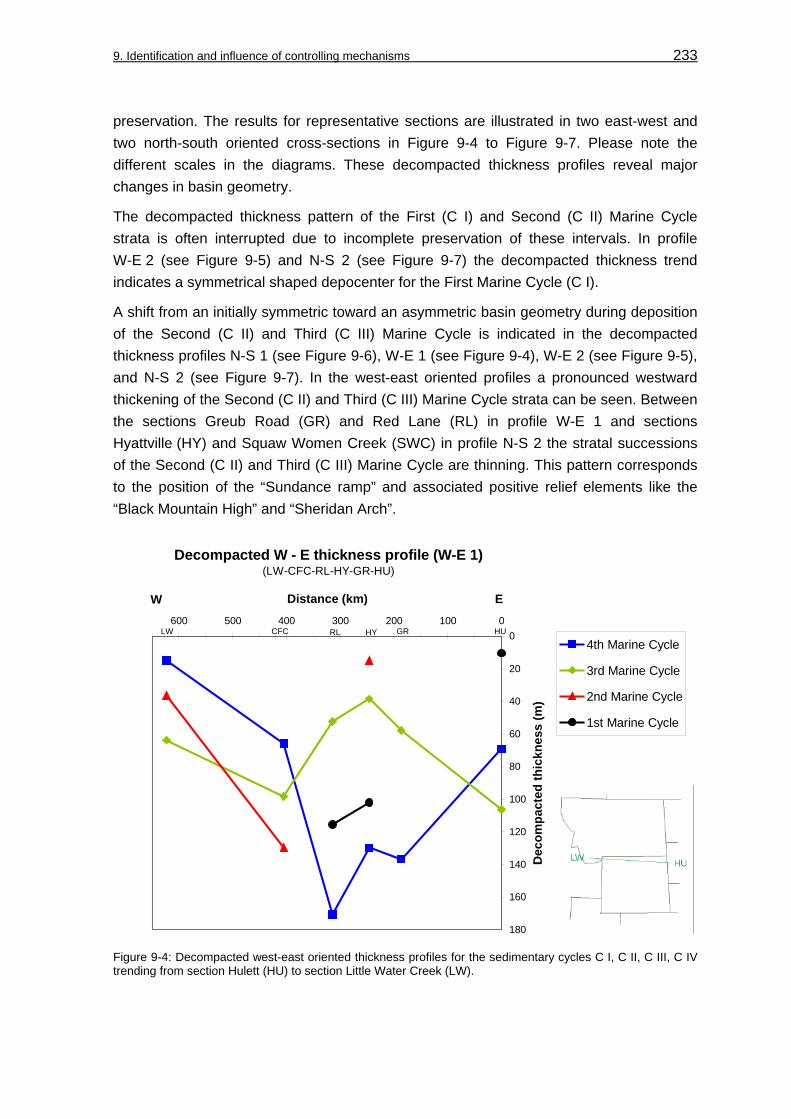
9. Identification and influence of controlling mechanisms 233
preservation. The results for representative sections are illustrated in two east-west and two north-south oriented cross-sections in Figure 9-4 to Figure 9-7. Please note the different scales in the diagrams. These decompacted thickness profiles reveal major changes in basin geometry.
The decompacted thickness pattern of the First (C I) and Second (C II) Marine Cycle strata is often interrupted due to incomplete preservation of these intervals. In profile W-E 2 (see Figure 9-5) and N-S 2 (see Figure 9-7) the decompacted thickness trend indicates a symmetrical shaped depocenter for the First Marine Cycle (C I).
A shift from an initially symmetric toward an asymmetric basin geometry during deposition of the Second (C II) and Third (C III) Marine Cycle is indicated in the decompacted thickness profiles N-S 1 (see Figure 9-6), W-E 1 (see Figure 9-4), W-E 2 (see Figure 9-5), and N-S 2 (see Figure 9-7). In the west-east oriented profiles a pronounced westward thickening of the Second (C II) and Third (C III) Marine Cycle strata can be seen. Between the sections Greub Road (GR) and Red Lane (RL) in profile W-E 1 and sections Hyattville (HY) and Squaw Women Creek (SWC) in profile N-S 2 the stratal successions of the Second (C II) and Third (C III) Marine Cycle are thinning. This pattern corresponds to the position of the “Sundance ramp” and associated positive relief elements like the “Black Mountain High” and “Sheridan Arch”.
Decompacted W - E thickness profile (W-E 1)(LW-CFC-RL-HY-GR-HU)
0
20
40
60
80
100
120
140
160
180
0100200300400500600
Distance (km)
Dec
ompa
cted
thic
knes
s (m
)
4th Marine Cycle
3rd Marine Cycle
2nd Marine Cycle
1st Marine Cycle
LW
W E
HUGRHYRLCFC
Figure 9-4: Decompacted west-east oriented thickness profiles for the sedimentary cycles C I, C II, C III, C IV trending from section Hulett (HU) to section Little Water Creek (LW).

9. Identification and influence of controlling mechanisms 234
Decompacted W - E thickness profile (W-E 2)(BE-CC-HC-SWC-AR-SBC)
0
100
200
300
400
500
600
700
0100200300400500600
Distance (km)
Dec
ompa
cted
thic
knes
s (m
)
4th Marine Cycle
3rd Marine Cycle
2nd Marine Cycle
1st Marine Cycle
BE
W E
SBCARSWCCHC
Figure 9-5: Decompacted west-east oriented thickness profiles for the sedimentary cycles C I, C II, C III, C IV trending from section Stockade Beaver Creek (SBC) to section Big Elk Mountain (BE).
Decompacted N - S thickness profile (N-S 1)(SRC-LW-BE-SC-TF-FG-V)
0
200
400
600
800
1000
1200
1400
0100200300400500600700800900
Distance (km)
Dec
ompa
cted
thic
knes
s (m
)
4th Marine Cycle
3rd Marine Cycle
2nd Marine Cycle
1st Marine Cycle
FG
N
SRCTFV LWBESC
S
Figure 9-6: Decompacted north-south oriented thickness profiles for the sedimentary cycles C I, C II, C III, C IV trending from section Sun River Canyon (SRC) to section Vernal (V).

9. Identification and influence of controlling mechanisms 235
Decompacted N - S thickness profile (N-S 2)(HE-CD-HY-RL-SWC-FG-V)
0
50
100
150
200
250
300
350
0100200300400500600700800900
Distance (km)
Dec
ompa
cted
thic
knes
s (m
)
4th Marine Cycle
3rd Marine Cycle
2nd Marine Cycle
1st Marine Cycle
FG
S N
SWCV HYRL CD HE
Figure 9-7: Decompacted north-south oriented thickness profiles for the sedimentary cycles C I, C II, C III, C IV trending from section Heath (HE) to section Vernal (V).
The decompacted thickness pattern of the Fourth Marine Cycle (C IV) reveals another major shift in basin configuration. The profiles W-E 1, W-E 2 and N-S 2 show an almost symmetric depocenter that is located in central Wyoming and Montana. Former positive elements as identified in the Second (C II) and Third (C III) Marine Cycle can no longer be recognized.
9.2.5 Subsidence and sediment accumulation curves
Sediment accumulation curves, comparable to total subsidence curves, were constructed for eleven representative decompacted stratigraphic sections (see Figure 9-8). An additional section compiled from stratigraphic data of IMLAY (1980) and HINTZE (1988) was decompacted to trace the subsidence pattern toward the “Utah-Idaho trough” center.
The sediment accumulation curves were constructed for the sedimentary cycles C I, C II, C III, and C IV. The “unnamed cycle” was exclusively decompacted for the sections Big Elk Mountain (BE) and Stump Creek (SC) in the “Utah-Idaho trough” where the unit ranges between 90 m and about 30 m in thickness. Therefore, the curves for the sections Big Elk Mountain (BE) and Stump Creek (SC) differ slightly from the other curves. Outside the “Utah-Idaho trough” the “unnamed cycle” is either not present as in northern Wyoming and Montana or of a negligible thickness.

9. Identification and influence of controlling mechanisms 236
3rd
4th
1st
2nd & 3rd
4th
no record
SBC
RLAR
VFG
SRCHELW
“Sundance ramp”
Time scaleafterGRADSTEINet al. (1995)
Dec
ompa
cted
thic
knes
s (m
)
SRC
BE
AR
SBCRL
BESCTF
“Utah-Idaho trough”
Burr Fork, NE of Salt Lake City,additional section compiled fromthickness and lithology data ofTwin Creek Lst. and Preuss Fm.provided by IMLAY (1967)and HINTZE (1988)
“Belt Island Complex”
southern study area
Black Hills
ARRL
SBCSRCHELW
V
FG
BE
SC
TF
Burr Fork
J-2
J-2a
J-4
J-5
J-1
J-3
180 155160165170175 150
#1
#2
#3
4th3rd2nd1st Allostratigraphic units
Unconformities
“uc”
“uc” = “unnamed cycle”
Figure 9-8: Sediment accumulation curve (total subsidence curve) for selected stratigraphic sections in the “Sundance Basin”.

9. Identification and influence of controlling mechanisms 237
The curves in Figure 9-8 are sediment accumulation curves (total subsidence curves), corrected only for sediment loads, since the purpose of the subsidence analysis is to determine the timing and style of changes in basin configuration. Tectonic subsidence curves were not constructed, since it is not attempted in this subsidence analysis to evaluate potential contributors, for example, the movement and loading of various thrust sheets, that initiated the subsidence. Corrections for paleobathymetry and water load were not carried out. It could be demonstrated by the facies analysis that sedimentary successions like the prograding “offshore-shoreface-foreshore” suites within the Hulett Sandstone Member of the Sundance Formation in the Black Hills were deposited in shallow water depths between 5 and 15 m. Knowledge about the water depth in the depositional environments is provided by the homoclinal and distally steepened ramp facies models for the “Sundance Basin” that derived from “offshore-shoreface-foreshore” models of WALKER & PLINT (1992) and the ramp model of BURCHETTE & WRIGHT (1992) (see chapter: 4.3, Facies model for a siliciclastic depositional system in the „Sundance Basin“ and Figure 4-7). Water depths for these models are 5 to 15 m in the shallow water “shoreface-foreshore” zone in the model of WALKER & PLINT (1992). For normal marine sediments maximum water depths were < 50 m as concluded by BJERRUM & DORSEY (1995) and as suggested by the applied facies models for the “Sundance Basin”. Therefore, paleobathmetry and water load affects can be neglected. Further, corrections were not made for Airy-isostatic response because it is inaccurate to assume this effect to sediment loads in flexural basins (JORDAN et al. 1988).
More difficulties are related to the influence of the formation of the Jurassic unconformities on the sediment accumulation curves. It is neither known which time span can be assigned to the unconformities, nor how much strata was removed by their origin. Nevertheless, the Jurassic unconformities can be considered periods of reduced accommodation space. The problems that derived from the lack of absolute subsidence rates and uncertainties in the age dates of unconformities were also recognized by BJERRUM & DORSEY (1995). Due to these problems the original age dates of the Jurassic unconformities as postulated by PIPIRINGOS & O’ SULLIVAN (1978) were applied in this study.
The attempt to reconstruct the spatial and temporal subsidence behavior of the “Sundance Basin” on the basis of sediment accumulation curves (total subsidence curves) is a prominent approach. In previous investigations PETERSON, F. (1994), BJERRUM & DORSEY (1995) and DeCELLES & CURRIE (1996) were able to successfully apply sediment accumulation curves for this purpose.

9. Identification and influence of controlling mechanisms 238
9.3 Influence of tectonism on sedimentation in the “Sundance Basin”
It was demonstrated by the comparison of relative and global sea-level curves that sedimentation within the “Sundance Basin” was primarily influenced by regional tectonic activities, rather than by global eustasy. In this chapter, the tectonic influence on deposition and the basin evolution can now be evaluated with the available data from decompacted thickness profiles and sediment accumulation curves. This data will further provide knowledge about changes in basin geometry and the temporal and spatial distribution of subsidence.
9.3.1 Subsidence pattern
The temporal and spatial subsidence pattern is reflected in the sediment accumulation curve in Figure 9-8 and the decompacted thickness profiles in Figure 9-4 to Figure 9-7. The sediment accumulation curves (total subsidence curves) reveal the general subsidence pattern in time and space. The timing of changes in subsidence behavior is marked by asterisk #1 to #3 in Figure 9-8.
Asterisk #1 in Figure 9-8 marks the subsidence pattern for the First Marine Cycle (C I). This phase is characterized by very low subsidence rates in the Gypsum Spring interval in western Wyoming (section BE) and moderate rates of 0,02 km/Ma in eastern Idaho (section SC) and northern Utah (section Burr Fork). The depocenter was symmetric as shown in decompacted thickness profiles and isopach maps for sedimentary cycle C I and subordinate sequences in Figure 7-2 and Figure 7-3 (see chapter: 7, Sequence stratigraphic correlation).
An onset of rapid subsidence during deposition of the sedimentary cycle C II is indicated by asterisk #2, at about 170 Ma. Due to the spatially contrasting subsidence pattern, stable ramp configurations of the “Sundance ramp” and the “Belt Island Complex” developed eastward and northward of the area of maximum subsidence and separated the “Utah-Idaho trough” from the intracratonic remnants of the Williston Basin. Subsidence rates increased to 0,1 – 0,3 km/Ma in the “Utah-Idaho trough”. On the “Sundance ramp” subsidence rates remained low to moderate with 0,008 – 0,015 km/Ma. In the vicinity of the “Belt Island Complex” subsidence rates ranged between 0,012 – 0,014 km/Ma. A similar increase of subsidence rates in the “Utah-Idaho trough” at about 170 Ma is reflected in sediment accumulation curves of BJERRUM & DORSEY (1995), HELLER et al. (1986), PETERSON, F. (1994), and DeCELLES & CURRIE (1996). In the southern portion of the “Utah-Idaho trough” subsidence rates reached 0,5 km/Ma as documented by BJERRUM & DORSEY (1995). This subsidence pattern remained steady in the “Utah-Idaho trough” during the Bathonian and Callovian. Thus, the basin geometry is characterized by an asymmetric shape as shown in decompacted thickness profiles and isopach maps for the sedimentary cycles C II and C III (see Figures 7-7 and 7-11) and

9. Identification and influence of controlling mechanisms 239
their subordinate sequences in Figures 7-8 and 7-12 (see chapter: 7, Sequence stratigraphic correlation). Please remember that the “unnamed cycle” was neglected from decompaction outside the “Utah-Idaho trough”, because of its very limited distribution in the study area and the poor stratal preservation. Therefore, no subsidence pattern can be detected for this interval.
During deposition of the sedimentary cycle C IV in the Oxfordian, the subsidence rates slowed down (see asterisk #3 in Figure 9-8). Subsidence rates in the eastward shifted depocenter reached 0,05 – 0,06 km/Ma. Uplift occurred in the former “Utah-Idaho trough” as indicated by the limited stratal preservation and thinning of the Redwater Shale Member of the Stump Formation in western Wyoming. This Oxfordian subsidence pattern clearly marks another phase in basin evolution. The depocenter was almost symmetric as shown in decompacted thickness profiles and isopach maps for sedimentary cycle C IV and subordinate sequences in Figure 7-19 and Figure 7-20 (see chapter: 7, Sequence stratigraphic correlation).
9.3.2 Basin geometry
It derives from the spatial and temporal subsidence pattern, sequence thickness maps and decompacted thickness profiles that two major changes in basin geometry, between the First (C I) and Second (C II) as well as between the Third (C III) and Fourth (C IV) Marine Cycle are obvious. The “unnamed cycle” is not included in the decompacted thickness profiles and consequently the basin geometry during its deposition can not be identified.
The initially symmetric basin geometry during the First Marine Cycle (C I) changed temporarily toward an asymmetric configuration during the Second (C II) and Third (C III) Marine Cycle and back to a symmetric geometry during the Fourth Marine Cycle (C IV). These changes in basin geometry are schematically shown in Figure 9-9.
For example, sections Hyattville (HY) and South Piney Creek (SPC) occupied initially marginal positions in a symmetric basin configuration during the First Marine Cycle (C I). With progressive geometric transformation during the Second (C II) and Third (C III) Marine Cycle the basinal setting of section Hyattville (HY) shifted toward a position on the “Sundance ramp”. The section South Piney Creek (SPC) was now located in the “Utah-Idaho trough”. During the Fourth Marine Cycle (C IV) this setting was inverted. The section South Piney Creek (SPC) occupied a ramp position in the uplifted former trough position, while section Hyattville (HY) was located in the shifted basin center.

9. Identification and influence of controlling mechanisms 240
J-2a
J-4
J-5
J-1
4th
3rd
2nd
1st
J-2
EW
SPC
SPC
HY
HYbasin
?
?
?
W-E oriented sketches of the basin geometry
basin ramp
symmetric basin
SPC
basin geometryand settingof example sections
Allo
stra
tigra
phic
un
itsB
ound
ing
unco
nfor
miti
es
J-3“uc”
“uc” = “unnamed cycle”
?
?
?
SPC
?HY
?
basin ramp
SPC HY
HY
asymmetric basin:morphological differentiation “Utah-Idaho trough”
“Utah-Idaho trough”
“Sundance ramp”
“Sundance ramp”
symmetric basin
ramp
? ?
Figure 9-9: Schematic sketch to display the basin evolution of the “Sundance Basin”. Note that major changes in basin geometric configuration occurred between the First (C I) and Second (C II) and between the Third (C III) and Fourth (C IV) Marine Cycle. The “unnamed cycle” is too poorly preserved to reconstruct the basin geometry during the time of deposition.
9.3.3 Depositional environments and facies evolution
As discussed in the chapter Facies modelling (see chapters: 4 and 4.5, Ramp models for differing basin configuration in the “Sundance Basin”), two ramp models are required to describe the 3-dimensional arrangement of depositional environments in the “Sundance Basin”. It is evident from the facies analysis in this study, that the major phases of basin evolution are expressed in the stratigraphic basin fill. The transformation from a symmetric basin geometry to an asymmetric geometry is accompanied by the evolution of a homoclinal ramp toward a distally steepened ramp. In detail, the asymmetric subsidence resulted in a morphological differentiation between ramp and trough areas. The modified morphological gradients are documented by:
• The pronounced thickening of shallow and normal marine carbonates of the Sliderock, Rich Member, Watton Canyon, and Leeds Creek Member of the Twin Creek Limestone in western Wyoming and eastern Idaho where morphological gradients became distally steeper. The dominance of shallow to normal marine environments is shown by monotonous mudstones, biomudstones, detritusmudstones, and biowackestones and further by the presence of diagnostic facies fossils like oysters (Camptonectes sp., Gryphea sp., Ostrea sp.) and crinoids as identified by IMLAY (1967).

9. Identification and influence of controlling mechanisms 241
• A temporary lithological differentiation that is expressed by siliciclastic and mixed carbonate-siliciclastic sedimentation realms on the “Sundance ramp” and massive carbonate sedimentation in the “Utah-Idaho trough”. This pattern is representative for the Second (C II) and Third (C III) Marine Cycle. On the “Sundance ramp”, red bed-carbonate successions of the Piper Formation and the mixed carbonate-siliciclastic and pure siliciclastic suites of the Canyon Springs, Stockade Beaver Shale, Hulett Sandstone, and Lak Member of the Sundance Formation were deposited. In contrast, massive carbonate sedimentation is reflected by the Twin Creek Limestone in the “Utah-Idaho trough”.
In the next chapter the research results that derived so far from this study will be combined to obtain a basinwide geologic model for the “Sundance Basin”.

242
10 Geologic modelling of the “Sundance Basin” evolution
As demonstrated in the previous chapter, the major allogenetic factor tectonism controlled the spatial and temporal subsidence pattern as well as the basin geometry. These basin properties primarily drive the facies evolution and sequence architecture within the “Sundance Basin. At this point, characteristic trends in facies evolution and sequence architecture will be combined with the basin geometric styles, thickness trends, facies distribution pattern, and facies maps to establish a 3-dimensional geologic model for the “Sundance Basin”. The following major aspects will play an important role for the integration of a basinwide geologic model:
• Facies distribution: Continuous facies belts characterize a homoclinal or distally steepened ramp.
• Results from the 2- and 3-dimensional facies correlation: A continuous facies evolution was interrupted by discontinuous facies shifts or erosional surfaces. Distinct basin geometric configurations are accompanied by a lithologic and facies differentiation.
• Compiled facies maps reveal facies domains like the “Sundance ramp”, “Utah-Idaho trough”, Williston Basin, and “Belt Island Complex”.
• Isopach maps for the sedimentary cycles illustrate a symmetric-asymmetric isopach pattern. Isopach maps of third-order sequences show a similar pattern.
• Three sequence types are evident in the “Sundance Basin”: Layer cake, wedge-shaped and tabular sequence types 1 to 3.
• The subsidence analysis documented a temporary and spatial asymmetry in subsidence pattern.
• Changes in basin geometry evolved from a symmetric into an asymmetric and back to a symmetric configuration.
The geologic basin model will be based on the research results of this study, but existing theories for the development of the “Utah-Idaho trough” will be considered. In general, three theories about the structural setting and the tectonic evolution of the “Utah-Idaho trough” are discussed between workers. These theories are schematically illustrated in Figure 10-1 and will be briefly introduced and evaluated in context with the research results from this study.

10. Geologic modelling of the “Sundance Basin” evolution 243
“Utah-Idaho trough”
retroarc foreland basin
unsteady forebulge
B: retroarc foreland basin
Nevadavolcanic arcpre-Farallon slab
“Utah-Idaho trough”
back-arc basinC: dynamic subsidence
forebulge“Utah-Idaho
trough” back-bulge basin
Middle Jurassic
forebulgeuplift
“Utah-Idaho trough”
transformed into ramp on east side of forebulge
Late JurassicA: foreland basin system
Figure 10-1: Schematic sketch to display mechanisms behind the discussed theories about the tectonic evolution of the “Utah-Idaho trough”.
10.1 Existing geologic models for the “Utah-Idaho trough”
A number of geologic models are proposed for the “Utah-Idaho trough”, as part of the “Sundance Basin” structure. Controversies between these tectonic models are primarily caused by:
• The removal of the Middle and Late Jurassic sedimentary record in western states like Arizona, Nevada, Utah, southeastern California, and Idaho.
• The limited age resolution in the stratal record.
• The fact that rocks in Nevada underwent multiple phases of deformation and metamorphism, which led to divergent views of the tectonic evolution of the Middle Jurassic Cordilleran orogen.
Foreland basin system theory
According to DeCELLES & GILES (1996), a foreland basin system comprises elongated zones of potential sediment accumulation that develop on the forelandward side of a contradictional orogen in response to flexural processes. These systems consist of

10. Geologic modelling of the “Sundance Basin” evolution 244
wedge-top, foredeep, forebulge, and back-bulge zone (see Figure 10-2). The wedge-top depozone is characterized by local and regional unconformities, thinning toward the fold-and-thrust belt and coarse-grained sediments that accumulate on top of the front part of the orogenic wedge. In the 100-300 km wide foredeep zone thick sediment successions accumulate and thin toward the craton. Sediments are commonly lacustrine or marine and range from deltaic or shallow shelf to turbiditic in subaqueous foredeeps. The forebulge depozone is characterized by the region of potential flexural uplift along the cratonward side of the foredeep. An important aspect of unconformities that are caused by forebulge migration is the cratonward increasing stratigraphic gap on the foredeep side of the forebulge. In some foreland basin systems this zone is an area of nondeposition or erosion, in others sediment is supplied from the thrust belt. The back-bulge depozone is a broad region of potential accommodation between the forebulge and the craton. “A key aspect of these back-bulge accumulations is that isopach patterns show regional closure around a central thick zone, which suggests that sediment accommodation may involve some component of flexural subsidence cratonward of the forebulge” (DeCELLES & GILES 1996: 113). The sedimentary spectrum comprises deposits that derive from the orogenic belt. On the cratonward side carbonate platforms may develop in submarine settings.
WEDGE-TOP
FOREDEEP
FOREBULGE
BACKBULGE
Figure 10-2: Schematic cross-section showing foreland basin system depozones (modified from DeCELLES & GILES 1996).
DeCELLES & CURRIE (1996) presented a new interpretation of the Middle Jurassic to Eocene Cordilleran foreland evolution in context with the described general model for foreland basin systems proposed by DeCELLES & GILES (1996). DeCELLES & CURRIE (1996) interpreted the Middle Jurassic strata to be deposited in a back-bulge depozone of an eastward prograding foreland basin system (see Figure 10-1 A). The Late Jurassic strata was deposited on the eastern flank of a flexural forebulge, while the foreland basin system moved further eastward. The foreland basin theory is consistent with horizontal shortening, metamorphism and igneous activities in the evolving Cordilleran orogen and does not require unsteady thrust loads and/or regional isostatic events. However, as DeCELLES & CURRIE (1996) admitted a potential problem in interpreting the “Utah-Idaho trough” as a back-bulge depozone is the thickness of the Middle Jurassic Twin Creek Limestone-Carmel strata in Utah. An explanation comes from a combination of isostatic compensation of the back-bulge sedimentary load and the influence of “dynamic subsidence” that may exceed 1 km in back-bulge regions according to GURNIS (1992).
10. Geologic modelling of the “Sundance Basin” evolution 245
Retroarc foreland basin theory
BJERRUM & DORSEY (1995) attributed the Middle Jurassic sedimentary successions in Utah to be deposited in a retroarc foreland basin. This basin formed east of the Cordilleran orogenic belt that evolved in Nevada and southeastern California. The “Utah-Idaho trough” formed in response to flexural subsidence initiated by an eastward moving thrust front. The bounding unconformities J-1, J-2, J-s-up, and J-5 developed due to the existence of a forebulge that migrated laterally through time in response to episodic thrusting as illustrated in Figure 10-1 B. The decrease in subsidence rates during deposition of the Morrison Formation marks the beginning of quiescence in the orogen that lasted until the Sevier orogeny began.
Dynamic backarc basin theory
According to LAWTON (1994), the Middle Jurassic basin in Utah and Nevada (“Utah-Idaho trough”) developed due to a process that was primarily introduced by GURNIS (1992) and is termed “dynamic subsidence”. This process is derived from modelling of the subduction of oceanic lithosphere slabs. The model predicts the temporal evolution from initiation of subduction through steep early descent and subsequent progressive shallowing of dip angle (GURNIS & HAGER 1988, GURNIS 1992). Slab evolution in turn affects the surface topography of the overlying continental lithosphere through stress transmitted by viscous mantle flow on the cratonward side of a continental margin.
In applying the “dynamic subsidence” concept to the Middle and Late Jurassic tectonic evolution of the Cordilleran region LAWTON (1994) proposed that the collision of an island-arc terrane caused the subduction of a lithospheric slab that preceded the subduction of the Farallon plate (see Figure 10-1 C). A decrease in subduction angle of this earlier pre-Farallon slab during the Middle Jurassic resulted in an eastward expansion of magmatism across Nevada and originated a broad plateau-like uplift in Nevada and surrounding areas. Consequently, the San Rafael Group and its equivalents (see chapter: 2.3, Lithostratigraphy; Figure 2-3) filled a proximal backarc basin adjacent to the plateau uplift. This westward thickening sedimentary basin was filled with arc-derived detritus. The Morrison Formation was deposited as a consequence of abandonment of the volcanic arc in Nevada and southern Arizona. Isostatic or dynamic driven uplift caused erosion and transportation of arc-detritus eastward onto the craton during deposition of the Morrison Formation. Decreasing subsidence rates during deposition of the Morrison Formation resulted from the continued presence of the detached, deep pre-Farallon slab beneath the Rocky Mountain region. The gap in the stratigraphic record between the Morrison Formation and overlying Aptian-Albian sediments can be attributed to a decrease in orthogonal plate convergence at the end of the Jurassic, followed by the subduction of the Farallon plate.

10. Geologic modelling of the “Sundance Basin” evolution 246
10.2 Discussion and evaluation of existing theories
Three possible settings for the “Utah-Idaho trough” are proposed. A backbulge setting as part of a major foreland basin system (DeCELLES & CURRIE 1996), a backarc setting on the cratonward side of a volcanic arc (LAWTON 1994) and a retroarc foreland basin on the cratonwide side of an orogenic belt (BJERRUM & DORSEY 1995). The main problems that exist with the geologic evidence for the one or the other theory (removal of strata, limited age resolution, multiple metamorphic events) were already named at the beginning of this chapter. It is obvious that it is not the intention of the contrasting theories to provide a comprehensive geologic model for the “Sundance Basin” structure. But if compared with results that derived from the research in the study area at least some aspects of the theories can be evaluated.
The three models include a number of aspects that are consistent with the allostratigraphy, sedimentological aspects, isopach pattern, and the subsidence analysis for the central and northern portions of the “Sundance Basin”. For instance, the models involve:
• A spatial thickness pattern of the Twin Creek Limestone and Preuss Formation during deposition of the Second (C II) and Third (C III) Marine Cycle that delineates an individual, characteristic structural element. This element is the “Utah-Idaho trough” and documented by a characteristic subsidence behavior that stands in sharp contrast to other parts of the “Sundance Basin”. The thickness pattern clearly encloses a zone of thick sediment accumulation where accommodation space is provided by sufficient subsidence over a cratonic basement.
• Progressive changes of the basin geometry. After the decrease of subsidence rates in the “Utah-Idaho trough” uplift occurred in the former trough area and created ramp-like settings during deposition of the Stump Formation in the Late Jurassic. The uplift was accompanied by an increasing input of coarser-grained sediments of the “upper sandstone units” of the Stump Formation and Swift Formation from evolving orogenic areas in the west. The ramp-like settings were initiated either by an approaching, eastward migrating forebulge zone (DeCELLES & CURRIE 1996) or by isostatic/dynamic uplift of an abandoned volcanic arc in Nevada and southern Arizona (LAWTON 1994). Whether the “Utah-Idaho trough” can be considered a backbulge basin as part of a foreland basin system as proposed by DeCELLES & CURRIE (1996) or as a backarc basin and part of a volcanic arc as concluded by LAWTON (1994) can not be decided here. The controversies that are related to the identification of the driving mechanism (thrust loading versus “dynamic subsidence”) of the “Utah-Idaho trough” tectonic evolution can not be solved in this work. The problem seems more semantic since backarc basins may develop thrust-faulted outer margins as pointed out by EINSELE (1992). Therefore, the distinct tectonic setting of a basin can only be determined with aid of the overall plate tectonic setting (EINSELE 1992, BUSBY & INGERSOLL 1995).

10. Geologic modelling of the “Sundance Basin” evolution 247
However, besides the named similarities some discrepancies exist between aspects of the “retrocarc foreland basin” theory of BJERRUM & DORSEY (1995) and the geologic research results of this study. These discrepancies concern the existence of a migrating forebulge that created the Jurassic unconformities and stratal geometries as well as the foredeep setting as highlighted by BJERRUM & DORSEY (1995). Although the “retroarc foreland basin” theory was primarily modeled for the southern “Sundance Basin” in the area between northern Arizona and eastern Idaho a number of allostratigraphical, facies and sequence architectural aspects from the study area do not support this interpretation. It is important to note that these discrepancies do not concern the possible retroarc setting (foreland basin on the continental side of continental-magmatic arcs) of the “Utah-Idaho trough”.
Allostratigraphic aspects
While the models of DeCELLES & CURRIE (1996) and LAWTON (1994) are consistent with the results of this study, discrepancies exist to the model of BJERRUM & DORSEY (1995). This concerns the following allostratigraphic aspects:
• The truncational direction of the Jurassic unconformities. The unconformities J-1, J-2, J-s-up, and J-5 unconformities are interpreted by BJERRUM & DORSEY (1995) as products of forebulge migration in the “Utah-Idaho trough”. This interpretation is questionable, due to the fact that the J-1, J-2 and J-5 are major unconformities that occur basinwide as proposed by PIPIRINGOS & O’ SULLIVAN (1978) and confirmed in this study. Moreover, the J-2, J-2a and J-5 unconformities in the study area truncate strata from the eastern or southeastern portions of the “Sundance Basin” in a western or northwestern direction. For example, the J-2 unconformity removes strata of the Gypsum Spring Formation from southeast to northwest in the Bighorn Basin. The J-2a unconformity lacks major erosional features and is documented by a westward directed facies shift between the Boundary Ridge Member and the Watton Canyon Member of the Twin Creek Limestone. The J-5 unconformity at the base of the Windy Hill Member of the Sundance Formation progressively removes strata from the Black Hills toward central Wyoming. Additionally, the generation of the J-5 unconformity is of Late Jurassic age and must be assigned to a different basin evolutionary stage. During generation of the J-5 unconformity, the “Utah-Idaho trough” was already filled with sediments of the Twin Creek Limestone and Preuss Formation and progressively transformed into a positive ramp-like setting. In consequence, the development of the J-5 unconformity can genetically not be related to a migrating forebulge. The major bounding J-4 unconformity at the base of the Stump, Swift and “upper” Sundance formations is not included in the model of BJERRUM & DORSEY (1995). The J-4 unconformity removes strata from the basin margins toward the inner portions of the basin and cuts down onto the J-3 unconformity.
• Unconformities that are related to forebulge migration should be time transgressive and show a cratonward stratigraphic climb (WHITE et al. 2002). The J-2a and J-3

10. Geologic modelling of the “Sundance Basin” evolution 248
unconformities lack this typical cratonward increasing stratigraphic gap. To level out this gap the forebulge in the “Utah-Idaho trough” must have migrated repeatedly from west to east with a considerable speed. As pointed out by DeCELLES & CURRIE (1996), this would require a highly unsteady thrust-load, but data from younger orogens shows that orogenic wedges migrate continuously.
• The generation of unconformities by the regional activity of a forebulge in the “Utah-Idaho trough” is opposed by the circumstance that these unconformities lack evidence for intensive erosion in the southern “Sundance Basin” as emphasized by DeCELLES & CURRIE (1996).
Sedimentological aspects
Discrepancies that concern results of the facies analysis, facies modelling, facies correlation, sequence identification, sequence correlation, and sequence thickness pattern exist to the model of BJERRUM & DORSEY (1995). In contrast, these results are in context with the proposed models of DeCELLES & CURRIE (1996) and LAWTON (1994).
• The lacking foredeep character of the “Utah-Idaho trough” fill in the study area. Under sedimentological aspects a foredeep fill, as proposed for the “Utah-Idaho trough” by BJERRUM & DORSEY (1995), should be derived primarily from the approaching thrust-front and comprise diagnostic sediments like turbidites, gravity flows, alluvial fans, deltaic, and fluvial successions as described by ALLEN et al. (1986) and EINSELE (1992) from other foredeep settings. Evidence for these diagnostic features were neither found during examination of outcrops, nor confirmed by the facies analysis of the Twin Creek Limestone, Carmel Formation, Preuss Formation, and Entrada Sandstone in the study area.
• In their flexural model of the “Utah-Idaho trough” BJERRUM & DORSEY (1995) proposed that coarse-grained clastic sediments should prograde into the trough from the western thrust front during periods of tectonic quiescence. Evidence for such coarse-grained sheets were neither found during examination of outcrops, nor confirmed by the facies analysis of the Twin Creek Limestone, Carmel Formation, Preuss Formation, and Entrada Sandstone in the study area.
• The spatial and temporal facies relationships in the Second (C II) and Third (C III) Marine Cycle show laterally adjacent facies belts of a distally steepened ramp. The depositional zones of this model grade from terrigenous over shallow marine into normal marine environments. A similar depositional setting was also proposed by BLAKEY et al. (1983) for the southern “Sundance Basin”. These facies relationships are illustrated in the facies maps (see also chapter: 5.2, Spatial facies distribution within unconformity bound units, Figures 5-11, 5-12 and 5-13).
• The lacking sedimentological evidence for a spatially and temporarily migrating high-energy deposition zone above a potential forebulge zone that would interrupt the continuous facies zonation. For instance, WHITE et al. (2002) described the

10. Geologic modelling of the “Sundance Basin” evolution 249
anomalous development of a barrier island system far away from the mainland as an indicator for shoaling over a migrating forebulge in the Western Interior Seaway during the upper Middle Turonian. Similar features are absent in the “Sundance Basin” fill.
• Stratal geometries of sedimentary cycles and sequences. Discrepancies are related to the fact that the isopach pattern for the Second (C II) and Third (C III) Marine Cycle and their subordinate third-order sequences in the “Sundance Basin” show an obvious westward and southwestward thickening. From the “Sundance ramp” the stratal packages of the Piper Formation and Sundance Formation thicken toward the Twin Creek Limestone in the “Utah-Idaho trough”. This trend is consistent in the Second (C II) and Third (C III) Marine Cycle. A migrating forebulge zone would cause stratal packages to thin away from that zone as demonstrated by WHITE et al. (2002) for upper Middle Turonian strata of the Western Interior Seaway. A similar isopach pattern was not recognized in the Second (C II) and Third (C III) Marine Cycle in the study area.
10.3 Geologic scenario: 3-dimensional modelling
Geologic models that involve the evolution of the complete structure that is considered herein as the “Sundance Basin” do presently not exist. Based on the research results (compacted and decompacted isopach pattern, sediment accumulation curves, constructed facies maps, 2- and 3-dimensional facies correlation, prograding/aggrading facies successions, changes in sequence architecture) that derived so far from this study 3-dimensional block diagrams were constructed to illustrate the major stages in evolution of the “Sundance Basin”. In the relatively shallow “Sundance Basin”, those stages should represent time slices of the basin evolution. The block diagrams are not palinspastically restored for the “Overthrust Belt”. The color code for the block diagrams is shown in Figure 10-3. Due to the limited distribution and poor stratal preservation the “unnamed cycle” was not displayed in a three dimensional block diagram. The following three basin evolutionary stages can be distinguished.
Explanation chart
red beds, locally with gypsum and limestone
gypsum and limestone
sandy limestone and red shale
shale, siltstone, detritic mudstone and thin gypsum layers
high-energy shoreline-detachted faciesperitidal/ shallow marine facies
subtidal/ marine facies
peloidal, skeletal and oolitic packstones and wackestonesoolitic grainstones and packstones with varying amounts of bioclasts
lenticular to flaser bedded lithofacies
wave rippled lithofacies
low-angle laminated lithofacies
mudstones, wackestones with varying amounts of bioclastsshale (calcareous or/and glauconitic)
confirmedinferred
Isopach (m)glauconitic lithofacies
coquinoid storm beds
discontinuous facies types
silty lithofacies
Figure 10-3: Explanation chart for the color code of facies types and lithologies for the block diagrams.
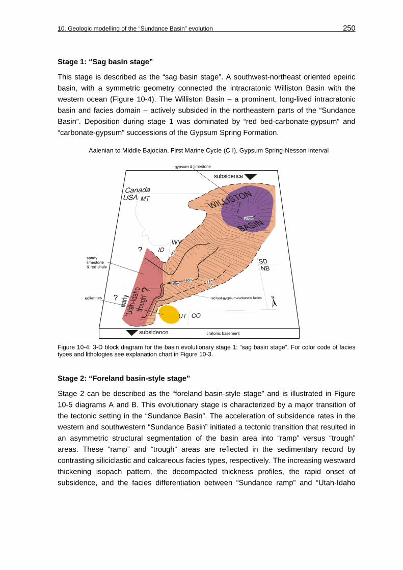
10. Geologic modelling of the “Sundance Basin” evolution 250
Stage 1: “Sag basin stage”
This stage is described as the “sag basin stage”. A southwest-northeast oriented epeiric basin, with a symmetric geometry connected the intracratonic Williston Basin with the western ocean (Figure 10-4). The Williston Basin – a prominent, long-lived intracratonic basin and facies domain – actively subsided in the northeastern parts of the “Sundance Basin”. Deposition during stage 1 was dominated by “red bed-carbonate-gypsum” and “carbonate-gypsum” successions of the Gypsum Spring Formation.
?
?
0m15m
0m
60m40m
100m
subsidence
red bed-gygpsum-carbonate facies
cratonic basement
gypsum & limestone
Aalenian to Middle Bajocian, First Marine Cycle (C I), Gypsum Spring-Nesson interval
eolianites
sandy limestone & red shale
Figure 10-4: 3-D block diagram for the basin evolutionary stage 1: “sag basin stage”. For color code of facies types and lithologies see explanation chart in Figure 10-3.
Stage 2: “Foreland basin-style stage”
Stage 2 can be described as the “foreland basin-style stage” and is illustrated in Figure 10-5 diagrams A and B. This evolutionary stage is characterized by a major transition of the tectonic setting in the “Sundance Basin”. The acceleration of subsidence rates in the western and southwestern “Sundance Basin” initiated a tectonic transition that resulted in an asymmetric structural segmentation of the basin area into “ramp” versus “trough” areas. These “ramp” and “trough” areas are reflected in the sedimentary record by contrasting siliciclastic and calcareous facies types, respectively. The increasing westward thickening isopach pattern, the decompacted thickness profiles, the rapid onset of subsidence, and the facies differentiation between “Sundance ramp” and “Utah-Idaho

10. Geologic modelling of the “Sundance Basin” evolution 251
25m
>120m
60m
200m
0m
0m
?
?
?
0m
70m
50m
A: Middle Bajocian to Middle Bathonian, Second Marine Cycle (C II), lower Twin Creek-Piper-Sawtooth interval
??
?
?
cratonic basement
cratonic basement
subsidence
subsidence
eolianites
mudstones, biomudstones,detritic mudstones
oolitic grainstonesand packstoneswith various amountsof bioclasts
biograinstones,glauconitic, detritic
shale, siltstone, detritic mudstones and thin gypsum layers
red bed-gypsum-carbonate facies (biograinstones, mudstones, bindstones)
subsidence
B: Middle Bathonian to early Middle Callovian, Third Marine Cycle (C III), upper Twin Creek-Preuss-Entrada-”lower Sundance”-Rierdon interval
biowackestones,mudstones,biomudstones,incl. detriticmudstones
oolitic grainstonesand packstones with various amounts of bioclasts
peloidal, skeletal and ooliticwacke- andpackstones
shalelithofacies
siltylithofacies
incised paleovalleyfilled witheolian-estuarine-shallow marine fill
Figure 10-5: 3-D block diagrams for the basin evolutionary stage 2: “foreland basin-style stage”. A: Second Marine Cycle (C II), B: Third Marine Cycle (C III). For color code of facies types and lithologies see explanation chart in Figure 10-3.

10. Geologic modelling of the “Sundance Basin” evolution 252
trough” document this drastic change in the basin configuration. The isopach pattern in northeastern Utah and the Wyoming-Idaho border encircles an area that is characterized by a remarkable increase in thickness.
Sedimentation of shallow marine carbonates of the Sliderock and Rich Member of the Twin Creek Limestone in the developing “Utah-Idaho trough” area became detached from the sedimentary evolution on adjacent ramp areas, where deposition of the Piper and Sawtooth Formation was primarily dominated by inter- to supratidal “red bed-carbonate-evaporite” successions (Figure 10-5, diagram A) and fine clastics, respectively. With time, proximal and restricted conditions were ramp-upward overstepped by shallow marine depositional environments of the Sundance and Rierdon Formations that spread onto marginal ramps as the basin extended. In the “Utah-Idaho trough”, sedimentation of shallow marine carbonates of the Watton Canyon and Leeds Member of the Twin Creek Limestone was detached and finally determined by the increasing input of siliciclastics of the Giraffe Creek Member, Preuss Formation, Hulett Sandstone Member, Lak Member, and Entrada Sandstone (Figure 10-5, diagram B).
During stage 2, the spatial extent of the “Sundance Basin” reached its maximum. Similar to stage 1, the Williston Basin was the dominant element in the northern parts of the “Sundance Basin”.
Stage 3: “Rebound stage”
The “rebound stage” is displayed in Figure 10-6, diagrams A and B. The term “rebound stage” was chosen, because isopach pattern, decompacted thickness profiles, subsidence analysis, and facies distribution reveal remarkable changes from a temporary asymmetric toward a symmetric basin geometry. As in the “sag basin stage”, the Williston Basin can be recognized as the most important tectonic element within the “Sundance Basin”.
However, the “rebound stage” is characterized by the initial filling phase, which is succeeded by the major filling phase during deposition of the Morrison Formation of the Upper Continental Cycle as defined by BRENNER & PETERSON (1994). The initial filling sediments of the “upper sandstone unit” of the Swift Formation are primarily derived from an early pulse of coarser-grained siliciclastics from western and southwestern source areas. This siliciclastic pulse was also recognized as a precursor of developing western source areas by PETERSON (1957a), HILEMAN (1973), BRENNER (1983), JORDAN (1985), and CROSS (1989). The former “Utah-Idaho trough” area was modified into a “ramp”-like setting. The subsidence analysis revealed the eastward shift of the main depocenter, but in comparison to the subsidence pattern during the preceding “foreland basin-style stage” these subsidence rates were only moderate.

10. Geologic modelling of the “Sundance Basin” evolution 253
glauconitic lithofacies:deposited under tidal influence
coquinoidstorm layers,calcareous (biowacke-and packstones) or silciclastic (bioclastrichsands and silts)
tidalchannels
silty lithofacies
oolitic grainstonesand packstones with various amounts of bioclasts
?
?
?
B: Early Oxfordian to early Late Oxfordian, Fourth Marine Cycle (C IV), Stump-Swift-”upper Sundance” interval
generation of hardgrounds;documented by boredlimestone cobbles& concretions
reworking of early transgressive deposits
coquinoid storm layers,calcareous (biowacke-and packstones) or silciclastic(bioclast-rich sands and silts)
offshore “carbonatesand bodies”(biopack- to grainstones or quartzarenitic sediments)
siltylithofacies
shale lithofacies
oolitic grainstonesand packstones with various amounts of bioclasts
lenticular toflaser bedded lithofacies
glauconiticlithofacies
SA: South ArchSwA: Sweetgrass Arch
A: early Middle Callovian to Early Oxfordian, Fourth Marine Cycle (C IV), Swift-Stump-”upper Sundance” interval
SA: South ArchSwA: Sweetgrass Arch
subsidence
subsidence
Figure 10-6: 3-D block diagrams for the basin evolutionary stage 3: “rebound stage”. A and B: Fourth Marine Cycle (C IV). For color code of facies types and lithologies see explanation chart in Figure 10-3.

10. Geologic modelling of the “Sundance Basin” evolution 254
Basin evolutionary stages and sequence types
The most important information that becomes obvious from the geologic model is the correspondence between basin evolutionary stages and the development of sequence types. During the “sag basin stage”, tabular, layer cake stacked sequences of type 1 developed during the First Marine Cycle (C I). During the “foreland basin-style stage”, wedge-shaped sequences of type 2 evolved and form the strata of the Second (C II) and Third (C III) Marine Cycle. Due to the limited distribution and poor stratal record no distinct sequence architectural style and no corresponding sequence type can be recognized for the “unnamed cycle”. The Fourth Marine Cycle (C IV) was deposited during the “rebound stage” and is documented by tabular, truncated sequences of type 3. This relation is shown in Figure 10-7.
Stratigraphicrange
Basingeometry
Sequence type Basin evolutionary stage
First MarineCycle (C I)
Second MarineCycle (C II)
Third MarineCycle (C III)
asymmetric:thickeningtoward“UT-ID TR”
Fourth MarineCycle (C IV)
1
3
2
symmetric
wedge-shaped sequences
tabular,truncatedsequences
tabularsequences symmetric
“rebound stage”
“foreland basin-style stage”
“sag basin stage”
Figure 10-7: The basin evolutionary stages of the “Sundance Basin” correspond to the development of characteristic sequence types 1 to 3. Note that no sequence type can be distinguished for the “unnamed cycle”.
The “Utah-Idaho trough” had only a temporary importance during the tectonic evolution of the “Sundance Basin”, as becomes obvious from the geologic model. Not only the evidence for the discussed theories for the “Utah-Idaho trough” is removed by erosion, the dating and identification of potential Jurassic thrust-sheets that would serve as evidence is problematic (DeCELLES & BURDEN 1992) in the present Cordillera. For example, BJERRUM & DORSEY (1995) proposed contraction and evidence for crustal loading by the Middle and Late Jurassic Luning-Fencemaker thrust (OLDOW 1984, SMITH et al. 1993, MILLER & HOISCH 1992) in western Nevada and the east Sierran thrust belt (BOETTCHER & WALKER 1993). In contrast, SLOSS (1988: 44) proposed that the “date of initiation of the Sevier orogeny is clouded by a debate that is more semantic than geologic” and “no thrust of appropriate age and position are known” to attribute the Jurassic subsidence pattern solely to tectonic loading.
Hence, the “Utah-Idaho trough” strongly contrasts the development in the northern part of the “Sundance Basin” in respect to facies and tectonic development. In the northern “Sundance Basin” a persistent, intracratonic element, the Williston Basin influenced the tectonic evolution. Sedimentary facies types, facies maps and isopach pattern of the Twin Creek Limestone, decompacted thickness profiles, and sediment accumulation curves delineate a distinct area in northwestern Utah and the Wyoming-Idaho border with a

10. Geologic modelling of the “Sundance Basin” evolution 255
tectonic evolution that took placed independently from driving mechanisms in the northern parts. Uplift occurred in the former trough area and created ramp-like settings in the Late Jurassic. Uplift was accompanied by an increasing input of coarser-grained sediments from evolving orogenic areas in the west. The occurrence of ramp-like settings fits very well with the proposed uplift either initiated either by an approaching, eastward migrating forebulge zone (DeCELLES & CURRIE 1996) or isostatic/dynamic uplift of an abandoned volcanic arc in Nevada and southern Arizona (LAWTON 1994).
Consequently, the evolution of the complete “Sundance Basin” structure should not be genetically integrated into the general Cordilleran foreland basin evolution, which culminated in the development of the Western Interior Seaway in the Cretaceous. Existing theories for the Cordilleran tectonic evolution commonly do not include the central and northern parts of the “Sundance Basin”. This interpretation is further supported by SLOSS (1988) who noted that the subsidence pattern of the Zuni subsequence I is remarkably similar to that of the preceding Absaroka subsequence III. Moreover, another important fact is, according to SLOSS (1988), the reappearance of the Williston Basin as a negative element during evolution of the Zuni subsequence I, that was known only from previous Paleozoic subsequences.
The evolutionary phase which is represented by the “Sundance Basin” structure is definitely characterized by the coexistence of tectonic elements that were already representative in preceding geological stages (Williston Basin) and elements that can be interpreted as precursors of subsequent Cretaceous orogenic events (“Utah-Idaho trough”).

256
11 Influence of allogenetic factors on facies evolution and sequence architecture in the “Sundance Basin”
The geologic model for the “Sundance Basin” comprises three basin evolutionary stages that correlate with characteristic facies evolutionary and sequence architectural styles as shown in Figure 11-1. The basin evolutionary stages are accompanied by the development of the three sequence types 1 (tabular sequences), 2 (wedge-shaped sequences) and 3 (tabular, truncated sequences). Supported by the geologic model the influence of allogenetic controlling mechanisms on the facies evolution and sequence architecture of the “Sundance Basin” can finally be evaluated in this chapter. This concerns primarily variations and interplay of the major allogenetic mechanisms eustasy, tectonism and climatic changes, as summarized in Figure 11-2 and Figure 11-3.
C I R
STTS
T
1
3
2
Figure 11-1: Wheeler diagram for the “Sundance Basin” fill, basin evolutionary stages, basin geometry, and characteristic sequence types for unconformity bound allounits (sedimentary cycles). Note that the differing geometric configurations of the basin correspond to characteristic sequence types. Due to the limited stratal preservation no particular sequence type can be proposed for the “unnamed cycle”. For color code see explanation chart in Figure 8-6.
Eustasy
The influence of eustasy on the depositional history within the “Sundance Basin” is minor as indicated by the poor correlation between relative sea-level curves for the unconformity bound allounits in the “Sundance Basin” and global eustasy curves (see chapter: 9.1, Relative sea-level curves). As demonstrated by the comparison of relative sea-level changes with global eustasy, the late Bathonian sequence C III-S 2 marks an inflection

11. Influence of allogenetic factors on facies evolution and sequence architecture in the “Sundance Basin” 257
point from which the “Sundance Basin” fill becomes evidently regressive. As shown in Figure 11-2, the regressive part of the basinfill above this inflection point (#4) correlates with the timing and onset of major siliciclastic pulses.
Tectonism
Tectonism operated the interplay between uplift that controlled primarily the sediment supply and subsidence that created the accommodation space within the basin. The timing of significant phases of subsidence and uplift during deposition within the “Sundance Basin” is illustrated in Figure 11-2. As emphasized above, the influence of eustasy on deposition was minor. Hence, the interplay between subsidence and uplift is documented in the stratigraphic basin fill and consequently in the facies evolution and the sequence architecture as will be explained below. In general, subsidence and uplift controlled significant factors like morphological gradients, water depths as well as the spatial distribution of accommodation potential and subsidence rates.
Uplift as tectonic influence on sediment supply
The clastic sediments that were transported into the “Sundance Basin” were supplied by internal and external source areas. Internal source areas like the “Belt Island Complex” in Montana played volumetrically a minor role (PETERSON 1957a, HILEMAN 1973, JORDAN 1985). In contrast, the majority of clastic sediments were derived from external sources as the “Ancestral Rocky Mountain” remnants in Colorado on the cratonward side of the “Sundance Basin” as noted by PETERSON, F. (1994). Another significant external source area developed due to tectono-orogenetic activities during the Nevadian orogeny at the western edge of the North American craton. This orogeny created a land mass, that acted as the primary external sedimentary source area since the Callovian (PETERSON 1957a, HILEMAN 1973, JORDAN 1985, IMLAY 1980). Minor and major clastic pulses from the external source areas are documented in the basin fill and marked in Figure 11-2. Siliciclastic pulses from “Ancestral Rocky Mountain” remnants are documented in the study area in the facies evolution of stratigraphic intervals like the progradational Hulett Sandstone Member and Lak Member in Wyoming and South Dakota. Major clastic pulses from the external source areas are reflected in the prograding subtidal to supratidal successions of the Giraffe Creek Member and Preuss Formation in western Wyoming and eastern Idaho, respectively. In northeastern Utah, the eolian Entrada Sandstone represents a major basinward directed siliciclastic pulse.
Subsidence as tectonic influence on accommodation space
The asymmetric subsidence pattern within the “Sundance Basin” was temporarily and spatially confined to western and southwestern areas as revealed by subsidence curves for the “Utah-Idaho trough” and the “Sundance ramp” (see Figure 11-2). A representative sediment accumulation curve (total subsidence curve) for the stable ramp and the subsiding trough in Figure 11-2 shows that temporarily accelerated (see #1 and #2 in Figure 11-2) subsidence rates slowed down (see #3 in Figure 11-2) and accommodation

11. Influence of allogenetic factors on facies evolution and sequence architecture in the “Sundance Basin” 258
space was progressively filled with the increasing influx of siliciclastics contributed from external source areas. The subsidence pattern controlled basinwide the morphological gradients within the “Sundance Basin” and created the available accommodation space. Uplift and partial removal of strata occurred subsequently in former trough areas in the west, while subsidence and sedimentation prevailed farther east and northward in Wyoming and Montana.
Eustasyglobal/regional
Allo
unit
J-4
J-2b
J-2a
J-2
J-1
J-4a
J-5
1st M
arin
e C
ycle
(C I)
2nd
Mar
ine
Cyc
le (C
II)
3rd
Mar
ine
Cyc
le (C
III)
4th
Mar
ine
Cyc
le (C
IV)
siliciclastic input
major pulse
minor pulse
Allogenetic mechanisms
Dinosaur track-bearing interval
local shallowing-upward trend
dilution by siliciclastic influx and termination of carbonate production
globa sea-level curve
from HALLAM (1988)
“Sundance Basin”from
BRENNER &PETERSON (1994)
J-3
Sedimentary evolution:siliciclastic pulses
contributed by uplift
third-orderrelative
sea-level
C I-S 1
C III-S 1
C IV-S 1
Grain size
Basin evolutionary
stage
stage 2:foreland
basin-stylestage
stage 3:rebound
stage
stage 1: sag basin stage
Basin evolutionary
stage
symmetric
asymmetric
symmetric
#1
#2
#3
Tectonism
“Uta
h-Id
aho
t roug
h”
“ Sun
danc
eram
p”
“uc”
C I-S 2
C I-S 3
C II-S 1
C II-S 2
C II-S 3
C II-S 4
C III-S 2
C III-S 3
C IV-S 2
#4
#1 acceleration of subsidence (~ 170 Ma)#2 acceleration of subsidence (~ 165 Ma)
“uc” = “unnamed cycle”
#3 subsidence slows down (~ 159 Ma)#4 inflection point: basinfill becomes regressive
sandstone
siltstone
claystone
gypsum
limestone
?
Figure 11-2: Diagram to display the interplay and timing of allogenetic influences on deposition in the “Sundance Basin”.

11. Influence of allogenetic factors on facies evolution and sequence architecture in the “Sundance Basin” 259
A similar increase of subsidence rates at about 170 Ma was noticed by HELLER et al. (1986) in western Wyoming, by BJERRUM & DORSEY (1995) in central Utah and western Wyoming and by KOMINZ & BOND (1986) in southern Canada. These workers assigned the tectonic event that initiated the asymmetric subsidence pattern to activity in the orogenic thrust belt, farther west of the “Sundance Basin” structure. Moreover, the observed temporary modification of the spatial subsidence pattern in this study correlates with available radiometric age dates for the beginning of the Nevadian orogeny. These age dates range between 180-160 Ma (EVERNDEN & KISTLER 1970) and 170-160 Ma (EISBACHER 1988). SCHWEICHERT & COWAN (1975) suggested that an eastward shifting arc collided with the existing Andean-type-like magmatic arc at the western edge of the North American continent. This resulted in the phase of deformation and plutonism which is referred to as the Nevadian orogeny.
Climate
The climate during the Jurassic was warm and dry (KOCUREK & DOTT 1983, PETERSON, F. 1994). Especially the southern portion of the “Sundance Basin” was under the influence of an arid paleoclimate, as recorded by extensive eolian deposits and evaporites (KOCUREK & DOTT 1983, PARRISH 1993). The central parts of the “Sundance Basin” show evidence for temporary humid climatic conditions (JOHNSON 1992). The paleoclimate shifted from dry subtropical to more humid conditions during the Late Jurassic (BRENNER 1983) which can be related to the northward movement of the North American continent and contemporaneous topographic deflections, initiated by the Nevadian orogeny.
The arid climate in the southern “Sundance Basin” during the Middle Jurassic supported the influx of fluvial and eolian sediments (PETERSON, F. 1994) and is confined to regressive stages, associated by the development of extensive inland dune fields (MARZOLF 1988). As shown in the process flow diagram (see Figure 11-3), it seems likely that arid paleoclimatic conditions during the Bajocian and Bathonian favored several times the precipitation of local evaporitic beds of the Gypsum Spring, Piper, Sundance, and Carmel formations in the study area.
The temporary intense carbonate production in the “Utah-Idaho trough” during the Bajocian and Bathonian, despite of an almost continuous clastic background sedimentation, is a perplexing aspect of the “Sundance Basin” fill. A common sedimentological theme is that carbonate production is surpressed as soon as fine-grained siliciclastic influx arrives in the sedimentation area even in small amounts (MOUNT 1984, WALKER et al. 1983, EINSELE 1992).
YANCEY (1991) demonstrated that the deposition of large amounts of carbonate will persist even under moderate rates of siliciclastic sedimentation if other factors favor the growth of carbonate producers.

11. Influence of allogenetic factors on facies evolution and sequence architecture in the “Sundance Basin” 260
These variable factors in a mixed depositional system are according to YANCEY (1991):
• The quantity and composition of siliciclastics delivered to the shoreline and transported onto the shelf or ramp.
• The depositional gradient.
• The depth of the lower limit of the photic zone.
As illustrated in the process flow diagram, the amount of clastic sediment input is primarily controlled by the sediment supply from internal and external source areas. The depositional gradient is a function of the spatial subsidence pattern in the “Sundance Basin”. In contrast, the lower limit of the photic zone is a function of light supply and controlled by the climate (YANCEY 1991). Consequently, it seems reasonable to attribute the almost continuous carbonate sedimentation of the Twin Creek Limestone in the “Utah-Idaho trough” to the interplay of tectonism (sediment supply and accommodation space) and the paleoclimate. Times of favorable conditions for carbonate production in a warm and dry climate are indicated in the process flow diagram for the Second (C II) and Third (C III) Marine Cycle.
Interplay of controlling factors (process flow diagram)
The interplay of subsidence and uplift that influenced the facies evolution and sequence architecture within the “Sundance Basin” will be summarized in this chapter.
As shown in the process flow diagram in Figure 11-3, the interplay between long-term low subsidence rates, minimum accommodation potential and low morphological gradients controlled the facies distribution pattern and the sequence architecture during deposition of the First Marine Cycle (C I). The low and uniformly distributed accommodation space promoted the generation of third-order sequences, composed internally of extensive facies sheets. The resulting third-order sequences are stacked in a layer cake stratification during the “sag basin stage”.
An onset of asymmetric subsidence can be recognized at 170 Ma, as demonstrated by the subsidence analysis and shown in the process flow diagram. This regional acceleration of subsidence rates corresponds to the onset of tectonic activities in the orogenic thrust belt west of the “Sundance Basin” that synchronously initiated the asymmetric subsidence pattern in a belt that stretches from central Utah to southern Alberta, as noticed by HELLER et al. (1986), BJERRUM & DORSEY (1995) and KOMINZ & BOND (1986). In addition, this temporary modification of the spatial subsidence pattern correlates with available radiometric age dates for the beginning of the Nevadian orogeny. These age dates range between 180-160 Ma (EVERNDEN & KISTLER 1970) and 170-160 Ma (EISBACHER 1988).
The asymmetric subsidence pattern is characteristic for the “foreland basin-style stage” and caused a major change in the geometric basin configuration during deposition of the sedimentary cycles C II and C III. Additional accommodation space was created in the “Utah-Idaho trough“. The resulting wedge-shaped sequences and their systems tracts

11. Influence of allogenetic factors on facies evolution and sequence architecture in the “Sundance Basin” 261
(transgressive, regressive complexes) are stacked in an aggradational/progradational pattern. Further, in the distal portion the depositional gradients steepened during carbonate sedimentation of the Twin Creek Limestone. The clastic sediment influx into the “Utah-Idaho trough” was temporarily reduced during deposition of the carbonate-dominated members Sliderock, Rich, Watton Canyon, and Leeds Creek of the Twin Creek Limestone and subsequently the carbonate productivity was supported. The spatially asymmetric subsidence pattern formed distinct sedimentation areas in the “Utah-Idaho trough”, “Sundance ramp” and “Belt Island Complex”. The thickness pattern and correlation potential of third-order sequences differs strongly in these areas.
On the “Sundance ramp”, seven third-order sequences can be distinguished in the second-order Second (C II) and Third (C III) Marine Cycle. The third-order sequences are expressed in the Piper Formation and Sundance Formation and fade out toward the carbonate succession of the Twin Creek Limestone in the rapidly subsiding “Utah-Idaho trough”. A major pulse of siliciclastic sediments was transported from the western and eastern margins into the “Sundance Basin” in the early Callovian. This pulse is documented in the Hulett Sandstone and Lak Member on the “Sundance ramp” in the Bighorn Basin, the Black Hills and central Wyoming, further by the Giraffe Creek Member and the Preuss Formation in the “Utah-Idaho trough” in western Wyoming and eastern Idaho. This interval is represented by the Entrada Sandstone in northeastern Utah. The onset of the final progradational phase can be confined to the third-order sequence C III-S 3. The increasing clastic sediment influx diluted the carbonates of the Twin Creek Limestone and determined production in the carbonate factory. Further, sediment supply exceeded the subsidence rates and initiated basinward progradation that resulted in the filling of the “Utah-Idaho trough”.
As shown in the process flow diagram, the changes in subsidence rates and sediment supply in the “rebound stage” characterize another basin configuration. The subsidence slowed down at about 159 Ma (see #3 Figure 11-2). Low subsidence rates and low morphological gradients are affected by an increasing sediment supply during deposition of the Redwater Shale Member of the Stump Formation and Sundance Formation in Wyoming as well as the Swift Formation in Montana during the “rebound stage”. This interplay promoted partial overfilling of the “Sundance Basin” and resulted in the generation of tabular, unconformity bound sequences of type 3. Initially, sediment supply was low during the early Oxfordian. The limited, uniformly distributed accommodation space supported the generation of the third-order sequence C IV-S 1, characterized by extensive shale lithofacies successions, diastemic sedimentation and generation of hardgrounds. Increasing sediment supply after the early Oxfordian from a western source area exceeded the subsidence and generated a fall in relative sea-level that resulted in the J-4a unconformity. The overlying sequence is characterized by an eastward dispersal

11. Influence of allogenetic factors on facies evolution and sequence architecture in the “Sundance Basin” 262
Processes initiated by:allogenetic mechanisms
Firs
t Mar
ine
Cyc
le (C
I)S
econ
d M
arin
e C
ycle
(C II
)Th
ird M
arin
e C
ycle
(C II
I)Fo
urth
Mar
ine
Cyc
le (C
IV)
climate
warm and dry climate:widespread eolian deposits, evaporites
southward directed wind
modification of wind direction: eastwardand more humid, temporate climate
as result of northward drift of NA continent and topographic
deflection at western continent margin
departure from arid conditions associated with evidence for
increasing storm influence on deposition
modification of wind direction: northeastward as result of northward drift of NA continent and topographic
deflection at western continent margin
semi-arid to arid:episodic wet vs. dry conditions,
large quantities of water demanded by vegetation and vertebrates suppliedby streams from bordering highlands
warm and dry climate:evaporites, carbonates, eolianites
tectonic rebound(eastward shift of subsidence,
symmetric subsidence pattern)
generation of J-2 unconformity:expressed erosional
tectonics
symmetric subsidence pattern
low morphological gradients, minimum accomodation potential:
sedimentation rate > subsidence rate
reactivation of ancient tectonic element:Williston Basin
sedimentation rate subsidence ratefine siliciclastics and minor amount of
hardground carbonate beds
~
generation of J-4a unconformity:expressed erosional and cobble accumulation
sedimentation rate > subsidence rateinflux and eastward dispersal of impure,glauconitic, coarser-grained siliciclastics
latest phase of Nevadian orogeny
generation of J-5 unconformity
sedimentation rate > subsidence ratedevelopment of eolian, fluvial and
lacustrine environments,filling stage (molasse stage)
onset of asymmetric subsidence at ~ 170 Ma
distalsubsidence rate > sedimentation rate
reduction of siliciclastic influxincreasing accomodation space
favorable conditions for carbonate production:biological and chemical
sedimentation rate > subsidence rateincreasing input of siliciclastics from ramp
dilution of carbonatesassociated with basinward shift of siliciclastics
and temporary decrease in accomodation space
generation of J-2a unconformity:expressed by facies shift
proximalsedimentation rate ~ subsidence rate
sedimentation of siliciclastics
morphological differentiation: ramp vs. trough
~
Nevadian orogeny begins at 160-170 Ma
generation of J-4 unconformity:expressed erosional/facies shift
acceleration of (asymmetric) subsidence at ~ 165 Ma
distalgenerates new accomodation space subsidence rate > sedimentation rate
proximalsedimentation rate ~ subsidence rate
sedimentation of siliciclastics
morphological differentiation: ramp vs. trough
favorable conditions for carbonate production:biological and chemical
sedimentation rate > subsidence rateincreasing input of siliciclastics from E and W,
first pulse to derive from a western source
dilution of carbonates, by prograding siliciclastic sediments
and decrease in accomodation space:filling of “Utah-Idaho trough”
~
tectonic activity :western margin andColorado Plateau
global sea-level fallin HALLAM (1988) curve
global sea-level fallin HALLAM (1988) curve
eustasy
trans
gres
sive
glo
bal e
usta
sy
?
“fore
land
bas
in-s
tyle
sta
ge”
wed
ge-s
hape
d se
quen
ces
Basin geometry&
sequence architecture
“sag
bas
in s
tage
”la
yer c
ake
sequ
ence
s“re
boun
d st
age”
tabu
lar,
unco
nfor
mity
boun
d se
quen
ces
AAL
ENIA
NB
AJO
CIA
NB
ATH
ON
IAN
CA
LLO
VIA
NO
XFO
RD
IAN
“unn
amed
cy
cle”
generation of J-3 unconformity:expressed facies shift/erosional ?/
marine flooding: sedimentation of glauconitic beds
~
tectonic rebound phase
late phase of Nevadian orogeny
?
Figure 11-3: Process flow diagram to display the interplay between the allogenetic factors climate, tectonism and eustasy on facies evolution and sequence architecture.

11. Influence of allogenetic factors on facies evolution and sequence architecture in the “Sundance Basin” 263
of coarse-grained sediments from a major western source area. The sediment supply exceeded the available accommodation space and created the bounding J-5 unconformity that removed large portions of the stratigraphic record of the sequence C IV-S 2.
The unconformity bound sedimentary cycles are succeeded by the Upper Continental cycle, proposed by BRENNER & PETERSON (1994) (see chapter: 2.5, Cyclostratigraphy and Figure 2-30). The top of the Upper Continental cycle is marked by the K-1 unconformity. However, this uppermost allogroup represents the final filling stage of the entire “Sundance Basin” structure, before the Cretaceous Sevier orogeny began. The Morrison Formation, a widespread non-marine complex, was deposited in a wide range of fluvial, lacustrine and eolian environments (IMLAY 1980, JOHNSON 1992, PETERSON, F. 1994). The Upper Continental cycle includes the Windy Hill Sandstone Member of the Sundance Formation in southeastern Wyoming and the Black Hills that grades laterally into the Morrison Formation (BRENNER & PETERSON 1994).

264
12 Identification of potential reservoir-seal facies types and stratigraphic traps in the “Sundance Basin”
The generation of potential reservoir and seal facies types within the depositional system of the “Sundance Basin” will be evaluated in this chapter. Some potential reservoir-seal associations are already known from the stratigraphic basinfill.
12.1 Existing reservoir rocks in the “Sundance Basin”
Black Hills
Significant oil accumulations occur in sandstone reservoirs of the Sundance Formation in Wyoming (AHLBRANDT & FOX 1997). More precisely, the lower and upper sandstone units of the Canyon Spring Sandstone Member form structural/stratigraphic and stratigraphic traps, respectively. Both units bear distinct reservoirs. The lower Canyon Springs Member represents the eolian fill of lowstand incised valleys (see chapter: 2.4, Allostratigraphy and 2.4.2.3, J-2a unconformity; Figure 2-19), while the upper part is a nearshore sedimentary suite. Further, undeveloped hydrocarbon shows are present in the Hulett Sandstone Member in the Red Bird field area (AHLBRANDT & FOX 1997).
Williston Basin
Excellent reservoir rocks are developed as carbonate bodies in the basal part of the Swift Formation in the Williston Basin area (LANGTRY 1983). The carbonate sand bodies (see chapter: 5.2, Spatial facies distribution within sedimentary cycles; facies map C IV-A in Figure 5-14) consist of coarsening-upward, mollusc grainstone bodies, 35 km in length, 11 km in width and up to 45 m thick. These calcareous sediment bodies are embedded in a sealing shale-mudstone-siltstone-quartzarenite facies. The carbonate bodies are excellent reservoirs in respect to porosity, permeability and trapping mechanism but lack a principal relation to available source rocks (LANGTRY 1983).
Further, lenticular porous sand bodies, sealed by a lateral facies change to non-porous fine clastics within the “ribbon sandstone” member of the Swift Formation form stratigraphic traps (HAYES 1984). According to MOLGAT & ARNOTT (2001), this principal reservoir bodies formed as discontinuous, migrating sand ridges due to intrabasinal tide and wave dominated processes in a low-energy strait that connected the Williston Basin via the “Sweetgrass trough” with the western ocean.

12. Identification of potential reservoir-seal facies types and stratigraphic traps in the “Sundance Basin” 265
12.2 Potential reservoir and seal facies types in the “Sundance Basin”
12.2.1 Theoretical framework
Internal sedimentary heterogeneities are of special importance during the reservoir developing stage, since they create internal domains with differing porosity and permeability within the reservoir rock. These variations are primarily determined by the sedimentary regime (tide, storm or wave dominated) and the depositional history (BURCHETTE et al. 1990). Primary depositional characteristics are as well influenced and overprinted by diagenesis in siliciclastic and calcareous sediments. Diagenesis remains a secondary consideration, and at present can only be addressed at the time of exploration drilling (BURCHETTE et al. 1990).
A systematic strategy that would provide an approach to reservoir prediction in the “Sundance Basin” comes from the integration of the methods of facies analysis, the 2- and 3-dimensional facies correlation, the identification of allostratigraphic contacts, cyclostratigraphy, the subsidence analysis, and the sequence stratigraphic correlation. For this approach the focus was drawn to the following aspects:
• The identification and correlation of major transgressive-regressive cycles and subordinate contemporaneous sequences, that link temporally and spatially related depositional environments.
• Spatial facies variations to identify potential reservoir and associated seal facies types in siliciclastic and carbonate depositional settings in the “Sundance Basin”.
• The identification of bounding unconformities, expressed either erosional or as discontinuous facies shifts.
• The understanding of the hydrodynamic energy zonation within the basin that derived from facies analysis and facies correlation. This supported the identification of shoreline-detached, high-energetic deposits. Grainstones, as sandbodies, generated on high-energy, grainstone-dominated ramps, are the most obvious exploration targets after biogenic buildups in sedimentary basins (BURCHETTE et al. 1990). Since biogenic buildups are not developed in the “Sundance Basin”, the focus must be drawn to grainstone domains, characterized by a bioclastic or/and oolitic particle spectrum. This consideration is confirmed by the fact that existing potential reservoirs in the Williston Basin are developed as bioclastic, quartzose grainstone bodies with high moldic porosity and good permeability as described by LANGTRY (1983).
• The identification of transgressive stages and deposits, that are commonly well expressed in the stratal package and therefore can objectively be recognized. The applicability is demonstrated in the transgressive-regressive sequence concept highlighted by EMBRY (1993). Besides potential reservoir rocks appropriate seals are

12. Identification of potential reservoir-seal facies types and stratigraphic traps in the “Sundance Basin” 266
• of equivalent importance. According to BURCHETTE et al. (1990), the greatest reservoir and stratigraphic trapping potential exists in the earliest ramp parasequences where enveloping and sealing sediments are siliciclastic mudstones.
• The isopach pattern for individual transgressive-regressive sequences, since thickness trends correspond to facies trends, especially when tectonically stable versus unstable structural domains exist. As pointed out by AIGNER & PÖPPELREITER (2003) the tectonic control on accommodation potential very likely influence reservoir thickness and spatial pattern.
12.2.2 Basin configurations and prediction of potential reservoir rocks
The evolution of the “Sundance Basin” comprises three stages. The basin configuration was temporarily modified from a symmetric toward an asymmetric geometry.
The sequence stratigraphic position of reservoir facies associations during basin evolutionary stages is displayed in the Wheeler diagram in Figure 12-1. The spatial distribution of reservoir facies associations is representatively illustrated for the “foreland basin-style stage” in the schematic 3-dimensional facies correlation in Figure 12-2. The existence of petroleum systems within the Fourth Marine Cycle (C IV), deposited during the “rebound stage”, is restricted to the Williston Basin area and was already described above. Production from strata of the two earlier stages (C II and C III) is only developed in the Black Hills (see above) but their potential will be evaluated in the following.
“Sag basin stage”
The generation of predictable reservoir facies types can be expected during the “sag basin stage”. The successions from this interval host potential reservoir rocks as well as potential seals. The symmetric distribution of accommodation space and limitation of sediment supply in combination with the low morphological gradients during deposition of the Gypsum Springs Formation in the Bighorn Basin in Wyoming supported a layer cake stacking of the third-order sequences C I-S 1, C I-S 2 and C I-S 3. This predictable sequence stacking pattern reflects the internal sequence architecture and facies distribution. In the red bed-carbonate-evaporite successions of the First Marine Cycle (C I) the third-order sequences bear, for example, widespread skeletal and oolitic/peloidal grainstones beside peritidal bindstones, biomudstones and subtidal biopackstones in their transgressive complexes (TC) as potential reservoir rocks. Potential seals are discussed in the following chapter (see chapter: 1.2.2.3, Basin configurations and prediction of potential seals).

12. Identification of potential reservoir-seal facies types and stratigraphic traps in the “Sundance Basin” 267
Potential reservoir facies associationsGrainstone reservoir facies types (oograinstones and -packstones, oobiograinstones, biograinstones) with sealing mudstones
Sandstone reservoir facies types (LX-lithofacies or WR-lithofacies)with sealing shales
bounding unconformityerosionalfacies shift
strata undifferentiated
Figure 12-1: Simplified Wheeler diagram for the First (C I), Second (C II) and Third (C III) Marine Cycle. The “unnamed cycle” is not illustrated due to its lack of potential reservoir or seal facies types. The general sequence architecture during the „sag basin stage” and “foreland basin-style stage” is illustrated schematically, while the position of potential reservoir facies types is highlighted in red and yellow.
“Foreland basin-style stage”
The stratal packages of the Second (C II) and Third (C III) Marine Cycle that were deposited during the “foreland basin-style stage” contain potential reservoir facies types as shown in Figure 12-1. The “unnamed cycle” is not considered in this chapter due to its poor stratal preservation. The reservoir facies of the Second (C II) and Third (C III) Marine Cycle is either developed on the “Sundance ramp” or in the “Utah-Idaho trough”. The Piper Formation in the Bighorn Basin is lithologically very similar to the underlying Gypsum Spring Formation. Limited accommodation space and sediment supply in combination with the low morphological gradients on the “Sundance ramp” created parameters that resemble the conditions during the preceding “sag basin stage”. The red bed-carbonate successions of the Piper Formation bear a number of grainstone-dominated carbonate facies types in their transgressive complexes (TC).
The 3-dimensional distribution of potential reservoir facies types in the strata of the Second (C II) and Third (C III) Marine Cycle during the foreland basin-style sage is shown in Figure 12-2. The Canyon Springs Sandstone Member of the Sundance Formation in the Black Hills contains reservoir facies rocks in eolian sediments in incised valley fills (see above: 12.1, Existing reservoir rocks in the “Sundance Basin”). The upper part of the

12. Identification of potential reservoir-seal facies types and stratigraphic traps in the “Sundance Basin” 268
Canyon Springs Sandstone Member contains large-scale cross-bedded, nearshore sandstone successions (LX-lithofacies) in southeastern and central Wyoming. These well-sorted sediments are within the transgressive complex TC-C III-S1 of the third-order sequence C III-S 1.
Further, the Hulett Sandstone Member of the Sundance Formation contains potential reservoir facies associations in the Black Hills and Bighorn Basin in northwestern Wyoming. In the Bighorn Basin, these associations are lenticular, discontinuous shoreface-foreshore sediment bodies (STONE & VONDRA 1972) composed of prograding quartzose, oolitic/skeletal packstones and grainstones, overlain by or interbedded with marine shales (DEJARNETTE & UTGAARD 1986). Undeveloped hydrocarbon shows exist in the Hulett Sandstone Member (AHLBRANDT & FOX 1997) in the Black Hills. The Hulett Sandstone Member is represented by prograding offshore-shoreface-foreshore successions as demonstrated by the facies analysis and correlation in this study. The Hulett Sandstone is assigned to the regressive complex RC-C III-S 3 of the third-order sequence C III-S 3. Laterally, the Hulett Sandstone grades into the Giraffe Creek Member of the Twin Creek Limestone in western Wyoming. This member is lithologically more glauconitic and impure than the Hulett Sandstone Member. However, quartzose, oolitic/skeletal carbonates are present in the Giraffe Creek Member that potentially are reservoir facies types. In the vicinity of positive relief elements, reservoir associations occur in the massive oolitic grainstone successions of the Rierdon Formation at sections Little Water Creek (LW) and Rocky Creek Canyon (RC) that evolved on the southern flanks of the “Belt Island Complex” (MEYERS 1981).
Increasing subsidence rates in the “Utah-Idaho trough”, accompanied by marine deepening created the required accommodation space in which the reservoir-prone carbonate build-up facies in the lower portions of the Twin Creek Limestone was protected against redistribution and reworking. Oolitic and/or bioclastic grainstone lithologies are developed within the Sliderock Member and Watton Canyon Member of the Twin Creek Limestone. These members are within second-order transgressive systems tracts. As can be obtained from the 3-dimensional diagram in Figure 12-2, with the outcrop grit available in this study it can not be decided if the potential grainstone reservoir facies associations can be correlated with certainty between examined locations in the “Utah-Idaho trough”. Very likely the carbonate facies types are not continuously interconnected and form lenticular, isolated sediment bodies. However, the thickness pattern of the reservoir-prone grainstone facies types in the “Utah-Idaho trough” is persistent and ranges between 0,4 m at section Thistle (THI) and 8 m at section Devils Hole Creek (DH). The lower contacts of these beds are sharp based and upward the grainstones grade into various types of wacke or mudstones. Further, laterally reservoir-prone grainstones at sections South

12. Identification of potential reservoir-seal facies types and stratigraphic traps in the “Sundance Basin” 269
A
B
LW SAP
RC#CD
HY
FG
W#DRTHI
LBDHBE
SC
TFTC
FG
VW
THI
TF
SC
BE
LW
SAP
RC #CD
#CFC
TRHU
SBC#BAR
AR
FH
SWC
LB
Potential reservoir facies associationsGrainstone reservoir facies types (oograinstones and -packstones, oobiograinstones, biograinstones) with sealing mudstones
Sandstone reservoir facies types (LX-lithofacies or WR-lithofacies)with sealing shales
lower CanyonSprings Mbr.
upper CanyonSprings Mbr.
Hulett Sandstone Mbr.
Rierdon Fm.
Watton Canyon Mbr.
strata undifferentiated
emerged/ areaof non-deposition
#GR
RL
SPC
HY
Figure 12-2: Schematic 3-dimensional distribution of reservoir facies during the “foreland basin-style stage”. A: Second Marine Cycle (C II), B: Third Marine Cycle (C III). For full names of sections see Figure 1-2.

12. Identification of potential reservoir-seal facies types and stratigraphic traps in the “Sundance Basin” 270
Piney Creek (SPC) and La Barge Creek (LB) grade into packstones, wackestones and mudstones at sections Hoback Canyon (HC) and Poker Flat (PF). Westward the grainstone facies pinch out into basinal and outer ramp detritic or non-detritic mudstones and wackestones.
The migration of the high-energetic facies belt was not very pronounced as is indicated by the occurrence of this reservoir facies at the base of the Sliderock Member and Watton Canyon Member of the Twin Creek Limestone. The distribution of this high-energetic facies can be confined to an approximately 75 km wide area between section South Piney Creek (SPC) and section Thomas Fork Canyon (TF) at the Wyoming-Idaho border.
12.2.3 Basin configurations and prediction of potential seals
Potential seal facies types in the “Sundance Basin” are matrix-supported carbonates of the mudstone, detritic mudstone, biomudstone, and biowackestone facies. In addition, fine-grained siliciclastics or evaporites may perform potentially a seal function in the “Sundance Basin”.
Potential reservoir facies types are developed in the Gypsum Spring Formation during the “sag basin stage” as discussed above. The transgressive complexes (TC) of the Gypsum Spring Formation are composed of thin, but relatively widespread carbonate facies sheets. Nevertheless, a negative aspect is the limited occurrence of seals in the transgressive complexes (TC). Evaporites, potentially excellent seals, are present in the Gypsum Spring Formation in the Bighorn Basin, but their occurrence is restricted to the “gypsum red claystone member” in the lower portion of the formation and therefore could not perform a seal function.
Further, matrix-supported carbonates are abundant in the sedimentary cycles C II and C III in the “Utah-Idaho trough”. Reservoir-prone carbonate facies types composed of oolitic and/or bioclastic grainstone lithologies are interbedded with matrix-supported carbonates. On the “Sundance ramp” the Hulett Sandstone Member of the Sundance Formation contains potential reservoir facies associations in the Black Hills and Bighorn Basin in northwestern Wyoming. The lenticular, discontinuous shoreface-foreshore sediment bodies and prograding offshore-shoreface-foreshore successions are overlain and interbedded with potentially sealing marine shales.
That these shale facies types may serve as seals is evident from the occurrence of non-porous fine clastics within the “ribbon sandstone” member of the Swift Formation. These shales seal lenticular porous sand bodies within the Fourth Marine Cycle (C IV) during the “rebound stage” in the Williston Basin (see chapter: 12.1, Existing reservoir rocks in the “Sundance Basin”).

12. Identification of potential reservoir-seal facies types and stratigraphic traps in the “Sundance Basin” 271
Finally, it is important to evaluate the seal potential of the Jurassic unconformities within the “Sundance Basin”. Unconformities with an erosional nature may generate stratigraphic configurations that provide a seal function. For instance, in the Hulett Sandstone Member of the Sundance Formation (sedimentary cycle C III) in the Bighorn Basin. In this case, potential reservoir rocks (lenticular, discontinuous shoreface-foreshore sediment bodies and prograding offshore-shoreface-foreshore successions) are capped by the erosional J-4 unconformity and are disconformably overlain by glauconitic shales of the Redwater Shale Member (sedimentary cycle C IV). This configuration is developed exclusively between the lithologies of the sedimentary cycles C III and C IV. Furthermore, unconformities expressed as discontinuous facies shifts, like the J-2a unconformity, generate a seal configuration. For example, the Canyon Springs Sandstone Member of the Sundance Formation in the Black Hills contains reservoir facies types in eolian sediments in incised valley fills (see above: 12.1, Existing reservoir rocks in the “Sundance Basin”). These valley fills are capped by the unconformable facies shift that mark the J-2a unconformity. Here, the eolian reservoir facies is sealed by the fine-grained deposits of the informal member “brown shale” (see chapter: 2.4.2.3, J-2a unconformity and Figure 2-19).
12.2.4 Basin configurations and potential reservoir rocks and seals
Yet, it can be summarized that potential reservoir and seal facies types in the “Sundance Basin” fill occur in stratigraphic traps. In addition, each of the three basin configurations show a typical distribution of potential reservoir and seal facies types.
Potential reservoir and seal facies types are developed in transgressive (TC) complexes in the symmetric “sag basin stage”. A reliable reservoir prediction for this basin evolutionary stage is supported by the layer cake stacking of third-order sequences and their transgressive complexes. The good predictability of reservoir facies types is shadowed by the lack of potential seal facies types in this basin configuration.
During the asymmetric “foreland basin-style stage” the parameters that controlled the depositional regime within the “Sundance Basin” changed remarkably. Potential reservoir associations during the “foreland basin style-stage” are stacked in transgressive complexes (TC) of aggradational sequences in the Second Marine Cycle (C II) on the “Sundance ramp”. In the Third Marine Cycle (C III) the associations are developed in both: transgressive (TC) and regressive complexes (RC) on the “Sundance ramp”. In the subsiding “Utah-Idaho trough”, potential reservoir associations are within second-order transgressive systems tracts (TST) and high-energetic reservoir-prone carbonate facies types, bound to shoreline-detached environmental belts. In contrast to the thin, but extensive associations on the “Sundance ramp” the reservoir-prone oolitic/skeletal carbonates are most likely isolated, lenticular sediment bodies. Moreover, the “unnamed cycle” may neither contain potential reservoir facies nor seal facies types.

12. Identification of potential reservoir-seal facies types and stratigraphic traps in the “Sundance Basin” 272
The existence of reservoir and seal associations within the Fourth Marine Cycle (C IV) that were deposited during the “rebound stage” is restricted to the Williston Basin area. In the studied sections of the Fourth Marine Cycle (C IV) no potential reservoir-seal configurations can be found.
A relation exist between the basin geometry and the distribution of potential reservoir and seal facies types. During a symmetric basin configuration (“sag basin stage”), potential reservoir and seal facies types are thin, sheetlike and widespread. Thus, this relation does not apply for the “rebound stage”. During this particular stage the parameters were not favorable for the generation of reservoir rocks. The partial overfilling of the basin with coarse-grained sediments caused frequent erosion. In contrast, an asymmetric basin geometry supports the origin of spatially disconnected reservoir rocks and associated seals. Such a relation was found in this case study in the grainstone-supported carbonate facies types in the “Utah-Idaho trough” that developed in a distinct high-energy facies belt.
273
13 Comparison with other basin studies
A literature study was conducted to compare the research results from this study with investigations from other sedimentary basins. It was the purpose of this comparison to determine if sequence architectural styles and subsidence pattern are exclusive features of the “Sundance Basin” or if similarities exist to other sedimentary basins. This includes special regard to the sequence types 1 to 3 (tabular, wedge-shaped and tabular-truncated). Since each sequence type correlates with a particular evolutionary stage of the “Sundance Basin” it seems appropriate to focus on sedimentary basins from comparable tectonic settings.
Intracratonic settings
Intracratonic sag basinal settings are known from all regions of the world (KLEIN 1995). The “sag basin stage” is the earliest evolutionary phase of the “Sundance Basin”. During this stage, the Williston Basin, one of the major intracratonic basins on the North American continent (QUINLAN 1987, KLEIN 1995), was connected via a northwest trending epeiric passage with the western ocean (see chapter: 5.2, Spatial facies distribution within unconformity bound units: facies maps; Figure 5-10). The identified parameters that influenced deposition of the Gypsum Spring Formation (First Marine Cycle) during the “sag basin stage” were low subsidence rates, low depositional gradients of a homoclinal ramp configuration and shallow water depths in peritidal environments. The tabular, layer cake stacked sequence type 1 was generated by these parameters (see chapter: 11, Influence of allogenetic factors on facies evolution and sequence architecture). A similar interplay of control parameters and sequence architecture was described for instance by LINDSAY et al. (1993) from the Amadeus Basin in Australia. The similarities in sequence style are shown in Figure 13-1.
The Amadeus Basin on the Australian continent is a broad, shallow intracratonic sag basin with a saucer pan-like geometry that contains Proterozoic to early Paleozoic strata. In this basin LINDSAY et al. (1993) recognized five stratigraphic sequences. The sequences and their sequence boundaries resemble very much the conditions described in this study from the “Sundance Basin” (see chapters: 7.2, Sequence characteristics and 8, Facies and sequence architecture). In the Amadeus Basin sequences are thin and widespread. As concluded by LINDSAY et al. (1993), slow subsidence rates, low depositional gradients and shallow water depths reduced the accommodation space within the basin. The resulting sequences are vertically compressed and stacked in a simple fashion. Internally, they are composed of stacked transgressive-highstand deposits. The sequence boundaries that separate these units are almost planar unconformities developed as transgressive flooding surfaces. In Figure 13-1 the resemblance between

13. Comparison with other basin studies 274
the sequence types in intracratonic settings becomes obvious. Please note that the basin cross sections in Figure 13-1 are not proportional. Sequences in the “Sundance Basin” are thinner than in the Amadeus Basin, but in both basins tabular sequences are truncated by unconformable stratigraphic contacts.
A comparable sequence architectural pattern is described by AIGNER & PÖPPELREITER (2003) from the Lower Keuper. A major intracratonic sag basin with a symmetric geometry, the German Basin, existed during the Mesozoic in central and western Europe (EINSELE 1992). Like in the Amadeus Basin and the “Sundance Basin” low subsidence rates, minimum depositional gradients and shallow water depths initiated a low accommodation potential. The deposited sequences are characterized by an amalgamated stacking accompanied by a lack of retrogradational and/or progradational patterns.
C I-S 1
C I-S 2
C I-S 3 J-2
RC-C I-S 1
TC-C I-S 1
RC-C I-S 2TC-C I-S 2
RC-C I-S 3TC-C I-S 3
First Marine Cycle (C I), Middle Jurassic of “Sundance Basin”
Seq. 1
Dep
th (m
)
0
2000
Seq. 2Seq. 3
Seq. 4
Seq. 5
Proterozoic-Cambrian sequences in the northern Amadeus Basin, Australia
~ 70
m
Figure 13-1 Schematic tabular architectural style and amalgamated stacking of intracratonic sequences. The resemblance between Proterozoic-Cambrian sequences in the Amadeus Basin in central Australia and the First Marine Cycle (C I) in the “Sundance Basin” on the western edge of the North American craton is striking. Note that in both cases tabular sequences are truncated by unconformable contacts (Amadeus Basin sketch modified from LINDSAY et al. 1993).
Convergent settings
Comprehensive reviews of convergent tectonic settings, geodynamic mechanisms, subsidence history, facies development, and basin classifications are published by BUSBY & INGERSOLL (1995), JORDAN (1995) and MIALL (1995). Since this matter is too voluminous to be discussed in this study only the major similarities between the “Sundance Basin” and other basin studies will be presented here.
Convergent plate tectonic settings generate a wide range of basinal configurations. Most comparable to the active margin system that developed during the Jurassic at the western margin of the North American continent are backarc basins, retroarc foreland basins or to a certain degree peripheral foreland basins. Remember that for instance three possible settings for the “Utah-Idaho trough” are proposed (see discussion in chapter: 10.1, Existing geologic models for the “Utah-Idaho trough”): a backbulge setting as part of a

13. Comparison with other basin studies 275
major foreland basin system (DeCELLES & CURRIE 1996), a backarc setting on the cratonward side of an volcanic arc (LAWTON 1994) and a retroarc foreland basin on the cratonwide side of an orogenic belt (BJERRUM & DORSEY 1995).
Backarc basins, as defined by BUSBY & INGERSOLL (1995), are continental basins behind continental-margin magmatic arcs without foreland fold-thrust belts. A modern example of this basin type is the Bering Sea or the South China sea. Retroarc foreland basins are per definition by BUSBY & INGERSOLL (1995) and JORDAN (1995) foreland basins on continental sides of continental-margin arc-trench systems with thin-skinned thrust-belts. The most cited example for this basin type is the Cretaceous Cordilleran foreland basin in the Western United States. Peripheral foreland basins result from arc-arc, arc-continent or continent-continent collision (MIALL 1995). Certain evolutionary stages of the Alberta Basin or the Mid-Cenozoic Swiss Molasse Basin are appropriate examples.
GILES & DICKINSON (1995) demonstrated that the sequence geometry within the Antler foreland basin in eastern Nevada and western Utah changed with progressive migration of flexural elements during the Early Mississippian (Late Kinderkookian). According to GILES & DICKINSON (1995), during deposition of sequence 7, this geometric reorganization lead to the development of wedge-shaped sequences. These sequences thicken from the craton into a backbulge portion of the foreland basin and are accompanied by marine deepening. Like in the “Utah-Idaho trough” of the “Sundance Basin”, laterally extensive shallow subtidal carbonate facies types document the onset of marine deepening and represent transgressive systems tracts of a gently dipping carbonate ramp. The transgressive systems tracts in the Antler foreland basin are subsequently succeeded by thick, subtidal bioturbated to massive crinoidal wackestones and packstones of a subtidal ramp facies. Like in the “Utah-Idaho trough”, the subtidal facies shoals upward and grades from a transgressive into a regressive systems tract (in the Antler foreland basin study the term highstand systems tracts is applied by GILES & DICKINSON 1995). In contrast to the “Sundance Basin”, a distinct foredeep facies composed of allochthonous coarse-grained debris and turbititic sediments associated with periods of sediment starvation is developed. The wedge-shaped back-bulge sequences in the Antler foreland basin are about 100 m thick although as much as 300 m of strata was removed as estimated by GILES & DICKINSON (1995). Comparable sequences in the “Sundance Basin” show maximum thickness values of about 1000 m. Although the marine deepening and the wedge-shaped sequence geometries are comparable this extreme thickness is a potential problem in the proposed backbulge setting for the “Utah-Idaho trough” in the foreland basin-system theory of DeCELLES & CURRIE (1996) as discussed in the chapter: 10.1, Existing geologic models for the “Utah-Idaho trough”).
Varying geodynamic configurations during subsequent orogenies are for instance expressed in the basin geometry and composition of the stratal record of the Appalachian Basin as shown in Figure 13-2. The Middle Ordovician sequences in the Appalachian Basin record the early terrane accretion during the Taconic orogeny. The structural
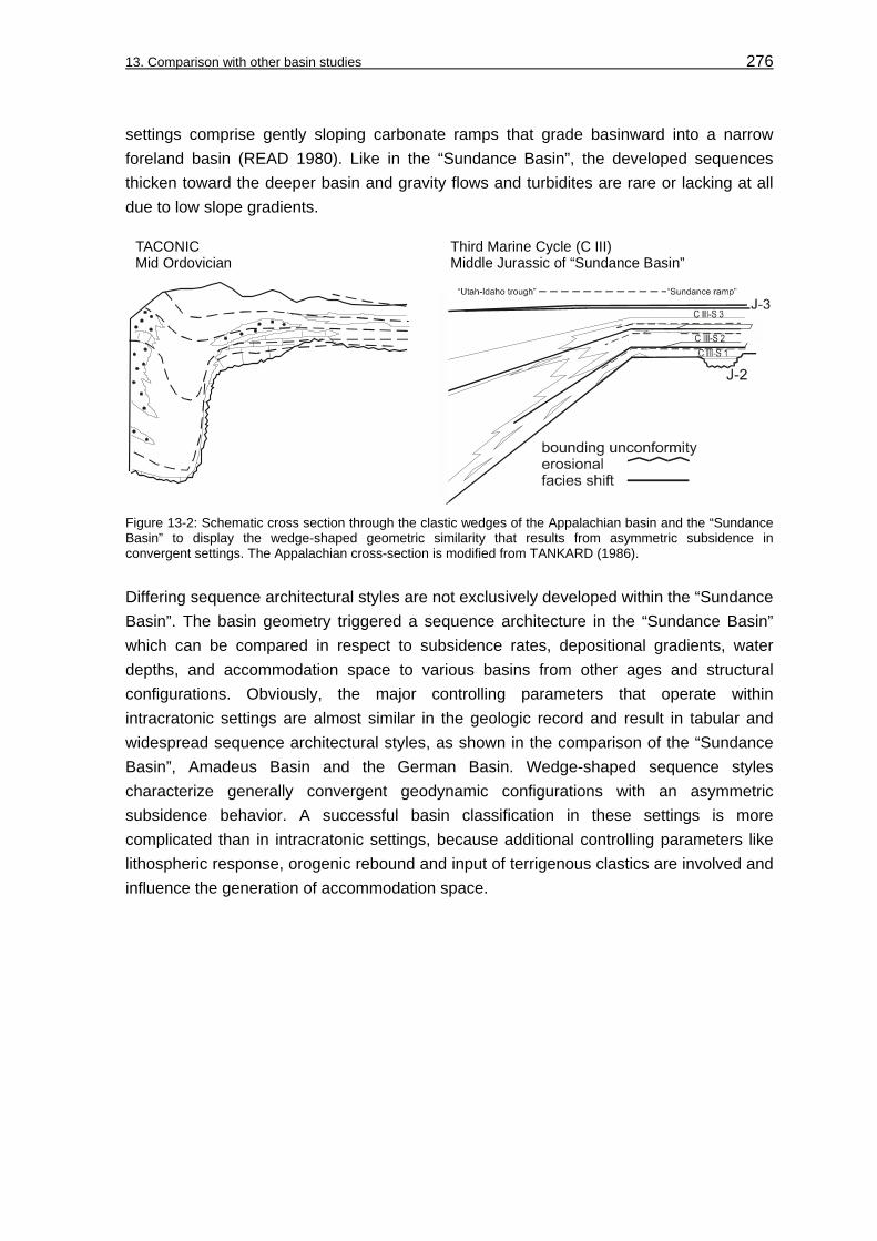
13. Comparison with other basin studies 276
settings comprise gently sloping carbonate ramps that grade basinward into a narrow foreland basin (READ 1980). Like in the “Sundance Basin”, the developed sequences thicken toward the deeper basin and gravity flows and turbidites are rare or lacking at all due to low slope gradients.
TACONICMid Ordovician
Third Marine Cycle (C III)Middle Jurassic of “Sundance Basin”
Figure 13-2: Schematic cross section through the clastic wedges of the Appalachian basin and the “Sundance Basin” to display the wedge-shaped geometric similarity that results from asymmetric subsidence in convergent settings. The Appalachian cross-section is modified from TANKARD (1986).
Differing sequence architectural styles are not exclusively developed within the “Sundance Basin”. The basin geometry triggered a sequence architecture in the “Sundance Basin” which can be compared in respect to subsidence rates, depositional gradients, water depths, and accommodation space to various basins from other ages and structural configurations. Obviously, the major controlling parameters that operate within intracratonic settings are almost similar in the geologic record and result in tabular and widespread sequence architectural styles, as shown in the comparison of the “Sundance Basin”, Amadeus Basin and the German Basin. Wedge-shaped sequence styles characterize generally convergent geodynamic configurations with an asymmetric subsidence behavior. A successful basin classification in these settings is more complicated than in intracratonic settings, because additional controlling parameters like lithospheric response, orogenic rebound and input of terrigenous clastics are involved and influence the generation of accommodation space.

277
14 Summary of results and conclusions
Owing to the scope of this research project the focus was drawn to the facies evolution and sequence architecture of an evolving sedimentary basin and to give insight into distinct evolutionary stages. The established basinwide facies model, the sequence stratigraphic concept and the geologic model are useful tools for the prediction of potential reservoir/seal facies associations in differing basin geometries. The research results of this case study give answer to a number of previously untouched geologic questions in basin analysis (see chapter: 1.1, Study objectives).
Sedimentary cycles and allostratigraphy: Basinwide erosional discontinuity surfaces are subdividing five stratal units in the “Sundance Basin” that each represent remnants of a transgressive-regressive sedimentary cycle. The five major marine sedimentary cycles in the Middle and Late Jurassic strata were identified primarily by BRENNER & PETERSON (1994). The original nomenclature was generally confirmed, but modified in this study in order to add subordinate sequences and sequence boundaries. The five sedimentary cycles are termed in ascending order First Marine Cycle (C I), Second Marine Cycle (C II), Third Marine Cycle (C III), “unnamed cycle”, and Fourth Marine Cycle (C IV). The stratal preservation of the sedimentary cycles is strongly controlled by the basinwide erosional bounding unconformities. An extreme example for poor stratal preservation by erosional unconformities is the “unnamed cycle”.
The bounding unconformities are the Jurassic unconformities J-1 to J-5 proposed by PIPIRINGOS & O’ SULLIVAN (1978). In an allostratigraphic nomenclature the sedimentary cycles and their subordinate sequences are allogroups and alloformations, respectively. Within the allogroups additional minor unconformable stratigraphic contacts of the J-2a, J-2b and J-4a unconformities are identified either by discontinuous facies shifts and/or erosional surfaces. In this study, these surfaces are correlated on a regional scale for the first time.
Facies analysis, facies models: 11 carbonate microfacies types, 10 siliciclastic lithofacies types and one evaporitic facies type can be distinguished in the Middle and Late Jurassic strata of the “Sundance Basin”. These major facies types in combination with the observed ichnofacies spectrum indicate deposition under low to high-energetic conditions in subtidal, normal marine to terrigenous environments on homoclinal to distally steepened ramps and the influence of storm events.
Facies correlation: A lithological and facies differentiation for every major sedimentary cycle is evident from the 2 and 3-dimensional facies correlation and the compiled facies maps. Although incompletely preserved below bounding unconformities each sedimentary cycle differs in facies associations and distribution. Major facies domains can be identified in facies maps representing time slices of the basin evolution. Characteristic facies domains are the “Utah-Idaho trough”, the “Belt Island Complex”, the Williston Basin, and the “Sundance ramp”.

14. Summary of results and conclusions 278
The First Marine Cycle (C I) is basinwide traceable and correlative. The facies distribution and facies models for this cycle characterize hypersaline to peritidal and shallow subtidal depositional environments on a homoclinal ramp. The persisting hypersaline to peritidal red bed facies of the Gypsum Spring Formation in northwestern Wyoming unconformably alternates with thin, but widespread peritidal to shallow subtidal carbonate beds that overlie transgressive surfaces and indicate repeated advance of marine conditions into the sedimentation area.
The facies distribution and facies model for the Second Marine Cycle (C II) reveal sedimentation of peritidal red beds and shallow subtidal carbonate beds of the Piper Formation in northwestern Wyoming. Like in the preceding cycle C I, a persisting peritidal red bed facies is unconformably intercalated with thin, but widespread peritidal to shallow subtidal carbonate beds overlying transgressive surfaces. In the distal portion shallow to normal marine carbonates of the Twin Creek Limestone were deposited in the “Utah-Idaho trough”. Depositional settings of the Second Marine Cycle (C II) describe a ramp morphology with distally steepened gradients toward the “Utah-Idaho trough”.
The facies distribution and facies model for the Third Marine Cycle (C III) reveal a differentiation between shallow to normal marine siliciclastic or mixed carbonate-siliciclastic facies types of the Sundance Formation in the eastern “Sundance Basin” and marine carbonate facies types of the Twin Creek Limestone in the “Utah-Idaho trough” and of the Rierdon Formation on the south flank of the “Belt Island Complex”. Deposition of the siliciclastic-dominated Sundance Formation occurred in the proximal portions of a distally steepened ramp. In the distal portion, shallow to normal marine carbonates of the Twin Creek Limestone were deposited in the “Utah-Idaho trough”.
The facies distribution and facies model for the Fourth Marine Cycle (C IV) characterize normal marine to intertidal depositional environments on homoclinal ramp morphologies. The glauconitic shales of the Redwater Shale Member of the Sundance Formation and its equivalents in the Stump and Swift Formations grade disconformably into coarse-grained, impure glauconitic sandstones of the uppermost portions of the Sundance, Swift and Stump Formations. Conspicuous changes of the homoclinal ramp inclination are not evident for particular basin evolutionary stages from the facies analysis and facies distribution.
Sequence stratigraphic framework: Sequences within the “Sundance Basin” fill are tectonically generated. The application of the transgressive-regressive sequence concept of EMBRY (1993) provided a reliable basinwide stratigraphic framework.
The sequence correlation confirms basinwide traceable second-order sedimentary cycles C I, C II, C III, and C IV. The “unnamed cycle”, a second-order sedimentary cycle between the cycles C III and C IV, is poorly preserved and is spatially restricted to Wyoming, eastern Idaho and northeastern Utah. Within the sedimentary cycles the subordinate sequences can not be identified in areas with low facies contrasts, monotonous lithologies, limited biostratigraphic resolution or poor outcrop conditions. For example,

14. Summary of results and conclusions 279
third-order sequences can not be recognized in the monotonous shales of the Sawtooth Formation and Rierdon Formation in northwestern Montana. In the “Utah-Idaho trough” only local, non-correlative shallowing upward suites are recorded in the massive carbonates of the Twin Creek Limestone.
Third-order sequences are basinwide correlative in the Gypsum Spring Formation of the First Marine Cycle (C I) and in the Redwater Shale Member of the Sundance Formation and its stratigraphic equivalents of the Fourth Marine Cycle (C IV). In contrast, the sequences can not be traced in the Piper Formation of the Second Marine Cycle (C II) and in the Rierdon Formation of the Third Marine Cycle (C III) in northwestern Montana. The third-order sequences and their bounding surfaces are only developed where distinct facies and lithologic contrasts are identifiable by the facies analysis being supported by good outcrop conditions.
Sequence hierarchy: With the application of the transgressive-regressive sequence concept of EMBRY (1993) and the sequence concept of VAIL et al. (1991) a basinwide hierarchical system for sedimentary cycles, subordinate sequences and sequence boundaries can be established for the “Sundance Basin”. The major sedimentary cycles and their bounding erosional surfaces are assigned second-order rank, while subordinate sequences and boundaries are of the third-order rank.
Sequence boundaries: The sequence boundaries are expressed by transgressive, shallow to normal marine deposits that overlie unconformable stratigraphic contacts. These contacts are either expressed as erosional surfaces or discontinuous facies shifts.
Systems tracts and internal sequence organization: Internally, the sedimentary cycles and their sequences are composed of transgressive and regressive facies successions. In the sequence stratigraphic nomenclature these facies successions are equivalent to systems tracts. Second-order transgressive (TST) and regressive (RST) systems tracts can be identified for the second-order sedimentary cycles. Within the third-order sequences contemporaneous facies successions in transgressive and regressive systems tracts are termed transgressive (TC) and regressive (RC) complexes.
Regressive systems tracts (RST) and regressive complexes (RC) are commonly preserved in the sedimentary cycles C I to C III as progradational, siliciclastic to mixed carbonate-siliciclastic successions, for instance, in the Hulett Sandstone and in the Lak Member of the Sundance Formation and the Giraffe Creek Member of the Twin Creek Limestone overlain by the Preuss Formation. The “unnamed cycle” is considered to represent remnants of a poorly preserved transgressive complex. In the sedimentary cycle C IV, regressive complexes (RC) only occur as sedimentary relics below erosional sequence boundaries as the J-4a in the Redwater Shale Member of the Sundance Formation in Wyoming.
14. Summary of results and conclusions 280
Sequence types and stacking pattern: Three sequence types can be distinguished for the third-order sequences from the internal organization (facies, lithology and internal sequence architecture) and external physical appearance (isopach pattern, sequence boundaries, sequence correlation, sequence geometry, sequence preservation, sequence stacking).
Sequence type 1 is characterized by extensive, tabular sequences stacked in a layer cake stratification in the First Marine Cycle (C I). Sequence type 2 is wedge-shaped, composed of aggradational or progradational transgressive (TC) and regressive (RC) complexes. This sequence type is typical for the Second Marine Cycle (C II) and Third Marine Cycle (C III). Sequence type 3 occurs in the Fourth Marine Cycle (C IV) and is simple stacked, tabular and truncated.
Control on sequence stacking pattern: The sequence stacking pattern is controlled by the interplay of subsidence rates, morphological gradients and water depths. Low subsidence rates and morphological gradients produced extensive, layer cake stacked sequences of type 1. In contrast, increasing, spatially asymmetric subsidence rates in the western portion of the “Sundance Basin” supported the formation of wedge-shaped sequences of type 2 that are stacked in an aggradational or progradational fashion. Low subsidence rates, morphological gradients and an increasing sediment supply caused an overfilling of the available accommodation space and resulted in tabular, truncated sequences of type 3.
Controlling parameters: Major facies evolutionary trends and sequence architectural styles within the “Sundance Basin” can be explained by the interplay of the factors regional tectonism (uplift and subsidence) in the evolving Nevadian orogen and the arid to humid Jurassic climate. Subsidence rates and uplift in sedimentary source areas controlled the relationship between accommodation space, depositional gradients and input of siliciclastic material. The warm and dry Jurassic climate influenced the depth of the photic zone and prevented the carbonate depositional system in the “Utah-Idaho trough” from termination by the permanent fine clastic input.
Relative sea-level changes: The relative sea-level development within the “Sundance Basin” was primarily controlled by regional tectonics. The generation of sedimentary cycles and bounding surfaces relates poorly to global eustasy. A third-order sea-level curve constructed for the “Sundance Basin” revealed a limited correspondence to global eustasy curves of HAQ et al. (1984) and VAIL et al. (1987). Some correspondence exists between the global eustasy curve of HALLAM (1988) and the “Sundance Basin” curve in sea-level fluctuations at the Aalenian-Bajocian boundary, in the Middle Callovian and at the Callovian-Oxfordian boundary.
Subsidence behaviour and basin geometry: Compiled sequence thickness maps, decompacted thickness profiles and constructed sediment accumulation curves (total subsidence curves) record two geometric basin configurations during evolution of the “Sundance Basin”. A symmetric basin geometry with low to moderate subsidence rates is

14. Summary of results and conclusions 281
characteristic for the First Marine Cycle (C I) and the Fourth Marine Cycle (C IV). An asymmetric basin geometry and an onset of rapid subsidence at about 170 Ma was detected for the depositional period of the Second (C II) and Third (C III) Marine Cycle. This temporary modification of the spatial subsidence pattern correlates with available radiometric age dates for the beginning of the Nevadian orogeny. These age dates range between 180-160 Ma (EVERNDEN & KISTLER 1970) and 170-160 Ma (EISBACHER 1988). The changing subsidence pattern is further reflected in the distally steepening of morphological gradients and the increasing thickness and sedimentation of normal marine carbonates in the “Utah-Idaho trough”. Due to the spatially contrasting subsidence pattern stable ramp configurations of the “Sundance ramp” and the “Belt Island Complex” developed eastward and northward of the area of maximum subsidence and separated the “Utah-Idaho trough” from the intracratonic Williston Basin.
Basin evolutionary stages and sequence types in a geologic model: A geologic model for the “Sundance Basin” comprises three basin tectono-evolutionary stages. The sequence architectural style of each stage is reflected by one of the three different sequence types 1, 2 and 3.
During the initial evolutionary intracratonic “sag basin stage” the strata of the First Marine Cycle (C I) were deposited and sequence type 1 developed. The subsequent “foreland basin-style stage” covers the depositional period of the Second Marine Cycle (C II) and Third Marine Cycle (C III). This stage is documented by sequence type 2. The “rebound stage” contains the stratal record of the Fourth Marine Cycle (C IV) and represents the final filling stage of the “Sundance Basin”. Sequences of type 3 were formed during this stage. Partial overfilling of the “Sundance Basin”, initiated by the increasing input with coarse-grained siliciclastics from western source areas, caused the truncation of the generated sequences during the “rebound stage”.
Potential reservoir facies: Potential reservoir and seal facies types in the basinfill occur in stratigraphic traps. These associations are developed in thin, but widespread high-energetic carbonate facies bodies of transgressive complexes (TC) in the “sag basin stage”. A reliable reservoir prediction for this basin evolutionary stage is supported by the layer cake stacking of third-order sequences and their transgressive complexes. In the “foreland basin-style stage”, additional potential reservoir and seal facies types occur in shoreline-detached facies belts where isolated high-energetic reservoir-prone carbonate facies types developed in the “Utah-Idaho trough”. On the “Sundance ramp”, potential reservoir-prone sediments and seals are developed in continuous siliciclastic shoreface-foreshore successions. The sequence stratigraphic positions of these potential reservoir facies types comprise transgressive complexes (TC) of aggradational sequences and progradational regressive complexes (RC). The potential reservoir facies types are associated with interstratified and enveloping shales or mudstones that could perform a seal function.

14. Summary of results and conclusions 282
Comparison with other basin studies: The different sequence architectural styles are not exclusively developed within the “Sundance Basin”. The evolutionary stages of the “Sundance Basin” and the sequence architectural styles can be compared in respect to subsidence rates, depositional gradients, water depths, and accommodation potential to various sedimentary basins from other geologic ages and geodynamic settings.
The major controlling parameters that operate within intracratonic settings are obviously similar in the geologic record and result in tabular and widespread sequence architectural styles as revealed in the comparison of the “Sundance Basin” with the Amadeus Basin and the German Basin.
Generally, wedge-shaped sequence styles characterize convergent geodynamic configurations that are accompanied by an asymmetric subsidence behavior. A successful basin classification in these settings is more complicated than in intracratonic settings because additional controlling parameters like lithospheric response, orogenic rebound and input of terrigenous clastics are involved and affect the generation of accommodation space.
From the research results of this case study answers can be given to a number of geologic questions.
1. In which way changed the geometry and the subsidence pattern within the transformed basin?
The basin geometry is directly related to the subsidence pattern. Subsidence rates accelerated temporarily in a confined portion of the basin. In consequence, the basin geometry changed in short time spans from symmetric to asymmetric and back to symmetric. The subsidence behavior was forced by active tectono-orogenic processes.
A representative sediment accumulation curve (total subsidence curve) for stable and subsiding areas shows a temporary variation of subsidence rates before the subsidence finally slowed down and the accommodation space was progressively filled with the increasing influx of siliciclastics. Uplift and partial removal of strata occurred subsequently in previously subsided areas, while subsidence and sedimentation prevailed in adjacent intracratonic portions.
2. Is the changing basin geometry triggering characteristic facies evolutionary and sequence architectural styles?
Yes, the changing geometry is recorded in the facies evolution and sequence architectural styles during particular stages of basin evolution. The interplay of subsidence and uplift had also a tremendous impact on the sequence boundary formation. The development of sequence types correlates to distinct basin geometric configurations. The facies evolution within the sequence types is additionally controlled by the regional tectonism that drove the sediment supply.
14. Summary of results and conclusions 283
A symmetric basin geometry produces tabular sequences, composed of extensive facies sheets. Depending on the sediment supply two sequence types can be distinguished. Low subsidence rates and low sediment supply promote layer cake-like sequences. In contrast, low subsidence rates and increasing sediment supply employ partial overfilling and result in sequence truncation.
In an asymmetric basin geometry wedge-shaped sequences develop. These sequences are more differentiated in their distribution of carbonate and siliciclastic facies types. The generation of wedge-shaped sequences is favored by an asymmetric subsidence pattern and the generation of additional accommodation space.
3. Can the dynamic stratigraphy of a carbonate-siliciclastic depositional system be explained by sequence stratigraphic models? Both aspects are poorly understood. Furthermore, facies models for mixed carbonate-siliciclastic systems do rarely exist.
Yes, both aspects can be combined in a dynamic stratigraphic concept. Major sedimentary cycles and allostratigraphic bounding surfaces are developed in the mixed carbonate-siliciclastic depositional systems. An appropriate sequence stratigraphic framework is provided by the transgressive-regressive sequence model of EMBRY (1993). This model integrates allostratigraphic units, transgressive surfaces and a hierarchical system of sequence boundaries. Transgressive surfaces and sequence boundaries can be easily identified in the basinfill. This allows the definition of subordinate stratigraphic sequences and systems tracts. In addition, the concept implies tectonic control on sequence generation.
Conspicuous interfaces in siliciclastic and carbonate deposystems are the fairweather wave base (FWWB) and the storm wave base (SWB). These interfaces mark also identifiable boundaries between differing depozones in mixed depositional environments. The spatial arrangement of depositional environments can be understand as homoclinal to distally steepened ramp facies models. The depositional model consists of three facies belts with a specific offshore protracted decrease of hydrodynamic energy gradients. In depozone 0 terrigenous and sabkha sedimentation prevails. Zone I includes shoreface-foreshore environments above the fairweather wave base (FWWB), while zone II is characterized by offshore mid- to outer ramp settings above storm wave base (SWB). Due to the low morphological gradient in the proximal homoclinal portions of the facies models, the resulting depozones 0, I and II are very broad.

14. Summary of results and conclusions 284
4. Is the generation and distribution of resource sediments responding to the basin geometry?
Yes, resource sediment systems respond instantaneously to the basin geometry. They are produced and distributed differently during symmetric and asymmetric geometric basin configurations.
In a symmetric basin configuration they develop as thin, but widespread carbonate facies types in transgressive systems tracts. In an asymmetric basin geometry stage, they occur in shoreline-detached carbonate facies belts that fringe areas of increased subsidence or in continuous siliciclastic shoreface-foreshore successions of tectonically stable areas. No resource sediments were identified in symmetric basin settings that undergo partial overfilling, because intense erosion and redistribution within the sedimentary system destroys these deposits.
5. Are the research results contributing insights into the principal origin and subsequent evolution of intracratonic basins?
The question for the mechanism, either thermal- or mechanically-driven, that controls the origin of intracratonic sag basins can not be solved in this study. However, the subsequent basin evolution can be evaluated. The geologic model shows the coexistence of intracratonic elements that were representative in preceding geological stages and elements that can be interpreted as precursors of subsequent orogenic events.
The case study further contributes solutions for some regional geologic problems in the Jurassic system of the western United States, in particular, the “Sundance Basin”. For the first time, a facies models, a sequence stratigraphic concept, a stratigraphic framework and a geologic model are completed for the entire “Sundance Basin”. With these tools allogenetic controlling factors on the sedimentation and formation of bounding surfaces can be accurately addressed and evaluated.

285
Acknowledgements
I would like to express my sincerest thanks to PD Dr. Jörg Trappe for his support during field work and the great efforts he put into this study. I remain deeply indebted to him for his constructive supervision and his great confidence. He gave me not only the opportunity to work on a highly fascinating subject, but also to spend the most memorable time in the unique landscape of the Rocky Mountains.
I acknowledge my colleagues from the Geological Institute of Bonn for their support. I am particularly obliged to Prof. Dr. Thein for his support and his interest in the “America” research projects.
I gratefully acknowledge Prof. James Steidtmann for realising my stay at the Department of Geology & Geophysics at the University of Wyoming in Laramie. He generously provided office space and granted use of the departmental facilities. My deepest thanks also to all staff members at the Department of Geology & Geophysics at UW or their help. Shawn Sheen is especially thanked for her support. My student fellows Diane Burns and Maggie Hutna are thanked for lifts to and from Denver International Airport.
Prof. Carl Vondra (Iowa State University Geological Department) is thanked for letting me stay at the Geology Field Station in Shell/Wyoming during field work in the Bighorn Basin.
All the friendly and cooperative landowners in Wyoming, Montana and South Dakota are thanked for allowing me trespass and for not shooting at me.
I would also like to acknowledge Dr. Christian Enzl for his help during carbonate microfacies analysis and Rainer Schwarz for helping with the production of thin-sections.
I am most grateful to the German National Academic Foundation (Studienstiftung des deutschen Volkes) for a continuous support since 1997. This project was financed by postgraduate and doctoral scholarships from the German National Academic Foundation (Studienstiftung des deutschen Volkes).
The IAS (International Association of Sedimentologists) is thanked for releasing student travel grants to attend the IAS Meeting 2002 in Johannesburg/South Africa.
I owe thanks to Anette for her assistance during field work and for her patience and ongoing support during the preparation of this study.

286
References
AHLBRANDT, T. S. (1996a): Thermal Pfister #43-25, Canyon Springs sandstone reservoir example, Red Bird Field, Niobrara County, Wyoming. – in: DOLLY, E. D. & MULLARKEY, J. C. (eds.): Hydrocarbon production from low contrast, low resistivity reservoirs, Rocky Mountain and Mid-Continent Regions: Log examples of subtle plays (example from Red Bird Field, Wyoming), Rocky Mtn. Assoc. Geologists, Guidebook: 258-259.
AHLBRANDT, T. S. (1996b): Thermal Pfister #13-49, Canyon Springs sandstone reservoir example, Red Bird Field, Niobrara County, Wyoming. – in: DOLLY, E. D. & MULLARKEY, J. C. (eds.): Hydrocarbon production from low contrast, low resistivity reservoirs, Rocky Mountain and Mid-Continent Regions: Log examples of subtle plays (example from Red Bird Field, Wyoming), Rocky Mtn. Assoc. Geologists, Guidebook: 260-261.
AHLBRANDT, T. S. & FOX, J. E. (1997): Middle Jurassic incised valley fill (eolian/estuarine) and nearshore marine petroleum reservoirs, Powder River Basin. – The Mountain Geologist, 34, 3: 97 – 115; Denver/Colorado.
AIGNER, T. (1985): Storm depositional systems. – 174 pp., Lecture Notes in Earth Science, 3; Amsterdam (Springer).
AIGNER, T. & PÖPPELREITER, M. (2003): Unconventional pattern of reservoir facies distribution in epeiric successions: Lessons from an outcrop analog (Lower Keuper, Germany). – Amer. Assoc. Petrol. Geol., Bull. 87, 1: 39-70; Tulsa/Oklahoma.
ALLEN, P. A., HOMEWOOD, P. & WILLIAMS, G. D. (1986): Foreland basins: an introduction. – IAS Spec. Pub., 8: 3-12; Oxford (Blackwell Science).
ALLMENDINGER, R. W. & JORDAN, T. E. (1984): Mesozoic structure of the Newfoundland Mountains, Utah: Horizontal shortening and subsequent extension in the hinterland of the Sevier Belt. – Geol. Soc. America, Bull., 95: 1280-1292; Boulder/ Colorado.
ANDERSON, K. A. (1978): Early lithification of limestones in the Redwater Shale Member of the Sundance Formation (Jurassic) of southeastern Wyoming. – 74 pp.; unpub. MSc thesis, University of Wyoming: Laramie.
ANDERSON, K. A. (1979): Early lithification of limestones in the Redwater Shale Member of the Sundance Formation (Jurassic) of southeastern Wyoming. – Contrib. Geology, 18, 1: 1-17; University of Wyoming/Laramie.
ATKINS, J. E. & McBRIDE, E. F. (1992): Porosity and packing of Holocene river, dune and beach sands. – Amer. Assoc. Petrol. Geol., Bull., 76, 3: 339-355; Tulsa/ Oklahoma.

References 287
BAIRD, G. C. & FÜRSICH, T. F. (1975): Taphonomy and biologic progression associated with submarine erosion surfaces from the German Lias. – N. Jahrb. Geol. Paläont., 6: 321-338; Stuttgart.
BAKER, A. A., DANE, C. H. & REESIDE, J. B. jr. (1936): Correlation of the Jurassic formations of parts of Utah, Arizona, New Mexico, and Colorado – U. S. Geol. Surv., Prof. Pap., 183; Washington.
BATES, R. L. & JACKSON, J. A. (1987): Glossary of Geology. – 788 pp.; Amer. Geol. Inst.; Alexandria/ Virginia.
BATHURST, R. G. C. (1980): Lithification of carbonate sediments. – Sci. Prog., 66: 451-471.
BEARD, D. C. & WEYL, P. K. (1973): Influence of texture on porosity and permeability of unconsolidated sand. – Amer. Assoc. Petrol. Geol., Bull., 57, 2: 349-369; Tulsa/Oklahoma.
BJERRUM, C. J. & DORSEY, R. J. (1995): Tectonic controls on deposition of Middle Jurassic strata in a retroarc foreland basin, Utah-Idaho trough, Western Interior, United States. – Tectonics, 14, 4: 962-978.
BJORLYKKE, K. (1988): Sandstone diagenesis in relation to preservation, destruction and creation of porosity. – in: CHILINGARIAN, G. V. & WOLF, K. H. (eds): Diagenesis I, Developments in Sedimentology, 41: 555-595; Amsterdam (Elsevier).
BJORLYKKE, K., RAMM, M., & SAIGAL, G. C. (1989): Sandstone diagenesis and porosity modification during basin evolution. – Geol. Rundschau, 78: 243-268; Stuttgart.
BLAKEY, R. C., PETERSON, F., CAPUTO, M. V., GEESAMAN, R.C. & VOORHEES, B.J. (1983): Paleogeography of Middle Jurassic continental, shoreline and shallow marine sedimentation, southern Utah. – in: REYNOLDS, M. W. & DOLLY, E. D. (eds.): Mesozoic paleogeography of the west-central United States, Rocky Mountain Paleogeography Symposium 2: 77-100; SEPM, Rocky Mountain Section; Denver/Colorado.
BLAKEY, R.C. (1988): Basin tectonics and erg response.– Sed. Geology, 56: 127-151; Amsterdam.
BLAKEY, R.C. & JONES, L. S. (1993): Erosional remnants and adjacent unconformities along an eolian-marine boundary of the Page Sandstone and Carmel Formation, Middle Jurassic, south-central Utah. – Jour. Sed. Petrol., 63, 5: 852-859; Tulsa/Oklahoma.
BLAKEY, R. C., HAVHOLM, K. G. & JONES, L. S. (1996): Stratigraphic analysis of eolian interactions with marine and fluvial deposits, Middle Jurassic Page Sandstone and Carmel Formation, Colorado Plateau, USA. – Jour. Sed. Petrol., 66, 2: 324-342; Tulsa/ Oklahoma.

References 288
BLAKEY, R. C., PETERSON, F. & KOCUREK, G. (1988): Synthesis of late Paleozoic and Mesozoic eolian deposits of the Western Interior of the United States. – Sed. Geol., 56: 3-125; Amsterdam.
BOETTCHER, S. S. & WALKER, J. D. (1993). Geologic evolution of the Iron Mountain, central Mojave Desert, California. – Tectonics, 12: 372-386.
BOND, G. C. & KOMINZ, M. A. (1984): Construction of tectonic subsidence curves for the early Paleozoic miogeocline, southern Canadian Rocky Mountains: implications for subsidence mechanisms, age of breakup, and crustal thinning. – Geol. Soc. America, Bull. 95: 155-173; Boulder/Colorado.
BRENNER, R. L. & DAVIES, D. K. (1973): Storm-generated coquinoid sandstone genesis of high-energy marine sediments from the Upper Jurassic of Wyoming and Montana. - Geol. Soc. America, Bull., 84: 1685-1698; Boulder/Colorado.
BRENNER, R. L. & DAVIES, D. K. (1974): Oxfordian sedimentation in Western Interior United States. - Amer. Assoc. Petrol. Geol., Bull., 58: 444 - 467; Tulsa/Oklahoma.
BRENNER, R. L. (1983): Late Jurassic tectonic setting and paleogeography of Western Interior, North America. – in REYNOLDS, M. W. & DOLLY, E. D. (eds.): Mesozoic paleogeography of the west-central United States, Rocky Mountain Paleogeography Symposium 2: 119-132; SEPM, Rocky Mountain Section; Denver/Colorado.
BRENNER, R. L., SWIFT, D. J. P. & GAYNOR, G. C. (1985): Re-evaluation of coquinoid sandstone depositional model, Upper Jurassic of central Wyoming and south-central Montana. – Sedimentology, 32: 363-372; Amsterdam.
BRENNER, R. L. & PETERSON, J. A. (1994): Jurassic sedimentary history of the northern portion of the Western Interior Seaway, USA. – in: CAPUTO, M. V., PETERSON, J. A. & FRANCZYK, K. J. (eds.): Mesozoic Systems of the Rocky Mountain Region, USA: 217-231; Denver/Colorado.
BROWN, W. G. (1993): Structural style of Laramide basement-cored uplifts and associated folds. – in: SNOKE, A. W., STEIDTMANN, J. R. & ROBERTS, S. M. (eds.): Geology of Wyoming, Geol. Surv. Wyoming, Mem., 5: 312-371; Laramie/Wyoming.
BURCHETTE, T. P., WRIGHT, P. V. & FAULKNER, T. J. (1990): Oolitic sandbody depositional models and geometries, Mississippian of southwest Britain: implications for petroleum exploration in carbonate ramp settings. – Sed. Geology, 68: 87-115; Amsterdam.
BURCHETTE, T. P. & WRIGHT, P. V. (1992): Carbonate ramp depositional systems. – Sed. Geol., 79: 3-57; Amsterdam.
BUSBY, C. J. & INGERSOLL, R. V. (1995): Tectonics of sedimentary basins. – 549 pp., Blackwell Science, Oxford.
References 289
BUTLER, G. P., HARRIS, P.M. & KENDALL, C. (1982): Recent evaporites from the Abu Dhabi coastal flats: - in: HANDFORD, C.R., LOUCKS, R.G. & DAVIES, G.R. (eds.): Depositional and diagenetic spectra of evaporites, SEPM, Core Workshop, 3: 33-64.
BÜSCHER, O. (2000): Die jurassische Sundance Formation im westlichen Powder River Basin, Wyoming, USA – Faziesanalyse und Zyklostratigraphie. – 104 pp.; unpubl. Dipl. Arb., Univ. Bonn.
CAPARCO, N. J. (1989): Callovian and Oxfordian foraminifera from the Late Jurassic of northern and western Wyoming. – 159 pp.; unpub. MSc thesis, University of Wyoming: Laramie.
CECIL, B. C. (1990): Paleoclimate control on stratigraphic repetition of chemical and siliciclastic rocks. – Geology, 18: 533-536; Boulder/Colorado.
COBBAN, W. A. (1945): Marine Jurassic formations of Sweetgrass Arch, Montana. – Amer. Assoc. Petrol. Geol., Bull., 29: 1262-1303; Tulsa/Oklahoma.
CONROY, J. & TANG, C. M. (2002): Bored and encrusted carbonate cobbles and hardgrounds at the base of a regressive sequence (Lower Sundance Formation, Middle Jurassic, eastern Wyoming. – Poster, Geol. Soc. America Joint Ann. Meeting 2002, North-Central Section (36th) and Southeastern Section (51st).
CROSS, T. A. (1989): Tectonic controls of foreland basin subsidence and Laramide style deformation, western United States. – in: ALLEN, P. A. & HOMEWOOD, P. (eds.): Foreland basins, IAS Spec. Pub., 8: 15-39; Oxford (Blackwell Science).
CURRIE, B. S. (1998) : Upper Jurassic-Lower Cretaceous Morrison and Cedar Mountain Formations, NE Utah – NW Colorado: relationships between nonmarine deposition and early Cordilleran foreland basin development. – Jour. Sed. Res., 68: 632-652; Tulsa/Oklahoma.
CURRIE, B. S. (2002): Structural configuration of the Early Cretaceous Cordilleran foreland-basin system and Sevier Thrust Belt, Utah and Colorado. – Jour. Geol., 110: 697-718: Chicago.
DARTON, N. H. (1899): Jurassic formations of the Black Hills of South Dakota. – Geol. Soc. America, Bull., 10: 383-396; Boulder/Colorado.
DASSEL, I. (2002): Die jurassische Sundance Formation im östlichen Bighorn Basin, Wyoming; USA – Faziesanalyse und Zyklostratigraphie. – 83 pp.; unpublished Dipl. Arb., Univ. Bonn.
DeCELLES, P. G. & BURDEN, E. T. (1992): Non-marine sedimentation in the overfilled part of the Jurassic-Cretaceous Cordilleran foreland basin: Morrison and Cloverly Formations, central Wyoming, U. S. A.– Basin Res., 4: 291-313; Oxford.
DeCELLES, P. G. & CURRIE, B. S. (1996): Long-term sediment accumulation in the Middle Jurassic-Early Eocene Cordilleran retroarc foreland basin system. – Geology, 24, 7: 591-594; Boulder/Colorado.

References 290
DeCELLES, P. G. & GILES, K. A. (1996): Foreland basin systems. – Basin Res., 8: 105-123; Oxford.
DeJARNETTE, M. L. & UTGAARD, J. E. (1986) : Facies and depositional environments of a mixed carbonate-siliciclastic sequence in the Sundance Formation (Jurassic), northeastern Bighorn Basin, Montana and Wyoming, Montana Geol. Soc., Yellowstone Bighorn Res. Assoc. Joint Field Conference and Symposium Guidebook, Geology of the Beartooth Uplift and adjacent basins: 27-31.
DICKINSON, W. R., KLUTE, M. A., HAYES, M. J., JANECKE, U. S., LUNDIN, E. R., McKITTRICK, M. A. & OLIVARES, M. D. (1988): Paleogeographic and paleotectonic setting of Laramide sedimentary basins in the central Rocky Mountains. – Geol. Soc. America, Bull., 100: 1023-1039; Boulder/Colorado.
DRESSER, H. W. (1959): A field study of the Jurassic „lower Sundance“ beds in southeastern Wyoming. – 667 pp.; unpub. PhD thesis, University of Wyoming: Laramie.
DUNHAM, R.J. (1962): Classification of carbonate rocks according to depositional texture. – Amer. Assoc. Petrol Geol., Mem., 1: 108 – 121; Tulsa/Oklahoma.
EINSELE, G. & BAYER, U. (1991): Assymetry in transgressive-regressive cycles in shallow seas and passive continental margin settings. – in: EINSELE, G., RICKEN, W., & SEILACHER, A. (eds.): Cycles and events in stratigraphy. – 660-681; Berlin, Heidelberg, New York (Springer).
EINSELE, G. (1992): Sedimentary basins: evolution, facies and sediment budget. – 613 pp., 269 fig.; Berlin, Heidelberg, New York (Springer).
EISBACHER, G. H. (1988): Nordamerika, Geologie der Erde, Band 2. – 176 pp.; Stuttgart (Enke).
EKDALE, A. A. & PICARD, M. D. (1985): Trace fossils in a Jurassic eolianite, Entrada Sandstone, Utah, U. S. A. – in: CURRAN, H. A. (ed.): Biogenic structures: their use in interpreting depositional environments, SEPM, Spec. Pub., 35: 3-12; Tulsa/Oklahoma.
ELLIOT, T. (1984): Evidence for diurnal tides in the Upper Jurassic of the Western Interior Basin, U. S. A. – in: Progr. Abstr., Res. Symp. Sedimentology of Shelf Sands and Sandstones, Can. Soc. Petrol. Geol.; Calgary.
EMBRY, A. F. & PODRUSKI, J. A. (1988): Third-order depositional sequences of the Mesozoic succession of Sverdrup Basin. – in: JAMES, D. & LECKIE, D. (eds.): Sequences, stratigraphy and sedimentology: surface and subsurface, Can. Soc. Petrol. Geol. Mem., 15: 73-84.
EMBRY, A. F. (1993) : Transgressive-regressive (T – R) sequence analysis of the Jurassic succession of the Sverdrup Basin, Canadian Arctic Archipelago. – Can. Jour. Earth Sci., 30: 301-320.

References 291
EVERNDEN, J. F. & KISTLER, R. W. (1970): Chronology of emplacement of Mesozoic batholith complexes in California and western Nevada. – U. S. Geol. Surv., Prof. Pap., 216; Washington.
FILIPPICH, M. (2001): Faziesanalyse und Zyklostratigraphie der jurassischen Gypsum Spring Formation im Bighorn Basin, Wyoming, USA. – 99 pp.; unpubl. Dipl. Arb., Univ. Bonn.
FLÜGEL, E. (1982): Microfacies analysis of limestones. – 633 pp., Berlin, New York, Heidelberg (Springer).
FLÜGEL, E. (1985): Fazies-Lexikon: Mikrofazielle Untersuchungsmethoden von Karbonatgesteinen. – 90 pp., Arbeitsunterlagen Interuniversitärer Kompaktkurs, Institut f. Paläontologie Erlangen.
FOLK, R. L. (1962): Practical petrographical classification of limestones. – Amer. Assoc. Petrol. Geol., Bull., 43: 1-38; Tulsa/Oklahoma.
FRAZIER, J. W. & SCHWIMMER, D. R. (1987): Regional stratigraphy of North America. – 719 pp.; New York (Plenum Press).
FREY, R. W., PEMBERTON, S. G. & SAUNDERS, T. D. A. (1990): Ichnofacies and bathymetry: a passive relationship. – Jour. Paleontology, 64: 155-158.
FÜCHTBAUER, H. (1988): Sedimente und Sedimentgesteine. – 1141 pp., 4. Aufl.; Stuttgart (Schweizerbart).
GALLOWAY, W. E. (1989): Genetic stratigraphic sequences in basin analysis I: architecture and genesis of flooding-surface bounded depositional units. - Amer. Assoc. Petrol. Geol., Bull., 73: 125-142; Tulsa/Oklahoma.
GILES, K. A. & DICKINSON, W. R. (1995) : The interplay of eustasy and lithospheric flexure in forming stratigraphic sequences in foreland settings : an example from the Antler foreland, Nevada and Utah. – in: DOROBEK, S. L., ROSS, G. M. & SCHOLLE, P. A. (eds.): Stratigraphic evolution of foreland basins, SEPM, Spec. Pub. 52: 187-211; Tulsa/Oklahoma.
GILES, M. R. (1997) : Diagenesis: a quantitative perspective: implications for basin modelling and rock property prediction. – 526 pp.; Dordrecht, Boston, London (Kluwer Academic Publishers).
GOLONKA, J. & FORD, D. (2000): Pangean (Late Carboniferous-Middle Jurassic) paleoenvironment and lithofacies. – Palaeogeogr., Palaeoclimatol., Palaeoecol., 161: 1-34: Amsterdam.
GRADSTEIN, F. M., AGTERBERG, F. P., OGG, J. G., HARDENBOL, J., VAN VEEN, P., THIERRY, J. & HUANG, Z. (1995): A Triassic, Jurassic and Cretaceous time scale. – in BERGGREN, W. A., KENT, D., & HARDENBOL, J. (eds.): Geochronology time scales and global stratigraphic correlation, SEPM, Spec. Pub., 54: 95-126; Tulsa/Oklahoma.

References 292
GRIES, J. P. (1996): Roadside geology of South Dakota. – 358 pp.; Missoula (Mountain Press Pub. Company).
GURNIS, M. & HAGER, B. H. (1988): Controls of the structure of subducted slabs. – Nature, 335: 317-321.
GURNIS, M. (1992): Rapid continental subsidence following the initiation and evolution of subduction. – Science, 225: 1556-1558.
HADLEY, H. D., LEWIS, P. J., & LARSON, R. B. (1955): Catalogue of formation names for the Sweetgrass Arch and adjacent areas. – Billings Geol. Soc., 6th Ann. Field Conf. Guidebook: 233-243; Billings/Montana.
HADLEY, H. D. & LEWIS, P. J. (1956): Catalogue of formation names for central Montana and adjacent areas. – Billings Geol. Soc., 7th Ann. Field Conf. Guidebook: 141-151; Billings/Montana.
HALLAM, A. (1969): A pyritized limestone hardground in the Lower Jurassic of Dorset (England). – Sedimentology, 12: 231-240; Amsterdam.
HALLAM, A. (1988): A reevaluation of Jurassic eustasy in the light of new data and the revised Exxon curve. – in: WILGUS, C. K., HASTINGS, B. S., POSAMENTIER, H., VAN WAGONER, J., ROSS, C. A. & KENDALL, C. G. (eds.): Sea-level changes – an integrated approach, SEPM, Spec. Pub., 42: 261-273; Tulsa/Oklahoma.
HALLAM, A. (1992): Phanerozoic sea-level changes. – 266 pp., New York (Columbia University Press).
HALLAM, A. (1999): Evidence of sea-level fall in sequence stratigraphy: examples from the Jurassic. – Geology, 27, 4: 343-346: Boulder/Colorado.
HAMILTON, E. L. (1976): Variations of density and porosity with depth in deep-sea sediments. – Jour. Sed. Petrol., 46: 280-300: Tulsa/Oklahoma.
HANSEN, W. R. (1965): Geology of the Flaming Gorge area Utah-Colorado-Wyoming. – U. S. Geol. Surv., Prof. Pap., 490, Washington.
HÄNTZSCHEL, W. (1975): Treatise on invertebrate paleontology; part W: trace fossils and problematica. – Geol. Soc. America and University of Kansas; Boulder, Lawrence.
HANDFORD, C. R. & LOUCKS, R. G. (1993): Carbonate depositional sequences and systems tracts – response of carbonate platforms to relative sea-level changes. – in: LOUCKS, R. G. & SARG, J. F. (eds.): Carbonate sequence stratigraphy – recent developments and applications, Amer. Assoc. Petrol. Geol., Mem. 57: 3-41; Tulsa/Oklahoma.
HAQ, B. U., HARDENBOL. J. & VAIL, P. R. (1987): Chronology of fluctuating sea levels since the Triassic. - Science, 235; 1156 – 1167; Washington.
HARMS, J. C. (1969): Hydraulic significance of some sand ripples. – Geol. Soc. America, Bull., Vol. 84, 363-396: Boulder/Colorado.
References 293
HAVHOLM, K. G., BLAKEY, R. C., CAPPS, M., JONES, L. S., KING, D. D. & KOCUREK, G. (1993): Aeolian genetic stratigraphy: an example from the Middle Jurassic Page Sandstone, Colorado Plateau. – in: PYE, K. & LANCSTER, N. (eds): Aeolian sediments: ancient and modern, IAS, Spec. Pub. 16: 87-107; Oxford (Blackwell Science).
HAYES, B. J. R. (1984): Stratigraphy and petroleum potential of the Swift Formation (Upper Jurassic) southern Alberta and north-central Montana. – Can. Petrol. Geol., Bull.; 31: 37-52: Calgary.
HEASLER, H. P., JAWOROWSKI, C., JONES, R. W., De BRUIN, R. H. & VERPLOEG, A. J. (1986): A self-guided geologic tour of the Chief Joseph Scenic Highway and surrounding area, northwestern Wyoming (2nd printing). – Wyoming Geol. Surv., Mem. 35; Laramie.
HELLER, P. L. BOWDLER, S. S., CHAMBERS, H. P., COOGAN, J. C., HAGEN, E. S., SHUSTER, M. W. & WINSLOW, N. S. (1986): Time of initial thrusting in the Sevier orogenic belt, Idaho-Wyoming and Utah. – Geology, 14: 388-391: Boulder/Colorado.
HELLER, P. L., ANGEVINE, C. L. & WINSLOW, N. S. (1988): Two-phase stratigraphic model of foreland-basin sequences. – Geology, 16: 501-504: Boulder/Colorado.
HILEMAN, M. E. (1973): Stratigraphy and paleoenvironmental analysis of the Upper Jurassic Preuss and Stump Formations, western Wyoming and southeastern Idaho. – 198 pp.; unpub. PhD thesis, University of Michigan.
HINTZE, L. F. (1988): Geologic history of Utah. – Brigham Young University, Geology Studies, Special Publ., 7: 202 pp.; Provo/Utah.
IMLAY, R. W. (1947): Marine Jurassic of Black Hills area, South Dakota and Wyoming. – Amer. Assoc. Petrol. Geol., Bull., 31: 227-273; Tulsa/Oklahoma.
IMLAY, R. W., GARDNER, L. S., ROGERS, C. P. & HADLEY, H. D. (1948): Marine Jurassic formations of Montana. – U. S. Geol. Surv. Oil and Gas Inv. Prelim. Chart 32.
IMLAY, R. W. (1952): Marine origin of Preuss Sandstone of Idaho, Wyoming and Utah. – Amer. Assoc. Petrol. Geol., Bull., 36: 1735-1753; Tulsa/Oklahoma.
IMLAY, R. W. (1953): Characteristics of the Jurassic Twin Creek Limestone in Idaho, Wyoming and Utah. – 54-62; Intermount. Assoc. Petrol. Geol. 4th Ann. Field Conf.
IMLAY, R. W. (1954): Marine Jurassic formations in the Pryor Mountains and northern Bighorn Mountains, Montana. – 54-64; Billings Geol. Soc. Guidebook 5th Ann. Field Conf.
IMLAY, R. W. (1956): Marine Jurassic exposed in Bighorn Basin, Pryor Mountains, Wyoming and Montana. – Amer. Assoc. Petrol. Geol., Bull., 40: 562-599; Tulsa/Oklahoma.

References 294
IMLAY, R. W. (1957): Paleoecology of Jurassic seas in the Western Interior of the United States. – in: LADD, S. (eds.): Treatise on marine ecology and paleoecology, II, Geol. Soc. America, Mem., 67: 469-505; Boulder/Colorado.
IMLAY, R. W. (1967): Twin Creek Limestone (Jurassic) in the Western Interior of the United States. – U. S. Geol. Surv., Prof. Pap., 540: 103 pp.; Washington.
IMLAY, R. W. (1980): Jurassic paleobiogeography of conterminous United States in its continental setting. – U. S. Geol. Surv., Prof. Pap., 1062: 127 pp.; Washington.
IRWIN, M. L. (1965): General theory of epeiric clear water sedimentation. – Amer. Assoc. Petrol. Geol. Bull., 49: 445-459; Tulsa/Oklahoma.
JOHNSON, E. A. (1992): Depositional history of Jurassic rocks in the area of the Powder River Basin, northeastern Wyoming and southeastern Montana. – U. S. Geol. Surv., Prof. Pap.,1917 J: 1-32; Washington.
JOHNSON, H. D. & BALDWIN, C. T. (1986): Shallow siliciclastic seas. – in: READING, H. G. (ed.): Sedimentary environments and facies. – 229-283; Oxford (Blackwell Science).
JOHNSON, H. D. & LEVELL, B. K. (1995): Sedimentology of a transgressive, estuarine sand complex: the Lower Cretaceous Woburn Sands (Lower Greensands), southern England. – in PLINT, G. (ed.): Sedimentary facies analysis: a tribute to the teaching of Harold G. Reading, IAS, Spec. Pub. 22: 17-47; Oxford (Blackwell Science).
JORDAN, T. E. (1985): Tectonic setting and petrography of Jurassic foreland basin sandstones, Idaho-Wyoming-Utah. – in: KERNS, G. J. & KERNS, R. L. jr. (eds.): Orogenic patterns and stratigraphy of north-central Utah and southeastern Idaho, Utah Geol. Assoc. Pub., 14: 201-213; Salt Lake City/Utah.
JORDAN, T.E. (1995): Retroarc foreland and related basins. – in: BUSBY, C. J. & INGERSOLL , R. V (eds.): Tectonics of sedimentary basins. – 331-361; Oxford (Blackwell Science).
JORDAN, T. E., FLEMINGS, P. B. & BEER, J. A. (1988): Dating thrust-fault activity by use of foreland-basin strata. – in: KLIENSPEHN, K. L. & PAOLA, C. (eds.): New perspectives in basin analysis. – 307-330; New York (Springer).
KENNEDY, W. J. & KLINGER, H. C. (1972): Hiatus concretions and hardground horizons in the Cretaceous of Zululand (South Africa). – Palaeontology, 15: 539-549.
KENNEDY, W. J., LINDHOLM, R. C., HELMOND, K. P. & HANCOCK, J. M. (1977): Genesis and diagenesis of hiatus- and breccia-concretions from the mid-Cretaceous of Texas and northern Mexico. – Sedimentology, 24: 833-844; Amsterdam.
KILIBARDA, Z. & LOOPE, D. B. (1997): Jurassic eolian oolite on a paleohigh in the Sundance Sea, Bighorn Basin, Wyoming. – Sedimentology, 44: 391-404; Amsterdam.
KLEIN, G. D. (1995): Intracratonic basins. – in: BUSBY, C. J. & INGERSOLL , R. V (eds.): Tectonics of sedimentary basins. – 459-477; Oxford (Blackwell Science).

References 295
KOCUREK, G. & DOTT, R. H. jr. (1983): Jurassic paleogeography and paleoclimate of the central and southern Rocky Mountain Region. – in: REYNOLDS, M. W. & DOLLY, E. D. (eds): Mesozoic paleogeography of the west-central United States, Rocky Mountain Paleogeography Symposium 2: 101-116; SEPM, Rocky Mountain Section: Denver/Colorado.
KOMINZ, M. A. & BOND, G. C. (1986): Geophysical modelling of the thermal history of foreland basins. – Nature, 320: 252-256.
KREIS, L. K. (1991): Depositional history of the Jurassic system and hydrocarbon accumulation in the Wapella-Moosomin area, southwestern Saskatchewan. – in: CHRISTOHER, J.E. & HAIDL, F. M. (eds.): 6th Int. Williston Basin Symposium, Saskatchewan Geol. Soc., Spec. Pub. 11: 101-116; Regina, Saskatchewan.
KREISA, R. D. (1981): Storm-generated sedimentary structures in subtidal marine facies with examples from the Middle and Upper Ordovician of southwestern Virginia. – Jour. Sed. Petrol., 51: 823-848; Tulsa/Oklahoma.
KREISA, R. D. & MOIOLA, R. J. (1986): Sigmoidal tidal bundles and other tide-generated sedimentary structures of the Curtis Formation, Utah. - Geol. Soc. America, Bull. 97: 381-387; Boulder/Colorado.
KVALE, E. P., JOHNSON, G. D., MICKELSON, D.L., KELLER, K., FURER, L. C. & ARCHER, A. W. (2001): Middle Jurassic (Bajocian and Bathonian) dinosaur megatracksites, Bighorn Basin, Wyoming, USA. – Palaios, 16: 233-254.
LAGESON, D. R. & SPEARING, D. R. (1991): Roadside geology of Wyoming. – 2nd Edition, 271 pp.; Missoula (Mountain Press Publishing).
LANGTRY, T. M. (1983): Carbonate sand bodies within the basal Swift Formation (Upper Jurassic) of northwestern North Dakota. – in CHRISTOHER, J.E. & KALDI, J. (eds.): 4th Int. Williston Basin Symposium, Saskatchewan Geol. Soc., Spec. Pub. 6: 263-275; Regina, Saskatchewan.
LAWTON, T. F. (1994): Tectonic setting of Mesozoic sedimentary basins, Rocky Mountain Region, United States. – in: CAPUTO, M. V., PETERSON, J. A. & FRANCZYK, K. J. (eds.): Mesozoic systems of the Rocky Mountain Region, USA. – 1-25; Denver/Colorado.
LINDSAY, J. F., KENNARD, J. M. & SOUTHGATE, P. N. (1993): Application of sequence stratigraphy in an intracratonic setting, Amadeus basin, central Australia. – in: POSAMENTIER, H. W., SUMMERHAYES, C. P., HAQ, B. U. & ALLEN, G. P. (eds.): Sequence stratigraphy and facies associations, IAS, Spec. Pub., 18: 605-631; Oxford (Blackwell Science).
LOVE, J. D., TOURTELOT, H. A., JOHNSON, C. O., THOMPSON, R. M, SEARKEY, H. H. R. & ZAPP, A. D. (1945): Stratigraphic sections of Mesozoic rocks in central Wyoming. - Geol. Surv. Wyoming, Bull., 38; Laramie/Wyoming.

References 296
MANSFIELD, G. R. & ROUNDY, P. V. (1916): Revision of the Beckwith and Bear River Formations of southeastern Idaho. – U. S. Geol. Surv., Prof. Pap., 98 G: 75-84; Washington.
MARZOLF, J. E. (1988): Controls on Paleozoic and early Mesozoic eolian deposition of the western United States. – Sed. Geol., 56: 167-191; Amsterdam.
MAXWELL, C. H. (1982): Mesozoic stratigraphy of the Laguna-Grants Region. – in: GRAMBLING, J. A. & WELS, S. G. (eds.): Albuquerque Country II. – 261-266; New Mexico Geol. Soc., Guidebook.
McCUBBIN, D. G. (1982): Barrier-islands and strand plain facies. – in: SCHOLLE, P. A. & SPEARING, D. (eds.): Sandstone depositional environments. – 247-281; Amer. Assoc. Petrol., Mem. 31; Tulsa/Oklahoma.
MEYER, J. E. (1984): The stratigraphy of the Gypsum Spring Formation (Middle Jurassic) northwestern Bighorn Basin, Wyoming. – 94pp., unpub. Msc. thesis, University of Wyoming: Laramie.
MEYERS, W. J. & HILL, B. E. (1983): Quantitative studies of compaction in Mississippian skeletal limestones, New Mexico. – Jour. Sed. Petrol., 53: 231-242; Tulsa/Oklahoma.
MEYERS, J. H. (1981): Carbonate sedimentation in the Ellis Group (Jurassic) on the southern flank of Belt Island, southwestern Montana. – in TUCKER, T. E. (ed.): Montana Geol. Soc. 1981 Field Conf. and Symposium Guidebook to southwest Montana. – 83-91; Billings/Montana.
MEYERS, J. H. & SCHWARTZ, R. K. (1994): Summary of depositional environments, paleogeography and structural control on sedimentation in the Late Jurassic (Oxfordian) Sundance foreland basin, western Montana. – in CAPUTO, M. V., PETERSON, J. A. & FRANCZYK, K. J. (eds.): Mesozoic systems of the Rocky Mountain Region, USA. – 331-349; Denver/Colorado.
MIALL, A. D. (1986): Eustatic sea-level changes interpreted from seismic stratigraphy: a critique of the methodology with particular reference to the North Sea Jurassic record. – Amer. Assoc. Petrol. Geol., Bull., 70, 2: 131-137; Tulsa/Oklahoma.
MIALL, A. D. (1991): Stratigraphic sequences and their chronostratigraphic correlation. – Jour. Sed. Geol., 61, 4: 497-505; Tulsa/Oklahoma.
MIALL, A. D. (1995): Collision-related foreland basins. - in: BUSBY, C. J. & INGERSOLL , R. V. (eds.): Tectonics of sedimentary basins. – 393-423; Oxford (Blackwell Science).
MIALL, A. D. (1997): The geology of stratigraphic sequences. – 433 pp.; New York, Heidelberg (Springer).
MILLER, D. M. & HOISCH, T. D. (1992): Mesozoic structure, metamorphism, and magmatism in the Pilot and Toano Ranges. – in: WILSON, J. R. (ed.): Field guide to geologic excursions in Utah and adjacent areas of Nevada, Idaho and Wyoming. – 79-92; Geol. Soc. America, Rocky Mtn. Sec. Field Trip Guidebook; Boulder/Colorado.

References 297
MOLGAT, M. & ARNOTT, R. W. C. (2001): Combined tide and wave influence on sedimentation patterns in the Upper Jurassic Swift Formation, south-eastern Alberta. – Sedimentology, 48: 1353-1369; Amsterdam.
MORITZ, C.A. (1951): Triassic and Jurassic stratigraphy of southwestern Montana. – Amer. Assoc. Petrol. Geol., Bull., 35: 1781-1814; Tulsa/Oklahoma.
MOUNT, J. F. (1984): Mixing of siliciclastic and carbonate sediments in shallow shelf environments. – Geology, 12: 432-435; Boulder/Colorado.
NEELY, J. (1937): Stratigraphy of Sundance Formation and related Jurassic rocks in Wyoming and their petroleum aspects. – Amer. Assoc. Petrol. Geol., Bull., 53: 937-996; Tulsa/Oklahoma.
NORTH AMERICAN COMMISSION ON STRATIGRAPHIC NOMENCLATURE (1983): North American stratigraphic code. – Amer. Assoc. Petrol. Geol., Bull., 67: 841-875; Tulsa/Oklahoma.
NORDQUIST, J.W. (1955): Pre-Rierdon Jurassic stratigraphy in northern Montana and Williston Basin. – 96-106; Billings Geol. Soc., 6th Ann. Field Conference Guidebook; Billings/Montana.
OLDOW, J. S. (1984): Evolution of a late Mesozoic back-arc fold and thrust belt, northwestern Great Basin, U. S. A. – Tectonophysics, 102: 245-274; Amsterdam.
O’ SULLIVAN (1980): Stratigraphic sections of Middle Jurassic Sand Rafael Group and related rocks from the Green River to the Moab area in east-central Utah. – U. S. Geol. Surv., Misc. Field Studies Map MF-1247; Washington.
OWEN, G. (1987): Deformation processes in unconsolidated sands. – in: JONES, M. E. & PRESTON, R. M. F. (eds.): Deformation of sediments and sedimentary rocks – 11-24; Geol. Soc., Spec. Publ., 29.
PARRISH, J. T. & PETERSON, F. (1988): Wind directions predicted from global circulation models and wind directions determined from eolian sandstones of the western United States. – Sed. Geol., 56: 261-282; Amsterdam.
PARRISH, J. T. (1993): Mesozoic climates of the Colorado Plateau. – in: MORALES, M. (ed.): Aspects of Mesozoic geology and paleontology of the Colorado Plateau, Mus. Northern Arizona Bull., 59: 1-11.
PAXTON, S. T., SZABO, J. O., AJDUKIEWICZ, J. M. & KLIMENTIDIS, R. E. (2003): Construction of an intergranular volume compaction curve for evaluating and predicting compaction and porosity loss in rigid-grain sandstone reservoirs. – Assoc. Amer. Petrol. Geol. Bull., 12: 2047-2067: Tulsa/Oklahoma.
PEALE, A. C. (1893): The Paleozoic section in the vicinity of Three Forks, Montana. – U. S. Geol. Surv., Bull., 110: 56 pp.; Washington.

References 298
PEMBERTON, S. G., MacEACHERN, J. A. & FREY, R. W. (1992): Trace fossil facies models: their environmental and allostratigraphic significance. – in: WALKER, R. G. & JAMES, N. P. (eds.): Facies models: a response to sea-level changes. – 47-72; Geol. Assoc. Can.; St. John’s/Newfoundland.
PETERSON, F. & PIPIRINGOS, G. N. (1979): Stratigraphic relations of the Navajo Sandstone to Middle Jurassic formations, southern Utah and northern Arizona. U. S. Geol. Surv., Prof. Pap., 1035 B: 1-43; Washington.
PETERSON, F. (1986): Jurassic paleotectonics in the west-central part of the Colorado Plateau, Utah and Arizona. – in: PETERSON, J. A. (ed.): Paleotectonics and sedimentation, Rocky Mountain Region, United States, Amer. Assoc. Petrol. Geol., Mem. 41: 563-596; Tulsa/Oklahoma.
PETERSON, F. (1988): Pennsylvanian to Jurassic eolian transportation systems in the western United States. – Sed. Geol., 56: 207-260; Amsterdam.
PETERSON, F. (1994): Sand dunes, sabkhas, streams, and shallow seas: Jurassic paleogeography in the southern part of the Western Interior Basin. – in: CAPUTO, M. V., PETERSON, J. A. & FRANCZYK, K. J. (eds.): Mesozoic systems of the Rocky Mountain Region, USA. – 233-271; Denver/Colorado.
PETERSON, J. A. (1954): Marine Upper Jurassic, eastern Wyoming. – Amer. Assoc. Petrol. Geol., Bull., 38: 463-507; Tulsa/Oklahoma.
PETERSON, J. A. (1957a): Marine Jurassic of northern Rocky Mountains and Williston Basin. – Amer. Assoc. Petrol. Geol., Bull., 41: 399-440; Tulsa/Oklahoma.
PETERSON, J. A. (1957b): Gypsum Spring and Sundance Formations, central Wyoming. – 47-54; Wyoming Geol. Assoc., 12th Ann. Field Conf. Guidebook; Casper/Wyoming.
PETERSON, J. A. (1958): Paleotectonic control of marine Jurassic sedimentation in the Powder River Basin. – 56-63; Wyoming Geol. Survey, 13th Ann. Field Conf. Guidebook; Casper/Wyoming.
PETERSON, J. A. (1972): Jurassic system. – in: Geologic Atlas of the Rocky Mountain Region. – 177-189; Rocky Mtn. Assoc. Geol.; Denver/Colorado.
PETERSON, J. A. (1994): Regional paleogeologic and paleogeographic maps of the Mesozoic systems, Rocky Mountain Region, United States. – in: CAPUTO, M. V., PETERSON, J. A. & FRANCZYK, K. J. (eds.): Mesozoic systems of the Rocky Mountain Region, USA. – 65-71; Denver/Colorado.
PETERSON, J. A., KENT, D. M., ANDERSON, J. B., PILATZKE, R. A. & LONGMAN, W. M. (1987): Williston Basin: anatomy of a cratonic oil province. – 440 pp.; Rock. Mtn. Assoc. Geol.; Denver/Colorado.
PICARD, M. D. (1993): The early Mesozoic history of Wyoming. – in: SNOKE, A. W., STEIDTMANN, J. R. & ROBERTS, S. M. (eds.): Geology of Wyoming, Wyoming Geol. Surv., Mem. 5: 480-508; Laramie/Wyoming.
References 299
PIPIRINGOS, G. N. (1957): Stratigraphy of the Sundance, Nugget and Jelm Formations in the Laramie Basin, Wyoming. – Wyoming Geol. Surv., Bull. 47: 63 pp.; Laramie/Wyoming.
PIPIRINGOS, G. N (1968): Correlation and nomenclature of some Triassic and Jurassic Rocks in south-central Wyoming. – U. S. Geol. Surv., Prof. Pap., 594 D: 1-25; Washington.
PIPIRINGOS, G. N. (1972): Upper Triassic and pre-Morrison Jurassic rocks. – in: SEGERSTROM; K. & YOUNG, E. J. (eds.): General geology of the Hahns Peak and Farwell Mountains in north-central Colorado. – U. S. Geol. Surv., Bull., 1349: 18-29; Washington.
PIPIRINGOS, G. N. & O´SULLIVAN, R. B. (1978): Principal unconformities in Triassic and Jurassic rocks, Western Interior United States – a preliminary survey. – U. S. Geol. Surv., Prof. Pap., 1035 A; 1-26; Washington.
PIPIRINGOS, G. N. & IMLAY, R. W. (1979): Lithology and subdivisions of the Jurassic Stump Formation in southeastern Idaho and adjoining areas: unconformities and nomenclature of some Triassic and Jurassic rocks, Western Interior United States. – U. S. Geol. Surv., Prof. Pap., 1035 C: 1-25; Washington.
POELCHAU, H. S., BAKER, D. R., HANTSCHEL, T., HORSFIELD, B. & WYGRALA, B. (1996): Basin simulation and the design of the conceptual basin model. – in: WELTE, D. H., HORSFIELD, B. & BAKER, D. R. (eds.): Petroleum and basin evolution: insights from petroleum geochemistry, geology and basin modeling. – 3-62; 535 pp; Amsterdam (Springer).
PORTER, K. W. (1989): Marine Jurassic rocks of western Montana: new considerations. – in: FRENCH, D. E. & GRABB. R. F. (eds.): 1989 Field conference guidebook: Montana Centennial edition, Geologic resources of Montana, Vol. 1: 91-102; Montana Geol. Soc.
POSAMENTIER, H. W., JERVEY, M. T. & VAIL, P. R. (1988a): Eustatic controls on clastic deposition I – conceptual framework. – in: WILGUS, C. K., HASTINGS, B. S., POSAMENTIER, H., VAN WAGONER, J., ROSS, C. A. & KENDALL, C. G. (eds.): Sea-level changes – an integrated approach, SEPM, Spec. Pub., 42: 109-124; Tulsa/Oklahoma.
POSAMENTIER, H. W. & VAIL, P. R. (1988b): Eustatic controls on clastic deposition II – sequence and systems tract models. – in: WILGUS, C. K., HASTINGS, B. S., POSAMENTIER, H., VAN WAGONER, J., ROSS, C. A. & KENDALL, C. G. (eds.): Sea-level changes – an integrated approach, SEPM, Spec. Pub., 42: 125-154; Tulsa/Oklahoma.

References 300
POSAMENTIER, H. W. & JAMES, D. P. (1993): An overview of sequence stratigraphic concepts: uses and abuses. – in: POSAMENTIER, H. W., SUMMERHAYES, C. P., HAQ, B. U. & ALLEN, G. P. (eds.): Sequence stratigraphy and facies associations, IAS Spec. Pub., 18: 3-18; Oxford (Blackwell Science).
POULTON, T. P. (1984): The Jurassic of the Canadian Western Interior: from 49° latitude to Beaufort Sea. – in: STOTT, D. F. & GLASS, D. J. (eds.): The Mesozoic of middle North America, Can. Soc. Petrol. Geol., Mem. 9: 15-41; Calgary.
PRATT, B. & JAMES, N. (1986): The St. George Group (Lower Ordovician) of western Newfoundland: tidal flat island model for carbonate sedimentation in shallow epeiric seas. – Sedimentology, 33: 313-343; Amsterdam.
QUINLAN, G. (1987) Models of subsidence mechanisms in intracratonic basins, and their applicability to North American examples. – in: BEAUMONT, C. & TANKARD, A. J. (eds.): Sedimentary basins and basin-forming mechanisms, Can. Soc. Petrol. Geol., Mem. 12: 463-481; Calgary.
RAUTMANN, C. A. (1976): Depositional environments of the lower Sundance Formation (Upper Jurassic) of the eastern Wyoming Region. – 79 pp., unpub. PhD thesis, University of Wisconsin: Madison.
RAUTMANN, C. A. & DOTT, R. H. jr. (1977): Dish structures formed by fluid escape in Jurassic shallow marine sandstones. – Jour. Sed. Petrol., 47: 101-106; Tulsa/Oklahoma.
READ, J. F. (1980): Carbonate ramp-to-basin transition and foreland basin evolution, Middle Ordovician, Virginia Appalachians. – Amer. Assoc. Petrol. Geol., Bull., 64: 1575-1612; Tulsa/Oklahoma.
READ, J. F. (1982): Carbonate platforms of passive (extensional) continental margins: types, characteristics and evolution. – Tectonophysics, 81: 195-212; Amsterdam.
READ, J. F. (1985): Carbonate platform facies models. – Amer. Assoc. Petrol. Geol., Bull., 69: 1-21; Tulsa/Oklahoma.
REESIDE, J. B. jr. & GILULY, J. (1928): Sedimentary rocks of the San Rafael Swell and some adjacent areas in eastern Utah. – U. S. Geol. Surv., Prof. Pap., 150 D: 61-110; Washington.
REINECK, H.-E. (1963): Sedimentgefüge im Bereich der südlichen Nordsee. – Abh. Senchenbergische naturforsch. Ges., 505: 138 pp.; Wilhelmshaven.
REINECK, H.-E. & SINGH, I. B. (1980): Depositional sedimentary environments. – 551 pp.; Berlin (Springer).
RICHMOND, G. M. (1945): Geology and oil possibilities of the north-west end of the Wind River Mountains, Sublette County, Wyoming. – U. S. Geol. Surv. Oil and Gas Inv. Prelim. Map 31; Washington.

References 301
RICKEN, W. (1987): The carbonate compaction law: a new tool. – Sedimentology, 34: 571-584; Amsterdam.
RIEKE, H. H. III, & CHILINGARIAN, G. V. (1974): Compaction of argillaceous sediments. – 424 pp.; Amsterdam (Elsevier).
RIGGS, N. R. & BLAKEY, R. C. (1993): Early and Middle Jurassic paleogeography and volcanology of Arizona and adjacent areas. – in: DUNN, G. & McDOUGALL, K. (eds.): Mesozoic paleogeography of the Western United States II, SEPM, Pacific Section, Book 71: 347-375; Tulsa/Oklahoma.
SARG, J. F. (1988): Carbonate sequence stratigraphy. – in: WILGUS, C. K., HASTINGS, B. S., POSAMENTIER, H., VAN WAGONER, J., ROSS, C. A. & KENDALL, C. G. (eds.): Sea-level changes – an integrated approach, SEPM, Spec. Pub., 42: 155-181; Tulsa/Oklahoma.
SCHMITT, G.T. (1953): Regional stratigraphic analysis of Middle and Upper Marine Jurassic in northern Rocky Mountains-Great Plains. – Amer. Assoc. Petrol. Geol., Bull., 37: 355-393; Tulsa/Oklahoma.
SCHMUDE, D. E. (2000): Interplay of paleostructure, sedimentation and preservation of Middle Jurassic rocks, Bighorn Basin, Wyoming. – The Mountain Geologist, 37, 4: 145-155; Denver/Colorado
SCHLANGER, S. O. & DOUGLAS, R. G. (1974): Pelagic ooze-chalk-limestone transition and its implications for marine stratigraphy. – in: HSÜ, K. J. & JENKINS, C. (eds.): Pelagic sediments: on land and under sea, IAS Spec. Pub., 1: 117-148; Oxford (Blackwell Science).
SCHWEICHERT, R. A. & COWAN, D. S. (1975): Early Mesozoic tectonic evolution of the western Sierra Nevada, California. – Geol. Soc. America, Bull. 86: 1329-1336; Boulder/Colorado.
SCLATER, J. G. & CHRISTIE, P. A. F. (1980): Continental stretching: an explanation of the post-mid-Cretaceous subsidence of the central North Sea basin. – Jour. Geophys. Res., 85: 3711-3739.
SEILACHER, A. (1967): Paleobathymetry of trace fossils. – Mar. Geol., 5: 413-428; Amsterdam.
SHINN, E. A., HALLEY, R. B., HUDSON, J. H. & LINDZ, B. H. (1977): Limestone compaction – an enigma. – Geology, 5: 21-24; Boulder/Colorado.
SHINN, E. A. & ROBBIN, D. M. (1983): Mechanical and chemical compaction in fine-grained shallow-water limestones. – Jour. Sed. Petrol., 53: 595-618; Tulsa/Oklahoma.
SLOSS, L. L. (1963): Sequences in the cratonic interior of North America. – Geol. Soc. America, Bull., 74: 93-114; Boulder/Colorado.

References 302
SLOSS, L. L. (1988): Tectonic evolution of the craton in Phanerozoic time. – in: SLOSS, L. L. (ed.): Geology of North America, Vol. D-2: Sedimentary Cover-North American Craton. – 25-51; Geol. Soc. America; Boulder/Colorado.
SMITH, D. L., WYLD, E. L., MILER, E. L. & WRIGHT, J. E. (1993): Progression and timing of Mesozoic crustal shortening in the northern Great Basin, western U. S. A. – in: DUNN, G. C. & McDOUGALL (eds.): Mesozoic paleogeography of the Western United States II, SEPM, Pacific Sec., Book 71: 389-406; Tulsa/Oklahoma.
SNOKE, A. W. (1993): Geologic history of Wyoming within the tectonic framework of the North American Cordillera. – in: SNOKE, A. W., STEIDTMANN, J. R. & ROBERTS, S. M. (eds.): Geology of Wyoming, Wyoming Geol. Surv., Mem. 5: 2-56; Laramie/Wyoming.
SPECHT, R. W. & BRENNER, R. L. (1979): Storm-wave genesis of bioclastic, carbonates in Upper Jurassic epicontinental mudstones, east-central Wyoming. – Jour. Sed. Petrol., 49: 1307-1322, Tulsa/Oklahoma.
SPRIESTERSBACH, P. (2002): Die jurassische Sundance Formation im nördlichen Bighorn Basin, Wyoming, USA – Faziesanalyse und Zyklostratigraphie. – 74 pp.; unpubl. Dipl. Arb., Univ. Bonn.
STONE, R. & VONDRA, C. (1972): Sediment dispersal patterns of oolitic calcarenite in the Sundance Formation (Jurassic), Wyoming. – Jour. Sed. Petrol.; 42: 227-229; Tulsa/Oklahoma.
TANG, C. M., BOTTJER, D. J. & SIMMS, M. J. (2000): Stalked crinoids from a Jurassic tidal deposit in western North America. – Lethaia, 33: 46-54; Oslo.
TANKARD, A. J. (1986): On the depositional response to thrusting and lithospheric flexure: examples from the Appalachian and Rocky Mountain foreland. – in: ALLEN, P. A., HOMEWOOD, P. & WILLIAMS, G. D. (eds.): Foreland basins, IAS Spec. Pub., 8: 369-392; Oxford (Blackwell Science).
THORMAN, C. H., KETNER, K. B. & PETERSON, F. (1990): The Elko orogeny _ Late Jurassic orogenesis in the Cordilleran miogeocline. – 88; Geol. Soc. America, Abstract & Programs, 22.
THORNE, J. A. & SWIFT, D. J. P. (1991): Sedimentation on continental margins, VI: a regime model for depositional sequences, their component systems tracts, and bounding surfaces. – in: SWIFT, D. J. P., OERTEL, G. F., TILLMAN, R. W. & THORNE, J. A. (eds.): Shelf sand and sandstone bodies, geometry, facies and sequence stratigraphy, IAS Spec. Pub., 14: 189-258; Oxford (Blackwell Science).
TUCKER, M.E. (1985): Einführung in die Sedimentpetrologie. – 265 pp.; Stuttgart (Enke).
TUCKER, M. E. & WRIGHT, V. P. (1990): Carbonate sedimentology. – 482 pp.; Oxford (Blackwell Scientific Publications).

References 303
UHLIR, D. M., AKERS, A. & VONDRA, C. (1988): Tidal inlet sequence, Sundance Formation (Upper Jurassic), north-central Wyoming. – Sedimentology, 35: 739-752; Amsterdam.
UYGUR, K. & PICARD, M. D. (1985): Mesozoic stratigraphy of Uinta Basin, northeast Utah. – in: PICARD, M. D. (ed.): Geology and energy resources, Uinta Basin of Utah. – 21-37; Utah Geol. Assoc. Pub.; Salt Lake City./Utah.
VAIL, P. R., MITCHUM, R.M. & THOMAS, S., III. (1977): Seismic stratigraphy and global changes of sea level; part 4, global cycles of relative changes of sea level. – in: PAYTON, C. (ed.): Seismic stratigraphy; applications to hydrocarbon exploration, Amer. Assoc. Petrol. Geol., Mem., 26: 83-97; Tulsa/Oklahoma.
VAIL, P. R., HARDENBOL, J. & TODD, R. G. (1984): Jurassic unconformities, chronostratigraphy and sea-level changes from seismic stratigraphy and biostratigraphy. – in: SCHLEE, J. S. (ed.): Interregional unconformities and hydrocarbon accumulation, Amer. Assoc. Petrol. Geol., Mem., 36: 129-144; Tulsa/Oklahoma.
VAIL, P. R., AUDEMARD, F., BOWMAN, S. A., EISNER, P. N. & PEREZ-CRUZ, C. (1991): The stratigraphic signatures of tectonics, eustasy, and sedimentology – an overview. – in: EINSELE, G., RICKEN, W., & SEILACHER, A. (eds.): Cycles and events in stratigraphy. – 617-659; Berlin, Heidelberg, New York (Springer).
VAN STRAATEN, L. M. J. U. (1951): Longitudinal ripple marks in mud and sand. – Jour. Sed. Petrol., 21: 47-54; Tulsa/Oklahoma.
VAN STRAATEN, L. M. J. U. (1954): Composition and structure of recent marine sediments in the Netherlands. – Leidse Geol. Mededel., 19: 1-10.
VAN WAGONER, J. C., MITCHUM, R. M., CAMPION, K. M. & RAHMANIAN, V. D. (1990): Siliciclastic sequence stratigraphy in well logs, cores and outcrops. – Amer. Assoc. Petrol. Geol., Methods in Exploration Series, 7; Tulsa/Oklahoma.
VEATCH, A. C. (1907): Geography and geology of a portion of south-western Wyoming. – U. S. Geol. Surv., Prof. Pap. 56: 178 pp.; Washington.
VOIGT, E. (1968): Über Hiatus-Konkretionen dargestellt and Beispielen aus dem Lias. – Geol. Rundschau, 58: 281-296; Stuttgart.
WALKER, K. R., SHANMUGAM, G. & RUPPEL, S. C. (1983): A model for carbonate to terrigenous clastic sequences. – Geol. Soc. America, Bull., 94: 700-712; Tulsa/Oklahoma.
WALKER, R. G. & PLINT, A. G. (1992): Wave- and storm-dominated shallow marine systems. – in: WALKER, R. G. & JAMES, N. P. (eds.): Facies models: response to sea-level change. – 219-238; Geol. Assoc. Can.; St. John’s/Newfoundland.
WARREN, J. K. (1989): Evaporite sedimentology: importance in hydrocarbon accumulation. – 285 pp.; Englewood Cliffs/New Jersey (Prentice Hall).

References 304
WARREN, J. K. (1991): Sulfate dominated sea-marginal and platform evaporitive settings: sabkhas and salines, mudflats and salterns. – in: MELVIN, J. L. (ed.): Evaporites, petroleum and mineral resources, Developments in sedimentology, 50: 69-180; Amsterdam (Elsevier).
WATTS, A. B. & STRECKLER, M. S. (1979): Subsidence and eustasy at continental margin of eastern North America. – in: TALWANI, M., HAY, W. & RYAN, W. B. F. (eds.): Deep drilling results in the Atlantic Ocean, continental margins and paleoenvironment. –American Geophys. Union, Maurice Ewing Series, 3: 218-234.
WEST, C. M. (1985): Stratigraphy and depositional environments of the lower Sundance Formation, eastern Bighorn Basin, Wyoming. – 90 pp.; unpub. MSc thesis, University of Wyoming: Laramie.
WHITE, T., FURLONG, K. & ARTHUR, M. (2002): Forebulge migration in the Cretaceous Western Interior of the central United States. – Basin Res., 14: 43-54; Oxford.
WILKINSON, B. H., SMITH, A. L. & LOHMANN, K. C. (1985): Sparry calcite marine cement in Upper Jurassic limestones of southeastern Wyoming. – in: SCNNEIDERMANN, N. & HARRIS, P. M. (eds.): Carbonate cements, SEPM, Spec. Pub. 36: 169-184; Tulsa/Oklahoma.
WILSON, M. A., OZANNE, C. R. & PALMER, T. J. (1998): Origin and paleoecology of free-rolling oyster accumulations (Ostreoliths) in the Middle Jurassic of southwestern Utah, USA. – Palaios, 13: 70-78.
WOLF, K. H. & CHILINGARIAN, G. V. (1976): Diagenesis of sandstones and compaction. –in: CHILINGARIAN, G. V. & WOLF, K. H. (eds.): Compaction of coarse-grained sediments, II. – 69-444; Amsterdam (Elsevier).
WOODWARD, T. C. (1957): Geology of the Deadman Butte area, Natrona County, Wyoming. – Amer. Assoc. Petrol. Geol., Bull., 41, 2: 212-262; Tulsa/Oklahoma.
WRIGHT, R. P. (1973): Marine Jurassic of Wyoming and South Dakota – its paleoenvironments and paleobiogeography. – 49 pp.; Papers on Paleontology, 2; University of Michigan Museum of Paleontology.
WRIGHT, R. P. (1974): Jurassic bivalves from Wyoming and South Dakota – a study of feeding relationships. – Jour. Paleontology, 48: 425-433.
WURSTER, P. & STETS, J. (1979): Der Bonner Profilstab (BPS) – ein geländegeologisches Grundgerät. – N. Jb. Geol. Paläont., 9: 560-567; Stuttgart.
YANCEY, T. E. (1991): Controls on carbonate and siliciclastic sediment deposition on a mixed carbonate-siliciclastic shelf (Pennsylvanian Eastern Shelf of north Texas). – in: FRANSEEN, E. K., WATNEY, W. L., KENDALL, C., G. St. C. & ROSS, W. (eds.): Sedimentary modelling: computer simulations methods for improved parameter definition, Kansas Geol. Surv., Bull., 233: 263-272; Lawrence.

Appendix
Content
• Overview map for locations, numbers and names of measured stratigraphic sections (Figure 1)
• List of names and locations of additional stratigraphic sections (List 1)
• Graphic logs of measured stratigraphic sections from number 1 to 35

Section: Swift Reservoir
Location:Formation:
(Pondera County/MT),2,5 km W of Dupuyer
T 28 N., R 10 W., Sec. 26 & 27Ellis Group( Rierdon Fm., )Sawtooth Fm., Swift Fm.
glauconitic
gray-gr.
gr.
gr.
glauconitic
glauconitic
glauconiticSR 7
SR 8 FG/5
FG/6
130 m
135 m
140 m
145 m
150 m
155 m
160 m
l.gr.
gray-gr.
gray-gr.
gray-gr.
gr.
grey-gr.
glauconitic
L-Fb-lf
glauconitic-lf
Sw
ift
Form
ation
MorrisonFormation
depozoneMicrofacies III0LithofaciesPictureSample
Sediment structure& fossils
ColorSandClaySilt
CarbonateEvaporite C M F
SR:page 1/4

l.gr.
gr.
SR 5
SR 6
85 m
90 m
100 m
95 m
105 m
110 m
115 m
120 m
125 m
130 m
gr.
l.gr.
det.-MS
shale-lf
shale-lf
shale-lf
Gr
ou
p
Form
ation
SR:page 2/4

Cruziana
-if,(Planolites),escapestructures
SR 1
gr. SR 2
SR 3
SR 4
FG/2
40 m
45 m
50 m
55 m
60 m
65 m
70 m
75 m
80 m
gr.
d.gr.
gr.
gr.
d.gr.
l.gr.
FG/3-4
Bio-mudstone
Bio-mudstone
Bio-mudstone
shale-lf
BIO-PS
BIO-PS
shale-lf
El
li
s
Rie
rdon
SR:page 3/4
shale-lf

l.-gr.
FG/1
d.gr.
d.gr.
0 m
5 m
10 m
15 m
20 m
25 m
30 m
35 m
shale-lf
MadisonLimestone
Saw
tooth
Form
ation
SR:page 4/4

Section: Sun River Canyon
Location:Formation:
(Teton County/MT),~ 5 km E of Gibson Reservoir
T 22 N., R 9 W., Sec. 25Ellis Group(Sawtooth Fm., Rierdon Fm., Swift Fm.)
70 m
75 m
80 m
85 m
90 m
95 m
gray-gr.
channels
FF/29
FF/30-34
Planolites
glauconitic
gr.
gr.
gray-gr.
Sw
ift
Fo
rma
tio
n
MorrisonFormation
shale-lf
shale-lf
L-Fb-lf
glauconitic-lf
Planolites,
Chondrites
glauconitic
Planolites
Planolites,
Chondrites
depozoneMicrofacies III0LithofaciesPictureSample
Sediment structure& fossils
ColorSandClaySilt
CarbonateEvaporite C M F
SRC:page 1/3
br.
SRC3
SRC4
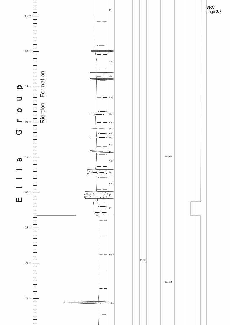
25 m
30 m
35 m
40 m
45 m
50 m
55 m
60 m
65 m
El
li
sG
ro
up
d.gr.
gr.
FF/28
gr.
gr.
d.gr.
gr.
d.gr.
d.gr.
gr.
gr.
d.gr.
d.gr.
gr.
gr.
d.gr.
gr.
d.gr.
gr.
gr.
Rie
rdo
nF
orm
atio
n
shale-lf
shale-lf
SRC:page 2/3

0 m
5 m
10 m
15 m
20 m
ThaynesFormation
l.gr.
gray-gr.
gr.
FF/24-27
SRC1
gray-gr.
gr.
gray-gr.
Sa
wto
oth
Fo
rma
tio
n
shale-lf
SRC:page 3/3
SRC2

Section: Heath
Location:Formation:
(Fergus County/ MT),on property of ”Allied ”, 555 East Fork Road~ 12 km SE of Lewistown
Ellis Group( Swift Fm.)
Steel
Piper Fm., Rierdon Fm.,
T 14 N., R 19 E., Sec. 12 NW ½
35 m
40 m
45 m
50 m
55 m
60 m
65 m
Gr
ou
p
Sw
ift
Form
ation
Rie
rdon
Form
ation
HE 2
HE 3
HE 4
br.
br.
l.br.
FG/12-14
shale-lf
glauconitic-lf
BIO-GS
BIO-GS
BIO-GS
depozoneMicrofacies III0LithofaciesPictureSample
Sediment structure& fossils
ColorSandClaySilt
CarbonateEvaporite C M F
HE:page 1/2

0 m
5 m
10 m
15 m
20 m
25 m
30 m
El
li
s
Pip
er
Form
ation
“basalgypsumunit”
“shale,gypsum &limestoneunit”
l.gr-gr.
HE 1
FG/7
gr.
w.
gray-gr.
gr.
br.
gray-gr.
red.br.
l.gr-gr.
l.gr-gr.
FG/8
FG/9
FG/10
FG/11
gypsiferousshale
&evaporites
shale or siltwithinterbeddeddetriticmudstones,thin tonodulargypsum layers,
sabkhared bed-lf
det. MS
HE:page 2/2
“upper red bed unit”

Section: Rocky Creek Canyon
Location:Formation:
, (Park County/MT),along Interstate 90, ~ 7 km E of Bozeman
T 2 S., R 7 E., Sec. 19Ellis Group( , Rierdon Fm., )Sawtooth Fm. Swift Fm.
Sw
ift
Fo
rma
tio
n
65 m
70 m
75 m
80 m
85 m
90 m
MorrisonFormation
grey-gr.
erosivecontacts
quartzitic
F6/4
grey-gr.
grey-gr.
grey-gr.
grey-gr.
gr.
erosivecontacts
quartzitic
erosivecontacts
quartzitic
erosivecontacts
quartzitic
erosivecontacts
quartzitic
glauconitic
glauconitic
RC 9
RC10
L-Fb-lf
glauconitic-lf
depozoneMicrofacies III0LithofaciesPictureSampleSediment structure
& fossilsColor
SandClaySilt
CarbonateEvaporite C M F
RC:page 1/3

El
li
sG
ro
up
Rie
rdo
nF
orm
atio
n
20 m
25 m
30 m
35 m
40 m
45 m
50 m
55 m
60 m
F6/1
erosivecontacts
quartzitic
RC 4
F6/3
br.
br.
gr.
l.gr.
F6/2
RC 3
Oobio-GS
RC 5
RC 6
RC 7
RC 2
lam. MS
BIO-WS
RC 8 BIO-GS
Oo-GS
sandymudstone
RC:page 2/3
Oobio-GS
Oobio-GS

Sa
wto
oth
Fo
rma
tio
n
0 m
5 m
10 m
ThaynesFormation
quartziticRC 1l.br.
RC:page 3/3

Section: Sappington
Location:Formation:
(Gallatin County/MT),~ 500 m W of Intersection Hwy. 2/287
T 1 N., R 2 W., Sec. 25Ellis Group( Rierdon Fm.,Sawtooth Fm., Swift Fm.)
MorrisonFormation
70 m
75 m
80 m
85 m
90 m
95 m
Sw
ift
Fo
rma
tio
n
US2/7
US2/8quartzitic
glauconitic
gr
gray-gr.
gray-gr.
gray-gr.
gray-gr.
gray-gr.
quartzitic
glauconitic
quartzitic
glauconitic
quartzitic
glauconitic
glauconitic-lf
depozoneMicrofacies III0
LithofaciesPictureSampleSediment structure& fossils
ColorSandClaySilt
CarbonateEvaporite C M F
shale-lf
SAP:page 1/3

25 m
30 m
35 m
40 m
45 m
50 m
55 m
60 m
65 m
El
li
sG
ro
up
Sa
wto
oth
Fo
rma
tio
nR
ierd
on
Fo
rma
tio
n
US2/1
US2/2
US2/3
US2/4
US2/5
US2/6
det. MS
BIO-PS
BIO-PS
Oobio-GS
BIO-WS;identicL to US 1,US 2 and US 5
BIO-PS
MS
d.gr.
d.gr.
d.gr.
d.gr.
d.gr.
d.gr.
gr.
l.gr.
gray-gr.
gray-gr.
gr.
glauconitic
SAP:page 2/3

PhosphoriaFormation
0 m
5 m
10 m
20 m
det. MS
det. MS
l.br.
d.gr.
d.gr.
SAP:page 3/3

Section: Little Water Creek
Location:Formation:
(Beaverhead County/MT),~ 8 km W of Dell
T 13 S., R 31 E., Sec. 10Ellis Group (Sawtooth Fm., Rierdon Fm., Swift Fm.)
LW:page 1/2
45 m
50 m
55 m
60 m
65 m
70 m
75 m
80 m
85 m
Gr
ou
p
Sw
ift
Fo
rma
tio
nR
ierd
on
Fo
rma
tio
n
LW 7
LW8a
LW 8
LW 9
LW10
gr.
l.gr.
gr.
grey-gr.
d.gr.
FF/22-23
stony casts &fragmentedshells
l.br.
l.br.
gr.
l.gr.
gr.
gr.
grey-gr.
Oobio-GS
det. MS conglomerate
well roundedclasts of det.MS in shalyto sandycalcareousmatrix
lam. MS
BIO-GS
LW10a BIO-GS
shale-lf
depozoneMicrofacies III0
LithofaciesPictureSampleSediment structure& fossils
ColorSand
ClaySiltCarbonateEvaporite C M F
glauconitic-lf
BIO-GS;identical toLW 10
glauconitic-lf
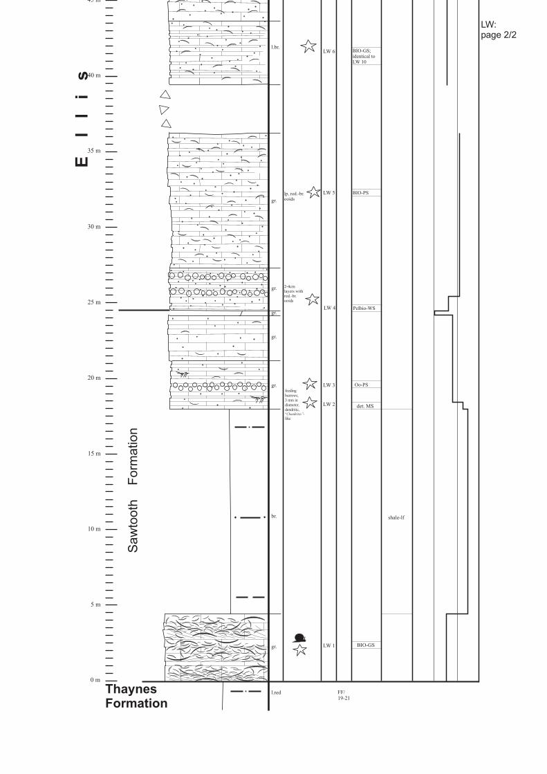
LW:page 2/2
0 m
5 m
10 m
15 m
20 m
25 m
30 m
35 m
40 m
45 m
ThaynesFormation
El
li
s
Sa
wto
oth
Fo
rma
tio
n
l.red
2-4cmlayers withred.-br.ooids
FF/19-21
LW 2
LW 3
LW 4
LW 5
LW 6
gr.
br.
gr.
l.br.
lp, red.-br.ooids
gr.
gr.
gr.
gr.
BIO-GSLW 1
shale-lf
Oo-PS
det. MS
Pelbio-WS
BIO-PS
BIO-GS;identical toLW 10
feedingburrows,3 mm indiameter,dendritic,
like“ -Chondrites”

Section: Hyattville
Location:Formation:
(Bighorn County/WY),NW of Cedar Mountain
T 49 N., R 89 W., Sec. 16 S ½Sundance Formation
MorrisonFormation
65 m
70 m
75 m
80 m
85 m
90 m
HY 10
H 11
HY 9 FC/22-24
grey-gr.
grey-gr.
glauconitic-lf
BIO-GS
BIO-GS
glauconitic
depozoneMicrofacies III0LithofaciesPictureSample
Sediment structure& fossils
ColorSandClaySilt
CarbonateEvaporite C M F
HY 11 BIO-GS
HY:page 1/3

20 m
25 m
30 m
35 m
40 m
45 m
50 m
55 m
60 m
Su
nd
an
ce
Fo
rm
at
io
n
HY 5
HY 6
HY 7cba
HY 8
HY 4
FC/9
FC/10
FC/11
FC/12
FC/13
FC/14
FC/15
FC/17-21
Redwater ShaleMember
“Up
pe
r”S
un
da
nce
Fo
rma
tio
n
grey-gr.
l.gr.
grey-gr.
l.gr.
d.gr.-gr.
L-Fb-lf
shale-lf
glauconitic
silt-lf
BIO-PS
bioclasticaccumulation:crinoids,pelecypods
HY:page 2/3

PiperFormation
0 m
5 m
10 m
15 m
FC/0HY 1
HY 2
HY 3
FC/1
FC/3-6
FC/7
FC/8
“Lo
we
r”S
un
da
nce
Fo
rma
tio
n
Stockade BeaverShale Member
HulettSandstoneMember
grey.-gr.
l.br.-yell.
w.
shale-lf
L-Fb-lf
Oo-lf HY:page 3/3

Section: Red Rim RanchLocation:Formation:
(Washakie County/WY)
Sundance FormationT 46 N., R 87 W., Sec. 16 NW ¼ to SW ¼
MorrisonFormation
50 m
55 m
60 m
65 m
70 m
75 m
80 m
85 m
Fo
rm
at
io
n
FD/34
gr.
l.gr.
grey-gr.
l.red
gr.
grey-gr.
grey-gr.
l.gr.
RR 6
RR 7
RR 8
FD/35
FD/31-33
Redwater ShaleMember
BIO-PS
silt-lf
BIO-PS;identical toRR 6
glauconitic-lf
biocl.richchannels
glauconitic
glauconitic
glauconitic
Planolites,Cruziana
depozoneMicrofacies III0LithofaciesPictureSample
Sediment structure& fossils
ColorSandClaySilt
CarbonateEvaporite C M F
BIO-PS
BIO-GS
RR:page 1/2
“Upper”
Sundance
Form
ation
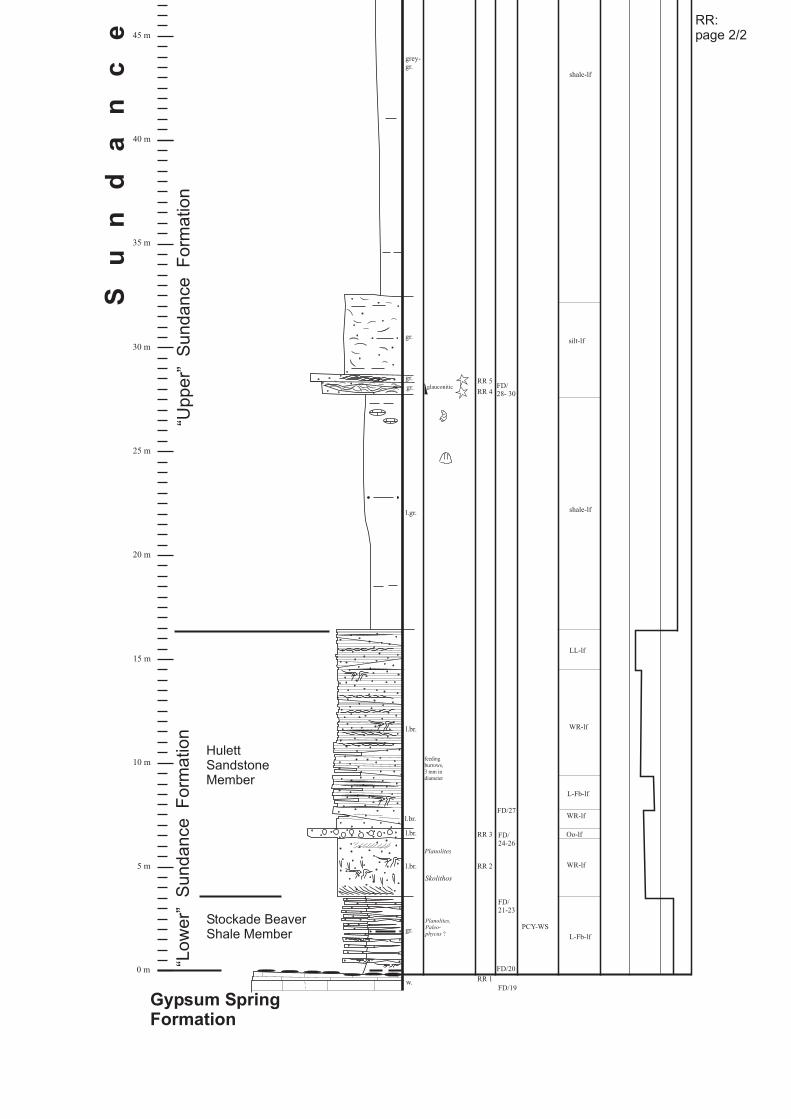
Gypsum SpringFormation
0 m
5 m
10 m
15 m
20 m
25 m
30 m
35 m
40 m
45 m
Su
nd
an
ce
RR 1
FD/27
FD/28- 30
RR 2
RR 3
RR 4
w.
gr.
l.br.
l.gr.
grey-gr.
Skolithos
l.br.
l.br.
l.br.
gr.
gr.
gr.
RR 5
FD/24-26
FD/21-23
FD/20
FD/19
Stockade BeaverShale Member
HulettSandstoneMember
“Low
er”
Sundance
Form
ation
“Upper”
Sundance
Form
ation
L-Fb-lf
PCY-WS
WR-lf
Planolites,Paleo-phycus ?
Planolites
feedingburrows,3 mm indiameter
shale-lf
glauconitic
shale-lf
silt-lf
Oo-lf
WR-lf
LL-lf
L-Fb-lf
WR-lf
RR:page 2/2

Section: Hampton RanchLocation:Formation:
(Washakie County/WY)
Sundance FormationT 43 N., R 88 W., Sec. 24 SE ¼ to NE ¼
grey-gr.
grey-gr.
HR 10a
HR 11
HR 10b
Redwater ShaleMember
shale-lf
L-Fb-lf
glauconitic-lf
Bio-MS
glauconitic
MorrisonFormation
70 m
75 m
80 m
85 m
90 m
95 m
100 m
“Upper”
Sundance
Form
ation
depozoneMicrofacies III0LithofaciesPictureSample
Sediment structure& fossils
ColorSandClaySilt
CarbonateEvaporite C M F
FD/5-18
det.-MS
HR:page 1/3

l.br.
HR 5
HR 7
HR 6
HR 8
HR 9
Oobio-GS
shale-lf
Oo-lf
Oobio-GS
Gyrochorte
Oobio-GS
25 m
30 m
35 m
40 m
45 m
50 m
55 m
60 m
65 m
Su
nd
an
ce
Fo
rm
at
io
n
FC/30-36
FD/1
FD/2-3
FD/4
HR:page 2/3
“Upper”
Sundance
Form
ation
shale-lf

w.
grey-gr.
HR 1
HR 2
HR 3
HR 4
Stockade BeaverShale Member
HulettSandstoneMember
Oo-lf
det.-MS
shale-lf
L-Fb-lf
WR-lf
Gyrochorte
Planolites
Thalassinoides
Planolites
GypsumSpringFormation
0 m
5 m
10 m
15 m
20 m
“Low
er”
Sundance
Form
ation
L-Fb-lf
WR-lf
FC/26
FC/27-29
HR:page 3/3

Section: Red Lane
Location:Formation:
, (Hot Springs County/WY),N of Thermopolis,
Sundance FormationT 43 N., R 6 E., Sec. 18 SW ¼
MorrisonFormation
75 m
80 m
85 m
90 m
95 m
100 m
l.red
glauconitic
RL10
FB/24-30
FB/31
FB/32
gr.
gray-gr.
gray-gr.
glauconitic
RL11
FB/33
FB/34
glauconitic
glauconitic-lf
L-Fb-lf
RL12
depozoneMicrofacies III0LithofaciesPictureSample
Sediment structure& fossils
ColorSandClaySilt
CarbonateEvaporite C M F
RL:page 1/3
Redwater ShaleMember

Redwater ShaleMember
30 m
35 m
40 m
45 m
50 m
55 m
60 m
65 m
70 m
Su
nd
an
ce
Fo
rm
at
io
n
“Up
pe
r”S
un
da
nce
Fo
rma
tio
n
l.gr.
gray-gr.
gr.RL 7
RL 8
RL 9
gray-gr.
gray-gr.
gr.
gr.
gray-gr.
Oo-lf
BIO-GS
BIO-PS
feedingburrows,3 mm indiameter
LS-lf
RL:page 2/3

GypsumSpringFormation
“ooliticlimestoneunit”
Stockade BeaverShale Member
HulettSandstoneMember
0 m
5 m
10 m
15 m
20 m
25 m
reworkedooliticlags
red.br.
l.gr.
gr.
gray-gr.
l.gr.
FB/8
load casts
RL 1
RL 6
FB/9-12
gr.
gray-gr.
l.gr.
gr.
gr.
RL 2
RL 3
RL 4
RL 5
FB/13-21
FB/22
shale-lf
L-Fb-lf
170/20
110/20
168/20
30/15
Oo-GS;identical to RL 3
Oo-GS
Oo-GS
WR-lf
feedingburrows,3 mm indiameter
FB/23
“Lo
we
r”S
un
da
nce
Fo
rma
tio
n
Oo-lf
silt-lfOo-lf
silt-lfreworked oolites
L-Fb-lf
Oo-lf
RL:page 3/3
Oo-GS;identical to RL 3

Section: Squaw Women Creek
Location:Formation:
(Fremont County/WY),~ 4 km W of Lander, along Squaw Creek Road
T 33 N., R 1 E., Sec. 22 N ½Sundance Formation
35 m
40 m
45 m
50 m
55 m
60 m
MorrisonFormation
Fo
rm
at
io
n
“Up
pe
r”S
un
da
nce
Fo
rma
tio
n
gr.
l.gr.
gray-gr.
gray-gr.
gray-gr.
gr.
gr.
gray-gr.
gr.
gray-gr.
l.gr.
l.gr.
SWC5
SWC6
SWC10
SWC11
SWC7
SWC8
SWC9
F2/3
F2/4-8
F2/10-14
F2/9
shale-lf
BIO-PS
glauconitic
glauconitic
glauconitic
glauconitic-lf
feedingburrows,3 mm indiameter
glauconitic
depozoneMicrofacies III0LithofaciesPictureSampleSediment structure
& fossilsColorSand
ClaySiltCarbonateEvaporite C M F
SWC:page 1/2
BIO-PS
BIO-PS
BIO-PS

0 m
5 m
10 m
15 m
20 m
25 m
30 m
Gypsum SpringFormation
Su
nd
an
ce
“Lo
we
r”S
un
da
nce
Fo
rma
tio
n
F2/1SWC1
red.br.
gr.
l.br.
gray-gr.
red.br.
l.br.
gr.
gr.
gr.
gr.
gr.
gr.
gray-gr.
gray-gr.
SWC2
SWC3
SWC4
F2/2
?
?
“Sundance red”
Oobio-GS;identical toSWC 2
shale-lf
feedingburrows,3 mm indiameter WR-lf
sabkhared bed-lf
L-Fb-lf
silt-lf
feedingburrows,3 mm indiameter,
like“Planolites -”
Pine ButteMember
SWC:page 2/2
Oobio-GS
Oobio-GS;identical toSWC 2

Section: Alcova Reservoir
Location:
Formation:
(Natrona County/WY)T 30 N, R 84 W, Sec. 30 NE ¼
Sundance Formation
85 m
90 m
100 m
95 m
105 m
110 m
115 m
gradedbedding;
d.gr.-gr.
gr.
d.gr.-gr.
gr.
gray-gr.
gr.
gr.
gr.
l.br.
gray-gr.
gray-gr.
l.br.
erosivecontacts;
AR 3
AR 4AR 5
AR 6
AR 7
AR 8
AR 9
AR 10
AR 15
AR 13
AR 12
AR 14
F1/14
F1/15
F1/16
F1/19-20
F1/17
F1/18
Morrison
Formation
Redwater ShaleMember
Windy HillSandstoneMember
shale-lf
BIO-WS
Cruziana
ichnofacies
Cruziana
ichnofacies
Cruziana
ichnofacies
silt-lf
MCL(MAINCOBBLELAYER)
“lowershaleunit”
“uppersilstsoneunit”
“uppershaleunit”
depozoneMicrofacies III0LithofaciesPictureSample
Sediment structure& fossils
ColorSandClaySilt
CarbonateEvaporite C M F
AR:page 1/3
BIO-WS
BIO-WS
BIO-PS
BIO-WS
BIO-WS
BIO-GS
oolites, reworked
oolites, reworked
silt-lf
L-Fb-lf
Oo-lf
BIO-WS
AR 11
Oo-lf

40 m
45 m
50 m
55 m
60 m
65 m
70 m
75 m
80 m
gr.
l.red
l.gr.
LakMember
Pine ButteMember
silt-lf
Su
nd
an
ce
Fo
rm
at
io
n
“lowersilstoneunit”
AR:page 2/3
sabkhared bed-lf

0 m
5 m
10 m
20 m
25 m
30 m
35 m
l.red
l.br.
l.gr Planolites
F1/1-7
gray-gr.
gray-gr.
d.gr.
gr.
l.gr.
gr.
gr.
l.red
AR 1
AR 2
F1/8-11
F1/12
F1/13
Jelm
Formation
CanyonSpringsSandstoneMember
Stockade BeaverShale Member
HulettSandstoneMember
LX-lf
WR-lf
L-Fb-lf
WR-lf
shale-lf
Planolites
AR:page 3/3

40 m
45 m
50 m
55 m
60 m
65 m
Section: Freezeout HillsLocation:Formation:
(Carbon County/WY)T 26 N., R 79 W., Sec. 33, NW ¼ & SE ¼
Sundance Fm.
gr.
w.
red.br.
FH 5
FH 6
FH 7
FB/1
gray-gr.
gr.
FB/2
Fo
rm
at
io
n
MorrisonFormation
Redwater ShaleMember
Windy HillSandstone Member
shale-lf
BIO-WS
glauconitic-lf
MS
det. MS
“lowersilstoneunit”
“lowershaleunit”
“uppersilstoneunit”
MCL(MAINCOBBLELAYER)
depozoneMicrofacies III0LithofaciesPictureSample
Sediment structure& fossils
ColorSand
ClaySiltCarbonateEvaporite C M F
FH:page 1/2

0 m
5 m
10 m
15 m
20 m
25 m
30 m
35 m
FH 1
FA/17
l.gr.
br.
w.
gr.
l.red
l.gr.
gray-gr.
FH 2
FH 3
FH 4
FA/18-21
FA/22
w.
l.gr.
l.gr.
br.
gr.
l.gr.
w.
w.
FA/23
FA/24
FA/25
FA/26
FA/27
FA/28
FA/29
FA/30-32
FA/33
FA/34
FA/35
Su
nd
an
ce Pine Butte
Member
LakMember
HulettSandstoneMember
Stockade BeaverShale Member
CanyonSpringsSandstoneMember
NuggetSandstone
LX-lf
WR-lf
silt-lf
sabkhared bed-lf
WR-lf
FH:page 2/2
algal lamination
reworked oolitelags
heavilybioturbated by
ichnofaciesCruziana
“silt
ma
rke
r”

Section: Jelm MountainLocation:Formation:
(Albany County/WY)T 13 N., R 77 W., Sec. 35 NE ¼
Sundance Formation
0 m
5 m
10 m
15 m
depozoneMicrofacies III0Lithofacies
PictureSampleSediment structure& fossils
ColorSandClaySilt
CarbonateEvaporite C M F
Su
nd
an
ce
Fo
rma
tio
n
Nugget Sandstone
l.-gr.
J:page 1/1
Pine ButteMember
Windy Hill SandstoneMember
yell.-br.
gray-green
small, coalifiedwood fragments
J 1
J 2
J 3
WR-lf
shale-lf

Section: Hulett
Location:Formation:
(Crook County/WY),1,5 km NW of Hulett
T 54 N, R 65 W, NW Sec. 12 & E Sec. 2Sundance Formation
imbrication
HU11
HU12
HU14
HU13
HU15
HU16 F4/1
MorrisonFormation
Redwater ShaleMember
70 m
75 m
80 m
85 m
90 m
95 m
shale-lf
det-MS
gray-gr.
gr.
d.gr.
gray-gr.
gr.
gray-gr.
gray-gr.
gr.
gr.
gr.
depozoneMicrofacies III0LithofaciesPictureSample
Sediment structure& fossils
ColorSandClaySilt
CarbonateEvaporite C M F
BIO-GS
BIO-GS
BIO-GS
HU:page 1/3
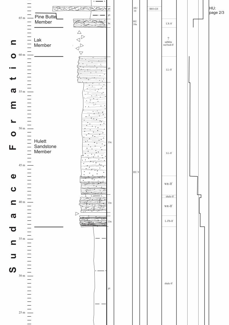
HU 9
HU10
HulettSandstoneMember
LakMember
25 m
30 m
35 m
40 m
45 m
50 m
55 m
60 m
65 mS
un
da
nc
eF
or
ma
ti
on
LX-lf
LL-lf
shale-lf
BIO-GS
shale-lf
HU10a
l.br.
br.
gr.
l.br.
l.br.
gr.
gr.
gr.
WR-lf
L-Fb-lf
LL-lf
Pine ButteMember
WR-lf
HU:page 2/3
?sabkha
red bed-lf

HU 1 F3/33
HU 2HU 3
HU 4
HU 5
HU 6
HU 7
HU 8
hardgroundwithborings etc.
F3/34
F3/35-37
GypsumSpringFormation
Stockade BeaverShale Member
0 m
5 m
10 m
15 m
20 m
shale-lf
silt-lf
Bio-MS
det-MS
BIO-WS
silt-lf
red.br.
w.
l.br.
gr.
gr.gr.
gr.
gr.gr.
gr.
gr.
gr.gr.
gr.
gr.
gr.
gr.
gr.
gr.
gr.
gr.
gr.
gr.
gr.
gr.
L-Fb-lf
“silt marker”
“limestonemarker”
“brownshale”
HU:page 3/3

Section: T cross T Ranch
Location:Formation:
, (Crook County/ WY),~ 13,75 km NE of Hulett along Beaver Creek
T 55 N., R 64 W., Sec. 1Sundance Formation
30 m
35 m
40 m
45 m
50 m
55 m
HulettSandstoneMember
Fo
rm
at
io
n
T/T 4
stony casts
l.gr.
l.br.
l.br.
l.br.
l.br.
yell.-br.
Planolites,Paleo-phycus ?
F3/26
F3/27
F3/28
F3/29
F3/30
F3/31
shale-lf
WR-lf
L-Fb-lf
LL-lf
depozoneMicrofacies III0LithofaciesPictureSample
Sediment structure& fossils
ColorSand
ClaySiltCarbonateEvaporite C M F
WR-lf
Sundance Formation erodedabove Hulett Sandstone Member
T-T:page 1/2

0 m
5 m
10 m
15 m
20 m
25 m
GypsumSpringFormation
Stockade BeaverShale Member
Su
nd
an
ce
T/T21red-
br.
gr. hardgroundwithborings andchert clasts
gray-gr.
l.br.
l.gr.
T/T 3 F3/20
F3/22-25
l.br.
l.gr.
l.br.
F3/19
F3/21
lam. MSMS
chert
shale-lf
silt-lf
shale-lf
LX-lf
imbricatedclasts
“silt marker”
T-T:page 2/2
slumped foresets

Section: Thompson Ranch
Location:Formation:
(Butte County/SD),N of Redwater Creek
T 7 N, R 1 E, Sec. 2 S ½Sundance Formation
yell.-br.
TR 10 F4/17-20
85 m
90 m
100 m
95 m
105 m
110 m
115 m
MorrisonFormation
Redwater ShaleMember shale-lf
dgr.
det. MS
depozoneMicrofacies III0LithofaciesPictureSample
Sediment structure& fossils
ColorSand
ClaySiltCarbonateEvaporite C M F
TR:page 1/3

red.-br.
gray-gr.
flattenedripples
TR 9
40 m
45 m
50 m
55 m
60 m
65 m
70 m
75 m
80 m
LakMember
Su
nd
an
ce
Fo
rm
at
io
n
F4/16
gr.
gr.
sabkhared bed-lf
TR:page 2/3
Pine ButteMember
silt-lf

F4/2-3
TR 1
gray-br.
stony casts
Skolithos
TR 2
TR 3
TR 4
TR 5
TR 6
TR 7
TR 8
0 m
5 m
10 m
20 m
25 m
30 m
35 m
GypsumSpringFormation
Stockade BeaverShale Member
HulettSandstoneMember
red.-br.
F4/4
F4/5-6
F4/7-9
F4/10-11
F4/12
F4/13
F4/14-15
shale-lf
chert
L-Fb-lf
LX-lf
WR-lf
LL-lf
feedingburrows,3 mm indiameter,beddingparallel tooblique,
like“Planolites -”
DiplocraterionMonocraterion
gr.
l.gr.
l.gr.
l.gr.
l.gr.
gr.
l.gr.
gr.
l.br.
Skolithos
silt-lf
Oo-lf
TR:page 3/3
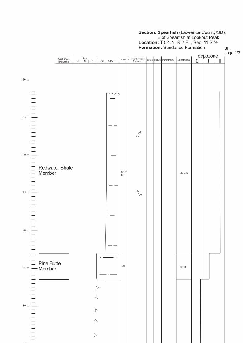
Section: Spearfish
Location:Formation:
(Lawrence County/SD),E of Spearfish at
T 52 .N, R 2 E. , Sec. 11 S ½Sundance Formation
Lookout Peak
75 m
80 m
85 m
90 m
100 m
95 m
110 m
105 m
Pine ButteMember
Redwater ShaleMember
gray-gr.
l.br. silt-lf
shale-lf
depozoneMicrofacies III0LithofaciesPictureSample
Sediment structure& fossils
ColorSand
ClaySiltCarbonateEvaporite C M F
SF:page 1/3

30 m
35 m
40 m
45 m
50 m
55 m
60 m
65 m
70 m
75 m
HulettSandstoneMember
LakMember
Su
nd
an
ce
Fo
rm
at
io
n
SF 3
feedingburrows,3 mm indiameter,
like“ ”-Planolites
gray-gr.
l.gr.
l.gr.
gray-gr.
l.br.
l.gr.
l.br.
gray-br.
gray-gr.
gray-br.
gray-gr.
red.-br.
LL-lf
silt-lf
silt-lf
WR-lf
sabkhared bed-lf
SF:page 2/3

Stockade BeaverShale Member
0 m
5 m
10 m
15 m
20 m
25 m
GypsumSpringFormation
F4/21-22
SF 1Skolithos
SF 2
F4/23-24
shale-lf
feedingburrows,3 mm indiameter,
like“ ”-Planolites
WR-lf
gr.
l.br.
w.
w.
Diplocraterion,Monocraterion
SF:page 3/3

depozoneMicrofacies
III0LithofaciesPictureSampleSediment structure
& fossilsColorSand
ClaySiltCarbonateEvaporite C M F
Section: Stockade Beaver Creek
Location:Formation:
(Weston County/WY),8,5 km NE of Newcastle
T 45 N., R 60 W., Sec. 18Sundance Formation
Redwater ShaleMember
75 m
80 m
85 m
90 m
100 m
95 m
gray-gr.
glauconitic shale-lf
SBC:page 1/3

HulettSandstoneMember
LakMember
Pine ButteMember
25 m
30 m
35 m
40 m
45 m
50 m
55 m
60 m
65 m
70 m
Su
nd
an
ce
Fo
rm
at
io
n
SBC 4
F2/20
F2/21-22
F2/23
F2/24yell.-br.
gray.-gr.
red.br.
l.br.
l.br.
gr.
gr.
gr.
gr.
gr.
LL-lf
L-Fb-lf
sabkhared bed
-lf
silt-lf
Oo-lf
silt-lf
L-Fb-lf
SBC:page 2/3
WR-lf

Stockade BeaverShale Member
GypsumSpringFormation
0 m
5 m
10 m
15 m
20 m
SBC 1
F2/17
SBC 2
SBC 3
F2/18-19
shale-lf
det. MSl.gr.
w.
red.-br.
l.br.
d.gr.
WR-lf
L-Fb-lf
SBC:page 3/3

Section: Elk Mountain
Location:
Formation:
(Custer County/SD),~ 18 km SE of Newcastle
T 6 S., R 1E., Sec. 10Sundance Formation
S ½
gr.
br.
EM 5
EM 6
F3/7
gray-gr.
gray-gr.
MorrisonFormation
80 m
85 m
90 m
100 m
95 m
105 m
110 m
115 m
Redwater ShaleMember
shale-lf
bio-mudstone
depozoneMicrofacies III0LithofaciesPictureSampleSediment structure
& fossilsColorSand
ClaySiltCarbonateEvaporite C M F
EM:page 1/3

l.gr.
gr.
F3/6gr.
red.br.
gray-gr.
gray-gr.
gray-gr.
l.gr.
red.br.
l.br.
Su
nd
an
ce
Fo
rm
at
io
n
LakMember
Pine ButteMember
35 m
40 m
45 m
50 m
55 m
60 m
65 m
70 m
75 m
silt-lf
shale-lf
silt-lf
EM:page 2/3
silt-lf
sabkhared bed-lf
shale-lf
Redwater ShaleMember

l.gr.
gray-gr.
l.br.
l.gr.
EM 2
F3/2
F3/3
F3/4-5
l.gr.
EM 1
F3/1
Skolithos
d.gr.
gr.
EM 3
EM 4
w.
gr.
CanyonSpringsSandstoneMember
Stockade BeaverShale Member
HulettSandstoneMember
0 m
5 m
10 m
15 m
20 m
25 m
30 m
GypsumSpringFormation
mudstone
shale-lf
mudstone
mudstone
mudstone
Planolites
L-Fb-lf
WR-lf
WR-lf
EM:page 3/3

Section: Minnekatha
Location:Formation:
, (Fall River County/SD),~ 12,5 km W of Hot Springs/ SD,(1 km S of US Hwy. 18)
T 7 S, R 4 E, S ½ Sec. 21Sundance Formation,contact to Triassic Spearfish Formationnot exposed (covered)
70 m
75 m
80 m
85 m
90 m
100 m
95 m
MorrisonFormation
Redwater ShaleMember
yell.br.
gray-br.
MIN11
MIN12
gray-gr.
gray-gr.
gr.
shale-lf
BIO-GS
Bio-MS
depozoneMicrofacies III0LithofaciesPictureSample
Sediment structure& fossils
ColorSand
ClaySiltCarbonateEvaporite C M F
MIN:page 1/3

25 m
30 m
35 m
40 m
45 m
50 m
55 m
60 m
65 m
LakMember
Pine ButteMember
Su
nd
an
ce
Fo
rm
at
io
n
halitepseudomorphs
br.
l.red
br.
gr.
gray-gr.
br.
MIN 5
MIN 7
MIN 8
MIN 9
gr.
gray-gr.
gray-gr.
gr.
gr.
F3/17
sabkhared bed-lf
shale-lf
det.-MS
MS
MIN10
BIO-PS
l.red
MIN:page 2/3
MIN 6

0 m
5 m
10 m
15 m
20 m
SpearfishFormation
Stockade BeaverShale Member
HulettSandstoneMember
MIN 1
F3/9
gr.
l.br.
d.gr.
gr.
MIN 2
MIN 3
MIN 4
gr.
gr.
F3/10
F3/11
F3/12-16
d.gr.shale-lf
Bio-PS;identical toMIN 10
L-Fb-lf
WR-lf
L-Fb-lf
L-Fb-lf
WR-lf
MIN:page 3/3

0 m
10 m
20 m
30 m
40 m
50 m
60 m
70 m
80 m
90 m
100 m
110 m
120 m0 I IIdepozone
Slid
ero
ck
Mb
r.R
ich
Mb
r.B
ou
nd
ary
Rid
ge
Mb
r.
Second
Marine
Cycle
Gypsu
mS
prin
gM
br.1st
Marine
Cycle
brown unsorted, angular and rounded limestone clasts insilty matrix, clast diameters ranges between 2 cmto 2 m, identical to “brecciated and honeycombedlimestone” as descibed by IMLAY (1967)
brecciatedlimestone
grayishbrown
Film
5/22
-23
oobiograin-stone
bio-mudstone
crinoids,pelecypods
thin-bedded (2 - 3 cm)ooids,crinoids,pelecypods
crinoids,pelecypods
Film
5/
24
grayishbrown
redbrown
Navajo Sandstone
HC: page 3/3
red-brown
siltstone, poorly exposed, covered with float
dense packed, angular to moderately rounded,3 to 20 cm carbonate clasts in silty matrix
brecciatedlimestone
redbeds
HC1a
bio-mudstone
thin-bedded (2 - 3 cm)gray
dark-gray
oobiograin-stone
identical to HC 1a: massive, trough cross-bedded ( 0,4 m sets), cliff-forming
very thin- to thin-bedded (1 - 3 cm), partly covered,bioclast fragments, flasery, breaks conchoidal
dark-gray
bio-mudstone
massive, poorly preserved ripple marks, sandy,bioturbation
HC 1
gray
very thin- to thin-bedded (1 - 3 cm), partly covered,forms slope, bioclast fragments, flasery, breaksconchoidal, weathers into chips
detritusmudstone
siltstone, poorly exposed, covered with float,forms ravine
smallshellfragments
sabkhared bed-lf
Fossils& particles
Sedimentary structures & lithologyPictureSample FaciesColor

0 m
10 m
20 m
30 m
40 m
50 m
60 m
70 m
80 m
90 m
100 m
110 m
120 m 0 I IIdepozone
Gira
ffe
Cre
ek
Mb
r.L
ee
ds
Cre
ek
Mb
r.W
att
on
Ca
nyo
nM
br.
thick-bedded (0,4 m) to massive, cliff-forming,wavy planar stratification (cm scale) becomesvery sandy in upper 2 m
becomes sandy upwards
Third
Marine
Cycle
gray HC 2biowacke-stone
thin- to thick-bedded (5 - 20 cm)crinoids,pelecypods,ooids
graybiowacke-stone
thin- to thick-bedded (5 - 20 cm)crinoids,pelecypods,ooids
gray
gray biomud-stone
biomud-stone
thin-bedded (5 cm), shell fragments
thin-bedded (5 cm), shell fragments
thin-bedded (2 - 5 cm), irregular thick-beddedintervals, partly sandy, breaks conchoidal
mud-stonegray
very thin- to medium-bedded (3 - 20 cm),weathers into long splinters, poorly exposed,forms ravines covered with sagebrush,shaly, mostly non-fossiliferous
mudstone,identicalto “shalylimestone”describedbyIMLAY(1967)Gryphea
neb.reported byIMLAY(1967)
lightgray
HC 3
HC 4oobio-packstone
ooids,intraclasts,peloids,crinoids,pelecypods
brown
HC: page 2/3
Fossils& particles
Sedimentary structures & lithologyPictureSample FaciesColor
HC 2aHC 2a, identical to HC 2

Pre
uss
Fo
rma
tio
n
red.-brown
grayish
Stu
mp
Fo
rma
tio
n
thin- to medium-bedded (3 - 20 cm) structureless,siltstone and fine sandstone, very poorly exposed,covered by vegetation
WR-lf
marinered beds
Section: Hoback Canyon
Location:Formation:
(S of Hoback Junction, along Hwy. 191/189
T 38 N., R 114 W., Sec. 6
Teton County/WY),
Twin Creek Limestone, Preuss Fm., Stump Fm.
Cu
rtis
Mb
r.R
ed
wa
ter
Mb
r .
very poorly exposed, isolated cliffs on asagebrush covered slope,mostly olive-green soil, wave-rippled,glauconitic, medium-bedded shale and sandstone
very poorly exposed, isolated cliffs on asagebrush covered slope,mostly olive-green soil, wave-rippled,glauconitic, medium-bedded shale and sandstone
shale-lf
glauconitic-lf
0 m
10 m
20 m
30 m
40 m
50 m
60 m 0 I IIdepozone
Third
Marine
Cycle
Fourt
hM
arine
Cycle
HC: page 1/3
grayish-green
“shale
unit”
“sandsto
ne
unit”
“sandsto
ne
unit”
“unnam
ed
cycle
”
Fossils& particles
Sedimentary structures & lithologyPictureSample FaciesColor

Ric
hM
br.
140 m
150 m
0 m
10 m
20 m
30 m
40 m
50 m
60 m
70 m
80 m
90 m
100 m
110 m
120 m
130 m
0 I IIdepozone
redbrown
Slid
ero
ck
Mb
r.
Second
Marine
Cycle
dark-gray
thin-bedded (2 - 4 cm), some thicker beds (0,2 m),structureless, weathers into angular flakes,
Imlay reported byIMLAY (1967) and found as fragments, sandyGryphea planoconvexa fraterna
detritusmudstone
Gypsu
mS
prin
gM
br.
Film
5/1
8
brownish
mudstone
Bo
un
da
ryR
idg
eM
br.
First
Marine
Cycle
CC 1
CC 2dark-gray
grayishbrown
beccia
angular limestone and sandstone clasts,2 cm to 20 cm in diameter in sandy-silty matrix,not sorted, bedding parallel oriented
angular to subrounded limestone, chert andsandstone clasts and pebbles, 2 cm to 5 cm indiameter, chert layers (2 cm)
beccia
gray
oograin-stone
massiveooids,intraclasts,peloids,crinoids,pelecypods
CC 3
mostly covereddetritusmudstone
thin-bedded (2 - 4 cm), structureless, soft,partly covered by vegetation, becomesthicker-bedded towards top (0,2 m)
gray
dense packed shell fragments, beddingparallel oriented, thick-bedded (0,4 m), stuctureless
ooids,peloids,crinoids,pelecypods
oobio-grainstonegray
CC 3a
partly covered by vegetation, forms ravine
redbed
CC: page 3/3
Navajo Sandstone
sabkhared bed-lf
Fossils& particles
Sedimentary structures & lithologyPictureSample FaciesColor

very thin to medium-bedded (3 - 20 cm),weathers yellowish-brown into long splinters,forms ravines and slopes covered with vegetation,,shaly, mostly non-fossiliferous,in irregular intervals bedding planes covered withshell fragments, some harder beds (0,3 - 0,4 m),
Meek & Hayden reportedby IMLAY (1967) and found as fragmentsGryphea nebrascensis
mudstone,identicalto “shalylimestone”describedbyIMLAY(1967)
0 m
10 m
20 m
30 m
40 m
50 m
60 m
70 m
80 m
90 m
100 m
110 m
120 m
130 m
140 m
150 m
0 I IIdepozone
biomudstone
Wa
tto
nC
an
yo
nM
br.
Third
Marine
Cycle
gray
gray
gray
CC 4
Film
5/1
9-2
0
thin-bedded (2 - 4 cm), becomes thick-bedded(0,4 m) upward
ooids,peloids,crinoids,pelecypods
oobio-grainstone
CC 4abio-wackestone
ooids,peloids,crinoids,pelecypods
thin-bedded (2 - 4 cm)
thin-bedded (2 - 4 cm), some beds with beddingparallel accumulation of large oyster shells
Le
ed
sC
ree
kM
br.
CC: page 2/3
Fossils& particles
Sedimentary structures & lithologyPictureSample FaciesColor

redbrown
0 m
10 m
20 m
30 m
40 m
50 m
60 m
70 m
80 m
90 m
100 m
110 m
120 m
130 m
0 I IIdepozone
grayish
very poorly exposed, isolated cliffs on asagebrush covered slope,mostly olive-green soil, wave-rippled,glauconitic, medium-bedded shale and sandstone
very poorly exposed, isolated cliffs on asagebrush covered slope,mostly olive-green soil, wave-rippled,glauconitic, medium-bedded shale and sandstone
shale-lf
glauconitic-lf
Stu
mp
Fo
rma
tio
nC
urt
isM
br.
Re
dw
ate
rM
br.
Fourt
hM
arine
Cycle
Third
Marine
Cycle
Pre
uss
Fo
rma
tio
nG
ira
ffe
Cre
ek
Mb
r.
CC 5
grayishbrown
grayishgreen
WR lf
oograin-stone
massiveooids,intraclasts,peloids,crinoids,pelecypods
detritusmudstone
thin- to medium -bedded (0,1 - 0,4 m), sandy
fine- to medium-grained sandstone,thin- to medium-bedded (0,1 - 0,4 m),glauconitic, abundant wave ripples, thin shalyinterbeds, cross-bedding and bioturbation( burrows)Planolites
CC: page 1/3
thin- to medium-bedded (3 - 20 cm) structureless,siltstone and fine sandstone, very poorly exposed,covered by vegetation
Section: Cabin Creek
Location:
Formation:
(Lincoln County/WY)T 38 N., R 116 W., Sec. 17 N ½
Twin Creek Limestone, Preuss Fm., Stump Fm.
“sandsto
ne
unit”
“shale
unit”
“shale
unit”
“sandsto
ne
unit”
grayish
grayish-green
glauconitic-lf
“unnam
ed
cycle
”
marinered bed-lf
Fossils& particles
Sedimentary structures & lithologyPictureSample FaciesColor

0 m
10 m
20 m
30 m
40 m
50 m
60 m
70 m
80 m
90 m
100 m
110 m
120 m
130 m
0 I IIdepozone
Fossils& particles
Sedimentary structures & lithologyPictureSample FaciesColor
Slid
ero
ck
Mb
r.R
ich
Mb
r.B
ou
nd
ary
Rid
ge
Mb
r.
Second
Marine
Cycle
Gypsu
mS
prin
gM
br.
brownishred
angular and rounded limestone clasts and chertsin silty matrix, clast diameters ranges between0,5 and 8 cm, fining upward, partly covered,best exposed along Bear Cree Trail on west sideof Palisade Reservoir
brecciatedlimestone
biograin-stone
crinoids,pelecypods
Navajo Sandstone
BE: page 4/4
red-brown
sabkhared bed-lf
dark-gray
bio-mudstone
massive, structureless, weathers nodular, irregularbedding planes, some bioclasts
medium to thick-bedded (0,15 - 0,40 m), bioclastfragments, sandy, sand content increase upward
BE1a-c
brownishgray
detritusmudstone
thick-bedded (0,40 m) to massive, bioclastfragments bedding parallel oriented, sandy,sand content increase upward
gray
medium-bedded (0,15 ), sandy,shell fragments bedding parallel oriented
gray
crinoids,pelecypods
bio-mudstone
thin-bedded (2 - 4 cm), structureless, weathersinto splinters, scare bioclasts, becomes medium-bedded upward
mudstone
BE 1
gray
BE 2
crinoids,pelecypods
biowackestone
thick-bedded (0,4 m)darkgray
massive, low-angle, trough-shaped cross-bedding,0,2 to 0,3 m sets, angular, 2 cm clasts of limestoneat base
oobio-grain-stones
darkgray
ooids,peloids,intraclasts,crinoids,pelecypods
medium to thick-bedded (0,15 - 0,40 m), bioclastfragments, sandy, sand content increase upward
detritusmudstone
siltstone, poorly exposed, covered with float,forms ravine
1st
Ma
rin
eC
ycle
OFFSET

0 I IIFossils& particles
Sedimentary structures & lithologyPictureSample Facies
depozone
Gira
ffe
Cre
ek
Mb
r.L
ee
ds
Cre
ek
Mb
r.W
att
on
Ca
nyo
nM
br.
gray
becomes sandy upwards
Third
Marine
Cycle
gray BE 3oobio-grainstone
thick-bedded (0,35 m)ooids,intraclasts,peloids,crinoids,pelecypods
detritusmud-stone
gray
very thin to medium-bedded (3 - 20 cm),weathers into long splinters, poorly exposed,forms ravines covered with sagebrush,shaly, mostly non-fossiliferous,in irregular intervals bedding planes covered withshell fragments, some harder beds (0,3 - 0,4 m)form low cliffs
mudstone,identicalto “shalylimestone”describedbyIMLAY(1967)
Grypheaneb.reported byIMLAY(1967)
lightgray
WR-lfbrown
52,5 m
0 m
211 m
247,5 m
medium to thick-bedded (0,15 - 0,40 m), bioclastfragments, sandy, bioturbation on bedding planes,some intervals with wavy lamination in cm thicklayers and shell plaster on bedding planes
BE 4
Film
5/
17
BE 5
thick-bedded (0,3 m), cliff-forming, sandy,some bioclasts detritus
mud-stone
BE 6
medium-grained, thick-bedded (0,4 m),intensebioturbation, ripple marks
peloids,shellfragments
sand content decreases upwards
BE: page 3/4
Color

thin- to medium-bedded (3 - 20 cm) or massive,planar laminated (2 to 5 cm) to structureless,siltstone and fine sandstone, poorly exposed,covered by vegetation, some wavy andflaser-bedding, some wrinkled lamination,in lower 15 m salt cyrstal casts (BE 7)
BE 7
redbrown
redbrown
redbrown
0 m
10 m
20 m
30 m
40 m
50 m
60 m
70 m
80 m
90 m
100 m
110 m
120 m
130 m
0 I IIFossils& particles
Sedimentary structures & lithologyPictureSample Facies
depozone
Pre
uss
Fo
rma
tio
n
Third
Marine
Cycle
BE: page 2/4
marinered bed-lf
Color

0 m
10 m
20 m
30 m
40 m
50 m
60 m
“un
na
me
dcycle
”F
ou
rth
Ma
rin
eC
ycle
0 I IIFossils& particles
Sedimentary structures & lithologyPictureSample Facies
depozone
Section: Big Elk Mountain
Location:
Formation:
(Caribou County/ID),W side of Palisades Reservoir
Gypsum Spring, Sliderock & Rich Mbr. measured at:T 1 S., R 45 E., Sec. 29 N ½:Boundary Ridge, Watton Canyon, Leeds Creek, Giraffe Creek Mbr.& Preuss Fm. measured at:T 2 S., R 45 E., Sec. 6
Twin Creek Limestone, Preuss Fm., Stump Fm.
Cu
rtis
Mb
r.
Stu
mp
Fo
rma
tio
n
Re
dw
ate
rM
br .
shale-lf
shale-lf
glauconitic-lf
thick-bedded fine- to medium-grainedsandstone, glauconitic, symmetric wave ripplesand thin shale interbeds, poorly exposed
glauconitic shale, mostly coverd
glauconitic shale, mostly coverd
thick-bedded fine- to medium-grainedsandstone, glauconitic, symmetric wave ripplesand thin shale interbeds, poorly exposed
grayish-green
grayish-green
grayish-green
“sandsto
ne
unit”
“shale
unit”
“shale
unit”
“sandsto
ne
unit”
BE: page 1/4
glauconitic-lf
“unnam
ed
cycle
”
Color
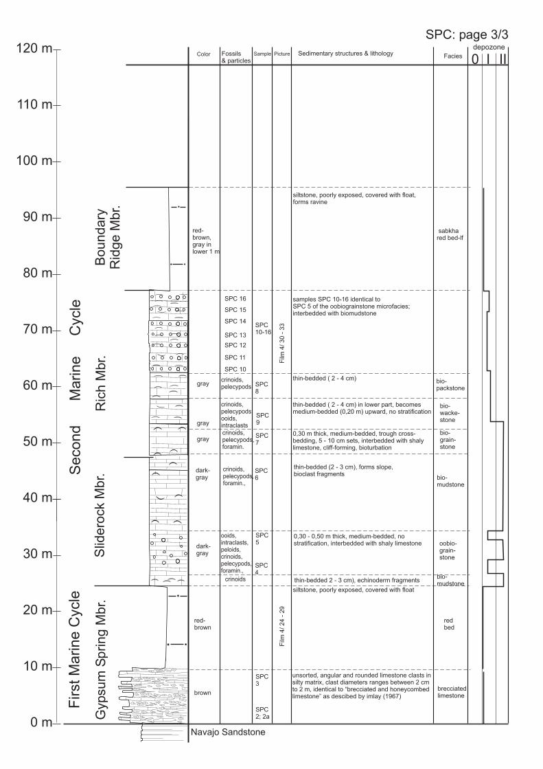
Slid
ero
ck
Mb
r.R
ich
Mb
r.B
ou
nd
ary
Rid
ge
Mb
r.
Second
Marine
Cycle
Gypsu
mS
prin
gM
br.
FirstM
arine
Cycle
dark-gray
SPC2; 2a
brown
unsorted, angular and rounded limestone clasts insilty matrix, clast diameters ranges between 2 cmto 2 m, identical to “brecciated and honeycombedlimestone” as descibed by imlay (1967)
brecciatedlimestone
red-brown
siltstone, poorly exposed, covered with float
redbed
Film
4/
24
-29
thin-bedded (2 - 3 cm), forms slope,bioclast fragments
SPC4
SPC5
dark-gray
0,30 - 0,50 m thick, medium-bedded, nostratification, interbedded with shaly limestone oobio-
grain-stone
bio-mudstone
bio-mudstone
crinoids thin-bedded 2 - 3 cm), echinoderm fragments
ooids,intraclasts,peloids,crinoids,pelecypods,foramin.,
SPC6
crinoids,pelecypods,foramin.,
bio-grain-stone
crinoids,pelecypods,ooids,intraclasts
SPC7
SPC9
SPC8
bio-wacke-stone
bio-packstone
Film
4/
30
-3
3
0,30 m thick, medium-bedded, trough cross-bedding, 5 - 10 cm sets, interbedded with shalylimestone, cliff-forming, bioturbation
crinoids,pelecypods,foramin.
gray
thin-bedded ( 2 - 4 cm) in lower part, becomesmedium-bedded (0,20 m) upward, no stratification
gray
crinoids,pelecypods
graythin-bedded ( 2 - 4 cm)
red-brown,gray inlower 1 m
siltstone, poorly exposed, covered with float,forms ravine
sabkhared bed-lf
Navajo Sandstone
SPC: page 3/3
Fossils& particles
Sedimentary structures & lithologyPictureSample FaciesColor
0 m
10 m
20 m
30 m
40 m
50 m
60 m
70 m
80 m
90 m
100 m
110 m
120 m0 I IIdepozone
SPC3
SPC10-16
samples SPC 10-16 identical toSPC 5 of the oobiograinstone microfacies;interbedded with biomudstone
SPC 10
SPC 11
SPC 12
SPC 13
SPC 16
SPC 14
SPC 15

SPC17
thin- to thick-bedded ( 2 - 40 cm), low-anglecross-bedding, 5 - 15 cm trough-shaped sets,ripple marks (1 x 7), bioturbation,interbedded with mudstone oograin-
stone
bio-mudstone
Film
4/
34
-36
darkgray
SPC18
thin-bedded, bioclast fragmentsgray
darkgray
thin- to thick-bedded ( 2 - 40 cm), low-anglecross-bedding, 5 - 15 cm trough-shaped sets,ripple marks (1 x 7), bioturbation,interbedded with mudstone
ooids,intraclasts,peloids,crinoids,pelecypods,foramin.,
ooids,intraclasts,peloids,crinoids,pelecypods
oograin-stone
very thin- to medium-bedded (3 - 20 cm),weathers into long splinters, forms slopes withno vegetation, shaly, mostly non-fossiliferous
mudstone,identicalto “shalylimestone”describedbyIMLAY(1967)
lightgray
Gira
ffe
Cre
ek
Mb
r.L
ee
ds
Cre
ek
Mb
r.W
att
on
Ca
nyo
nM
br.
covered interval
medium-grained, massive, cliff-forming,small-scale cross-bedding
gray
medium-grained, thick-bedded (0,4 m),large-scale cross-bedding (30 cm, through-shaped sets) LX-lf
WR-lf
gray
oobio-grain-stone
identical to SPC 19 and 20gray
SPC19
1,2 m thick, medium-bedded (0,30 m), nostratification
ooids,peloids,ntraclasts,crinoids,pelecypods
oobio-grain-stone
gray
oobio-grain-stone
identical to SPC 19gray SPC20
gray
47,85 m
0 m
127,7 m
153 m
181 m
Third
Marine
Cycle
SPC: page 2/3
Fossils& particles
Sedimentary structures & lithologyPictureSample FaciesColor
199 m
0 I IIdepozone

red.-brown
grayish-green
Pre
uss
Fo
rma
tio
n
very poorly exposed, thin- to medium-bedded(3 - 20 cm) or massive, planar laminated(2 to 5 cm) to structureless, siltstone and finesandstone, forms steep cliff, some wavy andflaser-bedding, some wrinkled lamination
Stu
mp
Fo
rma
tio
n
thick-bedded fine-grainedsandstone, symmetric wave ripplesand thin shale interbeds,poorly exposed along northside ofSouth Piney Creek
Section: South Piney Creek
Location:Formation:
(Sublette County/WY),~ along Lander Cutoff (Emigrant Trail)
T 29 N., R 115 W., Sec. 12, 11, 10Twin Creek Limestone, Preuss Fm., Stump Fm.
Third
Marine
Cycle
Fourt
hM
arine
Cycle
SPC: page 1/3
Cu
rtis
Mb
r.R
ed
wa
ter
Mb
r.
“sandsto
ne
unit”
“shale
unit”
“sandsto
ne
unit”
“un
na
me
dcycle
”
marinered bed-lf
Fossils& particles
Sedimentary structures & lithologyPictureSample FaciesColor
0 m
10 m
20 m
30 m
40 m
50 m
60 m
70 m
80 m
90 m
100 m
110 m
u l0 I IIdepozone
grayish-green
glauconitic shale, mostly covered shale-lf
glauconitic-lf
SPC21
biowacke-stone
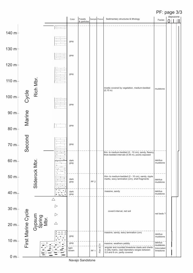
Slid
ero
ck
Mb
r.R
ich
Mb
r.
Second
Marine
Cycle
Gypsu
mS
prin
gM
br.
lightbrown
angular and rounded limestone clasts and chertsin silty matrix, clast diameters ranges between0,5 and 8 cm, partly covered
brecciatedlimestone
Navajo Sandstone
coverd interval, red soil
PF 1
gray
detritusmudstone
mostly covered by vegetation, medium-bedded(0,15 m)
First
Ma
rin
eC
ycle
massive, weathers pebbly
massive, sandy, wavy lamination (cm)
gray
detritusmudstone
red beds ?
darkgray
massive, sandy detritusmudstone
darkgray
thin- to medium-bedded (2 - 10 cm), sandy, ripplemarks, wavy lamination (cm), shell fragments
PF 2detritusmudstone
thin- to medium-bedded (2 - 10 cm), sandy, flasery,thick-bedded intervals (0,45 m), poorly exposed
detritusmudstone
mudstone
Film
5/11
PF: page 3/3
darkgray
gray
gray
gray
gray
gray
gray
Fossils& particles
Sedimentary structures & lithologyPictureSample FaciesColor
0 m
10 m
20 m
30 m
40 m
50 m
60 m
70 m
80 m
90 m
100 m
110 m
120 m
130 m
140 m
0 I IIdepozone

Wa
tto
nC
an
yo
nM
br.
Third
Marine
Cycle
ooids,peloids,crinoids,pelecypods
dark-gray
medium-bedded (0,15 )
crinoids,pelecypods
Bo
un
da
ryR
idg
eM
br.
thin to medium-bedded (2 - 10 cm), sandy,ripple marks detritus
mudstone
sabkhared bed-lf-bio-wackestone
soft, flaser bedded, reddish siltstone with 5 - 10 cmthick layers of oolitic limestone (PF 3)
PF 3redbrown
gray
massive, lower part poorly exposed, formscliff
biopack-stone
PF 4
Le
ed
sC
ree
kM
br.
very thin to medium-bedded (3 - 20 cm),weathers into long splinters, forms slopes,shaly, mostly non-fossiliferous
mudstone,identicalto “shalylimestone”describedbyIMLAY(1967)
gray
PF 5
275 m
Oo-GS
gray
Gira
ffe
Cre
ek
Mb
r.
thin-bedded (5 cm), weathered,glauconitic, fine-grained sandstone
WR-lf
PF 6greenish-brown
Film
5/1
2
PF: page 2/3
Fossils& particles
Sedimentary structures & lithologyPictureSample FaciesColor
0 m
10 m
20 m
30 m
271 m
285 m
295 m
305 m
315 m
325 m
0 I IIdepozone

red.-brown
very poorly exposed, mostly covered,thin to medium-bedded (3 - 20 cm) or massive,planar laminated (2 to 5 cm) to structureless
Section: Poker Flat
Location:
Formation:
(Lincoln County/WY),~ 12,5 km E of Salt River Pass (Hwy. 89),along Smiths Fork Creek Road,2 km W of “Estella Brown Grave”
T 29 N., R 117 W., Sec. 3 & 10Twin Creek Limestone, Preuss Fm.
red.-brown
red.-brown
Third
Marine
Cycle
Pre
uss
Fo
rma
tio
n
PF: page 1/3
marinered bed-lf
Fossils& particles
Sedimentary structures & lithologyPictureSample FaciesColor
0 m
10 m
20 m
30 m
40 m
50 m
60 m
70 m
80 m
90 m
100 m
110 m
120 m
0 I IIdepozone
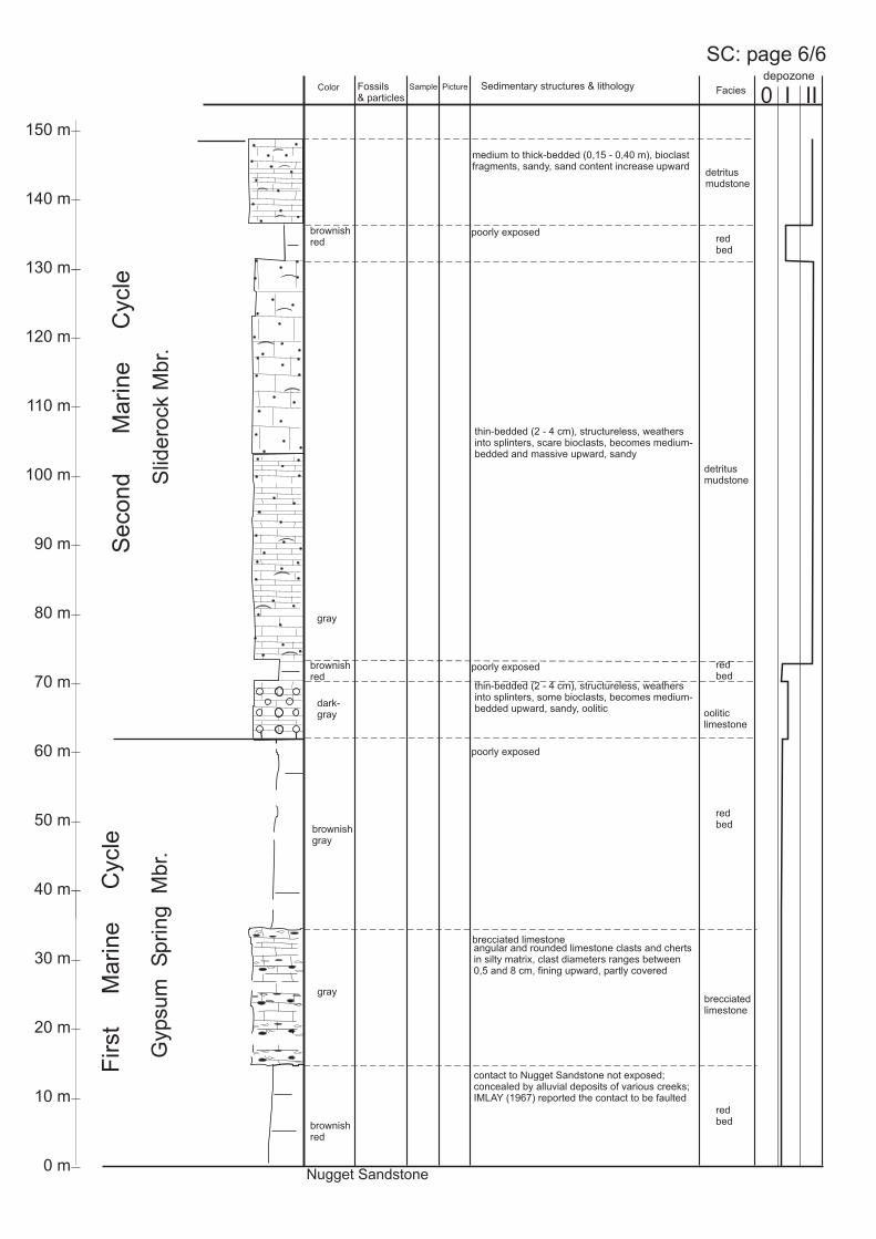
First
Marine
Cycle
contact to Nugget Sandstone not exposed;concealed by alluvial deposits of various creeks;IMLAY (1967) reported the contact to be faulted
gray
brownishred
thin-bedded (2 - 4 cm), structureless, weathersinto splinters, scare bioclasts, becomes medium-bedded and massive upward, sandy
brownishred red
bed
redbed
redbed
redbed
poorly exposed
poorly exposed
Slid
ero
ck
Mb
r.
Second
Marine
Cycle
Gypsu
mS
prin
gM
br.
brownishred
angular and rounded limestone clasts and chertsin silty matrix, clast diameters ranges between0,5 and 8 cm, fining upward, partly covered
brecciatedlimestone
Nugget Sandstone
dark-gray
brecciated limestone
brownishgray
gray
ooliticlimestone
thin-bedded (2 - 4 cm), structureless, weathersinto splinters, some bioclasts, becomes medium-bedded upward, sandy, oolitic
poorly exposed
medium to thick-bedded (0,15 - 0,40 m), bioclastfragments, sandy, sand content increase upward
detritusmudstone
detritusmudstone
SC: page 6/6
Fossils& particles
Sedimentary structures & lithologyPictureSample FaciesColor
140 m
150 m
0 m
10 m
20 m
30 m
40 m
50 m
60 m
70 m
80 m
90 m
100 m
110 m
120 m
130 m
0 I IIdepozone

poorly exposed
gray
Ric
hM
br.
Bo
un
da
ryR
idg
eM
br.
mostly covered, medium-bedded(0,15 m) , IMLAY (1967) reported
WhitfieldGryphea
planoconvexa
mudstone
crinoids,pelecypods
bio-packstone
SC 1
gray
gray
medium-bedded (0,2 - 0,4 m)
SC 2gray
gray
crinoids,pelecypods,foraminifer. biograin-
stone
medium-bedded (0,2 - 0,4 m),glauconitic
detritusmudstone
medium- to thick-bedded (0,15 - 0,40 m), rippledbedding planes, bioturbated, sandycrinoids,
pelecypods
bio-packstone
SC 3
Second
Marine
Cycle
detritusmudstone
SC: page 5/6
Fossils& particles
Sedimentary structures & lithologyPictureSample FaciesColor
0 m
10 m
20 m
30 m
40 m
50 m
60 m
70 m
80 m
90 m
100 m
110 m
120 m
130 m
140 m
150 m
0 I IIdepozone

SC 5
SC 6; identical to SC 4
Wa
tto
nC
an
yo
nM
br.
Third
Marine
Cycle
ooids,peloids,crinoids,pelecypods
massive, structureless
SC 4oobio-grain-stone
grayishblue
ooids,peloids,crinoids,pelecypods
massive, structurelessSC 5; identical to SC 4
oobio-grain-stone
gray
ooids,peloids,crinoids,pelecypods
massive, structurelessSC 6
oobio-grain-stone
gray
thick-bedded to massive, structureless,scare pelecypod fragments
bio-mud-stone
bio-mud-stone
grayishblue
thick-bedded to massive, structureless,scare pelecypod fragments
grayishbrown
thick-bedded (0,15 - 0,4 m), rippled beddingpanes, scare pelecypod fragments bio-
mud-stone
mudstone
mudstone
SC: page 4/6Fossils& particles
Sedimentary structures & lithologyPictureSample FaciesColor
0 m
10 m
20 m
30 m
40 m
50 m
60 m
70 m
80 m
90 m
100 m
110 m
120 m
130 m
0 I IIdepozone

Le
ed
sC
ree
kM
br.
Third
Marine
Cycle
grayishblue
very thin to medium-bedded (3 - 20 cm),weathers into long splinters, poorly exposed,forms ravines covered with sagebrush,shaly, mostly non-fossiliferous,in irregular intervals bedding planes covered withshell fragments, some harder beds (0,3 - 0,4 m)form low cliffs
mudstone,identicalto “shalylimestone”describedbyIMLAY(1967)
lightgray
SC: page 3/6Fossils& particles
Sedimentary structures & lithologyPictureSample FaciesColor
0 m
310 m
0 I IIdepozone

redbrown
redbrown
Gira
ffe
Cre
ek
Mb
r.
Third
Marine
Cycle
detritusmudstone
grayishbrown
thick-bedded to massive, structureless,some pelecypod fragments
SC 8gray crinoids,pelecypods biograin-
stone
medium-bedded (0,2 - 0,4 m),glauconitic
SC 7gray crinoids,
pelecypods biograin-stone
medium-bedded (0,2 - 0,4 m),glauconitic
detritusmudstone
grayishbrown
detritusmudstone
grayishbrown
thick-bedded to massive, structureless,becomes very sandy upward, flaser-likebedding
thick-bedded to massive, structureless,some pelecypod fragments
thin- to medium-bedded (3 - 20 cm) or massive,planar laminated (2 to 5 cm) to structureless,siltstone and fine sandstone, poorly exposed,some wavy and flaser-bedding,some wrinkled lamination, in upper part thin,leached gypsum layers
Pre
uss
Fo
rma
tio
n
SC: page 2/6
marinered bed-lf
Fossils& particles
Sedimentary structures & lithologyPictureSample FaciesColor
0 m
10 m
20 m
30 m
330 m
0 I IIdepozone

Stu
mp
Fo
rma
tio
n
“un
na
me
dcycle
”
Cu
rtis
Me
mb
er
“sa
nd
sto
ne
un
it”
“sh
ale
un
it”
grayish-green
grayish-green
thick-bedded, fine- to medium-grainedsandstone, glauconitic, poorly preservedwave ripples, forms cliff
glauconiticlf
glauconitic shale, upper part poorly exposed,limestone cobbles and infrequently interbedded,thin sandstone layers (2 - 6 cm), with scouredlower bedding planes and bioturbation
shale-lf
contact to Preuss Fm. poorly exposed,forms ravine
thin-bedded, fine- to medium-grainedsandstone, glauconitic, poorly preservedplanar bedding in 2 to 4 cm thick layers, forms cliff glauconitic
lf
glauconiticlf
grayish-green
Section: Stump CreekLocation:Formation:
(Caribou County/ID)T 6 S., R 45 E., Sec. 26 & 27
Twin Creek Limestone, Preuss Fm., Stump Fm.
SC: page 1/6
Fossils& particles
Sedimentary structures & lithologyPictureSample FaciesColor
0 m
10 m
20 m
30 m
40 m
50 m
60 m
70 m
80 m
90 m
100 m
0 I IIdepozone

FirstM
arine
Cycle
Gypsum
Spring
Mbr.
mostly covered, contact to underlyingNugget Sandstone not exposed
detritusmudstone
very thin-bedded (1 - 4 cm), weathers intoanglular chip, sscare bioclasts, sandy
oograin-stone
LB 2
ooids,peloids,crinoids,pelecypods
thin- to medium-bedded (3 - 15 cm)
mudstone
med.gray detritus
mudstone
LB 4
0 m
10 m
20 m
30 m
40 m
50 m
60 m
70 m
80 m
90 m
100 m
110 m
120 m
Se
co
nd
Ma
rin
eC
ycle
medium-bedded (0,15 m) to massive, nostratification
crinoids,pelecypods
darkgray
upper part with wave ripples and larger, beddingparallel oriented shell fragments
very thin- to medium-bedded (3 - 20 cm),some times massive, weathers intoangular chips, forms slopes with no vegetation,clayey, mostly non-fossiliferous, only scareshell fragments
darkgray
darkgray
lightgray
very thin-bedded (3 cm), sandy
bio-packstone
medium-bedded (30 cm), sandy, ripple marks,bedding parallel oriented, large shell fragments
pelecypods,crinoids,foramin.
bio-packstone
bio-packstone
bio-packstone
identical to LB 4
identical to LB 4
identical to LB 4
light redto red.-brown poorly exposed, unstratified red siltstone sabkha
red bed-lf
Film
F/4
LB: page 3/3
LB 1gray brecciated
limestone
?red bedsreddish
Fossils& particles
Sedimentary structures & lithologyPictureSample FaciesColor
Slid
ero
ck
Mb
r.R
ich
Mb
r.B
ou
nd
ary
Rid
ge
Mb
r.
0 I IIdepozone

crinoids,pelecypods
oobio-grain-stone
ooids,peloids,crinoids,pelecypods
thin- to medium-bedded (4 - 15 cm),no stratification
darkgray LB 3
thin bedded (4cm), no stratification,non-fossiliferous
thin-bedded, symmetric wave ripples (6 x 1),bedding oriented shell fragments, sandyinterbedded with LB 5; 6; 7
gray
gray
gray
LB 5
LB 6
LB 7
detritusmudstone
mudstone
pelecypodscrinoids,foramin.,gastropds,ostracods,bryozoans
bio-packstone
thick-bedded (0,4 m), bedding parallel orientedshell fragments, slightly sandy, scare shellfragments
detritusmudstone
LB 8
oobio-grain-stone
darkgray
poorly exposed, massive, no stratificationooids,peloids,crinoids,pelecypods
LB9
LB10
LB11
darkgray
very thin- to medium-bedded (3 - 20 cm),weathers into long splinters, forms slopes withno vegetation, shaly, mostly non-fossiliferous,in lower 20 m intercalated oolitic limestonesLB 9 - 12: 1 to 1,3 m thick, massive, cliff-forming,structureless
ooids,peloids,crinoids,pelecypods
oobio-grain-stone
oobio-pack-stonestone
mudstone,identicalto “shalylimestone”noted byIMLAY(1967)
LB13
LB12
oobiograin-stone
darkgray
180 m
219 m
57 m
0 m
15 m
10 m
35 m
69 m
79 m
207 m
211 m
thin- to medium-bedded (4 - 15 cm),shell and echinoderm fragments
lightgray
biomud-stone
crinoids,pelecypods
red
darkgray
red bedssoft, laminated
mudstonemm thick, planar and wrinkled laminationbrown
LB14
identical to samples LB 10; 11; 12; 13 oobiograin-stone
Le
ed
sC
ree
kM
br.
Wa
tto
nC
an
yo
nM
br.
Gira
ffe
Cre
ek
Mb
r.
Third
Marine
Cycle
Film
F/5
LB: page 2/3
Fossils& particles
Sedimentary structures & lithologyPictureSample FaciesColor
0 I IIdepozone
LB 9 identical to LB 10
LB 11 identical to LB 12

0 m
10 m
20 m
30 m
40 m
50 m
60 m
70 m
80 m
90 m
100 m
110 m
120 m
red.-brown
grayish-green
Pre
uss
Fo
rma
tio
nS
tum
pF
orm
atio
n
thin- to medium-bedded (3 - 20 cm) or massive,planar laminated (2 to 5 cm) to structureless,siltstone and fine sandstone, forms steep cliff,some wavy and flaser-bedding, some wrinkledlamination
“sh
ale
un
it”
“sa
nd
sto
ne
un
it”
“sa
nd
sto
ne
un
it”
grayish-green
glauconiticglauconitic
-lf
shale-lf
glauconitic-lf
thick-bedded, fine- to medium-grainedsandstone, glauconitic, symmetric wave ripplesand thin shale interbeds, poorly exposed
glauconitic shale, mostly coverd
thick-bedded, fine- to medium-grainedsandstone, glauconitic, symmetric wave ripplesand thin shale interbeds, poorly exposed
Film
F/6
-7
Third
Marine
Cycle
Section: La Barge Creek
Location:Formation:
(Sublette County/WY),~ 25 km W of La Barge
T 27 N., R 115 W., Sec. 16 & 17Twin Creek Limestone, Preuss Formation, Stump Fm.
LB: page 1/3F
ourt
hM
arine
Cycle
Cu
rtis
Mb
r.R
ed
wa
ter
Mb
r .
“un
na
me
dcycle
”
marinered bed-lf
Fossils& particles
Sedimentary structures & lithologyPictureSample FaciesColor
0 I IIdepozone

Slid
ero
ck
Mb
r.R
ich
Mb
r.B
ou
nd
ary
Rid
ge
Mb
r.
0 I IIdepozone
medium-bedded (0,15 m)
dark-gray
mudstone
massive to thick-bedded, no stratification,small shell fragments
oograin-stoneDH 1
ooids,peloids,crinoids,pelecypods
thin- to medium-bedded (3 - 15 cm)
mudstone
med.gray
thin- to medium-bedded (3 - 20 cm),some times massive, weathers intoangular chips, forms slopes with no vegetation,clayey, mostly non-fossiliferous, only scareshell fragments
mudstoneDH 2
pelecypods accumulation of small shell fragments
pelecypods accumulation of small shell fragments
very thin-bedded (3 cm), sandy detritusmudstone
med.gray
Film
E/28
-33
light redto red.-brown poorly exposed, unstratified clayey red beds sabkha
red bed-lf
0 m
10 m
20 m
30 m
40 m
50 m
60 m
70 m
80 m
90 m
100 m
110 m
120 m
Se
co
nd
Ma
rin
eC
ycle
DH: page 3/3
dark-gray
dark-gray
Fossils& particles
Sedimentary structures & lithologyPictureSample FaciesColor

321,5 m
290,5 m
66,5 m
0 I IIdepozone
medium-bedded (0,2 m) to massive,no stratification, forms cliff
grayish
d.-gray DH 3oobio-grain-stone
mudstoneDH 4
thin- to medium-bedded (2 - 20 cm), weathers intoangular chips, forms slope
light-gray
0,15m thick, thin-bedded, coquina,no stratification
mudstone,identicalto “shalylimestone”noted byIMLAY(1967)
DH 5
120 m
200 m
DH5a
DH5b
crinoids,pelecypods,foramin.,ooids,intraclasts,peloids
dark-gray
bio-grain-stone
dark-gray
0,30 m thick, medium-bedded, sp.fragments bedding parallel oriented, coquina
Camptonectesoobio-grain-stone
crinoids,pelecypods,foramin.,ooids,intraclasts,peloids
mudstone
very thin- to medium-bedded (3 - 20 cm),weathers into long splinters, forms slopes withno vegetation, shaly, mostly non-fossiliferous,some times scare shell fragments, isolatedbioclastic coquinas
Film
E/3
4-
36
Le
ed
sC
ree
kM
br.
Gira
ffe
Cre
ek
Mb
r.W
att
on
Ca
nyo
nM
br.
Th
ird
Ma
rin
eC
ycle
0 m
DH 6
ooids,intraclasts,peloidscrinoids,pelecypods
ooids,intraclasts,peloidscrinoids,pelecypods
dark-gray
oobio-grain-stone
oobio-grain-stone
1,1 m thick, medium-bedded, no stratification
1,1 m thick, medium-bedded, no stratificationdark-gray
grayish-brown
thin-bedded, symmetric wave ripples (6 x 1),bedding parallel bioturbation
Film
F/1 upper 5 m : very thin-bedded,
wavy, thin lamination
304 m
silt-lf
DH: page 2/3
Fossils& particles
Sedimentary structures & lithologyPictureSample FaciesColor
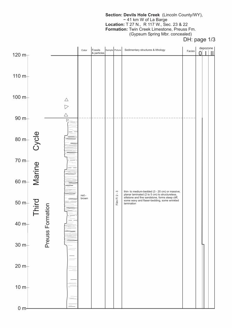
0 m
10 m
20 m
30 m
40 m
50 m
60 m
70 m
80 m
90 m
100 m
110 m
120 m
DH: page 1/3
Pre
uss
Fo
rma
tio
n
Th
ird
Ma
rin
eC
ycle
thin- to medium-bedded (3 - 20 cm) or massive,planar laminated (2 to 5 cm) to structureless,siltstone and fine sandstone, forms steep cliff,some wavy and flaser-bedding, some wrinkledlamination
0 I IIdepozone
red.-brown
Section: Devils Hole Creek
Location:
Formation:
(Lincoln County/WY),~ 41 km W of La Barge
T 27 N., R 117 W., Sec. 23 & 22Twin Creek Limestone, Preuss Fm.(Gypsum Spring Mbr. concealed)
Film
F/2
-3
Fossils& particles
Sedimentary structures & lithologyPictureSample FaciesColor

Ric
hM
br.
140 m
150 m
0 m
10 m
20 m
30 m
40 m
50 m
60 m
70 m
80 m
90 m
100 m
110 m
120 m
130 m
0 I IIdepozone
gray
thin-bedded (2 - 4 cm), structureless, soft,densly covered by vegetation
Slid
ero
ck
Mb
r.
Second
Marine
Cycle
dark-gray
thin-bedded (2 - 4 cm), structureless, weathersinto angular flakes,
fragments, sandyGryphea planoconvexa
fraterna
detritusmudstone
Gypsum Spring Mbr. and parts of Sliderock Mbr.not exposed
TF 1
Film
F/8
-9
peloids,ooids,pelecypods,crinoids,gastropods
gray
pelbio-wackestone
mudstone
TF: page 4/4
Fossils& particles
Sedimentary structures & lithologyPictureSample FaciesColor

TF 3
0 m
10 m
20 m
30 m
40 m
50 m
60 m
70 m
80 m
90 m
100 m
110 m
120 m
130 m
140 m
150 m
0 I IIdepozone
TF 3
massive
grayishbrown
Bo
un
da
ryR
idg
eM
br.
TF 2
Second
Marine
Cycle
grayishbrown
detritusmudstone
detritusmudstone
TF 4
TF 6
gray
oograin-stone
massive, cross-bedded, sharp basedooids,intraclasts,peloids,crinoids,pelecypods
oograin-stone
ooids,intraclasts,peloids,crinoids,pelecypods
grayishbrown
medium-bedded (0,15 - 0,20 m), weathers intolong splinters, sandy, sand contentdecrease upward
massive, structureless
mudstone
darkgray
to
grayishblue
TF 5
grayishbrown
poorly fragmented, non-oriented, dense packedshells, sharp basedCamptonectesF
ilmF
/18 bio-
wackestone
peloids,ooids,pelecypods,crinoids,gastropods
bio-wackestone
sandy, faint cross-bedding, some fine laminationof skeletal and sandy layersbrown
oograin-stone
massive, structureless
grayishblue
Film
F/1
7
Wa
tto
nC
an
yo
nM
br.
Third
Marine
Cycle
TF: page 3/4
Fossils& particles
Sedimentary structures & lithologyPictureSample FaciesColor

0 m
0 I IIdepozone
Le
ed
sC
ree
kM
br.
Third
Marine
Cycle
grayishblue
very thin- to medium-bedded (3 - 20 cm),weathers into long splinters, exposed alongUS Highway 89,forms ravines covered with sagebrush,shaly, mostly non-fossiliferous,in irregular intervals bedding planes covered withshell fragments, some harder beds (0,3 - 0,4 m)form low cliffs
mudstone,identicalto “shalylimestone”describedbyIMLAY(1967)
lightgray
485 m
TF 7
TF 9
massive, structureless
TF 8
grayishbrown
poorly fragmented, non-oriented, dense packedshells, sharp basedCamptonectesF
ilmF
/18 bio-
wackestone
bio-wackestone
sandy, faint cross-bedding, some fine laminationof skeletal and sandy layers, TF 8 idetical to TF 5brown
oograin-stone
grayishblue
Film
F/1
7
TF: page 2/4
Fossils& particles
Sedimentary structures & lithologyPictureSample FaciesColor
TF 9 identical to TF 6
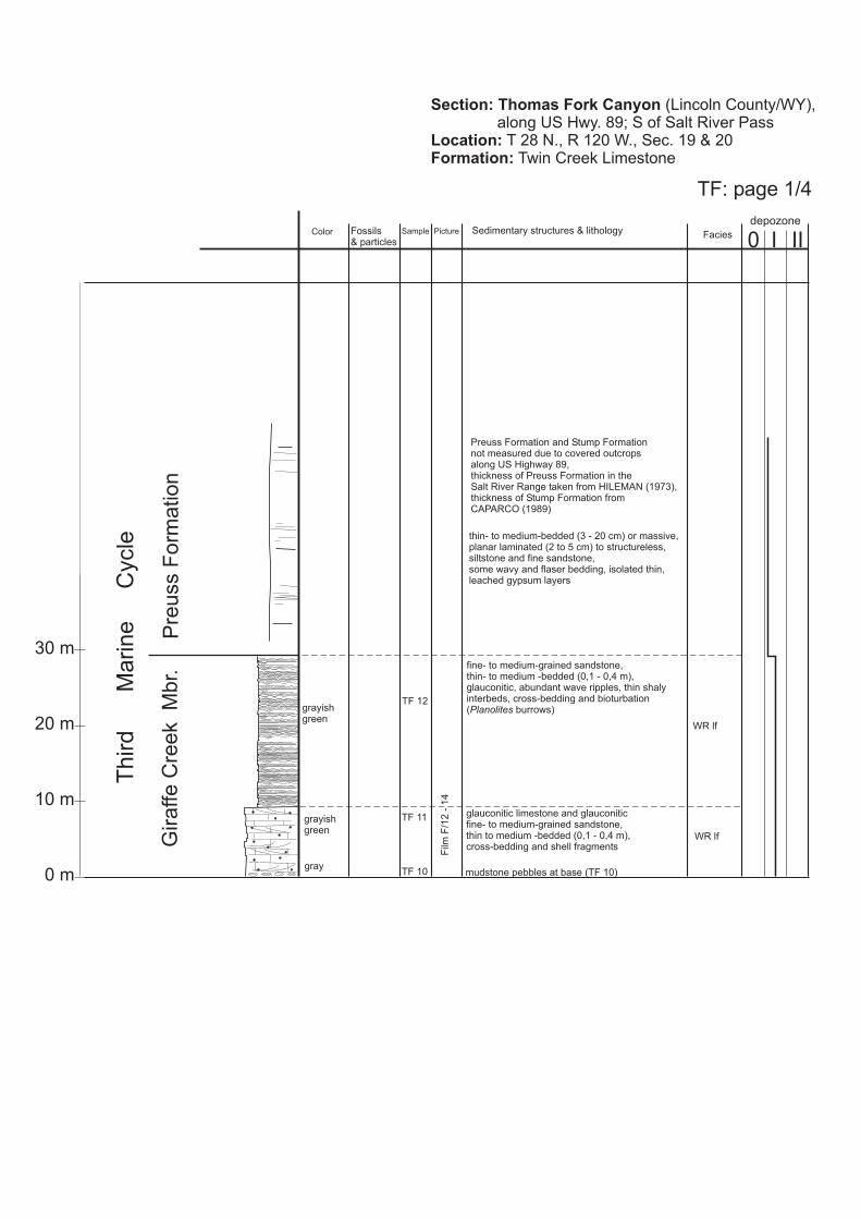
0 m
10 m
20 m
30 m
0 I IIdepozone
Third
Marine
Cycle
Pre
uss
Fo
rma
tio
nG
ira
ffe
Cre
ek
Mb
r.
fine- to medium-grained sandstone,thin- to medium -bedded (0,1 - 0,4 m),glauconitic, abundant wave ripples, thin shalyinterbeds, cross-bedding and bioturbation( burrows)Planolites
gray
TF 12
TF 11grayishgreen
grayishgreen
glauconitic limestone and glauconiticfine- to medium-grained sandstone,thin to medium -bedded (0,1 - 0,4 m),cross-bedding and shell fragments
Film
F/1
2-
14
WR lf
WR lf
thin- to medium-bedded (3 - 20 cm) or massive,planar laminated (2 to 5 cm) to structureless,siltstone and fine sandstone,some wavy and flaser bedding, isolated thin,leached gypsum layers
Preuss Formation and Stump Formationnot measured due to covered outcropsalong US Highway 89,thickness of Preuss Formation in theSalt River Range taken from HILEMAN (1973),thickness of Stump Formation fromCAPARCO (1989)
Section: Thomas Fork Canyon
Location:Formation:
(Lincoln County/WY),along US Hwy. 89; S of Salt River Pass
T 28 N., R 120 W., Sec. 19 & 20Twin Creek Limestone
TF: page 1/4
TF 10 mudstone pebbles at base (TF 10)
Fossils& particles
Sedimentary structures & lithologyPictureSample FaciesColor

0 m
10 m
20 m
30 m
40 m
50 m
60 m
70 m
80 m
90 m
100 m
110 m
150 m
140 m
130 m
120 m
0 I IIdepozone
Slid
ero
ck
Mb
r.R
ich
Mb
r.
Second
Marine
Cycle
Gypsu
mS
prin
gM
br.
FirstM
arine
Cycle
TC 1
lightbrown
laminatedmudstone
red-brown
siltstone, poorly exposed, covered
redbed
Film
E/19
-27
mudstone
Navajo Sandstone
TC 2
TC 3
TC 4
red-brown
dark-gray
0,30 - 0,50 m thick, medium-bedded, nostratification, interbedded with shaly limestone
oo-grain-stone
ooids,intraclasts,peloids,crinoids,pelecypods
gray TC 5
thin-bedded (2 - 10 cm), poorly exposed
mudstone
thin-bedded (2 - 3 cm), soft, shalyforms ravine and is covered by float,poorly exposed, weathers into chips
gray
TC 6
lightgray
thin-bedded (2 - 3 cm), forms cliff, weathersinto splinters
bio-mudstone
crinoids,pelecypods,ooids,peloids
TC: page 2/2
Fossils& particles
Sedimentary structures & lithologyPictureSample FaciesColor
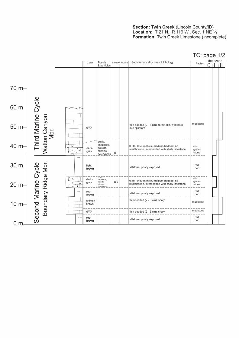
0 I IIdepozone
0 m
10 m
20 m
30 m
40 m
50 m
60 m
70 m
Wa
tto
nC
an
yo
nM
br.
Third
Marine
Cycle
Bo
un
da
ryR
idg
eM
br.
thin-bedded (2 - 3 cm), shaly
TC 8
ooids,intraclasts,peloids,crinoids,pelecypods
oo-grain-stone
dark-gray
0,30 - 0,50 m thick, medium-bedded, nostratification, interbedded with shaly limestone
red-brown
siltstone, poorly exposedredbed
gray mudstone
red-brown
siltstone, poorly exposedredbed
thin-bedded (2 - 3 cm), shalymudstonegrayish
brown
red-brown
lightbrown
siltstone, poorly exposedredbed
lightbrown
gray
mudstonethin-bedded (2 - 3 cm), forms cliff, weathersinto splinters
Section: Twin Creek
Location:
Formation:
(Lincoln County/ID)T 21 N., R 119 W., Sec. 1Twin Creek Limestone (incomplete)
NE ¼S
econd
Marine
Cycle
TC 7
ooids,intraclasts,peloids,crinoids,pelecypods
oo-grain-stone
dark-gray
0,30 - 0,50 m thick, medium-bedded, nostratification, interbedded with shaly limestone
TC: page 1/2Fossils& particles
Sedimentary structures & lithologyPictureSample FaciesColor

Section: Flaming Gorge
Location:
Formation:
(Daggett County/UT),in Sheep Creek Gap, along US Hwy. 44,~ 7 km S of Manila/UT
T 2 N., R 20 E., Sec. 6offset at 207 m to T 2 N., R 20 E., Sec. 31Carmel Fm., Entrada Sandstone, Stump Fm.
depozoneMicrofacies III0
LithofaciesPictureSampleSediment structure& fossils
ColorSand
ClaySiltCarbonateEvaporite C M F
210 m
180 m
170 m
175 m
190 m
185 m
195 m
205 m
220 m
215 m
230 m
225 m
235 m
200 m
OFFSET
Stu
mp
Fo
rma
tio
n(R
ed
wate
rM
em
ber)
FG 23
FG 24
red-
gray-gr.
gray-gr.
br.
FE/11
FE/12
FE/13-17
L-Fb-lf
shale-lf
det.MS
glauconitic-lf
FG 25
FG 26
FG 27
FG 28
FG 29
FG 30
BIO-PS
Oobio-GS
Oobio-PS
Oobio-GS
Oobio-GS
FG:page 1/3
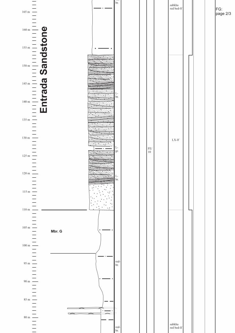
80 m
95 m
100 m
85 m
90 m
110 m
105 m
120 m
115 m
130 m
125 m
140 m
135 m
150 m
145 m
160 m
155 m
165 m
En
tra
da
Sa
nd
sto
ne
Mbr. G
red-br.
red-br.
l.-br.
l.-gr.
l.-br.
redbr.
FE/10
LX-lf
sabkhared bed-lf
sabkhared bed-lf
FG:page 2/3

5 m
15 m
20 m
45 m
55 m
60 m
70 m
0 m
10 m
25 m
30 m
35 m
40 m
50 m
65 m
75 m
NavajoSandstone
Ca
rme
lF
orm
ati
on
Mbr. C
Mbr. D
Mbr. E
Mbr. F
FG 1
FE/1-2
br.
FG 2
gr.
gr.
FG 3
FG 4FG 5FG 6
FG 8
FG 9
FG 10
FG11
FG 12
FG14-17
gr.
br.
FG 13
FG18-20
FG 21
FE/3-4
FE/6
FE/7-9
det.MSBIO-WS
FG 7 BIO-WS
BIO-PS
Oobio-GS
Oobio-PS
det.MS
Oobio-PS
BIO-PS
Oobio-PS
det.MS
det.MS
FG 22
gr.
gr.
red-br.
w.
w.
with
evaporites
sabkhared bed-lf
&
oolitic innerramp facies
FG:page 3/3

Section: Vernal
Location:Formation:
(8 km N of Vernal along Hwy. 191(along Flaming Gorge-Uintas scenic byway)
T 3 S., R 22 E., Sec. 5Carmel Fm.,
Uinta County/UT),
Entrada Sandstone, Curtis Fm.
depozoneMicrofacies III0LithofaciesPictureSampleSediment structure
& fossilsColor
SandClaySilt
CarbonateEvaporite C M F
210 m
180 m
175 m
190 m
185 m
195 m
205 m
220 m
215 m
230 m
225 m
235 m
200 m
glauconitic
gray-gr.
240 m
245 m
Cu
rtis
Fo
rma
tio
n
red-br.
sabkhared bed-lf
gray-gr.
shale-lf
V6-8
V9-10
V11-12
V 13
V14-16
sigmoidalforesets
F11/22-23
F11/20-21
layer of mudstonecobbles at baseof bed
glauconitic
Oobio-GS
Oobio-GS
Oobio-GS
V 7:det.MS
reworkedmudstone cobbles
V:page 1/3

80 m
95 m
100 m
85 m
90 m
110 m
105 m
120 m
115 m
130 m
125 m
140 m
135 m
150 m
145 m
160 m
155 m
165 m
170 m
En
tra
da
Sa
nd
sto
ne
F11/12-13
V 3l.-br.
w.
l.-br.
l.-br.
LX-lf
V 4
V 5
F11/18-19
F11/14-17
poorlycemented
poorlycemented
V:page 2/3

5 m
15 m
20 m
45 m
55 m
60 m
70 m
0 m
10 m
25 m
30 m
35 m
40 m
50 m
65 m
75 m
V 1
F11/6
Ca
rme
lF
orm
ati
on
NavajoSandstone
red-br.
sabkhared bed-lf
sabkhared bed-lf
red-br.
red-br.
V 2
V:page 3/3

Section: Whiterocks CanyonLocation:Formation:
(Uintah County/UT)T 21 N., R 119 W., Sec. 1 NE ¼
Carmel Formation
FD/19-20
W 1
gray-gr.
l.-gr.
W 2
W 3
W 4
W 5-W 5a
W 6
W 7
W 8
gr.
br.
red-br.
0 m
5 m
10 m
15 m
20 m
25 m
30 m
depozoneMicrofacies III0Lithofacies
PictureSampleSediment structure& fossils
ColorSandClaySilt
CarbonateEvaporite C M F
Ca
rme
lF
orm
ati
on
NavajoSandstone
Mbr. C
Mbr. D
Mbr. E
red-br.
l.-gr.
l.-gr.
det.MS
BIO-WS
BIO-MS
BIO-MS
Oobio-PS
red-br.
gr.
Pelbio-WS
det.MS
W:page 1/1
BIO-PS
Copyright © 2022 FDOKUMEN