fabrication of 3d printed titanium scaffolds and ... - UPCommons
59
MASTER´S THESIS Master in Interdisciplinary and Innovative Engineering FABRICATION OF 3D PRINTED TITANIUM SCAFFOLDS AND CHARACTERIZATION OF PHYSICOCHEMICAL AND MECHANICAL PROPERTIES Report and Annexes Author: Patricia Veloz Torres Directors: Elisa Rupérez – Daniel Rodríguez Call: September 2021
-
Upload
khangminh22 -
Category
Documents
-
view
6 -
download
0
Transcript of fabrication of 3d printed titanium scaffolds and ... - UPCommons

MASTER´S THESIS
Master in Interdisciplinary and Innovative Engineering
FABRICATION OF 3D PRINTED TITANIUM SCAFFOLDS AND
CHARACTERIZATION OF PHYSICOCHEMICAL AND
MECHANICAL PROPERTIES
Report and Annexes
Author: Patricia Veloz Torres
Directors: Elisa Rupérez – Daniel Rodríguez
Call: September 2021

Fabrication of 3D printed Titanium scaffolds and characterization of physicochemical and mechanical properties
2
ABSTRACT
In this work, different geometries of 3D printed porous titanium structures were developed and
tested in order to determine if they are suitable for bone implants in humans.
Commercial pure Titanium (99.5%) and an hydrogel were mixed in order to obtain the ink to
print through 3D printing technique direct ink writing. After the printing process, samples were
subjected to thermal treatments in order to remove the hydrogel and obtain pieces with a
mechanical behavior suitable for use on human bone.
Physicochemical and mechanical characterization was performed to the samples to characterize
them.
SEM images were taken in order to observe the general microstructure of the samples,
micropores and macropores. Micro-CT technique was used to obtain porosity and density.
Mercury Intrusion Porosimetry was performed and along with Micro-CT results obtained,
allowing us to characterized micropores. Surface topographic characteristics (roughness) were
studied through Chromatic Confocal Microscopy equipment.
Young modulus was obtained using compressive strength results in order to compare them with
human bone. Vickers hardness results allowed us to determine hardness of the samples printed,
that is, the resistance of a material to being penetrated.
Results obtained on assays performed, demonstrated that all samples have physicochemical and
mechanical properties suitable for fluid transport and cellular proliferation if used as bone
scaffolds.

Fabrication of 3D printed Titanium scaffolds and characterization of physicochemical and mechanical properties
3
RESUMEN
En este trabajo, se desarrollaron y ensayaron diferentes geometrías de estructuras porosas de
titanio impresas en 3D con el fin de determinar si son adecuadas para implantes óseos en
humanos.
Se utilizó una mezcla de titanio comercialmente puro (99,5%) y un hidrogel con el fin de obtener
la tinta para imprimir mediante la técnica de impresión 3D Direct Ink Writing. Después del
proceso de impresión, las muestras fueron sometidas a tratamientos térmicos con el fin de
eliminar el hidrogel y obtener piezas con un comportamiento mecánico adecuado para su uso
en hueso humano.
A las muestras se les realizaron una serie de ensayos con el fin de obtener sus características
fisicoquímica y mecánica.
Se tomaron imágenes SEM con el fin de observar la microestructura general de las muestras,
microporos y macroporos. Se utilizó la técnica de Micro-CT para obtener la porosidad y densidad
de las estructuras impresas. Se realizó el ensayo de Mercury Intrusion Porosimetry y junto con
los resultados de Micro-CT obtenidos, nos permitieron caracterizar los microporos. Las
características topográficas de la superficie (rugosidad) fueron estudiadas mediante un equipo
de Microscopía Cromática Confocal.
El módulo de Young se obtuvo utilizando los resultados de la resistencia a la compresión para
compararlos con el del hueso humano. Los resultados de dureza Vickers nos permitieron
determinar la dureza de las muestras impresas, es decir, la resistencia de un material a ser
penetrado.
Los resultados obtenidos en los distintos ensayos realizados, demostraron que todas las
muestran tienen propiedades fisicoquímicas y mecánicas apropiadas para permitir el transporte
de fluidos en ellas y la proliferación celular, si son usadas como material para implante en hueso
humano.

Fabrication of 3D printed Titanium scaffolds and characterization of physicochemical and mechanical properties
4
RESUM
En aquest treball, es van desenvolupar i van assajar diferents geometries d'estructures poroses
de titani impreses en 3D per tal de determinar si són adients per a implants ossis en humans.
Es va utilitzar una mescla de titani comercialment pur (99,5%) i un hidrogel per tal d'obtenir una
tinta per imprimir mitjançant la tècnica d'impressió 3D Direct Ink Writing. Després del procés
d'impressió, les mostres van ser sotmeses a tractaments tèrmics per tal d'eliminar el hidrogel i
sinteritzar, obtenint peces amb un comportament mecànic adequat per al seu ús en teixit dur.
A les mostres se'ls van realitzar una sèrie d'assajos per tal d'obtenir les seves característiques
fisicoquímiques i mecàniques.
Es van prendre imatges SEM per tal d'observar la microestructura general de les mostres,
microporositat i macroporositat. Es va utilitzar la tècnica de Micro-CT per a mesurar la porositat
i la densitat. Es van realitzar assaigs de Mercury Intrusion Porosimetry i juntament amb els
resultats de Micro-CT obtinguts, van permetre caracteritzar els microporus de les mostres. Les
característiques topogràfiques de la superfície (rugositat) es van mesurar mitjançant un equip
de Microscopia Cromàtica Confocal.
El mòdul de Young es va obtenir utilitzant assaigs de resistència a la compressió per comparar-
los amb el del os humà. Els resultats de duresa Vickers van permetre determinar la duresa de
les mostres impreses, és a dir, la resistència d'un material a ser deformat plàsticament.
Els resultats obtinguts en els diferents assajos realitzats, van demostrar que totes les mostren
tenen propietats fisicoquímiques i mecàniques apropiades per permetre el transport de fluids
en elles i la proliferació cel·lular, si són usades com a material per a implant en os humà.

Fabrication of 3D printed Titanium scaffolds and characterization of physicochemical and mechanical properties
5
Contents
1. OBJECTIVES .................................................................................................................................. 7
1.1. Project Scope ....................................................................................................................... 7
1.2. Previous Projects ................................................................................................................. 7
2. INTRODUCTION ............................................................................................................................ 8
2.1. Titanium ............................................................................................................................... 8
2.2. 3D Printing ......................................................................................................................... 17
2.2.1.Binder Jetting ....................................................................................................... 20
2.2.2.Direct Energy Deposition ..................................................................................... 20
2.2.3.Materials jetting ................................................................................................... 20
2.2.4.Materials Extrusion .............................................................................................. 21
2.2.5.Powder Bed Fusion (PBF) ..................................................................................... 22
2.2.6.Sheet Lamination ................................................................................................. 22
2.2.7.Vat Photopolymerization ..................................................................................... 22
3. MATERIALS AND METHODS ....................................................................................................... 24
3.1. Ink fabrication .................................................................................................................... 24
3.2. Printing parameters ........................................................................................................... 25
3.3. Binder elimination and sintering process ......................................................................... 27
3.4. Physicochemical Characterization .................................................................................... 29
3.4.1.SEM ....................................................................................................................... 29
3.4.2.Micro-CT ............................................................................................................... 29
3.4.3.Mercury Intrusion Porosimetry (MIP) ................................................................. 30
3.4.4.Roughness ............................................................................................................ 31
3.5. Mechanical Characterization ............................................................................................. 33
3.5.1.Compressive Strength .......................................................................................... 33
3.5.2.Vickers Hardness .................................................................................................. 34
4. RESULTS ...................................................................................................................................... 35
4.1. Characterization of structures........................................................................................... 35
4.2. Physicochemical Characterization .................................................................................... 38
4.2.1.Dimensional changes ........................................................................................... 38
4.2.2.SEM ....................................................................................................................... 39
4.2.3.Porosity ................................................................................................................. 42
4.2.4.Roughness ............................................................................................................ 43
4.3. Mechanical Characterization ............................................................................................. 44

Fabrication of 3D printed Titanium scaffolds and characterization of physicochemical and mechanical properties
6
4.3.1.Young Modulus .................................................................................................... 44
4.3.2.Vickers Hardness (HV) .......................................................................................... 46
5. DISCUSSION............................................................................................................................ 47
6. CONCLUSIONS ........................................................................................................................ 48
7. BIBLIOGRAPHY ....................................................................................................................... 49
8. ANNEXES ................................................................................................................................. 54

Fabrication of 3D printed Titanium scaffolds and characterization of physicochemical and mechanical properties
7
1. OBJECTIVES
1.1. Project Scope
The objective of this project is to obtain samples of 3D printed titanium ink, with two patterns
and two different densities in order to analyze them and compare their mechanical properties
with previous projects with similar structures.
Other objectives are:
- Define the parameter range for feasible printing structures
- Compare the printed structures in function of their design.
- Characterize their physical-chemical properties.
1.2. Previous Projects
Elia Vidal (Vidal E, 2020) performed titanium ink 3D printed samples and analyzed their physical-
chemical properties and cell response.

Fabrication of 3D printed Titanium scaffolds and characterization of physicochemical and mechanical properties
8
2. INTRODUCTION
2.1. Titanium
In order to cover the high demand of materials for prostheses by an aging population with an
increasing average weight, biomaterials is a field that is constantly expanding. Biomaterials are
artificial or natural materials that are used to restore or replace a biological structure's form and
function after it has lost or failed in order to improve the quality and duration of human life.
(Saenz & Fuentes, 2013).
The highest number of implants is for spinal, hip and knee replacements. It is estimated that by
the end of 2030, only in the United States of America, the number of total hip replacements will
rise by 174% (572,000 procedures) and total knee arthroplasties are projected to grow by 673%
from the present rate (3.48 million procedures) (Kurtz, Ong, Jau, Mowart, & Halpern, 2007).
Figure nº1: Schematic diagram of artificial hip joint (left) and knee implant (Saenz & Fuentes,
2013)
This is because degenerative illnesses such as osteoarthritis (inflammation of the bone joints),
osteoporosis (weakening of the bones), and trauma cause pain and loss of function in human
joints. Due to excessive stress or the absence of a normal biological self-healing mechanism,
degenerative disorders cause the mechanical characteristics of the bone to deteriorate. (Saenz
& Fuentes, 2013)
Artificial biomaterials are the answers to these challenges, and surgical implantation of
appropriate artificial biomaterials helps restore the function of these human structures which
are otherwise functionally compromised. (Saenz & Fuentes, 2013).
Titanium (Ti) and its alloys, which were originally developed for aeronautics applications, have
gained significant attention in the biomedical sector because of their outstanding
characteristics, which include a moderate elastic modulus of approximately 110 GPa, a good

Fabrication of 3D printed Titanium scaffolds and characterization of physicochemical and mechanical properties
9
corrosion resistance and a low density (approx. 4700 kg m−3). (Navarro, Michiardi, Castaño, &
Planell, 2008).
The investigation of dental and surgical applications of Ti alloys began when Branemark (Breine,
et al., 1964)discovered what he named the osseointegration phenomena for Ti implants.
Titanium and its alloys are able to form a strong attachment with bone. This characteristic
improves the long-term performance of implanted devices by lowering the risks of loosening
and failure.
To establish effective metallic/bone bonding, mechanical and biological specific requirements
must be fulfilled. (Ottria, et al., 2018)
The biocompatibility, mechanical properties, and surface properties of the material, as well as
its chemical properties and failure properties, must all be considered in the design of these
implants so that the implant closely mimics the biomechanical properties of bone and
incorporates with the native tissue while preserving its integrity for the required period. (Kim,
Wang See, Xiaochun, & Donghui, 2020).
The diamond representation may be used to describe the cardinal needs of bone tissue
engineering (figure nº2), which describes the following critical elements for effective bone
healing employing bone tissue engineering: An osteoconductive scaffold amenable to bone
growth, a healthy population of osteogenic cells to allow bone regrowth, growth factors to effect
cellular events to promote healing, and a good mechanical atmosphere capable of providing
sufficient enough stability for healing while still mimicking the native tissue's mechanical
characteristics. (Giannouidis, Einhorn, & Marsh, 2007)
Figure nº2: (A) Diamond concept of bone healing. (N) Natural healing process of bone: (1)
hematoma formation, (2) soft callus formation, (3) hard callus formation, and (4) remodeling.
(Giannouidis, Einhorn, & Marsh, 2007)

Fabrication of 3D printed Titanium scaffolds and characterization of physicochemical and mechanical properties
10
The mechanism of implant-assisted bone regeneration is close to that of non-implant-assisted
bone regeneration. The implant is stabilized by the bone that extends around it, and this bone
development is dependent largely on the surface chemistry and topography of the
implanted device. Blood is one of the first tissues to come into contact with implants when is
introduced in human body, resulting in the presence and activation of platelets on the implant
surface, and therefore a subsequent inflammatory response generated by neutrophils and
macrophages, which leads to the development of hematomas. (Kuzyk & Schemitsch, 2011)
These platelets and leukocytes help to develop an environment that encourages mesenchymal
stem cells recruitment (MSCs) to the implant's surface, where their differentiate into
osteoblasts and start to generate new bone in the direction of the bone edges in a process
known as contact osteogenesis. (Davies, 2003) (Kuzyk & Schemitsch, 2011).
In a process known as distance osteogenesis, bone development happens in the opposite
direction, from the edges of the bone to the implant. (Kuzyk & Schemitsch, 2011).
Both contact and distance osteogenesis result in the development of young woven bone, which
fills the areas between the bone and the implant. (Davies, 2003) (Kuzyk & Schemitsch,
2011). The immature bone in the peri-implant bone is replaced with mature bone, which
improves the connection between the bone and the implant (remodeling). (Kuzyk & Schemitsch,
2011).
The linkages between both the bone and the implant should ideally stay stable while remodeling
proceeds; nevertheless, if somehow the peri-implant bone is not adequately stimulated, such as
due to disuse or stress shielding by the implant, the peri-implant bone can deteriorate and lead
to implant failure. (Kim, Wang See, Xiaochun, & Donghui, 2020)
On large bones of human body, this tissue is composed by two bone architectures: compact or
cortical bone and trabecular or cancellous bone. The inner part of the bone corresponds to
cancellous bone and is surrounded by cortical bone. Cortical bone's elastic modulus has been
estimated to be between 7.0 and 18.9 GPa and total porosity between 30%-90%. (Wu, Liu,
Yeung, Liu, & Yang, 2014)
Commercially pure titanium (cp Ti) is classified as biologically inert biomaterial, meaning that
when it is implanted into human bodies it does not present changes on their conformation, the
immune system identifies it as outsider but is tolerated. This action does not cause adverse
effects and are well tolerated by human tissues. (Aldani & Dominguez, 2012)
Initial and ongoing interactions between the material and the host body regulate
biocompatibility, such as molecule adsorption, protein adsorption, cell adhesion, bacterial
adhesion, macrophage activation, tissue development and inflammation. (Takao, 2019)
The formation of a strong and stable layer of oxide (TiO2) when in contact with air, the formation
limits oxygen diffusion from the environment, resulting in corrosion resistance.. (Aldani &
Dominguez, 2012)
There are four grades of cp-Ti (table nº1), classified from 1 through 4 depending on the yield
strength and allowable levels of iron, carbon, nitrogen and oxygen.

Fabrication of 3D printed Titanium scaffolds and characterization of physicochemical and mechanical properties
11
Components (%) Grade 1 Grade 2 Grade 3 Grade 4
Iron max 0.20 0.30 0.30 0.50
Carbon max 0.10 0.10 0.10 0.10
Oxygen max 0.18 0.25 0.35 0.40
Nitrogen max 0.03 0.03 0.005 0.05
Hydrogen max 0.015 0.015 0.015 0.015
Ti (%) Balance Balance Balance Balance
Table nº1: Components of commercially pure titanium grades 1-4. (ASTM-Standard, 2005)
The study of Leonardo (Leonardo, 2013) showed that titanium has a great greed for carbon,
nitrogen, hydrogen and oxygen and the effect of these interstitials in the mechanical properties
of traction and fatigue are notable. Is possible to determine the amount of oxygen, nitrogen,
carbon and hydrogen present by instrumental analysis.
cp-Ti Grade
Young Modulus
(GPa)
Ultimate Tensile
Strength (MPa)
Yield Strength (MPa)
Elongation (%)
Density (g/cc)
1 102 240 170 24 4.5
2 102 345 275 20 4.5
3 102 450 380 18 4.5
4 104 550 483 15 4.5
Table nº2: Mechanical properties of cp-Ti grades 1-4. Source: (ASTM-Standard, 2005)
In figure nº3 we can observe the effect of oxygen in the traction resistance and creep resistance
of cp-Ti.
Figure nº3: Influence of the content of oxygen in the mechanical properties (traction) of cp- Ti.
Source: (Leonardo, 2013)

Fabrication of 3D printed Titanium scaffolds and characterization of physicochemical and mechanical properties
12
In high temperatures, Titanium reacts with gaseous elements such as nitrogen, oxygen, and
hydrogen, therefore it must be handled in a controlled atmosphere; otherwise, the risk of
forming a thick layer of oxides, known as the "alpha case," might weaken the structure's
resistance and ductility. (Pala, et al., 2013).
Vidal (Vidal E, 2020) in her work details that in order to avoid Titanium oxidation, treatment
temperatures should be under 300ºC under air.
Titanium is a biomaterial with a high surface energy, which leads to a positive body reaction that
promotes mineral apposition on the bone-titanium interface and improves titanium
osseointegration. (Acero, Calderón, Salmeron, Verdaguer, & Consejo, 1999)
Because of their good biocompatibility, reduced in vivo corrosion, high specific strength, high
fatigue and wear resistance, ductility, and great combination of high strength and low modulus,
open-cell porous titanium scaffolds are a promising alternative for orthopedic applications.
(Lewis, 2013) (Lei Zhang, 2018) (Diana Lopes, 2018)
On the other hand, this titanium scaffold has a significant risk of loosening the implant due to
three factors: stress shielding (bone and titanium have different elastic and young modulus),
weak interfacial bonding implant/bone, and a deficiency of biological anchoring for cell in-
growth. (Lewis, 2013)
Wang & Tang (Wang & Tang, 2019) identified four main challenges can be identified in the
prevalence of implant-related infections:
(i) Insufficient mechanical stability can cause detachment of the implant surface coating, altering
the antimicrobial ability of functionalized surfaces.
(ii) Regarding drug-loaded coatings, a stable drug release profile is of vital importance for
achieving effective bactericidal effect locally; however, burst release of the loaded antibacterial
agents remains common.
(iii) Although many coatings and modified surfaces provide superior antibacterial action, such
functionalization of surfaces sometimes has a detrimental effect on tissue biocompatibility,
impairing the integration of the implants into the surrounding tissue.
(iv) Biofilm eradication at the implant surface remains particularly challenging.
Despite latest improvements in biotechnology, microorganisms can still infect the surface of
implants. Other procedures to avoid this problem includes applying a thicker oxide coating to
the implant's surface, electrochemical techniques, and plasma spraying.. (Ribeiro, Montero, &
Ferraz, 2012)
Regardless that surface coating or microstructuring can substantially reduce bacterial
adherence, it is impossible to fully remove this adhesion, and some germs may still adhere to
the implant surface. Once germs have adhered to the implant surface, a biofilm is formed, which
is difficult to eliminate. As a result, a secondary line of defense must be established to handle

Fabrication of 3D printed Titanium scaffolds and characterization of physicochemical and mechanical properties
13
with germs that are resistant to the surface treatment's antiadhesion activity. Contact killing is
a pathogen-eradication method that aims to eliminate all attached pathogens. (Wang & Tang,
2019)
This sort of antiinfection technique usually entails immobilizing bactericidal substances on the
implant's surface, resulting in a bactericidal-capable functioning surface. The immobilized
antimicrobial agent is more permanent than coatings, which decreases the possibility of surface
morphological changes induced by coating degradation and therefore the risk of further
infection. Moreover, After binding to and killing bacteria attached to the implant surface, the
immobilized agents can recover their antibacterial activity when removed from the debris of
deceased bacteria, resulting in long-term infection control. (Costa, Carvalho, Montelaro, &
Gomes, 2011).
Bacterial biofilm will form if bacterial adhesion is not prevented and attached bacteria are not
eliminated. Treatment becomes much more difficult after a mature biofilm has formed, for two
primary reasons. First, bacteria's extracellular polymeric material acts as a barrier, preventing
chemicals from being transported. (Including antibacterial agents) through the biofilm. Second,
metabolic states of bacteria in biofilms are always substantially changed, reducing their
susceptibility to antibiotic therapy. (Costerton, Stewart, & Greenberg, 1999)
Hardness, tensile strength, Young's modulus, and elongation are the most significant mechanical
characteristics that determine the kind of material to be used as scaffold. A biomechanical
mismatch is linked to an implant fracture caused by mechanical failure. (Saenz & Fuentes, 2013)
Specifically in the mechanical aspect, Titanium elastic modulus is 110GPa and even if alloys can
go down to 55GPa, it is significantly higher than bone´s modulus (that fluctuates between 4GPa
to 30 GPa) (Magda Dziaduszewska, Andrzej Zielinski, 2019).
An important challenge for Ti scaffolds is to achieve an apparent elastic modulus similar to
nature bone to avoid mechanical issues mentioned below.
This stress shielding phenomenon is caused by the human body's predisposition to decrease or
destroy its own components when they are not in use. Even though mechanical strength is
a significant factor for scaffolds, Ti implants also need to present low stiffness to minimize bone
stress shielding. When the stresses imposed on bone by a prosthesis differ from the forces
exerted by a natural anatomical component, stress shielding occurs. (Elias, Jogaib, Moura de
Souza, Dos Santos, & de Biasi, 2019)
This discrepancy causes osteopenia (loss of bone density), which leads to bone atrophy. Lower
elastic modulus materials distribute stress better at the implant-bone contact, resulting in
reduced bone atrophy. (Niinomi & Nakai, 2011) (Schmidutz, Agarwal, Müller, & Gueorgui, 2014)
Methods to achieve a better match between bone and implant include: modification of the
geometric of the implant, modification of its material properties, or a combination of both
material and geometrical modifications. (Sajad, Burnett, & Michael, 2016)
Due to a combination of outstanding properties such as high strength, low density, high
corrosion resistance, complete inertness to the biological environment, elevated compatibility,

Fabrication of 3D printed Titanium scaffolds and characterization of physicochemical and mechanical properties
14
low Young's modulus, and high capacity to join with bone or other tissues, titanium alloys are
rapidly emerging as the first choice for the majority of applications in biomedicine. In compared
to traditional stainless steels and cobalt-based alloys, titanium have a lower Young's modulus,
higher biocompatibility, and better corrosion resistance, making titanium solutions scaffolds an
excellent choice for bio-applications. (Liu, Chu, & Ding, 2004)
When metals and alloys enter under contact with body fluid, they are subjected to corrode since
body environment is extremely hostile due to the presence of chloride ions and proteins. On the
surface of an implanted alloy, a number of chemical reactions take place. The alloy's metallic
components are reduced to their ionic forms and dissolved oxygen results into hydroxide ions.
(Saenz & Fuentes, 2013) .
It is well known that the protective and stable oxides (TiO2) on titanium surfaces can promote
osseointegration. The chemical structure and thickness of the film have a significant impact on
the oxide's stability. (Zhu, Chen, Scheideler, Reichl, & Geis-Gerstorfer, 2004).
(Wang, et al., 2016) performed a study where subjected different titanium samples to oxidation
treatments during 2,4 and 6 hours. The nano-scaled titanium surface grew sturdier, the rutile
ratio increased, and the oxide layer thickness rose after 6 hours of heat oxidation treatment,
resulting in improved cell adhesion and osteogenic activity in vitro. Despite the lack of a
substantial change in various cell activities, such as cell attachment, cell adhesion, and cell
shape, osteogenic activity in vitro and in vivo were both enhanced. Cells grown on the three
oxidized titanium surfaces developed faster and had more osteogenic activity than cells cultured
on the control samples.
The disintegration rate of a passive metal at a given potential is significantly lower than that of
an active metal due to the existence of an oxide layer. It is mostly determined by the passive
film's characteristics and solubility in the environment. These layers, which develop
spontaneously on the metal's surface, doesn’t allow metallic ions and/or electrons from moving
over the film. In order to conform an effective protective barrier, films must have an atomic
structure that prevents ions and/or electrons from migrating across the metal oxide–solution
interface. Additionally, must be tight and completely cover the metal surface. They must be able
to stay on the surface of these alloys even when subjected to mechanical stress or abrasion, as
is common with orthopedic devices. (Hallab, Urban, & Jacobs, 2004).
The lack of appropriate tribological properties (wear, friction & lubrication) and potential
corrosion problems have led to the development of surface treatments that highly affect and
improve near-surface strength, achieve better hardness and abrasive wear resistance, reducing
the coefficient of friction, and avoiding or reducing the transference of ions from the surface or
bulk material to the surrounding tissue. To achieve the desired biological reactions after
implantation, great effort has been put towards thickening and stabilizing surface oxides on
titanium. The biological reaction to titanium is determined by the chemical constitution of the
surface as well as the capacity of titanium oxides to absorb molecules and integrate
components. Surface topography is critical in managing cell behavior, such as cell shape,
orientation, and adhesion. (Saenz & Fuentes, 2013)

Fabrication of 3D printed Titanium scaffolds and characterization of physicochemical and mechanical properties
15
Different alloy chemistry and thermomechanical treatments can be applied to create a large
range of microstructures. These various alloys aid in lowering Titanium's young modulus to a
comparable rate of natural human bone. (Chen Q, 2015). Niobium, Zirconia, Molybdenum, and
Tantalum are alloy ‘elements that may be used to lower the modulus of elasticity without
sacrificing strength. (Li N et al, 2019)
Healing and remodeling process are influenced by surface roughness. In vitro, osteoblastic cells
bond to rough metal surfaces effectively. (Ratner, Hoffman, Schoen, & Lemons, 2013).
Porosity is significant because it influences fatigue response of the implant. This factor is
calculated in scaffolds to find the balance between preserving the implant's mechanical strength
while this value also enables tissue ingrowth. (Cameron, Pilliar, & Macnab, 1976)
Porosity encourages cells to develop into desirable physical forms and encourages ingrown
tissue vascularization. Scaffolds must have a total open porosity of 60%-70% or higher, with a
minimum pore size of 100 µm to ensure adequate cell penetration and vascularization. (Mitra,
Tripathi, Sharma, & Basu, 2013)
The ingrowth of bone tissue into pores leads mechanical anchoring. Even when surface
treatment enhances the chemical composition, the impacts of not just the chemical composition
but also the roughness generated by the treatment appear to accelerate bone growth and bone
bonding in the majority of cases. (Takao, 2019)
Her-Hsiung, et al (Her-Hsiung, et al., 2004) conducted a research into the influence of ground Ti
surface roughness on the first adhesion of osteoblasts. For commercial Ti implants with
machined surfaces, the range of surface roughness was studied. U-2 OS cells (105 cells/3.8 cm2
in density) were cultured on the metal specimens with different surface roughness. Three of the
samples suffered surface modification trough sandpaper #120, #600, and #1500 and two
samples Al2O3 powder polishing (1μ and 0.3μm). Results of roughness are shown on table nº3
and percentage of optical density (OD) (%) on figure nº4.
Since light absorbance is proportional to the quantity of the absorbing particles in the sample,
optical density is a typical approach for quantifying the concentration of substances (Beer-
Lambert law).
#120 #600 #1500 1μm 0.3μm
Ra(μm) 1.2 ± 0.12 0.33 ± 0.005 0.15 ± 0.004 0.007 ± 0.01 0.005 ± 0.002
Table nº3: Surface roughness (Ra) results for the 5 surface modified titanium samples. Source:
(Her-Hsiung, et al., 2004)

Fabrication of 3D printed Titanium scaffolds and characterization of physicochemical and mechanical properties
16
Figure nº4: Percentage of optical density (OD) (%) of ground Ti specimens after 2 h cell
incubation. (Her-Hsiung, et al., 2004)
Their study showed that when surface roughness increasing (figure nº6), lead into a surface in
which topography revealed a more significant groove and ridge morphology. In terms of the OD
value, the polished Ti samples (with values of Ra:0.05μm and 0.07μm) had a surface roughness
less optimal for initial cell adhesion, while the #1500 Ti samples with an Ra of 0.15μm had the
optimal cell adhesion performance. For the ground Ti specimen with an Ra higher than 0.15μm,
the OD value decreased with an increase in the roughness (Ra: 0.15μm–1.20μm). (Her-Hsiung,
et al., 2004).
After 2 hours of cell incubation (figure nº5 and figure nº6), results demonstrated that the surface
roughness of Ti is an important factor on the attachment of osteoblast. In the commented study,
the ground Ti specimen with an Ra value of 0.15 μm has the best cell adhesion and spreading
appearance as compared with either the smoother (Ra: 0.05μm and 0.07μm) or rougher (Ra:
0.33μm and 1.20μm) specimens. (Her-Hsiung, et al., 2004).
Figure nº5: Crystal violet staining micrographs a)Ra:1.2 ± 0.12 µm: , b)Ra: 0.33 ± 0.005 µm, and
c)Ra: 0.15 ± 0.004 µm, of ground Ti specimens after 2 h cell incubation (light violet: cytoplasm;
dark violet: nucleus).Source: (Her-Hsiung, et al., 2004)

Fabrication of 3D printed Titanium scaffolds and characterization of physicochemical and mechanical properties
17
Figure nº6: Crystal violet staining micrographs a)1μm polished and b)0.3μm polished Ti
specimens after 2 h cell incubation (light violet: cytoplasm; dark violet: nucleus). Source: (Her-
Hsiung, et al., 2004)
2.2. 3D Printing
3D printing is a process for creating a diverse range of structures and challenging geometries
from three-dimensional digital models. Printing consecutive layers of materials that are
produced on top of each other constitutes the process. Charles Hull invented stereolithography
(SLA) in 1986, which was followed by advancements such as powder bed fusion, fused
deposition modeling (FDM), inkjet printing, and contour crafting (CC). Novel materials and
additive manufacturing (AM) techniques like 3D printing are constantly being explored, resulting
in the development of new applications. The expiration of previous patents, which has given
manufacturers the opportunity to build new 3D printing equipment, is one of the primary
reasons for this technology becoming more accessible. Metals, polymers, ceramics, and
concrete are just a few of the materials utilized in 3D printing today. The poorer mechanical
characteristics and anisotropic behavior of 3D printed components, on the other hand, continue
to limit the possibilities of large-scale printing. (Tuang, Kashani, Imbalzano, Nguyen, & Hui, 2017)
The precision of the printed components, on the other hand, is determined by the accuracy of
the printing process and the printing scale. Micro-scale 3D printing, for example, has problems
with resolution, surface quality, and layer bonding, requiring post-processing methods like as
sintering. (Vaezi, Seitz, & Yang, 2013)
3D printing is now extensively used all around the world. In the fields of agricultural, healthcare,
automotive, and aerospace, 3D printing technology is rapidly being used for mass customization
and manufacture of any sort of open source design. (Keles, Blevins, & Bowman)
Nowadays is possible to print in 3D a wide spectrum of structures with a large variety of
materials with different properties according to the purpose. Complex 3D printed structures
with highly accurate and specific architecture is one of the biggest advantages that additive
manufacturing breakthrough in biomaterials is bringing to the biomedical field. Most of these
geometries are impossible to manufacture with traditional techniques, thus 3D printing is
solving an important problem for complex surgical cases.The process to obtain a personalized
3D printed scaffold for bone in humans, is explained in figure nº7.

Fabrication of 3D printed Titanium scaffolds and characterization of physicochemical and mechanical properties
18
Figure nº7: The process stages of titanium EBM (electron bean melting 3D printing technique)
implant production. Source: (Vladimir Popov Jr., et al., 2018)
Figure nº8: Titanium 3D printed scaffolds. Source: Left: Renishaw, right: EOS.
The goal of 3D printing technology is to provide solutions to challenges like mechanical
mismatches between titanium scaffolds and natural human bone. It is possible to alter the
volume fraction of porous structures, the degree of porosity, the size and form of the pores, and
therefore modify mechanical behavior, by adjusting several parameters in the 3D printing pre-
process. (Zhao S, 2016). Furthermore, this defined porosity allows for cell growth, support for
nutrients and waste movement, and enhances angiogenesis. (Wang, 2017)
Different techniques of 3D printing have been developed during the last 20 years and have been
used to print titanium as a biomaterial for different applications on human body.
Ni et.al (Ni, et al., 2019) performed a bibliographic revision of the most important 3D printing
applications for biomaterials, summarizing their application field, objectives and benefits. (table
nº4)

Fabrication of 3D printed Titanium scaffolds and characterization of physicochemical and mechanical properties
19
Application field Objectives Benefits
General-purpose complex
implants
Provide complex-structure
implants for general purposes
including hip, knee, shoulder,
oral implants, and so on.
Metal implants with complex
3D internal structures can be
produced by 3D printing
technology with high speed
and high precision.
Personalized permanent
implants
Solve the problem brought by
the mismatch between
general-purpose implants and
patients with individual
differences such as poor
adaptability, intraoperative
incomplete coverage, implant
wear and loosening, and so
on.
3D printed metal implants can
be custom designed and
fabricated into specific
structure to meet the
individual requirements of
different patients, and thus
become a personalized
treatment.
Porous implant prosthesis
Circumvent the stress
shielding effect brought by
the dense metal implants due
to the mismatch of stiffness
and elastic modulus between
them and human bone tissue
3D printing technology is
significantly superior to
traditional machining
methods in constructing
porous metal implants
Personalized surgical tools
Reduce the long processing
cycle for traditionally
personalized surgical tools
Personalized surgical tools
fabricated by 3D printing
technology enable more
precise procedures, simplify
the operation, and increase
the operational speed and
efficiency.
In vitro medical devices
Provide in vitro medical
models and devices such as
prosthesis, hearing aids,
dental surgery template
models, and so on.
With 3D printing technology,
simulation models of human
tissues and bones can be
printed out in advance, which
allows surgeons to practice
the operation procedures,
thus enabling more accurate
and safer actual surgical
operations.
Table nº4: Application fields of 3D-printed biometals in medical devices. Source: (Ni, et al., 2019)
Binding jetting, directed energy deposition, material extrusion, material jetting, powder bed
fusion, sheet lamination, and vat photopolymerization are the seven 3D printing processes
classified by ASTM. There are no disagreements about whether equipment or technology
performs better because each has its own set of uses. 3D printing technologies are no longer
restricted to prototype but are rapidly being utilized to create a wide range of goods.
(Shahrubudin, Lee, & Ramlan, 2019)

Fabrication of 3D printed Titanium scaffolds and characterization of physicochemical and mechanical properties
20
2.2.1. Binder Jetting
To connect powder particles, a liquid binding agent is applied selectively. Binder jetting
technique forms a layer by spraying a chemical binder onto the dispersed powder. (Ze-Xian, et
al., 2016)
Binder jetting is used to make casting patterns, raw sintered goods, and other large-volume
products from sand. Metals, sands, polymers, hybrids, and ceramics are some of the materials
that binder jetting can print. Some materials, such as sand, may not require further processing.
Binder jetting is also easy, quick, and inexpensive since powder particles are bonded together.
Finally, binder jetting allows for the printing of very large objects. (Shahrubudin, Lee, & Ramlan,
2019)
2.2.2. Direct Energy Deposition
Thermal energy is used to melt materials (in powder or wire form) as they are placed to fuse
them. Because of the reduced precision and post-processing requirements, directed energy
deposition for metal AM is less common for whole-part additive manufacturing. (Duda & Venkat,
2016)
Directed energy deposition (DED) is a more complicated printing method that is frequently used
to repair or add material to existing components.
The idea behind directed energy deposition is similar to extrusion of material, however the
nozzle is not locked to a single axis and may move in any direction. In addition, this technique
may be utilized with ceramics and polymers, although it is most commonly employed with
metals and metal-based hybrids in the form of metals and metal-based hybrids. Wire or powder
can be used. (Shahrubudin, Lee, & Ramlan, 2019)
2.2.3. Materials jetting
A printhead distributes droplets of a photosensitive substance that hardens, layer by layer,
creating a component under ultraviolet light. (Silbernagel, 2018)
Material jetting offers multi-material printing and a wide range of materials such as polymers,
ceramics, composites, biologicals, and hybrids. Material jetting produces components with an
extremely smooth surface finish and excellent dimensional accuracy at the same time. (Syed, et
al., 2017).

Fabrication of 3D printed Titanium scaffolds and characterization of physicochemical and mechanical properties
21
• Direct Ink Writing
This was the 3D printing employed to print the scaffolds of this thesis. The ink is deposited onto
a surface in a predefined order creating a continuous filament writing. New sections can then
be layered on top of each other to build a multilayer 3D object. (Solis, Smirnov, Peretyagin,
Seleznev, & Peretyagin, 2020)
Figure nº9: Scheme of direct ink writing process. Ink is deposited in the syringe and is extruded
thought-out the nozzle in order to built the object. Syringe moves along axis X and Y, while built
platform performs movements along Z axis. Source: (Solis, Smirnov, Peretyagin, Seleznev, &
Peretyagin, 2020)
2.2.4. Materials Extrusion
Plastics, food, and live cells may be printed in multi-materials and multi-colors using material
extrusion-based 3D printing technology. (Muller & Karevska, 2016). This method is widely
utilized, and the costs are low. Furthermore, this method may be used to create completely
functional product pieces. (Syed, et al., 2017)
The earliest example of a material extrusion system is fused deposition modeling (FDM). Was
created in the early 1990s and is based on the usage of polymer as the primary material.
(Stansbury & Idacavage, 2016).
By heating and extruding thermoplastic filament, FDM creates parts layer by layer from the
bottom to the top. (Shahrubudin, Lee, & Ramlan, 2019)

Fabrication of 3D printed Titanium scaffolds and characterization of physicochemical and mechanical properties
22
2.2.5. Powder Bed Fusion (PBF)
Thermal energy selectively fuses areas of the powder bed in PBF-based technologies. (Duda &
Venkat, 2016)
The electron beam melting (EBM), selective laser sintering (SLS), and selective heat sintering
(SHS) printing techniques are all used in the powder bed fusion process. To melt or fuse the
material powder together, this approach employs an electron beam or a laser. Metals, ceramics,
polymers, composites, and hybrids are examples of materials utilized in this procedure. Powder-
based 3D printing method is most often known as selective laser sintering (SLS). In 1987, Carl
Deckard invented SLS technology. SLS is a 3D printing process that is functionally fast, accurate,
and offers a wide range of surface finishes. (Tiwari, Pande, Agrawal, & Bobade, 2015).
Figure nº10: Concept of SLM process. (i) High-power laser melts selective areas of the powder
bed. (ii) Process is repeats for successive layers. (iii) Loose powder removed and finished part
revealed. (Yap, et al., 2015)
2.2.6. Sheet Lamination
Sheet lamination has the advantages of being able to print in full color, being reasonably
affordable, ease material handling, and the ability to recycle leftover material.
Two of the most important techniques that uses this technology are Laminated Object
Manufacturing (LOM) and Ultrasound Additive Manufacturing (UAM). LOM allows for the
creation of complex geometrical elements at a cheaper cost and with less operation time. UAM
is a cutting-edge technique that combines layers of metal taken from featureless foil material
using sound. (Vikayavenkataraman, Jerry, & Wen, 2017)
2.2.7. Vat Photopolymerization
Stereolithography (SLA) and digital light processing (DLP) are two examples of
photopolymerization-based 3D printing technologies. (Stansbury & Idacavage, 2016)
A more traditional light source, such as an arc lamp with a liquid crystal display panel, is used in
the DLP. It can cover the whole surface of the photopolymer resin pot in a single step, making it
quicker than other methods. (Reddy, 2019).

Fabrication of 3D printed Titanium scaffolds and characterization of physicochemical and mechanical properties
23
Photopolymerization is ideal for creating a premium product with fine features and a high
surface quality. The period of exposure, wavelength, and quantity of power supply are all critical
elements in Vat Photopolymerization. Physical state at the beginning of the process are liquid,
but when subjected to UV radiation, they solidify. (Muller & Karevska, 2016)

Fabrication of 3D printed Titanium scaffolds and characterization of physicochemical and mechanical properties
24
3. MATERIALS AND METHODS
In order to obtain the designed geometries, is necessary to follow the process:
- Ink fabrication
- 3D impression
- Binder elimination and sintering process
3.1. Ink fabrication
Ti powder (~ 325 mesh, 99,5% purity, density: 4.5g/cm³, Alfa Aesar, MA, USA) is the titanium
powder used in this study. To form an hydrogel and mix it with the Ti Powder, Pluronic F-127®,
(density: 1.1g/cm³, Sigma-Aldrich, St Louis, MO, USA) was used. The hydrogel was prepared by
dissolving Pluronic F-127®in distilled water by means of a off-axis planetary mixer (Hauschield
SpeedMixer®, Hauschdil, GmbH, Germany), - at 2.500 rpm for 5 minutes (30% w/v). After this
mixing process, titanium powder is added to the hydrogel and mixed 2.500 rpm for 5 minutes.
The proportion of hydrogel/titanium of the ink is based on the work of Elia Vidal (Vidal E, 2020),
because this concentration has an appropriate viscosity for 3D printing (the load to extrude the
ink is supported by the printer) and the fraction of metal powder is enough to ensure mechanical
properties required. In Figure nº12 we can distinguish the first image on the left from the image
in the center, where in this last one titanium is already added and finally the texture of the mix
is a consistent paste.
Titanium Powder (%w/w) Hydrogel (%w/w)
69.0 31.0
Table nº5: Ink composition chosen to perform the samples. Source: Elia Vidal, 2020.
Figure nº11: left to right: Pluronic F127 hydrogel, final titanium ink and syringe with ink previous
printing process.

Fabrication of 3D printed Titanium scaffolds and characterization of physicochemical and mechanical properties
25
3.2. Printing parameters
All the samples were printed using a modified Reprap 3D printer for extruding pastes (Reprap,
Centre CIM, UPC, Barcelona). This printer was the first low-cost 3D printer and is capable of
printing some of his parts in order to replicate the printer.
This printer uses dense materials (paste) that are extruded at high pressure by a piston. It is
possible to regulate the temperature of the paste before extrusion, in order of obtain a desired
consistence on the printed paste. In the case of this study, was not necessary to heat the paste
in order to obtain a certain consistence because the material used had enough viscosity to flow.
To proceed with the printing of the samples, is necessary to adjust the parameters in order to
obtain the different geometries. Extrude parameters are the same for all the samples. A total of
20 samples of 2 different geometries (rectilinear and full honeycomb, with 45% and 50% infill,
creating a variety of 4 different type of samples) were printed using this parameter.
The program used to modify the models and obtain the final geometries of the pieces is Simplify
3D v3.0.2. (Simplify 3D, OH, USA).
One of the most important parameters that is able to be adjusted in order to obtain a feasible
sample is “Infill”, that is related to the density of the 3D printed object. It is possible to adjust
this value to obtain different patterns with the same geometry, that in this case correspond to
rectilinear and fully honeycomb. If this value is reduced, the printed piece have more hollow
space, increasing this value implies a higher density of the sample.
Velocity of the printing process itself (how fast the nozzle moves to create the geometry) is an
important factor to control because a non-appropriate value will lead on layer tinner than
expected and non-accurate shape if the velocity is too fast and ticker and distorted layers if the
velocity is too low.
Different values of infill were experimented, was not possible to increase the infill over 50%
because the samples could not resist their own weight, thus 50% the maximum value of infill
using this ink and 45% was the minimum.

Fabrication of 3D printed Titanium scaffolds and characterization of physicochemical and mechanical properties
26
Figure nº12: Extruder parameters for printing. Source: Simplify 3D Software
• Rectilinear, infill 45%
Figure nº13: printing parameters for rectilinear infill 45% sample, using Modify3D Software.
• Rectilinear, infill 50%
Figure nº14: printing parameters for rectilinear infill 50% sample, using Modify3D Software.

Fabrication of 3D printed Titanium scaffolds and characterization of physicochemical and mechanical properties
27
• Full Honeycomb, infill 45%
Figure nº15: printing parameters for full honeycomb infill 45% sample, using Modify3D
Software.
• Full Honeycomb, infill 50%
Figure nº16: printing parameters for full honeycomb infill 50% sample, using Modify3D
Software.
3.3. Binder elimination and sintering process
In order to reduce the contamination of the samples during binder elimination and sintering
heat treatment, clean ceramic platforms with zirconia (ZrO₂) beads were used to position them
inside the oven , as shown in figure nº17.
Figure nº17: Samples positioned in the ceramic base with zirconia previous insertion in the
vacuum tubular furnace.

Fabrication of 3D printed Titanium scaffolds and characterization of physicochemical and mechanical properties
28
With the aim of eliminating the binder (debinding) and avoid titanium oxidation (under 300ºC
in air atmosphere), after 6 hours of air drying at room temperature, the samples were heated in
an oven at 275ºC for 12 hours in air atmosphere. Immediately after, scaffolds were sintered in
a vacuum tubular furnace (Hobersal, Spain) at 1.200 ºC for 2 hours, at a pressure of 1·10-5 mbar.
The sintering atmosphere must fulfill the following functions: protecting the material from
oxidation during the sintering process, reducing surface oxides in order to improve the contact
between adjacent particles and preventing carburization of manufactured Titanium samples due
to incomplete binder removal.
The presence of impurities that could contaminate the samples is reduced because of the high-
quality vacuum created inside the furnace (below 10-5 mbar), that removes air and impurities
from inside the vacuum chamber constantly by means of a diffusion pump. (Peawband &
Thedsakhulwong, 2017)

Fabrication of 3D printed Titanium scaffolds and characterization of physicochemical and mechanical properties
29
3.4. Physicochemical Characterization
3.4.1. SEM
In order to obtain SEM images of the samples, equipment used was JEOL JSM-7001F Field
Emission Scanning Electron Microscope (JEOL, Japan).
Figure nº18: Field Emission Scanning Electron Microscope. Source: JEOL
3.4.2. Micro-CT
Micro-CT is a high-resolution X-Ray 3D imaging technology that permits the viewing of a sample's
interior structure without damaging it. It is possible to analyze the photos and create a 3D model
(reconstruction) of the item as well as a cross-section expansion using the related software, and
it is also feasible to determine porosity, structural thickness, and object volume using the images
and 3D model. In this case, was used to obtain the total porosity of the samples.
Equipment used to obtain total porosimetry was High-resolution 3D X-ray Microscopy Skyscan
1272 (Bruker, Belgium).
Figure nº19: micro-CT employed to obtain total porosity of the samples.

Fabrication of 3D printed Titanium scaffolds and characterization of physicochemical and mechanical properties
30
3.4.3. Mercury Intrusion Porosimetry (MIP)
This method is used to determine only the open porosity of a material by applying different
levels of pressure on a sample immersed in mercury. The amount of pressure needed to get the
mercury into the pores is inversely related to the size of the holes. This enables the entrance
size of micro pores and macro pores.
MIP was performed to samples on sample of each geometry and infill (in total 4 samples were
subjected to these assay), in order to analyze open porosity and micropore entrance size
distribution. This technique only allows you to measure diameters from 0.003 µm to 360 µm. In
the case of the printed samples in this study, macropores exceed 360 µm.
To characterize the sample, size smaller than 50µm are considered micropores and higher than
50µm are macropores.
Parameters used were evacuation pressure 50 μmHg, evacuation time 5 minutes, mercury filling
pressure 0,50 psia and equilibration time 30 seconds.
With the value of density (ρbulk, with volume obtained with micro-CT and weight of the sample),
calculations were made to obtain total porosity of the samples and knowing that density of cp-
Ti is 4.5 g/cm3 (ρ cp − Ti ), applying equation nº1:
𝑇𝑜𝑡𝑎𝑙 𝑃𝑜𝑟𝑜𝑠𝑖𝑡𝑦 (%) = 100 𝑥 (1 −(ρbulk )
(ρ cp−Ti)) Equation nº1
Is important to mention that total porosity is a value given by Micro-CT but is possible to obtain it also through equation mentioned before. The difference between the results using both methods, is due to lack of accuracy in micro-CT assay regarding the edges of the samples (real volume). Afterwards, to obtain microporosity, equation nº2 was applied: 𝑃𝑒𝑟𝑐𝑒𝑛𝑡𝑎𝑔𝑒 𝑜𝑓 𝑀𝑖𝑐𝑟𝑜𝑝𝑜𝑟𝑒𝑠 (%) = (𝑉𝑚𝑖𝑐𝑟𝑜 𝑥 ρbulk )𝑥100 Equation nº2 Where: 𝑉𝑚𝑖𝑐𝑟𝑜= volume of micropores obtained after the sum of the incremental mercury intrusion in micropores (size lower than 50 μm) In order to obtain closed porosity, we applied equation nº3:
𝐶𝑙𝑜𝑠𝑒𝑑 𝑃𝑜𝑟𝑜𝑠𝑖𝑡𝑦 (%) = 1 −(ρ skeletal )
(ρ cp−Ti)) Equation nº3
Where: ρ skeletal correspondes to apparent density, obtained with MIP.

Fabrication of 3D printed Titanium scaffolds and characterization of physicochemical and mechanical properties
31
3.4.4. Roughness
Chromatic Confocal Microscopy equipment "Station Micromesure 2 3D" (STIL, France) was the
equipment used to obtain the parameters of roughness on the different samples, one per
geometry.
The optical axis is “colour coded” by passing incident white light through a chromatic lens, which
produces a continuous stream of monochromatic light along the z-axis. When a single
wavelength is fixed to the surface of an item in this color field, it is reflected back to the optical
system. The backscattered beam is collected by a spectrometer after passing through a filtering
pinhole. To accurately determine the position of the surface in the measurement field, the
particular wavelength of the beam is determined. Chromatic confocal technique enables for
high-resolution dimensional measurements that are reliable, accurate, and repeatable.
Figure nº20: Scheme of the chromatic-confocal measurement principle. Source: Polytec
For each sample, an area of 0,1mm2 was considered (X=200μm, Y=500μm), and measures were
made every 2μm. Before starting with measures procedure, special attention to the inclination
of the sample in the platform of the equipment was taken, in order to obtain an horizontal
surface, maintaining the intensity of the focus in the moving Z axis.
Data obtained from these measures was analyzed using SPIP 6.6.5 software (STIL, France).
Using the investigation of Saurí (Saurí, et al., 2015) to describe the different amplitude roughness
parameters obtained:
- Sa: arithmetical mean height (mean surface roughness). Average distance to mean
surface.
Fabrication of 3D printed Titanium scaffolds and characterization of physicochemical and mechanical properties
32
- Sq: root mean square height of the surface. Standard deviation of the height distribution.
Higher amplitude peaks and valleys have more weight in the quadratic mean.
- Sz: defined as the average of the five highest local maximums plus the average of the
five local minimums.
- Sv: Depth of deepest valley
- Sp: Height of highest peak
Figure nº21: Surface Roughness parameters. Source: ISO 4287:1997. Geometrical Product
Specifications (GPS) — Surface texture: Profile method — Terms, definitions and surface texture
parameters.

Fabrication of 3D printed Titanium scaffolds and characterization of physicochemical and mechanical properties
33
3.5. Mechanical Characterization
3.5.1. Compressive Strength
Assays were made with a servohydraulic universal testing machine Bionix 858 (MTS, CA, USA),
according to ISO 13314:2011 (it specifies a test method for compressive properties of porous
and cellular metals). Speed of the press was set at 1 mm/minute.
Figure nº22 shows an example of the results of this assay, where point 3 of the curve represent
the maximum compressive strength.
In this figure is possible to distinguish two regions, the first one corresponds to a quasi-elastic
region followed by a long plastic deformation plateau.
In the case of this structures, deformation causes a rapid rise in stress in the elastoplastic area.
Stress concentration occurs in particular areas, such as sinter necks, due to the non-uniform
distribution of stress in the porous titanium structure. This results in local plastic deformation
below the porous structure's yield strength. The main contributor of deformation at this stage
is macroscopic buckling of the cell walls. (Özbilen, Liebert, Beck, & Bram, 2016)
In the Y axis is represented σ, hat corresponds to compressive force divided by the initial cross-
sectional area perpendicular to the loading direction. Compressive stress is expressed in
newtons per square millimeter. In X axis compressive strain is represented, that is the overall
compressive displacement divided by the initial height (gauge length) of the test specimen.
Additionally, “first maximum compressive strength” is defined as the first local maximum in the
stress-strain curve if there is one (ISO13314, 2011).
Figure nº 22: Stress-strain curve to determine the characteristic values from compression testing
of porous and cellular metals. Source: (ISO13314, 2011)
Young's modulus (also known as elasticity modulus) is the slope of the linear part of the stress-
strain curve for a material under tension or compression, this describes the elastic
characteristics of the material. Young’s modulus is equal to the longitudinal stress divided by the
strain.
Fabrication of 3D printed Titanium scaffolds and characterization of physicochemical and mechanical properties
34
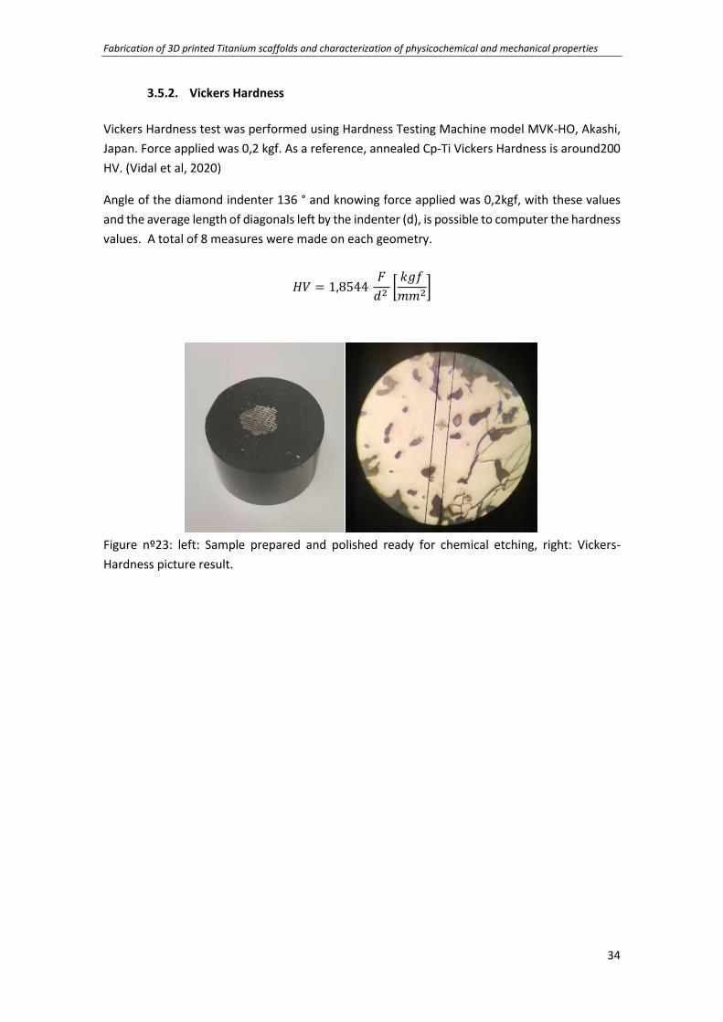
3.5.2. Vickers Hardness
Vickers Hardness test was performed using Hardness Testing Machine model MVK-HO, Akashi,
Japan. Force applied was 0,2 kgf. As a reference, annealed Cp-Ti Vickers Hardness is around200
HV. (Vidal et al, 2020)
Angle of the diamond indenter 136 ° and knowing force applied was 0,2kgf, with these values
and the average length of diagonals left by the indenter (d), is possible to computer the hardness
values. A total of 8 measures were made on each geometry.
𝐻𝑉 = 1,8544 𝐹
𝑑2 [𝑘𝑔𝑓
𝑚𝑚2]
Figure nº23: left: Sample prepared and polished ready for chemical etching, right: Vickers-
Hardness picture result.
Fabrication of 3D printed Titanium scaffolds and characterization of physicochemical and mechanical properties
35
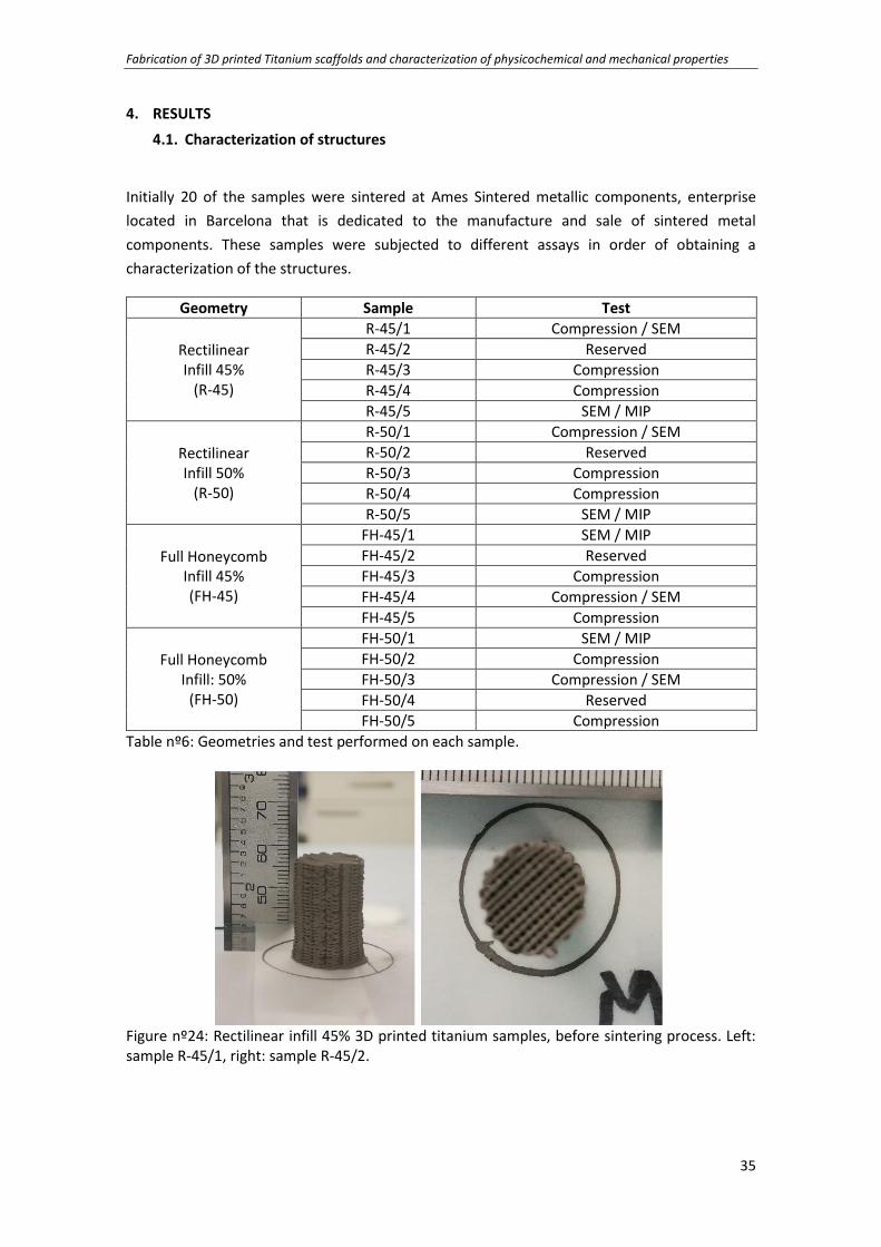
4. RESULTS
4.1. Characterization of structures
Initially 20 of the samples were sintered at Ames Sintered metallic components, enterprise
located in Barcelona that is dedicated to the manufacture and sale of sintered metal
components. These samples were subjected to different assays in order of obtaining a
characterization of the structures.
Geometry Sample Test
Rectilinear Infill 45%
(R-45)
R-45/1 Compression / SEM
R-45/2 Reserved
R-45/3 Compression
R-45/4 Compression
R-45/5 SEM / MIP
Rectilinear Infill 50%
(R-50)
R-50/1 Compression / SEM
R-50/2 Reserved
R-50/3 Compression
R-50/4 Compression
R-50/5 SEM / MIP
Full Honeycomb Infill 45% (FH-45)
FH-45/1 SEM / MIP
FH-45/2 Reserved
FH-45/3 Compression
FH-45/4 Compression / SEM
FH-45/5 Compression
Full Honeycomb Infill: 50%
(FH-50)
FH-50/1 SEM / MIP
FH-50/2 Compression
FH-50/3 Compression / SEM
FH-50/4 Reserved
FH-50/5 Compression
Table nº6: Geometries and test performed on each sample.
Figure nº24: Rectilinear infill 45% 3D printed titanium samples, before sintering process. Left: sample R-45/1, right: sample R-45/2.

Fabrication of 3D printed Titanium scaffolds and characterization of physicochemical and mechanical properties
36
Figure nº25: Rectilinear infill 50% 3D printed titanium sample R-50/1, before sintering process.
Figure nº26: Full Honeycomb infill 45% 3D printed titanium sample FH-45/1, before sintering process.
Figure nº27: Full Honeycomb infill 50% 3D printed titanium sample FH-50/2, before sintering process.

Fabrication of 3D printed Titanium scaffolds and characterization of physicochemical and mechanical properties
37
Other 4 samples (one each geometry) were printed and sintered using the equipment available
in the University, using a modified vacuum tubular furnace at 1.200ºC for 2 hours. This samples
were used to measure the Vickers hardness.
Figure nº28: Samples after sintering process.

Fabrication of 3D printed Titanium scaffolds and characterization of physicochemical and mechanical properties
38
4.2. Physicochemical Characterization
4.2.1. Dimensional changes
All the samples were subjected to high temperatures to eliminate the binder and obtain a pure
titanium piece, subsequently the vacuum tubular furnace elevated the temperature of the
pieces.
In both process the samples experimented morphological changes (dimensional changes) (figure
nº24). Removal of the binder and the mass loss this implies, triggered the shrinkage of the
sample. Height variation showed a reduction of the dimensions between 24.07% and 25.82%,
both are full honeycomb geometries and the one that suffered the biggest reduction
corresponds to infill 45%. In the other hand, the one with less height reduction had 50% infill.
Measures of the dimensions of each sample were made pre and post sintering in order to
obtain the contraction of the samples (figure nº25). Sample number 3.1 (R-50) could not be
measured due to a human mistake.
Sample Height Variation (%) Diameter Variation (%)
R-45/1 to R-45/5 25.08 ± 1.18 34.36 ± 3.21
R-50/1 to R-50/5 24.64 ± 4.10 37.03 ± 1.91
FH-45/2 to FH-45/5 25.82 ± 1.68 35.59 ± 1.74
FH-50/1 to FH-50/5 24.07 ± 1.16 37.34 ± 1.94
Table nº7: Height and diameter variation of samples according to the different geometries and
infill value.
Diameter variation were mostly experimented by full honeycomb samples with 50% infil, with
37.34% of reduction. By contrast the rectilinear 45% infill sample had the lowest diameter
variation (34.36%).

Fabrication of 3D printed Titanium scaffolds and characterization of physicochemical and mechanical properties
39
4.2.2. SEM
Figure nº29: top to bottom: Different printed structures x12 and x50, corresponds to a) R-45,
b)R-50, c)FH-45 and d)FH-50.
In SEM images of figure nº29 is possible to observe the different amount of contact points
between filaments of the different layers on each geometry printed, where figure d), which infill
is 50% and geometry is fully honeycomb, we can observe a higher number of filaments in contact
with another filament on the different layers. This images corresponds to samples subjected to
compression assay in order to analyze their resistance.
SEM images showed on figure nº29 to nº32 to different number of pores, micropores (on the
filament, size lower than 50µm) and macropores (between filaments, size bigger than 50µm). It

Fabrication of 3D printed Titanium scaffolds and characterization of physicochemical and mechanical properties
40
is possible to notice that honeycomb infill 45% has a higher number of visible pores. On the
other hand, the rectilinear infill 45% samples showed the lower number of visible pores.
Figure nº30: SEM images of sample rectilinear infill 45%, R-45/5.
Figure nº31: SEM images of sample rectilinear infill 50%, R-50/5.
Figure nº32: SEM images of sample full honeycomb 45% Infill, FH-45/1

Fabrication of 3D printed Titanium scaffolds and characterization of physicochemical and mechanical properties
41
Figure nº33: SEM images of sample full honeycomb 50% Infill, FH-50/1

Fabrication of 3D printed Titanium scaffolds and characterization of physicochemical and mechanical properties
42
4.2.3. Porosity
Was possible to obtain the parameters of porosity with MIP and Micro-ct results. Considering
that for those pores with a size smaller than 50µm are considered micropores and higher than
50µm are macropores.
With the values of weight, volume and density obtained with Micro-CT and using equation nº1,
was possible to compute closed porosity.
Sample Weight
(g) Bulk Density
(g/cm3) Vmicro MIP
(cm3/g) Skeletal Density
(MIP) (g/cm3) Total Porosity
(equation nº1) (%)
R-45/5 1.770 1.845 0.013 4.251 59,1
R-50/5 1.909 1.928 0.011 4.168 57,3
FH-45/1 1.710 1.616 0.016 4.276 64,2
FH-50/1 1.815 1.718 0.015 4.253 61,9
Table nº8: Porosity parameters and total porosity result according to equation nº1.
With the aim of compute microporosity, closed porosity and microporosity and by applying
equations nº2 and nº3, was possible to generate table nº9 with the results for each sample:
Total Porosity Micro-CT (%) (a)
Microporosity (%) (equation nº2) (b)
Closed Porosity (%) (equation nº3) (c)
Macroporosity (%) (a-b-c)
61.3 2.44 0.06 58.80
56 2.17 0.08 53.75
63.6 2.60 0.05 60.94
61.9 2.63 0.06 59.21
Table nº9: Microporosity, microporosity and closed porosity results for each sample studied.
MIP results shows that Micropore size average was found between 11,78μm and 23μm. Samples
with higher open microporosity is honeycomb with 50% of infill, followed by the same geometry
with 45% infill. Rectilinear 50% infill samples is the one with lowest porosity. Honeycomb
geometry has a bigger macroporosity possibly because there are more contact points between
filaments than in the rectilinear geometry.
Results of distribution of entrance pore diameter are shown on figure nº34. In general, size of
the micropores are similar for all the samples. Macro porosity results are also similar except for
R-45/1 where the number of smallest micropores are considerably less in comparison with the
rest of the samples.

Fabrication of 3D printed Titanium scaffolds and characterization of physicochemical and mechanical properties
43
Figure nº34: Entrance pore diameter distribution for samples.
Micro-CT total porosity exposed that both honeycomb 45% and 50%, had more total porosity
with values of 63,6% and 61,9% respectively. The lowest values correspond to rectilinear infill,
where the lowest porosity is 56% (rectilinear 50% infill).
4.2.4. Roughness
Values obtained after measures and the processing of the data for the samples can be seen on
figure nº33.
Regarding rugosity, results showed on table with an average roughness (Sa) between 3 and 5
microns, are similar between samples.
Sample Sa (µm) Sq (µm) Sz (µm) Sv (µm) Sp (µm)
R-45/1 3.296 4.405 40.887 25.146 15.741
R-50/4 3.525 4.574 33.258 14.767 18.491
FH-45/3 4.743 6.344 60.825 34.739 26.086
FH-50/5 3.829 9.188 100.038 90.203 10.181
Table nº10: Rugosity parameters for 4 samples (one each geometry).
00,010,020,030,040,050,060,070,080,09
0,10,110,12
2,3
E-0
1
2,8
E-0
1
3,6
E-0
1
5,2
E-0
1
8,1
E-0
1
1,2
E+0
0
1,5
E+0
0
2,0
E+0
0
2,5
E+0
0
3,1
E+0
0
4,1
E+0
0
5,9
E+0
0
6,6
E+0
0
8,0
E+0
0
1,0
E+0
1
1,2
E+0
1
1,5
E+0
1
2,0
E+0
1
3,0
E+0
1
4,5
E+0
1
1,0
E+0
2
3,0
E+0
2
dV
/dlo
gD
Entrance Pore Diameter (µm)
MIP
R-45/1
R-50/5
FH-45/1
FH-50/1

Fabrication of 3D printed Titanium scaffolds and characterization of physicochemical and mechanical properties
44
4.3. Mechanical Characterization
4.3.1. Young Modulus
Young modulus of the samples are situated between 2.5 6GPa and 3.8GPa (figure nº37) with
standard deviations between ±5% and ±13%. The geometry that experimented higher young
modulus is rectilinear with infill 50% and both honeycombs (45% and 50% infill) performed the
lowest young modulus of the entire set of samples.
If we relate infill and young modulus, in the case of infill 45% for both geometry, Young Modulus
mean equals to 2.81 ± 0.41 GPa and for infill 50% value of the mean is 3.09 ± 0.55 GPa.
For example, to obtain young modulus of sample R-50/1 we use the values of the curve between
11 seconds and 42 seconds (figure nº35), as explained in the chapter before, we need to avoid
the mistake of consider a value of local plastic deformation below the porous structure's yield
strength.
Time 31 Seconds Time 27,2 Seconds
Force (N/mm2) 42 11
Deformation (mm) 0.06 0.05
dF (N/mm2) 31
dD (mm) 0,01
Young Modulus (GPa) 3.22E+03
Table nº11: Young modulus value and variables for sample R-50/1.
Figure nº35: Tension vs deformation graph for sample R-50/1.
1,11E+01
4,21E+01
0,00E+00
2,00E+01
4,00E+01
6,00E+01
8,00E+01
1,00E+02
1,20E+02
3,E-03 1,4E+00 5,4E+00 1,1E+01 1,8E+01 2,7E+01 3,9E+01 5,4E+01 7,1E+01
Ten
sio
n (
N/m
m²)
Displacement(%)
Tension vs Deformation R-50/1

Fabrication of 3D printed Titanium scaffolds and characterization of physicochemical and mechanical properties
45
Figure nº36: Young modulus assay´s results for every sample.
Figure nº37: Average of young modulus per geometry and infill.
3,303,00
3,22
3,82
2,34
2,712,48
3,00
0,00
0,50
1,00
1,50
2,00
2,50
3,00
3,50
4,00
4,50
R-45/1 R-45/3 R-50/1 R-50/3 FH-45/3 FH-45/4 FH-50/2 FH-50/3
You
ng
Mo
du
lus
(GP
a)
Samples
Young Modulus
3.417 3.509
2.521 2.726
0.000
0.500
1.000
1.500
2.000
2.500
3.000
3.500
4.000
4.500
You
ng
Mo
du
lus
(GP
a)
Young Modulus
R-45
R-50
FH-45
FH-50
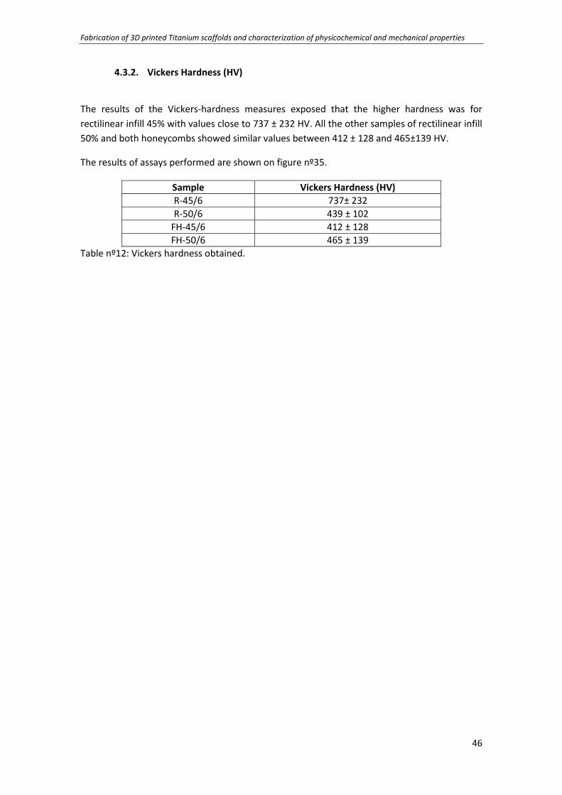
Fabrication of 3D printed Titanium scaffolds and characterization of physicochemical and mechanical properties
46
4.3.2. Vickers Hardness (HV)
The results of the Vickers-hardness measures exposed that the higher hardness was for
rectilinear infill 45% with values close to 737 ± 232 HV. All the other samples of rectilinear infill
50% and both honeycombs showed similar values between 412 ± 128 and 465±139 HV.
The results of assays performed are shown on figure nº35.
Sample Vickers Hardness (HV)
R-45/6 737± 232
R-50/6 439 ± 102
FH-45/6 412 ± 128
FH-50/6 465 ± 139
Table nº12: Vickers hardness obtained.
Fabrication of 3D printed Titanium scaffolds and characterization of physicochemical and mechanical properties
47
5. DISCUSSION
Direct ink writing technique allowed the fabrication of the samples successfully, but is important
to mention that filling the syringe with the mix of titanium and hydrogel is a critical process
because presence of bubbles in the paste inside the syringe will lead on a non-continuous
filament on the printed sample. This is the reason why printing process must be strictly
supervised in order to be aware of this possible discontinuous segment on the sample because
this would affect the shape of the sample (due to non-continuous filament, some part of the
upper layers would not have support underneath, thus a deformation on the sample is going to
be visible immediately).
According to literature revision, dimensional changes use to be higher in the vertical axis (height
variation with respect to diameter variation) due to the action of gravity force (Vidal E, 2020). In
the case of this study, diameter presented a higher variation, this could be explained because
possibly an expansion was generated in the outer loop of the filament, and exaggerated the
measured diameter.
Is demonstrated that porosity is a key influence in bone ingrowth. Values obtained in the
porosity analysis, using micro-CT and MIP results, evidence that porosity of the samples
(between 56% and 63.6%) are in the range of bone porosity (30%-90%) and microporosity and
macroporosity values are consistent with literature revision and suitable for bone regeneration
when implanted in human body because allows body fluids circulation and cell migration and
ingrowth.
Surface analysis of the samples concerning roughness parameters, demonstrated that surface
characteristics of the samples are acceptable for a biomaterial in contact with hard tissue, since
it is a suitable roughness range for the osseointegration of titanium with bone.
Regarding the images obtained through SEM on figure nº29, number and location of contact
point of metal on each layer of the samples are important because that affects compressive
resistance and microporosity ass well. Higher number of filaments in contact means a better
distribution of the loading charges and higher infill means more material to support that load,
in consequence, higher infill demonstrated to show higher young modulus for the 50% infill in
comparison with 45% infill samples for each geometry.
Mechanical results showed that young modulus of all samples studied, was between the range
of cancellous bone (0.1 to 5 GPa), thus the material is appropriate to perform as scaffold for
human bone without risk of stress shielding.
Assays results of Vickers-Hardness showed that all the samples performed a remarkable higher
resistance to penetration than cp-Ti. This value could be caused because a presence of oxygen
during sintering process may interfere and affect the sample, in consequence affecting HV.

Fabrication of 3D printed Titanium scaffolds and characterization of physicochemical and mechanical properties
48
6. CONCLUSIONS
In this study, porous titanium structures printed in 3D through direct ink writing were obtained
with physicochemical and mechanic characteristics compatibles and suitable to act as implants
in human bodies.
• It was possible to successfully print in 3D titanium scaffold through direct ink writing and
post process them in order to eliminate binder and obtain samples with certain
physicochemical and mechanical properties to study them.
• Total porosity situated between 59% and 64%. Micropore size average was found
between 11,78μm and 23μm. The values presented are suitable for fluid transport and
cellular proliferation if used as bone implants on human body.
• Regarding mechanical behavior, elastic modulus situated between 2.3 and 3.8 GPa.
These results are appropriate for scaffolds in human bone.
• Results of microhardness (Vickers Hardness) demonstrated to be higher than
commercially pure titanium. Presence of oxygen during sintering process may interfere
and affect the sample hardness.

Fabrication of 3D printed Titanium scaffolds and characterization of physicochemical and mechanical properties
49
7. BIBLIOGRAPHY
Acero, J., Calderón, J., Salmeron, J., Verdaguer, J., & Consejo, C. (1999). The behaviour of titanium
as a biomaterial: microscopy study of plates and surrounding tissue in facial
osteosynthesis. (J. o.-m. Surgery, Ed.) pp. 117-123.
Aldani, C., & Dominguez, A. (2012, January). Titanium as a Biomaterial for Implants. In Recent
Advances in Arthroplasty. doi:10.5772/27413
ASTM-Standard. (2005). Standard specification for wrought titanium-6 aluminum-7 niobium alloy
for surgical implant applications.
Breine, U., Johansson, B., Roylance, B., Roeckert, P., Yoffey, J., & Branemarck, P. (1964).
Regeneration of bone marrow. A clinical and experimental study following removal of
bone marrow by curettage. 59, 146.
Cameron, H., Pilliar, R., & Macnab, I. (1976). The rate of bone ingrowth into porous metals. Journal
of Biomedical Materials Research. doi:DOI: 10.1002/jbm.820100210
Chen Q, T. G. (2015). Metalic Implant Biomaterials. Materials Science & Engineering, pp. 1-57. doi:
https://doi.org/10.1016/j.mser.2014.10.001
Costa, F., Carvalho, I., Montelaro, R., & Gomes, P. (2011). Covalent immobilization of antimicrobial
peptides (AMPs) onto biomaterial surfaces. Acta Biomater, 7, 1431-1440.
Costerton, J., Stewart, P., & Greenberg, E. (1999). Bacterial biofilms: a common cause of persistent
infections. Science, 284, 1318-1322.
Davies, J. (2003). Understanding peri-implant endosseous healing. Journal of Dental Education, 67,
932-949.
Diana Lopes, C. M.-C. (2018). Bone Physiology as Inspiration for Tissue Regenerative Therapies.
Biomaterials. doi:doi: https://10.1016/j.biomaterials.2018.09.028
Duda, T., & Venkat, L. (2016). 3D Metal Printing Technologies. IFAC- Papers On Line, 103-110.
Elias, C., Jogaib, D., Moura de Souza, F., Dos Santos, E., & de Biasi, S. (2019). Mechanical and clinical
properties of titanium and titanium-based alloys (Ti G2, Ti G4 cold worked nanostructured
and Ti G5) for biomedical applications. Journal of Materials Research and Technology, 8,
1060-1069.
Giannouidis, P., Einhorn, T., & Marsh, D. (2007). Fracture healing: The diamond concept. Injury, 38,
S3-S6.
Hallab, N., Urban, R., & Jacobs, J. (2004). Corrosion and Biocompatibility of Orthopedic Implants.
Biomaterials in Orthopedics, 63-92. doi:DOI:10.1201/b14227-4

Fabrication of 3D printed Titanium scaffolds and characterization of physicochemical and mechanical properties
50
Her-Hsiung, H., Chun-Te, H., Tzu-Hsin, L., Tien-Ling, L., Ko-Kaung, L., & Fang-Lung, C. (2004). Effect
of surface roughness of ground titanium on initial cell adhesion. Biomolecular Engineering,
93-97.
ISO13314. (2011). Mechanical testing of metals — Ductility testing — Compression test for porous
and cellular metals.
Keles, O., Blevins, C., & Bowman, K. (n.d.). “Effect of build orientation on the mechanical reliability
of 3D printed ABS. Rapid Prototyping Journal, 320-328.
Kim, T., Wang See, C., Xiaochun, L., & Donghui, Z. (2020). Orthopedic implants and devices for bone
fractures and defects: Past, present and perspective. Enginereed Regeneration, 1, 6-18.
Kurtz, S., Ong, K., Jau, E., Mowart, F., & Halpern, M. (2007). Projections of primary and revision hip
and knee arthroplasty in the United States from 2005 to 2030. Journal of Bone and Joint
Surgery – American, 89, 780-785.
Kuzyk, P., & Schemitsch, E. (2011). The basic science of peri-implant bone healing. Indian Journal
Orthopedics, 45, 108-115.
Lei Zhang, G. Y. (2018). Three-dimensional (3D) Printed Scaffold and Material Selection for Bone
Repair. Acta Biomaterialia. doi:https://doi.org/10.1016/j.actbio.2018.11.039
Leonardo, G. (2013). Trabajo de investigacion bibliográfica: Estructura y propiedades de fatiga del
titanio y sus aleaciones utilizadas como biomateriales (Vol. 17). (C. y. Universidad, Ed.)
Lewis, G. (2013). Properties of open-cell porous metals and alloys for orthopaedic applications.
Journal of Materials Science: Materials in Medicine. doi:https://doi.org/10.1007/s10856-
013-4998-y
Li N et al. (2019). Progress of additive manufacturing technology for porous metal implant
applications and triple minimal surface structures: A review. J Mater Sci Technology.
Liu, X., Chu, P., & Ding, C. (2004). Surface modification of titanium, titanium alloys, and related
materials for biomedical applications. Mater Science Engineering, 47, 49-121.
Magda Dziaduszewska, Andrzej Zielinski. (2019). Titanium Scaffolds – Hopes and Limitations.
American Journal of Biomedical Science & Research. doi:DOI:
10.34297/AJBSR.2019.04.000841
Mitra, J., Tripathi, G., Sharma, A., & Basu, B. (2013). Scaffolds for bone tissue engineering: role of
surface pattering on osteoblast response. RSC Advances.
Muller, K., & Karevska, S. (2016). How will 3D printing make your company the strongest link in the
value chain? Retrieved from http://www.ey.com/Publication/vwLUAssets/EY-3d-druck-
studie-executive-summary/$FILE/EY-3d-druck-studie-executive-summary.pdf
Navarro, M., Michiardi, A., Castaño, O., & Planell, J. (2008). Biomaterials in orthopaedics. doi:DOI:
10.1098/rsif.2008.0151

Fabrication of 3D printed Titanium scaffolds and characterization of physicochemical and mechanical properties
51
Ni, J., Ling, H., Zhang, S., Wang, Z., Peng, Z., Benyshek, C., . . . Khademhosseini, A. (2019). Three-
dimensional printing of metals for biomedical applications. Materials Today Bio, 3.
doi:https://doi.org/10.1016/j.mtbio.2019.100024
Niinomi, N., & Nakai, M. (2011). Titanium-based biomaterials for preventing stress shielding
between implant devices and bone. International Journal of Biomaterials, 10.
Ottria, L., Lauritano, D., Andreasi Bassi, M., Palmiera, A., Candotto, V., Tagliabue, A., & Tettamanti,
L. (2018). Mechanical, chemical and biological aspects of Titanium. Journal of Biological
Regulators and Homeostatic Agents, pp. 81-90.
Özbilen, S., Liebert, D., Beck, T., & Bram, M. (2016). Fatigue behavior of highly porous titanium
produced by powder metallurgy with temporary space holders. Material Science
Engineering, 60, pp. 446-457.
Pala, J., Barao, V., Aparecida, J., Pérez, L., Pereira, T., & Goncalves, W. (2013). Titanium in Dentistry:
Historical Development, State of the Art. Indian Prosthodont Society. doi:DOI
10.1007/s13191-012-0190-1
Pattanayak, D., Fukuda, A., Matsushita, M., Takemoto, M., Fujibayashi, S., Sasaki, K., . . . Kokubo, T.
(2011). Bioactive Ti metal analogous to human cancellous bone: fabrication by selective
laser melting and chemical treatments. Acta Biomaterials, 1398-1406.
Peawband, A., & Thedsakhulwong, A. (2017). Design and Construction of a Small Vacuum Furnace.
Journal of Physics: Conference Series. IOP Publishing.
Ratner, B., Hoffman, A., Schoen, F., & Lemons, J. (2013). Biomaterials Science-An Introduction to
Materials in Medicine. (Oxford, Ed.) U.K.: Academic Press.
Reddy, P. (2019). Digital Light Processing (DLP). Think3D.
Ribeiro, J., Barao, V., Aparecida, J., & Perez, L. (2013). Titanium in Dentistry: Historical
Development, State of the Art and Future Perspectives. The Journal of Indian Prosthodontic
Society. doi:DOI:10.1007/s13191-012-0190-1
Ribeiro, M., Montero, F., & Ferraz, M. (2012). Infection of orthopedic implants with emphasis on
bacterial adhesion process and techniques used in studying bacterial-material interactions.
Biomatter 2(4):176-194.
Saenz, V., & Fuentes, E. (2013). Titanium and Titanium Alloys as Biomaterials. IntechOpen. doi:DOI:
10.5772/55860
Sajad, A., Burnett, J., & Michael, T. (2016). Fully porous 3D printed titanium femoral stem to reduce
stress-shielding following total hip arthroplasty. Journal of Medical Virology.
Saurí, J., Suñé-Negre, J., Díaz-Marcos, J., Vilana, J., Millán, D., Ticó, J., . . . García- Montoya, E.
(2015). Relationships between surface free energy, surface texture parameters and
controlled drug release in hydrophilic matrices. International Journal of Pharmaceutics,
328-340.

Fabrication of 3D printed Titanium scaffolds and characterization of physicochemical and mechanical properties
52
Schmidutz, F., Agarwal, Y., Müller, P., & Gueorgui, B. (2014). Stress-shielding induced bone
remodeling in cementless shoulder resurfacing arthroplasty: a finite element analysis and
in vivo results. Journal Biomechanics, 3509-3516.
Shahrubudin, N., Lee, T., & Ramlan, R. (2019). An Overview on 3D Printing Technology:
Technological, Materials and Applications. 2nd International Conference on Sustainable
Materials Processing and Manufacturing.
Silbernagel, C. (2018). What is material jetting? Retrieved from Canada Makers: Avaliable:
http://canadamakes.ca/what-is-material-jetting/ [Accesed 2021]
Solis, N., Smirnov, A., Peretyagin, N., Seleznev, A., & Peretyagin, A. (2020). Direct Ink Writing
Technology (3D Printing) of Graphene-Based Ceramic Nanocomposites: A Review.
Standard, A. (2005). Standard specification for wrought titanium-6 aluminum-7 niobium alloy for
surgical implant applications (Vol. F1295). West Conshohocken.
Stansbury, W., & Idacavage, M. (2016). 3D Printing with polymers: Challenges among expanding
options and opportunities. Dental Materials, 54-64.
Syed, A., Elias, P., Amit, B., Susmita, B., Lisa, O., & Charitidis, C. (2017). Additive manufacturing:
scientific and technological challenges, market uptake and opportunities. Materials Today,
1, 1-16.
Takao, H. (2019). Titanium–Tissue Interface Reaction and Its Control With Surface Treatment.
Tokyo: Department of Metallic Biomaterials, Institute of Biomaterials and Bioengineering.
Tiwari, S., Pande, S., Agrawal, S., & Bobade, S. (2015). Selection of selective laser sintering materials
for different applications. Rapid Prototyping Journal, 21, 630-648.
Tuang, D., Kashani, A., Imbalzano, G., Nguyen, K., & Hui, D. (2017). Additive manufacturing (3D
printing): A review of materials, methods, applications and challenges. Composites.
Vaezi, M., Seitz, H., & Yang, S. (2013). A review on 3D micro-additive manufacturing technologies.
The International Journal of Advanced Manufacturing Technology, 67.
Vidal E, T. D.-M.-P. (2020). Titanium Scaffolds by Direct Ink Writing: Fabrication and
Functionalization to Guide Osteoblast Behavior. Metals.
doi:https://doi.org/10.3390/met10091156
Vikayavenkataraman, S., Jerry, Y., & Wen, F. (2017). 3D Printing and 3D Bioprinting in Pediatrics.
Bioengineering, 63, 1-11. doi:10.3390/bioengineering4030063
Vladimir Popov Jr., V., Muller-Kamskii, G., Kovalevsky, A., Dzhenzhera, G., Strokin, E., Kolomiets, A.,
& Ramon, J. (2018). Design and 3D-printing of titanium bone implants: brief review of
approach and clinical cases. Biomedical Engineering Letters.
Wang. (2017). Analysis of factor influencing bone ingrowth into three-dimensional printed porous
metal scaffolds: A review (Vol. 717). J Alloys Compd.

Fabrication of 3D printed Titanium scaffolds and characterization of physicochemical and mechanical properties
53
Wang, G., Li, J., Kaige, L., Wenjie, Z., Xun, D., Guanghzeng, Y., . . . Xinquan, J. (2016). Surface
thermal oxidation on titanium implants to enhance osteogenic activity and in vivo
osseointegration. Sci Rep, 6. doi:https://doi.org/10.1038/srep31769
Wang, M., & Tang, T. (2019). Surface treatment strategies to combat implant-related infection from
the beginning. Journal of Orthopedics Translation, 17, 42-54.
Wu, S., Liu, X., Yeung, K., Liu, C., & Yang, X. (2014). Biomimetic porous scaffolds for bone tissue.
Materials Science Engineering, 80(1), 1-36.
Yap, C., Chua, C., Dong, Z., Liu, Z., Zhang, D., Loh, L., & Sing, S. (2015). Review of selective laser
melting: Materials and applications. Applied Physics Reviews.
Ze-Xian, L., Yen, T., Ray, M., Mattia, D., Metcalfe, I., & Patterson, D. (2016). Perspective on 3D
printing of separation membranes and comparison to related unconventional fabrication
techniques. Journal of Membrane Science, 523, 596-613.
Zhao S, L. S. (2016). The influence of cell morphology on the compressive fatigue behavior of Ti-6Al-
4V meshes fabricated by electron beam melting (Vol. 59). J Mech Behav Biomed Mater.
Zhu, X., Chen, J., Scheideler, L., Reichl, R., & Geis-Gerstorfer, J. (2004). Effects of topography and
composition of titanium surface oxides on osteoblast responses. Biomaterials, 25, 4087-
4103.

Fabrication of 3D printed Titanium scaffolds and characterization of physicochemical and mechanical properties
54
8. ANNEXES
Figure nº36: Tension vs deformation graph for sample R-45/1.
Figure nº37: Tension vs deformation graph for sample R-45/3.
6,99E+00
5,19E+01
0,00E+00
2,00E+01
4,00E+01
6,00E+01
8,00E+01
1,00E+02
1,20E+02
2,7E-03 5,4E-02 7,7E-02 1,0E-01 1,3E-01 1,8E-01 2,3E-01 2,8E-01 3,3E-01
Ten
sio
n (
N/m
m²)
Deformation (%)
Tension vs Deformation R-45/1
1,35E+01
5,25E+01
0,00E+00
2,00E+01
4,00E+01
6,00E+01
8,00E+01
1,00E+02
1,20E+02
1,40E+02
8,E-04 2,7E-02 5,3E-02 5,8E-02 8,4E-02 1,1E-01 1,4E-01 1,6E-01 1,9E-01
Ten
sio
n (
N/m
m²)
Deformation (%)
Tension vs Deformation R-45/3

Fabrication of 3D printed Titanium scaffolds and characterization of physicochemical and mechanical properties
55
Figure nº38: Tension vs deformation graph for sample R-50/1
.
Figure nº39: Tension vs deformation graph for sample R-50/3.
1,11E+01
4,21E+01
0,00E+00
2,00E+01
4,00E+01
6,00E+01
8,00E+01
1,00E+02
1,20E+02
3,E-03 1,4E+00 5,4E+00 1,1E+01 1,8E+01 2,7E+01 3,9E+01 5,4E+01 7,1E+01
Ten
sio
n (
N/m
m²)
Displacement(%)
Tension vs Deformation R-50/1
1,43E+01
5,52E+01
0,00E+00
2,00E+01
4,00E+01
6,00E+01
8,00E+01
1,00E+02
1,20E+02
1,40E+02
1,60E+02
1,80E+02
2,4E-01 3,6E-03 -7,5E-02 2,5E-04 1,8E-01 4,4E-01 8,4E-01 1,4E+00 2,1E+00 3,E+00
Ten
sio
n (
N/m
m²)
Deformation(%)
Tension vs Deformation R-50/3

Fabrication of 3D printed Titanium scaffolds and characterization of physicochemical and mechanical properties
56
Figure nº40: Tension vs deformation graph for sample FH-45/3.
Figure nº41: Tension vs deformation graph for sample FH-45/4.
1,14E+01
4,24E+01
0,00E+00
1,00E+01
2,00E+01
3,00E+01
4,00E+01
5,00E+01
6,00E+01
7,00E+01
8,00E+01
1,41E-04 8,90E-02 3,38E-01 7,48E-01 1,23E+00 1,79E+00 2,51E+00 3,39E+00
Ten
sio
n (
N/m
m²)
Deformation (%)
Tension vs Deformation FH-45/3
1,2E+01
3,9E+01
0,0E+00
1,0E+01
2,0E+01
3,0E+01
4,0E+01
5,0E+01
6,0E+01
7,0E+01
8,0E+01
9,0E+01
-1,1E-03 2,9E-02 2,3E-01 5,9E-01 1,1E+00 1,6E+00 2,4E+00 3,3E+00 4,3E+00 5,6E+00
Ten
sio
n (
N/m
m²)
Deformation (%)
Tension vs Deformation FH-45/4

Fabrication of 3D printed Titanium scaffolds and characterization of physicochemical and mechanical properties
57
Figure nº42: Tension vs deformation graph for sample FH-50/2.
Figure nº43: Tension vs deformation graph for sample FH-50/3.
1,03E+01
4,61E+01
0,00E+00
2,00E+01
4,00E+01
6,00E+01
8,00E+01
1,00E+02
1,20E+02
1,40E+02
1,60E+02
-2,6E-03 7,4E-02 7,3E-01 1,8E+00 3,5E+00 5,8E+00 8,8E+00 1,2E+01
Ten
sio
n(N
/mm
²)
Deformation (%)
Tension vs Deformation FH-50/2
1,01E+01
4,81E+01
0,00E+00
2,00E+01
4,00E+01
6,00E+01
8,00E+01
1,00E+02
1,20E+02
8,4E-05 1,9E-01 7,6E-01 1,5E+00 2,6E+00 4,E+00 5,8E+00 8,E+00
Ten
sio
n (
N/m
m²)
Deformation (%)
Tension vs Deformation FH-50/3

Fabrication of 3D printed Titanium scaffolds and characterization of physicochemical and mechanical properties
58
Vickers Hardness
Geometry Diameter
1 (d1) Diameter
2 (d2) d1
[um] d2
[um] d1
[mm] d2
[mm] D
[mm] HV Gpa
Rectilinear 45% Infill
112 113 28 28,25 0,028 0,028 0,028 469 4,594
70 77 17,5 19,25 0,018 0,019 0,018 1098 10,762
78 80 19,5 20 0,020 0,020 0,020 951 9,316
103 104 25,75 26 0,026 0,026 0,026 554 5,428
84 85 21 21,25 0,021 0,021 0,021 831 8,143
83 86 20,75 21,5 0,021 0,022 0,021 831 8,143
114 113 28,5 28,25 0,029 0,028 0,028 461 4,513
90 94 22,5 23,5 0,023 0,024 0,023 701 6,869
Rectilinear 50% Infill
111 115 27,75 28,75 0,028 0,029 0,028 465 4,553
103 98 25,75 24,5 0,026 0,025 0,025 587 5,756
121 119 30,25 29,75 0,030 0,030 0,030 412 4,038
103 115 25,75 28,75 0,026 0,029 0,027 499 4,894
130 123 32,5 30,75 0,033 0,031 0,032 371 3,633
109 110 27,25 27,5 0,027 0,028 0,027 495 4,849
151 160 37,75 40 0,038 0,040 0,039 245 2,405
109 123 27,25 30,75 0,027 0,031 0,029 441 4,321
Honeycomb 45% Infill
141 151 35,25 37,75 0,035 0,038 0,037 278 2,728
98 95 24,5 23,75 0,025 0,024 0,024 637 6,244
106 123 26,5 30,75 0,027 0,031 0,029 453 4,435
132 139 33 34,75 0,033 0,035 0,034 323 3,167
118 113 29,5 28,25 0,030 0,028 0,029 445 4,358
128 139 32 34,75 0,032 0,035 0,033 333 3,262
143 142 35,75 35,5 0,036 0,036 0,036 292 2,863
107 104 26,75 26 0,027 0,026 0,026 533 5,224
Honeycomb 50% Infill
113 121 28,25 30,25 0,028 0,030 0,029 433 4,247
114 119 28,5 29,75 0,029 0,030 0,029 437 4,284
97 96 24,25 24 0,024 0,024 0,024 637 6,244
137 136 34,25 34 0,034 0,034 0,034 318 3,120
135 140 33,75 35 0,034 0,035 0,034 314 3,075
130 126 32,5 31,5 0,033 0,032 0,032 362 3,549
98 111 24,5 27,75 0,025 0,028 0,026 543 5,324
93 95 23,25 23,75 0,023 0,024 0,024 671 6,580
Table nº13: Vickers-Hardness results for each sample.

Fabrication of 3D printed Titanium scaffolds and characterization of physicochemical and mechanical properties
59