F(8H8 li C> 15523 6 .' '.' . U.S. DEPARTMENT OF TRANSPORTATION
206
REPORT NO. FRA/ORD- 80/87 PB F (8H8 li C> 155 23 6 .' '.' GRADE Cf{)SSING ACCIDENT INJURY MINIMIZATION STUDY PB81·155236 11111111111111111111111111 11111111111 ElMER J. FREY CHARLES E. THEOBALD) JR. HH AEROSPACE DESIGN CoMPANY) INC. CIVIL AIR TERMINAL BEDFORD) M4 01730 . . . • DECEMBER 1980 FINAL REpORT Document is available to the public through the National Technical Information Service, Springfield, Virginia 22161. u.s. National Technicallnfol1l1alion Service Springfield, 22161 Prepared for U.S. DEPARTMENT OF TRANSPORTATION FEDERAL RAILROAD ADMINISTRATION Office of Research and Development Washlnaton, D.C. 20590 '
-
Upload
khangminh22 -
Category
Documents
-
view
0 -
download
0
Transcript of F(8H8 li C> 15523 6 .' '.' . U.S. DEPARTMENT OF TRANSPORTATION

REPORT NO. FRA/ORD- 80/87 PBF(8H8 li C> 15523 6 .' '.'
GRADE Cf{)SSING ACCIDENT INJURY MINIMIZATION STUDYPB81·15523611111111111111111111111111 11111111111
ElMER J. FREY
CHARLES E. THEOBALD) JR.
HH AEROSPACE DESIGN CoMPANY) INC.
CIVIL AIR TERMINALBEDFORD) M4 01730
..
.•
DECEMBER 1980FINAL REpORT
Document is available to the public through theNational Technical Information Service,
Springfield, Virginia 22161.
u.s.National Technicallnfol1l1alion Service
Springfield, 22161
Prepared forU.S. DEPARTMENT OF TRANSPORTATION
FEDERAL RAILROAD ADMINISTRATIONOffice of Research and Development
Washlnaton, D.C. 20590 '

NOTICE
This document is disseminated under the sponsorshipof the Department of Transportation in the interestof information exchange. The United States Govern-ment assumes no liability for its contents or usethereof.
NOTICEThe United States Government does not endorse pro-ducts or manufacturers. Trade or manufacturers'names appear herein solely because they are con-sidered essential to the object of this report.

TOCI101icllll Pogo
FRA/ORD-80/87 155236 J....l-- ----I-=--=- . '__
4 T, 110 and Sub'i.l" 5 Repor! Do'"
1. Rop"" No.
Grade Crossing Accident Injury Minimization StudyDecember 1980
j;-----:------,,------_.._------6, Porforming Organl loti on
. 8. P",dorming OrgoniEotion Repor' No.7
Elmer J. Frey and Charles E. Theobald Jr .9. Performing Organization Name and
...... ---------.--10. Unit No. (TRAIS)
Final Report
14. Span.oring Agency Code
--' . __ ..-- -. ----_._------ - ..--
U.S. Department of TransportationFederal Railroad Administration
__. .... . ...... __'5. Suppla,non'ory Moto.
HH Aerospace Design Co., Inc. II. Con'roc' or Gron' No.
Civil Air Terminal DOT-FR-8197I Bedford, 01730 _. . -413. Typ'e 01 Report ond Perood Co.ered
I '2. Spon,oro n9 Agency Nome ond Add ,,.,,
If--..,...-'--,...-----------------------------------------------f116". Ab."oc'
,. The purpose of this study was to identify and evaluate potential conceptsfor reducing injuries to highway occupants and train occupants in rail-highwaygrade ctossing collisions. A review of railroad, highway vehicle, andaviation sources was made. The identified concepts were principally thosefrom railroad crashworthiness and collision attenuation studies, plus somecollision attenuation concepts from highway safety work. A list of conceptswas developed and each approach evaluated for effectiveness according to aset of criteria based primarily on performance in normal operations and inaccidents.=·Several concepts were rejected on this basis. Certain conceptswere effective but applied to situations of very low statistical importancewhere preventive measures are more effective. Some·numerical simulation of
was done in the evaluation. The more effective concepts consistedof a hard-faced deflector covering the locomotive coupler to remove thehighway vehicle from the tracks. a soft crushable collision attenuator toreduce impact accelerations and forces. and increased use of rail brakes inpassenger cars. '. Estimates of fatality reduction from various measures andof costs are made. It is concluded that testing of the more promising conceptsis wa rranted.
17. Key Wordo
Grade Crossing AccidentsCrashworthinessInjury Minimization
lB. Dlshlbutlon Stolemoni
Document is available to the U. S. publicthrough the National Technical InformationService. Springfield, Virginia 22161
Rall-Hlghway Coll1s10ns
19. Securily Clo .. d. (of ,opo,t)
Unclassified
I
20. 21. __J[Fcrll'l 001 f UOO.7 (8-721 Reproduclion of completed poge outhori.ed
;(0.)

METR
ICCONVERSION
FACTO
RS

ATTENTION
AS NOTED IN THE NTIS ANNOUNCEMENT I
PORTIONS OF THIS REPORT ARE NOT LEGIBLE.
HOWEVER, IT IS THE BEST REPRODUCTION
AVAILABLE FROM TrlE COpy SENT TO NTIS.


EDGr'1ENTS
The authors wish to acknowledge the continued advice and assistance
of Mr. John V. Mirabella of the Office of Rail Safety Research, Federal
Railroad Administration, and the valuable comments of Mr. Donald Levine
of the Office of Rail Safety Research at discussions of the progress of
the study. They also wish to thank Ms. Mary Cross of the Transportation
Systems Center for her useful suggestions and advice on deriving data
from the FRA accident files, and for rapid execution of the actual
processing work. Mr. Louis Edmonds of HH Aerospace Design also contributed
useful information on railroad rolling stock and operations.
iii


TABLE OF CONTENTS
SectionExecutive Summary1. Introduction and Summary
1.1 Background Information1.2 Organization of Report1.3 Study Organization
. 2. Collection of Injury Reduction Concepts2.1 Classification of Concepts by Type2.2 Concept Search
2.2.1 Railroad Sources2.2.2 Other Industry Sources
2.3 Concept List2.3.1 Concepts for Rail-Highway Collision
Attenuation
E-l1-11-11-31-3
2-12-12-32-32-92-10
2-11
Applicability and EffectivenessConcept ApplicabilityEvaluation CriteriaIndividual Concept Evaluations3.3.1 General3.3.2 Conventional Structural and Fire
Crashworthiness Measures
3. Concept3.13.23.3
3.3.33.3.43.3.53.3.63.3.7
3.3.83.3.9
3.3.10
Front End Structural CrashworthinessIndividual Protective EquipmentElectromagnetic Rail BrakesGas Bag Collision Attenuator SystemsSpray to Reduce Surface Coefficient ofFrictionPiston Collision AttenuatorsCollision Attenuators Based on HighwayAbutment Collision DevicesRigid Flat-Front and Rounded-FrontLocomotives (Deflectors)
v
3-13-13-93-153-15
3-153-171-22l-24]-26
3-323-33
3-35
3-42
Preceding page blank

TABLE DF CONTENTS (cont)
Section
3.3.113.3.12
The Water-Jet Collision AttenuatorCrushable Collision Attenuators
3-563-64
4. Benefit Estimation4.1 Statistical Basic and Injury 1s
4.1.1 Injury Statistics4.1. 2 Injury Models
4.2 Individual Concept Estimates
5. Cost Estimates5.1 General Cost Considerations5.2 Individual Concept Cost Estimates
6. Conclusions (and comparisons of concepts)
7. Recommendations
4-14-14-14-154-22
5-15-15-3
6-1
7-1
ReferencesAppendix AAppendix BAppendix C
Simulation EquationsSimulation Run PrintoutsPotential Accident Increase Due to AddedLength of Collision Attenuator
vi

Table
2-12:..22-32-42.-52-63-13-23-33-4
4-14-2
. 4-3
4-4
4-54-64-74-84-9
4-10
LIST OF TABLES
List of RRIS and NTIS BibliographiesRailway Periodicals ReviewedRailway Periodicals Not Reviewed IndividuallyPassive Collision Attenuation SystemsPotential Active Collision Attenuation SystemsDesign Principles For CrashworthinessDesign Criteria For Rail Vehicle CrashworthinessSequence of Events During Test TGB-4Simulation Results, Water-Jet AttenuatorSummary of Simulations of Crushable AttenuatorCollisions
Casualty Importance of Various Events 1977 StatisticsRail-Highway Grade Crossing Accidents Resulting inDerailmentsGrade Crossing Accident Data Form FRA Rail EquipmentAccident/Incident Reports, 1977Grade Crossing Accident Data Form FRA Rail EquipmentAccident/Incident, Reports, 1976Automobile-Train Collision by Train SpeedTruck-Train Collisions by Train SpeedBus-Train Collisions by Train SpeedPedestrian-Train Collisions by Train SpeedDistribution of Accidents and Fatalities by TrainSpeed (Train Strikes Highway Vehicle, 1977)Possible Fatality Reduction Due to Flat Front Locomotive
vii
2-5
2-72-82-122-132-133-93-453-60
3-764-2
4-5
4-7
4-84-114-124-134-14
4-204-24

Figure
1-13-13-23- 3
3-43-53-6
/
3-73-8
3-93-103-113-123..:13
3-14
3-153-16
3-17
3-183-193-20
3-214-1
4-2
LIST OF FIGURES
Rail-Highway Collisions, Possible EventsApplicability of Collision Attenuators at Front of TrainApplicability of Rail Brakes For Passenger CarsApplicability of Derailment Prevention DeviceApplicability of Fire CrashworthinessApplicability of Structural Crashworthiness (I)Applicability of Structural Crashworthiness (II)Applicability of Individual Protective GearPossible Sealing of MU Car Front Against Entry ofFlammable FluidsLocomotive Airbag Attenuator SchematicSensor-Deployed Airbag AttenuatorContinuously or Engineer-Deployed Airbag (Stowed E Deployed)Continuously or Engineer Deployed Airbag (Interior Views)Locomotive-Automobile Crash Test, Lateral Accelerationsin Occupant CompartmentComparison of Laternal Accelerations in Tests (LeftRear Occupant Compartment) and Along-Track Accelerationin SimulationSimulation of Hard Front CrashesPrototype Water Jet Attenuator System Installed onLocomotiveLocomotive-To-Automobile Relationship Deployed CAD(Crushable Attenuator)Basic Dimensions of CAD Design ConceptCAD in Stowed Position, Plan ViewRelationship of Depth of Crush of Attenuator to LocomotiveSpeed and AutomobileSimulation Results Crushable AttenuatorTypical Shape of Fatality Probability Curve as a Functionof Automobile LocationFatal ity Rate Per Accident - Data and i10del
vii i
1-23-43-43-53-53-63-63-7
3-213.,.27
3-28
3-303-31
3-47
3-513-53
3-57
:3-65
3-663-68
3-72
3-77
4-184-21

EXECUTI VE SUMr1ARY
GRADE CROSSING ACCIDENT INJURY MINIMIZATION STUDY
1. Purpose of Study
The goal of this study was investigation and evaluation of conceptsfor the reduction of injuries to occupants of highway vehicles and oftrains in rail-highway grade crossing accidents. For each concept identified,the study was to determine the conditions in which it would be applicable,its effectiveness in reducing injuries, and estimates of potential reductionsin injuries achieved, and of costs of implementation.
2. Study Procedure
Consideration of certain accident situations and certain injuryreduction concepts was specifically required by the contract. A reviewof rail literature on injury reduction methods was followed by a reviewof the highway transport and aviation fields. Some highway work suggestedalternative implementation methods, but no new concepts were identified.
Evaluation criteria were developed involving feasibility, performancein routine operations and in emergency situations, acceptability andconvenience to the personnel involved, costs, and logistic and indirecteffects. Estimates of injury reductions and of costs were developedonly for concepts meeting the criteria for feasibility and satisfactoryperformance. Estimates were based on existing accident statistics, obtainedfrom FRA data files, and from injury models which were related to thestatistics to the extent possible. Whenever possible, results of previouscrashworthiness studies were used in cost estimates.
E-l

3. Conclusions
,A list of the primary conclusions appears below. and followed by
estimates of benefits and costs of certain concepts, and a brief discussionof the background of some of the conclusions.
(1) Of approximately 1,150 fatalities from grade crossinq accidentsin a typical recent year, about 200 occur in cases where the highwayvehicle strikes the train. For such accidents, which constitute about30 percent of all accidents, there is no practical train-mounted palli-ative measure. Of the 860 fatalities occurring annually when trainsstrike motor vehicles, about two thirds occur when the train speed isbetween 20 and 50 miles per hour; it is these fatalities which offerthe greatest potential for reduction.
Collisions of trains with buses are so uncommon that the mosteffective approach to injury reduction is preventive, rather thanpalliative. Collisions of MU cars with fuel trucks are even more un-common, and although there are potential design countermeasures forinjury reduction, the most effective procedures are essentiallypreventive, for example, improved braking.
(2) Three concepts for reduction met performance criteriasufficiently well and offered enough potential to warrant further study.The concepts are:
I a rigid hard faced deflector at the front of a locomotive.covering the coupler to orevent impalement and retention ofhighway vehicles in a collision. Simulations indicate thedevice removes the highway vehicle from the train's path withlower accelerations than those imparted by conventional flat-front locomotives. When the coupler is to be used, the devicehinges back and is stowed on the locomotive front. Thedeflector could also be covered with a soft layer for furtherreduction of impact forces.
E-2

• a soft faced crushable attenuator at the front of a locomotive,which significantly reduces the forces between train and highwayvehicle in a collision, and helps remove the highway vehiclefrom the path of train. When the locomotive is not at thefront of a train, the device, about eight feet long, is foldedback into a stowed position on the locomotive front. The addedlength presents a problem, because it may convert into actualcollisions incidents which might otherwise have been near misses .
• addition of rail brakes to MU cars, and possibly to other oassen-ger cars, to improve braking capability and reduce both incidenceand severity of collisions.
(3) Certain essentially negative conclusions were reached aboutvarious other concepts for injury reduction and about certain accidentsituations.
I existing locomotive construction generally protects locomotiveoccupants adequately in collisions not involving hnzardousmaterials or very heavy trucks. Recent changes in FRA standardson glazing and locomotives nddress some of the whichmay occur in collisions involvinq combustible fuels.Individual protective equipment and c10thinq for train crewsfor use in collisions involving hazardous materials do notappear to be practical.
none of the proposed collision attenuation systems deoendinqupon automatic actuation of a mechanism immediately before apotential collision is practical.
i very long crushable attenuators, equipped with their own wheelsand articulated to the locomotive front, do not appear to bepractical, although they offer the possibility of the greatestreduction in forces and accelerations of the highway vehicle.
E-3

(4) Collection of more detailed accident records, reflecting medicalexaminers' or coroners' reports and further detail on automobilelocation and condition after the accident, might make it more possible. to predict the effects on injuries of changes in automotive and railroaddesign. Such data might also help establish clearer relationships betweentrain speed and injury.
The concepts considered worthy of future consideration were chosenon the basis of the feasibility of implementation, compatibility withnormal railroad operations and equipment, convenience of use and freedomfrom trouble or malfunction, long life and reasonable cost, and, ofcourse, effectiveness in reducing injuries in accident situations. Thesame criteria served for rejection of other concepts, for example, thecomplexity of automatically actuated systems, the possibility of in-. advertent actuation, the need for frequent maintenance, and the cost wereall reasons for rejection. None of the acceptable concepts involves newtechnology, but materials behavior of the honeycomb proposed for thecrushable attenuator may require some significant development and testefforts.
The effectiveness of the concepts in reducing injury is expressedin terms of the estimated savings in lives of the approximately 860 annualfatalities occurring when trains strike highway vehicles. The estimatedsavings in lives due to use of the deflector depends on the deflector.design. and ranges from about 120 for a short coupler cover to about 240for a longer rounded design. The estimated savings for the soft-facedcrushable attenuator were about 390 lives annually. The estimates are notadjusted for the possibility of additional accidents caused by the lengthof the attenuator. No estimates were made for the addition of rail brakesto MU cars, since the statistics are too sparse and the benefits may occurin accidents other than rail-highway collisions.
The major probiem anticipated with both attenuators and deflectorsis achievement of relatively uniform and effective designs which arecompatible with the varying geometry of locomotive fronts, and with currentoperatinq procedures. The construction materials and methods are conventional.
E-4

The principal problem of addition of rail brakes to MU cars would be thecomplexity and cost of an additional system. Such devices are alreadyin use on various urban transit and liqht rail vehicles, but developmentis required to them to new cars.
Cost estimates can vary by a factor of three or even more, dependingon the specific design characteristics. The estimates shown in the tablebelow reflect middle of the range values for the attenuator and the deflector.Such costs may be partially offset by reduction in damages to rail propertyoccurring in rail-highway collisions. The current annual amount of suchdamages is more than $10,000,000. No estimate of the potential reductionhas been made, but any reduction in derailments could have a significanteffect. No costs are shown in the table for rail brakes; in recent yearsthe cost of the rail brakes for a light rail vehicle has been approximately$7,000.
ESTIMATED COSTS - ATTENUATOR AND DEFLECTOR
ITEM ATTENUATOR DEFLECTORNumber Cost Number CostInitial Costs of Units (Millions of $) of Units (Millions of $)
(1) Development, Test, 1.0 1.0and Evaluation
(2) Retrofit, Both Ends of 20,000 60.0 20,000 30.010,000 Line Haul Locomotives
Annual Recurring Costs
(3) Installation on 1,000 new 2,000 5.0 2,000 2.0locomotives
(4 ) Replacement, units destroyed 1,800 5.4 900 1.35i.n acci.dents
- (5 ) Repairs to damaged units 3,200 1.0 2,000 0.5(6 ) Operating costs (deployment, 4.5 2.5Storage, Lubrication)
Total annual cost: 15.9 6.35
E-5


Chapter 1
1.1
Introduction and Summary
Background Information
For many years the leading cause of death in railroad operations hasbeen grade crossing accidents. In 1977, of the 1,530 deaths in railroad
*operations, 944 occurred as a result of the 12,299 such accidents.These accidents, together with the 390 non-railroad and non-passengerpersonnel killed by being struck or run over, form 87 percent of allfatalities. The preventive measures of recent years, along with anumber of other factors, have succeeded in reducing the grade crossingdeaths significantly from earlier years, e.g. from the 1,780 recorded in
**1966. However, they remain the dominant cause, and have received attentionfrom the Federal Railroad Administration (FRA), the National TransportationSafety Board (NTSB), and various other organizations. This is indicatedby publications of various personnel describing some of the problems and
approaches to dealing with them. (1-1), (1-2)
This report presents the results of a study, performed for the FRA,aimed at reducing injuries and fatalities from grade cross;ng collision.Although earlier studies tend to concentrate only on protecting the motorist,the FRA directed that this study measures aimed at protecting railpassengers and crew members as well. The study was to consider certainspecific accident situations and certain proposed measures described in thisreport. Figure 1-1 illustrates some of the situations to be considered.
*
**
(1-1 )
(1-2)
Figures from Accident/Incident Bulletin No. 146, Calendar Year 1977,Federal Railroad Administration.
Figures from Rail-Highway Grade-Crossing Accidents/Incidents Bulletin,Calendar Year 1976, Federal Railroad Administration.
"Crash Safety for Railroad Passengers, Train Crews, and Grade CrossingCrash Victims", Wakeland, Hentry H., SAE Congress, Feb 27-March 3,1978,Paper 0148-7191/78/0022.
"An Array of Social Values for Use in Analyzing The Need for SafetyRegulations", Wakeland, Henry H., Fourth Intl. Congo on AutomobileSafety, San Francisco, July 14-16, 1975.
1-1

........
I N
HIGHW
AYOC
CUPA
NT
Pedestrian
Autom
obile
Truck
with
hazardousmaterial
withouthazardousmaterial
Bus
t1otorcyc1e
Other
vehicle
RAIL
CONS
IST
Freighttrain
with
hazardousmaterial
with
outhazardousmaterial
Passengertrain
(locomotivedrawn)
Passengertrain
(nolocomotive)
Fig.
1-1
RAIL-
HIGH
WAY
COLL
ISIONS
,PO
SSIBLE
EVEN
TS

1.2 Organization of Report
Chapter 1 of this report provides introducing information and a briefoutline of the study organization. Chapter 2 starts by classifying thepossible methods of achieving injury reduction, describes the literaturesearch aimed at identifying possible injury reduction measures, and thenprovides a list of the possibilities Chapter 3 considers first thecriteria of judgment to be applied to evaluation of the various injuryreduction concepts, and then proceeds to evaluate the effectiveness andacceptability of each of the concepts listed in the preceding chapter. Someof the concepts are rejected. Chapter 4 proceeds to an estimation of thebenefits to be derived from some of the acceptable concepts, and Chapter 5contains a brief estimation of costs of a few of the measures. Chapter 6contains the conclusions, and chapter 7 the recommendations. Two appendicescontain the equations and the program used in the numerical simulationsconducted and the numerical results. The final appendix is an analysis ofexpected accident increases which could occur with certain types of injury reductionsystems.
1.3 Study OrganizationThe statement of work defined the following five tasks to be accomplished
in the study:
(1) Review of past work in grade crossing injury minimization andidentification of possible concepts.
(2) Review of injury minimization concepts from other fields oftransportation and identification of those appropriate to rail-highway grade crossing accidents.
(3) Classification of concepts by type of accident involved and typeof personnel protected, and evaluation of effectiveness of eachconcept.
(4) Estimation of benefits derived from each concept, certainspecified individual accident situations.
(5) Estimation of costs of development and implementation of each concept,and of potential benefits of lives saved and injuries prevented oror reduced.
1-3


2. Collection of Injury Reduction Concepts
2.1 Classification of Concepts by Type
Logical classification of injury reduction concepts starts with thenature of the injuries themselves, which generally involve mechanicalinjury, fire, asphyxiation, or chemical toxicity. Mechanical injuryoccurs when the human body meets another object at a force level sufficientto damage the tissue; the sharper the object and the smaller the contactsurface, the less the force required to produce injury. For occupantsof moving vehicles, such injury is frequently labelled as due to primaryor to secondary impact, depending on whether it occurs at the time ofthe initial collision, or after a period of "free flight" during whichthe motion of the occupant is substantially independent of the motionof the vehicle.
Reduction of accident injuries by appropriate design of the vehicleor its environment is the goal of crashworthiness, a topic which has beenthe subject of effort in all fields of transportation. Structuralcrashworthiness addresses mechanical injury from primary or secondaryimpact; fire crashworthiness is concerned with fire and its potentialresults of asphyxia or poisoning,with escape from vehicles after accidents,and with fire-fighting measures.
Injury reduction concepts are usually directed at specific occurrenceswhich produce injury; consequently the nature of the injury provides aconvenient means of classification of concepts, which will be used insucceeding sections where concepts are listed. In certuin cases theconcepts may be identical or closely related to those applying to other'
types of accidents; in other cases the concept may apply only to rail-highway collisions.
Classification is also possible according to the group of victimsprotected; for example, measures which protect highway vehicle occupantsin a collision need not offer protection to the rail vehicle occupants,and conversely. Crashworthy design of passenger trains is concerned
2-1

with the occupants of the train, and while it may protect them during arail-highway collisions as well as during a train-to-train collision,it will generally do nothing for the highway vehicle occupants. Firecrashworthiness for rail vehicles may also have a special connotation forrail-highway collisions, where the danger of fire, asphyxiation, or toxicmaterial release is generally related to the presence of a hazardous cargoon the train or the highway vehicle.
2-2

2.2 Concept Search
Task 1 of the contract statement of work requires a review ofpast work on grade crossing injury minimization, and Task 2 requires reviewof work in other fields of transportation, such as automotive or aerospace,which may be applicable to grade crossing collisions. The results of thesereviews are then to be included in a list of all potentially applicableconcepts. This section discusses briefly the material surveyed andrizes the results. Reference lists are included in tables in the texiof this section when they involve bibliographies; otherwise, referencesappear in Appendix A. The section concludes with a tabulation of conceptssuitable for injury minimization which were identified in the study.
2.2.1 Railroad Sources
The statement of work lists several possible approaches to injuryminimization and specifies certain accident situations which must beconsidered. The major injury reduction approaches involve reducing highwayvehicle accelerations in collisions, i.e., collision attenuation, andproviding structural and fire protection to rail vehicle occupants, i.e.,crashworthiness. Not all of the work done in these areas has resulted inpublications. FRA provided references to its principal efforts in theseareas, including the locomotive-automobile crash tests conducted at theTransportation Test Center in 1974. (2-1) A workshop on crashworthinesssponsored by the Urban t1ass Transportation Administration (UMTA) in 1978will result in a publication which should appear at about the time ofcompletion of work on the present study. (2-2)
(2-1)
(2-2)
Locomotive to Automobile Baseline Crash Tests, Report No.R.L. Anderson, Dynamic Science Division of Ultrasystems, Aug. 1975
Proceedings of the Urban Rail Vehicle Crashworthiness Workshop, April1978, Report DOT-TSC-UMTA-79-34, to appear November 1979
2-3

The principal sources used for the survey were the Railroad InformationService (RRIS) bibliographies and abstracts, National Technical InformationService (NTIS), and various domestic and international railroad journals.A number of safety recommendations from the National Transportation SafetyBoard (NTSB) also referred to the grade crossing accident area. Althoughthe crashworthiness literature available includes many specific techniquesfor protection of personnel in crew and passenger compartments, in generalthe literature seemed to be almost totally devoid of concepts for collisionattenuation beyond those already suggested by FRA. As anticipated, gradecrossing accident literature dealt almost exlusively with prevention.However, one paper (2-3) suggested broader application of electromagneticrail brakes for emergency use on rail passenger cars as a means of reducingcrash severity or completely avoiding some collisions.
Table 2-1 lists the major pertinent RRIS publications, all of whichwere reviewed for appropriate references. These publications are listedin a table rather than cited in the appendix of references, since theyconsist of bibliographies and abstracts, i.e., indexes to the subjectmaterial rather than subject matter itself. The Railroad Research Bulle-tin list and very briefly describe United States and Canadian researchprograms, as well as publications. Unfortunately, no new leads were de-rived from this source, since the cited programs were in general alreadyknown to the investigators from other sources, such as publications.
Table 2-1 also lists major pertinent NTIS bibliographies from thetransportation field; review of this material indicated that in generalit had already been included in the RRIS indexes. Computer searches ofsome of the automated files, such as NTIS (1964-1978), Engineering Index(Compendex, 1970-1978), SSIE Current Research (1975-1978), Predicasts'PROMT (1972-1978), and ABIjINFORM (1971-1978) revealed no new material.Consequently no further computer searches were conducted in this area.
(2-3) "American Railcars - A Study in Safety", Prosser, R.S.; RailInternational, Vol. 5, No.2, Feb. 1974, 143-153
2-4

TABLE 2-1
List of RRIS and NTIS Bibliographies
1. Special Bibliography: Safety-Related Technology, RRIS, PublicationNo. 73 Sl, March 1973
2. Special Bibliography: Railroad Safety Research, RRIS, ReportFRA OR8D 76-280, October 1976
3. Railroad Research Bulletin, RRIS
No. 7601 - Spring 1976No. 7701 - Spring 1977No. 7801 - Spring 1978No. 7901 - Spring 1979
No. 7602 - Fall 1976No. 7702 - Fall 1977No. 7802 - Fall 1978
4. NTIS Annual Index, Transportation
1976 - NTISUBjBj085-76j0521977 - NTISUBjCj085-0521978 - NTISUBjDj085-053
5. NTIS Weekly Index, Transportation, 1979, NTISUBjEj085-001 to 035 inclusive
2-5

Table 2-2 presents a list of railroad periodicals which werereviewed individually, and a separate list which were not reviewedindividually because they had been covered in one of the bibliographieslisted in Table 2-1, or by the Engineering Index which had been coveredby a computer search. Table 2-3 presents a list of journals, primarilyforeign, which were not reviewed, and which were not necessarily includedin the bibliographies of Table 2-1, nor in the computer files which hadbeen searched. However, a large part of the content of these journalshad presumably been covered by RRIS, especially in its first safetysurvey (item 1 of Table 2-1), which included a very large percentage offoreign publications. The later RRIS bibliography also included a signif-icant amount of foreign material. Reference 2-3, the railcar safety study,was located in this process.
References 2-4, 2-5, and 2-6 are reports on three of the crashworthinessstudies sponsored by FRA and UMTA. Since the primary concerns are train-to-train collisions and derailments, rather than grade crossing collisionsor hazardous material accidents, the studies emphasize primary andsecondary collision injury considerations. Reference 2-7 reports ona more general study. Naturally, measures to reduce collision injuriesto personnel in the rail vehicles during the more serious accelerationsencountered in train-to-train collisions will be effective in the lessviolent accelerations generally prevailing in rail highway grade crossingcollisions.
(2 -4)
(2-5)
(2-6)
(2-7)
Rail Safety/Equipment Crashworthiness (4 volumes), Reilly, MH, JinesRH, Tanner, AE (Boeing Vertol Co.), Report FRAjORD-77j73, July 1978
An Assessment of the Crashworthiness of Existing Urban Rail Vehicles,(3 volumes) Cassidy, R.J., Romeo, D.J. (Calspan Corp.), ReportUMTA-MA-06-0075-16, Jan 1977
Crashworthiness Analysis of the UMTA State-of-the-Art Cars, WidmayerE, Tanner, AE, Klump R. (Boeing Vertol Co.), Report UMTA-MA-06-0025-7515, Oct 1975
Human Factors and Hardware Design Considerations for PassengerProtection in High Speed Crashes", Wilkins, L.O., Hullender, D.A.,High Speed Ground Transportation Journal, Vol. 9 No.1, 1975,425-433
2-6

TABLE 2-2
Railway Periodicals Reviewed
Direct Review
High Speed Ground Transportation Journal (1970-1979)International Railway Congress Association Monthly Bulletin(to 1970, replaced by Rail Interhational)International Railway Journal (1975 - ) (U.K.)Japanese Railway EngineeringProgressive Railroading (1960 - )Rail International (1971 -Railway Age (1970 - )Railway Engineer (1976 - ) (U.K.)Railway Division Journal(to 1971, replaced by Railway Engineering Journal) (U.K.)Railway Engineering Journal(1972-1976, replaced by Railway Engineer) (U.K.)Railway Gazette (1970 - ) (U.K.)Railway Locomotive and Cars (1971 - )
Covered by RRIS, Engineering Index, or NTIS Bibliographies
ASCE Transportation Engineering JournalAREA BulletinModern Railroads - Rail TransitRailway Technical Research Institute, Quarterly Reports (Japan)
2-7

TABLE 2-3
Railway Periodicals Not Reviewed Individually
DET Eisenbahntechnik (German Oem. Rep.)
Eisenbahningenieur (Fed. Rep. of Germany)
Eisenbahntechnische Rundschau (German Fed. Rep.)
Elektrische Bahnen (Switz)
French Rail News (Fr.)
French Railway Technology (Fr.)
Glasers Annalen ZEV (German Fed. Rep.)
Ingegneria Ferroviaria (It)
Institution of Locomotive Engineers Journal (U.K.)
International Railway Documentation (U.K.)
Revue Generale des Chemins de Fer (Fr.)
Vestnik Vniizt (USSR)
2-8

Reference 2-8 reports on il fire hazard study of an urban transitrailcar, and references 2-9 to 2-11 also refer to fire hazard studies.
2.2.2 Other Transportation Industry Sources
The principal non-railroad areas in which appropriate conceptscan be anticipated to exist are the automobile and aerospace fields.Much recent work in automobile collision attenuation, structural crash-worthiness, and personnel restraint has contributed both publishedmaterial and systems in actual use, often with sponsorship by the FederalHighway Administration (FHWA) or the National Highway Traffic SafetyAdministration (NHTSA). Impact attenuation features are provided byboth the automobile bumper and by various devices designed to reducethe effects of collisions of automobiles with highway abutments, pillars,etc.
A variety of impact attenuation systems were tested for FHWAby the Texas Transportation Institute(2-12), and some of the mechanismsappeared to be applicable to the rail-highway collision situation, andhad been the subject of significant study and test, as described inreferences (2-13) to (2-16.) (See footnotes on next page).
(2-8) A Fire Hazard Evaluation of the Interior of WMATA Cars,Braun, E., (Natl. Bur. of Stds), Report NBSIR-75-971, Dec. 1975(NBS-4927371, NTIS PB-249776/6 ST, DOTL)
(2-9) Transit Flammability Requirements, Schafran E., (Transit DevelopmentCorp.), Report TOC/500-74/3, June 1974 (NTIS PB-241851/5ST, OOTL)
(2-10)Safety Priorities in Rail Rapid Transit, Connell, (TransitDevelopment Corp.), Report UMTA-OC-06-0091-75-1, March 1975(NTIS PB-242953, OOTL)
(2-11)"Fire Experiments of Coach", Oikawa, I., Railway Technical ResearchInstitute, Quarterly Report, Vol. 15, No.3, Sept 1974,131-132.
(2-12)Test and Evaluation of Vehicle Arresting, Energy Absorbing, andImpact Attenuation Systems, Texas Transportation Inst itute,November 1971. (Final Report on FHWA Contract No. CPR-11-5851)
2-9

Searches of aerospace literature revealed no collision attenuationmethods suited for rail application which had not already appeared inthe ground transportation literature. The extensive work on aircraftwindshield safety was also reflected in the ground transportationliterature, inparticular the rail literature.
Thus the appropriate concepts derived from these fields cameexclusively from the automobile and highway safety sources.
2.3 Concept List
The potentially applicable concepts identified in the searchprocess are listed in this section, grouped into the following fourcategories:
(1) Collision attenuation - reduction of impact forces between railvehicle and highway vehicles, and removal of object struck byrail vehicle from the rail right of way.
(2) Structural crashworthiness - rail personnel compartment designmeasures to reduce injury from primary and secondary collision,flying objects, and derailments.
(3) Fire crashworthiness - rail personnel compartment design measuresto reduce hazard from fire and toxic materials
(4) Individual protective clothing and equipment.
(2-13)Development of a Hydraulic-Plastic Barrier for Impact EnergyAbsorption, Warner, C.Y. and Free, J.C. Brigham Young Univ.,,April 1970 (Final Report on FHWA Contract No. FH-11-6909)
(2-14) "Vehicle Impact Attenuation by Modular Crash Cushion," TexasTransportation Inst. Research Report No. 146-1, June 1969
(2-15) A Reusable Energy Absorbing Highway Protective System for MedianAreas, Aerospace Research Associates Inc., Report No. 96,June 1968
(2-16) TOR-Shok Energy Absorbing Protective Barrier, Texas Transp. Inst.,Technical Memo 505-2, July 1968
2-10

The first of these four categories is the only one whichapplies exclusively to rail-highway collisions; a system whichreduces forces between a train and a highway vehicle may havevery little or no effect on a train-to-train collision. Thebenefits of crashworthy design apply more to derailments ortrain-to-train collisions than to rail··h-igh';;ay ro-Ilisions whichusually involve lower levels of acceleration. An exception isthe case of collision of a rail vehicle with a hazardous mater-ials truck, where fire crashworthiness becomes extremely important.
2.3.1 Concepts for Rail Highway Collision Attenuation
The concepts all involve modifications of the front end ofthe locomotive or railcar to achieve the desired result, exceptfor one concept involving improved braking for passenger cars. Inmost cases, the modication involves addition of some energy-absorb-ing structure which reduces force levels between the vehicles, inwhich case the structure may be permanently mounted in place ormounted with degrees of freedom which permit it to he deployedinto position of use. For "passivell systems, the deployment occursbefore use of the rail vehicle, and during use the structure isalways in functional position. For "ac tive" systems, deploymentoccurs immediately before collision. Several passive attenuationmechanisms were studied and tested by FHWA as means of reducingautomobile injuries in collisions with massive stationary objects(references 2-12 to 2-16). These mechanisms constitute the onlyconcepts identified which were nut already suggested by FRA or byrail literature.
Table 2-4 lists the passive systems, table 2-5 the activesystems. Some of the individual concepts are capable of beingcombined with others; for example, various crushable or rigidattenuator structures may be mounted to a locomotive through ahydraulic piston damper. The inclusion of a concept does notautomatically imply its acceptability and effectiveness; itimplies only that the concept has suggested and is there-fore being considered. Many of the concepts will indeed beexcluded as unacceptable or ineffective in the analysis.
2-11

Table 2-4
Passive Collision Attenuation Systems(No action required upon collision)
1. Flat front locomotive with coupler covered by blunt protrusion orrecessed by folding (deflector).
2. Rigid deflector covering coupler, designed to remove encounterp.rlobjects from the right of way. High yield level.
3. Crushable attenuator structure with low yield point,covering coupler.Structure may consist of any of the following:
i Honeycombii Plastic foamiii Light weight cellular concrete
4. Composite attenuator structure of cylindrical steel structuralelements interconnected by panels, cables, welding, etc. toprovide desired collision properties. Individual elements mayrange in size from diameters of a few inches to the size of55 gallon drums.
5. Hydraulic Cushion- composite of multiple polyvinyl chloride cylindricalcells containing inert liquid which is expelled under load. Cylindersconnected by cables and reinforced by structural panels or diaphragms.
6. Toroidal shock cushion of cylindrical steel tubing supported by energy -absorbing steel structural elements.
7. Hydraulic piston or dashpot similar to hydraulic buffer arrangements.
8. Pneumatic pressurized gas bag system.
2-12

Table 2-5
Potential Active Collision Attenbation Systems(Actuation required before collision)
1. Pneumatic gas-bag system deployed immediately before collision.
2. Water-jet system energized immediately before impact; high speedspray of water used to reduce relative velocity at collision,and to remove highway vehicle from right of way·
3. Spray of slippery liquid before impact to reduce coefficient offriction between highway vehicle and grade crossing surface tohelp remove highway vehicle from right of way more rapidly.
4. Electromagnetic rail brakes for emergency use on all passengercars.
2-13

Table 2-6 presents both structural and fire crashworthiness conceptsin the form of design principles or functional requirements, rather thanas specific design concepts. This table is partially drawn from acrashworthiness study performed by FRA by Boeing-Vertol (2-4), and ispresented in the form of principles rather than specific mechanismsbecause most of the specific design measures relate more to train-to-traincollisions than to rail-highway collisions. Specific measures which areappropriate to rail-highway collisions, such as sealing of locomotive cabsagainst entry burning fuel in a collision with a fuel truck, are discussedin more detail than the less important factors such as secondary collision.
The final group of concepts for individual protective clothing andequipment, applies only to train crews. The list is brief, and theequipment is essentially similar to fire·fighting protective gear. Thelist is brief, and the equipment is essentially similar to fire-fightingprotective gear. The list follows:
(1) Fire protective clothing for locomotive crew, either as regular weEror for emergency use
(2) Emergency' breathing apparatus for locomotive and caboose crews
(3) Clothing and helmets for impact protection against flying objects,sharp surfaces, etc.
2-14

TAI3L
E2-6
DESIG
NPR
INCIPLES
FOR
CRAS
HWOR
THINESS
N I f-'
lJ1
PRIM
ARY
IMPA
CTPR
OTEC
TION
Keep
areassubjectto
colla
pseunoccupied;avoid
structural
collapse
orvehicleingressin
occupied
areas
.Designseatsto
restrain
occupantswith
outinjury
(whiplash,
legentrapment,
etc.)
.Sealfrontsurfacestructures
againstmassive
entryof
combustible
ortoxicliquids
(glazing
anddoor
design)
SECO
NDAR
YIM
PACT
PROT
ECTION
·Designgeom
etry
tominlmlze
forceandtrajectory
distances
andreduce
probabilityof
dangerousimpact
·Surface
passivationof
areas
potentiallystruck
byoccupants
toreduce
gloads;
elim
ination
ofprotrusions,
etc.
·Retentio
nor
restraintof
personnel,
cargo,
baggage,
interior
equipm
entand
fittings
(including
seat
anchoring)
POST
CRAS
HPR
OTEC
TION
AND
ESCA
PE
Emergencyexit
design-structural
integrityto
preventjamming;
location
andaccess
toperm
itrapidegress
with
vehicle
inanyposition
·Interior
design
tofacilitate
rapid
removal
ofinjured
·Emergencylighting
·Availabilityandaccessibi1ity
ofem
ergencyandfire-fighting
equipm
ent
·Materials
selectionto
reduce
post-
crashfire,smoke,
andtoxicfumes
generatio
n


I -
3. Concept Applicability and Effectiveness
This section is concerned with analysis of the various injuryreduction concepts listed in section 2.3, first to determine the typeof occurrences in which a particular concept is useful, and then todetermine how effective the concept is. Applicability of various groupsof concepts is discussed first, followed by evolution of some criteriafor judging effectiveness, and finally by analysis of individual concepts.When concepts are judged unsuitable for use, several c0ncepts may begrouped together in one subsection for discussion of the reasons forelimination.
For certain collision attenuation devices, numerical simulationsof collisions were conducted. In these cases, results and conclusionsare discussed in this section, and details of the simulation are presentedin Appendix A and Appendix B.
3.1 Concept Applicability
Performance of an injury reduction concept depends onfue relationshipof the protective measure to the group of people protected, to the people'slocation at the time of the accident, and to the events which occur duringand after the collision. Those relationships suggest grouping people,vehicles, protective measures, and events according to the nature of whathappens in rail-highway collisions. The consideration of each case alsoinvolves the frequency of occurrence of the event, and the severity ofthe consequences. For example, consideration of train-motorcycle colli-sions has already been eliminated on the basis of infrequency of occur-rence and low number of fatalities in cases where injury reduction ispossible.
3-1

The concepts for injury reduction can be tabulated in a slightlydifferent version from the list of Sec. 2.3, as follows:
1. Collision attenuation (front of train)2. Derailment prevention (front of train)3. Structural crashworthiness4. Fire crashworthiness5. On-board fire fighting equipment6. Individual protective gear7. Improved emergency braking for passenger cars
The first two items on the list are functions potentially performedby a device or system at the front of the train which may serve bothgoals. However, the collision attenuation function attempts in generalto protect the highway vehicle occupant, since in most collisions withautomobiles, buses, and light trucks (at least), the occupants of thetrain are quite safe. The prevention of derailment attempts to protecttrain occupants and bystanders who might be injured by a derailment.The remaining items on the list also refer to measures designed to pro-tect train occupants.
The victim groups can be categorized by location:
Vl Pedestrians and highway vehicle occupantsV2 Locomotive occupantsV3 Passenger railcar occupantsV4 Caboose occupantsV5 Bystanders
Thus the collision attenuator concept attempts primarily to protect thegroup of highway occupants, since in a collision with an automobile,train occupants are rarely at risk. Derailment prevention aims at pro-tecting all the other groups. Relationships may be complex; for examplecollision attenuation could serve to protect railcar occupants in acollision with a heavy highway vehicle.
3-2

I -
This introduces the subject of vehicle characteristics, and suggestssome revision of the list of highway occupants which appears in Figure1-1, to reflect differences in behavior in an accident. A revised listfollows:
HI Passenger automobile and light truck or vanHZ BusH3 Heavy truck, no hazardous cargoH4 Truck with hazardous chemical cargoH5 Truck with mechanically hazardous cargo
Combining light trucks with passenger automobiles is logical because boththe hazard for the occupants and the potential for causing derailmentsare similar. Buses are grouped separately because of the concern forthe passengers at risk. Separation of trucks with hazardous cargo reflectsthe risk for train occupants posed by such cargo.
The list of rail consists which appears in Figure 1-1 alreadyreflects the possible differences in behavior during a collision,distinguishing the presence of passengers or of hazardous cargo, andthe presence or absence of a locomotive which protects rail passengercars in a collision.
In the event of a collision, the hazards depend on the events,notably whether or not a derailment occurs, and whether or not hazardousmaterial is released from either the train or the highway vehicle.
The importance of various types of protection depends on thestatistical incidence of the hazardous events involved and on the numberof endangered persons. Figures 3-1 to 3-7 inclusive show the potentialapplicability of different injury reduction concepts to various eventsand victim groups. In general, cases of negligible statistical occurrenceare omitted, except where very severe consequences ensue, such as occurswhen a passenger car is filled with burning fuel from a truck. Thesefigures summarize, in very brief form, the cases or circumstances wheninjury reduction concepts can apply.
3-3

CIRCUMSTANCESAND VEHICLES
GROUP PROTECTED
COLLISION ATTENUATION
OCCUPANT
STATISTICALINCIDENCE 1:]f,978 -OCCURENCES
760 DEATHS, 2,988 INJURIESI (1977 Data)
5 INCIDENTS IN 35 YEARS(Excludes 4 cases involvingcombustible truck carqo)
PASSENGER TRAIN STRIKESHEAVY TRUCK OR TRUCK WITHHAZARDOUS MATERIALS
I
HIGHWAY AND TRAIN OCCUPANTS
I
[- NOT
CIRCUMSTANCESAND VEHICLES
GROUP PROTECTED
STATISTICALINCIDENCE
FIG. 3-1 APPLICABILITY OF COLLISION ATTENUATORS AT FRONT OF TRAIN
COLLISION ATTENUATION-ELECTROMAGNETIC RAIL BRAKES
i .--'--------1PASSENGER TRAIN STRIKESAUTOMOBILE, PEDESTRIAN,LIGHT TRUCK, BUS--------r=-
[
L NOT DETERMINED l___________JFIG. 3-2 APPLICABILITY OF RAIL BRAKES FOR PASSENGER CARS
3-4

DERAILMENT PREVENTION
TRAIN HITS HEAVY TRUCK(Automobile cases statistically
unimportant)
i, II
TRAIN OCCUPANTS BYSTANDERS
I T2,371 TRUCK COLLISIONS NO EXACT FIGURES I
(a11 trucks) 4 CARS OF HAZARDOUSESTIMATED 40 DERAILMENTS MATERIAL PUNCTURED:
(1977 Data) DETAIL OF EVACUATIONSUNIDENTIFIED (1977 Data)
STATISTICALINCIDENCE
CIRCUMSTANCESAND VEHICLES
GROUP PROTECTED
! -
FIG. 3-3 APPLICABILITY OF DERAILMENT PREVENTION DEVICE
FIRE CRASHWORTHINESS
CIRCUMSTANCESAND VEHICLES
GROUP PROTECTED
STATISTICALINCIDENCE
COLLISION WITH HAZARDOUS FIRE SUBSEQUENT TOMATERIAL TRUCK AND COLLISION, NO HAZARDOUSINGRESS OF SMALL AMOUNT MATERIAL RELEASED FROMOF COMBUSTIBLES HIGHWAY VEHICLE
-----LOCOMOTIVE OR PASSENGER TRAIN OCCUPANTSVEHICLE OCCUPANTS
I -1 ------
4 RPV COLLI SIONS IN 35YEARSLOCOMOTIVE STATISTICS DATA NOT AVAILABLENOT OBTAINED
_.FIG. 3-4 APPLICABILITY OF FIRE CRASHWORTHINESS
3-5

STRUCTURAL CRASHWORTHINESS I(Rail vehicle provisions to protect occupants inprimary and secondary impacts and ensure safe egress)
CI RCUMSTANCESAND VEHICLES
GROUP PROTECTED
STATISTICALINCIDENCE
_______________J _DERAILMENT SUBSEQUENT TOJHIGHWAY VEHICLE COLLISION
RPV CONSIST HITS HEAVYTRUCK (no locomotive)
RPV OCCUPANTS
FIG. 3-5 APPLICABILITY OF STRUCTURAL CRASHWORTHINESS (I)
STRUCTURAL CRASHWORTHINESS II(ProvisiQns to prevent massive entry of flammable
liquids in collision with fuel truck
CIRCUMSTANCESAND VEHICLES
GROUP PROTECTED
_STATISTICALINCIDENCE
-- ---LOCOMOTIVE STRIKES FUELOR HAZARDOUS CHEMICAL TRUCK
--LOCOMOTIVE OCCUPANTS--- ---
OCCURRENCES NOT IDENTIFIED 1IN STATISTICAL DATA REVIEWPERFORMEDI - - - - --
RPV CONSIST (no locomotive)HITS FUEL OR HAZARDOUSCHEMICAL TRUCK-- -L ---I RPV OCCUPANTS
4 INCIDENTS IN 35 YEARS18 FATALITIES, 45 INJURIES
- _._.,-,- -- ---- --,-_.__._-------------'
FIG. 3-6 APPLICABILITY OF STRUCTURAL CRASHWORTHINESS (II)
3-6

I INDIVIDUAL PROTECTIVE GEAR
CIRCUMSTANCESAND VEHICLES
GROUP PROTECTED
STATISTICALINCIDENCE
RELEASE OF HAZARDOUSMATERIAL FROM TRUCKAFTER COLLISION
LOCOMOTIVE OCCUPANTS
rI
OCCURRENCES NOT IDENTIFIED!IN DATA FILES REVIEWED I
__-I
RELEASE OF HAZARDOUSMATERIAL FROM PUNCTUREDTANK CAR SUBSEQUENT TORAIL-HIGHWAY COLLISION j
II LOCnMOTIVE ANn CABOOSEI1 ----,- _
4 CARS PUNCTURED IN1977NONE IN 1976
L _
FIG. 3-7 APPLICABILITY OF INDIVIDUAL PROTECTIVE GEAR
3-7

3.2 Evaluation Criteria
To evaluate and to establish requirements for injury reductionmeasures, one must review several aspects of the acquisition and theoperation of the system. These can be summarized as follows:
• Performance in situations (including conditionsother than those for which the systems was intended)
• Performance in and effects on normal operations
• Economic and logistical effects (acquisition and operationcosts, facility requirements, materials availability)
• Indirect effects (personnel, environmental, marketing,legal, etc.)
Since these considerations may depend on the intended function, separateanalysis of some groups of measures may be necessary.
Consider first the crashworthiness measures. With one exception,none of the events against which these measures offer protection differsin a rail-highway collision from the occurrences in any other derailmentor crash. The exception is structural design aimed at preventing entryinto the rail vehicle of large amounts of flammable or toxic liquidsduring a collision with a fuel or hazardous material truck (see fig.3-6). For all the other cases, the work already performed for FRA
*and UMTA (references 2-2, 2-4, 2-5, 2-6, and 3-1 ) has produced a setof criteria and of design measures which apply to the rail-highwaycollision events without change. (See table 3-1) This work need notbe duplicated, and the design measures of these studies are thereforeimplicitly included as part of the concepts listed under crashworthiness,with no change and with no need for further evaluation. The statisticalsurveys in reference 3-1 also indicate that the incidence of appropriaterail-highway collisions and their casualty importance are significantlybelow those of train-train events and derailments.
*3-1 A Structural Survey of Classes of Vehicles for Crashworthiness",Report No. FRA/ORD-79-13, Widmayer, E., Boeing Vertol Co.,Sept 1979.
3-8

*TABLE 3-1
DESIGN CRITERIA FOR RAIL VEHICLE CRASHWORTHINESS
1. Restrain seated rail vehicle occupants from being thrown forwardinto an unyielding or hazardous surface.
2. Minimize the distance an unrestrained occupant can travel fromtheir seated position to a non hazardous surface or object infront of them.
3. Assure that the object impacted in front of an unrestrained seatedposition presents a smooth surface free of protrusions and issufficiently deformable or padded to absorb the impact energy, toreduce the forces below the injury threshold.
4. Provide sufficient seat beack surface and strength to support theupper torso and head to prevent back and neck injury (whip-lash)due to rearward accelerations.
5. Eliminate the capability for passenger seats to be rotated to aface-to-face position or to become unlocked during a collision.(Seat rotation should be limited to train personnel using aspecial tool or key.)
6. Eliminate the capability for seated occupants' legs to becomewedged under a seat or equipment in front of them.
7. Eliminate or minimize hazardous furnishings such as window shades,unpadded or nonyielding sunvisors. flammable materials or materialswhich give off toxic fumes.
8. Equipment which is irregularly shaped or has a high temperature andwhich can be struck by standing rail vehicle occupants should becovered with shrouds, shields or flush panels.
9. Remove small irregularly surfaced objects mounted on bulkheadsand stow in flush surface compartments.
10. Eliminate protective railings, rails and stanchions and replacewith recessed hand grabs in flush panels.
11. Flush or recess all knobs, handles, latches, lighting fixtures etc.
12. Secure all portable and fixed equipment to withstand collision forceswithout tearing loose.
13. Provide closed compartments for passenger luggage.
14. Pad or design for deformation all surfaces subject to impact by railvehicle occupants.
*Extracted from reference 2-4.
3-9

On-board fire fighting equipment 1S concer'ned primarily with fin'swhich may occur in derailments due to arbitrary causes, 01' in tl"lill-tr,lincollisions. Thus similar remarks apply to requirements and criteriafor this purpose, i.e. there is nothing special in the rail-highwaycollision. For individual protective gear in cabooses, the samecomments apply; however, individual protective gear for locomotiveoccupants tends to be a measure aimed particularly at collisions withhazardous material trucks.
Thus the list requiring study is reduced to the collisionattenuation and derailment prevention measures, and the protectivemeasures for collisions with hazardous materials trucks. For thismore restricted group, a set of criteria may be stated. The topicsof primary and secondary impact for train occupants are no longerinvolved; in fact with the exception of protection in collisionwith hazardous materials trucks, all of the considerations of Table2-6 have been covered.
The possibility of establishing numerical evaluation criteria wasconsidered, but rejected on the basis of the diversity of the measuresand the difficulty of establishing valid criteria for a study of limitedscope. No numerical criteria were found in the earlier studies, suchas the collision attenuation study by Minicars Inc. done for FRA, theFRA crashworthiness studies (2-4, 3-1), the UMTA crashworthiness studies(2-5, 2-6), and the FHWA impact attenuation study (2-12). Thereforethe criteria remain qualitative, and follow the functional and logicaloutline set forth above.
1. Emergency situation performance.Criteria for behavior in collisions and derailments involve physical
behavior of the system in these situations, and thus may depend on thefunction the system is designed to perform. The goal in all cases isreduction of injury severity and fatality rates, but the measures may beaimed at protecting different groups in vehicles of different sizes.
3-10

A brief restatement of goals is desirable here. The purposes ofimproved braking and of structural design of the rail vehicle frontto prevent entry of burning fuel in collisions with tank trucks areobvious. For collision attenuation and for derailment prevention,rapid removal of the highway vehicle from the right of way, as gentlyas possible, and the avoidance of entrapment of the highway vehiclebetween train and roadbed, are the goals. In collision attenuation,reduction of forces between train and highway vehicle, and betweenhighway vehicle and its environment, are the means of injury reduction.
For each of the primary goals, the purpose must be served aseffectively as possible in the occurrence of the primary event for whichprotection is intended. An additional criterion is that injury severityshould not be increased by the measure in other collision or derailmentevents. Thus a collision attenuator designed to protect automobileoccupants should not increase risk for bus or truck occupants, nor increaserisk for train occupants in a train-to-train collision, e.g., by inter-fering with the functioning of other safety of protective systems, suchas anti-climbing devices. In summary, there must be functional compat-ability with other safety measures and other accident situations, as wellas effective performance in one particular situation. Finally, in theevent of a minor collision involving either no injury or minor injuries,any damage to the collision attenuator or derailment prevention devicealone should not prevent continued operation of the consist.
2. Performance in normal operations.
For each system, there are three aspects of normal operations toconsider: safety, compatibility, and reliability.
For safety, the system should not increase the chances of anaccident or injury of any type in normal operations, nor, for deployabledevices or devices which require some preparatory operations, should theseoperations be hazardous. The possible malfunctions of the system shouldnot lead to hazBt'ds in normal consist preparation or operation.
3-11

Compatabi1ity with other elements of the railroad system impliesthat the measures require no changes to the right-of-way or track, thatany changes to normal operations be minimal in extent and simple innature, and that they impose no inconveniences to the execution of normaloperations and normal schedules. This requirement is particularlyimportant for systems requiring either test or deployment before usein a consist.
Reliability of a system in use implies long life and low maintenance,with little mechanical or structural deterioration in the normal rangeof environment and operating conditions. Changes which interfere eitherwith the collision functions of the safety system, or with normaloperations, require replacement. For collision attenuation devices,for example, this implies resistance to vibration, temperature andhumidity changes, impacts from small debris encountered along theright-of-way, hard coupling shocks. etc. Ease of repair of damagefrom normal operations would come under the same heading.
3. Economic and logistic effects.
Economic factors include costs of acquisition, including developmentand test, retrofit installation if applicable, maintenance and replacementcosts, and those operating costs traceable to the system, such as timespent in deploying, testing, or vertifying devices. Replacement rateand repair rate caused by accidents as well as by normal wearout mustbe considered.
Logistic factors involve time spent in repair or replacement afteraccidents, and possible effects of regulations on operations. Forexample, in the proposed new standards for locomotive cab glazing, itis specified that in a multiple-locomotive consist, if one of the loco-motives meets the new glazing standard, then such a locomotive shall beused as control unit.
3-12

Similar standards could conceivably be applied in this case; however,since it is not known whether such regulations will apply, thequestion is not considered here. The question of facilities requiredarises only in the case of complex systems such as some of the "active"radar actuated systems, and is otherwise unimportant. Materialsavailability should be no problem if reasonable design choices are made.Thus in general, logistic considerations should be minor.
Economic factors and logistic factors are to be examined only forsystems which meet the performance criteria in both normal use andemergency situations.
4. Indirect effects
This classification includes any influence the system may have onthe railroad system and on the public through other than operational anddirect economic costs. A possible example would be adverse environmentaleffects; actually none are anticipated to exist. Another example iseffects on railroad personnel; it is conceivable that measures whichreduce injury and fatality rates among highway victims, and (perhapsmore important) among rail personnel could improve personnel morale.A further possible effect would 0ccur if reduction in injury levelsalso was accompanied by reduction in operating delays and in railroadsrolling stock damage; for example, if schedule improvements resulted,there could be a favorable influence on marketing. All of thepreceding involve rather tenuous relationships which would be hard torelate to valid estimates of results, so none have actually beenconsidered in the evaluation process.
However, one category of possible results does deserve mention;this is the potential legal results of the measure. Grade crossingaccidents can result in insurance claims and lawsuits against the rail-road, and any measure which increases the responsibility or liability ofthe railroad in an accident is undesirable to that extent. In particular,
3-13

with systems which are actuated automatically immediately before collision,the question can be raised as to what would have happended if the systemhad not been actuated, and as to whether the system should beenactuated or was properly actuated (e.g. at the right time).' Conversely,if in an accident the system was not actuated, additional liability mayaccrue to the railroad. Since suits against railroads are not uncommon,the subject is of some concern, and has been investigated by the Departmentof Transportation. (3-2)
3-2 ilLegal Effects of Use of Innovative Equipment at Railroad-HighwayGrade Crossings on Railroads' Accident Liability," Glater,David S. and Terry K. Mond, DOT Report No. FRA-RRS-8o-o1, Oct. 1979.
3-14

3.3 Individual Concept Evaluations
3.3.1 General
In the evaluation process, some of the concepts are judgedunacceptable and excluded from further analysis. Several of the crashattenuation systems tested by FHWA are discussed in one section becauseof their functional similarity. For one of the active devices, the water-jet system, simulations of the performance were considered worthwhilebecause the results could serve as limits or bounds on the performanceof other systems. For general structural and fire crashworthiness measuresaimed at all collisions or derailment situations, the evaluations performedin completed FRA and UMTA studies are accepted without modification asapplicable also to rail-highway collisions. The evaluation follow
3.3.2 Conventional Structural and Fire Crashworthiness Measures
Volume I of reference 2-4, the report by Boeing-Vertol forFRA, lists a number of specific measures for locomotives,passenger cars, and cabooses, and estimates costs of implementation.Volume III suggests standards which could be used to require the appropriateperformance characteristics. The report mentions the paucity of informationon specific injury mechanisms in current accident reports, but does indicatethat injury severity in existing passenger railcar accidents is less thanin locomotives and cabooses, except for override situations. Sinceaccelerations of passenger cars are more severe in train-to-train collisionsthan in rail-highway collisions, it appears that the subject may not betoo important for the latter case, where override is not a problem.
The Cal span Corp. crashworthiness studies for UMTA(ref 2-5, 2-6) concern urban rail transportation, which often has nohighway grade crossings. Consequently the situations addressed are train-to-train collisions. The several collision attenuators considered aretoo stiff to protect highway vehicle occupants in anything except veryheavy trucks. Therefore the Calspan study has more limited application torail-hiqhway collisions than the Boeing-Vertol study, and the conclusions
3-15

of the latter can be accepted as appropriate for this study.
Both studies emphasize the importance ofin rail passenger cars; there is consequently a need for
compatibility with the anti-climbing system in any front end rail-highwaycollision attenuator for such cars. requirement is of majorimportance for MU cars, and will be considered in the sections on collisonattenuators.
The standards section of Boeing study lists majorheadings of occupant containment, impact protection, seating systems,windows, and materials flammability (including smoke and toxicity).For the design modification section, the list was restricted to seating,partition and bulkhead padding, and luggage retention. Since improvedglazing has already been proposed for revised FRA standards, this measuredoes not appear appropriate to include in a rail-highway collision study .. The remainder of the measures are accepted as valid for inclusion, i.e.seats, padding, luggage retention, and materials choice.
3-16

3.3.3 Front End Structural Crashworthiness(Collisions with Hazardous Materials Trucks)
This section deals with protective procedures for collisionswith trucks carrying hazardous or flammable chemicals or mechanicallyhazardous cargo. The study contract specifically requires examinationof collisions involving mechanically hazardous cargo, perhaps as a resultof a collision between an electric rail passenger car and a truck-trailercarrying three heavy coils of steel, (3-3) or of other accidents involvingheavy truck cargo.
In the accident cited, an 8 ton coil of steel plate shearedoff one of the collision posts of the lead car and traveled approximately66 feet through the 85 foot car, and a 5-ton coil traveled a shorterdistance through the car. The three occupants of the car were killed.The train had been traveling at 60 mph. Although the mechanical potentialenergy stored in tightly wound steel coils makes them qualify as hazardouscargo if they are released, any equally heavy and dense cargo of similarstructural integrity could have done equal damage. In fact, in thisaccident, at one of the coils did not unwind. Although heavy piecesof steel do occur as truck cargo, the shapes vary and the occurrence isnot very common.
The comment of the NTSB follows: "It is not feasible todesign commuter trains to protect passengers against forces such as thoseexperienced by the train in this accident". Accordingly, the NTSBrecommendations referred to preventive measures rather than structuralredesign, e.g. elimination of grade crossings in the relatively modestamount of track then used by commuter transport (about 3,000 miles).Although design against such events may indeed be feasible, it does notappear to be very practical or economical, in large part because protectionagainst all possible heavy masses, struck at arbitrary locations, imposesextremely severe structural design limits. Hence this problem is notaddressed here, for no reasonable injury reduction concept is available.
3-3 "Collision of Reading Company Commuter Train and Tractor-SemitrailerNear Yardley, Pennsylvania, June 5, 1975" National TransportationSafety Board Railroad Accident Report No. NTSB-RAR-76-4, March 3, 1976
3-17

The locomotive is generally better protected in similar accidentsby a sturdier front structure, and frequently by the presence of somesand to help absorb the impact. Consequently additional protectivemeasures seem to be impractical for locomotives as well as for MLJ cars.
Protection against flammable truck cargo is important since fueltrucks are relatively numerous. The functional requirement is to prevententry into occupied areas of the train of any large quantity of combustibleor toxic liquids. This means that some front structure must remainsubstantially intact in the collision to protect the occupied sectionto the rear (locomotive cab or passenger section of an MU car).
The height of current locomotive cabs places them above the bulk ofthe fuel in a tank truck, but fuel can splash upward and enter throughshattered cab windows, or directly through a break in a locomotive frontstructure, such as a nose door. Struct0res meeting the new glazingstandard(3-4) are probably adequate to keep windows substantially intactduring a collision, so that this problem seems to be addressed adequately.While the presence of a nose door is not required in the new locomotivestandard (3-4), there is no requirement for the front structure to bestrong and staunch enough to prevent fuel entry in a collision. Sincethe revisions in the standards and the work on such topics as collisionoverride indicate that similiar problems are being given someno further detailed attention is devoted to the subject here.
For MU cars, the situation is different. since the cab is closerto the ground and the front surface is neither as rugged nor as easilystrengthened as that of a locomotive. The usual flat front offersa fairly large surface to be sealed against entry of liquids. Therelatively low mass of a one of two car consist, compared to that of
'.a locomotive and its consist. also presents a problem. In a collision.the locomotive momentum carries it away from the fuel spill and itstops at some distance from the fire. A sinqle MU car, with a smallermass and momemtum, may be stopped close to the burning fuel. The onlycounter of this problem consists of conventional fire suopressiontechniques.
3-4 Federal Register, Vol, 44, 77348 et seq., Dec. 31, 1979, Docket No.RSGM-1, Notice 3; also 45FR 21092 et seq., March 31, 1980
3-18

The logical place for sealing the front of a MU car against theentry of liquids from a tank truck would be in the plane of the collisionposts located at or near the end of the car. The 200,000 pound yield ofeach post specified in current crash post standards should be adequateto keep the posts intact as they contact the sides of a fuel tank. Thetypical large fuel tank truck has the tank bottom at approximately thesame height above the ground as the passenger car floor. Thus, with atank five feet high, the contact between tank and post would occurapproximately 30 inches above the attachment of the crash posts to theunderframe. The contact height will change very little if the posts aremoved back from the end of the car, since the sill and underframe nowunderride the truck tank in a cbllision, and present underframe and tankbottom heights are not expected to change.
If the posts remain at present locations next to the diaphragm, thearea netween can be effectively closed to entry of liquid by a slidingdoor of suitable strength, placed at the rear of the posts so that itwill not have to sustain the load of the initial contact. Once the tankhas yielded at the crash post locations, the portion between will presenta much lower load per unit of area to the door, since the tank section willalready have been accelerated by the posts, and the rupture of the tankpermits the fluid behind the tank wall to flow freely. The design loadcould be determined by experiment using a simple model.
However, the l'emaining section of the plane through the posts, i.e.,the section outboard of the posts, will still require strengthening. Cornerposts of suitable strength could extend the section, but the interveningarea still presents a problem. On one side a metal structural surface canprovide the needed integrity, but in front of the motorman, a transparentsurface is needed. The materials for front glazing referenced in the newlyproposed FRA glazing standards appear to be inadequate to survive a truckcollision i,ntact. (3-5) Metallic structural grillwork in front of the glazingcould ensure that the glazing remains intact; however such grillwork mustnot seriously interfere with the motorman's forward vision and thereby
3-5 "The Design and Development of Heated, Impact Resistant Windshieldsfor Locomotives", Wright, R.W., ASME paper 78-RT-5, IEEE-ASME JointRailroad Conference, St. Paul, Minn. April 11-13, 1978.
3-19

introduce a different hazard. A visibility study is beyond the scope ofthis effort, and is therefore pursued no further. here,'
When the tank 'truck is angled iJ.cr:oss the rails, and the corller postsare in the same plane as the collision posts, as shown in figure 3-8 (a),the corner post strikes the tank first and sustains the maximum force.This increases the needed strength for corner posts. Alternatively, thecorner posts may be moved ,back as shown in figure 3-8 (b), and bulkheadand windshield slanted between posts. This may introduce design problemsin sealing the center opening, and may also cause the loss of, usable space."
Another possi bi 1ity is that the 'rear of the motorman I s cab constitute;part of the barrier, and the cab door, running aft from the collision postto the back of the cab, constitute the other part. In this case, shown infigure 3-8 (c), the front collision post sustains the load, and the cabdoor is only under such side load as is transmitted the post. Thisarrangement appears feasible but presents difficulties in
The final possibility occurs if the collision posts are located' b-ehind'the motorman's cab, as shown in figure 3-8 (d), thus permitting a s-.ing1eplane cross-section of the car to constitute the sealing surface. 'In allcases the crash posts must be braced sufficiently in the upper sections, .to withstand anticipated crash loads without rupture or major inelasticdistortion. The entry of a modest amount of liquid through small intersticesmight be considered acceptable.
Aside from the problems of visibility through a protective grill,or a slanted windshield, the major effects of these changes on rail operationsarise from use of end vestibules for exits. Some of the arrangements shownmay cost additional space lost if side doors are included at the ends, asis common in many MU cars. Sliding doors might serve to seal the centeropening, but sticking problems could occur, especially under loads thatdistort them, such as occur in train-to-train accidents. The only otherknown effect of these measures is the minor weight addition they cause,which ,is unimportant compared to the operational problems.
(3-6) "The Design of Drivers j Cabs", Powell A.D., Cartwright, A., ProcInst Mech Eng. Vol 191-33/77, 1977
3-20

C Protective grillorner jX)stCollision jX)st Windshield
Cab
(a) Corner Posts Even WithCollision Posts
P11I '"
cab
!'1 t IZisecondary jX)st
Bulkhead
(c) Corner Post And BulkheadAt Rear Of Cab
Cab
(b) Corner Posts Moved BackFrom Collision Posts
CabWJl m:
I ,
(d) Crush Zone Forward OfCollision Posts
FIGURE 3-8 POSSIBLE SEALING OF MU CAR FRONT AGAINST ENTRYOF FLAMMABLE FLUIDS
3-21

3.3.4 Individual Protective Equipment
Three types of individual protective gear mentioned inSec. 2.3 were respirators, fire protective clothing, and imoactprotection items such as helmets and resistant clothing or body armor.All of the items are relatively conventional, normally used either byfirefighters or other security personnel.
Each of the items involves a certain amount of discomfort,inconvenience, or other difficulty, and presents some uncertainties inits acceptability for use and effectiveness.
Consider first the fireman's respirator, which typically providesa 15 minute or 30 minute oxygen supply. This is a conceivable item forlocomotive cab emergency use, to protect the lungs against high temperaturesor toxic matter in the cab. However, personnel must be trained in itsuse, and the equipment requires periodic inspection and recharging ifnecessary. In recent fires, firefighters have perished because of defectsin their breathing apparatus (3-7); it should not be assumed that railroadcrews will exercise greater care then professional firefighters for whomsuch gear is normal equipment. The regular training exercises and equipmentmaintenance checks needed for proper use of respirators would be inconvenientand costly, and might not be effective unless personnel were highly motivated.Hence the respirator is dismissed as impractical for those not dailyengaged in hazardous occupat1ons.
There are similar objections to body armor, helmets, and impactresistant clothing. All of these tend to be heavy and uncomfortable,enough so that their use (except for helmets) by professional securitypersonnel, other than firefighters, is extremely rare. Crashworthy designof crew compartments woald generally eliminate the needs. Unless specificcases arise where helmets appear to offer some protection, there does notappear to be any benefit from use of such items equivalent to the negativeeffects on comfort, freedom of motion, etc.
(3-7) "The Lubbock Fatalities", Fire Command, V46 No. 11, Nov. 1979, pp 20-23
3-22

Most fire protective clothing has similar drawbacks, and isunacceptable for regular wear. Although improved fabrics such asnovoloid have high fire resistance and reasonable weight, their durabilityand comfort are not equal to those of conventional fabrics. A throw-onponcho for emergency use, such as is used occasionally in the chemicalindustry, is a conceivable alternative. Even this has its limits, forwhile it may protect the body in a fire in the locomotive cab, the lungsare unprotected. In a collision with a gasoline truck, (3-8) of the threeoccupants of the locomotive cab, two were killed by injuries as they jumpedfrom the locomotive at high speed. The third, who left the cab last,succumbed three days later - timing which is consistent with lung lnJuryfrom high temperatures, although the NTSB report did not identify theactual cause of death.
Thus individual protective equipment does not appear to bethe best answer to collisions with hazardous materials trucks, forreasons of inconvenience of use, ineffectiveness in many accidentcircumstances, and the operational inconveniences of necessary trainingand equipment care. The structural measures discussed in Section 3.3.3,which would keep most of the flammable or toxic liquids outside of thelocomoti've cab, appear to be preferable. If only small amounts of flammableliquids enter the cab. conventional dry chemical fire extinguishants,such as were available in the locomotive in the incident cited, wouldprobably suffice for momentary protection until it is safe to leave thecab.
Consequently no individual protective gear is recommended asan injury reduction measure.
(3-8) Railroad/Highway Accident Report, Illinois Central Railroad Co.Train No.1 Collision with Gasoline Tank Truck at South SecondStreet Grade Crossing, Loda, Illinois, Jan. 24, 1979; NTSBReport No. NTSB-RHR-71-1, July 8, 1971.
3-23

3.3.5 Electromagnetic Rail Brakes
The small contact surface between wheels and rail and the lowcoefficient of friction provide rail transport its high energy effective-ness, but make braking relatively ineffective. Sanding increases thecoefficient of friction, but not the contact surface. The rail brake isone means of increasing the braking surface.
Rail brakes are common in electrically powered urban rail trans-port, where the power is readily available to supply the electromagneticactuators. The Boeing-Vertol light rail vehicle is a modern example ofsuch vehiclps. Since freight cars are not electrically powered, theelectromagnetic rail brake is impractical for freight use. It does notseem to have been used on MU cars in the United States, perhaps for reasonsof tradition, additional weight, or cost. The principal difficulty appearsto be rail condition. With continuous welded rail. use of rail brakes onnew MU cars. with the possibility of reducing accident severity by reducingimpact speed or even avoiding collision, is worth considering.
In addition, since passenger cars are all provided with electricpower when drawn by locomotives, the use of rail brakes on these carsis also possible. In this cuse, however, the dynamics of relative brakingaction of passenger cars and of locomotives must be studied to determinewhether the system can be truly effective.
Thus electromagnetic rail brakes appear to offer distinct injuryreduction possibilities to MU cars, and may offer advantages to coachesas well. The technology is known, reliable, and tested by years of use;it is effective for the intended purpose of braking. Normal railroadoperations are relatively unaffected by the addition of rail brakes.Maximum acceleration and deceleration achievable in normal starts and stopsare decreased by the amount of relative increase in the loaded vehicleweight; this is a relatively unimportant effect. The initial checkout rou-time at the start of a day's operation should be changed to include a testof the rail brakes. Otherwise operations are unchanged. For any powereddevice, the possibility of inadvertent actuation should be considered; sincethis has not been a problem with existing rail brake systems, no difficultiesneed be anticipated here.
3-24

For emergency situations other than rail-highway collisions,
the additional braking capability is a distinct advantage. A known
disadvantage is that every car in a consist must be equipped with the
brakes, No \nd\rect effects are known, and none are anticipated. Thus,
the rail brake system meets all the criteria listed in Sec. 3.2 for
normal operations, emergency situations, and indirect effects.
Tests with the UMTA Boeing-Vertol light rail vehicle gave decelerations
using the rail brakes at a level ranging from two to three times the
maximum braking level of the wheel brakes, i.e. up to 9 mph per second
. with the rail brakes versus about 3 mph per second with the wheel brakes.
In summary, the concept suggested in reference 2-3 appears to be
worthy of further consideration on a feasibility and effectiveness basis.
3-25

1.3.6 Gas Bag Collisior Attenuator Systems
An unpublished study performed by Minicars Inc. for FRAconsidered twc concepts for gas bag collision attenuators. One involveda device similar to an gas bag, normally tarried stowed, andreleased automatically upon command of a radar detection system. Theother system was to be inflated by locomotive air before travel, toremain permanently inflated during travel, and to be collapsed intostorage configuration upon completion of the route. Minicars foundneither system competitive with other collision attenuators, primarilyon the basis of benefits. Although this study evaluates one" system asunacceptable and the other as noncompetitive, the reasons differ tosome extent from those of Minicars. Therefore a short description ofthe systems and a brief discussion of the problems follow.
Figures 3-9 and 3-10, extracted from the Minicars study,illustrate the concept for a gas bag deployed upon radar signal. Inflationrequires one second. During impact, total force level is controlled bysuccessive release valves which provide increasing pressure, ranging from6 psi inflation pressure, to 10 psi and then 18 psi, as the bag is crushed.However, bag length must be limited compared to bag width, or bucklingoccurs; this limits the effective attenuator length to 5 or 6 feet at most.In the automotive application of gas bags, the well controlled geometry,with a short distance between driver and windshield and steering wheel,avoids such problems. The length may be less important than the factthat the attenuator has no controlled mechanism for application of forcesnormal to the track direction, i.e. forces tending to move the highwayvehicle off the tracks. As the bag conforms to the shape of the side ofthe automobile, it will provide a force normal to the automobile axis,which may have a small cross-track component working either with or againstthe automobile velocity. This is a fairly common problem with "soft"crash attenuators, but for the gas bag, the authors know of no solutions.
There is also the problem of possible inadvertent deployments,with resultant costs and delays. To ensure that the system is actually
3-26

w , N --.J
Orifice
1Tfrnrr."7"""rtr-n.
,p Deploym
ent
A.!lfb89
HoulSling
plate
-.. ....
Figure
3-9
LOCO
MOTIV
EAIRB
AGAT
TENU
ATOR
SCHE
MATIC
(Extracted
from
MinicarsInc.

"6"
AirbagHaterial.
Allied
Chem
ical
SpecialHoven
Nylon
120.0"OverallWidth
?-=,
IlII
I
tI
.-----
-'Iq-I
:r--'.
I
ITiT
! !./
IV7777777
Com
municationPorts
65.0",
Length
,lIighPressure
VentH
-L,fit..""
LI-h-L-:-f1------
!
I:'I
I!.
\----
1J 9.0·'
(·(•,......
...\.........:\'
""''''"'''\
'\.............
........\'""\\.
............
-".-
r"'--
'II!){l
Ir)if'
_Lo
wPressure
V,m
t.
l'iIL
,....
01.....\Jl
:[II-,
--:=--___
_.....-'
LJI
II
I\
-----
,I
-.
IJ
\--"0
0("',
72•O
·I
IIll"
.-/
I:.=T'C---
•I
---'0
II
"".--c:;"
,-'\
II-/
-<!'_J
r-Il
II
_--
..-----
II'
I=------
,.-,1
I'J--
0{
1ILt<
:'(-fJ
"""<",
II'-
"5-1
Locom
otive
FrontPlatform
Airbag
St.otageeay
LV I N CO
Fiqure
3-10
(DuobloTest
(Extracted
from
MinicarsInc.
document)

functional would require regular checks of at least the radar system, upto the deployment command signal. Such checks might be necessary beforeeach trip, if current experience with police radar is used as a guide,and could be both inconvenient and time-consuming. Finally, there arealso the potential indirect effects mentioned in Sec. 3.2, specificallythe increased probability of legal controversy and potentially increasedliability of the railroad in any collision involving an automaticallydeployed device. On the basis of these considerations, this gas-bag conceptis considered unacceptable.
Figures 3-11 and 3-12, also extracted from the Minicars study,illustrate the concept for a gas bag which is permanently inflatedduring locomotive operation. In a collision, its effectiveness has thesame limitations of length and lateral force capability as the othergas bag system. The system proposed was self-stowing, automatically,when its air supply stopped, and was to be inflated upon push-buttoncommand, at the beginning of consist operation. Thus there is generalcompatibility with normal operations, and relatively little requirementfor checkout, since the normal deployment is at least a partial checkout.
One potential problem with this system is the durability of thegas bags, both through repeated foldings and deployments, and throughdamage from debris encountered on the track, and from thrown objects andother forms of vandalism. The proposed material for the two 36-inchdiameter tubes was polyurethane; presumably other materials of suitablecharacteristics could also be chosen. In recent years there has been anincreasing incidence of railroad vandalism (ref. 3-5, e.q.), one of tile typesof occurrences which have led to the newly proposed glazing standards.A continuously deployed airbag might be an attractive target for vandalism.On the other hand, an airbag deployment is estimated to require only tenseconds, so that when the engineer is aware of the possibility of collisionearly enough to deploy the device, a mode of use is possible for thecollision attenuator which can avoid vandalism and much of the potentialdamage from debris along the tracks. This advantage is obtained at thecost of the attenuator being inoperable for unexpected collisions, andof potential litigation problems. The remaining problem is to ensure that
3-29

W I W o
MVlTT"tL
1t/t:J6J
rna!"Rti:J.4.d&
./0S11
!POLAVrLO
.BY
rJrC'.
1'I'1f!IM"l.4'Ot1U!JI!S
f','I't!'I'U5/!$Aee
oenAJ/-LJ
o·
KJD
6"e:JY
'-
N...I.
1JIf!.
Figure
3-11
CONT
INUO
USLY
OREN
GINE
ER-DEPLO
YED
AIRB
AG(Stowed
andDeployed)
(Extracted
from
MinicarsInc.
document)

·Ii 'I-I ,!
i!
''-.' f, ., "
3-31
\; /
I
I... L.
....... ,I'/' --- --- - .-.. ..../ ".... I/ <'.1
I \Q:::-.... '" .
VI
'"ClJ>o
ClJ+'s::-
+''" s::ex: ClJ<Xl E0:: "_ U
ex: 0Q'"OUJ '>- Uo s::-' -Cl.UJ VIQ
ttl0:: UUJUJ s::z:_ ::Ii!:
'"z: EUJ 00:: ....o
'"0>- ClJ-' +'til U::> ttlo::> +'z: x_ UJI-z:ou
N-IM
r7VClJ
"'"u..
the attenuator does not interfere with any anticlimbing provlslons onthe train, an essential compatibility requirement for all front-endcollision attenuators.
No computer simulation of this type of airbag system was attemptedsince the Minicars study provided no guide to the crash dynamics of thedevice.
3.3.7 Spray to Reduce Surface Coefficient of Friction
This concept was an outgrowth of the water jet concept,based on the thought that the water spray reduced the coefficient offriction between the ground and the highway vehicle, and thereby couldreduce the net force on the highway vehicle. Only a brief considerationwas needed to find the concept unacceptable.
The first problem is that the concept relies only on thecoefficient of friction of the surface, and on no other collisionattenuation mechanism. Thus,its potential for injury reduction is quitelimited, since the force reduction due to this cause alone is very modest.The second objection arises from the fact that only on a relatively smoothgrade crossing surface will the friction coefficient be seriously reduced;once the vehicle is off the surfaced grade crossing, there is littleeffective reduction in friction. Finally, the effects on pedestrians inthe area may be diastrous if it causes them to lose their footing infront of the train.
These considerations are adequate to dismiss furtherexamination of this concept.
3-32

3.3.8 Piston Collision Attenuators
The contract statement of work lists piston devices as oneof the collision attenuation concepts to be studied. Hydraulic deviceshave long been used to reduce coupling shocks. (3-9) Such devices canabsorb a large amount of energy in a relatively short stroke, which isimportant in coupling, which joins large masses with potentially high
Ishock levels resulting from the closing speed at contact. In gradecrossing accidents a heavy locomotive meets a light highway vehicle, anddifferent characteristics are desired.
A piston device alone, supporting a relatively rigid frontsurface, will produce peak force at impact, and decreasing force thereafter,if it meets a completely rigid body. Of course this does not actuallyhappen in a collision, because the highway vehicle structure starts toyield. However, in order to delay the deformation of the highway vehicle,it is usually desired that the collision attenuator provide a small forceinitially, which subsequently increases to a maximum value. This is theforce profile sought by Minicars Inc. in their work for FRA. A variabledamping coefficient piston which provides a force increasing with pistondisplacement is feasible and has been used (3-10), but may add somemechanical complexity, although it need not reduce reliability.
The potential reliability of simple hydraulic devices andthe fairly extensive experience with them make them attractive asengineering devices with well known characteristics. If, however, afairly soft initial contact is desired for a rail highway vehicle collisionattenuator, it is probably necessary to combine a hydraulic device withsome other type of energy absorber, such as a frangible structure. Sucha combination may be more versatile in what it can achieve then eitherelement alone.
(3-9) "Advantages of Hydraulic Buffers," Railway Gazette, V106, Feb 1957,pp 180-181
(3-10)"The Hydracushion Car," MacCurdy, W.K., and Hermes, R.M., in "Anthologyof Rail Vehicle Dynamics, Vol. 1, Freight Car Impact," (S. Guins, Ed,)ASME, New York, 1971, pp 9-14.
3-33

Hence all that can be said at this point is that the hydraulicpiston is a candidate for use, in combination with another attenuationdevice. Deployment and retraction of the hydraulic device appear topresent no serious problems or inconvenience. If the hydraulic devicehas a long stroke, it can be subject to sufficient damage from transverseforces in accidents to incapacitate the system and require its replacement.This may be a limiting factor on stroke length. No other problems whichexclude the hydraulic system have been identified. To the extent thathydraulic devices may help solve problems in other collision attenuationsystems, they should be considered.
3-34

3.3.9 Collision Attenuators Based on Highway Abutment Colltion Devices
FHWA sponsored the test of a variety of fixed systems designedto protect automobile occupants in collisions with piers, abutments,dividing structures, bridges, etc (ref. 2-12 to 2-16 inclusive). Testsby the Texas Transportation Institute indicated that several systemswere very effective in reducing automobile damage and occupant accelera-tions, and thus in reducing occupant injury. Therefore these systems werelisted in Table 2-4 as potential rail-highway collision attenuation concepts:
(1) Crushable attenuator structure of light weight cellular concrete(2) Composite structure of vertical cylindrical steel structural elements,
interconnected by cables, panels, welding, etc. Typical elementdiameters from several inches to two feet, several configurations'tested.
(3) Toroidal shock cushion of cylindrical steel tubinq mounted on enerav-absorbing steel elements.
(4) Hydrauliccushion composite of polyvinyl chloride vertical cylindricalcells containing inert liquid which is expelled under load. Cellsinterconnected by cables and reinforced by structural panels ordiaphragms.
In addition to the preceding, a plastic foam crushable attenuator was tested;however, a similar arrangement had already been studied by Minicars Inc.for rail-highway use.
The effectiveness of a fairly wide variety of devices gave hopethat some of the techniques might be adaptable to rail-highway collisions.Unfortunately, most of the methods appear not to be effective in the newapplication. The following list identifies some of the most importantdifferences between the two uses, which affect the desired attenuatorcharacteristics.
(1) In the highway application, the direction of the impact on the automobile
3-35

is longitudinal; in the rail-highway collision the direction is transverse.The automobile structure by design is suited to withstanding lonqitudillalimpacts better than transverse, for that is the direction of motion.
(2) The dynamic environment of a railroad collision attenuator imposes moresevere structural demands and limitations due to vibration, acceleration,and increased probability of contact with debris in motion.
(3) The railroad use imposes more stringent limits on dimensions, especiallylength.
(4) The railroad use may impose greater climatic variations, i.e. temperatureand humidity, than the fixed highway application.
(5) For attenuators made of multiple separate elements, in the highway applicationthe earth can serve as a compression member against which tension membersused to hold the elements together can be stressed. In the railroad application,a sturdy compression member would act in similar fashion to the locomotive
which serves essentially as a battering ram in a rail-highwaycollision.
Note that all of the concepts listed, except for the light weight cellular concreteattenuator, are composite structures assembled out of multiple elements. Thisis characteristic of many approaches to shock attenuation, for it makes itpossible to choose desired behavior characteristics in modest size units wherebehavior can be controlled. Even the cellular concrete structure was cast aroundcylindrical voids to give it the desired structural softness properties; thus ittoo is a non-uniform, if not a composite, structure.
The with the various concepts are now discussed and in some casesbrief description of the concepts are included. Drawings and photographs of thesystems are contained in reference 2-12.
3.3.9.1 Lightweight Cellular Concrete Cushion
This attenuator is made of concrete mixed with vermiculite
3-36

(expanded mica) to make it extremely light, and cast with welded wire fabricreinforcement in a three foot height, around an array of empty verticalcardboard tubes of 23 inch diameter. A typical cushion was 24 feet longand somewhat over 6 feet wide (three tubes). The light material and thelarge voids make for a soft structure which performed well in the crashtests. However, the structure is inadequate to withstand the rail vibrationenvironment without rapid deterioration. It is also subject to moistureabsorption and subsequent degradation, especially in freezing cycles. Thelatter problem has been solved in fixed locations by coatings or covers,which are probably not effective in the rail conditions. Thus this conceptis excluded as not effective in the rail environment.
3.3.9.2 Hydraulic Cushion
This device consists of an array of vertical tubes typically 6 inchesin diameter and 42 inches long, filled with water, and with openings at thetop covered by flexible flaps so that the liquid can exit if the tube issqueezed. The dynamic behavior under load provides a viscous hydrauliceffect; the coefficients are adjusted by choice of the size of the openings.The tubes were made either of polyvinyl chloride or of vinyl-impregnatednylon fabric. The array held together by longitudinal cables anchoredto the ground at both ends and arranged to give the desired structuralproperties. Directional properties are provided by plywood panels along thesides and longitudinal diaphragms between the tubes. For freezing climates,calcium chloride solutions are used instead of water.
Performance in the TTl crash tests, and in experimentalinstallations in southern states, was good. The basic problem is holdingthe assembly together with no longitudinal compression member other thanthe plywood diaphragms and the water cylinders themselves. Although thiscould conceivably be done by using the diaphragms as compression members,the need to support the considerable weight of the liquid imposes arelatively heavy structure which would not have the desired property ofyielding at low force levels. With a lighter structure the attenuator islikely to fly apart upon impact. The large weight needed to implement the
3-37

concept suggests that any attenuator of this type would have to ride onits own supporting wheels, rather than be contilevered from a locomotive,this would further increase the cost. Thus this concept was reluctantlydiscarded, in the absence of an effective and economical structural design.
3.3.9.3 Toroidal Shock Cushion
This device is of interest primarily because itsconstruction is sufficiently rugged to perform in the railroad environment.It is composed of a number of lengths of high-strength steel tubing withan elliptical cross section 4 inches by 7 inches, and thickness of .065inch. The tubing is shaped to surround a concrete pier, for example,in approximately a rounded V or U shape, whose total length may be 20 feet.One typical installation contained five tubes arranged one above the otherin a vertical tier. The tubes are mounted to fixed piers by arms whichprovide friction forces; the arms consist of concentric steel tubes withsteel tori between the tubes, and the rolling of the tori provides thefriction. When the device is struck by an automobile, the cushion effectis provided by the combination of plastic deformation of the ellipsoidalcylinders and the frictional forces of the arms.
In the TTl tests, the toroidal shock system behaved well in head-on direct collisions. especially with heavy cars. It performed less wellwith the one light car (2520 pounds), which sustained fairly severe damageand fairly high accelerations of the dummy occupant (33g longitudinal peak).In side impacts it did not perform well until a revised mountin9 arm designembodying rotary action energy absorption was used; however the side impactperformance is not of interest in the railroad application.
Although the cushioning effect of the system was notgenerally superior to that of other successful systems tested by TTl, thesystem has interest because the type of construction is compatible withrailroad rolling stock, the materials are commonly used and relatively cheap,
3-38

and there appear to be no particular maintenance problems. The structureis also integrally self-supporting. The combination makes it worth furtherconsideration in comparison with other collision attenuation devices.
For railroad use, it would be necessary to reduce the yield pointof the elliptical tubes, probably by reducing the thickness of the tubewalls. This would undoubtedly be required to reduce the intrusion of thetubes into the automobile, because of the transverse direction in whichthe train strikes the automobile. The .065 inch thickness can undoubtedlybe reduced while still maintaining a structure which will survive normalrail travel. The arms could also be modified to achieve desired frictioncharacteristics; hydraulic substitutes may also be possible replacementsfor the present arm design.
In summary, the toroidal shock system, suitably redesigned, can providesome collision attenuation, and has few drawbacks in normal railroadoperations. To achieve the length needed to provide a reasonable amountof attenuation would require a deployable device which is lowered intoposition on the locomotive before use. This is not a major interferencewith normal operations. Since the metal structure in a collision between trainscould interfere with anticlimbing devices, such a system should probably notbe used on an MU car. For locomotives, it may be possible to retain compatibilitywith devices aimed at preventing caboose override. No indirect effects whichcreate problems are known to exist.
3.3.9.4 Cylindrical Steel Composite Structures
Composite structures consisting of assemblies of 55 gallondrums, or of corrugated steel pipes in diameters ranging from 8 inches to36 inches, were studied by TTl and a number of crash tests were conducted,especially with the drums. These structures, like the toroidal shock cushion,are suitable for use in the motion and vibration environment of the railroad,and therefore are of interest. Various configurations of steel drums weretested, and some gave excellent crash test results.
3-39

The composite structures of vertical cylinders were held togetherby various means, including tension cables and welded steel crossmembers,or were welded to each other. Fiberglass coated plywood panels were alsoused to provide directional properties and to bounce off automobilesimpacting the structure at an angle. In some initial tests, the drumswere filled with empty metal beverage containers; this configuration provedto be too stiff and was discarded. The empty 16 gage barrels first testedwere also too stiff, and holes had to be cut in the top and bottom to reducetheir yield point. 20-gage barrels were used in later tests, and smallerholes were cut. Finally, in some tests, the hole sizes were varied, withthe softest structures used in front, and with stiffness increasing towardthe rear. Since barrels are manufactured in gages down to 24, use of lighterweight barrels may be considered.
Only limited tests were conducted on the corrugated steel tubes,and the results were not satisfactory. Although the problems appeared tobe solvable by suitable redesign, the later tests concentrated on the steeldrum approach, because of the ready availability and low cost of the drums.However, there is nothing which inherently rules out the tubes, and tubesin suitable smaller diameters can be interspersed with 55 gallon drums tofill the voids and thus adjust structural stiffness.
In all of the crash tests, the drums tended only to crush, and not totear apart nor fly apart. This is important because individual pieces ofsheet metal flying loose can cause severe injuries if they strike anpant a highway vehicle, who might otherwise be protected by the vehiclestructure.
None of the tests, however, involved an impact which was transverseto the automobile. Presumably a much softer structure would be needed toprotect automobile occupants in this case, where little deformation of theautomobile structure can be allowed. Use of a fairly long crash attenuatorand the lightest gage of metal readily available is indicated as a first ap-proach. A shorter stiffer structure could still reduce occupant accelera-tions and injuries, but to a lesser extent.
3-40

As with the toroidal shock cushion, effects on normal operationsare limited to a possible need for deployment. Interference with anti-climbers is still a problem with the MU car, but probably not with thelocomotive. No indirect problems have been determined to exist.
3-41

3.3.10
3.3.10.1
Rigid Flat-Front and Rounded-Front Locomotives (Deflectors)
Description and General Discussion
One concept for injury reduction involves covering the locomotivecoupler to prevent it from impaling the highway vehicle and retaining iton locomotive front. Such retention increases the probable injuriesbecause the vehicle is battered against the ground until the locomotivecomes to a stop. This occurred in the two FRA crash tests(2-1) where theautomobile was centered on the track and the coupler entered the bodythrough the front door. The occurrence is avoided if a rigid metal coverconceals the coupler; the cover can be moved into place from a storageposition for a locomotive in leading position. Similar covers were usedon some locomotive designs in the past, especially with folding couplers.To minimize injury the leading surface should be flat or rounded, ratherthan pointed, as it was in some of the old cowcatchers.
This system constitutes one extreme of a possible range ofattenuators, with the other extreme being a very long and very "soft"easily crushable structure, which would significantly reduce the highwayvehicle acceleration. The flat-front locomotive used in the FRA crashtests was fairly representative of the hard-front case for the testswhere the automobile was not centered on the tracks and thus not impaled.
The crash test data provide a standard to which numerical simulationresults can be compared. Therefore crash simulation was attempted forthe flat and rounded front locomotives, and also for the soft honeycombattenuator and the water-jet attenuator. For the two latter systems thereare no corresponding crash test data.
The efficacy of the hard front system in reducing injury is discussedbelow in the summarization of simulation results. The one certain capabilityis a substantial reduction of impalement and retention of highway vehiclesin a collision. The compatibility with other safety measures, primarily
3-42

with antl-climbing devices. for train-to-train collisions ;s stillnecessary. despite the relatively sturdy structure in front. The anti-climb provisions vary with the rail vehicle and the type of situationaddressed, and it may not be possible to desiqn a compatible cover forevery existing anticlimbing design. In normal operations the shorthard front coupler has no known disadvantages. other than the need toclose or move it in front of the coupler on the locomotive which is inlead position. The various types of designs used in the past (largelywith steam locomotives) have appeared to be unobjectionable. No otheroperational or indirect drawbacks are nor anticipated.
3.3.10.2 Crash Simulation
It was hoped that a crash simulation using a fairly simple modelof automobile and structural behavior could reproduce the results ofthe FAA crash tests. Reasonable reproduction of the crash test resultswould provide confidence that the model can also represent the physicalbehavior of the system in somewhat different circumstances.
Two earlier crash simulations had been conducted. one by Minicars,Inc. in its study of collision attenuation for FRA, the other (3-11) byControl Systems Research. Inc. (CSR). as an outgrowth of work on automobilestiffness under side loading. The Minicars simulation covered a two-dimensional horizontal plane encounter between an automobile and a softattenuator. in which both bodies yielded. The automobile forces wererepresented by springs at various locations, with each spring having astiffness curve composed of several linear force-deflection segments, andwith each spring accompanied by a parallel viscous dampinq element. Anoccupant was attached to the automobile through a set of four springs.The attenuator was described by two springs. with its contact surfaceand deflections represented by forward linear motion and rotation inthe plane. The train had constant velocity corresponding to infinitemomentum. The Minicars report summarized the results of a number ofcomputer runs covering different train and highway vehicle speeds andrelative positions.
3-11 "A Fortran Program for Grade Crossing Collision Studies UsingGraphics." Report No. 351-001-01, 27 July 1973. J. Taylor. ControlSystems Research, Inc .• and P. Spencer, FRA.
3-43

The CSR simulation was designed for rapid CRT screen display of thegeometric situation and vehicle configuration. No attenuator was involved.The force model used simple linear springs, so that force depended onlyon crush distance until the vehicles started to move apart, when forceswere set to zero. No simulation results were available to the authors.
The first goal of simulation in this study was to determine whetherthe gross behavior of the highway vehicles in the FRA crash tests couldbe duplicated by a relatively simple model of a flat front locomotivestriking an automobile, at least for the period when the motion was sub-stantially planar, i.e. with essentially no sustained vertical accelerationand with rotational motion about a vertical axis only. In the crash tests,this behavior was typical of the body of the impaled automobile throughoutthe encounter, and in the case where the vehicle was not impaled, it lastedfor at least 0.3 second, and generally until contact between locomotiveand automobile ceased. Thus a two dimensional model should adequately
the automobile behavior during the period of maximum forces andaccelerations in the collision with a hard-front locomotive, which is theperiod of initial contact.
In the instrumented crash tests, accelerometer signal recordings,from several clusters of threee accelerometers each,mounted at variouslocations on the automobile (and also on the locomotive front), providedinformation on the linear accelerations of the vehicle. Information onangular motion came only from the high speed cameras and from what could bebe deduced from the accelerometer data. For the case where the automobilewas off-center and ultimately cleared the tracks, several events gavesome information on the rotation, up to 180 degrees of motion, after whichsignificant rotation about horizontal axes occurred.
The sequence, starting from time zero at initial contact of couplerwith automobile, appears in Table 3-2, reprinted from reference 2-1. Theautomobile is perpendicular to the locomotive when struck by the couplerabove the left front wheel. At 269 milliseconds the left rear of theautomobile strikes the side of the locomotive, indicating angular motionof approximately 90 degrees, perhaps a bit more. At 285 milliseconds thetable indicates the automobile approximately parallel to the locomotive,
3-44

Table 3-2
Time(msec)
142728303131353840445457
82148162162
189234269285775
1558190026003875
Test conditions:
SEQUENCE OF EVENTS DURING TEST TGB-4
Event,
Coupler contacts hoodDriver's window breaksDummy right arm begins to rotate upward and rearwardLocomotive front plate contacts left front doorLocomotive front plate contacts front bumperPanel under dash comes looseLeft lower corner of front windshield breaksLeft front door begins to openLeft rear door buckles open at top
IDash begins to crushA post contacts steering wheelFront seat begins rearward rotation as dummy torsomoves back toward rear windowDummy head passes through rear door windowRight front wheel dips between railsAutomobile is free of couplerLeft front fender and left side of hood begin torotate away from firewallRight front wheel is on top of north railAutomobile is free of front plate of locomotiveRear of automobile impacts side of locomotiveAutomobile is approximately parallel to trackAutomobile is approximately perpendicular to trackand facing away from trackAutomobile is facing up the track on left (driver's side)Automobile is on roof, facing up trackAutomobile on right (passenger) side, focing up trackAutomobile is on wheels, facing up track
Automobile at rest perpendicular to tracks, weight 4693pounds. Locomotive coupler strikes left front fenderat wheel, at 50 miles per hour.
3-45

i.e. 90 degrees of rotation. At 775 milliseconds, the automobile isperpendicular to the track and facing away, i.e. 180 degrees of motion.In the first test (TGB-2), without instrumentation, the times are fairlysimilar: 250 and 824 milliseconds for 90 and 180 degrees respectively.Since the major linear accelerations occur during the first 200 milliseconds,the 90 degree point is of major interest in the simulation, the 180 degreepoint is not.
Linear motions of the automobiles in the crash tests are describedby the accelerometer recordings. Figure 3-13 shows plots of the outputof the lateral accelerometers in four locations on the automobiles in thetwo test crashes. In test TGB-3 the automobile is centeredon the track and the coupler enters the front door and retains the auto-mobile on the locomotive front. In test TGB-4 the automobile is offsetand bounced off the track after the coupler strikes the left front fenderabove the wheel. The recordings all show an initial period of low acceler-ation while the coupler penetrates sheet metal only, followed by high acceler-ation once the locomotive front plate engages the side of the vehicle. Atthe locomotive speed of 50 mph, the approximately 35 milliseconds of lowacceleration correspond to about 30 inches of locomotive motion, somewhatmore than the coupler length. This allows for the crush of a few inches ofrelatively fragile sheet metal.
Besides the accelerometers in the four locations shown in Figure 3-13,several other locations were equipped with either a single lateral acceler-ometer or a cluster of three orthogonal accelerometers. All except for thosemounted at the point actually struck by the coupler, indicated similardelays in the onset of high acceleration.
3-46

• I
. -"\--- "."t"
I::o'r-
:;'tl .. __.1-1,VI ,t"
l: " .._,l__ ---,
I : :.. , ;-- f I' -. . f?l'\ ,f
.• : 1", I'" I \ I. \ . 1 . . , :, ';!" i I ,j \ '" !
•.' :, ' 'i! .. \ L .\ /1\., / \.. /'\..--J t ':.,... III j J \ ' I .... : iV '.
! : I ; \: [i. . ,I 'f. • . •, ii, i t=J\ . I • '. I II l.---\V r I I
, j : ': I .- , . : '. : - I • .
L ' :,1 11: I! i ''. .._L ._.1-....:-4 r,' d.,j l' ! ,.' 1.1 l 4 I:' 1 r ... fli ;:1 .'.
<lJUU«
TIME - MSEC TH1E - MSEC
(a) Test TGB-3 Automobile centered on tracks
1,i I '/' i:! 1 ,1':;:1
,,-I
, \\.'"t
TIME - t1SEC
.....- ,1
f' -" -.
I
TIME - MSEC
(b) Test TGB-4 Automobile offset on tracks
Location 2 Right FrontLocation 3 Left Front
Location 4 Right RearLocation 5 Left Rear
Figure 3-13 Locomotive-Automobile Crash Test, Lateral Accelerationsin Occupant Compartment
3-47

3.3.10.3 Crash Model
For the hard front locomotive, the crash model assumes infiniterigidity and strength for the locomotive front. All deflection is assumedto occur in the automobile, which instantaneously conforms to the locomotiveshape at the contact points. For computational uniformity, the hardfronts were chosen to be parabolic in shape, with the nominally "flat"front represented by a one-foot protrusion of the center of the parabolafrom the ten foot wide segment which joins the two front corners. Thisshape kept the contact surface relatively flat during the collision, yetpermitted the same formulae to be used when a more rounded shape, i.e.a longer parabolic protrusion, represented the locomotive front.
Originally it was hoped that a continuous, homogeneous body represent-ation of the automobile could be used. To match the FRA tests, theautomobile was assumed to weigh 4700 pounds, with 55 percent of theweight on the front wheels, and to be a rectangle 18.6 feet long and6.6 feet wide. The intersection of the car side and locomotive frontdetermines the depth of penetration of the automobile.
An initial attempt to model the forces on a simple spring basis, asin the CSR model, was unsuccessful, as an inspection of Figure 3-13 wouldindicate. As soon as the major structure of the automobile is engaged,a maximum acceleration is reached for the entire vehicle, while the deform-ation is still minimal, except for the coupler passing through thinsheet metal. As the deformation increases, the acceleration and force aredecreasing. Thus a spring would have to have negative force coefficientsagainst displacement in order to describe the actual behavior recorded.A standard curve of force as a function of deflection alone would beunrealistic, for clearly the force is a dynamic quantity depending onrelative speed, rather than exclusively on static deflection. In fact,after inelastic distortiQn, there may be no force once the deflectionhas been produced. Thus a viscous force proportional to deflectionrate similar to that used by Minicars in its model, was introduced. Sucha force is relatively realistic because the force can now be proportionalto the rate at which structural volume is crushed, which is an energy rate,
3-48

di.mensionally equivalent to force when one realizes that the rate is adisplacement or distance rate rather than a time rate.
With these assumptions for the model it became possible to duplicatethe accelerations recorded in the test where the automobile was centeredon the tracks. However, this was essentially a one-dimensional trajectorywith the automobile impaled on the coupler. Attempts to duplicate boththe linear and angular motions that occurred in test TGB-4, with theautomobile offset on the tracks, were unsuccessful , even when differentforce coefficients were allowed for along-track and normal-to-trackmotion. Coefficients that produced reasonable duplication of the linearaccelerations would not produce the proper angular motion, and conversely.The quickest solution was modifying the automobile model by replacingthe homogeneous body with a structure with four tranverse elements whichreceived all the load. This resembles the Minicars approach. The trans-verse elements were located at each end and at locations equivalent to theA and C posts at the front and rear of the passenger compartment. Withthese modifications it became possible to reproduce the behavior of theautomobiles in the test crashes, but only after applying drasticallydifferent coefficients to along-track and cross-track forces.
The forces needed to match the test data were reassuring in thatpractically all of the force applied came from the viscous, or crushedvolume rate, force, with only a few percent (typically 2 or 3) originatingin the spring forces. This would be expected from the shape of the curvesin Figure 3-13. There were some problems in choosing the direction ofthe forces, which is difficult to identify in a rigid metal to metal contact.The very small spring forces, proportional to penetration depth, weresimply assumed to point straight ahead along the tracks. The firstapproach was to make the crush rate forces normal to the nominal un-distorted automobile side, for want of any better model. This approachwas unsuccessful and the cross-track components were simply increased byuse of a larger coefficient. The forces were assumed to apply equally toeach of the transverse elements encountered by the locomotive front
3-49

(typically two in an off-center crash); and the moments determing auto-mobile rotation were thereby fixed as well.
Simulations were then conducted with this model for parabolicfronts which protruded either one foot (flat front) or ten feet (roundedfront), with the automobile center of gravity midway between the tracksas in test TGB-3, or in front of the left side of the locomotive as intest TGB-4. Time zero for the simulation runs represented the start ofthe period of high acceleration, and therefore corresponded to time .035seconds of the tests.
details on the simulation equations are presented in AppendixA, and numerical results appear in runs N1 to N5 inclusive of Appendix B.For one run with the rounded front, the center of gravity of the automobilewas moved two feet in from the left side of the locomotive.
3.3.10.4 Simulation Results
With the automobile initially centered on the tracks, it remains onthe tracks. With the automobile initally offset, it clears the tracksin about 225 milliseconds. With two feet less offset, the automobileclears the tracks at 300 milliseconds. This agrees in general with thetests, since 225 milliseconds for the simulation corresponds to 260milliseconds for the crash test. with the 35 millisecond delay in startingtime of the simulation runs.
Figure 3-14 shows plots of the automobile lateral acceleration, asrecorded in the tests, and points from the corresponding simulation runs,where the along-track acceleration is recorded. For the first 100milliseconds, the lateral automobile accelerations are essentially alongthe track direction. Figure 3-14 (a) shows very good agreement betweenthe test and the corresponding simulation; figure 3-14 (b) shows lessagreement. Actually, in the test accelerometers located at various partsof the automobile show distinctly different traces. The simulation is
3-50

I1!-.
c,U')
___-,f)
N
, ' I,-
c.!J, --- ..,.
Il::0 ic\+> U,ro!-OJ ..'I...... '"OJUUc:r: ')
II
.1,) . J 4' ,
TH1E - MSEC(a) Test-TGB-3 (curve) and Run N-2 (points)
iI'III
- -_OJ
. ,I..'- '0' ..
i.....1I+I
C> 'f' I .
o . \w.-'Irf\ 1-- - - ----1f r,( .J i'\ I I _.J" 1\;__
, ' II I I: I
;! :
C1c-
o<£'
f.',',c.!J
,..,l::0'r- r-+> ,ro!-OJ
rOJ ('.,
UUc:r: c
, '
TIME - MSEC(b) Test TGB-4 (curve) and Run N-l (points)
Figure 3-14
Comparison of Lateral Accelerations in Tests (Left RearOccupant Compartment) and Along-Track Acceleration in Simulation
3-51

intended to represent the motion of the center of gravity, which would bea weighted average of the motions of individual parts of the automobile.The plotted points of figure 3-14 (b) show a peak acceleration of 96.5 g;points of the automobile body in the test showed acceleration peaks ranginggenerally from 70 to 117 g, with values from 80 g to 100 g fairly common.The time of occurrence of the peak acceleration varies with the location,being a function of how the locomotive plate and the coupler strike theautomobile and how it responds.
Comparison of cross-track accelerations in the simulation with thelongitudinal automobile accelerations in test TGB-4 was difficult becausethe curves in reference 2-1 are not easily read since the longitu-dinal accelerations appear only as part of a triplet of accelerometer curveswhich cannot readily be distinguished from one another. However, the cross-track accelerations in run N-1 were matched to the one readable curve fromtest TGB-4, which showed longitudinal acceleration at the engine.
In summary, runs N-2 and N-1 provide reasonable, but not precise,representations of the along-track motion of the automobile center ofgravity in conditions corresponding to those of tests TGB-3 and TGB-4respectively. The cross-track linear motion and the angular motion inrun N-1 are also reasonable representation of the corresponding quantitiesin test TGB-4, to the limited extent that the test observations of thesequantities were available and readable.
Test TBG-4, with the automobile offset, shows significantly lowerautomobile accelerations than test TGB-3, where the automobile is centered.The simulator runs showed similar behavior.
The behavior of the flat front in simulations can be compared to thatof the rounded front, represented by Tables N-3, N-4, and N-5 of AppendixB. Figure 3-15 presents plots of the linear accelerations for the twoshapes and for the two different automobile locations. As with the flatfront, the rounded front shows lower accelerations for the offset automobile.
3-52
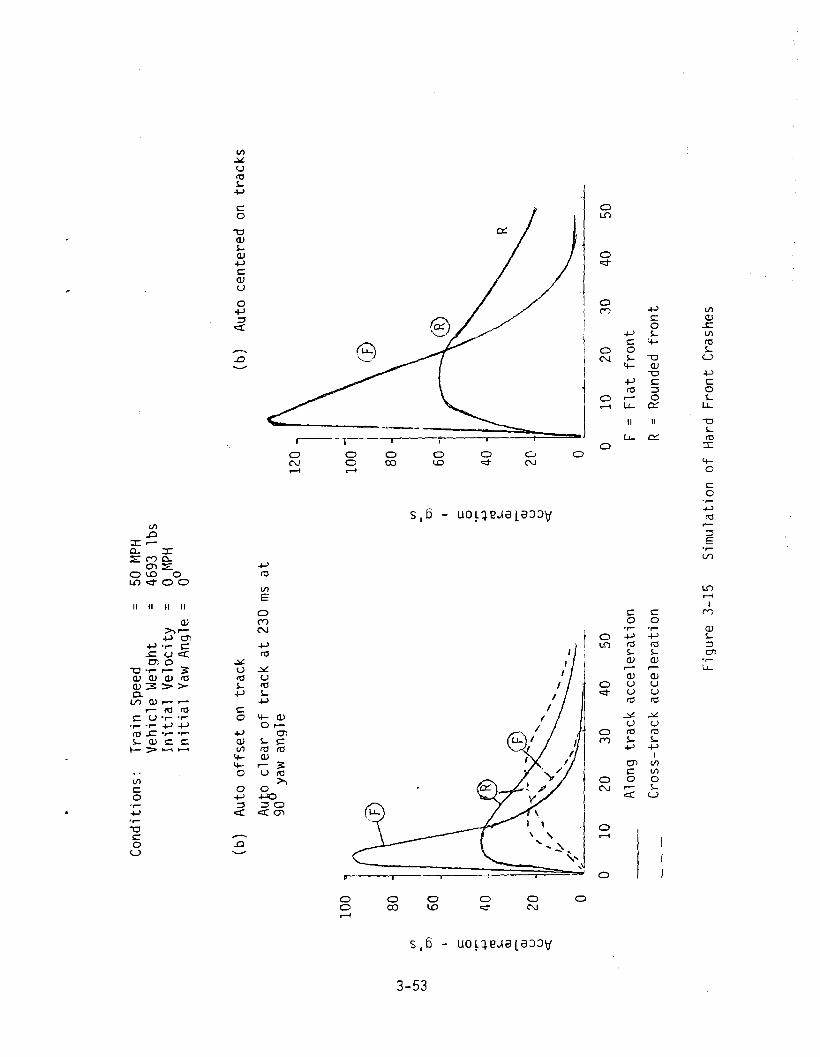
Conditions:
TrainSpeed
=Vehicle
Weight
=InitialVelocity
Initial
YawAngle
=
50 4693
1bs
aMP
H0°
W IIII
U1
-W
0) I c: 0 .,....
+-'
ttl s- <lJ - <lJ U U ce
(b)
Auto
offset
ontrack
clearof
trackat
230
msat
90yaw
angle
100
i
80j
60j
401
20"'
,; 1/
/'
01-:-'-
___
,.
010
2030
4050
Alongtrackacceleration
Cross-track
acceleration
(b)
Auto
centered
ontracks
1201 I ...
100!I
\CDj.
80III
0)
60c: 0 ,.... +-'
40ttl s-
III
\,
R<lJ r- <lJ
20u u c:r.:
0----
-_....-------
010
2030
4050
F=Flat
front
R=Roundedfront
Figure
3-15
Simulationof
Hard
FrontCrashes

For each automobile position, the rounded front shows a much loweracceleration peak, and a longer duration of the period of acceleration.The centered automobile reaches a forward speed of 45 mph at time 25milliseconds with the flat front, and at about 53 milliseconds with therounded front (see runs N-2 and N-5). The 45 mph speed is nine tenthsof the locomotive speed and thus represents the end of the major along-track acclerations. However, the reduces acceleration with the roundedfront is accompanied by a greater penetration depth of 1.37 feet at 25milliseconds, versus 0.88 feet for the flat and 1.84 feet at 50milliseconds versus 0.94 feet. Primary impact injury increases withpenetration depth secondary impact injury grows with acceleration.
The lower acceleration with the rounded front is the result of themodel used Which makes the force between the vehicles proportional tothe rate of crush of volume, which is in turn the product of the cross-section of the contact area, and the relative speed. The flat frontalmost immediately engages a large area of the automobile side, producinga large force and acceleration. The rounded front has the same relativespeed at first contact, but engages a much smaller area. For an encounterwith a homogeneous body, this model is probably relatively realistic, butin a crash with a rigid locomotive front the yielding automobile body isfar from homogeneous. In fact, a sheet metal skin covers a structure ofdistinct members, with separated lateral stiffening structures, and thesestructures determine how the vehicle yields.
In light of the difficulties encountered in modeling cross-trackacceleration, and of the drastically different coefficients of forceused for the along-track and cross-track components, there is little tobe gained by drawing conclusions from the cross-track motion in thesimulation. An additional problem came from the fact that the longitudinalautomobile accelerations in the crash were frequently not easilyreadable from the figures of reference 2-1. The simulation coefficientswere chosen to match the one curve that was most easily readable, whichmay not have been typical, and also to match approximately the behaviordescribed from the photographic record. Consequently, it appears that anyconclusions should be based on the along-track motions only, for theseappear relatively consistent and are satisfied by simple and relatively
3-54

realistic equations ',_
3.3.10.5 Summarization
A rounded front appears to offer some significant reductions inautomobile accelerations in a hard front collision. The rounded frontrequires deployment with a larger and probably more complex mechanismthan the simple flat front, and has the probable drawbacks of increasingthe number of accidents. Compatibility with anti-climbing mechanismsis necessary for both flat and rounded fronts, and may present more problemswith the rounded front, simply because it involves more material. Thematerials and techniques involved are conventional and familiar to therailroad industry. Both devices should prevent impalement of a struckautomobile on the coupler.
A serious problem may appear with long deflectors. This is theprobabilitY,discussed in Appendix C, that increasing the length of thelocomotive by extending the front forward, will cause an increase in thenumber of accidents. A particular class of accidents, where drivers attemptto cross in front of a consist they know is moving, is affected. and canbe affected quite seriously. The increase in accidents is approximatelyproportional to the deflector length.
3-55

3.3.11
3.3.11.1
The Water-Jet Collision Attenuator
Description and General Discussion
This collision attenuator was considered in an unpublished study byMinicars, Inc., and a preliminary design was presented. Figure 3-16,extracted from this study, illustrates the concept. A supply of water iscarried on board the locomotive for use, in water-cannon fashion toaccelerate a vehicle which is in the locomotive's path. The goalis either removing the highway vehicle from the right of way before thelocomotive arrives, or accelerating the vehicle to make the collision withthe locomotive less violent.
The system is "ac tive", i.e. it requires automatic actuation when acollision is imminent, by a signal from a radar detection subsystem whichsenses the presence of the highway vehicle on the right of way. In thedesign illustrated, the water is stored in five tanks of 15 cubic feeteach, and released through five nozzles which point forward. Energy todrive the water is provided by a 200 cubic foot tank of compressed air to250 psi. Actuation is accomplish by explosive rupture of a diaphragm bymeans of a pyrotechnic device (blasting cap). If the locomotive is tooperate in a freezing climate, presumably a calcium chloride solution orother non-freezing solution would be used. Water exit velocities of up to150 feet per second are achievable with such pressures if the cross sectionof each nozzle is about 0.5 square foot. With five nozzles, the releaserate of 375 cubic feet per second corresponding to a 150 feet per secondnozzle velocity would provide a spray of 0.2 second duration. Presumablythe spray would be released at an initial distance of between 20 and 50 feetfrom the automobile; the range could be adjusted to depend on train speed.
The concept is of interest since in effect it constitutes a very longand very soft attenuator. The momentum of the water is transferred to theautomobile while the automobile is still at a considerable distance fromthe locomotive. This allows time for removing the automobile from the
3-56

------------
-----
W I U1
-.....J
.Figure
3-16
PROT
OTYP
EWA
TERJET
ATTE
NUAT
ORSY
STEM
INSTAL
LED
ONLO
COMO
TIVE
(Reprintedfrom
studyfor
FRA
byMinicars,
Inc.)

tracks or bringing it up to a speed along the tracks which minimizes theeffects of the actual collision. Because of the system's implicit positionas the "gentlest" of possible attenuators, it was decided to simulate it,so that the results could be compared to those of other simulations. Thesimulation is discussed before the system characteristics are evaluated.
3.3.11.2 Simulation Model
The water is assumed to be emitted in a stream spread uniformlyacross the locomotive front's ten foot width. The stream retains itsoriginal nozzle velocity and remains in a ten foot width without spreadingout. Two nozzle velocities, 150 fps and 110 fps, were used; the actualwater' velocity is the sum of the locomotive velocity and the relativenozzle velocity. Two locomotive speeds, 40 mph and 80 mph, were used.The height of the stream is assumed to be such that an automobile interceptingany horizontal segment of the stream receives all of water passing throughthat segment. This corresponds to the water stream remaining at a heightwhich meets the automobile sides, e.g. between about 10 and 36 inches.These assumptions give the system maximum effectiveness acceleratingthe automobile.
Upon contact with the side of the automobile , the water transfersto the car all the momentum due to its velocity component normal to theside. The velocity component parallel to the automobile side is presumednot to affect the automobile, i.e. the water simply rolls along the side.The, automobileis modeled as a homogeneous body with no width, a center ofgravity 40 percent from the front end, and uniform densities in front ofand behind the center of gravity. The length is 15 feet and the weight3200 pounds, except for one run in which a weight of 5000 pounds was used.The automobile is initially either at rest or moving at 25 mph to the right;its longitudinal axis makes an angle e with the x axis (perpendicular tothe tracks), of either 00 or 300 , positive a being a counterclockwisemeasurement from the x axis to the automobile axis. Two of the runs includeda simple model of friction between automobile and ground.
The automobile center of gravity was located in either of three
3-58

positions. in front of either the left side. the center. or the right sideof the locomotive. Time t=o occurs when the water first contacts theautomobile. at which time it is 40 feet from the locomotive. This meansthat the water was initially between .267 and .364 second. earlier.depending on the nozzle speed. At that time. depending on its speed.the locomotive is between 55.6 and 82.7 feet from the automobile.
Equations of the simulation are presented in Appendix A. and resultsin Apoendix 8.
3.3.11.3 Attenuator Performance
Table 3-3 summarizes results of 14 simulation runs. In most caseswhere the automobile was not centered on the tracks. it clears the trackbefore the arrival of the locomotive. The acceleration levels are modestand survivable; the highest acceleration of 19.2 g occurring in one casewhere the automobile is centered on the tracks and the train is moving at80 mph. Collisions occur in both runs where the locomotive speed is 80mph. and also in the cases where a friction coefficient between groundand automobile was used. Otherwise. the automobile was clear of the tracksbefore the arrival of the train.
The apparent good performance in the simulation runs should be subjectto some words of caution. First. as indicated earlier. the model favoredthe system performance by assuming that the water stream neither divergednor slowed down; both assumptions are not very realistic at release distancesof between 55 and 80 feet. In addition. it was assumed that the automobilereceived the full stream of water it intercepted. and all the momentum inthe water at a direction normal to the siae of the car. In fact, much of thewater is likely to pass under or over a typical automobile, and themomentum transfer may not be total. However, other considerations applyingto the water jet system will determine whether or not it is acceptable.For the moment. the runs provide boundaries on a attenuator performancein the sense of attenuator lilength" (range at water release), andacceleration levels.
3-59

TABL
E3-3
SIMUL
ATION
RESU
LTS,
WAT
ER-JE
TAT
TENU
ATOR
RUN
DURA
TION
OFWA
TER
FLOW
(seconds)
MAX,
AUTO
,INITIAL
ACCE
LERA
TION
AUTO
**AL
ONG
TRAC
K(9'S)
LOCA
TION
(ft)
INITIAL
AUTO
SPEE
D(mph)
INITIAL
TIME
WHEN
AUTO
AUTO
CLEA
RSDIRE
CTION
()
TRAC
K(seconds)
LOCO
MOTIV
ESPEE
D(mph)
W-l
.210.9
+10
00
8sec
40
·W-IF
.210.6
+10
00
maynotc1ear
40
W-2
.27.6
+10
030°
1.7sec
40
W-3
.29.8
+10
250
.2sec
40
W-4
.28.5
025
0.45sec
40
*W-5
.25.6
025
0.5
sec
40
.27
5.6
025
0.6
sec
40w I
300
(j)
W-7
.211.4
025
1.25
sec
a
"'W-7F
.211.4
a25
30°
collision
40at
1.58
sec
vi-8
.24.8
00
30°
.3sec
40
W-9
.29.2
+50
30°
.45sec
40
vi-l0
.212.0
+525
0.25sec
40
.219.2
+50
0collision
80at
1.261sec
,"",
,
.27
14.1
+50
0co
11ision
80at
.32sec
•Acrudefriction
model
wasused
intheseruns
*Au
toweight.5000
1bs.
Forallotherruns,weightis
3200
pounds
**Distancefrom
locomotiveleft
side
toautomobile
center
ofgravity

Consider first the performance in the emergency pre-collisionsituation. The water jet may indeed remove an automobile from thelocomotive path or reduce the collision severity in the simulationconditions, but there are several additional factors to consider. Firstis that the water stream may actually trap pedestrians or persons escapingfrom the automobile in the locomotive path. A person between the auto-mobile and locomotive would be driven into the automobile by the water.A person on the other side Of the automobile would probably lose hisfooting, and then be swept down track, ultimately to be struck by thelocomotive. If automobile windows are open, persons in the automobilemay be injured by the water, or may claim to be injured.
If the automobile is ultimately struck by the train, it can be claimedthat it would have escaped without collision had not the water jet beenactuated. If there is no collision, the same claim may be made for anyproperty and personal damages, including psychological trauma. The operationof any remote acting system always opens the question of what might havehappened had the device not been actuated, and invites litigation. Thisis one of the indirect effects listed among the evaluation criteria inSection 3.2; the occurrences described in reference 3-2 indicate that suchlitigation does actually occur. Finally, there may also be cases where nocollision would have occurred had the water jet not been actuated, in otherwords, where the collision is actually caused by the system, even though thesimulations do not identify any such cases.
With an active system, there is also always the possibility that thesystem does not function when it should, or malfunctions in some way. Forexample, the radar may malfunction and not provide the actuation signal atthe proper time, or at all. Actuation at the wrong time could indeed createa collision when none would have occurred. There is also the possibilityof the blasting caps failing to explode to release the water, and possibilityof blockage of or damage of the nozzles by debris encountered during travelor by vandalism. Finally, the influence of the water jet on the vehicle alsodepends on the shape of the vehicle; a jet that is effective against an
3-61

automobile may be ineffective against a van, and conversely.
The preceding problems are enough to create serious doubt aboutthe overall system effectiveness. To these must be added the problem ofinadvertent actuation of the system (either unintentially or by intent,through vandalism) and the potential damages and injuries created bysuch actuation. The radar system must also be protected against actuationby the transmitter on another locomotive approaching on double tracksystem, and against the reflections from a passing train. Such protectionis possible, increases system complexity and cost. Finally, attemptsto actuate the! system would be attractive to juveniles interested in thedisplay and in vandalism.
Consider next the problems of maintenance and inspection duringroutine operations. Police radars, which are admittedly different sincethey are doppler devices, are normally calibrated daily before use. Asimilar checkout before each trip is probably for the complexwater jet system, to determine that an actuation signal will be emittedin the proper circumstances, and at the proper range. Note that suchcheckout only check subsystems up to the point of firing the blastingcaps, and that a separate inspection of the nozzles would be needed. Asignificant amount of time would be required for checkout, with correspondingcosts. In addition, the blasting caps would require periodic replacementas they age.
The Minicars study also mentioned the possibility of a system whichcould detect automobile velocity and which could swivel the nozzles todirect the water stream so as to move the vehicle off the track. Sucha system would require a complex and expensive scanning radar, and acomputer and servo system for the nozzles. To keep such a system workingwould require a very high level of maintenance and would be extremelyexpensive, as would be the initial cost. Such a system is totally out ofthe range of practicality for any sort of economic railroad operation.
3-62

In addition, the cost estimates for the water jet system included afigure of $15 per year for total maintenance and operating expenses ofeither the water jet system or the more complicated "steered water jet"system just mentioned. This estimate is probably low by several ordersof magnitude.
Consequently, the water jet system is dismissed from furtherconsideration as impractical.
3-63

3.3.12
3.3.12.1
Crushable Collision Attenuators
Description and General Discussion
In the unpublished study done for FRA, Minicars Inc. examined theconcept of a crushable attenuator aimed at controlling impact forces onthe automobile. Attenuators of lengths up to ten feet, capable of beingstowed permanently on locomotives and deployed into position of use whenthe locomotive was used in lead position, were given some preliminarydesign studies. Longer separate attenuators with their own wheels,capable of being articulated or coupled to the locomotive, were alsoconsidered. The studies included examination of choice of materials,and two kinds of honeycomb were selected for the initial design concept,paper for a very soft easily crushable front section, backed up by afirmer aluminum honeycomb. The design goals were to hold the initialcontact forces with the automobile to a level of 10,000 pounds, to befollowed by forces rising to a peak of 110,000 pounds. The risingforce curve was obtained by varying the cross-section of the aluminumhoneyccmbalong the length of the attenuator. Figures 3-17 and 3-18,reprinted from the Minicars study, illustrate the deployable attenuatorconcept.
In its crashworthiness study performed for UMTA (2-5), Cal span Corpexamined similar crusBable attenuators to reduce injuries in. collisionsbetween passenger cars. Various lengths between 8 feet and 50 feetwere considered, with the shortest version being cantilevered to the car,the intermediate lengths articulated through the coupler, with one truckon the attenuator, and the longest version an attenuator with two trucksthat couples to the car. Since the design goal was to absorb the energyof an eight car train at speeds in the twenty to thirty mph range, thematerials proposed had much higher yield points than the automobilecollision attenuator. the concepts were the train-to-train collision attenuator concept emphasized the anti-climbing problem.
3-64

i _
I
..
Scale 1/87
Figure 3-17 LOCOt10TIVE-TO-AUTOMOBILE RELATIONSHIP--DEPLOYED CAD(Crushable Attenuator)
Reprinted from study for FRA by t1inicars, Inc.3-65

.""_....
)-](
I ;'j
3-66
f- u0- CW .......UZ0 VlU !-
ro:z: uC.!J or-....... CUi or-W ::ECl »Cl .D
.C::(U c::(
0::LL L.L0
!-Ui 0Z 4-0 »Ui -0Z ::::lW +oJ::E Vl.......Cl E
0U !-....... 4-Uic::( -0o:J OJ
+oJC
C() !-....-< 0-I OJ
M 0::
OJ!-::::lenLL

! -
Minicars in its study chose the illustrated design for their mostdetailed effort. The deployable device, shown in stowed position infigure 3-19, is shaped to permit access from one locomotive to anotherdespite the presence of stowed attenuators on both locomotives. (Suchaccess will not be available if proposed new standards require closingand considerable strengthening of the access doors at the end, to preventflammable fluid entry.) The materials used were selected for structuralsuitability, cost, and availability, and consideration was given to properweatherproofing and protection from collisions with small pieces of debrisalong the right of way. The arguments are not repeated here, ratherthe concept is accepted as reasonably effective and some simulation runsare made. Minicars also reported on the results of somewhat similarsimulations accomplished in its study. The simulation results would provideinteresting comparisons with those for the extremely "soft" water-jetattenuator.
The effectiveness of a soft collision attenuator in reducing injurieswill be discussed after the simulation procedure is outlined. Clearlythe soft attenuator can potentially provide a milder collision environmentthan a hard face deflector. There may be questions of effectiveness andof potential problems in collisions, depending on the design.
In addition to behavior in collisions, the requirement and performanceof the attenuators in normal operations must be considered. The cantileveredhoneycomb attenuator is stowed in vertical position on the locomotive front.A horizontal cross section of the stowed configuration is shown in figure3-19; the attenuator must be lowered into the operating position (fig. 3-17)on the lead locomotive before each trip. After the trip it must be stqwedback in the vertical position. The durability of the device is presumablyachieved by suitable design procedures, some of which were discussed byMinicars. Thus the operationa'l characteristics are accepted as satisfactory.No other operational problems are known at present.
3-67

----
Figure 3-19 CAD in Stowed Position, Plan View(Extracted from Minicars, Inc. study)
3-68

The long attenuator with wheels must be attached to the locomotivefront, either through the coupler or other attachment points, before eachtrip, and detached and stored afterwards. The same methods used toensure durability of the deployable attenuator can be applied to thisversion. However, another problem appears for the wheeled attenuator,which must be light in weight if it is to serve effectively to reducelnJuries. The light weight may make the attenuator very subject toderailment, particularly since the articulation to the locomotive maysupply additional vibratory excitations beyond those imposed by railirregularities. Attenuator derailments imply stops and delays for theconsist, and may also frequently imply destruction of the attenuator.Thus this attenuator would be acceptable only if relatively free fromderailment problems, but no information on behavior of such a device hasbeen located in this study.
Aside from the problems in normal operations mentioned above, thereis a question of behavior in other emergency situations, notably train-to-train collisions. Compatibility with anticlimbing measures is the principalrequirement and should be achievable by suitable design measures, butcould conceivably require modification of the anticlimbing system in somecases. Since there are now no standard, universal, anticlimbing systemson locomotive fronts, this does not appear to present a problem.
3-69

3.3.12.2 Crash Force Models
With the crushable attenuator, the automobile is assumed to beinfinitely rigid for simulation purposes, and the attenuator instantaneouslyconforms to the automobile shape. In interpreting results, the automobilecould be assumed to have yielded also, perhaps in proportion to theattenuator yield, with the relationship established by some sort of yieldlevel or stiffness factor.
In its simulation work, Minicars was able to express force exertedby the crushable attenuator solely in terms of the crush distance, becausethe materials and cross section had been chosen to produce selected forcevalues. The choice of materials fixed the yield pressure, and the crosssection, which was varied, determined the area and total force. Thefirst three feet of crush material was paper honeycomb with a yield pressureof 5 psi and a total cross section that could produce a 10,000 pound forceat the yield point. The next five feet involved aluminum honeycomb of50 psi yield strength, but with cross section increasing from front torear, so that force exerted increases from 10,000 to 110,000 as theattenuator is crushed. The final foot of crush remained at 110,000 poundsyield force.
The simulation in this study was simplified by assuming a constantcross section of uniform material, and the results were supplemented by ananalytic study which allowed variable cross section and determined relation-ships between some of the variables involved. The analytic study assumedthe be shaped like a horizontal truncated pyramid with squarecross-section and straight line taper from front to rear. In both simulationand analytic study, the material yield point is assumed to be exceededimmediately upon contact, and the forces are assumed to remain at the yieldpoint level until the vehicles have the same forward velocity or start to"move apart, at which point contact forces drop to zero. Equations forboth the analytic model and the simulation are presented in Appendix A;the simulation program and tabulations of runs appear in Appendix B.
3-70

The analytic study covered only the case of an automobile whichremains centered on the tracks without rotation or motion.In this case the automobile remains in contact with the full cross-sectionof the attenuator throughout the collision, and the force is the productof the contact area and the yield pressure of the material, until thefinal moment t = t f when the automobile reaches the same speed as thelocomotive and force ceases. (No friction with the ground is assumed.)The same force model is used in the simulation, except that the contactarea varies with the automobile angular position, and the force ispresumed normal to the automobile side. In the few simulation cases wherethe complete length of the attenuator is crushed. the force on the auto-mobile is assumed to be a linear combination of the crushable attenuatorforce model and the hard front locomotive force model.
3.3.12.3 Analytic Study and Simulation Results
IThe analytic study expressed maximum depth of crush (df ) of the
attenuator in terms of three quantities - locomotive speed (vL) andinitial and final accelerations (gI' gF)' Final acceleration occursat the time t f when the automobile reaches the same speed as the locomotive,initial acceleration at time of first contact. Relating the two accelerationsto attenuator characteristics and automobile mass permits interpreting theinitial results in terms of performance goals or guidelines for the attenuator.The formula expressing the relationship is:
1. 5VL2 1dF = 32.17 gF + V (3-1)gfg· + g.1 1
where df is expressed in feet, VL in feet/second, and gf and,gi in gis,with 9 = 32.17 feet/second 2. Figure 3-20 shows plots of this relationship,in the form of a set of curves, with the initial and final accelerationsas the abscissa and ordinate, where each turve represents some combinationof values for df and VL. Each curve begins where initial acceleration gris zero (corresponding to a pointed pyramid .. 'attenuator) and ends whereinitial and final acceleration are equal (corresponding to a constantattenuator cross section). For example, one curve represents a penetrationdepth of df of 8 feet and a locomotive speed VL of 50 mph. At one endof the curve a final acceleration of 32 9 is required, at the other end
3-71

____ -.1,,II
--,,,---- --I
4
- ..
:1---' -,
- j -_:-- - t-! ,1
III
,4 L
,L
- .... - ----- - --W- -
I1- --- - -l- -- ------- --:-
f -------- - ----,9 __ +- ..... ,. _
L________ _ __:1
l _l
3 +_ -=-3-=--0--Ar-
r-
---;-o
:::- ....--i:1J_ u-
----------------U------ ---c;:c
--
-
j.
'''-'"
3-72

a uniform acceleration of 10.5 g keeps the total crush depth to 8 feet.The same curve could equally represent behavior with a 25 mph locomotiveand two foot crush depth. or 35 mph speed and 3.92 foot depth.
The parameters considered thus far, acceleration and attenuatorcrush depth, are important to injury rates in accidents, and to theattenuator geometry. The relationship above (3-1) admittedly is derivedfor only the case of an automobile centered on the track, and does notcover the collision with an offset automobile, but it is still usefulas a guide. The simulation can help explore the behavior for the offsetcase. However, formula 3-1 permits selecting a range of survivableaccelerations and relating it to an attenuator length for a range ofspeeds. Attenuator length is a factor influencing acceptability of thesystem to the railroads. The speed ranges of importance will be consideredlater under the subject of benefits and injury models; what is importantis to influence a statistically important part of the total number ofaccidents involving casualties.
Note that the parameter represents a maximum crush depth in, I
certain speed and acceleration conditions, but is used also as the totalattenuator length, if one the pdstulated conditions to be themaximum the attenuator will withstand. Note also the assumption thatuntil the final time t f , the attenuator is always yielding at its crushyield point.
When turning to the question of automobile and attenuator characteristics,the desired goals in acceleration and crush distance must be translated intofeasible and practical attenuator materials, sizes, and constructionpractices, and into a design that satisfies the goals for a satisfactorystatistical part of the automobiles and other vehicles which will be encountered.The criteria now are forces, which for the attenuator involves materialyield point and cross section, and which relate back to the accelerationsthrough the highway vehicle mass.
3-73

The relationship can be illustrated by an example. For instance,suppose it was decided that acceptable acceleration levels were 6 g initialand 24 g final acceleration, and that the attenuator should be completelyused up, or crushed, by a 4,000 pound automobile in a 50 mph collision.The curves of figure 3-20 imply a 6 foot attenutor length, and theattenuator yield point and cross section can be matched to these requirements.
Obviously, at 50 mph a 5,000 pound vehicle will completely crush thisattenuator and will sustain higher accelerations when it meets the rigidattenuator backing. On the other hand, a 3,000 pound vehicle will beaccelerated to locomotive speed before the material is to a depthof 6 feet; in this case initial acceleration will be higher because of thelower mass of the automobile. The crush depth for this case can becomputed using the formula given in Appendix A. For the case cited,a 40 psi crush point material would require a pyramid 2.04 feet on theside at its tip and 4.08 feet at the base; the 3000 pound automobile wouldhave a crush depth of 5.04 feet. The initial acceleration Yr variesinversely with the automobile mass, it will therefore be 8 g. The finalacceleration can be read from figure 3-20 by interpolating to a curve wheredf is 5.04; it is 27.1 g.
Note that the pyramidal attenutor shape was chosen only for computionalconvenience, and is not a recommended design shape; the Minicars studypresented arguments in favor of an increasing acceleration level, and thisshape is adaptable either to a uniform or an increasing cross section.
The analytic results discussed so far pertain only to the collisionwhere the automobile is centered on the tracks and does not rotate; theyalso do not cover the cases where the full length of the attenuator iscrushed, either on one side or along its full cross section. The simulationaddresses these situation, although it is limited to a uniform attenuatorcross-section, assumed to be ten foot wide and three feet high, with threepossible yield levels of 5.0, 7.5, and 10.0 psi. These yield levels arenot practical for aluminum honeycomb, although they might be achievable withpaper honeycomb. One could think of the 30 square foot cross section asa broad front which contacts the automobile, backed up by a much smaller
3-74

cross section of material with a higher yield point, such as aluminumhoneycomb. Paper honeycomb is structurally suitable for only a modestdepth and load.
As indicated earlier, the automobile ;s assumed to be infinitelyrigid, and the attenuator instantaneously conforms to its shape. Theforce is proportional to the contact area between the two bodies, andperpendicular to the side of the automobile. If only part of the auto-mobile is in contact with the attenuator, the equations reflect the areaengaged. The locomotive and attenuator move at constant speed with infinitemomentum; when the automobile reaches the locomotive speed, force ceases.
When the automobile penetrates the full depth of the attenuator, theforce formula becomes a linear combination of the hard-front contactformulae of Section 3.3.10 and the crushable attenuator formula, with aweighting factor depending on the relative areas engaged.
Tables A-I to A-II of Appendix B present the results of elevensimulator runs; with material yield points of 5.0, 7.5, and 10.0 psi,train speeds of 30 and 50 mph, mostly with a 3000 pound vehicle 16 feetlong and 5 feet wide, and initially at rest perpendicular to the tracks.The vehicle center of gravity is either in front of the left edge of theattenuator, or three feet to either side of that location. For threeruns a larger vehicle matching the crash test sizes was postulated -4693 pounds and 18.6 by 6.6 feet. Table 3-4 and Figure 3-21 summarizesome features of the simulation results, the table showing all the runsand the figure showing accelerations for a few runs, all with the samevehicle weight and initial location.
The modest acceleration levels reflect the relatively low yield pointspostulated for the material, and are generally comparable with the accelerationsshown in the water-jet simulations. With the low yield point used, for allbut one run involving a 50 mph train speed, the attenuator was crushedthrough its complete 10 foot depth. The exception was one run with a 10psi yield point material. At 30 mph in general the attenuator did notcrush through its complete depth. Complete crushing led in some cases
3-75

**MA
XIMUM
FORC
E(PO
UNDS
)RU
NMA
TERIAL
YIEL
D(PSI)
TABL
E3-4
SUMM
ARY
OFSIM
ULAT
IONS
OFCR
USHA
BLE
ATTE
NUAT
ORCO
LLISIONS
ATTE
NUAT
ORINITIAL
AUTO
LOCO
MOTIV
EMA
X.AC
CELE
RATION
(G)
CRUS
HED
TOC.G.
LOCA
TION
(FT)
SPEE
D(M
PH)
ALON
GTR
ACK
CROS
S-TRA
CKEN
D
AUTO
CLEA
RBF
TRAC
K90
ROTA
TION
A-I
1031.100
050
10.8
-l3eg
NoNo
A-2
7.5
23,300
050
8.2
-9.5
Yes
No
A-3
7.5
32,400
+350
10.8
-7.3
Yes
No5.4
A-4
5.0
15,600
050
(21.1)''''
-5.2
Yes
NoYes
A-5
5.0
15,600
030
5.4
-7.9
(Corneronly)
Almost
A-6*
7.5
27,100
050
6.1
-8.3
Yes
Almost
Yes
A-7*
10.0
36,200
050
8.2
-12.1
(CornerOnly)
Almost
0.1
3.3
I .......
A-8*
5.0
9,100
-350
(43.5)·
-1.8
Yes
Yes
O't
A-9
7.5
23,300
030
8.2
-5.0
NoNo
A-10
7.5
13,600
-330
4.9
-3.1
NoYes
A-ll
7.5
32,400
+330
10.8
-2.0
NoNo
Autom
obile
-3000
pounds,16
feet
long,5feet
wide,
except
anoted
*Runs
A-6,A-7,A-8-5,000pounds,18.6
feet
long,6.6feet
wide.
Autom
obile
initiallyat
rest,perpendicularto
tracks,center
ofgravitylocation
measured
from
left
edge
oftrain,
positive
toright(intotrainpath),
negativ
eto
left.
Attenuator
10feet
wide
by3feet
high,10
feet
long.
**Based
onactual
area
incontactwith
automobile,
before
bottomingout.
Observedafterbottomingout.

Conditio
ns:
AUTavlO
OILE
INITIALLY
ATRE
ST}
PERP
ENDIC
ULAR
TOTR
ACKS
C.G•
INFR
O'JT
OFLE
FTED
GEOF
LOCa
vlaTI
VE•
WEIG
HT:50
00LBS.
TRAIN
SPEE
DSJU
MPH
AND30
MPH
.AT
TENUAT
ffiYIELD
LEVE
LS:
5,0}7,S
}10.0
PSI
Accelerationalongtrack(g's)
Accelerationnormal
totrack(g's)
20
o50
100
150
200
TIME
(MSEC)
A-4
A-5A-2
A-9
RUN
10.0
A-I
50100
150
200
TIM
E(M
SEC)
o4o o1620
endofattenuator
5.0
7.5
---
10.0
481216
LV I -...,J
-...,J
50mph
locomotive
30mph
locomotive
FIGU
RE3-21
SIMUL
ATION
RESU
LTS
-CR
USHA
BLE
ATTE
NUAT
OR

to a much higher acceleration when the automobile met the rigid platebehind the attenuator. Naturally, increasing the yield force raisesthe acceleration and reduces the depth of penetration.
In an effort to provide a comparison with the crash tests, wherethe off center automobile cleared the locomotive path at about the timeit had rotated through 900 , the table provides for each run informationas to whether or not the automobile was clear of the right of way at thattime. In general, it is not, unless the automobile was offset to the leftinitially, in which case only 4.2 feet of the car extend into the locomotive'spath. However, these results should be viewed with caution, since theydepend completely on the cross track acceleration of the automobile.This in turn depends on the assumption that the force exerted by the atten-uator is normal to the side of the automobile. Such an assumption appearsto be more reasonable for a crushable attenuator than for a collision ofhard surfaces, but it is still unverified by experiment or detailedanalysis. Consequently, the results on lateral motion are consideredto be very tentative.
The simulator results overall indicate that the crushable attenuatorcan significantly reduce the automobile acceleration levels in a collision,even with use of a design much stiffer than those postulated in thesimulator runs.
3.3.12.4 Summary of Attenuator Effectiveness
If one accepts the results of the Minicars study, adequate and effectivematerials are and designs which are potentially effective inreducing injury at various speeds are also available. These designs arethose which involve an attenuator which is cantilevered in front of thelocomotive. The acceptability of a design may depend on its size and onthe inconvenience of deploying the attenuator into position of use, andon any perceived inconveniences or defects of the device in normal operations.Generally, the smaller and simpler the device. the more reliable andacceptable it should be. Such a device should also be able to be madecompatible with other safety devices (such as anticlimbers) on locomotives.
3-78

with little or no difficulty. Simulation results indicate that a variety ofdevices, aimed at different speed ranges, are feasible and can be effectiveat injury reduction.
On the other hand, for the MU car, where anticlimber provisionsare extremely important, the cantilevered attenuator which reduces injuryfor highway vehicle occupants will do nothing to protect rail passengersin collisions with heavy trucks, other consists, or fuel trucks. Therelative importance of train-to-train collisions suggests that any attenuatorsused for MU car should be aimed at this situation. In particular, anattenuator aimed at highway collisions, which interferes with anticlimbersin train-to-train collisions, must be avoided at all costs. Hence thedevice seems to be at best dubious for application to MU cars, and isnot recommended. The devices studied by Calspan Corp. for UMTA seem moreappropriate.
There is finally the long crushable attenuator equipped with itsown wheels, which can be articulated to the locomotive. The seriousproblem of keeping such a long and light device from derailing must bestudied or tested carefully before such a device can be considered effective.The acceptability of the need to articulate the attenuator to the leadlocomotive before each trip, and detach it afterward, must also beinvestigated. Although the individual accident can probably be significantlyreduced in severity by such a device, the increase in accidents which wouldprobably occur because of its great length must be taken into account. Thisincrease, discussed in Appendix C, occurs because drivers who attempt tocross in front of a moving train frequently misjudge thesituation and are hit by the train or hit the lead locomotive or car. Theincrease in such accidents varies with the length of the extensions, in themodel created in Appendix C, and would be very serious with an attenuatorwhich is twenty feet long. This same increase must also be taken intoaccount with the shorter collision attenuator, and the eight foot lengthused for the calculations of Appendix C indicates potentially serious problems.
3-79


4. Benefit Estimation
4.1
4.1.1
Statistical Basis and Injury Models
Injury Statistics
Any estimation of benefits of a procedure must be based on historicalor present damages or costs, and must proceed from that information to theestimates of the anticipated reductions due to the measures considered.The injury information is contained in the FRA accident record files, andan annual summary is published in the Rail-Highway Grade-Crossing Accidents/Incidents Bulletin. As indicated earlier, there has been a quite steadydecline in fatalities from 1966 to 1977. Fatalities, injuries, and numberof reported accidents all decreased rather uniformly from 1966 to 1974.However, in 1975 there was a change in the reporting procedures, so that allgrade crossing occurrences were reported, rather than only meetingthe earlier reporting criteria. While fatalities continued to decline,on the new reporting basis the number of occurrences was tripled in 1975,and increased by about ten percent from 1975 to 1977. The number ofinjured also increased by 28% from 1974 to 1975, and by another 11.5% from1975 to 1977. Thus total number of casulties actually increased from 1966to 1977, (which may partly be due to the reporting method change), and seemsalso to have risen since 1975. Of course the number of highway vehiclesregistered and miles driven also increased, by more than 80%, during thisperiod, while the number of train miles decreased by 16.2%.
Table 4-1, presenting the casualty figures for 1977, is derived fromthe FRA bulletin for that year, and can form one of the starting points forthe study. The table separates the occurrences where the highway vehiclestruck the train, for no practical means of protection of highway vehicleoccupants in such circumstances was identified. The question of trainoccupants in such collisions is examined separately below, and also turnsout to be neither s'..:atistically important nor affected bv the devices
considered in this study. For the moment, it is ignored here.
4-1

TABL
E4-1
CASUA.LTY
IMPO
RTAN
CEOF
VARIOUS
EVEN
TS1977
Statistics
HIGH
WAY
OCCU
PANT
TRAIN
STRIKES
HIGH
WAY
OCCU
PANT
HIGH
WAY
VEH
ICLE
STRIKES
TRAIN*
Occurences
Fatalities
Injuries
Occurences
Fatalities
Injuries
PEDE
STRIAN
114
7044
Al.J'I'OIDBILE
6,102
477
2,234
2,433
100
1,031
+::>
BUS
316
561
00
I N
TRUC
K2,371
185
766
818
54330
rvuIDR
CYCL
E24
61
6918
37**
MISCE
LLAN
EDUS
336
28150
TOTA
L8,978
772
3,251
3,321
172
1,398
*No
practicalcounterm
easuresidentified
**Notclassified
asto
trainor
highway
vehiclestriking
This means that of the 12,299 accidents. only 8,978. or 73.0%. aresubject to proposed injury reduction methods. and only 81.8% of thefatalities and 69.9% of the injuries. These figures define the currentstatistical incidence of the problems addressed. an incidence which canvary independently of the injury minimization because of variationsin highway and rail traffic. in number and protection of grade crossings,and in other preventive measures. In the absence of other information. itwill be assumed that the current incidence will remain unchanged. Thusthe figures on the left side of Table 4-1 can be considered as the targetnumber of injuries which are potentially subject to reduction.
Two items in Table 4-1 lead to some immediate conclusions. Thefirst concerns motorcycles, where the number of fatalities caused bymotorcycles striking trains is thrice the number due to trains strikingmotorcycles. Over the last five years of data. exactly 75% of the motorcyclefatalities were due to cases where the motorcycle struck the train. The smallnumber of the remaining cases. averaging 7.4 per year. makes it unreasonableto attempt to do anything to reduce motorcycle fatalities, and thereforethe subject is henceforward ignored.
The bus accidents are also worthy of comment; once again thestatistical incidence is small, with a five year average of 21 incidents oftrain hitting a bus, 8.6 fatalities, and 55.8 injuries. In recent years thebus incidents constitute about 0.3% of the total occurrences of train strikinghighway vehicle, and about 1.0% of fatalities and 1.7% of injuries. Sincethe bus casualties represent only a very small portion of the total, tominimize total casulties the automobile should be given priority over thebus in any measure which might protect occupants of either highway vehicle.A typical example occurs in selection of stiffness for a crushable attenuator;different values are desired for the different masses involved. The smallnumber of train-bus accidents suggests that emphasis on preventive, ratherthan palliative, measures might be more effective. Preventive measuresare not the subject of this study, but examples include selection of busroutes to avoid unprotected crossings. as well as the more conventionalwarning systems, visibility improvements, and driver training.
4-3

The hazards to occupants of a train struck by a highway vehicle canarise either in direct injury by the striking vehicle, or from lnJury ina derailment caused by the collision. Table 4-2 presents some statisticson derailments subsequent to rail-highway collisions, derived partly fromearlier FRA annual Accident/Incident Bulletins and partly from more recent
*automated FRA Equipment Accident file records. Such derailments amountto just above one percent of the total number of derailments, i.e. a veryunimportant fraction. Protection of occupants involves conventional crash-worthiness measures which have no special relationship tocollisions, and benefits and costs would be counted only in proportion tothe incidence of casualties involved. (The annual bulletin provided onlynumber of accidents in this category, not the number of casulties.) Inview of the small statistical importance of these events, no further consid-eration is qiven.
Consider next injuries caused directly by the striking highway vehicle.In two thirds of the cases of a hiqhway vehicle striking a consist, it isa locomotive that is struck. A locomotive structure provides its occupantsenough protection from direct impact by a highway vehicle, and caboosesrarely seem to be struck. Since passenger train derailments, or heavyvehicles striking passenger trains, place a larger number of personnelat risk, they might warrant some special attention. Less than four percentof rail-highway collisions involve passenger trains; if the same percentagefigures hold for the cases where the highway vehicle hits the train, ofthe 3,321 such collisions occurring in 1977, 127 might have involved passengertrains, or 3 or 4 of the resulting derailments could have involved passenger
* The DOT Transportation Systems Center derived the data presentedin this and in subsequent tables, and also provided adviceand suggestions on the selection of data and on specific questionsto be explored.
4-4

TABL
E4-2
*RA
IL-HIGHW
AYGR
ADE
CROS
SING
ACCIDE
NTS
RESU
LTING
INDE
RAILMEN
TS
TYPE
OFAC
CIDE
NTNU
MBER
OFDE
RAILMEN
TSBY
PERC
ENT
****
1977
1976
1971
ACCIDE
NTTY
PEVE
HICL
ETY
PE
TRUC
KSTRU
CKTR
AIN
3234
'2635.6%}-
.TRU
CK78.1%
TRAIN
STRU
CKTR
UCK
3841
3142.5
AUTO
STRU
CKTR
AIN
1112
912.3}-
AUTO
13.7%
TRAIN
STRU
CKAU
TO1
11
1.4
SUDD
ENBR
AKE
.j:::>
APPLICAT
ION
TOI
2.7}
U1
AVOID
COLL
ISIONS
23
2.
OTHE
R8.2
%OT
HER
55
45.5
TOTA
LDE
RAILMEN
TS
TOTA
LNU
MBER
OFAC
CIDE
NTS
89 321
96 339
73 }11
100%
100%
DERA
ILMEN
TSAS
PERC
ENT
OFAC
CIDE
NTS
27.7%
28.3%
23.5%
*AL
LFIGU
RES
BASED
ONAN
NUAL
EQUIPM
ENT
ACCIDE
NTRE
PORT
S
**PERC
ENT
BREA
KDOW
NBY
TYPE
NOT
AVAILA
BLE
FOR
THESE
YEAR
S;1971
BREA
KDOW
NAS
SUMED
.

trains. Such occurrences are thus infrequent, although they have indeedoccurred, for example, in 1975, when a truck struck a passenger train andcaused a derailment. (4-1) The particular incident caused fatalitiesbut 41 injuries resulted primarily from derailment rather than truckimpact. The French-built turbotain involved was not equipped with AARcouplers, the presence of which might have reduced the number of carsderailed. The point is that the injuries were derailment injuries. exceptfor two caused by the gl ass windows broken at impact. In other words,injuries from direct impact seem to be unimportant even in the fpwwhere this occurs.
Tables 4-3 and 4-4, covering the years 1977 and 1976 thestatistics readily available on derailments caused by rail-highway gradecrossing accidents. The annual FRA Accident/Incident Bulletins usedto provide a count of derailments by type of highway vehicle and by \...hetherthe train or the highway vehicle was struck, but by 1975 this informationhad been eliminated. The 1977 and 1976 data were obtained from the automatedFRA Equipment Accident/Incident Reports, by identifying all repor,ts with arail-highway crossing accident type code or collision cause code. Presumablythe count includes all such occurrences; the numbers are consistent withthose from the earlier bulletins. These are the numbers which were usedas the basis for Table 4-1, by assuming that the 1976 and 1977 eventsfollowed the same ratios of automobiles versus trucks and of highwayvehicle striking versus being struck.
These tables presumably cover all, or almost all, cases of derailmentscaused by rail-highway accidents. They indicate that the number of suchoccurrences is quite limited, currently running somewhat below one hundredper year, and that about six percent of these accidents involve consistscarrying hazardous materials, and 1.4 per cent involve derailment or damageto a hazardous material car. For hazardous material accidents, the concern
(4-1) National Transportation Safety Board Report NTSB-RHR-76-2,"Collision of a Crown-Trygg Construction Truck with an AmtrakPassenger Train, Elwood, Illinois, Nov. 19,1975".
4-6

TABLE 4-3
GRADE CROSSING ACCIDENT DATA FROMFRA RAIL EQUIPMENT ACCIDENT/INCIDENT REPORTS, 1977
Group 1: Accident Type = 7, Cause Code = 700.
(1) (a)
(b)
(c)
(2) (a)(b)
(3 )
(4)
(5 )
(6)
(7)
(8)
(9)
(10)(a)
(b)
(l1)(a)(b)
(12)(a)
(b)
(13)(a)
(b)
Total ReportsTotal AccidentsDerailments
**Events involving HMTrains not carrying HM
Trains carrying HM, with no HM cars damagedor derailed
Trains carrying HM, with no HM released
Events requiring evacuation
HM cars
HM cars damaged or derailed
Cars releasing HM
Persons evacuated
Total locomotivesLocomotives derailed
Total carsCars derailed
Total injuries (accident report)Total injuries (injury report)
Total fatalities (accident report)Total fatalities (injury report)
*34132189
22299
14
19
6
98
25
4
2288
830113
16,216489
159290
2593
Group 2:Group 3:
Accident type = 7; Cause code 1 700; Number of reportsAccident type 1 7; Cause code = 700; Number of reports
2a
Accident Type 7 - Rail Highway CrossingCause Code 700 - Collision with Highway User at Grade Crossing
* Two reports are possible for one accident** HM = hazardous material
4-7

TABLE 4-4
GRADE CROSSING ACCIDENT DATA FROMFRA RAIL EQUIPMENT ACCIDENT/INCIDENT REPORTS, 1976
Group 1: Accident Type 7, Cause Code 700
(1) (a)(b)
(c)
(2) (a)(b)
(3 )
(4 )
(5)
(6)
(7)
(8)
(9)
(10) (a)(b)
(11)(a)(b)
(l2)(a)(b)
(13)(a)(b)
Total reportsTotal accidentsDera i "lments
Events involving HM**Trains not carrying HM
Trains carrying HM, with no HM cars damagedor derailedTrains carrying HM, with no HM released
Events requiring evacuation
Total HM cars
HM cars damaged or derailed
Cars releasing HM
Persons evacuated
Total locomotivesLocomotives derailed
Total carsCars derailed
Total injuries (accident report)Total injuries (injury report)
Total fatalities (accident report)Total fatalities (injury report)
367*33996
17322
1317
a114
4
aa
869113
14,606471
190291
36115
Group 2: Accident type 7; Cause code 1 700; Number of reports 14Group 3: Accident type f 7; Cause code 700; Number of reports 0
Accident type 7 - Rail Highway Crossing* Two reports are possible for one accident** HM hazardous materialCaGse code 700 - Collision with Highway User at Grade Crossing
4-8

is as much with other personnel in the area as with train or highwayvehicle occupants. (For example, in a recent collision between a freighttrain and an anhydrous ammonia tank truck, two bystanders were killed,while both the truck driver and the locomotive crew survived.) The onlycountermeasures within the scope of this study involve avoidance ofderailment, and benefits accrue only to the extent that casualties dueto these derailments are reduced. Since at present this classs of casualtiesis negligible, no benefits can be expected in this area.
In summary, one reaches the conclusion that, with negligible exceptions,the casualties which can be reduced by measures within the scope of thisstudy are limited to those resulting from a rail consist striking apedestrian, an automobile, or a truck. The statistics of these casualtiesare examined as a functiom of train speed, which clearly affects the results.Tables 4-5, 4-6, 4-7, and 4-8 present incident and casualty figures forcollisions involving automobiles, trucks, buses, and pedestrians respectively.Each table separates the incidents into ten mile per hour groups of trainspeed, and groups those incidents where the train strikes the highway userseparately from the events where the highway user strikes the train.At this point there is no longer any benefit interest in the latter group,which appears as a separate unit in the lower half of each table.
Tables 4-5 and 4-6 present the most interest, since they show thatthe greatest number of casualties occur in collisions which involve trainspeeds between twenty and fifty miles per hour. 417 automobile collisionfatalities and 152 truck collision fatalities occurred when trains struckvehicles at speeds within this range (out of 561 and 286 respectively forall speeds). There is also a sizable number of injuries occurring atlower speeds, which might be reduced, although the number of fatalitiesis modest (46 for automobiles, 74 for trucks). Thus it is in thisgroup of 569 fatalities, and similar injuries, that one can look for thegreatest possibility of injury reduction or benefit.
4-9

The fatality figures of Tables 4-5 and 4-6, derived from the FRAaccident files, show a significantly greater number of fatalities fromtrains striking automobiles and trucks, than does Table 4-1, derivedfrom the annual summary bulletin. Since the files have been updatedto reflect injuries which become deaths, Tables 4-5 and 4-6 should beused rather than 4-1 in estimating total fatalities. The net effectis to increase the total fatanties in instances where the train hitsthe highway occupant from 772 to 964, with negligible change in injuries.Since injury reduction metbods do not apply to cases where a highwayoccupant strikes a train, the fatality increase and injury decreaseobserved in the FRA f"iles have no effect on estimated benefits.
The next step is to attempt to derive some model or statisticalbasis for the actual injury as a function of accident conditions.
4-10

TABL
E4-5
AUTO
MOBILE
-TRAIN
COLL
ISION
BYTR
AIN
SPEE
D
SOURC
E:RA
IL-HIGHWAY
GRAD
ECB
OSSING
ACC
IDEN
T/INCIDEN
TRE
PORT
S-
1977
GROU
P1:
ITE..
12'"1;
ITEM
18,.,1:
NUMBE
ROP
EVEN
TS-:
65113(Train
StrikesAu
to)
SPEE
DEV
ENTS
WITH
EVEN
TSCA
TEGO
RYNO
..OF
PORB
F6180
..54
\fITH
NO("PR
)EVENTS
AlSO
PILE
DCA
SUAl·T
IES
PATA
LITIES
INJU
RIES
OCCU
PART
S
1-
102495
222124
15463
3376
11-
201176
6791
31505
1541
21-
301250
1q7S
q140
602
1562
31-
40792
151151
126
384
9611
II1
-530
8285
151
2Q7
699
51-
60142
977
6053
192
61-
7069
04E
2713
8371
-80
321
1013
2165
+>0
81-
906
02
80-
10I I-'
91-999
10
,0
00
I-'
GROU
P2:
ITEPI12
'"1:
IT!PI18
'"2:
NUPIBE
ROP
EVEN
TS'"
(AutoStrikesTrain)
SPEE
DEV
ERTS
WITH
EVEN
TSCA
TEGO
RYNO
.OP
FORI'P6180.54
WITH
NO(PlPH)
EVEN
TSAL
SOPIlED
CASU
AlTIES
PATALITI
ESIN
JURIES
OCCU
PANT
S
1-
101185
16887
20371
1635
11-
20353
1220
15161
484
21-
30300
7183
12153
4q7
31-
40218
Ql1U
30116
323
41-
50J:\O
23Q
1040
114
51-
602E
010
12.,3
3561
-70
[J0
00
48
71-
BO11
07
17
17.
,0
81-
902
0a
22
910
00
00
0

TABL
E4-6
TRUC
K-TR
AIN
COLL
ISIONS
BYTR
AIN
SPEE
D
sOURer!::
aCCID
!RT/XiCID
EIT
REPO
ITS
-1977
GROU
P)::
11'r!fi
12=
203:
l8""l:
NtHIBER
OF
EVENTS""2151
(Train
StrikesTruck)
sper.o
EVEN
TSI:HTB
EVENTS
reo"
Of
/?'OR
HNO
«AI?H)
l.!1!EW
TSIf-.S
OPX
lED
CASU
llYTIES
PATAtITIES
B1JURIES
OCCU
PANT
S
1-
'101061
2065
133
11-
20JB
929
214
9129
21)0
5£J2
563'88
35186
559
31-
«10
32194
671f3q
367
41-
5034
129
5099
263
51=
6099
q;"j
1823
9361
=10
266
279
71-
8031
1116
159
50+>-
8190
00
00
0I
91=999
00
00
00
.......
N
GRO
UP
4::
IT!8
12
:g2
03;
I'i'EH
18::
NUMBE
ROf
EVEN
TS=
656
(Truck
StrikesTrain)
SPEE
D!V
EN'l'S
MYTH
EVENTS
CATEGORY
no..Of
fORB
l"6180.,S
Q91TH
NO(M
PH)
I!VEN
TSALSO
rILED
CASIJAI.T
IES
"ATALITIE'S
INJU
RIES
OCCU
PANT
S
1-
10378
l'28U
439!?
465
11-
20126
878
549
145
21-
30134
1170
13.72
183
31-
4096
1250
1637
120
41-
SO37
422
513
4551
-60
122
81
616
f1-
70c:
14
10
5-
71-
RO.
31
a3
1&7
81-
QO2
00
02
491
-99Q
00
00
00

TABL
E4-7
BUS-T
RAIN
COLL
ISION
SBY
TRAIN
SPEE
D
SOUR
CE:
RAIL=R
IGRB
AY
GRAD
ECR
OSSING
ACCIDEN
T/INCIDEN
TRE
PORT
S-
1977
GROU
P5:
ITEn
12:
ITER
18=1;
"tJAB
EDOF
EVEN
TS=
31(Train
StrikesBus)
SPEE
DBV
ENTS
WITH
EVEN
TSCA
TEGO
RYNO
..OF'
PORA
'6180,,54
81TH
Ne("PH
)EV
ENTS
lUSO
FILE
DCA
SUALT
IES
FATA
LITIES
IRJU
RIES
OCCU
PANT
S
1-
10"
011
015
9311
-20
80
S0
1634
21-
30q
11
113
2031
-110
10
0IS
48
41-
501
00
02
351
-60
00
00
00
+:>61
-70
00
00
00
I71
-80
00
00
00
I-'
w81
-90
00
00
091
-9g9
00
00
00
GROU
P6:
12=
ITER
18=2;
NU!!B
EBOF
E'EIfTS=
1(Bus
StrikesTrain)
SPEE
DEV
ERTS
WITH
EVEN
TSCA
TEGO
RYNO
.OF
FOSP!176180.54
WITH
NO(I'!PH)
EVEN
TSAL
SOPILE
DCA
SUAl
TIES
FATA
LITIES
INJU
RIES
OCCU
PANT
S
1-
100
00
00
a11
-20
00
00
00
21-
301
a1
00
131
-qO
00
00
00
41-
500
00
00
051
-60
00
00
00
61-
700
00
00
071
-80.
00
0I)
00
81-
900
00
00
091
_Qoq
00
00
00

TABL
E4-8
PEDE
STRIAN
-TRA
INCO
LLISION
SBY
TRAIN
SPEE
DCRCSSING
nCCID
EMT/IM
CID
£IT
REPO
RTS
1917
YTEfl
'".,:
R'l'f;R
18g
NIHJB
!Bor
::11lt
(Train
StrikesPedestrian)
SPEED
MITa
EVEN
TSCA
TEGO
R'l
NOeor
BITH
NO
(EV£N
TS
ALS
OPILED
caSU
ALT
IES
paT,Iu
.y'X'lt!S
INJtHH:ES
OCCUP1
HlTS
'i=
1025
00
116
-20
210
56
105
21=
3021
01
1S6
3123
01
202
5831
=50
110
0H
2:2
51=
606
00
20
6110
30
0,
20
803
02
00
e1=
900
00
00
+:>91
00
00
00
I t-'
+:>
GROUP
8::
ITER
12=7:
XTE
!118
=2:
NUMBE
ROf
=1
(PedestrianStrikesTrain)
SPEE
DEVENTS
WITH
EVEN
TSClTE
GORY
NO",or
PORF
116180.,54
WITH
NO(tlPH)
EVENTS
ALSO
fILED
CASU
ALT
IES
f.111'111.l'i"lE
SIN
JURIBS
OCCU
PANT
S
'1=
103
00
0:3
111
20r
01
11
021
-30
-,0
01
00
31-
QO0
00
00
0ISl
-50
00
00
00
51-
600
00
00
061
-70
00
00
00
71-
800
00
00
081
-90
I0
00
00
091
-qqq
00
00
00

4.1. 2 Injury Models
The modeling of injuries attempts to establish statistical ormathematical formulae relating the physical accident situation to theresulting injuries. The large number of automobile casualties had ledto extensive work in this field, establishing numerical values forinjury severity and to criteria and indices relating velocity andacceleration t6 injury severity. How well and how easily this workcan be applied to rail-highway accidents?
In the analysis of the FRAlocomotive-automobile crash tests (2-1),Dynamic Science applied one of the commonly used formulae which relateacceleration to injury, the Gadd severity index. This index is theintegral of the 2.5 power of the acceleration; if the index exceedsa certain ',/allJe tl1e occurrence is considered to be fatal. A relatedunit is the head injury criterion, which consists of an averaqedacceleration raised to the power 2.5 and multiplied by the averaginqtime; this measure, applied to either head or thorax, is considered todefine a fatal situation if it exceeds certain limits for any periodof time. Note that these indices require knowledge of the acceleration,which was measured in the test crashes. Since the simulated accelerationsin this study are dubious in comparison with the measured accelerationsin the test crashes, it did not appear worthwhile to carry the computationsto the extent of a severity index. In addition, the simulation includedonly mean vehicle acceleration and not occupant acceleration. Theexponent of 2.5 which is common to both the severity index and the injurycriterion indicate that the relationship between acceleration and injuryis far from linear. In the unpublished study of collision attenuationfor Minicars Inc. set up a model relating train speed in the collisionto fatality and injury distribution, using formulae for train speeddistribution, collision probability, and injury severity distribution.
4-15

Unfortunately the statistics used were derived from the 1971 annual rail-highway accident bulletin, which included only those collisions causingeither personal or railroad damages exceeding a certain monetarylimit. Most collisions did not meet this criterion and were classifiedas "incidents " and excluded from the report. In later years, whenincidents were also reported, the number of occurrences in the annualbulletin quadrupled. Thus, since the study was based on the 1971 data,almost all the collisions not resulting in injuries were ignored in themodel; in particular, most of the low speed accidents were excluded andthe train speed distribution was thus heavily biased toward higher speeds.
Admittedly the statistics used did cover the cases where injuriesoccurred, and could therefore conceivably provide a valid basis ofprediction. the exclusion of the large part of the samplespace where injury could occur, and the inclusion of another portionwhere the injuries which occur are not subject to collision attenuationmethods (highway vehicle strikes train cases), raise questions as to theapplicability of the models. A further drawback is that the benefitestimates were made on the basis of the total number of casualties, ratherthan on the basis of only those casulties occurring when a train strikesa highway vehicle.
The Minicars study related injury, expressed in dollar value, toboth train speed and the location of the automobile with respect to thetrack at collision time. Although injuries are not translated intodollar values in this study, clearly the train speed and automobilelocation are primary factors in determining injury severity. The difficultiesencountered with the earlier model using the simplest possiblemodel based on these two factors, with the two parameters related in somesimple way to acceleration of the highway vehicle. When the basic physicalrelationships are as complex and as imprecisely understood as those ofcrash injuries, sophisticated mathematical models cannot be verified andtherefore cannot replace extensive statistics in making predictions. Thusonly a simple model is used, coupled with the statistics of Tables 4-5and 4-6, i.e. current statistics of accidents where trains strike auto-mobiles and trucks.
4-16

Two convenient assumptions may be made in the absence of contraindicatingdata: first, that automobile speed may be ignored, and next, that theeffects of train speed and automobile location are independent. Clearlyautomobile speed does affect the outcome of a collision, but availabledata include only very imprecise speed estimates and very incompleteaccident descriptions, providing no basis for a mathematical model ofspeed effects.
In considering the effects of automobile location on the tracks, onewould expect maximum injury and fatalities when the automobile is centeredon the tracks, a condition in which retention on the coupler is veryprobable and casualties should be highest. The Minicars study includedcurves of expected injury (dollar value) as a function of automobile location,which showed this effect; at each train speed, the injury value increasedtoward the central location. For this study a fatality probability isprobably an adequate measure, and it should be maximal when the couplercan entrap the vehicle. Measurements of the distance between the A andC pillars of a number of recent domestic and imported automobiles ofall sizes gave an average slightly less than 6 feet, a figure whichcould therefore be used in the model. Making the questionableassumption that automobile position is uniformly distributed over allpossible collision locations, a high probability of the vehicle beinqentrapped occurs over a range of six feet, between the automobile A and Cpillars, out of a total range equal to the sum of the automobile length,taken to be 16 feet, and the width of the train, assumed to be 10 feet.Thus the high probability of entrapment occurs with frequency 6/26 = 0.23,and the fatality probability should drop fairly stee;.Jly at adistance of 3 feet from the center of the automobile. A typical fatalityprobability distribution might then have the appearance shown in figure4-1. Naturally a separate curve would apply at each speed.
4-17

Fatality Probability or Expected Fatality Rate(no units specified)
1 3 6
Distance from track centerto auto e.g. (feet)
12
Figure 4-1 Typical Shape of Fatality Probability Curve As A FunctionOf Automobile Location
Curves such as the one in the figure could also repr.esent theexpected number of fatalities per accident, as a function of automobilelocation. The fatality figures of Tables 4-5 and 4-6 could be used forthis purpose. Note that with collision attenuation or deflection,separate curves must be used for automobiles and trucks, since thecountermeasure will apply differently to the different vehicles, dependingon their mass, geometry, and average number of occupants. The curvesof the figure could be integrated over all possible positions and matchedto the fatality rates of the tables, for each speed group of the tables.The effects of attenuators could then be expressed as equivalent tomoving from one train speed to a lower speed, which is the qeneral approachused by NHTSA in automobile accidents. A deflector would tend to flattenthe curves by avoiding entrapment.
In this connection, some comments on vehicle occupancy rates areappropriate. From Table 4-6, the average number of occupants of a truckwhich strikes a train is 990/793 = 1.248, while the when thetrain hits the truck is 2991/2742 = 1.091. The lower rJteis expected, because occupants may have fled from some of the trucksbefore they were struck. From the FRA accident files it was determined
4-18

that 309 of the trucks had no occupants when struck, which would make theaverage occupancy of the remaining trucks 2991/2433 = 1.229, a figureclose to that prevailing for trucks which strike trains. For automobilesthe figures are somewhat different. The average automobile strikinga train has 1.407 occupants, and the average automobile being struckby a train has 1.308 occupants. However, of the 6493 automobiles whichwere struck, 861 were not occupied, leaving an occupancy rate of 1.508persons for the remaining automobiles, a figure significantly hiaherthan that of the automobile which strike trains. These figures couldbe affected by time of occurrence of the accidents, e.g. night versusday, or by the possibility of occupants having jumped from automobilesbefore they struck the train, which would raise the occupancy rate of theremaining automobiles striking trains. They could also be affected bythe possibility of entering injury claims against railroad or insurancecompanies, something which could affect the supposed number of automobileoccupants at the moment of impact.
A separate model for injuries and fatalities is not warranted bythe quality of information available; in the circumstances the simplestapproach is to assume that there would be a proportional decline inboth fatalities and severity of injuries.
The statistical information of importance to simple models of benefitscan be derived from Tables 4-5 and 4-6, and is summarized in Table 4-9.This table presents the percent of accidents in each ten mile per hourspeed range, the percent of fatalities, and the fatalities per accident.Figures for automobiles and trucks are tabulated separately; since thereare some differences. For both automobiles and trucks, the percentage ofaccidents decreases with increasing train speed, with no important differencebetween the two, almost 40 percent of the accidents occurring at ten milesper hour of less. There is a difference in fatalities, since for automobilesvery few fatalities oocur at collision speeds of 20 mph or less, while fortrucks fully 22.7 percent of the fatalities occur at 10 mph or less.
4-19

Table 4-9Distribution of Accidents and Fatalities by Train Speed
(Train Strikes Highway Vehicle, 1977)
Train Speed (mph) 1-10 11-20 21-30 31-40 41-50 51-60 61-70 71-80 81+
Percent of AccidentsAutomobiles 38.4 18.1 19.2 12.2 8.2 2.2 1.1 0.5 0.1Trucks 38.9 14.2 19.8 12.5 8.9 3.6 0.9 1.1 0Percent of FatalitiesAutomobiles 2.6 5.4 24.5 22.1 26.4 10.5 4.7 2.3 1.4Trucks 22.7 3.1 12.2 23.4 17.5 6.3 9.4 5.2 0Fatal ities per AccidentAutomobiles .0060 .026 .112 .159 .285 .423 .391 .406 1. 14Trucks .0609 .023 .065 .195 .205 . 182 1. 04 .484
Fatality Count; Automobiles-571, Trucks-286. Total-85?
Evidently there is something in the nature of truck operations whichcreates this very significantly higher fatality rate at low train speeds.The table shows that at 10 mph or less. there are 6 fatalities perthousand automobile-train collisions. and 6 fatalities per hundredtruck-train collisions. At other speed ranges there are far lowerdifferences in fatality rates for automobiles and trucks.
The fatality rate per accident can be used in estimating benefitsif the effect of an attenuator or deflector is made equivalent to areduction in train speed. For automobiles. this rate can be expressedas an increasing function of train speed. as shown in Figure 4-2. Fortrucks. assuming a rate of .055 up to 30 mph. and a rate of .20 up to 50mph.and .50 thereafter. would agree fairly well with the 1977 data. Theaccuracy of the postulated rates at high and very low speeds is unimportant,because the of importance is the speed range from 21 to 50 mph. whichincludes 73 percent of the automobile fatalities and 53 percent of the truckfatalities.
4-20

This speed range includes 569 fatalities out of a total of 857fatalities from trains striking automobiles or trucks, i.e. 65.6 percentof the fatalities which are potentially subject to injury reduction.To be successful, injury reduction approaches should focus on thisspeed range.
Fatality Rate/Accident
0.5
0.4
x.. (1.04)
tAutomobile MOdel"",,- _/'
0.3
0.2
0.1
G
Truck__ peed (f'lp h)
1- 0 11-20 21-30 31-40 41-50 51-60 61-
o
x
1977 Automobile Data
1977 Truck Data
Automobile Model
Truck Model
Speed Range (mph)Model-Automobile Rate
Truck Rate
1-10.006.055
11-20.023.055
21-30.105.055
31-40.188.20
41-50.271.20
51-60.353.20
Fig. 4-2 FATALITY RATE PER ACCIDENT - DATA AND MODEL
4-21

4.2 Individual Concept Estimates
Three concepts examined in this study are worthy of estimates ofanticipated benefits. Short comings in both supporting data and modelsimply that no estimate can be considered to be of high reliability.The three concepts consist of the soft collision attenuator, studiedin some detail by Minicars, the hard-front deflector, and the sealingof the front of MU cars against the entry of flammable liquids incollisions with tank trucks.
(1) The MU car is considered first. Four instances of railcar-fuel truck collisions have been identified (2-3) as occurring overthe past 50 years, with the last two being the most serious in termsof casualties. In the most serious accident (4-2), several normalcrashworthiness measures would have reduced the toll of 13 deaths.The accident itself, and the fatalities, were partly due to inadequateor malfunctioning safety provlslons on both train and truck. Thedesign of the truck'smalfunctioning brake system and its safety featuresleft the truck immovable across the right of way; the condition of thecrossing, with numerous potholes,probably contributed to the failure'soccurring at that point. Improved braking in the MU car could havereduced the accident severity or possibly avoided collision entirely;emergency lighting and emergency egress methods would probably havedrastically reduced the number of fatalities. Thus benefits may bederived from a variety of different measures.
However, ,the probability of such collisions, which have averagedapproximately one per decade, is difficult to estimate for the future.The probability depends not only on the incidence of fuel trucks atgrade crossings used by MU cars, but also on the condition of the crossingsand on the design and condition of the trucks.
(4-2) NTSB Railroad Highway Accident Report, "Boston and Maine SingleDiesel-Powered Passenger Car 563 Collision with Oxbow TransportCompany Tank Truck at Second Street Railroad-Highway Grade Crossing,Everett, Massachusetts, Dec 28, 1966", Report dated Mar 7, 1968
4-22

Assuming the historic fatality rate, there are approximately five livesto be saved per decade from protective measures designed to preventingress of burning fuel into an MU car. If the same measures also serveother safety purposes, the benefits would be increased, but no suchadvantages are known to the authors. The low fatality benefit suggeststhat such features as improved braking, which serve in many differentsituations, may have higher benefits.
(2) The hard faced deflector is considered The benefitestimate requires predicting the reduction in entrapment and its effecton casualties, and also any reduction in highway vehicle accelerationand its effect. The reduction in entrapment would be the only benefitof a flat front locomotive without a projecting coupler. The simulationdescribed in Section 3.3.10 indicates that a rounded front deflectorwill also produce lower accelerations, but the accuracy of the modelis sufficiently in question to suggest a conservative approach tobenefits arisng thereby.
For a uniform distribution of automobile locations across the trackat time of collision, and a typical selection of sub-compact, compact,and full-size automobiles, the coupler would strike between the A andC pillars of the automobile with probability 0.23, according to thediscussion presented in Sec. 4.12. The "high" probability of entrapmentin such a case was not given any numerical value. In the FRA crash tests,both automobiles tested in this way were retained. However, theseautomobiles were stationary, and forward automobile velocity at impactmay reduce the probability of retention. If 50% of these cases areretained on the coupler, than 11.5 percent of all automobiles in collisionsare retained. In the absence of other information, a similar figure willbe used for trucks. In the tests, with a locomotive speed of 50 mph,the accidents were judged to be fatal to the automobile occupants. Ifthese figures are applied to the collisions of Table 4-5, it implies that80 out of 151 fatalities in the 41-50 mph range and 22 out of 60 fatalities
4-23

in the 51-60 mph range occurred when automobiles were trapped. In the31-40 mph range, III out of 964 automobile occupants would be in retainedcars, but the fatality rate might be decreased to 0.7 because of thelower speed, producing 78 fatalities out of a total of 126. At 21-30mph, 180 occupants out of 1562 would be on impaled cars, and assuminga fatality rate of 0.4 would attribyte 72 fatalities out of 140 to thissource. Not all of the fatalites would be avoided if the automobileswere not retained, but some percentage which decreases with speed.Table 4-10 suggests the possible savings.
Table 4-10 Possible Fatality Reduction Due To Flat Front LocomotiveEstimated Estimated
Total Fatalities FatalitiesSpeed Range ) Fatal ities In Impaled Cars With No Impalement Benefit
21-30 140 72 36 36 (0.5)31-40 126 78 47 31 (0.4)
41-50 151 80 64 16 (0.2)51-60 60 22 20 2 (0. 1)
TOTAL 477 252 167 85
This table was constructed on the assumption of savings in fatalitiesbecause of avoidance of impalement ranging from 0.5 in the 21-30 mphspeed range down to 0.1 in the 51-60 mph range. The table assumes that252 of the 477 fatalities, i.e. 53 percent, occurred in cases where theautomobile was impaled. Since there are no collected data on the actualpercentage of impalements and of fatalities occurring in these cases,there is no basis for better estimates than these. Applying similarratios to the 172 truck collision fatalities occurring in the same rangeproduces an estimated reduction of 32 fatalities, for an overall totalof 117.
The importance of more detailed accident records in providing abetter statistical basis for estimates of this type cannot be overemphasized.
4-24

For the rounded frontdeflector, additional benefits would presumablyapply due to reduced accelerations. The simulation results brieflysummarized in Figure 3-15 show that a ten-foot long rounded front reducedpeak accelerations by approximately one half, composed to the crash testdata. Assuming a more modest, and more manageable, deflector length offive feet might reduce the peak accelerations to an intermediate level,say 0.8. Then the reduction in acceleration can be considered equivalentto a reduction in fatality rate, equivalent to the fatality rate of alower speed. This is NHTSA's approach to using barrier equivalentvelocity as the criterion.
Unfortunately there is no firm basis for establishing this equivalence.A crude approach would be to assume that the momentum involved, which isproportional to the train speed, is roughly linear with the accelerationsover the limited speed range of 20 to 50 mph which is of primary interest.In this case, using the factor of 0.8 would approximately change the40-50 mph range to 33-40 mph, and the 31-40 mph range to 25-32 mph, andthe 21-30 mph to 17-24 mph. The fatality rates can then be read fromthe model curve of Figure 4-2, and the associated fatality reductionscomputed from the differences in fatality rates multiplied by the numberof accidents in the group. Since the curve is linear over the rangecovered, the same reduction rate of .074 applies to each group from 21to 50 mph, and the total of 2572 accidents in this range gives a benefitof 191 fewer fatalities in automobile accidents, compared to the 417 actualfatalities. If the same technique were applied to trucks, the resultswould be considerably different, for the corresponding truck curves wouldconsist of two flat segments, and the only savings would occur in the31-40 mph range, where the 0.14 fatality per accident difference, over 344accidents, would correspond to a 48 reduction in fatalities. (No claimis made for the realism of this estimate.) Thus the total estimatedreduction for automobiles and trucks is 239 fatalities, compared to 117for the flat faced deflector.
4-25

These benefits could be further increased if the rounded attenuatorwere covered with even a shallow layer of crushable material such ashoneycomb, with a stiffness chosen to provide the maximum acceptableinitial acceleration to automobiles, thereby reducing the severity ofthe final contact with the hard deflector surface.
The benefits should probably be reduced to account for a probableincrease in the number of accidents due to the deflector length, asdiscussed in Appendix C. The Appendix C are based on aneight foot long deflector, but are easily convertible to the five footlength used as the basis of estimating benefits. The estimated benefitscould then easily decrease by ten percent from 239 fatalities to about210. The effect of a ten foot long attenuator would be twice as serious.
(3) To estimate the benefits from a soft-face attenuator, the 10foot long version designed by Minicars Inc in its study is used, and thesimulations from that study are applied in preference to those describedin Sec. 3.3.12 and Appendices A and B. The technique of calculatingreduction in fatality rate per accident, which was employed with therounded front deflector, could be used with .the attenuator. However, withthe soft attenuator, as long as the attenuator has not completely crushedthrough. the acceleration is primarily established by the attenuator designrather than the train speed, which predominates for the deflector. Thereforethe simplest procedure is to adopt the overall result from the earlier studyof a fatality saving of .45 for a feasible design, and couple this with the857 fatalities from Tables 4-5 and 4-6 to obtain a fatality reduction of386 for automobile and truck collisions. This figure is adequate to expressthe total savings, since bus and motorcylce fatalities are not major items,and the behavior in pedestrian collisions is not known.
These fatality reductions should also be adjusted to account for theprobable increase in accidents discussed in Appendix C. A ten foot attenuatorextension could decrease the benefits by twenty percent or more, from 386fatalities to about 300.
4-26

5. Cost Estimates
5.1 General Cost Considerations
Among the earlier studies on crashworthiness and collision attenuationwhich developed cost estimates were the work by Boeing-Vertol (ref. 2-4)and Calspan (ref. 2-5), and the unpublished work by Minicars Inc. Someof the techniques and results are directly applicable to this work, andwill be used as appropriate.
Since the benefit estimates are fairly crudely computed, the costestimates do not warrant a very complex and detailed procedure, especially
I
since this study included no detailed design efforts, which are neededto provide the basis of accurate estimates. Therefore results of theearlier efforts are used wherever possible. All estimates are made interms of 1979 dollars; once again the quality of the information does notwarrant a more complex approach.
The study must generate preliminary estimates of the cost ofresearch to develop each suitable concept, and the cost per year ofimplementing the concept. Th cost per year may be expressed in termsof an initial cost, with separate values for ,new equipment installationsand for rewofits on existing rolling stock, and in terms of expected lifeand and operatin9 costs. The Minicars study produced suchestimates for several collision attenuation devices, which will beused in updated form. The Cal span estimates also included costs oftrain-to-train collision attenuators, and the methods used are appropriatehere.
Operating may be derived from extra time required to operatethe new feature, and from maintenance costs. Replacements anddue to accidents constitute another category of costs, which can beestimated from the number of collisions.
5-1

In certain cases, the injury reduction devices may also causereductions in damage to rolling stock, and the savings onstitutean offset to the gross costs of the device.
In 1976 and 1977, there were respectively 352 and 322 accidentsexceeding the monetary thesholds of $1750 and $2300, with totaldamages of $8,394,168 and $10,482,498 respectively. The averagedamage per accident was thus $23,840 in 1976 and $32,548 in 1977.These costs are potentially reducible by deflectors and collisionattenuators, especially if derailments are prevented. The data ofTable 4-2 indicate that there are approximately 40 derailments peryear due to trains striking highway vehicles.
Another potential saving could occur if the injury reductionsystem reduces the time loss attendant upon the accident, or ifit prevents a derailment which might otherwise occur. These savingswould be much more difficult to estimate, since there are no collectedstatistics to form a basis.
5-2

5.2 Individual Concept Cost Estimates
Cost estimates are developed only for the concepts of statisticalimportance, i.e., the soft collision attenuator and the hard-frontdeflector, and the use of rail brakes for passenger cars.
(1) The Minicars studies of the soft collision attenuator producedseveral estimates of initial cost, including one of $1,400 and othersranging from $2,000 to $6,000 per unit, for a deployable honeycomb deviceapproximately ten feet long. An inflation factor computed from the costprice index, for the period from 1974 to 1979 would increase these figuressignificantly. A figure of $2,500 is used here for installations on newrolling stock covering both the attenuator and the push-button deploymentmechanism, and a figure of $3,000 for retrofits on existing equipment andreplacements of destroyed units.
At this cost, installation of attenuators at both ends of line haullocomotives would cost $180,000,000 for a fleet of 30,000 locomotives.It is assumed that switchers would not be equipped. Power units withoutcabs would not need the equipment, but the total number of such unitsis now so low that it can be ignored here. If retrofits were limited onlyto a part of the fleet, and only fitted units were used in lead position,the initial requirement could be reduced to 10,000 units, with a cost of$60,000,000, after which new units could all be equipped. At a deliveryrate of 1000 line haul units per year, the annual cost would be $5,000,000for continuing years. (In actual practice, initial retrofitting would pro-bably be accomplished at time of major locomotive rebuilding or maintenance.)
The Minicars estimate of the cost of deployments and storage during opera-tions for the total fleet was $5,600,000, per year (1977 for this estimate).Reassessment of the cost basis led to an estimate of $4,500,000 annually,due to a reduction in the number of deployments and unit costs. Note thatthis amount does not differ very significantly from the continued procure-ment rate.
5-3

To these costs must be added the replacement and repair rate dueto accidents and wear and tear from objects encountered along theright of way. The best source for repair and replacement estimatesis the automobile and truck collision data tabulated for varioustrain speeds in Tables 4-5 and 4-6. The 6500 automobile collisionsand 2740 truck collisions must be reduced to account for the 3080 yardcollisions where no are involved. Assuminq 2220 of theyard collisions were cases where train strikes vehicle, with 1500automobiles and 720 trucks, leaves approximately 5,000 automobilecollisions and 2000 truck collisions as occurrences in which attenuatorsare involved. Then assume the attenuator is totally destroyed in550 automobile collisions and 750 truck collisions, for a total of1,800 replacements costing $5,400,000. The remaining cases areassumed to be repairable, at an average cost dependinq on the trainspeed, or not to require repair. For automobiles, usinq a slidinqrepair cost ranging from $100 to $500 for 2,000 accidents, and norepair for the rest, leads to a total annual repair cost of $350,000.For trucks, using a cost between $200 and $600 for 1200 accidents leadsto a repair cost of $350,000. Thus the total annual replacement ratedue to accidents is 1800 units at $5)400,000, and the annual repaircost due to accidents is $700,000. To this must be added repairand replacement costs due to striking other objects on the right ofway, and to losses in derailments and other accidents. It is difficultto estimate these from existing data, so the above figures areincreased by about 40 percent to allow for these factors.
Thus the attenuator costs may be summarized as follows:
( i ) Initial development, test, and evaluation $1,000,000( i i ) Initial retrofit at both ends of 10,000
line haul locomotives $60, 000,000(iii) Annual installation on 1,000 new 1ine
haul locomotives $5,000,000/year(i v) Annual replacement of 1,800 destroyed units $5,400,000/year(v) Annual repairs to damaged units $l,OOO,OOO/year(v i ) Annual operating costs $4,500,000/year
5-4

(2) A similar approach can be used to develop costs for theh . (2-5)ard-faced deflector. In thlS case, theCalspan Corp. studyprovides estimates for cost per pound of essentially structural items.This category includes the rigid deflector, and the cost per poundvaried from one dollar for heavy simple structures to three dollarsfor complex structures. Estimates for a ten foot wide and four footdeep deflector, of one fourth inch steel, with strengthening truss work,gave a weight of about 400 pounds. Allowing for additional costs forthe hydraulic deployment system, and using an intermediate figure oftwo dollars per pound for the basic structure, produces an estimateof about $1000 for a new installation and $1500 for a retrofit.
Destruction and damage of hard faced deflectors are considerablyreduced compared to soft-faced attenuators. Assuming that thedestroyed units are reduced to 900 per year, compared to the 1,800attenuators, and reducingrepair costs to allow for lower damage ofthe simple sturdy structure. produces the following estimates.
J
(i)(i i)
(iii)
(iv)(v)(vi)
Initial ctevelopment, test, and evaluationInitial retrofit at both ends of 10,000 linehaul 1ocomoti yes
Annual installation on 1,000 new line haullocomotives
Annual replacement of 900 destroyed unitsAnnual repairs to 2,000 damaged unitsAnnual operating costs
5-5
$1,000,000
$30,000,000
$2,000,000/year$1,350,000/year$ 580,000/year$2,500,000/year

The annual operating cost reflects time spent in deploying the deflectorin preparation for a trip and stowing it afterwards, and in lubrication.The figure was derived from the Minicars study and corrected for thedifferences and simplifications in procedure, and for some reduction isdeployments per year. Obviously this figure, which is the major annualcost for the deflector, and the next to largest annual cost for theattenuator, is strongly affected by operating procedures. For thisreason, the importance assigned to the item should not be overemphasized;a more careful study might identify changes in the item.
(3) The costs of braking systems in rail passenger cars wereidentified by Calspan Corp. in its UMTA study(2-5). The costs citedthere applied to urban transit cars of the Light Rail Vehicle Type.A current figure of $15,000 for the complete braking system applies;this can be divided more or less equally between the wheel brakes andrail brakes at $7,000 each, with $1,000 allowed for emergency hand brakesand emergency air supply system. Allowing $7,000 per car for additionof a rail brake system appears to be reasonable.
The number of passenger cars and MU cars ordered per year isvariable. Assuming 1,000 per year would imply a cost of $7,000,000per year. The benefits of such devices, however, would be largely derivedfrom accidents other than rail-highway collisions.
5-6

6. Conclusions
(1) The present form of grade crossing accident data, ascollected on a national basis, does not permit injury modeling ofthe accuracy which is possible for automotive accident data. Thisis due in part to the much smaller annual set of accidents, and inpart to the fact that the collected data include very little physicaldetail of the accident and injuries. The closest approach to predictionof injury severity, or of the effects of various safety measures, isto attempt to use the train speed in the same way as NHTSA uses"barrier equivalent velocity" as a criterion for automotive accidentsand standards.
Collection of more detailed accident records, reflecting medicalexaminers ' or coroners l reports and further detail on automobilelocation and condition after the accident, might make it more possibleto predict the effects on injuries of changes in automotive and railroaddesign. Such data might also help establish clearer relationshipsbetween train speed and injury.
(2) Several specific approaches to injury reduction in gradecrossing accidents appear to be feasible, reasonably effective, andreasonably economical. The concepts involve:
(a) prevention of highway vehicle impalement on the locomotive coupler(b) reduction of collision intensity by use of a yielding attenuator
or shape which tends to remove the highway .vehicle from the tracks(c) prevention of entry of flammable fuels into an MU car in collision
with a fuel truck(d) improvement of passenger car braking capability.
There may be problems of performance, operational characteristics,acceptability, or cost associated with some Or all of the concepts.Solution of these problems will usually involve analysis, design andtest.
6-1

(3) The specific methods for achieving the goals listed abovefollow. Potential problems which may exist are stated with the method.
(a) A hard faced coupler cover, either short and relatively flat orlonger and rounded, designed for the front of a locomotive to preventthe coupler from striking and impaling the highway vehicle. The devicemay be folded back to uncover the coupler when the locomotive is not inlead position. Several materials and methods of construction, some ofwhich have been tested by FHWA with favorable results in longitudinalautomobile collisions, are possible.
Associated problems: (i) the effectiveness is limited by the smallsize and low strength of the automobile in the laternal direction (ii)compatibility with different locomotive geometries and with anticlimbingfeatures may require individual designs for each unit, which is expensive,(iii) the rounded deflector will probably cause an increase in the numberof accidents, depending on its length.
(b) A crushable collision attenuator of intermediate length, e.g. tenfeet, to be deployed in cantilever fashion in front of a locomotive.Low yield strength of the attenuator is achieved by choice of suitablematerials such as honeycomb.
Associated problems: (i) possible significant increase in numberof accidents, caused by the length of the attenuator, (ii) possibilityof buckling or tearing of the material, especially under transverse loads,(iii) material stability, strength, and durability in a high vibrationoperating environment.
(c) A long crushable attenuator, e.g. twenty or more feet long, equippedwith wheels, to be articulated to locomotive through coupler or otherattachment method, and to be made of materials similar to those of theintermediate length attenuator.
Associated problems: (i)' possibility of derailment of attenuator innormal train operation, (ii) possible very serious increase in number ofaccidents, (iii) structural and material problems similiar to those of theintermediate length attenuator, but increased by greater length (especiallybuckling and tearing)
6-2

(d) Hybrid attenuators consisting of a firm deflector with acrushable covering layer of modest depth. to be folded back on thelocomotive front when the coupler is in use. There are essentiallyhybrids of (a) and (b) above, and have similar associated problems.
(e) Increased use of electromagnetic rail brakes on rail passenqercars. to reduce collision speeds or avoid collisions.
Associated problems: (i) possible train dynamics problems forlocomotive-drawn consist. (ii) cost and weight.
(f) Sealing of MU car fronts against entry of flammable fluids duringcollision with tank trucks.
Associated problems: (i)to passengers and crew; (iii)system is useful.
cost; (ii) operational acceptabilitylimited number of occurrences where
(4) Several negative conclusions were also reached.
(a) There is no practical system depending on automatic actuationof a device immediately before an anticipated collision.
(b) Collision attenuators for grade crossing collisions do notappear to be suitable for MU cars.
(c) Protective clothing and equipment for train crews does notappear to be as effective as other procedures.
6-3


7. Recommendations
(1) Several of the injury minimization concepts described appearto be worth continued effort. In particular, further effort might bedirected at answering the basic questions concerning the hard andsoft faced deflectors, indicated by the anticipated problems associatedwith each concept. Initial efforts could be aimed at:
(a) Scale model experiments aimed at determing automobile behaviorin collisions with hard front locomotives.(b) Design studies of different structural approaches to hard frontcollision deflectors. Geometric compatibility studies.(c) Identification of operational problems with deflectors andcollision attenuators. Further study of the question of possible increasein number of accidents due to additional length of protective device.(d) Identification of railroad industry and highway user attitudeson deflectors and collision attenuators.(e) Tests of performance of honeycomb under transverse loads. Bucklingproblems.(f) Design efforts at providing desired directional properties andtransverse strength to honeycomb assemblies.
Ultimately, these efforts should lead to experimental test ofone or more suitable collision injury reduction devices.
(2) The possibility of increased use of electromagnetic brakeson rail passenger cars should be investigated further. Informationexchange with UMTA and with European railroads may be useful. Ifpotential dynamics problems are determined to exist, analytic studiesof these problems should be initiated.
(3) Modification of FRA accident data collection procedure shouldbe considered, so that the files could provide more useful data. Someof these data may now be available in state or local government files,and if so, how to organize and use the results should be studied. Inparticular. information on accident associated derailments, nature ofinjuries. and summarizes of medical examiner reports, blood alcohol ordrug counts. and location and condition of highway vehicle wreckage, wouldbe useful. 7-1


REFERENCES
1-1 "Crash Safety for Railroad Passengers, Train Crews, and GradeCrossing Crash Victims", Wakeland, Henry H., SAE Congress,Feb 27 - March, 1978, Paper 0148-7191/78/0022.
1-2 "An Array of Social Values for Use in Analyzing the Need forSafety Regulation", Wakeland, Henry H., Fourth Intl. Congo onAutomotive SafetY,San Francisco, July 14-16, 1975.
2-1 Locomotive to Automobile Baseline Crash Tests, Report No. FRA-OR&D-76-03, R.L. Anderson, Dynamic Science Division of Untrasystems, Aug 1975.
2-2 Proceedings of the Urban Rail Vehicle Crashworthiness Workshop, April1978, Report DOT-TSC-UMTA-79-34, November 1979.
2-3 "American Railcars - A Study in Safety", Prosser, R.S., Rail Inter-national, Vol. 5, No.2, Feb. 1974, 143-153.
2-4 Rail Safety/Equipment Crashworthiness (4 volumes), Reilly, MH, JinesR.H., Tanner, AE (Boeing Vertol Co.), Report FRA/ORD-77/73, July 1978.
2-5 An Assessment of the Crashworthiness of Existing Urban Rail Vehicles,(3 Volumes) Cassidy, R.J., Romeo, D.J. (Calspan Corp.), ReportUMTA-MA-06-0075-16, Jan 1977.
2-6 Crashworthiness Analysis of the UMTA State-of-the-Art Cars, WidmayerE.,Tanner, A.E., Klump R. (Boeing Vertol Co.), Report UMTA-MA-06-0025- 7515, Oct 1975.
2-7 "Human Factors and Hardware Design Considerations for PassengerProtection in High Speed Crashes", Wilkins, L.O., Hullender, D.A., HighSpeed Ground Transportation Journal, Vol. 9. No.1, 1975,425-433.
2-8 A Fire Hazard Evaluation of the Interior of WMATA Metrorail Cars, Braun,E., (Natl. Bur. of Stds), Report NBSIR-75-971, Dec. 1975NTIS PB-249776/6 ST, DOTL).
2-9 Transit Flammability Requirements, Schafran E., (Transit DevelopmentCorp.), Report TDC/500/74/3, June 1974 (NTIS PB-241851/5ST, DOTL).
2-10 Safety Priorities in Rail Rapid Transit, Connell, W.M. (TransitDevelopment Corp.), Report UMTA-DC-06-0091-75-1, March 1975(NTIS PB-242953, DOTL).
2-11 "Fire Experiments of Coach". Oikawa, 1., Railway Technical ResearchInstitute, Quarterly Report, Vol. 15, No.3, Sept 1974,131-132.
2-12 Test and Evaluation of Vehicle Arresting, Energy Absorbing, andImpact Attenuation of Systems, Texas Transporation Institute, November1971. (Final Report on FHWA Contract No. CPR-11-5851).
2-13 Development of a Hydraulic-Plastic Barrier for Impact Energy Absorp-tion. Warner C.Y. and Free, J.C. Bringham Young Univ., April 1970(Final Report on FHWA Contact No. FH-11-6909).
R-l

2-14 "Vehicle Impact Attenuation by t10dular Crash Cushion," TexasTransportation Inst. Research Report No. 146-1, June 1969
2-15 A Resusable Energy Absorbing Highway Protective System for MedianAreas, Aerospace Research Associates Inc., Report No. 96, June 1968
2-16 TOR-SHOK Energy Absorbing Protective Barrier, Texas Transp. Inst.,Technical Memo 505-2, July 1968
3-1 A Structural Survey of Classes of Vehicles for Crashworthiness",Report No. FRA/ORD-79-13, Widmayer, E., Boeing Vertol Co., Sept 1979
3-2 "Legal Effects of Use of Innovative Equipment at Railroad-HighwayGrade Crossings on Railroads· Accident Liability", Glater, D.S. andT.K. Mond, DOT Report FRA-RRS-80-0l, October 1979.
3-3 "Collision of Reading Company Commuter Train and Tractor-SemitrailerNear Yardley, Pennsylvania, June 5, 1975" National TransportationSafety Board Railroad Accident Report No. NTSB-RAR-76-4, March3, 1976
3-4 Federal Register, Vol. 44,77348 et seq., Dec 31, 1979,Docket No. RSGM-l, Notice 2; also 45FR21092 et seq.,March 31, 1980.
3-5 "The Design and Development of Heated, Impact Resistant Windshieldsfor Locomotive l', Wright R. W., ASME Paper 78-RT-5, IEEE-ASMEJoint Railroad Conference, St. Paul, Minn, April 11-13, 1978
3-6 "The Design of Drivers' Cabs", Powell A. d., Cartwright, A. Proc InstMech Eng. Vol 191-33/77, 1977
3-7 "The Lubbock Fatalities", Fire Command, V46 No. 11, Nov. 1979, PP20-23
3-8 Railroad/Highway Accident Report, Illinois Central Railroad Co.Train No 1 Collision with Gasoline Tank Truck at South SecondStreet Grade Crossing, Loda, Illinois, Jan 24, 1979; NTSB ReportNo. NTSB-RHP-71-1, July 8, 1971
3-9 "Advantages of Hydraulic Buffers'l, Railway Gazette, V106, Feb 1957,pp 180-181
3-10 "The Hydracushion Car", MacCurdy, W.K., and Hermes, R.M., in "Anthologyof Rail Vehicle Dynamics, Vol. 1, Freight Car Impact," (S. Guins, Ed )ASME, New York, 1971, pp 9-14
3-11 "A Fortran Program for Grade Crossing Collision Studies Using ComputerGraphics," Report No. 351-001-01, 27 July 1973, J. Taylor, ControlSystems Research, Inc., and P. Spencer, FRA.
R-2

APPENDIX A
SIMULATION EQUATIONS
A.l Hard-Front Locomotive
The locomotive is ten feet wide and has two front shapes. The"flat" front isa parabola extending one foot forward from the two sides;the rounded front is also parabolic, but extends ten feet forward. Thelocomotive speed VL is 50 miles per hour throughout the encounter, corre-sponding to infinite momentum. The parabo"lic front surface is assumedto be infinitely rigid and the automobile surface conforms instantaneouslyto the locomotive shape. Horizontal plane cross sections are used torepresent both locomotive and automobile, and all motion takes place inthe plane. Locomotive motion is in the positive y direction at constantspeed. The automobile, initially at rest in all runs, translates androtates under the influence of forces applied by the locomotive.
The automobile is a rectangle with its longitudinal axis originallyparallel to the x axis, facing forward toward positive x. Automobilelength is 18.6 feet, width is 6.6 feet, and weight 4693 pounds, 55 percenton the front wheels. The center of gravity is 8.37 feet from the frontof the car. These values are chosen to match conditions in the FRAcrash tests. (The same coordinate system and automobile shape are usedin all simulations, but different automobile weights are used is someof the simulations not involving hard-front locomotives.) The locomotivesstrikesthe automobile onits right side, although it hit the left side inthe crash tests.
Two sets of forces act between the locomotive front and the auto-mobile. Figure A-I illustrates the geometry for both forces. The firstforce is a "spring" force proportional to the depth of penetration of theautomobile by the locomotive. This force acts only in the positive ydirection and only when the penetration distance is increasing; it represents
A-I

y
__ t Penetration Depth yp
Initial point of impact onautomobile
(a) GEOMETRY AND PENETRATION DEPTH FOR ELASTIC FORCES
\ 2w\
- x
(b) GEOMETRY AND VARIABLES FOR CRUSH RATE FORCES
FIGURE A-I GEOMETRY FOR HARD-FRONT COLLISION SIMULATION
A-2

elastic properties of the automobile in a lateral direction, and forms onlya very small, almost negligible, part of the total body forces. However,the calculation of the penetration distance and rate was necessary todetermine when the contact forces stop, and the spring force was associatedwith this calculation. It was also needed in the modeling of the otherforces.
Let xc' Yc be the coordinates of the automobile center of gravity,and YT the y coordinate of the tip of the locomotive. Let 8 be the anglefrom the x axis to the longitudinal axis of the automobile, let 2w be thecar width, and Lo the x distance from the automobile center of gravity tothe locomotive tip at time (t=o) of initial contact, i.e.
Lo = XT(o) - xc(o) (A. I-I)The penetration depth Yp is then defined as:
Yp = YT - (Yc + Lo sine - wcose ) (A.1-2)
which is the difference in y coordinates of the locomotive tip and thepoint on the automobile side first struck by the locomotive tip, assumingthat this point moves uniformly with the undistorted portion of theautomobile. The automobile center of gravity and the moments of inertiaboth remain fixed with respect to the original undistorted geometry, sothat simple rigid body dynamics are used to describe the automobile motion.
(A .1-3)}
The spring force Fly is then defined to be:
Fly = Ky Yp. when y p > 0
= 0 otherwise
Thus no force is applied if the automobile starts to move away from thelocomotive.
The second, and by far the largest, force is assumed to beto the volume of material crushed per unit interval of time. This assumptionis realistic for ilsoft" attenuators or homogeneous crushable structures,and was convenient for use in the hard-front case, where the forces are
A-3

less easily defined, especially in direction. If h is the height ofthe section being crushed, xR and xL the x coordinates of the rightand left edges of the contact zone, the increase dV in volume crushedover time will be:
(A.1-4)
where Vr is the average relative y velocity of the two vehicles over theimpact zone, defined by the relationship:
VR = VL - (Yc + Me) (A.1-5)Mis a particular moment arm described below.
The use of 8 is an approximation which is adequate for the importantperiod of contact forces, which occur when G is small.
The moment arm Mis related to the four load point structure assumedfor the lateral loads on the automobile. This structure, similar to oneused by Minicars, was postulated when it was difficult to obtain angularmotions matching the crash tests with a continuous structure. The modelassumes that the load is applied exclusively to four points on theautomobile side, which represent the ends of transverse structural members.These points are located at the two ends of the automobile, and atdistance .242 LA forward and aft of the center of gravity, where LAis the automobile length. The center of gravity is at distance .45 LAfrom the front, corresponding to approximately 55 per cent of theweight on the front wheels. The force is then assumed to be appliedequally to all the load points engaged, and the moment arm Mis theaverage for the points engaged. These points are those lying betweenthe xL and xR limits of the contact area, which are determined by theintersection of the parabolic locomotive front and the near side of thecar. The equation of the near side of the car is:
Y-Yc + W sec8 = (x - x ) tanGcand of the pa ra bo1i c front is:
Y-YT = - P (1- #) 2
(A.1-6)
(A.l-7)
where P is the protrusion distance of the locomotive tip and WT the
A- 4

locomotive width, and the y axis lies midway between the tracks. Thesolution of the two equations provide xL and XR ' except for the caseswhere these are beyond the car limits, e.g. when the front corner ofthe car is to the left of the solution giving xR. Let XRF be thecoordinate of the front right corner; it satisfies:
XRF = Jt + .45 Lc cos8 - wsin8'
In that case, the value used for xR is
xR = min [ xR,x RF ]
(A.I-8)
(A.I-9)
Similarly, for the ri ght rear corner, with coordinate xRR satisfying
x RR ::: \ - .55 Lc cos8 - \.,r sin 8 (A.I-IO)
the corresponding choice for XL is:x x I
L = max [ L, Xrr] . (A.I-H)
} (A.I-I2)
x coefficient being aboutactual forces F2x and FZy
F2x = Cxh (xR-xL) Vr sin 8F2y = Ch (XR-XL) Vr cos 8Y
It was first attempted, for simplicity, to make the viscous forcenormal to the side of the car, with x and y components varying with-sin8 and cos8 respectively. However, in this case the cross-trackmotions were well below those observed in test TGB-4. Since the directionof the forces in a plastic deformation crash involving a complex structureis highly uncertain, the simplest solution was to allow different co-efficients in the two directions, and use whatever values gave reasonableresults. The coefficients turned out to be drastically different, the
twenty times the size of the y coefficient. Thehad the form:
The final force components acting on the automobile are then:
(A.I-I3)
i.e .• the sum of the spring and the viscous forces. The normal equations
A-5

of rigid body motion then relate the automobile position and attitudeto these forces:
(A.1-14)
where Mis the automobile mass and Mx and My appropriate resolved momentarms. In the tables N1 through N5, the spring force coefficient Kyis expressed in terms of the damping coefficient cy through a dampingfactor zeta (1;;):
Ky = Cy2/4Mz;;2 (A.1-15)
The unusual cross-track coefficient ex should be recognized onlyas a means of matching the cross-track motion in the test crash, whichwould be very difficult to model with simple equations.
The results presented in Tables N-l to N-5 inclusive in Appendix Bsummarize the numerical results. Runs N-l and N-2 correspond to testsTGB-4 and TGB-3 respectively; runs N-5 and N-4 correspond to the sameinitial conditions, but with the rounded front. Run N-3 corresponds toa situation where the automobile offset is only three feet, rather thanfive feet as in run N-4.
A-6

A.2 Water Jet System
The x, y coordinate system is similar to that used in the simulationof the hard-front collision, and is shown in Figure A-2. The trainmoves in the positive y direction with its left side on the y axis.The automobile is modeled as a thin body, or line of length Lc = 15 feet,facing toward positive x, with its center of gravity on the x axis attime t=o. The automobile makes an angle 8 with the x axis, with 0 measuredfrom the axis to the automobile. The center of gravity is located atdistance 0.4 lc (6 feet) from the forward end of the automobile, andseparate uniform densities in ratios 0.6 to 0.4 apply in front of andbehind the center of gravity. Moment of inertia (0.0876 m Lc 2) iscalculated from these densities. Time t = 0 is when the stream of waterfirst reaches the x axis and meets the automobile.
y
IIIr::: C.G. (xc' Yc)
I..I I StreamI II !I II I
Automobiletime t
Train front at time ty =-40 + VLt
Y =-40 I
o (xR,O);
I- - ---If i
II+--- xIII
,-- //1rain?(at·t=O)
intercepted at time t
x-------
10 ft.
Figure A-2 Geometry for Water Jet Attenuator Simulation
A-7

At time t=O, the locomotive front is located along y = 40 feet. Thelocomotive speed is VL, the nozzle exit speed of the water is Ve , andthe water covers the ten foot wide path in front of the locomotiveuniformly, without spreading out or slowing down. The water speed is thusVL + Ve. The simplifying assumption is made that the water stream contactsall parts of the automobile lying between x = 0 and x = 10 feet, fromtime t = 0 until the time t=75/A V where A is the nozzle exit area ande e eAeV e is therefore the total rate of water flow from the nozzles. Actuallythis time represents the period of water flow at the nozzles, but theautomobile will be in the water stream longer than this time if it movesin the positive y direction, for at time t, the water stream will stillcover the strip between y = t (VL + Ve) and y = 0, and will continue tomove forward past that time under the assumptions of no loss of speed.Another small effect which has been ignored is that of the water reachingone end of the car first when the angle 8 is not zero; it is simplyassumed that water arrives over the whole surface once it meets the centerof gravity. The same simplification applies at water cutoff.
Total water force per unit length along the car is derived fromthe difference between the water velocity, parallel to the y axis,and the automobile speed wi th components x. c' ycal ong both axes. Wi thland j representing unit vectors in the x and y directions, the relativewater velocity is:
(A.2-1)
The component of relative velocity normal to the automobile side istherefore (VL + Ve - Yc ) cos 8 + Xc sin e, and the rate at whi ch waterimpinges on the side is proportional to this component. Thus themomentum transfer follows the usual pressure relationship, in beingproportional to the square of this velocity component. Designating thenormal force Fn, one has:
2Fn =0 A [(VL + Ve Yc ) cos8 + Xc sinO] (jcosO - isinCJ) (A.2-2)
A- 8

where p is the water density and A the area of the cross-section beingstruck by the water. These can be expressed in terms of the total waterrelease rate PAeVe over the ten foot width, and the coordinates xR and xLof the right and left extremes of the automobile which are in the stream.The quantities xR and xL are defined as in section A.l, xR as: the minimumof the right edge of the car and of the stream, and xL as the maximum ofthe 1eft edges:
xR= min (xc + 0.4 Lcose , YR = max (e, Xc -0.6 Lcose) (A.2-3)
The automobile x velocity Xc is relatively small compared to the watervelocity, so equation A.2-2 is simplified, and the magnitude of the forceis simply represented as proportional to (VL + Ve - Yc )2. The x and ycomponents are then suitably resolved fran the d"irection normal to theautomobile side, and applied to the usual equations of motion.
In some of the runs, a friction force was added to represent frictionbetween automobile and ground. The force is proportional to automobileweight, but not to speed. A higher starting friction coefficient of 0.9,compared to the moving friction coefficient of 0.3, is used. Forcomputational ease the two coefficients are approximated by a singleexponential function:9.66+ e -115.72 VA (711L.030 VA - 9.66) (A.2-4)
which provides a coefficient which reaches 0.9 at .01 fps and reduces to0.3 at .07 fps.
Twelve runs with varying initial conditions are presented in TablesW-l to W-12 of Appendix B; with no friction. Two of the runs are thenrepeated with friction.
A- 9

•
A.3 Crushable Attenuator
A.3.1 Analytic Model Equations
The automobile is centered on the tracks and does not rotate; itremains in contact with the attenuator steadily. Force starts instantaneouslyat contact and ceases when the automobile velocity equals the locomotivevelocity;force equals the contact area of the attenuator times the constantyield pressure Py of the material. The attenuator crushes to adapt to theshape of the automobile o which does not yield.
The attenuator is a horizontal truncated pyramid with square cross-section of area (a 0 + al d)2 at distance d from the tip. The side of thesquare increases from tip to rear of the attenuator, with slope a l . Arelationship is derived for the depth of crush df at the time t f whenautomobile speed J equals locomotive speed VL. Figure A-3 illustrates thegeometry at an time t; t 0 corresponds to initial contact.Attenuator initial length is Lo' automobile mass is m and half width C.The automobile center of gravity at time t is at y; the train coordinateis '{T= VLt, with the train moving at constant speed VL.
2C
TRAIN
---
ATTENUATOR
y
Figure A-3 ATTENUATOR GEOMETRYA-IO

Thus attenuator crush depth d equals the difference in current positionof locomotive and automobile:
Si nce L0 and VL are constants:
2d = y = Flm= - (Py/m)(ao + aId)
Integration gives:
where K is a constant of integration which iswhen d = 0 and d = VL because y(o) = o. Thus
(j2 (py /3a l )3m + (ao + aId) = 12 'm
(A.3-1)
(A.3-2)
(A.3-3)
evaluated at time t = 0,
the last equation becomes:
2 3VL + (P /3a ) a (A.3-4)y I 0
At time t f when d = 0, the corresponding value of df satisfies:
or :
(Py/3al ) (a 0 + a I df )3 = (m/2) \ 2 + (P/3a l ) ao3
ao + al df = (1.5almVL2/j + a0
3 )1/3
(A.3-5)
(A.3-6)
from which df may be determined.
It is convenient to express the in a different forminvolving the initial and final accelerations VI and YF. These aredetermined from the initial and final cross sections:
Equation A.3-5 may first be simplified to the form:
A-ll

which combines with A.3-7 to provide the result:2
1. 5 VLdf =
'y'F <'/-"\IvFij r + yr (A.3-9)
where the units are normal accelerations in feet per second squared.Expressed in units 9. this becomes:
d =1. 5 VL , 1
(A.3-10)f 32.17 + GrNote that if units of feet, pounds, and slugs are used, yield pressurePy must be expressed in pounds per square foot, rather per squareinch. For the examples cited in the text, the 5 psi and 40 psi become720 and 5760 psf.
A.3.2 Simulation Equations
The equations of motion are essentially the same as those for thehard-front deflector simulation, presented in section A.l. The differencesare noted below.
The highway vehicle is now assumed to be infinitely rigid, and theattenuator conforms instanteneously to the highway vehicle shape, whichretains its flat side undistorted. The attenuator width is 10 feet andheight 3 feet, which approximate the dimensions used in the Minicarsstudy of a crushable attenuator.
The force between attenuator and aut6mobile equals the yield pressureP of the material times the area of the contact surface. The contactysurface area is defined, as in the preceding sections, by a left and rightlimit xL and xR determined by the automobile and attenuator geometry:
A = 3 (XR - XL) sec eF = 3 Py (XR - XL) sec e
A-12
(A.3-11)(A.3-12)

Since the force is normal to the side of the vehicle:
(A.3-13)F = 3 P (X - X )Y Y R L
Three values of P are 720, 1080, and 1440 pounds per squarey
foot (i.e. 10 psi). These equations and the corresponding momentequations based on assuming uniform force over the contact thusdetermine the equations of linear and angular motion of the automobile.The automobile position and attitude in turn determines the amount ofcrush of the attenuator.
If the attenuator has been crushed completely through its ten footdepth, the preceding force is combined linearly with a force calculatedas for the hard front locomotive given in section A.1.
Appendix B presents the results for eleven A-I through A-II,covering two locomotive 30 and 50 and three initial automobilelocations. The automobile is always initially at perpendicular tothe track direction, with its center of gravity either directly in frontof the left edge of the or 3 feet to the left or right ofthat location. The automobile weight is length 16 feetand width 5 except for three runs where an automobile of the sizeused in the crush tests is i.e. 18.6 feet longand 6.6. feet wide.
Appendix B also includes a print of the FORTRAN program used forboth the water jet and the crushable attenuator simulations.
A-13

',.

APPENDIX B
Simulation Run Printouts
i _i
B.l
B.2
B.3
B.4
Hard Front Locomotive, Runs Nl to N5 inclusive
Crushable Attenuator, Runs Al to All inclusive
Water Jet Attenuator, Runs WI to W12 inclusive, W1F and W7F
Listing of Program for Crushable and Water Jet Attenuators
B-1
/.d

B.1 Hard Front Locomotive
RUN N-l
LOCO 'i-DAMP I Nt:;FtHEA-D 1. FT 1750.00
><-DFWIPHP:; IrIIDTH""'FT A-TTE1·j. U·H3TH··FTJ:3 0 U(I • 0 (I 1 o. (I 0 1:1. 0 (I
',,'-LCC C.. r'1F-H-51:,.1:11:,
ONTO LEFT SIDEOF TRACk IJ.37 FT
:<- IiD /-[1[1 TH-DD ('TR "iEH(; ,- PAD/'S:2 FT. CLR"
(I. 0(1 o. Oi) U. 1)1) - :=:0 110-'-'L....O. 01:1 1J O. '37 O. OU - 4--:> no-c.o. 00 113. 26 O. 00 -2. 07 r-m-o. ou P:"IJ
.-,--:" O. 00 -1 70 noI ..:' f ·(I. 00 46. 15 o. 0(1 -1 . - riO· -: :"- -O. CI (I 4-0 O. 00 -(I. '?7 1'101:1. (lIJ 14-. 6:3 (: . 1:10 - 0 . 60 r·mo. CIO <:' ::14- I) Q ::10 -(I L..._: rm'-' " ·I:J- CI (I +. - 1:1,. 1:11:: I:! 1:: rm'.:: , ·O. CIO - >::" I:: 1:11:1 IL '5 (I riOc.o. (1(1 1 - - 1:1• (11:1 I) • 1-'-:" r·m-,:_,
'::' I'. L..-'_'
(I. 00 o. (11:1 o. (I (I - 70 ['10-'L....
(I. (I (I o. 1:11) O. ':1 C' 4. c:: -: [10-I. .-
ZETA-1 c 0.5 0
',,JEH: I"DTH 1•.IT/LB:::: U::;TH·· FT :F'D,··"MPH ',' hiT. FL I..JH·,'11
6. 60 • 1 :?, • 6 (I I) • 0 c::.- c::.- O,_I._I ..
TIME :,,:-"f'EH '/-',,JEH THETA- :<-[I0T '/-DOT TI-+-DT, 11S:EC FEET FEET IiEG I ,·'HR 111/HR
O. 5. 00 O. 00 o. (1) o. 00 o. 00 O. o(I5. 5. 00 O. 02 o. 00 O. 00 '::0 . 1 '::> O. 00
1 O. 5. 0 "I O. 14- O. I) (I o. 00 .:,.-:. 17 O. 00L-"_' CI"
15. c::.- O 0.:36 O. 00 (I. (1) -:,.:' O. 00"_I I:\' _"_' a
20. 5. 0 o. o. (1) ':t- O(I 4-0. 9J o. 00;:,c: 5. 0 o• '?5 I) • 01) I) • 0 4.5. (14- O. 0(1....._l.;: o. c::.- O 1 2'? o. (I
. o• I) 4-7. :'""7 O. 00_, . . "_, I
-, c::.- c::.- O 1 • 64- O• (i (I • 0 4':J 65 O. (I CI";1 _I D "-' .. ,_, ICI
40. c::.- 01.1 ':J 00 O. I) o. I) 4-9.35 O. 0(1-' . L....
4-5. c::.- OO ;:, :>; o. 0 o. 0 4'4 ....,.-, O• (10-' . L.... I. "-50. c::.- oo ;:, 7-:1 o. 0 o. 0 4'4 '::<4- o. 00-' . L.... , -7C:: 5. 00 4. 56 1:1 • 0 o. 0 50. (I 1 o. 00, ,J.
1 00. c::.- OO 60 40 O. (I I O. 01.1 50. 01 o. 00,_I a .
•4760.
=IDEO. 5 (I U
RUN N-2LOCO FRONT: Y-DAMPINGAHEAD 1.FT 1750.00
::,;:-D8r'lp HiG' I DTH-....FT Uli::;TH,··'FT::: :3 0 (I (I. 0 0 1 O. 0 0 I). 0 (I
',,.'-LDCO'f'1PH'5(I.Ot)
ZETA1 • 05 (I
•4'760.
I DE CRU:S H .. FT,:1 • 5 00
'",IEH-: I,IDTI-+ 1.,IT,,'LB:: u;n..t,··FT :PD.·,'MPH ;. I.•IT. FT .II.IH "/EH. FRotH mHO LEFT: I DE6 • .:. I) 46 '::03 • 1:3 . .:. (I o. 0 55. 1:1 0 F TPAC 1< ,::1 •. FT
rmrm
/E.S.
I,.'EH-CLRI'mliDfmr·mr'mrmr [j
(I. 1 ::(I • -:' , I
CI.;C:. :- I i
/TRFT.-2. II-2.
-, ,.--c. II,
=: . c:. II1 I) 0 =:1 1 • ::;"1=.7'014. I) i
5. 1t:,
:::'? '::<2 -1. 7' I:,=: I I • r:: + -1.12. 4(1 - CI. :-+ (
! • 1:1- - I I (I
5 . C:I ::' - I-I .':'
.to.551 =. t::A1: . 5611). '?5I). III)I:' 11I1I). I:, (I
TH-DD
('. 110t:,115 hi:::
',' -[IIi
I I 1:,'5I I I I I)
541. 771. 0 ('(I,; :::2I) •O. :3,51. =:71. ';:.+
:3027
. -, ,-,c. ,=' ,_,
-, ,-,.::.,.. ':-1"
(I. 0096.4':=04:=:.712 0.26
:::-[lIi
U. 0 CI
-21,;2.3
-6.75
-1. 12- (I. 1 I)(I. UI) .
O. I) I)
-4.(I. 00I). I) IIO. i) (I! i. I) 0II. I1II
II. I) (III II U
TH-DTDEI::;,::;:-o. (10
139.'70
324. 0 I)
,:,. ':,,-::''_' 1:1 L.. I
16.7220.62
\'-DOT11I"'HF'O. 00
'" •.c::::: II .:::.56 .. :34-
22 C7 :3:3 :34? CI 6:=:,=::::. 1::: 0.4-:323.34 :::52.3123", 44-
24.22 366.,624-. '::"4 1226", .;: 1 .. 7:32:?,. CI t,:, 41 I • 6 9:: I) • '=' (I tS. =: n::2. :3'? 62JJ. 4-7 62.::J. 4 (' 62
:::-DOTr'1 I ,··HR0.00
-0.1:3-2",05-4.6-9·-e,,,, 6.-( .. 79
-:3.60-:3.6,
1':\,-:3.
-10. ':.+5-10. ':.+5-10.95-10.95-1 I). ';:'5-1 (I. '::os-10.95
THETADEGo. (100.26
4.526.24
'? 7511. 5113.2:315. I) 724-. 10:::::.444-:::. 165::, .3564.0275.06:36. 15
" .. _-=, l=':3.61:3. :35
oIV 5:30",75O. ':.+21 • 0'31.261.44-2 1: .• c 14-.155.150.22
'/-'·,.'EHFEETO. 0 I)O. 02O. 120.26-t).41
-:3.1,..-3.25
-I) '" ... ,..-1. 1 f-1.56--1. '?6
>;:-'.,·'EH-FEETO. I) 00.00
-0.01-0.03-0.07·-0. 1J-0. 1'?--0.25-0.31-(1.3:=:-0.44
-2", :36
40.45.50.
e-' .1 I).15.20.25.30.
TIMEr1S:EC
(I •
1 0 ':1 •125.150.175.200.225.2:30.
- 75.
B-2

......:z:
_:1-'u-,
-'a:::
.-::-::-
,=,.:.:."=,
,=.1=,,=..=,1=,
r··-,=,
'_'.=..
.::..=,1=
1
':tf',·
'J.,:oj":t
'.j)f"
f··..f"-f'··["-f"-f"-
f',·f"-
tI
I................,.......f-r-1r-1-r-lT"'""tT""""C
II
II
I
',,[,
(t.'J','J'.0)',0)',
,(,.",:,C
Ij["-"t
":t"1"
":t"77
DII
•8
•..
..•
0II
a..
D..
0I
II..
0
'.-...=,
E:". .=.t,=..j
).=,
IJ"C,)r-_
((I.=.
(I)
......-1
'.(1
J.!',
11::
((If·.'1'·C')1])
'ofCIj'"U
.....
ll:.
'"UIlJ
..........
I!) W·='
t--u::
.=,OJ(0
-r-l
'-[11'·-(I).=,
"1r·-
IT.
1-'-'(.)
.•••.
IIII
I
I1--1.=.
.=,.=.
r-1
II-
.=,.....
U".'I'U
..-.).,(,,=,
1.1'.,I'U
'il;
If.',):'
(T,"'t
'J,
":t
WW
.=.,=,
,=,--t.-Ij
,-(,((I(T,r-i
(T'.((I(I)r·-
r·-'.D
',.(10)
::-W
IIII
IIII
IIII
•..
•II
IIII
IIII
IIII
••
8•
ILL
.=..=..
=,.=,
,=.'..:.'
,=,....::::.
'::.::.'r'i
(IJ,'Ij
'·'-1--:tLJ-'
'.[1r·,-
I))I))
:I:I-
,=,.=..
=,.....
,-'-,I"
'1.,',I,"oj',"
If'
",(I.....I·.
(I).....
11.1W
.=..:=:.
c·c·.=.
,=,...'I
J.'-,,,.
1.1",,'U
':.:'U-,,-;((.":t_
f'--'J'.
:::::-UJ
..II
0II
II•
II11
II•
IIII
II•
••
IIII
•II
ILL
.=..=.
c·.=..=..=..=.
c·':.:''.':"
'.::'....._
,,-,J..-')
,-.)':t
U·,U
-:'lJ-'
"'.'
II
II
II
II
II
II
II
II
I
trI_D
.=.1)-.
U-I.=.
(j-I
,:.,:.
!"(Iu-.
I,fl
'.(I',fl
CO'-'Ij
U-I
0:1
((ICIjr'--
((I
I-LlJ.=,
c'
7oJ'·,Y
,",u
-,'U
'J,r··.
,T,'"'J
r·-(I)7
IJ·.((I
IIII
IIII
III
•CI
..II
•II
.."
tIIIII.
II0
I.=..=.
,=..,.......f
U-I'.(.((I.=,
-r-l.=.
(T'.
(T',tJ)((Ir··-
r··-'.[1(I)
::::-
H':oJ,=,
<:oJ.=,
,=."1"
r'··,=,
'.J:!":t
':0:0
'"Ij
((,',(,,=,
,=,1...-',=.
(t·,r-,-
...(1I))Ii)CIJ
.,.....-4(1,
I..l1
u-,(,-,
(t·,":'j-.=.
,=.± I-J..:Il
00
00
00
0[]
0CJDun
1:1[J
Cl0".(
.',f,':'
(/).=,
U--:IT
-I([I(U
-+If)1)'1
-r-i
CI·,,=.
1:0.=.
'=1,=,
':..:'.=,
,=,.:4
....,=.
((,
((,......=,
,....,.:U
.J',
LCof"_
7,=.
,=,,=,
.=,.=,
'::..I
•II
88
DII
IIII
IIII
IIII
•II
•II
II..
IIII
.....O"""DDDDOO
-.t-'t-
C·)Co
j-
.....
(V)
I-Ll
e,,1',.....
"';f-U-:
.-r-1
.....'.It-r-1
e,,=,
'):0f·-
f'"'u
'-u'-1.1'-u
':·U':U
I
a=..
.....II
IIII
II0
D•
II•
IIII
••
IIIII
II..
•D
II
I.=.
CIj(I)OJ'..(1(I).=.
....-1
I-Ij
u-,1...-)•[I
1.('I.!)
'..(1·.(1'..(1
,.-.E:
...........-U
.-u'·oJ'"',I,"oj1"1j
(oj'-oj
(Ij
,"IJ(Ij,"oj
,=,r··-
,=,r··-
.:.=.
C,),=,
r'-,_.
r-..,=
.I.'If"--.=.
(-'-1
':.=.
Lt.:
•((I-.:t,=,
f--C·)
(1-••[I(Ij
?"""'I
1.(1r"-
lJ-'
IIj,=,
((Ir·-
telI}-,
.IID.
IIII••
II•
.II.II•••
II•
IIII
IIII
:-LL
,-Uy-t
:=,1='
,=.,=,
,=,,=,
,-Ij7"
'.11((I,=.
.......-l
1.-')
(f-j
II
II
II
II
............................
t---
I..",=,
± I-Q00
.....
.....
.::.'-'"
,=,U--:
IT"""I
'.J)•(IJ)J
(I),=.
r·--,=,
,=.,=..=,
.=,.=.
,=,.=,
,=,J
'.!I
IIII
II..
•0
IIII
IIII
0II
II..
IIj]
•II
II
D.......
.....
I.....'lJ
OJ'"IjOJ
.....-
II
II
II
II
(jJ
VE
W.=.
U-:,,=,
lJ-:',=,
U-:'.=,
U'",•.::'U",'=.'
.=,U-,c·
,=.U.-
:,.=.
I......0
.....
......./
.
I·=·
I--
'.(0 D
:::,,(,
I----
I-,=,
Ll.',(,
:r:: L1Ju... (.....
-:;:Ie,
•... I«(I
I!)
--l
l- LLO:C
'UJ --l
I,=.
11...
•E:,=,
i:2;;'
--l,or: '7
LlJ ...... ("'!f"-
I--
0("':'
I-'1::
:L.Ll.
01-
I-LL
ZO
o u.:: l.L I [1.1 .In
t-U-:
'11.
.=.,rlJ-'
I-.=.
W f··.Jrl
l- LL I (,":1 =1 u.::,=,
1·'1.=.
w·
...... ..-) u:: [1. ./).=. ',,(,
Lt.f',-
11::":t
I:""':'
0''::'
u:......
lLH
D'I
0:"':'
L.lJ
o::t:
--l'I
z::t!),=,
....- ••I- I..l.
....._."....,_,
--l
I.D.=,
z=.=.
......
':""':1 o --l I01.1-'
u....=.
EU")
IIf"-
IIe,
I- I.D z:I-,=.
LL.=,
I,=.
1-.....
11....=.
.E:.:.=
'II
,=, ((I
I<:.:'
......I-e,
LL,=.
:t:c·
ll.c'
E: z: W l- I- ,1::
u-:'u
-:'u-:'
':U':'J
'-oJ
..........
',(I'.(1
'.J)
o::t"
(I)CO
(I)
1-----',
.....
I1'--
:1II
II•
bII
II•
IIII
IIII
II•
IIII
DII
•II
m
,=,.=,
"';f-,....,(1'.
,J',,=,
'1',f"-
':f-,=,c,
.=..=,
e·,=,
,=,.=.c·
'_'I
Irl
.....'-ojI)J
(.:,':U
')J':Ij
II
II
II
II
,:::,,'.:0,=,
'1',,:Ij.....(Ijf"-
',f!':t"t
.=.'J.U-:
'e,,=.
,=,,=,
,=,,=,
.=..=.
c.
t'_,!)
IIII
IIII
....
I•
IIb
110II
IlB.
••
••
II
.....
.....DDDDDDDDD
"';f-
u-,"t
':f-I:')':IjI:'Jrlrl
,=,,:.)
r-·-.=.
r--,=.
1,-')
,=,r--
.=.(-._
,=,r·-
.=,r.-
,=.u.
III))
,=,r-·-
IJ'.
'.£1OJ
T-IIf)(I)
r·o-If)
'-IJ.=.
0)r-·-
If)
(IJf---t--II.II."
aIIII.
IIII
I'II•••
IIII
IIill
II
II
It
I,
II
.....
III
IIII
IIII
IIII
IIII
IIb
IIII
0II
IIII
0
::l:t=t
.=,(0
.=.IJ)
.....-t(I),=.
("--(I)
(I)
.=.,=,
,=,.=.
1'=,'=1
'_',_,_
I-'I
D,"Ij.=.
'J)
U'-:'':t
I.'lJrl.......
rlu.::
-r--tT""'iT
""""i
I-',..
:0.=,
COf'"
(':'(Ij':f-
.....In
(Ij'J','of
f',·
U-:.U)U-:'
=.rljr-·-
.=..fI
CI).=..=.
(I)(I)
.....-tCIJ(IJ(IJtlJ
I)J
I-IJtl..!)
a...JII1I1IBB.IlIliO
T""'""'4.....--4T-trl..,........T
""""1T
-tT""""lT-t
........
r--4-r-1T-1T"""f,
II'.!).=.
T"""IlrlIFI'-..(Ir·--
":t'7
((I-o:t
'·i)
'-1)flJ((II.-.1
(r.,
'=1'.,(t
t--w
,=,.=.
I-IjU·).=.
·.[1
........
I)'"r··-.[I
.=.(--_
,=..D
q.,'j)
1.-')
,)-.
liJt=I
1&..
IIII
II
IIII
IIII
II•
IIII
IIII
0II
1&•
II
DDDD
..........
.....
I-Lt:.:=:
':"'"f":
::.:'
.=.')J
flj'-oj'-Ij::u
,"oj,'oj'-oj.)J")
o:t:
--
'.oj'1·U!'J.(r,IIJ
1.''.oJ
f·-":t
":t":t":t":t
":t':t"t
"t'-'••
II•
IIII
..II
III
III
II•
fIII
0I
Iill
IIII
I
'..":::::
:t
I,
II
I...............
'-'J(U
nJ'.-.J(U
'-oj'"u
.-U(oj(ojfU
II
II
II
II
II
II
II
:t:I-
,=,.....
"1"f"-u-,
(T,lJ·'':Ij.....
(f'.
<:IJ
((,'"Ij
'J',I,-Ij
IJ,
WW
,=.,=.
,=......
':U":t',LI(0
....."t
f"-':'J
,J'.U-,rl
((I":t,=,
f"-':.:.(I'.
-:-W
.II•
0•
•1&Db.
II.II
.IID
II_II
•II
II•
II0
Il..L
.=,,=.
,=,,=.
,=,.=..=..=
.-r-t--t
1""""1
7··it(I)IJ,
T""'t
(.-.
'_£1r··-
.....
I-Q
.=,,))
IJ',
.....,....,'.,(,.....'.(1
,....,'J'.,=,
lJ',
lJ:'U-:'in
InOID
DOO
.....D
.....
Io=t-
IIIII•••••
IIII••
IIII••
IIb
II
I Tt-
.::...=,
,=..=,
':(,'(I
.....
"';f-"t
,-u«(,
7.=,
":t'J',,".",r·-
,....,u-,
.::..-.:t
UJW
,=,,=,
'::..,=,
'J,'J.':T,':(,f"-,(,
U-,In
lJ-'
'(0'(,r·,f'
<:(,((I
-:11J
•II
••
II•
••
•II
•B
••
II•
••
IIII
•
Iu.
11JI"J(IJ(IJ
(Ij(IJ
T""'i,=.
,=."'1
LJ-,•J)
r·,-I
II
II
II
I
UJ"_'
.......I..':'
..........(Ij'-IJ
(':'(':1
"';f-":t
r··-.=.
I)Jf"-
.=.<:U
f'·.c·
I W...... I.I('-I
t=Li,i'.
--l
,,'.(1 "t
:"
,-,)
[ llJ/- lL t--=WI- 11
.
l- LL.....
LJJ.....
..J "'.,"r-
t-,:::,
LL ",-"1
.:.:.:..
o /-'1:
z:a::
01-
I-lL
L:O o a: 11. :r::,=,
:rc,
t-'1'
...:...'f
I
::l:,=,
ll..
•E
,=,
I-,=.
LL'j)
:I:((,
1-.....
I-!.I --l
T (.....:a.=. .=.
l- ll..
Inwc·
...... 1"'-)Lt..c·
'1.'If'
I-.=.
llJ f'-J.....
u:: LL (.-),=. '.J)
Il::
f'"'I7
I..··.. =,
1:'-:1 o --l I z=,=.
---l z:.:' ••I-
I-ll-
Din
W l- I- 'I LI-.=.
Elrl
'If'·.
,:::,..
...II..!:I·='
I-.=,
LL,=.
.•••
II
:t.=,
l- I!:.
.:....
,rj.=.
f:-.=.
:;:,=,
ID
11...c·
E:
I-,=,
LL.=.
-'.
D
:t.=.
/-.....
...... 11....=,
,r.,=.
I,".",
.......
0'='
u.:.....
lL O'I
()WOI
--l'I
.......
") J 2: 2:
:l::
'"

RUN N-5
LOCO 'r'-[IAf'lP I r'iI:,10.FT 1750.00
;·:-[IAr1P H1G 101 I DTH/FT ATTEr'L Lr11:;TH· FT:;::? (I (I 1:1. 1:1 I:' 1 O. I) (I I). 1:1 /:1
ZETFt1 . 1:1'51:1
·/EH: 1',I[iTH '.IT ,.' L B:S Li::;TH.··FT'=", • .:' (I :: • 1 :3. 60
TIr1E ::':;-"/EH -( - '",' EH- THETAFEET FEET DEGo. == 0 o. 00 o. 00-' .
.:.. = (I o. 01 o. 00,_! II
1o. = 0 o. (IS o. 00,_r.
15. = 0 o. 14- o. 00,_I •
e,l (I • = (I (I • .;r,:. o. 00-' . L...,_,
25. == 0 I o. 4-6 o. 00"_I ..
:;; (I. = I) I) O. 6:3 o. 00-' .-.= 5. 00 o. '3:: I) • 00..:' -' ..4-0. = ,:11) 1 21 (I. CiO-' . ·45. = (II) 1 51 o. 00-' . ·SO. <= 00 1 :::;::: I) • (10-' . · - -== I) I) - === (I. 00, -' . -' . ,_I • -,-,
1 (10. == 00 c::; - - O. 0(1-' . · -.,-:,- - -125. == 0(1 .. 21 I) • 0(1,_I ..
150. = 01:1 '3 (15 o. 01)'-' .. ·
[FiP476 (I •
SPD.··r'1Pf+ 1,IT. FT. I,.IH \,'EH. FRotH mHO c..E=T =EE0.0 55.0 OF
:-:;-DOT (-DDT TH-DT :'::-DD /-DD TH-IiD /TP '·... EHj'lI"HP r-lr",'HR I::;.S I::;.' FT. CL?-c
00 o. (11:1 o. 00 (I. I) I:' 1:1. I) 0 o. 1:1 (I - U r·1O· ·00 - o'? o. 00 1:1. 01) 4':':' 96 o. (11:1 - 4-.:: rm.'· -' . ,_, .. -c.00 '3 J):j o. 00 (I. (II) 5'j .. 19 I) • 00 - (17 r·1O· · --''-.00 15. 5'? o. 00 1:1. (10 59 . .::, -: o. 00 -1 70 no· L-'': ·00 21 o. I) I) (I. 00 54-. 17 (I. (10 -1 - - r·1O -· · ·-" --'. 00 .;:./ =-, o. 00 O. 00 46. ':;.::: o. 0(1 -0. 'j? rID'- , · ._1":'1:1. 00 ':1 :' '-"-1 O. (t 0 O. 00 .. 2 (I O. 0 -0 • .:. I) rlO'_, L.. • .':1.':,
o. 00 ·=:6. :::0 o. 0 O. 00 1 O. (I -0. - -: no. c' --o. I) 0 -, 1:1 • (! 0. 00 54- O. 0 O. 1:' rm,_Ie C,_I.
0. 00 42. 07 o. 0 o. 00 2 15 o. (I 0 ·5 (I [10o. 00 44. 0:3 r:r (I (I. (10 1= O. 0 o. :- '-::"' no. '-' . ,... __I - ,-o. 00 06 1:1 0 o. 00 4. '-IC' /:1 • (I I - ('(I tiO. c-_, CIIo. (10 50. 04 (I 1.1 (I o. 01.1 O. o1:1 o. (II) 4. :=: - rm- "-,-
I) • 00 50. 04 /:1. 1:10 1:' • 00 o. 1:1 (I o. (I (I 1':-, • -, .,. rm- ,I) • OU 5 I). 0.:+ IL 00 (I
B.2 Crushable Attenuator
RUN A-I
LOCO =PDrn: ·,-'-[iHt'·P I r'1'::;1750.00
:-::-DAf-1P I riG hi I DTH"'FT ATTEr·i. Lr·H:;T4·· FT0 0 O. (I (I 1 1:1. (I (I 1 o. 1:1 (I
'./ - L0 Cc·, 1'1 P f+50. 01:1
XATTEN.DAMP ATT.YLD,PSI1 . (151:1 4 0 . 20. 11:1. I)
Ci4R= PP.7447.
= I DE ,=:F:U=f-+. FT1::.51) (I
i,,.'EH:I.lDTH IrIT·LBS ;; IdT.FT.I,IH "... EH-.FRorH mno LEFT=IIiC:'5. I) 1:1 0 (I (I • 1 is. 0 (I o. 0 55. (j CF TP (" . 2 1:1 F T
rj CirjO.['jO
1mrmr·m[jO
·... EH-CL;;:'rj 0-
C:. 1 7
-1. 511
-5. I,-, ---'=1. _ .:
-:=00: .11. 116
r::,'?" ,
TH-DIi 'npr;'H[I..._ =:::. FT.
II. :;11, I • ,,,-
I 1 4 -::. =: =:;- -+. I I - I • I i r!
,'-DI!
! I. 1111
I II 4-:;:
1 II •111. :::4-
'4. 'JS'=, • t::,'2. : 1
1,i 62
,<-IiIi
I'. 1111
- II. 1- II • ::":-c.15-4.
-Ie •.;:.5-1 :'. ::(
TH-IiTDEG.·'S11.1111
:,14.1;-"41:::.24-512.755':;+2 :::6..='. 6 I i
22.
'f'-DCTr-1 r ,'Hi'-:'
, I. IIII
+.7?111.541 t> •
;' 7 • 6 1 I!4 II • 6::: 6 '34-. ;; 1
- -:'"-. I _'
-1.11:3
:-::-DOTr'1I"HR
11.111-1
-II. 11::;i
-11 11 2'?
-5 .. ,56
-15.7:3(11
THETADEG
(t. I i (I1 • (124-.7511.25211.4-2:;:2. (I:::45. '?o.l.-
.5:?,
1. 5';2.4':0- . -4. '34
·/-'·... EHFEET1-'. 11'1II. II:::Ii. '=,
:-::-'·.·'EH
II. I 1 i:1
J I. I! I)
t I. I I (I
- o.-1:,. '-1'3-11.24--u.52-1-'.9'::0-1.6':;
-.=..:. _I
TI r'1E
1 1111.
125.15 '-11 ?S.2111-'.
B-4

-. -
RUN A-2
lOCO FRONT: Y-DAMPINGAHEAD 1.FT 1750.00
:-::-DAr'1p I II) I IiTH-FT ATTEr·1. Ujl;TH··FT::: ;:; CI 0 CI. 0 0 1 CI • 1.11:1 1O. (I 1:,
'/-LOCO· r'1F'H'50. 1:1 Ci
ZETA YATTEN.DAMP XATTEN.DAMP1 • 0:::240.:::240.
CAP ::FP.7447.
I IiE C 1_: ;::- T• :: ':1 ':'
''''EH:I,IDTH U:;TH-···FT:F'D.··r·WH .• I,iT.FT.I,iH ",.'EH.FF-OtH orne LEFT =IDE5. (I Cr :::: 1:1 (I (I • 16. (I (I o. 1:1 ':,5. I) 0 F h( f< -;-' • 2 1:1 ;= T
·.·'EHelF'romimiHJnor:mrmt:m,10NCNCNCNCNCNCNCNC
2.172.542.903.273.644.004.374.74
1.5'J(I ..
..
1;'- ,-,-,
--.,!., ....:,.!'
5:; .. (I';:'d
54-.57..
44.21
38.9936.2832.9929.5025.9722.4218.6313.79
11--1-DIi ',T;;;:;:AD. FT.
1:1. (I (I - 12 .5 (I:; :=: • 52 - 1 (I. 6 7"
8.037.637.026.275.414.483.502.49
I). (10, .:317'.
'7
:-[1[1
-8.39-8.57-8.74-8.91-9.07-9.22-9.35-9.47
0.0(1-1:,. 1 (I
.... 2')
--2d24
-5. :.:: 1.2(1
TH-DTDEI;. :::O. 01:1
70.::::::
Ii!<. i!o3d- 17
46 .:j.
573.00583.88593.91602.96611.01618.04624.04628.87
12.16.21. 1 '?
'r'-DoTr'1I.·HPo. 1:1 (I
25 ...5129.4i!o33.4434.3135.1235.8636.5137.0637.5137.85
c= r:= ,-,...
'?2
:=:;-[IOTr·1I.····HPO. 00-0.02-0. 16(I. is {I-1.52-3. 1 (I
-13.24-14.17-15.12-16.08-17.07-18.07-19.08-20.12
:; d 4557
THETADEI;;
(I. 000.76
15.
';;'24'1.60.8063.7066.6469.6372.6775.7478.8581. 98
4.885.125.385.645.906.176.456.72
','-'.... EH
o. 1:1 (I(I. 06(I -:'-::'• D I-. I
.. iS4L 171 •
-0.96-1.06-1.17-1.28-1.40-1.53-1. 67-1. 81
:,·:-\·'EHFEET!:I.I:II)
CI. ':1 CI1:1. I) I)
(15
- (I. 14-- (I. 2'?-
55200205210215220225230235
I" I r'lE;'EEC
O.
1 .).).125.15 (I.175.
RUN A-3
UJI: C ',-'-D8f'1P1750.00
X-DAMPING ATTEN.lNGTH/FT3::: 0 I) 1:1. 1:1 0 1 (I. (I 0 I (I. Ci 1:1
1,/ - L DC0·' f'l PH5 (I. UU
:ETP DAt'1F' ':ATTErL DAr'1P1 • os0::: c:. ·hl 2 41) •
8TT. /LD.P·:I<::'
I • -_I
•7447.
"iEH: I,IDTI-I 1..11' lGTH· FT -\ I,IT. FT. I,IH ",'EH. Ff:;,or-n oniD '-EFT =rDE5. (I (I ::: (I (i (I • 1 6. CI I) (I. (I 55. 0 0 F TPACY 1 (I • 2 F T
',,.'EHCLRr-1Onormrmrm:11]r··iOrmN(I'IJ (N(N(N(N(N(N(N(
-1 . 50.:::::;:2.172.542.903.273.644.005.347.6710.22
46.0041.4937.0432.5928.1123.57-1 .99-46.30
o
TH-D[I 'n;;-FT.
O. 1:1 (1- 12 .5 (I2 ::: • 2 5 - 1 • 6 ;:"2 (' • -+.;=: -:::. ::: J26. (I (I - ? 1:1 1:1
24. I)'::' -c::. 17
(-DIiI;; ..':
I). I) (I1U.:::(I.1 I) • :::: 1:11 CI. ::: (I1 (I. :3 (I1 (I. :.:' (I1 (I. ::: 01 (I • ::-: I)
9.789.348.918.498.077.655.442.98
o
::-[1[1
1:1. (10-1:1.1:16- • ::: 1
74-1.36-c.15-::,.;:6-'S.21:1
-7.33-7.63-7.95-8.27-3.60-8.94-10.60-12.07
o
TH-DT
0.0032. 31
11(1.6.5146.621 ::3 ::: • ..;.:;::
:::::34. :::5474.35487.01498.39508.49Sl7.31524.84541.83513.16474.35
','-DOTr'1 I ...(I.CICI4.70
1 (I.
324-1).2446.5747.6248.6349.5950.5051. 3754.9957.3446.57
- -, c:_' • ..;.,_1
::;-IiOTr'1 I ·'HF:(I. I) 0
-0. (111 0
-I). ;::::-0. '?4-1 • :3:::
-5.64-9.33-10.15-11. 00-11. 88-12.80-13.76-19.11-25.32-9.33
THETADE!;;
(1.0(1o1. 64::" '?4I • 16
11.251-:".26-,0: "",,:,--,L',_I. "
36.8739.2741.7444.2546.8249.4262.8376.1589.05
1.57
'/-',,·'EHFEET(I. 1:1 (II). 07(10 =;·5(10:35
6.646.987.347.708.068.4410.3912.4514.15
_'...... '_' L...
2.c.. 92
2.382.312.242.152.061. 961. 360.550.87
>:-'·/EHFEET
1:1.:::. ':/1:13. I)2.
I) •25.
200205210215220225250275310
., """:'C"
.l I' ,_I •
T Ii'lE
150.
R-5

LOCO FRONT: Y-DAMPINGAHEAD I.FT 1750.00
RUN A-4
:::-[IAf1F' I t-H:; 1,,11 DTH···FT ATTEf·i. UH:;TH··FT:;:: ::: 0 (I o. 0 0 1 I). I) 0 1 1:1. 1:1 (I
I", -LOC o.r'1PH51:1. (II:'
ZETA YATTEN.DAMP XATTEN.DAMP ATT.YLD.PSI1 . (I ':- I:' 2 16 0 . 2 16 I).5. 1:1
CAP :F'F'.7447.
: I DE f-h FT1).51:11:1
=- .... : 1... :',4 I,IT LB: U3TH.··FT :PD"f1F'H • I,IT. FT. I,IH ',,'EH. FF'orn mno LEFT Ir::::.. ,', (! :;:: (II) O. 16. 0 (I o. 1:1 55. I) L1F TPHI: r ;' . ..:: I. C 7
TH-DD,T:;,:;'AD .. :2 FT.
O. UIJ - 1.:. • 5 I:':;:: ? 0:;:: - 1 (I • 6;'
T I r'lEr'EEC
-, c:..:. ,-' .5 I).-,c:" "_I •
1 0 (I.125.1'5 I).
17518018519019:;200205210235260
- .. '=H(I. 1:1 I)
I:'. I:! I)1:1. I) 0
-1:1. (11-0. :)2-0.1)6-(I. 1::::
-0.30-0.38-0.45-0.53-0.61-0.70-0.78-0.87-1. 36-1.94
'/-',,.'EHFEET0.000.04-1:1. 1 :::0.42
1. 24-1 • I:: 1
2.512.682.873.083.303.543.794.045.456.99
THETA-DEG
O. (I (I0.51,-, ,-,,-,.....:.1:'1
5.64-10. 2:316.272:;:.54
32.1434.2036.4538.8741. 4544.1646.9949.9165.5682.25
:'::-DOTf1I..-HR(I. 0 0
-0.01-0. 07-0.27-0.67-1.'::::6-2.42-9.91-10.22-10.54-10.86-11. 20-11.55-11. 92-12.31-14.53-17.19
'(-DDTf" I ...I). 0 '-'
I:' -,e:;-_1 • Co "_I
:3. 1511.1014-.1)717.04-
22.6224.9727.2729.4031. 3132.9834.4635.7840.5742.92
TH-DTDEI3.·":'o. U0
46.102.7615:::. 17212. 7::::
392.97431. 22467.99501. 08529.79554.30575.15592.98651. 90679.30
I:;:;., _(I. 1:11:1
-1:1.1:15-1:1.22- (1.5;:-1:1.9:3-1.59-2. :>+-2.80-2.85-2.93-3.04-3.16-3.31-3.46-3.63-4.49-5.20
'r'- IiD
O. 005.20I:"" -or::::,_I. C,_I
5.5.415.44
21. 0921. 4420.1818.2016.1014.1712.5311.166.461. 83
:;:::::.44-37.61:;::6. 14;:3. :::4
132.58132.13121. 35106.3991.1677.5566.1356.7627.7010.83
-'-' '-'-.,_" . '-'--'-i.IHI-5. 17
'.=. ..::-1.5('
0.340.701. 071. 441.802.172.542.904.746.57
..'::: i-t': LF.r'iOr-1Orm -tmNOrmfmNO*NO*NO*NO*NO*NO*NO*NO*NO*NO*
LiJCO '(-DAt'lF1750.00
RUN A-5
I 1,1 I HTTEr·j. U1 13THFT0 (I (I. 1:1 (I 1 (;. 0 (I 1 (I. (I 0
LI ce· r'1FI-t
:;:: ':'. ':1 IJ
ZETA (ATTEN.DAMP XATTEN.DRMP RTT.YLD.PSI1 • 05 ':i .:: 1 1:1 • 2 16 (I • 5. 0
CAR :PP.7447.
:IDE CRU=H.FT':1.5':' (I
'",'EH: l,iDn+ i,1 T·· LB.: :PD.·'r1PH \ :,.IT. FT. I•. IH "/EH. orno '--EFi =1l,t::5.00 3000. 16.00 0.0 55.0 OF TRACk 7.20
I I!'1EEI:II.
-:"1:- .1 iii 1 •
1 S 1I.'1 -:'1:J. I _'.
21J o.225.2511.275:: 1"[ I I.
:
:: 1 0 •
><-'·iEH-
II. I j II
II. I I IiI,. i I (,
-If. r 11-11.1.12-II. 1,':'0
-1 1.12-II.':' :;
-11.4(1
-(j. r:-6-1. (11-1.-16-2 (11-2. 1 ;:
\'-'",'EHFEETII. II 1"1II. U'::::II. 1 ':'11.4-011.74-1 •1. is2.42:;::.194. II':'5. 111e,. 0 1! • 'I;:7.24,...45
THETADEt;
II. II I I
II. 44-2. 1,;'5. ::: 1
15.6:322. :=:4-::: 1 .2241).7rl51.15
7:::::. , Ci:::5. 14
::=:-DOTj'lI./HR
i I. 1"111
-II. n1-li.1I6
-11.24-II. r:,2-1 .2':1-2.;1
-,- ='. ,. .:1-5.77-:::. 21
-11"'. ,::6-1:;::. ':'oc
-I, .:;:::3-1:::.11
,-DOTr'lI,·'HR
1:1. 1I11
2. 124.:":::
1 (I. :3':"1::::. 7':::-16 ... .-1 '::'.22.4424. ::'426. ,=,11
-,,-,Cl' .; I'
8-6
TH-DT[IEGo'S'"I. rill
4-1 • I :;:,
15::::. (122 ('( .67260.7':::-:;:: 1 1 • :;::6
4 :,:::. :::..4'5::;::. 1245':4. , :::'452.3544;=,.1111
4-:;:::::.51
:';-DD
II. 1111-II 1:14-11.21:1-11.4'::--1:1 • :4:-1.5:::
-:='. 1 c::;-4. 14-
'"=,:::
- ,:;. 1 ;-'-,=,::4
(-IiIl
Ii. 1111
5.211C" -, t=_I. Co ,_,
5 . ...1-11:,.44's.
4. I:: 1_ • I j
c:..
1. '= I11.54II
II U II
TH-[l[J r'TF'.• FT
1'1. I I I 1- 1.:. • =- (I:;::'3 1:;4-11.41:1:;:":' . :::::: -1 I I. I I::..::.4'.? -':" I!
:;:: r:,. _: II - - • 1"1 I I
:;::4. Ii::: -5. ':'11
II .=+ -4 - II,c:., • II;::: _:: ,- 1'1
1 :: ::: ':' - c:. •., I !
'4 IIII -1. '':;11
-II. ,,:, -II. +11
- 1c. r:, c' I I. - I I
Ii. IIII 1 1
',,.'EH-
rjOi10r40'10lei
r'IC!110-r1c:il [Jij(]ill::rIc

LOCO FRONT: V-DAMPINGAHEAD 1.FT 1750.00
RUN A-6
:";-DAMP I DTH-/FT ATTEN.0 0o. 00 10. 00 1O. 00
'·i-LOCO/MPH50.00
ZETA vATTEN.DAMP XATTEN.DAMP1.050 324-0. 324-0. 7.5
CAR SPR.+760.
::; I DE CRUSH-", FT0.500
',,iEH: I,IT","LBS U3TH-/FTS:PD/MPH- \ I...IT. FT. '·,iEH. FRmn mHO LEFT :s: I DE6.60 4-6'?-3. 1::;l.60 O. I) 55.0 OF TRACK :3.:37 FT
T I r1E ><:-'·,iEH- Y-\/EH TH-ETA ;:<:-DOT 'l-DOT TH-DT ;:<:-DD 'l-DD TH-DD lTR '·... EHr'EEC FEET FEET DEG r1I""HR r1I...-·HR DEI3-·-"S 13/$ 13 ....·S RAD-<:2 FT. CLIO'
O. O. 00 O. 00 O. 00 o. 00 o. 00 O. 00 o. 00 o. 00 O. 00-13.::'1.1 r·m25. (I. 00 O. 04 O. 4-7 -0. 01 ';:' 65 4:3.67 -0. 05 c= ::: 0 36. 4-':;'-1 1 4-7 t-i0..... "_I •
• I
50. O. 00 O. 20 2.21 -0. 07 5. ':;'5. :35 -0.2:3 5. 36. :3:3 -':;'. 6:? r·m75. -0. 01 0.4-7 5.26 -0. 28 9. 0:3 14-7.65 -0. 55 5. 96 :35. ':;'4- -7· r·m
1 00. -0. 02 O. :36 ':;'.59 -0.6'?- 12.:37 198.65 -1 ·02 6. 06 :35. 16 -5.97 r·m125. -0. 06 1 • :3:3 15. 1 -1 .4-2 15. 72 248. 17 -1 .66 6. 13 33. -4-. 1:' rm-..I
150. -0. 13 2. 02 21 • ':;'8 _.:, 5:3 1 0:3 295.26 -2.47 6. 12 31 71 -2.30 r·m..... .175. -0. 25 .;:. 29. ':;"1 -4-. 1:3 22.41 33::3 • 75 -3. 4--' 5. 9? '::..:' 75 -0. 4-7 no..... •20(1. -0. 44- 3.66 • :3:3 -6.:30 25. 60 377.4-4- -4.5:3 5. 62 25. 01 1 37 r·m'='25. -0. 72 4-. 65 74- -9. 1 0 2:3. 54- 4-1 O. -5. 7:3 5. 02 20.-77 3. 20 r·m250. -1 12 5. ..."c :34 -12. c- ..." 31 07 4-37. -6. 97 4-. 13 16 •.52 c- 03 rom· I" "_I ,_II' · "_I.
275. -1 ·6.5 6. 70. 55 -16. 7-") ''':!.-:' 04 4-57. :34- -8. 30 ;:. ';":3 1 0.39 6. ;37 r·mI ,_, '-"-' . .....-':" -, ,-, ,-. 1 1 :31 -21- 51 34.2::;: 04 O. 00 2 .. O. 00 .':'3 rm··L... ·.,:.c ':. . - ." ..
:;: I) O. -2 .. :36 ,-, 16 :32. 15 -21 51 :34. 469. 04- O. 00 ;:. 4-1 O. 00 :3. 70 riD",=- • · .....;:0'5. -2.51 :3 • 4-1 :34-. 50 -21 ·51 34.50 4-6':;'. 04- O. 00 1 .. 2:3 O. 00 9. 07 no ..31 o. -';:' ,:=,7 67 :=.6. :34- -21 51 34-.60 469·. 04- O. 00 O. 4-7 O. 00 rm.L... - , ·;: 15. -2. ::;:3 .':;'2 1':;' -21 .51 34.6:;: 04- O. 00 O. 0:3 O. 00 ':;'.:30 r-m··- .' .
RUN A-7
LOCO FRONT: V-DAMPINGAHEAD 1.FT 1750.00
:::;-DAr'lP 1'-'1 DTH---'FT ATTEN-. U'iI3TH/FT3:3000.01:1 10.00 10.00
',,·'-LOCD·.... r1PH50.00
:ETF! 'r'ATTEri. DAr1P ::::ATTEN. DAr1P ATT. '/LD p:s:I1.050 4320. 4-:320. 10.0
CAP SPR.4760.
S: IDE FT0.500
',,.'EH: I•.IDTH '-'.IT.·-LK U:;TH....-FT :S;PD··-r1PH- \ I.•.IT. FT .I.•.IH '·...EH. FRorH orHO LEFT :s:I DE6.60 4693. 18.60 0.0 55.0 OF TRACK 8.37 FT
Tlr'lE ::-:;-'·... EH- Y-\/EH THETA- ::<-DOT \'-DOT TH-DT ::<;-DD r'-DD TH-DD 'lTR- '\·'EHr'EEC FEET FEET DEI:; Ml/HR rlI /HR- DEi3.<: 13..... :s: G...-:: RAD.····S:2 FT. CLR
O. O. 00 o. 00 o. 00 o. 00 o. 00 o. 00 o. 00 o. 00 O. 00-1:3. 30 r'iD25. o. 00 O. 06 0.62 -0. 01 .-, 5:3 20 -0. 0:3 I
-- 74- 4-:3. 64--1 1.4-7 NO.;... .50. O. 00 O. 26 2. '?5 -0. 13 7 ·:30 127w70 -0. 4-0 I
.' . :35 4-'3. :=:3 -9.6.3 r·m
-0. 01 O. 7 00 -0. 4-':;' 1';:' 14- 1':;"6.4-6 -0. ':;':3 . 01 47. 54- -7.:30 riD" ,_I. I. L...
1 1)0. -0. 04- 1 15 1:- 76 -1 • 25 16 • 57 26:3. 57 -1 ·:34- :3. I:, 45. '?:3 -5. riD· "'.125. -0. 1 1 1. :34- 20. 16 -2.55 21 06 57 --,3. 00 ,-. 1 4:;: • 0':;' -4. 13 r·m· . I • .,:. .150. -0. 24- 2.70 29. 1 0 -4-. 56 25. 50 3:36.51 -4-.4--5 7 ':;..:;.. :3:3. -2. 30 NOI • I ,.
175. -0. 4-6 :3 71 :3';:'. 42 -7' 44- '::».::.. 76 4-:;::3.24- -6. 1:' 7 .4-6 -, -, 03 - ,) • 4-,-"'" riD· J,;;;..' • '-' .;'1.':••
-= I) I). -0. 0 4-. 50. '?-3 -1 1 • 2:3 :3:3 • 62 4-81 -( 6. '::J'- 4-6 1 37 r·m. · ....P:!. ·225. -1 ·:30 6. 17 6:3.40 -16. 17 36. :30 514-.51 -9. 93 4-. 20. 05 3.20 NO250. -2. 00 56 76.57' -22. 17 :3'? 01 537.21 -12. 14- 2.90 :3. :32 c- 0:3 rom
... · ,_I •
275. -2. 'E"::: 01 0:::: -2:3. 0':;" 5:34. ':;'0 O. 00 o. 00 o. 00 6. ::t7 r·m-
B-7

RUN A-8LOCO FRONT: V-DAMPING
1.FT 1750.00::<-DAMP I NI;; 1.\1 I Dn+---FT ATTEr-i. UiGTH.-FT
(I 0o. 00 1o. 00 1o. 00'·/-loco.---r1PH-
50. (I I)
:ETA 'r'ATTEN.DF+/'lP ::ATTEN.DAMP1.050 2160. 2160.5.0
CRRSPR.7447.
SI DE FT0.500
,/EH:I.,IDTH '.IT--LE:: lGTH---FTS:PD.'---MPH \ l.oIT.FT.'_\IH "iEH-.FfO'or-n mHO lEFT :::IDE5.00 3000. 16.00 0.0 55.0 OF TRACK 4.20 FT
.40
.26
53.28
'·... EHCLPI'mI'mr·mI'mr'iOI'mr-iOI'mI'mr·mromr-mrmI'mI'mr-iDi:'r-m'f:.r-m >J(
t-JOit--io*NOt'r-m>t.1'10*
'/ES: 'f:6.5'?4.76
-5.14-3.:;:1-1 47O. ::;:E,0.721 • 0';'1.46-1.:322.1·?2.562.'32
TH-DD ",-'TRRAD----::2 FT.
O. 00-12.4-712.64-12.111'425-11.74-22.79-11.::::722. :30-11.0122. :31-10.64-22. :31-10.2722.:32 '?122. :33 -';!S422. :34- 1722. :36 -;3. :::: 122.'j.l -6.9722.22. ;34
166.5:31 04.40. '::>.;15. '?210.4-:3-19.02
272.67223.2:3
22.5::::30J.:32
47
3.2742.66
51
-, ,-,.-,'':'. c-.:.
:3.03::. 0;:::::. OJJ.043.04-3.05:3.06:;:. 06J. 11:3. I,
'-,-'-[lD13--,--:::o. 001.6:3
24-.9216.05
':::'?2:332.6'?
6.272.20o. '?8
-0.65
-0.94--1. 11-1.:31-1.5:3-1.66-1. J 11.7:3
1.3-.,-:::,-::-[lD
o. 0 I)O. 00o. 000.00-0. 01-0.01-0.02-0. 0:3-0.04-0.05-0.07-0.17-0.-0.53-0.:::(1-0.77-0.?6-0.
12.:301:3.:::325.:37
nt-DTDE':; ---,- :S:0.001.7'3>6.22
31.903:3.444-4. ':.0:351.52
06·?o. :34123.68
.•1:3'? 04269.72
.;. :37
'? '?-21 -::' .-:"=!
J .. --'
4-.65
2.2.622. '?6
:3. 13
'/-DoTMI.----HRO. 000.0':.00.320.63O. '?61.1.621. '?6
:37. 75 6:36.:3:::. 1:3 64-3. 14--:3':.0. 04 662.6539.16 664.84
22.1726. 7:3 442.6230.:31515.-30:34. 06 572.:36.4-1 613.65
THETADEGn. 00
00• 0207
• 15
::-DoTr'1 I .---HPO. 0O. I)
O. 0O. 0O. 0O. 0O. 0-0.0
.7:3 -0.01
.03 -0.021.:30 -0.023.16 -0.0:35.:=:4 -0.22'? 3 4 - I). 4-'5
1 3 • 66 - 0 • :3 1P3 • -;-:=0-; - -1 ':.0. 1320.50 -I'? 2122.51 -19.3024-. ':.01 -19. 3'?27.64 -1'3>.5030.61 -19.6:=:33.74 -19.7936. ':.04 -1 ':.0.96
-20. :34--2 1h.1!3
/- ..... EH-FEETo. 000.00O. 000.01o. 010.020.030.04O. 06O. 0:3O. 101).240.44-0.701. 041. 461. 601.7:32.002.2:32.4'?L,;". I ,
3.044.4-65 .. '?O
-"3.62-:j.77-3. '3>1-4--. 05-4--. 2 I)-4. ':.05-5.72
:=:-'·iEHFEET-3.00-=:.00
0000
-3.0n-=:.0-3.0-3. 0-;:. 0-3.0
0-3. (I
I) 102
-;'.04-:::.20
-3.4:3
:;: (I.
51 O.15.20.
, -'
::.5.41) •-1.5.50.
C,_I.
175.1 :3 ('.1:=:5.1:=00.1 ';:'5.00.
'- 05.1 o.
1 ':1/) •125.151:'
T Ii'1E:'1SEC
1:1.
RUN A-9LOCO FRONT: V-DAMPING
I.FT 1750.00;:<-DAt'1P I NI;; 101 I DTH··FT FtTTEr-i. Lr-JI3TH,·.-FT
0 00. 0 (I 1O. 00 1 (I. 00""'-lOCD---r1F'H
3 I). 00
:ETfi 'r·ATTEN. [lAr'1P ::<FtTTEl'i. DAr'1p Ft-TT. P::IJ240. 7.5
CAP -:PR.7447.
::IDE0.500
·,,'EH:I·!DTH I_H--LB::: LI3TH---FTSPD-/MPH ;.; IH.FT.I,oM '·/EH.FPDtH DtHo lEFT :::IDE5.00 3000. 16.00 0.0 55.0 OF TRACK 7.20 FT
7.33 90.17 -7.82 28.19 493.83B-8
'·,.'EHClF'rmr-iOr'mflOr-mr-mrmr·mriOr·mrIOr-mflO ..
-.84 NO
--..:.-....... '-'-5.
-:::. 1-7.0
-2. (I-3.71.1
-9.2
a
-7.6.5
.57.54.:3550.:::5:;::3.1120.625. ::ll
-27.61 -1.5 (I-4::::.41 -1. 2:3
(I. I) 0 -1. U6
TH-DD '/TRRAD,-->::2 FT.
(I. I) 0-12. 505:3.5:;:-11.4ft5::::. 14---1 O. 3
a
'-,-'-DD
1. :3::;;O. :310.620.00
:3.076. :304. :3::-:
O. 00,- • ::: 17. '?1:::. OtS,;. 15
3.22
;:::-DD
aO. I) I)
1:; ..--' :S'0.1)0-0.09-0.45-1. 13-2.14-3.4-'?-4.5'::'-5. I) 1
-9 •.53
-5.22-5.52-7.49
TH-IiTDEG---::0.00
62.146.06
O·;!. 14I'?
451.4-649::::. :33512.79512.74491. 'n
-, .-, ,-, .-,l.:. c':'t. ( .=1
482.25
\'-DDTr'l I /-HPO. 00J. 1:37.4;311. :3616.3120.7724.'?82:3.30.42:;: 1 • :::: 132.55
6:;:
-{. :32-5.19-2.93
::-:;-DoTr'1I/HPO. 00
-(1.01-I). 14-1).55-1.42
-10.63
-16.:3·?-1. .7:3-17.·?9
-13.55
THETADE';;
O. 000.6526
7.95
,-,.-, ,-,.-,':"':'. ':1.,:,
71.21
7·3:3. :3645.7:35:::.36
·.... -\·'EHFEET0.00I). 1)50.240.601. 111.7'?2.643.614.695. :=::;:7.027.257.49
':<-"/EHFEETO. 00O. 00o. 00
-(I. I) 1-0. 05- O. 1 ::
-0.51-0.27
-0. :::5-1.2':.0-1. :::5-1. '??-2. 11-1 54
"'r=" -'.
265
1 (I (I.125.
T I r1Ej,rSEC
O.
150...L I "_I.
I) I).
.:. 5 (I.-, r:::: c:':=. _I _' •
225.

RUN A-l0
LOCO FRONt: Y-DAMPINGAHEAD 1.FT 1750.00
::;-DAr1P HiI::; 1,.1 I DTH····FT ATTEN. U·iGTH..·FT::: I) 0 I). I) 0 1o. 0 0 1 (I. 0 0
'·,'-LOCO/MPH30. 00
YATTEN.DAMP XATTEN.DAMP1. (ISO 3':'40.;:'::41.1.
ATT. 'lLD p:: I CAF':PP.7447.
:: I DE CRU::H, FT0.500
',,.'EH: I,I,IDTH J,iT··LE::: LGTH.·· FT:PD.···t1PH ;; I.',IT. FT. I,•.IH ',,.'EH. FPmH mHO LEFT :rDE5 I) 0 0 0 0 • 1"='. 0 0 (I. (I 55. 0 0F TRAC 4. 2 0 FT
"/EHCLRr-mrmr·mr-mtiDr-mr-mt·mr-mtiDr-mr·m
'/ES'/E::\'E:
-1.47-0.37O. 7':'
-4.77-:':;:.67-2.57
o. (10O. 00o. 00
-, .-, E:'L:.. C,_l
5220. 120.7215.55
TH-DD 'lTPRAD.···S2 FT.0.00-12.4734.21-11.3734. 0.2734.3';' -9.17
-:::.0733.'::>1 -6.97;:3. (I (I -5.:37
,'-DIi'::; .."-;:
O. 004.55+.614.714.:::24. ';'14. ';. 04.734.3:;:
632.07I).o. 0 0O. (I (Io. 0 (I
;:-:;-DD
-0.51o. (100.00O. 0 0
o. 00-0.02-0.14-0.36-0.69-1. 15-1.74-'::.41
10e,4
TH-DTDEG"-:::
1:1. I) 031.2:;:1:=:0.
12'? 55
227. 7:3275.74::::22.06362. OE.:::91 •419.44
465 0
+3'?5043';'.51)
6. e,527
11.9414.6317.2:3
'(-DOTr'1I .····HPo. 001.5'?4. 10
24-.28
19.7:?'21.23.
24.4624.4624.46
-4.3621
-:::. 16-':;'.22
-';.76-'? 76
::;-DOTr'lI ... HR0.00o. 00
-0.04-0.17-0.45-0. '?4-1.72
DE(:;o. 00O.1.6·?4.31:::. 1713.2519.5427.02
6145.0:::S5.1:365. :=16... 72:37. 71
2.0:32.
6.147., .21
5.24
'l-'.,iEHFEETo. 0 0(I. 02o. 130.320.611 • 0 (I1 • 4';<
-4.0:3-4.-4.7'?-4. :::6
:::-',,.'EHFEET
0 (I0 I)00
-3.01-.;:.1.14-:;:. o'?
170
49
-,<=,..:. ,_I.
I).
" ,_I.
':' (I.-,;'C _I
o.TI/'lE
51) •
10 I).125.150.175.-=. ':' (I- -,I:'.:...:. _I
'::5 ('.
RUN A-ll
LOCO FRONT: 'Y-DAMPING4HEAD 1.FT 1750.00
X-DAMPING WIDTH/FT ATTEN.LNGTH/FT::: 0 0 0 • (I (I 1 o. 0 0 1 I) • (I 0
',/-LoCo.... r·1PHO. i) 0
:ETA YATTEN.DAMP XATTEN.IiAMP1.050 3240. 3240.
ATT. \'LIi. p::: I..., <=',.• ,_I 7447 .
: I DE C:F:U:::H FT(1 •.500
\iEH:WDTH WT/LBS LGTH/FT SPD/MPH % WT.FT.WH VEH.FRoNT ONTO LEFT SIDE5.00 3000. 16.00 0.0 55.0 OF TRACK 10.20 FT
11.69 51.04 -1.75 27.64 175.4020.61 89.63 -1.75 27.64 175.40
15.79 105.:312 1 • 7 1 142. 1 127.6+ 175.4(1
T Ir'lE
o.-, <=':.:. '-' .50.
1 (I (i.1.:. 5.355575
,::;-",.'EHFEET
01:,0 (I(10
2.97
2.331. 76
\'-'·,.'EHFEETo. (IIJI). Oe,I). 10.7:::1. 47
THETADEI::;0.000.271. 45
10.;"0
::;-DOTt-1!··.. HP0.00-0. 01-(I. 0:3-I).-0. ::-:-5-1.75
'/-DOTr1I·,·HRO. 003.95
:::7
TH-DTDEI:;;.":::(1.00
27 .. 1367.21
:::;-[lD \'-DD TH-DIi '(TR ',/EHt::; .... :: I::; ..... :=::· RAIl.·'-:::2 FT. CLRo. 00 o. 0 o. 00-12. 50 r·m
-0. 05 1O. :;:1 -,,-, 29-1 1 40 r·mc'::-. .-0. 27 1 o. :=. O. 3(1 rm-' Cr'
-0. - 1o. :::: c6. 20 -';'. 21) riO-1 27 1o. :=: 24. .:,.:' -;?. 1 0 rm.-2. (14 1O. ::;: 74. 01 -,. . (I I) no
0 0 0 +3. 12 NO0 0 0 12.80 NO
8-9

ONON
ONON
S3AS3!
ONON
ONON
dlJH3A
L'?":::1
0:::"21L • Eo:::.:.. ';.00"t'LO " 1L::: "1-0;:: "r-:::2-2-L9'Ol-09'81-8£'91-Lt"61-0t'"22-
G2-L2 • :::;::-02 "1:::-::::1 't::::-
·2::::-00 "Oto-133.:::!OJ01-/,
11 "0 t:::-• I)
6::: "1':;':::·-toO "2L::::-::: 9 .::' ::: ::::-:::::::: .::::";,::::-L6"80r-19"tlt'-
06"£St-££'9tt-61 "L£t-S8"L9t'-8t'"S2t'-21 "68t'-22 "66to-lr"Ol£-
• ':.:::1='-2::: ·2':,::::-:::::: -I) 22-00 "0
1011-1:U3Hl
Ll;t -1200"22:::::::--22
-22fiE. -22-,,-.. ,-.....,':.,:. ':...:.
f2If. -:::::20:::· "t2:::'? "t29E, "t<='':.2· fi2
£6"£2:::2 -92lCl"Q:'toE, "92:::,l •
·02o'? "II(10 "0dH.··1l'J101] -/,
01-8
£ 1 " 1:::t' " 11::: " 1t'1 "22to"2(1:=:. eS: 1 '::::9t":.:::t,2 . ::::1 1 "t't't't22"t01 "fr::::t' , £
60"92t"922't'L::: " 1'? 1 "000 "0dH·"WlOll -::<
91 "60t-68"168-60 "t'28-1-' .. -1--1-":'-_....
.:. ::: • 9 :::: ::::-€,t"21::-
6(I-LL2-
0£"212-16"681-82"991-SI"2t'1-t6"811-12 "t-E,-9r:,2L -:::t'-E,2· t 2-02 8 £-00 "0
i:l13Hl
to::: "::::.::t2 '2:'::
'1:1-:::2
tiC -le.I ':' • C'':'I'_"_
21 -22f;:::: ·02'?£ "::::1t2 ",? 106"t'1:::0 "21t'1"11::::2 alE,62-.22:::2:::: -:::t9" 1tot"OI) 0 "0133.=JH3i'I-/'
21:=:0 '£!96"tol1 :=: "t 1t"?"tlfrtatl
':·6 "::: 1::::2'::: 1tt' ";.:: 1'? 1 '::: 1:::2 "212t"21toO "21::'? " 1 1
" 11::::2 "0 11::: "0 1'?(1"0100 "I) 100 "01133.:!H3i'I-::<
"·'·01) !1- -.:::11':1
(I':s_(1 ::.-, I
(I
oI.:::1_-=1- 11-,,=Sf"I'j :;
1- ':-='-n :::1---".::I ':
! It:'0:; ;:I) (I (II-I C
=c>',
I
1.=J 00' 91 >Di:ldl .=JO 0 '09 0 "0 0 '£ 1 '002::: X:?W 's I 63111:: 1.:::f31 OHJD HJDd.=J "H3i'l Hlf'"l.=J "1/ '1 \ HdL.J···l]d: . .lI'1 :i--I3i',
00 "OtHd [,j ... 0:101-i'l
00"£1 00"01 O£"O '202'=l1dJl1.=J"nJ/10A'lINI l.:::f/Hlll1M dH/IW"13A
S3A
dlJH3A
2'? "::: 1::::20:::"21L::: • tl
(10 "tLO " 1L:::" 1-0::: "t'-:::2·2-L9"Ol-09"21-8£"91-2t"61-Ot"22-
Lc· :::2-02 "1:::-::: 1 "t'::::-20 -L::::-OO"Ot-133.:lOJ01- ....,
9t'"88:;-9t'"88£-
9t"8S£-9t"88£-
91::' •'?t"
• ::: ::: fI-9t .';tt' I
9to "::::::£-•
'?t12"21£-1.:' "0 1t'-2200 "0
101]-i:l13Hl
.... ':I_....
) '='-'-'
:;t-L:?
.::It' L2fit- -2.?
-L.?st·22
£ 1 '1206" 1100 "0
I101]-,\
':'C'" • ,I1_,,_.
:::f - L,=.,:-. - ..'-"-' .:...;:::::: -:::::::·2::::::: - 2..;.:;::::: ·2::::::: ..;.Sf: ·2·=·c, ....'-"-' -E::::'·2E::::'·2,-,,-, ...':.,:.':::::::·2::::::: - 2
•
6t"2"(r
00 "0dH.····1l·j10IJ->::
':=:6 •.'?O "'?2 t-tl'6t't-12"22t-t::12 •2::::· :::'?:::'-tt'"!t8-2£'t'18-09'282-
::::::: '902-16'621-::::.:' • t-'?O "?21-t 1
12'£t-
00"0
i:l13Hl
to'? "2:::
2'? .o'? " 1:::
·':,2I:' 1-' -='-'.::I '_·1- -,.-.:::::1 .::l':';f; .t£ "12::::£ "61T£ "n
6to "::: 12t"11'?t' '6
:::to "££t' "S::::9" 1£t"O00 "0133.=H3,'\-,.'.,
'?£ '6 T10"612t '::: 1:::.:' ' 21t:,:::a21£::: ",? 1!::: ".? 1LL-;;l
r:::'? "t' 1t 1 't 1o'? "::: 190 "::: 1
::::6 " 11t'to'11.:,::: "0 1Ot"Ol01 '0110 "0 100 "01133.:::fH3i',-::<
(I I) r
1:1
1- ':'=> '-CI ::
cr'?
0:;frtOtol- ':-='-1:1:::
•
" 0,:, 1• (I!
·0£"0")3:l·.;3l.J I 1
1,:j ooa':n ::Oi:ldl.:::fD 0"0':" 0"0 "Oo,?:::xeL'! 'Sib 6'0131]IS HdW/Qd2 1.:::f/H191 :H3A
00 "OtHdl,j .....OJ01-i',
1 00 "01 O£"O L2 "201 ":(12 "=1 I d:,11.:::f "nJ.·lOi'l"lUJI H·I 1.:::f" O-S···i:l3dl:l 1W l3i', :i:lli:lQ
t-M

RUN 1'/-2
,,lATER DATA-: 1·,iEL. MI .··HR FtPEA.·--:SI:;J. FT 1.•1I I NIT. '·/OL··CU.FT-:-: PIT=. 2 0: • 1 02 • 27 0 . 5 0 1 O. 0 0 15. 0 0
',i-LOCO/MF'H41). I) f)
IH"'LB::: LGTH-.--FT -:PD.--MPH \ ItIT.FT.I.I.1H "iEH.FRONT ONTO LEFT:IDE7.5 -' 5, max 32 0 O. 15. 0 o. 0 o. (I OF TPACl-: 15.2 I) FT
T I ;1E;":: EC.
O.'50.lOt) •150.200.
_ 250.00 •
':::5(1.400.450.':,00.55 1) •.:. 1:1 1:1 .'::50.70 I).750.:::: 0 I).:350.'?I) O.950.1000..1.700
;:< -'·iEH-FEET
1 I). 00'? :3:3
:3.72:3. 16, . 71,.- 26'='. :31P';t.
5.915. +6
.. 024.574--.12j.67"3 .. 22:J """-::-'- a I ,
L- a' "-! L..
1. :37L4-2(I • ':":3
-5.30
'-r·-...·'EH-FEETO. 00O. :301.24---..-..Co ••:J .'
5.20- -,-(c:r{i:'
10.:3212.:3:315.441:3.002 0.562:3. 1225.6:32:3.2430. :::: I)
:::5.91
41.0:34-:3.5946.1581 98
THETADEG
:30.0025.1 --::·'-'. ,-,.-.08
-:35.:35-&6.23-97.11-127.98-15:3. :36-1::::9.74-220.62-251 .
:37-313.25-:344-. 1:3-375.00-405. :3:3-4:36.76-467.64--49:3.51
-961.67
;::;-DOTMI ./HRO. 00-4.56-8.01-:3. 78-6. 12-6.12-6.12-6.12-6.12-6.12-6. 12-6.12-6. 12-6.12-6. 12-6.12-6.12-6.12-6. 12-6.12-6.12
-6.12
RUN W-3
'i-DOTMI·-HPO. 00- -..,••':1.:'-
17.4-"3-27 40:34-.:34-.34-.34.:34. '30:34.9034-.90:::4-. 9034-.90:34.90:34-.9034-.:::4.90:34.9034-.90:34-.90:34-. ':"0
34.90
THETA-DOTDEG-<:'EC
I}. (10-160. j,--:329.9:3-500.6:3-617.54--617.54--617.54--61 .• 54--61, .54--617.54-61, .54-617.54--617.54--617.54-617.54--617.54-617.54--617.54--617.54--617.54-617.54--617.54
I- -LOCOFEET
-4-0.00
-J 1.20'-"1 ';:''''''':'-c I:' • L... '"
-25. :::::3-22.4-0-19.47-16.5:::-1:3.60-11). 67
-4-. (I-1.1. (174.00
12.:3015.7:31:3.67
59.74
1,,.'EHCLRNOt·mromr'loromriDj-mnot-mr-jOt-m
r·mt'mt'1Onoromrm
YES
DATA: '·iEL.rHHF ril;'EA·· l.oIIDTI-!·-FTT ;:;; I T=. 2 (C . 1 (12 • 27 ':1 • :' (I 1 (I. (I (I 1:;. ':' I)
i'i EH: i,iT L L (; TH· FT:F'D·, r,lF' H3 . 8 g' s rna x 2 I) ':1 • 1 '5. 0 25. 0
I.IT. FT. l,iH,,'EH. r per-n- Crno 1LiEf, O. I) 0 F T F' H(f 1 t,. ,", (I F T
T I r'lE['1: EC •
I' •
511..i. rJ!- •
1'5! I.I r II II
25u.: I I I I
::': II •
I
:1:1 15511.
::-:;-'·... EHFEET
1 II. 1"111
1 1 • ::: 41::. 74
1 -;" .:: =1'?21 ..? '5,2..1. 1112f..:::: • 1 ::: ! I. 1,:,
·r"-'·,o'EHFEETII. 0 II
11.421.4':'
4. :::2
-,,-,
111.1':'11. _ I
1: . 1)214.4(
THETADE(;
II. ""-5. ':. 3-21. '?, I
'36
-':i!). :: II
-114.22-1::('.fA-161.116-1 ::::4.4;-'
-..:.: 1 • :: 1
,:- [10 Tr'l I/HP25. III1
2::::. II:::2:::. 112 ::::. 112 :::. 112:3. 112::::. 112::. 11c::. 1 1.:. :::. 11
B-ll
',-[lOTr'll
I I. 1111
1 I I • ::: II
l;-'.·..H1 ':.. ;-'41 ':.. " "1 ':.. " ,.1 ':. ....'1':' I I
1 ':. "1,:, .--
.' • I I
1 ':..1 ':.. , ,
THETH-[liHDEI; -
II II I I
-22::: .:<4
-4f,(. 15- 4 6 :::-4f,::;-4':;,::::. :::?- ::: .y::,- 4 f,- 4 t, :::. :-4':;,::.>---4'::,:'::. ::';:.
,'-L Cit:, CFEET
-"+ II III i
-22.41 1
- 1 _: ,:. I- 1 : I ,":,-'
·,.'EHI:L;:::'rmr'jO'll],-"0,'E =
'IE:!C._
IE:[ --
IL.:..:. ...

RUN W-4fllATER DFtfFt:· I",'EL. I'll /HP. FtPEA-.<SQ. FT t.JI DH+,·JFT I rt IT. ',/OL.···CU FTTCPIT=.20S. 102.27 0.50 10.00 15.00
I.... -LOCO/MPH40.00
I.,n/LB::; LGTH/FT8.5 9 's. max. :::2 I)O. 15. I)
SPD/MPH % WT.FT.WH VEH.FRONT ONtO LEFT SIDE25. 0 60. 0 OF TRft(¥ 6. I) 0 FT
-- .5 ('.
1 00.150.2 I) (I.250.:;: (I I).:350.400.450.500.550.600.650.7 I) 0 •750::: 00.:?,50.'? (10.'?50.
1 I) I) I).
/,-',/EH-;::EET0.001. :33:3.625.2S'
:3. 1 (I'::0.4-5
1 I).12.14-1:3 • 4'?-14. :3316. 1:317.521:3.8720.212105622. '?124.2525.6026.9428 II 2 1:0
\'-'?'EHFEET0.00I).1. :3:3:3. 155.5:3:3. 1610.791:3.4216.0518.6:321.312:3 g 1?426115729.20:31.84-34.47:::',7 • 1 0
7:342C144' '4C>· .. " -'47.62
THETA-DEG
2.65'?-. 67
1'?-. 122:3. 16:36.1744. 1:352.1'?-60.2068.2176.21:34.22'?2 Q 2:3100.24-10:3.25116.26124.27
14;3.:3 (I156.:3(1
:<:-DOTt11,'HR25.00c:4. :35
21.50
18.:351:3.:351:3.:351:3. :351:3.:351:3.:351:3.:351:3. :351:3.:351:3. :351:3.:351:3. :351:3.:351:3. :35U3.:351:3. :35
RUN W-5
\'-DOT THETA-DOT 'i-LOCO ,,,'EHr1L'HR DEG.SEC FEET
O. 00 0.00 -40. I) I) t·m9 .-:. -:J 1 02. 1)5 - -,""",":,, 07 NO·._' .... ,J , ·1'::' :34 1-,.'=' 54 -34. 1-' NO.' . , .... ,,J
2:3. 6:3 -31 20"-' ." ·35. :37 160. 1,-, ,-"",,,\ .-. """:'" NO':1 -c'::- ill c.·:35. '-I"'" 160. 1:3 -25. :::::3 tiDI=' ":35. :37 160. 1:3 ,-", 40-ce. 0
35. :37 16 (I. 1:3 -19. 47 NO:35. :37 160. 18 -16. 5:3 NO:35. :37 160. 1 :3 -1:3 • 60 \'ES:35. Id7 160. 1':' -1 O. 67 r'ES'-':35. :37 160. 1,-, -{ I'E:;':' · .. -':1:35. :37 16 (I. t::3 -4. :30 '·f'ES35. II """':" 16 I). 1:3 -1 1-'"""':'" 'f'E:S:1:J ( III- I=' I:35. 16 (I. 1:3 1 07 r'ESI=' I-
:::5. 160. 1,-, 4. (1) 'f'ES'::t " ':1
:35. 160. t::3 6. I'E:;.::t ..:35. -,.., 16 I). 1,-, '? :37 YE::;I=' r' ,=' ·::::5. :37 16 (I. 1:3 :3 (I \'E::;....:35. :37 160. 1,-, 15. """':'--1 \'E:S':' I' -.]
:35. 87 16 I). 1,-, 1:3 • /ES':' - ,
1,.18TER DATA-: '",'EL.MI.,··HR AREA-·....SG!.FT I,IIDTH.·"FT HiIT.",.'OL,J'CU.FTTCRIT=.20S. 102.27 0.50 10.00 15.00
'.,i-LOCo.· MPH• 1:10
'/EH: l.oJT'LE:S U3TH-.··'FTSPD,....MPH- I.,IT. FT. I.•JH "."EH. FRONT mHO LEFTS I DE5.6 9 I 5, max. 5 I) 0 O. 15. 0 25. 0 6 I). 0 OF TRACf< 6. 00 FT
T I ME ::=:-',/EH- THETA- ::-::-DOTi'EEC · FEET FEET DEb MI /HR
I) · O. 00 0·0 0 O. 00 25. 0 0<= I) 1 :33 0 1 7':J 24. 94. I · · ·...... , ...
1 00 - 65 O. '4'=- 6 '-11-' 24. 47.:· - · .' ... ·15 0 5. 40 ':J 14- 12 74 .,.-.. :32· ... · · .=. ..:. ·2 I) 0 05 '-. L-' '! 1:3 6 (I 21 6:3· I · '.:' ·,=' ..:' · ·'-I c- O :3 64- 5 75 ,=,.-, 4>9 21 63a=.-_J a · · .....:1 · ·-: 0O. 1 (I '::. '"J 7 66 '::1,1 '':)'7 .=, 1 63- · , · ·--.II ... ·1 1 :31 ':.0 57 ,-,--, 26 '=' 1 6.3· · · .:'-.:' · ... ·400 1 ,-, 4>0 1 1 4:3 :3:3 15 21 6:3.,;. · · · ·45 I) 14. 1:3. 4·-:' 04- 21 6:3· '.' · ·5 I-I (I 1 be 57 15. :31 47 q.::> 21· ·. ... ·c=<:; I) 1:3 16 17 -, '=' 520 ,-, 1 :' 1 6:3,_1,_, · · ·C ... ':' ... ·'=' I) I) 1 '? 74- 1 '4 1 '-. 57s 70 21 6:3· · ,;, ·>:·5 0· 21 ·:33 2 1 ·1)4 62 ·5:3 21 ·6:30 (I :,.::r '=:.::. '::05 "=' ,. 4-7 2 1 6:3I ....... - ... ... ... · · ·(51) 24 5 (I 24-. ,-,/ 72 :36 - 1 6:3· ,=' , ·:- (1 I) 26 OS' 26 7:3 24- :' 1 6:3=: · · · I , L- ·::::50 .-."""":' 6 7 2:3. 6'? 1'-:. .
1 63· CI- a I '_'L- · .-! .:::: ·'30 I) 26 :: 0 61) 02 - 1 6:3· .... . - · ':' , · .:. ·'35 0 :3 O. :35 :320 5 1 91 '?I) :' 1 6:3· · ... ·1 I) (10. .-,,::. 4'-:' :34. 4'') 96 7'4 '-. 1 6:3· '-' '-' · , . .:. ·
B-12
'(-DDT THETA-DOT \'-LOCO '.,,'EHrl I /HP DEI:;'/':EC FEET CLR0·0 0 O. 0 0 -40. 0(1"=' 1 1 66 -,-,. 07 r·m· ·, ':' - :.:' , ·13. 0:3 1 15 66 1.') no· '-'
20. 06 1.-. 0 16 - ,-, 1 20,,J · ,,J ·26cr 07 '17 74- -2811 ':J7 I'm· ... ,26 07 74 -25 '-"-1 no· · -:> ..,:;
260 07 137 = 74- -'=":;' 41) r·m.......07 '?7 ·74- -1'? 47 t·m
26. 07 '?-7 74 -16 ·26cr 07 II 74 1" ell-' iIi]- ·26. 07 '?7 ·74- -1 I) ·t:1 , 'f'E ..::26 07 74 -,. 7':' 'r'ES:· · I ·, '-'260 07 '::17 74 -4 ,-, (I 'r'E::; ... , · ,='26 07 74 -1 ,-,-:,· · · -, ..-26 07 '::17 74- 1 1:17 'r'E::· -' , · ·2611I 07 '?7 74- 4 (I I-I ','E::·26 · 1)7 ·74 '=' · 'r'E?26 07 ':+7 74- '::. \t::· · ·.=1
"26 07 '=*7. 74- 1 :' :3 I:, 'r'E:· ....2E. 07 '?7 ·74- 15 ·, ." E:-26 07 'j-7 74- 1 - 7 'E::'m · :=1 ·'=' '1'

KUN W-b
II.IATER I,,JEL. MI .. AREA...-:SO. FT 1.1.1 I DHt/FT HUT. I·/OLCU. FTTCPIT=.27:. 75.00 0.50 10.00 15.00
'·,.'-LOCO.··MPH41). 1:1 (I
'/EHCLPNO
nor-m
NONONO
NONOr·m
'/E:=::;'-( E-::\'E::;'I'E::'r'E=:\'E:\'E::,..,.1.. :;;:J •.:;.
-4.:30-1. ::::71. 074.00.;. '?:3
_",,? 7'-:1I • I _'
-2:3.27-25. :3:3-22.4-0-1'3-.47-16.5:3-1:3.60-10.67
'(-LOCOFEET
-4(1. (I(!• 0('
-34.13-:31.20
6. :34-6. :346.84-6.:34-6.:34-6. :34-6.:34-6. :34-tr. :34-6. :34-6. :34-6. :34o. :34-6. :34-6. :34
';.-"? 27:3:3 .. 1:3
THETA-DDTDEI:;./SEC
0.0067.4-7115.71129.74
(-DOTMI··HPO. 006.1713.04-1 '? 7525.39-30.14-:32.0032.0032.00:32.00:32.0032.0032.00:32.00:32.0032.0032.00:32. 00::::2.0032.0032.00
19.99-1'?-.221'3-.221Q .;;>.:'-- . .....1 '? 2219.2219.221 '? 22
:,.::._' • L-L-
1 ':1. .:,.:'_' • L- L..
19-. 2219.2219.221·:. .::..;;>
_' .. L.. 0-.
1'? 221'3.22
::·::-DOTMI ./HR2'5.0024. '?424-.4-7
THETA-DEG(1.001. 74-6.4212.7'71::3.6522.1822. :382:3.222:3.562:3.9124.2524-.59-24. '3-325.2:325.6225.9626.3026.64-26.27. :3:327.67
24.'5:326. '32
31.61
'y'-'·,JEHFEET0.000.221:1. '3-22.133.79'5. :3:3:3. 1510.5012. :34-
17.54-:3:3
.. 6541. 00
5.40,'.06:3. S'?10.0211.431·::. '-""J..... ....J
:;:. 65
24. 112'5.52
::<-',,iEHFEETI). 001 • ::1:3
14-.2415.6517.061:3.4-71'? :3:321.2'?22.70
'.,JEH: 1,iT/LBS ::PD/MPH l.olT. FT .1,lH 1,,iEH. FRONT ONTO LEFT := I DE5.6 q's. may :::200. 15. t) 25.0 60.1) OF 6.1:11) FT
SO.1 I) t).150.200.250.:::: 00.::::50.400.
500.550.60 I) •
('00.750.:::: 0 I).e,'5o.'::000.'?50.1000.
RUN W..:7
I.,IATER DATA: 1·,iEL.MI/HR AREA./SO.FT I.I.IIDTH·'FT INIT.',,iOl···CU.F·TTCPIT:.20S. 102.27 0.50 10.00 15.00
\·'-LOCO.... MFH-4-(1. 00
I,.IT.·LE::: LGTH-·"·FT SPD/MPH I•.IT. FT .1.l.IH "/EH. FPmn ONTO LEFT :: I DEIrA g's. 15.025.0 60. I) OF TRACK 5.20 FT
TIME >::-'·/EH '/-\iEH THETA- ::<-DOT
r'1:::EC. FEET FEET DEI:; MI/HPI) • o. 00 (I ·00 ::',0. 00 21 ·65
50. 1·4:3 1·1 0 31 . 1:3. 66
1 00. ::. 2.5:3 :35. .:' .:J 15. 1'3-..... .. .;1 ._1 ....
150. .:.' 70 4. 44 40.6:3 1 1 4:3'-' . ·
200. 4. 4-0 o. 63 46.61 ,.' .64-250. 4. '?6 ,-, '3-5 5211 57 64-(=' .- , ·::: 0 I). 5. Cj.::, 1 1·2:3 58.5:3 I
.' ·64-.- ....O. o. 0:3 13. 61 64. 48 .. 64
- 400. 6.64 15. 9:::: 70.44 I.. ·64
4'5 (I • ..' ·20 1:3. 26 76. 40 , 64·5 (II). ,. ·76 20.58 :32.35 I 64-55 (I. :3. - - '=' -::, '3-1 :=::3 D :31 64-:3c l...l.... I
.' ·. 6 I) O. 8., :3'? 25. '-'-I 94 . . 64-C·", ·
O. 9 4'5 ':""'7 56 100.23 .' 64-· l...' • • ·7 I) (I. 1 O. 01 2'3. :3'3- 1 06. 1:3 7.64-('50. 1 O. .-,.-, 1 1::' 14 64'- , .;.t=. • l.... I ·:300. t 1 13 :::4. 54 1 1:3 • 1 0 - 64-· , ·::::5 O. 1 1 6'? 36. :36 124. 05 64-· I ·'3 I) (I • 1';;> 25 :;:'? • 19 13 I). 01 64..... I ·950. 1::' :31 4-1 52 1:35. '?7 I 64-
l.... · ·1 000. 103. 4-:3. :34 141 .93 7.64-.,;) ,
1250. 16. 17 55.47 171 72 7. 64
/-DOTNI./HP12.5017.5:3
..,..,CI" .... C
31.72:31.72:31.72::: 1.7'2J 1. 7231.7231.72:31.7231.72:31 .. 7231.7231.72Jl.721 • 72
:31.72::: 1. 72'31. 72
31. 72
THETA-DOTDEG.... :SEC:
0.0055.94-95.67115. 7 CI11'3.14-11'3-.14-11 '3-. 14-11'3.14-11':' 14-119.14-11 '3-. 14-11':' 14-11'? 14119.14
14-11'?14-119.14-119. 14-11'3-.14-119.14
14-
119.14
'r'-LOCOFEET
-4-0.1)0-37.07-:34-.1:3-31.20
,-,,-, --,-:'l-c.'=" .. ..:: ..-25.:::::'-22.4-0-1 '? 4 7-16.5:::-1::::.6 1"'
-10.6?-,-.73-4. :30-1. :371 • 1)('4. (11:16. '?:=::'?12. :::: (I15. 1'31:3.67
33.34
'.,iEH-elp.riOrm
romr·mr·mrmNOr"o
YES
B-13

1,IFlTER DATA:TCFIT= • 2 1)= •
RUNI·/EL. r'1I/HP FT I,IIDTH"FT
1 ;) 2 • 27 O. 5 (I 1 I). 0 (II rj IT. I,,.. 0 L" CU. FT
15. 0 (I',/-L oeD f'lF'H
41:'. I) (,
,JEY: ;.1 T " - , U; TH", F T :: P Dr" F' H11 . 4 g' s, ma x 2 i) 1:1 • 15. ;) 25. 1:1
.1,iT.FT.I,IH 1",IEH.FFmn mHO LEFT:IDE60.0 OF TRACK 5.20 FT
i) •
1 (I I:,2/111
.=: I:, (i.4 ':' !) •'51:1'1.
600.70 I:'.:: ,_, II
'::":/1:1.1 i /1:1 I I •
1 1 (I C! •
l I) (! •1 '-J,;) (;.
15(1(1.15:: 4.
,<-"/EHFEETI). 1:11:1
4.21
,. . 14I'" II .:' ::::
::. i::-4:: t:;.4:::
','-'·/EHFEETI). (II)
':" 5111. (1415.4':'1 '? :::::24. II:::
36.2440.11143. :::747.5451.1154.5:::
t:l li ll ?2
THETADEI:;
:: O. II (I
2'342. ;:: 7
cC'_I _I II I ':'
:I'?< 1:14':' I I. 166 (I. 16i::. I).toO.16toO. It.",::.11. It:;,,:Ji. 16':' I). 1 6t, (I. 1 t,611. 16':' ;). 16
::-DOTr'11 ... HP21 . e·,s14.54.:.. 1
4. '?'?<4. ::;:4
0220 '':::.:.1 • i I)1 • (14I:'.I). IJ 0O. (11o. (I (I
1:1. 01O. (11
1'-DDTf'1 I ,"'HF12.51:1
:' 1 • 27:;: (I • ':,1
,-,-,.::.. I II ..:' c.2t..2e,. 110
25. :;:424. t,:::24. Ik
22117122.1:,
THETA-DOT[lE':; ... ::E':
O. 0'175.94:=05. ::,164.524':'::.0=:421.95-11.25-(laC-"S-(1.25-1) .. 25-1).25-0 25-0.25-1=1. c:5-U.25- I. 25-11.25
,-LOCOFEET
-411.lill
1
-22.40-1,=·. 5::-1 CI. I':> r
-4. :::01. 07'=1 1112. :: II1 ':' . ':' ,24.5::: 11.41 r
42. 1 ::4:::. 1I11
=: '::.:;
',,'EI-lLFriOriD1mrmr-mrmrmrmrmnorm1'10iJ
rmriO
fi C;
TRAIN COLLIDED WITH VEHICLE AT 1584. MILLISECONDS
RUN W-8I,IJRTER I,,"EL.MI.-·--HR AREA.·--:SO wFT lo.II DTH--"'FT I NIT w FTTCRIT=.20Sw 102.27 0.50 10.00 15.00
'.,i-LOCO.·1'1F'H41). 1:11)
I,/EH-: l,oIT.··LB:: LGTH--.···-FT :SPD/i"iPH- I,JT. FT .I,H+ ',iEH-. FRONT mno LEFT :: IDE4.8 g's, max 15.0 0.0 60.0 OF TRACt..: 5.20 FT
TIME ><-\·'EH- THETA-r'EEC . FEET FEET
O. I) • 00 o. 00 :30 = 0050. -0. 12 o. 20 31 ·761 00. -0. 4-5 o. 75 36.69-150. -0. 1·56 44. 12200. -1 65 -::r C;':;' 53. 19-· ..... '- ....250. - :3. 5:3 62=-c= I •
'300. -3D 1 I) 4. 54 -::'-::> 4-0, .... G
O. .... II -:r 5.55 ,-,.::> 00':'! ...... I=' L... c
400. -4-. 55 6. 55 ·614-50. -5. ,.' 56 1 01 21.... , · ·500 . . 00 :3. 57 1 1 o. :3155 o. -So /'=' 9- 5:3 120. 4'-', .... · c6 (I (I. -( ·45 1 O. 59 1:3 (I • 0265 (I. -::: 1 ..,. 1 1 139-. 6.:3· ; ·700. -:3. :3':+ 12.61) ':1':1
L.."_'
75 (I. 62 1:3. 61 15:3. :3:3:3 I) O. -1 O. 34- 1+. 62 16:3. 4-4-
(I. -1 1 ·07 15.62 17:?'. 04-'?O O. -1 1 -::'0 1 .- 6:3 1,-,.., ';4-·1 • ,=. '" ·'?5 O. -12. C;:I 17.64- 1 ':1-::' 25'- .... _. I 11
1 I) 0 o. -1:3.24- 1:3. 65 206. :35
:<-DOTMI.···HRO. 0 (I-3. 12-5.95-:3.30-9. :3:3-9-.88-9. :38-9.-9. :3:3-9. :3:3
:38-'? :38
-':+. :3:3-9. :3:3_l?lI :3:3-'?-1I-9. :3:3-9. :3:3-'3. :38
(-DOTMI·-··HPO. 005.29-9.5112.3213.74-1:3.74-13.7"4-1:3.74-13.74-1:3.74-1:3.74-1:3.74-1::3. 74-1:3. 74-1:3.74-13.74-13.74-1:3.74-13.741:3.74-1:3.74
THETA-DDT
O. I) 06:3. :39126.21167. :371'32. (1:31 '32. 1):3192. 0:31 ':<2. 0:3
0:::0:::
192.0:31'32. 0:::19-2. 1):31'?2.1 0:31'?2. 0:::192.0:31 0',::1'3'2 D 0:3192. I)::::1'32 D 0:3
\'-LOCOFEET
-40.1)1)-'::7. 07-34.-31.2(1-28.27-25 • .3:3-22.4-1)
47-11:, .5:::-1::.60-10.67
"""':" '"""':'"' ...,J CI I _'
-4. :3 I)-1 • :371 . 1)74-. 1)1)6.
L:. • :3 (I15.1,3.67
',,·'ErtCLRNO
NONONO
'rE::'iE:
'r'E::'-(E.::'/E.::'('E::\'E::\'E:\'E::'iE ='IE:\E:'IE::'IE:

RUN W-9
i),IRTER DRTA: '·...El. MI /HF=: ftPEA/S:GI. FT 1,,1 I DTH-/FT I NIT. 'v'DL.·"·CU. FTTCRIT=.20S. 102.27 0.50 10.00 15.00
\,'-LOCO,·,"MPH40. 00
'·,.'EH: I,.IT""LE::S: U;;TH,,"FT :::PII.·..'MPH \ I,IT. FT. I..IH VEH. FPDNTmnO LEFT ;;: I DE9.2 .q' 5, m&x 320 I). 15. 0 (I. 0 60. 0 OF TPAO 1 (1.2 (I FT
TIMEM:::EC.
(I •
':' O.1 I) o.1 ':' I) •200.
0 I).:3':,0.40 O.450.500.550.Eo 00.E.':, O.700.750Cl::: 0 (I •
I).'? (I O.'?5 O.
10(1 (I.
>:-","EHFEET:'. 004. 7:=:4. 17
2.020.69-0.64-1. '3'-6-:3.29--4.62-5.94
"""':"- ... ..:. I'
-:=:. t. (I-91' '32-11.25-12.5:::-1:;:.90-15.2,3-16.56-17. ::::::-19.21
·/-'·...EHFEET(I. (10(I. :3:::1.44:;:. 065. 10...., .-,.-,1'1:1 ·':'C
11.771::: • '?St16.211:3.4::;:20.66
25.10.-...,. .-,.-,L:." •.
:;: 1. 77• '? '?
36.21:;: ::: = 4
THETADEI;;
::;: O. 0 (I::;: O. 04
:31. 13534.74:;:::: • :;: (I41. :::645.424:=:. '3'3
1C't:",_' ......._1,_'56. 11
6::::.2466. :3070 •.367:;:. '7277.4'3::: 1 . 0':,:::4.61::::::. 1791.74
>::-DOTML"HF:(I. (10
-1 (I.-14.:30-1:3. 09-1 :::. 0'3-1 :::. 0'3-1:3. 0'3-1:::.09-1:3.0'3-1 :::. 09-1:3.0'3-1:3.09-1:3.0'3-1:3. 09-1:3. 09-1:::.09-18.09-1:3. 09-1:::.09-18.09
RUN W-IO
','-DOTMI ,o'HF'O. 0 (I
1 O. 0:::1:3.5425.26:::: o. :::: 0:::: o. :::: 0::::0.:;:0:::: O. :;: 0:::: O. :::: 0:;: O. :::: 0:::: O. :::: 0:::: O. :::: 0:;: O. :;: 0:30. :;: 0;: O. ::: 0:::: O. :::: 0O. :::: 0
:::: O. :::: 0:::: O. :::: 0:::: O. :::: 0:::: O. :::: 0
THETA-DDTDEG,":::EC
I). (I (I::;:.4:,17.4540. '3271.2571.2:,71.2571.2571.2571.2571.2571.25
71. 2571.2571.25
71.2571 2571.2571.25
')'-LDCOFEET
-4 (I. I) I)-:;:7 a (17-;:4. 1::::-::;:1.20'-II-I ,-,-,
III C. I'
-25 .-22.40-1'3.47-16.53-1::::.60-11).67.., ..,.-,
- t' • '" .:..
-4. ::: I)-1. :::71. 074.006.
II :::712.::::015. 7;:1:::.67
l:U::r..H....'
!"lDr'iOrmr'mr-mnoI'mno
\'E:::'-,'E::\'E:\'E:\'E::\'E::\'E::'I'E:"I'E:'r'E':\'E:','E,:
/I.IATEF' DATR: '·,.'EL. r'1 I o'HF' RPEA,,'SC'. FT 1.,1 I DTH,·"FT I IT. '·/DL"CU. FTTCPIT=.2(C. 11)2.27 0.50 10.1)1:' l:,.I)CI
',,.' - L 0 ': D·, r'1;:' H4 (I. 1:11)
T I r1Er'1::EC•
1 (I (I •
152025 .
':'.1.4:,0.5':'1).S5 (J ..':'1)(0.t·SO II
-;-" I) (I.
::: 0 I) •:::5 (I II
901:1.'?5 CI.
1 0 I) (I.
::-:-"/EHFEET
10.6212.14.:::.::1-1E, • '??1'? 14.:.' 1 • .:.' :::2:::.4;:
:' ;t ':'...... I II t '_'
::::::.;:2. I);:
4CI. E,242.7744. '?247. ':I?
\·_··... EHFEET1).000.5(/1 . I:: 7
6.4'?9.15
1 1 • ;:: 214. 4::1? . 141 '? ;:: I)22.472:,.1:::27 •.::: (I.
.. 12..,.-,
.:'1,_1 II I' ':'
;::::.4441.11
46.4;:4'? 1 0
THETRDEI;;
I:,. I) (I
- O. :::4-6.21-1 :::. 92- :::7 II :::'?
-I:: (I. 01-1 I) 1 . I) :::-122.14-14;:.2(1-164.26- 1::::' .;:;:-20E, .;:'?
-24::: .51
-291:1.64-:;: 1 1. ? I)
::::-DOTr'1 I .o'25. CI (I25. (/425.-,...,. -, ,-,..:.,' • cc2'? :;: CI29 . :;: I)2 '? .;: I)2'? .;: (I2'? .;: (I2'? .;:2'? .;: c'2'? .;: (I
.. (I
2'? ::: I:'2 '? .::: I)
JI.-I2 1?1I :;:0
:;: 1:1. ';: (J,;: Cl
P 1 h
'(-DOT1'1 I / Hr;.'(I. I) (J
1 ::::. 1424. 02;:2. 16;:6. :;: 1
• ::;: 1:>:' 1
:::6 1:::E, 1
>:" ::: 1>'. :::1>:-. :::]:::':" :: 1
'=', 1;:E,. :: 1>:' .:; 1;:.:' .::: 1.;: 1....:: 1
THETA-L=:TDEI;;,::EC
1:1. 1:1 (i-49. 1 '?
-1 ?E,.II
-421.25-421.25-421.25-421.2:,-421 • 2,5-42 i . 2:,-421.2:,-421. 2:,-421.25-421 . c'':'-4c: 1. c.-c:,-421.2:;-421.25-4':: 1 . 2:,-421. 2':,-421.25
! -LLE 0r=-EET
-4 (I. (I (I
II CI7'- :::4. 1:::-;: 1.2 (I-..-, .-,--'-c,:, .. C l"-It::'" .-,-,
-":'._1 11 .;,,':,
- 1 -:;, .:;:::-1;:. E,I: I
-... ....... -,I II I _
-4.:": 1:1
- 1 . ::::1 • 1I ;'
4.1:111
12. ::: I:·1'5.
"ErCl...F-rE:r1[[, [r'EI'[
'I'E:\E:
'1 E .•'I'E"!'E',' t: .','[:-
,E:'I::
','E'Co
':::'
I::'

RUN W-ll
I...IATER DATA: '·,'EL. M1..... HR RRffi/SQ. FT I,,II DTH-/FT I NIT. '.iOL./ClI. FTTeRIT .20_5 102,27 0.50 10.00 15.00
'\,'-LOCO/MPH:30. (10
'.,.'EH: I,n /lBS U5Hf.·'FT :::PD.·'·MPH- •... I.n, FT • I.•IH- '·... EH-. FRONT ONTO lE-FT :: I DE.'.19.2 g s, max 3200. 15. 0 o. 0 60. 0 OF TRAU:: 1 1 . 00 FT
TIME ><-l.;.'EH '-(-YEH- THETA ::':;-DOT '/-DDT TAETA-DOT ,"!'-LOCOM:::EC. FEET FEET DE6 MI/H-P MI/HR DE f::;./::;EC FEET ClR
O. 5. 00 O. 00 o. 00 ·00 o. 00 O. (10 -40. 00 r·m50. 5, 00 O. t: 0 o. 00 00 21 0:::: O. I) -, -:34. 1 '-:. r·m· , '-'lOt) • 5, 00 2 .. 9-:3 O. 00 00 --. ..., ,7(1 o. 0 .-,,-, r·m· ..:', -C':'ID':'I'
150, 5. 00 6. 26 0, 00 ·00 51.25 o. 0 -22.40 ND_200. 5. 00 1 0.44 o. 00 ·00 62.47 O. 0 -16.5:::: r·m250. 5. 00 15. 0::: o. 00 00 h-::' -I, 0 -10.67 t·m· -,300. 5. 00 1'3.63 o. 00 '-I D' 00 62D67 ·0 -4.::-: 0 tiD:3500 5. 00 24- 0 2.:::: O. 00 o. 00 62.67 ·01 1 ·07 riD400. 5. 00 2t:.82 o. 00 O. on 62067 · 0 6.9:::: no450. 5. 00 42 o. 00 O. 0 ·0 12.:30 tiD500. 5. 00 3:=: • 01 o. 00 O. 0 620 i=,-::' I 0 1:3.67 no_I -550. 5. 00 42.61 O. 00 O. 0 62067 (I. 0 24.5:::: t·m600. 5. 00 4-7.21 O. 00 O. 0 62D67 o. (I :;: (1.4 (I t·m650. 5. 00 51. 80 O. 00 o. 0 62 .. 67 O. 01 .36m .-, '""":" no..:.(700. 5. 00 56.40 o. 00 o. 0 I 62.67 o. (10 42. 1-:' tiD."
750. 5. 00 6 O. O. 00 o. 0 62067 O. 00 4:3. (I (I:3 I) O. 5. 00 65.5'3 O. 00 o. 0 62067 O. 00 C,-, ,-1--0 t·m_' .':' II ,:) "
:350. 5. 00 70, 1 :3 O. 00 o. 0 62,,67 o. 00 5'3. tiDI..,:.
900. 5. 00 74 0 7:=: O. (10 0, 0 621' i=,-::' O. 00 65.60 tiD-,'3150. 5. 00 O. 00 o. 0 62a67 o. 00 71 .47 t·m10000 5. 00 8':' o. 00 o. 00 62=67 o. (I I) 77 .-,,-, t·m-..J co .- I ·.;,,,:,.1261. 5.00 107.98 0.00 0.00 62.67 0.00 107.98 NO
Train collided with vehicle at 1261. milliseconds
RUN W-12
WATER DATA:1CR,IT .275
-'·/EL. MI ./HP AP.EA-.. FT 1...1 I DTH-.·'FT I NIT. '·...Ol ..·.. CU. FT
75. 00 0 . 50 1 O. 00 1s. I) I)
',,.'-LoCD.....MPH:=:0. 00
I.•.IT /LBS: u::;n+.·'FT :::PD.····MPH I,n. FT .IA1H "!'EH. FRONT mno lEFT :: IDE14.'1 gis, max :3200. 15.0 0.0 60.0 OF 11.1)0 FT
TIME ::<-VEH 'r'-J".'EH THETA ><-IIOT '-('-DOT THETA-DOT '-('-LOCO ',"'EHMSEC. FEET FEET DEG MI.····HR MI/HR DEf:;.···SEC FEET ClF'
o. 5. 00 O. 00 o. 00 o. o. 00 O. nn -2 O. 0(1 tiD •50. 5. 00 0.59 0. 0-1 O. 15.4-7 O. -14. 1-:' riO"-)
1(1) • 5. 0(1 2020 O. (I O. c 1-:' O. -:31' 27 iHJ._'1500 5. 00 4. 66 O. 0 o. .-,,-, 6:3 (I. -2.4(1 tiD•.:.,:' Cl
2 (I O. 5. 00 I,. . :3:3 O. 0 O. 4-7. 61 O. :3.47 t·m
250. 5. 00 1 1. 61 O. 0 O. I u 55026 O. '3 - -: t·r]- ·'-" -:3 0 O. c:- OO 15.84- O. (I O. oCI 5:3.4-3 o. u 15.20 t'1C,_Ill
:321 . 5. 00 17.64 o, 0 -' O. 00 5:=:.43 o. (I 17.66 rEJ
TRAIN COllIDED WITH VEHICLE AT 321. MILLISECONDS
B-16

B.4 Listing of Program for Crushable and Water Jet Attenuators
J
1 : (>::1 Ci I) 1 0(I ::,,:,2 I)
(I :::: (I':i I:'': I:: :::: ':'1_: :_, .. i_'
I) :) 7l:i (i ::" l:i(I i:i I)
(I ',:, 1,:,1:'(, ,:r 1 1 (i
(11:'120ou (I(i C· 1 4(1(I':, 1'5 (I
':' ':') (I 1 ;:' (I:' ':' 1 I::: i):J 01'::":1':' ':,2 0(Ii., ':,21 (Ii:11:1220':i ')2;: 0':1':'24(1')(125(1I) ('20:' ':1(11)2:""':,1:102:=: (I(I 02'? 0J) I)J ':' 0I" 1 0
(:1:,:::40::':::50
,.' I) :: -=, (I':' (I':1;) :::::- I),:, 1:, ::,'::<1:,':' (141:' (I;) 1:1411:'00421:,o 0':1(144(1':' Ci45 I:'(11:1460
(11:i4.; (I(I (14.'? I)1:11:,50(10 1)51 (Ii) 052 (I
0(i 054.0(10550
REAL ::-:: 0:" .:::::. • ;:<D (;:::. ;:<DD (:::::. ;:< r'1 (;:) ;:-:; Ii r'i '..:::.' F' Ii ': .:::) • r,' ;:', r'1 F!. k: ECINTEGERDATA- rAT.··· '. '$0".'-DATA- I (3r'1····· r·m·· '/E::''-DATADATA- •• 10.,1./DATA- ••• 5'DATA- I,,.'E,. AE, 1.1.1f::' ,.1.,leAP"'! 02. 2 .5, 1 (I. (I. 15. (I.DATAIiATR 1.,.1R. Ii A , PF1.•.1 1.•.1DTH···3 (I (I O. , 16. • 5 5 5. I:, /II:1IlL:lI B\'=O
C:<=. 5 <;>i,lDTHPS IIF!AL.EQ.O) CX=CX-CPSr'lIi=I,IA/:::2. 17BA:<=.
Cp:: PR=CP: F'R -${ F:: PR/MRJET = 0rETEP=r-CTEP +- 1PHD = 62.2::'::5DEL T=DELT"'l 000.
TNTH = TAN(X(;:»F'FI..1 1=1 0 (I. ¢lPFI,1I,,.'LF=\,IL (1)22 ..... 15.
::: (1" =>:: 0;'Ii =0.;=: [I I 2> =I....H I r'i '.:: '.:::" <>22 •.. ' 15 •:[1'.1) =',,:lioCO: ,':< ':::'.' ...... 15..L:I;: =pF /,1 <:>D Ii
0:":.: ) +::-:0IF(JET.EQ.l) GO TO 2
= :: I) - (;:: .I:-:TE::T = . S<lPI,IR - ..(,lp ..n1TH.···· <::.::. "'PR·''( 1IF(XTEST.LT.PTRk) ..
Yl =p;:.: >:: =(\' 1-;:':: 1.1 ):,····CO:: ':< I.:::> .' -C;:"<$>-Tr'iTf-t'/2= ,..... 1-:: '·1) ) <>-Tr·HH-C<····CO::,..::'. .I -A-L'(TR=-\'2 + PA9'.1. -2 ••\ ..( 1. -2. -¢>\' 1. 1.•Ij;i,corn I r-iUEB= ,.. [lp <>DR+DF <:>-DF::O"6 •+c< <1>+': :::: .... .::.V=<VL+VE)o22./1S.
IF(JET.EQ.1) YTP=-TOFFTeF.: r T=I,ICAP .... t 5 ... (AE"*"'.;o'E<>22 .::.HiDl,I=I).r::p=l.TC\'C= I).
8-17

I) (156 01:11:,570(II:; '5:? 1:1':1(I (I (II) 1':1 (1620(I I:: 6 :::: (I(I (It::,401:1 (11:7,5 I)(11)66 (I0('670(I (16::: 0006'?0(I (170 (I(I (1;-' 1 (I':; 072 (I0(17::; ':10(1;-'40i:i 075 (I1:11:170::,0CI 0(10 ;:":j 0n07':+00::: (I 0O:? 100:::2 (I
0::::::: ':10:::4(10:::50
0.I ':1 :::;-' (I(I I:' :::::: (I':1 (I :::'? (I':' O'?':, (I1:11/:=0 1 ':1(I ':1'?2 (I(l1/?3 (io(I'? 4. (I(11:1'?51:'(11)'?61:1(I 0'?7 n0(1 '? :::I:IO'?'?01(10I:' 1 I:' 1(11 ('2C: 1 ':1 ;: !.i::1 1
21
22
1 1
12
2(12
1:::
IF'IB·/.EC'. > (3D TO 2(12IF(JET.EC'. ) TYPE 18FO;;!' AT I.::: ;:<. L0 CO F ' • 2;:'::, .' 'f - [I Hr·,PHH3' • .:: ;..: '>: - Ii F< i=' I i: . c •1'1,1 I DTH,"-FT' 2:< . 8TTEt-i. Lril::;TH,"-FT' .:.::;.:.' "/-LOCO", j'1PH ,',I F (JET. EO. 0' T'(F'E 1'? PA. BEel , 1,.lP. HL, "il
15:::, F:3. 2 • ..-)IF(JET.EQ.(I>TYPE 21FORMAT(::::X,/ZET8/,2X./YATTEN.DAMP/.2X."XATTEN.D8MP/.2X.1 .' ATT • 'f l D• p:: I' .;:;:: • ,,'CAR: F'p. ' • ::: ::::. ,,: I IiE CPU::H. F T ,',IF'jET.EO.O>TYPEFOR r·,AT (:.::::: , F5 .;: • F ':+. (i, F 12. 0, F 1::::. 1 0 F 15. (I. 1 0:::: • F 5 • :::: , ,..- :'IF'JET.EQ.O> GO TO 20n"PE :3r/PE '? TCR IT, I,,.'E, AE .I,I,IR .. I,II:AP. '",ILFOPMAT(::::X./WATEP1",1 I IiTH,'FT" • 2>:: 0 ' un T. 1",IOl"'CU. FT' , ,:'::;:'::, '.,,'-LOCO.'· r'lPH- ,:tFOPMAT I J:-: .' T CR I T=' .. F::: • 2 .. .:. ", 2>:: , F9. 2 • 2 ::< FlO. 2 , .=:-:: .. F ::: • 2 .. ;::::: • 1=:: • 2 ,15:::: , F:3 • 2 .... )coriT I riUET,('PE 11FORMAT'," ',,.'EH: I,IDTH ItIT"LEi:: U:':;TH·, FT=F'D··r'1PH. :dT. FT. 1,1r-+l/VEH.FRONT ONTO LEFT :IDE/lT'('PE 12, 1.,iDTH. IdA. DR .. I,,,, A • F'FI,I,I 1 ,"FOR r1HT ':"4::-:: .. F 6 • 2 F '? 0 ,. F5 • 2 , 5::-:: • F4. 1 :3;:;. F4. 1 ,. '?;:.:; ,. OF TF' h 0 " .1F6. 2 .. ' FT ." ... ,coriT I t'iUET\'PE 13F0 F' r., AT';: 1 ::<, "T I r1E " • .= ::. '::: - I,,.'EH" .. 2:=-:: .. ,. '(' -'.... EH" • 2:::. ,,' THETA' • 2 ;:.:;. " :-: - [r 0 T ,.' •12::: ..... '/ - DOT ,.' .. 2;:; ...' TH- [I T " • 3 ::; .' >: -Ii Ii ..' ,. 4:::, , . '(' - Ii Ii .' • :;: >:: .. ,. TH- [I Ii ',' T;;' I,,.. EH' :.n'PE 14FOFr1AT '1:-:,,' r'EEC.2 ,;:::' .. FEET··:'" +'::;. "DEI:. 202:-:." r·ll,l-jp·l •12><. ' DEI:;":" • 4;:':,.' I:;.: ,,' .. 5:: •. I:;.: ,,' .2;:':; " F:AD·':2 FT. ': LF'"DO 1(1;'1 :-:: =(I. 1:1
F' ::<=O. 1:1
1CLR=1UCOL=DF'ABSN=ABSOS1NrX(31))I F I :S I ri ',::< I;:)' • LT. O. (I,' UeeL=-IiFUF=IiF 0·(: 0 I:: (:-:; I:::':'UP=DP+(:D:: (::< .. :::' "IF fCO::: (>:: (3;' ) • l T • o. 0:0 UF=-DF'+(O:: 'I;:':: (:::;,)IF (CO:: (;< (3) > • l T. O. 0;' UF'=-[lF¢'(O::: I;:':; I:;:;'.'
IF':< I. 1 ;. • LE. - 1UF+C:: <»RB:: t-1;';' I CLR=2IF C::: 0: 1:' • I:;E. (I,IP+UP+C<<>AB':NI) I CLF'=2I --1:1',1= I CLP+2¢>'JET1:':;0 TO (::0.4(1.::::.4:'. 1J'::I..1
B-18

:' 1 5 (, --::! 1 1 ":' !Ji:l 1,
'=:' I:'1 01 1 001 1 1 I:'L
1 i 20!
1 1:;: I)I 114001 1 5 (I01 160i) 1 1(' (I 4-IH 1 :3 0I:' 1 1 ? (I(I 12 (II:'':1121':1122 (I('12::: 1:1 ::: (I(J 124(1(11 25(101 26(1012701)12:30':1129':'':11 300(I 1 :;: 1 I)
01 :;:2001:::::: (I(11 ::4(1':d :;: '5 I:, .:' ==:
':11:::':. (I!H ;: 7 1
)
':11 :::::: (iIH ::: '?- (I(114 (1 1: 1
1)1 -+ 1 r::':1142 (II) 1-+::: (i01441)0 i 45 (I!
01 461). : IH 47(1
J)l 4;::,1"'
015000151 0':1152 (I i ,
P;:::= (>:: ( I:' +UF> .·,·h.lPMX=PX-(UF-X(1),/2.0IF (UR. ':;;T • i,iP. ::-: (U . LE. (1"iR-UF):' (;0 TO 4IF(UR.LE.WR.AND.X(l).LE.UR) GO TO 4p::--:=Ftr'1 I 1 (l,iP Ut=I) ...- !o.lf"r'r-::= ():: "1) -1.dP) .... ':::< f 1> -i.,IP> - ::=: (1 > ',,1)IF (UA. L T .'".Ip.r'l::: =t'l:-:: ,.,' '2. 0$>I,.Ip)IF(UA.GT.WR.AND.X(I).LE.UP) GO TO 4-I F (UA. LE • 1.1.1 P • Arm • ,::: 11) • LE. '1,.1R- LF» I:;;0 TO 4P;:-::= (UF'+l,iP-;:-:: ( 1>:. /I,.IF'r'1::<=-p::<<J>,'UP-I,JP+::-:: (1) >""2. 0AU:::;=C<>-(,'.,.'-::-::[I (2) > ....;.. ',;-::-::[1 (2.)) c::: (::::::' :'IF (nml,I··1 000 •• I:;;E. TCPIT> AIY:;=(I.0:-:DD <: 1 :', =-FtU::-::<l>S I i-j '.:-:: Ii:=;> ) -tI>oP:-::-FPC (}=:D '.1':> ;.:-::DD (2,:' =Ftu::-::<t>-(O: (;:-:: (:::', , (}::D (2) )::DD (::':' =AB::: (AU:--::) ¢>t'1:-...-f:-FPC (;:-m (::;:,:,..,.. S-..[lH...-B':;;0 TO :::5CDri T IB0 Ii =- ,I tIR- BFr-::¢-TAn (:: '.::: )'" • -. 5COIi=BA:':-¢>-IPA+;:-:: (2) -'/TP-AL -C:::--'CO: (:-:: J ';::' " -:-=: (1) q.TAfjl.:': (:;:)':'DISCR=BQIi.BQD-CQIiI F (AB::: r:: Ii I: Cf":' • LT. • 0 0 0 1> DI: CP=O. 0
XDISP=O.OIF (DI:::CP. LT. (I. 0> (;0 TO 25:::LO=BQIi-SORT(DISCR,XLU=-BOD+SORT(DISCP):-::LO=F+r1A:::1 "'>:: 1,1;' ,';:'< ';::::", -uP,. O. CI.'<LU=Af1 r r'j 1 (:::LU I;:':; (1:r +c::.*'-s I h,:-:: (:::'" +UF'I .1.iF':':::D I:P=:-::LU-;-::LO,:mnIr-jUE','LC=- (::·:;LU+::<LOI <>. (::-:: ,:;:":r'{ DATT=-O. (IIF ( I: I::CP. I:;;E. 0.:' '/DFtTT=>-=: ,2> -C::::·,·' co:: (:.: ':::' .' -':: (1' <t>-T!-=n'1'-::: "::'.'1-'/TR+Ar'1 I r'j 1 ,;:'::LO-.TAI·t 1;-:: ';::::," '::: J :;:'"
'/D I·: P=-P;:-::::-::<>S: I t-j ',:-:: I::;::,) +(>::":0,: C:-:; ':;:.:',' ->-=: '.2' +:/TP+ALA>-::D::=AB: (;:<;D I::P>IF(AXDS.GT.D6.0R.J.EQ.l:r Ii6=-AXIiSIF(AXDS.LT.Ii6> XDISP=O.OIF<:YDISP.GT.D5.0R.J.EQ.I> Ii5=YDISPIF 0: (\'D I :::P-D5> • LT. O. 0) ','D I:P=O. (II F C/DI: P • E1;'. I). I). Ft t-1D. HiD '-.I • '.:; r . 2 (I • , D55=Ii 5I F ('.,'DISP • EO. (I. (I. Ar-m. HiD I.,i • GT • 2 I). I)' Ii 5=1 0 0 (I •
IFIXDISP.EO.O.0.AND.TNOW.GT.20.)D6=-1000.',-'DF I .::= 1.IF(AL.GT.O.O.AND.YDFtTT.GT.O.) GO TO 17IF J (:-:: DI :: P +\' DIS. p, • EQ. (I. (I,," Ii F I ;:.:: = o. 0c.mHIrKiE
B-19

':' 1 '5 ;: ::1': ': .J,
:i: S: (::' 1 S -= ':(115; ':'(i 1S:: I)(11 'S'::- (ICllE, CII)016100162 (I016::: !)0164(1(i 165 (I016600167(1(11 t>3 I)0169(11:, 1 7 (i (i"11 71 0172017::: (I174(11;5017e· (I.117( 1)1:11 7:30>:11 I)I) 1 ::: (i '"I
1:::21:::::;:1:::41:::5 J
.11 :::6 )(, 1,:,7 i):) 1 :::::: I)I:' 1 I:: ':- I) 111
IFrYDATT.LT.O.i))AkEQ=KEQIF(YDATT.LT.O.O)ABEQ=BEQ::F'R=FWEGI". 5····::ETA::PR=:::P pP.···MA-IF (AL. GT. (i. I). Arm. \'DATT • GE. O. 1),:Pf"'=O. (iIF(AL.GT.O.O.AND.YDATT.LE.O.O) 11=2PM 1=::< (1:' -upPM2=>< (1:0 -. 44.-J.JRpr-n=::< (1:' +. 5:::: 77:?,.-J.JFPM4=::< (1) +UFAPr1= (i. 0IF(PMl.GT.O.0.AND.PM1.LT.WRl APM=ARM+PM1-X 1)IFIPM2.GT.O.O.AND.PM2.LT.WP) APM=APM+PM2-X 1)IF(PM3.GT.O.O.AND.PM3.LT.WP) ARM=ARM+PM3-X 1:0IF Ipr14. I:3T • (I. O. Ar·m. pr14. LT. "IP, APr1=AF'M+Fr14-:-:: 11. 1I F • GT• I). (I. rl rm. \' Ii ATT • GE. O. 0) GOT 0 2 JCOEF='·/LF-APM+. 5"><D 13' -:::D '2)GO TO 24COEF=I./COSIX(3»IF iA-i-=:D::. GT • i). O. Ar·m. C:DEF • GT • IiA..-A:-:: Ii:) COEF=DA·R::·=:D::IFrCOEF.LT.O.O) COEF=O.OcornH,uE
= A::<D:I F (AL • GT • (I. I). Arm. 'y' IiATT • LT. I). I)) con=Ar'1I rH 1-\' IiATT..r At'1 1::< (::::' 1'1:: "::<RPM=>< (2) -\'TPI F (A-L. !3 T • (I. I). >:: ARr1=C>< ..-' C0: I ::< (;:) ) - \' LC+:-:: . 1.. ...rAr" I >< ,;:. •:<DD 11) =-ABEQ• .:s I r., (>: ,.:;:) ••-(Dr',.COEF<>-r'[lF I :::;.··t1A>::DD '2':' (:=: '3)' ..- I:p··t1R:-::DIi ':;:0 ='>::DD 0: 1) ....:::<FfPr1:' -:-:IiIi '2> ---a 5+-Apr1.:rBf,F'PT= (IIF(XIiIiI2:o.GT.160 •• NPPT=lIF.:' :.-:: Ii Ii '2> • 1:3 T • 1':' (I. • Ar·m. I I • GT • I I U I I L= I IDO 111 ITEr1P = 1 .. :::I F ( I CLR• ECi • 2.:r :-:: [IIi ,- I TEr·,F"I = (I.cor-n I r'WE
Jelete symbols .AND.YDATT.GE.O.O01730, 01740, 01750, 01810: Replace COEF by COEFX
Rep 1ace symbo1 by /lines in indicated sequenceCOEF=VLF-(X(l)+CON) XD(3)-XD(2)IF(COEF.LT.O.O)COEF=O.OIF(II.EQ.1)COEF=COEFXIF(II.EQ.2.AND.COEFX.LE.-XD(1)COEFX=O.OIF(II.EQ.2)XDD(1)=XDD(1)-(AXDS-CON)+AKATX TAN(X(3))/MAIF(II.EQ.2)XDD(2)=XDD(2)+(ASDS-CON).AKATY/MA
Line 01590:Lines 01710,Line 01780:Insert fo11owing018020180301805018070182301825
B-20

r:i 1 '? I:,I) 1 '? 1
(11 '? ;:I) 1 '?4I) 1'?::1:11 '?6
': 1:11 '?7I) 1 '?:?I) 1 '?9 J
i (12(1 (I (I
(12010(12 (12 (I(21),:;: (I(12 (14(11)2 (15 (I(, 2 (I':, I:'02(17(1I)':: (I I:: I)1)2 (I '? I:'(121 (II)0211(10212(1I) 2 1::: (Ii)214(1(1215 (I1:1;216 (I!:121 (' (I1:121 I:: (I1:,21 '? I)':122 (I (:0221 I:,0222 I:'022;: (I(12241:'0225(11:1226 (I0227(1(122:::022'? (I(12::: ':11:'•
-:'
1 01516
DO 5 I = 1 :=::::: Dn 1 I .:> =::-=:D I I ) +- >:: DD <: I) .. [J ELT:::t'j 1I' = :<, I' + ::<[11 I) .-rIEL T + . S+>:DD 1I) .{IElT+DEl TIF(I.EQ.3> GO TO 5
CmnIriUEI F 1\' TP • (; E • I>=: (2) -uCOL ..-:s I r'i (::-:: I ::::.1 .'" ncoL = I 2 - I CLP ) "JET
IFITNOW.LT.TCYC.AND.NCDl.EQ.O.AND.NPRT.EQ.Oj GO TO ?XDDll)=XDDll)/32.1?
T\'PEl 5 Tri0 1.11 I. ::-=: Ill) l l =- 1 I >:: PD ILL) l L=1 :;::t I. >-:: DIi 'lL) l l = 1-::: :.1 ,,"'TR I Gr'l (I ClF') I AT': I I)
XDDll)=XD[I'l)o32.1?
',·TR=-\'TP+'·... l ¢>{IElT¢>22 ..... 15.IF n-iCOL. EO. 1) T\'PE 16 Tt-im.1IF n·iCOl. GT • 0) ::TOPnHJI,I = Himl + DELT.1 I) (I (I.T:P==5. (IIFITNDW.GT.5(1.)TSP=-5.IF IA-B::. C< (:=:». GT. 1. +:t T:F'=-1.IF': T r-j 0 1.11 • I::; T • TC\' C) TC',' C= TC'/C+ TPp ..T: PDO 1 0 I =1 ::;::::: '. I.:' =- ,<N .: I :.:::D (I) =:;·::Di·j '. I')cmiT IiiUEF0 F'io'l8T I F'5. I) 7 (F 7 • 2) 2 IF:3 • 2' F6 • 2 1 ::< rl:: - t=t 1·FOPi'lAT I...... 9>=: .,' TF:A I ij COll I DED 1,1 I TH- ',,.'EH- I CLE AT .,' F5. ('.
::TDPErmFUNCTION FRC(VIN)AA=ABS I'.... I ionF2='?-. 66+FJ9(?111. - ':<.FRC = :: I I::; r--l (F 2 I,,.' I r-i>¢>t). (IRETURnEr-m
B-21


I -
•
APPENDIX CPOTENTIAL ACCIDENT INCREASE DUE TO ADDED LENGTH OF COLLISION ATTENUATOR
A collision attenuation device by lenqtheninq a locomotive Illayconvert what might otherwise have been a near. miss into an actualaccident. Review of current accident statistics provides some insightto develop a mathematical model of the rail-highway encounter foruse in predicting the incidence of such events. The key statisticaldata of Table C-1 are extracted from the 1978 FRA Rail-Highway CrossingAccident/Incident and Inventory Bulletin.
These data provide some information on accident circumstances andperhaps on driver behavior. However, before analyzinq the figures inthe table. one should identify those situations where the chance ofaccident occurrence is not changed by addition of the attenuator ordeflector. Such cases can then be excluded from the statistics in predic-tions.
Stationary automobiles struck by trains wi 11 presumably be struckwhether or not the locomotive is oreceded by an attenuator, althoughthe severity of the collision will be affected. Presumably the incidenceof stationary trains or light locomotives beinq struck by automobilesmight be increased slightly if the train is lengthened by the additionof an attenuator; the increase would probably be proportional to therelative increase in train length, in the absence of any special contraryindications. For a light locomotive, an 8 foot attenuator would causea significant increase in length, and a correspondinq increase in accidents.However. this case is still statistically unimportant. since there areonly 26 such accidents per year. In addition, if the part struck is asoft attenuator, the accident would be serious only if the automobilesDeed were high. For a typical freight consist of perhaps 2,000 footlength, the relative increase in length is only 0.4 percent, andonce again the effect is statistically unimportant. Hence it will beassumed that accidents where either the train or the highway vehicle is
are unaffected, and attention will be limited to cases whereboth are in motion.
C-1

TABL
EAC
CIDE
NTS/INC
IDEN
TSAT
GRAD
ECR
OSSIN
GSINVO
LVING
MOTO
RVE
HICL
ESBY
RAILR
OAD
EQUIPM
ENT
INVO
LVED
,PA
RTOF
TRAIN
STRU
CK,
AND
CIRC
UMSTAN
CE,1978
*
***
CIRC
UMSTAN
CE***
*********PAR
TOF
TRAIN
STRU
CK***********
RAILR
OAD
EQUIPM
ENT
INVO
LVED
CONS
ISTSTRU
CKVE
HICL
EAC
C/INC
VEHICL
ESTRU
CKCO
NSIST
ACC/INC
LOCO
(S)#
-QU
ARTE
R---
1234
UNKN
OWN
TRAIN
(UNITS
PULL
ING)
6969
2380
1610
175
184
117
156
138
TRAIN
(UNITS
PUSH
ING)
623
289
46117
4830
3315
nTR
AIN
(STAN
DING
)1
252
6130
5241
5018
I NLIGH
TLO
COS#
(MOV
ING)
54**
731
265
211
00
00
LIGHT
LOCO
S#(ST
ANDING
)0
2620
00
0**
06
OTHE
R235
238
312
53
38148
TOTA
L#
8559
3440
1979
328
289
191
274
379
*EX
TRAC
TED
FROM
FRA
RAIL-
HIGH
WAY
CROS
SING
ACCIDE
NT/IN
CIDE
NTAN
DINVE
NTOR
YBU
LLET
INNO
.I,
CALE
NDAR
YEAR
1978
**OB
VIOU
SLY
LOCO
MOTIV
ES,AC
CIDE
NTFO
RMPR
OBAB
LYINCO
MPLE
TE
•

•
The part of Table C-1 dealing with highway vehicles strikinqconsists shows very clearly that the leading part of a movinq consistis the one which is most commonly struck. For standing consists, thelocomotive is struck 24.2 percent of the time, with the other impactsrelatively uniformly distributed along the length of the train. Whenthe consist struck is moving, with a locomotive pushing, the locomotiveis struck only 15.9 percent of the time and the first quarter of thetrain is struck 40.5 percent of the time, with the remaining 44.6percent evenly distributed over the balance of the train. However,in those cases where a locomotive is pulling, the locomotive is struck67.6 percent of the time, and the rest of the train shares the remaininq32.4 percent fairly uniformly.
This distribution of accidents, with impacts concentrating heavilyon the locomotive or leading part of the consist, suggests that collisionprobability is not directly proportional- to train length, for a longpart of the train in the middle and rear receives relatively few hits.It is obvious that in one group of accidents, the driver simply doesnot see the train until too late, and crashes into it. Such accidentsprovide most of the impacts which are relatively evenly distributedover the length of the train. the involvement of poor visibility issuggested by separate data wh1ch show that 33.0 percent of the tl'ain-strikes-highway-vehicle accidents occur at night, while 50.1 percentof the highway-vehicle-strikes-train accidents occur at night. Driverinattention is also probably involved. For some of these accidentsthe highway vehicles may tend to hit the leadinq part of the train morefrequently than other sections because the drivers' attention was limitedto the road before them, which was clear of the arriving train untilthe last moment. These cases could involve drivers who have not detectedthe warnings and who do not observe occurrences to the sides, but whomight have detected a train crossing the road had it arrived well beforethe highway vehicle reached the crossing. Such cases would tend toincrease the number of impacts on the front of the train.
C-3

Other cases may involve drivers who are aware of the trainand believe they can cross the intersection first. If they misjudgethe situation, they either are struck by the train or strike theleading part, depending on the amount of miscalculation. Whenthey clear the crossing before the arrival of the train, no accidentoccurs. Such occurrences have been observed and documented.
There are no statistics covering the number of misses whichare the situations potentially converted into accidents. The modelattempts to estimate the statistics of the near misses in terms ofthe statistics of the events where the train hits a moving highwayvehicle. This is done by postulating a distribution of automobilesmoving along a highway toward a grade crossing which is also beingapproached by a train. The model is not concerned with whether ornot the driver observes the train, but only in the driver actionswhich affect the highway vehicle motions and the resulting positionand velocity statistics.
The assumptions involved are discussed at a later point of thedevelopment. At this point it is merely pointed out that, if thosedrivers who are consciously trying to cross before a train arecredited with any semblance of competence, probably more of themget across without accident than are hit or hit the train. For thosewho are unaware of the train, a given time interval before the arrivalof the train is likely to witness the arrival of the same number ofhighway vehicles as the same time interval a moment later. Theseobservations I'lill lead to an assumption of a uniform positiondistribution of cars along the highway at any given automohile speed.
Consider the situation shown in Figure C-1. A train is movingwith its left edge on the y axis at constant speed VL, in the positivey direction. The train front at time t = 0 is at y = D.
C-4

J
IIj
L W----7l
Automobile b_V_A -ffi,,"'_-:-:--_-,-1 .__(x,o) \. \
D Attenua torIt
x
NOTE: Attenuator front arrives at y axis at time t = o. Automobilefront at that time is at x = JU.
• Figure C-1 GEOnETRY OF ACCIDENT MODEL
C-5

When the train is preceded by an attenuator of length,D, thefront of the attenuator arrives at the x axis at time t = o. At timet = O/VL the train front arrives at the x axis. The train width is W.An automobile of length L is moving in the positive x direction atconstant speed VA' with its right side on the x axis. At time t = 0,
the automobile front is at x = xo; thus at time t, the automobile frontis at x = Xo + VAt and the rear is at x = Xo + VAt - L. Automobile,attenuator, and locomotive are assumed to have rectangular horizontalcross-sections. Trucks are not considered in this model, primarilybecause the fatality incidence in collisions at low train speeds isdrastically different from the automobile pattern.
Examine first the situation when the train is not equipped with anattenuator. When the train front arrives at the x axis, if the automobilehas already cleared the crossing there will be no collision. This requiresthat the rear of the auto be located to the right of x = W, at time t =
D/VL, i.e.
or(C-1)
On the other hand, if when the locomotive arrives at the x axis,the automobile front has not yet arrived at the y axis, the automobile willpresumably either hit the train or cross after the train has passed.Neither of these cases will be affected by the attenuator, and both casesare excluded from consideration. This situation arises if:
(C-2)
Thus if the initial position Xo of the front of the automobile liesin the interval (-VAD/VL,-VAD/VL+W+L), the automobile will be struck by thetrain.
C-6
•

•
The next step is to determine how the interval of automobileinitial positions which result in collisions is extended by the additionof the attenuator. The growth of this collision interval, togethel'with an estimate of how many automobiles are found in each interval,will provide a means of estimating the increase in the number ofcollisions. It will be assumed that there is a uniform distributionof automobiles at all positions along the x axis; the assumption isdiscussed below. Initial positions to the left of the collisioninterval already defined are of no interest; they cover the cases ofautomobiles which strike the train or cross after its passage, and thesecases are unaffected by the attenuator. The extension of the collisioninterval to the right is what affects the number of accidents. Once aformula for the interval growth is obtained in terms of VA and VL, thetrain velocity distributions from table 4-5 and the automobile velocitydistributions from table C-2 can be applied to estimate the overallincrease in accidents.
The several statistical assumptions inherent in this estimate arediscussed briefly. These are the constant automobile and trainand the uniform distribution of automobile initial positions along thex axis. Consider the automobile speed first. In fact, an automobiletrying to cross in front of a moving train should be accelerating (butis not necessarily doing so). For thp brief period of the actual crossingof the right of way, a speed assumption is probably not unreasonable.Similarly, for the short distance involved, a constant speed assumption forthe train is probably also fairly reasonable, espe:ially in light of thelimited acceleration of the train,
however, the distribution of automobiles along the x axis is prntablynot uniform. Attributing some judgment ability to the drivers whoconsciously try to cross in front of the train suggests that more atthem succeed than fail. In that case, one would expect that to the riqhtof the point Xo = W+L-VAD/VL, which is the last point of safe crossing,the density of automobiles might increase, reflecting correct judgmenton the possibility of crossing without conision. Thus assurninq theuniform distribution along the x axis probably underestimates the numberof additional accidents of this type caused by extension of the train,unless the decisions of the drivers in evaluating the situation arechanged by the addition of the attenuatol'.
C-7

TABLE C-2
DISTRIBUTION OF HIGHWAY VEHICLE SPEEDS FOR VEHICLES STRUCK BY TRAINS, 1978
ESTIMATEDSPEED U1PH)
ACCIDENTS *NUMBER PERCENTAGE
FATALITIES *NUMBER PERCENTAGE
INJURIES *NUMBER PERCENTAGE
STANDING 2014 50 340
1 - 9 1605 34.8 120 22.9 462 24.7
10 - 19 1363 29.6 158 30.2 603 32.3
20 - 29 897 19.5 107 20.5 394 21. 1
30 - 39 453 9.8 67 12.8 254 13.6
40 - 49 186 4.0 36 6.9 109 5.8
50 - 59 85 1.8 28 5.4 43 2.3
60 and over 17 0.4 7 1.3 4 0.2
Unknown 1939 133 585
TOTAL 8559 706 2794*Partial Total 4606 523 1869
* EXCLUDES STANDING VEHICLES AND UNKNOWN SPEED CASES.
C-8
•

Assessing the driver response to the introduction of attenuators isextremely difficult. Three factors come into play - frequency of attenua-tor presence or absence, driver habituation to and anticipation of attenun-tor presence, and attenuator visibility. None of these can be accuratelyestimated in advance. If attenuators were universal on line haul locomo-tives, at crossings traversed principally by such consists experienceddrivers might anticipate the presence of attenuators, but those unfamiliarwith the crossing might not. At crossings traversed principally for deliver-ies to sidings, attenuators could be rare and pusher locomotives might becommon, in which case the lead car would never carry an attenuator. Thus,attenuator frequency would be a characteristic of the rail traffic at aparticular intersection, and driver anticipation would depend on the indivi-dual driver, his experience and knowledge of the intersection, and hiscompetence in judgment. The drivers who are involved in these accidentsmay be assumed to be fairly limited in judgment, which suggests that theymay not anticipate the presence of the attenuator in their calculations, andthat consequently the attenuator might influence the situation only if itwere clearly visible. However, typical attenuator desigr6are quite low,extending up to a height of about four feet, and therefore are less visiblethan the much higher locomotive. In these conditions, the assumption thatthe drivers concerned react primarily to the locomotive and not to theattenuator may be fairly realistic. On this basis, the model proceeds as ifthe driver actions were unaffected by the attenuator presence. The pessimis-tic assumption about the driver is offset by the optimistic assumption aboutuniform position distribution of the automobiles.
Now examine the range of initial positions resulting in collisions whenthe locomotive is preceded by an attenuator of length D. In order to crossthe right of way before arrival of the attenuator front at the x axis attime t = 0, the rear of the car must now be to the right of x = Wat thistime, i.e .• x -L>W, or x >W+Lo 0
(C-3)
and the interval of accident occurrence is now -VAD/VL<xo<W+L. The caseswhere the automobile strikes the locomotive (xo<-VAD/VL) are still excludedfrom consideration. The width of this interval is now extended from
C-9

The relative ratio in the intervalwhich is:
a width of W+L to a width of W+L+VAD/VL"width is the quotient of these quantities,
VA D1 + -'-VL H+L
The relative increase is simply the right hand term of this expression, andis proportional to the automobile speed and attenuator length, and inverselyproportional to the locomotive speed and to the sum of the automobile lengthand train width. This result may appear less surprising if one expresses itin the form:
which is the ratio of the time the train spends covering the distance of theattenuator length to the time the automobile spends in the risk lone. Therelative increase is then simply a matter of the added risk time due to thepresence of the attenuator.
Once this formula is available, the statistical occurrence of theautomobile speed ranges shown in Table C-1 and the train speeds of Table 4-5can be applied, and values of D, W, and L can be chosen to determine therelative increase. In the absence of any information, it is assumed thatautomobile and train speeds are statistically independent. This is a ques-tionable assumption, since both speeds are limited by the grade crossing charac-teristics. Therefore, it seems simplest to omit the extremes caused by smallvalues of VL in the denominator and high values of VA' and to consider theresults as approximate lower for the expected increase. The expectedincrease is calculated by multiplying the fixed ratio D/(W+L) by an expecta-tion reflecting the increase in accidents for all speed This expecta-tion is the sum of individual elements for each speed range, i.e.
where n(vA,VL) is the number of occurrences in the speed range, determined
C-10
•

as the product of the number of occurrences at a train speed VL, taken fromTable 4-5, multiplied by the probability of the speed range VA taken fromTable C-2. Summation may then be done over both automobile and tl"ain speedranges. The omission of any speed range, for example, the lowest train speedsof 1-9 mph, means that the summation is a lower bound for the estimate. Ifthe final result is divided by the original total number of theresult is the expected relative increase in accidents, rather than the expectedincrease in number of accidents. The overall relative increase is the quantitycalculated below.
Using values of 0 = 8 feet, W= 10 feet, and L = 16 feet, some increasesare determined for various speed ranges. First the values of VA above 40mph are excluded to reduce the influence of the VA term in the numerator andmake the estimate more conservative. Then the relative increase in accidentsfor various train speed ranges above 10 mph are compared, with the followingresults for automobiles struck by trains, based on Table 4-5 data.
Train Speed (mph)
11-2021-3031-4041-5051-6061-7011-70
Relative Increase (%)
28.516.612.19.37.56.318.5
Increase In Number of Accidents
3352079649404
731
i
"
..
This indicates a relatively serious increase in the number of accidentsoccurring at train speeds above 10 mph, by a factor of 18.5 percent. Ifautomobile speeds above 40 mph were included in the calculation, theincrease for train speeds from 10 to 70 mph would change from 18.5 to 21.3percent, i.e. a relative increase of more than one fifth.
C-11

At lower train speeds, the factor VL in the denominator bf the formulaproduces a very striking increase in the number of accidents. For example,at 8 mph, the relative increase is 50 percent, and at 5 mph, it is 80 percent.A longer or shorter attenuator would change the relative increase in proportionto attenuator length, which suggests that for both collision attenuators anddeflectors, there are tradeoffs favoring reduced length.
In summary, the present accident statistics indicate that there are afair number of drivers who attempt to cross in front of a train which theyknow is approaching a grade crossing, and that a significant number of themmiscalculate seriously enough so that they strike the locomotive or lead car.Another percentage of these drivers are caught by the train in the intersection.Logic indicates that such drivers are not very good judges of speeds and crossingtimes, and are likely to be equally poor judges of the added train length dueto the presence of an attenuator or deflector. These drivers are even morelikely to be unaware of the presence of an attenuator, which is far lessvisible than a locomotive. The model is created on a conservative basis whichtends to underestimate the number of additional accidents due to the lengthenedconsist, but it assumes that the driver does not react to the presence of theattenuator. On this basis, there is about a 20 percent increase in the numberof automobile accidents which occur at train speeds above 10 mph, due toaddition of an 8 foot long attenuator or deflector. This suggests that thepotential problem should be carefully investigated before the introduction oflong attenuators or deflectors. No estimate of the increase in truck accidentshas been made, but presumably there will be some increase there too.
(-12
•