Extreme response of reinforced concrete buildings through fiber force-based finite element analysis
10
Extreme response of reinforced concrete buildings through fiber force-based finite element analysis E. Brunesi a,⇑ , R. Nascimbene b,1 a ROSE Programme, UME School, IUSS Pavia, Institute for Advanced Study, Via Ferrata 1, 27100 Pavia, Italy b EUCENTRE, European Centre for Training and Research in Earthquake Engineering, Via Ferrata 1, 27100 Pavia, Italy article info Article history: Received 19 November 2013 Revised 4 March 2014 Accepted 19 March 2014 Keywords: Progressive collapse Robustness Fiber model Finite element model Nonlinear dynamics Reinforced concrete buildings abstract Recent events showed that buildings designed according to conventional codes are not necessarily able to resist man-made extreme events such as impact or explosions. In the past, safety against disproportion- ate collapse of key elements has been increased by non-structural protective measures such as barriers, sacrificial elements and limitation or control of public access. Codified procedures emerged in the last decade asking for resistant structural design methodologies to inhibit failure incidents acting on structural components performance. This paper presents an open access procedure using a fiber-based model in order to reproduce the progressive collapse of reinforced concrete (RC) buildings subjected to blast loading in an urban environ- ment that leads to the loss of one or more bearing elements. Member removal in this fashion represents an event that happens when extreme situations or abnormal loads destroy the member itself. Two- and three-dimensional models of frame structures have been created and compared using three different numerical tools: an open source program such as OpenSees and two different commercial codes, SeismoStruct and Ls-Dyna. The first two are more classical fiber-based software, while the last one is a well-established general purpose finite element (FE) package. Removal of critical elements is assumed to occur in the building studied and a special purpose routine has been developed, within OpenSees and SeismoStruct, to create a fiber model capable of simulating overall structural response due to their failure. In this computational routine, one or more vertical members are instantaneously removed from the model and the ability of the building to successfully absorb member loss is investigated. The results obtained have been compared and validated by using the transient dynamic FE program Ls-Dyna. The numerical and modeling outcome of this research on progressive collapse behavior of RC buildings may be immediately applied to the design, vulnerability assessment and strengthening of different structural typologies ranging from residential frames to strategic and military facilities. Ó 2014 Elsevier Ltd. All rights reserved. 1. Introduction In order to ensure resistance against progressive collapse phenomena, a structure should respect five main requirements [1]: robustness, integrity, continuity, redundancy and ductility. According to the definition given by Starossek [2], robustness is purely a property of the structure in contrast with a more general definition given in Eurocode UNI EN 1991-1-7 [3] that refers to a broader triggering accidental actions (i.e. the Eurocodes do not include a separate ‘‘structural’’ standard for progressive collapse, but include it in the Accidental Action code). Integrity regards the ability of the structural connections between members to carry loads after the presence of abnormal events. The document pub- lished by NIST in February 2007 [4] offers an overview of approaches for structural integrity [5], and a review of available standards for design against progressive collapse, such as GSA [6] and DoD [7]. Continuity defines the interconnectivity between structural elements such as beams, columns and slabs. ASCE 7-02 [8] requires that the structural integrity be achieved by providing sufficient continuity, redundancy, and ductility in the members of the structure. The existence in a building of alternative load path for forces is usually referred to as redundancy: this simply implies the capability of ‘‘other’’ structural members, different from the one collapsed, to carry extra load. The term ductility refers to the ability of a structural system, elements, section or material to de- form beyond elastic limits without excessive strength or stiffness degradation [9]. http://dx.doi.org/10.1016/j.engstruct.2014.03.020 0141-0296/Ó 2014 Elsevier Ltd. All rights reserved. ⇑ Corresponding author. Tel.: +39 0382 5169893; fax: +39 0382 529131. E-mail addresses: [email protected] (E. Brunesi), roberto. [email protected] (R. Nascimbene). 1 Tel.: +39 0382 5169827; fax: +39 0382 529131. Engineering Structures 69 (2014) 206–215 Contents lists available at ScienceDirect Engineering Structures journal homepage: www.elsevier.com/locate/engstruct
Transcript of Extreme response of reinforced concrete buildings through fiber force-based finite element analysis
Engineering Structures 69 (2014) 206–215
Contents lists available at ScienceDirect
Engineering Structures
journal homepage: www.elsevier .com/locate /engstruct
Extreme response of reinforced concrete buildings throughfiber force-based finite element analysis
http://dx.doi.org/10.1016/j.engstruct.2014.03.0200141-0296/� 2014 Elsevier Ltd. All rights reserved.
⇑ Corresponding author. Tel.: +39 0382 5169893; fax: +39 0382 529131.E-mail addresses: [email protected] (E. Brunesi), roberto.
[email protected] (R. Nascimbene).1 Tel.: +39 0382 5169827; fax: +39 0382 529131.
E. Brunesi a,⇑, R. Nascimbene b,1
a ROSE Programme, UME School, IUSS Pavia, Institute for Advanced Study, Via Ferrata 1, 27100 Pavia, Italyb EUCENTRE, European Centre for Training and Research in Earthquake Engineering, Via Ferrata 1, 27100 Pavia, Italy
a r t i c l e i n f o a b s t r a c t
Article history:Received 19 November 2013Revised 4 March 2014Accepted 19 March 2014
Keywords:Progressive collapseRobustnessFiber modelFinite element modelNonlinear dynamicsReinforced concrete buildings
Recent events showed that buildings designed according to conventional codes are not necessarily able toresist man-made extreme events such as impact or explosions. In the past, safety against disproportion-ate collapse of key elements has been increased by non-structural protective measures such as barriers,sacrificial elements and limitation or control of public access. Codified procedures emerged in the lastdecade asking for resistant structural design methodologies to inhibit failure incidents acting onstructural components performance.
This paper presents an open access procedure using a fiber-based model in order to reproduce theprogressive collapse of reinforced concrete (RC) buildings subjected to blast loading in an urban environ-ment that leads to the loss of one or more bearing elements. Member removal in this fashion representsan event that happens when extreme situations or abnormal loads destroy the member itself. Two- andthree-dimensional models of frame structures have been created and compared using three differentnumerical tools: an open source program such as OpenSees and two different commercial codes,SeismoStruct and Ls-Dyna. The first two are more classical fiber-based software, while the last one is awell-established general purpose finite element (FE) package. Removal of critical elements is assumedto occur in the building studied and a special purpose routine has been developed, within OpenSeesand SeismoStruct, to create a fiber model capable of simulating overall structural response due to theirfailure. In this computational routine, one or more vertical members are instantaneously removed fromthe model and the ability of the building to successfully absorb member loss is investigated. The resultsobtained have been compared and validated by using the transient dynamic FE program Ls-Dyna.
The numerical and modeling outcome of this research on progressive collapse behavior of RC buildingsmay be immediately applied to the design, vulnerability assessment and strengthening of differentstructural typologies ranging from residential frames to strategic and military facilities.
� 2014 Elsevier Ltd. All rights reserved.
1. Introduction
In order to ensure resistance against progressive collapsephenomena, a structure should respect five main requirements[1]: robustness, integrity, continuity, redundancy and ductility.According to the definition given by Starossek [2], robustness ispurely a property of the structure in contrast with a more generaldefinition given in Eurocode UNI EN 1991-1-7 [3] that refers to abroader triggering accidental actions (i.e. the Eurocodes do notinclude a separate ‘‘structural’’ standard for progressive collapse,but include it in the Accidental Action code). Integrity regards
the ability of the structural connections between members to carryloads after the presence of abnormal events. The document pub-lished by NIST in February 2007 [4] offers an overview ofapproaches for structural integrity [5], and a review of availablestandards for design against progressive collapse, such as GSA [6]and DoD [7]. Continuity defines the interconnectivity betweenstructural elements such as beams, columns and slabs. ASCE 7-02[8] requires that the structural integrity be achieved by providingsufficient continuity, redundancy, and ductility in the membersof the structure. The existence in a building of alternative load pathfor forces is usually referred to as redundancy: this simply impliesthe capability of ‘‘other’’ structural members, different from theone collapsed, to carry extra load. The term ductility refers to theability of a structural system, elements, section or material to de-form beyond elastic limits without excessive strength or stiffnessdegradation [9].
E. Brunesi, R. Nascimbene / Engineering Structures 69 (2014) 206–215 207
2. Direct vs. indirect design methods
Therefore, in designing (or verifying) a structure to be consid-ered as less vulnerable to progressive collapse it must be consid-ered the comprehensive aspects of the five main requirementslisted above by following two main methods: direct and indirect.The direct design method explicitly provides resistance to thestructure by enhancing the strength of key elements [4] (by pre-venting local failure assuming specific local resistance [2]) or bydesigning the skeletal frame in order to bridge across collapse(by assuming local failure using alternative load paths [6,7]). Whilethe direct approach relies explicitly on structural analysis and de-sign [10], the indirect method considers resistance to progressivecollapse implicitly through prescriptive design rules, intended toprovide minimum levels of ductility and continuity [7,8,11,12].According to the review done by Dusenberry and Juneja [13] andthe description commented by Starossek [2], the following com-mon prescriptive rules must be reached in building design:
1. according to UNI EN 1991-1-7 [3] and ACI 318 [14] horizontaland vertical tie elements (such as ordinary steel cables orpost-tensioned strands) should be provided to transfer tensileforces and enhance overall integrity [15];
2. in case of intermediate column failure a transition from flexuralto tensile load transfer happens. Beam-catenary (or slab-mem-brane) action should be enabled in order to activate a bridgeover the failed column and, consequently, provide continuitywithin structural members [16,17]. In RC sections this couldbe done by using composite section or more classical seismicdetails such as the continuity of top/bottom reinforcementsover a failing column;
3. when a major abnormal load imposes large deformation, thestructure should be capable of sustaining a high proportion ofthe initial strength. This ability of the building or its elementsor its sections or its materials to be beyond the elastic limit isusually referred to be ductility [9].
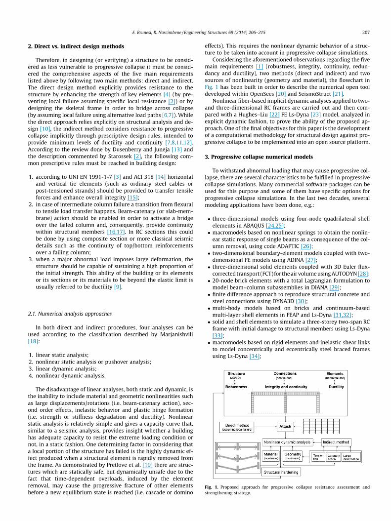
Fig. 1. Proposed approach for progressive collapse resistance assessment andstrengthening strategy.
2.1. Numerical analysis approaches
In both direct and indirect procedures, four analyses can beused according to the classification described by Marjanishvili[18]:
1. linear static analysis;2. nonlinear static analysis or pushover analysis;3. linear dynamic analysis;4. nonlinear dynamic analysis.
The disadvantage of linear analyses, both static and dynamic, isthe inability to include material and geometric nonlinearities suchas large displacements/rotations (i.e. beam-catenary action), sec-ond order effects, inelastic behavior and plastic hinge formation(i.e. strength or stiffness degradation and ductility). Nonlinearstatic analysis is relatively simple and gives a capacity curve that,similar to a seismic analysis, provides insight whether a buildinghas adequate capacity to resist the extreme loading condition ornot, in a static fashion. One determining factor in considering thata local portion of the structure has failed is the highly dynamic ef-fect produced when a structural element is rapidly removed fromthe frame. As demonstrated by Pretlove et al. [19] there are struc-tures which are statically safe, but dynamically unsafe due to thefact that time-dependent overloads, induced by the elementremoval, may cause the progressive fracture of other elementsbefore a new equilibrium state is reached (i.e. cascade or domino
effects). This requires the nonlinear dynamic behavior of a struc-ture to be taken into account in progressive collapse simulations.
Considering the aforementioned observations regarding the fivemain requirements [1] (robustness, integrity, continuity, redun-dancy and ductility), two methods (direct and indirect) and twosources of nonlinearity (geometry and material), the flowchart inFig. 1 has been built in order to describe the numerical open tooldeveloped within OpenSees [20] and SeismoStruct [21].
Nonlinear fiber-based implicit dynamic analyses applied to two-and three-dimensional RC frames are carried out and then com-pared with a Hughes–Liu [22] FE Ls-Dyna [23] model, analyzed inexplicit dynamic fashion, to prove the ability of the proposed ap-proach. One of the final objectives for this paper is the developmentof a computational methodology for structural design against pro-gressive collapse to be implemented into an open source platform.
3. Progressive collapse numerical models
To withstand abnormal loading that may cause progressive col-lapse, there are several characteristics to be fulfilled in progressivecollapse simulations. Many commercial software packages can beused for this purpose and some of them have specific options forprogressive collapse simulations. In the last two decades, severalmodeling applications have been done, e.g.:
� three-dimensional models using four-node quadrilateral shellelements in ABAQUS [24,25];� macromodels based on nonlinear springs to obtain the nonlin-
ear static response of single beams as a consequence of the col-umn removal, using code ADAPTIC [26];� two-dimensional boundary-element models coupled with two-
dimensional FE models using ADINA [27];� three-dimensional solid elements coupled with 3D Euler flux-
corrected transport (FCT) for the air volume using AUTODYN [28];� 20-node brick elements with a total Lagrangian formulation to
model beam–column subassemblies in DIANA [29];� finite difference approach to reproduce structural concrete and
steel connections using DYNA3D [30];� multi-body models based on bricks and continuum-based
multi-layer shell elements in FEAP and Ls-Dyna [31,32];� solid and shell elements to simulate a three-storey two-span RC
frame with initial damage to structural members using Ls-Dyna[33];� macromodels based on rigid elements and inelastic shear links
to model concentrically and eccentrically steel braced framesusing Ls-Dyna [34];
208 E. Brunesi, R. Nascimbene / Engineering Structures 69 (2014) 206–215
� Bernoulli beam elements with concentrated plastic hingesassigned a priori to all possible locations where stiffness andstrength degradation can occur, using SAP2000 [35,36].
Beam FEs have the advantages of reducing computational costsbut most of the past attempts are confined to two-dimensionalsubsystems [37–39] and numerous simplifications are appliedsuch as trilinear model for RC compact sections [40] or a lumpedplasticity assumed to occur only at the element ends [38,41,5].By contrast, detailed brick elements with embedded steel rein-forcements and shell elements [33] may give some more insightbut tremendously increase computational time asking necessarilyadvantage of parallel processing on multiprocessor computers.
A third way to model is through a fiber-based force [42] or dis-placement [43,44] approach, commonly used in seismic analysis ofsteel structures [45,46], RC buildings [47,48], masonry panels [49]or connections [50,51] and continuous span bridges [52]. A firstapplication of fiber beam models based on the general-purposecommercial FE package MSC.MARC has been done by Lu et al.[53] and then used to improve the tie force method, adopted bythe BS8110-1:1997 [12], Eurocode 1 [3], and DoD 2005 [7], includ-ing load redistribution in three dimensions, dynamic effect andinternal force correction [15].
Recently, Kim et al. in [37] applied the open source code Open-Sees for the development of an integrated system of progressivecollapse analysis; two- and three-storey two-dimensional framestructures have been analyzed, however assuming that concen-trated plastic hinges form only at the ends of structural elements.Therefore, one of the main objectives of the presented study is todevelop an appropriate procedure for large scale nonlinear tran-sient dynamic analysis of three-dimensional frames, combiningthe force-based fiber element with the open platform OpenSees.The automatic element removal algorithm is formulated in lightof an object-oriented architecture and the main capabilities ofthe computational solution strategy herein proposed can be cate-gorized into two levels: local/element and global/structural.
4. Reference MRF structure
In the following, geometric characteristics and assumptions re-lated to the structural configuration analyzed will be discussed, aswell as its FE representation and the column-removal strategyused to assess the two- and three-dimensional idealization of thereference MRF structure.
4.1. Description and assumptions
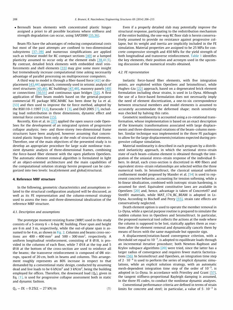
The prototype moment resisting frame (MRF) used in this studyconsists of a 5-storey 6 � 6-bay RC building. Floor span and heightare 6 m and 3 m, respectively, while the out-of-plane span is as-sumed to be 4 m, as shown in Fig. 2. Columns and beams cross-sec-tions are 400 � 400 mm2 and 500 � 300 mm2, respectively. Auniform longitudinal reinforcement, consisting of 8 Ø18, is pro-vided in the columns of each floor, while 7 Ø18 at the top and 5Ø18 at the bottom of the cross-section are used to reinforce allthe beams; the transverse reinforcement is composed of Ø8 stir-rups, spaced of 20 cm, both in beams and columns. This arrange-ment roughly represents an 80% increase in respect to thatdemanded by a conventional static design, conducted by assumingdead and live loads to be 6 kN/m2 and 3 kN/m2, being the buildingemployed for offices. Therefore, the downward load (Qb), given inEq. (1), is used for progressive collapse assessment both in staticand dynamic fashion.
Q b ¼ DLþ 0:25LL ¼ 27 kN=m ð1Þ
Even if a properly detailed slab may potentially improve thestructural response, participating to the redistribution mechanismof the entire building, the one-way RC floor slab is herein conserva-tively assumed to provide no resistance against progressive col-lapse, but its weight and inertia are implicitly included in the FEsimulation. Material properties are assigned to be 25 MPa for con-crete compressive strength and 450 MPa for the yield strength ofboth longitudinal and transverse reinforcement. Table 1 identifiesthe key elements, their position and acronym used in the upcom-ing discussion of the numerical results obtained.
4.2. FE representation
Inelastic force-based fiber elements, with five integrationpoints, are exploited within OpenSees and SeismoStruct, whileHughes–Liu [22] approach, based on a degenerated brick elementformulation including shear strains, is used in Ls-Dyna. Althoughthe use of a force-based formulation does not necessarily implythe need of element discretization, a one-to-six correspondencebetween structural members and model elements is assumed toaccurately accommodate the deformed shape; mesh sensitivitywas checked by halving this ratio.
Geometric nonlinearity is accounted using a co-rotational trans-formation, whose implementation is based on an exact descriptionof the kinematic transformations associated with large displace-ments and three-dimensional rotations of the beam–column mem-ber. Similar technique was implemented in the three FE packagesto allow for the large displacements/rotations expected during pro-gressive collapse simulation.
Material nonlinearity is described in each program by a distrib-uted inelasticity approach, in which the sectional stress–strainstate of each beam–column element is obtained through the inte-gration of the uniaxial stress–strain response of the individual fi-bers. In detail, each cross-section is discretized in 400 fibers andequivalent stress–strain relationships are selected within the threenumerical tools. In SeismoStruct, the classical uniaxial uniformconfinement model proposed by Mander et al. [54] is used to rep-resent concrete behavior, accounting for tension softening, while abi-linear idealization, combined with isotropic strain hardening, isassumed for steel. Equivalent constitutive laws are available inOpenSees [20] and, hence, advantage is taken of Concrete07 andSteel01 materials, while MAT_174_RC_BEAM is adopted in Ls-Dyna. According to Bischoff and Perry [55], strain rate effects areconservatively neglected.
Death element option is used to operate the member removal inLs-Dyna, while a special purpose routine is prepared to simulate thesudden column loss in OpenSees and SeismoStruct. In particular,the proposed numerical tool collects the actions at the node wherethe column is supposed to be lost, statically applies them as reac-tions after the element removal and dynamically cancels them bymeans of forces with the same magnitude but opposite sign.
A displacement/rotation-based convergence criterion, with athreshold set equal to 10�3, is adopted to equilibrate loads throughan incremental iterative procedure; both Newton–Raphson andKrylov subspace algorithms [20] were tried, since the latter has alarger radius of convergence and requires fewer matrix factoriza-tions [56]. In SeismoStruct and OpenSees, an integration time stepof 2 � 10�4 is used to perform the series of implicit dynamic simu-lations, while an explicit solution strategy, with an automaticmesh-dependent integration time step of the order of 10�5, isadopted in Ls-Dyna. In accordance with Priestley and Grant [57],the tangent stiffness-proportional Rayleigh damping is assumed,in the three FE codes, to conduct the nonlinear dynamic analyses.
Conventional performance criteria are defined in terms of strainlimits for concrete and steel; in particular, a value of 5 � 10�3 is
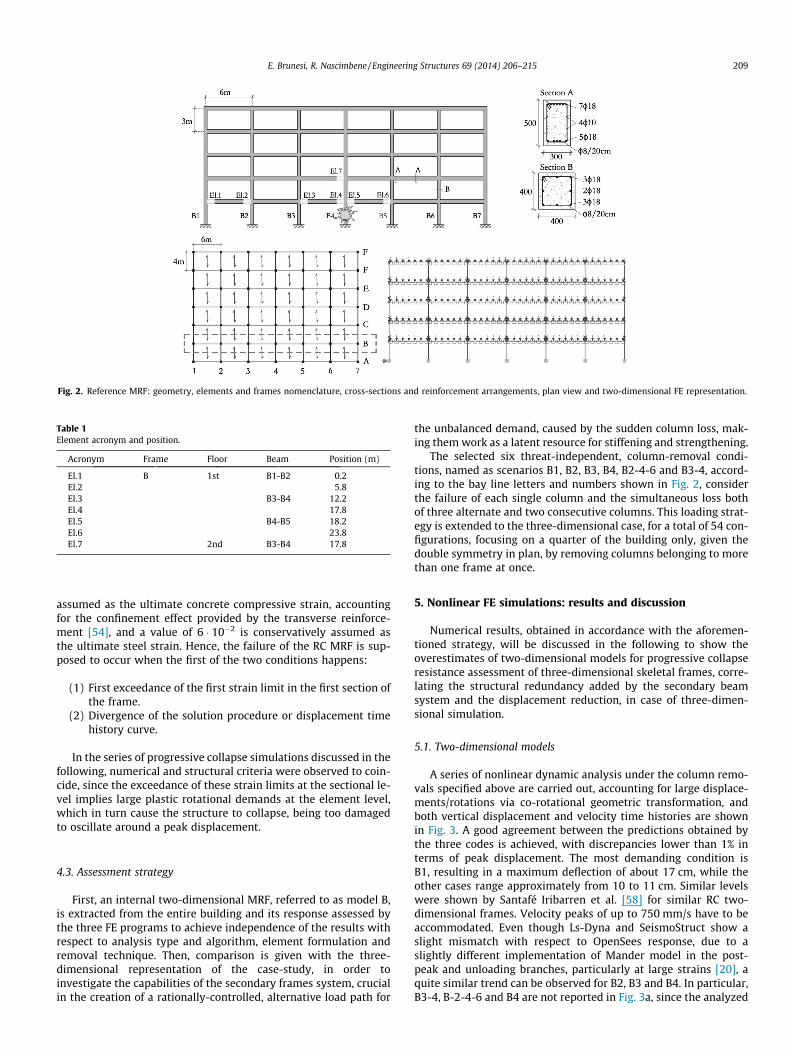
Fig. 2. Reference MRF: geometry, elements and frames nomenclature, cross-sections and reinforcement arrangements, plan view and two-dimensional FE representation.
Table 1Element acronym and position.
Acronym Frame Floor Beam Position (m)
El.1 B 1st B1-B2 0.2El.2 5.8El.3 B3-B4 12.2El.4 17.8El.5 B4-B5 18.2El.6 23.8El.7 2nd B3-B4 17.8
E. Brunesi, R. Nascimbene / Engineering Structures 69 (2014) 206–215 209
assumed as the ultimate concrete compressive strain, accountingfor the confinement effect provided by the transverse reinforce-ment [54], and a value of 6 � 10�2 is conservatively assumed asthe ultimate steel strain. Hence, the failure of the RC MRF is sup-posed to occur when the first of the two conditions happens:
(1) First exceedance of the first strain limit in the first section ofthe frame.
(2) Divergence of the solution procedure or displacement timehistory curve.
In the series of progressive collapse simulations discussed in thefollowing, numerical and structural criteria were observed to coin-cide, since the exceedance of these strain limits at the sectional le-vel implies large plastic rotational demands at the element level,which in turn cause the structure to collapse, being too damagedto oscillate around a peak displacement.
4.3. Assessment strategy
First, an internal two-dimensional MRF, referred to as model B,is extracted from the entire building and its response assessed bythe three FE programs to achieve independence of the results withrespect to analysis type and algorithm, element formulation andremoval technique. Then, comparison is given with the three-dimensional representation of the case-study, in order toinvestigate the capabilities of the secondary frames system, crucialin the creation of a rationally-controlled, alternative load path for
the unbalanced demand, caused by the sudden column loss, mak-ing them work as a latent resource for stiffening and strengthening.
The selected six threat-independent, column-removal condi-tions, named as scenarios B1, B2, B3, B4, B2-4-6 and B3-4, accord-ing to the bay line letters and numbers shown in Fig. 2, considerthe failure of each single column and the simultaneous loss bothof three alternate and two consecutive columns. This loading strat-egy is extended to the three-dimensional case, for a total of 54 con-figurations, focusing on a quarter of the building only, given thedouble symmetry in plan, by removing columns belonging to morethan one frame at once.
5. Nonlinear FE simulations: results and discussion
Numerical results, obtained in accordance with the aforemen-tioned strategy, will be discussed in the following to show theoverestimates of two-dimensional models for progressive collapseresistance assessment of three-dimensional skeletal frames, corre-lating the structural redundancy added by the secondary beamsystem and the displacement reduction, in case of three-dimen-sional simulation.
5.1. Two-dimensional models
A series of nonlinear dynamic analysis under the column remo-vals specified above are carried out, accounting for large displace-ments/rotations via co-rotational geometric transformation, andboth vertical displacement and velocity time histories are shownin Fig. 3. A good agreement between the predictions obtained bythe three codes is achieved, with discrepancies lower than 1% interms of peak displacement. The most demanding condition isB1, resulting in a maximum deflection of about 17 cm, while theother cases range approximately from 10 to 11 cm. Similar levelswere shown by Santafé Iribarren et al. [58] for similar RC two-dimensional frames. Velocity peaks of up to 750 mm/s have to beaccommodated. Even though Ls-Dyna and SeismoStruct show aslight mismatch with respect to OpenSees response, due to aslightly different implementation of Mander model in the post-peak and unloading branches, particularly at large strains [20], aquite similar trend can be observed for B2, B3 and B4. In particular,B3-4, B-2-4-6 and B4 are not reported in Fig. 3a, since the analyzed
0 0.4 0.8 1.2 1.6 2−180
−150
−120
−90
−60
−30
0
Time [s]
Verti
cal D
ispl
acem
ent [
mm
]
S B1O B1L B1S B2O B2L B2S B3O B3L B3
0 0.4 0.8 1.2 1.6 2−800
−600
−400
−200
0
200
Time [s]
Verti
cal V
eloc
ity [m
m/s
]
B1B2B3B4
(a) (b)
Fig. 3. 2D MRF: (a) displacement and (b) velocity time histories under different column removal conditions. Note that S, O and L stand for SeismoStruct, OpenSees and Ls-Dyna, respectively.
210 E. Brunesi, R. Nascimbene / Engineering Structures 69 (2014) 206–215
MRF collapsed in the case of both two consecutive and threealternate columns, while B4 and B3 reveals an almost identicalresponse, as confirmed by Fig. 3b.
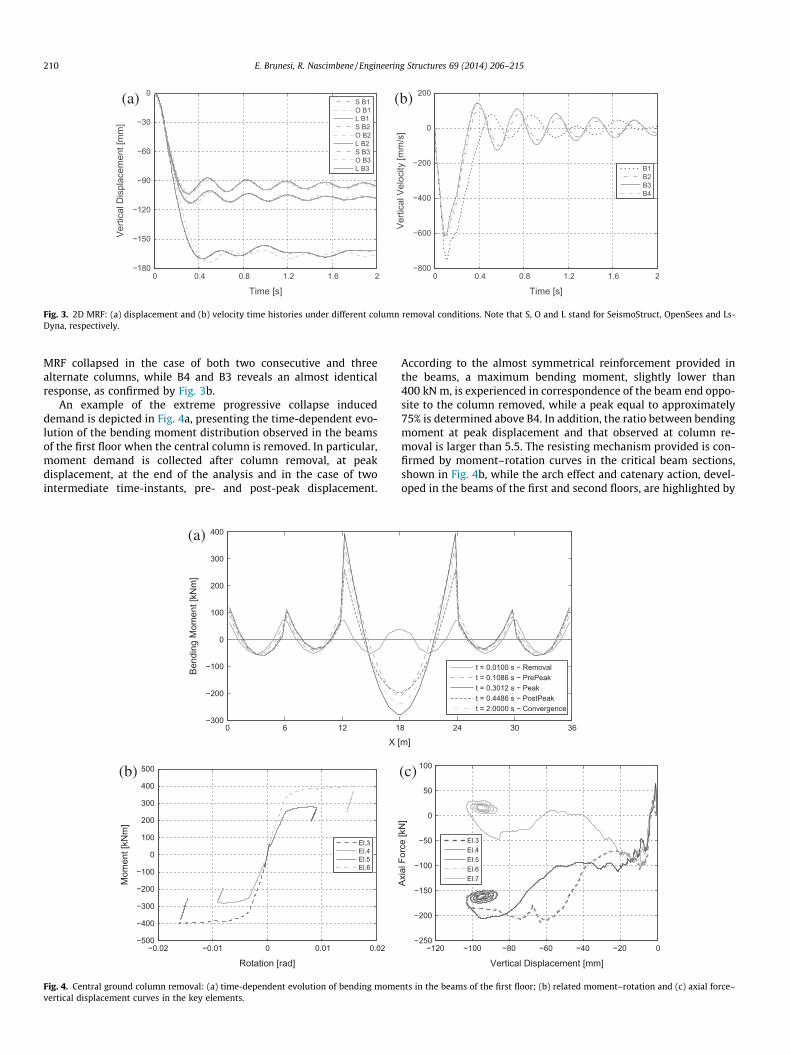
An example of the extreme progressive collapse induceddemand is depicted in Fig. 4a, presenting the time-dependent evo-lution of the bending moment distribution observed in the beamsof the first floor when the central column is removed. In particular,moment demand is collected after column removal, at peakdisplacement, at the end of the analysis and in the case of twointermediate time-instants, pre- and post-peak displacement.
0 6 12 1−300
−200
−100
0
100
200
300
400
X [
Bend
ing
Mom
ent [
kNm
]
−0.02 −0.01 0 0.01 0.02−500
−400
−300
−200
−100
0
100
200
300
400
500
Rotation [rad]
Mom
ent [
kNm
]
El.3El.4El.5El.6
(a)
(b)
Fig. 4. Central ground column removal: (a) time-dependent evolution of bending momevertical displacement curves in the key elements.
According to the almost symmetrical reinforcement provided inthe beams, a maximum bending moment, slightly lower than400 kN m, is experienced in correspondence of the beam end oppo-site to the column removed, while a peak equal to approximately75% is determined above B4. In addition, the ratio between bendingmoment at peak displacement and that observed at column re-moval is larger than 5.5. The resisting mechanism provided is con-firmed by moment–rotation curves in the critical beam sections,shown in Fig. 4b, while the arch effect and catenary action, devel-oped in the beams of the first and second floors, are highlighted by
8 24 30 36
m]
t = 0.0100 s − Removalt = 0.1086 s − PrePeakt = 0.3012 s − Peakt = 0.4486 s − PostPeakt = 2.0000 s − Convergence
−120 −100 −80 −60 −40 −20 0−250
−200
−150
−100
−50
0
50
100
Vertical Displacement [mm]
Axia
l For
ce [k
N]
El.3El.4El.5El.6El.7
(c)
nts in the beams of the first floor; (b) related moment–rotation and (c) axial force–
E. Brunesi, R. Nascimbene / Engineering Structures 69 (2014) 206–215 211
Fig. 4c. In particular, the change in bending moment sign producesa reduction in the demand, being the RC cross-section character-ized by a similar capacity under reversal loading. Moment–rotationcurve reaches its ‘‘unloading’’ branch and oscillates upward anddownward, when the structure oscillates around its displacementpeak.
After column removal, an arch mechanism develops betweenthe top of the middle joint and the bottom of the exterior joint,resulting into axial compressive forces in the beams. Stresses in-crease until concrete crushing and cracking occur in the compres-sive and tensile regions, respectively, resulting in a plastic hingethat was observed to limit sectional carrying capability. Crackingfurther develops through the beam depth and catenary action de-creases the compressive forces. Moderate tension appears in thebeams of the second floor, while those at the first floor are observedto fluctuate, being further damaged and, hence, unable to react.
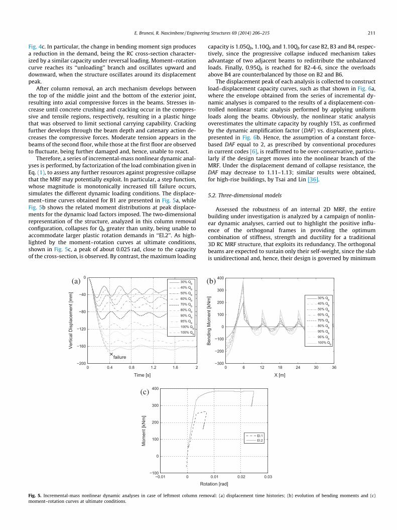
Therefore, a series of incremental-mass nonlinear dynamic anal-yses is performed, by factorization of the load combination given inEq. (1), to assess any further resources against progressive collapsethat the MRF may potentially exploit. In particular, a step function,whose magnitude is monotonically increased till failure occurs,simulates the different dynamic loading conditions. The displace-ment–time curves obtained for B1 are presented in Fig. 5a, whileFig. 5b shows the related moment distributions at peak displace-ments for the dynamic load factors imposed. The two-dimensionalrepresentation of the structure, analyzed in this column removalconfiguration, collapses for Qb greater than unity, being unable toaccommodate larger plastic rotation demands in ‘‘El.2’’. As high-lighted by the moment–rotation curves at ultimate conditions,shown in Fig. 5c, a peak of about 0.025 rad, close to the capacityof the cross-section, is observed. By contrast, the maximum loading
0 0.4 0.8 1.2 1.6 2−200
−160
−120
−80
−40
0
Time [s]
Verti
cal D
ispl
acem
ent [
mm
]
failure
30% Qb40% Qb50% Qb60% Qb70% Qb80% Qb90% Qb95% Qb100% Qb105% Qb
−0.01 0−100
0
100
200
300
400
Rot
Mom
ent [
kNm
]
(a)
(c)
Fig. 5. Incremental-mass nonlinear dynamic analyses in case of leftmost column remmoment–rotation curves at ultimate conditions.
capacity is 1.05Qb, 1.10Qb and 1.10Qb for case B2, B3 and B4, respec-tively, since the progressive collapse induced mechanism takesadvantage of two adjacent beams to redistribute the unbalancedloads. Finally, 0.95Qb is reached for B2-4-6, since the overloadsabove B4 are counterbalanced by those on B2 and B6.
The displacement peak of each analysis is collected to constructload–displacement capacity curves, such as that shown in Fig. 6a,where the envelope obtained from the series of incremental dy-namic analyses is compared to the results of a displacement-con-trolled nonlinear static analysis performed by applying uniformloads along the beams. Obviously, the nonlinear static analysisoverestimates the ultimate capacity by roughly 15%, as confirmedby the dynamic amplification factor (DAF) vs. displacement plots,presented in Fig. 6b. Hence, the assumption of a constant force-based DAF equal to 2, as prescribed by conventional proceduresin current codes [6], is reaffirmed to be over-conservative, particu-larly if the design target moves into the nonlinear branch of theMRF. Under the displacement demand of collapse resistance, theDAF may decrease to 1.11–1.13; similar results were obtained,for high-rise buildings, by Tsai and Lin [36].
5.2. Three-dimensional models
Assessed the robustness of an internal 2D MRF, the entirebuilding under investigation is analyzed by a campaign of nonlin-ear dynamic analyses, carried out to highlight the positive influ-ence of the orthogonal frames in providing the optimumcombination of stiffness, strength and ductility for a traditional3D RC MRF structure, that exploits its redundancy. The orthogonalbeams are expected to sustain only their self-weight, since the slabis unidirectional and, hence, their design is governed by minimum
0.01 0.02 0.03
ation [rad]
El.1El.2
0 6 12 18 24 30 36−300
−200
−100
0
100
200
300
400
X [m]
Bend
ing
Mom
ent [
kNm
] 30% Qb40% Qb50% Qb60% Qb70% Qb80% Qb90% Qb95% Qb100% Qb
(b)
oval: (a) displacement time histories; (b) evolution of bending moments and (c)

0 30 60 90 120 150 1800
20
40
60
80
100
120
Vertical Displacement [mm]
Qb=
DL+
0.25
LL [%
]
StDyn
0 30 60 90 120 150 1800
1
2
3
Dynamic Vertical Displacement [mm]
Qb,
St/Q
b,D
yn [−
]
B1B2B3B4B2−4−6
(a) (b)
Fig. 6. Nonlinear static vs. dynamic analyses: (a) capacity curves (leftmost column removal) and (b) DAF.
212 E. Brunesi, R. Nascimbene / Engineering Structures 69 (2014) 206–215
requirements, ordinarily prescribed in conventional codes. In par-ticular, cross-section depth is kept constant and 1% of longitudinalreinforcement, symmetrically arranged, is imposed to satisfy min-imum seismic requirements [59], always mandatory in EuropeanStandards; this results into a flexural resistance roughly equal toone half of that provided in the primary beams. Therefore, theredundancy added is observed to control the structural response,providing an alternative load path. Fig. 7 presents both displace-ment and velocity histories for some significant column removalconditions, while Table 2 summarizes the peaks obtained in termsof vertical displacement (Dmax,3D) and bending moment demand in
0 0.4 0.8 1.2 1.6 2−50
−40
−30
−20
−10
0
Time [s]
Verti
cal D
ispl
acem
ent [
mm
]
A1A2A2−4−6A3−4B1B2B2−4−6B3−4
0 0.4 0.8 1.2 1.6 2−500
−400
−300
−200
−100
0
100
200
Time [s]
Verti
cal V
eloc
ity [m
m/s
]
A1A2A2−4−6A3−4B1B2B2−4−6B3−4
(a)
(c)
Fig. 7. 3D MRF: (a and b) displacement and (c and d) velocity time history curves undeselected.
the beams of both primary (Mmax,P) and secondary (Mmax,S) framesystems. In addition, their ratio with respect to those observed instatic condition (RM,P and RM,S) is computed and collected. Finally,normalization with respect to the peaks determined through the2D representation of the reference building is proposed.
Displacement peaks ranging from 11 to 21 mm are shown in thecase of a single column removal, while the related velocities decayto about 150–250 mm/s. This significant reduction leads the MRFto behave almost elastically. If the frame A is taken as reference,a significant decrease (55–65%) is experienced in terms of momentin the primary beams, according to the notable redistribution effect
0 0.4 0.8 1.2 1.6 2−50
−40
−30
−20
−10
0
Time [s]
Verti
cal D
ispl
acem
ent [
mm
]
C3−4A1−B1A2−B2A3−B3A4−B3−C2−D1B1−C1B2−C2B3−C3
0 0.4 0.8 1.2 1.6 2−500
−400
−300
−200
−100
0
100
200
Time [s]
Verti
cal V
eloc
ity [m
m/s
]
C3−4A1−B1A2−B2A3−B3A4−B3−C2−D1B1−C1B2−C2B3−C3
(b)
(d)
r significant ground column removal conditions, according to the loading strategy
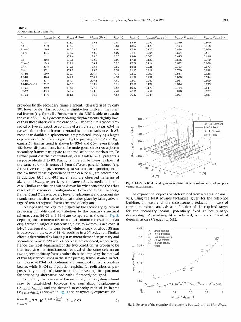
Table 23D MRF significant quantities.
Case Dmax,3D (mm) Mmax,P (kN m) Mmax,S (kN m) RM,P (–) RM,S (–) Dmax,3D/Dmax,2D (–) Mmax,P/Mmax,2D (–) Mmax,S/Mmax,P (–)
A1 13.7 131.5 119.1 2.84 13.30 0.080 0.339 0.906A2 21.0 175.7 161.2 3.81 18.02 0.123 0.453 0.918A2-4-6 19.6 185.2 159.3 4.04 17.88 0.115 0.478 0.860A3-4 43.5 234.2 189.9 5.07 21.17 0.255 0.604 0.811B1 11.1 172.4 120.0 2.23 13.40 0.065 0.445 0.696B2 20.8 238.6 169.5 3.09 17.35 0.122 0.616 0.710B2-4-6 19.5 252.6 168.7 3.28 17.28 0.114 0.652 0.668B3-4 37.8 272.6 183.4 3.53 18.89 0.221 0.703 0.673C3-4 37.1 271.3 189.5 3.51 21.17 0.218 0.700 0.698A1-B1 50.0 322.1 201.7 4.16 22.52 0.293 0.831 0.626A2-B2 49.6 348.8 203.9 4.51 21.99 0.291 0.900 0.584A3-B3 47.7 357.1 203.1 4.62 22.07 0.280 0.921 0.569A4-B3-C2-D1 21.7 245.7 170.8 3.18 17.59 0.127 0.634 0.695B1-C1 29.0 276.9 177.4 3.58 19.82 0.170 0.714 0.641B2-C2 43.3 343.4 198.0 4.44 20.39 0.254 0.886 0.577B3-C3 41.6 351.6 195.9 4.55 20.32 0.244 0.907 0.557
061218243036
−12−8
−40
−200
−100
0
100
200
300
400
Y [m]X [m]
Bend
ing
Mom
ent [
kNm
]
B4−C4 RemovalB4−C4 PeakB3−4 RemovalB3−4 Peak
Fig. 8. B4-C4 vs. B3-4: bending moment distributions at column removal and peakvertical displacement.
0.5 0.6 0.7 0.8 0.9 10
0.05
0.1
0.15
0.2
0.25
0.3
0.35
Mmax,S / MRd,S [−]
D max
,3D
/ D m
ax,2
D [−
]
Dmax,3D / Dmax,2D = 7.7*10−3e3.6812*Mmax,S / MRd,S − R2 = 0.92
Single columnThree alternateTwo consecutiveOn two framesFour diagonallyFitted
Fig. 9. Reserves of the secondary frame system: Dmax,3D/Dmax,2D vs. Mmax,S/MRd,S.
E. Brunesi, R. Nascimbene / Engineering Structures 69 (2014) 206–215 213
provided by the secondary frame elements, characterized by only10% lower peaks. This reduction is slightly less visible in the inter-nal frames (e.g. frame B). Furthermore, the MRF is able to sustainthe case of A2-4-6, by accommodating displacements slightly low-er than those observed in the case of A2. Even the simultaneous re-moval of two consecutive columns of a single frame (e.g. A3-4) ispassed, although much more demanding. In comparison with A3,more than doubled displacements are predicted, implying a largerexploitation of the reserves given by the primary frame A (i.e. RM,P
equals 5). Similar trend is shown by B3-4 and C3-4, even though15% lower displacements has to be undergone, since two adjacentsecondary frames participate to the redistribution mechanism. Tofurther point out their contribution, case A4-B3-C2-D1 presents aresponse identical to B3. Finally, a different behavior is shown ifthe same column is removed from different parallel frames (e.g.A1-B1). Vertical displacements up to 50 mm, corresponding to al-most 4 times those experienced in the case of A1, are determined.In addition, 60% and 40% increments are observed in terms ofMmax,P and Mmax,S, respectively; the largest RM,S is predicted in thiscase. Similar conclusions can be drawn for what concerns the othercases of this removal configuration. However, those involvingframes B and C present barely lower displacement and moment de-mand, since the alternative load path takes place by taking advan-tage of two orthogonal frames instead of only one.
To emphasize the key role played by the secondary system inproviding an additional contribution to the primary structuralscheme, cases B4-C4 and B3-4 are compared, as shown in Fig. 8,depicting their moment distribution at column removal and peakdisplacement. Larger displacement, close to 42 mm, is achieved ifB4-C4 configuration is considered, while a peak of about 38 mmis observed in the case of B3-4, resulting in a 9% reduction. Similareffect is determined by looking at moment demand in primary andsecondary frames: 22% and 7% decrease are observed, respectively.Hence, the most demanding of the two conditions is proven to bethat involving the simultaneous removal of the same column ontwo adjacent primary frames rather than that implying the removalof two adjacent columns in the same primary frame, at once. In fact,in the case of B3-4 both columns are connected to two secondarybeams, while B4-C4 configuration exploits, for redistribution pur-poses, only one out-of-plane beam, thus revealing their potentialfor developing alternative load paths, if properly designed.
To quantify the reserves of the secondary frame system a trendmay be established between the normalized displacement(Dmax,3D/Dmax,2D) and the demand-to-capacity ratio of its beams(Mmax,S/MRd,S), as shown in Fig. 9 and analytically expressed in:
Dmax;3D
Dmax;2D¼ 7:7 � 10�3e
3:6812�Mmax;SMRd;S � R2 ¼ 0:92 ð2Þ
The exponential expression, determined from a regression anal-ysis, using the least squares technique, gives, for the referencebuilding, a measure of the displacement reduction in case ofthree-dimensional analysis as a function of the required targetfor the secondary beams, potentially fixed at preliminary-design-stage. A satisfying fit is achieved, with a coefficient ofdetermination (R2) equal to 0.92.

214 E. Brunesi, R. Nascimbene / Engineering Structures 69 (2014) 206–215
6. Conclusions
A procedure for simulating the large displacement inelastic dy-namic response of MRF buildings, subjected to sudden column loss,is implemented into an open source fiber-based code and verifiedby comparison with general purpose FE software. Independenceof the results in respect to analysis type and algorithm, elementformulation and removal technique is achieved by assessing aninternal 2D frame of a 5-storey 6 � 6-bay RC structure. Progressivecollapse resistance assessment is carried out using nonlinear staticand dynamic, implicit and explicit, analyses. Load–displacementcapacity curves, determined from the two methods, are compared,revealing the former to be conservative by roughly 15%, at ultimateconditions; the decay of the force-based DAF throughout overallinelastic response of the frame is captured, proving current codes’procedures to be over-conservative.
Ultimately, 3D simulations are conducted to assess the behaviorof the entire skeletal frame investigated, establishing the limita-tions of 2D models. In particular, the secondary frames system,with proper design and detailing, is demonstrated to significantlycontribute to the structural response, acting as a latent resourcefor stiffening and strengthening. Therefore, a rationally-controlled,alternative load path for the unbalanced demand, caused by thesudden column loss, is feasible at the design stage and may takeadvantage of the structural redundancy, demanded by modernseismic codes to ensure the three-dimensional behavior of MRFs.A trend is established between displacement reduction, in case of3D simulation, and demand-to-capacity ratio of the secondarybeams, designed to be weaker than the primary system. Several re-moval conditions are discussed to figure out the trend observed,using them as a sort of incremental load to push the 3D MRF atthe limit of its capacity.
Finally, the use of minimum seismic requirements, prescribedin codes, reveals to be a promising technique for costly-effectiveprogressive collapse mitigation and strengthening strategy fornew constructions. Additional redistribution capabilities may beresearched in a properly designed and detailed floor slab system,whose resistance, conservatively omitted in the analyses presentedin this study, is expected to provide a significant potential for alter-native load paths.
References
[1] Wibowo H, Lau DT. Seismic progressive collapse: qualitative point of view. CivEng Dimens 2009;11(1):8–14.
[2] Starossek U. Progressive collapse of structures. Thomas Telford Limited; 2009.[3] CEN, European Committee for Standardisation. ENV 1991-1-7, Eurocode 1:
actions on structures – part 1. 7: general actions – accidental actions. Brussels;2006.
[4] United States National Institute of Standards and Technology (NIST). Bestpractices for reducing the potential for progressive collapse in buildings,technology administration. U.S. Department of Commerce, Washington, DC;2007.
[5] Menchel K. Progressive collapse: comparison of main standards, formulationand validation of new computational procedures. PhD thesis, ULB UniversiteLibre de Bruxelles; 2009.
[6] United States General Services Administration (GSA). Progressive collapseanalysis and design guidelines for new federal office buildings and majormodernization project. Washington, DC; 2003.
[7] Department of Defense (DoD). Unified facilities criteria (UFC): design ofstructures to resist progressive collapse. Washington, DC; 2005.
[8] ASCE 7-02. Minimum design loads for buildings and other structures.American Society of Civil Engineers, Reston, VA; 2002.
[9] Paulay T, Priestley MJN. Seismic design of reinforced concrete and masonrybuildings. John Wiley & Sons; 1992.
[10] Saad A, Said A, Tian Y. Overview of progressive collapse analysis and retrofittechniques. In: 5th International engineering and construction conference;August 2008. p. 765–72.
[11] National Research Council of Canada, NRC. National building code of Canada,Ottawa; 1996.
[12] British Standards Institution, BS 8110-1:1997. Structural use of concrete. Codeof practice for design and construction. BSI, London; 1997.
[13] Dusenberry DO, Juneja G. Review of existing guidelines and provisions relatedto progressive collapse. Washington, DC: Multihazard Mitigation Council ofthe National Institute of Building Standards; 2003. p. 1–31.
[14] American Concrete Institute. ACI 318. Building code requirements forstructural concrete (ACI 318-02) and commentary (ACI 318R-01). FarmingtonHills, MI; 2002.
[15] Li Y, Lu XZ, Guan H, Ye LP. An improved tie force method for progressivecollapse resistance design of reinforced concrete frame structures. Eng Struct2011;33(10):2931–42.
[16] Valipour HR, Foster SJ. Finite element modelling of reinforced concrete framedstructures including catenary action. Comput Struct 2010;88(9–10):529–38.
[17] Dat PX, Hai TK. Membrane actions of RC slabs in mitigating progressivecollapse of building structures. Eng Struct 2013;55:107–15.
[18] Marjanishvili SM. Progressive analysis procedure for progressive collapse. JPerf Constr Fac ASCE 2004;18(2):79–85.
[19] Pretlove AJ, Ramsden M, Atkins AG. Dynamic effects in progressive failure ofstructures. Int J Impact Eng 1991;11(4):539–46.
[20] OpenSees. Open system for earthquake engineering simulation. PacificEarthquake Engineering Research Center, University of California, Berkeley,CA.
[21] Seismosoft – SeismoStruct – A computer program for static and dynamicnonlinear analysis of framed structures. <www.seismosoft.com>.
[22] Hughes TJR, Liu WK. Nonlinear finite element analysis of shells: part II. Threedimensional shells. Comp Meth Appl Mech Eng 1981;26(3):331–62.
[23] Ls-Dyna user manual. Livermore Software Technology Corporation.[24] Lee CH, Kim S, Han KH, Lee K. Simplified nonlinear progressive collapse
analysis of welded steel moment frames. J Constr Steel Res 2009;65:1130–7.[25] Wei J, Quintero R, Galati N, Nanni A. Failure modeling of bridge components
subjected to blast loading – part I: strain rate-dependent damage model forconcrete. Int J Concr Struct Mater 2007;1(1):19–28.
[26] Vlassis AG, Izzuddin BA, Elghazouli AY, Nethercot DA. Progressive collapse ofmulti-storey buildings due to sudden column loss – part II: application. EngStruct 2008;30(5):1424–38.
[27] Kripakov NP, Sun MC, Donato DA. ADINA applied toward simulation ofprogressive failure in underground mine structures. Comput Struct1995;56(2–3):329–44.
[28] Luccioni BM, Ambrosini RD, Danesi RF. Analysis of building collapse underblast loads. Eng Struct 2004;26(1):63–71.
[29] Bao Y, Kunnath SK, El-Tawil S, Lew HS. Macromodel-based simulation ofprogressive collapse: RC frame structures. J Struct Eng ASCE 2008;134(7):1079–91.
[30] Krauthammer T. Blast-resistant structural concrete and steel connections. Int JImpact Eng 1999;22(9–10):887–910.
[31] Möller B, Liebscher M, Schweizerhof K, Mattern S, Blankenhorn G. Structuralcollapse simulation under consideration of uncertainty – improvement ofnumerical efficiency. Comput Struct 2008;86(19–20):1875–84.
[32] Hartmann D, Breidt M, Nguyen V, Stangenberg F, Höhler S, Schweizerhof K,et al. Structural collapse simulation under consideration of uncertainty –fundamental concept and results. Comput Struct 2008;86(21–22):2064–78.
[33] Shi Y, Li Z-X, Hao H. A new method for progressive collapse analysis of RCframes under blast loading. Eng Struct 2010;32(6):1691–703.
[34] Khandelwal K, El-Tawil S, Sadek F. Progressive collapse analysis of seismicallydesigned steel braced frames. J Constr Steel Res 2009;65(3):699–708.
[35] Sasani M. Response of a reinforced concrete infilled-frame structure toremoval of two adjacent columns. Eng Struct 2008;30(9):2478–91.
[36] Tsai M-H, Lin B-H. Investigation of progressive collapse resistance and inelasticresponse for an earthquake-resistant RC building subjected to column failure.Eng Struct 2008;30(12):3619–28.
[37] Kim HS, Kim J, An DW. Development of integrated system for progressivecollapse analysis of building structures considering dynamic effects. Adv EngSoftw 2009;40(1):1–8.
[38] Kaewkulchai G, Williamson EB. Beam element formulation and solutionprocedure for dynamic progressive collapse analysis. Comput Struct2004;82(7–8):639–51.
[39] Usmani AS, Chung YC, Torero JL. How did the WTC towers collapse: a newtheory. Fire Saf J 2003;38(6):501–33.
[40] Isobe D, Tsuda M. Seismic collapse analysis of reinforced concrete framedstructures using the finite element method. Earthq Eng Struct 2003;32(13):2027–46.
[41] Talaat MM, Mosalam KM. Computational modeling of progressive collapse inreinforced concrete frame structures. PEER report 2007/10. Department ofCivil and Environmental Engineering, University of California, Berkeley; 2008.
[42] Spacone E, Filippou FC, Taucer FF. Fibre beam–column model for non-linearanalysis of RC frames: part I. Formulation. Earthq Eng Struct 1996;25(7):711–25.
[43] Hellesland J, Scordelis A. Analysis of RC bridge columns under imposeddeformations. IABSE colloquium; 1981, Delft. p. 545–59.
[44] Mari A, Scordelis A. Nonlinear geometric material and time dependent analysisof three dimensional reinforced and prestressed concrete frames. SESM report82-12. Department of Civil Engineering, University of California, Berkeley.
[45] Wijesundara KK, Bolognini D, Nascimbene R, Calvi GM. Review of designparameters of concentrically braced frames with RHS shape braces. J EarthqEng 2009;13(S1):109–31.
[46] Wijesundara KK, Nascimbene R, Sullivan T. Equivalent viscous damping forsteel concentrically braced frame structures. Bull Earthq Eng 2011;9(5):1535–58.
E. Brunesi, R. Nascimbene / Engineering Structures 69 (2014) 206–215 215
[47] Mpampatsikos V, Nascimbene R, Petrini L. A critical review of the R.C. frameexisting building assessment procedure according to EUROCODE 8 and ItalianSeismic Code. J Earthq Eng 2008;12(S1):52–82.
[48] Sousa R, Bianchi F, Pinho R, Nascimbene R, Kazantzidou D. Modelling issues onseismic assessment of irregular RC structures. In: ECCOMAS thematicconference – COMPDYN 2011: 3rd international conference on computationalmethods in structural dynamics and earthquake engineering: an IACM specialinterest conference, programme.
[49] Smyrou E, Blandon C, Antoniou S, Pinho R, Crisafulli F. Implementation andverification of a masonry panel model for nonlinear dynamic analysis ofinfilled RC frames. Bull Earthq Eng 2011;9(5):1519–34.
[50] Nascimbene R, Rassati GA, Wijesundara KK. Numerical simulation of gusset-plate connections with rectangular hollow section shape brace under quasi-static cyclic loading. J Constr Steel Res 2012;70:177–89.
[51] Brunesi E, Nascimbene R, Rassati GA. Response of partially-restrained boltedbeam-to-column connections under cyclic loads. J Constr Steel Res 2014.http://dx.doi.org/10.1016/j.jcsr.2014.01.014.
[52] Casarotti C, Pinho R. Seismic response of continuous span bridges throughfiber-based finite element analysis. Earthq Eng Eng Vib 2006;5(1):119–31.
[53] Lu X, Li Y, Ye L, Liang Y. Application of fiber model for progressive collapseanalysis of reinforced concrete frames. In: Proc 12th int conf on computing incivil and building engineering, Beijing; October 2008.
[54] Mander JB, Priestley MJN, Park R. Theoretical stress–strain model for confinedconcrete. J Struct Eng ASCE 1988;114(8):1804–26.
[55] Bischoff PH, Perry SH. Compressive behaviour of concrete at high strain rates.Mater Struct 1991;24(6):425–50.
[56] Scott MH, Fenves GL. Krylov subspace accelerated Newton algorithm:application to dynamic progressive collapse simulation of frames. J StructEng ASCE 2010;136(5):473–80.
[57] Priestley MJN, Grant DN. Viscous damping in seismic design and analysis. JEarthq Eng 2005;9:229–55.
[58] Santafé Iribarren B, Berke P, Bouillard Ph, Vantomme J, Massart TJ.Investigation of the influence of design and material parameters inthe progressive collapse analysis of RC structures. Eng Struct 2011;33:2805–20.
[59] CEN, European Committee for Standardisation. ENV 1998-1-5. Eurocode 8:design of structures for earthquake resistance – part 1. 5: specific rules forconcrete buildings. Brussels; 2004.