Contribution of Earthquake-Resistant Design for Reinforced Concrete Buildings when Coping with...
27
Full Terms & Conditions of access and use can be found at http://www.tandfonline.com/action/journalInformation?journalCode=ueqe20 Download by: [EPFL Bibliothèque] Date: 17 January 2016, At: 10:10 Journal of Earthquake Engineering ISSN: 1363-2469 (Print) 1559-808X (Online) Journal homepage: http://www.tandfonline.com/loi/ueqe20 Contribution of Earthquake-Resistant Design for Reinforced Concrete Buildings when Coping with External Explosions Ioannis-Sokratis Drakatos & Stephanos E. Dritsos To cite this article: Ioannis-Sokratis Drakatos & Stephanos E. Dritsos (2014) Contribution of Earthquake-Resistant Design for Reinforced Concrete Buildings when Coping with External Explosions, Journal of Earthquake Engineering, 18:4, 502-527, DOI: 10.1080/13632469.2013.872061 To link to this article: http://dx.doi.org/10.1080/13632469.2013.872061 Accepted author version posted online: 31 Dec 2013. Submit your article to this journal Article views: 167 View related articles View Crossmark data
Transcript of Contribution of Earthquake-Resistant Design for Reinforced Concrete Buildings when Coping with...
Full Terms & Conditions of access and use can be found athttp://www.tandfonline.com/action/journalInformation?journalCode=ueqe20
Download by: [EPFL Bibliothèque] Date: 17 January 2016, At: 10:10
Journal of Earthquake Engineering
ISSN: 1363-2469 (Print) 1559-808X (Online) Journal homepage: http://www.tandfonline.com/loi/ueqe20
Contribution of Earthquake-Resistant Design forReinforced Concrete Buildings when Coping withExternal Explosions
Ioannis-Sokratis Drakatos & Stephanos E. Dritsos
To cite this article: Ioannis-Sokratis Drakatos & Stephanos E. Dritsos (2014) Contributionof Earthquake-Resistant Design for Reinforced Concrete Buildings when Copingwith External Explosions, Journal of Earthquake Engineering, 18:4, 502-527, DOI:10.1080/13632469.2013.872061
To link to this article: http://dx.doi.org/10.1080/13632469.2013.872061
Accepted author version posted online: 31Dec 2013.
Submit your article to this journal
Article views: 167
View related articles
View Crossmark data

Journal of Earthquake Engineering, 18:502–527, 2014Copyright © A. S. ElnashaiISSN: 1363-2469 print / 1559-808X onlineDOI: 10.1080/13632469.2013.872061
Contribution of Earthquake-Resistant Designfor Reinforced Concrete Buildings when Coping
with External Explosions
IOANNIS-SOKRATIS DRAKATOSand STEPHANOS E. DRITSOS
Department of Civil Engineering, University of Patras, Patras, Greece
Fanaticism, as well as social and economic crises, has provoked a significant increase in the fre-quency of terrorist attacks during the last two decades and, when considered together with possibleaccidental explosions, has lead to a higher awareness among involved staff (owners, designers, con-structors, government entities). Additionally, the fact that some buildings or targets are in seismicareas while others are not leads to a blast-loading behavior comparison. This article examines thecontribution of earthquake-resistant design when coping with ground-surface explosions throughnonlinear seismic assessment static analyses and nonlinear time-history analyses of blast resistanceassessment using finite elements.
Keywords Terrorist Attack; Strengthening; Blast Resistance; Threat-Independent; SeismicAssessment
1. Introduction
Although proper design against vertical loads (dead and live) is a rather conventional pro-cedure for structural engineers all over the world, appropriate design against accidental anddynamic loading, such as earthquakes, explosions, wind, flood, fire, etc., is more compli-cated due to the difficult quantification and simulation of the hazard of these phenomena,an even more complex material behavior depending on the applied type and duration of theloading, and uncertainties with the adopted design method. Among the topics mentionedabove, seismic and blast loading nowadays rank among the highest levels of interest andresearch among experts and non experts worldwide because, apart from dominating thedesign of structural components, improper design against these two phenomena can lead toa high and, most of the time, unpredictable number of casualties. Moreover, as the majorityof the world’s building stock consists of reinforced concrete (RC) buildings, which behaverather better than other constructional systems (e.g., steel or steel-concrete composite) dur-ing a possible fire after an abnormal event such as an earthquake or an explosion, it is moreessential to compare the behavior of these phenomena for RC buildings as, for this mate-rial, the design or assessment against fire is not considered as equally critical. Althoughthe threat of an external explosion is lower when compared to that of an internal one,external attacks are more frequent, uncontrollable, and range varying, thus dominating theblast-resistance design of a building.
Received 31 May 2013; accepted 20 November 2013.Address correspondence to Stephanos E. Dritsos, Department of Civil Engineering, University of Patras,
26500, Patras, Greece. E-mail: [email protected]
502
Dow
nloa
ded
by [
EPF
L B
iblio
thèq
ue]
at 1
0:10
17
Janu
ary
2016

Earthquake Resistance and External Explosions 503
The first methods for the proper design of buildings to resist progressive collapseemerged soon after the partial collapse of the Ronan Point tower block in England in1968 and were incorporated into British Standards [BS 8110-1, 1997]. The collapse ofthe twin World Trade Center towers on September 11, 2001 provoked a significant rise inthe involved staffs’ awareness concerning progressive collapse and caused the emergenceof U.S. guidelines such as the General Services Administration (GSA) [GSA, 2003] andthe Unified Facilities Criteria (UFC), published by the Department of Defense. Apart fromminimum antiterrorism standards for buildings [UFC, 2007], these guidelines also con-sider the effects of accidental explosions [UFC, 2008], progressive collapse assessment ofexisting buildings, as well as the way that new buildings should be designed in order to beresistant during unexpected events such as a terrorist attack [UFC, 2009]. However, apartfrom the correlation of progressive collapse design methods to the Occupancy Category ofa structure and the adoption of acceptance criteria, the philosophy of the design meth-ods remained the same. They can be categorized into either Indirect or Direct Designapproaches as follows.
1. For Indirect Design, the control is performed implicitly by respecting minimumlevels of strength, continuity, and ductility. This is realized by the requirement ofhorizontal and vertical “ties” that keep the structure together and transfer loads(prescribed by relevant codes) from a damaged part of the structure to an undam-aged part. This check is carried out in accordance with the Load-Resistance FactorDesign method and the required tie force (TF) is prescribed depending on the typeof tie, structural system, floor loads, and geometry of the structure in layout andheight. The capability of horizontal members (beams, girders, spandrels, etc.) toprovide the required horizontal TF without excessive rotation must be examined.Otherwise, the floor and roof system have to carry them [UFC, 2009].
2. For Direct Design, the progressive collapse potential of the building is consideredduring the design procedure by proving through the Alternate Path (AP) method thatthe structure can bridge over a removed vertical member. This method is applied,depending on the level of protection, in combination with the Enhanced LocalResistance method for perimeter load-bearing members of the ground or first twostories, as well as the TF method mentioned above [UFC, 2009]. The AP method isthe basic design procedure of GSA [2003]. The assessment of progressive collapsepotential is based on the Demand Capacity Ratio for each structural member of thedamaged structure, after the application of the prescribed combination of verticalloads (dead and live).
Furthermore, Agnew and Marjanishvili [2006] provided a dynamic (linear and non-linear) analysis procedure for progressive collapse. However, the threat was considered ina different way, by neglecting the type of hazard (earthquake, explosion, traffic accident,etc.) that may provoke progressive collapse, the degree of vulnerability depending on thestructural features and, therefore the range of the risk. Procedures that neglect the range ofthe associated risk are termed as threat independent [Agnew and Marjanishvili, 2006]. Theanalysis was carried out by instantaneously removing one primary load-bearing member(according to GSA [2003] guidelines) and analyzing the ability of the remaining structureto find alternative load paths. In this method, before the beginning of an analysis, initialdisplacement conditions are applied to the structure in order to return it to its undamagedshape and then the structure is left to vibrate freely in order to simulate dynamically thesudden loss of a column. However, through neglecting the self-weight of the removed mem-ber, the displacements of the unloaded undamaged structure (which are zero) are the same
Dow
nloa
ded
by [
EPF
L B
iblio
thèq
ue]
at 1
0:10
17
Janu
ary
2016

504 I.-S. Drakatos and S. E. Dritsos
as the displacements of the unloaded damaged structure and, so, an assumption of “zeroinitial conditions” can be adopted.
This previous research and especially the U.S. guidelines provided several innovativemethods for the design of progressive collapse resistant structures and the assessment ofexisting ones, as well as some minimum criteria that should be respected when a newbuilding is designed. However, they fall short of taking into consideration the fact thata certain phenomenon (earthquake, explosion, traffic accident, etc.), which could causethe progressive collapse of a building, in general provokes different hazards in differentbuildings, or that different phenomena may cause a different vulnerability to progressivecollapse in a certain structure. In other words, they treat progressive collapse analysis asthreat independent. Additionally, although UFC [2009] and Agnew’s and Marjanishvili’s[2006] work provide a methodology for dynamic progressive collapse analysis, they aimto simulate the sudden loss of a load-bearing member and, consequently, remain threatindependent. Moreover, U.S. guidelines discourage the use of inelastic analyses because oftheir complexity.
This article aims to examine the contribution of earthquake-resistant design whenconsidering the behavior of RC buildings subjected to explosions on the ground sur-face (surface blast). To attain this aim, a threat-dependent method for the vulnerabilityassessment of RC buildings subjected to blast loading is applied. This method takes intoconsideration material behavior (nonlinearity), as well as the fundamental parameters of theexplosion such as the quantity of explosive, the distance of the source of explosion fromthe building, and the arrival time of the blast wave at each member. Therefore, the generalway in which the threat from explosions on the ground surface might occur is accountedfor in the progressive collapse analysis and the method is threat dependent. The simu-lation of the material’s nonlinearity is performed in accordance with the Greek Code ofStructural Interventions [Greek CSI, 2012], which is fully harmonized with the Eurocodesand Supplements Part 3 of EC 8 [2004b]. As for the simulation of explosive loading, theprovisions of the UFC [2009] have been adopted. Firstly, these two phenomena are com-pared in terms of loading, material behavior, structural behavior, and assessment methods.Afterwards, SAP2000 [2007] is used to perform inelastic analyses of seismic and blastassessment on an existing building, constructed in 1975, and then in the same buildingafter retrofitting.
2. Comparison in Terms of Loading
2.1. Type of Loading
The most important difference between an earthquake and an impact or blast load is thetype of loading imposed on structures. An earthquake, considered as the acceleration of thebase of the structure as a function of time, is distributed globally. An explosion is a pres-sure (or equally a force) applied locally to part of the structure [Hinman, 2009; Smilowitz,2010]. In addition, the role of the mass is completely different because, during an earth-quake, inertial forces are proportional to the mass, whereas a high mass to strength ratio isrequired for the blast resistance of a structure [Alkhrdaji, 2006; Hinman, 2009]. One com-mon characteristic of earthquake and blast loading is the fact that they represent ultimatedesign or assessment conditions and, therefore, do not need to be factored [Schmidt, 2003].
2.2. Duration of Loading
Although both phenomena are dynamic, impact and blast loads have a much higher impul-sive component because they have a much smaller duration when compared to earthquake
Dow
nloa
ded
by [
EPF
L B
iblio
thèq
ue]
at 1
0:10
17
Janu
ary
2016

Earthquake Resistance and External Explosions 505
loading. This is in the region of about 3–4 orders of magnitude (milliseconds as opposed toseconds or tens of seconds) [Hinman, 2009].
2.3. Hazard
For an earthquake, although the probability of occurrence of the phenomenon can be, dueto its repeatability, sufficiently estimated by the use of earthquake accelerometer recordswithin a specific time period in a given area (seismic hazard), it can in no way be mitigated.
On the other hand, an impact or blast load hazard cannot be estimated accurately dueto the uncertainty and lack of repeatability of the phenomenon (the source may vary froma small packet to a double tractor trailer), as well as the efficiency of the chemical reactionof the explosive [Smilowitz, 2010]. Although all these uncertainties are uncontrollable,this hazard can be mitigated by adopting the following general strategies of protection,which aim to increase the distance of the building from its protected perimeter (measuresof protection of the building and staff that do not have to do with any structural interventionin the building but aim to reduce the hazard of impact and blast loads).
1. Security measures that need to be applied during the entrance of every person orvehicle (in the case of underground parking) into the building concerned or in someparts of it (e.g., mailrooms, loading docks, etc.), as a function of a building’s impor-tance. The purpose of these measures is the mitigation of the internal explosionhazard, which is more difficult to be treated than an external one [Smilowitz, 2010;UFC, 2007].
2. The biggest possible increase in a building’s standoff distance, i.e., the distancebetween the building and its protected perimeter. This can be realized by increasingthe distance between the building and the curb, or other restrictions having to dowith maximum speed or parking in the surrounding area. Additionally, anti-rambollards and large planters can reduce the external explosion hazard for a structure[Schmidt, 2003; Smilowitz, 2010; UFC, 2007].
3. Comparison in Terms of Behavior
3.1. Material Behavior (Strength – Deformations)
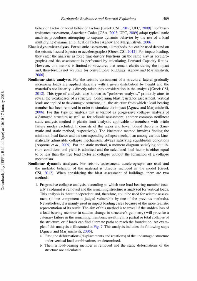
The most important difference concerning the behavior of RC structures in earthquakeswhen compared to impact loads has to do with the loading rate and, consequently, thestrain rate of the material. Even if the moduli of elasticity and the ultimate strains are notsignificantly affected, the yield (reinforcing steel) and peak stresses (concrete) are differ-ent. With earthquake loading (strain rate range: 10−5 to 101 s−1), the strength increase isgenerally neglected whereas, in impact loading and explosions (strain rate range: 101 to106 s−1), because of the velocity, the shock wave created tries to bring the material to astress level earlier than the moment that it can respond. In this way, a high strain rate is pro-voked, i.e., the material reaches a stress level without being deformed to the correspondingstrain level under static loading. Therefore, when the material reaches the peak strain underimpact loading, it could respond with a stress higher than the peak stress under static load-ing (fp.stat), equal to fp.dyn. The ratio fp.dyn/fp.stat is defined as the dynamic increase factor(DIF). Tests on concrete cubes [ELSA, 2011] showed that for strain rates corresponding tothe margin between earthquake and blast loading [Model Code, 2010], the DIF can attainvalues of up to 2.3 (see Fig. 1).
Dow
nloa
ded
by [
EPF
L B
iblio
thèq
ue]
at 1
0:10
17
Janu
ary
2016
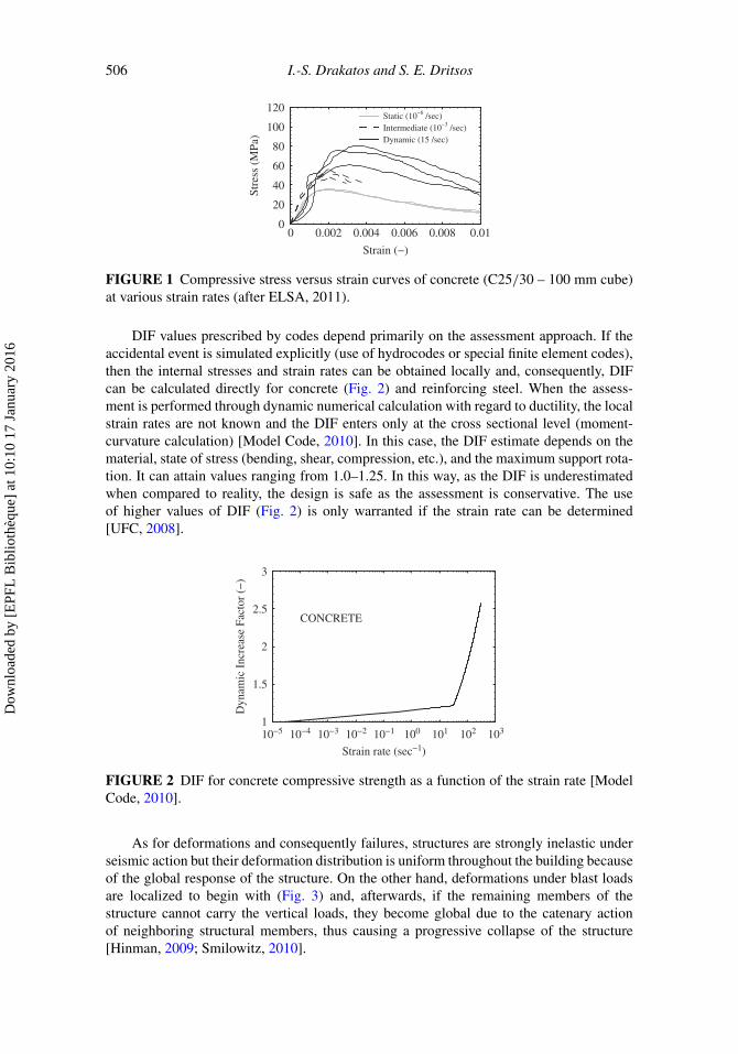
506 I.-S. Drakatos and S. E. Dritsos
0 0.002 0.004 0.006 0.008 0.010
20
40
60
80
100
120
Strain (−)St
ress
(M
Pa) Dynamic (15 /sec)
Static (10−6 /sec)Intermediate (10−3 /sec)
FIGURE 1 Compressive stress versus strain curves of concrete (C25/30 – 100 mm cube)at various strain rates (after ELSA, 2011).
DIF values prescribed by codes depend primarily on the assessment approach. If theaccidental event is simulated explicitly (use of hydrocodes or special finite element codes),then the internal stresses and strain rates can be obtained locally and, consequently, DIFcan be calculated directly for concrete (Fig. 2) and reinforcing steel. When the assess-ment is performed through dynamic numerical calculation with regard to ductility, the localstrain rates are not known and the DIF enters only at the cross sectional level (moment-curvature calculation) [Model Code, 2010]. In this case, the DIF estimate depends on thematerial, state of stress (bending, shear, compression, etc.), and the maximum support rota-tion. It can attain values ranging from 1.0–1.25. In this way, as the DIF is underestimatedwhen compared to reality, the design is safe as the assessment is conservative. The useof higher values of DIF (Fig. 2) is only warranted if the strain rate can be determined[UFC, 2008].
10−5 10−4 10−3 10−2 10−1 100 101 102 1031
1.5
2
2.5
3
Strain rate (sec−1)
Dyn
amic
Inc
reas
e Fa
ctor
(−
)
CONCRETE
FIGURE 2 DIF for concrete compressive strength as a function of the strain rate [ModelCode, 2010].
As for deformations and consequently failures, structures are strongly inelastic underseismic action but their deformation distribution is uniform throughout the building becauseof the global response of the structure. On the other hand, deformations under blast loadsare localized to begin with (Fig. 3) and, afterwards, if the remaining members of thestructure cannot carry the vertical loads, they become global due to the catenary actionof neighboring structural members, thus causing a progressive collapse of the structure[Hinman, 2009; Smilowitz, 2010].
Dow
nloa
ded
by [
EPF
L B
iblio
thèq
ue]
at 1
0:10
17
Janu
ary
2016

Earthquake Resistance and External Explosions 507
FIGURE 3 Blast and seismic response of a structure (after Hinman, 2009).
3.2. Structural Behavior (Ductility – Lateral Resistance)
Although RC is deformed in a more ductile way during an earthquake, a sufficient ductilityof a structure’s components is equally desirable for both earthquake and blast resistantdesign. The location of stress concentrations during a blast event is significantly differentfrom an earthquake. However, even under extreme overload, the structure has to be able todissipate large amounts of energy prior to failure [Smilowitz, 2010].
As for a structure’s lateral resistance, the most important difference between earth-quakes and explosions is the diaphragm action of the floors. Because of upward pressurescreated in the floors of the upper stories nearest the explosion (when the explosion takesplace on the ground surface), the diaphragm action of floors usually adopted in seismicanalyses is not suitable and a full 3-D analysis of the building might be required [Smilowitz,2010]. Figure 4 presents floor diaphragm behavior during a surface blast.
FIGURE 4 Floor diaphragm actions during an explosion on the ground surface (afterHinman, 2009).
In addition, the position of shear walls plays a fundamental role in the deformabilityof diaphragms [Smilowitz, 2010]. For blast resistance, shear walls are used in the samesense as in earthquake-resistant design [EC 8, 2004a], with an even bigger emphasis ontheir placement in the building’s perimeter whose components are the first to be exposed toblast overload created by an explosion [Hayes et al., 2004]. In this way, perimeter frames,which are less resistant to external explosions, are protected and floor diaphragms are notdeformed excessively. Figure 5 presents example arrangements of walls in layout ideal forseismic loading and Fig. 6 illustrates the effect on diaphragm behavior when not adoptingsuch arrangements for seismic and blast loading situations.
FIGURE 5 Arrangements of walls in layout proposed EAK [2003].
Dow
nloa
ded
by [
EPF
L B
iblio
thèq
ue]
at 1
0:10
17
Janu
ary
2016

508 I.-S. Drakatos and S. E. Dritsos
FIGURE 6 Diaphragm deformability of a building with an inner core under (a) seismicand (b) blast loads [Smilowitz, 2010].
The main object of shear walls is to prevent the progressive collapse of a buildingsoon after an explosion. Behind them, they also protect a building’s internal space fromhazardous flying debris [Hayes et al., 2004]. Moreover, in the case that the building’s façadeis near a busy road, people passing outside the building or evacuating from it after theexplosion are protected from falling and flying debris.
4. Comparison of Assessment Methods
4.1. Performance Criteria
For the seismic assessment of existing RC buildings, the main purpose of the analyses isto satisfy acceptance criteria (Immediate Occupancy (IO), Life Safety (LS), and CollapsePrevention (CP)), depending on the building’s importance [Greek CSI, 2012]. These crite-ria can be expressed either in terms of forces and moments or deformations (displacements,rotations, or curvatures), depending on the adopted method and the way that the memberfails (brittle or ductile) [Greek CSI, 2012].
On the other hand, for the blast assessment of a building, the definition of performancelevels is uneconomical, impractical, and often not clear because of the non general haz-ard level of each building, as well as the security measures adopted. The main object ofthe assessment or design of a building is to minimize the loss of life, which is achievedthroughout the following actions [Alkhrdaji, 2006]:
1. reduction of local structural failures;2. control of flying debris; and3. progressive collapse prevention, at least until the building can be evacuated.
4.2. Assessment Methods
Various assessment methods can be used in both cases (earthquake or impact and explosiveloading). The differences by method are as follows.
Elastic static analyses. In the case of seismic assessment, the elastic (equivalent) staticmethod (simplified spectral analysis) is used by the application of either the global
Dow
nloa
ded
by [
EPF
L B
iblio
thèq
ue]
at 1
0:10
17
Janu
ary
2016
Earthquake Resistance and External Explosions 509
behavior factor or local behavior factors [Greek CSI, 2012; UFC, 2009]. For blast-resistance assessment, American Codes [GSA, 2003; UFC, 2009] adopt typical staticanalysis procedures attempting to capture dynamic behavior by the use of a loadmultiplying dynamic amplification factor [Agnew and Marjanishvili, 2006].
Elastic dynamic analyses. For seismic assessment, all methods that can be used depend onthe seismic hazard (spectra or accelerographs) [Greek CSI, 2012]. For impact loading,they enter the analysis as force time-history functions (in the same way as accelero-graphs) and the assessment is performed by calculating Demand Capacity Ratios.However, this method is limited to structures that remain elastic during the impactand, therefore, is not accurate for conventional buildings [Agnew and Marjanishvili,2006].
Nonlinear static analyses. For the seismic assessment of a structure, lateral graduallyincreasing loads are applied statically with a given distribution by height and thematerial’s nonlinearity is directly taken into consideration in the analysis [Greek CSI,2012]. This type of analysis, also known as “pushover analysis,” primarily aims toreveal the weaknesses of a structure. Concerning blast resistance assessment, verticalloads are applied to the damaged structure, i.e., the structure from which a load-bearingmember has been removed in order to simulate the impact [Agnew and Marjanishvili,2006]. For this type of analysis that is termed as progressive collapse analysis ofa damaged structure as well as for seismic assessment, another common nonlinearstatic analysis method is plastic limit analysis, applicable to members with brittlefailure modes excluded. It consists of the upper and lower bound theorems (kine-matic and static method, respectively). The kinematic method involves finding theminimum load factor and the corresponding collapse mechanism among various kine-matically admissible collapse mechanisms always satisfying equilibrium conditions[Asprone et al., 2009]. For the static method, a moment diagram satisfying equilib-rium conditions and yield is admitted and the calculated load factor is either equalto or less than the true load factor at collapse without the formation of a collapsemechanism.
Nonlinear dynamic analyses. For seismic assessment, accelerographs are used andthe inelastic behavior of the material is directly included in the model [GreekCSI, 2012]. When considering the blast assessment of buildings, there are twomethods.
1. Progressive collapse analysis, according to which one load-bearing member (usu-ally a column) is removed and the remaining structure is analyzed for vertical loads.This analysis is threat independent and, therefore, could be used for seismic assess-ment (if one component is judged vulnerable by one of the previous methods).Nevertheless, it is mainly used in impact loading cases because of the more realisticrepresentation of its result. The aim of this method is to reveal if the sudden loss ofa load-bearing member (a sudden change in structure’s geometry) will provoke acatenary failure in the remaining members, resulting in a partial or total collapse ofthe structure, or if loads can find alternate paths to reach the foundation. An exam-ple of this analysis is illustrated in Fig. 7. This analysis includes the following steps[Agnew and Marjanishvili, 2006]:a. First, the deformations (displacements and rotations) of the undamaged structure
under vertical load combinations are determined.b. Then, a load-bearing member is removed and the static deformations of the
structure are calculated.
Dow
nloa
ded
by [
EPF
L B
iblio
thèq
ue]
at 1
0:10
17
Janu
ary
2016

510 I.-S. Drakatos and S. E. Dritsos
FIGURE 7 Threat-independent progressive collapse nonlinear dynamic analysis [Agnewand Marjanishvili, 2006].
c. Finally, the initial conditions of the deformations found in the previous step areapplied in order to make the structure return in its initial position before carryingout the analysis. For simplification, it can be assumed that the deformations ofthe undamaged structure under vertical loads (those computed in step a) are neg-ligible comparing to those caused by the loss of the load-bearing member (thosecomputed in step b). Thus, a dynamic analysis can be carried out with the ini-tial conditions of the deformations of the unloaded damaged structure (i.e., zeroinitial conditions, if the self-weight of the removed member is neglected).
2. Nonlinear (inelastic) dynamic analysis, using as input the impact loading (time-history similar to an accelerograph). This method of assessment is the most realisticbecause the excitation’s features (maximum pressure, duration, and arrival time)are directly included in the analysis. For this reason, it is adopted in the presentwork. It includes the following three steps, each one using as initial conditions thedeformations determined at the end of the previous stage:a. forced vibration (with zero initial conditions);b. free vibration; andc. progressive collapse analysis (static application of the vertical loads).
An example of this analysis is illustrated in Fig. 8.
FIGURE 8 Threat-dependent progressive collapse time-history analysis.
Dow
nloa
ded
by [
EPF
L B
iblio
thèq
ue]
at 1
0:10
17
Janu
ary
2016

Earthquake Resistance and External Explosions 511
5. Examining the Contribution of Earthquake-Resistant Design whenCoping with External Explosions in RC Buildings
Initially, inelastic analyses for seismic assessment and blast analyses were carried out ona typical two story RC building with layout dimensions of 14.5 m by 13.0 m and an inter-story height of 3.2 m. This building, constructed in 1975, comprised of three frames ineach direction. The building’s layout is presented in Fig. 9. The member’s geometricaldimensions and reinforcement are given in Table 1. For the material properties, the concretewas C16/20 and the reinforcing steel was StIII (S400). The building’s foundation consistedof a grid of beams of 400 by 1000 mm cross section. For simplification, the ground floorcolumns were considered fixed at their base. The Data Reliability Level was assumed as“Sufficient” in order to be allowed to perform inelastic analyses [Greek CSI, 2012].
Subsequently, analyses were performed on the same building after it was retrofittedby the addition of four perimeter shear walls. The adoption of this strengthening methodwill be discussed later. Two shear walls were in the direction of the impulsive loading andthe other two were perpendicular to it (one in the façade of the building exposed to theblast load and the other in the opposite corner). These walls were positioned as wing wallsto the existing corner columns and, including the original column, had a length of 1.0 mand a width of 0.2 m. Additional reinforcement was 6�10 in the web and 4�20 arrangedin a confined area at the opposite end from the existing corner columns. It was assumedthat these new load-bearing members would behave as shear walls, as their cross sectionaldimension ratio was higher than four [EC 2, 2004].
FIGURE 9 Layout of existing building’s typical story (dimensions in meters).
Dow
nloa
ded
by [
EPF
L B
iblio
thèq
ue]
at 1
0:10
17
Janu
ary
2016

512 I.-S. Drakatos and S. E. Dritsos
TABLE 1 Dimensions and reinforcement of the existing building’s members
Member PositionDimensions
(mm)
Longitudinalreinforcement
(mm)
Shearreinforcement
(mm)
Columns Corner 300×300 4�20 �8/200Peripheral 350×350 4�18 �8/200Central 450×450 8�16 �8/200
Ground and firstfloor beams
Internal 200×600 4�16 at the bottomand 2�18 at thetop at the ends
�8/300
Peripheral 200×500 4�14 at the bottomand 2�14 at thetop at the ends
�8/300
Ground and firstfloor slabs
− 150 �8/150 −
5.1. Simulation of the Structure
The simulation of the existing and retrofitted buildings was performed using SAP2000[2007]. Figure 10 presents the numerical models of the examined structures.
Each member (column, beam, or wall) was modeled as a linear finite element with twonodes and six degrees of freedom, which is included in the library of the software.
In order to simplify the dynamic analysis procedure, the following assumptions weremade.
1. To simulate the nonlinear (elastic-perfectly-plastic) behavior of the material, thelumped plasticity model was adopted (plastic hinge). According to this consider-ation, plastic hinges can theoretically appear anywhere along the frame members.Nevertheless, in order to simplify the model, it was arranged that they appear onlyat the ends of the members. For the beams, the hinges were determined by themoment around the horizontal direction perpendicular to their axes and relevantchord rotations. The chord rotation is the angle between the tangent at the end ofthe member that is under consideration and the chord that connects the two ends ofthe deformed member [Greek CSI, 2012]. For the columns and shear walls (in thecase of the retrofitted building), their properties were defined by the interaction ofthe axial force (P) and bending moment (M) in each horizontal direction (P vs. M2;P vs. M3),
FIGURE 10 Model of the (a) existing and (b) the retrofitted building.
Dow
nloa
ded
by [
EPF
L B
iblio
thèq
ue]
at 1
0:10
17
Janu
ary
2016
Earthquake Resistance and External Explosions 513
2. Effects of geometric nonlinearities (P-Delta effect, large deflections) are governedby the internal drift index (θ ) [EC 8, 2004a], as follows:
θ = Ntot.st · Δ/Vtot.st · hst, (1)
where Ntot.st and Vtot.st are the total axial and shear forces of the examined story’svertical members, respectively under the examined seismic combination, Δ is theinter-story drift of the examined story, and hst is the story’s height. For RC build-ings, this index is usually less than 0.1 [Greek CSI, 2012]. Therefore, the presentstudy neglects second-order effects. Further examination requires additional elasticanalyses.
3. The damping ratio was assumed to be 5% (which is conventional for RC)throughout the analyses.
4. All beam-column and beam-wall joints were moment-resistant and stronger than therelevant members. Therefore, plastic hinges will form in the body of these membersand not at their joints.
To find the chord rotations of each member’s end, Eqs. (2) and (3) [Greek CSI, 2012]for the mean chord rotation at failure (θum) and its plastic portion (θpl
um) were used. In addi-tion, appropriate modifications for the shear walls were incorporated in the model of theretrofitted building in order to take into account their limited rotation capacity [Greek CSI,2012]. The resulting values for the existing members (but not the shear walls which wereadded later) were divided by 1.2 because the building was constructed before 1985 [GreekCSI, 2012]:
θum = 0.016 · (0.3ν) ·[
max(0.01; ω′)max(0.01; ω)
· fc
]0.225
· (as)0.35 · 25
(a·ρs· fyw
fc
)· (1.25100·ρd ), (2)
θplum = θum − θy
= 0.0145 · (0.25ν) ·[
max(0.01; ω′)max(0.01; ω)
]0.3
(fc)0.2 · (as)0.35 · 25
(a·ρs· fyw
fc
)· (1.275100·ρd ).
(3)
The definition of the acceptance criteria (IO, LS, CP) was performed according to theGreek CSI [2012] using a strength safety factor of 1.8 for the model. In addition, reducedvalues of stiffness (Keff), which correspond to effective cracked sections [Greek CSI, 2012]were inserted into the model, using the Eq. (4), as well as Eqs. (2), (3), and (5) [Greek CSI,2012]:
Keff = My · Ls/3θy, (4)
My
b · d3=
[(1/r)y ·
{Ec · ξy
2
2·[
0.5 · (1 + δ′) − ξy
3
]+
[(1 − ξy) · ρ
+ (ξy − δ′) · ρ ′ + ρv
6· (1 − δ′)
]· (1 − δ′) · Es
2
}].
(5)
Finally, in order to examine the influence of the shear force on the behavior of theplastic hinges, the shear strength values corresponding to the yield moment (μpl
θ = 0) and
Dow
nloa
ded
by [
EPF
L B
iblio
thèq
ue]
at 1
0:10
17
Janu
ary
2016

514 I.-S. Drakatos and S. E. Dritsos
the failure moment (μplθ = θpl/θ y) of each member were calculated in order to take into
consideration the reduction of shear strength due to cyclical loading (VR). The equationused was as follows [Greek CSI, 2012]:
VR =[
h − x
2Lsmin(N; 0.55Acfc) +
[1 − 0.05 min
(5, μpl
θ
)]
·{
0.16 · max(0.5; 100 · ρtot) · [1 − 0.16 · min(5; as)] · √fc · Ac + Vw
} ].
(6)
In the above equations, ν is the normalized axial force N/(b·h·fc), where N is the member’saxial force (positive for compression), b and h are the width and depth of the cross section,respectively, fc is the cylindrical concrete strength, ω and ω′ are the mechanical percent-ages of reinforcement in tension and compression, respectively, as is the shear ratio of themember Ls/h, where Ls is the shear span (equal to the bending moment to shear forceratio), a is a confinement effectiveness factor, ρs is the ratio of transverse reinforcementparallel to the direction of loading, fyw is the shear reinforcement yield stress, ρd is the ratioof diagonal reinforcement in each diagonal direction, θ y is the chord rotation at yield, My
is the yield moment, d is the distance from the extreme compression fiber to the centroidof the longitudinal tensile reinforcement (the effective depth of the member), (1/r)y is thecurvature of the member at yield, Ec and Es are the modulus of elasticity of the concreteand reinforcing steel, respectively, θpl is the plastic portion of the chord rotation at failure,ξ y is the dimensionless height of the compression zone at yield, δ’ is the dimensionlessdistance of the reinforcement in compression from the extreme compression fiber of con-crete (divided by d), ρ tot (ρ, ρ’, ρv), are the geometrical percentages of the flexural (tensile,compressive, intermediate) reinforcement, x is the height of the compression zone, Ac is themember’s cross sectional area, μ
plθ is the plastic portion of the ductility factor (expressed in
terms of chord rotations), and Vw is the contribution of transverse reinforcement to the shearstrength.
Shear strength values corresponding to the moment at yield and failure were comparedto the shear force corresponding to the moment at yield (= My/Ls), in order to find out howeach member fails (ductile or brittle failure). It was found that the shear force correspondingto the moment at yield was less than the shear strength corresponding to moment at failurefor all members of the existing building. Therefore, the moment at yield occurs before shearfailure and no change of the plastic portion of the chord rotation at failure (due to limitedrotation capacity) is required [Greek CSI, 2012]. It should be noted that it is possible fora member to behave in a ductile way until the moment at yield (VMy < VRMy) but, due tocyclic loading that leads to shear strength degradation, it might finally fail in a brittle way(VRMu < VMy). For this reason, the shear strength corresponding to the moment at failurewas also calculated [Greek CSI, 2012]. Here, VMy is the shear force corresponding to themoment at yield, while VRMy and VRMu are the shear strengths corresponding to the momentat yield and ultimate, respectively.
Concerning the blast analysis, as discussed in Sec. 3.1, DIF values for concrete andreinforcing steel of 1.25 for bending and 1.10 for shear were applied to both models, as thesupport rotations were less than 2 degrees [Model Code, 2010; UFC, 2008].
5.2. Seismic Assessment of the Existing and the Retrofitted Building
Initially, before simulating an explosion, static inelastic pushover analyses of the existingbuilding were carried out in order to examine its vulnerability during an earthquake and,
Dow
nloa
ded
by [
EPF
L B
iblio
thèq
ue]
at 1
0:10
17
Janu
ary
2016
Earthquake Resistance and External Explosions 515
consequently, the need or not for strengthening. From the modal analyses, it was found thatthe 1st mode shape was rotational and corresponded to a period T1 of 1.32 s. The 2nd modeshape was translational in y direction with period T2 of 1.30 s. The relatively high vibrationperiod is justified by the values of the effective stiffness calculated through Eq. (4), whichcorrespond to a range of 10.2–15.4% of the uncracked stiffness for the beams, and from9.2–13.7% of the uncracked stiffness for the columns.
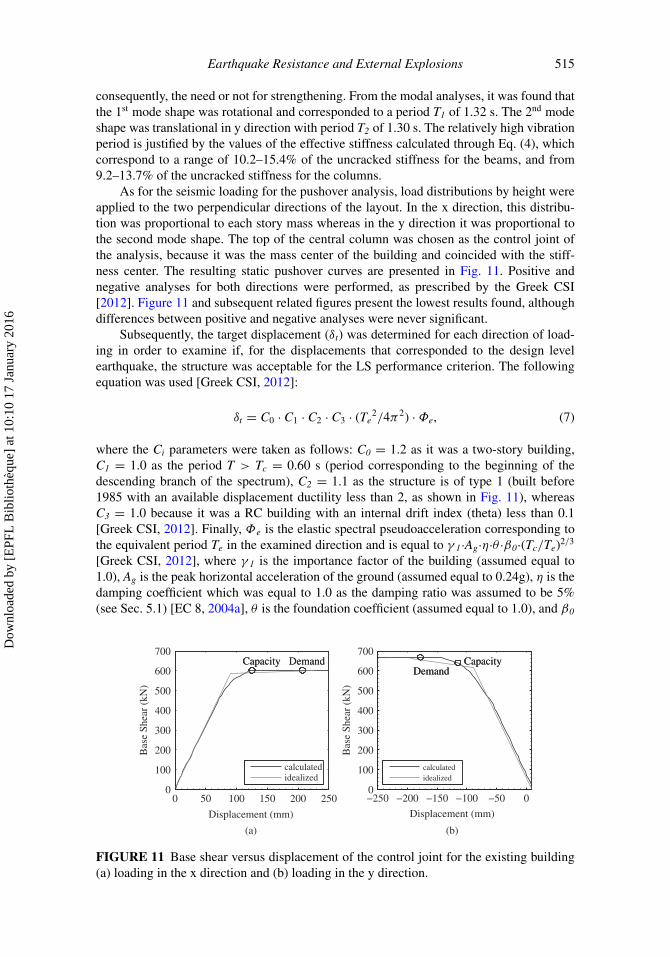
As for the seismic loading for the pushover analysis, load distributions by height wereapplied to the two perpendicular directions of the layout. In the x direction, this distribu-tion was proportional to each story mass whereas in the y direction it was proportional tothe second mode shape. The top of the central column was chosen as the control joint ofthe analysis, because it was the mass center of the building and coincided with the stiff-ness center. The resulting static pushover curves are presented in Fig. 11. Positive andnegative analyses for both directions were performed, as prescribed by the Greek CSI[2012]. Figure 11 and subsequent related figures present the lowest results found, althoughdifferences between positive and negative analyses were never significant.
Subsequently, the target displacement (δt) was determined for each direction of load-ing in order to examine if, for the displacements that corresponded to the design levelearthquake, the structure was acceptable for the LS performance criterion. The followingequation was used [Greek CSI, 2012]:
δt = C0 · C1 · C2 · C3 · (Te2/4π2) · Φe, (7)
where the Ci parameters were taken as follows: C0 = 1.2 as it was a two-story building,C1 = 1.0 as the period T > Tc = 0.60 s (period corresponding to the beginning of thedescending branch of the spectrum), C2 = 1.1 as the structure is of type 1 (built before1985 with an available displacement ductility less than 2, as shown in Fig. 11), whereasC3 = 1.0 because it was a RC building with an internal drift index (theta) less than 0.1[Greek CSI, 2012]. Finally, Φe is the elastic spectral pseudoacceleration corresponding tothe equivalent period Te in the examined direction and is equal to γ 1·Ag·η·θ ·β0·(Tc/Te)2/3
[Greek CSI, 2012], where γ 1 is the importance factor of the building (assumed equal to1.0), Ag is the peak horizontal acceleration of the ground (assumed equal to 0.24g), η is thedamping coefficient which was equal to 1.0 as the damping ratio was assumed to be 5%(see Sec. 5.1) [EC 8, 2004a], θ is the foundation coefficient (assumed equal to 1.0), and β0
0 50 100 150 200 2500
100
200
300
400
500
600
700
Displacement (mm)
(a)
Bas
e Sh
ear
(kN
)
DemandCapacity DemandCapacity
calculatedidealized
−250 −200 −150 −100 −50 00
100
200
300
400
500
600
700
Displacement (mm)
(b)
Bas
e Sh
ear
(kN
)
DemandCapacity
DemandCapacity
calculatedidealized
FIGURE 11 Base shear versus displacement of the control joint for the existing building(a) loading in the x direction and (b) loading in the y direction.
Dow
nloa
ded
by [
EPF
L B
iblio
thèq
ue]
at 1
0:10
17
Janu
ary
2016

516 I.-S. Drakatos and S. E. Dritsos
is the dynamic amplification factor (equal to 2.5). The equivalent period (Te) is given bythe Greek CSI [2012], as follows:
Te = T0 · √K0/Ke, (8)
where T0 is the elastic prevailing period in the examined direction, while K0 and Ke are theinitial and the equivalent stiffness of the structure, respectively.
From the base shear versus displacement curves of Fig. 11, the behavior factor (q) ofthe structure can be calculated in various ways. In this case, the method proposed by Uang[1991] and adopted by many codes [EC 8, 2004a; Greek CSI, 2012] was chosen, accordingto which the behavior factor is defined as:
q = qd · qo, (9)
where qo is the overstrength portion of the behavior factor and is equal to Vy/Ve, the ratio ofthe base shear at the idealized yield limit of the structure to the base shear corresponding tothe appearance of the first plastic hinge (the beginning of deviation from the elastic branch),and qd is the ductility portion of the behavior factor and is equal to the ratio of the baseshear corresponding to elastic behavior of the structure near its maximum displacement(calculated as the product of the initial stiffness and the maximum displacement) to Vy.The results of the seismic assessment of the existing building are presented in Table 2.
In Table 2, μΔ is the ductility displacement factor, calculated as the displacement ofthe control joint at the load step of first exceedance of the LS performance criterion dividedby the displacement of the control joint at the idealized yielding of the structure. As Te washigher than Tc, the calculated values of μΔ were found almost equal to values of qd [GreekCSI, 2012].
As can be seen from the results, the existing building is stiffer in the y direction thanin the x direction, with smaller elastic and equivalent prevailing periods T0 and Te, respec-tively, as well as a smaller behavior factor and displacement ductility and, consequently,a smaller target displacement. The estimation of qo was near the value of 1.30 proposedin the Greek CSI [2012] for multicolumn systems of frames of two stories or more withregularity in layout.
The deformed shape of the existing building for the target displacement, which repre-sents the design level earthquake, is presented in Fig. 12 for each direction of loading. It canbe seen from Fig. 12 that plastic hinges exceeded the LS performance level. Therefore, for
TABLE 2 Seismic assessment of the existing building (results)
Parameter x direction y direction
To (s) 1.30 1.19Te (s) 1.34 1.20Ko (kN/m) 6800.00 6440.00Ke (kN/m) 6360.00 6380.00δt (mm) 207.00 178.00qo 1.27 1.33qd 1.47 1.21q 1.87 1.61μΔ 1.41 1.29
Dow
nloa
ded
by [
EPF
L B
iblio
thèq
ue]
at 1
0:10
17
Janu
ary
2016

Earthquake Resistance and External Explosions 517
FIGURE 12 Deformed shape of the existing building for the target displacement (a)loading in the x direction and (b) loading in the y direction.
both directions of loading and corresponding target displacements of the control joint, theexisting building would not be considered as acceptable for the LS performance criterion.Consequently, the building requires strengthening.
The most common methods for global earthquake-resistant strengthening include theconstruction of new concrete walls or steel truss systems well connected to the frames, theconstruction of wing walls in continuity with the existing columns, the construction of RCjackets around the structure’s vertical members, the addition of vertical members, and theintroduction of dissipation systems [Dritsos, 2009].
Seismic strengthening aims to increase the ductility, the stiffness or the strength. Theaddition of vertical members ranks first as it offers a significant enhancement to all threeparameters. The construction of new concrete walls offers significant increases mainly to astructure’s stiffness and strength, while RC jackets enhance mainly the ductility. The use ofsteel bracing systems increases mainly the ductility and stiffness. Constructing wing wallsimproves a structure’s ductility and partially enhances its strength and stiffness. The intro-duction of dissipation systems aims to reduce the seismic action on the structure [Dritsos,2009]. If the retrofit of a building is designed to provide a certain degree of blast resistanceagainst external explosions, some additional criteria should be respected, the most impor-tant being the increase of a structure’s mass, the protection of the blast sensitive perimeterand the control of flying debris.
Many parameters influence the choice of the retrofit design. Some solutions may ini-tially be excluded from the basket of possible choices. For example, the use of steel bracingplaced into frames can be excluded because it usually leads to the use of partition wallsystems normally not strongly connected to the existing structure, increasing thus the fly-ing debris hazard [Schmidt, 2003], and offers much lower mass to the structure than RC.Furthermore, the construction of concrete jackets around the columns and the addition ofnew elements should be excluded since they do not increase significantly the structure’smass, do not offer protection to the building’s perimeter, and the works related to theirapplication should be distributed throughout the building, thereby interrupting its function-ality. However, some others may need an extended examination of the specific buildingfeatures. A detailed procedure for the selection of the most proper seismic retrofit designcan be found elsewhere [Baros and Dritsos, 2008].
In the present study, the construction of wing walls was decided on as it satisfiesmost of the criteria mentioned above: (a) construction in the perimeter with a considerable
Dow
nloa
ded
by [
EPF
L B
iblio
thèq
ue]
at 1
0:10
17
Janu
ary
2016

518 I.-S. Drakatos and S. E. Dritsos
increase in the mass of the building could offer better resistance under blast loading, (b)by following earthquake resistance detailing, a considerable ductility increase and a partialenhancement of the stiffness and strength could be expected, and (c) it is a low cost easilyapplied method using a non-specialist workforce and causes a minimum disruption to thefunctioning of the building as work is carried out in the perimeter of a building.
From the modal analyses of the retrofitted building, it was found that the first modeshape was rotational and T1 was 0.92 s. The second mode shape was translational in the xdirection and T2 was 0.82 s. For the retrofitted building, effective stiffness values for thecolumns ranged from 7.2% and 15.6% of the uncracked stiffness. The differences whencompared to effective stiffness values determined for the existing building can be attributedto the variation of axial forces that influence both the yield moment and the yield rotationthat are necessary for the calculation of the effective stiffness using Eq. (1).
When simulating the lateral loads in the strengthened building, in the x direction thedistribution of these loads was proportional to the second mode shape, whereas in y direc-tion it was proportional to each stories’ mass. The resulting static pushover curves arepresented in Fig. 13 and Table 3 summarizes the results of the seismic assessment of theretrofitted building.
When comparing results presented in Tables 2 and 3, it can be seen that q increased inboth directions for the retrofitted building and it is obviously stiffer. This can be explained
−200 −150 −100 −50 00
200
400
600
800
1000
1200
Displacement (mm)(a)
Bas
e Sh
ear
(kN
)
DemandCapacity
DemandCapacity
calculatedidealized
0 50 100 1500
200
400
600
800
1000
1200
Displacement (mm)
(b)
Bas
e Sh
ear
(kN
) Demand CapacityDemand Capacity
calculatedidealized
FIGURE 13 Base shear vs. displacement of control joint for the retrofitted building (a)loading in the x direction and (b) loading in the y direction.
TABLE 3 Seismic assessment of the retrofitted building (results)
Parameter x direction y direction
To (s) 0.82 0.69Te (s) 0.83 0.68Ko (kN/m) 13000.00 12090.00Ke (kN/m) 12550.00 12500.00δt (mm) 109.00 76.00qo 1.20 1.25qd 1.73 1.38q 2.08 1.73μΔ 1.60 1.45
Dow
nloa
ded
by [
EPF
L B
iblio
thèq
ue]
at 1
0:10
17
Janu
ary
2016

Earthquake Resistance and External Explosions 519
FIGURE 14 Deformed shape of the retrofitted building for the target displacement (a)loading in the x direction and (b) loading in the y direction.
by the larger increase of the lateral stiffness comparing to the reduction of ultimate dis-placement (increase in the ductility behavior factor qd) as the overstrength behavior factoris approximately constant for both numerical models and directions. On the other hand,μΔ for the retrofitted building was larger in both directions when compared to the existingbuilding. Thus, the enhancement of the structure’s ductility by the use of wing walls wasconfirmed by the pushover analyses. Moreover, the increase of strength (by approximately50%) and the doubling of the lateral stiffness of the existing building clearly demonstratethat this choice of strengthening was successful, at least for seismic behavior.
Figure 14 presents the deformed shape of the retrofitted building for the target displace-ment for each direction of loading. From Fig. 14, it can be seen that plastic hinges exceededthe IO performance level. Therefore, for both directions of loading and corresponding targetdisplacements of the control joint, the retrofitted building would be considered acceptablefor the LS performance criterion.
5.3. Blast Analysis
Blast analyses were carried out for both buildings (existing and retrofitted). Initially, aforced vibration analysis was performed. Then the deformed shape of the structure at theend of the forced vibration analysis was used as the initial conditions for a free vibrationanalysis. Likewise, the deformed shape of the structure at the end of the free vibrationanalysis was used as the initial conditions for a progressive collapse analysis.
5.3.1. Forced Vibration. Both the existing building (which was previously judged to beseismically insufficient) and the retrofitted building were analyzed for an external explosiondetonated from a compact car trunk. This was equivalent to a weight (W) of 250 lb (≈113 kg) of TNT on the ground surface (surface blast). Initially, all real distances (R) ofeach member from the source of the explosion were scaled using the following parameter[Schmidt, 2003]:
Z = R/W1/3, (10)
to take into consideration the fact that a large quantity of explosive (W) placed close to astructure is more easily detected than a smaller one.
Dow
nloa
ded
by [
EPF
L B
iblio
thèq
ue]
at 1
0:10
17
Janu
ary
2016

520 I.-S. Drakatos and S. E. Dritsos
FIGURE 15 Parameters of positive phase of impulsive wave for an explosion on theground surface (adapted from UFC, 2008).
To find the maximum incident pressures (acting during the explosion) and reflectedpressures (reflected from existing members or buildings) that act on the members of theexternal frame of the structure nearest to the explosion, Fig. 15 [UFC, 2008] was used inconjunction with the scaled distance (Z) (Eq. (10)).
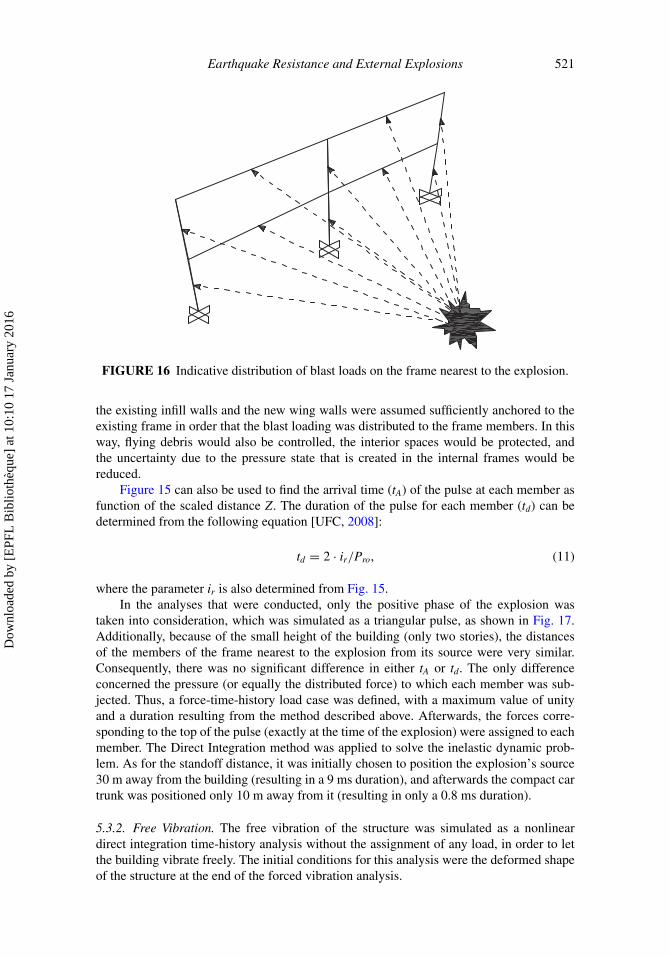
The reflected pressure (Pro), when compared to the incident pressure (Pso), gave themaximum values and, therefore, was used for the analyses. To transform these pressures todistributed forces, they were multiplied by the vertical influence surface of each memberdivided by its length. This means that the load distribution due to blast action was assumedto be uniform over the height for each column and over the length for each beam. For theexisting building, the influence surfaces were found using the trapezoidal method (similarto distributing vertical loads from slabs, fictitious lines starting from each joint and hav-ing an inclination of 45o determined the surface distribution) because the concrete areasof the members of the façade were similar. On the other hand, for the retrofitted build-ing, it was considered more realistic to distribute the loads proportionally to the ratio ofeach member’s concrete area to the total concrete area of the façade of the story. This wasdeemed necessary because the presence of the shear wall parallel to the façade influencedsignificantly the distribution of the loads due to the explosion on the existing masonry infillwalls. An indicative distribution of the blast loads is shown in Fig. 16. For the analyses,
Dow
nloa
ded
by [
EPF
L B
iblio
thèq
ue]
at 1
0:10
17
Janu
ary
2016
Earthquake Resistance and External Explosions 521
FIGURE 16 Indicative distribution of blast loads on the frame nearest to the explosion.
the existing infill walls and the new wing walls were assumed sufficiently anchored to theexisting frame in order that the blast loading was distributed to the frame members. In thisway, flying debris would also be controlled, the interior spaces would be protected, andthe uncertainty due to the pressure state that is created in the internal frames would bereduced.
Figure 15 can also be used to find the arrival time (tA) of the pulse at each member asfunction of the scaled distance Z. The duration of the pulse for each member (td) can bedetermined from the following equation [UFC, 2008]:
td = 2 · ir/Pro, (11)
where the parameter ir is also determined from Fig. 15.In the analyses that were conducted, only the positive phase of the explosion was
taken into consideration, which was simulated as a triangular pulse, as shown in Fig. 17.Additionally, because of the small height of the building (only two stories), the distancesof the members of the frame nearest to the explosion from its source were very similar.Consequently, there was no significant difference in either tA or td. The only differenceconcerned the pressure (or equally the distributed force) to which each member was sub-jected. Thus, a force-time-history load case was defined, with a maximum value of unityand a duration resulting from the method described above. Afterwards, the forces corre-sponding to the top of the pulse (exactly at the time of the explosion) were assigned to eachmember. The Direct Integration method was applied to solve the inelastic dynamic prob-lem. As for the standoff distance, it was initially chosen to position the explosion’s source30 m away from the building (resulting in a 9 ms duration), and afterwards the compact cartrunk was positioned only 10 m away from it (resulting in only a 0.8 ms duration).
5.3.2. Free Vibration. The free vibration of the structure was simulated as a nonlineardirect integration time-history analysis without the assignment of any load, in order to letthe building vibrate freely. The initial conditions for this analysis were the deformed shapeof the structure at the end of the forced vibration analysis.
Dow
nloa
ded
by [
EPF
L B
iblio
thèq
ue]
at 1
0:10
17
Janu
ary
2016
522 I.-S. Drakatos and S. E. Dritsos
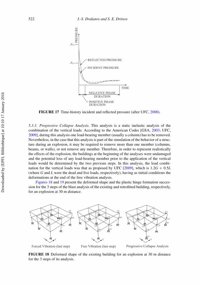
FIGURE 17 Time-history incident and reflected pressure (after UFC, 2008).
5.3.3. Progressive Collapse Analysis. This analysis is a static inelastic analysis of thecombination of the vertical loads. According to the American Codes [GSA, 2003; UFC,2009], during this analysis one load-bearing member (usually a column) has to be removed.Nevertheless, in the case that this analysis is part of the simulation of the behavior of a struc-ture during an explosion, it may be required to remove more than one member (columns,beams, or walls), or not remove any member. Therefore, in order to represent realisticallythe effects of the explosion, the buildings at the beginning of the analyses were undamagedand the potential loss of any load-bearing member prior to the application of the verticalloads would be determined by the two previous steps. In this analysis, the load combi-nation for the vertical loads was that as proposed by UFC [2009], which is 1.2G + 0.5L(where G and L were the dead and live loads, respectively), having as initial conditions thedeformations at the end of the free vibration analysis.
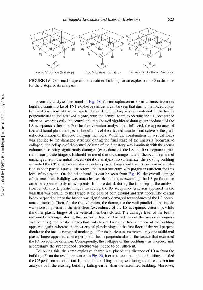
Figures 18 and 19 present the deformed shape and the plastic hinge formation succes-sion for the 3 steps of the blast analysis of the existing and retrofitted building, respectively,for an explosion at 30 m distance.
FIGURE 18 Deformed shape of the existing building for an explosion at 30 m distancefor the 3 steps of its analysis.
Dow
nloa
ded
by [
EPF
L B
iblio
thèq
ue]
at 1
0:10
17
Janu
ary
2016
Earthquake Resistance and External Explosions 523
FIGURE 19 Deformed shape of the retrofitted building for an explosion at 30 m distancefor the 3 steps of its analysis.
From the analyses presented in Fig. 18, for an explosion at 30 m distance from thebuilding using 113 kg of TNT explosive charge, it can be seen that during the forced vibra-tion analysis, most of the damage to the existing building was concentrated in the beamsperpendicular to the attacked façade, with the central beam exceeding the CP acceptancecriterion, whereas only the central column showed significant damage (exceedance of theLS acceptance criterion). For the free vibration analysis that followed, the appearance oftwo additional plastic hinges in the columns of the attacked façade is indicative of the grad-ual deterioration of the load carrying members. When the combination of vertical loadswas applied to the damaged structure during the final stage of the analysis (progressivecollapse), the collapse of the central column of the first story was imminent with the cornercolumns also being significantly damaged (exceedance of the LS and IO acceptance crite-ria in four plastic hinges). It should be noted that the damage state of the beams remainedunchanged from the initial forced vibration analysis. To summarize, the existing buildingexceeded the CP acceptance criterion in two plastic hinges and the LS performance crite-rion in four plastic hinges. Therefore, the initial structure was judged insufficient for thislevel of explosion. On the other hand, as can be seen from Fig. 19, the overall damageof the retrofitted building was much less as plastic hinges exceeding the LS performancecriterion appeared only in two points. In more detail, during the first step of the analysis(forced vibration), plastic hinges exceeding the IO acceptance criterion appeared in thewall that was parallel to the façade at the base of both ground and first floors. The centralbeam perpendicular to the façade was significantly damaged (exceedance of the LS accep-tance criterion). Then, for the free vibration, the damage to the wall parallel to the façadewas more important in the first floor (exceedance of the LS acceptance criterion), whilethe other plastic hinges of the vertical members closed. The damage level of the beamsremained unchanged during this analysis step. For the last step of the analysis (progres-sive collapse), the plastic hinges that had closed during the free vibration of the buildingappeared again, whereas the most crucial plastic hinge at the first floor of the wall perpen-dicular to the façade remained unchanged. For the horizontal members, only one additionalplastic hinge appeared at one peripheral beam perpendicular to the façade that exceededthe IO acceptance criterion. Consequently, the collapse of this building was avoided, and,accordingly, the strengthened structure was judged to be sufficient.
Following this, the same explosive charge was placed at a distance of 10 m from thebuilding. From the results presented in Fig. 20, it can be seen that neither building satisfiedthe CP performance criterion. In fact, both buildings collapsed during the forced vibrationanalysis with the existing building failing earlier than the retrofitted building. Moreover,
Dow
nloa
ded
by [
EPF
L B
iblio
thèq
ue]
at 1
0:10
17
Janu
ary
2016
524 I.-S. Drakatos and S. E. Dritsos
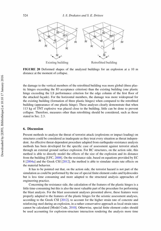
FIGURE 20 Deformed shapes of the analyzed buildings for an explosion at a 10 mdistance at the moment of collapse.
the damage to the vertical members of the retrofitted building was more global (three plas-tic hinges exceeding the IO acceptance criterion) than the existing building (one plastichinge exceeding the LS performance criterion for the edge column of the first floor ofthe attacked façade). For the horizontal members, the damage was more widespread forthe existing building (formation of three plastic hinges) when compared to the retrofittedbuilding (appearance of one plastic hinge). These analyses clearly demonstrate that when113 kg of TNT explosive was placed close to the building, little can be done to preventcollapse. Therefore, measures other than retrofitting should be considered, such as thosestated in Sec. 2.3.
6. Discussion
Present methods to analyze the threat of terrorist attack (explosions or impact loading) onstructures could be considered as inadequate as they treat every situation as threat indepen-dent. An effective threat-dependent procedure adapted from earthquake-resistance analysismethods has been developed for the specific case of assessment against terrorist attackthrough an external ground surface explosion. For RC structures, on the action side, thismethod is able to directly model the effects of the size of the explosion and its distancefrom the building [UFC, 2008]. On the resistance side, based on equations provided by EC8 [2004a] and the Greek CSI [2012], the method is able to simulate strain rate effects onthe material behavior.
It has to be pointed out that, on the action side, the terrorist hazard is not part of thesimulation as could be performed by the use of special finite element codes and hydrocodesbut is less time consuming and more adapted to the structural analysis approaches ofengineering practice.
Concerning the resistance side, the calculation of the features of the plastic hinges is alittle time-consuming but this is also the most valuable part of the procedure for performingthe blast analysis. For the blast assessment analyses presented above, these features wereproperly adapted to the features of the plastic hinges for the seismic assessment analyses,according to the Greek CSI [2012], to account for the higher strain rate of concrete andreinforcing steel during an explosion, in a rather conservative approach as local strain ratescannot be calculated [Model Code, 2010]. Otherwise, special finite element codes shouldbe used accounting for explosion-structure interaction rendering the analysis more time
Dow
nloa
ded
by [
EPF
L B
iblio
thèq
ue]
at 1
0:10
17
Janu
ary
2016

Earthquake Resistance and External Explosions 525
consuming, the establishment of performance criteria inconsistent with seismic assessmentperformance criteria and resulting in comparisons difficult to interpret.
Using this threat-dependent procedure and an iterative process, an appropriate standoffcontour distance could be reasonably defined for a particular size of explosion and, takinginto account urban layout, its possible location in relation to a building. Obviously, thismeans that threat-dependent procedures would entail several analyses when compared tothe single analysis of threat-independent methods.
Due to the time-consuming feature of the analysis and the fact that several analysesmay be necessary to properly define a posed threat, the procedure would be suitable onlyfor more important buildings but this is exactly the type of buildings targeted by terrorists.Nevertheless, besides the number of personnel and visitors, these types of buildings are notonly important for the prestige of a city but also for urban and transportation development,especially when they are constructed in central urban areas. Therefore, as limitations in thedistance between buildings, parking places, and vehicle velocities can be established on thebasis of these analyses, it is thought to be a cost-effective and multi-benefit approach.
For the contribution of earthquake-resistant design to the blast resistance of the struc-ture, it was found that when 113 kg of TNT explosive was placed at a distance of 30 m fromthe building, the existing building, which through pushover analyses was previously judgedas insufficient in the seismic assessment, collapsed during the forced vibration. On the otherhand, the retrofitted building, which was judged seismically sufficient did not collapse dur-ing the explosion and carried the vertical loads with safety. This retrofitting technique,developed for improved earthquake resistance involving the addition of wing walls, hasbeen demonstrated to be effective to resist blast loading but placing the additional walls inthe outer perimeter of the building has more significance for the latter case. As a result, forthis level of blast hazard, the chosen strengthening method was proved adequate to preventcollapse.
When the same quantity of explosive was placed at a distance of 10 m from the build-ing, the addition of the wing walls did not enhance sufficiently the blast resistance of thebuilding, as both buildings collapsed during the forced vibration. In this situation, othersecurity measures must be considered.
Infill walls and new members have to be sufficiently anchored to the existing building’smembers. Otherwise, the distribution of the impulse load on the members for the presentedanalyses would not be realistic and, as a result, the infill walls would fail prematurely outof plane and flying debris would not be controlled. Consequently, interior spaces would beunprotected and internal frames would be exposed to high pressures that would be difficultto predict.
7. Conclusions
The conclusions from this study, which primarily aimed to examine the contribution ofearthquake-resistant design to the behavior of a RC building under blast loads, can besummarized as follows.
● Present methods to analyze the threat of terrorist attack could be considered asinadequate as they treat every situation as threat independent.
● Analysis methods and retrofitting techniques specifically developed for earthquakeresistance can be successfully adapted to determine and limit the consequences ofterrorist attack and such analysis methods lead to a more realistic method to assessthe vulnerability of RC buildings subjected to blast loading.
Dow
nloa
ded
by [
EPF
L B
iblio
thèq
ue]
at 1
0:10
17
Janu
ary
2016
526 I.-S. Drakatos and S. E. Dritsos
● It is rather easy to conduct the blast assessment analyses in three steps (forced vibra-tion, free vibration, and progressive collapse), as presented in this study. However,the features of the plastic hinges should be realistically determined, which meansthat especially in the case of explosions a realistic estimation of the strain rate isnecessary.
● Even though the two phenomena earthquake and explosion are fundamentally differ-ent, the application of the rules of earthquake-resistant design can offer significantimprovements for the behavior of RC buildings during explosions of moderate andlong range, as local failures are limited and progressive collapse is avoided.
● When a terrorist attack with explosives is of short range, the principles ofearthquake-resistant design cannot offer sufficient additional resistance. In this case,other measures should be applied aiming to render shock pressures lower anddistribute them more uniformly over the building’s façade.
● As the analysis method described in this article could be considered as time con-suming and there is now the possibility of performing several analyses, the methodwould be suitable only for more important structures. This is precisely the type ofbuilding targeted by terrorists.
Acknowledgments
The authors would like to acknowledge the significant assistance of Dr. V. J. Moseleyduring the preparation of this manuscript.
References
Agnew, E. and Marjanishvili, S. [2006] “Dynamic analysis procedures for progressive collapse,”Structure Magazine April, 24–27.
Alkhrdaji, T. [2006] “Blast mitigation of concrete structures,” Construction Specifier. Retrieved fromhttp://www.vsl.net/Article/tabid/157/contentid/93/Default.aspx (January 3, 2011).
Asprone, D., Jalayer, F., Prota, A., and Manfredi, G. [2009] “Proposal of a probabilistic model formulti-hazard risk assessment of structures in seismic zones subjected to blast for the limit state ofcollapse,” Structural Safety 32(1), 25–34.
Baros, D. and Dritsos, S. E. [2008] “A simplified procedure to select a suitable retrofit strategyfor existing RC buildings using pushover analysis,” Journal of Earthquake Engineering 12(6),823–848.
BS 8110-1 [1997] Structural Use of Concrete – Section 3: Design and Detailing: ReinforcedConcrete, British Standards Institution, London, UK.
Dritsos, S. E. [2009] “Repair and strengthening of reinforced concrete structures,” University ofPatras, Patras, Greece (in Greek).
EAK [2003] “Greek code for seismic resistant structures,” Greek Organization for Seismic Planningand Protection, Greek Ministry for Environmental Planning and Public Works, Athens, Greece (inGreek).
EC 2 [2004] “European Standard EN, design of concrete structures - Part 1-1: General rules and rulesfor buildings,” EN 1992-1-1: European Committee for Standardization, CEN/TC250, Brussels.
EC 8 [2004a] “European Standard EN, design of structures for earthquake resistance, Part 1:General rules, seismic actions and rules for buildings,” prEN 1998-1: European Committee forStandardization, CEN/TC250, Brussels.
EC 8 [2004b] “European Standard EN, design of structures for earthquake resistance,Part 3: Assessment and Retrofitting of Buildings,” prEN 1998-3: European Committee forStandardization, CEN/TC250, Brussels.
Dow
nloa
ded
by [
EPF
L B
iblio
thèq
ue]
at 1
0:10
17
Janu
ary
2016

Earthquake Resistance and External Explosions 527
ELSA [2011] “Physical vulnerability assessment of critical structure,” European Laboratoryfor Structural Assessment, Retrieved from http://elsa.jrc.ec.europa.eu/showinstaction.php?id=2(February 17, 2011).
Greek CSI [2012] “Greek code of structural interventions,” Greek Organization for Seismic Planningand Protection, Greek Ministry for Environmental Planning and Public Works, Athens, Greece.
GSA [2003] “Progressive collapse analysis and design guidelines for new federal office buildings andmajor modernization projects,” U.S. General Services Administration, Washington, D.C.
Hayes, J., Woodson, S., Pekelnicky, R., Poland, C., Corley, W.G., Sozen, M., Mahoney, M., andHanson, R. [2004] “Earthquake resistance and blast resistance: A structural comparison,” Proc.of the 13th World Conference on Earthquake Engineering, Vancouver, Canada.
Hinman, E. [2009] “Blast safety of the building envelope,” National Institute of Building Sciences,Whole Building Design Guide (WBDG), Retrieved from http://www.wbdg.org/resources/env_blast.php (January 5, 2011).
Model Code [2010], Part II (Design input data) and Part III (Design), Fédération Internationale duBéton (fib), Lausanne, Switzerland.
SAP2000 [2007] Structural analysis program, Computers and Structures, Inc., Berkeley, California.Schmidt, J. [2003] “Structural design for external terrorist bomb attacks,” Structure Magazine March,
14–15.Smilowitz, R. [2010] “Designing buildings to resist explosive threats,” National Institute of Building
Sciences, Whole Building Design Guide, Retrieved from http://www.wbdg.org/resources/resistexplosivethreat.php (December 4, 2010).
Uang, C. [1991] “Establishing R (or Rw) and Cd factors for building seismic provisions,” ASCEJournal of Structural Engineering 117(1), 19–28.
UFC [2007] “DoD minimum antiterrorism standards for buildings,” U.S. Department of Defense,Unified Facilities Criteria 4-010-01, Washington, D.C.
UFC [2008] “Structures to resist the effects of accidental explosions,” Department of Defense,Unified Facilities Criteria 3-340-02, Washington, D.C.
UFC [2009] “Design of buildings to resist progressive collapse,” Department of Defense, UnifiedFacilities Criteria 4-023-03, Washington, D.C.
Dow
nloa
ded
by [
EPF
L B
iblio
thèq
ue]
at 1
0:10
17
Janu
ary
2016