
Extreme Fast Charging Technology—Prospects to Enhance ...
17
energies Review Extreme Fast Charging Technology—Prospects to Enhance Sustainable Electric Transportation Deepak Ronanki * ,† , Apoorva Kelkar † , Sheldon S. Williamson * ,† Electric Mobility and Transportation Innovation (E-MOTION) Laboratory, Smart Transportation Electrification and Energy Research (STEER) Group, Department of Electrical, Faculty of Engineering and Applied Science, Computer and Software Engineering, University of Ontario Institute of Technology, Oshawa, ON L1G 0C5, Canada; [email protected] * Correspondence: [email protected] (D.R.); [email protected] (S.S.W.) † These authors contributed equally to this work. Received: 27 August 2019; Accepted: 25 September 2019; Published: 29 September 2019 Abstract: With the growing fleet of a new generation electric vehicles (EVs), it is essential to develop an adequate high power charging infrastructure that can mimic conventional gasoline fuel stations. Therefore, much research attention must be focused on the development of off-board DC fast chargers which can quickly replenish the charge in an EV battery. However, use of the service transformer in the existing fast charging architecture adds to the system cost, size and complicates the installation process while directly connected to medium-voltage (MV) line. With continual improvements in power electronics and magnetics, solid state transformer (SST) technology can be adopted to enhance power density and efficiency of the system. This paper aims to review the current state of the art architectures and challenges of fast charging infrastructure using SST technology while directly connected to the MV line. Finally, this paper discusses technical considerations, challenges and introduces future research possibilities. Keywords: electric vehicles; energy storage; fast charging station; power converters; solid state transformer; transportation electrification 1. Introduction Due to an increase in the fuel crisis and environmental concerns, governments and automotive manufacturers have announced various strategic plans to promote efficient vehicles with a lower carbon footprint [1]. The U.S Department of Energy (DOE) has initiated and updated a technology road map of 2025 for EVs that can compete with the conventional fossil-fuel based vehicles [2]. However, range anxiety has become a serious issue which has led to the need to re-think refuelling similar to the conventional gasoline stations. In order to provide a better performance in terms of range of the vehicle, two possible solutions come into picture. First one involving increasing the battery capacity resulting in the increase in the cost, size and weight of the vehicle [3]. The second one would be to enhance fast charging infrastructure around the world thus enabling the users the ability to recharge their vehicle more frequently. Out of these two possible solutions, the latter proves to be a more beneficial as well as economic [4–6]. Recharging the battery while parking at work place could be one of the prominent solutions. However, consumers are bound to charge their EVs via residential mains due to the lack of charging infrastructure. These residential chargers are referred to as level-1 (120 V) and level-2 (240 V) chargers as per SAEJ1772 standards [7] and their typical configuration is shown in Figure 1. Energies 2019, 12, 3721; doi:10.3390/en12193721 www.mdpi.com/journal/energies
-
Upload
khangminh22 -
Category
Documents
-
view
0 -
download
0
Transcript of Extreme Fast Charging Technology—Prospects to Enhance ...
energies
Review
Extreme Fast Charging Technology—Prospects toEnhance Sustainable Electric Transportation
Deepak Ronanki *,† , Apoorva Kelkar † , Sheldon S. Williamson *,†
Electric Mobility and Transportation Innovation (E-MOTION) Laboratory, Smart Transportation Electrificationand Energy Research (STEER) Group, Department of Electrical, Faculty of Engineering and Applied Science,Computer and Software Engineering, University of Ontario Institute of Technology, Oshawa, ON L1G 0C5,Canada; [email protected]* Correspondence: [email protected] (D.R.); [email protected] (S.S.W.)† These authors contributed equally to this work.
Received: 27 August 2019; Accepted: 25 September 2019; Published: 29 September 2019�����������������
Abstract: With the growing fleet of a new generation electric vehicles (EVs), it is essential to developan adequate high power charging infrastructure that can mimic conventional gasoline fuel stations.Therefore, much research attention must be focused on the development of off-board DC fast chargerswhich can quickly replenish the charge in an EV battery. However, use of the service transformer inthe existing fast charging architecture adds to the system cost, size and complicates the installationprocess while directly connected to medium-voltage (MV) line. With continual improvements inpower electronics and magnetics, solid state transformer (SST) technology can be adopted to enhancepower density and efficiency of the system. This paper aims to review the current state of the artarchitectures and challenges of fast charging infrastructure using SST technology while directlyconnected to the MV line. Finally, this paper discusses technical considerations, challenges andintroduces future research possibilities.
Keywords: electric vehicles; energy storage; fast charging station; power converters;solid state transformer; transportation electrification
1. Introduction
Due to an increase in the fuel crisis and environmental concerns, governments and automotivemanufacturers have announced various strategic plans to promote efficient vehicles with a lowercarbon footprint [1]. The U.S Department of Energy (DOE) has initiated and updated a technology roadmap of 2025 for EVs that can compete with the conventional fossil-fuel based vehicles [2]. However,range anxiety has become a serious issue which has led to the need to re-think refuelling similar tothe conventional gasoline stations. In order to provide a better performance in terms of range of thevehicle, two possible solutions come into picture. First one involving increasing the battery capacityresulting in the increase in the cost, size and weight of the vehicle [3]. The second one would be toenhance fast charging infrastructure around the world thus enabling the users the ability to rechargetheir vehicle more frequently. Out of these two possible solutions, the latter proves to be a morebeneficial as well as economic [4–6].
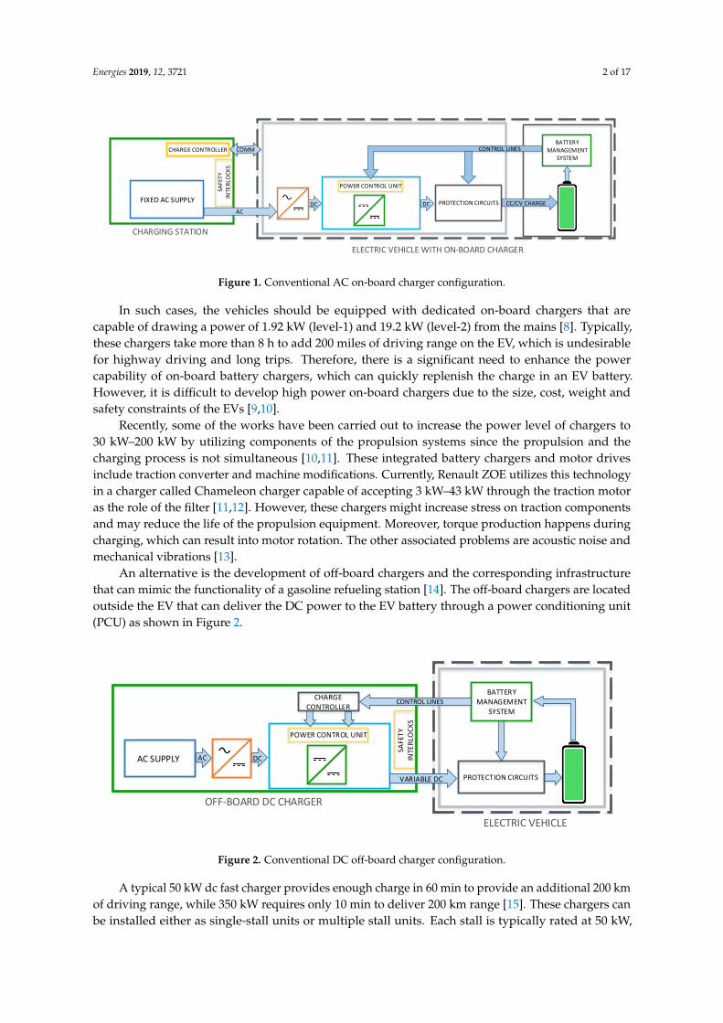
Recharging the battery while parking at work place could be one of the prominent solutions.However, consumers are bound to charge their EVs via residential mains due to the lack of charginginfrastructure. These residential chargers are referred to as level-1 (120 V) and level-2 (240 V) chargersas per SAEJ1772 standards [7] and their typical configuration is shown in Figure 1.
Energies 2019, 12, 3721; doi:10.3390/en12193721 www.mdpi.com/journal/energies
Energies 2019, 12, 3721 2 of 17
POWER CONTROL UNIT
PROTECTION CIRCUITS
SAFE
TY
INTE
RLO
CK
S
FIXED AC SUPPLY
BATTERY MANAGEMENT
SYSTEM
AC
CHARGE CONTROLLER
CC/CV CHARGE
CONTROL LINES
DC DC
COMM
ELECTRIC VEHICLE WITH ON-BOARD CHARGER
CHARGING STATION
Figure 1. Conventional AC on-board charger configuration.
In such cases, the vehicles should be equipped with dedicated on-board chargers that arecapable of drawing a power of 1.92 kW (level-1) and 19.2 kW (level-2) from the mains [8]. Typically,these chargers take more than 8 h to add 200 miles of driving range on the EV, which is undesirablefor highway driving and long trips. Therefore, there is a significant need to enhance the powercapability of on-board battery chargers, which can quickly replenish the charge in an EV battery.However, it is difficult to develop high power on-board chargers due to the size, cost, weight andsafety constraints of the EVs [9,10].
Recently, some of the works have been carried out to increase the power level of chargers to30 kW–200 kW by utilizing components of the propulsion systems since the propulsion and thecharging process is not simultaneous [10,11]. These integrated battery chargers and motor drivesinclude traction converter and machine modifications. Currently, Renault ZOE utilizes this technologyin a charger called Chameleon charger capable of accepting 3 kW–43 kW through the traction motoras the role of the filter [11,12]. However, these chargers might increase stress on traction componentsand may reduce the life of the propulsion equipment. Moreover, torque production happens duringcharging, which can result into motor rotation. The other associated problems are acoustic noise andmechanical vibrations [13].
An alternative is the development of off-board chargers and the corresponding infrastructurethat can mimic the functionality of a gasoline refueling station [14]. The off-board chargers are locatedoutside the EV that can deliver the DC power to the EV battery through a power conditioning unit(PCU) as shown in Figure 2.
POWER CONTROL UNIT
PROTECTION CIRCUITS
AC SUPPLY
BATTERY MANAGEMENT
SYSTEM
DC
ELECTRIC VEHICLE
OFF-BOARD DC CHARGER
CHARGE CONTROLLER
AC
SAFE
TY
INTE
RLO
CK
S
VARIABLE DC
CONTROL LINES
Figure 2. Conventional DC off-board charger configuration.
A typical 50 kW dc fast charger provides enough charge in 60 min to provide an additional 200 kmof driving range, while 350 kW requires only 10 min to deliver 200 km range [15]. These chargers canbe installed either as single-stall units or multiple stall units. Each stall is typically rated at 50 kW,
Energies 2019, 12, 3721 3 of 17
which is composed of three-phase AC/DC rectification stages with power factor correction (PFC) andis powered by a dedicated low frequency (LF) transformer. However, the LF transformer adds to thesystem cost and complicates the installation when directly connected to the MV line [16].
To overcome the aforementioned problems, utilization of solid-state transformer (SST) technologyto extreme fast charging (XFC) architectures help to achieve an improved power density and efficiency,thus eliminating the LF step-down transformer [17]. Moreover, it provides better power quality andadditional functionality such as bi-directional power flow, fault current limitation and fault isolation.However, some issues and challenges include reliability of the LF transformer, integration of SSTinto existing power systems, power conversion equipment and fluctuations in the power demand forbattery charging due to the connection of multiple EVs simultaneously to the DC micro-grid. Thus,it is compelling to perform an extensive review on requirements, challenges and opportunities forfurther improvements of SST-based XFC infrastructure systems.
The paper is organized as follows: Section 2 provides the background, standards and classificationof charging infrastructure. Then, the state of the art and recent developments of DC fast chargingarchitecture are reviewed and discussed in Section 3. Challenges and opportunities of XFCs arepresented in Section 4. Finally, conclusions are drawn in the final section.
2. Background
2.1. Specifications of Popular EVs
The EV sales are mainly dominated by ten countries including US, Canada, Japan, China, France,Germany, UK, Netherlands, Norway and Sweden [18]. Table 1 shows the specifications of commerciallyavailable chargers in terms of motor rating, motor type, battery capacity and electric range [11,12,19–27].It is evident that more research activities have been carried out to make EVs more cost effective whiledelivering an electric range of more than 200 miles. Concurrently, significant advances in batterytechnologies have empowered charge acceptance with faster charging rates.
Table 1. Specifications of Commercially Available EVs.
Vehicle Model Motor Rating (kW) Motor Battery Capacity (kWh) Electric Range (mil)
Smart FortoWo ED 55 PMSM 17.6 58Hyundai Ioniq Elec. 88 PMSM 28 124Mahindra Reva 35 IM 16 75Kia Soul EV 81 PMSM 30 110Renault Zoe 80 PMSM 41 250Tesla Model 3 192 PMSM 75 220Tesla Model S 70D BEV 100 IM 100 240Chevy Bolt 150 PMSM 60 238Chevy Volt PHEV 87 PMSM 18.4 420Ford Focus Electric 107 PMSM 33.5 115Nissan LEAF BEV 110 PMSM 40 151BMW i3 BEV 125 PMSM 33 114Audi A3 e-Tron PHEV 75 PM-SynRM 8.8 31Toyota Prius PHEV 50 PMSM 8.8 640Cadillac CT6 PHEV 250 PMSM 18.4 31VW e-Golf 100 IM 35.8 125Chery eQ 41 PMSM 23.6 157NIO EP9 1000 PMSM 90 265Tesla Model X 193 IM 100 325
2.2. Classification of Battery Chargers and Connectors
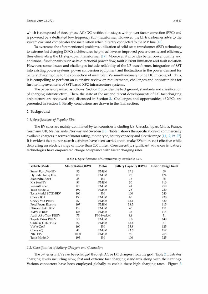
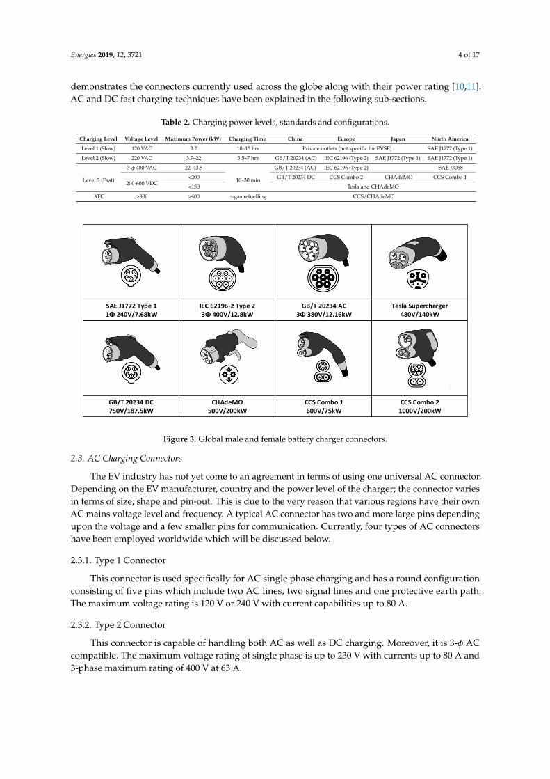
The batteries in EVs can be recharged through AC or DC chargers from the grid. Table 2 illustratescharging levels including slow, fast and extreme fast charging standards along with their ratings.Various connectors have been employed globally to enable these high charging rates. Figure 3
Energies 2019, 12, 3721 4 of 17
demonstrates the connectors currently used across the globe along with their power rating [10,11].AC and DC fast charging techniques have been explained in the following sub-sections.
Table 2. Charging power levels, standards and configurations.
Charging Level Voltage Level Maximum Power (kW) Charging Time China Europe Japan North America
Level 1 (Slow) 120 VAC 3.7 10–15 hrs Private outlets (not specific for EVSE) SAE J1772 (Type 1)
Level 2 (Slow) 220 VAC 3.7–22 3.5–7 hrs GB/T 20234 (AC) IEC 62196 (Type 2) SAE J1772 (Type 1) SAE J1772 (Type 1)
3-φ 480 VAC 22–43.5 GB/T 20234 (AC) IEC 62196 (Type 2) SAE J3068
<200 GB/T 20234 DC CCS Combo 2 CHAdeMO CCS Combo 1Level 3 (Fast) 200-600 VDC <15010–30 min
Tesla and CHAdeMO
XFC >800 >400 ∼gas refuelling CCS/CHAdeMO
SAE J1772 Type 1 1Φ 240V/7.68kW
IEC 62196-2 Type 23Φ 400V/12.8kW
GB/T 20234 AC3Φ 380V/12.16kW
Tesla Supercharger480V/140kW
CCS Combo 21000V/200kW
CCS Combo 1600V/75kW
CHAdeMO500V/200kW
GB/T 20234 DC750V/187.5kW
Figure 3. Global male and female battery charger connectors.
2.3. AC Charging Connectors
The EV industry has not yet come to an agreement in terms of using one universal AC connector.Depending on the EV manufacturer, country and the power level of the charger; the connector variesin terms of size, shape and pin-out. This is due to the very reason that various regions have their ownAC mains voltage level and frequency. A typical AC connector has two and more large pins dependingupon the voltage and a few smaller pins for communication. Currently, four types of AC connectorshave been employed worldwide which will be discussed below.
2.3.1. Type 1 Connector
This connector is used specifically for AC single phase charging and has a round configurationconsisting of five pins which include two AC lines, two signal lines and one protective earth path.The maximum voltage rating is 120 V or 240 V with current capabilities up to 80 A.
2.3.2. Type 2 Connector
This connector is capable of handling both AC as well as DC charging. Moreover, it is 3-φ ACcompatible. The maximum voltage rating of single phase is up to 230 V with currents up to 80 A and3-phase maximum rating of 400 V at 63 A.
Energies 2019, 12, 3721 5 of 17
2.3.3. Tesla US Connector
This connector is designed by Tesla to be specifically used in the US. This connector is capable ofhandling single phase AC as well as DC power. The maximum charging power is rated at 17.2 kW at240 VAC maximum.
2.4. DC Charging Connectors
DC fast chargers are designed to supersede level 1 and level 2 chargers. They are rated between50 kW to 500 kW depending on the manufacturer. With higher power capability, the power conversionand the control stage become more bulky and expensive. This is one of the main reasons why DC fastchargers are implemented off-board. The other reason being that of safety concern. With high powerconverters and increased size of power handling components, safety of the passengers becomes a keyissue. There are mainly five variants of DC connectors and are discussed as follows.
2.4.1. CCS Combo 1 and Combo 2
The Charging Interface Initiative e. V. (CharIN e. V.) is a registered organization founded by Audi,BMW, Daimler, Mennekes, Opel, Phoenix Contact, Porsche, TÜV SÜD and Volkswagen. CharIN is thecoverning body behind the Combo type connectors. The main attraction of the Combined ChargingSystem connector is that it is compatible with both AC as well as DC charging. These connectorsare a part of the IEC 62196-1, IEC 62196-2 and IEC 62196-3 standards. These connectors are capableof handling up to 350 A at voltage ranging from 200 V to 1 kV having a maximum power handlingcapability of 350 kW.
2.4.2. CHAdeMO
The “CHAdeMO Association” was established in 2010 by companies like Toyota MotorCorporation, Nissan Motor Co. Ltd., Mitsubishi Motors Corporation, Fuji Heavy Industries Ltd.and Tokyo Electric Power Company, Inc. The CHAdeMO has been a part of the IEC standard(IEC 61851-23, -24, as well as 62196-3) and IEEE standard (IEEE Standard 2030.1.1TM-2015). With powerhandling capability of up to 200 kW to 400 kW, CHAdeMO is the first DC standard to facilitate V2X(vehicle to x, ‘x’ might be grid, vehicle, infrastructure etc.) via the 1.1 version of the protocol.
2.4.3. Tesla DC Connector
Tesla superchargers in the US use their own proprietary charging connector. A unique feature ofthe Tesla connector is that it uses the same connector and pins for both AC as well as DC charging.They also offer an option for an adapter that makes the connector compatible with CHAdeMO chargingstations as well. These connectors offer power levels up to 120 kW.
2.4.4. China GB/T Connector
China has their own DC charging connector based on the 20234.3-2015 standard. This connectorcommunicates with the on-board power management system via the Controller Access Network(CAN) protocol. The main attraction of this connector is that it is equipped to charge 2 on-boardbatteries; the low-voltage auxiliary battery as well as the main high-voltage battery. Having a nominalvoltage range of 750 V to 1 kV, it can deliver currents up to 250 A.
3. State of the Art DC Fast Charging Infrastructure
Due to various challenges such as cost, footprint and power levels, on-board fast chargingof EVs today seems like an ambitious goal. Hence, it is essential to focus on the development ofoff-board fast chargers that can mimic the gas refuelling experience. This concept in partnership withbattery technologies that are capable of accepting charging rates of more than 10–12 C and severalthousands of charging cycles [28], makes fast charging a realistic possibility [29,30]. The conventional
Energies 2019, 12, 3721 6 of 17
DC fast chargers are installed in either in single or multi-stall charging units. Each stall is typicallyrated at 50 kW and powered from a three-phase low-voltage (LV) distribution grid through a LFdistribution transformer.
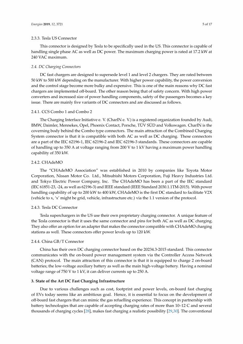
The basic blocks of the conventional DC fast charger power stage is shown in Figure 4. It comprisesof two conversation stages from three-phase AC to DC and a DC/DC stage with galvanic isolation.The AC/DC rectification stage includes Power Factor Correction (PFC) circuit, which ensures requiredpower quality on the grid side complies with the grid codes. The DC/DC stage provides galvanicisolation between the EV and the grid and also incorporates the parallel connectivity at the chargeroutput stage [17]. Table 3 illustrates the technical specifications of the commercially available highpower DC-fast chargers [31–35]. Most of the chargers are available in 50 kW units and those areconnected to meet the required power demands. For instance, Tesla’s Terra HP super charger wasmade by combining various single units [31]. These chargers adopt different charging protocols andconnectors based on geographical location, which is discussed in Section 2. The charging process willfollow a particular sequence defined by charging protocol. It starts with signal hand shaking, theninsulation testing and finally exchanging defined constraints between the EV and the charger. If abovecriteria is met, then EV closes its DC contractor. Even though there are different advanced chargingprofiles that exist in the literature, it is usually follows the constant current-constant voltage (CC-CV)method as is widely accepted approach in the case of lithium-ion batteries [4].
A B C
INPUT FILTER
RECTIFIER + PFC STAGE ISOLATED DC/DC STAGE
OUTPUT FILTER
BATTERY
HFTR
Figure 4. Basic blocks of DC fast charger power stage.
Table 3. Specifications of DC-fast chargers by equipment manufacturers [31–35].
Fast Charger Tesla Terra HP EFAECE-QC45 Tritium Veefil PK Delta Ultra Fast EVTec Espresso
Input Voltage Range (AC) [V] 3-φ 400 3-φ 480 3-φ 480 3-φ 400 3-φ 480Full Load Power Factor >0.99 0.98 0.95 0.99 0.93
Efficiency [%] 95 93 98.5 94 93Output Voltage Range (DC) [V] 150–920 50–500 920 170–550 170–500
Output Current [A] 375/500 120 500 300 300Output Power [kW] 150 50 475 150 120Charging Connector CHAdeMO 1.2 ChadeMO/Combo-1 CHAdeMO/CCS CHAdeMO/CCS CHAdeMO/CCS
Dimensions (H×W×D) [mm] 2103 × 1170 × 770 1800 × 600 × 600 1998 × 980 × 525 2079 × 998 × 852 2000 × 930 × 850Weight [kg] 350 600 700 400 400
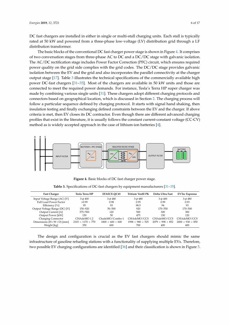
The design and configuration is crucial as the EV fast chargers should mimic the sameinfrastructure of gasoline refueling stations with a functionality of supplying multiple EVs. Therefore,two possible EV charging configurations are identified [36] and their classification is shown in Figure 5.
Energies 2019, 12, 3721 7 of 17
Common AC-bus
Configuration
Uni-polar DC-bus Bi-polar DC-bus
Fast Charging Architectures
Common DC-bus
Configuratin
Figure 5. Classification of fast charging architectures.
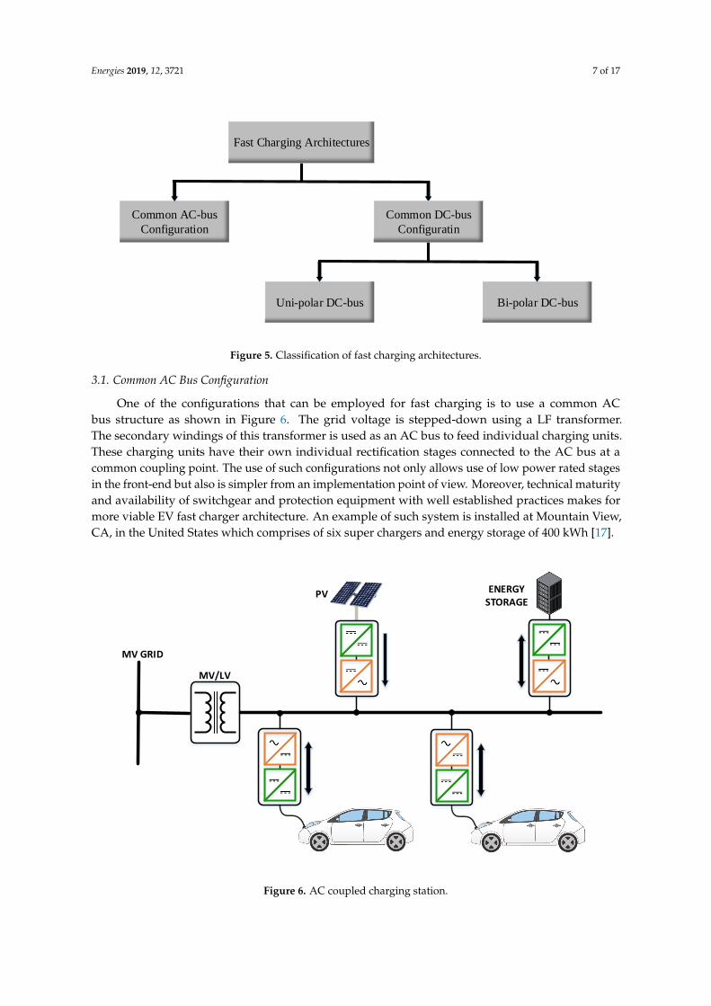
3.1. Common AC Bus Configuration
One of the configurations that can be employed for fast charging is to use a common ACbus structure as shown in Figure 6. The grid voltage is stepped-down using a LF transformer.The secondary windings of this transformer is used as an AC bus to feed individual charging units.These charging units have their own individual rectification stages connected to the AC bus at acommon coupling point. The use of such configurations not only allows use of low power rated stagesin the front-end but also is simpler from an implementation point of view. Moreover, technical maturityand availability of switchgear and protection equipment with well established practices makes formore viable EV fast charger architecture. An example of such system is installed at Mountain View,CA, in the United States which comprises of six super chargers and energy storage of 400 kWh [17].
MV GRID
MV/LV
PV ENERGY STORAGE
Figure 6. AC coupled charging station.
Energies 2019, 12, 3721 8 of 17
However, individual charging units with their own conversion stage displays poor power factorand may worsen the grid voltage [37]. Moreover, increased number of conversion stages reducesthe efficiency and increases the complexity as each conversion stage need its own filters, controland sensing requirements. Addition of renewable and energy storage systems further increases theconversion stages and consequently complicates the system and increases the system cost [38]. In viewof system control, control of AC systems are more complicated compared to DC systems which includesgrid synchronization, reactive power control and islanding operation [39].
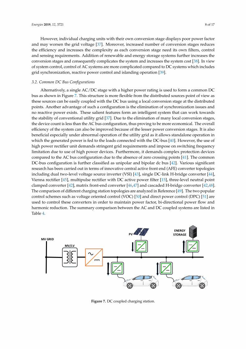
3.2. Common DC Bus Configurations
Alternatively, a single AC/DC stage with a higher power rating is used to form a common DCbus as shown in Figure 7. This structure is more flexible from the distributed sources point of view asthese sources can be easily coupled with the DC bus using a local conversion stage at the distributedpoints. Another advantage of such a configuration is the elimination of synchronization issues andno reactive power exists. These salient features form an intelligent system that can work towardsthe stability of conventional utility grid [37]. Due to the elimination of many local conversion stages,the device count is less than the AC bus configuration, thus proving to be more economical. The overallefficiency of the system can also be improved because of the lesser power conversion stages. It is alsobeneficial especially under abnormal operation of the utility grid as it allows standalone operation inwhich the generated power is fed to the loads connected with the DC-bus [40]. However, the use ofhigh power rectifier unit demands stringent grid requirements and impose on switching frequencylimitation due to use of high power devices. Furthermore, it demands complex protection devicescompared to the AC bus configuration due to the absence of zero crossing points [41]. The commonDC-bus configuration is further classified as unipolar and bipolar dc bus [42]. Various significantresearch has been carried out in terms of innovative central active front end (AFE) converter topologiesincluding dual two-level voltage source inverter (VSI) [43], single DC-link H-bridge converter [44],Vienna rectifier [45], multipulse rectifier with DC active power filter [15], three-level neutral pointclamped converter [42], matrix front-end converter [46,47] and cascaded H-bridge converter [42,48].The comparison of different charging station topologies are analyzed in Reference [49]. The two popularcontrol schemes such as voltage oriented control (VOC) [50] and direct power control (DPC) [51] areused to control these converters in order to maintain power factor, bi-directional power flow andharmonic reduction. The summary comparison between the AC and DC coupled systems are listed inTable 4.
MV GRID
MV/LV
PVENERGY
STORAGE
Figure 7. DC coupled charging station.
Energies 2019, 12, 3721 9 of 17
Table 4. Comparison between AC and DC coupled electric vehicle (EV) architecture.
Parameter AC Coupled System DC Coupled System
Technical Maturity High LowAvailability High Low
Complexity of Protective Devices Low HighConversion Stages High Low
Efficiency Low HighControl Complexity High Low
Operation at grid abnormality No YesCost High Low
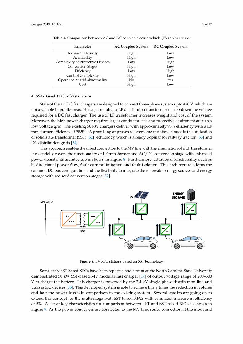
4. SST-Based XFC Infrastructure
State of the art DC fast chargers are designed to connect three-phase system upto 480 V, which arenot available in public areas. Hence, it requires a LF distribution transformer to step down the voltagerequired for a DC fast charger. The use of LF transformer increases weight and cost of the system.Moreover, the high power charger requires larger conductor size and protective equipment at such alow voltage grid. The existing 50 kW chargers deliver with approximately 93% efficiency with a LFtransformer efficiency of 98.5%. A promising approach to overcome the above issues is the utilizationof solid state transformer (SST) [52] technology, which is already popular for railway traction [53] andDC distribution grids [54].
This approach enables the direct connection to the MV line with the elimination of a LF transformer.It essentially covers the functionality of LF transformer and AC/DC conversion stage with enhancedpower density, its architecture is shown in Figure 8. Furthermore, additional functionality such asbi-directional power flow, fault current limitation and fault isolation. This architecture adopts thecommon DC bus configuration and the flexibility to integrate the renewable energy sources and energystorage with reduced conversion stages [52].
MV GRID
PVENERGY
STORAGEPVENERGY
STORAGE
HFTR
SST
Figure 8. EV XFC stations based on SST technology.
Some early SST-based XFCs have been reported and a team at the North Carolina State Universitydemonstrated 50 kW SST-based MV modular fast charger [17] of output voltage range of 200–500V to charge the battery. This charger is powered by the 2.4 kV single-phase distribution line andutilizes SiC devices [55]. This developed system is able to achieve thirty times the reduction in volumeand half the power losses in comparison to the existing system. Several studies are going on toextend this concept for the multi-mega watt SST based XFCs with estimated increase in efficiencyof 5%. A list of key characteristics for comparison between LFT and SST-based XFCs is shown inFigure 9. As the power converters are connected to the MV line, series connection at the input and

Energies 2019, 12, 3721 10 of 17
parallel connection of the out stages are recommended. Various AFE power converter topologies havebeen studied [49], among them cascaded H-bridge [56] and modular multilevel converters [13,57]are becoming popular. The SST-based XFCs are beneficial to both EV users and charging stationowners with increased efficiency and smaller foot print. It provides faster charging, high availabilityand cheaper charging to EV users whereas it reduces installation cost and enhances the utilizationof resources [58]. For instance, fast charger installation demands concentrate foundation for both LFtransformer and charger in seismically active areas. The presented SST-based XFC able to reduced costto 40% of the conventional 50 kW charging systems [17].
Figure 9. Comparison between LFT and SST based EV charging stations.
5. Challenges and Opportunities in Adopting SST-Based XFC Architectures
5.1. Challenges
Despite salient features, like the high power density and high efficiency of the SST technology,there are some serious concerns associated with it. The cost of the charging is directly proportional toits speed. Due to this economical reason, it becomes very important to weigh if the benefits of fastcharging outweigh the cost of slow charging. There have been major deployments of fast chargeracross the globe in the recent years. Although the EVs will demand a lot of power from the grid ascompared to the other loads they will inject harmonics into the grid which is undesirable. One ofthe studies predict that EVs will account for 80% of the European Union’s passenger vehicle fleetwill consume 9.5% of the total grid load [59]. This demands upgrading the conventional distributionsystems and transformers to accommodate the fast charging needs. In addition, integration of multipleEV chargers can cause adverse effects on stability of the grid. The use of intelligent features to controlthe charging creates a sustainable, low-cost and effective environment. Smart charging techniqueshave gained significance due to proving to be very beneficial for the grid.
Another main concern is the integration of SST technology with the existing power systems,which needs modification of communication layers. Another significant challenge is lack of fast actingprotective devices such as circuit breakers (CBs) to act against short circuit faults, circuit overloads andover voltages [60]. The CBs should be able to interrupt the fault current in several µs to protect MVpower electronic systems. In addition to the above concerns, the standardization and establishment ofproper practices for XFC infrastructure that directly connected to MV line are to be addressed.
Apart from the above mentioned challenges, an important concern is the effect of fast charging onthe battery pack. The usage of battery over time, results in the degradation of the SOH of the battery.The electro-chemical reactions taking place in the battery have a direct impact on the lifetime of thebattery. The rate at which the chemical reactions take place for each of the battery chemistry is welldefined. Since the battery is subjected to such high voltage and current during fast charging, it willexperience greater thermal degradation as a result of the comparatively higher temperatures generated

Energies 2019, 12, 3721 11 of 17
during this process. The degradation of the active material on the cell plates is due to: (i) The repeatedprocesses of dissolution and re-crystallization results in the loss of active surface area on the plates(ii) Decrease in electrical contact between the metallic grids and active materials and (iii) Increase inthe growth of inactive materials [61]. There is a need for research to improve the calendar life of thebatteries employing fast charging.
5.2. Opportunities
In the last decade, significant research contributions have been carried out to adopt the SSTtechnology in various applications. However, there are many serious concerns in various componentsof SST technology to replace the conventional bulky LF transformer systems especially in powerconverter topologies, control schemes, power switching devices, digital controllers and HF transformerdesign. Recent trends in the aforementioned areas can adopt the SST technology in near future.
5.2.1. Wide Bandgap Devices
In order to directly connect SST-based AFE converter to the MV grid (6.6–15 kV) and have theability to operate at high switching frequency, there needs to be exploration of wide-bandgap (WBG)devices such as SiCs and GaNs. The physical properties of WBG devices in comparison to Si-baseddevices are shown in Figure 10 [53,62,63]. The SiC devices are the preferred option for SST basedsystems as it can operate at higher switching frequency and operating temperature. These featuressignificantly minimizes volume, size, weight of heat sink and magnetics size [62,63].
Figure 10. Comparison of wide bandgap devices.
Moreover, device utilization factor (>0.7) of SiC devices in comparison to Si-IGBT counterparts [53].A preliminary comparison between SiC and Si-IGBT based SST designs are investigated inReference [64]. A 1-MVA SST with SiC modules was developed in Reference [65], which has anefficiency of 98% with 70% reduction in weight. The design aspects of SiC inverters along with gatedriver and the bus-bar is well described in References [66–68]. There is a trend towards smart gatedrivers which rely on turn-on and turn-off slopes of SiC devices. Despite SiC devices being ableto withstand high temperature, high voltage (HV) and high switching operation, there are someserious concerns that cause a hindrance for mass production. Due to the faster operation of SiCdevices (10 kV/µs), some issues related to the short circuit protection, proper dv/dt and di/dt controlneed to be addressed [69]. Active gate control methods in gate drivers and laminated bus-bars arerecommended for MV applications so as to minimize the conducted noise and parasitic rings.
Typically, laminated bus-bars are employed in MV applications so as to eliminate snubber circuits,HV arcing, critical design issues, and electro-magnetic interference issues. Furthermore, it providesflexible and error-free installation [70]. Another important consideration for power converter designis the design of an effective cooling system to achieve higher power density [71]. Advanced passive
Energies 2019, 12, 3721 12 of 17
cooling methods have to be adopted in order to achieve high power density [72]. Overall, SiC deviceshave some technical challenges in terms of the gate driver design, reliability, manufacturing process,thermal management and bus bar layout which need to be addressed.
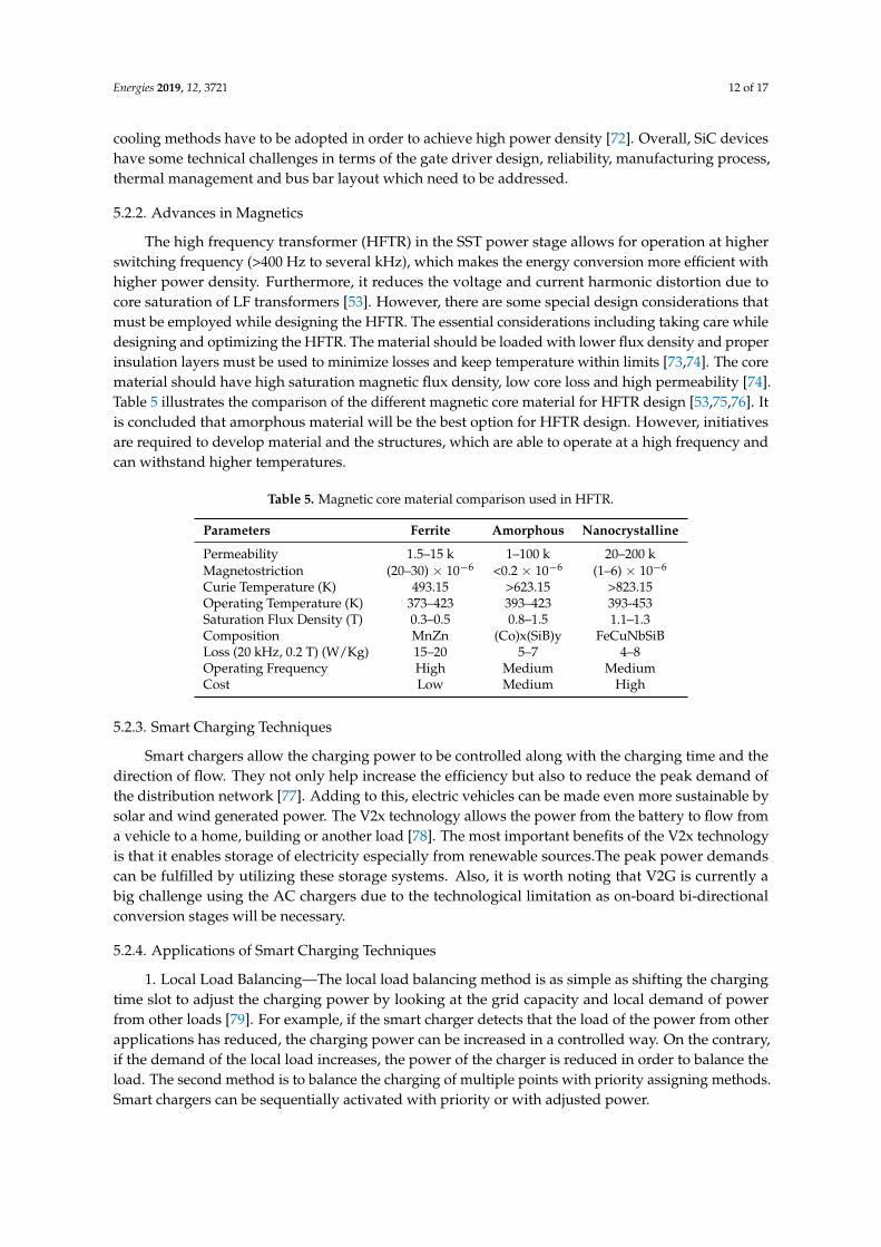
5.2.2. Advances in Magnetics
The high frequency transformer (HFTR) in the SST power stage allows for operation at higherswitching frequency (>400 Hz to several kHz), which makes the energy conversion more efficient withhigher power density. Furthermore, it reduces the voltage and current harmonic distortion due tocore saturation of LF transformers [53]. However, there are some special design considerations thatmust be employed while designing the HFTR. The essential considerations including taking care whiledesigning and optimizing the HFTR. The material should be loaded with lower flux density and properinsulation layers must be used to minimize losses and keep temperature within limits [73,74]. The corematerial should have high saturation magnetic flux density, low core loss and high permeability [74].Table 5 illustrates the comparison of the different magnetic core material for HFTR design [53,75,76]. Itis concluded that amorphous material will be the best option for HFTR design. However, initiativesare required to develop material and the structures, which are able to operate at a high frequency andcan withstand higher temperatures.
Table 5. Magnetic core material comparison used in HFTR.
Parameters Ferrite Amorphous Nanocrystalline
Permeability 1.5–15 k 1–100 k 20–200 kMagnetostriction (20–30) × 10−6 <0.2 × 10⁻⁶ (1–6) × 10−6
Curie Temperature (K) 493.15 >623.15 >823.15Operating Temperature (K) 373–423 393–423 393-453Saturation Flux Density (T) 0.3–0.5 0.8–1.5 1.1–1.3Composition MnZn (Co)x(SiB)y FeCuNbSiBLoss (20 kHz, 0.2 T) (W/Kg) 15–20 5–7 4–8Operating Frequency High Medium MediumCost Low Medium High
5.2.3. Smart Charging Techniques
Smart chargers allow the charging power to be controlled along with the charging time and thedirection of flow. They not only help increase the efficiency but also to reduce the peak demand ofthe distribution network [77]. Adding to this, electric vehicles can be made even more sustainable bysolar and wind generated power. The V2x technology allows the power from the battery to flow froma vehicle to a home, building or another load [78]. The most important benefits of the V2x technologyis that it enables storage of electricity especially from renewable sources.The peak power demandscan be fulfilled by utilizing these storage systems. Also, it is worth noting that V2G is currently abig challenge using the AC chargers due to the technological limitation as on-board bi-directionalconversion stages will be necessary.
5.2.4. Applications of Smart Charging Techniques
1. Local Load Balancing—The local load balancing method is as simple as shifting the chargingtime slot to adjust the charging power by looking at the grid capacity and local demand of powerfrom other loads [79]. For example, if the smart charger detects that the load of the power from otherapplications has reduced, the charging power can be increased in a controlled way. On the contrary,if the demand of the local load increases, the power of the charger is reduced in order to balance theload. The second method is to balance the charging of multiple points with priority assigning methods.Smart chargers can be sequentially activated with priority or with adjusted power.
Energies 2019, 12, 3721 13 of 17
2. Renewable energy utilization—The charging power of the car can be adjusted according tothe availability of the renewable resources as well [80,81]. It may be wind energy, solar energy or anyother source. Additionally, V2G technology can enable people to use their car as a massive energystorage in order to help the gird imbalance during peak loads.
3. Peak Shaving—As mentioned earlier, all electric vehicles can act as a massive storage fromthe grid’s point of view. With implementation of proper control strategies, electric vehicles can becharged when there is extra energy from renewable sources and also this energy can be given back tothe grid using V2G technology. This will help to shift the beak of both the consumption as well as thegeneration and thus fill the supply-demand gap.
4. Grid backup—Electric vehicles can act as backup power generators in the future. In the casewhere there is a failure of the grid for a very short period of time, electric vehicles can be used to powerup the local loads thus providing emergency power during an outage.
5. Battery Swapping—It is a concept of switching out the depleted battery and replacing the samewith a fully charged one. This process is done by driving the car into a battery switching bay where thecar will be automatically aligned and then the old battery is swapped with the new one. This conceptworks on a business model where the vehicle is owned by individuals but the batteries are rented outon energy basis. This technique needs a good battery state of health (SOH) estimation algorithm formonitoring its usage pattern and to make sure that it is charged by authorised charging stations only.The main advantage of this concept is the elimination of range anxiety and the ability to mimic therefueling gas stations. However, it demands a requirement of having a standardized battery interfaceacross all the car manufacturers.
6. Conclusions
This paper presents an overview of the challenges and opportunities of XFCs using SST technologyto facilitate the next step for future charging solutions for future generation of EVs. It can be concludedthat with the evolution of new power conversion topologies, new standards, advanced control schemes,fast acting protective devices, the improvements in wide bandgap (WBG) power devices, digitalcontrollers and magnetic materials make the XFC stations that are capable to mimic refuelling likegas stations a possibility. However operation, design and control of XFC stations must be addressedproperly without affecting the stability of the grid.
Author Contributions: All authors contributed collectively to the manuscript preparation and approved thefinal manuscript.
Funding: This research received no external funding.
Conflicts of Interest: The Authors declare no conflict of interest.
References
1. Wirasingha, S.G.; Emadi, A. Classification and Review of Control Strategies for Plug-In Hybrid ElectricVehicles. IEEE Trans. Veh. Technol. 2011, 60, 111–122. [CrossRef]
2. Matthew, M.; Clément, R.; Eric, W. Meeting 2025 Zero Emission Vehicle Goals: An Assessment of ElectricVehicle Charging Infrastructure in Maryland. Available online: Https://www.nrel.gov/docs/fy19osti/71198.pdf (accessed on 1 June 2019).
3. Hannan, M.A.; Hoque, M.M.; Hussain, A.; Yusof, Y.; Ker, P.J. State-of-the-Art and Energy ManagementSystem of Lithium-Ion Batteries in Electric Vehicle Applications: Issues and Recommendations. IEEE Access2018, 6, 19362–19378. [CrossRef]
4. Gao, Y.; Zhang, X.; Cheng, Q.; Guo, B.; Yang, J. Classification and Review of the Charging Strategies forCommercial Lithium-Ion Batteries. IEEE Access 2019, 7, 43511–43524. [CrossRef]
5. Ahmed, S.; Bloom, I.; Jansen, A.N.; Tanim, T.; Dufek, E.J.; Pesaran, A.; Zhang, J. Enabling fastcharging—A battery technology gap assessment. J. Power Sour. 2017, 367, 250–262. [CrossRef]
6. Collin, R.; Miao, Y.; Yokochi, A.; Enjeti, P.; Jouanne, A. Advanced Electric Vehicle Fast-Charging Technologies.Energies 2019, 12, 1839. [CrossRef]
Energies 2019, 12, 3721 14 of 17
7. Williamson, S.S.; Rathore, A.K.; Musavi, F. Industrial Electronics for Electric Transportation: CurrentState-of-the-Art and Future Challenges. IEEE Trans. Ind. Electron. 2015, 62, 3021–3032. [CrossRef]
8. Khaligh, A.; Dusmez, S. Comprehensive Topological Analysis of Conductive and Inductive ChargingSolutions for Plug-In Electric Vehicles. IEEE Trans. Veh. Technol. 2012, 61, 3475–3489. [CrossRef]
9. Vehicle On-Board Charger. 2018. Available online: https://www.tesla.com/support/home-charging-\installation-redirect (accessed on 1 June 2019).
10. Yilmaz, M.; Krein, P.T. Review of Battery Charger Topologies, Charging Power Levels, and Infrastructure forPlug-In Electric and Hybrid Vehicles. IEEE Trans. Power Electron. 2013, 28, 2151–2169. [CrossRef]
11. Khaligh, A.; D’Antonio, M. Global Trends in High-Power On-Board Chargers for Electric Vehicles. IEEE Trans.Veh. Technol. 2019, 68, 3306–3324. [CrossRef]
12. Renault Zoe 2018. Available online: Https://www.renault.co.uk/vehicles/new-vehicles/zoe.html(accessed on 1 May 2019).
13. Ronanki, D.; Williamson, S.S. Modular Multilevel Converters for Transportation Electrification: Challengesand Opportunities. IEEE Trans. Transp. Electrif. 2018, 4, 399–407. [CrossRef]
14. Rivera, S.; Wu, B.; Kouro, S.; Yaramasu, V.; Wang, J. Electric Vehicle Charging Station Using a Neutral PointClamped Converter With Bipolar DC Bus. IEEE Trans. Power Electron. 2013, 12, 5793–5803. [CrossRef]
15. Bai, S.; Lukic, S.M. Unified Active Filter and Energy Storage System for an MW Electric Vehicle ChargingStation. IEEE Trans. Power Electron. 2013, 12, 5793–5803. [CrossRef]
16. Aggeler, D.; Canales, F.; Zelaya-De La Parra, H.; Coccia, A.; Butcher, N.; Apeldoorn, O. Ultra-fast DC-chargeinfrastructures for EV-mobility and future smart grids. In Proceedings of the IEEE PES Innovative SmartGrid Technologies Conference Europe (ISGT Europe), Gothenberg, Sweden, 11–13 October 2010; pp. 1–8.
17. Srdic, S.; Lukic, S. Toward Extreme Fast Charging: Challenges and Opportunities in Directly Connecting toMedium-Voltage Line. IEEE Electrif. Mag. 2019, 7, 22–31. [CrossRef]
18. Electric Car Sales. 2018. Available online: Https://evobsession.com/electric-car-sales/ (accessed on 1 July2019).
19. Smart EQ Fortwo. 2018. Available online: Https://www.smartusa.com/models/electric-pure-coupe(accessed on 1 July 2019).
20. Ioniq Electric. 2018. Available online: Https://www.hyundaiusa.com/ioniq/ (accessed on 1 July 2019).21. e-Golf. 2018. Available online: Http://www.vw.com/models/e-golf/ (accessed on 1 July 2019).22. 2018 Nissan Leaf. 2018. Available online: Https://www.nissanusa.com/vehicles/electric- (accessed on
1 July 2019).23. Tesla Model 3. 2018. Available online: Https://www.tesla.com/model3 (accessed on 1 July 2019).24. 2018 Chery eQ1 EV. 2018. Available online: Https://wattev2buy.com/electric-vehicles/chery-auto/chery-
eq1-ev-electric-car (accessed on 1 July 2019).25. JMC E200S EV. 2017. Available online: https://wattev2buy.com/electric-vehicles/jiangling-motor-
corporation-jmc-ev/jmc-e200s-ev-specs-sales-news-pictures-range/ (accessed on 1 July 2019).26. JAC iEV7 EV. 2017. Available online: Https://wattev2buy.com/electric-vehicles/jac-motors-electric-
vehicles/jac-iev7/ (accessed on 1 July 2019).27. NIO EP9. 2019. Available online: Https://www.nio.com/ep9 (accessed on 1 July 2019).28. Toshiba. 2016. Available online: Https://www.scib.jp/en/ (accessed on 1 May 2019).29. UFCEV EPFL. 2016. Available online: Https://ufcev.epfl.ch (accessed on 1 May 2019).30. Christen, D.; Tschannen, S.; Biela, J. Highly efficient and compact DC-DC converter for ultra-fast charging of
electric vehicles. In Proceedings of the 15th International Power Electronics and Motion Control Conference(EPE/PEMC), Novi Sad, Serbia, 4–6 September 2012; pp. LS5d.3-1–LS5d.3-8.
31. Tesla Terra HP. 2019. Available online: Https://new.abb.com/news/detail/4996/ABBs-fast-chargers-power-the-e-mobility-revolution (accessed on 1 June 2019).
32. Efacec EV DC Quick Charger. 2019. Available online: http://electricmobility.efacec.com/wp-content/uploads/201/06/QC-45.pdf (accessed on 1 June 2019).
33. Tritium Veefil PK. 2019. Available online: https://www.tritium.com.au/product/productitem?url=veefil-pk(accessed on 1 June 2019).
34. Delta Ultra Fast. 2019. Available online: http://www.delta-emea.com/Solutions/CategoryListT1.aspx?CID=03&SID=319&hl=en-GB&Name=EV%20Charging%20Solutions (accessed on 1 June 2019).
Energies 2019, 12, 3721 15 of 17
35. EVTec Espresso. 2019. Available online: https://www.evtec.ch/en/products/espressoandcharge-usp/(accessed on 1 June 2019).
36. Tan, L.; Wu, B.; Yaramasu, V.; Rivera, S.; Guo, X. Effective Voltage Balance Control for Bipolar-DC-Bus-FedEV Charging Station With Three-Level DC–DC Fast Charger. IEEE Trans. Ind. Electron. 2016, 63, 4031–4041.[CrossRef]
37. Gomez, J.C.; Morcos, M.M. Impact of EV battery chargers on the power quality of distribution systems.IEEE Trans. Power Deliv. 2003, 18, 975–981. [CrossRef]
38. Chan, C.C.; Chau, K.T. An overview of power electronics in electric vehicles. IEEE Trans. Ind. Electron. 1997,44, 3–13. [CrossRef]
39. Eghtedarpour, N.; Farjah, E. Power Control and Management in a Hybrid AC/DC Microgrid. IEEE Trans.Smart Grid 2014, 5, 1494–1505. [CrossRef]
40. Ito, Y.; Zhongqing, Y.; Akagi, H. DC microgrid based distribution power generation system. In Proceedingsof the 4th International Power Electronics and Motion Control Conference, (IPEMC) 2004, Xi’an, China,14–16 August 2004; pp. 1740–1745.
41. Kakigano, H.; Miura, Y.; Ise, T. Low-Voltage Bipolar-Type DC Microgrid for Super High Quality Distribution.IEEE Trans. Power Electron. 2010, 25, 3066–3075. [CrossRef]
42. Rivera, S.; Wu, B. Electric Vehicle Charging Station With an Energy Storage Stage for Split-DC Bus VoltageBalancing. IEEE Trans. Power Electron. 2017, 32, 2376–2386. [CrossRef]
43. Bai, S.; Lukic, S. Design considerations for DC charging station for plug-in vehicles. In Proceedings of the2011 IEEE Vehicle Power and Propulsion Conference, Chicago, IL, USA, 6–9 September 2011; pp. 1–6.
44. Rivera, S.; Wu, B.; Kouro, S. Distributed dc bus EV charging station using a single dc-link h-bridge multilevelconverter. In Proceedings of the IEEE 23rd International Symposium on Industrial Electronics (ISIE), Istanbul,Turkey, 1–4 June 2014; pp. 1496–1501.
45. Dusmez, S.; Cook, A.; Khaligh, A. Comprehensive analysis of high quality power converters for level 3off-board chargers. In Proceedings of the IEEE 2011 IEEE Vehicle Power and Propulsion Conference, Chicago,IL, USA, 6–9 September 2011; pp. 1–10.
46. Waltrich, G.; Duarte, J.L.; Hendrix, M.A.M. Multiport Converter for Fast Charging of Electrical VehicleBattery. IEEE Trans. Ind. Appl. 2012, 48, 2129–2139. [CrossRef]
47. Shuo, W.; Crosier, R.; Chu, Y. Investigating the power architectures and circuit topologies for megawattsuperfast electric vehicle charging stations with enhanced grid support functionality. In Proceedings of theIEEE International Electric Vehicle Conference, Greenville, SC, USA, 4–8 March 2012; pp. 1–8.
48. Crosier, R.; Wang, S.; Jamshidi, M. A 4800-V grid-connected electric vehicle charging station thatprovides STACOM-APF functions with a bi-directional, multi-level, cascaded converter. In Proceedingsof the 2012 Twenty-Seventh Annual IEEE Applied Power Electronics Conference and Exposition (APEC),Orlando, FL, USA, 5–9 February 2012; pp. 1508–1515.
49. Ahmadi, M.; Mithulananthan, N.; Sharma, R. A review on topologies for fast charging stations for electricvehicles. In Proceedings of the IEEE International Conference on Power System Technology (POWERCON),Wollongong, NSW, Australia, 28 September–1 October 2016; pp. 1–6.
50. Milnowski, M. Sensorless Control Strategies for Three-Phase PWM Rectifiers. Ph.D. Thesis, WarsawUniversity of Technology, Warsaw, Poland, 2001.
51. Malinowski, M.; Kazmierkowski, M.P.; Hansen, S.; Blaabjerg, F.; Marques, G. Virtual flux based direct powercontrol of three-phase PWM rectifiers. In Proceedings of the 2000 IEEE Industry Applications Conference.Thirty-Fifth IAS Annual Meeting and World Conference on Industrial Applications of Electrical Energy (Cat.No.00CH37129), Rome, Italy, 8–12 October 2000; pp. 2369–2375.
52. Ahmed, A.-S.; Jad, B.; Ahmed, F.A. Solid state transformers topologies, controllers, and applications:State-of-the-art literature review. Electronics 2018, 7, 298.
53. Ronanki, D.; Williamson, S.S. Evolution of Power Converter Topologies and Technical Considerations ofPower Electronic Transformer-Based Rolling Stock Architectures. IEEE Trans. Transp. Electrif. 2018, 4,211–219. [CrossRef]
54. Huber, J.E.; Kolar, J.W. Applicability of Solid-State Transformers in Today’s and Future Distribution Grids.IEEE Trans. Smart Grid 2019, 10, 317–326.
Energies 2019, 12, 3721 16 of 17
[CrossRef]55. Srdic, S.; Liang, X.; Zhang, C.; Yu, W.; Lukic, S. A SiC-based high-performance medium-voltage fast charger
for plug-in electric vehicles. In Proceedings of the 2016 IEEE Energy Conversion Congress and Exposition(ECCE), Milwaukee, WI, USA, 18–22 September 2016; pp. 1–6.
56. Vasiladiotis, M.; Rufer, A.; Béguin, A. Modular converter architecture for medium voltage ultra fast EVcharging stations: Global system considerations. In Proceedings of the 2012 IEEE International ElectricVehicle Conference, Greenville, SC, USA, 4–8 March 2012; pp. 1–7.
57. Vasiladiotis, M.; Rufer, A. A Modular Multiport Power Electronic Transformer With Integrated Split BatteryEnergy Storage for Versatile Ultrafast EV Charging Stations. IEEE Trans. Ind. Electron. 2015, 62, 3213–3222.[CrossRef]
58. Muratori, M.; Elgqvist, E.; Cutler, D.; Eichman, J.; Salisbury, S.; Fuller, Z.; Smart, J. Technology solutions tomitigate electricity cost for electric vehicle DC fast charging. Appl. Energy 2019, 242, 415–423. [CrossRef]
59. Kasten, P.; Bracker, J.; Haller, M.; Purwanto, J. Electric Mobility in Europe—Future Impact on the Emissionsand the Energy Systems. 2016. Available online: Https://www.eea.europa.eu/themes/transport/electric-vehicles/electric-vehicles-and-energy/action-download-pdf (accessed on 1 April 2019).
60. Guillod, T.; Krismer, F.; Färber, R.; Franck, C.M.; Kolar, J.W. Protection of MV/LV solid-state transformersin the distribution grid. In Proceedings of the 41st Annual Conference of the IEEE Industrial ElectronicsSociety, Yokohama, Japan, 9–12 November 2015; pp. 003531–003538.
61. Kim, I.S. A Technique for Estimating the State of Health of Lithium Batteries Through a Dual-Sliding-ModeObserver. IEEE Trans. Power Electron. 2017, 25, 1013–1022.
62. She, X.; Huang, A.Q.; Lucía, Ó.; Ozpineci, B. Review of Silicon Carbide Power Devices and Their Applications.IEEE Trans. Ind. Electron. 2017, 64, 8193–8205. [CrossRef]
63. Ronanki, D. Singh, S.A.; Williamson, S.S. Comprehensive Topological Overview of Rolling StockArchitectures and Recent Trends in Electric Railway Traction Systems. IEEE Trans. Transp. Electrif.2017, 3, 724–738. [CrossRef]
64. Evans, N.M.; Lagier, T.; Pereira, A. A preliminary loss comparison of solid-state transformers in a railapplication employing silicon carbide (SiC) MOSFET switches. In Proceedings of the IET InternationalConference Power Electronics, Machine Drives (PEMD), Glasgow, UK, 19–21 April 2016; pp. 1–6.
65. Huang, A.Q.; Wang, L.; Tian, Q.; Zhu, Q.; Chen, D.; Yu, W. Medium voltage solid state transformers basedon 15 kV SiC MOSFET and JBS diode. In Proceedings of the 42nd Annual Conference of the IEEE IndustrialElectronics Society, Florence, Italy, 23–26 October 2016; pp. 6996–7002.
66. Colmenares, J.; Peftitsis, D.; Rabkowski, J.; Sadik, D.; Tolstoy, G.; Nee, H. High-Efficiency 312-kVAThree-Phase Inverter Using Parallel Connection of Silicon Carbide MOSFET Power Modules. IEEE Trans.Ind. Appl. 2017, 51, 4664–4676. [CrossRef]
67. Hazra, S.; Madhusoodhanan, S.; Moghaddam, G.K.; Hatua, K.; Bhattacharya, S. Design Considerationsand Performance Evaluation of 1200-V 100-A SiC MOSFET-Based Two-Level Voltage Source Converter.IEEE Trans. Ind. Appl. 2016, 52, 4257–4268. [CrossRef]
68. Ning, P.; Zhang, D.; Lai, R.; Jiang, D.; Wang, F.; Boroyevich, D.; Burgos, R.; Karimi, K.; Immanuel, V.D.;Solodovnik, E.V. High-Temperature Hardware: Development of a 10-kW High-Temperature, High-Power-Density Three-Phase ac-dc-ac SiC Converter. IEEE Ind. Electron. Mag. 2013, 7, 6–17. [CrossRef]
69. Sun, K.; Wang, J.; Burgos, R.; Boroyevich, D. Design, Analysis, and Discussion of Shortcircuit and OverloadGate-Driver Dual-Protection Scheme for 1.2-kV, 400 A SiC MOSFET Modules. IEEE Trans. Power Electron.2019. [CrossRef]
70. Callegaro, A.D.; Guo, J.; Eull, M.; Danen, B.; Gibson, J.; Preindl, M.; Bilgin, B.; Emadi, A. Bus Bar Design forHigh-Power Inverters. IEEE Trans. Power Electron. 2018, 33, 2354–2367. [CrossRef]
71. Ning, P.; Wang, F.; Ngo, K.D.T. Forced-air cooling system design under weight constraint forhigh-temperature SiC converter. IEEE Trans. Power Electron. 2014, 29, 1998–2007. [CrossRef]
72. Laloya, E.; Lucia, Ó.; Sarnago, H.; Burdío, J.M. Heat management in power converters: From state of the artto future ultrahigh efficiency. IEEE Trans. Power Electron. 2016, 31, 7896–7908. [CrossRef]
73. Vaisambhayana, S.; Dincan, C.; Shuyu, C.; Tripathi, A.; Haonan, T.; Karthikeya, B.R. State of art surveyfor design of medium frequency high power transformer. In Proceedings of the 2016 Asian Conference onEnergy, Power and Transportation Electrification (ACEPT), Singapore, 25–27 October 2016; pp. 1–9.

Energies 2019, 12, 3721 17 of 17
74. Leibl, M.; Ortiz, G.; Kolar, J.W. Design and Experimental Analysis of a Medium-Frequency Transformer forSolid-State Transformer Applications. IEEE J. Emerg. Sel. Top. Power Electron. 2017, 5, 110–123. [CrossRef]
75. She, X.; Huang, A.Q.; Burgos, R. Review of Solid-State Transformer Technologies and Their Application inPower Distribution Systems. IEEE J. Emerg. Sel. Top. Power Electron. 2013, 1, 186–198. [CrossRef]
76. Ronanki, D.; Williamson, S.S. Topological Overview on Solid-state Transformer Traction Technology inHigh-speed Trains. In Proceedings of the IEEE Transportation Electrification Conference and Expo (ITEC),Long Beach, CA, USA, 13–15 June 2018; pp. 32–37.
77. Kim, B. Smart charging architecture for between a plug-in electrical vehicle (PEV) and a smart home.In Proceedings of the International Conference on Connected Vehicles and Expo (ICCVE), Las Vegas, NV,USA, 2–6 December 2013; pp. 306–307.
78. Mouli, G.R.C.; Kaptein, J.; Bauer, P.; Zeman, M. Implementation of dynamic charging and V2G usingChademo and CCS/Combo DC charging standard. In Proceedings of the IEEE Transportation ElectrificationConference and Expo (ITEC), Dearborn, MI, USA, 27–29 June 2016; pp. 1–6.
79. Bayram, I.S.; Michailidis, G.; Devetsikiotis, M. Unsplittable Load Balancing in a Network of ChargingStations Under QoS Guarantees. IEEE Trans. Smart Grid, 2015, 6, 1292–1302. [CrossRef]
80. Zhang, J.; Zhang, Y.; Li, T.; Jiang, L.; Li, K.; Yin, H.; Ma, C. A Hierarchical Distributed Energy Managementfor Multiple PV-Based EV Charging Stations. In Proceedings of the 44th Annual Conference of the IEEEIndustrial Electronics Society, Washington, DC, USA, 21–23 October 2018; pp. 1603–1608.
81. Domínguez-Navarro, J.A.; Dufo-López, R.; Yusta-Loyo, J.M.; Artal-Sevil, J.S.; BernalAgustín, J.L. Design of anelectric vehicle fast-charging station with integration of renewable energy and storage systems. Int. J. Electr.Power Energy Syst. 2019, 105, 46–58. [CrossRef]
c© 2019 by the authors. Licensee MDPI, Basel, Switzerland. This article is an open accessarticle distributed under the terms and conditions of the Creative Commons Attribution(CC BY) license (http://creativecommons.org/licenses/by/4.0/).