Extraction of Separation Manifolds using Topological Structures in Flow Cross Sections
14
Extraction of Separation Manifolds using Topological Structures in Flow Cross Sections Alexander Wiebel 1 , Xavier Tricoche 2 , and Gerik Scheuermann 1 1 Institut f¨ ur Informatik, Universit¨at Leipzig {wiebel|scheuermann}@informatik.uni-leipzig.de 2 Scientific Computing and Imaging Institute, University of Utah [email protected] Summary: The study of flow separation from walls or solid objects is still an active research area in the fluid dynamics and flow visualization communi- ties and many open questions remain. This paper aims at introducing a new method for the extraction of separation manifolds originating from separation lines. We address the problem from the flow visualization side by investigating features in flow cross sections around separation lines. We use the topological signature of the separation in these sections, in particular the presence of sad- dle points and their separatrices, as a guide to initiate the construction of the separation manifolds. Having this first part we use well known stream surface construction methods to propagate the surface further into the flow. Addi- tionally, we discuss some lessons learned in the course of our experimentation with well known and new ideas for the extraction of separation lines. 1 Introduction In the panel “Even more theory, or more practical applications to particu- lar problems: In which direction will Topology-Based Flow Visualization go?” of the previous workshop (TopoInVis 2005) the (still unsolved) question of benchmark problems arose. These problems should be used to measure the success of the visualization community and more specifically the success of topological methods. The problem posed by one of the participants was the following: “Given a set of data, say of an ICE train, develop a visualization software which is capable to produce these type of Schlichting 1 flow visualizations including the stream surfaces separating from the body, including the separation points, vortex core lines and the things which 1 The speaker refers to drawings in a major textbook for fluid dynamics by Schlicht- ing [9]. See Fig. 1 for an example.
Transcript of Extraction of Separation Manifolds using Topological Structures in Flow Cross Sections

Extraction of Separation Manifolds using
Topological Structures in Flow Cross Sections
Alexander Wiebel1, Xavier Tricoche2, and Gerik Scheuermann1
1 Institut fur Informatik, Universitat Leipzig{wiebel|scheuermann}@informatik.uni-leipzig.de
2 Scientific Computing and Imaging Institute, University of [email protected]
Summary: The study of flow separation from walls or solid objects is stillan active research area in the fluid dynamics and flow visualization communi-ties and many open questions remain. This paper aims at introducing a newmethod for the extraction of separation manifolds originating from separationlines. We address the problem from the flow visualization side by investigatingfeatures in flow cross sections around separation lines. We use the topologicalsignature of the separation in these sections, in particular the presence of sad-dle points and their separatrices, as a guide to initiate the construction of theseparation manifolds. Having this first part we use well known stream surfaceconstruction methods to propagate the surface further into the flow. Addi-tionally, we discuss some lessons learned in the course of our experimentationwith well known and new ideas for the extraction of separation lines.
1 Introduction
In the panel “Even more theory, or more practical applications to particu-lar problems: In which direction will Topology-Based Flow Visualization go?”of the previous workshop (TopoInVis 2005) the (still unsolved) question ofbenchmark problems arose. These problems should be used to measure thesuccess of the visualization community and more specifically the success oftopological methods. The problem posed by one of the participants was thefollowing:
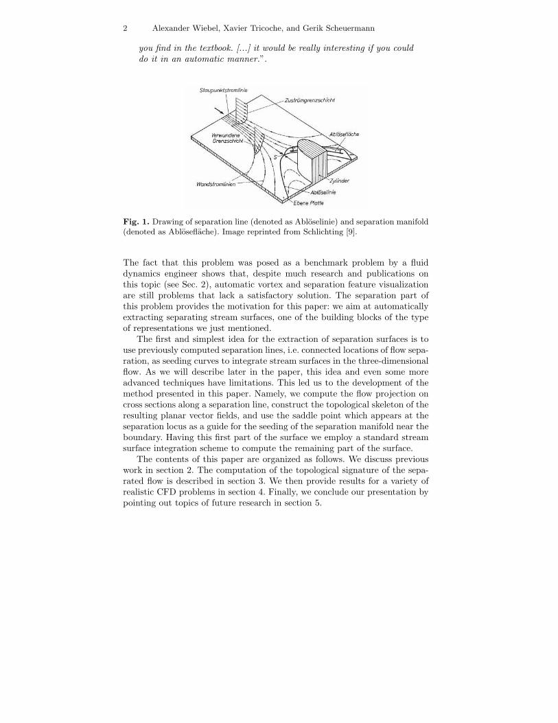
“Given a set of data, say of an ICE train, develop a visualizationsoftware which is capable to produce these type of Schlichting1 flowvisualizations including the stream surfaces separating from the body,including the separation points, vortex core lines and the things which
1 The speaker refers to drawings in a major textbook for fluid dynamics by Schlicht-ing [9]. See Fig. 1 for an example.
2 Alexander Wiebel, Xavier Tricoche, and Gerik Scheuermann
you find in the textbook. [...] it would be really interesting if you coulddo it in an automatic manner.”.
Fig. 1. Drawing of separation line (denoted as Abloselinie) and separation manifold(denoted as Abloseflache). Image reprinted from Schlichting [9].
The fact that this problem was posed as a benchmark problem by a fluiddynamics engineer shows that, despite much research and publications onthis topic (see Sec. 2), automatic vortex and separation feature visualizationare still problems that lack a satisfactory solution. The separation part ofthis problem provides the motivation for this paper: we aim at automaticallyextracting separating stream surfaces, one of the building blocks of the typeof representations we just mentioned.
The first and simplest idea for the extraction of separation surfaces is touse previously computed separation lines, i.e. connected locations of flow sepa-ration, as seeding curves to integrate stream surfaces in the three-dimensionalflow. As we will describe later in the paper, this idea and even some moreadvanced techniques have limitations. This led us to the development of themethod presented in this paper. Namely, we compute the flow projection oncross sections along a separation line, construct the topological skeleton of theresulting planar vector fields, and use the saddle point which appears at theseparation locus as a guide for the seeding of the separation manifold near theboundary. Having this first part of the surface we employ a standard streamsurface integration scheme to compute the remaining part of the surface.
The contents of this paper are organized as follows. We discuss previouswork in section 2. The computation of the topological signature of the sepa-rated flow is described in section 3. We then provide results for a variety ofrealistic CFD problems in section 4. Finally, we conclude our presentation bypointing out topics of future research in section 5.
Extraction of Separation Manifolds using Topological Structures ... 3
2 Related Work
As mentioned in the introduction, flow separation has been a topic of centralinterest for both the theoretical and experimental sides of fluid dynamics re-search since the 1950’s. A complete overview of the topic is clearly beyondthe scope of this paper. Therefore we refer the interested reader to [2, 10]and the references therein. Delery [2] described a variety of three-dimensionaltopological configurations corresponding to separated flows in the smooth set-ting2 and associates them with similar experimental visualizations obtainedin a wind tunnel. In a very recent paper Surana et al. [10] proposed a formaltheory connecting the Navier-Stokes equations to a topological characteriza-tion of separation lines and associated 2-manifolds. The same authors alsoapplied their approach to numerical models computed over simple geometriesin [11]. Unfortunately the topological characterization advocated by these au-thors fails to extract the separation lines and manifolds present in CFD flowsdefined over more complex polygonal geometries if only the spatial velocityand vorticity data is provided and no access to the simulation is possible (pre-computed data). In this case it may be impossible to locate the saddles neededfor three of the four separation types mentioned by Surana et al. [10]. Thisis especially true for the delta wing example they mention. A higher ordersaddle (or several very close saddles) has to exist at the tip of the wing toserve as origin for separation lines. It strongly depends on the discretization(at the pointed tip) whether such a saddle can be found. Additionally, theskin friction field derived from the precomputed data may be of minor qualityprohibiting the use of the formulas reported by Surana et al. [10].
From the visualization viewpoint, the extraction of line-type flow featureshas motivated a significant body of research in recent years. In addition tothe definition and computation of vortex core lines (see [8] for a bibliogra-phy), several authors have attempted to detect and display separation andattachment lines on surfaces. The major contribution in this field was madeby Kenwright [6] who proposed a method that looks for the presence of sep-aration lines on a cell-wise basis. Upon the assumption of local linearity ofthe flow a section of separation line is extracted in each triangle as the inter-section of specific lines present in the phase portrait of a first-order criticalpoint with the interior of the cell. The discontinuity across cell edges yieldsdisconnected line segments, which was addressed in a subsequent paper [7].Making the observation that the criterion used in the original method is infact equivalent to that of zero streamline curvature the authors reformulatedtheir extraction algorithm as the computation of isolines of the flow curvaturefield. The resulting curves must be filtered in a post-processing step to dis-card false positives (see [8]). Moreover, the requirement of zero curvature is fartoo restrictive to account for the general flow geometry associated with flow
2 Here “smooth setting” means the opposite of “discrete setting” like for vectorfields from CFD simulations.

4 Alexander Wiebel, Xavier Tricoche, and Gerik Scheuermann
separation or attachment. In fact, this criterion was basically tailored to thespecial case of delta wings, for which separation and attachment lines describealmost straight lines linking the tip of the wing to its back edge. Based on thisobservation Tricoche et al. [13] recently proposed a method combining a localpredictor (the flow divergence) and a global corrector (the one-dimensionalconvergence behavior of streamlines) to provide a more flexible and robustextraction mechanism. Yet, the corresponding method requires the integra-tion of many streamlines to ensure reliable detection of flow convergence andthe filtering of false positives remains a non-trivial and error-prone task. Con-cerning the use of cross-flow sections or cutting planes Tricoche et al. [12] andWu et al. [14] proposed methods related to ours. Tricoche uses the cuttingplanes for general flow visualization problems on special application data setswhile Wu discusses cross sections explicitly in the field of flow separation fromthe fluid dynamics side.
3 Extracting Separation Manifolds
In this section we propose an approach for seeding stream surfaces repre-senting sheets that divide the flow at separation and attachment lines, i.e.separation manifolds. First, we discuss the problems usually arising when try-ing to compute such surfaces then we give possible solutions to the problemsand finally we describe the basic procedures involved in our solution.
3.1 Seeding Stream Surfaces
Stream surfaces are well known from the literature [4] and good implemen-tations [3] are readily available for visualization of vector fields. The qualityof a stream surface or even the possibility to compute it, however, stronglydepends on the availability of a good seed curve for the integration of thedense set of streamlines spanning the surface. The first and obvious idea toget such line strips is to use the extracted feature lines. Unfortunately, this isonly a good idea at first sight, because the integration of streamlines in thiscase starts directly from the surface. This poses problems resulting from thediscretization of the surface with polygons and from numerical inaccuracies.The first problem means that if we start streamlines directly from the surface,the integration may yield steps that lead out of the grid as the surface hasdiscontinuities at polygon edges and is not smooth. The second problem isthat vertices of feature lines may lie on the wrong side of the surface poly-gon, i.e. outside of the grid, because of small numerical round-off added whilecomputing the line segments.
Our first attempt to solve these problems consisted in moving the featurelines by a small distance in the direction of the surface normal in order to avoidthe issues caused by the irregularities of the polygonal surface while remainingin its immediate vicinity. When we started stream surfaces from the shifted

Extraction of Separation Manifolds using Topological Structures ... 5
lines the integration ran well, but the surfaces, in some cases, did not capturethe separation manifold correctly. This is due to the fact that the separationneed not happen perpendicular to the surface. Therefore, this method requiresknowledge of the angle of the separation in relation to the surface normal.Assuming that this information is available for a point on a feature line wewould be able to determine the correct offset vector for this point. We founda formula to do this in the previously mentioned paper of Surana et al. [10].However, we chose an alternative solution that we found simpler and for ourdiscrete numerical data more appropriate3: we chose to compute the topologyof the projected flow in cutting planes along the feature lines and to use theseparatrix indicating the separation as guide for the movement of our featurelines or, more precisely, the generation of new starting line strips. Near thesurface, the angle between the separation and the surface normal is the sameas the angle of this separatrix. The following subsection will describe this ideain more detail.
3.2 Moving Cutting Planes
Cutting planes, a very basic and widely used technique, gain more informa-tional value if they are moved along interesting curves (see Fig. 4a). In ourcase, the type of curves to be used is inherent in the idea of using movingcutting planes. The separation lines provide the natural paths for the mov-ing planes but also leave several degrees of freedom for the orientation of theplane.
Plane Orientation
The orientation of the plane is a critical parameter of our flow explorationtechnique because the topological structure in the plane can change dramat-ically when changing the orientation of the plane. Even when keeping thecenter position of the plane constant, features can appear or disappear fordifferent orientations of the plane. We would like to use the topology in theplane as a guide for the structure of the flow separation. As the structureswhich are important for us appear normal to the flow along the separation,we use the surface flow vector at the separation line as first approximationof the normal vector for the cutting plane (see Fig. 4). With this choice, theprojected vector field should exhibit a zero vector exactly where the separa-tion line intersects the plane. The zero is a half-saddle with one separatrixleading away from the surface. Near the surface this separatrix indicates thedirection of the separation. However, the saddle point can only be found reli-ably in an analytical setting. As our procedure requires resampling the dataand projecting it into the plane, we introduce numerical noise and round-off
3 As mentioned before, we are only working on precomputed data. Thus, not allquantities used in the formula by Surana et al. [10] are available.

6 Alexander Wiebel, Xavier Tricoche, and Gerik Scheuermann
error to some extent. This can cause the saddle to move. Lying directly onthe boundary of the body, even a small shift can cause the saddle to moveout of the plane and thus disappear. Hence, in the case where we do not finda saddle point in the plane we have to adjust its orientation in order to movethe desired saddle back onto the plane. Figure 2 shows the basic idea of theadjustment and Figure 3 gives an impression for a real 3D vector field. Whilewe have to tilt the plane against the flow direction for separating flow, wemust tilt it with the flow to move the saddle into the plane for attaching flow(see Fig. 2).
Fig. 2. Saddle moves when tilting plane in separating flow: a) no saddle is presentbecause flow is nowhere perpendicular to plane, b) half-saddle because plane isperpendicular to wall and thus to surface flow, c) saddle moved a small distanceaway from the wall because plane is perpendicular to separating flow.
We said previously that the orientation of the plane can change the flowdramatically. We have to keep this in mind when tilting the plane, i.e. wehave to change the orientation of the plane as little as possible. Changing theinclination of all cutting planes along a line in the same way is the simplestidea but it does not account for the different flow situations at the differentbase positions along the line. Additionally, such a uniform change would surelynot be the smallest change possible for all planes at the same time. Hence,we do not change the inclination uniformly but instead compute the angle foreach separate plane through an iterative approach.
As mentioned earlier, we use the velocity as first approximation for theplane normal. To tilt the plane, we turn its normal vector in the plane spannedby the wall normal and the plane normal. This is illustrated in Figure 4b.

Extraction of Separation Manifolds using Topological Structures ... 7
Fig. 3. The left image shows streamlines in a synthetic vector field representingperfect separation and an example for a cutting plane. The image in the middlegives an impression of the projected flow in the plane and the right image shows theflow after tilting the plane. In the middle image only the upper part of the saddlecan be seen. The saddle lies exactly on the base plane bounding the flow from below.All sectors of the saddle are observable after it is shifted in the lower image.
The iterative approaching works in two parts. All steps are described in thefollowing:
1. a) Set current angle to a small and constant user prescribed angle.b) Tilt the original plane by the current angle (against the flow for sep-
aration and with the flow in the attachment case).c) Compute the flow in the tilted plane.d) Extract the topological structures of the flow.e) If there is no saddle, decrease the current angle and go back to 1b.f) If there is a saddle go to 2a.
2. a) Set αmax to the current angle and αmin := 0.b) Decrease the current angle.c) Tilt the original plane by the current angle.d) Compute the flow in the tilted plane.e) Extract the topological structures of the flow.f) If there is a saddle set αmax to the current angle.g) If there is no saddle set αmin to the current angle.h) Set the current angle value to 0.5(αmax + αmin) and go to 2c.
We iterate for both parts until a maximum number of iterations has beenreached. The first part tries to find an initial angle for which a saddle ispresent on the plane. In the second part of the algorithm, we know that thereis a saddle in the plane and try to find the plane with smallest tilting angleand a saddle.
3.3 Construction of Seed Line for Separation Manifold
In the previous subsection we described how we compute the topological sig-nature of the separation in the cutting planes. Having this signature, i.e. theseparatrices of the saddle point, we can use it to construct the first part of theseparation manifold and a start strip for the rest of the surface. At first wehave to choose the correct separatrix out of the four separatrices emanating

8 Alexander Wiebel, Xavier Tricoche, and Gerik Scheuermann
Fig. 4. a) Cutting Planes moving along feature line oriented normal to the flow attheir center position. b) Tilting the plane by tilting the normal vector in the planespanned by the normal vector of the plane and the normal vector of the surface.
from the saddle point. For this task, we take the vector representing the firstsegment of each of the separatrices and compute its dot product with the bodysurface normal (all vectors normalized). The segment with the largest valueindicates the desired separatrix, as this separatrix is the one which leaves thesurface.
To construct the first part of the surface, we take a number of steps alongthe chosen separatrices in all planes. The step size and the number of stepsm can be determined by the user. We then connect the steps of neighboringplanes to construct triangles. These triangles build up a surface consisting ofm rows of triangles. This surface is the first part of the separation manifold.Splitting the distance for moving along the separatrix into several steps isonly important for constructing the triangles. The upper boundary of thelast row of triangles, i.e. the connection of the (last) step on all separatrices,constitutes the starting line strip for the rest of the separation manifold.
As mentioned before when discussing the tilting of the plane, it is im-portant to use only structures of the flow in the planes that are very closeto the separation line and thus to the body surface. This ensures that theseparatrices precisely approximate the structure of the separation manifold.
4 Results
In this section we demonstrate our method on two different datasets from CFDsimulations. We give a short overview of each dataset, apply our method anddiscuss the resulting images.

Extraction of Separation Manifolds using Topological Structures ... 9
4.1 Blunt Fin
Our first example is a standard reference for flow visualization, the well knownblunt fin dataset [5], courtesy of NASA. It represents a steady Mach 2.95airflow over a flat plate with a blunt fin rising from the plate. The free inflowwith a Reynolds number of 2.1 · 106 is parallel to the plate and to the flatpart of the fin. The dataset represents only one half of the real flow, as it isassumed to be symmetrical about center plane of the fin. In front of the fintwo horseshoe vortices coexist with a shock front. The first vortex causes theflow reaching it to separate from the plate. This separation is what we areinterested in. The upper image in Figure 5 shows a LIC [1] visualization of theflow over the plate where patterns of converging flow indicate the separation.For the application of our method we extracted a separation line (shownin black) and computed the topological skeleton of 38 section planes movingalong the separation line, which took us 2 minutes. We show the section planesto illustrate the procedure. The closeup in the middle left image shows howthe separatrices of the saddles in the planes indicate the separation.
The middle right and the lower images show a red surface representing theseparation manifold we constructed from the cutting planes. In the right imageit is combined with the separatrices of the saddles in the cutting planes. Theseparatrices are tangential to the surface near the saddle point but intersect itwhen the distance to the saddle increases. This supports what we mentionedbefore: the separatrices are good guides for the surface construction but onlyvery close to the saddle. Finally, streamlines in the lower image prove that wecomputed the correct stream surface, i.e. the one representing the separationmanifold.
minimum maximum average
Angle (◦) 0.006 0.27 0.026Distance 0 0.008 0.0016
Table 1. Final angle of plane and distance of saddle to surface. Note: size of dataset is approx. 10 units.
4.2 ICE High Speed Train
The second dataset is a more practically relevant example. It is the high-speed(ICE ) train already mentioned in the introduction. This dataset is the resultof a simulation of the train traveling at a velocity of about 250 km/h with windblowing from the side at an angle of 30 degrees. The wind causes vortices toform on the lee side of the train, creating a drop in pressure that has adverseeffects on the train’s track holding. The vortices and the flow passing over thetop of the train lead to separating flow at the upper angle on the lee side.

10 Alexander Wiebel, Xavier Tricoche, and Gerik Scheuermann
The separation line we extracted and the flow structure in the correspondingcutting planes is shown in Figure 6. Note how there are no saddles along theblue line where the line does not capture the location of separation correctly.We observed this also in cases where the separation becomes very weak orfuzzy along a line. Streamlines, the separation line, the separation surface weseeded using the cutting planes, and a LIC on the surface of the train give apicture of the complete situation in the lower image. The causal connectionbetween the separation and the vortex formation becomes obvious in thisimage.
The computations for the 100 cutting planes took 12 minutes.
minimum maximum average
Angle (◦) < 10−8 3.26 0.60Distance (mm) 0 82.04 16.75
Table 2. Final angle of plane and distance of saddle to surface. Note: length of trainis approx. 5 · 104 mm
5 Conclusion
We have presented a method for automatic computation of separation man-ifolds from separation lines on bodies immersed in a flow. The method con-structs and uses flow cross-sections and the topological signature of the sep-aration therein to construct the surface section in the direct vicinity of theboundary. The construction of the remaining part of the surface relies on stan-dard techniques. Our method proved its usefulness and robustness throughapplication to several different CFD datasets.
For datasets with more intricate flow structures than those presented inthis paper, e.g. flows with a very small separation angle, we found problemswith the cross-flow in planes very close to the boundary. Thus, our futurework will include close collaboration with engineers in order to inspect whatis happening near the boundary in these simulations, to try to understandwhat the problems are and how we can improve our method to handle theseproblems. As mentioned previously the quality of the surfaces representingthe separating flow strongly depends on the accuracy of previously extractedseparation lines. Research in the direction of separation line extraction is thusstill necessary and will be part of our work until extraction can be performedefficiently and reliably.

Extraction of Separation Manifolds using Topological Structures ... 11
Acknowledgments
The authors wish to thank Markus Rutten from DLR Gottingen for providingthe ICE dataset. Further we are thankful to all members of the FAnToM devel-opment team for their programming efforts. This work was partly supportedby DFG grant SCHE 663/3-7.
References
1. Brian Cabral and Leith Casey Leedom. Imaging Vector Fields Using Line In-tegral Convolution. In SIGGRAPH ’93: Proceedings of the 20th Annual Con-ference on Computer Graphics and Interactive Techniques, pages 263–270, NewYork, NY, USA, 1993. ACM Press.
2. Jean M. Delery. Robert Legendre and Henri Werle: Toward the Elucidation ofThree-Dimensional Separation. Ann. Rev. Fluid Mechanics, 33:129 – 154, 2001.
3. Christoph Garth, Xavier Tricoche, Tobias Salzbrunn, Tom Bobach, and GerikScheuermann. Surface Techniques for Vortex Visualization. In Oliver Deussen,Charles Hansen, Daniel A. Keim, and Dietmar Saupe, editors, Data Visualiza-tion 2004 - Eurographics/IEEE TCVG Symposium on Visualization Proceedings,pages 155 – 164, Konstanz, Germany, May 2004. Eurographics Association.
4. Jeffrey P. M. Hultquist. Constructing Stream Surfaces in Steady 3D VectorFields. In Arie E. Kaufman and Gregory M. Nielson, editors, Proceedings of the3rd conference on Visualization ’92, pages 171 – 178, Boston, MA, 1992.
5. C.M. Hung and P.G. Buning. Simulation of blunt-fin induced shock wave andturbulent boundary layer separation, AIAA Paper 84-0457. In AIAA AerospaceSciences Conference, Reno, NV, January 1984. AIAA.
6. D. N. Kenwright. Automatic detection of open and closed separation and at-tachment lines. In IEEE Computer Society Press, editor, IEEE VisualizationProceedings, pages 151–158, Los Alamitos, CA, 1998.
7. D. N. Kenwright, C. Henze, and C. Levit. Features extraction of separation andattachment lines. IEEE Transactions on Visualization and Computer Graphics,5(2):135–144, 1999.
8. M. Roth. Automatic Extraction of Vortex Core Lines and Other Line-TypeFeatures for Scientific Visualization. PhD thesis, ETH Zrich, 2000.
9. Herrmann Schlichting. Grenzschicht-Theorie. Braun, Karlsruhe, 1992.10. A. Surana, O. Grunberg, and G. Haller. Exact Theory of Three-dimensional
Flow Separation. Part I: Steady Separation. J. Fluid Mech., 564:57 – 103, 2006.11. A. Surana, G.B. Jacobs, and G. Haller. Extraction of Separation and Reattach-
ment Surfaces from 3D Steady Shear Flows. AIAA Journal, in press, 2006.12. Xavier Tricoche, Christoph Garth, Gordon Kindlmann, Eduard Deines, Gerik
Scheuermann, Markus Ruetten, and Charles Hansen. Visualization of IntricateFlow Structures for Vortex Breakdown Analysis. In Holly Rushmeier, GregTurk, and Jarke J. van Wijk, editors, Proceedings of the IEEE Visualization2004 (VIS’04), pages 187 – 194. IEEE Computer Society, October 2004.
13. Xavier Tricoche, Christoph Garth, and Gerik Scheuermann. Fast and robustextraction of separation line features. In Scientific Visualization: The VisualExtraction of Knowledge from Data, pages 245–263. Mathematics + Visualiza-tion, Springer, 2005.

12 Alexander Wiebel, Xavier Tricoche, and Gerik Scheuermann
14. J. Z. Wu, R. W. Tramel, F. L. Zhu, and X. Y. Yin. A vorticity dynamics theoryof three-dimensional flow separation. Physics of Fluids, 12:1932–1954, August2000.

Extraction of Separation Manifolds using Topological Structures ... 13
Fig. 5. Blunt fin dataset: The upper image gives an overview of the dataset, theseparation line and a number of cutting planes with their topological skeletons. Aclose-up of the same setting is provided in the middle left image. The middle rightand the lower images show the separation manifold constructed from the saddles. Inthe middle right image the surface is compared with the separatrices in the cuttingplanes. Streamlines in the lower image prove that the extracted surface is indeedthe separation manifold.

14 Alexander Wiebel, Xavier Tricoche, and Gerik Scheuermann
Fig. 6. The upper images show the surface of the ICE train with one separationline and the topological skeletons of about 100 cutting planes along the separationline. Blue and green points mark sinks and source in the cutting planes. The lowerimage shows a separation manifold generated from the guides in the cutting planes.We additionally provide streamlines to prove that we found the correct separationmanifold.