Extending FreeRTOS development environment - cems.uwe ...
109
Silvestrs Timofejevs University of the West of England Extending FreeRTOS development environment 11000746
-
Upload
khangminh22 -
Category
Documents
-
view
0 -
download
0
Transcript of Extending FreeRTOS development environment - cems.uwe ...

Silvestrs TimofejevsUniversity of the West of England
Extending FreeRTOSdevelopment environment
11000746

Silvestrs Timofejevs 11000746
Acknowledgements
I wish to express my sincere gratitude to Craig Duffy, without whose help I would not
have achieved as high a standard of work.
I would also like to mention the people who have made the most impact on me
throughout the time in university: Ian Johnson, Rob Williams, Nigel Gunton.
Finally, I would like to acknowledge the lovely geese family, who have made my nights in
university less lonely.
1 | P a g e

Silvestrs Timofejevs 11000746
Table of Contents1. Introduction.................................................................................................4
1.1 Scope of the project................................................................................4
1.2 Hardware Choice....................................................................................5
1.3 Project Planning and strategy.................................................................6
1.4 Project format.........................................................................................6
2. Risk assessment..........................................................................................7
3. Hardware.....................................................................................................9
3.1 GPIO`s..................................................................................................10
3.2 CIMSIS and the STM Standard Peripheral Library..................................11
3.3 Linker script..........................................................................................14
3.4 Cortex-M3 boot sequence.....................................................................18
3.5 JTAG and CoreSight debug interface.....................................................19
3.6 On-Chip Debugging and In-system programming.................................24
4. Libraries.....................................................................................................28
4.1 NewLib..................................................................................................29
4.2 Reentrancy and thread safety..............................................................30
4.3 Reentrancy in NewLib and integration with FreeRTOS..........................31
4.4 Porting NewLib......................................................................................32
4.5 NewLib printf on a bare metal olimex STM32-P107..............................35
4.6 Hardware initialization..........................................................................35
4.7 Printf relevant system calls...................................................................38
4.8 Main and the interrupt handler.............................................................41
5. FreeRTOS...................................................................................................43
5.1 Documentation.....................................................................................43
5.2 Porting FreeRTOS..................................................................................44
5.3 FreeRTOS interrupts configuration........................................................51
5.4 A simple application running FreeRTOS................................................53
5.5 Debugging............................................................................................53
6. FreeRTOS + IO...........................................................................................55
6.1 FreeRTOS IO structure...........................................................................56
6.2 Porting FreeRTOS IO..............................................................................58
6.3 FreeRTOS IO types, definitions and prototypes.....................................59
6.4 FreeRTOS_open.....................................................................................64
6.5 FreeRTOS_ioctl......................................................................................68
6.6 FreeRTOS_read......................................................................................71
6.7 FreeRTOS_write.....................................................................................72
6.8 Interrupt Service Routines....................................................................75
2 | P a g e

Silvestrs Timofejevs 11000746
6.9 Macros and debug................................................................................78
6.10 Integration with NewLib......................................................................78
7. FreeRTOS + CLI..........................................................................................81
7.1 Fundamentals of the FreeRTOS CLI.......................................................82
8. Conclusion.................................................................................................84
8.1 STMCube...............................................................................................85
8.2 Words of praise to FreeRTOS and STMicroelectronics...........................86
8.3 Work assessment..................................................................................86
9. Bibliography...............................................................................................88
Appendix A....................................................................................................91
Cortex-M3 exception model........................................................................91
Exception types..........................................................................................92
Nested Vectored Interrupt Controller (NVIC)...............................................93
Appendix B....................................................................................................96
Development tools and environment..........................................................96
GNU tools and utilities................................................................................96
3 | P a g e

Silvestrs Timofejevs 11000746
1. Introduction
In modern society, computer technology is an ever-growing field, which has expanded
exponentially in the last couple decades, and is promising to advance even faster pace.
Some computer systems are used on daily basis, usually such systems are labelled –
interactive. Interactive systems imply user interaction: personal computers, gadgets,
laptops and many other. A larger group of computer systems is usually hidden from the
unaware public – embedded systems. An embedded system can be a part of a bigger
system, it often have to comply with certain Real-Time constrains, and is expected to
run continuously without the human interaction. Just as an overview of the size of the
embedded market – every year there are more than 1.5 billion ARM based processors
sold alone. [1]
Computer systems are designed to satisfy different requirements, involving different
types of hardware, an ability to run different software. Personal computers are often
required to work with graphics or other highly resource consuming tasks. Such
systems must have vast amounts of RAM, powerful CPU and a graphics card.
Embedded systems strive for the lowest cost and energy efficiency, and usually have got
many constraints to be taken into account.
Interactive and modern mobile systems, usually are powerful enough, and can benefit
from larger Operating Systems. Such Operating Systems could be: Windows, Linux
distributions, iOS, Android, etc. Deeply embedded systems might have RAM limited to
only several kilobytes. Even the Linux kernel, which can be shrunk to less than a
megabyte of size – can be too heavy for some deeply embedded systems. Thus, deeply
embedded systems often are only able to run a simple scheduler and/or use lightweight
libraries.
1.1 Scope of the project
Embedded systems play a huge role in our daily lives, yet many of us fail to recognise
the importance. It is a common approach by the software developers to use the Linux
kernel in mobile and embedded systems, there are good reasons behind it. Linux is a
4 | P a g e

Silvestrs Timofejevs 11000746
free, open source Operating System, there are number of extremely powerful
development tools that make the development process so much easier. Unfortunately,
smaller embedded systems are not always capable of running a Linux build. The idea of
this project is the research of smaller operating systems and set of standard libraries to
be used within the deeply embedded computer systems, and explore the possibilities of
the improvement of the development environment of such systems.
The Real-Time Operating System (RTOS) that I have chosen for the project - FreeRTOS,
a free and open source RTOS. The source code consists of just several C source and
header files, hence it has a very small memory footprint, and allows it to fit with
constrain of even the smallest embedded systems. It has grown from being a simple
executive to an almost complete Real-Time Operating System. FreeRTOS has got a great
support, and there are number of additional modules provided with the source code. It
allows the developer to add or exclude certain components, making the FreeRTOS build
more flexible and configurable. FreeRTOS lacks certain features common in the better
known Operating Systems, such as memory management, access control, etc.
FreeRTOS has been around on the market for some time, however is still a relatively
new product, and is in the phase of an active development. [3]
Working with different Operating Systems and hardware, I can conclude that one of the
major reasons of the popularity of those products – is the development environment.
The popularity of Linux in the embedded market comes from the scalability and
extremely powerful and mature utilities that can be used with it. Linux has got a great
number of development tools – binutils, buildroot, OpenEmbedded, OpenOCD and
many more that make the programming experience easier and more efficient. The goal
of the project is to explore the possibilities of improving the FreeRTOS development
environment. It will include the investigation into the additional software modules
provided with the FreeRTOS source, and use of the C libraries with the FreeRTOS
build.
I think this project could be a subject of an interest amongst the people who have
decided to use FreeRTOS, or the STM32 microcontroller in their development.
Throughout the project I will strive to cover the hardware configuration and
exploitation, as well as the porting of FreeRTOS and C library/libraries.
5 | P a g e

Silvestrs Timofejevs 11000746
1.2 Hardware Choice
The project is based on the Olimex STM 32-P107 development board, which has got an
ARM Cortex-M3 based microcontroller unit from STMicroelectronics. The Olimex
development board has all the necessary interfaces to satisfy the needs of the project. It
has also got a space for soldering additional electronic components, which could be
useful if the project is considered for further experimental developments. It is a good a
choice in terms of price/capabilities. [2]
1.3 Project Planning and strategy
The project consists of porting FreeRTOS and extending development environment. The
initial idea was to port the uClibc (standard C library for the uClinux build, and many
other custom Linux builds) onto the STM32P107VCT6 – the microcontroller unit of the
Olimex STM32-P107 development board. Although, having a look around the open
source C libraries, the decision has been made to use NewLib instead. Soon after the
first research efforts, it became apparent that the system does not benefit from the full
functionality spectre provided by uClibc. A decision was made to use NewLib instead,
with the possibility of adding extensions by porting relevant parts of uClibc. The main
goal of the project is to build a BusyBox like CLI, and incorporate with a customized C
library.
Why porting is a better idea than writing the software from scratch? Libraries that have
been used extensively throughout a period of time, and across different hardware – will
usually be in a stable state, with majority of bugs tested and fixed. Any new
development will almost certainly contain bugs, and in widely used software across the
system, it is very difficult to foresee all potential problems. And most importantly, there
is no need, and not enough time to “reinvent the wheel”.
1.4 Project format
This document introduces the reader with hardware, firmware and software
development tools. The design of the document follows an incremental format, where
processes described in earlier chapters, are generally relevant to the development in
6 | P a g e

Silvestrs Timofejevs 11000746
later chapters; in other words, by the end of this report the reader should be familiar
with the development stages – starting with the low level hardware configuration,
followed by NewLib and FreeRTOS.
The project follows a less conventional structure, where there is no dedicated research,
design or development. There is no need to have a designated design section, because
the software components used are the end products. However, the reader is introduced
to some design concepts in chapters describing the relevant software.
2. Risk assessment
The project is a research into development and improvement of the FreeRTOS
development environment. The bulk of the development process falls into
porting different software products to cooperate together, gather information
and provide ground for future development. The project does not claim to have
a particular end product, with potential beneficiaries being the developers
conducting or looking into FreeRTOS and the functionality it provides.
The main risks associated with the project are:
Time management:
Being a research project, it is almost impossible to foresee whether some
of the initially planned features and goals can be achieved. There is a
risk that the amount of work originally estimated between the subtasks
of the project may sway in one the other way;
Hardware malfunction:
Working with hardware the possibility of it being corrupted should
always be considered, the main risk is not having back-up equipment, or
a long wait period before the replacement can be obtained;
Possibility of someone developing an identical type of software first:
7 | P a g e

Silvestrs Timofejevs 11000746
It is possible that someone had a similar idea, and develops the product
first, which would give the competitor an advantage in the market.
Reflecting on the first issue – time management, the inability to achieve the
initial goals, in a research project (particularly in an Open Source project) could
be as valuable as an achievement of the set goals. Well supported conclusion
that an attempted task cannot be carried out, could be a valuable contribution
amongst the developers.
Hardware malfunction in some cases could be a serious bottleneck, if the
development of a system relies on corrupted software. However, the hardware
used in this project, is relatively cheap and available for order online.
Possibility of someone developing software, which is targeting the same area,
could be disastrous in commercial projects, or even in the Open Source projects
intended for a specific end user. However, this project is more of a contribution
to the Open Source community, rather than anything else; which means that
production of same purpose software is even beneficial, as two projects can be
compared, and potentially merged into one.
8 | P a g e

Silvestrs Timofejevs 11000746
3. Hardware
Figure 1 [2]
Olimex STM32-P107 uses an ARM-based ST Microelectronics
STM32F107VCT6 microcontroller, with the following features:
CPU: STM32F107VCT6 32 bit ARM-based microcontroller with 256 KB
Flash, 64 KB RAM;
USB OTG, Ethernet, 10 timers, 2 CANs, 2 ADCs, 14 communication
interfaces;
JTAG connector with ARM 2×10 pin layout for programming/debugging;
USB_OTG connector;
USB_HOST connector;
100Mbit Ethernet;
RS232;
Mini SD/MMC card connector;
UEXT connector;
9 | P a g e
Silvestrs Timofejevs 11000746
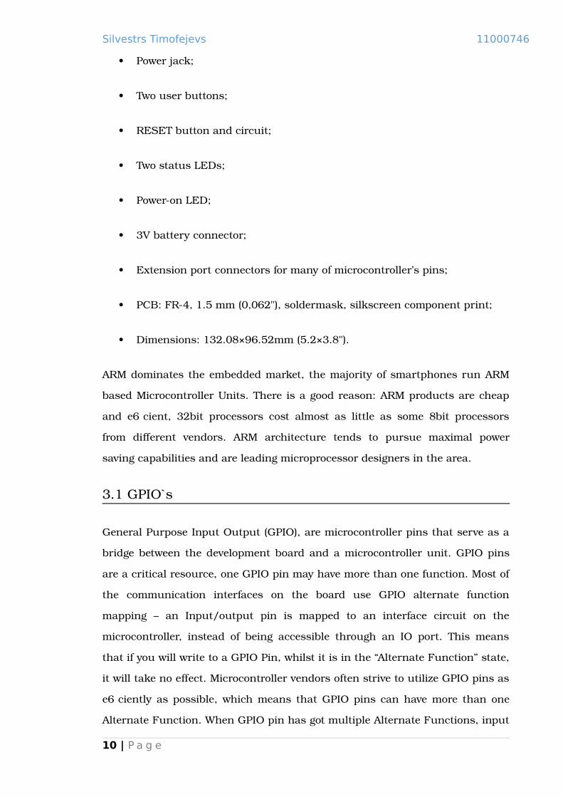
Power jack;
Two user buttons;
RESET button and circuit;
Two status LEDs;
Power-on LED;
3V battery connector;
Extension port connectors for many of microcontroller’s pins;
PCB: FR-4, 1.5 mm (0,062"), soldermask, silkscreen component print;
Dimensions: 132.08×96.52mm (5.2×3.8").
ARM dominates the embedded market, the majority of smartphones run ARM
based Microcontroller Units. There is a good reason: ARM products are cheap
and efficient, 32bit processors cost almost as little as some 8bit processors
from different vendors. ARM architecture tends to pursue maximal power
saving capabilities and are leading microprocessor designers in the area.
3.1 GPIO`s
General Purpose Input Output (GPIO), are microcontroller pins that serve as a
bridge between the development board and a microcontroller unit. GPIO pins
are a critical resource, one GPIO pin may have more than one function. Most of
the communication interfaces on the board use GPIO alternate function
mapping – an Input/output pin is mapped to an interface circuit on the
microcontroller, instead of being accessible through an IO port. This means
that if you will write to a GPIO Pin, whilst it is in the “Alternate Function” state,
it will take no effect. Microcontroller vendors often strive to utilize GPIO pins as
efficiently as possible, which means that GPIO pins can have more than one
Alternate Function. When GPIO pin has got multiple Alternate Functions, input
10 | P a g e

Silvestrs Timofejevs 11000746
will propagate into all the Alternate Function peripherals associated with that
pin. The simultaneous output from multiple peripherals will probably result in
corrupted data. The peripherals can be remapped to different GPIO`s, which
means that if you are planning utilize multiple peripherals associated with the
pin, you can remap them onto a different port. [4] Otherwise, to work with
desired peripheral, you will have to disable the other peripherals associated
with the GPIO pin in use. Below you can see a schematic of a standard IO port
bit.
Figure 2 [4]
By default GPIO pins and communication interfaces are not enabled, it is
designed this way for power saving reasons. In order to enable a GPIO port or
an interface, the corresponding unit has to be clocked. CIMSIS provides all the
necessary routines to configure and manipulate the hardware (please refer to
the CIMSIS and the STM Standard Peripheral Library chapter).
3.2 CIMSIS and the STM Standard Peripheral Library
The Cortex-M3 is growing in the embedded market, ARM strives for
standardization. The goal of the CIMSIS is to provide better inter-operability
with different ARM based microcontroller software. [24] Everything in software11 | P a g e
Silvestrs Timofejevs 11000746
development tends towards reusability, ease of use and portability. It is not
necessary that these goals are always achieved, but in practice a good product
always strives to provide it. We can extend our analogy to programming
languages, “C” programming language emerged for similar reasons. Before
“high” level programming languages software development was carried out
predominantly in assembly programming language, which is machine specific.
Intermediate ground had been found in addition of extra abstraction layer –
“high” level language. “C” programming language is probably the best known
and most used in software industry. CIMSIS principle is different yet similar.
Standard defines a set of functions and corresponding names that have to be
implemented by hardware vendors. [24]
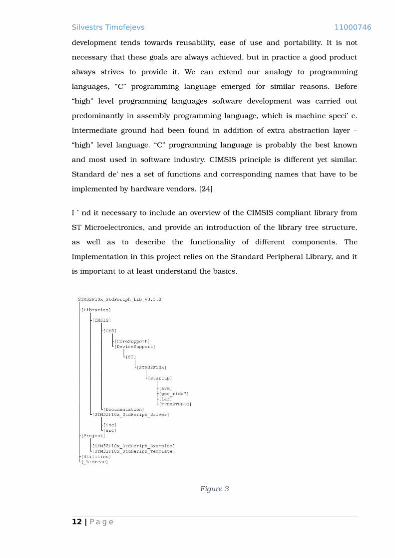
I find it necessary to include an overview of the CIMSIS compliant library from
ST Microelectronics, and provide an introduction of the library tree structure,
as well as to describe the functionality of different components. The
Implementation in this project relies on the Standard Peripheral Library, and it
is important to at least understand the basics.
Figure 3
12 | P a g e

Silvestrs Timofejevs 11000746
The directory that we are interested in the most is called “Libraries”, it contains
two further subdirectories:
CMSIS: [24]
Under “Libraries/CM3/DeviceSupport/ST/STM32F10X” you will find
stm32f10x.h file, which contains system definitions for multiple Cortex-
M3 based microcontroller architectures. The directory also contains
“system_stm32f10x” header and source files, along with the “start-up”
subfolder. “system_stm32f10x” contains SystemInit() – system
initialization routine. SystemInit() routine has to be called before the
program execution jumps into the main() function. In the “startup”
directory, there are several “stm32f10x” series specific assembler start-
up files. Start-up files constitute to different STM32F10x microcontroller
types, which differ in flash and ram memory size, as well as, in presence
or absence of some peripherals. Device that we have on Olimex STM32-
P107 board is STM32F107VCT6 connectivity line microcontroller. It
means that for our hardware we need to use the
“startup_stm32f10x_cl.s” start-up file. The “startup_stm32f10x_cl.s”
start-up file is a bootloader in a way. It defines interrupt vector and
provides Reset_Handler routine, which in turn handles Flash to RAM
data transfer. It is worth mentioning that start-up routines can be
written fully in “C”.
Under “Libraries/CM3/CoreSupport” you will find “core_cm3” header
and source files. This component defines some system specific
structures, and “intrinsic” “C” functions that represent one or several
assembler instructions. “Intrinsic” instructions are ARM extension to
“ISO C and C++” Standard. Compiler might implement “intrinsic”
instructions, although even if they are implemented, using core_cm3
constitutes more portable code. If using core_cm3 provided “intrinsic”
instructions, it is guaranteed that code will run on any CIMSIS
compliant product from a different vendor. As an example, following
instruction returns Main Stack Pointer address:13 | P a g e

Silvestrs Timofejevs 11000746
__ASM uint32_t __get_MSP(void)
{
mrs r0, msp
bx lr
}
STM32F10x_StdPeriph_Driver: [6]
Under “Libraries/STM32F10x_StdPeriph_Driver” are two directories,
“inc” directory with header files, and the source “src” directory with
source files. “STM32F10x_StdPeriph_Driver” contains Hardware
Abstraction Level (HAL), in other words – low level peripheral driver code.
Initialisation, configuration and other routines to work with peripherals.
For more details, please refer to corresponding reference manual, and
look into source code. File names describe well which peripheral code a
file contains. Exception can be “misc”, which supplies NVIC
configuration and initialization routines, as well as SysTick clock source
configuration.
ST Microelectronics does not provide any detailed “Standard Peripheral Library”
documentation. ARM CIMSIS reference manual has got some information about
functionality provided by the components, although to get deeper and more
detailed understanding of supplied functionality, a good idea might be to look
into the source code. The rest of Standard Peripheral Library content is various
examples and templates, which show how to use the library provided
functionality.
3.3 Linker script
The make utility is used to compile applications for this project, it automates
the build process and allows for an easier administering of alterations. Unlike
developing software on the host machine, it is not enough to just run the GCC,
instead the developer needs to put appropriate code and data segments into
specific memory regions; to achieve this a script is used, which instructs the14 | P a g e

Silvestrs Timofejevs 11000746
linker to assemble the code in a desired fashion. The linker script is unlikely to
change throughout the progress of this project, which means that it can be
used in the later developments. [18]
Figure 4
The generic linker script for the STM32F10x series microcontroller, manually
modified to comply with the memory layout of the STM32P107VCT6. ”ENTRY”
allegedly loads the first byte of the .text section with the value of a passed
parameter, however I have checked the symbol table of the executable with
objdump, and it seems that the operator has got no effect on linking; which
means that it can be excluded from the script, besides the Cortex-M3 executes
the first instruction at the 0x00000004 offset of the ROM code – 0x80000004 in
the case of the STM32F107 (please see Cortex-M3 boot sequence section for
more details ). We need to make sure that the Interrupt Service Routine table is
loaded at the first address of the ROM memory, and that the first entry is the
stack address, whilst the second is the Reset_Handler. It is up to the developer
by the means of a linker script to make sure the table, amongst everything else
is loaded correctly.
15 | P a g e

Silvestrs Timofejevs 11000746
“Figure 4” shows various variable definitions that might be used internally by
the linker, or the other modules. The variable naming is self-explanatory, and
should not be too hard to grasp. MEMORY operator defines the ROM and RAM
regions, they are mainly used to check if there is enough memory to hold the
code and data. [18] Some symbols defined in the linker script might not be used
elsewhere in the code at all, but are kept there in case they are required.
Figure 5
16 | P a g e

Silvestrs Timofejevs 11000746
Figure 6
“Figure 5” and “Figure 6” show various symbol definitions that are used in the
start-up file, in order to load .data and .bss sections from ROM to RAM. Notice
that the first entry in the .text section is the .isr_vector table, the comments
explain the meaning of the symbols well. As you can see in the end of each
section there is “>FLASH” or “>RAM” operations, which have confused me the
first time I have looked at them. Basically, it does not affect the application in
any way, it is used internally by the linker to determine if there are enough
memory for the sections. In case if there is not sufficient memory, the linker
will output an error.
The original linker script had a lot of debug stubs and also user stack
definitions, but as they were not used anywhere (at least the use was not
apparent), were removed. Such approach contributes to more comprehensive
code, and makes sure that the problems are not masked out by a code that is
not fully understood. My personal practice shows that it is easier to find an
appropriate solution to the problem when it manifests itself, otherwise there is
a risk to end up with the system that is extremely hard to debug.
17 | P a g e

Silvestrs Timofejevs 11000746
3.4 Cortex-M3 boot sequence
The Cortex-M3 microprocessor has got an unusual boot/reset sequence. It loads Main
Stack Pointer (MSP) from the first executable memory location. After MSP has been
loaded, Cortex-M3 starts execution from the address found at 0x00000004 offset. It is
worth noting that STM32P107VCT6 microcontroller (hardware we use), has got flash
memory starting at 0x08000000 address offset. Actual implementation is device
specific, so STM32P107VCT6 will have MSP at the address 0x08000000 and
Reset_Handler at the 0x08000004. “
” illustrates memory map and the reset sequence. [7]
Figure 7 [7]
Main Stack Pointer (MSP) is loaded from 0x00000000 offset. Then the Reset
Vector is executed, which is pointed to by the address contained at the
0x00000004 memory offset.
18 | P a g e

Silvestrs Timofejevs 11000746
3.5 JTAG and CoreSight debug interface
In the Cortex-M3 debug capabilities and in-system programming are provided
by the means of the SWJ-DP interface. It contains two Debug Ports, one for SW
interface and the other for JTAG access. By default JTAG Debug Port is active,
in order to switch between Debug Ports, a series of signals has to be sent.
Picture below shows SWJ-DP interface circuit. [4]
Figure 8 [4]
The Olimex board utilizes the JTAG interface. [2] JTAG interface is described by
the IEEE 1149.1 standard, which can be regarded as an underlying hardware
solution for data transfer. IEEE 1149.1 standard was originally devised, to test
interconnections between IC components and the board. Eventually some parts
of the standard have been adopted and used for in-system programming and
on-chip debugging. [14]
Every JTAG compliant device or in-system component must be daisy chained.
Normally JTAG compliant IC implements a Boundary Scan Register (BSR),
which is a shift register – connected to on-chip pin mechanisms. Because pins
can be of a different kind, IO, Input, Output – there might be more than just a
single register bit to represent a pin. [14] There are different ways of in-system
programming, some vendors might implement it under BSR, different provide a
separate debug interface. In Cortex-M3 all the debug and in-system
programming capabilities are provided by the CoreSight technology. [13] Strictly
speaking, CoreSight technology is not IEEE 1149.1 compliant, because it does
19 | P a g e

Silvestrs Timofejevs 11000746
not implement Boundary Scan Register and corresponding mandatory
instructions. However, it uses underlying hardware mechanisms.
Every JTAG device implements a Test Access Port (TAP) controller – a state
machine with 16 different states. I will briefly describe some states and signals,
although more detailed information can be found in IEEE 1149.1 document.
TAP is a heart of a JTAG circuitry. [14][25]
Figure 9 [25]
JTAG IEEE 1149.1 standard interface defined 4 compulsory and 1 optional
signal. Those signals are:
TCK: clock signal, is used for synchronisation;
TMS: control signal, is used to switch between the states (note “1” and
“0” on a picture above, which constitute to TMS high or low);
TDI: Input signal into a shift register;
TDO: output from the shift register;
TRST (optional): asynchronous reset signal.
20 | P a g e

Silvestrs Timofejevs 11000746
It is important to note that TAP controller of every device in a chain always is in
the same state. Only exception is power-up, however, we can see from the
“Figure 9 [25]” that by applying five consecutive TMS signals – will put TAP
Controller in Test-Logic-Reset state. TAP controller works in a following way –
instruction and data registers, both are shift registers. In order to change
instruction, TAP controller must be set to Shift-IR state. When data has been
shifted in and the state changed to Update-IR, the corresponding Data Register
is connected into DR shift register chain. IR`s are also in a shift register chain.
Connections between TDI and TDO with IR shift register and DR shift register
chain, are made by changing TAP Controller states. There can be more than one
Data Register, every Data Register is designed to drive some in-system logic.
The IEEE 1149.1 Standard defines Boundary Scan Register (BSR) – compulsory
register. However, apart from the BSR, it is up to a manufacturer to add other
Data registers if they desire. IEEE 1149.1 Standard also defines three
compulsory instructions to be implemented – BYPASS, SAMPLE/PRELOAD and
EXTEST. CoreSight system is not fully IEEE 1149.1 compliant, because it does
not implement BSR, nor SAMPLE/PRELOAD or EXTEST instructions. [12] It
does not implement those instructions and a register, because CoreSight is not
concerned with Boundary Scan, it provides debug and in-system programming
capabilities.
STM32P107VCT6 has got two components in a JTAG chain, microcontroller
Boundary Scan Tap and Cortex-M3 TAP. Connection is illustrated bellow.
21 | P a g e

Silvestrs Timofejevs 11000746
Figure 10 [4]
In order to access one of the components, the other has to be put in BYPASS
mode. When component is in the mode, it has got 1bit wide data register
attached in a chain. Together the length of IR register of two components is 9-
bit wide. In order to set one of them, the corresponding register has to be filled
with all ones (the instruction code is defined by the IEEE 1149.1 standard, and
is set by shifting all ones in an Instruction Register). [12]
CoreSight DAP implements five registers: [12]
BYPASS (1111): 1-bit wide register, is chained, when BYPASS instruction
has been issued;
IDCODE (1110): 32-bit wide register, loads component ID;
DPACC (1010): 35-bit wide Debug port access register, initiates a debug
port and allows access to a debug port register.
– When transferring data IN:
Bits 34:3 = DATA[31:0] = 32-bit data to transfer for a write request
Bits 2:1 = A[3:2] = 2-bit address of a debug port register.
22 | P a g e

Silvestrs Timofejevs 11000746
Bit 0 = RnW = Read request (1) or write request (0).
– When transferring data OUT:
Bits 34:3 = DATA[31:0] = 32-bit data which is read following a read request
Bits 2:0 = ACK[2:0] = 3-bit Acknowledge:
010 = OK/FAULT
001 = WAIT
OTHER = reserved
DPACC is an interface into combination of three registers, which are
accessed by changing A[3:2] bits of DPAAC register.
DP CTRL/STAT (A[3:2] = 01) register is used to:
– Request a system or debug power-up;
– Configure the transfer operation for AP accesses;
– Control the pushed compare and pushed verify operations;
– Read some status flags (overrun, power-up acknowledges).
DP SELECT (A[3:2] = 10) register: Used to select the current access port
and the active 4-words register window:
– Bits 31:24: APSEL: select the current AP;
– Bits 23:8: reserved;
– Bits 7:4: APBANKSEL: select the active 4-words register window on the current AP;
– Bits 3:0: reserved.
DP RDBUFF (A[3:2] = 11) register: Used to allow the debugger to get the
final result after a sequence of operations (without requesting new JTAG-
DP operation).
23 | P a g e

Silvestrs Timofejevs 11000746
It is worth mentioning DP SELECT register, APSEL bits select one of the
APACC Access Ports. APACC Access Ports constitute to different bus
interfaces:
[31:24] APSEL Selects the current access port.
0x00- AHB-AP
0x01- APB-AP
0x02- JTAG-AP
0x03- Cortex-M3 if present.
The reset value of this field is Unpredictable.
APACC (1011):
Provides access to one of the buses. For detailed information, please refer
to the CoreSight reference manual.
ABORT (1000):
Every APACC Access Port implements Transfer Address Register and
Data Read/Write register. In such way, by setting an address and data,
we can access the whole system. We can access peripherals by using
APB-AP, or we can write to flash or access core resources by using AHB-
AP bus.
24 | P a g e

Silvestrs Timofejevs 11000746
3.6 On-Chip Debugging and In-system programming
There are several ways how different microcontrollers and Printed Circuit
Boards (PCB) implement the On-Chip Flash Memory programming. The design
solutions could be:
JTAG - we have an access to the CPU through the special set of shift
registers, and effectively can program the flash memory, by forcing the
data onto the data and address buses of the CPU;
External connection with the microprocessor – the PCB is designed
with an external connector (e.g. USB), where the on-board
microprocessor controlling flash memory read and write operations. The
drawback of this method is that the firmware must reside somewhere in
the memory (flash/ROM), and be executed on the power-on and reset;
External connection without microprocessor – the PCB is designed
with an external connector (e.g. UART) and control logic to program the
flash device directly without the microprocessor interaction. This method
is more costly and requires additional logic;
Speaking from the experience and from the material available on-line (different
microcontroller and board specifications), can be concluded that nearly all of
the microcontroller vendors implement the JTAG interface. JTAG interface is
commonly used for the On-Chip Flash Programming, “de-bricking” and
debugging. The Olimex board has got a JATG interface, which is connected to
the corresponding pins on the STM32 microcontroller, and is the only way to
interface the On-Chip Flash Memory. [2]
There are number of different On-Chip Debuggers available in the market. For
this project OpenOCD is used. The rationale behind using this particular OCD,
was number of worksheets I had access to, Open Source nature of the software,
and a good reference manual. The fundamental functionality is provided by the
25 | P a g e

Silvestrs Timofejevs 11000746
following commands: “reset halt”, “reset run”, “flash write_bank” and “flash
write_image”. [15].
Important to remember that “flash write_image” command has to be used to
handle an image other than of the raw binary format, the type of the image can
be also specified. The “flash write_image” command, only writes the loadable
sections of the image, and performs necessary manipulations. [15] Problems
will arise when, for example, an “elf” image is loaded using the “flash
write_bank” command. It is treated as a raw binary, and will just put the image
at the specified place in memory, which is not the appropriate way. I have
encountered such problem first hand, whilst working through the introductory
worksheets on OpenOCD by Craig Duffy. An Example in one of the worksheets
suggested that “elf” image should be loaded into memory, using the “flash
write_bank” command. In order to diagnose the issue I have used the “arm-
none-eabi-objdump” utility to check the address of the Reset_Handler:
Figure 11
As you can see the address of the reset handler is “0800029c”. When the image
had been loaded with the “flash write_bank” command, the output was
following:
26 | P a g e

Silvestrs Timofejevs 11000746
Figure 12
The fault occurs, and when we type in the “reset halt” command, OpenOCD
dumps the contents of the relevant system registers. The values seen in “Figure
12”, are the values of the registers at reset or power-on. It is apparent that the
value of the PC is not the expected address of the Reset_Handler (0x0800029c),
even more it is not even within the flash memory address space. The start and
the size of flash and RAM in memory are described in the lines of code in
“Figure 13”:
Figure 13
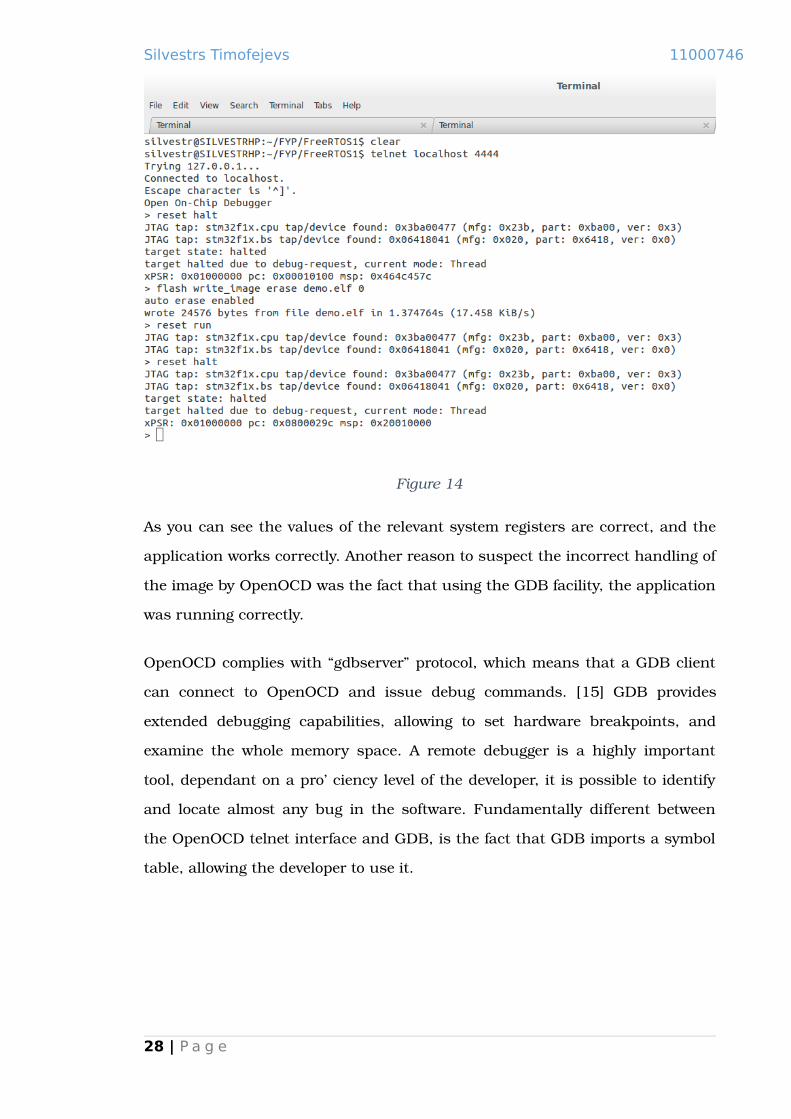
If we look at the output produced by the “flash write_image” command shown
in the “Figure 14”:
27 | P a g e
Silvestrs Timofejevs 11000746
Figure 14
As you can see the values of the relevant system registers are correct, and the
application works correctly. Another reason to suspect the incorrect handling of
the image by OpenOCD was the fact that using the GDB facility, the application
was running correctly.
OpenOCD complies with “gdbserver” protocol, which means that a GDB client
can connect to OpenOCD and issue debug commands. [15] GDB provides
extended debugging capabilities, allowing to set hardware breakpoints, and
examine the whole memory space. A remote debugger is a highly important
tool, dependant on a proficiency level of the developer, it is possible to identify
and locate almost any bug in the software. Fundamentally different between
the OpenOCD telnet interface and GDB, is the fact that GDB imports a symbol
table, allowing the developer to use it.
28 | P a g e

Silvestrs Timofejevs 11000746
4. Libraries
Standard C Library is specified in the ANSI C Standard. The standard specifies
header files, function prototypes, file types, macros and behaviour of the
routines. Most of the better known Operating Systems, have their own
implementation of the C Library, it usually sits on top of the OS specific system
calls, unless it has been designed to be OS independent.
GNU Standard C Library (Glibc), is a native Linux C library. It is POSIX
compliant, as well as ANSI C. Glibc, has got an impressive functional
base, but is usually way too big for embedded systems. [21]
uClibc is an embedded Linux Standard C Library, which is often used
with custom Linux builds. It is a fully revised, reduced version of Glibc.
It covers most of the Glibc functional base, although is considerably
smaller. It is tuned towards the size, often at the cost of performance. It
is much more configurable than Glibc, which makes it more flexible in
terms of embedded development. However, uClibc is the C Library for
uClinux (Linux build aimed at the embedded systems), and was never
designed to work with anything apart from Linux kernel. It is heavily
dependent on Linux system calls, and integrating it with other Operating
System would be a non-trivial task. [20]
NewLib is much smaller library than even uClibc, and has well
established on an embedded software market. NewLib was designed with
portability in mind. It does not intend to cover functional base of the
larger C libraries, however it is ANSI C Standard compliant. A number of
large projects and corporations use NewLib as the Standard C Library.
Such projects and systems include: Google Native Client SDK (NaCI),
Game Boy Advance systems, Playstation Portable homebrew SDK,
Mentor Graphics, etc. [19]
29 | P a g e

Silvestrs Timofejevs 11000746
Often C Standard Libraries, like in example above with Glibc, extend
functionality by including POSIX compliant routines, etc. Any Standard C
Library should at least implement ANSI C Standard defined functionality, which
means that those routines can be used on any Operating System.
30 | P a g e

Silvestrs Timofejevs 11000746
4.1 NewLib
NewLib is a freely – available C runtime library with a portable and flexible
architecture that makes it suitable for use in resource – constrained embedded
systems. [19]
NewLib can be easily adapted to run on both – bare metal, and OS driven
systems. NewLib functionality sits on top of integration layer, consisting of
seventeen system call stubs. The rationale for such architecture of the library is
quite simple. In order to be easily portable across different architectures, there
had to be an easy interface for linking with an Operating System Kernel
routines, or providing code for the system routines on bare hardware. In other
words NewLib system calls are Hardware Abstraction Layer. There are
numerous examples and tutorials of porting NewLib across different platforms
and Operating Systems. [8][9] Requirements for system call stubs are fully
documented in NewLib libc.info file. Care should be taken whilst implementing
system call code. It is reasonable to assume that quality of the code in the
system calls, will make an impact on overall performance of the software
written using NewLib. In the case of the bare metal, it is up to a developer to
provide implementation of the system calls. If working with OS driven
hardware, the developer has to link system call interface provided by NewLib
with actual Kernel system routines. It is worth mentioning that NewLib system
call interface consists of the stubs of an actual Linux kernel system call
functions. Which means – linking NewLib with Linux kernel is a rather straight
forward task, although linking NewLib with other operating systems might be
more challenging.
NewLib strives for configurability and compactness. ANSI C Standard functions,
like printf family routines, are large and complicated. printf includes
capabilities of parsing and representing floating point numbers. Many
embedded systems do not require floating point support, which means that if
floating point functionality could be amended, the size of a library would
decrease. NewLib addresses the problem in two ways: by providing a
31 | P a g e

Silvestrs Timofejevs 11000746
FLOATING_POINT, which allows to selectively disable floating point support in
the library functions. The second feature that addresses floating point issue, is
iprintf function. It works in the same way as printf does, but only deals with
integers, and does not rely on dynamic memory allocation (malloc) routine.
In case if NewLib is compiled as a static library, and needs to preserve floating
point support, iprintf provides additional flexibility. Two different executables
can use different versions of printf, with and without floating point support. In
such way, we could use the same version of library for different builds.
NewLib includes a complete IEEE math library called libm. [19] In order to
enhance performance, it provides single precision floating point math function
counterparts. Single precision floating point math functions, such as sinf,
provide a considerable performance advantage.
4.2 Reentrancy and thread safety
Often thread safety and reentrancy are used as if two terms were synonymous,
although it is a misconception. Reentrant function is not always thread safe,
and vice versa, not every thread safe function is reentrant. Although, in
practice, nearly all reentrant routines are also thread safe. [28]
A reentrant function: [10]
Does not hold static data over successive calls;
Does not return a pointer to static data; all data is provided by the caller
of the function;
Uses local data or ensures protection of global data by making a local
copy of it;
Must not call any non-reentrant functions.
I agree with the above list, although it is worth adding that reentrant functions
should not be blocked on a mutex or a semaphore. If function is using mutual
32 | P a g e

Silvestrs Timofejevs 11000746
exclusion, and is directly or indirectly accessed recursively, it would result in
deadlock. Indirect recursive access may occur, if one of the nested functions
calls a routine, which is already on a stack. Indirect recursion is very hard to
identify and predict, almost impossible if working on a large project. Reentrant
functions can be also used in Interrupt Service Routines.
33 | P a g e

Silvestrs Timofejevs 11000746
4.3 Reentrancy in NewLib and integration with FreeRTOS
NewLib can be configured and compiled as both, reentrant or non-reentrant
library. Non-reentrant version is sufficient for use in a single threaded
environment, providing that Interrupt Service Routines do not call non-
reentrant NewLib functions. Such environment could be a bare metal system,
integrated with non-reentrant NewLib. The Non-reentrant version of NewLib
uses less stack space, as it does not need to allocate space for reentrancy
metadata. The only difference between reentrant and non-reentrant version, is
that system calls stubs in reentrant version include _reent structure pointer in
their signatures. [9][19]
NewLib handles re-entrancy by providing a _reent structure, and impure_ptr,
which is a global pointer to a _reent structure. Then, it is up to a developer to
utilize this mechanism, and integrate it with the OS. _reent structure effectively
holds context specific information – errno, etc. To provide re-entrancy in
NewLib, you will need to compile it with a “-DREENTRANT_SYSCALLS_PROVIDED”
flag, and implement reentrant stubs. A global array with _reent structure for
every context should be defined, and when a context switch occurs, impure_ptr
should point at the appropriate structure. However, in FreeRTOS it is even
easier, to provide reentrancy, we just need to define a
“configUSE_NEWLIB_REENTRANT” flag. The flag tells FreeRTOS to define a
_reent structure in every new task it creates, and to point the impure_ptr at the
corresponding structure on a scheduler context switch. Bellow you can see
corresponding FreeRTOS code snippets that utilize NewLib reentrancy
mechanisms, to integrate with the OS. [9][19]
Figure 15
34 | P a g e

Silvestrs Timofejevs 11000746
“Figure 15” shows a fragment of “tskTaskControlBlock” structure in tasks.c
source file. The structure holds a task specific information, and is used by the
scheduler. The code above defines the _reent structure for the task, when
“configUSE_NEWLIB_REENTRANT” flag is defined with a value of 1.
Figure 16
The code in “Figure 16” shows a fragment of “vTaskStartScheduler” routine in
tasks.c source file, which points the _impure_ptr at the _reent structure of the
first task to be run by the scheduler.
Figure 17
The code in “Figure 17” shows a fragment of “vTaskSwitchContext” routine in
tasks.c source file, which points the _impure_ptr at the _reent structure of the
new active task, on every context switch.
4.4 Porting NewLib
Like most of the larger projects, NewLib has a configuration and compilation
stage. It has a great guide on how to configure and compile it, in a README
file. Almost everything that will be described in this chapter, is on the basis of
the information provided in the README file. [19]
The developer must create a new directory separate from the NewLib source,
configure and make commands will be issued from this directory. In the image
below you can see the directory layout on my computer, and configuration
parameters that I have used to configure the library.
35 | P a g e

Silvestrs Timofejevs 11000746
Figure 18
Configuration options are very well documented in a README file, instead of
providing all of them, I will simply try to justify my configuration choice: [19]
“--target=arm-none-eabi”, tells the configuration script that we are using
arm platform, flag value can be shorten to just “arm”, and should be
recognized as well. This flag sets the Makefile to use arm specific
sources;
“--prefix=/home/silvestr/FYP/newlib-arm-none-eabi-reent”, sets the
variable in a Makefile to hold the path to a target directory;
“--srcdir=../newlib_source”, sets the variable in a Makefile to hold the
path to a NewLib source directory;
“--enable-newlib-nano-malloc”, documentation claims that this is a
lighter and more appropriate version for the embedded systems;
“--disable-newlib-supplied-syscalls”, just tells NewLib not to use “pre-
made” system call routines;
36 | P a g e

Silvestrs Timofejevs 11000746
“--enable-newlib-nano-formated-io”, the same principle as with the “--
enable-newlib-nano-malloc”, option lowers the size of the library. This is
what readme says about the option:
“Floating-point support is split out of the formatted I/O code into weak
functions which are not linked by default. Programs that need floating-
point I/O support must explicitly request linking of one or both of the
floating-point functions: _printf_float or _scanf_float. This can be done at
link time using the -u option which can be passed to either gcc or ld. The
-u option forces the link to resolve those function references. Floating-point
format specifiers are recognized by default, but if the floating-point
functions are not explicitly linked in, this may result in undefined
behaviour for programs that need floating-point I/O support.” [19]
“--enable-target-optspace”, optimizes for the space. I think what it does,
it just specifies in a Makefile, either to compile with “-0s” flag, or to add
“--DPREFER_SIZE_OVER_SPEED” to a “CFLAGS” variable.
“--disable-multilib”, disables compilation for multiple platforms.
After configuration script has finished, the developer should have a directory
with a customized Makefile. The next step would be to compile NewLib. There
are two ways of passing the parameters: [19]
Editing Makefile manually, adding parameters to the
CFLAGS_FOR_TARGET variable.
Running a make command setting the CFLAGS_FOR_TARGET in the
console.
The developer has to enter the directory with a configured Makefile, and issuethe following make command:
make CFLAGS_FOR_TARGET="-ffunction-sections -fdata-sections
-DPREFER_SIZE_OVER_SPEED -D__OPTIMIZE_SIZE__ -Os -fomit-frame-pointer
37 | P a g e

Silvestrs Timofejevs 11000746
-march=armv7-m -mcpu=cortex-m3 -mthumb -mthumb-interwork -D__thumb2__
-D__BUFSIZ__=256" CCASFLAGS="-march=armv7-m -mcpu=cortex-m3 -mthumb
-mthumb-interwork -D__thumb2__"
Dependant on the way the developer wants to compile the library, additional flags can
be added. The author has not been able to find any relevant documentation describing
macros, and went through the source files manually. A notable compilation flag is
-DREENTRANT_SYSCALLS_PROVIDED, which is used to compile NewLib with the re-
entrancy support. The second notable macro is –DMALLOC_PROVIDED, which
excludes generic memory allocation routines.
4.5 NewLib printf on a bare metal olimex STM32-P107
In order to familiarize with NewLib porting principles, decision have been made
to port the library across the bare metal (Olimex STM32-P107). I have decided
to develop a simple output application, the task can be implemented without
any libraries at all, although incorporating output functionality with NewLib`s
generated libc, is a good exercise. It involves the use NewLib generated libc
printf, etc. It can be later extended to cope with the rest of the libc API. Program
runs as a single thread, which means that there is no need for re-entrancy. It is
always better to start small, gradually adding functionality.
4.6 Hardware initialization
Implementation of serial communication via USART on embedded system, is
not as straight forward as on the host system. On a host system USART drivers
are present, and low level functionality is provided. User can benefit from a
friendly API, and to a large extent concern himself only with software
development. On a bare metal system, without Operating System present, the
developer must manually configure hardware. CIMSIS, described in the CIMSIS
and the STM Standard Peripheral Library, provides almost all the low level
routines for this purpose. It can be regarded as a Hardware Abstraction Level
(HAL). In order to implement reasonable quality serial communication software,38 | P a g e

Silvestrs Timofejevs 11000746
we will need slightly more than just to configure USART. Hardware
configuration stage involves:
Clock the relevant GPIO pins:
The STM32 MCU implements three USART and two UART peripherals,
only two of them are wired to physical interfaces on the Olimex board.
USART2 is connected to the RS232 interface, whilst USART3 is
connected through the UEXT connector. We are using the USART2
interface, so we will need to clock and configure the corresponding GPIO
pins. In this example only the basic receive and transmit is used, so the
pins we have to look at are Port D – pin_5 and pin_6. [2]
Figure 19
“Figure 19” shows relevant initialization type structures (defined within
CIMSIS), and the GPIO configuration. “RCC_APB2PeripheralClockCmd”
enables the GPIO port D, and also the APB2 bus alternate function
mapping infrastructure. GPIO_Pin_5 is connected to the USART transmit
line, and uses an alternate mapping. GPIO pins used in output
operations, have to be configured in one of the output modes (push-pull
in this case), when GPIO pins performing input operation have to be
configured in one of the input modes (input-floating in this case). Note
that the speed of GPIO is set way above the minimal required for the
USART operations, the speed of 2MHz should be sufficient.
39 | P a g e

Silvestrs Timofejevs 11000746
GPIO_InitTypeDef structure is used to set up the corresponding values,
and is mapped onto the actual peripheral through the GPIO_Init routine.
[2]
40 | P a g e

Silvestrs Timofejevs 11000746
Clock, configure and enable the USART:
Figure 20
Like with the GPIO port, a peripheral has to be clocked before it can be
used. In the “Figure 20” Port D and the alternate function infrastructure
has been enabled, now the corresponding pins have to be remapped from
using the Port D registers, to the corresponding peripheral. The
“GPIO_PinRemapConfig” routine does exactly that. Using
“Gpio_Remap_USART2” as an argument, it reconfigures the whole
portfolio of pins associated with the peripheral. When the USART
configuration has been done, the values have to be mapped to the
peripheral registers; it is done by running the USART_Init command,
with the USART2 base address as the first argument, and the populated
configuration structure as the second. Receive Not Empty interrupt
trigger is set, and the final step is to enable the peripheral, by running
the USART_Cmd command (different from clocking).
41 | P a g e

Silvestrs Timofejevs 11000746
Configure the interrupts:
Figure 21
In order for the peripheral to be able to trigger an interrupt, the
corresponding NVIC registers have to be configured. Following the same
principle, as with the GPIOs and peripherals, there is an
NVIC_InitTypeDef structure, which is set and mapped to the NVIC
registers using the NVIC_Init command.
4.7 Printf relevant system calls
Printf requires only implementation of two system calls, _sbrk “ Figure 22” and _write
“Figure 23”.
Figure 22
42 | P a g e

Silvestrs Timofejevs 11000746
_sbrk is used by malloc to increase the heap region, when there is not enough memory
in the heap to allocate. The first _sbrk call sets up the heap, assigning it the value of the
end address of the BSS segment (_ebss symbol is set and exported by the linker). The
subsequent calls check for the heap/stack collision, and increase the heap region, or
return the error. To get the stack pointer, CIMSIS routine is called. Providing that the
operation has been successful, the first address of the allocated block is returned.
Figure 23
In the case of application using other NewLib routines, the relevant stubs have to be
implemented. Note that the developer has to provide minimal implementation of all the
system stubs, although in this example, only two mentioned above have to be full; the
rest can just return an error code. Minimal implementation of the system stubs is
documented in the NewLib`s readme, which can be found on the official website [19].
The _write system call is shown in “Figure 23”. Dependant on a file handler type (in this
case only stdout and stderr), it sends out the characters from a buffer pointed at by the
*ptr parameter. The code should not be too difficult to interpret, so a thorough analysis
is not required.
43 | P a g e

Silvestrs Timofejevs 11000746
Figure 24
The outbyte routine in “Figure 24”, is used by the _write system call to put the
characters in a queue. A delay for loop is introduced, as the USART interface is much
slower than the processor. After a character is put in a queue, the interrupt has to be
enabled (calls the interrupt handler, which sends out a character).
The implementation of a queue is not included in the chapter, as it is only partially
relevant. The developer could use different character storing mechanisms. Circular
buffer (the type of queues been used in this example) is a good option. Providing that
there is only one task of execution, and a single interrupt uses a circular queue – it
eliminates the race conditions.
Figure 25
This example is using a non-reentrant version of the library, meaning that a
workaround the NewLib`s re-entrancy mechanism should be applied [9], shown in the
“Figure 25”.
44 | P a g e

Silvestrs Timofejevs 11000746
45 | P a g e

Silvestrs Timofejevs 11000746
4.8 Main and the interrupt handler
Figure 26
“Figure 26” shows the main function of the simple printf application. The configuration
routines were described in the Hardware initialization section. QueueInit initializes the
RX and TX queues.
Figure 27
46 | P a g e

Silvestrs Timofejevs 11000746
“Figure 27” shows the USART2 interrupt handler, which checks what USART mapped
trigger has caused the interrupt to occur, and executes the relevant code. In the case of
transmit, it takes a character from a queue and sends it out. It only disables the
interrupt trigger when the queue is empty.
47 | P a g e

Silvestrs Timofejevs 11000746
5. FreeRTOS
Figure 28 [3]
FreeRTOS a market leading open source Real-Time Operating System. It is
targeting smaller embedded systems, and has got a very small memory
footprint. The focus is around compactness and speed of execution. [3] Being a
Real-Time Operating System it has to be lightweight, hence it does not aim to
implement features that are common in better known Operating Systems, such
as Windows and Linux, etc. FreeRTOS is well established in the embedded
market, however it is still a relatively new product, and is in the state of active
development.
5.1 Documentation
Overwhelming documentation and support will be apparent to the developers
using FreeRTOS, the team is doing a great job helping with the development
issues in a fast and professional manner. The official website [3] has got all the
required materials to get the developer going. The porting process is well
described, and the configuration phase is thoroughly documented. Besides, the
support is great, most of the troubles that the developer comes across – is
possible to resolve through the official support forum.
Source code is well structured and laid out. Providing the developer has got
reasonable C competency, it should not be too hard to make sense out of the
48 | P a g e

Silvestrs Timofejevs 11000746
source code. It is enough to take a look at the NewLib source code to appreciate
the FreeRTOS design.
49 | P a g e

Silvestrs Timofejevs 11000746
5.2 Porting FreeRTOS
Figure 29
FreeRTOS has been ported across the variety of different architectures,
including Cortex-M3 family microcontrollers. Unlike better known Operating
systems, it`s foundation is based on just several source files. [3] Traditional
Operating Systems would usually have a dedicated, or general purpose
bootloader available, which would configure peripherals, and load the OS
image. When dealing with FreeRTOS it is up to the developer, to configure the
hardware and provide a bootstrapper to load relevant data into RAM. When
compiled, you should have a single executable image, which contains the OS,
bootloader and the application. “Figure 30” shows the source directory
structure.
50 | P a g e

Silvestrs Timofejevs 11000746
Figure 30
Under the source directory, further two subdirectories and a number of source
files can be found. The files under the top level source directory are architecture
independent OS files. The include subdirectory contains header files, whilst the
portable subdirectory contains architecture specific code. The architecture
dependant files that we are interested in, reside under the
“FreeRTOS/Source/portable/GCC/ARM_CM3” or
“FreeRTOS/Source/portable/GCC/ARM_CM3_MPU” directory. The “MemMang”
subdirectory contains five heap implementations, the available heap
implementations are described on the official website. [3]
Note: heap_3 implementation is just a wrapper around the Standard “C” malloc
and free implementation.
51 | P a g e

Silvestrs Timofejevs 11000746
“Figure 31”, “Figure 32”, “Figure 33”, “Figure 34” show the portions of Makefile
relevant to FreeRTOS:
Figure 31
The relative path to the FreeRTOS source code top directory.
Figure 32
The search directories, which GCC uses to find the FreeRTOS source files.
Figure 33
The Object files that provide the fundamental FreeRTOS functionality. "heap_1”
is just one of the available FreeRTOS heap implementations.
Figure 34
“-I.”, “-I$(FreeRTOS)/include” and “–I$(FreeRTOS)/portable/GCC/ARM_CM3”
specifies the location of the FreeRTOS header files to be used by the compiler.
The “-DGCC_ARMCM3=” macro is used by the linker to tailor the source files
for a specific architecture, in this case the Cortex-M3 microprocessor and the
GCC compiler. The “-DGCC_ARMCM3=” means that the macro is defined
without the value, which if defined in the source file would be in the following
format “#define GCC_ARMCM3”.
52 | P a g e
Silvestrs Timofejevs 11000746
FreeRTOS provides thorough guide for adopting an existing demo project, or
creating the new project. [3] The “FreeRTOS porting guide” suggests that the
developer starts off with adapting the existing demo project, however, I find it
better to build the project from scratch, using the existing demo projects as the
reference. In my opinion it helps the developer to familiarize, and reduces the
possibility of inducing “harder to track bugs” in later stages of development.
One of the main components of is the “FreeRTOSConfig.h” configuration file, it
has to be provided by the developer. It is used as a tailoring mechanism, which
allows to configure the kernel by defining specific macros. All the available
macros are well documented on the following page of the website. [3] The design
decision to include all the configuration into a separate header file, in my
opinion is very sensible. It results in a better layout, where the FreeRTOS
specific macros are separated from the rest required for the build. I would like
to outline in more details, the macros that have caused me some problems
throughout the project development:
NOTE: Most of the macros have to be defined in the configuration file, and if the
support of a specific feature is not needed by the build, they should be set to
“0”. Otherwise it will fail to compile, and the compiler will output error
messages for each undefined macro.
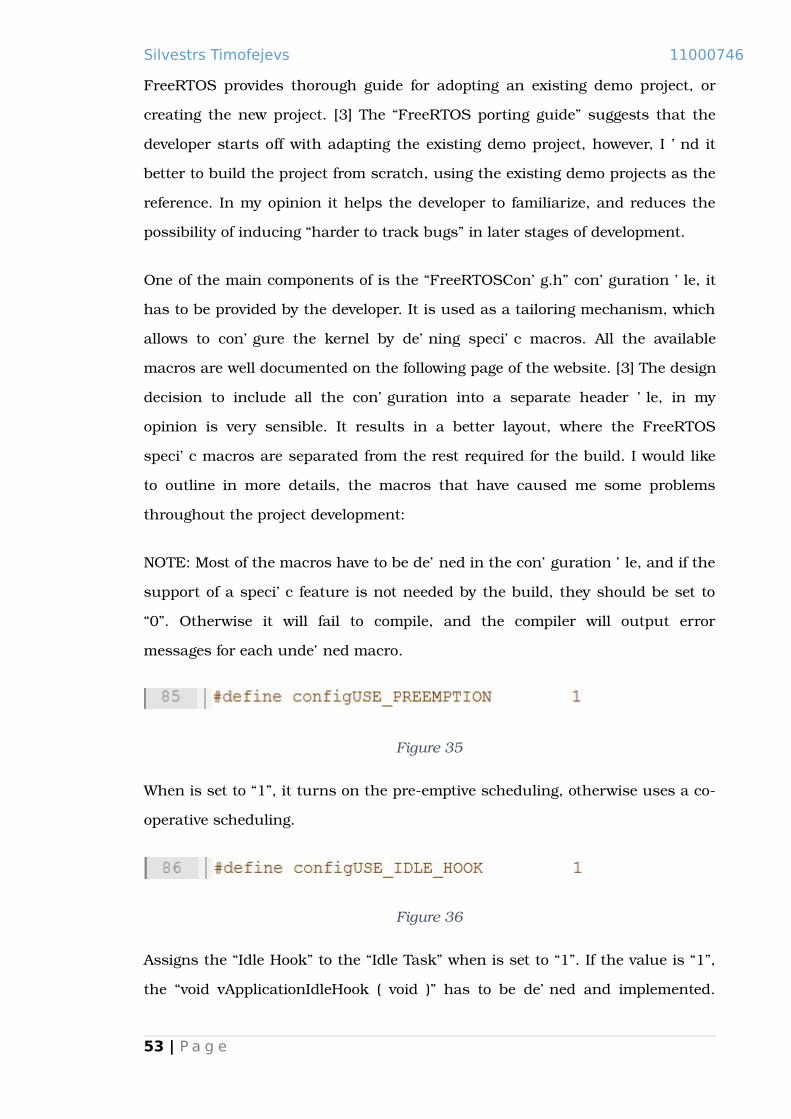
Figure 35
When is set to “1”, it turns on the pre-emptive scheduling, otherwise uses a co-
operative scheduling.
Figure 36
Assigns the “Idle Hook” to the “Idle Task” when is set to “1”. If the value is “1”,
the “void vApplicationIdleHook ( void )” has to be defined and implemented.
53 | P a g e

Silvestrs Timofejevs 11000746
“Idle Hook” is often used to put the microcontroller into a power saving mode. If
the value is “0”, FreeRTOS uses the default handler.
Figure 37
The size of the “Idle Task” stack. The name of the macro can be misleading, it
only represents the stack size of the “Idle Task”, and does not affect any of the
other tasks. Minimal stack size of 128 bytes is enough to just run the task, in
case if the implementation of the “Idle Hook” is more complicated, you might
need to allocate more stack space. The stack overflow in the “Idle Task” can be
tricky to track. When I had allocated too little stack for the “Idle Task”, the
application was crashing in the portion of the FreeRTOS core code. This code
where the fault occurred was the code to handle the “Critical Sections”, it made
me think that the issue was with the interrupt priorities configuration. It took
me about six hours of debugging and a fair amount of the FreeRTOS support
content reading, to find the cause of the problem. I have found that another
person has experienced similar issues, and that those were caused by the stack
overflow. Finally I have increased the stack size of the “Idle” task, which
resolved the problem.
Figure 38
This macro can be cause of major problems if set incorrectly. FreeRTOS does
not configure the clock frequency of the microcontroller. It is up to the
developer to set the actual microcontroller clock frequency, and make sure that
the macro matches it, otherwise you will get the wrong SysTick interrupt
intervals.
Figure 39
54 | P a g e

Silvestrs Timofejevs 11000746
The macro defines the SysTick interrupt occurrence rate in Hertz, where 1000
represents a one millisecond interval, which means that the scheduler will be
called every millisecond. Internally the configTICK_RATE_HZ and the
configCPU_CLOCK_HZ macros used together to configure the system timer.
Figure 40
The image shows the implementation of the function in the “port.c” source file
used to configure the system timer, specifically line “665”;
Figure 41
The size of the heap must be considered carefully, as the FreeRTOS allocates
space for the tasks from the heap memory pool. The configuration in the
“Figure 41”, allocates 1024 bytes of RAM to every of the 5 tasks. The developer
must remember that the memory allocated by the xTaskCreate routine, is
measured in units of 32bits, when the configTOTAL_HEAP_SIZE is configured
in bytes. If the “Heap 3” scheme is used, the configTOTAL_HEAP_SIZE macro is
ignored, instead memory allocation is the subject of the “C” library`s malloc
and free [3].
Figure 42
The macro has got three valid values of: [3]
55 | P a g e

Silvestrs Timofejevs 11000746
“0” – the “Stack Overflow Hook” is not being used;
“1” – FreeRTOS implements the “Stack Overflow” detection in the kernel,
because the stack will reach it maximum size on a context switch at that
point the kernel checks if the stack pointer contains a value outside of
the valid stack range. If the Stack Overflow occurred, the “Stack
Overflow” hook function is called;
“2” – slightly more complicated method. The FreeRTOS fills last 16 bytes
of the valid stack range with known values, and on every context switch
it checks that those values have not been overwritten. This method is
complementary to the first method, and still requires a valid Stack
Overflow hook implementation.
Stack Overflow hook function has to be implemented using the following
prototype:
Figure 43
FreeRTOS allows inclusion or exclusion of the API routines from the build, this
feature gives the developer with additional control over the size of the
executable. The fragment of code above is telling the kernel to include the
vTaskDelay function in the build.
Scheduling relies on three system exceptions. The system handlers for these
exceptions have to be mapped onto the corresponding entries of the Cortex-M3
interrupt vector, otherwise when the interrupt occurs it will not call the
FreeRTOS exception handler. If CIMSIS is being used, the FreeRTOS system
handlers cannot simply be mapped onto the interrupt vector, as CIMSIS use it`s
own interrupt naming convention. CIMSIS implements the interrupt handlers
as “weak symbols” and aliases them with the “default_handler” (just an endless
for loop). Defining the handlers as “weak symbols”, means that they can be
56 | P a g e

Silvestrs Timofejevs 11000746
redefined anywhere else in the code. Aliasing the handlers with the
“default_handler” makes sure that if the handlers are not implemented
anywhere else, the execution will not fall through, and the developer would be
able to detect that execution has fallen into the “default_handler. When using
CIMSIS, the best solution (as suggested by the FreeRTOS developers) to map
CIMSIS handlers onto the FreeRTOS handlers in the “FreeRTOSConfig.h” file. It
can be easily done by using pre-processor “#define” directive, which essentially
instructs the linker to substitute the handler names used by FreeRTOS for the
handler names used in CIMSIS. The example below shows how it is done:
Figure 44
These three system exceptions are really the core of the FreeRTOS scheduling.
The kernel makes use of these system exceptions in the following way:
SysTick interrupt is the system timer interrupt, when it elapses the
scheduler is executed. It then asserts the PendSV interrupt, which
handles the context switch;
PendSV interrupt is used to implement context switching. The reason
why context switching is implemented in the PendSV exception handler,
instead of being implemented directly in the SysTick handler, is the fact
that the context switch can be issued by the software (kernel). For
example, if a thread has blocked on the queue read or write, and cannot
execute further, the internal implementation of the FreeRTOS queue will
assert the PendSV causing the context switch;
SVC interrupt is often used in the RTOS to implement system calls,
although FreeRTOS uses it only in the beginning to start the scheduler.
5.3 FreeRTOS interrupts configuration
57 | P a g e

Silvestrs Timofejevs 11000746
The Cortex-M3 uses unorthodox priority scheme, where the lowest numerical
value corresponds to the highest interrupt priority. FreeRTOS tasks – on the
contrary, are assigned priorities, where the highest numerical value
corresponds to the highest priority (although task priorities are the software
priorities, and are handled by FreeRTOS internally). The interrupts are
configured in the “FreeRTOSConfig.h” header file. [3]
Figure 45
The Cortex-M3 supports up to 255 different priorities, however the most
hardware vendors implement only a subset of available priorities range. The
STM32P107VCT6 microcontroller implements only 16 different priorities – top 4
bits, and the bottom 4 bits are dropped. As you can see from the code portion
above, FreeRTOS defines corresponding interrupt priority macros using the full
8bits. Because the Cortex-M3 microprocessor interrupt priorities are higher
with a smaller numerical priority value, it makes sense to use full byte and only
use the necessary top bits, setting the remaining bits to logical “1”. In this way
it does not matter how many priority bits are implemented, the priorities are
assigned from the lowest logical priority (highest numerical value). [13]
One of the main causes of the FreeRTOS misbehaviour are incorrectly
configured interrupts, it has to do with how critical sections are handled. It
does not disable all interrupts when it is entering a “critical section”, instead it
masks out the priorities beyond the certain priority margin. The “critical
section” is used to protect the kernel data, and other shared data from
corruption. Problems will arise if the peripheral and other interrupts are
configured with a higher priority than the
58 | P a g e
Silvestrs Timofejevs 11000746
“configMAX_SYSCALL_INTERRUPT_PRIORITY”, which is used to mask out all
the interrupts with a lower logical priority (higher numerical value). Imagine if a
peripheral interrupt occurs when the scheduler is handling the critical data,
and the newly arrived interrupt pre-empts the scheduler. It can potentially
issue a context switch, making the scheduler re-enter the “critical section”, and
read partially written data from the previous context switch (the one which is
being re-entered now), or overwrite the initial write. [3]
In the code above, the “configMAX_SYSCALL_INTERRUPT_PRIORITY” value is
11, which means that the peripheral interrupts have to be configured with a
priority value from 11 to 15 (higher numerical value than 11, which means a
lower logical priority).
To find out in more detail how the Cortex-M3, and the STM32P107VCT6
handles the interrupts, please refer to the Appendix A.
59 | P a g e

Silvestrs Timofejevs 11000746
5.4 A simple application running FreeRTOS
The approach I am taking when working with a new software, or hardware – is
to start with the simple things. The first program I have implemented, which
makes use of FreeRTOS features, is a basic application that toggles LED`s. The
application consists of some hardware configuration – to enable GPIO pins that
are connected to the LED`s on board, and the routines to write into and read
from the GPIO ports. The other part of the application is FreeRTOS
configuration and integration, using the scheduler and synchronisation
mechanisms. Basically this application serves as the test to make sure that
FreeRTOS has been configured correctly and the scheduler is able to run. For
the reason of testing the scheduler, toggling of the green and the orange LEDs
was done in two separate tasks. The idea is that the first task toggles the green
LED, and then blocks for three seconds, the second task becomes active,
toggles the orange LED, and also blocks for three seconds. The scheduling
works in the following way, when the first task blocks, the context switch is
issued, and the scheduler activate the second task. When the second task
blocks, the scheduler activates the “idle” task. If the application runs correctly,
you should be able to see the both LED`s light up and turn off for three second
intervals.
The task has helped me to detect the problem with unassigned system
handlers, which have been discussed above in this chapter. It is a good starting
point to get the developer going with FreeRTOS. The application can be found in
the supplementary code under the “FreeRTOS_introduction” folder.
5.5 Debugging
FreeRTOS allows to assign the stack overflow hook, which was described
previously in this chapter, it also provides the configuration option to enable
trace facilities. However, apart from the FreeRTOS provided debug facilities, I
would like to suggest implementing the hardware fault handlers. Even if those
handlers have nothing but the endless “for” loop, when the exception occurs, it
60 | P a g e

Silvestrs Timofejevs 11000746
will end up in the handler, and the developer will be detect in which exception
handler the execution has ended up. The exception handlers [13]:
Hard Fault – the final destination for any interrupt, if has not been
caught by any of the specialised exception handlers, or if those handlers
have not been implemented;
Memory Management – the MPU mismatch detection, is enabled even if
the MPU is not present or is disabled, to support the Executable Never
(XN) regions of the default memory map;
Bus Fault – the memory related faults, such as pre-fetch fault and
memory access faults;
Usage Fault – usage faults, such as undefined instruction executed or
illegal state transition attempt.
Minimal implementation of these handlers might not be enough to detect the
cause of the exception, but it will help the developer to narrow down the
possible causes.
The other reason for implementing these handlers could be development of
fault-tolerant software, when the software has to continue the execution even if
the fault has occurred, or at least degrade gracefully.
61 | P a g e

Silvestrs Timofejevs 11000746
6. FreeRTOS + IO
There are common features and principles in different engineering fields:
mechanical, electronic, software, etc. As a rough example – building software is
similar to building a house, there are a number of specialists that possess
different skills, and perform different duties. An architect does not to need to
know all the traits of engineering process to design a building, obviously he
needs to have some knowledge, but it is then up to engineers/builders to
handle the building side. What I am trying to say with the above example, is
that software is similar – an application developer does necessarily need to
know about the underlying low level implementation of device specific code. It is
a good thing to separate low level implementation form the “application layer”,
which provides more flexibility to the development process. Besides the
separation of duties and work allocation, good interface certainly enhances the
maintainability and contributes to the growth of the project. I am not much
familiar with Windows or Mac OS IO interfaces, however the Linux/POSIX
model in my opinion is comprehensive and flexible. Linux device drivers are
represented as a set of device files that map to the corresponding device
structure in the kernel, using the major and minor numbers. The device
structure in turn contains the set of device specific operations, such as write,
read, open, ioctl, etc. [29]. The overall process goes through a number of
abstraction layers:
Standard C routines, which are wrappers around the Operating System
calls, and perform some additional administrative work, before and after
calling the underlying system calls;
System calls, which distinguish between the requests and call device
specific routines;
Finally, there are device specific routines, which handle the hardware by
reading and writing data to the memory mapped addresses that
represent the device registers and memory buffers.
62 | P a g e
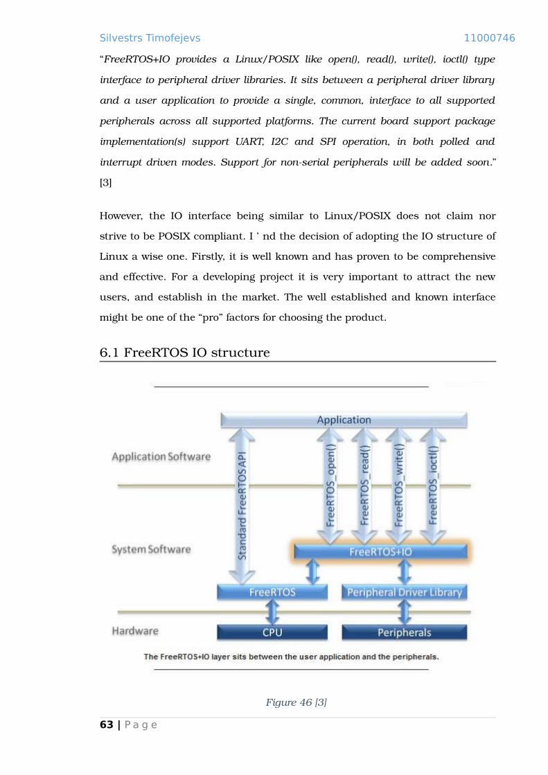
Silvestrs Timofejevs 11000746
“FreeRTOS+IO provides a Linux/POSIX like open(), read(), write(), ioctl() type
interface to peripheral driver libraries. It sits between a peripheral driver library
and a user application to provide a single, common, interface to all supported
peripherals across all supported platforms. The current board support package
implementation(s) support UART, I2C and SPI operation, in both polled and
interrupt driven modes. Support for non-serial peripherals will be added soon.”
[3]
However, the IO interface being similar to Linux/POSIX does not claim nor
strive to be POSIX compliant. I find the decision of adopting the IO structure of
Linux a wise one. Firstly, it is well known and has proven to be comprehensive
and effective. For a developing project it is very important to attract the new
users, and establish in the market. The well established and known interface
might be one of the “pro” factors for choosing the product.
6.1 FreeRTOS IO structure
Figure 46 [3]
63 | P a g e

Silvestrs Timofejevs 11000746
The image illustrates the interaction between the software abstraction levels of
the system, where FreeRTOS+IO is a common interface to access, configure and
manipulate the underlying hardware. The Peripheral Driver Library in the case
of Cortex family microprocessors will be MCU specific version of CIMSIS, the
Driver Library can be amended (however I would strongly advise against that,
the benefits were described in the previous chapters), in case if the developer
decides to implement his own low level library. A typical application flow would
be something like – FreeRTOS API controls the application logic, and system
execution (using queues, tasks, scheduling mechanisms, etc.), peripheral
access is achieved through the IO interface, which in turn calls low level
hardware routines.
The FreeRTOS IO does not come together with the source code, as many other
additions, instead the IO folder contains only a readme file with a description
where to find the sample project examples. The sample projects can be found
on the official website [3]. The interface consists of the set of common source
and header files, and hardware specific board support package. Support
package consists of the set of device drivers and information about the available
devices. Below you can see the source layout, LPC17xx folder contains an
official LPC Cortex-M3 based microcontroller port. STM32F10X folder and its
contents were created by me, and hold the STM32F10X BSP source. An
addition to one of the common UART IOUtils had to be implemented, it takes
into consideration STM32 microcontrollers UART architecture (not supporting
FIFO buffers).
64 | P a g e

Silvestrs Timofejevs 11000746
Figure 47
6.2 Porting FreeRTOS IO
The easiest way to port the IO interface across the new microcontroller, is to
adopt an existing demo project. The porting process is not that hard, the logic
is common between different architectures. The low level driver implementation,
however needs to be changed. The USART driver implementation and peripheral
initialization has been covered in the previous chapters, and is not much
different. The best way of providing an overview of the IO mechanism, is to
follow through the porting process.
65 | P a g e

Silvestrs Timofejevs 11000746
6.3 FreeRTOS IO types, definitions and prototypes
The tricky part of porting the IO interface, is to get to understand the relation
between a number of different types, definitions and routines. The fundamental
modules that create the background for the peripheral specific code integration
are: FreeRTOS_DeviceInterface and stm32f10x_base_board.h. Understanding
the functionality provided by these modules is essential to make any justifiable
modifications.
We will start by looking at the stm32f10x_base_board.h, which is the part of
the BSP. This file has to be provided by the developer, and is basically a
modified LPCXpresso17xx-base-board.h file with some functionality being
stripped out, and architecture specific code being re-written. The header file
contains the base data, which is a summary of on-chip peripherals, and the
metadata used by the IO mechanisms.
Figure 48
This macro is then used in a common FreeRTOS_DeviceInterface.c source file,
which will be described later in the chapter. It is basically the initialization data
used to initialize the Available_Peripherals_t type structure (essentially is a
peripheral descriptor) defined in the FreeRTOS_DeviceInterface.h h. This macro
is only used by the FreeRTOS_open routine. The official LPC port supports
more interfaces, however it is easier to get the peripherals working one by one,
and UART has the priority in this project. It is not too hard to guess what the
data represents:
“/USART2/” – specially formatted name of the peripheral;
eUART_TYPE – just an enumeration, which later is used to differentiate
between the devices;
66 | P a g e

Silvestrs Timofejevs 11000746
( void * ) USART2 – is the base address of the USART2 peripheral in the
STM32F10x microcontroller.
Figure 49
The corresponding routine is used to differentiate between peripheral specific
open routines. The #define – in this case just contributes towards cross-
platform interface, so that common FreeRTOS IO routines can call the general
definition, which then is translated into the architecture specific routine by the
BSP layer.
Figure 50
The macro represents the number of UART peripherals in the STM32F10x
microcontroller. It is later used to verify if the index number of an issued
peripheral is correct. The STM32F10x microcontroller series have got 3 USART
and 2 UART peripherals.
67 | P a g e

Silvestrs Timofejevs 11000746
Figure 51
The macro shown in “Figure 51” configures the microcontroller GPIO pins.
Moving to the next set of IO files – the common FreeRTOS_DeviceInterface
source and header files. The first thing to look at here are the type definitions in
the header file, and IO function prototypes:
Figure 52
“Figure 52” shows the type definition a structure describing a peripheral
descriptor, the array of Available_Peripheral_t type members, and using the
macro described previously (boardAVAILABLE_DEVICES_LIST) to populate it.
68 | P a g e

Silvestrs Timofejevs 11000746
Figure 53
“Figure 53” displays the type definition of a device descriptor structure, which
consists of pointers to the peripheral specific functions. It is similar to the
file_operations structure in Linux that holds pointers to the device specific
routines. Transmit and receive transfer control structures, that are dependant
on the peripheral type and mode – points to an actual IO method, such as the
FreeRTOS queue. pxDevice points to the peripheral Available_Peripheral_t type
member. cPeripheralNumber is an index number of a peripheral (such as “2” in
“USART2” – note, USART2 is actual definition of the peripheral base address in
the CIMSIS library). It is the main device descriptor that is created and
configured in the FreeRTOS_open routine, and is used by all of the rest IO
interface functions.
Figure 54
The peripheral enumeration type, is used to differentiate between the devices.
Peripheral_Control_t structure as was mentioned above, contains a peripheral
descriptor, which is used as an argument into the switch statement in the
vFreeRTOS_stm32f10x_PopulateFunctionPointers routine of the
FreeRTOS_stm32f10x_DriverInterface.c, and differentiates between the
peripheral open routines.
69 | P a g e

Silvestrs Timofejevs 11000746
Figure 55
“Figure 55” shows the definition of the transfer control structure,
pvTransferState can be one of the IO methods, dependant on the transfer type
chosen (for instance – a character queue).
Figure 56
Definition of the IO function types, which are effectively function pointers used
in the Peripheral_Control_t type structure, to point to the peripheral specific
routines.
Figure 57
In “Figure 57”, the FreeRTOS_read and FreeRTOS_write macros are definitions
that expand to call IO operations in a Peripheral_Control_t structure. Unlike
the FreeRTOS_open and FreeRTOS_ioctl, these functions do not require an
intermediate stage, so just directly access the private peripheral routines.
70 | P a g e

Silvestrs Timofejevs 11000746
6.4 FreeRTOS_open
Figure 58
The Open routine, creates the peripheral descriptor, and performs the device
specific configuration. Please note that all the peripheral specific IO routines
are defined in the FreeRTOS_stm32f10x_uart,
FreeRTOS_stm32f10x_DriverInterface and the stm32f10x_base_board source
files. The first routine to look at is the common open routine:
Figure 59
The use of xAvailablePeripherals array has been partially described earlier in
this chapter, it holds the metadata of the peripherals exposed to the IO
interface.
71 | P a g e

Silvestrs Timofejevs 11000746
Figure 60
The FreeRTOS_open function goes through all the entries trying to find a match
for the peripheral name passed to the function. If the match has been found,
the index number is extracted – the corresponding code has not been shown in
the “Figure 60”, as it is rather obvious and does not require detailed
explanation. If a peripheral has been successfully identified, the descriptor is
created. Notice that the pxPeripheralControl->pxTxControl and
pxPeripheralControl->pxRxControl are set to NULL; dependant on a chosen IO
method, those can be different mechanisms, and are configured by the ioctl
routines described later in the chapter. An address and an index number of an
identified peripheral is stored, and the control is passed to the
boardFreeRTOS_PopulateFunctionPointers routine. One thing to remember is
that it is a macro, which is substituted by the pre-processor with an
architecture specific routine during the compilation.
72 | P a g e

Silvestrs Timofejevs 11000746
Figure 61
The PopulateFunctionPointers routine does not do much other than calling a
peripheral specific open function dependant on a passed type. It then returns
to the top level open routine, which check that peripheral has been configured
without errors. In case of a failure, the open routine will free the memory
allocated for a descriptor, and return NULL.
The next step is to look into the FreeRTOS_UART_open routine, which is a part
of the BSP FreeRTOS_stm32f10x_uart module.
Figure 62
Note that apart from the common includes, an additional header file developed
by the author had to be added. The need this file will be described later in the
chapter, it implements the macros that support non-FIFO UART operations
73 | P a g e

Silvestrs Timofejevs 11000746
(STM32F107 USART and UART peripherals do not implement the hardware
FIFO buffers).
Figure 63
The heart of the BSP open function, which populates a peripheral descriptor IO
pointers with the correct routines, configures the GPIO pins along with a
peripheral. The current version of the STM32F107 port developed by author,
only supports the USART as a peripheral IO device. Implementation of the
other IO interfaces could be a subject of a further development.
boardCONFIGURE_USART_PINS is a macro, the only reason for using a macro–
is the stack depth reduction. It can be called number of times, but is only
referenced once in the code.
74 | P a g e

Silvestrs Timofejevs 11000746
6.5 FreeRTOS_ioctl
Figure 64
Ioctl stands for (Input Output Control), and is a powerful and flexible way of
controlling devices. As an example, imagine a graphics card. It is reasonable to
assume that the general read and write will not be sufficient to control the
device. Complicated hardware modules might have variety of different registers,
buffers and memory regions that need to be accessed. One of the methods for
differentiating between the write and read addresses and other operations is
ioctl; Dependant on a request code, it can “hook up” different write and read
routines, or set the variables that control the process within the routines, etc.
Figure 65
In “Figure 65” the last two parameters passed into the function, are the ones to
look at. ulRequest holds a request code, which is fed into a switch statement to
choose a device specific operation. pvValue can be any type of data that might
be needed to configure a peripheral.
75 | P a g e

Silvestrs Timofejevs 11000746
Figure 66
“Figure 66” shows the code that creates and configures IO transfer structures.
FreeRTOS implements number of different IO mechanisms, however the only
ones used in this port are transmit and receive queues. Dependant on the
ulRequest the corresponding transfer mechanism will be set. It then might
issue a device specific ioctl operation by setting xCommandIsDeviceSpecific
variable to true, and reassigning ulRequest a new code.
Figure 67
“Figure 67” shows that there might be cases when a device specific ioctl routine
is not called at all. Note, because the common layer implements only a number
of ioctl operations, any requests that are not defined in this layer will be passed
to a device specific ioctl routine.
The next step is to explore the BSP ioctl implementation, in the
FreeRTOS_stm32f10x_uart module.
76 | P a g e
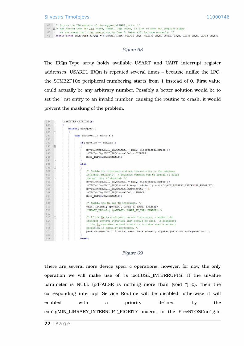
Silvestrs Timofejevs 11000746
Figure 68
The IRQn_Type array holds available USART and UART interrupt register
addresses. USART1_IRQn is repeated several times – because unlike the LPC,
the STM32F10x peripheral numbering starts from 1 instead of 0. First value
could actually be any arbitrary number. Possibly a better solution would be to
set the first entry to an invalid number, causing the routine to crash, it would
prevent the masking of the problem.
Figure 69
There are several more device specific operations, however, for now the only
operation we will make use of, is ioctlUSE_INTERRUPTS. If the ulValue
parameter is NULL (pdFALSE is nothing more than (void *) 0), then the
corresponding interrupt Service Routine will be disabled; otherwise it will
enabled with a priority defined by the
configMIN_LIBRARY_INTERRUPT_PIORITY macro, in the FreeRTOSConfig.h.
77 | P a g e

Silvestrs Timofejevs 11000746
The routine also enables the “Receive Not Empty” interrupt, the “Transmit
Empty” is set and disabled elsewhere. It needs to be enabled after a write into a
transmit queue, and disabled from the ISR when a queue is empty. More
detailed explanation will be provided will later in the chapter.
6.6 FreeRTOS_read
Figure 70
The FreeRTOS_UART_read routine is mostly taken out from the official LPC
port, apart from a stripped down functionality (only receive and transmit queue
transfer methods are supported). The only read platform dependant code is in
the ISR. The read routine just attempts to read from a receive queue, and
blocks if queue is empty, it then stays in the blocked state until the Interrupt
Service Routine writes into the corresponding queue and unblocks the thread.
Figure 71
78 | P a g e

Silvestrs Timofejevs 11000746
If the peripheral descriptor transfer structure is NULL, this means that the only
available read method is the polled UART receive method. However, this port
will be only using the character queue based receive and transmit operations,
so polled receive option is not implemented.
Figure 72
The switch statement chooses the receive method based on the configuration
performed by an ioctl operation, in our case it is the character queue receive
method.
6.7 FreeRTOS_write
79 | P a g e

Silvestrs Timofejevs 11000746
Figure 73
The write routine is slightly more different from the LPC port write routine. The
difference is that LPC port uses the hardware UART buffers, whilst the
STM32F107 microcontroller does not have such mechanisms. Several macros
in the IOUtils had to be modified, instead of changing the common layer of the
FreeRTOS IO, another header file have been added; it implements the read and
write operations without using the UART hardware FIFO buffers. STM32 MCU
can potentially achieve a buffered UART functionality through the use of DMA,
and could be a subject for further development. The method used is a simple
single character receive and transmit at the ISR level, which resulted in
addition of modified header file with appropriate read and write macros.
Figure 74
Similarly to the read routine, the code in “Figure 74” checks if the transfer
method is a polled transmit.
80 | P a g e
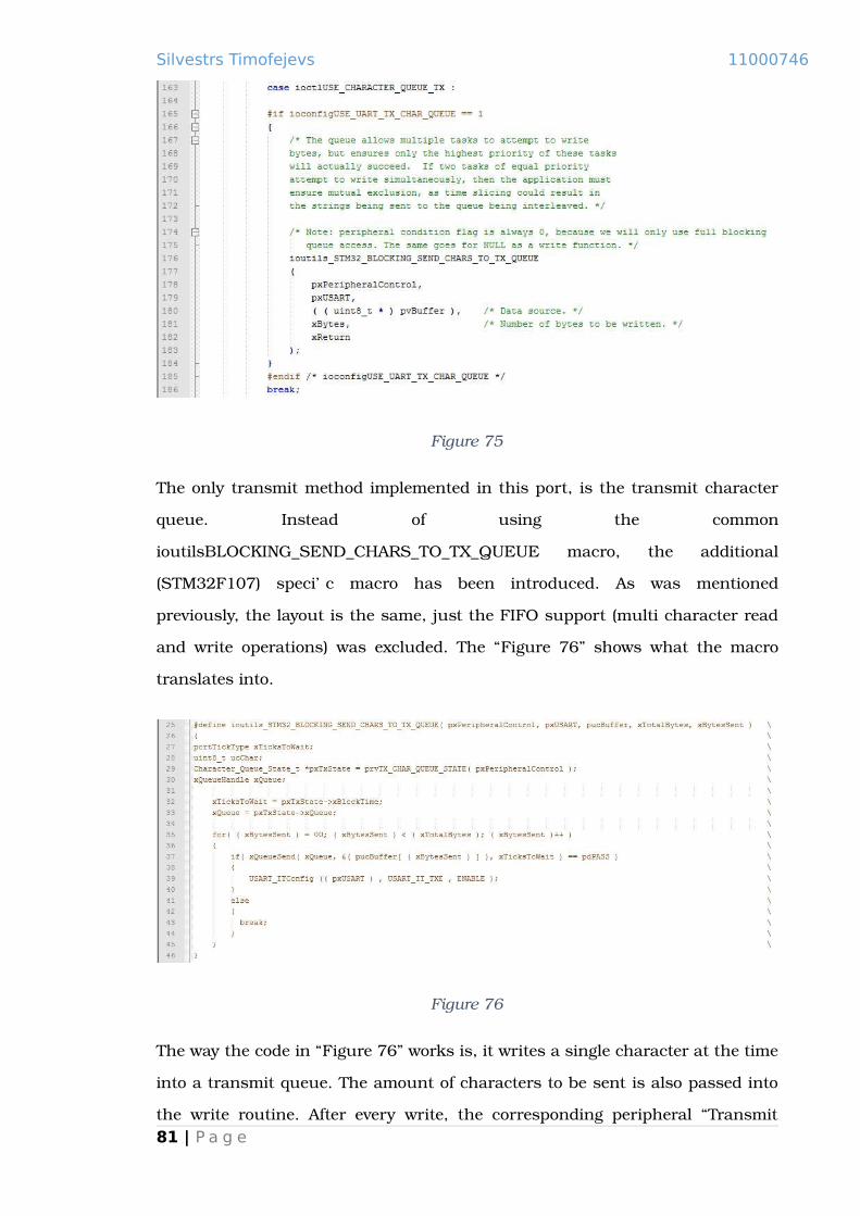
Silvestrs Timofejevs 11000746
Figure 75
The only transmit method implemented in this port, is the transmit character
queue. Instead of using the common
ioutilsBLOCKING_SEND_CHARS_TO_TX_QUEUE macro, the additional
(STM32F107) specific macro has been introduced. As was mentioned
previously, the layout is the same, just the FIFO support (multi character read
and write operations) was excluded. The “Figure 76” shows what the macro
translates into.
Figure 76
The way the code in “Figure 76” works is, it writes a single character at the time
into a transmit queue. The amount of characters to be sent is also passed into
the write routine. After every write, the corresponding peripheral “Transmit81 | P a g e
Silvestrs Timofejevs 11000746
Empty” interrupt is enabled. The ISR will then remove a character from the
queue and send it out, and when the queue is drained, it will disable the
interrupt (otherwise execution will forever remain in the ISR). UART is
commonly operates at the 115200 bps speed, when the processor max
frequency is 72MHz, which is marginally faster than the peripheral; it means
that whilst the hardware is performing even a single character transfer, the
processor can perform a reasonable amount of useful work. The way it is
implemented is not optimal, although it is still much more efficient than using
a polled receive and transmit method. This port has only been tested with
blocking read and write operations, using a non-blocking mode will most likely
cause the program to crash.
82 | P a g e
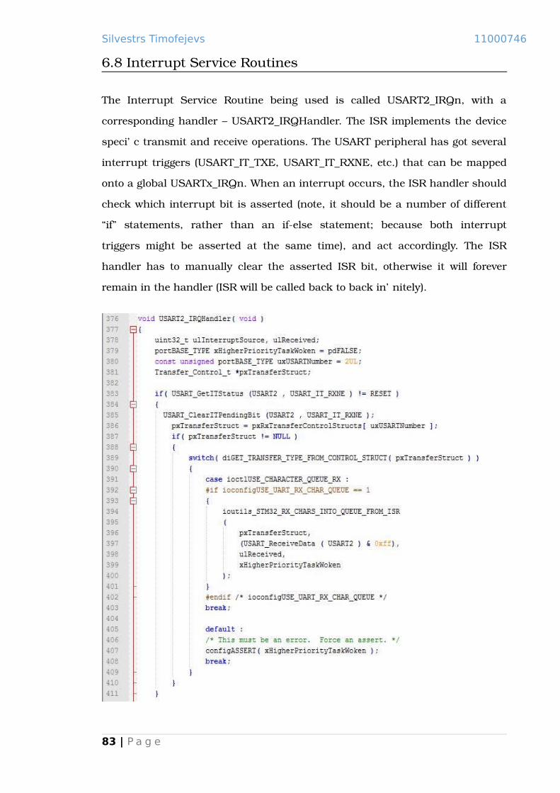
Silvestrs Timofejevs 11000746
6.8 Interrupt Service Routines
The Interrupt Service Routine being used is called USART2_IRQn, with a
corresponding handler – USART2_IRQHandler. The ISR implements the device
specific transmit and receive operations. The USART peripheral has got several
interrupt triggers (USART_IT_TXE, USART_IT_RXNE, etc.) that can be mapped
onto a global USARTx_IRQn. When an interrupt occurs, the ISR handler should
check which interrupt bit is asserted (note, it should be a number of different
“if” statements, rather than an if-else statement; because both interrupt
triggers might be asserted at the same time), and act accordingly. The ISR
handler has to manually clear the asserted ISR bit, otherwise it will forever
remain in the handler (ISR will be called back to back infinitely).
83 | P a g e

Silvestrs Timofejevs 11000746
Figure 77
The code in “Figure 77” handles the receive side of the USART peripheral. The
Interrupt Service Routine checks if the RXNE bit is asserted, and dependant on
the type of the receive method (character queue) calls the corresponding macro.
Following the same principle as with the write routine, the macro has to be
modified, to eliminate the use of UART FIFO buffers. Notice the arguments
passed into the macro: character receive routine, pxTransferStruct (type of
structure that holds the corresponding FreeRTOS queue, and the metadata
such as type), receive character counter and the xHigherPriorityTaskWoken
variable. The last parameter variable is used to check if an action in the ISR
have unblocked one of the tasks with a higher priority than the one is
scheduled for the execution, then the kernel reschedules the tasks.
Figure 78
The macro is really to prevent the re-writing of code in every single handler, and
minimize stack depth. It is important to understand what the pre-processor
does with macros; every occurrence of a macro in the code is substituted by the
portion of code described in a macro.
84 | P a g e
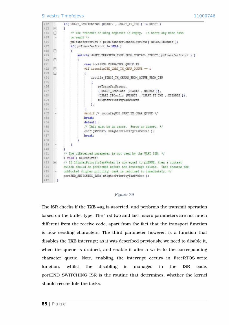
Silvestrs Timofejevs 11000746
Figure 79
The ISR checks if the TXE flag is asserted, and performs the transmit operation
based on the buffer type. The first two and last macro parameters are not much
different from the receive code, apart from the fact that the transport function
is now sending characters. The third parameter however, is a function that
disables the TXE interrupt; as it was described previously, we need to disable it,
when the queue is drained, and enable it after a write to the corresponding
character queue. Note, enabling the interrupt occurs in FreeRTOS_write
function, whilst the disabling is managed in the ISR code.
portEND_SWITCHING_ISR is the routine that determines, whether the kernel
should reschedule the tasks.
85 | P a g e

Silvestrs Timofejevs 11000746
Figure 80
The character is read from the queue and transmitted, if it failed to read a
character from the queue (queue is empty), and the interrupt is disabled.
6.9 Macros and debug
One notable problem working with macros, is debugging. GCC does not create
debug symbols for macros, and the only the macros cod can be stepped
through, is single-stepping the machine instructions. There is nothing wrong to
go through the assembly code, although it will certainly take more time to
logically map it to the source code. The approach used in this project, is to copy
the macros content into the place in the code where it is referenced. By defining
a debug macro in FreeRTOSConfig.h, and using the pre-processor directives, an
easy macro debugging method can be achieved.
6.10 Integration with NewLib
NewLib and FreeRTOS both use POSIX style IO interface, although the
FreeRTOS routine have got different signature – same logical structure, but the
types of parameters and the return type are different. It makes much more
sense to use the set of FreeRTOS IO mechanisms, instead of implementing the
system calls from scratch; fortunately getting them work together is a rather
simple process. NewLib has to be recompiled with the “-DMALLOC_PROVIDED”
flag, which tells the library to exclude the “malloc family” routines, which are:
_realloc_r, _calloc_r, _malloc_r, _free_r. It is possible to use the standard malloc86 | P a g e

Silvestrs Timofejevs 11000746
implementation, although I ran into various problems trying to make it work,
and it might take a while to resolve the problem, unfortunately there is not
enough time for it. On the other hand, it makes much more sense to use the
FreeRTOS native implementation of the dynamic memory allocation
mechanism. The routines excluded from the library, obviously have to be
provided by the developer.
Figure 81
“Figure 81” shows the implementation of the relevant dynamic memory
allocation routines, realloc is not implemented at the moment, and is a subject
to the further development.
87 | P a g e

Silvestrs Timofejevs 11000746
Figure 82
“Figure 82” displays the integration of open and write routines, the read and
ioctl routines are the subject of further development.
Figure 83
The comparison between the function prototypes, shows that function
arguments and the return types are different, there are much better ways of
integrating the functions together, but it will involve an introduction of an
additional infrastructure layer. An easier “hacky” approach has been taken,
where pointers are casted into integers and vice versa. This is a perfectly legal
method, as both are 32bit values, and the only difference is how compiler
interprets them. The same kind of manipulations have to be applied anywhere
in the code where these routines are used.
88 | P a g e

Silvestrs Timofejevs 11000746
89 | P a g e
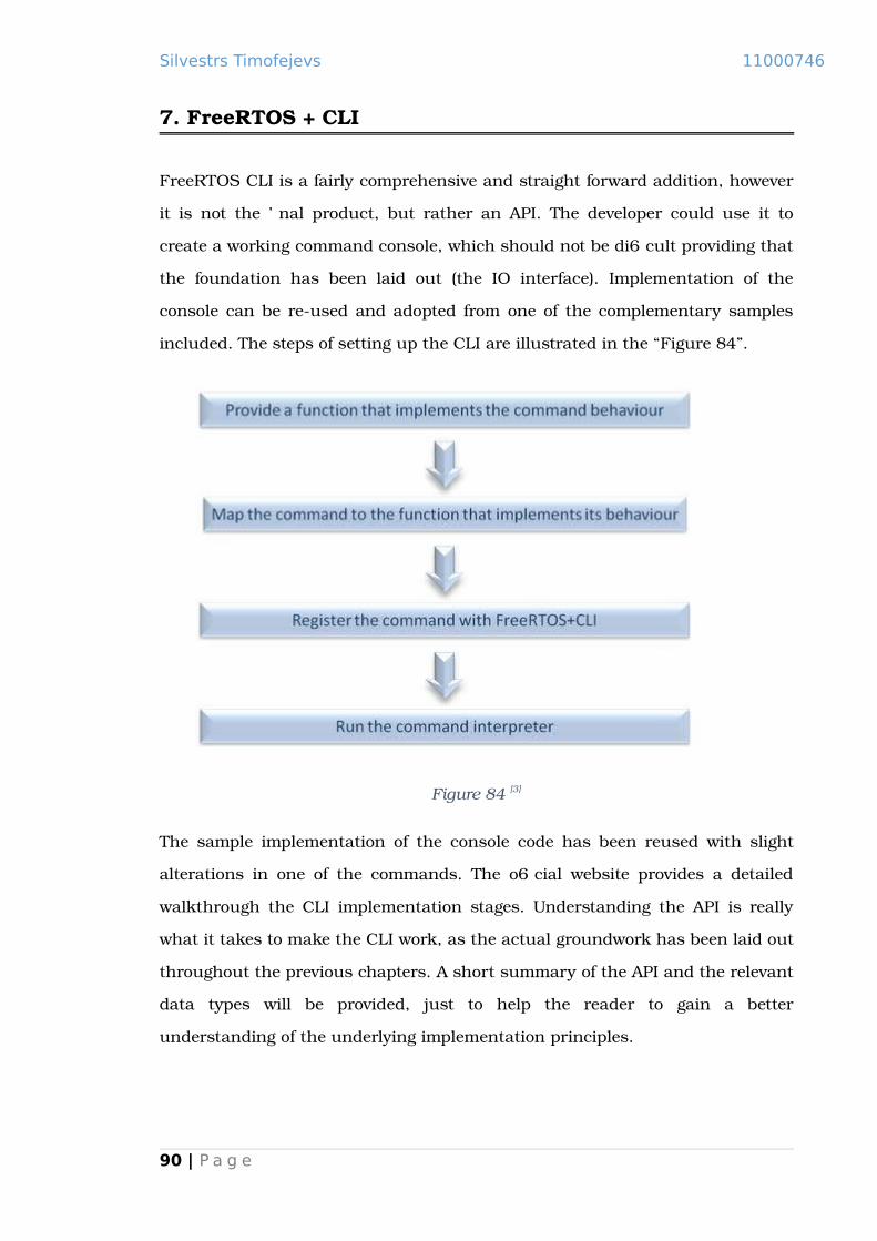
Silvestrs Timofejevs 11000746
7. FreeRTOS + CLI
FreeRTOS CLI is a fairly comprehensive and straight forward addition, however
it is not the final product, but rather an API. The developer could use it to
create a working command console, which should not be difficult providing that
the foundation has been laid out (the IO interface). Implementation of the
console can be re-used and adopted from one of the complementary samples
included. The steps of setting up the CLI are illustrated in the “Figure 84”.
Figure 84 [3]
The sample implementation of the console code has been reused with slight
alterations in one of the commands. The official website provides a detailed
walkthrough the CLI implementation stages. Understanding the API is really
what it takes to make the CLI work, as the actual groundwork has been laid out
throughout the previous chapters. A short summary of the API and the relevant
data types will be provided, just to help the reader to gain a better
understanding of the underlying implementation principles.
90 | P a g e

Silvestrs Timofejevs 11000746
7.1 Fundamentals of the FreeRTOS CLI
Figure 85
The command descriptor holds the name of a command (pcCommand), the help
string (pcHelpString), a pointer to a function implementing the command
(pxCommandInterpreter, the format of the function port is defined in the first
non-comment line of the above code) and the maximal number of parameters
the routine could take. The CLI_Command_Definition_t type structure is the
main descriptor of the command, which is used to describe and register the
command. It is useful to take a look at the resources used by the command
register function.
Figure 86
The command list type, where the first member holds the address of a
command call-back routine, and the second points to the descriptor of a next
command.
91 | P a g e

Silvestrs Timofejevs 11000746
Figure 87
“Figure 87” shows the variable that holds the address of the first CLI command
(xHelpCommand, implemented in the FreeRTOS+CLI. When “help” is typed into
the console, it will output the names of all registered commands) – beginning of
the command list.
Figure 88
“Figure 88” shows how the command is actually being registered – new
command list item is created, and the previous command`s next pointer points
to the command descriptor passed in the routine (a typical list implementation).
The rest of the API routines are exceptionally well documented on the official
website. [3]
92 | P a g e

Silvestrs Timofejevs 11000746
8. Conclusion
As has been mentioned in the Risk assessment chapter, the main risk
associated with the project – is the possibility that someone else would come up
with a product first. The STMicroelectronics has released a software tool for
configuring the portfolio of the STM32 microcontrollers. It incorporates
FreeRTOS, and various other modules. It could seem as a pitfall, in reality,
however, it is rather encouraging. One of the biggest hardware vendors in the
world has decided to extend the development environment of the hardware they
produce, with one of the approaches being incorporating of the FreeRTOS into
their new software tool; ultimately having the same rationale as the goals
behind this project, although having different means. This project strives to
extend the FreeRTOS development environment, using the ST Microelectronics
microcontroller as the underlying hardware, when STMicroelectronics
intentions are to improve the infrastructure around the hardware they produce
by incorporating FreeRTOS into their new development.
However, it does not mean that the efforts of this project have been for granted.
First of all, not all hardware vendors supplement their products with as
powerful software package as the STMicroelectronics do; the developers
working on other MCUs could find this project useful, as the underlying
principles covered are universal across the similar functionality hardware. The
projects consists of several step-by-step guides of software and hardware
configuration, giving an overview of the development tools used.
I am inclined to believe that STMicroelectronics are following a great business
concept by not only creating a reliable and efficient hardware, but also by
making things easier for the developers. Important criteria of choosing
hardware is cost, efficiency, support and ease of use. Speaking from experience,
in my opinion STMicroelectronics have achieved it with Excellency.
93 | P a g e

Silvestrs Timofejevs 11000746
8.1 STMCube
In beginning of the 2015 STMicroelectronics have released the STM32Cube,
which provides a visual development environment for peripheral configuration.
It actually goes far beyond, the STM32Cube includes various resource
monitoring facilities, such as the power consumption used by the peripherals.
The Cube includes consistent set of middleware products, such as RTOS, USB,
TCP/IP, Graphics, and a number of related examples. Major feature that is
conceptually different in the STMCube, is an introduction of the new HAL. [23]
[22]
Throughout the development I have come across certain issues with CIMSIS,
one of them being the fact that Standard Peripheral Library, which is imposed
by ARM – is relatively different across different microcontroller vendors. This
fact diminishes its usefulness, being easily portable and using the same
naming conventions within the same MCU portfolio; it is in fact quite different
between the MCU lines from different vendors, and cannot be served as the
HAL in full sense of the term. I think what STMicroelectronics are trying to
achieve with the introduction of the new HAL, is extending portability even
further.
FreeRTOS integration with the STMCube is done through the introduction of
RTOS HAL, which means that it might be possible to substitute it with a
different RTOS.
94 | P a g e

Silvestrs Timofejevs 11000746
8.2 Words of praise to FreeRTOS and STMicroelectronics
In my opinion the next great success in the software market, might happen in the Real-
Time Operating System field. The 21st century has witnessed a great expansion of
mobile devices in the market, which has contributed to Apple emerging with an
exceptional UI. With most fields of computing already claimed by the giants’ such as
Microsoft, Linux and Apple, the embedded software market is relatively open.
FreeRTOS could be the product that conquers the embedded market, with their open
source approach, great support and comprehensive API.
The fact that the STMicroelectronics have included FreeRTOS in the STMCube speaks
for the quality of the software. A great customer support and a comprehensive code
structure has already been mentioned in the “FreeRTOS” chapter, although I would like
to emphasize it once more.
Similar words could be said about STMicroelectronics, with the amount of
supplementary software available, and the overwhelming documentation base. Most
importantly the materials are easily available on their website [6].
8.3 Work assessment
The main goal of the project has been reached - I have built a working system running
FreeRTOS incorporated with NewLib, IO interface and CLI. This project has been a
tremendous learning curve for me. The choice of a low level programming project, was a
considerate decision. I had realized that low level hardware development was one of my
weakest points, which was a motivation to dive into it.
I am slightly disappointed that the USB porting section is not completed, and hence is
not included in the report. I am planning to continue the development and include the
USB support into the demonstration.
Working on the project the idea of an interesting addition has come up – building a
binary loader to cooperate with FreeRTOS. Normally it is compiled together with a
bootstrapper, and the initialization code. The two parts could be separated – the low
level initialization, and the kernel with its utilities, from a high level application. That95 | P a g e

Silvestrs Timofejevs 11000746
way there will be no need to recompile the system every time an actual software
changes. The facility for loading binary images could be CLI, as the FreeRTOS API
provides a powerful task management mechanisms. The system then could be run in
two modes, configuration mode, and the performance mode. When image/images have
been loaded, and configuration mode is no longer required – the system could terminate
the CLI, and other unnecessary tasks, switching into the performance mode.
96 | P a g e

Silvestrs Timofejevs 11000746
9. Bibliography
1. Goodacre, J. and Sloss, A.N. (July 2005) Parallelism and the ARM Instruction SetArchitecture. Computer [online]. 38 (7), p. 42. [Accessed 08 February 2015].
2. OLIMEX Ltd. (January 2015) STM32-P107 development board User's manual, Rev. I. [online]. OLIMEX Ltd. Available from: https://www.olimex.com/ [Accessed 10 February 2015].
3. FreeRTOS [online] Available at: http://www.freertos.org/. [Accessed 12 April 2015].
4. STMicroelectronics (June 2014) RM0008 Reference manual (STM32F101xx, STM32F102xx, STM32F103xx, STM32F105xx and STM32F107xx advanced ARM ®-based 32-bit MCUs), DocID13902 Rev 15. [online]. STMicroelectronics, Available from: http://www.st.com [Accessed 12 April 2015].
5. Richard Barry, R.B. (2010) Using the FreeRTOS Real Time Kernel - a Practical Guide [online]. 1st ed.: Unknown. [Accessed 31 January 2015].
6. STMicroelectronics [online] Available at: http://www.st.com [Accessed 12 April 2015].
7. Yiu, J. (2010) The Definitive Guide to the Arm Cortex-m3 [online]. 2nd ed. Burlington, Usa: Newnes. [Accessed 01 April 2015].
8. Brown, G. (2014) Discovering the STM32 Microcontroller [online]. Cortex, 3, 34: Unknown [Accessed 03 April 2015]
9. Gatliff, B. (2001) Porting and Using Newlib in Embedded Systems. [online]. [Accessed 09 April 2015].
10. Ganssle, J.G. (2001) Reentrancy. Embedded Systems Programming [online]. 14 (4), pp. 183-184. [Accessed 09 April 2015].
11. STMicroelectronics (May 2013) PM0056 Programming manual (STM32F10xxx/20xxx/21xxx/L1xxxx Cortex-M3 programming manual), DocID15491 Rev 5. [online]. STMicroelectronics, Available from: http://www.st.com [Accessed 12 April 2015].
12. A. R. M. (2004-2009) CoreSight Components Technical Reference Manual. [online]. A.R.M., Available from: http://www.arm.com/. [Accessed 12 April 2015].
97 | P a g e

Silvestrs Timofejevs 11000746
13. A.R.M. (2005 - 2006) Cortex™-M3 Technical Reference Manual, Rev r1p1. [online] A.R.M., Available from: http://www.arm.com/. [Accessed 12 April 2015].
14. IEEE (2013) IEEE Std 1149.1, Standard Test Access Port and Boundary Scan Architecture, Revision of IEEE Std 1149.1-2001. [online]. IEEE. Available from: http://ieeexplore.ieee.org/. [Accessed 12 April 2015].
15. Open On-Chip Debugger [online] Available at: http://openocd.org/. [Accessed12 April 2015].
16. Pre-built GNU toolchain from ARM Cortex-M & Cortex-R processors (Cortex-M0/M0+/M3/M4/M7, Cortex-R4/R5/R7). [online] Available at: https://launchpad.net/gcc-arm-embedded. [Accessed 12 April 2015].
17. GCC online documentation [online] Available at: https://gcc.gnu.org/. [Accessed 12 April 2015].
18. Documentation for binutils 2.25 [online] Available at: https://sourceware.org/binutils/docs-2.25/. [Accessed 12 April 2015].
19. NewLib [online] Available at: https://sourceware.org/newlib/. [Accessed 12 April 2015].
20. uClibc [online] Available at: http://www.uclibc.org/. [Accessed 12 April 2015].
21. The GNU C Library (glibc) [online] Available at: http://www.gnu.org/software/libc/. [Accessed 12 April 2015].
22. STMicroelectronics (February 2015) UM1850 User manual (Description of STM32F1xx HAL drivers), DOCID027328 Rev 1. [online]. STMicroelectronics, Available from: http://www.st.com [Accessed 12 April 2015].
23. STMicroelectronics (March 2015) UM1718 User manual (STM32CubeMX for STM32 configuration and initialization C code generation), DocID025776 Rev 7.[online]. STMicroelectronics, Available from: http://www.st.com [Accessed 12 April 2015].
24. CMSIS - Cortex Microcontroller Software Interface Standard [online] Available at: http://www.arm.com/products/processors/cortex-m/cortex-microcontroller-software-interface-standard.php. [Accessed 12 April 2015].
25. How JTAG works [online] Available at: http://www.fpga4fun.com/JTAG2.html. [Accessed 12 April 2015].
98 | P a g e

Silvestrs Timofejevs 11000746
26. GNU Software [online] Available at https://www.gnu.org/software/software.html.[Accessed 12 April 2015].
27. Git [online] Available at http://git-scm.com/. [Accessed 12 April 2015].
28. Use reentrant functions for safer signal handling [online] Available at https://www.ibm.com/developerworks/library/l-reent/. [Accessed 12 April 2015].
29. Corbet, J. and Rubini, A. (2001) Linux Device Drivers [online]. 2nd ed. : O'ReillyMedia. [Accessed 13 April 2015].
99 | P a g e

Silvestrs Timofejevs 11000746
Appendix A
Cortex-M3 exception model
The Cortex-M3 microprocessor supports nesting of the interrupts, it also automatically
saves the execution state when the exception elapses, and pops the saved state when
Interrupt Service Routine has finished. Each exception can be in one of the 4 states:
[13]
Inactive – self-explanatory, the exception has not been asserted;
Pending – exception has been asserted by the hardware or software, and is
waiting to be serviced by the processor;
Active – Exception is being serviced by the processor, but has not yet finished (if
one ISR has been interrupted by a different ISR with a higher priority, both will
stay in the active state);
Active and Pending – Exception is being serviced, and is also asserted, will run
back to back (unless a higher priority exception is also in a pending state, which
can occur if even higher priority exception is also in the active state, and has
interrupted the other);
There can be several scenarios when an interrupt occurs: [13]
There are no active interrupts – there could be situations when one or several
interrupts can become pending at the same time. These interrupts could have
equal or different priorities. If the interrupts have the same priority (the Cortex-
M3 allows to group interrupts into priorities, in that case there will also be sub
priorities, although throughout this project we will only use unique priority
scheme), the one with the lowest IRQ number will be executed first. Position of
the Interrupt Service Routine Handler in the ISR vector table, corresponds to an
IRQ number. The ISR Vector table can be found [4]. If several pending
100 | P a g e

Silvestrs Timofejevs 11000746
exceptions have got different priorities, the one with the highest will be made
active and executed;
There is an interrupt executing, and one or several interrupts get asserted; if the
executing interrupt has the highest priority, then it keeps executing and the
other interrupts remain in the pending state. In the case of one of the pending
interrupts being a higher priority, currently executing ISR gets context switched,
and it`s state is pushed on the stack meanwhile the new interrupt becomes
active and executes;
An interrupt arrives when the processor is restoring the state – the processor
has finished handling an ISR, and there are no interrupts in the pending state.
It starts the process of restoring the state by popping the stack. If an interrupt
arrives at this time, the processor will abandon the state restoration (because
state does not change – there is no need, to pop and the push the same register
values), and will fetch the new ISR handler;
An interrupt arrives when the processor is saving the state – an interrupt has
occurred, and the processor has started saving the context of the previous
thread or ISR on the stack, when the new interrupt with a higher priority got
asserted. In this case, the state saving continues, and the handler of the new
interrupt with a higher priority is fetched and executed.
The Cortex-M3 implements “Tail-chaining”, which goes along with the last two bullet
points above. Tail-chaining means that when an interrupt is executing, and the pending
interrupts are of the same or lower priority level, then those interrupts are executed
back to back without popping and pushing the register state (because it does not
change). [13]
Exception types
The Cortex-M3 microprocessor provides different types of the interrupts. The interrupt
types can be grouped in five categories: [11]
101 | P a g e
Silvestrs Timofejevs 11000746
Reset: a special kind of an interrupt, which is invoked on a power-up or a warm
reset. When asserted the processor stops, when the interrupt is deasserted, the
processor starts to execute instructions from the address pointed by the Reset
Handler;
NMI (Non-Maskable Interrupt): an interrupt of the second highest priority after
the Reset. The NMI cannot be masked or disabled, it can only be pre-empted by
the Reset;
Fault interrupts: fault interrupts can be used for debugging, running processor
diagnostics and safety critical solutions. If a safety critical systems such as an
autopilot encounters a problem, it would be sensible to handle the problem in a
graceful manner, and keep the system in a functional state. The Hard Fault
handler is the final destination of an exception, if it has not been caught by the
higher rings of the system, it will end up in the Hard Fault handler.
OS implementation interrupts: Operating Systems often base their functionality
on top of the set of dedicated exception handlers. The Cortex-M3 provides –
SVCall, PendSV and SysTick exceptions for the scheduling, and system call
implementation.
Peripheral and EXTI interrupts: all the peripheral and EXTI interrupts.
Nested Vectored Interrupt Controller (NVIC)
The Cortex-M3 supports up to 240 interrupts, and 256 levels of programmable
priorities, however, most of the Cortex-M3 based microcontrollers implement only a
subset of the available interrupts and priorities. STM32P107VCT6 implements only top
4 bits, which leaves us with 16 configurable interrupt priorities (0 - 15). The lower is the
number, the higher is the priority. The highest configurable/dynamic priority of the
Cortex-M3 microprocessor is 0, however there are even higher priority interrupts. The
Cortex-M3 implements three exceptions with static/non-configurable priorities:
Reset (-3) is the highest priority interrupt, and cannot be disabled, nor it can be
masked or context switched;
102 | P a g e

Silvestrs Timofejevs 11000746
NMI (-2) can only be interrupted by the Reset exception, it cannot be disabled or
masked;
Hard Fault (-1) cannot be masked, but can be switched off along with the
configurable interrupts.
The Cortex-M3 implements three core registers, which allow the developer to control
(disable and enable) configurable interrupts and the Hard Fault exception, as well as to
set the priority mask:
PRIMASK is the register which prevents the activation of all the exceptions with
a configurable priority. Bellow you can see PRIMASK register bit definitions;
Figure 89 [11]
The Cortex-M3 provides special assembler instructions to set and clear the zero
bit of the PRIMASK register – “CPSID i” to disable configurable interrupts and
fault handlers, and “CPSIE i” to enable them.
FAULTMASK is the register which is used to disable all the configurable
interrupts, as well as the fault handlers including the Hard Fault.
Figure 90 [11]
The Cortex-M3 uses the same instructions as for the PRIMASK register, but
with the “f” operand instead of the “i” operand – “CPSID f” to disable the
103 | P a g e

Silvestrs Timofejevs 11000746
configurable interrupts and the Hard Fault handler, and “CPSIE f” to enable
them.
BASEPRI is the register which defines the minimum priority for the exception
processing. When it is set to non-zero value, it prevents the execution of any
exceptions with the same or lower priorities.
Figure 91 [11]
Example – if BASEPRI bits [7:4] are set to 0x6, it would disable all the interrupts
with priority of 6 and above (remember that the highest is the priority value, the
smaller is priority). Because value 0x00 constitutes to disabling the mask,
BASEPRI cannot mask out 0 priority interrupts.
The Cortex-M3 does not provide an atomic instruction for the BASEPRI register.
It can be set by using the assembler instruction to load the data into the special
purpose registers from a general purpose register – “MSR BASEPRI, r0” (where
BASEPRI is the special purpose register, and r0 is the general purpose register
with a value of the exception mask).
The STM Standard Peripheral Library provides the “core_cm3” source file, which
amongst other, contains intrinsic instructions for the exception registers. Below you can
see prototypes of these instructions;
104 | P a g e

Silvestrs Timofejevs 11000746
Figure 92 [13]
105 | P a g e

Silvestrs Timofejevs 11000746
Appendix B
Development tools and environment
The development process of the project took place on the host machine –
running Ubuntu Linux Distributive. The choice of using Ubuntu is rather a
personal preference, although the decision to use Linux in the project
development is motivated by number of factors. The most important “pros” for
using Linux are number of free and Open Source tools and utilities available on
Linux. [26] To certain extent, I have had an experience working with most of the
tools used throughout the project.
GNU tools and utilities
The system that runs the project is based on the ARM Cortex-M3
microprocessor, which means that the project has to be compiled with the
correct compiler. This process is called “cross compilation”, when the host
machine instead of using a native compiler (compiler that produces binary
image for the host processor), uses a cross compiler – a compiler that produces
the binary image for the target architecture. There are number of different free
and proprietary compilers available in the market. This project uses GCC.
“The GNU Compiler Collection includes front ends for C, C++, Objective-C,
Fortran, Java, Ada, and Go, as well as libraries for these languages (libstdc++,
libgcj,...). GCC was originally written as the compiler for the GNU operating
system. The GNU system was developed to be 100% free software, free in the
sense that it respects the user's freedom.” [17]
The GNU GCC is the collection of compilers of different type (C, C++, etc.), and
for different hardware architectures (ARM, x86, etc.). In our case the compiler
that we make use of is the “gcc-arm-none-eabi” (where “gcc” is the name of the
compiler, “arm” describes the architecture of the output binary, “none” means
that the binary is for the bare metal – without the Operating System, and
106 | P a g e

Silvestrs Timofejevs 11000746
finally “eabi” – is the convention for passing the parameters, return values,
etc.).
The other useful utilities used in the project are:
gdb-arm-none-eabi – GNU Debugger (GDB) is a debugging tool, which
allows to single step through the execution, examine memory regions
and the registers, etc. It can be used to detect the fault in the code, and
examine the state of the system at the time when the fault occurs. One
of the ways I have used the GDB, was to examine how the CIMSIS
routines set the interrupt specific Cortex-M3 registers, just to get more
insight on the interrupt configuration. So it is a versatile tool that not
only can be used by the developer to detect and eliminate bugs, but also
to examine the system internals. For thorough description of the features
provided, please refer to the GDB Documentation; [18]
objdump-arm-none-eabi – “objdump displays information about one or
more object files. The options control what particular information to
display. This information is mostly useful to programmers who are working
on the compilation tools, as opposed to programmers who just want their
program to compile and work.” [18]
Another powerful tool that provides the developer with the options to
examine the symbol table, disassemble the executable sections of an
object file or an image, and many other useful actions;
ld-arm-none-eabi – “ld combines a number of object and archive files,
relocates their data and ties up symbol references. Usually the last step in
compiling a program is to run ld.” [18]
When developing software for a “bare metal” system, the understanding
of the hardware is essential. It is important to know where the code and
data should reside in memory, the developer has to be familiar with the
boot sequence of the system, and provide the reset vector at the correct
107 | P a g e

Silvestrs Timofejevs 11000746
location if necessary, etc. It can all be done by writing a linker script to
be used with the linker.
as-arm-none-eabi – “gnu as is really a family of assemblers. If you use
(or have used) the gnu assembler on one architecture, you should find a
fairly similar environment when you use it on another architecture. Each
version has much in common with the others, including object file formats,
most assembler directives (often called pseudo-ops) and assembler syntax.
as is primarily intended to assemble the output of the gnu C compiler gcc
for use by the linker ld. Nevertheless, we've tried to make as assemble
correctly everything that other assemblers for the same machine would
assemble.” [18]
GNU Make – “To prepare to use make, you must write a file called the
makefile that describes the relationships among files in your program and
provides commands for updating each file. In a program, typically, the
executable file is updated from object files, which are in turn made by
compiling source files.” [26]
Git – “Git is a free and open source distributed version control system
designed to handle everything from small to very large projects with speed
and efficiency.” [27]
108 | P a g e