
ASKALON: a Grid application development and computing environment
Upload
independentCategory
view
0download
0
ASKALON: A Grid Application Development andComputing Environment
Thomas Fahringer, Radu Prodan, Rubing Duan, Francesco Nerieri, Stefan Podlipnig,Jun Qin, Mumtaz Siddiqui, Hong-Linh Truong, Alex Villazon, Marek Wieczorek
Institute of Computer Science, University of Innsbruck, Technikerstraße 21A, A-6020 Innsbruck, AustriaEmail: [email protected]
Abstract— We present the ASKALON environment whosegoal is to simplify the development and execution of workflowapplications on the Grid. ASKALON is centered around a setof high-level services for transparent and effective Grid access,including a Scheduler for optimized mapping of workflows ontothe Grid, an Enactment Engine for reliable application execution,a Resource Manager covering both computers and applicationcomponents, and a Performance Prediction service based ontraining phase and statistical methods. A sophisticated XML-based programming interface that shields the user from theGrid middleware details allows the high-level composition ofworkflow applications. ASKALON is used to develop and portscientific applications as workflows in the Austrian Grid project.We present experimental results using two real-world scientificapplications to demonstrate the effectiveness of our approach.
I. INTRODUCTION
A computational Grid is a set of hardware and softwareresources that provide seamless, dependable, and pervasiveaccess to high-end computational capabilities. Resources onthe Grid are usually geographically distributed and commonlybelong to different administrative domains. While Grid in-frastructures can provide massive compute and data storagepower, it is still an art to effectively harness the power ofGrid computing. Most existing Grid application developmentenvironments provide the application developer with a non-transparent Grid. Commonly application developers are ex-plicitly involved in tedious tasks such as selecting softwarecomponents deployed on specific sites, mapping applicationsonto the Grid, or selecting appropriate computers for theirapplications. Moreover, many programming interfaces are ei-ther implementation technology specific (e.g. based on Webservices [23]) or force the application developer to programat a low-level middleware abstraction (e.g. start task, transferdata [2], [15]). In this paper we describe the ASKALON Gridapplication development and computing environment whosefinal goal is to provide an invisible Grid to the applicationdevelopers.
In ASKALON (see Fig. 1), the user composes Grid work-flow applications at a high-level of abstraction using an XML-based language (AGWL) that shields the application developerfrom the Grid. The AGWL representation of a workflow isthen given to the middleware services (run-time system) forscheduling and reliable execution.
ASKALON provides the following set of middleware ser-vices that support the execution of scientific workflows on
Fig. 1. The ASKALON architecture.
the Grid. The Resource Manager service is responsible fornegotiation, reservation, and allocation of resources, as wellas automatic deployment of services required to execute Gridapplications. The Enactment Engine service targets reliableand fault tolerant execution of workflows through techniquessuch as checkpointing, migration, restart, retry, and replication.Performance analysis [24] supports automatic instrumentationand bottleneck detection (e.g. excessive synchronization, com-munication, load imbalance, inefficiency, or non-scalability)within Grid workflow executions. The Performance Predictionservice currently focuses on estimating execution times ofworkflow activities through training phase and statistical meth-ods using the Performance analysis service. The Scheduleris a service that determines effective mappings of single ormultiple workflow applications onto the Grid using graph-based heuristics and optimization algorithms on top of thePerformance Prediction and Resource Manager services. Ad-ditionally, the Scheduler aims to provide Quality of Service(QoS) by dynamically adjusting the optimized static schedulesto meet the dynamic nature of Grid infrastructures throughexecution contract monitoring [18].
Due to space limitations we limit the scope of this paper to aset of distinguishing new features of ASKALON. Descriptionsof other parts can be found at [10].
This paper is organized as follows. In the next sectionwe describe the programming interface of ASKALON. InSections III – VI we introduce the main middleware services:the Scheduler, the Enactment Engine, the Resource Manager,

and the Performance Prediction service. Section VII presentsexperimental results involving two real-world Grid workflowapplications. Related work is summarized in Section VIII. InSection IX we conclude the paper with an outlook to the futurework.
II. GRID WORKFLOW COMPOSITION WITH AGWL
In contrast to related work [2], [8], [23], [21], [6],ASKALON enables the description of workflow applicationsat a high-level of abstraction that shields the user from themiddleware complexity and dynamic nature of the Grid.
We designed the XML-based Abstract Grid Workflow Lan-guage (AGWL) [11] for composing a workflow applicationfrom atomic units of work called activities interconnectedthrough control flow and data flow dependencies. Activitiesare represented at two abstract levels: activity types andactivity deployments. An activity type is a simplified abstractdescription of functions or semantics of an activity, whereasan activity deployment (not seen at the level of AGWL butresolved by the underlying Resource Manager – see Section V)refers to an executable or a deployed Web service and de-scribes how they can be accessed and executed on the Grid.
In contrast to most existing work, AGWL is notbound to any implementation technology such as Web ser-vices. The control-flow constructs include sequences, Di-rected Acyclic Graphs (dag), for, forEach, while anddo-while loops, if and switch constructs, as wellas more advanced constructs such as parallel activi-ties, parallelFor and parallelForEach loops, andcollection iterators. In order to modularize and reuseworkflows, so called sub-workflows can be defined and in-voked. Basic data flow is specified by connecting input andoutput ports between activities, while more advanced data flowconstructs include access to abstract data repositories.
Optionally, the user can specify properties andconstraints for activities and data flow dependencies thatprovide functional and non-functional information to the run-time system for optimization and steering of the Grid workflowexecution. Properties define additional information about ac-tivities or data links, such as computational or communicationcomplexity, or semantic description of workflow activities.Constraints define additional requirements or contracts to befulfilled by the run-time system that executes the workflowapplication, such as the minimum memory necessary for anactivity execution, or the minimum bandwidth required on adata flow link.
The AGWL representation of a workflow serves as input tothe ASKALON run-time middleware services (see Fig. 1).
III. SCHEDULER
The Scheduler service prepares a workflow application forexecution on the Grid. It processes the workflow specificationdescribed in AGWL, converts it to an executable form, andmaps it onto the available Grid resources.
The scheduling process starts when the Enactment Enginesends a scheduling request with a workflow description. The
workflow
performance
ManagerResource
PerformanceAnalysis
PerformancePrediction
Scheduler
. . .
Scheduling
Engine
Workflow
Converter
Eventrequest
notificationevent
convertedworkflow
resourceinfo
info
schedulingrequestEngine
Enactment
scheduledMyopic Marchmaking
HEFT Algorithm
rescheduling
Genetic Algorithm
Generator
Fig. 2. The Scheduler architecture.
workflow consists of nodes representing activity types con-nected through control and data flow dependencies, as wellas overall workflow input and output data. The Scheduleruses the Resource Manager (see Section V) to retrieve thecurrent status of the Grid resources and to determine availableactivity deployments that correspond to the workflow activitytypes. In addition, the queries submitted by the Schedulerto the Resource Manager can contain constraints that mustbe honored, such as processor type, minimum clock rate, oroperating system. The Performance Prediction service suppliespredicted activity execution times and data transfer timesrequired by the performance-driven scheduling algorithms.
The Scheduler consists of three main components, as il-lustrated in Fig. 2: workflow converter, scheduling engine,and event generator, which we describe in more detail in thefollowing.
The workflow converter resolves all the ambiguities andtransforms sophisticated workflow graphs into simple DirectedAcyclic Graphs (DAGs – usually through loop unrolling) onwhich existing graph scheduling algorithms can be applied.Many transformations are based on assumptions which maychange during the execution. Assumptions are made for condi-tions (e.g. while, if, switch) and parameters (e.g. numberof parallel loop iterations) that cannot be evaluated staticallybefore the execution begins. Transformations based on correctassumptions can imply substantial performance benefits, par-ticularly if a strong imbalance in the workflow is predicted(see Section VII). Incorrect assumptions require appropriaterun-time adjustments such as undoing existing optimizationsand rescheduling based on the new Grid information available.
The scheduling engine is responsible for the actual mappingof a converted workflow onto the Grid. It is based on amodular architecture, where different DAG-based schedulingheuristics can be used interchangeably. The algorithms withvarying accuracy and complexity are based on different metricsas optimization goals. We have currently incorporated threescheduling algorithms: Heterogeneous Earliest Finish Time(HEFT) [26], a genetic algorithm [18], and a ”myopic” just-in-time algorithm acting like a resource broker, similar tothe Condor matchmaking mechanism used by DAGMan [6].All algorithms receive as input two matrices representing thepredicted execution time of every activity instance on eachcompute architecture, respectively the predicted transfer time

of each data dependency link on every Grid site interconnec-tion network, and deliver a Grid schedule.
After the initial scheduling, the workflow is executed basedon the current mapping until the execution finishes or anyinterrupting event occurs. The event generator module usesthe Performance analysis service to monitor the workflowexecution and detect whether any of the initial assumptions,also called execution contracts, has been violated. Executioncontracts that we are currently monitor include structuralassumptions made by the workflow converter, external loadon processors, processors no longer available, congested in-terconnection networks, or new Grid sites available. In caseof a contract violation, the Scheduler sends a reschedulingevent to the Enactment Engine, which generates and returns tothe Scheduler a new workflow based on the current executionstatus (by excluding the completed activities and including theones that need to be re-executed). We have formally presentedthis approach in detail in [18].
IV. ENACTMENT ENGINE
The Enactment Engine is the central service of theASKALON middleware responsible for executing a workflowapplication based on the Grid mapping decided by the Sched-uler. The main tasks performed by the Enactment Engine isto coordinate the workflow execution according to the con-trol flow constructs (i.e. sequence, if, switch, while,for, dag, parallel, parallelFor) and to effectivelyresolve the data flow dependencies (e.g. activity arguments,I/O file staging, high bandwidth third-party transfers, accessto databases) specified by the application developer in AGWL.
Among the novel features, the Enactment Engine providesflexible management of large collections of intermediate datagenerated by hundreds of parallel activities that are typical toscientific workflows (see Fig. 4). Additionally, it provides amechanism to automatically track data dependencies betweenactivities and performs static and run-time workflow opti-mizations, including archiving and compressing of multiplefiles to be transferred between two Grid sites, or mergingmultiple activities to reduce the job submission and pollingfor termination overheads.
The Enactment Engine provides fault tolerance at threelevels of abstraction:
1) activity-level through retry and replication;2) control flow-level using light-weight workflow check-
pointing and migration (described later in this section);3) workflow-level based on alternative task, workflow-level
redundancy, and workflow-level checkpointing.
Checkpointing and recovery are fundamental techniquesfor saving the application state during normal execution andrestoring the saved state after a failure to reduce the amountof lost work. The Enactment Engine provides two types ofcheckpointing mechanisms described in the following.
Light-weight workflow checkpointing saves the workflowstate and URL references to intermediate data (together withadditional semantics that characterize the physical URLs) at
customizable execution time intervals. The light-weight check-point is very fast because it does not back-up the intermediatedata. The disadvantage is that the intermediate data remainsstored on possibly unsecured and volatile file systems. Light-weight workflow checkpointing is typically used for immediaterecovery during one workflow execution.
Workflow-level checkpointing saves the workflow state andthe intermediate data at the point when the checkpoint istaken. The advantage of the workflow-level checkpointing isthat it completely saves backup copies of the intermediatedata into a checkpoint database, such that the execution canrestored and resumed at any time and from any Grid location.The disadvantage is that the checkpointing overhead growssignificantly for large intermediate data.
Let W = (AS, CF, DF ) represent a Grid workflowapplication, where AS denotes the set of activities ofthe workflow, CF = {(Afrom, Ato) | Afrom, Ato ∈ AS}represents the set of control flow dependencies, andDF = {(Afrom, Ato, Data)| Afrom, Ato ∈ AS} the dataflow dependencies, where Data denotes the workflowintermediate data, usually instantiated by a set of files andparameters. Let State : AS → {Executed, Unexecuted}denote the execution state function of an activity. We formallydefine a workflow checkpoint as a set of tuples:
CKPTW = {(A, State(A), Data) | ∀ A, Afrom ∈ AS ∧
State(A) = Unexecuted ∧ State(Afrom) = Executed ∧
(Afrom, A, Data) ∈ DF}.
As we can notice, there are two possible options for thecheckpointed state of an executing activity for which wepropose three solutions:
1) We let the job run and regard the activity as Unexecuted;2) We wait for the activity to terminate and set the state to
Executed, if the execution was successful. Otherwise,we set the state to Unexecuted. Both solutions arenot obviously perfect, therefore, we propose a thirdcompromise option that uses the predicted executiontime of the job, as follows:
3) Delay the checkpoint for a significantly shorter amountof time CD and compute the state of an activity A usingthe following formula:
State(A) =
{
Unexecuted, PTA − CD ≥ ETA;Executed, PTA − CD < ETA,
where PTA is the predicted execution time of theactivity A as reported by the Performance Predictionservice and ETA is the elapsed execution time of theactivity from the beginning until the current time. Thissolution reduces the checkpoint overhead and lets thecheckpoint complete within a shorter time frame.
V. RESOURCE MANAGER
Resource management is a key concern for the imple-mentation of an effective Grid middleware and for shieldingapplication developers from its low-level details. The Resource

Manager renders the boundaries of Grid resource managementand brokerage and provides Grid resource discovery, advancedreservation and virtual organization-wide authorization alongwith a dynamic registration framework for the Grid activi-ties [19], [20]. The Resource Manager covers both physicalresources, including processors, storage devices, and networkinterconnections, as well as logical resources comprisingGrid/Web services and executables.
Based on Scheduler requests, the Resource Manager dis-covers resources or software activities, performs user autho-rization to verify resource accessibility, optionally makes areservation, and returns the result. The result could be a listof resources along with their specifications, a list of softwarecomponents, or a reservation ticket, depending on the requesttype. In case of a failure, a Resource Manager can interactwith other Resource Managers distributed in the Grid torecursively discover and allocate required resources. Moreover,the Resource Manager monitors the allocated resources andpropagates exceptional situations to the client. The ResourceManager can also work as a co-allocation manager.
Grid resource discovery and matching is performed basedon the constraints provided by the Scheduler in the form of aresource request (see Section III). The Resource Manager canbe configured with one or more Monitoring and DiscoveryServices (MDS) [12] (of Globus versions 2 and 4) and theNetwork Weather Service (NWS) [25].
Advanced reservation of the Grid resources (including com-puters and software components) based on the constraintsprovided by the resource requester is a distinguishing featureof the Resource Manager. The Scheduler can negotiate forreservation based on time, cost, and QoS models. The essentialattributes of a reservation include resource contact information,time frame, and resource requester and provider constraints.The acquisition of reserved resources by the Enactment Engineis only possible by providing a valid user credential based onwhich the reservation was made, or a valid reservation ticket.
The Resource Manager also provides a distributed frame-work for dynamic registration, automatic deployment, and on-demand provision of workflow activities. Automatic deploy-ment is performed based on Autoconf / AutoBuild [3] andExpect [9] tools. The framework provides an effective mappingbetween high-level application descriptions (activity types) andactual installations (activity deployments) on specific Gridsites. Activity types are described in a hierarchy of abstract andconcrete types. Concrete types may have activity deploymentswhich are shielded from the Grid application developer. Fig. 3illustrates a real-world example of a concrete activity typecalled POVray [17] which inherits generic rendering andimaging types. The activity type POVray has two activitydeployments: a legacy executable povray and a Web ServicesResource Framework (WSRF) [13]-compliant service calledWS-POVray, both visible only internally to the registrationframework. The registration framework performs on-demandinstallation of these activity deployments and maps themautomatically to the activity types, thus shields the Grid fromthe application developers.
Fig. 3. Activity type hierarchy and type to deployment mapping.
VI. PERFORMANCE PREDICTION
ASKALON provides a service for predicting the time re-quired by activity executions and data transfers. Predicting theexecution time of an activity on a given computer depends onvarious factors, like the problem size. While there exist severalproposals for the execution time estimation problem, the mostgeneral form is statistical prediction based on historical datawhich relies on past measurements for different input param-eter values on different Grid computers. Furthermore, suchtechniques are generic and do not need any direct knowledgeof the internals of an algorithm or computer.
ASKALON employs active history-based predictions byintroducing a training phase for each workflow application.Initially, all activity types are selected which usually representa fraction of the total number of activity instances (i.e. numberof activity executions) of a scientific workflow. For eachactivity type, different parameter combinations on differentGrid computers are tested (usually all in parallel to minimizethe duration of the training phase) and the execution timesare stored in a performance database. This technique has theadvantage that the quality of the data stored is improvedcompared to the passive prediction methods. In the lattercase, the lack of measurements must be compensated byadditional interpolation. To further minimize the training phaseoverhead, we divide it in two phases. The first phase findsthe minimum number of measurements for each parametervalue (i.e. minimizing the introduced error according to somethreshold criterion) that are needed for an accurate predictionon a specific computer. In the second phase, we measure theexecution time on all the available computer architectures onthe Grid with the reduced number of measurements.

(a) The WIEN2k workflow. (b) The Invmod workflow.
100
(c) Large unbalanced Invmod workflow.
Fig. 4. Real-world workflow applications.
VII. EXPERIMENTS
We have implemented the ASKALON services described inthis paper on top of the Globus toolkit [12] as the underlyinginfrastructure. Furthermore, ASKALON is used as the mainapplication development and computing environment in theAustrian Grid project [1]. In this section we demonstrateseveral experiments that evaluate the Performance Predictionservice, the Scheduler, the Enactment Engine, and the Re-source Manager of ASKALON. Our experiments are centeredaround two real-world applications, executed on a subset ofthe Austrian Grid testbed depicted in Table I.
Site # CPU GHz Job Manager Location
altix1.jku 16 Itanium 2 1.6 Fork Linzgescher.vcpc 16 Pentium 4 3 PBS Viennaaltix1.uibk 16 Itanium 2 1.6 Fork Innsbruckschafberg 16 Itanium 2 1.6 Fork Salzburg
agrid1 10 Pentium 4 1.8 PBS Innsbruckarch19 10 Pentium 4 1.8 PBS Innsbruck
TABLE I
THE AUSTRIAN GRID TESTBED.
Firstly, WIEN2k is a program package for performing elec-tronic structure calculations of solids using density functionaltheory, based on the full-potential (linearized) augmentedplane-wave ((L)APW) and local orbital (lo) method [4]. Wehave ported the WIEN2k application onto the Grid by split-ting the monolithic code into several course-grain activitiescoordinated in a workflow (see Fig. 4(a)). The LAPW1 andLAPW2 activities can be solved in parallel by a fixed numberof so-called k-points. A final activity converged appliedon several output files tests whether the problem convergencecriterion is fulfilled. The number of recursive loops is staticallyunknown.
Secondly, Invmod is a hydrological application for rivermodeling which has been designed for inverse modeling
calibration of the WaSiM-ETH program [22]. Invmod has twolevels of nested parallelism with variable number of innerloop iterations that depends on the actual convergence of theoptimization process (see Fig. 4(b)). Fig. 5 gives a sampleexcerpt from the Invmod AGWL representation.
<agwl name="invmod"<dataIn name="nRuns" type="xs:integer" /><dataIn name="isFinish" type="xs:boolean" /><activity name="DeterParas" type="...">
<dataIn name="nRunsIn" source="invmod/nRuns" /><dataOut name="numRuns" /><dataOut name="numParas" />
</activity><parallelFor name="parallelFor1">
<loopCounter name="index" from="1"to="DeterParas/numRuns"/>
<loopBody><activity name="WasimA" ... /><while name="whileLoop">
<dataIn name="finish"source="invmod/isFinish"loopSource="WasimB2C/isFinish" />
<condition> finish != true </condition><loopBody><parallelFor name="parallelFor2" .../><activity name="WasimB2C" ... >
<dataOut name="isFinish" /></activity>
</loopBody><dataOut name="dataTarball" ... />
</while><activity name="WasimD" ... />
</loopBody><dataOut name="dataTarball" type="collection"
source="WasimD/wasimDOutput" /></parallelFor><activity name="FindBest" ... /><dataOut name="result" .../>
</agwl>
Fig. 5. Invmod AGWL Excerpt

A. Prediction Service
We illustrate the applicability of our prediction approachfor the WIEN2k application. We chose LAPW1 in our examplebecause it is computationally the most expensive activity type.The problem size and the execution time of all WIEN2kactivities are influenced by one parameter called KMAX whichrepresents the number of plane waves used (i.e. the sizeof the matrix to be diagonalized). We ran LAPW1 with aKMAX parameter range between 5.0 and 8.5. We show inFig. 6(a) the execution times for a parameter step of size0.1 and 0.5 on some of the computer architectures fromour Grid environment. We choose the minimum value from10 different executions for each parameter value to obtaina lower bound for the execution times. The plots in thisfigure demonstrate that a reduction to one fifth of the originalnumber of experiments through interpolation hardly changesthe measured execution time. We thus can provide predictionsat much smaller costs.
Our actual research concentrates on simple heuristics forminimizing the number of measurements needed. Theseheuristics are influenced by an error criterion that, for example,should drop below some threshold for providing reasonableaccurate predictions.
The measured execution times are obtained in a trainingphase, stored in a database, and used for statistical predic-tions. Currently, we use polynomial fitting (of degree five)to obtain a model for our prediction. This model is usedwhen the Scheduler asks for estimated execution times of aspecific activity deployment (i.e. activity type plus computerarchitecture) with a specific parameter value (e.g. LAPW1 withparameter 8.2). Fig. 6(b) tries to answer an interesting questionabout how the reduced number of experiments influences thepolynomial fitting process. From this example we can see thatthe reduced number of measurements does not harm the modelbuilding process and delivers results similar to the originalmeasurements. We will investigate in the future the ability topredict beyond the training phase range. At present we baseour prediction on a useful maximal parameter range.
For data transfer predictions we use an approximationtechnique. From the training phase we know the size of theoutput data that is produced by an activity. If this output isthe input to another activity scheduled on a different Gridsite, we use the data size and the actual available bandwidthbetween the involved sites measured using NWS [25] toapproximate the transfer time. We realized from our test runsthat this procedure of prediction is not very accurate. Due todifferent heterogeneous overheads (e.g. Grid middleware, NFSoverhead, multiple parallel connections with different transfertimes), the network transfer time prediction is a very difficultproblem. Currently, we are using pessimistic assumptions thatforce the Scheduler to perform Grid mappings with good datalocality (e.g. LAPW1 and LAPW2 k-points in Fig. 4(a) that havea considerable data dependency). Therefore, future researchwill investigate more elaborated techniques for data transfertime prediction.
5 5.5 6 6.5 7 7.5 8 8.50
50
100
150
200
250
300
350
KMAX Parameter
Exe
cutio
n tim
e in
sec
onds
Data with step size 0.1 (Pentium 4)Data with step size 0.1 (AMD 2000)Data with step size 0.1 (Itanium)Data with step size 0.5 (Pentium 4)Data with step size 0.5 (AMD 2000)Data with step size 0.5 (Itanium)
(a) Execution times.
5 5.5 6 6.5 7 7.5 8 8.50
50
100
150
200
250
300
350
KMAX Parameter
Exe
cutio
n tim
e in
sec
onds
Polynomial − 0.1 (Pentium 4)Polynomial − 0.1 (AMD 2000)Polynomial − 0.1 (Itanium)Polynomial − 0.5 (Pentium 4)Polynomial − 0.5 (AMD 2000)Polynomial − 0.5 (Itanium)
(b) Polynomial fitting.
Fig. 6. Performance prediction experiments.
B. Scheduling
For testing the Scheduler, we examined the WIEN2k andInvmod applications which represent two different classesof workflows considering the balance between the parallelbranches. We considered a WIEN2k workflow with one itera-tion of the outermost loop, and 250 parallel activities in each ofthe two parallel sections (see Fig. 4(a)). The Invmod workflowrepresents a class of strongly unbalanced workflows, wheresome of the parallel iterations are considerably longer than theothers. Fig. 4(c) displays a sample Invmod workflow generatedby the workflow converter using a loop unrolling transfor-mation (based on static speculative assumptions), where oneparallel iteration is significantly longer than the other 99iterations. The goal of our experiments was to compare threedifferent heuristic algorithms supported by the Scheduler: theHEFT algorithm [26], a genetic algorithm [18], and a simplemyopic algorithm similar to a resource broker such as the Con-dor DAGMan [6]. We also compared a full-graph schedulingstrategy (i.e. schedule all the workflow activities in advance)against a workflow partitioning approach which resembles theone applied in the Pegasus project [7]. Partitioning means thedivision of a workflow into a set of sub-workflows (usually ofa certain depth that is decided ad-hoc), that are executed insequence. We performed the partitioning with various depths(i.e. 3, 10, 20 and 30) in different experiments to observe thedifference in the results obtained.
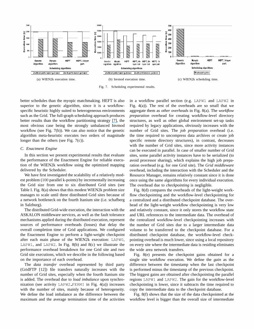
The results depicted in Fig. 7 show that optimization algo-rithms such as HEFT and genetic search produce substantially
(a) WIEN2k execution time. (b) Invmod execution time. (c) WIEN2k scheduling time.
Fig. 7. Scheduling experimental results.
better schedules than the myopic matchmaking. HEFT is alsosuperior to the genetic algorithm, since it is a workflow-specific heuristic highly suited to heterogeneous environmentssuch as the Grid. The full-graph scheduling approach producesbetter results than the workflow partitioning strategy [7], themost obvious case being the strongly unbalanced Invmodworkflow (see Fig. 7(b)). We can also notice that the geneticalgorithm meta-heuristic executes two orders of magnitudelonger than the others (see Fig. 7(c)).
C. Enactment Engine
In this section we present experimental results that evaluatethe performance of the Enactment Engine for reliable execu-tion of the WIEN2k workflow using the optimized mappingdelivered by the Scheduler.
We have first investigated the scalability of a relatively mod-est problem (100 parallel k-points) by incrementally increasingthe Grid size from one to six distributed Grid sites (seeTable I. Fig. 8(a) shows that this modest WIEN2k problem sizemanages to scale until three distributed Grid sites because ofa network bottleneck on the fourth Itanium site (i.e. schafbergin Salzburg).
The distributed Grid-wide execution, the interaction with theASKALON middleware services, as well as the fault tolerancemechanisms applied during the distributed execution, representsources of performance overheads (losses) that delay theoverall completion time of Grid applications. We configuredthe Enactment Engine to perform a light-weight checkpointafter each main phase of the WIEN2k execution: LAPW0,LAPW1, and LAPW2. In Fig. 8(b) and 8(c) we illustrate theperformance overhead breakdown for one Grid site and twoGrid site executions, which we describe in the following basedon the importance of each overhead.
The data transfer overhead represented by third party(GridFTP [12]) file transfers naturally increases with thenumber of Grid sites, especially when the fourth Itanium siteis added. The overhead due to load imbalance upon synchro-nization (see activity LAPW2 FERMI in Fig. 4(a)) increaseswith the number of sites, mainly because of heterogeneity.We define the load imbalance as the difference between themaximum and the average termination time of the activities
in a workflow parallel section (e.g. LAPW1 and LAPW2 inFig. 4(a)). The rest of the overheads are so small that weaggregate them as other overheads in Fig. 8(a). The workflowpreparation overhead for creating workflow-level directorystructures, as well as other global environment set-up tasksrequired by legacy applications, obviously increases with thenumber of Grid sites. The job preparation overhead (i.e.the time required to uncompress data archives or create jobspecific remote directory structures), in contrast, decreaseswith the number of Grid sites, since more activity instancescan be executed in parallel. In case of smaller number of Gridsites, some parallel activity instances have to be serialized (toavoid processor sharing), which explains the high job prepa-ration overhead (e.g. for one Grid site). The Grid middlewareoverhead, including the interaction with the Scheduler and theResource Manager, remains relatively constant since it is doneonce using the same algorithms for every individual execution.The overhead due to checkpointing is negligible.
Fig. 8(d) compares the overheads of the light-weight work-flow checkpointing and the workflow-level checkpointing fora centralized and a distributed checkpoint database. The over-head of the light-weight workflow checkpointing is very lowand relatively constant, since it only stores the workflow stateand URL references to the intermediate data. The overhead ofthe centralized workflow-level checkpointing increases withthe number of Grid sites due to a larger intermediate datavolume to be transferred to the checkpoint database. For adistributed checkpoint database, the workflow-level check-pointing overhead is much lower, since using a local repositoryon every site where the intermediate data is residing eliminatesthe wide area network transfers.
Fig. 8(e) presents the checkpoint gains obtained for asingle site workflow execution. We define the gain as thedifference between the timestamp when the last checkpointis performed minus the timestamp of the previous checkpoint.The biggest gains are obtained after checkpointing the parallelregions LAPW1 and LAPW2. The gain for the workflow-levelcheckpointing is lower, since it subtracts the time required tocopy the intermediate data to the checkpoint database.
Fig. 8(f) shows that the size of the data checkpointed at theworkflow level is bigger than the overall size of intermediate

100 kpoints (8.0)
0
500
1000
1500
2000
2500
3000
3500
altix1
.jku
gesher
altix1
.uib
k
schaf
berg
agrid
1
arch
_19
Grid configuration(aggregated)
Tim
e [s
eco
nd
s]
Otheroverheads
Loadimbalance
Data transfer
Execution time
(a) Scalability and overheads.
Jobpreparation
4.327%
ResourceManager0.349%
Loadimbalance
0.000%
Light-weight
workflowcheckpoint
0.206%
Restore0.047%
Datatransfer0.293%Scheduler
0.447%
Executiontime
94.331%
(b) All overheads on one Grid site.
Jobpreparation
3.991%
Loadimbalance18.060%
Data transfe2.132%
Checkpointoverhead0.306%
Restore0.137%
Scheduler0.719%
ResourceManager0.588%
ExecutionTime
74.067%
(c) All overheads on two Grid sites.
050
100150200250300350400450500
altix1
.jku
gesher
altix1
.uib
k
schaf
berg
agrid
1
arch
_19
Grid configuration(aggregated)
Tim
e [S
eco
nd
s]
Light-weight workflow checkpointWorkflow level checkpointDistributed workflow checkpoint
(d) Checkpointing overhead comparison.
0
500
1000
1500
2000
2500
3000
3500
4000
Exect
ution ti
me
LAPW0
LAPW1
LAPW2_
FERMI
LAPW2
Gai
n [
Sec
on
ds]
Light-weight workflow level checkpointWorkflow level checkpoint
(e) Checkpoint gains.
0
50
100
150
200
250
300
350
400
altix1
.jku
gesher
altix1
.uib
k
schaf
berg
agrid
1
arch
_19
Grid configuration (aggregated)
Dat
a si
ze (
MB
)
All workflowLight-weight workflow checkpointingWorkflow level checkpointing
(f) Size of data transferred.
Fig. 8. Enactment Engine experimental results.
data transferred for a small number of Grid sites (up to three,when scalability is achieved). Beyond four Grid sites, the sizeof the intermediate data exceeds the workflow-level check-point data size. The data size of the light-weight workflowcheckpoint is insignificant.
D. Resource Manager
In this section we present experiences on using the ResourceManager for allocation of resources and automatic deploymentof workflow activities.
When serving a resource allocation request from the Sched-uler, the Resource Manager performs four operations in asingle transaction: discovery, authorization, allocation, andacquisition. All these operations introduce an overhead to theworkflow execution, as already presented in Section VII-C. Inthe following, we further study and breakdown this overheadby benchmarking a series of requests which vary both thetotal number of required resources and their attributes. Wemeasure the time for each request by starting a timer inthe client program immediately before invoking the ResourceManager and stopping it upon the successful acquisition of theresource ensemble. The result of this experiment depicted inFig. 9(a) shows that allocation is the most expensive overhead,which increases with the number of resources, as it involvesnegotiation for advanced reservation.
One of the important feature of the Resource Manager isthe automatic deployment of software activities, implementedeither as legacy applications or as WSRF services. We have
evaluated this feature and calibrated the deployment overheadsfor two real world scientific applications (i.e. WIEN2k andInvmod), as well as a sample WSRF service (i.e. Counter). Wehave used two methods to perform the automatic deployment:
1) Globus, using the GridFTP protocol [12] to remotelytransfer and the Globus Resource Allocation Manager(GRAM) [12] to remotely deploy the code;
2) Expect, by programmatically acquiring local shell on atarget site and automatizing the installation [20].
Table II illustrates the overheads associated with differentdeployment operations. The communication overhead dependson the size of the installation files and is generally lower thanthe deployment overhead introduced by the code compilation.The registration of a new activity type and its deploymentsimply reasonable costs. The Expect-based deployment is moreefficient than Globus because it accesses sites using built-insystem shells.
We have also studied the scalability of the registrationframework on one, three, and seven Grid site configurations,by enabling and disabling the caching of activity types anddeployments on local sites for faster future access. Fig. 9(b)shows the response time per request for a list of deploymentsassociated with an activity type. The deployment entries areequally distributed on all involved sites. We can observethat there is a significant improvement in performance byincreasing number of sites and also by enabling the caching.

0.5
1
2
4
8
1 2 4 8 16 32
Tim
e (S
ec)
No. of Nodes (Grid sites)
DiscoveryAuthorization
AllocationAcquisition
(a) Resource Manager overhead breakdown.
16
32
64
128
256
512
1024
2048
4096
8192
4 8 16 32 64 128 256 512
Res
pons
e tim
e (m
s)
Number of deployments
1 Site (Cache Enabled)1 Site
3 Sites7 Sites
16
32
64
128
256
512
1024
2048
4096
8192
4 8 16 32 64 128 256 512
Res
pons
e tim
e (m
s)
Number of deployments
1 Site (Cache Enabled)1 Site
3 Sites7 Sites
(b) Response time per activity deployment request withcaching on one Grid site and without caching on one, threeand seven Grid sites.
Fig. 9. Resource Manager experimental results.
Method Operation / Overhead WIEN2k Invmod Counter
Expect
Activity type registration 633 632 665Communication 1,667 1,381 1,279
Installation / deployment 8,068 27,776 29,843Deployment registration 700 695 697
Expect overhead 2,100 2,100 2,100Total overhead 11,068 30,484 32,484
Globus
Activity type registration 633 632 665Communication 5,600 2,500 2,400
Installation / deployment 18,068 49,700 39,756Deployment registration 700 695 697
Globus overhead 9,800 9,900 9,800Total overhead 25,001 53,527 43,518
TABLE II
TIME SPENT IN DIFFERENT DEPLOYMENT OPERATIONS (MILLISECONDS).
VIII. RELATED WORK
DAGMan [6] is a centralized meta-scheduler for Condorjobs organized in a directed acyclic graph. Important controlflow constructs such as branches and loops are missing.Scheduling is done through matchmaking with no advancedoptimization. Fault tolerance is addressed through rescueDAG, automatically generated whenever an activity instancefails. The ASKALON checkpointing, in contrast, addressesalso the case when the Enactment Engine itself crashes.
Pegasus [7] uses DAGMan as enactment engine, enhancedwith data derivation techniques that simplify the workflowat run-time based on data availability. Pegasus provides aworkflow partitioning approach, which is problematic forstrongly unbalanced workflows like our Invmod application.Research results report simulation-based scheduling using aweighted Min-min heuristic.
Triana [21] uses the Grid Application Toolkit interface tothe Grid through Web services. It misses compact mechanismsfor expressing large parallel loops. Scheduling is done just-in-time with no optimizations or performance estimates.
ICENI [15] contains low-level enactment engine-specificconstructs such as start and stop in the workflow defi-nition. Scheduling is done using random, best of n-random,
simulated annealing, and game theory algorithms.Taverna’s [16] workflow language called SCUFL is also
limited to DAGs. Scheduling is done just-in-time, while faulttolerance is addressed at activity-level through retries andalternate resources.
The GridAnt [2] centralized workflow engine extends theAnt commodity tool for controlling the application build-ing processes in Java with low-level constructs such asgrid-copy and grid-execute. Scheduling is done man-ually and fault tolerance is not addressed.
The GrADS project [14] restricts workflows to a DAGmodel and does not propose any workflow specification lan-guage. The architecture is centralized and does not considerany service-oriented Grid technology. Scheduling is done us-ing Min-min, Max-min, and Sufferage algorithms traditionallyused for independent tasks, which are less appropriate forworkflows with large control flow depths and data flow depen-dencies. Like in ASKALON, performance prediction modelsare derived from historical executions based on processoroperations and memory access patterns.
UNICORE [8] provides a graphical composition of directedgraph-based workflows. It does not support parallel loopconstructs. Scheduling is user-directed (manual) and faulttolerance is not addressed.
The workflow management in Gridbus [5] provides anXML-based workflow language, oriented towards parametriza-tion and QoS requirements. No branches and loops are sup-ported. The scheduler provides just-in-time mappings usingGrid economy mechanisms. Fault tolerance is limited toactivity-level using replication.
ASKALON differs in several aspects compared to theabove mentioned related projects. AGWL allows a scalablespecification of large numbers of parallel activities, typicalto scientific workflows, by using compact parallel loops. TheEnactment Engine effectively handles large data collectionsgenerated by large-scale control and data flow constructs.Additionally, it provides two levels of workflow checkpointingfor restoring and resuming the execution in case of failures of

the engine itself. The HEFT and genetic search algorithmsimplemented by the ASKALON Scheduler are, to the best ofour knowledge, not addressed by any of the related projects.ASKALON proposes novel architectural feature based on aclear separation between the Scheduler and the ResourceManager which covers both physical and logical resources andprovides brokerage, constraint-based advanced reservations,and activity type to deployment mappings.
IX. CONCLUSIONS
In this paper we presented the ASKALON application de-velopment and computing environment. The new contributionsof this work are centered around several integrated run-timemiddleware services.
In contrast to many existing systems, ASKALON supportsa programming interface that shields the application developerfrom the low-level middleware technologies with the goal ofproviding an invisible Grid. Our Scheduler supports HEFTand genetic search as optimization algorithms which performsignificantly better than a pure resource broker, in particularin the case of unbalanced workflows. The Scheduler signif-icantly benefits from a Performance Prediction service thatprovides expected execution times based on a training phaseand statistical methods. The Enactment Engine efficientlyhandles large collections of data dependencies produced byhundreds of parallel activities specific to scientific workflows.We have demonstrated significant performance gains throughtwo checkpointing methods for saving and restoring the exe-cution of Grid workflows upon engine and application failures.A separate Resource Manager, which covers both physicalresources and workflow activities, renders the boundaries ofresource brokerage, virtual organization-wide authorization,advanced reservation, and provides mechanisms for Grid re-source discovery, selection, and allocation along with resourcerequester and provider interaction.
We have demonstrated the integrated use of the ASKALONservices for two real-world scientific workflows executed in theAustrian Grid infrastructure. Our future work will focus onfurther optimization of workflow executions to increase theirscalability on the Grid, scheduling based on QoS parametersto be negotiated between the Scheduler and the ResourceManager, and automatic bottleneck detection and steeringbased on on-line performance analysis.
ACKNOWLEDGEMENT
This research has been partially supported by the AustrianScience Fund as part of the Aurora project under the contractSFBF1104 and the Austrian Federal Ministry for Education,Science and Culture as part of the Austrian Grid project underthe contract GZ 4003/2-VI/4c/2004.
REFERENCES
[1] “The Austrian Grid Consortium,” http://www.austriangrid.at.[2] K. Amin, M. Hategan, G. von Laszewski, N. J. Zaluzec, S. Hampton,
and A. Rossi, “GridAnt: A Client-Controllable Grid Workflow System,”in 37th Hawai’i International Conference on System Science, 5-8 2004.
[3] “GNU AutoConf Tool,” http://www.gnu.org/software/autoconf.
[4] P. Blaha, K. Schwarz, G. Madsen, D. Kvasnicka, and J. Luitz, WIEN2k:An Augmented Plane Wave plus Local Orbitals Program for CalculatingCrystal Properties. Institute of Physical and Theoretical Chemistry, TUVienna, 2001.
[5] R. Buyya and S. Venugopal, “The Gridbus Toolkit for Service OrientedGrid and Utility Computing: An Overview and Status Report,” in1st International Workshop on Grid Economics and Business Models(GECON 2004). IEEE Computer Society Press, Apr. 2004, pp. 19–36.
[6] Condor Team, “Dagman (directed acyclic graph manager),”http://www.cs.wisc.edu/condor/dagman/.
[7] E. Deelman, J. Blythe, Y. Gil, C. Kesselman, G. Mehta, S. Patil, M.-H.Su, K. Vahi, and M. Livny, “Pegasus: Mapping Scientific Workflowsonto the Grid,” in European Across Grids Conference, 2004, pp. 11–20.
[8] D. W. Erwin and D. F. Snelling, “UNICORE: A Grid computingenvironment,” Lecture Notes in Computer Science, vol. 2150, 2001.
[9] “Expect,” http://expect.nist.gov.[10] T. Fahringer, “ASKALON Grid Application Development and
Computing Environment,” Distributed and Parallel SystemsGroup, Institute for Computer Science, University of Innsbruck,http://dps.uibk.ac.at/askalon.
[11] T. Fahringer, J. Qin, and S. Hainzer, “Specification of Grid WorkflowApplications with AGWL: An Abstract Grid Workflow Language,” inInternational Symposium on Cluster Computing and the Grid 2005(CCGrid 2005). IEEE Computer Society Press, May 9-12 2005.
[12] Globus Alliance, “The Globus Toolkit,” http://www.globus.org.[13] ——, “The Web Services Resource Framework,”
http://www.globus.org/wsrf.[14] Ken Kennedy et.al., “New Grid Scheduling and Rescheduling Methods
in the GrADS Project,” in International Parallel and Distributed Pro-cessing Symposium, Workshop for Next Generation Software. IEEEComputer Society Press, Apr. 2004.
[15] A. Mayer, S. McGough, N. Furmento, W. Lee, S. Newhouse, and J. Dar-lington, “ICENI Dataflow and Workflow: Composition and Schedulingin Space and Time,” in UK e-Science All Hands Meeting, Nottingham,UK, Sept. 2003, pp. 627–634.
[16] T. Oinn, M. Addis, J. Ferris, D. Marvin, M. Senger, M. Greenwood,T. C. adn K. Glover, M. Pocock, A. Wipat, and P. Li, “Taverna: atool for the composition and enactment of bioinformatics workflows,”Bioinformatics, vol. 20, no. 17, pp. 3045–3054, 2004.
[17] POVray, http://www.povray.org/.[18] R. Prodan and T. Fahringer, “Dynamic Scheduling of Scientific Work-
flow Applications on the Grid using a Modular Optimisation Tool: ACase Study,” in 20th Symposion of Applied Computing (SAC 2005).ACM Press, Mar. 2005.
[19] M. Siddiqui and T. Fahringer, “GridARM: Askalon’s Grid ResourceManagement System,” in Advances in Grid Computing - EGC 2005 -Revised Selected Papers, ser. Lecture Notes in Computer Science, vol.3470. Amsterdam, Netherlands: Springer Verlag GmbH, ISBN 3-540-26918-5, June 2005, pp. 122–131.
[20] M. Siddiqui, A. Villazon, J. Hofer, and T. Fahringer, “GLARE: Agrid activity registration, deployment and provisioning framework,” inSupercomputing Conference. ACM Press, November 12-18 2005.
[21] I. Taylor, M. Shields, I. Wang, and R. Rana, “Triana applicationswithin Grid computing and peer to peer environments,” Journal of GridComputing, vol. 1, no. 2, pp. 199–217, 2003.
[22] D. Theiner and P. Rutschmann, “An inverse modelling approach for theestimation of hydrological model parameters,” in Journal of Hydroin-formatics, 2005.
[23] Tony Andrews et.al., “Business Process Execution Language for WebServices (BPEL4WS),” OASIS,” Specification Version 1.1, May 2003.
[24] H.-L. Truong and T. Fahringer, “SCALEA-G: a Unified Monitoring andPerformance Analysis System for the Grid,” Scientific Programming,vol. 12, no. 4, pp. 225–237, 2004, iOS Press.
[25] R. Wolski, N. T. Spring, and J. Hayes, “The network weather service:a distributed resource performance forecasting service for metacomput-ing,” Future Generation Computer Systems, vol. 15, no. 5–6, pp. 757–768, Oct. 1999.
[26] H. Zhao and R. Sakellariou, “An experimental investigation into the rankfunction of the heterogeneous earliest finish time scheduling algorithm.”in Euro-Par, 2003, pp. 189–194.
Copyright © 2022 FDOKUMEN