
GRID AND CLOUD COMPUTING Mr. B.Sunil Kumar M.Tech ...
117
GRID AND CLOUD COMPUTING AITS –TIRUPATI, Dept Of CSE ANNAMACHARYA INSTITUTE OF TECHNOLOGY AND SCIENCES, TIRUPATI (AUTONOMOUS) DEPARTMENT OF COMPUTER SCIENCEAND ENGINEERING COURSE MATERIAL 15A05701- GRID AND CLOUD COMPUTING B. Tech IV-I Sem. (CSE) Mr. B.Sunil Kumar M.Tech., Assistant Professor Dept of CSE AITS –Tirupati Annamacharya Institute of Technology & Sciences, Tirupati (Autonomous)
-
Upload
khangminh22 -
Category
Documents
-
view
0 -
download
0
Transcript of GRID AND CLOUD COMPUTING Mr. B.Sunil Kumar M.Tech ...

GRID AND CLOUD COMPUTING
AITS –TIRUPATI, Dept Of CSE
ANNAMACHARYA INSTITUTE OF TECHNOLOGY AND
SCIENCES, TIRUPATI (AUTONOMOUS)
DEPARTMENT OF COMPUTER SCIENCE AND ENGINEERING
COURSE MATERIAL
15A05701- GRID AND CLOUD COMPUTING
B. Tech IV-I Sem. (CSE)
Mr. B.Sunil Kumar M.Tech.,
Assistant Professor
Dept of CSE
AITS –Tirupati
Annamacharya Institute of Technology & Sciences, Tirupati (Autonomous)
GRID AND CLOUD COMPUTING
AITS –TIRUPATI, Dept Of CSE
Annamacharya Institute of Technology & Sciences, Tirupati
(Autonomous)
DEPARTMENT OF COMPUTER SCIENCE AND ENGINEERING
SYLLABUS (THEORY)
Sub. Code Sub Name
: 15A05701 : GRID AND CLOUD COMPUTING
Branch/Year/Sem : CSE/IV/I :
Staff Name : Mr B .Sunil Kumar Academic Year : 2021-2022
L T P C
3 1 0 3
UNIT I INTRODUCTION
Evolution of Distributed computing: Scalable computing over the Internet – Technologies for network
based systems – clusters of cooperative computers- Grid computing Infrastructures – cloud
computing - service oriented architecture – Introduction to Grid Architecture and standards –
Elements of Grid – Overview of Grid Architecture.
UNIT II GRID SERVICE
Introduction to Open Grid Services Architecture (OGSA) – Motivation – Functionality
Requirements – Practical & Detailed view of OGSA/OGSI – Data intensive grid service models –
OGSA services.
UNIT III VIRTUALIZATION
Cloud deployment models: public, private, hybrid, community – Categories of cloud
computing: Everything as a service: Infrastructure, platform, software - Pros and Cons of
cloud computing – Implementation levels of virtualization – virtualization structure –
virtualization of CPU, Memory and I/O devices – virtual clusters and Resource Management –
Virtualization for data center automation.
UNIT IV PROGRAMMING MODEL
Open source grid middleware packages – Globus Toolkit (GT4) Architecture , Configuration –
Usage of Globus – Main components and Programming model - Introduction to Hadoop
Framework - Mapreduce, Input splitting, map and reduce functions, specifying input and
output parameters, configuring and running a job – Design of Hadoop file system, HDFS
concepts, command line and java interface, dataflow of File read & File write.
UNIT V SECURITY
Trust models for Grid security environment – Authentication and Authorization methods – Grid
security infrastructure – Cloud Infrastructure security: network, host and application level – aspects of
data security, provider data and its security, Identity and access management architecture, IAM
practices in the cloud, SaaS, PaaS, IaaS availability in the cloud, Key privacy issues in the cloud.

GRID AND CLOUD COMPUTING
AITS –TIRUPATI, Dept Of CSE
TEXT BOOK:
1. Kai Hwang, Geoffery C. Fox and Jack J. Dongarra, ╉Distributed and Cloud Computing:
Clusters, Grids, Clouds and the Future of Internet╊, First Edition, Morgan Kaufman
Publisher, an Imprint of Elsevier, 2012.
REFERENCES:
1. Jason Venner, ╉Pro Hadoop- Build Scalable, Distributed Applications in the Cloud╊, A
Press, 2009
2. Tom White, ╉Hadoop The Definitive Guide╊, First Edition. O’Reilly, 2009.
3. Bart Jacob (Editor), ╉Introduction to Grid Computing╊, IBM Red Books, Vervante, 2005
4. Ian Foster, Carl Kesselman, ╉The Grid: Blueprint for a New Computing Infrastructure╊, 2nd
Edition, Morgan Kaufmann.
5. Frederic Magoules and Jie Pan, ╉Introduction to Grid Computing╊ CRC Press, 2009.
6. Daniel Minoli, ╉A Networking Approach to Grid Computing╊, John Wiley Publication,
2005.
7. Barry Wilkinson, ╉Grid Computing: Techniques and Applications╊, Chapman and Hall, CRC,
Taylor and Francis Group, 2010.
SUBJECT IN-CHARGE HOD/CSE

GRID AND CLOUD COMPUTING
AITS –TIRUPATI, Dept Of CSE
Annamacharya Institute of Technology & Sciences, Tirupati
(Autonomous)
DEPARTMENT OF COMPUTER SCIENCE AND ENGINEERING
Sub. Code Sub Name
: 15A05701 : GRID AND CLOUD COMPUTING
Branch/Year/Sem : CSE/IV/I
Staff Name : Mr B .Sunil Kumar Academic Year : 2021-2022
COURSE OBJECTIVE
1. Understand how Grid computing helps in solving large scale scientific problems.
2. Gain knowledge on the concept of virtualization that is fundamental to cloud
computing.
3. Learn how to program the grid and the cloud
4. Understand the security issues in the grid and the cloud environment.
COURSE OUTCOMES
1. Apply the security models in the grid and the cloud environment
2. Use the grid and cloud tool kits.
3. Understand the concept of virtualization
4. Apply grid computing techniques to solve large scale scientific problems
Prepared by Verified By STAFF NAME
HOD

GRID AND CLOUD COMPUTING
AITS –TIRUPATI, Dept Of CSE
UNIT-I
INTRODUCTION:
Evolution of Distributed computing:
Scalable computing over the Internet:
Data Deluge enabling new challenges:
From Desktop/HPC/Grids to Internet Clouds in 30 Years
HPC moving from centralized supercomputers to geographically distributed
desktops, desk sides, clusters, and grids to clouds over last 30 years
Location of computing infrastructure in areas with lower costs in hardware,
software, datasets, space, and power requirements – moving from desktop
computing to datacenter-based clouds
Interactions among 4 technical challenges: Data Deluge, Cloud Technology,
eScience, and Multicore/Parallel Computing
Clouds and Internet of Things

GRID AND CLOUD COMPUTING
AITS –TIRUPATI, Dept Of CSE
Computing Paradigm Distinctions
Centralized Computing
All computer resources are centralized in one physical system.
Parallel Computing
All processors are either tightly coupled with central shared memory or
loosely coupled with distributed memory
Distributed Computing
A distributed system consists of multiple autonomous computers, each with its
own private memory, communicating over a network.
Cloud Computing
An Internet cloud of resources that may be either centralized or decentralized.
The cloud apples to parallel or distributed computing or both. Clouds may be
built from physical or virtualized resources.
Technology Convergence toward HPC for Science and HTC for Business: Utility
Computing

GRID AND CLOUD COMPUTING
AITS –TIRUPATI, Dept Of CSE
Technologies for Network-based Systems
33 year Improvement in Processor and Network Technologies
Modern Multi-core CPU Chip
Multi-threading Processors
Four-issue superscalar (e.g. Sun Ultras arc I)
Implements instruction level parallelism (ILP) within a single processor.
Executes more than one instruction during a clock cycle by sending multiple
instructions to redundant functional units.
Fine-grain multithreaded processor
Switch threads after each cycle
Interleave instruction execution
If one thread stalls, others are executed
Coarse-grain multithreaded processor
Executes a single thread until it reaches certain situations
Simultaneous multithread processor (SMT)
Instructions from more than one thread can execute in any given pipeline stage
at a time.

GRID AND CLOUD COMPUTING
AITS –TIRUPATI, Dept Of CSE
5 Micro-architectures of CPUs
Each row represents the issue slots for a single execution cycle:
• A filled box indicates that the processor found an instruction to execute in that issue
slot on that cycle;
An empty box denotes an unused slot.
33 year Improvement in Memory and Disk Technologies
Architecture of A Many-Core Multiprocessor GPU interacting with a CPU Processor

GRID AND CLOUD COMPUTING
AITS –TIRUPATI, Dept Of CSE
GPU Performance
Bottom – CPU - 0.8 Gflops/W/Core (2011)
Middle – GPU - 5 Gflops/W/Core (2011)
Top - EF – Exascale computing (10^18 Flops)
Interconnection Networks
• SAN (storage area network) - connects servers with disk arrays
• LAN (local area network) – connects clients, hosts, and servers
• NAS (network attached storage) – connects clients with large storage systems

GRID AND CLOUD COMPUTING
AITS –TIRUPATI, Dept Of CSE
Datacenter and Server Cost Distribution:
Virtual Machines
Eliminate real machine constraint
Increases portability and flexibility
Virtual machine adds software to a physical machine to give it the appearance of a
different platform or multiple platforms.
Benefits
Cross platform compatibility
Increase Security
Enhance Performance
Simplify software migration
Initial Hardware Model
All applications access hardware resources (i.e. memory, i/o) through system calls to
operating system (privileged instructions)
Advantages
Design is decoupled (i.e. OS people can develop OS separate of Hardware
people developing hardware)
Hardware and software can be upgraded without notifying the Application
programs

GRID AND CLOUD COMPUTING
AITS –TIRUPATI, Dept Of CSE
Disadvantage
Application compiled on one ISA will not run on another ISA.
Applications compiled for Mac use different operating system calls
then application designed for windows.
ISA’s must support old software
Can often be inhibiting in terms of performance
Since software is developed separately from hardware… Software is not
necessarily optimized for hardware.
Virtual Machine Basics
Virtual software placed between underlying machine and conventional software
Conventional software sees different ISA from the one supported by the
hardware
Virtualization process involves:
Mapping of virtual resources (registers and memory) to real hardware
resources
Using real machine instructions to carry out the actions specified by the virtual
machine instructions
Three VM Architectures

GRID AND CLOUD COMPUTING
AITS –TIRUPATI, Dept Of CSE
System Models for Distributed and Cloud Computing
Clusters of cooperative computers A
Typical Cluster Architecture
Computational or Data Grid:

GRID AND CLOUD COMPUTING
AITS –TIRUPATI, Dept Of CSE
Peer-to-Peer (P2P) Network
A distributed system architecture
Each computer in the network can act as a client or server for other network
computers.
No centralized control
Typically many nodes, but unreliable and heterogeneous
Nodes are symmetric in function
Take advantage of distributed, shared resources (bandwidth, CPU, storage) on peer-
nodes
Fault-tolerant, self-organizing
Operate in dynamic environment, frequent join and leave is the norm
Overlay network - computer network built on top of another network.
• Nodes in the overlay can be thought of as being connected by virtual or logical links,
each of which corresponds to a path, perhaps through many physical links, in the
underlying network.
• For example, distributed systems such as cloud computing, peer-to-peer networks,
and client-server applications are overlay networks because their nodes run on top of
the Internet.
Grid computing Infrastructures
Grid Computing is based on the concept of information and electricity sharing, which
allowing us to access to another type of heterogeneous and geographically separated
resources.
Grid gives the sharing of:
1. Storage elements
2. Computational resources
3. Equipment
4. Specific applications
5. Other
Thus, Grid is based on:
• Internet protocols.
• Ideas of parallel and distributed computing.

GRID AND CLOUD COMPUTING
AITS –TIRUPATI, Dept Of CSE
A Grid is a system that,
1) Coordinates resources that may not subject to a centralized control. 2) Using standard, open, general-purpose protocols and interfaces.
3) To deliver nontrivial qualities of services.
Flexible, secure, coordinated resource sharing among individuals and institutions.
Enable communities (virtual organizations) to share geographically distributed resources in
order to achieve a common goal.
In applications which can’t be solved by resources of an only institution or the results can be
achieved faster and/or cheaper.
The Cloud
Historical roots in today’s Internet apps
Search, email, social networks
File storage (Live Mesh, Mobile Me, Flicker, …)
A cloud infrastructure provides a framework to manage scalable, reliable, on-demand
access to applications
A cloud is the “invisible” backend to many of our mobile applications
A model of computation and data storage based on “pay as you go” access to
“unlimited” remote data center capabilities
Basic Concept of Internet Clouds
• Cloud computing is the use of computing resources (hardware and software) that are
delivered as a service over a network (typically the Internet).
• The name comes from the use of a cloud-shaped symbol as an abstraction for the
complex infrastructure it contains in system diagrams.
• Cloud computing entrusts remote services with a user's data, software and
computation.
Cloud computing supports platform independency, as the software is not required to be
installed locally on the PC. Hence, the Cloud Computing is making our business applications
mobile and collaborative.

GRID AND CLOUD COMPUTING
AITS –TIRUPATI, Dept Of CSE
Characteristics of Cloud Computing
There are four key characteristics of cloud computing. They are shown in the following
diagram:
On Demand Self Service
Cloud Computing allows the users to use web services and resources on demand. One can
logon to a website at any time and use them.
Broad Network Access
Since cloud computing is completely web based, it can be accessed from anywhere and at any
time.
Resource Pooling
Cloud computing allows multiple tenants to share a pool of resources. One can share single
physical instance of hardware, database and basic infrastructure.
Rapid Elasticity
It is very easy to scale the resources vertically or horizontally at any time. Scaling of
resources means the ability of resources to deal with increasing or decreasing demand.
The resources being used by customers at any given point of time are automatically
monitored.
Measured Service
In this service cloud provider controls and monitors all the aspects of cloud service. Resource
optimization, billing capacity planning etc. depend on it.
Benefits
1. One can access applications as utilities, over the Internet. 2. One can manipulate and configure the applications online at any time.
3. It does not require to install a software to access or manipulate cloud application.
4. Cloud Computing offers online development and deployment tools, programming runtime
environment through PaaS model.
5. Cloud resources are available over the network in a manner that provide platform
independent access to any type of clients.

GRID AND CLOUD COMPUTING
AITS –TIRUPATI, Dept Of CSE
6. Cloud Computing offers on-demand self-service. The resources can be used without
interaction with cloud service provider.
Disadvantages of cloud computing
• Requires a high-speed internet connection • Security and confidentiality of data
• Not solved yet the execution of HPC apps in cloud computing Interoperability between
cloud based systems
Cloud Service Models
Infrastructure as a service (IaaS)
Most basic cloud service model
Cloud providers offer computers, as physical or more often as virtual machines, and
other resources.
Virtual machines are run as guests by a hypervisor, such as Xen or KVM.
Cloud users deploy their applications by then installing operating system images on
the machines as well as their application software.
Cloud providers typically bill IaaS services on a utility computing basis, that is, cost
will reflect the amount of resources allocated and consumed.
Examples of IaaS include: Amazon Cloud Formation (and underlying services such as
Amazon EC2), Rackspace Cloud, Terre mark, and Google Compute Engine.
Platform as a service (PaaS)
Cloud providers deliver a computing platform typically including operating system,
programming language execution environment, database, and web server.
Application developers develop and run their software on a cloud platform without
the cost and complexity of buying and managing the underlying hardware and
software layers.
Examples of PaaS include: Amazon Elastic Beanstalk, Cloud Foundry, Heroku,
Force.com, Engine Yard, Mendix, Google App Engine, Microsoft Azure and
OrangeScape.
Software as a service (SaaS)
Cloud providers install and operate application software in the cloud and cloud users
access the software from cloud clients.
The pricing model for SaaS applications is typically a monthly or yearly flat fee per
user, so price is scalable and adjustable if users are added or removed at any point.
Examples of SaaS include: Google Apps, innkeypos, QuickBooks Online, Limelight
Video Platform, Salesforce.com, and Microsoft Office 365.
Service-oriented architecture (SOA)
SOA is an evolution of distributed computing based on the request/reply design
paradigm for synchronous and asynchronous applications.
An application's business logic or individual functions are modularized and presented
as services for consumer/client applications.

GRID AND CLOUD COMPUTING
AITS –TIRUPATI, Dept Of CSE
Key to these services - their loosely coupled nature;
i.e., the service interface is independent of the implementation.
Application developers or system integrators can build applications by composing one
or more services without knowing the services' underlying implementations.
For example, a service can be implemented either in .Net or J2EE, and the application
consuming the service can be on a different platform or language
SOA key characteristics:
SOA services have self-describing interfaces in platform-independent XML
documents.
Web Services Description Language (WSDL) is the standard used to describe
the services.
SOA services communicate with messages formally defined via XML Schema (also
called XSD).
Communication among consumers and providers or services typically happens
in heterogeneous environments, with little or no knowledge about the
provider.
Messages between services can be viewed as key business documents
processed in an enterprise.
SOA services are maintained in the enterprise by a registry that acts as a directory
listing.
Applications can look up the services in the registry and invoke the service.
Universal Description, Definition, and Integration (UDDI) is the standard used
for service registry.
Each SOA service has a quality of service (QoS) associated with it.
Some of the key QoS elements are security requirements, such as
authentication and authorization, reliable messaging, and policies regarding
who can invoke services.
Layered Architecture for Web Services

GRID AND CLOUD COMPUTING
AITS –TIRUPATI, Dept Of CSE
Introduction to Grid Architecture and Standards
Grid computing is a form of distributed computing whereby a "super and virtual
computer" is composed of a cluster of networked, loosely coupled computers, acting
in concert to perform very large tasks.
Grid computing (Foster and Kesselman, 1999) is a growing technology that facilitates
the executions of large-scale resource intensive applications on geographically
distributed computing resources.
Facilitates flexible, secure, coordinated large scale resource sharing among dynamic
collections of individuals, institutions, and resource
Enable communities (“virtual organizations”) to share geographically distributed
resources as they pursue common goals
Criteria for a Grid:
Coordinates resources that are not subject to centralized control.
Uses standard, open, general-purpose protocols and interfaces.
Delivers nontrivial qualities of service.
Benefits
Exploit Underutilized resources
Resource load Balancing
Virtualize resources across an enterprise
Data Grids, Compute Grids
Enable collaboration for virtual organizations
Grid Applications
Data and computationally intensive applications:
This technology has been applied to computationally-intensive scientific, mathematical, and
academic problems like drug discovery, economic forecasting, seismic analysis back office
data processing in support of e-commerce
A chemist may utilize hundreds of processors to screen thousands of compounds per
hour.
Teams of engineers worldwide pool resources to analyze terabytes of structural data.
Meteorologists seek to visualize and analyze petabytes of climate data with enormous
computational demands.
Resource sharing
Computers, storage, sensors, networks, …
Sharing always conditional: issues of trust, policy, negotiation, payment, …
Coordinated problem solving
Distributed data analysis, computation, collaboration…

GRID AND CLOUD COMPUTING
AITS –TIRUPATI, Dept Of CSE
Elements of Grid Computing
Resource sharing
Computers, data, storage, sensors, networks, …
Sharing always conditional: issues of trust, policy, negotiation, payment, …
Coordinated problem solving
Beyond client-server: distributed data analysis, computation, collaboration, …
Dynamic, multi-institutional virtual organizations
Community overlays on classic org structures
Large or small, static or dynamic
Grid Topologies
• Intragrid
– Local grid within an organization
– Trust based on personal contracts
• Extragrid
– Resources of a consortium of organizations
Connected through a (Virtual) Private Network
– Trust based on Business to Business contracts
• Intergrid
– Global sharing of resources through the internet
– Trust based on certification
Computational Grid
“A computational grid is a hardware and software infrastructure that provides dependable,
consistent, pervasive, and inexpensive access to high-end computational capabilities.”
Example: Science Grid (US Department of Energy)
Data Grid
A data grid is a grid computing system that deals with data — the controlled sharing
and management of large amounts of distributed data.
Data Grid is the storage component of a grid environment. Scientific and engineering
applications require access to large amounts of data, and often this data is widely
distributed. A data grid provides seamless access to the local or remote data required
to complete compute intensive calculations.
Example:
Biomedical informatics Research Network (BIRN),
The Southern California earthquake Center (SCEC)
Methods of Grid Computing
Distributed Supercomputing
High-Throughput Computing
On-Demand Computing
Data-Intensive Computing
Collaborative Computing
Logistical Networking

GRID AND CLOUD COMPUTING
AITS –TIRUPATI, Dept Of CSE
Grid Standards and Middleware
A typical view of Grid environment
Grids are typically managed by grid ware - a special type of middleware that enable
sharing and manage grid components based on user requirements and resource
attributes (e.g., capacity, performance)
Software that connects other software components or applications to provide the
following functions:
Run applications on suitable available resources
– Brokering, Scheduling
Provide uniform, high-level access to resources
– Semantic interfaces
– Web Services, Service Oriented Architectures
Address inter-domain issues of security, policy, etc.
-Monitoring and control

GRID AND CLOUD COMPUTING
AITS –TIRUPATI, Dept Of CSE
Middleware
Globus –chicago Univ
Condor – Wisconsin Univ – High throughput computing
Legion – Virginia Univ – virtual workspaces- collaborative computing
IBP – Internet back pane – Tennesse Univ – logistical networking
NetSolve – solving scientific problems in heterogeneous env – high throughput &
data intensive
Grid Architecture
The Hourglass Model
Focus on architecture issues
Propose set of core services as basic infrastructure
Used to construct high-level, domain-specific solutions (diverse)
Design principles
Keep participation cost low
Enable local control
Support for adaptation
“IP hourglass” model
An Overview of Grid Architecture
The Computing Element (CE) is a set of gLite services that provide access for Grid jobs to a
local resource management system (LRMS, batch system) running on a computer farm, or
possibly to computing resources local to the CE host. Typically the CE provides access to a
set of job queues within the LRMS.
Utilization Period
Booking Conditions
No particular booking is required to use this service. However, the user MUST have a valid
grid certificate of an accepted Certificate Authority and MUST be member of a valid Virtual
Organization (VO).
The service is initiated by respective commands that can be submitted from any gLite User
Interface either interactively or through batch submission.
To run a job on the cluster the user must install an own or at least have access to a gLite User
Interface. Certificates can be requested for example at the German Grid Certificate Authority.
Deregistration
No particular deregistration is required for this service. A user with an expired Grid
certificate or VO membership is automatically blocked from accessing the CE.
IT-Security
The database and log files of the CEs contain information on the status and results of the jobs
and the certificate that was used to initiate the task.
The required data files themselves are stored on the worker nodes or in the Grid Storage
Elements (SEs). No other personal data is stored.
Technical requirements
To run a job at the Grid cluster of the Steinbuch Centre for Computing (SCC) the user needs:
1. A valid Grid user certificate.
2. Membership in a Virtual Organization (VO).
3. An own or at least access to a User Interface.

GRID AND CLOUD COMPUTING
AITS –TIRUPATI, Dept Of CSE
Layered Grid Architecture
Data Grid Architecture

GRID AND CLOUD COMPUTING
AITS –TIRUPATI, Dept Of CSE
Simulation tools
GridSim – job scheduling
SimGrid – single client multiserver scheduling
Bricks – scheduling
GangSim- Ganglia VO
OptoSim – Data Grid Simulations
G3S – Grid Security services Simulator – security services

GRID AND CLOUD COMPUTING
AITS –TIRUPATI, Dept Of CSE
UNIT-II
GRID SERVICES
Introduction to Open Grid Services Architecture (OGSA)
OGSA defines what Grid services are, what they should be capable of, what type of
technologies they should be based on. OGSA does not give a technical and detailed
specification. It uses WSDL
• It is a formal and technical specification of the concepts described in OGSA.
• The Globus Toolkit 3 is an implementation of OGSI.
The OGSA is an open source grid service standard jointly developed by academia and
the IT industry under coordination of a working group in the Global Grid Forum (GGF). The
standard was specifically developed for the emerging grid and cloud service communities.
The OGSA is extended from web service concepts and technologies. The standard defines a
common framework that allows businesses to build grid platforms across enterprises and
business partners. The intent is to define the standards required for both open source and
commercial software to support a global grid infrastructure
OGSA Framework
The OGSA was built on two basic software technologies: the Globus Toolkit widely
adopted as a grid technology solution for scientific and technical computing, and web
services (WS 2.0) as a popular standards-based framework for business and network
applications. The OGSA is intended to support the creation, termination, management, and
invocation of stateful, transient grid services via standard interfaces and conventions
OGSA Interfaces
The OGSA is centered on grid services. These services demand special well-defined
application interfaces.
These interfaces provide resource discovery, dynamic service creation, lifetime management,
notification, and manageability. These properties have significant implications regarding how
a grid service is named, discovered, and managed

GRID AND CLOUD COMPUTING
AITS –TIRUPATI, Dept Of CSE
Grid Service Handle
A GSH is a globally unique name that distinguishes a specific grid service instance from all
others. The status of a grid service instance could be that it exists now or that it will exist in
the future.
These instances carry no protocol or instance-specific addresses or supported protocol
bindings. Instead, these information items are encapsulated along with all other instance-
specific information. In order to interact with a specific service instance, a single abstraction
is defined as a GSR.
Grid Service Migration
This is a mechanism for creating new services and specifying assertions regarding the
lifetime of a service. The OGSA model defines a standard interface, known as a factor, to
implement this reference. This creates a requested grid service with a specified interface and
returns the GSH and initial GSR for the new service instance.
If the time period expires without having received a reaffirmed interest from a client, the
service instance can be terminated on its own and release the associated resources
accordingly
OGSA Security Models
The grid works in a heterogeneous distributed environment, which is essentially open to the
general public. We must be able to detect intrusions or stop viruses from spreading by
implementing secure conversations, single logon, access control, and auditing for
nonrepudiation.
At the security policy and user levels, we want to apply a service or endpoint policy, resource
mapping rules, authorized access of critical resources, and privacy protection. At the Public
Key Infrastructure (PKI) service level, the OGSA demands security binding with the security
protocol stack and bridging of certificate authorities (CAs), use of multiple trusted
intermediaries, and so on.

GRID AND CLOUD COMPUTING
AITS –TIRUPATI, Dept Of CSE
Motivation
Grid Evolution: Open Grid Services Architecture
Four largely orthogonal goals 1) Refactor Globus protocol suite to enable common base and expose key capabilities
2) Extend for new technical requirements
3) Service orientation to virtualize resources and unify resources/services/information
4) Embrace key Web services technologies for standard IDL, leverage commercial efforts
Result
Standard interfaces & behaviors for building distributed systems: the Grid service

GRID AND CLOUD COMPUTING
AITS –TIRUPATI, Dept Of CSE
Refactor Globus Protocol Suite
Extract, generalize, allow modular use of protocols and mechanisms for
Reliable invocation
Service description & information access
Notification
Policy management
Lifetime management
Service naming
Authentication
Designed in an integrated, uniform fashion and Extend into New Areas
Extend core protocol suite to address
Manageability
Concurrency control
Others
Service Orientation
Define all entities by interface & behavior, so that Resources and programs are treated in the
same manner & accessed in the same way Virtualization easy to achieve: e.g. “compute
service” may be computer or network
Embrace Standards:
Two Distinct (But Interrelated) Issues Standard means of defining, discovering, and invoking interfaces
Addressed by Web services
Standard means of customizing computer systems to application requirements
Addressed by hosting environments: J2EE, .NET, ...
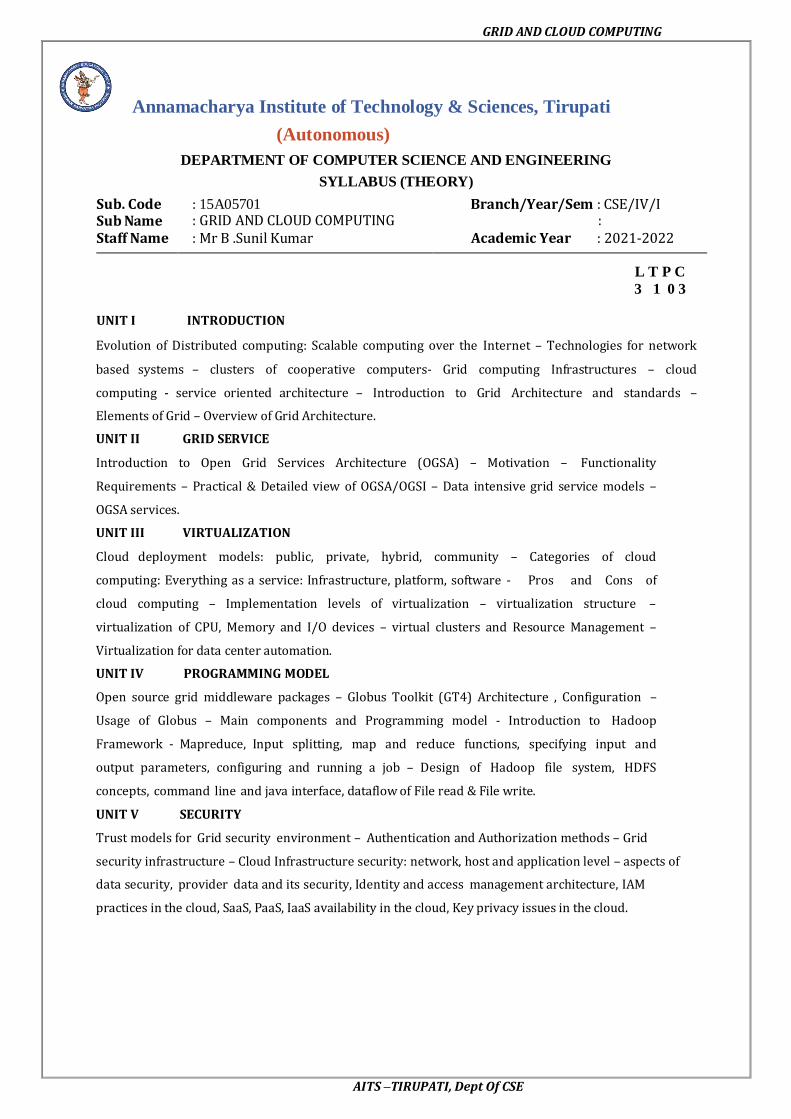
OGSA System Structure
A standard substrate: the Grid service Standard interfaces and behaviors that
address key distributed system issues.
The “Grid Service Specification”
supports standard service specifications
Resource management, databases, workflow, security, diagnostics,
etc., etc.
Target of current & planned GGF efforts
Arbitrary application-specific services based on these & other
definitions
GRID AND CLOUD COMPUTING
AITS –TIRUPATI, Dept Of CSE
Functionality requirements and System Properties Requirements
Basic functionality requirements
Discovery and brokering. Mechanisms are required for discovering and/or allocating
services, data, and resources with desired properties. For example, clients need to discover
network services before they are used, service brokers need to discover hardware and
software availability, and service brokers must identify codes and platforms suitable for
execution requested by the client
Metering and accounting. Applications and schemas for metering, auditing, and billing for
IT infrastructure and management use cases. The metering function records the usage and
duration, especially metering the usage of licenses. The auditing function audits usage and
application profiles on machines, and the billing function bills the user based on metering.
Data sharing. Data sharing and data management are common as well as important grid
applications. chanisms are required for accessing and managing data archives, for caching
data and managing its consistency, and for indexing and discovering data and metadata.
Deployment. Data is deployed to the hosting environment that will execute the job (or made
available in or via a high-performance infrastructure). Also, applications (executable) are
migrated to the computer that will execute them
Virtual organizations (VOs). The need to support collaborative VOs introduces a need for
mechanisms to support VO creation and management, including group membership services
[58]. For the commercial data center use case [55], the grid creates a VO in a data center that
provides IT resources to the job upon the customer’s job request.
Monitoring. A global, cross-organizational view of resources and assets for project and fiscal
planning, troubleshooting, and other purposes. The users want to monitor their applications
running on the grid. Also, the resource or service owners need to surface certain states so that
the user of those resources or services may manage the usage using the state information
Policy. An error and event policy guides self-controlling management, including failover and
provisioning. It is important to be able to represent policy at multiple stages in hierarchical
systems, with the goal of automating the enforcement of policies that might otherwise be
implemented as organizational processes or managed manually
System Properties Requirements
Fault tolerance. Support is required for failover, load redistribution, and other techniques
used to achieve fault tolerance. Fault tolerance is particularly important for long running
queries that can potentially return large amounts of data, for dynamic scientific applications,
and for commercial data center applications.

GRID AND CLOUD COMPUTING
AITS –TIRUPATI, Dept Of CSE
Disaster recovery. Disaster recovery is a critical capability for complex distributed grid
infrastructures. For distributed systems, failure must be considered one of the natural
behaviors and disaster recovery mechanisms must be considered an essential component of
the design.
Self-healing capabilities of resources, services and systems are required. Significant manual
effort should not be required to monitor, diagnose, and repair faults.
Legacy application management. Legacy applications are those that cannot be changed, but
they are too valuable to give up or to complex to rewrite. Grid infrastructure has to be built
around them so that they can continue to be used
Administration. Be able to ―codify‖ and ―automate‖ the normal practices used to
administer the environment. The goal is that systems should be able to self-organize and self-
describe to manage low-level configuration details based on higher-level configurations and
management policies specified by administrators.
Agreement-based interaction. Some initiatives require agreement-based interactions capable
of specifying and enacting agreements between clients and servers (not necessarily human)
and then composing those agreements into higher-level end-user structures
Grouping/aggregation of services. The ability to instantiate (compose) services using some
set of existing services is a key requirement. There are two main types of composition
techniques: selection and aggregation. Selection involves choosing to use a particular service
among many services with the same operational interface.
Security requirements
Grids also introduce a rich set of security requirements; some of these requirements are:
Multiple security infrastructures. Distributed operation implies a need to interoperate with
and manage multiple security infrastructures. For example, for a commercial data center
application, isolation of customers in the same commercial data center is a crucial
requirement; the grid should provide not only access control but also performance isolation.
Perimeter security solutions. Many use cases require applications to be deployed on the other
side of firewalls from the intended user clients. Intergrade collaboration often requires
crossing institutional firewalls.
Authentication, Authorization, and Accounting. Obtaining application programs and
deploying them into a grid system may require authentication/authorization. In the
commercial data center use case, the commercial data center authenticates the customer and
authorizes the submitted request when the customer submits a job request.
Encryption. The IT infrastructure and management use case requires encrypting of the
communications, at least of the payload
Application and Network-Level Firewalls. This is a long-standing problem; it is made
particularly difficult by the many different policies one is dealing with and the particularly
harsh restrictions at international sites.
Certification. A trusted party certifies that a particular service has certain semantic behavior.
For example, a company could establish a policy of only using e-commerce services certified
by Yahoo
Resource Management Requirements
Resource management is another multilevel requirement, encompassing SLA negotiation,
provisioning, and scheduling for a variety of resource types and activities
Provisioning. Computer processors, applications, licenses, storage, networks, and
instruments are all grid resources that require provisioning. OGSA needs a framework that
allows resource provisioning to be done in a uniform, consistent manner.
Resource virtualization. Dynamic provisioning implies a need for resource virtualization
mechanisms that allow resources to be transitioned flexibly to different tasks as required; for
example, when bringing more Web servers on line as demand exceeds a threshold..
Optimization of resource usage while meeting cost targets (i.e., dealing with finite
resources). Mechanisms to manage conflicting demands from various organizations, groups,
projects, and users and implement a fair sharing of resources and access to the grid

GRID AND CLOUD COMPUTING
AITS –TIRUPATI, Dept Of CSE
Transport management. For applications that require some form of real-time scheduling, it
can be important to be able to schedule or provision bandwidth dynamically for data transfers
or in support of the other data sharing applications. In many (if not all) commercial
applications, reliable transport management is essential to obtain the end-to-end QoS required
by the application
Management and monitoring. Support for the management and monitoring of resource
usage and the detection of SLA or contract violations by all relevant parties. Also, conflict
management is necessary;
Processor scavenging is an important tool that allows an enterprise or VO to use to aggregate
computing power that would otherwise go to waste
Scheduling of service tasks. Long recognized as an important capability for any information
processing system, scheduling becomes extremely important and difficult for distributed grid
systems.
Load balancing. In many applications, it is necessary to make sure make sure deadlines are
met or resources are used uniformly. These are both forms of load balancing that must be
made possible by the underlying infrastructure.
Advanced reservation. This functionality may be required in order to execute the application
on reserved resources.
Notification and messaging. Notification and messaging are critical in most dynamic
scientific problems.
Logging. It may be desirable to log processes such as obtaining/deploying application
programs because, for example, the information might be used for accounting. This
functionality is represented as ―metering and accounting.‖
Workflow management. Many applications can be wrapped in scripts or processes that
require licenses and other resources from multiple sources. Applications coordinate using the
file system based on events
Pricing. Mechanisms for determining how to render appropriate bills to users of a grid.
Practical and detailed view of OGSA/OGSI
OGSA aims at addressing standardization (for interoperability) by defining the basic
framework of a grid application structure. Some of the mechanisms employed in the
standards formulation of grid computing
The objectives of OGSA are
Manage resources across distributed heterogeneous platforms Support QoS-oriented Service Level Agreements (SLAs). The topology of grids is often
complex; the interactions between/among grid resources are almost invariably dynamic.
Provide a common base for autonomic management. A grid can contain a plethora of
resources, along with an abundance of combinations of resource
MPICH-G2: Grid-enabled message passing (Message Passing Interface)
_ CoG Kits, GridPort: Portal construction, based on N-tier architectures
_ Condor-G: workflow management
_ Legion: object models for grid computing
_ Cactus: Grid-aware numerical solver framework
Portals
N-tier architectures enabling thin clients, with middle tiers using grid functions
Thin clients = web browsers
Middle tier = e.g., Java Server Pages, with Java CoG Kit, GPDK, Grid Port utilities
Bottom tier = various grid resources
Numerous applications and projects, e.g.,

GRID AND CLOUD COMPUTING
AITS –TIRUPATI, Dept Of CSE
Unicore, Gateway, Discover, Mississippi Computational Web Portal, NPACI Grid
Port, Lattice Portal, Nimrod-G, Cactus, NASA IPG Launchpad, Grid Resource Broker
High-Throughput Computing and Condor
High-throughput computing
Processor cycles/day (week, month, year?) under non ideal circumstances
How many times can I run simulation X in a month using all available machines?
Condor converts collections of distributive owned workstations and dedicated clusters
into a distributed high-throughput computing facility
Emphasis on policy management and reliability
Object-Based Approaches
Grid-enabled CORBA
NASA Lewis, Rutgers, ANL, others
CORBA wrappers for grid protocols
Some initial successes
Legion
University of Virginia
Object models for grid components (e.g., ―vault‖ = storage, ―host‖ = computer)
Cactus: Modular, portable framework for parallel, multidimensional simulations
Construct codes by linking
Small core: management services
Selected modules: Numerical methods, grids and domain decamps, visualization and
Steering, etc.
Custom linking/configuration tools
Developed for astrophysics, but not astrophysics specific

GRID AND CLOUD COMPUTING
AITS –TIRUPATI, Dept Of CSE
There are two fundamental requirements for describing Web services based on the OGSI
1. The ability to describe interface inheritance—a basic concept with most of the distributed
object systems.
2. The ability to describe additional information elements with the interface definitions.
Detailed view of OGSA/OGSI
It provides a more detailed view of OGSI based on the OGSI specification itself. For a
more comprehensive description of these concepts, the reader should consult the specification
OGSI defines a component model that extends WSDL and XML schema definition to
incorporate the concepts of Stateful Web services
Extension of Web services interfaces
Asynchronous notification of state change
References to instances of services
Collections of service instances
Service state data that augment the constraint capabilities of XML schema definition
Setting the Context
GGF calls OGSI the ―base for OGSA.‖ Specifically, there is a relationship between OGSI
and distributed object systems and also a relationship between OGSI and the existing (and
evolving) Web services framework
Relationship to Distributed Object Systems
Given grid service implementation is an addressable and potentially stateful instance that
implements one or more interfaces described by WSDL port Types. Grid service factories can
be used to create instances implementing a given set of port Type(s).

GRID AND CLOUD COMPUTING
AITS –TIRUPATI, Dept Of CSE
Client-Side Programming Patterns
Another important issue is how OGSI interfaces are likely to be invoked from client
applications. OGSI exploits an important component of the Web services framework: the use
of WSDL to describe multiple protocol bindings, encoding styles, messaging styles (RPC
versus document oriented), and so on, for a given Web service.
Client Use of Grid Service Handles and References
Client gains access to a grid service instance through grid service handles and grid
service references. A grid service handle (GSH) can be thought of as a permanent network
pointer to a particular grid service instance.

GRID AND CLOUD COMPUTING
AITS –TIRUPATI, Dept Of CSE
Relationship to Hosting Environment
OGSI does not dictate a particular service-provider-side implementation architecture.
A variety of approaches are possible, ranging from implementing the grid service instance
directly as an operating system process to a sophisticated server-side component model such
as J2EE. In the former case, most or even all support for standard grid service behaviors
(invocation, lifetime management, registration, etc.)
The Grid Service
The purpose of the OGSI document is to specify the (standardized) interfaces and
behaviors that define a grid service
WSDL Extensions and Conventions
OGSI is based on Web services; in particular, it uses WSDL as the mechanism to
describe the public interfaces of grid services.
Service Data
The approach to stateful Web services introduced in OGSI identified the need for a
common mechanism to expose a service instance’s state data to service requestors for query,
update, and change notification.
Motivation and Comparison to JavaBean Properties
OGSI specification introduces the service Data concept to provide a flexible,
properties- style approach to accessing state data of a Web service. The service Data concept
is similar to the notion of a public instance variable or field in object-oriented programming
languages such as Java, Smalltalk, and C++.
Extending port Type with service Data
Service Data defines a Newport Type child element named service Data, used to define
service Data elements, or SDEs, associated with that port Type. These service Data element
definitions are referred to as service Data declarations, or SDDs.
Service Data Values.
Each service instance is associated with a collection of service Data elements: those service
Data elements defined within the various port Types that form the service’s interface, and
also, potentially, additional service
SDE Aggregation within a port Type Interface Hierarchy
WSDL 1.2 has introduced the notion of multiple port Type extension, and one can model that
construct within the GWSDL namespace. A port Type can extend zero or more other port
Types.

GRID AND CLOUD COMPUTING
AITS –TIRUPATI, Dept Of CSE
Dynamic service Data Elements
Although many service Data elements are most naturally defined in a service’s interface
definition, situations can arise in which it is useful to add or move service Data elements
dynamically to or from an instance.
Core Grid Service Properties
Service Description and Service Instance
One can distinguish in OGSI between the description of a grid service and an instance of a
grid service:
A grid service description describes how a client interacts with service instances.
This description is independent of any particular instance. Within a WSDL document, the
grid service description is embodied in the most derived port Type
A grid service description may be simultaneously used by any number of grid service
instances, each of which
_ embodies some state with which the service description describes how to interact
_ Has one or more grid service handles
_ Has one or more grid service references to it
Modeling Time in OGSI
The need arises at various points throughout this specification to represent time that is
meaningful to multiple parties in the distributed Grid.
The GMT global time standard is assumed for grid services, allowing operations to refer
unambiguously to absolute times. However, assuming the GMT time standard to represent
time does not imply any particular level of clock synchronization between clients and
services in the grid. In fact, no specific accuracy of synchronization is specified or expected
by OGSI, as this is a service-quality issue
XML Element Lifetime Declaration Properties
Service Data elements may represent instantaneous observations of the dynamic state of a
service instance, it is critical that consumers of service Data be able to understand the valid
lifetimes of these observations.
The three lifetime declaration properties are:
1. ogsi:goodFrom. Declares the time from which the content of the element is said to be valid.
This is typically the time at which the value was created.
2. ogsi:goodUntil. Declares the time until which the content of the element is said to be valid.
This property must be greater than or equal to the good From time
3. ogsi:availableUntil. Declares the time until which this element itself is expected to be
available, perhaps with updated values. Prior to this time, a client should be able to obtain an
updated copy of this element
b) Grid Service Handles and Grid Service References
Client gains access to a grid service instance through grid service handles and grid service
references. A grid service handle (GSH) can be thought of as a permanent network pointer to
a particular grid service instance.
The client resolves a GSH into a GSR by invoking a Handle Resolver grid service instance
identified by some out-of-band mechanism. The Handle Resolver can use various means to
do the resolution.

GRID AND CLOUD COMPUTING
AITS –TIRUPATI, Dept Of CSE
Data-Intensive Grid Service Models
Applications in the grid are normally grouped into two categories: computation-intensive and
data intensive. For data-intensive applications, we may have to deal with massive amounts of
data. For example, the data produced annually by a Large Hadron Collider may exceed
several petabytes (1015 bytes). The grid system must be specially designed to discover,
transfer, and manipulate these massive data sets. Transferring massive data sets is a time-
consuming task. Efficient data management demands low-cost storage and high-speed data
movement
Data Replication and Unified Namespace
This data access method is also known as caching, which is often applied to enhance data
efficiency in a grid environment. By replicating the same data blocks and scattering them in
multiple regions of a grid, users can access the same data with locality of references.
Replication strategies determine when and where to create a replica of the data. The factors to
consider include data demand, network conditions, and transfer cost
Grid Data Access Models
Multiple participants may want to share the same data collection. To retrieve any piece of
data, we need a grid with a unique global namespace. Similarly, we desire to have unique file
names. To achieve these, we have to resolve inconsistencies among multiple data objects
bearing the same name Monadic model: This is a centralized data repository model, All the
data is saved in a central data repository. When users want to access some data they have to
submit requests directly to the central repository.
Hierarchical model: The hierarchical model, is suitable for building a large data grid which
has only one large data access directory. The data may be transferred from the source to a
second-level center.
Federation model: This data access model is better suited for designing a data grid with
multiple sources of data supplies. Sometimes this model is also known as a mesh model.
Hybrid model: This data access model. The model combines the best features of the
hierarchical and mesh models. Traditional data transfer technology, such as FTP, applies for
networks with lower bandwidth.

GRID AND CLOUD COMPUTING
AITS –TIRUPATI, Dept Of CSE
Parallel versus Striped Data Transfers
Compared with traditional FTP data transfer, parallel data transfer opens multiple data streams
for passing subdivided segments of a file simultaneously. Although the speed of each stream is the same as in sequential streaming, the total time to move data in all streams can be significantly
reduced compared to FTP transfer.
OGSA Service
a) Metering Service
Different grid deployments may integrate different services and resources and feature
different underlying economic motivations and models; however, regardless of these
differences, it is a quasiuniversal requirement that resource utilization can be monitored,
whether for purposes of cost allocation (i.e., charge back), capacity and trend analysis,
dynamic provisioning, grid-service pricing, fraud and intrusion detection, and/or billing.
A grid service may consume multiple resources and a resource may be shared by multiple
service instances. Ultimately, the sharing of underlying resources is managed by middleware
and operating systems.
A metering interface provides access to a standard description of such aggregated data
(metering service Data). A key parameter is the time window over which measurements are
aggregated. In commercial UNIX systems, measurements are aggregated at administrator-
defined intervals (chronological entry), usually daily, primarily for the purpose of accounting.
Several use cases require metering systems that support multitier, end-to-end flows involving
multiple services. An OGSA metering service must be able to meter the resource
consumption of configurable classes of these types of flows executing on widely distributed,
loosely coupled server, storage, and network resources. Configurable classes should support,
for example, a departmental charge-back scenario where incoming requests and their
subsequent flows are partitioned into account classes determined by the department providing
the service.
b) Service Groups and Discovery Services
GSHs and GSRs together realize a two-level naming scheme, with Handle Resolver services
mapping from handles to references; however, GSHs are not intended to contain semantic
information and indeed may be viewed for most purposes as opaque. Thus, other entities
(both humans and applications) need other means for
Discovering services with particular properties, whether relating to interface, function,
availability, location, policy

GRID AND CLOUD COMPUTING
AITS –TIRUPATI, Dept Of CSE
Attribute naming schemes associate various metadata with services and support retrieval via
queries on attribute values. A registry implementing such a scheme allows service providers
to publish the existence and properties of the services that they provide, so that service
consumers can discover them
A Service Group is a collection of entries, where each entry is a grid service implementing
the service Group Entry interface. The Service Group interface also extends the Grid Service
interface
It is also envisioned that many registries will inherit and implement the notification Source
interface so as to facilitate client subscription to register state changes
Path naming or directory schemes (as used, for example, in file systems) represent an
alternative approach to attribute schemes for organizing services into a hierarchical name
space that can be navigated. The two approaches can be combined, as in LDAP.
c) Rating Service
A rating interface needs to address two types of behaviors. Once the metered information is
available, it has to be translated into financial terms. That is, for each unit of usage, a price
has to be associated with it. This step is accomplished by the rating interfaces, which provide
operations that take the metered information and a rating package as input and output the
usage in terms of chargeable amounts.
For example,
A commercial UNIX system indicates that 10 hours of prime-time resource and 10 hours on
nonprime-time resource are consumed, and the rating package indicates that each hour of
prime-time resource is priced at 2 dollars and each hour of nonprime- time resource is priced
at 1 dollar, a rating service will apply the pricing indicated in the rating package
Furthermore, when a business service is developed, a rating service is used to aggregate the
costs of the components used to deliver the service, so that the service owner can determine
the pricing, terms, and conditions under which the service will be offered to subscribe
d) Other Data Services
A variety of higher-level data interfaces can and must be defined on top of the base
Data interfaces, to address functions such as:
_ Data access and movement
_ Data replication and caching
_ Data and schema mediation
_ Metadata management and looking
Data Replication. Data replication can be important as a means of meeting performance
objectives by allowing local computer resources to have access to local data. Although
closely related to caching (indeed, a ―replica store‖ and a ―cache may differ only in their
policies), replicas may provide different interfaces
Data Caching. In order to improve performance of access to remote data items, caching
services will be employed. At the minimum, caching services for traditional flat file data will
be employed. Caching of other data types, such as views on RDBMS data, streaming data,
and application binaries, are also envisioned
Consistency—Is the data in the cache the same as in the source? If not, what is the coherence
window? Different applications have very different requirements. _ Cache invalidation
protocols—How and when is cached data invalidated? _ Write through or write back? When
are writes to the cache committed back to the original data source?
Security—How will access control to cached items be handled? Will access control
enforcement be delegated to the cache, or will access control be somehow enforced by the
original data source? _ Integrity of cached data—Is the cached data kept in memory or on
disk? How is it protected from unauthorized access? Is it encrypted?
Schema Transformation. Schema transformation interfaces support the transformation of
data from one schema to another. For example, XML transformations as specified in XSLT.

GRID AND CLOUD COMPUTING
AITS –TIRUPATI, Dept Of CSE
Open Grid Services Infrastructure and Distributed Logging
The OGSI defines fundamental mechanisms on which OGSA is constructed. These
mechanisms address issues relating to the creation, naming, management, and exchange of
information among entities called grid services. The following list recaps the key OGSI
features and briefly discusses their relevance to OGSA.
Grid Service descriptions and instances. OGSI introduces the twin concepts of the grid
service description and grid service instance as organizing principles of distributed systems.
Grid Service descriptions and instances. OGSI introduces the twin concepts of the grid
service description and grid service instance as organizing principles of distributed systems.
Naming and name resolution. OGSI defines a two-level naming scheme for grid service
instances based on abstract, long-lived grid service handles that can be mapped by Handle
Mapper services to concrete but potentially less long- lived grid service references.
Fault model. OGSI defines a common approach for conveying fault information from
operations.
Life cycle. OGSI defines mechanisms for managing the life cycle of a grid service instance,
including both explicit destruction and soft-state lifetime management functions for grid
service instances, and grid service factories that can be used to create instances implementing
specified interfaces
Service groups. OGSI defines a means of organizing groups of service instances.
Distributed Logging
Distributed logging can be viewed as a typical messaging application in which message
producers generate log artifacts, (atomic expressions of diagnostic information) that may or
may not be used at a later time by other independent message consumers. OGSA-based
logging can leverage the notification mechanism available in OGSI as the transport for
messages.
Logging services provide the extensions needed to deal with the following issues:
Decoupling. The logical separation of logging artifact creation from logging artifact
consumption. The ultimate usage of the data (e.g., logging, tracing, management) is
determined by the message consumer
Transformation and common representation. Logging packages commonly annotate the
data that they generate with useful common information such as category, priority, time
stamp, and location
Filtering and aggregation. The amount of logging data generated can be large, whereas the
amount of data actually consumed can be small. Therefore, it can be desirable to have a
mechanism for controlling the amount of data generated and for filtering out what is actually
kept and where.
Configurable persistency. Depending on consumer needs, data may have different durability
characteristics. For example, in a real-time monitoring application, data may become
irrelevant quickly, but be needed as soon as it is generated; data for an auditing program may
be needed months or even years after it was generated.
Consumption patterns. Consumption patterns differ according to the needs of the consumer
application. For example, a real-time monitoring application needs to be notified whenever a
particular event occurs, whereas a postmortem problem determination program queries
historical data, trying to find known patterns.
a) Job Agreement Service
The job agreement service is created by the agreement factory service with a set of job terms,
including command line, resource requirements, execution environment, data staging, job
control, scheduler directives, and accounting and notification term.
The job agreement service provides an interface for placing jobs on a resource manager (i.e.,
representing a machine or a cluster), and for interacting with the job once it has been
dispatched to the resource manager. The job agreement service provides basic matchmaking
capabilities between the requirements of the job and the underlying resource manager
available for running the job.
GRID AND CLOUD COMPUTING
AITS –TIRUPATI, Dept Of CSE
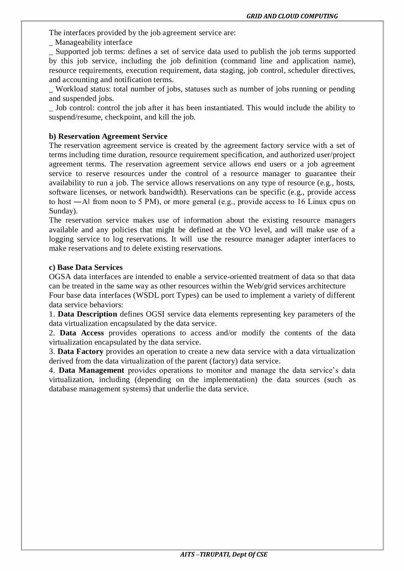
The interfaces provided by the job agreement service are:
_ Manageability interface
_ Supported job terms: defines a set of service data used to publish the job terms supported
by this job service, including the job definition (command line and application name),
resource requirements, execution requirement, data staging, job control, scheduler directives,
and accounting and notification terms.
_ Workload status: total number of jobs, statuses such as number of jobs running or pending
and suspended jobs.
_ Job control: control the job after it has been instantiated. This would include the ability to
suspend/resume, checkpoint, and kill the job.
b) Reservation Agreement Service
The reservation agreement service is created by the agreement factory service with a set of
terms including time duration, resource requirement specification, and authorized user/project
agreement terms. The reservation agreement service allows end users or a job agreement
service to reserve resources under the control of a resource manager to guarantee their
availability to run a job. The service allows reservations on any type of resource (e.g., hosts,
software licenses, or network bandwidth). Reservations can be specific (e.g., provide access
to host ―A‖ from noon to 5 PM), or more general (e.g., provide access to 16 Linux cpus on
Sunday).
The reservation service makes use of information about the existing resource managers
available and any policies that might be defined at the VO level, and will make use of a
logging service to log reservations. It will use the resource manager adapter interfaces to
make reservations and to delete existing reservations.
c) Base Data Services
OGSA data interfaces are intended to enable a service-oriented treatment of data so that data
can be treated in the same way as other resources within the Web/grid services architecture
Four base data interfaces (WSDL port Types) can be used to implement a variety of different
data service behaviors:
1. Data Description defines OGSI service data elements representing key parameters of the
data virtualization encapsulated by the data service.
2. Data Access provides operations to access and/or modify the contents of the data
virtualization encapsulated by the data service.
3. Data Factory provides an operation to create a new data service with a data virtualization
derived from the data virtualization of the parent (factory) data service.
4. Data Management provides operations to monitor and manage the data service’s data
virtualization, including (depending on the implementation) the data sources (such as
database management systems) that underlie the data service.

GRID AND CLOUD COMPUTING
AITS –TIRUPATI, Dept Of CSE
UNIT-III
VIRTUALIZATION
Cloud deployment models
Deployment models define the type of access to the cloud, i.e., how the cloud is located?
Cloud can have any of the four types of access: Public, Private, Hybrid, and Community.
1. PUBLIC CLOUD The public cloud allows systems and services to be easily accessible to the general
public. Public cloud may be less secure because of its openness.
2. PRIVATE CLOUD
The private cloud allows systems and services to be accessible within an
organization. It is more secured because of its private nature.
3. COMMUNITY CLOUD
The community cloud allows systems and services to be accessible by a group of
organizations.
4. HYBRID CLOUD
The hybrid cloud is a mixture of public and private cloud, in which the critical
activities are performed using private cloud while the non-critical activities are performed
using public cloud.
Public cloud
Public Cloud allows systems and services to be easily accessible to general public.
The IT giants such as Google, Amazon and Microsoft offer cloud services via Internet. The
Public Cloud Model is shown in the diagram below.

GRID AND CLOUD COMPUTING
AITS –TIRUPATI, Dept Of CSE
Public cloud Model
Benefits
There are many benefits of deploying cloud as public cloud model. The following diagram
shows some of those benefits:
Cost Effective
Since public cloud shares same resources with large number of customers it turns out
inexpensive.
Reliability
The public cloud employs large number of resources from different locations. If any of the
resources fails, public cloud can employ another one.
Flexibility
The public cloud can smoothly integrate with private cloud, which gives customers a flexible
approach.
Location Independence
Public cloud services are delivered through Internet, ensuring location independence.
Utility Style Costing
Public cloud is also based on pay-per-use model and resources are accessible whenever
customer needs them.

GRID AND CLOUD COMPUTING
AITS –TIRUPATI, Dept Of CSE
High Scalability
Cloud resources are made available on demand from a pool of resources, i.e., they can be
scaled up or down according the requirement.
Disadvantages
Here are some disadvantages of public cloud model:
Low Security
In public cloud model, data is hosted off-site and resources are shared publicly, therefore
does not ensure higher level of security.
Less Customizable
It is comparatively less customizable than private cloud.
3.3. Private cloud
Private Cloud allows systems and services to be accessible within an organization.
The Private Cloud is operated only within a single organization. However, it may be managed
internally by the organization itself or by third-party. The private cloud model is shown in the
diagram below.
Public cloud model
Benefits
There are many benefits of deploying cloud as private cloud model. The following diagram
shows some of those benefits:
High Security and Privacy
Private cloud operations are not available to general public and resources are shared from
distinct pool of resources. Therefore, it ensures high security and privacy.
More Control
The private cloud has more control on its resources and hardware than public cloud because
it is accessed only within an organization.

GRID AND CLOUD COMPUTING
AITS –TIRUPATI, Dept Of CSE
Cost and Energy Efficiency
The private cloud resources are not as cost effective as resources in public clouds but they
offer more efficiency than public cloud resources.
Disadvantages
Here are the disadvantages of using private cloud model:
Restricted Area of Operation
The private cloud is only accessible locally and is very difficult to deploy globally.
High Priced
Purchasing new hardware in order to fulfill the demand is a costly transaction.
Limited Scalability
The private cloud can be scaled only within capacity of internal hosted resources.
Additional Skills
In order to maintain cloud deployment, organization requires skilled expertise.
Hybrid cloud
Hybrid Cloud is a mixture of public and private cloud. Non-critical activities are
performed using public cloud while the critical activities are performed using private cloud.
The Hybrid Cloud Model is shown in the diagram below.
Hybrid cloud model
Benefits
There are many benefits of deploying cloud as hybrid cloud model. The following diagram
shows some of those benefits:
Scalability
It offers features of both, the public cloud scalability and the private cloud scalability.
Flexibility
It offers secure resources and scalable public resources.

GRID AND CLOUD COMPUTING
AITS –TIRUPATI, Dept Of CSE
Cost Efficiency
Public clouds are more cost effective than private ones. Therefore, hybrid clouds can be cost
saving.
Security
The private cloud in hybrid cloud ensures higher degree of security.
Disadvantages
Networking Issues
Networking becomes complex due to presence of private and public cloud.
Security Compliance
It is necessary to ensure that cloud services are compliant with security policies of the
organization.
Infrastructure Dependency
The hybrid cloud model is dependent on internal IT infrastructure, therefore it is necessary to
ensure redundancy across data centers.
Community cloud
Community Cloud allows system and services to be accessible by group of
organizations. It shares the infrastructure between several organizations from a specific
community. It may be managed internally by organizations or by the third-party. The
Community Cloud Model is shown in the diagram below.
Fig: Community cloud model
Benefits
There are many benefits of deploying cloud as community cloud model.

GRID AND CLOUD COMPUTING
AITS –TIRUPATI, Dept Of CSE
Cost Effective
Community cloud offers same advantages as that of private cloud at low cost.
Sharing Among Organizations
Community cloud provides an infrastructure to share cloud resources and capabilities among
several organizations.
Security
The community cloud is comparatively more secure than the public cloud but less secured
than the private cloud.
Issues
Since all data is located at one place, one must be careful in storing data in community cloud
because it might be accessible to others.
It is also challenging to allocate responsibilities of governance, security and cost among
organizations.
Categories of cloud computing
Cloud is made feasible through the deployment and interoperability of three platform
types. These three layers are:
IaaS - Infrastructure as a Service
PaaS - Platform as a Service
SaaS - Software as a Service
Now this stack is easily broken down as follows: Think of the “Infrastructure-as-a-Service”
as the road. It’s the basis for communication. It’s the bottom layer that we build our platform
on. The platform are the cars traveling on the infrastructure. PaaS rides on IaaS. But on the
top of that, the goods and passengers inside the cars are the SaaS. It’s the end user
experience. It’s the end result. Let’s take that a step further.
Infrastructure-as-a-Service (IaaS)
Cloud Providers offering Infrastructure as a Service tout data-center space and servers; as
well as network equipment such as routers/switches and software for businesses. These data -
centers are fully outsourced, we need not lift a finger, upgrade an IOS or re-route data.
Although this is the base layer, it allows for scalability and reliability; as well as better
security than an organization may have in a local co-lo or local data center. In addition, these
services are charged as utilities, so we pay for what we use, like our water, electric and gas.
Depending on our capacity or usage, our payment is a variable.
Because the IaaS vendors purchase equipment in such bulk, we, Mr. Customer, get the best
gear for the lowest price. Hence, the financial benefits of IaaS are cheaper access to
infrastructure.
With the pay-as-we-go model, instead of investing in a fixed capacity infrastructure, which
will either fall short or exceed the organizational need, customers are able to save quite a bit
of coin. Buying hardware that’s barely used is a waste of hardware, air conditioning, space
and power.

GRID AND CLOUD COMPUTING
AITS –TIRUPATI, Dept Of CSE
Operational expenses versus Capital expenses: Cloud is better. Because these computing
resources are basically used and paid for like a utility they can be paid via the operating
expenditures budget versus being paid for via capital investments. In other words, instead of
depreciating the gear over three years, we’re able to expense the monthly charge this year.
And the year after that. It’s an elastic service.
Platform-as-a-Service (Paas)
Provisioning a full hardware architecture and software framework to allow applications to run
is the essence of Platform-as-a-Service. There’s a huge market for customers who require
flexible, robust web-based applications. But, in order for these applications to run, there
needs to be platform supporting it that is just as robust and flexible. Cloud providers offer this
environment and framework as a service. Their developers can write their code regardless of
the OS behind it. So instead of software being written for Apple, Linux or Windows, it’s
being written for a development environment provided by Cloud Providers such as Amazon,
Microsoft and Google.
Software-as-a-Service (SaaS)
Software-as-a-Service is the process of provisioning commercially available software but
giving access over the net. The customer doesn’t have to worry about software licenses, since
they are handled by the service provider. The provider also handles upgrades, patches or bug
fixes. Some examples of this software might be office productivity software, which we may
access online, like Google Docs.
We can also essentially rent contact management software, content management software,
email software (Google mail?), project management software and scheduling software. It’s
all online. All easily available on the internet. Why is this a big deal? Well, we no longer
have to pay for expensive hardware to host the software, or get to the software (VPNs,
dedicated links, etc.), we don’t need the employees (and their associated salaries, benefits,
office costs, etc.) to install, configure or maintain the software. The application is handled on
the back end by the SaaS provider. That’s sort of a big deal regardless the size of our
business. Money is money. Our IT staff is then able to use its time and resources to work on
other projects or we can simply eliminate unnecessary IT staff.
Everything as a service
Infrastructure as a service
Infrastructure-as-a-Service provides access to fundamental resources such as
physical machines, virtual machines, virtual storage, etc. Apart from these resources, the IaaS
also offers:
a. Virtual machine disk storage
b. Virtual local area network (VLANs)
c. Load balancers
d. IP addresses
e. Software bundles
All of the above resources are made available to end user via server virtualization.
Moreover, these resources are accessed by the customers as if they own them.

GRID AND CLOUD COMPUTING
AITS –TIRUPATI, Dept Of CSE
Benefits
IaaS allows the cloud provider to freely locate the infrastructure over the Internet in a cost-
effective manner. Some of the key benefits of IaaS are listed below:
Full control of the computing resources through administrative access to VMs.
Flexible and efficient renting of computer hardware.
Portability, interoperability with legacy applications.
Full control over computing resources through administrative access to VMs
IaaS allows the customer to access computing resources through administrative access to
virtual machines in the following manner:
Customer issues administrative command to cloud provider to run the virtual machine or to
save data on cloud server.
Customer issues administrative command to virtual machines they owned to start web server
or to install new applications.
Flexible and efficient renting of computer hardware
IaaS resources such as virtual machines, storage devices, bandwidth, IP addresses,
monitoring services, firewalls, etc. are made available to the customers on rent. The payment
is based upon the amount of time the customer retains a resource. Also with administrative
access to virtual machines, the customer can run any software, even a custom operating
system.
Portability, interoperability with legacy applications
It is possible to maintain legacy between applications and workloads between IaaS clouds.
For example, network applications such as web server or e-mail server that normally runs on
customer-owned server hardware can also run from VMs in IaaS cloud.
Issues
IaaS shares issues with PaaS and SaaS, such as Network dependence and browser based risks.
It also has some specific issues, which are mentioned in the following diagram:

GRID AND CLOUD COMPUTING
AITS –TIRUPATI, Dept Of CSE
Compatibility with legacy security vulnerabilities
Because IaaS offers the customer to run legacy software in provider's infrastructure, it
exposes customers to all of the security vulnerabilities of such legacy software.
Virtual Machine sprawl
The VM can become out-of-date with respect to security updates because IaaS allows the
customer to operate the virtual machines in running, suspended and off state. However, the
provider can automatically update such VMs, but this mechanism is hard and complex.
Robustness of VM-level isolation
IaaS offers an isolated environment to individual customers through hypervisor. Hypervisor
is a software layer that includes hardware support for virtualization to split a physical
computer into multiple virtual machines.
Data erase practices
The customer uses virtual machines that in turn use the common disk resources provided by
the cloud provider. When the customer releases the resource, the cloud provider must ensure
that next customer to rent the resource does not observe data residue from previous customer.
Characteristics Here are the characteristics of IaaS service model:
Virtual machines with pre-installed software.
Virtual machines with pre-installed operating systems such as Windows, Linux, and
Solaris.
On-demand availability of resources.
Allows storing copies of particular data at different locations.
The computing resources can be easily scaled up and down.
Platform as a service
Platform-as-a-Service offers the runtime environment for applications. It also offers
development and deployment tools required to develop applications. PaaS has a feature of
point-and-click tools that enables non-developers to create web applications.
App Engine of Google and Force.com are examples of PaaS offering vendors.
Developer may log on to these websites and use the built-in API to create web-based
applications.
But the disadvantage of using PaaS is that, the developer locks-in with a particular
vendor. For example, an application written in Python against API of Google, and using App
Engine of Google is likely to work only in that environment.

GRID AND CLOUD COMPUTING
AITS –TIRUPATI, Dept Of CSE
The following diagram shows how PaaS offers an API and development tools to the
developers and how it helps the end user to access business applications.
Benefits
Following are the benefits of PaaS model:
Lower administrative overhead
Customer need not bother about the administration because it is the responsibility of cloud
provider.
Lower total cost of ownership
Customer need not purchase expensive hardware, servers, power, and data storage.
Scalable solutions
It is very easy to scale the resources up or down automatically, based on their demand.
More current system software
It is the responsibility of the cloud provider to maintain software versions and patch
installations.
Issues
Like SaaS, PaaS also places significant burdens on customer's browsers to maintain reliable
and secure connections to the provider’s systems. Therefore, PaaS shares many of the issues
of SaaS. However, there are some specific issues associated with PaaS as shown in the
following diagram:

GRID AND CLOUD COMPUTING
AITS –TIRUPATI, Dept Of CSE
Lack of portability between PaaS clouds
Although standard languages are used, yet the implementations of platform services may
vary. For example, file, queue, or hash table interfaces of one platform may differ from
another, making it difficult to transfer the workloads from one platform to another.
Event based processor scheduling
The PaaS applications are event-oriented which poses resource constraints on applications,
i.e., they have to answer a request in a given interval of time.
Security engineering of PaaS applications
Since PaaS applications are dependent on network, they must explicitly use cryptography and
manage security exposures.
Characteristics
Here are the characteristics of PaaS service model: PaaS offers browser based development environment. It allows the developer to create
database and edit the application code either via Application Programming Interface or point-
and-click tools.
PaaS provides built-in security, scalability, and web service interfaces.
PaaS provides built-in tools for defining workflow, approval processes, and business rules.
It is easy to integrate PaaS with other applications on the same platform.
PaaS also provides web services interfaces that allow us to connect the applications outside
the platform.
PaaS Types
Based on the functions, PaaS can be classified into four types as shown in the following
diagram:
Stand-alone development environments
The stand-alone PaaS works as an independent entity for a specific function. It does not
include licensing or technical dependencies on specific SaaS applications.

GRID AND CLOUD COMPUTING
AITS –TIRUPATI, Dept Of CSE
Application delivery-only environments
The application delivery PaaS includes on-demand scaling and application security.
Open platform as a service
Open PaaS offers an open source software that helps a PaaS provider to run applications.
Add-on development facilities
The add-on PaaS allows to customize the existing SaaS platform.
3.10. Software as a service
Software-as-a-Service (SaaS) model allows to provide software application as a
service to the end users. It refers to a software that is deployed on a host service and is
accessible via Internet. There are several SaaS applications listed below:
a. Billing and invoicing system
b. Customer Relationship Management (CRM) applications
c. Help desk applications
d. Human Resource (HR) solutions
Some of the SaaS applications are not customizable such as Microsoft Office Suite.
But SaaS provides us Application Programming Interface (API), which allows the
developer to develop a customized application.
Characteristics
Here are the characteristics of SaaS service model:
SaaS makes the software available over the Internet.
The software applications are maintained by the vendor.
The license to the software may be subscription based or usage based. And it is billed
on recurring basis.
SaaS applications are cost-effective since they do not require any maintenance at end user side.
They are available on demand.
They can be scaled up or down on demand.
They are automatically upgraded and updated.
SaaS offers shared data model. Therefore, multiple users can share single instance of
infrastructure. It is not required to hard code the functionality for individual users.
All users run the same version of the software.
Benefits
Using SaaS has proved to be beneficial in terms of scalability, efficiency and performance.
Some of the benefits are listed below:
a. Modest software tools
b. Efficient use of software licenses
c. Centralized management and data
d. Platform responsibilities managed by provider
e. Multitenant solutions
Modest software tools
The SaaS application deployment requires a little or no client side software installation,
which results in the following benefits:
a. No requirement for complex software packages at client side
b. Little or no risk of configuration at client side
c. Low distribution cost
Efficient use of software licenses
The customer can have single license for multiple computers running at different locations
which reduces the licensing cost. Also, there is no requirement for license servers because the
software runs in the provider's infrastructure.
Centralized management and data
The cloud provider stores data centrally. However, the cloud providers may store data in a
decentralized manner for the sake of redundancy and reliability.

GRID AND CLOUD COMPUTING
AITS –TIRUPATI, Dept Of CSE
Platform responsibilities managed by providers
All platform responsibilities such as backups, system maintenance, security, hardware
refresh, power management, etc. are performed by the cloud provider. The customer does not
need to bother about them.
Multitenant solutions
Multitenant solutions allow multiple users to share single instance of different resources in
virtual isolation. Customers can customize their application without affecting the core
functionality.
Issues
There are several issues associated with SaaS, some of them are listed below: a) Browser based risks
b) Network dependence
c) Lack of portability between SaaS clouds
Browser based risks
If the customer visits malicious website and browser becomes infected, the subsequent access
to SaaS application might compromise the customer's data.
To avoid such risks, the customer can use multiple browsers and dedicate a specific browser
to access SaaS applications or can use virtual desktop while accessing the SaaS applications.
Network dependence
The SaaS application can be delivered only when network is continuously available. Also
network should be reliable but the network reliability cannot be guaranteed either by cloud
provider or by the customer.
Lack of portability between SaaS clouds
Transferring workloads from one SaaS cloud to another is not so easy because work flow,
business logics, user interfaces, support scripts can be provider specific.
Open SaaS and SOA
Open SaaS uses those SaaS applications, which are developed using open source
programming language. These SaaS applications can run on any open source operating
system and database. Open SaaS has several benefits listed below:
i. No License Required
ii. Low Deployment Cost
iii. Less Vendor Lock-in
iv. More portable applications
v. More Robust Solution
The following diagram shows the SaaS implementation based on SOA:

GRID AND CLOUD COMPUTING
AITS –TIRUPATI, Dept Of CSE
Pros and Cons of cloud computing
Cloud Computing: 3 Pros
1. Improved Disaster Recovery
Moving our business data to the cloud can make disaster recovery (DR)—i.e.,
retrieving data in the event of a hardware compromise—easier and less expensive. We can
even set up our system to back up data automatically to ensure we will be able to recover the
most up-to-date information in case of emergency.
2. Increased Collaboration and Flexibility
For many businesses, moving to the cloud increases opportunities for collaboration
between employees. Colleagues can sync and work on documents or shared apps with ease,
often simultaneously, receiving updates in real time.
Additionally, cloud computing allows each team member to work from anywhere. The cloud
centralizes our data, which means that we, our employees and even our clients can access our
company data from any location with Internet access.
3. Environmentally Friendly
Cloud computing decreases a business carbon footprint by reducing energy
consumption and carbon emissions by more than 30 percent. For small companies, the
decreased energy usage can reach 90 percent—a huge money saver. It can also help a
business project an environmentally sound image.
Cloud Computing: 3 Cons
1. Internet Connectivity
Running all or some of our business applications in the cloud is great, as long as we
can maintain a consistent Internet connection. If any one of our cloud-based service providers
loses connectivity or if our ISP experiences an outage, we are out of business until that
Internet connection returns. Even the best servers go down occasionally, so if we decide to
use this method, it's important to implement a backup plan.
2. Ongoing Costs
While cloud computing is relatively inexpensive to start up, depending on our needs,
an in-house solution may cost less in the long run. Buying an in-house server and installing a
network system is definitely a large, up-front capital investment, and we also need to consider
ongoing IT maintenance costs.
With cloud computing, we pay the same amount each month to maintain not only our
server, but also all our data. The choice we make may depend on whether we have a lot of
start-up capital to invest in a private network. Be sure to compare all the costs for supporting
both an in-house server and cloud-based server to see which option works best for our
situation.
3. Security
It boils down to whom do we trust with our business data? Not every business should
place its data in the cloud. Companies with highly sensitive data—or that must meet stringent
compliance regulations—may well need their own IT department to keep data secure. When
we store data in the cloud, we trust a third party to keep it safe.

GRID AND CLOUD COMPUTING
AITS –TIRUPATI, Dept Of CSE
Implementation levels of virtualization
Virtualization is a technique, which allows to share single physical instance of an
application or resource among multiple organizations or tenants (customers). It does so by
assigning a logical name to a physical resource and providing a pointer to that physical
resource on demand.
Virtualization Concept
Creating a virtual machine over existing operating system and hardware is referred as
Hardware Virtualization. Virtual Machines provide an environment that is logically separated
from the underlying hardware.
The machine on which the virtual machine is created is known as host machine and
virtual machine is referred as a guest machine. This virtual machine is managed by a
software or firmware, which is known as hypervisor.
Hypervisor
The hypervisor is a firmware or low-level program that acts as a Virtual Machine
Manager. There are two types of hypervisor:
Type 1 hypervisor executes on bare system. Lynx Secure, RTS Hypervisor, Oracle
VM, Sun xVM Server, Virtual Logic VLX are examples of Type 1 hypervisor. The following
diagram shows the Type 1 hypervisor.
The type1 hypervisor does not have any host operating system because they are
installed on a bare system.
Type 2 hypervisor is a software interface that emulates the devices with which a
system normally interacts. Containers, KVM, Microsoft Hyper V, VMWare Fusion, Virtual
Server 2005 R2, Windows Virtual PC and VMW are workstation 6.0 are examples of Type
2 hypervisor. The following diagram shows the Type 2 hypervisor.
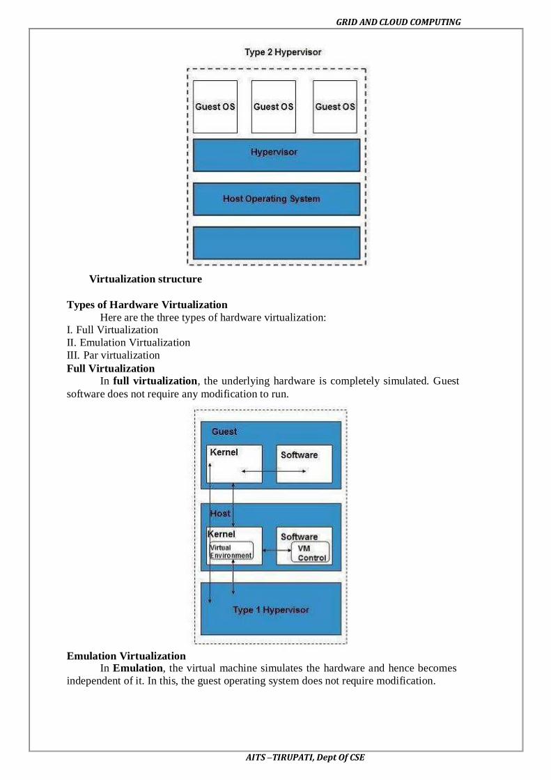
GRID AND CLOUD COMPUTING
AITS –TIRUPATI, Dept Of CSE
Virtualization structure
Types of Hardware Virtualization
Here are the three types of hardware virtualization: I. Full Virtualization
II. Emulation Virtualization
III. Par virtualization
Full Virtualization
In full virtualization, the underlying hardware is completely simulated. Guest
software does not require any modification to run.
Emulation Virtualization In Emulation, the virtual machine simulates the hardware and hence becomes
independent of it. In this, the guest operating system does not require modification.

GRID AND CLOUD COMPUTING
AITS –TIRUPATI, Dept Of CSE
Par virtualization
In Par virtualization, the hardware is not simulated. The guest software run their
own isolated domains.
VMware vSphere is highly developed infrastructure that offers a management infrastructure
framework for virtualization. It virtualizes the system, storage and networking hardware.
Virtualization of CPU, Memory and I/O devices
1. Hardware Support for Virtualization
2. CPU Virtualization
3. Memory Virtualization
4. I/O Virtualization
5. Virtualization in Multi-Core Processors
Hardware Support for Virtualization:
EPT (Extended Page Table); VT-x (Intel’s Virtualization Technology)

GRID AND CLOUD COMPUTING
AITS –TIRUPATI, Dept Of CSE
VMCS (Virtual Machine Control Structure):
3.14 Virtualization of CPU:
Intel Hardware-assisted CPU Virtualization:
A VM is a duplicate of an existing computer system in which a majority of the VM
instructions are executed on the host processor in native mode. Thus, unprivileged
instructions of VMs run directly on the host machine for higher efficiency. Other critical
instructions should be handled carefully for correctness and stability. The critical instructions
are divided into three categories: privileged instructions, control-sensitive instructions, and
behavior-sensitive instructions.
Privileged instructions execute in a privileged mode and will be trapped if executed
outside this mode. Control-sensitive instructions attempt to change the configuration of
resources used. Behavior-sensitive instructions have different behaviors depending on the
configuration of resources, including the load and store operations over the virtual memory.
A CPU architecture is virtualizable if it supports the ability to run the VM’s
privileged and unprivileged instructions in the CPU’s user mode while the VMM runs in
supervisor mode. When the privileged instructions including control- and behavior-sensitive
instructions of a VM are executed, they are trapped in the VMM. In this case, the VMM acts
as a unified mediator for hardware access from different VMs to guarantee the correctness
and stability of the whole system.

GRID AND CLOUD COMPUTING
AITS –TIRUPATI, Dept Of CSE
Virtual Clusters vs. Physical Clusters:
3.15. Virtualization of memory and I/O devices
Memory Virtualization
Virtual memory virtualization is similar to the virtual memory support provided by
modern operating systems. In a traditional execution environment, the operating system
maintains mappings of virtual memory to machine memory using page tables, which is a one-
stage mapping from virtual memory to machine memory. All modern x86 CPUs include a
memory management unit (MMU) and a translation look aside buffer (TLB) to optimize
virtual memory performance.
However, in a virtual execution environment, virtual memory virtualization involves
sharing the physical system memory in RAM and dynamically allocating it to the physical
memory of the VMs.That means a two-stage mapping process should be maintained by the
guest OS and the VMM, respectively: virtual memory to physical memory and physical
memory to machine memory.
Furthermore, MMU virtualization should be supported, which is transparent to the
guest OS. The guest OS continues to control the mapping of virtual addresses to the physical
memory addresses of VMs. But the guest OS cannot directly access the actual machine
memory. The VMM is responsible for mapping the guest physical memory to the actual
machine memory, shows the two-level memory mapping procedure.
Two-level memory mapping procedure. Courtesy of R. Rblig, et al. Since each page
table of the guest OSes has a separate page table in the VMM corresponding to it, the VMM
page table is called the shadow page table. Nested page tables add another layer of indirection
to virtual memory.
A Virtual Clusters based on Application Partitioning:

GRID AND CLOUD COMPUTING
AITS –TIRUPATI, Dept Of CSE
Virtual Clusters Projects:
The MMU already handles virtual-to-physical translations as defined by the OS. Then
the physical memory addresses are translated to machine addresses using another set of page
tables defined by the hypervisor. Since modern operating systems maintain a set of page
tables for every process, the shadow page tables will get flooded.
Consequently, the performance overhead and cost of memory will be very high.
VMware uses shadow page tables to perform virtual memory- to-machine-memory address
translation. Processors use TLB hardware to map the virtual memory directly to the machine
memory to avoid the two levels of translation on every access. When the guest OS changes
the virtual memory to a physical memory mapping, the VMM updates the shadow page tables
to enable a direct lookup.
The AMD Barcelona processor has featured hardware-assisted memory virtualization
since 2007. It provides hardware assistance to the two-stage address translation in a virtual
execution environment by using a technology called nested paging.
I/O Virtualization
I/O virtualization involves managing the routing of I/O requests between virtual
devices and the shared physical hardware. At the time of this writing, there are three ways to
implement I/O virtualization: full device emulation, para-virtualization, and direct I/Full
device emulation is the first approach for I/O virtualization. Generally, this approach
emulates well-known, real-world devices. All the functions of a device or bus infrastructure,
such as device enumeration, identification, interrupts, and DMA, are replicated in software.
This software is located in the VMM and acts as a virtual device. The I/O access requests of
the guest OS are trapped in the VMM which interacts with the I/O devices. Device emulation
for I/O virtualization implemented inside the middle layer that maps real I/O devices into the
virtual devices for the guest device driver to use. Courtesy of V. Chadha, et al. and Y. Dong,
et al. A single hardware device can be shared by multiple VMs that run concurrently.
However, software emulation runs much slower than the hardware it emulates.
The para-virtualization method of I/O virtualization is typically used in Xen. It is also
known as the split driver model consisting of a frontend driver and a backend driver. The
frontend driver is running in Domain U and the backend driver is running in Domain 0. They
interact with each other via a block of shared memory.
The frontend driver manages the I/O requests of the guest OSes and the backend
driver is responsible for managing the real I/O devices and multiplexing the I/O data of
different VMs. Although para-I/O-virtualization achieves better device performance than full
device emulation, it comes with a higher CPU overhead.
Direct I/O virtualization lets the VM access devices directly. It can achieve close-to-
native performance without high CPU costs. However, current direct I/O virtualization
implementations focus on networking for mainframes. There are a lot of challenges for
commodity hardware devices.

GRID AND CLOUD COMPUTING
AITS –TIRUPATI, Dept Of CSE
For example, when a physical device is reclaimed (required by workload migration)
for later reassignment, it may have been set to an arbitrary state (e.g., DMA to some arbitrary
memory locations) that can function incorrectly or even crash the whole system.
Since software based I/O virtualization requires a very high overhead of device
emulation, hardware-assisted I/O virtualization is critical. Intel VT-d supports the remapping
of I/O DMA transfers and device-generated interrupts. The architecture of VT-d provides the
flexibility to support multiple usage models that may run unmodified, special-purpose, or
―virtualization-aware‖ guest OSes.
Another way to help I/O virtualization is via self-virtualized I/O (SV-IO) . The key
idea of SVIO is to harness the rich resources of a multicore processor. All tasks associated
with virtualizing an I/O device are encapsulated in SV-IO. It provides virtual devices and an
associated access API to VMs and a management API to the VMM. SV-IO defines one
virtual interface (VIF) for every kind of virtualized I/O device, such as virtual network
interfaces, virtual block devices (disk), virtual camera devices, and others.
The guest OS interacts with the VIFs via VIF device drivers. Each VIF consists of
two message queues. One is for outgoing messages to the devices and the other is for
incoming messages from the devices. In addition, each VIF has a unique ID for identifying it
in SV-IO.
COD (Cluster-on-Demand) Project at Duke University:
DHCP (Dynamic Host Configuration Protocol); VCM (configuration Manager); NIS
(Network Information Service)
VIOLIN Project at Purdue University
• Live VM migration to reconfigure a virtual cluster environment, Five concurrent virtual
environment, labeled VIOLIN 1-5, sharing two physical clusters.
Virtualization Support at Intel

GRID AND CLOUD COMPUTING
AITS –TIRUPATI, Dept Of CSE
Virtual clusters and Resource Management
A physical cluster is a collection of servers (physical machines) interconnected by a
physical network such as a LAN.
Let us study three critical design issues of virtual clusters: live migration of VMs, memory
and file migrations, and dynamic deployment of virtual clusters.
When a traditional VM is initialized, the administrator needs to manually write
configuration information or specify the configuration sources. When more VMs join a
network, an inefficient configuration always causes problems with overloading or
underutilization.
Amazon’s Elastic Compute Cloud (EC2)is a good example of a web service that
provides elastic computing power in a cloud. EC2 permits customers to create VMs and to
manage user accounts over the time of their use.
Most virtualization platforms, including XenServer and VMware ESX Server, support
a brid-ging mode which allows all domains to appear on the network as individual hosts. By
using this mode, VMs can communicate with one another freely through the virtual network
interface card and configure the network automatically.
Physical versus Virtual Clusters
Virtual clusters are built with VMs installed at distributed servers from one or more
physical clusters. The VMs in a virtual cluster are interconnected logically by a virtual
network across several physical networks.
The below figure illustrates the concepts of virtual clusters and physical clusters. Each
virtual cluster is formed with physical machines or a VM hosted by multiple physical
clusters. The virtual cluster boundaries are shown as distinct boundaries.
The provisioning of VMs to a virtual cluster is done dynamically to have the
following interesting properties:
• The virtual cluster nodes can be either physical or virtual machines. Multiple VMs running
with different OSes can be deployed on the same physical node.
• A VM runs with a guest OS, which is often different from the host OS, that manages the
resources in the physical machine, where the VM is implemented.
• The purpose of using VMs is to consolidate multiple functionalities on the same server.
This will greatly enhance server utilization and application flexibility.

GRID AND CLOUD COMPUTING
AITS –TIRUPATI, Dept Of CSE
A cloud platform with four virtual clusters over three physical clusters shaded
differently
• VMs can be colonized (replicated) in multiple servers for the purpose of promoting
distributed parallelism, fault tolerance, and disaster recovery.
• The size of a virtual cluster can grow or shrink dynamically, similar to the way an overlay
network varies in size in a peer-to-peer (P2P) network.
• The failure of any physical nodes may disable some VMs installed on the failing nodes. But
the failure of VMs will not pull down the host system.
Since system virtualization has been widely used, it is necessary to effectively
manage VMs running on a mass of physical computing nodes (also called virtual clusters)
and consequently build a high-performance virtualized computing environment. This
involves virtual cluster deployment, monitoring and management over large-scale clusters, as
well as resource scheduling, load balancing, server consolidation, fault tolerance, and other
techniques.
The different node colors in the figure above refer to different virtual clusters. In a
virtual cluster system, it is quite important to store the large number of VM images
efficiently.
The below figure shows the concept of a virtual cluster based on application
partitioning or customization. The different colors in the figure represent the nodes in
different virtual clusters. As a large number of VM images might be present, the most
important thing is to determine how to store those images in the system efficiently. There are
common installations for most users or applications, such as operating systems or user-level
programming libraries. These software packages can be preinstalled as templates.
With these templates, users can build their own software stacks. New OS instances
can be copied from the template VM. User-specific components such as programming
libraries and applications can be installed to those instances.
Three physical clusters are shown on the left side of figure below. Four virtual
clusters are created on the right, over the physical clusters. The physical machines are also
called host systems.
Concept of a virtual cluster based on application partitioning
In contrast, the VMs are guest systems. The host and guest systems may run with
different operating systems. Each VM can be installed on a remote server or replicated on
multiple servers belonging to the same or different physical clusters. The boundary of a
virtual cluster can change as VM nodes are added, removed, or migrated dynamically over
time.

GRID AND CLOUD COMPUTING
AITS –TIRUPATI, Dept Of CSE
Fast Deployment and Effective Scheduling
The system should have the capability of fast deployment. Here, deployment means
two things: to construct and distribute software stacks (OS, libraries, applications) to a
physical node inside clusters as fast as possible, and to quickly switch runtime environments
from one user’s virtual cluster to another user’s virtual cluster.
If one user finishes using his system, the corresponding virtual cluster should shut
down or suspend quickly to save the resources to run other VMs for other users.
The concept of “green computing “has attracted much attention recently. However,
previous approaches have focused on saving the energy cost of components in a single
workstation without a global vision.
Consequently, they do not necessarily reduce the power consumption of the whole
cluster. Other cluster-wide energy-efficient techniques can only be applied to homogeneous
workstations and specific applications. The live migration of VMs allows workloads of one
node to transfer to another node. However, it does not guarantee that VMs can randomly
migrate among themselves.
In fact, the potential overhead caused by live migrations of VMs cannot be ignored.
The overhead may have serious negative effects on cluster utilization, throughput and QoS
issues. Therefore, the challenge is to determine how to design migration strategies to
implement green computing without influencing the performance of clusters. Another
advantage of virtualization is load balancing of applications in a virtual cluster. Load
balancing can be achieved using the load index and frequency of user logins. The automatic
scale-up and scale-down mechanism of a virtual cluster can be implemented based on this
model.
Consequently, we can increase the resource utilization of nodes and shorten the
response time of systems. Mapping VMs onto the most appropriate physical node should
promote performance. Dynamically adjusting loads among nodes by live migration of VMs is
desired, when the loads on cluster nodes become quite unbalanced.
High-Performance Virtual Storage
The template VM can be distributed to several physical hosts in the cluster to
customize the VMs. In addition, existing software packages reduce the time for customization
as well as switching virtual environments. It is important to efficiently manage the disk
spaces occupied by template software packages.
Some storage architecture design can be applied to reduce duplicated blocks in a
distributed file system of virtual clusters. Hash values are used to compare the contents of
data blocks. Users have their own profiles which store the identification of the data blocks for
corresponding VMs in a user-specific virtual cluster. New blocks are created when users
modify the corresponding data.
Newly created blocks are identified in the users ‘profiles. Basically, there are four
steps to deploy a group of VMs onto a target cluster: preparing the disk image, conuring the
VMs, choosing the destination nodes and executing the VM deployment command on every
host. Many systems use templates to simplify the disk image preparation process.
A template is a disk image that includes a preinstalled operating system with or
without certain application software. Users choose a proper template according to their
requirements and make a duplicate of it as their own disk image. Templates could implement
the COW (Copy on Write) format.
A new COW backup file is very small and easy to create and transfer. Therefore, it
definitely reduces disk space consumption. In addition, VM deployment time is much shorter
than that of copying the whole raw image file.
Every VM is configured with a name, disk image, network setting and allocated CPU
and memory. One needs to record each VM configuration into a file. However, this method is
inefficient when managing a large group of VMs. VMs with the same configurations could
use predicted profiles to simplify the process.

GRID AND CLOUD COMPUTING
AITS –TIRUPATI, Dept Of CSE
In this scenario, the system configures the VMs according to the chosen pro-file. Most
configuration items use the same settings, while some of them, such as UUID, VM name and
IP address, are assigned with automatically calculated values. Normally, users do not care
which host is running their VM.
A strategy to choose the proper destination host for any VM is needed. The
deployment principle is to fulfil the VM requirement and to balance workloads among the
whole host network.
Live VM Migration Steps and Performance Effects
In a cluster built with mixed nodes of host and guest systems, the normal method of
operation is to run everything on the physical machine. When a VM fails, its role could be
replaced by another VM on a different node, as long as they both run with the same guest OS.
In other words, a physical node can fail over to a VM on another host. This is
different from physical-to-physical failover in a traditional physical cluster. The advantage is
enhanced failover flexibility. The potential drawback is that a VM must stop playing its role
if its residing host node fails. However, this problem can be mitigated with VM life
migration.
The figure below shows the process of life migration of a VM from host A to host B.
The migration copies the VM state file from the storage area to the host machine. There are
four ways to manage a virtual cluster. First, we can use a guest-based manager, by which the
cluster manager resides on a guest system. In this case, multiple VMs form a virtual cluster.
For example, openMosix is an open source Linux cluster running different guest
systems on top of the Xen hypervisor. Another example is Sun’s cluster Oasis, an
experimental Solar is cluster of VMs supported by a VM ware VMM. Second, we can build a
cluster manager on the host systems. The host-based manager supervises the guest systems
and can restart the guest system on another physical machine.
A good example is the VMware HA system that can restart a guest system after
failure. These two cluster management systems are either guest-only or host-only, but they do
not mix. A third way to manage a virtual cluster is to use an independent cluster manager on
both the host and guest systems. This will make infrastructure management more complex,
however.
Finally, we can use an integrated cluster on the guest and host systems. This means
the manager must be designed to distinguish between virtualized resources and physical
resources. Various cluster management schemes can be greatly enhanced when VM life
migration is enabled with minimal overhead.
VMs can be live-migrated from one physical machine to another; in case of failure,
one VM can be replaced by another VM. Virtual clusters can be applied in computational
grids, cloud platforms and high-performance computing (HPC) systems.
The major attraction of this scenario is that virtual clustering provides dynamic
resources that can be quickly put together upon user demand or after a node failure.
In particular, virtual clustering plays a key role in cloud computing. When a VM runs
a live service, it is necessary to make a trade-off to ensure that the migration occurs in a
manner that minimizes all three metrics. The motivation is to design a live VM migration
scheme with negligible downtime, the lowest network bandwidth consumption possible and a
reasonable total migration time.
Furthermore, we should ensure that the migration will not disrupt other active services
residing in the same host through resource contention (e.g., CPU, network bandwidth). A VM
can be in one of the following four states. An inactive state is defined by the virtualization
platform, under which the VM is not enabled.
An active state refers to a VM that has been instantiated at the virtualization platform
to perform a real task. A paused state corresponds to a VM that has been instantiated but
disabled to process a task or paused in a waiting state. A VM enters the suspended state if its
machine file and virtual resources are stored back to the disk.

GRID AND CLOUD COMPUTING
AITS –TIRUPATI, Dept Of CSE
As shown in the figure below, live migration of a VM consists of the following six
steps:
Steps 0 and 1: Start migration. This step makes preparations for the migration, including
determining the migrating VM and the destination host. Although users could manually make
a VM migrate to an appointed host, in most circumstances, the migration is automatically
started by strategies such as load balancing and server consolidation.
Steps 2: Transfer memory. Since the whole execution state of the VM is stored in memory,
sending the VM’s memory to the destination node ensures continuity of the service provided
by the VM. All of the memory data is transferred in the first round, and then the migration
controller recopies the memory data which is changed in the last round.
These steps keep iterating until the dirty portion of the memory is small enough to handle the
final copy. Although precopying memory is performed iteratively, the execution of programs
is not obviously interrupted.
Live migration process of a VM from one host to another
Step 3: Suspend the VM and copy the last portion of the data. The migrating VM’s execution
is suspended when the last round’s memory data is transferred. Other non-memory data such
as CPU and network states should be sent as well.
During this step, the VM is stopped and its applications will no longer run. This “service
unavailable “time is called the “downtime “of migration, which should be as short as possible
so that it can be negligible to users.
Steps 4 and 5: Commit and activate the new host. After all the needed data is copied, on the
destination host, the VM reloads the states and recovers the execution of programs in it and
the service provided by this VM continues. Then the network connection is redirected to the
new VM and the dependency to the source host is cleared. The whole migration process
finishes by removing the original VM from the source host.
The bellow figure shows the effect on the data transmission rate (Mbit/second) of live
migration of a VM from one host to another. Before copying the VM with 512 KB files for
100 clients, the data throughput was 870 MB/second.

GRID AND CLOUD COMPUTING
AITS –TIRUPATI, Dept Of CSE
The first precopy takes 63 seconds, during which the rate is reduced to 765 MB/second. Then
the data rate reduces to 694 MB/second in 9.8 seconds for more iterations of the copying
process. The system experiences only 165 ms of downtime, before the VM is restored at the
destination host. This experimental result shows a very small migration overhead in live
transfer of a VM between host nodes. This is critical to achieve dynamic cluster
reconfiguration and disaster recovery as needed in cloud computing.
With the emergence of widespread cluster computing more than a decade ago, many cluster
configuration and management systems have been developed to achieve a range of goals.
These goals naturally influence individual approaches to cluster management. VM
technology has become a popular method for simplifying management and sharing of
physical computing resources. Platforms such as VMware and Xen allow multiple VMs with
different operating systems and configurations to coexist on the same physical host in mutual
isolation. Clustering inexpensive computers is an effective way to obtain reliable, scalable
computing power for network services and compute-intensive applications.
Effect on data transmission rate of a VM migrated from one failing web server to another
Migration of Memory, Files, and Network Resources
Since clusters have a high initial cost of ownership, including space, power conditioning, and
cooling equipment, leasing or sharing access to a common cluster is an attractive solution
when demands vary over time. Shared clusters offer economies of scale and more effective
utilization of resources by multiplexing.
Early configuration and management systems focus on expressive and scalable mechanisms
for defining clusters for specific types of service, and physically partition cluster nodes
among those types. When one system migrates to another physical node, we should consider
the following issues.
1. Memory Migration 2. File System Migration
3. Network Migration
4. Live Migration of VM Using Xen
Dynamic Deployment of Virtual Clusters
The below table summarizes four virtual cluster research projects. We briefly introduce them
here just to identify their design objectives and reported results. The Cellular Disco at
Stanford is a virtual cluster built in a shared-memory multiprocessor system. The INRIA
virtual cluster was built to test parallel algorithm performance. The COD and VIOLIN
clusters are studied in forthcoming examples.
Experimental Results on Four Research Virtual Clusters

GRID AND CLOUD COMPUTING
AITS –TIRUPATI, Dept Of CSE
COD partitioning a physical cluster into multiple virtual clusters
Virtualization for data center automation
1. Virtual Storage Management
2. Cloud OS for Virtualized Data Centers
3. Trust Management in Virtualized Data Centers
4. VM-based Intrusion Detection
Parallax Providing Virtual Disks to Clients VMs from a Large Common Shared Physical
Disk.
Cloud OS for Building Private Clouds (VI: Virtual Infrastructure, EC2: Elastic Compute
Cloud).

GRID AND CLOUD COMPUTING
AITS –TIRUPATI, Dept Of CSE
Eucalptus: An Open-Source OS for Setting Up and Managing Private Clouds (IaaS)
Three Resource Managers: CM (Cloud Manager), GM (Group Manager), and IM (Instance
Manager)
Works like AWS APIs
VMware vSphere 4 – A Commercial Cloud OS.
VM-based Intrusion Detection.

GRID AND CLOUD COMPUTING
AITS –TIRUPATI, Dept Of CSE
Techniques for establishing trusted zones for virtual cluster insulation and VM isolation.

GRID AND CLOUD COMPUTING
AITS –TIRUPATI, Dept Of CSE
UNIT-IV
PROGRAMMING MODEL
OPEN SOURCE GRID MIDDLEWARE PACKAGES
As reviewed in Berman, Fox, and Hey , many software, middleware, and
programming environments have been developed for grid computing over past 15 years.
Below we assess their relative strength and limitations based on recently reported
applications. We first introduce some grid standards and popular APIs. Then we present the
desired software support and middleware developed for grid computing includesfour grid
middleware packages.
Grid Software Support and Middleware Packages
BOINC Berkeley Open Infrastructure for Network Computing.
UNICORE Middleware developed by the German grid computing community.
Globus (GT4) A middleware library jointly developed by Argonne National Lab.,
Univ. of Chicago, and USC Information Science Institute, funded by DARPA, NSF, and
NIH. CGSP in ChinaGrid
The CGSP (ChinaGrid Support Platform) is a middleware library developed by 20 top
universities in China as part of the ChinaGridProject .
Condor-G Originally developed at the Univ. of Wisconsin for general distributed computing,
and later extended to Condor-G for grid job management. .
Sun Grid Engine (SGE)
Developed by Sun Microsystems for business grid applications.Applied to private
grids and local clusters within enterprises or campuses.
Grid Standards and APIs
Grid standards have been developed over the years. The Open Grid Forum (formally
Global Grid Forum) and Object Management Group are two well-formed organizations
behind those standards. We have already introduced the OGSA (Open Grid Services
Architecture) in standards including the GLUE for resource representation, SAGA (Simple
API for Grid Applications), GSI (Grid Security Infrastructure), OGSI (Open Grid Service
Infrastructure), and WSRE (Web Service Resource Framework).
The grid standards have guided the development of several middleware libraries and
API tools for grid computing. They are applied in both research grids and production grids
today. Research grids tested include the EGEE, France Grilles, D-Grid (German), CNGrid
(China), TeraGrid (USA), etc. Production grids built with the standards include the EGEE,
INFN grid (Italian), NorduGrid, Sun Grid, Techila, and Xgrid . We review next the software
environments and middleware implementations based on these standards.

GRID AND CLOUD COMPUTING
AITS –TIRUPATI, Dept Of CSE
Software Support and Middleware
Grid middleware is specifically designed a layer between hardware and the software.
The middleware products enable the sharing of heterogeneous resources and managing
virtual organizations created around the grid. Middleware glues the allocated resources with
specific user applications. Popular grid middleware tools include the Globus Toolkits (USA),
gLight, UNICORE (German), BOINC (Berkeley), CGSP (China), Condor-G, and Sun Grid
Engine, etc. summarizes the grid software support and middleware packages developed for
grid systems since 1995. In subsequent sections, we will describe the features in Condor-G,
SGE, GT4, and CGSP.
The Globus Toolkit Architecture (GT4)
The Globus Toolkit, is an open middleware library for the grid computing
communities. These open source software libraries support many operational grids and their
applications on an international basis. The toolkit addresses common problems and issues
related to grid resource discovery, management, communication, security, fault detection, and
portability. The software itself provides a variety of components and capabilities. The library
includes a rich set of service implementations.
The implemented software supports
Grid infrastructure management,
Provides tools for building new web services in Java, C, and Python,
Builds a powerful std-based security infrastructure and client APIs (in diff languages)
Offers comprehensive command-line programs for accessing various grid services.
The Globus Toolkit was initially motivated by a desire to remove obstacles that prevent seamless
Collaboration and thus sharing of resources and services, in scientific and engineering
applications. The shared resources can be computers, storage, data, services, networks,
science instruments (e.g., sensors), and so on. The Globus library version GT4, is
conceptually shown in Figure

GRID AND CLOUD COMPUTING
AITS –TIRUPATI, Dept Of CSE
The GT4 Library
Globus Toolkit 4 provides components in the following five categories: _ Common runtime components
_ Security
_ Data management
_ Information services
_ Execution management
GT4 offers the middle-level core services in grid applications. The high-level services and
tools, such as MPI, Condor-G, and Nimrod/G, are developed by third parties for general
purpose distributed computing applications. The local services, such as LSF, TCP, Linux, and
Condor, are at the bottom level and are fundamental tools supplied by other developers.
Nexus is used for collective communications and HBM for heartbeat monitoring of resource
nodes. Grid FTP is for speeding up internode file transfers. The module GASS is used for
global access of secondary storage. GSI (grid security infrastructure)
Globus Job Workflow
Figure shows the typical job workflow when using the Globus tools. A typical job
execution sequence proceeds as follows: The user delegates his credentials to a delegation
service. The user submits a job request to GRAM with the delegation identifier as a
parameter. GRAM parses the request, retrieves the user proxy certificate from the delegation
service, and then acts on behalf of the user. GRAM sends a transfer request to the RFT
(Reliable File Transfer), which applies Grid FTP to bring in the necessary files.

GRID AND CLOUD COMPUTING
AITS –TIRUPATI, Dept Of CSE
GRAM invokes a local scheduler via a GRAM adapter and the SEG (Scheduler Event
Generator) initiates a set of user jobs. The local scheduler reports the job state to the SEG.
Once the job is complete, GRAM uses RFT and Grid FTP to stage out the resultant files. The
grid monitors the progress of these operations and sends the user a notification when they
succeed, fail, or are delayed.
Configuration Installing
Globus Toolkit 4
You may install Globus Toolkit 4 in many ways. In this section, we introduce both binary and source package installation.
Installation of the binary package is extremely fast, while installation using the
Source package will take longer, as would be expected
Installation from binary package
To install from a binary package:
1. Obtain the Globus Toolkit 4 binary package from the Globus site
2. 2. Extract the binary package as the Globus user
3. 3. Set environmental variables for the Globus location
4. 4. Create and change the ownership of directory for user and group Globus.
5. 5. Configure and install Globus Toolkit 4
Configuration and testing of grid environment
After the installation of the Globus Toolkit, each element of your grid environment
Must be configured.
Configuring environmental variables
Before starting the configuration process, it is useful to set up the
GLOBUS_LOCATION environmental variables in either /etc/profile or
(User home)/.bash profile.
Security set up
In this book, we use Simple CA, which is a wrapper of Open SSL CA functionality.
Important: Before setting up a certificate authority (CA), make sure to
Synchronize the system time of all the machines in your environment
Setting up security in each grid node
After performing the steps above, a package file has been created that needs to
be used on other nodes, as described in this section. In order to use certificates
from this CA in other grid nodes, you need to copy and install the CA setup
package to each grid node.
Obtain and sign a host certificate
In order to use some of the services provided by Globus Toolkit 4, such as Grid
FTP, you need to have a CA signed host certificate and host key in the
appropriate directory.
Set mapping information between a grid user and a local user
Globus Toolkit 4 requires a mapping between an authenticated grid user and a
local user.
Configuration of Java WS Core
The Java WS Core container is installed as a part of the default Globus Toolkit 4 installation.

GRID AND CLOUD COMPUTING
AITS –TIRUPATI, Dept Of CSE
Usage of Globus
Client-Globus Interactions
GT4 service programs are designed to support user applications as illustrated in
Figure. There are strong interactions between provider programs and user code. GT4 makes
heavy use of industry-standard web service protocols and mechanisms in service description,
discovery, access, authentication, authorization, and the like. GT4 makes extensive use of
Java, C, and Python to write user code. Web service mechanisms define specific interfaces
for grid computing. Web services provide flexible, extensible, and widely adopted XML-
based interfaces.
Three containers are used to host user-developed services written in Java, Python, and C,
respectively. These containers provide implementations of security, management, discovery,
state management, and other mechanisms frequently required when building services. They
Extend open source service hosting environments with support for a range of useful web
service specifications, including WSRF, WS-Notification, and WS-Security.
Containers and Resources/Data Management
GRAM supports dynamic job execution with coordinated file staging. MDS is used
for monitoring and discovery of available grid resources in a grid execution environment.
Globus Container: A Runtime Environment
The Globus Container (also called a web service core or WS container) provides a
basic runtime environment for hosting the web services needed to execute grid jobs. The
container is built with heavy use of SOAP engines. The WS-addressing, WSRF, and WS-
Notification functions are implemented.

GRID AND CLOUD COMPUTING
AITS –TIRUPATI, Dept Of CSE
The main SOAP functions performed include the transport of incoming job requests and
corresponding responses.
To implement the SOAP commands over the HTTP engine as a message transport protocol.
Both transport-level and message-level security is enforced in all communications.. GT4
container can host many services to multiple jobs simultaneously.
The container also hosts advanced services provided by GT4, such as GRAM, MDS, and
RFT. The application clients use the Globus container registry interfaces to determine which
services are hosted in a particular container.
The container administration interfaces are used to perform routine management functions.
Web service containers written in Java, C, and Python in the GT4 suite.
Data Management Using GT4
Grid applications often need to provide access to and/or integrate large quantities of
data at multiple sites. The following list briefly
Introduces these GT4 tools:
1. Grid FTP supports reliable, secure, and fast memory-to-memory and disk-to-disk data
movement over high-bandwidth WANs. Based on the popular FTP protocol for Internet file
transfer, Grid FTP adds additional features such as parallel data transfer, third-party data
transfer, and striped data transfer. In addition, Grid FTP benefits from using the strong
Globus Security Infrastructure (GSI to be studied in Section 7.5.5) for securing data channels
with authentication and reusability. It has been reported that the grid has achieved 27
Gbit/second end-to-end transfer speeds over some WANs.
2. RFT provides reliable management of multiple Grid FTP transfers. It has been used to
orchestrate the transfer of millions of files among many sites simultaneously.
3. RLS (Replica Location Service) is a scalable system for maintaining and providing access
to information about the location of replicated files and data sets.
4. OGSA-DAI (Globus Data Access and Integration) tools were developed by the UK e-
Science program and provide access to relational and XML databases.
The MDS Services
Monitoring and discovery are two vital functions in any distributed system. Both tasks
require the ability to collect information from multiple distributed information sources.GT4
provides monitoring and discovery support at a fundamental level. GT4 enables the
association of XML-based resource properties t to carry out MDS indexing, Grid FTP, and
other functions needed to conduct monitoring and discovery of available resources. Grid
services can be registered with distributed containers.
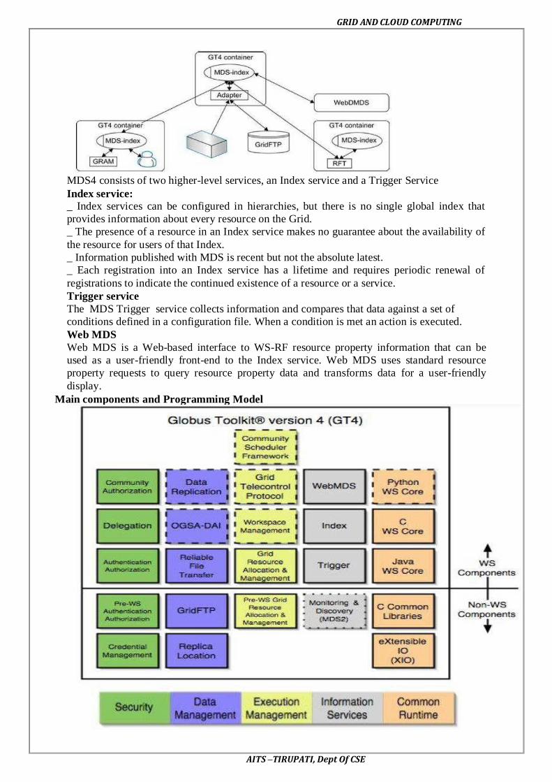
GRID AND CLOUD COMPUTING
AITS –TIRUPATI, Dept Of CSE
MDS4 consists of two higher-level services, an Index service and a Trigger Service
Index service:
_ Index services can be configured in hierarchies, but there is no single global index that
provides information about every resource on the Grid.
_ The presence of a resource in an Index service makes no guarantee about the availability of
the resource for users of that Index.
_ Information published with MDS is recent but not the absolute latest.
_ Each registration into an Index service has a lifetime and requires periodic renewal of
registrations to indicate the continued existence of a resource or a service.
Trigger service
The MDS Trigger service collects information and compares that data against a set of
conditions defined in a configuration file. When a condition is met an action is executed.
Web MDS
Web MDS is a Web-based interface to WS-RF resource property information that can be
used as a user-friendly front-end to the Index service. Web MDS uses standard resource
property requests to query resource property data and transforms data for a user-friendly
display.
Main components and Programming Model

GRID AND CLOUD COMPUTING
AITS –TIRUPATI, Dept Of CSE
It is important to realize that the Globus Toolkit includes a lot of other components
which can help us build Grid systems. Even so, the Java WS Core component is especially
interesting because it is the base for most of the WS components. Note that we do not need to
have in-depth knowledge about Java WS Core to use many GT4 components like GRAM,
MDS, etc. However, if we want to build aGrid system that integrates all of these components
with our own services, we will need to know about Java WS Core to actually "glue" all those
services together and to program our own services.
Introduction to Hadoop Framework
Apache Hadoop and the Hadoop Ecosystem
Although Hadoop is best known for Map Reduce and its distributed file system
(HDFS,
Renamed from NDFS),
Map Reduce is a programming model for data processing. The model is simple, yet
not
Too simple to express useful programs in. Hadoop can run Map Reduce programs written in
various languages; in this chapter, we shall look at the same program expressed in Java,
Ruby, Python, and C++. Most important, Map Reduce programs are inherently parallel, thus
putting very large-scale data analysis into the hands of anyone with enough machines at their
disposal. Map Reduce comes into its own for large datasets, so let’s start by looking at one.
Analyzing the Data with Hadoop
To take advantage of the parallel processing that Hadoop provides, we need to express
our query as a Map Reduce job. After some local, small-scale testing, we will be able torun it
on a cluster of machines.

GRID AND CLOUD COMPUTING
AITS –TIRUPATI, Dept Of CSE
• Distributed, with some centralization
• Main nodes of cluster are where most of the computational power and storage of the
system lies
• Main nodes run Task Tracker to accept and reply to Map Reduce tasks, and also Data
Node to store needed blocks closely as possible
• Central control node runs Name Node to keep track of HDFS directories & files, and
Job Tracker to dispatch compute tasks to Task Tracker
• Written in Java, also supports Python and Ruby
Map and Reduce
Map Reduce works by breaking the processing into two phases: the map phase and
the reduce phase. Each phase has key-value pairs as input and output, the types of which may
be chosen by the programmer. The programmer also specifies two functions: the map
function and the reduce function
Anatomy of a Map Reduce Job Run
You can run a Map Reduce job with a single line of code: Job Client .run Job(conf).
It’s very short, but it conceals a great deal of processing behind the scenes. This section
uncovers the steps Hadoop takes to run a job.
The whole process is illustrated in Figure. At the highest level, there are four independent
entities:
• The client, which submits the Map Reduce job.
• The job tracker, which coordinates the job run. The job tracker is a Java application
whose main class is Job Tracker.
• The task trackers, which run the tasks that the job has been split into. Task trackers
are Java applications whose main class is Task Tracker.
• The distributed file system, which is used for sharing job files between the other
entities.
Job Submission
The run Job () method on Job Client is a convenience method that creates a new Job
Client instance and calls submit Job() on it (step 1 ). Having submitted the job, run Job() polls
the job’s progress once a second and reports the progress to the console if it has changed
since the last report. When the job is complete, if it was successful, the job counters are
displayed. Otherwise, the error that caused the job to fail is logged to the console.
The job submission process implemented by Job Client’s submit Job() method does the
following:
• Asks the job tracker for a new job ID (by calling get New Job Id () on Job Tracker) (step2).
• Checks the output specification of the job. For example, if the output directory has not been
specified or it already exists, the job is not submitted and an error is thrown to the Map
Reduce program.
• Computes the input splits for the job. If the splits cannot be computed, because the input
paths don’t exist, for example, then the job is not submitted and an error is thrown to the Map
Reduce program.

GRID AND CLOUD COMPUTING
AITS –TIRUPATI, Dept Of CSE
• Copies the resources needed to run the job, including the job JAR file, the configuration
file, and the computed input splits, to the job tracker’s file system in a directory named after
the job ID. The job JAR is copied with a high replication factor (controlled by the mapped.
submit .replication property, which defaults to10) so that there are lots of copies across the
cluster for the task trackers to access when they run tasks for the job (step 3).
• Tells the job tracker that the job is ready for execution (by calling submit Job() on Job
Tracker) (step 4).
Job Initialization
When the Job Tracker receives a call to its submit Job() method, it puts it into an
internal queue from where the job scheduler will pick it up and initialize it. Initialization
involves creating an object to represent the job being run, which encapsulates its tasks, and
bookkeeping information to keep track of the tasks’ status and progress (step 5).
To create the list of tasks to run, the job scheduler first retrieves the input splits
computed
by the Job Client from the shared file system (step 6). It then creates one map task for each
split. The number of reduce tasks to create is determined by the mapped. Reduce. Tasks
property in the Job Conf, which is set by the set Num Reduce Tasks() method, and the
scheduler simply creates this number of reduce tasks to be run. Tasks are given IDs at this
point.
• Tells the job tracker that the job is ready for execution (by calling submit Job() on Job
Tracker) (step 4).
Input Splitting
Task Assignment
Task trackers run a simple loop that periodically sends heartbeat method calls to the job
tracker. Heartbeats tell the job tracker that a task tracker is alive, but they also double as a
channel for messages. As a part of the heartbeat, a task tracker will indicate whether it is
ready to run a new task, and if it is, the job tracker will allocate it a task, which it
communicates to the task tracker using the heartbeat return value (step 7).
Before it can choose a task for the task tracker, the job tracker must choose a job to select the
task from.
Task Execution
Now that the task tracker has been assigned a task, the next step is for it to run the task. First,
it localizes the job JAR by copying it from the shared file system to the task tracker’s file
system. It also copies any files needed from the distributed cache by the application to the
local disk. Second, it creates a local working directory for the task, and un-jars the contents of
the JAR into this directory. Third, it creates an instance of Task Runner to run the task. Task
Runner launches a new Java Virtual Machine (step 9) to run each task in (step 10),so that any
bugs in the user-defined map and reduce functions don’t affect the task tracker(by causing it
to crash or hang, for example). It is, however, possible to reuse the JVM between tasks.
The child process communicates with its parent through the umbilical interface. This way it
informs the parent of the task’s progress every few seconds until the task is complete.
Job Completion
When the job tracker receives a notification that the last task for a job is complete, it
changes the status for the job to “successful.” Then, when the Job Client polls for status, it
learns that the job has completed successfully, so it prints a message to tell the user and then
returns from the run Job() method.

GRID AND CLOUD COMPUTING
AITS –TIRUPATI, Dept Of CSE
Java Map Reduce
Having run through how the Map Reduce program works, the next step is to express it
in code. We need three things: a map function, a reduce function, and some code to run the
job. The map function is represented by an implementation of the Mapper interface, which
declares a map() method.
Analyzing the Data with Hadoop
To take advantage of the parallel processing that Hadoop provides, we need to express
our query as a Map Reduce job. After some local, small-scale testing, we will be able to run it
on a cluster of machines.
HADOOP LIBRARY FROM APACHE
Hadoop is an open source implementation of Map Reduce coded and released in Java
(rather than C) by Apache. The Hadoop implementation of Map Reduce uses the Hadoop
Distributed File System (HDFS) as its underlying layer rather than GFS. The Hadoop core is
divided into two fundamental layers: the Map Reduce engine and HDFS. The Map Reduce
engine is the computation engine running on top of HDFS as its data storage manager. The
following two sections cover the details of these two fundamental layers.
HDFS: HDFS is a distributed file system inspired by GFS that organizes files and
stores their data on a distributed computing system.
HDFS Architecture: HDFS has a master/slave architecture containing a single Name
Node as the master and a number of Data Nodes as workers (slaves). To store a file in this
architecture, HDFS splits the file into fixed-size blocks (e.g., 64 MB) and stores them on
workers (Data Nodes). The mapping of blocks to Data Nodes is determined by the Name
Node. The Name Node (master) also manages the file system’s metadata and namespace. In
such systems, the namespace is the area maintaining the metadata, and metadata refers to all
the information stored by a file system that is needed for overall management of all files. For
example, Name Node in the metadata stores all information regarding the location of input
splits/blocks in all Data Nodes. Each Data Node, usually one per node in a cluster, manages
the storage attached to the node. Each Data Node is responsible for storing and retrieving its
file blocks.
HDFS Features: Distributed file systems have special requirements, such as
performance, scalability, concurrency control, fault tolerance, and security requirements, to
operate efficiently. However, because HDFS is not a general-purpose file system, as it only
executes specific types of applications, it does not need all the requirements of a general
distributed file system. For example, security has never been supported for HDFS systems.
The following discussion highlights two important characteristics of HDFS to distinguish it
from other generic distributed file systems.
HDFS Fault Tolerance: One of the main aspects of HDFS is its fault tolerance
characteristic. Since Hadoop is designed to be deployed on low-cost hardware by default, a
hardware failure in this system is considered to be common rather than an exception.
Therefore, Hadoop considers the following issues to fulfill reliability requirements of the file
system:
• Block replication to reliably store data in HDFS, file blocks are replicated in this
system. In other words, HDFS stores a file as a set of blocks and each block is replicated and
distributed across the whole cluster. The replication factor is set by the user and is three by
default.

GRID AND CLOUD COMPUTING
AITS –TIRUPATI, Dept Of CSE
• Replica placement the placement of replicas is another factor to fulfill the desired
fault tolerance in HDFS. Although storing replicas on different nodes (Data Nodes) located in
different racks across the whole cluster provides more reliability, it is sometimes ignored as
the cost of communication between two nodes in different racks is relatively high in
comparison with that of different nodes located in the same rack. Therefore, sometimes
HDFS compromises its reliability to achieve lower communication costs. For example, for
the default replication factor of three, HDFS stores one replica in the same node the original
data is stored, one replica on a different node but in the same rack, and one replica on a
different node in a different rack to provide three copies of the data .
• Heartbeat and Block report messages Heartbeats and Block reports are periodic
messages sent to the Name Node by each Data Node in a cluster. Receipt of a Heartbeat
implies that the Data Node is functioning properly, while each Block report contains a list of
all blocks on a Data Node. The Name Node receives such messages because it is the sole
decision maker of all replicas in the system.
HDFS High-Throughput Access to Large Data Sets (Files): Because HDFS is
primarily designed for batch processing rather than interactive processing, data access
throughput in HDFS is more important than latency. Also, because applications run on HDFS
typically have large data sets, individual files are broken into large blocks (e.g., 64 MB) to
allow HDFS to decrease the amount of metadata storage required per file. This provides two
advantages: The list of blocks per file will shrink as the size of individual blocks increases,
and by keeping large amounts of data sequentially within a block, HDFS provides fast
streaming reads of data.
HDFS Operation: The control flow of HDFS operations such as write and read can
properly highlight roles of the Name Node and Data Nodes in the managing operations. In
this section, the control flow of the main operations of HDFS on files is further described to
manifest the interaction between the user, the Name Node, and the Data Nodes in such
systems.
• Reading a file to read a file in HDFS, a user sends an ―open‖ request to the Name
Node to get the location of file blocks. For each file block, the Name Node returns the
address of a set of Data Nodes containing replica information for the requested file. The
number of addresses depends on the number of block replicas. Upon receiving such
information, the user calls the read function to connect to the closest Data Node containing
the first block of the file. After the first block is streamed from the respective Data Node to
the user, the established connection is terminated and the same process is repeated for all
blocks of the requested file until the whole file is streamed to the user.
• Writing to a file To write a file in HDFS, a user sends a ―create‖ request to the
Name Node to create a new file in the file system namespace. If the file does not exist, the
Name Node notifies the user and allows him to start writing data to the file by calling the
write function. The first block of the file is written to an internal queue termed the data queue
while a data streamer monitors its writing into a Data Node. Since each file block needs to be
replicated by a predefined factor, the data streamer first sends a request to the Name Node to
get a list of suitable Data Nodes to store replicas of the first block.
The steamer then stores the block in the first allocated Data Node. Afterward, the
block is forwarded to the second Data Node by the first Data Node. The process continues
until all allocated Data Nodes receive a replica of the first block from the previous Data
Node.
Once this replication process is finalized, the same process starts for the second block
and continues until all blocks of the file are stored and replicated on the file system.

GRID AND CLOUD COMPUTING
AITS –TIRUPATI, Dept Of CSE
Architecture of Map Reduce in Hadoop
The topmost layer of Hadoop is the Map Reduce engine that manages the data flow
and control flow of Map Reduce jobs over distributed computing systems shows the Map
Reduce engine architecture cooperating with HDFS. Similar to HDFS, the Map Reduce
engine also has a master/slave architecture consisting of a single Job Tracker as the master
and a number of Task Trackers as the slaves (workers). The Job Tracker manages the Map
Reduce job over a cluster and is responsible for monitoring jobs and assigning tasks to Task
Trackers. The Task Tracker manages the execution of the map and/or reduce tasks on a single
computation node in the cluster. HDFS and Map Reduce architecture in Hadoop where boxes
with different shadings refer to different functional nodes applied to different blocks of data.
Each Task Tracker node has a number of simultaneous execution slots, each
executing either a map or a reduce task. Slots are defined as the number of simultaneous
threads supported by CPUs of the Task Tracker node. For example, a Task Tracker node with
N CPUs, each supporting M threads, has M * N simultaneous execution slots. It is worth
noting that each data block is processed by one map task running on a single slot. Therefore,
there is a one-to-one correspondence between map tasks in a Task Tracker and data blocks in
the respective Data Node.
Map and Reduce functions
Map Reduce works by breaking the processing into two phases: the map phase and the reduce
phase. Each phase has key-value pairs as input and output, the types of which may be chosen
by the programmer. The programmer also specifies two functions: the map function and the
reduce function.
The input to our map phase is the raw NCDC data. We choose a text input format that
gives us each line in the dataset as a text value. The key is the offset of the beginning of the
line from the beginning of the file, but as we have no need for this, we ignore it.
Our map function is simple. We pull out the year and the air temperature, since these
are the only fields we are interested in. In this case, the map function is just a data preparation
phase, setting up the data in such a way that the reducer function can do its work on it:
finding the maximum temperature for each year. The map function is also a good place to
drop bad records: here we filter out temperatures that are missing, suspect, or erroneous.
These lines are presented to the map function as the key-value pairs:
The keys are the line offsets within the file, which we ignore in our map function. The
map function merely extracts the year and the air temperature (indicated in bold text),and
emits them as its output (the temperature values have been interpreted as integers):
The output from the map function is processed by the Map Reduce framework before
being sent to the reduce function. This processing sorts and groups the key-value pairs by
key. So, continuing the example, our reduce function sees the following input:
Java Map Reduce
Having run through how the Map Reduce program works, the next step is to express it
in code. We need three things: a map function, a reduce function, and some code to run the
job. The map function is represented by an implementation of the Mapper interface, which
declares a map() method.

GRID AND CLOUD COMPUTING
AITS –TIRUPATI, Dept Of CSE
The implementation of four map function.
public class Max Temperature Mapper extends Map Reduce Base
implements Mapper<Long Writable, Text, Text, Int Writable> {
private static final int MISSING = 9999;
public void map(Long Writable key, Text value,
Output Collector<Text, Int Writable> output, Reporter reporter)
throwsIOException {
String line = value.toString();
String year = line.substring(15, 19);
intairTemperature;
if (line.charAt(87) == '+') { // parseInt doesn't like leading plus signs
airTemperature = Integer.parseInt(line.substring(88, 92));
} else {
airTemperature = Integer.parseInt(line.substring(87, 92));
}
String quality = line.substring(92, 93);
if (airTemperature != MISSING &&quality.matches("[01459]")) {
output.collect(new Text(year), new IntWritable(airTemperature));
}
}
}
The Mapper interface is a generic type, with four formal type parameters that specify the
input key, input value, output key, and output value types of the map function.
Hadoop provides its own set of basic types that are optimized for network
serialization. These are found in the org.apache.hadoop.io package. Here we use Long
Writable, which corresponds to a Java Long, Text (like Java String),and Int Writable(like
Java Integer).
The map() method is passed a key and a value. We convert the Text value containing the line
of input into a Java String, then use its substring() method to extract the columns we are
interested in.
The map() method also provides an instance of Output Collector to write the output to.In this
case, we write the year as a Text object (since we are just using it as a key), and the
temperature is wrapped in an Int Writable. We write an output record only if the temperature
is present and the quality code indicates the temperature reading is OK. The reduce function
is similarly defined using a Reducer, as illustrated in Example 2-4.
Example 2-4. Reducer for maximum temperature example
importjava.io.IOException;
importjava.util.Iterator;
importorg.apache.hadoop.io.IntWritable;
importorg.apache.hadoop.io.Text;
importorg.apache.hadoop.mapred.MapReduceBase;
importorg.apache.hadoop.mapred.OutputCollector;
importorg.apache.hadoop.mapred.Reducer;
importorg.apache.hadoop.mapred.Reporter;
public class MaxTemperatureReducer extends MapReduceBase
implements Reducer<Text, IntWritable, Text, IntWritable> {
public void reduce(Text key, Iterator<IntWritable> values,
OutputCollector<Text, IntWritable> output, Reporter reporter)
throwsIOException {
intmaxValue = Integer.MIN_VALUE;
while (values.hasNext()) {
maxValue = Math.max(maxValue, values.next().get());
}
output.collect(key, new IntWritable(maxValue));}}

GRID AND CLOUD COMPUTING
AITS –TIRUPATI, Dept Of CSE
Again, four formal type parameters are used to specify the input and output types, this
time for the reduce function. The input types of the reduce function must match the output
types of the map function: Text and In Writable. And in this case, the output types of the
reduce function are Text and Int Writable, for a year and its maximum The third piece of
code runs the Map Reduce job (see Example 2-5).
Example 2-5. Application to find the maximum temperature in the weather dataset
importjava.io.IOException;
importorg.apache.hadoop.fs.Path;
importorg.apache.hadoop.io.IntWritable;
importorg.apache.hadoop.io.Text;
importorg.apache.hadoop.mapred.FileInputFormat;
importorg.apache.hadoop.mapred.FileOutputFormat;
importorg.apache.hadoop.mapred.JobClient;
importorg.apache.hadoop.mapred.JobConf;
public class MaxTemperature {
public static void main(String[] args) throws IOException {
if (args.length != 2) {
System.err.println("Usage: MaxTemperature<input path><output path>");
System.exit(-1);
}
JobConfconf = new JobConf(MaxTemperature.class);
conf.setJobName("Max temperature");
FileInputFormat.addInputPath(conf, new Path(args[0]));
FileOutputFormat.setOutputPath(conf, new Path(args[1]));
conf.setMapperClass(MaxTemperatureMapper.class);
conf.setReducerClass(MaxTemperatureReducer.class);
conf.setOutputKeyClass(Text.class);
conf.setOutputValueClass(IntWritable.class);
JobClient.runJob(conf);
}
}
A Job Conf object forms the specification of the job. It gives you control over how the
job is run. When we run this job on a Hadoop cluster, we will package the code into a JAR
file (which Hadoop will distribute around the cluster). Rather than explicitly specify the name
of the JAR file, we can pass a class in the Job Conf constructor, which Hadoop will use to
locate the relevant JAR file by looking for the JAR file containing this class.
Having constructed a Job Conf object, we specify the input and output paths. An input
path is specified by calling the static add Input Path() method on File Input Format, and it can
be a single file, a directory (in which case, the input forms all the files in that directory), or a
file pattern. As the name suggests, add Input Path() can be called more than once to use input
from multiple paths.
The output path (of which there is only one) is specified by the static set Output Path()
method on File Output Format. It specifies a directory where the output files from the reducer
functions are written. The directory shouldn’t exist before running the job, as Hadoop will
complain and not run the job. This precaution is to prevent data loss(it can be very annoying
to accidentally overwrite the output of a long job with another).
Next, we specify the map and reduce types to use via the set Mapper Class() and Set
Reducer Class() methods.
The set Output Key Class() and set Output Value Class() methods control the output
types for the map and the reduce functions, which are often the same, as they are in our case.
If they are different, then the map output types can be set using the methods set Map Output
Key Class() and set Map Output Value Class().
The input types are controlled via the input format, which we have not explicitly set
since we are using the default Text Input Format.

GRID AND CLOUD COMPUTING
AITS –TIRUPATI, Dept Of CSE
After setting the classes that define the map and reduce functions, we are ready to run
the job. The static run Job() method on Job Client submits the job and waits for it to finish,
writing information about its progress to the console.
Data Flow
First, some terminology. A Map Reduce job is a unit of work that the client wants to
be performed: it consists of the input data, the Map Reduce program, and configuration
information. Hadoop runs the job by dividing it into tasks, of which there are two types: map
tasks and reduce tasks.
There are two types of nodes that control the job execution process: a job tracker and
a number of task trackers. The job tracker coordinates all the jobs run on the system by
scheduling tasks to run on task trackers. Task trackers run tasks and send progress reports to
the job tracker, which keeps a record of the overall progress of each job. If a task fails, the job
tracker can reschedule it on a different task tracker.
Hadoop divides the input to a Map Reduce job into fixed-size pieces called input
splits, or just splits. Hadoop creates one map task for each split, which runs the user defined
map function for each record in the split.
Having many splits means the time taken to process each split is small compared to
the time to process the whole input. So if we are processing the splits in parallel, the
processing is better load-balanced if the splits are small, since a faster machine will be able to
process proportionally more splits over the course of the job than a slower machine. Even if
the machines are identical, failed processes or other jobs running concurrently make load
balancing desirable, and the quality of the load balancing increases as the splits become more
fine-grained.
On the other hand, if splits are too small, then the overhead of managing the splits and
of map task creation begins to dominate the total job execution time. For most jobs, a good
split size tends to be the size of an HDFS block, 64 MB by default, although this can be
changed for the cluster (for all newly created files), or specified when each file is created.
Hadoop does its best to run the map task on a node where the input data resides in
HDFS. This is called the data locality optimization. It should now be clear why the optimal
split size is the same as the block size: it is the largest size of input that can be guaranteed to
be stored on a single node. If the split spanned two blocks, it would be unlikely that any
HDFS node stored both blocks, so some of the split would have to be transferred across the
network to the node running the map task, which is clearly less efficient than running the
whole map task using local data.
Map tasks write their output to the local disk, not to HDFS. Why is this? Map output
is intermediate output: it’s processed by reduce tasks to produce the final output, and once the
job is complete the map output can be thrown away. So storing it in HDFS, with replication,
would be overkill. If the node running the map task fails before the map output has been
consumed by the reduce task, then Hadoop will automatically run.
Specifying Input Output Parameters Map
Parameters
A record emitted from a map will be serialized into a buffer and metadata will be
stored into accounting buffers. As described in the following options, when either the
serialization buffer or the metadata exceed a threshold, the contents of the buffers will be
sorted and written to disk in the background while the map continues to output records. If
either buffer fills completely while the spill is in progress, the map thread will block. When
the map is finished, any remaining records are written to disk and all on-disk segments are
merged into a single file. Minimizing the number of spills to disk can decrease map time, but
a larger buffer also decreases the memory available to the mapper.

GRID AND CLOUD COMPUTING
AITS –TIRUPATI, Dept Of CSE
Name Type Description
io.sort.mb int The cumulative size of the serialization and accounting buffers
storing records emitted from the map, in megabytes.
io.sort.record.percent
float
The ratio of serialization to accounting space can be adjusted.
Each serialized record requires 16 bytes of accounting
information in addition to its serialized size to effect the sort.
This percentage of space allocated from io.sort.mb affects the
probability of a spill to disk being caused by either exhaustion
of the serialization buffer or the accounting space. Clearly, for a
map outputting small records, a higher value than the default
will likely decrease the number of spills to disk.
io.sort.spill.percent
float
This is the threshold for the accounting and serialization
buffers. When this percentage of either buffer has filled, their
contents will be spilled to disk in the background. Let
io.sort.record.percent be r, io.sort.mb be x, and this value be q.
The maximum number of records collected before the
collection thread will spill is r * x * q * 2^16. Note that a higher
value may decrease the number of- or even eliminate- merges,
but will also increase the probability of the map task getting
blocked. The lowest average map times are usually obtained by
accurately estimating the size of the map output and preventing
multiple spills.
Other notes
If either spill threshold is exceeded while a spill is in progress, collection will
continue until the spill is finished. For example, if io.sort.buffer.spill.percent is set to
0.33, and the remainder of the buffer is filled while the spill runs, the next spill will
include all the collected records, or 0.66 of the buffer, and will not generate additional
spills. In other words, the thresholds are defining triggers, not blocking.
A record larger than the serialization buffer will first trigger a spill, then be spilled to
a separate file. It is undefined whether or not this record will first pass through the
combiner.
Shuffle/Reduce Parameters
As described previously, each reduce fetches the output assigned to it by the Partitioner via
HTTP into memory and periodically merges these outputs to disk. If intermediate
compression of map outputs is turned on, each output is decompressed into memory. The
following options affect the frequency of these merges to disk prior to the reduce and the
memory allocated to map output during the reduce.
Name Type Description
io.sort.factor
int
Specifies the number of segments on disk to
be merged at the same time. It limits the
number of open files and compression codecs
during the merge. If the number of files
exceeds this limit, the merge will proceed in
several passes. Though this limit also applies
to the map, most jobs should be configured so
that hitting this limit is unlikely there.

GRID AND CLOUD COMPUTING
AITS –TIRUPATI, Dept Of CSE
mapred.inmem.merge.threshold
int
The number of sorted map outputs fetched
into memory before being merged to disk.
Like the spill thresholds in the preceding
note, this is not defining a unit of partition,
but a trigger. In practice, this is usually set
very high (1000) or disabled (0), since
merging in-memory segments is often less
expensive than merging from disk (see notes
following this table). This threshold
influences only the frequency of in-memory
merges during the shuffle.
mapred.job.shuffle.merge.percent
float
The memory threshold for fetched map
outputs before an in-memory merge is
started, expressed as a percentage of memory
allocated to storing map outputs in memory.
Since map outputs that can't fit in memory
can be stalled, setting this high may decrease
parallelism between the fetch and merge.
Conversely, values as high as 1.0 have been
effective for reduces whose input can fit
entirely in memory. This parameter
influences only the frequency of in-memory
merges during the shuffle.
mapred.job.shuffle.input.buffer.percent
float
The percentage of memory- relative to the
maximum heapsize as typically specified in
mapred.reduce.child.java.opts- that can be
allocated to storing map outputs during the
shuffle. Though some memory should be set
aside for the framework, in general it is
advantageous to set this high enough to store
large and numerous map outputs.
mapred.job.reduce.input.buffer.percent
float
The percentage of memory relative to the
maximum heapsize in which map outputs
may be retained during the reduce. When the
reduce begins, map outputs will be merged to
disk until those that remain are under the
resource limit this defines. By default, all
map outputs are merged to disk before the
reduce begins to maximize the memory
available to the reduce. For less memory-
intensive reduces, this should be increased to
avoid trips to disk.
Configuring and Running a Job
Running a Job in Hadoop
Three components contribute in running a job in this system: a user node, a Job
Tracker, and several Task Trackers. The data flow starts by calling the runJob(conf) function
inside a user program running on the user node, in which conf is an object containing some
tuning parameters for the Map Reduce framework and HDFS.

GRID AND CLOUD COMPUTING
AITS –TIRUPATI, Dept Of CSE
The runJob(conf) function and conf are comparable to the Map Reduce(Spec,
&Results) function and Spec in the first implementation of Map Reduce by Google, depicts
the data flow of running a Map Reduce job in Hadoop . Data flow in running a Map Reduce
job at various task trackers using the Hadoop library.
• Job Submission Each job is submitted from a user node to the Job Tracker node that
might be situated in a different node within the cluster through the following procedure:
• A user node asks for a new job ID from the Job Tracker and computes input file
splits.
• The user node copies some resources, such as the job’s JAR file, configuration file,
and computed input splits, to the Job Tracker’s file system.
• The user node submits the job to the Job Tracker by calling the submitJob()
function.
• Task assignment The Job Tracker creates one map task for each computed input split
by the user node and assigns the map tasks to the execution slots of the Task Trackers.
The Job Tracker considers the localization of the data when assigning the map tasks to
the Task Trackers. The Job Tracker also creates reduce tasks and assigns them to the Task
Trackers. The number of reduce tasks is predetermined by the user, and there is no locality
consideration in assigning them.
• Task execution The control flow to execute a task (either map or reduce) starts
inside the Task Tracker by copying the job JAR file to its file system. Instructions inside the
job JAR file are executed after launching a Java Virtual Machine (JVM) to run its map or
reduce task.
• Task running check A task running check is performed by receiving periodic
heartbeat messages to the Job Tracker from the Task Trackers. Each heartbeat notifies the Job
Tracker that the sending Task Tracker is alive, and whether the sending Task Tracker is ready
to run a new task.

GRID AND CLOUD COMPUTING
AITS –TIRUPATI, Dept Of CSE
Design of Hadoop file system
Basic File system Operations
The file system is ready to be used, and we can do all of the usual file system
operations such as reading files, creating directories, moving files, deleting data, and listing
directories. You can type hadoop fs -help to get detailed help on every command.
Start by copying a file from the local file system to HDFS:
% hadoop fs –copy From Local input/docs/quangle.txt
hdfs://localhost/user/tom/quangle.txt
This command invokes Hadoop’s file system shell command fs, which supports a
number of subcommands—in this case, we are running –copy From Local. The local file
quangle.txt is copied to the file /user/tom/quangle.txt on the HDFS instance running on local
host. In fact, we could have omitted the scheme and host of the URI and picked
up the default, hdfs://localhost, as specified in core-site.xml.
% hadoopfs -copyFromLocal input/docs/quangle.txt /user/tom/quangle.txt
We could also have used a relative path, and copied the file to our home directory in
HDFS, which in this case is /user/tom:
% hadoopfs -copyFromLocal input/docs/quangle.txt quangle.txt
Let’s copy the file back to the local filesystem and check whether it’s the same:
% hadoopfs -copyToLocal quangle.txt quangle.copy.txt
% md5 input/docs/quangle.txt quangle.copy.txt
MD5 (input/docs/quangle.txt) = a16f231da6b05e2ba7a339320e7dacd9
MD5 (quangle.copy.txt) = a16f231da6b05e2ba7a339320e7dacd9
The MD5 digests are the same, showing that the file survived its trip to HDFS and is
back intact.
Finally, let’s look at an HDFS file listing. We create a directory first just to see how it
is displayed in the listing:
% hadoopfs -mkdir books
% hadoopfs -ls .
Found 2 items
drwxr-xr-x - tom supergroup 0 2009-04-02 22:41 /user/tom/books
-rw-r--r-- 1 tom supergroup 118 2009-04-02 22:29 /user/tom/quangle.txt
The information returned is very similar to the Unix command ls -l, with a few minor
differences. The first column shows the file mode. The second column is the replication
factor of the file (something a traditional Unixfilesystems does not have). Remember we set
the default replication factor in the site-wide configuration to be 1, which is why we see the
same value here. The entry in this column is empty for directories since the concept of
replication does not apply to them—directories are treated as metadata and stored by the
namenode, not the datanodes. The third and fourth columns show the file owner and group.
The fifth column is the size of the file in bytes, or zero for directories. The six and seventh
columns are the last modified date and time. Finally, the eighth column is the absolute name
of the file or directory.
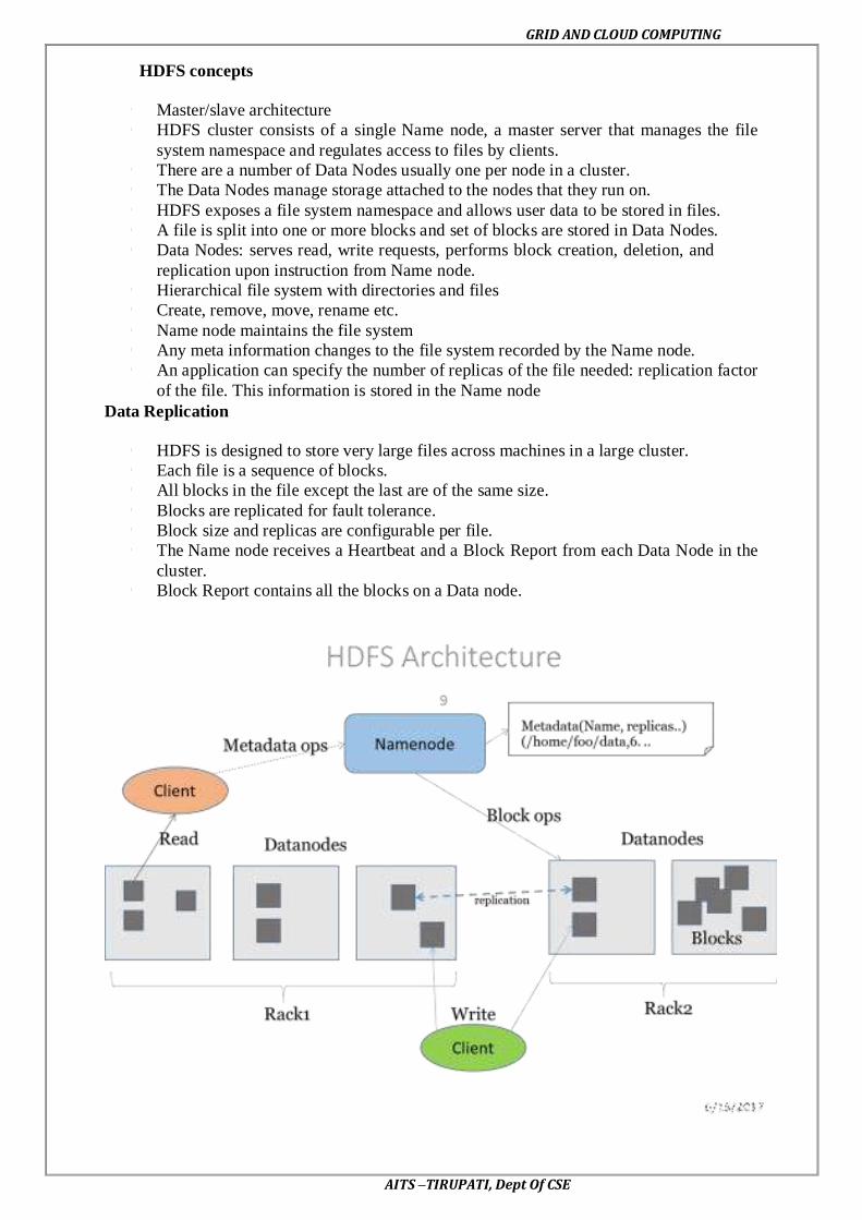
GRID AND CLOUD COMPUTING
AITS –TIRUPATI, Dept Of CSE
HDFS concepts
Master/slave architecture
HDFS cluster consists of a single Name node, a master server that manages the file
system namespace and regulates access to files by clients.
There are a number of Data Nodes usually one per node in a cluster.
The Data Nodes manage storage attached to the nodes that they run on.
HDFS exposes a file system namespace and allows user data to be stored in files.
A file is split into one or more blocks and set of blocks are stored in Data Nodes.
Data Nodes: serves read, write requests, performs block creation, deletion, and
replication upon instruction from Name node.
Hierarchical file system with directories and files
Create, remove, move, rename etc.
Name node maintains the file system
Any meta information changes to the file system recorded by the Name node.
An application can specify the number of replicas of the file needed: replication factor
of the file. This information is stored in the Name node
Data Replication
HDFS is designed to store very large files across machines in a large cluster.
Each file is a sequence of blocks.
All blocks in the file except the last are of the same size.
Blocks are replicated for fault tolerance.
Block size and replicas are configurable per file.
The Name node receives a Heartbeat and a Block Report from each Data Node in the
cluster.
Block Report contains all the blocks on a Data node.

GRID AND CLOUD COMPUTING
AITS –TIRUPATI, Dept Of CSE
Command line interface in HDFS
There are many other interfaces to HDFS, but the command line is one of the
simplest, and to many developers the most familiar. We are going to run HDFS on one
machine, so first follow the instructions for setting up Hadoop in pseudo-distributed mode
.Later you’ll see how to run on a cluster of machines to give us scalability and fault tolerance.
There are two properties that we set in the pseudo-distributed configuration that
deserve further explanation. The first is fs.default.name, set to hdfs://localhost/, which is used
to set a default file system for Hadoop. File systems are specified by a URI, and here we have
used a hdfs URI to configure Hadoop to use HDFS by default. The HDFS daemons will use
this property to determine the host and port for the HDFS name node. We’ll be running it on
local host, on the default HDFS port, 8020. And HDFS clients will use this property to work
out where the name node is running so they can connect to it.
We set the second property, dfs.replication, to one so that HDFS doesn’t replicate file
system blocks by the usual default of three. When running with a single data node, HDFS
can’t replicate blocks to three data nodes, so it would perpetually warn about blocks being
under-replicated. This setting solves that problem.
The HDFS can be manipulated through a Java API or through a command line
interface. ll commands for manipulating HDFS through Hadoop's command line interface
begin with "hadoop", a space, and "fs". This is the file system shell. This is followed by the
command name as an argument to "hadoop fs". These commands start with a dash. For
example, the "ls" command for listing a directory is a common UNIX command and is
preceded with a dash. As on UNIX systems, ls can take a path as an argument.
In this example, the path is the current directory, represented by a single dot. Let's
begin looking at these HDFS commands by starting up Hadoop. We'll run the start.sh script
to bring up each of the Hadoop nodes: first the Name Node, the Secondary Name Node, a
Data Node, the Job Tracker, and a Task Tracker. Now we'll run the -ls command to give us
the current directory.
As we saw for the "ls" command, the file system shell commands can take paths as
arguments. These paths can be expressed in the form of uniform resource identifiers or URIs.
The URI format consists of a scheme, an authority, and path. There are multiple schemes
support. The local file system has a scheme of "file". HDFS has a scheme called "hdfs".
For example, let us say you wish to copy a file called "myfile.txt" from your local file
system to an HDFS file system on the loca host. You can do this by issuing the command
shown. The copy From Local command takes a URI for the source and a URI for the
destination. The scheme and the authority do not always need to be specified. Instead you
may rely on their default values. These defaults can be overridden by specifying them in a
file named core-site.xml in the conf directory of your Hadoop installation.
Now let's examine the cop From Local command. We will copy a file named
myfile.txt to the HDFS. Now we can just examine the HDFS with the -ls command and see
that our file has been copied. And there it is. HDFS supports many POSIX-like commands.
HDFS is not a fully POSIX compliant file system, but it supports many of the commands.
The HDFS commands are mostly easily-recognized UNIX commands like cat and chmod.
There are also a few commands that are specific to HDFS such as copy From Local.
Copy from Local and put are two HDFS-specific commands that do the same thing - copy
files from the local file system to a location on another file system. Their opposite is the
copy To Local command which can also be referred to as get. This command copies files out
of the file system you specify and into the local file system. Get merge is an enhanced form
of get that can merge the files from multiple locations into a single local file.

GRID AND CLOUD COMPUTING
AITS –TIRUPATI, Dept Of CSE
Now let's try out the get merge command. First we will copy the myfile.txt into a
second copy on the HDFS called myfile2.txt. Then we will use the get merge command to
combine the two and write them as one file in the local file system called myfiles.txt. Now if
we cat out the value, we see the text twice. setrep lets you override the default level of
replication to a level you specify. You can do this for one file or, with the -R option, to an
entire tree. This command returns immediately after requesting the new replication level. If
you want the command to block until the job is done, pass the -w option.
Dataflow of file read and write in HDFS
Dataflow of file read in HDFS
To get an idea of how data flows between the client interacting with HDFS, the name
node and the data node, consider the below diagram, which shows the main sequence of
events when reading a file.
The client opens the file it wishes to read by calling open() on the File System object,
which for HDFS is an instance of Distributed File System (step 1). Distributed File System
calls the name node, using RPC, to determine the locations of the blocks for the first few
blocks in the file (step 2). For each block, the name node returns the addresses of the data
nodes that have a copy of that block. Furthermore, the data nodes are sorted according to their
proximity to the client. If the client is itself a data node (in the case of a Map Reduce task, for
instance), then it will read from the local data node.
The Distributed File System returns a FS Data Input Stream to the client for it to read
data from. FS Data Input Stream in turn wraps a DFS Input Stream, which manages the data
node and name node I/O. The client then calls read() on the stream (step 3). DFS Input
Stream, which has stored the data node addresses for the first few blocks in the file, then
connects to the first (closest) data node for the first block in the file. Data is streamed from
the data node back to the client, which calls read() repeatedly on the stream (step 4). When
the end of the block is reached, DFS Input Stream will close the connection to the data node,
then find the best data node for the next block (step 5). This happens transparently to the
client, which from its point of view is just reading a continuous stream. Blocks are read in
order with the DFS Input Stream opening new connections to data nodes as the client reads
through the stream. It will also call the name node to retrieve the data node locations for the
next batch of blocks as needed. When the client has finished reading, it calls close() on the FS
Data Input Stream (step 6).

GRID AND CLOUD COMPUTING
AITS –TIRUPATI, Dept Of CSE
One important aspect of this design is that the client contacts data nodes directly to
retrieve data, and is guided by the name node to the best data node for each block. This
design allows HDFS to scale to large number of concurrent clients, since the data traffic is
spread across all the data nodes in the cluster. The name node meanwhile merely has to
service block location requests (which it stores in memory, making them very efficient), and
does not, for example, serve data, which would quickly become a bottleneck as the number of
clients grew.
Dataflow of file write in HDFS
The case we’re going to consider is the case of creating a new file, writing data to it,
then closing the file.
The client creates the file by calling create() on Distributed File System (step 1).
Distributed File System makes an RPC call to the name node to create a new file in the file
system’s namespace, with no blocks associated with it (step 2). The name node performs
various checks to make sure the file doesn’t already exist, and that the client has the right
permissions to create the file. If these checks pass, the name node makes a record of the new
file; otherwise, file creation fails and the client is thrown an IO Exception. The Distributed
File System returns a FS Data Output Stream for the client to start writing data to. Just as in
the read case, FS Data Output Stream wraps a DFS Output Stream, which handles
communication with the data nodes and name node.
As the client writes data (step 3), DFS Output Stream splits it into packets, which it
writes to an internal queue, called the data queue. The data queue is consumed by the Data
Streamer, whose responsibility it is to ask the name node to allocate new blocks by picking a
list of suitable data nodes to store the replicas. The list of data nodes forms a pipeline—we’ll
assume the replication level is 3, so there are three nodes in the pipeline. The Data Streamer
streams the packets to the first data node in the pipeline, which stores the packet and forwards
it to the second data node in the pipeline. Similarly, the second data node stores the packet
and forwards it to the third (and last) data node in the pipeline (step 4). DFS Output Stream
also maintains an internal queue of packets that are waiting to be acknowledged by data
nodes, called the ack queue. A packet is removed from the ack queue only when it has been
acknowledged by all the data nodes in the pipeline (step 5).

GRID AND CLOUD COMPUTING
AITS –TIRUPATI, Dept Of CSE
If a data node fails while data is being written to it, then the following actions are
taken, which are transparent to the client writing the data. First the pipeline is closed, and any
packets in the ack queue are added to the front of the data queue so that data nodes that are
downstream from the failed node will not miss any packets. The current block on the good
data nodes is given a new identity, which is communicated to the name node, so that the
partial block on the failed data node will be deleted if the failed data node recovers later on.
The failed data node is removed from the pipeline and the remainder of the block’s data is
written to the two good data nodes in the pipeline. The name node notices that the block is
under-replicated, and it arranges for a further replica to be created on another node.
Subsequent blocks are then treated as normal.
When the client has finished writing data it calls close() on the stream (step 6). This
action flushes all the remaining packets to the data node pipeline and waits for
acknowledgments before contacting the name node to signal that the file is complete (step7).
The name node already knows which blocks the file is made up of (via Data Streamer asking
for block allocations), so it only has to wait for blocks to be minimally replicated before
returning successfully.
Reading Data from a Hadoop URL and Deleting Data
The Hadoop’s File System class: the API for interacting with one of Hadoop’s file
systems. While we focus mainly on the HDFS implementation, Distributed File System, in
general you should strive to write your code against the File System abstract class, to retain
portability across file systems. This is very useful when testing your program.
One of the simplest ways to read a file from a Hadoop file system is by using a
java.net.URL object to open a stream to read the data from. The general idiom is:
try {
in = new URL("hdfs://host/path").openStream();
// process in
} finally {
IOUtils.closeStream(in);
}
There’s a little bit more work required to make Java recognize Hadoop’shdfs URL
scheme. This is achieved by calling the set URL Stream Handler Factory method on URL
with an instance of Fs Url Stream Handler Factory. This method can only be called once per
JVM, so it is typically executed in a static block. This limitation means that if some other part
of your program perhaps a third-party component outside your control sets RL Stream
Handler Factory, you won’t be able to use this approach for reading data from Hadoop. The
next section discusses an alternative. A program for displaying files from Hadoop file
systems on standard output, like the Unix cat command.
We make use of the handy IOUtils class that comes with Hadoop for closing the
stream in the finally clause, and also for copying bytes between the input stream and the
output stream (System.out in this case). The last two arguments to the copyBytes method are
the buffer size used for copying, and whether to close the streams when the copy is complete.
We close the input stream ourselves, and System.out doesn’t need to be closed.

GRID AND CLOUD COMPUTING
AITS –TIRUPATI, Dept Of CSE
Deleting Data
Use the delete() method on File System to permanently remove files or directories:
public Boolean delete(Path f, boolean recursive) throws IOException. If f is a file or an
empty directory, then the value of recursive is ignored. A nonempty directory is only deleted,
along with its contents, if recursive is true (otherwise an IOException is thrown).
File pattern in HDFS
It is a common requirement to process sets of files in a single operation. For example,
a Map Reduce job for log processing might analyze a month worth of files, contained in a
number of directories. Rather than having to enumerate each file and directory to specify the
input, it is convenient to use wildcard characters to match multiple files with a single
expression, an operation that is known as globing. Hadoop provides two File System methods
for processing globs:
publicFileStatus[] globStatus(Path pathPattern) throws IOException
publicFileStatus[] globStatus(Path pathPattern, PathFilter filter) throws IOException
The globStatus() methods returns an array of FileStatus objects whose paths match the
supplied pattern, sorted by path. An optional PathFilter can be specified to restrict the
matches further.
Hadoop supports the same set of glob characters as Unixbash.
Imagine that logfiles are stored in a directory structure organized hierarchically by
date. So, for example, logfiles for the last day of 2007 would go in a directory named
/2007/12/31. Suppose that the full file listing is:
/2007/12/30
/2007/12/31
/2008/01/01
/2008/01/02

GRID AND CLOUD COMPUTING
AITS –TIRUPATI, Dept Of CSE
UNIT-V
SECURITY
Trust models for Grid security environment
Many potential security issues may occur in a grid environment includes network
sniffers, out-of-control access, faulty operation, malicious operation, integration of local
security mechanisms, delegation, dynamic resources and services, attack provenance, and so
on. Computational grids are motivated by the desire to share processing resources among
many organizations to solve large-scale problems. Indeed, grid sites may exhibit
unacceptable security conditions and system vulnerabilities.
User job demands the resource site to provide security assurance by issuing a security
demand (SD),trust index (TI). These two parameters must satisfy a security assurance
condition: TI ≥ SD during the job mapping process. These attributes and their values are
dynamically changing and depend heavily on the trust model, security policy, accumulated
reputation, self-defense capability, attack history, and site vulnerability.
Three challenges are outlined below to establish the trust among grid sites.
1. Integration with existing systems and technologies. The resources sites in a grid are
usually heterogeneous and autonomous.
2. Interoperability with different “hosting environments. “Services are often invoked
across multiple domains, and need to be able to interact with one another.
Resource sharing among entities is one of the major goals of grid computing. A trust
relationship must be established before the entities in the grid interoperate with one another.
The grid aims to construct a large-scale network computing system by integrating distributed,
heterogeneous, and autonomous resources.
The security challenges faced by the grid are much greater than other computing
systems. Before any effective sharing and cooperation occurs, a trust relationship has to be
established among participants.

GRID AND CLOUD COMPUTING
AITS –TIRUPATI, Dept Of CSE
Generalized Trust Model
Figure shows a general trust model.
At the bottom, we identify three major factors which influence the trustworthiness of
a resource site. An inference module is required to aggregate these factors. Followings are
some existing inference or aggregation methods.
1. Defense capability is decided by the firewall, intrusion detection system (IDS), intrusion
response capability, and anti-virus capacity of the individual resource site.
2. Direct reputation is decided based on the job success rate, site utilization, job turnaround
time, and job slowdown ratio measured.
3. Recommended trust is also known as secondary trust and is obtained indirectly over the
grid network
Reputation-Based Trust Model
In a reputation-based model, jobs are sent to a resource site only when the site is
trustworthy to meet users’ demands. The site trustworthiness is usually calculated from the
following information:
1. Defense capability 2. Direct reputation, and
3. Recommendation trust.
The defense capability refers to the site’s ability to protect itself from danger. It is
assessed according to such factors as intrusion detection, firewall, response capabilities, anti-
virus capacity, and so on.
Direct reputation is based on experiences of prior jobs previously submitted to the
site. The reputation is measured by many factors such as prior job execution success rate,
cumulative site utilization, job turnaround time, jobs lowdown ratio, and so on. A positive
experience associated with a site will improve its reputation. On the contrary, a negative
experience with a site will decrease its reputation.

GRID AND CLOUD COMPUTING
AITS –TIRUPATI, Dept Of CSE
A Fuzzy-Trust Model
In this model, the job security demand (SD) is supplied by the user programs. The
trust index (TI) of a resource site is aggregated through the fuzzy-logic inference process over
all related parameters.
The TI is normalized as a single real number with 0 representing the condition with
the highest risk at a site and 1 representing the condition which is totally risk-free or fully
trusted.
The fuzzy inference is accomplished through four steps: fuzzification, inference, aggregation,
and defuzzification. The second salient feature of the trust model is that if a site’s trust index
cannot match the job security demand (i.e., SD > TI), the trust model could deduce detailed
security features to guide the site security upgrade as a result of tuning the fuzzy system.
Authentication and Authorization Methods
The major authentication methods in the grid include
Passwords, PKI, and Kerberos.
The password is the simplest method to identify users, but the most vulnerable one to use.
The PKI is the most popular method supported by GSI. To implement PKI, we use a
trusted third party, called the certificate authority (CA). Each user applies a unique
pair of public and private keys. The public keys are issued by the CA by issuing a
certificate, after recognizing a legitimate user. The private key is exclusive for each
user to use, and is unknown to any other users.
A digital certificate in IEEE X.509 format consists of the username, user public key, CA name, and a secrete signature of the user. The following example illustrates the
use of a PKI service in a grid environment.
Authorization for Access Control
The authorization is a process to exercise access control of shared resources.
Decisions can be made either at the access point of service or at a centralized place.
Typically, there source is a host that provides processors and storage for services deployed on
it. Based on a set predefined policies or rules, the resource may enforce access for local
services.
The central authority is a special entity which is capable of issuing and revoking
polices of access rights granted to remote accesses. The authority can be classified into three
categories:
attribute authorities,
policy authorities, and
Density authorities.
Attribute authorities issue attribute assertions; policy authorities issue authorization
policies; identity authorities issue certificates. The authorization server makes the final
authorization decision.

GRID AND CLOUD COMPUTING
AITS –TIRUPATI, Dept Of CSE
Three Authorization Models
The subject is the user and the resource refers to the machine side. The subject-push
model is shown at the top diagram.
The user conducts handshake with the authority first and then with the resource site in a
sequence. The resource-pulling model puts the resource in the middle.
The user checks there source first.
Then the resource contacts its authority to verify the request, and the authority authorizes at
step the resource accepts or rejects the request from the subject at step 4.
The authorization agent model puts the authority in the middle. The subject check with the
authority at step 1 and the authority makes decisions on the access of the requested resources.
The authorization process is complete at steps 3 and 4 in the reverse direction.
Grid Security Infrastructure (GSI)
The grid requires a security infrastructure with the following properties:
Easy to use;
Conforms to the VO’s security needs while working well with site policies of each resource
provider site;
Provides appropriate authentication and encryption of all interactions.
The GSI is an important step toward satisfying these requirements. As a well-known security
solution in the grid environment,
GSI is a portion of the Globus Toolkit and provides fundamental security services
needed to support grids, including supporting for
message protection
authentication and
delegation,
Authorization.
GSI enables secure authentication and communication over an open network, and
permits mutual authentication across and among distributed sites with single sign-on
capability. No centrally managed security system is required, and the grid maintains the
integrity of its members’ local policies. GSI supports both message-level security, which
supports the WS-Security standard and the WS-Secure Conversation specification to provide
message protection for SOAP messages, and transport-level security, which means
authentication via TLS with support for X.509 proxy certificates.

GRID AND CLOUD COMPUTING
AITS –TIRUPATI, Dept Of CSE
GSI Functional Layers
GT4 provides distinct WS and pre-WS authentication and authorization capabilities.
Both build on the same base, namely the
X.509 standard
Entity certificates
Proxy certificates
Which are used to identify persistent entities such as users and servers and to support the
temporary delegation of privileges to other entities, respectively.
Message protection
TLS (transport-level security) or WS-Security and WS-Secure Conversation (message
level)are used as mechanisms in combination with SOAP. X.509
Authentication
End Entity Certificates or Username and Password are used as authentication credentials.
Delegation
X.509 Proxy Certificates and WS-Trust are used for delegation.
Authorization
ACL, an ACL defined by a service, a custom authorization handler, and access to an
authorization service via the SAML protocol.
The remainder of this section reviews both the GT implementations of each of these functions
and the standards that are used in these implementations. The web services portions of GT4
use SOAP as their message protocol for communication. Message protection can be provided
either by transport-level security, which transports SOAP messages over TLS, or by message-
level security, which is signing and/or encrypting portions of the SOAP message using the
WS-Security standard. Here we describe these two methods.
Transport-Level Security
Transport-level security entails SOAP messages conveyed over a network connection
protected by TLS. TLS provides for both integrity protection and privacy (via encryption).
Transport-level security is normally used in conjunction with X.509 credentials for
authentication.

GRID AND CLOUD COMPUTING
AITS –TIRUPATI, Dept Of CSE
Message-Level Security
GSI also provides message-level security for message protection for SOAP messages
by implementing the WS-Security standard and the WS-Secure Conversation specification.
The WS-Security standard from OASIS defines a framework for applying security to
individual SOAP messages;
WS-Secure Conversation is a proposed standard from IBM and Microsoft that allows for an
initial exchange of messages to establish a security context which can then be used to protect
subsequent messages in a manner that requires less computational overhead.
GSI, as described further in the subsequent section on authentication, allows for both
X.509public key credentials and the combination of username and password for
authentication;
GSI allows three additional protection mechanisms.
The first is integrity protection, by which a receiver can verify that messages were not
altered in transit from the sender.
The second is encryption, by which messages can be protected to provide
confidentiality.
The third is replay prevention, by which a receiver can verify that it has not received
the same message previously.
These protections are provided between WS-Security and WS-Secure Conversation. The
former applies the keys associated with the sender and receiver’sX.509 credentials. The
X.509 credentials are used to establish a session key that is used to provide the message
protection.
Authentication and Delegation
GSI has traditionally supported authentication and delegation through the use of
X.509certificates and public keys. As a new feature in GT4, GSI also supports authentication
through plain usernames and passwords as a deployment option.
As a central concept in GSI authentication, a certificate includes four primary pieces of
information:
(1) A subject name, which identifies the person or object that the certificate represents;
(2) The public key belonging to the subject;
(3) The identity of a CA that has signed the certificate to certify that the public key and the
identity both belong to the subject; and
(4) The digital signature of the named CA. X.509 provides each entity with a unique
identifier (i.e., a distinguished name) and a method to assert that identifier to another party
through the use of an asymmetric key pair bound to the identifier by the certificate.
Trust Delegation
To reduce or even avoid the number of times the user must enter his passphrase when
several grids are used or have agents (local or remote) requesting services on behalf of a user,
GSI provides a delegation capability and a delegation service that provides an interface to
allow clients to delegate (and renew) X.509 proxy certificates to a service. The interface to
this service is based on the WS-Trust specification. A proxy consists of a new certificate and
a private key. The key pair that is used for the proxy, that is, the public key embedded in the
certificate and the private key, may either be regenerated for each proxy or be obtained by
other means. The new certificate contains the owner’s identity, modified slightly to indicate
that it is a proxy. The new certificate is signed by the owner, rather than a CA.
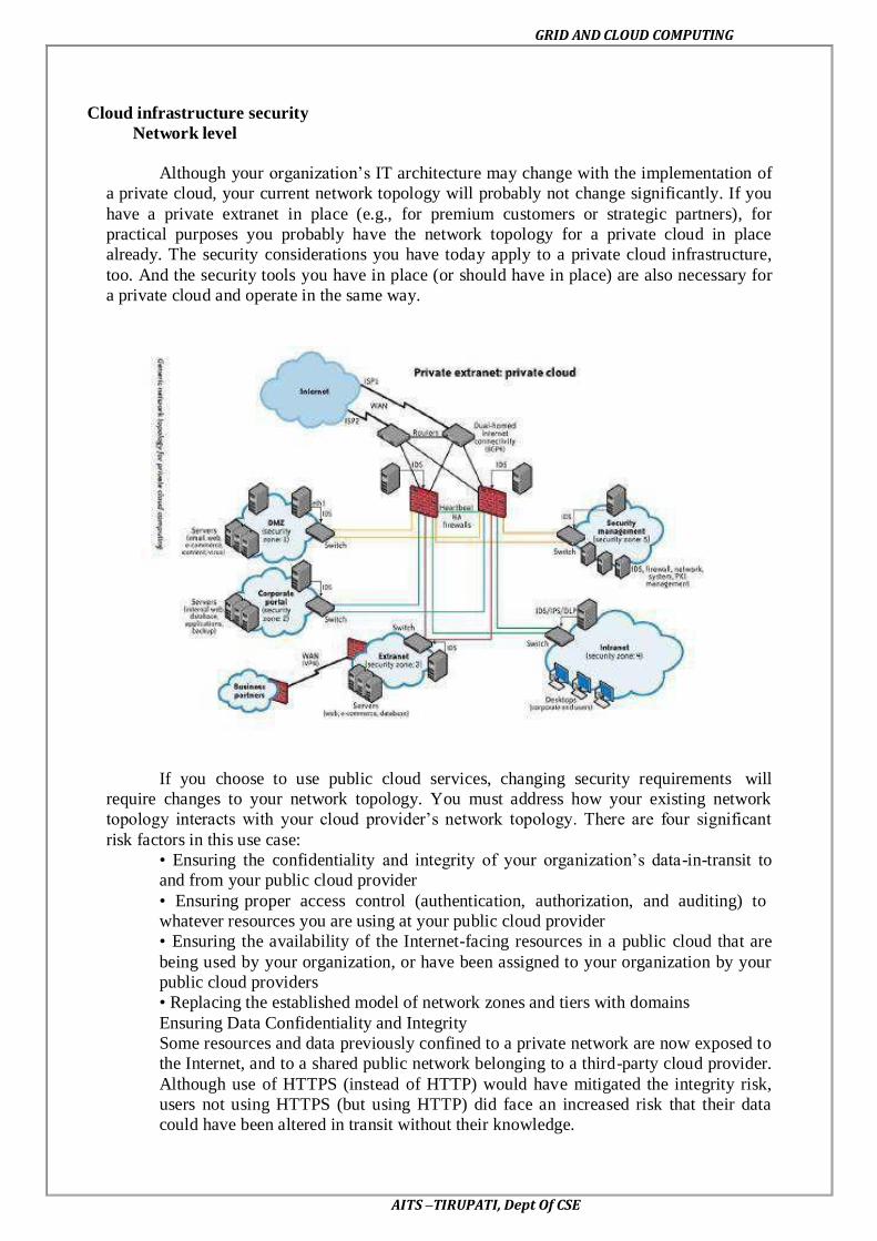
GRID AND CLOUD COMPUTING
AITS –TIRUPATI, Dept Of CSE
Cloud infrastructure security
Network level
Although your organization’s IT architecture may change with the implementation of
a private cloud, your current network topology will probably not change significantly. If you
have a private extranet in place (e.g., for premium customers or strategic partners), for
practical purposes you probably have the network topology for a private cloud in place
already. The security considerations you have today apply to a private cloud infrastructure,
too. And the security tools you have in place (or should have in place) are also necessary for
a private cloud and operate in the same way.
If you choose to use public cloud services, changing security requirements will
require changes to your network topology. You must address how your existing network
topology interacts with your cloud provider’s network topology. There are four significant
risk factors in this use case:
• Ensuring the confidentiality and integrity of your organization’s data-in-transit to
and from your public cloud provider
• Ensuring proper access control (authentication, authorization, and auditing) to
whatever resources you are using at your public cloud provider
• Ensuring the availability of the Internet-facing resources in a public cloud that are
being used by your organization, or have been assigned to your organization by your
public cloud providers
• Replacing the established model of network zones and tiers with domains
Ensuring Data Confidentiality and Integrity
Some resources and data previously confined to a private network are now exposed to
the Internet, and to a shared public network belonging to a third-party cloud provider.
Although use of HTTPS (instead of HTTP) would have mitigated the integrity risk,
users not using HTTPS (but using HTTP) did face an increased risk that their data
could have been altered in transit without their knowledge.

GRID AND CLOUD COMPUTING
AITS –TIRUPATI, Dept Of CSE
Ensuring Proper Access Control
Since some subset of these resources (or maybe even all of them) is now exposed to
the Internet, an organization using a public cloud faces a significant increase in risk to its
data. The ability to audit the operations of your cloud provider’s network (let alone to
conduct any real time monitoring, such as on your own network), even after the fact, is
probably non-existent. You will have decreased access to relevant network-level logs and
data, and a limited ability to thoroughly conduct investigations and gather forensic data.
However, the issue of ―non-aged‖ IP addresses and unauthorized network access to
resources does not apply only to routable IP addresses (i.e., resources intended to be
reachable directly from the Internet). The issue also applies to cloud providers’ internal
networks for customer use and the assignment of non-routable IP addresses.
Host Level
Ensuring the Availability of Internet-Facing Resources
There are deliberate attacks as well. Although prefix hijacking due to deliberate
attacks is far less common than misconfigurations, it still occurs and can block access to data.
According to the same study presented to NANOG, attacks occur fewer than 100 times per
month. Although prefix hijackings are not new, that attack figure will certainly rise, and
probably significantly, along with a rise in cloud computing.
DNS attacks are another example of problems associated with this third risk factor. In
fact, there are several forms of DNS attacks to worry about with regard to cloud computing.
Although DNS attacks are not new and are not directly related to the use of cloud computing,
the issue with DNS and cloud computing is an increase in an organization’s risk at the
network level because of increased external DNS querying.
Cloud infrastructure security at application level
We will limit our discussion to web application security: web applications in the
cloud accessed by users with standard Internet browsers, such as Firefox, Internet Explorer,
or Safari, from any computer connected to the Internet.
Application-Level Security Threats
The existing threats exploit well-known application vulnerabilities including cross-
site scripting (XSS), SQL injection, malicious file execution, and other vulnerabilities
resulting from programming errors and design flaws. Armed with knowledge and tools,
hackers are constantly scanning web applications (accessible from the Internet) for
application vulnerabilities.
It has been a common practice to use a combination of perimeter security controls and
network- and host-based access controls to protect web applications deployed in a tightly
controlled environment, including corporate intranets and private clouds, from external
hackers.
Web applications built and deployed in a public cloud platform will be subjected to a
high threat level, attacked, and potentially exploited by hackers to support fraudulent and
illegal activities. In that threat model, web applications deployed in a public cloud (the SPI
model) must be designed for an Internet threat model, and security must be embedded into
the Software Development Life Cycle (SDLC).

GRID AND CLOUD COMPUTING
AITS –TIRUPATI, Dept Of CSE
DoS and EDoS
Additionally, you should be cognizant of application-level DoS and EDDoS attacks
that can potentially disrupt cloud services for an extended time. These attacks typically
originate from compromised computer systems attached to the Internet.
Application-level DoS attacks could manifest themselves as high-volume web page
reloads, XML* web services requests (over HTTP or HTTPS), or protocol-specific requests
supported by a cloud service. Since these malicious requests blend with the legitimate traffic,
it is extremely difficult to selectively filter the malicious traffic without impacting the service
as a whole
DoS attacks on pay-as-you-go cloud applications will result in a dramatic increase in
your cloud utility bill: you’ll see increased use of network bandwidth, CPU, and storage
consumption. This type of attack is also being characterized as economic denial of
sustainability (EDoS)
Aspects of Data Security
End User Security
A customer of a cloud service, are responsible for end user security tasks—security
procedures to protect your Internet-connected PC—and for practicing ―safe surfing.‖
Protection measures include use of security software, such as anti-malware, antivirus,
personal firewalls, security patches, and IPS-type software on your Internet-connected
computer.
The new mantra of ―the browser is your operating system‖ appropriately conveys the
message that browsers have become the ubiquitous ―operating systems‖ for consuming
cloud services. All Internet browsers routinely suffer from software vulnerabilities that make
them vulnerable to end user security attacks. Hence, our recommendation is that cloud
customers take appropriate steps to protect browsers from attacks. To achieve end-to-end
security in a cloud, it is essential for customers to maintain good browser hygiene. The means
keeping the browser (e.g., Internet Explorer, Firefox, Safari) patched and updated to mitigate
threats related to browser vulnerabilities.
Currently, although browser security add-ons are not commercially available, users
are encouraged to frequently check their browser vendor’s website for security updates, use
the auto-update feature, and install patches on a timely basis to maintain end user security.

GRID AND CLOUD COMPUTING
AITS –TIRUPATI, Dept Of CSE
SaaS Application Security
The SaaS model dictates that the provider manages the entire suite of applications
delivered to users. Therefore, SaaS providers are largely responsible for securing the
applications and components they offer to customers. Customers are usually responsible for
operational security functions, including user and access management as supported by the
provider.
Extra attention needs to be paid to the authentication and access control features
offered by SaaS CSPs. Usually that is the only security control available to manage risk to
information. Most services, including those from Salesforce.com and Google, offer a web-
based administration user interface tool to manage authentication and access control of the
application.
Cloud customers should try to understand cloud-specific access control
mechanisms— including support for strong authentication and privilege management based
on user roles and functions—and take the steps necessary to protect information hosted in the
cloud. Additional controls should be implemented to manage privileged access to the SaaS
administration tool, and enforce segregation of duties to protect the application from insider
threats. In line with security standard practices, customers should implement a strong
password policy—one that forces users to choose strong passwords when authenticating to an
application.
PaaS Application Security
PaaS vendors broadly fall into the following two major categories:
• Software vendors (e.g., Bungee, Etelos, GigaSpaces, Eucalyptus)
• CSPs (e.g., Google App Engine, Salesforce.com’s Force.com, Microsoft Azure,
Intuit Quick Base)
A PaaS cloud (public or private) offers an integrated environment to design, develop,
test, deploy, and support custom applications developed in the language the platform
supports.
PaaS application security encompasses two software layers:
• Security of the PaaS platform itself (i.e., runtime engine)
• Security of customer applications deployed on a PaaS platform
PaaS CSPs (e.g., Google, Microsoft, and Force.com) are responsible for securing the
platform software stack that includes the runtime engine that runs the customer applications.
Since PaaS applications may use third-party applications, components, or web services, the
third-party application provider may be responsible for securing their services. Hence,
customers should understand the dependency of their application on all services and assess
risks pertaining to third-party service providers.
IaaS Application Security
IaaS cloud providers (e.g., Amazon EC2, GoGrid, and Joyent) treat the applications
on customer virtual instances as a black box, and therefore are completely agnostic to the
operations and management of the customer’s applications.
The entire stack—customer applications, runtime application platform (Java, .NET,
PHP, Ruby on Rails, etc.), and so on— runs on the customer’s virtual servers and is deployed
and managed by customers. To that end, customers have full responsibility for securing their
applications deployed in the IaaS cloud.

GRID AND CLOUD COMPUTING
AITS –TIRUPATI, Dept Of CSE
Web applications deployed in a public cloud must be designed for an Internet threat
model, embedded with standard security countermeasures against common web
vulnerabilities. In adherence with common security development practices, they should also
be periodically tested for vulnerabilities, and most importantly, security should be embedded
into the SDLC. Customers are solely responsible for keeping their applications and runtime
platform patched to protect the system from malware and hackers scanning for vulnerabilities
to gain unauthorized access to their data in the cloud. It is highly recommended that you
design and implement applications with a ”least-privileged” runtime model.
Developers writing applications for IaaS clouds must implement their own features to
handle authentication and authorization. In line with enterprise identity management
practices, cloud applications should be designed to leverage delegated authentication service
features supported by an enterprise Identity Provider (e.g., OpenSSO, Oracle IAM, IBM, CA)
or third-party identity service provider (e.g., Ping Identity, Simplified, TriCipher). Any
custom implementations of Authentication, Authorization, and Accounting (AAA) features
can become a weak link if they are not properly implemented, and you should avoid them
when possible.
Provider data and its security:
Customers should also be concerned about what data the provider collects and how
the CSP protects that data. Additionally, your provider collects and must protect a huge
amount of security-related data.
Storage
For data stored in the cloud (i.e., storage-as-a-service), we are referring to IaaS and
not data associated with an application running in the cloud on PaaS or SaaS. The same three
information security concerns are associated with this data stored in the cloud (e.g.,
Amazon’s S3) as with data stored elsewhere: confidentiality, integrity, and availability.
Confidentiality
When it comes to the confidentiality of data stored in a public cloud, you have two
potential concerns. First, what access control exists to protect the data? Access control
consists of both authentication and authorization.
CSPs generally use weak authentication mechanisms (e.g., username + password),
and the authorization (―access‖) controls available to users tend to be quite coarse and not
very granular. For large organizations, this coarse authorization presents significant security
concerns unto itself. Often, the only authorization levels cloud vendors provide are
administrator authorization (i.e., the owner of the account itself) and user authorization (i.e.,
all other authorized users)—with no levels in between (e.g., business unit administrators, who
are authorized to approve access for their own business unit personnel).
If a CSP does encrypt a customer’s data, the next consideration concerns what
encryption algorithm it uses. Not all encryption algorithms are created equal.
Cryptographically, many algorithms provide insufficient security. Only algorithms that have
been publicly vetted by a formal standards body (e.g., NIST) or at least informally by the
cryptographic community should be used. Any algorithm that is proprietary should absolutely
be avoided.
Symmetric encryption involves the use of a single secret key for both the encryption
and decryption of data. Only symmetric encryption has the speed and computational
efficiency to handle encryption of large volumes of data. It would be highly unusual to use an
asymmetric algorithm for this encryption use case.
Although the example in diagram is related to email, the same concept (i.e., a single
shared, secret key) is used in data storage encryption.

GRID AND CLOUD COMPUTING
AITS –TIRUPATI, Dept Of CSE
Although the example in diagram is related to email, the same concept (i.e., a public
key and a private key) is not used in data storage encryption.
Integrity
Confidentiality does not imply integrity; data can be encrypted for confidentiality
purposes, and yet you might not have a way to verify the integrity of that data. Encryption
alone is sufficient for confidentiality, but integrity also requires the use of message
authentication codes (MACs). The simplest way to use MACs on encrypted data is to use a
block symmetric algorithm (as opposed to a streaming symmetric algorithm) in cipher block
chaining (CBC) mode, and to include a one-way hash function.
Another aspect of data integrity is important, especially with bulk storage using IaaS.
Once a customer has several gigabytes (or more) of its data up in the cloud for storage, how
does the customer check on the integrity of the data stored there? There are IaaS transfer
costs associated with moving data into and back down from the cloud,* as well as network
utilization (bandwidth) considerations for the customer’s own network. What a customer
really wants to do is to validate the integrity of its data while that data remains in the cloud—
without having to download and reload that data.

GRID AND CLOUD COMPUTING
AITS –TIRUPATI, Dept Of CSE
Availability
Assuming that a customer’s data has maintained its confidentiality and integrity, you
must also be concerned about the availability of your data. There are currently three major
threats in this regard—none of which are new to computing, but all of which take on
increased importance in cloud computing because of increased risk.
The first threat to availability is network-based attacks
The second threat to availability is the CSP’s own availability.
Cloud storage customers must be certain to ascertain just what services their provider
is actually offering. Cloud storage does not mean the stored data is actually backed up. Some
cloud storage providers do back up customer data, in addition to providing storage. However,
many cloud storage providers do not back up customer data, or do so only as an additional
service for an additional cost.
All three of these considerations (confidentiality, integrity, and availability) should be
encapsulated in a CSP’s service-level agreement (SLA) to its customers. However, at this
time, CSP SLAs are extremely weak—in fact, for all practical purposes, they are essentially
worthless. Even where a CSP appears to have at least a partially sufficient SLA, how that
SLA actually gets measured is problematic. For all of these reasons, data security
considerations and how data is actually stored in the cloud should merit considerable
attention by customers.
Identity and access management functional architecture:
The basic concepts and definitions of IAM functions for any service:
Authentication
Authentication is the process of verifying the identity of a user or system.
Authentication usually connotes a more robust form of identification. In some use cases, such
as service-to-service interaction, authentication involves verifying the network service
requesting access to information served by another service.
Authorization
Authorization is the process of determining the privileges the user or system is
entitled to once the identity is established. —in other words, authorization is the process of
enforcing policies.
Auditing
In the context of IAM, auditing entails the process of review and examination of
authentication, authorization records, and activities to determine the adequacy of IAM system
controls, to verify compliance with established security policies and procedures (e.g.,
separation of duties), to detect breaches in security services (e.g., privilege escalation), and to
recommend any changes that are indicated for countermeasures.
IAM Architecture
Standard enterprise IAM architecture encompasses several layers of technology,
services, and processes. At the core of the deployment architecture is a directory service
(such as LDAP or Active Directory) that acts as a repository for the identity, credential, and
user attributes of the organization’s user pool. The directory interacts with IAM technology
components such as authentication, user management, provisioning, and federation services
that support the standard IAM practice and processes within the organization. It is not
uncommon for organizations to use several directories that were deployed for environment-
specific reasons (e.g., Windows systems using Active Directory, UNIX systems using LDAP)
or that were integrated into the environment by way of business mergers and acquisitions.

GRID AND CLOUD COMPUTING
AITS –TIRUPATI, Dept Of CSE
The IAM processes to support the business can be broadly categorized as follows:
User management
Activities for the effective governance and management of identity life cycles
Authentication management
Activities for the effective governance and management of the process for
determining that an entity is who or what it claims to be
Authorization management
Activities for the effective governance and management of the process for
determining entitlement rights that decide what resources an entity is permitted to access in
accordance with the organization’s policies.
Access management
Enforcement of policies for access control in response to a request from an entity
(user, services) wanting to access an IT resource within the organization
Data management and provisioning
Propagation of identity and data for authorization to IT resources via automated or
manual processes
Monitoring and auditing
Monitoring, auditing, and reporting compliance by users regarding access to resources
within the organization based on the defined policies.
IAM processes support the following operational activities:
Provisioning
This is the process of on-boarding users to systems and applications. These processes
provide users with necessary access to data and technology resources. The term typically is
used in reference to enterprise-level resource management.
Credential and attribute management
These processes are designed to manage the life cycle of credentials and user
attributes— create, issue, manage, revoke—to minimize the business risk associated with
identity impersonation and inappropriate account use. Credentials are usually bound to an
individual and are verified during the authentication process.
The processes include provisioning of attributes, static (e.g., standard text password)
and dynamic (e.g., one-time password) credentials that comply with a password standard
(e.g., passwords resistant to dictionary attacks), handling password expiration, and encryption
management of credentials during transit and at rest, and access policies of user attributes

GRID AND CLOUD COMPUTING
AITS –TIRUPATI, Dept Of CSE
Entitlement management
Entitlements are also referred to as authorization policies. The processes in this
domain address the provisioning and DE provisioning of privileges needed for the user to
access resources including systems, applications, and databases.
Compliance management
This process implies that access rights and privileges are monitored and tracked to
ensure the security of an enterprise’s resources. The process also helps auditors verify
compliance to various internal access control policies, and standards that include practices
such as segregation of duties, access monitoring, periodic auditing, and reporting.
Identity federation management
Federation is the process of managing the trust relationships established beyond the
internal network boundaries or administrative domain boundaries among distinct
organizations. A federation is an association of organizations that come together to exchange
information about their users and resources to enable collaborations and transactions
Centralization of authentication (authN) and authorization (authZ)
A central authentication and authorization infrastructure alleviates the need for
application developers to build custom authentication and authorization features into their
applications. Furthermore, it promotes a loose coupling architecture where applications
become agnostic to the authentication methods and policies. This approach is also called an
“externalization of authN and authZ” from applications.

GRID AND CLOUD COMPUTING
AITS –TIRUPATI, Dept Of CSE
IAM practices in cloud:
User management functions in the cloud
User management functions in the cloud can be categorized as follows:
1. Cloud identity administration
2. Federation or SSO
3. Authorization management
4. Compliance management
Cloud Identity Administration
Cloud identity administrative functions should focus on life cycle management of user
identities in the cloud—provisioning, DE provisioning, identity federation, SSO, password or
credentials management, profile management, and administrative management. Organizations
that are not capable of supporting federation should explore cloud-based identity
management services.
By federating identities using either an internal Internet-facing IdP or a cloud identity
management service provider, organizations can avoid duplicating identities and attributes
and storing them with the CSP. Given the inconsistent and sparse support for identity
standards among CSPs, customers may have to devise custom methods to address user
management functions in the cloud. Provisioning users when federation is not supported can
be complex and laborious.
Federated Identity (SSO)
Organizations planning to implement identity federation that enables SSO for users
can take one of the following two paths (architectures):
1. Implement an enterprise IdP within an organization perimeter.
2. Integrate with a trusted cloud-based identity management service provider.

GRID AND CLOUD COMPUTING
AITS –TIRUPATI, Dept Of CSE
Enterprise identity provider
In this architecture, cloud services will delegate authentication to an organization’s
IdP. In this delegated authentication architecture, the organization federates identities within
a trusted circle of CSP domains. A circle of trust can be created with all the domains that are
authorized to delegate authentication to the IdP. In this deployment architecture, where the
organization will provide and support an IdP, greater control can be exercised over user
identities, attributes, credentials, and policies for authenticating and authorizing users to a
cloud service.
Identity management-as-a-service
In this architecture, cloud services can delegate authentication to an identity
management-as-a- service (IDaaS) provider. In this model, organizations outsource the
federated identity management technology and user management processes to a third-party
service provider. In essence, this is a SaaS model for identity management, where the SaaS
IdP stores identities in a ―trusted identity store‖ and acts as a proxy for the organization’s
users accessing cloud services.
The identity store in the cloud is kept in sync with the corporate directory through a
provider proprietary scheme (e.g., agents running on the customer’s premises synchronizing a
subset of an organization’s identity store to the identity store in the cloud using SSL VPNs).
Once the IdP is established in the cloud, the organization should work with the CSP to
delegate authentication to the cloud identity service provider. The cloud IdP will authenticate
the cloud users prior to them accessing any cloud services
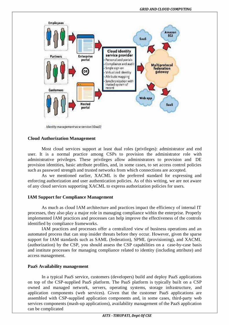
GRID AND CLOUD COMPUTING
AITS –TIRUPATI, Dept Of CSE
Cloud Authorization Management
Most cloud services support at least dual roles (privileges): administrator and end
user. It is a normal practice among CSPs to provision the administrator role with
administrative privileges. These privileges allow administrators to provision and DE
provision identities, basic attribute profiles, and, in some cases, to set access control policies
such as password strength and trusted networks from which connections are accepted.
As we mentioned earlier, XACML is the preferred standard for expressing and
enforcing authorization and user authentication policies. As of this writing, we are not aware
of any cloud services supporting XACML to express authorization policies for users.
IAM Support for Compliance Management
As much as cloud IAM architecture and practices impact the efficiency of internal IT
processes, they also play a major role in managing compliance within the enterprise. Properly
implemented IAM practices and processes can help improve the effectiveness of the controls
identified by compliance frameworks.
IAM practices and processes offer a centralized view of business operations and an
automated process that can stop insider threats before they occur. However, given the sparse
support for IAM standards such as SAML (federation), SPML (provisioning), and XACML
(authorization) by the CSP, you should assess the CSP capabilities on a case-by-case basis
and institute processes for managing compliance related to identity (including attribute) and
access management.
PaaS Availability management
In a typical PaaS service, customers (developers) build and deploy PaaS applications
on top of the CSP-supplied PaaS platform. The PaaS platform is typically built on a CSP
owned and managed network, servers, operating systems, storage infrastructure, and
application components (web services). Given that the customer PaaS applications are
assembled with CSP-supplied application components and, in some cases, third-party web
services components (mash-up applications), availability management of the PaaS application
can be complicated

GRID AND CLOUD COMPUTING
AITS –TIRUPATI, Dept Of CSE
PaaS applications may rely on other third-party web services components that are not
part of the PaaS service offerings; hence, understanding the dependency of your application
on third-party services, including services supplied by the PaaS vendor, is essential. PaaS
providers may also offer a set of web services, including a message queue service, identity
and authentication service, and database service, and your application may depend on the
availability of those service components.
App Engine resource is measured against one of two kinds of quotas: a billable quota
or a fixed quota.
Billable quotas are resource maximums set by you, the application’s administrator, to
prevent the cost of the application from exceeding your budget. Every application gets an
amount of each billable quota for free. You can increase billable quotas for your application
by enabling billing, setting a daily budget, and then allocating the budget to the quotas. You
will be charged only for the resources your app actually uses, and only for the amount of
resources used above the free quota thresholds.
Fixed quotas are resource maximums set by the App Engine to ensure the integrity of the
system. These resources describe the boundaries of the architecture, and all applications are
expected to run within the same limits. They ensure that another app that is consuming too
many resources will not affect the performance of your app.
Customer Responsibility
The PaaS application customer should carefully analyze the dependencies of the
application on the third-party web services (components) and outline a holistic management
strategy to manage and monitor all the dependencies.
PaaS platform service levels
Customers should carefully review the terms and conditions of the CSP’s SLAs and understand the availability constraints.
Third-party web services provider service levels
When your PaaS application depends on a third-party service, it is critical to
understand the SLA of that service.
PaaS Health Monitoring
The following options are available to customers to monitor the health of their
service:
occurred outages
-party-based service monitoring tools that periodically check your
PaaS application, as well as third-party web services that monitor your application
IaaS Availability management
Availability considerations for the IaaS delivery model should include both a
computing and storage (persistent and ephemeral) infrastructure in the cloud. IaaS providers
may also offer other services such as account management, a message queue service, an
identity and authentication service, a database service, a billing service, and monitoring
services.
Managing your IaaS virtual infrastructure in the cloud depends on five factors:
This factor depends on the following:
1. CSP data center architecture, including a geographically diverse and fault-tolerance
architecture.
2. Reliability, diversity, and redundancy of Internet connectivity used by the customer
and the CSP.
3. Reliability and redundancy architecture of the hardware and software components
used for delivering compute and storage services.

GRID AND CLOUD COMPUTING
AITS –TIRUPATI, Dept Of CSE
4. Availability management process and procedures, including business continuity
processes established by the CSP.
Availability of your virtual servers and the attached storage (persistent and
ephemeral) for compute services
Availability of virtual storage that your users and virtual server depend on for
storage service. This includes both synchronous and asynchronous storage
access use cases. Synchronous storage access use cases demand low data
access latency and continuous availability, whereas asynchronous use cases
are more tolerant to latency and availability.
Availability of your network connectivity to the Internet or virtual network
connectivity to IaaS services. In some cases, this can involve virtual private
network (VPN) connectivity between your internal private data center and the
public IaaS cloud
Availability of network services, including a DNS, routing services, and
authentication services required to connect to the IaaS service.
IaaS Health Monitoring
Service health dashboard published by the CSP.
CSP customer mailing list that notifies customers of occurring and recently occurred
outages.
Web console or API that publishes the current health status of your virtual servers and network.
Key Privacy Concerns in the Cloud:
These concerns typically mix security and privacy. Here are some additional
considerations to be aware of:
Access
Data subjects have a right to know what personal information is held and, in some
cases, can make a request to stop processing it. This is especially important with regard to
marketing activities; in some jurisdictions, marketing activities are subject to additional
regulations and are almost always addressed in the end user privacy policy for applicable
organizations. In the cloud, the main concern is the organization’s ability to provide the
individual with access to all personal information, and to comply with stated requests.
Compliance
What are the privacy compliance requirements in the cloud? What are the applicable
laws, regulations, standards, and contractual commitments that govern this information, and
who is responsible for maintaining the compliance? How are existing privacy compliance
requirements impacted by the move to the cloud? Clouds can cross multiple jurisdictions;
Storage
Where is the data in the cloud stored? Was it transferred to another data center in
another country? Is it commingled with information from other organizations that use the
same CSP? Privacy laws in various countries place limitations on the ability of organizations
to transfer some types of personal information to other countries. When the data is stored in
the cloud, such a transfer may occur without the knowledge of the organization, resulting in a
potential violation of the local law.
Retention
How long is personal information (that is transferred to the cloud) retained? Which
retention policy governs the data? Does the organization own the data, or the CSP? Who
enforces the retention policy in the cloud, and how are exceptions to this policy (such as
litigation holds) managed?

GRID AND CLOUD COMPUTING
AITS –TIRUPATI, Dept Of CSE
Destruction
How does the cloud provider destroy PII at the end of the retention period? How do
organizations ensure that their PII is destroyed by the CSP at the right point and is not
available to other cloud users? How do they know that the CSP didn’t retain additional
copies? Cloud storage providers usually replicate the data across multiple systems and sites—
increased availability is one of the benefits they provide. This benefit turns into a challenge
when the organization tries to destroy the data—can you truly destroy information once it is
in the cloud? Did the CSP really destroy the data, or just make it inaccessible to the
organization? Is the CSP keeping the information longer than necessary so that it can mine
the data for its own use?
Audit and monitoring
How can organizations monitor their CSP and provide assurance to relevant
stakeholders that privacy requirements are met when their PII is in the cloud?
Privacy breaches
How do you know that a breach has occurred, how do you ensure that the CSP
notifies you when a breach occurs, and who is responsible for managing the breach
notification process (and costs associated with the process)? If contracts include liability for
breaches resulting from negligence of the CSP, how is the contract enforced and how is it
determined who is at fault?
SaaS Availability Management
SaaS service providers are responsible for business continuity, application, and
infrastructure security management processes. This means the tasks your IT organization
once handled will now be handled by the CSP. Some mature organizations that are aligned
with industry standards, such as ITIL, will be faced with new challenges of governance of
SaaS services as they try to map internal service-level categories to a CSP.
Customer Responsibility
Customers should understand the SLA and communication methods (e.g., email, RSS
feed, website URL with outage information) to stay informed on service outages. When
possible, customers should use automated tools such as Nagios or Siteuptime.com to verify
the availability of the SaaS service. As of this writing, customers of a SaaS service have a
limited number of options to support availability management. Hence, customers should seek
to understand the availability management factors, including the SLA of the service, and
clarify with the CSP any gaps in SLA exclusions and service credits when disruptions occur.
SaaS Health Monitoring
The following options are available to customers to stay informed on the health of
their service:
Service health dashboard published by the CSP. Usually SaaS providers, such as
Salesforce.com, publish the current state of the service, current outages that may impact customers, and upcoming scheduled maintenance services on their website
The Cloud Computing Incidents Database (CCID).
Customer mailing list that notifies customers of occurring and recently occurred
outages.
Internal or third-party-based service monitoring tools that periodically check SaaS
provider health and alert customers when service becomes unavailable
RSS feed hosted at the SaaS service provider.