
Efficient simulation of hybrid systems: A hybrid bond graph approach
Upload
independentCategory
view
0download
0
Eng. & Tech. Journal ,Vol. 27,No.9,2009
*Refrigeration &Air conditioning Department, College of Technical–Baghdad/ Baghdad. **Mechanical Engineering Department, University of Technology/ Baghdad.
1790
Experimental Study on A Hybrid Adsorption Refrigeration System
Abdul Hadi Nema K* & Hassan Jawdat Fadiel** Received on: 7/7/2008 Accepted on: 5/3/2009
Abstract One of the most new methods of solar applications are the adsorption refrigeration methods, which can be powered by solar energy or waste heat. A hybrid adsorption refrigeration unit was designed, built and tested in this work, on January, 2008. A series of test on the solar collector was achieved to simulate the temperature of hot water that used to heat the unit generator of the field unit. Also from the field adsorption unit using an adsorption pair active carbon and methanol, it was found that there is an optimum generator temperature at which the cycle COP reach max. The cycle COP was varied from 0.07 to 0.3. It was found that it can chill one liter of water from an initial temperature of 35°C also a formation of 1cm thick ice around the evaporator was obtained, when the mass of active carbon was 1.25kg and methanol concentration of 0.07 kg(meth.)/kg(A.C.). Keywords: adsorption; hybrid; active carbon; methanol.
متزازية هجينةإ تجميددراسة عملية لمنظومة : الخالصة
التثليج أنتعتبر الطاقة الشمسية مصدر بديل و نظيف للطاقة و الذي حضي باهتمام كبير، و حيث االمتزازي هو واحد من احدث الطرق في استغالل الطاقة الشمسية ، لذا انصبت هذه الدراسة على
.2008تصميم و بناء منظومة تثليج امتزازية ، واختبرت في شهر كانون الثاني اء على الم اء الساخن التي تم الحصول عليها تم اختبار مجمع شمسي لتمثيل حدود درجات الحرارة للم
من خالل المنظومة الحقلية وجد بان هنالك درجة و. الذي يتم إمراره على المولد في المنظومة الحقليةحرارة معينة للمولد و التي يمكن أن تحقق اكبر معامل أداء، أما معامل أداء المنظومة قد تراوح
درجة مؤوية 35ارة ابتدائية تساوي في حين تم تثليج لتر واحد من الماء بدرجة حر0.3 الى 0.07من 1.25عندما كان وزن الكاربون المنشط , سم1 طبقة من الثلج حول المبخر بسمك و يمكن الحصول على . kg(meth.)/kg(A.C.) 0.07 كغم وتركيز الميثانول
1-Introduction The concept of using solar energy for powering a refrigerator appeared forty years ago (Chinnappa [1]) with a prototype using a liquid sorption cycle. Solar-powered refrigeration can also use solid sorption, with either a chemical reaction (Worse-Schmidt et al.[2]), or adsorption. Meunier published a comparison of those three sorption systems for solar cooling (Meunier[3]).
The solid-gas system used in the present study is adsorption. Adsorption refrigeration and heat pump cycles rely on the adsorption of a refrigerant gas into an adsorbent at low pressure and subsequent desorption by heating. The adsorbent acts as a ‘chemical compressor” driven by heat (thermally driven). It consists of a solar collector, a condenser or heat-exchanger and an
PDF created with pdfFactory Pro trial version www.pdffactory.com

Eng. & Tech. Journal ,Vol.27, No.9, 2009 Experimental Study On A Hybrid Adsorption Refrigeration System.
1791
evaporator that is placed in a refrigerator box. The inside of the collector is lined with an adsorption bed packed with adsorbent (activated carbon) absorbed with refrigerant (methanol). The refrigerator box is insulated and filled with water. The adsorbent can adsorb a large amount of refrigerant vapor in ambient temperature and desorb it at a higher temperature (around 100°C). During the daytime, the sunshine irradiates the collector, so the collector is heated up and the refrigerant is desorbed from the adsorbent. The refrigerant vapor condenses and is stored in the evaporator. At night, the collector temperature decreases to the ambient temperature, and the adsorbent adsorbs the refrigerant from the evaporator. The liquid refrigerant in the evaporator vaporizes and adsorbs the heat from the water contained in the trays. Since adsorption is a process of releasing heat (when refrigerant molecule is fixed onto a solid matrix, it looses some energy [4]), the generator must be cooled efficiently at night, to adsorb the vapour methanol that flows from evaporator. The development and first production for Adsorption Chiller was by Nishiyodo Kuchou Manufacturing Company [5]. Since being first produced the Adsorption Chiller had been used and closely evaluated in a wide area of applications in Japan and Europe with sensational response. The Adsorption Chiller contains only water as a refrigerant and a silica gel as an adsorbent. The evaporator section cools the chilled water by the refrigerant (water) being evaporated by adsorption of the silica gel in one of two adsorbent chambers. It can produce chilled water temperatures of less than (3.3°C) with hot water temperatures ranging from (90°C) to as low as(50°C). The hot
water regenerates the silica gel in the second of the two adsorbent chambers. The COP had been improved by 13% with the introduction of high efficiency heat exchangers and become 0.68. A research of R.Z. Wang [6] on adsorption refrigeration in Shanghai Jiao Tong University (SJTU), was started in 1993. Various adsorption refrigeration cycles had been investigated and several prototype adsorption refrigeration systems had been developed and tested. Reasonable experimental results have been obtained. It was found that with a heat source temperature of 100°C , the refrigerator can obtain specific refrigeration power for 5.2 kg-ice/day per kg of activated carbon in one adsorber. The heat pump can reach a specific cooling power for more than 150W/kg -adsorbent with a COP close to 0.5 when used methanol as adsorbate. The adsorption solar ice maker yields 5-7 kg-ice per day per square meter solar collector. The hybrid solar water heater and ice maker is capable of heating 60 kg of water up to about 90°C and meanwhile yields ice making about 5 kg per day with a 2 m2 solar collector. The prototype presented by R. A Wang and R. G. Oliveira [7] were designed to use waste heat or solar energy as the main heat sources. The waste heat could be from diesel engines or from power plants, in combined cooling, heating and power systems (CCHP). The current technology of adsorption solar powered icemakers allows a daily ice production of between 4 and 7 kg per m2 of solar collector with a solar COP between 0.1, and 0.15. The silica gel-water chillers studied can be powered by hot water warmer than 55 °C. The COP is usually around 0.2 to 0.6, and in some commercially produced machines, the COP can be up to 0.7. Sorarat Hongprapas [8]
PDF created with pdfFactory Pro trial version www.pdffactory.com

Eng. & Tech. Journal ,Vol.27, No.9, 2009 Experimental Study On A Hybrid Adsorption Refrigeration System.
1792
presented the results from the experimental part of the research for solid-sorption(adsorption) cooling machine prototype. The feasibility of using coconut-shell-based activated carbon adsorbent together with fluorinated refrigerant (particularly R-22) was explored. A bench-scale prototype was consisting of major components such as two shell-and-tube adsorbers, a condenser, a coil evaporator, two circulating pumps, and an electric heater to represent the thermal energy source. The prototype can achieve cooling effect at cold space temperature of 21°C when the available cooling water temperature was more than 35°C and the heating water temperature was lower than 85°C . The resulting coefficient of performance (COP) was about one order of magnitude less than that of a typical vapor-compression machine at the same condition. The adsorption cooling effect was still possible even with the relatively low hot water temperature under which the conventional absorption machine will not be feasible. In the University of Technology in Iraq one of its students Ammar S.[9] presented a research about solar adsorption icemaker by using plate type adsorber/collector. In which the adsorber was made as a generator and a solar radiation collector at the same time. The shape of it was parallelogram with dimensions (0.46m*0.46m*0.46m). the adsorption working pair was active carbon +methanol. The mass of active carbon was 3kg, and the mass of methanol was 0.936 kg under operating pressure 3.5 kpas (at starting of desorption) and after adsorption process the less(best) temperature of evaporator was -0.5°C (this assures production of ice) and the COP of system was 0.39, these result
were under atmospheric temperature 38°C . 2-System Setup: The field hybrid adsorption refrigerator was built in Technical College- Baghdad on 2007 and tested on 2008. This unit consists of: 2-1Generator (Bed): It is the main part of the field unit, it consists of two identical parts, each one was built from a hemispherical shell of (240.4 mm) diameter and (100 mm) height. The upper end of hemispherical shell contains a valve, while the lower end was closed by brass disk of 1.75mm thick. The brass disk was drilled to have a 22 holes , each hole was in the form of tinny holes with average of 28 holes and each of it in diameter of 1.5 mm (to allow refrigerant to flow through this tinny holes and at the same time to keep the active carbon within the tubes). The brass disk was fixed at the hemispherical shell end by soldering; the soldering surface was cleaned to assure perfect welding, A 22 copper tubes of 22.22 mm diameter and 440 mm long were fixed on the brass disk (on the appointee places fixed on the same disk) by soldering, When the two parts of generator were made, they were combined together by a cylindrical shell to form the generator as shown in Figures 1 and 2. the single part of generator that have hemispheric shell, brass disk and 22 copper tubes are ready to be charged with active carbon. This part was cleaned carefully and then charged with 1.25 kg of active carbon. The free ends of the tubes was punched and soldered. After that a 0.3kg methanol was charged to each part of generator. 2-2 Condenser A finned steel tubes were set in parallel and soldered by headers to form the condenser and inclined by 5°, to
PDF created with pdfFactory Pro trial version www.pdffactory.com
Eng. & Tech. Journal ,Vol.27, No.9, 2009 Experimental Study On A Hybrid Adsorption Refrigeration System.
1793
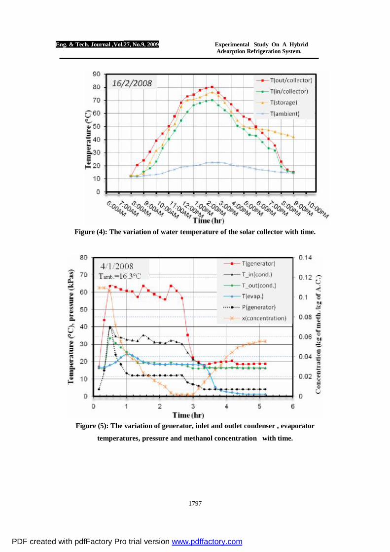
ensure that no condensate were collected in the condenser, as shown in Fig 3. The condenser was cooled naturally by air. 2-3 Receiver / Evaporator: A glass pecker of 1 lit capacity was used as a receiver –evaporator, although, the glass have poor thermal conductivity but it was used here for one reason, that the volume of condensate methanol can be observed through the glass. 2-4 Solar Collector: One of the most advantages of the adsorption unit, is that, it can be operated at relatively low temperature namely 60-70°C , which can be obtained by a flat plate solar collector. Therefore, a flat plate solar collector of 1.63 m2 area was tested as shown in Figure (4) to establish the performance of the collector, a storage tank of 12 lit. the same capacity of unit generator, was connected to the solar collector. 4-Results and Discussion Figure (5) shows the variation of generator, inlet and outlet condenser, evaporator temperature, pressure and methanol concentration with time, when the two parts of the field unit were used, the average generator temperature was about 60°C . Here, the mass of methanol was 273 kg (345 mlit) . As shown in the Figure, that the initial unit pressure was chosen carefully to maintain an evaporator temperature of about 0°C , to use this system for freezing purposes ,while , the initial pressure should be about 10 kpas, If the unit is used for air conditioning processes , the success of the unit was when the initial pressure of the unit is returned to its initial value after a complete adsorption cycle . From the Figure mentioned above, it can be seen that the unit pressure starting from initial pressure of 4 kpas
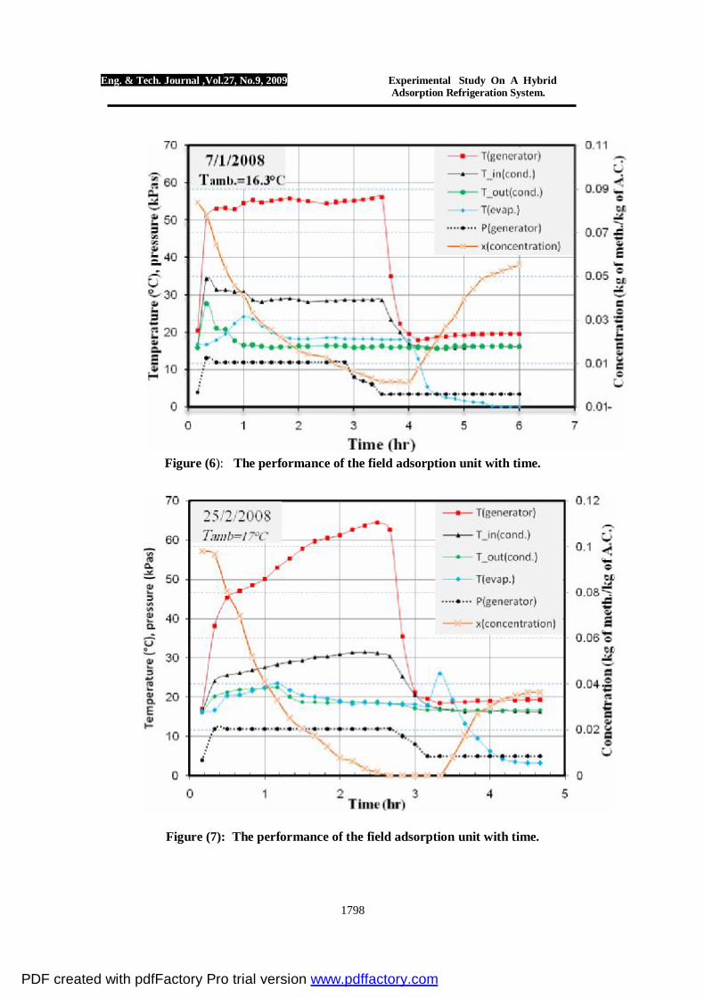
and increased gradually to about 40 kpas , as a result of heating the generator and closing the exit valve of the generator. As the generator valve is opened the unit pressure falls to about 12 kpas corresponding to saturation temperature that equal to ambient temperature. The unit pressure remains constant until all the methanol vapore condenses, at about hour 3:30. And when all the liquid methanol was collected at the evaporator , the exit valve from evaporator is closed and the generator is cooled by water at 19°C , here , the unit pressure falls rapidly from 10 to 4 kpas .At this pressure (hour 4) the exit valve from evaporator was opened, and the methanol boils at about 2°C . It can be seen from the figure that the desorption – condensation process takes about 3 hours , while the evaporation process takes about 2hours .The concentration of methanol within active carbon can be seen in figure mentioned above. It was started at 0.11kg(meth.)/kg(A.C.) and reduced gradually as the desorption process started and reached to about zero , as all methanol condensate ,and started to increase as the evaporation process started and reaches to 0.06 kg(meth.)/kg(A.C.) , and return to its initial value (not shown in the figure) after a period of time(next day). Figure (6) shows the performance of the field adsorption unit with time, when the two parts of generator were used, at average generator temperature of 55 °C. It can be seen from the figure that, the system behavior was about the same condensing temperature (as explained in figure (5)), but the methanol concentration dose not reach zero level, because of the reduction in generator temperature which makes the desorption process uncompleted. The minimum evaporator temperature was about 0.1°C .
PDF created with pdfFactory Pro trial version www.pdffactory.com

Eng. & Tech. Journal ,Vol.27, No.9, 2009 Experimental Study On A Hybrid Adsorption Refrigeration System.
1794
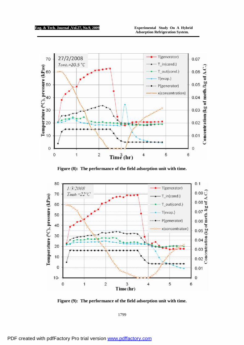
From the figure it can be seen also that the generator temperature increases from 18 to 20 °C as a result of adsorption process and releasing the heat of adsorption in the active carbon. Figure (7) shows the performance of field adsorption unit with time , when only a single part of generator was used , due to the failure of the second part. The generator temperature was increased gradually to simulate the performance of the solar collector , as shown in Figures (4) . Thus, it can be seen that the generator temperature started from 15°C and reached about 65 °C in nearly 2:30 hour , the system pressure was about 12 kpas which correspondes to saturation temperature that equals to the ambient temperature the evaporation temperature is still relatively high , namely 3°C . Then evaporator was immersed in water bath of 1 lit capacity at 26°C , and after 30 min the temperature falls to 3.2°C as a result of evaporation of 91g of methanol in the evaporator . Figure (8) shows the performance of the adsorption refrigeration unit, when the amount of methanol was increased to 150g and at the ambient temperature of 20.5°C . After starting the heating process, the exit valve of generator was opened before all the desorption processes was completed, to give enough time for condensation process. Therefore, the valve was opened when the generator temperature reached 40°C . The system pressure was 12 kpas, and the load imposed on the generator was 1 lit. of water at 34.5°C . As the generator is cooled by cooling water, the evaporator valve was opened and the cooling process started and about 79g evaporates , causing to cool the water to 4.5°C . The problems here is that the amount of the collected methanol in the evaporator dose not
evaporates completely, it leaves about 72g of methanol in evaporator. Figure (9) shows that, the performance of the system with time when the ambient temperature was 22 °C. It can be seen from the figure that the heating time of generator increased to 3:30hour compared with 2:30hour as mentioned in Figure (8), and the generator valve was opened when the temperature was 38.6°C at 16 kpas .The amount of condensate methanol was 194g , while the actual methanol evaporated was 87g . A thick shell of ice was formed around the evaporator. The minimum evaporator temperature was -1°C . Figure (10) shows the coefficient of performance of the cycle for different cases. It can be seen from the figure that, the minimum COP of the cycle was that when the temperature of the generator was held constant at 55°C , as shown in Figure (6) which means higher generator temperature. This is because, as the generator temperature increases the cycle COP decreases , also it can be seen that the COP can be improved when heating the generator gradually .The best COP was achieved when given enough time to the methanol to desorbs. The maximum COP was about 0.32, when the generator was heated gradually at ambient temperature of 22°C . 5-Conclusions:
1. The adsorption refrigeration system is suitable when the ambient temperature is low, as the ambient temperature increases the cycle COP decreases.
2. The proper concentration of methanol in active carbon obtained in this study was 0.07.
3. For a certain ambient temperature there is an optimum generator temperature at which the COP
PDF created with pdfFactory Pro trial version www.pdffactory.com
Eng. & Tech. Journal ,Vol.27, No.9, 2009 Experimental Study On A Hybrid Adsorption Refrigeration System.
1795
reaches a maximum .Therefore, there is no need to increase the generator temperature more than necessary.
References: [1] Chinnappa J.C.V. (1962). Performance of an intermittent refrigerator operated by a flat-plate collector, Solar Energy 6, 143-150 [2] Worsøe-Schmidt P. (1983). Solar refrigeration for developing countries using a solid absorption cycle, Int. J. Ambient Energy 4, 115-123 [3] Meunier F. (1994). Sorption solar cooling, Renewable Energy 5(1), 422-42 [4] Michel Pons "Principle of adsorption cycles for refrigeration or heat pumping , http://www.limsi.fr/Individu/mpons/indexENG.html. [5] "ADSORPTION CHILLER" Web site: www.adsorptionchiller.com. [6] R.Z. Wang "Adsorption refrigeration research in Shanghai Jiao Tong University" Institute of Refrigeration and Cryogenics, Shanghai Jiao Tong University, Shanghai 200030, China, Vol 5,P 1–37, 2001.
web page: www.sjtuirc.sjtu.edu.cn/Person/WangRuZhu/No9.pdf [7] R.Z. Wang and R. G. Oliveira " Adsorption Refrigeration-An Efficient Way To Make Good Use Of Waste Heat And Solar Energy" Institute of Refrigeration and Cryogenics, Shanghai Jiao Tong University, Shanghai 200030, China, 2005. [8] Performance measurement of a double-bed, solid-sorption cooling machine using activated carbon-freon pair, 2006 web page: www.me.psu.ac.th/ME_NETT/paper/TFM/TFM048.pdf
و [9] تصمیم" ر سعدون عبد الزھرة،المھندس عما بناء و دراسة أداء منظومة لصناعة الثلج تعمل
،أطروحة ماجستیر قسم ھندسة "بالطاقة الشمسیة 2006 بغداد، المكائن والمعدات،الجامعة التكنولوجیة
.
PDF created with pdfFactory Pro trial version www.pdffactory.com

Eng. & Tech. Journal ,Vol.27, No.9, 2009 Experimental Study On A Hybrid Adsorption Refrigeration System.
1796
Figure(1): A single part of generator. Figure(2): Both parts of generator after combined together
Figure (3): Front view of field system after installation.
PDF created with pdfFactory Pro trial version www.pdffactory.com
Eng. & Tech. Journal ,Vol.27, No.9, 2009 Experimental Study On A Hybrid Adsorption Refrigeration System.
1797
Figure (4): The variation of water temperature of the solar collector with time.
Figure (5): The variation of generator, inlet and outlet condenser , evaporator
temperatures, pressure and methanol concentration with time.
PDF created with pdfFactory Pro trial version www.pdffactory.com
Eng. & Tech. Journal ,Vol.27, No.9, 2009 Experimental Study On A Hybrid Adsorption Refrigeration System.
1798
Figure (6): The performance of the field adsorption unit with time.
Figure (7): The performance of the field adsorption unit with time.
PDF created with pdfFactory Pro trial version www.pdffactory.com
Eng. & Tech. Journal ,Vol.27, No.9, 2009 Experimental Study On A Hybrid Adsorption Refrigeration System.
1799
Figure (8): The performance of the field adsorption unit with time.
Figure (9): The performance of the field adsorption unit with time.
PDF created with pdfFactory Pro trial version www.pdffactory.com

Eng. & Tech. Journal ,Vol.27, No.9, 2009 Experimental Study On A Hybrid Adsorption Refrigeration System.
1800
Figure (10): The COP of some test taken by field unit.
PDF created with pdfFactory Pro trial version www.pdffactory.com
Copyright © 2022 FDOKUMEN