Experimental and simulation investigations of acoustic cavitation in megasonic cleaning
8
Experimental and simulation investigations on self-heat recuperative fluidized bed dryer for biomass drying with superheated steam Yuping Liu, Yasuki Kansha, Masanori Ishizuka, Qian Fu, Atsushi Tsutsumi ⁎ Collaborative Research Center for Energy Engineering, Institute of Industrial Science, The University of Tokyo, 4-6-1 Komaba, Meguro-ku, Tokyo 153-8505, Japan abstract article info Article history: Received 6 April 2014 Received in revised form 5 September 2014 Accepted 2 October 2014 Available online 4 December 2014 Keywords: Drying Self-heat recuperation technology Steam Heat pairing An exergy recuperative module was developed and applied to biomass drying. The proposed drying process has an energy consumption 1/20 that of a conventional heat recovery drying system. Experimental work was conducted to confirm the details of the self-heat recuperation technology concept. A high drying rate and a stable heat exchange were found through the experimental drying results. Furthermore, the heat pairing was confirmed in the drying system for the first time. © 2014 Published by Elsevier B.V. 1. Introduction Global warming is a common problem of concern that every country has made great efforts to solve. Solar energy, hydrogen energy, and CCS process technologies have been developed to minimize the large amounts of CO 2 emitted by fossil fuel combustion processes. The use of biomass has also been promoted in many countries as a solution to the global warming problem. Biomass is considered to be a kind of renewable energy because it is able to store solar energy through pho- tosynthesis using CO 2 as the raw material. Energy conversion processes such as pyrolysis and gasification, combustion and co-combustion with coal, and torrefaction may be used to supply energy from biomass [1–3]. However, biomass residues and wastes, which are readily available in large amounts, cannot be effectively converted by these processes. One of the main reasons for this is their high water content, which usually exceeds 50 wt.% (wet basis). A high moisture content makes bio- mass conversion uneconomical by reducing the heat value of the bio- mass and increasing its transportation cost. Drying processes are used to reduce the water content of wet biomass to under 10 wt.% (wb) [4]. However, such biomass drying processes consume much energy owing to the high energy required for water evaporation. The dramatic increases in energy costs caused by the shortage of fossil fuels have motivated the development of many energy-saving technologies for biomass drying in the past few decades. For example, heat-pump drying, multistage drying, mechanical vapor recompression, and heat recovery by recycling exhausted air and inte- grating the drying system with other exothermic processes have been developed for energy-saving [5–7]. In existing heat integration drying processes based on pinch technology, the use of such methods can decrease the furnace load. Moreover, only part of the heat can be recov- ered for the minimum temperature difference required for heat ex- change [8]. While multistage drying can make full use of the exhausted heat from the upper stage as the heat supply for the downstream stage, a large amount of energy input is still required during the steam genera- tion period. This is because the reaction heat is paired with the heat of steam generation. To minimize energy input during steam generation, mechanical vapor recompression dryer has been developed. Energy consumption could be reduced by using a compressor to increase the exergy rate of the exhausted steam and latent heat can be recovered [9], but the sensible heat of dried material was not recycled. Thus, the current energy-saving processes still require a significant amount of energy input. It is therefore necessary to explore new energy-saving drying processes to improve the overall energy efficiency of biomass drying. A self-heat recuperation technology has been recently developed as a better energy-saving method [10]. Through compression of the effluent stream and optimal heat pairing, each sensible and latent heat in the process could be recirculated, and thus no heater is required at any stage of the process. Based on this self-heat recuperation technol- ogy, Liu et al. developed a self-heat recuperative process for biomass drying in air which could save energy to 1/5 of the conventional heat re- covery dryer [11]. However, this method still consumed so much energy owing to the use of air as the drying medium, which caused a mis- matched heat pairing. Furthermore, a biomass drying plant requires a high drying rate and good system stability, whatever the energy-saving methods used. It is important to investigate the drying rate and system stability experimentally because it is difficult to predict these factors Fuel Processing Technology 136 (2015) 79–86 ⁎ Corresponding author. Tel.: +81 3 5452 6727; fax: +81 3 5452 6728. E-mail address: [email protected] (A. Tsutsumi). http://dx.doi.org/10.1016/j.fuproc.2014.10.005 0378-3820/© 2014 Published by Elsevier B.V. Contents lists available at ScienceDirect Fuel Processing Technology journal homepage: www.elsevier.com/locate/fuproc
-
Upload
independent -
Category
Documents
-
view
0 -
download
0
Transcript of Experimental and simulation investigations of acoustic cavitation in megasonic cleaning

Fuel Processing Technology 136 (2015) 79–86
Contents lists available at ScienceDirect
Fuel Processing Technology
j ourna l homepage: www.e lsev ie r .com/ locate / fuproc
Experimental and simulation investigations on self-heat recuperativefluidized bed dryer for biomass drying with superheated steam
Yuping Liu, Yasuki Kansha, Masanori Ishizuka, Qian Fu, Atsushi Tsutsumi ⁎Collaborative Research Center for Energy Engineering, Institute of Industrial Science, The University of Tokyo, 4-6-1 Komaba, Meguro-ku, Tokyo 153-8505, Japan
⁎ Corresponding author. Tel.: +81 3 5452 6727; fax: +E-mail address: [email protected] (A. Tsutsum
http://dx.doi.org/10.1016/j.fuproc.2014.10.0050378-3820/© 2014 Published by Elsevier B.V.
a b s t r a c t
a r t i c l e i n f oArticle history:Received 6 April 2014Received in revised form 5 September 2014Accepted 2 October 2014Available online 4 December 2014
Keywords:DryingSelf-heat recuperation technologySteamHeat pairing
An exergy recuperative module was developed and applied to biomass drying. The proposed drying process hasan energy consumption 1/20 that of a conventional heat recovery drying system. Experimental work wasconducted to confirm the details of the self-heat recuperation technology concept. A high drying rate and a stableheat exchangewere found through the experimental drying results. Furthermore, theheat pairingwas confirmedin the drying system for the first time.
© 2014 Published by Elsevier B.V.
1. Introduction
Global warming is a common problem of concern that every countryhas made great efforts to solve. Solar energy, hydrogen energy, and CCSprocess technologies have been developed to minimize the largeamounts of CO2 emitted by fossil fuel combustion processes. The useof biomass has also been promoted in many countries as a solution tothe global warming problem. Biomass is considered to be a kind ofrenewable energy because it is able to store solar energy through pho-tosynthesis using CO2 as the rawmaterial. Energy conversion processessuch as pyrolysis and gasification, combustion and co-combustion withcoal, and torrefactionmay be used to supply energy frombiomass [1–3].However, biomass residues and wastes, which are readily available inlarge amounts, cannot be effectively converted by these processes.One of the main reasons for this is their high water content, whichusually exceeds 50wt.% (wet basis). A highmoisture contentmakes bio-mass conversion uneconomical by reducing the heat value of the bio-mass and increasing its transportation cost.
Drying processes are used to reduce thewater content ofwet biomassto under 10 wt.% (wb) [4]. However, such biomass drying processesconsume much energy owing to the high energy required for waterevaporation. The dramatic increases in energy costs caused by theshortage of fossil fuels have motivated the development of manyenergy-saving technologies for biomass drying in the past few decades.For example, heat-pump drying, multistage drying, mechanical vaporrecompression, and heat recovery by recycling exhausted air and inte-grating the drying system with other exothermic processes have been
81 3 5452 6728.i).
developed for energy-saving [5–7]. In existing heat integration dryingprocesses based on pinch technology, the use of such methods candecrease the furnace load. Moreover, only part of the heat can be recov-ered for the minimum temperature difference required for heat ex-change [8]. While multistage drying can make full use of the exhaustedheat from the upper stage as the heat supply for the downstream stage,a large amount of energy input is still required during the steam genera-tion period. This is because the reaction heat is paired with the heat ofsteam generation. To minimize energy input during steam generation,mechanical vapor recompression dryer has been developed. Energyconsumption could be reduced by using a compressor to increase theexergy rate of the exhausted steam and latent heat can be recovered[9], but the sensible heat of dried material was not recycled. Thus, thecurrent energy-saving processes still require a significant amount ofenergy input. It is therefore necessary to explore new energy-savingdrying processes to improve the overall energy efficiency of biomassdrying.
A self-heat recuperation technology has been recently developedas a better energy-saving method [10]. Through compression of theeffluent stream and optimal heat pairing, each sensible and latentheat in the process could be recirculated, and thus no heater is requiredat any stage of the process. Based on this self-heat recuperation technol-ogy, Liu et al. developed a self-heat recuperative process for biomassdrying in air which could save energy to 1/5 of the conventional heat re-covery dryer [11]. However, this method still consumed so much energyowing to the use of air as the drying medium, which caused a mis-matched heat pairing. Furthermore, a biomass drying plant requires ahigh drying rate and good system stability, whatever the energy-savingmethods used. It is important to investigate the drying rate and systemstability experimentally because it is difficult to predict these factors

80 Y. Liu et al. / Fuel Processing Technology 136 (2015) 79–86
using simulation software. In this study, we aimed to develop an im-proved energy-saving biomass drying process based on self-heat recu-peration technology using steam as the drying medium. The resultingenergy consumption was investigated through simulations. A lab-scalebiomass fluidized bed dryerwas built to confirm the successful operationof the self-heat recuperation technology and the overall drying perfor-mance. The results of this work will be useful for future large plantconstruction.
2. Simulation
2.1. Exergy recuperative biomass drying process
The process diagram for the proposed biomass drying process basedon self-heat recuperation technology is displayed in Fig. 1. A fluidizedbed dryer, which shortens drying time by the rapid transfer of heatand moisture between solids and gas during particle fluidization, waschosen as the evaporator. Initially, the wet biomass receives sensibleheat from the heat exchanger (HX1) and is preheated to the boilingpoint of water. Subsequently, it is fed to a fluidized bed dryer (HX2),where free water is evaporated. Immersed heat exchange tubes areinserted in the bed such that the compressed steam flowing inside thetubes have latent heat exchange with the water in the biomass. Then,the exhausted steam is split into recycled steam and purged steam,equivalent to the evaporated freewater. The purged steam is then com-pressed, and recycled for water evaporation and biomass preheating.The dried solid has heat exchange with the cold wet biomass in HX4,and then is cooled to ambient temperature.
2.2. Simulation conditions
Analysis of the energy consumption of the drying processes wasconducted busing PRO/II ver. 9.1 software (Invensys Corp.). The wetbiomass inlet flow rate was set to 5000 kg h−1 with an initial moisturecontent of 75 wt.% (wb). The fluidized bed was square with a slidelength of 4.0 m and a height of 4.0 m. The bed voidage at the minimumfluidization velocity was 0.42. The Soave–Redlich–Kwong method wasused as the model for calculation of the drying process. Heat exchangeis concurrent in the fluidized bed dryer and countercurrent in otherheat exchangers, and the minimum temperature difference in eachheat exchanger is 10 K. Adiabatic efficiencies of the compressor and
Fig. 1. Exergy recuperative b
blower are both 80%. The blower is used for particle fluidization. Itspower consumptionwas determined from thepressure loss in thefluid-ized bed Δpf, which included the pressure drop across the bed Δpb andthe pressure drop across the distributor Δpd. The pressure drops werecalculated according to the equation proposed by Kunii and Levenspiel[12]:
Δp f ¼ Δpb þ Δpd ð1Þ
Δpb ¼ 1−εmfð Þ ρp−ρg
� �Hb
g�c ð2Þ
Δpd ¼ 0:4Δpb ð3Þ
where εmf is the bed voidage, ρp and ρg are the densities of particles andgas, respectively, Hb is the bed height, and c is the conversion factor(1 kg m N−1 s−2).
3. Experiment
Wet sawdust (Echigo cedar, diameter 0.34–0.5 mm, density0.28 g/cm3) was used as the biomass material to be dried in thiswork. Silica sand was mixed with the sawdust because sawdustparticles of any moisture content are poorly fluidized in a singlecomponent system. Mixing and fluidization performance werefirst investigated in the fluidized bed dryer with air as the dryingmedium. Based on the results, an optimal diameter and weightratio of silica sand to sawdust was determined for the batchwiseand semicontinuous experiments using steam as the drying medium.The drying behavior of the sawdust in the fluidized bed dryer wasinvestigated, and the system stability of heat exchange was alsochecked in the fluidized bed under semicontinuous operation.
3.1. Experimental setup
Based on the above concept, a laboratory-scale fluidized bed dryerwas set up as shown in Fig. 2. The main body was made of stainlesssteel, and contained some inspection windows to allow the observationof particle fluidization. The fluidized bed dryer had a square cross-section with a side length of 0.2 m and a height of 1.0 m. This size was
iomass drying process.
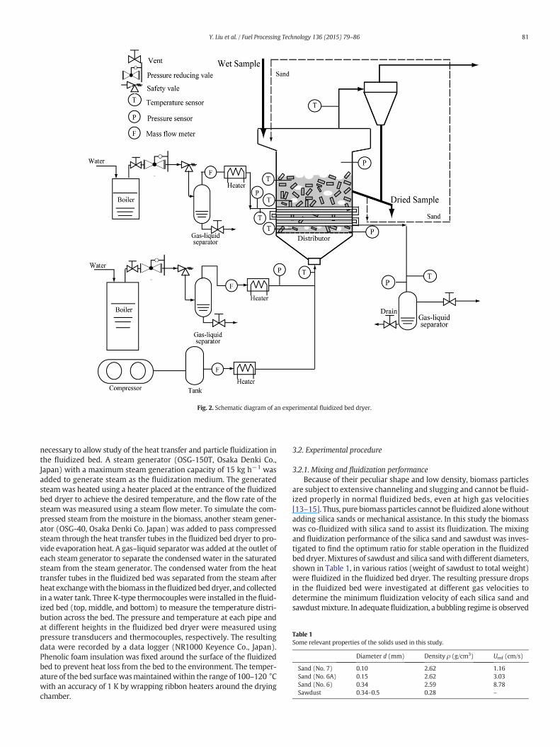
Fig. 2. Schematic diagram of an experimental fluidized bed dryer.
Table 1Some relevant properties of the solids used in this study.
Diameter d (mm) Density ρ (g/cm3) Umf (cm/s)
Sand (No. 7) 0.10 2.62 1.16Sand (No. 6A) 0.15 2.62 3.03Sand (No. 6) 0.34 2.59 8.78Sawdust 0.34–0.5 0.28 –
81Y. Liu et al. / Fuel Processing Technology 136 (2015) 79–86
necessary to allow study of the heat transfer and particle fluidization inthe fluidized bed. A steam generator (OSG-150T, Osaka Denki Co.,Japan) with a maximum steam generation capacity of 15 kg h−1 wasadded to generate steam as the fluidization medium. The generatedsteamwas heated using a heater placed at the entrance of the fluidizedbed dryer to achieve the desired temperature, and the flow rate of thesteam was measured using a steam flow meter. To simulate the com-pressed steam from the moisture in the biomass, another steam gener-ator (OSG-40, Osaka Denki Co. Japan) was added to pass compressedsteam through the heat transfer tubes in the fluidized bed dryer to pro-vide evaporation heat. A gas–liquid separator was added at the outlet ofeach steam generator to separate the condensed water in the saturatedsteam from the steam generator. The condensed water from the heattransfer tubes in the fluidized bed was separated from the steam afterheat exchangewith thebiomass in thefluidized bed dryer, and collectedin awater tank. Three K-type thermocouples were installed in the fluid-ized bed (top, middle, and bottom) to measure the temperature distri-bution across the bed. The pressure and temperature at each pipe andat different heights in the fluidized bed dryer were measured usingpressure transducers and thermocouples, respectively. The resultingdata were recorded by a data logger (NR1000 Keyence Co., Japan).Phenolic foam insulation was fixed around the surface of the fluidizedbed to prevent heat loss from the bed to the environment. The temper-ature of the bed surfacewasmaintainedwithin the range of 100–120 °Cwith an accuracy of 1 K by wrapping ribbon heaters around the dryingchamber.
3.2. Experimental procedure
3.2.1. Mixing and fluidization performanceBecause of their peculiar shape and low density, biomass particles
are subject to extensive channeling and slugging and cannot be fluid-ized properly in normal fluidized beds, even at high gas velocities[13–15]. Thus, pure biomass particles cannot befluidized alonewithoutadding silica sands or mechanical assistance. In this study the biomasswas co-fluidized with silica sand to assist its fluidization. The mixingand fluidization performance of the silica sand and sawdust was inves-tigated to find the optimum ratio for stable operation in the fluidizedbed dryer.Mixtures of sawdust and silica sandwith different diameters,shown in Table 1, in various ratios (weight of sawdust to total weight)were fluidized in the fluidized bed dryer. The resulting pressure dropsin the fluidized bed were investigated at different gas velocities todetermine the minimum fluidization velocity of each silica sand andsawdustmixture. In adequatefluidization, a bubbling regime is observed
82 Y. Liu et al. / Fuel Processing Technology 136 (2015) 79–86
without the formation of channels at increasing gas velocities [15]. Withmixing ratio further increasing, experiment was stopped when the poorfluidization occurred, which was determined visually and from theoccurrence of a pressure drop across the bed.
3.2.2. Batch experimentBiomass drying with steam is commonly conducted at high tem-
peratures. To reduce the exergy loss during the drying process usingself-heat recuperation technology, a low drying temperature near theboiling point of water is required. However, this may cause steam tocondense easily on the particles surface. There are few reports on thedrying of biomass with steam in a fluidized bed dryer at low tempera-ture [16,17]. To confirm thepossibility and drying rate,wefirst conduct-ed batch-wise biomass drying experiments.
Before the steamdrying experiment, thefluidized bedwas preheatedwith hot air to over 100 °C to prevent the steam condensing when itentered the fluidized bed. Then, the fluidization medium was switchedfrom air to steam. Based on the simulation results, the generated steamwas initially preheated to 120 °C before it entered the fluidized beddryer. In these batch experiments, for better control and investigationof the amount of energy input, we first used three sheathed heaters(diameter 6 mm, length 120 mm) installed inside the fluidized beddryer at a height of 25 mm above the distributor to simulate the com-pressed steam used as the heat source for drying. After the bed temper-ature was stable at around 110 °C, the wet sawdust was added into thefluidized bed. The drying process began to progress and water in thesawdust was evaporated into the fluidizing/drying medium. Samplesof the mixture of sawdust and sand were taken from the fluidized bedduring the drying process. After sampling was completed, the sawdustwas separated from the sand using a mesh sieve and weighed beforebeing placed into an oven. Then, an amount of sand equal to the amountremoved from the fluidized bed dryer was previously heated in an ovenat 103 °C and then added to the fluidized bed to maintain a constantamount of sand in the dryer. The dried sawdust sample was heatedfor 24 h at 103 °C and then weighed again. The moisture content ofthe sawdust, Wwet, was calculated as follows:
Wwet ¼M1−M2
M1� 100% ð4Þ
where M1 is the weight of the sampled dried sawdust and M2 is theweight of the sampled sawdust after being kept in the oven for 24 h.
3.2.3. Semicontinuous experimentIn the semicontinuous experiment, we changed the heat source
from sheathed heaters to compressed steam to investigate system sta-bility and heat pairing between the evaporation heat and condensationheat of the steam. In the semicontinuous experiment, 150 g sawdustwith a water content of 61.8 wt.% (wb) was fed intermittently into thefluidized bed dryer at intervals of 8 min. Meanwhile, the dried sawdustwas discharged with the silica sand from the exit tube at an interval of15min. Compressed steamwith a pressure of 190 kPa at 119 °C flowedthrough the heat exchange tubes (as shown in Table 2) in the fluidized
Table 2Properties of heat transfer tubes immersed inside fluidized bed dryer and steam.
Tube properties Values
Tube material SUS316 (18% Cr, Ni 12%, Mo 2.5%, 67.5% Fe)Thermal conductivity (W mK−1) 16.7Inner diameter (mm) 8Outer diameter (mm) 10Arrangement HorizontalPitch distance (mm) 50
Compressed steamInlet temperature (°C) 119Inlet pressure (kPa) 190
bed and supplied steam condensation heat for water evaporation. Thesampling time was controlled by opening and closing the door at theoutlet. Condensed water was collected through a tank and weighedafter the drying process had completed. Discharged sand–sawdustmixture was moved to the oven, and the moisture content of the driedsawdust was measured using the same method as that describedabove. The drying experiment was typically conducted for 180 minbut was stopped in cases of poor fluidization, which was determinedvisually and from the temperature distribution across the bed.
4. Results and discussion
4.1. Simulation results
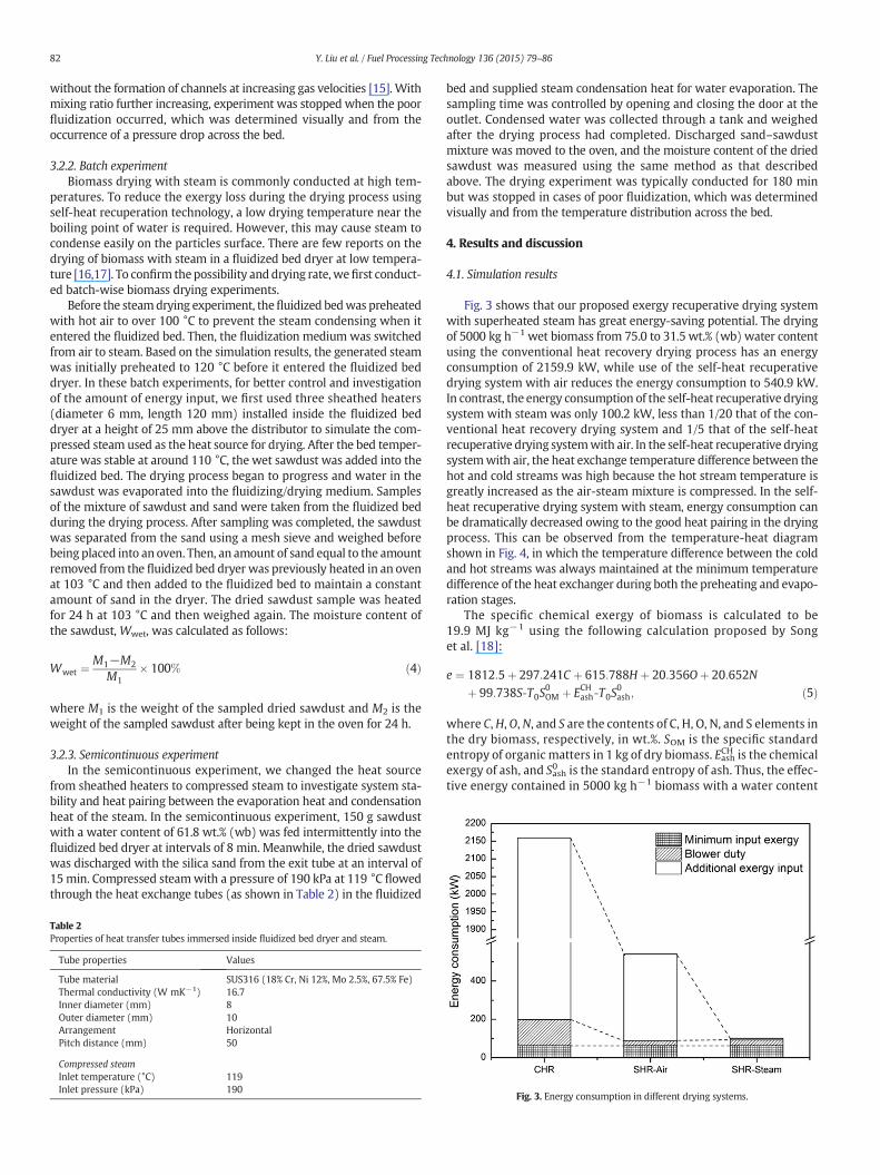
Fig. 3 shows that our proposed exergy recuperative drying systemwith superheated steam has great energy-saving potential. The dryingof 5000 kg h−1 wet biomass from 75.0 to 31.5 wt.% (wb) water contentusing the conventional heat recovery drying process has an energyconsumption of 2159.9 kW, while use of the self-heat recuperativedrying system with air reduces the energy consumption to 540.9 kW.In contrast, the energy consumption of the self-heat recuperative dryingsystem with steam was only 100.2 kW, less than 1/20 that of the con-ventional heat recovery drying system and 1/5 that of the self-heatrecuperative drying systemwith air. In the self-heat recuperative dryingsystemwith air, the heat exchange temperature difference between thehot and cold streams was high because the hot stream temperature isgreatly increased as the air-steam mixture is compressed. In the self-heat recuperative drying system with steam, energy consumption canbe dramatically decreased owing to the good heat pairing in the dryingprocess. This can be observed from the temperature-heat diagramshown in Fig. 4, in which the temperature difference between the coldand hot streams was always maintained at the minimum temperaturedifference of the heat exchanger during both the preheating and evapo-ration stages.
The specific chemical exergy of biomass is calculated to be19.9 MJ kg−1 using the following calculation proposed by Songet al. [18]:
e ¼ 1812:5þ 297:241C þ 615:788H þ 20:356Oþ 20:652Nþ 99:738S‐T0S
0OM þ ECHash‐T0S
0ash; ð5Þ
where C,H, O, N, and S are the contents of C, H, O, N, and S elements inthe dry biomass, respectively, in wt.%. SOM is the specific standardentropy of organic matters in 1 kg of dry biomass. EashCH is the chemicalexergy of ash, and Sash
0 is the standard entropy of ash. Thus, the effec-tive energy contained in 5000 kg h−1 biomass with a water content
Fig. 3. Energy consumption in different drying systems.

Fig. 4. Temperature and heat diagram of the exergy recuperative.
83Y. Liu et al. / Fuel Processing Technology 136 (2015) 79–86
of 75.0 wt.% (wb) is calculated to be 16,363 MJ h−1, and that in thesame amount of dried biomass is 23,477 MJ h−1. The energy con-sumption of the self-heat recuperative drying system with steamwas 360 MJ h−1. Therefore, compared with the energy held by thedried biomass, the input energy for drying was relatively low, about1.5% of the energy in the biomass. This result validates the merits ofour designed biomass drying process.
4.2. Experimental results
4.2.1. Mixing and fluidization performanceThree different diameters of silica sand were used to investigate the
hydrodynamic performance of co-fluidized wet sawdust. The resultsshowed that the diameter of the sand had an important effect on thefluidization performance. The minimum fluidization velocity of eachsilica sand and sawdust mixture at different mixing ratios is shown inFig. 5. The minimum fluidization velocity was determined from the re-lationship between the velocity of the drying gas and the pressure loss
Fig. 5. Minimum fluidization veloc
in the bed. Good mixing and fluidization performance was achievedfor each diameter of silica sand when the mixing weight ratio wasbetween 0 and 0.05. However, channeling occurred in the mixture ofsawdust and silica sand (d = 0.1 mm) when the weight ratio wasincreased to 0.07, signified by a trough in the pressure drop curve(Fig. 5). The bed did not return to a packed bed conformation and con-tinued to exhibit channeling until the gas velocity became zero. In thecase of silica sand (d = 0.34 mm), sawdust and silica sand were co-fluidized well at a low mixing ratio. However, the binary mixture wasdifficult to co-fluidize when the mixing ratio was larger than 0.05,owing to the limitations of the blower used in our experimental device.In the case of silica sand (d = 0.154 mm), the mixing and fluidizationperformance was good even at a high mixing ratio. Based on theabove results, silica sand with a diameter of 0.154 mm was chosen foruse in our steam drying experiments. The minimum fluidization veloc-ity of themixture of 0.154mmdiameter sand andwet biomasswas alsocalculated from equations recommended by Bilbao et al. [19] as:
uv f ¼ upk− upk−u f
� �X f ; ð6Þ
upk ¼ 50d0:84pk ; ð7Þ
X f ¼x f
x f þ ρ f=ρpk
� �1−x fð Þ
; ð8Þ
where uvf is superficial velocity of gas where both components in abinary mixture are fluidized, upk is fictitious minimum fluidizationvelocity of sawdust, and uf is sand volume fraction in bed. dpk is theparticle size of packed component, and xf is weight fraction of fluidand packed component in binary mixture. ρf and ρpk are density ofsand and sawdust, respectively. Fig. 6 shows the approximate valuesof the calculated and experimental values obtained when defining ahigher value of upk of 0.71.
4.2.2. Batch experimentThe sawdust was preheated to 80 °C to avoid condensation of the
steamcondensation on the sawdust surface leading to an increased dry-ing time when sawdust was put into the fluidized bed dryer. The steam
ity of silica sand and sawdust.

Fig. 6. Comparison of experimental minimum fluidization velocity.
Fig. 7. a. Temperature distribution and pressure drop in the fluidized bed. b. energy inputfrom sheathed heater 240 W. c. Energy input from sheathed heater 360 W.
84 Y. Liu et al. / Fuel Processing Technology 136 (2015) 79–86
flow rate was 4.1 kg h−1 with a velocity of 7.79 cm s−1. The steam inlettemperature was 120 °Cwith an absolute pressure of 160 kPa. The tem-perature at the top, middle, and bottom of the fluidized bed were mon-itored during the drying process. The temperature difference among thelevels was very small, indicating a homogenous state in the fluidizedbed. As shown in Fig. 7a, in our system, the biomass could be fluidizedand dried at a very low temperature of 101.5 °C without condensationof the steam. This low bed temperature reduced exergy loss duringthe heat exchange process. The bed temperature dropped from 112 °Cto 101.5 °Cwhen the sawdustwas put into the bed andwasmaintainedat 101.5 °C for 27min during the free water removal. Because the ener-gy supply was used as the heat for water evaporation, the bed temper-ature kept constant during the free water drying process. The bedtemperature began to increase during the removal of adsorbedor chem-ically bound water from the biomass. The bed temperature was a littlehigher than the boiling point of water owing to the presence of a tem-perature difference for heat transfer from the sand to the biomass parti-cles. Furthermore, the energy input increased to 240 W, and theconstant drying rate period was shortened from 27 min to 12.6 min(Fig. 7b). Drying time may be shortened by increasing the number ofheaters. In the case of indirect steam fluidized dryer, energy supplywas from the steam condensation; thus, a similar effect could beachieved by increasing the amount of heat exchange surface in the indi-rect steam fluidized bed dryer. When the energy input was increased to360W, the constant drying rate period almost disappeared owing to thelarge amount of heat supply (Fig. 7c). The constant rate period was sig-nificantly affected by the amount of energy input (W) into the dryer,compared with its effect on the fall rate period. Although the boundwater removal time also decreasedwith increasing input energy, the re-duction was not as dramatic as that for the free water removal stage.This was because the mass and heat transfer rates were high in the flu-idization bed dryer; thus, the free water in the biomass could be re-moved quickly. During the removal of bound water, the physicalproperties of the sample such as water diffusivity and thermal conduc-tivity affected the drying performance. Thus, the time taken for theboundwater to be removedwas almost the same as that for the removalof the free water, despite the initial amount of bound water in the bio-mass being less than half that of the free water.
4.2.3. Semicontinuous experimentA semicontinuous experiment was conducted to investigate the
exergy recuperative drying system stability and heat pairing. Fig. 8shows that the bed temperature dropped near to the boiling point atthe time of wet biomass intake as a result of the evaporation of free
water. Afterwards, the temperature quickly returned to the mean tem-perature owing to the good mixing in the fluidized bed. The tempera-ture difference between the top and bottom levels in the fluidized bedwas very small, indicating good particle mixing during the fluidization.
The pressure and temperature of the compressed steam at the inletand outlet of the heat exchange tubeswere alsomonitored. A consistenttemperature and pressure of the air–steam mixture at the outlet ofheat-exchange tubes were confirmed, as shown in Fig. 9. The meanvalues of the outlet absolute pressure and temperature of the steam

Fig. 8. Bed temperature distribution in the fluidized bed dryer. Fig. 10. Water content of dried sawdust during the drying process.
85Y. Liu et al. / Fuel Processing Technology 136 (2015) 79–86
were about 182 kPa and 118 °C, respectively. The drops in pressure andtemperature through the 18 immersed tubes were about 8.0 kPa and1.0 K, respectively. The pressure drop was due to the steam condensa-tion in the tubes. The temperature difference between the inlet and out-let heat exchange tubes was 1.0 K, indicating that themainly latent heatexchange occurred. The constant pressure and temperature drop indi-cated that the heat exchange between the compressed steam and thewet biomass was consistent. Sawdust was sampled and its water con-tent was measured every 15 min. Fig. 10 shows that the water contentof the sawdust was constant during the drying process, maintaining alow value of 2.5 wt.% (wb). The amount of condensed water from theheat exchange tubes collected in the tank was 1040 g, while the waterevaporated from the biomass was calculated to be 1092 g based onthe water content of the dried biomass. This means that almost all ofthe evaporation heat of the water in the biomass was supplied fromthe condensation heat of the steamobtained fromwater in the biomass.Thus, a good heat pairing was formed in the fluidized bed dryer forlatent heat exchange.
5. Conclusions
Anovel exergy recuperativemodulewas applied to a biomass dryingsystem. Energy consumptionwas saved to the 1/20 of conventional heat
Fig. 9. Temperature and pressure of the compressed steam at the dryer.
recovery drying system in the self-heat recuperativefluidized bed dryer.A good stability in fluidized bed dryer based on simulation conditions isconfirmed. The batch experiment showed that biomass could be driedwith steam near the boiling point at the operation pressure in the fluid-ized bed dryer with a high drying rate. Increasing the energy supply byincreasing the amount of heat exchange surface could shorten thedrying time to less than half of the drying process, especially for theconstant drying period. The heat exchange stability in the fluidizedbed was good. Almost all the evaporation heat was supplied from thewater condensation heat, confirming a good heat pairing in our devel-oped dryer design.
Acknowledgments
The authors are grateful for financial support provided by theJapanese–Canadian (JST-NSERC) Research Cooperative Program aspart of the FY 2012 Strategic International Research Cooperative Program.
References
[1] A. Maciejewska, H. Veringa, J. Sanders, S.D. Peteves, Co-firing of biomass with coal:constraints and role of biomass pre-treatment, http://ie.jrc.ec.europa.eu/publications/scientific_publications/2006/EUR22461EN.pdf.
[2] L. Wang, C.L. Weller, D.D. Jones, M.A. Hanna, Contemporary issues in thermal gasifi-cation of biomass and its application to electricity and fuel production, Biomass andBioenergy 32 (2008) 573–581.
[3] P. McKendry, Energy production from biomass (part 2): conversion technologies,Bioresource Technology 83 (2002) 47–54.
[4] N. Kaliyan, R.V. Morey, Factors affecting strength and durability of densified biomassproducts, Biomass and Bioenergy 33 (2009) 337–359.
[5] M. Djaeni, P. Bartels, J. Sanders, G. van Straten, A.J.B. van Boxtel, Multistage zeolitedrying for energy-efficient drying, Drying Technology 25 (2007) 1053–1067.
[6] I.C. Kemp, Reducing dryer energy use by process integration and pinch analysis,Drying Technology 23 (2005) 2089–2104.
[7] M. Krokida, D.Marinos-Kouris, A.S.Mujumdar, RotaryDrying, Handbookof IndustrialDrying, 2009.
[8] B. Linnhoff, E. Hindmarsh, The pinch design method for heat-exchanger networks,Chemical Engineering Science 38 (1983) 745–763.
[9] J. Fitzpatrick, D. Lynch, Thermodynamic analysis of the energy saving potential ofsuperheated steam drying, Transactions of IChemE 73 (1995) 3–8.
[10] Y. Kansha, N. Tsuru, K. Sato, C. Fushimi, A. Tsutsumi, Self-heat recuperation technol-ogy for energy saving in chemical processes, Industrial & Engineering ChemistryResearch 48 (2009) 7682–7686.
[11] Y.P. Liu, M. Aziz, Y. Kansha, S. Bhattacharya, A. Tsutsumi, Application of the self-heatrecuperation technology for energy saving in biomass drying system, Fuel ProcessingTechnology 117 (2014) 66–74.
[12] D. Kunii, O. Levenspiel, Fluidization Engineering, 1991.[13] R. Moreno, G. Antolin, A. Reyes, Quality of fluidisation for the drying of forestry
biomass particles in a fluidised bed, Biosystems Engineering 94 (2006) 47–56.[14] H.P. Cui, J.R. Grace, Fluidization of biomass particles: a review of experimental
multiphase flow aspects, Chemical Engineering Science 62 (2007) 45–55.

86 Y. Liu et al. / Fuel Processing Technology 136 (2015) 79–86
[15] K.L. Clarke, T. Pugsley, G.A. Hill, Fluidization ofmoist sawdust in binary particle systemsin a gas–solid fluidized bed, Chemical Engineering Science 60 (2005) 6909–6918.
[16] C. Fyhr, A. Rasmuson, Mathematical model of steam drying of wood chips and otherhygroscopic porous media, Aiche Journal 42 (1996) 2491–2502.
[17] C. Fyhr, A. Rasmuson, Steam drying of wood chips in pneumatic conveying dryers,Drying Technology 15 (1997) 1775–1785.
[18] G.H. Song, L.H. Shen, J. Xiao, Estimating specific chemical exergy of biomass frombasicanalysis data, Industrial & Engineering Chemistry Research 50 (2011) 9758–9766.
[19] R. Bilbao, J. Lezaun, J.C. Abanades, Fluidization velocities of sand straw binary-mixtures, Powder Technology 52 (1987) 1–6.