Developing flow in a converging tube and a diverging tube (in Chinese)
EXPERIMENTANALYSISANDPERFORMANCETESTINGOFCAPILLARYTUBEANDTHERMOSTATICEXPANSIONVALVE
1AMOLA.GAWALI,2MADHAVS.JOSHI,3RUPESHL.RAUT,4RAHULA.BHOGARE
1,3,4Student,HeatPowerEngineering,WalchandCollegeofEngineering,Sangli,Maharashtra,INDIA
2AssociateProfessor,MechanicalEngineering,WalchandCollegeofEngineering,Sangli,Maharashtra,INDIA
Email:[email protected],[email protected],[email protected],[email protected]
ABSTRACT
Thispaperprovideanoverviewoftheproject,thefundamentalphysicsunderlyingthe
operation of fixed and variable expansion devices, and summarizes results of the
analyses performed to compare them. This paper analyzes a broad spectrum of
strategies for actively or passively controlling the inlet state of fixed‐geometry
expansiondevicessuchascapillarytubeandThermostaticexpansiondevice,tomatch
compressormassflowrateswithminimalperformancedegradationinanefficientR12
refrigerationsystem.ATXV(ThermalExpansionValve)systemwasselectedasperload
requirementandtypeofrefrigerant.Resultsyieldedinsightsthatcanbegeneralizedto
other refrigerants and systems. TXV were found to produce and control degree of
superheatofrefrigerant,higherefficiencythancapillarytubesacrosstheentirerangeof
operatingconditions,althoughthedifferencecanbemitigatedbyproperchoiceofthe
latter’slengthanddiameter.
INDEX TERMS: capillary tube; thermostatic expansion valve; fixed and variable
restriction;cop;
1. INTRODUCTION
Theselectionoftheexpansiondeviceis
of particular importance to the
operation of the refrigeration system
because it regulates refrigerant flow
into the evaporator. An expansion
device which is misapplied or
incorrectlysizedwillordinarilyresultin
operationaldifficultiesandpoorsystem
AMOL A. GAWALI et al DATE OF PUBLICATION: JUNE 28, 2014
ISSN: 2348-4098 VOLUME 02 ISSUE 05 JUNE 2014
INTERNATIONAL JOURNAL OF SCIENCE, ENGINEERING AND TECHNOLOGY- www.ijset.in 327
performance. For example, an
undersized expansion device will
prevent sufficient refrigerant from
flowing into the evaporator causing a
reduction in the design cooling
capability of the system. An oversized
expansion device may allow too much
refrigerant into the evaporator causing
liquid refrigerant to flow back to the
compressor.Capillarytubesareusedto
expand the refrigerant from the
condenser pressure to the evaporator
pressure in low capacity refrigerating
machinessuchasdomesticrefrigerators
andwindowtyperoomairconditioners.
It also balances the systempressure in
the refrigeration cycle however; it has
no provision to adjust the mass flow
rate when load conditions changes. In
spite of this fact, capillary tubes are
preferredinsmallcapacityrefrigerating
machines, where the load is fairly
constant due to its several advantages
such as simplicity, low cost, zero
maintenance, and requirementofa low
starting torque motor to run the
compressor.Fig1showssimplecapillary
tube.Thethermostaticexpansionvalves
provide an excellent solution to
regulatingrefrigerant flow intoadirect
expansion type evaporator. The TEV
regulates refrigerant flow by
maintaininganearlyconstantsuperheat
at the evaporator outlet. Fig 2 shows
thermostatic expansion valve. As
superheatattheevaporatoroutletrises
due to increased heat load on the
evaporator, the TEV increases
refrigerantflowuntilsuperheatreturns
to the valve’s setting. Conversely, the
TEVwilldecreaserefrigerantflowwhen
superheat lowers as a result of a
decreased heat load on the evaporator.
Theeffectofthistypeofregulationisit
allows the evaporator to remain as
nearly fully active aspossibleunder all
loadconditions.
2. EXPANSIONDEVICEFUCTION
The basic function of expansion device
usedinrefrigerationsystem(1)Reduce
pressure from condenser pressure to
evaporator pressure, and (2) regulate
the refrigerant flow from the high‐
pressure liquid line into theevaporator
atarateequaltotheevaporationratein
the evaporator. Under ideal conditions,
themass flow rateof refrigerant in the
system should be proportional to the
cooling load sometimes; the product to
be cooled is such that a constant
evaporator temperature has to be
maintained. In other cases, it is
desirable that liquid refrigerant should
notenterthecompressor.Insuchacase,
themass flowratehas tobe controlled
AMOL A. GAWALI et al DATE OF PUBLICATION: JUNE 28, 2014
ISSN: 2348-4098 VOLUME 02 ISSUE 05 JUNE 2014
INTERNATIONAL JOURNAL OF SCIENCE, ENGINEERING AND TECHNOLOGY- www.ijset.in 328
insuchamannerthatonlysuperheated
vapor leaves the evaporator. Again, an
ideal refrigeration system should have
the facility to control it in such a way
that the energy requirement is
minimum and the required criterion of
temperature and cooling load are
satisfied. Some additional controls to
control the capacity of compressor and
thespacetemperaturemayberequired
inaddition,soastominimizetheenergy
consumption.
The expansion devices used in
refrigeration systems can be divided
into fixed opening type or variable
opening type. As the name implies, in
fixed opening type the flow area
remainsfixed,whileinvariableopening
type the flow area changes with
changingmassflowrates.Capillarytube
belongstothefixedopeningtype,while
the thermostatic expansion valve
belongstothevariableopeningtype.
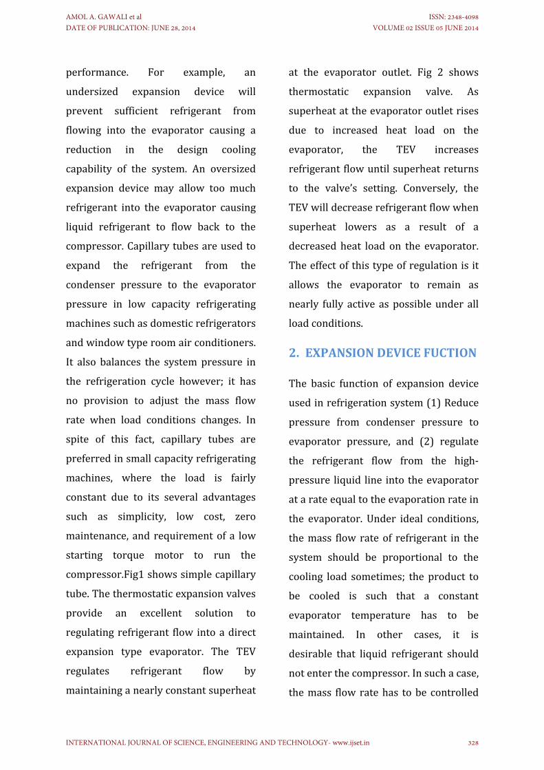
2.1CAPILLARYTUBE
Acapillarytubeisalong,narrowtubeof
constant diameter. Typical tube
diameters of refrigerant capillary tubes
range from 0.5 mm to 3 mm and the
length ranges from 1.0 m to 6 m. The
pressure reduction in a capillary tube
occursdue to the following two factors
(1) therefrigeranthas toovercomethe
frictional resistance offered by tube
walls this leads to somepressuredrop.
(2) The liquid refrigerant flashes
(evaporates) intomixture of liquid and
vapor as its pressure reduces. The
densityofvapor is less than thatof the
liquid. Hence, the average density of
refrigerant decreases as it flows in the
tube. (3) The mass flow rate and tube
diameter (hence area) being constant,
the velocity of refrigerant increases
since=ρVA.The increase invelocityor
acceleration of the refrigerant also
requirespressuredrop
Figure1:CapillaryTube
2.2 THERMOSTATIC EXPANSION
VALVE
Thermostatic expansion valve is the
most versatile expansion valve and is
most commonly used in refrigeration
systems. It is variable opening type
expansion device. A thermostatic
expansion valve maintains a constant
degree of superheat at the exit of
AMOL A. GAWALI et al DATE OF PUBLICATION: JUNE 28, 2014
ISSN: 2348-4098 VOLUME 02 ISSUE 05 JUNE 2014
INTERNATIONAL JOURNAL OF SCIENCE, ENGINEERING AND TECHNOLOGY- www.ijset.in 329
evaporator;henceitismosteffectivefor
dry evaporators in preventing the
slugging of the compressors since it
does not allow the liquid refrigerant to
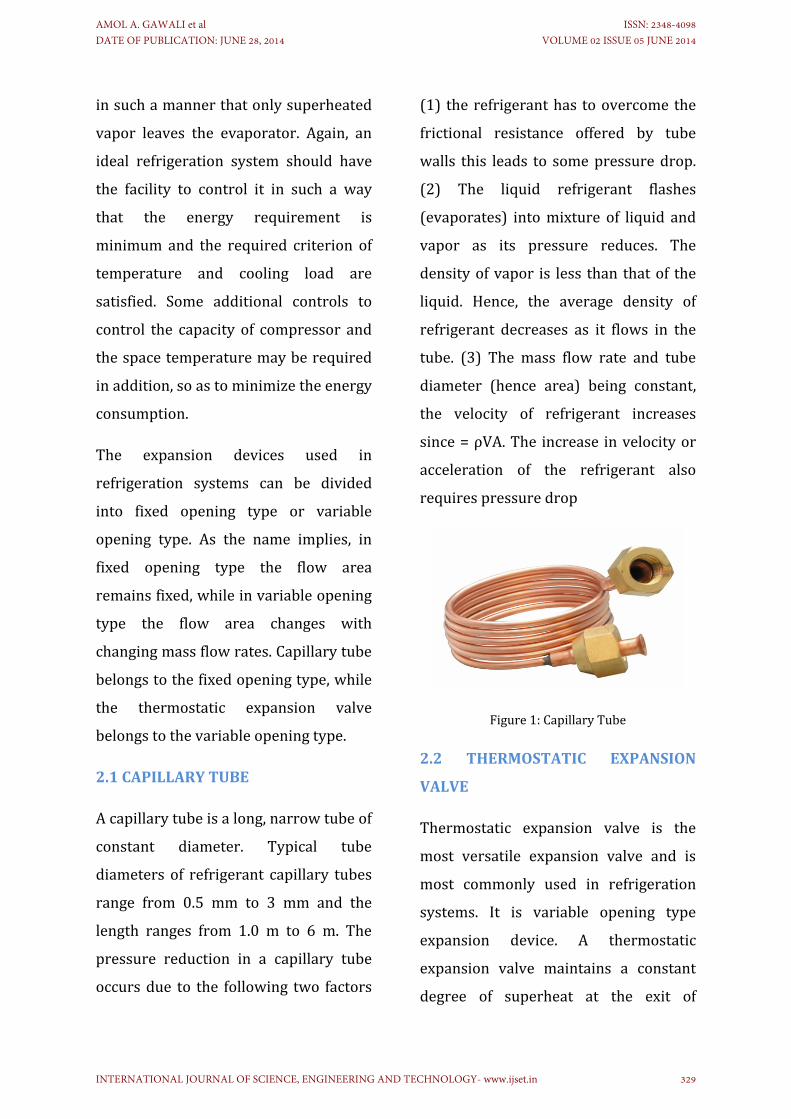
enter the compressor. The schematic
diagramofthevalveisgiveninFigure2.
This consists of a feeler bulb that is
attached to the evaporator exit tube so
thatitsensesthetemperatureattheexit
of evaporator. The feeler bulb is
connectedtothetopofthebellowsbya
capillary tube. The feeler bulb and the
narrow tube contain some fluid that is
calledpowerfluid.Thepowerfluidmay
be the same as the refrigerant in the
refrigeration system, or it may be
different.Incaseit isdifferentfromthe
refrigerant, then the TEV is called TEV
withcrosscharge.
Figure2:ThermostaticExpansionValve
3. EXPERIMENTSET‐UP
Asetupmanufacturedtoexperimentally
investigatetheperformanceofcapillary
tubeandThermostaticExpansionvalve
for refrigerant R‐12.Experiment setup
consist of four major part of
refrigeration system such as
compressor, which compress
refrigerant,condenserwhichrejectsthe
heat from refrigerant at constant
pressure .expansion device which drop
down the temperature and pressure of
the refrigerant. And finally evaporator
whichisabsorbsheatfromrefrigerated
space. All the component of the
refrigeration system is displayed on
portable the metallic panel. The unit
consist 0.3 TR capacity compressor,
condenser thermostatic Expansion
Valveandcapillarytubeandevaporator.
Here for the experiment purpose two
expansion devices capillary and
thermostatic expansion valve are used
in system.fig 3, shows line diagram of
simple vapor compression system.
Evaporator coil is deep in water
calorimeter to so that the water
temperaturelowersdownduetolossof
heatenergyduetoevaporationprocess.
Heaterisprovidingatthebottomofthe
calorimeter which offers the heat load
which is balanced by the refrigeration
effectproducebythesystem.
Calorimeter contain sufficient of water
that the evaporative coils totally
immersed. Temperature of water
AMOL A. GAWALI et al DATE OF PUBLICATION: JUNE 28, 2014
ISSN: 2348-4098 VOLUME 02 ISSUE 05 JUNE 2014
INTERNATIONAL JOURNAL OF SCIENCE, ENGINEERING AND TECHNOLOGY- www.ijset.in 330
presentincalorimeterismeasuredwith
the help of digital temperature
indicator. Pressure gauges are attached
at inlet andoutlet of condenser aswell
asEvaporator.Forsafetyofcompressor
purpose high temperature and low
temperaturecutoffswitchisprovide
Table‐1:SpecificationofExperimentSet‐up
Sr.
No
Parameters Description
1 Type RefrigerationTutor
2 Refrigerant R12
3 Capacity 0.33TR
4 Compressor Hermetically Sealed,
single cylinder
reciprocating
5 Condenser Finnedcoils,Aircooled
6 Expansion
device
CapillarytubeandTXV
7 Evaporator Baretubetype
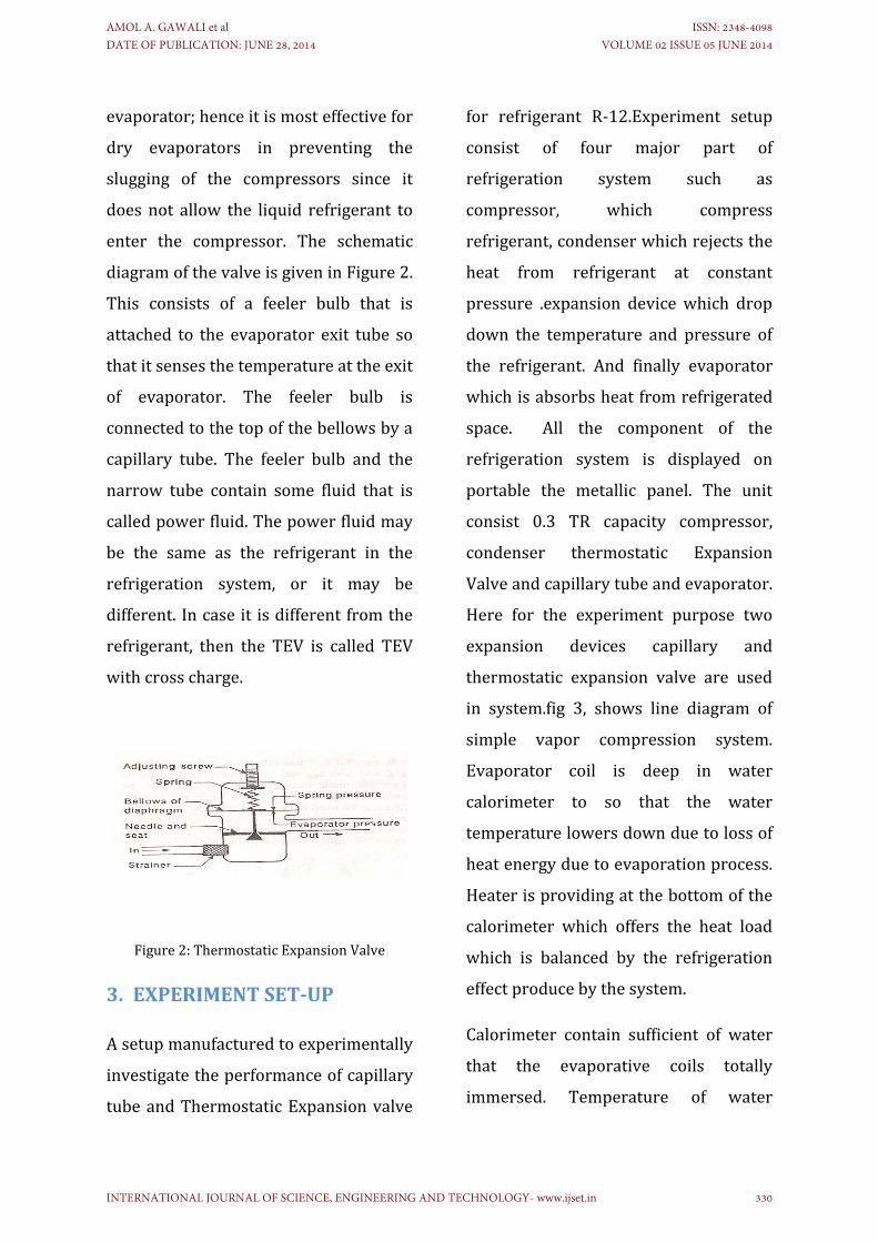
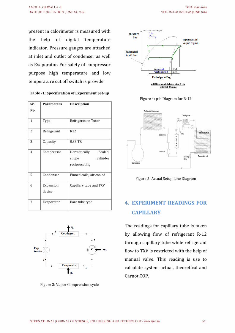
Figure3:VaporCompressioncycle
Figure4:p‐hDiagramforR‐12
Figure5:ActualSetupLineDiagram
4. EXPERIMENTREADINGSFOR
CAPILLARY
Thereadings forcapillary tube is taken
by allowing flow of refrigerant R‐12
throughcapillarytubewhilerefrigerant
flowtoTXVisrestrictedwiththehelpof
manual valve. This reading is use to
calculate system actual, theoretical and
CarnotCOP.
AMOL A. GAWALI et al DATE OF PUBLICATION: JUNE 28, 2014
ISSN: 2348-4098 VOLUME 02 ISSUE 05 JUNE 2014
INTERNATIONAL JOURNAL OF SCIENCE, ENGINEERING AND TECHNOLOGY- www.ijset.in 331
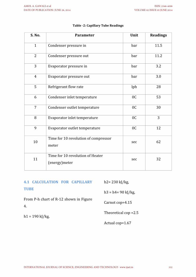
Table‐2:CapillaryTubeReadings
S.No. Parameter Unit Readings
1 Condenserpressurein bar 11.5
2 Condenserpressureout bar 11.2
3 Evaporatorpressurein bar 3.2
4 Evaporatorpressureout bar 3.0
5 Refrigerantflowrate lph 28
6 Condenserinlettemperature 0C 53
7 Condenseroutlettemperature 0C 30
8 Evaporatorinlettemperature 0C 3
9 Evaporatoroutlettemperature 0C 12
10Timefor10revolutionofcompressor
metersec 62
11Timefor10revolutionofHeater
(energy)metersec 32
4.1 CALCULATION FOR CAPILLARY
TUBE
FromP‐hchartofR‐12showninFigure
4.
h1=190kJ/kg,
h2=230kJ/kg,
h3=h4=90kJ/kg,
Carnotcop=4.15
Theoreticalcop=2.5
Actualcop=1.67
AMOL A. GAWALI et al DATE OF PUBLICATION: JUNE 28, 2014
ISSN: 2348-4098 VOLUME 02 ISSUE 05 JUNE 2014
INTERNATIONAL JOURNAL OF SCIENCE, ENGINEERING AND TECHNOLOGY- www.ijset.in 332
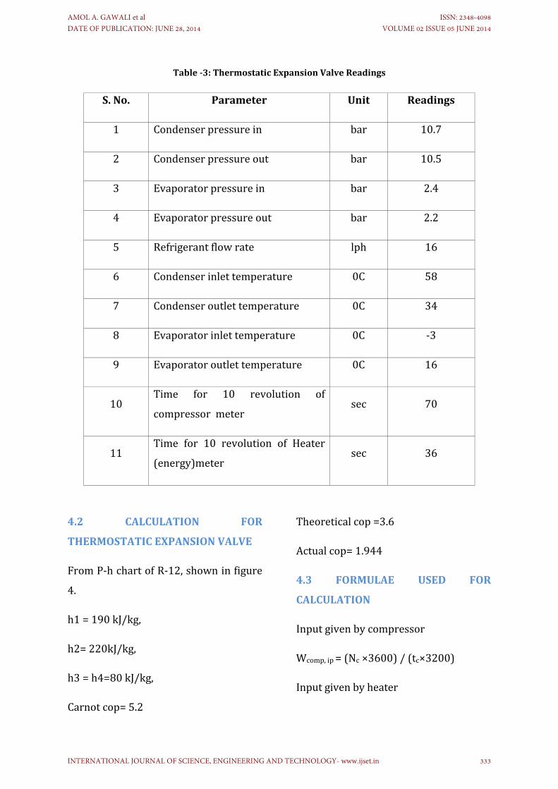
Table‐3:ThermostaticExpansionValveReadings
S.No. Parameter Unit Readings
1 Condenserpressurein bar 10.7
2 Condenserpressureout bar 10.5
3 Evaporatorpressurein bar 2.4
4 Evaporatorpressureout bar 2.2
5 Refrigerantflowrate lph 16
6 Condenserinlettemperature 0C 58
7 Condenseroutlettemperature 0C 34
8 Evaporatorinlettemperature 0C ‐3
9 Evaporatoroutlettemperature 0C 16
10Time for 10 revolution of
compressormetersec 70
11Time for 10 revolution of Heater
(energy)metersec 36
4.2 CALCULATION FOR
THERMOSTATICEXPANSIONVALVE
FromP‐hchartofR‐12,showninfigure
4.
h1=190kJ/kg,
h2=220kJ/kg,
h3=h4=80kJ/kg,
Carnotcop=5.2
Theoreticalcop=3.6
Actualcop=1.944
4.3 FORMULAE USED FOR
CALCULATION
Inputgivenbycompressor
Wcomp,ip=(Nc×3600)/(tc×3200)
Inputgivenbyheater
AMOL A. GAWALI et al DATE OF PUBLICATION: JUNE 28, 2014
ISSN: 2348-4098 VOLUME 02 ISSUE 05 JUNE 2014
INTERNATIONAL JOURNAL OF SCIENCE, ENGINEERING AND TECHNOLOGY- www.ijset.in 333
Wheater,ip=(Nh×3600)/(th×3200)
Carnotcop
(COP)Carnot=TL/(TH‐TL)
Actualcop
(COP)Actual=Wheater,ip/Wcomp,ip
Theoreticalcop
(COP) theoretical =Refrigerating effect /
compressorwork
=(h1‐h4)/(h2‐h1)
4.4 NOMENCLATURE AND
SUBSCRIPTS
W=workdone
h=enthalpy
Cop=coefficientofperformance
Comp=compressor
ip=input
L=lower
H=higher
1,2,3,4=enthalpypointvalue.
5. CONCLUSION
1) A TXV equipped refrigeration
system provides energy saving.TXV
have shown that they maintain higher
levelofefficiencyevenwhenrefrigerant
charge is lower than the manufactures
specification.
2) Fixed expansion devices, such
ascapillary tubes, work at one preset
levelandhavenoabilitytocompensate
forloadchanges
3) Variations of capacity over the
ambient temperaturerangeof260C to
55 0C can cause a performance loss of
85% with a cap tube system. A well
tuned expansion valve systemwill lose
less than one half this amounts, while
maintaining better compressor
temperaturecontrol.
4) Thermostatic expansion valve
Maximum efficiency over a wide
temperature and load range, it gives
improved refrigerant return to the
compressor assures better cooling at
high temperatures and reduces the
possibility of liquid sluggingwhich can
destroythecompressor
5) Carnot cop is higher than
theoreticalcopandactualcopincaseof
both thermostatic expansion valve and
capillarytube.
6) Experimental results shows
thermostaticexpansionvalvehashigher
Carnot,, theoreticalandActualcopthan
capillarytube.TXVhaslesscompressor
workthancapillarytube.
AMOL A. GAWALI et al DATE OF PUBLICATION: JUNE 28, 2014
ISSN: 2348-4098 VOLUME 02 ISSUE 05 JUNE 2014
INTERNATIONAL JOURNAL OF SCIENCE, ENGINEERING AND TECHNOLOGY- www.ijset.in 334
7) It was found that the energy
consumption of the thermostatic
expansionvalvesystemwasonly lower
thanthatofthecapillarytubesystemat
higher cooling loads and at lower
coolingcapacities
8) During experiment it is occurs
that thermostatic expansion valve able
to drop down more pressure than the
capillary which is produce more
refrigeranteffectforthesystem.
9) During experiment it is occurs
that thermostatic expansion valve able
to control degree of superheat of
refrigerant which causes reduction in
compressorwork and energy saving of
system.
ACKNOWLEDGEMENTS
I with great pleasure take this
opportunitytoexpressmydeepsenseof
gratitude towardsWalchand College of
Engineering,Sangli..Forallowingmeto
dothecasestudyworkon“Experiment
analysis and performance testing of
capillary tube and thermostatic
expansion valve”. I also would like to
thank my guide Prof. M.S.Joshi,
Department of Mechanical Engineering
for his valuable guidance and constant
inspirationduringthecompletionofthis
paper.
REFERENCES
[1]. Jackson B. Marcinichen, Claudio
Melo “Comparative analysis between a
capillary tube and an electronic
expansionvalveinahousehold”Federal
University of Santa
CatarinaInternational Refrigeration and
AirConditioningConference.Paper838,
March2006.
[2]. Mutalubi Aremu Akintunde,
”Effect of coiled capillary tube pitch on
vapour compression refrigeration
systemperformance”FederalUniversity
of Technology, Department of
Mechanical Engineering Akure, Ondo
State,Nigeriapp14‐22,July2007
[3]. Nishant P. Tekade, Dr. U. S.
Wankhede,”Selectionofspiralcapillary
tube for refrigeration appliances”
International Journal of Modern
EngineeringResearch,Vol.2,Issue.3,pp‐
1430‐1434,May‐June2012.
[3]. Sporlan “Installing and servicing
thermostatic expansion valves”
bulletin10‐9,June2001
[4]. Marco Noro,Renato Lazzarin,
DanieleNardotto,“Electronicexpansion
valve vs thermal expansion valve”
ASHRAE Journal, pp. 34‐39, February
2009
AMOL A. GAWALI et al DATE OF PUBLICATION: JUNE 28, 2014
ISSN: 2348-4098 VOLUME 02 ISSUE 05 JUNE 2014
INTERNATIONAL JOURNAL OF SCIENCE, ENGINEERING AND TECHNOLOGY- www.ijset.in 335

[5]. Amit Kulkarni,Veerendra Mulay
and Dereje Agonafer, ”Effect of the
thermostatic expansion valve
characteristics on the stability of a
refrigeration system” 2002 IEEE Inter
Society Conference on Thermal
Phenomena,pp.403‐412
[6]. Schmidt, Roger, “Low
temperature electronic cooling”,
Electronics Cooling Magazine,
September2000,Vol.6,No.3.
[7]. Pakawat Kritsadathikarn,
Tirawat Songnetichaovalit, ”Pressure
distribution of refrigerant flow in an
adiabaticcapillarytube”ScienceAsia28
jan.2002,pp.71‐76.
BIOGRAPHIES:
AmolA.GawalireceivedtheB.E.
and M. Tech degrees in
MechanicalEngineeringfromDr.
Babasaheb Ambedakar
UniversityandShivajiUniversity
in2010and2014,respectively.
Prof. Madhav S. Joshi received
the B.E. andM. Tech degrees in
Mechanical Engineering from
Shivaji University 1976 and
1979,respectively.Heisworking
as Associate professor in
WalchandcollegeofEngineering
since1980totilldate.
RupeshL.RautreceivedtheB.E.
and M. Tech degrees in
Mechanical Engineering from
Pune University and Shivaji
University in 2010 and 2014,
respectively.
Rahul A. Bhogare received the
B.E. and M. Tech degrees in
MechanicalEngineeringfromDr.
Babasaheb Ambedakar
University and MITCOE,
Kuthrud,Punein2010and2014,
respectively.
AMOL A. GAWALI et al DATE OF PUBLICATION: JUNE 28, 2014
ISSN: 2348-4098 VOLUME 02 ISSUE 05 JUNE 2014
INTERNATIONAL JOURNAL OF SCIENCE, ENGINEERING AND TECHNOLOGY- www.ijset.in 336
Copyright © 2022 FDOKUMEN