EXHIBIT C 2 Description of Landlord Work - SBS Corporation
315
• • • • • • • •
-
Upload
khangminh22 -
Category
Documents
-
view
4 -
download
0
Transcript of EXHIBIT C 2 Description of Landlord Work - SBS Corporation

��
�����������
� ���������������������������� ���������� �����!������"������
#�$� #��� ��� !��%�
� �������
������ ���� ��� ������
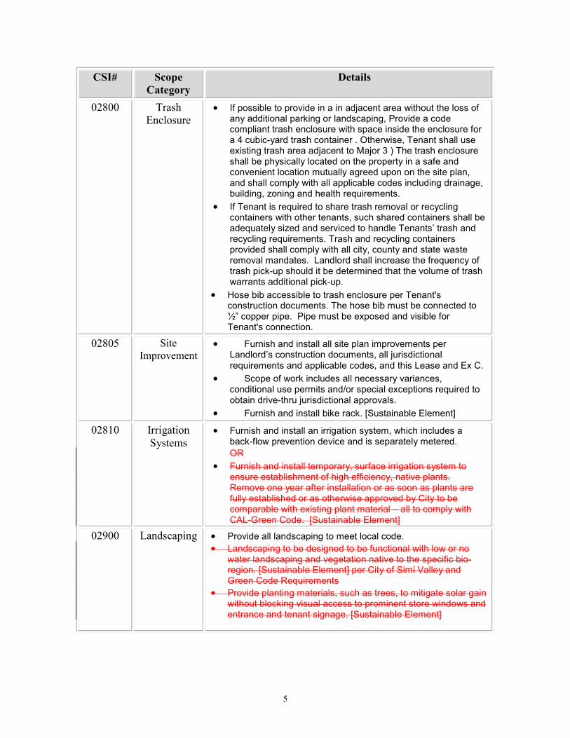
•� ����������� �������� ������������������������������ �� ������ ��� ����������� �� ����������������������������������������
������ ��������������������
•� ���!� ���������������
������ ���������� �����
•� "������������������� �����������#����#�������� �������$������������%����������
•� %���� ���������$����������������������#�����������������������������������������������������������������%�����������������&���� �������������'����(����������)��������������
•� %���� ���������$���������� ��������������������������������������������������%�����������������&���� �������������'����(����������)��������������
������ ���� ����� �������
•� "������� ����������� �������������*�+,�����������-� ������������� ��.����/�012#�� ������3�����.����������$����3�����������������������������������������������2#������� ��������������������������%��������������������������#�������� ������������������������� �������������+�������������������������������� �������������������������������45�����������������*��,6�������������������������������45������� ����7������85������ $���������������������������9���������������������������������������#��� ��� �������������#��������� ��������������������������������������� ��������������������
•� "������� ����������������� #������ �� ��������� ����(��������������������$#������&���� ��$�������������� ��#�������������� ������ �������:������������� ���������� ��� �����������������(��������������������$���������7������������������ �������/4���������45�����
•� ��������������������$����� � ��������������$�����$�������������� ����������������������
�

��
#�$� #��� ��� !��%�
� �������
������ ����� ������ �
•� %���� �������;1�������$������������������������%������� � ����� ��������)��������������������������������������������������������������������';1������������� �������.��2�� ����������������������<1����������������� ���������������������� ���
•� =��������(������������ ��������$������������������������
������ ������� �������
•� 9��������$� ����� ��
���!�� �����"���� ��������� �������
�������
•� "������� ������������������������� ��������������$���������������������������%�������� ���������������� ����������������������������� ������������
•� >�������� ����������� ���������� ���������� �������� �������������������������������������������?������������������������������ ���������� � �������������������� � ����� ���������:��������$����
•� %���� �������������$������ �������$#����� ������������������������*��,�����(�� ���������#����������#� ���������������#�����#��� ������������������������$���������������������:�������������������������������������������������������������� ��$�������������
•� "������� �������������� ���#�����#�� �����������������������������������$���&��������� ����� �������?������������ ���������$�����������������������������������������������
•� ������������ ������������������$�����$�������������������;55����#�/'5�'58�@����A�������;�������������������������� ��������:����������������������9����$�/'5�';5�@������������������������#�� ������������ �����$��
•� ?��������������������������������� �������������$���-� �(���������������������������� �����������������������������"������� �����������/45B@��������������� ���������������������������������������������;55�����/'5�'58�����������������������������������������:������������� ��������
�
��##�� ���������$�%�������
•� %���� �����������'55�="�C�� ����=�����������������7������������<1�����������9������������������ D�������������������������#��������������������������������$��� ������ ��� ���������� ��� �����������������������C�� ����=�����������&���� ��$�������������� ��� �C�� ����=���������������������������������
•� %���� ��E1������������������������������������(����������� D���������� ����(�����������
•� %���� ��� �&������������������7������������������� ��� )������������� �������� ���������������)�������������
��
#�$� #��� ��� !��%�
� �������
��!��� & ��'�"����� ��
•� 9������������������� ��������� D�������������������������������$�� ����������(�������� ������#�%���� ������ ��������������������������������������� ���������������������;������3$�� �����������������C��������#�����������������7������������������ D����������D���A�2�������������������������������$������$������� ��������������$����������� �����������������������$������ �������������������#�� �����������$����������������������� ������� ��� ������#����� ��#�-����� ����������&���������
•� 9������������&���� �����������������������������$������������������������������#����������� �������������������� �&�����$���-� �� �������� ������ ��������)�������� ����$�������&���������������� ����$������������������� � �����������$�������������$#�����$�� ��������������������� ��������� ��� ����������������������&���$�������������(3�������� ������� ������ ���������������������������������� ����������(3����
•� F���������������������������������������������:������������� ���������������������������������� ����01���������������%������������7���� �� �����������������:�����������
��!��� �����(�) ������
•� "������� ������������������������������������� ��� )������������� ������#�����D���� ����������&��������� �������������� ��#�� ������������� �?7�����
•� =�����������(����� ��������������$���������#��� ������������������� �������������7����������&���� ���������� ����3�����D���� �������������������
•� "������� ����������(�����(��*=����������?����,�
��!��� ( �*�������������
•� "������� ���������������������$���#����������� ��������(3�������������� ������� �������������$������ ��C>�
•� "������� ���������������$#��������������������$�����������������������������������������$#���������������>��������$������������������������������������������������$����������� ������������������������ ��$����$�����������������������7�������������������!������������$���������3������� ����*=����������?����,�
��+��� �����)�* •� %���� �������� ���������������������� ����•� �� ������������� ����� ������������������������������
�������� �������� ������������������������������������3�������*=����������?����,��������$����=���@����$�� �������� ��>�&��������
•� %���� �����������������#��������������#����������������������������������(����������������������������������� ����� ��������� ��������������*=����������?����,��

,�
#�$� #��� ��� !��%�
� �������
������ -��� �*� •� %���� ���������������� #������� �������������������� ������������� ��������������#���������#� �$��� ��������������������������������#�������� ��������$����� #������ �D������ ���� $���������������:�������������������
•� ������������������������������� �� �� ��������� ��� ��#����� ��������������� ����������������������� ��#������������� �����D���� ����������&����������
�#���� .��/� •� %���� �������� ��������������������������������������� ��������������� ��������������.G����2�� ������������������ ������������������)������������� ����������D��������$����� �������������.� �������$������ ��������������2�������$��������
•� ���������3�%���� ����������#�������� ��� ������������������������� �����������&��������������)������������� ���������� ��� ��������� ������������������������������������������������������������������������
•� %���� ������������������$�����������������������������-���������������D���� ����������&��������� ������������3������� ��>�&���������*=����������?����,�
•� %���� ������������������������������=�����>����������9 �7�.=>92���������������3������� ��>�&��������
�!���� 0�������� ��$�- �����
•� 9����&���� ���������)������������������#��������� ����������������$������ ���������������� ���7�������������������� ���������������������������� ���� ��������������������D���� �������
•� "������� �������������7������� ������� ��������� ��� �����������#����(����#����������#��������� #�����������������#� ����������� � ����� �������������� ��$��� ��� )������������� ��������
�!���� ��� �/ ���������$���� ��
•� =������������-��������������#��3���� #��3����������#� ���������-� �� ����3�������H3����������$��������������������������������-������������3������� ��
•� %���� ���������.�2�����������������������������(��$������#����.�2������������������������������������������ �������������� ����#������#����������#�� ����������� ��#�����������$#�� ��� �����������������$��� �����
•� %���� �������������$����� ��������������$� �������������$������ �������������&�����$#���������$������ ��������������
•� %���� �� ������� ����������� ��� )������������� ��������
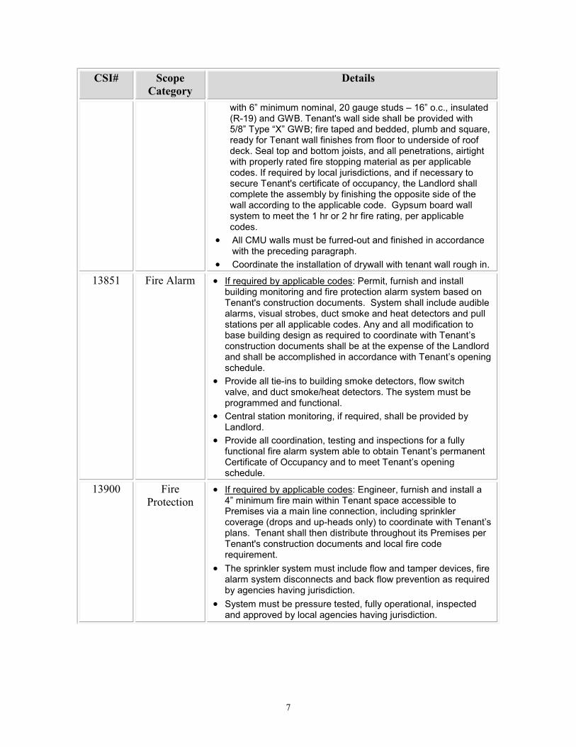
�+���� �)����1�� �
•� %���� �� ���� �� ���������������������� ����������;��������������������� ���� ���������� ��(������4�81��$���IJ1��+G���"������������� � ����������#���������������� �������$�������������������������������� ����?7�������������4�81��+G���������������������������������/�F������������� ����� �� ������ �����/���������������������&���� ��$��� ���
• �$������������� �*�+G,����������������������������� �
#�
#�$� #��� ��� !��%�
� �������
�����E1���������#�'5���������� ��!�/E1�����#�������� �.>3/K2�� ��+G������:��������� ���������������� � ������4�81��$���IJ1��+G6���������� �� ��� � #������� ��&����#���� $������������������������������������� ���� ���������� ��(��=��������� �������D�����#�� ���������������#����������������������$����� ������������������������������������������ ����9����&���� ��$�������D���� ������#�� �����������$���������������:������������������������$#������� ��� �������������������������$��$������������������������ ������������������� ����������������������� �����$�������� �������$���������������/�������'��������������#������������������ ����
•� ������H������������������� 3����� ������� �������� ������������������ ��������������
•� ���� ����������������������� �$�����������������������������
��!��� -� ��2�� �� •� 9����&���� ��$�������������� ��L�%����#��������� ������������ ������������ ����������������������$�������� �������:������������� ���������=$�������������� ���� ����������#���������������#� ������(��� ������ ���������� ����������������������������������� �����$�� ������ ��������������������� ��� ����������&���� �������� ��������������)������������� ������������������������7�������������� ��� �� �������������������� �������� �������������)������������ �����
•� %���� ���������3���������� �����(�� ��������#������������������#�� � ������(������� ���������������$������������������ �� �����������
•� ���������������������#������&���� #��������������� � ��$��� ��� ��
•� %���� ���������� �����#��������� ���������������������$���������������������$����������������������)������������������������C������$�� ������������)������������ �����
��+��� -� ��% ��������
•� 9����&���� ��$�������������� ��L�?�����#��������� ����������;1��������������������������������������������%���������������������������#����� �������(�������������. ������ ���3��� ����$2�������� ��������������)������������������������ �������������������������%���������������:������������� �������� �������������� ����&����������
•� ��������(�����$������������ �������� ������� ������#������������$���� ���������� ����(��������������������&���� ��$���������������D���� ���������
•� =$������������������������� #�����$�����������#�������� �� �������� ��$���������������������D���� �������

!�
#�$� #��� ��� !��%�
� �������
������ %�����*�-�3�� ���$�"4��)����
•� ���������������� ��������������������������������)������������� ������������������������������������������������������������������ �������������������%��������
•� B�$�������� ��7������������������������:������������� ���������������������������������� ����01�������������� ������������ ����� ���������9����������7���� �� �����������������:�����������
•� 9����&���� ��$�������������� ��L��"������� ������������������������������������������-� �� ������� ���������)������������� �������� ����������� ���������D���� ������������������������������� ��
������ 5627��
•� "������� �����������F@����������������*>�H,�����������$����#����� ��������������������������#����������������#��������������� ������������F@����������#���������:������������� ������#����������������� ������� ������������������ ������
•� ���� ������ ����� ������������������������������������������������ ������ �����)����(���� ������
•� "��������������������./2���������������������������$�����/45�="���������������������������$#������������������������M�4�������������������$#����D�����������:��F@�������������� ��������"��������������������$���������)������������� ��������F@��������������������� �� ����������� ������$��������������)��������$����������������� ���������� ����������*=����������?����,�
•� �� ��� ������������ �����������������/45������������������������������������������������������� �� ������������������������#����� ����������
•� F@������������������� � �������������������������� ������-����������&���� ��$��� ����F@��������M�4������ ������������������-��������������������� ��7�������������(� ����������������������-����������������������������������� �.����G�� ������� �� �������$������ ���2���
•� F@�������������'555��"�� ������$�������������������������� � �������� �������� ���(�� ������������������������ �����
•� F@��������������������� ������� ���������������������� ������������� ����&���������
•� =����������������������F@����$������������������������������� ���� ����� ������������������������������������ ������ ���������
•� �����������F@���������������������$����������:������������� �������� ��$������� ����&�������L��������./2������������������������������������������������������ ������ ����������:������������� ����������
•� %���� �� ���� ��������������(���������� ������������ �����$������������)������������� ��������

+�
#�$� #��� ��� !��%�
� �������
•� %���� ������$������������ ���������������������������������������������.�2������&���� ��$�������D���� �������
��!��� ������ ���
9��������$� ����� �
�,���� "���� �����%�����
•� "������� ������������.'2������N=&����3�)�����&����.���������������������$�����2� ?���%G/#��$���/#�;55�������� ���������������(����#����� � ���3�3 ������������������������������������ ����� 3������������������� �������������������������������������� ����������������#�������������� ������ ��$������������
•� ?������������������������������������ ������;'�������� �����(������������)������������� �������� ���������� �����
•� %��������������������9�����������������.�9�2��������������������������� �����������������������������������������������������$���
�,���� ��*'��*� •� "������� �����������������$������#��������������������������������������������� �������������������������� �����������4555������������������������������� ����&�����������7������������ ������������� ������/5)������������� �������*�"",�� ��������� �������)���������*=����������?����,�
•� "������� �����������(�������������������������������/�4�"������� ��������� ���� ������������������������������������ ����?7����������� ����������������������� ���������� �����������������������)������������� ���������
�,#����
&���)'����������
•� 9������������������������������?��.������?7��������������������������������������� ��2��
•� %���� �������������$�������$���������� ������� ��?��������������������������������� ������� ��������.�2���������
•� %���� ���������$�� ���������������� ���������������������������������������������#������&���� ��$�������� ��������?�#���������� �D���� �������������������$����������������������������������������
•� "������� �����������./2�'1��� �������������������������������� ��:����������������$�*�%C?,�������������������������)����������������������
�
���
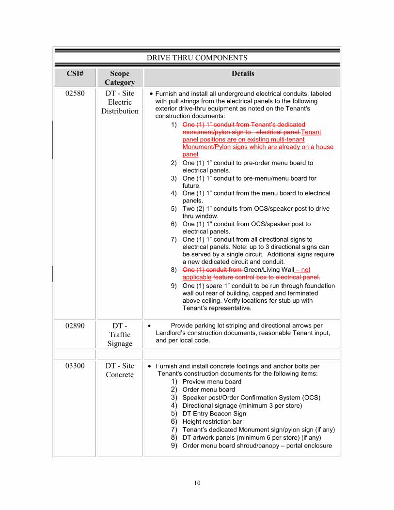
�.(6"�&5.��780%89"9&��
#�$� #��� ��� !��%�
� ������
���!�� �&�:������"���� ���
���� ������
•�"������� ������������� ������ �������������� ����#������� �������������������������������������������������������������7������� ����3������&������������ �����������:������������� ������L�
/2� C��./2�/1��� ������������)�� � ����� �������$������������������������������������������������������7����������3�����������%$����������������������� $����������������
'2� C��./2�/1��� ����������3�� ���������� ����������������������
A2� C��./2�/1��� ����������3���������� �������������
;2� C��./2�/1��� ������������������� ����������������������
42� ����.'2�/1��� ���������C�=�����(����������� ������������ ����
E2� C��./2�/O��� ��������C�=�����(�����������������������������
M2� C��./2�/1��� ������������ ������������������������������������ ���L�������A� �������������������������� ��$�������������������� ��������������&���������� � ����� ���������� ��� ������� � �
82� C��./2��� �������������������+����!��������������������������������7����������������������
K2� C��./2�������/1��� ������������������������ �������������������������� ��#������ �� �������� ���������������@����$�������������������������������)�����������������
�
��!+�� �&�:�& �//�����*�*��
•� %���� �����(���������������� � ����������������������� ��� )������������� ������#��������������������#�� ������������� ���
� � �
������ �&�:������7�� ����
�
•� "������� ������������������������� ���������������������:������������� ����������������������������L��
/2� %�������������� �'2� C� ���������� ��A2� =���(��������C� �������������=$����.C�=2�;2� ������������������.����A����������2�42� ���?��$�G�����=���E2� F���������������������M2� ����)�� � ����� ������������$�������.����$2�82� ���������(�������.����E����������2�.����$2�K2� C� ���������� ������ �����$�!������������������

���
•� %���� ���� ���������� ����E1�����(#��������� ���������� � ���������#������ ���������������� ������������ ���������������� ���������� ����3�����������������������/')��� ��� ������������������7�� �/8)��
•� "������� ��������E1� ������������������������ �#������ �������������#������ �� ������� ���������)������������� ��������
�!���� �&�:�� ���:&' ��
�����
•� "������� ������������������������� � ����3��������������� �������������������������$��������������������������)������������������������)������������� ���������
•� "������� ��������//53�����/4�����������#��������� ��� �������#����� ������������ ��7������������#���������)������������� ���������
•� F������������������� ����������AE1���������� �������������� �������� �;'1������������ �������� ����� ����3����������
•� "������� ���������������������$������� ������������ �����������)������������� ������������������ ���
������ �&�:�2��*��
•� "������� �����������7��������������������� ����3������� �����������$������������� ��� )���� ������������� ������?7��������������������
�,���� �&�:��������*'��*�
•� "������� ������������.'2��7������#�������������� #�������������� �� D�������� ����3������� �����������)������������� ��������
•� ������������ ���������7������������������� ����� ������������������������������/�4����������� ���������
����� ;� � &���;� �% ���9���;�� �
% ���9���;�� �
&����;� � &����;� �����;� � ����;� �
�

NOT
NNNNNNNNNNNNNNNNNNNNNNNNNNNNNNNNNNNNNNNNNNNNNNNNNNNNNNNNNNFOR
FFFFFFFOFOFOFOFOFOFOFOFFFFFFFFFFFFFFOFOFFFFFFFCONSTRUC
TRU
ONSTRTTTTTTTTTTTST NSTTTTSTSSTSTSTSTSSSTTSNSSSSTTTSNSSSTTTSSSTTTSSSNNNNSNSNNSNSNSSSSNNN
ONNNNNNNNNNNNNNNNNNSTSTRRRRRRRRRRRRRRRRRRRRTRTRTRTRTRTRTRRRRRRRRRRRRRRRRU
TRTRTRTRTRTRTRTRRRR STRT
ONTTTRTRTRTRTRTRTRTRTRTRTRTRTRTRTRTRTRTRTTRRRRRRRRRR STSSSTSSSSSSNNNNNNNNNNNN
OOOOOONNONNONONNONNONONNNONONONONNNNNNNNN

NOT
NNNNNNNNNNNNNNNNNNNNNNNNNNNNNNNNNNNNNNNNNNNNNNNNNNNNNNNNNNFOR
FFFFFFFOFOFOFOFOFOFOFOFFFFFOFOFFFFFFFCOCCCCCCCON
COCOCOOOCCCCOCCOCCOOCCCCONONONONONONONOOOOOOOOONOOONOOOOOONONONONONONOONOCOOONONONON
CCOOOOOOONOONONOOOONONOCONONONONONOCONONONONONONONONONONONONOONSTR
NSNSNSSSSSSSNSNNNNNNNNNNNNNNNNNNNNNNNSSSSSSSSSSSSSTSTSTSTSTSTSTSTSTSTSTSTSTSTSTTTTTTTSSSSSSSSSSSSSSSSSSSSSSSSSNSNSNSNS
OCON
CONON
CCCCCOCOCCCCCCCCCCCCCCCOOOOOOOOOONONONONONONONONONONONONONONONOOOOOOOOOOOOOOOOOOOOOOOOOOOOOO
TRUCTION
RUCTION
RUCUUCUCUCURURURURUUUUUCCC
TRTRTRIOIO
RURRRRRRURURURURURURURURURURUUUUUUUUUUUUCCCCIIIIIION
TIOO
TTTTTTRRUUCTTCTTIO
CONN
TTIOO
TCCURURRRUUCCCTCTTTIOON
RUCTIO
CO
RUCCTIOOIOOTCURRU
CTTIOON
CRUCCTT
RRONO
TI CTTCTCUCURURRRRRRURUCUCCTCTTTIOON
RRTRRC
TRRTCCT U
TRRCTTTI
URRTTIO
CUUCUTTIOO
CCTOOON
TTOO
RRURRRRRUUUUCUCCTCCTTTTI TTTI TIOIOOOOOOONN
RTRRTRTRUUURURTRCUCURRTCTCUC RCTTOOIOTI TCTCCOOIOTIO
TI TTOIOIO
TRRTRRRRUUUCUCUCUCCCCTTI TTI TI TIOIOOOONN
TRUCUCUCUCCCCCCCCUUUUUUCCCCCCCCCCTCTCTCTCTCTCTCTCCCCCCCCTCTCTCTCTCTCTCTCTCTCT UCUUCCTCTCTTCCCCCCURUCCUCUCUCUCUCUCUCUCUCUCUCUCUCUUCUCCCCCCCCCCCON
TRUCTIONOOOOOOOOOOOOOOOOOOOOOO

NOT
NNNNNNNNNNNNNNNNNNNNNNNNNNNNNNNNNNNNNNNNNNNNNNNNNNNNNNNNNNFOR
FFFFFFFOFOFOFOFOFOFOFOFFFFFFFFFFFFFFFFOFOFFFFFFFOOOOOOOOOOCONSTRUC R
SSSSSSSSSSSTSTSTSTSTTTTTTTTTT NSTRTST NSNSSSSSNSSNSNSSSSNSNSSSSRUUUUURURRRRRRRRRRRRRRRURRURURURURURURURURURU TRTTTTTTTTTTTTTTTTTT
NOT
NNNNNNNNNNNNNNNNNNNNNNNNNNNNNNNNNNNNNNNNNNNNNNNNNNNNNNNNNNFOR
FFFFFFFOFOFOFOFOFOFOFOFFFFFFFFFFFFFFOFOFFFFFFFFFFFFFFFFFOFFOFOFOFOFOFOFOFOFOCONSTRURUCT
TTTTTTTTTTTTTTTTTTTTTTTTNSTR
NTRTRTRTRTRTRTRTTTTTTTTTRTRTRTR
NNSSTSSTSSTRRURRRRURRTRR
NNSSSTSTSSNNSSSSSTSTTRRRR
NSSRRU TTRRU
NSSTTRRRRURURURRURTRT
NSSRRUR
NSR
SSTRR
SSRURRRRR
STSNSSSNSSSSTSRRRRRU TRRRRRRRURRRRRRURU
SSSSSSNSTTSTSTSSSNSNSNSNR
NTRTRRRRRRURRRURRRURRRRRTRURTSSRUR
STSTRUR
SSRUR
SSRUR
SNSR
NST
NSSNSNSNSNSSSSTSTTTRRRRRRRURRRU
NSNNSNSNSSSNSSSSTSTSTTSSSSSSSSRURURURURURUUUUUUUUUUUUUUUUUURURURURURURUURUUUUUUUUUUUUUUUUUUUUUURUUUUUUUUUUUUUUUUUUUUUUUUUCUCUUCUCUCUCUCUCUUUUUUUUUUUUUUUUUUUCUCUCUCUCUCUCUCUCUCURURURURRURURURUUUUUUUUUUU TTRU
NNNSTRU

NOT
NNNNNNNNNNNNNNNNNNNNNNNNNNNNNNNNNNNNNNNNNNNNNNNNNNNNNNNNNNFOR
FFFFFFFOFOFOFOFOFOFOFOFFFFFOFOFFFFFFFRRRRRRRRRCONSTRUC
SSSST NNSTST NNNNSNSNSNSNSNSNSNSNSNSNSNSNSNSNSNNNNNNNNNNSNSNSNSNSSSSSSSSSSSS
ONSONONON
RRSSSSSSSSSSSTTTTTTTTRTRTSTTRTS
ONONNNNNNNNNN

RESTAURANT PADSimi Valley, CaliforniaFA Project Number 16017
SUMMARY 011000 - 1
SECTION 011000 - SUMMARY
PART 1 - GENERAL
1.1 SUMMARY
A. Section Includes:
1. Project information.2. Work covered by Contract Documents.3. Phased construction.4. Work under separate contracts.5. Access to site.6. Coordination with occupants.7. Work restrictions.8. Specification and Drawing conventions.
B. Related Requirements:
1. Section 015000 "Temporary Facilities and Controls" for limitations and procedures governing temporary use of Owner's facilities.
1.2 PROJECT INFORMATION
A. Project Identification: Restaurant Pad Building, FA Project No. 16017
1. Project Location: 599 Country Club Drive, Simi Valley, CA 93065
B. Owner: Wood Ranch Center, LLC Contact: Albert Cohen 15490 Ventura Blvd., Suite 200 Sherman Oaks, CA 91403 Telephone: 818-501-5500 Email:[email protected] Cc: [email protected]
C. Architect: Fisher Architects, Inc. Contact: Michael Fisher6593 Collins Drive, Suite D-17Moorpark, CA 93021Telephone: 805-990-8292Email: [email protected]

RESTAURANT PADSimi Valley, CaliforniaFA Project Number 16017
SUMMARY 011000 - 2
1.3 WORK COVERED BY CONTRACT DOCUMENTS
A. The Work of Project is defined by the Contract Documents and consists of the following:
1. Approximately 3,500 sf Multi-Tenant Restaurant Building and associated Site Work as indicated in the Contract Documents.
B. Type of Contract:
1. Project will be constructed under a single prime contract.
1.4 ACCESS TO SITE
A. Use of Site: Limit use of Project site to areas within the Contract limits indicated. Do not disturb portions of Project site beyond areas in which the Work is indicated.1. Driveways, Walkways, and Entrances: Keep driveways, loading areas, and entrances
serving premises clear and available to Owner, Owner's employees, and emergency vehicles at all times. Do not use these areas for parking or for storage of materials.
1.5 COORDINATION WITH OCCUPANTS
A. Full Owner Occupancy: Owner will occupy site and adjacent building(s) during entire construction period. Cooperate with Owner during construction operations to minimize conflicts and facilitate Owner usage. Perform the Work so as not to interfere with Owner's day-to-day operations. Maintain existing exits unless otherwise indicated.
B. Partial Owner Occupancy: Owner will occupy the premises during entire construction period, with the exception of areas under construction. Cooperate with Owner during construction operations to minimize conflicts and facilitate Owner usage. Perform the Work so as not to interfere with Owner's operations. Maintain existing exits unless otherwise indicated.
C. Owner Limited Occupancy of Completed Areas of Construction: Owner reserves the right to occupy and to place and install equipment in completed portions of the Work, prior to Substantial Completion of the Work, provided such occupancy does not interfere with completion of the Work. Such placement of equipment and limited occupancy shall not constitute acceptance of the total Work.
1.6 WORK RESTRICTIONS
A. Work Restrictions, General: Comply with restrictions on construction operations.
1. Comply with limitations on use of public streets and with other requirements of authorities having jurisdiction.
B. On-Site Work Hours: Limit work in the existing building to normal business working hours of 8:00 a.m. to 5:00 p.m., Monday through Friday, unless otherwise indicated.

RESTAURANT PADSimi Valley, CaliforniaFA Project Number 16017
SUMMARY 011000 - 3
C. Existing Utility Interruptions: Do not interrupt utilities serving facilities occupied by Owner or others unless permitted under the following conditions and then only after providing temporary utility services according to requirements indicated:
1. Notify Owner not less than two days in advance of proposed utility interruptions.2. Obtain Owner's written permission before proceeding with utility interruptions.
D. Restricted Substances: Use of tobacco products and other controlled substances on Project site is not permitted.
1.7 SPECIFICATION AND DRAWING CONVENTIONS
A. Specification Content: The Specifications use certain conventions for the style of language and the intended meaning of certain terms, words, and phrases when used in particular situations. These conventions are as follows:
1. Imperative mood and streamlined language are generally used in the Specifications. The words "shall," "shall be," or "shall comply with," depending on the context, are implied where a colon (:) is used within a sentence or phrase.
2. Specification requirements are to be performed by Contractor unless specifically stated otherwise.
B. Division 01 General Requirements: Requirements of Sections in Division 01 apply to the Work of all Sections in the Specifications.
PART 2 - PRODUCTS (Not Used)
PART 3 - EXECUTION (Not Used)
END OF SECTION 011000

RESTAURANT PADSimi Valley, CaliforniaFA Project Number 16017
PROJECT MANAGEMENT AND COORDINATION 013100 - 1
SECTION 013100 - PROJECT MANAGEMENT AND COORDINATION
PART 1 - GENERAL
1.1 SUMMARY
A. Section includes administrative provisions for coordinating construction operations on Project including, but not limited to, the following:
1. Coordination drawings.2. Requests for Information (RFIs).3. Project Web site.4. Project meetings.
B. Related Sections:
1. Division 01 Section "Multiple Contract Summary" for a description of the division of work among separate contracts and responsibility for coordination activities not in this Section.
2. Division 01 Section "Execution" for procedures for coordinating general installation and field-engineering services, including establishment of benchmarks and control points.
1.2 DEFINITIONS
A. RFI: Request from Owner, Architect, or Contractor seeking information from each other during construction.
1.3 COORDINATION
A. Coordination: Coordinate construction operations included in different Sections of the Specifications to ensure efficient and orderly installation of each part of the Work. Coordinate construction operations, included in different Sections that depend on each other for proper installation, connection, and operation.
1. Schedule construction operations in sequence required to obtain the best practices results where installation of one part of the Work depends on installation of other components, before or after its own installation.
2. Coordinate installation of different components to ensure maximum performance and accessibility for required maintenance, service, and repair.
3. Make adequate provisions to accommodate items scheduled for later installation.4. Coordinate with works scheduled as deferred submittals.
B. Prepare memoranda for distribution to each party involved, outlining special procedures required for coordination. Include such items as required notices, reports, and list of attendees at meetings.

RESTAURANT PADSimi Valley, CaliforniaFA Project Number 16017
PROJECT MANAGEMENT AND COORDINATION 013100 - 2
1. Prepare similar memoranda for Owner and separate contractors whether coordination of their Work is required or not.
C. Administrative Procedures: Coordinate scheduling and timing of required administrative procedures with other construction activities and activities of other contractors to avoid conflicts and to ensure orderly progress of the Work. Such administrative activities include, but are not limited to, the following:
1. Preparation of Contractor's construction schedule.2. Preparation of the schedule of values.3. Installation and removal of temporary facilities and controls.4. Delivery and processing of submittals.5. Progress meetings.6. Preinstallation conferences.7. Project closeout activities.8. Startup and adjustment of systems.9. Project closeout activities.
1.4 COORDINATION DRAWINGS
A. Coordination Drawings, General: Prepare coordination drawings in accordance with requirements in individual Sections, where installation is not completely shown on Shop Drawings, where limited space availability necessitates coordination, or if coordination is required to facilitate integration of products and materials fabricated or installed by more than one entity.
1. Content: Project-specific information, drawn accurately to a scale large enough to indicate and resolve conflicts. Do not base coordination drawings on standard printed data. Include the following information, as applicable:
a. Indicate functional and spatial relationships of components of architectural, structural, civil, mechanical, and electrical systems.
b. Indicate dimensions and elevations shown on the Drawings. Specifically note dimensions and/or elevations that appear to be in conflict with submitted equipment and minimum clearance requirements. Provide alternate sketches to Architect indicating proposed resolution of such conflicts. Minor dimension changes and difficult installations will not be considered changes to the Contract.
B. Coordination Drawing Organization: Organize coordination drawings as follows:
1. Floor Plans and Reflected Ceiling Plans: Show architectural and structural elements, and mechanical, plumbing, fire protection, fire alarm, and electrical Work. Show locations of visible ceiling-mounted devices relative to acoustical ceiling grid.
2. Plenum Space: Indicate subframing for support of ceiling and wall systems, mechanical and electrical equipment, and related Work. Locate components within ceiling plenum to accommodate layout of light fixtures indicated on Drawings.
3. Mechanical Rooms: Provide coordination drawings for mechanical rooms showing plans and elevations of mechanical, plumbing, fire protection, fire alarm, and electrical equipment.

RESTAURANT PADSimi Valley, CaliforniaFA Project Number 16017
PROJECT MANAGEMENT AND COORDINATION 013100 - 3
4. Structural Penetrations: Indicate penetrations and openings required for all disciplines.5. Slab Edge and Embedded Items: Indicate slab edge locations and sizes and locations of
embedded items for metal fabrications, sleeves, anchor bolts, bearing plates, angles, door floor closers, slab depressions for floor finishes, curbs and housekeeping pads, and similar items.
6. Review: Architect will review coordination drawings to confirm that the Work is being coordinated, but not for the details of the coordination, which are the Contractor's responsibility.
1.5 REQUESTS FOR INFORMATION (RFIs)
A. General: Immediately on discovery of the need for additional information or interpretation of the Contract Documents, Contractor shall prepare and submit an RFI in the form specified.
1. Architect will return RFIs submitted to Architect by other entities controlled by Contractor with no response.
2. Coordinate and submit RFIs in a prompt manner so as to avoid delays in Contractor's work or work of subcontractors.
B. Content of the RFI: Include a detailed, legible description of item needing information or interpretation and the following:
1. Project name.2. Project number.3. Date.4. Name of Contractor.5. Name of Architect.6. RFI number, numbered sequentially.7. RFI subject.8. Specification Section number and title and related paragraphs, as appropriate.9. Drawing number and detail references, as appropriate.10. Field dimensions and conditions, as appropriate.11. Contractor's suggested resolution. If Contractor's solution(s) impacts the Contract Time
or the Contract Sum, Contractor shall state impact in the RFI.12. Contractor's signature.13. Attachments: Include sketches, descriptions, measurements, photos, Product Data, Shop
Drawings, coordination drawings, and other information necessary to fully describe items needing interpretation.
C. RFI Forms: AIA Document G716 or Software-generated form with substantially the same content as indicated above, acceptable to Architect.
D. Architect's Action: Architect will review each RFI, determine action required, and respond. Allow three working days for Architect's response for each RFI. RFIs received by Architect after 1:00 p.m. will be considered as received the following working day.
1. The following RFIs will be returned without action:
a. Requests for approval of submittals.
RESTAURANT PADSimi Valley, CaliforniaFA Project Number 16017
PROJECT MANAGEMENT AND COORDINATION 013100 - 4
b. Requests for approval of substitutions.c. Requests for coordination information already indicated in the Contract
Documents.d. Requests for adjustments in the Contract Time or the Contract Sum.e. Requests for interpretation of Architect's actions on submittals.f. Incomplete RFIs or inaccurately prepared RFIs.
2. Architect's action may include a request for additional information, in which case Architect's time for response will date from time of receipt of additional information.
3. Architect's action on RFIs that may result in a change to the Contract Time or the Contract Sum may be eligible for Contractor to submit Change Proposal according to Division 01 Section "Contract Modification Procedures."
a. If Contractor believes the RFI response warrants change in the Contract Time or the Contract Sum, notify Architect in writing within 7 days of receipt of the RFI response.
E. On receipt of Architect's action, update the RFI log and immediately distribute the RFI response to affected parties. Review response and notify Architect within three (3) days if Contractor disagrees with response.
F. RFI Log: Prepare, maintain, and submit a tabular log of RFIs organized by the RFI number. Submit log weekly. Use CSI Log Form 13.2B.
1. Project name.2. Name and address of Contractor.3. Name and address of Architect.4. RFI number including RFIs that were dropped and not submitted.5. RFI description.6. Date the RFI was submitted.7. Date Architect's response was received.8. Identification of related Minor Change in the Work, Construction Change Directive, and
Proposal Request, as appropriate.9. Identification of related Field Order, Work Change Directive, and Proposal Request, as
appropriate.
1.6 PROJECT MEETINGS
A. General: Schedule and conduct meetings and conferences at Project site, unless otherwise indicated.
1. Attendees: Inform participants and others involved, and individuals whose presence is required, of date and time of each meeting. Notify Owner and Architect of scheduled meeting dates and times.
2. Agenda: Prepare the meeting agenda. Distribute the agenda to all invited attendees.3. Minutes: Entity responsible for conducting meeting will record significant discussions
and agreements achieved. Distribute the meeting minutes to everyone concerned, including Owner, and Architect, within three (3) days of the meeting.

RESTAURANT PADSimi Valley, CaliforniaFA Project Number 16017
PROJECT MANAGEMENT AND COORDINATION 013100 - 5
B. Preconstruction Conference: Owner will schedule and Contractor will conduct a preconstruction conference before starting construction, at a time convenient to Owner and Architect, but no later than ten (10) calendar days after execution of the Agreement.
1. Attendees: Authorized representatives of Owner, Architect, Contractor and its superintendent; all subcontractors; major suppliers; and other concerned parties shall attend the conference. Participants at the conference shall be familiar with Project and authorized to conclude matters relating to the Work for each of their respective responsibilities, without reservation.
2. Agenda: Discuss items of significance that could affect progress, including the following:a. Tentative construction schedule.b. Site Constraintsc. Logistics and laydown aread. Phasing.e. Special conditions of the workf. Critical work sequencing and long-lead items.g. Designation of key personnel and their duties.h. Procedures for processing field decisions and Change Orders.i. Procedures for RFIs.j. Procedures for testing and inspecting.k. Procedures for processing Applications for Payment.l. Distribution of the Contract Documents.m. Submittal procedures.n. Sustainable design requirements.o. Preparation of record documents.p. Use of the premises.q. Work restrictions.r. Working hours.s. Owner's occupancy requirements.t. Responsibility for temporary facilities and controls.u. Procedures for moisture and mold control.v. Procedures for disruptions and shutdowns.w. Construction waste management and recycling.x. Parking availability.y. Office, work, and storage areas.z. Equipment deliveries and priorities.aa. First aid.bb. Security.cc. Progress cleaning.
3. Minutes: Contractor is responsible for conducting the meeting and will record and distribute meeting minutes to all project participants.
C. Preinstallation Conferences: Each major subcontractor will conduct a preinstallation conference at Project site before each major construction activity that requires coordination with other construction.
1. Attendees: Installer and representatives of manufacturers and fabricators involved in or affected by the installation and its coordination or integration with other materials and

RESTAURANT PADSimi Valley, CaliforniaFA Project Number 16017
PROJECT MANAGEMENT AND COORDINATION 013100 - 6
installations that have preceded or will follow, shall attend the meeting. Advise Owner and Architect of scheduled meeting dates.
2. Agenda: Review progress of other construction activities and preparations for the particular activity under consideration, including requirements for the following:
a. Contract Documents.b. Options.c. Safety report logd. Issues loge. Related RFIs.f. Related Change Orders.g. Purchases.h. Deliveries.i. Submittals.j. Review of mockups.k. Possible conflicts and clashesl. Compatibility problems.m. Schedules including master, updates, fragnets, recovery and floatn. Weather limitations.o. Manufacturer's written recommendations.p. Warranty requirements.q. Compatibility of materials.r. Acceptability of substrates.s. Temporary facilities and controls.t. Space and access limitations.u. Regulations of authorities having jurisdiction.v. Testing and inspecting requirements.w. Installation procedures.x. Coordination with other work.y. Required performance resultsz. Damages for delayaa. Protection of adjacent work.bb. Protection of construction and personnel.
3. Record significant conference discussions, agreements, and disagreements, including required corrective measures and actions. Identify party responsible for action.
4. Reporting: Distribute minutes of the meeting to each party whether present or not and to other parties requiring information.
5. Do not proceed with installation if the conference cannot be successfully concluded. Initiate whatever actions are necessary to resolve impediments to performance of the Work and reconvene the conference at earliest feasible date.
D. Progress Meetings: Conduct progress meetings at weekly intervals.
1. Attendees: In addition to representatives of Owner, each contractor, subcontractor, supplier, and other entity concerned with current progress or involved in planning, coordination, or performance of future activities shall be represented at these meetings. All participants at the meeting shall be familiar with Project and authorized to conclude matters relating to the Work.

RESTAURANT PADSimi Valley, CaliforniaFA Project Number 16017
PROJECT MANAGEMENT AND COORDINATION 013100 - 7
2. Agenda: Review and correct or approve minutes of previous progress meeting. Review other items of significance that could affect progress. Include topics for discussion as appropriate to status of Project. Update the action items and responsible party.
a. Contractor's Construction Schedule: Review progress since the last meeting. Determine whether each activity is on time, ahead of schedule, or behind schedule, in relation to Contractor's construction schedule. Determine how activities behind schedule will be recovered any short term or extended term impact(s); secure commitments from parties involved to do so. Discuss whether schedule revisions are required to ensure that current and subsequent activities will be completed within the Contract Time.
1) Review schedule for next period and distribute two week look-ahead schedule to all parties with any required fragnets or other impact modifications.
b. Review present and future needs of each entity present, including the following:
1) Interface requirements.2) Sequence of operations.3) Status of submittals.4) Deliveries.5) Off-site fabrication.6) Access.7) Site utilization.8) Temporary facilities and controls.9) General clean-up and housekeeping10) Quality and work standards. Review best practices and reconfirm.11) Status of correction of deficiencies12) Field observations.13) Status of RFIs.14) Status of proposal requests.15) Pending changes.16) Status of Change Orders.17) Disputes resolution issues18) Documentation of information for payment requests.
3. Minutes: Entity responsible for conducting the meeting will record and distribute the meeting minutes to each party present and to parties requiring information.
a. Schedule Updating: Revise Contractor's construction schedule after each progress meeting where revisions to the schedule have been made or recognized. Issue revised schedule concurrently with the report of each meeting. The Master Project Schedule shall be updated no less than monthly.

RESTAURANT PADSimi Valley, CaliforniaFA Project Number 16017
PROJECT MANAGEMENT AND COORDINATION 013100 - 8
PART 2 - PRODUCTS (Not Used)
PART 3 - EXECUTION (Not Used)
END OF SECTION 013100

RESTAURANT PADSimi Valley, CaliforniaFA Project Number 16017
CONSTRUCTION PROGRESS DOCUMENTATION 013200 - 1
SECTION 013200 - CONSTRUCTION PROGRESS DOCUMENTATION
PART 1 - GENERAL
1.1 SUMMARY
A. Section includes administrative and procedural requirements for documenting the progress of construction during performance of the Work, including the following:
1. Contractor's construction schedule.2. Daily construction reports.3. Field condition reports.
1.2 DEFINITIONS
A. Activity: A discrete part of a project that can be identified for planning, scheduling, monitoring, and controlling the construction project. Activities included in a construction schedule consume time and resources.
1. Critical Activity: An activity on the critical path that must start and finish on the planned early start and finish times.
2. Predecessor Activity: An activity that precedes another activity in the network.3. Successor Activity: An activity that follows another activity in the network.4. Fragnet: An unscheduled event, occurrence, condition or activity that may disrupt the
current; approved critical path of Master Project Schedule. Impact is proven or disproven by entering the event, occurrence, condition or activity into the current schedule.
B. CPM: Critical path method, which is a method of planning and scheduling a construction project where activities are arranged based on activity relationships. Network calculations determine when activities can be performed and the critical path of the Project.
C. Critical Path: The longest connected chain of interdependent activities through the network schedule that establishes the minimum overall Project duration and contains no float. No single activity shall be shown greater than ten (10) calendar days.
D. Float: The measure of uncommitted time in starting and completing an activity.
1. Float time belongs to Owner if scheduled by the Owner and agreed to by the Contractor. If the schedule is prepared and submitted by the Contractor and is accepted by the Owner; the Contractor shall own the float unless otherwise agreed in writing.
1.3 INFORMATIONAL SUBMITTALS
A. Format for Submittals: Submit required submittals in the following format:
1. PDF electronic file.
RESTAURANT PADSimi Valley, CaliforniaFA Project Number 16017
CONSTRUCTION PROGRESS DOCUMENTATION 013200 - 2
2. Two paper copies.
B. Start-up Network Diagram: Of size required to display entire network for entire construction period. Show logic ties for activities.
C. Contractor's Master Project Schedule: Initial schedule, of size required to display entire schedule for entire construction period. All required project submittals shall be listed in the schedule to show submission date, review time (shall be fair and reasonable) and the date the submittal is expected to be returned so as not to delay any work on the critical path of the Master Project Schedule. No time extension will be allowed for incorrect, incomplete or non-compliant submittals.
1. Submit a working electronic copy of schedule, using software indicated, and labeled to comply with requirements for submittals. Include type of schedule (initial or updated) and date on label.
D. CPM Reports: Concurrent with CMP Schedule, submit each of the following reports. Format for each activity in reports shall contain activity number, activity description, original duration, remaining duration, early start date, early finish date, late start date, late finish date, and total float in calendar days.
1. Activity Report: List of all activities sorted by activity number and then early start date, or actual start date if known.
2. Linked Logic Report: List of preceding and succeeding activities for all activities, sorted in ascending order by activity number and then early start date, or actual start date if known.
3. Fragnets for every Change Order Request submitted unless time is to remain unchanged.4. Total Float Report: List of all activities sorted in ascending order of total float.5. Earnings Report: Compilation of Contractor's total earnings from commencement of the
Work until most recent Application for Payment.6. A two-week Look-Ahead Schedule taken-off and enlarged from the CMPS for each
scheduled progress meeting.
E. Daily Construction Reports are to be submitted to the Owner’s Project Manager / Construction Manager each day before 10:00 am. (See Special Conditions of the Contract for details).
F. Field Condition Reports: Submit at time of discovery for differing conditions. No consideration will be given for differing conditions if not reported verbally within one (1) hour of discovery. A comprehensive written report shall be submitted before the end of the same work day the discovery was made.
1.4 COORDINATION
A. Coordinate preparation and processing of schedules and reports with performance of construction activities and with scheduling and reporting of separate contractors.
B. Coordinate Contractor's Master Project Schedule with the schedule of values, list of subcontracts, submittal schedule, progress reports, payment requests, and other required schedules and reports.

RESTAURANT PADSimi Valley, CaliforniaFA Project Number 16017
CONSTRUCTION PROGRESS DOCUMENTATION 013200 - 3
1. Secure time commitments for performing critical elements of the Work from entities involved.
2. Coordinate each construction activity in the network with other activities and schedule them in proper sequence.
3. Contractor shall provide and submit a certification letter from each major project subcontractor and vendor they are in full agreement with the Contractor’s Master Project Schedule.
PART 2 - PRODUCTS
2.1 CONTRACTOR'S CONSTRUCTION SCHEDULE, GENERAL
A. Time Frame: Extend schedule from date the Notice to Proceed was issued to date of final completion. Any delay in start of construction between the NTP and the actual start date shall be noted in the first update of the CMPS.
1. Contract completion date shall not be changed by submission of a schedule that shows an early completion date, unless specifically authorized by Change Order.
B. Activities: Treat each story or separate area as a separate numbered activity for each principal element of the Work. Comply with the following:
1. Activity Duration: Define activities so no activity is longer than ten (10) calendar days, unless specifically allowed by Owner.
2. Procurement Activities: Include procurement process activities for the following long lead items and major items, requiring a cycle of more than thirty (30) calendar days, as separate activities in schedule. Procurement cycle activities include, but are not limited to, submittals, approvals, purchasing, fabrication, and delivery.
a. Elevatorb. Major mechanical equipmentc. Major electrical systems and light fixtures
3. Submittal Review Time: Include review and resubmittal times indicated in Division 01 Section "Submittal Procedures" in schedule. Coordinate submittal review times in Contractor's construction schedule with submittal schedule.
4. Startup and Testing Time: Include not less than fifteen (15) days for startup and testing.5. Substantial Completion: Indicate completion in advance of date established for
Substantial Completion, and allow time for Architect's administrative procedures necessary for certification of Substantial Completion.
6. Punch List and Final Completion: Include not more than thirty (30) days for punch list and final completion.
C. Constraints: Include constraints and work restrictions indicated in the Contract Documents and as follows in schedule, and show how the sequence of the Work is affected.
1. Phasing: Arrange list of activities on schedule by phase.2. Work under More Than One Contract: Include a separate activity for each contract.

RESTAURANT PADSimi Valley, CaliforniaFA Project Number 16017
CONSTRUCTION PROGRESS DOCUMENTATION 013200 - 4
3. Work by Owner: Include a separate activity for each portion of the Work performed by Owner or items the Owner is to furnish and the time of schedule delivery.
4. Work Restrictions: Show the effect of the following items on the schedule:
a. Coordination with existing construction.b. Limitations of continued occupancies.c. Uninterruptible services.d. Partial occupancy before Substantial Completion.e. Use of premises restrictions.f. Provisions for future construction.g. Seasonal variations.h. Environmental control.
5. Work Stages: Indicate important stages of construction for each major portion of the Work.
D. Milestones: Include milestones indicated in the Contract Documents in schedule, including, but not limited to, the Notice to Proceed, foundation complete, structural steel top out including metal deck, concrete on metal deck complete, skin complete, watertight date, permanent power Substantial Completion, and final completion.
E. Upcoming Work Summary: Prepare summary report indicating activities scheduled to occur or commence prior to submittal of next schedule update. Summarize the following issues:
1. Unresolved issues and party responsible for action.2. Unanswered RFIs.3. Rejected or unreturned submittals.4. Notations on returned submittals.
F. Recovery Schedule: When any periodic update indicates the Work is seven (7) or more calendar days behind the current approved schedule, submit a separate recovery schedule indicating means by which Contractor intends to regain compliance with the schedule.
G. Computer Scheduling Software: Prepare schedules using current version of a program that has been developed specifically to manage construction schedules.
1. Utilize Microsoft Project for Windows or P6 operating system.
2.2 CONTRACTOR'S CONSTRUCTION SCHEDULE (GHANT CHART)
A. (Not Used)
2.3 CONTRACTOR'S MASTER CONSTRUCTION SCHEDULE (CPM SCHEDULE)
A. General: Prepare network diagrams using AON (activity-on-node) format.

RESTAURANT PADSimi Valley, CaliforniaFA Project Number 16017
CONSTRUCTION PROGRESS DOCUMENTATION 013200 - 5
B. Start-up Network Diagram: Submit diagram within seven (7) days of date established for the Notice to Proceed. Outline significant construction activities for the entire period of construction.
C. CPM Schedule: Prepare Contractor's construction schedule using a cost- and resource-loaded, time-scaled CPM network analysis diagram for the Work.
1. Develop network diagram in sufficient time to submit CPM schedule so it can be accepted for use no later than fourteen (14) days after date established for the Notice to Proceed. No single activity shall exceed ten (10) calendar days in duration.
a. Failure to include any work item required for performance of this Contract shall not excuse Contractor from completing all work within applicable completion dates, regardless of Architect's approval of the schedule.
2. Establish procedures for monitoring and updating CPM schedule and for reporting progress. Coordinate procedures with progress meeting and payment request dates.
3. Use "one workday" as the unit of time for individual activities. Indicate nonworking days and holidays incorporated into the schedule in order to correlate with Contract Time.
D. CPM Schedule Preparation: Prepare a list of all activities required to complete the Work. Using the start-up network diagram, prepare a skeleton network to identify probable critical paths.
1. Activities: Indicate the estimated time duration, sequence requirements, and relationship of each activity in relation to other activities. Include estimated time frames for the following activities:
a. Preparation and processing of submittals.b. Mobilization and demobilization.c. Purchase of materials.d. Delivery.e. Fabrication.f. Utility interruptions.g. Installation.h. Work by Owner that may affect or be affected by Contractor's activities.i. Testing.j. Punch list and final completion.k. Activities occurring following final completion.
2. Critical Path Activities: Identify critical path activities, including those for interim completion dates. Scheduled start and completion dates shall be consistent with Contract milestone dates.
3. Processing: Process data to produce output data on a computer-drawn, time-scaled network. Revise data, reorganize activity sequences, and reproduce as often as necessary to produce the CPM schedule within the limitations of the Contract Time.

RESTAURANT PADSimi Valley, CaliforniaFA Project Number 16017
CONSTRUCTION PROGRESS DOCUMENTATION 013200 - 6
4. Format: Mark the critical path. Locate the critical path near center of network; locate paths with most float near the edges.
a. Sub-networks on separate sheets are permissible for activities clearly off the critical path.
E. Contract Modifications: For each proposed contract modification and concurrent with its submission, prepare a time-impact analysis using a network fragnet to demonstrate the effect of the proposed change on the critical path. No extension of time will be approved without the critical path being affected. Dummies will not be allowed to promote time exposure.
F. Initial Issue of Schedule: Prepare initial network diagram from a sorted activity list indicating straight "early start-total float." Identify critical activities. Prepare tabulated reports showing the following:
1. Contractor or subcontractor and the Work or activity.2. Description of activity.3. Principal events of activity.4. Immediate preceding and succeeding activities.5. Early and late start dates.6. Early and late finish dates.7. Activity duration in calendar days.8. Total float or slack time.9. Average size of workforce.10. Dollar value of activity (coordinated with the schedule of values).
G. Schedule Updating: Concurrent with making revisions to schedule, prepare tabulated reports showing the following:
1. Identification of activities that have changed.2. Changes in early and late start dates.3. Changes in early and late finish dates.4. Changes in activity durations in workdays.5. Changes in the critical path.6. Changes in total float or slack time.7. Changes in the Contract Time.8. Prove impact in time and cost.
2.4 REPORTS
A. Daily Construction Reports: Prepare a daily construction report recording the following information concerning events at Project site:
1. List of subcontractors at Project site.2. List of separate contractors at Project site.3. Approximate count of personnel at Project site.4. Equipment at Project site.5. Material deliveries.

RESTAURANT PADSimi Valley, CaliforniaFA Project Number 16017
CONSTRUCTION PROGRESS DOCUMENTATION 013200 - 7
6. High and low temperatures and general weather conditions, including presence of rain or snow.
7. Accidents.8. Meetings and significant decisions.9. Unusual events.10. Stoppages, delays, shortages, and losses.11. Meter readings and similar recordings.12. Emergency procedures.13. Orders and requests of authorities having jurisdiction.14. Change Orders received and implemented.15. Construction Change Directives received and implemented.16. Services connected and disconnected.17. Equipment or system tests and startups.18. Partial completions and occupancies.19. Substantial Completions authorized.
B. Field Condition Reports: Immediately on discovery of a difference between field conditions and the Contract Documents, prepare and submit a detailed report. Submit with a Request for Information. Include a detailed description of the differing conditions, together with recommendations for changing the Contract Documents.
PART 3 - EXECUTION
3.1 CONTRACTOR'S CONSTRUCTION SCHEDULE
A. Contractor's Construction Schedule Updating: At bi-weekly intervals, update schedule to reflect actual construction progress and activities. Issue schedule one day before each regularly scheduled progress meeting.
1. Revise schedule immediately after each meeting or other activity where revisions have been recognized or made. Issue updated schedule concurrently with the report of each such meeting.
2. Include a report with updated schedule that indicates every change, including, but not limited to, changes in logic, durations, actual starts and finishes, and activity durations.
3. As the Work progresses, indicate final completion percentage for each activity.
B. Distribution: Distribute copies of approved schedule to Architect, Owner, separate contractors, testing and inspecting agencies, and other parties identified by Contractor with a need-to-know schedule responsibility.
1. Post copies in Project meeting rooms and temporary field offices.2. When revisions are made, distribute updated schedules to the same parties and post in the
same locations. Delete parties from distribution when they have completed their assigned portion of the Work and are no longer involved in performance of construction activities.
END OF SECTION 013200

RESTAURANT PADSimi Valley, CaliforniaFA Project Number 16017
PHOTOGRAPHIC DOCUMENTATION 013233 - 1
SECTION 013233 - PHOTOGRAPHIC DOCUMENTATION
PART 1 - GENERAL
1.1 SUMMARY
A. Section includes administrative and procedural requirements for the following:
1. Preconstruction photographs.2. Periodic construction photographs.
B. Related Sections:
1. Division 01 Section "Closeout Procedures" for submitting photographic documentation as Project Record Documents at Project closeout.
1.2 INFORMATIONAL SUBMITTALS
A. Key Plan: Submit key plan of Project site and building with notation of vantage points marked for location and direction of each photograph. Indicate elevation or story of construction. Include same information as corresponding photographic documentation.
B. Digital Photographs: Submit image files within three days of taking photographs.
1. Digital Camera: Minimum sensor resolution of 8 megapixels.2. Identification: Provide the following information with each image description in file
metadata tag:
a. Name of Project.b. Name and contact information for photographer.c. Date photograph was taken.d. Description of vantage point, indicating location, direction (by compass point), and
elevation or story of construction.
C. Construction Photographs: Submit two prints of each photographic view within three (3) days of taking photographs.
1. Format: 8-by-10-inch (203-by-254-mm) smooth-surface matte prints on single-weight commercial-grade photographic paper, enclosed back to back in clear plastic sleeves that are punched for standard three-ring binder.
2. Identification: On back of each print, provide an applied label or rubber-stamped impression with the following information:
a. Name of Project.b. Name and contact information for photographer.c. Name of Architect.

RESTAURANT PADSimi Valley, CaliforniaFA Project Number 16017
PHOTOGRAPHIC DOCUMENTATION 013233 - 2
d. Name of Contractor.e. Date photograph was taken if not date stamped by camera.f. Description of vantage point, indicating location, direction (by compass point), and
elevation or story of construction.g. Unique sequential identifier keyed to accompanying key plan.
1.3 QUALITY ASSURANCE
A. Photographer Qualifications: An individual who has been regularly engaged as a professional photographer of construction projects for not less than three years or qualified construction individual versed in construction photography.
1.4 COORDINATION
A. Auxiliary Services: Cooperate with photographer and provide auxiliary services requested, including access to Project site and use of temporary facilities, including temporary lighting required to produce clear, well-lit photographs. (See above qualifications of individual)
1.5 USAGE RIGHTS
A. Obtain and transfer copyright usage rights from photographer to Owner for unlimited reproduction of photographic documentation.
PART 2 - PRODUCTS
2.1 PHOTOGRAPHIC MEDIA
A. Digital Images: Provide images in JPG format, with minimum size of 8 megapixels.
PART 3 - EXECUTION
3.1 CONSTRUCTION PHOTOGRAPHS
A. Photographer: Engage a qualified photographer or individual to take construction photographs.
B. General: Take photographs using the maximum range of depth of field, and that are in focus, to clearly show the Work. Photographs with blurry or out-of-focus areas will not be accepted.
1. Maintain key plan with each set of construction photographs that identifies each photographic location.
C. Digital Images: Submit digital images exactly as originally recorded in the digital camera, without alteration, manipulation, editing, or modifications using image-editing software.

RESTAURANT PADSimi Valley, CaliforniaFA Project Number 16017
PHOTOGRAPHIC DOCUMENTATION 013233 - 3
1. Date and Time: Include date and time in file name for each image.2. Field Office Images: Maintain one set of images accessible in the field office at Project
site, available at all times for reference. Identify images in the same manner as those submitted to Architect.
D. Preconstruction Photographs: Before starting construction, take photographs of Project site and surrounding properties, including existing items to remain during construction.
1. Flag construction limits before taking construction photographs.2. Take 20 photographs to show existing conditions adjacent to property before starting the
Work. Provide one complete set for Owner’s records.3. Take 20 photographs of existing buildings either on or adjoining property to accurately
record physical conditions at start of construction. Provide one complete set for Owner’s records.
E. Periodic Construction Photographs: Take 20 photographs weekly, with timing each month adjusted to coincide with the cutoff date associated with each Application for Payment. Select vantage points to show status of construction and progress since last photographs were taken. Provide one complete set for Owner’s records.
F. Final Completion Construction Photographs: Take 20 color photographs after date of Substantial Completion for submission as Project Record Documents. Provide one complete set for Owner’s records.
G. Additional Photographs: Architect may request photographs in addition to periodic photographs specified.
1. Three days' notice will be given, where feasible.2. In emergency situations, take additional photographs within 24 hours of request.3. Circumstances that could require additional photographs include, but are not limited to,
the following:
a. Special events planned at Project site.b. Immediate follow-up when on-site events result in construction damage or losses.c. Photographs to be taken at fabrication locations away from Project site. These
photographs are not subject to unit prices or unit-cost allowances.d. Substantial Completion of a major phase or component of the Work.e. Extra record photographs at time of final acceptance.f. Owner's request for special publicity photographs.
END OF SECTION 013233

RESTAURANT PADSimi Valley, CaliforniaFA Project Number 16017
SHOP DRAWINGS & SAMPLES 013400-1
SECTION 013400 - SHOP DRAWINGS & SAMPLES
1.0 GENERAL
1.1 SCOPE: The provision of this Section establishes submittal procedures for shop drawings and samples required by various technical sections of the specifications.
1.2 GENERAL REQUIREMENTS:
A. Do not reproduce contract documents or copy standard information as the basis of shop drawings. Standard information prepared without specific reference to the project is not a shop drawing.
B. Prior to submission to Architect, all shop drawings, brochures, and other submission construction data shall be checked for quantity, size and dimensions by Contractor's personnel especially assigned for this purpose. Architect will answer questions raised by the Contractor or his subcontractors and will make all determinations regarding quality of materials and equipment, design and arrangement decisions and color selections but will not be responsible for quantity, size or dimensional errors on shop drawings. In cases of omissions and obvious error and in cases of conflict, either between details on contract drawings, or specifications. Such questions shall be called to Architect's attention and the Architect shall give prompt answers to such questions.
C. Contractor shall carefully review Subcontractors submittals for completeness and correctness and acknowledge such review on submittals prior to transmitting to the Architect for his review.
D. The Architect/Engineer’s review of submittals shall not relieve the Contractor from responsibility for any deviation from the drawings or specifications, unless the Contractor has, in writing, called the Architect/Engineer’s attention to such deviation at the time of submittal. The Architect/Engineer’s review shall also not relieve the Contractor from responsibility for unidentified submittal errors, omissions, or coordination of the provisions for the installed submittal item, and interface with other items of construction affected by such deviations.
E. Close adherence to the requirements noted herein before is required to avoid delays in the processing of the shop drawings by the Architect. Deviation from these requirements may result in rejection of the submittal. Contractor will be held responsible for the delays resulting from an improper submittal.
F. Obtain approvals from required agencies prior to submittal to Architect.
1.3 SUBMITTALS:
A. Shop drawings:
1. Five prints - Bound in sequence.

RESTAURANT PADSimi Valley, CaliforniaFA Project Number 16017
SHOP DRAWINGS & SAMPLES 013400-2
2. Provide shop drawings for Architect and Office review as follows:
a. Shop Structural Steelb. Miscellaneous Metalsc. Glue Laminated Lumberd. Web Joist Trussese. Architectural Pre-Coated Foam Shapesf. Sheet Metalg. Storefront Systemsh. Automatic Fire Sprinklersi. Fire Alarm System
B. Brochures/Materials Lists/Specifications/Concrete Mix Designs:
1. Five sets each - Bound in sequence.
C. Samples:
1. Four each unless additional samples are requested by Owner. Client’s requirements may increase quantity of samples or drawings to be submitted.
1.4 SUBMITTAL PROCEDURES:
A. All submittals shall be identified with the job name, location and L.H.A. job number and shall be reviewed, stamped with approximately 3" x 1-1/2" identification stamp and signed approved by the Contractor prior to submission to the Architect. Each sheet of Drawings, both prints and transparencies, shall be so identified and signed.
Reviewed by:_________________
GENERAL CONTRACTOR'S NAME
JOB NAME
JOB LOCATION
LHA I.D. NO. 00.00 DATE________
RESTAURANT PADSimi Valley, CaliforniaFA Project Number 16017
SHOP DRAWINGS & SAMPLES 013400-3
Reviewed by:_________________
CONTRACTOR'S NAME
JOB NAME
BLDG. LHA I.D. NO. 00.00________BLDG. LHA I.D. NO. 00.00________BLDG. LHA I.D. NO. 00.00________BLDG. LHA I.D. NO. 00.00________
B. Bound sets of brochures, catalog sheets, specifications and materials lists shall include an index sheet completely identifying the entire contents of the submittal in sequential order. The Contractor may identify, stamp and sign only this index sheet at his option.
C. In lieu of signing each brochure or specification sheet, the Contractor may indicate on the letter of transmittal that he has reviewed and approved all the material included. This does not eliminate the requirement for identification stamp information.
D Architect will return to the Contractor one copy of the ozalid transparency, two brochures and prints, stamped and signed with the corrections, if any.
E. Resubmittals shall be handled the same as original submittals, but identified as such and bearing the Fisher Architects, Inc. original Shop Drawings number.
F. Each submittal shall be accompanied by letter of transmittal containing a complete itemized and numbered list of the submitted material together with the subcontractor's name. Separate letters of transmittal shall accompany each submittal from different Subcontractors and different categories (trades and building units).
G. Shop drawing submittals shall be segregated and submitted separately for each building unit comprising the entire project. The submittals shall be made as though each building unit and the site is a separate project and the submittal procedures to be as indicated heretofore.
H. All submittals shall be forwarded to the office of the Architect.
1.5 SAMPLES:
A. Labeling: Identify each sample with at least a 3" x 4" label with the following information:
1. Complete identification stamp information in accordance with submittal procedure 1.4.A.
RESTAURANT PADSimi Valley, CaliforniaFA Project Number 16017
SHOP DRAWINGS & SAMPLES 013400-4
2. Name, finish and composition of material.
3. Location or intended use on the project.
B. Size of samples: Provide samples of sufficient size to show all salient features of the material or item, and which are truly representative of the extremes of variation in color, texture, finish and construction to be expected in the installed work. Samples of framing materials shall include a corner joint. Samples to be large enough to receive the aforementioned label in addition to Architect's 3" x 5" label.
C. Mock-ups: Various specifications sections may require mock-ups of proposed construction elements using actual materials and full- size components. Such mock-ups shall be included in the Contract sum.
D. Review of samples: Upon review, the samples will be stamped or labeled to indicate review and one of the samples returned to the Contractor. The reviewed sample retained by the Architect will constitute the standard of quality and appearance of all materials of the type represented by the samples to be installed. In the event samples are rejected, the Contractor will be given the reasons for rejection and he shall re-submit samples until acceptance is obtained.
E. At the option of the Owner or Architect, samples will be subject to testing, and in such event additional samples as may be required shall be supplied by the Contractor at no additional cost.
END OF SECTION 013400

RESTAURANT PADSimi Valley, CaliforniaFA Project Number 16017
QUALITY REQUIREMENTS 014000 - 1
SECTION 014000 - QUALITY REQUIREMENTS
PART 1 - GENERAL
1.1 SUMMARY
A. Section includes administrative and procedural requirements for quality assurance and quality control.
B. Testing and inspecting services are required to verify compliance with requirements specified or indicated. These services do not relieve Contractor of responsibility for compliance with the Contract Document requirements.
1. Specified tests, inspections, and related actions do not limit Contractor's other quality-assurance and -control procedures that facilitate compliance with the Contract Document requirements.
2. Requirements for Contractor to provide quality-assurance and -control services required by Architect, Owner, or authorities having jurisdiction are not limited by provisions of this Section.
C. Related Sections:
1. Divisions 02 through 49 Sections for specific test and inspection requirements.
1.2 DEFINITIONS
A. Quality-Assurance Services: Activities, actions, and procedures performed before and during execution of the Work to guard against defects and deficiencies and substantiate that proposed construction will comply with requirements.
B. Quality-Control Services: Tests, inspections, procedures, and related actions during and after execution of the Work to evaluate that actual products incorporated into the Work and completed construction comply with requirements. Services do not include contract enforcement activities performed by Architect.
C. Mockups: Full size physical assemblies that are constructed on-site. Mockups are constructed to verify selections made under sample submittals; to demonstrate aesthetic effects and, where indicated, qualities of materials and execution; to review coordination, testing, or operation; to show interface between dissimilar materials; and to demonstrate compliance with specified installation tolerances. Mockups are not Samples. Unless otherwise indicated, approved mockups establish the standard by which the Work will be judged.
1. Laboratory Mockups: Full-size, physical assemblies constructed at testing facility to verify performance characteristics.
RESTAURANT PADSimi Valley, CaliforniaFA Project Number 16017
QUALITY REQUIREMENTS 014000 - 2
D. Preconstruction Testing: Tests and inspections performed specifically for the Project before products and materials are incorporated into the Work to verify performance or compliance with specified criteria.
E. Product Testing: Tests and inspections that are performed by an NRTL, an NVLAP, or a testing agency qualified to conduct product testing and acceptable to authorities having jurisdiction, to establish product performance and compliance with specified requirements.
F. Source Quality-Control Testing: Tests and inspections that are performed at the source, i.e., plant, mill, factory, or shop.
G. Field Quality-Control Testing: Tests and inspections that are performed on-site for installation of the Work and for completed Work.
H. Testing Agency: An entity engaged to perform specific tests, inspections, or both. Testing laboratory shall mean the same as testing agency.
I. Installer/Applicator/Erector: Contractor or another entity engaged by Contractor as an employee, Subcontractor, or Sub-subcontractor, to perform a particular construction operation, including installation, erection, application, and similar operations.
1. Use of trade-specific terminology in referring to a trade or entity does not require that certain construction activities be performed by accredited or unionized individuals, or that requirements specified apply exclusively to specific trade or trades.
J. Experienced: When used with an entity or individual, "experienced" means having successfully completed a minimum of five previous projects similar in nature, size, and extent to this Project; being familiar with special requirements indicated; and having complied with requirements of authorities having jurisdiction.
1.3 CONFLICTING REQUIREMENTS
A. Referenced Standards: If compliance with two or more standards is specified and the standards establish different or conflicting requirements for minimum quantities or quality levels, comply with the most stringent requirement. Refer conflicting requirements that are different, but apparently equal, to Architect for a decision before proceeding.
B. Minimum Quantity or Quality Levels: The quantity or quality level shown or specified shall be the minimum provided or performed. The actual installation may comply exactly with the minimum quantity or quality specified, or it may exceed the minimum within reasonable limits. To comply with these requirements, indicated numeric values are minimum or maximum, as appropriate, for the context of requirements. Refer uncertainties to Architect for a decision before proceeding.

RESTAURANT PADSimi Valley, CaliforniaFA Project Number 16017
QUALITY REQUIREMENTS 014000 - 3
1.4 INFORMATIONAL SUBMITTALS
A. Contractor's Statement of Responsibility: When required by authorities having jurisdiction, submit copy of written statement of responsibility sent to authorities having jurisdiction before starting work on the following systems.
1. Seismic-force resisting system, designated seismic system, or component listed in the designated seismic system quality assurance plan prepared by the Architect.
2. Main wind-force resisting system or a wind-resisting component listed in the wind-force-resisting system quality assurance plan prepared by the Architect.
B. Testing Agency Qualifications: For testing agencies specified in "Quality Assurance" Article to demonstrate their capabilities and experience. Include proof of qualifications in the form of a recent report on the inspection of the testing agency by a recognized authority.
1.5 REPORTS AND DOCUMENTS
A. Test and Inspection Reports: Prepare and submit certified written reports specified in other Sections. Include the following:
1. Date of issue.2. Project title and number.3. Name, address, and telephone number of testing agency.4. Dates and locations of samples and tests or inspections.5. Names of individuals making tests and inspections.6. Description of the Work and test and inspection method.7. Identification of product and Specification Section.8. Complete test or inspection data.9. Test and inspection results and an interpretation of test results.10. Record of temperature and weather conditions at time of sample taking and testing and
inspecting.11. Comments or professional opinion on whether tested or inspected Work complies with
the Contract Document requirements.12. Name and signature of laboratory inspector.13. Recommendations on retesting and reinspecting.
B. Manufacturer's Field Reports: Prepare written information documenting tests and inspections specified in other Sections. Include the following:
1. Name, address, and telephone number of representative making report.2. Statement on condition of substrates and their acceptability for installation of product.3. Summary of installation procedures being followed, whether they comply with
requirements and, if not, what corrective action was taken.4. Results of operational and other tests and a statement of whether observed performance
complies with requirements.5. Other required items indicated in individual Specification Sections.
C. Permits, Licenses, and Certificates: For Owner's records, submit copies of permits, licenses, certifications, inspection reports, releases, jurisdictional settlements, notices, receipts for fee

RESTAURANT PADSimi Valley, CaliforniaFA Project Number 16017
QUALITY REQUIREMENTS 014000 - 4
payments, judgments, correspondence, records, and similar documents, established for compliance with standards and regulations bearing on performance of the Work.
1.6 QUALITY ASSURANCE
A. General: Qualifications paragraphs in this article establish the minimum qualification levels required; individual Specification Sections specify additional requirements.
B. Manufacturer Qualifications: A firm experienced in manufacturing products or systems similar to those indicated for this Project and with a record of successful in-service performance, as well as sufficient production capacity to produce required units.
C. Fabricator Qualifications: A firm experienced in producing products similar to those indicated for this Project and with a record of successful in-service performance, as well as sufficient production capacity to produce required units.
D. Installer Qualifications: A firm or individual experienced in installing, erecting, or assembling work similar in material, design, and extent to that indicated for this Project, whose work has resulted in construction with a record of successful in-service performance.
E. Professional Engineer Qualifications: A professional engineer who is legally qualified to practice in jurisdiction where Project is located and who is experienced in providing engineering services of the kind indicated. Engineering services are defined as those performed for installations of the system, assembly, or product that are similar to those indicated for this Project in material, design, and extent.
F. Specialists: Certain Specification Sections require that specific construction activities shall be performed by entities who are recognized experts in those operations. Specialists shall satisfy qualification requirements indicated and shall be engaged for the activities indicated.
1. Requirements of authorities having jurisdiction shall supersede requirements for specialists.
G. Testing Agency Qualifications: An NRTL, an NVLAP, or an independent agency with the experience and capability to conduct testing and inspecting indicated, as documented according to ASTM E 329 and with additional qualifications specified in individual Sections; and where required by authorities having jurisdiction, that is acceptable to authorities.
1. NRTL: A nationally recognized testing laboratory according to 29 CFR 1910.7.2. NVLAP: A testing agency accredited according to NIST's National Voluntary
Laboratory Accreditation Program.
H. Manufacturer's Representative Qualifications: An authorized representative of manufacturer who is trained and approved by manufacturer to observe and inspect installation of manufacturer's products that are similar in material, design, and extent to those indicated for this Project.

RESTAURANT PADSimi Valley, CaliforniaFA Project Number 16017
QUALITY REQUIREMENTS 014000 - 5
I. Preconstruction Testing: Where testing agency is indicated to perform preconstruction testing for compliance with specified requirements for performance and test methods, comply with the following:
1. Contractor responsibilities include the following:
a. Provide test specimens representative of proposed products and construction.b. Submit specimens in a timely manner with sufficient time for testing and analyzing
results to prevent delaying the Work.c. Build laboratory mockups at testing facility using personnel, products, and
methods of construction indicated for the completed Work.d. When testing is complete, remove test specimens, assemblies, mockups and
laboratory mockups; do not reuse products on Project.
2. Testing Agency Responsibilities: Submit a certified written report of each test, inspection, and similar quality-assurance service to Architect, with copy to Contractor. Interpret tests and inspections and state in each report whether tested and inspected work complies with or deviates from the Contract Documents.
J. Mockups: Before installing portions of the Work requiring mockups, build mockups for each form of construction and finish required to comply with the following requirements, using materials indicated for the completed Work:
1. Build mockups in location and of size indicated or, if not indicated, as directed by Architect.
2. Notify Architect seven days in advance of dates and times when mockups will be constructed.
3. Demonstrate the proposed range of aesthetic effects and workmanship.4. Obtain Architect's approval of mockups before starting work, fabrication, or construction.
a. Allow seven days for initial review and each re-review of each mockup.
5. Maintain mockups during construction in an undisturbed condition as a standard for judging the completed Work.
6. Demolish and remove mockups when directed, unless otherwise indicated.
K. Laboratory Mockups: Comply with requirements of preconstruction testing and those specified in individual Specification Sections in Divisions 02 through 49.
1.7 QUALITY CONTROL
A. Owner Responsibilities: Where quality-control services are indicated as Owner's responsibility, Owner will engage a qualified testing agency to perform these services.
1. Owner will furnish Contractor with names, addresses, and telephone numbers of testing agencies engaged and a description of types of testing and inspecting they are engaged to perform.
2. Costs for retesting and reinspecting construction that replaces or is necessitated by work that failed to comply with the Contract Documents will be charged to Contractor.

RESTAURANT PADSimi Valley, CaliforniaFA Project Number 16017
QUALITY REQUIREMENTS 014000 - 6
B. Contractor Responsibilities: Tests and inspections not explicitly assigned to Owner are Contractor's responsibility. Perform additional quality-control activities required to verify that the Work complies with requirements, whether specified or not.
1. Where services are indicated as Contractor's responsibility, engage a qualified testing agency to perform these quality-control services.
a. Contractor shall not employ same entity engaged by Owner, unless agreed to in writing by Owner.
2. Notify testing agencies at least 24 hours in advance of time when Work that requires testing or inspecting will be performed.
3. Where quality-control services are indicated as Contractor's responsibility, submit a certified written report, in duplicate, of each quality-control service.
4. Testing and inspecting requested by Contractor and not required by the Contract Documents are Contractor's responsibility.
5. Submit additional copies of each written report directly to authorities having jurisdiction, when they so direct.
C. Manufacturer's Field Services: Where indicated, engage a manufacturer's representative to observe and inspect the Work. Manufacturer's representative's services include examination of substrates and conditions, verification of materials, inspection of completed portions of the Work, and submittal of written reports.
D. Retesting/Reinspecting: Regardless of whether original tests or inspections were Contractor's responsibility, provide quality-control services, including retesting and reinspecting, for construction that replaced Work that failed to comply with the Contract Documents.
E. Testing Agency Responsibilities: Cooperate with Architect and Contractor in performance of duties. Provide qualified personnel to perform required tests and inspections.
1. Notify Architect and Contractor promptly of irregularities or deficiencies observed in the Work during performance of its services.
2. Determine the location from which test samples will be taken and in which in-situ tests are conducted.
3. Conduct and interpret tests and inspections and state in each report whether tested and inspected work complies with or deviates from requirements.
4. Submit a certified written report, in duplicate, of each test, inspection, and similar quality-control service through Contractor.
5. Do not release, revoke, alter, or increase the Contract Document requirements or approve or accept any portion of the Work.
6. Do not perform any duties of Contractor.
F. Associated Services: Cooperate with agencies performing required tests, inspections, and similar quality-control services, and provide reasonable auxiliary services as requested. Notify agency sufficiently in advance of operations to permit assignment of personnel. Provide the following:
1. Access to the Work.2. Incidental labor and facilities necessary to facilitate tests and inspections.

RESTAURANT PADSimi Valley, CaliforniaFA Project Number 16017
QUALITY REQUIREMENTS 014000 - 7
3. Adequate quantities of representative samples of materials that require testing and inspecting. Assist agency in obtaining samples.
4. Facilities for storage and field curing of test samples.5. Delivery of samples to testing agencies.6. Preliminary design mix proposed for use for material mixes that require control by testing
agency.7. Security and protection for samples and for testing and inspecting equipment at Project
site.
G. Coordination: Coordinate sequence of activities to accommodate required quality-assurance and -control services with a minimum of delay and to avoid necessity of removing and replacing construction to accommodate testing and inspecting.
1. Schedule times for tests, inspections, obtaining samples, and similar activities.
1.8 SPECIAL TESTS AND INSPECTIONS
A. Special Tests and Inspections: Owner will engage a qualified testing agency to conduct special tests and inspections required by authorities having jurisdiction as the responsibility of Owner, as indicated in Statement of Special Inspections as noted on the drawings, and as follows:
1. Verifying that manufacturer maintains detailed fabrication and quality-control procedures and reviewing the completeness and adequacy of those procedures to perform the Work.
2. Notifying Architect and Contractor promptly of irregularities and deficiencies observed in the Work during performance of its services.
3. Submitting a certified written report of each test, inspection, and similar quality-control service to Architect with copy to Contractor and to authorities having jurisdiction.
4. Submitting a final report of special tests and inspections at Substantial Completion, which includes a list of unresolved deficiencies.
5. Interpreting tests and inspections and stating in each report whether tested and inspected work complies with or deviates from the Contract Documents.
6. Retesting and reinspecting corrected work.
PART 2 - PRODUCTS (Not Used)
PART 3 - EXECUTION
3.1 REPAIR AND PROTECTION
A. General: On completion of testing, inspecting, sample taking, and similar services, repair damaged construction and restore substrates and finishes.
1. Provide materials and comply with installation requirements specified in other Specification Sections or matching existing substrates and finishes. Restore patched areas and extend restoration into adjoining areas with durable seams that are as invisible

RESTAURANT PADSimi Valley, CaliforniaFA Project Number 16017
QUALITY REQUIREMENTS 014000 - 8
as possible. Comply with the Contract Document requirements for cutting and patching in Division 01 Section "Execution."
B. Protect construction exposed by or for quality-control service activities.
C. Repair and protection are Contractor's responsibility, regardless of the assignment of responsibility for quality-control services.
END OF SECTION 014000

RESTAURANT PADSimi Valley, CaliforniaFA Project Number 16017
REFERENCES 014200 - 1
SECTION 014200 - REFERENCES
PART 1 - GENERAL
1.1 DEFINITIONS
A. General: Basic Contract definitions are included in the Conditions of the Contract.
B. "Approved": When used to convey Architect's action on Contractor's submittals, applications, and requests, "approved" is limited to Architect's duties and responsibilities as stated in the Conditions of the Contract.
C. "Directed": A command or instruction by Architect. Other terms including "requested," "authorized," "selected," "required," and "permitted" have the same meaning as "directed."
D. "Indicated": Requirements expressed by graphic representations or in written form on Drawings, in Specifications, and in other Contract Documents. Other terms including "shown," "noted," "scheduled," and "specified" have the same meaning as "indicated."
E. "Regulations": Laws, ordinances, statutes, and lawful orders issued by authorities having jurisdiction, and rules, conventions, and agreements within the construction industry that control performance of the Work.
F. "Furnish": Supply and deliver to Project site, ready for unloading, unpacking, assembly, installation, and similar operations.
G. "Install": Operations at Project site including unloading, temporarily storing, unpacking, assembling, erecting, placing, anchoring, applying, working to dimension, finishing, curing, protecting, cleaning, and similar operations.
H. "Provide": Furnish and install, complete and ready for the intended use.
I. "Project Site": Space available for performing construction activities. The extent of Project site is shown on Drawings and may or may not be identical with the description of the land on which Project is to be built.
J. “Best Practices”: The work shall be performed utilizing the best practices throughout the entirety of the Works of the Project. Contractor shall provide assurance to the Owner that best practices are being applied to each division, category and sub-category of the Works.
1.2 INDUSTRY STANDARDS
A. Applicability of Standards: Unless the Contract Documents include more stringent requirements, applicable construction industry standards have the same force and effect as if bound or copied directly into the Contract Documents to the extent referenced. Such standards are made a part of the Contract Documents by reference.

RESTAURANT PADSimi Valley, CaliforniaFA Project Number 16017
REFERENCES 014200 - 2
B. Publication Dates: Comply with standards in effect as of date of the Contract Documents unless otherwise indicated.
C. Copies of Standards: Each entity engaged in construction on Project should be familiar with industry standards applicable to its construction activity. Copies of applicable standards are not bound with the Contract Documents.
1. Where copies of standards are needed to perform a required construction activity, obtain copies directly from publication source.
1.3 ABBREVIATIONS AND ACRONYMS
A. Industry Organizations: Where abbreviations and acronyms are used in Specifications or other Contract Documents, they shall mean the recognized name of the entities indicated in Gale's "Encyclopedia of Associations" or in Columbia Books' "National Trade & Professional Associations of the United States."
B. Industry Organizations: Where abbreviations and acronyms are used in Specifications or other Contract Documents, they shall mean the recognized name of the entities in the following list.
AA Aluminum Association, Inc. (The)
AAADM American Association of Automatic Door Manufacturers
AABC Associated Air Balance Council
AAMA American Architectural Manufacturers Association
AASHTO American Association of State Highway and Transportation Officials
AATCC American Association of Textile Chemists and Colorists
ABAA Air Barrier Association of America
ABMA American Bearing Manufacturers Association
ACI American Concrete Institute
ACPA American Concrete Pipe Association
AEIC Association of Edison Illuminating Companies, Inc. (The)
AF&PA American Forest & Paper Association
AGA American Gas Association
AGC Associated General Contractors of America (The)
AHAM Association of Home Appliance Manufacturers

RESTAURANT PADSimi Valley, CaliforniaFA Project Number 16017
REFERENCES 014200 - 3
AHRI Air-Conditioning, Heating, and Refrigeration Institute
AI Asphalt Institute
AIA American Institute of Architects (The)
AISC American Institute of Steel Construction
AISI American Iron and Steel Institute
AITC American Institute of Timber Construction
ALSC American Lumber Standard Committee, Incorporated
AMCA Air Movement and Control Association International, Inc.
ANSI American National Standards Institute
AOSA Association of Official Seed Analysts, Inc.
APA Architectural Precast Association
APA APA - The Engineered Wood Association
API American Petroleum Institute
ARI Air-Conditioning & Refrigeration Institute(Now AHRI)
ARMA Asphalt Roofing Manufacturers Association
ASCE American Society of Civil Engineers
ASCE/SEI American Society of Civil Engineers/Structural Engineering Institute(See ASCE)
ASHRAE American Society of Heating, Refrigerating and Air-Conditioning Engineers
ASME ASME International(American Society of Mechanical Engineers International)
ASSE American Society of Safety Engineers
ASSE American Society of Sanitary Engineering
ASTM ASTM International(American Society for Testing and Materials International)
ATIS Alliance for Telecommunications Industry Solutions

RESTAURANT PADSimi Valley, CaliforniaFA Project Number 16017
REFERENCES 014200 - 4
AWCI Association of the Wall and Ceiling Industry
AWCMA American Window Covering Manufacturers Association(Now WCMA)
AWI Architectural Woodwork Institute
AWPA American Wood Protection Association(Formerly: American Wood Preservers' Association)
AWS American Welding Society
AWWA American Water Works Association
BHMA Builders Hardware Manufacturers Association
BIA Brick Industry Association (The)
BICSI BICSI, Inc.
BIFMA BIFMA International(Business and Institutional Furniture Manufacturer's Association International)
BISSC Baking Industry Sanitation Standards Committee
BWF Badminton World Federation(Formerly: IBF - International Badminton Federation)
CCC Carpet Cushion Council
CDA Copper Development Association
CEA Canadian Electricity Association
CEA Consumer Electronics Association
CFFA Chemical Fabrics & Film Association, Inc.
CGA Compressed Gas Association
CIMA Cellulose Insulation Manufacturers Association
CISCA Ceilings & Interior Systems Construction Association
CISPI Cast Iron Soil Pipe Institute
CLFMI Chain Link Fence Manufacturers Institute
CRRC Cool Roof Rating Council

RESTAURANT PADSimi Valley, CaliforniaFA Project Number 16017
REFERENCES 014200 - 5
CPA Composite Panel Association
CPPA Corrugated Polyethylene Pipe Association
CRI Carpet and Rug Institute (The)
CRSI Concrete Reinforcing Steel Institute
CSA Canadian Standards Association
CSA CSA International(Formerly: IAS - International Approval Services)
CSI Cast Stone Institute
CSI Construction Specifications Institute (The)
CSSB Cedar Shake & Shingle Bureau
CTI Cooling Technology Institute(Formerly: Cooling Tower Institute)
DHI Door and Hardware Institute
ECA Electronic Components Association
EIA Electronic Industries Alliance
EIMA EIFS Industry Members Association
EJCDC Engineers Joint Contract Documents Committee
EJMA Expansion Joint Manufacturers Association, Inc.
ESD ESD Association(Electrostatic Discharge Association)
ETL SEMCO Intertek ETL SEMCO
FIBA Federation Internationale de Basketball(The International Basketball Federation)
FIVB Federation Internationale de Volleyball(The International Volleyball Federation)
FM Approvals FM Approvals LLC
FM Global FM Global(Formerly: FMG - FM Global)

RESTAURANT PADSimi Valley, CaliforniaFA Project Number 16017
REFERENCES 014200 - 6
FRSA Florida Roofing, Sheet Metal & Air Conditioning Contractors Association, Inc.
FSA Fluid Sealing Association
FSC Forest Stewardship Council
GA Gypsum Association
GANA Glass Association of North America
GRI (Part of GSI)
GS Green Seal
GSI Geosynthetic Institute
HI Hydraulic Institute
HI Hydronics Institute
HMMA Hollow Metal Manufacturers Association(Part of NAAMM)
HPVA Hardwood Plywood & Veneer Association
HPW H. P. White Laboratory, Inc.
IAS International Approval Services(Now CSA International)
IBF International Badminton Federation(Now BWF)
ICEA Insulated Cable Engineers Association, Inc.
ICRI International Concrete Repair Institute, Inc.
IEC International Electrotechnical Commission
IEEE Institute of Electrical and Electronics Engineers, Inc. (The)
IES Illuminating Engineering Society
IESNA Illuminating Engineering Society of North America(Now IES)
IEST Institute of Environmental Sciences and Technology
IGCC Insulating Glass Certification Council

RESTAURANT PADSimi Valley, CaliforniaFA Project Number 16017
REFERENCES 014200 - 7
IGMA Insulating Glass Manufacturers Alliance
ILI Indiana Limestone Institute of America, Inc.
ISO International Organization for StandardizationAvailable from ANSI
ISSFA International Solid Surface Fabricators Association
ITS Intertek Testing Service NA(Now ETL SEMCO)
ITU International Telecommunication Union
KCMA Kitchen Cabinet Manufacturers Association
LPI Lightning Protection Institute
MBMA Metal Building Manufacturers Association
MFMA Maple Flooring Manufacturers Association, Inc.
MFMA Metal Framing Manufacturers Association, Inc.
MH Material Handling(Now MHIA)
MHIA Material Handling Industry of America
MIA Marble Institute of America
MPI Master Painters Institute
MSS Manufacturers Standardization Society of The Valve and Fittings Industry Inc.
NAAMM National Association of Architectural Metal Manufacturers
NACE NACE International(National Association of Corrosion Engineers International)
NADCA National Air Duct Cleaners Association
NAGWS National Association for Girls and Women in Sport
NAIMA North American Insulation Manufacturers Association
NBGQA National Building Granite Quarries Association, Inc.
NCAA National Collegiate Athletic Association (The)

RESTAURANT PADSimi Valley, CaliforniaFA Project Number 16017
REFERENCES 014200 - 8
NCMA National Concrete Masonry Association
NCPI National Clay Pipe Institute
NCTA National Cable & Telecommunications Association
NEBB National Environmental Balancing Bureau
NECA National Electrical Contractors Association
NeLMA Northeastern Lumber Manufacturers' Association
NEMA National Electrical Manufacturers Association
NETA InterNational Electrical Testing Association
NFHS National Federation of State High School Associations
NFPA NFPA(National Fire Protection Association)
NFRC National Fenestration Rating Council
NGA National Glass Association
NHLA National Hardwood Lumber Association
NLGA National Lumber Grades Authority
NOFMA NOFMA: The Wood Flooring Manufacturers Association(Formerly: National Oak Flooring Manufacturers Association)
NOMMA National Ornamental & Miscellaneous Metals Association
NRCA National Roofing Contractors Association
NRMCA National Ready Mixed Concrete Association
NSF NSF International(National Sanitation Foundation International)
NSSGA National Stone, Sand & Gravel Association
NTMA National Terrazzo & Mosaic Association, Inc. (The)
NTRMA National Tile Roofing Manufacturers Association(Now TRI)
NWFA National Wood Flooring Association

RESTAURANT PADSimi Valley, CaliforniaFA Project Number 16017
REFERENCES 014200 - 9
NWWDA National Wood Window and Door Association(Now WDMA)
PCI Precast/Prestressed Concrete Institute
PDCA Painting & Decorating Contractors of America
PDI Plumbing & Drainage Institute
PGI PVC Geomembrane Institute
PLANET Professional Landcare Network
PTI Post-Tensioning Institute
RCSC Research Council on Structural Connections
RFCI Resilient Floor Covering Institute
RIS Redwood Inspection Service
SAE SAE International
SCTE Society of Cable Telecommunications Engineers
SDI Steel Deck Institute
SDI Steel Door Institute
SEFA Scientific Equipment and Furniture Association
SEI/ASCE Structural Engineering Institute/American Society of Civil Engineers(See ASCE)
SGCC Safety Glazing Certification Council
SIA Security Industry Association
SJI Steel Joist Institute
SMA Screen Manufacturers Association
SMACNA Sheet Metal and Air Conditioning Contractors'National Association
SMPTE Society of Motion Picture and Television Engineers
SPFA Spray Polyurethane Foam Alliance

RESTAURANT PADSimi Valley, CaliforniaFA Project Number 16017
REFERENCES 014200 - 10
SPIB Southern Pine Inspection Bureau
SPRI Single Ply Roofing Industry
SSINA Specialty Steel Industry of North America
SSPC SSPC: The Society for Protective Coatings
STI Steel Tank Institute
SWI Steel Window Institute
SWRI Sealant, Waterproofing, & Restoration Institute
TCNA Tile Council of North America, Inc.
TIA/EIA Telecommunications Industry Association/Electronic Industries Alliance
TMS The Masonry Society
TPI Truss Plate Institute, Inc.
TPI Turfgrass Producers International
TRI Tile Roofing Institute
UL Underwriters Laboratories Inc.
UNI Uni-Bell PVC Pipe Association
USAV USA Volleyball
USGBC U.S. Green Building Council
USITT United States Institute for Theatre Technology, Inc.
WASTEC Waste Equipment Technology Association
WCLIB West Coast Lumber Inspection Bureau
WCMA Window Covering Manufacturers Association
WCSC Window Covering Safety Council
WDMA Window & Door Manufacturers Association
WI Woodwork Institute (Formerly: WIC - Woodwork Institute of California)
WIC Woodwork Institute of California(Now WI)

RESTAURANT PADSimi Valley, CaliforniaFA Project Number 16017
REFERENCES 014200 - 11
WMMPA Wood Moulding & Millwork Producers Association
WSRCA Western States Roofing Contractors Association
WWPA Western Wood Products Association
C. Code Agencies: Where abbreviations and acronyms are used in Specifications or other Contract Documents, they shall mean the recognized name of the entities in the following list.
DIN Deutsches Institut f?r Normung e.V.
IAPMO International Association of Plumbing and Mechanical Officials
ICC International Code Council
ICC-ES ICC Evaluation Service, Inc.
UBC Uniform Building Code(See ICC)
D. Federal Government Agencies: Where abbreviations and acronyms are used in Specifications or other Contract Documents, they shall mean the recognized name of the entities in the following list. Names are subject to change and are believed to be accurate and up-to-date as of the date of the Contract Documents.
CE Army Corps of Engineers
CPSC Consumer Product Safety Commission
DOC Department of Commerce
DOD Department of Defense
DOE Department of Energy
EPA Environmental Protection Agency
FAA Federal Aviation Administration
FCC Federal Communications Commission
FDA Food and Drug Administration
GSA General Services Administration
HUD Department of Housing and Urban Development
LBL Lawrence Berkeley National Laboratory

RESTAURANT PADSimi Valley, CaliforniaFA Project Number 16017
REFERENCES 014200 - 12
NCHRP National Cooperative Highway Research Program(See TRB)
NIST National Institute of Standards and Technology
OSHA Occupational Safety & Health Administration
PBS Public Buildings Service(See GSA)
PHS Office of Public Health and Science
RUS Rural Utilities Service(See USDA)
SD State Department
TRB Transportation Research Board
USDA Department of Agriculture
USPS Postal Service
E. Standards and Regulations: Where abbreviations and acronyms are used in Specifications or other Contract Documents, they shall mean the recognized name of the standards and regulations in the following list. Names are subject to change and are believed to be accurate and up-to-date as of the date of the Contract Documents.
ADAAG Americans with Disabilities Act (ADA)Architectural Barriers Act (ABA)Accessibility Guidelines for Buildings and FacilitiesAvailable from U.S. Access Board
CFR Code of Federal RegulationsAvailable from Government Printing Office
DOD Department of Defense Military Specifications and StandardsAvailable from Department of Defense Single Stock Point
DSCC Defense Supply Center Columbus(See FS)
FED-STD Federal Standard(See FS)
FS Federal SpecificationAvailable from Department of Defense Single Stock Point
Available from Defense Standardization Program

RESTAURANT PADSimi Valley, CaliforniaFA Project Number 16017
REFERENCES 014200 - 13
Available from General Services Administration
Available from National Institute of Building Sciences
FTMS Federal Test Method Standard(See FS)
MIL (See MILSPEC)
MIL-STD (See MILSPEC)
MILSPEC Military Specification and StandardsAvailable from Department of Defense Single Stock Point
UFAS Uniform Federal Accessibility StandardsAvailable from Access Board
F. State Government Agencies: Where abbreviations and acronyms are used in Specifications or other Contract Documents, they shall mean the recognized name of the entities in the following list. Names are subject to change and are believed to be accurate and up-to-date as of the date of the Contract Documents.
CBHF State of California, Department of Consumer Affairs Bureau of Home Furnishings and Thermal Insulation
CCR California Code of Regulations
CDHS California Department of Health Services(See CDPH)
CDPH California Department of Public Health, Indoor Air Quality Section
CPUC California Public Utilities Commission
TFS Texas Forest ServiceForest Resource Development
PART 2 - PRODUCTS (Not Used)
PART 3 - EXECUTION (Not Used)
END OF SECTION 014200

RESTAURANT PADSimi Valley, CaliforniaFA Project Number 16017
TEMPORARY FACILITIES AND CONTROLS 015000 - 1
SECTION 015000 - TEMPORARY FACILITIES AND CONTROLS
PART 1 - GENERAL
1.1 SUMMARY
A. Section includes requirements for temporary utilities, support facilities, and security and protection facilities.
B. Related Section:
1. Division 01 Section "Summary" for work restrictions and limitations on utility interruptions.
1.2 USE CHARGES
A. General: Installation and removal of and use charges for temporary facilities shall be included in the Contract Sum unless otherwise indicated. Allow other entities to use temporary services and facilities without cost, including, but not limited to, Owner's construction forces, Architect, testing agencies, and authorities having jurisdiction.
B. Water and Sewer Service from Existing System: Water from Owner's existing water system is available for use without metering and without payment of use charges. Provide connections and extensions of services as required for construction operations.
C. Electric Power Service from Existing System: Electric power from Owner's existing system is available for use without metering and without payment of use charges. Provide connections and extensions of services as required for construction operations.
1.3 INFORMATIONAL SUBMITTALS
A. Site Plan: Show temporary facilities, utility hookups, staging areas, and parking areas for construction personnel.
B. Erosion- and Sedimentation-Control Plan: Show compliance with requirements of EPA Construction General Permit or authorities having jurisdiction, whichever is more stringent.
1.4 QUALITY ASSURANCE
A. Electric Service: Comply with NECA, NEMA, and UL standards and regulations for temporary electric service. Install service to comply with NFPA 70.
B. Tests and Inspections: Arrange for authorities having jurisdiction to test and inspect each temporary utility before use. Obtain required certifications and permits.

RESTAURANT PADSimi Valley, CaliforniaFA Project Number 16017
TEMPORARY FACILITIES AND CONTROLS 015000 - 2
C. Accessible Temporary Egress: Comply with applicable provisions in the U.S. Architectural & Transportation Barriers Compliance Board's ADA-ABA Accessibility Guidelines and ICC/ANSI A117.1.
1.5 PROJECT CONDITIONS
A. Temporary Use of Permanent Facilities: Engage installer of each permanent service to assume responsibility for operation, maintenance, and protection of each permanent service during its use as a construction facility before Owner's acceptance, regardless of previously assigned responsibilities.
PART 2 - PRODUCTS
2.1 MATERIALS
A. Chain-Link Fencing: Minimum 2-inch thick, galvanized steel, chain-link fabric fencing; minimum 6 feet high with galvanized steel pipe posts; minimum 2-3/8-inch- OD line posts and 2-7/8-inch- (73-mm-) OD corner and pull posts, with 1-5/8-inch- (42-mm-) OD top rails.
2.2 TEMPORARY FACILITIES
A. Field Offices, General: Prefabricated or mobile units with serviceable finishes, temperature controls, and foundations adequate for normal loading.
B. Common-Use Field Office: Of sufficient size to accommodate needs of Owner, Architect and construction personnel office activities and to accommodate project meetings specified in other Division 01 Sections. Keep office clean and orderly.
C. Storage and Fabrication Sheds: Provide sheds sized, furnished, and equipped to accommodate materials and equipment for construction operations.
D. Owner may require Contractor to provide hoarding / barricades be made of wood materials. Contractor shall provide such hoarding / barricades as directed by the Owner. Where required, hoarding and / or barricades shall be designed to protect the public in accordance with designs approved by the Owner and any public authorities having jurisdiction thereof. The Owner may direct the Contractor to paint hoarding / barricades in a color selected by the Owner. The Owner shall retain the right to decorate hoarding and barricades as they deem appropriate for the area and Contractor shall reasonably protect such graphics, painting, art work or decoration from damage.
2.3 EQUIPMENT
A. Fire Extinguishers: Portable, UL rated; with class and extinguishing agent as required by locations and classes of fire exposures.
RESTAURANT PADSimi Valley, CaliforniaFA Project Number 16017
TEMPORARY FACILITIES AND CONTROLS 015000 - 3
B. HVAC Equipment: Unless Owner authorizes use of permanent HVAC system, provide vented, self-contained, liquid-propane-gas or fuel (Removed fuel-oil heaters) with individual space thermostatic control and automatic shut-off solenoids. Heaters shall be as regulated and approved by AQMD.1. Permanent HVAC System: If Owner authorizes use of permanent HVAC system for
temporary use during construction, provide filter with MERV of 8 at each return air grille in system and remove at end of construction and clean HVAC system as required in Division 01 Section "Closeout Procedures."
PART 3 - EXECUTION
3.1 INSTALLATION, GENERAL
A. Locate facilities where they will serve Project adequately and result in minimum interference with performance of the Work. Relocate and modify facilities as required by progress of the Work.
1. Locate facilities to limit site disturbance as specified in Division 01 Section "Summary."
B. Provide each facility ready for use when needed to avoid delay. Do not remove until facilities are no longer needed or are replaced by authorized use of completed permanent facilities.
3.2 TEMPORARY UTILITY INSTALLATION
A. General: Install temporary service or connect to existing service.
1. Arrange with utility company, Owner, and existing users for time when service can be interrupted, if necessary, to make connections for temporary services.
2. Where appropriate, Contractor shall coordinate temporary utilities with the Owner’s Tech Services Division to ensure there will be no unscheduled loss of any utility service to the Park or that no critical service is interrupted, particularly life/safety.
B. Sewers and Drainage: Provide temporary utilities to remove effluent lawfully.
1. Connect temporary sewers to municipal system or private system indicated as directed by authorities having jurisdiction.
C. Water Service: Install water service and distribution piping in sizes and pressures adequate for construction.
D. Water Service: Connect to Owner's existing water service facilities. Clean and maintain water service facilities in a condition acceptable to Owner. At Substantial Completion, restore these facilities to condition existing before initial use.
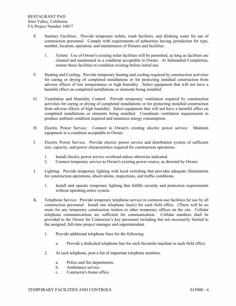
RESTAURANT PADSimi Valley, CaliforniaFA Project Number 16017
TEMPORARY FACILITIES AND CONTROLS 015000 - 4
E. Sanitary Facilities: Provide temporary toilets, wash facilities, and drinking water for use of construction personnel. Comply with requirements of authorities having jurisdiction for type, number, location, operation, and maintenance of fixtures and facilities.
1. Toilets: Use of Owner's existing toilet facilities will be permitted, as long as facilities are cleaned and maintained in a condition acceptable to Owner. At Substantial Completion, restore these facilities to condition existing before initial use.
F. Heating and Cooling: Provide temporary heating and cooling required by construction activities for curing or drying of completed installations or for protecting installed construction from adverse effects of low temperatures or high humidity. Select equipment that will not have a harmful effect on completed installations or elements being installed.
G. Ventilation and Humidity Control: Provide temporary ventilation required by construction activities for curing or drying of completed installations or for protecting installed construction from adverse effects of high humidity. Select equipment that will not have a harmful effect on completed installations or elements being installed. Coordinate ventilation requirements to produce ambient condition required and minimize energy consumption.
H. Electric Power Service: Connect to Owner's existing electric power service. Maintain equipment in a condition acceptable to Owner.
I. Electric Power Service: Provide electric power service and distribution system of sufficient size, capacity, and power characteristics required for construction operations.
1. Install electric power service overhead unless otherwise indicated.2. Connect temporary service to Owner's existing power source, as directed by Owner.
J. Lighting: Provide temporary lighting with local switching that provides adequate illumination for construction operations, observations, inspections, and traffic conditions.
1. Install and operate temporary lighting that fulfills security and protection requirements without operating entire system.
K. Telephone Service: Provide temporary telephone service in common-use facilities for use by all construction personnel. Install one telephone line(s) for each field office. (There will be no room for any temporary construction trailers or other temporary offices on the site. Cellular telephone communications are sufficient for communication. Cellular numbers shall be provided to the Owner for Contractor’s key personnel including but not necessarily limited to the assigned, full-time project manager and superintendent.
1. Provide additional telephone lines for the following:
a. Provide a dedicated telephone line for each facsimile machine in each field office.
2. At each telephone, post a list of important telephone numbers.
a. Police and fire departments.b. Ambulance service.c. Contractor's home office.

RESTAURANT PADSimi Valley, CaliforniaFA Project Number 16017
TEMPORARY FACILITIES AND CONTROLS 015000 - 5
d. Architect's office.e. Engineers' offices.f. Owner's office.g. Principal subcontractors' field and home offices.
3. Provide superintendent with cellular telephone or portable two-way radio for use when away from field office.
L. Electronic Communication Service: Provide a desktop computer in the primary field office adequate for use by Architect and Owner to access project electronic documents and maintain electronic communications.
3.3 SUPPORT FACILITIES INSTALLATION
A. General: Comply with the following:
1. Provide construction for temporary offices, shops, and sheds located within construction area or within 30 feet of building lines that is noncombustible according to ASTM E 136. Comply with NFPA 241.
2. Maintain support facilities until Architect schedules Substantial Completion inspection. Remove before Substantial Completion. Personnel remaining after Substantial Completion will be permitted to use permanent facilities, under conditions acceptable to Owner.
B. Temporary Roads and Paved Areas: Construct and maintain temporary roads and paved areas adequate for construction operations. Locate temporary roads and paved areas within construction limits indicated on Drawings.
1. Provide dust-control treatment that is nonpolluting and nontracking. Reapply treatment as required to minimize dust.
C. Temporary Use of Permanent Roads and Paved Areas: Locate temporary roads and paved areas in same location as permanent roads and paved areas. Construct and maintain temporary roads and paved areas adequate for construction operations. Extend temporary roads and paved areas, within construction limits indicated, as necessary for construction operations.
1. Coordinate elevations of temporary roads and paved areas with permanent roads and paved areas.
2. Prepare subgrade and install sub-base and base for temporary roads and paved areas according to Division 31 Section "Earth Moving."
3. Recondition base after temporary use, including removing contaminated material, regrading, proof-rolling, compacting, and testing.
4. Delay installation of final course of permanent hot-mix asphalt pavement until immediately before Substantial Completion. Repair hot-mix asphalt base-course pavement before installation of final course.
D. Traffic Controls: Comply with requirements of the Owner and authorities having jurisdiction.
1. Protect existing site improvements to remain including curbs, pavement, and utilities.

RESTAURANT PADSimi Valley, CaliforniaFA Project Number 16017
TEMPORARY FACILITIES AND CONTROLS 015000 - 6
2. Maintain access for fire-fighting equipment and access to fire hydrants.
E. Parking: Use designated areas of Owner's existing parking areas for construction personnel.
F. Dewatering Facilities and Drains: Comply with requirements of authorities having jurisdiction. Maintain Project site, excavations, and construction free of water.
1. Dispose of rainwater in a lawful manner that will not result in flooding Project or adjoining properties nor endanger permanent Work or temporary facilities.
2. Remove snow and ice as required to minimize accumulations.
G. Project Signs: Provide Project signs as indicated. Unauthorized signs are not permitted.
1. Identification Signs: Provide Project identification signs as indicated on Drawings.2. Temporary Signs: Provide other signs as indicated and as required to inform public and
individuals seeking entrance to Project.
a. Provide temporary, directional signs for construction personnel and visitors.
3. Maintain and touchup signs so they are legible at all times.
H. Waste Disposal Facilities: Comply with requirements specified in Division 01 Section "Construction Waste Management and Disposal." Waste disposal services including removal of spoils and soil overburden shall be arranged with Crown disposal as the sole on-site disposal company. Contractor shall ensure best efforts in assisting Crown in recycling of all trash and debris from their operations. Crown disposal services shall be paid for by Contractor.
I. Crowne Waste Disposal Facilities: Crown will provide waste-collection containers in sizes adequate to handle waste from construction operations. Comply with requirements of the Park and authorities having jurisdiction. Comply with Division 01 Section "Execution" for progress cleaning requirements.
J. Lifts and Hoists: Provide facilities necessary for hoisting materials and personnel.
1. Truck cranes and similar devices used for hoisting materials are considered "tools and equipment" and not temporary facilities. Cranes shall have current safety certifications and shall provide a copy for the Contractor who shall provide same to Owner.
K. Temporary Elevator Use: Refer to Division 14 Sections for temporary use of new elevators.
L. Existing Elevator Use: Use of Owner's existing elevators will be permitted, provided elevators are cleaned and maintained in a condition acceptable to Owner. At Substantial Completion, restore elevators to condition existing before initial use, including replacing worn cables, guide shoes, and similar items of limited life.
1. Do not load elevators beyond their rated weight capacity.2. Provide protective coverings, barriers, devices, signs, or other procedures to protect
elevator car and entrance doors and frame. If, despite such protection, elevators become damaged, engage elevator Installer to restore damaged work so no evidence remains of

RESTAURANT PADSimi Valley, CaliforniaFA Project Number 16017
TEMPORARY FACILITIES AND CONTROLS 015000 - 7
correction work. Return items that cannot be refinished in field to the shop, make required repairs and refinish entire unit, or provide new units as required.
M. Temporary Stairs: Until permanent stairs are available, provide temporary stairs where ladders are not adequate.
N. Existing Stair Usage: Use of Owner's existing stairs will be permitted, provided stairs are cleaned and maintained in a condition acceptable to Owner. At Substantial Completion, restore stairs to condition existing before initial use.
1. Provide protective coverings, barriers, devices, signs, or other procedures to protect stairs and to maintain means of egress. If stairs become damaged, restore damaged areas so no evidence remains of correction work.
O. Temporary Use of Permanent Stairs: Use of new stairs for construction traffic will be permitted, provided stairs are protected and finishes restored to new condition at time of Substantial Completion.
3.4 SECURITY AND PROTECTION FACILITIES INSTALLATION
A. Environmental Protection: Provide protection, operate temporary facilities, and conduct construction as required to comply with environmental regulations and that minimize possible air, waterway, and subsoil contamination or pollution or other undesirable effects.
B. Temporary Erosion and Sedimentation Control: Comply with requirements of the latest EPA Construction General Permit or authorities having jurisdiction, whichever is more stringent.
C. Temporary Erosion and Sedimentation Control: Provide measures to prevent soil erosion and discharge of soil-bearing water run-off and airborne dust to undisturbed areas and to adjacent properties and walkways and requirements of 2003 EPA Construction General Permit or authorities having jurisdiction, whichever is more stringent. Install truck and equipment wash-down area if required by the Owner or public authorities having jurisdiction.
D. Stormwater Control: Comply with requirements of authorities having jurisdiction. Provide barriers in and around excavations and subgrade construction to prevent flooding by run-off of stormwater from heavy rains.
E. Tree and Plant Protection: Comply with requirements specified in Division 01 Section "Temporary Tree and Plant Protection."
F. Tree and Plant Protection: Install temporary fencing located as indicated or outside the drip line of trees to protect vegetation from damage from construction operations. Protect tree root systems from damage, flooding, and erosion.
G. Pest Control: Engage pest-control service to recommend practices to minimize attraction and harboring of rodents, roaches, and other pests and to perform extermination and control procedures at regular intervals so Project will be free of pests and their residues at Substantial

RESTAURANT PADSimi Valley, CaliforniaFA Project Number 16017
TEMPORARY FACILITIES AND CONTROLS 015000 - 8
Completion. Obtain extended warranty for Owner. Perform control operations lawfully, using environmentally safe materials.
H. Site Enclosure Fence: Before construction operations begin, furnish and install site enclosure fence in a manner that will prevent people and animals from easily entering site except by entrance gates. (See Part 2, Section 2.2; paragraph D above)
1. Extent of Fence: As required to enclose entire Project site or portion determined sufficient to accommodate construction operations.
2. Maintain security by limiting number of keys and restricting distribution to authorized personnel. Furnish one set of keys to Owner.
I. Security Enclosure and Lockup: Install temporary enclosure around partially completed areas of construction. Provide lockable entrances to prevent unauthorized entrance, vandalism, theft, and similar violations of security. Lock entrances at end of each work day.
J. Barricades, Warning Signs, and Lights: Comply with requirements of authorities having jurisdiction for erecting structurally adequate barricades, including warning signs and lighting.
K. Temporary Egress: Maintain temporary egress from existing occupied facilities as indicated and as required by authorities having jurisdiction.
L. Temporary Enclosures: Provide temporary enclosures for protection of construction, in progress and completed, from exposure, foul weather, other construction operations, and similar activities. Provide temporary weathertight enclosure for building exterior.
1. Where heating or cooling is needed and permanent enclosure is not complete, insulate temporary enclosures.
M. Temporary Partitions: Provide floor-to-ceiling dustproof partitions to limit dust and dirt migration and to separate areas occupied by Owner from fumes and noise.
1. Construct dustproof partitions with gypsum wallboard with joints taped on occupied side, and fire-retardant plywood on construction operations side.
2. Construct dustproof partitions with two layers of 6-mil (0.14-mm) polyethylene sheet on each side. Cover floor with two layers of 6-mil (0.14-mm) polyethylene sheet, extending sheets 18 inches (460 mm) up the sidewalls. Overlap and tape full length of joints. Cover floor with fire-retardant treated plywood.
3. Where fire-resistance-rated temporary partitions are indicated or are required by authorities having jurisdiction, construct partitions according to the rated assemblies.
4. Insulate partitions to control noise transmission to occupied areas.5. Seal joints and perimeter. Equip partitions with gasketed dustproof doors and security
locks where openings are required.6. Protect air-handling equipment.7. Provide walk-off mats at each entrance through temporary partition.
N. Temporary Fire Protection: Install and maintain temporary fire-protection facilities of types needed to protect against reasonably predictable and controllable fire losses. Comply with NFPA 241.

RESTAURANT PADSimi Valley, CaliforniaFA Project Number 16017
TEMPORARY FACILITIES AND CONTROLS 015000 - 9
1. Prohibit smoking in construction areas.2. Supervise welding operations, combustion-type temporary heating units, and similar
sources of fire ignition according to requirements of authorities having jurisdiction.3. Develop and supervise an overall fire-prevention and -protection program for personnel
at Project site. Review needs with local fire department and establish procedures to be followed. Instruct personnel in methods and procedures. Post warnings and information.
4. Provide temporary standpipes and hoses for fire protection. Hang hoses with a warning sign stating that hoses are for fire-protection purposes only and are not to be removed. Match hose size with outlet size and equip with suitable nozzles.
3.5 MOISTURE AND MOLD CONTROL
A. Contractor's Moisture Protection Plan: Avoid trapping water in finished work. Document visible signs of mold that may appear during construction.
B. Exposed Construction Phase: Before installation of weather barriers, when materials are subject to wetting and exposure and to airborne mold spores, protect materials from water damage and keep porous and organic materials from coming into prolonged contact with concrete.
C. Partially Enclosed Construction Phase: After installation of weather barriers but before full enclosure and conditioning of building, when installed materials are still subject to infiltration of moisture and ambient mold spores, protect as follows:
1. Do not load or install drywall or other porous materials or components, or items with high organic content, into partially enclosed building.
2. Keep interior spaces reasonably clean and protected from water damage.3. Discard or replace water-damaged and wet material.4. Discard, replace or clean stored or installed material that begins to grow mold.5. Perform work in a sequence that allows any wet materials adequate time to dry before
enclosing the material in drywall or other interior finishes.
D. Controlled Construction Phase of Construction: After completing and sealing of the building enclosure but prior to the full operation of permanent HVAC systems, maintain as follows:
1. Control moisture and humidity inside building by maintaining effective dry-in conditions.2. Remove materials that cannot be completely restored to their manufactured moisture
level within 48 hours.
3.6 OPERATION, TERMINATION, AND REMOVAL
A. Supervision: Enforce strict discipline in use of temporary facilities. To minimize waste and abuse, limit availability of temporary facilities to essential and intended uses.
B. Maintenance: Maintain facilities in good operating condition until removal.
1. Maintain operation of temporary enclosures, heating, cooling, humidity control, ventilation, and similar facilities on a 24-hour basis where required to achieve indicated results and to avoid possibility of damage.

RESTAURANT PADSimi Valley, CaliforniaFA Project Number 16017
TEMPORARY FACILITIES AND CONTROLS 015000 - 10
C. Temporary Facility Changeover: Do not change over from using temporary security and protection facilities to permanent facilities until Substantial Completion.
D. Termination and Removal: Remove each temporary facility when need for its service has ended, when it has been replaced by authorized use of a permanent facility, or no later than Substantial Completion. Complete or, if necessary, restore permanent construction that may have been delayed because of interference with temporary facility. Repair damaged Work, clean exposed surfaces, and replace construction that cannot be satisfactorily repaired.
1. Materials and facilities that constitute temporary facilities are property of Contractor. Owner reserves right to take possession of Project identification signs.
2. At Substantial Completion, repair, renovate, and clean permanent facilities used during construction period. Comply with final cleaning requirements specified in Division 01 Section "Closeout Procedures."
END OF SECTION 015000

RESTAURANT PADSimi Valley, CaliforniaFA Project Number 16017
PRODUCT REQUIREMENTS 016000 - 1
SECTION 016000 - PRODUCT REQUIREMENTS
PART 1 - GENERAL
1.1 SUMMARY
A. Section includes administrative and procedural requirements for selection of products for use in Project; product delivery, storage, and handling; manufacturers' standard warranties on products; special warranties; and comparable products.
B. Related Section:
1. Division 01 Section "Substitution Procedures" for requests for substitutions.
1.2 DEFINITIONS
A. Products: Items obtained for incorporating into the Work, whether purchased for Project or taken from previously purchased stock. The term "product" includes the terms "material," "equipment," "system," and terms of similar intent.
1. Named Products: Items identified by manufacturer's product name, including make or model number or other designation shown or listed in manufacturer's published product literature that is current as of date of the Contract Documents.
2. New Products: Items that have not previously been incorporated into another project or facility. Products salvaged or recycled from other projects are not considered new products.
3. Comparable Product: Product that is demonstrated and approved through submittal process to have the indicated qualities related to type, function, dimension, in-service performance, physical properties, appearance, and other characteristics that equal or exceed those of specified product.
B. Basis-of-Design Product Specification: A specification in which a specific manufacturer's product is named and accompanied by the words "basis-of-design product," including make or model number or other designation, to establish the significant qualities related to type, function, dimension, in-service performance, physical properties, appearance, and other characteristics for purposes of evaluating comparable products of additional manufacturers named in the specification.
1.3 ACTION SUBMITTALS
A. Comparable Product Requests: Submit request for consideration of each comparable product. Identify product or fabrication or installation method to be replaced. Include Specification Section number and title and Drawing numbers and titles.

RESTAURANT PADSimi Valley, CaliforniaFA Project Number 16017
PRODUCT REQUIREMENTS 016000 - 2
1. Architect's Action: If necessary, Architect will request additional information or documentation for evaluation within one week of receipt of a comparable product request. Architect will notify Contractor of approval or rejection of proposed comparable product request within 15 of receipt of request, or seven (7) days of receipt of additional information or documentation, whichever is later.
a. Form of Approval: As specified in Division 01 Section "Submittal Procedures."b. Use product specified if Architect does not issue a decision on use of a comparable
product request within time allocated.
B. Basis-of-Design Product Specification Submittal: Comply with requirements in Division 01 Section "Submittal Procedures." Show compliance with requirements.
1.4 QUALITY ASSURANCE
A. Compatibility of Options: If Contractor is given option of selecting between two or more products for use on Project, select product compatible with products previously selected, even if previously selected products were also options.
1.5 PRODUCT DELIVERY, STORAGE, AND HANDLING
A. Deliver, store, and handle products using means and methods that will prevent damage, deterioration, and loss, including theft and vandalism. Comply with manufacturer's written instructions.
B. Delivery and Handling:
1. Schedule delivery to minimize long-term storage at Project site and to prevent overcrowding of construction spaces.
2. Coordinate delivery with installation time to ensure minimum holding time for items that are flammable, hazardous, easily damaged, or sensitive to deterioration, theft, and other losses.
3. Deliver products to Project site in an undamaged condition in manufacturer's original sealed container or other packaging system, complete with labels and instructions for handling, storing, unpacking, protecting, and installing.
4. Inspect products on delivery to determine compliance with the Contract Documents and to determine that products are undamaged and properly protected.
C. Storage:
1. Store products to allow for inspection and measurement of quantity or counting of units.2. Store materials in a manner that will not endanger Project structure.3. Store products that are subject to damage by the elements, under cover in a weathertight
enclosure above ground, with ventilation adequate to prevent condensation.4. Store foam plastic from exposure to sunlight, except to extent necessary for period of
installation and concealment.5. Comply with product manufacturer's written instructions for temperature, humidity,
ventilation, and weather-protection requirements for storage.
RESTAURANT PADSimi Valley, CaliforniaFA Project Number 16017
PRODUCT REQUIREMENTS 016000 - 3
6. Protect stored products from damage and liquids from freezing.
1.6 PRODUCT WARRANTIES
A. Warranties specified in other Sections shall be in addition to, and run concurrent with, other warranties required by the Contract Documents. Manufacturer's disclaimers and limitations on product warranties do not relieve Contractor of obligations under requirements of the Contract Documents.
1. Manufacturer's Warranty: Written warranty furnished by individual manufacturer for a particular product and specifically endorsed by manufacturer to Owner.
2. Special Warranty: Written warranty required by the Contract Documents to provide specific rights for Owner. Completed contracts warranty shall be two (2) years in addition to other specific warranty requirements.
B. Special Warranties: Prepare a written document that contains appropriate terms and identification, ready for execution.
1. Manufacturer's Standard Form: Modified to include Project-specific information and properly executed.
2. Specified Form: When specified forms are included with the Specifications, prepare a written document using indicated form properly executed.
3. Refer to Divisions 02 through 49. Sections for specific content requirements and particular requirements for submitting special warranties.
C. Submittal Time: Comply with requirements in Division 01 Section "Closeout Procedures."
PART 2 - PRODUCTS
2.1 PRODUCT SELECTION PROCEDURES
A. General Product Requirements: Provide products that comply with the Contract Documents, are undamaged and, unless otherwise indicated, are new at time of installation.
1. Provide products complete with accessories, trim, finish, fasteners, and other items needed for a complete installation and indicated use and effect.
2. Standard Products: If available, and unless custom products or nonstandard options are specified, provide standard products of types that have been produced and used successfully in similar situations on other projects.
3. Owner reserves the right to limit selection to products with warranties not in conflict with requirements of the Contract Documents.
4. Where products are accompanied by the term "as selected," Architect will make selection.
5. Descriptive, performance, and reference standard requirements in the Specifications establish salient characteristics of products.

RESTAURANT PADSimi Valley, CaliforniaFA Project Number 16017
PRODUCT REQUIREMENTS 016000 - 4
B. Product Selection Procedures:
1. Product: Where Specifications name a single manufacturer and product, provide the named product that complies with requirements. Comparable products or substitutions for Contractor's convenience will not be considered.
2. Manufacturer/Source: Where Specifications name a single manufacturer or source, provide a product by the named manufacturer or source that complies with requirements. Comparable products or substitutions for Contractor's convenience will not be considered.
3. Products:
a. Restricted List: Where Specifications include a list of names of both manufacturers and products, provide one of the products listed that complies with requirements. Comparable products or substitutions for Contractor's convenience will not be considered.
b. Non-restricted List: Where Specifications include a list of names of both available manufacturers and products, provide one of the products listed, or an unnamed product, that complies with requirements. Comply with requirements in "Comparable Products" Article for consideration of an unnamed product.
4. Manufacturers:
a. Restricted List: Where Specifications include a list of manufacturers' names, provide a product by one of the manufacturers listed that complies with requirements. Comparable products or substitutions for Contractor's convenience will not be considered.
b. Non-restricted List: Where Specifications include a list of available manufacturers, provide a product by one of the manufacturers listed, or a product by an unnamed manufacturer, that complies with requirements. Comply with requirements in "Comparable Products" Article for consideration of an unnamed manufacturer's product.
5. Basis-of-Design Product: Where Specifications name a product, or refer to a product indicated on Drawings, and include a list of manufacturers, provide the specified or indicated product or a comparable product by one of the other named manufacturers. Drawings and Specifications indicate sizes, profiles, dimensions, and other characteristics that are based on the product named. Comply with requirements in "Comparable Products" Article for consideration of an unnamed product by one of the other named manufacturers.
C. Visual Matching Specification: Where Specifications require "match Architect's sample", provide a product that complies with requirements and matches Architect's sample. Architect's decision will be final on whether a proposed product matches.
1. If no product available within specified category matches and complies with other specified requirements, comply with requirements in Division 01 Section "Substitution Procedures" for proposal of product.

RESTAURANT PADSimi Valley, CaliforniaFA Project Number 16017
PRODUCT REQUIREMENTS 016000 - 5
D. Visual Selection Specification: Where Specifications include the phrase "as selected by Architect from manufacturer's full range" or similar phrase, select a product that complies with requirements. Architect will select color, gloss, pattern, density, or texture from manufacturer's product line that includes both standard and premium items.
2.2 COMPARABLE PRODUCTS
A. Conditions for Consideration: Architect will consider Contractor's request for comparable product when the following conditions are satisfied. If the following conditions are not satisfied, Architect may return requests without action, except to record noncompliance with these requirements:
1. Evidence that the proposed product does not require revisions to the Contract Documents, that it is consistent with the Contract Documents and will produce the indicated results, and that it is compatible with other portions of the Work.
2. Detailed comparison of significant qualities of proposed product with those named in the Specifications. Significant qualities include attributes such as performance, weight, size, durability, visual effect, and specific features and requirements indicated.
3. Evidence that proposed product provides specified warranty.4. List of similar installations for completed projects with project names and addresses and
names and addresses of architects and owners, if requested.5. Samples, if requested.
PART 3 - EXECUTION (Not Used)
END OF SECTION 016000

RESTAURANT PADSimi Valley, CaliforniaFA Project Number 16017
CLEAN-UP AND DISPOSAL 017100-1
SECTION 017100 - CLEAN-UP AND DISPOSAL
1.0 GENERAL
1.1 SCOPE:
A. Provide complete clean project ready for occupancy.
1. Combustible rubbish shall not be burned on the property. All residue and non-combustible rubbish shall be removed from the site, leaving the entire site clean.
2. As soon as the building is completed, the General Contractor shall thoroughly clean the interior; the floors shall be swept and wiped clean; all fixtures, hardware and equipment shall be cleaned and polished; all plaster spots, stains, paint spots and accumulated dust and dirt removed. All glass should be thoroughly cleaned of all putty and paint marks; glass shall be washed clean, polished and left free of scratches and in perfect condition. All debris shall be removed from the premises.
B. During the progress of the work, all debris shall be removed at least once each week from the premises, unless otherwise required by the governing agencies. See specific Sections for cleaning up related to any particular work.
C. Prior to the acceptance of the completed project, the entire premises shall be cleaned to the approval of the Architect and Owner.
END OF SECTION 017100

RESTAURANT PADSimi Valley, CaliforniaFA Project Number 16017
EXECUTION 017300 - 1
SECTION 017300 - EXECUTION
PART 1 - GENERAL
1.1 SUMMARY
A. Section includes general administrative and procedural requirements governing execution of the Work including, but not limited to, the following:
1. Construction layout.2. Field engineering and surveying.3. Site logistics and laydown area.4. Installation of the Work.5. Cutting and patching.6. Coordination of Owner-installed products.7. Progress cleaning.8. Starting and adjusting.9. Protection of installed construction.10. Correction of the Work.
B. Related Sections:
1. Division 01 Section "Closeout Procedures" for submitting final property survey with Project Record Documents, recording of Owner-accepted deviations from indicated lines and levels, and final cleaning.
1.2 INFORMATIONAL SUBMITTALS
A. Certificates: Submit certificate signed by professional engineer certifying that location and elevation of improvements comply with requirements.
B. Landfill Receipts: Submit copy of receipts issued by a landfill facility, licensed to accept hazardous materials, for hazardous waste disposal. If hazardous materials are encountered in the work, Contractor may request disposal in the Park’s hazardous waste disposal area whose permission will not be unreasonably withheld. Crown disposal will transport hazardous waste.
C. Certified Surveys: Submit two copies signed by professional engineer.
D. Final Property Survey: Submit 10 copies showing the Work performed and record survey data.
1.3 QUALITY ASSURANCE
A. Land Surveyor Qualifications: A professional land surveyor who is legally qualified to practice in jurisdiction where Project is located and who is experienced in providing land-surveying services of the kind indicated.

RESTAURANT PADSimi Valley, CaliforniaFA Project Number 16017
EXECUTION 017300 - 2
B. Cutting and Patching: Comply with requirements for and limitations on cutting and patching of construction elements.
1. Structural Elements: When cutting and patching structural elements, notify Architect of locations and details of cutting and await directions from the Architect before proceeding. Shore, brace, and support structural element during cutting and patching. Do not cut and patch structural elements in a manner that could change their load-carrying capacity or increase deflection
2. Operational Elements: Do not cut and patch operating elements and related components in a manner that results in reducing their capacity to perform as intended or that results in increased maintenance or decreased operational life or safety
3. Other Construction Elements: Do not cut and patch other construction elements or components in a manner that could change their load-carrying capacity that results in reducing their capacity to perform as intended, or that result in increased maintenance or decreased operational life or safety.
4. Visual Elements: Do not cut and patch construction in a manner that results in visual evidence of cutting and patching. Do not cut and patch exposed construction in a manner that would, in Architect's opinion, reduce the building's aesthetic qualities. Remove and replace construction that has been cut and patched in a visually unsatisfactory manner.
1.4 WARRANTY
A. Existing Warranties: Remove, replace, patch, and repair materials and surfaces cut or damaged during installation or cutting and patching operations, by methods and with materials so as not to void existing warranties.
PART 2 - PRODUCTS
2.1 MATERIALS
A. General: Comply with requirements specified in other Sections.
B. In-Place Materials: Use materials for patching identical to in-place materials. For exposed surfaces, use materials that visually match in-place adjacent surfaces to the fullest extent possible.
1. If identical materials are unavailable or cannot be used, use materials that, when installed, will provide a match acceptable to the Architect for the visual and functional performance of in-place materials.

RESTAURANT PADSimi Valley, CaliforniaFA Project Number 16017
EXECUTION 017300 - 3
PART 3 - EXECUTION
3.1 EXAMINATION
A. Existing Conditions: The existence and location of underground and other utilities and construction indicated as existing are not guaranteed. Before beginning sitework, investigate and verify the existence and location of underground utilities, mechanical and electrical systems, and other construction affecting the Work.
1. Before construction, verify the location and invert elevation at points of connection of sanitary sewer, storm sewer, and water-service piping; underground electrical services, and other utilities.
2. Furnish location data for work related to Project that must be performed by public utilities serving Project site.
B. Examination and Acceptance of Conditions: Before proceeding with each component of the Work, examine substrates, areas, and conditions, with Installer or Applicator present where indicated, for compliance with requirements for installation tolerances and other conditions affecting performance. Record observations.
1. Verify compatibility with and suitability of substrates, including compatibility with existing finishes or primers.
2. Examine roughing-in for mechanical and electrical systems to verify actual locations of connections before equipment and fixture installation.
3. Examine walls, floors, and roofs for suitable conditions where products and systems are to be installed.
4. Proceed with installation only after unsatisfactory conditions have been corrected. Proceeding with the Work indicates acceptance of surfaces and conditions.
3.2 PREPARATION
A. Existing Utility Information: Furnish information to Owner that is necessary to adjust, move, or relocate existing utility structures, utility poles, lines, services, or other utility appurtenances located in or affected by construction. Coordinate with authorities having jurisdiction.
B. Field Measurements: Take field measurements as required to fit the Work properly. Recheck measurements before installing each product. Where portions of the Work are indicated to fit to other construction, verify dimensions of other construction by field measurements before fabrication. Coordinate fabrication schedule with construction progress to avoid delaying the Work.
C. Space Requirements: Verify space requirements and dimensions of items shown diagrammatically on Drawings.
D. Review of Contract Documents and Field Conditions: Immediately on discovery of the need for clarification of the Contract Documents caused by differing field conditions outside the control of the Contractor, submit a request for information to Architect according to requirements in Division 01 Section "Project Management and Coordination."
RESTAURANT PADSimi Valley, CaliforniaFA Project Number 16017
EXECUTION 017300 - 4
3.3 CONSTRUCTION LAYOUT
A. Verification: Before proceeding to lay out the Work, verify layout information shown on Drawings, in relation to the property survey and existing benchmarks. If discrepancies are discovered, notify Architect promptly.
B. General: Engage a professional engineer to lay out the Work using accepted surveying practices.
1. Establish benchmarks and control points to set lines and levels at each story of construction and elsewhere as needed to locate each element of Project.
2. Establish dimensions within tolerances indicated. Do not scale Drawings to obtain required dimensions.
3. Inform installers of lines and levels to which they must comply.4. Check the location, level and plumb, of every major element as the Work progresses.5. Notify Architect when deviations from required lines and levels exceed allowable
tolerances.6. Close site surveys with an error of closure equal to or less than the standard established
by authorities having jurisdiction.
C. Site Improvements: Locate and lay out site improvements, including pavements, grading, fill and topsoil placement, utility slopes, and rim and invert elevations.
D. Building Lines and Levels: Locate and lay out control lines and levels for structures, building foundations, column grids, and floor levels, including those required for mechanical and electrical work. Transfer survey markings and elevations for use with control lines and levels. Level foundations and piers from two or more locations.
E. Record Log: Maintain a log of layout control work. Record deviations from required lines and levels. Include beginning and ending dates and times of surveys, weather conditions, name and duty of each survey party member, and types of instruments and tapes used. Make the log available for reference by Architect.
3.4 FIELD ENGINEERING
A. Reference Points: Locate existing permanent benchmarks, control points, and similar reference points before beginning the Work. Preserve and protect permanent benchmarks and control points during construction operations.
B. Benchmarks: Establish and maintain a minimum of two permanent benchmarks on Project site, referenced to data established by survey control points. Comply with authorities having jurisdiction for type and size of benchmark.
1. Record benchmark locations, with horizontal and vertical data, on Project Record Documents.
C. Certified Survey: On completion of foundation walls, major site improvements, and other work requiring field-engineering services, prepare a certified survey showing dimensions, locations, angles, and elevations of construction and sitework.
RESTAURANT PADSimi Valley, CaliforniaFA Project Number 16017
EXECUTION 017300 - 5
D. Final Property Survey: Engage a professional engineer to prepare a final property survey showing significant features (real property) for Project. Include on the survey a certification, signed by professional engineer, that principal metes, bounds, lines, and levels of Project are accurately positioned as shown on the survey.
1. Recording: At Substantial Completion, have the final property survey recorded by or with authorities having jurisdiction as the official "property survey."
3.5 INSTALLATION
A. General: Locate the Work and components of the Work accurately, in correct alignment and elevation, as indicated.
1. Make vertical work plumb and make horizontal work level.2. Where space is limited, install components to maximize space available for maintenance
and ease of removal for replacement.3. Conceal pipes, ducts, and wiring in finished areas, unless otherwise indicated.
B. Comply with manufacturer's written instructions and recommendations for installing products in applications indicated.
C. Install products at the time and under conditions that will ensure the best possible results. Maintain conditions required for product performance until Substantial Completion.
D. Conduct construction operations so no part of the Work is subjected to damaging operations or loading in excess of that expected during normal conditions of occupancy.
E. Tools and Equipment: Do not use tools or equipment that produce harmful noise levels.
F. Templates: Obtain and distribute to the parties involved templates for work specified to be factory prepared and field installed. Check Shop Drawings of other work to confirm that adequate provisions are made for locating and installing products to comply with indicated requirements.
G. Attachment: Provide blocking and attachment plates and anchors and fasteners of adequate size and number to securely anchor each component in place, accurately located and aligned with other portions of the Work. Where size and type of attachments are not indicated, verify size and type required for load conditions.
1. Mounting Heights: Where mounting heights are not indicated, mount components at heights directed by Architect.
2. Allow for building movement, including thermal expansion and contraction.3. Coordinate installation of anchorages. Furnish setting drawings, templates, and
directions for installing anchorages, including sleeves, concrete inserts, anchor bolts, and items with integral anchors, that are to be embedded in concrete or masonry. Deliver such items to Project site in time for installation.

RESTAURANT PADSimi Valley, CaliforniaFA Project Number 16017
EXECUTION 017300 - 6
H. Joints: Make joints of uniform width. Where joint locations in exposed work are not indicated, arrange joints for the best visual effect. Fit exposed connections together to form hairline joints.
I. Hazardous Materials: Use products, cleaners, and installation materials that are not considered hazardous.
3.6 CUTTING AND PATCHING
A. Cutting and Patching, General: Employ skilled workers to perform cutting and patching. Proceed with cutting and patching at the earliest feasible time, and complete without delay.
1. Cut in-place construction to provide for installation of other components or performance of other construction, and subsequently patch as required to restore surfaces to their original condition.
B. Temporary Support: Provide temporary support of work to be cut.
C. Protection: Protect in-place construction during cutting and patching to prevent damage. Provide protection from adverse weather conditions for portions of Project that might be exposed during cutting and patching operations.
D. Adjacent Occupied Areas: Avoid interference with use of adjoining areas or interruption of free passage to adjoining areas.
E. Existing Utility Services and Mechanical/Electrical Systems: Where existing services/systems are required to be removed, relocated, or abandoned, bypass such services/systems before cutting to prevent interruption to occupied areas.
F. Cutting: Cut in-place construction by sawing, drilling, breaking, chipping, grinding, and similar operations, including excavation, using methods least likely to damage elements retained or adjoining construction. If possible, review proposed procedures with original Installer; comply with original Installer's written recommendations.
1. In general, use hand or small power tools designed for sawing and grinding, not hammering and chopping. Cut holes and slots neatly to minimum size required, and with minimum disturbance of adjacent surfaces. Temporarily cover openings when not in use.
2. Finished Surfaces: Cut or drill from the exposed or finished side into concealed surfaces.3. Concrete and Masonry: Cut using a cutting machine, such as an abrasive saw or a
diamond-core drill.4. Excavating and Backfilling: Comply with requirements in applicable Division 31
Sections where required by cutting and patching operations.5. Mechanical and Electrical Services: Cut off pipe or conduit in walls or partitions to be
removed. Cap, valve, or plug and seal remaining portion of pipe or conduit to prevent entrance of moisture or other foreign matter after cutting.
6. Proceed with patching after construction operations requiring cutting are complete.

RESTAURANT PADSimi Valley, CaliforniaFA Project Number 16017
EXECUTION 017300 - 7
G. Patching: Patch construction by filling, repairing, refinishing, closing up, and similar operations following performance of other work. Patch with durable seams that are as invisible as practicable. Provide materials and comply with installation requirements specified in other Sections, where applicable.
1. Inspection: Where feasible, test and inspect patched areas after completion to demonstrate physical integrity of installation.
2. Exposed Finishes: Restore exposed finishes of patched areas and extend finish restoration into retained adjoining construction in a manner that will minimize evidence of patching and refinishing.
3. Floors and Walls: Where walls or partitions that are removed extend one finished area into another, patch and repair floor and wall surfaces in the new space. Provide an even surface of uniform finish, color, texture, and appearance. Remove in-place floor and wall coverings and replace with new materials, if necessary, to achieve uniform color and appearance.
4. Ceilings: Patch, repair, or rehang in-place ceilings as necessary to provide an even-plane surface of uniform appearance.
5. Exterior Building Enclosure: Patch components in a manner that restores enclosure to a weathertight condition.
H. Cleaning: Clean areas and spaces where cutting and patching are performed. Remove paint, mortar, oils, putty, and similar materials from adjacent finished surfaces.
3.7 PROGRESS CLEANING
A. General: Clean Project site and work areas daily, including common areas. Enforce requirements strictly. Dispose of materials lawfully. Safe housekeeping, pathways and material storage are of paramount importance to the Park. Work areas shall be kept in a safe working environment at all times.
1. Comply with requirements in NFPA 241 for removal of combustible waste materials and debris.
2. Do not hold waste materials more than three (3) days during normal weather or one (1) days if the temperature is expected to rise above 80 deg F (27 deg C).
3. Containerize hazardous and unsanitary waste materials separately from other waste. Mark containers appropriately and dispose of legally, according to regulations.
B. Site: Maintain Project site free of waste materials and debris.
C. Work Areas: Clean areas where work is in progress to the level of cleanliness necessary for proper execution of the Work.
1. Remove liquid spills promptly.2. Where dust would impair proper execution of the Work, broom-clean or vacuum the
entire work area, as appropriate.
D. Installed Work: Keep installed work clean. Clean and protect installed surfaces according to written instructions of manufacturer or fabricator of product installed, using only cleaning materials specifically recommended. If specific cleaning materials are not recommended, use

RESTAURANT PADSimi Valley, CaliforniaFA Project Number 16017
EXECUTION 017300 - 8
cleaning materials that are not hazardous to health or property and that will not damage exposed surfaces.
E. Concealed Spaces: Remove debris from concealed spaces before enclosing the space.
F. Exposed Surfaces in Finished Areas: Clean exposed surfaces and protect as necessary to ensure freedom from damage and deterioration at time of Substantial Completion.
G. Waste Disposal: Do not bury or burn waste materials on-site. Do not wash waste materials down sewers or into waterways. Disposal of paint, solvents, or other chemicals will be cause for immediate termination and severe penalties without limitation.
H. During handling and installation, clean and protect construction in progress and adjoining materials already in place. Apply protective covering where required to ensure protection from damage or deterioration at Substantial Completion.
I. Clean and provide maintenance on completed construction as frequently as necessary through the remainder of the construction period. Adjust and lubricate operable components to ensure operability without damaging effects.
J. Limiting Exposures: Supervise construction operations to assure that no part of the construction, completed or in progress, is subject to harmful, dangerous, damaging, or otherwise deleterious exposure during the construction period.
3.8 STARTING AND ADJUSTING
A. Start equipment and operating components to confirm proper operation. Remove malfunctioning units, replace with new units, and retest.
B. Adjust equipment for proper operation. Adjust operating components for proper operation without binding.
C. Test each piece of equipment to verify proper operation. Test and adjust controls and safeties. Replace damaged and malfunctioning controls and equipment.
D. Manufacturer's Field Service: Comply with qualification requirements in Division 01 Section "Quality Requirements." Where required, Contractor shall provide the detailed information on manufacturer’s field service representatives including certification from the manufacturer that their services have been retained and the service performed in complete as specified.
3.9 PROTECTION OF INSTALLED CONSTRUCTION
A. Provide final protection and maintain conditions that ensure installed Work is without damage or deterioration at time of Substantial Completion.
B. Comply with manufacturer's written instructions for temperature and relative humidity.

RESTAURANT PADSimi Valley, CaliforniaFA Project Number 16017
EXECUTION 017300 - 9
3.10 CORRECTION OF THE WORK
A. Repair or remove and replace defective construction. Restore damaged substrates and finishes.
1. Repairing includes replacing defective parts, refinishing damaged surfaces, touching up with matching materials, and properly adjusting operating equipment.
B. Restore permanent facilities used during construction to their specified condition.
C. Remove and replace damaged surfaces that are exposed to view if surfaces cannot be repaired without visible evidence of repair.
D. Repair components that do not operate properly. Remove and replace operating components that cannot be repaired.
E. Remove and replace chipped, scratched, and broken glass or reflective surfaces.
END OF SECTION 017300

RESTAURANT PADSimi Valley, CaliforniaFA Project Number 16017
CONSTRUCTION WASTE MANAGEMENT AND DISPOSAL 017419 - 1
SECTION 017419 - CONSTRUCTION WASTE MANAGEMENT AND DISPOSAL
PART 1 - GENERAL
1.1 SUMMARY
A. Section includes administrative and procedural requirements for the following:
1. Salvaging nonhazardous demolition and construction waste.2. Recycling nonhazardous demolition and construction waste.3. Disposing of nonhazardous demolition and construction waste.
B. Related Sections:1. Division 04 Section "Unit Masonry" for disposal requirements for masonry waste.
1.2 DEFINITIONS
A. Construction Waste: Building and site improvement materials and other solid waste resulting from construction, remodeling, renovation, or repair operations. Construction waste includes packaging. Crown disposal shall be the sole waste removal company utilized for the Project.
B. Demolition Waste: Building and site improvement materials resulting from demolition or selective demolition operations.
C. Disposal: Removal off-site of demolition and construction waste and subsequent sale, recycling, reuse, or deposit in landfill or incinerator acceptable to authorities having jurisdiction.
D. Recycle: Recovery of demolition or construction waste for subsequent processing in preparation for reuse.
E. Salvage: Recovery of demolition or construction waste and subsequent sale or reuse in another facility.
F. Salvage and Reuse: Recovery of demolition or construction waste and subsequent incorporation into the Work.
1.3 PERFORMANCE REQUIREMENTS
A. General: Achieve end-of-Project rates for salvage/recycling of a required by local jurisdiction. Facilitate recycling and salvage of materials.

RESTAURANT PADSimi Valley, CaliforniaFA Project Number 16017
CONSTRUCTION WASTE MANAGEMENT AND DISPOSAL 017419 - 2
1.4 WASTE MANAGEMENT PLAN
A. General: Develop a waste management plan according to ASTM E 1609 and requirements of this Section. Plan shall consist of waste identification, waste reduction work plan, and cost/revenue analysis. Distinguish between demolition and construction waste. Indicate quantities by weight or volume, but use same units of measure throughout waste management plan.
B. Waste Identification: Indicate anticipated types and quantities of demolition, site-clearing, and construction waste generated by the Work. Include estimated quantities and assumptions for estimates.
C. Waste Reduction Work Plan: List each type of waste and whether it will be salvaged, recycled, or disposed of in landfill or incinerator. Include points of waste generation, total quantity of each type of waste, quantity for each means of recovery, and handling and transportation procedures.
1. Salvaged Materials for Reuse: For materials that will be salvaged and reused in this Project, describe methods for preparing salvaged materials before incorporation into the Work.
2. Salvaged Materials for Sale: For materials that will be sold to individuals and organizations, include list of their names, addresses, and telephone numbers.
3. Salvaged Materials for Donation: For materials that will be donated to individuals and organizations, include list of their names, addresses, and telephone numbers.
4. Recycled Materials: Include list of local receivers and processors and type of recycled materials each will accept. Include names, addresses, and telephone numbers.
5. Disposed Materials: Indicate how and where materials will be disposed of. Include name, address, and telephone number of each landfill and incinerator facility.
6. Handling and Transportation Procedures: Include method that will be used for separating recyclable waste including sizes of containers, container labeling, and designated location on Project site where materials separation will be located.
PART 2 - PRODUCTS (Not Used)
PART 3 - EXECUTION
3.1 PLAN IMPLEMENTATION
A. General: Implement approved waste management plan. Provide handling, containers, storage, signage, transportation, and other items as required to implement waste management plan during the entire duration of the Contract.
B. Waste Management Coordinator: Engage a waste management coordinator to be responsible for implementing, monitoring, and reporting status of waste management work plan.
C. Training: Train workers, subcontractors, and suppliers on proper waste management procedures, as appropriate for the Work occurring at Project site.
RESTAURANT PADSimi Valley, CaliforniaFA Project Number 16017
CONSTRUCTION WASTE MANAGEMENT AND DISPOSAL 017419 - 3
1. Distribute waste management plan to everyone concerned.2. Distribute waste management plan to entities when they first begin work on-site. Review
plan procedures and locations established for salvage, recycling, and disposal.
D. Site Access and Temporary Controls: Conduct waste management operations to ensure minimum interference with roads, streets, walks, walkways, and other adjacent occupied and used facilities.
1. Designate and label specific areas on Project site necessary for separating materials that are to be salvaged, recycled, reused, donated, and sold.
2. Comply with Division 01 Section "Temporary Facilities and Controls" for controlling dust and dirt, environmental protection, and noise control.
3.2 SALVAGING DEMOLITION WASTE
A. Salvaged Items for Reuse in the Work:
1. Clean salvaged items.2. Pack or crate items after cleaning. Identify contents of containers.3. Store items in a secure area until installation.4. Protect items from damage during transport and storage.5. Install salvaged items to comply with installation requirements for new materials and
equipment. Provide connections, supports, and miscellaneous materials necessary to make items functional for use indicated.
B. Salvaged Items for Sale and Donation: Not permitted on Project site.
C. Salvaged Items for Owner's Use:
1. Clean salvaged items.2. Pack or crate items after cleaning. Identify contents of containers.3. Store items in a secure area until delivery to Owner.4. Transport items to Owner's storage area designated by Owner.5. Protect items from damage during transport and storage.
3.3 RECYCLING DEMOLITION AND CONSTRUCTION WASTE, GENERAL
A. General: Recycle paper and beverage containers used by on-site workers.
B. Recycling Incentives: Revenues, savings, rebates, tax credits, and other incentives received for recycling waste materials shall accrue to Owner.
C. Procedures: Separate recyclable waste from other waste materials, trash, and debris. Separate recyclable waste by type at Project site to the maximum extent practical according to approved construction waste management plan.

RESTAURANT PADSimi Valley, CaliforniaFA Project Number 16017
CONSTRUCTION WASTE MANAGEMENT AND DISPOSAL 017419 - 4
1. Provide appropriately marked containers or bins for controlling recyclable waste until they are removed from Project site. Include list of acceptable and unacceptable materials at each container and bin.
a. Inspect containers and bins for contamination and remove contaminated materials if found.
2. Stockpile processed materials on-site without intermixing with other materials. Place, grade, and shape stockpiles to drain surface water. Cover to prevent windblown dust.
3. Stockpile materials away from construction area. Do not store within drip line of remaining trees.
4. Store components off the ground and protect from the weather.5. Remove recyclable waste off Owner's property and transport to recycling receiver or
processor.
3.4 RECYCLING DEMOLITION WASTE
A. Asphaltic Concrete Paving: Break up and transport paving to asphalt-recycling facility.
B. Concrete: Remove reinforcement and other metals from concrete and sort with other metals.
C. Masonry: Remove metal reinforcement, anchors, and ties from masonry and sort with other metals.
D. Wood Materials: Sort and stack members according to size, type, and length. Separate lumber, engineered wood products, panel products, and treated wood materials.
E. Metals: Separate metals by type.
1. Structural Steel: Stack members according to size, type of member, and length.2. Remove and dispose of bolts, nuts, washers, and other rough hardware.
F. Asphalt Shingle Roofing: Separate organic and glass-fiber asphalt shingles and felts. Remove and dispose of nails, staples, and accessories.
G. Gypsum Board: Stack large clean pieces on wood pallets or in container and store in a dry location. Remove edge trim and sort with other metals. Remove and dispose of fasteners.
H. Acoustical Ceiling Panels and Tile: Stack large clean pieces on wood pallets and store in a dry location.
I. Metal Suspension System: Separate metal members including trim, and other metals from acoustical panels and tile and sort with other metals.
J. Carpet: Roll large pieces tightly after removing debris, trash, adhesive, and tack strips.
1. Store clean, dry carpet in a closed container or trailer provided by Carpet Reclamation Agency or carpet recycler.

RESTAURANT PADSimi Valley, CaliforniaFA Project Number 16017
CONSTRUCTION WASTE MANAGEMENT AND DISPOSAL 017419 - 5
K. Piping: Reduce piping to straight lengths and store by type and size. Separate supports, hangers, valves, sprinklers, and other components by type and size.
L. Conduit: Reduce conduit to straight lengths and store by type and size.
3.5 RECYCLING CONSTRUCTION WASTE
A. Packaging:
1. Cardboard and Boxes: Break down packaging into flat sheets. Bundle and store in a dry location.
2. Polystyrene Packaging: Separate and bag materials.3. Pallets: As much as possible, require deliveries using pallets to remove pallets from
Project site. For pallets that remain on-site, break down pallets into component wood pieces and comply with requirements for recycling wood.
4. Crates: Break down crates into component wood pieces and comply with requirements for recycling wood.
B. Site-Clearing Wastes: Chip brush, branches, and trees at landfill facility.
C. Wood Materials:
1. Clean Cut-Offs of Lumber: Grind or chip into small pieces.2. Clean Sawdust: Bag sawdust that does not contain painted or treated wood.
D. Gypsum Board: Stack large clean pieces on wood pallets or in container and store in a dry location.
1. Clean Gypsum Board: Grind scraps of clean gypsum board using small mobile chipper or hammer mill. Screen out paper after grinding.
3.6 DISPOSAL OF WASTE
A. General: Except for items or materials to be salvaged, recycled, or otherwise reused, remove waste materials from Project site and legally dispose of them in a landfill or incinerator acceptable to authorities having jurisdiction.
1. Except as otherwise specified, do not allow waste materials that are to be disposed of accumulate on-site.
2. Remove and transport debris in a manner that will prevent spillage on adjacent surfaces and areas.
B. Burning: Do not burn waste materials.
C. Burning: Burning of waste materials is permitted only at designated areas on Owner's property, provided required permits are obtained. Provide full-time monitoring for burning materials until fires are extinguished.

RESTAURANT PADSimi Valley, CaliforniaFA Project Number 16017
CONSTRUCTION WASTE MANAGEMENT AND DISPOSAL 017419 - 6
D. Disposal: Transport waste materials and dispose of at designated spoil areas on Owner's property.
E. Disposal: Transport waste materials off Owner's property and legally dispose of them.
END OF SECTION 017419

RESTAURANT PADSimi Valley, CaliforniaFA Project Number 16017
CLOSEOUT PROCEDURES 017700 - 1
SECTION 017700 - CLOSEOUT PROCEDURES
PART 1 - GENERAL
1.1 SUMMARY
A. Section includes administrative and procedural requirements for contract closeout, including, but not limited to, the following:
1. Substantial Completion procedures.2. Final completion procedures.3. Warranties.4. Final cleaning.
B. Related Sections:
1. Division 01 Section "Photographic Documentation" for submitting final completion construction photographic documentation.
2. Division 01 Section "Operation and Maintenance Data" for operation and maintenance manual requirements.
3. Division 01 Section "Project Record Documents" for submitting Record Drawings, Record Specifications, and Record Product Data.
4. Division 01 Section "Demonstration and Training" for requirements for instructing Owner's personnel.
5. Divisions 02 through 49 Sections for specific closeout and special cleaning requirements for the Work in those Sections.
1.2 SUBSTANTIAL COMPLETION
A. Preliminary Procedures: Before requesting inspection for determining date of Substantial Completion, complete the following. List items below that are incomplete with request.
1. Prepare a list of items to be completed and corrected (punch list), the value of items on the list, and reasons why the Work is not complete.
2. Advise Owner of pending insurance changeover requirements.3. Submit specific warranties, workmanship bonds, maintenance service agreements, final
certifications, and similar documents.4. Obtain and submit releases permitting Owner unrestricted use of the Work and access to
services and utilities. Include occupancy permits, operating certificates, and similar releases.
5. Prepare and submit Project Record Documents, operation and maintenance manuals, final completion construction photographic documentation, damage or settlement surveys, property surveys, and similar final record information.
6. Deliver tools, spare parts, extra materials, and similar items to location designated by Owner. Label with manufacturer's name and model number where applicable.

RESTAURANT PADSimi Valley, CaliforniaFA Project Number 16017
CLOSEOUT PROCEDURES 017700 - 2
7. Make final changeover of permanent locks and deliver keys to Owner. Advise Owner's personnel of changeover in security provisions.
8. Complete startup testing of systems.9. Submit test/adjust/balance records.10. Terminate and remove temporary facilities from Project site, along with mockups,
construction tools, and similar elements.11. Advise Owner of changeover in heat and other utilities.12. Submit changeover information related to Owner's occupancy, use, operation, and
maintenance.13. Complete final cleaning requirements, including touchup painting.14. Touch up and otherwise repair and restore marred exposed finishes to eliminate visual
defects.15. Submit as-built drawings, operations and maintenance manuals and any attic stock
required by the Construction Documents. Recordable documents, including approved shop drawings, shall be submitted in two (2) hard copies and one (1) electronic disc.
B. Inspection: Submit a written request for inspection for Substantial Completion. On receipt of request, Architect will either proceed with inspection or notify Contractor of unfulfilled requirements. Architect will prepare the Certificate of Substantial Completion after inspection or will notify Contractor of items, either on Contractor's list or additional items identified by Architect, that must be completed or corrected before certificate will be issued.
1. Re-inspection: Request re-inspection when the Work identified in previous inspections as incomplete is completed or corrected.
2. Results of completed inspection will form the basis of requirements for final completion.
1.3 FINAL COMPLETION
A. Preliminary Procedures: Before requesting final inspection for determining final completion, complete the following:1. Submit certified copy of Architect's Substantial Completion inspection list of items to be
completed or corrected (punch list), endorsed and dated by Architect. The certified copy of the list shall state that each item has been completed or otherwise resolved for acceptance.
2. Submit evidence of final, continuing insurance coverage complying with insurance requirements.
3. Submit pest-control final inspection report and warranty.4. Instruct Owner's personnel in operation, adjustment, and maintenance of products,
equipment, and systems.
B. Inspection: Submit a written request for final inspection for acceptance. On receipt of request, Architect will either proceed with inspection or notify Contractor of unfulfilled requirements. Architect will prepare a final Certificate for Payment after inspection or will notify Contractor of construction that must be completed or corrected before certificate will be issued.
1. Re-inspection: Request re-inspection when the Work identified in previous inspections as incomplete is completed or corrected.
RESTAURANT PADSimi Valley, CaliforniaFA Project Number 16017
CLOSEOUT PROCEDURES 017700 - 3
1.4 LIST OF INCOMPLETE ITEMS (PUNCH LIST)
A. Organization of List: Include name and identification of each space and area affected by construction operations for incomplete items and items needing correction including, if necessary, areas disturbed by Contractor that are outside the limits of construction. Use CSI Form 14.1A.
1. Organize list of spaces in sequential order, starting with exterior areas first and proceeding from lowest floor to highest floor.
2. Organize items applying to each space by major element, including categories for ceiling, individual walls, floors, equipment, and building systems.
3. Submit list of incomplete items in the following format:
a. PDF electronic file.
1.5 WARRANTIES
A. Submittal Time: Submit written warranties on request of Architect for designated portions of the Work where commencement of warranties other than date of Substantial Completion is indicated.
B. Organize warranty documents into an orderly sequence based on the table of contents of the Project Manual.
1. Bind warranties and bonds in heavy-duty, 3-ring, vinyl-covered, loose-leaf binders, thickness as necessary to accommodate contents, and sized to receive 8-1/2-by-11-inch paper.
2. Provide heavy paper dividers with plastic-covered tabs for each separate warranty. Mark tab to identify the product or installation. Provide a typed description of the product or installation, including the name of the product and the name, address, and telephone number of Installer.
3. Identify each binder on the front and spine with the typed or printed title "WARRANTIES," Project name, and name of Contractor.
4. Scan warranties and bonds and assemble complete warranty and bond submittal package into a single indexed electronic PDF file with links enabling navigation to each item. Provide table of contents at beginning of document.
C. Provide additional copies of each warranty to include in operation and maintenance manuals.
PART 2 - PRODUCTS
2.1 MATERIALS
A. Cleaning Agents: Use cleaning materials and agents recommended by manufacturer or fabricator of the surface to be cleaned. Do not use cleaning agents that are potentially hazardous to health or property or that might damage finished surfaces.

RESTAURANT PADSimi Valley, CaliforniaFA Project Number 16017
CLOSEOUT PROCEDURES 017700 - 4
1. Use cleaning products that meet Green Seal GS-37, or if GS-37 is not applicable, use products that comply with the California Code of Regulations maximum allowable VOC levels.
PART 3 - EXECUTION
3.1 FINAL CLEANING
A. General: Perform final cleaning. Conduct cleaning and waste-removal operations to comply with local laws and ordinances and Federal and local environmental and antipollution regulations.
B. Cleaning: Employ experienced workers or professional cleaners for final cleaning. Clean each surface or unit to condition expected in an average commercial building cleaning and maintenance program. Comply with manufacturer's written instructions.
1. Complete the following cleaning operations before requesting inspection for certification of Substantial Completion for entire Project or for a portion of Project:
a. Clean Project site, yard, and grounds, in areas disturbed by construction activities, including landscape development areas, of rubbish, waste material, litter, and other foreign substances.
b. Sweep paved areas broom clean. Remove petrochemical spills, stains, and other foreign deposits.
c. Rake grounds that are neither planted nor paved to a smooth, even-textured surface.
d. Remove tools, construction equipment, machinery, and surplus material from Project site.
e. Remove snow and ice to provide safe access to building.f. Clean exposed exterior and interior hard-surfaced finishes to a dirt-free condition,
free of stains, films, and similar foreign substances. Avoid disturbing natural weathering of exterior surfaces. Restore reflective surfaces to their original condition.
g. Remove debris and surface dust from limited access spaces, including roofs, plenums, shafts, trenches, equipment vaults, manholes, attics, and similar spaces.
h. Sweep concrete floors broom clean in unoccupied spaces.i. Vacuum carpet and similar soft surfaces, removing debris and excess nap;
shampoo if visible soil or stains remain.j. Clean transparent materials, including mirrors and glass in doors and windows.
Remove glazing compounds and other noticeable, vision-obscuring materials. Replace chipped or broken glass and other damaged transparent materials. Polish mirrors and glass, taking care not to scratch surfaces.
k. Remove labels that are not permanent.l. Touch up and otherwise repair and restore marred, exposed finishes and surfaces.
Replace finishes and surfaces that cannot be satisfactorily repaired or restored or that already show evidence of repair or restoration.

RESTAURANT PADSimi Valley, CaliforniaFA Project Number 16017
CLOSEOUT PROCEDURES 017700 - 5
1) Do not paint over "UL" and other required labels and identification, including mechanical and electrical nameplates.
m. Wipe surfaces of mechanical and electrical equipment, elevator equipment, and similar equipment. Remove excess lubrication, paint and mortar droppings, and other foreign substances.
n. Replace parts subject to operating conditions during construction that may impede operation or reduce longevity.
o. Clean plumbing fixtures to a sanitary condition, free of stains, including stains resulting from water exposure.
p. Replace disposable air filters and clean permanent air filters. Clean exposed surfaces of diffusers, registers, and grills.
q. Clean light fixtures, lamps, globes, and reflectors to function with full efficiency. Replace burned-out bulbs, and those noticeably dimmed by hours of use, and defective and noisy starters in fluorescent and mercury vapor fixtures to comply with requirements for new fixtures.
r. Leave Project clean and ready for occupancy.
C. Pest Control: Engage an experienced, licensed exterminator to make a final inspection and rid Project of rodents, insects, and other pests. Prepare a report.
END OF SECTION 017700

RESTAURANT PADSimi Valley, CaliforniaFA Project Number 16017
OPERATION AND MAINTENANCE DATA 017823 - 1
SECTION 017823 - OPERATION AND MAINTENANCE DATA
PART 1 - GENERAL
1.1 SUMMARY
A. Section includes administrative and procedural requirements for preparing operation and maintenance manuals, including the following:
1. Operation and maintenance documentation directory.2. Emergency manuals.3. Operation manuals for systems, subsystems, and equipment.4. Product maintenance manuals.5. Systems and equipment maintenance manuals.
B. Related Sections:
1. Divisions 02 through 49 Sections for specific operation and maintenance manual requirements for the Work in those Sections.
1.2 CLOSEOUT SUBMITTALS
A. Format: Submit operations and maintenance manuals in the following format:
1. PDF electronic file. Assemble each manual into a composite electronically-indexed file. Submit on digital media acceptable to Architect.
a. Name each indexed document file in composite electronic index with applicable item name. Include a complete electronically-linked operation and maintenance directory.
b. Enable inserted reviewer comments on draft submittals.
2. Two paper copies and one electronic disc. Include a complete operation and maintenance directory. Enclose title pages and directories in clear plastic sleeves. Architect, through Construction Manager, will return one copy.
B. Manual Submittal: Submit each manual in final form prior to requesting inspection for Substantial Completion and at least fifteen (15) days before commencing demonstration and training. Architect will return copy with comments.
1. Correct or modify each manual to comply with Architect's comments. Submit copies of each corrected manual within ten (10) days of receipt of Architect's comments and prior to commencing demonstration and training.
RESTAURANT PADSimi Valley, CaliforniaFA Project Number 16017
OPERATION AND MAINTENANCE DATA 017823 - 2
PART 2 - PRODUCTS
2.1 REQUIREMENTS FOR EMERGENCY, OPERATION, AND MAINTENANCE MANUALS
A. Organization: Unless otherwise indicated, organize each manual into a separate section for each system and subsystem, and a separate section for each piece of equipment not part of a system. Each manual shall contain the following materials, in the order listed:
1. Title page.2. Table of contents.3. Manual contents.
B. Title Page: Include the following information:
1. Subject matter included in manual.2. Name and address of Project.3. Name and address of Owner.4. Date of submittal.5. Name and contact information for Contractor.6. Name and contact information for Construction Manager.7. Name and contact information for Architect.8. Name and contact information for Commissioning Agent.9. Names and contact information for major consultants to the Architect that designed the
systems contained in the manuals.10. Cross-reference to related systems in other operation and maintenance manuals.
C. Table of Contents: List each product included in manual, identified by product name, indexed to the content of the volume, and cross-referenced to Specification Section number in Project Manual.
D. Manual Contents: Organize into sets of manageable size. Arrange contents alphabetically by system, subsystem, and equipment. If possible, assemble instructions for subsystems, equipment, and components of one system into a single binder.
E. Manuals, Electronic Files: Submit manuals in the form of a multiple file composite electronic PDF file for each manual type required.
1. Electronic Files: Use electronic files prepared by manufacturer where available. Where scanning of paper documents is required, configure scanned file for minimum readable file size.
2. File Names and Bookmarks: Enable bookmarking of individual documents based upon file names. Name document files to correspond to system, subsystem, and equipment names used in manual directory and table of contents. Group documents for each system and subsystem into individual composite bookmarked files, then create composite manual, so that resulting bookmarks reflect the system, subsystem, and equipment names in a readily navigated file tree. Configure electronic manual to display bookmark panel upon opening file.
F. Manuals, Paper Copy: Submit manuals in the form of hard copy, bound and labeled volumes.

RESTAURANT PADSimi Valley, CaliforniaFA Project Number 16017
OPERATION AND MAINTENANCE DATA 017823 - 3
1. Binders: Heavy-duty, three-ring, vinyl-covered, loose-leaf binders, in thickness necessary to accommodate contents, sized to hold 8-1/2-by-11-inch (215-by-280-mm) paper; with clear plastic sleeve on spine to hold label describing contents and with pockets inside covers to hold folded oversize sheets.
a. Identify each binder on front and spine, with printed title "OPERATION AND MAINTENANCE MANUAL," Project title or name, and subject matter of contents, and indicate Specification Section number on bottom of spine. Indicate volume number for multiple-volume sets.
2. Dividers: Heavy-paper dividers with plastic-covered tabs for each section of the manual. Mark each tab to indicate contents. Include typed list of products and major components of equipment included in the section on each divider, cross-referenced to Specification Section number and title of Project Manual.
3. Protective Plastic Sleeves: Transparent plastic sleeves designed to enclose diagnostic software storage media for computerized electronic equipment.
4. Drawings: Attach reinforced, punched binder tabs on drawings and bind with text.
a. If oversize drawings are necessary, fold drawings to same size as text pages and use as foldouts.
b. If drawings are too large to be used as foldouts, fold and place drawings in labeled envelopes and bind envelopes in rear of manual. At appropriate locations in manual, insert typewritten pages indicating drawing titles, descriptions of contents, and drawing locations.
2.2 EMERGENCY MANUALS
A. Content: Organize manual into a separate section for each of the following:
1. Type of emergency.2. Emergency instructions.3. Emergency procedures.
B. Type of Emergency: Where applicable for each type of emergency indicated below, include instructions and procedures for each system, subsystem, piece of equipment, and component:
1. Fire.2. Flood.3. Gas leak.4. Water leak.5. Power failure.6. Water outage.7. System, subsystem, or equipment failure.8. Chemical release or spill.
C. Emergency Instructions: Describe and explain warnings, trouble indications, error messages, and similar codes and signals. Include responsibilities of Owner's operating personnel for notification of Installer, supplier, and manufacturer to maintain warranties.

RESTAURANT PADSimi Valley, CaliforniaFA Project Number 16017
OPERATION AND MAINTENANCE DATA 017823 - 4
D. Emergency Procedures: Include the following, as applicable:
1. Instructions on stopping.2. Shutdown instructions for each type of emergency.3. Operating instructions for conditions outside normal operating limits.4. Required sequences for electric or electronic systems.5. Special operating instructions and procedures.
2.3 OPERATION MANUALS
A. Content: In addition to requirements in this Section, include operation data required in individual Specification Sections and the following information:
1. System, subsystem, and equipment descriptions. Use designations for systems and equipment indicated on Contract Documents.
2. Performance and design criteria if Contractor is delegated design responsibility.3. Operating standards.4. Operating procedures.5. Operating logs.6. Wiring diagrams.7. Control diagrams.8. Piped system diagrams.9. Precautions against improper use.10. License requirements including inspection and renewal dates.
B. Descriptions: Include the following:
1. Product name and model number. Use designations for products indicated on Contract Documents.
2. Manufacturer's name.3. Equipment identification with serial number of each component.4. Equipment function.5. Operating characteristics.6. Limiting conditions.7. Performance curves.8. Engineering data and tests.9. Complete nomenclature and number of replacement parts.
C. Operating Procedures: Include the following, as applicable:
1. Startup procedures.2. Equipment or system break-in procedures.3. Routine and normal operating instructions.4. Regulation and control procedures.5. Instructions on stopping.6. Normal shutdown instructions.7. Seasonal and weekend operating instructions.8. Required sequences for electric or electronic systems.9. Special operating instructions and procedures.

RESTAURANT PADSimi Valley, CaliforniaFA Project Number 16017
OPERATION AND MAINTENANCE DATA 017823 - 5
D. Systems and Equipment Controls: Describe the sequence of operation, and diagram controls as installed.
E. Piped Systems: Diagram piping as installed, and identify color-coding where required for identification.
2.4 PRODUCT MAINTENANCE MANUALS
A. Content: Organize manual into a separate section for each product, material, and finish. Include source information, product information, maintenance procedures, repair materials and sources, and warranties and bonds, as described below.
B. Source Information: List each product included in manual, identified by product name and arranged to match manual's table of contents. For each product, list name, address, and telephone number of Installer or supplier and maintenance service agent, and cross-reference Specification Section number and title in Project Manual.
C. Product Information: Include the following, as applicable:
1. Product name and model number.2. Manufacturer's name.3. Color, pattern, and texture.4. Material and chemical composition.5. Reordering information for specially manufactured products.
D. Maintenance Procedures: Include manufacturer's written recommendations and the following:
1. Inspection procedures.2. Types of cleaning agents to be used and methods of cleaning.3. List of cleaning agents and methods of cleaning detrimental to product.4. Schedule for routine cleaning and maintenance.5. Repair instructions.
E. Repair Materials and Sources: Include lists of materials and local sources of materials and related services.
F. Warranties and Bonds: Include copies of warranties and bonds and lists of circumstances and conditions that would affect validity of warranties or bonds.
2.5 SYSTEMS AND EQUIPMENT MAINTENANCE MANUALS
A. Content: For each system, subsystem, and piece of equipment not part of a system, include source information, manufacturers' maintenance documentation, maintenance procedures, maintenance and service schedules, spare parts list and source information, maintenance service contracts, and warranty and bond information, as described below.

RESTAURANT PADSimi Valley, CaliforniaFA Project Number 16017
OPERATION AND MAINTENANCE DATA 017823 - 6
B. Source Information: List each system, subsystem, and piece of equipment included in manual, identified by product name and arranged to match manual's table of contents. For each product, list name, address, and telephone number of Installer or supplier and maintenance service agent, and cross-reference Specification Section number and title in Project Manual.
C. Manufacturers' Maintenance Documentation: Manufacturers' maintenance documentation including the following information for each component part or piece of equipment:
1. Standard maintenance instructions and bulletins.2. Drawings, diagrams, and instructions required for maintenance, including disassembly
and component removal, replacement, and assembly.3. Identification and nomenclature of parts and components.4. List of items recommended to be stocked as spare parts.
D. Maintenance Procedures: Include the following information and items that detail essential maintenance procedures:
1. Test and inspection instructions.2. Troubleshooting guide.3. Precautions against improper maintenance.4. Disassembly; component removal, repair, and replacement; and reassembly instructions.5. Aligning, adjusting, and checking instructions.6. Demonstration and training video recording, if available.
E. Maintenance and Service Schedules: Include service and lubrication requirements, list of required lubricants for equipment, and separate schedules for preventive and routine maintenance and service with standard time allotment.
F. Spare Parts List and Source Information: Include lists of replacement and repair parts, with parts identified and cross-referenced to manufacturers' maintenance documentation and local sources of maintenance materials and related services.
G. Maintenance Service Contracts: Include copies of maintenance agreements with name and telephone number of service agent.
H. Warranties and Bonds: Include copies of warranties and bonds and lists of circumstances and conditions that would affect validity of warranties or bonds.
PART 3 - EXECUTION
3.1 MANUAL PREPARATION
A. Emergency Manual: Assemble a complete set of emergency information indicating procedures for use by emergency personnel and by Owner's operating personnel for types of emergencies indicated.
B. Product Maintenance Manual: Assemble a complete set of maintenance data indicating care and maintenance of each product, material, and finish incorporated into the Work.

RESTAURANT PADSimi Valley, CaliforniaFA Project Number 16017
OPERATION AND MAINTENANCE DATA 017823 - 7
C. Operation and Maintenance Manuals: Assemble a complete set of operation and maintenance data indicating operation and maintenance of each system, subsystem, and piece of equipment not part of a system.
D. Manufacturers' Data: Where manuals contain manufacturers' standard printed data, include only sheets pertinent to product or component installed. Mark each sheet to identify each product or component incorporated into the Work. If data include more than one item in a tabular format, identify each item using appropriate references from the Contract Documents. Identify data applicable to the Work and delete references to information not applicable.
E. Drawings: Prepare drawings supplementing manufacturers' printed data to illustrate the relationship of component parts of equipment and systems and to illustrate control sequence and flow diagrams. Coordinate these drawings with information contained in record Drawings to ensure correct illustration of completed installation.
1. Do not use original project record documents as part of operation and maintenance manuals.
F. Comply with Division 01 Section "Closeout Procedures" for schedule for submitting operation and maintenance documentation.
END OF SECTION 017823
RESTAURANT PADSimi Valley, CaliforniaFA Project Number 16017
PROJECT RECORD DOCUMENTS 017839 - 1
SECTION 017839 - PROJECT RECORD DOCUMENTS
PART 1 - GENERAL
1.1 SUMMARY
A. Section includes administrative and procedural requirements for project record documents, including the following:
1. Record Drawings.2. Record Specifications.3. Record Product Data.
B. Related Sections:
1. Division 01 Section "Operation and Maintenance Data" for operation and maintenance manual requirements.
2. Divisions 02 through 49 Sections for specific requirements for project record documents of the Work in those Sections.
1.2 CLOSEOUT SUBMITTALS
A. Record Drawings: Comply with the following:
1. Number of Copies: Submit two set(s) of marked-up record prints.2. Number of Copies: Submit copies of record Drawings as follows:
a. Initial Submittal: Submit one paper copy set and one PDF electronic files of marked-up record prints and one set(s) of plots from corrected record digital data files. Architect will indicate whether general scope of changes, additional information recorded, and quality of drafting are acceptable.
b. Final Submittal: Submit two (2) paper copy sets, one (1) reproducible electronic file and one (1) PDF electronic files of marked-up record prints. Print each Drawing, whether or not changes and additional information were recorded.
B. Record Specifications: Submit one paper copy and two (2) annotated PDF electronic files of Project's Specifications, including addenda and contract modifications.
C. Record Product Data: Submit one paper copy and two (2) annotated PDF electronic files and directories of each submittal.
RESTAURANT PADSimi Valley, CaliforniaFA Project Number 16017
PROJECT RECORD DOCUMENTS 017839 - 2
PART 2 - PRODUCTS
2.1 RECORD DRAWINGS
A. Record Prints: Maintain one set of marked-up paper copies of the Contract Drawings and Shop Drawings.
1. Preparation: Mark record prints to show the actual installation where installation varies from that shown originally. Require individual or entity who obtained record data, whether individual or entity is Installer, subcontractor, or similar entity, to provide information for preparation of corresponding marked-up record prints.
a. Give particular attention to information on concealed elements that would be difficult to identify or measure and record later.
b. Record data as soon as possible after obtaining it.c. Record and check the markup before enclosing concealed installations.
2. Mark the Contract Drawings and Shop Drawings completely and accurately. Utilize personnel proficient at recording graphic information in production of marked-up record prints.
3. Mark record sets with erasable, red-colored pencil. Use other colors to distinguish between changes for different categories of the Work at same location.
4. Note Construction Change Directive numbers, alternate numbers, Change Order numbers, and similar identification, where applicable.
B. Record Digital Data Files: Immediately before inspection for Certificate of Substantial Completion, review marked-up record prints with Architect. When authorized, prepare a full set of corrected digital data files of the Contract Drawings, as follows:
1. Format: Same digital data software program, version, and operating system as the original Contract Drawings.
2. Format: DWG, Version, operating in Microsoft Windows operating system.3. Format: Annotated PDF electronic file with comment function enabled.4. Incorporate changes and additional information previously marked on record prints.
Delete, redraw, and add details and notations where applicable.5. Refer instances of uncertainty to Architect for resolution.6. Architect will furnish Contractor one set of digital data files of the Contract Drawings for
use in recording information.
C. Format: Identify and date each record Drawing; include the designation "PROJECT RECORD DRAWING" in a prominent location.
1. Record Prints: Organize record prints and newly prepared record Drawings into manageable sets. Bind each set with durable paper cover sheets. Include identification on cover sheets.
2. Format: Annotated PDF electronic file with comment function enabled.3. Record Digital Data Files: Organize digital data information into separate electronic files
that correspond to each sheet of the Contract Drawings. Name each file with the sheet identification. Include identification in each digital data file.
RESTAURANT PADSimi Valley, CaliforniaFA Project Number 16017
PROJECT RECORD DOCUMENTS 017839 - 3
4. Identification: As follows:
a. Project name.b. Date.c. Designation "PROJECT RECORD DRAWINGS."d. Name of Architect.e. Name of Contractor.
2.2 RECORD SPECIFICATIONS
A. Preparation: Mark Specifications to indicate the actual product installation where installation varies from that indicated in Specifications, addenda, and contract modifications.
1. Give particular attention to information on concealed products and installations that cannot be readily identified and recorded later.
2. Mark copy with the proprietary name and model number of products, materials, and equipment furnished, including substitutions and product options selected.
3. Record the name of manufacturer, supplier, Installer, and other information necessary to provide a record of selections made.
4. Note related Change Orders, record Product Data, and record Drawings where applicable.
B. Format: Submit record Specifications as annotated PDF electronic file.
2.3 RECORD PRODUCT DATA
A. Preparation: Mark Product Data to indicate the actual product installation where installation varies substantially from that indicated in Product Data submittal.
1. Give particular attention to information on concealed products and installations that cannot be readily identified and recorded later.
2. Include significant changes in the product delivered to Project site and changes in manufacturer's written instructions for installation.
3. Note related Change Orders, record Specifications, and record Drawings where applicable.
B. Format: Submit record Product Data as annotated PDF electronic file.
2.4 MISCELLANEOUS RECORD SUBMITTALS
A. Assemble miscellaneous records required by other Specification Sections for miscellaneous record keeping and submittal in connection with actual performance of the Work. Bind or file miscellaneous records and identify each, ready for continued use and reference.
B. Format: Submit miscellaneous record submittals as PDF electronic file.

RESTAURANT PADSimi Valley, CaliforniaFA Project Number 16017
PROJECT RECORD DOCUMENTS 017839 - 4
PART 3 - EXECUTION
3.1 RECORDING AND MAINTENANCE
A. Recording: Maintain one copy of each submittal during the construction period for project record document purposes. Post changes and modifications to project record documents as they occur; do not wait until the end of Project.
B. Maintenance of Record Documents and Samples: Store record documents and Samples in the field office apart from the Contract Documents used for construction. Do not use project record documents for construction purposes. Maintain record documents in good order and in a clean, dry, legible condition, protected from deterioration and loss. Provide access to project record documents for Architect's reference during normal working hours.
END OF SECTION 017839

RESTAURANT PADSimi Valley, CaliforniaFA Project Number 16017
DEMONSTRATION AND TRAINING 017900 - 1
SECTION 017900 - DEMONSTRATION AND TRAINING
PART 1 - GENERAL
1.1 SUMMARY
A. Section includes administrative and procedural requirements for instructing Owner's personnel, including the following:
1. Demonstration of operation of systems, subsystems, and equipment.2. Training in operation and maintenance of systems, subsystems, and equipment.3. Demonstration and training video recordings.
1.2 INFORMATIONAL SUBMITTALS
A. Instruction Program: Submit outline of instructional program for demonstration and training, including a list of training modules and a schedule of proposed dates, times, length of instruction time, and instructors' names for each training module. Include learning objective and outline for each training module.
1. Indicate proposed training modules utilizing manufacturer-produced demonstration and training video recordings for systems, equipment, and products in lieu of video recording of live instructional module.
1.3 CLOSEOUT SUBMITTALS
A. Demonstration and Training Video Recordings: Submit two copies within seven days of end of each training module.
1. At completion of training, submit complete training manual(s) for Owner's use.
1.4 QUALITY ASSURANCE
A. Facilitator Qualifications: A firm or individual experienced in training or educating maintenance personnel in a training program similar in content and extent to that indicated for this Project, and whose work has resulted in training or education with a record of successful learning performance.
B. Instructor Qualifications: A factory-authorized service representative, complying with requirements in Division 01 Section "Quality Requirements," experienced in operation and maintenance procedures and training.
C. Pre-instruction Conference: Conduct conference at Project site to comply with requirements in Division 01 Section "Project Management and Coordination." Review methods and procedures related to demonstration and training.

RESTAURANT PADSimi Valley, CaliforniaFA Project Number 16017
DEMONSTRATION AND TRAINING 017900 - 2
1.5 COORDINATION
A. Coordinate instruction schedule with Owner's operations. Adjust schedule as required to minimize disrupting Owner's operations.
B. Coordinate content of training modules with content of approved emergency, operation, and maintenance manuals. Do not submit instruction program until operation and maintenance data has been reviewed and approved by Architect.
PART 2 - PRODUCTS
2.1 INSTRUCTION PROGRAM
A. Program Structure: Develop an instruction program that includes individual training modules for each system and for equipment not part of a system, as required by individual Specification Sections.
B. Training Modules: Develop a learning objective and teaching outline for each module. Include a description of specific skills and knowledge that participant is expected to master. For each module, include instruction for the following as applicable to the system, equipment, or component:
1. Basis of System Design, Operational Requirements, and Criteria: Include the following:
a. System, subsystem, and equipment descriptions.b. Performance and design criteria if Contractor is delegated design responsibility.c. Operating standards.d. Regulatory requirements.e. Equipment function.f. Operating characteristics.g. Limiting conditions.h. Performance curves.
2. Documentation: Review the following items in detail:
a. Emergency manuals.b. Operations manuals.c. Maintenance manuals.d. Project record documents.e. Identification systems.f. Warranties and bonds.g. Maintenance service agreements and similar continuing commitments.
3. Emergencies: Include the following, as applicable:
a. Instructions on meaning of warnings, trouble indications, and error messages.b. Instructions on stopping.c. Shutdown instructions for each type of emergency.

RESTAURANT PADSimi Valley, CaliforniaFA Project Number 16017
DEMONSTRATION AND TRAINING 017900 - 3
d. Operating instructions for conditions outside of normal operating limits.e. Sequences for electric or electronic systems.f. Special operating instructions and procedures.
4. Operations: Include the following, as applicable:
a. Startup procedures.b. Equipment or system break-in procedures.c. Routine and normal operating instructions.d. Regulation and control procedures.e. Control sequences.f. Safety procedures.g. Instructions on stopping.h. Normal shutdown instructions.i. Operating procedures for emergencies.j. Operating procedures for system, subsystem, or equipment failure.k. Seasonal and weekend operating instructions.l. Required sequences for electric or electronic systems.m. Special operating instructions and procedures.
5. Adjustments: Include the following:
a. Alignments.b. Checking adjustments.c. Noise and vibration adjustments.d. Economy and efficiency adjustments.
6. Troubleshooting: Include the following:
a. Diagnostic instructions.b. Test and inspection procedures.
7. Maintenance: Include the following:
a. Inspection procedures.b. Types of cleaning agents to be used and methods of cleaning.c. List of cleaning agents and methods of cleaning detrimental to product.d. Procedures for routine cleaninge. Procedures for preventive maintenance.f. Procedures for routine maintenance.g. Instruction on use of special tools.
8. Repairs: Include the following:
a. Diagnosis instructions.b. Repair instructions.c. Disassembly; component removal, repair, and replacement; and reassembly
instructions.d. Instructions for identifying parts and components.e. Review of spare parts needed for operation and maintenance.

RESTAURANT PADSimi Valley, CaliforniaFA Project Number 16017
DEMONSTRATION AND TRAINING 017900 - 4
PART 3 - EXECUTION
3.1 PREPARATION
A. Assemble educational materials necessary for instruction, including documentation and training module. Assemble training modules into a training manual organized in coordination with requirements in Division 01 Section "Operations and Maintenance Data."
3.2 INSTRUCTION
A. Facilitator: Engage a qualified facilitator to prepare instruction program and training modules, to coordinate instructors, and to coordinate between Contractor and Owner for number of participants, instruction times, and location.
B. Engage qualified instructors to instruct Owner's personnel to adjust, operate, and maintain systems, subsystems, and equipment not part of a system.
1. Architect will furnish an instructor to describe basis of system design, operational requirements, criteria, and regulatory requirements.
2. Owner will furnish an instructor to describe Owner's operational philosophy.3. Owner will furnish Contractor with names and positions of participants.
C. Scheduling: Provide instruction at mutually agreed on times. For equipment that requires seasonal operation, provide similar instruction at start of each season.
1. Schedule training with Owner with at least seven days' advance notice.
D. Evaluation: At conclusion of each training module, assess and document each participant's mastery of module by use of a demonstration performance-based test.
3.3 DEMONSTRATION AND TRAINING VIDEO RECORDINGS
A. General: Engage a qualified commercial videographer to record demonstration and training video recordings. Record each training module separately. Include classroom instructions and demonstrations, board diagrams, and other visual aids, but not student practice.
1. At beginning of each training module, record each chart containing learning objective and lesson outline.
B. Video Recording Format: Provide high-quality color video recordings with menu navigation in format acceptable to Architect.
C. Narration: Describe scenes on video recording by audio narration by microphone while video recording is recorded. Include description of items being viewed.
D. Pre-Produced Video Recordings: Provide video recordings used as a component of training modules in same format as recordings of live training.

RESTAURANT PADSimi Valley, CaliforniaFA Project Number 16017
DEMONSTRATION AND TRAINING 017900 - 5
END OF SECTION 017900

RESTAURANT PADSimi Valley, CaliforniaFA Project Number 16017
SELECTIVE DEMOLITION 024119 - 1
SECTION 024119 - SELECTIVE DEMOLITION
PART 1 - GENERAL
1.1 SUMMARY
A. Section Includes:1. Demolition and removal of selected site elements.2. Salvage of existing items to be reused or recycled.
1.2 MATERIALS OWNERSHIP
A. Unless otherwise indicated, demolition waste becomes property of Contractor.
B. Historic items, relics, antiques, and similar objects including, but not limited to, cornerstones and their contents, commemorative plaques and tablets, and other items of interest or value to Owner that may be uncovered during demolition remain the property of Owner.
1. Carefully salvage in a manner to prevent damage and promptly return to Owner.
1.3 PREINSTALLATION MEETINGS
A. Predemolition Conference: Conduct conference at Project site.
1.4 INFORMATIONAL SUBMITTALS
A. Engineering Survey: Submit engineering survey of condition of building.
B. Proposed Protection Measures: Submit report, including Drawings, that indicates the measures proposed for protecting individuals and property, for environmental protection, for dust control and, for noise control. Indicate proposed locations and construction of barriers.
C. Schedule of selective demolition activities with starting and ending dates for each activity.
D. Predemolition photographs or video.
E. Statement of Refrigerant Recovery: Signed by refrigerant recovery technician.
1.5 CLOSEOUT SUBMITTALS
A. Inventory of items that have been removed and salvaged.
RESTAURANT PADSimi Valley, CaliforniaFA Project Number 16017
SELECTIVE DEMOLITION 024119 - 2
1.6 QUALITY ASSURANCE
A. Refrigerant Recovery Technician Qualifications: Certified by an EPA-approved certification program.
1.7 FIELD CONDITIONS
A. Owner will occupy portions of building immediately adjacent to selective demolition area. Conduct selective demolition so Owner's operations will not be disrupted.
B. Conditions existing at time of inspection for bidding purpose will be maintained by Owner as far as practical.
C. Notify Architect of discrepancies between existing conditions and Drawings before proceeding with selective demolition.
D. Hazardous Materials: It is not expected that hazardous materials will be encountered in the Work.
1. Hazardous materials will be removed by Owner before start of the Work.2. If suspected hazardous materials are encountered, do not disturb; immediately notify
Architect and Owner. Hazardous materials will be removed by Owner under a separate contract.
E. Storage or sale of removed items or materials on-site is not permitted.
F. Utility Service: Maintain existing utilities indicated to remain in service and protect them against damage during selective demolition operations.
1. Maintain fire-protection facilities in service during selective demolition operations.
G. Arrange selective demolition schedule so as not to interfere with Owner's operations.
1.8 WARRANTY
A. Existing Warranties: Remove, replace, patch, and repair materials and surfaces cut or damaged during selective demolition, by methods and with materials and using approved contractors so as not to void existing warranties.
PART 2 - PRODUCTS
2.1 PERFORMANCE REQUIREMENTS
A. Regulatory Requirements: Comply with governing EPA notification regulations before beginning selective demolition. Comply with hauling and disposal regulations of authorities having jurisdiction.

RESTAURANT PADSimi Valley, CaliforniaFA Project Number 16017
SELECTIVE DEMOLITION 024119 - 3
B. Standards: Comply with ASSE A10.6 and NFPA 241.
PART 3 - EXECUTION
3.1 EXAMINATION
A. Verify that utilities have been disconnected and capped before starting selective demolition operations.
B. Engage a professional engineer to perform an engineering survey of condition of building to determine whether removing any element might result in structural deficiency or unplanned collapse of any portion of structure or adjacent structures during selective building demolition operations.
C. Inventory and record the condition of items to be removed and salvaged.
3.2 PREPARATION
A. Refrigerant: Before starting demolition, remove refrigerant from mechanical equipment according to 40 CFR 82 and regulations of authorities having jurisdiction.
3.3 UTILITY SERVICES AND MECHANICAL/ELECTRICAL SYSTEMS
A. Existing Services/Systems to Remain: Maintain services/systems indicated to remain and protect them against damage.
B. Existing Services/Systems to Be Removed, Relocated, or Abandoned: Locate, identify, disconnect, and seal or cap off utility services and mechanical/electrical systems serving areas to be selectively demolished.
1. Owner will arrange to shut off indicated services/systems when requested by Contractor.2. Arrange to shut off utilities with utility companies.3. If services/systems are required to be removed, relocated, or abandoned, provide
temporary services/systems that bypass area of selective demolition and that maintain continuity of services/systems to other parts of building.
4. Disconnect, demolish, and remove fire-suppression systems, plumbing, and HVAC systems, equipment, and components indicated on Drawings to be removed.
a. Piping to Be Removed: Remove portion of piping indicated to be removed and cap or plug remaining piping with same or compatible piping material.
b. Piping to Be Abandoned in Place: Drain piping and cap or plug piping with same or compatible piping material and leave in place.
c. Equipment to Be Removed: Disconnect and cap services and remove equipment.d. Equipment to Be Removed and Reinstalled: Disconnect and cap services and
remove, clean, and store equipment; when appropriate, reinstall, reconnect, and make equipment operational.
RESTAURANT PADSimi Valley, CaliforniaFA Project Number 16017
SELECTIVE DEMOLITION 024119 - 4
e. Equipment to Be Removed and Salvaged: Disconnect and cap services and remove equipment and deliver to Owner.
f. Ducts to Be Removed: Remove portion of ducts indicated to be removed and plug remaining ducts with same or compatible ductwork material.
g. Ducts to Be Abandoned in Place: Cap or plug ducts with same or compatible ductwork material and leave in place.
3.4 PROTECTION
A. Temporary Protection: Provide temporary barricades and other protection required to prevent injury to people and damage to adjacent buildings and facilities to remain.
B. Temporary Shoring: Design, provide, and maintain shoring, bracing, and structural supports as required to preserve stability and prevent movement, settlement, or collapse of construction and finishes to remain, and to prevent unexpected or uncontrolled movement or collapse of construction being demolished.
C. Remove temporary barricades and protections where hazards no longer exist.
3.5 SELECTIVE DEMOLITION
A. General: Demolish and remove existing construction only to the extent required by new construction and as indicated. Use methods required to complete the Work within limitations of governing regulations and as follows:
1. Neatly cut openings and holes plumb, square, and true to dimensions required. Use cutting methods least likely to damage construction to remain or adjoining construction. Use hand tools or small power tools designed for sawing or grinding, not hammering and chopping. Temporarily cover openings to remain.
2. Cut or drill from the exposed or finished side into concealed surfaces to avoid marring existing finished surfaces.
3. Do not use cutting torches until work area is cleared of flammable materials. At concealed spaces, such as duct and pipe interiors, verify condition and contents of hidden space before starting flame-cutting operations. Maintain portable fire-suppression devices during flame-cutting operations.
4. Maintain fire watch during and for as required after flame-cutting operations.5. Locate selective demolition equipment and remove debris and materials so as not to
impose excessive loads on supporting walls, floors, or framing.6. Dispose of demolished items and materials promptly. Comply with requirements in
Section 017419 "Construction Waste Management and Disposal."
B. Site Access and Temporary Controls: Conduct selective demolition and debris-removal operations to ensure minimum interference with roads, streets, walks, walkways, and other adjacent occupied and used facilities.
C. Removed and Salvaged Items:
1. Clean salvaged items.

RESTAURANT PADSimi Valley, CaliforniaFA Project Number 16017
SELECTIVE DEMOLITION 024119 - 5
2. Pack or crate items after cleaning. Identify contents of containers.3. Store items in a secure area until delivery to Owner.4. Transport items to Owner's storage area off-site.5. Protect items from damage during transport and storage.
D. Removed and Reinstalled Items:
1. Clean and repair items to functional condition adequate for intended reuse.2. Pack or crate items after cleaning and repairing. Identify contents of containers.3. Protect items from damage during transport and storage.4. Reinstall items in locations indicated. Comply with installation requirements for new
materials and equipment. Provide connections, supports, and miscellaneous materials necessary to make item functional for use indicated.
E. Existing Items to Remain: Protect construction indicated to remain against damage and soiling during selective demolition. When permitted by Architect, items may be removed to a suitable, protected storage location during selective demolition and cleaned and reinstalled in their original locations after selective demolition operations are complete.
3.6 CLEANING
A. Remove demolition waste materials from Project site and dispose of them in an EPA-approved construction and demolition waste landfill acceptable to authorities having jurisdiction and recycle or dispose of them according to Section 017419 "Construction Waste Management and Disposal."
1. Do not allow demolished materials to accumulate on-site.2. Remove and transport debris in a manner that will prevent spillage on adjacent surfaces
and areas.3. Remove debris from elevated portions of building by chute, hoist, or other device that
will convey debris to grade level in a controlled descent.4. Comply with requirements specified in Section 017419 "Construction Waste
Management and Disposal."
B. Burning: Do not burn demolished materials.
C. Clean adjacent structures and improvements of dust, dirt, and debris caused by selective demolition operations. Return adjacent areas to condition existing before selective demolition operations began.
END OF SECTION 024119

RESTAURANT PADSimi Valley, CaliforniaFA Project Number 16017
CONCRETE 033000-1
SECTION 033000 - CONCRETE
1.0 GENERAL
1.1 SCOPE: Furnish materials and perform labor required to execute this work as indicated on the drawings, as specified and as necessary to complete the Contract, including, but not limited to, these major items:
A. Concrete footings, foundations, slabs, walls.
B. Deepening of footings if necessary, where drainage pipe system or minimum daylighting is required, or where grade elevation changes occur.
C. Forms for concrete.
D. Reinforcing steel.
E. Embedded items.
F. Waterproof membrane and sand cover.
1.2 GENERAL REQUIREMENTS:
A. Field conditions: Verify drawing dimensions with actual field conditions. Inspect related work and adjacent surfaces. Report to the Architect all conditions which prevent proper execution of this work.
B. Placement drawings: Submit in accordance with Division 1, showing placement of reinforcing steel. Such drawings shall consist of placing drawings as well as bar lists.
C. Codes: Materials and work shall conform to the governing Building Code. In case of conflict between these specifications and the Building Code, the more stringent shall govern.
D. Notes: General Notes on the Structural drawings are part of this Section.
2.0 PRODUCTS
2.1 MATERIALS:
A. Portland cement: ASTM C150 Type I or II, low alkali cement, ready mixed sulfate resistant. Use one brand for all concrete work.
B. Aggregates: ASTM C33 and as follows, from approved pits. Do not use aggregates known to cause excessive shrinkage.

RESTAURANT PADSimi Valley, CaliforniaFA Project Number 16017
CONCRETE 033000-2
1. Coarse aggregate: Uniformly graded between maximum size (not over 1-1/2" and not less than 3/4") and minimum size (No. 4) crushed rock or washed gravel.
2. Fine aggregate: Clean, natural washed sand of hard and durable particles varying from fine to particles passing 3/8" screen, of which at least 12% pass 50 mesh screen.
C. Water: Clean; from a source suitable for domestic consumption.
D. Reinforcement:
1. Bars: ASTM A615, Grade 40, #4 bars and smaller, Grade 60 for #5 bars and larger.
2. Welded wire fabric: ASTM A 185.
3. Bending: Conform to requirements of ACI 318-63.
E. Forms: For exposed work, use PS 1-74 "B-B Concrete Forms", plywood forms or equal. Elsewhere, forms may be plywood, metal or 1" x 6" boards.
F. Moisture/Vapor Barrier:
1. Provide a Moisture/Vapor Barrier – below 2 inches of approved granular fill (or as approved by the Geotechnical Engineer)) – under the subsequently placed concrete slab. The moisture/vapor barrier shall be Stego Wrap (15 mil) Vapor Barrier by Stego Industries LLC, Griffolyn Vaporguard by Reef Industries or premoulded membrane with plastmatic core by W.R. Meadows. The vapor barrier shall conform to ASTM E1745, Class A or B. The membrane shall have a water-vapor permeance rate no greater than 0.012 perms when tested in accordance with ASTM E154, Section 7.
G. Non-shrink additive for dry pack and for patching: Five Star Grout or Master Builders' Co. "Embeco". Above grade where exposed to weather or moisture, use dry pack without non-shrink additive.
3.0 EXECUTION
3.1 WORKMANSHIP AND CONSTRUCTION:
A. Design mix: Concrete composed of Portland cement, coarse aggregates, fine aggregate and water. For use as footings, foundation walls, and slabs on grade, concrete shall attain minimum 28 days compressive strength of 3,000 psi unless noted otherwise in the structural drawings. All concrete shall contain a minimum of 5 sacks of cement per cubic yard of concrete. Slump shall not exceed 4 inches. See structural drawings.

RESTAURANT PADSimi Valley, CaliforniaFA Project Number 16017
CONCRETE 033000-3
1. Minimum Mix Requirements: It shall be the Contractor’s responsibility to design the mixes to provide the minimum requirements listed above. Cement content shall be increased over that listed if required to obtain the listed compressive strength.
B. Mixing: Use batch machine mixer of approved type. After ingredients are in mixer, mix for at least 1-1/2 minutes.
C. Transit mixing: May be approved in lieu of mixing at site, if rate of delivery, haul time, mixing time, and hopper capacity is such that concrete delivered will be placed in forms within 90 minutes from time of introduction of cement and water to mixer.
D. Forms: Construct forms to exact shapes, sizes, lines, and dimensions required to obtain accurate alignment, location, grades and level and plumb work. Provide openings required for work of other trades. Make joints tight to prevent loss of mortar from concrete. Use metal spreaders providing accurate spreading and positive tying of forms together; wood spreaders and on-the-job hand-twisted wire ties are not permitted. Form coating shall not adversely affect bonding of paint, plaster adhesive or bonding agents applied to concrete surface.
1. Re-use of forms will be permitted if they are suitable for intended use after cleaning.
2. Remove forms only when safe to do so. For structurally supported concrete, obtain Architect's permission prior to form removal. Cut off nails and tie wire 3/8" behind face of concrete, and patch exposed surfaces smooth.
3. Concrete below grade may be poured against earth banks when they are sufficiently stable that crumbling or sloughing does not occur, provided that the poured footing is 1" wider on each side than the dimension shown for formed footings.
E. Placing: Before placing concrete, remove wood, rubbing, vegetable matter, and loose material from inside forms. Thoroughly wet down wood forms to close joints.
1. Before each concreting operation is started, check the bottom of excavation and all floor sub-grade to make sure they are free of extraneous matter, cave-ins, mud, water, frost, etc., before concrete is poured.
2. All hardened concrete, debris, and foreign materials shall be removed from the interior of forms and the inner surfaces of conveying and placing equipment immediately prior to each pour.
3. No concrete that has partially hardened or has been contaminated by foreign materials shall be incorporated in the work, no retempered concrete shall be used.
4. Once started, placing shall be continuous until the panel or section is completed.

RESTAURANT PADSimi Valley, CaliforniaFA Project Number 16017
CONCRETE 033000-4
5. Porous fill for slabs on grade shall be checked for proper slope and elevation. The top grade of the fill shall be parallel to the finish slab so as to maintain the required thickness of concrete slabs.
6. Vapor barrier under slabs on grade shall be checked prior to placing concrete for tears. All laps, tears, or splits in the vapor barrier to be sealed in a watertight manner before concrete is poured.
7. Prior to placing concrete, all drains, grates, sills, etc., shall be checked to determine proper elevations.
8. Proper protective measures shall be taken when pouring to prevent damage to surrounding finish work.
9. Clean reinforcement, remove paint, loose rust, scale and foreign matter. Bars with bends not called for will be rejected. Hold securely in place to prevent displacement. Lap bar splices 30 diameters minimum; lap fabric one mesh minimum. Tie intersections, corners, splices with 16 gage annealed wire or as otherwise specified.
10. Place concrete immediately after mixing, never after it has begun to set; no tempering will be allowed. If chuting is used, avoid segregating. Concrete at time of placing shall have slump of not more than 4" and temperature of not more than 75° F. Use chilled water or ice if necessary to reduce temperature.
F. Compacting: Thoroughly compact concrete within 15 minutes after placing. Use mechanical vibrators for structural concrete.
G. Joints in concrete:
1. Construction joints: Only at locations and of type approved.
2. Control joints: Locate where shown. When not shown for slabs on grade; locate not more than 12' o.c., and form with offset keyways, metal, or 1" deep saw cuts filled with approved sealant in exposed concrete slabs that do not receive flooring coverings, or as otherwise indicated.
H. Curing formed work:
1. Forms containing concrete: Wet thoroughly, including tops, and maintain in a thoroughly moist condition until forms are removed.
2. Membrane curing: Nonstructural concrete may be cured by membrane curing compound in lieu of wet curing specified above. Apply compound by spray method in two coats, the second at right angles to first. Apply without delay on newly finished surface, at coverage rate for each coat as recommended by manufacturer. Protect integrity of membrane and touch up damaged spots immediately.
RESTAURANT PADSimi Valley, CaliforniaFA Project Number 16017
CONCRETE 033000-5
I. Preparation for waterproofing:
1. Where finish floors, exterior or interior wall surfaces occur below grade, prepare concrete surfaces to receive waterproofing application. See Waterproofing Sections for requirements.
3.2 ITEMS BUILT INTO CONCRETE:
A. Embedded items; Including conduit, anchors and rough hardware built into concrete as indicated.
1. Conduit: Do not embed piping, other than electrical conduit, in structural concrete. Locate conduit to maintain strength of the structure at maximum. Increase the thickness of the concrete if the outside diameter exceeds 25% of the concrete thickness.
2. Anchors and rough hardware: Bolts, inserts and other items embedded in the concrete, accurately secured so that they shall not be displaced during the placing and compacting of the concrete. Set embedded bolts for light poles, and sleeves for pipe standards and other equipment on concrete, to template, in accordance with layouts or shop drawings of the manufacturer. Verify size, length and location of electric conduit with respect to equipment supports.
3. Underfloor Metal Duct:
a. No concrete containing chlorides from any source will be placed over in floor units.
b. Reinforced concrete design shall be in accordance with American Concrete Institute Specifications for Structural Concrete for Buildings (ACI 301-72) and ACI Building Code Requirements for Reinforced Concrete (ACI 318-83). Concrete placement shall follow proper and accepted industry practice and in accordance with ACI Recommended Practice for Measuring, Mixing, Transporting and Placing Concrete (ACI 304-73).
c. Concrete must be vibrated at all headers, junction boxes and raceway to insure that the concrete completely fills underneath the Walkerduct system. Care must be taken not to over vibrate.
d. Shrinkage and temperature reinforcement above the Walkerduct system shall be in accordance with ACI318-83. Care shall be taken during concrete placement and, in particular, during concrete vibration, to prevent rising of top reinforcement within the slab.
e. Contractor placing the concrete shall carefully hand finish a minimum of 24’’ (610 mm) adjacent to junction box access openings, so that the top of finished concrete and junction box access openings are flush.
RESTAURANT PADSimi Valley, CaliforniaFA Project Number 16017
CONCRETE 033000-6
f. Protect in floor system from damage. Do not allow equipment or heavy traffic over duct during construction period, without first installing ramps over the duct. Ramps shall be designed so that imposed loads are not transferred to the duct. Components of the system which are damaged during construction shall be replaced at no cost to the Owner.
3.3 EQUIPMENT BASES:
A. Provide concrete bases for mechanical and electrical equipment where indicated. The bases shall be formed in accordance with approved shop details furnished by the trades involved.
3.4 PITS, TRENCHES AND CURES:
A. Construct pits, trenches, curbs and other miscellaneous concrete work as detailed.
3.5 WORK OUTSIDE PROPERTY LINES:
A. Work outside property lines shall be done in accordance with standards and specifications of the governing municipality.
3.6 GRAVEL SUB-BASE FOR BUILDING ON-GRADE SLABS (When Noted on Plans):
A. Sub-base shall be a layer of gravel of thickness as indicated having the following gradation:
Sieve Size Percent Paving
3/4" 90-100No. 4 0-10No. 100 0-3
3.7 MOISTURE BARRIER FOR BUILDING ON-GRADE SLABS: (When Noted on Plans)
A. Prior to installation of reinforcing, cover sub-base with continuous moisture/vapor barrier as indicated. Where lapping joints occurs, lap edges a minimum of 12" in the direction of the pour and seal. Exercise reasonable care in placing reinforcing steel or mesh, and concrete, to avoid puncturing the sheeting. Patch all punctures that occur. Turn the vapor barrier up at the walls and stop 2” below floor line.
1. Cover membrane with 2" of moist sand prior to pouring concrete or as required by Soils Report.
3.8 CONCRETE TESTS:
A. All materials and tests shall be in accordance with code requirements and testing laboratory recommendations.
B. Slump Tests - Contractor shall have available at the job site the equipment required to performed slump tests. Tests shall be made by an independent testing agency to

RESTAURANT PADSimi Valley, CaliforniaFA Project Number 16017
CONCRETE 033000-7
be provided by the Owner. This agency will have the authority to reject concrete trucks at the job site. One slump test shall be made for each cylinder sample from the same concrete batch.
C. Shrinkage Test - Prior to placing any concrete required to have a combined shrinkage characteristic of 0.032% maximum, a trial batch of mix designed of structural concrete shall be prepared using the aggregates, cement and old mixes, if any, proposed for the project. From each trial batch at least three (3) specimens for determining the "drying shrinkage" shall be prepared.
D. Slump: See above sections for additional information.
E. Copies of all tests shall be furnished to the Building Department and Architect.
F. All concrete work shall be inspected by a testing laboratory engaged by the General Contractor, and approved by the Structural Engineer unless restricted by code or other governing agencies requirements. A record shall be kept of such inspection covering the quantity, quality and location of concrete materials. This record will be available for inspection at all times during progress of work.
G. All test shall be made by a certified laboratory in accordance with A.S.T.M. requirements. Test reports if required shall be filed with building department by Inspecting Engineer within 10 days of receipt from the certified testing laboratory.
H. If laboratory reports indicate that concrete strength requirements have not been obtained, concrete tested and found not meeting required 28 day strengths shall be removed and replaced by the General Contractor at his sole expense.
I. The Contractor will employ and pay for the services of an independent testing agency to provide testing and inspection of concrete work. The testing agency shall be licensed in the state where the structure is located and shall meet the requirements of “Recommended Practices for Inspection and Testing Agencies for Concrete, Steel, and Bituminous Materials as used in Construction”. (ASTM E329).
J. Concrete materials and operations shall be tested and inspected as the work progresses. Failure to detect any defective work or material shall not in any way prevent later rejection when such defect is discovered nor shall it obligate the Owner/Tenant for final acceptance.
K. The testing agency shall report all test and inspection results to the Architect, the Owner/Tenant and Contractor immediately after they are performed. All test and inspection / reports shall include the exact location of the work represented by the test.
L. At the completion of all concrete work, the testing agency shall submit a letter of certification stating that all concrete work has been constructed in accordance with the contract documents and all applicable code requirements.
M. The Contractor shall notify the testing agency and the Owner/Tenant a minimum of three (3) days in advance of all concrete work and all reasonable facilities shall be made available for technicians.

RESTAURANT PADSimi Valley, CaliforniaFA Project Number 16017
CONCRETE 033000-8
N. Records of inspection shall be kept available to the building official during progress of work for two years after completion of the project. Records shall be preserved by the independent testing agency.
O. The testing agency shall conduct strength tests of the concrete during construction in accordance with the following procedures:
1. Secure composite samples in accordance with "Method of Sampling Fresh Concrete" (ASTM C172). Each sample shall be obtained from a different batch of concrete on a random basis, avoiding any selection of the test batch other than by a number selected at random before commencement of concrete placement.
II. Mold and cure four specimens from each sample in accordance with "Method of Making and Curing Concrete Test Specimens in the Field" (ASTM C31). Any deviations from the requirements of this Standard shall be recorded in the test report.
III. Test specimens in accordance with "Method of Test for Compressive Strength of Cylindrical Concrete Specimens" (ASTM C39). Two specimens shall be tested at 28 days and one shall be tested at 7 days. The acceptance test results shall be the average of the strengths of the two specimens tested at 28 days. If one specimen in a test manifest evidence of improper sampling, molding or testing, it shall be discarded and the strength of the remaining cylinder shall be considered the test result. Should both specimens in a test show any of the above defects, the entire test shall be discarded.
IV. Make at least one strength test (3 cylinders) for each 50 cubic yard, or fraction thereof, of each mix design of concrete placed in any one (1) day.
V Determine slump of the concrete sample for each strength test and whenever consistency of concrete appears to vary using "Method of Test for Slump of Portland Cement Concrete" (ASTM C143).
VI. Determine air content of normal weight concrete sample for each strength test in accordance with either "Method of Test for Air Content of freshly Mixed Concrete by the Pressure Method" (ASTM C231), Method of Test for Air Content of or “Method of Test for Unit Weight Yield, and Aire Content (Gravimetric) of Concrete" (ASTM C138).
VII. Determine temperature of concrete sample for each strength test.
VIII. All costs involved with testing work to be paid for by the contractor.
Note: Concrete tests as listed above are not required when work is an interior renovation and remodeling only. Building additions shall require the above testing.
END OF SECTION 033000

RESTAURANT PADSimi Valley, CaliforniaFA Project Number 16017
CONCRETE FLOOR FINISHES 033500-1
SECTION 033500 - CONCRETE FLOOR FINISHES
1.0 GENERAL
1.1 SCOPE: Furnish materials and perform labor required to execute this work as indicated on the drawings, as specified and as necessary to complete the Contract, including, but not limited to, these major items:
A. Finish of all concrete placed under Concrete Section 033000.
B. Curing of flatwork.
C. Sealers.
1.2 GENERAL REQUIREMENTS:
A. Field conditions: Verify drawing dimensions with actual field conditions. Inspect related work and adjacent surfaces. Report to the Architect all conditions which prevent proper execution of this work.
B. This section supplements the "Concrete" section.
C. Finish all surfaces to present a uniform appearance throughout the area involved, and throughout adjacent areas with the same treatment.
D. Where finishing occurs adjacent to finished metal or other finished surfaces, particularly where serrated or indented, remove all traces of cement film before it hardens. This applies particularly to stair nosings and similar items.
E. Samples: In accordance with Division 1, submit duplicate samples of proposed finished requested by the Architect; sizes as directed.
2.0 PRODUCTS
2.1 MATERIALS:
A. Curing and protection paper: Sisalkraft 822 nonstaining or other conforming to ASTM C171, as approved by the Architect.
B. Divider strips embedded in concrete finish: One-piece extruded zinc alloy strips. Do not embed any aluminum items.
C. Expansion joint sealer for use except where sealants specified under Caulking & Sealants Section are required: "Sikaflex - Construction", by Sika Chemical Corp., or other approved by the Architect.
D. Curing, hardening and sealer: Ashford Formula or approved equal.
Ashford Formula

RESTAURANT PADSimi Valley, CaliforniaFA Project Number 16017
CONCRETE FLOOR FINISHES 033500-2
Curecrete Distribution, Inc.1203 West Spring Creek PlaceSpringville, Utah 84663
E. Concrete Impression Devices: Clean and free of all deleterious materials providing impressions as required by A.D.A (Americans with Disabilities Act) for detectable warning strips and other additional patterns as may be selected by the Architect; see plans.
3.0 EXECUTION
3.1 FLOATING:
A. Bring slabs to proper level, using screeds and strike off with a straightedge. Remove excess water and laitance. Compact by rolling with weighted rollers and by tamping with grid tampers. Float with power rotary machine. Thoroughly hand tamp areas not accessible for rolling. Float areas not accessible for power floating by hand, using a wood float. Test surface with a l0' straightedge, and eliminate high and low spots of 1/8" or more. Cumulative tolerances are not allowed.
B. Screeds: Of such type and construction, and so spaced and located as to produce surface tolerances specified. Use continuous screeds to provide surface over which to drag straightedges. Refer to requirements under the "Concrete" section which apply to this work.
3.2 METAL DIVIDER STRIPS:
A. Where concrete floors finish against other materials, set combination screed and divider strip, secured in place and protected by shores until concrete on opposite side is installed. Insure that top of screed is at the exact required relationship with the top of the two finished surfaces to finish flush.
3.3 EMBEDDED ITEMS:
A. Set items at exact required elevations, level and in proper relationship to other work. Where items have a drainage function, insure that floors slope to them properly. Adjust finish work to properly connect and fit to other work. Do not embed aluminum items.
3.4 DEFECTIVE FINISHING:
A. Finish which is not true to line and plane, which is not thoroughly troweled and properly surfaced as required, which varies in excess of 1/4” along a 10' straightedge, which scuffs or has a rough top surface (except where required), which does not connect properly to adjoining work, which does not slope to drains, which does not match approved samples, or is not properly cured, will be deemed defective. Remove and replace with proper work and material conforming with contract requirements, as directed by the Architect.

RESTAURANT PADSimi Valley, CaliforniaFA Project Number 16017
CONCRETE FLOOR FINISHES 033500-3
3.5 PROTECTION:
A. Protect all finished work from damage by impact or from building rubbish. Protect work of others from damage by this work. Protect exposed slabs, and slabs which receive applied coatings from soiling from foot traffic and subsequent work performed after finishing; use protective paper cover herein before specified. Maintain protection in effective condition as long as the need exists. Control the use of water within the building so that no damage to previously installed work or exiting structure and finish occurs.
3.6 MARKINGS:
A. At expansion joints and elsewhere as indicated on the drawings, provide markings with a rounded edging or marking tool to a 1/4" radius. In textured work, edge and mark with a combination edging and smoothing tool approximately 1-1/2" wide.
B. Where so indicated, or where required tooled marking may have been inadvertently omitted, provide markings cut into surface of cured concrete with a diamond abrasive saw. Properly coordinate this work with the work of other trades in order to avoid damage to adjacent surfaces. Unless detailed otherwise, cut sawn markings 1/8" wide by 3/4" deep.
C. Make marking lines straight, or curved where required by the drawings, equally spaced and parallel to adjacent lines or walls, edges and other construction, and of uniform depth and cross section, with intersections accurately formed.
3.7 BASES AND CURBS:
A. Provide cement base stair risers, curbs, sills, machine bases and formed thresholds where indicated. Mix: Two parts fine aggregate to one part Portland cement with a minimum amount of water to make a relatively dry mixture. Shape all work true to detail.
3.8 HORIZONTAL SURFACES:
A. Steel trowel: After concrete is sufficiently hardened to prevent drawing moisture and fines to the surface, finish trowel in 2 operations. Perform first operation with a power rotary trowel until matrix no longer accumulates on the trowel. Do not use cement, sand or mixture thereof to absorb excess moisture and do not add water to facilitate troweling. Perform second troweling until there is a distinct ringing sound under the trowel and a smooth, hard burnished surface is obtained. Use liquid curing membrane.
1. Location: Under resilient flooring, carpet, thin set tile and at all interior exposed floors not otherwise indicated.
2. Types of exposed finishes
a. Single Trowel

RESTAURANT PADSimi Valley, CaliforniaFA Project Number 16017
CONCRETE FLOOR FINISHES 033500-4
1) Surfaces required to have a single trowel surface shall be trowelled with steel hand trowels or power driven steel trowels to produce a smooth, dense, hard surface free from ridges and similar defects.
2) Surfaces shall be checked with a straight edge to determine conformance with allowable surface tolerance.
b. Double Trowel
1) Surfaces required to have a double trowel finish shall be finished the same as a float finish except that after further set has taken place after the first troweling, such that no mortar adheres to the trowel, polish the entire surface by hand with steel trowels.
2) The second troweling shall produce an extremely dense hard surface free from defects of any kind.
3) Schedule of finishes
a) Concrete Finish Floors Double Trowel
b) Concrete Covered with Flooring Double Trowel
c) Equipment Pads Single Trowel
B. Broomed: After floating, draw broom across the surface at right angle to flow of traffic producing a uniform non-skid surface. For light broom finish, use a fiber broom, leaving depressions approximately 1/16" deep. For heavy broom finish, use a coarse broom leaving depressions approximately 1/8" deep. Use liquid curing membrane.
1. Location: Light or medium broom finish--slightly sloping ramps, exterior walks. Heavy broom finish--steep ramps, exterior driveways. See drawings for location and finish.
C. Abrasive: After first steel troweling, spread abrasive aggregate at the uniform rate of 25 lbs/100 s.f. After second troweling, rub surface with steel wool pads to remove surface film of matrix and expose the abrasive aggregate. Use liquid curing membrane.
1. Location: Concrete stair treads, interior ramps, when specifically indicated.
D. Detectable Warning Strips: When a pedestrian walk crosses or adjoins a vehicular way or other hazardous area(s) and the walk surface is not separated by curbs, railing, or other protective elements between the pedestrian areas and vehicular or

RESTAURANT PADSimi Valley, CaliforniaFA Project Number 16017
CONCRETE FLOOR FINISHES 033500-5
other hazardous areas, the boundary between the areas shall be defined by a continuous detectable warning strip extending across the accessible pathway consisting of raised truncated domes and shall contrast usually with adjoining surfaces, either light-on-dark or dark-on-light as selected by the Architect in accordance with A.D.A. (Americans with Disabilities Act).
3.10 CLEAN-UP
A. Upon completion of all work under this section, this contractor shall promptly remove all equipment and debris caused by the work.
END OF SECTION 033500

RESTAURANT PADSimi Valley, CaliforniaFA Project Number 16017
CONCRETE BLOCK MASONRY 042200-1
SECTION 042200 - CONCRETE BLOCK MASONRY
1.0 GENERAL
1.1 SCOPE: Furnish materials and perform labor required to execute this work as indicated on the drawings, as specified and as necessary to complete the Contract, including, but not limited to these major items.
A. Concrete block, integral color as required.
B. Vertical and horizontal reinforcing and dowels projecting into subsequently placed concrete.
C. Setting of flashings and other work to be embedded in masonry.
D. Control joints in masonry.
1.2 GENERAL REQUIREMENTS:
A. Field conditions: Verify drawing dimensions with actual field conditions. Inspect related work and adjacent surfaces. Report to the Architect all conditions which prevent proper execution of this work.
B. Codes: Materials and work shall conform to the governing Building Code. In case of conflict between these specifications and the Building Code, the more stringent shall govern.
C. Tests and inspections: The Contractor shall pay for all tests and inspections required by public agencies. Costs of all tests and inspections at material sources and costs of re-tests of rejected work shall be borne by the Contractor. Arranging for and scheduling of tests and inspections are responsibilities of the Contractor.
1. Continuous inspection by a registered deputy building inspector will be required for all concrete block masonry when required by the governing code.
D. Samples: In accordance with Division 1, submit samples of all blocks used in the work.
E. Sample panel: Erect a 4' high x 6' long sample panel of concrete block masonry. After approval by the Architect, insure that all masonry work matches the approved panel.
F. Notes: General Notes on the Structural drawings are part of this Section.
2.0 PRODUCTS
2.1 MATERIALS:
RESTAURANT PADSimi Valley, CaliforniaFA Project Number 16017
CONCRETE BLOCK MASONRY 042200-2
A. Concrete block units: conform to ASTM C90, Grade "N-1", hollow medium weight loadbearing units manufactured with aggregates conforming to ASTM C-33 and weighing no more than 125 p.s.f., oven dry. Grade "N" may be used providing cells are fully grouted. Provide all indicated open end units, special sizes and special shapes. Refer to the drawings for sizes, textures and colors required.
1. Block units, 8” x 16” face size in general, and other block units as specified herein, of thickness as required for walls, shall have the following minimum shell thickness:
4” wide unit ¾”6” wide unit 1”8” wide unit 1-1/14”10” wide unit 1-3/8”12” wide unit 1-1/2”
a. Split face masonry units: 4” D x 4” H x 16” L, 4” D x 8” H x 16” L, 8” D x 8” H x 16”L and 12” D x 16”L (split face on one side), manufactured with natural aggregates conforming with ASTM C-33.
2. Masonry lintel units where and if shown (For use Iintels) shall match size, face size of adjacent masonry units in wall.
3. All masonry units shall be sound and free from cracks and structural defects. All units exposed in the finish work shall be free from broken corners or edges, chips, pops, stains, and other blemishes.
4. All exposed corners to interior concrete masonry units shall be bullnose units.
B. Cement: Conform to ASTM C150, Type I or Type II, low alkali. Use only one brand.
C. Hydrated lime: Conform to ASTM C207, Type S, and containing 85% by weight of calcium oxide.
D. Aggregates: Conform to ASTM C144.
1. Sand: Consist of fine granular material, composed of hard, strong, durable mineral particles, free from injurious amounts of saline, alkaline, organic or other deleterious substances.
2. Pea gravel: Graded with no more than 5% passing the No. 8 sieve and with 100% passing the 3/8" sieve.
E. Water: Clean; from source intended for domestic consumption.
F. Admixtures: Sika Chemical Red Label Suconem for mortar and Grout Aid for grout.

RESTAURANT PADSimi Valley, CaliforniaFA Project Number 16017
CONCRETE BLOCK MASONRY 042200-3
G. Reinforcing steel: New, tested material of domestic manufacture conforming to ASTM A615, deformed reinforcing conforming to ASTM A305, grades as required by the General Notes on the Structural Drawings.
H. Mortar coloring pigments: Pure ground mineral oxides, non- fading and alkali-proof. Color of mortar shall match integral color blocks.
I. Expansion joint filler: Owens-Corning Fiberglas "Noise Stop Board", 7/16" thick, or other approved by the Architect.
2.2 MORTAR AND GROUT:
A. Mortar: Shall be Type "S", composed (by volume) for one part Portland cement, 1/4 part lime putty, and sand in not less than 2-1/4 times and not more than 3 times the sum of the volumes of cement and lime used, and 1 pint of admixture for each sack of cement. Color of mortar when dry shall match masonry, unless painting of masonry is indicated.
1. Lime putty: Store lime putty, made from hydrated lime, for 48 hours before use. Screen through a 16 mesh sieve.
2. Mixing: Mix water, sand and cement for two minutes, then add lime and the admixture, and mix for ten additional minutes in a mechanically operated batch mixer; a continuous mortar mixer will not be permitted. Make to maintain a slump of from 2-1/2" to 3".
B. Grout: Composed (by volume) of one part Portland Cement, three parts mortar sand, two parts pea gravel to which may be added 1/10 part lime putty and six pounds of admixture per cubic yard of cement. Mix as required for mortar, except adjust the amount of water to make a creamy flow that will not allow the gravel to segregate. Properly puddle grout to fill voids. Omit gravel for grout spaces less than 2" clear in horizontal dimension.
C. Mortar and grout not used within 30 minutes after leaving mixer shall not be permitted on the work. Re-tempering of mixture will not be allowed.
D. Strength of grout shall be minimum 2,000 psi at 28 days.
2.3 WALL REINFORCING:
A. Steel Bar Reinforcing shall be not less than sizes indicated on the drawings, and shall conform with the requirements of ASTM A-615, Grade 60 or Grade 40 for #4 bars or less.
B. Block Wall Reinforcing shall be of No. 9 gauge galvanized steel wire and of width approximately 1-1/2" less than wall thickness. Reinforcing shall be one of the following or comparable product subject to the Architect's approval.
1. AA Wire Products Co., Chicago, ILL - "Blok-Lok AA500" or "Block-LOK Truss AA600" for block masonry only.

RESTAURANT PADSimi Valley, CaliforniaFA Project Number 16017
CONCRETE BLOCK MASONRY 042200-4
2. Dur-O-Wal, IND., Arlington Heigh, ILL - Standard "Dur-O-Wal".
3. Keystone Steel and Wire Co., Peoria, ILL - Masonry Wall Reinforcement.
2.4 MISCELLANEOUS ITEMS:
A. Block Masonry Grout: Fill for block cores shall be 2000-psi grout - 28-day compressive strength.
B. Fabric Flashing
1. Kamak Chemical Corp., 330 Central Avenue, Clark, N.J. 07066, (201) 388-0300 "62 Spandrel Full Seal Fabric and "86 Spandrel Mastic."
2. Gulf States Asphalt Co., Inc.., "Gulf-Seal 210 Mastic Coating" (in combination with felts).
3. Comparable products subject to approval by the Architect.
C. Pre-molded Joint Filler: Pre-molded joint filler conforming to ASTM Designation D-1752, Type l latest addition, non-Bituminous, as manufactured by Sonneborn Building Product, or comparable product subject to approval by the Architect.
2.5 MASONRY CONTROL JOINTS:
A. Masonry Control Joints shall be the Michigan Type Control Joint, spac joits at distance equal to wall height X 1.5 or 30’-0” o.c maximum, consisting of the following:
1. Masonry and / or steel column.
2. Insulation Gasket
3. Foam Filler - Expanded vinyl 3/4" "Everlastic" gasket as manufactured by Williams Products, Inc., Troy, Michigan.
4. Sealant-Refer to Specification Division 7 - Caulking, one part sealants. Color shall match coloring of adjacent mortar grout.
3.0 EXECUTION
3.1 SCAFFOLD AND PROTECTION:
A. Provide, install and maintain scaffolding, staging and forms of protection necessary for execution of the work required, substantially constructed, moved and dismantled as necessary to properly follow the sequence of operation.
B. Contractor shall be responsible to rigidly brace walls until roof diaphragm is completely nailed.

RESTAURANT PADSimi Valley, CaliforniaFA Project Number 16017
CONCRETE BLOCK MASONRY 042200-5
3.2 SHORES AND CENTERING:
A. Provide and install shores and centering for the work, constructed true to required shape, size and form, well braced and made rigid, and capable of supporting and sustaining the loads to which subjected. Leave shores and centering in place until the masonry is sufficiently set to safely carry its own weight and added loads of construction.
3.3 PLACING REINFORCEMENT:
A. Reinforcing steel, except dowels in other material: Accurately set and place strictly as shown or noted. In spaces containing reinforcement, except small rods or mesh one- quarter inch or less in diameter, the clear distances between masonry and the reinforcement shall be at least one-fourth inch. Coordinate placement of reinforcing with beam pocket and other embedded items requirements.
1. Vertical bars: Continuous from bottom of cell to top of wall, centered in cells, except where otherwise indicated. Where necessary, hold vertical steel firmly in place by frames or other suitable devices as approved.
2. Mixing: Mix water, sand and cement for two minutes, then add lime and the admixture, and mix for ten additional minutes in a mechanically operated batch mixer; a continuous mortar mixer will not be permitted. Make to maintain a slump of from 2-1/2" to 3".
B. Grout: Composed (by volume) of one part Portland Cement, three parts mortar sand, two parts pea gravel to which may be added 1/10 part lime putty and six pounds of admixture per cubic yard of cement. Mix as required for mortar, except adjust the amount of water to make a creamy flow that will not allow the gravel to segregate. Properly puddle grout to fill voids. Omit gravel for grout spaces less than 2" clear in horizontal dimension.
C. Mortar and grout not used within 30 minutes after leaving mixer shall not be permitted on the work. Re-tempering of mixture will not be allowed.
D. Strength of grout shall be minimum 2,000 psi at 28 days, higher unless strengths are otherwise required.
3.4 PREPARATION:
A. Previously placed concrete or masonry: Clean of encrustations, laitance, oil and coatings which would reduce bond. Wash work thoroughly with water under pressure; leave surfaces damp where masonry units connect with earlier placed work.
B. Masonry units: Thoroughly clean of dust, grease, oil or other matter which would reduce bond.
C. Wetting: Do not wet concrete block units before installation.

RESTAURANT PADSimi Valley, CaliforniaFA Project Number 16017
CONCRETE BLOCK MASONRY 042200-6
D. Reinforcement: Clean of mill scale, loose rust, oil and coatings which would reduce bond. Securely anchor in place.
E. Obtain approval of methods of placement and fastening of reinforcement prior to start of work.
F. Preparation for waterproofing: Where finish floors, exterior or interior wall surfaces occur below grade, prepare concrete block surfaces to receive waterproofing application. See waterproofing sections for requirements.
3.5 WORKMANSHIP:
A. Preserve unobstructed vertical continuity of cells to be filled. Fully bed webs and cross-walls forming such cells in mortar to prevent leakage of grout. Strike joints around such cells smooth.
B. Fractional parts of masonry units are prohibited where whole units can be used. The chinking of interstices with fragments will not be allowed. Provide special units as necessary to form openings and lintels.
C. Fill all cells of masonry solidly with grout in lifts not exceeding 4' in height. Except at the finish course, stop grout one-half the course height below the top of the last course grouted.
D. No part of any masonry wall may be carried more than 6 feet higher than adjoining portions.
E. Where it is absolutely necessary, for construction purposes, to stop off longitudinal runs of masonry, stop off only by racking back one-half unit length in each course. Toothing will not be permitted.
F. At openings for ducts, pipes, and conduit built into the masonry walls, cut to form fractional units with abrasive saw.
G. Unless otherwise indicated, lay block in regular running bond.
H. When the possibility of rain occurs, cover the tops of all walls exposed to the weather, and all concrete masonry units with sheets of polyethylene film, or other approved effective forms of protection, to prevent absorption of water. Store masonry units above the ground if the possibility of surface flooding exists.
I. Rigidly brace walls as required until roof and/or floor diaphragm are in place and properly connected.
J. Where masonry wall are indicated to receive a finish material or veneer (i.e. ceramic tile, thin brick, etc.) the variation in masonry surface shall not exceed the limits recommended by the manufacturer of the finish material or veneer to be applied.
3.6 MORTAR MIXING:

RESTAURANT PADSimi Valley, CaliforniaFA Project Number 16017
CONCRETE BLOCK MASONRY 042200-7
A. All mortar materials shall be accurately measured and mixed in a mechanical batch mixer, in the proportions specified and to a uniform consistency.
B. All materials shall measured by volume, and, for this purpose 40 Ibs. of hydrated lime shall equal 1 cubic foot.
C. Mortar shall not be mixed in greater quantities than required for immediate use, as no retempering of mortar will be allowed.
D. The use of salt, chlorides, anti-freezing or set accelerating mixture in the mortar will not be permitted.
3.7 LAYING MASONRY UNITS:
A. Wall Reinforcement
1. Wall reinforcing shall be provided in all concrete masonry block walls.
2. Reinforcing shall be of proper width for wall thickness; shall be centered in wall; installed in first and second bed joints (8" o.c.); in the joint directly over and under openings in the walls; and in every second course of block (16" o.c.) throughout the remainder of the structure, and wherever else shown on the drawings. Reinforcement in the second bed joint above or below openings shall extend two feet beyond the jambs. Reinforcing shall be lapped not less than 6" at ends, and shall be continuous and extended around corners, but shall terminate at either side of relieving and expansion joints.
3. Install vertical reinforcement bars where shown on the drawings. Reinforcement shall extend from foundations to full height of wall as indicated on drawings. Splices may be made only at such points and in such a manner that the structural strength of member shall not be reduced. Lapped splices shall provide sufficient lap to transfer the working stress of the reinforcement by bond and shear. Minimum lap shall be 30 -bar diameters. Welded or mechanical connections shall develop the strength of the reinforcement
4. Vertical reinforcement shall be continuous through bond beams.
B. Joints
1. Masonry control joints shall be continued vertically from the top of the foundation wall to the coping above maintaining a continuous vertical joint as detailed on the drawing.
3.8 CONTROL JOINTS: (When indicated)
A. Cut joint filler to width required to prevent bridging of mortar or grout behind the joint and to establish thickness of sealant at wall face. Apply sealant in accordance with Caulking and Sealants Section.

RESTAURANT PADSimi Valley, CaliforniaFA Project Number 16017
CONCRETE BLOCK MASONRY 042200-8
B. Mortar joints in masonry surfaces which are exposed to the weather shall be pointed flush as approved with a pointing tool making solid, smooth, watertight joints. Interior joints shall be struck flush and the surfaces sacked as the work progresses.
3.9 BOLTS, ANCHORS AND REGLETS:
A. Set bolts, anchors, reglets and inserts for the attachment of subsequent work and items furnished under other sections.
3.10 OPENINGS, HOLES AND CHASES:
A. This trade shall provide all openings, holes and chases in masonry as shown on the drawings, and as required for pipes, ducts, conduits, lights and other work of mechanical and electrical trades. Such work shall be accurately located by the trade requiring same, but this trade shall not construct such parts without giving other trades due notice and opportunity to lay out such work.
B. After work of other trades is complete, this trade shall fill all such openings, holes, or chases with material similar to adjacent surfaces.
3.11 POINTING AND CLEANING:
A. Leave exposed surfaces clean and free of surplus mortar or foreign material. Exercise care to keep grout and mortar droppings off finished surfaces.
1. Defective joints: Holes or defective mortar joints, in exposed masonry, shall be pointed and where necessary, defective joints cut out and repointed.
2. Staining and excess mortar: Protect exposed masonry against staining. Where grout or mortar does contact the faces of masonry, remove it immediately. Should accidental spillage occur, wash and clean surfaces immediately.
B. Thoroughly clean all masonry blocks, including integrally colored split face masonry units. Remove all mortar dirt, or paint spots; and point up all joints full and even. In general, use only clean water and soap for cleaning. Thoroughly flush the surface with clean water after cleaning. Use of acids or alkali cleaning agents will not be permitted in the work.
C. All exposed masonry shall be dry brushed clean as the work progresses and at completion, all spots and dirt shall be removed and joints where necessary. The use of wire brushes or other abrasives will not be permitted in the work.
3.12 JOINTS:
A. Mortar joints in masonry surfaces which are exposed to the weather shall be pointed flush as approved with a pointing tool making solid, smooth, watertight joints. Interior joints shall be struck flush and the surfaces sacked as the work progresses.

RESTAURANT PADSimi Valley, CaliforniaFA Project Number 16017
CONCRETE BLOCK MASONRY 042200-9
3.13 BOLTS, ANCHORS AND REGLETS:
A. Set bolts, anchors, reglets and inserts for the attachment of subsequent work and items furnished under other sections.
END OF SECTION 042200

RESTAURANT PADSimi Valley, CaliforniaFA Project Number 16017
SHOP STRUCTURAL STEEL 051000-1
SECTION 051000 - SHOP STRUCTURAL STEEL
1.0 GENERAL
1.1 SCOPE: Furnish materials and perform labor required to execute this work as indicated on the drawings, as specified and as necessary to complete the Contract, including, but not limited to, these major items:
A. All structural steel framing, including plates and channels.
B. Base plates, and the furnishing of anchor bolts and other incidental items of structural steel required to be built into concrete or masonry, including loose lintels, bearing plates, etc., shall be furnished to respective trades at proper time and shall include templates or instructions for their installation.
1.2 GENERAL REQUIREMENTS:
A. Field conditions: Verify drawing dimensions with actual field conditions. Inspect related work and adjacent surfaces. Report to the Architect all conditions which prevent proper execution of this work.
B. Codes: Materials and work shall conform to the governing Building Code. In case of conflict between these specifications, and the Building Code, the more stringent shall govern.
C. Notes: General Notes on the Structural drawings are part of this Section.
D. Shop drawings:
1. Prepare and submit for approval complete checked shop drawings as required for this work. Refer to Division 1 for additional requirements.
2. Improper correction: Should the Architect, in reviewing shop drawings, make corrections that would cause incorrect fitting or reduced strength, give written notice of such fact at once, so that the correction may be modified before the work affected is started.
3. As-built drawings: After this work has been erected, correct or revise the originals of the approved shop drawings and erection diagrams to correspond with field changes.
E. Tests & Inspections: The Owner will pay for all tests and inspections of completed installation of this work. Costs of all tests and inspections at materials sources and costs of re-tests of rejected work shall be borne by the Contractor. Arranging for and scheduling of tests and inspections are responsibilities of the Contractor.
2.0 PRODUCTS
2.1 MATERIAL:

RESTAURANT PADSimi Valley, CaliforniaFA Project Number 16017
SHOP STRUCTURAL STEEL 051000-2
A. Materials: New tested stock of domestic manufacture complying with standard specifications herein referenced. If foreign material is used, it shall meet or exceed the requirements of all authorities having jurisdiction.
B. Structural steel: Conform to ASTM A992 Fy = 50 KSI for I-shape, ASTM A36 Fy = 36 KSI for plates and angles. All members shall be cut from full length stock.
C. Steel pipe: Conform to ASTM A53 Grade “B” Fy = 36 KSI
D. Steel tube: Conform to ASTM A500 Grade "B" Fy = 46 KSI
E. Machine bolts: Conform to ASTM A307, Grade A and ANS B18.2, square or hexagonal heads. Use hex heads on all exposed connections.
F. Arc-welding electrodes: Conform to requirements of AWS; as required for the conditions of intended use.
G. Paint: Tnemec #99 Red metal Primer; Rust-Oleum X-60 Red BareMetal primer or #960 Zinc Chromate; or SR-50 (Spray) or SR-51(Brush) Steelcote Universal Primer.
H. High strength bolts (when indicated): Conform to ASTM A325.
2.2 TESTS:
A. Identified material: If material is properly identified, mill report will be accepted.
B. Unidentified material: One tension and bend test for every 20 tons or fractional part thereof. Copies of all test reports shall be submitted to the Architect a reasonable time before starting fabrication.
2.3 TESTS OF WELDING AND BOLTING:
A. Testing agency shall inspect all shop and field welding and furnish qualified deputy inspectors, approved by the Architect and registered with the Building Department under which the project is constructed. Testing and inspection shall comply with all regulations of the Building Department having jurisdiction. Testing agency shall certify in writing upon completion of the work, that the welding has been performed by fully qualified welders in accordance with drawing and specifications require-ments and with all applicable requirements of regulatory agencies having jurisdiction. All full penetration welds and all butt welds shall be ultrasonically tested and certified.
2.4 PAINTING:
A. Thoroughly clean structural steel of loose mill scale, grease, dirt and foreign matter by thoroughly scraping, wire brushing or sandblasting, and give surfaces an application of paint to a dry film thickness of one mil.
3.0 EXECUTION

RESTAURANT PADSimi Valley, CaliforniaFA Project Number 16017
SHOP STRUCTURAL STEEL 051000-3
3.1 FIELD MEASUREMENTS:
A. Before starting work obtain field measurements pertaining to, or affecting this work, and verify the locations and exact positions of concrete and anchor bolts occurring therein.
3.2 WORKMANSHIP:
A. Workmanship: Equal to the best standard practices in modern structural shops, and conforming to applicable provisions contained in the AISC Code of Standard Practice, except where these requirements govern.
B. Injury and excessive stress: Transport, handle and erect structural steel, in shop and field, to preclude injury. In no case shall it be subject to excessive stress in any part or connection.
3.3 FABRICATION AND ASSEMBLY:
A. Before being fabricated or worked, materials shall be thoroughly wire brushed, cleaned of loose mill scale and rust, and straightened by methods that will not injure it. After punching or working the component parts of a member, remove twists or bends before the parts are assembled. Finished members shall be free from twists, bends, and open joints when erected.
B. Field joining: Members and sections shall be sizes, weights, shapes, and arrangements indicated, closely fitted, and finished true to line and in precise position necessary to allow accurate erection and proper joining of parts in the field. Drifting to enlarge unfair holes will not be allowed. Rolled sections, except for minor details, shall not be heated without prior approval.
C. Contact: Component parts of built-up members shall be well pinned and rigidly maintained in close contact using clamps or temporary bolting during welding. Compression joints depending upon contact bearing shall have bearing surfaces accurately milled perpendicular to their axes, or as detailed.
D. Connections shall be to develop the stresses in the members connected using rivets, welds, or bolts as shown on the drawings.
E. Shop painting shall conform to Section 1.24 of the A.I.S.C. Specifications.
F. Refer to notes on structural drawings for additional information.
G. Provide such temporary bracing as is necessary to maintain the structure in a true and safe position. Such temporary bracing shall remain in place until its removal is necessary to allow masonry wall construction to proceed.
H. No cutting of sections, flanges or webs may be done without the Architect’s approval. Cut no holes for installation of other work unless so directed by the Architect or his Engineer.

RESTAURANT PADSimi Valley, CaliforniaFA Project Number 16017
SHOP STRUCTURAL STEEL 051000-4
I. Under no conditions will a substitution be approved which is of less strength than that indicated, or which will decrease any of the established clearances of the building.
J. Provide necessary bearings plates, stiffeners, gusset plates, shims, whether or not called for on the drawings.
K. Erection includes unloading from trucks at the job site, placing all material as shown and specified, erecting all structural material, bolting and welding, except loose lintels and mason’s anchors, which will be set by the mason.
L. Welding shall be in accordance with the current “Code of Fusion Welding and Gas Cutting in Building Construction. Part A – Structural Steel”, issued by the American Welding Society, using “qualified” operators by tests as prescribed in the American Welding Society “Standard Qualification Procedure”. Electrodes and methods shall be compatible with the stresses of A-36. No welding shall be done when the temperature of the base metal is lower than O.F., the surfaces of all areas within three (3) inches of a point where a weld is started shall be heated until they are too hot to touch.
M. All field rivets, bolts, field welds, and serious abrasions to the shop coat shall be spot-painted with the material used for the shop coat after erection.
3.4 GAS CUTTING:
A. Use of a cutting torch is allowed where the metal being cut is not carrying stress during the operation, and provided stresses will not be transmitted through a flame-cut surface. Make gas cuts smooth and regular in contour. To determine the effective width of members so cut, deduct 1/8 inch from the width of the gas cut edges. Make the radius or re-entrant gas cut fillets as large as practicable, but in no case less than one inch.
3.5 PUNCHING, DRILLING AND REAMING:
A. Materials may be punched 1/16-inch larger than the nominal diameter of the bolt, wherever the thickness of the metal is equal to or less than the diameter of the bolt plus 1/8-inch. Where the metal is thicker than the diameter of the bolt plus 1/8-inch, holes shall be drilled or sub-punched or reamed. The diameter for sub-punched holes, and the drill for sub-drilled holes, shall be 1/16-inch smaller than the nominal diameter of the bolt to be accommodated. Precisely locate finished holes to insure passage of bolts through assembled materials without drifting. Enlarge holes, where necessary, to receive bolts by reaming. Poor matching of holes is sufficient cause for rejection.
3.6 WELDING:
A. Welding and welded joints: Detail and execute in accordance with the requirements of the American Welding Society standards and as modified by AISC Specifications or as detailed and noted on the drawings. In the event of conflict, the notes and details on the drawings take precedence. Structural welding shall be done by Low Hydrogen, CO 2, Innershield or Submerged arc.

RESTAURANT PADSimi Valley, CaliforniaFA Project Number 16017
SHOP STRUCTURAL STEEL 051000-5
B. All exposed welds shall be ground smooth.
3.7 ERECTION:
A. Erect structural steel by professional riggers, carefully planned and laid out so that a minimum of cutting will be necessary. Erect the work plumb, square and true to line and level, and in precise positions as indicated. Provide temporary bracing and guys wherever necessary to provide for loads and stresses to which the structure equipment and its operation, and leave in place as long as necessary to safeguard all part of the work.
B. Temporary connections: As erection progresses, the work shall be securely bolted up as necessary to maintain the steel in proper position while field bolting and welding is being done, and as necessary to take care of dead loads, wind, and erection stresses. No field welding or high-strength bolting shall be done until the work has been properly aligned, plumbed and leveled.
C. Set column base plates in exact position, both as to alignment, level, and elevation, and support on steel wedges, or equivalent until the grout thereunder has thoroughly set. The center of each base shall be true to the column center within 1/16 inch and adjust its elevation to +.0025 ft. (1/32-inch). Exactly level plates on both axes.
D. Sequence: Carry out the erection of structural steel in proper sequence with the work of other trades. Frame, bed, and anchor to the concrete and related work in strict accordance with the detailed drawings and approved setting diagrams.
E. Erection tolerance: In accordance with the current AISC Code of Standard Practice of Steel Buildings and Bridges.
3.8 ANCHOR BOLTS:
A. Furnish to the site when and as required to maintain job progress, for installation under the "Concrete" section, all anchor bolts to be embedded in the concrete for the securing of structural steel in proper position. Provide necessary drawings and templates for the setting of such anchor bolts in the concrete forms. Be jointly responsible with others for the proper location, and installation, and make good deficiencies and errors. Setting of anchor bolts in hardened concrete, necessitated through error or oversight, shall be made under direction of the Architect in suitably drilled holes solidly grouted in place, or embedded in an approved structural epoxy.
3.9 GROUTING OF BASES AND PLATES:
A. Be responsible for maintaining bases and bearing plates in proper location and in proper level while they are being grouted and be jointly responsible for a perfect job. Refer to "Concrete" section, for materials, mix and procedures for grouting of base plates.
3.10 CUTTING STRUCTURAL STEEL:

RESTAURANT PADSimi Valley, CaliforniaFA Project Number 16017
SHOP STRUCTURAL STEEL 051000-6
A. Provide cuts in structural steel for mechanical, plumbing and electrical pipes as approved by Architect. Locate as shown on Mechanical, Plumbing and Electrical drawings. All proposed cuts shall be submitted to Architect for review prior to making cut. No cutting shall start until the location and size have been reviewed and permission granted by Architect. Cutting prior to receiving approval of Architect shall be done at contractor own risk and may be subject for rejection.
3.11 QUALITY CONTROL
A. Contractor will engage an independent testing and inspection agency to inspect high-strength bolted connections and welded connections and to perform tests and prepare tests reports. Testing agency shall conduct and interpret tests and state in each report whether test specimens comply with requirements, noting any deviation therefrom.
B. Testing work shall be done under supervision of a registered engineer. After completion of the work of this Section, testing agency shall certify that work conforms to structural drawings. This certification shall bear registered engineer’s seal.
C. Correct deficiencies in structural steel work which inspections and laboratory test reports have indicated to be not in compliance with requirements. Perform additional tests, at Contractor’s expense, as may be necessary to reconfirm any noncompliance original work, and as may be necessary to show compliance of corrected work.
D. Shop and Field Bolted Connections: Inspect in accordance with AISC specifications.
E. Shop and Field Welding: Inspect and test during fabrication and/or of structural steel. Certify welders and conduct inspections and test as required. Record types and locations of defects found in work. Record work required and performed to correct deficiencies. Perform visual inspection of all welds, and perform ultrasonic tests of welds in accordance with ASTM E 164.
END OF SECTION 051000

RESTAURANT PADSimi Valley, CaliforniaFA Project Number 16017
MISCELLANEOUS METAL 055000-1
SECTION 055000 - MISCELLANEOUS METAL
1.0 GENERAL
1.1 SCOPE: Furnish materials and perform labor required to execute this work as indicated on the drawings, as specified and as necessary to complete the Contract, including, but not limited to, these major items:
A. Shapes, sleeves, anchors, connectors, plates, backing plates, supports, and fastenings required but which are not specified in other Sections
B. Gratings and Frames
C. Ladders
D. Burglar bars
E. Metal canopies
F. Angles, channels, masonry lintels, dwarf wall supports and similar items
G. Pipe guard posts as indicated on building plan, which is already included in the site development work
H. Trash enclosures units.
2 GENERAL REQUIREMENTS:
A. Field conditions: Verify drawing dimensions with actual field conditions. Inspect related work and adjacent surfaces. Report to the Architect all conditions which prevent proper execution of this work.
B. Shop drawings: Submit in accordance with Division 1, showing in complete detail all information required for fabrication, finishing and installation of this work.
C. Notes: General Notes on the Structural drawings are part of this Section.
D. Codes: Materials and work shall conform to the governing Building Code. In case of conflict between these Specifications and the Building Code, the more stringent shall govern.
E. General: Examine all drawings and specifications and include all miscellaneous metal which is specified in other Sections. Provide all connections, anchors, bolts, and other fastenings as required. Do all cutting, punching, drilling and tapping required for proper assembly of the work.
F. Delivery: Insure that items to be set in concrete are delivered at the proper time.
2.0 PRODUCTS

RESTAURANT PADSimi Valley, CaliforniaFA Project Number 16017
MISCELLANEOUS METAL 055000-2
2.1 MATERIALS: (As required)
A. Steel shapes: Conform to ASTM A36.
B. Pipe for railings: Conform to ASTM A53 or A120.
C. Cast iron: Conform to ASTM A48, soft gray iron.
D. Malleable iron castings: Conform to ASTM A47.
E. Welding rods: Conform to requirements of AWS for intended use.
F. Galvanizing: Conform to ASTM A123.
G. Bolts, nuts, screws: Conform to ASTM A307, Grade A.
H. Steel plate: Conform to ASTM A36, Grade A.
I. Steel tubing: Conform to ASTM A500, Grade B.
J. Bars, flats, rounds: Conform to ASTM A36, standard grade mild steel.
K. Paint-shop prime coat for ferrous metal except stainless steel: "X-60 Red Bare Metal Primer," "769 Damp-Proof Red Primer", or "960 Zinc Chromate Primer", as manufactured by Rust-Oleum Corporation, or TNEMEC #99 Metal Primer.
L. Touch-up for galvanized surfaces: All State #321 Galvanizing Powder (30% tin, 30% zinc, 40% lead and flux).
M. Miscellaneous material: As indicated or specified.
2.2 SHOP PRIME COAT:
A. Ferrous metal except stainless steel: Properly clean and prepare for painting in compliance with the paint manufacturer's instructions and apply one shop coat of material of the type specified. Thoroughly and completely cover all exposed surfaces as well as surfaces concealed after assembly. Apply paint by brush or spraygun, as best adapted to the paint material and surface conditions. Allow paint to become dry and hard before handling.
1. Apply primer to 1 mil. minimum dry coat thickness and touch up after installation and leave in proper condition to receive finish coats.
2.3 GALVANIZING:
A. Galvanize all exterior items and those interior items so specified. Use the hot dip process, conforming to ASTM A123.

RESTAURANT PADSimi Valley, CaliforniaFA Project Number 16017
MISCELLANEOUS METAL 055000-3
B. Average weight of zinc coating per square foot of actual surface: Not less than 2.0 ounces, with no individual specimen showing less than 1.8 ounces. (One oz. of zinc corresponds to a coating thickness of 0.0017").
2.4 FABRICATION:
A. Using skilled mechanics, form and fabricate items of work as indicated and as required to meet installation conditions. Make provisions to connect with or receive the work of other trades.
B. Unless otherwise indicated, weld or bolt connections between members. Where possible, conceal connections in the finished work. Where exposed screw fastenings are required, use Phillips ovalhead screws to match parent material. Fit or miter exposed joints to hairline tolerance or use welded joints. On finished surfaces, grind all welds smooth and flush with base metal.
C. Bend pipe or tubing without collapsing or deforming the walls, and so as to produce a smooth uniform curved section and maintain uniform sectional shape.
D. Where items are to be embedded in concrete, provide welded-on anchors or lugs as indicated or required.
3.0 EXECUTION
3.1 ITEMS EMBEDDED IN CONCRETE OR MASONRY:
A. Provide bolts, eyebolts, dowels, anchors, plates, inserts, and other miscellaneous items that are to be installed in forms before concrete pouring, or for building into masonry, as indicated. Examine and check the drawings for the number, type and location of such items. Do not embed any aluminum items.
3.2 INSTALLATION:
A. Install all items plumb, level and square, securely and rigidly attached to supporting construction and as detailed.
3.3 DESCRIPTION OF ITEMS:
A. Those items which are of standard or stock design or which are sufficiently detailed or described on the drawings to permit their fabrication and installation, are not covered herein even though they may be included in the Scope.
B. Backing plates in connection with studs and furring necessary for engaging and fastening of stair rail brackets, lavatories and fixtures, etc., shall be provided in locations indicated, or as necessary. Secure backing plates to stud supporting members in required position. Finish with rust inhibitive prime coat.
C. Ladders: Unless otherwise indicated, fabricate stringers of 2-1/2" x 3/8" flat steel bars, 1" diameter rungs spaced equally at 12" centers, extending through stringers
RESTAURANT PADSimi Valley, CaliforniaFA Project Number 16017
MISCELLANEOUS METAL 055000-4
and welded around each end. Hot dip galvanize. Provide minimum 7" clearance between wall finish and rungs, all in compliance with federal standards.
D. Burglar bars: Over all roof openings larger than 5" in the smaller dimension, set 1/2" diameter min. steel rods at not to exceed 8" o.c. Refer to drawings for bar size.
END OF SECTION 055000

RESTAURANT PADSimi Valley, CaliforniaFA Project Number 16017
CARPENTRY 061500-1
SECTION 061500 - CARPENTRY
1.0 GENERAL
1.1 SCOPE: Furnish materials and perform labor required to execute this work as indicated on the drawings, as specified and as necessary to complete the Contract, including, but not limited to, these major items:
A. Wood framing.
1. Wood grounds, blocking and other carpentry items as shown, for supporting and fastening millwork, casework, carpentry, toilet partitions, grab bars and the work of the various other sections.
2. Framing including wood studs, headers, etc.; plywood, rough wood blocking, blocking for roof curbs and other roof wood members.
B. Finish carpentry.
C. Miscellaneous rough and finish items as indicated and required for complete installation including bolts, nails, screws, spikes, hangers, etc., required in connection with the installation of all materials under this section.
D. All miscellaneous work shown on drawings but not furnished or installed by other trades.
1.2 GENERAL REQUIREMENTS:
A. Field conditions: Verify drawing dimensions with actual field conditions. Inspect related work and adjacent surfaces. Report to the Architect all conditions which prevent proper execution of this work.
B. Notes: General Notes on the Structural drawings are a part of this Section.
C. Shop drawings: Submit in accordance with Division 1, showing in complete detail all information required for fabrication, finishing and installation of this work.
D. Samples: In accordance with Division 1, submit samples of wood which will receive transparent finish and of laminated plastic.
E. Delivery: Materials shall be left in an undamaged state after delivery to the site. Protect materials from damage and deterioration prior to installation.
1. Erect temporary protection for all completed or partially completed work where required to protect materials, surfaces, finishes and equipment; this includes temporary doors until hollow metal doors are delivered.
F. Examine the conditions including existing dimensions under which the work is to be performed and notify the Architect in writing of any unsatisfactory conditions. Do not proceed with work until unsatisfactory conditions have been corrected.

RESTAURANT PADSimi Valley, CaliforniaFA Project Number 16017
CARPENTRY 061500-2
G. Coordination and cooperation: Perform work in a fully coordinated and cooperative manner with work of other related trades to provide a completed installation as detailed and specified to provide uniform match with like materials furnished and installed by other trades.
1.3 TEMPORARY PROTECTION
A. Construct temporary doors, ladders, runways, barricades and railings in and about the building.
B. The building shall be closed with temporary doors and windows as the work progresses, and during periods of inclement weather. All unglazed windows shall be closed with 4 mil polyethylene film in rough frames or old sash, plywood or other suitable means. Temporary doors shall be storm tight with locks; do not fasten to finished frame of permanent door.
C. Protect well and in the proper manner with nonstaining sheathing paper, all materials in construction likely to be damaged by other trades or affected by the weather. The use of nails, wire, or metal likely to rust or cause discoloration, will not be permitted, nails shall be driven into masonry joints. All protection must be placed immediately after materials or work is set in place, and when directed by the various trades or Project Manager’s Representative.
D. Guard rails shall be constructed around all large duct openings, etc., occurring in the floor and roof constructions. Rails shall be of height specified by Code and of substantial construction, and shall remain in place until the enclosing walls or partitions are erected and roof openings closed, at which time the guard shall be removed.
2.0 PRODUCTS
2.1 MATERIALS:
A. Rough Carpentry:
1. Lumber: Manufactured, graded and grade-marked in compliance with the following reference specifications and grading rules. Grades and species as hereinafter specified or noted on drawings. Provide dressed lumber S4S unless otherwise noted or specified. Provide rough sawn lumber where stains are to be applied unless noted otherwise.
2. Douglas Fir: Grade #1 U.N.O. in compliance with one of the following:
a. "Standard Grading and Dressing Rules No. 16 for Douglas Fir West Coast Hemlock, Sitka Spruce, Western Red Cedar", by the West Coast Lumber Inspection Bureau.
b. "1970 Grading Rules", issued by the Western Wood Products Associations, Portland Oregon.

RESTAURANT PADSimi Valley, CaliforniaFA Project Number 16017
CARPENTRY 061500-3
3. Redwood: "Standard Specifications for Grades of California Redwood Lumber", latest edition, Redwood Inspection Service.
4. Western Larch - Western Hemlock: Lumber of these species, of equal or better stress grade and quality than the grades of Douglas Fir specified, if graded in compliance with either of the grading rules specified above, may be used in lieu of Douglas Fir.
5. Plywood: U.S. Department of Commerce, Product Standard PS 1-74, graded and grade-marked by the American Plywood Association.a. Roof sheathing: Structural I, with exterior type glue, APA 32/16, 5
ply.
b. Provide plywood as specified for the type of exposure and finish shown or schedule as follows:
1) For smooth plywood exposed on the interior and to receive a paint finish, provide Interior Type, Grade A on exposed face; Grade D on concealed face.
2) Sheathing: Provide standard grade, with exterior glue.
6. Lumber seasoning: Dry and well seasoned, moisture content not exceeding 19%. Air season all lumber not less than thirty days before covering with finishing materials.
7. General: Where wood framing from 2” to 5” (but not including 5”) in nominal thickness, and 2” or more in nominal width is shown or scheduled; provide lumber complying with grading rules which conform to the requirements of the “National Grading Rule for Dimension Lumber” of the American Lumber Standards Committee established under PS 20.
8. For light framing (2” to 4” thick and 2” to 4” wide), provide construction grade.
9. Structural Framing
a. Structural Framing (6" and wider and from 2" to 4" thick), provide No. 1 grade lumber U.N.O. of any species of specified grade meeting or exceeding the following values:
1) "Fb" (minimum extreme fiber stress in bending) 1000 pounds per square inch.
2) "E" (minimum modulus of elasticity) 1,760, 000 pounds per square inch.
10. Boards:

RESTAURANT PADSimi Valley, CaliforniaFA Project Number 16017
CARPENTRY 061500-4
a. General: Where lumber less than 2" in nominal thickness and 2" or more in nominal width is shown or specified, provide boards complying with dry size requirements of PS 20.
b. Exposed boards: Where boards will be exposed in the finished work, provide the following:
1) Moisture content: 15% maximum.
2) For transparent finish (or natural finish), where shown or scheduled, provide the following: Select Heart Boards, Red Oak.
3) For paint finish, where shown or scheduled, provide the following: No. 2 boards Ponderosa Pine (SPIB).
c. Concealed boards: Where boards will be concealed by other work, provide the following:
1) Moisture content: 15% maximum.
2) Species and grade: Southern Pine (SPIB) No. 2 boards or WWPA (any species) "Construction" boards.
11. Lumber in contact with concrete or masonry: Use only treated wood in compliance with FS TT-W-571C or foundation grade Redwood for all wood bucks, grounds, sills and other members in contact with soil, concrete or masonry. Apply two brush coats of same preservative used in original treatment to all sawed or cut surfaces of treated lumber.
12. Bolts: Conform to ASTM A307, Grade A, square or hexagonal head, sizes and spacing as required by the drawings. All heads and nuts bearing on wood shall be fitted with square plate washers of 3/16” x 2” x 2”.
a. Bolts, nuts and square plate washers for use in locations subject to moisture, for outside use or in portions of the structure which are not completely enclosed, or elsewhere as indicated: Galvanize in compliance with ASTM A153.
b. All exterior exposed connections shall have hex heads.
13. Nails: Sizes and types indicated, specified or required for the purpose, in compliance with FS FF-N-105A. Unless specified otherwise, use top quality hot dipped galvanized siding nails for all exposed wood finishes. Use common nails for all rough framing.
14. Special purpose nails: As manufactured by the Independence Nail Corp., Bridgewater, Mass., or similar and equal as manufactured by Philstone Nail Corp., Needham Heights, Mass., or other as approved by the Architect. Requirements for galvanizing or other types of non- corrosive coating as specified above.

RESTAURANT PADSimi Valley, CaliforniaFA Project Number 16017
CARPENTRY 061500-5
a. "Screw-Tite" common spiral tread nails.
b. “Screw-Tite” hardened steel, knurIed masonry walls (0.148" - 0.177" dia.) or "Heavy Duty" masonry nails (0.250"dia.).
c. Concrete stub nails (0.148" dia.).
15. Powder-actuated fasteners may be used only where specifically permitted hereinafter, or when subsequently approved, provided all available safety features and guards are used. Use low velocity equipment, if adequate. Submit detailed list of equipment and type of fasteners for Architect's approval prior to use.
16. Timber connectors: Refer to drawings.
17. Miscellaneous materials: As hereinafter specified.
18. Building paper: “SisaIkraft” or as otherwise indicated.
19. Fire-Retardant Treatment
a. Where used in contact with or in composition of rated walls or as shown or scheduled, comply with AWPI Specification C-208 for pressure impregnation, with fire-retardant chemicals to achieve a flame-spread rating of not more than 25 when tested in accordance with UL Test 723, ASTM E84 or NFPA Test 355.
b. Where treated items are indicated to receive a transparent or paint finish use a fire-retardant treatment that will not bleed through or adversely affect bond or finish.
c. Complete fabrication of treated items prior to treatment, wherever possible. If cut after treatment, coat cut surfaces with heavy brush coat of same fire-retardant chemical used for treatment. Inspect each piece of lumber or plywood after drying and discard damaged or defective pieces.
20. Wood Preservative Treatment
a. The following items of rough framing or finish woodwork shall be treated with "Woodlife" or equal wood preservative process:
1) Where shown on drawings.
2) Roofing grounds and nailers.
21. Gypsum Sheathing
a. Gypsum Sheathing: Exterior grade conforming to ASTM C79, thickness indicated on the drawings. Provide corrosion-resistant self-drilling and self-tapping fasteners for attaching sheathing to

RESTAURANT PADSimi Valley, CaliforniaFA Project Number 16017
CARPENTRY 061500-6
metal studs when occurs. Fasteners spacing as indicated or as recommended by sheathing manufacturer.
22. Wood Framing
a. Securely attach carpentry work to substrates by anchoring and fastening as shown and as required by recognized standards. Countersink nail heads on exposed carpentry work and fill holes.
b. Set carpentry work accurately to required levels and lines, with members plumb and true and accurately cut and fitted.
c. Trim shall be installed with lengths as long as practicable and closely fitted joints. Blind nail to the extent practicable; set and stop face nailing with non-staining putty to match finish. Use screws for fastening to metal; set and stop as done for nails. Stagger and conceal joints. Cap molded work at returns and interior angles and miter at exterior comers. Shoulder flat work to reduce warping.
d. For exterior canopy, fascia/soffit and other construction attached to and projecting from the building, provide fire-retardant treated blocking, framing lumber and plywood as indicated or as required by all applicable codes, regulations, ordinances and by authorities having jurisdiction. Fire-treated lumber and plywood shall conform to Paragraph 2.1.A.5 as specified in this Section.
23. Attachment and Anchorage
a. Use common wire nails, except as otherwise shown or specified. Use finishing nails for finish work. Select fasteners of size that will not penetrate members where opposite side will be exposed to view or will receive finish materials. Make tight connections between members. Install fasteners without splitting of wood; predrill as required.
24. Wood Grounds, Nailers, Blocking and Sleepers
a. Provide wherever shown and where required for screeding or attachment of other work. Form to shapes as shown and cut as required for true line and level of work to be attached. Set true to line and level, plumb, with intersections true as required angle. Coordinate location with other work involved.
b. Attach to substrates securely with anchor bolts and other attachment devices as shown and as required to support applied loading. Countersink bolts and nuts flush with surfaces, unless otherwise shown. Build into masonry; anchor to form work before concrete placement.
25. Wood Furring

RESTAURANT PADSimi Valley, CaliforniaFA Project Number 16017
CARPENTRY 061500-7
a. Install plumb and level with closure strips at all edges and openings. Shim with wood blocking or incombustible materials, accurately fitted to close furred spaces.
b. Furring to receive gypsum drywall: Unless otherwise shown, provide 1" x 2" furring at 16" o.c. vertically.
3.0 EXECUTION
3.1 VERIFICATION OF DIMENSIONS:
A. Verify dimensions from the job when fabricated materials and assemblies are required to conform to, and fit, adjacent walls, ceilings and building surfaces.
B. Verify dimensions of materials and equipment furnished under other sections of the specifications for installation hereunder and provide proper facilities for installation of same.
3.2 CARPENTRY INSTALLATION:
A. Workmanship: Perform entire work in accordance with the best standards of practice relating to the trade and carefully plan and layout the work as required. Properly accommodate the work of other trades. Accurately saw-cut and fit lumber into the respective locations, true to line, grade, and level, as indicated or required, and permanently secure in proper position with spikes, nails, lag screws, bolts, hangers, or other fastenings to render the same substantial and rigid in all parts and connections. Exposed nailing in T1-11 plywood shall occur in grooves. All exterior finish materials and trim to be applied over a minimum of 15#, grade B-felt for weather and water protection. Where building felt is applied over wood base sheathing two layers of grade D paper shall be installed. All in accordance with the governing code.
3.3 WOOD STUD PARTITIONS:
A. Wood stud partitions: Single bottom sill and double top plates of the same widths as studs unless otherwise shown.
B. Floor sills: Attach sills to concrete floors with powder actuated attachments (Ramset No. 3330) manufactured by Ramset Fasteners, Inc. unless specifically shown differently on plans. Locate fasteners between 6" and 10" from each end of each piece and not to exceed 32" o.c. Attach each piece with a minimum of two fasteners.
C. Plates: Doubled, with splices staggered at least 4' and with corners and intersections lapped and nailed.
D. Studs adjacent to concrete or masonry: Attach with power driven fasteners (three minimum to each stud), unless noted otherwise on structural drawings.

RESTAURANT PADSimi Valley, CaliforniaFA Project Number 16017
CARPENTRY 061500-8
E. Openings: Frame openings with full height stud at each jamb with adjacent triple supporting header and nailed to stud. Use single member headers, full width of studs, vertical dimension as follows:
Width of Opening Header Height (Nom.)
Up to 6'-0" 6"6'-0" to 8'-0" 8"8'-0" to 10'-0" 10"
F. Blocking:
1. Provide fire stops at ceiling line, either composed of continuous plate or 2" width of stud blocking installed between studs. Provide intermediate blocking between floor and ceiling where required by code.
2. Provide 2" thick blocking cut between studs and properly located where required for attachment of handrails, wall hung cabinets, and similar accessories and equipment.
G. Frame out openings as required for installation of recessed equipment. Verify sizes from the trade furnishing the equipment.
H. Provide horizontal blocking installed at proper height above floor for installation of electrical switch boxes, receptacle boxes and similar items of equipment. This blocking may be omitted only where a stud is properly located for attachment of the box.
I. Pipes and conduit in partitions: This paragraph sets limitations on cutting, boring and metal reinforcing required for the passage of piping or conduit required by other trades. The work will be performed by the affected trade.
1. Install all piping and conduit on the centerline of the partition. Installation in notches in the face of the stud or plate is not permitted except where reinforced with metal straps. Bore holes for passage of pipes and conduit no larger than 1/4" more than the outside diameter of the pipe or conduit and in no event larger than to leave a minimum of 1" of wood between the hole and face of stud.
2. Where horizontal runs of piping are required, it may be installed in notches, provided the pipe is located no closer than 1" from the face of the stud on either side and notch bridged over with a metal strap or angle on plastered partitions or an angle on drywall partitions.
a. Metal strap: 12 gauge x 12" long cold or hot rolled carbon steel drilled or punched to receive three 8d "Hold-fast", Baker Nail Co., Framingham, Mass., or "Screw-Tite", Independent Nail Corporation, Bridgewater, Mass., spiral shank nails each end.

RESTAURANT PADSimi Valley, CaliforniaFA Project Number 16017
CARPENTRY 061500-9
b. Steel angle: 1" x 1" x 1/8" hot rolled steel angle nailed to side of stud as above specified. Install angle flush or slightly back form edge of stud to avoid interference with gypsum board or lath.
3. Where necessary, plates may be cut completely in two, provided the cut is bridged with a metal strap or angle, as above specified, on each side and the alignment of the plate is maintained.
END OF SECTION 061500

RESTAURANT PADSimi Valley, CaliforniaFA Project Number 16017
GLUED-LAMINATED LUMBER 061800-1
SECTION 061800 - GLUED-LAMINATED LUMBER
1.0 GENERAL
1.1 SCOPE: Furnish materials and perform labor required to execute this work as indicated on the drawings, as specified and as necessary to complete the contract, including, but not limited to, these major items:
A. Glued-laminated lumber.
B. Connection steel and hardware.
C. Sealing and wrapping.
1.2 GENERAL REQUIREMENTS:
A. Field conditions: Verify drawing dimensions with actual field conditions. Inspect related work and adjacent surfaces. Report to the Architect all conditions which prevent proper execution of this work.
B. Fabrication and workmanship shall be in conformance with AITC 117 "Standard Specifications for Structural Glued Laminated Timber of Softwood Species", the AITC Present Voluntary Product Standard PS56-73 for structural glued fabricated timber and the AITC "Timber Construction Manual", except as modified herein.
C. Shop drawings: Submit in accordance with Division 1, complete engineering calculations and complete shop and installation drawings for approval prior to fabrication.
D. Protection: Individually wrap each member exposed to the public with water resistant, non-staining paper. Use non-marring slings to handle and erect members. Store off ground.
E. Notes: General Notes on the Structural drawings are part of this Section.
2.0 PRODUCTS
2.1 MATERIALS:
A. Laminated structural members shall conform to AITC Standard Appearance Grade requirements for "Industrial Appearance" grade. Members shall be combination 24-F, unless noted otherwise. All laminations shall be Coast Regional Douglas Fir graded in accordance with current "Standard Grading and Dressing Rules" of the WCLIB and modified by the "Standard Specifications for Structural Glued Laminated Douglas Fir (Coast Region) Lumber" of the WCLA. Dry lumber to a moisture content approximately that which it will attain in service, but not to be less than 7% nor more than 12%.
1. See current A.I.T.C. specifications.

RESTAURANT PADSimi Valley, CaliforniaFA Project Number 16017
GLUED-LAMINATED LUMBER 061800-2
B. Adhesive: Use exterior glue.
C. Connections: Furnish and install connection steel and hardware for joining members to each other and to their supports, except for anchor bolts embedded in masonry, setting plates and items welded to structural steel.
2.2 FINISH TREATMENT:
A. Apply one coat of penetrating sealer to all surfaces; 2 coats to end grain.
2.3 APPEARANCE GRADE:
A. Beams to be "Industrial" grade finish, AITC 119-65.
B. Exposed canopy beams to be rough sawn finish. Option to achieve rough sawn finish by sandblasting.
C. Submit rough sawn sample to Architect for approval prior to sandblasting glu-lam beam members.
3.0 EXECUTION
3.1 PROTECTION:
A. All field trimmed ends or other cut surfaces, including inaccessible areas, shall receive two coats of approved sealer prior to erection.
3.2 IDENTIFICATION:
A. Provide specific identification for each completed member. When required for proper installation, plainly mark the top or bottom and the North or East end.
3.3 INSPECTION:
A. Stamp each member with an identifying number and submit two (2) AITC cer-tificates of inspection. Include pertinent data such as grade and species of lumber, type of glue and all other required information.
3.4 ERECTION:
A. Furnish and erect members true and plumb. Brace temporarily to take care of all loads to which the structure may be subjected, including erection equipment and its operation, and to keep structure and members in proper position and alignment. Leave in place until safety requirements are met. As erection progresses, securely bolt and take care of dead loads, lateral forces and erection stresses.
END OF SECTION 061800
RESTAURANT PADSimi Valley, CaliforniaFA Project Number 16017
BUILDING INSULATION 072000-1
SECTION 072000 - BUILDING INSULATION
1.0 GENERAL
1.1 SCOPE: Furnish materials and perform labor required to execute this work as indicated on the drawings, as specified and as necessary to complete the Contract, including, but not limited to these major items:
A. Thermal insulation in walls.
B. Sound insulation in walls.
C. Thermal insulation below roof deck.
D. Cap Sheet.
1.2 RELATED WORK SPECIFIED ELSEWHERE:
A. Acoustical treatment.
B. Insulation of pipes and ducts.
C. Partition framing.
D. Roof framing.
1.3 GENERAL REQUIREMENTS:
A. Field condition: Verify drawing dimension with actual field conditions. Inspect related work and adjacent surfaces. Report to the Architect all conditions which prevent proper execution of this work.
2.0 PRODUCTS
2.1 MATERIALS:
A. Thermal insulation: conform to FS HH-I-521F, Type II, incombustible mineral fiber batts or blankets, "Thermafiber" to be in concealed areas and FS-HH-I-421F, Type III, FSK 25 in all areas where finish walls and ceiling are not applied directly over installation. As manufactured by U.S. Gypsum, or equivalent product by Mineral Wool Insulation, Owens-Corning Fiberglass, or Manville. Provide with flanges on each side. Material shall be of sufficient thickness to provide a minimum insulation value as indicated on the plans.
B. Sound insulation: Conform to FS HH-I-521F, Type II or Type III FSK-25 incombustible mineral fiber batts or blankets, 3-1/2" thick, "Thermafiber" as manufactured by U.S. Gypsum or equivalent product by Mineral Wood Insulations, Owens-Corning Fiberglass

RESTAURANT PADSimi Valley, CaliforniaFA Project Number 16017
BUILDING INSULATION 072000-2
or Manville. Provide with kraft paper facing and flanges on each side. Use proper type batt for each installation permitted by code.
3.0 EXECUTION
3.1 INSTALLATION:
A. Thermal insulation:
1. Below roof deck: Install batt or blanket type thermal insulation between roof members by stapling through flanges to joists where joists are 6" or greater in depth. For 4" deep joists, fasten insulation to bottom of rafter by means of 16d nails extended 2" from bottom of joists. Run 18 gauge zinc coated wires under insulation at 12" o.c. perpendicular to and secured to each rafter. Sagging batts will not be acceptable. Run 18 gage zinc coated wires under insulation at 12" o.c. perpendicular to and secured to each joist or rafter.
2. In walls: Install insulation between framing members where indicated with a friction fit and stapling through flanges to supports.
B. Sound insulation: Install between studs where indicated, with a friction fit and by stapling through flanges to supports.
C. Install all insulation snugly against adjacent pieces and against all obstructions. Cut and fit as required. Leave no voids.
D. After installing wall and ceiling insulation, the contractor shall post, in a conspicuous location in the building, a certificate signed by the contractor stating that this insulation conforms with the plans and the requirements of Title 24, Chapter 2-53. The certificate shall also state the manufacturer's name material identification, and installed R-values.
END OF SECTION 072000

RESTAURANT PADSimi Valley, CaliforniaFA Project Number 16017
FIBERGLASS SHINGLES 073120-1
SECTION 073120 - FIBERGLASS SHINGLES
1.0 GENERAL
1.1 SCOPE: Furnish materials and perform labor required to execute this work as indicated on the drawings, as specified and as necessary to complete the Contract, including, not limited to, these major items:
A. Fiberglass shingles.
B. Underlayment.
C. Fasteners.
D. Maintenance Agreement.
E. Guarantee.
1.2 GENERAL REQUIREMENTS:
A. Field Conditions: Verify drawing dimensions with actual field conditions. Inspect related work and adjacent surfaces. Report to the Architect all conditions which prevent proper execution of this work.
B. Samples: In accordance with Division 1, submit 2 samples of asphalt shingles.
1. Contractor shall submit the manufacturer's requirements for Architect's review.
C. Codes: Materials and work at a minimum shall conform to the governing Building Code. In case of conflict between these specifications, material manufacturer's requirements, and the Building Code, the more stringent shall govern.
2.0 PRODUCTS
2.1 MATERIALS:
A. Fiberglass Shingles:
1. Midweight, granule surfaced self-sealing asphalt shingle with a strong fiberglass reinforced Micro Weave® core and StainGuard® protection, which prevents pronounced discoloration from blue-green algae through formulation/unique blends of granules. Traditional 3-tab styling with a 5 inch or 5 5/8 inch exposure. UL 790 Class A rated with UL 997 Wind Resistance Label; ASTM D 7158, Class H; ASTM D 3161, Type 1; ASTM D 3018, Type 1; ASTM D 3462; AC438, ICC Report Approval, Royal Sovereign® Shingles, by GAF®.
2. Color: White

RESTAURANT PADSimi Valley, CaliforniaFA Project Number 16017
FIBERGLASS SHINGLES 073120-2
B. Fastening system: Hot dipped, galvanized or aluminum barbed shank nails as recommended by the shingle manufacturer for the particular installation conditions. Stapling at vertical walls and mansard are not acceptable.
C. #30 Roofing Underlayment - Water repellent breather type cellulose fiber building paper. Meets or exceeds the requirements of ASTM D-4869 Type II.
D. Asphalt Plastic Roofing Cement meeting the requirements of ASTM D 4586, Type I or II.
E. Warranty and guarantees:
1. Contractor shall provide a five (5) year material and workmanship guarantee for his work, the manufacturer's warranty and the manufacturer's twenty (20) year material guarantee.
2. Final payment will not be given until the Architect and Owner have received a copy of the material manufacturer's written material warranty.
3.0 EXECUTION
3.1 INSTALLATION:
A. Prior to all work of this section, carefully inspect the installed work of all other trades and verify that all such work is complete to the point where this installation may properly commence. Verify that all roofing may be installed in accordance with all pertinent codes and regulations, the original design and the referenced standards. In the event of discrepancies, the Architect must be immediately notified. The roofing contractor should not proceed with the installation in the areas of discrepancy until all such discrepancies have been fully resolved.
B. Install underlayment in accordance with shingle manufacturer's published recommendations and instructions.
C. Lay and secure shingles in place as recommended by the shingle manufacturer's published instructions.
D. Build in sheet metal flashings as the work progresses.
E. Any exposed felts buckling from moisture must be removed and replaced prior to shingle placement.
F. Provide wind protection by placing a spot of asphaltic plastic cement, the size of a quarter, on the underlying shingle, lifting the tab of the underlying shingle to apply the cement. Press the shingle tab into the cement to secure, but do not squeeze cement out beyond edge of tab. Cement all tabs. Do not use excessive amount of cement.
G. Roofing and Shingles: Provide continuous 6" x 6" flashing at inside and outside corner conditions from parapet to over cant strip to roof diaphragm over the

RESTAURANT PADSimi Valley, CaliforniaFA Project Number 16017
FIBERGLASS SHINGLES 073120-3
underlayment prior to final finish application. Surfaces exposed to roofing and shingles application shall be primed.
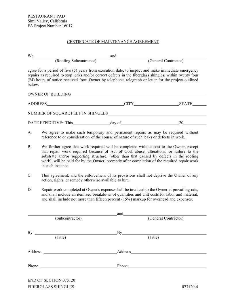
RESTAURANT PADSimi Valley, CaliforniaFA Project Number 16017
FIBERGLASS SHINGLES 073120-4
CERTIFICATE OF MAINTENANCE AGREEMENT
We and(Roofing Subcontractor) (General Contractor)
agree for a period of five (5) years from execution date, to inspect and make immediate emergency repairs as required to stop leaks and/or correct defects in the fiberglass shingles, within twenty four (24) hours of notice received from Owner by telephone, telegraph or letter for the project outlined below.
OWNER OF BUILDING
ADDRESS CITY STATE
NUMBER OF SQUARE FEET IN SHINGLES
DATE EFFECTIVE: This day of 20
A. We agree to make such temporary and permanent repairs as may be required without reference to or consideration of the course of nature of such leaks or defects in work.
B. We further agree that work required will be completed without cost to the Owner, except that repair work required because of Act of God, abuse, alterations, or failure to the substrate and/or supporting structure, (other than that caused by defects in the roofing work), will be paid for by the Owner, promptly after completion of the required repair work in each instance.
C. This agreement, and the enforcement of its provisions shall not deprive the Owner of any action, rights, or remedy otherwise available to him.
D. Repair work completed at Owner's expense shall be invoiced to the Owner at prevailing rate, and shall include an itemized breakdown of quantities and unit costs for labor and material, and shall include not more than fifteen percent (15%) markup for overhead and expenses.
and(Subcontractor) (General Contractor)
By By(Title) (Title)
Address Address
Phone Phone
END OF SECTION 073120

RESTAURANT PADSimi Valley, CaliforniaFA Project Number 16017
BUILT-UP ROOFING 075113 - 1
SECTION 075113 - BUILT-UP ROOFING
PART 1 GENERAL
1.1 SUMMARY
A. Section Includes: Provide a five ply fiberglass reinforced membrane roofing system with a factory coated highly reflective cap sheet surfacing. Provide complete with related flashings, scuppers, cant strips, and performing such incidental or other work as may be necessitated by these operations.
1. Built-up asphalt roofing.
1.2 RELATED SECTIONS
A. Section 061000: Rough Carpentry.
B. Section 076200: Sheet Metal Flashing and Trim.
1.3 REFERENCES
A. ASTM D312 Standard Specification for Asphalt Used in Roofing.
B. ASTM D4586 Standard Specification for Asphalt Roof Cement, Asbestos-Free.
C. ASTM D4601 Standard Specification for Asphalt-Coated Glass Fiber Base Sheet Used in Roofing.
D. ASTM E108 Standard Test Methods for Fire Tests of Roof Coverings.
E. ASTM D3909 Standard Specification for Asphalt Roll Roofing (Glass Felt) Surfaced With Mineral Granules.
F. ASTM D1079 Standard Terminology Relating to Roofing and Waterproofing.
G. ASTM D41 Standard Specification for Asphalt Primer Used in Roofing, Dampproofing, and Waterproofing.
H. ASTM D 2178 Standard Specification for Asphalt Glass Felt Used in Roofing and Waterproofing.
I. UL 790 Standard Test Methods for Fire Tests of Roof Coverings.
J. NRCA - Roofing and Waterproofing Manual.
K. INTERTEK TESTING SERVICES - Fire Resistance Directory, Current Edition.
1.4 DEFINITIONS

RESTAURANT PADSimi Valley, CaliforniaFA Project Number 16017
BUILT-UP ROOFING 075113 - 2
A. Roofing Terminology: See ASTM D 1079 and glossary of the National Roofing Contractors Association (NRCA) “The Roofing and Waterproofing Manual” for definition of terms related to built-up roofing.
1.5 PERFORMANCE REQUIREMENTS
A. General Performance: Installed built-up roofing and base flashings shall withstand exposure to weather without failure due to defective manufacture.
B. Material Compatibility: Provide roofing materials that are compatible with one another under conditions of service and application required as demonstrated by built-up roofing manufacturer based on testing and field experience.
1.6 SUBMITTALS
A. Product Data: For each type of product indicated.
B. Shop Drawings: For built-up roofing. Include plans, elevations, sections, details, and attachments to other work.
C. Samples for Verification:
1. Submit sample of built-up roofing materials, including base sheet, ply sheet, reflective cap sheet, and flashing sheets.
D. Maintenance Data: For built-up roofing to include in maintenance manuals.
E. Installer Authorization Letter: Submit letter stating applicator is authorized to install the roofing system.
1.7 QUALITY ASSURANCE
A. Manufacturer: Company specializing in manufacturing the products specified in this Section with minimum twenty years documented experience.
B. Applicator: Company specializing in applying bituminous roofing with minimum five years documented experience and authorized by materials manufacturer.
C. Work of this Section to conform to NRCA Roofing and Waterproofing Manual and manufacturer's instructions. It is the responsibility of the applicator to address any conflicts or disparities between NRCA requirements and manufacturer’s requirements.
D. Material Source Limitation: Obtain components including base, ply, cap sheet, and mastics for built-up roofing from same materials manufacturer.
E. Preliminary Roofing Meeting: Before starting roofing installation, conduct conference at the project site.

RESTAURANT PADSimi Valley, CaliforniaFA Project Number 16017
BUILT-UP ROOFING 075113 - 3
1. Meet with Owner, Architect, Roofing Applicator, roofing manufacturer’s representative, deck installer, and installers whose work interfaces with or affects roofing, including installers of roof accessories and roof- mounted equipment.
2. Review methods and procedures related to roofing installation, including manufacturer’s written instructions.
3. Review and finalize construction schedule and verify availability of materials, installers’ personnel, equipment, and facilities needed to make progress and avoid delays.
4. Review deck surface conditions and finishes, including flatness and fastening.
5. Review structural loading limitations of roof deck during and after roofing.
6. Review base flashings, special roofing details, roof drainage, roof penetrations, equipment curbs, and condition of other construction that will affect roofing.
7. Review temporary protection requirements for roofing during and after construction.
8. Review repair procedures after roofing installation.
1.8 REGULATORY REQUIREMENTS
A. Comply with current applicable International Building Code/State Building Code and all current local and State Amendments to the applicable Code. Comply with all other Regulatory Requirements as delineated in previous Sections of the Contract Documents.
B. Roof Assembly Fire Listing: Class A roof assembly as tested in accordance with either ASTM E108 Standard or UL 790 Standard at an ICC/ES approved testing laboratory.
1.9 DELIVERY, STORAGE, AND HANDLING
A. Deliver products in manufacturer's original containers, dry, undamaged, with seals and labels intact. Store products in weather protected environment, clear of ground and moisture. Cover material so as to prevent condensation beneath covering.
B. Store roll roofing materials on end on pallets. Store all materials and equipment in a manner to avoid significant and/or permanent deflection of the roofing substrate. Spread loads of roofing materials on roof structures to avoid damage to existing structure. Use protective plywood as required. No material shall be stored on new roofing.
1.10 PROJECT CONDITIONS
A. Weather Limitations: Proceed with installation only when existing ambient temperatures and forecasted weather conditions permit roofing to be installed according to manufacturer’s written instructions and warranty requirements.
RESTAURANT PADSimi Valley, CaliforniaFA Project Number 16017
BUILT-UP ROOFING 075113 - 4
1.11 WARRANTY
A. Water tightness: Membrane roofing system, including membrane type base flashing and roofing accessories, is part of the watertight integrity of the project and as such shall be warranted for five (2) years by the authorized applicator.
B. Manufacturer's Warranty: Submit executed copy of roofing manufacturer's No Dollar Limit (NDL) Warranty for twenty (20) years total from the date of final acceptance by the Owner.
PART 2 PRODUCTS
2.1 MANUFACTURER
A. The Malarkey Roofing R5-WU-AIO-H roofing system specified herein is the basis of design for all roofing assemblies. The structural deck, method of attachment and insulation boards will be specific to each roofing assembly identified.
1. Base sheet: Asphalt coated fiberglass base sheet, ASTM D 4601, Malarkey 515 Base Sheet. 25 lbs. per square.
2. Inter-Ply sheet(s): Asphalt coated fiberglass ply sheet, ASTM D 2178, Type VI, Malarkey 506 Ply 6 Sheet.
3. Cap sheet: SBS Modified fiberglass reinforced, mineral surfaced with a highly reflective coating cap sheet, ASTM D 3909, Malarkey 524 RCap Plus Cap Sheet. 77 lbs. per square.
4. Flashing Base/Ply sheet: SBS Modified fiberglass base sheet, ASTM D 4601, Malarkey 501 Modified Base Sheet. 30.5 lbs. per square.
5. Flashing Surface Ply: SBS Modified fiberglass reinforced, mineral surfaced with a highly reflective coating cap sheet, ASTM D 3909, Malarkey 624 RCap Cap Sheet. 100 lbs. per square.
2.2 AUXILLARY ROOFING MEMBRANE MATERIALS
A. General: Auxiliary materials recommended by roofing system manufacturer for intended use and compatible with roofing membrane.
B. Asphalt Primer: 707 Low VOC Asphalt Primer, ASTM D41.
C. Roofing Asphalt: ASTM D312, Type III or IV.
D. Asphalt Roofing Cement: 709 Modified Flashing Cement, ASTM D4586.
E. Lead Plate for embedment in drain construction: 4 lb. minimum lead.
F. Sealant: Polyurethane non-hardening, non-migrating, and non-drying, Vulkem 921, ChemCaulk 900; or equal.
G. Walkway Pads: Recycled Rubber Walkboard Pads, 3/8” thick, 32” x 36”, Malarkey 141 Recycled Rubber Walkboard Pads.

RESTAURANT PADSimi Valley, CaliforniaFA Project Number 16017
BUILT-UP ROOFING 075113 - 5
H. 824 RCap Touch Up.
PART 3 EXECUTION
3.1 EXAMINATION
A. Examine substrates, areas, and conditions, with the roofing applicator present, for compliance with the following requirements and other conditions affecting performance of roofing system.
B. Verify that roof openings, curbs, pipes, sleeves, ducts, drains, and vents through roof are solidly set.
C. Beginning of installation means roofing applicator accepts substrate.
3.2 PROTECTION
A. Protect building surfaces against damage from roofing work. Provide protection under kettles when damage to area may occur. Provide safety barriers and other protection devises as needed to protect property and people.
3.3 PREPARATION
A. Clean substrate of dust, debris, and other substances detrimental to roofing installation. Remove sharp projections.
B. Provide material to substrate as required to produce an even substrate that will maintain the required slope for drainage.
C. Prevent materials from entering or clogging roof drains and conductors and from migrating onto surfaces of other construction. Remove roof drain plugs when no work is taking place or when rain is forecast.
3.4 GENERAL INSTALLATION REQUIREMENTS
A. All drains, projections and edges shall be installed in strict accordance with practices set forth by the applicable code, NRCA Roofing Manual, ARMA, or material manufacturer, whichever is more stringent. All mechanical equipment requiring fastening shall be fastened with hex head screws with EPDM sealing washers.
B. Commercial roofing systems over decks greater than 1”:12” in slope are to be considered Steep Slope Installations and are to be installed as specified by the Designer of Record, see also Malarkey Roofing Products General Requirements, 3.4.2 of the current Malarkey Roofing Products Specification Manual.
C. Cooperate with inspection and testing agencies engaged or required to perform services in connection with roofing system installation.

RESTAURANT PADSimi Valley, CaliforniaFA Project Number 16017
BUILT-UP ROOFING 075113 - 6
D. Asphalt Bitumen Heating: Heat and apply bitumen in accordance with equiviscous temperature method ("EVT Method") as specified or recommended by asphalt supply and industry recommendations. Do not raise temperature above minimum normal finished blowing temperature necessary to attain EVT (+25 F or 14 C) at point of application more than one hour prior to time of application. Discard bitumen which has been held at temperature exceeding finished blowing temperature (FBT) for a period exceeding three hours. Determine flash point, finished blowing temperature and EVT of bitumen, either by information from bitumen producer or by suitable tests, and determine maximum fire-safe handling temperature and do not exceed that temperature in heating bitumen; but in no case heat bitumen to a temperature higher than 25 F (14 C) below flash point. Inter-ply moppings of asphalt shall be a nominal 25 lbs. per 100 Sq. Ft.
E. Cants: Provide cants at all intersections with vertical surfaces. Install in accurate lengths, cut to suit conditions; miter all corners and intersections.
F. Provide cut-offs at end of each day's work, to cover exposed plies. Remove cut-offs before resuming work.
3.5 MEMBRANE APPLICATION
A. Bitumen Mopping Weights: For interply mopping, and other moppings, except as otherwise indicated, apply bitumen at the nominal rate of 25 lbs. of asphalt (+/- 25% on a total job average basis) per 100 sq. ft. between plies.
B. Base Sheet: Turn up all cant strips and down all roof edges. Install all base sheets so that the water is over or parallel to, but never against the laps. Lap 2” on all sides, 6” on all ends. Mechanically attach the base sheet to comply with the projects wind loads as defined by IBC/ASCE 7. Install with no buckles.
C. Inter-Ply: Install fiberglass ply sheets in accordance with manufacturer's recommendations, or as specified, whichever is more stringent. Install so that the water flows over or parallel to, but never against the laps. Install the sheets to the correct exposure as described in the current edition of the Malarkey Specification Manual. Embed ply sheets in a uniform mopping of hot asphalt applied at the nominal rate of 25 lbs (+/- 25%) per ply per square. Install with no voids, wrinkles, or buckles. Ensure adhesion between the mopping asphalt and the bottom of all ply sheets.
D. Flashings: Install primed flashings (lead, metal, scuppers, etc.) in a layer of plastic roof cement on top of the inter-ply and stripped off with two plies of reinforcement, feathering each ply 3” from the edge of the flange and corresponding ply.
E. Surfacing: After the completion of the inter-plies, striping plies to all flashings and the installation of the base flashing reinforcement, install the reflective cap sheet surfacing. Install so the water flows over or parallel to, but never against the laps. Cut cap sheet into 1/3’s and allow to fully relax before installing. Adhere cap sheet in a uniform mopping of hot asphalt applied at the nominal rate of 25 lbs. per square. Ensure newly installed cap sheet is fully adhered.
RESTAURANT PADSimi Valley, CaliforniaFA Project Number 16017
BUILT-UP ROOFING 075113 - 7
3.6 MEMBRANE BASE FLASHING
A. Membrane Base Flashing: Base flashing stripping ply(s) is/are to be installed over the inter-ply before the installation of the surfacing. Stripping ply(s) is/are to extend 3” beyond the toe of the cant and up the vertical surface of all flat to vertical transitions (curbs, walls, roof top equipment, etc.) Install the specified cap sheet base flashing extending 6” beyond the toe of the cant and up the vertical surface. Terminate the base flashing as shown in the manufacturers roofing details.
END OF SECTION 075113

RESTAURANT PADSimi Valley, CaliforniaFA Project Number 16017
SHEET METAL 076100-1
SECTION 076100 - SHEET METAL
1.0 GENERAL
1.1 SCOPE: Furnish materials and perform labor required to execute this work as indicated on the drawings, as specified and as necessary to complete the Contract, including, but not limited to, these major items:
A. Flashings and counter flashings in connection with built-up roofing, tile roofing and shingles.
B. Water sealing and caulking in connection with this work.
C. Special plaster screeds and accessories.
D. Roof equipment pad covers.
E. Parapet coverings (when indicated).
F. Attic ventilating louvers (when indicated).
G. Exhaust vents and hoods (when indicated).
H. Warranty.
1.2 GENERAL REQUIREMENTS:
A. Field conditions: Verify drawing dimensions with actual field conditions. Inspect related work and adjacent surfaces. Report to the Architect all conditions which prevent proper execution of this work.
B. Shop Drawings: Submit in accordance with Division 1, showing in complete detail all information required for fabrication, finishing and installation of this work.
1.3 QUALITY ASSURANCE:
A. Insurance Requirements: Provide coping systems which comply with Factory Mutual requirements for roof perimeter flashing in either of the following categories and wind zones.
1. Approval by Factory Mutual Research Corporation for use indicated.
B. Industry Standards: Provide products that comply with applicable requirements of SMACNA “Architectural Sheet Metal Manual”, except as otherwise indicated.
1.4 JOB CONDITIONS:
A. Coordinate work of this section with adjoining work for proper sequencing of each installation to ensure best possible weather resistance and protection of materials and finishes against damage.
RESTAURANT PADSimi Valley, CaliforniaFA Project Number 16017
SHEET METAL 076100-2
2.0 PRODUCTS
2.1 MATERIALS:
A. Galvanized sheet metal: Conform to ASTM A526, thickness indicated or specified, but not less than 24 gage; coating class 1.25 commercial.
B. Aluminum Materials
1. Aluminum Sheet. Alloy and temper recommended by manufacturer for use intended and as required for proper application of finish indicated but with not less than the strength and durability properties specified in ASTM B 209 or 5005-H 15.
C. Miscellaneous Materials
1. Concealed Fasteners: Same metal as item fastened or other noncorrosive metal as a recommended by manufacturer.
2. Mastic Sealant: Polyisobutylene; non-hardening, nonskinning, nondrying, nonmigrating sealant.
3. Foam Rubber Seal: Manufacturer's standard foam.
4. Adhesives Type recommended by manufacturer for substrate and project conditions; and formulated to withstand minimum 60 psf uplift force.
D. Expansion Provisions: Fabricate copings to allow controlled expansion in running lengths not only for movement of metal components in relationship to one another but also to adjoining dissimilar materials, including flashing and roofing membrane materials, in a manner which is sufficient to prevent water, leakage, deformation or damage.
2.2 COPINGS:
A. Interlocking Multi-Part Coping System: Provide manufacturer's standard system consisting of coping formed from galvanized sheet metal to profile and of thickness indicated, zinc-coated steel anchor plate or cleat located at coping joint and formed aluminum gutter chair or gutter/splice plate or compression pad/gutter; with prefabricated inside and outside corners, miters welded before finishing; without exposed fasteners.
1. Thickness of Coping: Minimum 22 gauge.
2. Products: Subject to compliance with requirements, provide one of the following:
a. Permasnap Coping; W.P. Hickman Co.

RESTAURANT PADSimi Valley, CaliforniaFA Project Number 16017
SHEET METAL 076100-3
b. ME #104 "Neolock Coping; Merchant and Evans Industries, Inc.
c. Snap-Lok Coping; MM Systems Corp.
2.3 FINISHES:
A. General: Comply with NAAMM "Metal Finishes Manual" for finish designations and application recommendations, except as otherwise indicated. For components that are assembled or welded in factory, apply finish after fabrication is completed.
1. Provide colors or color matches as indicated or, if not indicated, as selected by Architect from manufacturer's standard colors.
B. High Performance Coating: AA-C12C42R1X (cleaned with inhibitive chemicals, conversion coated with an acid-chromate-fluoride-phosphate treatment and painted with organic coating specified below). Apply in strict compliance with coating and resin manufacturer's instructions using a licensed applicator.
1. Fluorocarbon Coating: Inhibitive thermo-cured primer, 0.2 minimum mil dry film thickness, and thermo-cured flurocarbon coating containing "Kynar 500" resin 1.0 mil minimum dry film thickness.
C. Solder: Standard brand of 50:50 Alloy Lead-Tin, complying with ASTM B32. Name of manufacturer and grade designation shall be cast or die-marked on each bar.
D. Solder flux: Compatible with material being joined. No muriatic acids allowed.
E. Sheet metal fasteners: Rivets, nails, sheet metal screws, machine screws, self-tapping screws, and stove bolts, of the types and size best adapted to the condition of the use. Provide fasteners of the type specified or indicated.
1. Use galvanized steel, cadmium plated steel or 300 Series alloy stainless steel.
2. Pop rivets may be used for metal-to-metal connections when future dis-assembly is not required. Open-end type may be used for all applications except where watertight connections are required, in which case, use closed end type.
3. Use neoprene washers with screws at all penetrations requiring a watertight installation.
F. Shop prime coat except stainless steel: Tnemec #99 Red metal Primer, or #1009 Gray metal primer, manufactured by Tnemec Company, Inc., or Rust Oleum #3202 Undercoat followed #3268 Red, as manufactured by Rust-Oleum Corporation, Apply #3202 to 1/2 mil wet coating thickness; #3268 to 1 mil dry coating thickness.
G. Flashings and reglets: Fry or Lane Aire complete assemblies with all splices, performed in-and-out corner assemblies, and accessories required for proper

RESTAURANT PADSimi Valley, CaliforniaFA Project Number 16017
SHEET METAL 076100-4
installation in compliance with manufacturer's instructions. Fabricate and install flashing to exert a constant pressure against reglet and roofing. Install flashing with overlapped ends to ensure a tight waterproof seal. Tape or fill reglets with a removable filler to prevent intrusion of mortar or dirt. Flashings shall be readily removable and replaceable without clips or screws unless otherwise approved. Select from following types as required by job conditions.
1. Surface-mounted flashing: Fry Surface Mounted Type SM with "Expan-O-Seal" flashing reglet system. Install in accordance with manufacturer's instructions, level and true, 7" minimum above high point. Step down or slope down to maintain 7" minimum above cant strip. Lap reglet 3" at joints.
2. For installation in masonry: Fry "Springlok" flashings system Type MA (Masonry). Install in horizontal joints 7" above high point of cant strip. Step down to maintain 7" minimum above cant strip. See manufacturer's recommendations.
After base flashing has been installed, inspected and approved, install counterflashing immediately in compliance with manufacturer's instructions to eliminate water migration. Lap flashings a minimum of 3". Water damaged base flashings shall be removed and replaced with new, undamaged material.
2.4 FABRICATION AND ASSEMBLY-GENERAL:
A. Workmanship: Fabricate and finish metal work in a first class manner in accordance with best trade practices that are in accordance with SMACNA with all joints and corners accurately machined, filed and fitted, and rigidly framed together and connected. Carefully match components to produce perfect continuity of line and design. Make joints and connections in exterior face metal watertight, using approved sealing materials and methods of assembly. Fit faces of metal in contact with hairline joints, except as otherwise indicated or required for expansion or fitting. Conceal fastenings, unless otherwise indicated. Conceal required reinforcements within the finished assembly.
B. Provide copings which are designed and fabricated to fit applications indicated and to perform optimally with respect to weather resistance, water tightness, durability, strength and uniform appearance, Provide manufacturer's logo on non-exposed surface of copings.
C. Expansions and contraction: Form and fabricate work to adequately provide for thermal expansion and contraction and building movement in the completed work, without overstressing the materials, breaking connections, or producing wrinkles and distortion in finished surfaces. Finish sheet metal work to be water and weathertight throughout.
D. Attachment clips: Where subject to thermal expansion and contraction, attach members with clips to permit movement without damage to the installation, or provide slotted or over-sized holes with washers where appearance is not critical, as approved by the Architect.

RESTAURANT PADSimi Valley, CaliforniaFA Project Number 16017
SHEET METAL 076100-5
E. Lock seams: Make lock seam work flat and true to line; sweat full of solder except where installed to permit expansion and contraction. Lap flat lock seams, and lap seams where soldered, according to pitch but in no case less than 3". Make seams in direction of flow. Fill expansion joints with sealant.
F. Soldering: Thoroughly clean and tin material prior to soldering. Solder with heavy coppers of blunt design, properly tinned before use. Solder slowly with well heated coppers, heating the seams thoroughly and completely filling them with solder. Finish surfaces neatly, full-flowing and smooth. Wash acid flux thoroughly with a soda solution after soldering and completely remove soldering flux on exposed surfaces.
G. Caulking: Where indicated or needed, caulk joints in sheet metal work and between sheet metal work and adjacent construction with polysulfide sealing compound. Apply in accordance with Caulking and Sealants Section.
3.0 EXECUTION
3.1 DESCRIPTION OF ELEMENTS:
A. Standard of stock items and those items which are sufficiently detailed to permit fabrication and installation are not covered even though they are listed in the scope.
B. Parapet coping: Fabricate true to section indicated. Provide standing seam joints at not to exceed 10'-0” o.c. and at corner joints. Fill joints with an approved high-grade urethane sealant. Install with continuous concealed clip at inside and outside of parapet.
C. Equipment pad covers: Fabricate with flat lock seams made in direction of water flow and solder seams for a watertight installation.
D. Parapet fire flashing: Install galvanized sheet metal flashing where and as required by code. Fabricate true to section indicated. Provide folding standing seam joint at not to exceed 10'-0” o.c. Fill expansion joints with fire resistant sealant. Install with concealed clips.
E. Attic louvers: Install galvanized unit as recommended by manufacturer with insect screen as an integral part of the unit suitable for the particular installation. Seal installation in a watertight manner. Provide and install size as required by code. Approved manufacturer: Noll Manufacturing Co. or approved equal. Fusible link as required. Prime coat flanges.
F. Roofing and Shingles: Provide continuous 6" x 6" flashing at inside and outside corner conditions from parapet to over cant strip to roof diaphragm over the underlayment prior to final finish application. Surfaces exposed to roofing and shingles application shall be primed.
G. Pitch Pans and Drain Scuppers: Continuous solder of all lap joints.

RESTAURANT PADSimi Valley, CaliforniaFA Project Number 16017
SHEET METAL 076100-6
3.2 INSTALLATION:
A. General: Comply with manufacturer's written installation instructions and recommendations. Coordinate with installation of roof deck and other substrates to receive work of this section, with vapor retarders, roof insulation, roofing membrane, flashing, and wall construction, as required, to ensure that each element of the work performs properly, and that combined elements are waterproof and weather-tight. Anchor products, included in this section, securely to structural substrate, adequate to withstand lateral and thermal stresses as well as inward and outward loading pressures.
B. Isolation; Where metal surfaces of units are installed in contact with dissimilar metal or corrosive substrates, including wood, apply bituminous coating on concealed metal surfaces or provide other permanent separation as recommended by aluminum producer.
3.3 CLEANING AND PROTECTION:
A. Clean exposed metal surfaces in accordance with manufacturer's instructions. Touch-up damaged metal coatings.
B. Protection: Provide protective measures as required to ensure that work of this section will be without damage or deterioration at time of substantial completion.
4.0 WARRANTY
4.1 REQUIREMENTS:
A. Unconditionally warrant the work of this section for five (5) years.
B. Install in compliance with roofing manufacturer's recommendations in order to provide Owner's guarantee requirements.
END OF SECTION 076100
RESTAURANT PADSimi Valley, CaliforniaFA Project Number 16017
ROOF ACCESSORIES 077200-1
SECTION 077200 - ROOF ACCESSORIES
1.0 GENERAL
1.1 SCOPE: Furnish materials and equipment and perform labor required to execute this work as indicated on the drawings, as specified herein and as necessary to complete the Contract, including, but not limited to, the following principal items:
A. Roof hatches.
B. Ladder assist device.
1.2 RELATED WORK SPECIFIED ELSEWHERE:
A. Rough carpentry.
B. Roofing
C. Steel ladder.
1.3 GENERAL REQUIREMENTS:
A. Field conditions: Verify drawing dimensions with actual field conditions. Inspect related work and adjacent surfaces. Report all conditions which prevent proper execution of this work to the Architect.
B. Shop drawings: In accordance with requirements of Division 0, submit shop drawings showing in complete detail, all information required for fabrication, finishing and installation of this work.
2.0 PRODUCTS
2.1 MANUFACTURER AND TYPE:
A. Roof hatches:
1. Type S-20, manufactured by the Bilco Company, New Haven, Connecticut.
2. Type 6-102, manufactured by Babcock-Davis Associates Inc., Boston, Massachusetts.
3. Type LH-G, Dur-Red Products, manufactured by Red Plastic Co., Inc., Los Angeles, California.
B. Guardrail at roof hatch:
1. Provide DRA Safety Products KeeHatch Railing System Model No. RHSR-SS or approved equal. Telephone no. (877) 723-3766).

RESTAURANT PADSimi Valley, CaliforniaFA Project Number 16017
ROOF ACCESSORIES 077200-2
2.2 CONSTRUCTION ROOF HATCHES:
A. Cover of 14 gage galvanized steel with 3" beaded flange. Insulation shall be glass fiber 1" thick, fully covered and protected by 22 ga. galvanized steel liner. Curb shall be 12" in height of 14. ga. galvanized steel with full welded corners, equipped with an integral metal capflashing of 14 ga. galvanized steel. Insulation on the exterior of curb shall be 1" thick rigid fiber board. Roof hatch shall be completely assembled with heavy pintle hinges, compression spring operators enclosed in telescopic tubes, position snap latch with turn handles and padlock hasps inside with neoprene draft seal. All hardware shall be zinc plated in accordance with manufacturer's standards. Equip cover with an automatic hold-open arm complete with red vinyl grip handles to permit easy, one hand release.
3.0 EXECUTION
3.1 INSTALLATION:
A. Install in accordance with manufacturer's instruction. Coordinate work with Roofing Section.
B. Install guardrail system in accordance with manufacturer's recommendations.
END OF SECTION 077200

RESTAURANT PADSimi Valley, CaliforniaFA Project Number 16017
JOINT SEALANTS 079000-1
SECTION 079000 - JOINT SEALANTS
1.0 GENERAL
1.1 SCOPE
A. This Section contains general specifications pertaining to all weather sealing and caulking throughout the project, and becomes a part of all sections containing reference hereto, or where materials of the types specified in this Section are required by the drawings.
B. Specific requirements contained in the various trade sections making references to this section supersede general or conflicting requirements herein.
C. For the purpose of this specification, all EXTERIOR work shall receive SEALANT, and INTERIOR work shall receive a CAULKING COMPOUND.
D. First-class workmanship only will be acceptable.
E. Completely seal, but do not limit to the following:
1. All joints in conjunction with masonry work.
1.2 JOB CONDITIONS
A. Weather Conditions: Do not proceed with installation of liquid sealants under unfavorable weather conditions. Install elastomeric sealants when temperature is in lower tier of temperature range recommended by manufacturer for installation (45 degrees to 55 degrees F).
1.3 PRODUCT HANDLING
A. Deliver, store and handle material in a manner to prevent the entrance of foreign materials and damage of materials by water or breakage. Damaged material shall be rejected. The name of the manufacturer and the trade name of the caulking compound shall be on each container.
B. Provide joint sealants for interior applications that have been produced and installed to establish and maintain airtight continuous seals that are water resistant and cause no staining or deterioration of joint substrates.
1.4 GENERAL REQUIREMENTS
A. Guarantee: Provide written guarantee for all caulking and sealants against all defects of material or application for a period of five years after date of acceptance. All failures that may occur within this period, due to defective application of materials shall, upon written notification of such failure, be repaired or replaced
RESTAURANT PADSimi Valley, CaliforniaFA Project Number 16017
JOINT SEALANTS 079000-2
with proper materials and labor as approved by the Architect, at no additional cost to the Owner.
B. In accordance with Division 0, submit to the Architect samples of the various types (and colors where applicable) of materials specified, prior to delivery of materials to the job.
C. Deliver Materials to the job in original unopened containers bearing manufacturer's name, product designation and date of manufacture.
D. Install proprietary materials specified herein in compliance with manufacturer's instructions. Send copies of manufacturer's instructions to Architect at least 2 weeks before application.
E. Verify limitations of products with manufacturers.
2.0 PRODUCTS
2.1 MATERIALS
A. Use sealants of the following types and manufacturers. Unless specified or directed otherwise, use materials to match color of adjacent materials. Where adjacent materials on each side of the joint are different colors, the Architect will select sealant colors. If the desired color is not available from one manufacturer, select proper color from another manufacturer.
2.2 INCIDENTAL MATERIALS
A. Staining characteristics: All joint filler primers, or other materials used in conjunction with sealants shall be of such composition as to not cause staining of the sealant or the materials to which they are applied.
B. Compressible Joint Filler: Closed cell neoprene, plastic foam, or urethane, as recommended by the sealant manufacturer for use in conjunction with the sealant.
1. Use butyl rod backing for all compressible joints.
C. Primers: As recommended by the sealant manufacturer for use in conjunction with the sealant for application onto the various types of materials to which the sealer is applied.
D. Cleaners, where required in lieu of primers: As recommended by the sealant manufacturer.
2.3 MATERIALS TYPES

RESTAURANT PADSimi Valley, CaliforniaFA Project Number 16017
JOINT SEALANTS 079000-3
A. Type #1 - One-part polysulfide, FS TT-S-00230C. Use for vertical and horizontal joints in connection with concrete, plaster, steel, aluminum and glass. Do not use in traffic areas.
1. Rubber Caulk 5000, by PRC.
2. One-part Caulking & Glazing Sealant, by Coast Pro-Seal.
3. Sonolastic - One-part, by Sonneborn-Contech.
4. Weatherban 101, by 3M.
B. Type #2 - Two-part polysulfide, FS TT-S000227E. Use for vertical and horizontal joints in connection with masonry, concrete, plaster, steel, aluminum and glass. Do not use in traffic areas.
1. Rubber Caulk 150 (flow type) or 250 (heavy type), by PRC.
2. Caulking and Glazing Compound, by Coast Pro-Seal.3. Lasto-Meric, by Tremco.
4. Sonolastic - Two-part, by Sonneborn-Contech.
C. Type #3 - Multi-part Polyurethane Base, FS TT-S-00227E. Use for vertical joints in connection with all building materials. Use rubber Caulk 220 or Dymeric for traffic areas.
1. Rubber Caulk 210 (heavy) or 220 (flow), by PRC.
2. Polyurethane 962 Expansion Joint Sealant, by Coast Pro-Seal.
3. Dymeric, by Tremco.
4. Vulkern 247 (non-sag) or 245 (self-leveling), by Master Builders.
D. Type #4 -One-part silicone (non-porous surfaces) FS TT-S-1543. Use for vertical joints above grade in connection with glass, ceramics, steel, wood and aluminum.
1. SCS-1200 Construction Sealant, by GE.
2. 781 Building Sealant, by Dow Corning.
E. Type #5 - One-part silicone (porous surfaces) FS TT0-S-00154A. Use for vertical joints above grade in connection with concrete, masonry, steel, aluminum and glass.
1. SCS-1200 Construction Sealant, by GE.
2. 781 Building Sealant, by Dow Corning.
RESTAURANT PADSimi Valley, CaliforniaFA Project Number 16017
JOINT SEALANTS 079000-4
F. Type #6 - Two-part silicone (porous and non-porous). Use for vertical and horizontal joints above grade in connection with concrete, ceramics, wood, steel, aluminum and glass.
1. SCS-1600, by GE.
G. Type #7 - One-part acrylic sealant. Use for vertical and horizontal joint in connection with all building materials. Do not use in traffic areas.
1. Mono, by Tremco.
2. Latex Caulk, by Parr.
3. Elastoseal Latex, by Pacific Polymers.
H. Type #8 - Compressible polyurethane foam. Use for vertical and horizontal joints in connection with concrete, precast concrete, masonry, roofing, siding plaster, drywall, metal and glazing and may be used in traffic areas. Use Poly-Tile only under hard protection.
1. Poly-Tite, by Sandell.
2. Compribond, by Secoa, Inc.
3.0 EXECUTION
3.1 INSPECTION
A. Installer must examine substrates and caulking (joint surfaces) and conditions under which joint sealer work is to be performed and must notify Contractor in writing of unsatisfactory conditions. Do not proceed with joint sealer work until unsatisfactory conditions have been corrected in a manner acceptable to installer.
B. Failure or refusal of the manufacturer to provide the inspection and supervision as required hereunder constitutes ground for non-acceptability of materials manufactured by him even though such materials have been specified or approved.
3.2 JOINT PREPARATION
A. Clean joint surfaces immediately before installation of sealants or caulking compounds. Remove dirt, insecure coatings, moisture and other substrates that could interfere with seal or gasket or bond of sealant or caulking compound. Etch masonry joint surfaces as recommended by sealant manufacturer. Roughen vitreous surfaces as recommended by sealant manufacturer and applications indicated, except where more stringent requirements apply.
RESTAURANT PADSimi Valley, CaliforniaFA Project Number 16017
JOINT SEALANTS 079000-5
B. Prime or seal joint surfaces where recommended by sealant manufacturer. Confine primer/sealer to areas of sealant bond. Do not allow spillage or mitigation onto adjoining surfaces.
3.3 INSTALLATION
A. General: Comply with joint sealant manufacturer's printed installation instructions applicable to products and applications indicated, except where more stringent requirements apply.
C. Set joint filler units at depths or position in joint as indicated to coordinate with other work, including installation of bond breakers, backer rods and sealants. Do not leave voids or gaps between ends of joint filler units.
D. Apply sealant with a hand or power caulking fun of the proper size to fit the joint. Avoid apply materials to surfaces outside areas to be sealed.
E. Joints that are open to a depth greater than 1/2" shall receive joint closed cell backing materials.
F. After sealant is applied, tool material to insure that joints are filled completely and solidly. Finish joints shall be smooth, even and concave and shall be watertight. Unsatisfactory joints shall be completely removed and replaced.
3.4 APPLICATION
A. Joint Filler: Accurately position within the joint to establish and control and uniform designated thickness of sealant.
B. Apply material with sufficient pressure to completely fill the void space and to assure complete wetting of contact area to obtain uniform adhesion. During application, keep tip of nozzle at bottom of joint, forcing sealant to fill from bottom to top. Finish joint smooth and flush with adjacent surface unless detailed to be finished below the surface.
C. Perform joint preparation, including cleaning and priming, in accordance with manufacturer's instructions.
D. Provide manufacturer's inspection of conditions prior to start of the work and initial supervision at the start of each application, in order to insure that any physical conditions which would result in defective work are properly corrected before materials are applied, that properly instructed personnel are available to do the work, and that proper procedures are being followed. Provide such inspection and supervision by qualified personnel. Report all satisfactory conditions existing at the time of inspection in writing to the Architect for correction before proceeding with the work.
E. Notify the manufacturer at least 72 hours prior to the time inspection is required.

RESTAURANT PADSimi Valley, CaliforniaFA Project Number 16017
JOINT SEALANTS 079000-6
F. Failure or refusal of the manufacturer to provide the inspection and supervision as required hereunder constitutes ground for non-acceptability of materials manufactured by him even though such materials have been specified or approved.
3.5 CURE AND PROTECTION
. Cure sealants and caulking compounds in compliance with manufacturer's instructions and recommendations to obtain high, early bond strength, internal cohesive strength and surface durability. Advise Contractor of procedures required for cure and protection of joint sealant during construction period so they will be without deterioration or damage (other than normal wear and weathering) at time of substantial completion. Cure and protect sealants in a manner that will minimize increases in modulus of elasticity and other accelerated aging effects. Replace or restore sealants that are damaged or deteriorated during construction period.
3.6 CLEANING
A. Any adjacent materials that have become soiled due to installation of this work shall be thoroughly cleaned with a suitable solvent of the type as recommended by the sealant compound manufacturer.
B. Site shall be cleaned up at the end of each day's work. All unused materials shall be placed in tightly sealed containers and stored. Upon completion of all the work, this Contractor shall remove cartons and other debris related to this work from the project site at the direction of the project superintendent.
END OF SECTION 079000
RESTAURANT PADSimi Valley, CaliforniaFA Project Number 16017
HOLLOW METAL DOORS & FRAME 081000-1
SECTION 081000 - HOLLOW METAL DOORS & FRAMES
1.0 GENERAL
1.1 SCOPE: Furnish materials and perform labor required to execute this work as indicated on the drawings, as specified and as necessary to complete the Contract, including, but not limited to, these major items:
A. Hollow metal doors.
B. Pressed steel frames.
C. Louvers (where indicated).
D. Shop prime coat.
E. Installation of frames.
F. Shop drawings.
G. U.L. labeled construction (where required).
H. Transom panels (when indicated).
I. Guarantee.
1.2 GENERAL REQUIREMENTS:
A. Field conditions: Verify drawing dimensions with actual field conditions. Inspect related work and adjacent surfaces. Report to the Architect all conditions which prevent proper execution of this work.
B. Codes: Materials and work shall conform to the governing Building Code. In case of conflict between these specifications and the Building Code, the more stringent shall govern.
C. Shop drawings: In accordance with Division 1, submit the following: Doors and frames, showing gages and types of metal, frame anchorage, construction, sound deadening insulation, molding profiles, location of hardware and reinforcements and preparation to receive hardware. Include a schedule relating the type of door and frame to be installed in each scheduled door opening or place of installation.
D. Coordination of work: Coordinate with the supplier of finish hardware and the supplier of other doors to be installed in hollow metal frames. Templates will be furnished by the hardware supplier for use in preparation of shop drawings and for preparation and reinforcement of doors and frames to receive the hardware as required.
E. Labeled openings: Where labeled openings are scheduled or are required by codes, construct doors and frames in strict accordance with the requirements of Underwriters' Laboratories and attach labels for the indicated classification.

RESTAURANT PADSimi Valley, CaliforniaFA Project Number 16017
HOLLOW METAL DOORS & FRAME 081000-2
F. Approved manufacturers: Doors and frames shall be equal to units manufactured by Amweld Corporation or Steelcraft, Inc. All 1-3/4” thick doors shall conform to CS-242 Standards.
G. Frames shall be sufficient width to fit the wall thickness indicated on the drawings and complete with proper anchors for securing to wall. All frames shall be mortised and reinforced for hinges, strikes, and all surface applied hardware. All welds shall be smooth and flush with surface.
H. Doors shall have standard cutouts for hardware as called for on the Hardware Schedule.
I. Doors and frames shall be bonderized and receive baked on rust-inhibiting primer.
J. Provide metal drip hood over all exterior doors.
K. Note compactor door and frame size.
L. All exterior hollow metal doors to be insulated with Polystyrene – U = 0.21.
M. All fire rated doors to meet NFPA Standard No. 80.
N. Guarantee: Submit written guarantee in approved form that all defective materials or workmanship reported within a period of 2 years after final acceptance will be promptly repaired or replaced to the satisfaction of the Owner.
2.0 PRODUCTS
2.1 DOORS:
A. Materials and fabrication: Fabricate of two formed sheets of commercial quality roller leveled carbon steel sheets of not less than 16 gage for interior doors and 14 gage for exterior doors. Reinforce inside with 20 gage, minimum, vertical channel reinforcement running full length of door, approximately 6" o.c. and spot welded 4" o.c. Close top and bottom and reinforce with channel member full width of door, not lighter than 18 gage. Spot weld door edges at 2" o.c. for full height of door or reinforce with channels, as standard with the manufacturer. Provide sound deadening materials to make doors free of metallic ring. Use rock mineral wool, cellular fire retardant insulation, or equal as standard with the manufacturer. Exposed seams at edge or on face of doors are not acceptable.
B. Reinforcement: Mortise and reinforce doors for hardware in accordance with templates furnished by hardware supplier. Drill and tap to receive mortise hardware. Provide suitable reinforcement for surface applied hardware items; drilling and tapping for surface applied items will be done in field. Reinforcement for hinges: 9 gage flat bar reinforcement, drilled and tapped for hinges. Reinforcement for locks and other mortise type hardware: not less than 12 gage. Provide 14 gage reinforcement for surface applied items.

RESTAURANT PADSimi Valley, CaliforniaFA Project Number 16017
HOLLOW METAL DOORS & FRAME 081000-3
C. Clearances: Bevel lock edges and meeting stiles of pairs of doors 1/8" in 2". Allow 1/8" clearance at top rails at lock and hinge stiles. At floors and thresholds allow 1/4" nominal clearance, except where otherwise indicated or scheduled.
D. Astragals: Provide full height astragals, as standard with the manufacturer, on all exterior pairs of doors.
E. Transom panels: Construct as for doors over which they occur, including U.L. label, where required.
2.2 PRESSED STEEL FRAMES:
A. Material and fabrication: Form of not less than 16 gage cold-rolled or hot-rolled prime carbon steel sheet, free of defects impairing strength, durability and appearance. Miter corners and continuously weld, with exposed joints ground smooth to a true plane, flush with surfaces of base metal. Form surfaces free of warp, wave, buckle and other defects, with edges, angles and corners square, clean and sharp. Provide Pemco #346A alum. Drip at head section of each exterior door. (Paint Pemco drip to match adjacent surface; verify with Architect for any clarifications.)
B. Reinforcement: Mortise and reinforce frames to receive all hardware. Drill and tap in accordance with templates furnished by hardware supplier. Punch door stops to receive rubber silencers. Weld 22 gage steel plaster guards over hardware reinforcing plates at mortice hardware locations. Provide hinge reinforcement of 3/16" thick flat steel bar welded to frame at each hinge cutout, drilled and tapped. Provide 12 gage minimum reinforcing plates, spot welded to frames at lock, latch, and other mortise hardware locations, including door closers and brackets. Reinforce at surface applied hardware locations with 14 gage minimum reinfor-cement. Reinforce head members with 12 gage steel channel full length of head-frame, where door openings exceed 42" in width.
C. Anchors: Provide 14 gage steel anchors, spot welded to inside of frames, fixed or with adjustable feature as required by wall conditions, spaced not to exceed 24" o.c. at jambs and head. Where installed in masonry walls, arrange anchors to provide vertical adjustment to coincide with horizontal masonry joints. Attach 14 gage steel floor clips, spot welded to each jamb and punched for anchorage to floor. Do not remove steel spreader until frames are securely anchored in place, square and plumb.
2.3 DOOR LOUVERS:
A. Stationary: Airolite No. 583-G or Panelouvre 188 metal louvers, 1-3/4 inch thick, 20-gage minimum metal thickness. Furnish with Airolite or Panelouvre Type "G" metal molding (both sides). Furnish louvers and molding with factory applied prime coat as specified for metal doors. Provide removable aluminum mesh hard-ware cloth insect screen in standard folded aluminum frame on the interior face of all louvered doors located at building exterior.
B. Fusible link louvers (when indicated): Conform to Building Code requirements for type and location.

RESTAURANT PADSimi Valley, CaliforniaFA Project Number 16017
HOLLOW METAL DOORS & FRAME 081000-4
2.4 FINISH:
A. Doors and frames: After assembly, grind door edges smooth and fill flush with mineral filler to conceal seams. Follow with thorough cleaning, rinsing and phosphate coating of all exposed surfaces. Give doors and frames one shop coat of baked-on rust- inhibitive metal primer, as standard with manufacturer, not less than 1 mil thick except stainless steel. Finish paint as specified in Painting Section.
2.5 PROVISIONS FOR GLAZING:
A. Where glazing is indicated or required, provide flush integral stops one side and removable screw-on stops on the opposite side of the glazing, unless otherwise indicated.
3.0 EXECUTION
3.1 FRAME INSTALLATION:
A. Installation in concrete walls: Install frames in forms securely anchored in place, prior to placing concrete. Provide welded anchors and horizontal stiffeners to prevent jambs from bowing in due to pressure of fluid concrete.
B. Installation in masonry walls: Erect frames in position, plumbed and securely braced, and with clip angles attached to floor. Provide adjustable masonry anchors with sufficient adjustment to permit placing anchors in masonry joints without bending. Install horizontal spreaders to keep jambs from bowing in as frames are being filled with grout or mortar. Erect masonry after frames are installed and fill frame with grout or mortar as erection of wall progresses.
C. Installation of stud partitions: Attach frames to studs with "Z" type clips or strap anchors secured to adjacent studs. Exercise particular care to insure that frames are installed symmetrically with respect to the studs.
D. All exterior door frames to be grouted solid.
E. Provide rubber silencers for all frames.
F. Provide weather-stripped thresholds.
3.2 CAULKING:
A. Where frames are required by the drawings to be installed with caulking, provide watertight and weathertight construction. Conform to the requirements of Caulking and Sealants Section for both material and workmanship.
END OF SECTION 081000

RESTAURANT PADSimi Valley, CaliforniaFA Project Number 16017
METAL ACCESS DOORS 081200-1
SECTION 081200 - METAL ACCESS DOORS
1.0 GENERAL
1.1 SCOPE: Furnish materials and perform labor required to execute this work as indicated on the drawings, as specified and as necessary to complete the Contract, including, but not limited to, these major items:
A. Metal access doors.
B. Shop prime coat.
C. Installation of frames.
D. Shop drawings.
1.2 GENERAL REQUIREMENTS:
A. Field conditions: Verify drawing dimensions with actual field conditions. Inspect related work and adjacent surfaces. Report to the Architect all conditions which prevent proper execution of this work.
B. Codes: Materials and work shall conform to the governing Building Code. In case of conflict between these specifications and the Building Code, the more stringent shall govern.
C. Shop drawings: In accordance with Division 1, submit the following: Doors and frames, showing gages and types of metal, frame anchorage, construction, sound deadening insulation, molding profiles, location of hardware and reinforcements and preparation to receive hardware. Include a schedule relating the type of door and frame to the installed in each scheduled door opening or place of installation.
D. Coordination of work: Coordinate with the supplier of finish hardware and the supplier of other doors to be installed in hollow metal frames. Templates will be furnished by the hardware supplier for use in preparation of shop drawings and for preparation and reinforcement of doors and frames to receive the hardware as required.
E. Labeled openings: Where labeled openings are scheduled or are required by codes, construct doors and frames in strict accordance with the requirements of Underwriters' Laboratories and attach labels for the indicated classification.
F. Approved manufacturers: Inryco Milcor, J.L. Industries, Inc., Nystrom Products, Larsen’s Manufacturing Co.
G. Guarantee: In accordance with Division 0, submit written guarantee in approved form that all defective materials or workmanship reported within a period of 1 year after final acceptance will be promptly repaired or replaced to the satisfaction of the Owner.

RESTAURANT PADSimi Valley, CaliforniaFA Project Number 16017
METAL ACCESS DOORS 081200-2
2.0 PRODUCTS
2.1 DOORS:
A. Access doors within plaster ceiling/soffit exposed to public view.
1. Materials and fabrication: Fabricate of 14 gage minimum galvanized steel with self-furred metal lath welded to panel for a securely, keyed plaster finish application, continuous 1" minimum casing beads and continuous hinge of steel with stainless steel pin mounted on long side of door.
2. Reinforcements: As required by manufacturer.
3. Locks: Key-operated cylinder lock in place of one cam lock, with steel sleeve welded to panel, to access cam locks after plastering. Contractor shall furnish the number of keys per the Finish Hardware Section.
B. Flush Panel Doors
1. Fabricate from no less than 14 gage sheet steel with concealed spring hinge set to open 175 . Finish with manufacturer’s factory approved prime paint.
2. Locks:
a. Exterior: Key-operated cylinder lock in place of one cam lock, with steel sleeve welded to panel, to access cam locks after plastering. Contractor shall furnish the number of keys per the Finish Hardware Section.
b. Interior: Furnish flush and screwdriver-operated cam locks of number required to hold door in flush and smooth plane when closed.
2.2 METAL FRAME:
A. Material and fabrication: Fabricate of 14 gage minimum steel with continuous hinge.
2.3 FINISH:
A. Door and Frame: Shall be finished with a chemically bonded prime coat of baked-on electrostatic powder. Exposed edges shall have a prime coat of white, rust inhibitive paint.
1. Finish exposed metal surfaces with paint to match adjacent exterior plaster color. Do not paint keyed lock.
3.0 EXECUTION

RESTAURANT PADSimi Valley, CaliforniaFA Project Number 16017
METAL ACCESS DOORS 081200-3
3.1 INSTALLATION:
A. Contractor shall provide an appropriately framed opening sized as required to receive the specified access door size. Bolt frame to framing members per manufacturer's recommendations via bolt holes. Secure plaster lath expansion wings to building plaster lath in accordance with the best trade practices.
3.2 CLEAN UP:
A. Upon completion, provide final cleaning. Remove all excess plaster from hinge, jambs, and locking area to provide efficient, unimpeded movement and functioning.
END OF SECTION 081200

RESTAURANT PADSimi Valley, CaliforniaFA Project Number 16017
STOREFRONT SYSTEM 084000-1
SECTION 084000 - STOREFRONT SYSTEM
1.0 GENERAL
1.1 SCOPE: Furnish materials and perform labor required to execute this work as indicated on the drawings, as specified as necessary to complete the Contract, including, but not limited to, these major items:
A. All aluminum storefront work including specially shaped sections and closures.
B. Entrance doors.
C. Caulking and sealants for this work.
D. Glazing accessories.
E. Installation of finish hardware.
F. Shop drawings.
G. Samples
1.2 GENERAL REQUIREMENTS:
A. Field conditions: Verify drawing dimensions with actual field conditions. Inspect related work and adjacent surfaces. Report to the Architect all conditions which prevent proper execution of this work.
B. Shop drawings: Submit in accordance with Division 1, showing in complete detail all information required for fabrication, finishing and installation of this work.
C. Samples: In accordance with Division 1, submit samples of door and framing sections with specified finish.
2.0 PRODUCTS
2.1 ALUMINUM WORK:
A. Approved manufacturers: One of the following:
1. Kawneer Company, Division of American Metal Clima, Inc.
2. United States Aluminum
3. Vistawall & Co.
4. Arcadia, Inc.

RESTAURANT PADSimi Valley, CaliforniaFA Project Number 16017
STOREFRONT SYSTEM 084000-2
B. Aluminum work shall be prefabricated and delivered in as large assembled units as practicable. Miter joints in exposed work and accurately fit with hairline joints. Screws, bolts, nuts and other fastening devices shall be of aluminum or nonmagnetic stainless steel, concealed where practicable. Exposed screws, where required and approved by the Architect, shall match the aluminum surface finish. Cutouts, recesses mortising or milling operations required for hardware shall be accurately made and reinforced with backing plates as required to insure adequate strength of connection.1. Protection of contact surfaces: Aluminum surfaces in contact with
dissimilar metals or with incompatible materials such as concrete, masonry and plaster, shall have the contact surfaces painted with a protective coating of alkali-resistant bituminous paint before installation, or isolated in an approved manner with nonabsorptive tape or gaskets.
2. Expansion and contraction: Construct and install aluminum work so as to avoid objectionable distortion or overstress of parts and fastenings resulting from thermal expansion and contraction.
3. Welding: Aluminum neatly welded by expert aluminum welders, using inert gas shielded or fluxless resistant method. Grind welds on exposed surfaces smooth and flush with surrounding surfaces and finish to match adjacent surfaces. Locate welded joints necessary in assemblies to receive anodized finish inconspicuously to avoid discoloration in finished work that may occur in heat-affected zone. Design and construct aluminum assemblies so that faying surfaces are free finishing and will not trap anodizing solutions.
4. Steel reinforcements: Furnish and install where indicated or required to job conditions. Securely anchor members to building construction and structural backing. Isolate from contact with aluminum by approved method.
C. Aluminum Storefront:
1. Door construction: Single or double acting, as indicated. Rails and stiles of extruded aluminum tubing not less than 0.125" thick, securely joined and reinforced by means of die-cast structural corner assemblies. Lock hinge and meeting stiles shall be beveled 1/8". Corners of doors accurately joined and fitted to flush hairline joints and welded along the concealed lines of contact. All welding shall be on unexposed sides to prevent pitting, discoloration, weld halo, or other surface imperfections after finishing. Glazing stops shall be not less than 0.50" thick, with sponge rubber glazing channel seals extending on both sides of glass, and shall be snap-in type of size and detail required for indicated glazing. No exposed screws permitted. Equip each door leaf with adjusting mechanism located in top rail near the lock style, providing for minor clearance adjustments after installation. All cutouts, recesses, mortising or milling for hardware preparation shall be accurately made and reinforced as required. Exterior doors shall be weather stripped on three sides and at meeting rails of pairs with metal backed pile cloth, or similar approved weatherstripping standard

RESTAURANT PADSimi Valley, CaliforniaFA Project Number 16017
STOREFRONT SYSTEM 084000-3
with the manufacturer. Where scheduled on drawings, provide weatherstripping at sill of exterior doors, of type shown on drawings.
2. Storefront construction: Framing members, transition members, mullions, base trim, fascia panels, spandrel panels, aluminum sheeting, coping, adapters and mounting shall be 6063-T5 extruded aluminum alloy. All screws concealed, miscellaneous fastening devices and internal components shall be of stainless steel. Glass framing member shall provide for flush glazing on all sides with through sight lines, and not projecting stops of face joints.
a. Wind load and deflection devices: Provide members of sizes shown, and of section designed to support minimum wind load in jurisdiction with maximum deflection of 1/175 of unsupported length. Provide bent plate or rolled steel internal stiffeners wherever necessary to meet deflection requirements. Steel shall conform to applicable requirements of Miscellaneous Metal Section. Precoat stiffeners with heavy bituminous coating to isolate from aluminum. Contractor and storefront manufacturer shall verify storefront height and mullion spacing, as indicated in the drawings, with the applicable manufacturer's geographical windload charts. Contractor shall advise Architect of any discrepancies prior to bid submittal. Contractor shall install storefront in accordance with the appropriate windload chart and governing agencies, whichever is most stringent. Cross sectional dimensions of the storefront framing members shall not be smaller than as indicated in the drawings.
3. Hardware: Finish hardware for entrance doors will be furnished under Finish Hardware Section, for installation and adjustment under this Section, except as hereinafter specified. Prepare doors and frames to receive finish hardware from templates or the physical hardware furnished by the hard-ware supplier. Contractor shall provide storefront manufacturer with finish hardware, as storefront manufacturer may require, prior to storefront fabrication.
D. Finish of aluminum: Class I anodic coating, .0007" thick, 32 mg per square inch, followed by a complete seal in accordance with ASTM B136, unless otherwise indicated.
1. Kawneer Anodized: See drawings for color. 2. U.S. Aluminum Anodized: See drawings for color.
3. Vistawall & Co. Anodized: See drawings for color.
4. Arcadia Anodized: See drawings for color.
3.0 EXECUTION

RESTAURANT PADSimi Valley, CaliforniaFA Project Number 16017
STOREFRONT SYSTEM 084000-4
3.1 INSTALLATION:
A. General: Install the work in a secure, watertight manner, using skilled workmen. Erect all work in accordance with the drawings, specifications and approved shop drawings. Erect all framing members square, plumb, in true alignment with one another and with adjoining work, with surfaces free from dents, buckles, dimples, or other defects. Provide secure fastening anchors in accordance with required safety factors. Where anchorage involves other trades, provide setting drawings for proper installation.
B. Protection of contact surfaces: Protect aluminum surfaces in contact with dissimilar metals or with incompatible materials such as concrete, masonry and plaster, by painting contact surfaces with bituminous paint before installation or isolating in an approved manner with non-absorptive tape or gaskets.
C. Expansion and contraction: Install aluminum work so as to avoid objectionable distortion or overstress of parts and fastenings resulting from thermal expansion and contractions.
3.2 GLAZING:
A. All glass shall be accurately cut to fit openings and set with equal bearing on entire width of pane, and shall be installed in accordance with recommended procedures of the Plate Glass Jobbers Association’s “Glazing Manual.” – See Spec Section 088000 for additional information.
B. Setting: Determine glass sizes and edge clearances by measuring actual openings. Set glass on neoprene blocks (40-50 durometer), springs or other supports to equally support the full glass weight and prevent any give or fracture. Conceal tong marks on tempered glass.
C. Upon completion of glazing operation, all dirt, excess glazing compound and stains shall be removed from aluminum frames.
D. Before turning building over to Owner or Tenant, all glass shall be cleaned and polished on both sides.
E. All glass breakage prior to Owner or Tenant’s acceptance of the building, caused by this Contractor due to faulty work, material or vandalism shall be replaced without extra cost.
3.3 CAULKING:
A. Frame: At juncture between frames and adjacent materials, caulk and seal entire perimeter on both sides, using materials and methods specified under Caulking & Sealants Section.
3.4 FINAL CLEANING:
A. After installation, metal and glass surfaces of the walls shall be cleaned on both interior and exterior, of all mortar, plaster, paint and other contaminants.

RESTAURANT PADSimi Valley, CaliforniaFA Project Number 16017
STOREFRONT SYSTEM 084000-5
B. Perform final cleaning of aluminum surfaces strictly in accordance with the manufacturer's instructions. Use no abrasives.
C. The contractor shall be responsible for removal of protective materials and cleaning with plain water, or water with soap or household detergent. This Subcontractor shall be held responsible for damages resulting from the use of other cleaning materials.
D. After being cleaned, all work shall be protected against damage until it is accepted by the General Contractor. Thereafter, it shall be the responsibility of the General Contractor to maintain protection and provide anal cleaning.
E. Cleaning of all frames to be complete a minimum of one (1) week before store opening.
END OF SECTION 084000

RESTAURANT PADSimi Valley, CaliforniaFA Project Number 16017
FINISH HARDWARE 087000-1
SECTION 087000 - FINISH HARDWARE
1.0 GENERAL
1.1 SCOPE: Furnish materials and equipment and perform labor required to execute this work as indicated on the drawings, specified herein and necessary to complete the work of this Section, including, but not limited to, the following principal items:
A. This Section includes furnishing and delivering, properly boxed and tagged, all finish hardware as hereinafter specified.
B. Furnish and deliver items not listed in the Schedule which are obviously required to finish the work.
C. All hardware shall be guaranteed a minimum of 2 years against defective workmanship and material.
1.2 RELATED WORK SPECIFIED ELSEWHERE:
A. Finish carpentry.
B. Steel doors and frames.
B. Hardware for toilet partitions.
C. Wood doors.
D. Toilet accessories.
E. Aluminum storefront.
1.3 DESCRIPTION OF WORK
A. Definition: "Finish Hardware" includes items known commercially as finish hardware which are required for swing and Bi-parting doors, except special types of unique and non-matching hardware specified in the same section as the door and door frame.
1.4 GENERAL REQUIREMENTS:
A. Hardware not listed: Items of hardware not definitely specified herein and necessary for completion of the work shall be provided. Such items shall be of type and quality suitable to the service required and comparable to adjacent hardware. Where size or shape or members is such as to prevent the use of types specified, hardware shall be furnished to suitable types having as nearly as practical the same operation and quality as the type specified, and shall be subject to the approval of the Architect.
B. Delivery and marking:
RESTAURANT PADSimi Valley, CaliforniaFA Project Number 16017
FINISH HARDWARE 087000-2
1. Hardware shall be delivered to the job site as directed. Each item shall be packed separately, together with all necessary screws, fittings, trim, etc., complete and ready for installation. Each package shall be tagged, itemizing the contents and indicating the location or opening upon which the hardware will be applied.
C. Schedule submittal:
1. Contractor shall submit to the Architect for approval six typewritten copies of the schedule of hardware which he proposes to furnish in sufficient time for submittal review and approval in order that Contractor can supply finish hardware samples to the storefront manufacturer, as storefront manufacturer may require, for storefront door fabrication.
2. The following information shall be given for each item in the schedule to be submitted:
a. Doors: Number involved, location, symbol, hand, material of door and frame, size and thickness.
b. Organize schedule into “Hardware Sets” with an index of doors and heading, indicating complete designations of every item required for each door or opening. Include the following information.
1) Type, style, function, size, quantity and finish of each hardware item. Use BHMA finish codes as per ANSI A156.18.
2) Name, part number and manufacturer of each item.
3) Fastenings and other pertinent information.
4) Location of hardware set cross referenced to indications on drawings both on floor plans and in door schedule.
5) Explanation of all abbreviations, symbols and codes contained in schedule.
6) Mounting location for hardware.
7) Door and frame sizes and materials and degree of swing.
8) Include a list of all manufacturer used and their nearest representative with address and phone number.
9) Submit manufacturer’s technical data and installation instructions for the electronic hardware.
D. Fabricate doors, frames and walls with necessary reinforcement to receive the specified hardware. No extra cost will be allowed for changes or corrections necessary to facilitate the proper installation of hardware.

RESTAURANT PADSimi Valley, CaliforniaFA Project Number 16017
FINISH HARDWARE 087000-3
E. Materials:
1. Furnish templates to proper suppliers when required for template hardware.
1.5 DETAIL REQUIREMENTS:
A. Finish: Oil rubbed bronze US10B or as otherwise noted. Where painted finish is specified the finish shall match painted finish noted in Storefront System: Section 08400.
B. Closers: Install on doors with sex bolts. Sweep period shall be adjusted so that from an open position of 70 degrees, the door will take a least 3 seconds to move to a point 3 inches from the latch measured to the leading edge of the door. Opening force shall be in accordance with A.D.A. and applicable governing agencies.
C. Stops, etc., installed on concrete: Provide flat head "Rawl Drives" or equal.
D. Keying: To be confirmed with tenant prior to installation.
1.6 QUALITY ASSURANCE:
A. Qualifications:
1. Obtain each kind of hardware (latch and lock sets, exit devices, hinges and closers) from one manufacturer.
2. Hardware supplier: Direct factory contract supplier who has in employment a certified hardware consultant (AHC) who is available at all reasonable times, during the course of the work, for project hardware consultation to the Owner, Architect and Contractor.
a. Has a maintenance and service facility located within 100 miles of the project site. This facility will stock parts for products supplied and be capable of repairing and replacing hardware items found defective within the warranty period specified in section 1.5.
B. Exit Doors: Openable from the inside without the use of a key or any special knowledge or effort.
C. Fire-rated Openings: Provide hardware for fire-rated openings in compliance with NFPA Standard No. 80. Provide hardware which has been tested and listed by UL for the type and size of each door and door frame label. Latching hardware, door closers, ball bearing hinges, and seals are required whether listed on the hardware schedule or not.
1. Where exit devices are required on fire-rated doors, provide supplementary marking on door UL label indicating “Fire Door to be Equipped with Fire Exit Hardware” and provide UL label on exit device indicating “Fire Exit Hardware”.
1.7 DELIVERY, STORAGE AND HANDLING:

RESTAURANT PADSimi Valley, CaliforniaFA Project Number 16017
FINISH HARDWARE 087000-4
A. Acceptance at Site: Individually package each unit of finish hardware complete with proper fastening and appurtenances, clearly marked on the outside to indicate contents and specific locations in the work.
B. Deliver packaged hardware items at the times and to the locations (shop or field) for installation, as directed by the Contractor.
C. Unused Hardware: Return new hardware not installed and existing hardware not indicated to be reinstalled to the Owner.
1.8 PROJECT CONDITIONS:
A. Coordination: Coordination hardware with other work. Furnish hardware items of proper design for use on doors and frames of the thickness, profile, swing, security and similar requirements indicated, as necessary for proper installation and function, regardless of omissions or conflicts in the information on the Contract Documents.
B. Upon request, check the shop drawings for doors and entrances to confirm that adequate provisions will be made for the proper installation of hardware.
1.9 WARRANTY
A. Provide guarantee from hardware supplier as follows:
1. Closers: Ten years.
2. Exit devices: Three years.
3. Hinges: Life of the Building.
2.0 PRODUCTS
2.1 APPROVED MANUFACTURERS:
A. Adams Rite ArB. Alarm Lock ALC. Almont ALMD. Builders' Brass Works BBWE. Falcon FF. Jackson JAG. Jaybee JBH. Master MASI. McGill Hardware Co. McGJ. McKinney Sales Mc

RESTAURANT PADSimi Valley, CaliforniaFA Project Number 16017
FINISH HARDWARE 087000-5
K. Pemko PL. Reading RDCM. Rixson RLN. Schlage Lock Co. SO. Von Duprin VD
2.2 MATERIALS
A. Locksets and latchsets: Strikes shall be 16 gage curved steel, bronze or brass with 1” deep box construction, and have lips of sufficient length to clear trim and protect clothing.
1. Latchbolts: minimum ¾-inch throw.
2. Deadbolts: 1-inch minimum throw.
3. Comply with requirements of local security ordinances.
4. Thumbturns: accessible design not requiring a pinching or twisting motion to operate.
5. Lock series and design: D Rhodes, AL Sparta.
B. Hinges: Hinge open widths shall be minimum, but of sufficient size to permit door to swing 180. Furnish hinges with steel or stainless-steel pins and concealed bearings.
1. Furnish 3 hinges per leaf to 7 foot, 6 inch height. Add one for each additional 30 inches in height or fraction thereof.
2. Provide extra heavy weight hinges on doors over 3 foot, 5 inches.
3. Outswinging exterior doors to be non-ferrous and have non-removable (NRP) pin.
4. Provide shims and shimming instructions for proper door adjustment.
C. Exit Devices: Furnish devices at wood doors with sleeve nuts unless doors are furnished with blocking locksets. Touch bar type devices; quiet return, deadlocking latchbolt, stainless steel touchpads – or vinyl covered pads, non-handed. Device push bar must release with 32 lbs. maximum pressure when 250 lbs. or pull is applied against the pull side of door.
D. Surface Door Closers: Rack and pinion type with removable non-ferrous case and cast iron body. Provide thru-bolts at wood doors unless doors are furnished with blocking for closers. Non-handed, non-sized, and adjustable. Place closers inside building, stairs, and rooms.

RESTAURANT PADSimi Valley, CaliforniaFA Project Number 16017
FINISH HARDWARE 087000-6
1. Flush transom offset brackets where parallel arm closers are listed for doors with fixed panels over.
2. Drop brackets at narrow head rails.
3. Opening pressure: Exterior doors 8.5 lbs., interior doors 5 lbs., labeled fire doors 15 lbs.
4. ¼ in., ½ in., 5/8 in., ¾ in., or 7/8 in. fifth screw spacers as required for parallel-arm brackets.
5. Exterior door closers: tested to 100 hours of ASTM B117 salt spray test.
6. Exterior doors shall not require seasonal adjustments in temperatures from 120 F to –30 F.
E. Kick plates: Four beveled edges, .050 inches minimum thickness, height and width as specified. Machine or wood screws of bronze or stainless steel to match other hardware.
F. Door stops: Provide stops to protect all walls, casework or other hardware.
1. Unless otherwise noted in the Hardware Sets, furnish wall type with appropriate fasteners. Where wall type cannot be used, furnish floor type. If neither can be used, furnish overhead type.
2. Unless otherwise noted in the Hardware Sets, furnish floor type with appropriate fasteners. Where floor type cannot be used, furnish wall type. If neither can be used, furnish overhead type.
G. Seals: Finished to match adjacent frame color. Resilient seal material: Santroprene, silicone rubber, polyurethane or polypropylene. U.L. label applied to seals on rated doors.
1. Solid neoprene: MIL Spec. R6855-CL III, Grade 40. Sponge neoprene: MIL Spec. R6130, Type II, Group C.
H. Thresholds: As specified and per details.
1. Exteriors: Set in full bed of butyl-rubber or polyisobutylene mastic sealant complying with the requirements in Division 7 “Thermal and Moisture Protection”. Non-ferrous ¼ inch fasteners, Red-Head #SFS-1420 (or approved equivalent) Flat Head Sleeve Anchors (FHSL).
I. Screws: Exposed screws to be Phillips head. Flat head sleeve anchors (FHSL) may be slotted drive. Sleeve nuts to be full length to prevent door compression.
J. Silencers: Furnish silencers for interior hollow metal frames, 3 for single doors, 4 for pairs of doors. Omit where sound or light seals occurs, or for fire-resistive rated door assemblies.

RESTAURANT PADSimi Valley, CaliforniaFA Project Number 16017
FINISH HARDWARE 087000-7
K. Overhead Stops: Furnish units with non-plastic mechanisms and finished metal end caps.
2.3 FINISH:
A. Generally BHMA 626 Dull Chromium.
1. Areas using BHMA shall have push, pulls and kickplates of BHMA 630, Satin Stainless Steel, unless otherwise noted.
B. Door closers shall be factory powder coated to match other hardware, unless otherwise noted.
C. Aluminum items: match predominant adjacent material.
D. Seals to coordinate with frame color.
2.4 KEYING REQUIREMENTS:
A. Initiate and conduct meeting(s) with the Owner to determine the Key System requirements. Keying system shall be approved by Owner’s representative in writing. Stamp keys “Do not Duplicate”.
1. Key system: Schlage.
B. Locks and cylinders: Keyed at the factory of the lock manufacturer where permanent records are maintained. Locks and cylinders shall be of the same manufacturer.
C. Permanent keys: deliver only to Owner’s representative.
D. Keying Schedule: Submit three copies indicating how the Owner’s final instructions has been fulfilled.
3.0 – EXECUTION
3.1 HARDWARE LOCATIONS:
A. Locate hardware per SDI-100 and applicable building, fire, life-safety, accessibility and security codes.
1. Where new hardware is to be installed near existing doors/hardware which are scheduled to remain, match locations of the existing hardware.
2. Notify Architect of any code conflicts before ordering material.
3.2 INSTALLATION:
A. Install each hardware item per manufacturer’s instructions and recommendations. Do not install surface mounted items until finishes have been completed on the substrate.

RESTAURANT PADSimi Valley, CaliforniaFA Project Number 16017
FINISH HARDWARE 087000-8
Set units level, plumb and true to line and location. Adjust and reinforce the attachment substrate as necessary for proper installation and operation.
B. Installation shall conform to local governing agency security ordinance.
C. Thresholds: See 2.2.I.1.
D. Drill pilot holes for fasteners in wood doors and/or frames.
E. When hardware is to be attached to an existing metal surface without reinforcement, use RevNuts, or similar anchoring device, for all screws.
3.3 ADJUSTING:
A. Adjust and check each operating item of hardware and each door, to ensure proper operation or function of every component. Replace components which cannot be adjusted, to operate freely and smoothly.
1. Hardware damaged by improper adjustments methods to be repaired or replaced to Owner’s satisfaction.
B. Inspection: By hardware supplier within 10 days of contractor request. Inspector or Contractor will sign off the hardware as being complete and correctly installed and adjusted. Further corrections of defective material shall be the responsibility of his representative.
C. Follow up inspection: Installer to provide a letter of agreement to the Owner that approximately 6 months after substantial completion, the installer shall visit the job site with the representatives of the manufacturers of the locking devices and door closers and accomplish the following:
1. Readjust all hardware.
2. Evaluate maintenance procedures and recommend changes or additions, and instruct owner’s personnel.
3. Identify items that have deteriorated or failed.
4. Submit a written report identifying problems and likely future problems.
3.4 HARDWARE SCHEDULE
A. See Door Finish Schedule for Hardware Schedule.
3.5 MATERIALS AND FABRICATION
A. General

RESTAURANT PADSimi Valley, CaliforniaFA Project Number 16017
FINISH HARDWARE 087000-9
1. Hand of door: Drawings show direction of swing or hand of each door leaf. Furnish each item of hardware for proper installation and operation of door movement as shown.
2. Manufacturer's Name Plate: Do not use manufacturer's products which have manufacturer's name or trade name displayed in a visible location (omit removable nameplates), except in conjunction with required UL labels and as otherwise acceptable to Architect.
3. Base Metals: Produce hardware units of basic metal and forming method indicated, using manufacturer's standard metal alloy, composition, temper and hardness, but in no case of lesser (commercially recognized) quality than specified for applicable hardware units. See ANSI A156. 18 for finish designations indicated. Do not furnish "Optional" materials for those indicated, except as otherwise specified.
4. Furnish screws for installation, with each hardware item. Provide Phillips flat-head screws except as otherwise indicated. Furnish exposed (exposed under any conditions) screws to match hardware finish or, if exposed in surfaces of other work, to match finish of such other work as closely as possible, including "prepared for paint" in surfaces to receive painted finish.
5. Provide concealed fasteners for hardware units which are exposed when door is closed, except to extent no standard units of type specified are available with concealed fasteners. Do not use thru-bolts for installation where bolt head or nut on opposite face is exposed in other work.
3.6 HINGES AND BUTTS
A. Screws: Furnish Phillips flat-head or machine screws for installation of units.
B. Hinge Pins: Except as otherwise indicated, provide hinge pins as follows:
1. Exterior Doors: Non-Removable pins.
2. Tips: Flat button and matching plug, finished to match leaves.
3. Number of Hinges: Provide number indicated but no less than 3 hinges per door leaf.
3.7 LOCK CYLINDERS AND KEYING
A. General: Supplier will meet with Owners Representative to finalize keying requirements and obtain final instructions in writing.
B. Refer to Door and Hardware Schedule in the drawings for hardware required for each door and keying. All building hardware is to be master keyed. The General Contractor shall change construction cores to final keying cores as directed by Owner.
All locks to have removable cores.

RESTAURANT PADSimi Valley, CaliforniaFA Project Number 16017
FINISH HARDWARE 087000-10
Mounting hardware must not be exposed to exterior or modified in a manner that would allow unauthorized entry to the building.
C. Provide Locks: with manufacturer's standard 7 pin tumbler cylinders. (Cores to have satin finish)
D. Construction Cylinders: to be supplied during the construction phase.
E. Comply with Owner's instructions for master keying and, except as otherwise indicated, provide individual change key for each lock which is not designated to be keyed alike with a group of related locks.
F. Permanently inscribe each key with number or lock that identifies cylinder manufacturer key symbol, and notation "DO NOT DUPLICATE".
G. Key Material: Provide keys of nickel silver only. Provide four (4) of each type key to owner.
H. Key Quantity: Best Lock Company to be contacted for proper number of master and grandmaster keys required.
I. Hardware for aluminum entrance doors shall be furnished and installed in the doors by the door manufacturer. Contact National Account Representative regarding such during bidding.
3.8 LATCHES AND BOLTS
A. Strikes: Provide manufacturer's standard strike for each latch or lock both, with curved lip extended to protect frame, finished to match hardware set.
B. Lock Throw: Provide 5/8" minimum throw of latch and deadbolt used on pairs of doors. Comply with UL requirements for throw of bolts and latch bolts on rated fire openings. Provide 1/2" minimum throw on other latch and deadlock bolts.
3.9 PUSH/PULL UNITS
A. Exposed Fasteners: Provide manufacturer's standard exposed fasteners for installation; through-bolted for matched pairs, but not for single units. Clear anodized finish.
3.10 CLOSERS AND DOOR CONTROL DEVICES
A. Size of Units: Except as otherwise specifically indicated, comply with the manufacturer's recommendations for size of door control unit, depending upon size of door, exposure to weather and anticipated frequency of use. Mount all door closers on the interior side of doors. No closets are to be seen from the exterior.
B. Provide black resilient parts for exposed bumpers.

RESTAURANT PADSimi Valley, CaliforniaFA Project Number 16017
FINISH HARDWARE 087000-11
C. Provide for adjustment of closers by use of a special key, and with an adjustment stem guarded to prevent unauthorized setting.
3.11 WEATHERSTRIPPING
A. General: Except as otherwise indicated, provide continuous weatherstripping at each edge of every exterior door leaf. Provide type, sizes and profiles shown or scheduled. Provide non-corrosive fasteners as recommended by manufacturer for application indicated.
1. Weatherstripping at Jamb and Heads: Provide bumper-type resilient insert and metal retainer strips, surface-applied. No. 160 DKB.
2. Provide drip cap over all exterior doors.
3.12 THRESHOLDS
A. General: Except as otherwise indicated provide standard metal threshold No. 426. Thresholds shall meet A.D.A. requirements.
1. Exterior Hinged Doors: All thresholds to be 6’’ wide, fabricated to accommodate door hardware and to fit door frames, and as follows: For all exterior doors provide bottom door seal. NO.600 DKB.
3.13 ANCHORAGE TO FLOORS:
A. Where finish hardware will be anchored to concrete floors, provide "Cinch Anchors" manufactured by National Lead Company. "Super Grip" anchors manufactured by Diamond Expansion Bolt Company, or equal items acceptable to the Architect.
3.14 SIGNS
A. General:
1. Provide as indicated below door signs as manufactured by one of the following manufacturers to meet A.D.A. and Title 24 accessibility requirements:
a. Innerface Inc- 1-800-445-4796
b. Desk & Door Nameplate Co - 1-813-327-1472
c. Environmental Graphic Systems - 1-800-868-9147
2. Signs to be ADA Tactile Sign Series, color to be blue on white. Size to be 6" X 6" with raised letters. Lettering to be Helvetica medium. All signs to have grade 2 Braille.
3. Attach signs to wall latch side of door. No exposed fasteners will be allowed. Mount 60" A.F.F. to centerline of sign and 18" from door frame.]

RESTAURANT PADSimi Valley, CaliforniaFA Project Number 16017
FINISH HARDWARE 087000-12
4. Rooms to be provided with signs are as follows: MEN, WOMEN, LOUNGE, JANITOR AND MANAGER.
3.15 HARDWARE SETS:
HW-1
EACH TENANT ENTRY DOOR TO RECEIVE: (Glass)
1 Overhead Hinge JED101 x G Pivot 312E JA 1 Lockset MS 1850A 312E AR 1 Push Plate 9550 312E BBW 1 Push Bar 9520A 312E BBW 1 Indicator 4089 312E AR 1 Cylinder Guard MS 4043 312E AR 1 Threshold 170D MS &A 312E P 2 Cylinders 20-013 613 SCH
HW-2
EACH PR. TENANT ENTRY DOORS TO RECEIVE: (Glass)
2 Overhead Hinge JED101 x G Pivot 312E JA 1 Lockset MS1850A x 2 PT 312E AR 2 Push Plates 9550 312E BBW 2 Push Bars 9520A 312E BBW 1 Indicator 4089 312E AR 1 Cylinder Guard MS 4043 312E AR 1 Threshold 170D MS & A 312E P 2 Cylinders 20-013 613 SCH
HW-3
EACH REAR TENANT DOOR TO RECEIVE:
3 EA Butts T2714 4-1/2 x 4-1/2 NRP 600 MC 1 Lockset L9453P03A 613 SCH 1 Closer 7600 PA DURO RDC 1 Threshold 170D MS & A 312E P 1 Door Bottom 210DV 312E P 1 Stop WC12X 613 BBW 1 Set Seals 316 DV 312E P 1 Rain Drip 346A (Paint to Match) P

RESTAURANT PADSimi Valley, CaliforniaFA Project Number 16017
FINISH HARDWARE 087000-13
HW-4
EACH INTERIOR TOILET DOOR TO RECEIVE:
3 EA Butts 1400 4 x 4 613 MC 1 Privacy Lock A40S LEV 613 SCH 1 Stop 1133 05 JB
HW-5
EACH SGL. INTERIOR OFFICE DOOR TO RECEIVE:
3 EA Butts 1400 4 x 4 613 MC 1 Latchset A10S LEV 613 SCH 1 Stop F8061X 613 BBW
HW-6
EACH SGL. EXTERIOR ELECTRIC ROOM DOOR TO RECEIVE:
3 EA Butts T2714 4-1/2 x 4-1/2 NRP 600 MC 1 Lockset L9080P03A 613 SCH 1 Threshold 170D MS & A 312E P 1 Rain Drip 345D 311E P 3 Silencers W-07 MCG
HW-7
EACH PAIR EXTERIOR ELECTRIC ROOM DOORS TO RECEIVE:
6 EA Butts T2714 4-1/2 x 4-1/2 NRP 600 MC 1 Lockset L9080P03A 613 SCH 2 Flush Bolts 5021-2 x 12" 613 BBW 1 Threshold 170D MS & A 312E P 2 Rain Drips 345D 312E P 4 Silencers W-07 MCG

RESTAURANT PADSimi Valley, CaliforniaFA Project Number 16017
FINISH HARDWARE 087000-14
HW-8
EACH PAIR EXTERIOR DOORS FROM EXIT CORRIDOR:
6 EA Butts TA 2714 4-1/2 x 4-1/2 NRP 600 MC 1 Set Panics 8827 x 8858 TP 613 VD 1 Cylinder 20-001 613 SCH 2 Closers 7600 PA DURO RDC 1 Threshold 170 MS & A 312E P 2 Door Bottoms 210DV 312E P 1 Set Seals 316 DV 312E P
HW-9
EACH ROOF HATCH TO RECEIVE:
1 EA Padlocks MAS
HW-10
EACH TENANT ENTRY DOOR TO RECEIVE: (Wood)
3 EA Butts TA2714 4-1/2 x 4-1/2 NRP613 MC1 Lockset MS1850 Ansi 312E AR1 Exit Indicator 4089 312E AR1 Cylinder 20-001-ARC 613 AR1 Closer 7600PA DURO RDC1 Threshold 171D MS/A 313E P3Pcs. Door Seal 316DV-HsJ 313E P1 Door Bottom 210DV 313E P1 Push Plate 47 4 x 16 613 BBW1 Door Pull 290-4 613 BBW
HW-11
EACH PAIR TENANT ENTRY DOORS TO RECEIVE: (Wood)
6 EA Butts TA2714 4-1/2 x 4-1/2 NRP 613 MC1 Lockset MS1837 312E AR1 Exit Indicator 4089 312E AR2 Cylinders 20-001 ARC 613 AR2 Closers 7600PA DURO RDC1 Threshold 170D MS/A 313E P3Pcs .Door Seal 316DV HSJ 313E P2 Door Bottoms 210DV 313E P2 Push Plates 47 4 x 16 613 BBW2 Door Pulls 290-4 613 BBW

RESTAURANT PADSimi Valley, CaliforniaFA Project Number 16017
FINISH HARDWARE 087000-15
END OF SECTION 087000
RESTAURANT PADSimi Valley, CaliforniaFA Project Number 16017
GLAZING 088000 - 1
SECTION 088000 - GLAZING
PART 1 - GENERAL
1.1 SUMMARY
A. Section includes glazing for the following products and applications, including those specified in other Sections where glazing requirements are specified by reference to this Section:1. Doors.2. Sidelites.3. Storefront framing.
1.2 PERFORMANCE REQUIREMENTS
A. Delegated Design: Design glass, including comprehensive engineering analysis according to ASTM E 1300 by a qualified professional engineer, using the following design criteria:1. Vertical Glazing: For glass surfaces sloped 15 degrees or less from vertical, design glass
to resist design wind pressure based on glass type factors for short-duration load.2. Thickness of Patterned Glass: Base design of patterned glass on thickness at thinnest part
of the glass.3. Differential Shading: Design glass to resist thermal stresses induced by differential
shading within individual glass lites.
1.3 PRECONSTRUCTION TESTING
A. Preconstruction Adhesion and Compatibility Testing: Test each glazing material type, tape sealant, gasket, glazing accessory, and glass-framing member for adhesion to and compatibility with elastomeric glazing sealants.
1. Testing will not be required if data are submitted based on previous testing of current sealant products and glazing materials matching those submitted.
1.4 SUBMITTALS
A. Product Data: For each glass product and glazing material indicated.
B. Glass Samples: For each type of glass product other than clear monolithic vision glass; 12 inches (300 mm) square.
C. Glazing Schedule: List glass types and thicknesses for each size opening and location. Use same designations indicated on Drawings.
D. Delegated-Design Submittal: For glass indicated to comply with performance requirements and design criteria, including analysis data signed and sealed by the qualified professional engineer responsible for their preparation.

RESTAURANT PADSimi Valley, CaliforniaFA Project Number 16017
GLAZING 088000 - 2
E. Preconstruction adhesion and compatibility test report.
1.5 QUALITY ASSURANCE
A. Glazing Publications: Comply with published recommendations of glass product manufacturers and organizations below, unless more stringent requirements are indicated. Refer to these publications for glazing terms not otherwise defined in this Section or in referenced standards.
1. GANA Publications: GANA's "Glazing Manual."2. AAMA Publications: AAMA GDSG-1, "Glass Design for Sloped Glazing," and
AAMA TIR-A7, "Sloped Glazing Guidelines."3. IGMA Publication for Sloped Glazing: IGMA TB-3001, "Guidelines for Sloped
Glazing."4. IGMA Publication for Insulating Glass: SIGMA TM-3000, "North American Glazing
Guidelines for Sealed Insulating Glass Units for Commercial and Residential Use."
B. Safety Glazing Labeling: Where safety glazing labeling is indicated, permanently mark glazing with certification label of the SGCC or another certification agency acceptable to authorities having jurisdiction. Label shall indicate manufacturer's name, type of glass, thickness, and safety glazing standard with which glass complies.
C. Fire-Protection-Rated Glazing Labeling: Permanently mark fire-protection-rated glazing with certification label of a testing agency acceptable to authorities having jurisdiction. Label shall indicate manufacturer's name, test standard, whether glazing is for use in fire doors or other openings, whether or not glazing passes hose-stream test, whether or not glazing has a temperature rise rating of 450 deg F (250 deg C), and the fire-resistance rating in minutes.
D. Insulating-Glass Certification Program: Permanently marked either on spacers or on at least one component lite of units with appropriate certification label of IGCC.
1.6 WARRANTY
A. Manufacturer's Special Warranty on Insulating Glass: Manufacturer's standard form in which insulating-glass manufacturer agrees to replace insulating-glass units that deteriorate within specified warranty period. Deterioration of insulating glass is defined as failure of hermetic seal under normal use that is not attributed to glass breakage or to maintaining and cleaning insulating glass contrary to manufacturer's written instructions. Evidence of failure is the obstruction of vision by dust, moisture, or film on interior surfaces of glass.
1. Warranty Period: 10 years from date of Substantial Completion.

RESTAURANT PADSimi Valley, CaliforniaFA Project Number 16017
GLAZING 088000 - 3
PART 2 - PRODUCTS
2.1 GLASS PRODUCTS, GENERAL
A. Thickness: Where glass thickness is indicated, it is a minimum. Provide glass lites in thicknesses as needed to comply with requirements indicated.
B. Strength: Where float glass is indicated, provide annealed float glass, Kind HS heat-treated float glass, or Kind FT heat-treated float glass. Where heat-strengthened glass is indicated, provide Kind HS heat-treated float glass or Kind FT heat-treated float glass as needed to comply with "Performance Requirements" Article. Where fully tempered glass is indicated, provide Kind FT heat-treated float glass.
C. Windborne-Debris-Impact Resistance: Provide exterior glazing that passes basic protection testing requirements in ASTM E 1996. Test specimens shall be no smaller in width and length than glazing indicated for use on the Project and shall be installed in same manner as glazing indicated for use on the Project.
D. Thermal and Optical Performance Properties: Provide glass with performance properties specified, as indicated in manufacturer's published test data, based on procedures indicated below:
1. U-Factors: Center-of-glazing values, according to NFRC 100 and based on LBL's WINDOW 5.2 computer program, expressed as Btu/sq. ft. x h x deg F (W/sq. m x K).
2. Solar Heat-Gain Coefficient and Visible Transmittance: Center-of-glazing values, according to NFRC 200 and based on LBL's WINDOW 5.2 computer program.
3. Visible Reflectance: Center-of-glazing values, according to NFRC 300.
2.2 GLASS PRODUCTS
A. Float Glass: ASTM C 1036, Type I, Quality-Q3, Class I (clear) unless otherwise indicated.
B. Heat-Treated Float Glass: ASTM C 1048; Type I; Quality-Q3; Class I (clear) unless otherwise indicated; of kind and condition indicated.
2.3 POLYCARBONATE SECURITY GLAZING
A. Polycarbonate Sheet: ASTM C 1349, Appendix X1, Type II, coated, mar-resistant, UV-stabilized polycarbonate with coating on exposed surfaces and Type I, standard, UV-stabilized polycarbonate where no surfaces are exposed.
B. Laminated Polycarbonate: Polycarbonate sheets laminated with clear urethane interlayer that complies with ASTM C 1349, Appendix X2, and has a proven record of no tendency to bubble, discolor, or lose physical and mechanical properties after fabrication and installation. Provide laminated units that comply with requirements of ASTM C 1349 for maximum allowable laminating process blemishes and haze.

RESTAURANT PADSimi Valley, CaliforniaFA Project Number 16017
GLAZING 088000 - 4
C. Glass-Clad Polycarbonate: ASTM C 1349, and other requirements specified.
1. Provide glass-clad polycarbonate that complies with testing requirements in 16 CFR 1201 for Category II materials, and with other requirements specified.
D. Laminated Glass and Polycarbonate: ASTM C 1349, and other requirements specified.
1. Provide laminated glass and polycarbonate that complies with testing requirements in 16 CFR 1201 for Category II materials, and with other requirements specified.
2.4 INSULATING GLASS
A. Insulating-Glass Units: Factory-assembled units consisting of sealed lites of glass separated by a dehydrated interspace, qualified according to ASTM E 2190, and complying with other requirements specified.
1. Sealing System: Dual seal.2. Spacer: Aluminum with dark bronze, color anodic finish3. Low ‘E’ Coating: Sputter
2.5 MISCELLANEOUS GLAZING MATERIALS
A. Cleaners, Primers, and Sealers: Types recommended by sealant or gasket manufacturer.
B. Setting Blocks: Elastomeric material with a Shore, Type A durometer hardness of 85, plus or minus 5.
C. Spacers: Elastomeric blocks or continuous extrusions of hardness required by glass manufacturer to maintain glass lites in place for installation indicated.
D. Edge Blocks: Elastomeric material of hardness needed to limit glass lateral movement (side walking).
E. Cylindrical Glazing Sealant Backing: ASTM C 1330, Type O (open-cell material), of size and density to control glazing sealant depth and otherwise produce optimum glazing sealant performance.
F. Perimeter Insulation for Fire-Resistive Glazing: Product that is approved by testing agency that listed and labeled fire-resistant glazing product with which it is used for application and fire-protection rating indicated.

RESTAURANT PADSimi Valley, CaliforniaFA Project Number 16017
GLAZING 088000 - 5
PART 3 - EXECUTION
3.1 GLAZING, GENERAL
A. Comply with combined written instructions of manufacturers of glass, sealants, gaskets, and other glazing materials, unless more stringent requirements are indicated, including those in referenced glazing publications.
B. Adjust glazing channel dimensions as required by Project conditions during installation to provide necessary bite on glass, minimum edge and face clearances, and adequate sealant thicknesses, with reasonable tolerances.
C. Protect glass edges from damage during handling and installation. Remove damaged glass from Project site and legally dispose of off Project site. Damaged glass is glass with edge damage or other imperfections that, when installed, could weaken glass and impair performance and appearance.
D. Apply primers to joint surfaces where required for adhesion of sealants, as determined by preconstruction testing.
E. Install setting blocks in sill rabbets, sized and located to comply with referenced glazing publications, unless otherwise required by glass manufacturer. Set blocks in thin course of compatible sealant suitable for heel bead.
F. Do not exceed edge pressures stipulated by glass manufacturers for installing glass lites.
G. Provide spacers for glass lites where length plus width is larger than 50 inches (1270 mm).
H. Provide edge blocking where indicated or needed to prevent glass lites from moving sideways in glazing channel, as recommended in writing by glass manufacturer and according to requirements in referenced glazing publications.
3.2 CLEANING AND PROTECTION
A. Protect exterior glass from damage immediately after installation by attaching crossed streamers to framing held away from glass. Do not apply markers to glass surface. Remove nonpermanent labels and clean surfaces.
B. Protect glass from contact with contaminating substances resulting from construction operations. If, despite such protection, contaminating substances do come into contact with glass, remove substances immediately as recommended in writing by glass manufacturer.
C. Examine glass surfaces adjacent to or below exterior concrete and other masonry surfaces at frequent intervals during construction, but not less than once a month, for buildup of dirt, scum, alkaline deposits, or stains; remove as recommended in writing by glass manufacturer.
D. Remove and replace glass that is broken, chipped, cracked, or abraded or that is damaged from natural causes, accidents, and vandalism, during construction period.
RESTAURANT PADSimi Valley, CaliforniaFA Project Number 16017
GLAZING 088000 - 6
END OF SECTION 088000

RESTAURANT PADSimi Valley, CaliforniaFA Project Number 16017
LATH & PLASTER 091000-1
SECTION 091000 - LATH & PLASTER
1.0 GENERAL
1.1 SCOPE: Furnish materials and perform labor required to execute this work as indicated on the drawings, as specified and as necessary to complete the Contract, including, but not limited to these major items.
A. Plaster reinforcement and lath of all types.
B. Lathing accessories including expansion screeds, casing beads, corner beads and all similar items normal to lathing and plastering.
C. All plastering work.
1.2 GENERAL REQUIREMENTS:
A. Field conditions: Verify drawing dimensions with actual field conditions. Inspect related work and adjacent surfaces. Report to the Architect all conditions which prevent proper execution of this work.
B. Delivery: Deliver all materials in their original containers with seals unbroken and manufacturer's name and product identification clearly legible on each package.
C. Storage: Store so as to preclude damage from moisture or from any other source.
D. Scaffolding and protection: Provide, install and maintain for the duration of the work all scaffolding, staging, trestles and planking necessary for the work in strict conformity with applicable laws and ordinances, and so as not to interfere with or obstruct the work of others. Provide all forms of protection as necessary to preserve the work of other trades free from damage.
E. Reference specifications: Unless otherwise indicated or specified, all materials and workmanship shall conform to the applicable requirements of "Plaster/Metal Framing Systems/Lath Manual" of the California Lathing and Plastering Contractor's Association, which is hereby made a part of this specification.
F. Codes: Materials and work shall conform to the governing Building Code. In case of conflict between these specifications, the reference specifications and the Building Code, the more stringent shall govern.
G. Samples: Submit samples of finish texture and color of all plaster work.
2.0 PRODUCTS
2.1 MATERIALS FOR FRAMING AND LATHING:

RESTAURANT PADSimi Valley, CaliforniaFA Project Number 16017
LATH & PLASTER 091000-2
A. Metal lath (Base Bid): Typically, 3.4 lb./s.y. G.I. flat rib, expanded mesh; self-furring type for solid backing.
1. Metal lath for ceilings: 3.4 lb./s.y., flat rib, expanded metal lath, diamond mesh. Where support spacing exceeds 13-1/2", use 3/8" rib lath.
2. Where lath is used on exterior vertical surfaces, it shall be backed with double-ply waterproof backing FS UUB-790A, Type I, Grade B or D, as recommended by the manufacturer for the specific location and Building Code requirements.
3. Lath not galvanized shall be shop coated, after fabrication, with a rust-inhibitive primer.
B. Woven wire fabric lath (stucco netting) (Alternative Bid): No. 17 gauge wire with 1-1/2 openings backed with waterproofed paper conforming to FS UU-B-790A, Type I, Grade B.
C. Lathing accessories: Longest available lengths; fabricated of smooth galvanized steel for interior; zinc-alloy for exterior. Use anodized aluminum where specifically indicated.
1. Casing beads: Minimum 24 gauge, square or bullnose as required.
2. Corner beads: Minimum 26 gauge, small nose or bullnose as required.
3. Corner reinforcement (exterior): Fabricate from expanded metal lath with large openings or 18 gauge minimum welded or woven wire.
4. Control joints: 28 gauge, plain, perforated or expanded flange.
5. Special screeds: Preformed to profiles as detailed with perforated flanges. Minimum 24 gauge.
6. Drip Screeds: As indicated on the drawings minimum 0.0225 steel, 0.0240 Zinc, or extended aluminum.
7. Weep Screed: 24 GA, galvanized.
8. Provide weep holes as required for drainage.
D. Fasteners:
1. Provide galvanized fasteners in size and type to suit application, as published by manufacturer and in compliance with applicable codes and regulations.
2. Screws, Type, Thread and head designs and lengths as recommended by manufacturer for uses and materials involved.

RESTAURANT PADSimi Valley, CaliforniaFA Project Number 16017
LATH & PLASTER 091000-3
3. Hanger and Bracing Wire Fasteners: ITT Phillips Drill Div. “Red Head Sleeve Anchor” No. TW-1614.
4. Tie Wire: Galvanized Steel, 18 gauge minimum.
5. Lath attachment to masonry or concrete walls shall be “Pneutech”, ¾” long minimum. Each fastener shall provide a minimum 50 lbs. withdraw resistant.
2.2 MATERIALS FOR PLASTERING:
A. Portland cement: ASTM C150, Type I. Use only one company's brand throughout the work.
B. Hydrated lime: Normal hydrated, conforming to ASTM C6, Type N, made into putty, or special finish hydrated, conforming to ASTM C206, Type S.
C. Aggregates:
1. Sand aggregates (washed natural sand): Clean, sharp, and free from clay, loam or other foreign matter.
2. Cement plaster: Conform to ASTM C897, graded as follows:
Sieve Size % Retained Sieve Size % Retained
4 0 30 30-658 0-10 50 70-9016 10-40 100 90-100
For base coats: Not more than 50% retained between any two consecutive sieves nor more than 25% between the No. 50 and No. 100 sieves.
Finish coat: Sand passing No. 14 to No. 20 sieve, for medium texture sand finish, unless otherwise indicated. Where smooth finish is indicated, use No. 30 mesh graded silica sand.
D. Water: Clean and from a source intended for domestic consumption.
E. Color coat plaster: A medium textured aggregate, Portland cement and lime product, specifically prepared for spray application in a color and texture as indicated on the drawings and below. Submit samples for the approval of the Architect.
F. Bonding agent (when required): conform to ASTM C631; "Weld-Crete" for Portland cement plaster, or equivalent product by Upco or H.B. Fuller.
2.3 MIXES:
A. Portland cement plaster:

RESTAURANT PADSimi Valley, CaliforniaFA Project Number 16017
LATH & PLASTER 091000-4
1. Scratch coat: 1 part cement, 4 parts sand, 1/10 part lime or lime putty, and water.
2. Brown coat: 1 part cement, 5 parts sand, 1/10 part lime or lime putty, and water.
3. If plastic cement is used, omit the lime or lime putty.
4. Finishing coats: For fine sand float finish, use one part Portland cement and 3 parts fine sand with sufficient hydrated lime added to make mortar work easy under the trowel, but not in excess of 10% of cement volume.
a. Mix integrally colored plaster in accordance with manufacturer's directions.
2.4 MEASURING AND MIXING:
A. Measure all materials in calibrated boxes; shovel measurements are prohibited. For mechanical mixing, completely discharge the mixer and remove all set or partially hardened material before loading the next batch. Partially set material may not be retempered or used.
B. Mix all materials in the proportions specified, adding only sufficient water to attain proper consistency for proper application.
3.0 EXECUTION
3.1 LATHING:
A. Metal lath: Apply to all surfaces to receive plaster, in plane with studs and on all areas so scheduled. Tie lath with 18 gauge wire. Use typical metal lath for areas not otherwise indicated.
B. Application of metal lath: With long dimension of the sheets across the supports, lath soffit area first and carry down at walls for at least 6 inches. On vertical surfaces, start lathing at the bottom and continue to the top. Lap lath 1" along sides and ends of all sheets. Secure lath to supports at 6" centers. Tie laps between supports at 6" centers.
C. Metal lath joining concrete or masonry to be plastered: Extend over the concrete or masonry 6" and secure with concrete nails at 8" centers.
3.2 PLASTERING:
A. Perform the work in accordance with the best standards of practice related to the trade, and properly coordinate the plastering work with the work of other trades. Comply with all applicable requirements of the governing Building Code, including Fire-Resistive Standards.

RESTAURANT PADSimi Valley, CaliforniaFA Project Number 16017
LATH & PLASTER 091000-5
B. Arrange and install plastering work when and as required to conceal or connect with work of others in a finished manner. Ascertain if inspections of concealed work are necessary or have been made before this work is installed. Uncover any work covered before inspections are made when directed by the Architect or other authority having jurisdiction.
C. Application of plaster by machine methods is approved providing it can be demonstrated that uniformly satisfactory results can be obtained.
D. Rod and straightedge plaster to uniform surfaces in true plane and finish free from laps, cracks, checks or other structural defects, and surface imperfections, and flush with grounds, corner beads, base screed, outlet boxes and similar details.
E. Finish at flush trim: Tool to a slight "V" where detailed. Provide scoring where indicated. Plane surface shall not vary more than 1/8" when tried with a 10 ft. straightedge, except where closer tolerances are specified.
F. Take special care when working into re-entrant corners to see that the plaster is not allowed to build out beyond the established finished wall plane. Do not lap successive coats over laps in former coats. Avoid joining marks by working top and bottom of area at same time.
3.3 APPLICATION OF PORTLAND CEMENT PLASTER:
A. Thickness of plaster: Not less than 7/8" thick for all exterior plastering.
B. Portland cement plaster base coats on metal lath: Apply scratch coat to metal reinforcement with sufficient material and pressure to embed the reinforcement in a full 1/2" of plaster. Before the scratch coat has hardened, rake in a horizontal direction to provide keying for the brown coat. After initial set, keep continuously moist for 48 hours, then allow to dry. Apply brown coat to scratch coat, bring out to grounds 1/4" below finish coat, straighten to a true surface, float and compact, and leave sufficiently rough to assure adequate bond for finish coat. Make no cold joints in brown coat over cold joints in the scratch coat. Leave brown coat surface free of imperfections which might reflect in the finish coat. Moist cure brown coat for 48 hours and allow to set for 7 days before applying finish coat.
C. Portland cement finish: Lightly dampen brown coat before applying finish coat. Apply finish coat to an approximate thickness of 1/8". Machine applied light dash finish texture. Bring to a finish to match approved sample.
D. Plaster on masonry and concrete: Apply bond coat in accordance with manufacturer's recommendations. Apply and cure Portland cement plaster in two coats to the total required thickness.
3.4 PATCHING AND REPAIRS:
A. Inspection: Plaster will be rejected if finished surfaces are not of uniform thickness, not plumb or true to plane, are not of uniform texture, or if excessive cracking results.

RESTAURANT PADSimi Valley, CaliforniaFA Project Number 16017
LATH & PLASTER 091000-6
B. Prior to the start of painting: Repair damaged portion of plastering. Neatly and accurately patch and repair work to match finish of adjoining work. Where plaster surfaces are marred, discolored, stained or otherwise damaged, carry patching and repairing to the limits as determined and, where necessary, remove the finish coat and replace with new and acceptable work. Cut out broken or damaged portions of plaster and repair with new work. Cut out cracks not less than 1" wide, undercut to form key, and plaster full and smooth. Moisten edges of patch area before new plaster is applied. Match plaster patches of adjacent work.
END OF SECTION 091000

RESTAURANT PADSimi Valley, CaliforniaFA Project Number 16017
NON-STRUCTURAL METAL FRAMING 092216 - 1
SECTION 092216 - NON-STRUCTURAL METAL FRAMING
PART 1 - GENERAL
1.1 SUMMARY
A. Section Includes:
1. Non-load-bearing steel framing systems for interior gypsum board assemblies.2. Suspension systems for interior gypsum ceilings and soffits.
1.2 ACTION SUBMITTALS
A. Product Data: For each type of product.
PART 2 - PRODUCTS
2.1 PERFORMANCE REQUIREMENTS
A. Fire-Test-Response Characteristics: Provide materials and construction identical to those tested according to ASTM E 119.
B. STC-Rated Assemblies: Provide materials and construction identical to those tested in assembly indicated according to ASTM E 90 and classified according to ASTM E 413.
2.2 FRAMING SYSTEMS
A. Steel Studs and Runners: ASTM C 645. Use either steel studs and runners or dimpled steel studs and runners of equivalent minimum base-metal thickness.
1. Minimum Base-Metal Thickness: As indicated on Drawings2. Depth: As indicated on Drawings
B. Slip-Type Head Joints: Where indicated, provide one of the following in thickness not less than indicated for studs and in width to accommodate depth of studs:
1. Single Long-Leg Runner System: ASTM C 645 top runner with 2-inch- (51-mm-) deep flanges, installed with studs friction fit into top runner and with continuous bridging located within 12 inches (305 mm) of the top of studs to provide lateral bracing.
2. Double-Runner System: ASTM C 645 top runners, inside runner with 2-inch- (51-mm-) deep flanges and fastened to studs, and outer runner sized to friction fit inside runner.
3. Deflection Track: Steel sheet top runner manufactured to prevent cracking of finishes due to deflection of structure above.

RESTAURANT PADSimi Valley, CaliforniaFA Project Number 16017
NON-STRUCTURAL METAL FRAMING 092216 - 2
a. Products: Subject to compliance with requirements, available products that may be incorporated into the Work include, but are not limited to, the following:
1) Dietrich Metal Framing; SLP-TRK Slotted Deflection Track.2) MBA Building Supplies; Slotted Deflecto Track.3) Steel Network Inc. (The); VertiTrack VTD Series.4) Superior Metal Trim; Superior Flex Track System (SFT).5) Telling Industries; Vertical Slip Track.
C. Firestop Tracks: Manufactured to allow partition heads to expand and contract with movement of the structure while maintaining continuity of fire-resistance-rated assembly indicated; in thickness not less than indicated for studs and in width to accommodate depth of studs.
1. Products: Subject to compliance with requirements, available products that may be incorporated into the Work include, but are not limited to, the following:
a. Fire Trak Corp.; Fire Trak System attached to studs with Fire Trak Posi Klip.b. Grace Construction Products; FlameSafe FlowTrak System.c. Metal-Lite, Inc.; The System.d. Steel Network Inc. (The); VertiTrack VTD Series.
D. Flat Strap and Backing Plate: Steel sheet for blocking and bracing in length and width indicated.
1. Minimum Base-Metal Thickness: As indicated on Drawings.
E. Cold-Rolled Channel Bridging: Steel, 0.053-inch (1.34-mm) minimum base-metal thickness, with minimum 1/2-inch- (13-mm-) wide flanges.
1. Depth: As indicated on Drawings.2. Clip Angle: Not less than 1-1/2 by 1-1/2 inches (38 by 38 mm), 0.068-inch- (1.72-mm-)
thick, galvanized steel.
F. Hat-Shaped, Rigid Furring Channels: ASTM C 645.
1. Minimum Base-Metal Thickness: As indicated on Drawings.2. Depth: As indicated on Drawings.
G. Resilient Furring Channels: 1/2-inch- (13-mm-) deep, steel sheet members designed to reduce sound transmission.
1. Configuration: hat shaped.
H. Cold-Rolled Furring Channels: 0.053-inch (1.34-mm) uncoated-steel thickness, with minimum 1/2-inch- (13-mm-) wide flanges.
1. Depth: As indicated on Drawings.2. Furring Brackets: Adjustable, corrugated-edge type of steel sheet with minimum
uncoated-steel thickness of 0.033 inch (0.8 mm).

RESTAURANT PADSimi Valley, CaliforniaFA Project Number 16017
NON-STRUCTURAL METAL FRAMING 092216 - 3
3. Tie Wire: ASTM A 641/A 641M, Class 1 zinc coating, soft temper, 0.062-inch- (1.59-mm-) diameter wire, or double strand of 0.048-inch- (1.21-mm-) diameter wire.
I. Z-Shaped Furring: With slotted or nonslotted web, face flange of 1-1/4 inches (31.8 mm) wall attachment flange of 7/8 inch (22 mm), minimum uncoated-metal thickness of 0.018 inch (0.45 mm), and depth required to fit insulation thickness indicated.
2.3 SUSPENSION SYSTEMS
A. Tie Wire: ASTM A 641/A 641M, Class 1 zinc coating, soft temper, 0.062-inch- (1.59-mm-) diameter wire, or double strand of 0.048-inch- (1.21-mm-) diameter wire.
B. Hanger Attachments to Concrete:
1. Anchors: Capable of sustaining a load equal to 5 times that imposed as determined by ASTM E 488.
a. Type: Postinstalled, chemical anchor or Postinstalled, expansion anchor.
2. Powder-Actuated Fasteners: Capable of sustaining, a load equal to 10 times that imposed as determined by ASTM E 1190.
C. Wire Hangers: ASTM A 641/A 641M, Class 1 zinc coating, soft temper, 0.16 inch (4.12 mm) in diameter.
D. Flat Hangers: Steel sheet, in size indicated on Drawings by length indicated.
E. Carrying Channels: Cold-rolled, commercial-steel sheet with a base-metal thickness of 0.053 inch (1.34 mm) and minimum 1/2-inch- (13-mm-) wide flanges.
1. Depth: As indicated on Drawings.
F. Furring Channels (Furring Members):
1. Cold-Rolled Channels: 0.053-inch (1.34-mm) uncoated-steel thickness, with minimum 1/2-inch- (13-mm-) wide flanges, 3/4 inch (19 mm) deep.
2. Steel Studs and Runners: ASTM C 645.
a. Minimum Base-Metal Thickness: As indicated on Drawings.b. Depth: As indicated on Drawings.
3. Hat-Shaped, Rigid Furring Channels: ASTM C 645, 7/8 inch (22 mm) deep.
a. Minimum Base-Metal Thickness: As indicated on Drawings.
4. Resilient Furring Channels: 1/2-inch- (13-mm-) deep members designed to reduce sound transmission.
a. Configuration: hat shaped.

RESTAURANT PADSimi Valley, CaliforniaFA Project Number 16017
NON-STRUCTURAL METAL FRAMING 092216 - 4
2.4 AUXILIARY MATERIALS
A. Fasteners for Metal Framing: Of type, material, size, corrosion resistance, holding power, and other properties required to fasten steel members to substrates.
B. Isolation Strip at Exterior Walls: Provide asphalt saturated organic felt or foam gasket.
PART 3 - EXECUTION
3.1 INSTALLATION, GENERAL
A. Installation Standard: ASTM C 754.
1. Gypsum Plaster Assemblies: Also comply with requirements in ASTM C 841 that apply to framing installation.
2. Portland Cement Plaster Assemblies: Also comply with requirements in ASTM C 1063 that apply to framing installation.
3. Gypsum Veneer Plaster Assemblies: Also comply with requirements in ASTM C 844 that apply to framing installation.
4. Gypsum Board Assemblies: Also comply with requirements in ASTM C 840 that apply to framing installation.
B. Install supplementary framing, and blocking to support fixtures, equipment services, heavy trim, grab bars, toilet accessories, furnishings, or similar construction.
C. Install bracing at terminations in assemblies.
D. Do not bridge building control and expansion joints with non-load-bearing steel framing members. Frame both sides of joints independently.
3.2 INSTALLING FRAMED ASSEMBLIES
A. Install framing system components according to spacings indicated, but not greater than spacings required by referenced installation standards for assembly types.
B. Where studs are installed directly against exterior masonry walls or dissimilar metals at exterior walls, install isolation strip between studs and exterior wall.
C. Install studs so flanges within framing system point in same direction.
D. Install tracks (runners) at floors and overhead supports. Extend framing full height to structural supports or substrates above suspended ceilings, except where partitions are indicated to terminate at suspended ceilings. Continue framing around ducts penetrating partitions above ceiling.

RESTAURANT PADSimi Valley, CaliforniaFA Project Number 16017
NON-STRUCTURAL METAL FRAMING 092216 - 5
1. Slip-Type Head Joints: Where framing extends to overhead structural supports, install to produce joints at tops of framing systems that prevent axial loading of finished assemblies.
2. Door Openings: Screw vertical studs at jambs to jamb anchor clips on door frames; install runner track section (for cripple studs) at head and secure to jamb studs.
a. Install two studs at each jamb unless otherwise indicated.b. Install cripple studs at head adjacent to each jamb stud, with a minimum 1/2-inch
(13-mm) clearance from jamb stud to allow for installation of control joint in finished assembly.
c. Extend jamb studs through suspended ceilings and attach to underside of overhead structure.
3. Other Framed Openings: Frame openings other than door openings the same as required for door openings unless otherwise indicated. Install framing below sills of openings to match framing required above door heads.
4. Fire-Resistance-Rated Partitions: Install framing to comply with fire-resistance-rated assembly indicated and support closures and to make partitions continuous from floor to underside of solid structure.
a. Firestop Track: Where indicated, install to maintain continuity of fire-resistance-rated assembly indicated.
5. Sound-Rated Partitions: Install framing to comply with sound-rated assembly indicated.6. Curved Partitions:
a. Bend track to uniform curve and locate straight lengths so they are tangent to arcs.b. Begin and end each arc with a stud, and space intermediate studs equally along
arcs. On straight lengths of no fewer than two studs at ends of arcs, place studs 6 inches (150 mm) o.c.
E. Direct Furring:
1. Screw to wood framing.2. Attach to concrete or masonry with stub nails, screws designed for masonry attachment,
or powder-driven fasteners spaced 24 inches (610 mm) o.c.
F. Z-Furring Members:
1. Erect insulation vertically and hold in place with Z-furring members spaced 24 inches (610 mm) o.c.
2. Except at exterior corners, securely attach narrow flanges of furring members to wall with concrete stub nails, screws designed for masonry attachment, or powder-driven fasteners spaced 24 inches (610 mm) o.c.
3. At exterior corners, attach wide flange of furring members to wall with short flange extending beyond corner; on adjacent wall surface, screw-attach short flange of furring channel to web of attached channel. At interior corners, space second member no more than 12 inches (305 mm) from corner and cut insulation to fit.

RESTAURANT PADSimi Valley, CaliforniaFA Project Number 16017
NON-STRUCTURAL METAL FRAMING 092216 - 6
G. Installation Tolerance: Install each framing member so fastening surfaces vary not more than 1/8 inch (3 mm) from the plane formed by faces of adjacent framing.
3.3 INSTALLING SUSPENSION SYSTEMS
A. Install suspension system components according to spacings indicated, but not greater than spacings required by referenced installation standards for assembly types.
B. Isolate suspension systems from building structure where they abut or are penetrated by building structure to prevent transfer of loading imposed by structural movement.
C. Suspend hangers from building structure as follows:
1. Install hangers plumb and free from contact with insulation or other objects within ceiling plenum that are not part of supporting structural or suspension system.
a. Splay hangers only where required to miss obstructions and offset resulting horizontal forces by bracing, countersplaying, or other equally effective means.
2. Where width of ducts and other construction within ceiling plenum produces hanger spacings that interfere with locations of hangers, install supplemental suspension members and hangers in the form of trapezes or equivalent devices.
3. Do not attach hangers to steel roof deck.4. Do not attach hangers to permanent metal forms. Furnish cast-in-place hanger inserts
that extend through forms.5. Do not attach hangers to rolled-in hanger tabs of composite steel floor deck.6. Do not connect or suspend steel framing from ducts, pipes, or conduit.
D. Fire-Resistance-Rated Assemblies: Wire tie furring channels to supports.
E. Seismic Bracing: Sway-brace suspension systems with hangers used for support and splay wires in four directions.
F. Installation Tolerances: Install suspension systems that are level to within 1/8 inch in 12 feet (3 mm in 3.6 m) measured lengthwise on each member that will receive finishes and transversely between parallel members that will receive finishes.
END OF SECTION 092216

RESTAURANT PADSimi Valley, CaliforniaFA Project Number 16017
GYPSUM BOARD 092900 - 1
SECTION 092900 - GYPSUM BOARD
PART 1 - GENERAL
1.1 SUMMARY
A. Section Includes:
1. Interior gypsum board.2. Tile backing panels.
1.2 ACTION SUBMITTALS
A. Product Data: For each type of product.
B. Samples:
1. Textured Finishes: for each textured finish indicated and on same backing indicated for Work.
PART 2 - PRODUCTS
2.1 PERFORMANCE REQUIREMENTS
A. Fire-Resistance-Rated Assemblies: For fire-resistance-rated assemblies, provide materials and construction identical to those tested in assembly indicated according to ASTM E 119 by an independent testing agency.
B. STC-Rated Assemblies: For STC-rated assemblies, provide materials and construction identical to those tested in assembly indicated according to ASTM E 90 and classified according to ASTM E 413 by an independent testing agency.
C. Low Emitting Materials: For ceiling and wall assemblies, provide materials and construction identical to those tested in assembly and complying with the testing and product requirements of the California Department of Health Services' "Standard Practice for the Testing of Volatile Organic Emissions from Various Sources Using Small-Scale Environmental Chambers."
2.2 INTERIOR GYPSUM BOARD
A. Manufacturers: Subject to compliance with requirements, provide products by one of the following
1. American Gypsum.2. CertainTeed Corp.

RESTAURANT PADSimi Valley, CaliforniaFA Project Number 16017
GYPSUM BOARD 092900 - 2
3. Georgia-Pacific Gypsum LLC.4. National Gypsum Company.5. USG Corporation.
B. Gypsum Wallboard: ASTM C 1396/C 1396M.
1. Thickness: 5/8 inch.2. Long Edges: Tapered
C. Gypsum Board, Type X: ASTM C 1396/C 1396M.
1. Thickness: 5/8 inch.2. Long Edges: Tapered.
D. Gypsum Ceiling Board: ASTM C 1396/C 1396M.
1. Thickness: 5/8 inch.2. Long Edges: Tapered.
E. Abuse-Resistant Gypsum Board: ASTM C 1629/C 1629M.
1. Core: 5/8 inch.2. Long Edges: Tapered.3. Mold Resistance: ASTM D 3273, score of 10.
F. Moisture- and Mold-Resistant Gypsum Board: ASTM C 1396/C 1396M. With moisture- and mold-resistant core and paper surfaces.
1. Core: 5/8 inch.2. Long Edges: Tapered.3. Mold Resistance: ASTM D 3273, score of 10.
2.3 TILE BACKING PANELS
A. Cementitious Backer Units: ANSI A118.9 and ASTM C 1288 or 1325, with manufacturer's standard edges.
1. Products: Subject to compliance with requirements, provide the following:a. CertainTeed Corp.; FiberCement BackerBoard.b. Custom Building Products; Wonderboard.c. National Gypsum Company, Permabase Cement Board.d. USG Corporation; DUROCK Cement Board.
2. Thickness: 5/8 inch.3. Mold Resistance: ASTM D 3273, score of 10.
B. Water-Resistant Gypsum Backing Board: ASTM C 1396/C 1396M, with manufacturer's standard edges.

RESTAURANT PADSimi Valley, CaliforniaFA Project Number 16017
GYPSUM BOARD 092900 - 3
1. Manufacturers: Subject to compliance with requirements, provide products by the following:
a. American Gypsum.b. CertainTeed Corp.c. Georgia-Pacific Gypsum LLC.d. Lafarge North America Inc.e. PABCO Gypsum.f. Temple-Inland.g. USG Corporation.
2. Core: 5/8 inch
2.4 TRIM ACCESSORIES
A. Interior Trim: ASTM C 1047.
1. Material: Galvanized or aluminum-coated steel sheet.
2.5 JOINT TREATMENT MATERIALS
A. General: Comply with ASTM C 475/C 475M.
B. Joint Tape:
1. Interior Gypsum Board: Paper.2. Tile Backing Panels: As recommended by panel manufacturer.
C. Joint Compound for Interior Gypsum Board: For each coat use formulation that is compatible with other compounds applied on previous or for successive coats.
2.6 AUXILIARY MATERIALS
A. Steel Drill Screws: ASTM C 1002, unless otherwise indicated.
B. Sound Attenuation Blankets: ASTM C 665, Type I (blankets without membrane facing).
C. Acoustical Joint Sealant: ASTM C 834. Product effectively reduces airborne sound transmission through perimeter joints and openings as demonstrated by testing according to ASTM E 90.
1. Products: Subject to compliance with requirements, provide the following:
a. Accumetric LLC; BOSS 824 Acoustical Sound Sealant.b. Grabber Construction Products; Acoustical Sealant GSC.c. Pecora Corporation; AC-20 FTR.d. Specified Technologies, Inc.; Smoke N Sound Acoustical Sealant.e. USG Corporation; SHEETROCK Acoustical Sealant.

RESTAURANT PADSimi Valley, CaliforniaFA Project Number 16017
GYPSUM BOARD 092900 - 4
2. Acoustical joint sealant shall comply with the testing and product requirements of the California Department of Health Services' "Standard Practice for the Testing of Volatile Organic Emissions from Various Sources Using Small-Scale Environmental Chambers."
D. Thermal Insulation: As specified in Division 07 Section "Thermal Insulation."
E. Vapor Retarder: As specified in Division 07 Section "Thermal Insulation."
2.7 APPLYING AND FINISHING PANELS
A. Comply with ASTM C 840.
B. Examine panels before installation. Reject panels that are wet, moisture damaged, and mold damaged.
C. Isolate perimeter of gypsum board applied to non-load-bearing partitions at structural abutments, except floors. Provide 1/2-inch wide spaces at these locations and trim edges with edge trim where edges of panels are exposed. Seal joints between edges and abutting structural surfaces with acoustical sealant.
D. Install trim with back flanges intended for fasteners, attach to framing with same fasteners used for panels. Otherwise, attach trim according to manufacturer's written instructions.1. Control Joints: Install control joints according to ASTM C 840 and in specific locations
approved by Architect for visual effect.
E. Prefill open joints and damaged surface areas.
F. Apply joint tape over gypsum board joints, except for trim products specifically indicated as not intended to receive tape.
G. Gypsum Board Finish Levels: Finish panels to levels indicated below and according to ASTM C 840:
1. Level 1: Ceiling plenum areas, concealed areas, and where indicated.2. Level 2: Panels that are substrate for tile or Fiberglass Reinforced Panels3. Level 3: Utility Closet and IT closet4. Level 4: At all walls.
a. Primer and its application to surfaces are specified in other Division 09 Sections.
5. Level 5: At all ceilings.
a. Primer and its application to surfaces are specified in other Division 09 Sections.
H. Protect adjacent surfaces from drywall compound and texture finishes and promptly remove from floors and other non-drywall surfaces. Repair surfaces stained, marred, or otherwise damaged during drywall application.
I. Remove and replace panels that are wet, moisture damaged, and mold damaged.

RESTAURANT PADSimi Valley, CaliforniaFA Project Number 16017
GYPSUM BOARD 092900 - 5
END OF SECTION 092900

RESTAURANT PADSimi Valley, CaliforniaFA Project Number 16017
ACOUSTICAL PANEL CEILINGS 095113 - 1
SECTION 095113 - ACOUSTICAL PANEL CEILINGS
PART 1 - GENERAL
1.1 SUMMARY
A. This Section includes acoustical panels and exposed suspension systems for ceilings.
1.2 SUBMITTALS
A. Product Data: For each type of product indicated.
B. Coordination Drawings: Drawn to scale and coordinating acoustical panel ceiling installation with hanger attachment to building structure and ceiling mounted items:
C. Samples: For each exposed finish.
D. Product test reports.
E. Research/evaluation reports.
F. Maintenance data.
1.3 QUALITY ASSURANCE
A. Acoustical Testing Agency Qualifications: An independent testing laboratory or an NVLAP-accredited laboratory.
B. Fire-Test-Response Characteristics:
1. Fire-Resistance Characteristics: Where indicated, provide acoustical panel ceilings identical to those of assemblies tested for fire resistance per ASTM E 119 by UL or another testing and inspecting agency acceptable to authorities having jurisdiction.
a. Identify materials with appropriate markings of applicable testing and inspecting agency.
2. Surface-Burning Characteristics: Acoustical panels complying with ASTM E 1264 for Class A materials, when tested per ASTM E 84.
a. Smoke-Developed Index: 450 or less.
C. Seismic Standard: Comply with the following:
1. Standard for Ceiling Suspension Systems Requiring Seismic Restraint: Comply with ASTM E 580.
RESTAURANT PADSimi Valley, CaliforniaFA Project Number 16017
ACOUSTICAL PANEL CEILINGS 095113 - 2
2. CISCA's Recommendations for Acoustical Ceilings: Comply with CISCA's "Recommendations for Direct-Hung Acoustical Tile and Lay-in Panel Ceilings--Seismic Zones 0-2."
3. CISCA's Guidelines for Systems Requiring Seismic Restraint: Comply with CISCA's "Guidelines for Seismic Restraint of Direct-Hung Suspended Ceiling Assemblies--Seismic Zones 3 & 4."
4. UBC Standard 25-2, "Metal Suspension Systems for Acoustical Tile and for Lay-in Panel Ceilings."
5. ASCE 7, "Minimum Design Loads for Buildings and Other Structures": Section 9, "Earthquake Loads."
1.4 EXTRA MATERIALS
A. Furnish extra materials described below that match products installed and that are packaged with protective covering for storage and identified with labels describing contents.
1. Acoustical Ceiling Panels: Full-size panels equal to 10.0 percent of quantity installed.
PART 2 - PRODUCTS
2.1 ACOUSTICAL PANEL CEILINGS, GENERAL
A. Acoustical Panel Standard: Comply with ASTM E 1264.
B. Metal Suspension System Standard: Comply with ASTM C 635.
C. Attachment Devices: Size for five times the design load indicated in ASTM C 635, Table 1, "Direct Hung," unless otherwise indicated. Comply with seismic design requirements.
1. Anchors in Concrete: Expansion anchors fabricated from corrosion-resistant materials, with holes or loops for attaching hangers of type indicated and with capability to sustain, without failure, a load equal to 10 times that imposed by ceiling construction, as determined by testing per ASTM E 488 or ASTM E 1512 as applicable, conducted by a qualified testing and inspecting agency.
2. Power-Actuated Fasteners in Concrete: Fastener system of type suitable for application indicated, fabricated from corrosion-resistant materials, with clips or other accessory devices for attaching hangers of type indicated, and with capability to sustain, without failure, a load equal to 10 times that imposed by ceiling construction, as determined by testing per ASTM E 1190, conducted by a qualified testing and inspecting agency.
D. Wire Hangers, Braces, and Ties: Zinc-coated carbon-steel wire; ASTM A 641/A 641M, Class 1 zinc coating, soft temper.
1. Size: Select wire diameter so its stress at 3 times hanger design load (ASTM C 635, Table 1, "Direct Hung") will be less than yield stress of wire, but provide not less than 0.106-inch- (2.69-mm-) diameter wire.
RESTAURANT PADSimi Valley, CaliforniaFA Project Number 16017
ACOUSTICAL PANEL CEILINGS 095113 - 3
E. Seismic perimeter stabilizer bars, seismic struts, and seismic clips.
F. Metal Edge Moldings and Trim: Type and profile indicated or, if not indicated, manufacturer's standard moldings for edges and penetrations that comply with seismic design requirements; formed from sheet metal of same material, finish, and color as that used for exposed flanges of suspension system runners.
2.2 ACOUSTICAL PANELS FOR ACOUSTICAL PANEL CEILING
A. Available Products: Subject to compliance with requirements, products that may be incorporated into the Work include, but are not limited to, the following:
B. Products: Subject to compliance with requirements, provide one of the following:
1. Armstrong World Industries, Inc.
C. Color: White
2.3 METAL SUSPENSION SYSTEM FOR ACOUSTICAL PANEL CEILING
A. Available Products: Subject to compliance with requirements, products that may be incorporated into the Work include, but are not limited to, the following:
B. Products: Subject to compliance with requirements, provide one of the following:
1. Armstrong World Industries, Inc.
C. Double-Web, Steel Suspension System: Main and cross runners roll formed from cold-rolled steel sheet, prepainted, electrolytically zinc coated, or hot-dip galvanized according to ASTM A 653/A 653M, not less than G30 (Z90) coating designation, with prefinished 9/16-inch- (15-mm-) wide metal caps on flanges.
1. Structural Classification: Heavy-duty system.2. Cap Finish: Painted white
PART 3 - EXECUTION
3.1 INSTALLATION
A. Comply with ASTM C 636 and seismic design requirements indicated, per manufacturer's written instructions and CISCA's "Ceiling Systems Handbook."
B. Measure each ceiling area and establish layout of acoustical panels to balance border widths at opposite edges of each ceiling. Avoid using less-than-half-width panels at borders.
C. Suspend ceiling hangers from building's structural members, plumb and free from contact with insulation or other objects within ceiling plenum. Splay hangers only where required and, if

RESTAURANT PADSimi Valley, CaliforniaFA Project Number 16017
ACOUSTICAL PANEL CEILINGS 095113 - 4
permitted with fire-resistance-rated ceilings, to miss obstructions; offset resulting horizontal forces by bracing, countersplaying, or other equally effective means. Where width of ducts and other construction within ceiling plenum produces hanger spacings that interfere with location of hangers, use trapezes or equivalent devices. When steel framing does not permit installation of hanger wires at spacing required, install carrying channels or other supplemental support for attachment of hanger wires.
1. Do not support ceilings directly from permanent metal forms or floor deck; anchor into concrete slabs.
2. Do not attach hangers to steel deck tabs or to steel roof deck.
D. Install edge moldings and trim of type indicated at perimeter of acoustical ceiling area and where necessary to conceal edges of acoustical panels. Screw attach moldings to substrate at intervals not more than 16 inches (400 mm) o.c. and not more than 3 inches (75 mm) from ends, leveling with ceiling suspension system to a tolerance of 1/8 inch in 12 feet (3.2 mm in 3.6 m). Miter corners accurately and connect securely.
E. Install suspension system runners so they are square and securely interlocked with one another. Remove and replace dented, bent, or kinked members.
F. Install acoustical panels with undamaged edges and fit accurately into suspension system runners and edge moldings. Scribe and cut panels at borders and penetrations to provide a neat, precise fit.
END OF SECTION 095113

RESTAURANT PADSimi Valley, CaliforniaFA Project Number 16017
PAINTING 099000-1
SECTION 099000 - PAINTING
1.0 GENERAL
1.1 SCOPE: Furnish all material, equipment and perform all labor required to execute this work as indicated on the drawings, specified herein and as necessary to complete the work of this Section, including, but not limited to, the following items:
A. Preparation of surfaces to be painted.
B. Painting exterior surfaces, as indicated.
C. Painting exposed mechanical and electrical items in areas to be painted.
D. Painting exterior mechanical items on the roof of building exterior to match roof finishing color as directed by Architect.
E. Preparation of surfaces to receive graffiti resistant coating, if applicable.
1.2 MATERIALS AND EQUIPMENT NOT TO BE PAINTED:
A. Unless scheduled, specified, or required by the drawings to be painted, the following items do not require painting. These surfaces shall be left completely clean and free from droppings and accidentally applied material.
1. Non-ferrous metals.
2. Ceramic tile as occurs.
3. Equipment furnished with complete factory-applied finish, unless specifically noted on the drawings or specified herein to be painted.
4. Stainless steel.
1.3 MATERIAL SUBMITTAL:
A. Prior to start of painting, and not less than thirty (30) days prior to start of work, submit three copies of a complete list of all materials, identified by manufacturer's name and product label or stock number, to the Architect for approval. This list shall be in the form of a repetition of the paint finishes specified, together with a parallel listing of products, intended for each coat. Two copies bearing Architect's approval and correc-tions will be returned to the Contractor, one copy of which shall be on file in the Contractor's construction office on the job prior to start of painting work.
1.4 COATS AND INSPECTION:
A. The number of coats specified is the minimum that shall be applied. It is intended that paint finishes of even, uniform color, free from cloudy or mottled surfaces, be provided. The work shall be "spot-coated" or undercoated as necessary. Each coat shall be of a

RESTAURANT PADSimi Valley, CaliforniaFA Project Number 16017
PAINTING 099000-2
proper ground color to receive a succeeding coat, and wherever practicable, shall differ in color tint. Each coat shall be approved by the Architect before the next coat is applied; otherwise an extra coat will be required over the entire surface involved, except where otherwise directed.
1.5 MISCELLANEOUS REQUIREMENTS:
A. Store and mix paint materials in places as directed. Portions of the building used for paint and miscellaneous coating materials storage and mixing shall be suitably safeguarded against stains, damage and defects. Take adequate precautions against fire hazard and provide the required ventilation.
B. Mixing and thinning of prepared paints: In accordance with recommendations of manufacturer whose material is being altered, where necessary to produce satisfactory results.
C. Apply waterproofing over masonry units in accordance with manufacturer's recommendations prior to paint material application. See Masonry Waterproofing specification section.
D. Apply graffiti resistant coatings over finished surface coating in accordance with manufacturer's recommendations. See anti-graffiti specification section.
E. Conform to the current rules and regulations of all governing air quality management district (AQMD) and other public environmental control and protection agencies having jurisdiction. Materials shall also be approved for by governing agencies.
1.6 CERTIFICATION:
A. Each shipment of painting materials delivered to the site shall be accompanied by duplicate copies of an affidavit from the manufacturer certifying that each classification or type of material furnished complies with specification requirements. Deliver one copy of affidavit to the Contractor and one copy to the Architect.
1.7 COLORS AND SAMPLES:
A. Colors shall be as selected by the Architect.
B. Prepare and submit to the Architect, four 8-1/2" by 11" samples each of all colors and paint finishes. Samples shall be on the same materials that are used for this project. Upon approval, two samples will be returned to the Contractor. Where transparent or stained finishes are used, these samples shall be prepared on species and quality of wood that will be installed on the project, and indicating system used.
C. Prepare a finish painted sample wall area approximately 20'-0" wide, for the Architect's approval. Do not proceed with the work until an approval has been received from the Architect.
RESTAURANT PADSimi Valley, CaliforniaFA Project Number 16017
PAINTING 099000-3
D. Contractor shall paint a sample 20'-0" wide section of building, full height, of all colors to be applied to building. Contractor shall obtain Owner and Architect's approval prior to painting of entire building.
1.8 TESTING OF MATERIALS:
A. Material samples will be subject to testing to determine quality of material and compliance with specification requirements. Testing will be at Owner's expense, unless the material fails to meet specification requirements, in which event the cost of tests shall be borne by the Contractor.
B. At the option of the Architect, tests may be required on samples obtained from the job from material intended for use thereon.
1.9 PROJECT CONDITIONS:
A. Regulatory Requirements: All materials used must comply with local, State and Federal Air Quality regulations and Federal lead content laws.
B. Comply with manufacturer's recommendations as to environmental condition under which coatings and coating systems can be applied. Do not apply varnish or paint where temperature is below 55° F. Do not apply exterior paint in damp or rainy weather; ensure that the surface has dried thoroughly before proceeding.
C. Do not apply finish in areas where dust is being generated.
1.10 PROTECTION:
A. Provide drop cloths, barricades, or other forms of protection necessary to safeguard work of others, and as required to preserve painted work free from damages of every nature. Post signs immediately following application of paint. Exercise proper care to completely protect fixtures, cabinets, etc., that will be installed before painting operations are complete. Cover well with drop cloths and do not use fixtures or finished building construction of any type for scaffolding or support of scaffolding.
B. In the event finish materials which require no painting should be accidentally splashed with paint or otherwise disfigured by unauthorized application of paint, and if the paint cannot be removed without damage to the material involved, then these materials shall be removed and replaced with new materials, and all costs incidental thereto shall be paid by the Contractor. Cleaning and removal of unauthorized paint or other such materials shall be accomplished with materials and procedures which are noninjurious to the surface, all as recommended by the manufacturer and approved by the Architect.
C. After completion and acceptance of the painter's work in any area, the Contractor shall be responsible for provision and maintenance of such forms of protection that may be required to protect finished work from damage of any cause prior to acceptance of the job by the Owner. Schedule the work, and exclude traffic and unauthorized personnel from finished areas, to the extent necessary to prevent damage.
1.11 SPECULAR REFLECTANCE:

RESTAURANT PADSimi Valley, CaliforniaFA Project Number 16017
PAINTING 099000-4
A. Reflectance of paint: Determine the degrees of gloss or flatness in painting materials by specular reflectance of gloss meter reading on a scale of 100 using "Method of Test of Specular Gloss", ASTM D523, within the following ranges:
Gloss 75 - 90Semi-Gloss 50 - 60Eggshell 35 - 50Flat 1 - 6
B. Graffiti resistant coating shall be clear with flat reflectance.
2.0 PRODUCTS
2.1 MATERIALS:
A. Materials necessary to complete the painting and finishing schedule as herein specified and listed by material number and names are standards for kind, quality and function, and are taken from the stock list of Architectural finishes of the Frazee Paint Company, ICI Paint Company and the Vista Paint Company. Materials from the Architectural Products line of Dunn Edwards, Pratt and Lambert, or Sherwin Williams Paint may be submitted to the Architect for approval for use on the project. Except for specialty items or as otherwise specified, all materials shall be by one manufacturer.
B. Employ coats and undercoats for all types of finishes in strict accordance with the manufacturers recommendations of the finish paints used.
C. Materials for undercoats and finish coats of paint shall be ready mixed and shall not be changed, except thinning of undercoats (when required), reinforcing, or coloring, any of which shall be in strict accordance with the manufacturers recommendations.
3.0 EXECUTION
3.1 ACCEPTANCE OF SURFACE:
A. All surfaces which are found to be unsuitable for application of paint finish, shall be properly prepared before painting is started. Application of the first coat of paint shall be construed as acceptance of the surface as satisfactory for application of painter's finish.
B. Report unsatisfactory conditions disclosed by inspection in writing for correction. Do not proceed with the work until such unsatisfactory conditions have been properly corrected.
3.2 SURFACE PREPARATION:
A. Properly prepare all surfaces to receive the finishes herein specified or designated in the Schedule of Finishes. In general, all such work of preparation shall be as follows:

RESTAURANT PADSimi Valley, CaliforniaFA Project Number 16017
PAINTING 099000-5
B. Finish woodwork: Additional sanding required for first class finishes shall be done under this Section. Open joints, cracks, nail holes, etc. shall be filled flush and smooth using plastic wood or putty as best adapted to the condition. Knots and permissible pitch pockets shall be shellacked or otherwise suitably sealed prior to further application of material thereon. Woodwork scheduled for transparent finish shall be free of all surface defects.
C. Galvanized metalwork: When installed without shop prime coat and required to be painted, thoroughly clean with commercial phosphoric acid solution, or other prepared product recommended by the paint manufacturer for pre-treatment for application of galvanized metal primer. Galvanized metal primer shall be recoated with the next coat within the period specified by the manufacturer of the pre-treatment material.
D. Shop-coated metal work: Thoroughly clean off oil, grease, dirt and foreign matter. Filed conditions, welds, soldered joints, and burned and abraded portions shall be spot-coated with the same material used in the shop coats and permitted to thoroughly set and harden. Sand surfaces for coat to follow.
E. Uncoated ferrous metalwork except stainless steel: Clean metal surfaces not provided with a shop prime coat by others, of rust, mill scale, oil, grease encrustations, and foreign matter, using rotary brushes, solvents, or sandblasting, as necessary, and leave ready for coat to follow. Pits shall be cleaned down to bright metal.
F. Equipment installed with complete factory finish and required to be painted: Sand or etch finished surface to increase adherence of finish coats to the factory finish. After preparation, surfaces shall be subject to Architect's inspection and approval before application of paint.
G. Concrete, masonry and plaster surfaces: Clean surfaces of dirt, laitance, excess mortar, encrustations and foreign matter. Cracks, holes, pits and other imperfections shall be neatly patched flush and smooth.
3.3 PRIMING OF WOOD:
A. Prime surfaces of wood which is to receive a pigmented paint finish with a prepared primer, as produced by the manufacturer of the paint finish coats, to provide a good tooth for the succeeding coats.
B. Transparent finish: Apply first scheduled coat or finish, preceded by stain, where required, to match approved samples.
C. Back-priming: Seal back surfaces of wall paneling and applied trim with one coat of Rez Clear-Sealer and Primer, or other as approved by Architect, and allow to dry before handling. Where stained or natural finishes are involved, exercise care to see that no sealer is applied to finished surfaces. Back prime any wood base adjacent to masonry.
3.4 PUTTYING AND PUTTY GLAZING:
A. Knife-putty nail holes in the priming coat, using putty tinted to color of finished work. Putty full and flush. Thumb puttying will not be permitted. Flush-glaze exposed end

RESTAURANT PADSimi Valley, CaliforniaFA Project Number 16017
PAINTING 099000-6
grain and face grain where required to kill the grain pattern and prevent it showing through the finish coat. Permit to dry and harden and sand before next coat is applied.
3.5 PAINTING OF PIPES, DUCTS AND CONDUITS:
A. Exposed pipes, ducts and conduits, with their hangers, supports, fittings shall be provided with paint, finish, except where otherwise specified. In rooms in which the walls and ceilings are scheduled to be painted, all exposed piping, ductwork and miscellaneous metalwork shall be painted to match. Exposed machinery, equipment, pipes, conduits and ducts shall receive industrial enamel finish, including work in equipment rooms. Bare pipe lines, ducts carrying temperatures in excess of l75°F, shall receive Koppers Company "Bitumastic", high heat finish. Covered pipe primed coat shall be a coat of "size" substituted for the prime coat described for exposed pipe finish. Exposed metal surfaces of electric fixtures, panelboards, switch cabinets, registers and access panels shall have finish same as for exposed conduits, except where installed flush in painted surfaces, or against painted surfaces, finish to match.
B. Paint frames of all recessed lighting fixtures, cabinets, panels, etc., to match adjacent surfaces. Where such frames are installed on unpainted surfaces, and supplied with prime coat finish, they shall be painted as specified or directed.
C. Carefully examine the mechanical and electrical drawings, to determine the amount of exposed work, and the various items of equipment furnished under these sections which are furnished with complete manufacturer's finish.
D. Paint exposed sheet metal items, including items at roof, except roof platforms.
3.6 PAINTING OF EQUIPMENT FOUNDATIONS:
A. The exposed concrete foundations of machinery and equipment shall be provided with the same painter's finish as is used for walls in the room in which they occur. In other places, foundations shall be painted in colors as directed.
3.7 FINISH HARDWARE:
A. Finish hardware, except prime coated butts, shall be properly fitted to the doors and frames, and then removed for finish painting, after the completion of which it shall be reinstalled. Prime coated butts shall be painted to match adjacent surfaces. All plated and non-ferrous hardware shall be clean and completely free of paint upon completion.
3.8 WORKMANSHIP:
A. All work shall be executed by skilled craftsmen, experienced in their trade, under constant supervision by a well qualified foreman. All work shall be of the highest standards and methods.
B. Mix paint thoroughly and break up with paddles to smooth, uniform and good brushing consistency, and use strictly in accordance with the manufacturer's directions. Keep all brush washes outside paint storeroom and remove all brush washes from the job site

RESTAURANT PADSimi Valley, CaliforniaFA Project Number 16017
PAINTING 099000-7
daily. After sealers are applied, make sure that all suction, hot or burned spots, are resealed to assure correct finish coats.
C. All work shall be done under favorable weather conditions, or conditions suitable for the production of first-class work.
D. No exterior painting shall be done until the surface is thoroughly dry and cured. Exterior painting shall not be done in rainy or windy weather.
E. Enamels, varnishes and sanding sealers shall be sanded lightly and dusted clean between coats to produce an even, smooth finish.
F. Graffiti resistant coatings shall have a minimum of three (3) coats spray applied. Contractor shall apply additional coatings as required and recommended by the manufacturer to protect surfaces from anticipated types of defacement.
3.9 TOUCH-UP WORK:
A. A detailed inspection of paint work shall be made, and abraded, stained or otherwise disfigured portions shall be satisfactorily touched-up or refinished as necessary to produce a first-class workmanlike and acceptable job.
3.10 CLEANING:
A. After painting work has been completed, make a detailed inspection of paint finish and carefully remove spatterings of paint material from adjoining work particularly from glass, plumbing fixtures, tile and trim. Repair damages that may be caused by such cleaning operations. All implements of service shall be removed from the premises and the entire project left in a condition acceptable to the Architect and Owner.
3.11 PAINT FINISH SCHEDULE
Surfaces shall be finished in accordance with the following procedure for the surface and finish desired thereon. Catalog names and numbers refer to products as manufactured by the Vista, ICI Dulux and Frazee Paint Companies, except as otherwise specified.
Numbers used to identify paint indicate the paint in white. Same material shall be in color selected.

RESTAURANT PADSimi Valley, CaliforniaFA Project Number 16017
PAINTING 099000-8
A. EXTERIOR: (Provide as required.)
1. Cement Plaster (Stucco), Concrete and Brick Masonry (100% Acrylic Flat Finish):
Sherwin-WilliamsCode/Product
Vista Paint Code/Product
ICICode/Product
Frazee Code/Product
First Coat: Epoxy Tilt 4600 Uniprime II 36 Unipoxy 266 Epotilt
Second Coat: A-100 Flat 2000 Duratone 2200 Acrylic Flat 203 Duratec
Third Coat: A-100 Flat 2000 Duratone 2200 Acrylic Flat 203 Duratec
2. Concrete Block Masonry (100% Acrylic Flat Finish):
Sherwin-WilliamsCode/Product
Vista Paint Code/Product
ICICode/Product
Frazee Code/Product
First Coat: PrepRite Block Filler B25W25
040 Block Kote 3010 Block Filler 262 Block Filler
Second Coat: A-100 Flat 2000 Duratone 2200 Acrylic Flat 203 Duratec
Third Coat: A-100 Flat 2000 Duratone 2200 Acrylic Flat 203 Duratec
3. Free Standing Masonry / Cement Plaster Walls (100% Acrylic Flat Finish)
Sherwin-WilliamsCode/Product
Vista Paint Code/Product
ICICode/Product
Frazee Code/Product
Two Coats: A-100 Flat 2000 Duratone 2200 Acrylic Flat 203 Duratec
4. Wood (Stain Finish):
Sherwin-WilliamsCode/Product
Vista Paint Code/Product
ICICode/Product
Frazee Code/Product
One Coat: Wood Scapes Semi-Transparent Stain A15T5
Olympic Semi-Transparent Oil
Stain
2610 Woodpride Waterborne Semi-Transparent Stain
385 Madera Wood Stain (Oil)
OR
One Coat: ProMar Solid Color Stain A16
3000 Acribond 2600 Woodpride 209 Acrikote

RESTAURANT PADSimi Valley, CaliforniaFA Project Number 16017
PAINTING 099000-9
OR
One Coat: No VOC Compliant Alkyd Stain Available in CA
Olympic Solid-Bodied Stain
2700 Woodpride
5. Wood – Clear Marine Spar Varnish:
Sherwin-WilliamsCode/Product
Vista Paint Code/Product
ICICode/Product
Frazee Code/Product
Two Coats: Minwax Helmsman Spar Varnish
McCloskey Spar Marine
Varnish #6509
McCloskey Spar Marine
Varnish #6509
McCloskey Spar Marine
Varnish #6509
6. Wood (Enamel Finish):
Sherwin-WilliamsCode/Product
Vista Paint Code/Product
ICICode/Product
Frazee Code/Product
First Coat: A-100 Latex Primer B42
4200 Terminator II 2000 Acrylic Primer
168 Prime Plus
Second Coat: Enamel Finish as Directed
Enamel Finish As Directed
Enamel Finish As Directed
Enamel Finish As Directed
7. Metal – Ferrous (Enamel Finish):
Sherwin-WilliamsCode/Product
Vista Paint Code/Product
ICICode/Product
Frazee Code/Product
First Coat: DTM Acrylic Primer B66W1
4500 Galva-Poxy White
4020 Devflex 561 Acrylic Metal Prime
Second Coat: Enamel Finish as Directed
Enamel Finish As Directed
Enamel Finish As Directed
Enamel Finish As Directed
Third Coat: Enamel Finish as Directed
Enamel Finish As Directed
Enamel Finish As Directed
Enamel Finish As Directed
8. Metal – Galvanized / Aluminum (Enamel Finish):
Sherwin-WilliamsCode/Product
Vista Paint Code/Product
ICICode/Product
Frazee Code/Product
Pretreatment: N/A Jasco Prep & Jasco Prep & Jasco Prep &

RESTAURANT PADSimi Valley, CaliforniaFA Project Number 16017
PAINTING 099000-10
Prime Prime Prime
First Coat: DTM Acrylic Primer B66W1
4500 Galva-Poxy White
4020 Devflex 561 Acrylic Metal Prime
Second Coat: Enamel Finish as Directed
Enamel Finish As Directed
Enamel Finish As Directed
Enamel Finish As Directed d
Third Coat: Enamel Finish as Directed
Enamel Finish As Directed
Enamel Finish As Directed
Enamel Finish As Directed
9. Enamel Finishes:
Sherwin-WilliamsCode/Product
Vista Paint Code/Product
ICICode/Product
Frazee Code/Product
Gloss Enamel: Superpaint Gloss A84
OR
8500 Carefree GlossOR
9000 Proformer
3028 Dulux Acrylic
OR4328 Devshield
143 Mirro Glide
OR648 Aro-Plate
Semi-Gloss Enamel:
DTM Acrylic Gloss B66 SeriesA-100 Gloss
8400 Carefree Semi-Glss
2406 Dulux Acrylic
124 Mirro Glide
A-100 Satin 8000 Carefree Eggshell
2402 Acrylic Satin 215 Royal Supreme
10. Concrete:
a. Parking Striping (4" Wide):
First Coat 001 White Second Coat 001 White
b. Curbs and asphaltstriping (Red):
First Coat 273 Red Second Coat 273 Red
c. Curbs (Yellow):
First Coat 426 Yellow Second Coat 426 Yellow

RESTAURANT PADSimi Valley, CaliforniaFA Project Number 16017
PAINTING 099000-11
B. INTERIOR:
1. Drywall (Gypsum Board):
Sherwin-WilliamsCode/Product
Vista Paint Code/Product
ICICode/Product
Frazee Code/Product
First Coat: PrepRite Primer B28W400
1100 Hi-Build PVA Sealer
1030 PVA Sealer 061 Aqua Seal
Second Coat: ProMar 200 FlatOR
Enamel Sheen as Selected
8100 Carefree FlatOR
Enamel Sheen as Selected
1201 Dulux Ultra Velvet/Flat
OREnamel Sheen as
Selected
002 Majestic Flat/Velvet
OREnamel Sheen as
Selected
Third Coat: ProMar 200 FlatOR
Enamel Sheen as Selected
8100 Carefree FlatOR
Enamel Sheen as Selected
1201 Dulux Ultra Velvet/Flat
OREnamel Sheen as
Selected
002 Majestic Flat/Velvet
OREnamel Sheen as
Selected
2. Plaster, Concrete and Brick Masonry:
Sherwin-WilliamsCode/Product
Vista Paint Code/Product
ICICode/Product
Frazee Code/Product
First Coat: PrepRite Masonry Primer B28W300
4600 Uniprime II 36 Unipoxy 266 Epotilt
Second Coat: ProMar 200 FlatOR
Enamel Sheen as Selected
8100 Carefree FlatOR
Enamel Sheen as Selected
1201 Dulux Ultra Velvet/Flat
OREnamel Sheen as
Selected
002 Majestic Flat/Velvet
OREnamel Sheen as
Selected
Third Coat: ProMar 200 FlatOR
Enamel Sheen as Selected
8100 Carefree FlatOR
Enamel Sheen as Selected
1201 Dulux Ultra Velvet/Flat
OREnamel Sheen as
Selected
002 Majestic Flat/Velvet
OREnamel Sheen as
Selected

RESTAURANT PADSimi Valley, CaliforniaFA Project Number 16017
PAINTING 099000-12
3. Concrete Block (CMU):
Sherwin-WilliamsCode/Product
Vista Paint Code/Product
ICICode/Product
Frazee Code/Product
First Coat: PrepRite Block Filler B25W25
040 Block Kote 3010 Latex Block Filler
262 Block Filler
Second Coat: ProMar 200 FlatOR
Enamel Sheen as Selected
8100 Carefree FlatOR
Enamel Sheen as Selected
1201 Dulux Ultra Velvet/Flat
OREnamel Sheen as
Selected
002 Majestic Flat/Velvet
OREnamel Sheen as
Selected
Third Coat: ProMar 200 FlatOR
Enamel Sheen as Selected
8100 Carefree FlatOR
Enamel Sheen as Selected
1201 Dulux Ultra Velvet/Flat
OREnamel Sheen as
Selected
002 Majestic Flat/Velvet
OREnamel Sheen as
Selected
4. Wood and Hardboard:
Sherwin-WilliamsCode/Product
Vista Paint Code/Product
ICICode/Product
Frazee Code/Product
First Coat: PrepRite Classic Primer B28W101
188 Acrylic Primer
3210 Gripper 168 Prime Plus
Second Coat: ProMar 200 FlatOR
Enamel Sheen as Selected
8100 Carefree FlatOR
Enamel Sheen as Selected
1201 Dulux Ultra Velvet/Flat
OREnamel Sheen as
Selected
002 Majestic Flat/Velvet
OREnamel Sheen as
Selected
Third Coat: ProMar 200 FlatOR
Enamel Sheen as Selected
8100 Carefree FlatOR
Enamel Sheen as Selected
1201 Dulux Ultra Velvet/Flat
OREnamel Sheen as
Selected
002 Majestic Flat/Velvet
OREnamel Sheen as
Selected

RESTAURANT PADSimi Valley, CaliforniaFA Project Number 16017
PAINTING 099000-13
5. Metal – Ferrous, Galvanized and Aluminum:
Sherwin-WilliamsCode/Product
Vista Paint Code/Product
ICICode/Product
Frazee Code/Product
First Coat: DTM Acrylic Primer B66W1
4500 Galva-Poxy White
4020 Devflex 561 Acrylic Metal Prime
Second Coat: ProMar 200 Flat 8100 Carefree Flat 1201 Dulux Ultra Velvet/Flat
002 Majestic Flat/Velvet
Third Coat: ProMar 200 FlatOR
Enamel Sheen as Selected
8100 Carefree FlatOR
Enamel Sheen as Selected
1201 Dulux Ultra Velvet/Flat
OREnamel Sheen as
Selected
002 Majestic Flat/Velvet
OREnamel Sheen as
Selected
6. Enamel Finishes:
Sherwin-WilliamsCode/Product
Vista Paint Code/Product
ICICode/Product
Frazee Code/Product
Gloss Enamel:(Premium or Production)
ProMar 200 Gloss B21 Series
ORProMar 400 Gloss B21W400
8500 Carefree GlossOR
7900 Premogloss
3028 Dulux Gloss
OR3038 Durus
Acrylic
143 Mirro Glide GlossOR
041 Gloss Enamel
Semi-Gloss Enamel:
ProMar 200 FlatOR
Enamel Sheen as Selected
8400 Carefree Semi-Gloss
1407 Dulux Semi Gloss
124 Mirro Glide Semi-
Eggshell Enamel: ProMar 200 EgShel B20-W200
8000 Carefree Eggshell
1402 Dulux Ultra 022 Lo Glo
Low Sheen Finish: ProMar LoSheenB20W0251
8200 Carefree Velva Sheen
1201 Dulux Ultra Velvet/Flat
126 Mirro GlideLow Sheen

RESTAURANT PADSimi Valley, CaliforniaFA Project Number 16017
PAINTING 099000-14
7. Wood – Stain and Clear Lacquer (Acrylic Type):
Sherwin-WilliamsCode/Product
Vista Paint Code/Product
ICICode/Product
Frazee Code/Product
Stain: No VOC Compliant Lacquers Available in California
Lilly Wiping Stain VS Series
WW Series Stain 685 Madera Wood Stain
Sealer: TC10 Waterbase Sanding Sealer
LS1000 Sanding Sealer
560 HO32 Sanding Sealer
Two Coats: TC20 Waterbase (Satin) Wood
Lacquer
LC1002 Satin Lacquer
520 HO36 Satin Lacquer
OR OR ORTC60 Waterbase
(Semi-Gloss) Wood Lacquer
LC1001 Semi-Gloss Lacquer
520 HO42 Semi-Gloss Lacquer
OR OR ORTC80 Waterbase
(Gloss) Wood Lacquer
LC1000 Gloss Lacquer
540 HO34 Gloss Lacquer
8. Wood – Stain and Clear Lacquer (Solvent Type):
Sherwin-WilliamsCode/Product
Vista Paint Code/Product
ICICode/Product
Frazee Code/Product
Stain: No VOC Compliant Lacquers Available in California
Lilly Wiping Stain VS Series
WW Series Stains 685 Madera Stain
Sealer: Lilly Water White High Solids
Lacquer Sealer LCS 300
LS153 Trinity Sanding Sealer
NY550SS Sanding Sealer
Two Coats: Lilly High Build Water White
Lacquer LC 1320
LC309 Trinity Satin Lacquer
NY550020 Satin Lacquer
OR ORLilly High Build
Water White Lacquer LC1360
LC311 Trinity Semi-Gloss
Lacquer
NY550040 Semi Gloss Lacquer

RESTAURANT PADSimi Valley, CaliforniaFA Project Number 16017
PAINTING 099000-15
(Semi-Gloss)OR OR OR
Lilly High Build Water White
Lacquer LC 1300 (Gloss)
LC308 Trinity Gloss Lacquer
NY550090 Gloss Lacquer
9. Wood – Stain and Waterborne Urethane:
Sherwin-WilliamsCode/Product
Vista Paint Code/Product
ICICode/Product
Frazee Code/Product
Stain: WoodClassics Int.Stain A49-200 Series
Lilly Wiping Stain VS Series
1700 Woodpride Stain
685 Madera Stain
Two Coats: WoodClassicsPolyurethane Varnish A68 Satin or Gloss
Deft Millennium (Semi-Gloss)
2001 Varathane Flecto Diamond
2001 Varathane Flecto Diamond
ORDeft Millennium
(Gloss)
C. High Performance Architectural Systems
1. Metal – Ferrous (Aliphatic Urethane):
Sherwin-WilliamsCode/Product
Vista Paint Code/Product
ICICode/Product
Frazee Code/Product
First Coat: Macropoxy 646 Carboline Carboguard 890
224 Devran Gloss Ameron Amerlock 2
Second and Third Coats:
Hi-Solids PolyurethaneB65WJ311
Carboline Carbothane 133
HB Satin
379 Devthane Urethane Gloss
Ameron Amershield
VOCOR
Carboline Carbothane
134HG High Gloss

RESTAURANT PADSimi Valley, CaliforniaFA Project Number 16017
PAINTING 099000-16
2. Metal – Galvanized / Aluminum / Anodized Aluminum (Aliphatic Urethane):
Sherwin-WilliamsCode/Product
Vista Paint Code/Product
ICICode/Product
Frazee Code/Product
Pretreatment (if required)
Carboline Rustbond
Penetrating Sealer
205 Devran Alumnaprep
First Coat: ProCryl Universal Water Based Primer B66-310
Carboline Carboguard 890
224 Devran Gloss Ameron Amerlock 2
Second and Third Coats:
Hi-Solids Polyurethane B65WJ311
Carboline Carbothane 133
HB Satin
378 Devthane Urethane Semi-
Gloss
Ameron Amershield
VOCOR OR
Carboline Carbothane 134 HG High Gloss
379 Devthane Urethane Gloss
3. Metal – Ferrous / Galvanized / Aluminum / Anodized Aluminum (Interior / Exterior Waterborne Acrylic:
Sherwin-WilliamsCode/Product
Vista Paint Code/Product
ICICode/Product
Frazee Code/Product
First Coat: ProCryl Universal Primer B66-310 Series
Carboline Carbocrylic 120
Devflex 4020 DTM
Ameron Amercoat 148
Second and Third Coats:
DTM Acrylic Coating Gloss B66-100
ORSemi-Gloss B66-200
Carboline Carbocrylic 3359
Gloss
659 DTM Acrylic Gloss
Ameron Amercoat 220
OR ORCarboline
Carbocrylic 3350 Semi-Gloss
4206 Acrylic Semi-Gloss
END OF SECTION 099000

RESTAURANT PADSimi Valley, CaliforniaFA Project Number 16017
SIGNAGE 101400 - 1
SECTION 101400 - SIGNAGE
PART 1 - GENERAL
1.1 SCOPE
A. Furnish materials and equipment and perform labor required to execute this work as indicated on the drawings, as specified herein and as necessary to complete the including, but not limited to, the following items:1. Room signs.
1.2 RELATED WORK SPECIFIED ELSEWHERE:
A. Lathering and plastering.
B. Furnishing access panels required for access to mechanical and electrical equipment, for installation under this Section.
C. Insulation.
D. Wood or metal framing for drywall.
E. All work in connection with gypsum drywall.
1.3 GENERAL REQUIREMENTS
A. Products and installation shall be in accordance with A.D.A. and the State of California Accessibility requirements.
B. Field conditions: Verify drawings dimensions with actual field conditions. Inspect related work and adjacent surfaces. Report all conditions which prevent proper execution of this work to the Architect.
C. Shop drawings: In accordance with requirements of Division 1, submit shop drawings showing in complete detail all information required for fabrication, finishing and installation of this work.
D. Samples: In accordance with requirements of Division 1, submit duplicate samples of finishes and colors.
E. Approved Manufacturers: Bunting Inc., (800) 735-0445, Best (407) 282-3583, or Mohawk Sign Systems (518) 370-3433.
F. Colors: To meet A.D.A. requirements and as selected by the Architect, submit samples for approval.
RESTAURANT PADSimi Valley, CaliforniaFA Project Number 16017
SIGNAGE 101400 - 2
PART 2 - PRODUCTS
2.1 ACCESSIBILITY SIGNAGE
A. Raised Plastic Signs: Signs shall be of the following style having the following characteristics:1. Tactile characters/symbols shall be raised the required 1/32 inches from sign plate face.
Signs shall be of one piece construction; added on and/or engraved characters are unacceptable.
2. Test shall be accompanied by Grade 2 Braille.3. All letters, numbers and/or symbols shall contrast with their background either light
characters on a dark background or dark characters on a light background. Characters and background shall have matte finish. Raised image color must be heat applied for durability not screen painted.
4. Molded plastic frame shall have a matte finish.
B. Plaque material shall consist of DTL plastic material with a 1/32" relief having integral .018" galvanized steel base laminated to .062" acrylic base, approximately 1/8" thick, with contrasting colors, non-static, fire-retardant and self-extinguishing.
C. Lettering style shall be Helvetica Medium, upper case, or other sans serif or simple typeface.
D. Sizes of letters and numbers shall be as follows:1. Room numbers shall be 5/8" high.2. Lettering for room usage identification shall be 5/8" high.3. Lettering for restroom identification shall be 5/8" high, corresponding symbols shall be
3".
E. Letters and numbers shall be centered on sign.
F. Framing shall be molded plastic painted to match background.
2.2 SIGN SIZE
A. Room number placard signs shall be 4" x 2".
B. Room identification placard signs shall be 6" x 6" or 8" x 8".
C. Room identification placard signs, with 6" x 1" opening for all occupants name, shall be 6" x 6".
D. Restroom A.D.A. placard signs shall be 6" x 6".1. Provide on restroom door: a 12" Equilateral Triangle for Men, a 12" diameter circle for
women and a triangle superimposed over 12" diameter circle shall be provided and installed for unisex usages. Thickness of these signs shall be 1/4" thick and of contrasting color. See disabled access notes and details sheets.
E. Thickness of sign: .112"; radius corners: 3/8".

RESTAURANT PADSimi Valley, CaliforniaFA Project Number 16017
SIGNAGE 101400 - 3
2.3 ACCESSORIES
A. Mounting Hardware: Manufacturer's standard holes and screws or vinyl foam tape and silastic adhesive.
PART 3 - EXECUTION
3.1 INSTALLATION
A. Install in strict accordance with the manufacturer's printed recommendations and instructions, the Americans with Disabilities Act (A.D.A.) and State of California Accessibility requirements.
3.2 CLEANING
A. Cleaning: Upon completion of work, clean all surfaces and remove all foreign matter and debris caused by work of this Contractor.
END OF SECTION 101400

RESTAURANT PADSimi Valley, CaliforniaFA Project Number 16017
TOILET, BATH, AND LAUNDRY ACCESSORIES 102800 - 1
SECTION 102800 – TOILET ACCESSORIES
PART 1 - GENERAL
1.1 SUMMARY
A. Section Includes:
1. Public-use washroom accessories.2. Warm-air dryers.3. Custodial accessories.
1.2 SUBMITTALS
A. Product Data: For each type of product indicated.
B. Product Schedule: Indicating types, quantities, sizes, and installation locations by room of each accessory required.
1. Identify locations using room designations indicated.2. Identify products using designations indicated.
C. Maintenance data.
D. Warranty: Sample of special warranty.
1.3 QUALITY ASSURANCE
A. Electrical Components, Devices, and Accessories: Listed and labeled as defined in NFPA 70, by a qualified testing agency, and marked for intended location and application.
1.4 WARRANTY
A. Warranty Period: 3 years from date of Substantial Completion.
PART 2 - PRODUCTS
2.1 PUBLIC-USE WASHROOM ACCESSORIES
A. Basis-of-Design Product: Subject to compliance with requirements, provide product indicated on Drawings or comparable product by the following:

RESTAURANT PADSimi Valley, CaliforniaFA Project Number 16017
TOILET, BATH, AND LAUNDRY ACCESSORIES 102800 - 2
1. Bobrick Washroom Equipment, Inc.
B. Toilet Tissue (Roll) Dispenser:1. Description: See plans.
C. Toilet Seat Cover Dispenser1. Description: See plans.
D. Waste Receptacle:1. Description: See plans.
E. Grab Bar:1. Description: See plans.
PART 3 - EXECUTION
3.1 INSTALLATION
A. Install accessories according to manufacturers' written instructions, using fasteners appropriate to substrate indicated and recommended by unit manufacturer. Install units level, plumb, and firmly anchored in locations and at heights indicated.
B. Grab Bars: Install to withstand a downward load of at least 250 lbf, when tested according to ASTM F 446.
END OF SECTION 102800
RESTAURANT PADSimi Valley, CaliforniaFA Project Number 16017
MISCELLANEOUS SPECIALTIES 103000-1
SECTION 103000 – MISCELLANEOUS SPECIALTIES
1.0 GENERAL
1.1 SCOPE: Furnish materials and perform labor required to execute this work as indicated on the drawings, as specified herein and as necessary to complete the work.
A. Fire extinguishers
B. Fire Department Knox Box
1.2 GENERAL REQUIREMENTS:
A. Products and installation shall be in accordance with local Public Agency requirements, A.D.A. and the State of California Accessibility requirements.
B. Field conditions: Verify drawings dimensions with actual field conditions. Inspect related work and adjacent surfaces. Report all conditions which prevent proper execution of this work to the Architect.
C. Shop drawings: In accordance with requirements of Division 1, submit shop drawings showing in complete detail all information required for fabrication, finishing and installation of this work.
2.0 PRODUCTS
A. Fire Extinguishers:
1. The Contractor shall provide fire extinguishers located within seventy-five (75) feet from any part within Tenant space or as may be additionally required by the local jurisdiction, equal to MP Series, Multi-Purpose Dry Chemical, UL Rating 2A-10B:C, nominal capacity 5 pounds dry chemical. Contractor shall provide mounting bracket.
B. Knox Box:
1. The Contractor shall provide knox box(es) key entry systems for each building or each Tenant as directed by the local governing agency. Provide tamper switch when required by Public Agency. Coordinate with fire alarm sub-contractor.
3.0 EXECUTION
3.1 INSTALLATION:
A. Install in strict accordance with the manufacturer's printed recommendations and instructions, local public agencies, the Americans with Disabilities Act (A.D.A.) and State of California Accessibility requirements.
RESTAURANT PADSimi Valley, CaliforniaFA Project Number 16017
MISCELLANEOUS SPECIALTIES 103000-2
3.2 CLEANING:
A. Cleaning: Upon completion of work, clean all surfaces and remove all foreign matter and debris caused by work of this Contractor.
END OF SECTION 103000

RESTAURANT PADSimi Valley, CaliforniaFA Project Number 16017
AUTOMATIC FIRE SPRINKLER (DESIGN/BUILD) 210500-1
SECTION 210500 - AUTOMATIC FIRE SPRINKLER(DESIGN/BUILD)
This Section is not a part of the Contract Documents prepared by Fisher Architects, Inc. However, the entire assembly including all labor and materials shall be included in the scope of the General Contractor.

RESTAURANT PADSimi Valley, CaliforniaFA Project Number 16017
PLUMBING 220000 - 1
SECTION 220000 – PLUMBING
1.00 GENERAL
1.01 SCOPE
A. Furnish all material, equipment and perform all labor required to execute this work as indicated on the drawings, specified herein and as necessary to complete the work of this section, including but not limited to, the following items.
1. Study work (and related drawings and specifications) of all other crafts whose work abuts, adjoins or is in any manner affected by work of this Section. Consult with other trades and with them expedite and coordinate materials and labor to avoid omissions and delays.
2. Soil, waste and vent piping and connection to sewer, as indicated on drawings.
3. Soil, waste and vent branches and final connections to all plumbing fixtures as indicated on drawings.
4. Roof drains, overflow drains, leaders, branches, and discharges as indicated on drawings.
5. Cold water systems consisting of piping, valves, controls, all accessories with final connection to water service as indicated on drawings.
6. All permits and permit fees.
7. Provide isolation for all water lines and for all movable equipment to prevent noise transmission.
8. Plumbing fixtures, trim, stops, supplies, traps, etc, as indicated on drawings.
9. Roof flashings and counterflashings, and flashing at the water proofed membrane slabs and floors.
10. Sleeves, hangers, and shock arresters.
11. Excavation, backfill and compaction for work of this section.
12. Condensate drains from air conditioning equipment to locations shown on plans or to approved locations.
13. Final connection to equipment furnished by other, including all valves, stops, traps, trim, etc., required to completely connect the equipment.
14. Tests, inspection, cleaning, guarantee, shop drawings, “as-built” drawings, valve charts and operating manuals.
15. Temporary and final water meter and service. Make all arrangements and pay all fees.

RESTAURANT PADSimi Valley, CaliforniaFA Project Number 16017
PLUMBING 220000 - 2
16. Label and tax all valves, and identify all piping.
17. Start-up and instruction period.18. Provide fittings and shut-off valves as indicated on drawings to provide future
connections for water, sanitary waste and vent systems.
19. Provide and maintain sanitary temporary flushing toilet facilities as required by Code.
20. Temporary piping and valves to supply water during construction for all Contractors, at all locations required to prosecute the work.
21. Plumbing drain and water lines protective wrap at elevations and sinks.
1.02 WORK SPECIFIED IN OTHER SECTIONS
A. Cutting and patching of the building structure, as specified elsewhere.
B. Form concrete work.
C. Electrical wiring as specified in Electrical Section.
D. Finish painting, unless specified herein.
E. Landscape sprinkler system.
F. Air Conditioning.
1.03 GENERAL REQUIREMENTS
A. Survey of site: Before submitting proposals for this work, each bidder shall be familiar with plans and specifications, shall have examined the premises and understand the conditions, under which he will be obligated to operate in performing his part of the contract. No allowance shall be made subsequently in this connection, in behalf of the Contractor for any error through negligence on his part.
B. Accessibility: The Contractor shall fully inform himself regarding any and all peculiarities and limitations of the spaces available for the installation of all work and materials furnished installed under this Section. The Contractor shall exercise due and particular cautions to determine that all parts of the work are made quickly and easily accessible. Although the location of the equipment may be shown on the drawings in certain positions, the Contractor shall be guided by the Architectural details and conditions at the job, correlating his work with that of the other trades and Sections of the specifications.
C. Explanation and precedence of drawings:
1. For purposes of clearness and legibility, drawings are essentially diagrammatic and although size and location of equipment is drawn to scale wherever possible, Contractor shall make use of all data in all the Contract documents, and shall verify this information at building.

RESTAURANT PADSimi Valley, CaliforniaFA Project Number 16017
PLUMBING 220000 - 3
2. The drawings indicate required size and points of termination and suggest proper routes to conform to structure, avoid obstructions and preserve clearances. However, it is not the intention of drawings to indicate all necessary offsets, and it shall be the responsibility of this Section to install items in such a manner as to conform to structure, avoid obstructions and preserve headroom and keep openings and passageways clear without further instructions or cost.
3. Note on drawings: Where notes occur on the drawings regarding materials or installation, they shall supersede the specifications where at variance and shall have the special material of fixtures installed as required by the note; otherwise, all material shall be in conformance to these specifications.
D. Discrepancies: Contractor shall refer to “Plans and Specifications” and “Interpretation of Plans and Specifications” in the General Conditions. Any discrepancies found by the Contractor after signing of the Contract between the specifications and the drawings or between drawings, or any contradictory sizes or plate numbers describing the manufacturer’s items, shall be brought to the attention of the Architect, and the Architect shall determine the proper items to be used, with no additional cost to the owner.
E. Note: General Notes on the P-Drawings are part of this section.
F. Ordinances, codes and permits:
1. Ordinances: The work shall be in accordance with the governing State and Local Ordinances, Codes and Regulations, all of which are hereby made a part of these specifications. However, when these specifications and/or drawings call for or describe materials, workmanship or construction of a better quality, higher standard, or larger size than it is required by the above mentioned rules and regulations, the provisions of these specifications and/or drawings shall take precedence over the requirements of the said rules and regulations. the Contractor shall furnish, without any extra charge, any additional material or labor, or both, required for compliance with these rules and regulations, although not mentioned in these specifications nor indicate on the drawings.
2. Permits: The Contractor shall secure and pay for all permits, inspections and certificates of any inspection of any government body having jurisdiction over all or any part of the work included under this Section, and/or such inspections, etc. required by these specifications.
3. Certificates: At completion of the work, deliver to the Owner, a certificate of acceptance issued by the local authorities approving the complete plumbing installations.
G. Erection: The Contractor shall furnish the services of an experienced superintendent, who shall be constantly in charge of the erection of the work, together will all necessary journeymen, helpers, and laborers required to properly unload, erect, connect, adjust, start and operate and test the work involved.
H. Preliminary operation: Should the Owner demand that any portion of the systems or equipment be operated previous to the final completion and acceptance of the work, the Contractor shall consent. Such operation shall be under direct supervision of the Contractor but the expense

RESTAURANT PADSimi Valley, CaliforniaFA Project Number 16017
PLUMBING 220000 - 4
thereof shall be paid on account of the contract sum. Such preliminary operation, or payment thereof, shall not be construed as acceptance of any of the work.
I. Hoisting: The Contractor shall do all hoisting of his own materials and equipment, or pay any charges that may be made for the use of any hoists of other tradesmen that may be used for this purpose.
J. Openings – cuttings, patching, repairing:
1. The Contractor shall cooperate with the work to be done under separate sections in providing information as to openings required in rough walls, slabs and footings.
2. Holes in concrete: Sleeves shall be furnished, accurately located and installed in forms before pouring of concrete. The contractor shall pay all additional costs of cutting of holes as the result of the incorrect location of sleeves.
3. Ascertain that all chases, shafts and openings are properly located; otherwise the Contractor shall cut all new openings required at his own expense, and shall be held responsible for any damage done to other work by unnecessary and/or careless cutting, drilling. No cutting, notching, or boring will be allowed that may impair strength of building construction; no holes, except for small screws, shall be drilled in beams or other structural members, without obtaining prior consent of the Architect. Execute all work with competent workmen skilled in the material involved. Patching materials and workmanship shall accurately match original work.
4. Cutting and patching in finish area: refer to respective paragraph in the General Conditions.
K. Excavation: All excavating, trench work and backfilling required for the installation of the work shall be performed in accordance with the applicable portions of the Earthwork Section of the specifications. Contract shall obtain a copy of the Soils Report for his use and reference on this project. Contractor shall also coordinate with the Corrosion Protection Section of the Soils Report regarding installation of his work.
L. Quality: Equipment and materials used shall be new, except as specifically approved by the Architect for each separate item, and in perfect condition when installed and shall be furnished in ample quantities at the proper time. Except as otherwise specified , materials used in the construction of systems included in this Section shall be of American manufacturer and shall be in strict accordance with standard specifications of the American Society for Testing Materials. All Articles provided for the same general purpose or use shall be of the same make, except as otherwise specified. Capacities, sizes and dimensions are minimum unless otherwise noted.
M. Shop Drawings: Refer to Section 013400.
1. List of all materials and equipment required under this section, showing the following for each items
a. Manufacturer’s name.
b. Trade name.

RESTAURANT PADSimi Valley, CaliforniaFA Project Number 16017
PLUMBING 220000 - 5
c. Catalog number.
d. Data giving size, capacities, etc., of all equipment.
2. Cuts of all equipment, fixtures, valves, etc.
3. Roughing-in drawings, with dimensions of all fixtures and equipment.
4. “Contractor agrees that shop drawings submittals processed by the Engineers do not become Contract Documents and are not Change Orders; that the purpose of the shop drawing review is to establish a reporting procedure and is intended for the Contractor’s convenience in organizing his work and to permit the Engineer to monitor the Contractor’s progress and understanding of the design. The process of review of the Contractor’s submittals is not for the purpose of the testing the Engineer’s perception. If deviations, discrepancies or conflicts between shop drawings submittals and the Contract documents are discovered either prior to or after the shop drawing submittal are processed by the Engineer, the Contractor agrees that the Contract Documents shall control and shall be followed.
N. Record drawings:
1. The Contractor shall provide and keep up to date a complete “as-built” record set of white prints which shall be corrected daily and show every change from the original drawings and specifications and the extra “as-built” location, size, and kind of apparatus and equipment and run of pipe. Parts of this purpose may be obtained from the Architect at cost. This set of drawings shall be used only as a record set.
2. On completion of the work, two sets of reproducible prints shall be obtained from the Architect at cost, upon which all changes as noted above, shall be drawn in black ink. These sets of record drawings shall be delivered to the Architect.
O. Clean-Up:
1. During the process of the work, the premises shall be kept reasonably free of all debris, and waste materials resulting from the work under this section. All such debris and rubbish shall be removed from the site.
2. Upon completion and before final acceptance of the work, all debris, rubbish, leftover materials, tools, and equipment shall be removed from the site.
3. Machinery, apparatus, fixtures and equipment: Thoroughly cleaned of cement, plaster, and other materials, grease and oil spots removed with cleaning solvent; surfaces carefully wiped; cracks and corners scraped clean.
4. Exposed piping: Same as machinery and apparatus. Entire installation left in a clean, neat and useable condition.
P. Operating instructions: Upon completion of the work, carefully prepare four descriptive booklets of the entire plumbing system and a fully description of the operation and maintenance of each

RESTAURANT PADSimi Valley, CaliforniaFA Project Number 16017
PLUMBING 220000 - 6
piece of equipment. Details of the design of the diagram and general description shall be subject to the approval of the Owner. In the presence of the Owner’s representative, thoroughly and completely operate the equipment and systems as directed by the instructions.
Q. Roughing-in: Rough-in connections shall be provided for equipment furnished by the Owner or under other divisions or contracts, in accordance with roughing-in drawings furnished including future equipment as noted on the drawings.
R. Electrically operated equipment: For purposes of estimating, electrical current characteristics are listed as 120/208 volt, single phase. The Contractor shall be responsible for furnishing motors and equipment to operate on the current characteristic as finally installed under the Electrical Section. Check with the electrical drawings, Electrical Engineer and Electrical Contractor before ordering equipment. All motors supplied under this section of the Specifications shall be Underwriters’ approved. All electric motors exposed to weather shall be furnished with encapsulated windings.
S. Flashing:
1. Whenever installation penetrate the roof, outer walls or membrane floor of any kind, all base flashings and all necessary counter-flashing shall be furnished and installed under this Section.
2. Furnish and install on each pipe passing through roof, a Semco No. 1100-4, four-pound seamless lead flashing assembly with 8” skirt. Pipes through waterproofed floors and/or walls shall be installed as approved by the Architect, or as detailed on the drawings.
T. Substitutions: (The substitution section of the specifications shall supercede the substitution section of the “General Conditions”). Certain units’ equipment and materials are specified by name or manufacturer and in most cases a choice is given. The Contractor shall base his bid on these products. If desired, the Contractor may submit a request for substitution. Such requests shall be made in writing accompanied by complete technical data, giving sizes, capacities, details of construction, and all other pertinent information.
1. The Engineer’s interpretation of any alternate product being approved equal shall be final. No articles or materials of any kind shall be substituted for those specified unless written permission to make such substitution is granted by the personnel involved.
2. In all cases where substitutions are proposed, The Contractor shall bear the cost of evaluating on the basis of 2-1/2 times technical salaries of engineering personnel involved.
3. Any and all costs or changes arising from the consideration of alternate materials or equipment shall be paid for by the Contractor. He shall also be responsible for fitting any such alternates into spaces available and paying the costs of any changes or revisions required in the work of any other trade.
U. Warranty:
1. Furnish a written to the effect that all material and work furnished under this Section is guaranteed for one (1) year to be free from defects and faulty workmanship, and that any defective material or work shall be promptly repaired or replaced without additional cost

RESTAURANT PADSimi Valley, CaliforniaFA Project Number 16017
PLUMBING 220000 - 7
to the Owner. Guarantees for equipment having more than one (1) year shall be passed on to the Owner.
2. The Owner reserves the right to make temporary repairs as necessary to keep equipment in operating condition without voiding responsibilities during the guarantee period.
V. Protection of equipment: Be responsible for any damage to any of the work of this Section until final acceptance. Cover all openings, apparatus, equipment and appliances both before and after being set in place to prevent misuse or disfigurement of the apparatus, equipment or appliances.
W. Tests, general: Tests shall comply with all necessary codes, rules and regulations, as noted herein before. Supply all instruments, labor, and tools required, adjusted or replaced by new materials or equipment and be tested before acceptance. This Contractor shall notify the Inspector and Architect at least seven (7) days in advance of when he proposes to test all or any part of the various piping systems.
1. All piping shall be tested on completion of roughing-in, or at other times as directed by the Architect, in accordance with the following schedule.
TEST SCHEDULE
Gauge Pressure at Gauge Pressure TestSystem Tested Start of the Test After 4 hours WithSoil, waste Fill with water to topstorm drain of highest vent or drain,and vent allow to stand three (3)piping hours without drop in
water level
Water piping 150 psi 150 psi Water
X. Adjusting: All valves and equipment shall be tested and adjusted so that each fixture receives the proper amount of water; likewise, all faucets, bibbs, etc., shall be properly regulated to the approved of the Architect, so that the entire system is left in a first-class condition, ready for acceptance by the Architect.
Y. Damage by leaks: Attention is especially called to the fact that the Contractor shall be responsible for damage to any part of the premises caused by leaks or breaks in the pipe or fixtures or equipment installed under this Section, for a period of one (1) year from the date of acceptance of the work by the Owner.
Z. Intent of contract: It is the intent of these drawings and specifications to provide complete working installation. Although the drawings describe methods and materials to be used, they are not necessarily complete in every detail, but rather shall be considered only as minimum requirements. The Contractor for the particular specialty shall take full responsibility for proper operation of all parts of this installation, shall furnish any necessary refinements or additions to the specified items or methods required to insure such proper operation.
1.04 SERVICE CONNECTIONS

RESTAURANT PADSimi Valley, CaliforniaFA Project Number 16017
PLUMBING 220000 - 8
A. Waste: Connect to sewer as indicated on plans. Determine exact locations of points of connections and be responsible for proper location of waste line from building for most direct and suitable connection. Pay for all permits, inspections and connection fees.
B. Gas and water: Connect to service; arrange for and pay all charges for installation of meters and lines.
2.00 PRODUCTS AND EXECUTION
2.01 All products, fixtures, and plumbing devices shall be of approved type as required by authorities having jurisdiction.
2.02 MATERIAL AND WORKMANSHIP
A. Piping materials:
1. List of systems:a. Soil, water and vent.
b. Downspout and storm drain.
c. Domestic cold water.
d. Indirect drains.
2. Pipe and fittings; hereinafter specified shall be of the type indicated for the service as called out in the Pipe Schedule Table and shall conform to “Table A Plumbing Material Standards” latest edition of the Uniform Plumbing Code, and all other local codes.
3. Pipe Schedule:
SERVICE SIZE PIPE FITTINGS LOCATIONSSoil Waste All Sized Std. Wt. C.I. Std. Wt. C.I. Above & BelowVent or HublessHublessGradeStorm Drain
Water All Sized Type “L” Wrought Above & BelowHard Copper Copper Grade
Indirect Drains All Sized Type “M” Wrought Above GradeHard Copper Copper
B. Unions – locations and type:
1. On inlet and outlet of all apparatus or equipment having screwed and/or soldered connections, 2” and smaller.
2. On outlet of all screwed valves 2” and smaller.

RESTAURANT PADSimi Valley, CaliforniaFA Project Number 16017
PLUMBING 220000 - 9
3. Steel and wrought iron pipe: Malleable iron railroad type: 250 psi brass to iron seat, ground joints.
4. Copper tubing: Ground joint, cast bronze, Mueller type C-107 or Nibco No. 633.
C. Nipples:
1. Nipples shall conform to requirements of U.S. Department of Commerce Commercial CS-5 “Pipe Nipples; Brass, Copper, Steel and Wrought-Iron”. Use nipples from packages which bear manufacturer’s label or tag reading: “Guaranteed Pipe Nipples Conforming to CS-5 Made From New Pipe” or other words to this effect.
2. Make nipples of same material with weight as pipe whereon used.
3. Do not use close nipples.
1. Nipples shall conform to requirements of U.S. Department of Commerce Commercial CS-5 “Pipe Nipples; Brass, Copper, Steel and Wrought-Iron”. Use nipples from packages which bear manufacture’s label or tag reading: Guaranteed Pipe Nipples Conforming to CS-5 Made From New Pipe” or other words to this effect.
2. Make nipples of same material with weight as pipe whereon used.
3. Do not use close nipples.
D. Hangers, support and isolation:
1. Horizontal pipes: Hangers and supports shall be hung from adequate solid rods, the lengths of which shall be adjustable.
a. Types of hangers and supports shall be as specified below, as manufactured by Super-Strut, Inc. or equal.
b. Hanger Schedule:HANGER OTHER
SERVICE PIPE SIZE SIZE SPACING NUMBER LOCATIONSCopper 1/2” 3/8” 5’-0” 727 ValvesWater Tube 3/4” & 1” 3/8” 6’-0” 727 Fittings
1 1/4” thru 2” 3/8” 8’-0” 727 and Changes in Direction__
Sch. 40 1/2” & 3/4” 3/8” 6’-0” 710 ValvesSteel 1” & 1 1/2” 3/8” 8’-0” 710 Fittings
1 1/2” & 2” 3/8” 10’-0” 710 and2 1/2” & 3” 1/2” 10’-0” 710 Changes in
Direction__Soil 2” 3/8” 5’-0” 710 FittingsWaste 3” 1/2” 5’-0” 710 andand 4” 5/8” 5’-0” 710 Changes inStorm 6” 3/4” 5’-0” 710 DirectionDrain* 8” 7/8” 5’-0” 710

RESTAURANT PADSimi Valley, CaliforniaFA Project Number 16017
PLUMBING 220000 - 10
*Minimum pipe size for storm drain is 3”.
2. Protection shields and isolators:
a. All piping which is not isolated from contact with the building by its insulation shall be installed with a manufactured type isolator. Horizontal piping in stud walls may be isolated with hair felt pads securely wired in place.
b. Isolators shall be Semco Triscolators, Series No. 100 for I.P.S. piping and Series No. 500 for copper tubing as manufactured by the Stoneman Engineering and Mfg. Co.
3. Fixture Supports:
a. All fixtures shall be hung, supported or set with 1/4” bolts or screws of sufficient length to securely fasten the fixture to the backing, wall or closet ring.
2.03 PIPE INSTALLATIONS
A. All piping shall be installed to clear beams, etc., even if plans do not indicate the same. This Contractor shall constantly check with other work to prevent any interference with this installation. Should structural difficulties prevent the running of pipes or the setting of equipment at the points indicated by drawings, the necessary deviations therefrom as determined by the Architect will be allowed, but must be made without an additional cost to the Owner.
B. Properly install all sewers, drains and piping, after excavation or cutting for same has been done so as to keep the openings for this piping open as short a time as possible. No piping, however, shall be permanently closed up, furred in, or covered before the examination of same by Architect
C. All exposed polished or enamel connections from fixtures shall be put on the with special care showing no tool marks or threads as fittings.
D. All horizontal sanitary drain piping shall be run on a uniform grade of not less than ¼” per foot unless otherwise noted or required, but in no case shall be less than 1/8” per foot. All vent piping shall be graded so as to free itself quickly of any water or condensation.
E. All water and gas piping shall be run generally level free of traps or unnecessary bends. This piping shall be so graded and valved to provide for the complete drainage and control of the system. No piping shall be installed to cause an unusual noise from the flow of its contents under normal conditions.
F. All piping shall be carried in chases where provided through the openings in floors, and in furred spaces; otherwise, exposed as directed. Under no conditions shall any piping be run in the floor fill except as shown or directed.
G. All piping shall have reducing fittings used for reducers or increasers where any change in the pipe size occurs. Bushings will not be allowed to be used, except with special permission.

RESTAURANT PADSimi Valley, CaliforniaFA Project Number 16017
PLUMBING 220000 - 11
H. Each piece of pipe and each filling shall be carefully inspected on the inside and outside to see that there is no defective workmanship on the pipe or obstructions in the pipes and fittings.
I. Cast iron hubless joints. Shall be installed in accordance with manufacturer’s recommendations.
J. Screwed steel pipe joints: Pipe shall be properly reamed and threads cut straight and true. Apply Crane Thread Lubricant or Grinnel Fir. 1698 not more than two (2) threads shall remain exposed.
K. Copper tubing with soldered joints: Tubing shall be properly cut and thoroughly cleaned on the inside and outside to a bright finish slightly longer than depth of the fitting. Application finish slightly longer than the depth of the fitting. Application of solder shall be in accordance with the manufacturer's recommendation and solder shall have a melting point in excess of 440° F. Lead content of the solder shall meet current State Building Standards for lead content of less than 0.20% per ASTM B32.
L. Do not use lead products.
M. Welded joints:
1. Welds shall be made with electric arc using suitable coated rods.
2. Joints shall be properly beveled and cleaned before welding.
3. All joints shall be made by a qualified welder.
4. All welding shall be done in accordance with American Welding Society Standards and governing codes.
N. Dielectric connection:
1. Location: For connection between dissimilar metals, in the piping systems, to control corrosion caused by galvanic or electrolytic action.
2. Type: Union for size 2” and smaller and flanges for sizes 2-1/2’ and larger.
3. Manufacturer: Epco.
O. Freezing Protection: All apparatus and piping shall be installed in such a manner as to prevent the formation of ice in any section of the plumbing system.
P. Escutcheon plates formation shall be installed and held tight to wall, floor, or ceiling as occurs.
2.04 PLUMBING FIXTURES AND EQUIPMENT
A. Furnish and install, complete, all plumbing fixtures and trim and fittings in quantity and location as shown on the drawings and in accordance with the requirements of these specifications.
B. All fixtures shall be firmly anchored and free from undue vibrations.
C. Fixture list shall be as follows: Refer to Sheet P-1 of Drawings for Make and Model.

RESTAURANT PADSimi Valley, CaliforniaFA Project Number 16017
PLUMBING 220000 - 12
D. Access covers: Provide and install access covers over all valves with hammer arrestors, walls and floors cleanouts. All doors and covers to be completely removable from frames. All hinges must be concealed type. Exposed piano hinges not acceptable.
1. Dry walls or ceiling – block or lie – Smith No. 4760 prime coated steel, concealed hinge type with Allen key lock on removable door, for painted walls. Tile and unpainted walls, use Smith No. 4762, No. 4 Satin finish 18-8 stainless steel.
2. Dry walls or ceiling – block or lie – Smith No. 4765 prime coated steel, concealed hinge type with Allen key lock on removable door and with perforated plaster ground for painted plaster. Unpainted walls use Smith No. 4767, No. 4 Satin finish 18-8 stainless steel.
3. Exterior areas – Smith No. 488OU cast iron surface level access cover assembly with lifting device.
E. Cleanouts:
1. Provide and install cleanouts, where indicated on drawings and at all bends, angles, upper terminals and not over 50-ft. apart. All shall be accessible; if not, they shall be extended to the floor above or outside the building in manner acceptable to Owner.
2. All cleanouts shall have cast iron body and bronze plug. All flush-with-floor cleanouts shall have adjustable watertight covers. When waterproofing membrane is used, the cleanout body shall have internal anchoring flange and heavy clamping collar. Equals by Josam or Zurn are acceptable.
a. Finished room floors – Smith No. 4043 cast iron adjustable floor-level cleanout assembly with round nickel assembly with round nickel-bronze top with gasketed watertight cover. (With flashing flange and flashing ring as required).
b. Well cleanouts – dry walls – block or tile – Smith No. 4512T cast iron C.O. tee with 4760 prime coated steel, concealed hinge type access covers with removable door, on all but tile walls. Tile walls use Smith 4512T with 4762, 18-8 No. 4 finish stainless steel access cover.
c. Wall cleanouts – wet walls – plaster – Smith No. 4558 cast iron C.O. tee with prime coated steel, concealed hinge type access covers with removable door and perforated plaster ground. Terrazzo walls, use Smith 4588 No.4 Stain finish stainless steel.
d. Yard areas – Smith No. 4252U cast iron suface-level cleanout assembly with lifting device for concrete surface for black-top or earth surface, Smith 4263U.
e. Above ground caulk ferrule cleanouts – Smith No. 4421 cast iron ferrule with bronze plug (No. 4471 plug only).
F. Valves:

RESTAURANT PADSimi Valley, CaliforniaFA Project Number 16017
PLUMBING 220000 - 13
1. All piping systems shall have valves at points shown on the drawings and as required for complete isolation of all equipment arranged so as to give complete and regulating control of piping systems throughout the building. All valves shall be installed with best of workmanship, with neat appearance and grouping, so that all parts are easily accessible for maintenance.
2. Figure numbers listed are given as standards for type and construction. Valves for similar service shall be of one manufacturer.
3. Trim shall be as recommended by the manufacturer for the service on which valve is to be installed.
4. Valve Schedule:
TYPE CRANE KENNEDY NIBCO/SCOTT STOCKHAMWALWORTH
Gated 1320 427-SJ S-113 B-112 4-SJGlobe 1310 89-SJ S-221-Y B-14 95-SJCheck 1342 440-SJ S-413-Y B-310 406-SJ
NORDSTROMCock1-2 TO 2” 142 1762-1/2” andLarge 143 1796F
2.05 IDENTIFICATION OF VALVES
A. Provide 2-1/2” diameter 16 gauge brass tag on each valve indicating function of valve, i.e., DOM, HWS, DOM, HWR. Cold water, etc. All exposed piping shall be stenciled showing same use as tags. All as manufactured by Seton Nameplate Company.
2.06 DOWNSPOUT NOZLE
A. Furnish and install downspout nozzle “Zurn” No. Z-199-ZAB wherever roof/overflood drain lines penetrate the outer walls of any kind.
2.07 DISINFECTING OF WATER SYSTEMS
A. Required: For each hot water, cold water and drinking water system, after all fixtures have been completely connected and are ready for operation.
B. Disinfecting Agent: Gas or liquid chlorine, as normally used for the chlorination of water systems; calcium or sodium hypochlorite as approved by Federal and American Water Works Associates procedures may be used.
C. Disinfecting Connection: Service cock or riser, 3/4” to 1-1/4” size, to be located near service entrance.
D. Procedure:

RESTAURANT PADSimi Valley, CaliforniaFA Project Number 16017
PLUMBING 220000 - 14
1. Remove all screens on faucets.
2. Flush all line fixtures thoroughly with clear water.
3. Adjust all faucets and outlets so that a trickle of water flows from each; water service supply valve to remain open.
4. Connect a hand-operated pump or other injection device to the disinfecting connection, the pump or device to provide a pressure greater than that of the water supply to the system.
5. Inject the disinfectant slowly and continuously at an even rate (not in slugs).
Check the effluent at each faucet and outlet with an orthotolidin solution while injection is continuing until chlorine residual concentration indicates not less than 50 parts per million at all outlets.
6. Close all outlets including water service supply valve and disinfecting connection and hold for twenty four (24) hours.
7. After retention the chlorine residual concentration at most outlets when checked with an orthotolidin solution to be not less than ten parts per million. If less, disinfecting procedure to be repeated.
8. If check is satisfactory, all disinfected systems to be flushed with clear water until chlorine residual concentration when checked with an orthotolidin solution to be not greater than that of the incoming water supply.
E. Bacteriological Analysis:
1. Upon completion of final flushing after retention period, a water sample to be obtained and tested by recognized laboratory acceptable to the Architect.
2. A written report to be submitted by the laboratory to the Architect Showing:
a. Name and location of job and date sample was obtained.
b. That the coliform-aerogenes organisms are negative.c. That the total plate count is less than 100 bacteria per cubic centimeter.
d. That the water is safe to use.
F. Costs: All costs of the materials, equipment and application, including charges and laboratory fees, shall be borne by the Contractor.
END OF SECTION 220000

RESTAURANT PADSimi Valley, CaliforniaFA PROJECT NUMBER 16017
HEATING, VENTILATING & AIR CONDITIONING 230000-1
SECTION 230000 - HEATING, VENTILATING & AIR CONDITIONING
1.0 GENERAL
1.1 SCOPE: Provide all materials, tools, appurtenances and appliances necessary to complete all Heating and Air Conditioning Work indicated on the drawings and/or described in these specifications. Work shall consist of but not necessarily be limited to:
A. Package heat pump, single zone units complete with direct- expansion cooling section, thermostats, manual outside air section operating and safety controls, motors, compressors, condensers, filters, and as hereinafter specified.
B. Complete system of air conditioning supply and return ductwork complete with outlets as shown on plans.
C. Exhaust systems complete including fans, motors, ductwork, outlets and controls as shown on plans.
D. Temperature controls, including all low voltage wiring.
E. Motors.
F. Acoustical and thermal insulation of ducts and equipment.
G. Shop drawings.
H. Secure and pay for all permits, plan check if required, inspections, and certificates for work included under this section.
I. Coordinate with Electrical Contractor prior to installation, the routing of all conduit necessary for proper operation of the Heating, Ventilating and Air Conditioning Systems.
J. Study work (and related drawings and specifications) of all other crafts whose work abuts, adjoins or is in any manner affected by work of this Section. Consult with other trades and with them expedite and coordinate materials and labor to avoid omissions and delays.
1.2 WORK NOT INCLUDED:
A. The furnishing and installation of all conduit, line voltage wiring, magnetic manual starters, disconnects, relays, pilot lights, etc., as specified, shown on the drawings, or required for the specified operations of the equipment.
B. Connection of all motors and controls.
C. The installation and connection of all electrical devices, furnished under the mechanical sections of the specifications not installed in ductwork, or integral with equipment.
D. Access doors and/or door frames in building walls or ceilings.
E. Door and wall louvers.

RESTAURANT PADSimi Valley, CaliforniaFA PROJECT NUMBER 16017
HEATING, VENTILATING & AIR CONDITIONING 230000-2
F. Painting except as specifically noted.
G. Cutting, fitting and patching for the work of separate sections specifically noted.
H. Concrete or structural equipment bases.
I. Indirect drains and gas piping.
1.3 GENERAL:
A. Explanation of drawings:
1. The drawings indicated required size and points of termination of ducts and suggest proper routes of ducts to conform to structure, avoid obstructions and preserve clearances. However, it is not the intention of drawings to indicate all necessary offsets. Install ductwork in such a manner as to conform to structure, avoid obstructions, preserve headroom and keep openings and passageways clear without further instructions or cost to the Owner.
B. Permits:
1. Secure and pay for all permits, plan check if required, inspections, and certificates of any inspection of any governmental body having jurisdiction over all or any part of the work included under this section and/or such inspections, etc., required by these Specifications.
C. Erection: Furnish the services of an experienced superintendent who shall be constantly in charge of the erection of the work, together with all necessary journeymen, helpers, and laborers required to properly unload, erect, connect, adjust, start, operate and text the work involved.
D. Openings - cutting, patching, repairing: The Contractor shall operate with the work to be done under separate section in providing information as to openings required in rough walls, slabs and footings for all piping and equipment, including providing sleeves where required.
Ascertain that all chases, supports, openings, etc., are properly located; otherwise the Contractor shall be responsible for all new openings required and at his own expense. No cutting, notching or boring that may impair strength of building construction; no holes except for small screws, shall be drilled in beams or other structural members, without obtaining prior consent of the Architect.
E. Quality: Equipment and materials shall be manufactured in the United States and shall be new and in perfect condition when installed. All articles provided for the same general purpose or use shall be of the same make except as otherwise specified. Capacities, sizes and dimensions are minimum unless otherwise noted.
F. Vibration isolation: Vibration of motors, fans and other rotating machinery shall be effectively isolated to prevent transmission to building.

RESTAURANT PADSimi Valley, CaliforniaFA PROJECT NUMBER 16017
HEATING, VENTILATING & AIR CONDITIONING 230000-3
G. Cleaning system: Equipment and ductwork shall be thoroughly cleaned of iron cuttings and other foreign substance.
H. Record drawings: One complete set of prints shall be kept on the job, reserved for use a record prints on which progress of the job shall be neatly and legibly indicated daily. Any change in locations, directions or size of installation or equipment shall be indicated. Plan shall show dimensions and location of all volume dampers, automatic dampers, fire dampers, etc. At the completion of the job and before final acceptance, a set of reproducibles shall be obtained from the Architect; all changes in work of this Section shall be recorded neatly and accurately thereon, and the set signed and delivered to the Architect. Reproducibles will be furnished to the Contractor at cost. See General Conditions for requirements.
I. Clean-up:
1. During the progress of the work, the premises shall be kept reasonably free of all debris, and waste materials resulting from the work under this section. All such debris and rubbish shall be removed from the site.
2. Upon completion and before final acceptance of the work, all debris, rubbish, left-over materials, tools, and equipment shall be removed from the site.
3. Machinery and apparatus: Thoroughly cleaned of cement, plaster, and other materials, grease and oil spots removed with cleaning solvent; surfaces carefully wiped; cracks and corners scraped clean.
J. Guarantee:
1. Furnish a written guarantee to the effect that all material and work furnished under this section is guaranteed for one (1) year from the date of acceptance to be free from defects and faulty workmanship, and that any defective material or work shall be promptly repaired or replaced without additional cost to the Owner. Guarantee for equipment having more than one (1) year shall be turned over to the Owner.
2. The Owner reserves the right to make temporary repairs as necessary to keep equipment in operating condition without voiding the Contractor's guarantee, nor relieving the Contractor of his responsibilities during the guarantee period.
1.4 SHOP DRAWINGS:
A. All items of material and equipment required by this Section shall bear the approval of the Architect prior to the start of any work. The Contractor shall submit all items requiring such approval, allowing sample time for checking and processing and shall assume all responsibility for delays incurred due to the rejected items. Six copies each of the following will be required for approval within 15 days after the award of the Contract.
B. Contractor agrees that shop drawing submittals processed by the Engineers do not become Contract Documents and are not Change Orders; that the purpose of the shop drawing review is to establish a reporting procedure and is intended for the Contractor's

RESTAURANT PADSimi Valley, CaliforniaFA PROJECT NUMBER 16017
HEATING, VENTILATING & AIR CONDITIONING 230000-4
convenience in organizing his work and to permit the Engineer to monitor the Contractor's progress and understanding of the design. The process of review of the Contractor's submittals is not the purpose of testing the Engineer's perception. If deviations, discrepancies or conflicts between shop drawing submittals and the Contract Documents are discovered by the Engineer, the Contractor agrees that the Contract Documents shall control and shall be followed.
C. List of all materials and equipment required under this Section, showing the following for each item:
1. Manufacturer's name
2. Trade name.
3. Catalog number.
4. Data giving size, capacities, motor horsepower, etc., of all equipment.
D. Cuts of air outlets, controls, thermometers, gauges, temperature indicators, and insulation.
E. Wiring diagram for all equipment and control systems under this Section.
F. Alternates:
1. Base bid must be submitted in exact accordance with the Plans and Specifications.
2. Contractors desiring to use alternate equipment shall submit, in writing, the request for substitution together with all pertinent details and capacities of the alternate equipment and any addition to, or deduction from, base bid price.
3. Decision of the Architect and Engineer shall be final and no substitution shall be allowed without written consent of the Engineers.
4. In all cases where substitutions are proposed, the Contractor shall bear the cost of evaluation of the basis of 2-1/2 times direct personnel expense of all personnel involved.
1.5 OPERATION AND INSTRUCTIONS: Furnish six (6) complete sets of operating instructions and manuals to the Owner.
A. Operating instructions shall include control charts, etc., clearly indicating operation of all equipment.
B. Service manuals shall include complete lubricating, cleaning, and servicing data, compiled in clearly and easily understood form. Data shall show all serial numbers of every piece of equipment, complete lists of replacement parts, belt data, motor rating and actual loads.

RESTAURANT PADSimi Valley, CaliforniaFA PROJECT NUMBER 16017
HEATING, VENTILATING & AIR CONDITIONING 230000-5
C. All mounted charts shall be large enough to be easily read and shall be in a neat metal frame under glass.
D. Provide four (4) unmounted copies of all charts to Owner.
E. Instruction period: Where noted as indicated for the work of the specific system of building unit hereinafter, the Contractor shall furnish a competent Engineer to supervise the operation of specified equipment and to instruct the Owner's operators as required.
1.6 INSTALLATION REQUIREMENTS - GENERAL:
A. Belt guards (where required): V-belt drives for the fans and shaft ends/or running equipment shall be properly protected by State-approved metal guards. Guard over V-belts shall be made of not less than 20 gauge expanded metal on an angle iron frame so as to securely close in the top, bottom and sides of the drive. Ample allowance shall be made in guard for motor and belt adjustment. These guards shall be easily removable and provided with openings so that the RPM's may be obtained.
B. Flashing: Wherever ducts penetrate the roof, outer walls or waterproofing of any kind, all base flashing and/or all necessary counterflashing shall be furnished and installed under this Section.
C. Contractor shall install all necessary offsets, bends, and transitions required to provide a complete system at no additional cost to the Owner.
D. Coordinate location of all ceiling diffusers, grilles, and registers in the field with the General Contractor and other trades to prevent conflict with the light fixtures and other architectural elements.
E. Mount equipment per code seismic requirements; Contractor verification with the Structural Engineer shall be part of Contractor's bid.
F. Coordinate with Electrical for HVAC unit voltage requirements and confirm with the HVAC equipment manufacturer.
2.0 MATERIALS AND EQUIPMENT:
A. Materials and equipment shall be manufactured in the United States and be suitable to the use intended, shall be new, shall be of the type, grade, size and quality called for and shall be complete in all details.
2.1 DUCTWORK: Materials shall conform to the following:
General: Furnish and install all of the sheet metal ducts and the sheet meal work required for the complete installation of the Heating, Ventilating and Air Conditioning Systems. All ductwork shall be air tight and shall be constructed of galvanized sheet iron or steel in accordance with the latest edition of SMACNA Standards, Pressure Duct Construction Standards Manual and the City of Simi Valley Municipal code, most stringent shall apply. Sheet metal gauges and construction of ductwork shall comply with the local code requirements. All seams of supply air plenums and ductwork shall be wrapped with Arabol and canvas taped with pressure sensitive tape.

RESTAURANT PADSimi Valley, CaliforniaFA PROJECT NUMBER 16017
HEATING, VENTILATING & AIR CONDITIONING 230000-6
A. All ducts to be rectangular in shape, round where exposed, and constructed of galvanized sheet metal of the following U.S. gauges unless heavier gauges are required by code:
Ducts to 12” on any dimension #26 gauge.Ducts 13” to 30” inclusive #24 gauge.Ducts 31” to 54” inclusive #22 gauge
B. Ductwork exposed to the weather shall be watertight with mastic joints.
C. Flexible ducts:
1. Flexible ducts, six (6) feet long, may be used for the connection all ceiling diffusers to the supply duct branches.
2. Flexible ducts shall be Glass-Flex for supply and return air.
3. Flexible ductwork can be Aluminum Flex for exhaust air.
4. Flexible-duct insulated spiral wire reinforced type, suitable for pressures up to 2 inches water gauge, velocities up to 2500 FPM. Insulation shall be one-inch nominal thickness. The interior surface shall be protected by a fire-resistant fiberglass cloth, vapor barrier jacket. Connectors shall be standard size galvanized sheet metal male and female sleeves attached to the duct.
D. Sheet metal access doors: Provide hinged, airtight, insulated sheet meal access doors in casings at locations indicated on the drawings, complete with two Ventlock No. 260 latches, operable from either side. Access doors shall be provided in ductwork wherever required for access to fire dampers and controls.
E. Manual dampers: Manual dampers of the gradient or opposed blade types shall have blades not exceeding 12 inches in width. All manual dampers with more than one blade shall have the blades linked together. Damper hardware shall be Ventlock, or approved equal.
F. Net inside dimensions off all lined ductwork shall be as indicated on the drawings. Sheet metal ductwork dimensions shall be increased in size to provide for the thickness of the insulation lining.
G. Ductwork shall be constructed and installed per the latest SMACNA standards or local codes, whichever governs in the area.
2.2 INSULATION:
A. Concealed ducts: All supply and return ductwork shall be insulated with 3/4 PCF fiberglass duct wrap, J.M., Owens-Corning, PPG or CSG. Insulation blanket shall be 1-1/2" thick.
B. Insulation shall be firmly wrapped around ductwork covering all surfaces, including standing seams, and with all joints lapped a minimum of 2". Insulation shall be securely

RESTAURANT PADSimi Valley, CaliforniaFA PROJECT NUMBER 16017
HEATING, VENTILATING & AIR CONDITIONING 230000-7
fastened in place with 16 gauge mately 12" on centers for straight runs, and 3" centers with elbows and fittings.
C. Acoustical duct liner: All ducts, as noted on drawings, shall be lined with CSG No. 300 coated, PPG 3 P.C.F. Superfine (or Textrafine) Fiberglass PF-615, or J-M 3 P.C.F. Miscrotex coated duct liner. Duct liner shall be a minimum of 1" thick. Duct liner material shall be applied with coated side facing air stream and secured to sheet metal using ED-104 adhesive or fastened mechanical clips as recommended by the manufacturer. All joints shall be tightly butted and heavily sized with Lagfas or Arabol Lagging Adhesive to assure continuity of the surfaces.
2.3 VIBRATION ISOLATION AND FLEXIBLE CONNECTIONS
A. Flexible connections shall be Ventloc with a minimum of 3" full length.
2.4 AIR OUTLETS:
A. Installation: Sponge rubber under all flanges.
B. Ceiling diffusers: Sizes, capacities, pattern, and manufacturer as noted on Drawings. Equals: Tuttle and Bailey, Anemostat. Furnish all diffusers with damper and equalizing grid. Furnish and install insulated adaptor boxes above each diffuse neck to permit connection of flexible duct.
C. Grilles: Sizes and manufacturer as noted on drawings. Equals: Tuttle and Bailey, Anemostat, or Krueger.
D. Registers: sizes and manufacturer as noted on drawings. Equals: Tuttle and Bailey and Anemostat.
E. Linear Diffusers and Returns: Sizes and manufacturer as noted on drawings. Equals: Tuttle and Bailey, Anemostat or Krueger.
F. Paint inside of all air outlets one coat flat black, or alternatively, may be factory applied.
G. Verify color with the Architect.
2.5 EXHAUST FANS:
A. As specified on drawings or approval equal. Provide backdraft damper.
B. Shall maintain noise criteria (N.C.) rating level between 25 and 35.
2.6 PACKAGED FACTORY ASSEMBLED AIR CONDITIONING UNIT:
A. General: Packaged rooftop air conditioner of one-piece packaged construction completely assembled, wired, factory tested and with a full operating charge of Refrigerant. Each unit shall include one or more sealed or accessible hermetic compressors, evaporator fans, one or more condenser fans, controls, filters, roof curb if shown on plans, and unit platform, insulation, and cabinet. Units shall be A.G.A. or A.R.I. approved.

RESTAURANT PADSimi Valley, CaliforniaFA PROJECT NUMBER 16017
HEATING, VENTILATING & AIR CONDITIONING 230000-8
B. Compressor: Accessible hermetic or hermetic suction gas cooled with forced feed lubrication and crankcase heater. Compressor shall be mounted on vibration absorbing spring or rubber pads.
C. Evaporator Fan: Statically and dynamically balanced double inlet centrifugal type direct or belt-driven with an adjustable pitch pulley. Fan shaft shall rotate in life-lubricated ball bearings. The whole assembly shall be resilient mounted so as not to transmit vibrations to the rest of the unit.
D. Evaporator and Condenser Coils: Embossed aluminum fins permanently bonded to seamless prime surface copper tubing. Minimum rows shall be three (3) on evaporator coils and two (2) on condenser coils.
E. Condenser Fan: Provide a complete low temperature ambient control for operation at 35°F outdoor temperature conditions. Direct or belt-driven condenser fan. Motor shall be resilient mounted.
F. Refrigeration System Arrangement: Unit may have one or two compressors.
1. Single compressor unit shall have compressors of accessible hermetic construction.
2. Dual compressor units shall have two separate refrigeration circuits, each 50% capacity.
G. Filters: 2" thick throwaway type, Farr 30/30 approved equal.
H. Cabinet: Completely weatherproof bonderized steel construction throughout with two coats of baked-on enamel factory finish. Rigging holes shall be provided on all units. Access panels shall be provided to all serviceable components. Cabinet of indoor fan section shall be insulated with 1" thick insulation on the interior and shall have insulated drain pan.
I. Wiring and Controls:
1. Wiring within unit shall be completely factory installed. Provide terminals for convenient field wiring connections.
2. All wiring and devices shall be as recommended by the latest National Electric Code and as required by state and local codes and authorities having jurisdiction.
3. Miscellaneous controls and thermostats necessary for complete operation of unit shall be furnished under this paragraph of the specifications. These shall include FAN-OFF-AUTO selector switch, time delay relay, and miscellaneous relays factory wired within unit, plus thermostat, and control switch assembly mounted outside of unit. See drawings for details and more complete information.
4. Submit detailed wiring diagrams, written description of system operation and details of thermostats and control switch assembly for approval. Wiring diagrams and written description of operation shall include all controls furnished
RESTAURANT PADSimi Valley, CaliforniaFA PROJECT NUMBER 16017
HEATING, VENTILATING & AIR CONDITIONING 230000-9
under this paragraph of the specifications, plus all wiring indicated on drawings to be supervised. Wiring diagrams shall indicate factory wiring and field wiring and shall permit an electrician to conveniently hook up all power and control cir-cuits not factory wired.
5. Provide complete supervision of the power and control system installation for the package air conditioners under this paragraph of the specification.
J. Service: The electric controls and compressor sections shall be so arranged that electrical and refrigeration service analyses can be accomplished without disturbing the normal air flow over the heat transfer surfaces. Suitable fittings shall be provided for attached gauges to read suction and discharge pressures without loss of refrigerant.
K. Warranty: In addition to guarantees specified elsewhere, every hermetic compressor and motor shall be warranted for a period of not less than five year beginning after acceptance of the installation.
L. Factory Start-up: Supervision of start-up, check test and start report shall be furnished by the equipment manufacturer for each unit using his personnel. Report shall be furnished to the Architect for approval.
M. Manufacturer: As scheduled on the drawings. Approved equal by Carrier or Trane.
N. Model, Size, Capacity and Electrical Characteristics: As indicated on drawings.
2.7 TEMPERATURE CONTROL SYSTEM:
A. General: Controls shall be as noted on the drawings. Approved equals by Barber-Coleman, Honeywell, Penn Johnson, or Robert Shaw.
2.8 TESTING AND ADJUSTING:
A. Each piece of equipment and all systems shall be adjusted and re- adjusted to insure proper function of all controls, maintenance of temperature, elimination of noise and vibration and left in first class operating condition.
B. The Contractor shall test the various systems as follows:
1. Ventilating and air conditioning systems: Test and regulate all systems to conform to air volumes indicated on the Drawings. All tests and adjustments in apparatus and ducts for securing the proper volume and face distribution of air for each grille and ceiling outlet shall be made by the Contractor. Where required, fans shall be provided with pulleys at no additional cost to the Owner to drive the fans at the speed necessary to give the indicated volumes. For each system, the following test data shall be taken and submitted in tabulated form to the Owner.
a. Air volumes at all supply, return and exhaust outlets.
b. Total CFM returned to each A.C. unit.

RESTAURANT PADSimi Valley, CaliforniaFA PROJECT NUMBER 16017
HEATING, VENTILATING & AIR CONDITIONING 230000-10
c. Total static pressure each fan.
d. Motor speed, fan speed, and input ampere reading each fan.
2. Cooling coil: The following test data shall be taken and submitted in tabulated form to the Owner:
a. Average velocity over intake side of coil face.
b. Entering and leaving air dry and wet bulb temperatures.
END OF SECTION 230000

RESTAURANT PADSimi Valley, CaliforniaFA Project Number 16017
ELECTRICAL 260000-1
SECTION 260000 - ELECTRICAL
1.0 GENERAL
1.1 SCOPE: Furnish materials and equipment and perform labor required to execute this work as indicated on the drawings, specified herein and necessary to complete the work of this section, including, but not limited to, the following principal items:
A. Main lighting and power switchboard, including metering facilities as approved by the utility company. Provide extension from site development stubs to switchboard.
B. Lighting and power feeders and panel boards.
C. Branch circuit wiring and devices.
D. Lighting fixtures and lamps.
E. Telephone conduit system including terminals and grounding and extension from site development stubs to telephone backboard.
F. Temporary light and power services, sockets, lamps and wiring for construction power as required for work under this section. 175A - 120/208V minimum.
G. Shop Drawings.
H. Record Drawings. Tests.
I. Grounding for power and telephone.
J. All utility company charges.
K. Complete electrical work required for heating and ventilating system.
L. Cable television conduit and terminals.
M. Time clocks, photo-sensors, and relays for control of exterior lights and tenant signs.
N. Install 120 volt weatherproof duplex outlet mounted above roof on each H.V.A.C. unit in a watertight manner.
O. Assist Owner with obtaining electrical meters installation from the serving utility company.
1.2 NOT REQUIRED IN THIS DIVISION:
A. Motors and their installation (respective division requiring same).
B. Public telephone wires, cables, terminal strips, instruments and miscellaneous telephone equipment.

RESTAURANT PADSimi Valley, CaliforniaFA Project Number 16017
ELECTRICAL 260000-2
C. Finish painting (Painting).
1.3 GENERAL:
A. Regulations and Codes:
1. All work and material shall conform with the requirements of the drawings and specifications, the latest rules of the National Electrical Code, Americans with Disabilities Act (A.D.A.) and with local and State Ordinances having jurisdiction, over electrical work, whichever is most stringent.
2. Nothing in the drawings or specifications shall be deemed as authority to violate applicable codes.
3. The Contractor shall observe, O.S.H.A., where applicable, the prevailing rules and requirements of the National Board of Fire Underwriters, the State and Local Fire Marshals, and shall observe standards pertaining to adequate protection and/or guarding of any moving parts or otherwise hazardous conditions.
4. The Contractor shall comply with the requirements of the serving utilities for rendering service.
5. All conflicts with applicable regulations shall be resolved before installation by the Contractor as part of the work.
6. If additional clarifying details on systems indicated are required by the local inspection authorities, these shall be prepared and approved secured, by the Contractor, as part of the work.
B. Drawings:
1. For purposes of clearness and legibility, the drawings are essentially diagrammatic, and although the size and location of equipment is shown to scale wherever possible, the Contractor shall make use of all the data in all the Contract Documents and shall finally verify this information against field conditions.
2. The drawings indicate the required size and points of termination of the conduits, and the number and size of wires therein, and suggest the proper routing of conduit. However, it shall be the responsibility of the Contractor to install conduit with all necessary offsets, junction boxes, etc., in such a manner as to conform to the structure, avoid obstructions, preserve headroom, and satisfy the requirements of the governing codes and the standards of good practice.
3. The Architectural and Structural Drawings take precedence over the Electrical Drawings in the representation of the general construction work, and the drawings of the various trades take precedence in the representation

RESTAURANT PADSimi Valley, CaliforniaFA Project Number 16017
ELECTRICAL 260000-3
of the work of these trades. The Contractor shall refer to all the drawings in order to coordinate the electrical work with the other work on the premises.
4. Where changes in indicated locations or arrangements are necessary due to changed conditions in building construction, arrangement of equipment, or conflict in location, such changes shall be made by the Contractor at no extra cost, provided that the change is ordered before conduit is installed and that the length of conduit run is not revised by more than 10% of the indicated run.
5. Discrepancies between different drawings, between drawings and actual field conditions, or between drawings and specifications involving drastic changes, shall be promptly brought to the attention of the Architect for decision, and all work on affected areas shall be stopped until a decision is made.
6. Equipment in Electrical Rooms has been laid out in accordance with the requirements of one manufacturer. Wiring and location shall be modified as necessary to meet the requirements of the particular manufacturer's equipment which is installed where it is different from that shown on the drawings.
7. The Contractor shall coordinate the location of lighting fixtures and framing with the ceiling construction so that the overall pattern is acceptable to the Architect. To the extent reflected ceiling drawings are available, they shall govern.
8. Floor outlets, sleeves, etc., for business operation of the Owner, service, or built-in fixtures, shall be accurately located in accordance with dimensions on the respective fixture drawings.
C. Notes: General Notes on the E-Drawings are a part of this Section.
D. Record Drawings:
1. The Contractor shall provide and maintain in good order, a complete set of black line electrical contract drawings. Actual location of electrical work shall be clearly recorded as the work progresses, including all changes to the Contract and equipment size and type. Drawings shall be available at the site at all times for inspection.
2. At the conclusion of the work, the Contractor shall, as outlined in the conditions, obtain a set of reproducibles and incorporate all "as-built" data. All underground stubouts shall be dimensionally located from building structure.
E. Examination of the Drawings and Site: The Contractor shall be responsible for careful examination of all the drawings and the specifications and shall survey the existing site conditions. The resolution of conflicts with code requirements, site conditions, or the work of other trades, shall be the responsibility of the Contractor. By the act of performing any work, the Contractor will be deemed to have made
RESTAURANT PADSimi Valley, CaliforniaFA Project Number 16017
ELECTRICAL 260000-4
such an examination and survey, to have accepted such conditions, and to have made allowance therefore as he deems necessary.
F. Protection: Until final acceptance of the work by the Owner, the Contractor shall be responsible for the safety, good condition of all material, equipment and its protection from damage by any cause, and the replacement of all damaged or defective work. Sensitive or delicate equipment should not be installed until major construction work is completed.
G. Permits, Licenses and Inspections: The Contractor shall obtain and pay for all permits and licenses required for the execution of the work, arrange for all tests and inspections required by the authorities having jurisdiction, pay all associated costs, and obtain all certificates of inspection and approval form authorities having jurisdiction and deliver them to the Owner as a prerequisite for acceptance of the work.
H. Excavation and Backfill: The work shall include all excavation and backfilling required for the work under this division.
1. Underground conduit shall be buried to a depth of at least 24 inches below finished grade, except below building slab. For utility services, utility rules shall govern.
2. Underground conduit, within building limits, shall be at least 6 inches below bottom of slab or structure, unless specifically permitted otherwise elsewhere in these specifications.
3. After installation of work has been inspected and approved, trenches shall be backfilled as described under the Excavation and Backfilling Division of the Project Manual.
I. Cutting, Patching, Sleeves and Flashing:
1. The Contractor shall accurately locate all sleeves, anchors, etc., required for the work of this division.
2. For cutting and patching finish work, the Contractor shall refer to the applicable provisions of the Conditions.
3. Conduits shall not pass through structural members, except as directed by the Architect.
4. Conduits which pass through slabs on grade shall be placed before the concrete is poured. Wherever conduits pass through concrete walls, furnish and install sleeves of ample size to permit installation of conduit. Sleeves shall be either steel pipe or galvanized sheet metal and installed with the ends flush with the wall or floor surfaces. Space between conduit and sleeves, where conduit passes through exterior walls, shall be sealed with mastic to permit movement of conduit but prevent entrance of water. Where conduit pierces waterproofing, installation shall be as directed by the Architect.

RESTAURANT PADSimi Valley, CaliforniaFA Project Number 16017
ELECTRICAL 260000-5
5. Wherever conduit extends through roof, furnish and install zinc-alloy flashing consisting of .020 inch gauge roof jack and flashing collar brazed to conduit and covering top of roof jack. Roof jack shall extend 6" out on roof and up conduit at least 8". Coordinate installation of flashing with roofing installation. Zinc-alloy per Sheet Metal Division.
J. Building Service:
1. Contractor shall also furnish and install all grounding and underground conduit and fittings shown on the drawings and as required by the utility company for the new service equipment.
2. The Contractor shall contact the serving utility company and arrange for the new service. Any charges made by the utility company for the installation of the service shall be paid for by the Contractor.
1.4 SHOP DRAWINGS:
A. Submit all shop drawings as one complete set of ozalid transparencies and one complete set of prints. Architect will mark corrections, if any, directly on the transparencies, affix his stamp, and return same to Contractor. If required to be resubmitted, Contractor shall correct original tracings and resubmit one complete set of ozalid transparencies and three sets of prints, made from such corrected originals, to the Architect for final approval. Contractor shall make such copies of "Approved" stamped transparencies or prints for his own use as he requires. Submit seven copies of material, brochures, bound in covers and organized as to type. Any material not approved, shall be submitted as required to the Architect for approval.
B. The Contractor shall submit all items requiring such approval, allowing ample time for checking and processing, and shall assume all responsibility for delays incurred due to the rejected items. Brochures may be submitted for stock items; however, sufficient information shall be included to illustrate compliance with the specifications. Shop drawings shall be submitted for the following items:
1. Panelboards and switchboards.
2. Cuts of lighting fixtures (complete brochure).
2.0 PRODUCTS
2.1 MATERIALS AND INSTALLATION:
A. List of Materials: Within fifteen (15) days after the award of Contract, the Contractor shall submit to the Architect for approval, three (3) copies of a complete list of all materials he proposes to install in the electrical system covered by these specifications. Each electrical fixture shall be identified by the manufacturer's name and exact catalog number. Other items shall be identified by the name of the manufacturer and the trade name of the item. No materials shall be delivered to the job until the list has been approved by the Architect.

RESTAURANT PADSimi Valley, CaliforniaFA Project Number 16017
ELECTRICAL 260000-6
B. General:
1. Materials shall be new and shall be listed and approved by Underwriters' Laboratories and shall bear the Underwriters' Label where labeling service is furnished. Materials shall meet with the approval of all state and local governing bodies having jurisdiction.
2. Materials shall be manufactured in accordance with applicable standards established by ASA, NEMA, AIEE.
3. All similar materials shall be by the same manufacturer.
4. Installation shall be made on the basis of specified materials and in accordance with applicable Americans with Disabilities Act (A.D.A.) Requirements. Substitutions shall be as described under the Conditions.
5. All work shall be executed in a workmanlike manner in conformance with the latest industry standards, and shall present a neat and finished appearance.
6. Installation shall be in accordance with the Soils Report section regarding Corrosion Protection. Contractor shall obtain a copy of the Soils Report from Soils Engineer.
C. Connections to Equipment:
1. All electrical outlets, motors, devices, apparatus, equipment, fixtures and appliances, whether installed by this or by other divisions, shall be fully connected to the proper electrical source and controls hereunder and left in operating condition.
2. Where connections are specified to be made to equipment furnished by other divisions, obtain the required roughing-in dimensions and connection diagrams from the respective division for each item, and assume full responsibility for the neat and workmanlike installation of the conduit and wire connection.
D. Grounding: The complete electrical installation, including the neutral conductor, metallic conduits and raceways, boxes, cabinets, and equipment shall be permanently and effectually grounded in accordance with all code requirements, whether or not such connections are specifically shown and/or specified.
Ground conductor shall be type "THHN" or "THWN" wire installed in conduit and extended to a cold water line within 5 feet of the building main, which is not less than a 1-1/4" iron pipe from point of ground connection to earth, and attached thereto with T&B conduit hub and water pipe clamp. Ground resistance at any point shall not exceed 3 ohms. UFER grounding system shall be installed where required by local authorities having jurisdiction.

RESTAURANT PADSimi Valley, CaliforniaFA Project Number 16017
ELECTRICAL 260000-7
Furnish and install a complete grounding system as indicated on the drawings, specified, or required by the National Electrical Code National Safety Code and/or local codes or ordinances.
It is the intent of this specification to provide a complete and continuous grounding system to provide an adequate path for ground fault hazards. Whether or not indicated in detail on the drawings a continuous ground path shall be provided for all electrical circuits from the point of utilization back to the main ground grid by means of ground wires, bonded metallic conduit runs, grounded cable trays, etc. Grounding shall be accomplished by the building structural steel, a system ground rod, the cold water piping system and twenty feet of bare #4 copper wire two inches from the bottom of a concrete footing. Provide jumpers for any section of the cold water piping system that may be interrupted by the removal of equipment in the system.
Conduits shall be effectively grounded to the metal framework of switches, generators, dry type transformers, motors, motor starters, panelboards and junction boxes by means of double locknuts or grounding bushings and bonding jumpers.
Grounding or bonding jumpers shall be sized in accordance with the requirements of the National Electrical Code unless otherwise specified or shown on the drawings.
Domestic and fire protection metallic water pipes, miscellaneous metal tanks and piping shall be connected to the grounding system.
All connections to apparatus and conduits shall be made with an approved type of solderless connector. Connectors shall be securely bolted or clamped to the equipment. All contact surfaces shall be thoroughly cleaned and bright before connections are made in order to insure a good metal to metal contact. The grounding system shall be a unified ground system throughout.
All connections to ground conductors shall be made accessible for visual inspection.
E. EQUIPMENT GROUNDING – PVC CONDUITS
1. The Electrical Contractor shall provide and install in all PVC conduit, a code size, green colored, copper wire in addition to the conductors required for normal operation. The green ground line shall be connected to equipment and extended back to the ground bars in the panels and thence back to the main system ground bar in ‘’MDP’’.
F. Wiring Method: All conductors shall be installed in conduit. BX wiring Romex and Direct Burial wiring system will not be acceptable.

RESTAURANT PADSimi Valley, CaliforniaFA Project Number 16017
ELECTRICAL 260000-8
G. Conduit and Installation:
1. Conduit shall be galvanized zinc-coated, threaded rigid steel, electric metallic tubing.
2. Conduit shall be installed as a complete system, continuous from outlet to outlet, cabinet, box or fitting and be so mechanically and electrically connected that adequate electrical continuity from one conduit to another is secured.
3. Conduit shall be concealed within the ceilings, walls and partitions wherever possible, unless otherwise specified or shown. Exposed conduit runs shall be parallel with supporting wall, beams or ceiling, and each other, with right-angel turns consisting of cast metal fittings or symmetrical bends.
4. Bends or offsets will not be permitted unless absolutely necessary. All elbows in 1" and larger size conduits shall be factory made.
5. Conduit shall be kept at least 6" from the covering on hot water pipes, flues and breechings.
6. All runs of conduit shall be installed in such manner as to be devoid of traps wherever possible, and to avoid trapped condensation.
7. Use approved conduit unions where union joints are necessary. Running threads will not be permitted.
8. The open ends of all conduit shall be kept closed with approved conduit seals during the construction of the building.
9. Conduit supported by ceiling furring channels, or metal studs or joists, shall be securely tied thereto with No. 16 gauge, galvanized, double annealed steel wires not more than 5'-0" apart which shall hold the conduit tight against the support. No conduit larger than 1" size shall be supported by ceiling furring channels.
10. Conduit installed underground, in masonry, wet locations, and in or below concrete in contact with the ground, shall be rigid PVC conduit. All feeders shall be installed in rigid conduit or PVC Schedule 40. All steel conduits in contact with earth shall be PVC coated equal to OCCAL 40. All ells and sweeps shall be PVC coated rigid steel.
11. Exposed conduit, and concealed conduit not supported by ceiling channels or metal studs or joists shall be supported with factory made pipe straps or suspended with pipe hangers or racks.
a. The pipe straps shall be attached to, and hold the conduit tight against the supporting structure.
b. Pipe hangers shall be factory made, consisting of a pipe ring and threaded suspension rod, with socket. The pipe ring shall be

RESTAURANT PADSimi Valley, CaliforniaFA Project Number 16017
ELECTRICAL 260000-9
malleable iron, split and hinged, or shall be springable steel. Rings shall be bolted to or interlocked with the suspension rod socket. Rods shall be 3/8" for 2" and smaller hangers and 1/2" for 2-8" and larger hangers.
c. Straps, hangers and racks shall be attached to concrete with inserts set at the time the concrete is poured to frame construction with not smaller than No. 5-3/4" flat head wood screws to steel members with beam clamps or machine bolts, as approved.
12. The entire conduit system shall be securely fastened in place with a support within 3' of each outlet or junction box, cabinet or fitting, and at intervals not exceeding 10' except as otherwise specified or shown. Nails, perforated strap, or plumber's tape shall not be used for the support of conduit. Wooden plugs inserted in masonry or concrete shall not be used as a base to fasten supports.
13. Provide a 3/16” Nylon Polyrope in all conduits shown as conduit only.
H. Outlets and Fittings:
1. Outlets in concealed work, and for lighting outlets in exposed work not supported by the conduit, and their covers shall be galvanized or sherardized one-piece pressed steel, knockout type, and of size and type most suitable for the outlet use. All unused openings in boxes shall be closed with factory made knockout seals.
2. Outlets in exposed work, except as above specified for lighting outlets, and all fittings required for making up exposed conduit runs, shall be of cast metal with threaded cast hubs integral with the fittings, and of a size and type most suitable for the outlet use, fitting with appropriate sheet steel or cast metal covers.
3. Fixture outlet boxes shall be not less than 4-inch square or octagonal, except outlet boxes in concrete ceilings may be of the 4-inch octagonal concrete type set flush with the finished surface. Fixture outlet boxes in plastered ceilings shall be fitted with open covers finish flush with the surrounding finished surface.
4. Switch, and receptacle, and other wiring device outlet boxes shall be not less than 4 inches square, each fitted with raised cover most suitable for the outlet use.
5. Telephone outlets shall be 4-11/16 inches square by 2-1/8 inches deep, each fitted with raised cover for single device.
6. All boxes shall be installed in a rigid and satisfactory manner by means of wood screws on wood, expansion shields on masonry, or machine screws on steel work.
7. Outlets shall be generally installed in the locations shown, but the Contractor shall study the general building plans in relation to the spaces

RESTAURANT PADSimi Valley, CaliforniaFA Project Number 16017
ELECTRICAL 260000-10
surrounding each outlet in order that his work may fit the other work required by these specifications and when necessary, shall relocate outlets so that when fixtures or other fittings are installed, they will be sym-metrically located according to room layout and will not interfere with other work or equipment.
I. Junction and Pull Boxes: Junction and pull boxes shall be installed where or as may be required for pulling or tapping conductors.1. Outlet boxes, as specified above, shall be used for junction and pull boxes
wherever possible. Outlets in concealed work shall be finished with a blank wall plate as specified under "Wall Plates", those in exposed work shall be fitted with blank sheet steel or cast metal cover.
2. Large boxes and covers shall be made of code gauge galvanized steel. A sufficient number of cover screws shall be installed to hold the cover firmly in place along its entire contact surface. Covers shall line up accurately with the edges of surface mounted boxes, and shall extend 3/4 inch beyond the edges of flush mounted boxes. All such surfaces of boxes and covers, inside and out, shall be given a galvanized iron primer and one coat of aluminum paint.
3. Weatherproof pull boxes shall conform to the foregoing with the following exceptions:
a. The edges of the boxes shall be welded and ground smooth and rounded, leaving interior fillets.
b. The cover shall be provided with a watertight gasket cemented to and trimmed even with the cover all around.
c. In addition to the primer and aluminum paint previously specified, all exterior surfaces shall be given two coats of black nitrocellulose lacquer dull finished.
4. All junction boxes shall be rigidly fastened to the structure and shall not depend on the conduits for support.
J. Installation and Support of Outlets:
1. Outlet boxes shall be plumbed, securely fastened and accurately placed so as to finish flush with the finished surface. Factory made steel bar hangers shall be used to support outlet boxes not fastened directly to masonry or other solid backing. Hangers for fluorescent fixtures shall be 150# rated.
2. Heights of outlets and equipment shown on the drawings shall govern, but in the absence of such indication, the following centerline heights above the finished floor shall be maintained:
a. Wall Switches, Fire Alarm stations, Thermostats, and Telephones/ Intercoms mounted on a vertical surface: 44", except as noted. See drawings.

RESTAURANT PADSimi Valley, CaliforniaFA Project Number 16017
ELECTRICAL 260000-11
b. Convenience Outlets: 18" except as noted. See drawings.
c. Panelboards, terminal and equipment cabinets shall be installed with the top at 6'-6" above the finished floor, unless indicated otherwise.
K. Conductors:
1. All conductors shall be delivered to the site in unbroken packages plainly marked with the manufacturer's name, date of manufacture, voltage and classification letter, and shall be inspected and approved before being used.
2. Power and light conductors shall be insulated for not less than 600 volts, copper only.
a. Those installed underground, or in or below concrete floors in contact with the ground or locations requiring moisture-resisting insulation shall be N.E.C. type THWN/THHN.
b. Conductor No. 1 AWG and larger shall be type THWN/THHN.
c. THHN/THWN wire to be utilized for branch circuits only.
d. All wire No. 10 and larger shall be stranded. All wire No. 12 and smaller shall be solid.
e. The minimum wire size shall be #12 AWG unless indicated otherwise on the drawings or specified.
3. All wires shall be color identified.
L. Conductor Installation:
1. No conductors shall be pulled in until outlets, boxes and cabinets are thoroughly clean of plaster and debris, and conduits are swabbed dry and clean.
2. Use no lubricant except powdered soapstone.
3. All circuit and feeder wires shall be continuous from switch to terminal or farthest outlet. No joints shall be made except in pull, junction or outlet boxes or in panels or switchboards.
4. All splices and connections in secondary junction boxes shall be made with solderless pressure connectors and shall be taped to provide an insulation equal to the insulation on the conductors.
5. Terminal connections, joints and splices for No. 2 and larger conductors, shall be made with suitable solderless connectors of the wedge and screw principle, T&B "Tite-Bind" or equivalent by O.Z., or Burndy or Ilsco. For

RESTAURANT PADSimi Valley, CaliforniaFA Project Number 16017
ELECTRICAL 260000-12
No. 4 and smaller conductors, connectors shall be as above specified to T&B "Wedge-On" lugs and wire splicers, Scotch electric or equal.
6. Except where approved insulation of a connection is provided by the connector, such connection shall be properly insulated with Scotch #33 or Dutch Brand #166 electrical plastic tape.
7. Conductors in panel cabinets, pull boxes and switchboard wiring gutters shall be neatly grouped, laced with No. 12 stranded lacing twine and fanned out to the terminals.
8. Conductors terminating at wired outlet shall have not less than 8 inches of free ends for connections.
9. All power and light feeders shall be tagged at each point where the conduit run is broken. Tags shall be linen, plainly marked with indelible pen or plastic with raised letters and shall be tied to the wires.
10. Each neutral conductor shall be color-identified throughout its entire length.
M. Wiring Devices:
1. Wall switches shall be Specification Grade, A.C. quiet, bakelite or composition enclosed, with handle and with pilot lights where indicated. Color as indicated on drawings. Switches shall be 20 amperes, 120 volt A.C., single pole, two pole or 3-way of the following series:
1 Pole 2 Pole 3-Way
Bryant 4801 4802 4803-l5ABryant 4901 4902 4903-20A
Approved substitutions Sierra, P & S, Hubbell or Leviton.
2. Motor switches shall be flush or surface mounted as required by the wiring in the particular area, with overload heaters. They shall be Allen Bradley Bulletin 600 Forms 51 and 52, or equal by Westinghouse or General Electric.
3. Standard duplex receptacles shall be 15 ampere, 125 volts, Bryant #5262 or approved equal. Color as indicated on drawings.
4. All switches, wall plate, receptacles and similar shall have spanner head screws; oval heads for wall plates.
N. Wall Plates: Wall plates for wiring devices, phone outlets, push buttons and small junction and pull boxes shall be .040 stainless steel satin finish US32D of proper size and type for the outlet use.
One such plate shall be furnished and installed for each. Manufacturer; Hubbell, Bryant, Sierra or P.S.

RESTAURANT PADSimi Valley, CaliforniaFA Project Number 16017
ELECTRICAL 260000-13
1. Switch plates for motors shall bear an engraved designation.
O. Contactors: Contactors for lighting control shall be ASCO Bulletin 920 of the poles, voltage and sizes indicated on the drawings.
P. Enclosed Switches: Shall be type HD, single-throw, externally operated safety switches, non-fused and of poles and ampere rating shown, in NEMA-1 or NEMA-3R enclosures as required or noted.
Q. Lighting and Distribution Panelboards: Panelboards shall be dead front, bolted circuit breaker type, with main lugs or breakers, sub-feed and branch breakers, bussing connections as required by the panelboard schedules and diagrams on the drawings. Breakers shall be series rated.
1. Panelboards shall be by G.E., Square D, Siemens or Cutler-Hammer. Panelboard shall be flush or surface mounted as indicated on the drawings.
2. Cabinets shall conform to NEMA Standards and be constructed of Code gauge galvanized sheet steel, with single door flush trim, unless otherwise specifically noted. Doors shall be equipped with flush catch and lock, with all locks keyed alike. Provide one key for each cabinet. All lighting panels to have each breaker lockable in open position. Maximum panelboard cabinet size: 20" wide, 5-3/4" depth.
3. Provide a typewritten directory on inside of each cabinet door designating the rooms, outlets and equipment served by each branch circuit of the panel. Written or hand printed identification will not be acceptable.
4. Cabinet trim shall have gray lacquer finish or prime coat as directed for unfinished areas and shall be painted to match adjacent surfaces in finished areas.
5. Breakers for 120/208V panelboards shall be Square D, "QOB" or G.E. "TQ" or equal. Branch circuit breakers shall be bolt-on, thermal magnetic, quick make, quick break with on-off tripped portion suitable for regular switching of incandescent or fluorescent load. Breakers shall not trip when it has a continuous load of 16 ampere or less. A statement to this effect must appear on the shop drawings.
6. All devices to be series rated.
R. Main Switchboard:
1. Switchboard shall be floor standing, self-supporting, dead front and rear, front operated, manufactured complete with all parts, fittings and equipment, including switches as required by the switchboard schedules and diagrams on the drawings, together with all required bussing, barriers, terminals and connections.

RESTAURANT PADSimi Valley, CaliforniaFA Project Number 16017
ELECTRICAL 260000-14
2. Switchboard shall be line bussed and constructed and arranged so that all devices and accessories are removable from the front and all connections are made from the rear. The removal of any device shall not affect the use of any unit not dependent thereon.
3. The switchboard shall consist of main and metering section, distribution section as indicated on the drawings. Furnish one spare set of fuses for each main switchboard switch.
4. Provide permanent identification of each piece of equipment by means of approved engraved Micarta nameplates. 1/4" white on black lettering. Written felt ink or snap tabs will not be acceptable.
5. Provisions for Power Company metering shall be incorporated according to their requirements.
6. Switchboard shall be G.E., Square D, Cutler-Hammer, or Siemens.
3.0 EXECUTION
3.1 CONTROL WIRING:
A. All motor starters, circuit breakers, push buttons, relays, control transformers, and disconnect switches, and conduit and wiring for low voltage and line voltage controls shall be furnished and installed by this Contractor, unless indicated otherwise.
3.2 TELEPHONE SYSTEM:
A. The complete conduit and raceway system, including the service conduit and conduit sleeves between floors shall be furnished and installed by this division.
B. All telephone boards shall be 3/4 inch thick plywood for mounting telephone equipment, with 1/2" conduit and #6 T.W. ground to incoming cold water line.
C Telephone outlets as specified under "Outlet Boxes" shall be furnished and installed.
D. All telephone wiring and equipment will be furnished by the Telephone Company.
3.3 LIGHTING FIXTURES
A. Furnish, install and connect all lighting fixtures in accordance with the fixture schedules on the drawings. Fixtures shall be complete with lamps and all fittings and accessories, wiring and connections necessary for their complete installation and correct operation and control, and shall be clean and in perfect condition when installed.
B. All surface mounted fixtures to have 1-1/2" spacers between ceiling and fixtures unless approved for direct mounting.

RESTAURANT PADSimi Valley, CaliforniaFA Project Number 16017
ELECTRICAL 260000-15
C. Wiring in fixture raceways shall be an approved type. Fixtures not constructed for attaching the circuit conductors to socket terminals shall be wired from outlet to socket with not less than 12 AWG approved fixture wire.
D. Sockets shall be medium for 300 watt and smaller lamps, and mogul for 500 watts and larger lamps, except as noted.
E. Ballasts shall be CBM-ETL certified, U.L. approved, high power factor, General Electric, Universal or Advance. Ballast shall have an "A" sound rating, and thermal overload - Advan-Guard or approved equal, with a 2 year guarantee.
F. All fixtures shall be U.L. approved. Installation of recessed fixtures shall be coordinated with the Ceiling Contractor for the type of ceiling installed. See Fixture Schedule notes.
G. Each fixture shall be provided with the kind, number and wattage of lamps required by the schedules.
1. Incandescent lamps shall be general service 120 volts, inside frosted, General Electric, Westinghouse or Sylvania.
2. Fluorescent shall be standard cool white, General Electric, Westinghouse or Sylvania.
3. In general, fixtures shall be as listed on the fixture schedule on the drawings.
H. Install each fixture to meet the governing agencies seismic restraint requirements.
3.4 HEATING AND VENTILATING SYSTEM:
A. Furnish and install all live and low voltage wiring, conduits, outlets and devices, disconnect switches and fuses required for the specific operation of the equipment.
B. Connect all motors and control equipment.
3.5 CLEANING:
A. The Contractor shall remove waste and rubbish and maintain order daily.
B. All finished metal surfaces shall be cleaned and polished. All exposed materials, equipment and apparatus shall be thoroughly cleaned of dirt, rust, cement, plaster, etc., all cracks and corners scraped out clean, and all surfaces carefully cleaned of grease, and oil spots and left smooth and clean with all unfinished surfaces ready for painting.
C. All grease, oil, etc, caused by the work under this division, shall be cleaned from floors, walls, ceilings, fixtures and the premises shall be left clean and free from all debris and unused construction materials.
RESTAURANT PADSimi Valley, CaliforniaFA Project Number 16017
ELECTRICAL 260000-16
3.6 TESTS:
Upon completion of the work, and as a condition for acceptance by the Owner, all systems shall be tested in the presence of the Owner's representative.
A. Tests shall be made in accordance with requirements of the authorities having jurisdiction.
B. All wiring shall be tested for continuity, short circuit, and improper grounds.
C. Each lighting panel shall be tested with mains disconnected from the feeder, branch circuits connected, wall switches closes, fixtures permanently connected and without lamps.
D. Each individual power circuit shall be tested at the panel or switchboard with the power equipment connected for proper operation.
E. All failures or improper operation shall be corrected.
F. The Contractor shall furnish all necessary test equipment and pay all cost of testing, replacing, and repairing.
3.7 GUARANTEE:
In addition to the specific warranties called for under the specifications, the Contractor shall guarantee his work as follows:
A. All parts of the systems shall be guaranteed to perform the required functions in accordance with the performance requirements which are indicated or specified, or where such particular requirements are not stated, shall perform in accordance with the prevailing recognized trade standards or performance requirements, during the period of one (l) year following final acceptance of the work. The Contractor shall make all repairs or replacement necessary to accomplish the required performance.
B. For factory-assembled equipment and devices on which the manufacturers furnish standard published guarantees greater than one (l) year as regular trade practice, the Contractor shall obtain such guarantee and will be held to replace any such equipment which proves defective during the life of the guarantee.
C. All work for which materials are furnished, fabricated or erected by the Contractor, all factory-assembled equipment for which no specific manufacturer's guarantee is furnished, and all work in connection with installing manufacturer's guaranteed equipment, shall be guaranteed by the Contractor for a period of one (1) year from final acceptance of the work against defects in materials and defective workmanship of any kind.

RESTAURANT PADSimi Valley, CaliforniaFA Project Number 16017
ELECTRICAL 260000-17
D. In the event of failure of any work, equipment, or device during the life of the guarantee, the Contractor shall repair or replace the defective work and shall remove, replace, or restore at no cost to the Owner, any parts of the structure or building which may be damaged as the direct result of the Contractor's defective work or in the course of the Contractor's making replacement of his defective work or materials.
3.8 SUBSTITUTIONS:
A. Catalog and manufacturer's numbers in this section and on the drawings are for the purpose of establishing standards of quality and types of materials to be used. Products of other manufacturers may be used if equal in quality and design in the opinion of the Architect and are specifically approved by the Architect, in writing, 10 days prior to close of bidding.
B. The format for substitution requests is contained in these specifications and a separate request shall be submitted for each proposed substitution. The decision of the Architect-Engineer as to approval or rejection will be affixed to the request form and copies shall be distributed to all bidding General Contractors. That decision will be final and will not be subject to appeal after the contract is signed.
C. The bidding Contractors shall be responsible for their own "Request for Substitution" forms reproduction.
D. After the contract is signed, the successful Contractor may, at his option, suggest substitute makes and kinds of materials and equipment (other than those specified), indicating the amount of credit in each instance. Acceptance of substitute items shall be only by written approval of the Owner. In the event the Architect's and Engineer's evaluation of the suggested substitute item is required to obtain Owner's approval, the Contractor shall pay the Architect's and Engineer's fee for investigating and evaluating the substitution. In all instances of substitution, the Contractor shall assume full responsibility of substitution and the Contractor shall assume full responsibility of having all substitute items comply in all respects with the applicable portions of the contract specifications, except where such requirement is specifically waived by the Owner.
E. The successful Contractor may request a "No-Credit" substitution only in the event it is found that the specified item is not available or is obsolete at the time of construction.
F. The Electrical Contractor shall be responsible for any costs incurred by other trades which are a result of an electrical substitution of equipment.
3.9 PERMANENT ROOM/SPACE DESIGNATION:
A. Permanent room/space designation shall be provided and installed in accordance with governing agencies' requirements including those requirements of the Americans with Disabilities Act (A.D.A.). See Signage Section 101400.
END OF SECTION 260000
RESTAURANT PADSimi Valley, CaliforniaFA Project Number 16017
Fire Alarm (Design/Build) 280000-1
SECTION 280000 - FIRE ALARM(DESIGN/BUILD)
This Section is not a part of the Contract Documents prepared by Fisher Architects, Inc. However, the entire assembly including all labor and materials shall be included in the scope of the General Contractor.

RESTAURANT PADSimi Valley, CaliforniaFA Project Number 16017
EXCAVATION & BACKFILLING 311000-1
SECTION 311000 - EXCAVATION & BACKFILLING
1.0 GENERAL
1.1 SCOPE: Furnish materials and equipment and perform labor under the supervision of the Soils Engineer as required to execute this work as indicated on the drawings, specified herein and necessary to complete the work of this Section, including, but not limited to, the following principal items:
A. Excavation, as required, including but not limited to, excavations for loading dock wells, walls, footings, and below-grade waterproofing.
B. Backfilling
1.2 VERIFICATION OF EXISTING CONDITIONS:
A. Visit the site to determine existing conditions, nature of materials to be encountered and all other facts concerning or affecting the work. Information on the drawings pertaining to soil conditions does not constitute a guarantee of the uniformity of soil conditions over the construction site, nor a guarantee of ground water levels.
2.0 PRODUCTS
2.1 EXCAVATION:
A. Perform excavation to dimensions and elevations indicated on the drawings or required for the footings and all work incidentals thereto. Excavation shall extend a sufficient distance from footings to allow for forming and inspection, except for spread footings where concrete may be deposited directly against earth surfaces, when approved by the Architect and the governing authorities. Install all erosion control measures as required by local ordinances.
B. Excess excavation shall be avoided. Should an excavation, through error, be cut to greater depth than required, such additional depth shall be filled with concrete of the type and strength used in the construction adjacent to or bearing on the excavated surface, at no additional cost to the Owner.
C. All excavated material not suitable for filling, backfilling, as approved by the Architect or Soil Engineer and all excess earth or other material shall be removed from the site so as not to be mistakenly used for fill.
D. Contractor shall make note of utility lines in the area of the new building. Protect all active lines and correct to the satisfaction of all authorities having jurisdiction, any damage done during construction.
2.2 ROCK EXCAVATION (when occurs)

RESTAURANT PADSimi Valley, CaliforniaFA Project Number 16017
EXCAVATION & BACKFILLING 311000-2
A. Unit Price: Unit price on bid form will be based on rock as herein described, when occurs, and shall include costs complete to the Owner/Tenant for the complete removal and disposal of the rock.
B. Rock: Rock includes all rock material that requires drilling for removal, and which is over one cubic yard in content. Isolated boulders under one cubic yard, ledge rock or shale separated by earth that can be lifted by power shovel will not be considered for rock extra.
2.3 PUMPING AND SHORING
A. This contractor shall provide and operate all pumping equipment and do everything necessary to keep water out of excavation, pits, trenches and away from the building during the construction, under any and all circumstances. If springs are encountered, they shall be conducted away from the buildings by means of approved permanent drains.
2.4 FILL AND BACKFILL:
A. After completion of footings, and other construction below the elevation of the finish grades, all forms shall be removed and the excavation cleaned of all trash and debris prior to filling and backfilling.
B. Material for filling and backfilling shall consist of excavated material and/or imported borrow, and shall be free of organic matter, trash, lumber, and other debris.
C. Unless specifically noted otherwise, all backfill material under all floor, drives, walks, and exterior slabs shall be sand and gravel, or other approved local fill material. All other fill shall be clean subsoil, free from debris, topsoil, and large rocks.
D. All fill under building slabs and paved areas shall be compacted in accordance with the Geotechnical Report.
E. This contractor shall make good any damage caused to the work by settlement.
2.5 QUALITY ASSURANCE
A. General
1. All geotechnical observation and testing should be performed by the Geotechnical Engineer of Record, hired by the Owner. If a firm other the Geotechnical Engineer of Record is retained to provide these services, they will need to assume full responsibility as the Geotechnical Engineer of Record.
2. The General Contractor will employ and pay for the services of an independent testing agency acceptable to the Owner to provide testing and inspection of the excavation and backfill work. The testing agency shall be licensed in the state where the structure is located and all testing and

RESTAURANT PADSimi Valley, CaliforniaFA Project Number 16017
EXCAVATION & BACKFILLING 311000-3
inspections shall be performed under the supervision of an engineer registered in the state where the structure is located
3. Excavation and backfill operations shall be tested and inspected as the work progresses. Failure to detect any defective work or material shall not in any way prevent later rejection when such defect is not discovered nor shall it obligate Owner's Representative for final acceptance.
4. The testing agency shall report all test and inspection results tothe Owner, Architect, and Contractor immediately after they are performed.
5. The testing agency and its representatives are not authorized to revoke, alter, relay, enlarge, or release any requirement of the contract documents, approve or accept any portion of the work, perform any duties of the Contractor, or be a Party to scheduling of work.
6. The Contractor shall notify the testing agency and the Owner/Tenant a minimum of 24 hours in advance of all excavation and backfill work.
The testing agency shall conduct excavation inspections and tests as necessary to determine that:
a. Subgrade areas have been constructed per the specifications criteria.
b. All footing subgrade areas have been inspected, tested, and accepted prior to placement of concrete.
c. All excavations are free of water at all time.
d. All footing excavations are protected from freezing temperatures.
e. All over-excavations are inspected, tested and accepted prior to backfilling.
The testing agency shall conduct backfilling inspections as necessary to determine that:
a. Backfilling materials meet the criteria for fill per the specifications.
b. Foundation walls are braced and foundation concrete is of adequate strength prior to backfilling.
c. Backfill has been placed and compacted per the specifications.
The testing agency shall conduct post-excavation and backfilling inspections as necessary to determine that:
a. All excess and unsuitable materials have been removed from the site.
2.6 FINE GRADING

RESTAURANT PADSimi Valley, CaliforniaFA Project Number 16017
EXCAVATION & BACKFILLING 311000-4
A. Fine grading shall consist of fine excavation and filling necessary to bring sub-grade to elevations shown, prior to spreading granular base.
B. Any additional fill required beneath the building and in paved areas shall be compacted per 2.4.
2.7 EXCAVATION
A. Excavate sub-grades for placing of footings, retaining walls, pits, trench, etc., to depths given on drawings, or as otherwise required to meet governing agency requirements.
B. Where forms for concrete are required within excavations, such excavations shall be made to allow sufficient space to permit erection and removal of forms and inspection of work.
C. Excavate or backfill to sub-grade elevations required for concrete slabs, allowing for thickness plus granular base.
D. Keep excavations free from water at all times. Keep all excavations clean of all loose earth and rock at all times.
E. When freezing temperatures may be expected, excavation shall not be made to full depth indicated, unless footings can be poured immediately after excavation work is completed. When the excavation has been carried to required depth, and concrete cannot be immediately deposited the bottoms of excavations shall be protected from frost by suitable means. Any protective covering so placed shall not be removed until immediately before concrete is placed.
2.8 BACKFILLING
A. When backfill is to be placed before floor slabs are in place and of proper strength, this Contractor shall be responsible to see that all foundation walls are properly braced and that the foundation concrete is of adequate strength (28 days cure) before backfilling operations are started.
B. Materials for backfilling may be site borrow earth material, free from broken masonry, rock, frozen earth, roots or other organic matter.
C. Earth backfill in building and paved areas shall be placed in lifts not to exceed the requirement outlined in the Geotechnical Report.
D. Obtaining satisfactory densities is the responsibility of this Contractor, but the Owner/Tenant shall have the right to access to the working areas at all times and to verify compliance with the specifications.
2.9 CLEAN UP
A. The entire area of the site where excavation, filling, backfilling and grading is to be performed, shall be raked clean of all trash and other debris after completion of the

RESTAURANT PADSimi Valley, CaliforniaFA Project Number 16017
EXCAVATION & BACKFILLING 311000-5
work and excess material removed from the site. Remove all equipment and implements of service and leave the entire area in a neat, clean and acceptable condition as approved by the Owner.
2.10 PERMITS
A. This contractor shall obtain and pay for all permits, for over-the road hauling of excavated material, borrow, debris, etc., as may be required by local and state agencies having jurisdiction thereof, and any truck be loaded to cause spillage. This contractor will be responsible for keeping the streets and roads clean and free of dirt and debris caused by the hauling.
2.11 SOIL FOUNDATION ENGINEERS: Contractor shall obtain at Contractor’s cost, a copy of the latest edition including all addenda and amendments of the Geotechnical Investigation Report from the Geotechnical Engineer noted below.
EARTH SYSTEMS SOUTHERN CALIFORNIA1731 WALTER STREET, SUITE AVENTURA, CA 93003TELEPHONE: 805-642-6727
END OF SECTION 311000

RESTAURANT PADSimi Valley, CaliforniaFA Project Number 16017
TERMITE CONTROL 313116 - 1
SECTION 313116 - TERMITE CONTROL
PART 1 - GENERAL
1.1 SUMMARY
A. Section Includes:
1. Soil treatment.2. Bait-station system.
1.2 PREINSTALLATION MEETINGS
A. Preinstallation Conference: Conduct conference at Project site.
1.3 ACTION SUBMITTALS
A. Product Data: For each type of product. Include the EPA-Registered Label for termiticide products.
1.4 INFORMATIONAL SUBMITTALS
A. Product certificates.
B. Soil Treatment Application Report: Include the following:
1. Date and time of application.2. Moisture content of soil before application.3. Termiticide brand name and manufacturer.4. Quantity of undiluted termiticide used.5. Dilutions, methods, volumes used, and rates of application.6. Areas of application.7. Water source for application.
C. Sample Warranties: For special warranties.
1.5 WARRANTY
A. Soil Treatment Special Warranty: Manufacturer's standard form, signed by Applicator and Contractor, certifying that termite control work consisting of applied soil termiticide treatment will prevent infestation of subterranean termites, including Formosan termites (Coptotermes formosanus). If subterranean termite activity or damage is discovered during warranty period, re-treat soil and repair or replace damage caused by termite infestation.

RESTAURANT PADSimi Valley, CaliforniaFA Project Number 16017
TERMITE CONTROL 313116 - 2
1. Warranty Period: Three years from date of Substantial Completion.
PART 2 - PRODUCTS
2.1 SOIL TREATMENT
A. Termiticide: EPA-Registered termiticide acceptable to authorities having jurisdiction, in an aqueous solution formulated to prevent termite infestation.1. Service Life of Treatment: Soil treatment termiticide that is effective for not less than five
years against infestation of subterranean termites.
PART 3 - EXECUTION
3.1 PREPARATION
A. Remove extraneous sources of wood cellulose and other edible materials, such as wood debris, tree stumps and roots, stakes, formwork, and construction waste wood from soil within and around foundations.
B. Soil Treatment Preparation: Remove foreign matter and impermeable soil materials that could decrease treatment effectiveness on areas to be treated.
3.2 APPLYING SOIL TREATMENT
A. Application: Mix soil treatment termiticide solution to a uniform consistency. Distribute treatment uniformly. Apply treatment at the product's EPA-Registered Label volume and rate for maximum specified concentration of termiticide to the following so that a continuous horizontal and vertical termiticidal barrier or treated zone is established around and under building construction.
1. Slabs-on-Grade and Basement Slabs: Underground-supported slab construction, including footings, building slabs, and attached slabs as an overall treatment. Treat soil materials before concrete footings and slabs are placed.
2. Foundations: Soil adjacent to and along the entire inside perimeter of foundation walls; along both sides of interior partition walls; around plumbing pipes and electric conduit penetrating the slab; around interior column footers, piers, and chimney bases; and along the entire outside perimeter, from grade to bottom of footing.
3. Crawlspaces: Soil under and adjacent to foundations. Treat adjacent areas, including around entrance platform, porches, and equipment bases. Apply overall treatment only where attached concrete platform and porches are on fill or ground.
4. Masonry: Treat voids.5. Penetrations: At expansion joints, control joints, and areas where slabs and below-grade
walls will be penetrated.
B. Post warning signs in areas of application.

RESTAURANT PADSimi Valley, CaliforniaFA Project Number 16017
TERMITE CONTROL 313116 - 3
C. Reapply soil treatment solution to areas disturbed by subsequent excavation, grading, landscaping, or other construction activities following application.
END OF SECTION 313116