CNT/Graphite/SBS Conductive Fibers for Strain Sensing in ...
14
Citation: Walter, P.; Podsiadly, B.; Zych, M.; Kami ´ nski, M.; Skalski, A.; Raczy ´ nski, T.; Janczak, D.; Jakubowska, M. CNT/Graphite/SBS Conductive Fibers for Strain Sensing in Wearable Telerehabilitation Devices. Sensors 2022, 22, 800. https://doi.org/10.3390/s22030800 Academic Editor: Egidio De Benedetto Received: 26 November 2021 Accepted: 18 January 2022 Published: 21 January 2022 Publisher’s Note: MDPI stays neutral with regard to jurisdictional claims in published maps and institutional affil- iations. Copyright: © 2022 by the authors. Licensee MDPI, Basel, Switzerland. This article is an open access article distributed under the terms and conditions of the Creative Commons Attribution (CC BY) license (https:// creativecommons.org/licenses/by/ 4.0/). sensors Article CNT/Graphite/SBS Conductive Fibers for Strain Sensing in Wearable Telerehabilitation Devices Piotr Walter 1,2, * , Bartlomiej Podsiadly 1 , Marcin Zych 1 , Michal Kami ´ nski 1 , Andrzej Skalski 1 , Tomasz Raczy´ nski 1,2 , Daniel Janczak 1,2 and Malgorzata Jakubowska 1,2 1 Faculty of Mechatronics, Institute of Metrology and Biomedical Engineering, Warsaw University of Technology, 02-525 Warsaw, Poland; [email protected] (B.P.); [email protected] (M.Z.); [email protected] (M.K.); [email protected] (A.S.); [email protected] (T.R.);[email protected] (D.J.); [email protected] (M.J.) 2 Centre for Advanced Materials and Technologies, Warsaw University of Technology, 02-822 Warsaw, Poland * Correspondence: [email protected] Abstract: Rapid growth of personal electronics with concurrent research into telerehabilitation solutions discovers opportunities to redefine the future of orthopedic rehabilitation. After joint injury or operation, convalescence includes free active range of movement exercises, such as joints bending and straightening under medical supervision. Flexion detection through wearable textile sensors provides numerous potential benefits such as: (1) reduced cost; (2) continuous monitoring; (3) remote telerehabilitation; (4) gamification; and (5) detection of risk-inducing activities in daily routine. To address this issue, novel piezoresistive multi-walled carbon nanotubes/graphite/styrene–butadiene– styrene copolymer (CNT/Gr/SBS) fiber was developed. The extrusion process allowed adjustable diameter fiber production, while being a scalable, industrially adapted method of manufacturing textile electronics. Composite fibers were highly stretchable, withstanding strains up to 285%, and exhibited exceptional piezoresistive parameters with a gauge factor of 91.64 for 0–100% strain range and 2955 for the full scope. Considering the composite’s flexibility and sensitivity during a series of cyclic loading, it was concluded that developed Gr/CNT/SBS fibers were suitable for application in wearable piezoresistive sensors for telerehabilitation application. Keywords: strain sensor; conductive polymer composite; conductive fiber; textile electronics 1. Introduction The recent prevalence of personal electronics in everyday usage holds a great premise towards the rapid development of rehabilitation-assisting devices. Investigation of new and emerging rehabilitation modalities has gained even more significance during the COVID-19 pandemic, as telemedicine and telerehabilitation have been widely adopted. The opportunity to remotely consult patients, verify rehabilitation progress, and adjust exercises accordingly is not the only advantage. Monitoring orthopedic rehabilitation through personal electronics devices allows the acquisition of motor metrics and biomarkers outside the doctor’s office. It improves the reliability of the assessment because (1) patients can be monitored over an extended period; (2) individual’s motor performance is not influenced by ongoing clinical examination, which can distort typical motor patterns and spatiotemporal parameters. Numerous research has reported non-inferiority of in-home telerehabilitation in comparison with face-to-face rehabilitation [1,2]. Moreover, wearable medical devices offer the opportunity to gamify the orthopedic rehabilitation process to motivate participants, which has been proven effective in several fields of disabilities [3,4]. After joint injury or operation, convalescence includes free active range of move- ment exercises, such as bending and straightening of the joints. Instead of continuous Sensors 2022, 22, 800. https://doi.org/10.3390/s22030800 https://www.mdpi.com/journal/sensors
-
Upload
khangminh22 -
Category
Documents
-
view
1 -
download
0
Transcript of CNT/Graphite/SBS Conductive Fibers for Strain Sensing in ...
Citation: Walter, P.; Podsiadły, B.;
Zych, M.; Kaminski, M.; Skalski, A.;
Raczynski, T.; Janczak, D.;
Jakubowska, M. CNT/Graphite/SBS
Conductive Fibers for Strain Sensing
in Wearable Telerehabilitation
Devices. Sensors 2022, 22, 800.
https://doi.org/10.3390/s22030800
Academic Editor: Egidio De
Benedetto
Received: 26 November 2021
Accepted: 18 January 2022
Published: 21 January 2022
Publisher’s Note: MDPI stays neutral
with regard to jurisdictional claims in
published maps and institutional affil-
iations.
Copyright: © 2022 by the authors.
Licensee MDPI, Basel, Switzerland.
This article is an open access article
distributed under the terms and
conditions of the Creative Commons
Attribution (CC BY) license (https://
creativecommons.org/licenses/by/
4.0/).
sensors
Article
CNT/Graphite/SBS Conductive Fibers for Strain Sensing inWearable Telerehabilitation DevicesPiotr Walter 1,2,* , Bartłomiej Podsiadły 1, Marcin Zych 1, Michał Kaminski 1, Andrzej Skalski 1,Tomasz Raczynski 1,2, Daniel Janczak 1,2 and Małgorzata Jakubowska 1,2
1 Faculty of Mechatronics, Institute of Metrology and Biomedical Engineering, Warsaw University ofTechnology, 02-525 Warsaw, Poland; [email protected] (B.P.);[email protected] (M.Z.); [email protected] (M.K.); [email protected] (A.S.);[email protected] (T.R.); [email protected] (D.J.);[email protected] (M.J.)
2 Centre for Advanced Materials and Technologies, Warsaw University of Technology, 02-822 Warsaw, Poland* Correspondence: [email protected]
Abstract: Rapid growth of personal electronics with concurrent research into telerehabilitationsolutions discovers opportunities to redefine the future of orthopedic rehabilitation. After joint injuryor operation, convalescence includes free active range of movement exercises, such as joints bendingand straightening under medical supervision. Flexion detection through wearable textile sensorsprovides numerous potential benefits such as: (1) reduced cost; (2) continuous monitoring; (3) remotetelerehabilitation; (4) gamification; and (5) detection of risk-inducing activities in daily routine. Toaddress this issue, novel piezoresistive multi-walled carbon nanotubes/graphite/styrene–butadiene–styrene copolymer (CNT/Gr/SBS) fiber was developed. The extrusion process allowed adjustablediameter fiber production, while being a scalable, industrially adapted method of manufacturingtextile electronics. Composite fibers were highly stretchable, withstanding strains up to 285%, andexhibited exceptional piezoresistive parameters with a gauge factor of 91.64 for 0–100% strain rangeand 2955 for the full scope. Considering the composite’s flexibility and sensitivity during a series ofcyclic loading, it was concluded that developed Gr/CNT/SBS fibers were suitable for application inwearable piezoresistive sensors for telerehabilitation application.
Keywords: strain sensor; conductive polymer composite; conductive fiber; textile electronics
1. Introduction
The recent prevalence of personal electronics in everyday usage holds a great premisetowards the rapid development of rehabilitation-assisting devices. Investigation of newand emerging rehabilitation modalities has gained even more significance during theCOVID-19 pandemic, as telemedicine and telerehabilitation have been widely adopted.The opportunity to remotely consult patients, verify rehabilitation progress, and adjustexercises accordingly is not the only advantage. Monitoring orthopedic rehabilitationthrough personal electronics devices allows the acquisition of motor metrics and biomarkersoutside the doctor’s office. It improves the reliability of the assessment because (1) patientscan be monitored over an extended period; (2) individual’s motor performance is notinfluenced by ongoing clinical examination, which can distort typical motor patterns andspatiotemporal parameters. Numerous research has reported non-inferiority of in-hometelerehabilitation in comparison with face-to-face rehabilitation [1,2]. Moreover, wearablemedical devices offer the opportunity to gamify the orthopedic rehabilitation process tomotivate participants, which has been proven effective in several fields of disabilities [3,4].
After joint injury or operation, convalescence includes free active range of move-ment exercises, such as bending and straightening of the joints. Instead of continuous
Sensors 2022, 22, 800. https://doi.org/10.3390/s22030800 https://www.mdpi.com/journal/sensors
Sensors 2022, 22, 800 2 of 14
professional observation, whenever possible, the patient could perform the exercises inde-pendently with feedback from the wearable flexion sensor. This could greatly improve therehabilitation process, reducing the necessary time of medical supervision. Venkataramanet al. described “although formal gait analysis using motion-capture systems is the goldstandard for evaluating gait and mobility performance, such analysis is expensive andrequires a specialized laboratory setup that may not be feasible or practicable for clinical orhome settings” [5]. Low-cost, wearable sensors would also enable continuous monitoringof the patient’s everyday activities to identify risk-inducing movements and prevent futurehealth complications.
To detect joint flexion with a wearable sensor, flexible strain gauges are consideredto be the most promising solution. Conventional metal strain gauges and extensometersfail to meet the requirements posed by capturing the garment elongation associated withjoint flexion. Moreover, their gauge factor at ~2% and 5% of maximal strain [6] are insuffi-cient for wearable sensor applications. Textile strain sensors must be lightweight, flexible,stretchable, strictly integrated with the garment structure, and withstand strains up to55% [7]. Due to these requirements, conventional electrical solutions cannot be adopted totextile strain sensors. Apart from the flexibility aspect, there are challenges regarding un-conventional substrate adhesion to the textile, thermal expansion compatibility, resistanceto washing, environmental resistance, and stability of electrical parameters over time.
To meet the requirements posed by flexible, stretchable textronic sensors, substantialresearch has been devoted to the development of elastic conductive polymers composites(elastic CPCs). The vast majority of these solutions are composites based on conductiveparticles immobilized in an elastomer matrix. The conductive phase of the CPC mayconstitute of metal particles (gold [8,9], platinum [10], silver [11–14], copper [15,16], andnickel [17,18]), metal oxides (ZnO [19,20], Fe3O4 [21,22], and RuO2 [23]) carbon nanostruc-tures (carbon black [24–26], graphite [27], graphene [28–32], and carbon nanotubes [32–37])and their oxides (reduced graphene oxide [38,39] and graphene oxide [40]). The elastomermatrixes most commonly used are: poly (dimethylsiloxane) (PDMS) [9,20,28,31,35,41],TPU [33,38,42–45], PU [46–48], SBS [49,50], and Ecoflex [8,25,51,52].
Although CPCs outperform conventional electric materials in terms of mechanicalproperties, their usage in textile electronics poses two significant challenges—manufacturingprocess and stabilizing their electrical properties, especially under strains. NumerousCPC solutions have been reported, yet most manufacturing methods fail to scale intoelectronics production. The majority of these solutions are manufactured as separate,fully-functional structures, and only at the end are they coupled with the substrate usinggluing [53–55], stitching [56], or fastening with adhesive tape [14,54,57–59]. These methodsare not repeatable or/and are hand labor-intensive and therefore not scalable for high-volume production. However, the application of screen printing and heat transfer printinghas been reported [60–62]. These manufacturing methods enable large-format, scalable,time-efficient production of sensors firmly embedded in the textile fibers of the substrate.
Although screen-printing techniques offer numerous advantages, their usage in flexi-ble strain sensors is limited by several factors. Firstly, screen-printing requires a relativelyuniform, planar surface of the substrate. It is particularly challenging considering variousforms of orthoses and fiber thickness of the bands stabilizing the joints. Secondly, due tolow layer thickness, screen-printed strain gauges often require a higher print area over thetextile substrate in comparison with fibers. The polymer layer impairs uniformity of thetextile elasticity, which can significantly alter the stretching of the fabric, restrict the user’smovement, and result in additional creasing of the fabric. In response to mentioned require-ments, substantial research has been conducted towards the development of conductivefibers in fiber-based electronics that are expected to be lightweight, long-lasting, flexible,and conformable [7].
Therefore, we present a novel CPC piezoresistive fiber intended to meet the require-ments of textile, fiber-based electronics and suitable for strain sensing in telerehabilitationapplication. Our composite is based on the elastomer–styrene–butadiene–styrene copoly-
Sensors 2022, 22, 800 3 of 14
mer (SBS), with the addition of a carbon conductive phase. Numerous proportions ofgraphite (Gr) and multi-walled carbon nanotubes (CNT, MWCNT) and SBS elastomer havebeen tested. Out of 14 compositions, 4 with superior conductivity were selected and furthercharacterized with strain testing, piezoresistive testing, and cyclic loading. Fibers withdiameters of 1 mm, 0.5 mm, and 0.2 mm have been successfully manufactured from pre-pared granulate. The employed method of hot extrusion allows scalable, bulk productionof continuous fibers with adjustable diameter, determined by an interchangeable nozzle.The developed composite fibers exhibit exceptional piezoresistive parameters with a gaugefactor up to 2955 and maximal strain over 200%. With their high flexibility and smalldiameter, the fibers can be easily integrated as textronics strain gauges by knitting directlyonto the garment.
2. Experimental2.1. Fiber Preparation
Utilized composite substrates consisting of styrene–butadiene–styrene (SBS) triblockcopolymer Europrene SOL T 166 (Versalis, San Donato Milanese, Italy), graphite (Gr)powder MG1596 (Sinograf SA, Torun, Poland), multiwall carbon nanotubes (CNT) NC7000(Nanocyl SA, Sambreville, Belgium), and chloroform (Merck KGaA, Darmstadt, Germany).
SBS was prepared by mixing copolymer granulate with chloroform (50 wt%) andsubjected to ultrasound sonification until a homogenous solution was achieved. Similarly,CNT agglomerates and graphite were dispersed within separate chloroform solutions and30′ of sonification. Carbon suspensions were mixed with SBS solution so that CNT to Gr toSBS weight ratios would correspond to the target filament’s yield composition (Table 1),as solvents are evaporated in the following steps. Solutions were thoroughly mixed usingan MS7-H550-Pro magnetic stirrer for two hours to ensure uniform distribution of thecarbon particles and initial evaporation of the solvent. Then, the solution was mixed byhand, poured onto a large area container, followed by drying at 50 C for 24 h to evaporatethe remaining chloroform. The composite cast was fragmented with pliers into ~1 cmchunks and poured into the hopper of the extruder. A single screw extruder with dualheating zones (set to 150 C) was incorporated to manufacture continuous CPC fibers withdiameters of 0.2 mm, 0.5 mm, and 1 mm corresponding to the interchangeable extruder’snozzle diameter.
Table 1. Conductive SBS fiber compositions of various CNT and Gr filler loading. Fibers withdiameters of 0.2 mm, 0.5 mm, and 1 mm were extruded and assessed based on electrical conductivity.
Fiber Notation Carbon Filler Loading Conductivity Qualification
CNT wt% Gr wt% ø0.2 mm ø0.5 mm ø1 mm
- - 10 — — —- - 20 — — —- - 30 — — —- - 40 — — —- - 45 — — —
FGr - 50 + + —- 2 - — — —- 5 - — — —
FCNT 10 - N/E + +- 2 2 — — —- 5 2 — — —- 5 5 — — —
FM1 5 10 + + +FM2 5 15 + + +
“+”—fiber conductivity exceeding 5 S m−1; “—”—fiber conductivity below 5 S m−1; N/E—fiber not extruded dueto rheological performance.

Sensors 2022, 22, 800 4 of 14
2.2. Carbon Content Selection
To establish a filament’s yield target carbon content, numerous filaments of variousCNT/SBS, Gr/SBS, and CNT/Gr/SBS ratios were prepared (Table 1). The preliminarycomposition selection was carried out based on the electrical conductivity requirement. Forapplication on knee-stabilizing bands with joint flexion detection, 10 cm of the flexible fila-ment was assumed as the target length. To ensure an appropriate resistance measurementfor the portable and wearable electrical module, a subjective maximum resistance value of5·106 Ω was established for the stretched fibers. A 50-fold increase in initial resistance for50% elongation was assumed through preliminary testing. Therefore, for 10 cm in lengthfilaments, a maximum initial resistance value of 1·105 Ω was desired. Assuming 0.5 mmfilament diameter, the calculated value of 5 S·m−1 was the target minimal conductivityfor composite selection. Fibers with graphite content above 50% and fibers with over 10%CNTs failed to extrude due to the rheology of the melted mixture. FGr, FCNT, FM1, andFM2 fibers of 0.5 mm diameter were chosen for further characterization.
2.3. SBS Fiber Characterization
Static tensile tests and fibers’ critical strain were investigated with the CometechQC-506M2 tensile testing machine (Cometech Testing Machines Co., Ltd., Taichung City,Taiwan). Fibers were characterized at 50 mm in-between jaws length, and custom softjaws were employed to reduce the stresses resulting from the specimen fixing. The criticalstrain was calculated as maximal elongation at the breaking point relative to the initialsample length. Preliminary conductivity qualification of the fibers was performed by2-point resistance measurement using Fluke 177 multimeter (Fluke Corporation, Everett,WA, USA). Further conductivity assessment was established with 4-wire resistance probingwith Keysight 34461A multimeter (Keysight Technologies, Santa Rosa, CA, USA).
The influence of stretching of the samples on its electrical resistance was investigatedon a self-made device. The device allows mounting of the specimen in copper clamps, whileone is fixed and the other can be moved by a stepper motor with a screw gear. Currentelongation and electrical resistance are recorded in 25 ms intervals and transferred to thepersonal computer. The measurement range of resistance is from 2 Ω to 50 MΩ with anaccuracy of 2%; the linear range of the movable clamp is 200 mm. Three samples with adiameter of 0.5 mm were selected to examine the given composite. Linear stretching wascarried out at a speed of 0.15 mm·s−1, while resistance was probed at 39 Hz frequency.The samples were mounted in the clamps with a 10 mm distance between each clamp.Cyclic stretching was carried out for the FM1 fiber at a speed of 0.5 mm·s− for preliminarycyclic loading, addressing dynamics of resistivity drop at the unloaded state, and 8 min ofidle time was set after every 10% stretch–release cycle. For the 500-cycle testing, the sameparameters and mounting were used, but at 20% strain cycles and no idle time betweencycles. For clarity of the graphical representation, only one point indicated resistance in thestretched/released cycle, which was the maximum value measured in a 0.5 s span after theencoder recorded the target position.
3. Results and Discussion
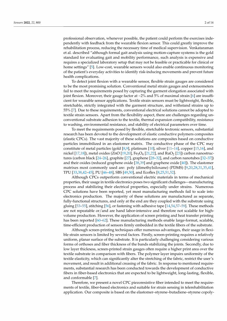
Extruded carbon-SBS fibers were highly elastic, which allowed for their storage incoils. Composites containing carbon nanotubes are matte black in color, while graphite/SBSfibers exhibit a gray appearance with metallic gloss (Figure 1).
For application as strain sensors in wearable textronic systems, fibers should withstandthe associated elongation of the garment structure during joint flexion. Human skinduring limb movements undergoes stretching over 100%, with local extensions up to 400%,as reported by on-skin sensor measurements [13]. However, garment textiles typicallyexperience elongation under 10% since they do not exhibit mechanical compliance withthe body and allow for movement of the garment relative to the skin surface. Mostcommon yarns like cotton, wool, silk, bamboo, viscose, polyester, or polyamide fibersexhibit elongation at break in the range of 7–41% [63–65].
Sensors 2022, 22, 800 5 of 14
Sensors 2022, 22, x FOR PEER REVIEW 5 of 15
3. Results and Discussion Extruded carbon-SBS fibers were highly elastic, which allowed for their storage in
coils. Composites containing carbon nanotubes are matte black in color, while graph-ite/SBS fibers exhibit a gray appearance with metallic gloss (Figure 1).
Figure 1. Coils of extruded composite fibers. From left to right, FGr (Gr/SBS), FCNT (CNT/SBS), FM1 (CNT/Gr/SBS), FM2 (CNT/Gr/SBS) are shown, respectively.
For application as strain sensors in wearable textronic systems, fibers should with-stand the associated elongation of the garment structure during joint flexion. Human skin during limb movements undergoes stretching over 100%, with local extensions up to 400%, as reported by on-skin sensor measurements [13]. However, garment textiles typ-ically experience elongation under 10% since they do not exhibit mechanical compliance with the body and allow for movement of the garment relative to the skin surface. Most common yarns like cotton, wool, silk, bamboo, viscose, polyester, or polyamide fibers exhibit elongation at break in the range of 7–41% [63–65].
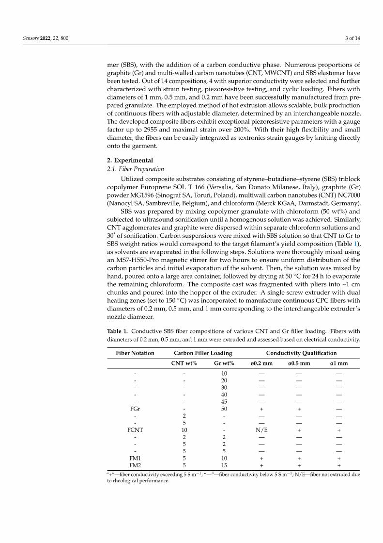
However, for capturing joint flexion, it is necessary to employ a tightly-fitted gar-ment made from highly elastic synthetic fibers such as nylon or elastane to ensure textile elongations compliance with skin movement. Generally for wearable sensors, the strain associated with joint flexion is under 50% [66,67] with reported strains varying from ~40% for finger bending [68–72], 23–45% for wrist movement [41,66,68,69,72], 35–63% for elbow flexion [68,69,72], and 30–40% for bending of the knee [68,72,73]. Values measured with knee flexion sensors are congruent with the motion capture analysis conducted by Wessendorf et al., which provides a value of 44.6% as maximum skin strain (in any di-rection) associated with the knee joint for full flexion and the extension cycle [74]. Wu et al. reported 40% maximal strain of the textronic system embedded onto the kneecap area of tight-fitting exercise pants [73]. This value was used as a base strain benchmark of our fibers, as they are intended for motion-capturing telerehabilitation devices. Therefore, with the employment of a universal testing machine, the critical strain of various com-positions was established for fibers 0.5 mm in diameter (Figure 2).
Figure 2. Breaking strain for different carbon/SBS composite 0.5 mm fibers with the assessment of the conductivity of the unstrained fiber. FGr is Gr/SBS filament; FCNT is CNT/SBS composition; and FM1 and FM2 are mixes of SBS, graphite, and CNT in different ratios.
Only FCNT and FM1 have sufficient elasticity to be applicable in wearable strain sensors (>40%), with FM1 exhibiting outstanding 230% elongation at break and FCNT
Figure 1. Coils of extruded composite fibers. From left to right, FGr (Gr/SBS), FCNT (CNT/SBS),FM1 (CNT/Gr/SBS), FM2 (CNT/Gr/SBS) are shown, respectively.
However, for capturing joint flexion, it is necessary to employ a tightly-fitted gar-ment made from highly elastic synthetic fibers such as nylon or elastane to ensure textileelongations compliance with skin movement. Generally for wearable sensors, the strain as-sociated with joint flexion is under 50% [66,67] with reported strains varying from ~40% forfinger bending [68–72], 23–45% for wrist movement [41,66,68,69,72], 35–63% for elbow flex-ion [68,69,72], and 30–40% for bending of the knee [68,72,73]. Values measured with kneeflexion sensors are congruent with the motion capture analysis conducted by Wessendorfet al., which provides a value of 44.6% as maximum skin strain (in any direction) associatedwith the knee joint for full flexion and the extension cycle [74]. Wu et al. reported 40%maximal strain of the textronic system embedded onto the kneecap area of tight-fittingexercise pants [73]. This value was used as a base strain benchmark of our fibers, as they areintended for motion-capturing telerehabilitation devices. Therefore, with the employmentof a universal testing machine, the critical strain of various compositions was establishedfor fibers 0.5 mm in diameter (Figure 2).
Sensors 2022, 22, x FOR PEER REVIEW 5 of 15
3. Results and Discussion Extruded carbon-SBS fibers were highly elastic, which allowed for their storage in
coils. Composites containing carbon nanotubes are matte black in color, while graph-ite/SBS fibers exhibit a gray appearance with metallic gloss (Figure 1).
Figure 1. Coils of extruded composite fibers. From left to right, FGr (Gr/SBS), FCNT (CNT/SBS), FM1 (CNT/Gr/SBS), FM2 (CNT/Gr/SBS) are shown, respectively.
For application as strain sensors in wearable textronic systems, fibers should with-stand the associated elongation of the garment structure during joint flexion. Human skin during limb movements undergoes stretching over 100%, with local extensions up to 400%, as reported by on-skin sensor measurements [13]. However, garment textiles typ-ically experience elongation under 10% since they do not exhibit mechanical compliance with the body and allow for movement of the garment relative to the skin surface. Most common yarns like cotton, wool, silk, bamboo, viscose, polyester, or polyamide fibers exhibit elongation at break in the range of 7–41% [63–65].
However, for capturing joint flexion, it is necessary to employ a tightly-fitted gar-ment made from highly elastic synthetic fibers such as nylon or elastane to ensure textile elongations compliance with skin movement. Generally for wearable sensors, the strain associated with joint flexion is under 50% [66,67] with reported strains varying from ~40% for finger bending [68–72], 23–45% for wrist movement [41,66,68,69,72], 35–63% for elbow flexion [68,69,72], and 30–40% for bending of the knee [68,72,73]. Values measured with knee flexion sensors are congruent with the motion capture analysis conducted by Wessendorf et al., which provides a value of 44.6% as maximum skin strain (in any di-rection) associated with the knee joint for full flexion and the extension cycle [74]. Wu et al. reported 40% maximal strain of the textronic system embedded onto the kneecap area of tight-fitting exercise pants [73]. This value was used as a base strain benchmark of our fibers, as they are intended for motion-capturing telerehabilitation devices. Therefore, with the employment of a universal testing machine, the critical strain of various com-positions was established for fibers 0.5 mm in diameter (Figure 2).
Figure 2. Breaking strain for different carbon/SBS composite 0.5 mm fibers with the assessment of the conductivity of the unstrained fiber. FGr is Gr/SBS filament; FCNT is CNT/SBS composition; and FM1 and FM2 are mixes of SBS, graphite, and CNT in different ratios.
Only FCNT and FM1 have sufficient elasticity to be applicable in wearable strain sensors (>40%), with FM1 exhibiting outstanding 230% elongation at break and FCNT
Figure 2. Breaking strain for different carbon/SBS composite 0.5 mm fibers with the assessment ofthe conductivity of the unstrained fiber. FGr is Gr/SBS filament; FCNT is CNT/SBS composition;and FM1 and FM2 are mixes of SBS, graphite, and CNT in different ratios.
Only FCNT and FM1 have sufficient elasticity to be applicable in wearable strain sen-sors (>40%), with FM1 exhibiting outstanding 230% elongation at break and FCNT breakingat 92% strain. All the fibers display elastic behavior while maintaining adequate conduc-tivity at an unstrained state; therefore, piezoresistive testing was carried out (Figure 3) toestablish linearity and sensitivity.
Gr/SBS filament FGr proved to have excellent sensitivity to stretching; however, itsusage in strain sensors is limited due to its low breaking point. Fiber based on carbonnanotubes (FCNT) exhibits excellent linearity and strain working range; its gauge factor,however, is orders of magnitude lower than that of other filaments. As shown in thesnippets of Figure 3, fibers FCNT and FM2 exhibit highly linear piezoresistive characteristicswithin the first 80% of their operating range. On the other hand, R/ε curves of FGr and FM1are non-linear with a quasi-exponential course. Notably, of the two CNT/Gr/SBS filaments,FM1 displays an exceptional strain range with superior resistance change. Therefore, FM1was chosen as the most promising option for high-sensitivity, long-range strain sensing.

Sensors 2022, 22, 800 6 of 14
Sensors 2022, 22, x FOR PEER REVIEW 6 of 15
breaking at 92% strain. All the fibers display elastic behavior while maintaining adequate conductivity at an unstrained state; therefore, piezoresistive testing was carried out (Figure 3) to establish linearity and sensitivity.
Figure 3. Piezoresistive characteristic of the fibers. (a) Resistance curve under strain for 0.5 mm fi-bers FGr, FCNT, FM1, and FM2; (b–d) R/ε plots for individual FM2, FCNT, and FM1 fibers.
Gr/SBS filament FGr proved to have excellent sensitivity to stretching; however, its usage in strain sensors is limited due to its low breaking point. Fiber based on carbon nanotubes (FCNT) exhibits excellent linearity and strain working range; its gauge factor, however, is orders of magnitude lower than that of other filaments. As shown in the snip-pets of Figure 3, fibers FCNT and FM2 exhibit highly linear piezoresistive characteristics within the first 80% of their operating range. On the other hand, R/ε curves of FGr and FM1 are non-linear with a quasi-exponential course. Notably, of the two CNT/Gr/SBS filaments, FM1 displays an exceptional strain range with superior resistance change. Therefore, FM1 was chosen as the most promising option for high-sensitivity, long-range strain sensing.
The presented piezoresistive curves ended with the breaking of the samples. It was prevalent that all the fibers exhibited higher maximal strain in piezoresistive tests com-pared with tensile testing. The trend was too evident to be explained by the dispersion of measurements. It is believed that the tensile strength of the fiber could be described by the weakest link theory, which assumes Weibull distribution of the flaws in the material, therefore providing fiber fracture probability as a function of the length of the specimen [75,76]:
( ) tt
0
1 exp lFl
ασσβ
= − −
(1)
where tσ stands for normalized tensile strength; l is the length of the specimen; and
0l stands for reference gauge length, while α and β are parameters for shape and scale of the specimen. Since the initial Weibel’s description of the statistical theory of damage in materials in 1939 [77], numerous models have been developed to describe the mechanical strength of fibers [78,79], fiber-reinforced composites [80], and particle-filled elastomers [81] with very notable Payne and Mullins effect [82]. Nevertheless, these models indicate a strong correlation between the length of the gauge and the decrease in the specimen’s strength. For tensile testing, the 50 mm gauge length was chosen, as it is the prevalent gauge length for tensile testing. For piezoresistive tests, shorter 10 mm samples were used, as a consequence of 2 Ω to 50 MΩ resistance measuring range. Therefore, we be-lieve that the reason for higher elongation at break in piezoresistive characterization is an
Figure 3. Piezoresistive characteristic of the fibers. (a) Resistance curve under strain for 0.5 mm fibersFGr, FCNT, FM1, and FM2; (b–d) R/ε plots for individual FM2, FCNT, and FM1 fibers.
The presented piezoresistive curves ended with the breaking of the samples. It wasprevalent that all the fibers exhibited higher maximal strain in piezoresistive tests comparedwith tensile testing. The trend was too evident to be explained by the dispersion of measure-ments. It is believed that the tensile strength of the fiber could be described by the weakestlink theory, which assumes Weibull distribution of the flaws in the material, thereforeproviding fiber fracture probability as a function of the length of the specimen [75,76]:
F(σt) = 1− exp[− l
l0
(σt
β
)α](1)
where σt stands for normalized tensile strength; l is the length of the specimen; and l0stands for reference gauge length, while α and β are parameters for shape and scale ofthe specimen. Since the initial Weibel’s description of the statistical theory of damage inmaterials in 1939 [77], numerous models have been developed to describe the mechanicalstrength of fibers [78,79], fiber-reinforced composites [80], and particle-filled elastomers [81]with very notable Payne and Mullins effect [82]. Nevertheless, these models indicate astrong correlation between the length of the gauge and the decrease in the specimen’sstrength. For tensile testing, the 50 mm gauge length was chosen, as it is the prevalentgauge length for tensile testing. For piezoresistive tests, shorter 10 mm samples were used,as a consequence of 2 Ω to 50 MΩ resistance measuring range. Therefore, we believe thatthe reason for higher elongation at break in piezoresistive characterization is an effect ofshorter gauge length and is explained by the distribution of weak points throughout thefiber length, as indicated by cited models.
For piezoresistive strain gauges, one of the most critical parameters is the gauge factor(GF), defined as the ratio of the relative change in resistance (∆R/R0) to the engineeringstrain of the specimen (ε):
GF =∆R/R0
ε=
∆R/R0
∆l/l0=
R−R0R0
l−l0l0
(2)
where l0 is the initial, unstrained length of the specimen, R0 its initial resistivity; l is thetotal length of the strained composite, with R as its measured resistivity. For fibers FGr,FCNT, FM1, and FM2, the gauge factor was calculated in various strain ranges, as presentedin Table 2.
Sensors 2022, 22, 800 7 of 14
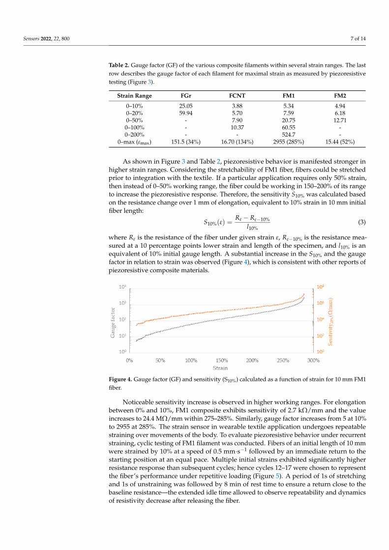
Table 2. Gauge factor (GF) of the various composite filaments within several strain ranges. The lastrow describes the gauge factor of each filament for maximal strain as measured by piezoresistivetesting (Figure 3).
Strain Range FGr FCNT FM1 FM2
0–10% 25.05 3.88 5.34 4.940–20% 59.94 5.70 7.59 6.180–50% - 7.90 20.75 12.71
0–100% - 10.37 60.55 -0–200% - - 524.7 -
0–max (εmax) 151.5 (34%) 16.70 (134%) 2955 (285%) 15.44 (52%)
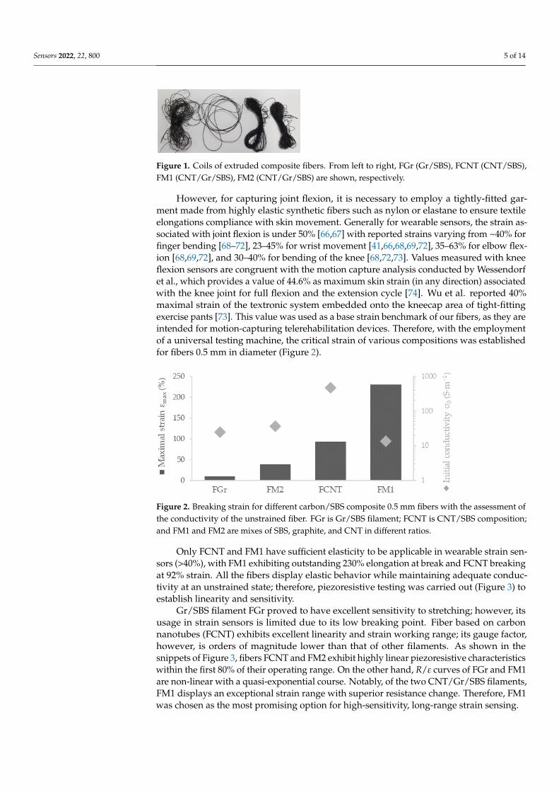
As shown in Figure 3 and Table 2, piezoresistive behavior is manifested stronger inhigher strain ranges. Considering the stretchability of FM1 fiber, fibers could be stretchedprior to integration with the textile. If a particular application requires only 50% strain,then instead of 0–50% working range, the fiber could be working in 150–200% of its rangeto increase the piezoresistive response. Therefore, the sensitivity S10% was calculated basedon the resistance change over 1 mm of elongation, equivalent to 10% strain in 10 mm initialfiber length:
S10%(ε) =Rε − Rε−10%
l10%(3)
where Rε is the resistance of the fiber under given strain ε, Rε−10% is the resistance mea-sured at a 10 percentage points lower strain and length of the specimen, and l10% is anequivalent of 10% initial gauge length. A substantial increase in the S10% and the gaugefactor in relation to strain was observed (Figure 4), which is consistent with other reports ofpiezoresistive composite materials.
Sensors 2022, 22, x FOR PEER REVIEW 8 of 15
Figure 4. Gauge factor (GF) and sensitivity (S10%) calculated as a function of strain for 10 mm FM1 fi-ber.
Noticeable sensitivity increase is observed in higher working ranges. For elongation between 0% and 10%, FM1 composite exhibits sensitivity of 2.7 kΩ/mm and the value increases to 24.4 MΩ/mm within 275–285%. Similarly, gauge factor increases from 5 at 10% to 2955 at 285%. The strain sensor in wearable textile application undergoes repeat-able straining over movements of the body. To evaluate piezoresistive behavior under recurrent straining, cyclic testing of FM1 filament was conducted. Fibers of an initial length of 10 mm were strained by 10% at a speed of 0.5 mm·s−1 followed by an immediate return to the starting position at an equal pace. Multiple initial strains exhibited signifi-cantly higher resistance response than subsequent cycles; hence cycles 12–17 were chosen to represent the fiber’s performance under repetitive loading (Figure 5). A period of 1s of stretching and 1s of unstraining was followed by 8 min of rest time to ensure a return close to the baseline resistance—the extended idle time allowed to observe repeatability and dynamics of resistivity decrease after releasing the fiber.
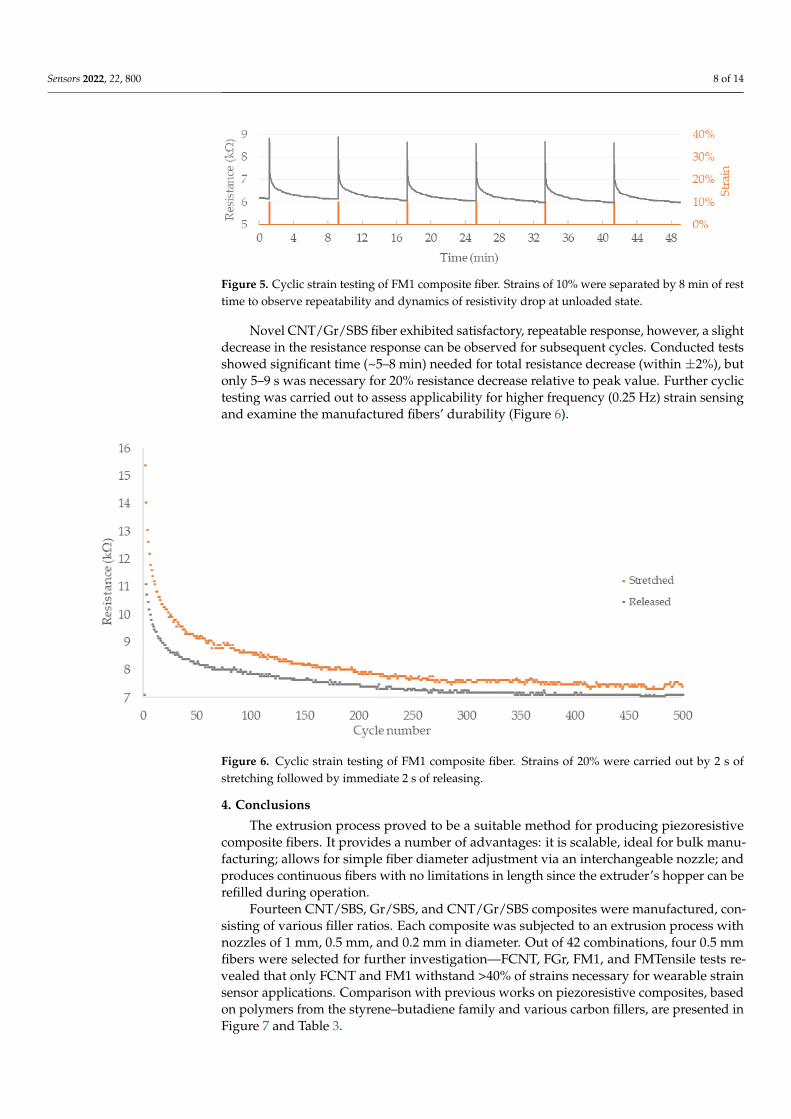
Figure 5. Cyclic strain testing of FM1 composite fiber. Strains of 10% were separated by 8 min of rest time to observe repeatability and dynamics of resistivity drop at unloaded state.
Novel CNT/Gr/SBS fiber exhibited satisfactory, repeatable response, however, a slight decrease in the resistance response can be observed for subsequent cycles. Con-ducted tests showed significant time (~5–8 min) needed for total resistance decrease (within ±2%), but only 5–9 s was necessary for 20% resistance decrease relative to peak value. Further cyclic testing was carried out to assess applicability for higher frequency (0.25 Hz) strain sensing and examine the manufactured fibers’ durability (Figure 6).
Figure 4. Gauge factor (GF) and sensitivity (S10%) calculated as a function of strain for 10 mm FM1fiber.
Noticeable sensitivity increase is observed in higher working ranges. For elongationbetween 0% and 10%, FM1 composite exhibits sensitivity of 2.7 kΩ/mm and the valueincreases to 24.4 MΩ/mm within 275–285%. Similarly, gauge factor increases from 5 at 10%to 2955 at 285%. The strain sensor in wearable textile application undergoes repeatablestraining over movements of the body. To evaluate piezoresistive behavior under recurrentstraining, cyclic testing of FM1 filament was conducted. Fibers of an initial length of 10 mmwere strained by 10% at a speed of 0.5 mm·s−1 followed by an immediate return to thestarting position at an equal pace. Multiple initial strains exhibited significantly higherresistance response than subsequent cycles; hence cycles 12–17 were chosen to representthe fiber’s performance under repetitive loading (Figure 5). A period of 1s of stretchingand 1s of unstraining was followed by 8 min of rest time to ensure a return close to thebaseline resistance—the extended idle time allowed to observe repeatability and dynamicsof resistivity decrease after releasing the fiber.
Sensors 2022, 22, 800 8 of 14
Sensors 2022, 22, x FOR PEER REVIEW 8 of 15
Figure 4. Gauge factor (GF) and sensitivity (S10%) calculated as a function of strain for 10 mm FM1 fi-ber.
Noticeable sensitivity increase is observed in higher working ranges. For elongation between 0% and 10%, FM1 composite exhibits sensitivity of 2.7 kΩ/mm and the value increases to 24.4 MΩ/mm within 275–285%. Similarly, gauge factor increases from 5 at 10% to 2955 at 285%. The strain sensor in wearable textile application undergoes repeat-able straining over movements of the body. To evaluate piezoresistive behavior under recurrent straining, cyclic testing of FM1 filament was conducted. Fibers of an initial length of 10 mm were strained by 10% at a speed of 0.5 mm·s−1 followed by an immediate return to the starting position at an equal pace. Multiple initial strains exhibited signifi-cantly higher resistance response than subsequent cycles; hence cycles 12–17 were chosen to represent the fiber’s performance under repetitive loading (Figure 5). A period of 1s of stretching and 1s of unstraining was followed by 8 min of rest time to ensure a return close to the baseline resistance—the extended idle time allowed to observe repeatability and dynamics of resistivity decrease after releasing the fiber.
Figure 5. Cyclic strain testing of FM1 composite fiber. Strains of 10% were separated by 8 min of rest time to observe repeatability and dynamics of resistivity drop at unloaded state.
Novel CNT/Gr/SBS fiber exhibited satisfactory, repeatable response, however, a slight decrease in the resistance response can be observed for subsequent cycles. Con-ducted tests showed significant time (~5–8 min) needed for total resistance decrease (within ±2%), but only 5–9 s was necessary for 20% resistance decrease relative to peak value. Further cyclic testing was carried out to assess applicability for higher frequency (0.25 Hz) strain sensing and examine the manufactured fibers’ durability (Figure 6).
Figure 5. Cyclic strain testing of FM1 composite fiber. Strains of 10% were separated by 8 min of resttime to observe repeatability and dynamics of resistivity drop at unloaded state.
Novel CNT/Gr/SBS fiber exhibited satisfactory, repeatable response, however, a slightdecrease in the resistance response can be observed for subsequent cycles. Conducted testsshowed significant time (~5–8 min) needed for total resistance decrease (within ±2%), butonly 5–9 s was necessary for 20% resistance decrease relative to peak value. Further cyclictesting was carried out to assess applicability for higher frequency (0.25 Hz) strain sensingand examine the manufactured fibers’ durability (Figure 6).
Sensors 2022, 22, x FOR PEER REVIEW 9 of 15
Figure 6. Cyclic strain testing of FM1 composite fiber. Strains of 20% were carried out by 2 s of stretching followed by immediate 2 s of releasing.
4. Conclusions The extrusion process proved to be a suitable method for producing piezoresistive
composite fibers. It provides a number of advantages: it is scalable, ideal for bulk manu-facturing; allows for simple fiber diameter adjustment via an interchangeable nozzle; and produces continuous fibers with no limitations in length since the extruder’s hopper can be refilled during operation.
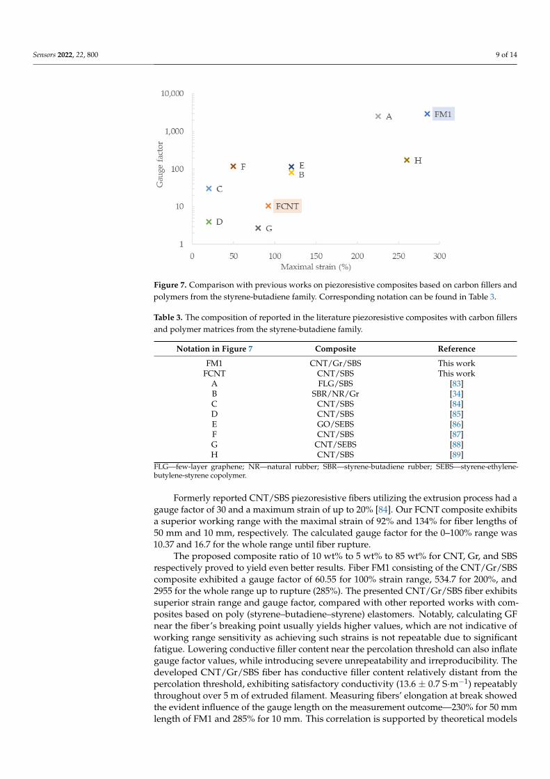
Fourteen CNT/SBS, Gr/SBS, and CNT/Gr/SBS composites were manufactured, con-sisting of various filler ratios. Each composite was subjected to an extrusion process with nozzles of 1 mm, 0.5 mm, and 0.2 mm in diameter. Out of 42 combinations, four 0.5 mm fibers were selected for further investigation—FCNT, FGr, FM1, and FMTensile tests re-vealed that only FCNT and FM1 withstand >40% of strains necessary for wearable strain sensor applications. Comparison with previous works on piezoresistive composites, based on polymers from the styrene–butadiene family and various carbon fillers, are presented in Figure 7 and Table 3.
Figure 7. Comparison with previous works on piezoresistive composites based on carbon fillers and polymers from the styrene-butadiene family. Corresponding notation can be found in Table 3.
Figure 6. Cyclic strain testing of FM1 composite fiber. Strains of 20% were carried out by 2 s ofstretching followed by immediate 2 s of releasing.
4. Conclusions
The extrusion process proved to be a suitable method for producing piezoresistivecomposite fibers. It provides a number of advantages: it is scalable, ideal for bulk manu-facturing; allows for simple fiber diameter adjustment via an interchangeable nozzle; andproduces continuous fibers with no limitations in length since the extruder’s hopper can berefilled during operation.
Fourteen CNT/SBS, Gr/SBS, and CNT/Gr/SBS composites were manufactured, con-sisting of various filler ratios. Each composite was subjected to an extrusion process withnozzles of 1 mm, 0.5 mm, and 0.2 mm in diameter. Out of 42 combinations, four 0.5 mmfibers were selected for further investigation—FCNT, FGr, FM1, and FMTensile tests re-vealed that only FCNT and FM1 withstand >40% of strains necessary for wearable strainsensor applications. Comparison with previous works on piezoresistive composites, basedon polymers from the styrene–butadiene family and various carbon fillers, are presented inFigure 7 and Table 3.
Sensors 2022, 22, 800 9 of 14
Sensors 2022, 22, x FOR PEER REVIEW 9 of 15
Figure 6. Cyclic strain testing of FM1 composite fiber. Strains of 20% were carried out by 2 s of stretching followed by immediate 2 s of releasing.
4. Conclusions The extrusion process proved to be a suitable method for producing piezoresistive
composite fibers. It provides a number of advantages: it is scalable, ideal for bulk manu-facturing; allows for simple fiber diameter adjustment via an interchangeable nozzle; and produces continuous fibers with no limitations in length since the extruder’s hopper can be refilled during operation.
Fourteen CNT/SBS, Gr/SBS, and CNT/Gr/SBS composites were manufactured, con-sisting of various filler ratios. Each composite was subjected to an extrusion process with nozzles of 1 mm, 0.5 mm, and 0.2 mm in diameter. Out of 42 combinations, four 0.5 mm fibers were selected for further investigation—FCNT, FGr, FM1, and FMTensile tests re-vealed that only FCNT and FM1 withstand >40% of strains necessary for wearable strain sensor applications. Comparison with previous works on piezoresistive composites, based on polymers from the styrene–butadiene family and various carbon fillers, are presented in Figure 7 and Table 3.
Figure 7. Comparison with previous works on piezoresistive composites based on carbon fillers and polymers from the styrene-butadiene family. Corresponding notation can be found in Table 3. Figure 7. Comparison with previous works on piezoresistive composites based on carbon fillers andpolymers from the styrene-butadiene family. Corresponding notation can be found in Table 3.
Table 3. The composition of reported in the literature piezoresistive composites with carbon fillersand polymer matrices from the styrene-butadiene family.
Notation in Figure 7 Composite Reference
FM1 CNT/Gr/SBS This workFCNT CNT/SBS This work
A FLG/SBS [83]B SBR/NR/Gr [34]C CNT/SBS [84]D CNT/SBS [85]E GO/SEBS [86]F CNT/SBS [87]G CNT/SEBS [88]H CNT/SBS [89]
FLG—few-layer graphene; NR—natural rubber; SBR—styrene-butadiene rubber; SEBS—styrene-ethylene-butylene-styrene copolymer.
Formerly reported CNT/SBS piezoresistive fibers utilizing the extrusion process had agauge factor of 30 and a maximum strain of up to 20% [84]. Our FCNT composite exhibitsa superior working range with the maximal strain of 92% and 134% for fiber lengths of50 mm and 10 mm, respectively. The calculated gauge factor for the 0–100% range was10.37 and 16.7 for the whole range until fiber rupture.
The proposed composite ratio of 10 wt% to 5 wt% to 85 wt% for CNT, Gr, and SBSrespectively proved to yield even better results. Fiber FM1 consisting of the CNT/Gr/SBScomposite exhibited a gauge factor of 60.55 for 100% strain range, 534.7 for 200%, and2955 for the whole range up to rupture (285%). The presented CNT/Gr/SBS fiber exhibitssuperior strain range and gauge factor, compared with other reported works with com-posites based on poly (styrene–butadiene–styrene) elastomers. Notably, calculating GFnear the fiber’s breaking point usually yields higher values, which are not indicative ofworking range sensitivity as achieving such strains is not repeatable due to significantfatigue. Lowering conductive filler content near the percolation threshold can also inflategauge factor values, while introducing severe unrepeatability and irreproducibility. Thedeveloped CNT/Gr/SBS fiber has conductive filler content relatively distant from thepercolation threshold, exhibiting satisfactory conductivity (13.6 ± 0.7 S·m−1) repeatablythroughout over 5 m of extruded filament. Measuring fibers’ elongation at break showedthe evident influence of the gauge length on the measurement outcome—230% for 50 mmlength of FM1 and 285% for 10 mm. This correlation is supported by theoretical models
Sensors 2022, 22, 800 10 of 14
in the literature devoted to conventional materials yet is frequently not considered in thepiezoresistive composite reports.
Conducted testing revealed significant time (~5–8 min) necessary for the resistancevalue to return to the baseline. To assess applicability for the on-body telerehabilitationdevices, cyclic strains at 0.25 Hz frequency were performed on the FM1 fiber. Throughoutall 500 cycles, the dynamic of the resistance changes was sufficient, leaving the strainresponse clearly distinguishable from adjacent release values. While relative resistancechange was apparent within the cycle, the absolute resistance value for the same 20% straindecreased significantly throughout the series, especially in the initial cycles. For applicationin wearable sensors, the electric signal from piezoresistive fiber has to be digitally analyzedto provide the current strain value accurately.
Combining carbon nanotubes and graphite in the SBS composite induces severaladvantages over CNT/SBS or graphite/SBS composites as summarized below:
Carbon nanotubes exhibit non-linear current/voltage characteristics; graphite, on theother hand, is highly linear within low electric fields—as observed in the literature [90,91]and our experimental data for Gr/SBS and CNT/SBS fibers. Combining CNT and graphitein the composite results in a nearly linear characteristic, while maintaining electromechan-ical advantages of carbon nanotubes content. Linearity of the U/I curve is desirable insensor applications, as it results in a constant resistance response with respect to the appliedprobing voltage.
Composites with conductive particles of high aspect ratio, such as carbon nanotubes,tend to have significantly lower gauge factors than materials filled with low aspect ra-tio particles, such as graphite [24,43,92]. The addition of the graphite to the CNT/SBScomposition greatly increased the sensitivity of the manufactured fibers at a similar initialconductivity baseline.
Carbon nanotubes are far more potent than graphite at improving carbon/SBS com-posite conductivity. Introducing CNT allows for lower wt% total carbon content at the sameconductivity, which further enhances mechanical properties—stretchability and fatiguestrength.
Reported methodology of preparing carbon nanotubes/graphite/poly (styrene–butadiene–styrene) composite fibers proved to attain excellent mechanical and piezoresis-tive behavior while maintaining a scalable, industrially adapted manufacturing process.
Author Contributions: Conceptualization, P.W. and A.S.; methodology, P.W. and B.P.; software, M.Z.;validation, B.P., D.J. and T.R.; formal analysis, P.W. and M.Z.; investigation, P.W., B.P., M.Z., M.K., A.S.and T.R.; resources, A.S. and D.J.; data curation, P.W. and M.Z.; writing—original draft preparation,P.W.; writing—review and editing, P.W. and M.Z.; visualization, P.W.; supervision, M.J.; projectadministration, A.S. and M.J.; funding acquisition, M.J. All authors have read and agreed to thepublished version of the manuscript.
Funding: This research received no external funding.
Institutional Review Board Statement: Not applicable.
Informed Consent Statement: Not applicable.
Data Availability Statement: All the data is available within the manuscript.
Conflicts of Interest: The authors declare no conflict of interest.
References1. Moffet, H.; Tousignant, M.; Nadeau, S.; Mérette, C.; Boissy, P.; Corriveau, H.; Marquis, F.; Cabana, F.; Ranger, P.; Belzile, É.L.; et al.
In-home telerehabilitation compared with faceto-face rehabilitation after total knee arthroplasty: A noninferiority randomizedcontrolled trial. J. Bone Jt. Surg. Am. Vol. 2015, 97, 1129–1141. [CrossRef]
2. Azma, K.; RezaSoltani, Z.; Rezaeimoghaddam, F.; Dadarkhah, A.; Mohsenolhosseini, S. Efficacy of tele-rehabilitation comparedwith office-based physical therapy in patients with knee osteoarthritis: A randomized clinical trial. J. Telemed. Telecare 2018, 24,560–565. [CrossRef]

Sensors 2022, 22, 800 11 of 14
3. Berton, A.; Longo, U.G.; Candela, V.; Fioravanti, S.; Giannone, L.; Arcangeli, V.; Alciati, V.; Berton, C.; Facchinetti, G.; Marchetti,A.; et al. Virtual Reality, Augmented Reality, Gamification, and Telerehabilitation: Psychological Impact on Orthopedic Patients’Rehabilitation. J. Clin. Med. 2020, 9, 2567. [CrossRef]
4. Negrillo-Cárdenas, J.; Jiménez-Pérez, J.R.; Feito, F.R. The role of virtual and augmented reality in orthopedic trauma surgery:From diagnosis to rehabilitation. Comput. Methods Programs Biomed. 2020, 191, 105407. [CrossRef]
5. Venkataraman, K.; Amis, K.; Landerman, L.R.; Caves, K.; Koh, G.C.; Hoenig, H. Teleassessment of Gait and Gait Aids: Validityand Interrater Reliability. Phys. Ther. 2020, 100, 708–717. [CrossRef]
6. Dobie, W.B.; Isaac Peter, C.G. Electric Resistance Strain Gauges; English Universities Press: London, UK, 1948.7. Zeng, W.; Shu, L.; Li, Q.; Chen, S.; Wang, F.; Tao, X.M. Fiber-Based Wearable Electronics: A Review of Materials, Fabrication,
Devices, and Applications. Adv. Mater. 2014, 26, 5310–5336. [CrossRef]8. Lim, G.H.; Lee, N.E.; Lim, B. Highly sensitive, tunable, and durable gold nanosheet strain sensors for human motion detection. J.
Mater. Chem. C 2016, 4, 5642–5647. [CrossRef]9. Loh, K.; Karimzada, M.; Ryu, D.; Loh, K.J.; Ireland, R.; Yaghmaie, F.; Gusman, A.M. In situ reduction of gold nanoparticles in
PDMS matrices and applications for large strain sensing. Smart Struct. Syst. 2011, 8, 471–486. [CrossRef]10. Kang, D.; Pikhitsa, P.V.; Choi, Y.W.; Lee, C.; Shin, S.S.; Piao, L.; Park, B.; Suh, K.Y.; Kim, T.I.; Choi, M. Ultrasensitive mechanical
crack-based sensor inspired by the spider sensory system. Nature 2014, 516, 222–226. [CrossRef] [PubMed]11. Lee, C.J.; Park, K.H.; Han, C.J.; Oh, M.S.; You, B.; Kim, Y.S.; Kim, J.W. Crack-induced Ag nanowire networks for transparent,
stretchable, and highly sensitive strain sensors. Sci. Rep. 2017, 7, 7959. [CrossRef] [PubMed]12. Hu, W.; Chen, S.; Zhuo, B.; Li, Q.; Wang, R.; Guo, X. Highly Sensitive and Transparent Strain Sensor Based on Thin Elastomer
Film. IEEE Electron. Device Lett. 2016, 37, 667–670. [CrossRef]13. Xu, H.; Lv, Y.; Qiu, D.; Zhou, Y.; Zeng, H.; Chu, Y. An ultra-stretchable, highly sensitive and biocompatible capacitive strain sensor
from an ionic nanocomposite for on-skin monitoring. Nanoscale 2019, 11, 1570–1578. [CrossRef]14. Kim, S.R.; Kim, J.H.; Park, J.W. Wearable and Transparent Capacitive Strain Sensor with High Sensitivity Based on Patterned Ag
Nanowire Networks. ACS Appl. Mater. Interfaces 2017, 9, 26407–26416. [CrossRef] [PubMed]15. Wang, Z.; Wang, Y.; Chen, Y.; Yousaf, M.; Wu, H.; Cao, A.; Han, R.P.S. Reticulate Dual-Nanowire Aerogel for Multifunctional
Applications: A High-Performance Strain Sensor and a High Areal Capacity Rechargeable Anode. Adv. Funct. Mater. 2019, 29,1807467. [CrossRef]
16. Podsiadły, B.; Skalski, A.; Wałpuski, B.; Walter, P.; Słoma, M.; Podsiadły, B.; Skalski, A.; Wałpuski, B.; Walter, P.; Słoma, M.Electrically conductive acrylonitrile butadiene styrene(ABS)/copper composite filament for fused deposition modeling. PhotonicsAppl. Astron. Commun. Ind. High-Energy Phys. Exp. 2018, 10808, 1080856. [CrossRef]
17. Canavese, G.; Stassi, S.; Fallauto, C.; Corbellini, S.; Cauda, V.; Camarchia, V.; Pirola, M.; Pirri, C.F. Piezoresistive flexible compositefor robotic tactile applications. Sens. Actuators A Phys. 2014, 208, 1–9. [CrossRef]
18. Podsiadły, B.; Skalski, A.; Słoma, M.; Podsiadły, B.; Skalski, A.; Słoma, M. Conductive ABS/Ni Composite Filaments for FusedDeposition Modeling of Structural Electronics. Adv. Intell. Syst. Comput. 2019, 1044, 62–70. [CrossRef]
19. Xiao, X.; Yuan, L.; Zhong, J.; Ding, T.; Liu, Y.; Cai, Z.; Rong, Y.; Han, H.; Zhou, J.; Wang, Z.L. High-Strain Sensors Based on ZnONanowire/Polystyrene Hybridized Flexible Films. Adv. Mater. 2011, 23, 5440–5444. [CrossRef] [PubMed]
20. Lee, T.; Lee, W.; Kim, S.W.; Kim, J.J.; Kim, B.S. Flexible Textile Strain Wireless Sensor Functionalized with Hybrid CarbonNanomaterials Supported ZnO Nanowires with Controlled Aspect Ratio. Adv. Funct. Mater. 2016, 26, 6206–6214. [CrossRef]
21. Ryu, K.; Kwon, N.; Lee, K.J. Manufacture of high sensitive Ag-Fe3O4-PDMS nanocomposite pressure sensor through morphologycontrol of conductive filler. Adv. Powder Technol. 2021, 32, 2441–2448. [CrossRef]
22. Zhang, M.; Wang, M.; Zhang, M.; Gao, Q.; Feng, X.; Zhang, Y.; Hu, J.; Wu, G. Stretchable conductive Ni@Fe3O4@Polyesterfabric strain sensor with negative resistance variation and electromagnetic interference shielding. Org. Electron. 2020, 81, 105677.[CrossRef]
23. Janczak, D.; Peplowski, A.; Wroblewski, G.; Gorski, L.; Zwierkowska, E.; Jakubowska, M. Investigations of Printed Flexible pHSensing Materials Based on Graphene Platelets and Submicron RuO2 Powders. J. Sens. 2017, 2017, 2190429. [CrossRef]
24. Zheng, Y.; Li, Y.; Li, Z.; Wang, Y.; Dai, K.; Zheng, G.; Liu, C.; Shen, C. The effect of filler dimensionality on the electromechanicalperformance of polydimethylsiloxane based conductive nanocomposites for flexible strain sensors. Compos. Sci. Technol. 2017,139, 64–73. [CrossRef]
25. Shintake, J.; Piskarev, Y.; Jeong, H.; Floreano, D.; Shintake, J.; Jeong, S.H.; Floreano, D.; Piskarev, Y. Ultrastretchable Strain SensorsUsing Carbon Black-Filled Elastomer Composites and Comparison of Capacitive Versus Resistive Sensors. Adv. Mater. Technol.2018, 3, 1700284. [CrossRef]
26. Mattmann, C.; Clemens, F.; Tröster, G. Sensor for Measuring Strain in Textile. Sensors 2008, 8, 3719–3732. [CrossRef]27. Agrawal, N.; Parihar, A.S.; Singh, J.P.; Goswami, T.H.; Tripathi, D.N. Efficient Nanocomposite formation of Acyrlo Nitrile Rubber
by incorporation of Graphite and Graphene layers: Reduction in Friction and Wear Rate. Procedia Mater. Sci. 2015, 10, 139–148.[CrossRef]
28. Wang, Y.; Yang, R.; Shi, Z.; Zhang, L.; Shi, D.; Wang, E.; Zhang, G. Super-elastic graphene ripples for flexible strain sensors. ACSNano 2011, 5, 3645–3650. [CrossRef]
29. Bae, S.H.; Lee, Y.; Sharma, B.K.; Lee, H.J.; Kim, J.H.; Ahn, J.H. Graphene-based transparent strain sensor. Carbon N. Y. 2013, 51,236–242. [CrossRef]

Sensors 2022, 22, 800 12 of 14
30. Tadakaluru, S.; Thongsuwan, W.; Singjai, P. Stretchable and Flexible High-Strain Sensors Made Using Carbon Nanotubes andGraphite Films on Natural Rubber. Sensors 2014, 14, 868–876. [CrossRef]
31. Pepłowski, A.; Walter, P.A.; Janczak, D.; Górecka, Z.; Swieszkowski, W.; Jakubowska, M. Solventless Conducting Paste Based onGraphene Nanoplatelets for Printing of Flexible, Standalone Routes in Room Temperature. Nanomaterials 2018, 8, 829. [CrossRef]
32. Janczak, D.; Słoma, M.; Wróblewski, G.; Młozniak, A.; Jakubowska, M. Screen-Printed Resistive Pressure Sensors ContainingGraphene Nanoplatelets and Carbon Nanotubes. Sensors 2014, 14, 17304–17312. [CrossRef]
33. Liu, H.; Gao, J.; Huang, W.; Dai, K.; Zheng, G.; Liu, C.; Shen, C.; Yan, X.; Guo, J.; Guo, Z. Electrically conductive strainsensing polyurethane nanocomposites with synergistic carbon nanotubes and graphene bifillers. Nanoscale 2016, 8, 12977–12989.[CrossRef]
34. Lin, Y.; Liu, S.; Chen, S.; Wei, Y.; Dong, X.; Liu, L. A highly stretchable and sensitive strain sensor based on graphene–elastomercomposites with a novel double-interconnected network. J. Mater. Chem. C 2016, 4, 6345–6352. [CrossRef]
35. Liu, C.X.; Choi, J.W. Analyzing resistance response of embedded PDMS and carbon nanotubes composite under tensile strain.Microelectron. Eng. 2014, 117, 1–7. [CrossRef]
36. Pepłowski, A.; Janczak, D.; Krzeminska, P.; Jakubowska, M. Temporary tattoo for wireless human pulse measurement. PhotonicsAppl. Astron. Commun. Ind. High-Energy Phys. Exp. 2016, 10031, 701–708. [CrossRef]
37. Podsiadły, B.; Matuszewski, P.; Skalski, A.; Słoma, M. Carbon Nanotube-Based Composite Filaments for 3D Printing of Structuraland Conductive Elements. Appl. Sci. 2021, 11, 1272. [CrossRef]
38. Wang, Y.; Hao, J.; Huang, Z.; Zheng, G.; Dai, K.; Liu, C.; Shen, C. Flexible electrically resistive-type strain sensors based onreduced graphene oxide-decorated electrospun polymer fibrous mats for human motion monitoring. Carbon N. Y. 2018, 126,360–371. [CrossRef]
39. Tang, Y.; Zhao, Z.; Hu, H.; Liu, Y.; Wang, X.; Zhou, S.; Qiu, J. Highly Stretchable and Ultrasensitive Strain Sensor Based on ReducedGraphene Oxide Microtubes-Elastomer Composite. ACS Appl. Mater. Interfaces 2015, 7, 27432–27439. [CrossRef] [PubMed]
40. Hwang, S.H.; Kang, D.; Ruoff, R.S.; Shin, H.S.; Park, Y. Bin Poly(vinyl alcohol) reinforced and toughened with poly(dopamine)-treated graphene oxide, and its use for humidity sensing. ACS Nano 2014, 8, 6739–6747. [CrossRef]
41. Lu, N.; Lu, C.; Yang, S.; Rogers, J. Highly Sensitive Skin-Mountable Strain Gauges Based Entirely on Elastomers. Adv. Funct.Mater. 2012, 22, 4044–4050. [CrossRef]
42. Fan, Q.; Qin, Z.; Gao, S.; Wu, Y.; Pionteck, J.; Mäder, E.; Zhu, M. The use of a carbon nanotube layer on a polyurethanemultifilament substrate for monitoring strains as large as 400%. Carbon N. Y. 2012, 50, 4085–4092. [CrossRef]
43. Lin, L.; Liu, S.; Zhang, Q.; Li, X.; Ji, M.; Deng, H.; Fu, Q. Towards tunable sensitivity of electrical property to strain for conductivepolymer composites based on thermoplastic elastomer. ACS Appl. Mater. Interfaces 2013, 5, 5815–5824. [CrossRef]
44. Lepak-Kuc, S.; Podsiadły, B.; Skalski, A.; Janczak, D.; Jakubowska, M.; Lekawa-Raus, A.; Lepak-Kuc, S.; Podsiadły, B.; Skalski,A.; Janczak, D.; et al. Highly Conductive Carbon Nanotube-Thermoplastic Polyurethane Nanocomposite for Smart ClothingApplications and Beyond. Nanomaterials 2019, 9, 1287. [CrossRef]
45. Janczak, D.; Zych, M.; Raczynski, T.; Dybowska-Sarapuk, Ł.; Pepłowski, A.; Krzeminski, J.; Sosna-Glłebska, A.; Znajdek, K.;Sibinski, M.; Jakubowska, M. Stretchable and Washable Electroluminescent Display Screen-Printed on Textile. Nanomaterials 2019,9, 1276. [CrossRef]
46. Wu, X.; Han, Y.; Zhang, X.; Lu, C. Highly Sensitive, Stretchable, and Wash-Durable Strain Sensor Based on Ultrathin ConductiveLayer@Polyurethane Yarn for Tiny Motion Monitoring. ACS Appl. Mater. Interfaces 2016, 8, 9936–9945. [CrossRef] [PubMed]
47. Slobodian, P.; Riha, P.; Benlikaya, R.; Svoboda, P.; Petras, D. A flexible multifunctional sensor based on carbon nan-otube/polyurethane composite. IEEE Sens. J. 2013, 13, 4045–4048. [CrossRef]
48. Lee, J.; Shin, S.; Lee, S.; Song, J.; Kang, S.; Han, H.; Kim, S.; Kim, S.; Seo, J.; Kim, D.; et al. Highly Sensitive Multifilament FiberStrain Sensors with Ultrabroad Sensing Range for Textile Electronics. ACS Nano 2018, 12, 4259–4268. [CrossRef]
49. Lee, S.; Shin, S.; Lee, S.; Seo, J.; Lee, J.; Son, S.; Cho, H.J.; Algadi, H.; Al-Sayari, S.; Kim, D.E.; et al. Ag Nanowire ReinforcedHighly Stretchable Conductive Fibers for Wearable Electronics. Adv. Funct. Mater. 2015, 25, 3114–3121. [CrossRef]
50. Zhao, S.; Li, J.; Cao, D.; Gao, Y.; Huang, W.; Zhang, G.; Sun, R.; Wong, C.P. Percolation threshold-inspired design of hierarchicalmultiscale hybrid architectures based on carbon nanotubes and silver nanoparticles for stretchable and printable electronics. J.Mater. Chem. C 2016, 4, 6666–6674. [CrossRef]
51. Park, S.J.; Kim, J.; Chu, M.; Khine, M. Highly Flexible Wrinkled Carbon Nanotube Thin Film Strain Sensor to Monitor HumanMovement. Adv. Mater. Technol. 2016, 1, 1600053. [CrossRef]
52. Atalay, A.; Sanchez, V.; Atalay, O.; Vogt, D.M.; Haufe, F.; Wood, R.J.; Walsh, C.J. Batch Fabrication of Customizable Silicone-TextileComposite Capacitive Strain Sensors for Human Motion Tracking. Adv. Mater. Technol. 2017, 2, 1700136. [CrossRef]
53. Mattmann, C.; Amft, O.; Harms, H.; Tröster, G.; Clemens, F. Recognizing upper body postures using textile strain sensors. InProceedings of the 2007 11th IEEE International Symposium on Wearable Computers, Boston, MA, USA, 11–13 October 2007;pp. 29–36. [CrossRef]
54. Cai, L.; Song, L.; Luan, P.; Zhang, Q.; Zhang, N.; Gao, Q.; Zhao, D.; Zhang, X.; Tu, M.; Yang, F.; et al. Super-stretchable, TransparentCarbon Nanotube-Based Capacitive Strain Sensors for Human Motion Detection. Sci. Rep. 2013, 3, 3048. [CrossRef] [PubMed]
55. Yamada, T.; Hayamizu, Y.; Yamamoto, Y.; Yomogida, Y.; Izadi-Najafabadi, A.; Futaba, D.N.; Hata, K. A stretchable carbonnanotube strain sensor for human-motion detection. Nat. Nanotechnol. 2011, 6, 296–301. [CrossRef]
Sensors 2022, 22, 800 13 of 14
56. Amjadi, M.; Pichitpajongkit, A.; Lee, S.; Ryu, S.; Park, I. Highly stretchable and sensitive strain sensor based on silver nanowire-elastomer nanocomposite. ACS Nano 2014, 8, 5154–5163. [CrossRef]
57. Li, C.; Cui, Y.L.; Tian, G.L.; Shu, Y.; Wang, X.F.; Tian, H.; Yang, Y.; Wei, F.; Ren, T.L. Flexible CNT-array double helices Strain Sensorwith high stretchability for Motion Capture. Sci. Rep. 2015, 5, 15554. [CrossRef]
58. Nakamura, A.; Hamanishi, T.; Kawakami, S.; Takeda, M. A piezo-resistive graphene strain sensor with a hollow cylindricalgeometry. Mater. Sci. Eng. B 2017, 219, 20–27. [CrossRef]
59. Wang, C.; Li, X.; Gao, E.L.; Jian, M.Q.; Xia, K.L.; Wang, Q.; Xu, Z.P.; Ren, T.L.; Zhang, Y.Y. Carbonized Silk Fabric for Ultrastretch-able, Highly Sensitive, and Wearable Strain Sensors. Adv. Mater. 2016, 28, 6640–6648. [CrossRef]
60. Wei, Y.; Li, X.; Wang, Y.; Hirtz, T.; Guo, Z.; Qiao, Y.; Cui, T.; Tian, H.; Yang, Y.; Ren, T.-L. Graphene-Based Multifunctional Textilefor Sensing and Actuating. ACS Nano 2021, 15, 17738–17747. [CrossRef]
61. Mohammed Ali, M.; Maddipatla, D.; Narakathu, B.B.; Chlaihawi, A.A.; Emamian, S.; Janabi, F.; Bazuin, B.J.; Atashbar, M.Z.Printed strain sensor based on silver nanowire/silver flake composite on flexible and stretchable TPU substrate. Sens. Actuators APhys. 2018, 274, 109–115. [CrossRef]
62. Qi, X.; Ha, H.; Hwang, B.; Lim, S. Printability of the Screen-Printed Strain Sensor with Carbon Black/Silver Paste for SensitiveWearable Electronics. Appl. Sci. 2020, 10, 6983. [CrossRef]
63. Eriksson, P.-A.; Boydell, P.; Eriksson, K.; Må Nson, J.-A.E.; Albertsson, A.-C. Effect of Thermal-Oxidative Aging on Mechanical,Chemical, and Thermal Properties of Recycled Polyamide 66. J. Appl. Polym. Sci. 1997, 65, 1619–1630. [CrossRef]
64. Vasanthan, N. Polyamide fiber formation: Structure, properties and characterization. Handb. Text. Fibre Struct. 2009, 1, 232–256.[CrossRef]
65. Zupin, Z.; Dimitrovski, K.; Zupin, Ž. Mechanical Properties of Fabrics Made from Cotton and Biodegradable Yarns Bamboo, SPF,PLA in Weft. In Woven Fabric Engineering; IntechOpen: London, UK, 2010. [CrossRef]
66. Wang, X.; Li, J.; Song, H.; Huang, H.; Gou, J. Highly Stretchable and Wearable Strain Sensor Based on Printable Carbon NanotubeLayers/Polydimethylsiloxane Composites with Adjustable Sensitivity. ACS Appl. Mater. Interfaces 2018, 10, 7371–7380. [CrossRef]
67. Jeong, S.Y.; Lee, J.U.; Hong, S.M.; Lee, C.W.; Hwang, S.H.; Cho, S.C.; Shin, B.S. Highly skin-conformal laser-induced graphene-based human motion monitoring sensor. Nanomaterials 2021, 11, 951. [CrossRef] [PubMed]
68. Shi, C.; Zou, Z.; Lei, Z.; Zhu, P.; Nie, G.; Zhang, W.; Xiao, J. Stretchable, Rehealable, Recyclable, and Reconfigurable IntegratedStrain Sensor for Joint Motion and Respiration Monitoring. Research 2021, 2021, 9846036. [CrossRef]
69. Amjadi, M.; Yoon, Y.J.; Park, I. Ultra-stretchable and skin-mountable strain sensors using carbon nanotubes–Ecoflex nanocompos-ites. Nanotechnology 2015, 26, 375501. [CrossRef]
70. Wu, S.; Zhang, J.; Ladani, R.B.; Ravindran, A.R.; Mouritz, A.P.; Kinloch, A.J.; Wang, C.H. Novel Electrically Conductive PorousPDMS/Carbon Nanofiber Composites for Deformable Strain Sensors and Conductors. ACS Appl. Mater. Interfaces 2017, 9,14207–14215. [CrossRef]
71. Yan, C.; Wang, J.; Kang, W.; Cui, M.; Wang, X.; Yao Foo, C.; Jianzhi Chee, K.; See Lee, P.; Yan, C.Y.; Wang, J.X.; et al. HighlyStretchable Piezoresistive Graphene–Nanocellulose Nanopaper for Strain Sensors. Adv. Mater. 2014, 26, 2022–2027. [CrossRef]
72. Sun, X.; Qin, Z.; Ye, L.; Zhang, H.; Yu, Q.; Wu, X.; Li, J.; Yao, F. Carbon nanotubes reinforced hydrogel as flexible strain sensorwith high stretchability and mechanically toughness. Chem. Eng. J. 2020, 382, 122832. [CrossRef]
73. Wu, Y.; Mechael, S.S.; Chen, Y.; Carmichael, T.B. Solution Deposition of Conformal Gold Coatings on Knitted Fabric for E-Textilesand Electroluminescent Clothing. Adv. Mater. Technol. 2018, 3, 1700292. [CrossRef]
74. Wessendorf, A.M.; Newman, D.J. Dynamic understanding of human-skin movement and strain-field analysis. IEEE Trans. Biomed.Eng. 2012, 59, 3432–3438. [CrossRef] [PubMed]
75. Paramonov, Y.; Andersons, J. A family of weakest link models for fiber strength distribution. Compos. Part A Appl. Sci. Manuf.2007, 38, 1227–1233. [CrossRef]
76. Zok, F.W. On weakest link theory and Weibull statistics. J. Am. Ceram. Soc. 2017, 100, 1265–1268. [CrossRef]77. Weibull, W. A Statistical Theory of Strength of Materials; Generalstabens Litografiska Anstalts Förlag: Stockholm, Sweden, 1939.78. Cao, Y.; Wu, Y.-Q. Evaluation of statistical strength of bamboo fiber and mechanical properties of fiber reinforced green composites.
J. Cent. South Univ. Technol 2008, 15, 564–567. [CrossRef]79. Watson, A.S.; Smith, R.L. An examination of statistical theories for fibrous materials in the light of experimental data. J. Mater. Sci.
1985, 20, 3260–3270. [CrossRef]80. Curtin, W.A. Tensile strength of fiber-reinforced composites: III. Beyond the traditional Weibull model for fiber strengths. J.
Compos. Mater. 2000, 34, 1301–1332. [CrossRef]81. Bergström, J.S.; Boyce, M.C. Mechanical Behavior of Particle Filled Elastomers. Rubber Chem. Technol. 1999, 72, 633–656. [CrossRef]82. Merabia, S.; Sotta, P.; Long, D.R. A Microscopic Model for the Reinforcement and the Nonlinear Behavior of Filled Elastomers
and Thermoplastic Elastomers (Payne and Mullins Effects). Macromolecules 2008, 41, 8252–8266. [CrossRef]83. Wang, X.; Meng, S.; Tebyetekerwa, M.; Li, Y.; Pionteck, J.; Sun, B.; Qin, Z.; Zhu, M. Highly sensitive and stretchable piezoresistive
strain sensor based on conductive poly(styrene-butadiene-styrene)/few layer graphene composite fiber. Compos. Part A Appl. Sci.Manuf. 2018, 105, 291–299. [CrossRef]
84. Costa, P.; Silvia, C.; Viana, J.C.; Lanceros Mendez, S. Extruded thermoplastic elastomers styrene–butadiene–styrene/carbonnanotubes composites for strain sensor applications. Compos. Part B Eng. 2014, 57, 242–249. [CrossRef]
Sensors 2022, 22, 800 14 of 14
85. Costa, P.; Carvalho, M.F.; Correia, V.; Viana, J.C.; Lanceros-Mendez, S. Polymer Nanocomposite-Based Strain Sensors with TailoredProcessability and Improved Device Integration. ACS Appl. Nano Mater. 2018, 1, 3015–3025. [CrossRef]
86. Costa, P.; Gonçalves, S.; Mora, H.; Carabineiro, S.A.C.; Viana, J.C.; Lanceros-Mendez, S. Highly Sensitive Piezoresistive Graphene-Based Stretchable Composites for Sensing Applications. ACS Appl. Mater. Interfaces 2019, 11, 46286–46295. [CrossRef]
87. Costa, P.; Ferreira, A.; Sencadas, V.; Viana, J.C.; Lanceros-Méndez, S. Electro-mechanical properties of triblock copolymer styrene–butadiene–styrene/carbon nanotube composites for large deformation sensor applications. Sens. Actuators A Phys. 2013, 201,458–467. [CrossRef]
88. Gonçalves, B.F.; Costa, P.; Oliveira, J.; Ribeiro, S.; Correia, V.; Botelho, G.; Lanceros-Mendez, S. Green solvent approach forprintable large deformation thermoplastic elastomer based piezoresistive sensors and their suitability for biomedical applications.J. Polym. Sci. Part B Polym. Phys. 2016, 54, 2092–2103. [CrossRef]
89. Yu, S.; Wang, X.; Xiang, H.; Zhu, L.; Tebyetekerwa, M.; Zhu, M. Superior piezoresistive strain sensing behaviors of carbonnanotubes in one-dimensional polymer fiber structure. Carbon N. Y. 2018, 140, 1–9. [CrossRef]
90. Celzard, A.; McRae, E.; Furdin, G.; Marêché, J.F. Conduction mechanisms in some graphite—Polymer composites: The effect of adirect-current electric field. J. Phys. Condens. Matter 1997, 9, 2225. [CrossRef]
91. Wang, J.; Yu, S.; Luo, S.; Chu, B.; Sun, R.; Wong, C.P. Investigation of nonlinear I–V behavior of CNTs filled polymer composites.Mater. Sci. Eng. B 2016, 206, 55–60. [CrossRef]
92. De Vivo, B.; Lamberti, P.; Spinelli, G.; Tucci, V.; Vertuccio, L.; Vittoria, V. Simulation and experimental characterization ofpolymer/carbon nanotubes composites for strain sensor applications. J. Appl. Phys. 2014, 116, 054307. [CrossRef]