Permeation, diffusion, and solution of cyclopropane in silicone rubber
Upload
khangminh22Category
view
0download
0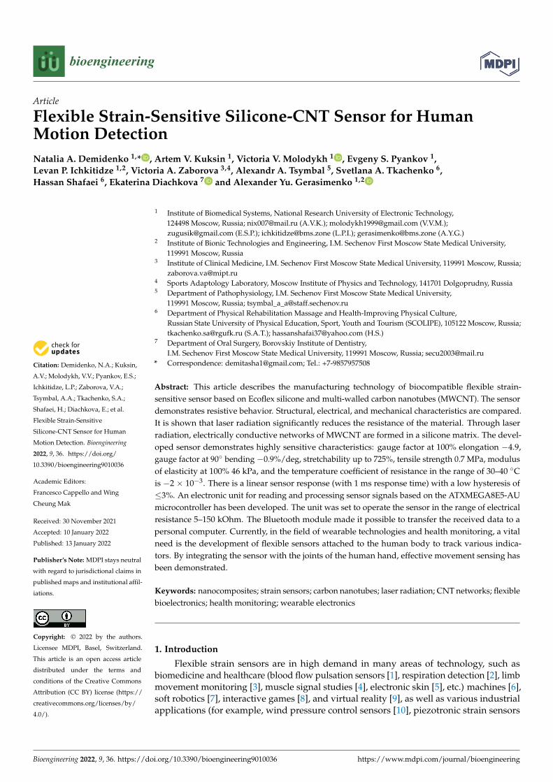
�����������������
Citation: Demidenko, N.A.; Kuksin,
A.V.; Molodykh, V.V.; Pyankov, E.S.;
Ichkitidze, L.P.; Zaborova, V.A.;
Tsymbal, A.A.; Tkachenko, S.A.;
Shafaei, H.; Diachkova, E.; et al.
Flexible Strain-Sensitive
Silicone-CNT Sensor for Human
Motion Detection. Bioengineering
2022, 9, 36. https://doi.org/
10.3390/bioengineering9010036
Academic Editors:
Francesco Cappello and Wing
Cheung Mak
Received: 30 November 2021
Accepted: 10 January 2022
Published: 13 January 2022
Publisher’s Note: MDPI stays neutral
with regard to jurisdictional claims in
published maps and institutional affil-
iations.
Copyright: © 2022 by the authors.
Licensee MDPI, Basel, Switzerland.
This article is an open access article
distributed under the terms and
conditions of the Creative Commons
Attribution (CC BY) license (https://
creativecommons.org/licenses/by/
4.0/).
bioengineering
Article
Flexible Strain-Sensitive Silicone-CNT Sensor for HumanMotion DetectionNatalia A. Demidenko 1,* , Artem V. Kuksin 1, Victoria V. Molodykh 1 , Evgeny S. Pyankov 1,Levan P. Ichkitidze 1,2, Victoria A. Zaborova 3,4, Alexandr A. Tsymbal 5, Svetlana A. Tkachenko 6,Hassan Shafaei 6, Ekaterina Diachkova 7 and Alexander Yu. Gerasimenko 1,2
1 Institute of Biomedical Systems, National Research University of Electronic Technology,124498 Moscow, Russia; [email protected] (A.V.K.); [email protected] (V.V.M.);[email protected] (E.S.P.); [email protected] (L.P.I.); [email protected] (A.Y.G.)
2 Institute of Bionic Technologies and Engineering, I.M. Sechenov First Moscow State Medical University,119991 Moscow, Russia
3 Institute of Clinical Medicine, I.M. Sechenov First Moscow State Medical University, 119991 Moscow, Russia;[email protected]
4 Sports Adaptology Laboratory, Moscow Institute of Physics and Technology, 141701 Dolgoprudny, Russia5 Department of Pathophysiology, I.M. Sechenov First Moscow State Medical University,
119991 Moscow, Russia; [email protected] Department of Physical Rehabilitation Massage and Health-Improving Physical Culture,
Russian State University of Physical Education, Sport, Youth and Tourism (SCOLIPE), 105122 Moscow, Russia;[email protected] (S.A.T.); [email protected] (H.S.)
7 Department of Oral Surgery, Borovskiy Institute of Dentistry,I.M. Sechenov First Moscow State Medical University, 119991 Moscow, Russia; [email protected]
* Correspondence: [email protected]; Tel.: +7-9857957508
Abstract: This article describes the manufacturing technology of biocompatible flexible strain-sensitive sensor based on Ecoflex silicone and multi-walled carbon nanotubes (MWCNT). The sensordemonstrates resistive behavior. Structural, electrical, and mechanical characteristics are compared.It is shown that laser radiation significantly reduces the resistance of the material. Through laserradiation, electrically conductive networks of MWCNT are formed in a silicone matrix. The devel-oped sensor demonstrates highly sensitive characteristics: gauge factor at 100% elongation −4.9,gauge factor at 90◦ bending −0.9%/deg, stretchability up to 725%, tensile strength 0.7 MPa, modulusof elasticity at 100% 46 kPa, and the temperature coefficient of resistance in the range of 30–40 ◦Cis −2 × 10⁻³. There is a linear sensor response (with 1 ms response time) with a low hysteresis of≤3%. An electronic unit for reading and processing sensor signals based on the ATXMEGA8E5-AUmicrocontroller has been developed. The unit was set to operate the sensor in the range of electricalresistance 5–150 kOhm. The Bluetooth module made it possible to transfer the received data to apersonal computer. Currently, in the field of wearable technologies and health monitoring, a vitalneed is the development of flexible sensors attached to the human body to track various indica-tors. By integrating the sensor with the joints of the human hand, effective movement sensing hasbeen demonstrated.
Keywords: nanocomposites; strain sensors; carbon nanotubes; laser radiation; CNT networks; flexiblebioelectronics; health monitoring; wearable electronics
1. Introduction
Flexible strain sensors are in high demand in many areas of technology, such asbiomedicine and healthcare (blood flow pulsation sensors [1], respiration detection [2], limbmovement monitoring [3], muscle signal studies [4], electronic skin [5], etc.) machines [6],soft robotics [7], interactive games [8], and virtual reality [9], as well as various industrialapplications (for example, wind pressure control sensors [10], piezotronic strain sensors
Bioengineering 2022, 9, 36. https://doi.org/10.3390/bioengineering9010036 https://www.mdpi.com/journal/bioengineering
Bioengineering 2022, 9, 36 2 of 17
for transistors [11], etc.). The high interest in the development of flexible sensors is dueto their (1) large elongation, which allow them to be used for registering deformation inboth low and large ranges, and (2) softness, which leads to a potentially simpler integrationwith the human body, and also makes it possible to solve the problem of rigidity andbulkiness of structures. In the field of wearable electronics, resistive and capacitive strainand pressure sensors are currently the most widely used and actively studied [12]. Existingtypes of strain sensors, such as fiber Bragg grating (FBG) [13], triboelectric [14], andpiezoelectric [15] strain sensors, usually cannot take slow or static deformation due to fastcharge transfer. In addition, their practical implementation as wearable devices on the skinremains difficult due to the sophisticated measurement equipment required. On the otherhand, resistive [16] and capacitive [17] sensors require simpler measuring equipment anddemonstrate high flexibility and stretchability. In general, sensors of capacitive and resistivetypes, in which deformation is measured by changing the capacitance or electrical resistanceof strain-sensitive materials, respectively, show similar characteristics in all parameters.However, the sensitivity of resistive sensors in comparison with capacitive ones with thesame manufacturing technology remains higher and less susceptible to interference [18].
In general, strain sensors are made from functional materials integrated into flexi-ble substrates. For resistive sensors, these materials include carbon (carbon nanotubes(CNT) [19], graphene [20], carbon black [21], etc.), metals (metal particles [22], nanowires [23],films [24], etc.), and various electrically conductive polymers [25] (polypyrrole (PPy),polyaniline (PANI), poly (3,4-ethylenedioxythiophene) polystyrene sulfonate (PEDOT: PSS)).Elastomers (rubber [26], polydimethylsiloxane (PDMS) [27], Ecoflex silicone [28], thermo-plastic polyurethane elastomer (TPU) [29], etc.) are most often used as flexible supportingmaterials/substrates (flexible matrices), as well as other synthetic and natural polymers.Moreover, strain sensors based on conducting hydrogels have been developed, the sen-sitivity of which is caused by ionic or electronic conductivity [30]. However, due to thepeculiarities of the phase state of hydrogels, the manufacture of strain sensors based onhydrogels with high extensibility or torsion remains a difficult task.
Of all the types of electrically conductive additives, CNT attract the most attention.They have ultra-light weight, large aspect ratio, outstanding electrical conductivity, hightensile strength, and high chemical and thermal stability [31]. Moreover, their abilityto form percolation networks capable of self-healing after applied deformation makesnanotubes ideal candidates for the development of highly efficient flexible sensors [32]. Itis important to consider human skin compatibility developing flexible sensors. Therefore, aflexible matrix should not only be biocompatible, highly elastic, but also have a modulus ofelasticity comparable to a modulus of human skin. Silicones, especially Ecoflex [33], meetthese criteria perfectly. Ecoflex is an environmentally sustainable polymer due to its waterresistance, is suitable for long-term applications, and its biocompatibility allows it to beused as a skin attachment device without any limitation, irritation, or discomfort.
However, the problem of integrating electrically conductive additives into a flexi-ble matrix remains. Due to the difference in the rigidity of the components, there is aproblem of their incompatibility, poor adhesion to each other and, as a consequence, theappearance of the slip effect, which complicates production and leads to deterioration ofcharacteristics [34]. Currently, the following methods of fabricating strain sensors basedon carbon and silicone are most often used: transfer of an array of nanotubes [35], screenprinting [36], CNT deposition [37], and dry spinning [38]. However, manufacturing oftenrequires sophisticated equipment or chemical solvents, making manufacturing expensiveand unsafe. Recently, an inexpensive method for obtaining porous graphene using laserirradiation of a polyimide film was reported [39]. Such laser-induced graphene (LIG) hasfound application for the manufacture of strain sensors, for example, on cellulose mate-rials [40]. As far as we know, this method is not currently used in the context of carbonnanotubes. Another serious problem is connecting the sensor to power supplies, as well ascollecting and processing the received signals. Much of the work conducted in this area
Bioengineering 2022, 9, 36 3 of 17
has focused on improving the performance of flexible sensors rather than integrating themwith electronics.
In this paper, we propose a simple and reliable method for manufacturing a strain-sensitive resistive sensors based on the Ecoflex-CNT-Ecoflex sandwich structure. Usinglaser structuring, we formed strong conductive CNT networks in a silicone matrix, whichsignificantly improved the characteristics of the strain sensors. The inclusion of CNT in thepolymers leads to the formation of nanocomposites with high electrical conductivity at alow concentration of CNT [41]. The use of the laser structuring method proposed in thisresearch makes it possible to further improve the electrical characteristics. The proposedmethod will make it possible to use the uniqueness of the advantages of CNT at a low cost.In addition, accompanying electronics to easily integrate with the strain sensors to providea fully wearable device for collecting human strain data have been developed. The work ofa strain gauge attached to the joints of a human hand was demonstrated. A comparativeanalysis of the technology proposed in the study with previously developed sensorsdemonstrates the competitive characteristics of our strain sensors (Table 1). The measuredand calculated parameters of the proposed strain sensors based on MWCNT/Ecoflexmanufactured by the laser structuring method are described in Section 2 “Materials andMethods” and Section 3 “Results and Discussion”.
Table 1. Comparison of the characteristics of the MWCNT/Ecoflex strain sensors with sensorsmanufactured by other methods.
Materials &Methods ε, % ∆R/R0 GF σ, MPa E, kPa Response Time,
ms
CNT/Ecoflex, Transfer of anArray of Nanotubes [42] 500 <10 (Depending on the
Height of the CNT Array) 3–18 NotIdentified
NotIdentified Not Identified
MWCNT/Ecoflex, CNTDeposition [43] 300 4 (ε = 80%); 0.45 θ = 90◦ 2.1 Not
IdentifiedNot
Identified 274
MWCNT/Ecoflex, CNTDeposition [37] 750 0.5 (ε = 100%) 0.65 (ε = 0–400%);
48 (ε = 400–700%)Not
IdentifiedNot
Identified Not Identified
MWCNT/Ecoflex, ScreenPrinting [36] 200 <0.5 (ε = 100%) <0.4 0.82 ± 0.12 200 1.16
CNT/Rubber, DrySpinning [44] 500 Not Identified 10.5 Not
Identified 2000–5000 15
PSPI/PDMS, LIG [45] 125 Not Identified 380 (ε = 115–120%) NotIdentified
NotIdentified 90
MWCNT/Ecoflex, LaserStructuring (This Work) 725 7 (ε = 100%) 7 (ε = 100%) 0.7 46 1
The article has the following structure. Section 2 presents the characteristics of theusing components, describes the sensors proposed manufacturing technology, and presentstest methods and the mathematical apparatus used for calculations. Section 3 includes adetailed description of the developed sensors and their characteristics based on the testresults. This section also provides a discussion of the obtained results. Section 4 containsconcluding remarks.
2. Materials and Methods
This section includes descriptions and specifications of the components used to makethe sensors. It also outlines the proposed strain-sensitive material manufacturing technol-ogy using laser structuring and presents the manufacture of an electronic unit for readingand processing signals from a sensitive material, as well as presenting test methods, equip-ment, and formulas used to quantify electrical, sensitive, and mechanical characteristics ofthe developed sensor.
2.1. Components
The developed strain sensors consisted of material that is sensitive to deformationsand a portable compact electronic unit for signal reading and processing.
Bioengineering 2022, 9, 36 4 of 17
The strain-sensitive material was a composite constructed of multi-walled carbonnanotubes (MWCNT) and a silicone elastomer. MWCNT (NanoTechCenter Ltd., Tambov,Russia) were produced by CVD synthesis and were quasi-one-dimensional, nanoscale,filamentary formations of polycrystalline graphite, predominantly cylindrical in shape withan inner channel in form of powder, with the following measurements: outer diameter8–30 nm, inner diameter 5–15 nm, length ≥ 20 µm, specific surface area ≥ 270 m2/g, bulkdensity 0.025–0.06 g/cm3. A silicone elastomer on platinum Ecoflex 00-10 (Smooth-OnInc, Macungie, PA, USA) was used as a matrix. Silicone is a liquid of two components,where the first (A) is the base part, and the second (B) is the polymerization initiator.It has the following characteristics: dynamic viscosity of Ecoflex 00-10 in mixed state140 Pa·s, Young’s modulus at 100% elongation 0.06 MPa, Shore hardness 10 A, density1.04 g/cm3, operating temperature range from 19 ◦C up to 232 ◦C. Carbon fiber electrodeswere included in the finished strain-sensitive material.
The package of the electronic unit included: an electronic system and software forelectrical signals processing, a signal receiver from a strain-sensitive material, batteries—4 AA batteries; it is possible to connect the unit to a computer via a USB cable. The blockwas based on a 12-bit ATXMEGA8E5-AU (Microchip Technology Inc., Chandler, AZ, USA)microcontroller. The body of electronic unit was made of ABS plastic.
2.2. Manufacturing of the Strain-Sensitive Material
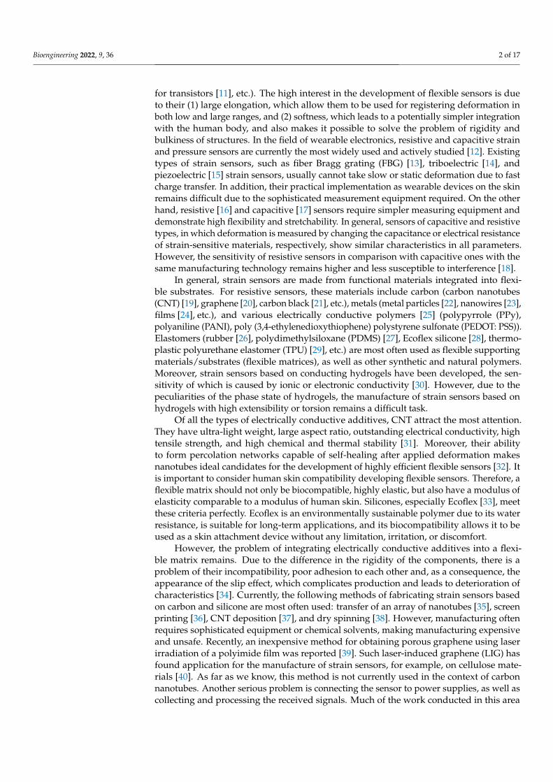
A diagram of the strain-sensitive material manufacturing process is shown in Figure 1.
Bioengineering 2022, 9, x FOR PEER REVIEW 4 of 18
2. Materials and Methods This section includes descriptions and specifications of the components used to make
the sensors. It also outlines the proposed strain-sensitive material manufacturing technol-ogy using laser structuring and presents the manufacture of an electronic unit for reading and processing signals from a sensitive material, as well as presenting test methods, equipment, and formulas used to quantify electrical, sensitive, and mechanical character-istics of the developed sensor.
2.1. Components The developed strain sensors consisted of material that is sensitive to deformations
and a portable compact electronic unit for signal reading and processing. The strain-sensitive material was a composite constructed of multi-walled carbon
nanotubes (MWCNT) and a silicone elastomer. MWCNT (NanoTechCenter Ltd., Tambov, Russia) were produced by CVD synthesis and were quasi-one-dimensional, nanoscale, filamentary formations of polycrystalline graphite, predominantly cylindrical in shape with an inner channel in form of powder, with the following measurements: outer diam-eter 8–30 nm, inner diameter 5–15 nm, length ≥ 20 μm, specific surface area ≥ 270 m2/g, bulk density 0.025–0.06 g/cm3. A silicone elastomer on platinum Ecoflex 00-10 (Smooth-On Inc, Macungie, PA, USA) was used as a matrix. Silicone is a liquid of two components, where the first (A) is the base part, and the second (B) is the polymerization initiator. It has the following characteristics: dynamic viscosity of Ecoflex 00-10 in mixed state 140 Pa∙s, Young’s modulus at 100% elongation 0.06 MPa, Shore hardness 10 A, density 1.04 g/cm3, operating temperature range from 19 °С up to 232 °С. Carbon fiber electrodes were included in the finished strain-sensitive material.
The package of the electronic unit included: an electronic system and software for electrical signals processing, a signal receiver from a strain-sensitive material, batteries—4 AA batteries; it is possible to connect the unit to a computer via a USB cable. The block was based on a 12-bit ATXMEGA8E5-AU (Microchip Technology Inc., Chandler, AZ, USA) microcontroller. The body of electronic unit was made of ABS plastic.
2.2. Manufacturing of the Strain-Sensitive Material A diagram of the strain-sensitive material manufacturing process is shown in Figure
1.
Figure 1. Strain-sensitive material manufacturing process.
First, a 3D printer was used to print a mold from a photopolymer. In our case, the mold was rectangular, with the dimensions 3.5 × 1.5 × 2 mm, and had an internal U-shape hollowed section with dimensions of 3 × 1.2 × 1 mm. Next, a strain-sensitive material was
Figure 1. Strain-sensitive material manufacturing process.
First, a 3D printer was used to print a mold from a photopolymer. In our case, themold was rectangular, with the dimensions 3.5 × 1.5 × 2 mm, and had an internal U-shapehollowed section with dimensions of 3 × 1.2 × 1 mm. Next, a strain-sensitive materialwas manufactured, consisting of an Ecoflex/MWCNT composite. The first step was toadd MWCNT to Ecoflex silicone in the liquid phase at a rate of MWCNT 3 wt.%. Theresulting mixture of components was thoroughly mixed with a magnetic stirrer for at least5 min for homogeneous distribution of nanotubes in silicone. To remove air microbubblesformed as a result of stirring, the mixture was placed in a vacuum chamber and thedegassing process was started until the air bubbles were completely removed. Thereafter,the Ecoflex/MWCNT nanocomposite was prepared through the screen-printing method.For this, the Ecoflex/MWCNT mixture was placed in the inner U-shaped hollowed sectionof the mold. Next, the electrodes were added in a way that the mixture completely coveredthem. As a result, the electrodes had good adhesion to the material, which made it possibleto effectively record the resistance values. The composite with electrodes in the mold wasleft at room temperature (23 ± 5 ◦C) until complete solidification was achieved (~4 h).
Bioengineering 2022, 9, 36 5 of 17
After complete polymerization, the resulting nanocomposite was subjected to laserstructuring [46,47]. It was treated with laser radiation to reduce the resistivity values, formwelded joints between nanotubes, and form a structured MWCNT conductive networkinside the nanocomposite [48–51]. It is important to ensure the formation of contactsbetween nanotubes. The most crystalline contacts are formed when covalent C–C bondsappear [52]. During the formation of reliable contacts between nanotubes, the contactresistance decreases and, as a consequence, the electrical conductivity of the structuresincreases [53]. Moreover, it also increases the mechanical strength and fatigue strengthof composites, which allows for the use of such materials for a long time [54]. Aftersynthesis, nanotubes are mainly presented in the form of disordered systems [55], sincethe methods for synthesizing ordered nanoparticles are extremely difficult to control anddifficult to implement. For this reason, methods for binding CNTs after synthesis byexternal influence are actively developing. Such methods are based on the mechanisms ofaction of concentrated energy, based on the latest advances in laser technology and precisionmechanics. The use of the laser forming method proposed in this research makes it possibleto further improve the electrical and mechanical characteristics [47,50]. The parameters ofthe laser irradiation were selected experimentally so as to prevent the combustion of thesilicone. We used a pulsed Yb fiber laser with a wavelength of 1064 nm, radiation powerwas selected experimentally and amounted to 12 W, and irradiation time was 2 min. Finally,a laser-structured Ecoflex/MWCNT composite with electrodes was cast on both sides withlayers of pure silicone to create an insulating and fully biocompatible coating. As a result ofthe simple manufacturing process, flexible and soft strain-sensitive material for the strainsensor was obtained, which is a sandwich structure: Ecoflex-CNT-Ecoflex.
In order to select the optimal concentration of MWCNT, rectangular Ecoflex/MWCNTcomposites with dimensions 3.5 × 1.5 × 1 and MWCNT concentrations 2, 3, 4 wt.%were initially manufactured. In order to assess the effect of laser radiation on electricalcharacteristics, the samples were subjected to laser structuring, as described above. Elec-trical resistance values were measured using UT33A+ (Uni-Trend Technology Co. Ltd.,Dongguan, China) multimeter before and after laser structuring for each concentrationof MWCNT.
Group of investigated sensors contained five samples from different batches to obtainstatistical results during research.
2.3. Manufacturing of Electronic Circuit
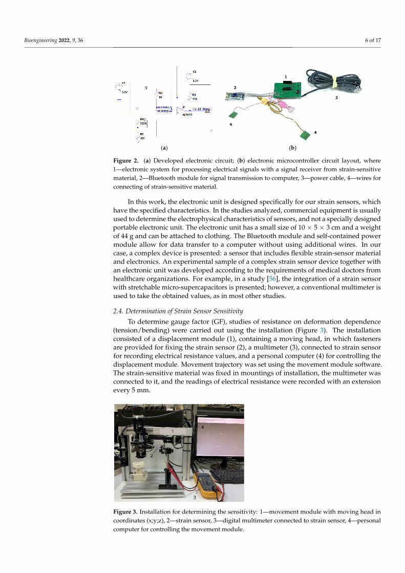
To create an electronic system for processing electrical signals (electronic unit) froma strain-sensitive material, an electrical circuit was developed using the LTspice software(Analog Devices Inc., Wilmington, NC, USA) (Figure 2a). Based on the resistance valuesof the material, the circuit was simulated, and values of resistors used in the circuit wereselected. As a result of the experimental measurements, we determined the range ofpossible resistances of the strain sensors. A circuit converting resistance to voltage usingan ATXMEGA8E5-AU microcontroller (Atmel Corporation, San Jose, CA, USA) equippedwith an ADC (10 bit) was calculated. The input voltage range for this ADC was 0 to 1.14 V.The analog circuit was calculated so that the voltage converting the LM358D operationalamplifier (STMicroelectronics, Geneva, Switzerland) from the sensor resistance was in theinput voltage range. In this case, the sensor acts as a variable resistor. In the diagram,it is designated R4 (Figure 2a). In accordance with the developed circuit, an electronicmicrocontroller unit model was assembled from electronic components (Figure 2b). Theelectronic circuit (1) was based on the ATXMEGA8E5-AU microcontroller. The Bluetoothmodule (2) made it possible to transfer the data received from the strain-sensitive materialto computer with installed software. Power was supplied by connecting the USB connector(3) to 5V power supply or to computer. Moreover, leads for connecting a strain-sensitivematerial were developed (4). Finally, a plastic body was made, in which the components ofunit were placed, and in addition to the power cable, a block for batteries was added.
Bioengineering 2022, 9, 36 6 of 17
Bioengineering 2022, 9, x FOR PEER REVIEW 6 of 18
V. The analog circuit was calculated so that the voltage converting the LM358D opera-tional amplifier (STMicroelectronics, Geneva, Switzerland) from the sensor resistance was in the input voltage range. In this case, the sensor acts as a variable resistor. In the diagram, it is designated R4 (Figure 2a). In accordance with the developed circuit, an electronic microcontroller unit model was assembled from electronic components (Figure 2b). The electronic circuit (1) was based on the ATXMEGA8E5-AU microcontroller. The Bluetooth module (2) made it possible to transfer the data received from the strain-sensitive material to computer with installed software. Power was supplied by connecting the USB con-nector (3) to 5V power supply or to computer. Moreover, leads for connecting a strain-sensitive material were developed (4). Finally, a plastic body was made, in which the com-ponents of unit were placed, and in addition to the power cable, a block for batteries was added.
(a) (b)
Figure 2. (a) Developed electronic circuit; (b) electronic microcontroller circuit layout, where 1—electronic system for processing electrical signals with a signal receiver from strain-sensitive mate-rial, 2—Bluetooth module for signal transmission to computer, 3—power cable, 4—wires for con-necting of strain-sensitive material.
In this work, the electronic unit is designed specifically for our strain sensors, which have the specified characteristics. In the studies analyzed, commercial equipment is usu-ally used to determine the electrophysical characteristics of sensors, and not a specially designed portable electronic unit. The electronic unit has a small size of 10 × 5 × 3 cm and a weight of 44 g and can be attached to clothing. The Bluetooth module and self-contained power module allow for data transfer to a computer without using additional wires. In our case, а complex device is presented: a sensor that includes flexible strain-sensor ma-terial and electronics. An experimental sample of a complex strain sensor device together with an electronic unit was developed according to the requirements of medical doctors from healthcare organizations. For example, in a study [56], the integration of a strain sensor with stretchable micro-supercapacitors is presented; however, a conventional mul-timeter is used to take the obtained values, as in most other studies.
2.4. Determination of Strain Sensor Sensitivity To determine gauge factor (GF), studies of resistance on deformation dependence
(tension/bending) were carried out using the installation (Figure 3). The installation con-sisted of a displacement module (1), containing a moving head, in which fasteners are provided for fixing the strain sensor (2), a multimeter (3), connected to strain sensor for recording electrical resistance values, and a personal computer (4) for controlling the dis-placement module. Movement trajectory was set using the movement module software. The strain-sensitive material was fixed in mountings of installation, the multimeter was connected to it, and the readings of electrical resistance were recorded with an extension every 5 mm.
Figure 2. (a) Developed electronic circuit; (b) electronic microcontroller circuit layout, where1—electronic system for processing electrical signals with a signal receiver from strain-sensitivematerial, 2—Bluetooth module for signal transmission to computer, 3—power cable, 4—wires forconnecting of strain-sensitive material.
In this work, the electronic unit is designed specifically for our strain sensors, whichhave the specified characteristics. In the studies analyzed, commercial equipment is usuallyused to determine the electrophysical characteristics of sensors, and not a specially designedportable electronic unit. The electronic unit has a small size of 10 × 5 × 3 cm and a weightof 44 g and can be attached to clothing. The Bluetooth module and self-contained powermodule allow for data transfer to a computer without using additional wires. In ourcase, a complex device is presented: a sensor that includes flexible strain-sensor materialand electronics. An experimental sample of a complex strain sensor device together withan electronic unit was developed according to the requirements of medical doctors fromhealthcare organizations. For example, in a study [56], the integration of a strain sensorwith stretchable micro-supercapacitors is presented; however, a conventional multimeter isused to take the obtained values, as in most other studies.
2.4. Determination of Strain Sensor Sensitivity
To determine gauge factor (GF), studies of resistance on deformation dependence(tension/bending) were carried out using the installation (Figure 3). The installationconsisted of a displacement module (1), containing a moving head, in which fastenersare provided for fixing the strain sensor (2), a multimeter (3), connected to strain sensorfor recording electrical resistance values, and a personal computer (4) for controlling thedisplacement module. Movement trajectory was set using the movement module software.The strain-sensitive material was fixed in mountings of installation, the multimeter wasconnected to it, and the readings of electrical resistance were recorded with an extensionevery 5 mm.
Bioengineering 2022, 9, x FOR PEER REVIEW 7 of 18
Figure 3. Installation for determining the sensitivity: 1—movement module with moving head in coordinates (x;y;z), 2—strain sensor, 3—digital multimeter connected to strain sensor, 4—personal computer for controlling the movement module.
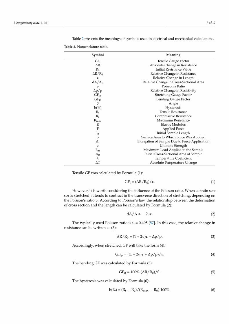
Table 2 presents the meanings of symbols used in electrical and mechanical calcula-tions.
Table 2. Nomenclature table.
Symbol Meaning GFl Tensile Gauge Factor ΔR Absolute Change in Resistance R0 Initial Resistance Value
ΔR/R0 Relative Change in Resistance Ɛ Relative Change in Length dA/A0 Relative Change in Cross-Sectional Area υ Poisson’s Ratio
Δp/p Relative Change in Resistivity GFlp Stretching Gauge Factor GFθ Bending Gauge Factor θ Angle
h(%) Hysteresis Rt Tensile Resistance Rc Compressive Resistance
Rmax Maximum Resistance E Elastic Modulus F Applied Force l0 Initial Sample Length S Surface Area to Which Force Was Applied ∆l Elongation of Sample Due to Force Application σ Ultimate Strength Fm Maximum Load Applied to the Sample А0 Initial Cross-Sectional Area of Sample λ Temperature Coefficient ΔT Absolute Temperature Change
Tensile GF was calculated by Formula (1):
GFl = (ΔR/R0)/Ɛ. (1)
However, it is worth considering the influence of the Poisson ratio. When a strain sensor is stretched, it tends to contract in the transverse direction of stretching, depending on the Poisson’s ratio υ. According to Poisson’s law, the relationship between the defor-mation of cross section and the length can be calculated by Formula (2):
Figure 3. Installation for determining the sensitivity: 1—movement module with moving head incoordinates (x;y;z), 2—strain sensor, 3—digital multimeter connected to strain sensor, 4—personalcomputer for controlling the movement module.
Bioengineering 2022, 9, 36 7 of 17
Table 2 presents the meanings of symbols used in electrical and mechanical calculations.
Table 2. Nomenclature table.
Symbol Meaning
GFl Tensile Gauge Factor∆R Absolute Change in ResistanceR0 Initial Resistance Value
∆R/R0 Relative Change in Resistanceε Relative Change in Length
dA/A0 Relative Change in Cross-Sectional Areaυ Poisson’s Ratio
∆p/p Relative Change in ResistivityGFlp Stretching Gauge FactorGFθ Bending Gauge Factorθ Angle
h(%) HysteresisRt Tensile ResistanceRc Compressive Resistance
Rmax Maximum ResistanceE Elastic ModulusF Applied Forcel0 Initial Sample LengthS Surface Area to Which Force Was Applied∆l Elongation of Sample Due to Force Applicationσ Ultimate Strength
Fm Maximum Load Applied to the SampleA0 Initial Cross-Sectional Area of Sampleλ Temperature Coefficient
∆T Absolute Temperature Change
Tensile GF was calculated by Formula (1):
GFl = (∆R/R0)/ε. (1)
However, it is worth considering the influence of the Poisson ratio. When a strain sen-sor is stretched, it tends to contract in the transverse direction of stretching, depending onthe Poisson’s ratio υ. According to Poisson’s law, the relationship between the deformationof cross section and the length can be calculated by Formula (2):
dA/A ≈ −2υε. (2)
The typically used Poisson ratio is υ = 0.495 [57]. In this case, the relative change inresistance can be written as (3):
∆R/R0 = (1 + 2υ)ε + ∆p/p. (3)
Accordingly, when stretched, GF will take the form (4):
GFlp = ((1 + 2υ)ε + ∆p/p)/ε. (4)
The bending GF was calculated by Formula (5):
GFθ = 100%·(∆R/R0)/θ. (5)
The hysteresis was calculated by Formula (6):
h(%) = (Rt − Rc)/(Rmax − R0)·100%. (6)
Bioengineering 2022, 9, 36 8 of 17
2.5. Measurement of Strain Sensor Mechanical Characteristics
Using a digital multimeter Megeon 03100 (Megeon Llc., Zelenodolsk, Russia) andmeasuring ruler, applied force was determined depending on strain sensor elongation.Then, the elastic modulus was calculated using Formula (7):
E = F·l0/S·∆l. (7)
Maximum possible load (ultimate strength) that strain sensor can withstand wascalculated using Formula (8):
σ = Fm/A0. (8)
2.6. Investigation of Temperature Influence on Strain Sensor
The temperature coefficient of resistance was determined for temperature range30–40 ◦C. To do this, strain sensors were placed on a heating table with temperaturecontrol function, and their resistance was recorded every 5 ◦C (from 25 to 50 ◦C). Thetemperature coefficient λwas calculated by Formula (9):
λ = ∆R/(R0·∆T). (9)
2.7. Investigation of Strain Sensor Working Capacity
The working capacity of strain sensors was monitored at cyclic deformation. Strainsensors were attached to the finger joint using a polymer medical plaster to assess effective-ness in registering flexion-relaxing movements. In addition, a study to accurately determinethe sensors response speed was carried out. Strain sensors were stretched by 50% andthe time taken for the electrical resistance after deformation to return to its initial valuewas monitored.
3. Results and Discussion
This section includes a demonstration of the developed sensors, their structural,electrical, sensitive, mechanical characteristics, and performance under conditions of strainmeasurement, as well as a discussion of the results obtained.
3.1. Structure
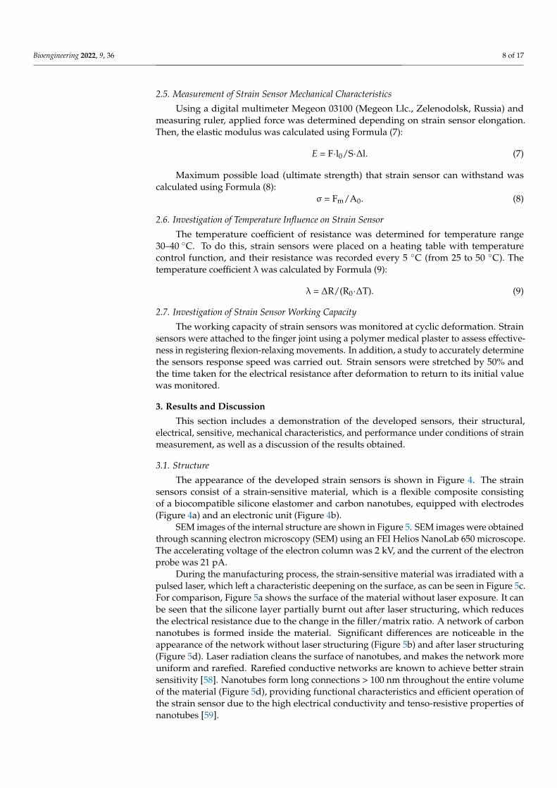
The appearance of the developed strain sensors is shown in Figure 4. The strainsensors consist of a strain-sensitive material, which is a flexible composite consistingof a biocompatible silicone elastomer and carbon nanotubes, equipped with electrodes(Figure 4a) and an electronic unit (Figure 4b).
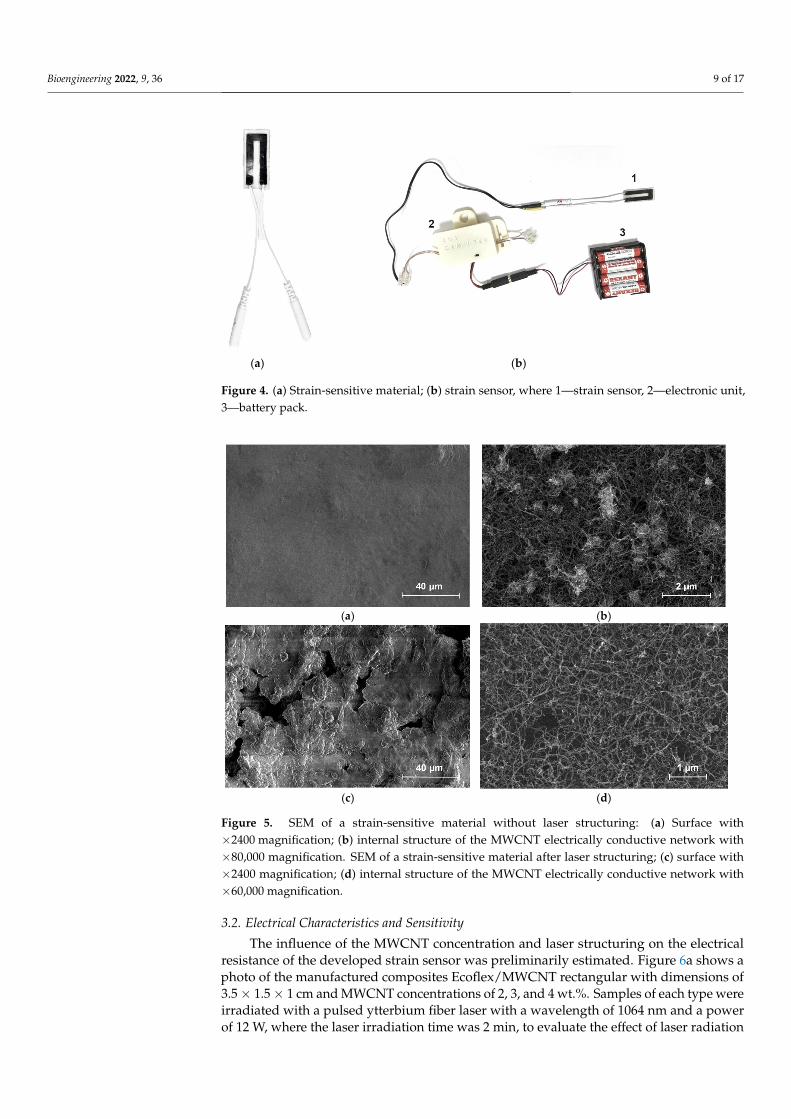
SEM images of the internal structure are shown in Figure 5. SEM images were obtainedthrough scanning electron microscopy (SEM) using an FEI Helios NanoLab 650 microscope.The accelerating voltage of the electron column was 2 kV, and the current of the electronprobe was 21 pA.
During the manufacturing process, the strain-sensitive material was irradiated with apulsed laser, which left a characteristic deepening on the surface, as can be seen in Figure 5c.For comparison, Figure 5a shows the surface of the material without laser exposure. It canbe seen that the silicone layer partially burnt out after laser structuring, which reducesthe electrical resistance due to the change in the filler/matrix ratio. A network of carbonnanotubes is formed inside the material. Significant differences are noticeable in theappearance of the network without laser structuring (Figure 5b) and after laser structuring(Figure 5d). Laser radiation cleans the surface of nanotubes, and makes the network moreuniform and rarefied. Rarefied conductive networks are known to achieve better strainsensitivity [58]. Nanotubes form long connections > 100 nm throughout the entire volumeof the material (Figure 5d), providing functional characteristics and efficient operation ofthe strain sensor due to the high electrical conductivity and tenso-resistive properties ofnanotubes [59].
Bioengineering 2022, 9, 36 9 of 17Bioengineering 2022, 9, x FOR PEER REVIEW 9 of 18
(a) (b)
Figure 4. (a) Strain-sensitive material; (b) strain sensor, where 1—strain sensor, 2—electronic unit, 3—battery pack.
SEM images of the internal structure are shown in Figure 5. SEM images were ob-tained through scanning electron microscopy (SEM) using an FEI Helios NanoLab 650 microscope. The accelerating voltage of the electron column was 2 kV, and the current of the electron probe was 21 pA.
(a) (b)
(c) (d)
Figure 5. SEM of a strain-sensitive material without laser structuring: (a) Surface with ×2400 mag-nification; (b) internal structure of the MWCNT electrically conductive network with ×80,000 mag-nification. SEM of a strain-sensitive material after laser structuring; (c) surface with ×2400 magnifi-cation; (d) internal structure of the MWCNT electrically conductive network with ×60,000 magnifi-cation.
During the manufacturing process, the strain-sensitive material was irradiated with a pulsed laser, which left a characteristic deepening on the surface, as can be seen in Figure 5c. For comparison, Figure 5a shows the surface of the material without laser exposure. It can be seen that the silicone layer partially burnt out after laser structuring, which reduces
Figure 4. (a) Strain-sensitive material; (b) strain sensor, where 1—strain sensor, 2—electronic unit,3—battery pack.
Bioengineering 2022, 9, x FOR PEER REVIEW 9 of 18
(a) (b)
Figure 4. (a) Strain-sensitive material; (b) strain sensor, where 1—strain sensor, 2—electronic unit, 3—battery pack.
SEM images of the internal structure are shown in Figure 5. SEM images were ob-tained through scanning electron microscopy (SEM) using an FEI Helios NanoLab 650 microscope. The accelerating voltage of the electron column was 2 kV, and the current of the electron probe was 21 pA.
(a) (b)
(c) (d)
Figure 5. SEM of a strain-sensitive material without laser structuring: (a) Surface with ×2400 mag-nification; (b) internal structure of the MWCNT electrically conductive network with ×80,000 mag-nification. SEM of a strain-sensitive material after laser structuring; (c) surface with ×2400 magnifi-cation; (d) internal structure of the MWCNT electrically conductive network with ×60,000 magnifi-cation.
During the manufacturing process, the strain-sensitive material was irradiated with a pulsed laser, which left a characteristic deepening on the surface, as can be seen in Figure 5c. For comparison, Figure 5a shows the surface of the material without laser exposure. It can be seen that the silicone layer partially burnt out after laser structuring, which reduces
Figure 5. SEM of a strain-sensitive material without laser structuring: (a) Surface with×2400 magnification; (b) internal structure of the MWCNT electrically conductive network with×80,000 magnification. SEM of a strain-sensitive material after laser structuring; (c) surface with×2400 magnification; (d) internal structure of the MWCNT electrically conductive network with×60,000 magnification.
3.2. Electrical Characteristics and Sensitivity
The influence of the MWCNT concentration and laser structuring on the electricalresistance of the developed strain sensor was preliminarily estimated. Figure 6a shows aphoto of the manufactured composites Ecoflex/MWCNT rectangular with dimensions of3.5 × 1.5 × 1 cm and MWCNT concentrations of 2, 3, and 4 wt.%. Samples of each type wereirradiated with a pulsed ytterbium fiber laser with a wavelength of 1064 nm and a powerof 12 W, where the laser irradiation time was 2 min, to evaluate the effect of laser radiation
Bioengineering 2022, 9, 36 10 of 17
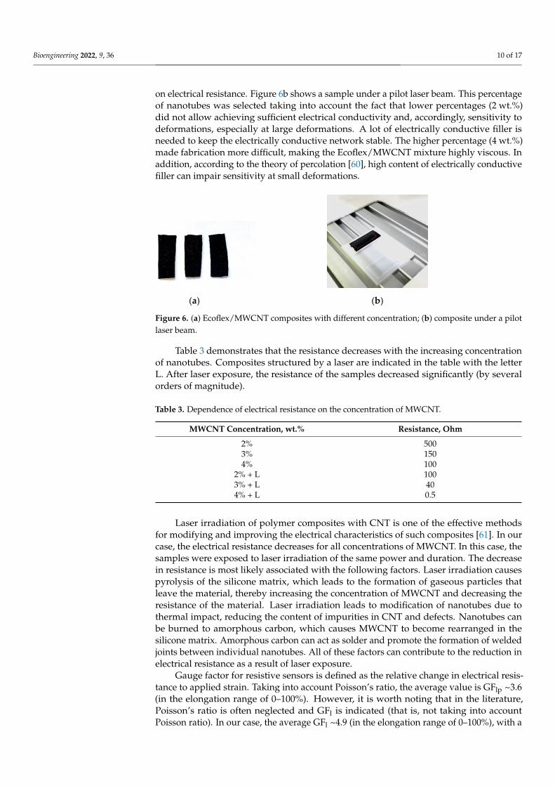
on electrical resistance. Figure 6b shows a sample under a pilot laser beam. This percentageof nanotubes was selected taking into account the fact that lower percentages (2 wt.%)did not allow achieving sufficient electrical conductivity and, accordingly, sensitivity todeformations, especially at large deformations. A lot of electrically conductive filler isneeded to keep the electrically conductive network stable. The higher percentage (4 wt.%)made fabrication more difficult, making the Ecoflex/MWCNT mixture highly viscous. Inaddition, according to the theory of percolation [60], high content of electrically conductivefiller can impair sensitivity at small deformations.
Bioengineering 2022, 9, x FOR PEER REVIEW 10 of 18
the electrical resistance due to the change in the filler/matrix ratio. A network of carbon nanotubes is formed inside the material. Significant differences are noticeable in the ap-pearance of the network without laser structuring (Figure 5b) and after laser structuring (Figure 5d). Laser radiation cleans the surface of nanotubes, and makes the network more uniform and rarefied. Rarefied conductive networks are known to achieve better strain sensitivity [58]. Nanotubes form long connections > 100 nm throughout the entire volume of the material (Figure 5d), providing functional characteristics and efficient operation of the strain sensor due to the high electrical conductivity and tenso-resistive properties of nanotubes [59].
3.2. Electrical Characteristics and Sensitivity The influence of the MWCNT concentration and laser structuring on the electrical
resistance of the developed strain sensor was preliminarily estimated. Figure 6a shows a photo of the manufactured composites Ecoflex/MWCNT rectangular with dimensions of 3.5 × 1.5 × 1 cm and MWCNT concentrations of 2, 3, and 4 wt.%. Samples of each type were irradiated with a pulsed ytterbium fiber laser with a wavelength of 1064 nm and a power of 12 W, where the laser irradiation time was 2 min, to evaluate the effect of laser radiation on electrical resistance. Figure 6b shows a sample under a pilot laser beam. This percentage of nanotubes was selected taking into account the fact that lower percentages (2 wt.%) did not allow achieving sufficient electrical conductivity and, accordingly, sensi-tivity to deformations, especially at large deformations. A lot of electrically conductive filler is needed to keep the electrically conductive network stable. The higher percentage (4 wt.%) made fabrication more difficult, making the Ecoflex/MWCNT mixture highly vis-cous. In addition, according to the theory of percolation [60], high content of electrically conductive filler can impair sensitivity at small deformations.
(a) (b)
Figure 6. (a) Ecoflex/MWCNT composites with different concentration; (b) composite under a pilot laser beam.
Table 3 demonstrates that the resistance decreases with the increasing concentration of nanotubes. Composites structured by a laser are indicated in the table with the letter L. After laser exposure, the resistance of the samples decreased significantly (by several or-ders of magnitude).
Table 3. Dependence of electrical resistance on the concentration of MWCNT.
MWCNT Concentration, wt.% Resistance, Ohm 2% 500 3% 150 4% 100
2% + L 100 3% + L 40 4% + L 0.5
Figure 6. (a) Ecoflex/MWCNT composites with different concentration; (b) composite under a pilotlaser beam.
Table 3 demonstrates that the resistance decreases with the increasing concentrationof nanotubes. Composites structured by a laser are indicated in the table with the letterL. After laser exposure, the resistance of the samples decreased significantly (by severalorders of magnitude).
Table 3. Dependence of electrical resistance on the concentration of MWCNT.
MWCNT Concentration, wt.% Resistance, Ohm
2% 5003% 1504% 100
2% + L 1003% + L 404% + L 0.5
Laser irradiation of polymer composites with CNT is one of the effective methodsfor modifying and improving the electrical characteristics of such composites [61]. In ourcase, the electrical resistance decreases for all concentrations of MWCNT. In this case, thesamples were exposed to laser irradiation of the same power and duration. The decreasein resistance is most likely associated with the following factors. Laser irradiation causespyrolysis of the silicone matrix, which leads to the formation of gaseous particles thatleave the material, thereby increasing the concentration of MWCNT and decreasing theresistance of the material. Laser irradiation leads to modification of nanotubes due tothermal impact, reducing the content of impurities in CNT and defects. Nanotubes canbe burned to amorphous carbon, which causes MWCNT to become rearranged in thesilicone matrix. Amorphous carbon can act as solder and promote the formation of weldedjoints between individual nanotubes. All of these factors can contribute to the reduction inelectrical resistance as a result of laser exposure.
Gauge factor for resistive sensors is defined as the relative change in electrical resis-tance to applied strain. Taking into account Poisson’s ratio, the average value is GFlp ~3.6(in the elongation range of 0–100%). However, it is worth noting that in the literature,Poisson’s ratio is often neglected and GFl is indicated (that is, not taking into accountPoisson ratio). In our case, the average GFl ~4.9 (in the elongation range of 0–100%), with a
Bioengineering 2022, 9, 36 11 of 17
maximum value of 7 (at 100% elongation). These values are higher than those of similarsensors based on Ecoflex and CNT silicone, for which the linear GFl often does not exceed2 [62]. Angular GFθ was ~0.9%/deg (at bending 0–90◦).
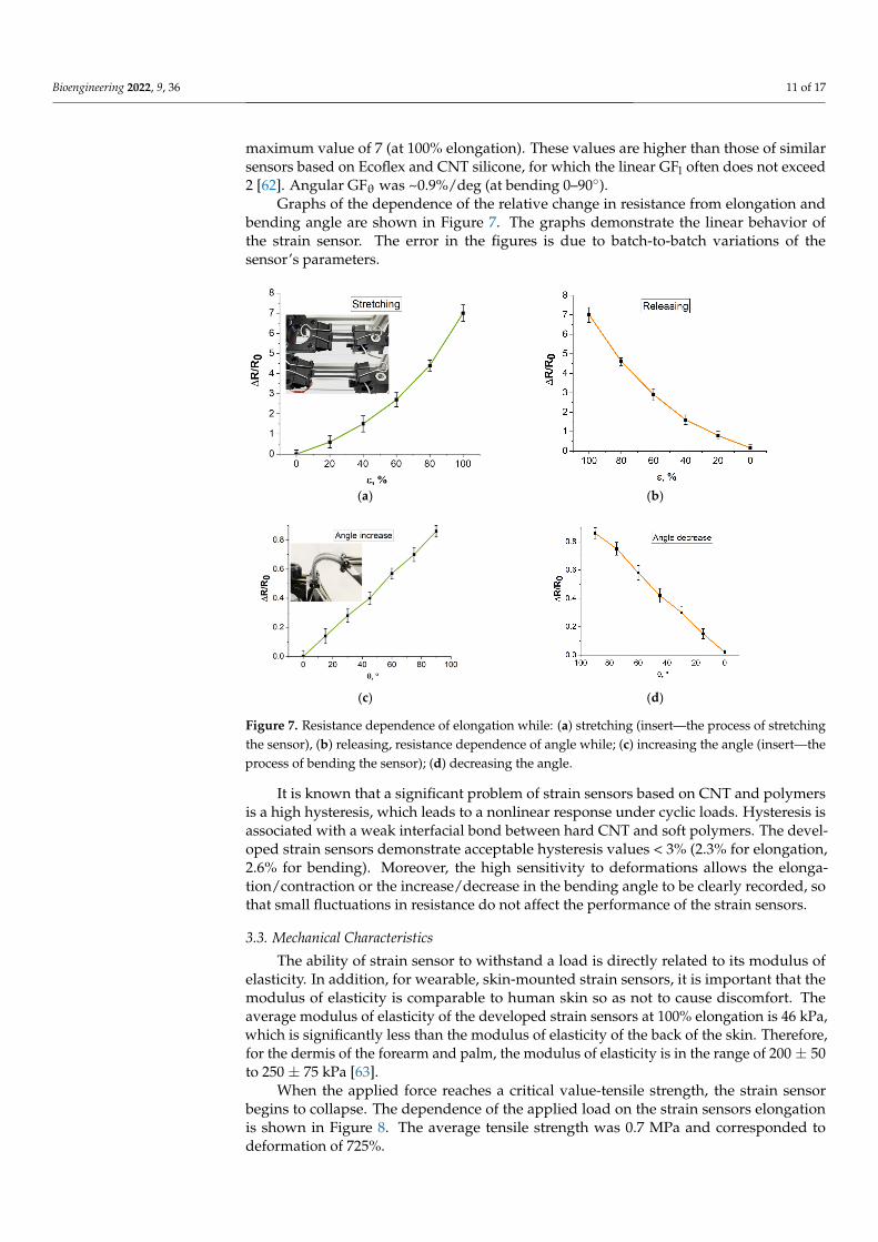
Graphs of the dependence of the relative change in resistance from elongation andbending angle are shown in Figure 7. The graphs demonstrate the linear behavior ofthe strain sensor. The error in the figures is due to batch-to-batch variations of thesensor’s parameters.
Bioengineering 2022, 9, x FOR PEER REVIEW 11 of 18
Laser irradiation of polymer composites with CNT is one of the effective methods for modifying and improving the electrical characteristics of such composites [61]. In our case, the electrical resistance decreases for all concentrations of MWCNT. In this case, the sam-ples were exposed to laser irradiation of the same power and duration. The decrease in resistance is most likely associated with the following factors. Laser irradiation causes py-rolysis of the silicone matrix, which leads to the formation of gaseous particles that leave the material, thereby increasing the concentration of MWCNT and decreasing the re-sistance of the material. Laser irradiation leads to modification of nanotubes due to ther-mal impact, reducing the content of impurities in CNT and defects. Nanotubes can be burned to amorphous carbon, which causes MWCNT to become rearranged in the silicone matrix. Amorphous carbon can act as solder and promote the formation of welded joints between individual nanotubes. All of these factors can contribute to the reduction in elec-trical resistance as a result of laser exposure.
Gauge factor for resistive sensors is defined as the relative change in electrical re-sistance to applied strain. Taking into account Poisson’s ratio, the average value is GFlp
∼3.6 (in the elongation range of 0–100%). However, it is worth noting that in the literature, Poisson’s ratio is often neglected and GFl is indicated (that is, not taking into account Pois-son ratio). In our case, the average GFl ∼4.9 (in the elongation range of 0–100%), with a maximum value of 7 (at 100% elongation). These values are higher than those of similar sensors based on Ecoflex and CNT silicone, for which the linear GFl often does not exceed 2 [62]. Angular GFθ was ∼0.9%/deg (at bending 0–90°).
Graphs of the dependence of the relative change in resistance from elongation and bending angle are shown in Figure 7. The graphs demonstrate the linear behavior of the strain sensor. The error in the figures is due to batch-to-batch variations of the sensor’s parameters.
(a) (b)
(c) (d)
Figure 7. Resistance dependence of elongation while: (a) stretching (insert—the process of stretching the sensor), (b) releasing, resistance dependence of angle while; (c) increasing the angle (insert—the process of bending the sensor); (d) decreasing the angle.
It is known that a significant problem of strain sensors based on CNT and polymers is a high hysteresis, which leads to a nonlinear response under cyclic loads. Hysteresis is
Figure 7. Resistance dependence of elongation while: (a) stretching (insert—the process of stretchingthe sensor), (b) releasing, resistance dependence of angle while; (c) increasing the angle (insert—theprocess of bending the sensor); (d) decreasing the angle.
It is known that a significant problem of strain sensors based on CNT and polymersis a high hysteresis, which leads to a nonlinear response under cyclic loads. Hysteresis isassociated with a weak interfacial bond between hard CNT and soft polymers. The devel-oped strain sensors demonstrate acceptable hysteresis values < 3% (2.3% for elongation,2.6% for bending). Moreover, the high sensitivity to deformations allows the elonga-tion/contraction or the increase/decrease in the bending angle to be clearly recorded, sothat small fluctuations in resistance do not affect the performance of the strain sensors.
3.3. Mechanical Characteristics
The ability of strain sensor to withstand a load is directly related to its modulus ofelasticity. In addition, for wearable, skin-mounted strain sensors, it is important that themodulus of elasticity is comparable to human skin so as not to cause discomfort. Theaverage modulus of elasticity of the developed strain sensors at 100% elongation is 46 kPa,which is significantly less than the modulus of elasticity of the back of the skin. Therefore,for the dermis of the forearm and palm, the modulus of elasticity is in the range of 200 ± 50to 250 ± 75 kPa [63].
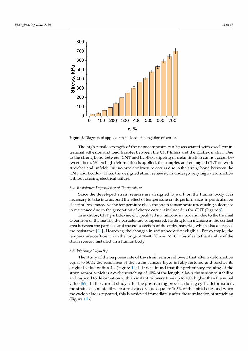
When the applied force reaches a critical value-tensile strength, the strain sensorbegins to collapse. The dependence of the applied load on the strain sensors elongationis shown in Figure 8. The average tensile strength was 0.7 MPa and corresponded todeformation of 725%.
Bioengineering 2022, 9, 36 12 of 17
Bioengineering 2022, 9, x FOR PEER REVIEW 12 of 18
associated with a weak interfacial bond between hard CNT and soft polymers. The devel-oped strain sensors demonstrate acceptable hysteresis values < 3% (2.3% for elongation, 2.6% for bending). Moreover, the high sensitivity to deformations allows the elonga-tion/contraction or the increase/decrease in the bending angle to be clearly recorded, so that small fluctuations in resistance do not affect the performance of the strain sensors.
3.3. Mechanical Characteristics The ability of strain sensor to withstand a load is directly related to its modulus of
elasticity. In addition, for wearable, skin-mounted strain sensors, it is important that the modulus of elasticity is comparable to human skin so as not to cause discomfort. The av-erage modulus of elasticity of the developed strain sensors at 100% elongation is 46 kPa, which is significantly less than the modulus of elasticity of the back of the skin. Therefore, for the dermis of the forearm and palm, the modulus of elasticity is in the range of 200 ± 50 to 250 ± 75 kPa [63].
When the applied force reaches a critical value-tensile strength, the strain sensor be-gins to collapse. The dependence of the applied load on the strain sensors elongation is shown in Figure 8. The average tensile strength was 0.7 MPa and corresponded to defor-mation of 725%.
Figure 8. Diagram of applied tensile load of elongation of sensor.
The high tensile strength of the nanocomposite can be associated with excellent in-terfacial adhesion and load transfer between the CNT fillers and the Ecoflex matrix. Due to the strong bond between CNT and Ecoflex, slipping or delamination cannot occur be-tween them. When high deformation is applied, the complex and entangled CNT network stretches and unfolds, but no break or fracture occurs due to the strong bond between the CNT and Ecoflex. Thus, the designed strain sensors can undergo very high deformation without causing electrical failure.
3.4. Resistance Dependence of Temperature Since the developed strain sensors are designed to work on the human body, it is
necessary to take into account the effect of temperature on its performance, in particular,
Figure 8. Diagram of applied tensile load of elongation of sensor.
The high tensile strength of the nanocomposite can be associated with excellent in-terfacial adhesion and load transfer between the CNT fillers and the Ecoflex matrix. Dueto the strong bond between CNT and Ecoflex, slipping or delamination cannot occur be-tween them. When high deformation is applied, the complex and entangled CNT networkstretches and unfolds, but no break or fracture occurs due to the strong bond between theCNT and Ecoflex. Thus, the designed strain sensors can undergo very high deformationwithout causing electrical failure.
3.4. Resistance Dependence of Temperature
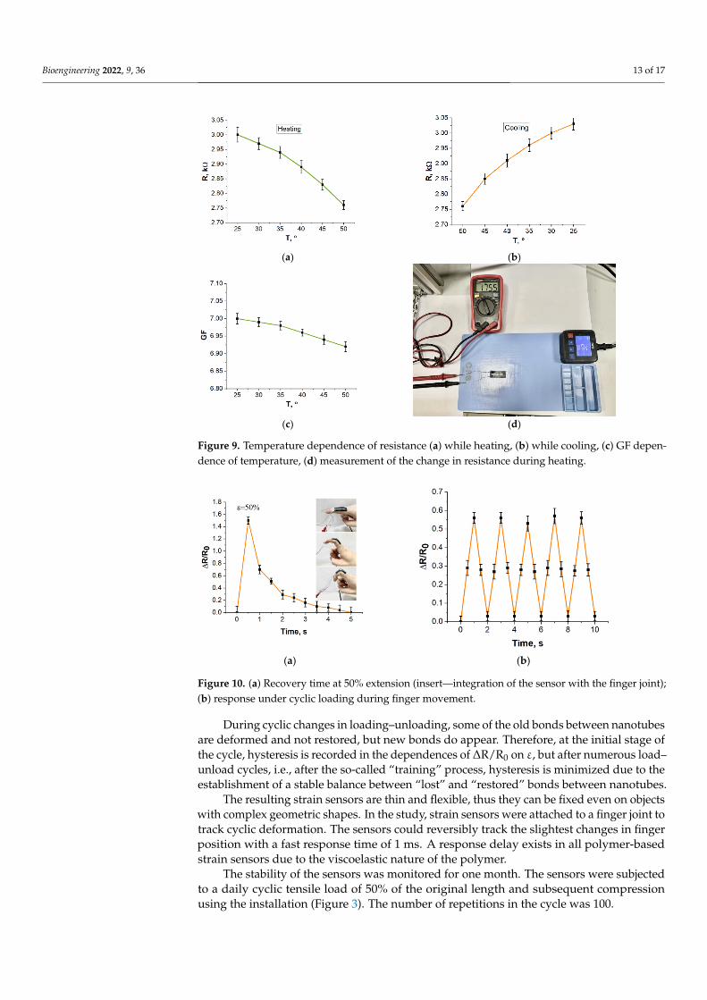
Since the developed strain sensors are designed to work on the human body, it isnecessary to take into account the effect of temperature on its performance, in particular, onelectrical resistance. As the temperature rises, the strain sensor heats up, causing a decreasein resistance due to the generation of charge carriers included in the CNT (Figure 9).
In addition, CNT particles are encapsulated in a silicone matrix and, due to the thermalexpansion of the matrix, the particles are compressed, leading to an increase in the contactarea between the particles and the cross-section of the entire material, which also decreasesthe resistance [64]. However, the changes in resistance are negligible. For example, thetemperature coefficient λ in the range of 30–40 ◦C ~ –2 × 10⁻³ testifies to the stability of thestrain sensors installed on a human body.
3.5. Working Capacity
The study of the response rate of the strain sensors showed that after a deformationequal to 50%, the resistance of the strain sensors layer is fully restored and reaches itsoriginal value within 4 s (Figure 10a). It was found that the preliminary training of thestrain sensor, which is a cyclic stretching of 10% of the length, allows the sensor to stabilizeand respond to deformation with an instant recovery time up to 10% higher than the initialvalue [65]. In the current study, after the pre-training process, during cyclic deformation,the strain sensors stabilize to a resistance value equal to 103% of the initial one, and whenthe cycle value is repeated, this is achieved immediately after the termination of stretching(Figure 10b).
Bioengineering 2022, 9, 36 13 of 17
Bioengineering 2022, 9, x FOR PEER REVIEW 13 of 18
on electrical resistance. As the temperature rises, the strain sensor heats up, causing a de-crease in resistance due to the generation of charge carriers included in the CNT (Figure 9).
(a) (b)
(c) (d)
Figure 9. Temperature dependence of resistance (a) while heating, (b) while cooling, (c) GF depend-ence of temperature, (d) measurement of the change in resistance during heating.
In addition, CNT particles are encapsulated in a silicone matrix and, due to the ther-mal expansion of the matrix, the particles are compressed, leading to an increase in the contact area between the particles and the cross-section of the entire material, which also decreases the resistance [64]. However, the changes in resistance are negligible. For exam-ple, the temperature coefficient λ in the range of 30–40 °С ∼ –2 × 10⁻³ testifies to the stability of the strain sensors installed on a human body.
3.5. Working Capacity The study of the response rate of the strain sensors showed that after a deformation
equal to 50%, the resistance of the strain sensors layer is fully restored and reaches its original value within 4 s (Figure 10a). It was found that the preliminary training of the strain sensor, which is a cyclic stretching of 10% of the length, allows the sensor to stabilize and respond to deformation with an instant recovery time up to 10% higher than the initial value [65]. In the current study, after the pre-training process, during cyclic deformation, the strain sensors stabilize to a resistance value equal to 103% of the initial one, and when the cycle value is repeated, this is achieved immediately after the termination of stretching (Figure 10b).
Figure 9. Temperature dependence of resistance (a) while heating, (b) while cooling, (c) GF depen-dence of temperature, (d) measurement of the change in resistance during heating.
Bioengineering 2022, 9, x FOR PEER REVIEW 14 of 18
(a) (b)
Figure 10. (a) Recovery time at 50% extension (insert—integration of the sensor with the finger joint); (b) response under cyclic loading during finger movement.
During cyclic changes in loading–unloading, some of the old bonds between nano-tubes are deformed and not restored, but new bonds do appear. Therefore, at the initial stage of the cycle, hysteresis is recorded in the dependences of ΔR/R0 on ε, but after nu-merous load–unload cycles, i.e., after the so-called “training” process, hysteresis is mini-mized due to the establishment of a stable balance between “lost” and “restored” bonds between nanotubes.
The resulting strain sensors are thin and flexible, thus they can be fixed even on ob-jects with complex geometric shapes. In the study, strain sensors were attached to a finger joint to track cyclic deformation. The sensors could reversibly track the slightest changes in finger position with a fast response time of 1 ms. A response delay exists in all polymer-based strain sensors due to the viscoelastic nature of the polymer.
The stability of the sensors was monitored for one month. The sensors were subjected to a daily cyclic tensile load of 50% of the original length and subsequent compression using the installation (Figure 3). The number of repetitions in the cycle was 100.
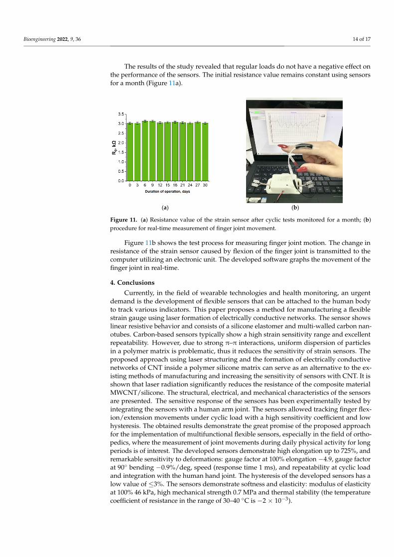
The results of the study revealed that regular loads do not have a negative effect on the performance of the sensors. The initial resistance value remains constant using sensors for a month (Figure 11a).
(a) (b)
Figure 11. (a) Resistance value of the strain sensor after cyclic tests monitored for a month; (b) pro-cedure for real-time measurement of finger joint movement.
Figure 11b shows the test process for measuring finger joint motion. The change in resistance of the strain sensor caused by flexion of the finger joint is transmitted to the
Figure 10. (a) Recovery time at 50% extension (insert—integration of the sensor with the finger joint);(b) response under cyclic loading during finger movement.
During cyclic changes in loading–unloading, some of the old bonds between nanotubesare deformed and not restored, but new bonds do appear. Therefore, at the initial stage ofthe cycle, hysteresis is recorded in the dependences of ∆R/R0 on ε, but after numerous load–unload cycles, i.e., after the so-called “training” process, hysteresis is minimized due to theestablishment of a stable balance between “lost” and “restored” bonds between nanotubes.
The resulting strain sensors are thin and flexible, thus they can be fixed even on objectswith complex geometric shapes. In the study, strain sensors were attached to a finger joint totrack cyclic deformation. The sensors could reversibly track the slightest changes in fingerposition with a fast response time of 1 ms. A response delay exists in all polymer-basedstrain sensors due to the viscoelastic nature of the polymer.
The stability of the sensors was monitored for one month. The sensors were subjectedto a daily cyclic tensile load of 50% of the original length and subsequent compressionusing the installation (Figure 3). The number of repetitions in the cycle was 100.
Bioengineering 2022, 9, 36 14 of 17
The results of the study revealed that regular loads do not have a negative effect onthe performance of the sensors. The initial resistance value remains constant using sensorsfor a month (Figure 11a).
Bioengineering 2022, 9, x FOR PEER REVIEW 14 of 18
(a) (b)
Figure 10. (a) Recovery time at 50% extension (insert—integration of the sensor with the finger joint); (b) response under cyclic loading during finger movement.
During cyclic changes in loading–unloading, some of the old bonds between nano-tubes are deformed and not restored, but new bonds do appear. Therefore, at the initial stage of the cycle, hysteresis is recorded in the dependences of ΔR/R0 on ε, but after nu-merous load–unload cycles, i.e., after the so-called “training” process, hysteresis is mini-mized due to the establishment of a stable balance between “lost” and “restored” bonds between nanotubes.
The resulting strain sensors are thin and flexible, thus they can be fixed even on ob-jects with complex geometric shapes. In the study, strain sensors were attached to a finger joint to track cyclic deformation. The sensors could reversibly track the slightest changes in finger position with a fast response time of 1 ms. A response delay exists in all polymer-based strain sensors due to the viscoelastic nature of the polymer.
The stability of the sensors was monitored for one month. The sensors were subjected to a daily cyclic tensile load of 50% of the original length and subsequent compression using the installation (Figure 3). The number of repetitions in the cycle was 100.
The results of the study revealed that regular loads do not have a negative effect on the performance of the sensors. The initial resistance value remains constant using sensors for a month (Figure 11a).
(a) (b)
Figure 11. (a) Resistance value of the strain sensor after cyclic tests monitored for a month; (b) pro-cedure for real-time measurement of finger joint movement.
Figure 11b shows the test process for measuring finger joint motion. The change in resistance of the strain sensor caused by flexion of the finger joint is transmitted to the
Figure 11. (a) Resistance value of the strain sensor after cyclic tests monitored for a month; (b)procedure for real-time measurement of finger joint movement.
Figure 11b shows the test process for measuring finger joint motion. The change inresistance of the strain sensor caused by flexion of the finger joint is transmitted to thecomputer utilizing an electronic unit. The developed software graphs the movement of thefinger joint in real-time.
4. Conclusions
Currently, in the field of wearable technologies and health monitoring, an urgentdemand is the development of flexible sensors that can be attached to the human bodyto track various indicators. This paper proposes a method for manufacturing a flexiblestrain gauge using laser formation of electrically conductive networks. The sensor showslinear resistive behavior and consists of a silicone elastomer and multi-walled carbon nan-otubes. Carbon-based sensors typically show a high strain sensitivity range and excellentrepeatability. However, due to strong π–π interactions, uniform dispersion of particlesin a polymer matrix is problematic, thus it reduces the sensitivity of strain sensors. Theproposed approach using laser structuring and the formation of electrically conductivenetworks of CNT inside a polymer silicone matrix can serve as an alternative to the ex-isting methods of manufacturing and increasing the sensitivity of sensors with CNT. It isshown that laser radiation significantly reduces the resistance of the composite materialMWCNT/silicone. The structural, electrical, and mechanical characteristics of the sensorsare presented. The sensitive response of the sensors has been experimentally tested byintegrating the sensors with a human arm joint. The sensors allowed tracking finger flex-ion/extension movements under cyclic load with a high sensitivity coefficient and lowhysteresis. The obtained results demonstrate the great promise of the proposed approachfor the implementation of multifunctional flexible sensors, especially in the field of ortho-pedics, where the measurement of joint movements during daily physical activity for longperiods is of interest. The developed sensors demonstrate high elongation up to 725%, andremarkable sensitivity to deformations: gauge factor at 100% elongation −4.9, gauge factorat 90◦ bending −0.9%/deg, speed (response time 1 ms), and repeatability at cyclic loadand integration with the human hand joint. The hysteresis of the developed sensors has alow value of ≤3%. The sensors demonstrate softness and elasticity: modulus of elasticityat 100% 46 kPa, high mechanical strength 0.7 MPa and thermal stability (the temperaturecoefficient of resistance in the range of 30–40 ◦C is −2 × 10⁻³).
Bioengineering 2022, 9, 36 15 of 17
In the future, further study of the sensor due to the large number of repetitions andthe longer duration of both electrochemical and mechanical tests is planned, as well asa more detailed study of the sensitivity mechanism and the possibility of adjusting theoutput parameters of the sensor by changing the parameters of laser radiation (exposuretime, power).
Author Contributions: Conceptualization, N.A.D., A.Y.G.; methodology, L.P.I., E.S.P.; software, E.S.P.;validation, A.V.K., N.A.D. and V.A.Z.; formal analysis, V.A.Z., A.A.T., E.D.; investigation, A.V.K.,N.A.D., V.V.M., E.S.P., V.A.Z., S.A.T.; resources, N.A.D., V.V.M., A.Y.G., A.A.T.; data curation, A.Y.G.,A.A.T.; writing—original draft preparation, A.V.K., N.A.D., V.V.M., E.S.P., V.A.Z., S.A.T.; writing—review and editing, L.P.I., A.Y.G.; visualization, N.A.D., E.S.P., H.S.; supervision, A.Y.G., V.A.Z.;project administration, A.Y.G., funding acquisition, A.Y.G. All authors have read and agreed to thepublished version of the manuscript.
Funding: This work was financed by the Ministry of Science and Higher Education of the RussianFederation within the framework of state support for the creation and development of World-ClassResearch Centers “Digital Biodesign and Personalized Healthcare” No. 075-15-2020-926.
Institutional Review Board Statement: Not applicable.
Informed Consent Statement: Not applicable.
Data Availability Statement: The data presented in this study are available on request from thecorresponding author.
Acknowledgments: The authors are grateful to colleagues who helped in performing the experimen-tal work and discussing the results: Alexander Pavlov, Alexander Dudin, and Elena Eganova.
Conflicts of Interest: The authors declare no conflict of interest.
References1. Chong, H.; Lou, J.; Bogie, K.M.; Zorman, C.A.; Majerus, S.J.A. Vascular Pressure–Flow Measurement Using CB-PDMS Flexible
Strain Sensor. IEEE Trans. Biomed. Circuits Syst. 2019, 13, 1451–1461. [CrossRef]2. Slobodian, P.; Danova, R.; Olejnik, R.; Matyas, J.; Münster, L. Multifunctional flexible and stretchable polyurethane/carbon
nanotube strain sensor for human breath monitoring. Polym. Adv. Technol. 2019, 30, 1891–1898. [CrossRef]3. Zhang, P.; Chen, Y.; Li, Y.; Zhang, Y.; Zhang, J.; Huang, L. A Flexible Strain Sensor Based on the Porous Structure of a Carbon
Black/Carbon Nanotube Conducting Network for Human Motion Detection. Sensors 2020, 20, 1154. [CrossRef] [PubMed]4. Toledo-Pérez, D.C.; Martínez-Prado, M.A.; Gómez-Loenzo, R.A.; Paredes-García, W.J.; Rodríguez-Reséndiz, J. A Study of
Movement Classification of the Lower Limb Based on up to 4-EMG Channels. Electronics 2019, 8, 259. [CrossRef]5. Zhao, Y.; Huang, Y.; Hu, W.; Guo, X.; Wang, Y.; Liu, P.; Liu, C.; Zhang, Y. Highly sensitive flexible strain sensor based on threadlike
spandex substrate coating with conductive nanocomposites for wearable electronic skin. Smart Mater. Struct. 2018, 28, 035004.[CrossRef]
6. Dong, W.; Yang, L.; Fortino, G. Stretchable Human Machine Interface Based on Smart Glove Embedded with PDMS-CB StrainSensors. IEEE Sens. J. 2020, 20, 8073–8081. [CrossRef]
7. Yeo, J.C.; Yap, H.K.; Xi, W.; Wang, Z.; Yeow, C.-H.; Lim, C.T. Flexible and Stretchable Strain Sensing Actuator for Wearable SoftRobotic Applications. Adv. Mater. Technol. 2016, 1, 1600018. [CrossRef]
8. Ghate, S.; Yu, L.; Du, K.; Lim, C.T.; Yeo, J.C. Sensorized fabric glove as game controller for rehabilitation. In Proceedings of the2020 IEEE Sensors, Rotterdam, The Netherlands, 25–28 October 2020; pp. 1–4.
9. Yin, J.; Hinchet, R.; Shea, H.; Majidi, C. Wearable Soft Technologies for Haptic Sensing and Feedback. Adv. Funct. Mater. 2021, 31,2007428. [CrossRef]
10. Kanazawa, S.; Ushijima, H. Development of a Strain Sensor Matrix on Mobilized Flexible Substrate for the Imaging of WindPressure Distribution. Micromachines 2020, 11, 232. [CrossRef] [PubMed]
11. Zhu, P.; Zhao, Z.; Nie, J.; Hu, G.; Li, L.; Zhang, Y. Ultra-high sensitivity strain sensor based on piezotronic bipolar transistor. NanoEnergy 2018, 50, 744–749. [CrossRef]
12. Amjadi, M.; Kyung, K.-U.; Park, I.; Sitti, M. Stretchable, Skin-Mountable, and Wearable Strain Sensors and Their PotentialApplications: A Review. Adv. Funct. Mater. 2016, 26, 1678–1698. [CrossRef]
13. Yu, J.; Xu, S.; Jiang, Y.; Chen, H.; Feng, W. Multi-parameter sensor based on the fiber Bragg grating combined with triangular-latticefour-core fiber. Optik 2020, 208, 164094. [CrossRef]
14. He, T.; Shi, Q.; Wang, H.; Wen, F.; Chen, T.; Ouyang, J.; Lee, C. Beyond energy harvesting—Multi-functional triboelectricnanosensors on a textile. Nano Energy 2019, 57, 338–352. [CrossRef]

Bioengineering 2022, 9, 36 16 of 17
15. Tian, Y.; He, P.; Yang, B.; Yi, Z.; Lu, L.; Liu, J. A Flexible Piezoelectric Strain Sensor Array With Laser-Patterned SerpentineInterconnects. IEEE Sens. J. 2020, 20, 8463–8468. [CrossRef]
16. Panth, M.; Cook, B.; Zhang, Y.; Ewing, D.; Tramble, A.; Wilson, A.; Wu, J. High-Performance Strain Sensors Based on VerticallyAligned Piezoelectric Zinc Oxide Nanowire Array/Graphene Nanohybrids. ACS Appl. Nano Mater. 2020, 3, 6711–6718. [CrossRef]
17. Aslanidis, E.; Skotadis, E.; Tsoukalas, D. Resistive crack-based nanoparticle strain sensors with extreme sensitivity and adjustablegauge factor, made on flexible substrates. Nanoscale 2021, 13, 3263–3274. [CrossRef]
18. Cai, L.; Song, L.; Luan, P.; Zhang, Q.; Zhang, N.; Gao, Q.; Zhao, D.; Zhang, X.; Tu, M.; Yang, F.; et al. Super-stretchable, TransparentCarbon Nanotube-Based Capacitive Strain Sensors for Human Motion Detection. Sci. Rep. 2013, 3, 3048. [CrossRef]
19. Dong, T.; Gu, Y.; Liu, T.; Pecht, M. Resistive and capacitive strain sensors based on customized compliant electrode: Comparisonand their wearable applications. Sens. Actuators A Phys. 2021, 326, 112720. [CrossRef]
20. Qaiser, N.; Al-Modaf, F.; Khan, S.M.; Shaikh, S.F.; El-Atab, N.; Hussain, M.M. A Robust Wearable Point-of-Care CNT-Based StrainSensor for Wirelessly Monitoring Throat-Related Illnesses. Adv. Funct. Mater. 2021, 31, 2103375. [CrossRef]
21. Song, X.; Liu, X.; Peng, Y.; Xu, Z.; Liu, W.; Pang, K.; Wang, J.; Zhong, L.; Yang, Q.; Meng, J. A graphene-coated silk-spandex fabricstrain sensor for human movement monitoring and recognition. Nanotechnology 2021, 32, 215501. [CrossRef]
22. Wang, X.; Liu, X.; Schubert, D.W. Highly Sensitive Ultrathin Flexible Thermoplastic Polyurethane/Carbon Black Fibrous FilmStrain Sensor with Adjustable Scaffold Networks. Nano-Micro Lett. 2021, 13, 1–19. [CrossRef]
23. Lee, J.; Kim, S.; Lee, J.; Yang, D.; Park, B.C.; Ryu, S.; Park, I. A stretchable strain sensor based on a metal nanoparticle thin film forhuman motion detection. Nanoscale 2014, 6, 11932–11939. [CrossRef] [PubMed]
24. Ha, S.-H.; Kim, J.-M. Highly sensitive and stretchable strain sensor based on self-aligned and periodic cracking of wavy metalnanowire/elastomer composite film. Smart Mater. Struct. 2021, 30, 065022. [CrossRef]
25. Zhu, M.; Sakamoto, K.; Li, J.; Inomata, N.; Toda, M.; Ono, T. Piezoresistive strain sensor based on monolayer molybdenumdisulfide continuous film deposited by chemical vapor deposition. J. Micromech. Microeng. 2019, 29, 055002. [CrossRef]
26. Selvan, N.T.; Eshwaran, S.B.; Das, A.; Stöckelhuber, K.W.; Wießner, S.; Pötschke, P.; Nando, G.B.; Chervanyov, A.I.; Heinrich, G.Piezoresistive natural rubber-multiwall carbon nanotube nanocomposite for sensor applications. Sens. Actuators A Phys. 2016,239, 102–113. [CrossRef]
27. Lin, L.; Choi, Y.; Chen, T.; Kim, H.; Lee, K.S.; Kang, J.; Lyu, L.; Gao, J.; Piao, Y. Superhydrophobic and wearable TPU basednanofiber strain sensor with outstanding sensitivity for high-quality body motion monitoring. Chem. Eng. J. 2021, 419, 129513.[CrossRef]
28. Park, J.W.; Kim, T.; Kim, D.; Hong, Y.; Gong, H.S. Measurement of finger joint angle using stretchable carbon nanotube strainsensor. PLoS ONE 2019, 14, e0225164. [CrossRef] [PubMed]
29. Ryu, S.; Lee, P.; Chou, J.B.; Xu, R.; Zhao, R.; Hart, A.J.; Kim, S.-G. Extremely Elastic Wearable Carbon Nanotube Fiber StrainSensor for Monitoring of Human Motion. ACS Nano 2015, 9, 5929–5936. [CrossRef]
30. Wang, Y.; Gao, G.; Ren, X. Graphene assisted ion-conductive hydrogel with super sensitivity for strain sensor. Polym. J. 2021, 215,123340. [CrossRef]
31. Ibrahim, K.S. Carbon nanotubes-properties and applications: A review. Carbon Lett. 2013, 14, 131–144. [CrossRef]32. Jung, S.; Choi, H.W.; Mocanu, F.C.; Shin, D.-W.; Chowdhury, M.F.; Han, S.D.; Suh, Y.-H.; Cho, Y.; Lee, H.; Fan, X.; et al. Modeling
Electrical Percolation to optimize the Electromechanical Properties of CNT/Polymer Composites in Highly Stretchable FiberStrain Sensors. Sci. Rep. 2019, 9, 1–10. [CrossRef]
33. Vaicekauskaite, J.; Mazurek, P.; Vudayagiri, S.; Skov, A.L. Mapping the mechanical and electrical properties of commercial siliconeelastomer formulations for stretchable transducers. J. Mater. Chem. C 2020, 8, 1273–1279. [CrossRef]
34. Li, Y.; Luo, S.; Yang, M.-C.; Liang, R.; Zeng, C. Poisson Ratio and Piezoresistive Sensing: A New Route to High-Performance 3DFlexible and Stretchable Sensors of Multimodal Sensing Capability. Adv. Funct. Mater. 2016, 26, 2900–2908. [CrossRef]
35. Lee, J.; Pyo, S.; Kwon, D.-S.; Jo, E.; Kim, W.; Kim, J. Ultrasensitive Strain Sensor Based on Separation of Overlapped CarbonNanotubes. Small 2019, 15, 1805120. [CrossRef]
36. Mai, H.; Mutlu, R.; Tawk, C.; Alici, G.; Sencadas, V. Ultra-stretchable MWCNT–Ecoflex piezoresistive sensors for human motiondetection applications. Compos. Sci. Technol. 2019, 173, 118–124. [CrossRef]
37. Park, S.-J.; Kim, J.; Chu, M.; Khine, M. Highly Flexible Wrinkled Carbon Nanotube Thin Film Strain Sensor to Monitor HumanMovement. Adv. Mater. Technol. 2016, 1, 1600053. [CrossRef]
38. Kim, S.Y.; Park, S.; Park, H.W.; Park, D.H.; Jeong, Y.; Kim, D.H. Highly Sensitive and Multimodal All-Carbon Skin SensorsCapable of Simultaneously Detecting Tactile and Biological Stimuli. Adv. Mater. 2015, 27, 4178–4185. [CrossRef]
39. Wang, H.; Zhao, Z.; Liu, P.; Guo, X. Laser-induced porous graphene on Polyimide/PDMS composites and its kirigami-inspiredstrain sensor. Theor. Appl. Mech. Lett. 2021, 11, 100240. [CrossRef]
40. Kulyk, B.; Silva, B.F.R.; Carvalho, A.F.; Silvestre, S.; Fernandes, A.J.S.; Martins, R.; Fortunato, E.; Costa, F.M. Laser-InducedGraphene from Paper for Mechanical Sensing. ACS Appl. Mater. Interfaces 2021, 13, 10210–10221. [CrossRef]
41. Chu, M.; E Naguib, H. Soft flexible conductive CNT nanocomposites for ECG monitoring. Smart Mater. Struct. 2021, 30, 065003.[CrossRef]
42. Zhang, S.; Wen, L.; Wang, H.; Zhu, K.; Zhang, M. Vertical CNT–Ecoflex nanofins for highly linear broad-range-detection wearablestrain sensors. J. Mater. Chem. C 2018, 6, 5132–5139. [CrossRef]
Bioengineering 2022, 9, 36 17 of 17
43. Yan, B.; Ding, H.; Zhang, Y.; Lin, P.; Wu, D.; Shi, Z.; Chen, X.; Tian, Y.; Li, X. Skin-attachable and flexible MWCNT grid/Ecoflexstrain sensors with fast equilibrium of response for detection of sound vibrations and human motions. J. Mater. Sci. Mater.Electron. 2021, 32, 26439–26448. [CrossRef]
44. Suzuki, K.; Yataka, K.; Okumiya, Y.; Sakakibara, S.; Sako, K.; Mimura, H.; Inoue, Y. Rapid-Response, Widely Stretchable Sensor ofAligned MWCNT/Elastomer Composites for Human Motion Detection. ACS Sens. 2016, 1, 817–825. [CrossRef]
45. Jeong, S.-Y.; Lee, J.-U.; Hong, S.-M.; Lee, C.-W.; Hwang, S.-H.; Cho, S.-C.; Shin, B.-S. Highly Skin-Conformal Laser-InducedGraphene-Based Human Motion Monitoring Sensor. Nanomaterials 2021, 11, 951. [CrossRef]
46. Gerasimenko, A.Y.; Kitsyuk, E.P.; Kuksin, A.V.; Ryazanov, R.M.; Savitskiy, A.I.; Savelyev, M.S.; Pavlov, A.A. Influence of laserstructuring and barium nitrate treatment on morphology and electrophysical characteristics of vertically aligned carbon nanotubearrays. Diam. Relat. Mater. 2019, 96, 104–111. [CrossRef]
47. Gerasimenko, A.; Kuksin, A.; Shaman, Y.; Kitsyuk, E.; Fedorova, Y.; Sysa, A.; Pavlov, A.; Glukhova, O. Electrically ConductiveNetworks from Hybrids of Carbon Nanotubes and Graphene Created by Laser Radiation. Nanomaterials 2021, 11, 1875. [CrossRef]
48. Ichkitidze, L.P.; Gerasimenko, A.Y. Electrical Conductivity of the Nanocomposite Layers for Use in Biomedical Systems. Mater.Phys. Mech. 2018, 37, 140–145. [CrossRef]
49. Gerasimenko, A.Y.; Kurilova, U.E.; Suetina, I.A.; Mezentseva, M.V.; Zubko, A.V.; Sekacheva, M.I.; Glukhova, O.E. LaserTechnology for the Formation of Bioelectronic Nanocomposites Based on Single-Walled Carbon Nanotubes and Proteins withDifferent Structures, Electrical Conductivity and Biocompatibility. Appl. Sci. 2021, 11, 8036. [CrossRef]
50. Gerasimenko, A.Y.; Kurilova, U.E.; Savelyev, M.S.; Murashko, D.T.; Glukhova, O.E. Laser fabrication of composite layers frombiopolymers with branched 3D networks of single-walled carbon nanotubes for cardiovascular implants. Compos. Struct. 2021,260, 113517. [CrossRef]
51. Tereshchenko, S.A.; Lysenko, A.Y. Single-photon emission computed tomography in the scattering medium with the property of“scattering straight back”. J. Appl. Phys. 2021, 129, 035101. [CrossRef]
52. Liu, Z.; Yuan, Y.; Shang, Y.; Han, W. Structural changes and electrical properties of nanowelded multiwalled carbon nanotubejunctions. Appl. Opt. 2018, 57, 7435–7439. [CrossRef]
53. Yao, Y.; Jiang, F.; Yang, C.; Fu, K.K.; Hayden, J.; Lin, C.-F.; Xie, H.; Jiao, M.; Yang, C.; Wang, Y.; et al. Epitaxial Welding of CarbonNanotube Networks for Aqueous Battery Current Collectors. ACS Nano 2018, 12, 5266–5273. [CrossRef]
54. Li, Z.; Sun, H.; Gao, C. Super structured Assembly of Nanocarbons: Fullerenes, Nanotubes, and Graphene. Chem. Rev. 2015, 115,7046–7117. [CrossRef]
55. Rao, R.; Pint, C.L.; Islam, A.E.; Weatherup, R.S.; Hofmann, S.; Meshot, E.R.; Wu, F.; Zhou, C.; Dee, N.; Amama, P.B.; et al.Carbon Nanotubes and Related Nanomaterials: Critical Advances and Challenges for Synthesis toward Mainstream CommercialApplications. ACS Nano 2018, 12, 11756–11784. [CrossRef] [PubMed]
56. Zhangac, C.; Penga, Z.; Huanga, C.; Zhanga, B.; Xinga, C.; Chena, H.; Chengb, H.; Wanga, J.; Tangc, S. High-energy all-in-onestretchable micro-supercapacitor arrays based on 3D laser-induced graphene foams decorated with mesoporous ZnP nanosheetsfor self-powered stretchable systems. Nano Energy 2021, 81, 105609. [CrossRef]
57. Unseld, S.; Baumer, A. Design and Analysis of a Hyperelastic Pneumatic Honeycomb Network Made of Ecoflex 00-35. InProceedings of the COMSOL Conference 2020 Europe, Online, 14–15 October 2020.
58. Huang, K.; Ning, H.; Hu, N.; Liu, F.; Wu, X.; Wang, S.; Liu, Y.; Zou, R.; Yuan, W.; Alamusi; et al. Ultrasensitive MWCNT/PDMScomposite strain sensor fabricated by laser ablation process. Compos. Sci. Technol. 2020, 192, 108105. [CrossRef]
59. De Vivo, B.; Lamberti, P.; Spinelli, G.; Tucci, V.; Vertuccio, L.; Vittoria, V. Simulation and experimental characterization ofpolymer/carbon nanotubes composites for strain sensor applications. J. Appl. Phys. 2014, 116, 54307. [CrossRef]
60. Duan, L.; Fu, S.; Deng, H.; Zhang, Q.; Wang, K.; Chen, F.; Fu, Q. The resistivity–strain behavior of conductive polymer composites:Stability and sensitivity. J. Mater. Chem. A 2014, 2, 17085–17098. [CrossRef]
61. Caradonna, A.; Badini, C.; Padovano, E.; Veca, A.; De Meo, E.; Pietroluongo, M. Laser Treatments for Improving ElectricalConductivity and Piezoresistive Behavior of Polymer–Carbon Nanofiller Composites. Micromachines 2019, 10, 63. [CrossRef]
62. Amjadi, M.; Pichitpajongkit, A.; Lee, S.; Ryu, S.; Park, I. Highly Stretchable and Sensitive Strain Sensor Based on Silver Nanowire–Elastomer Nanocomposite. ACS Nano 2014, 8, 5154–5163. [CrossRef]
63. Li, C.; Guan, G.; Reif, R.K.; Huang, Z.; Wang, R. Determining elastic properties of skin by measuring surface waves from animpulse mechanical stimulus using phase-sensitive optical coherence tomography. J. R. Soc. Interface 2012, 9, 831–841. [CrossRef][PubMed]
64. Karimov, K.S.; Khalid, F.A. Carbon nanotubes based flexible temperature sensors. Optoelectron. Adv. Mater. Rapid Commun. 2012,6, 194–196.
65. Gilshteyn, E.P.; Romanov, S.A.; Kopylova, D.S.; Savostyanov, G.V.; Anisimov, A.S.; Glukhova, O.E.; Nasibulin, A.G. MechanicallyTunable Single-Walled Carbon Nanotube Films as a Universal Material for Transparent and Stretchable Electronics. ACS Appl.Mater. Interfaces 2019, 11, 27327–27334. [CrossRef] [PubMed]
Copyright © 2022 FDOKUMEN