
excom I/O System for the Non-Ex Area - TURCK
263
Your Global Automation Partner excom I/O System for the Non-Ex Area System description
-
Upload
khangminh22 -
Category
Documents
-
view
0 -
download
0
Transcript of excom I/O System for the Non-Ex Area - TURCK

Your Global Automation Partner
excom I/O System for the Non-Ex AreaSystem description

2 Hans Turck GmbH & Co. KG | T +49 208 4952-0 | F +49 208 4952-264 | [email protected] | www.turck.com

V02.01 | 2022/05 3
Contents1 About this manual ............................................................................................................................ 11
1.1 Target groups................................................................................................................. 111.2 Explanation of symbols used ...................................................................................... 111.3 Other documents .......................................................................................................... 111.4 Feedback about these instructions............................................................................ 11
2 Notes on the product....................................................................................................................... 122.1 Product identification................................................................................................... 122.2 Turck service................................................................................................................... 12
3 For your safety .................................................................................................................................. 133.1 Intended use................................................................................................................... 133.2 General safety instructions.......................................................................................... 13
4 System overview .............................................................................................................................. 144.1 System setup .................................................................................................................. 144.1.1 excom – system components, slots and connections...................................................... 144.1.2 excom – I/O system in the system enclosure....................................................................... 164.2 Operating principle....................................................................................................... 184.3 System features ............................................................................................................. 204.4 Functions and operating modes ................................................................................ 214.4.1 HART functions ............................................................................................................................... 214.4.2 Redundancy functions ................................................................................................................. 214.5 Typical application areas ............................................................................................. 22
5 Planning and preparation............................................................................................................... 235.1 Overview of all system components.......................................................................... 235.2 Planning hardware components................................................................................ 275.2.1 Selecting I/O modules.................................................................................................................. 275.2.2 Planning cable routes................................................................................................................... 275.2.3 Defining the baud rate................................................................................................................. 275.2.4 Calculating the cycle time .......................................................................................................... 285.2.5 Specifying a mounting variant.................................................................................................. 285.2.6 Carry out a temperature test ..................................................................................................... 285.2.7 Setting up the system .................................................................................................................. 305.3 Planning redundancy concepts.................................................................................. 315.4 Implement shielding and grounding concepts (PROFIBUS-DP) .......................... 345.4.1 Direct grounding on both sides ............................................................................................... 345.4.2 Direct grounding at the feeding device ................................................................................ 35
6 System components ........................................................................................................................ 366.1 MT08-N, MT16-N, MT24-N module racks .................................................................. 366.1.1 Intended use.................................................................................................................................... 366.1.2 Device overview ............................................................................................................................. 366.1.3 Properties and features................................................................................................................ 386.1.4 Functions and operating modes .............................................................................................. 386.1.5 Installing............................................................................................................................................ 386.1.6 Connection....................................................................................................................................... 396.1.7 Setting................................................................................................................................................ 436.1.8 Technical data ................................................................................................................................. 45

Contents
4 Hans Turck GmbH & Co. KG | T +49 208 4952-0 | F +49 208 4952-264 | [email protected] | www.turck.com
6.2 PSM24-N power supply module................................................................................. 476.2.1 Intended use.................................................................................................................................... 476.2.2 Device overview ............................................................................................................................. 476.2.3 Properties and features................................................................................................................ 476.2.4 Functions and operating modes .............................................................................................. 486.2.5 Mounting .......................................................................................................................................... 486.2.6 Connection....................................................................................................................................... 486.2.7 LED indications ............................................................................................................................... 496.2.8 Technical data ................................................................................................................................. 506.3 Gateway GDP-N ............................................................................................................. 516.3.1 Intended use.................................................................................................................................... 516.3.2 Device overview ............................................................................................................................. 516.3.3 Properties and features................................................................................................................ 516.3.4 Functions and operating modes .............................................................................................. 526.3.5 Mounting .......................................................................................................................................... 536.3.6 Connection....................................................................................................................................... 536.3.7 Setting................................................................................................................................................ 546.3.8 LED indications ............................................................................................................................... 566.3.9 Bit assignment of the input word ............................................................................................ 576.3.10 PROFIBUS: diagnostic information .......................................................................................... 586.3.11 Technical data ................................................................................................................................. 596.4 Gateway GEN-N.............................................................................................................. 606.4.1 Intended use.................................................................................................................................... 606.4.2 Device overview ............................................................................................................................. 606.4.3 Properties and features................................................................................................................ 606.4.4 Functions and operating modes .............................................................................................. 606.4.5 Mounting .......................................................................................................................................... 616.4.6 Connection....................................................................................................................................... 616.4.7 LED indications ............................................................................................................................... 626.4.8 Setting................................................................................................................................................ 636.4.9 Bit assignment of the input word ............................................................................................ 646.4.10 Technical data ................................................................................................................................. 666.5 AI40-N analog input module....................................................................................... 686.5.1 Intended use.................................................................................................................................... 686.5.2 Device overview ............................................................................................................................. 686.5.3 Properties and features................................................................................................................ 686.5.4 Functions and operating modes .............................................................................................. 696.5.5 Mounting .......................................................................................................................................... 696.5.6 Connection....................................................................................................................................... 706.5.7 LED indications ............................................................................................................................... 716.5.8 Setting................................................................................................................................................ 716.5.9 Measuring range and substitute values ................................................................................ 736.5.10 Bit assignment of the input word ............................................................................................ 736.5.11 PROFIBUS: diagnostic information .......................................................................................... 746.5.12 Technical data ................................................................................................................................. 756.6 AI41-N analog input module....................................................................................... 766.6.1 Intended use.................................................................................................................................... 766.6.2 Device overview ............................................................................................................................. 766.6.3 Properties and features................................................................................................................ 766.6.4 Functions and operating modes .............................................................................................. 766.6.5 Mounting .......................................................................................................................................... 776.6.6 Connection....................................................................................................................................... 776.6.7 LED indications ............................................................................................................................... 786.6.8 Setting................................................................................................................................................ 786.6.9 Measuring range and substitute values ................................................................................ 80

V02.01 | 2022/05 5
6.6.10 Bit assignment of the input word ............................................................................................ 806.6.11 PROFIBUS: diagnostic information .......................................................................................... 816.6.12 Technical data ................................................................................................................................. 826.7 AI43-N analog input module....................................................................................... 836.7.1 Intended use.................................................................................................................................... 836.7.2 Device overview ............................................................................................................................. 836.7.3 Properties and features................................................................................................................ 836.7.4 Functions and operating modes .............................................................................................. 836.7.5 Mounting .......................................................................................................................................... 836.7.6 Connection....................................................................................................................................... 846.7.7 LED indications ............................................................................................................................... 846.7.8 Setting................................................................................................................................................ 856.7.9 Measuring range and substitute values ................................................................................ 866.7.10 Bit assignment of the input word ............................................................................................ 866.7.11 PROFIBUS: diagnostic information .......................................................................................... 866.7.12 Technical data ................................................................................................................................. 876.8 AIH40-N analog input module.................................................................................... 886.8.1 Intended use.................................................................................................................................... 886.8.2 Device overview ............................................................................................................................. 886.8.3 Properties and features................................................................................................................ 886.8.4 Functions and operating modes .............................................................................................. 896.8.5 Mounting .......................................................................................................................................... 896.8.6 Connection....................................................................................................................................... 906.8.7 LED indications ............................................................................................................................... 916.8.8 Setting................................................................................................................................................ 916.8.9 Measuring range and substitute values ................................................................................ 966.8.10 Bit assignment of the input word ............................................................................................ 976.8.11 PROFIBUS: diagnostic information .......................................................................................... 986.8.12 Technical data ................................................................................................................................. 996.9 AIH41-N analog input module................................................................................. 1006.9.1 Intended use................................................................................................................................. 1006.9.2 Device overview .......................................................................................................................... 1006.9.3 Properties and features............................................................................................................. 1006.9.4 Functions and operating modes ........................................................................................... 1016.9.5 Mounting ....................................................................................................................................... 1016.9.6 Connection.................................................................................................................................... 1026.9.7 LED indications ............................................................................................................................ 1036.9.8 Setting............................................................................................................................................. 1036.9.9 Measuring range and substitute values ............................................................................. 1076.9.10 Bit assignment of the input word ......................................................................................... 1086.9.11 PROFIBUS: diagnostic information ....................................................................................... 1096.9.12 Technical data .............................................................................................................................. 1106.10 AIH401-N analog input module............................................................................... 1116.10.1 Intended use................................................................................................................................. 1116.10.2 Device overview .......................................................................................................................... 1116.10.3 Properties and features............................................................................................................. 1116.10.4 Functions and operating modes ........................................................................................... 1126.10.5 Mounting ....................................................................................................................................... 1136.10.6 Connection.................................................................................................................................... 1136.10.7 LED indications ............................................................................................................................ 1146.10.8 Setting............................................................................................................................................. 1156.10.9 Measuring range and substitute values ............................................................................. 1206.10.10 Bit assignment of the input word ......................................................................................... 1216.10.11 PROFIBUS: diagnostic information ....................................................................................... 1226.10.12 Technical data .............................................................................................................................. 123

Contents
6 Hans Turck GmbH & Co. KG | T +49 208 4952-0 | F +49 208 4952-264 | [email protected] | www.turck.com
6.11 AO40-N analog output module .............................................................................. 1246.11.1 Intended use................................................................................................................................. 1246.11.2 Device overview .......................................................................................................................... 1246.11.3 Properties and features............................................................................................................. 1246.11.4 Functions and operating modes ........................................................................................... 1246.11.5 Mounting ....................................................................................................................................... 1256.11.6 Connection.................................................................................................................................... 1256.11.7 LED indications ............................................................................................................................ 1266.11.8 Setting............................................................................................................................................. 1266.11.9 Measuring range and substitute values ............................................................................. 1276.11.10 Bit assignment of the output word ...................................................................................... 1286.11.11 PROFIBUS: diagnostic information ....................................................................................... 1286.11.12 Technical data .............................................................................................................................. 1296.12 AOH40-N analog output module ............................................................................ 1306.12.1 Intended use................................................................................................................................. 1306.12.2 Device overview .......................................................................................................................... 1306.12.3 Properties and features............................................................................................................. 1306.12.4 Functions and operating modes ........................................................................................... 1316.12.5 Mounting ....................................................................................................................................... 1316.12.6 Connection.................................................................................................................................... 1326.12.7 LED indications ............................................................................................................................ 1336.12.8 Setting............................................................................................................................................. 1336.12.9 Measuring range and substitute values ............................................................................. 1386.12.10 Bit assignment of the output word ...................................................................................... 1396.12.11 PROFIBUS: diagnostic information ....................................................................................... 1406.12.12 Technical data .............................................................................................................................. 1416.13 AOH401-N analog output module .......................................................................... 1426.13.1 Intended use................................................................................................................................. 1426.13.2 Device overview .......................................................................................................................... 1426.13.3 Properties and features............................................................................................................. 1426.13.4 Functions and operating modes ........................................................................................... 1436.13.5 Mounting ....................................................................................................................................... 1436.13.6 Connection.................................................................................................................................... 1446.13.7 LED indications ............................................................................................................................ 1456.13.8 Setting............................................................................................................................................. 1466.13.9 Measuring range and substitute values ............................................................................. 1516.13.10 Bit assignment of the output word ...................................................................................... 1526.13.11 PROFIBUS: diagnostic information ....................................................................................... 1536.13.12 Technical data .............................................................................................................................. 1546.14 DM80-N digital input/output module.................................................................... 1556.14.1 Intended use................................................................................................................................. 1556.14.2 Device overview .......................................................................................................................... 1556.14.3 Properties and features............................................................................................................. 1556.14.4 Functions and operating modes ........................................................................................... 1566.14.5 Mounting ....................................................................................................................................... 1566.14.6 Connection.................................................................................................................................... 1576.14.7 LED indications ............................................................................................................................ 1586.14.8 Setting............................................................................................................................................. 1596.14.9 Bit assignment of the data byte............................................................................................. 1626.14.10 PROFIBUS: diagnostic information ....................................................................................... 1626.14.11 Technical data .............................................................................................................................. 163

V02.01 | 2022/05 7
6.15 DI40-N digital input module .................................................................................... 1646.15.1 Intended use................................................................................................................................. 1646.15.2 Device overview .......................................................................................................................... 1646.15.3 Properties and features............................................................................................................. 1646.15.4 Functions and operating modes ........................................................................................... 1646.15.5 Mounting ....................................................................................................................................... 1646.15.6 Connection.................................................................................................................................... 1656.15.7 LED indications ............................................................................................................................ 1656.15.8 Setting............................................................................................................................................. 1666.15.9 Bit assignment of the input byte........................................................................................... 1676.15.10 PROFIBUS: diagnostic information ....................................................................................... 1676.15.11 Technical data .............................................................................................................................. 1686.16 DI80-N digital input module .................................................................................... 1696.16.1 Intended Use ................................................................................................................................ 1696.16.2 Device Overview ......................................................................................................................... 1696.16.3 Properties and Characteristics................................................................................................ 1696.16.4 Functions and Operating Modes........................................................................................... 1706.16.5 Mounting ....................................................................................................................................... 1706.16.6 Connection.................................................................................................................................... 1716.16.7 LED indications ............................................................................................................................ 1716.16.8 Setting............................................................................................................................................. 1726.16.9 Bit assignment of the input byte........................................................................................... 1746.16.10 PROFIBUS: diagnostic information ....................................................................................... 1746.16.11 Technical data .............................................................................................................................. 1756.17 DO40-N digital output module................................................................................ 1766.17.1 Intended use................................................................................................................................. 1766.17.2 Device overview .......................................................................................................................... 1766.17.3 Properties and features............................................................................................................. 1766.17.4 Functions and operating modes ........................................................................................... 1766.17.5 Mounting ....................................................................................................................................... 1776.17.6 Connection.................................................................................................................................... 1776.17.7 LED indications ............................................................................................................................ 1796.17.8 Setting............................................................................................................................................. 1806.17.9 Bit assignment of the output byte........................................................................................ 1816.17.10 PROFIBUS: diagnostic information ....................................................................................... 1816.17.11 Technical data .............................................................................................................................. 1826.18 DO60R-N digital output module ............................................................................. 1836.18.1 Intended use................................................................................................................................. 1836.18.2 Device overview .......................................................................................................................... 1836.18.3 Properties and features............................................................................................................. 1836.18.4 Functions and operating modes ........................................................................................... 1836.18.5 Mounting ....................................................................................................................................... 1836.18.6 Connection.................................................................................................................................... 1846.18.7 LED indications ............................................................................................................................ 1856.18.8 Setting............................................................................................................................................. 1856.18.9 Bit assignment of the output byte........................................................................................ 1866.18.10 PROFIBUS: diagnostic information ....................................................................................... 1876.18.11 Technical data .............................................................................................................................. 1886.19 DO80-N digital output module................................................................................ 1896.19.1 Intended Use ................................................................................................................................ 1896.19.2 Device Overview ......................................................................................................................... 1896.19.3 Properties and Characteristics................................................................................................ 1896.19.4 Functions and Operating Modes........................................................................................... 1896.19.5 Mounting ....................................................................................................................................... 1906.19.6 Connection.................................................................................................................................... 190

Contents
8 Hans Turck GmbH & Co. KG | T +49 208 4952-0 | F +49 208 4952-264 | [email protected] | www.turck.com
6.19.7 LED indications ............................................................................................................................ 1916.19.8 Setting............................................................................................................................................. 1916.19.9 Bit assignment of the output byte........................................................................................ 1926.19.10 PROFIBUS: diagnostic information ....................................................................................... 1936.19.11 Technical data .............................................................................................................................. 1946.20 TI40-N temperature module .................................................................................... 1956.20.1 Intended use................................................................................................................................. 1956.20.2 Device overview .......................................................................................................................... 1966.20.3 Properties and features............................................................................................................. 1966.20.4 Functions and operating modes ........................................................................................... 1966.20.5 Mounting ....................................................................................................................................... 1976.20.6 Connection.................................................................................................................................... 1976.20.7 LED indications ............................................................................................................................ 1986.20.8 Commissioning............................................................................................................................ 1986.20.9 Setting............................................................................................................................................. 1996.20.10 Measuring ranges ....................................................................................................................... 2046.20.11 Bit assignment of the input word ......................................................................................... 2066.20.12 PROFIBUS: diagnostic information ....................................................................................... 2066.20.13 Technical data .............................................................................................................................. 2076.21 TI41-N temperature module .................................................................................... 2096.21.1 Intended use................................................................................................................................. 2096.21.2 Device overview .......................................................................................................................... 2096.21.3 Properties and features............................................................................................................. 2096.21.4 Functions and operating modes ........................................................................................... 2096.21.5 Mounting ....................................................................................................................................... 2106.21.6 Connection.................................................................................................................................... 2106.21.7 LED indications ............................................................................................................................ 2116.21.8 Commissioning............................................................................................................................ 2116.21.9 Setting............................................................................................................................................. 2126.21.10 Measuring ranges ....................................................................................................................... 2156.21.11 Bit assignment of the input word ......................................................................................... 2156.21.12 PROFIBUS: diagnostic information ....................................................................................... 2166.21.13 Technical data .............................................................................................................................. 2176.22 DF20-N frequency and counter module ................................................................ 2186.22.1 Intended use................................................................................................................................. 2186.22.2 Device overview .......................................................................................................................... 2186.22.3 Properties and features............................................................................................................. 2186.22.4 Functions and operating modes ........................................................................................... 2196.22.5 Mounting ....................................................................................................................................... 2226.22.6 Connection.................................................................................................................................... 2236.22.7 LED indications ............................................................................................................................ 2246.22.8 Setting............................................................................................................................................. 2256.22.9 PROFIBUS: diagnostic information ....................................................................................... 2296.22.10 Technical data .............................................................................................................................. 2306.23 OC11Ex/3G.2 PROFIBUS-DP FO coupler................................................................. 2316.23.1 Intended use................................................................................................................................. 2316.23.2 Notes on Ex protection ............................................................................................................. 2316.23.3 Device overview .......................................................................................................................... 2316.23.4 Properties and features............................................................................................................. 2326.23.5 Functions and operating modes ........................................................................................... 2326.23.6 Installing......................................................................................................................................... 2366.23.7 Connection.................................................................................................................................... 2366.23.8 LED indications ............................................................................................................................ 2386.23.9 Setting............................................................................................................................................. 2396.23.10 Technical data .............................................................................................................................. 240

V02.01 | 2022/05 9
6.24 SC11-3G segment coupler ........................................................................................ 2426.24.1 Intended use................................................................................................................................. 2426.24.2 Notes on Ex protection ............................................................................................................. 2426.24.3 Device overview .......................................................................................................................... 2426.24.4 Properties and features............................................................................................................. 2426.24.5 Functions and operating modes ........................................................................................... 2436.24.6 Installing......................................................................................................................................... 2476.24.7 Connection.................................................................................................................................... 2476.24.8 LED indications ............................................................................................................................ 2506.24.9 Setting............................................................................................................................................. 2506.24.10 Technical data .............................................................................................................................. 2516.25 System enclosure with integrated excom system ............................................... 2526.25.1 Intended use................................................................................................................................. 2526.25.2 Device overview .......................................................................................................................... 2526.25.3 Properties and features............................................................................................................. 2566.25.4 Installing......................................................................................................................................... 2566.25.5 Connection.................................................................................................................................... 2576.26 Accessories .................................................................................................................. 259
7 Turck subsidiaries – contact information................................................................................... 261

Contents
10 Hans Turck GmbH & Co. KG | T +49 208 4952-0 | F +49 208 4952-264 | [email protected] | www.turck.com

V02.01 | 2022/05 11
1 About this manualThis manual describes the setup, functions, components and use of the system and helps youto plan and design the system for its intended purpose.
Read this manual carefully before planning, engineering and commissioning. This will preventthe risk of personal injury and damage to property. Keep this manual safe during the service lifeof the product. If the product is passed on, hand over this manual as well.
1.1 Target groupsThese instructions are aimed at qualified personal and must be carefully read by anyonemounting, commissioning, operating, maintaining, dismantling or disposing of the device.
1.2 Explanation of symbols usedThe following symbols are used in these instructions:
DANGERDANGER indicates a dangerous situation with high risk of death or severe injury ifnot avoided.
WARNINGWARNING indicates a dangerous situation with medium risk of death or severe in-jury if not avoided.
CAUTIONCAUTION indicates a dangerous situation of medium risk which may result in minoror moderate injury if not avoided.
NOTICENOTICE indicates a situation which may lead to property damage if not avoided.
NOTENOTE indicates tips, recommendations and useful information on specific actionsand facts. The notes simplify your work and help you to avoid additional work.
u CALL TO ACTIONThis symbol denotes actions that the user must carry out.
a RESULTS OF ACTIONThis symbol denotes relevant results of actions.
1.3 Other documentsBesides this document the following material can be found on the Internet at www.turck.com:
n Integration manualsn Data sheetn Quick start guidesn EU declarations of conformityn Approvals
1.4 Feedback about these instructionsWe make every effort to ensure that these instructions are as informative and as clear as possible. If you have any suggestions for improving the design or if some information is missingin the document, please send your suggestions to [email protected].

Notes on the productTurck service
12 Hans Turck GmbH & Co. KG | T +49 208 4952-0 | F +49 208 4952-264 | [email protected] | www.turck.com
2 Notes on the product
2.1 Product identificationThis system description applies to the excom I/O system for the non-Ex area.
2.2 Turck serviceTurck supports you with your projects, from initial analysis to the commissioning of your applic-ation. The Turck product database under www.turck.com contains software tools for program-ming, configuration or commissioning, data sheets and CAD files in numerous export formats.
The contact details of Turck subsidiaries worldwide can be found on p. [ 261].

V02.01 | 2022/05 13
3 For your safetyThe product is designed according to state-of-the-art technology. However, residual risks stillexist. Observe the following warnings and safety notices to prevent damage to persons andproperty. Turck accepts no liability for damage caused by failure to observe these warning andsafety notices.
3.1 Intended useThe excom system for the non-Ex area is used to exchange and process signals between peri-pheral devices (actuators or sensors) and the higher-level controller via the fieldbus. The systemsupports the PROFIBUS-DP fieldbus protocol PROFIBUS and Industrial Ethernet protocolsPROFINET, EtherNet/IP as well as Modbus TCP.
The devices may only be used as described in these instructions. Any other use is not in accord-ance with the intended use. Turck accepts no liability for any resulting damage.
3.2 General safety instructionsn The device may only be assembled, installed, operated, parameterized and maintained by
professionally-trained personnel.n The device may only be used in accordance with applicable national and international
regulations, standards and laws.n The device meets the EMC requirements for industrial areas. When used in residential areas,
take measures to avoid radio interference.n Only combine devices for which the technical data is suitable for joint use.n Faulty repairs may cause device failure resulting in injury to persons and damage to
property. Do not interfere with system components or modify them. The devices are notintended for repair. Decommission faulty devices. Observe our return acceptance conditionswhen returning the device to Turck.

System overviewSystem setup
14 Hans Turck GmbH & Co. KG | T +49 208 4952-0 | F +49 208 4952-264 | [email protected] | www.turck.com
4 System overview
4.1 System setupexcom is an I/O system for the PROFIBUS, PROFINET, EtherNet/IP and Modbus TCP fieldbus systems. The system is based on a module rack with an integrated backplane for the powersupply and data transfer of the following system components:
n Gateways for PROFIBUS or multiprotocol gateways for the Ethernet fieldbus protocolsPROFINET, EtherNet/IP and Modbus TCP
n Decentralized I/O modules with protection type IP20 for connecting analog and digital fielddevices
n Temperature modules with protection type IP20 for connecting analog field devicesn Frequency and counter modules with protection type IP20 for connecting analog and digital
field devices
The system is powered with an AC voltage by power supply modules. Segment couplers andrepeaters are optional elements of the excom system for the non-Ex area.
4.1.1 excom – system components, slots and connections
excom system with PROFIBUS gateways
B
C
E
D
GF H
0 1
23
456
78
90 1
23
456
78
9
I
A
Fig. 1: excom system – PROFIBUS
V02.01 | 2022/05 15
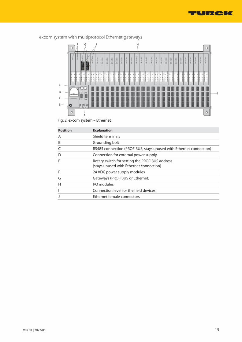
excom system with multiprotocol Ethernet gateways
0 1
23
456
78
90 1
23
456
78
9
B
C
E
D
G JF H
I
A
Fig. 2: excom system – Ethernet
Position Explanation
A Shield terminals
B Grounding bolt
C RS485 connection (PROFIBUS, stays unused with Ethernet connection)
D Connection for external power supply
E Rotary switch for setting the PROFIBUS address (stays unused with Ethernet connection)
F 24 VDC power supply modules
G Gateways (PROFIBUS or Ethernet)
H I/O modules
I Connection level for the field devices
J Ethernet female connectors

System overviewSystem setup
16 Hans Turck GmbH & Co. KG | T +49 208 4952-0 | F +49 208 4952-264 | [email protected] | www.turck.com
4.1.2 excom – I/O system in the system enclosureDifferent system enclosures with an integrated excom I/O system are available for protectionagainst dust, dirt, humidity and other environmental influences. Turck offers the excomI/O system including the system enclosure as a standard variant or with accessory equipmentaccording to individual requirements. The customer determines the specific combination ofI/O modules used.
550
650
260
505685 ø 11
5
Fig. 3: System enclosure with integrated excom I/O system
The standard variant of the system enclosure with integrated excom I/O system consists of thefollowing standard accessory equipment:
n 1 × module rackn 2 × power supply modulesn 2 × optocouplers

V02.01 | 2022/05 17
The following excom system components are available for integration in excom systems in thenon-Ex area:
EG - VA 65 55 26 / 1 1 1 - 02 0 0 / 2GD 60 . …
EG System enclosure -
System enclosureEG excom system enclosure,
stainless steel
VA Optional labeling
Optional labelingVA Optional labeling
1 Material
Material0 Stainless steel 1.43011 Stainless steel 1.44042 Other alloy
2GD System enclosure
System enclosure2GD System enclosure category 2
for installation in zone 1 and 21
3GD System enclosure category 3 for installation in zone 2 and 22
N System enclosure for installa-tion in safe area (non-ex area)
02 Module rack
Module rack
00 Without module rack01 Module rack MT08-2G02 Module rack MT16-2G04 Module rack MT08-3G05 Module rack MT16-3G06 Module rack MT24-3G07 Module rack MT08-N08 Module rack MT16-N09 Module rack MT24-N10 Module rack MT16-2G/MSA
1 Viewing window
Viewing window0 Without viewing window1 With viewing window
1 Drilling pattern –
Drilling pattern0 Dummy plate1 Receptacle plate M16*,
version 12 Receptacle plate M20*,
version 13 Special version, such as drilling
pattern* With M16/M20 cable gland for
I/O signals
65 55 26 Dimensions /
Depth26 Housing depth (cm)
Height55 Housing height (cm)
Width46 Housing width (cm)65 Housing width (cm)80 Housing width (cm)
0 Upstream sub-rack
Upstream sub-rack
0 Without upstream sub-rack MT-PPS1 With upstream sub-rack MT-PPS2 Installation of one power supply
230 VAC3 Installation of two power supplies
230 VAC4 Special version
0 Segment coupler /
Segment coupler0 Without segment coupler1 Installation of one segment coupler
OC11Ex/2G.22 Installation of two segment
couplers OC11Ex/2G.23 Installation of one external coupler4 Installation of two external couplers5 Installation of a segment coupler
OC11Ex/3G.26 Installation of two segment
couplers OC11Ex/3G.2
… Special number
Special number… Special number for all additional
installations such as trace heating, circuit breaker, fuses or drilling pattern
Housing width Version 1
46 cm 66
65 cm 96
80 cm 108
Number of cable glands for I/O signals
Number of cable glands per flange plate
4 × M25 Power supply
4 × M20 Fieldbus
1 × M20 Breather-drainer element
60 Temperature class .
Only for system enclosures category 2: Max. ambient temperature of the I/O modules 60 60 °C and 70 °C70 70 °C
Fig. 4: Type code
The user is provided with an Excel template of all system enclosures with an integrated excomI/O system in order to determine the power loss and to check the ambient temperature.

System overviewOperating principle
18 Hans Turck GmbH & Co. KG | T +49 208 4952-0 | F +49 208 4952-264 | [email protected] | www.turck.com
4.2 Operating principleexcom is an I/O system for the PROFIBUS-DP fieldbus protocol and the PROFINET, EtherNet/IPindustrial Ethernet protocols, as well as Modbus TCP. Depending on the fitted gateway, the sys-tem communicates either via a PROFIBUS cable or via an Ethernet cable. The system is providedwith bus-capable, decentralized I/O modules with protection type IP20 for connecting analogand digital field devices. The data traffic between the I/O modules and the field devices is processed via the gateway. The gateway is the slave of the process control system (DCS) at thesame time and executes the commands sent from the controller level on the module level. Thegateway is thus the master for internal data traffic as well as the device (slave) for the processcontrol system and controls the entire data traffic between the I/O modules and the processcontrol system. In this way, the gateway is able to provide the user with extended fieldbus diagnostics. The fieldbus diagnostics cannot display error messages down to the channel level.
The connection between the excom system and the process control system depends on thefieldbus protocol.
0 1
23
456
78
90 1
23
456
78
9
ETH
RUN
PB
PB
-X
EP
I
DCS
Asset
Management
Fig. 5: Connection of an excom station to the process control system (DCS) via PROFIBUS

V02.01 | 2022/05 19
To connect the excom system to the process control system via PROFIBUS, up to two PROFIBUScables – starting from the SUB-D female connectors on the rack of the excom system – are connected to the process control system. The asset management system is accessed directlyvia the controller or via an Ethernet PROFIBUS interface, as shown in the figure above.
0 1
23
456
78
90 1
23
456
78
9
DCS
Asset
Management
Fig. 6: Connection of an excom station to the process control system (DCS) via Ethernet
The Ethernet connectors on the fitted GEN-N gateway are used to connect the excom system tothe process control system via Ethernet. The above figure shows an Ethernet switch betweenthe excom system, process control system and asset management since the excom system canalso be connected to the asset management system.

System overviewSystem features
20 Hans Turck GmbH & Co. KG | T +49 208 4952-0 | F +49 208 4952-264 | [email protected] | www.turck.com
The module racks are each provided with an integrated backplane. The backplane is used forthe power supply and for transferring the data of the installed gateways and I/O modules. Depending on their design, different module rack sizes allow the following number of compon-ents to be fitted:
n 8 I/O modules (MT08-N)n 16 I/O modules (MT16-N)n 24 I/O modules (MT24-N)n 2 gatewaysn 2 power supply modules
Two gateways and two power supply modules (redundancy) increase system availability. If twopower supply modules are used, the load is distributed evenly. The power supply modulesprovide the excom system with the required voltage and galvanic isolation up to 40 V.
4.3 System featuresn Different module rack sizes and packing densitiesn Hot swapping:
All I/O modules can be fitted or removed (hot swapped) during operation without dis-connecting the power supply. The system checks automatically whether the new modulecomplies with the configuration stored in the control system. If the configuration matches,the individual module channels are assigned parameters by the process control system viathe gateway. The module also starts cyclic data exchange with the process control system.The existing data exchange of the remaining system remains undisturbed.
n Hot configuration in run (HCIR): The HCIR function enables the user to extend the configuration of the I/O modules or tochange the parameters of the module channels during operation. The PROFIBUS communic-ation of the excom station is stopped during the HCIR sequence. All outputs are frozen forthe predefined time. Diagnostics messages are not sent during the HCIR sequence. After aconfiguration is changed successfully, data is transferred to the cyclic bus communicationaccording to the new configuration and the slave continues to operate in normal mode.
n Redundancy: The system can be operated redundantly with two gateways (different redundancy conceptsfor PROFIBUS-DP and Ethernet fieldbus systems) and with two power supply modules, thusincreasing the availability of the system.
n HART-compatibility: HART-compatible field devices can be connected to the system. Consistent HART communic-ation up to the process control system (DCS) or asset management is possible via the field-bus system.
n Asset management:The following I/O system functions can be managed with the modular excom DTM:
– Commissioning– Parameterization– Simulation– Diagnostics– Identification– Configuration
The individual functions are arranged in the Rack, Module, Channel and Connected devicelevels in an FDT frame. The hierarchical arrangement makes it possible to click on theindividual components and stations selectively in the browser. Field devices with theirDTMs can also be configured and parameterized via the HART function.
n Diagnostics: LEDs indicate diagnostics and status on the front of each system component. All indicationscomply with NAMUR NE 107. Detailed diagnostics are provided via the fieldbus.

V02.01 | 2022/05 21
4.4 Functions and operating modes
4.4.1 HART functionsHART-compatible field devices can be connected to the system. Depending on the field device,consistent HART communication up to the process control system (DCS) or asset managementis possible via the fieldbus system.
HART compatibility with I/O modules without a HART controller
n HART compatibility:
– Connection of HART-compatible sensors to the I/O module– Parameterization of the field devices with FSK modem via connection terminals on the
module rack– Burden already integrated in the module: no additional impedance required
HART compatibility with I/O modules with a HART controller
n HART-compatibility:
– HART variables (up to eight HART variables, a maximum of four per channel) for directdata exchange between the process control system (DCS) and the field device
– HART field device parameterization via DTM (FDT technology)– Transfer of HART data between DCS and HART-compatible field device with extended
process information of the field devices (e.g. current position of a control valve)
4.4.2 Redundancy functions
Gateway redundancy (PROFIBUS-DP)
n Line redundancy: Only one active master is needed to implement line redundancy. The redundancy is achieved by dividing a fieldbus line into two redundant fieldbus lines close tothe fieldbus master. Both gateways are each coupled to a redundant bus line, with onegateway communicating with the master. The second gateway is in standby mode.
n System redundancy: With system redundancy, two separate and independent fieldbus masters are connected to an excom station. The two independent fieldbus masters are set tocyclic data exchange via the two gateways of the excom station. The redundant gatewaysare given identical configurations and parameterizations via the fieldbus master.
Gateway redundancy (Ethernet)
Multiprotocol gateways can be used to set up redundant communication in ring topologies.Automatic support is provided here for PROFINET MRP and EtherNet/IP DLR.
The GEN-N supports the S2 redundancy for PROFINET. Application-specific system redundancycan be used for EtherNet/IP and Modbus TCP.

System overviewTypical application areas
22 Hans Turck GmbH & Co. KG | T +49 208 4952-0 | F +49 208 4952-264 | [email protected] | www.turck.com
Power supply module redundancy
The power supply modules are directly connected by plugging them onto the module rack. Thepower supply modules provide the excom modules and gateways with the required power inthis way. In order to prevent a possible power supply failure, two power supply modules areplugged in next each other in the slots provided for them.
All the types of redundancy mentioned are described in greater detail in the chapter “Planningredundancy concepts”.
NOTEThe rated output values of the individual modules must be added up and comparedwith the rated output of the power supply module for the engineering.The output of the power supply module is normally sufficient for any combination ofI/O modules on each module rack. In exceptional cases, however, the output limit ofthe power supply module may be exceeded, e.g. in the case of a fully expandedmodule rack of modules with a high power consumption. The user must thereforecheck whether the supply output of a power supply module is sufficient or whethera second power supply module is required. The second power supply module in thiscase is not a redundant power supply module.
4.5 Typical application areasexcom I/O systems can be used in various areas of process automation:
n Food industryn Pharmaceutical industryn Chemical industryn Oil and gasn Marine industry

V02.01 | 2022/05 23
5 Planning and preparation
5.1 Overview of all system components
Module rack
Type ID Function Channels Galvanic isolation
MT08-N 9100689 Module racks for fastening the system components and the ACpower supply distribution:n Max. 2 gatewaysn Max. 8 I/O modules
Max. 64 binary inputs/outputs or max. 32 analoginputs/outputs or a combination
–
MT16-N 9100686 Module racks for fastening the system components and the ACpower supply distribution:n Max. 2 gatewaysn Max. 16 I/O modules
Max. 128 binary inputs/outputs or max. 64 analoginputs/outputs or a combination
–
MT24-N 9100683 Module racks for fastening thesystem components and the ACpower supply distribution:n Max. 2 gatewaysn Max. 24 I/O modules
Max. 192 binary inputs/outputs or max. 96 analoginputs/outputs or acombination
–
Power supply
Type ID Function Channels Galvanic isolation
PSM24-N 6881723 Power supply module convertingexternally fed DC voltage into ACvoltage and supplying the excomsystem (non-Ex) with AC voltage
– Provided (complete)
Gateways
Type ID Function Channels Galvanic isolation
GDP-N 6884277 Gateway as the interface betweenthe excom I/O system and thehigher-level fieldbus system(PROFIBUS)
– Provided (complete)
GEN-N 100000129 Gateway as the Ethernet interfacebetween the excom I/O system andthe higher-level fieldbus system(multiprotocol)
– Provided (complete)

Planning and preparationOverview of all system components
24 Hans Turck GmbH & Co. KG | T +49 208 4952-0 | F +49 208 4952-264 | [email protected] | www.turck.com
Analog input/output modules
Type ID Function Channels Galvanic isolation
AI40-N 6884215 Analog input module for connecting passive 2-wiretransmitters and active 4-wire transmitters
4 Provided (complete)
AI41-N 6884216 Analog input modulefor connecting active 4-wiretransmitters
4 Provided (complete)
AI43-N 6884217 Analog input modulefor connecting active 3- or 4-wirepotentiometers
4 Provided (complete)
AIH40-N 6884219 Analog input modulefor connecting 2-wire transmitterswith HART functionality
4 Galvanic isolation fromthe power supply andbackplane, channels isnot provided. The channels are notgalvanically isolatedfrom each other.
AIH41-N 6884220 Analog input modulefor connecting 4-wire transmitterswith HART functionality
4 Galvanic isolation fromthe power supply andbackplane, channels isnot provided. The channels are notgalvanically isolatedfrom each other.
AIH401-N 6884269 Analog input modulefor connecting active and/or passive2- or 4-wire transmitters with HARTfunctionality
4 Provided (complete)
AO40-N 6884218 Analog output modulefor connecting analog field devices
4 Provided (complete)
AOH40-N 6884221 Analog output modulefor connecting analog field deviceswith HART functionality
4 Galvanic isolation fromthe power supply andbackplane, channels isnot provided. The channels are notgalvanically isolatedfrom each other.
AOH401-N 6884270 Analog output modulefor connecting analog field devices(e.g. control valves or processdisplays) with HART functionality
4 Provided (complete)

V02.01 | 2022/05 25
Digital input and output modules
Type ID Function Channels Galvanic isolation
DM80-N 6884211 Binary input/output module for connecting NAMUR sensors andactuators
8 Galvanic isolation fromthe power supply andbackplane, channels isnot provided. The channels are notgalvanically isolatedfrom each other.
DI40-N 6884213 Binary input module for connecting up to four sensors according to NAMUR (EN 60947-5-63), 3-wire sensors(NPN, PNP) or mechanical contacts
4 Provided (complete)
DI80-N 6884273 Binary input module for connecting eight 3-wire PNP/NPN sensors (IEC 61131, Type 3)
8 Inputs are galvanicallyisolated from eachother.
DO40-N 6884214 Binary output modulefor connecting low-power fielddevices (e.g. valves or signaltransmitters)
4 Provided (complete)
DO60R-N 6884196 Relay modulefor connecting digital field devices(e.g. valves or signal transmitters)
6 Provided (complete)
DO80-N 6884274 Binary output modulefor connecting eight 24 VDC fielddevices (e.g. 0.5 A rated valves orindicator elements)
8 Two output groups aregalvanically isolatedfrom each other andfrom the power supplyas well as from thebackplane bus.
Temperature and frequency modules
Type ID Function Channels Galvanic isolation
TI40-N 6884222 Analog input modulefor connecting 2-, 3- or 4-wire temperature resistors and thermo-couples
4 Provided (complete)
TI41-N 6884223 Analog input modulefor connecting 2-, 3- or 4-wiretemperature resistors
4 Provided (complete)
DF20-N 6884212 Input modules for the pulse counting or frequencymeasurement of binary pulsesequences
2 Galvanic isolation fromthe power supply andbackplane, channels isnot provided.The channels are notgalvanically isolatedfrom each other.

Planning and preparationOverview of all system components
26 Hans Turck GmbH & Co. KG | T +49 208 4952-0 | F +49 208 4952-264 | [email protected] | www.turck.com
Couplers
Type ID Function Channels Galvanic isolation
OC11Ex/3G.2
6890428 Fiber optic couplerfor signal transmission and conversion to an RS485 signal onfiber optic cable
– Provided (complete)
SC11-3G 100000548 Segment coupler for the extension of PROFIBUS-DPand Modbus RTU networks with additional regeneration of data telegrams
– Provided (complete)

V02.01 | 2022/05 27
5.2 Planning hardware components
NOTEThe following instructions describe the general procedure for planning the hard-ware components. Turck plans each project together with the user right from the start and provides theuser with all the necessary details during the joint planning.
5.2.1 Selecting I/O modules Before specific I/O modules can be selected:
Identify the type of input and output functions required for the system. Before the number of specific I/O modules can be selected:
Identify the required number for each type of input and output functions.From the number required by each type of input and output function, determine thenumber of corresponding I/O modules.
5.2.2 Planning cable routes Define the precise installation locations. Identify and evaluate cable routes based on defined installation locations. Check whether the determined cable length requires the use of segment couplers
(OC11Ex/3G.2) or repeaters (REP-DP 0002). If necessary, define the number of segmentcouplers and repeaters required (see table for transmission rate and bus cable length).
5.2.3 Defining the baud rateThe PROFIBUS-DP master determines the system's baud rate depending on the cable length.Baud rates from 9.6 kbps…1500 kbps are permissible.
The internal cycle time TI for the signal processing of a fully developed excom system is with
n digital signals: 5 ms (10 ms with MT24… module rack).n analog signals: 20 ms (40 ms with MT24… module rack).
The following table shows the maximum cable length of the bus segment depending on thebaud rate:
Baud rate in kbps Bus segment (length of bus cable in m)
9.6 1200
19.2 1200
45.45 1200
93.75 1200
187.5 1000
500 400
1500 200
Further information can be found in the PROFIBUS system description, e.g. the maximum permissible number of repeaters or segment couplers that can be used.

Planning and preparationPlanning hardware components
28 Hans Turck GmbH & Co. KG | T +49 208 4952-0 | F +49 208 4952-264 | [email protected] | www.turck.com
5.2.4 Calculating the cycle timeThe cycle times of the higher level bus TB and the process control system TPLS have to be addedto the cycle time of the excom system.
The following generally applies:
TR 2 × (TI + TB+ TPLS)
TR = response time
TI internal cycle time excom (see “Defining the baud rate”)
TB Cycle time of the higher-level bus
TPLS Cycle time of the process control system
5.2.5 Specifying a mounting variantThe location of the system determines the choice of connection and mounting concept. The following two connection and mounting concepts are possible:
n Installation in the control roomn Installation in the field
Decide whether installation in an enclosure is required according to the intended install-ation location.
If required: Install in an enclosure to protect against environmental influences (e.g. dust,dirt or moisture).
Select the IP protection type of the enclosure according to the environmental influences.
5.2.6 Carry out a temperature testThe operator must take the operating temperature of the excom system into account to ensureits availability. The following steps refer to installation in a system enclosure.
Determine the maximum possible ambient temperature that can occur at the installationlocation of the excom I/O system and enter it in table 2.
Select the appropriate temperature range on the nameplate of the system enclosure inthe table column Tamb in °C.
On the nameplate, select the value of the maximum total permissible power loss Padmissible
that corresponds to the selected temperature range. Enter the maximum permissible total power loss Padmissible of the modules in table 2. For each module type: Enter the number of planned modules in table 2, column nmodule. For each module type: Multiply the power Pmodule by the number nmodule and enter the
result in table 2, column Ptotal. Add values of column Ptotal and enter sum Σ (Ptotal) in table 2.
If Σ (Ptotal) ≤ Padmissible: The temperature test has been successful, i.e. the total power loss of themodules is less than or equal to the permissible total loss. The intended modules can beinstalled.
Include the temperature test in the system documentation.
If Σ (Ptotal) > Padmissible: The temperature test has not been successful, i.e. the maximum totalpower loss of the modules exceeds the permissible total power loss.
Reduce the number of modules. Repeat the temperature test.

V02.01 | 2022/05 29
Table 1
Type Label Tamb in °C Padmissible in W
-20…+40 ≤ 55
-20…+45 ≤ 38
-20…+50 ≤ 22
-20…+55 ≤ 6
Table 2
Ptotal (Tamb ≤ … °C )
Module type
Pmodule in W nmodule Ptotal = Pmodule × nmodule
with Pmodule in W
AI40-N 2.2
AI41-N 2.0
AI43-N 1.5
AIH40-N 3.0
AIH41-N 1.5
AIH401-N 3.0
AO40-N 2.5
AOH40-N 3.0
AOH401-N 3.0
DM80-N 1.0
DI40-N 2.0
DI80-N 2.2
DO40-N 4.5
DO60R-N 2.0
DO80-N 3.0
TI40-N 1.0
TI41-N 1.0
DF20-N 1.0
Σ (Ptotal)
Padmissible … W

Planning and preparationPlanning hardware components
30 Hans Turck GmbH & Co. KG | T +49 208 4952-0 | F +49 208 4952-264 | [email protected] | www.turck.com
Example of temperature test
Requirements:
n The ambient temperature at the installation location of the excom I/O system must notexceed 48 °C.
n Padmissible ≤ 22 W for Tamb -20…+50 °C according to nameplate on housing (see Table 1)n The temperature test must be performed for Padmissible ≤ 22 W.n 10 modules are to be installed in the system enclosure.
A successful temperature test is described in table 3: The modules provided achieve a maximum total power loss of 22 W. The temperature test for Padmissible (max. 22 W) is thereforesuccessful.
Table 3
Ptotal (Tamb ≤ 48 °C )
Module type
Pmodule in W nmodule Ptotal = Pmodule × nmodule
with Pmodule in W
AI40-N 2.2
AI41-N 2.0 1 2.0
AI43-N 1.5 1 1.5
AIH40-N 3.0 1 3.0
AIH41-N 1.5
AIH401-N 3.0
AO40-N 2.5 1 2.5
AOH40-N 3.0 1 3.0
AOH401-N 3.0
DM80-N 1.0
DI40-N 2.0 1 1.9
DI80-N 2.2
DO40-N 4.5
DO60R-N 2.0 1 2.0
DO80-N 3.0 1 3.0
TI40-N 1.0 1 1.0
TI41-N 1.0 1 1.0
DF20-N 1.0 1 1.0
Σ (Πtotal) 22.0
Padmissible 22.0 W
5.2.7 Setting up the systemAfter all preparatory planning measures have been completed, the system can be set up andtested in advance with PACTware.

V02.01 | 2022/05 31
5.3 Planning redundancy concepts
Gateway redundancy (PROFIBUS-DP)
Line redundancy
Line redundancy increases availability with little effort and can be implemented with only oneactive master.
In line redundancy the bus line is split into two redundant bus lines close to the master. TheTurck PROFIBUS-DP repeater REP-DP 0002, for example, can be used to decouple the lines.
The excom station must have two gateways for the line redundancy function. Line redundancyis set in the master. The standby gateway monitors the communication of the associatedPROFIBUS segment without actively participating in the process data exchange. Each gatewayis then connected separately to one of the two redundant bus lines.
The switchover can be initiated both by the master as well as independently via the gateways,e.g. if there is a fault in the PROFIBUS line. If a gateway fails, or the connection to the master isinterrupted, the second gateway is automatically activated. This switchover causes a short interruption of the cyclic data exchange.
Segment 1
Pow
er
Test
Out
Out
In
Out
Function
Function
RE
P-D
P 0
00
2
Segment 1
Segment 2Segment 2
Pow
er
excom
REP-DP-0002 MT16-N
Master MasterPROFIBUS-DPRS485
Host Hostreserve
Redundancy-connection
Fig. 7: Line redundancy
System redundancy
System redundancy is achieved by connecting two separate and independent PROFIBUS masters with an excom station. With system redundancy, the excom station has two gatewaysthat are put into cyclic data exchange by their assigned masters. Both masters must configureand parameterize the redundant gateways identically.
One of the two gateways operates as a primary device (slave), the second as a secondarydevice. The primary device receives the output data transferred by the master and transmitsthese to the output modules. The primary gateway also forwards the currently valid inputvalues to the master. The secondary gateway ignores the received output data and suppliesonly the currently valid input values. Both masters always know the current status of the inputs.Both gateways always know the current status of the outputs.

Planning and preparationPlanning redundancy concepts
32 Hans Turck GmbH & Co. KG | T +49 208 4952-0 | F +49 208 4952-264 | [email protected] | www.turck.com
In the event of a switchover, the primary gateway transfers to the secondary gateway the function of being able to send output data to the output modules. With system redundancy,the gateway or the master can trigger a switchover.
Switching via the gateway is automated. If communication is lost on the primary line or byunplugging the primary gateway, the gateway performs a time-controlled automaticswitchover (watchdog timeout). If the master forces a switchover, the switchover happens viathe cyclic data of the gateway.
excom
MT16-N
Master Master
PROFIBUS-DPRS485
Host Hostreserve
Redundancy-connection
Fig. 8: System redundancy
Gateway redundancy (Ethernet)
Multiprotocol gateways can be used to establish redundant communication in ring topologies.The following protocols are suitable for checking the functionality of the ring topologies:
n Device level ring (DLR): Device level ring (DLR) is used to increase the availability of EtherNet/IP networks. DLR-compatible products have an integrated switch and can thus be integrated into a ring topology. The DLR protocol is used to detect a break in the ring. In the event of a data lineinterruption, there is a bumpless switchover to communication on the remaining active line.DLR supervisor network nodes are equipped with advanced diagnostic functions that locatea point of failure, thus speeding up troubleshooting and maintenance work. The excomgateways act in DLR as participants without a supervisor function.
n Media redundancy protocol (MRP):MRP is a standardized protocol acc. to IEC 62439. The protocol describes a mechanism formedia redundancy in ring topologies. The Media Redundancy Manager (MRM) checks thecorrect functioning of the ring structure of a PROFINET network specified in the configura-tion. The excom system acts as a Media Redundancy Client (MRC). For more informationabout MRP on PROFINET, visit the PROFIBUS User Organization website atwww.profibus.com.

V02.01 | 2022/05 33
Power supply module redundancy
The power supply modules are directly connected by plugging them onto the module rack. Inthis way, the power supply modules provide the excom modules and gateways with the required power.
Two power supply modules are plugged in next to each other in the slots provided for them inorder to prevent a possible power supply failure. Redundant power supply modules provide anequal power supply to the plugged modules.
NOTEThe rated output values of the modules must be added up and compared with therated output of the power supply module for the engineering. The output suppliedis normally sufficient for any combination of I/O modules on each station.In exceptional cases, however, the output limit of the power supply module may beexceeded, e.g. in the event of a fully expanded module rack of modules with a highpower consumption. The second power supply module in this case is not a redund-ant power supply module. The user must therefore check whether the power supplyoutput of just one power supply module is sufficient.

Planning and preparationImplement shielding and grounding concepts (PROFIBUS-DP)
34 Hans Turck GmbH & Co. KG | T +49 208 4952-0 | F +49 208 4952-264 | [email protected] | www.turck.com
5.4 Implement shielding and grounding concepts (PROFIBUS-DP)
NOTEFor a grounding concept, observe the relevant local requirements.
5.4.1 Direct grounding on both sides Connect the connection at the supplying device and at the excom station to the ground
potential - ground directly on both sides. An additional equipotential bonding cable must be connected in order to prevent
equalizing currents across the cable shield. Use equipotential bonding cables with a wire cross section of ≥ 6 mm². In order to keep the shield area small, lay the equipotential bonding cable parallel to the
fieldbus cable. The shield of the PROFIBUS cable must also be connected to the connector body inside
the PROFIBUS-DP connector. Route the shield and equipotential bonding cable separately from the control room.
excom excom
Host
Shield
Data line
6 mm equipotential bonding cable (hard grounded)
Fig. 9: Direct grounding on both sides
If the equipotential bonding cable is to be omitted: Check whether the shielding conceptwith direct grounding on one side at the feeding device is suitable for the overallconcept.

V02.01 | 2022/05 35
5.4.2 Direct grounding at the feeding device Ground the connection at the feeding device directly with the ground potential. Capacitively ground the connections of all segment participants. An equipotential bond-
ing cable routed parallel to the fieldbus is not required, since no compensating currentscan flow.
The shield of the PROFIBUS cable must also be connected to the connector body insidethe PROFIBUS-DP connector.
excom excom
Host
Shield
Data line
Fig. 10: Direct grounding at the feeding device

System componentsMT08-N, MT16-N, MT24-N module racks
36 Hans Turck GmbH & Co. KG | T +49 208 4952-0 | F +49 208 4952-264 | [email protected] | www.turck.com
6 System components
6.1 MT08-N, MT16-N, MT24-N module racks
6.1.1 Intended useThe device is designed as equipment of the excom I/O system for the non-Ex area and mustonly be operated within the excom system with compatible components for the non-Ex area.
The module rack with an integrated backplane is used for the mounting and power supply ofthe system components as well as for data transfer between the field level, the I/O system leveland the higher-level controller, the process control system (DCS).
6.1.2 Device overview
Module rack – MT08-N
130235
207
260 235
ø 7
Fig. 11: Setup and dimensions

V02.01 | 2022/05 37
Module rack – MT16-N
130380
352
260 235
ø 7
Fig. 12: Setup and dimensions
Module rack – MT24-N
130525
498
260 235
ø 7
Fig. 13: Setup and dimensions

System componentsMT08-N, MT16-N, MT24-N module racks
38 Hans Turck GmbH & Co. KG | T +49 208 4952-0 | F +49 208 4952-264 | [email protected] | www.turck.com
6.1.3 Properties and features
Module rack types
MT08-N MT16-N MT24-N
n 24 VDC power supplyn Max. 2 power supply modulesn Max. 2 gatewaysn Max. 8 I/O modulesn Max. 64 binary inputs/outputs or
max. 32 analog inputs/outputs or acombination
n 24 VDC power supplyn Max. 2 power supply modulesn Max. 2 gatewaysn Max. 16 I/O modulesn Max. 128 binary inputs/outputs or
max. 64 analog inputs/outputs or acombination
n 24 VDC power supplyn Max. 2 power supply modulesn Max. 2 gatewaysn Max. 24 I/O modulesn Max. 192 binary inputs/outputs or
max. 96 analog inputs/outputs or acombination
6.1.4 Functions and operating modesThe connected I/O modules are fed with power via the backplane. The data traffic between theI/O modules and the gateways is processed via the internal backplane bus.
6.1.5 InstallingThe module racks are suitable for mounting on mounting plates or support systems.
Only mount the device via the drill holes provided (Ø 7 mm) with M6 screws or M6 bolts. Mounting in a stainless steel enclosure (EG-VA…): Use type GM306 sliding nuts, type
GS406 threaded pins and M6 nuts in accordance with DIN 934.
DANGERElectrical charge on the deviceDanger of electric shock Before replacing or dismounting individual parts that are not connected by plug
fitting on the module rack: isolate equipment. Only use approved original Turck parts.

V02.01 | 2022/05 39
6.1.6 Connection
Connecting an external power supply
Connect the device as shown in the “Wiring diagrams”.
x 10 x 1
GW2GW1
+ – + –
22
0 p
F
GW2GW1PS2PS1 Slot2 Slot3 Slot7 Slot8
3 8711121314
21222324
31323334
41424344
Add
Pwr1 Pwr2
GW1
47
0 k
Ω GW2
COM
1
Slot1 Slot4
4
Slot5
5
Slot6
62
47
0 k
Ω
22
0 p
F
Fig. 14: Wiring diagram – MT08-N

System componentsMT08-N, MT16-N, MT24-N module racks
40 Hans Turck GmbH & Co. KG | T +49 208 4952-0 | F +49 208 4952-264 | [email protected] | www.turck.com
x 10 x 1
GW2GW1
+ – + –
22
0 p
F
GW2GW1PS2PS1 Slot2 Slot3 Slot15 Slot16
311121314
21222324
31323334
41424344
Add
Pwr1 Pwr2
GW1
47
0 k
Ω GW2
COM
1
Slot1 Slot4
4
Slot14
2
47
0 k
Ω
22
0 p
F
…
…
…
161514
Fig. 15: Wiring diagram – MT16-N
x 10 x 1
GW2GW1
+ – + –
22
0 p
F
GW2GW1PS2PS1 Slot2 Slot3
311121314
21222324
31323334
41424344
Add
Pwr1 Pwr2
GW1
47
0 k
Ω GW2
COM
1
Slot1 Slot4
42
47
0 k
Ω
22
0 p
F
…
…
…
Slot23 Slot24
2423
Slot22
22
Fig. 16: Wiring diagram – MT24-N
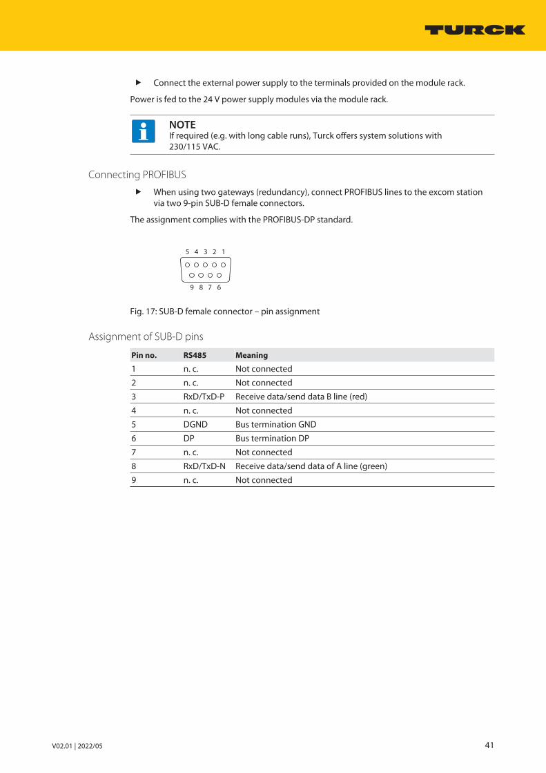
V02.01 | 2022/05 41
Connect the external power supply to the terminals provided on the module rack.
Power is fed to the 24 V power supply modules via the module rack.
NOTEIf required (e.g. with long cable runs), Turck offers system solutions with 230/115 VAC.
Connecting PROFIBUS
When using two gateways (redundancy), connect PROFIBUS lines to the excom stationvia two 9-pin SUB-D female connectors.
The assignment complies with the PROFIBUS-DP standard.
12345
6789
Fig. 17: SUB-D female connector – pin assignment
Assignment of SUB-D pins
Pin no. RS485 Meaning
1 n. c. Not connected
2 n. c. Not connected
3 RxD/TxD-P Receive data/send data B line (red)
4 n. c. Not connected
5 DGND Bus termination GND
6 DP Bus termination DP
7 n. c. Not connected
8 RxD/TxD-N Receive data/send data of A line (green)
9 n. c. Not connected

System componentsMT08-N, MT16-N, MT24-N module racks
42 Hans Turck GmbH & Co. KG | T +49 208 4952-0 | F +49 208 4952-264 | [email protected] | www.turck.com
Ground shield of the fieldbus line via the module rack
The excom module rack connects the shield connection of the RS485 line to ground via anintegrated R/C combination. A bridge for shorting the R/C combination can be installed if required. On delivery, park position B of the bridge is located on the left fixing bracket.
0 1
23
456
78
90 1
23
456
78
9
AB
Fig. 18: Shield connection and park position of the bridge
Protect RS485 fieldbus lines from interference by using a suitable shielding and ground-ing concept (see “Implementing shielding and grounding concepts (PROFIBUS)”).
Ground the module rack directly on both sides:
5 4 3 2 1
Fig. 19: Fitting the connection bolt
Ground the shield of the fieldbus line directly via the center screw of the bridge (see Fig.“Shield connection and park position of the bridge” – position “A”).
Connect the PA equipotential bonding conductor to the ground terminal bolt. The min.cable cross section is 4 mm². The order of fitting the connection bolt is shown in the figure above.

V02.01 | 2022/05 43
6.1.7 Setting
Setting the PROFIBUS address
A station in a PROFIBUS-DP network is identified by a bus address. The station in this case is theexcom station. The excom station is assigned its bus address by a manual setting on the mod-ule rack.
× 1× 10
Fig. 20: Setting a fieldbus address
Set a PROFIBUS-DP address with the rotary switches on the module rack. A maximum of 01 to 99 addresses (99 stations) can be assigned. Bus address 00 is not used.
The switches represent the digits of the network address. The figure above shows an exampleof the setting of the network address “05”.
Coding module rack slots
The user has the option of coding the module rack via mechanical coding pins. The coding onthe module rack ensures that a module can only be exchanged with a module of the same type.Coding is carried out with hexagonal coding pins. The coding is implemented with hexagonalcoding pins that are inserted in the appropriate recesses on the module rack. Each slot has fourrecesses, two of which can be used for coding the module. The other two recesses are used forcoding the type (Ex module: left; non-Ex module: right). Each module has two hard coded pinsfor module coding when delivered.
AIH401-N
factory coding
factory coding
keep coding holes
free for
non-Ex modules.
Code 1
Code 2
Code 3
Code 4
Code 5
Code 6
Fig. 21: Example coding AIH401-N – rear view with coding position

System componentsMT08-N, MT16-N, MT24-N module racks
44 Hans Turck GmbH & Co. KG | T +49 208 4952-0 | F +49 208 4952-264 | [email protected] | www.turck.com
System components Factory coding of the modules on delivery (left)
Coding on the module rackto be carried out by theuser if required
GDP-N 11
44
AI40-N 15
42
AI41-N 24
51
AI43-N 35
62
AIH40-N 25
52
AIH41-N 34
61
AIH401-N 25
52
AO40-N 12
45
AOH40-N 32
65
AOH401-N 32
65
DM80-N 13
46
DI40-N 23
56
DI80-N 53
26
DO40-N 22
55
DO60R-N 42
22
DO80-N 52
25
PSM24-N 66
33
TI40-N 14
41
TI41-N 44
11
DF20-N F/P 13
46

V02.01 | 2022/05 45
6.1.8 Technical data
Type code MT08-N
ID 9100689
SlotsDC power supply module 2
Gateway 2
I/O modules 8
I/O module connection cross-section 1.5 mm2
Power supply connection cross-section Rigid: 4.0 mm2
Flexible: 2.5 mm2
Bus connection 2 × 9-pin SUB-D
Bus address 2 × decimal coded rotary switch
Housing material Aluminum profile
Fixing type Mounting plate
Type of protection IP20
Ambient temperature -20…+70 °C
Relative air humidity ≤ 93 % at 40 °C acc. to IEC 60068-2-78
Vibration test Acc. to EN 60068-2-6
Shock testing Acc. to EN 60068-2-27
EMC Acc. to NAMUR NE21 acc. to EN 61326-1
Dimensions 235 × 260 × 130 mm
Type code MT16-N
ID 9100686
SlotsDC power supply module 2
Gateway 2
I/O modules 16
I/O module connection cross-section 1.5 mm2
Power supply connection cross-section Rigid: 4.0 mm2
Flexible: 2.5 mm2
Bus connection 2 × 9-pin SUB-D
Bus address 2 × decimal coded rotary switch
Housing material Aluminum profile
Fixing type Mounting plate
Type of protection IP20
Ambient temperature -20…+70 °C
Relative air humidity ≤ 93 % at 40 °C acc. to IEC 60068-2-78
Vibration test Acc. to EN 60068-2-6
Shock testing Acc. to EN 60068-2-27
EMC Acc. to NAMUR NE21 acc. to EN 61326-1
Dimensions 380 × 260 × 130 mm

System componentsMT08-N, MT16-N, MT24-N module racks
46 Hans Turck GmbH & Co. KG | T +49 208 4952-0 | F +49 208 4952-264 | [email protected] | www.turck.com
Type code MT24-N
ID 9100683
SlotsDC power supply module 2
Gateway 2
I/O modules 24
I/O module connection cross-section 1.5 mm2
Power supply connection cross-section Rigid: 4.0 mm2
Flexible: 2.5 mm2
Bus connection 2 × 9-pin SUB-D
Bus address 2 × decimal coded rotary switch
Housing material Aluminum profile
Fixing type Mounting plate
Type of protection IP20
Ambient temperature -20…+70 °C
Relative air humidity ≤ 93 % at 40 °C acc. to IEC 60068-2-78
Vibration test Acc. to EN 60068-2-6
Shock testing Acc. to EN 60068-2-27
EMC Acc. to EN 61326-1 acc. to NAMUR NE21
MTTF 1211 years acc. to SN 29500 (Ed. 99) 40 °C
Dimensions 525 × 260 × 130 mm

V02.01 | 2022/05 47
6.2 PSM24-N power supply module
6.2.1 Intended useThe device is designed as equipment of the excom I/O system for the non-Ex area and mustonly be operated within the excom system with the MT…-N module racks.
The power supply module is used for the power supply of the excom I/O system with ACvoltage.
6.2.2 Device overview
118
18
106
Fig. 22: Dimensions
6.2.3 Properties and featuresn 24 VDC power supplyn Connections of the external power supply via terminals on the module rackn Knurled screws prevent the unintentional pulling out of the power supply modules under
power and mechanical release of the power supplyn Full galvanic isolation

System componentsPSM24-N power supply module
48 Hans Turck GmbH & Co. KG | T +49 208 4952-0 | F +49 208 4952-264 | [email protected] | www.turck.com
6.2.4 Functions and operating modes
Supplying the excom system with power
The power supply module requires a 24 VDC power supply and feeds all connected excommodules with AC voltage. The power supply modules can be operated individually or redund-antly.
Supplying the excom system redundantly with power
In redundancy mode, the load is divided between both power supply modules. If one devicefails or the power supply is interrupted, the intact device takes over the power supply of the entire system. Different power sources can be used for the supply. One PSM24-N power supplymodule is sufficient for the proper operation of the excom system. Redundant power supplymodules increase availability.
NOTEThe rated output values of the modules must be added up and compared with therated output of the power supply module for the engineering. The output suppliedis normally sufficient for any combination of I/O modules on each station.In exceptional cases, however, the output limit of the power supply module may beexceeded, e.g. in the event of a fully expanded module rack of modules with a highpower consumption. The second power supply module in this case is not a redund-ant power supply module. The user must therefore check whether the power supplyoutput of just one power supply module is sufficient.
6.2.5 MountingMultiple devices can be mounted directly next to each other on the module rack. The devicescan also be changed during operation.
Protect the mounting location from thermal radiation, sudden temperature fluctuations,dust, dirt, humidity and other ambient influences.
Plug the device into the designated position on the module rack so that it noticeablysnaps into place.
6.2.6 Connection If an external power supply is not yet connected to the module rack: Connect the power
supply to the module rack.
24 VDC
+ DC
– AC
Fig. 23: Wiring diagram – PSM24-N
Connect the external power supply to the module rack with terminals. Make sure that the power supply module clicks into place. If the power supply module clicks into place: fully tighten the knurled screws underneath
the module.a The power supply is enabled.

V02.01 | 2022/05 49
In redundant operation, 24 VDC power supply modules can be replaced under power.
If redundancy is required, connect two power supply modules.
PSM24
+
–24 VDC
+
–24 VDC
Fig. 24: Connecting redundant power supply modules
Connect each power supply module to a separate supply line.
6.2.7 LED indications
LED Indication Meaning
PWR Green Ready for operation
Off No power supply
ERR Red Error
Off Error-free

System componentsPSM24-N power supply module
50 Hans Turck GmbH & Co. KG | T +49 208 4952-0 | F +49 208 4952-264 | [email protected] | www.turck.com
6.2.8 Technical data
Type code PSM24-N
ID 6881723
Power supplyRated voltage 24 VDC
Supply voltage range 19.2…32 VDC
Power consumption ≤ 66.5 W
Output power ≤ 60 W
Galvanic isolation Safe between input and output circuit, ratedvoltage 40 V
LEDsOperational readiness 1 × green
Status/error 1 × red
Terminal cross-section Rigid: 4.0 mm2
Flexible: 2.5 mm2
Housing material Plastic
Fixing type Module design, pluggable in the module rack
Protection type IP20
Ambient temperature -20…+70 °C
Relative air humidity ≤ 93 % at 40 °C acc. to IEC 60068-2-78
Vibration test Acc. to EN 60068-2-6
Shock testing Acc. to EN 60068-2-27
EMC Acc. to EN 61326-1 acc. to NAMUR NE21
MTTF 61 years acc. to SN 29500 (Ed. 99) 40 °C
Dimensions (W × H × D) 18 × 118 × 106 mm

V02.01 | 2022/05 51
6.3 Gateway GDP-N
6.3.1 Intended useThe device is designed as equipment of the excom I/O system for the non-Ex area and mustonly be operated within the excom system with the MT…-N module racks.
The gateway forms the interface between the excom I/O system and the higher-levelPROFIBUS-DP fieldbus system. The gateway may be configured for a maximum transmissionrate of 1500 kbps. The gateways (2 × GDP-N/FW2.3) support line redundancy and system redundancy.
The excom system can be connected to any host system containing a class 1 PROFIBUS DP master and operated via the interface to PROFIBUS-DP acc. to IEC 61158.
6.3.2 Device overview
118
18
106
Fig. 25: Dimensions
6.3.3 Properties and featuresn Gateway for PROFIBUS-DP communicationn PROFIBUS interface for connecting the higher-level fieldbus master and the excom station
according to the PROFIBUS user organization (PNO)n Baud rate: max. 1.5 Mbpsn Diagnostic scope: Channel-based diagnostics and diagnosis of manufacturer-specific errorsn Availability of different redundancy conceptsn Full galvanic isolation

System componentsGateway GDP-N
52 Hans Turck GmbH & Co. KG | T +49 208 4952-0 | F +49 208 4952-264 | [email protected] | www.turck.com
6.3.4 Functions and operating modesThe gateway connects the excom modules to the PROFIBUS-DP fieldbus system. The gatewayhandles all process data traffic and generates diagnostic information for the higher-level control system. The gateway also transfers manufacturer-specific error codes.
The PROFIBUS-DP standards ensure the correct cyclic data exchange between master and excom, correct configuration and parameterization, and the correct display of diagnostic messages. The DPV1 extensions are implemented in excom in order to process acyclic data viaPROFIBUS-DP.
The GSD files fully define the behaviors of excom on PROFIBUS-DP and store the configurationand parameters of the individual modules.
To increase availability, two gateways can be used redundantly.
NOTE Only redundantly operate gateways with the same hardware and firmware
status.
Redundancy types
The different types of redundancy can be selected in the control system via the gateway para-meters. Different parameter settings must be made depending on the selected redundancytype.
n Line redundancy: Only one active master is required for line redundancy. The redundancy isachieved by dividing a fieldbus line into two redundant fieldbus lines close to the fieldbusmaster. A gateway is connected to each one of the two bus lines. The “Redundancy mode“parameter in the gateway is set at the “Line redundancy” value. The “Address offset” para-meter is also set to “on”. A value is also defined under the “Offset value” parameter, e.g. in asystem all active stations with an even bus address (2, 4, 6, 8, …16, …) and all passive sta-tions with an odd bus address (3, 5, 7, 9 , …17, …) can be set. To do this, set the “Offsetvalue” to “1”. The active gateway is then assigned the address “2” and the redundant gate-way the address “3”. This virtual address enables the redundant gateway to recognize itsreadiness for communication without actively participating in the process data exchange.Besides the variant described above, it is also possible, for example, to set the offset to “64”.All redundant stations then have an address above 64. When selecting the offset, make sure
– when using several excom stations that all have the same offset value.– the virtual address (base address + offset) is not occupied by configured PROFIBUS
stations.– the virtual address is lower than the HSA (Highest Station Address) set at the master.
n System redundancy: With system redundancy, two separate and independent fieldbus mas-ters are connected to an excom station. The two independent fieldbus masters activate cyc-lic data exchange on the two gateways of the excom station. Both fieldbus masters mustconfigure and parameterize the redundant gateways identically. The Redundancy modegateway parameter must be set for System redundancy. System redundancy involves theuse of two separate fieldbus systems. Identical PROFIBUS addresses are assigned to the redundant gateways. The gateway withaddress “2” has a redundant partner with the same address. The cyclic data of the gateway inthe “GDP-… C” configuration is used to monitor and control both line and system redund-ancy.
All the stated types of redundancy are described in more detail in chapter “Planning redund-ancy concepts”.

V02.01 | 2022/05 53
6.3.5 MountingMultiple devices can be mounted directly next to each other on the module rack. The devicescan also be changed during operation.
Protect the mounting location from thermal radiation, sudden temperature fluctuations,dust, dirt, humidity and other ambient influences.
Plug the device into the designated position on the module rack so that it noticeablysnaps into place.
6.3.6 ConnectionWhen plugged into the module rack, the device is connected to the module rack’s internalpower supply and data communication.
Connect the device as shown in the “Wiring diagram”.
GN/RD
Status
YE/RD
CAN
YE/RD
PDP
YE
PRIO
RD
Config
internalpowersupply
internalbus
1 n.c.
2 n.c.
3 RxD / TxD-P
4 n.c.
5 DGND
6 DP
7 n.c.
8 RxD / TxD-N
P
R
O
F
I
B
U
S
9 n.c.
Fig. 26: Wiring diagram – GDP-N
Connecting the gateway to higher-level systems
The excom system can be connected to any host system with a PROFIBUS-DP master class 1 viaits interface to PROFIBUS-DP according to EN 61158.
A standard SUB-D connector on the module rack serves to connect the fieldbus.
Connect the device to the fieldbus with copper cables. Use an FO coupler pair (see “FO coupler OC11Ex/3G.2”). Use repeaters (REP-DP 0002).

System componentsGateway GDP-N
54 Hans Turck GmbH & Co. KG | T +49 208 4952-0 | F +49 208 4952-264 | [email protected] | www.turck.com
6.3.7 SettingThe devices are set via the controller level. The configuration files are available free of chargefor download from www.turck.com. A configuration change and parameterization during operation is possible with hot configuration in run (HCIR) compatible host systems.
Configuration via GSD files
The GDP-N gateway can be configured using GSD files. The GSD files are available in Germanand English. The GSD files are provided with two variants. The difference between the two GSDfile variants is the support and therefore also the use of DPV1-specific functions and keywords,such as those used in the implementation of PNO redundancy.
Depending on the gateway entry (configuration) used in the network configurator of the con-troller software, the gateway can be provided with additional status information on the statesof the respective gateways. These additional functions are identified by the additions “C” (cyclicdata) or “YO” (control data for Yokogawa redundancy) after the product name.
GDP-… C: The gateway provides input and output data in this configuration. The input dataand the output data are used as status and control registers of the gateway. This status inform-ation indicates which of the two gateways is currently active and which one is passive. If a gate-way fails, this status information can be recorded and the neighboring gateway can also be activated as a measure via the output data word.
GDP-…YO: Settings are activated that are required for the use of Yokogawa redundancy (withALP 111). The gateway provides input and output data in this configuration. The input data andthe output data are used as status and control registers of the gateway. This status informationindicates during redundancy operation which of the two gateways is currently active andwhich one is passive. If a gateway fails, this status information can be recorded and the neigh-boring gateway can also be activated as a measure via the output data word.
The following configurations are possible:
Gateway designation in the GSD file“T…FF9F”
Data exchange Input data Output data
GDP-… 0 0
GDP-… C Cyclic data 1 word 1 word
GDP-… YO Cyclic data 1 bytes 1 bytes
Configuration with a DTM
A DTM is available for configuration via an FDT frame. The modules are displayed in an optim-ized user interface. The parameters entered are checked for plausibility. The resulting datamodel ( I/O image) is transferred to the engineering tool. The user interface also suppliesinformation online on the status of the I/O level and the overall system. The following FDTframes support the configuration by DTM:
n ABB Freelancen ABB Melodyn Schneider Foxboro

V02.01 | 2022/05 55
Parameters – GDP
The default parameter values are shown in the following table in bold type.
Parameter name Value Meaning
Network frequency 50 Hz60 Hz
Choose filter:Either a 50 Hz filter or a 60 Hz filter can be selected in orderto suppress superimposed power supply interference withanalog signals.
Analog data format Status MSBStatus LSBNo status
Define status bit position: The status bit of an analog input channel can be mappedinto the process input data of the channel and the position(MSB or LSB) can be defined.n Status MSB: Status bit at bit position 215
n Status LSB: Status bit at 20
n No status: Measured value without status bit
Module rack MT08MT16MT24
Select the module rack used:n MT08 (8 I/O modules)n MT16 (16 I/O modules)n MT24 (24 I/O modules)
Redundancy mode OffLine redundancySystem redundancy
Select redundancy type:n Gateway without redundancy functionn Line redundancyn System redundancy
Power supply module SimpleRedundant
Select diagnosticsSimple: Both power supply modules feed the excom stationwith voltage, however, status information on the redundantsupply is not output.Redundant: Both power supply modules feed the excom sta-tion with voltage and station information on the redundantsupply.
HCIR active OffOn
Enable online configurationThis bit must be set by the PROFIBUS master before the HCIRsequence is started. Nothing changes at the outputs duringthe HCIR sequence. After the HCIR sequence is completed,the outputs are set to the current state of the process values.
HCIR WCBC factor Base × 1Base × 16
Choose the factor for generating the maximum switchingtime between old and new configuration
HCIR WCBC base (× 100 ms)
0…63 (default: 5) Define the base of the switching time
Address offset OffOn
Activate or deactivate the address offsets with line redund-ancy
Offset value 0…124 (default: 0) Select address offsets to generate a virtual address for theredundant gateway (default value: 0, must be at least 1)
CAN redundancy OffOn
Activate or deactivate internal communication redundancy(gateway module communication)
SF2/ SF3 Reserved
The following parameter only applies to the gateway configuration with a suffix “C” (cyclic data) or “YO” (controldata for Yokogawa redundancy) of ALP111.
Cyclic data The default value of this parameter is “0“ and must not bechanged.

System componentsGateway GDP-N
56 Hans Turck GmbH & Co. KG | T +49 208 4952-0 | F +49 208 4952-264 | [email protected] | www.turck.com
Parameter data mapping
The following bits and bytes can be set via the parameters.
The default parameter values are shown in the following table in bold type.
Bit no.
Byte no. Channelno.
7 6 5 4 3 2 1 0
0 1 SF10: Selection 01: Selection 1
Module rack00: not used01: MT8 (8 I/O modules)10: MT16 (16 I/O modules)11: MT24 (24 I/O modules)
Analog data format00: Status MSB01: Status LSB10: No status11: PNO profile
Network frequency0: 50 Hz1: 60 Hz
Prm. mode01: mode(parametermode: set by theGSD file as aconstantparameter)
1 2 SF200: Selection 001: Selection 110: Selection 211: Selection 3
Reserved00
Power sup-ply module0: Single1: Redundant
SF 30: Selection 01: Selection 1
Redundancymode00: Off01: Line redundancy11: Systemredundancy
2 3 Address offset0: Off1: On
Address offset value0…124
3 4 HCIR active0: Off1: On
HCIR WCBCfactor0: Base × 11: Base × 16
HCIR WCBC base (× 100 ms)0 …63 (5)
6.3.8 LED indications
LED Indication Meaning
Status Green Ready for operation
Off No power supply
CAN Yellow Internal communication error-free
Red No communication via the backplane possible
PDP Yellow flashing Invalid PROFIBUS-DP address (000)
Red No data exchange with PROFIBUS-DP master
Yellow Data exchange with PROFIBUS-DP master
PRIO (redundancystatus)
Off Gateway passive
Yellow Gateway active
Yellow flashing Redundant gateway missing,different firmware detected
Config Off Configuration error-free
Flashing red Configuration error (missing or incorrectly fitted modules)

V02.01 | 2022/05 57
6.3.9 Bit assignment of the input wordThe status of the current gateway is stored in the input word. If line redundancy is configured,only the active gateway sends its status information.The passive gateway communicates via FDL telegrams whether it participates in fieldbus communication or not. With system redundancy, both gateways send their status to their respective PROFIBUS master.
Assignment of the status bits
Bit
Status bit 7 6 5 4 3 2 1 0
0 Not used Left power sup-ply module
Rightpower sup-ply module
Gatewayredundancy
Gatewayslot
Redund-ancy status
1 Not used
Meaning of the status bits
Designation Meaning
Left power supply module 0: Left power supply module failed
1: Left power supply module error-free
Right power supply module 0: Right power supply module failed
1: Right power supply module error-free
Gateway redundancy 0: Redundant gateway not available
1: Redundant gateway available
Gateway slot 0: Right slot
1: Left slot
Redundancy status 0: Passive
1: Active
Redundancy switchover
Bits 0…2 control the redundancy switchover. The redundancy switchover only responds if bits0 and 1 change their status from 11 to 01 or from 11 to 10. Bit 2 defines the response to an edgechange.
If Bit 2 = 0, a redundancy switchover is initiated irrespective of the position of the gateways.
If Bit 2 = 1, the left or the right gateway is activated selectively. Bit 2 can be used statically. Bit 2 = 1 is re-evaluated with each edge change.

System componentsGateway GDP-N
58 Hans Turck GmbH & Co. KG | T +49 208 4952-0 | F +49 208 4952-264 | [email protected] | www.turck.com
Bit assignment of the command bits
Bit
Status bit 7 6 5 4 3 2 1 0
0 Not used See “Meaning of the command bits”
1 Not used
Meaning of the command bits
Behavior Bit 2 Behavior Bit 0 and 1
Redundancy switchover is initiated(Bit 2 = 0)
11Ò 01 : The receiver is the passive gateway.The passive gateway requests control from theactive gateway and becomes active.
11 Ò 10 : The receiver is the active gateway.The active gateway gives control to the passive gateway and becomes passive.
Activation of the right or left gateway(Bit 2 = 1)
11 Ò 01 : The receiver is the left gateway. Theleft gateway requests control from the rightgateway and becomes active.
11 Ò 10 : The receiver is the right gateway.The right gateway requests control from theleft gateway and becomes active.
6.3.10 PROFIBUS: diagnostic informationThe gateway supplies manufacturer-specific error codes via slot 0 and channel 0.
Error code No. Meaning
Specific 16 ROM error
17 RAM error
18 EEPROM error
19 Startup after cold start
20 Different configuration (with redundancy)
21 Different firmware (with redundancy)
22 Malfunction of internal bus (CAN error)
23 Malfunction of internal bus (passive) (CAN error)
24 Error in power supply module 1
25 Error in power supply module 2
26 Startup after watchdog reset
27 Redundancy switchover executed
28 Redundant gateway missing
29 Redundant gateway not ready
30 Redundant gateway has an error
31 Redundant gateway does not have PROFIBUS-DPcommunication

V02.01 | 2022/05 59
6.3.11 Technical data
Type code GDP-N
ID 6884277
Power supply Via the module rack, central power supplymodule
Power consumption ≤ 1 W
Galvanic isolation Complete galvanic isolation
Baud rate 9.6 kbps to 1.5 Mbps
Address range 1…99
LEDsOperational readiness 1 × green/red
Int. communication (CAN) 1 × yellow/red
Ext. communication (PDP) 1 × yellow/red
Redundancy readiness (PRIO) 1 × yellow/red
Error message 1 × red
Housing material Plastic
Fixing type Module design, pluggable in the module rack
Protection type IP20
Ambient temperature -20…+70 °C
Relative air humidity ≤ 93 % at 40 °C acc. to IEC 60068-2-78
Vibration test Acc. to EN 60068-2-6
Shock testing Acc. to EN 60068-2-27
EMC Acc. to EN 61326-1 acc. to NAMUR NE21
MTTF 144 years acc. to SN 29500 (Ed. 99) 40 °C
Dimensions (W × H × D) 18 × 118 × 106 mm

System componentsGateway GEN-N
60 Hans Turck GmbH & Co. KG | T +49 208 4952-0 | F +49 208 4952-264 | [email protected] | www.turck.com
6.4 Gateway GEN-N
6.4.1 Intended useThe gateway forms the interface between the excom I/O system and the higher-level fieldbussystem. Multiprotocol gateways support the Industrial Ethernet protocols PROFINET, EtherNet/IP and Modbus TCP. The devices are suitable for the implementation of redundant communica-tion. A ring master enables gateways to be networked in a ring topology.
6.4.2 Device overview
118
18
106
Fig. 27: Dimensions
6.4.3 Properties and featuresn Supports Industrial Ethernet protocols PROFINET, EtherNet/IP and Modbus TCPn Baud rate: 10/100 Mbpsn Half/full duplexn Autonegotiationn Autocrossingn Diagnostic scope: Channel, module and system specific errorsn Full galvanic isolation
6.4.4 Functions and operating modesThe gateway connects the excom modules to the Ethernet fieldbus system. The gatewayhandles all process data traffic and generates diagnostic information for the higher-level control system. The device also transfers manufacturer-specific error codes.
The gateway features an integrated Ethernet switch that can be used to implement ring topolo-gies via DLR (Device Level Ring) and MRP (Media Redundancy Protocol). The gateway supports10/100 Mbps, full/half duplex, autonegotiation and autocrossing.

V02.01 | 2022/05 61
6.4.5 MountingMultiple devices can be mounted directly next to each other on the module rack. The devicescan also be changed during operation.
Protect the mounting location from thermal radiation, sudden temperature fluctuations,dust, dirt, humidity and other ambient influences.
Plug the device into the designated position on the module rack so that it noticeablysnaps into place.
6.4.6 ConnectionWhen plugged into the module rack, the device is connected to the module rack’s internalpower supply and data communication.
Two Ethernet ports are provided for connection to the fieldbus.
Use RJ45 connectors with integrated status LEDs for the fieldbus connection. Connect the device as shown in the “Wiring diagram”.
GN/RD
Status
YE/RD
Prio
YE/RD
Config
YE
ETH1-10M
GN
ETH1-100M
YE
ETH2-10M
GN
ETH2-100M
internalpowersupply
internalbus
1 TX +
2 TX –
3 RX +
4
5
6 RX –
7
8
RJ45EtherNet/IP
PROFINET
Modbus TCP
ETH1
1 TX +
2 TX –
3 RX +
4
5
6 RX –
7
8
RJ45EtherNet/IP
PROFINET
Modbus TCP
ETH2
Fig. 28: Wiring diagram – GEN-N
Retain the specified assignment when autocrossing is switched off.
12345678
1 = TX +
2 = TX
3 = RX +
4 = n.c.
5 = n.c.
6 = RX
7 = n.c.
8 = n.c.
Fig. 29: Pin assignment – Ethernet male connector

System componentsGateway GEN-N
62 Hans Turck GmbH & Co. KG | T +49 208 4952-0 | F +49 208 4952-264 | [email protected] | www.turck.com
6.4.7 LED indications
LED Indication Meaning
Status Off No power supply
Green Ready for operation
Red Memory error
Flashing red No or faulty communication via the internalCAN bus
Red/green alternate flashing
Wink command activeService mode active: Firmware update loading
PRIO (redundancystatus)
Off Gateway passive
Yellow Gateway active
Yellow flashing Deviating firmware version on redundantgateway
Config Off No configuration
Yellow Configuration and master communication error-free
Yellow flashing Configuration error (missing or incorrectly fitted modules)
Red IP address conflict or no IP address set
Flashing red Gateway ready for operation, no communication with master active
Yellow/red alternate flashing
Autonegotiation and/or GEN-N wait/waits forIP address allocation in DHCP mode
10M Off No Ethernet connection (10 Mbps)
Yellow Ethernet connection (10 Mbps)
Yellow flashing Data transfer (10 Mbps)
100M Off No Ethernet connection (100 Mbps)
Green Ethernet connection (100 Mbps)
Green flashing Data transfer (100 Mbps)

V02.01 | 2022/05 63
6.4.8 SettingThe device can be configured and parameterized via the control level with an FDT frame orweb server. Configuration files for setting the system can be obtained from www.turck.com. Parameteriza-tion during operation is possible with HCIR compatible host systems.
Configuration files
The following configuration files are available for the GEN-N gateway:
n EDS (EtherNet/IP): Englishn GSDML (PROFINET): German, English
Parameter overview – GEN-N
The default parameter values are shown in the following table in bold type.
Parameter name Value Meaning
Grid 50 Hz60 Hz
Choose filter:Either a 50 Hz filter or a 60 Hz filter can be selected in orderto suppress superimposed power supply interference withanalog signals.
Analog data format Status MSBStatus LSBNo status
Define status bit position: The status bit of an analog input channel can be mappedinto the process input data of the channel and the position(MSB or LSB) can be defined.n Status MSB: Status bit at bit position 215
n Status LSB: Status bit at 20
n No status: Measured value without status bit
Redundancy mode OffLine redundancySystem redundancy
Select redundancy type:n Gateway without redundancy functionn Line redundancyn System redundancy
Power supply module SingleRedundant
Select diagnosticsSimple: Both power supply modules feed the excom stationwith voltage, however, status information on the redundantsupply is not output.Redundant: Both power supply modules feed the excom sta-tion with voltage and station information on the redundantsupply.
CAN redundancy OffOn
Activate or deactivate internal communication redundancy(gateway module communication)

System componentsGateway GEN-N
64 Hans Turck GmbH & Co. KG | T +49 208 4952-0 | F +49 208 4952-264 | [email protected] | www.turck.com
6.4.9 Bit assignment of the input wordStatus information of the respective gateway can be queried via the input word. The statusinformation can be used for redundancy concepts, for example.
Assignment of the status bits
Bit
Status bit 7 6 5 4 3 2 1 0
0 Not used Left power sup-ply module
Rightpower sup-ply module
Gateway redundancy
Gatewayslot
Redund-ancy status
1 Not used
Meaning of the status bits
Designation Meaning
Left power supply module 0: Left power supply module failed
1: Left power supply module error-free
Right power supply module 0: Right power supply module failed
1: Right power supply module error-free
Gateway redundancy 0: Redundant gateway not available
1: Redundant gateway available
Gateway slot 0: Right slot
1: Left slot
Redundancy status 0: Passive
1: Active

V02.01 | 2022/05 65
Redundancy switchover
Bits 0…2 control the redundancy switchover. The redundancy switchover only responds if bits0 and 1 change their status from 11 to 01 or from 11 to 10. Bit 2 defines the response to an edgechange.
If Bit 2 = 0, a redundancy switchover is initiated irrespective of the position of the gateways.
If Bit 2 = 1, the left or the right gateway is activated selectively. Bit 2 can be used statically. Bit 2 = 1 is re-evaluated with each edge change.
Bit assignment of the command bits
Bit
Status bit 7 6 5 4 3 2 1 0
0 Not used See “Meaning of the command bits”
1 Not used
Meaning of the command bits
Behavior Bit 2 Behavior Bit 0 and 1
Redundancy switchover is initiated(Bit 2 = 0)
11Ò 01 : The receiver is the passive gateway.The passive gateway requests control from theactive gateway and becomes active.
11 Ò 10 : The receiver is the active gateway.The active gateway gives control to thepassive gateway and becomes passive.
Activation of the right or left gateway(Bit 2 = 1)
11 Ò 01 : The receiver is the left gateway. Theleft gateway requests control from the rightgateway and becomes active.
11 Ò 10 : The receiver is the right gateway.The right gateway requests control from theleft gateway and becomes active.

System componentsGateway GEN-N
66 Hans Turck GmbH & Co. KG | T +49 208 4952-0 | F +49 208 4952-264 | [email protected] | www.turck.com
6.4.10 Technical data
Type code GEN-N
ID 100000129
Power supply Via the module rack, central power supplymodule
Power consumption ≤ 1.5 W
Galvanic isolation Complete galvanic isolation
Ethernet connection technology 2 × RJ45, female connector
Protocol detection Automatic
Baud rate 10/100 Mbps, full/half duplex, autonegotiation and autocrossing
Web server DHCP, 192.168.1.254 (fallback)
LEDsOperational readiness 1 × green/red
Redundancy readiness (PRIO) 1 × yellow/red
Configuration 1 × yellow/red
Baud rate detection 2 × yellow, 2 × green
EtherNet/IPAddressing As per EtherNet/IP specification
Device Level Ring (DLR) Supported
Class 1 connections (CIP) 24
Input assembly instance 107
Output assembly instance 104
Configuration assembly instance 106
PROFINETAddressing DCP
Conformity class B (RT)
MinCycleTime 1 ms
Diagnostics According to PROFINET Alarm Handling
Topology detection Supported
Automatic addressing Supported
Media redundancy protocol (MRP) Supported
Modbus TCPAddressing Static IP, BOOTP, DHCP
Supported function codes FC1, FC2, FC3, FC4, FC5, FC6, FC15, FC16, FC23
Number of TCP connections 8
Amout of input data (PAE) Max. 1024 registers
Input register start address 0 (0x0000)
Amount of output data (PAA) Max. 1024 registers
Output register start address 2048 (0x0800)
Housing material Plastic
Fixing type Module design, pluggable in the module rack

V02.01 | 2022/05 67
Type code GEN-N
Protection type IP20
Ambient temperature -20…+70 °C
Storage temperature -40…+85 °C
Relative air humidity ≤ 93 % at 40 °C acc. to IEC 60068-2-78
Vibration test Acc. to EN 60068-2-6
Shock testing Acc. to EN 60068-2-27
EMC Acc. to EN 61326-1 acc. to NAMUR NE21
MTTF 58 years acc. to SN 29500 (Ed. 99) 40 °C
Dimensions (W × H × D) 18 × 118 × 106 mm

System componentsAI40-N analog input module
68 Hans Turck GmbH & Co. KG | T +49 208 4952-0 | F +49 208 4952-264 | [email protected] | www.turck.com
6.5 AI40-N analog input module
6.5.1 Intended useThe device is designed as equipment of the excom I/O system for the non-Ex area and mustonly be operated within the excom system with the MT…-N module racks.
The 4-channel AI40-N analog input module is used to connect passive 2-wire transmitters andactive 4-wire transmitters.
6.5.2 Device overview
118
18
106
Fig. 30: Dimensions
6.5.3 Properties and featuresn Four channelsn Connection of 2-wire or 4-wire transmittersn Measuring range acc. to NAMUR specificationn Full galvanic isolation of the input circuits:
– From each other– From the power supply– From the internal bus
n HART compatibility (no HART variables):
– Connection of HART-compatible sensors to the I/O module– Parameterization of the field devices with HART modem via connection terminals on
the module rack– Burden already integrated in the module: no additional impedance required

V02.01 | 2022/05 69
6.5.4 Functions and operating modesThe module converts an analog input signal of 0…21 mA to a digital value of 0…21000 digits.This corresponds to a resolution of 1 µA per digit.
HART-compatible field devices and sensors can be connected to the module. The user canparameterize the relevant field device directly via the connection terminals on the module rackvia a HART modem. An additional impedance is not required since the corresponding burden isalready integrated in the module.
Operating modes
The user can select from three operating modes. A separate operating mode can be used foreach channel as the channels are galvanically isolated from each other.
No separate configuration is required to distinguish the three operating mode. The module isconfigured in the configuration tool of the process control system via the entry “AI40-N…”.
Operating mode I (active input):
In operating mode I, the particular channel of the module supplies the power supply for thefield device via terminals 11 and 12 (n1 - n2). The particular current consumption of the devicecorresponds to the physical process value and is represented within the set measuring rangewith an analog value from 4…20 mA. A value above 21 mA initiates a diagnostic message foran overflow of the measuring range and a value below 3.6 mA an underflow. The measuringrange must be set to 0…20 mA in order to send an underflow signal.
Operating mode II (passive input):
In operating mode II, the respective channel does not supply the supply voltage for the fielddevice. The power supply must be connected separately to the field device. The field devicesupplies an analog value of 0/4…20 mA via terminals 13 and 14 (n3 - n4), which corresponds tothe physical process value within the set measuring range. A value above 21 mA initiates a dia-gnostic message for an overflow of the measuring range and a value below 3.6 mA an under-flow.
Operating mode III (active input with additional auxiliary power):
Operating mode III is suitable for applications in which the 2-wire field device does not receivethe required operating voltage via the power supply. In this case, an auxiliary power supply canbe connected in series. The series connection of field device and auxiliary power acts like anactive device and is connected to terminals 13 and 14 (n3 - n4).
6.5.5 MountingMultiple devices can be mounted directly next to each other on the module rack. The devicescan also be changed during operation.
Protect the mounting location from thermal radiation, sudden temperature fluctuations,dust, dirt, humidity and other ambient influences.
Plug the device into the designated position on the module rack so that it noticeablysnaps into place.

System componentsAI40-N analog input module
70 Hans Turck GmbH & Co. KG | T +49 208 4952-0 | F +49 208 4952-264 | [email protected] | www.turck.com
6.5.6 ConnectionWhen plugged into the module rack, the device is connected to the module rack’s internalpower supply and data communication. Terminal blocks with screw or spring-loaded terminalscan be used to connect the field devices.
Connect the device as shown in the “Wiring diagram”.
GN/RD
Status
RD
1
RD
2
RD
3
RD
4
internalpowersupply
internalbus
11 +
12 –
13 +
14 –
21 +
22 –
23 +
24 –
31 +
32 –
33 +
34 –
41 +
42 –
43 +
44 –
Aux
Aux
Aux
Aux
I
I II III
I
I
I
15 V
15 V
15 V
15 V
I
I
I
I
Rs
Rs
Rs
Rs
Rs = Rshunt
Fig. 31: Wiring diagram – AI40-N
The AI40-N input module has active inputs for connecting 2-wire transmitters. The input mod-ule also has passive inputs for connecting 4-wire transmitters.
Assign parameters for the connection via the GSD file and either the value “passive“ or“active”.
With active connection: Connect the transmitter to the input terminal of the excom sta-tion (see “Wiring diagram - AI40-N”: I).
With passive connection: Connect the transmitter to the external supply (see “Wiring dia-gram - AI40-N”: II) .
With active connection but with no voltage: Connect the auxiliary power (see “Wiring dia-gram - AI40-N”: III) .

V02.01 | 2022/05 71
6.5.7 LED indicationsLEDs on the front of the module indicate module status and channel diagnostics.
LED Indication Meaning
Status Off No power supply
Flashing red Module not configured for currentslot
Green Power supply and communication error-free
Green flashing (slow: 0.5 Hz)
Module not yet configured by the gatewayand is waiting for configuration data
Green flashing (1.0 Hz asym.)
Module in failsafe mode
Channel 1…4 Off No channel error
Red Channel error (wire-break, short circuit), meas-uring range overflow or underflow: Channel diagnostics present
6.5.8 SettingThe user can set the following parameters on the module:
Parameter overview – AI40
The default parameter values are shown in the following table in bold type.
Parameter name Value Meaning
Short circuit monitoring OnOff
Activating or deactivating short circuit monitoring by channel
Wire-break monitoring OnOff
Activating or deactivating the wire-break monitoring bychannel
Failsafe mode Min. valueMax. valueLast valid value
Set substitute value by channel: minimum, maximum or lastvalid value
Connection ActivePassive
Setting the power supply (field device)If the transmitter is to be supplied via the input terminal ofthe excom station, the parameter must be active.If the transmitter is to be supplied externally, the parametermust be passive.
Measuring range 0…20 mA4…20 mA
Define measuring range0…20 mA: Diagnostics on measuring range underflow notpossible (cf. Substitute values)4…20 mA: Underflow and overflow diagnostics according toNAMUR recommendation
Filter (PT1) Off0.1 s2.6 s29.2 s
Activate or deactivate software filter for generating an average value
The behavior of the inputs is parameterized via an associated configuration tool, FDT frame orweb server, depending on the higher-level fieldbus system.

System componentsAI40-N analog input module
72 Hans Turck GmbH & Co. KG | T +49 208 4952-0 | F +49 208 4952-264 | [email protected] | www.turck.com
Parameter data mapping
The following bits and bytes can be set via the parameters.
The default parameter values are shown in the following table in bold type.
Bit no.
Byte no. Channelno.
7 6 5 4 3 2 1 0
0 1 Short circuitmonitor-ing0: On1: Off
Wire-breakmonitor-ing0: On1: Off
Failsafe mode00: Min. value01: Max. value10: Last valid value
Connec-tion0: Active1: Passive
Measuringrange0: 0…20 mA1: 4…20 mA
Filter (PT1)00: Off01: 0.1 s10: 2.6 s11: 29.2 s
1 2 Short circuitmonitor-ing0: On1: Off
Wire-breakmonitor-ing0: On1: Off
Failsafe mode00: Min. value01: Max. value10: Last valid value
Connec-tion0: Active1: Passive
Measuringrange0: 0…20 mA1: 4…20 mA
Filter (PT1)00: Off01: 0.1 s10: 2.6 s11: 29.2 s
2 3 Shortcircuitmonitor-ing0: On1: Off
Wire-breakmonitor-ing0: On1: Off
Failsafe mode00: Min. value01: Max. value10: Last valid value
Connec-tion0: Active1: Passive
Measuringrange0: 0…20 mA1: 4…20 mA
Filter (PT1)00: Off01: 0.1 s10: 2.6 s11: 29.2 s
3 4 Short circuitmonitor-ing0: On1: Off
Wire-breakmonitor-ing0: On1: Off
Failsafe mode00: Min. value01: Max. value10: Last valid value
Connec-tion0: Active1: Passive
Measuringrange0: 0…20 mA1: 4…20 mA
Filter (PT1)00: Off01: 0.1 s10: 2.6 s11: 29.2 s
4 Reserved00000000

V02.01 | 2022/05 73
6.5.9 Measuring range and substitute valuesDepending on the measuring range, the following substitute values are set in the event of anerror:
Measuring range Substitute values
0…20 mA Min. value: 0 mAMax. value: 21 mA
4…20 mA Min. value: 3.6 mAMax. value: 21 mA
The following table shows the measuring range limits:
Measuring range Meaning
< 2 mA Wire break
< 3.6 mA Measuring range underflow
3.6…21 mA Valid measured value
> 21 mA Measuring range overflow
> 24 mA Short circuit
The measuring range of 0…3.6 mA is only monitored with the “live zero” setting (0…20 mA).
6.5.10 Bit assignment of the input word
Configuring the input word
The AI40-N module acts exclusively as an input card with four input words and an additionalstatus bit (SB) for each of the four channels.
When a status message is present, the status bit of the corresponding channel is set to 1 in theinput word (depending on representation at bit 15 or bit 0).
In the Analog data format gateway parameter, select whether the status bit is to bemapped left-justified, right-justified or not at all in the process data.
Channel Bit
Para-meters
1…4 15 14 13 12 11 10 9 8 7 6 5 4 3 2 1 0
StatusMSB
SB Measured value (0…21000 corresponds to 0…21 mA)
StatusLSB
Measured value (0…21000 corresponds to 0…21 mA) SB
Withoutstatus
– Measured value (0…21000 corresponds to 0…21 mA)

System componentsAI40-N analog input module
74 Hans Turck GmbH & Co. KG | T +49 208 4952-0 | F +49 208 4952-264 | [email protected] | www.turck.com
6.5.11 PROFIBUS: diagnostic informationThe diagnostics data is structured according to EN 61158, part 1/3/10.
Besides the module status (device-specific diagnostics) and the status overview (ID diagnostics)the module supports the following channel status indications (channel-specific diagnostics):
Error code No. Meaning
Standard 2 Understeer
3 Overmodulation
6 Wire break
Specific 16 Line fault
19 Module type (set configuration) unknown
20 Module type (actual configuration) unknown
22 Parameter not plausible (inconsistent)

V02.01 | 2022/05 75
6.5.12 Technical data
Type code AI40-N
ID 6884215
Power supply Via the module rack, central power supplymodule
Power consumption 2.2 W
Galvanic isolation Full galvanic isolation
Number of channels 4-channel
Input circuits 0/4…20 mA
Supply voltage 15 VDC at 21 mA
Overmodulation > 21 mA
Understeer < 3.6 mA (only with “live zero”)
Short circuit > 24 mA
Wire break < 2 mA (only with “live zero”)
Resolution 1 µA
Relative measurement deviation (includinglinearity, hysteresis and repeatability)
≤ 0.1 % of 20 mA at 25 °C
Linearity deviation ≤ 0.05 % of 20 mA at 25 °C
Temperature drift ≤ 0.005 % of 20 mA/K
Rise time/fall time ≤ 50 ms (10…90 %)
Max. measurement deviation under EMC influence
0.1 % of 20 mA at 25 °C
LEDsOperational readiness 1 × green/red
Status/error 4 × red
Housing material Plastic
Fixing type Module design, pluggable in the module rack
Protection type IP20
Ambient temperature -20…+70 °C
Relative air humidity ≤ 93 % at 40 °C acc. to IEC 60068-2-78
Vibration test Acc. to EN 60068-2-6
Shock testing Acc. to EN 60068-2-27
EMC Acc. to EN 61326-1 acc. to NAMUR NE21
MTTF 77 years acc. to SN 29500 (Ed. 99) 40 °C
Dimensions (W × H × D) 18 × 118 × 106 mm

System componentsAI41-N analog input module
76 Hans Turck GmbH & Co. KG | T +49 208 4952-0 | F +49 208 4952-264 | [email protected] | www.turck.com
6.6 AI41-N analog input module
6.6.1 Intended useThe device is designed as equipment of the excom I/O system for the non-Ex area and mustonly be operated within the excom system with the MT…-N module racks.
The AI41-N 4-channel analog input module is used to connect active 4-wire transmitters.
6.6.2 Device overview
118
18
106
Fig. 32: Dimensions
6.6.3 Properties and featuresn Four channelsn Input module for connecting active transmitters (passive inputs)n Measuring range acc. to NAMUR specificationn Full galvanic isolation of the input circuits:
– From each other– From the power supply– From the internal bus
n HART compatibility:
– Connection of HART-compatible sensors to the I/O module– Parameterization of the field devices with HART modem via connection terminals on
the module rack– Burden already integrated in the module: no additional impedance required
6.6.4 Functions and operating modesThe module converts an analog current signal of 0…21 mA to a digital value of 0…21000 digits. This corresponds to a resolution of 1 µA per digit. The module converts an analogvoltage signal of 0…10 V to a digital value of 0…10000 digits. This corresponds to a resolutionof 1 mV per digit.
HART-compatible field devices and sensors can be connected to the module. The user canparameterize the relevant field device directly via the connection terminals on the module rackvia a HART modem. An additional impedance is not required since the corresponding burden isalready integrated in the module.
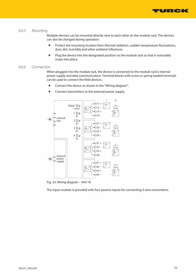
V02.01 | 2022/05 77
6.6.5 MountingMultiple devices can be mounted directly next to each other on the module rack. The devicescan also be changed during operation.
Protect the mounting location from thermal radiation, sudden temperature fluctuations,dust, dirt, humidity and other ambient influences.
Plug the device into the designated position on the module rack so that it noticeablysnaps into place.
6.6.6 ConnectionWhen plugged into the module rack, the device is connected to the module rack’s internalpower supply and data communication. Terminal blocks with screw or spring-loaded terminalscan be used to connect the field devices.
Connect the device as shown in the “Wiring diagram”.
Connect transmitters to the external power supply.
GN/RD
Status
RD
1
RD
2
RD
3
RD
4
internalpowersupply
internalbus
11 +
12 –
13 +
14 –
21 +
22 –
23 +
24 –
31 +
32 –
33 +
34 –
41 +
42 –
43 +
44 –
Aux
Aux
Aux
Aux
U
I II
U
U
U
Fig. 33: Wiring diagram – AI41-N
The input module is provided with four passive inputs for connecting 4-wire transmitters.

System componentsAI41-N analog input module
78 Hans Turck GmbH & Co. KG | T +49 208 4952-0 | F +49 208 4952-264 | [email protected] | www.turck.com
6.6.7 LED indicationsLEDs on the front of the module indicate module status and channel diagnostics.
LED Indication Meaning
Status Off No power supply
Flashing red Module not configured for currentslot
Green Power supply and communication error-free
Green flashing (slow: 0.5 Hz)
Module not yet configured by the gatewayand is waiting for configuration data
Green flashing(1.0 Hz asym.)
Module in failsafe mode
Channel 1…4 Off No channel error
Red Channel error (wire-break, overflow or under-flow), measuring range overflow or underflow: Channel diagnostics present
6.6.8 SettingThe user can set the following parameters on the module:
Parameter overview – AI41
The default parameter values are shown in the following table in bold type.
The diagnostics for the measuring range overflow is active and cannot be deactivated.
Parameter name Value Meaning
Line monitoring OnOff
Activate or deactivate wire-break monitoring
Failsafe mode Min. valueMax. valueLast valid value
Set substitute value by channel: minimum, maximum or lastvalid value
Measuring range 0…20 mA4…20 mA0…10 V2…10 V
Define measuring range0…20 mA: Dead zero diagnostics on measuring range un-derflow and wire break not possible0…10 V: Dead zero diagnostics on measuring range under-flow and wire break not possible4…20 mA: Live zero diagnostics for measuring range under-flow and overflow, diagnostics for wire break switchable2…10 V: Live zero diagnostics for measuring range under-flow and overflow, diagnostics for wire break switchable
Filter (PT1) Off0.1 s2.6 s29.2 s
Activate or deactivate software filter for generating anaverage value
The behavior of the inputs is parameterized via an associated configuration tool, FDT frame orweb server, depending on the higher-level fieldbus system.

V02.01 | 2022/05 79
Parameter data mapping
The following bits and bytes can be set via the parameters.
The default parameter values are shown in the following table in bold type.
Bit no.
Byte no. Channelno.
7 6 5 4 3 2 1 0
0 1 Line monitoring00: On11: Off
Failsafe mode00: Min. value01: Max. value10: Last valid value
Measuring range00: 0…10 V01: 2…10 V10: 0…20 mA11: 4…20 mA
Filter (PT1)00: Off01: 0.1 s10: 2.6 s11: 29.2 s
1 2 Line monitoring00: On11: Off
Failsafe mode00: Min. value01: Max. value10: Last valid value
Measuring range00: 0…10 V01: 2…10 V10: 0…20 mA11: 4…20 mA
Filter (PT1)00: Off01: 0.1 s10: 2.6 s11: 29.2 s
2 3 Line monitoring00: On11: Off
Failsafe mode00: Min. value01: Max. value10: Last valid value
Measuring range00: 0…10 V01: 2…10 V10: 0…20 mA11: 4…20 mA
Filter (PT1)00: Off01: 0.1 s10: 2.6 s11: 29.2 s
3 4 Line monitoring00: On11: Off
Failsafe mode00: Min. value01: Max. value10: Last valid value
Measuring range00: 0…10 V01: 2…10 V10: 0…20 mA11: 4…20 mA
Filter (PT1)00: Off01: 0.1 s10: 2.6 s11: 29.2 s
4 Reserved00000000

System componentsAI41-N analog input module
80 Hans Turck GmbH & Co. KG | T +49 208 4952-0 | F +49 208 4952-264 | [email protected] | www.turck.com
6.6.9 Measuring range and substitute valuesDepending on the measuring range, the following substitute values are set in the event of anerror:
Measuring range Substitute values
0…20 mA Min. value: 0 mAMax. value: 21 mA
4…20 mA Min. value: 3.6 mAMax. value: 21 mA
0…10 V Min. value: 0 VMax. value: 10.5 V
2…10 V Min. value: 1.8 VMax. value: 10.5 V
The following table shows the measuring range limits:
Measuring range Meaning
< 2 mA < 1 V Wire break
< 3.6 mA < 1.8 V Measuring range underflow
3.6…21 mA 1.8…10.5 V Valid measured value
> 21 mA > 10.5 V Measuring range overflow
The measuring range of 0…3.6 mA or 0…1.8 V is only monitored with the “live zero” setting(4…20 mA or 2…10 V).
6.6.10 Bit assignment of the input wordThe AI41-N module acts exclusively as an input card with four input words and additional statusbit (SB) for each of the four channels.
When a status message is present, the status bit of the corresponding channel is set to 1 in theinput word (depending on representation at bit 15 or bit 0).
Select in the Analog data format gateway parameter whether the status bit is to bemapped left-justified, right-justified or not at all in the process data.
Channel Bit
Para-meters
1…4 15 14 13 12 11 10 9 8 7 6 5 4 3 2 1 0
StatusMSB
SB Measured value (0…21000 corresponds to 0…21 mA)orMeasured value (0…10000 corresponds to 0…10 V)
StatusLSB
Measured value (0…21000 corresponds to 0…21 mA)orMeasured value (0…10000 corresponds to 0…10 V)
SB
Withoutstatus
– Measured value (0…21000 corresponds to 0…21 mA)orMeasured value (0…10000 corresponds to 0…10 V)

V02.01 | 2022/05 81
6.6.11 PROFIBUS: diagnostic informationThe diagnostics data is structured according to EN 61158, part 1/3/10.
Besides the module status (device-specific diagnostics) and the status overview (ID diagnostics)the module supports the following channel status indications (channel-specific diagnostics):
Error code No. Meaning
Standard 2 Understeer
3 Overmodulation
6 Wire break
Specific 16 Line fault
19 Module type (set configuration) unknown
20 Module type (actual configuration) unknown
22 Parameter not plausible (inconsistent)

System componentsAI41-N analog input module
82 Hans Turck GmbH & Co. KG | T +49 208 4952-0 | F +49 208 4952-264 | [email protected] | www.turck.com
6.6.12 Technical data
Type code AI41-N
ID 6884216
Power supply Via the module rack, central power supplymodule
Power consumption ≤ 2 W
Galvanic isolation Full galvanic isolation
Number of channels 4-channel
Input circuits 0/4…20 mA0/2…10 V
Overmodulation > 22 mA
Understeer < 3.6 mA
Wire break < 2 mA (only with “live zero”)
Resolution 1 µA1 mV
Relative measurement deviation (includinglinearity, hysteresis and repeatability)
≤ 0.1 % of full scale at 25 °C
Temperature drift ≤ 0.005 % of full scale/K
Rise time/fall time ≤ 50 ms (10…90 %)
Max. measurement deviation under EMCinfluence
With shielded signal cable:0.1 % of full scale at 25 °CWith shielded signal cable:1 % of full scale at 25 °C
Linearity deviation ≤ 0.1 % of full scale at 25 °C
LEDsOperational readiness 1 × green/red
Status/error 4 × red
Housing material Plastic
Fixing type Module design, pluggable in the module rack
Protection type IP20
Ambient temperature -20…+70 °C
Relative air humidity ≤ 93 % at 40 °C acc. to IEC 60068-2-78
Vibration test Acc. to EN 60068-2-6
Shock testing Acc. to EN 60068-2-27
EMC Acc. to EN 61326-1 acc. to NAMUR NE21
MTTF 98 years acc. to SN 29500 (Ed. 99) 40 °C
Dimensions (W × H × D) 18 × 118 × 106 mm

V02.01 | 2022/05 83
6.7 AI43-N analog input module
6.7.1 Intended useThe device is designed as equipment of the excom I/O system for the non-Ex area and mustonly be operated within the excom system with the MT…-N module racks.
The AI43-N 4-channel analog potentiometer module is used to connect active 3- or 4-wirepotentiometers.
6.7.2 Device overview
118
18
106
Fig. 34: Dimensions
6.7.3 Properties and featuresn Four channelsn Input module for connecting potentiometersn Full galvanic isolation of the input circuits:
– From each other– From the power supply– From the internal bus
6.7.4 Functions and operating modesThe module has four channels for scanning 3-wire or 4-wire potentiometers. The potentiometerinputs are monitored for line faults. The device detects the line faults of a single as well as mul-tiple connection cables of an input. No short-circuit monitoring is possible. After a line fault hasoccurred, the set substitute value is output immediately and the Invalid bit of the input word isset until valid measured values are restored. The analog value of 0…100 % is converted to a 15-bit digital value with a resolution of 0.1% per digit and sent to the host system.
6.7.5 MountingMultiple devices can be mounted directly next to each other on the module rack. The devicescan also be changed during operation.
Protect the mounting location from thermal radiation, sudden temperature fluctuations,dust, dirt, humidity and other ambient influences.
Plug the device into the designated position on the module rack so that it noticeablysnaps into place.

System componentsAI43-N analog input module
84 Hans Turck GmbH & Co. KG | T +49 208 4952-0 | F +49 208 4952-264 | [email protected] | www.turck.com
6.7.6 ConnectionWhen plugged into the module rack, the device is connected to the module rack’s internalpower supply and data communication. Terminal blocks with screw or spring-loaded terminalscan be used to connect the field devices.
Connect the device as shown in the “Wiring diagram”.
GN/RD
Status
RD
1
RD
2
RD
3
RD
4
internalpowersupply
internalbus
11
12
13
14
21
22
23
24
31
32
33
34
41
42
43
44
I II
R-3L
R-3L
R-3L
R-3L
R-4L
R-4L
R-4L
R-4L
Fig. 35: Wiring diagram – AI43-N
The AI43-N input module is provided with four inputs for connecting 3- or 4-wire potentio-meters. Peripheral devices can be connected as required.
When connecting 3-wire potentiometers: Set the bridge at the connection terminals ofthe module rack.
Resistance measurements, i.e. the evaluation of potentiometers with a 2-wire connection, arenot possible.
6.7.7 LED indicationsLEDs on the front of the module indicate module status and channel diagnostics.
LED Indication Meaning
Status Off No power supply
Flashing red Module not configured for the current slot
Green Power supply and communication error-free
Green flashing (slow: 0.5 Hz)
Module not yet configured by the gatewayand is waiting for configuration data
Green flashing(1.0 Hz asym.)
Module in failsafe mode
Channel 1…4 Off No channel error
Red Channel diagnostics present

V02.01 | 2022/05 85
6.7.8 SettingThe user can set the following parameters on the module:
Parameter overview – AI43
The default parameter values are shown in the following table in bold type.
Parameter name Value Meaning
Line monitoring OnOff
Activate or deactivate line monitoring (only wire-break)
Failsafe mode Min. valueMax. valueLast valid value
Set substitute value by channel: minimum, maximum or lastvalid value
Filter (PT1) Off0.1 s2.6 s29.2 s
Activate or deactivate software filter for generating an average value
The behavior of the inputs is parameterized via an associated configuration tool, FDT frame orweb server, depending on the higher-level fieldbus system.
Parameter data mapping
The following bits and bytes can be set via the parameters.
The default parameter values are shown in the following table in bold type.
Bit no.
Byte no. Channelno.
7 6 5 4 3 2 1 0
0 1 Line monitoring00: On11: Off
Failsafe mode00: Min. value01: Max. value10: Last valid value
Filter (PT1)00: Off01: 0.1 s10: 2.6 s11: 29.2 s
1 2 Line monitoring00: On11: Off
Failsafe mode00: Min. value01: Max. value10: Last valid value
Filter (PT1)00: Off01: 0.1 s10: 2.6 s11: 29.2 s
2 3 Line monitoring00: On11: Off
Failsafe mode00: Min. value01: Max. value10: Last valid value
Filter (PT1)00: Off01: 0.1 s10: 2.6 s11: 29.2 s
3 4 Line monitoring00: On11: Off
Failsafe mode00: Min. value01: Max. value10: Last valid value
Filter (PT1)00: Off01: 0.1 s10: 2.6 s11: 29.2 s
4 Reserved00000000

System componentsAI43-N analog input module
86 Hans Turck GmbH & Co. KG | T +49 208 4952-0 | F +49 208 4952-264 | [email protected] | www.turck.com
6.7.9 Measuring range and substitute valuesIn the event of an error, the following substitute values are set:
Measuring range Substitute values
0…100 % Min. value: 0 %Max. value: 100 %
6.7.10 Bit assignment of the input wordThe AI43-N module acts exclusively as an input card with four input words and additional statusbit (SB) for each of the four channels.
When a status message is present, the status bit of the corresponding channel is set to 1 in theinput word (depending on representation at bit 15 or bit 1).
In the Analog data format gateway parameter, select whether the status bit is to bemapped left-justified, right-justified or not at all in the process data.
Channel Bit
Para-meters
1…4 15 14 13 12 11 10 9 8 7 6 5 4 3 2 1 0
StatusMSB
SB Measured value (0…10000 corresponds to 0…100 %)
StatusLSB
Measured value (0…10000 corresponds to 0…100 %) SB
Withoutstatus
– Measured value (0…10000 corresponds to 0…100 %)
6.7.11 PROFIBUS: diagnostic informationThe diagnostics data is structured according to EN 61158, part 1/3/10.
Besides the module status (device-specific diagnostics) and the status overview (ID diagnostics)the module supports the following channel status indications (channel-specific diagnostics):
Error code No. Meaning
Standard 6 Wire break
Specific 16 Line fault
19 Module type (set configuration) unknown
20 Module type (actual configuration) unknown
22 Parameter not plausible (inconsistent)
V02.01 | 2022/05 87
6.7.12 Technical data
Type code AI43-N
ID 6884217
Power supply Via the module rack, central power supplymodule
Power consumption 1.5 W
Galvanic isolation Full galvanic isolation
Number of channels 4-channel
Input circuits 3-/4 wire potentiometer 0…100 %
Line fault if < 400 Ω or if >12 kΩ
Nominal resistance 400 Ω …12 kΩ
Resolution 0.1 %
Linearity deviation ≤ 0.1 % of full scale at 25 °C
Temperature drift ≤ 0.005 % of full scale/K
Rise time/fall time ≤ 50 ms (10…90 %)
LEDsOperational readiness 1 × green/red
Status/error 4 × red
Housing material Plastic
Fixing type Module design, pluggable in the module rack
Protection type IP20
Ambient temperature -20…+70 °C
Relative air humidity ≤ 93 % at 40 °C acc. to IEC 60068-2-78
Vibration test Acc. to EN 60068-2-6
Shock testing Acc. to EN 60068-2-27
EMC Acc. to EN 61326-1 acc. to NAMUR NE21
MTTF 71 years acc. to SN 29500 (Ed. 99) 40 °C
Dimensions (W × H × D) 18 × 118 × 106 mm

System componentsAIH40-N analog input module
88 Hans Turck GmbH & Co. KG | T +49 208 4952-0 | F +49 208 4952-264 | [email protected] | www.turck.com
6.8 AIH40-N analog input module
6.8.1 Intended useThe device is designed as equipment of the excom I/O system for the non-Ex area and mustonly be operated within the excom system with the MT…-N module racks.
The AIH40-N 4-channel analog input module is used to connect passive 2-wire transmitters.HART compatible sensors, which communicate with the integrated HART controller can beconnected to the module.
6.8.2 Device overview
118
18
106
Fig. 36: Dimensions
6.8.3 Properties and featuresn Four channelsn Input module for connecting passive 2-wire transmittersn Measuring range acc. to NAMUR specificationn Galvanic isolation:
– Input circuits galvanically isolated from the power supply– Input circuits galvanically isolated from the internal bus
n HART-compatibility:
– HART variables (up to eight HART variables, a maximum of four per channel) for directdata exchange between the process control system (DCS) and the field device
– Transmission of HART data between DCS and HART-compatible field device with extended process information of the field devices

V02.01 | 2022/05 89
6.8.4 Functions and operating modesThe module converts an analog input signal of 0…21 mA to a digital value of 0…21000 digits.This corresponds to a resolution of 1 µA per digit.
Up to eight HART variables (maximum four per channel) can be read via the cyclic user datatraffic of the fieldbus. The acyclic data exchange offers enhanced communication options suchas the diagnostics and parameter setting of the HART field devices.
Configurations – AIH40-N
Input words Outputwords
Type Configuration
4 - AIH40-N Without cyclic HART data
6 - AIH40-N 1H 1 cyclic HART variables
12 - AIH40-N 4H 4 cyclic HART variables
20 - AIH40-N 8H 8 cyclic HART variables
The module hardware is the same in spite of the different configuration. The behavior of themodule is only influenced by the configuration. Depending on the fieldbus or fieldbus protocol, the configuration is carried out in the higher-level control system, DTM or web server.
6.8.5 MountingMultiple devices can be mounted directly next to each other on the module rack. The devicescan also be changed during operation.
Protect the mounting location from thermal radiation, sudden temperature fluctuations,dust, dirt, humidity and other ambient influences.
Plug the device into the designated position on the module rack so that it noticeablysnaps into place.

System componentsAIH40-N analog input module
90 Hans Turck GmbH & Co. KG | T +49 208 4952-0 | F +49 208 4952-264 | [email protected] | www.turck.com
6.8.6 ConnectionWhen plugged into the module rack, the device is connected to the module rack’s internalpower supply and data communication. Terminal blocks with screw or spring-loaded terminalscan be used to connect the field devices.
Connect the device as shown in the “Wiring diagram”.
GN/RD
Status
RD
1
RD
2
RD
3
RD
4
internalpowersupply
internalbus
11 +
12 –
13 +
14 –
21 +
22 –
23 +
24 –
31 +
32 –
33 +
34 –
41 +
42 –
43 +
44 –
HART
HART
I
HART
I
HART
I
HART
I
Fig. 37: Wiring diagram – AIH40-N
The AIH40-N input module is provided with four active inputs for connecting passive 2-wiretransmitters.
NOTEThe inputs are not galvanically isolated from each other. When connecting the fielddevices bear in mind that all inputs are connected to a common ground potential.
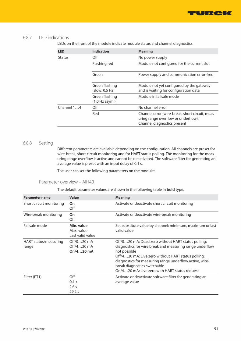
V02.01 | 2022/05 91
6.8.7 LED indicationsLEDs on the front of the module indicate module status and channel diagnostics.
LED Indication Meaning
Status Off No power supply
Flashing red Module not configured for the current slot
Green Power supply and communication error-free
Green flashing (slow: 0.5 Hz)
Module not yet configured by the gatewayand is waiting for configuration data
Green flashing(1.0 Hz asym.)
Module in failsafe mode
Channel 1…4 Off No channel error
Red Channel error (wire-break, short circuit, meas-uring range overflow or underflow): Channel diagnostics present
6.8.8 SettingDifferent parameters are available depending on the configuration. All channels are preset forwire-break, short circuit monitoring and for HART status polling. The monitoring for the meas-uring range overflow is active and cannot be deactivated. The software filter for generating anaverage value is preset with an input delay of 0.1 s.
The user can set the following parameters on the module:
Parameter overview – AIH40
The default parameter values are shown in the following table in bold type.
Parameter name Value Meaning
Short circuit monitoring OnOff
Activate or deactivate short circuit monitoring
Wire-break monitoring OnOff
Activate or deactivate wire-break monitoring
Failsafe mode Min. valueMax. valueLast valid value
Set substitute value by channel: minimum, maximum or lastvalid value
HART status/measuringrange
Off/0…20 mAOff/4…20 mAOn/4…20 mA
Off/0…20 mA: Dead zero without HART status polling;diagnostics for wire break and measuring range underflownot possibleOff/4…20 mA: Live zero without HART status polling;diagnostics for measuring range underflow active, wire-break diagnostics switchableOn/4…20 mA: Live zero with HART status request
Filter (PT1) Off0.1 s2.6 s29.2 s
Activate or deactivate software filter for generating an average value

System componentsAIH40-N analog input module
92 Hans Turck GmbH & Co. KG | T +49 208 4952-0 | F +49 208 4952-264 | [email protected] | www.turck.com
Parameters for AIH40 1H
In this configuration, the module also adds a HART variable to the cyclic data fieldbus traffic.
Parameter name Value Meaning
Short-circuit monitoring OnOff
Activate or deactivate short circuit monitoring
Wire-break monitoring OnOff
Activate or deactivate wire-break monitoring
Failsafe mode Min. valueMax. valueLast valid value
Set substitute value by channel: minimum, maximum or lastvalid value
HART status/measuringrange
Off/0…20 mAOff/4…20 mAOn/4…20 mA
Off/0…20 mA: Dead zero without HART status polling; diagnostics for wire break and measuring range underflownot possibleOff/4…20 mA: Live zero without HART status polling; diagnostics for measuring range underflow active, wire-break diagnostics switchableOn/4…20 mA: Live zero with HART status request
Filter (PT1) Off0.1 s2.6 s29.2 s
Activate or deactivate software filter for generating anaverage value
HART variable PrimarySecondary 1Secondary 2Secondary 3Secondary 4
Select HART variables
HART variable of channel Channel 1Channel 2Channel 3Channel 4
Select channel number belonging to the HART variable

V02.01 | 2022/05 93
Parameters for AIH40 4H and 8H
In this configuration, the module also adds four or eight HART variables to the cyclic data traffic.The module represents the measuring range from 4…20 mA. The monitoring of measuringrange underflows and overflows is active. The HART status polling is only for channels queryingthe secondary variables.
Parameter name Value Meaning
Line monitoring OnOff
Activate or deactivate wire-break monitoring
Failsafe mode Min. valueMax. valueLast valid value
Set substitute value per channel: minimum, maximum orlast valid value The min. value is 3.6 mA.
Filter (PT1) Off0.1 s2.6 s29.2 s
Activate or deactivate software filter for generating an average value
Channel 1: SV1…SV4Channel 2: SV1…SV4Channel 3: SV1…SV4Channel 4: SV1…SV4
On/offOn/offOn/offOn/off
Activate or deactivate secondary variables SV1…4 of channels 1…4The first secondary variable (SV1) is active by default for allfour channels.
The behavior of the inputs is parameterized via an associated configuration tool, FDT frame orweb server, depending on the higher-level fieldbus system.

System componentsAIH40-N analog input module
94 Hans Turck GmbH & Co. KG | T +49 208 4952-0 | F +49 208 4952-264 | [email protected] | www.turck.com
Parameter data mapping – AIH40-N
The following bits and bytes can be set via the parameters.
The default parameter values are shown in the following table in bold type.
Bit no.
Byte no. Channelno.
7 6 5 4 3 2 1 0
0 1 Short circuitmonitoring0: On1: Off
Wire-breakmonitoring0: On1: Off
Failsafe mode00: Min. value01: Max. value10: Last valid value
HART status/measuring range00: Off/0…20 mA01: Off/4…20 mA10: On/4…20 mA
Filter (PT1)00: Off01: 0.1 s10: 2.6 s11: 29.2 s
1 2 Short circuitmonitoring0: On1: Off
Wire-breakmonitoring0: On1: Off
Failsafe mode00: Min. value01: Max. value10: Last valid value
HART status/measuring range00: Off/0…20 mA01: Off/4…20 mA10: On/4…20 mA
Filter (PT1)00: Off01: 0.1 s10: 2.6 s11: 29.2 s
2 3 Short circuitmonitoring0: On1: Off
Wire-breakmonitoring0: On1: Off
Failsafe mode00: Min. value01: Max. value10: Last valid value
HART status/measuring range00: Off/0…20 mA01: Off/4…20 mA10: On/4…20 mA
Filter (PT1)00: Off01: 0.1 s10: 2.6 s11: 29.2 s
3 4 Short circuitmonitoring0: On1: Off
Wire-breakmonitoring0: On1: Off
Failsafe mode00: Min. value01: Max. value10: Last valid value
HART status/measuring range00: Off/0…20 mA01: Off/4…20 mA10: On/4…20 mA
Filter (PT1)00: Off01: 0.1 s10: 2.6 s11: 29.2 s
4 Reserved00000000

V02.01 | 2022/05 95
Parameter data mapping – AIH40 1H
Bit no.
Byte no. Channelno.
7 6 5 4 3 2 1 0
0 1 Short circuitmonitoring0: On1: Off
Wire-breakmonitoring0: On1: Off
Failsafe mode00: Min. value01: Max. value10: Last valid value
HART status/measuring range00: Off/0…20 mA01: Off/4…20 mA10: On/4…20 mA
Filter (PT1)00: Off01: 0.1 s10: 2.6 s11: 29.2 s
1 2 Short circuitmonitoring0: On1: Off
Wire-breakmonitoring0: On1: Off
Failsafe mode00: Min. value01: Max. value10: Last valid value
HART status/measuring range00: Off/0…20 mA01: Off/4…20 mA10: On/4…20 mA
Filter (PT1)00: Off01: 0.1 s10: 2.6 s11: 29.2 s
2 3 Short circuitmonitoring0: On1: Off
Wire-breakmonitoring0: On1: Off
Failsafe mode00: Min. value01: Max. value10: Last valid value
HART status/measuring range00: Off/0…20 mA01: Off/4…20 mA10: On/4…20 mA
Filter (PT1)00: Off01: 0.1 s10: 2.6 s11: 29.2 s
3 4 Short circuitmonitoring0: On1: Off
Wire-breakmonitoring0: On1: Off
Failsafe mode00: Min. value01: Max. value10: Last valid value
HART status/measuring range00: Off/0…20 mA01: Off/4…20 mA10: On/4…20 mA
Filter (PT1)00: Off01: 0.1 s10: 2.6 s11: 29.2 s
4 Reserved000
HART variable000: Primary001: Secondary 1010: Secondary 2011: Secondary 3100: Secondary 4
HART variable ofchannel00: Channel 101: Channel 210: Channel 311: Channel 4

System componentsAIH40-N analog input module
96 Hans Turck GmbH & Co. KG | T +49 208 4952-0 | F +49 208 4952-264 | [email protected] | www.turck.com
Parameter data mapping – AIH40 4H and 8H
Bit no.
Byte no. Channelno.
7 6 5 4 3 2 1 0
0 1 Short circuitmonitoring0: On1: Off
Wire-breakmonitoring0: On1: Off
Failsafe mode00: Min. value01: Max. value10: Last valid value
K1: SV40: Off1: On
K1: SV30: Off1: On
Filter (PT1)00: Off01: 0.1 s10: 2.6 s11: 29.2 s
1 2 Short circuitmonitoring0: On1: Off
Wire-breakmonitoring0: On1: Off
Failsafe mode00: Min. value01: Max. value10: Last valid value
K2: SV40: Off1: On
K2: SV30: Off1: On
Filter (PT1)00: Off01: 0.1 s10: 2.6 s11: 29.2 s
2 3 Short circuitmonitoring0: On1: Off
Wire-breakmonitoring0: On1: Off
Failsafe mode00: Min. value01: Max. value10: Last valid value
K3: SV40: Off1: On
K3: SV30: Off1: On
Filter (PT1)00: Off01: 0.1 s10: 2.6 s11: 29.2 s
3 4 Short circuitmonitoring0: On1: Off
Wire-breakmonitoring0: On1: Off
Failsafe mode00: Min. value01: Max. value10: Last valid value
K4: SV40: Off1: On
K4: SV30: Off1: On
Filter (PT1)00: Off01: 0.1 s10: 2.6 s11: 29.2 s
4 K4: SV20: Off1: On
K4: SV10: Off1: On
K3: SV20: Off1: On
K3: SV10: Off1: On
K2: SV20: Off1: On
K2: SV10: Off1: On
K1: SV20: Off1: On
K1: SV10: Off1: On
6.8.9 Measuring range and substitute valuesDepending on the measuring range, the following substitute values are set in the event of anerror:
Measuring range Substitute values
0…20 mA Min. value: 0 mAMax. value: 21 mA
4…20 mA Min. value: 3.6 mAMax. value: 21 mA
The substitute values apply to all previously listed variants of AIH40-N.
The following table shows the measuring range limits:
Measuring range Meaning
< 2 mA Wire break
< 3.6 mA Measuring range underflow
3.6…21 mA Valid measured value
> 21 mA Measuring range overflow
< 5 V terminal voltage Short circuit
The measuring range of 0…3.6 mA is only monitored with the “live zero” setting (4…20 mA).

V02.01 | 2022/05 97
6.8.10 Bit assignment of the input word
Configuring the input word
The AIH40-N module acts exclusively as an input card with 4, 6, 12 or 20 input words and anadditional status bit (SB) for each channel.
If a status message is present, the status bit of the corresponding channel is set to 1 in the inputword.
Depending on the selection of the Analog data format gateway parameter, the status bit ismapped left-justified, right-justified or not at all in the process data.
Depending on the fieldbus, the module is configured in the configuration tool of the controlsystem with an FDT frame or web server of an Ethernet-based system connection via the AIH40-N… entry (see table column “Type”). Different data rates are possible, depending on theconfiguration. The following configurations are possible:
Input words Outputwords
Type Configuration
4 - AIH40-N Without cyclic HART data
6 - AIH40-N 1H 1 cyclic HART variables
12 - AIH40-N 4H 4 cyclic HART variables
20 - AIH40-N 8H 8 cyclic HART variables
The module hardware is the same in spite of the different configuration. The behavior of themodule is only influenced by the configuration. Depending on the fieldbus or fieldbus protocol, the configuration is carried out in the higher-level control system, DTM or web server.
Channel Bit
Para-meters
1…4 15 14 13 12 11 10 9 8 7 6 5 4 3 2 1 0
StatusMSB
SB Measured value (0…20000 corresponds to 0…20 mA)
StatusLSB
Measured value (0…20000 corresponds to 0…20 mA) SB
Withoutstatus
– Measured value (0…20000 corresponds to 0…20 mA)
In the event of an error, the module sends, according to the set measuring range, an error message via the status bit in the input word.

System componentsAIH40-N analog input module
98 Hans Turck GmbH & Co. KG | T +49 208 4952-0 | F +49 208 4952-264 | [email protected] | www.turck.com
Input data mapping overview
The module input data and the HART variables are mapped as follows. The following tableshows a module with eight cyclic HART variables as an example:
Wort no. (1 word = 2 bytes) Contents
1 Input channel 1
2 Input channel 2
3 Input channel 3
4 Input channel 4
5…6 HART variable 1
7…8 HART variable 2
9…10 HART variable 3
11…12 HART variable 4
13…14 HART variable 5
15…16 HART variable 6
17…18 HART variable 7
19…20 HART variable 8
All dynamic HART variables that were activated at parameterization are assigned a space in themapped input data. The order starts with channel 1 and HART variable 1. If more than four oreight HART variables are selected, only the first four or eight selected HART variables are trans-mitted. A HART-compatible device must be connected to the corresponding channels for theassignment. If no HART-compatible device is connected or the device does not provide a valuefor the selected dynamic HART variable, the module sets the variable “NaN”.
The HART variables are presented in the floating point data format.
6.8.11 PROFIBUS: diagnostic informationThe diagnostics data is structured according to EN 61158, part 1/3/10.
Besides the module status (device-specific diagnostics) and the status overview (ID diagnostics)the module supports the following channel status indications (channel-specific diagnostics):
Error code No. Meaning
Standard 7 Above upper limit
8 Below lower limit
Specific 16 Line fault
19 Module type (set configuration) unknown
20 Module type (actual configuration) unknown
22 Parameter not plausible (inconsistent)
30 HART status error
31 HART communication error
The system sends two different HART error codes to the DCS:
n Error code 30: The HART variables are valid. The HART device status is reported.n Error code 31: The HART variables are not valid. The HART communication is faulty.

V02.01 | 2022/05 99
6.8.12 Technical data
Type code AIH40-N
ID 6884219
Power supply Via the module rack, central power supplymodule
Power consumption 3 W
Galvanic isolation From the internal bus and from the power supply circuit
Number of channels 4-channel
Input circuits 0/4…20 mA
Supply voltage 15.1 VDC at 21 mA
HART impedance > 240 Ω
Overmodulation > 21 mA
Understeer < 3.6 mA
Short circuit < 5 V
Wire break < 2 mA (only with “live zero”)
Resolution 1 µA
Relative measurement deviation (includinglinearity, hysteresis and repeatability)
≤ 0.1 % of 20 mA at 25 °C
Linearity deviation ≤ 0.1 % of 20 mA at 25 °C
Temperature drift ≤ 0.005 % of 20 mA/K
Rise time/fall time ≤ 50 ms (10…90 %)
Max. measurement deviation under EMC influence
With shielded signal cable:≤ 0.1 % of 20 mA at 25 °CWith unshielded signal cable:≤ 0.1 % of 20 mA at 25 °C
LEDsOperational readiness 1 × green/red
Status/error 4 × red
Housing material Plastic
Fixing type Module design, pluggable in the module rack
Protection type IP20
Ambient temperature -20…+60 °C
Relative air humidity ≤ 93 % at 40 °C acc. to IEC 60068-2-78
Vibration test Acc. to EN 60068-2-6
Shock testing Acc. to EN 60068-2-27
EMC Acc. to EN 61326-1 acc. to NAMUR NE21
MTTF 61 years acc. to SN 29500 (Ed. 99) 40 °C
Dimensions (W × H × D) 18 × 118 × 106 mm
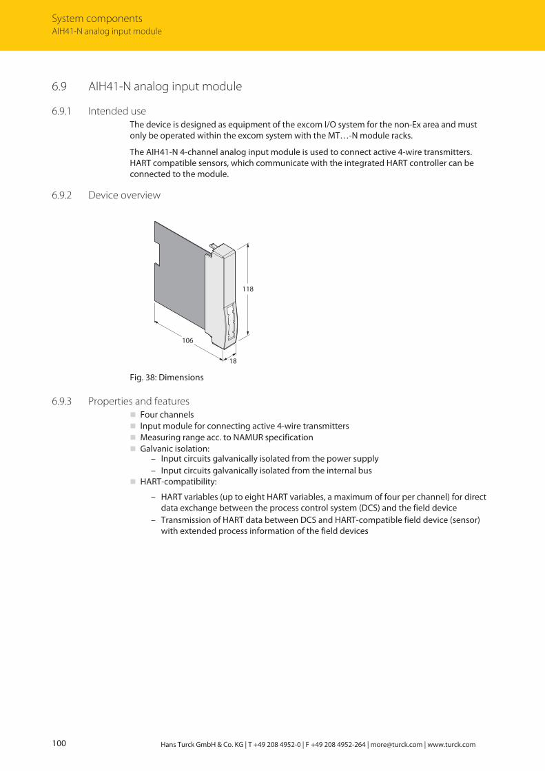
System componentsAIH41-N analog input module
100 Hans Turck GmbH & Co. KG | T +49 208 4952-0 | F +49 208 4952-264 | [email protected] | www.turck.com
6.9 AIH41-N analog input module
6.9.1 Intended useThe device is designed as equipment of the excom I/O system for the non-Ex area and mustonly be operated within the excom system with the MT…-N module racks.
The AIH41-N 4-channel analog input module is used to connect active 4-wire transmitters.HART compatible sensors, which communicate with the integrated HART controller can beconnected to the module.
6.9.2 Device overview
118
18
106
Fig. 38: Dimensions
6.9.3 Properties and featuresn Four channelsn Input module for connecting active 4-wire transmittersn Measuring range acc. to NAMUR specificationn Galvanic isolation:
– Input circuits galvanically isolated from the power supply– Input circuits galvanically isolated from the internal bus
n HART-compatibility:
– HART variables (up to eight HART variables, a maximum of four per channel) for directdata exchange between the process control system (DCS) and the field device
– Transmission of HART data between DCS and HART-compatible field device (sensor)with extended process information of the field devices

V02.01 | 2022/05 101
6.9.4 Functions and operating modesThe module converts an analog input signal of 0…21 mA to a digital value of 0…21000 digits.This corresponds to a resolution of 1 µA per digit.
Up to eight HART variables (maximum four per channel) can be read via the cyclic user datatraffic of the fieldbus. The acyclic data exchange offers enhanced communication options suchas the diagnostics and parameter setting of the HART field devices.
AIH41-N configurations
Input word Output word Type Configuration
4 - AIH41-N Without cyclic HART data
6 - AIH41-N 1H 1 cyclic HART variables
12 - AIH41-N 4H 4 cyclic HART variables
20 - AIH41-N 8H 8 cyclic HART variables
The module hardware is the same in spite of the different configuration. The behavior of themodule is only influenced by the configuration. Depending on the fieldbus or fieldbusprotocol, the configuration is carried out in the higher-level control system, DTM or web server.
6.9.5 MountingMultiple devices can be mounted directly next to each other on the module rack. The devicescan also be changed during operation.
Protect the mounting location from thermal radiation, sudden temperature fluctuations,dust, dirt, humidity and other ambient influences.
Plug the device into the designated position on the module rack so that it noticeablysnaps into place.

System componentsAIH41-N analog input module
102 Hans Turck GmbH & Co. KG | T +49 208 4952-0 | F +49 208 4952-264 | [email protected] | www.turck.com
6.9.6 ConnectionWhen plugged into the module rack, the device is connected to the module rack’s internalpower supply and data communication. Terminal blocks with screw or spring-loaded terminalscan be used to connect the field devices.
Connect the device as shown in the “Wiring diagram”.
GN/RD
Status
RD
1
RD
2
RD
3
RD
4
internalpowersupply
internalbus
11 +
12 –
13 +
14 –
21 +
22 –
23 +
24 –
31 +
32 –
33 +
34 –
41 +
42 –
43 +
44 –
HARTMaster
HA
RT
HA
RT
HA
RT
HA
RT
Aux
Aux
Aux
Aux
Fig. 39: Wiring diagram – AIH41-N
The AIH41-N input module is provided with four passive inputs for connecting active 4-wiretransmitters.
NOTEThe inputs are not galvanically isolated from each other. When connecting the fielddevices bear in mind that all inputs are connected to a common ground potential.

V02.01 | 2022/05 103
6.9.7 LED indicationsLEDs on the front of the module indicate module status and channel diagnostics.
LED Indication Meaning
Status Off No power supply
Flashing red Module not configured for the current slot
Green Power supply and communication error-free
Green flashing (slow: 0.5 Hz)
Module not yet configured by the gatewayand is waiting for configuration data
Green flashing (1.0 Hz asym.)
Module in failsafe mode
Channel 1…4 Off No channel error
Red Channel error (wire-break, short circuit, meas-uring range overflow or underflow): Channel diagnostics present
6.9.8 SettingDifferent parameters are available depending on the configuration. All channels are preset forwire-break, short circuit monitoring and for HART status polling. The monitoring for the meas-uring range overflow is active and cannot be deactivated. The software filter for generating anaverage value is preset with an input delay of 0.1 s.
The user can set the following parameters on the module:
Parameter overview – AIH41
The default parameter values are shown in the following table in bold type.
Parameter name Value Meaning
Line monitoring OnOff
Activate or deactivate wire-break monitoring
Failsafe mode Min. valueMax. valueLast valid value
Set substitute value by channel: minimum, maximum or lastvalid value
HART status/measuringrange
Off/0…20 mAOff/4…20 mAOn/4…20 mA
Off/0…20 mA: Dead zero without HART status polling;diagnostics for wire break and measuring range underflow isnot possible
Off/4…20 mA: Live zero without HART status polling;diagnostics for measuring range underflow and overflow isactive, wire-break diagnostics connectable
On/4…20 mA: Live zero with HART status polling; dia-gnostics for measuring range underflow and overflow aswell as wire break connectable
Filter (PT1) Off0.1 s2.6 s29.2 s
Activate or deactivate software filter for generating an average value

System componentsAIH41-N analog input module
104 Hans Turck GmbH & Co. KG | T +49 208 4952-0 | F +49 208 4952-264 | [email protected] | www.turck.com
Parameters for AIH41 1H
In this configuration, the module also adds a HART variable to the cyclic data fieldbus traffic.Compared to the parameter overview for AIH41, the parameter overview of the AIH41 1H configuration just has two additional parameters, which are shown in the following table:
Parameter name Value Meaning
HART variable PrimarySecondary 1Secondary 2Secondary 3Secondary 4
Select HART variables
HART variable of channel Channel 1Channel 2Channel 3Channel 4
Select channel number belonging to the HART variable
Parameters for AIH41 4H and 8H
In this configuration, the module also adds four or eight HART variables to the cyclic data traffic.Compared to the parameter overview of the AIH40 configuration, the parameter overview forAIH40 4H and 8H makes it possible to select four or eight secondary variables per channel asparameters. The total number of HART variables is limited to four or eight and must not be exceeded. The additional parameters are shown in bold type in the following table:
Parameter name Value Meaning
Line monitoring OnOff
Activate or deactivate wire-break monitoring
Failsafe mode Min. valueMax. valueLast valid value
Set substitute value per channel: minimum, maximum orlast valid value The min. value is 3.6 mA.
Filter (PT1) Off0.1 s2.6 s29.2 s
Activate or deactivate software filter for generating an average value
Channel 1: SV1…SV4Channel 2: SV1…SV4Channel 3: SV1…SV4Channel 4: SV1…SV4
On/offOn/offOn/offOn/off
Activate or deactivate secondary variables SV1…4 of channels 1…4The first secondary variable (SV1) is active by default for allfour channels.
The behavior of the inputs is parameterized via an associated configuration tool, FDT frame orweb server, depending on the higher-level fieldbus system.

V02.01 | 2022/05 105
Parameter data mapping – AIH41-N
The following bits and bytes can be set via the parameters.
The default parameter values are shown in the following table in bold type.
Bit no.
Byte no. Channelno.
7 6 5 4 3 2 1 0
0 1 Line monitoring0: On1: Off
Failsafe mode00: Min. value01: Max. value10: Last valid value
HART status/measuring range00: Off/0…20 mA01: Off/4…20 mA10: On/4…20 mA
Filter (PT1)00: Off01: 0.1 s10: 2.6 s11: 29.2 s
1 2 Line monitoring0: On1: Off
Failsafe mode00: Min. value01: Max. value10: Last valid value
HART status/measuring range00: Off/0…20 mA01: Off/4…20 mA10: On/4…20 mA
Filter (PT1)00: Off01: 0.1 s10: 2.6 s11: 29.2 s
2 3 Line monitoring0: On1: Off
Failsafe mode00: Min. value01: Max. value10: Last valid value
HART status/measuring range00: Off/0…20 mA01: Off/4…20 mA10: On/4…20 mA
Filter (PT1)00: Off01: 0.1 s10: 2.6 s11: 29.2 s
3 4 Line monitoring0: On1: Off
Failsafe mode00: Min. value01: Max. value10: Last valid value
HART status/measuring range00: Off/0…20 mA01: Off/4…20 mA10: On/4…20 mA
Filter (PT1)00: Off01: 0.1 s10: 2.6 s11: 29.2 s
4 Reserved: 00000000

System componentsAIH41-N analog input module
106 Hans Turck GmbH & Co. KG | T +49 208 4952-0 | F +49 208 4952-264 | [email protected] | www.turck.com
Parameter data mapping – AIH41 1H
Bit no.
Byte no. Channelno.
7 6 5 4 3 2 1 0
0 1 Line monitoring0: On1: Off
Failsafe mode00: Min. value01: Max. value10: Last valid value
HART status/measuring range00: Off/0…20 mA01: Off/4…20 mA10: On/4…20 mA
Filter (PT1)00: Off01: 0.1 s10: 2.6 s11: 29.2 s
1 2 Line monitoring0: On1: Off
Failsafe mode00: Min. value01: Max. value10: Last valid value
HART status/measuring range00: Off/0…20 mA01: Off/4…20 mA10: On/4…20 mA
Filter (PT1)00: Off01: 0.1 s10: 2.6 s11: 29.2 s
2 3 Line monitoring0: On1: Off
Failsafe mode00: Min. value01: Max. value10: Last valid value
HART status/measuring range00: Off/0…20 mA01: Off/4…20 mA10: On/4…20 mA
Filter (PT1)00: Off01: 0.1 s10: 2.6 s11: 29.2 s
3 4 Line monitoring0: On1: Off
Failsafe mode00: Min. value01: Max. value10: Last valid value
HART status/measuring range00: Off/0…20 mA01: Off/4…20 mA10: On/4…20 mA
Filter (PT1)00: Off01: 0.1 s10: 2.6 s11: 29.2 s
4 Channel 1…4: 00000000 (reserved) HART variable000: Primary001: Secondary 1010: Secondary 2011: Secondary 3100: Secondary 4
HART variable ofchannel00: Channel 101: Channel 210: Channel 311: Channel 4

V02.01 | 2022/05 107
Parameter data mapping – AIH41 4H and 8H
Bit no.
Byte no. Channelno.
7 6 5 4 3 2 1 0
0 1 Line monitoring0: On1: Off
Failsafe mode00: Min. value01: Max. value10: Last valid value
K1: SV40: Off1: On
K1: SV30: Off1: On
Filter (PT1)00: Off01: 0.1 s10: 2.6 s11: 29.2 s
1 2 Line monitoring0: On1: Off
Failsafe mode00: Min. value01: Max. value10: Last valid value
K2: SV40: Off1: On
K2: SV30: Off1: On
Filter (PT1)00: Off01: 0.1 s10: 2.6 s11: 29.2 s
2 3 Line monitoring0: On1: Off
Failsafe mode00: Min. value01: Max. value10: Last valid value
K3: SV40: Off1: On
K3: SV30: Off1: On
Filter (PT1)00: Off01: 0.1 s10: 2.6 s11: 29.2 s
3 4 Line monitoring0: On1: Off
Failsafe mode00: Min. value01: Max. value10: Last valid value
K4: SV40: Off1: On
K4: SV30: Off1: On
Filter (PT1)00: Off01: 0.1 s10: 2.6 s11: 29.2 s
4 K4: SV20: Off1: On
K4: SV10: Off1: On
K3: SV20: Off1: On
K3: SV10: Off1: On
K2: SV20: Off1: On
K2: SV10: Off1: On
K1: SV20: Off1: On
K1: SV10: Off1: On
6.9.9 Measuring range and substitute valuesDepending on the measuring range, the following substitute values are set in the event of anerror:
Measuring range Substitute values
0…20 mA Min. value: 0 mAMax. value: 21 mA
4…20 mA Min. value: 3.6 mAMax. value: 21 mA
The substitute values apply to all previously listed variants of AIH41-N.
The following table shows the measuring range limits:
Measuring range Meaning
< 2 mA Wire break
< 3.6 mA Measuring range underflow
3.6…21 mA Valid measured value
> 21 mA Measuring range overflow
The measuring range of 0…3.6 mA is only monitored with the “live zero” setting (4…20 mA).

System componentsAIH41-N analog input module
108 Hans Turck GmbH & Co. KG | T +49 208 4952-0 | F +49 208 4952-264 | [email protected] | www.turck.com
6.9.10 Bit assignment of the input word
Configuring the input word
The AIH41-N module acts exclusively as an input card with 4, 6, 12 or 20 input words and anadditional status bit (SB) for each channel.
If a status message is present, the status bit of the corresponding channel is set to 1 in the inputword.
Depending on the selection of the Analog data format gateway parameter, the status bit ismapped left-justified, right-justified or not at all in the process data.
Different data rates are possible, depending on the configuration. The following configurationsare possible:
Input word Output word Type Configuration
4 - AIH41-N Without cyclic HART data
6 - AIH41-N 1H 1 cyclic HART variables
12 - AIH41-N 4H 4 cyclic HART variables
20 - AIH41-N 8H 8 cyclic HART variables
The module hardware is the same in spite of the different configuration. The behavior of themodule is only influenced by the configuration. Depending on the fieldbus or fieldbus protocol, the configuration is carried out in the higher-level control system, DTM or web server.
Channel Bit
Para-meters
1…4 15 14 13 12 11 10 9 8 7 6 5 4 3 2 1 0
StatusMSB
SB Measured value (0…20000 corresponds to 0…20 mA)
StatusLSB
Measured value (0…20000 corresponds to 0…20 mA) SB
Withoutstatus
– Measured value (0…20000 corresponds to 0…20 mA)
In the event of an error the module provides an error message via the status bit of the data tele-gram, depending on the set measuring range (0…20 mA, 4…20 mA).

V02.01 | 2022/05 109
Input data mapping overview
The module input data and the HART variables are mapped as follows. This example is basedon a module with eight cyclic HART variables:
Wort no. (1 word = 2 bytes) Contents
1 Input channel 1
2 Input channel 2
3 Input channel 3
4 Input channel 4
5…6 HART variable 1
7…8 HART variable 2
9…10 HART variable 3
11…12 HART variable 4
13…14 HART variable 5
15…16 HART variable 6
17…18 HART variable 7
19…20 HART variable 8
All dynamic HART variables that were activated at parameterization are assigned a space in themapped input data. The order starts with channel 1 and HART variable 1. If more than four oreight HART variables are selected, only the first four or eight selected HART variables are trans-mitted. A HART-compatible device must be connected to the corresponding channels for theassignment. If no HART-compatible device is connected or the device does not provide a valuefor the selected dynamic HART variable, the module sets the variable “NaN”.
The HART variables are presented in the floating point data format.
6.9.11 PROFIBUS: diagnostic informationThe diagnostics data is structured according to EN 61158, part 1/3/10.
Besides the module status (device-specific diagnostics) and the status overview (ID diagnostics)the module supports the following channel status indications (channel-specific diagnostics):
Error code No. Meaning
Standard 7 Above upper limit
8 Below lower limit
Specific 16 Line fault
19 Module type (set configuration) unknown
20 Module type (actual configuration) unknown
22 Parameter not plausible (inconsistent)
30 HART status error
31 HART communication error
The system sends two different HART error codes to the DCS:
n Error code 30: The HART variables are valid. The HART device status is reported.n Error code 31: The HART variables are not valid. The HART communication is faulty.

System componentsAIH41-N analog input module
110 Hans Turck GmbH & Co. KG | T +49 208 4952-0 | F +49 208 4952-264 | [email protected] | www.turck.com
6.9.12 Technical data
Type code AIH41-N
ID 6884220
Power supply Via the module rack, central power supplymodule
Power consumption ≤ 1.5 W
Galvanic isolation From the internal bus and from the powersupply circuit
Number of channels 4-channel
Input circuits 0/4…20 mA
HART impedance > 240 Ω
Overmodulation > 21 mA
Understeer < 3.6 mA
Wire break < 2 mA (only with “live zero”)
Resolution 1 µA
Linearity deviation ≤ 0.1 % of 20 mA at 25 °C
Temperature drift ≤ 0.005 % of 20 mA/K
Rise time/fall time ≤ 50 ms (10…90 %)
Max. measurement deviation under EMCinfluence
With shielded signal cable: ≤ 0.1 % of 20 mA at 25 °CWith unshielded signal cable: ≤ 1 % of 20 mA at 25 °C
LEDsOperational readiness 1 × green/red
Status/error 4 × red
Housing material Plastic
Fixing type Module design, pluggable in the module rack
Protection type IP20
Ambient temperature -20…+60 °C
Relative air humidity ≤ 93 % at 40 °C acc. to IEC 60068-2-78
Vibration test Acc. to EN 60068-2-6
Shock testing Acc. to EN 60068-2-27
EMC Acc. to EN 61326-1 acc. to NAMUR NE21
MTTF 93 years acc. to SN 29500 (Ed. 99) 40 °C
Dimensions (W × H × D) 18 × 118 × 106 mm

V02.01 | 2022/05 111
6.10 AIH401-N analog input module
6.10.1 Intended useThe device is designed as equipment of the excom I/O system for the non-Ex area and mustonly be operated within the excom system with the MT…-N module racks.
The 4-channel AIH401-N analog input module is used to connect passive 2-wire transmittersand active 4-wire transmitters. HART compatible sensors, which communicate with the integ-rated HART controller can be connected to the module. The module is 100 % compatible withthe AIH40-N and AIH41-N input modules.
6.10.2 Device overview
118
18
106
Fig. 40: Dimensions
6.10.3 Properties and featuresn Four channelsn Input module for connecting passive 2-wire transmitters or active 4-wire transmittersn Measuring range acc. to NAMUR specificationn Full galvanic isolation of the input circuits:
– From each other– From the power supply– From the internal bus
n HART-compatibility:
– HART variables (up to eight HART variables, a maximum of four per channel) for directdata exchange between the process control system (DCS) and the field device
– Transmission of HART data between DCS and HART-compatible field device (sensor)with extended process information of the field devices
– A HART controller for each channel for faster access to HART data

System componentsAIH401-N analog input module
112 Hans Turck GmbH & Co. KG | T +49 208 4952-0 | F +49 208 4952-264 | [email protected] | www.turck.com
6.10.4 Functions and operating modesThe module converts an analog input signal of 0…21 mA to a digital value of 0…21000 digits.This corresponds to a resolution of 1 µA per digit.
Up to eight HART variables (maximum four per channel) can be read via the cyclic user datatraffic of the fieldbus. The acyclic data exchange offers enhanced communication options suchas the diagnostics and parameter setting of the HART field devices.
AIH401-N configurations
Input word Output word Type Configuration
4 - AIH40-N Without cyclic HART data
6 - AIH40-N 1H 1 cyclic HART variables
12 - AIH40-N 4H 4 cyclic HART variables
20 - AIH40-N 8H 8 cyclic HART variables
The module hardware is the same in spite of the different configuration. The behavior of themodule is only influenced by the configuration. Depending on the fieldbus or fieldbus protocol, the configuration is carried out in the higher-level control system, DTM or web server.
Operating modes
The user can select from three operating modes. A separate operating mode can be used foreach channel as the channels are galvanically isolated from each other.
No separate configuration is required to distinguish the three operating mode. All listed config-urations are supported.
Operating mode I (active input)
In operating mode I, the particular channel of the module supplies the power supply for thefield device via terminals 11 and 12 (n1 - n2). The particular current consumption of the devicecorresponds to the physical process value and is represented within the set measuring rangewith an analog value from 4…20 mA. A value above 21 mA initiates a diagnostic message foran overflow of the measuring range and a value below 3.6 mA an underflow. The measuringrange must be set to 0…20 mA in order to send an underflow signal.
Operating mode II (passive input)
The power supply must be connected separately to the field device. The field device suppliesan analog value of 0/4…20 mA via terminals 13 and 14 (n3 - n4), which corresponds to thephysical process value within the set measuring range. A value above 21 mA initiates a dia-gnostic message for an overflow of the measuring range and a value below 3.6 mA an under-flow.
Operating mode III (active input with additional auxiliary power)
Operating mode III is suitable for applications in which the 2-wire field device does not receivethe required operating voltage via the power supply. In this case, an auxiliary power supply canbe connected in series. The series connection of field device and auxiliary power acts like anactive device and is connected to terminals 13 and 14 (n3 - n4).

V02.01 | 2022/05 113
6.10.5 MountingMultiple devices can be mounted directly next to each other on the module rack. The devicescan also be changed during operation.
Protect the mounting location from thermal radiation, sudden temperature fluctuations,dust, dirt, humidity and other ambient influences.
Plug the device into the designated position on the module rack so that it noticeablysnaps into place.
6.10.6 ConnectionWhen plugged into the module rack, the device is connected to the module rack’s internalpower supply and data communication. Terminal blocks with screw or spring-loaded terminalscan be used to connect the field devices.
Connect the device as shown in the “Wiring diagram”.
GN/RD
Status
YE/RD
1
YE/RD
2
YE/RD
3
YE/RD
4
internalpowersupply
internalbus
11 +
12 –
13 +
14 –
21 +
22 –
23 +
24 –
31 +
32 –
33 +
34 –
41 +
42 –
43 +
44 –
Aux
Aux
Aux
Aux
I
I II III
I
I
I
Us
Us
Us
Us
HARTMaster
HARTMaster
HARTMaster
HARTMaster
HA
RT I
HA
RT
HA
RT
HA
RT
HA
RT
HA
RT
I
HA
RT
IH
AR
T
I
HA
RT
HA
RT
HA
RT
HA
RT
Rs
Rs
Rs
Rs
Fig. 41: Wiring diagram – AIH401-N
The AIH401-N input module has active inputs for connecting 2-wire transmitters. The AIH401-Ninput module also has passive inputs for connecting 4-wire transmitters.
With active connection: Connect the transmitter to the input terminal of the excom station (operating mode I).
With passive connection: Connect the transmitter to the external power supply (operating mode II).
With active connection but with no voltage: Connect the transmitter to the input terminal of the excom station and to the auxiliary power (operating mode III).

System componentsAIH401-N analog input module
114 Hans Turck GmbH & Co. KG | T +49 208 4952-0 | F +49 208 4952-264 | [email protected] | www.turck.com
6.10.7 LED indicationsLEDs on the front of the module indicate module status and channel diagnostics.
LED Indication Meaning
Status Off No power supply
Green Power supply and communication error-free
Red No communication possible: Module errorpresent
Flashing red Module not configured for the current slot
Green flashing (slow: 0.5 Hz)
Module not yet configured by the gatewayand is waiting for configuration data
Green flashing (1.0 Hz asym.)
Module in failsafe mode
Channel 1…4 Off HART status request is switched off, with error-free acyclic HART communication in ON statefor approx. 300 ms
Yellow HART status polling switched on and HART communication error-free
Yellow flashing (every secondmomentarily switched off)
HART status polling switched on and HART communication disrupted
Red Channel error (wire break, short circuit): Channel diagnostics present

V02.01 | 2022/05 115
6.10.8 SettingDifferent parameters are available depending on the configuration. All channels are preset forwire-break, short circuit monitoring and for HART status polling. The monitoring for the meas-uring range overflow is active and cannot be deactivated. The software filter for generating anaverage value is preset with an input delay of 0.1 s.
The user can set the following parameters on the module:
Parameter overview – AIH40
The default parameter values are shown in the following table in bold type.
Parameter name Value Meaning
Short circuit monitoring OnOff
Activate or deactivate short circuit monitoring
Wire-break monitoring OnOff
Activate or deactivate wire-break monitoring
Failsafe mode Min. valueMax. valueLast valid value
Set substitute value by channel: minimum, maximum or lastvalid value
HART status/measuringrange
Off/0…20 mAOff/4…20 mAOn/4…20 mA
Define HART status/measuring rangeSelect from three HART status/measuring ranges:Off/0…20 mA: Dead zero without HART status polling;diagnostics for wire break and measuring range underflow isnot possible.Off/4…20 mA: Live zero without HART status polling;diagnostics for measuring range underflow active, wire-break diagnostics switchableOn/4…20 mA: Live zero with HART status request
Filter (PT1) Off0.1 s2.6 s29.2 s
Activate or deactivate software filter for generating an average value

System componentsAIH401-N analog input module
116 Hans Turck GmbH & Co. KG | T +49 208 4952-0 | F +49 208 4952-264 | [email protected] | www.turck.com
AIH40 1H
In this configuration, the module also adds a HART variable to the cyclic data fieldbus traffic.
Parameter name Value Meaning
Short-circuit monitoring OnOff
Activate or deactivate short circuit monitoring
Wire-break monitoring OnOff
Activate or deactivate wire-break monitoring
Failsafe mode Min. valueMax. valueLast valid value
Set substitute value by channel: minimum, maximum or lastvalid value
HART status/measuringrange
Off/0…20 mAOff/4…20 mAOn/4…20 mA
Define HART status/measuring rangeSelect from three HART status/measuring ranges:Off/0…20 mA: Dead zero without HART status polling;diagnostics for wire break and measuring range underflow isnot possible.Off/4…20 mA: Live zero without HART status polling; dia-gnostics for measuring range underflow and overflow is act-ive. Wire-break and short circuit monitoring are possible.On/4…20 mA: Live zero with HART status polling; dia-gnostics for measuring range underflow and overflow is act-ive. Wire-break and short circuit monitoring are possible.
Filter (PT1) Off0.1 s2.6 s29.2 s
Activate or deactivate software filter for generating an average value
HART variable PrimarySecondary 1Secondary 2Secondary 3Secondary 4
Select a HART variable
HART variable channel based
Channel 1Channel 2Channel 3Channel 4
Select channel number belonging to the HART variable
V02.01 | 2022/05 117
AIH40 4H and 8H
In this configuration, the module also adds four or eight HART variables to the cyclic data traffic.The module represents the measuring range from 4…20 mA. The monitoring of measuringrange underflows and overflows is active. The HART status polling is only for channels queryingthe secondary variables.
Parameter name Value Meaning
Line monitoring OnOff
Activate or deactivate wire-break monitoring
Failsafe mode Min. valueMax. valueLast valid value
Set substitute value per channel: minimum, maximum orlast valid value The min. value is 3.6 mA.
Filter (PT1) Off0.1 s2.6 s29.2 s
Activate or deactivate software filter for generating an average value
Channel 1: SV1…SV4Channel 2: SV1…SV4Channel 3: SV1…SV4Channel 4: SV1…SV4
On/offOn/offOn/offOn/off
Activate or deactivate secondary variables SV1…4 of channels 1…4The first secondary variable (SV1) is active by default for allfour channels.
The behavior of the inputs is parameterized via an associated configuration tool, FDT frame orweb server, depending on the higher-level fieldbus system.
Compatibility behavior
The AIH401-N module can be used as a substitute for AIH40-N and AIH41-N. In an already configured system, AIH401-N takes over the settings of AIH40-N or AIH41-N and operates according to the set parameters. For new configurations with AIH401-N, active and passive fielddevices can be operated together on one module if the AIH40… configuration is used.

System componentsAIH401-N analog input module
118 Hans Turck GmbH & Co. KG | T +49 208 4952-0 | F +49 208 4952-264 | [email protected] | www.turck.com
Parameter data mapping
The following bits and bytes can be set via the parameters.
The default parameter values are shown in the following table in bold type.
Bit no.
Byte no. Channelno.
7 6 5 4 3 2 1 0
0 1 Short circuitmonitoring0: On1: Off
Wire-breakmonitoring0: On1: Off
Failsafe mode00: Min. value01: Max. value10: Last valid value
HART status/measuring range00: Off/0…20 mA01: Off/4…20 mA10: On/4…20 mA
Filter (PT1)00: Off01: 0.1 s10: 2.6 s11: 29.2 s
1 2 Short circuitmonitoring0: On1: Off
Wire-breakmonitoring0: On1: Off
Failsafe mode00: Min. value01: Max. value10: Last valid value
HART status/measuring range00: Off/0…20 mA01: Off/4…20 mA10: On/4…20 mA
Filter (PT1)00: Off01: 0.1 s10: 2.6 s11: 29.2 s
2 3 Short circuitmonitoring0: On1: Off
Wire-breakmonitoring0: On1: Off
Failsafe mode00: Min. value01: Max. value10: Last valid value
HART status/measuring range00: Off/0…20 mA01: Off/4…20 mA10: On/4…20 mA
Filter (PT1)00: Off01: 0.1 s10: 2.6 s11: 29.2 s
3 4 Short circuitmonitoring0: On1: Off
Wire-breakmonitoring0: On1: Off
Failsafe mode00: Min. value01: Max. value10: Last valid value
HART status/measuring range00: Off/0…20 mA01: Off/4…20 mA10: On/4…20 mA
Filter (PT1)00: Off01: 0.1 s10: 2.6 s11: 29.2 s
4 Reserved00000000

V02.01 | 2022/05 119
Parameter data mapping – AIH401 1H
Bit no.
Byte no. Channelno.
7 6 5 4 3 2 1 0
0 1 Short circuitmonitoring0: On1: Off
Wire-breakmonitoring0: On1: Off
Failsafe mode00: Min. value01: Max. value10: Last valid value
HART status/measuring range00: Off/0…20 mA01: Off/4…20 mA10: On/4…20 mA
Filter (PT1)00: Off01: 0.1 s10: 2.6 s11: 29.2 s
1 2 Short circuitmonitoring0: On1: Off
Wire-breakmonitoring0: On1: Off
Failsafe mode00: Min. value01: Max. value10: Last valid value
HART status/measuring range00: Off/0…20 mA01: Off/4…20 mA10: On/4…20 mA
Filter (PT1)00: Off01: 0.1 s10: 2.6 s11: 29.2 s
2 3 Short circuitmonitoring0: On1: Off
Wire-breakmonitoring0: On1: Off
Failsafe mode00: Min. value01: Max. value10: Last valid value
HART status/measuring range00: Off/0…20 mA01: Off/4…20 mA10: On/4…20 mA
Filter (PT1)00: Off01: 0.1 s10: 2.6 s11: 29.2 s
3 4 Short circuitmonitoring0: On1: Off
Wire-breakmonitoring0: On1: Off
Failsafe mode00: Min. value01: Max. value10: Last valid value
HART status/measuring range00: Off/0…20 mA01: Off/4…20 mA10: On/4…20 mA
Filter (PT1)00: Off01: 0.1 s10: 2.6 s11: 29.2 s
4 Reserved000
HART variable000: Primary001: Secondary 1010: Secondary 2011: Secondary 3100: Secondary 4
HART variable ofchannel00: Channel 101: Channel 210: Channel 311: Channel 4

System componentsAIH401-N analog input module
120 Hans Turck GmbH & Co. KG | T +49 208 4952-0 | F +49 208 4952-264 | [email protected] | www.turck.com
Parameter data mapping – AIH401 4H and 8H
Bit no.
Byte no. Channelno.
7 6 5 4 3 2 1 0
0 1 Short circuitmonitoring0: On1: Off
Wire-breakmonitoring0: On1: Off
Failsafe mode00: Min. value01: Max. value10: Last valid value
K1: SV40: Off1: On
K1: SV30: Off1: On
Filter (PT1)00: Off01: 0.1 s10: 2.6 s11: 29.2 s
1 2 Short circuitmonitoring0: On1: Off
Wire-breakmonitoring0: On1: Off
Failsafe mode00: Min. value01: Max. value10: Last valid value
K2: SV40: Off1: On
K2: SV30: Off1: On
Filter (PT1)00: Off01: 0.1 s10: 2.6 s11: 29.2 s
2 3 Short circuitmonitoring0: On1: Off
Wire-breakmonitoring0: On1: Off
Failsafe mode00: Min. value01: Max. value10: Last valid value
K3: SV40: Off1: On
K3: SV30: Off1: On
Filter (PT1)00: Off01: 0.1 s10: 2.6 s11: 29.2 s
3 4 Short circuitmonitoring0: On1: Off
Wire-breakmonitoring0: On1: Off
Failsafe mode00: Min. value01: Max. value10: Last valid value
K4: SV40: Off1: On
K4: SV30: Off1: On
Filter (PT1)00: Off01: 0.1 s10: 2.6 s11: 29.2 s
4 K4: SV20: Off1: On
K4: SV10: Off1: On
K3: SV20: Off1: On
K3: SV10: Off1: On
K2: SV20: Off1: On
K2: SV10: Off1: On
K1: SV20: Off1: On
K1: SV10: Off1: On
6.10.9 Measuring range and substitute valuesDepending on the measuring range, the following substitute values are set in the event of anerror:
Measuring range Substitute values
0…20 mA Min. value: 0 mAMax. value: 21 mA
4…20 mA Min. value: 3.6 mAMax. value: 21 mA
The substitute values apply to all previously listed variants of AIH401-N.
The following table shows the measuring range limits:
Measuring range Meaning
< 2 mA Wire break
< 3.6 mA Measuring range underflow
3.6…21 mA Valid measured value
> 21 mA Measuring range overflow
> 25 mA Short circuit
The measuring range of 0…3.6 mA is only monitored with the “live zero” setting (4…20 mA).

V02.01 | 2022/05 121
6.10.10 Bit assignment of the input wordThe AIH401-N module acts exclusively as an input card with 4, 6, 12 or 20 input words and anadditional status bit (SB) for each channel.
When a status message is present, the status bit of the corresponding channel is set to 1 in theinput word (depending on representation at bit 15 or bit 0).
Depending on the selection of the Analog data format gateway parameter, the status bit ismapped left-justified, right-justified or not at all in the process data.
Different data rates are possible, depending on the configuration. The following configurationsare possible:
Input word Output word Type Configuration
4 - AIH40-N Without cyclic HART data
6 - AIH40-N 1H 1 cyclic HART variables
12 - AIH40-N 4H 4 cyclic HART variables
20 - AIH40-N 8H 8 cyclic HART variables
The module hardware is the same in spite of the different configuration. The behavior of themodule is only influenced by the configuration. Depending on the fieldbus or fieldbus pro-tocol, the configuration is carried out in the higher-level control system, DTM or web server.
Channel Bit
Para-meters
1…4 15 14 13 12 11 10 9 8 7 6 5 4 3 2 1 0
StatusMSB
SB Measured value (0…20000 corresponds to 0…20 mA)
StatusLSB
Measured value (0…20000 corresponds to 0…20 mA) SB
Withoutstatus
– Measured value (0…20000 corresponds to 0…20 mA)

System componentsAIH401-N analog input module
122 Hans Turck GmbH & Co. KG | T +49 208 4952-0 | F +49 208 4952-264 | [email protected] | www.turck.com
Input data mapping overview
The module input data and the HART variables are mapped as follows. This example is basedon a module with eight cyclic HART variables:
Input word no. (1 word = 2 bytes) Contents
1 Input channel 1
2 Input channel 2
3 Input channel 3
4 Input channel 4
5…6 HART variable 1
7…8 HART variable 2
9…19 HART variable 3
11…12 HART variable 4
13…14 HART variable 5
15…16 HART variable 6
17…18 HART variable 7
19…20 HART variable 8
All dynamic HART variables that were activated at parameterization are assigned a space in themapped input data. The order starts with channel 1 and HART variable 1. If more than four oreight HART variables are selected, only the first four or eight selected HART variables are trans-mitted. A HART-compatible device must be connected to the corresponding channels for theassignment. If no HART-compatible device is connected or the device does not provide a valuefor the selected dynamic HART variable, the module sets the variable “NaN”.
The HART variables are presented in the floating point data format.
6.10.11 PROFIBUS: diagnostic informationThe diagnostics data is structured according to EN 61158, part 1/3/10.
Besides the module status (device-specific diagnostics) and the status overview (ID diagnostics)the module supports the following channel status indications (channel-specific diagnostics):
Error code No. Meaning
Standard 1 Short circuit
6 Wire break
7 Above upper limit
8 Below lower limit
Specific 16 Line fault
19 Module type (set configuration) unknown
20 Module type (actual configuration) unknown
22 Parameter not plausible (inconsistent)
30 HART status error
31 HART communication error
The system sends two different HART error codes to the DCS:
n Error code 30: The HART variables are valid. The HART device status is reported.n Error code 31: The HART variables are not valid. The HART communication is faulty.

V02.01 | 2022/05 123
6.10.12 Technical data
Type code AIH401-N
ID 6884269
Power supply Via the module rack, central power supplymodule
Power consumption 3 W
Heat dissipation ≤ 1.5 W
Galvanic isolation Full galvanic isolation from bus and from thepower supply circuit
Number of channels 4-channel
Input circuits 0/4…20 mA
Supply voltage 17.5 VDC at 21 mA
HART impedance > 240 Ω
Overmodulation > 21 mA
Understeer < 3.6 mA
Short circuit > 25 mA
Wire break < 2 mA (only with “live zero”)
Resolution 1µA
Linearity deviation ≤ 0.025 % of 20 mA at 25 °C
Relative measurement deviation (including linearity, hysteresis and repeatability)
≤ 0.06 % of 20 mA at 25 °C
Temperature drift ≤ 0.0025 % of 20 mA/K
Rise time/fall time ≤ 40 ms (10…90 %)
Max. measurement deviation under EMCinfluence
With shielded signal cable:≤ 0.06 % of 20 mA at 25 °CWith unshielded signal cable:≤ 1 % of 20 mA at 25 °C
LEDsOperational readiness 1 × green/red
Status/error 4 × yellow/red
Housing material Plastic
Fixing type Module design, pluggable in the module rack
Protection type IP20
Ambient temperature -20…+70 °C
Relative air humidity ≤ 93 % at 40 °C acc. to IEC 60068-2-78
Vibration test Acc. to EN 60068-2-6
Shock testing Acc. to EN 60068-2-27
EMC Acc. to EN 61326-1 acc. to NAMUR NE21
MTTF 61 years acc. to SN 29500 (Ed. 99) 40 °C
Dimensions (W × H × D) 18 × 118 × 106 mm

System componentsAO40-N analog output module
124 Hans Turck GmbH & Co. KG | T +49 208 4952-0 | F +49 208 4952-264 | [email protected] | www.turck.com
6.11 AO40-N analog output module
6.11.1 Intended useThe device is designed as equipment of the excom I/O system for the non-Ex area and mustonly be operated within the excom system with the MT…-N module racks.
The 4-channel AO40-N analog output module is used to connect analog field devices (e.g.valves or process displays).
6.11.2 Device overview
118
18
106
Fig. 42: Dimensions
6.11.3 Properties and featuresn Four channelsn Analog output module for connecting analog field devices such as control valves or process
displaysn Measuring range acc. to NAMUR specificationn Full galvanic isolation of the output circuits:
– From each other– From the power supply– From the internal bus
n HART compatibility:
– Connection of HART compatible field devices– Parameterization of the field devices with HART modem via connection terminals on
the module rack possible– Burden already integrated in the module: no additional impedance required
6.11.4 Functions and operating modesThe module converts a digital value of 0…21000 digits to an analog output signal of 0…21 mA.This corresponds to a resolution of 1 µA per digit.
HART-compatible field devices and actuators can be connected to the module. The user canparameterize the relevant field device directly via the connection terminals on the module rackvia a HART modem. An additional impedance is not required since the corresponding burden isalready integrated in the module.

V02.01 | 2022/05 125
6.11.5 MountingMultiple devices can be mounted directly next to each other on the module rack. The devicescan also be changed during operation.
Protect the mounting location from thermal radiation, sudden temperature fluctuations,dust, dirt, humidity and other ambient influences.
Plug the device into the designated position on the module rack so that it noticeablysnaps into place.
6.11.6 ConnectionWhen plugged into the module rack, the device is connected to the module rack’s internalpower supply and data communication. Terminal blocks with screw or spring-loaded terminalscan be used to connect the field devices.
Connect the device as shown in the “Wiring diagram”.
GN/RD
Status
RD
1
RD
2
RD
3
RD
4
internalpowersupply
internalbus
11 +
12 –
13
14
21 +
22 –
23
24
31 +
32 –
33
34
41 +
42 –
43
44
I
III
P
IP
IP
IP
Fig. 43: Wiring diagram – AO40-N
The AO40-N analog output module has four outputs for connecting analog field devices.

System componentsAO40-N analog output module
126 Hans Turck GmbH & Co. KG | T +49 208 4952-0 | F +49 208 4952-264 | [email protected] | www.turck.com
6.11.7 LED indicationsLEDs on the front of the module indicate module status and channel diagnostics.
LED Indication Meaning
Status Off No power supply
Flashing red Module not configured for the current slot
Green Power supply and communication error-free
Green flashing (slow: 0.5 Hz)
Module not yet configured by the gatewayand is waiting for configuration data
Green flashing (1.0 Hz asym.)
Module in failsafe mode
Green flashing (fast: 2.0 Hz)
Module configured, still no data exchangebetween module and master
Channel 1…4 Off No channel error
Red Channel error (wire break, short circuit): Channel diagnostics present
6.11.8 SettingThe user can set the following parameters on the module:
Parameter overview – AO40
The default parameter values are shown in the following table in bold type.
Parameter name Value Meaning
Short circuit monitoring OnOff
Activate or deactivate shortcircuit monitoring
Wire-break monitoring OnOff
Activate or deactivate wire-break monitoring
Failsafe mode Min. valueMax. valueLast valid value
Set substitute value by channel: minimum, maximumor last valid value
Measuring range 0…20 mA4…20 mA
0…20 mA: Diagnostics for wirebreak and short circuit notpossible4…20 mA: Wire break andshort circuit diagnostics according to NAMUR recom-mendation
The behavior of the outputs is parameterized via an associated configuration tool, FDT frame orweb server, depending on the higher-level fieldbus system.

V02.01 | 2022/05 127
Parameter data mapping
The following bits and bytes can be set via the parameters.
The default parameter values are shown in the following table in bold type.
Bit no.
Byte no. Channelno.
7 6 5 4 3 2 1 0
0 1 Short circuitmonitoring0: On1: Off
Wire-breakmonitoring0: On1: Off
Failsafe mode00: Min. value01: Max. value10: last valid value
Re-served:0
Measuringrange0: 0…20 mA1: 4…20 mA
1 2 Short circuitmonitoring0: On1: Off
Wire-breakmonitoring0: On1: Off
Failsafe mode00: Min. value01: Max. value10: last valid value
Re-served:0
Measuringrange0: 0…20 mA1: 4…20 mA
2 3 Short circuitmonitoring0: On1: Off
Wire-breakmonitoring0: On1: Off
Failsafe mode00: Min. value01: Max. value10: last valid value
Re-served:0
Measuringrange0: 0…20 mA1: 4…20 mA
3 4 Short circuitmonitoring0: On1: Off
Wire-breakmonitoring0: On1: Off
Failsafe mode00: Min. value01: Max. value10: last valid value
Re-served:0
Measuringrange0: 0…20 mA1: 4…20 mA
4 Reserved00000000
6.11.9 Measuring range and substitute valuesDepending on the measuring range, the following substitute values are set in the event of anerror:
Measuring range Substitute values
0…20 mA Min. value: 0 mAMax. value: 22 mA
4…20 mA Min. value: 3.6 mAMax. value: 22 mA

System componentsAO40-N analog output module
128 Hans Turck GmbH & Co. KG | T +49 208 4952-0 | F +49 208 4952-264 | [email protected] | www.turck.com
6.11.10 Bit assignment of the output wordThe AO40-N module operates exclusively as an output card with four output words.
Channel Bit
Para-meters
1…4 15 14 13 12 11 10 9 8 7 6 5 4 3 2 1 0
StatusMSB
– Measured value (0…21000 corresponds to 0…21 mA)
StatusLSB
Measured value (0…21000 corresponds to 0…21 mA) -
Withoutstatus
– Measured value (0…21000 corresponds to 0…21 mA)
6.11.11 PROFIBUS: diagnostic informationThe diagnostics data is structured according to EN 61158, part 1/3/10.
Besides the module status (device-specific diagnostics) and the status overview (ID diagnostics)the module supports the following channel status indications (channel-specific diagnostics):
Error code No. Meaning
Standard 1 Short circuit
6 Wire break
Specific 19 Module type (set configuration) unknown
20 Module type (actual configuration) unknown
22 Parameter not plausible (inconsistent)

V02.01 | 2022/05 129
6.11.12 Technical data
Type code AO40-N
ID 6884218
Power supply Via the module rack, central power supplymodule
Max. power consumption 2.5 W
Galvanic isolation Full galvanic isolation
Number of channels 4-channel
Output circuits 0/4…20 mA
Open circuit voltage ≥ 16 VDC
External load ≤ 640 Ω
Short circuit < 50 Ω
Wire break < 2 mA
Resolution 2 µA
Relative measurement deviation (includinglinearity, hysteresis and repeatability)
≤ 0.06 % of 20 mA at 25 °C
Linearity deviation ≤ 0.05 % of 20 mA at 25 °C
Temperature drift ≤ 0.005 % of 20 mA/K
Rise time/fall time ≤ 50 ms (10…90 %)
Max. measurement deviation under EMCinfluence
≤ 0.1 % of 20 mA at 25 °C
LEDsOperational readiness 1 × green/red
Status/error 4 × red
Housing material Plastic
Fixing type Module design, pluggable in the module rack
Protection type IP20
Ambient temperature -20…+70 °C
Relative air humidity ≤ 93 % at 40 °C acc. to IEC 60068-2-78
Vibration test Acc. to EN 60068-2-6
Shock testing Acc. to EN 60068-2-27
EMC Acc. to EN 61326-1 acc. to NAMUR NE21
MTTF 78 years acc. to SN 29500 (Ed. 99) 40 °C
Dimensions (W × H × D) 18 × 118 × 106 mm

System componentsAOH40-N analog output module
130 Hans Turck GmbH & Co. KG | T +49 208 4952-0 | F +49 208 4952-264 | [email protected] | www.turck.com
6.12 AOH40-N analog output module
6.12.1 Intended useThe device is designed as equipment of the excom I/O system for the non-Ex area and mustonly be operated within the excom system with the MT…-N module racks.
The 4-channel AOH40-N analog output module is used to connect analog field devices (e.g.control valves or process displays). HART compatible field devices, which communicate withthe integrated HART controller can be connected to the module.
6.12.2 Device overview
118
18
106
Fig. 44: Dimensions
6.12.3 Properties and featuresn Four channelsn Analog output module for connecting analog field devices such as control valves or process
displaysn Measuring range acc. to NAMUR specificationn Galvanic isolation:
– Output circuits galvanically isolated from the power supply– Output circuits galvanically isolated from the internal bus
n HART-compatibility:
– HART variables (up to eight HART variables, a maximum of four per channel) for directdata exchange between the process control system (DCS) and the field device
– Transfer of HART data between DCS and HART-compatible field device with extendedprocess information of the field devices (e.g. current position of a control valve)

V02.01 | 2022/05 131
6.12.4 Functions and operating modesThe module converts a digital value of 0…21000 digits to an analog output signal of 0…21 mA.This corresponds to a resolution of 1 µA per digit.
Up to eight HART variables (maximum four per channel) can be read via the cyclic user datatraffic of the fieldbus. The acyclic data exchange offers enhanced communication options suchas the diagnostics and parameter setting of the HART field devices.
AOH40-N configurations
Input words Outputwords
Type Configuration
0 4 AOH40-N Without cyclic HART data
2 4 AOH40-N 1H 1 cyclic HART variables
8 4 AOH40-N 4H 4 cyclic HART variables
16 4 AOH40-N 8H 8 cyclic HART variables
The module hardware is the same in spite of the different configuration. The behavior of themodule is only influenced by the configuration. Depending on the fieldbus or fieldbus pro-tocol, the configuration is carried out in the higher-level control system, DTM or web server.
6.12.5 MountingMultiple devices can be mounted directly next to each other on the module rack. The devicescan also be changed during operation.
Protect the mounting location from thermal radiation, sudden temperature fluctuations,dust, dirt, humidity and other ambient influences.
Plug the device into the designated position on the module rack so that it noticeablysnaps into place.

System componentsAOH40-N analog output module
132 Hans Turck GmbH & Co. KG | T +49 208 4952-0 | F +49 208 4952-264 | [email protected] | www.turck.com
6.12.6 ConnectionWhen plugged into the module rack, the device is connected to the module rack’s internalpower supply and data communication. Terminal blocks with screw or spring-loaded terminalscan be used to connect the field devices.
Connect the device as shown in the “Wiring diagram”.
GN/RD
Status
RD
1
RD
2
RD
3
RD
4
internalpowersupply
internalbus
11 +
12 –
13 +
14 –
21 +
22 –
23 +
24 –
31 +
32 –
33 +
34 –
41 +
42 –
43 +
44 –
HARTMaster
I
III
P
IP
IP
IP
HA
RT
HA
RT
HA
RT
HA
RT
Fig. 45: Wiring diagram – AOH40-N
The AOH40-N analog output module has four outputs for connecting analog field devices.
NOTEThere is no galvanic isolation between the outputs. When connecting the fielddevices bear in mind that all outputs are connected to a common ground potential.

V02.01 | 2022/05 133
6.12.7 LED indicationsLEDs on the front of the module indicate module status and channel diagnostics.
LED Indication Meaning
Status Off No power supply
Flashing red Module not configured for the current slot
Green Power supply and communication error-free
Green flashing (slow: 0.5 Hz)
Module not yet configured by the gatewayand is waiting for configuration data
Green flashing(1.0 Hz asym.)
Module in failsafe mode
Green flashing (fast: 2.0 Hz)
Module configured, still no data exchangebetween module and master
Channel 1…4 Off No channel error
Red Channel error (wire break, short circuit): Channel diagnostics present
6.12.8 SettingDifferent parameters are available depending on the configuration. All channels are preset forwire-break, short circuit monitoring and for HART status polling.
The user can set the following parameters on the module:
Parameter overview – AOH40
The default parameter values are shown in the following table in bold type.
Parameter name Value Meaning
Short circuit monitoring OnOff
Activate or deactivate short circuit monitoring
Wire-break monitoring OnOff
Activate or deactivate wire-break monitoring
Failsafe mode Min. valueMax. valueLast valid value
Set substitute value by channel: minimum, maximum or lastvalid value
HART status/measuringrange
Off/0…20 mAOff/4…20 mAOn/4…20 mA
Define HART status/measuring rangeOff/0…20 mA: Dead zero without HART status polling, shortcircuit monitoring from 3.6 mA with loop resistances of < 50 Ω connectable, wire break monitoring from 3.6 mAloop currentOff/4…20 mA: Live zero without HART status polling; diagnostics for wire break and short circuit measuring rangeconnectableOn/4…20 mA: Live zero with HART status polling: (HART diagnostics active), wire break and short circuit monitoring connectable

System componentsAOH40-N analog output module
134 Hans Turck GmbH & Co. KG | T +49 208 4952-0 | F +49 208 4952-264 | [email protected] | www.turck.com
Parameters for AOH40 1H
In this configuration, the module also adds a HART variable to the cyclic data fieldbus traffic.
Parameter name Value Meaning
Short-circuit monitoring OnOff
Activate or deactivate short circuit monitoring
Wire-break monitoring OnOff
Activate or deactivate wire-break monitoring
Failsafe mode Min. valueMax. valueLast valid value
Set substitute value by channel: minimum, maximum or lastvalid value
HART status/measuringrange
Off/0…20 mAOff/4…20 mAOn/4…20 mA
Define HART status/measuring rangeSelect from three HART status/measuring ranges:Off/0…20 mA: Dead zero without HART status polling, shortcircuit monitoring from 3.6 mA with loop resistances of < 50 Ω connectable, wire break monitoring from 3.6 mAloop currentOff/4…20 mA: Live zero without HART status polling, wirebreak monitoring connectableOn/4…20 mA: Live zero with HART status polling (HART diagnostics active), wire break monitoring connectable
HART variable PrimarySecondary 1Secondary 2Secondary 3Secondary 4
Select HART variables
HART variable of channel Channel 1Channel 2Channel 3Channel 4
Select channel number belonging to the HART variable

V02.01 | 2022/05 135
Parameters for AOH40 4H and 8H
In this configuration, the module also adds four or eight HART variables to the cyclic data traffic.
Parameter name Value Meaning
Short-circuit monitoring OnOff
Activate or deactivate short circuit monitoring
Wire-break monitoring OnOff
Activate or deactivate wire-break monitoring
Failsafe mode Min. valueMax. valueLast valid value
Set substitute value per channel: minimum, maximum orlast valid valueThe min. value is 3.6 mA.
HART status OnOff
Activate or deactivate HART status polling
Channel 1: SV1…SV4Channel 2: SV1…SV4Channel 3: SV1…SV4Channel 4: SV1…SV4
On/offOn/offOn/offOn/off
Activate or deactivate secondary variables SV1…4 of channels 1…4The first secondary variable (SV1) is active by default for allfour channels.
The behavior of the outputs is parameterized via an associated configuration tool, FDT frame orweb server, depending on the higher-level fieldbus system.
NOTEAvoid activating or deactivating more than four or eight possible dynamic HARTvariables. The module maps only the first dynamic HART variables by order ofchannel.

System componentsAOH40-N analog output module
136 Hans Turck GmbH & Co. KG | T +49 208 4952-0 | F +49 208 4952-264 | [email protected] | www.turck.com
Parameter data mapping
The following bits and bytes can be set via the parameters.
The default parameter values are shown in the following table in bold type.
Parameter data mapping – AOH40
Bit no.
Byte no. Channelno.
7 6 5 4 3 2 1 0
0 1 Short circuitmonitoring0: On1: Off
Wire-breakmonitoring0: On1: Off
Failsafe mode00: Min. value01: Max. value10: Last valid value
HART status/measuring range00: Off/0…20 mA01: Off/4…20 mA10: On/4…20 mA
Reserved: 00
1 2 Short circuitmonitoring0: On1: Off
Wire-breakmonitoring0: On1: Off
Failsafe mode00: Min. value01: Max. value10: Last valid value
HART status/measuring range00: Off/0…20 mA01: Off/4…20 mA10: On/4…20 mA
Reserved: 00
2 3 Short circuitmonitoring0: On1: Off
Wire-breakmonitoring0: On1: Off
Failsafe mode00: Min. value01: Max. value10: Last valid value
HART status/measuring range00: Off/0…20 mA01: Off/4…20 mA10: On/4…20 mA
Reserved: 00
3 4 Short circuitmonitoring0: On1: Off
Wire-breakmonitoring0: On1: Off
Failsafe mode00: Min. value01: Max. value10: Last valid value
HART status/measuring range00: Off/0…20 mA01: Off/4…20 mA10: On/4…20 mA
Reserved: 00
4 Channel 1…4: 00000000: Reserved

V02.01 | 2022/05 137
Parameter data mapping – AOH40 1H
Bit no.
Byte no. Channelno.
7 6 5 4 3 2 1 0
0 1 Short circuitmonitoring0: On1: Off
Wire-breakmonitoring0: On1: Off
Substitute valuestrategy00: Min. value01: Max. value10: Last valid value
HART status/measuring range00: Off/0…20 mA01: Off/4…20 mA10: On/4…20 mA
Reserved: 00
1 2 Short circuitmonitoring0: On1: Off
Wire-breakmonitoring0: On1: Off
Substitute valuestrategy00: Min. value01: Max. value10: Last valid value
HART status/measuring range00: Off/0…20 mA01: Off/4…20 mA10: On/4…20 mA
Reserved: 00
2 3 Short circuitmonitoring0: On1: Off
Wire-breakmonitoring0: On1: Off
Substitute valuestrategy00: Min. value01: Max. value10: Last valid value
HART status/measuring range00: Off/0…20 mA01: Off/4…20 mA10: On/4…20 mA
Reserved: 00
3 4 Short circuitmonitoring0: On1: Off
Wire-breakmonitoring0: On1: Off
Substitute valuestrategy00: Min. value01: Max. value10: Last valid value
HART status/measuring range00: Off/0…20 mA01: Off/4…20 mA10: On/4…20 mA
Reserved: 00
4 Channel 1…4: 00000000: Reserved HART variable000: Primary001: Secondary 1010: Secondary 2011: Secondary 3100: Secondary 4
HART variable ofchannel00: Channel 101: Channel 210: Channel 311: Channel 4

System componentsAOH40-N analog output module
138 Hans Turck GmbH & Co. KG | T +49 208 4952-0 | F +49 208 4952-264 | [email protected] | www.turck.com
Parameter data mapping – AOH40 4H and 8H
Bit no.
Byte no. Channelno.
7 6 5 4 3 2 1 0
0 1 Short circuitmonitoring0: On1: Off
Wire-breakmonitoring0: On1: Off
Failsafe mode00: Min. value01: Max. value10: Last valid value
K1: SV40: Off1: On
K1: SV30: Off1: On
HART status0: On1: Off
Reserved: 0
1 2 Short circuitmonitoring0: On1: Off
Wire-breakmonitoring0: On1: Off
Failsafe mode00: Min. value01: Max. value10: Last valid value
K2: SV40: Off1: On
K2: SV30: Off1: On
HART status0: On1: Off
Reserved:0
2 3 Short circuitmonitoring0: On1: Off
Wire-breakmonitoring0: On1: Off
Failsafe mode00: Min. value01: Max. value10: Last valid value
K3: SV40: Off1: On
K3: SV30: Off1: On
HART status0: On1: Off
Reserved: 0
3 4 Short circuitmonitoring0: On1: Off
Wire-breakmonitoring0: On1: Off
Failsafe mode00: Min. value01: Max. value10: Last valid value
K4: SV40: Off1: On
K4: SV30: Off1: On
HART status0: On1: Off
Reserved: 0
4 K4: SV20: Off1: On
K4: SV10: Off1: On
K3: SV20: Off1: On
K3: SV10: Off1: On
K2: SV20: Off1: On
K2: SV10: Off1: On
K1: SV20: Off1: On
K1: SV10: Off1: On
6.12.9 Measuring range and substitute valuesDepending on the measuring range, the following substitute values are set in the event of anerror:
Measuring range Substitute values
0…20 mA Min. value: 0 mAMax. value: 21 mA
4…20 mA Min. value: 3.6 mAMax. value: 21 mA
The substitute values apply to all previously listed variants of AOH40-N.

V02.01 | 2022/05 139
6.12.10 Bit assignment of the output wordThe AOH40-N module operates exclusively as an output card with 0, 2, 8 or 16 input words andfour output words.
Different data rates are possible, depending on the configuration. The following configurationsare possible:
Input words Outputwords
Type Configuration
0 4 AOH40-N Without cyclic HART data
2 4 AOH40-N 1H 1 cyclic HART variables
8 4 AOH40-N 4H 4 cyclic HART variables
16 4 AOH40-N 8H 8 cyclic HART variables
The module hardware is the same in spite of the different configuration. The behavior of themodule is only influenced by the configuration. Depending on the fieldbus or fieldbusprotocol, the configuration is carried out in the higher-level control system, DTM or web server.
The measured value starts at Bit 0 or Bit 1 depending on the Analog data format gatewayparameter.
Channel Bit
Para-meters
1…4 15 14 13 12 11 10 9 8 7 6 5 4 3 2 1 0
StatusMSB
– Measured value (0…21000 corresponds to 0…21 mA)
StatusLSB
Measured value (0…21000 corresponds to 0…21 mA) -
Withoutstatus
– Measured value (0…21000 corresponds to 0…21 mA)

System componentsAOH40-N analog output module
140 Hans Turck GmbH & Co. KG | T +49 208 4952-0 | F +49 208 4952-264 | [email protected] | www.turck.com
Input and output data mapping overview
The input and output data of the module and the HART variables are mapped as follows. Thefollowing table shows a module with eight cyclic HART variables as an example:
Input word no. (1 word = 2 bytes)
Output word no. Contents
1 Output channel 1
2 Output channel 2
3 Output channel 3
4 Output channel 4
1…2 HART variable 1
3…4 HART variable 2
5…6 HART variable 3
7…8 HART variable 4
9…10 HART variable 5
11…12 HART variable 6
13…14 HART variable 7
15…16 HART variable 8
All dynamic HART variables that were activated at parameterization are assigned a space in themapped input data. The order starts with channel 1 and HART variable 1. If more than four oreight HART variables are selected, only the first four or eight selected HART variables are trans-mitted. A HART-compatible device must be connected to the corresponding channels for theassignment. If no HART-compatible device is connected or the device does not provide a valuefor the selected dynamic HART variable, the module sets the variable “NaN”.
The HART variables are presented in the floating point data format.
6.12.11 PROFIBUS: diagnostic informationThe diagnostics data is structured according to EN 61158, part 1/3/10.
Besides the module status (device-specific diagnostics) and the status overview (ID diagnostics)the module supports the following channel status indications (channel-specific diagnostics):
Error code No. Meaning
Standard 1 Short circuit
6 Wire break
Specific 19 Module type (set configuration) unknown
20 Module type (actual configuration) unknown
22 Parameter not plausible (inconsistent)
30 HART status error
31 HART communication error
The system sends two different HART error codes to the DCS:
n Error code 30: The HART variables are valid. The HART device status is reported.n Error code 31: The HART variables are not valid. The HART communication is faulty.

V02.01 | 2022/05 141
6.12.12 Technical data
Type code AOH40-N
ID 6884221
Power supply Via the module rack, central power supplymodule
Power consumption 3 W
Galvanic isolation From the internal bus and from the power supply circuit
Number of channels 4-channel
Output circuits 0/4…20 mA
Open circuit voltage 22 VDC
HART impedance 240 Ω
External load ≤ 600 Ω
Short circuit < 50 Ω
Wire break > 15 V
Resolution 1 µA
Temperature drift ≤ 0.005 % of 20 mA/K
Rise time/fall time ≤ 50 ms (10…90 %)
Max. measurement deviation under EMCinfluence
With shielded signal cable: ≤ 0.1 % of 20 mA at 25 °CWith unshielded signal cable:≤ 1 % of 20 mA at 25 °C
LEDsOperational readiness 1 × green
Status/error 4 × red
Housing material Plastic
Fixing type Module design, pluggable in the module rack
Protection type IP20
Ambient temperature -20…+60 °C
Relative air humidity ≤ 93 % at 40 °C acc. to IEC 60068-2-78
Vibration test Acc. to EN 60068-2-6
Shock testing Acc. to EN 60068-2-27
EMC Acc. to EN 61326-1 acc. to NAMUR NE21
MTTF 66 years acc. to SN 29500 (Ed. 99) 40 °C
Dimensions (W × H × D) 18 × 118 × 106 mm

System componentsAOH401-N analog output module
142 Hans Turck GmbH & Co. KG | T +49 208 4952-0 | F +49 208 4952-264 | [email protected] | www.turck.com
6.13 AOH401-N analog output module
6.13.1 Intended useThe device is designed as equipment of the excom I/O system for the non-Ex area and mustonly be operated within the excom system with the MT…-N module racks.
The 4-channel AOH401-N analog output module is used to connect analog field devices (e.g.control valves or process displays). HART compatible field devices, which communicate withthe integrated HART controllers can be connected to the module. The module is 100 % func-tionally compatible with the AOH40-N output module.
6.13.2 Device overview
118
18
106
Fig. 46: Dimensions
6.13.3 Properties and featuresn Four channelsn Analog output module for connecting analog field devices such as control valves or process
displaysn Measuring range acc. to NAMUR specificationn Full galvanic isolation of the output circuits:
– From each other– From the power supply– From the internal bus
n HART variables (up to eight HART variables, a maximum of four per channel) for direct dataexchange between the process control system (DCS) and the field device
n Transfer of HART data between DCS and HART-compatible field device (actuator) with extended process information of the field devices (e.g. current position of a control valve)
n A HART controller for each channel for faster access to HART data

V02.01 | 2022/05 143
6.13.4 Functions and operating modesThe module converts a digital value of 0…21000 digits to an analog output signal of 0…21 mA.This corresponds to a resolution of 1 µA per digit.
Up to eight HART variables (maximum four per channel) can be read via the cyclic user datatraffic of the fieldbus. The acyclic data exchange offers enhanced communication options suchas the diagnostics and parameter setting of the HART field devices.
AOH401-N configurations
Depending on the fieldbus, the module is configured in the configuration tool of the controlsystem with an FDT frame or web server of an Ethernet-based system connection via theAOH40-N… entry (see table column “Type”). Different data rates are possible, depending onthe configuration. The following configurations are possible:
Input words Outputwords
Type Configuration
0 4 AOH40-N Without cyclic HART data
2 4 AOH40-N 1H 1 cyclic HART variables
8 4 AOH40-N 4H 4 cyclic HART variables
16 4 AOH40-N 8H 8 cyclic HART variables
The module hardware is the same in spite of the different configuration. The behavior of themodule is only influenced by the configuration. Depending on the fieldbus or fieldbus protocol, the configuration is carried out in the higher-level control system, DTM or web server.
6.13.5 MountingMultiple devices can be mounted directly next to each other on the module rack. The devicescan also be changed during operation.
Protect the mounting location from thermal radiation, sudden temperature fluctuations,dust, dirt, humidity and other ambient influences.
Plug the device into the designated position on the module rack so that it noticeablysnaps into place.

System componentsAOH401-N analog output module
144 Hans Turck GmbH & Co. KG | T +49 208 4952-0 | F +49 208 4952-264 | [email protected] | www.turck.com
6.13.6 ConnectionWhen plugged into the module rack, the device is connected to the module rack’s internalpower supply and data communication. Terminal blocks with screw or spring-loaded terminalscan be used to connect the field devices.
Connect the device as shown in the “Wiring diagram”.
GN/RD
Status
RD
1
RD
2
RD
3
RD
4
internalpowersupply
internalbus
11 +
12 –
13
14
21 +
22 –
23
24
31 +
32 –
33
34
41 +
42 –
43
44
I
III
P
IP
IP
IP
Fig. 47: Wiring diagram – AOH401-N
The AOH401-N analog output module has four outputs for connecting analog field devices.

V02.01 | 2022/05 145
6.13.7 LED indicationsLEDs on the front of the module indicate module status and channel diagnostics.
LED Indication Meaning
Status Off No power supply
Green Power supply and communication error-free
Red No communication possible: Module error present.
Flashing red Module not configured for the current slot
Green flashing (slow: 0.5 Hz)
Module not yet configured by the gatewayand is waiting for configuration data
Green flashing(1.0 Hz asym.)
Module in failsafe mode
Green flashing (fast: 2.0 Hz)
Module configured, still no data exchangebetween module and master
Channel 1…4 Off HART status request is switched off, with error-free acyclic HART communication in ON statefor approx 300 ms
Yellow HART status polling switched on and HART communication error-free
Yellow flashing (every secondmomentarily switched off)
HART status polling switched on and HART communication disrupted
Yellow flashing (on:300 ms per telegram)
HART status polling switched on and acylcic HART communication error-free
Red Channel error (wire break, short circuit): Channel diagnostics present

System componentsAOH401-N analog output module
146 Hans Turck GmbH & Co. KG | T +49 208 4952-0 | F +49 208 4952-264 | [email protected] | www.turck.com
6.13.8 SettingDifferent parameters are available depending on the configuration. All channels are preset forwire break, short circuit monitoring and for HART status polling.
The user can set the following parameters on the module:
Parameter overview – AOH401
The default parameter values are shown in the following table in bold type.
Parameter name Value Meaning
Short circuit monitoring OnOff
Activate or deactivate short circuit monitoring
Wire-break monitoring OnOff
Activate or deactivate wire-break monitoring
Failsafe mode Min. valueMax. valueLast valid value
Set substitute value by channel: minimum, maximum or lastvalid value
HART status/measuringrange
Off/0…20 mAOff/4…20 mAOn/4…20 mA
Off/0…20 mA: Dead zero without HART status polling;diagnostics for wire break is not possible, diagnostics forshort circuit possible from 1 mAOff/4…20 mA: Live zero without HART status polling; diagnostics for wire break and short circuit measuring rangeconnectableOn/4…20 mA: Live zero with HART status polling; diagnostics for wire break and short circuit connectable

V02.01 | 2022/05 147
AOH401 1H parameters
In this configuration, the module also adds a HART variable to the cyclic data fieldbus traffic.
Parameter name Value Meaning
Short-circuit monitoring OnOff
Activate or deactivate short circuit monitoring
Wire-break monitoring OnOff
Activate or deactivate wire-break monitoring
Failsafe mode Min. valueMax. valueLast valid value
Set substitute value by channel: minimum, maximum or lastvalid value
HART status/measuringrange
Off/0…20 mAOff/4…20 mAOn/4…20 mA
Select from three HART status/measuring ranges:Off/0…20 mA: Dead zero without HART status polling;diagnostics for wire break is not possible, diagnostics forshort circuit possible from 1 mAOff/4…20 mA: Live zero without HART status polling; wirebreak and short circuit monitoring are possibleOn/4…20 mA: Live zero with HART status polling; wire breakand short circuit monitoring are possible
HART variable PrimarySecondary 1Secondary 2Secondary 3Secondary 4
Select HART variables
HART variable channel based
Channel 1Channel 2Channel 3Channel 4
Select channel number belonging to the HART variable

System componentsAOH401-N analog output module
148 Hans Turck GmbH & Co. KG | T +49 208 4952-0 | F +49 208 4952-264 | [email protected] | www.turck.com
Parameters for AOH401 4H and 8H
In this configuration, the module also adds four or eight HART variables to the cyclic data trafficand by default 8 bytes for channels 1 to 4. Compared to the parameter overview of the AOH40configuration, the parameter overview for AOH401 4H and 8H makes it possible to select fouror eight secondary variables per channel as parameters. The total number of HART variables islimited to four or eight and must not be exceeded. The additional parameters are shown inbold type in the following table:
Parameter name Value Meaning
Short-circuit monitoring OnOff
Activate or deactivate short circuit monitoring
Wire-break monitoring OnOff
Activate or deactivate wire-break monitoring
Failsafe mode Min. valueMax. valueLast valid value
Set substitute value per channel: minimum, maximum orlast valid valueThe min. value is 3.6 mA.
HART status OnOff
Activate or deactivate HART status polling
Channel 1: SV1…SV4Channel 2: SV1…SV4Channel 3: SV1…SV4Channel 4: SV1…SV4
On/offOn/offOn/offOn/off
Activate or deactivate secondary variables SV1…4 of channels 1…4The first secondary variable (SV1) is active by default for allfour channels.
The behavior of the outputs is parameterized via an associated configuration tool, FDT frame orweb server, depending on the higher-level fieldbus system.

V02.01 | 2022/05 149
Parameter data mapping
The following bits and bytes can be set via the parameters.
The default parameter values are shown in the following table in bold type.
Parameter data mapping – AOH401
Bit no.
Byte no. Channelno.
7 6 5 4 3 2 1 0
0 1 Short circuitmonitoring0: On1: Off
Wire-breakmonitoring0: On1: Off
Failsafe mode00: Min. value01: Max. value10: Last valid value
HART status/measuring range00: Off/0…20 mA01: Off/4…20 mA10: On/4…20 mA
Reserved: 00
1 2 Short circuitmonitoring0: On1: Off
Wire-breakmonitoring0: On1: Off
Failsafe mode00: Min. value01: Max. value10: Last valid value
HART status/measuring range00: Off/0…20 mA01: Off/4…20 mA10: On/4…20 mA
Reserved: 00
2 3 Short circuitmonitoring0: On1: Off
Wire-breakmonitoring0: On1: Off
Failsafe mode00: Min. value01: Max. value10: Last valid value
HART status/measuring range00: Off/0…20 mA01: Off/4…20 mA10: On/4…20 mA
Reserved: 00
3 4 Short circuitmonitoring0: On1: Off
Wire-breakmonitoring0: On1: Off
Failsafe mode00: Min. value01: Max. value10: Last valid value
HART status/measuring range00: Off/0…20 mA01: Off/4…20 mA10: On/4…20 mA
Reserved: 00
4 Channel 1…4: 00000000: Reserved

System componentsAOH401-N analog output module
150 Hans Turck GmbH & Co. KG | T +49 208 4952-0 | F +49 208 4952-264 | [email protected] | www.turck.com
Parameter data mapping – AOH401 1H
Bit no.
Byte no. Channelno.
7 6 5 4 3 2 1 0
0 1 Short circuitmonitoring0: On1: Off
Wire-breakmonitoring0: On1: Off
Failsafe mode00: Min. value01: Max. value10: Last valid value
HART status/measuring range00: Off/0…20 mA01: Off/4…20 mA10: On/4…20 mA
Reserved: 00
1 2 Short circuitmonitoring0: On1: Off
Wire-breakmonitoring0: On1: Off
Failsafe mode00: Min. value01: Max. value10: Last valid value
HART status/measuring range00: Off/0…20 mA01: Off/4…20 mA10: On/4…20 mA
Reserved: 00
2 3 Short circuitmonitoring0: On1: Off
Wire-breakmonitoring0: On1: Off
Failsafe mode00: Min. value01: Max. value10: Last valid value
HART status/measuring range00: Off/0…20 mA01: Off/4…20 mA10: On/4…20 mA
Reserved: 00
3 4 Short circuitmonitoring0: On1: Off
Wire-breakmonitoring0: On1: Off
Failsafe mode00: Min. value01: Max. value10: Last valid value
HART status/measuring range00: Off/0…20 mA01: Off/4…20 mA10: On/4…20 mA
Reserved: 00
4 Channel 1…4: 00000000 (reserved) HART variable000: Primary001: Secondary 1010: Secondary 2011: Secondary 3100: Secondary 4
HART variable ofchannel00: Channel 101: Channel 210: Channel 311: Channel 4

V02.01 | 2022/05 151
Parameter data mapping – AOH401 4H and 8H
Bit no.
Byte no. Channelno.
7 6 5 4 3 2 1 0
0 1 Short circuitmonitoring0: On1: Off
Wire-breakmonitoring0: On1: Off
Failsafe mode00: Min. value01: Max. value10: Last valid value
K1: SV40: Off1: On
K1: SV30: Off1: On
HART status0: On1: Off
Reserved:0
1 2 Short circuitmonitoring0: On1: Off
Wire-breakmonitoring0: On1: Off
Failsafe mode00: Min. value01: Max. value10: Last valid value
K2: SV40: Off1: On
K2: SV30: Off1: On
HART status0: On1: Off
Reserved:0
2 3 Short circuitmonitoring0: On1: Off
Wire-breakmonitoring0: On1: Off
Failsafe mode00: Min. value01: Max. value10: Last valid value
K3: SV40: Off1: On
K3: SV30: Off1: On
HART status0: On1: Off
Reserved:0
3 4 Short circuitmonitoring0: On1: Off
Wire-breakmonitoring0: On1: Off
Failsafe mode00: Min. value01: Max. value10: Last valid value
K4: SV40: Off1: On
K4: SV30: Off1: On
HART status0: On1: Off
Reserved:0
4 K4: SV20: Off1: On
K4: SV10: Off1: On
K3: SV20: Off1: On
K3: SV10: Off1: On
K2: SV20: Off1: On
K2: SV10: Off1: On
K1: SV20: Off1: On
K1: SV10: Off1: On
6.13.9 Measuring range and substitute valuesDepending on the measuring range, the following substitute values are set in the event of anerror:
Measuring range Substitute values
0…20 mA Min. value: 0 mAMax. value: 21 mA
4…20 mA Min. value: 3.6 mAMax. value: 21 mA
The substitute values apply to all previously listed configurations of AOH401-N.

System componentsAOH401-N analog output module
152 Hans Turck GmbH & Co. KG | T +49 208 4952-0 | F +49 208 4952-264 | [email protected] | www.turck.com
6.13.10 Bit assignment of the output wordThe AOH401-N module operates exclusively as an input and output card with 0, 2, 8 or 16 inputwords and four output words.
Different data rates are possible, depending on the configuration. The following configurationsare possible:
Depending on the fieldbus, the module is configured in the configuration tool of the controlsystem with an FDT frame or web server of an Ethernet-based system connection via theAOH40-N… entry (see table column “Type”). Different data rates are possible, depending onthe configuration. The following configurations are possible:
Input words Outputwords
Type Configuration
0 4 AOH40-N Without cyclic HART data
2 4 AOH40-N 1H 1 cyclic HART variables
8 4 AOH40-N 4H 4 cyclic HART variables
16 4 AOH40-N 8H 8 cyclic HART variables
The module hardware is the same in spite of the different configuration. The behavior of themodule is only influenced by the configuration. Depending on the fieldbus or fieldbusprotocol, the configuration is carried out in the higher-level control system, DTM or web server.
Analogdataformat
Channel Bit
Para-meters
1…4 15 14 13 12 11 10 9 8 7 6 5 4 3 2 1 0
StatusMSB
– Measured value (0…20000 corresponds to 0…20 mA)
StatusLSB
Measured value (0…20000 corresponds to 0…20 mA) -
Withoutstatus
– Measured value (0…20000 corresponds to 0…20 mA)
The measured value starts at Bit 0 or Bit 1, depending on the Analog data format gatewayparameter.

V02.01 | 2022/05 153
Input and output data mapping overview
The input and output data of the module and the HART variables are mapped as follows. Thisexample is based on a module with eight cyclic HART variables:
Input word no. (1 word = 2 bytes)
Output word no. Contents
1 Output channel 1
2 Output channel 2
3 Output channel 3
4 Output channel 4
1…2 HART variable 1
3…4 HART variable 2
5…6 HART variable 3
7…8 HART variable 4
9…10 HART variable 5
11…12 HART variable 6
13…14 HART variable 7
15…16 HART variable 8
All dynamic HART variables that were activated at parameterization are assigned a space in themapped input data. The order starts with channel 1 and HART variable 1. If more than four oreight HART variables are selected, only the first four or eight selected HART variables are trans-mitted. A HART-compatible device must be connected to the corresponding channels for theassignment. If no HART-compatible device is connected or the device does not provide a valuefor the selected dynamic HART variable, the module sets the variable “NaN”.
The HART variables are presented in the floating point data format.
6.13.11 PROFIBUS: diagnostic informationThe diagnostics data is structured according to EN 61158, part 1/3/10.
Besides the module status (device-specific diagnostics) and the status overview (ID diagnostics)the module supports the following channel status indications (channel-specific diagnostics):
Error code No. Meaning
Standard 1 Short circuit
6 Wire break
Specific 19 Module type (set configuration) unknown
20 Module type (actual configuration) unknown
22 Parameter not plausible (inconsistent)
30 HART status error
31 HART communication error
The system sends two different HART error codes to the DCS:
n Error code 30: The HART variables are valid. The HART device status is reported.n Error code 31: The HART variables are not valid. The HART communication is faulty.

System componentsAOH401-N analog output module
154 Hans Turck GmbH & Co. KG | T +49 208 4952-0 | F +49 208 4952-264 | [email protected] | www.turck.com
6.13.12 Technical data
Type code AOH401-N
ID 6884270
Power supply Via the module rack, central power supplymodule
Power consumption 3 W
Heat dissipation 1.5 W
Galvanic isolation Full galvanic isolation
Number of channels 4-channel
Output circuits 0/4…20 mA
Open circuit voltage ≥ 18 VDC
HART impedance > 240 Ω
External load ≤ 680 Ω
Short circuit < 50 Ω
Wire break < 2 mA
Resolution 1µA
Relative measurement deviation (includinglinearity, hysteresis and repeatability)
≤ 0.06 % of 20 mA at 25 °C
Linearity deviation ≤ 0.025 % of 20 mA at 25 °C
Temperature drift ≤ 0.0025 % of 20 mA/K
Rise time/fall time ≤ 40 ms (10…90 %)
Max. measurement deviation under EMCinfluence
With shielded signal cable:≤ 0.06 % of 20 mA at 25 °CWith unshielded signal cable: ≤ 1 % of 20 mA at 25 °C
LEDsOperational readiness 1 × green/red
Status/error 4 × red/yellow
Housing material Plastic
Fixing type Module design, pluggable in the module rack
Protection type IP20
Ambient temperature -20…+70 °C
Relative air humidity ≤ 93 % at 40 °C acc. to IEC 60068-2-78
Vibration test Acc. to EN 60068-2-6
Shock testing Acc. to EN 60068-2-27
EMC Acc. to EN 61326-1 acc. to NAMUR NE21
MTTF 40 years acc. to SN 29500 (Ed. 99) 40 °C
Dimensions (W × H × D) 18 × 118 × 106 mm

V02.01 | 2022/05 155
6.14 DM80-N digital input/output module
6.14.1 Intended useThe device is designed as equipment of the excom I/O system for the non-Ex area and mustonly be operated within the excom system with the MT…-N module racks.
The DM80 digital I/O module is used to connect NAMUR sensors (EN 60947-5-6) and actuators.
6.14.2 Device overview
118
18
106
Fig. 48: Dimensions
6.14.3 Properties and featuresn Eight channelsn Input/output module for NAMUR sensors and actuatorsn Galvanic isolation:
– Input and output circuits galvanically isolated from the power supply– Input and output circuits galvanically isolated from the internal bus– Inputs and outputs are on a common potential

System componentsDM80-N digital input/output module
156 Hans Turck GmbH & Co. KG | T +49 208 4952-0 | F +49 208 4952-264 | [email protected] | www.turck.com
6.14.4 Functions and operating modesA sensor or actuator can be connected to each channel. All connection points can be configured in pairs as inputs or outputs. The following configurations are possible:
Number of inputs Number of outputs
8 0
6 2
4 4
2 6
0 8
There is no galvanic isolation between the inputs/outputs. All inputs and outputs are on acommon plus potential.
DM80-N configurations
Input bytes Output bytes Type Configuration
1 1 DM80-N Bidirectional DM80-N without status
2 1 DM80-N S Bidirectional DM80-N with status
1 0 DM80-N 8I DM80-N exclusively as an input modulewithout status
2 0 DM80-N S 8I DM80-N exclusively as an input modulewith status
The module hardware is the same in spite of the different configuration. The behavior of themodule is only influenced by the configuration. Depending on the fieldbus or fieldbusprotocol, the configuration is carried out in the higher-level control system, DTM or web server.
6.14.5 MountingMultiple devices can be mounted directly next to each other on the module rack. The devicescan also be changed during operation.
Protect the mounting location from thermal radiation, sudden temperature fluctuations,dust, dirt, humidity and other ambient influences.
Plug the device into the designated position on the module rack so that it noticeablysnaps into place.

V02.01 | 2022/05 157
6.14.6 ConnectionWhen plugged onto the module rack, the device is connected with the internal power supplyand the data communication of the module rack. Screw connection or spring-loaded terminalblocks can be used for connecting the field devices.
Connect the device as shown in the “Wiring diagram”.
When using mechanical contacts: Implement out a resistor circuit via a WM1 module (ID 0912101) if wire break or short-circuit monitoring is activated.
GN/RD
Status
YE/RD
1
YE/RD
2
YE/RD
3
YE/RD
4
YE/RD
5
YE/RD
6
YE/RD
7
YE/RD
8
internalpowersupply
internalbus
11 +
12 –
13 +
14 –
21 +
22 –
23 +
24 –
31 +
32 –
33 +
34 –
41 +
42 –
43 +
44 –
I II III IVBN
BU1…3.3 kΩ
10…33 kΩ
BN
BU
BN
BU1…3.3 kΩ
10…33 kΩ
BN
BU
BN
BU1…3.3 kΩ
10…33 kΩ
BN
BU
BN
BU1…3.3 kΩ
10…33 kΩ
BN
BU
+8 V
Fig. 49: Wiring diagram – DM80-N
The DM80-N binary input/output module has eight inputs or outputs for connecting NAMURsensors and actuators.
NOTEThere is no galvanic isolation between the outputs. When connecting the fielddevices bear in mind that all inputs are connected to a common plus potential.

System componentsDM80-N digital input/output module
158 Hans Turck GmbH & Co. KG | T +49 208 4952-0 | F +49 208 4952-264 | [email protected] | www.turck.com
6.14.7 LED indicationsLEDs on the front of the module indicate module status and channel diagnostics.
LED Indication Meaning
Status Off No power supply
Flashing red Module not configured for currentslot
Green Power supply and communication error-free
Green flashing (slow: 0.5 Hz)
Module not yet configured by the gatewayand is waiting for configuration data
Green flashing(1.0 Hz asym.)
Module in failsafe mode
Green flashing (fast: 2.0 Hz)
Module configured, still no data exchangebetween module and master
Channel 1…8 Off Channel not active (not switched)
Yellow Channel active (switched)
Red Channel error (wire break, short circuit): Channel diagnostics present

V02.01 | 2022/05 159
6.14.8 SettingThe user can set the following parameters on the module:
Parameter overview – DM80
The parameters are set in pairs for the particular two channels (1/2, 3/4, 5/6, 7/8).
The default parameter values are shown in the following table in bold type.
Parameter name Value Meaning
Short circuit monitoring OnOff
Activate or deactivate the short circuit monitoring in pairsThe output signal can only be monitored if the output is activated.
Wire-break monitoring OnOff
Activate or deactivate the wire-break monitoring in pairsThe output signal can only be monitored if the output is activated.
Failsafe mode Min. valueMax. valueLast valid value
Set substitute value per channel: minimum (0), maximum (1)or last valid value (0 or 1)
Polarity InputOutput
Activate or deactivate input or output
Input: The channels of the module are switched in groups asinputs (1/2, 3/4, 5/6, 7/8). The DM80-N S and DM80-N S8Ivariants provide a status.Output: The channels of the module are switched as outputsin groups (1/2, 3/4, 5/6, 7/8). The DM80-N S variant on theother hand also provides a status for the outputs.
Polarity NormalInverse
Activate or deactivate signal inversion
Debouncing Off10 ms20 ms50 ms
Activate or deactivate additional input debounce
Channel 1…8 ActiveInactive
Activate or deactivate channel 1…8If a channel is not used, it can be switched off to prevent unwanted error messages.
The behavior of the outputs is parameterized via a configuration tool, FDT frame or web server,depending on the higher-level fieldbus system.

System componentsDM80-N digital input/output module
160 Hans Turck GmbH & Co. KG | T +49 208 4952-0 | F +49 208 4952-264 | [email protected] | www.turck.com
Parameter data mapping
The following bits and bytes can be set via the parameters.
The default parameter values are shown in the following table in bold type.
Parameter data mapping – DM80 8I and DM80 S 8I
Bit no.
Byte no. Channelno.
7 6 5 4 3 2 1 0
0 1…2 Short circuitmonitoring0: On1: Off
Wire-breakmonitoring0: On1: Off
Failsafe mode00: Min. value01: Max. value10: Last valid value
Reserved0
Polarity0: Normal1: Inverted
Debouncing00: Off01: 10 ms10: 20 ms11: 30 ms
1 3…4 Short circuitmonitoring0: On1: Off
Wire-breakmonitoring0: On1: Off
Failsafe mode00: Min. value01: Max. value10: Last valid value
Reserved0
Polarity0: Normal1: Inverted
Debouncing00: Off01: 10 ms10: 20 ms11: 30 ms
2 5…6 Short circuitmonitoring0: On1: Off
Wire-breakmonitoring0: On1: Off
Failsafe mode00: Min. value01: Max. value10: Last valid value
Reserved0
Polarity0: Normal1: Inverted
Debouncing00: Off01: 10 ms10: 20 ms11: 30 ms
3 7…8 Short circuitmonitoring0: On1: Off
Wire-breakmonitoring0: On1: Off
Failsafe mode00: Min. value01: Max. value10: Last valid value
Reserved0
Polarity0: Normal1: Inverted
Debouncing00: Off01: 10 ms10: 20 ms11: 30 ms
4 Channel1…8
Channel 80: Active1: Inactive
Channel 70: Active1: Inactive
Channel 60: Active1: Inactive
Channel 50: Active1: Inactive
Channel 40: Active1: Inactive
Channel 30: Active1: Inactive
Channel 20: Active1: Inactive
Channel 10: Active1: Inactive
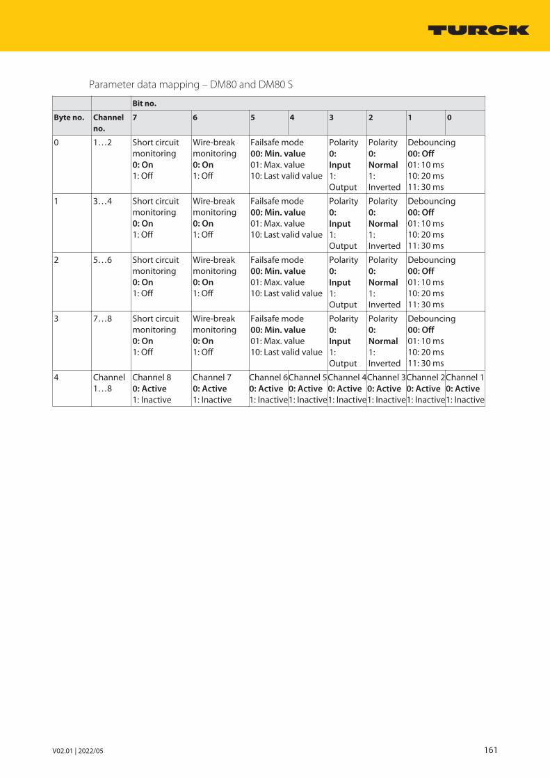
V02.01 | 2022/05 161
Parameter data mapping – DM80 and DM80 S
Bit no.
Byte no. Channelno.
7 6 5 4 3 2 1 0
0 1…2 Short circuitmonitoring0: On1: Off
Wire-breakmonitoring0: On1: Off
Failsafe mode00: Min. value01: Max. value10: Last valid value
Polarity0: Input1: Output
Polarity0: Normal1: Inverted
Debouncing00: Off01: 10 ms10: 20 ms11: 30 ms
1 3…4 Short circuitmonitoring0: On1: Off
Wire-breakmonitoring0: On1: Off
Failsafe mode00: Min. value01: Max. value10: Last valid value
Polarity0: Input1: Output
Polarity0: Normal1: Inverted
Debouncing00: Off01: 10 ms10: 20 ms11: 30 ms
2 5…6 Short circuitmonitoring0: On1: Off
Wire-breakmonitoring0: On1: Off
Failsafe mode00: Min. value01: Max. value10: Last valid value
Polarity0: Input1: Output
Polarity0: Normal1: Inverted
Debouncing00: Off01: 10 ms10: 20 ms11: 30 ms
3 7…8 Short circuitmonitoring0: On1: Off
Wire-breakmonitoring0: On1: Off
Failsafe mode00: Min. value01: Max. value10: Last valid value
Polarity0: Input1: Output
Polarity0: Normal1: Inverted
Debouncing00: Off01: 10 ms10: 20 ms11: 30 ms
4 Channel1…8
Channel 80: Active1: Inactive
Channel 70: Active1: Inactive
Channel 60: Active1: Inactive
Channel 50: Active1: Inactive
Channel 40: Active1: Inactive
Channel 30: Active1: Inactive
Channel 20: Active1: Inactive
Channel 10: Active1: Inactive

System componentsDM80-N digital input/output module
162 Hans Turck GmbH & Co. KG | T +49 208 4952-0 | F +49 208 4952-264 | [email protected] | www.turck.com
6.14.9 Bit assignment of the data byte
Configuring input and output bytes
Depending on the field of application, the DM80-N input and output module can be configuredexclusively as an input card or as an input and output card (all channels are parameterized inpairs as input or output) with or without status.
With the configuration with status, the status bit of the appropriate channel is set to 1 in thestatus byte when a status message (short circuit or wire break message) is present.
Different data rates are possible, depending on the configuration.
The following configurations are possible:
Input bytes Output bytes Type Configuration
1 1 DM80-N Bidirectional DM80-N without status
2 1 DM80-N S Bidirectional DM80-N with status
1 0 DM80-N 8I DM80-N exclusively as an input modulewithout status
2 0 DM80-N S 8I DM80-N exclusively as an input modulewith status
The module hardware is the same in spite of the different configuration. The behavior of themodule is only influenced by the configuration. Depending on the fieldbus or fieldbus protocol, the configuration is carried out in the higher-level control system, DTM or web server.
Status bit Bit
7 6 5 4 3 2 1 0
Input byte n Channel 8 active
Channel 7 active
Channel 6 active
Channel 5 active
Channel 4 active
Channel 3 active
Channel 2 active
Channel 1 active
Status byte (input byte n+1)
SB 8 SB 7 SB 6 SB 5 SB 4 SB 3 SB 2 SB 1
Output byte (input byte n +1)
Channel 8active
Channel 7 active
Channel 6 active
Channel 5 active
Channel 4 active
Channel 3 active
Channel 2 active
Channel 1 active
Example:
n Bits 0…5 in the input byte n are the inputs of channels 1…6.n Bits 6…7 in the output byte are the outputs of channels 7…8
The status byte is configured in the same way.
6.14.10 PROFIBUS: diagnostic informationThe diagnostics data is structured according to EN 61158, part 1/3/10.
Besides the module status (device-specific diagnostics) and the status overview (ID diagnostics)the module supports the following channel status indications (channel-specific diagnostics):
Error code No. Meaning
Standard 1 Short circuit
6 Wire break
Specific 19 Module type (set configuration) unknown
20 Module type (actual configuration) unknown
22 Parameter not plausible (inconsistent)

V02.01 | 2022/05 163
6.14.11 Technical data
Type code DM80-N
ID 6884211
Power supply Via the module rack, central power supplymodule
Power consumption 1 W
Galvanic isolation From the internal bus and from the powersupply circuit
Number of channels 8-channel
Input circuits According to EN 60947-5-6 (NAMUR)
Open circuit voltage (input) 8 VDC
Short-circuit current 4 mA
Switching threshold on/off (input) typ. 1.8 mA/typ. 1.4 mA
Switching frequency (input) ≤ 100 Hz with MT08…, MT16…≤ 50 Hz with MT24…, GEN…
Short circuit (input) < 367 Ω
Wire break (input) < 0.2 mA
Output circuits For low-power field devices
Open circuit voltage (output) 8 VDC
Rated current (output) 4 mA
Internal resistance Ri (output) 320 Ω
Switching frequency (output) ≤ 100 Hz
Short circuit (output) < 367 Ω
Wire break (output) < 0.2 mA
LEDsOperational readiness 1 × green/red
Status/error 8 × yellow/red
Housing material Plastic
Fixing type Module design, pluggable in the module rack
Protection type IP20
Ambient temperature -20…+70 °C
Relative air humidity ≤ 93 % at 40 °C acc. to IEC 60068-2-78
Vibration test Acc. to EN 60068-2-6
Shock testing Acc. to EN 60068-2-27
EMC Acc. to DIN EN 61326-1acc. to NAMUR NE21
MTTF 141 years acc. to SN 29500 (Ed. 99) 40 °C
Dimensions (W × H × D) 18 × 118 × 106 mm

System componentsDI40-N digital input module
164 Hans Turck GmbH & Co. KG | T +49 208 4952-0 | F +49 208 4952-264 | [email protected] | www.turck.com
6.15 DI40-N digital input module
6.15.1 Intended useThe device is designed as equipment of the excom I/O system for the non-Ex area and mustonly be operated within the excom system with the MT…-N module racks.
The 4-channel DI40-N digital input module is used to connect a maximum of four sensors according to NAMUR (EN 60947-5-6), 3-wire sensors (NPN, PNP) or mechanical contacts.
6.15.2 Device overview
118
18
106
Fig. 50: Dimensions
6.15.3 Properties and featuresn Four channelsn Input module (max. four) NAMUR sensorsn Full galvanic isolation of the input circuits:
– From each other– From the power supply– From the internal bus
6.15.4 Functions and operating modesOne NAMUR sensor (EN 60947-5-6), one 3-wire sensor (NPN, PNP) or one mechanical contactcan be connected per channel.
6.15.5 MountingMultiple devices can be mounted directly next to each other on the module rack. The devicescan also be changed during operation.
Protect the mounting location from thermal radiation, sudden temperature fluctuations,dust, dirt, humidity and other ambient influences.
Plug the device into the designated position on the module rack so that it noticeablysnaps into place.

V02.01 | 2022/05 165
6.15.6 ConnectionWhen plugged into the module rack, the device is connected to the module rack’s internalpower supply and data communication. Terminal blocks with screw or spring-loaded terminalscan be used to connect the field devices.
Connect the device as shown in the “Wiring diagram”.
GN/RD
Status
RD
1
RD
2
RD
3
RD
4
internalpowersupply
internalbus
11 +
12 –
13 +
14 –
21 +
22 –
23 +
24 –
31 +
32 –
33 +
34 –
41 +
42 –
43 +
44 –
BN +
BK
BU –
BN +
BU –
BN +
BU –
BN +
BK
BU –NAMURPNP
NPN
BN +
BK
BU –
BN +
BK
BU –
BN +
BK
BU –
NPN
NPN
NPN
BN +
BK
BU –PNP
BN +
BK
BU –PNP
BN +
BK
BU –PNP
BN +
BU –
BN +
BU –
NAMUR
BN +
BU –
BN +
BU –
NAMUR
BN +
BU –
BN +
BU –
NAMUR
Fig. 51: Wiring diagram – DI40-N
When using 3-wire sensors, terminals 1 and 4 are monitored for wire break and short circuit respectively. With NAMUR sensors, terminals 1 and 2 are monitored for wire break and shortcircuit respectively.
When using mechanical contacts: Implement out a resistor circuit via a WM1 module(ID 0912101) if wire break or short-circuit monitoring is activated.
6.15.7 LED indicationsLEDs on the front of the module indicate module status and channel diagnostics.
LED Indication Meaning
Status Off No power supply
Flashing red Module not configured for currentslot
Green Power supply and communication error-free
Green flashing (slow: 0.5 Hz)
Module not yet configured by the gatewayand is waiting for configuration data
Green flashing(1.0 Hz asym.)
Module in failsafe mode
Channel 1…4 Off Channel not active (not switched)
Yellow Channel active (switched)
Red Channel error (wire break, short circuit): Channel diagnostics present

System componentsDI40-N digital input module
166 Hans Turck GmbH & Co. KG | T +49 208 4952-0 | F +49 208 4952-264 | [email protected] | www.turck.com
6.15.8 SettingThe user can set the following parameters on the module:
Parameter overview – DI40.
The default parameter values are shown in the following table in bold type.
Parameter name Value Meaning
Short circuit monitoring OnOff
Activating or deactivating short circuit monitoring by channel
Wire-break monitoring OnOff
Activating or deactivating the wire-break monitoring bychannel
Failsafe mode Min. valueMax. valueLast valid value
Set substitute value per channel: minimum (0), maximum (1)or last valid value (0 or 1)
Polarity NormalInverse
Activate or deactivate signal inversion
Debouncing Off10 ms20 ms50 ms
Activate or deactivate additional damping of input signalsfor debouncing mechanical contacts
The behavior of the inputs is parameterized via an associated configuration tool, FDT frame orweb server, depending on the higher-level fieldbus system.
Parameter data mapping
The following bits and bytes can be set via the parameters.
The default parameter values are shown in the following table in bold type.
Bit no.
Byte no. Channelno.
7 6 5 4 3 2 1 0
0 1 Short circuitmonitoring0: On1: Off
Wire-breakmonitoring0: On1: Off
Failsafe mode00: Min. value01: Max. value10: Last valid value
Reserved0
Polarity0: Normal1: Inverted
Debouncing00: Off01: 10 ms10: 20 ms11: 30 ms
1 2 Short circuitmonitoring0: On1: Off
Wire-breakmonitoring0: On1: Off
Failsafe mode00: Min. value01: Max. value10: Last valid value
Reserved0
Polarity0: Normal1: Inverted
Debouncing00: Off01: 10 ms10: 20 ms11: 30 ms
2 3 Short circuitmonitoring0: On1: Off
Wire-breakmonitoring0: On1: Off
Failsafe mode00: Min. value01: Max. value10: Last valid value
Reserved0
Polarity0: Normal1: Inverted
Debouncing00: Off01: 10 ms10: 20 ms11: 30 ms
3 4 Short circuitmonitoring0: On1: Off
Wire-breakmonitoring0: On1: Off
Failsafe mode00: Min. value01: Max. value10: Last valid value
Reserved0
Polarity0: Normal1: Inverted
Debouncing00: Off01: 10 ms10: 20 ms11: 30 ms

V02.01 | 2022/05 167
6.15.9 Bit assignment of the input byte
Configuring an input byte
The DI40-N input module acts exclusively as an input card with one input byte and additionalstatus bit (SB) for each channel.
When a status message (short circuit or wire break message) is present, the status bit of the corresponding channel is set to 1 in the input byte (bit 4…7).
Status bit Bit
7 6 5 4 3 2 1 0
Input byte SB 4 SB 3 SB 2 SB 1 Channel 4 active
Channel 3 active
Channel 2 active
Channel 1 active
6.15.10 PROFIBUS: diagnostic informationThe diagnostics data is structured according to EN 61158, part 1/3/10.
Besides the module status (device-specific diagnostics) and the status overview (ID diagnostics)the module supports the following channel status indications (channel-specific diagnostics):
Error code No. Meaning
Standard 1 Short circuit
6 Wire break
Specific 19 Module type (set configuration) unknown
20 Module type (actual configuration) unknown
22 Parameter not plausible (inconsistent)

System componentsDI40-N digital input module
168 Hans Turck GmbH & Co. KG | T +49 208 4952-0 | F +49 208 4952-264 | [email protected] | www.turck.com
6.15.11 Technical data
Type code DI40-N
ID 6884213
Power supply Via the module rack, central power supplymodule
Max. power consumption 1.9 W
Max. heat dissipation 1.0 W
Galvanic isolation Full galvanic isolation
Number of channels 4-channel
Input circuits According to EN 60947-5-6 (NAMUR)
Open circuit voltage 8.2 VDC
Short-circuit current 2.7 mA
Switching threshold on/off typ. 1.8 / typ. 1.3 mA
Max. switching frequency 100 Hz with MT08…, MT16…50 Hz with MT24…, GEN…
Short circuit < 367 Ω
Wire break < 0.15 mA
3-wire input
Open circuit voltage 12 VDC
Current ≤ 20 mA
0 signal ≤ 4.5 V
1 signal ≥ 6.5 V
LEDsOperational readiness 1 × green/red
Status/error 4 × yellow/red
Housing material Plastic
Fixing type Module design, pluggable in the module rack
Protection type IP20
Ambient temperature -20…+70 °C
Relative air humidity ≤ 93 % at 40 °C acc. to IEC 60068-2-78
Vibration test Acc. to EN 60068-2-6
Shock testing Acc. to EN 60068-2-27
EMC Acc. to EN 61326-1 acc. to NAMUR NE21
MTTF 111 years acc. to SN 29500 (Ed. 99) 40 °C
Dimensions (W × H × D) 18 × 118 × 106 mm
Remark The supply of 3-wire sensors is also monitoredfor wire-break and short-circuit.

V02.01 | 2022/05 169
6.16 DI80-N digital input module
6.16.1 Intended UseThe device is designed as equipment of the excom I/O system for the non-Ex area and mustonly be operated within the excom system with the MT…-N module racks.
The DI80-N digital input module is used to connect eight 3-wire PNP/NPN sensors (IEC 61131,Type 3).
6.16.2 Device Overview
118
18
106
Fig. 52: Dimensions
6.16.3 Properties and Characteristicsn Eight channelsn Input module for 3-wire sensorsn Supply of the sensors: reverse polarity protected via separate auxiliary power supplyn Galvanic isolation of the inputs by groupn Bounce monitoring of the inputs

System componentsDI80-N digital input module
170 Hans Turck GmbH & Co. KG | T +49 208 4952-0 | F +49 208 4952-264 | [email protected] | www.turck.com
6.16.4 Functions and Operating ModesThe sensors are fed with auxiliary power (24 V). The auxiliary power is routed separately forchannels 1…4 (group 1) and 5…8 (group 2) externally via the connection terminals.
Bounce monitoring
The signal bounce monitoring detects and indicates any abnormal signal patterns in the process, e.g. frequent oscillation of the input signal between 0 and 1. The occurrence of thesesignal patterns is an indication of faulty sensors or unstable process conditions.
A configurable monitoring time window is provided for each input channel. Monitoring is started with the first signal change of the input signal. If the number of input signal changeswithin the configured monitoring period is greater than the configured number of permittedsignal changes, this is detected as a bounce error.
If no bounce error is detected within the monitoring period, monitoring starts again accordingto the configured time window at the next signal change.
If a bounce error occurs, the current signal state is entered in the process image and the statusof the signal is set to “invalid”. The Bounce error diagnostic information is entered and a dia-gnostic alarm is triggered. Status and diagnostic information can be evaluated and processedin the user program.
If a signal change of the input signal has not been detected within 3 successive monitoringperiods, the diagnostic entry is removed and a clearing diagnostic alarm is triggered. The statusof the current signal is set to “valid”.
6.16.5 MountingMultiple devices can be mounted directly next to each other on the module rack. The devicescan also be changed during operation.
Protect the mounting location from thermal radiation, sudden temperature fluctuations,dust, dirt, humidity and other ambient influences.
Plug the device into the designated position on the module rack so that it noticeablysnaps into place.

V02.01 | 2022/05 171
6.16.6 ConnectionWhen plugged into the module rack, the device is connected to the module rack’s internalpower supply and data communication. Terminal blocks with screw or spring-loaded terminalscan be used to connect the field devices.
Connect the device as shown in the “Wiring diagram”.
0.5 A
GN/RD
Status
YE/RD
1
YE/RD
2
YE/RD
3
YE/RD
4
YE/RD
5
YE/RD
6
YE/RD
7
YE/RD
8
internalpowersupply
internalbus
11 +
12 –
13 +
14 –
21 CH1
22 CH2
23 CH3
24 CH4
Aux
0.5 A
31 +
32 –
33 +
34 –
41 CH5
42 CH6
43 CH7
44 CH8
Aux
Fig. 53: Wiring diagram – DI80-N
The DI80-N digital input module is used for connecting eight 3-wire PNP/NPN sensors.
6.16.7 LED indicationsLEDs on the front of the module indicate module status and channel diagnostics.
LED Indication Meaning
Status Off No power supply
Flashing red Module is not configured for this slot
Green Power supply and communication error-free
Green flashing (slow: 0.5 Hz)
Module not yet configured by the gatewayand is waiting for configuration data
Green flashing(1.0 Hz asym.)
Module in failsafe mode
Channel 1…8 Off Channel not active (not switched)
Yellow Channel active (switched)
Red Channel error (wire break, short circuit): Channel diagnostics present
Flashing red External power supply missing

System componentsDI80-N digital input module
172 Hans Turck GmbH & Co. KG | T +49 208 4952-0 | F +49 208 4952-264 | [email protected] | www.turck.com
6.16.8 SettingThe user can set the following parameters on the module:
Parameter overview – DI80
The default parameter values are shown in the following table in bold type.
Parameter name Value Meaning
Failsafe mode Min. valueMax. valueLast valid value
Set substitute value per channel: minimum (0), maximum (1)or last valid value (0 or 1)
Sensor output PNPNPN
Select the sensor type (either PNP or NPN)
Polarity NormalInverse
Activate or deactivate signal inversion
Flutter time frame Off0.5 s1 s2 s
Select monitoring time window for bounce error
Number of signal changes 24816
Select the number of signal changes within the monitoringtime window (for bounce errors)
K 1…8: Line monitoring ActiveInactive
Channel-wise activation or deactivation of the line monitor-ingIf a channel is not used it can be switched off.
The behavior of the inputs is parameterized via an associated configuration tool, FDT frame orweb server, depending on the higher-level fieldbus system.

V02.01 | 2022/05 173
Parameter data mapping
The following bits and bytes can be set via the parameters.
The default parameter values are shown in the following table in bold type.
Bit no.
Byte no. Channelno.
7 6 5 4 3 2 1 0
0 1…2 Flutter time frame0: Off01: 0.5 s10: 1 s11: 2 s
Failsafe mode00: Min. value01: Max. value10: Last valid value
Sensoroutput0: pnp1: NPN
Polarity0: Normal1: Inverted
Number of signals00: 201: 410: 811: 16
1 3…4 Flutter time frame0: Off01: 0.5 s10: 1 s11: 2 s
Failsafe mode00: Min. value01: Max. value10: Last valid value
Sensoroutput0: pnp1: NPN
Polarity0: Normal1: Inverted
Number of signals00: 201: 410: 811: 16
2 5…6 Flutter time frame0: Off01: 0.5 s10: 1 s11: 2 s
Failsafe mode00: Min. value01: Max. value10: Last valid value
Sensoroutput0: pnp1: NPN
Polarity0: Normal1: Inverted
Number of signals00: 201: 410: 811: 16
3 7…8 Flutter time frame0: Off01: 0.5 s10: 1 s11: 2 s
Failsafe mode00: Min. value01: Max. value10: Last valid value
Sensoroutput0: pnp1: NPN
Polarity0: Normal1: Inverted
Number of signals00: 201: 410: 811: 16
4 1…8 Linemonitoringchannel 80: Active1: Inactive
Line monitoringchannel 70: Active1: Inactive
Line monitoringchannel 60: Active1: Inactive
Line monitoringchannel 50: Active1: Inactive
Line monitoringchannel 40: Active1: Inactive
Linemonitoringchannel 30: Active1: Inactive
Line monitoringchannel 20: Active1: Inactive
Line monitoringchannel 10: Active1: Inactive

System componentsDI80-N digital input module
174 Hans Turck GmbH & Co. KG | T +49 208 4952-0 | F +49 208 4952-264 | [email protected] | www.turck.com
6.16.9 Bit assignment of the input byte
Configuring an input byte
In the DI80-N configuration, the input module functions exclusively as an input card. In theDI80 S configuration, the process data contains an additional status bit (SB) for each channel.
When a status message (short circuit or wire break message) is present, the status bit of the corresponding channel is set to 1 in the input byte (bit 1…7).
Status bit Bit
7 6 5 4 3 2 1 0
Input byte n Channel 8 active
Channel 7 active
Channel 6 active
Channel 5 active
Channel 4 active
Channel 3 active
Channel 2 active
Channel 1 active
Status byte (input byte n+1)
SB 8 SB 7 SB 6 SB 5 SB 4 SB 3 SB 2 SB 1
6.16.10 PROFIBUS: diagnostic informationThe diagnostics data is structured according to EN 61158, part 1/3/10.
Besides the module status (device-specific diagnostics) and the status overview (ID diagnostics)the module supports the following channel status indications (channel-specific diagnostics):
Error code No. Meaning
Standard 1 Short circuit (with PNP to positive supply voltage,with NPN to negative supply voltage)
2 Undervoltage U < 19.2 V
3 Overvoltage U > 30 V
6 Wire break
9 Error (field circuit processor)
Specific 19 Module type (set configuration) unknown
20 Module type (actual configuration) unknown
21 Sensor supply not available
22 Parameter not plausible (inconsistent)
23 Short circuit of sensor supply
24 Bounce error detected

V02.01 | 2022/05 175
6.16.11 Technical data
Type code DI80-N
ID 6884273
Power supply Via the module rack, central power supplymodule
Power consumption ≤ 2.2 W
Galvanic isolation Two galvanically separated groups
Number of channels 8-channel
Input circuitsAuxiliary supply 2 × (19.2…30 VDC)
Switching frequency ≤ 50 Hz
Short circuit < 500 Ω
Wire break < 0.2 mA
3-wire input0 signal ≤ 5.0 V
1 signal ≥ 11.0 V
Output circuits
Output current ≤ 500 mA
Short-circuit protection Yes/cyclic
LEDsOperational readiness 1 × green/red
Status/error 8 × yellow/red
Housing material Plastic
Fixing type Module design, pluggable in the module rack
Protection type IP20
Ambient temperature -20…+70 °C
Relative air humidity ≤ 93 % at 40 °C acc. to IEC 60068-2-78
Vibration test Acc. to EN 60068-2-6
Shock testing Acc. to EN 60068-2-27
EMC Acc. to EN 61326-1 acc. to NAMUR NE21
MTTF 55 years acc. to SN 29500 (Ed. 99) 40 °C
Dimensions (W × H × D) 18 × 118 × 106 mm
System componentsDO40-N digital output module
176 Hans Turck GmbH & Co. KG | T +49 208 4952-0 | F +49 208 4952-264 | [email protected] | www.turck.com
6.17 DO40-N digital output module
6.17.1 Intended useThe device is designed as equipment of the excom I/O system for the non-Ex area and mustonly be operated within the excom system with the MT…-N module racks.
The 4-channel DO40-N digital output module is used to connect low-power digital field devices(e.g. control valves or signal transmitters).
6.17.2 Device overview
118
18
106
Fig. 54: Dimensions
6.17.3 Properties and featuresn Four channelsn Output module for field devicesn Full galvanic isolation of the output circuits:
– From each other– From the power supply– From the internal bus
6.17.4 Functions and operating modesOnly one field device per channel can be connected either to terminals 1 and 2 or to terminals 3 and 4. There are two types of terminal for each channel.
Valve control
Valves that require a higher power than the maximum output power of the DO40-N modulemust be controlled via the DO60-R-N, DO80-N module or valve control modules. Suitable control modules can be connected directly to the outputs of DO40-N.
The values for the valve control are shown in the corresponding load curve (see “Connection”).

V02.01 | 2022/05 177
6.17.5 MountingMultiple devices can be mounted directly next to each other on the module rack. The devicescan also be changed during operation.
Protect the mounting location from thermal radiation, sudden temperature fluctuations,dust, dirt, humidity and other ambient influences.
Plug the device into the designated position on the module rack so that it noticeablysnaps into place.
6.17.6 ConnectionWhen plugged into the module rack, the device is connected to the module rack’s internalpower supply and data communication. Terminal blocks with screw or spring-loaded terminalscan be used to connect the field devices.
Connect the device as shown in the “Wiring diagram”.
GN/RD
Status
YE/RD
1
YE/RD
2
YE/RD
3
YE/RD
4
internalpowersupply
internalbus
11 +
12 –
13 +
14 –
21 +
22 –
23 +
24 –
31 +
32 –
33 +
34 –
41 +
42 –
43 +
44 –
III
Fig. 55: Wiring diagram – DO40-N
The DO40-N digital output module has four outputs for connecting low-power field devices.
Each channel has two different connection options. These connection options have differentvalues for open circuit voltage and can only be connected alternatively and never together. Ifone terminal is used, the other terminal of the same channel loses its functionality. Only onelow-power field device can therefore be connected per channel.

System componentsDO40-N digital output module
178 Hans Turck GmbH & Co. KG | T +49 208 4952-0 | F +49 208 4952-264 | [email protected] | www.turck.com
Connection variants
Terminal connection 1 and 2
Voltage and maximum current with open circuit voltage 25 VDC
Maximum power at output
22.5 V/5 mA 112.5 mW
19 V/15 mA 285 mW
0
10
20
0 10 20
22
30 40 50
Uout [V]
Iout [mA]
17.5
Fig. 56: Load curve – terminal connection 1 and 2
Terminal connection 3 and 4
Voltage and maximum current with open circuit voltage 19 VDC
Maximum power at output
16 V/25 mA 400 mW
14 V/35 mA 490 mW
12 V/45 mA 540 mW
0
107.5
2024
0 10 20 30 40 50
Uout [V]
Iout [mA]
Fig. 57: Load curve – terminal connection 3 and 4
V02.01 | 2022/05 179
6.17.7 LED indicationsLEDs on the front of the module indicate module status and channel diagnostics.
LED Indication Meaning
Status Off No power supply
Flashing red Module is not configured for this slot
Green Power supply and communication error-free
Green flashing (slow: 0.5 Hz)
Module not yet configured by the gateway and iswaiting for configuration data
Green flashing (1.0 Hz) Module in failsafe mode
Green flashing (fast: 2.0 Hz)
Module configured, still no data exchange betweenmodule and master
Channel 1…4 Off Channel not active (not switched)
Yellow Channel active (switched)
Red Channel error (wire break, short circuit): Channel diagnostics presentChannel errors are only detected when the outputis switched.

System componentsDO40-N digital output module
180 Hans Turck GmbH & Co. KG | T +49 208 4952-0 | F +49 208 4952-264 | [email protected] | www.turck.com
6.17.8 SettingThe user can set the following parameters on the module:
Parameter overview – DO40
The default parameter values are shown in the following table in bold type.
Parameter name Value Meaning
Short circuit monitoring OnOff
Activating or deactivating short circuit monitoring by channelThe output signal can only be monitored if the output isactivated.
Wire-break monitoring OnOff
Activating or deactivating the wire-break monitoring bychannelThe output signal can only be monitored if the output is activated.
Failsafe mode Min. valueMax. valueLast valid value
Set substitute value per channel: minimum (0), maximum (1)or last valid value (0 or 1)
Polarity NormalInverse
Activate or deactivate signal inversion
The behavior of the outputs is parameterized via an associated configuration tool, FDT frame orweb server, depending on the higher-level fieldbus system.
Parameter data mapping
The following bits and bytes can be set via the parameters.
The default parameter values are shown in the following table in bold type.
Bit no.
Byte no. Channelno.
7 6 5 4 3 2 1 0
0 1 Short circuitmonitoring0: On1: Off
Wire-breakmonitoring0: On1: Off
Failsafe mode00: Min. value01: Max. value10: Last valid value
Reserved0
Polarity0: Normal1: Inverted
1 2 Short circuitmonitoring0: On1: Off
Wire-breakmonitoring0: On1: Off
Failsafe mode00: Min. value01: Max. value10: Last valid value
Reserved0
Polarity0: Normal1: Inverted
2 3 Short circuitmonitoring0: On1: Off
Wire-breakmonitoring0: On1: Off
Failsafe mode00: Min. value01: Max. value10: Last valid value
Reserved0
Polarity0: Normal1: Inverted
3 4 Short circuitmonitoring0: On1: Off
Wire-breakmonitoring0: On1: Off
Failsafe mode00: Min. value01: Max. value10: Last valid value
Reserved0
Polarity0: Normal1: Inverted

V02.01 | 2022/05 181
6.17.9 Bit assignment of the output byteThe DO40-N module operates exclusively as an output card with one output byte. Unlike the digital input cards, the module is not provided with an additional status bit. The four channelsare assigned to bits 0…3 of the output byte. Bits 4…7 are not assigned.
Status bit Bit
7 6 5 4 3 2 1 0
Output byte – – – – Channel 4 active
Channel 3 active
Channel 2 active
Channel 1 active
6.17.10 PROFIBUS: diagnostic informationThe diagnostics data is structured according to EN 61158, part 1/3/10.
Besides the module status (device-specific diagnostics) and the status overview (ID diagnostics)the module supports the following channel status indications (channel-specific diagnostics):
Wire break and short circuit (channel errors) are only detected when the output is switched.
Error code No. Meaning
Standard 1 Short circuit
6 Wire break
Specific 19 Module type (set configuration) unknown
20 Module type (actual configuration) unknown
22 Parameter not plausible (inconsistent)

System componentsDO40-N digital output module
182 Hans Turck GmbH & Co. KG | T +49 208 4952-0 | F +49 208 4952-264 | [email protected] | www.turck.com
6.17.11 Technical data
Type code DO40-N
ID 6884214
Power supply Via the module rack, central power supplymodule
Power consumption ≤ 4.5 W
Galvanic isolation Complete galvanic isolation
Number of channels 4-channel
Output circuits For low-power field devices
Open circuit voltage 24 VDC
Internal resistance Ri 300 Ω
Switching frequency ≤ 50 Hz
Short circuit ≥ 50 mA
Wire break < 1 mA
LEDsOperational readiness 1 × green/red
Status/error 4 × yellow/red
Housing material Plastic
Fixing type Module design, pluggable in the module rack
Protection type IP20
Ambient temperature -20…+70 °C
Relative air humidity ≤ 93 % at 40 °C acc. to IEC 60068-2-78
Vibration test Acc. to EN 60068-2-6
Shock testing Acc. to EN 60068-2-27
EMC Acc. to EN 61326-1 acc. to NAMUR NE21
MTTF 79 years acc. to SN 29500 (Ed. 99) 40 °C
Dimensions (W × H × D) 18 × 118 × 106 mm

V02.01 | 2022/05 183
6.18 DO60R-N digital output module
6.18.1 Intended useThe device is designed as equipment of the excom I/O system for the non-Ex area and mustonly be operated within the excom system with the MT…-N module racks.
The 6-channel digital relay module is used to connect digital field devices (e.g. valves or signaltransmitters).
6.18.2 Device overview
118
18
106
Fig. 58: Dimensions
6.18.3 Properties and featuresn Six channelsn Relay output for higher switching capacityn Configurable as output as NO contact and NC contactn Full galvanic isolation of the output circuits:
– From each other– From the power supply– From the internal bus
6.18.4 Functions and operating modesThe outputs of the relay module function as isolated relay contacts for higher switching capa-cities. The module has four NO contacts and two changeover contacts. The four NO contactscan be set in pairs as changeover contacts.
6.18.5 MountingMultiple devices can be mounted directly next to each other on the module rack. The devicescan also be changed during operation.
Protect the mounting location from thermal radiation, sudden temperature fluctuations,dust, dirt, humidity and other ambient influences.
Plug the device into the designated position on the module rack so that it noticeablysnaps into place.

System componentsDO60R-N digital output module
184 Hans Turck GmbH & Co. KG | T +49 208 4952-0 | F +49 208 4952-264 | [email protected] | www.turck.com
6.18.6 Connection
NOTETo protect the module rack, the contact circuits in the DO60R-N module are protec-ted by fuses (1.5 AT - ceramic). Replace the module after the fuses have tripped. Connections 12…13 and 22…23 are not further protected and can be loaded withthe maximum switching current of a relay contact. Preferably only use terminal 12 or22 for connection. For trouble-free operation, even in the event of a short circuit, usea backup fuse with a melting integral <2.1 A²s (e.g.: ESKA 522.714).
When plugged into the module rack, the device is connected to the module rack’s internalpower supply and data communication. Terminal blocks with screw or spring-loaded terminalscan be used to connect the field devices.
Connect the device as shown in the “Wiring diagram”.
GN/RD
Status
YE
1
YE
2
YE
3
YE
4
YE
5
YE
6
internalpowersupply
internalbus
11 NO
12 COM
13 COM
14 NC
21 NO
22 COM
23 COM
24 NC
31 NO
32 COM
33 NO
34 COM
41 NO
42 COM
43 NO
44 COM
Fig. 59: Wiring diagram – DO60R-N
The DO60R-N digital output module has six outputs for connecting field devices.
Load connections of terminals 12…13 and 22…23 max. with the switching current of arelay contact. The connections of the terminals 12…13 and 22…23 are not protectedfrom each other.
Relay configuration
When using channels 3 and 4 and/or 5 and 6 as changeover contacts, attach wire bridgesto 32…33 and/or 42…43 accordingly and change the parameters. Terminals 34 and 44become NC contacts due to the changeover configuration.

V02.01 | 2022/05 185
6.18.7 LED indicationsLEDs on the front of the module indicate module status and channel diagnostics.
LED Indication Meaning
Status Off No power supply
Flashing red Module is not configured for this slot
Green Power supply and communication error-free
Green flashing (slow: 0.5 Hz)
Module not yet configured by the gatewayand is waiting for configuration data
Green flashing (1.0 Hz) Module in failsafe mode
Green flashing (fast: 2.0 Hz)
Module configured, still no data exchangebetween module and master
Channel 1…6 Off Channel not active (not switched)
Yellow Channel active (switched)
6.18.8 SettingThe user can set the following parameters on the module:
Parameter overview - DO60R
The default parameter values are shown in the following table in bold type.
Parameter name Value Meaning
Failsafe mode Min. valueMax. valueLast valid value
Set substitute value per channel: minimum (0), maximum (1)or last valid value (0 or 1)
Polarity NormalInverse
Activate or deactivate signal inversion
Relay configurationChannel 3 + 4 and/or5 + 6 configurable aschangeover contact
2 NO contacts1 changeover
Configuring outputs (as isolated relay contacts) as NO orchangeover contacts
The behavior of the outputs is parameterized via an associated configuration tool, FDT frame orweb server, depending on the higher-level fieldbus system.
System componentsDO60R-N digital output module
186 Hans Turck GmbH & Co. KG | T +49 208 4952-0 | F +49 208 4952-264 | [email protected] | www.turck.com
Parameter data mapping
The following bits and bytes can be set via the parameters.
The default parameter values are shown in the following table in bold type.
Bit no.
Byte no. Channelno.
7 6 5 4 3 2 1 0
0 1 (Bit 6…4)2 (Bit 0…2)
Polarity Channel 10: Normal1: Inverted
Failsafe modeChannel 100: Min. value01: Max. value10: Last valid value
Polarity Channel 20: Normal1: Inverted
Failsafe mode Chan-nel 200: Min. value01: Max. value10: Last valid value
1 3 (Bit 7…4)4 (Bit 0…2)
Relay configuration Channel 3 + 40: 2 NO contact1: 1 Changeovercontact
Polarity Channel 30: Normal1: Inverted
Failsafe modeChannel 300: Min. value01: Max. value10: Last valid value
Polarity Channel 40: Normal1: Inverted
Failsafe mode Chan-nel 400: Min. value01: Max. value10: Last valid value
2 5 (Bit 7…4)6 (Bit 7 and2…0)
Relay configuration Channel 5 + 60: 2 NO contact1: 1 Changeovercontact
Polarity Channel 50: Normal1: Inverted
Failsafe modeChannel 500: Min. value01: Max. value10: Last valid value
Polarity Channel 60: Normal1: Inverted
Failsafe mode Chan-nel 600: Min. value01: Max. value10: Last valid value
6.18.9 Bit assignment of the output byteThe DO60R-N output module operates exclusively as an output card with one output byte. Unlike the digital input cards, the module is not provided with an additional status bit. The sixchannels are assigned to bits 0…5 of the output byte. Bits 6…7 are not assigned. When con-figured as a changeover contact, bit 2 controls channels 3 and 4, and bit 4 controls channels 5and 6.
Status bit Bit
7 6 5 4 3 2 1 0
Output byte – – Channel 6 active
Channel 5 active
Channel 4 active
Channel 3 active
Channel 2 active
Channel 1 active

V02.01 | 2022/05 187
6.18.10 PROFIBUS: diagnostic informationThe diagnostics data is structured according to EN 61158, part 1/3/10.
Besides the module status (device-specific diagnostics) and the status overview (ID diagnostics)the module supports the following channel status indications (channel-specific diagnostics):
Error code No. Meaning
Specific 19 Module type (set configuration) unknown
20 Module type (actual configuration) unknown
22 Parameter not plausible (inconsistent)

System componentsDO60R-N digital output module
188 Hans Turck GmbH & Co. KG | T +49 208 4952-0 | F +49 208 4952-264 | [email protected] | www.turck.com
6.18.11 Technical data
Type code DO60R-N
ID 6884196
Power supply Via the module rack, central power supplymodule
Max. power consumption 2 W
Galvanic isolation Complete galvanic isolation
Number of channels 6-channel
Output circuits 6 × relays (2 x changeover contacts, 4 × NOcontacts)
Switch voltage 12…60 VAC/DC
Switch current 0.01…1 A (60 VAC, 30 VDC)
0.01…0.7 A (60 VDC)
Switching circuits are fuse protected (1.5 AT)
Response time Max. 15 ms/max. 8 ms
Mechanical lifespan 1 × 10⁷ cycles
Potential isolation Int. bus/module supply: 1500 Vrms Between current circuits: 500 Vrms
LEDsOperational readiness 1 × green/red
Status/error 6 × yellow
Housing material Plastic
Fixing type Module design, pluggable in the module rack
Protection type IP20
Ambient temperature -20…+60 °C
Relative air humidity ≤ 93 % at 40 °C acc. to IEC 60068-2-78
Vibration test Acc. to EN 60068-2-6
Shock testing Acc. to EN 60068-2-27
EMC Acc. to EN 61326-1 acc. to NAMUR NE21
MTTF 224 years acc. to SN 29500 (Ed. 99) 40 °C
Dimensions (W × H × D) 18 × 118 × 106 mm

V02.01 | 2022/05 189
6.19 DO80-N digital output module
6.19.1 Intended UseThe device is designed as equipment of the excom I/O system for the non-Ex area and mustonly be operated within the excom system with the MT…-N module racks.
The DO80-N digital output module is used to connect eight 24 VDC field devices (e.g. valves orindication elements with up to 0.5 A).
6.19.2 Device Overview
118
18
106
Fig. 60: Dimensions
6.19.3 Properties and Characteristicsn Eight channelsn Output module for actuators or indicator elementsn Galvanic isolation of both output groups:
– From each other– From the power supply– From the backplane bus
6.19.4 Functions and Operating ModesThe field devices are controlled with 24 VDC. The auxiliary power is routed separately for channels 1…4 (group 1) and 5…8 (group 2) externally via the connection terminals. If the loadis to be increased, the outputs within a group can be connected in parallel.
Latching and cyclic short circuit monitoring
The user can set the outputs to latching or cyclic short circuit protection. After the short-circuithas been rectified, the latching short-circuit protection is canceled by changing the signal ofthe control value from 0 to 1. The rising edge of the 1 signal resets the latching short-circuitprotection. Latching short-circuit monitoring is restored after this step.
With cyclic short circuit protection the user does not have to reset the short circuit protection.The outputs are short circuit protected automatically until the short circuit is removed.

System componentsDO80-N digital output module
190 Hans Turck GmbH & Co. KG | T +49 208 4952-0 | F +49 208 4952-264 | [email protected] | www.turck.com
6.19.5 MountingMultiple devices can be mounted directly next to each other on the module rack. The devicescan also be changed during operation.
Protect the mounting location from thermal radiation, sudden temperature fluctuations,dust, dirt, humidity and other ambient influences.
Plug the device into the designated position on the module rack so that it noticeablysnaps into place.
6.19.6 ConnectionWhen plugged into the module rack, the device is connected to the module rack’s internalpower supply and data communication. Terminal blocks with screw or spring-loaded terminalscan be used to connect the field devices.
Connect the device as shown in the “Wiring diagram”.
GN/RD
Status
YE/RD
1
YE/RD
2
YE/RD
3
YE/RD
4
YE/RD
5
YE/RD
6
YE/RD
7
YE/RD
8
internalpowersupply
internalbus
11 +
12 –
13 +
14 –
21 + CH1
22 + CH2
23 + CH3
24 + CH4
Aux
31 +
32 –
33 +
34 –
41 + CH5
42 + CH6
43 + CH7
44 + CH8
Aux
Fig. 61: Wiring diagram – DO80-N
The DO80-N digital output module has eight outputs for connecting field devices.

V02.01 | 2022/05 191
6.19.7 LED indicationsLEDs on the front of the module indicate module status and channel diagnostics.
LED Indication Meaning
Status Off No power supply
Flashing red Module is not configured for this slot
Green Power supply and communication error-free
Green flashing (slow: 0.5 Hz)
Module not yet configured by the gatewayand is waiting for configuration data
Green flashing(1.0 Hz asym.)
Module in failsafe mode
Green flashing (fast: 2.0 Hz)
Module configured, still no data exchangebetween module and master
Channel 1…8 Off Channel not active (not switched)
Yellow Channel active (switched)
Red Channel error (wire break, short circuit): Channel diagnostics present
Flashing red External power supply missing
6.19.8 SettingThe user can set the following parameters on the module:
Parameter overview – DO80
The parameters are set in pairs for the particular two channels (1/2, 3/4, 5/6, 7/8).
The default parameter values are shown in the following table in bold type.
Short circuit monitoring OnOff
Activate or deactivate the short circuit monitoring in pairsThe output signal can only be monitored if the output is activated.
Wire-break monitoring OnOff
Activate or deactivate the wire-break monitoring in pairsThe output signal can only be monitored if the output isactivated.
Failsafe mode Min. valueMax. valueLast valid value
Set substitute value in pairs: minimum (0), maximum (1) orlast valid value (0 or 1)
Polarity NormalInverted
Activate or deactivate signal inversion in pairs
Short circuit current Non-lockingLocking
Set short circuit behavior parameters in pairs
Channel 1…8 ActiveInactive
Activate or deactivate channels 1…8
The behavior of the outputs is parameterized via an associated configuration tool, FDT frame orweb server, depending on the higher-level fieldbus system.

System componentsDO80-N digital output module
192 Hans Turck GmbH & Co. KG | T +49 208 4952-0 | F +49 208 4952-264 | [email protected] | www.turck.com
Parameter data mapping
The following bits and bytes can be set via the parameters.
The default parameter values are shown in the following table in bold type.
Bit no.
Byte no. Channelno.
7 6 5 4 3 2 1 0
0 1…2 Short circuitmonitor-ing0: On1: Off
Wire-breakmonitor-ing0: On1: Off
Failsafe mode00: Min. value01: Max. value10: Last valid value
Short circuitbehavior0: Non-Locking1: Locking
Polarity0: Normal1: Inverted
Reserved0
1 3…4 Shortcircuitmonitor-ing0: On1: Off
Wire-breakmonitor-ing0: On1: Off
Failsafe mode00: Min. value01: Max. value10: Last valid value
Short circuit behavior0: Non-Locking1: Locking
Polarity0: Normal1: Inverted
Reserved0
2 5…6 Short circuitmonitor-ing0: On1: Off
Wire-breakmonitor-ing0: On1: Off
Failsafe mode00: Min. value01: Max. value10: Last valid value
Short circuitbehavior0: Non-Locking1: Locking
Polarity0: Normal1: Inverted
Reserved0
3 7…8 Short circuitmonitor-ing0: On1: Off
Wire-breakmonitor-ing0: On1: Off
Failsafe mode00: Min. value01: Max. value10: Last valid value
Short circuit behavior0: Non-Locking1: Locking
Polarity0: Normal1: Inverted
Reserved0
4 1…8 Channel 80: Active1: Inactive
Channel 70: Active1: Inactive
Channel 60: Active1: Inactive
Channel 50: Active1: Inactive
Channel 40: Active1: Inactive
Channel 30: Active1: Inactive
Channel 20: Active1: Inactive
Channel 10: Active1: Inactive
6.19.9 Bit assignment of the output byteThe DO80-N output module operates exclusively as an output card with one output byte. Unlike the digital input cards, the module is not provided with an additional status bit. Theeight channels are assigned to bits 0…7 of the output byte.
Status bit Bit
7 6 5 4 3 2 1 0
Output byte Channel 8 active
Channel 7 active
Channel 6 active
Channel 5 active
Channel 4 active
Channel 3 active
Channel 2 active
Channel 1 active

V02.01 | 2022/05 193
6.19.10 PROFIBUS: diagnostic informationThe diagnostics data is structured according to EN 61158, part 1/3/10.
Besides the module status (device-specific diagnostics) and the status overview (ID diagnostics)the module supports the following channel status indications (channel-specific diagnostics):
Error code No. Meaning
Standard 1 Short circuit
2 Undervoltage U < 19.2 V
3 Overvoltage U > 30 V
6 Wire break
9 Error (field circuit processor)
Specific 19 Module type (set configuration) unknown
20 Module type (actual configuration) unknown
21 External power supply missing
22 Parameter not plausible (inconsistent)
A short circuit message is triggered if the output is activated and short circuited to ground. Thewire break message is triggered if outputs are activated or not activated when nothing is con-nected.

System componentsDO80-N digital output module
194 Hans Turck GmbH & Co. KG | T +49 208 4952-0 | F +49 208 4952-264 | [email protected] | www.turck.com
6.19.11 Technical data
Type code DO80-N
ID 6884274
Power supply Via the module rack, central power supplymodule
Power consumption ≤ 3 W
Galvanic isolation Two galvanically separated groups
Number of channels 8-channel
Input circuitsAuxiliary supply 2 × (19.2…30 VDC)
Heat dissipation ≤ 1.5 W
Output circuitsOutput current ≤ 500 mA
Switching frequency, resistive < 50 Hz
Inductive switching frequency < 1 Hz
Switching frequency, lamp load < 2 Hz
Short circuit < 48 Ω
Short-circuit protection Yes, cyclic or latching
Wire break with 0 signal > 10 kΩwith 1 signal > 5 kΩ
LEDsOperational readiness 1 × green/red
Status/error 8 × yellow/red
Housing material Plastic
Fixing type Module design, pluggable in the module rack
Protection type IP20
Ambient temperature -20…+70 °C
Relative air humidity ≤ 93 % at 40 °C acc. to IEC 60068-2-78
Vibration test Acc. to EN 60068-2-6
Shock testing Acc. to EN 60068-2-27
EMC Acc. to EN 61326-1 acc. to NAMUR NE21
MTTF 55 years acc. to SN 29500 (Ed. 99) 40 °C
Dimensions (W × H × D) 18 × 118 × 106 mm

V02.01 | 2022/05 195
6.20 TI40-N temperature module
6.20.1 Intended useThe device is designed as equipment of the excom I/O system for the non-Ex area and mustonly be operated within the excom system with the MT…-N module racks.
The 4-channel temperature input module records the following temperature probes, thermo-couples, extra low voltages and resistances:
Input Types
Temperature probe:n 2-wiren 3-wiren 4-wire
Pt100
Pt200
Pt500
Pt1000
Ni100
Cu100
Pt100 (JIS)
Pt1000 (JIS)
Pt100 (MIL)
Pt1000 (MIL)
Pt100 (GOST)
Thermocouples B
C
D
E
J
K
L
L (Gost)
N
R
S
T
U
Extra low voltages -75…+75 mV
-1.2…+1.2 V
Resistance measurement 0…30 Ω
0…300 Ω
0…3 kΩ

System componentsTI40-N temperature module
196 Hans Turck GmbH & Co. KG | T +49 208 4952-0 | F +49 208 4952-264 | [email protected] | www.turck.com
6.20.2 Device overview
118
18
106
Fig. 62: Dimensions
6.20.3 Properties and featuresn Four channelsn Input module for connecting RTD sensors and thermocouplesn Voltage measurementn Full galvanic isolation of the input circuits:
– From each other– From the power supply– From the internal bus
6.20.4 Functions and operating modesThe device can be set as an input module for temperature sensors and resistors (TI40 R mode)or for thermocouples and extra low voltages (TI40 mode). All four channels operate accordinglydepending on the operating mode of the device.
The digitized temperature value is output in Kelvin with a resolution of 0.1 K.
For conversion to °C, please observe an offset of 273.2. The numerical value 0…30000 corres-ponds to 0 to 3000 K. The following applies for conversion to °C: 0 K = -273.2 °C.
The temperature value in °C can be calculated from the numerical value with the following formula:
Temperature in °C = (digitized temperature value -2732) : 10
Line compensation
In R mode, the cable compensation function compensates the line fault for temperature meas-urement with temperature resistors. Cable compensation is automatic with 3-wire measure-ment and 4-wire measurement. With two-wire measurement a cable resistance of 0…15.5 Ωcan be compensated in 0.5 Ω steps.

V02.01 | 2022/05 197
Cold junction compensation
In T mode, the cold junction compensation increases measuring accuracy with thermocouples.For external cold junction compensation, the comparison temperature must be measured be-forehand and set in the device. Alternatively, an external cold junction compensation can beimplemented for each channel by connecting temperature resistors at both free terminals. Theinternal cold junction compensation is implemented for all channels via an integrated Pt100resistor.
6.20.5 MountingMultiple devices can be mounted directly next to each other on the module rack. The devicescan also be changed during operation.
Protect the mounting location from thermal radiation, sudden temperature fluctuations,dust, dirt, humidity and other ambient influences.
Plug the device into the designated position on the module rack so that it noticeablysnaps into place.
6.20.6 ConnectionWhen plugged into the module rack, the device is connected to the module rack’s internalpower supply and data communication. Terminal blocks with screw or spring-loaded terminalscan be used to connect the field devices.
Connect the device as shown in the “Wiring diagram”.
GN/RD
Status
RD
1
RD
2
RD
3
RD
4
internalpowersupply
internalbus
11
12
13
14
21
22
23
24
31
32
33
34
41
42
43
44
I II III IV
Fig. 63: Wiring diagram – TI40-N
The TI40-N analog temperature input module is provided with four inputs for connecting 2-, 3-or 4-wire temperature resistors or thermocouples.
The first channel of the device is permanently activated.
If only one temperature sensor is used: Use channel 1. If channel 1 is not used: use a 100 Ω resistor to prevent diagnostic messages.

System componentsTI40-N temperature module
198 Hans Turck GmbH & Co. KG | T +49 208 4952-0 | F +49 208 4952-264 | [email protected] | www.turck.com
6.20.7 LED indicationsLEDs on the front of the module indicate module status and channel diagnostics.
LED Indication Meaning
Status Off No power supply
Flashing red Module is not configured for this slot
Green Power supply and communication error-free
Green flashing (slow: 0.5 Hz)
Module not yet configured by the gatewayand is waiting for configuration data
Green flashing(1.0 Hz asym.)
Module in failsafe mode
Channel 1…4 Off No channel error
Red Channel error (wire break, short circuit): Channel diagnostics present
6.20.8 CommissioningSwitching on the power supply on the module rack immediately switches on the fitted device.During commissioning, the behavior of the inputs must be parameterized and the module slotconfigured via an associated configuration tool, FDT frame or web server, depending on thehigher-level fieldbus system.
V02.01 | 2022/05 199
6.20.9 SettingThe user can set the following parameters on the module:
Parameter overview – TI40
The default parameter values are shown in the following table in bold type.
Parameters for TI40 R
Parameter name Value Meaning
Sensor type PT100 (IEC)PT200 (IEC)PT500 (IEC)PT1000 (IEC)PT100 (JIS)PT1000 (JIS)PT100 (MIL)PT1000 (MIL)NI100PT100 (GOST)CU1000…30 Ω in [mΩ]0…300 Ω [10 mΩ]0…3 kΩ [100 mΩ]
Set the sensor type
Connection 2-wire /0 Ω Base2-wire /8 Ω Base3-wire4-wire
Choose the connection technology
Cable resistance Basis + 0 ΩBasis + 0.5 ΩBasis + 1.0 ΩBasis + 2.0 ΩBasis + 2.5 ΩBasis + 3.0 ΩBasis + 3.5 ΩBasis + 4.0 ΩBasis + 4.5 ΩBasis + 5.0 ΩBasis + 5.5 ΩBasis + 6.0 ΩBasis + 6.5 ΩBasis + 7.0 ΩBasis + 7.5 Ω
Set the cable resistanceWith a 2-wire connection, cable resistance and base are subtracted prior to linearization. Cable resistance otherwisefalsifies the result of linearization.
Short circuit monitoring OnOff
Activate or deactivate short circuit monitoring
Wire-break monitoring OnOff
Activate or deactivate wire-break monitoringNOTE: The wire break monitoring for channel 1 is always active. If channel 1 is not used, use a 100 Ω resistor.

System componentsTI40-N temperature module
200 Hans Turck GmbH & Co. KG | T +49 208 4952-0 | F +49 208 4952-264 | [email protected] | www.turck.com
Parameter name Value Meaning
Failsafe mode Min. valueMax. valueLast valid value
Set substitute value per channel: minimum, maximum(0x7FFF) or last valid value
Filter (PT1) Off1.2 s11 s25 s
Activate or deactivate software filter for generating an average value
Parameters for TI40 T
Parameter name Value Meaning
Sensor type Type BType CType DType EType JType KType LType L (GOST)Type NType RType SType TType U-75…+75 mV [5 μV]-1.2…+1.2 V [100 μV]
With TI40-N T set sensor type and thermocouple type
Cold junction compensation
NoneInternalPT100 on terminalExternal (fixed)
Choose reference point
None: no cold junction compensation
Internal: cold junction compensation via PT100 in the module
PT100 at terminal: cold junction compensation via PT100 atthe terminal of the module rack
External (fixed): cold junction compensation through extern-ally determined reference temperature (fixed value)
Wire-break monitoring OnOff
Activate or deactivate wire-break monitoring
Failsafe mode Min. valueMax. valueLast valid value
Set substitute value per channel: minimum, maximum(0x7FFF) or last valid value
Filter (PT1) Off1.2 s11 s25 s
Activate or deactivate software filter for generating anaverage value
Fix junction temperature 0 °C10 °C…70 °C
Determine reference temperature with external thermocouple

V02.01 | 2022/05 201
The behavior of the inputs is parameterized via an associated configuration tool, FDT frame orweb server, depending on the higher-level fieldbus system.
Parameter data mapping
The following bits and bytes can be set via the parameters.
The default parameter values are shown in the following table in bold type.
Parameter data mapping – TI40 R
Bit no.
Byte no. Channelno.
7 6 5 4 3 2 1 0
0 1 Short circuit monitoring0: On1: Off
Wire-break monitoring0: On1: Off
Failsafe mode00: Min. value01: Max. value10: Last valid value
Cable resistance:0000: Basis + 0 Ω0001: Basis + 0.5 Ω0010: Basis + 1.0 Ω0011: Basis + 1.5 Ω0100: Basis + 2.0 Ω0101: Basis + 2.5 Ω0110: Basis + 3.0 Ω0111: Basis + 3.5 Ω1000: Basis + 4.0Ω1001: Basis + 4.5 Ω1010: Basis + 5.0 Ω1011: Basis + 5.5 Ω1100: Basis + 6.0 Ω1101: Basis + 6.5 Ω1110: Basis + 7.0 Ω1111: Basis + 7.5 Ω
1 2 Short circuit monitoring0: On1: Off
Wire-break monitoring0: On1: Off
Failsafe mode00: Min. value01: Max. value10: Last valid value
Cable resistance:0000: Basis + 0 Ω0001: Basis + 0.5 Ω0010: Basis + 1.0 Ω0011: Basis + 1.5 Ω0100: Basis + 2.0 Ω0101: Basis + 2.5 Ω0110: Basis + 3.0 Ω0111: Basis + 3.5 Ω1000: Basis + 4.0Ω1001: Basis + 4.5 Ω1010: Basis + 5.0 Ω1011: Basis + 5.5 Ω1100: Basis + 6.0 Ω1101: Basis + 6.5 Ω1110: Basis + 7.0 Ω1111: Basis + 7.5 Ω

System componentsTI40-N temperature module
202 Hans Turck GmbH & Co. KG | T +49 208 4952-0 | F +49 208 4952-264 | [email protected] | www.turck.com
Bit no.
Byte no. Channelno.
7 6 5 4 3 2 1 0
2 3 Short circuit monitoring0: On1: Off
Wire-break monitoring0: On1: Off
Failsafe mode00: Min. value01: Max. value10: Last valid value
Cable resistance:0000: Basis + 0 Ω0001: Basis + 0.5 Ω0010: Basis + 1.0 Ω0011: Basis + 1.5 Ω0100: Basis + 2.0 Ω0101: Basis + 2.5 Ω0110: Basis + 3.0 Ω0111: Basis + 3.5 Ω1000: Basis + 4.0Ω1001: Basis + 4.5 Ω1010: Basis + 5.0 Ω1011: Basis + 5.5 Ω1100: Basis + 6.0 Ω1101: Basis + 6.5 Ω1110: Basis + 7.0 Ω1111: Basis + 7.5 Ω
3 4 Short circuit monitoring0: On1: Off
Wire-break monitoring0: On1: Off
Failsafe mode00: Min. value01: Max. value10: Last valid value
Cable resistance:0000: Basis + 0 Ω0001: Basis + 0.5 Ω0010: Basis + 1.0 Ω0011: Basis + 1.5 Ω0100: Basis + 2.0 Ω0101: Basis + 2.5 Ω0110: Basis + 3.0 Ω0111: Basis + 3.5 Ω1000: Basis + 4.0Ω1001: Basis + 4.5 Ω1010: Basis + 5.0 Ω1011: Basis + 5.5 Ω1100: Basis + 6.0 Ω1101: Basis + 6.5 Ω1110: Basis + 7.0 Ω1111: Basis + 7.5 Ω
4 1…4 Connection00: 2-wire /0 Ω Base01: 2-wire /8 Ω Base10: 3-wire11: 4-wire
Filter (PT1)00: Off01: 1.2 s10: 11 s11: 25 s
Sensor type0000: Pt100 (IEC 751)0001: Pt200 (IEC 751)0010: Pt400 (IEC 751)0011: Pt1000 (IEC 751)0100: Pt100 (JIS)0101: Pt1000 (JIS)0110: Pt100 (MIL)0111: Pt1000 (MIL)1000: Ni1001001: Pt100 (GOST)1011: Cu1001101: 0…30 Ω (1 mΩ)1110: 0…300 Ω (10 mΩ)1111: 0…3 kΩ (100 mΩ)

V02.01 | 2022/05 203
Parameter data mapping – TI40 T
Bit no.
Byte no. Channelno.
7 6 5 4 3 2 1 0
0 1 Reserved: 0 Wire-break monitoring0: On1: Off
Failsafe mode00: Min. value01: Max. value10: Last validvalue
Fix junctiontemperature000: 00 °C001: 10 °C010: 20 °C011: 30 °C100: 40 °C101: 50 °C110: 60 °C111: 70 °C
Reserved: 0
1 2 Reserved: 0 Wire-break monitoring0: On1: Off
Failsafe mode00: Min. value01: Max. value10: Last validvalue
Fix junction temperature000: 00 °C001: 10 °C010: 20 °C011: 30 °C100: 40 °C101: 50 °C110: 60 °C111: 70 °C
Reserved: 0
2 3 Reserved: 0 Wire-break monitoring0: On1: Off
Failsafe mode00: Min. value01: Max. value10: Last validvalue
Fix junction temperature000: 00 °C001: 10 °C010: 20 °C011: 30 °C100: 40 °C101: 50 °C110: 60 °C111: 70 °C
Reserved: 0
3 4 Reserved: 0 Wire-break monitoring0: On1: Off
Failsafe mode00: Min. value01: Max. value10: Last validvalue
Fix junction temperature000: 00 °C001: 10 °C010: 20 °C011: 30 °C100: 40 °C101: 50 °C110: 60 °C111: 70 °C
Reserved: 0

System componentsTI40-N temperature module
204 Hans Turck GmbH & Co. KG | T +49 208 4952-0 | F +49 208 4952-264 | [email protected] | www.turck.com
Bit no.
Byte no. Channelno.
7 6 5 4 3 2 1 0
4 1…4 Cold junction compensation00: None01: Internal10: Pt100 at terminal11: External (fixed)
Filter (PT1)00: Off01: 1.2 s10: 11 s11: 25 s
0000: Type B0001: Type E0010: Type J0011: Type K0100: Type L0101: Type N0110: Type R0111: Type S1000: Type T1001: Type U1010: Type C1011: Type D1100: Type L (GOST)1101: -75…+75 mV [5 μV]1111: -1.2…+1.2 V [100 μV]
6.20.10 Measuring ranges
Measuring range and substitute values for voltage and resistance measurement
Measuringrange
Value representa-tion
Resolution Not valid in event of measuring range violation
Substitute value with invalid measured value
Underflow Overflow min. max.
-75…+75 mV 7500…22500
5 μV -75 mV +75 mV 0 32767
-1200…+1200 mV
3000…27000
100 μV -1200 mV +1200 mV 0 32767
0…3000 K 0…30000 0.1 K Sensor-specific 0 32767
0…30 Ω 0…30000 1 mΩ 0 Ω 30 Ω 0 32767
0…300 Ω 0…30000 10 mΩ 0 Ω 300 Ω 0 32767
0…3000 Ω 0…30000 100 mΩ 0 Ω 3000 Ω 0 32767

V02.01 | 2022/05 205
Measuring ranges of the temperature sensors
Sensor Minimum value in K
Minimum in °C Maximum value in K
Maximum valuein °C
Pt100 (IEC) 73 - 200 1123 850
Pt200 (IEC) 73 - 200 1123 850
Pt500 (IEC) 73 - 200 1123 850
Pt1000 (IEC) 73 - 200 1123 850
Pt100 (JIS) 73 - 200 1123 850
Pt1000 (JIS) 73 - 200 1123 850
Pt100 (MIL) 73 - 200 1123 850
Pt1000 (MIL) 73 - 200 1123 850
Pt100 (GOST) 73 - 200 1373 1100
Ni100 213 - 60 523 250
Cu100 223 - 50 473 200
Type B 273 0 2093 1820
Type C 273 0 2588 2320
Type D 273 0 2588 2320
Type E 3 - 270 1273 1000
Type J 63 - 210 1473 1200
Type K 3 - 270 1645 1372
Type L 73 - 200 1173 900
Type L (GOST) 73 - 200 1073 800
Type N 3 - 270 1573 1300
Type R 223 - 50 2042 1769
Type S 223 - 50 2042 1769
Type T 3 - 270 673 400
Type U 73 - 200 873 600

System componentsTI40-N temperature module
206 Hans Turck GmbH & Co. KG | T +49 208 4952-0 | F +49 208 4952-264 | [email protected] | www.turck.com
6.20.11 Bit assignment of the input word
Configuring an input byte
The TI40-N module acts exclusively as an input card with eight input bytes and additionalstatus bit (SB) for each channel. If a status message (error message) is present, the status bit ofthe corresponding channel is set to 1 in the input word. Depending on the selection of theAnalog data format gateway parameter, the status bit is mapped left-justified, right-justified ornot at all in the process data.
The status bit is set if there is a measuring range violation or a line error. The error can thus beevaluated consistently with regard to the measuring value.
For conversion to °C, please observe an offset of 273.2. The numerical value 0…30000 corres-ponds to 0 to 3000 K. The following applies for conversion to °C: 0 K = -273.2 °C.
The temperature value in °C can be calculated from the numerical value with the followingformula:
Temperature in °C = (digitized temperature value -2732) : 10
Chan-nel
Bit
1…4 15 14 13 12 11 10 9 8 7 6 5 4 3 2 1 0
SB Measured value
Measured value SB
– Measured value
6.20.12 PROFIBUS: diagnostic informationThe diagnostics data is structured according to EN 61158, part 1/3/10.
Besides the module status (device-specific diagnostics) and the status overview (ID diagnostics)the module supports the following channel status indications (channel-specific diagnostics):
Error code No. Meaning
Standard 6 Wire break
7 Upper limit exceeded (see measuring range tables)
8 Below lower limit (see measuring range tables)
Specific 19 Module type (set configuration) unknown
20 Module type (actual configuration) unknown
22 Parameter not plausible (inconsistent)

V02.01 | 2022/05 207
6.20.13 Technical data
Type code TI40-N
ID 6884222
Power supply Via the module rack, central power supplymodule
Power consumption ≤ 1 W
Galvanic isolation Complete galvanic isolation
Number of channels 4-channel
Input circuits Pt100 (IEC)
Pt200 (IEC)
Pt500 (IEC)
Pt1000 (IEC)
Pt100 (JIS)
Pt1000 (JIS)
Pt100 (MIL)
Pt1000 (MIL)
Ni100
Pt100 (GOST)
Cu100
Thermocouple: B, C, D, E, J, K, L, L (GOST), N, R,S, T, U
Measuring range for RTD 100 -200…+850 °C
Resolution 0.1 K
Full scale Pt100: 1050 K
Linearity deviation ≤ 0.05 % of full scale at 25 °C
Temperature drift ≤ 0.005 % of full scale/K
Rise time/fall time ≤ 1.3 s (10…90 %)
Max. measurement deviation under EMCinfluence
With shielded signal cable:0.1 % of full scale at 25 °C
With unshielded signal cable:1 % of full scale at 25 °C
LEDsOperational readiness 1 × green/red
Status/error 4 × red
Housing material Plastic
Fixing type Module design, pluggable in the module rack

System componentsTI40-N temperature module
208 Hans Turck GmbH & Co. KG | T +49 208 4952-0 | F +49 208 4952-264 | [email protected] | www.turck.com
Type code TI40-N
Protection type IP20
Ambient temperature -20…+60 °C
Relative air humidity ≤ 93 % at 40 °C acc. to IEC 60068-2-78
Vibration test Acc. to EN 60068-2-6
Shock testing Acc. to EN 60068-2-27
EMC Acc. to EN 61326-1 acc. to NAMUR NE21
MTTF 62 years acc. to SN 29500 (Ed. 99) 40 °C
Dimensions (W × H × D) 18 × 118 × 106 mm

V02.01 | 2022/05 209
6.21 TI41-N temperature module
6.21.1 Intended useThe device is designed as equipment of the excom I/O system for the non-Ex area and mustonly be operated within the excom system with the MT…-N module racks.
The 4-channel temperature input module captures the value of 2-, 3- and 4-wire type Pt100,Ni100 and Cu100 resistors and outputs them as digital values.
6.21.2 Device overview
118
18
106
Fig. 64: Dimensions
6.21.3 Properties and featuresn Four channelsn Input module for connecting RTD temperature probesn Full galvanic isolation of the input circuits:
– From each other– From the power supply– From the internal bus
6.21.4 Functions and operating modesThe module converts an analog input signal to a digital value of 0…16383 digits. The internalresolution is 16 bits. The digitized temperature value is output in Kelvin with a resolution of 0.1 K.
For conversion to °C, please observe an offset of 273.2. The numerical value 0…30000 corres-ponds to 0 to 3000 K. The following applies for conversion to °C: 0 K = -273.2 °C.
The temperature value in °C can be calculated from the numerical value with the following formula:
Temperature in °C = (digitized temperature value -2732) : 10
Line compensation
The cable compensation function compensates the line fault for temperature measurement.Cable compensation is automatic with 3-wire measurement and 4-wire measurement. Withtwo-wire measurement a cable resistance of 0…15.5 Ω can be compensated in 0.5 Ω steps.

System componentsTI41-N temperature module
210 Hans Turck GmbH & Co. KG | T +49 208 4952-0 | F +49 208 4952-264 | [email protected] | www.turck.com
6.21.5 MountingMultiple devices can be mounted directly next to each other on the module rack. The devicescan also be changed during operation.
Protect the mounting location from thermal radiation, sudden temperature fluctuations,dust, dirt, humidity and other ambient influences.
Plug the device into the designated position on the module rack so that it noticeablysnaps into place.
6.21.6 ConnectionWhen plugged into the module rack, the device is connected to the module rack’s internalpower supply and data communication. Terminal blocks with screw or spring-loaded terminalscan be used to connect the field devices.
Connect the device as shown in the “Wiring diagram”.
GN/RD
Status
RD
1
RD
2
RD
3
RD
4
internalpowersupply
internalbus
11
12
13
14
21
22
23
24
31
32
33
34
41
42
43
44
I II III
Fig. 65: Wiring diagram – T41-N
The TI41-N analog temperature input module is provided with four inputs for connecting2-, 3- or 4-wire temperature resistors.

V02.01 | 2022/05 211
6.21.7 LED indicationsLEDs on the front of the module indicate module status and channel diagnostics.
LED Indication Meaning
Status Off No power supply
Flashing red Module not configured for current slot
Green Power supply and communication error-free
Green flashing (slow: 0.5 Hz)
Module not yet configured by the gatewayand is waiting for configuration data
Green flashing(1.0 Hz asym.)
Module in failsafe mode
Channel 1…4 Off No channel error
Red Channel error (wire break, short circuit): Channel diagnostics present
6.21.8 CommissioningSwitching on the power supply on the module rack immediately switches on the fitted device.During commissioning, the behavior of the inputs must be parameterized and the module slotconfigured via an associated configuration tool, FDT frame or web server, depending on thehigher-level fieldbus system.

System componentsTI41-N temperature module
212 Hans Turck GmbH & Co. KG | T +49 208 4952-0 | F +49 208 4952-264 | [email protected] | www.turck.com
6.21.9 SettingThe user can set the following parameters on the module:
Parameter overview – TI41
The default parameter values are shown in the following table in bold type.
Parameter name Value Meaning
Sensor type PT100 (IEC)PT100 (JIS)PT100 (MIL)NI100PT100 (GOST)CU100
Set the sensor type
Connection 2-wire /0 Ω Base2-wire /8 Ω Base3/4-wire
Choose the connection technology
Cable resistance Basis + 0 ΩBasis + 0.5 ΩBasis + 1.0 ΩBasis + 2.0 ΩBasis + 2.5 ΩBasis + 3.0 ΩBasis + 3.5 ΩBasis + 4.0 ΩBasis + 4.5 ΩBasis + 5.0 ΩBasis + 5.5 ΩBasis + 6.0 ΩBasis + 6.5 ΩBasis + 7.0 ΩBasis + 7.5 Ω
Set the cable resistanceWith a 2-wire connection, cable resistance and base are subtracted prior to linearization. Cable resistance otherwisefalsifies the result of linearization.
Line monitoring OnOff
Activate or deactivate cable monitoring
Failsafe mode Min. valueMax. valueLast valid value
Set substitute value by channel: minimum, maximum or lastvalid value
Filter (PT1) Off1.2 s11 s25 s
Activate or deactivate software filter for generating anaverage value
The behavior of the inputs is parameterized via an associated configuration tool, FDT frame orweb server, depending on the higher-level fieldbus system.

V02.01 | 2022/05 213
Parameter data mapping
The following bits and bytes can be set via the parameters.
The default parameter values are shown in the following table in bold type.
Bit no.
Byte no. Channel no. 7 6 5 4 3 2 1 0
0 1 Line monitoring00: On11: Off
Failsafe mode00: Min. value01: Max. value10: Last valid value
Cable resistance:0000: Basis + 0 Ω0001: Basis + 0.5 Ω0010: Basis + 1.0 Ω0011: Basis + 1.5 Ω0100: Basis + 2.0 Ω0101: Basis + 2.5 Ω0110: Basis + 3.0 Ω0111: Basis + 3.5 Ω1000: Basis + 4.0 Ω1001: Basis + 4.5 Ω1010: Basis + 5.0 Ω1011: Basis + 5.5 Ω1100: Basis + 6.0 Ω1101: Basis + 6.5 Ω1110: Basis + 7.0 Ω1111: Basis + 7.5 Ω
1 2 Line monitoring00: On11: Off
Failsafe mode00: Min. value01: Max. value10: Last valid value
Cable resistance:0000: Basis + 0 Ω0001: Basis + 0.5 Ω0010: Basis + 1.0 Ω0011: Basis + 1.5 Ω0100: Basis + 2.0 Ω0101: Basis + 2.5 Ω0110: Basis + 3.0 Ω0111: Basis + 3.5 Ω1000: Basis + 4.0 Ω1001: Basis + 4.5 Ω1010: Basis + 5.0 Ω1011: Basis + 5.5 Ω1100: Basis + 6.0 Ω1101: Basis + 6.5 Ω1110: Basis + 7.0 Ω1111: Basis + 7.5 Ω

System componentsTI41-N temperature module
214 Hans Turck GmbH & Co. KG | T +49 208 4952-0 | F +49 208 4952-264 | [email protected] | www.turck.com
Bit no.
Byte no. Channel no. 7 6 5 4 3 2 1 0
2 3 Line monitoring00: On11: Off
Failsafe mode00: Min. value01: Max. value10: Last valid value
Cable resistance:0000: Basis + 0 Ω0001: Basis + 0.5 Ω0010: Basis + 1.0 Ω0011: Basis + 1.5 Ω0100: Basis + 2.0 Ω0101: Basis + 2.5 Ω0110: Basis + 3.0 Ω0111: Basis + 3.5 Ω1000: Basis + 4.0 Ω1001: Basis + 4.5 Ω1010: Basis + 5.0 Ω1011: Basis + 5.5 Ω1100: Basis + 6.0 Ω1101: Basis + 6.5 Ω1110: Basis + 7.0 Ω1111: Basis + 7.5 Ω
3 4 Line monitoring00: On11: Off
Failsafe mode00: Min. value01: Max. value10: Last valid value
Cable resistance:0000: Basis + 0 Ω0001: Basis + 0.5 Ω0010: Basis + 1.0 Ω0011: Basis + 1.5 Ω0100: Basis + 2.0 Ω0101: Basis + 2.5 Ω0110: Basis + 3.0 Ω0111: Basis + 3.5 Ω1000: Basis + 4.0 Ω1001: Basis + 4.5 Ω1010: Basis + 5.0 Ω1011: Basis + 5.5 Ω1100: Basis + 6.0 Ω1101: Basis + 6.5 Ω1110: Basis + 7.0 Ω1111: Basis + 7.5 Ω
4 1…4 Connection00: 2-wire /0 Ω Base01: 2-wire /8 Ω Base10: 3/4-wire
Filter (PT1)00: Off01: 1.2 s10: 11 s11: 25 s
Sensor type0000: Pt100 (IEC 751)0100: Pt100 (JIS)0110: Pt100 (MIL)1000: Ni1001001: Pt100 (GOST)1011: Cu100

V02.01 | 2022/05 215
6.21.10 Measuring ranges
Measuring ranges of the temperature sensors for TI41-N
Sensor Minimum valuein K
Minimum in °C Maximum valuein K
Maximum valuein °C
Pt100 (IEC) 73 - 200 1123 850
Pt100 (JIS) 73 - 200 1123 850
Pt100 (SAMA) 73 - 200 1123 850
Pt100 (GOST) 73 - 200 1123 850A)
Ni100 213 - 60 523 250
Cu100 213 - 50 473 200
A) Not all the entire range of the GOST characteristic is supported.
6.21.11 Bit assignment of the input word
Configuring an input byte
The TI41-N module acts exclusively as an input card with eight input bytes and additionalstatus bit (SB) for each channel. If a status message (error message) is present, the status bit ofthe corresponding channel is set to 1 in the input word. Depending on the selection of theAnalog data format gateway parameter, the status bit is mapped left-justified, right-justified ornot at all in the process data.
The status bit is set if there is a measuring range violation or a line error. The error can thus beevaluated consistently with regard to the measuring value.
For conversion to °C, please observe an offset of 273.2. The numerical value 0…30000 corres-ponds to 0 to 3000 K. The following applies for conversion to °C: 0 K = -273.2 °C.
The temperature value in °C can be calculated from the numerical value with the followingformula:
Temperature in °C = (digitized temperature value -2732) : 10
Chan-nel
Bit
1…4 15 14 13 12 11 10 9 8 7 6 5 4 3 2 1 0
SB Measured value (0…30000 corresponds to 0 to 3000 K)
Measured value (0…30000 corresponds to 0 to 3000 K) SB
– Measured value (0…30000 corresponds to 0 to 3000 K)

System componentsTI41-N temperature module
216 Hans Turck GmbH & Co. KG | T +49 208 4952-0 | F +49 208 4952-264 | [email protected] | www.turck.com
6.21.12 PROFIBUS: diagnostic informationThe diagnostics data is structured according to EN 61158, part 1/3/10.
Besides the module status (device-specific diagnostics) and the status overview (ID diagnostics)the module supports the following channel status indications (channel-specific diagnostics):
Error code No. Meaning
Standard 6 Wire break
7 Upper limit exceeded (see measuring range tables)
8 Below lower limit (see measuring range tables)
Specific 19 Module type (set configuration) unknown
20 Module type (actual configuration) unknown
22 Parameter not plausible (inconsistent)

V02.01 | 2022/05 217
6.21.13 Technical data
Type code TI41-N
ID 6884223
Power supply Via the module rack, central power supplymodule
Power consumption 1 W
Galvanic isolation Complete galvanic isolation
Number of channels 4-channel
Input circuits Pt100 (IEC)
Pt100 (JIS)
Pt100 (MIL)
Ni100
Pt100 (GOST)
Cu100
Resolution 0.1 K (Cu100)
Measuring span Normal: 10…400 Ω
Pt100: -200…+850 °C (Cu100)
Full scale 390 mΩ (Pt100)1050 K (Cu100)
Relative measurement deviation (includinglinearity, hysteresis and repeatability)
≤ 0.02 % of full scale at 25 °C
Linearity deviation ≤ 0.01 % of measuring span
Temperature drift ≤ 0.002 % of full scale/K
Rise time/fall time ≤ 50 ms (10…90 %)
Max. measurement deviation under EMC influence
With shielded signal cable≤ 0.1 % of full scale at 25 °C
With unshielded signal cable≤ 0.5 % of full scale at 25 °C
LEDsOperational readiness 1 × green/red
Status/error 4 × red
Housing material Plastic
Fixing type Module design, pluggable in the module rack
Protection type IP20
Ambient temperature -20…+70 °C
Relative air humidity ≤ 93 % at 40 °C acc. to IEC 60068-2-78
Vibration test Acc. to EN 60068-2-6
Shock testing Acc. to EN 60068-2-27
EMC Acc. to EN 61326-1 acc. to NAMUR NE21
MTTF 80 years acc. to SN 29500 (Ed. 99) 40 °C
Dimensions (W × H × D) 18 × 118 × 106 mm

System componentsDF20-N frequency and counter module
218 Hans Turck GmbH & Co. KG | T +49 208 4952-0 | F +49 208 4952-264 | [email protected] | www.turck.com
6.22 DF20-N frequency and counter module
6.22.1 Intended useThe device is designed as equipment of the excom I/O system for the non-Ex area and mustonly be operated within the excom system with the MT…-N module racks.
Depending on the mode selected, the DF20-N frequency and counter module is used as a pulsecounter of binary input signals or as a frequency counter of binary pulse sequences fromNAMUR sensors according to EN 60947-5-6 or mechanical contacts.
6.22.2 Device overview
118
18
106
Fig. 66: Dimensions
6.22.3 Properties and featuresn Two separate function blocksn Two frequency measurement functions or counter functionsn Frequency and counter module for connecting NAMUR sensors or mechanical contactsn Galvanic isolation:
– Input circuits galvanically isolated from the power supply– Input circuits galvanically isolated from the internal bus

V02.01 | 2022/05 219
6.22.4 Functions and operating modes
NOTEFor error-free use, no diagnostic messages must be present at inputs or outputs offunction block A or B.
The device is provided with two function blocks. Each block has one frequency or counter inputas well as three control inputs and control outputs. There is no galvanic isolation between theinputs and outputs. All inputs and outputs are on a common potential. The output functionprovides a 4 mA current at 8 VDC.
Functions in both operating modes
n IN A and IN B:
One sensor can be connected to terminals IN A and IN B each, which measures either meas-ures the frequency or counts pulses. Both Block A as well as Block B can be used to measurefrequencies or for counting pulses. The count direction (direction detection, Reset and Enable) in Counter mode can either be set externally via a control input or parameterizedinternally by setting a control bit. The maximum frequency in Frequency input mode withone block is 4 kHz; with 2 blocks the frequency is reduced to 2 kHz.
n DIR A and DIR B:
The counter or rotation direction can be recorded with a second sensor via DIR A and DIR B.The count direction indicates whether up or down counting is active. The order in whichthe sensors are actuated indicates the rotation direction.
IN DIR
Fig. 67: Rotation direction detection with two sensors
IN
DIR
Fig. 68: Dynamic rotation direction detection IN leading
IN
DIR
Fig. 69: Dynamic rotation direction detection IN trailing

System componentsDF20-N frequency and counter module
220 Hans Turck GmbH & Co. KG | T +49 208 4952-0 | F +49 208 4952-264 | [email protected] | www.turck.com
Functions in counter mode (DF20-N P)
n Gate A and Gate B
The counter process can be started via the Gate A and Gate B inputs. Alternatively, counting can be initiated via the program of the process control system (DCS):
– 0: Counter input locked– 1: Counter input unlocked
n RST A and RST B:
The RST A and RST B inputs are used to reset the counter. The counter is switched to theinitial state (0) by resetting the overflow bit. The reset can be initiated manually via theinputs or via the software in the DCS via logic 1.
Functions in frequency counting mode (DF20-N F)
n DIR-OUT A and DIR-OUT B:
The rotation direction is output via the DIR-OUT A and DIR-OUT B outputs. The output of logic 0 indicates forward motion and the output of logic 1 reverse motion.
n ZERO A and ZERO B
The DCS can indicate via the ZERO A and ZERO B outputs that a measured value could bedetected (1) in frequency counting or that no measured value could be detected (0). Assoon as the module measures ≤ 0.1 Hz, the output value of the corresponding functionblock takes on the value 0.
Rotation direction detection (DF20-N F) and counter direction detection (DF20-N P) – evaluation
An input is also provided for rotation or counter direction detection in addition to the measur-ing input. The rotation or count direction is evaluated statically or dynamically depending onthe parameters set via the host system.
Static evaluation
If static evaluation of the input signal is selected, logic 0 stands for forward motion (rotation direction) and logic 1 stands for reverse motion (rotation direction: represented as negative frequency) or down counting (count direction) .
The rotation direction detection can be set by the host system. When set by the host system,the DIR input is inactive.
Dynamic evaluation
With dynamic evaluation the rotation or counter direction is determined using the phase location between the measuring input and the input for rotation or count direction detection.
With the dynamic rotation detection, the maximum measuring frequency is 1.25 kHz.
The figures “Dynamic rotation direction IN leading” and “Dynamic rotation direction detectionIN trailing” show the principle of dynamic evaluation.

V02.01 | 2022/05 221
Bit assignment of the input byte (measuring input) – DF20-N F Block A
The raw value corresponds to the LONG INTEGER representation, by which the resolution perdigit is 0.1 mHz.
The status bits must be masked out for the conversion to Hz, and the converted untreatedvalue must be divided by 10,000. The result is a fixed point number with four decimal places.
Status bit Bit 7 6 5 4 3 2 1 0
1 Significance 231 230 229 228 227 226 225 224
Meaning S 0 Sign Measured value
2 Significance 223 222 221 220 219 218 217 218
Meaning Measured value
3 Significance 215 214 213 212 211 210 29 28
Meaning Measured value
4 Significance 27 26 25 24 23 22 21 20
Meaning Measured value
Designation 0 1
S: Measured value status Valid measured value Invalid measured value
VZ: Sign Measured value positive Measured value negative
Negative counter states are transferred as twos' complement values (VZ = 1) and must be converted for display. The representation can also be used on function block B. In this casebytes 5…8 are assigned.
Bit assignment of the input byte (measuring input) – DF20-N F Block A
Status bit Bit 7 6 5 4 3 2 1 0
1 Significance 231 230 229 228 227 226 225 224
Meaning S OV Sign Counter state
2 Significance 223 222 221 220 219 218 217 218
Meaning Counter state
3 Significance 215 214 213 212 211 210 29 28
Meaning Counter state
4 Significance 27 26 25 24 23 22 21 20
Meaning Counter state
Designation 0 1
S: Measured value status Valid measured value Invalid measured value
OV: Overflow No overflow Overflow
VZ: Sign Measured value positive Measured value negative
Negative counter states are transferred as twos' complement values (VZ = 1) and must be converted for display. The representation can also be used on function block B. In this casebytes 5…8 are assigned.

System componentsDF20-N frequency and counter module
222 Hans Turck GmbH & Co. KG | T +49 208 4952-0 | F +49 208 4952-264 | [email protected] | www.turck.com
Bit assignment of the output byte – DF20-N F Block A
Bit 7 6 5 4 3 2 1 0
Meaning – – – – Up/Down – – –
Designation 0 1
Up/Down: Rotation direction Positive frequency Negative frequency
Output byte 1 has the same structure and controls function block B.
Bit assignment of the output byte – DF20-N P Block A
Bit 7 6 5 4 3 2 1 0
Meaning – – – – Up/Down RST OV Gate RST
Designation 0 1
Up/Down: Count direction Up Down
RST OV: Reset of the overflow bit OV(with values that are too high for thevalid number range)
Overflow bit released Overflow bit is reset
Gate: With host controller, thecounter is enabled
Counter locked Counter unlocked
RST: Counter reset Counter unlocked Counter reset and locked
Output byte 1 has the same structure and controls function block B.
6.22.5 MountingMultiple devices can be mounted directly next to each other on the module rack. The devicescan also be changed during operation.
Protect the mounting location from thermal radiation, sudden temperature fluctuations,dust, dirt, humidity and other ambient influences.
Plug the device into the designated position on the module rack so that it noticeablysnaps into place.

V02.01 | 2022/05 223
6.22.6 ConnectionWhen plugged into the module rack, the device is connected to the module rack’s internalpower supply and data communication. Terminal blocks with screw or spring-loaded terminalscan be used to connect the field devices.
Connect the device as shown in the “Wiring diagram”.
GN/RD
Status
YE/RD
1
YE/RD
2
YE/RD
3
YE/RD
4
YE/RD
5
YE/RD
6
YE/RD
7
YE/RD
8
internalpowersupply
internalbus
11 +
12 –
13 +
14 –
21 +
22 –
23 +
24 –
31 +
32 –
33 +
34 –
41 +
42 –
43 +
44 –
BN
BU
BN
BU
+8 V
DIR A DIR A
counter frequency
DIR B DIR B
GATE A DIR-OUT A
GATE B DIR-OUT B
RST A ZERO A
RST B ZERO B
BN
BU
BN
BU
I II III
IN A
IN B
(A1)
(A2)
(A3)
(A4)
Fig. 70: Wiring diagram – DF20-N
The DF20-N digital input module is provided with eight inputs (two function blocks with fourinputs each) for connecting max. four NAMUR sensors.
Depending on the operating mode, both function blocks can be used either as pulse countersor frequency counters.
NOTEThe inputs are not galvanically isolated from each other. When connecting the fielddevices bear in mind that all inputs are connected to a common ground potential.

System componentsDF20-N frequency and counter module
224 Hans Turck GmbH & Co. KG | T +49 208 4952-0 | F +49 208 4952-264 | [email protected] | www.turck.com
6.22.7 LED indicationsLEDs on the front of the module indicate module status and channel diagnostics.
LED Indication Meaning
Status Off No power supply
Flashing red Module is not configured for this slot
Green Power supply and communication error-free
Green flashing (slow: 0.5 Hz)
Module not yet configured by the gatewayand is waiting for configuration data
Green flashing(1.0 Hz asym.)
Module in failsafe mode
Channel 1…8 Off Channel not active (not switched)
Yellow Channel active (switched)
Red Channel error (wire break, short circuit): Channel diagnostics present
Overview of the channel LEDs DF20-N P
Channel LED Meaning
1 IN A
2 UP/DOWN A
3 MRS A
4 RST A
5 IN B
6 UP/DOWN B
7 MRS B
8 RST B
Overview of the channel LEDs DF20-N F
Channel LED Meaning
1 IN A
2 DIR A
3 DIR_OUT A
4 ZERO (f ≤ 0.1 Hz channel A)
5 IN B
6 DIR B
7 DIR_OUT B
8 ZERO (f ≤ 0.1 Hz channel B)

V02.01 | 2022/05 225
6.22.8 SettingThe DF20-N module is not provided with physical channels but function blocks (A and B). TheDF20-N does not therefore require parameterization by channel but the parameterization ofthe function blocks.
The following example shows function block A with the corresponding signal lines A1, A2, A3and A4 (cf. DF20-N block diagram). Function block B with the signal lines B1…B4 has behavesin the same way as function block A.
The user can set the following parameters on the module:
Parameter overview DF20 F (frequency measurement)
The default parameter values are shown in the following table in bold type.
Parameter name Value Meaning
A1…A4: Line monitoring OnOff
Activate or deactivate wire break and short circuit monitor-ing
A: Failsafe mode input Min. valueMax. valueLast valid value
Chose substitute value for the input value:Min. value: The input value of the corresponding functionblock assumes the value 0.
Max. value: The input value of the corresponding functionblock assumes the value 0xFFFFFFF.
Last valid value: The input value of the corresponding function block retains the last valid value.
A: Failsafe mode output Min. valueMax. valueLast valid value
Select substitute value for the output value:
Min. value: The output value of the corresponding functionblock assumes the value 0.
Max. value: The output value of the corresponding functionblock assumes the value 1.
Last valid value: The output value of the correspondingfunction block retains the last valid value (0 or 1).
A: Direction detection Up (f < 4 kHz)Host controlled (f < 4 kHz)Terminal (f < 4 kHz)Terminal (auto, f < 1.25 kHz)
Select the type of rotation direction detection:
Up: Rotation direction detection forward
Host controlled: The rotation direction detection is set bythe up/down control bit.
Terminal: Rotation direction detection is controlled by themeasuring inputs of channel 3 (function block A) or channel4 (function block B) (cf. static evaluation).
Terminal (auto): The rotation direction detection is carriedout by the second measuring input (z. B. DIR A). This para-meter setting allows the measurement of a frequency up to1.25 kHz.
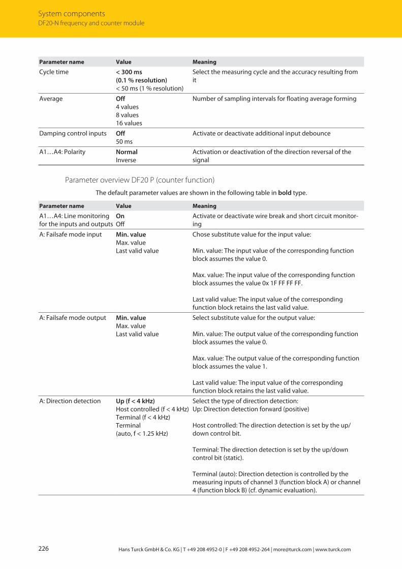
System componentsDF20-N frequency and counter module
226 Hans Turck GmbH & Co. KG | T +49 208 4952-0 | F +49 208 4952-264 | [email protected] | www.turck.com
Parameter name Value Meaning
Cycle time < 300 ms (0.1 % resolution)< 50 ms (1 % resolution)
Select the measuring cycle and the accuracy resulting fromit
Average Off4 values8 values16 values
Number of sampling intervals for floating average forming
Damping control inputs Off50 ms
Activate or deactivate additional input debounce
A1…A4: Polarity NormalInverse
Activation or deactivation of the direction reversal of the signal
Parameter overview DF20 P (counter function)
The default parameter values are shown in the following table in bold type.
Parameter name Value Meaning
A1…A4: Line monitoringfor the inputs and outputs
OnOff
Activate or deactivate wire break and short circuit monitor-ing
A: Failsafe mode input Min. valueMax. valueLast valid value
Chose substitute value for the input value:
Min. value: The input value of the corresponding functionblock assumes the value 0.
Max. value: The input value of the corresponding functionblock assumes the value 0x 1F FF FF FF.
Last valid value: The input value of the corresponding function block retains the last valid value.
A: Failsafe mode output Min. valueMax. valueLast valid value
Select substitute value for the output value:
Min. value: The output value of the corresponding functionblock assumes the value 0.
Max. value: The output value of the corresponding functionblock assumes the value 1.
Last valid value: The input value of the corresponding function block retains the last valid value.
A: Direction detection Up (f < 4 kHz)Host controlled (f < 4 kHz)Terminal (f < 4 kHz)Terminal (auto, f < 1.25 kHz)
Select the type of direction detection:Up: Direction detection forward (positive)
Host controlled: The direction detection is set by the up/down control bit.
Terminal: The direction detection is set by the up/down control bit (static).
Terminal (auto): Direction detection is controlled by themeasuring inputs of channel 3 (function block A) or channel4 (function block B) (cf. dynamic evaluation).
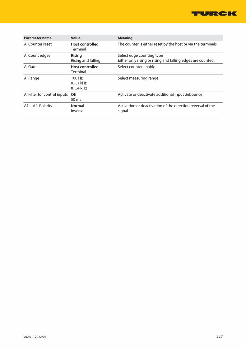
V02.01 | 2022/05 227
Parameter name Value Meaning
A: Counter reset Host controlledTerminal
The counter is either reset by the host or via the terminals.
A: Count edges RisingRising and falling
Select edge counting typeEither only rising or rising and falling edges are counted.
A: Gate Host controlledTerminal
Select counter enable
A: Range 100 Hz0…1 kHz0…4 kHz
Select measuring range
A: Filter for control inputs Off50 ms
Activate or deactivate additional input debounce
A1…A4: Polarity NormalInverse
Activation or deactivation of the direction reversal of thesignal

System componentsDF20-N frequency and counter module
228 Hans Turck GmbH & Co. KG | T +49 208 4952-0 | F +49 208 4952-264 | [email protected] | www.turck.com
Parameter data mapping
The following bits and bytes can be set via the parameters.
The default parameter values are shown in the following table in bold type.
Parameter data mapping – DF20 F
Bit no.
Byte no. Channelno.
7 6 5 4 3 2 1 0
0 B4: Line monitoring0: On1: Off
B3: Line monitoring0: On1: Off
B2: Line monitoring0: On1: Off
B1: Line monitoring0: On1: Off
A4: Line monitoring0: On1: Off
A3: Line monitoring0: On1: Off
A2: Line monitoring0: On1: Off
A1: Line monitoring0: On1: Off
1 A: Failsafe mode input00: Min. value01: Max. value10: Last valid value
A: Failsafe mode out-put00: Min. value01: Max. value10: Last valid value
A: Direction detection00: Up (f < 4 kHz)01: Host controlled (f < 4 kHz)10: Terminal (f < 4 kHz)11: Terminal(auto, f > 1.25 kHz)
A: Damp-ing controlinputs0: Off1: 50 ms
A: Cycletime0: < 300 ms(0.1 % resolution)1: < 50 ms(1 % resolution)
2 A: Average00: Off01: 4 values10: 8 values11:16 values
Reserved00
A4: Polarity0: Normal1: Inverted
A3: Polarity0: Normal1: Inverted
A2: Polarity0: Normal1: Inverted
A1: Polarity0: Normal1: Inverted
3 B: Failsafe mode input00: Min. value01: Max. value10: Last valid value
B: Failsafe mode output00: Min. value01: Max. value10: Last valid value
B: Direction detection00: Up (f < 4 kHz)01: Host controlled (f < 4 kHz)10: Terminal (f < 4 kHz)11: Terminal(auto, f > 1.25 kHz)
B: Damp-ing controlinputs0: Off1: 50 ms
B: Cycletime0: < 300 ms(0.1 % resolution)0: < 300 ms(0.1 % resolution) 1: < 50 ms(1 % resolution)
4 B: Average00: Off01: 4 values10: 8 values11:16 values
Reserved00
B4: Polarity0: Normal1: Inverted
B3: Polarity0: Normal1: Inverted
B2: Polarity0: Normal1: Inverted
B1: Polarity0: Normal1: Inverted

V02.01 | 2022/05 229
Parameter data mapping – DF20 P
Bit no.
Byte no. Channelno.
7 6 5 4 3 2 1 0
0 B4: Linemonitoring0: On1: Off
B3: Linemonitoring0: On1: Off
B2: Linemonitoring0: On1: Off
B1: Linemonitoring0: On1: Off
A4: Linemonitoring0: On1: Off
A3: Linemonitoring0: On1: Off
A2: Linemonitoring0: On1: Off
A1: Linemonitoring0: On1: Off
1 A: Failsafe mode input00: Min. value01: Max. value10: Last valid value
A: Failsafe mode output00: Min. value01: Max. value10: Last valid value
A: Direction detection00: Up (f < 4 kHz)01: Host controlled (f < 4 kHz)10: Terminal (f < 4 kHz)11: Terminal(auto, f > 1.25 kHz)
A: Damp-ing controlinputs0: Off1: 50 ms
A: Resetcounter0: Hostcontrolled1: Terminal
2 A: Edgecounting0: Rising1: Risingand falling
A: Enable0: Hostcontrolled1: Terminal
A: Measuring range00: 0…100 Hz01: 0…1 kHz10: 0…4 kHz
A4: Polarity0: Normal1: Inverted
A3: Polarity0: Normal1: Inverted
A2: Polarity0: Normal1: Inverted
A1: Polarity0: Normal1: Inverted
3 B: Failsafe mode input00: Min. value01: Max. value10: Last valid value
B: Failsafe mode output00: Min. value01: Max. value10: Last valid value
B: Direction detection00: Up (f < 4 kHz)01: Host controlled (f < 4 kHz)10: Terminal (f < 4 kHz)11: Terminal(auto, f > 1.25 kHz)
B: Damp-ing controlinputs0: Off1: 50 ms
B: Restcounter0: Hostcontrolled1: Terminal
4 B: Edgecounting0: Rising1: Risingand falling
B: Enable0: Hostcontrolled1: Terminal
B: Measuring range00: 0…100 Hz01: 0…1 kHz10: 0…4 kHz
B4: Polarity0: Normal1: Inverted
B3: Polarity0: Normal1: Inverted
B2: Polarity0: Normal1: Inverted
B1: Polarity0: Normal1: Inverted
6.22.9 PROFIBUS: diagnostic informationThe diagnostics data is structured according to EN 61158, part 1/3/10.
Besides the module status (device-specific diagnostics) and the status overview (ID diagnostics)the module supports the following channel status indications (channel-specific diagnostics):
Error code No. Meaning
Standard 1 Short circuit
6 Wire break
Specific 19 Module type (set configuration) unknown
20 Module type (actual configuration) unknown
22 Parameter not plausible (inconsistent)

System componentsDF20-N frequency and counter module
230 Hans Turck GmbH & Co. KG | T +49 208 4952-0 | F +49 208 4952-264 | [email protected] | www.turck.com
6.22.10 Technical data
Type code DF20-N F and P
ID 6884212
Power supply Via the module rack, central power supplymodule
Power consumption 1 W
Galvanic isolation From the internal bus and from the power supply circuit
Number of channels 2-channel
Input circuits According to EN 60947-5-6 (NAMUR)
Open circuit voltage 8 VDC
Short-circuit current 4 mA
Switching threshold on/off Typ. 1.8/typ. 1.4 mA
Switching frequency ≤ 4000 Hz
Short circuit < 367 Ω
Wire break < 0.2 mA
Measurement accuracy (including linearity,hysteresis and repeatability)
≤ 0.1 % (for frequency measurement)
LEDsOperational readiness 1 × green/red
Status/error 8 × yellow/red
Housing material Plastic
Fixing type Module design, pluggable in the module rack
Protection type IP20
Ambient temperature -20…+70 °C
Relative air humidity ≤ 93 % at 40 °C acc. to IEC 60068-2-78
Vibration test Acc. to EN 60068-2-6
Shock testing Acc. to EN 60068-2-27
EMC Acc. to EN 61326-1 acc. to NAMUR NE21
MTTF 101 years acc. to SN 29500 (Ed. 99) 40 °C
Dimensions (W × H × D) 18 × 118 × 106 mm

V02.01 | 2022/05 231
6.23 OC11Ex/3G.2 PROFIBUS-DP FO coupler
6.23.1 Intended useThe OC11Ex/3G.2 converts the Profibus DP signals for copper lines into optical signals for fiberoptic cables and vice versa. The couplers enable the isolated and interference free transmissionof bus signals to a PROFIBUS-DP station (e.g. to the excom I/O system) over distances of up to2500 m.
The OC11Ex/3G FO coupler is suitable for use in Zone 2 and converts the fiber optic signals ofan OC11Ex/2G FO coupler installed in Zone 1 to a RS485 signal. By connecting twoOC11Ex/3G.2 fiber optic couplers, fiber optic transmission in the safe area and zone 2 is alsopossible, as well as switching between RS485 and fiber optic transmission.
The couplers of the OC11Ex/…G version cannot be combined with the couplers of versionOC11Ex/…G.2.
6.23.2 Notes on Ex protectionn When using the device in Ex circuits, the user must also have an additional knowledge of
explosion protection (IEC/ EN 60079-14 etc.).n Use the device only within the permissible operating and ambient conditions (see approval
data and Ex approval specifications).n Observe national and international regulations for explosion protection.n Ensure sufficient ventilation if the devices are to mounted directly next to each other.n Do not open the device. Otherwise, the approval will expire.
Requirements for ATEX and IECEx approval
When used in Zone 2:
n Install the device in a separately approved enclosure in accordance with IEC/EN 60079-7 (“increased safety”) with a protection type of at least IP54 per IEC/EN 60529.
n Implement electrically insulating fiber optic cables and use without shielding or armor.
6.23.3 Device overview
U B
RS485
LWL
1 =2 =
3 =4 =
5 =6 =
7 =
9,619,2
45,45
93,75
187,5
5001500
kBit/s
Baud
rate4
3
5
12
67
Auto
OC11Ex/3G
72
105.5
31
Fig. 71: Dimensions

System componentsOC11Ex/3G.2 PROFIBUS-DP FO coupler
232 Hans Turck GmbH & Co. KG | T +49 208 4952-0 | F +49 208 4952-264 | [email protected] | www.turck.com
6.23.4 Properties and featuresn FO segment couplern Data transmission between electrical and optical fieldbus circuitsn Full galvanic isolationn Standard RS485 Profibus interfacen Intrinsically safe optical interface with ST connectors for transmitter and receiver terminalsn PROFIBUS-Link communication interface for the connection of two OC11Ex couplers for
redundancy and repeater functionn Transmission range with OM1 fiber optic cable up to 2500 m, with OM2 fiber optic cable up
to 1500 mn Automatic baud rate detection and setting of fixed baud raten Max. 31 bus devices (e.g. excom I/O systems) at the electrical connectionn Repeater functionn Support of various redundancy functions
6.23.5 Functions and operating modes
Segment coupler
The OC11Ex/3G FO coupler supports Profibus-DP protocols and is equipped with the followinginterfaces:
n Standard RS485 interfacen Optical interface with ST connectors for transmitter and receiver terminalsn Profibus link communication interface for connecting two OC11Ex3G.2 couplers for redund-
ancy and repeater functions
The device converts standard RS485 signals into intrinsically safe optical signals and vice versa.The intrinsically safe signals are routed via the optical interface of the segment coupler to theEx area via fiber optic cables. This enables the isolated and interference free transmission of bussignals over long distances up to Zone 1. Line errors (wire-break/short-circuit) are not trans-ferred from one segment to the other. The OC11Ex coupler is a physical station and must there-fore be considered in a segment as one of the maximum 32 possible bus participants.
The OC11Ex/3G FO coupler can be provided with a 24 VDC supply in the field without any addi-tional isolating devices (protection type Ex e).

V02.01 | 2022/05 233
DP-connector
DP-connector with integratedterminating resistor
Non-Ex-area
max. distancebetween thefibre-optic couplers 2,5 km
fibre-optic connection
DP-V1-Master
OC11Ex/3G.2
RS485
RS485
excom
OC11Ex/3G.2
Fig. 72: Connection of two OC11EX/3G.2 couplers – signal transmission with fiber optics
Repeater function
Repeaters are required if a network consists of more than 32 physical stations or if the cablelength of a bus segment is greater than the maximum permissible range. Repeaters divide upthe fieldbus network into segments of up to 32 stations each, connect the different segmentstogether and regenerate the bus signal to be transferred. This makes it possible to increase thenumber of stations, to electrically isolate stations and segments and cover large distances. Repeaters, unless they are diagnostic repeaters, do not have their own bus address.
The OC11Ex/3G.2 fiber optic segment coupler is not only used for Ex separation and the con-version of electrical and optical signals, but can also be used as a repeater: The coupler regener-ates the signal amplitude, slew rate and bit width of the data telegram when Profibus tele-grams are transmitted. PROFIBUS-DP telegrams with a valid start delimiter are forwarded, otherwise these are discarded. This makes it possible to transmit the signals over long distancesand increase the number of stations both in the segment and in the network.

System componentsOC11Ex/3G.2 PROFIBUS-DP FO coupler
234 Hans Turck GmbH & Co. KG | T +49 208 4952-0 | F +49 208 4952-264 | [email protected] | www.turck.com
Redundancy connections
The device also has an M8 communication interface (8-mm snap-in socket) in addition to theSUB-D Profibus-DP terminal. This interface can be used to establish a redundancy connectionbetween two OC11Ex3G.2 devices for setting up line and system redundancies.
Line redundancy
With line redundancy, a master is connected with an OC11Ex/3G.2 FO coupler. Another FOcoupler is connected to this FO coupler. A new line is created from the second fiber opticcoupler by connecting to further segments of the network. With this concept, redundancy isonly provided behind the only master of the network.
excom
MT16-N
Master
RS485
RS485
DP-connector
DP-connector with integratedterminating resistor
max. distancebetween thefibre-optic couplers 2,5 km
fibre-optic connection
Fig. 73: Line redundancy

V02.01 | 2022/05 235
System redundancy
A continuously redundant system requires two masters. One FO coupler is connected to eachmaster, which in turn is connected to another FO coupler or another segment of the network(max. 32 stations in the entire network). The connection of the respective master to the indi-vidual segments of the network up to the respective gateway runs in parallel. This splits thefieldbus into two separate lines after the FO connection.
With end-to-end redundancy up to the gateway, errors do not lead to data loss.
excom
MT16-N
Master2
Master1
RS485
DP-connector
DP-connector with integratedterminating resistor
max. distancebetween thefibre-optic couplers 2,5 km
fibre-optic connection
Redundancy-connection
Fig. 74: End-to-end redundancy (system redundancy)

System componentsOC11Ex/3G.2 PROFIBUS-DP FO coupler
236 Hans Turck GmbH & Co. KG | T +49 208 4952-0 | F +49 208 4952-264 | [email protected] | www.turck.com
6.23.6 Installing
DANGERPotentially explosive atmosphereRisk of explosion through spark ignitionWhen used in Zone 2: Only install the device if there is no potentially explosive atmosphere present. Install the device in an Ex e housing in accordance with IEC/EN 60079-7 with a
protection type of at least IP54. When mounting the device, ensure that its permissible operating temperature is
not exceeded even in unfavorable ambient conditions. Implement electrically isolating fiber optic cables and use without shielding or
armor. When connecting different areas via the FO cable: Only use additional lens sys-
tems or light amplifiers if they have been specifically approved for this purpose.
The devices can be mounted directly next to each other.
Protect the mounting location from radiated heat, sudden temperature fluctuations,dust, dirt, humidity and other ambient influences.
Fit the device at the intended mounting location.
6.23.7 Connection
U B
RS485
LWL
1 =2 =
3 =4 =
5 =6 =
7 =
9,619,2
45,45
93,75
187,5
5001500
kBit/s
Baud
rate4
3
5
12
67
Auto
OC11Ex/3G
12
3
4
5
6
7
72
105.5
31
Fig. 75: OC11Ex/3G – connections and interfaces
Position Description
1 Rotary switch for setting the baud rate
2 PROFIBUS Link communication interface for connecting two OC11Ex.3 couplersfor redundancy and repeater functions
3 Intrinsically safe optical interface for transmitter and receiver terminals (2 × ST male connectors)
4 RS485 interface PROFIBUS-DP (SUB-D socket, 9-pin)
5 Shield connection for capacitive or direct grounding
6 Terminal for power supply (male connector , 3-pin)
7 Ground terminal bolt (M5 thread)

V02.01 | 2022/05 237
Connecting the OC11Ex/3G.2 FO coupler to the fieldbus
Only connect the OC11Ex/3G.2 FO coupler to fiber optic cable with a multimode fiberoptic core.
When using single mode cores, error-free signal transmission cannot be guaranteed.
The PROFIBUS interface is provided with a 9-pin SUB-D female connector.
Connect the device to the fieldbus using a standard PROFIBUS SUB-D connector.
12345
6789
Fig. 76: SUB-D female connector
SUB-D pin layout
Pin No. RS485 Meaning
1 n. c. Not connected
2 n. c. Not connected
3 RxD/TxD-P Receive data/send data B line (red)
4 n. c. Not connected
5 DGND Bus termination GND
6 VP Bus termination VP (power supply +)
7 n. c. Not connected
8 RxD/TxD-N Receive data/send data of A line (green)
9 n. c. Not connected
Standard PROFIBUS-DP connectors can be used on the RS485 port. For active termination ofthe PROFIBUS-DP connector, the connector has a switchable resistor combination e.g. D9T-RS485 (ID 6890942) or D9T-RS485PG (ID 6890943).
A1B1
A2B2
54
16
39,5
A1B1
A2B2
54
16
39,5
Fig. 77: D9T-RS485PG – dimensions Fig. 78: D9T-RS485 – dimensions

System componentsOC11Ex/3G.2 PROFIBUS-DP FO coupler
238 Hans Turck GmbH & Co. KG | T +49 208 4952-0 | F +49 208 4952-264 | [email protected] | www.turck.com
Shielding and grounding
The FO coupler forms by design a capacitive connection between the shield of the connectedfieldbus cable and the grounding bolt.
A grounding bolt with an M5 thread is provided for the equipotential bonding of the housing.
Connecting the FO coupler to fibre optic cable
Connect the fiber optic cable via two ST connectors.
Connecting the FO coupler to the power supply
The device is provided with a 3-pin plug connectors for connecting the power supply. The maximum terminal cross section is:
Single connection Multi-wire connection
Rigid 4 mm2 0.2…2.5 mm2
Flexible 2.5 mm2 0.2…1 mm2
Strip the connection cables (9 mm).
Tighten the terminals. The tightening torque is 0.5…0.6 Nm.
Connecting the M8 interface
The device is provided with an M8 interface for internal communication.
Connect the communication interface via a 4-pin M8 connector OC11-LINKCABLE, ID 8031339) .
The internal communication interface must only be connected with another OC11EX/3Gdevice.
6.23.8 LED indications
DP interface (PROFIBUS) – data traffic
LED Color Meaning
UB Green Power supply error-free
Off Input voltage too low
RS485 Red Error in PROFIBUS segment
Yellow Device receiving valid data
Off No data traffic
FO Red Error in FO segment
Yellow Device receiving valid data
Off No data traffic
Auto Yellow Transmission rate detected
Yellow flashing Transmission rate detection active
Off Transmission rate set via rotary switches

V02.01 | 2022/05 239
6.23.9 Setting
Baud rate set via rotary switches
7
6
54
3
2
1
Auto
Baud
rate
Fig. 79: Setting the baud rate
Permanently set the baud rate via the rotary switch position according to the followingtable.
Rotary switch position Baud rate Max. segment length
Auto Automatic detection
1 9.6 kbps 1200 m
2 19.2 kbps 1200 m
3 45.45 kbps 1200 m
4 93.75 kbps 1200 m
5 187.5 kbps 1000 m
6 500 kbps 400 m
7 1.5 Mbps 200 m
NOTEWhen using an ABB RLM01, a fixed transmission rate must be set (rotary switch position 1…7).The automatic transmission rate (position Auto) can lead to faulty communication.

System componentsOC11Ex/3G.2 PROFIBUS-DP FO coupler
240 Hans Turck GmbH & Co. KG | T +49 208 4952-0 | F +49 208 4952-264 | [email protected] | www.turck.com
6.23.10 Technical data
Type code OC11Ex/3G.2
ID 6890428
Rated voltage 24 VDC
Supply voltage range 18…32 VDC
Current consumption ≤ 100 mA
Galvanic isolation Complete galvanic isolation acc. to IEC/EN 60079-11
Number of channels 1-channel
Baud rate 9.6 kbps to 1.5 Mbps
Ex approval acc. to conformity certificate IECEx PTB 16.0002X
Device designation Ex nAc [op is Gb] IIC T4
Ex approval acc. to conformity certificate PTB 05 ATEX 2052 X
Ex device designation É II 3(2) G Ex nAc [op is Gb] IIC T4
LEDsOperational readiness 1 × green
Status/error 2 × yellow/red
Baud rate detection 1 × yellow
Interfaces/connection technologyRS 485 PROFIBUS-DP 1 × SUB-D connector, 9-pin
FO 2 × ST male connectors
Power supply Screw connector, 3-pin
PROFIBUS LINK communication interface 1 × M8 connector
Equipotential bonding (PA) M5 × 1 grounding bolt
Housing material Anodized aluminum
Front plate FR4, gray
Fixing type Snap-fit on DIN rail (EN 60715) or wall mounting
Protection type IP20
Ambient temperature -20…+70 °C
Relative air humidity ≤ 93 % at 40 °C acc. to IEC 60068-2-78
Vibration test Acc. to EN 60068-2-6
Shock testing Acc. to EN 60068-2-27
EMC Acc. to EN 61326-1 acc. to NAMUR NE21
MTTF 442 years acc. to SN 29500 (Ed. 99) 40 °C
Dimensions (W × H × D) 72 × 105.5 × 31 mm

V02.01 | 2022/05 241
Type code OC11Ex/3G.2
Approvals ATEX
TR CU
KOSHA
INMETRO
GL
DNV
BV
LR

System componentsSC11-3G segment coupler
242 Hans Turck GmbH & Co. KG | T +49 208 4952-0 | F +49 208 4952-264 | [email protected] | www.turck.com
6.24 SC11-3G segment coupler
6.24.1 Intended useThe SC11-3G segment coupler is used to connect PROFIBUS-DP and Modbus RTU to the excomsystem. The device provides an RS485 line for connecting up to 32 stations (e.g. excom stations). The data transmission between fieldbus, coupler and bus station is implemented withcopper cable.
The segment coupler regenerates the data telegrams to be transmitted. This makes it possibleto increase the number of stations and transmit the signals over large distances.
Different redundancy concepts (line, system or device redundancy) can be implemented by interconnecting several segment couplers.
The device is suitable for operation in Zone 2.
6.24.2 Notes on Ex protectionInstallation in Zone 2:
n Do not connect or disconnect the RS485 connector when energized.
Use of devices in Zone 2 and Zone 22:
n Install the devices in a separately approved enclosure in accordance with IEC/EN 60079-7(“increased safety”) with a protection type of at least IP54 per IEC/EN 60529.
6.24.3 Device overview
65 [2.56]
73.5 [2.89]
105.4[4.15]
9.5 [0.37]
Fig. 80: Dimensions
6.24.4 Properties and featuresn Segment coupler for Zone 2n Connection of PROFIBUS-DP and Modbus RTUn Transmission via copper cablen 2 × PROFIBUS-DP RS485 interfacesn Automatic baud rate detection and setting of fixed baud raten Connection of up to 31 stations to one couplern Repeater functionn Transmission routes up to 1200 mn Line, system or device redundancy possible

V02.01 | 2022/05 243
6.24.5 Functions and operating modes
Segment coupler
The SC11/-3G segment coupler supports PROFIBUS-DP and Modbus RTU protocols and isequipped with the following interface:
n 2 × standard RS485 interfaces
The SC11-3G segment coupler is suitable for operation in Zone 2. Line errors (wire-break/short-circuit) are not transferred from one segment to the other. The SC11-3G coupler is a physicalstation and must be included when calculating the maximum number of bus stations within asegment.
Repeater function
The segment coupler also has a repeater function. This makes it possible to regenerate the signals before transmission or to extend fieldbus networks.
Repeaters are required if a network consists of more than 32 stations. Repeaters make it possible to increase the number of stations, to isolate stations and segments and cover largedistances. Repeaters divide up the fieldbus network into segments of up to 32 stations each,connect the different segments together and regenerate the bus signal to be transferred. Repeaters, do not have their own bus address unless they are diagnostic repeaters.
The SC11-3G segment coupler can be used as repeater: The coupler regenerates the signalamplitude, slew rate and bit width of the data telegram when PROFIBUS telegrams are trans-mitted. PROFIBUS-DP telegrams with a valid start delimiter are forwarded, otherwise they arediscarded. The coupler regenerates the bit length and signal amplitude of the data telegramswith Modbus RTU and other byte-oriented serial data streams. This makes it possible in the entire network to transmit the signals over long distances and increase the number of stations.

System componentsSC11-3G segment coupler
244 Hans Turck GmbH & Co. KG | T +49 208 4952-0 | F +49 208 4952-264 | [email protected] | www.turck.com
Master
Slave Repeater
RS485
RS485
RS485
RS485
Repeater
Repeater
RS485
excom
excom
excom
excom
excom
excom
excomRS485
DP-coupler
DP-coupler
DP-coupler
DP-coupler
DP-connectorDP-connector withintegrated terminating resistor
Fig. 81: System structure

V02.01 | 2022/05 245
Redundancy switching
Different redundancy concepts (line, system and device redundancy) can be implemented byinterconnecting several segment couplers.
Line redundancy
Line redundancy increases availability with little effort and can be implemented with only oneactive master. The bus line is split close to the master into two redundant bus lines. A segmentcoupler or repeater can be used to isolate the lines, for example, a segment coupler or repeatercan be used to prevent the transmission of errors from one segment to the next segment (non-reactive). With this concept, redundancy is only provided behind the only master of the net-work.
excomMT16-N
RS485
SC11-3G
RS485
SC11-3G
RS485
PROFIBUS-DP Master
DP-connector
DP-connector with integratedterminating resistor
Fig. 82: Line redundancy

System componentsSC11-3G segment coupler
246 Hans Turck GmbH & Co. KG | T +49 208 4952-0 | F +49 208 4952-264 | [email protected] | www.turck.com
System redundancy
System redundancy is achieved by connecting two separate and independent each via a segment coupler to an excom station. The excom station is provided with two gateways. Eachgateway is only put into cyclic data exchange by the master assigned to it. Both masters mustconfigure and parameterize the redundant gateways identically.
With system redundancy (end-to-end redundancy) up to the gateway, valid data is always available even in the event of a redundancy switchover.
excomMT16-N
RS485
SC11-3G
RS485
SC11-3G
RS485
PROFIBUS-DP Master
PROFIBUS-DP Master
DP-connector
DP-connector with integratedterminating resistor
Fig. 83: System redundancy (end-to-end redundancy)

V02.01 | 2022/05 247
6.24.6 Installing Install the device on a DIN rail (TH35). Maintain a clearance of ≥ 5 mm from the side of the adjacent device. Connect the M5 × 1 bolt (case ground) on the device to the equipotential bonding.
6.24.7 Connection
Wiring diagram
GN
Pwr
RS485
RS485
YE/RD
YE/RD
RS485
RS485
24 VDC Pwr+
–
0 19
46
2837
5
1
5
6
9
1
5
6
9
case ground
shield
shielda b
Fig. 84: Wiring diagram – SC11-3G

System componentsSC11-3G segment coupler
248 Hans Turck GmbH & Co. KG | T +49 208 4952-0 | F +49 208 4952-264 | [email protected] | www.turck.com
Connecting segment couplers to the fieldbus
Connect the segment coupler to the fieldbus via the 9-pin RS485 SUB-D female con-nector (see Wiring diagram) using a PROFIBUS SUB-D male connector.
12345
6789
Fig. 85: SUB-D female connector
RS485 – assignment of the SUB-D pins:
Pin no. RS485 Meaning
1 n. c. Not connected
2 n. c. Not connected
3 RxD/TxD-P Receive data/send data B line (red)
4 n. c. Not connected
5 DGND Bus termination GND
6 DP Bus termination VP (power supply +)
7 n. c. Not connected
8 RxD/TxD-N Receive data/send data of A line (green)
9 n. c. Not connected
Housing PE/FE Equipotential bonding cable
Connecting bus stations to segment couplers
PROFIBUS-DP male connectors are used for the RS485 connection, e.g. the D9T-RS485 maleconnector (ID 6890942) or the D9T-RS485PG (ID 6890943).
A1B1
A2B2
54
16
39,5
A1B1
A2B2
54
16
39,5
Fig. 86: D9T-RS485 – dimensions Fig. 87: D9T-RS485PG – dimensions

V02.01 | 2022/05 249
Switching on the terminating resistor at the RS485 interface
Terminating resistors must be activated at the start and end of each segment.
Connect terminating resistors in the SUB-D bus connector at the non-intrinsically safeRS485 interface.
When connecting with a Profibus SUB-D connector with an integrated resistor (e.g. TurckD9T-RS485 or D9-RS485PG): Switch on integrated pull-up/pull-down resistor of 200 Ω viathe slide switch.
When connecting with a 9-pin connector without an integrated resistor: Connect an external resistor of 150 Ω for passive termination between A (pin 8, internal A2) and B(pin 3, internal B2) of the SUB-D connector.
Connecting the segment coupler to the power supply
The device is provided with a 2-pin screw terminal for connecting the power supply.
Push the IP30 cover back into the connection position via the connection terminal. Connect the device as shown in the wiring diagram. The max. cable cross section is
2.5 mm². The tightening torque is 0.5…0.6 Nm. Push the IP30 cover over the connection terminals into the covering position.
Connecting the equipotential bonding
The PE terminal of the device (M5 × 1 ground terminal bolt “Case ground” see Wiring diagram)is not connected to the PA equipotential bonding conductor.
Connect the PA equipotential bonding cable to the “case ground” M5 × 1 groundterminal bolt. The min. cable cross section is 4 mm².
Grounding the shield of the Profibus DP fieldbus cable
The shield of the fieldbus cable is grounded via a separate connection. Depending on the ex-pected interference and the installation, the user may choose between capacitive and directgrounding. The shield of both RS485 interfaces is factory fitted with a capacitive connection tothe potential equalization. For this purpose, insulating washers are placed between the screwheads (marked on the housing by “Shield [a]” and “Shield [b]”) and the housing.
Grounding the shield of the Profibus DP fieldbus cable
Unscrew the screw at the screw heads “Shield [a]” and “Shield [b]”, remove the insulatingwashers and screw the screw back in.
Connect the M5 × 1 “Shield” bolt according to grounding concept with separately ex-ecuted FE or PE rail.

System componentsSC11-3G segment coupler
250 Hans Turck GmbH & Co. KG | T +49 208 4952-0 | F +49 208 4952-264 | [email protected] | www.turck.com
6.24.8 LED indications
DP interface (PROFIBUS) – data traffic
LED Indication Meaning
Power Green Device is operational
Off Operating voltage too low
RS485 Red Communication error
Yellow Bus communication active
Yellow flashing Searching for the transmissionrate
Off No communication
6.24.9 Setting
Baud rate set via rotary switches
019
46
28
37
5
Fig. 88: Setting the baud rate
The “Automatic transmission rate detection” function of the segment coupler automatically de-tects the transmission rate when the rotary switch is set to “0”.
Permanently set the transmission rate via the rotary switch position “0” to “9”.
Rotary switch position Baud rate
Position 0 Automatic transmission rate detection
Position 1 Not used
Position 2 Not used
Position 3 9.6 kbps
Position 4 19.2 kbps
Position 5 38.40 kbps
Position 6 57.60 kbps
Position 7 115.20 kbps
Position 8 500 kbps
Position 9 1.50 Mbps

V02.01 | 2022/05 251
6.24.10 Technical data
Type code SC11-3G
ID 100000548
Rated voltage 24 VDC
Supply voltage range 18…32 VDC
Current consumption ≤ 100 mA
Power consumption ≤ 2.4 W
Heat dissipation ≤ 2.4 W
Galvanic isolation Complete galvanic isolation, test voltage 250 V
Number of channels 1-channel
Baud rate 9.6 kbps to 1.5 Mbps
Ex approval acc. to conformity certificate IECEx EPS 17.0085X
Ex approval acc. to conformity certificate EPS 17 ATEX 1168X
Ex approval acc. to conformity certificate CML 21UKEX1624X
Device designation É II 3 G Ex ec ic IIC T4 Gc
LEDsOperational readiness 1 × green
Status/error 2 × yellow/red
Housing material Anodized aluminum
Fixing type Snap-fit on DIN rail (EN 60715)
Protection type IP20
Ambient temperature -40…+70 °C
Relative air humidity ≤ 93 % at 40 °C acc. to IEC 60068-2-78
EMC Acc. to EN 61326-1 (2013) acc. to NAMUR NE21(2012)
MTTF 999 years acc. to SN 29500 (Ed. 99) 40 °C
Dimensions (W × H × D) 65 × 105 × 73.5 mm
Approvals IECEx
ATEX
UKEX

System componentsSystem enclosure with integrated excom system
252 Hans Turck GmbH & Co. KG | T +49 208 4952-0 | F +49 208 4952-264 | [email protected] | www.turck.com
6.25 System enclosure with integrated excom system
6.25.1 Intended useThe device is designed as equipment of the excom I/O system for the non-Ex area and mustonly be operated within the excom system with the MT…-N module racks.
The system enclosure protects the assembled module rack in the field from environmentalinfluences.
Only the following modules can be retrofitted by the operator:
n AI40-Nn AI41-Nn AI43-Nn AIH40-Nn AIH401-Nn AIH41-Nn AO40-Nn AOH40-Nn AOH401-Nn DF20-Nn DI40-Nn DI80-Nn DM80-Nn DO40-Nn DO60R-Nn DO80-Nn TI40-Nn TI41-N
6.25.2 Device overviewEmpty system enclosures contain the following elements:
n Base body with gutter, four welded exterior clipsn Two profiles (C profile) for fastening the module rackn Two CU rails (nickel-plated) as shielding bus for termination of cable shieldsn M6 grounding bolts welded to the inside, M8 earthing studs welded to the outsiden Flange plate and front door with base body
Components of the excom stations installed in the system housing are indicated in the typecode.

V02.01 | 2022/05 253
Device overview – EG-VA465526…
460
550
80
50
90
235
495
505
40
Fig. 89: Top view
mm [Inch]
44.5 [1.75]
45 [1.77]
450 [17.72]
32 [1.26]
32 [1.26]
32 [1.26]
32 [1.26]
3 [0.12]34 [1.34]
66 [2.60]
224 [8.82]
Ø 20.3 [0.80]
Ø 20.3 [0.80]
Ø 25.3 [0.996]
112 [4.41]
Fig. 90: Flange plate

System componentsSystem enclosure with integrated excom system
254 Hans Turck GmbH & Co. KG | T +49 208 4952-0 | F +49 208 4952-264 | [email protected] | www.turck.com
Device overview – EG-VA655526…
650
550
50 150
80
50
90
235
685
505
130
40
Fig. 91: Top view
mm [Inch]640 [25.20]
112
[4.41]
3 [0.12]44 [1.73]
84 [3.31]
40 [1.57]
32 [1.26]
32 [1.26]
32 [1.26]
45 [1.77]
44.5 [1.75]
224 [8.82]
Ø 25.3 [0.996]
Ø 20.3 [0.80]
Ø 20.3 [0.80]
Fig. 92: Flange plate

V02.01 | 2022/05 255
Device overview – EG-VA805526…
800
550
48,5 150
80
50
90
235
835
505
130
40
Fig. 93: Top view
mm [Inch]
32 [1.26]
32 [1.26]
32 [1.26]
46 [1.81]
32 [1.26]
380 [14.96]380 [14.96]
45 [1.77]
44.5 [1.75]
224 [8.82]
Ø 25.3 [0.996]
Ø 20.3 [0.80]
Ø 20.3 [0.80] Ø 20.3 [0.80]
112[4.41]
3 [0.12]78 [3.07]
38 [1.50]
40 [1.57]
Fig. 94: Flange plate left and right

System componentsSystem enclosure with integrated excom system
256 Hans Turck GmbH & Co. KG | T +49 208 4952-0 | F +49 208 4952-264 | [email protected] | www.turck.com
6.25.3 Properties and featuresn Stainless steel enclosure with hinged cover and optional inspection window (visible area:
340 × 80 mm; 530 × 80 mm; 570 × 80 mm) for housing the excom module rack rack andflange plate.
n Standard sizes :– 460 × 550 × 260 mm– 650 × 550 × 260 mm– 800 × 550 × 260 mm
n Module rack:– MT08 (all system enclosure sizes)– MT16 (all system enclosure sizes)– MT24 (system enclosure with dimensions: 800 × 550 × 260 mm)
n M16 or M20 cable glands possible for I/O signals:– EG-VA 465526…: Standard: 35; maximum: 66– EG-VA 655526…: Standard: 65; maximum: 96– EG-VA 805526…: Standard: 108; maximum: 108
6.25.4 InstallingThe system enclosure with integrated excom station can be mounted directly on a wall.
NOTICEHeat buildup in the enclosurePossible device damage due to overheating Protect from direct sunlight. Carry out a written temperature test before equipping the excom I/O system
and any change to the equipment as well as before commissioning (see “Per-forming a temperature test”).
During commissioning ensure that the admissible operating temperature of theexcom I/O system is not exceeded.
Do not add any additional power to the enclosure. If the enclosure exceeds the permissible temperature, the module rack may
need to be installed in a larger system enclosure.

V02.01 | 2022/05 257
6.25.5 ConnectionLay the cables through the cable entries in the system enclosure. Only route permanently in-stalled, strain-relieved cables through the cable gland. Close unused cable entries with sealingplugs.
Shielding and grounding
Power supply and fieldbus cables must be routed separately; alternatively it is possible to installshielded power cables observing a minimum distance of 30 cm to the fieldbus cable. Thegrounding of the shield for field devices depends on the requirements of the specific fielddevice. If shielding is required on both sides, special attention must be paid to equipotentialbonding in order to prevent potential equalization currents via the shield.
The excom system and the system enclosure are permanently connected electrically. The system enclosure is part of the equipotential bonding system.
≥ 6 mm2
Fig. 95: Fitting the connection bolt
Connect system enclosures to the equipotential bonding on the outside of the enclos-ures with a cross section of at least 6 mm². The order of fitting the connection bolt isshown in the figure above.
Direct connection of the cable shield to the integrated shielding busbar of the excom enclosure:
Connect the shield busbar to the equipotential bonding (conductor cross-section ≥ 4 mm²) centrally or via a separate conductor in the control room.
When using shielded field cables:
Connect the shield of the field cables to existing shield busbars on one side in the enclos-ure.

System componentsSystem enclosure with integrated excom system
258 Hans Turck GmbH & Co. KG | T +49 208 4952-0 | F +49 208 4952-264 | [email protected] | www.turck.com
ma
ste
r
host
equipotential bond
Fig. 96: Installation without separate equipotential bonding
Insulated shield busbars are provided for separate routing of the shield and the equipotentialbonding cable. The insulated shield busbars must not be connected with the system enclosureand thus also not with the equipotential bonding cable.
mas
ter
host
equipotential bond
equipotential bond ≥ 6 mm²
Fig. 97: Installation with separate equipotential bonding
When using non-conductive system enclosures:
Connect the shield of the fieldbus cable and if necessary the equipotential bonding directly on the module rack, depending the grounding concept.
Equipotential bonding between the control room and the field installation is required.

V02.01 | 2022/05 259
6.26 Accessories
Figure Type ID Description
STB16-4RC/1.5-BK 9909625 Set of 16 4-pin terminal blocks,spring-loaded terminals, black
STB16-4RS/1.5-BK 9909624 Set of 16 4-pin terminal blocks,screw terminals, black
BM-N 6884226 Dummy module for unusedslots on the module rack, version “-N”. The BM-N dummymodule maintains IP20 protec-tion of the excom system for thenon-Ex area by covering unusedslots in the module rack.
excom-RMD1-BK 100020478 The resistor module suppresseswire break and short circuit detection with the digital inputmodules. With analog inputmodules, the messages for overflow and underflow are alsosuppressed.
WM1 0912101 The WM1 resistor module isused for cable monitoringbetween a mechanical contactand a Turck signal processor.The input circuit is designed forsensors according toEN 60947-5-6 (NAMUR) and isequipped with a wire-break andshort-circuit monitoring func-tion.

System componentsAccessories
260 Hans Turck GmbH & Co. KG | T +49 208 4952-0 | F +49 208 4952-264 | [email protected] | www.turck.com
Figure Type ID Description
TI-CJC-2 (10PCS) 6884209 The CJC-TI-2 is a temperaturedependent resistor and is usedas a cold junction compensationelement for temperature meas-urement of the thermocoupleconnected on the TI40-N temperature module.The TI-CJC must only be usedwith spring-loaded terminals.
D9T-RS485PG 6890943 The PROFIBUS terminal connector can be used on theOC11Ex/3G.2 as an alternative tothe D9T-RS485.Sub-D FastConnect connectorwith 125° cable outlet, switch-able terminating resistor,with programming deviceconnection socket
D9T-RS485 6890942 The PROFIBUS terminal con-nector can be used on theOC11Ex/3G.2 as an alternative tothe D9T-RS485PG.Sub-D FastConnect connectorwith 125° cable outlet, switch-able integrated terminating resistor

V02.01 | 2022/05 261
7 Turck subsidiaries – contact informationGermany Hans Turck GmbH & Co. KG
Witzlebenstraße 7, 45472 Mülheim an der Ruhrwww.turck.de
Australia Turck Australia Pty LtdBuilding 4, 19-25 Duerdin Street, Notting Hill, 3168 Victoriawww.turck.com.au
Belgium TURCK MULTIPROXLion d'Orweg 12, B-9300 Aalstwww.multiprox.be
Brazil Turck do Brasil Automação Ltda.Rua Anjo Custódio Nr. 42, Jardim Anália Franco, CEP 03358-040 São Paulowww.turck.com.br
China Turck (Tianjin) Sensor Co. Ltd.18,4th Xinghuazhi Road, Xiqing Economic Development Area, 300381Tianjinwww.turck.com.cn
France TURCK BANNER S.A.S.11 rue de Courtalin Bat C, Magny Le Hongre, F-77703 MARNE LA VALLEE Cedex 4www.turckbanner.fr
Great Britain TURCK BANNER LIMITEDBlenheim House, Hurricane Way, GB-SS11 8YT Wickford, Essexwww.turckbanner.co.uk
India TURCK India Automation Pvt. Ltd.401-403 Aurum Avenue, Survey. No 109 /4, Near Cummins Complex, Baner-Balewadi Link Rd., 411045 Pune - Maharashtrawww.turck.co.in
Italy TURCK BANNER S.R.L.Via San Domenico 5, IT-20008 Bareggio (MI)www.turckbanner.it
Japan TURCK Japan CorporationSyuuhou Bldg. 6F, 2-13-12, Kanda-Sudacho, Chiyoda-ku, 101-0041 Tokyowww.turck.jp
Canada Turck Canada Inc.140 Duffield Drive, CDN-Markham, Ontario L6G 1B5www.turck.ca
Korea Turck Korea Co, Ltd.B-509 Gwangmyeong Technopark, 60 Haan-ro, Gwangmyeong-si, 14322 Gyeonggi-Dowww.turck.kr
Malaysia Turck Banner Malaysia Sdn BhdUnit A-23A-08, Tower A, Pinnacle Petaling Jaya, Jalan Utara C, 46200 Petaling Jaya Selangorwww.turckbanner.my

Turck subsidiaries – contact information
262 Hans Turck GmbH & Co. KG | T +49 208 4952-0 | F +49 208 4952-264 | [email protected] | www.turck.com
Mexico Turck Comercial, S. de RL de CVBlvd. Campestre No. 100, Parque Industrial SERVER, C.P. 25350 Arteaga,Coahuilawww.turck.com.mx
Netherlands Turck B. V.Ruiterlaan 7, NL-8019 BN Zwollewww.turck.nl
Austria Turck GmbHGraumanngasse 7/A5-1, A-1150 Wienwww.turck.at
Poland TURCK sp.z.o.o.Wroclawska 115, PL-45-836 Opolewww.turck.pl
Romania Turck Automation Romania SRLStr. Siriului nr. 6-8, Sector 1, RO-014354 Bucurestiwww.turck.ro
Russian Federation
TURCK RUS OOO2-nd Pryadilnaya Street, 1, 105037 Moscowwww.turck.ru
Sweden Turck Sweden OfficeFabriksstråket 9, 433 76 Jonseredwww.turck.se
Singapore TURCK BANNER Singapore Pte. Ltd.25 International Business Park, #04-75/77 (West Wing) German Centre,609916 Singaporewww.turckbanner.sg
South Africa Turck Banner (Pty) LtdBoeing Road East, Bedfordview, ZA-2007 Johannesburgwww.turckbanner.co.za
Czech Republic TURCK s.r.o.Na Brne 2065, CZ-500 06 Hradec Královéwww.turck.cz
Turkey Turck Otomasyon Ticaret Limited SirketiInönü mah. Kayisdagi c., Yesil Konak Evleri No: 178, A Blok D:4, 34755 Kadiköy/ Istanbulwww.turck.com.tr
Hungary TURCK Hungary kft.Árpád fejedelem útja 26-28., Óbuda Gate, 2. em., H-1023 Budapestwww.turck.hu
USA Turck Inc.3000 Campus Drive, USA-MN 55441 Minneapoliswww.turck.us

Over 30 subsidiaries and over60 representations worldwide!
www.turck.com
D301268 | 2022/05
D301268