Excavations at 41LK67 a Prehistoric Site in the Choke Canyon ...
202
Volume 1982 Article 4 1982 Excavations at 41LK67 a Prehistoric Site in the Choke Canyon Excavations at 41LK67 a Prehistoric Site in the Choke Canyon Reservior, South Texas Reservior, South Texas Kenneth M. Brown Center for Archaeological Studies Daniel R. Potter Center for Archaeological Studies Grant D. Hall Center for Archaeological Studies Stephen L. Black Department of Anthropology, Texas State University Follow this and additional works at: https://scholarworks.sfasu.edu/ita Part of the American Material Culture Commons, Archaeological Anthropology Commons, Environmental Studies Commons, Other American Studies Commons, Other Arts and Humanities Commons, Other History of Art, Architecture, and Archaeology Commons, and the United States History Commons Tell us how this article helped you. This Article is brought to you for free and open access by the Center for Regional Heritage Research at SFA ScholarWorks. It has been accepted for inclusion in Index of Texas Archaeology: Open Access Gray Literature from the Lone Star State by an authorized editor of SFA ScholarWorks. For more information, please contact [email protected].
-
Upload
khangminh22 -
Category
Documents
-
view
1 -
download
0
Transcript of Excavations at 41LK67 a Prehistoric Site in the Choke Canyon ...

Volume 1982 Article 4
1982
Excavations at 41LK67 a Prehistoric Site in the Choke Canyon Excavations at 41LK67 a Prehistoric Site in the Choke Canyon
Reservior, South Texas Reservior, South Texas
Kenneth M. Brown Center for Archaeological Studies
Daniel R. Potter Center for Archaeological Studies
Grant D. Hall Center for Archaeological Studies
Stephen L. Black Department of Anthropology, Texas State University
Follow this and additional works at: https://scholarworks.sfasu.edu/ita
Part of the American Material Culture Commons, Archaeological Anthropology Commons,
Environmental Studies Commons, Other American Studies Commons, Other Arts and Humanities
Commons, Other History of Art, Architecture, and Archaeology Commons, and the United States History
Commons
Tell us how this article helped you.
This Article is brought to you for free and open access by the Center for Regional Heritage Research at SFA ScholarWorks. It has been accepted for inclusion in Index of Texas Archaeology: Open Access Gray Literature from the Lone Star State by an authorized editor of SFA ScholarWorks. For more information, please contact [email protected].

Excavations at 41LK67 a Prehistoric Site in the Choke Canyon Reservior, South Excavations at 41LK67 a Prehistoric Site in the Choke Canyon Reservior, South Texas Texas
Creative Commons License Creative Commons License
This work is licensed under a Creative Commons Attribution-NonCommercial 4.0 International License
This article is available in Index of Texas Archaeology: Open Access Gray Literature from the Lone Star State: https://scholarworks.sfasu.edu/ita/vol1982/iss1/4

EXCAVATIONS AT 41 LK 67 A PREHISTORIC SITE IN THE CHOKE CANYON RESERVOIR,
SOUTH TEXAS
By
Kenneth M. Brown, Daniel R. Potter,
Grant D. Hall, and Stephen L. Black
With An Appendix By C. K. Chandler
Center for Archaeological Research The University of Texas at San Antonio
Choke Canyon Series: Volume 7
1982


Center for Archaeological Research
The University of Texas at San Antonio
78285
Thomas R. Hester, Director
Volumes in the Phase I Choke Canyon Series.
Volume 1
Volume 2
Volume 3
Volume 4
Volume 5
Volume 6
Volume 7
Volume 8
Historic Indian Groups of the Choke Canyon Reservoir and Surrounding Area, Southern Texas. By T. N. Campbell and T. J. Campbell.
Part I - Historical Resources of the Choke Canyon Reservoir Area in McMullen and Live Oak Counties, Texas. By Dianna Everett.
Part II - Historical Archaeological Resources of the Choke Canyon Reservoir Area in McMullen and Live Oak Counties, Texas. By Philip A. Bandy.
An Archaeological Survey of a Portion of the Choke Canyon Reservoir Area in McMullen and Live Oak Counties, Texas. By Alston V. Thoms, John L. Montgomery, and Alice W. Portnoy.
The 1979 Archaeological Survey of Portions of the Choke Canyon Reservoir in Live Oak and McMullen Counties, Texas. By Erwin Roemer, Jr.
Archaeological Investigations at Choke Canyon Reservoir, South Texas: The Phase I Findings. By Grant D. Hall, Stephen L. Black, and Carol Graves.
Archaeological Testing and Collecting at Choke Canyon Reservoir, Nueces River Project, Texas. By Carol S. Weed and Harry J. Shafer.
Excavations at 41 LK 67, A Prehistoric Site in the Choke Canyon Reservoir, South Texas. By Kenneth M. Brown, Daniel R. Potter, Grant D. Hall, and Stephen L. Black.
Excavations at Sites 41 LK 31/32 and 41 LK 202 in the Choke Canyon Reservoir, South Texas. By Robert F. Scott IV and Daniel E. Fox.

EXCAVATIONS AT 41 LK 67 A PREHISTORIC SITE IN THE CHOKE CANYON RESERVOIR,
SOUTH TEXAS
By
Kenneth M. Brown, Daniel R. Potter,
Grant D. Hall, and Stephen L. Black
With An Appendix By
C. K. Chandler
Center for Archaeological Research The University of Texas at San Antonio
Choke Canyon Series: Volume 7
1982


ABSTRACT
In 1977-1978 excavations were conducted at 41 LK 67 in Live Oak County, south Texas, by the Center for Archaeological Research, The University of Texas at San Antonio. The investigation of this prehistoric archaeological site was part of an extensive program of reconnaissance and excavation necessitated by the construction of the Choke Canyon Reservoir on the Frio River by the Bureau of Reclamation.
The site is situated in shallow colluvial deposits capping an old terrace remnant of the Frio River. The excavations involved 193 m2 in three separate areas and revealed ~n ~Ltu Late Prehistoric and Late Archaic components. Recognizably older artifacts (including patinated chert flakes) from the surface and from excavations may represent older disturbed components or artifacts collected prehistorically from nearby sites. Radiocarbon dates, with medians ranging from 1590 to 660 B.C. (MASCA correction) are available only from the Late Archaic component.
The principal kinds of debris recovered from the excavations are fire-cracked rock, cores and chipping debris, shells of snails and freshwater mussels, plainware potsherds, and chipped stone tools. Mussel shell was surprisingly abundant; more than 9000 specimens, including 3000 specimens identified taxonomically, were recovered. Fish otoliths were the only animal bones preserved, except for a few recent, intrusive elements. Debris frequencies from the two larger excavation blocks (Areas A and B) were factor analyzed. In most cases the analysis showed the strongest covariation occurring among different classes of chipping debris. For Area C factor analysis indicated that the strongest spatial patterning occurred in the upper part of the deposits. Unfortunately, the analysis was not particularly successful in defining activity sets.
The small collection of chipped stone tools was examined microscopically. Two tool classes in particular, distally beveled tools (11 gouges 11
) and quadrilateral bifaces (11 beveled knives 11
) seem to represent more functionally specific tool forms, but other hafted bifaces (projectile points) show a wide range of use wear mostly unrelated to projectile use.
KEYWORDS: Archaeology, South Texas, Live Oak County, Late Archaic, Late Prehistoric.
i


Abstract ....
List of Figures
List of Tables
Pref ace
Acknowledgments
Introduction
Background
The Site Investigation
Description of the Site
Methods of Excavation
The Area A Excavations
The Area B Excavations
The Area C Excavations
The Machine Strip Excavations
The Features . . .
TABLE OF CONTENTS
Analysis of Debris Distributions
Artifacts
Freshwater Mussel and Marine Shell
Summary and Conclusions
Figures
References Cited
i
iv
v
vii
ix
1
2
3
4
8
11
11
12
13
13
18
29
94
96
101
133
Appendix I: Scope of Work 139
Appendix II: Rates of Recovery for Selected Classes of Debris by Unit and Level . . . . . . . . . . . . . 141
Appendix III: Descriptions of Soapstone Pipe and Ceramic Figurine 169
Glossary 177
iii

LIST OF FIGURES
1. 41 LK 67 Topography, Extent of Site, and Excavations
2. Aerial View of Main Site Area Looking West
3. General Views of the Site
4. Area A Excavations .
5. 41 LK 67 Topographic Plan of Rock Features in Area A
6. Area C Excavations .
7. 41 LK 67 Plan of Rock Features in Area C
8. 41 LK 67 Distribution and Topography of Features Found in Machine Strip Excavations .....
9. Cores--Groups 1-6 and Core Fragment
10. Biface Failures, Unifaces, and Hammerstones
11. Thinned Bifaces and Biface Failures
101
103
. 105
107
109
111
112
113
115
117
119
12. Biface Failures and Fragments, Miscellaneous Geologic Specimens 121
13. Distally Beveled Tools and Conch Columella Tool 122
14. Distally Beveled Tools and Core 123
15. Metate Recovered in Area A (I-18) 124
16. Ground Stone Artifacts . . 125
17. 41 LK 67 Distribution of Chert and Ceramic Concentrations in Area C . . . . . . . . . . . . . . . ..... . 126
18. 41 LK 67 Subsistence Remains, Concentrations and Selected Distinctive Chert Types in Area A • 127
19. Stepwise Rejuvenation Model 128
20. Functional Response to Morphological Change in Hafted Bifaces 129
21. Rotational Edge Wear on a Stemmed Biface 130
22. Quadrilateral Biface Forms . . . . . . . 131
23. Soapstone Pipe Found on the Surface at Area E (V-2). 132
iv

List of Figures (continued)
APPENDIX II I.
1. Map Showing Locations of San Patricio and Counties, Texas . . . . .
2. Figurine from San Patricio County, Texas
3. Figurine from San Patricio County, Texas
4. Figurine from Live Oak County, Texas
5. Figurine from Live Oak County, Texas
6. Figurine from Live Oak County, Texas
LIST OF TABLES
Live Oak 175
175
175
176
176
176
1. Feature Data--Excavation Areas . 16
2. Feature Data--Machine Strip Area 17
3. Synoptic Description of the Collection 31
4. Provenience of Ceramics Recovered in Excavations 41
5. Breakage and Manufacturing Characteristics of PeJtcllz Points 42
6. Damage and Wear Attributes for Hafted Bifaces 52
7. Quantitative Summary of Quadrilateral Bifaces from Choke Canyon (Protoforms Omitted) . . . . . . . . . . . . . . . 57
8. Ranked Coefficients of Variation for Quadrilateral Biface Sta ti sti cs . . . . . . . . . . . . . . . . . . . . . . . .
9. Product-Moment Correlation Coefficients for Quadrilateral Biface Statistics . . . . . . . . . ....
10. Attributes of Distally Beveled Bifaces and Unifaces
11. Attributes of Possible Hammerstones
12. Provenience of Cores Recovered in Excavations
13. Debitage ...
v
57
58
67
76
89
90
List of Tables (continued)
14. Distribution of Principal Categories of Chipping Debris at Four Choke Canyon Sites . . . 93
15. Freshwater Mussel Shell 95
16. Summary of Radiocarbon Assays--41 LK 67 167
17. Vertebrate Faunal Identifications 168
vi

PREFACE
Human tracks and human blood will not wash out of a soil, although cement may hide them. The region between the Nueces and the Rio Grande is not cemented over; comparatively little of it will ever be cemented; it will always be a land with a past.
J. Frank Dobie 1930
As this quote from J. Frank Dobie suggests, southern Texas is an area that changes slowly, as it has been since far back into the prehistoric era. But changes have taken place that Dobie could not have foreseen more than 50 years ago. There have been major modifications of the terrain of the brush country, a recent example being the construction of Choke Canyon Reservoir. The cement of modern culture that has altered parts of southern Texas has taken its toll, one case being the elimination of the prehistoric Indian site, 41 LK 67, reported in this volume. This remnant of the region's ancient past has been literally covered by the cement and fill of the northern end of Choke Canyon Dam. However, it must be emphasized that this change did not occur until the prehistoric human traces had been recovered through excavations by the Center for Archaeological Research, The University of Texas at San Antonio, under the terms of a contract with the United States Bureau of Reclamation. Thus, while the past of which Dobie wrote has been, at this spot, destroyed, its essence-its story--has been salvaged and interpreted through archaeology; it has not been lost to the cement of our present era.
Indeed, the remnants of the Indian past at 41 LK 67 have been recovered with great technical skill and have been subjected to intensive analysis. The area in which they lived, the tools they used, the foods they ate and the fires over which these were cooked have all been treated in detail in this report. The nature of a scientific document such as this does not permit either broad or popularized descriptions of the Indian way of life. Rather, such a report is a vital element in the accumulation of hard facts that will later allow syntheses of Indian life in the Choke Canyon region to be written.
The kinds of analyses presented here were made possible through a combination of factors. First, the site was originally discovered by avocational archaeologists of the Coastal Bend Archaeological Society. They later shared their findings with professional archaeologists from the Texas Historical Commission, whose evaluation of the site led them to recommend further investigations of an obviously important prehistoric locality. This prior information allowed the Center for Archaeological Research field team to develop a research design that focused on large excavation blocks of the type that would yield information on the nature of ancient activities at the site. Block excavation designed to recover behavioral data had been rarely used in southern Texas prior to the work at 41 LK 67. Perhaps the first instance was the block excavation at the Mariposa site (41 ZV 83) in Zavala County, the results of a field school program of The University of Texas at San Antonio in 1974 (see T. R. Hester, ed., and J. L. Montgomery, Vols. 1 and 2 of "Studies in the Archaeology of Chaparrosa
vii
Ranch, 11 Ce.Me.Jr. fioJt A1tc..ha.e.olog,[c..a£ Re.,oe.a.Jtc..h, The. Urii..ve!L6Uy ofi Te.XCl6 a;t San AJU:on.i.o, Spe.c..,la£ Re.polr..t 6, 1978). This type of open-area or block excavation strategy is crucial in the study of prehistoric sites in southern Texas and has been applied at several other sites during the Choke Canyon archaeological program.
The work done in this present report, by K. M. Brown, D. R. Potter, G. D. Hall, and S. L. Black, will be, I am certain, of great value in future studies of southern Texas prehistory. Monographs of this sort will, as Dobie would have wished, insure that this region 11
••• will always be a land with a past."
viii
Thomas R. Hester Principal Investigator

ACKNOWLEDGMENTS
The authors gratefully acknowledge contributions made by the following individuals as the data presented in this volume was gathered, analyzed, and reported.
FIELD CREW
Robert L. Stiba David 0. Brown Barbara Baskin Curtis Dusek Erwin Roemer, Jr. Cristi Assad Don White James T. Escobedo, Jr.
LABORATORY STAFF
Janet Stock Courtenay Jones Lynn Highley Rebekah Halpern
Shirley Van der Veer
OFFICE STAFF
Mary Lou Ellis Beverly Ewald Kathy McCauley Mary Lehr
Sylvia Bento
EDITOR
Al B. Wesolowsky Sharon Quirk
GRAPHICS
David Barrera Kerry Bartel John Poindexter Fernando Fernandez Olivia Lemelle Augustine Frkuska
Kathy Bareiss Roemer
U.S. BUREAU OF RECLAMATION
Allen C. Gates Meeks Etchieson Stephen Ireland Mary Barger Peter Aberle Bobbie Ferguson Robert Oram Van Button Ronald Mills Norma Armstrong Bob Rowel 1 Matilda Cuevas Don Hildebrand Rudy Olivo Chuck Hill Fred Robinson Jim Bayre Weldon Spinks Asa Davis Don McCabe
ix

SOIL DATA
Jay Guckian and Charles Meier - Soil Conservation Service
COMPUTER ANALYSIS
Elizabeth G. Frkuska
CARBONIZED WOOD SPECIES IDENTIFICATIONS
Phil Dering
MUSSEL SHELL IDENTIFICATIONS
Harold Murray - Department of Biology, Trinity University
RADIOCARBON ASSAYS
Salvatore Valastro, Jr. - Radiocarbon Laboratory, The University of Texas at Austin
FAUNAL IDENTIFICATIONS
H. G. (Woody) Wooldridge
ROCK TYPE IDENTIFICATIONS
Weldon W. Hammond - Division of Earth and Physical Sciences, The University of Texas at San Antonio
Harding Black T. C. Hill Bob Fromme
CERAMIC ANALYSIS
Donald R. Lewis
TYPING
Patricia Wa 11 ace
x
Mrs. Jack Klatt Alan Dulaney Danie 1 Fo-x

James W. Wagener Gordon H. Lamb Gary L. Hammon Rudolph Gomez
UTSA ADMINISTRATION
Joe A. Powe 11 William E. Stern Lynwood C. Siebold Dwight F. Henderson
Special thanks are extended to Thomas R. Hester, Joel Gunn, Jack Eaton, Anne A. Fox, and Mary Lou Ellis of the Center for Archaeological Research for the many ways in which they have supported, from beginning to end, the Phase I archaeological research at Choke Canyon.
xi


INTRODUCTION
This report documents findings made at prehistoric site 41 LK 67. The site is located beside the Frio River in Live Oak County, Texas, approximately 6.8 km northwest of Three Rivers, a small south Texas community. 41 LK 67 is one of nearly 400 cultural sites recorded over a land area of about 15,390 ha to be inundated by Choke Canyon Lake. The dam that will form this lake is now under construction by the U.S. Bureau of Reclamation (USBR) over a strip of land encompassing much of the site area. Site 41 LK 67 is situated on a high terrace where the northern end of the dam will abut that side of the Frio River valley. Plans showed that the centerlines for both the dam and its spillway would run directly through the site area. It was recognized that excavation of massive trenches for the foundations of both the dam and spillway would almost completely destroy the site and its contents.
Record was made of 41 LK 67 during the course of an archaeological survey conducted at Choke Canyon in 1974 and 1976 by personnel from the Texas Historical Commission (THC). The results of this survey were published in CuLtWta.i.. Re6oWtc.e. SWtve.y at) Chok.e. Can.yon. Re6Vtvo.bt, Uve. Oa.k. a.n.d Mc.Mulle.n. Cou.n.:U..e6, Te.xM (Lynn, Fox, and 01 Malley 1977). Recommendations set forth in this document (~b~d. :224-226) became the Scope of Work for Contract No. 7-07-50-V0897 issued by the USBR to the Center for Archaeological Research (CAR), The University of Texas at San Antonio (UTSA).
41 LK 67 was one locality among more than 100 prehistoric and historic sites at Choke Canyon recommended by the THC analysts for further investigation. An 11 intensive recovery 11 effort was recommended for the site (Lynn, Fox, and 0 1 Malley 1977:224). Translated into actual field activity, the required archaeological investigation at 41 LK 67 under terms of Contract No. 7-07-50-V0897 was carried out by a nine person CAR crew over a period of 24 days from 26 October 1977 to 1 December 1977. Approximately 1700 person hours were expended at 41 LK 67 during this initial phase.
Recognition of 41 LK 67 as containing significant prehistoric archaeological remains and knowledge that the site would be largely obliterated as construction of Choke Canyon Dam proceeded led to a CAR recommendation that the site be further investigated as a means of mitigating information loss consequent to site destruction. The USBR then issued to CAR Contract No. 8-07-5B-V0183, the terms of which were based on CAR recommendations formulated after the initial period of research activity on the site. The Scope of Work for this second contract is presented as Appendix I. Requirements for field work were carried out by a CAR crew consisting of 11 people. Twenty-eight work days were spent on the site between 30 March 1978 and 17 May 1978. Approximately 2400 person hours were expended at 41 LK 67 during this second phase of investigation.
Thus, the field work portion of the research reported in this volume was carried out under terms of two separate contracts issued to CAR by the USBR. The requirements for field research were fulfilled through expenditure of approximately 4100 person hours of effort. The crew, varying in strength from nine to eleven persons, was active on the site for a total of 52 work days.
2
The CAR field crew worked at 41 LK 67 under the direction of Grant D. Hall. Artifact analysis and report preparation were done in 1981 and 1982 by Kenneth M. Brown, Daniel R. Potter, Stephen L. Black, and Grant D. Hall. Brown wrote the sections on site description, methods of excavation. and description and analysis of lithic artifacts. Potter has analyzed and described the distributions of cultural debris and habitational features within the site. Black described and analyzed the prehistoric ceramics. Hall wrote the introduction and background sections. The other areas of analysis and report writing were prepared jointly by Brown and Hall.
BACKGROUND
THC analysts recognized 41 LK 67 as potentially a very significant prehistoric site on the basis of unusual artifacts previously recovered from its surface and on findings made in a l-m2 test pit excavated during their field investigation. In 1970, the site was surveyed and collected by members of the Coastal Bend Archeological Society (CBAS), an organization of avocational archaeologists headquartered in Corpus Christi, Texas. Two artifacts--a fired clay figurine and a soapstone elbow pipe--were found during the course of the early CBAS survey activities. The pipe (Fig. 23) and figurine are described and illustrated in Appendix III. Such specimens are rarely found at prehistoric sites in south Texas. The fact that 41 LK 67 yielded both specimens was considered extremely unusual.
The test pit excavated at 41 LK 67 by the THC surveyors revealed that prehistoric cultural debris was restricted to the upper 35 cm of deposit on the site. A relatively large amount of debitage (162 pieces) was recovered from the unit (Lynn, Fox, and O'Malley 1977:152). The color and texture of the debitage pieces permitted the suggestion "that the manufacture of at least six different bifaces is represented by a total of 55 specimens separable into groups of four or more flakes of similar stone . . . . In fact ... two ... tertiary flakes of mot-tled brown and tan chert fit together ... 11 (~bJ..d. :153-154). The THC analysts were impressed with the test pit findings that indicated that the subsurface prehistoric remains at 41 LK 67 had undergone little postdepositional disturbance. It was stated that 11
••• the archeological context of the knapping debris seems to be well preserved. It is possible that data recording spatial differentiation in cultural activities are potentially recoverable" (Lynn, Fox, and O'Malley 1977:154).
Based on their findings, THC analysts listed 41 LK 67 as containing cultural debris dating from Pre-Archaic up through Late Prehistoric times (~bJ..d..:44) In addition to cores and debitage, the artifact assemblage collected from the surface of 41 LK 67 by the THC surveyors contains five thick bifaces, five thin bifaces, and one sherd of aboriginal pottery. Among these specimens, one thick biface typed as a Cle.aJt Fo~k tool, three dart points classified as thin bifaces, and the sherd of pottery were the specimens used by THC analysts to diagnose the periods in prehistory during which the site was occupied. The Cle.aJr.. Fo~k tool was suggested to be a Pre-Archaic form. The thin bifaces--one stemmed and two unstemmed--were classified into three previously established typological groupings including To!Ltuga.6, Aba.6olo, and F~o (Suhm, Krieger, and Jelks 1954). These forms are at present recognized as being affiliated with a relatively long span of the Archaic period, perhaps with an emphasis more towards the Middle

3
and Late Archaic. The single sherd of aboriginal pottery found by the THC crew at 41 LK 67 indicated to them the presence of a Late Prehistoric component on the site.
No attempt will be made in this study to provide a comprehensive review of the archaeological background for the region of Texas within which 41 LK 67 occurs. Very adequate summaries of the prehistory and archaeology of the south Texas region surrounding Choke Canyon have been published previously (Lynn, Fox, and O'Malley 1977:38-42; Hester 1980; Hall, Black, and Graves 1982). These sources may be consulted for background information pertinent to findings made during investigation of the prehistoric remains at 41 LK 67.
This report is one of eight volumes constituting a research series generated as a result of various types of archaeological investigation carried out at Choke Canyon under terms of Contract No. 7-07-50-V0897. Other volumes in this series having a bearing on understanding or interpreting the findings made at 41 LK 67 include Chok.e Can.yon. Se!Uv.i 1 entitled "Historic Indian Groups of the Choke Canyon Reservoir and Surrounding Area, Southern Texas" (Campbell and Campbell 1981) and Chok.e Can.yon. Se!Uv.i 5, "Archaeological Investigations at Choke Canyon Reservoir, South Texas: The Phase I Findings" (Hall, Black, and Graves 1982). These studies provide a background matrix of ethnohistoric and archaeologic data to which the results of the 41 LK 67 investigation may be compared and contrasted.
THE SITE INVESTIGATION
On first inspection by the CAR crew, 41 LK 67 did not readily present itself as a prehistoric site worthy of large-scale investigation. Much of the site surface was heavily covered with dense stands of brush or thick grass. Little or no prehistoric cultural debris was visible on the surface in these areas of vegetation. Upon more careful inspection, however, it became apparent that a substantial amount of cultural debris was shallowly buried beneath the surface in some areas.
Shortly before the CAR investigation began at 41 LK 67, USBR engineers had cleared a -0en.dvc.o (path or trail) through the brush allowing surveyors to stake out the centerline for the dam. The -0en.dvc.o, approximately eight meters in width, was cleared using a small bulldozer. In the process of bulldozing this centerline, the ground was completely denuded of vegetation and a thin layer of soil (5-20 cm) scraped up and deposited in narrow berms running down either side of the -0en.dvc.o. It was later recognized to bisect the area where maximum densities of prehistoric cultural debris occurred in the site. This area of maximum density is shown in Figure l. The stakes marking the centerline for the dam were used to establish the north-south baseline for the archaeological grid superimposed on the site. It is shown as the ElOOO line in Figure 1.
As members of the CAR crew examined ground bared in the centerline -0en.dvc.o, they discovered a partially exposed cluster of rocks, apparently ~n. -0.{;tu, at a location along the -0eridvc.o indicated as the "Area A excavations" in Figure 1. Farther to the north in the vicinity of the NllOO ElOO grid point and the "Area B excavations," a substantial number of aboriginal pottery sherds were found scattered around in the -0en.dvc.o clearing.

4
Continuing with the inspection of the site surface, the distribution and frequency of observed surface artifacts and debris revealed that erosion occurred primarily downhill from the 62 m contour shown in Figure 1. The most severely eroded portions of the site are indicated as Areas D and E in Figure l. Along and below this elevation in the southern part of 41 LK 67, intensified erosion was apparent as deflated, gullied ground. The frequency of cultural debris on the site surface also increased in the zone between the 62 m contour and the southern and western boundaries of the site. East and south of the "Area C excavations" shown in Figure l, surface concentrations of mussel shell, debitage, aboriginal potsherds, and tuffaceous sedimentary rocks were noted. Several rock clusters believed to be hearth features were also discovered in this zone peripheral to Area C. In Areas D and E, cores, debitage, mussel shell, and tuffaceous rock were noted more frequently on badly eroded surfaces than elsewhere across the site.
Selection of the locations for controlled excavations at 41 LK 67 was guided by observations made in the centerline -0endvr.o and in the eroded areas peripheral to relatively intact areas of the site. Excavations in Area A began modestly as an attempt to determine the extent of the rock cluster partially revealed in the -0ende.Jto. This excavation eventually reached dimensions of 10 x 12 m. The Area B excavation was placed to sample intact deposits thought to have yielded the substantial collection of potsherds found in the nearby -0endvr.o. This excavation quickly proved unworthy of further effort and was abandoned after reaching dimensions of 2 x 4 m. Area C was selected for excavation on the basis of the comparatively dense accumulations of debris visible on the surface to the east and south of the excavation. The location of Area C was an area of clear, apparently undisturbed ground in close proximity to the maximal accumulations of surface cultural debris. An uncontrolled shovel test excavated prior to establishing the archaeological grid in Area C revealed that there was indeed prehistoric debris in the area's subsurface deposits. This excavation area eventually reached dimensions of 8 x 8 m. All excavations at 41 LK 67 were thus placed judgmentally on the basis of indications of one kind or another visible before digging.
The controlled excavations and related activities in Areas A through C consumed most of the crew time spent at 41 LK 67. Surface artifact collections, mapping, and additional reconnaissance over the site were among the ancillary activities carried out during the site investigation. A final major activity on the site involved use of a bulldozer to gradually blade off the surface over portions of the large tract of ground between Areas A and C (indicated as the "Machine stripped area" in Figure 1). With knowledge that much of the site would be destroyed by construction work following completion of the archaeological investigation, the purpose of the machine stripping operation was to determine, under semicontrolled circumstances, the extent of rock clusters similar to those isolated in Areas A and C. The results of this reasonably successful effort are illustrated in Figure 8.
pESCRIPTION OF THE SITE
As the Frio River passes through exposures of resistant tuffaceous siltstone and clay comprising the Catahoula Formation, about five kilometers west of its confluence with the Atascosa, its alluvial valley constricts markedly, narrowing

5
to less than half a kilometer. Here the river must pass fairly close to either valley wall, as it has for all of its recent history. This constriction has been se 1 ected as the Choke Canyon dams i te .. At its north end the dam is anchored on a broad, flat ridge between Live Oak and Willow Hollows. The ridge is actually an old, high, well-dissected Frio River terrace remnant capping Catahoula Formation bedrock. Its surface lies at about 216 feet above mean sea level (msl), or 26 m above the present river. Geomorphological studies have not yet proceeded far enough to allow us to assign an age to this terrace remnant or to identify it with a particular terrace system, but it is certainly among the oldest terrace systems recognized in the reservoir. Thoroughly patinated chert flakes and other artifacts can be seen in deflated areas of the terrace surface, especially Area E (Fig. 1).
41 LK 67 lies on the crest and gently sloping south face of the terrace remnant (Figs. 1, 2). Because it is situated near the river, yet elevated well above it on a south-facing slope, it occupies a topographic niche quite different from most of the other prehistoric sites known in the reservoir. This kind of niche is much more common in the upper end of the reservoir where resistant rocks of the Jackson Group crop out and narrow the alluvial valley from Yarbrough Bend upstream. There, analogous topographic settings are frequently occupied by historic Anglo and sometimes prehistoric sites, but most of these lie on the southern valley rim.
The southwestern edge of 41 LK 67 is defined by a steep, heavily dissected meander scarp cut into Catahoula bedrock. The present Frio River channel courses at the foot of this scarp. Headward erosion has produced three major northeasterly oriented gullies which now afford natural access routes to the river (Fig. 3,b-d). There is no obvious tendency for cultural debris on the surface to cluster at the heads of these gullies, unlike the situation at 41 LK 128, a somewhat similar site located a short distance to the east, where clusters of mussel shell seemed to occur at the heads of bedrock ravines leading down to the river. Tuffaceous rocks from the Catahoula Formation crop out in the 41 LK 67 gullies, perhaps the source of rock used in the cultural features.
Although the Frio River now flows at the base of the terrace, just 80 m from the edge of 41 LK 67, we cannot assume that it occupied the same position prehistorically. Geomorphological studies of the floodplain suggest that in Late Prehistoric times the Frio River might have passed to the south of 41 LK 41 (see Hall, Black, and Graves 1982), curving gently northeastward to flow no closer than about 850 m south of 41 LK 67. According to this interpretation, the Frio may now be reoccupying a former channel of the Willow Hollow drainage (?),which might have been the closest active watercourse in the Late Prehistoric period. This interpretation remains somewhat conjectural pending further studies, and, it should be noted, is at variance with that of Bunker (1982). The location of the Frio channel during the Late Archaic is unknown. The unionids (freshwater mussels) and a sphaeriid clam found at the site seem to have been drawn from at least two differing aquatic habitats, or perhaps different facies of the same habitat. Two genera, Lamp~~ (cf. anodovitoide.6) and Amblema (five specimens only), prefer a coarse, clean substrate and relatively high current velocity (H. Murray, personal communication). Conceivably these might have been collected from a tributary drainage such as the Willow Hollow paleochannel.

6
Two other taxa, CevtunQul.in.a.. pcvr.va and ViLto-0a sp., occur in very low frequency, but indicate very shallow standing water, possibly from oxbow lakes or seasonally flooded channel scars. A single sphaeriid clam found in Area A also indicates a similar aquatic habitat. Most of these are too small to have been a likely food source; Parmalee and Klippel (1974:Table 1) found the average weight of soft parts of CevtunQul.ina paJtva, for example, to be three grams compared to 82 g for Lamp-0~ anodon.:to..i.d.v.i. Presumably, these individuals were contaminants obtained while collecting aquatic macrophytes or other species of mussels. although no aquatic snails, which could also be considered likely contaminants, were identified in any of the fine screen or 1/4-inch samples from the site.
Small fragments (ca. 1.5 cm diameter) of tufa were recovered 7-12 cm below the machine-graded surface at Area A (in unit N907 E997, level 2, 98.90-98.85). Tufa is a calcareous spring deposit formed in association with hydrophytic or aquatic plants such as mosses or algae. Possibly the fragments were carried into the site adhering to vegetation collected by the prehistoric occupants from an active spring nearby, perhaps at the base of the meander scarp. No such active seeps or springs were observed during field work at the site.
The limits of the site on the surface form a broad oval whose long axis runs NNW-SSE for about 750 m, with the short axis about 400 m long. However, two subareas can be recognized: the northern portion, covering the high, flat terrace crest, at about 185-210 feet above msl, has thin, gravelly soils with heavy brush thickets and scattered cores, debitage, and preforms. No hearths were observed here, but gravel ranging in size up to small cobbles is abundant and was probably the chief source of raw material for stone tool manufacture at the site. The gently sloping, eroded southern portion of the terrace (Figs. l, 2) at about 197-216 feet, has thicker soils developed on accumulated colluvium, with somewhat higher and denser vegetation, and more substantial evidence of occupation debris. Heavy gravel deposits are absent here.
The area covered by the entire site is about 2.2 ha; the southern portion covers about 0.7 ha. The soil developed on the terrace deposit is Pernitas sandy clay loam (Jay Guckian and Charles Meier, U.S. Department of Agriculture, personal communication). The solum is best developed in the south central portion of the site (Area C), where slow colluvial aggradation has been taking place, and is less well developed in more sloping areas (such as Area B) where net removal of soil by sheetwashing is occurring. The measured pH of soil samples from the site ranges from 8.2 to 8.6, typical for the Pernitas Series, except for one sample, from the fill of Feature 6, with a pH of 7.1. It should be noted that under a more humid climatic regime, more substantial humus accumulation might be expected, perhaps depressing the pH significantly. Bone, except for two elements which are probably recent intrusions, has not been preserved at 41 LK 67.
The vegetation covering the site consists of patchy scrub brush and thinly scattered grasses (Fig. 3,a). Dead mesquite trees with a trunk diameter of up to about 15 cm are scattered across the site but live specimens are infrequent. The dominant vegetation consists of blackbrush, guayacan, lotebush, and guajillo in small but nearly impenetrable thickets about 2-5 m in diameter and 2-3 m high. Less common are granjeno (spiny hackberry), Spanish dagger, twisted leaf yucca,

7
desert yaupon, desert olive, agarita, prickly pear, tasajillo, allthorn, ephedra (Mormon tea), ragweed, and various acacias besides those already mentioned. Persimmon, Texas mountain laurel, and mesquite rarely occur on the site. Grasses, broomweed, wild oregano, and whitebrush thickets are heaviest in low swales and flat areas with the thickest and most stable soil development. On the northwestern edge of the site, along the rim and gullied slopes of the meander scarp, heavy veneers of lag gravels with thin, badly eroded soils occur (Fig. 3,d), and this area is thickly covered with ceniza (Fig. 3,b). This association of ceniza with very old (Uvalde?), well-drained lag gravel deposits is frequently seen at high elevations in the Choke Canyon reservoir area. Cooccurring at 41 LK 67 are lotebush, guajillo, ephedra, Spanish dagger, twisted leaf yucca, guayacan, and prickly pear (notes by Stephen L. Black, on file, CAR-UTSA, November 17, 1977). At the base of the meander scarp are several narrow, discontinuous and nonpaired terraces created by the recent historic Frio channel. These are covered with a heavy growth of timber and brush. To the south of the site, in a low swale separating it from 41 LK 10, is a heavy growth of mesquite. At our present level of knowledge, it is impossible to state what plant communities would have grown on or near the site in the Late . Archaic or Late Prehistoric periods. Two samples of wood charcoal from Feature 5 (TX-2909, 780 B.C. ± 70) were both identified by Phil Dering (Texas A&M University) as Aeac.ia. sp., a taxon still present on the site.
41 LK 67 is buried under a thin veneer of colluvium derived from sheetwashing of upslope portions of the terrace remnant. Evidently this has been a gradual, nondestructive, incremental process; little evidence of premodern gullying (other than small undulations in the surfaces or which fire-cracked rock was found to be resting) was found in the excavations, in contrast to the severe erosion occurring on the periphery of the site. An animal track (?) filled with sheetwashed sand, about 10 cm deep, and found in Area A, is presumed to be a recent cow path. Three fire-cracked rock clusters are exposed east to southwest of Area C (two in an old gully now stabilized by grass cover) and four others are exposed west to southwest of Area A, mostly in cow trails. Otherwise, most cultural debris in the southern part of the site appears to be effectively blanketed by colluvium.
The depth of the colluvium seems to increase progressively to the southsoutheast. Area B, the excavation farthest upslope, lacked intact cultural debris but had abundant gravels, and higher clay content, perhaps suggesting incipient exposure of the B horizon, and perhaps net loss of colluvium. Clusters of fire-cracked rock in Area A (to which TX-2909, 780 B.C. ± 70, probably applies) rest on a surface or surfaces about 7-37 cm below the surface of the machine-cleared ~endeJr.o (identification of how many surfaces are represented will be discussed later). Feat~re 5 itself~ the small charred acacia stick found ~n ~,i,tu, and from which the radiocarbon date was obtained, rests about 11 cm deep, dipping slightly southward. Figure 5 shows the topography of the buried surface bearing the fire-cracked rock, contoured as a single surface at 10 cm intervals. In Area C, the fire-cracked rock scatter lies about 18-26 cm below the ground surface, and both the buried and present surfaces are essentially level. The topography of the feature-bearing surface intervening between Areas A and C is shown in Figure 8, also contoured at 10 cm intervals. A slight tendency for features to cluster along the crest of a buried southwardrunning ridge corresponding to machine strip 1 seems evident.

8
The excavations, which reached a maximum depth of 85 cm in test pits in both Areas A and C, revealed no natural depositional stratification, although a fairly well-defined soil profile is present, having developed on the colluvium after it covered the cultural debris scatters. As the top of the profile is a fairly well-defined dark brown A zone (7.5 YR 4/2) about 20-30 cm thick, grading to a light gray-brown (7.5 YR 8-5/2-4) subsoil (Figs. 4,f; 6,f). Caliche flecking becomes more pronounced with depth in the subsoil.
METHODS OF EXCAVATION
Provenience Control
The bulldozed -0endVto created by the USBR, in order to stake the centerline for the dam foundation trench, served as an initial focus of investigation and also as a ready-made baseline for the archaeological grid. The centerline stakes were already accurately located on 50-cm interval contour maps of the site area. The baseline is oriented N 23° 07' W (magnetic), so the archaeological grid is rotated considerably counter-clockwise of magnetic north (Fig. 1). Centerline stake 32+04.076 was chosen as the primary datum for the site, and designated NlOOO ElOOO meters. Additional grid stakes were spaced along the centerline using a transit and steel tape.
A large nail driven into a dead mesquite tree west of Area A served as a primary elevation datum, arbitrarily designated 100.00 m (note that the elevations of Figure 1 are in meters above mean sea level and do not relate to the excavation datum, but elevations shown in Figures 5 and 8 are in relation to the excavation datum). Permanent datum points consisting of a one-inch steel reinforcing rod set vertically in concrete were later placed at N890 ElOOO and N890 E990 (Area A); at N992 El015 (Area B); and N882 El040 and N882 El057 (Area C).
A transit and metric stadia rod were used for elevation control, both as a depth check during excavation of arbitrary levels, and for measuring the elevation of objects.
Topographic Mapping
Photogrammetric mapping at 50-cm contour intervals was provided by the USBR. Ten rock clusters outside the excavations were plane table mapped, but no other field mapping was done.
Sampling
The archaeological debris exposed in the centerline -0endVto determined the location of two of the excavation areas, A and B. At Area A, machine clearing had partially stripped away the topsoil to a depth of a few centimeters, exposing a cluster of fire-cracked rock later designated Feature l. Excavations began here with exposure of the feature in three 1 x 1 m units and eventually expanded, as more features were uncovered, first to 48 m2 and

9
finally to 121 m2 . Erosion or machine grading was found to have cut somewhat closer to the occupied surface at the south side of Area A than at the north end, so that more excavation was done at the north end. The excavations at Area A generally expended northward and eastward as additional features were uncovered.
Discovery of more than 40 potsherds (apparently all from a single bone-tempered olla) exposed in the J.ie.n.dvw upslope from Area A led to the excavation of an additional 2 x 8 m area 81 m to the north. Little was found there, and the excavations were soon discontinued.
Area C was excavated because of the presence of mussel shell, chipping debris, and two nearby clusters of fire-cracked rock. In the first phase of work an area 3 x 4 m was excavated; in the second phase the area was expanded to the north and east by one meter, and to the south and west by three meters, resulting in an excavation 8 x 8 m in size. In addition, two pairs of contiguous 1 m2 lying to the west of Area C were also excavated (the southwest corner coordinates of these units are N841 El048, N841 El049, N843 El048, and N843 El 049) .
While excavations at Area C were in progress, a bulldozer was used to clear the brush between Areas A and C and to remove the overburden from a series of six bladed strips 40 to 62 m long and about 2.5 to 3 m wide, spaced three meters apart (Figs. 3,f; 8). As clusters of fire-cracked rock were exposed, the center and elevation of each was plotted on a plane table map, the rocks were quickly exposed with a shovel or trowel, and brief notes on the size and composition of each feature were recorded. Thirty-seven features were recorded in this way. Blading was resumed as each feature was recorded. A parallelogram-shaped area roughly 36 x 56 m across wa.s sampled. No controlled artifact collections were made during this operation.
Excavation Procedure
Excavation was done entirely within 1 m2 units, with contiguous units forming large excavation blocks. There were three units in Area A, however, that were begun as 0.5 x 1.0 m units forming a trench (these were subsequently expanded to 1 x 1 m units) in order to section Feature 6 (Fig. 4,d); and a 0.5 x 1.0 m trench dug in Area C to section Feature 8. Excavation was done in five centi• meter arbitrary levels dry screened through 1/4-inch mesh, with the following exceptions:
1. Initial levels in areas with a strong surface slope were frequently of uneven thickness;
2. Three units mentioned above (N902 El002, N903 El002, and N904 El002) were excavated in 10 cm levels in order to section Feature 6 in Area A;
3. At the close of excavations in Area A, some additional levels were shoveled out without screening in order to check for possible cultural debris that might be more deeply buried. Two of these were 15 cm levels, eight were 10 cm levels, and seven were five centimeter levels.

10
4. Four units in Area C were excavated in 10 cm levels: N844 E1056, N845 El056, N846 El056, and N847 E1056, except that the last (third) level in the first three units mentioned was a five centimeter level.
Cultural debris (fire-cracked rock, cobbles, tools, chipping debris, mussel shell) found in place was left pedestaled, then drawn on an excavation plan at a scale of 1 inch = 20 cm. Transit elevations were recorded for the base of most items drawn (the object was removed and the elevation of the lowest part of the impression left was taken), except where tightly packed clusters of fire-cracked rock made individual elevations redundant. In such cases, only a few representative elevations were recorded. Individual numbers unique to each excavation area were assigned to all plotted items except fire-cracked rock. The individually numbered items actually represent only a very small proportion of the debris recovered, chiefly the larger objects found.
Fire-cracked rock that appeared to be clustered was weighed as a group on a spring-loaded scale (regardless of distribution by excavation unit), and then the maximum dimension of each fragment was measured and tallied by one centimeter intervals (fragments under three centimeters were aggregated). A sample of the rocks representing the range of variation in size and composition was saved, and the remainder was discarded. Isolated rocks were not weighed or measured in the field, but were added to the lots recovered from the 1/4-inch screen. For Feature 6, the largest cluster in Area A, rocks were recorded by individual excavation unit.
Matrix samples were collected from the southwest corner of each excavation unit in each level, encompassing the complete thickness of the level, and usually covering an area about 25 cm2. The sample size varied, but was generally about two liters. These samples were processed in the lab by removing an unhomogenized standard-volume (1158.625 cc) subsample, which was washed through #12 and #35 geologic screens and sorted. Columns of matrix samples from eight excavation units, each in Areas A and C (selected by reference to a random numbers table), were processed in the lab (none from Area B were processed because of the generally unproductive character of the deposits revealed there).
Abundant rootlets, fecal pellets from small animals, insect parts, siltstone or chert pebbles, undecayed seeds, fragmentary or sometimes complete snail or mussel shells, and small bits of wood charcoal were recovered from the matrix samples; small chert flakes or thermal spalls were occasionally recovered; four bone fragments, three of them charred, were the only bone recovered from the sixteen matrix samples processed.
Phytolith samples were also collected from the floor of each level in the center of the unit after the level was completed. Trowels used to collect phytolith samples were rinsed in distilled water before collecting each sample (roughly 100 cc of matrix, placed in plastic bags). In addition to these routinely collected matrix samples, column samples for pollen or other analyses were collected from colluvium in the interstices of rock clusters.
Floors of units were not consistently troweled to check for post molds or other excavated disturbances, but about midway through the course of excava~ tions in Area A, the entire area was carefully troweled at the level at which most of the rock scatter occurred.

11
THE AREA A EXCAVATIONS
The unit block compr1s1ng Area A eventually reached dimensions of 10 x 12 m with one additional unit in the northeast corner being excavated to facilitate exposure of a metate found along the east wall of the unit block (Fig. 4,a,e). Excavations in this area revealed clusters and scatters of tuffaceous sedimentary rocks brought into the area from nearby sources by the site's prehistoric inhabitants (Fig. 4,b-d). The rocks were used to construct features presumed to have functioned as hearths. Eleven such habitational features were defined in Area A (Fig. 5). Screening of the matrix removed from above and around these rock features yielded a substantial collection of cultural debris. Most common in this collection were pieces of tuffaceous sedimentary rock too small to be left in ~.{;tu, and chert debitage. Lesser amounts of fire-fractured rock, mussel shell, Rabdot~ snail shells, cores, chipped stone tools and tool fragments, and bone were also recovered. Rates of recovery for selected classes of debris found in Area A are presented on a unit and level basis in Appendix II. Area A unit coordinates run from N901 to N910 and E997 to El008.
Among the artifacts recovered in the Area A excavation were a FcUJr1.and/E~o~ dart point, the base of an E~o~ dart point, a triangular biface resembling a To~g~ dart point, a medial arrow point fragment, two distally beveled bifaces ("gouges"), a metate and metate fragment, and a variety of chipped stone tool preforms and fragments resulting from manufacturing and/or use failures. With the single exception of the arrow point fragment, this artifact assemblage sug~ gests that the Area A remains were primarily the result of human activity on the site during the Late Archaic. As discussed in more detail below, there is definitely a Late Prehistoric component represented in some areas of the site. The medial arrow point fragment found in Area A likely relates to Late Prehistoric activity elsewhere at 41 LK 67. There does not, however, seem to have been a Late Prehistoric component superimposed over the Late Archaic remains in Area A.
Feature 5, a dense pocket of carbon found in Area A (Fig. 5), provided a sample adequate for radiocarbon dating purposes. (The reader is directed to Table 16 for a summary of radiocarbon analyses for 41 LK 67.) Assay of this sample yielded a radiocarbon date of 780 B.C. ± 70 (TX-2909, MASCA corrected). Aeac..-la. sp. was identified as the wood burned to produce the carbon comprising this feature. The vertebrate faunal collection representing Area A consists of ten fish otoliths (freshwater drum) and bones of a wood rat and a rabbit. Bones of these latter two species are believed to be recent introductions to the Area A deposits.
THE AREA B EXCAVATIONS
Numerous sherds of aboriginal ceramics found on the disturbed surface of the centerline ~endVto just west of the Area B excavations indicated the possibility of a Late Prehistoric component in that particular area of 41 LK 67 (Fig. 1). The Area B units were located on apparently undisturbed ground as close as possible to the section of the centerline clearing where the sherds were collected. Deposits in the units excavated in Area B did yield prehistoric cultural debris, but were not nearly as productive as expected. Only one

12
additional prehistoric sherd was found in the eight l-m2 units making up the area. No habitational features were isolated and no additional time- or function-diagnostics were recovered. The great numbers of pea gravels screened from the Area B matrix suggested that that portion of 41 LK 67 had undergone more severe erosion and deflation than certain other areas. Rates of recovery for selected classes of debris from Area B are provided on a unit and level basis in Appendix II. Area B unit coordinates run from N990 to N991 and El006 to El009.
THE AREA C EXCAVATIONS
The main Area C unit block reached final dimensions of 8 x 8 m (Fig. 7). Four additional l-m2 units were placed outside the unit block along its western edge. As in Area A, the most obvious cultural remains encountered in Area C were concentrations and scatters of tuffaceous sedimentary rocks (Fig. 6,a-e). Distinct clusters of rock, assumed to have functioned as hearths, were defined as features. Three feature numbers were assigned to clusters in Area C (Fig. 7).
The cultural debris assemblage from the Area C units is much the same as that described for Area A above, except that a considerably greater amount of mussel shell was present. Also, the presence of arrow points and numerous sherds of abori9inal pottery, confined primarily to the upper 10 cm of deposit (levels 1 and 2), permitted separation of the Area C remains into reasonably distinct Late Archaic and Late Prehistoric components. Rates of recovery for selected classes of debris are presented on a unit and level basis in Appendix II. In the material analysis records for Area C, the remains of Late Prehistoric activity are represented by debris listings for levels 1 and 2 while debris from level 3 on down represents the Late Archaic component. Area C unit coordinates run from N841 to N848 and El052 to E1059.
Artifacts recovered in the Area C excavations having potential as time- and function-diagnostics include PVtcliz and Seai..lo~n arrow points, prehistoric potsherds, certain unstemmed triangular bifaces, distally beveled bifaces (
11 gouges 11), metate fragments, and a number of chipped stone tool preforms and
fragments resulting from manufacturing and/or use failures. Three samples of carbon and one of mussel shell collected from Area C were submitted for radiocarbon assay. The assays yielded corrected dates ranging from 370 to 210 B.C. (TX-3024: mussel shell) to 1590 to 1520 B.C. (TX-3021: carbon). A complete list of radiocarbon data for Area C is provided in Table 16 of Appendix II. Among the four available assays, those yielding corrected dates ranging between 730 to 660 B.C. (TX-2910) and 1590 to 1520 B.C. are considered to be the most reliable. It should be noted, however, that the dates of 780 B.C. ± 70 (TX-2909) in Area A and 730 to 660 B.C. in Area C (TX-2910) are the most compatible dates available for the site.
The only vertebrate faunal material recovered in the Area C excavations was a fish otolith (freshwater drum). The condition of the carbon found in the area did not permit identification of the wood species represented.

13
THE MACHINE STRIP EXCAVATIONS
Upon conclusion of controlled excavations in Areas A, B, and C at 41 LK 67, the surface intervening between Areas A and C was mechanically cleared of vegetation. A small bulldozer was then used to gradually blade away deposits in six strips running more-or-less north to south across the area. The primary purpose of this blading effort was to determine the extent and distribution of rock cluster features between Areas A and C. Locations of more than 30 such features were recorded in the six machine strips (Fig. 8).
In the following sections of this report, more detailed descriptions are provided for the habitational features defined at 41 LK 67; the distributions of cultural debris over each area are analyzed and interpreted; and the lithic and ceramic artifacts are described and discussed in both functional and morphological terms.
THE FEATURES
Introduction
There were 65 features defined during field investigations at 41 LK 67. Eighteen of these were encountered in the excavation areas while 10 others were recorded on the site surface. An additional 37 features were noted in the machine strip excavations between Areas A and C. With two exceptions, all features at 41 LK 67 were circular to elliptical concentrations of burned tuffaceous sedimentary rock, a locally obtained raw material. The size of these features varied greatly. Feature 6, which occurred in Area A, enclosed an area of approximately 2.26 m2 while Feature 22, also in Area A, occupied a space of only 0.16 m2 ~ The hearthstone material itself is a soft, almost chalky sedimentary rock that fractures easily. It is so soft that often it is difficult to tell if a particular piece of rock is fire cracked or not; the characteristic angular fracture of harder rocks is not well preserved on this material.
None of these burned rock clusters exhibited clear evidence of in -0,[;tu burning. Charcoal mottling was present in some of these features, but not in sufficient quantities to indicate an in -0,[;tu context. Additionally, there did not appear to be any burned soil associated with the features. In fact, charcoal and burned soil occured in greatest frequency outside of the burned rock concentrations in Area A.
In Area C, charcoal mottling was found associated with Features 8 and 24 in quantities suitable for dating. Again, no evidence of in -0,[;tu firing is present in these features other than the fire-fractured rock concentrations themselves. This lack of well-defined burned soil or charcoal lenses may be due either to natural disturbance, or it may be that the features functioned in such a way that in -0,[;tu deposits were not formed. Because of the shallow nature of the cultural deposits, and the probability that these features were not quickly buried in this upland locale, it is most likely that poor preservation is responsible for the noted lack of charcoal or burned soil.

14
Two of the 65 features recognized at 41 LK 67 were not clusters of burned rock. The first, Feature 5, located in unit N903 ElOOO, Area A, is described in the field notes as a large chunk of charcoal associated with a small area of baked soil. The features was cross-sectioned, showing a profile of downward-displaced charcoal flecks and dark soil. At the time of excavation, it could not be determined whether the feature was simply rodent disturbed, or a post mold, or simply a burned root. The charcoal was well preserved, and its grain indicated the piece was dipping to the south and ran in a north-south direction. Around the carbonized wood was a 26 x 28 cm area of burned soil. Similar charcoal accumulations were encountered in adjacent units N902 E999 and N902 ElOOO, but were not given feature designations. It is still unclear whether these charcoal deposits are natural or cultural in origin. The second unusual feature, designated MSl-7 (the seventh feature found in machine strip 1), was a circular area of charcoal with mixed ash and a small amount of burned rock. This feature, too, could not be definitely identified as cultural or natural in origin. Field notes on Feature MSl-7 favor the possibility that it is a result of natural root burning. If, on the other hand, these two features are indeed man-made, they would be best interpreted as small burned posts. Whether these posts might be functionally associated with the burned rock features or with some other features, such as domestic structures, is not known.
The remaining features, all comprised of burned rock, can be confidently labeled as resulting from cultural activities. These features have been classified into two basic types according to their form. The first type might be called a 11 ring 11 type hearth. It is circular to elliptical in plan with the burned rock absent in the center of the hearth. The second type of hearth is also circular to elliptical in shape, but differs from the 11 ring 11 type in that the burned rock is continuous across the feature. This type could be termed a rock 11 mass 11 rather than a ring.
When comparing these two types of burned rock features, it is notable that the "ring" type feature, of which there are three, tends to be larger. Unfortunately, the sample size available in making this observation is very small (nine features from the controlled excavations in Areas A and C); sampling error is therefore a cause for concern in the above statements. If, however, the two feature types are 11 real, 11 a functional argument can be proposed to explain why two such feature types might co-occur. It could be that these features may all be of similar function but at different stages of use. A difficulty in functional interpretation with these features is discussed in the following section (see Analysis of Debris Distributions); in this analysis it was found that no material type was correlated well enough with features to suggest possible function(s) in most cases.
Feature Description
In this section, features are divided into three classes. The first class consists of the two features already described; Feature 5 in Area A, and Feature MSl-7, located in the machine stripped zone between Areas A and C. The origin of these features is problematical and will not be discussed further in this section.

15
The rema1n1ng features at 41 LK 67 are accumulations of burned tuffaceous sedimentary rock. Where controlled excavations were conducted these presumed 11 hearths 11 could be divided into ring and mass type hearths. Because of the repetitive nature of the feature data from controlled excavations (see Table 1), each type is described using one example.
Ring Features: Feature 6
Feature 6 is an example of the ring feature type at 41 LK 67. It was also the largest feature found at the site, having dimensions of 165 x 175 cm. The feature consisted of a single layer of burned limestone rocks set in an oval pattern with only a few burned rocks in the center of the feature. Many of the rocks were fire fractured, and ranged from 18 cm in diameter to numerous small fragments under five centimeters in diameter. Rocks were noted as larger on the north and west sides of the hearth while on the eastern margin rocks were smaller and scattered. The rocks making up the feature had a total weight of 50.01 kg, or 110.25 lbs. The fill of Feature 6 was not significantly different from the surrounding matrix, and had only occasional flecks of charcoal scattered throughout. As mentioned previously, charcoal was recovered in more quantity to the west and southwest of Feature 6, outside of the confines of the feature itself.
Rock Mass Features: Feature 8
Feature 8 was possibly the best preserved of the rock mass features encountered at 41 LK 67. It occurred in the Archaic component at Area C. This feature was among the largest at the site, being 130 x 140 cm in area. In a fashion similar to Feature 6, this feature comprised a single layer of burned rock. The rock layer had a total weight of almost 55 kg (120.98 lbs) and an average rock weight of .204 kg. As with Feature 6, the soil fill of Feature 8 did not differ noticeably in color from the surrounding site matrix. In this case, however, mussel shell was found in greater than average quantity in the surrounding area. The cooking of mussels may have been at least one of the functions of Feature 8.
Discussion and Recommendations
Several attributes are descriptive of the burned rock feature population as a whole. They do not exhibit noticeably darker soil color than the surrounding soil or any evidence of ~n ~i.:tu burning other than the burned rock itself. They are all surface features; i.e., the paleo-surface occupied by the features was not modified in any way by the site occupants. All features consisted of a single rock layer. Tables 1 and 2 provide basic formal and quantitative data on the features at 41 LK 67.
This feature description is hampered by the small number of features that occurred in the controlled excavation areas (Areas A or C). In essence, only six well-preserved features exist for which we have complete recorded information. These are Features la, lb, 2, 3, 6, and 8. The remaining features are either too badly disturbed to use, or they occurred in surface or machine

16
TABLE 1. FEATURE DATA--EXCAVATION AREAS
AVERAGE TOTAL ROCK
SIZE NO. WEIGHT WEIGHT FEATURE (cm) ROCKS (kg) (kg) PROVENIENCE COMMENTS
lA 95/70 62 8.16 . 132 AREA A 11 MASS TYPE 11
lB 75/60 82 6.57 • 157 AREA A 11 MASS TYPP 2 90/75 37 5066 . 211 AREA A 11 RING TYPE 11
3 70/58 33 7.48 .227 AREA A 11 MASS TYPE 11
4 120/ 40 78 5.44 .070 AREA A DISTURBED 5 28/26 AREA A NOT BURNED ROCK FEATURE 6 175/165 118 50.01 .460 AREA A 11 RING TYPE 11
7 120/65 38 8. 16 .215 AREA A DISTURBED 8 140/130 137 54.88 .204 AREA C 11 MASS TYPE 11
9 250/120 45 SURFACE DISTURBED 10 110/110 15 SURFACE DISTURBED 11 130/ 100 15 SURFACE DISTURBED 12 20/30 5 SURFACE DISTURBED-INCOMPLETE 13 10 SURFACE DISTURBED-INCOMPLETE 14 3 SURFACE DISTURBED-INCOMPLETE 15 300/200 30 SURFACE DISTURBED 16 150/150 SURFACE DISTURBED-RING TYPE? 17 30/30 5 SURFACE DISTURBED 18 60/25 6 SURFACE DISTURBED 19 37/28 9 L81 .201 AREA A POSSIBLE DISTURBED
20 55/35 10 2. 72 0 272 AREA A POSSIBLE DISTURBED MASS
21 60/40 14 3.29 .234 AREA A 11 RING TYPE 11 -INCOMPLETE 22 70/30 28 3.44 • 122 AREA A POSSIBLE DISTURBED
23 200/180 23 1. 70 . 073 AREA A DISTURBED 24 104/47 28 3.62 . 129 AREA C POSSIBLE DISTURBED 25 135/85 85 10.88 • 128 AREA C POSSIBLE DISTURBED 26 107 /70 38 4.59 . 119 AREA C POSSIBLE DISTURBED 27 30/22 7 2.26 AREA C INCOMPLETE

17
TABLE 2. FEATURE DATA--MACHINE STRIP AREA
SIZE (cm) FEATURE {Length/Width) NO. ROCKS ROCK SIZE COMMENTS
MSl-1 55/55 15 LARGE TIGHT CLUSTER MSl-2 40/40+ 15 SMALL DISTURBED MSl-3 25/15+ 3+ S and L DISTURBED MSl-4 55/30 12+ S and L DISTURBED MSl-5 45/45 12 SMALL INTACT MSl-6 35/35 5 LARGE INTACT MSl-7 50/45 LARGE POSS. PIT, OR ROOT MSl-8 70/50 25 S. to M INTACT MSl-9 45/35 5+ S to L SCATTERED MSl-10 40/30 5 MS2-l 50/35 18 S to L TIGHT CLUSTER MS2-2 45/35 6+ MS2-3 30/25 10 SMALL TIGHT CLUSTER MS2-4 37/35 5 . MEDIUM INTACT MS2-5 60/40 7 SMALL INTACT MS2-6 103/70 25 INTACT MS3-l 70/70 5 LARGE SCATTERED MS3-2 55/50 20 TIGHT CLUSTER MS4- l 45/35 13 INTACT MS4-2 90/80 25 INTACT MS4-3 60/40 15 INTACT MS4-4 75/47 12 INTACT MS4-5 50/50 25 INTACT MS4-6 45/44 8 INTACT MS4-7 45/25 14 INTACT MS5-1 50/50 0 BURNED SOIL, ASH,
CHARCOAL MS5-2 60/30+ 10 INCOMPLETE MS5-3 30/30 5 LARGE MS5-4 65/45 20+ INTACT, BASIN SHAPED MS6-l 50/35 10 S to M ONE GROUND STONE
FRAGMENT MS6-2 12 S to M 25+ MUSSEL VALVES MS6-3 45/40 10 TIGHT CLUSTER MS6-4 8+ ABUNDANT SHELL MS6-5 95/45 27 TIGHT CLUSTER
MS6-6 80/45 10 LOOSE CLUSTER
MS6-7 60/40 20 SMALL INTACT
MS6-8 25+ M to L "MASSIVE ACCUMULA-TION"

18
strip contexts, where time did not allow for detailed feature description and measurement. It is believed, however, that there is potential functional information available in the hearths themselves. By studying the relationships between hearth area, average rock weight, etc., patterning might be revealed in a larger feature population. As at 41 LK 67, in many cases we are left with only the feature materials themselves in attempting to explain feature function. More rigorous recording strategies might overcome this shortcoming somewhat. In particular, all features of this type should be accurately recorded in a uniform manner. Variables recorded might vary with the intent of the researcher but should include an accurate total rock count, including all rocks and rock fragments, regardless of size; an accurate total weight, including all rocks counted; and a consistent method of recording the morphological qualities of the feature. It is very possible that these variables change as feature function changes.
ANALYSIS OF DEBRIS DISTRIBUTIONS
Large block-type excavation methods have become increasingly popular in the past several years as a response to heightened interest in intrasite patterning. Ideally, if a large enough portion of a prehistoric habitation is opened by controlled excavation, statements may be made concerning a site's "activity areas" or functional subareas. This in turn gives us an idea of the site's function(s), and its place within the larger settlement and environmental systems.
The problems in discerning meaningful material distributions on prehistoric living surfaces have been rarely addressed in southern Texas. Montgomery (1978) dealt with this problem in his analysis of T. R. Hester's 1974 excavations at the Mariposa site in Zavala County, south Texas. At the time of analysis, Montgomery's data did not permit a statistical evaluation of the excavation. Instead, he used a series of visual plots by material class, and deduced site structure by that means. Montgomery (1978:111-128) notes only one consistent association occurring at the Mariposa site which includes hearth materials and faunal remains. Debitage and lithic artifacts did not appear to be spatially associated, and both of these material classes tended to occur away from hearth areas. Montgomery (1978:111) cautions the reader of the uncertain nature of his analysis as he states 11
••• conclusions reached from this kind of analysis must remain tentative until other methods are used on this kind of data. 11 This paper describes the quantitative method that was used to define patterning at 41 LK 67.
Story (1976) discusses the problem of intrasite patterning on a regional scale in summarizing the Archaic of east Texas. In her view, a major problem in defining intrasite patterning is that of site preservation, particularly in upland locales where archaeological components occur in areas with stable or deflating surfaces. In this setting, archaeological deposits remain close to the modern surface and are subject to bioturbation and other soil movement processes. She cites Brown's usage of statistical simulation to replicate natural disturbance of a single living surface, and concluded that significant modification of shallow archaeological components can occur through time due to natural factors.

19
Still another source of problems in defining site structure is that of differential preservation of the original prehistoric material inventory. We can only guess at the proportion of an assemblage which has not been preserved. Shafer (personal communication) has estimated that perishable tool types such as wooden, woven, and corded items make up at least 70% of the technological assemblage at Hinds Cave, a dry rock shelter site in Val Verde County, west Texas. Similarly, a look at Yellen's (1977) work with Bushman open campsites in South Africa can be discouraging to the prehistoric archaeologist in light of that group's heavy dependence on tools made of perishable materials. In essence, the archaeologist working with an open campsite is faced with the task of explicating intrasite patterns with a substantially reduced subset of an original material assemblage. Additionally, the context of this assemblage has been distorted to an unknown degree by natural factors over the course of time.
Objectives
Most of the 41 LK 67 data set had been computerized before this analysis was initiated. This allowed a flexible program of both visual inspection of material plots (done by hand) and statistical analysis of material association. These contrasting techniques were used complementarily.
Three interrelated questions were asked of the data. First, what kind of spatial patterning of material types existed across the excavations? The second question related to the amount of association among the various material classes. The third area of concern was the nature of postdepositional disturbance at the site, and the effect this disturbance might have had on buried archaeological components.
The first question, concerned with the kind of spatial patterning, was evaluated by simply plotting raw counts and weights by excavation unit.
The second question was investigated in two ways. First, a computer-generated correlation matrix was evaluated. Correlation coefficients are statistical measurements of association between two variables. The matrix format allows one to ascertain the strength of association between any two material types included in the analysis. In this case, the coefficients were computed from the frequency of various material types as they occurred by excavation unit. The second step used a factor analysis with varimax rotation (SPSS sub-program FACTOR). Using the correlation matrix as input, the factor analysis isolated suites of several material types which tended to co-occur within the excavations. In other words, where correlation coefficients can measure association between only two variables, factor analysis can indicate relationships among three or more variables.
To investigate the third question, a series of scattergrams were run on selected variables, comparing a material's frequency between upper and lower levels in excavation Area C. My assumption was that high correlation in the frequency of a given material type between upper and lower levels would indicate vertical movement of that material type. For example, if every unit that contained a high frequency of mussel shell fragments in its upper levels had a corresponding high frequency in its lower levels, I would conclude that

20
this was because of vertical disturbance and movement of that material class. In other words, we would not expect vertically separated components to have identical material distributions. If such was the case, vertical movement of cultural material due to natural factors is suggested as a probable explanation. The computer program (SPSS subprogram SCATTERGRAM) compared upper and lower level frequencies for each one meter square over the excavation block.
Horizontal movement of materials through time is harder to measure, but some results of the present analysis could be interpreted as indication of horizontal diffusion of materials. Finally, the fortunate occurrence of distinctive chert types and their frequency plots also shed light on the possible detection of postdepositional disturbance. I now describe the analysis in more detail, beginning with excavation Area C (Fig. 7), as it is the better preserved of the two and produced more satisfactory research results. I will then describe the results of the larger Area A excavation.
Area C
Area C, located in the high density surface scatter at 41 LK 67, was begun in order to investigate a small concentration of shell and debitage. The cultural deposit in the area averages around 30 cm in depth, and includes two cultural components. The upper component dates to the Late Prehistoric period, and the lower is assigned a Late Archaic date. The deposit as a whole is characterized by a large amount of burned tuffaceous sandstone, mussel and snail shell, chert debitage, bifacial and flake tools, and ceramics. The cultural material occurs in a matrix of dark brown sandy loam. At ca. 30 cm below the surface, a natural boundary was found between the "A" and "B" soil horizons. The B horizon is of a lighter colored sandy loam thought to be culturally sterile since the small amount of cultural material recovered from it appeared to come from rodent disturbances originating in the overlying cultural stratum.
In investigating the spatial patterning with Area C, the following variables were used: Tuffaceous sandstone weight, Fire-cracked rock weight, Mussel umbo count, Rabdotu.o sp. shell count, Biface count, Core count, Primary, Secondary, and Tertiary flake counts, Chip (or flake fragment) count, and Ceramic sherd count. Trimmed flake and Trimmed chip counts were also studied in the attempt to isolate activity-specific areas.
The Late Prehistoric Component
The Late Prehistoric component at Area C was represented by a scatter of the materials mentioned above, including arrow points and ceramics. Because there was no stratigraphic separation visible during excavation, separating the Late Prehistoric component from lower levels depends upon the vertical distribution of diagnostic artifact types. These include arrow points and ceramics, and two distinctive chert types which can be confidently assigned to the Late Prehistoric. Examination of vertical distribution histograms shows that the first 10 cm of deposit from surface contains 80 to 90% of the total Late Prehistoric diagnostic artifact inventory. The histograms also show that there is a certain amount of mixing between components, which will be discussed in more detail later in this chapter.
21
Once the Late Prehistoric component was isolated vertically, the analysis was able to move toward horizontal evaluation of material patterning. It was immediately seen that one artifact class, ceramics, was strongly clustered. The material plot for this artifact type shows a dense cluster of sherds in the southeast corner of Area C, with only a very few sherds scattered through the remainder of the excavation. Stephen L. Black',s study of this material suggests the possibility that the sherds originated from more than one vessel, although the eroded condition of the material precluded reliable estimates of the number of original vessels involved. Several distinctive chert types also showed strong clustering within the component. These include the 11 Gray-Blue, 11
0 Go1d Cortex," and "Pink" cherts. Of the three, the "Gray-Blue" and "Gold Cortex" debitage occurred in the approximate center of the excavation, trailing off to the south and west. The "Pink" chert debitage clustered in the southwest corner of Area C. The 11 Pink 11 and 11 Gray-Bl ue" chert types were found associated with PVtcU.z preforms (CLi.66ton points) of the same distinctive material. These clusters are interpreted as being the residue from discrete episodes of tool manufacture at 41 LK 67. Additional distinctive debitage clusters are known from Area C, but are not as easily assigned to the Late Prehistoric component.
The bulk of the Area C debitage was not visually distinctive and along with other material types such as tuffaceous sandstone, mussel and snail shell, lithic artifacts and cores, did not obviously cluster within the excavation. Factor analysis was used to detect possible spatial patterning in these materials.
The rotated factor matrix for the Late Prehistoric component isolated four suites of variables (called factors) that behave in a similar manner across the excavation. Three of these were thought to be significant.
Fa.c.to1t I : The. "Wh.i..c. Fa.c.to1t"
Factor I can be termed the 11 lithic factor, 11 as it includes most of the material classes associated with lithic reduction and tool manufacture. It accounts for 30% of the total component variation. Secondary flakes, tertiary flakes, chips, and trimmed chips show strong loadings on this factor. Cores and primary flakes, however, do not appear in this factor. These two artifact categories had a slightly different distribution pattern and were isolated in a separate factor. The strong loading of trimmed chips with the debitage group is also an unexpected finding. This class was thought to be associated with food or other material processing rather than lithic reduction/tool manufacture. The spatial associations of the class instead suggests the possibility that trimming of flakes and chips is associated with lithic workshop activities or that other activities besides chert knapping were undertaken in the workshop area. Perhaps these areas of dense chert debris were used for other activities because of their abundance of usable flakes.
Three distinct areas of debitage concentration were isolated in the component. For ease of description, these are labeled A, B, and C (Fig. 17) but must not be confused with Excavation Areas A, B, and C. Cluster A is a 1 x 3 m area in the southwest corner of the excavation block. This cluster is interesting for several reasons. First, it contains the largest amount of debitage of

22
the three. One unit in this cluster in particular, N841 E1054, showed the highest flake count of any unit in the excavation, for all flake types, including primary flakes. Also of great interest were the bifaces and cores found in the immediate area of Cluster A. Of the three bifaces found in or near the cluster, one is intensely burned, evidencing heat cracking and a gray to chalky color typical of burned chert (Fig. 10,b). I would suggest that this artifact is not in its original context. The remaining two bifaces both appear to be manufacturing failures or discards. The first of the two, a small triangular specimen (Fig; 11,p), is rather thick for its small size, has sinuous edges, and relatively crude flaking overall. This artifact was found 50 cm north of· the debitage cluster. The third artifact, also a biface, has a plunging hinge fracture that caused breakage of the specimen. The hinge fracture was certainly the cause of discard for this specimen. A core fragment and an exhausted core were also found associated with Cluster A.
Cluster B was centrally located in the excavation. It is 2 x 3 m in area and is aligned on a grid north-south orientation. Cluster B is not as dense as A, in terms of numbers of flakes and chips, and is interesting in that both examples of the Cli66Zon arrow point were found within the cluster. The occurrence of this type within a defined chipping area reinforces the idea that the Cli66zon 11 point 11 is actually a PVtcli.z type preform. Two examples of the Sea.11..o~n type also occur in this cluster. It is notable that these were the only two definite examples of SeaJ.1..o~n found at 41 LK 67. One of the points shows a substantially reworked blade.· The blade tip has been bifacially reworked (Fig. 11 ,b). One barb and the stem of this specimen reveal snap fractures. The second Sea.11..o~n point in Cluster B (Fig. 11,a) is markedly different in appearance and is completely bifacial (for a complete description of these two artifacts, see the artifact descriptions, category I-2). The appearance of these two arrow point types within the same debitage cluster is problematical. Their association with this cluster, however, indicates the possibility that the Sea.11..o~n points are curated specimens brought back to 41 LK 67 for reworking and use. They certainly seem to be physically associated with Cluster B, and the clusters in this component appear to be well preserved (i.e., the ceramic cluster already described). In contrast with Cluster A, Cluster B shows only arrow points or arrow point preforms associated with debitage.
Cluster C, in the extreme southeast corner of the excavation, was nearly equal to Cluster B in debitage density. The only artifacts associated with this cluster are an exhausted core or core fragment, and a fragmentary PVtcli.z arrow point (Fig. 11 ,c, specimen 1-4-9). These associations do not offer much assistance in assigning a possible function for this cluster. It is possible that other artifacts associated with Cluster C remain unexcavated to the immediate southeast of the excavation block.
Several points might be made concerning lithic distribution of the component. First, I have endeavored to show that patterning does exist within the component, even though there has been some vertical and horizontal movement of Late Prehistoric materials through time. Second, I have tried to describe the differences between the three recognized clusters of debitage at Area C. Cluster A, in the southwest corner of the excavation, is possibly a large biface manufacturing locus. Cluster B is slightly larger, slightly more diffuse, and contained two arrow point preforms and two possibly curated Sea.11..o~n

23
points. Cluster C was probably only partially excavated and contained a single Pvr..cl[z point and a small core fragment. No functional assignment is made for Cluster C at this time. While these functional interpretations may invite debate, the fact that the clusters exist at all and are somewhat different in character is in itself significant and encouraging.
Fac.:t.a.11.. II: The. "He.a.JL:t.h Fac.:t.a.11.. 11
The second factor defined by the computer analysis consisted of four material classes. These are Tuffaceous sandstone weight, Fire-cracked rock weight, Mussel umbo count, and Rabda:t.lL6 shell count. I term this the 11 hearth factor, 11
as fire-cracked rock and Tuffaceous sandstone are the two main components comprising the features at the site, and as with other sites in the Choke Canyon area, mussel and snail shell were often found in greatest abundance in or near features. Although no well-defined features were found in the Late Prehistoric Component during excavation, the plotting of Factor II scores has shown some interesting patterns. As with the debitage distribution, hearth materials and shell are most common in the southeastern and southwestern corners of the block. Whether these areas are the remains of disturbed hearths or are simply areas of dense midden deposit is not known. Certainly the material trend is suggesting that a very dense Late Prehistoric deposit lies immediately to the south of the Area C excavation block. Because of the good preservation of the ceramic and lithic clusters, it is unlikely that hearths would not be preserved as well. I assume that either hearths were not present, or they were destroyed by the occupants of the site. Evaluation of the factor analysis and of the single material plots show that hearth materials do not exhibit the degree of association that the lithic factor does. Whether this is due to original site structure or to weathering/disturbance is not known. Factor II accounts for 12.5% of the total assemblage variation.
Fac.:t.a.11.. III
Factor III was dominated by two strong and one moderate loading. Sandstone weight and Biface count, the strong loadings, were found to be 11 accidentally correlated 11 in that their frequency of occurrence was so small that the correlation between the two variables might well be due to sampling error. Ra.bdo:t.lL6 shell and to a lesser extent Mussel umbo count showed weaker loadings on the factor. Because of the problematical nature of Factor III, it is not considered further in this analysis.
Fac.:t.0.11.. IV
Factor IV consisted of the variables Core count and Primary flake count. The distribution of this factor is widespread but discontinuous across the excavation, and does not seem to correspond with either Factor I or II. The factor is a logical one, in that it includes cores and the decortication flakes presumably struck from them, and is present in all three factor solutions, accounting for 8% to 10.5% of the total variation within the component assemblages.

24
The Late Archaic Component
The Late Archaic assemblage used in this analysis came from level 3 and below. The distribution of the Archaic component is more diffuse than in the Late Prehistoric component and it is more difficult to establish in which direction(s) the component is likely to gain in material density. One reason for this is the presence of Feature 8. This large rock-mass feature definitely affects the way in which some materials are distributed within the excavation. An example of this is the mussel shell distribution. Mussel shell is a major element in all components at 41 LK 67, and seems to be a good indicator of where other cultural materials may be found. In this component, one of the densest concentrations of mussel shell is found in the l-m2 unit immediately west of the feature. This association suggests at least one of the ways in which Feature 8 may have functioned (e.g., in cooking mussels). Similarly, Feature 27, on the western margin of the block, has another major mussel and RabdotM shell concentration in and immediately to the south of that feature.
Fac.:toJt T
The factor analysis of the Area C showing strong loadings on Mussel classes associated with hearths: RabdotM shell .
Archaic component reflects this situation by shell umbo count and the other material Tuffaceous sandstone, Fire-cracked rock, and
Unlike the factor results from the Late Prehistoric component at Area C, the major debitage classes were also included in this factor, but at slightly weaker loadings. This indicates that the factoring procedure detected some distributional differences between the hearth materials and debitage, but not enough of a difference to justify separate factors. As mentioned previously, directional trends in material frequencies are harder to see in the Archaic assemblage. In contrast to the Late Prehistoric materials, the Archaic component seems to be discontinuous and 11 patchi1 in terms of where materials are found. One such cluster of debitage is found in unit N841 El052. This single l-m2 unit contained the highest number of secondary flakes, tertiary flakes, and flake fragments (chips) of any Archaic unit in Area C. This occurs, however, in an area of the excavation block which has a low density of chipping debris as a whole. The overall trend in the Archaic is for debitage materials to be more numerous to the north and east of Area C. It should be noted that this trend is opposite to that of the Late Prehistoric component, which gains strength to the south.
Mussel and RabdotM shell differ somewhat from the debitage trend. I have already described the numerous shell remains found just west of Feature 8 and south of Feature 27. Other than these two feature-associated clusters, shell remains tend to become more dense primarily to the east and to the south. Factor I accounts for one third (33.3%) of the total variability within the Area C Late Archaic component.
To summarize Factor I, it seems that the shell distributions and the combined debitage distribution differ slightly. While Rabdotll6 and mussel umbos are most numerous to the west and south, debitage seems to intensify to the west

25
and north. The features, especially Feature 8, appear to influence the shell distribution within Area C, but this influence is much harder to detect in the chipping debris.
Factor II was composed of two variables: Core count and Primary flakes. These two were also grouped together in Factor IV during the factor analysis of the Late Prehistoric component, and in Factor II of the Area A analysis. Despite the fact of its consistent appearance in the three factor solutions, this factor is not consistent in its horizontal distribution. In the Area C Archaic zone, cores and primary flakes are scattered across the unit in a way that makes pattern recognition difficult. There does seem to be a tendency for these two classes to increase in frequency to the northwest so that Factor II tends to behave in a similar fashion to the chipping debris variables included with Factor I. Factor II distribution does not seem to be affected by the Area C features, again similar to the debitage variables. Factor II accounts for 10.5% of the total observed variation within the component.
Summary of the Late Archaic in Area C
The Late Archaic component at Area C shows a slight difference in content and context from the overlying Late Prehistoric component. First, the presence of well-preserved features, not present in the upper levels, appears to affect certain distributions, namely mussel and Rabdozu.6 shell. While the shell distributions show a tendency to increase to the south and west, substantial shell concentrations occur with Feature 8 and Feature 27.
The debitage variables of Factor I, including tertiary, secondary, and fragmented flakes (or chips) show no strong clustering with any of the hearths. Cores and primary flakes, making up Factor II, also show no strong association with the hearths. These two groups, instead, show some tendency to increase to the north and west. I would add that this trend in the Late Archaic component debitage is not as clear-cut as that of the Late Prehistoric component. It is interesting to note the way in which the Late Archaic variables were loaded into factors as well. In the Late Prehistoric component, debitage and hearth materials were separated into two different factors. In the Archaic analysis, hearth materials and debitage were combined into one large factor.
The factor procedure suggests that debitage and hearth materials are not as closely related spatially in the Late Prehistoric zone as they are in the Archaic component.
Summary of Area C
The cultural deposit in Area C, about 30 cm deep, has been shown to have two recognizable components. The upper, Late Prehistoric component was defined by the presence of pottery, arrow points, and distinctive chert distributions. Factor analysis isolated suites of variables which were associated to a greater or lesser degree within the excavation. The three factors considered
26
significant out of the six-factor solution were Factor I, Chip count, Tertiary flake count, Secondary flake count, and Tri mrned chip count; Factor II, with Fire-cracked rock weight, Mussel umbo count, Tuffaceous sandstone weight, and Rabdo~UJ.i shell count; and Factor IV, with Core count and Primary flake count. The first factor, which includes primarily chipping debris variables, showed a tendency to be progressively stronger to the south, and contained three areas of relatively more dense chipping debris. It was suggested that these three areas are in ~,i.;t.u chipping stations.
The second factor is composed of hearth component materials and shell. Although not as well-defined as Factor I, this factor distribution also shows a pattern of increasing strength to the south. It was suggested that this factor represents disturbed, displaced hearth materials. Factor IV, composed of cores and primary flakes, is very diffuse and does not seem to show any directional trend.
The Area C Archaic zone analysis collapsed many of these variables into the first two factors. Factor I combined the above mentioned hearth materials with the same debitage variables, substituting Trimmed flake count for Trimmed chip count. Factor II included Core count and Primary flake count.
Area A
Analysis
Area A differs in several ways from Area C. First, Area A is thought to have only a single cultural component. Secondly, it is larger than Area C, with 121 m2 . Both of these conditions should assist in pattern recognition. The lower frequency, however, of cultural materials in Area A, including chert, mussel, snail shell, and so forth, detract somewhat from understanding the situation. The lower material counts and weights available for Area A make statistical analysis much more prone to error due to inadequate sample size.
As a result, the computer-generated material correlation at Area A came up with few clear results. Based upon the judgment that Area A was a single component area, all excavation unit levels were collapsed into a single level in terms of material counts and weights. A look at the vertical distribution of distinctive chert types within Area A shows that most of these types were found in all of the first six excavation levels, regardless of the horizontal extent of the material type. My conclusion was that the Archaic component in Area A had undergone extensive vertical movement, and that combining levels was a way of minimizing the effect of this movement upon the analysis. The correlations and the factor analysis of Area A data were indeed "weak." The debitage variables, Secondary and Teritary flakes and Chips were all intercorrelated strongly as in Area C. Moderate positive correlations were also seen between debitage and Fire-cracked rock weight and debitage and Mussel shell count.
Based upon these few correlations, the rotated factor matrix shows Chips, Secondary and Tertiary flakes strongly loaded on Factor I, with moderate loadings shown by Umbo count and Fire-cracked rock. Factor II loads Trimmed flakes and Trimmed chips together. This is unlike Area C, where trimmed debitage was included with the unmodified debitage in Factor I. Factor III loaded Cores and Primary flakes together.

27
Factor I, the strongest factor, accounts for 21.5% of the total measured variation at Area A. This factor represents the combined distributions of debitage (minus Primary flakes) and Mussel umbos with Fire-cracked rock. As such, this factor accounts for much of the cultural material at Area A. The distribution of Factor I scores across Area A shows that these materials are much more concentrated in the northwest quadrant, dropping off sharply to the south and southeast. It might be noted here that the best preserved features occupy the southwest corner of the excavation, and are completely outside of the Factor I distribution.
Factor II, which consisted of Trimmed chips and Trimmed flakes, was more widely dispersed than Factor I. The distribution centers loosely in and to the north of Features l, 2, 3, and 6. Factor II accounts for 10.4% of the total observed variation in Area A. It will be recalled that trimmed debitage was very similar in distribution to unmodified debitage at the Late Prehistoric component at Area C. Here, the trimmed material has moved away from the main debitage concentration, closer to the features previously mentioned. It may be that we are seeing the remains of hearth-oriented activities in this debris class. If so, this is the only example of a material class centering on the hearths.
The third factor loaded Cores and Primary flakes together. This factor is diffuse in its distribution, due to the low frequency of these two material classes. Additionally, it seems to be unrelated to any other material or factor distribution. Factor III accounts for only 9.2% of the total observed variation within Area A. Taken as a whole, the factor distribution shows a surprising tendency to concentrate to the west and north, away from the Area A features. In this it is somewhat similar to the Area C Archaic zone. Several arguments can be proposed to explain the observed pattern. One possibility is that the features (specifically 1, 2, 3, 5, and 6) were utilized in such a way as to leave behind no evidence of their function. Plant processing would be one possibility. It is also possible that there were features in the northwestern part of Area A, but these were disturbed and scattered through the intensive prehistoric usage of this area. Another explanation would be that there in fact was a large amount of shell and lithic debris associated with the features but that this material was displaced recently when a large ~ende.Jr..o was cut through the excavation area.
Additional Considerations
The factor analysis provided some basic information concerning spatial patterning. I have discussed how several material types were correlated in terms of their distribution and how overall material density increases to the northwest of the excavation block.
The presence of distinctive colors of chert enabled a different kind of look at the Area A habitation. Unlike Area C, which had two components, it was initially assumed that all distinctive chert types at Area A were archaeologically contemporaneous. While the distinctive cherts seemed to show some concentration in the northwest of the block, a previously unrecognized distribution trend was noted on the eastern side of Area A. Figure 19 illustrates this situation.

28
Furthermore, it was found that these distributions were possibly related to separate concentrations of subsistence remains within the area. Figure 18 shows the distributions of two distinctive chert types on the eastern edge of Area A, possibly associated with the area of RabdotlL6 shell concentration. Also associated are four fish otoliths. The chert types were termed "Brown-Tan with Gray Blotches" and "Tan/Brown" cherts in lab sorting. Towards the western half of the excavation, several chert types ("Marbled Cream and Gray," "Dark Brown Fine Grained," and "Cream-Tan-Rust-Gray'.') were found. These distributions all overlap with the area of maximum mussel umbo density.
Discussion
The distribution of materials over Area A has been studied from a number of different perspectives. It is known that, in terms of material density, prehistoric usage of the Area A paleosurface intensifies to the northwest. On the other hand, feature density is highest in the southwest quadrant of the excavation block, where large amounts of debris are lacking. Finally, distinctive chert distributions seem to indicate that two distinct "activity loci" are present. One occurs in the area of the highest chert and mussel shell density, in the northwest. This was not a surprising result, as the factor analysis had already defined that area as intensely used. The isolation of a second distribution extending from the east wall of the excavation was surprising. Consisting of a dense area of RabdotlL6 sp. shell and two distinctive chert types, this distribution was not picked up by the factor analysis. I would add here that this is not because of any inherent fault of the factor program, but simply because the computer did not have the distinctive chert distributions as input with which to work. It is also notable that in Area C, Rabdot!L6 was fairly well associated with mussel shell. Here, the two distributions are widely separated. The distinct distributions, which might be termed "activity areas," are actually composed of several separate elements, representing more than a single activity. For example the larger activity zone to the northwest has at least five distinctive chert types and a mussel shell concentration. Whether these different elements were deposited synchronically or sequentially is not known, although I suspect the latter possibility to be more likely. Similarly, it is not known whether these two distributions are contemporary or not. They could represent two different episodes of use of the Area A locale. Alternatively, they might be the result of synchronous collecting activities from two different resource zones.
Overview
At the beginning of this section, I mentioned some of the reasons why large block excavations are currently popular and some problems involved in pattern recognition within archaeological sites. I then described my attempts to define patterns in the material record left at 41 LK 67. In my view, I was only partially successful, for two reasons. First, it may well be that factor analysis is not the best tool available in this particular situation. If time had been available, it would have been worthwhile to contrast several different quantitative techniques against each other on the same data set. Cluster analysis certainly should be tried, as well as dimensional analysis of variance (Whallon 1973), and nearest neighbor analysis, if possible. Regardless of the

29
quantitative method used, I believe strongly that visual inspection of material counts and weights is a necessary check in this type of analysis. This was done in our analysis by using printed grids representing Area A or C, and colorcoding units according to their material content. This adds an important visual, readily understandable dimension to an analysis otherwise overrun by numbers. A particular weakness of the factor analysis in this case involved sample size. Several variables were present in the excavations in only very small quantity. These included bifaces, cores, sandstone, bone (otoliths included), primary flakes, and the trimmed debitage variables. Low counts or weights in this kind of analysis can lead to spurious correlations that are deceptively strong due to sampling error. Perhaps this problem could be negated by a quantitative method other than factor analysis.
The second problem I referred to deals with research orientation. My stated goal was to seek patterning in the cultural deposit at 41 LK 67. It was only after patterning had been detected that I tried to explain it. This is, of course, an inductive strategy and therefore has limited power to 11 explain 11
phenomena. A deductive orientation, in which certain forms of patterning would be explicitly anticipated to occur, would be of more value. Still, some results of the analysis appear to be of interpretive value. For example, it is interesting to note that chert debitage is not noticeably associated with wellpreserved features. Mussel and snail shell tend to be associated with hearth areas in more strength, but even so, some features have very little shell associated, and many units with large numbers of shells are not near features. Clearly, feature function cannot be completely explained through material distribution, at least not in this case.
ARTIFACTS
Interpretive Scheme
Artifacts--tools and the by-products of their manufacture and repair--at 41 LK 67 are almost exclusively of chipped stone (exceptions are ceramics, a metate, hammerstones, a conch shell adz, a soapstone pipe, and a figurine). This is not an unusual assemblage composition for Choke Canyon (excepting the ideotechnic or sociotechnic artifacts), but it does contrast somewhat with many Late Prehistoric components featuring abundant ground stone (presumably plant food processing artifacts) such as at 41 MC 268.
The inventory of tools is not large, considering the area (205 m2 ) excavated, and the ratio of tools to debitage is probably quite low as a consequence of the ready availability of chert in gravel deposits on the northern part of the site. The northern part of the site was probably a chert quarry like many of the sites scattered along the valley wall, although that part of the site did not receive systematic excavation. Furthermore, many of the nonexpedient tools appear to be manufacturing failures rather than functionally completed tools. The proportion of tools for which recycling was attempted or achieved also seems high, although no quantitative data allowing comparison with other sites in the reservoir are available.
In this report lithic artifacts will be categorized according to crosscutting functional and formal categories. The functional categories are based on a

30
series of working assumptions about the stages of manufacture and use repre:sented in the collection.
Examination of the stone tool collection from 41 LK 67 began with an initial sorting, into categories such as thin bifaces, thick bifaces, unifaces, and so forth, already completed by Grant D. Hall as part of a reservoir-wide study of tool assemblages. Most of the tools regarded here as finished bifaces fall into Hall 1 s 11 thin biface 11 category; and likewise, most of the biface manufacturing failures identified in the collection fall into his 11 thick biface" category. The closest examination was given to tools in the thin biface category.
The following assumptions have guided the assessment of tools as finished or manufacturing failures:
1. Finished bifaces correspond approximately to Callahan's (1979:Table 1) stage 4 (width/thickness ratio greater than 4:1, with aligned, cross-sectionally centered edges, edge angles about 25-45°, flake scars overreach the centerline) or stage 5 bifaces, although certainly not all specimens sati'sfy these criteria in monothetic fashion, especially where reworking is involved. Completed hafts, and edges defined by fine pressure flaking, can in some cases be used as additional criteria.
2. Thick bifaces, either unbroken or with transverse snap fractures, are assumed to represent manufacturing failures. In many cases the source of failure--overshot flake scars, material defects, dorsal knots, and the like-can readily be identified.
3. Finished unifaces are simply those with unifacial retouch--as distinguished from use wear.
Stone Tools: Method of Examination
Four principal categories of stone tools were systematically examined microscopically: (1) completed thinned bifaces, (2) completed unifaces, (3) expedient cutting or scraping tools (trimmed or edge-damaged flakes), (4) possible tool repair debris. While microscopic evidence of expedient use has also been noted on unfinished tools, systematic study of most of these was considered to lie beyond the scope of this project; all preforms were examined, however, for comparison with finished tools. In terms of the synoptic tool list (Table 3), the categories given close examination are I-1 through I-12, I-15, category II, and III-1 through III-3.
Two microscopes were used: (1) an Olympus stereozoom microscope with an auxiliary objective, capable of magnifications up to 160X; (2) an Olympus BHC microscope capable of SOX to lOOOX magnification. Nearly all examination was done with the first microscope, which is ideal for low-power scanning of sinuous tool edges (most scanning was done at BOX). Use of the second microscope was restricted to closer examination of unifaces and unifacelike tools, for the most part, to search for striations and examine polish. Scanning was generally done first at 2BX and then at BOX, moving from the distal to the proximal end, then reversing the tool and scanning in the opposite direction.

31
TABLE 3. SYNOPTIC DESCRIPTION OF THE COLLECTION
I. DISCARDED FINISHED TOOLS AND CONTAINERS
0. Ceramic Vessel Fragments 1. PVtcli..z Arrow Points 2. SQa..Le.o~n Arrow Points 3. Medial Arrow Point Fragments 4. Fa.,Url.a.nd/En.J.io~ Dart Points 5. ZoJUtO.. or Godi.~q Dart Point 6. Unclassified Side-notched or Corner-notched Dart Points 7. MaJteo~ Dart Point 8. Possible Pre-Late Archaic Dart Points and Fragments 9. Triangular Bifaces
10. Proximal Fragments of Thinned Bifaces 11. Distal Fragments of Thinned Bifaces 12. Quadrilateral (2-Beveled) Bifaces and Fragments 13. Haftless Unifaces 14. Distally Beveled Bifaces and Unifaces 15. Conch Shell Columella Adz or Gouge 16. Possible Hammerstones 17. Manos 18. Metates 19. Other Ground Stone Fragments 20. Expedient Cutting and Scraping Tools: Trimmed and Modified Flakes
II. TOOL REPAIR BY-PRODUCTS
1. Flakes with Possible Dorsal Polish 2. Possible Uniface Rejuvenation Flake or Core-Trimming Flake
III. MANUFACTURING FAILURES
1. PVtcli..z Arrow Point Preforms (Cl-i.66ton points) 2. Stemmed Biface Preform 3. Probable Quadrilateral (beveled) Biface Preform Failure 4. Distal Biface Failures 5. Medial and Lateral Biface Failures 6. Proximal Biface Failures 7. Rejected Bifaces
IV. MANUFACTURING DEBRIS
1. Tested Cobbles and Cores 2. Debitage
V. POSSIBLE SOCIOTECHNIC OR IDEOTECHNIC ARTIFACTS
1. Ceramic Figurine 2. Soapstone Elbow Pipe

32
Illumination was usually low oblique, parallel to the edge. Higher magnifications and different lighting was used where necessary. To check for polish, specimens were hand-held under oblique lighting, and faces as well as edges were examined. Edges were coated with methylene blue dye before examination, except in some cases where treatment might hamper photography.
When snap fractures were present on tools (especially transverse snaps on the blade elements of bifaces), both edges of the fracture were also examined closely to determine if any edge damage had occurred; nearly every specimen examined showed at least some damage. Untrimmed as well as trimmed edges of flakes were checked microscopically in order to determine if retouched flakes were backed knives.
Edge angles were measured with a contact goniometer, a method regarded here as imprecise but pragmatic. The spine-plahe angle, representing the pristine edge angle or the angle after rejuvenation, has been measured rather than the edge angle proper, which measures attrition due to use. The spine-plane angle can be measured more reliably and represents a functional working angle, while the edge angle proper may actually represent a dysfunctional edge. An effort was made to identify the maximum and minimum values and to report them as a range. Generally, several measurements were made on each artifact.
Objectives of Microscopic Examination
Because of the limited scope of this project, and its emphasis on lowmagnification examination, its objectives were limited to determination of:
1. whether edge wear or polish is present on the tool;
2. its 1 oca ti on ;
3. the type of motion indicated, where possible.
Determination of the hardness or type of material being worked lies mostly beyond the scope of this project, and requires an experimental approach. Despite these 1 imited goa 1 s, microscopic study proved worthwhile. Some evidence of nonprojectile use was found on most of the projectile points, for example, consistent with Ahler's (1970) findings at Rodgers Shelter in Missouri. Indications that tool function changed in response to morphological change produced by recycling or rejuvenation also seem present (Fig. 20), a dimension of tool use frequently overlooked by archaeologists. The functional equivalence of unifaces to certain kinds of bifaces is also suggested by microscopic study. These findings are all discussed in greater detail in the following pages.
Approach to Studying Edge Attrition
Edge attrition on stone tools has three possible sources: (1) biotic, (2) manufacturing traces, and (3) use.
Biotic attrition occurs when a stone tool is exposed to soil bioturbation over several centuries. This can result in microscopically scaled edge rounding,
33
much more minute and less obvious than the kind of damage discussed by Keeley (1980:30-35). The reality of bioturbation as a source of edge wear can be appreciated by viewing the feathered edge of a freshly struck flake under the microscope. Archaeologists rarely are presented with pristine-edged stone tools except in special contexts where deposits are rapidly sealed in some way, such as by cementation or heavy deposition. At 41 LK 67, probably all of the stone tools still lay within the active biotic zone when recovered. Biotic wear can be expected to occur in proportion to the acuteness of the edge, and in general should not be localized: it can be expected to affect reentrant segments of edges more than projections.
Manufacturing traces--edge damage documenting the manufacturing process can include crushing and extensive step fracturing en eQhe,lon (Keeley 1980:Plate 6), small-scale beveling (by percussion, transverse abrasion, or pressure retouch) executed for platform preparation, and longitudinal abrasion for intentional dulling of tool hafts or for platform preparation. The latter kind of treatment can produce edge faceting or rounding overlaid by polish and/or striations (Keeley 1974; Frison 1968:149-150), all of which could easily be mistaken for use wear.
Edge crushing as a manufacturing legacy is expected to appear chiefly in reentrants rather than on projections (where its occurrence is more likely due to use wear). See Zier (1978:Fig. 7) for an illustration of edge crushing of serration notches, accomplished by rocking the notching tool across the edge. Small remnants of former beveled platforms, on the other hand, probably cannot be reliably distinguished from use wear. Faceting or continuous heavy rounding of haft edges is assumed to be intentional dulling. However, in the case of tools such as quadrilateral bifaces, where absence of hafting is suspected, heavy rounding of basal edges may indicate contact with the material being worked.
Edge attrition due to tool function is even more difficult to characterize. The bulk of the relatively new and rapidly expanding literature on experimental edge wear studies is devoted to studies of flakes, rather than unifaces or bifaces, since most students have chosen (sensibly enough) to avoid the problem of discriminating manufacturing traces by concentrating initially on unretouched flakes. Most of the classic replicative studies such as those by Keeley (1980), Lawrence (1979), or Tringham e;t. al.. (1974) do not deal with bifaces. This approach makes sense, too, when considering that most light-duty cutting and scraping tools (that is, those requiring light tool loads, without the necessity of a haft) were probably done with expedient flake tools which were mostly used and discarded after a single task (this portion of the assemblage is probably represented by the trimmed flakes and perhaps by many of the flakes considered here as manufacturing waste). However, the heavy-duty portion of the 41 LK 67 assemblage (represented by the hafted and larger unhafted tools), despite extensive curation and recycling, is an important component of the collection and has received the most attention in this study.
Edge attrition on artifacts that are curated by periodic rejuvenation can be expected to proceed in stepwise fashion (Fig. 19) for the most part. Quadrilateral bifaces and distally beveled bifaces offer the best examples. In the case of both these tool forms, resharpening is done when dulling with repeated use begins to limit the efficiency of the edge. However, repeated resharpenings

34
tend to lead to long-term decreases in length or width (see Frison 1968:152-154) and increases in spine-plane angle (suggested in Fig. 19 by a secular rise in the trend line illustrating the spine-plane angle). Eventually this angle becomes so great that the tool must be discarded or recycled, or else an entirely different edge-reforming strategy must be adopted (cf. Shafer 1970).
The first implication of this model is that the amount of edge wear visible on a tool depends mainly on the particular point in its life cycle at which a tool is discarded. If for some reason a tool is discarded (due to haft failure, for example) immediately after edge rejuvenation, it will show little wear. On the other hand, if it is discarded without rejuvenation because, for example, the spine-plane angle has finally become too great to permit successful retouch, then it may show extensive wear. Or, attempted rejuvenation may cause breakage before much of the worn edge has been removed, in which case most, but not all, of the edge might be heavily worn.
The second implication is that there are long-term increases in spine-plane angle over the life history of a tool, so that its value is again dependent, to some extent, on when it is discarded. It seems likely that in the early history of a specimen, when the spine-plane angle is most acute, attrition will proceed most rapidly, and diminish as the angle gradually increases. Rejuvenation cycles are therefore expected to be shortest for a new tool, and longer for a well-used specimen.
Description of the Collection
I. Discarded Finished Tools and Containers
$. Cvi.a.rrU.c..-V e.6.6 el. F .1ta.gme.nto
The 238 sherds of aboriginal pottery recovered from 41 LK 67 represent the largest sherd sample collected during Phase I archaeological investigations at Choke Canyon Reservoir. Five vessel groups were identified. The descriptive groups were clustered in specific areas of the site. All groups are bone tempered with well-smoothed, burnished exteriors. Varied paste composition clearly indicates several distinct clay sources were used to construct the 41 LK 67 ceramics. Sherd condition and the presence of only a single rim sherd precluded vessel reconstruction; however, it appears likely that both olla and bowl forms were present in the collection. Asphaltum edge mending was observed on one rim sherd. Fire clouding was frequent on interior surfaces in several groups.
One of the more striking aspects of the 41 LK 67 ceramic collection is the degree of differential preservation between groups. Group 1 sherds were extremely corroded by chemical leaching of the bone. All exposed bone on the surfaces or on broken edges was destroyed, leaving pitted surfaces and rounded edges. Even unexposed bone seemed affected, and appeared to be stained brown. Sherd size in Group 1 was extremely small (averaging one centimeter or less in length) in contrast to Groups 2 and 3, which averaged more than 2.5 cm in length. Groups 2 and 3 were also much better preserved, exhibiting little or no chemical leaching. The nature of the chemical leaching that so adversely affected Group 1 sherds is unknown. Groups 3 and 5 were recovered from the

35
same excavation area (Area C) and levels as Group l, yet they were comparatively unaffected by chemical leaching. The fact that all three groups occur in the same deposits suggests that soil chemistry alone is not responsible for the chemical leaching. It is possible that the Group 1 vessel(s) was used as a container for some unknown type of corrosive liquid. It is also possible that Group 1 sherds were constructed of more porous materials and fired at lower temperatures, and thus were more friable and susceptible to weathering by acidic soil conditions. A similar degree of corrosion was not observed at any other sites.
Density or relative frequency of nonplastic paste inclusions was estimated visually as follows:
Percentage of paste represented by aplastic
<5% 5.., 15%
15-25% 25-50%
>50%
Particle shape is coded as follows:
Nominal class
very angular angular subangular sub rounded rounded well rounded
Nominal class
very sparse sparse moderate profuse very profuse
Numeric class
1 2 3 4 5
Numeric class
1 2 3 4 5
Particle size was measured with a reticle, calibrated for 30X, installed in the eyepiece of an Olympus stereozoom microscope. All measurements were taken at 30X. The Wentworth scale was used for coding particle size as follows:
Size class Dimensions Numeric class
pebble 64-4 mm granular 4-2 mm very coarse 2-1 mm 5 coarse 1-0.5 mm 4 medium 0.5-0.25 mm 3 fine 0.25-0.125 mm 2 very fine 0.125-0.062 mm 1 silt 0.062-0.0039 mm
For definitions of terms used in the ceramic descriptions, see Appendix IV.

36
Ghoup 1 (corroded, bone tempered)
Total No. of sherds: 146 (85 coded).
Provenience: Controlled subsurface, Area C.
Vessel fragments: Body.
Sherd thickness: 0.4~0.6 cm.
Sherd length: 0.5-2.0 cm.
Sherd condition: 3-4. Most sherds are extremely pitted. Virtually all exposed bone has been chemically leached. All sherds are very small.
Paste: Slightly porous. Slightly silty paste with hematite.
Core:
Exterior surface:
Interior surface:
Paste inclusions:
Estimated No. of vessels:
Comments:
Generally friable.
1/3-2/3 thickness. Occurs centered and toward interior.
>90% are severely pitted. On preserved surface fragments, the surface appears to have been smoothed, burnished, and occasionally clouded.
Again most are leached (pitted). On preserved surfaces, interior is a burnished black (clouded). Most sherds appear clouded on interior.
Bone: quantity= 4; particle size = 1-5. Most bone particles are brown; perhaps a result of chemical weathering.
Sand: Quantity = 1-2; particle size = 1-2; shape = 1-3. Most grains are clear (pure qurtz) and appear transported very little.
Hematite: Quantity = 1-2; particle size = 2-5. Orange to red. Frequently rounded.
Other: Resin bubble clusters are common. shell fragments are probably land snails. (#352) contains rounded chunks of tempered clay/temper fragments?).
Two or more (see 11 Comments 11).
Occasional One sherd clay (dried
Very poor condition of sherds makes estimation of number of vessels and vessel form impossible. Two or more vessels are probably represented. Paste and inclusions vary little from sherd to sherd. Heavily clouded interiors suggest one vessel was fired upside-down. The

Group 1 (continued)
nature of the chemical corrosion that literally ate the sherds away is unknown. Acidic soil at the site could be responsible. No bone was found during the excavations at 41 LK 67.
37
G~o~p Z (burnished, sparsely bone-tempered olla)
Total No. of sherds:
Provenience:
Vessel fragments:
Sherd thickness:
Sherd length:
Sherd condition:
Paste:
Core:
Exterior surface:
Interior surface:
Paste inclusions:
Estimated No. of
70 (28 coded).
69 controlled surface, controlled subsurface, Area B.
1 rim, 3 neck, 66 body.
0.6-0.8 cm.
>l-5.3 cm.
2-3. Sherd size much 1arger than Group 1. There is little evidence of chemical leaching.
Slightly porous sandy paste of very even consistency. Paste oxidizes light tan.
Typically even. Approx.imately 1/2 thickness. Centered. Light gray core.
Well smoothed and highly burnished. Light tan to reddish light tan.
Poorly smoothed. Wet brushed with a stick and fingers in generally paralleled patterns. Some lumps of clay protrude on surface. These probably fell from neck area as neck was constricted.
Bone: Quantity = 1-3; particle size = 1-5. Most bone particles are 2-3 in size, with occasional 4-5 chunks. Most bone is carbonized (black).
Sand: Quantity = 1-2; particle size = 1-3; shape = 2-4. Grains are opaque to multicolored. Olivine and amethyst may be present.
Other: Hematite. Occasional fine particles. Resin bubbles occasionally occur as small clusters. Two sherds have apparent quartzite fragments in paste, probably a result of using a quartzite tool to pulverize paste.
vessels: one.

38
Group 2 (continued)
Comments: Well-fired vessel; difficult to break sherds. The presence of one rim sherd is very significant. The rim and several double curved sherds (curved in two directions) indicate the vessel was a constricted neck olla. The rim is tapered slightly from the interior and markedly from the exterior. Large numbers of sizable sherds with slight curvatures suggest the vessel was rather large. An equally significant aspect of sherd #403 is the presence of asphaltum along a small segment of an exterior edge. Minute amounts of asphaltum occur along an s~m~ section of an edge approximately 2 cm below the rim. Asphaltum is present on the exterior surface near the edge and along the interior margin of the edge. Presence of asphaltum was noticed only during microscopic examination; similar traces could easily have been missed on other sherds in this group. Location of asphaltum indicates use as a mending glue for a cracked vessel.
G~oup 3 (profusely bone tempered)
Total No. of sherds: 10.
Provenience: 1 controlled surface, 9 controlled subsurface, Area C.
Vessel fragments: Body.
Sherd thickness: 0.5-0.7 cm.
Sherd length: 1.1-4.3 cm.
Sherd condition: 2-3. Most sherds are in good condition, but condition varies. Some are weathered and slightly pitted.
Paste: Very fine compact paste. Oxidizes to a gray light tan.
Core:
Exterior surface:
Interior surface:
Very little sand or hematite in paste.
Generally thick. >2/3 thickness from interior outward. Medium gray.
Well smoothed and highly burnished. Light grayish tan. Often appears worn with core color showing through thin spots. The exterior almost appears slipped on a few sherds. This is probably a burnishing slip from the same clay. Very fine-grained, even surface.
Poorly smoothed uneven surface. Dark gray to grayish tan. Fire clouded. Some sherds have a calcareous coating.

Group 3 (continued)
Paste inclusions:
Estimated No. of vessels:
Comments:
39
Bone: Quantity = 4-5; particle size= 1-5. Most bone is oxidized (white).
Sand: Quantity= l; particle size= 1-2.
Other: Hematite (quantity= 1; particle size= 2).
One.
Group 3 is a distinct small cluster of sherds within Area C and among Group l sherds. Chemical leaching occurs to a much lesser extent than in Group 1. Vessel form is unknown.
G~oup 4 (weathered, sparsely tempered)
Total No. of sherds: 10 (8 coded).
Provenience: Uncontrolled surface.
Vessel fragments: Body.
Sherd thickness: 0.5-0.6 cm.
Sherd length: 2.0-2.8 cm.
Sherd condition: 2~3. Group 4 sherds have weathered surfaces. They were probably exposed on the surface for a relatively long time.
Paste: Very fine grained. Porous. Somewhat convoluted. Poorly mixed with a few lighter colored patches of untempered clay (containing small amounts of very fine sand). Seam lines (coils?) visible on several sherds (on fresh break) as a thin white calcareous coating.
Core: Very distinct. Roughly 2/3 thickness. Extends from interior outward. Some sherds have a light band between interior surface and core. Medium to light gray.
Exterior surface: Well smoothed and probably burnished. Very weathered with some chemical leaching. Light sooting or clouding present on most sherds. Grayish light tan.
Interior surface: Well smoothed and probably burnished. Heavily clouded. Severe chemical leaching or pitting, noticeably more than exterior, may be due to use(?). Gray to grayish light tan.

40
Group 4 (continued)
Paste inclusions:
Estimated No. of vessels:
Comments:
Bone: Quantity = 1-2; particle size = 2-5.
Sand: Quantity = 1-2; particle size = 1-4; shape = 4-5. Sand and bone occur in approximately equal proportions.
One.
Vessel form unknown. Heavily clouded. Well-smoothed interior suggests a bowl form fired upside-down.
Gkoup 5 (burnished bone tempered)
Total No. of sherds:
Provenience:
Vessel fragments:
Sherd thickness:
Sherd length:
Sherd condition:
Paste:
Core:
Exterior surface:
Interior surface:
Paste inclusions:
Estimated No. of vessels:
Comments:
2 (1 coded).
Controlled subsurface, Area C.
Body.
0.5 cm.
1 .4-1 . 6 cm.
3.
Very fine grained. Slightly porous. Appears clean. Slightly sandy.
>2/3 width. Slightly closer to interior. Medium gray.
Well smoothed and highly burnished. Even reddish light brown.
Uneven surface. Light tan with gray calcareous coating.
Bone: Quantity = 3; particle size = 1-4.
Sand: Quantity= l; particle size= 1-2; shape= 2. Appears similar to Group l except less numerous.
One.
Group 5 is distinct from other groups at 41 LK 67. Clay source appears related to Group l except paste appears purer, with little sand and no hematite. This relative purity may be due to small sample size. Little chemical leaching of bone. Both sherds are from Area C, but were 6 m apart.
Table 4 provides provenience for all ceramic fragments recovered at 41 LK 67.

41
TABLE 4. PROVENIENCE OF CERAMICS RECOVERED IN EXCAVATIONS
GrouQ Unit Level Count
1 N841 El058 1 42 2 2 3 1
N841 El059 1 13 2 10 5 l
N841 El054 1 l N841 El 057 2 3
3 6 N842 El058 1 32
2 2 3 4
N842 E1059 l 7 2 12
N843 El058 l 5 2 1
N844 El052 4 l N844 El056 1 1 N845 El058 4 1 N847 El057 l l
2 N990 El006 2 l
3 N841 El056 5 l N841 El058 1 1 N842 El057 1 2 N842 El058 l l N842 El059 2 1 N843 El058 l l N843 El058 l l N845 El059 1 1
4*
5 N841 El059 2 1 N847 El058 2 1
*All Group 4 sherds were found on the surface.

42
1. PVtcLlz AIT..Jr..ow Po~n:to (five specimens, Fig. 11 ,c; Group 1, Form 4).
Only one of five PVtcLlz points is complete, but enough· of tbe stem is present' on the other four to allow confident classification. All of these four have similar transverse stem snaps, and three of them have transverse blade snaps near the tip. The complete specimen has a lower width/thickness ratio than the others and a shorter, broader stem, which might explain the absence of similar damage. All are made of chert except specimen 1-4-9, which is of petrified wood. Three are made of flakes chipped minimally on the ventral side except to shape the haft and barbs. Specimens 1-4-9 and 1-4-10 are bifacially chipped, and both have intact tips. None of these specimens shows any evidence of attempted repair or thermal damage. The petrified wood specimen has blade serrations apparently produced by fracturing along the wood grain, which runs nearly transversely across the blade; the serrations may not be intentional.
Microscopic examination of the stem remnants shows dulling, presumably intentional, of stem edges on four of the five specimens. The dulling consists of moderate to heavy edge rounding, with incipient faceting of the edge in one case, and generally extends to the notches. Its presence in such a confined space between the stem and the barb suggests it was done with the tip of a notching tool, rather than with an abrader. The base of the notch itself is generally blunted and step fractured by the notching tool, but there is little evidence of abrasion.
The apparent patterning in breakage is of special interest (Table 5), perhaps tending to suggest some uniformity in the way the points were used. Possibly all are a special kind of impact fracture. I would suggest that while an arrow point striking a hard object (such as bone or rock) is apt to shatter, an arrow which imbeds itself in a softer substance, such as soil or animal tissue, is
TABLE 5. BREAKAGE AND MANUFACTURING CHARACTERISTICS OF PERVIZ POINTS
Edge Distal Proxima 1 Stem Specimen # Damage Snap Snap Grinding Materi a 1 Retouch
8 x x x x chert uni faci a 1
9 x x petrified bi facial wood
10 chert bifaci a 1
11 x x x chert uni facial
12 x x slight chert uni faci a 1
susceptible to a transverse blade snap if it does not meet the target head-on, and the weight of the shaft following the point kicks it up or to one side upon impact. At the same time stress in the haft area may snap the stem, even though the fragments may remain in the haft. When the shaft is retrieved, the

43
distal fragment will remain at the impact site, but the medial section and proximal fragment may remain in the haft until discarded. From the few hafted PV1.cli.z points that have survived in dry caves in central Texas, we know that the foreshaft covered about 10 mm (Jelks 1962:69; Fig. 30,a) to seven millimeters (Olds 1965:114; Fig. l,c,d) of the stem. In both these examples the stem is snapped exactly at the end of the foreshaft; in the Kyle site example, the pointed end of the stem was forced two millimeters into the wood of the foreshaft at the base of the notch, either by impact or purposefully during hafting, to stabilize the point.
Since on none of the 41 LK 67 examples does the broken portion of the stem appear to have been as much as 7-10 mm long, a somewhat different breakage pattern must be implied, probably involving breakage of the stems inside the haft due to lateral stress on impact.
A cursory survey of PeJtcl{_z points illustrated in the archaeological literature reveals very few examples ot the type of breakage seen on the 41 LK 67 specimens, perhaps mainly the result of a bias against illustrating broken specimens.
Four of the PeJtcli.z points show no edge damage beyond that which might be expected from bioturbation. One specimen (#8) has light to moderate rounding of edges, primarily on the leading (distal) edges of projections, extending partly into reentrants. This occurs chiefly on one edge only, toward the distal end. Edge rounding on the opposite side is poorly developed but more extensive. This type of wear may suggest a slicing (one-way) rather than sawing motion.
Provenience: All from Area C; four from level 1 (N841 E1055, 98.65-98.55; N842 El058, 98.64-98.55; N846 El052, 98.61-98.55; ~n ~J.X.u, N848.28 El055.18, 98.57); one from level 2 (N846 El054, 98.55-98.50).
2. SQa.Le.o~n AtrAow Po~n.t!.i (two specimens, Fig. 11,a,b; Group 1, Form 5)
One specimen is nearly complete; the base of the stem is missing from the other (#15), although it is not apparent from the photograph; conceivably, then, this specimen could be a Sab~nal or Edwo.Jc..d.6 point, but is considered more likely to be a SQa.Le.o~n.
Specimen #15 (Fig. 11,b) is essentially uni facial, except for bifacial chipping defining the tip, stem, notches, and blade edges at the barbs. Blade edges are crudely but intentionally serrated, each serration having been produced by rocking a notching tool across the edge until a deep, unifacial notch was created; the flat ventral side of the blade was used as the platform (compare with Zier 1978:Fig. 7). This specimen does not show much evidence of edge wear; slight edge rounding is visible in a few places, on or adjacent to projections, but not on the serrations themselves. Edge rounding seems slightly more pronounced toward the distal end, but is conceivably within the range of biotic attrition. The stem edges are sharp and unmodified.
Specimen #14 (Fig. 11,a), also of chert, appears to be reworked; it is short (29.5 rrm) and thick (5.5 mm) with a width/thickness ratio of 2.4:1 (compared

44
to an average fo'r all five Pvr.cUz points of 5.9:1). Reworking is probably responsible for the absence of barbs and the presence of broad side notches. The specimen may even have been originally a small side-notched dart point. Under magnification, the blade edges of this specimen show extreme blunting and crushing of projections, especially near the tip, with subsequent rounding and polishing. Rounding and polishing are heaviest on projections, but extend into reentrants as well. Some polishing of both faces near the tip also seems to be present. Concentration of wear near the distal end and extension of wear into reentrants suggest penetration of the material being worked. The single surviving basal corner shows blunting and rounding similar to that of the blade edges.
Comment: Specimen #14 shows extensive use as a penetrating or cutting tool, a pattern duplicated by other 41 LK 67 hafted bifaces that are narrow and thick as a result of reworking (discussed more fully in a later section).
Provenience: Both Area C (N844 E1056, level 2, 98.50-98.40, south third of 10 cm level; N845 E1006, level l, ca. 98.53, south central portion of unit).
3. MecUal.. lvuc.ow Point Fnagmen.:t6 (two specimens, Fig. 11,e; Group 1, Form 7)
Both specimens represent the blade portion of serrated arrow points. The serration and the relatively long, narrow form of both specimens suggest they are somewhat more likely to be fragments of SQCLte.onn points. Both specimens are broken at the stem-blade juncture and at the distal end. Specimen #24, made of chalcedony, has an oblique distal snap (subsequently damaged) and one surviving short barb. Under magnification, the serration teeth show moderate to heavy rounding and polishing, extending only a short distance into the serration notches. Specimen #25, of petrified wood, has a transverse snap curving up onto one face, ending in a hinge fracture four millimeters from the break. The extent of the barbs cannot be determined. This specimen is very well made, with evenly spaced serrations. On one edge the serrations alternately originate first from one face and then the other beginning at the distal end, but after the first seven serrations, all originate from the same face. On the opposite edge the sequence is less clearly patterned and seems more or less random. The teeth show moderate blunting and rounding, chiefly toward the distal end, but to a lesser extent than the other specimen.
Comment: Both specimens appear to be fragments of completed arrow points, and both appear to have seen some use as cutting tools; both have similar breakage and both are made of somewhat unusual material. Specimen #25 may show some evidence of an attempt to establish a '1set 11 for the serration teeth, by notching from alternate faces of the point.
Provenience: Area A (N902 El006, level l, 98.82-98.75); and provenience unknown.
4. Fa.J.Jr.1.a.nd/En6on Van.:t Poin.:t.6 (three specimens, Fig. 11,h,i ,n; Group 1, Form 3)
Two of these (#12, 13; Fig. 11, hand i, respectively) appear to be Fa.J.Jr.1and points; the third (#6, Fig. 11,n) more closely resembles En6on, but is too

45
fragmentary for positive identification. All three specimens were found in Area A, either in the excavations or on the graded surface of the -0endvr..o. Specimen #13, a FaiJci.a.nd point, appears to have a complex history of use. It is a relatively narrow (21.5 mm at shoulders) and thick (7 mm), with a width/ thickness ratio of 3.1:1, and with steep, nearly beveled blade edges (spineplane angle ranges from about 62° to 74°). The blade element may well have been reworked. Both edges snow severe crushing and step fracturing of projections under magnification, with subsequent moderate to heavy rounding with some polishing. Light polishing of flake scar ridges on at least one face seems to be present, near the tip. The stem of this point shows a fairly complex history of damage: (1) one basal ear snapped off, followed by (2) a lateral burin blow with the ear snap as platform, followed by (3) a small flake removal using the burin scar as a platform. A few very small flakes have also been removed from the edges of the ear snap. The complexity of this sequence of events suggests not all of the damage occurred while the point was hafted.
Comment: This specimen seems to show some evidence of recycling and before discard apparently was used as a heavy-duty cutting, and possibly piercing tool. Significance of the stem damage is unclear, but little or none of it can be ascribed to impact fracturing.
Specimen #12 is also a Fa.,Url.and point with a slight barb on one side, the opposite barb having been broken off. It has a transverse medial snap. At SOX light edge rounding is visible in a few places, chiefly on edge projections, but for the most part both edges appear undamaged. A few small flake scars are present on the snap facet, originating from both faces. Slight to moderate rounding, perhaps intentional grinding, is visible at SOX on both basal corners.
Specimen #6, regarded as an En-00~ basal fragment, is made of thermally fractured, grainy chert with a quartzitic appearance. Heat spalling has removed the distal part of the point. Only 5.5 mm of one of the blade edges remain; moderate edge rounding is visible at one spot within this short segment. The stem base shows moderate to heavy rounding on projections, probably intentional dulling.
Provenience: All Area A (surface of ~endvr..o south of excavations at NS91 E999, #12; N901 El004, level 1, 9S.S5-9S.75, #13; N904 E997, level 3, 9S.70-9S.65, #6).
5. Zo~a o~ Gocle.ey Vcur;t Point (one specimen, Fig. 11 ,l; Group 1, Form 3)
This specimen (1-3-31) is made of patinated-appearing light gray chert with silicate fossil inclusions. It is tentatively identified as a Zo~a point (Johnson 1964:45), although the type is inadequately defined and the 41 LK 67 specimen lacks the convex base specified in Johnson's definition. It also resembles, somewhat, Gocle.ey points reported by Jelks (1962:40) from a Late Prehistoric context at Whitney Reservoir. Johnson's Zo~a points appear to come from Early and Middle Archaic contexts at the Devil's Mouth site, although there is substantial stratigraphic overlap (see Johnson 1964:Table 3). The 41 LK 67 specimen has broad side notches, is somewhat plano-convex in cross section, and has obtuse angular shoulders. Damage consists of a medial snap and one missing basal corner. The fossiliferous nature of the chert makes its

46
texture variable so that edge modification is difficult to recognize. Light rounding of both edges is visible at BOX, but as it appears to be nearly continuous and unlocalized, it may be primarily due to biotic attrition. Light edge rounding is also present in the side notches, but the base is undamaged as are the edges of the medial snap. In summary, this point shows no clear cut evidence of use vvear and no attempts at recycling.
Provenience; Surface, south of Area B, at N974 El000.9.
6. Unc1.M-0,[0,[e.d S,[de.-natc.he.d aft. Caft.nVt-natc.he.d VM.t Pa.lnt6 (two specimens, Fig. 11,m,o; Group 1, Form 3)
Specimen #32 (Fig. 11,m), crudely made of grainy chert, is broader with shallower side notches than the specimen discussed above. It also has obtuse angular shoulders and a straight base. The notches are uni facial, both originating from the same face. This point shows extensive damage. It has a transverse medial snap with severe crushing and battering of the more acute of the two snap edges, evidently representing an unsuccessful attempt to use the snap facet as a platform for distal thinning and repainting. Preceding the battering is a flake scar originating-ffom the distal end which could be either (1) an impact flute preceding the medial snap, or (2) an earlier flake removal using the snap facet as a platform. Further attempts to rework the point are evident at each 11 corner 11 made by the intersectionof the blade edges with the snap facet. Other damage consists of a missing basal corner.
Both blade edges show moderate to heavy rounding in only a few restricted spots (perhaps traces of edge grinding for platform preparation). Edges are extensively step fractured, but this probably indicates difficulty flaking the grainy chert rather than use wear. Heavy rounding and possibly light polish are evident on the one surviving basal corner.
Comment: This specimen lacks clear evidence of use wear; an impact flute may be present, but the evidence is inconclusive. Considerable effort seems to have been expended in an unsuccessful attempt to rework the point, probably hampered by the grainy texture of the chert.
Specimen #7 (Fig. 11 ,o) is made of chert and has been severely heat fractured. The base has been removed and both edges damaged by thermal spalling. The size and shape are strongly reminiscent of Late Archaic dart point types such as En6aft. or FcU.Jr.1a.nd. No edge wear observations are possible.
Provenience: Surface, ca. 50 m northeast of Area C excavations, #32; Area C (N847 El055, level 3, 98.50-98.45), #7.
7. MaJr.c.a-0 VM.t Pa,[nt (one specimen, Fig. 11,j; Group 1, Form 3)
This specimen is carefully crafted from a lightly patinated chert. The remaining portion is thin (6.5 mm) with a high width/thickness ratio (5.6:1) and is very symmetrical, with even, well-trimmed edges. It has (l) a slightly oblique medial snap, followed by (2) a burinlike blow delivered at the intersection of one edge and the snap facet, followed by (3) a small flake removed

47
at the intersection of these two facets by a force applied normal to one face. The significance of this sequence is unclear; events 2 and 3 are unlikely to represent impact damage and seem too inept to represent attempted reworking. The tip of one barb is also missing.
At BOX, light to heavy rounding is visible only on a few isolated edge projections; the modified areas are very localized and probably represent traces of edge grinding for platform preparation. Most of the edge is undamaged. The stem shows heavy grinding, with slight faceting and polishing, chiefly near the basal corners.
Provenience: Surface, west of Area A excavations, at N909 E990.
8. Po~~~ble P~e-La:te A!teho.,[e Vcur;t. Po~n.tl.i and F~ men.tl.i (four specimens, 1gs. 1 _,f,k,w; 2,u; Group 1, Forms , 3, and 5
None of these specimens can be associated with established projectile point types, but their large size and general configuration contrasts with the small Late Archaic dart points and they are regarded here--tentatively, at least--as possible pre-Late Archaic specimens.
Specimen #14 (Fig: 11,f) is thick (11 mm), with a low width/thickness ratio (2.6:1) and a wedge-shaped, basally thinned, slightly contracting stem. It may be slightly patinated. One edge of this specimen shows light to moderate edge rounding in a few spots, with occasional small edge breaks (cf. Hayden and Kamminga 1973:7) or microscopic nibbling. The opposite edge is heavily battered and step-fractured as a result of unsuccessful attempts to thin the biface from that edge. Moderate to heavy rounding of the step-fractured edge is present in places. More acute portions of the edge, lacking step fracturing, show localized light to moderate rounding of edge projections. Stem edges show moderate rounding restricted to a few projections. The base shows more uni• facial nibbling with one corner removed by an edge break, and may have been used as a scraping tool (?). This specimen has an oblique medial snap. At BOX, a variety of edge wear can be seen on the more acute edge of the snap facet, including moderate edge rounding, crushing (?), and step fracturing up to 2.2 mm from the edge. Most of the damage originates from the platform made by the snap facet, although a few small flake scars are present on the snap facet itself, originating from the face of the biface. The microscopic evidence suggests limited use of this biface as a scraping tool after breakage.
Specimen #30 (Fig. 11 ,k) appears to have been reworked distally to a slightly asymmetrical point. The spine-plane angle for the original part of the blade element ranges from about 51° to 66°, while for the reworked distal part it is about 7B 0
• Visible edge wear seems to be concentrated at this distal portion, both in the form of light polish on flake scar ridges and as heavy rounding (chiefly limited to the distal 3-5 mm) of both step-fractured edges. The remainder of the edges show light to moderate rounding over extensive unifacial step fracturing, or no edge wear at all. The step fracturing is probably manufacturing damage. The stem has snap fractures at both basal corners. One snap facet is extensively unifacially step fractured, suggesting movement of the stem in the haft after fracture, perhaps including abrasion against the

48
snapped-off corner (or alternatively, use of the stem as a scraping tool). The other snap facet has only a single small hinge fracture invading its surface.
Comment: Use wear on this biface appears confined to the tip, suggesting it may have been used as a piercing tool. The tip itself is somewhat rounded and smoothed when viewed at SOX, but lacks evidence of forceful application, suggesting the substance pierced was yielding. The stem damage is interpreted as movement within the haft following breakage of the basal corners.
Specimen #33 displays the most unique and well-defined microwear observed on any of the 41 LK 67 bifaces. It is made of medium-grained quartzite (silicified sandstone, with well-rounded, well-sorted quartz grains, mostly less than 0.2 mm in diameter, fairly closely packed in milky cement) and is lanceolate in shape with the base removed by a curving snap fracture. The distal end appears to have been reworked to a blunt point (Figs. 11 ,w; 21).
This specimen shows heavy and well-defined rotational wear as a result of use as a boring, prying or piercing tool. Interpretation of the wear as rotational is based on (1) presence of striations transverse to edges; (2) symmetry of wear patterns on the two edges. The following is an excerpt from notes made during microscopic observation:
Right edge: heavy faceting; discontinuous, but covering both projections and reentrant portions of edge; facets show pronounced striations, There are some sections of edge showing no faceting interspersed between segments showing heavy faceting. Striations visible at 28X and higher magnifications. Note that there are several examples of faceted segments completely covering reentrant sections of edge. On right edge, faceting extends from about 5.5 to 32.0 mm from the tip. Proximal from that area, the edge shows moderate to heavy rounding but is not faceted.
Left edge: area near tip shows heavy rounding and step fracturing; faceting begins about 7.5 mm back from present tip, extends to about 16 mm from tip; proximal from that area, heavy rounding occurs on projections, but faceting is absent except for a segment at 32-35 mm from tip (this segment has very faint transverse striations). The main faceted segment has transverse striations identical to those on the opposite edge.
Faces: limited polish on flake scar ridges, mostly confined to the face bearing the catalog number, near the top. No striations were visible despite careful examination.
Tip: the distal end is snapped by an oblique fracture; there is no clear evidence of wear following the snap.
Comment: The heavy faceting and well-developed striations may be chiefly due to somewhat greater friability of quartzite than chert, if loose quartz grains or matrix fragments break loose from the tool and become caught between the working edge and the material penetrated as the tool was used. Very similar wear patterns have been observed on quartzite GaJt..y).,t.o points from the Deshazo site in east Texas.
49
This specimen also has a curving lateral snap that originated at one edge of the stem, traveled across the base, removing it, and ended in a hinge fracture on the opposite edge. Subsequently, some small hinge fractures were formed on both faces, originating from the platform formed by the snap facet.
Tentatively included in this group of possible pre-L~te Archaic dart points is a single distal biface fragment (lot #958; Fig. 12,u). Although the proximal end is missing entirely, the general configuration suggests it may be part of a hafted biface. It is well made, with convex, pressure-trimmed edges. Under magnification, most sections of the edges appear essentially undamaged; but several short sections or isolated projections show light to heavy rounding, presumably traces of edge grinding. One small section, three millimeters long at the tip, shows rounding and possible light polish (?); otherwise no probable use wear was observed. The proximal snap has considerable damage on both edges. One edge shows a section a centimeter long at the midpoint, with fine unifacial retouch that looks as if it was created either by abrasion against another object (such as the proximal fragment of the biface) or by light scraping with the biface held vertically. The other edge shows a series of deeply conchoidal hinge fractures and invasive flake scars at one corner, penetrating up to 3.7 mm from the edge; these appear to have been caused by impact of one corner of the snap facet against some hard object.
While no evidence of hafting survives on this biface, the damage sustained by the edges of the snap facet resemble that expected on a broken but still hafted bi face.
Provenience: Area C (N841 El058, level l, 98.55-98.50), #14; Surface, Area D, #30; Surface of ~endeJto south of Area A excavations, at N881 .5 ElOol·, #33; Area A (N908.l El006.4, level 1, 99.05-98.95), lot #958.
9. T!U.a.nau£a.JL Biuae~ (four specimens, Fig. 11,p-r,t; Group 2, Form l; Group 3, Form 1 an Group 4, Form 1)
One specimen (3-1-3, Fig. 11,q) resembles Tofl.tug~ points except for the absence of alternate beveling. It has steeply, bifacially retouched but unbeveled edges at the distal end and a wedge-shaped, thinned base. It is made of patinated, vitreous petrified wood. The edges of this specimen appear pristine and undamaged under magnification, except for extensive step fracturing, frequently concentrated at flake scar ridges and probably a part of the manufacturing process. Light edge rounding occurs in a few places, but is probably due to biotic attrition or chemical weathering. One face appears slightly polished at the tip, but again this may be due to chemical weathering or the intrinsic vitreous luster of the rock. The basal edge, under magnification, is identical to the lateral edges except less sinuous and more acute. A fragment of what may be a similar specimen, found ~n ~);tu in area C, is described under the next heading.
Specimen 4-1-19 (Fig. 11,t) is a small, nearly equilateral triangular thinned biface 3.2 cm long, 2.9 cm wide at the base, with a maximum thickness of 4.5 mm. It is made of a very fine-grained, nearly completely recrystallized siltstone (or possibly, but less probably, some type of fossiliferous chert). This specimen is of particular interest because it appears to be an example of an infrequent
50
but distinctive kind of small, basally thinned bi face found in the Choke Canyon area. Similar specimens from 41 LK 106 in eastern Live Oak County are illustrated by Creel, McGraw, Valdez, and Kelly (1979:23; Figs. 10,c; 11 ,b,c), two of which were excavated in association with bone-tempered pottery. Their examples are classified as Ma;tamo~o~ points, but do not appear to correspond closely with the definition provided by Suhm and Jelks (1962:215 and Plate 108). Three other examples were recovered by the Center for Archaeological Research in Phase I investigations at Choke Canyon; all were surface finds at 41 MC 15, 41 MC 17, and 41 MC 95, with the first two sites also yielding pottery from the surface. The Choke Canyon examples are all isosceles triangles with slightly convex to nearly straight, well-thinned bases. Two have the extreme distal tip snapped off, and one has a snapped basal corner. Two of them have little remaining evidence of edge wear or platform preparation except for rounding of edge projections. The specimen from 41 MC 17, however, has heavily worn distal edges, with evidence of resharpening on the proximal parts of both lateral edges. It also appears to have polish developed on both faces at the tip and along both lateral edges, but not the base. Since this specimen seems to be made of a rock similar to that used for the 41 LK 67 biface, recognition of polish is tentative; and it may well be that both polish and edge wear are accentuated by the nature of the raw material, as in the case of the lanceolate biface with rotational use wear discussed earlier. The specimen from 41 MC 15 appears to have an intentionally ground base, suggesting it was hafted. The small size of these specimens and the lack of notches to receive binding, together with evidence of resharpening carried completely to the base, may suggest these small bifaces were mounted with a mastic but no binding, as in the case of the larger To!itugct6 and similar bifaces (cf. Word and Douglas 1970: Fig. 15A; Schuetz 196l:Fig. 28; Martinez del R1o 1953:Figs. 248, 25).
The specimen from 41 LK 67 has nearly continuous, light to moderate edge rounding near the tip; the remainder of one edge is essentially undamaged except for light edge rounding in a few localized areas. On the opposite edge, the midsection is unaltered, as if rejuvenated, but the proximal 11.5 mm of edge shows moderate to heavy rounding, primarily of projections but also extending well into reentrants. The base shows scattered edge breaks and occasional light rounding that is within the range of that to be expected from biotic attrition. (See Table 6 for damage and wear attributes for hafted bifaces.)
Comment: The evidence suggests the 41 LK 67 specimen, as well as some or all of the others examined, may be mastic-hafted light-duty cutting tools produced by pressure flaking. Whether they are associated with the Late Prehistoric component cannot be demonstrated as yet.
A third specimen (2-1-17, Fig. 11,p, of chert) resembles the first somewhat, but is. less well made. It is 4.9 cm long, 9.5 mm thick, and 2.8 cm wide. The proximal part is wedge shaped in cross section, with a single basal thinning flake on one face and several shorter ones on the opposite face. A deep step fracture originating at the tip resembles a very small impact fracture. Most of the edge wear on this specimen seems to be concentrated at the distal end, where light to moderate rounding of both crushed and step-fractured edges occurs. Some rounding also occurs along medial and proximal parts of the edges. At SOX, light polish can clearly be seen on flake scar ridges along the central axis of the biface and extending to either lateral edge. Tentatively, there

51
may also be an ill-defined zone up to three or four millimeters from the edges exhibiting polished ridges. Extension of the polish to the edge is significant, as it suggests much of the polish is due to contact with the material worked rather than to haft friction. There seems to be little or no visible polish on the edge itself, however.
The best developed back from the tip. and step-fractured during use.
polish occurs at the distal end and up to four•millimeters This moderately well developed polish covering the crushed
tip suggests a significant amount of penetration was involved
The fourth specimen (3-1-15, Fig. 11 ,r) is a small triangular chert biface 34.5 mm long and 35.5 mm wide, with a blunt, somewhat rounded distal end. It has a thinned base and a bevel on the left side of each face. It decreases in thickness from seven millimeters near the distal end to a thin, acute edge at the base. The lateral edges share some of the cross-sectional characteristics of the quadrilateral bifaces (category I-12, to be discussed later). Each face is formed by broad, flat soft-hammer retouch scars, except for the beveled portion which has smaller, deeper pressure or percussion scars. One lateral edge shows extensive heavy step fracturing on the beveled face, both in reentrants and on projecting and straight portions of the edge, forming an overhanging profile in some cases. Light polish occurs over the step fractured areas. Some sections of edge show light to moderate rounding, with polishing. The opposite edge has similar but less well developed wear, consisting of light step fracturing and polishing of the beveled face, with light to moderate edge rounding and polishing elsewhere. A small remnant of a heavily ground and polished edge remains near the proximal corner.
The fl at or 11 ventra 111 portion of both faces shows the heaviest development of polish at the distal 11 corners, 11 with less well developed polish near the proximal corners, and little or no polish along the intervening medial part of the edge. The polish is best developed near the edge, but light generalized polish appears on the rest of the ventral face. The basal corners show heavy rounding, with some edge nicking. The heaviest polish on the basal edge also appears on the corners, but some polish appears along the entire edge.
Lateral spine-plane angles range from about 38° to 58°, averaging about 50°; near the proximal end the angle is more acute. Basal spine-plane angles range from 33° to 38°, averaging about 36°.
Comment: The step fractured, steep lateral edges might suggest use of this bi face as a scraping tool, but the use wear visible under magnification is closely related to that shown by the quadrilateral bifaces, regarded here as probable cutting tools. This specimen can also be regarded tentatively as a cutting tool, perhaps unhafted.
Provenience: Area A (N910.58 E997.60, level 2, 98.90 m, distal end dipping slightly southeast), 3-1-3; Area A backdirt, west edge of ~ende.Jto, 4-1-19; Area C (N842.55 El054.30, level 1, 98.56); surface, south of Area C, 3-1-15.

52
TABLE 6. DAMAGE AND WEAR ATTRIBUTES FOR HAFTED BIFACES
Interpretive Specimen Di sta 1 Medi a 1 Major haft Attempted Completed Use category number snap snap damage reworking reworking wear
(if an
I-1 8 x x 1 i ght 9 x no
10 no 11 x x no 12 x x no
I-2 14 x ? heavy 15 x ?
I-3 24 x x moderate to heav
I-4 6 therma 1 damage ?
12 x ?
13 x ? moderate to heavy
I-5 31 x no I-6 32 x x no I-7 20 x ? no I-8 3 no
7 thermal damage indeterminate 14 x no 30 x x heavy
(reworked tip only)
33 x x heavy (lot 958) x ? no
I-9 4-1-19 moderate (unstemmed) to heavy
3-1-3 no 2-1-17 moderate

53
10. P~oxima.l F~agmevi:t6 on TYU.nned Bi.fiaee.6 (three specimens, Figs. 11 ,s,v; 12,s; Group 3, Form 2; Group 5, Form 10; Group 9)
Specimen 3-2-32 (Fig. 11,s) is a small (1.3 cm long) basal fragment of what may have been a lanceolate biface. The edges of the snap fracture are undamaged. The straighter of the two lateral edges shows fairly continuous moderate edge rounding; the opposite edge shows moderate rounding on edge projections and in one shallow reentrant. The base shows crushing and heavy rounding at the corners, but elsewhere the edge is undamaged. This specimen is too fragmentary to indicate whether the edge damage observed might represent use wear.
Another specimen (lot #647; Fig. 12,s) appears to be a basal corner fragment, possibly from a triangular T0Jt,tuga1.i-like biface similar to specimen 3-1-3 (Fig. 11 ,q). The correct orientation is uncertain, but the thinner edge probably represents the base and the steeply retouched part is probably a lateral edge. The latter appears essentially undamaged at SOX. The basal edge also appears undamaged except for slight unifacial nibbling near the corner and a few microscopic hinge flakes near the center of the edge. By far the most extensive edge damage occurs on the edges of the snap facet. The more acute of the two fracture edges is heavily damaged bifacially; that is, damage occurs both on the snap facet itself and on the adjacent face of the artifact, suggesting it may have been used as an expedient heavy-duty sawing or cutting tool. The angle formed by the damaged portion of the snap edge varies from about 76° to about S5°, although precise measurement is impossible. The more acute edge shows fairly heavy crushing and step fracturing, with some small hinge flake scars; quite a few paired step fractures--that is, matching scars on both facets--are apparent. Slight edge rounding may also be visible in some places at SOX. The less acute edge shows only scattered, small, non-paired step fractures and microscopic nicking.
Comment: The remaining portion of this biface shows no evidence of use wear as an intact tool, but seems to have received heavy use after breakage as an expedient, hand-held cutting tool.
A third specimen (lot #62S, Fig. 11 ,v) was at first classified as a manufacturing failure, partly because the edges show no use wear. Closer examination, however, revealed polish on both faces, indicating it has been used and then reworked, as some of the most recent flake scars clearly truncate patches of polish developed on previous flake scars. The following sequence of events is suggested: (1) manufacture; (2) use and development of polish; (3) possible breakage and/or discarding {?--conjectural); (4) reworking; (5) distal (?) fracture; and (6) discard without further use.
The specimen is a small (3.5 cm long) leaf-shaped, pressure-flaked biface of white chert with a small portion of the distal (?) end missing. The presumed proximal end is relatively thin, but the biface thickens as it narrows toward the reworked distal end. Maximum thickness is eight millimeters. At SOX, all edges appear completely pristine and undamaged.
Two kinds of polish--diffuse and mirrorlike--are visible. Both kinds also appear on the distally beveled tools (category I-14), where both are interpreted as a form of haft wear. Here the polish appears toward the distal end, which might seem to argue against the haft wear interpretation. However, since the original
54
configuration of the artifact is unknown, i~ is possibl~ the original 11 p:oxim~l end of the artifact may now represent what is here considered as the d~stal end. An alternate explanation, of course, would be that what has been.interpreted here as haft wear is, in fact, use wear (that is, produced by direct contact with the material being worked).
The polish appears on flake scar ri~ges, chiefly along the '.on~itudinal center line of the biface and toward the distal end. On one face it is poorly developed, but on the opposite face it is much more extensive and better defined. On the same face, a cluster of small glossy spots with a vitreous, mirrorlike finish appears within the hollow formed by a flake scar (adjacent to one edge near the distal end). The largest glossy spot is a millimeter in diameter and extends nearly to the edge. This kind of polish is much more tightly bounded and reflective than that appearing on the flake scar ridges.
Provenience: All from Area C (N845.16 El056.45, level 3, 98.39; found in ~l;t.u in Feature 8, associated with fire-cracked rock, charcoal, snail and mussel shell, and chipping debris), 3-2-31; (N848.11 El055.59, level 1, 98.55; in ~l;t.u. associated with PeJtcl[z point), lot #647; (N847 El059, level 1, 98.55-98.50), lot #628.
11. V~zai. F~agme~ on TfUn.ned &l.fiae~ (two specimens, Fig. 12,n,o; Group 9)
Of 11 distal biface fragments recovered from the site, only two are considered to be parts of completed artifacts. One specimen (lot #1201; Fig. 12,n) appears to be the distal part of a somewhat thick (width/thickness ratio= 3.5:1) biface with a rounded tip. It is made of chert that has been heat altered, but purposeful heat treatment does not seem indicated since heating apparently took place after manufacture, wtth two sma11 potlid spalls intruding previous flake scars. One edge shows considerable crushing and rounding near the distal end, especially of edge projections, with occasional slight polish (probably due to thermal alteration); the other edge appears essentially undamaged.
The other specimen (lot #'s 1070 and 749; Fig. 12,o) consists of two joining fragments found four or five meters apart in the Area A excavations (the exact distance in unknown since only one fragment was found in ~l;t.u). It is one of the few cross-mended artifacts found at the site. Made of an unidentified black aphanitic rock (argillaceous chert?), it has been pressure-flaked into a thick (8 mm) lenticular cross section (width/thickness ratio= 1 .9:1). The base of the biface has been removed by thermal fracturing, which may also have caused the transverse medial fracture; originally it appears to have been a small, thick, lanceolate bi face, with a slightly thinned base. Together the two restored fragments measure 3.8 cm long, with the complete biface probably not much longer. Both edges of this biface show extensive crushing and step fracturing as a result of the manufacturing process, but there is no clear evidence of wear. The slight edge rounding visible under magnification may be a result of thermal alteration·.
Provenience: Surface, Area E, lot #1201; Area A (distal matching fragment, N909.03 ElOOB.08, level 11, 98.59, lot #1070; proximal matching fragment, N904 El006, level 1, 98.91-98.85).

55
11 Beveled Knives 11 from Choke Canyon
Because so: much confusion exists in the archaeological literature regarding this tool form, a few extended comments are in order. Lozenge-shaped bifaces, alternately beveled on all four sides (11 Plains 11 or 11 Harahey 11 bi faces, Fig. 22,b), appear during the Late Prehistoric in the southern Great Plains and elsewhere in Texas, occurring with low frequency but with widespread geographic distribution. The HandbooQ ofi Texa.o A.11.eheology (Suhm, Krieger, and Jelks 1954), for example, lists 4-beveled bifaces present in the Sanders, Henrietta, Antelope Creek, Livermore, and Galveston Bay 11 foci, 11 the 11 Bravo Valley Aspect, 11 and the historic Allen 11 focus 11 (which may be identifiable with the Hasinai). They also occur in historic Norteno sites such as Stansbury (Stephenson 1970:89), Pearson (Duffield and Jelks 1961:24, Fig. 5,i), Gilbert (Jelks 1967:206), and Womack (Harris, Harris, Blaine, and Blaine 1965:294, Fig. l,P), all identified with 18th century Wichita-speaking tribes (Tawakoni, Yscani, Kichai). Most reported occurrences of 4-beveled bifaces seem to lie in the southern Great Plains or Blackland Prairies, with few occurrences on the Edwards Plateau (however, see Green and Hester 1973:74, Fig. 3), the eastern woodlands, or the Gulf coastal plain.
This tool form is of special interest because, although npt yet well dated, it seems to appear somewhat abruptly in the archaeological record at approximately A.O. 1300, usually accompanied (where preservation is adequate) by bison bone. Its appearance may correspond to Dillehay's (1975:184-185) bison presence period 3, during which bison again radiated into various Texas ecosystems after an absence of seven or eight centuries. The frequent occurrence of these beveledged tools with bison remains has sometimes led to the suggestion that they are task-specific tool forms associated with bison butchering--an as yet undemonstrated inference.
Co-occurring in low frequency at many of the sites with 4-bevel bifaces are 2-bevel bifaces (Fig. 22,c). These latter are seldom recognized as a unique tool form, yet are quite distinctive morphologically. Unlike the bipointed form in which both ends of the lozenge are of nearly equal length, the 2-beveled form has a short, convex-edged, 11 proximal 11 portion which is rarely beveled. Both forms seem invariably to be left-beveled (that is, when oriented with the distal, or longest end pointing away from the observer, a beveled edge is visible on the left side of the distal end). The 2-beveled form co-occurs with the 4-beveled form at the Pearson site (Duffield and Jelks 1961 :24, Fig. 5,j), at Buzzard Shelter (Stephenson 1970:178, Plate 271 ,m), the Harrell site (Krieger 1946:Fig. 6,b), and undoubtedly at many other sites. Elsewhere, as at Oblate Shelter (Johnson, Suhm, and Tunnell 1962~99, Fig. 38,E), apparently at the Wheatly site (Greer 1976:112, Fig. 18,g-i), possibly at the Happy Patch site (Green 1971 :326, Fig. 4,B), and in south Texas, only the 2-bevel form seems to occur, as is the case at Choke Canyon.
Based on a cursory survey of examples from recent reconnaissance and excavation in Choke Canyon, the 2-beveled form appears to originate as large, ovate, wellthinned bifaces (Fig. 22,a), with a slight distal bevel (two complete examples have an average spine-plane angle of about 48° and are 7.9 and 9.2 cm long). Those protoforms display essentially the same microscopic wear patterns as the quadrilateral form, except the edge is more acute. With continued use and distal edge rejuvenation, these tools acquire the characteristic steeply

56
beveled, quadrilateral outline, with progressively more concave, less acute distal edges. Length is variable but averages about eight centimeters; width at the lateral corners consistently amounts to about 3.8 cm (Table 7). The convex-edged proximal portion represents about 26% of the total length of the tool.
Several tentative conclusions can be drawn from this preliminary survey of Choke Canyon specimens:
1. The characteristic shape is a result of repeated rejuvenation, not the manfacturing process.
2. Beveling may serve to increase edge angles to allow for heavy-duty cutting, as well as minimizing width reduction due to resharpening.
3. Breakage nearly always occurs as a transverse snap, but its location may vary; the most common location is forward of the lateral corners; less common locations are at the tip and proximally from the lateral corners. Presumably most breakage was a result of snapping as the biface was inadvertently caught in the substance being severed. If these bifaces were indeed hafted, the location of the end of the haft may be related to the location of the snap.
4. The evidence for hafting is somewhat contradictory; at least one specimen is notched, presumably for hafting, at the lateral corners (this example is unusually narrow and somewhat worn). Another has traces of what may be hafting mastic (plant resin?) on the proximal part, but the organic residue overlies what may be use polish. Some examples also have been noted that have a slight, opposed bevel on the proximal portion, similar to 11 Harahey 11
knives except less pronounced; these imply that the proximal edges were at least occasionally'functional. No clear-cut examples of hafting wear are yet known.
5. Measurement of the sample shows overall consistency of dimensions and spine-plane angles, but little evidence of interdependence of measurable attributes. In other words, size seems more important than shape (Tables 8, 9).
6. As in the case of 11 Harahey 11 knives I have examined, spine-plane angles near the top of the tool tend to be greater than near the lateral corners, so that the width/thickness ratio is lower at the narrow end of the tool. Presumably, this makes the tip effectively strong.er and less susceptible to breakage. However, it may also indicate functional differences between different reaches of the same tool edge. A stronger case for this can be made for the 11 Harahey 11 knives, some of which show definite differences in edge wear between distal and proximal parts of the same edge. Probably only a part of the contrast can be ascribed to differing rejuvenation rates.
7. The average spine-plane angle for the Choke Canyon sample is about 53° for the distal part of the working edge and about 49° for the part nearest the lateral corners. These averages include everything from relatively pristine to heavily worn, exhausted specimens. This accords with Wylie's (1975:28) "sawing" and "carving" functions. Wilmsen (1970:70) allows a wider range of

TABLE 7. QUANTITATIVE SUMMARY OP QUADRILATERAL BIFACES FROM CHOKE CANYON (PROTOFORMS OMITTED)
All measurements in millimeters, except ratios, which are dimensionless, and angles, which are degrees.
Total length Width at lateral corners Length of proximal portion Ratio of proximal to total length Midpoint thickness at lateral corners Maximum thickness Ratio of width to thickness at
lateral corners Distal spine-plane angle Proximal spine-plane angle Averaged distal-proximal spine-plane
angles
80.50 37.84 20.38
.2603 6.80 8.25
5. 77 52.75 48.70
50.75
s.d.
15.26 4.40 7.04
.0542 1.08
.85
.80 8.80 8.27
8.25
N
15 22 21 13 22 24
15 18 20
20
57
TABLE 8. RANKED COEFFICIENTS OF VARIATION FOR QUADRILATERAL BIFACE STATISTICS
1. Maximum thickness 2. Width at lateral corners 3. Ratio of width to thickness at lateral corners 4. Midpoint thickness at lateral corners 5. Averaged distal-proximal spine-plane angles 6. Distal spine-plane angle 7. Proximal spine-plane angle 8. Total length 9. Ratio of proximal to total length
10. Length of proximal portion
c.v
.1030
.1163
.1386
. 1588
. 1625
. 1668
.1698
.1896
.2082
.3454
N
24 22 15 22 20 18 20 15 13 21

58
TABLE 9. PRODUCT-MOMENT CORRELATION COEFFICIENTS FOR QUADRILATERAL BIFACE STATISTICS
.7101 Distal X proximal spine-plane angles
.6439 Midpoint thickness at lateral corners X maximum thickness
.4604 Width at lateral corners X proximal spine-plane angle
.4568 Length of proximal portion X total length
.4240 Midpoint thickness at lateral corners X width at lateral corners
.3459
.2653
.0175
- .4484
- .6276
Width at lateral corners X averaged distal-proximal spineplane angles
Width at lateral corners X distal spine-plane angle
Averaged distal-proximal spine-plane angle X ratio of proximal to total length
Ratio of proximal to total length X ratio· of width to thickness at lateral corners
Proximal length X ratio of width to thickness at lateral corners
functions for tools with a similar array of angles. but his conclusions are not backed by examination of perishable residues as in the Hogup Cave case. Wilmsen lists (a) skinning and hide scraping, (b) sinew and plant fiber shredding, (c) heavy cutting of wood, bone, or horn, and (d) tool back blunting as possible functions associated with spine-plane angles ranging from 46° to 55°.
8. The Choke Canyon 2-beveled bifaces are made from large flakes. In cases where the striking platform is not removed by thinning, it appears at the base of the biface. Removal of the platform by a single basal flute is common, and in some cases can be seen to have overshot, breaking the biface. In some cases cobble cortex is retained on the striking platform remnant. The characteristic basal point is frequently due to preservation of the striking platform.
9. As far as can be determined, all of the beveled quadrilateral bifaces from Choke Canyon are made from locally available materials, usually chert but also including petrified wood, and possibly fine~grained orthoquartzite. The relative uniformity in length of the tools may be related to the maximum size of locally available rock in cobble form.

59
10. One or two examples in the Choke Canyon collection suggest that as beveled bifaces were functionally exhausted, with the working edges retreating to a narrow, concave configuration with steep edge angles, some specimens may have been recycled as drills or perforators by beveling the two ventral faces. This would narrow the distal end further, giving it a thick, lenticular cross section (Fig. 22,d).
11. As in other parts of Texas, 2-beveled bifaces from Choke Canyon seem to occur in the latter part of the Late Prehistoric. Nearly all of the examples located during this cursory survey came from sites producing pottery, and most came from sites with PvuLi..z arrow points. Seai.1.o~n and EdwaJtcl6 points are also present at a few sites with 2-beveled bifaces, but are usually greatly outnumbered by Pe..-~cli..z points. One site collection with a single Seai.1.o~n point and a 2-beveled biface, lacking other arrow points and pottery, is known but the site has not been thoroughly sampled. The evidence regarding association with bison bone is somewhat insubstantial because of generally poor bone preservation at Choke Canyon. Bison bone and beveled quadrilateral bifaces are associated at three sites at which extensive excavations have been done, and are possibly associated at three others. At another site, Skillet Mountain #4 (41 MC 222), bison bone, but no definite beveled quadrilateral bifaces, have been recovered in extensive excavations.
Nature and Attrition of the Working Edge
The Choke Canyon 2-beveled bifaces have been thinned by soft-hammer percussion, then beveled by pressure flaking. The effect of this technique is to create a working edge with cross-sectional characteristics nearly identical to those of unifacial tools. One face of the working edge is composed of a few very broad, shallow, flat flake scars, interrupted only by low ridges; this face is analogous to the ventral side of a uniface. The opposite (beveled) face is composed of many smaller, deeper pressure flake scars, with more prominent ridges, and some step fracturing produced by the flaking. process; this face is analogous to the dorsal face. The pristine working edge is presumably broadly serrate, with sharp edge projections, and with step fracturing confined to reentrants.
Microscopic examination of the distal edges of the Choke Canyon bifaces shows, for most specimens, almost exactly the same kind of edge damage sustained by unifacial scraping tools, chiefly moderate to severe step flaking en eehel.on on the beveled side of the edge, in some cases creating an 11 overhanging 11 profile; nibbling of the edge (a series of adjacent minute flakes creating a microbevel along the edge); occasional abruptly sheared edge projections; polish developed on both the ventral and beveled side, but more pronounced on the latter; and a general scarcity of use scarring of the ventral face. The micromorphology of the working edge is so similar to that of unifacial tools that, if accepted uncritically, it could suggest use of the beveled edge as a scraper, drawn transversely across the material being worked.
The polish and edge damage observed on the Choke Canyon bifaces are, in most cases, asymmetrical: most of the polish and nearly all of the fracturing produced by use accumulate on the beveled, rather than the ventral side. Most of
60
the current literature on edge wear, however, implies that slicing and sawing functions produce bifacially distributed edge wear. On the other hand, slicing and sawing with a beveled edge are not well documented in the literature. In order to learn whether these use modes could produce edge attrition on the ventral face, some informal experiments with beveled tools were carried out. The tools were applied to hard materials (dry mesquite wood and dry elk antler) in order to produce maximum stress on the edge. In the most extreme cases (sawing on elk antler) the tool was canted slightly with the ventral side slightly upward, to provide the most favorable orientation for detaching flakes from the ventral side. Despite the orientation and stress applied, almost no attrition occurred on the ventral side. In at least one case, however, a reasonable facsimile was produced of what may be a type of flake scar diagnostic of heavy sawing or slicing. These are produced by pressure against the edge during use, and consist of wide, extremely shallow scars, distinctly flat-bottomed, with a very shallow stepped termination. They are frequently expanding in shape, and on the Choke Canyon specimens are usually oriented obliquely to the edge. Where more than one example is present on an edge, there is usually some consistency in orientation displayed (that is, whether the termination is disposed proximally or distally). Presumably this consistency indicates the predominant direction in which the tool was moved as force was applied to the edge. Where significant amounts of polish are developed on the ventral face, these scars can sometimes be seen to have removed sections of accumulated polish.
With the experimental tools, the prime effect of sawing on hard materials was to straighten the edge by shearing or crushing edge projections. This wear pattern is not strictly duplicated in the archaeological specimens, which frequently have intact edge projections, possibly due to rejuvenation or to a difference in the hardness of the material being worked.
Four other types of use wear were observed on the Choke Canyon specimens:
1. Several specimens show extensive polish at the tip, on both faces as well as the edges, associated in many cases with extreme edge rounding. This suggests each cutting episode involved penetration as well as cutting, just as in the case of some of the projectile points discussed earlier.
2. Two or three examples show severe edge rounding, extending into reentrants as well as edge projections, suggesting extended use on yielding substances, without resharpening. One heavily reworked specimen actually shows well-developed edge faceting, but it may have been used as a scraping tool.
3. A few tools show nicks in the ventral face; these are deep, narrow invasive scars, almost V-shaped in cross section near the point of origin.
4. At least three specimens show some bifacially distributed edge damage; two are narrow, heavily worn specimens with distal edge rounding and polishing; the other has atypical, bifacial secondary pressure retouch. These specimens show edge breaks, edge crushing and step fracturing, all bifacially distributed.

61
Quadrilateral 2-beveled Bifaces: Summary of Observations
1. Quadrilateral 2-beveled bifaces are a distinctive Late Prehistoric south Texas tool form, clearly of local manufacture but occurring in contexts similar to those yielding diamond-shaped 4-bevel knives elsewhere in Texas. Limited evidence from Choke Canyon suggests close association with bison remains.
2. Intuitive assessments of these tools as cutting implements seems to be substantiated by microwear observations. In at least some cases there is evidence of penetration and application to yielding substances. However, significant variability of wear is documented even in the small Choke Canyon co 11 ecti on.
3. Most specimens demonstrate extended curation and maintenance of the working edge, in some cases probably followed by recycling into perforating or scraping tools. Patterned maintenance of this tool form is responsible for its distinctive shape.
1Z. Qu.a.dJUi..a;tvr.ai.. Z-Beveled &lfiaQe..6 and f4agmen-t6 (six specimens, Fig. 11 ,u; Group 4, Form 2)
This tool form is represented by one complete, but essentially exhausted specimen, another complete but fire-damaged specimen, one medial fragment, two basal thinned biface fragments which are thought likely to be completed examples broken in use, and another basal fragment broken by an overshot thinning flake (the latter is regarded as a manufacturing failure and is described in section III-3).
The most complete specimen (#3, Fig. 11 ,u) is made of an unidentified material, apparently a grainy chert with microscopic ferruginous inclusions, or possibly a recrystallized siltstone. Under magnification, the rock has a quartzitic texture, which may have accentuated edge wear rates. This specimen appears nearly exhausted, with a steep bevel on both edges (spine-plane angle near the tip is about 66-71°, diminishing to 50° near the lateral corner on one edge, remaining at about 69° on the other). Both edges show similar patterns of wear: large-scale, heavy step fracturing of the beveled faces (probably produced both by attempted resharpening and by use); some large-scale but less extensive step fracturing on the 11 ventral 11 faces (probably a side effect of attempted resharpening); moderate to heavy rounding of the medial part of the working edges, primarily edge projections but also well developed in reentrants; light polish on at least one face of the tip, and occasional light polish over rounded edges. The distal 6-8 mm of both edges are more acute, showing microscopic nibbling, and probably were rejuvenated shortly before discard. One basal edge appears relatively undamaged; the other shows light to heavy edge rounding with light polishing of the edge in some places. Some of the rounding extends into reentrants, suggesting that some or all of the attrition may be due to. use wear rather than pl at form preparation.
The second specimen (lot #1185) is made of crazed, discolored and heavily heatdamaged chert. A large flake scar resembling an impact flute originates on one edge near the tip, but may be a thermal spall. This edge is almost totally

62
destroyed by the spall and by thermal fracturing along the edge. The opposite edge is steeply chipped bifacially. Many reentrants show heavy step fracturing and crushing (on both faces), probably as a result of an attempted resharpening. Edge projections are moderately to heavily rounded. Portions of the edge and some flake scar ridges are polished, perhaps not entirely due to thermal alterations of the chert. The proximal edges show light to heavy edge rounding in some areas. The striking platform remnant at the base of the biface is polished and heavily rounded and on the opposite face, near the base, are two microscopic, highly polished areas that may have transverse striations (that is, running at right angles to the long axis of the tool); these appear on a single flake scar ridge and may be indicative of hafting wear. Because of the thermal alteration and the presence of aluminum foil deposits left from fieldwrapping the artifact, the evidence is inconclusive, despite examination at magnifications up to 400X.
This tool is about the same width as most of the Choke Canyon specimens, but is considerably shorter (falling at about the second standard deviation), suggesting it may have been reworked before being fire damaged.
Another specimen (lot #745, Fig. 12,1) appears to be a medial fragment of a beveled quadrilateral biface, although it is too fragmentary for completely positive identification. It is 2.4 cm long and has a maximum width of 2.85 cm and a maximum thickness of 7.5 mm. The lateral edges taper slightly and it is assumed that the distal end is the narrower end. It is made of light gray· chert and is somewhat atypical, as one edge has a steep unifacial bevel, while the opposite edge is retouched bifacially, but with a stronger 11 bevel 11 on the same face that bears the bevel for the opposite edge. It has a plano-convex cross section, then, rather than the more characteristic rhomboidal cross section usually associated with this tool form. The unifacially beveled edge has a spine-plane angle estimated at about 57-61°, averaging around 59°, while the bifacially retouched edge cannot be measured accurately, but appears to range from about 47-60°, perhaps averaging roughly 56°. The unifacially beveled edge shows step fracturtng on edge projections and in shallow reentrants, especially at the proximal end, where light polish appears on the edge. Step fracturing is concentrated on the beveled side of the edge; some nibbling is also present. On the ventral face, polish appears on flake scar ridges and undulations up to 6.5 mm from the edge; on the opposite face, the polish is essentially confined to the edge itself, not extending more than about 0.2 mm into the bevel, where the flake scar ridges appear pristine, possibly due to recent rejuvenation.
The opposite, bifacially retouched edge, appears mostly pristine except at the distal end where light rounding and polishing of edge projections is visible; elsewhere, occasional light rounding or shearing of projections and some small hinge flake scars are visible. The less steeply retouched face shows fairly well-developed polish on flake scar ridges up to 4.5 mm from the edge; rounding and polishing are heavier on step fracture edges back from the edge than on the edge itself; the opposite face shows light ridge polish up to 3.7 mm from the edge.
Microscopic examination of the two snap facets shows that the proximal snap facet (e.g., at the wide end) is undamaged except for scattered small nicks, while the distal facet shows a wide variety of damage: (1) a burinlike scar

63
on .. one corner, (2) nicks invading both snap facet and adjacent face, (3) some edge crushing, (4) nibbling, (5) polish overlying microscopic use retouch, (6) small hinge flake scars, (7) nearly continuous light edge rounding and polish on one snap edge. This contrast in snap facet damage suggests that the tool was used considerably after the distal end broke away, with no attempt to rework the snapped end. The tool then either broke again during usage or was broken after being discarded.
Another specimen (lot #1190) has a transverse medial snap forward of the lateral corners; it is bifacially thinned by soft-hammer percussion, and is unbeveled, but shows definite edge wear. This occurs as moderate to very heavy edge rounding, extending into reentrants as well as edge projections. Light polishing is visible on rounded portions of the edge, but seems to be essentially confined to the edge. Limited step fracturing is visible, apparently a result of manufacturing. The most prominent lateral corner shows especially heavy rounding and polishing. The proximal edges show much the same sort of attrition as the surviving parts of the distal edges; light to moderate rounding is visible, in some areas covering battered or crushed protions of the edge, with possible very light polishing in some areas. The snap facet is undamaged except for a few very small flake scars.
The fifth specimen (lot #1187) is a small basal fragment of a thinned biface, tentatively placed in this category because of its shape and size. Only 2.45 cm of the basal portion remains. If this is a fragment of a quadrilateral biface, none of the working edge is present. Parts of both proximal edges show light to moderate edge rounding, with some sections displaying light polish. Some portions are sharp edged, or show edge breaks. One edge projection has been battered, then rounded. One edge of the snap facet shows nibbling created by small flake scars about 0.5 mm wide and 0.2 mm long, present both on the facet itself and the adjacent face.
Comment: Specimens considered here to represent 2-beveled quadrilateral bifaces include a manufacturing failure (described in a later section), a used but not yet rejuvenated specimen, two specimens that seem to be essentially exhausted, and part of a tool that apparently broke during use on two separate occasions.
Provenience: The first specimen was found in machine strip 6, west of Area C; the second and fifth specimens also apparently came from the machine stripped area, perhaps from strip 6, although provenience information is unclear; the manufacturing failure (discussed in section III-3) came from the same area. The third specimen is from Area A, N904 El005, level 3 (98.75-98.70). The fourth specimen (lot #1190) came from the surface just east of Area A, near N908 El009. The apparent spatial clustering of this tool form should be noted.
13. Hafi..tlv.i-0 Unlfiaev., (four specimens, Fig. 10,i-k; trimmed flakes, Group 4, Form 5; unifaces, Group l, Form 6; cores, Group 5)
This category includes three small, thick, round to subround unifaces lacking a haft element, and a core that appears to have been recycled as a scraping tool. As a group, these tools have working edges that considerably resemble

64
those of the beveled quadrilateral bifaces with respect to cross-sectional shape and edge damage; the two categories also overlap with regard to spineplane angles. However, some significant differences can be observed: (1) most of the specimens show little or no edge rounding, polish, or ventral flake scarring, and (2) in most cases the edge is more regular and less sinuous.
One specimen (#6, lot #96, Fig. 10,j) is apparently made from a thick cortex flake (42.5 mm long, 52 mm wide, 21 mm thick), showing the heaviest wear at the distal end, although retouch is circumferential except for one side where cortex remains. Heaviest wear appears at the right distal aspect. Crushing and step fracturing is present, but seems to be mostly percussor-produced. Some nibbling of acute segments of the edge is visible; edge rounding is absent to moderate; no polish or striations were observed. The distal spineplane angle cannot be measured accurately but is estimated at about 59-83°, averaging perhaps around 67°.
Another specimen (#6, lot #1180, Fig. 10,i) is made from the distal end of a thick cortex flake with the bulb of percussion removed by shaping. It, too, is retouched almost circumferentially except for cortex along one lateral edge. Like the first specimen, the distal end of the flake appears to form the primary working edge. The exterior of this tool is dark gray and brown except where more recent retouch along the working edge appears to have removed this coloration or patina, suggesting this artifact may have been discarded, then collected later and rejuvenated.
Part of the distal edge has a microbevel produced by nibbling and small-scale step fracturing, extending about 0.3-0.5 mm from the edge; this part of the edge also shows three small nicks (invasive or stepped scars) in the ventral face. On the whole, edge rounding is slight to nonexistent; however, a few edge projections with moderate rounding are present, presumably remnants of a formerly worn edge mostly removed by resharpening. No polish or striations are visible under magnification. This tool essentially has three functional edges: a distal edge with spine-plane angles ranging from about 68-77°, averaging around 72°; a lateral edge, about 67°; and a more acute proximal edge with angles ranging from about 50-66°, averaging around 57°.
A third specimen (#1, lot #917, Fig. 10,k) is made from a fragmentary thick cortex flake with a shattered platform; it appears lightly patinated and probably heat-treated; it is finer-grained than the preceding two specimens. Only the right lateral portion of the edge is present. Heavy rounding is present on major edge projections along one short section of the edge, with possible light polishing (which cannot be verified because of probable heat treatment); other projections show substantial crushing and step fracturing; however, long sections of the edge are also present that appear acute and undamaged even at SOX and higher magnifications. In general, localized areas show heavy wear, essentially confined to edge projections, while the remainder shows little or no wear. Spine-plane angles on the lateral edge range from 53-68°, averaging about 58°.
The fourth specimen (lot #1063) is a large, thick, subrectangular flake with a cortex platform (possibly a core-trimming flake) with several hard hammer flake removals along one edge. The opposing edge is more even, with smaller

65
scale retouch; one section of this edge shows extremely heavy edge rounding, with a markedly overhanging profile, overlaid by very light polish. Light to moderate edge rounding with possible light polish also appear in some reentrants. Two microscopic areas, with what appears to be well-developed polish, are visible on the ventral face near the working edge. Other parts of this artifact also show some damage which may be associated with use; one corner has a microscopic burinlike scar that shows extensive crushing and rounding. Spine-plane angles for the working edge range from 69-82°, and average about 74°.
Comment: As a group, these tools show little wear, and when edge wear is v1s1-ble at all, it tends to be localized, perhaps indicating frequent rejuvenation. The ventral faces of all specimens were examined at magnifications up to 400X, but no striations and (with the exceptions noted) no polish was observed.
Provenience: Surface of ~endVl.o west of Area 8, at N997.7 E998.0 (lot #96); machine strip 2 (?--provenience uncertain; lot #1180); and Area A excavations, N908 E999, level 2 (98.90-98.85) lot #917; N904 El008, level 5 (98.75-98.70).
14. V.lo:tai.i.y Bevel.ed &i.pae~ and Un,lfiae~ (10 specimens, Figs. 13,a-e, 14: Group 2, Forms l, 2; Group 3, Form 3; Group 4; Group 7, Form 3: Group 8, Form 3; Group 9)
This is a class (or classes) of tools characterized after rejuvenation by a prominently chipped bevel on the distal end. Complete specimens are generally triangular in shape, and the wider end is here regarded as distal. Ten specimens are assigned to this class, including three unifacial examples (Table 8). Six are complete tools, while the other four show some sort of breakage that is probably due to use or maintenance. Tools like these, found at other Choke Canyon sites and elsewhere in Texas, often have distal working edges that are distinctly concave, both in plan view and in profile. The concavity seems to result from hard-hammer rejuvenation of the dulled working edge, probably with the tool still in the haft. Typically, the distal edge is reformed by a single blow (or a few blows at most) directed at the center of the bit, where the heaviest wear probably occurs, using the ventral face as the striking platform. Hard-hammer rejuvenation produces a well-developed negative bulb of percussion, resulting in the scooped-out bit profile frequently seen (this profile is not well illustrated at 41 LK 67 except on the specimen from lot #601, Fig. 14,c). We might also speculate that hard-hammer rejuvenation of tools mounted in a rigid haft may also be responsible for a high rate of breakage during rejuvenation. Apparently, little effort is made to maintain a constant bit shape, so that during the life cycle of the tool the working edge progresses from straight or convex to concave, and the bit profile changes from convex to concave. When the bit becomes too concave to remain functional or to permit further maintenance while hafted, it is either discarded or dismounted and reshaped.
Because these tools were often discarded in a nonfunctional, exhausted state, tools with scooplike bits are fairly common, although not well represented at 41 LK 67. These have often been labeled 11 gouges 11 because the exhausted working edge has been mistaken for a functional edge, by analogy with modern woodworking tools.
66
The stepwise rejuvenation model discussed earlier is particularly relevant to this tool class; if edge maintenance does proceed in stepwise fashion, a strictly covariant relationship between degree of edge damage, amount of edge retreat, and spine-plane angle cannot be expected. Likewise, if frequent edge maintenance is a feature of tool use, observable edge wear may not be a very suitable guide to tool function. I suspect that much of the larger scale step fracturing and crushing visible on the beveled face at the working edge is due to unsuccessful attempts at reforming the edge rather than to use wear. Certainly much of the platform crusning visible in reentrants along the edges of the 41 LK 67 specimens is a result of manufacturing or resharpening.
The following observations can be drawn from study of the small sample of distally beveled tools at 41 LK 67.
1. Most of the specimens probably collected from nearby examples were made on flakes. on one face.
appear to have been made on small pebbles, gravel deposits, although at least three Small patches of cortex are frequently visible
2. The generally poor workmanship, executed in most cases by hard-hammer percussion, and thick cross section (average width-to-thickness ratio about 2.7:1) argue that a high rate of failure during use and maintenance was expected and little effort was expended in manufacture as a consequence.
3. Most specimens show significant microscopic evidence of ventral polish; that is, smoothing and polishing of high spots on the surface of the tool face opposite that bearing the distal bevel (Table 10).
4. While ventral polish is most commonly seen adjacent to the distal edge, it is sometimes absent at the edge itself; and in several cases ventral polish was seen up to three centimeters from the working edge. This suggests that in most cases the entire ventral face of the tool, or at least the part not covered by the haft, came in contact with the polishing agent.
5. Confining of the polish to high spots, such as ventral flake scar ridges, indicates that the polishing agent was rigid, not pliable. Materials such as green hide, other animal tissues, soil, plant fiber, and the like can therefore be eliminated as possible polishing agents. In one case, extensive polish was seen on lateral ventral bevels, but this appears to indicate rotation of the tool rather than flexibility of the material worked.
6. Parallel striations, oriented with the long axis of the tool, were frequently associated with ventrally polished areas; oblique striations were sometimes also present, but in all cases were fainter than the longitudinal striations. These are taken to indicate that the primary motion during use was parallel to the long axis of the tool.
7. Haft wear can probably be eliminated as a possible source of the ventral polish observed since the polish usually extends to the working edge, and since the striations are longer than would be permitted simply by shifting of a tool in an insecure haft.

Lot # Mater1al
1199-1 chert
1201 chert
601 chert
Po11sh on face oppos 1te beve 1
TABLE 10.
extends to snap 2B nm from distal edge; absent at edge 1tself
light, near distal edge
at distal edge, w/long1tudinal striations and up to 5.8 nm from edge
1199-2 chert at distal edge, light; welldeveloped at 12.64 nm from edge, with longitudinal
636-1 chert
s tri at1ons
on and near distal edge (striations 7) and up to 2.3 nm, possibly as much as 19 mm from distal edge
166(12) petrified from distal edge to snap
57
wood ( 29. 5 nm)
petrified very light, beg1nning 1 cm wood from distal end; possible
haft wear with longitudinal and oblique striations 9 nm from proximal end
1199-2 chert
1187
1202
chert
chert well-developed at one distal corner, striations normal to distal edge; absent or weak more than 4.5 mm from distal edge; possibly present 14 mm from edge; haft wear near proximal edge
ATTRIBUTES OF DISTALLY BEVELED BIFACES AND UNIFACES
Polish on face w1th bevel
on flake scar ridges
Distal edge shape
nearly straight (slightly convex)
convex
lateral edge, slightly near distal end concave and on bevel face
haft wear (Ion- convex gltudi na l and oblique strlat1ons) and probable lash1ng
on flake scar r1 dges, heavy, especially at proximal end
s 11 ghtly convex
light polish on nearly flake scar ridges straight
(sllghtly convex)
s11ghtly concave
straight
slightly convex
Distal edge condi tlon
relatively pristine
extensive step fracturing; rounding, 11 ght po 11 sh lng, especially edge project1ons
relatively pristine; light rounding, polishing in a few areas
step fracturing en eclteio1t; edge spalling; light to moderate rounding
moderate to heavy rounding, chiefly edge projections; some step fracturing
small scale step fracturing and light to moderate rounding, on projections and 1n reentrants
relatively pristine
varied small scale scars (hinge, step, invasive) on face oppos He bevel; moderate to heavy rounding of some edge projections
sma 11 sea le step and invasive scars at lnterva ls
Distal spineplane angle, ~·mean and range Jn degrees
73.5 (73-74)
73.5 (71-77)
64.3 (60-71)
83 (78-95)
70.3 (67-78)
78.3 (63-88)
69.8 (54-79)
74 (72-76)
67 (51-78)
Cond1t1on
distal fragment
d1sta 1 fragment
complete
complete
Remarks
un1facial with lateral bevels on ventral face
unifacial; possible heat treatment; patinated
unifacial, opposed lateral notches; patinated
bifacial
lateral edge at bifacial proxima 1 end removed
dis ta 1 fragment
complete
complete
distal fragment
appears extensively reworked
bifacial; one lateral edge heavily rounded and polished
bifacial; small section of lateral edge heavily rounded
bifacial; possible heat treatment
bifacial; lateral and basal edges heavily ground
bifacial

68
8. Some evidence suggesting most of these tools were hafted was discov~ ered microscopically. Two different kinds of wear, here regarded tentatively as haft wear, were seen:
a. Ridge polish, similar in appearance to that on the ventral face, occurring on high spots on the dorsal, or beveled side, well away from the distal edge. This is a diffuse, poorly bounded, moderately reflective polish that I have been able to duplicate experimentally through short-term use of chert tools bound in a wooden haft.
b. Burnishing, a very distinctive type of wear consisting of extremely glossy, mirrorlike spots, microscopic in size and very isolated in extent, generally well bounded, occurring usually on the dorsal side, sometimes with longitudinal or oblique striations associated. These can easily be distinguished from direct use wear by their small size, mirrorlike finish, boundedness, and frequent occurrence in low rather than high spots. The properties seem to suggest friction due to limited tool-haft contact, a situation which might arise if a hafting cement was not evenly applied or if shifting of the tool in the haft sjmply wore away the cement during use. The infrequent occurrence and isolated extent of these mirrorlike patches suggests little direct contact of the tool with the haft, but it also suggests heavy and frequent stress during use. Through short-term use of chert replicas in a wooden haft with an adzing motion I have been able to duplicate, to a limited degree, the mirrorlike finish, but not the location, size, striations, or boundedness of the burnishing. Possibly more prolonged experiments with a closer replication of the prehistoric tool and haft would be successful. This kind of polish has not been seen on other tool forms at 41 LK 67, such as stemmed bifaces, although they were carefully examined for haft wear. The striations could perhaps arise from infiltration of grit during use, or even from mixing pulverized rock with resin to prepare cement, as reported for historic California Shoshoni (Colville 1892:360).
9. One example of the same kind of wear occurring near a lateral edge is interpreted as possible lashing wear; it occurs on a small, protected facet in such a position that it could not possibly have derived from contact with the material being worked, no matter how pliable, and contact with the haft itself also seems unlikely. Instead, friction with the seizing used to bind the tool to the haft may be indicated.
10. Intentional dulling of lateral edges by grinding is present, but is not common.
11. One specimen has bilateral opposed notches, which can probably be taken as further evidence of hafting.
12. The position and nature of use wear on the 41 LK 67 specimens suggest the haft rarely covered the ventral surface. The absence of major damage to the proximal end suggests the end of the tool was not violently forced against the haft during use, although the adzing experiments mentioned earlier did produce polishing over crushing and step fracturing, which agrees well with the proximal ends on some of the archaeological specimens.

13. The cause of the ventral polish is unknown: it might derive from wiping the ventral face against some hard object to clean off debris lodged against the working edge, in which case no indication of how the tool was
69
used would be implied. Or, the ventral polish might indicate contact with the object being worked, in which case Chandler's (1974:18) suggestion of planar motion for similar tools from the Falcon Reservoir area might be applicable.
14. Half of the specimens at 41 LK 67 were recovered from the surface, mostly along the western flank of the site, and some of these might date from pre-Late Archaic occupations. Four of the tools, including three that were excavated, have light patination.
Unifia.c..ia£. Exampiu (including 11 end scrapers, 11 three specimens)
Two small, well made distal fragments have been made on flakes beveled on the dorsal side. These would conventionally be designated end scrapers, but the microwear evidence links them with the distally beveled bifaces. The third specimen is complete, made on a large flake, and is unusual because the distal bevel occurs on the ventral face.
Specimen 10 (Group 9, lot #1199-1, Fig. 13,b) is the most carefully made tool in this class, with a nearly straight distal edge; the lateral edges have been retouched on the ventral face, forming slight 'bevels' along the edges; these show heavy polish, visible even without magnification. Less well-developed polish is present on ventral high spots near the snap fracture, but not at the distal edge. One lateral edge shows massive rounding produced by extensive step fracturing (on the dorsal side) followed by smoothing and polishing, with a few large, deep hinge fractures on the ventral side. Polish extends up to 2.5 mm onto dorsal ridges but is not as heavy as on the ventral side. The other lateral edge shows similar wear, except with step fracturing on the ventral face near the distal end. The distal edge appears relatively unworn. Step fracturing occurs mainly in reentrants, presumably due to platform crushing by the edge-forming tool. One large hinge fracture scar is present on the ventral face, as well as scattered small invasive scars penetrating up to 1.1 mm from the edge. On the dorsal face, polish occurs on flake scar ridges away from the distal bevel; oblique striations were seen on the central dorsal ridge. In summary, this tool shows evidence of fairly extensive use everywhere except the distal edge, which was presumably reformed shortly before breakage and discarding of the tool. The unusual ventral beveling of the lateral edges probably represents use and rejuvenation of the lateral edges. There is little damage to the snap facet indicating the tool was discarded after breaking and not reused.
Specimen 9 (Group 9, lot #1201-10; Fig. 13,a) is made of patinated chert, possibly heat treated. A large patch of cobble cortex remains on the dorsal side of the flake. This specimen has a more convex distal edge and is relatively thicker than the example discussed above, and it shows considerably more wear on the distal edge, but very little ventral polish. Nearly continuous step fracturing, extensive in some areas, occurs along the edge of the bevel face, with some rounding and light polishing of the edge itself (especially edge projections) visible at SOX; step fracturing occurs along straight

70
segments and in reentrants. One large and one smaller hinge fracture occur on the ventral face. The lateral edges show light (occasionally heavy) rounding and polishing over step fracturing (chiefly on the dorsal face), more pronounced than for the distal edge.
Specimen 7 (Group 2, Form 2; lot #601, Fig. 14,c) is made on a thick chert flake, its proximal end forming the distal end of the tool. An unusual feature is that the bevel (formed mostly by a single centrally placed heavy percussion flake scar) occurs on the ventral rather than on the dorsal side of the artifact. Viewed frontally, the working edge is V-shaped. The distal edge is acute and does not show much wear although a significant amount of polishing occurs on the bevel face. On the dorsal face, at the center of the working edge, well-defined striations occur at the peak of the 11 V11 formed by the central dorsal ridge. The striations are parallel, oriented with the long axis of the tool, and extend back from the distal edge, which shows fairly heavy polish over crushing at this point. The striations on this tool are more clearly defined than on any other tool in the collection. Fainter striations also appear elsewhere on the dorsal face up to 5.8 mm from the working edge.
Bilateral, opposed unifacial notches, one originating from the ventral face and the other from the dorsal are another unusual feature of this artifact; these may have accommodated seizing to bind the tool to a haft. On one lateral edge, the part located distally from the notch appears unworn, and on the opposite edge it is the part located proximally from the edge that is relatively unworn. In contrast, the remaining segments, proximal and distal respectively, show a variety of wear: scattered edge breaks, nibbling, polishing over step fracturing (some of it very heavy), crushing, and edge rounding, creating a nearly continuous overhanging edge in part; one of the distal segments may have served as a scraping edge. The significance of the asymmetrically arranged edge wear is unknown.
&<.uaei..ai. Ex..a.mpleo (seven specimens)
Except for one proximal fragment, these are all essentially biconvex in cross section; for convenient reference, however, the side bearing the distal bevel will be referred to as 11 dorsal. 11
Specimen 3 (Group 2, Form 1; lot #1199-2, Fig. 14,e) is made of a grainy, lightly patinated chert of variable texture: some parts are vitreous in texture, others grainy and cortexlike. This textural variability has caused some variability in expression of wear. It is complete except for a section of one lateral edge removed at the proximal end by a proximal-to-distal blow (possibly from forcing against a haft?). The central part of the distal edge shows somewhat polished step fracturing en echelon on the bevel face, with light to moderate rounding of edge projections to one side, and a large section of the edge carried away by an irregular spall on the other side. Light polish (possibly with longitudinal striations), obscured by the rock texture, seems to be present on the ventral face at the distal edge. Well-developed polish with parallel longitudinal striations appears on a ventral flake scar ridge 12.64 mm from the edge. Microscopic mirrorlike patches of possible haft wear

71
(discussed earlier) appear near the proximal end on the ventral side, and another (with primary longitudinal and secondary oblique striations) appears on the dorsal side forward of the midpoint of the tool. A small patch of possible lashing wear appears on a small hinge flake scar two centimeters from the proximal end, near a lateral edge on the ventral side. The proximal 34.5 mm of one edge shows heavy rounding and polishing; most of the remaining lateral edges show little wear.
Specimen 12 (Group 4; lot #636-1; Fig. 13,e), made of grainy chert, has a nearly straight, slightly convex distal edge, with moderate to heavy edge rounding, chiefly on edge projections. Reentrants that project downward toward the ventral face also show some rounding. Step fracturing is nearly absent on the dorsal face; two large step fractures (one severely rounded) and a couple of small ones are present on the ventral face. The grainy texture of the chert seems to have promoted comminution and rounding of the edge rather than spalling. The ventral surface shows extensive smoothing and slight polishing on high spots and on the termination of a major step fracture. Welldefined smoothing occurs up to 2.3 mm from the edge, but possible light smoothing can also be seen on many ventral ridges, up to 19 mm from the distal edge. Longitudinal striations, perhaps better termed "linear depressions 11 after Hayden (1979:213, Fig. S) because of their expression in the grainy texture, occur near the distal edge and extend part way onto the rounded edge.
Haft wear: Flake scar ridges on the dorsal side show smoothing and heavy polishing, developed approximately in proportion to the prominence of the ridge, and most intensive on the proximal half (21.5 mm) of the tool. One lateral edge and part of the opposite edge appear essentially unaltered, but some sections show moderate to heavy edge rounding.
Specimen S (Group 9; lot #166-12; Fig. 13,c) is a distal fragment with a slightly oblique transverse snap, and is made of petrified wood. The distal edge shows small scale step fracturing, both of reentrants and edge projections, developed on the bevel face, with light to moderate edge rounding (reentrants and projections) visible at SOX. Light to moderate polish is visible on ventral flake scar ridges, extending from the distal edge to the medial snap (up to 29.5 mm); nearly all ridges show some smoothing and polishing. Slight polish is also visible on most dorsal flake scar ridges. One lateral edge shows nearly continuous heavy rounding, which almost obliterates flake scars along the edge, associated with light polishing. Rounding is much more severe than on the distal edge and occurs in reentrants as well as on edge projections. The other lateral edge appears partly unaltered, with other parts showing moderate rounding over unifacial step fracturing; the distal corner shows heavy rounding. Little damage is visible on the snap facet.
Specimen 6 (Group 2, Form 2; lot #57; Fig. 14,d) is made from a petrified wood pebble and appears to be lightly patinated. The distal end appears pristine and unaltered except for very slight nibbling or rounding visible in some places at SOX, and percussor-produced step fracturing in reentrants. On the ventral face, no polish appears at the distal edge (although partly obscured by metal deposits frum screen abrasion). Very light polish appears on flake scar ridges beginning about one centimeter back from the distal edge, and becoming fairly generalized and well developed over the ventral face at the

72
proximal end. Probable haft wear occurs as a small glossy spot with a mirrorlike finish with primary longitudinal striations (oriented approximately 5° away from the long axis of the tool) and secondary oblique striations (oriented about 45° to the long axis). This area is located within a flake scar about nine millimeters from the proximal end and eight millimeters from one edge of the tool, on the ventral face. Most parts of the lateral edges appear undamaged except for percussor-produced step fracturing and crushing; an exception is a segment seven millimeters long near the midpoint of one edge showing moderate to heavy rounding, possibly remnant platform grinding.
Specimen 4 (Group 7, Form 3; lot #1199; Fig. 14,a) is made from a chert pebble that may have been heat treated. The distal end is essentially straight, but the lateral edges curve in to meet it, giving it a round-cornered appearance. A variety of small flake scars (hinge, step, invasive, half-cone of percussion) are visible on the ventral side of the distal edge; those immediately adjacent to the edge appear slightly rounded and polished. Some edge projections show moderate to heavy rounding at BOX. A few hinge and step fractures of comparable size also appear on the dorsal face. Away from the distal edge, both dorsal and ventral faces appear essentially unmodified. Both lateral edges show small scale fracturing accumulated chiefly on the ventral face (except for the distal two centimeters of one edge, which may show scraping wear). Larger scale step fracturing and crushing appear to be percussor-produced; the small scale step fracturing and crushing visible along the edges has been followed by smoothing, and possibly polishing, although heat alteration makes detection of polish difficult. The proximal end shows little damage.
Comment: This tool differs from others in its class in several respects: (1) it appears heat treated, an unlikely option for a tool intended to withstand heavy-duty use; (2) evidence of abrasive or haft wear is lacking, although thermal alteration has interfered with its recognition; (3) distal edge damage is at least as abundant on the ventral as on the dorsal side, if not more so.
Specimen 1 (Group 8, Form 3; lot #1187; Fig. 14,b) is a proximal fragment of chert, discolored or patinated on the outside but lacking discoloration on the oblique transverse snap facet. While there is no direct evidence that this specimen is part of a distally beveled biface, it is included in thic class because of its relatively thick plane-convex cross section, tapering outline, and heavily ground lateral edges. Both faces lack evidence of smoothing or polishing of flake scar ridges, but lateral and basal edges are heavily ground, with slight faceting of the edge occasionally visible. One large percussion flake driven off the snap facet from the more convex face, and a smaller spall scar adjacent seem to indicate unsuccessful attempts to rework the broken edge. Small scale step fractures may indicate subsequent use as a scraping edge.
Specimen 4 (Group 3, Form 3; lot #1202; Fig. 13,d) is made of a grainy chert and is somewhat lunate in shape. The longest edge is beveled and is assumed to be the distal edge. This specimen may have been reworked from a broken or exhausted tool. The distal edge is not heavily worn, but has small step fractures and invasive flake scars spaced (somewhat irregularly) along the edge on the dorsal side. The edge remains sharp and acute despite the damage. Ventral polish is well developed at one distal corner where a patch of cortexlike material occurs; the vitreous texture here seems to have enhanced development of
73
polish, which is very glossy on flat areas adjacent to the distal edge. Because of the surface texture, striations are not well defined, but appear to lie at right angles to the distal edge. Polish is less well developed, but visible at several other places on ridges and in scars, extending up to the distal edge. Ventral polish is poorly developed or absent more than 4.5 mm from the distal edge, but may appear on a central ridge 14 mm from the edge. Haft wear appears on the ventral side near the proximal edge, as a small, glossy, mirrorlike patch located within a flake scar; smaller patches also occur farther back from the edge, and a more generalized, duller polish occurs on an adjacent high spot on the ventral surface. No definite polish can be seen on the dorsal face. The lateral edges show some remnant rounding on edge projections, probably as a result of platform preparation; light nibbling or step fracturing also appears in some areas.
VA.,ota.1.1.y Be.vel.e.d Too.U: Con.cl.u.oiona
While the sample of distally beveled tools from 41 LK 67 is small, we may tentatively conclude that:
1. this tool class is coherent with respect to some use-wear attributes (abrasive damage), but less so with respect to others (edge damage). The microscopic evidence justifies placing most or all of the ten specimens in a single tool class. Distal edges show significant variability, with relatively pristine working edges sometimes associated with heavily polished tool surfaces; this suggests frequent edge maintenance, and is consistent with the evolutionary model of edge formation discussed earlier. Lateral edges show the most extreme variability, including impressive differences in the condition of left and right edges of the same tool. Perhaps lateral edges were used as accessory scraping or cutting tools.
2. use wear does not correspond to that reported for hide scrapers in ethnographic collections (Hayden 1979; Nissen and Dittemore 1974). The heavy distal edge abrasion, extending into reentrants, the dorsal abrasion along the working edge, the converging striations, and probably the extensive use fracturing reported by Hayden are absent from the 41 LK 67 specimens. But ventral polishing, reported as absent in both studies cited above, is definitely present.
3. use wear does not correspond closely to that reported by Hester, Gilbow, and Albee (1973) for Cle.all. Fo~R tools from Dimmit and Zavala Counties. They report nibbling of the distal edge (occurring on the dorsal face), without ventral polish, for their sample of 56 tools. Chandler 1 s (1974:17) specimens from the Falcon Reservoir area seem to compare more closely--about three-fourths of his sample of 22 showed, (a) extensive smoothing, with polish often present, on the (cortex covered) ventral surface; however, he also reports several characteristics not present or uncommon on the 41 LK 67 tools. These include distal edge rounding and polishing (not well developed at 41 LK 67), (b) extensive smoothing and polishing of the dorsal face (apparently including in some cases the bevel face), and (c) striations on the distal edge, extending "around the bit edge toward the ventral side, and in some cases, onto the ventral cortex surface without similar evidence on the edge toward the dorsal face" (Chandler 1974:17).

74
4. aggregate evidence of shape, size, and use wear may suggest heavy-duty, high-stress use with frequent rejuvenation and failure during use. The small sample from 41 LK 67 might indicate a preference for resilient raw material such as petrified wood and grainy-textured cherts (no quartzites or indurated siltstones are present, however). Presumably, force was applied to the tool through a haft with contact chiefly on the dorsal face of the tool, although some variability in hafting style seems indicated.
- . . . '
5. more experimental tool use is needed to identify the material(s) modified by the archaeological specimens. Hardwoods are plausible candidates~ but materials other than wood, and of a similar hardness, should also be considered.
Provenience: Fig. 13,b--surface, Area D; Fig. 13,a--surface, Area E; Fig. 14,c-Area C (N846.34 El059.44, level 1, 98.63-98.55); Fig. 14,e--surface, Area D; Fig. 13,e--Area C (N848 E1052, level 5, 98.40-98.35); Fig. 13,c--Area A, Feature 6 fill (N903.90 ElOOl.34, 98.62); Fig. 14,d--Area A (N904 E999, midlevel 3, 98.75-98.70); Fig. 14,a--surface, Area D; Fig. 14,b--surface, machine stripped area; Fig. 13,d--surface, provenience unknown.
15. Coneh She.Le. Colwne.Le..a. Adz o~ Gouge (one specimen, Fig. 13,f)
This specimen, 5.1 cm long and 2.1 cm in diameter, is made from the columella of a large left-handed whelk, possibly 8£Uiyeon eon;tJr.aJU.wn. One end has a scoopshaped bevel similar in shape to a contemporary carpenter 1 s gouge. The angle fo the working edge is about 50°. The end opposite the bevel has an irregular break. Like the steatite elbow pipe described in Appendix III, this artifact was found on the surface of the northern part of the site.
The weathered surface of parts of the artifact and the presence of well-defined growth lines make it impossible to detect striations under magnification. However, well-developed polish is present along the distal edge, visible at 28X, extending a maximum of 0.6 mm onto the interior (beve·led) surface. The most intense polish is present on the working edge itself; well-developed polish extends 1.5 mm back from the edge onto the exterior surface, but scattered, lightly to moderately polished high spots are visible the entire length of the tool on the exterior surface, all the way to the broken proximal end. Polish is heaviest at the apex of the curved exterior surface and is less well developed on the sides. High spots on the centrum of the columella show light polish that might be a form of haft wear, although it is identical in appearance to that on the exterior face.
The distribution of polish is identical to that seen on the distally beveled bifaces and unifaces, suggesting that in this case as well, the surface opposite the bevel maintained contact during use with the material being worked. The method of use and hafting may well have been the same.
Provenience: Surface, Area D.
76. Po-0-0~ble Hamme.Jt.6tone-0 (five specimens, Fig. 10,q-t)
No tools unquestionably identifiable as hammerstones were recovered from the site. However, four cobbles or pebbles with slight battering on one or more

75
ends were recovered from the surface or excavations (Table 11). These are identical to gravels exposed on the surface over the northern part of the site and on its western flank, and the limited battering observed could easily be due to hydraulic transport when these Pleistocene or Pliocene gravels were deposited. Also recovered from the excavations was a probable hammerstone failure, a thick cortex spall with a large, prominent cone of percussion showing extensive battering on one side. This almost certainly represents a chert cobble hammerstone broken during usage.
17. M~no-0 (three specimens, Fig. 16,b,d,e)
One complete sandstone mano and fragments of two others were recovered. The presence of one or more convex smoothed surfaces is the criterion for inclusion in this class. The complete specimen has a single slightly concave grinding surface, is 14 x 9.5 cm across, and was found on the surface along the western flank of the site (Fig. 16,e). A single deep U-shaped groove two millimeters wide and 6.7 cm long is present along one side. It appears to be made from a stream~rounded sandstone cobble. A small sandstone mane fragment (Fig. 16,b) appears to have a single, nearly flat grinding facet; another fragment (Fig. 16,d) has one flat, smoothed facet on one side and a slightly convex smoothed surface on the other. Both were found in machine strip 2.
All three specimens are made of similar but slightly differing sandstone. The first is a subangular, poorly cemented, well-sorted fine sand (visually estimated with a microscope scale at about 2.25-3.0 phi) with orange-brown cement; the second is similar but finer grained (estimated at 2.25-3.25 phi), with a light gray cement containing small orange particles probably oxidized by heating. The third specimen is a relatively clean, angular to subangular sand (estimated at 2.5-3.25 phi). All apparently have noncalcareous cements, and though differing slightly in composition, are probably well within the range of variation of a single outcrop.
Provenience: Surface, western flank of site (lot #366); and machine strip 2 (2 specimens, lot #1186).
18. Me.:ta.te.o (three specimens; Figs. 15; 16,a)
A large, broken metate was found at the northeast corner of the Area A excavations, resting at 98.86 m in units N910 El008 and N910 El009, or about 30 cm below the ground surface (Figs. 4,e; 5). It is 30 cm long and 22.5 cm wide, and has three principal grinding facets on one face (illustrated in Fig. 15); an area about 11 x 28 cm across remains of the largest, deepest facet, which has a secondary facet (about 6 x 18 cm remaining) worn into it; a smaller, adjacent facet appears to be oval and is 10 cm wide, with 18 cm of its length remaining. The third facet consists of a flat area about 8 x 13 cm across, bordering the other two. The opposite side of the metate has part of a long, concave grinding surface (11 x 29 cm remaining) with a deeper secondary facet (10 x 15 cm remaining) worn into it. Adjacent is an exfoliated surface which may also be smoothed. This specimen is made of a poorly sorted, loosely packed, very fine, thinly bedded sand (grain size estimated to range from about 1.25-5.0 phi, modally about J.25 phi) with white, calcareous cement.

Figure Lot # Reference
363 10,q
409 10, r
420 10, s
1181-8 10,t
none none
TABLE 11. ATTRIBUTES OF POSSIBLE HAMMERSTONES
Maximum Length Weight
(cm) (q) Materi a 1 Damaqe
7.8 334. l quartzite slight pecking on one end
4.6 64.2 quartz slight pecking on opposite ends
6.6 122.9 chert light pecking on one end, slightly heavier (with spalling) on the opposite end
6.8 260.5 chert battering with crushed percussion cones on 2 projections, possible slight crushing on a third
- - chert heavily battered and crushed percussion cone spall (hammer-stone failure)
Provenience
Surface, 50 m ESE of Area C, at N815.6-EllOO.O
Area C, N841.70El055.82 elev. 98.53 m
Area C, N84l.43El056.03 elev. 98.49 m
Machine strip 3
Area C, N843El057, level 1 (98.63-98.55)
....... CJ)

77
A much smaller fragment, 4.7 x 6.7 cm (Fig. 16,a), appears to be from the rim of a small, thin biconcave grinding slab, with a markedly concave grinding surface on one side and traces of another on the opposite side. The sandstone is a subround, well sorted and packed, very fine sand (estimated at about 2.75-3.25 phi) with a white, calcareous cement.
A third possible metate is represented only by a small fragment 2.8 x 4.3 cm across with a single flat facet, made of sandstone composed of very fine sand (estimated at about 2.75-3.25 phi) with white, calcareous cement containing small orange particles, probably oxidized by heating.
Comment: The raw material represented in the manos and metates is similar but not identical; the metate fragments seem to be slightly finer grained and to have calcareous cements. Presumably the metates were made of tabular bedded sandstone collected from an outcrop near the site, while the manos may have been made of sandstone cobbles collected from a ravine or an upland gravel deposit.
Provenience: Area A (Fig. 15, large fragment; see text above for exact provenience); Area C (Fig. 7; 16,a., N842.95 El054.73, elev. 98.38 m; and N848 El052, level 3, 98.50-98.45).
79. OtheA G~ound Stone F~agment6 (two specimens: Fig. 16,c)
A tabular sandstone fragment 5.2 x 8.8 cm in size has a small possibly smoothed area on one face (Fig. 16,c). Another fragment 3.5 x 5.1 cm in size has the edge of a well-smoothed grinding facet preserved, and appears slightly oxidized. Both have noncalcareous cements; the first is coated with a lime deposit.
Provenience: Area C, N844.66 El059.83, elev. 98.36 m; Area A, N901 El005, level 3 (98.70-98.65).
20. Ex.pecli.ent Cu.t:Ung and SCJtap)..ng TooiA: T~med and Mocli.{ih~.d Fla.k.v.i
Flakes and flake fragments that have been used as expedient cutting and scraping tools represent the largest single class of tools recovered from 41 LK 67. Since these tools are much more likely to have been discarded where they were used without being curated, stored, transported, or used repeatedly in multiple tasks than are the formal tools prepared for heavier tasks, expedient tools should demonstrate more reliably the location of activity areas (see Gould 1980:72-73). On the other hand, use-damage on tools of this sort is not very task-diagnostic; probably at best cutting and scraping tasks can be discriminated. Moreover, the abundance of these tools makes their study impossible unless an organized sampling scheme is used.
During lab processing of the chipping debris in 1977-1978, flakes and flake fragments were sorted (by Janet Stock, Lynn Highley, Grant D. Hall, and Stephen L. Black) into waste, trimmed (intentionally retouched), and modified (unintentionally edge-damaged) categories, without magnification. A small subsample (40 flakes) of the trimmed and modified flakes from Area C was reexamined carefully at 28X in 1982, and about the same number of waste flakes from Area C were also examined at 28X.

78
Under magnification nearly every flake could be seen to have edge damage of some kind. The flakes identified earlier as trimmed and modified seem to represent the most severely and repeatedly damaged end of a continuum of edge damage. About half of the sample of 40 11 trimmed 11 and 11 modified 11 flakes had fairly well defined, patterned unifacial scarring consisting of adjacent flake scars ranging from shallow invasive scars to abrupt, steep invasive scars to minute step flaking, producing in some cases an overhanging edge. Damage of this sort was frequently seen where flake edges formed a distinct corner, often near the distal end. This kind of retouch can result from use of the flake as a scraping tool, with fairly heavy pressure applied, but it can also result from contact with excavation tools or from traffic (if the flake is stepped on while lying on a hard surface). Obvious fresh breaks are not included in this estimate. The remainder of the flakes showed a variety of irregular edge damage: edge breaks, scattered or forming scalloped edges, deep nicks distributed unifacially or bifacially, larger unifacial notches (created by pressure from another sharp-edged object), and in some cases unifacially or bifacially distributed shallow invasive scars. Much of this damage may have resulted from use of the flakes as cutting tools, but excavation and storage damage, prehistoric foot traffic, and the like, are also possible causes. Two flakes were identified that appeared to have been deliberately and unifacially pressure flaked.
The waste flakes examined under magnification showed essentially the same kinds of damage, but usually to a much lesser degree and scale. The edges of snap facets on formal tools, such as hafted bifaces, also show much the same sort of damage. In some cases this may have been due to abrasion between broken parts of a still-hafted tool, but in many cases it is clear that broken formal tools were themselves used as expedient cutting and scraping tools, possibly some of them while hafted.
While this reexamination of the chipping debris has been limited in scope, it suggests that, in Area C at least, every flake should perhaps be regarded as a potential light-duty cutting or scraping tool.
Provenience: See the section on analysis of debris distributions for general comments, and Appendix II for specific provenience of items sorted and coded in 1977 -1978.
II. Tool Repair By-Products
During reexamination of the chipping debris from Area C, a careful search (without magnification) was made for debris which might have resulted from tool maintenance. Flakes with dorsal polish, uniface rejuvenation flakes, and biface thinning flakes with worn platform remnants might be examples of such debris. The chipping debris from Area A has not been checked. Only four items were identified as possible repair debris, none of which are definitive or clear cut examples. It should also be noted that most of the trimmed or modified flakes have not been rechecked.

79
A distal flake fragment and a small biface thinning flake are both made of chert similar enough in appearance to suggest both may have come from the same parent core. The dorsal surfaces of both show a slight polish that, if not a product of thermal alteration or patination, might represent abrasive use. The thinning flake is short and wide, with a multifaceted platform remnant. The remaining biface edge preserved on the platform remnant shows slight rounding over crushing and small scale step fracturing; platform grinding appears to be absent. Another flake has cortex on the dorsal surface, with a single facet, cortex free platform remnant. The cortex is heavily polished, but no polish appears on the parts lacking cortex. In this case there is a good chance the polish is a natural feature of the cortex.
Provenience: Thinning flake (N844 E1055, level 2, 98.55-98.50); flake fragment (N842 El057, level l, 98.65-98.55); cortex flake (N842 El055, level 5, 98.40-98.35).
Z. Po~~ible UrU.fiace Rejuvena;tlon Flake o~ Co~e-TJU.mming Flake
A small flake with a wide, broad, single facet platform apparently represents either a uniface retouch flake or a small core-trimming flake. The preserved section of edge varies in condition from acute and relatively undamaged, to parts with large scale step fracturing and heavy rounding produced by severe crushing and step fracturing; intentional grinding may be present. The spinepl ane angle ranges from about 72-79°, which is steeper than the unifaces in the collection.
Provenience: N842 El052, level 2, 98.50-98.45.
Comment: During macroscopic reexamination of the waste flakes from Area C, all flakes with heavily ground platforms were examined at 28X to check for biface rejuvenation flakes. No definite examples were found. Most of the flakes examined showed heavy edge rounding of the platform remnant, in a few cases with incipient faceting and polishing. In general, the edge rounding seen was much more extreme than that observed on all but the most heavily worn bifaces from the site, and is assumed to represent platform preparation rather than use wear. Dorsal surfaces of the flakes were checked for polish, but none was found.
III. Manufacturing Failures
In the small collection of stone tools from 41 LK 67, there are nearly as many manufacturing failures as completed tools (omitting hammerstones and ground stone artifacts, which require little or no manufacture). Tools that were discarded because the craftsman was unable to complete the manufacturing process are recognized according to the criteria mentioned earlier under the heading Interpretive Scheme. All are bifaces; many of them have thick profiles with irregular, sinuous edges and deep hard-hammer flake scars and are easily recognized as bifaces discarded during early stages of reduction. A few examples could be regarded as thinned bifaces, and here microscopic checking for

80
use wear may help to verify the classification. Of course, discriminating between (1) a completed biface with use wear, broken in use, and (2) a biface broken during manufacture, discarded, and later collected to use as an expedient tool may be difficult to resolve, except by comparing the patterning and degree of wear.
Of the 39 specimens in this category, 28 show failure due to some sort of transverse break. The other 11 appear to have been discarded because of an inability to thin the biface sufficiently. Tools in the first category show mostly soft-hammer reduction and appear to represent later stages of reduction; those in the second show mostly hard-hammer reduction and were discarded early. These two broad categories crosscut the descriptive groupings presented below (the two Pvr..d.i..z preforms, for example, show each kind of failure).
7. Pvr..d.i..z Alutow Po~n:t P~efio11Jn6 (CLi.fifiton points, two specimens; Fig. 11 ,d; Group 1, Form 4)
These two specimens, both found near the center of Area C in the upper 8-11 cm of fill, are interpreted as Pvr..d.i..z arrow points discarded during manufacture. Both are made from interior flakes of chert, using the same manufacturing techniques evident on the completed Pvr..d.i..z points, although neither specimen shows the intentional stem grinding visible on most of the completed specimens. Both lack barbs.
Specimen 19 (unbroken) has a broadly contracting stem and the distal end formed by bifacial pressure flaking; the medial blade edges are defined by chipping only on the dorsal face. At SOX neither edge shows any use wear; only light edge rounding, probably well within the range of postdepositional attrition, is visible, except for moderate rounding of one or two edge projections. The reason for discarding this specimen is unclear, as it seems suitable for completion.
Specimen 20 is similar to the first example, except the distal end has been removed by an oblique snap which presumably occurred during thinning of the blade element. One medial edge is formed by pressure flaking on the ventral face; the opposite edge is modified only by minute flake scars on the dorsal face; the stem is broadly contracting and bifacially flaked. The surviving blade edges appear unworn except for very slight rounding comparable to that on the other specimen. One edge of the snap facet, however, shows use scarring near the center, with small step and invasive scars extending onto the dorsal face. This seems to indicate limited use of the broken edge as a scraping tool with the preform held nearly vertically.
Provenience: Area C; specimen 19 (N844 El056, level l, 98.61-98.50); specimen 20(N844.10 El054.10, level 1, 98.58-98.50).
2. Stemmed &i.~aee P~eno~ (Abnag~e or G~y-like, one specimen; Fig. 11 ,g; Group 1 , Form )
This stemmed-biface has been thinned by soft-hammer percussion but lacks edge trimming by pressure flaking. It appears to be nearly completed, broken by a

Sl
medial snap which has removed the distal end. It meets most of Callahan 1 s (1979) criteria for stage 4 bifaces: the width/thickness ratio is 4.12:1; spine-plane angles range from 31-35°, averaging about 33°. It has a contracting, round-based stem and falls within the definition of Gall.y dart points, which form, however, a regional east Texas type. It somewhat resembles Abnag~e. bifaces, but is thinner (S.5 mm at the maximum) and much better made. This specimen is tentatively regarded as a preform rather than a completed biface largely on the basis of the absence of use wear. The medial snap presumably represents failure during thinning. At SOX, one lateral edge appears pristine except for step fracturing that is probably a result of manufacturing. The other edge appears slightly battered, with bifacial step fracturing, light crushing of the edge, and moderate rounding of some projections. This damage may be due to manufacture as well. The stem appears unaltered except for one segment with probable platform grinding.
One edge of the snap facet is unaltered, but the more acute edge (S5°) shows continuous moderate rounding along the central portion, associated with longitudinal striations or 11 linear depressions. 11 These are present only on the rounded edge itself, not extending onto the snap facet or the thinned face proper. The edge resembles, somewhat, Figure Sin Hayden (1979), but is less well defined. This abrasive wear on a snap facet is unique in the 41 LK 67 collection, where some kind of edge fracturing is the rule, and it suggests a different kind of expedient use of the broken artifact.
Provenience: Surface, near Area B.
3. P~obable. Q_uadJUl..a.,teJr.al (Be.ve.le.d) 8-<'..t\ac.e. P~e.fio.tun Fai.1.Me. (one specimen)
This proximal fragment of a thinned chert biface strongly resembles in shape and size the basal part of a quadrilateral biface. It has been broken by an overshot basal thinning flute which was probably intended to remove the striking p.latform remnant at the base of the biface. An almost identical specimen was found on the surface at 41 LK 201, probably associated with the major Late Prehistoric component there. The specimen from 41 LK 67 has been thinned by soft-hammer percussion, with secondary trimming of the edges probably done by transverse abrasion with the percussor rather than by pressure flaking (the minute secondary scars occur as short, deep hinge or step flakes rather than the long, shallow invasive scars characteristic of pressure remova 1).
At SOX, one lateral edge appears unaltered. The other edge shows nearly continuous light to moderate crushing and step fracturing, probably due to manufacture. The basal edges are heavily ground, with well-defined facets ~pparent in some places, in preparation for removal of the channel flake that ultimately broke the biface. Under magnification both edges of the snap facet show scattered small nicks, but little or no patterned wear.
Provenience: Surface, machine-stripped area.

82
4. V.lo.:tal. &i.6aQe FcUi.Wl.eJ.i (Nine specimens; Fig. 12,p-r,t,v-y; Group 9)
One specimen (not illustrated) is a small chert flake fragment that has been minimally pressure flaked on both the dorsal and ventral faces. It may represen"t either the stem or distal end of a Pvr..cli.z preform and was found in the upper 10 cm of fill in Area C near the two identifiable Pvr..dlz preforms.
The other examples appear to have been thinned by soft-hammer percussion (except probably Fig. 12,p,w,x, by hard-hammer percussion). All are chert except Fig. 12,w (coarse-grained orthoquartzite). Figure 12,n is firedamaged; Figure 12,p,t, and possibly y are patinated. None of the specimens show obvious use wear under magnification. Figure 12,p,v,y has remnant sections of ground edges (with well-defined facets) due to platform preparation.
Provenience: Possible Pvr..cli.z preform--Area C, N844 El053, level 1, 98.60-98.50; Fig~ 12,p--Feature 6 fill, Area A, N903.85 ElOOl.71, elev. 98.63; Fig. 12,q--Area C, N844 El058, level 2, 98.55-98.50; Fig. 12,r--Area C, N845 El058, level 1, 98.62-98.55; Fig. 12,t--Area A, N906.52 ElOOl.08, level 1, elev. 98.90; Fig. 12,v--Surface, Area E; Fig. 12,w--provenience unknown; Fig. 12,x--Surface, Area E; Fig. 12,y--Area A, N903.19 E999.85, level 1, elev. 98.76.
5. Mecllai. and La:teJ1..a1. &i.6aQe FcUi.uJteJ.i (Seven specimens; Fig. 12,d-f,h-j,m; Group 10)
Six of these are medial fragments; one (Fig. 12,e) is a lateral fragment. Most appear to have been made by soft-hammer percussion, except for two heavily patinated fragments which may show hard-hammer percussion (Fig. 12,i,m; the former has been reworked and broken, removing some of the patinated surface). Probably pressure flaked, the specimen shown in Figure 12,f, is a small, thick, lenticular piece which might represent a hafted biface stem or perforator fragment.
None of these specimens seem to have use wear predating breakage; two (Fig. 12,d,e) show localized heavy grinding for platform preparation. The snap facets on the lateral fragment (Fig. 12,e) and on Figure 12,h both show minute unifacial retouch suggesting use as an expedient scraping tool; the lateral fragment shows moderate step fracturing, creating an overhanging edge. The biface fragment shown in Figure 12,h has also been thermally fractured and crudely retouched with steep unifacial scars, but has no use wear except on the snap facet. Figure 12,m shows what may be part of the blade element of a pre-Late Archaic dart point; it is heavily patinated, probably heat treated, and shows extensive battering on the distal snap facet as a result of repeated unsuccessful attempts to rework the broken distal end.
Provenience: All excavated from Areas A and C. Fig. 12,d--Area A, N906 ElOOl, level 6, 98.70-98.65; Fig. 12,e--Area C, N848 El055, level 3, 98.50-98.45; Fig. 12,f--Area A, N910 ElOOl, level 6, 98.80-98.75; Fig. 12,h--Area C, excavated, provenience unknown; Fig. 12,i--Area C, N843 El053, level 1, 98.58-98.50; Fig. 12,j--Area C, N844 El058, level 5, 98.40-98.35; Fig. 12,m--Area A, N906 E998, level 2, 98.90-98.85.

83
6. P~oxA.mal. Bifiaee FaAl.uJr.v., (nine specimens; Figs. 10,l-p; 12,k; thick biface Group 7, Forms 1-3; Group 10; thin biface Group 5, specimen 10)
These specimens vary widely in size, shape, and completeness; all are of chert except two (including Fig. 10,p) of petrified wood. All have been broken by some sort of medial or distal snap. In one case (Fig. 12,k) the snap has been obscured by subsequent heat fracturing. One specimen (Fig. 10,o) was broken by an overshot basal thinning flake in exactly the same way as the quadrilateral biface preform discussed in category III-3. Most or all of these bifaces appear to have been thinned by hard-hammer percussion, and represent early stages of reduction. The largest example (Fig. 10,p) is two centimeters thick. Width/thickness ratios range from 2.33:1 to 6.43:1 and average about 3.84:1.
None of these bifaces show any clear-cut evidence of use wear, although scattered small patches of possible polish appear near the edges of one. Three examples show occasional moderate to heavy edge grinding, sometimes with visible faceting, as a result of platform preparation. None of the snap fractures show any evidence of sustained wear; occasional nicks are seen, but there seems to be no evidence of use as expedient tools as in the case of most of the completed and broken tools.
Provenience: Fig. 10,l--Area A, N907 El007, level 9, 98.65-98.60; Fig. 10,m-Surface, Area E; Fig. 10,n--Surface, machine-stripped area; Fig. 10,p--Surface, Area A; Fig. 12,k--Surface, Area E. No illustrations for Surface, Area A; Area A, N905 E997, level l, 98.90-98.79; machine strip 6.
7. Rejec..:t.ed B.lfiaev., (10 specimens; Figs. 10,a-h; 11,x,y; thick biface Groups 2, 3, and 5; thin biface Group 5, specimen 34; Group 8, specimen 11).
These complete bifaces appear to have been discarded as a result of unsuccessful thinning. All except Figure 11,y (pressure flaked) appear to have been made by hard-hammer percussion. Eight specimens are of chert (two are patinated); two (Fig. 10,a,c) are of petrified wood. Lengths range from 3.5 to 6.5 cm, maximum thickness from 0.8 to 21.5 cm. Width/thickness ratios range from 1.40:1 to 2.44:1, and average at l .96:1, the lowest ratio for any biface category from the site. These specimens correspond to Callahan's (1979) stage 2 bifaces. The low width/thickness ratio, scarcity of platform grinding, and frequent presence of cortex suggest these rejects represent the earliest stage of reduction visible in the collection, aside from the cores. The distal, proximal, and medial fragments already described tend to have higher ratios, more frequent evidence of platform preparation, and less cortex, indicating failure at a later stage of reduction.
None of these specimens shows good evidence of use wear. The biface shown in Figure 10,b has nearly continuous edge rounding, ranging from light to very heavy, frequently over severe unifacial step fracturing; flake scar ridges are also somewhat rounded. How much of the edge rounding is due to physical or chemical changes in the rock induced by heating and how much may be due to use wear is uncertain.
Provenience: Fig. 10,a--Area C (N843 El052, level 1, 98.62-98.50; Fig. 10,b-Area C (N841.35 El053.32, level 1, 98.62-98.50); Fig. 10,c--Surface, Area E;

84
Fig. 10,d--Surface, Area D; Fig. 10,e--Surface, Area D; Fig. 10,f--Area A (N905.85 ElOOl.92, level 1, 93~86); Fig. 10,g--Area C (N841 El056, level 1, 98.65-98.60); Fig. 10,h--Area A (N908.35 El00.07, level 2, 98.90-98.85), associated with Feature 19; Fig. 11,x--Surface, between Area A and Area B; Fig. 11,y--Area A (N903 E999, level 4, 98.65-98.60).
UlCAowe.CVl.: An. OveJtv,le.w 06 :the. Ob.6eJtva,tf,ow.:,
The small size of the artifact collection from 41 LK 67 has made it possible to examine the whole collection in some detail, but it has limited our ability to generalize these observations. For example, in order to understand evolutionary changes during the use-life of quadrilateral bifaces ("beveled knives 11
) it was necessary to examine most of the specimens in the Choke Canyon collections. Only then was some assurance provided that disparate forms simply represented different degrees of maturity in the use-life of a specimen. The comparative perspective provided by examining collections on a reservoirwide scale of sample size is needed to understand adequately most tool classes, but such a study is beyond the scope of this project, in which only the quadrilateral bifaces were examined comparatively.
With these reservations in mind, we can attempt a few cautious generalizations, and to encourage further study, we will cast these as formal hypotheses to be tested by further research on Choke Canyon and similar south Texas collections.
Hyqo:thv.i,lo 7: Large hafted bifaces are multipurpose tools. Although the maJority of the larger bifaces (dart points) show either no wear or indeterminate wear, a significant number remain showing microscopic evidence of use as cutting, piercing, or prying tools (Table 6). Only one has a possible impact flute. The arrow points, on the other hand, show little evidence of wear, but suggest a pattern of breakage, perhaps related to impact, which may or may not be duplicated at other south Texas sites. These findings agree with the few reliable published studies of projectile point microwear. Ahler (1970:Table 55) found 68.5% of his sample of Late Paleo-Indian/Archaic projectile points from Rodgers Shelter in Missouri showed some sort of nonprojectile use. Zier (1978:37) found nonprojectile wear on 52.5% of the points from Anasazi sites year Yellowjacket, Colorado, and use wear was most frequent on points longer than three centimeters. Grieser (1977:113) found evidence of cutting wear on 96% of her study sample of Paleo-Indian points from the Jurgens site in Colorado; however, half of them also had impact fractures. Presumably this contrast with Ahler 1 s and Zier 1 s samples documents the greater need for portability and raw material conservation among pedestrian hunters in a Plains environment. Undoubtedly as additional microwear studies of projectile points are accomplished, similar evidence of multipurpose use will continue to emerge.
Hy~o:thv.i,lo Z: In colluvial sites, the older an artifact, the more use wear an recycling it will display. Although this hypothesis is not substantiated by the limited data from 41 LK 67, it is offered to test the possibility that in sites with slow deposition, significant numbers of artifacts may be
85
collected and recycled by later occupants. At sites experienciilg alluvial deposition, there is a greater likelihood for artifacts to be sealed by sediment before recycling can occur. This proposition applies to all kinds of artifacts, but can be tested only with age-diagnostic forms such as hafted bifaces.
The artifact sample from 41 LK 67 is too small to demonstrate extended curation across components; two of the bifaces tentatively suggested as pre-Late Archaic show significant use wear, but both are surface finds--neither can be associated with a later component.
Hypo:theo,i,o 3: Tools experiencing low rates of wear will show extensive cumulative wear. The use-life of a stone tool is probably greater than most archaeologists realize. A common theme runs through the literature on experimental tool use: statements such as "despite 30 minutes of continuous heavy sawing, no microwear was visible on the working edge" seem to recur, suggesting that most experiments are far too short to duplicate the wear seen on archaeological specimens, some of which may have been used and curated for two or three generations.
Hypo;the,o,i,o 4: Tools experiencing high rates of wear wi.11 undergo stepwise rejuvenation; the amount of use wear and the edge angle visible on the working edge will depend on the stage at which a tool is discarded. A secular increase in the spine-plane angle will occur over the use-life of a tool, but the relationship between edge angle and condition may appear essentially stochastic. This proposition is best illustrated by two 41 LK 67 tool classes, quadrilateral bifaces and distally beveled tools (Figs. 19, 20).
Hypo;the,o,<,o 5: Some principles of tool use and recycling crosscut components. Hafted bifaces showing piercing or boring wear are good examples. Tools with acute edge angles used initially for cutting tasks became narrower and relatively thicker as the edges were repeatedly sharpened; when edge angles became too steep for effective cutting and attempts at rejuvenation began to produce extensive step fracturing, the function of the tool, rather than the tool itself, was abandoned. The increased strength of the biface afforded by the decreased width/thickness ratio was used to advantage by converting the biface to a penetrating tool. This principle is exemplified by an arrow point (category I-2, specimen 1-5-14) a FcUJri.a.nd point (category I-4, specimen 1-3-13), and two possible pre-Late Archaic dart points (category I-8, specimens 1-3-30 and 1-5-33), suggesting that the recycling principle involved crosscuts the components represented at the site. The width/thickness ratios of these specimens range from 2.4:1 to 3.1:1.
Hypo;thru,<,o 6: For tools with evidence of expedient wear on fractures, that wear is more relevant to the discard location than any wear accumulated before fracture. This hypothesis simply states that when expedient scraping or cutting wear is visible on the snap facet of a broken tool, that wear represents the last episode of use, and the location of the task determines where the artifact is discarded. Tools such as these may show closer spatial relationships to concentrations of edge-damaged flakes than to specialized tools.

86
IV. Manufacturing Debris
1. Te.llzed Cobble.ll and Co~e.ll (84 specimens; Figs. 9; 14,f)
Cores are stream-rolled cobbles or large, thick flakes from wnich two or more flakes have been struck by the aborigine with the probable intention being to produce flakes or initiate reduction of the cobble or flake into a finished tool form. The cores are grouped according to direction(s) from which flakes were struck, striking platform preparation, striking platform morphology, size, outline shape, and degree of reduction. The following groupings are used:
Group 1 - Natural Platform Group 2 - Bidirectional, Natural and Prepared Platforms Group 3 - Multidirectional, Natural and Prepared Platforms, Single
and Multiple Facets Group 4 - Unidirectional, Prepared Platforms, Single Facet Group 5 - Multidirectional, Natural and Prepared Platforms, Single Facet Group 6 - Core Nuclei
The directional references pertain to trends of flake scars relative to one another on the cobble or flake. In cases where a prepared platform was used, the flakes struck to form the platform are not considered when the core is grouped according to direction of flake remova 1 s. For "uni di recti ona l" cores, flakes were all driven off in the same direction relative to the platform such that the remaining scars parallel or overlap one another en eQnelon. On "bidirectional" cores, flakes were driven off in opposite directions from the same platform area. The 11 multidirectional 11 cores have scars running in trends other than parallel or opposite one another. Flakes were struck both from the same and different platforms. "Natural" platforms consist of the cobble 1 s cortex. "Prepared" platforms occur where a single flake scar forms the striking surface. "Multiple facet" platforms are made when the scars of two or more removals merge to form ridges in the striking area.
Specimens representing each of the following core groups are illustrated in Figure 9. Provenience information for specimens recovered in excavations is provided in Table 12.
G~ou.p 1 - NaZUJr.o.1. P!aZ6oJun (27 specimens)
Group 1 cores are cortex-covered cobbles from which flakes have been removed using natural platforms. The cobbles are irregularly shaped, varying in outline from round to oval to angular. Some of the specimens had flakes removed unidirectionally, but the majority were flaked multidirectionally. This particular group is not further divided according to direction of flake removals as there are generally so few scars that the directions of removal are not felt to be overly significant. Flake scars tend to be restricted to one end or edge. Most of the specimens in the group retain 80 to 85% of the cortex. Some have as little as 50% of the cortex remaining. Average dimensions for Group l cores are as follows: length, 8.4 cm; width, 5.8 cm; thickness, 4.8 cm; and weight, 285 g.

87
Gnoup Z - B,[cii.Jr.ec.;tf_ona.l, Na.twwi. and Pnepaned Pfcl.t6ohm6 (five specimens)
These cores are made of cobbles struck bidirectionally at one end or along one side. Flakes were removed initially using natural cortex platforms. Flake scars resulting from initial removals were then used as platforms for flake removals in the opposite direction. Specimens exhibit from two to eight large flake scars. Most specimens retain 80 to 95% of the cortex. Some have as little as 50% of the cortex remaining. Average dimensions for Group 2 cores are the following: length, 8.3 cm; width, 6.7 cm; thickness, 5.0 cm; and weight, 273 g.
Gnoup 3 - Mu.1.;tlcii.Jr.ec.;tf_ona.l, Na.twwi. and Pnepaned Pla.t6ohm6, Single and Mu.i;tlple 6aQe,to (23 specimens)
Group 3 cores have both natural and prepared platforms with single and multiple facets from which flakes have been removed multidirectionally. The group includes cobbles and large, thick flakes derived from cobbles. The cobble cores generally reflect the shape of the original unmodified cobble, retaining up to 90% of the cortex. Many of the flakes, however, have no cortex remaining. Average dimensions for Group 3 cores are: length, 8.1 cm; width, 6.5 cm; thickness, 5.3 cm; and weight, 272 g.
Gnoup 4 - UvU.cii.Jr.ec.;tf_ona.l, Pnepaned Pfcl.t6onm Single FaQe;t (four specimens)
This group of cores is characterized by prepared, single facet platforms from which flakes have been removed in one direction only, usually more-or-less perpendicular to the prepared platform. Platforms are prepared either by splitting a cobble or by knocking a large flake from the cobble. Specimens retain from 50 to 80% of the cortex. The following are average dimensions for Group 4 cores: length, 8.1 cm; width 6.6 cm; thickness, 4.9 cm; and weight, 300 g.
Gnoup 5 - Mu.i;tlcii.Jr.ec.;tf_ona.l, Na.twwi. and Pnepaned Pfcl.t6onm~, .s,[ngle FaQe;t (eight specimens)
Cores in this group show evidence of flakes struck multidirectionally from single facet natural and prepared platforms. Most of the specimens retain 25 to 50% cortex over their surfaces. In some cases, cortex remains over 25% or less of the surface. Average dimensions for Group 5 cores are the following: length, 7.5 cm; width, 6.4 cm; thickness, 4.4 cm; and weight, 216 g.
Gnoup 6 - Cone Nu~e,,i, (17 specimens)
Included in this group are core nuclei or exhausted cores reduced to the point where further flake removals were impossible or impractical. All are much smaller than the average size specimens in the other core groups. Shapes vary considerably from oval to subcircular to angular and irregular. Flake scars

88
indicate use of both cortex and prepared platforms with single and multiple facets. Flakes were removed multidirectionally. Platforms are commonly crushed and battered. Many retain no cortex. Some have 25% or less, and a smaller number have cortex covering up to 50% of their surfaces. Average dimensions for Group 6 cores are as follows: length, 5.2 cm; width, 3.9 cm; thickness 2.8 cm; and weight, 63 g.
Co~e F.tr.a.gmen:t.o (50 specimens)
In this category are core fragments believed to be remnants· of shattered cores. and trimmings resulting from platform preparation and general shaping procedures. No metric attributes are given. Provenience of specimens recovered in excavations is shown in Table 12.
Unmocli.fi~ed Cobbleo (16 specimens)
This group consists of unmodified, cortex-covered cobbles. They may have been transported to the site area with the intention of eventual reduction into chipped stone tools or perhaps for use in construction of hearth features. Specimens are not illustrated. Provenience of specimens recovered in excavations is provided in Table 12.
2. VebUa.ge
A total of 8292 pieces of lithic debitage was recovered during the investigations at 41 LK 67. All debitage recovered in controlled excavations was sorted by catalog lot (usually an assemblage collected from a five centimeter thick level in a l-m2 unit) into the following categories: (1) primary flakes, (2) secondary flakes, (3) tertiary flakes, (4) chips, and (5) chunks. The total of pieces separated into each of the categories was recorded. Pieces in each category were then further divided according to flake platform characteristics (for flakes) and degree of cortex removal (for chips and chunks). Subtotals for these divisions were recorded within each category. The number of modified or trimmed pieces within each division was recorded. The breakdown of categories, divisions, and subdivisions is shown in Table 13. Definitions for units in this system of debitage classification were adapted from studies by Crabtree (1972), Shafer (1969), and Mallouf (1976). Units are defined as follows:
P~cvc..y Flake. A flake retaining cortex over its entire external or dorsal surface. Results from initial testing and/or removal of cortex from a cobble core. As defined in this study, a primary flake may have a striking platform devoid of cortex.
Secondcvc..y Flake. A flake retaining from one to 99% cortex on its external or dorsal surface as a result of having been struck from a core partially free of cortex.
Tvc.:ti.,cvc..y Flake. A flake devoid of cortex, including the striking platform.
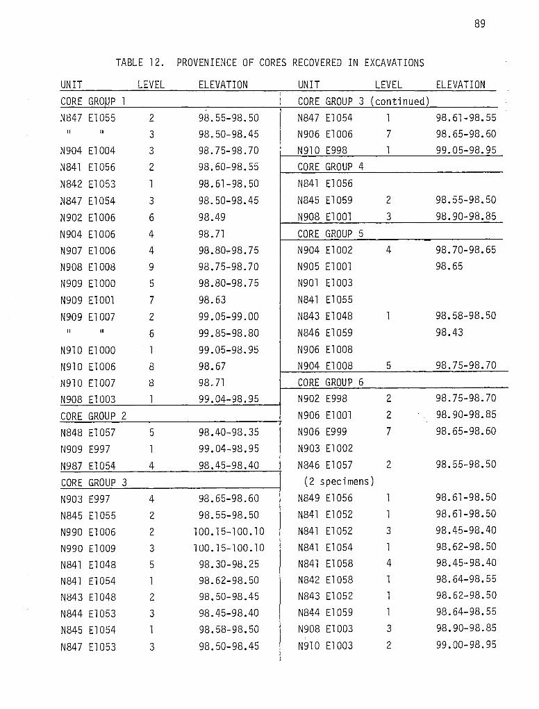
89
TABLE 12. PROVENIENCE OF CORES RECOVERED IN EXCAVATIONS
UNIT LEVEL ELEVATION UNIT LEVEL ELEVATION --
CORE GRO.WP 1 CORE GROUP 3 (continued)
N847 El055 2 98.55-98.50 N847 El054 1 98.61-98.55 II II 3 98.50-98.45 N906 El006 7 98.65-98.60
N904 El004 3 98. 75-98. 70 N910 E998 l 99.05-98.95
N841 El056 2 98.60-98.55 CORE GROUP 4
N842 El053 1 98.61-98.50 N841 El056
N847 El054 3 98.50-98.45 N845 El059 2 98.55-98.50
N902 El006 6 98.49 N908 ElOOl 3 98.90-98.85
N904 El006 4 98. 71 CORE GROUP 5
N907 El006 4 98.80.,-98.75 N904 El002 4 98.70-98.65
N908 El008 9 98.75-98.70 N905 ElOOl 98.65
N909 ElOOO 5 98.80-98.75 N901 El003
N909 ElOOl 7 98.63 N841 El055
N909 El007 2 99.05-99.00 N843 El048 1 98.58-98.50 II II 6 99.85-98.80 N846 El059 98.43
N910 El 000 1 99.05-98.9!5 N906 El008
N910 El006 8 98.67 N904 El008 5 98.75-98.70
N910 El007 8 98.71 CORE GROUP 6
N908 El003 1 99.04-98.95 N902 E998 2 98.75-98.70
CORE GROUP 2 N906 ElOOl 2 98.90-98.85
N848 El057 5 98.40-98.35 N906 E999 7 98.65-98.60
N909 E997 1 99.04-98.95 N903 El002
N987 El054 4 98.45-98.40 N846 El057 2 98.55-98.50
CORE GROUP 3 (2 specimens)
N903 E997 4 98.65-98.60 N849 El056 1 98.61-98.50
N845 El055 2 98.55-98.50 N841 El052 1 98.61-98.50
N990 El006 2 100. 15-100. 10 N841 El052 3 98.45-98.40
N990 El009 3 l 00. 1 5-1 00. 10 N841 El054 1 98.62-98.50
N841 El048 5 98.30-98.25 N841 El058 4 98.45-98.40
N841 El054 l 98.62-98.50 N842 El058 l 98.64-98.55
N843 El048 2 98.50-98.45 N843 El052 l 98.62-98.50
N844 El053 3 98.45-98.40 N844 El059 l 98.64-98.55
N845 El054 l 98.58-98.50 N908 El003 3 98.90-98.85 "
N847 El053 3 98.50-98.45 N910 El003 2 99.00-98.95

90
TABLE l3b DEBIT AGE
AREA A AREA C TOTAL TOTAi\. Levels 3+ Levels l -2 ARCHAIC SITEj
Primary Flakes - Total 72 18 37 90 1271 Cortex Platform 26 5 16 31 47
Modified 0 0 Trimmed 0 0 0 0 0
Single Facet Pl at form 27 14 12 41 53 Modified 0 0 0 0 0 Trimmed 0 0 0 0 0
Other Platform Types 17 1 7 18 25
Modified 0 0 0 0 0
Trimmed 0 0 0 0 0 I
Secondary Flakes - Total 832 311 381 1143 15241 Cortex Platform 366 146 146 512 658
Modified 32 6 14 38 52
Trimmed 5 2 3 7 10
Single Facet Platform 225 92 136 317 453
Modified 20 6 13 26 39
Trimmed 8 2 4 10 14
Small Multiple Facet Pl at form 8 2 3 10 13 Modified 0 0 1 0 Trimmed 0 0 0 0 0
Large Multiple Facet Platform 16 5 2 21 23
Modified 4 2 0 6 6
Trimmed 0 0 0 0 a Secondary Lipped 222 95 116 317 433
Modified 6 4 8 10 18
Trimmed 2 4 3 7

91
TABLE 13. (continued)
AREA A AREA C TOTAL TOTAL Levels 3+ Levels 1-2 ARCHAIC SITE
Tertiary Flakes - Total 1449 383 520 1832 2352 Single Facet Platform 639 145 191 784 975
Modified 29 6 10 35 45
Trimmed 4 1 5 5 10
Sma 11 Multi p 1 e Facet Platform 38 11 7 49 56
Modified 3 0 4 4
Trimmed 0 0 0 0 0
Large Multiple Facet Platform 43 10 14 53 67
Modified 4 0 0 4 4
Trimmed 2 0 1 2 3
Tertiary Lipped 755 229 322 984 1306
Modified 20 11 16 31 47
Trimmed 9 6 10 15 25
Chips - Tota 1 2283 665 1220 2948 4168
Cortex 68 20 36 88 124
Modified 0 0 0 0 0
Trimmed 0 0 0 0 0
Partial Cortex 567 188 369 755 1124
Modified 8 1 6 9 15
Trimmed 5 4 13 9 22
No Cortex 552 455 854 1007 1861
Modified 11 10 26 21 47
Trimmed 10 8 17 18 35
Chunks - Tota 1 61 29 31 90 121
Cortex 7 2 5 9 14
Partial Cortex 23 14 19 37 56
No Cortex 32 16 6 48 54

92
Co!Lte.x P£..a.tfio.tun Flake. A flake with a platform of unmodified, weathered cortex.
S~ngle Facet P£..a.tfio.tun Flake. A flake with platform consisting of a single removal scar (facet) produced by previous knapping.
MuLti.ple Facet P£..a.tfio.tun Flake. A flake with a platform consisting of two or more facets produced by previous knapping. Further subdivided into small (<l cm) and large (>l cm) according to width of combined facets.
Upped Flake. "Typically, these flakes have multifaceted, lenticular-shaped striking platforms and a characteristic lip or ridge which is at right angles to the axis of removal on the ventral side. The striking platforms are bifa-· cially prepared and multifaceted. The dorsal side of the flake is multifaceted and rarely exhibits cortex. Lipped flakes are characteristically thin and arched" (Shafer 1969:4).
Chlp. A portion of a flake which, due to breakage, crushing or shattering, has no platform. Further subdivided into primary, secondary, and tertiary according to the amount of cortex remaining on the external surface.
Chunk. Fragment showing no striking platform and no force rings (bulbs of percussion) emanating from the direction of applied force. Thickness approaches maximum length and width. Too small to be a core, too large and massive to qualify as a chip. Further subdivided into primary, secondary, and tertiary according to the amount of cortex remaining on the external surface.
Mo~fi~ed Flake a~ Chlp. A flake or chip that may have been used as a tool. Such use is evidenced by minute nicking, battering, or polish along the edge(s) of the flake or chip.
T!U.mmed Flake a~ Chlp. A flake or chip demonstrating intentional edge preparation through removal of a uniform series of tiny flakes along an edge. Distinguished from modified flakes and chips in that human alteration of the piece is unquestionable (Mallouf 1976).
For primary flakes, the "Other Platform Types" division was intended to include lipped and multiple facet platform flakes, both of whic.h were very minor elements of the primary flake collection.
Among secondary and tertiary flakes, lipping was a characteristic given precedence over platform faceting. Lipped flakes had either single facet or multiple facet platforms, but were always counted as lipped flakes.
Modified flakes were recognized through unenhanced visual inspection of the debitage as it was being sorted. No microscopic examination was attempted. It is therefore likely that some modified flakes were not recognized and that some believed to be modified actually are not.
The debitage counts for the 53 analytical/descriptive units are presented as a total of all levels for the excavations in Area A (first column in Table 13). This complete assemblage is suggested to represent Late Archaic activities in

93
that one portion of 41 LK 67. For Area C, the debitage has been separated into two assemblages. The column headed "Levels 3+" in Table 13 contains debitage from the Late Archaic component. The column headed "Levels 1-2" represents Area C. The column headed "Total Archaic" provides a combined figure for Archaic debitage assemblages from both Areas A and C. In Appendix II, the Material Analysis Records present debitage totals on a unit and level basis for the major debitage categories (primary, secondary, and tertiary flakes, chips, and totals of modified pieces within each category).
Genvr..al.. Comment!.>
The following comments are based on reexamination of waste flakes from the Area C excavations. The Area C chipping debris seems to represent predominately hard hammer freehand percussion. Biface thinning flakes (thin, broad flakes with narrow, gound platform remnants) are certainly present, but are not particularly abundant, much less so than the total for tertiary lipped flakes would indicate. Debris from the initial stages of cobble testing and cortex removal is also poorly represented, although 41 .24% of the complete flakes and 29.94% of the fragments have some cortex present. Table 14 presents some of the summary statistics in comparison to some relatively nearby sites excavated or tested during Phase I at Choke Canyon. 41 LK 41 and 41 LK 59 are sites flanking the Frio paleochannel to the southwest; 41 LK 201, also to the southwest, flanks what may be a paleochannel of Opossum Creek. All three are alluvial sites without gravel deposits, but 41 LK 41 lies fairly close to a major veneer of gravel covering the southern valley slope. Table 14 shows that all four sites have similarly proportionate arrays of primary, secondary, and teritary flakes, flake fragments and chunks of chert or other material. However, if this table
TABLE 14. DISTRIBUTION OF PRINCIPAL CATEGORIES OF CHIPPING DEBRIS AT FOUR CHOKE CANYON SITES
41 LK 67 41 LK 41 41 LK 59 41 LK 201 Totals
Primary Flakes 127 12 34 19 192
Secondary Flakes 1524 115 329 224 2192
Tertiary Flakes 2352 153 514 369 3388
Chips 4168 410 744 505 5827
Chunks 121 21 64 8 214
Total 8292 711 1685 1125 11 ,813
degrees of freedom = 12, computed x2 = 108.149

94
is treated as a 4 x 5 contingency table and tested with the X2 statistic, statistically significant differences emerge. For 12 degrees of freedom, the differences between expected and observed frequencies are greater than the critical value of p = .0001 or less. The greatest differences between observed and expected frequencies are as follows:
41 LK 59 - fewer flake fragments than expected
41 LK 67 - more flake fragments than expected
41 LK 41 - more flake fragments, but fewer tertiary flakes than expected
41 LK 201 - fewer flake fragments, but more tertiary flakes than expected
The sites that lie closest to gravel deposits tend to have more flake fragments than sites that are more distant; the meaning of this is obscure. Since flakes with shattered platforms were counted as flake fragments, perhaps the relative frequency of flake fragments has something to do with different proportions of hard-hammer or anvil percussion. It should be noted that from none of the four sites presented here were the samples drawn randomly; therefore, the samples cannot be considered representative of the sites as a whole.
V. Possible Sociotechnic or Ideotechnic Artifacts
The reader is referred to Appendix III for discussions of the ceramic figurine and the soapstone elbow pipe from 41 LK 67.
FRESHWATER MUSSEL AND MARINE SHELL
The unionids, or freshwater mussels, from 41 LK 67 have been identified by Harold Murray (Department of Biology, Trinity University). The discussion that follows is abstracted from and based on his report on unionids from Phase I excavations at Choke Canyon (Hall, Black, and Graves 1982:Appendix VI). Six unionid taxa and a single sphaeriid clam were recovered from 41 LK 67. Table 15 shows the distribution of specimens by taxa and reveals several things. First, an appreciable quantity of mussel shell was recovered from the site: from Areas A and C combined, over 3000 identified specimens were recovered. If identifiable fragments are added to the total, over 9000 specimens were found in the excavations. Second, the density of mussel shell by area excavated is about ten times greater in Area C (118 valves or fragments per m2) than in Area A (11 valves or fragments per m2). The smaller range of species at Area A presumably indicates sampling error, as a function of the smaller sample size at Area A. However, the ratio of identified to unidentified specimens is over eight times higher at Area A (3.39:1) than at Area C (0.39:1), indicating that the shell was at least better preserved there if not as abundant.
The composition of the unionid assemblage appears essentially the same as that of the other sites (such as 41 LK 41, 41 LK 59, and 41 MC 222) in a Late Archaic to Late Prehistoric time range, and thought to be associated with the active

95
TABLE 15. FRESHWATER MUSSEL SHELL
T axa N b um er o f s ,pec1 mens
Area A Area c Total
LampJ.iM'...lo a.no do mo,[dv.i 4 90 94
LampJ.iM'...lo sp. 476 500 976
CyJrX.on.a.,[a.,6 tampiQoeYl.J.i,[,6 514 1610 2124
CaJtun.eu.eJ..n.a. paJtva. 16 22 38
Amblema. sp. 1 4 5
v illOJ.i a. sp. 0 3 3
Qua.d!r.ula. a.Wtea. 0 1 1
Qua.d!r.ula. s p . 0 11 11
unidentified fraqments 298 5792 6090
Totals 1309 8033 9342
channel of the Frio or its major tributaries, except for the presence of three specimens tentatively identified as VillOJ.ia. sp. These specimens have worn umbos and could be damaged specimens of Ca.Jc.un.eulln.a. paJtva. (Hall, Black, and Graves 1982). The assemblage may suggest at least two different habitats or facies. Two genera, Lamp-6~ and Amblema., prefer a coarse, clean substrate and relatively high current velocity; two other taxa, CaJtun.eulln.a. paJtva. and VilloJ.ia. sp., indicate very shallow standing water, perhaps as in floodplain oxbow lakes or seasonally flooded depressions; the sphaeriid clam indicates a similar habitat (Murray, personal communication).
There are some indications that the distributions of different species within the excavation areas are different. At Area C, for example, the small sample of CaJtun.Qu.eJ..n.a. paJtva. individuals occurs primarily as two major clusters on the north side of the excavation, while CyJrX.o~ ta.mpieoeYl.J.i,[,6, a much more abundant species, occurs in subclusters widely distributed over the excavation. Future research might be directed toward discovering whether species with similar habitat requirements, presumably collected at the same time, also occur together in the same excavated clusters.

96
Modified Mussel Shell (five specimens)
Possible intentional shaping of five small fragments can be recognized at 28X, although the weathered and excavation-damaged nature of the shell makes positive recognition difficult. These are all small triangular, trapezoidal, or rectangular fragments snapped from the marginal portion of the valve, with the margin forming one edge. In some cases the pallial line is visible on the interior surface. No conclusive evidence of grooving before snapping is visible. These specimens may be blanks for manufacturing small pendants. All were recovered from Area C, four from levels 4 or 5; three were found in the same level of adjacent squares. The shape, size, and provenience of these specimens are as follows:
1. trapezoidal, 20.5 x 15.5 x 13 mm, two edges snapped and polished(?), one edge possibly sawed (?) and polished (faint vertical grooves visible on edge); N848 E1054, level 5 (98.40-98.35).
2. trapezoidal, 17 x 13.5 x 8 mm, three edges snapped, with light polish (?); N848 El054, level 5 (98.40-98.35).
3. rectangular, 18 x 11 mm, three edges snapped, possibly smoothed; N847 El055, level 5 (98.40-98.35).
4. triangular, 23 x 17, partially calcined, two edges snapped, one smoothed; N841 El054, level 1 (98.62-98.50).
5. triangular, 28.5 x 28, two edges snapped, one definitely smoothed; N843 E1049, level 5 (98.35-98.30); associated with a cluster of fire-cracked rock.
In addition to these shaped specimens, Murray has identified several perforated valves or portions of valves.
Marine Shell
The conch columella adz found on the surface at Area E has been described elsewhere. The only other marine shell from the site is a small (14.5 x 9 mm) quadrilateral fragment of dorsally ridged shell with four snapped edges, one showing possible smoothing. Light polish is visible at 28X on the dorsal ridges. This specimen was excavated from Area C, N843 El053, level 4 (98.40-98.35).
SUMMARY AND CONCLUSIONS
The excavations conducted at 41 LK 67 yielded evidence indicating that the site contains ~n ~,{,tu components representing Late Archaic and Late Prehistoric habitational activities. Certain other artifact forms, collected for the most part from heavily eroded surfaces peripheral to the main excavations, are suggestive of possible Pre-Archaic and Early or Middle Archaic activities. However, the presence of such earlier components at 41 LK 67 is not unquestionably demonstrated by any of the available evidence.

97
Carbon in quantities adequate for radiocarbon assay were recovered from the Late Archaic component only. Corrected radiocarbon dates considered reliable provide an age range from 1590 B.C. to 660 B.C. for the Late Archaic component. This age range is several hundred years earlier than ages available for deposits yielding comparable chipped stone diagnostics (that is, EYL6on dart points) in central Texas. The Late Prehistoric component contains materials (Pvr.cUz and SQa-ltonn arrow points, potsherds, and quadrilateral bifaces) that elsewhere in Choke Canyon and south Texas have been dated to about A.O. 1300. A similar age is suggested for the materials found at 41 LK 67.
In addition to a number of substantial habitational features composed of locally-obtained tuffaceous sedimentary rocks, the Late Archaic component at 41 LK 67 is represented by FcUAland and EYL6on dart points, a ManQo.6 dart point, at least three distally beveled tools, and at least three metate fragments, including the large metate found in -01.tu at the northeast corner of Area A. It is probable that some of the other side- and corner-notched dart points and unstemmed triangular bifaces found on the site also relate to Late Archie activities. Also associated with the Late Archaic occupation is mussel shell, RabdoZU6 snail shell, chipping debris, fire-cracked rock, and a small number of fish otoliths (freshwater drum).
Recovered from the Late Prehistoric component at 41 LK 67 were Pvr.cUz arrow points and preforms, SQa-ltonn arrow points, quadrilateral bifaces (beveled knives), bone-tempered plainware pottery, mussel and snail shell, chipping debris, fire-cracked rock, and other debris. Possibly associated with the Late Prehistoric component are the soapstone elbow pipe from Area D (Appendix III), a small triangular biface, and one or more of the distally beveled tools.
In addition to the Late Archaic and Late Prehistoric components recognized in the excavations, there are several stemmed bifaces that cannot be typologically categorized, but whose size and general configuration suggest that they predate the in .61.tu components. These (discussed as artifact category I-8) could have been collected prehistorically from earlier sites located nearby, or they may represent a still earlier component scattered over the old terrace remnant on which the site is located. The presence of patinated chipped stone tools and especially chipping debris may favor the second explanation. At Area C, for example, patinated flakes were scattered throughout all levels; other examples were seen on eroded surfaces in Area E.
Surface observations, findings made in controlled excavations, and feature distributions revealed in the machine-strip excavations indicate that Late Archaic remains were distributed much more extensively over the site than were the Late Pre11:storic remains. All rock cluster features observed surficially on the southern and western periphery, in the Area A and Area C excavations (Figs. 5 and 7), and in the machine strips (Fig. 8) are attributed to Late Archaic activities. The Late Prehistoric component is best represented in Area C, but scattered occurrences of quadrilateral bifaces and arrow point fragments in or near the machine strips suggest that it extended approximately to the eastern edge of Area A. It is also represented by potsherds found in the .6e.vidvr.o just west of Area B.

98
Remains of Late Archaic activity at 41 LK 67 were buried from 26 to 35 cm beneath the modern ground surface. In conjunction with reliable radiocarbon dates, this depth of burial suggests long-term accumulation rates of about 0.005 to 0.01 cm/year for the colluvial deposits in Area C. Since the surface of Area A was altered during clearing of the ~endeJr.o, a colluvial deposition rate of 0.004 cm/year can be taken only as a minimum. By comparison, radiocarbon-dated prehistoric cultural components adjacent to 41 LK 67 in the valley of the Frio River have been buried by overbank deposition from the river at rates on the order of 0.02 to 0.06 cm/year. The well-integrated condition of many of the Late Archaic hearth features exposed in Areas A and C suggests that they were covered by colluvial deposition subsequent to Late Archaic activities on the site, but prior to Late Prehistoric activity. This suggests that gradual, nondestructive sheetwashing, without gullying, was initiated sometime during the Late Archaic and has perhaps continued at a steady rate up to the present.
Subsistence-related residues recognized in debris collections from 41 LK 67 include mussel shells, Rabdozuo snail shells, fish otoliths, and metates. In this respect, the two prehistoric components recognized ~n ~~u on the site are exactly like most other prehistoric sites at Choke Canyon. Vertebrate faunal remains are rarely preserved. The fish otolith, a particularly durable skeletal element, is all that survives in the 41 LK 67 deposits to evidence use of vertebrates. Mussel shells and Rabdozuo snail shells are extremely common, almost ubiquitous, in Choke Canyon's prehistoric sites. Both kinds of shell are often found together in heaps. In Area Cat 41 LK 67, a close correspondence was recognized between mussel and snail shell and the large tuffaceous sedimentary rock cluster designated Feature 8. From this association, it has been inferred that at least one function of such tuff rock hearths was to cook mussels and snails before they were eaten by the site's prehistoric inhabitants. The presence of a mano, a relatively complete metate, and several metate fragments is interpreted as evidence of plant food processing on the site. Though indications of the specific kinds of food processed with these grinding implements are not at present available (or recognized), such items as beans, nuts, and seeds are likely possibilities. Ac.a.c,.i.a. sp., the plant identified as the source of the carbon in Feature 5 of Area A, produces a bean that, after appropriate processing, is fit for human consumption. At certain other prehistoric sites in the vicinity, species such as mesquite (P~o~op,W sp.) and oak (QueJr.QU6 sp.) have been identified in carbon samples radiocarbon-dated to periods coeval with both Late Archaic and Late Prehistoric activities at 41 LK 67. Mesquite beans and acorns may thus be offered as possible foodstuffs processed by the site's inhabitants. Relative to subsistence remains, there are no substantial differences between Late Archaic or Late Prehistoric foodgathering habits recognized in the remains.
The potential for definition of intrasite activity areas at 41 LK 67 was first recognized by THC surveyors in early test efforts on the site. Findings made in THC test excavations revealed that buried prehistoric debris in some areas of the site had apparently undergone very little disturbance following deposition. Because of the shallow depth of cultural deposits on the site, it was practical within available time limits to excavate over greater areas at 41 LK 67 than was possible at many of Choke Canyon's deeper prehistoric sites. An attempt was made to capitalize on this advantage during the investigation conducted by the CAR crew. The two major excavations at 41 LK 67--Area A,

99
measuring 10 x 12 m and Area C, 8 x 8 m--are some of the most extensive excavations yet attempted in southern Texas. Analysis of feature and debris distributions within these areas yielded a certain amount of information concerning patterning of human activities, but the exercise was generally not as revealing as anticipated.
The ability to recognize activity patterning in the prehistoric debris accumulations at 41 LK 67 was minimized by two critical factors. These were: (1) the size of the excavation areas, and (2) the classes of cultural debris preserved in the deposits. Though they are among the most extensive excavations yet attempted in south Texas, Areas A and Cat 41 LK 67 nevertheless appear to have been too limited in scope. In both areas, analysis of debris distributions revealed trends of patterning suggesting that the loci of prehistoric activities resulting in debris deposition lay in unexcavated ground adjacent to each unit block. For Area A, a trend of increased debris density and more distinct patterning was recognized as extending northwestward beyond the limits of excavation. In Area C, the distribution of debris representing the Late Prehistoric component indicated that the most intensive activity occurred slightly further to the south and southwest of the excavations. In future attempts directed at defining activity patterns within similar prehistoric sites in south Texas, even more extensive excavations should be planned and there should be provisions made for field recognition of recovery trends permitting immediate redirection of the excavations as necessary to sample more completely the portions of the site where intensive activity occurred. In the 41 LK 67 debris assemblage, analysis has shown that mussel shell umbos, strongly correlated with hearth stones and debitage, might be the best immediate indicator of overall trends in debris distribution.
Recognition of activity patterning within the excavation areas at 41 LK 67 has also been hindered by the range of materials preserved in deposits on the site. Limited essentially to stone and shell, the site assemblage offers an opportunity for definition of activities involving lithic tool manufacture and maintenance. A limited range of inferences and observations concerning food items consumed by site inhabitants as well as some indications -0f methods of food preparation have also been perceived. The study of chipped stone tool morphology and use-wear presented in this report demonstrates the potential for functional interpretations concerning prehistoric activities on the site. The inferences drawn from lithic tool use-wear analysis are limited, however, by the range of other forms of evidence recovered from the site. The scarcity of carbon (for radiocarbon assay, wood species identifications, and certain other data relating to subsistence orientations) and vertebrate faunal remains reduces inferences concerning tool use to a much more speculative level. In future research efforts aimed at the study of large-scale activity patterning within a prehistoric site, the importance of having substantial amounts of vertebrate faunal remains and carbon preserved in the deposits cannot be too strongly emphasized.
The major contributions to our understanding of prehistoric cultures resulting from the investigation at 41 LK 67 include: (1) the recognition of distinctive tool assemblages related to the Late Archaic.and Late Prehistoric periods, (2) a suite of radiocarbon dates that bring some level of chronological control to the Late Archaic of south Texas, (3) much useful information concerning the manufacture, maintenance, and use of chipped stone tools by both Late Archaic and Late Prehistoric people, and (4) some useful recommendations concerning the conduct of future research into the patterning of human activities in other south Texas prehistoric sites similar to 41 LK 67.


Figure 1. Topography, extent of site, and excavations.
PAGE 119 REDACTED

102
Figure 2. Avr.,i.a,f_ V..i.ew o0 Mun Sile.. M.e.a. LoofU.n.g wv.i:t. White truck is located by the Area C excavations. Straight ~e..ndvr.o is center-1 ine of dam where the Area A excavations were placed. Note gullies cut into Catahoula Formation. Frio River channel is marked by dense trees in the near background. Most of the vegetation visible is blackbrush. Note the many cattle paths across the site.

103

104
Figure 3. Genvr.a..l View6 at) :the SUe
a. View southwest from Area A across Frio valley. Horizon marks southern valley margin at the eastern end of Choke Canyon Reservoir. Density of brush shown in this photo is typical of the site in general. Blackbrush and guajillo predominate on the site. Also seen here are mesquite, yucca, and soapbrush.
b. View north of the large arroyo heading out near the Area A excavations (see also Figures 1 and 2). Rock faces along the walls are exposures of Catahoula tuff. This is the likely source of the tuffaceous rocks used in the construction of the Ar.ea A features. Blackbrush and ceniza predominate.
c. View south of the arroyo shown above as it meets the Frio River channel. Note gravel pavement on floor of channel and large trees along the river.
d. Gravel pavement on terrace downslope from Area A.
e. Initial stages of excavation in Area C. View is southwest across the Frio River valley. Mesquite, blackbrush, and yucca are seen in this photo.
f. View southeast from Area A to Area C following machine stripping operations.

105
a b
c d
e f

106
Figure 4. lvte.a A Exc.a.va.:Uon.6.
a. View north-northeast. Exca va ti ons in· Area A underway.
b. View grid north of features exposed in Area A. Cleared path (-0endeJc..o) in background marks centerline of dam. Features 1, 2, 3, 4, 5, 6, and 7 are shown.
c. Overview of Features 3 and 5 in Area A. All rocks are tuff. Arrow points magnetic north.
d. Cross section view of Feature 6 showing single layer construction common to most of the tuff rock clusters found.
e. Grinding slab ~n -0J..:tu, Area A (see Figure 5 for exact provenience).
f. Typical soil profile, Area A.

IU/
a b
c d
e f


NSll E997 _yo ;i;o ag& Feature 21
0
109
N911 E1009 ,o 'o
G2'0
c ~metate D 0 o Feature
•+ + 0 + + + 22 +
9 23\. + + .. '\\Do .i..D-"" + + +
gs.BO o.. o 0
0 Q c cP a
0 17 + + 0 + c +
0 0
+ + + + ~ + ' 0 0
o -=- 615<Po o e o c
0' ' • .;>cs-•Feature. PARTIALLY
'b o ----C 0 4 <I •_,..-C~~6'~D " Q .o 0 + l:IJO Q O o + + + +
0 0 •
~ 0 o g0 ~0~0 , Feature 3 ~ ·e • 0
+
0 p
+ + +
+ + ·+ +<> + + 0
Feature 20
+ol:QD~ 000
"o 0 ° Feature 6 Feature 2 s;:i
0 0
o Featu~;s • ~· •.sae_,.0 o ~ ~o a o
o• +, ~ .$ + + + 6 + t
~" "~ ~~~1:r-7 NBOIEBB7 u
~~ + +
• 98.'50~
+
+
N901 EIOO
+ + +
0
Figure 5
41 LK 67 Topographic plan of
features in Area rock A
{INSET TO FIGURE I)
CONTOUR INTERVAL: 10 CM
0 5 METERS
GRID

110
Figure 6. Alt.ea C Exc.ava;Uon.6.
a. View southwest of Area C excavations in progress.
b. Feature 8 fully exposed in Area C. Note relationship of feature floor to soil profile at rear of unit. View is grid north.
c. Overview of Feature 8, the largest single cluster of fire-cracked tuffaceous rock in Area C. Note locally more intense fracturing of some stones.
d. Cross section of Feature 8 in Area C. Note single layer construction.
e. Overview of Feature 24 in Area C. Arrow points magnetic north.
f. Typical soil profile, Area A.
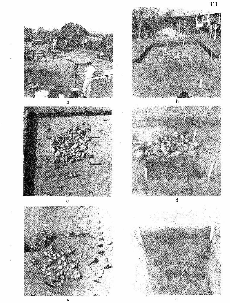
a b
c d
f

112
NB49EI062 NB49EI080 . D
0 a "o
+ + + + + + + 0 ~
" ... o, .
QQq . "' + + + + + + + •. .
9 ", 0 • . _,, "' • ... ~Q
. Oo 0 .5.. s "c:i 0
• .+ + + • ~It ()l + + +o o~o ·~~ 0 0 'O
0 q. sFeature -~ 0 ~ QO g 4 27 " " /JOO " 0
Q
+ + + a'?t> • +. +.. + ocPg 0 ... Q 0 g o"' 0 Cl \}•_.~go q 0 \>
' •,q 0 Oo 0 0 0 0 .. 01/Jl "o
CJ + T_~-~+. -i. v o+ "
+ " + 0 9 'b" -lo .. ~ .. •' .. 0 ••
o'lj '6-ei .. a Q
~~o:~ "·• •r;:,':::io Q o •O ~ tJoQ:. o an • Q o ~oq,1:1a ...
' 0 qi ti
~. '5' -0 0' QDO~ p • ..
"' ,p ! . 0
+ + • + +o +,, f. ~ ~ii q, + '@>· 0 ~etat;..
~
" "•o <b ;Feature 24 ·• 0 fragment
0 Q .. ~
+ + + + + + + 0 " .
• • • 0 0 .
e"• aQ_O O• . D
N941 E1052 ~·O , 0 " a NB41EIOSO
Figure 7 41 LK 67
Plan of rock features in Area C
(INSET TO FIGURE I)
0 5 METERS
GRID

GRID
113
Figure 8 41 LK 67
Distribution and topography of features found in machine
strip excavations
4
(INSET TO FIGURE I)
ELEVATIONS IN METERS RELATIVE TO ARBITRARY
ELEVATION DATUM (100.00M)
0 20M£T£RS
~,~F~~' ~~~;~···· .. ·•.·.· .. •.·· .. ·.--.· .. · .. · .. · .. ··.· .. •.··.·· .. ····.• .. ·: .. ••.·.•.· .. ••·· .. ·.·• ... ·•.·• .. ·.··.•·· .•. · .. ··.·.·• .. · .. ·.· •. · .. ·• .. ··.· .. '.···.-.-... •.··
: .. ·· ·.·· .·' •, •::c•.} NB41
MACHINE STRIP
6
EI060

114
Figure 9. Co4e6--G4oup~ 1-6 and Co4e F~agmenz. Numbers 1-6 beneath each specimen indicate group affiliation, and number 7 designates a Core Fragment.
1. natural platform;
2. bidirectional, natural and prepared platforms;
3. multidirectional, natural and prepared platforms, single and multiple facets;
4. unidirectional, prepared platforms, single facet;
5. multi directional, natural and prepared platforms, single facet;
6. core nuclei;
7. core fragment.

115
6
5 6 7
5
3 4
4
3
2 2
0 2 3 4
CM

116
Figure 10. Bifia.c.e. FaJl.uJr.U, Unlfia.c.v.,, a.nd Hammvu.i:tonv.,.
a-h, biface failures (III-7); i-k, haftless unifaces (I-13); 1-p, proximal biface failures (III-6); q-t, possible hammerstones (I-16).
Numbers in parentheses indicate artifact classes (see Table l); numbers beneath each specimen in the figure indicate the group, form, and specimen number for each artifact according to the reservoir-wide classification scheme presented in Volume 5 of the research series.

a 2
g
3
q
b
2
h
5
m 7-1
c 2
CM
d 2
e 2
117
3
k 4 -5-J

118
Figure 11. TIU..nne.d Bit)a.c.e..o a.nd Bit)a.c.e. FaM'..Wte..o.
a,b, Sc.aLe.oJz.n arrow points (I-2); c, Pvr..d,,[z arrow points (I-1); d, Pe.Jz.diz arrow point preforms (Cilt)t)-ton points, III-1); e, medial arrow point fragments (I-3); f, possible pre-Late Archaic dart point (I-8); g, stemmed biface preform (III-2);
h,i, F~nd dart points (III-4); j, Ma..1z.c.o-0 dart point (III-7); k, possible pre-Late Archaic dirt point (I-8); l, Zo.Jz.Jz.a. or GodJ..e.y dart point (I-5); m, unclassified side-notched dart point (I-6); n, En-00.1z. (?)dart point fragment (I-4), thermally
fractured; o, unclassified side-notched dart point fragment (I-6),
thermally fractured; p-r, small triangular basally thinned bifaces (I-9);
s, proximal thinned biface fragment (I-10); t, small triangular basally thinned biface (I-9); u, quadrilateral biface ("beveled knife," I-12); v, proximal fragment (nearly complete) of thinned
biface (I-10); w, possible pre-Late Archaic dart point (I-8);
x,y, biface failures (III-7).

a b
1-5-15
1-1-14
k I - 3 - 30
p 2- I -17
1-4-9 1-4-9 J-4-JO 1-4-11 J-4-12
g I - 2 -J
q 3 -1- 3
v 5-10
c
CM
r 3" 1-15
w
5 - 33
d
n I - 3- 6
s 3-2-32
x 5 - 34
e I - 7 - 24 J - 7- 25
j I - 3 - 20
0 I - 5-7
4 - 1- 19
y
8 - 11
119

120
Figure 12. B.l6a.c.e. Fa.,U.wc.e.1.i a.nd FJta.gme.n.tl.i, MM c.e11.a.ne.ou.6 Ge.a log.le. s p e.c..lm e.no .
a,b, satin spar gypsum; c, fossil shell fragment;
d-f, medial or lateral biface failures (III-5); g, part of distal biface fragment (fits proximal end of artifact
shown as 11 0 11) (I-11);
h-j, medial or lateral biface failures (III-5); k, proximal biface failure (III-6); l, probable quadrilateral biface C'beveled knife 11
) medial fragment (I-12);
m, medial biface failure (III-5); n, distal biface failure (III-4); o, distal biface fragment (I-11), fits 11 g; 11
p-r, distal biface failures (III-4); s, proximal thinned biface fragment (I-10); t, distal biface failure (III-4); u, distal fragment of possible pre-Late Archaic dart point (I-8);
v-y, distal biface failures (III-4).

i 10
n 9
u 9
d 10
a
0
9
j 10
v 9
b
e 10
p
9
0 2 3 4
10
CM
k 10
q
9
w 9
c
g h 10 10
m 10 10
r 9
x
9
s 9
y
9
121
9

122
a 9-9 b 9-10
c 9-a d
0 2 3 4 5
CM
e 4-12 f
Figure 13. VJ.Atal.1y Bevel.ed Too-l6 and Coneh Co.twneLe.a. Tool. a-e, distally beveled bifaces and unifaces (I-14); f, conch columella adz or gouge (I-15).
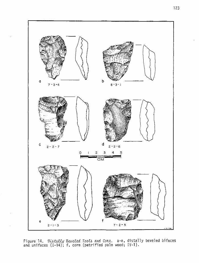
123
a 7 -3-4
l~~\,, . ~. 'f - ,,,...
-----c d
0 2 3 4 5
CM
7- 2 - 5
Figure 14. V-U:itall..y Beveled Too.lo and Cone. a-e, distally beveled bifaces and unifaces (I-14); f, core (petrified palm wood; IV-1).

124
0 2 4 6 8
CM lr:'l..."B·J'fliO
Figure 15. Me.tate. Re.c.ovvr_e.d ,Ln Me.a A (I- 7 8) .

I I a--
c
e
0 2 4 6 r--
CM
8 I
b
I ~
I I
d ..
Figure 16. Gnound Stone Atr;ti_6ae:t6. a, metate fragment (I-18); b, mano fragment (I-17); c, possible ground stone (I-19); d, mano fragment (I-17); e, ma no (I-17) .
125

126
NS49 EI052 N849 EI060
+ + + + + + +
+ + + + + + +
+ + + +
+ + + +
+ + + +
+ +
+
N841 EI052 N841 EI060
41 LK67 Figure 17
Distribution of chert and ceramic
concentrations in Area C
LATE PREHISTORIC
~CERAMIC LOCATION
~ CHERT LOCATION
0
COMPONENT
5 METERS
GRID

127
N91/ E997 N9/J E/009
z + + + + +
+ -t- + +
+ + + z
-t-
+ + +
+ + + + + +
~ + + + + + + +
I~ + + + + + + + + + -+- + + + + + + + + + +
N901 E997 N901 EI009
41LK67 Figure 18
Subsistence remains, concentrations
and selected distinctive chert types .
Area A 1n
1-GRID ~ SNAIL AND CHERT
~ MUSSEL AND CHERT
• OTOLITH LOCATION •
0 5 METERS

HIGH
UNSUCCESSFUL REJUVENATION: DISCARD OR RECYCLE:
ANGLE
ANGLE
EDGE ANGLE
/ .~/'
L()VVIL::...~~----------------------------------------~
Ul:::;>CARD MANUFACTURE - - - -
-----T /ME-------
STEPWISE REJUVENATION MODEL
Figure 19. S~epw,Ue Rejuvena;t,lon Model.. This is a heuristic model illustrating progressive changes in the working edge angle of a frequently resharpened artifact during the course of its useful life. The edge angle increases as the edge retreats from attrition due to use, but is periodically restored (indicated by the J-shaped steps in the heavy line); meanwhile, this periodic restoration produces gradual steepening of the spine-plane angle until the angle becomes so steep, or the shape of the tool so altered, that continued resharpening becomes unfeasible. At that point, the artifact is discarded or employed for a different function.
N co

REJUVENATE
Y£S
IS Y£S L)SE 1 CUTTING l l C Y£S.
EDGE ANGLE ACUTE ENOUGH
TO PERMIT REJUVENATION
>---Pl DISCARD
?
NO
STEPWISE REJUVENATION MODEL
NO
USE 2 SCRAPING OR BORING
FUNCTIONAL RESPONSE TO MORPHOLOGICAL CHANGE
NO
Figure 20. Fune.tional Reopon.6e to Mo~phologieal. Change in Ha0ted Bifiaeeo. This flowchart illustrates in more detail the decision point shown at the right-hand side of Figure 19: morphological changes induced by frequent edge maintenance may eventually become great enough to promote a change in the function of the tool. See Hypothesis 5 in 11 Microwear: An Overview of the Observations. 11
N lO

130
~ ~
~ Q" '{
< Cl)
.J
~ Cl)
a ~ a It "-~ (.)
< ~ Cl) .... Q
0
5.5
32.0
39.0
111111111111
7.5
16.0
35.0
38.S
FACE:TING WITH TRANSVE:RSE: STRIATIONS
HE:AVY ROUNDING OF PROJE:CTIONS
HE:AVY ROUNDING OF PROJE:CT!ONS, L /GHT ROUNDING OF RE:E:NTRANTS
Figure 21. Rota:ti.ona.1. Edge Wea.Jr.. on a Stemmed B~6a~e. (The same artifact is shown as Figure 11 ,w.) Note the considerable symmetry of wear type and location on opposing edges, discussed in artifact category I-8.

DISTAL EDGE
LATERAL CORNER
PROXIMAL EDGE
A. PROTOFORM 8. 4-BEVEL FORM C. 2- BEVEL FORM
Figure 22. Qua.dtzila;tvwl. lkfiac.e. Fa1u1M.
0. EXHAUSTED Bl FACE
w --1

132
B
r--------12.7----~
A
c D
0 IOCM
Figure 23. Soap~tone Pipe Found on the SUJtfiaQe at A!t..ea E (V-2).

133
REFERENCES CITED
Ahler, S. A.
1970 Projectile Point Forms and Function at Rodgers Shelter, Missouri. M-Lo-00U!U A!tc.ha.e.o.logic.a.1. Soc.ie.:t.y Rue.Mc.h SeJU..u 8.
Bunker, R. C.
1982 The Geomorphic Framework of Human Occupation in the Frio River Valley, Choke Canyon Dam Reservoir Area, Live Oak and McMullen Counties, Texas. Appendix II in Archaeological Investigations at Choke Canyon Reservoir, South Texas: The Phase I Findings, by G. D. Hall, S. L. Black, and C. Graves. Ce.ntVt fio~ A!tc.ha.e.o.logic.a.1. Rue.a.Jtc.h, The. UnivVt-OUy ofi Te.xM at Sa.n. Antonio, Chok.e. Can.yon. SVtiu 5.
Callahan, E.
1979 The Basics of Biface Knapping in the Eastern Fluted Point Tradition: A Manual for Flintknappers and Lithic Analysts. A!tc.he.o.logy on EMtVtn. No~h Ame.!U..c.a. 7 ( l ) : l - 180.
Campbell, T. N. and T. J. Campbell
1981 Historic Indian Groups of the Choke Canyon Reservoir and Surrounding Area, Southern Texas. Ce.ntVt fio~ A!tc.ha.e.o.logic.a.1. Rue.Mc.h, The. UnivVt-OUy o·n Te.xM at Sa.n. Antonio, Chok.e. Can.yon. SVtiu 1 .
Chandler, C. K.
1974 Use Wear Analysis of 'Clear Fork' Tools from the Falcon Reservoir Area, Southern Texas. La. TieNr..a. l (4): 15-2·1.
Colville, F. V.
1892 Tbe Panamint Indians of California. Ame.!U..c.a.n. Ant~opo.logi-Ot 5:351-361.
Crabtree, D. E.
1972 An Introduction to Flintworking. Oc.c.Mion.a.1. Pa.pVt-O ofi the. MlL6e.um, Ida.ho State. UnivVt-OUy 28. Pocatello, Idaho.
Creel, D., A. J; McGraw, F. Valdez, Jr., and T. C. Kelly
1979 Excavations at 41 LK 106, A Prehistoric Occupation Site in Live Oak County, Texas. Ce.ntVt fio~ A!tc.ha.e.o.logic.a.1. Rue.a.Jtc.h, The. UnivVt-OUy ofi Te.xM at Sa.n. Antonio, A!tc.ha.e.o.togic.a.1. Swwe.y Re.po~ 62.

134
Damon, P. E., C. W. Ferguson, A. Long, and E. I. Wallick
1974 Dendrochronologic Calibration of the Radiocarbon Time Scale. AmvU.Qan An;U_qu.A.:t.y 39:350-364.
Di 11 ehay, T. D.
1974 Late Quaternary Bison Population Changes on the Southern Plains. Pi.a.i.VL6 An:th!topolog.l6:t 19 ( 65) : 180-196.
Duffield, L. F. and E. B. Jelks
1961 The Pearson Site, A Historic Indian Site in Iron Bride Reservoir, Rains County, Texas. The UJU.ve.Jr,6J.:ty ofi Texa.6 a:t AU/.i.tin, VepaJt:tmen;t o 6 An:th!topology, MQheology Svr.J..v.i 4.
Frison, G. C.
1968 A Functional Analysis of Certain Chipped Stone Tools. Amvr.J..Qan An;tiqu.A.:t.y 33:156-161.
Gould, R. A.
1980 Living Atc..Qhaeology. Cambridge University Press, Cambridge.
Green, L. M.
1971 Notes on the Archeology of the Happy Patch Site, San Saba County, Texas. Buil.e;ti.n ofi :the Texa.6 Atc..QheologiQal Soue:ty 42:319-333.
Green, L. M. and T. R. Hester
1975
Greer, J. W.
The Finis Frost Site: County, Central Texas. Soue:ty 44:69-88.
A Toyah Phase Occupation in San Saba Buil.e;ti.n o 6 :the T exa.6 Atc..Qheolo giQal
1976 Nee-American Occupation at the Wheatley Site, Pedernales Falls State Park, Blanco County, Texas. Buil.e;ti.n ofi :the Texa.6 Atr.QheologiQal Soue:ty 47:89-169.
Greiser, S. T.
1977 Micro-Analysis of Wear-Patterns on Projectile Points and Knives from the Jurgens Site, Kersey, Colorado. Pi.a.i.VL6 An:th!topolog.l6:t 22-76(Pt. 1):107-116.
Hall, G. D., S. L. Black, and C. Graves
1982 Archaeological Investigations at Choke Canyon Reservoir, South Texas: The Phase I Findings. Cen;tVt 0o~ Atc..QhaeologiQal Rv.ie~Qh, The Unive.Jr,6J.:ty ofi Texa.6 a:t San Antonio, Chok.e Canyon Svr.J..v., 5.

135
Harris, R. K., I. M. Harris, J. C. Blaine, and J. Blaine
1965 A Preliminary Archeological and Documentary Study of the Womack Site, Lamar County, Texas. Bu11.e;tln on the Texa.6 Atr..eheologieaJ'.. Soudy 36:287-363.
Hayden, B.
1979 Snap, Shatter, and Superfractures: Use-Wear of Stone Skin Scrapers. In L.i.,t./U..e U-0e-WeaJt Anal..y-0~, edited by B. Hayden:207-229. Academic Press.
Hayden, B. and J. Kamminga
1973 Gould, Koster, and Santz on 'Microwear': A Critical Review. New-0leZZVt ofi L.i.,t./U..e Teehnology 2(1-2):3-8.
Hester, T. R.
1980 Vigg):.ng Into Sou.th Texa.6 P11..e~to11..y. Corona Publishing Company, San Antonio, Texas.
Hester, T. R., D. Gilbow, and A. D. Albee
1973 A Functional Analysis of "Clear Fork" Artifacts from the Rio Grande Plain, Texas. Ameltiean An:t,[qu.J.:ty 38:90-96.
Jelks, E. B.
1962 The Kyle Site: A Stratified Central Texas Aspect Site in Hill County, Texas. The Unive1t-0Uy on Texa.6 at Au..otin, Vepa.Jr..tment on Anth!r..oplogy, Atr..eheology Seltiu 5.
Jelks, E. B. (ed.)
1967 The Gilbert Site, A Norteno Focus Site in Northeastern Texas. Bu11.e;tln on the Texa.6 Atr..eheologieal.. Soudy 37.
Johnson, L., Jr.
1964 The Devil's Mouth Site: A Stratified Campsite at Amistad Reservoir, Val Verde County, Texas. The Unive1t-0Uy on Texa.6 at AM.tin, Vepa.Jr..tment ofi Anth!r..opology, Atr..eheology Seltiu 6.
Johnson, L., Jr.,. D. A. Suhm, and C. D. Tunnell
1962 Salvage Archeology of Canyon Reservoir: The Wunderlich, Footbridge and Oblate Sites. Bulle;tln on the Texa.6 MemoJr..ial.. MU-Oeum 5.
Kee 1 ey , L . H .
1974 The Methodology of Microwear Analysis: A Comment on Nance. AmeltiQan Antiqu)Xy 39:126-128.

136
1980 Expe!Ume.n.:tal Ve.:tVtmina.tion at} S.tone. Tool U6eo: A M,i,CAowe.aJt Ana.1..y.tiM. University of Chicago Press.
Kim, J. and C. W. Mueller
1978 Introduction to Factor Analysis. Sage. UvU.vVt-6.lt!J PapVt-6, Quan;t,l.ta;ti_ve. AppLlea..tloYL-6 in .the. Soeia.1.. Seie.neeo 13. Sage Publications; Beverly Hill, California.
Krieger, A. D.
1946 Culture Complexes and Chronology in Northern Texas with Extension of Puebloan Datings to the Mississippi Valley. The. UvU.vVt-6.lt!J ofi Te.xM PubLlea..tlon 4640
Lawrence, R. A.
1979 Experimental Evidence for the Significance of Attributes Used in Edge-Damage Analysis. In Lit.hie U.6e.-We.aJt Ana.1..y.tii-6, edited by B. Hayden:l13-121. Academic Press.
Lynn, W. M., D. E. Fox, and N. O'Malley
1977 Cultural Resource Survey of Choke Canyon Reservoir, Live Oak and McMullen Counties, Texas. Ot}t}iee. at} .the. S.ta.te. Att..ehe.ologi-6.t, Te.xa.ti HM.to!U..eal. Comrni-6.tiion, Att..ehe.ologieal. Swr.ve.y Re.poJt.t 20. Austin.
Ma 11 o u f , R • J .
1976 Archeological Investigations at Proposed Big Pine Lake, 1974-1975, Lamar and Red River Counties, Texas. Ot}fiiee. at} .the. S.ta.te. Att..ehe.olo gi-6.t, T e.xM Hi-6.to!U..ea.1.. CommM.tiio n, Att..ehe.olo gie!Ji. Swr.v e.y Re.poJt.t 18. Austin.
Martinez Del R1o, P.
1953 A Preliminary Report on the Mortuary Cave of Candelaria, Coahuila, Mexico. BlLle.e..tin at} .the. Te.xM A~ehe.ologiea.1.. Soeie.:ty 24:208-252.
Montgomery, J. L.
1978 The Mariposa Site: A Late Prehistoric Site on the Rio Grande Plain of Texas. Ce.YL.tVt t}o~ Att..ehae.ologiea.1.. Reoe.Meh, The. UvU.vVt.6.lt!J at} Te.xM a.t San AYL.tovU.o, Spe.eia.1.. Re.po~.t 6.
Morris, W. (ed. )
1976 The. AmvU.ean HvU.tage. Vie:ti..onMIJ at} the. Engwh Language.. Houghton Mifflin Company, Boston.

Nissen, K. and M. Dittemore
1974 Ethnographic Data and Wear Pattern Analysis: A Study of Socketed Eskimo Scrapers. Teb-lwa 17(1):67-88.
Olds, D. L.
137
1965 Report on Materials from Brawley's Cave, Bosque County, Texas. Bu.ll..e.Un. at) the Texcv., Atc.c.healagic.al.. Sac.ie:ty 36: 111-152.
Parmalee, P. W. and W. E. Klippel
1974 Freshwater Mussels as a Prehistoric Food Resource. AmvU.c.an. An.:tiquJ;t.y 39:421-434.
Ralph, E. K., H. N. Michael, and M. C. Han
1973 Radiocarbon Dates and Reality. MASCA New~le:t:tvr. 9:1-20.
Schuetz, M. K.
1961 An Analysis of Val Verde County Cave Material: Part II. Bu.ll..e.tin. at) the Texcv., Atc.c.healagic.al.. Sac.ie:ty 31:167-205.
Shafer, H. J.
1969 Archeological Investigations in the Robert Lee Reservoir Basin, West Central Texas. The UnA.vVL6Utj at) Texcv., at AU,6Un., Pap<VL6 at) the T excv., Atc.c.heala gic.al.. Sal..vag e P!ta j ec.:t 17 .
1970 Notes on Uniface Retouch Technology. AmvU.c.an. An.:tiquJ;t.y 35:480-487.
Shepard, A. 0.
1976 Ceramics for the Archaeologist. CaJtn.egie TYL6:ti:ta:tian. at) WMhin.gtan., Public.a:tian. 609. Washington, D.C. (Fifth Printing}.
Stephenson, R. L.
1970 Archeological Investigations in the Whitney Reservoir Area, Central Texas. Bu.il..e.tin. at) the Texcv., Atc.c.healagic.al.. Sac.ie:ty 41:37-286.
Story, D. A.
1976 The Archaic of East Texas. In The Texas Archaic: A Symposium. Cen.:tvr. t)a!t Atc.c.haealagic.al.. RueaJtc.h, The UnA.vVL6Utj at) Texcv., at San. An.:tanA.a, Spec.ia1.. Repo!t:t 2.

138
Suhm, D. A. and E. B. Jelks
1962 Handbook of Texas Archeology. Texa.o NLQhealagiQal Sa~e:t.y Spe&.ai. PubliQa;Uan. 1 and Texa.o Me.ma.tU.al. MMewn Bullmn. 4, Austin, Texas.
Suhm, D. A., A. D. Krieger, and E. J. Jelks
1954 An Introductory Handbook of Texas Archeo 1 ogy. Bulle.tin. at) .the Texa.o NLQhealagiQal Saue:t.y 25.
Tringham, R., G. Cooper, G. Odell, B. Voytek, and A. Whitman
1974 Experimentation in the Formation of Edge Damage: A New Approach to Lithic Analysis. JaUJt..n.ai. at) Field Atc.Qha.ealagy 1 :171-196.
Wha 11 on, R. , Jr.
1973 Spatial Analysis of Occupation Floors I: Application of Dimensional Analysis of Variance. AmvU.Qan. An;tJ_quJ.;ty 38:226-278.
Wilmsen, E.
1970 Lithic Analysis and Cultural Inference. An..th!tapalogiQal Papvr...6 16. University of Arizona.
Word, J. H. and C. L. Douglas
1970 Excavations at Baker Cave, Val Verde County, Texas. Texa.o Me.mo.tU.al. MM ewn, Bulimn. 1 6.
Wylie, H. G.
1975 Tool Microwear and Functional Types from Hogup Cave, Utah. Teb..i..wa 17(2):1-31.
Ye 11 en, J. E.
1977 Atc.Qha.eologiQal ApphoaQheJ.> .to the Pheoen..t. Academic Press, New York.
Zier, C. J.
1978 A Functional Analysis of 11 Projectile Points 11 from Yellowjacket, Colorado. Plain6 An..th!topalogJ.-6.t 23(79):31-45.

139
APPENDIX I.
SCOPE OF.WORK
Test excavation by the University of Texas at San Antonio (UTSA) has recovered significant data from 41 LK 67 and demonstrated the likelihood of this prehistoric site containing additional significant data. The preliminary results of the evaluation of 41 LK 67 are given in the attached UTSA report.
The mitigation of impact program to be conducted at 41 LK 67 shall include recovery of data through excavation, analysis of that data, and production of an investigative report detailing the results of the excavation and analysis. Previous investigator's suggestions have been incorporated in items a. and b. below. Proposals received by the Bureau of Reclamation in response to this solicitation which contain deviations from these requirements shall contain thorough justifications for same.
ao Investigative (research) design
A site-specific investigative design which addresses the sub-items below is required.
(1) Understanding the lifeways during the transition from Late Archaic to Late Prehistoric.
(2) Determination of the function of clustered rock occupational features.
(3) Determination of techniques utilized in lithic tool production.
b. Fieldwork
(1) Manual excavation in Areas A and C is required. These excavations shall expand and be contiguous to existing excavationso The methodology shall be consistent with that utilized by UTSA (i.e., by arbitrary five centimeter levels within large, block-type or open-areas comprised of contiguous one meter square excavation units)o Excavation of a combined total of 100 one meter square excavation units to a maximum depth of 40 centimeters is required. All major artifacts and elements of occupational features shall be left ~n ~,(;tu until photographed and plotted on measured plan maps. Carbon samples for radiocarbon assay shall be collected. Matrix samples for soil, pollen, and other analyses shall be collected from each excavation level and/or 11 living surface. 11
(2) The use of mechanical equipment such as a road maintainer to remove brush and scrape through the ground surface adjacent to the manual excavations [item b(l) above] is required. The object of this activity is to expose clustered rock features. All cultural features encountered shall be plotted on measured plan mapso All artifacts exposed shall be collected. Mechanical equipment shall not be used until all controlled manual excavation [item b(l) above] is completed.
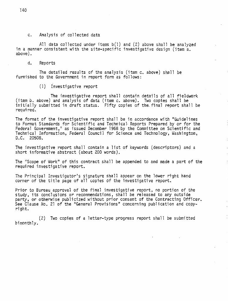
140
c. Analysis of collected data
All data collected under items b(l) and (2) above shall be analyzed in a manner consistent with the site-specific investigative design (item a. above).
d. Reports
The detailed results of the analysis (item c. above) shall be furnished to the Government in report form as follows:
(1) Investigative report
The investigative report shall contain details of all fieldwork (item b. above) and analysis of data (item c. above). Two copies shall be initially submitted in draft status. Fifty copies of the. final report shall be required.
The format of the investigative report shall be in accordance with "Guidelines to Format Standards for Sci en ti fi c and Technical Reports Prepared by or for the Federal Government," as issued December 1968 by the Committee on Scientific and Technical Information, Federal Council for Science and Technology, Washington~ D.C. 20508.
The investigative report shall contain a list of keywords (descriptors) and a short informative abstract (about 200 words).
The "Scope of Work" of this contract shall be appended to and made a part of the required investigative report.
The Principal Investigator 1 s signature shall appear on the lower ri·ght hand corner of the title page of all copies of the investigative report.
Prior to Bureau approval of the final investigative report, no portion of the study, its conclusions or recommendations, shall be released to any outside party, or otherwise publicized without prior consent of the Contracting Officer. See Clause No. 21 of the "General Provisions" concerning publication and copyright.
(2) Two copies of a letter-type progress report shall be submitted bimonthly.
APPENDIX II.
RATES OF RECOVERY FOR SELECTED CLASSES OF DEBRIS BY UNIT AND LEVEL
141
The following printouts provide laboratory counts and/or weights for selected classes of debris recovered in excavations at 41 LK 67. Columns on each page are headed by the following entries:
SITE - The site number, 41 LK 67.
NORTH/EAST - Grid coordinates at the southwest corner of the excavation unit.
LEV - Vertical level in the excavation unit starting with the surface level (1) and proceeding downward.
A - Tuff rock weight, in grams*
B - Sandstone weight, in grams*
C - Fire-fractured weight, in grams*
D - Mussel shell umbo count
E - Mussel shell weight (umbos and fragments combined), in grams*
F - Rabdotu.6 shell count (whole shells only)
G - Bone weight, in grams*
H - Primary Flakes, total count
I - Primary flakes, modified, total count
J - Secondary flakes, total count
K - Secondary flakes, modified, total count
L - Tertiary flakes, total count
M - Tertiary·flakes, modified, total count
N - Chips, total count
*Last figure in each weight figure represents tenths of a gram.

SI TF. NORTH EAST LEV A B c D E
LK 67 901.00 997.00 1 145 0 10 6 45 LI< 6 7 901. 00 998.00 1 3 65 D 70 0 20 LI< 6 7 goi. oo 998.00 2 515 0 0 2 40 LK 67 901. 00 999.00 1 880 0 25 3 30 LK 67 901.00 9 99 • 0 0 2 10 4 0 0 0 5 85 L< 67 901. 00 1000.00 1 0 0 25 3 30 LK 67 901. 00 1000.00 2 945 0 155 2 2 LK 67 90 1. 00 1001.00 1 95 0 5 0 l LK 67 901. 00 1001.0C 2 730 0 15 2 25 LK 67 901.00 1001.00 3 620 0 520 2 70 LK 67 901. 00 1002.00 1 275 0 20 2 20 LK 67 901.00 1002.00 2 575 0 5 0 0 LK 67 90 1. 00 1002.00 3 3355 0 0 2 3.0 LK 67 901. 00 1002.00 4 145 0 70 1 40 LK 67 901. 00 1003.00 1 140 0 10 2 5 LK o 7 901.0D 1J03.00 2 850 0 25 1 5 LK 67 901.00 1003 .o 0 3 105 0 45 3 15 LK 67 901.00 1003.00 4 65 0 0 4 30 LK 67 901.00 10 04 .oo 1 470 0 50 0 5 LK 67 9~)1.00 1004.00 2 2 50 ') 10 3 15 LK 67 901.00 1004.00 3 55 0 25 1 5 LK 67 901.00 1004. 0 0 4 650 0 15 2 10 LK 67 901.00 1J04.0C 5 35 0 5 5 95 LK 67 901.00 1J05.00 1 25J 0 75 0 5 LK 67 901. 00 1005.0C 2 710 12 0 190 1 20 LK 67 90 l. 00 1005.00 3 200 a 10 0 0 LK 67 901.00 1005.00 4 20 0 0 2 25 LK 67 901. 00 1005.0C 5 0 0 15 l 10 LK 67 91)1.00 1006.00 l 90 0 0 1 20 LI< 6 7 901.00 1006.00 2 580 0 50 6 90 Li( 67 CJOl.00 1006.0C 3 160 0 40 2 20 LK 6 7 901. 00 1006.0C 4 90 0 10 1 50 LK 67 901. 00 1006.00 5 1190 0 140 0 30 LK 67 901.0\J 1007.0C 1 310 0 10 4 110 LK 67 901. 00 1007 .oo 2 30 0 20 1 20 LK 67 g()l. 00 1007.00 3 60 0 390 0 0 LK 6 7 901.00 1007.00 4 990 0 0 1 40 LK 67 901.00 1007 .OG 5 0 0 10 3 50 LK 67 901.00 1008.00 l 1950 0 240 5 30 LK 6 7 qo1.oo 1008.00 2 120 0 40 1 10 LK 67 901.00 1008.0C 3 18.J 0 30 3 80 Li< 6 7 qo I. o o 1008.00 4 10 0 0 0 10 LK 67 901.00 1008.0C 5 10 0 20 0 5 LK 67 902.00 997 .GO l 850 0 325 10 95 LK 67 902.00 997.00 2 825 0 65 1 45
F G H I J
1 0 0 0 0 0 0 0 0 1 0 0 0 I) 0 2 0 a· 0 0 4 0 0 0 0 0 0 0 0 0 3 0 0 0 1 0 0 0 0 0 0 0 0 0 l 2 0 0 0 0 0 0 0 0 0 0 0 0 0 0 0 0 0 0 0 3 0 0 0 0 Q 0 0 0 0 0 0 Q 0 0 0 0 1 0 2 2 0 0 0 0 Q () 0 0 3 0 0 0 0 1 1 a 0 0 1 2 0 1 0 1 7 0 0 0 0 0 0 0 0 4 0 0 0 0 3 0 J 0 0 1 1 0 0 0 0 2 0 0 0 0 0 0 l 0 3 1 0 0 0 3 1 0 0 0 2 0 0 0 0 1 0 0 0 0 1 0 0 0 0 3 2 0 0 0 0 0 0 0 0 0 0 0 1 0 0 1 0 0 0 0 1 0 0 0 1 1 0 0 0 1 5 0 0 0 0 l 0 0 0 0 1 0 0 0 0 1 0 0 0 3 4 0 0 0 1
K l
0 3 0 1 0 3 0 2 0 2 0 0 l 2 0 0 0 2 0 0 0 1 0 2 0 0 0 l 0 3 0 1 0 0 0 1 0 2 l 5 0 2 0 2 0 0 0 2 0 l 0 2 0 1 0 0 2 4 0 3 0 l 1 4 0 0 0 4 0 l 0 0 0 1 0 1 0 2 0 1 0 1 0 0 0 0 0 1 0 2
M
0 0 0 0 0 0 0 0 0 0 0 0 0 0 0 0 0 0 0 0 0 0 )
0 0 0 0 0 0 1 0 1 0 l 0 0 0 0 0 0 0 0 0 0 0
N
6 2 0 2 2 5 5 2 1 1
11 3 1 5 4 0 4 2 4 2 1 2 3 3 9 6 6 l
12 4 2 2 0 6 0 0 3 l '.) .· J
4
k l
1 l 4
....... +:> N

SI TE NORTH EAST LEV A B c 0 E F G H I J K l M N
LK 67 9J2.00 997.00 3 230 0 35 5 80 7 0 0 0 2 l 2 0 2 LK 67 902.00 g9s.oo l 110 0 10 1 5 0 0 0 0 0 0 2 0 2 LK 6 7 qo2.oo 998.0C 2 470 0 260 6 80 0 0 0 0 0 0 l 0 4 LK 67 902.00 998.00 3 430 0 90 2 115 6 0 0 0 1 0 l 0 2 Li<. 6 7 902.00 998.00 4 390 0 20 0 105 6 0 0 0 0 0 3 0 0 LK 67 9()2.00 999.00 1 20 0 132 0 5 2 0 1 0 0 0 1 0 2 LK 67 902.00 999.00 2 820 0 140 3 30 0 0 0 0 5 0 l 0 4 LK 6 7 902.00 999.0C 3 13E5 0 45 5 75 2 0 0 0 1 0 5 0 7 LK 67 902.00 999.00 4 290 0 105 l 60 3 0 0 0 0 0 l 0 2 LK 67 902.00 1000.00 l 565 0 25 0 20 0 0 0 0 2 0 0 0 1 LK 67 902.00 1000.00 2 0 0 35 2 30 0 0 0 0 2 0 1 0 l LK 67 902.00 1000.00 3 65 0 95 1 5 2 0 0 0 l 0 l 0 4 Lt<. 67 902.00 1000.oc 4 480 0 10 2 75 4 0 0 0 0 0 3 0 3 LK 67 902.00 1001.00 1 695 0 80 0 20 0 0 0 0 0 0 0 0 2 LK 67 902.00 1001.00 2 985 0 0 2 25 l 0 0 0 0 0 2 0 4 LK 67 902.00 1001.00 3 1170 J 1 75 4 20 2 0 0 0 0 0 4 0 8 LK 67 902.00 1001 .oc 4 755 I) 140 10 35 4 0 0 0 0 0 1 0 0 LK 67 902.00 1002.00 1 350 0 475 3 10 3 a l 0 3 0 3 0 4 LK 67 902.00 1002 .oo 2 700 0 225 3 40 2 0 1 0 0 0 2 0 1 LK 67 902.00 1002 .oo 3 225 0 5 0 15 l 0 0 0 0 0 5 0 7 LK 67 902.00 l 0 02. 0 0 4 l 7 7 0 0 350 0 35 4 0 0 0 0 0 1 0 3 LK 67 9J2.00 1003 .oo 1 1755 0 245 l 5 0 0 l 0 0 0 2 0 3 LK 67 902.00 l 0 03 • 0 0 2 21 l 0 0 160 l 10 l 0 1 0 0 0 2 l 7 LK 67 902.00 1003 .oo 3 1210 () 15 3 35 1 0 0 0 0 0 0 0 5 LK 67 902.00 1003 .oo 4 380 0 20 4 35 1 0 0 0 0 0 1 0 0 LK 67 902.00 1004. 0 0 l 695 0 0 0 5 0 0 0 0 l 0 4 0 2 LK 67 902.00 1004 .oo 2 155 0 120 1 20 0 0 0 0 l 0 2 0 4 LK 67 902.00 1004.00 3 2235 0 0 l 10 2 0 0 0 0 0 l 0 3 LK 67 9J2.00 1004.00 4 455 ') 620 3 100 0 0 1 0 0 0 1 0 2 LK 67 902.00 1004.00 5 255 0 65 l 15 2 0 0 0 1 0 2 0 0 LK 67 902.00 1005.00 1 1505 0 440 1 35 1 0 0 0 7 l 4 0 7 LK 67 902.00 1005.00 2 335 0 135 1 35 l 0 0 0 1 0 4 0 l LK 67 902.00 1005 .oo 3 645 0 1930 0 0 l 0 0 0 l 0 3 0 1 LK 67 902.00 1005.0C 4 295 0 0 3 60 2 0 0 0 1 0 0 0 2 LK 67 902.00 1005.0C 5 1445 0 0 0 5 1 0 0 0 0 0 0 0 l LK 67 902.00 1006.0C l 720 0 160 2 40 1 0 0 0 3 0 5 0 9 LI<. 67 902.00 1006.0C 2 70 0 70 0 20 3 0 0 0 2 0 1 0 4 LK 67 qoz.oo 1006.0C 3 50 0 5 3 10 2 0 0 0 0 0 1 0 3 LK 67 902.00 10 06. 0 0 4 50 0 560 0 20 l 0 1 0 0 0 0 0 2 LK 67 9J2.00 l 0 06. 0 0 5 350 0 10 2 30 2 0 0 0 0 0 0 0 2 LK 67 CJIJ2.00 10 06. 0 0 6 0 0 0 0 0 0 0 0 0 0 0 0 0 0 LK 67 902.00 1o01. o o i 250 0 60 1 20 0 0 0 0 2 0 1 0 l ........ LK 67 902.00 10 07. 00 2 500 0 0 3 40 1 0 0 0 l 0 2 0 2 +=-
w LK 67 902.00 l 0 07. 0 0 3 980 0 30 0 0 2 0 0 0 l 0 l 0 2 LK 67 902.00 1007 .oo 4 ll 00 0 0 0 1 5 0 1 0 0 0 1 0 2

SITE NORTH EAST LEV A B c D E
LK 67 902.00 10 07 .oo 5 120 0 1970 2 60 LK 67 902.00 lQ 07. 00 6 40 0 60 0 10 LK 67 902.00 1008.,00 1 1120 0 0 0 30 LK o7 902.00 1008.00 2 90 0 220 0 20 LK 67 902.00 1008.00 3 260 ') 1060 0 0 LK 67 902.00 1008.00 4 40 () 0 1 20 LK 67 902.00 1008.0C 5 490 0 0 1 30 LK 67 9i)3. 00 997.00 l 435 0 260 5 60 LK 67 903.00 997.00 2 440 0 110 8 190 LK 67 903.00 q91.oo 3 2 50 0 60 l 120 LK 67 903.00 997.00 4 50 0 220 1 25 LK 67 903.00 998.00 1 450 0 165 6 95 LK 67 903.00 998.00 2 12S5 0 't05 12 130 LK 67 903.00 998.00 3 180 0 105 10 125 LK 67 903.00 998.00 4 40 f) 65 l 10 LK 67 9J3.00 999.00 l 30J 0 200 4 50 LK 67 903. 00 999.0G 2 1055 0 200 0 10 LK 67 903.00 999.0G 3 255 0 35 1 55 LK 67 903.00 9'19.00 4 5 0 750 0 10 LK 67 903.00 1000.00 1 330 0 225 8 65 LK 67 903.00 1000.oc 2 430 0 580 3 45 LK 67 CJ03.00 1000.00 3 2410 o 120 2 35 LK 67 903.00 lU00.00 4 130 0 5 1 20 LK 67 9()3.00 1001.00 1 775 0 20 3 30 LK 67 903.0J 1001.00 2 240 0 30 6 50 LK 67 903.00 1001.00 3 415 o 110 1 60 LK 67 903.00 1001.00 4 930 0 260 l 25 LK 67 903.00 1002.00 1 615 0 50 3 30 LK 67 903.0U 1002.00 2 1470 0 5 3 20 Li< 6 7 903.00 1002.00 3 1170 0 70 2 25 lK 67 903.00 1002.00 4 0 0 0 o o LK 67 903.00 1002.00 5 280 0 15 3 40 LK 67 903.00 1003.0C l 255 0 570 l 20 LK 67 903.00 1003.0C 2 1720 0 45 0 1 LK 67 903.00 1003.00 3 230 0 220 0 40 LK 67 903.00 1003.0C 4 240 0 60 6 65 LK 67 903.00 1003 .oo 5 155 0 5 5 45 LK 67 903.00 1004. 00 l 15 0 150 0 0 LK 67 903.00 1004.0C 2 110 0 0 2 35 LK 67 003.00 1o04. o a 3 10 85 0 80 1 15 LK 67 <J03.00 1004.00 4 85 0 5 4 80 LK 67 903.00 l 004 .o 0 5 4~0 0 60 3 90 LK 67 903.00 1004.00 6 115 0 25 1 20 LK 67 903.00 1005.00 l 105 a 75 1 65 LK 67 903.00 1005.00 2 205 0 1110 0 0
F G H I J
4 0 0 0 0 l 0 0 0 0 0 0 1 0 l 5 0 0 0 1 3 a a 0 1 2 0 0 0 0 2 0 0 0 0 6 0 1 0 1 6 0 0 0 0 9 () 0 () l
11 0 0 0 l 4 0 l 0 2 6 0 0 0 3 8 0 0 0 0 1 0 0 0 0 0 0 0 0 5 1 0 1 0 3 7 0 0 0 3 3 0 0 0 2 2 0 0 0 2 4 0 0 0 1 6 0 0 0 0 6 0 0 0 1 0 0 0 0 4 2 0 0 0 0 4 0 0 0 0 7 0 0 0 0 0 0 0 0 3 0 0 1 0 2 3 0 0 0 ?. 0 0 0 0 0 l 0 0 0 1 2 0 0 0 2 0 0 l 0 1 5 0 0 0 0 1 0 0 0 1 7 0 0 0 1 0 0 0 0 l . 2 0 o 0 2 3 0 0 0 2 9 i) 0 0 a 0 0 0 0 3 5 0 0 0 l 0 0 0 0 l 0 0 0 0 0
K l
0 0 0 1 0 5 0 l 0 2 0 2 0 0 1 0 0 5 0 2 0 l 0 1 0 3 0 0 0 1 0 0 0 0 0 0 0 l 0 4 0 2 0 2 0 0 0 l 0 l 0 2 0 3 0 1 o 3 0 3 0 0 l 0 0 5 o 3 0 1 0 3 1 0 ;) 0 0 0 0 5 0 1 1 0 0 2 0 4 0 3
M
0 0 1 0 0 0 0 0 0 0 0 0 0 0 0 0 0 0 0 0 0 0 0 0 0 0 0 0 0 0 0 0 0 o 0 0 0 0 0 0 0 0 0 0 0
N
3 2 5 3 0 0 0 0 3 2 5 3 9 0 l 6 2 5 0 2 4 l 3 g 3 5 4 2 4 2 0 2 3 2 l 2 0 2 5 2 1 3 l
11 6
__, .j:>. .j:>.

SITE NORTH EAST LEV A 3 c D E F G H I j K l M N LK 67 903.00 10 05. 0 0 3 170 0 5 l 25 2 0 0 0 1 0 0 0 0 LK 67 903.00 1J05.00 4 lt5 12 !) 50 1 5 1 0 0 0 2 0 l 0 5 LK 67 903.00 1005 .oc 5 100 0 90 0 0 4 0 0 0 0 0 l 0 2 LK 67 903.00 1005.00 6 130 0 10 0 0 1 0 0 a 0 0 1 0 0 LK 67 903.00 1006 .o a 1 380 0 290 1 30 0 0 0 0 2 0 3 1 6 LK 67 903.00 1006 .o 0 2 390 0 0 0 0 3 0 1 0 3 0 5 0 5 LK 67 903.00 lOOc.00 3 20 0 40 4 70 0 0 0 0 0 0 1 0 0 LK 67 903.00 1006.00 4 400 0 40 2 80 3 0 0 0 1 0 2 0 2 LK 67 903.00 1006.00 5 340 0 0 l 30 l 0 0 0 0 0 3 0 0 LK 67 903.00 1007 .oo 1 550 0 440 4 60 1 0 1 0 2 0 6 1 4 LK 67 903.00 10 07. 0 0 2 400 0 310 l 30 3 0 1 0 0 0 2 0 3 LK 67 g\)3.00 1007 .OC 3 l3SO 0 60 0 10 0 0 0 0 0 0 1 0 1 LK 67 903.00 1007 .oc 4 170 0 0 2 20 3 0 0 0 2 l 3 0 l LK 6 7 g)3.00 l.O 07. 0 C 5 200 0 100 0 0 1 0 0 0 0 0 3 0 2 LI<. 6 7 9J3.00 1J07.0C 6 1050 0 0 1 5 1 0 0 0 0 0 0 0 0 LK 67 903.00 1008.00 l 740 0 230 5 60 1 0 0 0 1 0 2 0 1 LK 67 903.00 urn8.oo 2 170 0 55 l 15 0 0 0 0 0 l 3 0 2 lK 67 903.00 1008.0C 3 5<;J 5 0 0 0 0 0 0 0 0 2 0 0 0 0 LK 67 903.00 1008.00 4 510 0 0 0 5 3 0 0 0 0 0 0 0 2 LK 67 903.00 1008.00 5 425 0 0 4 25 1 0 0 0 0 0 0 0 2 LK 67 903.00 1008.0C 6 830 0 5 0 0 2 l) 0 0 0 0 1 1 0 LK 67 904.00 997 .oo 1 1060 0 580 6 60 4 0 1 0 3 0 5 0 4 LK 67 904.00 997.iJO 2 125 0 20 2 40 7 0 0 0 2 0 4 0 3 LK 67 904.00 997.00 3 475 0 15 2 25 4 0 0 0 1 0 l 0 4 LK 67 904.00 997.00 4 315 0 10 2 45 3 0 0 0 1 0 0 0 0 LK 67 904.00 998.00 1 1415 0 565 3 55 6 0 0 0 0 0 2 0 2 LK 67 904.00 998.0C 2 495 0 lgo 4 60 1 0 0 0 1 0 2 0 1 LK 67 904.00 998.00 3 665 Cl 245 2 55 6 0 0 0 3 0 1 0 8 LK 67 904.00 998.00 4 1010 0 200 2 25 8 0 0 0 0 0 5 0 3 LK 67 904.00 998.00 5 15 0 10 2 15 7 0 0 0 0 0 l 0 1 LK 67 904.00 999.00 1 570 0 85 0 25 2 0 1 0 l 0 3 0 3 LI( 6 7 904.00 999 .oo 2 665 0 115 0 20 0 0 0 0 2 0 1 0 5 LK 67 904.00 999.00 3 545 0 115 2 40 3 J 0 0 1 0 3 0 3 LK 67 904.00 999.00 4 20 0 1365 4 35 5 0 0 0 0 0 2 0 6 LK 67 904.00 999.00 .5 15 0 0 0 5 0 0 0 0 0 0 0 0 0 LK 67 904.00 1000.00 1 415 0 90 0 35 0 0 0 0 3 0 2 0 2 LK 67 904.00 1000.0C 2 20 0 700 0 5 1 0 0 0 2 0 2 0 4 LK 67 904.00 1000.0C 3 30 0 55 2 25 0 0 0 0 4 0 5 1 4 LK 67 904.00 1000.00 4 130 0 135 3 50 5 0 l 0 2 0 l 0 1 LK 67 914.00 1001.0C 1 80 0 287 2 10 0 0 0 0 1 0 l 0 1 LK 67 904.00 1001.00 2 275 0 80 2 10 0 0 0 0 0 0 2 0 2 LK 67 904.00 1001.0C 3 110 0 80 2 35 3 0 1 0 0 0 0 0 2
__, +:> LK 67 904.00 1001.00 4 25 0 0 2 70 4 0 0 0 1 0 1 0 2 01 LK 67 904.00 1002.00 1 1995 0 5 5 45 3 0 0 0 3 0 3 0 8 LK 67 904.00 1002.00 2 570 0 70 0 10 1 0 0 0 4 0 4 0 3

.......
.j:::.
"'
SI TE NORTH EAST LEV A B c D E F G H I J K L M N
LK 67 904.00 1002.0C 3 890 0 130 1 5 4 0 0 0 1 0 3 0 4 LK 67 904.00 1002.00 4 670 0 20 0 25 5 0 0 0 l 0 3 1 5 LI( 67 904.00 1003.00 l 490 0 755 l 30 l 0 0 0 0 0 1 0 9 LK 67 904.00 1003 .oo 2 2960 0 105 6 85 2 0 0 0 l 0 1 0 2 LK 6 7 904.00 1003.0C 3 90 0 630 2 20 1 0 0 0 0 () l 0 l LK 6 7 qo4.oo 1003.00 4 165 0 65 0 20 3 0 0 0 1 0 3 0 3 LK 67 9Ql+. 00 1004.00 l 265 0 100 1 10 1 0 0 0 2 0 6 1 9 lK 6 7 904.00 1004.00 2 20 0 65 4 25 4 0 0 0 1 0 l 0 3 LK 67 904.00 1004. 0 0 3 49 50 0 350 2 20 3 0 l 0 0 0 3 0 4 LK 67 904.00 1004. 0 0 4 q5 0 25 1 25 6 0 0 0 l 0 3 0 2 LK 67 9J4.00 1004.00 5 235 0 0 1 15 7 0 0 0 0 0 2 0 5 LK 67 <)04.00 1005.00 1 520 0 2 85 5 10 1 0 0 0 5 0 l 0 11 LK 67 904.00 1005.00 2 630 0 265 2 45 2 0 0 0 0 0 0 0 2 LI< 6 7 G04.00 1005.00 3 2370 0 0 2 20 5 0 0 0 3 l 0 0 4 LK 67 904.00 1005.00 4 95 0 235 1 5 4 0 0 0 2 0 l 0 2 LK 67 qo4.oo 1005.00 5 12 20 0 255 3 25 l 0 0 0 3 0 2 0 l LK 67 904.00 1006 .o o l 525 0 220 3 35 l 0 0 0 3 0 2 0 8 LI< 67 gQ4.00 1006.00 2 135 0 360 0 15 2 0 0 0 0 0 2 0 3 LI< 6 7 904.00 1006.0C 3 890 0 5 2 25 2 0 0 0 2 0 0 0 1 LK 67 904.00 1006.00 4 2340 0 80 1 10 1 0 0 0 0 0 1 0 3 LK 67 904.00 1006.00 5 70 0 5 2 35 1 0 0 0 l 0 2 0 1 LK 67 904.00 1006.00 6 430 0 0 3 50 2 0 0 0 0 0 l 0 l LK 67 904.00 l 0 07. 0 0 l :;. 60 0 330 3 35 11 0 0 0 4 0 3 0 1 LI< 6 7 904.00 1007.0C 2 615 0 25 2 10 3 0 0 0 2 0 l 0 2 LK 67 904.00 1007.0C 3 30 0 370 1 10 5 0 0 0 0 0 0 0 3 LK 67 904.00 1o01. o o 4 0 ') 0 0 0 0 0 0 0 0 0 0 0 0 LI< 67 904e00 1007 .. 0C 5 go 0 10 0 15 1 0 0 0 2 0 1 0 0 LK 67 9J4.00 10 07 0 0 0 6 145 0 5 2 3 3 0 0 0 0 0 l 0 0 LK 67 904 .. 00 1008.0C l 650 0 5 2 40 9 0 0 0 l 0 3 0 4 LK 67 904.00 1008.00 2 310 0 5 2 90 5 0 0 0 0 0 5 0 2 LK 67 904.00 lOOA.00 3 70 0 60 1 25 2 0 0 0 0 0 0 0 0 LK 67 904.0Q 1008.00 4 1 35 0 680 1 20 2 0 0 0 0 0 1 0 1 LK 67 904.00 1008.00 5 575 0 0 l 20 4 0 0 0 0 0 2 0 1 LK 67 904.ou 1008.00 6 1515 0 70 l 5 l 0 0 0 l 0 0 0 l LK 67 904.00 1008 .oo 7 550 0 0 1 20 1 0 0 0 l 0 0 0 l LK 67 905.00 997.0C l 770 0 370 9 115 4 () 0 0 5 0 4 0 9 lK 67 qos.oo 997.00 2 1890 !) 470 3 95 10 0 0 0 2 0 2 0 7 lK 67 gos.oo 997.00 3 615 0 20 2 35 0 0 0 0 1 0 l 0 4 LK 67 905.00 9 97. 0 c 't 330 0 20 1 25 2 0 0 0 0 0 2 0 3 LK 6 7 qi)5.00 997.0C 5 30 0 50 3 20 0 0 0 0 0 0 l 0 0 LK 67 905.00 998.00 1 2355 0 690 7 55 2 0 0 0 1 0 6 0 10 LK 67 905.00 998.00 2 6 70 0 385 4 100 3 0 0 0 1 0 4 0 5 LK 67 905.00 <J98.00 3 715 0 80 3 60 5 0 0 0 l 0 5 0 4 LI<. 67 905.00 998.00 4 635 0 145 2 25 6 0 0 0 2 0 2 l. 2 LK 67 905.00 998.0C 5 20 0 20 2 25 5 0 0 0 0 0 0 0 0

SITE NOR TU EAST LEV A B c 0 E f G H I J K l H N
LK 67 905.0l) qqa .oo 6 80 0 30 0 0 l 0 0 0 0 0 0 0 0 LK 67 905.00 999.00 l 935 0 280 5 45 0 0 0 0 0 0 3 0 l l LK 6 7 905.00 C)99.00 2 730 0 730 l 45 5 0 0 0 5 0 2 0 10 LK 67 9:>5.00 999.00 3 4'}5 0 255 6 40 5 l) 0 0 1 0 4 0 1 LK 67 905.0J Q')9.00 4 0 () 0 0 0 0 0 0 0 0 0 0 0 0 LK 67 905.00 99<).00 5 8175 0 485 0 25 3 0 l 0 l 0 l 0 5 LK 67 905.00 999.00 6 25 0 15 2 50 l 0 0 0 0 0 2 0 0 LI< 6 7 905.0J qq<}.OC 7 0 0 0 0 0 0 0 0 0 0 0 0 0 0 LK 67 905.00 1000.00 1 330 0 220 2 20 0 0 0 0 0 0 4 0 1 LK 67 905.00 1000.00 2 BOO 0 140 2 10 l 0 0 0 2 0 l 0 0 LI< 6 7 905.00 1000.00 3 32t5 0 435 0 50 3 0 0 0 1 0 2 0 5 LK 67 9u5.oo 1000.00 4 40 0 10 l 25 3 0 0 0 l 0 2 0 l LK G 1 905.00 1000.00 5 15 ·o 0 5 65 3 0 0 0 2 J l 0 2 LK 67 <}()5.00 luOl .00 l 81.iO 0 l 30 2 50 0 0 0 0 2 0 0 0 9 LK 67 905.00 1001.00 2 1260 0 100 6 85 2 0 0 0 3 0 4 0 7 LK 6 7 q,)5. 00 lJOl.OC 3 1065 () 295 4 160 l 0 0 0 2 0 4 0 6 LK 67 905.00 lOOl.00 4 535 0 115 3 25 15 0 0 0 l 0 2 0 1 LK 67 905.00 1001.00 5 240 0 105 3 40 4 () 0 Q 0 0 l Q 5 LK b7 C)05.00 1<102.00 l 15l:5 0 985 3 40 3 0 0 0 l 0 l 0 l l LK 67 905.00 lJ02 .oo 2 210 0 155 4 50 2 0 0 0 l 0 2 0 6 LK 67 905.00 Ll02 .oo 3 570 0 305 4 3G 4 0 0 0 .3 0 l 0 2 l.K 6 7 905.00 1002.0C 4 385 0 55 10 30 9 0 0 0 0 0 2 0 3 LK 67 905.00 lG02.0C 5 400 0 330 0 10 0 0 0 0 l (} 2 .Q 3 LK 67 C)J5.0J lJ03.00 l t<ll5 0 805 4 55 3 0 0 0 5 0 4 0 8 LK 67 905.00 1103.00 2 0 0 0 0 0 0 0 0 0 0 0 0 0 0 LK 67 9u5.0ll 1J03.00 3 1195 () 335 3 50 3 0 0 (} 0 0 5 l 3 LK 67 9()5.00 lGOJ .OO 4 90 0 0 3 30 4 0 l 0 0 0 0 0 3 LK o7 905.00 l t) 04 • 0 0 l l 0 ,)0 0 145 l 20 0 Q 0 0 l 0 3 0 5 LK 6 7 9'.)5. l)J lJ04.00 2 965 0 155 2 25 l .) 0 0 0 3 0 4 LK 67 9115.0G 1004.00 3 ll5 0 80 2 JO 4 0 0 0 l 0 5 0 3 LK 67 qos.oo 1004.00 4 325 l'l 130 0 85 3 0 0 0 l 0 3 0 2 LK 6 7 9)5.()0 l 004. QO 5 470 0 155 5 85 9 0 0 0 0 0 2 0 1 LI< 6 7 905.00 1005.00 l Bil 5 () 290 4 40 2 0 0 0 3 0 7 l 1 LtZ 6 7 905.00 1005.00 2 6 lO 0 10 2 20 2 0 0 0 2 0 l 0 6 LK 67 C)05.00 1005.00 3 l) 5 0 0 2 30 4 0 0 0 0 0 l 0 4 LK 67 9:)5.00 1005.0C 4 145 0 0 0 l8 2 0 0 0 0 0 0 0 3 LK 67 'l.15.00 hl05.0C 5 5 05 0 50 2 0 0 0 0 l 0 0 • 0 l LK 6 ·r ')()5.00 1005.00 {: 3370 0 5 2 30 l 0 0 0 0 0 2 0 4 LK 67 905.00 1006.00 l 315 0 905 5 55 q 0 0 0 3 0 l 0 5 LK 67 <)05.00 tuo6.oo 2 635 0 105 l 30 3 0 0 0 0 0 3 0 2 LK 67 9()5. Oll lJ06.nO 3 40 0 0 3 25 2 0 l 0 l 0 2 0 l LK 67 9l)5.0J 1006.00 4 2~5 0 685 3 40 4 0 0 0 0 0 0 0 l LK 67 <)()5.00 1006.00 5 550 0 335 2 20 l 0 0 0 0 0 0 0 2 .j::.
"""" LK 6 7 90!..i. 00 1006.00 6 205 0 20 3 35 0 0 0 0 1 0 l 0 3 LK 6 7 905.00 lOOo.OC 1 0115 0 10 0 20 3 0 0 0 0 0 l 0 l

SI TE: NORTH EAST LEV A B c D E
LK 67 905.00 I 0 07. 0 0 1 375 0 35 0 20 LK 67 905.00 lu07 aUO 2 215 0 0 1 40 LK 67 qa5.oo lJ07.00 3 40 0 540 2 50 LK b7 905.00 1007.0C 4 45 0 20 l 0 LK 67 C)Q5.00 1007 .00 5 1545 0 5 0 5 LK 67 905.1)0 1007.00 6 1435 0 5 0 15 LK 67 905.00 lOOJ .00 7 1325 0 305 l 25 LK 67 905.00 1008.00 1 3l0 0 75 4 70 LK 67 905.00 1008.00 2 50 0 10 1 50 LK 67 905.00 lOOB.00 3 l .JO 0 130 2 80 LK 67 905.00 1008.00 4 30 ·o 0 2 50 LK 6 7 91)5. 00 1008 .oo 5 2 55 0 5 0 5 LK 6 7 qo5.oo 1008.00 6 345 0 530 3 90 LK 6 7 905.00 1008.00 7 £'.5 0 0 0 5 lK 6 7 906.00 997.00 1 3210 0 790 7 60 LK 6 7 906.00 997.00 2 80 0 95 3 90 LK 6 7 906.00 997.00 3 3 80 0 200 5 45 lK 67 906.00 997.CO 4 0 0 l 70 1 25 LK 6 7 906.00 £N7 .OO 5 230 0 155 0 5 LK 61 906.00 gen .cc 6 10 0 605 0 15 LK 6 7 qo6.ou 998.CC l 745 0 425 4 45 LK 6 7 906.00 998.00 2 695 0 160 7 10 LK 6 7 qob.OO 998.00 3 695 0 255 4 65 LK 6 7 906.0J 998.00 4 125 0 400 3 25 LK 6 7 906.00 998.0C 5 2720 0 4l5 l 20 lK 67 906.00 998.00 6 85 0 50 2 40 LK 67 906.00 998.0C 7 0 0 5 l 5 LK 67 906.00 999.00 l 745 0 310 l 20 LK 6 7 9Jb.OO 9oq.oo 2 5 CJ5 0 390 3 95 LK 67 906.00 999.00 3 fl30 0 495 4 55 LK 67 906.00 <)99.00 4 4700 0 55 2 45 LK 67 916.0Q CJ99.0C 5 q75 0 60 ~ 20 LK 67 906.00 999.00 6 240 0 30 25 LK 6 7 906.00 1000.0C 1 2005 0 950 3 225 LK 6 7 91)6. 00 1000.00 2 1605 0 10 l 25 LK 67 906.00 lilOOeOC 3 lO•tO 0 375 2 25 LK 67 qo6. O'.l lUOO.OC 4 2340 0 280 2 3 LK 6 7 906.l)D 1000.0C 5 1'10 0 110 0 0 LK 6 7 906.ou 1001.oc 1 '165 0 285 2 25 lK 67 916. OJ lllOLOC 2 725 I) l 7() 5 95 LK 67 906.00 1001.00 3 65 0 425 2 35 LK 6 7 C}Q6.00 lUOl .. 00 4 2)0 0 15 2 15 LK 6 7 906.00 1001.00 5 1485 0 255 5 55 LK 6 7 906.01) l 1JOl aOO 6 190 0 85 1 35 LK 67 906.00 1002 .oc l ll BO 0 1320 5 80
F G H I J
ll 0 1 0 0 5 0 0 0 0 2 0 0 0 0 3 0 0 0 0 3 0 0 0 0 0 0 0 0 0 3 0 0 0 0
45 Q 0 0 0 8 0 0 0 0 8 0 0 0 0 2 0 0 0 0 l 0 0 0 0 2 0 0 0 1 3 0 1 0 0
10 0 0 0 6 5 0 0 0 0 5 0 0 0 0 6 0 0 0 0 6 0 0 0 0 4 0 0 0 0 2 0 0 0 5
11 0 0 0 0 2 0 0 0 0 3 0 0 0 2 4 0 0 0 l 0 Q 0 0 0 l 0 0 0 0 0 0 1 0 0 2 () 0 0 3 2 0 l 0 2 6 0 0 0 2 6 0 0 0 l a 0 0 0 0 l 0 l 0 4 5 0 0 0 0 3 0 0 0 2 2 0 0 0 1 3 0 0 0 2 0 0 0 0 0 l 0 0 0 2 0 v 0 0 1 l 0 0 0 2 3 0 0 0 0 4 0 0 0 0 0 0 l 0 5
K l
0 l 0 2 0 0 0 1 0 0 0 0 0 3 0 0 0 l 0 l 0 l 0 0 0 0 0 l 2 9 0 3 0 2 0 3 0 l 0 0 1 B 0 4 0 3 0 3 0 2 0 0 0 0 0 5 0 3 0 5 0 l 0 0 0 0 0 5 0 l 0 5 0 2 0 l 0 5 0 4 0 3 • 0 3 0 5 0 2 0 3
M
0 i.) 0 0 0 0 0 0 0 0 0 0 0 l 2 0 0 0 0 0 0 0 0 0 0 0 0 l 0 0 0 0 0 l 0 0 0 0 0 0 0 0 l 0 0
N
3 0 l 0 2 1 l 3 l 2 4 2 0 0
l l 0 l 0 2 0
l l 5 6 4 l 2 0 q 4 4 2 2 0
18 4 a 4 2 5 9 2 l 2 0 1
__. -"'" 00

SITE NORTH EAST LEV A B c 0 E F G H I J K L M N
LK 67 go6.oo 1002.00 2 lOH5 0 710 3 145 4 0 0 0 0 0 4 0 7 LK 67 9L)6.00 1002.00 3 lc5 0 295 4 50 8 0 l 0 2 0 4 0 5 LK 67 qo6.oo 1002.00 4 l::l45 0 425 7 65 10 0 0 0 2 0 6 0 6 LK 67 906.00 1002.00 5 15 0 55 2 30 3 0 0 0 0 0 4 0 6 LK 67 906. 00 1002 .oo 6 5 3000 140 0 5 4 0 0 0 2 0 1 0 l LK 67 906.00 1003.00 1 7 58 0 305 0 10 2 0 0 0 3 1 6 0 14 LK 67 906.00 10 03. 0 0 2 112 5 0 190 7 70 5 0 0 0 l 0 0 0 3 Li< 6 7 906.00 i o o 1 • o· o 3 5 5 I) 140 l 15 6 J 0 0 2 0 3 0 3 LK 67 906.00 1003.00 4 25 0 310 2 45 4 0 0 0 0 0 3 0 6 LK 67 906.ou 1003.00 5 1380 0 5 2 35 4 0 0 0 l 0 l 0 4 LK 67 906.00 1004.0C 1 <105 0 40 0 25 3 0 0 0 l 0 2 0 8 LK 67 906.00 1004.00 2 280 () 130 3 50 3 0 0 0 2 0 5 0 10 LK 67 906.00 1004.00 3 190 0 155 4 90 2 0 1 0 2 0 2 0 6 LI< 6 7 906.00 1004.00 4 1010 0 10 2 35 2 0 0 0 l 0 0 0 4 LK 67 900.00 l l) 04. 00 5 3 50 0 160 4 30 4 0 0 0 l 0 l 0 4 LK 67 906.00 10 04. 0 0 6 60 0 10 5 50 5 0 0 0 0 0 0 0 5 LK 67 9;)6. 00 1005.00 1 1020 () 185 6 95 3 0 1 0 4 2 6 0 10 LK 67 906.00 1005 .oo 2 240 0 65 2 35 4 0 0 0 l 0 3 0 5 Li<. 6 7 906.00 1005.0C 3 200 0. 715 0 5 2 0 0 0 0 0 2 0 2 LK 67 go6.oo 1005.00 4 210 0 325 2 15 0 0 0 0 0 0 0 0 0 LK 67 91)6. co 1005.0C 5 40 0 30 l 20 l () 0 0 0 0 3 0 2 LK 67 906.00 1005 .oo 6 3490 0 10 4 100 2 0 0 0 0 1 0 0 0 LK 67 906.00 1006.00 l 1215 0 610 9 250 5 0 0 0 3 0 2 0 8 LK 67 906.00 1006.0C 2 245 a 5 l 30 l 0 0 0 0 0 0 0 6 LK 67 906.00 1006 .oo 3 1040 0 520 2 30 2 0 0 0 1 0 2 0 6 LK 67 906.00 1006 .. 00 4 420 0 410 3 30 l 0 0 0 0 0 0 0 0 LK 67 906.00 1006.CC 5 7 05 0 25 1 75 2 0 0 0 2 0 1 0 3 Li<. 6 7 906.00 1006.00 6 4675 0 295 2 15 2 0 0 0 0 0 l 0 4 Li< 67 906.00 1006.0C 7 3320 0 1825 0 30 4 0 0 0 0 0 2 0 2 LK 6 7 906.00 1007 .oc 1 1300 0 115 2 20 3 0 0 0 0 0 l 0 3 LK 67 goti.oo 1007.00 2 175 0 45 0 5 6 0 0 0 1 0 0 0 l LK 67 9.J6.00 1007.0C 3 1485 0 370 2 40 12 0 0 0 0 0 2 0 0 LK 6 7 906.00 1007.00 4 50 0 5 0 10 l 0 0 0 1 0 1 0 1 LK 67 qoo.oo 1007.0C 5 55 0 5 0 5 l 0 0 0 0 0 2 0 2 LK 67 906.00 1007.00 c sc;o 0 70 0 5 2 0 0 0 l 0 2 0 1 LK 67 906.00 1007 .oo 7 3 20 0 390 1 10 1 0 0 0 0 0 1 0 2 LK 67 906.00 1007.0C 8 195 0 10 0 5 1 0 0 0 0 0 0 0 l LK 67 906.00 1008.00 l 860 26 5 q5 2 25 14 0 0 0 0 0 0 0 0 LK 67 906.00 1008.00 2 725 0 0 0 0 11 0 0 0 0 0 0 0 0 LK 67 906.00 1008.0C 3 30 0 0 0 5 14 0 0 0 0 0 1 0 0 LK 67 906.00 l 0 08 • 0 0 4 10 15 0 140 0 0 6 0 0 0 1 0 1 0 2 lK 67 9()6.00 1008.00 5 1130 0 80 1 20 8 0 0 0 0 0 0 0 0 lK 67 906.0l.) 1008.00 6 330 40 I) 0 0 5 3 0 0 0 l 0 1 0 l LK 67 906.00 1008.0C 7 230 0 0 0 5 2 0 0 0 0 0 0 0 1 ~ LK 67 906.00 1008.0C 8 772 0 125 2 30 2 0 0 0 1 0 0 0 0 \0

SITE NORTH EAST LEV A B c D E F
LK 67 906.00 10081\0C 9 270 0 160 l 30 7 LK 67 907.00 997.00 1 1870 0 665 5 45 9 LK 67 907.00 997.00 2 3290 0 200 l 35 4 LK 67 907.DO 997.00 3 2 35 0 315 0 15 8 LK 67 907.00 997.00 4 100 0 595 1 20 9 LK 67 907.00 998.00 1 2120 0 360 10 70 3 LK 67 907.00 998.00 2 2160 0 310 4 70 6 LK 67 907.00 998 .oo 3 610 0 100 3 30 7 LK 67 907.00 998. o o 4 40 0 150 2 60 4 LK 6 7 907.00 99R .• oo s 20 0 90 0 0 6 LI< 6 7 907.00 998.00 6 80 0 400 0 10 3 LK 67 9J7.00 gc;g.oo 1 1705 0 1540 3 60 2 LK 67 907.00 999.00 2 280 0 515 1 30 4 LI<. 6 7 907.00 999 .oo 3 1095 0 395 5 40 5 LK 67 907.00 999.0C 4 120 0 240 l 20 4 LK 67 907.00 999.00 5 35 f) 325 3 45 7 LK 67 907.00 999.00 6 0 0 180 0 0 1 LK 67 907.00 1 1)00 .oo l 830 0 640 6 40 1 LK 67 907.00 1000.00 2 240 0 610 0 20 3 LK 67 907.00 1000.00 3 400 0 30 1 20 l LK 67 907.00 1000.00 4 140 0 280 2 20 9 LK 67 907.00 1000.00 5 30 0 80 0 20 4 LK 67 907.00 1001.00 1 710 0 480 3 70 0 LK 67 907.00 1001.00 2 290 0 60 0 1 3 LK 67 907.00 1001.00 3 140 0 50 0 20 2 LK 67 907.00 1001.00 4 260 () 270 3 60 1 LK 67 qo1.oo 1001.00 5 140 0 20 l 10 6 LK 67 907.00 1002.00 l 4l:5 0 300 l 25 0 LK 67 907.00 1002.00 2 530 0 320 7 65 2 LK b7 907.00 1002.00. 3 155 0 225 2 25 2 LK 67 907.00 1002. o a 4 960 0 220 1 25 5 LK 67 907.00 1002.00 5 135 0 130 2 25 1 LK 6 7 qo1.oo 1002.00 6 125 I) 95 l 90 2 LK 67 907.00 1003 .oo 1 l 65 0 265 0 5 0 LK 67 907.00 1003.00 2 6 75 0 10 3 25 2 LI<. 6 7 907.00 1003.00 3 1600 () 90 3 45 5 LK 67 907.00 1003.00 4 310 0 70 2 40 4 LK 67 9·) 7. 00 U03.00 5 1125 0 20 5 160 3 LK 6 7 907.00 1003.00 6 50 0 530 1 10 l LK 67 907.00 1004.00 l 8 30 0 300 2 20 2 LK 67 ql)7.1)0 1004.00 2 1910 0 140 1 40 6 LK 67 907.00 1004.00 3 10 50 0 410 2 50 4 LI\ 6 7 907.00 1004.00 4 180 0 0 4 30 3 LK 67 907.00 1004 .o a 5 140 0 20 1 30 0 U<. 67 907.00 1004.00 6 100 0 110 0 0 1
G H I J
0 0 0 0 0 0 0 5 0 0 0 2 a 0 0 1 0 0 0 0 0 0 0 3 0 0 0 4 0 l 0 1 0 0 0 4 0 0 0 1 0 0 0 0 0 1 0 l 0 0 0 3 0 0 0 2 5 0 0 0 0 0 0 l 0 0 0 0 0 0 0 3 0 l 0 l 0 0 0 4 0 0 0 1 0 0 0 2 0 0 0 6 0 0 0 l 0 0 0 1 0 0 0 7 0 0 0 2 0 1 0 2 0 0 0 0 0 0 0 2 0 0 0 0 0 0 0 l 0 0 0 2 0 l 0 2 0 0 0 4 0 0 0 l 0 0 0 l 0 0 <'.) 0 5 0 0 1 0 0 0 6 0 0 0 1 0 0 0 0 0 0 0 2 0 0 0 0 0 0 0 0
K l
0 0 0 9 0 2 0 6 1 0 l 2 0 2 0 3 0 3 0 5 0 2 0 3 l 7 0 5 0 l 0 2 0 0 1 8 0 2 0 5 0 5 0 4 0 11 0 5 0 3 l 2 0 l 0 5 0 l 0 4 0 0 0 2 0 l 1 2 2 3 0 3 0 3 1 1 0 2 0 5 0 3 0 2 0 5 0 0 0 2
M
0 2 0 0 0 0 0 l 0 0 0 l 0 0 0 0 0 0 0 0 1 0 1 0 0 0 l 0 0 0 l 0 0 0 l 1 0 0 0 3 0 0 0 0 l
N
2 10
0 3 0
10 10
3 5 1 l
10 9 8 l 6 0 7 4 4 0 5 8 2 3 4 1
14 2 7 0 5 2 5
12 4 4 3 1 3 3 2 5 3 2
01 C>

SITE ~JORTH EAST LEV A B c 0 E F G H I J K l M N LK 67 907.00 1005.00 1 1210 0 100 8 70 5 0 0 0 l 0 0 0 3 LI\ 6 7 907.00 1J05.00 2 140 0 330 l 20 2 0 0 0 1 0 0 0 1 LK &7 907.00 1005.0C 3 370 0 350 l ·20 3 0 0 0 0 0 0 0 l LK 67 907.00 1005.00 4 00 0 40 0 30 2 0 0 0 2 0 0 0 ·3 LK 67 907.00 1005 .oc 5 470 0 990 3 30 l 0 l 0 0 0 2 0 2 LK b7 907.00 lll05 .oo 6 330 0 270 2 50 2 0 l 0 l 0 1 0 3 Li<. 67 907.00 l.105.0C 7 60 0 0 2 10 l () 0 0 l 0 2 0 0 LK 67 <W 7. 00 1006 .oc 1 8-10 0 460 1 90 26 0 l 0 3 0 3 0 6 LK 67 '107.00 1006.0C 2 210 0 20 0 10 3 0 0 Q 2 0 2 l 4 LK 67 qo1.oo ldOt .OO 3 70 0 140 2 20 4 0 0 0 0 0 2 l 0 LK 67 907.00 1006.00 4 2840 0 10 2 30 2 0 0 0 0 0 2 0 l LK 67 907.00 1006.00 5 190 0 50 0 0 2 10 0 0 0 0 l 0 3 LK 67 907.00 1006.00 6 2 61) 0 10 l 10 2 0 0 0 2 1 1 0 2 LI<. &7 9J7.0() 1006.0C 7 190 0 10 0 10 1 0 2 0 0 0 l 0 0 LK 67 Oi)7.0Q 1007.JO 1 475 0 15 2 LO 16 0 0 0 2 0 3 0 2 LK 67 C)Q7.00 1007 .oo 2 3£15 0 360 1 20 18 0 0 0 0 0 2 0 0 LK 67 907.00 1007 .oo 3 145 0 5 0 10 11 0 0 0 l 0 3 0 l LK 67 907.0J 1007.00 4 375 0 15 l 5 4 0 0 0 0 0 0 0 2 LK 6 7 907.00 1007 .oc 5 100 0 0 l 35 6 0 0 0 3 0 l 0 1 LK 67 901.00 1007 .oo 6 JO 0 0 l 5 3 5 0 0 1 0 l 0 1 LK 67 907.00 1007 .oo 1 75 0 25 0 5 7 0 0 0 0 0 1 0 0 LK 67 907.0J 1007 .00 8 175 0 10 0 5 l 0 0 0 0 0 0 0 0 LK 67 907.00 11)07.0C CJ 12() 0 0 l 20 2 a l 0 l 0 0 0 0 LK 6 7 907.00 10013.00 l 750 0 15 3 0 5 0 0 ·O l 0 0 0 l LK 67 907.00 1008.00 2 95 0 45 2 15 17 0 0 0 0 0 l 0 4 LK 67 91)7. !)0 1008.00 3 475 0 5 '>5 0 10 15 0 0 0 l 0 l 0 2 LK 67 907.0U 1008.00 4 4l5 0 20 0 20 12 0 0 0 0 0 l 0 0 L:< 6 7 907.00 li)OH.OC 5 125 0 30 2 45 2 0 0 0 2 0 l 0 0 LK 67 907.00 1008.00 6 300 0 65 2 25 5 0 0 0 0 0 0 0 l LK l.17 qo1.oo lOOR.00 7 85 0 1._.5 2 70 4 0 0 0 2 0 l 0 l LK. 6 7 907. 01 1008.00 8 140 0 40 0 5 3 0 0 0 0 0 l 0 0 LK 67 907.00 1008.00 9 150 0 5 l 5 4 0 0 0 1 0 2 0 0 LK 6 7 907.00 1008.0010 890 0 30 2 20 1 0 0 0 2 0 2 0 2 LK 67 CJOH.00 CJ97.00 l 1430 0 320 13 140 4 0 0 0 3 0 13 l 19 LK 67 GOB.DO 097.00 2 120 0 10 4 ao 10 0 0 0 2 0 4 0 5 LK 67 908.00 997.0C 3 l <) 0 I) 10 4 40 9 0 0 0 1 0 5 0 6 LK 67 9t)8.00 997.0C 4 120 0 290 0 10 4 0 0 0 1 0 l 0 4 LK 67 908.00 998.00 l 3210 0 360 12 llO 18 0 l 0 9 0 l C) • l 10 LK 67 903.00 998.00 2 440 0 40 3 50 1 0 0 0 5 0 10 0 1 LK 67 908.00 Y98.00 3 310 0 40 2 30 3 0 0 0 l l 9 3 3 LK 67 908.00 998.00 4 200 0 600 l 20 5 0 0 0 2 0 3 0 2 LK 67 90A.OO 998.00 5 140 0 240 l 20 ] 0 0 0 1 0 l 0 2 LK 67 908.00 99C).00 1 3b20 0 800 10 160 3 0 l 0 5 l 5 0 25 LK 67 908.00 999.uC 2 l .?O 0 10 0 5 11 0 0 0 l 0 l 0 3 LK 67 9\)8.00 999.0C 3 5·10 0 1 A5 l 30 8 0 0 0 0 0 2 0 4 01 _,

SITE NORTH EAST LEV A B c 0 E
LK 67 908.00 999.00 4 70 12 () 380 3 70 LK 67 900.00 999.0C 5 30 () 110 0 30 LK 67 908.00 1000.00 l 1380 0 705 2 25 LK 67 908.00 1000 .oo 2 350 0 60 3 135 LI< 6 7 908.llO 1000.00 3 240 0 65 3 20 LK 67 908.00 lll00.00 4 30 0 385 l 25 LK 67 908.00 1001.oc t 550 0 320 2 20 LK 67 908.00 1001.00 2 330 0 60 l 20 LK 67 908.00 lOOl .00 3 200 0 50 2 40 LK 67 9J8.00 1101.00 4 305 () 320 1 30 LK 67 908.00 11.101.00 5 55 0 1300 l 20 LK 67 908.00 1uo2.oo 1 B !:iO 0 520 1 35 LK 67 908.nu 1002.00 2 2200 0 220 1 15 LK 67 908.00 1002.00 3 75 0 350 4 125 LK 67 qoa.oo 1002.00 4 855 0 755 3 30 LK 67 908.00 1002.00 5 110 0 50 6 50 LK 67 908.00 1002.00 6 235 0 10 0 15 L:< 6 7 q:rn.00 10J2.0C 7 20 :) 260 0 10 LK 67 900.00 100.3.00 1 1370 0 150 3 20 LK 67 908.00 1003.00 2 200 0 130 1 30 LK 67 9J8.00 1003.00 3 95 0 555 1 25 LK 67 908.0Q l 003. co 4 135 0 170 2 15 LK 6 7 C)QB.00 1J03 .. 00 5 95 '.) 5 4 50 LK 67 908.00 1003.00 l:. l 70 0 0 . 2 30 LK 6 7 908.0(J 1003.00 7 15 0 90 2 45 LK 67 QQ8.00 1004.00 l 470 0 445 0 5 lK &7 908.00 1004.00 2 930 0 115 l 15 LK 67 C)[)A.00 i o 04. o a 3 900 0 15 1 35 LK 6 7 9()8. 00 lJ04.00 4 200 0 75 0 1 LK 67 908.00 1005.00 l 060 0 140 3 40 LK 67 908.,00 1005.00 2 300 0 40 2 20 LI< 6 7 908.()0 1005.0C 3 1780 0 20 0 20 LK 67 908.00 1005.00 4 255 0 10 0 20 LK 67 908.00 1005.00 5 12 () I) 30 l 10 LK 67 C)08.00 1005.00 t.. 170 0 40 l 20 LK 67 908.0U ll.)05.00 1 690 ll 60 0 10 LK 67 qos.Jo 1005.00 8 0 0 55 o 10 LK 67 900.00 1006.00 l 1325 0 320 3 40 LK 67 908. 1)0 1006.00 2 245 o 35 0 5 LK 67 908.00 1006 .. 00 3 85 0 25 5 50 LK 67 908.00 1006.00 4 140 0 5 0 10 Li< 6 7 908.00 lOOt..00 5 535 () 20 2 10 ll\ 6 7 goa.oo l 006. 00 6 70 0 t.0 0 30 LK 6 7 908.0J 1006.0C 7 so 0 5 0 30 LI< 67 908.00 1006.00 a 35 0 160 0 10
F G H I J
5 0 0 0 0 6 0 0 0 l 4 0 0 0 5 2 J 0 0 5 1 0 0 0 2 4 0 0 0 1 0 0 0 0 2 1 0 0 0 l 1 0 0 0 0 2 0 0 0 0 3 0 0 0 l 0 () l 0 3 0 0 0 0 0 3 0 0 0 1 1 a 0 0 l
12 0 0 0 3 2 0 0 0 0 2 0 0 0 l 0 0 0 0 2 2 0 0 0 2 1 0 0 0 0 2 0 0 0 2 l 0 0 0 0 0 0 0 0 l 1 D 0 0 0 1 ) l 0 2 2 0 l 0 0 3 0 0 0 0 3 0 0 0 2 4 0 0 0 2 0 0 l 0 0 4 0 0 0 0 l 0 0 0 0 8 l) 0 0 1 l 0 0 0 0 2 0 0 0 0 2 0 0 0 0
16 I) 0 0 0 l 0 l 0 2 1 0 0 0 1 3 0 0 0 l 9 0 0 0 l 1 0 0 0 l 4 0 0 0 0 3 Q 0 0 2
K l
0 2 0 0 3 ll 0 4 0 3 0 l 0 1 0 4 0 4 0 2 0 0 2 6 0 3 0 2 0 0 1- 3 0 l 0 0 l 3 0 3 0 2 0 2 0 3 0 3 0 2 0 ll 0 0 0 2 0 0 0 1 0 4 0 l 0 1 0 2 0 l 0 2 0 o 0 3 0 l 0 l. 1 0 0 2 0 1 0 1 0 0
M
0 0 0 0 0 0 0 0 0 0 0 0 0 0 0 l 0 0 0 0 0 0 0 0 0 0 0 0 0 0 0 0 0 0 0 0 0 0 0 0 0 0 0 0 0
N
4 2
20 3 2 2
l 1 3 6 3 l
27 3 0 9 5 0 l 7 8 2 2 2 6 l 4 2 0 5 1 5 0 3 3 2 0 1 q 0 3 2 0 0 0 2
01 N
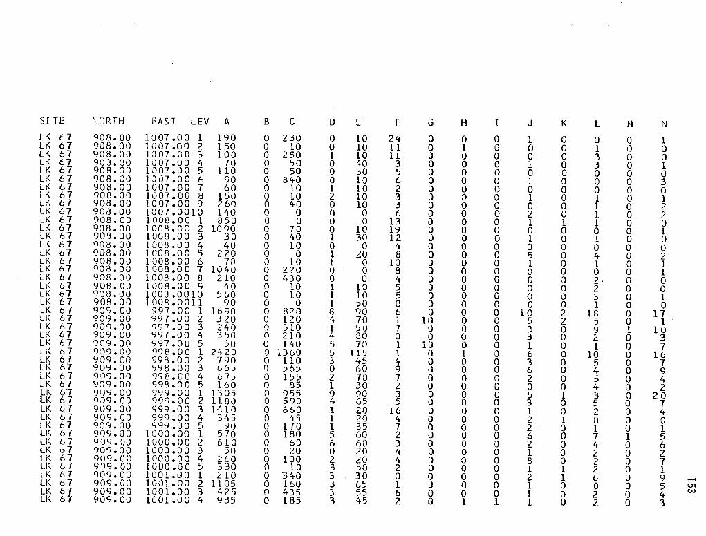
SITE i'.JORTH EAST LEV A B c D E F G H I J K L M N LK 67 908.00 10 07 .o 0 1 190 0 230 0 10 24 0 0 0 l 0 0 0 l LK 67 908.00 1007 .oo 2 150 0 10 0 10 l l 0 l 0 0 0 l 0 0 LK 67 908.0J l 3 07. 0 G 3 100 0 250 l 10 11 0 0 0 0 0 3 0 0 LK 67 908.00 1007 .oo 4 70 0 50 0 40 3 0 0 0 1 0 3 0 1 LK 67 908.00 1007.00 5 110 0 50 0 30 5 Q 0 0 0 0 0 0 0 LK 67 908.00 1J07.0C 6 90 0 840 0 10 6 0 0 0 1 0 0 0 3 LK 67 908.00 1007 .oc 1 60 0 10 l 10 2 0 0 0 0 0 0 0 0 LK 67 908.00 1007.00 8 150 0 10 2 10 3 0 a 0 1 0 l 0 1 LK 67 908.00 10 07. 00 9 260 0 40 0 10 3 0 0 0 0 0 1 0 2 LK 67 908.00 1007.0010 140 0 0 0 0 6 0 0 0 2 0 1 0 2 LK 67 908.00 1008.0C 1 850 0 0 0 0 13 0 0 0 1 l 1 0 0 LK 67 gos.oo 1008.0C 2 1090 0 70 0 10 19 0 0 0 0 0 0 0 1 LK 6 7 908.00 1008 .oo 3 30 0 40 1 30 12 u 0 0 l 0 1 0 0 LI<. 6 7 908.00 1008.00 4 40 0 10 0 0 4 0 0 0 0 0 0 0 0 LK 67 908.00 1008.0C 5 220 0 0 1 20 8 0 0 0 5 0 4 0 2 LI\ 67 908.00 1008.00 6 70 0 10 l 0 10 0 0 0 l 0 1 0 l LK 67 908.00 1008.00 7 1040 () 220 0 0 8 0 0 0 0 0 0 0 1 LK 67 908.00 1008.00 8 210 0 430 0 0 4 0 0 0 0 0 2· 0 0 Lt< 6 7 908.0J 1008.00 q 40 0 10 1 10 5 0 0 0 0 0 2 0 0 LK 67 goa.oo 1008.0010 560 0 10 1 10 5 0 0 0 0 0 3 0 1 LK 6 7 908.00 1008.0011 90 0 0 l 50 0 0 0 0 0 0 l 0 0 LK 6 7 qo9.0J 997 .oo l 1690 0 820 8 90 6 0 0 0 10 2 18 0 17 LK 67 909.00 9q7.oo 2 320 0 120 4 70 l 10 0 0 5 2 5 0 1 LK 67 909.00 997 .oo 3 240 0 510 1 50 7 () 0 0 3 0 9 l 10 LK 67 909. 00 9<:17. 0 0 ~ 3 50 0 210 4 80 0 0 0 0 3 0 2 0 3 LK 67 909.00 997.00 5 50 0 140 5 70 1 l() 0 0 l 0 l 0 7 Li<. 6 7 909.00 998.00 l 2420 0 1360 5 115 l 0 l 0 6 0 10 0 16 LK 67 909.00 998.00 2 790 0 110 3 45 4 0 0 0 3 0 5 0 7 LK 67 909.00 998.00 3 665 () 565 0 60 9 u 0 0 6 0 4 0 9 LK 6 7 909.00 998. u a 4 6 75 0 155 2 70 7 0 0 0 2 0 5 0 4 LK 67 909.00 998.00 5 160 0 85 1 30 2 0 0 0 0 0 4 0 2 LK 67 909.00 999.00 l 1305 0 955 9 90 3 0 0 0 5 l 3 0 20 LK 67 9.J<J. 00 999. 0 0 2 1180 0 5<:10 4 65 5 0 0 0 3 0 5 0 7 LK b7 909.00 99CJ .OO 3 l'tlO 0 660 1 20 16 0 0 0 1 0 2 0 4 LK 67 909.00 999.00 4 345 0 45 l 20 4 0 0 0 2 1 0 0 0 LK 67 909.00 999 .oo 5 90 0 170 l 35 7 0 0 0 2 0 l 0 l LI<. 6 7 909.00 1000.00 1 5 70 0 1 BO 5 60 2 0 0 0 6 0 7 1 5 LK 67 909.0Q 1000.00 2 610 0 60 6 60 3 \) 0 0 2 0 4 0 6 LK o7 909.00 1000.00 3 50 0 20 0 20 4 Q 0 0 1 0 2 0 2 LK 67 909.00 1000.00 4 2(:0 0 100 2 20 4 0 0 0 8 0 2 0 7 LI<. 6 7 9J9.00 1000.00 5 330 0 10 3 50 2 0 0 0 l 1 2 0 l LK 6 7 909.00 1001.00 1 210 0 340 3 30 0 0 0 0 2 1 6 0 CJ __. LK 67 9og.oo 1001.00 2 1105 0 160 3 65 1 () 0 0 l 0 0 0 5 U1 LK 67 909.00 1001.00 3 425 0 435 3 55 6 0 0 0 l 0 2 0 4 w LK 67 909.00 1001.oc 4 935 0 185 3 45 2 0 l l 1 0 2 0 3

SITE NORTH EAST LEV A B c D E
lK 67 909.00 lOOleOO 5 275 0 110 l 15 LK 67 909.00 1002 .oo l 950 0 2080 10 80 LK 67 909.00 l002s00 2 250 0 420 0 10 LK 67 909.0Q 1002.00 3 520 0 190 2 40 LK 67 909.00 1002.00 4 730 0 10 1 10 LK 67 909.00 1002.00 5 170 0 220 0 10 LK 67 909.00 1003.00 l 810 0 310 5 40 LK 67 909.00 · 1003 .oo 2 lJ30 350 1110 2 40 LK 67 909.00 1003.00 3 970 0 100 2 20 LK o7 909.00 1003 .oo 4 880 0 210 0 30 LK 67 909.,00 1003.00 5 280 0 9 1 3 lK 67 909.,00 1003 .. 00 t. 1020 () 60 l 10 LK 67 909.00 1004.00 l 1220 0 1000 2 20 LK 67 909.00 1004.00 2 400 0 60 4 90 LK 67 909.00 1004.00 3 640 0 60 3 30 LK 67 909.00 1004.00 4 80 0 20 0 10 LK 67 qoq.oo 1005.00 l 630 0 140 2 30 LK 67 909.00 1005.00 2 450 0 20 0 10 LK 67 909.00 1005 .. 00 3 200 0 80 2 20 LK 67 939.00 1005.00 4 1050 0 210 2 40 LK 67 909.00 1005 .. 00 5 1020 0 110 1 90 LI\ 67 909.00 1005 .. oo 6 1340 0 40 1 10 LK 67 9il9.00 1005.00 7 40 30 40 0 5 LK 67 909~00 1005 .. oo a 10 0 l o 5 LK 67 909 .. 00 1006 .. 00 l 495 0 135 4 60 LK 67 909 .. 00 1006 .. 00 2 370 0 0 1 10 LK 67 909 .. 00 1006.,CO 3 1015 !) 15 l HO LK 67 909.00 1006 .. 00 4 2JO 0 15 l 50 LK 67 qo9.oo 1006 .. 00 5 205 0 60 l 15 LK b7 909.00 1006.00 (; 75 0 30 0 5 LK 67 909.00 1006 .. oo 1 140 0 0 0 15 LK 67 9oq. oo l006.oo a 280 0 70 3 60 LK 67 909. 00 1006.UC S 595 0 30 2 25 LK 67 qoq.oo lu07s00 l 300 0 10 2 30 LK 6 7 909.00 1007.00 2 1140 0 190 2 50 LK 67 9D9.00 1007.00 3 870 0 50 5 30 LK 67 909.00 1007.00 4 480 0 30 0 0 LK 67 QQ9.00 1007 .00 5 'tO 0 20 l 60 lK 67 909.00 1007 .. oo f. 70 0 0 0 0 LK 67 909a00 1007.00 7 30 0 0 0 10 LI< 6 7 909.00 l 0 07. 0 c 8 760 0 0 0 0 LK 67 909000 1007 .00 9 70 0 200 2 40 LK 67 909.00 1007.()010 10 (} 260 l 20 LK 67 909.00 1008000 1 urn 0 160 l 5 LK 67 909., OU lOOA.OC 2 145. 0 105 0 15
f G H I J
l 0 0 0 l 4 0 0 0 8 4 0 0 0 3 2 0 0 0 1 3 0 0 0 2 2 0 0 0 2 0 0 0 0 10 2 0 0 0 4 l 0 0 0 1 4 0 0 0 1 3 0 0 0 2 1 0 0 0 l l 0 0 0 1 0 i) 0 0 3 2 0 0 0 1 1 0 0 0 0 4 10 0 0 5 2 0 0 0 0 2 0 0 0 1 5 0 0 0 1 6 0 0 0 0 6 0 0 0 0 .3 0 0 0 0 2 0 0 0 1 8 0 0 0 2 l 0 0 0 4 4 0 0 0 3 3 0 0 0 0 3 0 0 0 0 4 0 0 0 0 3 0 0 0 0 1 0 0 0 0 l 0 0 0 0
18 0 0 0 l 8 0 0 0 2 4 0 0 0 0 3 0 l 0 0 4 0 l 0 0 1 0 0 0 0 3 0 0 0 0 l 0 0 0 2 3 .o 2 0 1 3 0 l 0 0
10 0 0 0 0 23 0 1 0 0
K l
0 4 0 23 0 4 0 2 0 l 0 2 l 10 l 9 0 3 0 l 1 3 0 1 0 4 0 5 0 2 0 2 0 4 0 0 0 4 0 0 0 0 0 0 0 2 0 3 0 l 0 l 0 0 0 0 0 0 0 l 0 l 0 0 0 0 0 3 0 l 0 3 0 0 0 0 0 0 0 0 0 2 0 l 0 2 0 0 () l
M
0 1 0 0 0 0 0 2 0 0 0 0 0 0 0 0 0 0 0 0 0 0 0 0 0 0 0 0 0 0 0 0 o 0 0 0 0 0 0 0 l 0 0 0 0
N
l 30
4 0 0 4
16 8 2 3 4 3·
17 6 2 5
13 2 5 3 0 3 2 2 l 1 4 0 0 1 0 0 2 2 l 0 3 0 0 2 0 2 l 0 2
__. U1 .J:::.

SI TE NORTH EAST LEV A B c D E F G H I J K L M N LK 67 909.00 1008.CO 3 365 0 15 1 35 6 J 0 0 2 l 0 0 0 LK 67 9()9. ()0 1008.00 4 3 20 0 10 0 5 8 0 0 0 (J 0 0 0 2 LK 67 909.00 1008.00 5 280 0 95 1 5 3 0 0 0 1 0 0 0 l LK 67 909.00 1008.00 6 30 0 0 2 60 6 0 0 0 0 0 0 0 l LK 67 909.00 1008.00 7 665 0 600 0 5 1 Q 0 0 0 0 0 0 0 LK 67 909.00 1008.0C 8 40 0 150 l 10 3 0 0 0 0 0 0 0 0 LK 67 909.00 1008.00 9 510 0 195 4 90 3 0 0 0 0 0 2 0 1 LK 67 909.00 1008.0010 55 0 0 0 5 4 0 0 0 0 0 0 0 0 LK 6 7 909.00 lJOB.OCll 3 15 0 195 2 20 4 0 0 0 1 0 2 0 l LK 67 910.00 997.00 1 1260 o 680 8 130 3 0 0 0 8 2 16 0 18 Li( 6 7 910.00 997.00 2 1980 0 90 3 80 6 0 0 0 3 0 4 0 8 LK 67 910.00 997.0C 3 290 0 370 5 100 12 0 0 0 2 0 3 0 9 LK 67 910.00 997.00 4 80 o 100 2 100 4 0 0 0 0 0 2 0 1 LK 67 910.00 997.00 5 100 0 70 l 50 1 0 0 0 0 0 0 0 3 LK 67 910.00 998.00 1 13CJO 0 960 6 BO 29 0 0 0 6 0 9 0 28 LK 67 910.00 998.00 2 470 0 200 2 30 4 0 0 0 3 0 4 0 4 LK 67 910.0D 998.00 3 70 0 840 2 90 6 0 0 0 0 0 1 0 1 LK 67 910.00 998 .oo 4 300 0 50 5 50 0 0 0 0 2 0 4 0 3 LK 67 910.00 998.00 5 30 0 20 0 10 2 0 0 0 l 0 4 0 3 LK 67 910.00 999.00 1 1760 0 1030 3 60 4 0 3 0 10 0 23 1 12 LK 67 910.00 999 .oo 2 940 0 560 2 80 5 0 0 0 2 1 4 0 4 LK 67 910.00 999.00 3 190 0 720 4 70 8 0 0 0 2 0 8 l 5 LK 67 910.00 999.00 4 <; 10 0 100 0 30 5 0 0 0 2 1 2 0 4 LK 67 910.00 999.00 5 110 0 260 3 90 9 0 0 0 4 0 4 0 2 LK 67 910.10 1000.00 l 930 14 () 340 10 160 5 0 0 0 10 1 0 0 34 Li( 6 7 910.00 1000 .oo 2 240 0 150 l 20 3 0 0 0 l 0 1 0 2 LK 67 910.00 1000.00 3 190 0 140 0 30 2 a 0 0 l 0 3 0 9 Li< 67 910.00 1000.00 4 100 0 50 2 150 5 0 0 0 2 0 2 0 7 LK 67 910.00 1000.00 5 220 0 5 0 30 8 0 0 0 l 0 2 0 1 LK 6 7 910.00 lJOl.00 1 430 0 215 3 35 0 u 0 0 1 0 4 0 5 LK 67 910.00 1001.00 2 470 0 410 3 70 3 0 0 0 0 0 2 0 4 LK 67 910.00 1001.00 3 695 0 40 l 30 2 0 0 0 0 0 l a 6 LK 6 7 910.00 1001.00 4 280 J 280 0 10 8 0 0 0 1 0 4 0 2 LK 67 910. 00 1001.00 5 460 0 25 2 55 6 0 0 0 0 0 5 l 3 LK 67 910.00 lJOl.00 6 I) 0 0 0 0 0 0 0 0 0 0 0 0 0 LK 67 910.00 1002.00 1 3 30 0 160 1 30 0 0 0 0 4 1 3 l 4 LK 6 7 910.00 1002 .oo 2 640 0 40 4 50 0 0 0 0 2 0 5 0 8 LK 6 7 910.00 1002.0G 3 CJ20 0 210 0 0 l 0 0 0 3 l l 0 2 LK 67 910.00 1002 .oo 4 5.30 0 1 70 3 50 4 0 0 0 1 0 1 0 5 LK 67 g10.oo 1002.00 5 250 0 30 l 30 4 0 0 0 0 0 0 0 1 LK 6 7 91J.OO 1002.0C c c; 0 0 30 3 80 4 0 0 0 2 0 5 0 0 LK 67 910.00 1003.00 l 1170 0 1005 2 30 0 5 1 0 3 0 5 0 13 __, LK 6 7 910.00 1003.00 2 1120 0 485 4 65 3 0 l 0 2 l 6 0 9 c.n
c.n LK 6 7 910.00 1003.00 3 510 0 435 1 50 2 0 0 0 2 0 1 0 2 LK 67 910.0Q l.003.00 4 480 0 55 2 25 1 0 0 0 1 0 4 1 l

SITE NORTH EAST LEV A B c D E
LK 67 910.00 1003.00 5 835 0 55 l 25 LK 67 910.00 1003.00 6 225 0 15 3 . 90 LK 67 910.00 1004 .oo 1 1165 10 380 4 35 LK 67 en 0. 00 1004 .. 00 2 700 0 310 4 60 LK 67 910.00 1004.00 3 175 0 230 3 20 LK 67 910.00 10 04 .. 0 0 4 11 0 0 0 70 2 35 J_K 67 9lJ.OO 10 04 8 i) 0 5 2 50 0 10 0 20 LK 67 910.00 1005.00 1 540 0 260 1 30 LK 67 910.00 1005.,00 2 80 0 l () 7 120 LK 67 910.00 1005.00 3 740 0 10 2 10 LK 67 910.00 1005.0C 4 1650 0 40 0 10 LK 67 910.00 1005.00 5 1035 !) 25 1 0 LK 67 910.00 1005 .. 0C 6 60 0 20 0 5 LK 67 910.0J 1005.0C 7 65 0 50 2 30 LK 67 910.00 1005.,00 B 765 0 5 0 5 LK 67 910.00 1006.00 1 1030 0 1490 1 40 LK 67 910.00 1006.00 2 430 0 30 0 10 LK 67 q10.oo 1006. 00 3 300 0 140 0 10 LK 67 910.00 1006 .. 0C 4 1 7<) 0 120 0 5 LK 67 910.ou lJ06.00 5 100 f) 20 1 20 lK 67 910.00 1006.00 6 310 0 0 0 5 LK 6 7 910.00 1006.00 7 5 Q 190 2 60 LK 67 910.00 1006.00 8 140 0 160 1 50 LK 67 910.00 1007 .oo l 240 0 0 2 10 LK 67 910 .. 00 1007.0C 2 2<rn 0 610 2 60 LK 67 910.00 1007 .00 3 1620 0 160 1 60 LK 67 910.00 1007 .oo 4 310 0 0 1 40 LK 6 7 qio .. oo 1007 .. 00 5 420 0 190 0 20 LK 67 910.00 1007 .oo 6 310 370 170 0 120 LK 67 910.00 1007. 0 0 7 130 0 0 l 30 LK 67 910.00 ioo1 .. oo a 530 0 140 0 0 LK 67 910 .. 00 1007 .. 00 9 90 0 0 l 10 LK 67 910 .. 00 1007.0010 80 0 0 0 0 LK 67 910.00 1008 .. 00 1 20 0 10 0 5 LK 67 910.00 1008.00 2 410 0 135 1 20 LK 67 qlOeJJ 1008.00 3 520 0 1030 1 20 LK 67 (HO .. 00 lOOB.00 4 390 0 0 2 30 LK 67 <JlOeOO 1008.00 5 160 0 1345 0 20 LK 67 en 0. 00 1008.00 6 630 0 10 0 0 LK 67 9l0e00 1008.00 7 120 0 30 0 2 LK 67 910 .. 00 mos .oc e 765 0 0 3 45 LK 67 9l0e00 1008.00 9 50 0 100 0 10 LK 67 910m00 1008.0010 570 0 20 2 15 LK 67 910.00 1008.,0011 130 0 0 0 15 LK 67 910.00 1009 .. 00 l 710 0 120 3 30
f G H I J
6 0 0 0 0 3 0 0 0 0 l 0 0 0 2 2 () 0 0 4 3 0 0 0 5 3 Q 0 0 2 0 0 0 0 0 4 0 0 0 0 l 0 0 0 1 1 0 0 0 2 1 0 0 0 2 2 0 0 0 0 9 0 0 0 0 3 0 0 0 l 3 0 0 0 1 l 0 0 0 1 2 0 0 0 1 2 Q 0 0 0 3 0 0 0 1 3 0 0 0 3 1 0 0 0 0 1 0 0 0 l 1 0 0 0 0 2 0 1 0 0 4 0 0 0 1 4 0 0 0 2 l 20 0 0 0 1 0 0 0 0 2 0 0 0 0 1 0 0 0 0 1 0 0 0 0 2 0 0 0 1 0 0 0 0 l 0 0 0 0 1 8 0 1 0 1 4 0 0 0 0 5 0 0 0 0 3 0 0 0 0 2 0 0 0 1 l 0 0 0 0 7 0 0 0 0 3 0 0 0 0 3 0 0 0 l 2 0 0 0 0 l 0 I 0 0 0
K l
0 l 0 2 0 4 0 l 0 2 0 l 0 l 0 5 0 2 l l 0 l 0 l 0 2 0 l 0 0 0 2 0 3 0 l 0 2 0 l 0 0 0 0 0 2 0 1 0 0 0 2 0 l 0 0 0 0 0 0 0 0 0 l 0 4 0 0 0 l 0 2 0 0 0 0 0 0 0 0 0 0
.o 1 0 0 0 l 0 4
M
0 0 0 0 0 0 0 0 0 0 0 0 0 0 0 0 0 0 0 0 0 0 0 0 0 0 0 0 0 0 0 0 0 0 0 0 0 0 0 0 0 0 0 l 0
N
2 2
13 5 7 l -4 5 7· 6 3
. 3 l 3 l 6 2 1 2 0 0 l 2 2 2 1 l 1 0 l l 2 3 0 l 0 0 0 l 0 4 0 1 1 2
...... O'I 0\

SITE NORTH EAST LEV t!.. B c D E
LK 67 910.00 loog.oo 2 60 0 10 2 10 LK 67 910 .·oo 1009.00 3 170 0 40 0 5 LK 67 910.00 1009.00 4 40 0 470 0 5 LK 67 910.00 1009.0C 5 40 0 5 0 0 LK 67 910. 00 1009.00 t 20 0 5 0 5 LK 67 910.00 1009.00 7 100· 0 0 l 10 LK 67 910.00 L 009. O C e 830 0 10 0 20 LK 67 910.00 1009.00 g 100 0 40 l l
F G H I
1 0 0 0 6 0 0 0 2 0 0 0 5 0 0 0 l 0 O· 0 l 0 0 0 3 0 1 0 4 0 l 0
J K L
0 0 2 0 0 2 l 0 0 1 0 0 0 0 0 0 0 0 0 0 0 1 1 0
M
0 0 0 0 0 0 0 0
N
0 3 l 0 1 2 1 0
....... U1
"
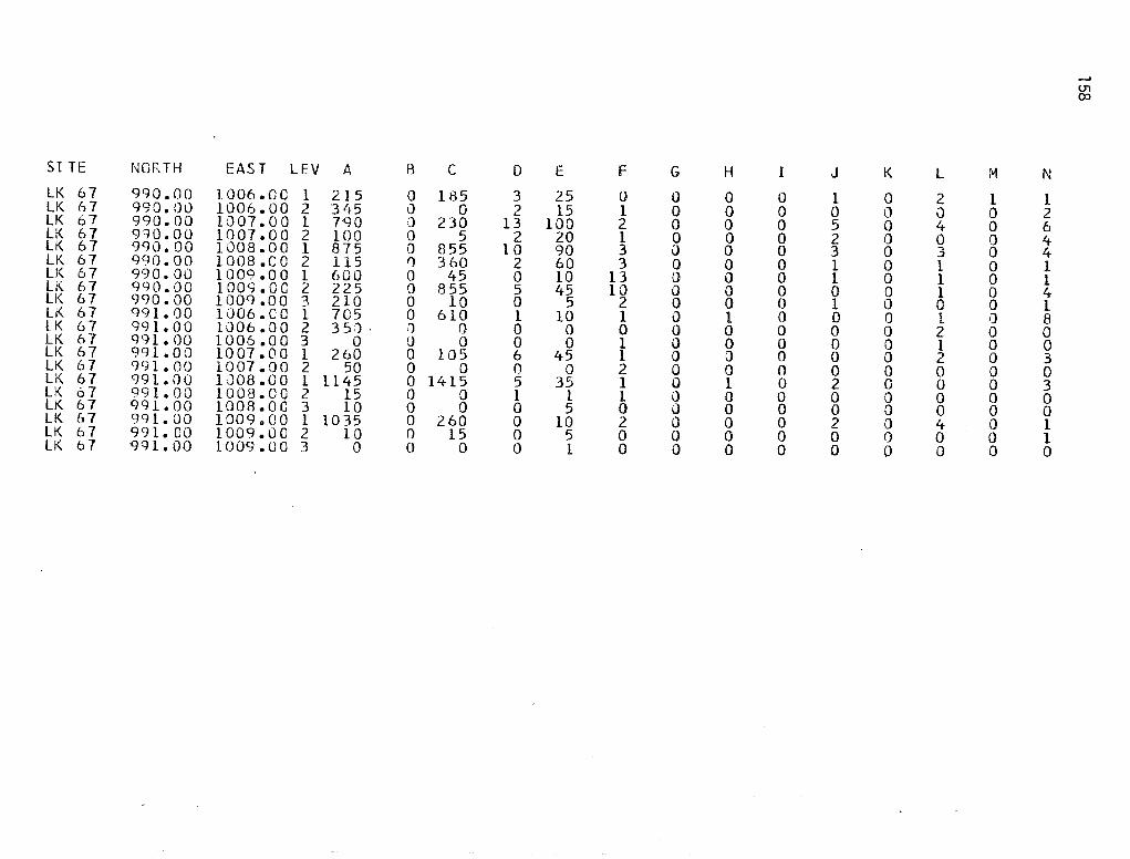
SI TE NORTH EAST LEV A R c D E
LK 67 qqo.oo 1006.0C 1 215 0 185 3 25 LI< 6 7 990. ()I.) 1006.00 2 3 lt5 0 0 2 15 LK 67 990.00 10 07. 0 0 1 7GO ;J 230 13 100 LK 67 9qo.oo 1007.00 2 100 0 5 2 20 LK 67 990.00 1008.00 1 875 0 855 10 90 LK 67 990.00 1008.00 2 115 ,., 360 2 60 LK 67 990.0() 1009.00 1 600 0 45 0 10 LK 67 990.00 lOOS.OC 2 225 0 8 55 5 45 LK 67 990.00 lOOCJ.OO 3 210 0 10 0 5 Li( 6 7 991.00 1006.CO l 705 0 610 1 10 LK 67 99 l. 0 0 1()06.00 2 3 5:1 . '1 0 0 0 LK 67 991.00 1006.00 3 0 !) 0 0 0 LK 67 991. 0 0 ioo1 .oo 1 260 0 105 6 45 LK 67 991.00 1007.00 2 50 0 0 0 0 LK 67 991.00 LJ08 .OO l 1145 0 1415 5 35 LK 67 991. 00 1008.00 2 15 0 0 1 l LK 67 991. 00 1008.0C 3 10 0 0 0 5 LK 67 9g1.oo 1009.00 1 1035 0 260 0 10 LK 67 991.00 1009.00 2 10 0 15 0 5 LK o 7 gg 1. 00 1009.00 3 0 0 0 0 1
F G H I
0 0 0 0 1 0 0 0 2 0 0 0 1 0 0 0 3 i) 0 0 3 0 0 0
13 0 0 0 10 0 0 0
2 0 0 0 1 0 1 0 0 0 0 0 1 0 0 0 1 0 0 0 2 0 0 0 1 0 1 0 l 0 0 0 0 J 0 0 2 0 0 0 0 0 0 0 0 0 0 0
J K l
l 0 2 0 0 0 5 0 4 2 0 0 3 0 3 1 0 l l 0 l 0 0 1 1 0 0 0 0 l 0 0 2 0 0 1 0 0 2 0 0 0 2 0 0 0 0 0 0 0 0 2 0 4 0 0 0 0 0 0
M
l 0 0 0 0 0 0 0 0 0 0 0 0 0 0 0 0 0 0 0
N
l 2 6 4 4 1 l 4 1 8 0 0 3 0 3 0 0 l 1 0
(.11
OJ

SITE NORTH EAST LEV A B c D E F G H I J K L M N LK 67 841.00 1048.0C 1 2400 a g430 62 1335 11 0 0 0 2 0 3 l 10 LK 67 841. 00 1048.00 2 3575 0 8070 73 2000 15 0 0 0 3 0 1 0 1 l LK 67 8 41. 00 1048.00 3 5255 0 2860 55 1715 10 0 1 0 l 0 4 0 4 LK 67 841.00 1048.00 4 6815 0 610 84 2235 21 0 3 0 3 1 4 0 0 LK 6 7 841. 00 1J4B.OC 5 c;g99 0 L910 66 1720 22 0 0 0 4 0 2 0 4 LK 67 841.00 1048.0C 6 2200 0 31 31 800 9 0 0 0 0 0 2 0 4 LK 67 841.00 1043.00 7 670 0 105 14 280 8 0 l 0 1 '.) 5 0 5 LK 67 841.JQ lJ48.0C 8 0 0 30 0 2 0 0 0 0 0 0 0 0 0 LK 67 841.00 1048.00 9 45 0 40 3 35 l 0 0 0 0 0 0 0 0 LK 67 841.00 1048.0010 5 0 180 2 25 0 0 0 0 0 0 0 0 0 LK 67 8 41. 00 l 049 • 0 c 1 13 8 0 0 2430 55 1645 22 0 0 0 3 0 6 0 9 LK 67 841. 00 1049.00 2 3620 0 1035 62 1500 14 0 0 0 2 2 3 1 7 LK 6 7 841. 00 1049.0C 3 770 0 5 80 48 1545 25 0 0 0 2 0 0 0 1 LK 67 8 1+1. 00 1049.CO 4 7145 0 1410 46 1460 12 0 0 0 0 0 3 0 2 LK 67 841.00 1049.0C 5 9170 0 640 30 1025 14 0 0 0 2 0 2 0 3 LK 67 841.00 10 52. 0 c 1 2820 55 0 1530 103 1670 19 0 0 0 8 1 7 0 10 LK 67 8 41. 00 1052.0C 2 900 40 25 63 1170 18 0 l 0 1 0 0 0 8 LI<. 6 7 841.00 1152.0C 3 2045 0 6 30 53 qs5 16 J 0 0 l 0 6 0 8 LK 67 841.00 1052.0C 4 995 0 145 42 605 25 0 0 0 0 0 4 0 8 LK 67 841.00 1053.0C 1 2940 0 930 8 6 1095 10 0 1 0 15 3 23 1 53 LK 6 7 841. 00 1053.0C 2 1055 0 800 57 1060 6 0 0 0 2 1 4 2 10 LK 67 841. 00 1053.0C 3 1075 0 8 32 570 5 0 0 0 l 0 2 l 5 LK 67 R41.00 1053.0C 4 1955 0 0 43 570 3 0 0 0 2 1 J 0 2 LK 67 841.00 1054.00 1 4415 0 1490 96 1310 14 0 4 0 19 7 39 6 83 LK 67 841.00 1054.0C 2 2725 Q 140 24 230 6 0 0 0 1 0 3 0 6 Lr\ 6 7 841. 00 L054.0C 3 3940 0 615 38 585 12 0 0 0 2 0 4 0 4 LK 67 841. 00 1054.0C 4 1455 0 50 27 715 11 0 0 0 0 0 0 0 0 LK 67 841.00 1055.0C 5 340 0 90 14 420 5 0 0 0 1 0 2 0 0 LK 67 8.'.tl.OO 1056.0C 5 1215 0 135 19 430 10 0 0 0 2 0 0 0 1 LK 67 841.00 1056.0C 6 555 0 140 22 2 50 14 0 0 0 1 0 l 0 0 LK 67 84 l. 00 1057.0C 1 825 0 245 5 70 2 u 0 0 1 0 1 0 7 LK 67 8 41. OQ 1057.0C 2 2560 0 1140 52 620 6 Q l 0 3 1 9 l 15 LK 6 7 841.00 1057.0C 3 ~725 0 675 53 715 7 0 l 0 3 0 6 0 5 LK 67 R41.00 1057.0C 4 885 0 8 29 380 2 0 0 0 l 0 3 l 5 LK 67 841.00 1057.CC 5 895 0 5 85 26 365 6 0 0 0 4 2 3 0 5 LK 6 7 841. 00 1057.vC 6 540 0 40 13 305 13 0 0 0 2 0 4 0 5 LK 67 841. 00 1058.0C ~ 61:JO 0 45 17 310 g 0 0 0 l 0 1 0 4 LK 67 841.00 1059.00 l 1910 0 1170 47 515 3 0 0 0 10 0 15 l 47 LK 6 7 841.00 iosg.oc 2 4235 1 21) 850 61 920 20 0 0 0 7 0 8 0 16 LK 67 841.00 1059.0C 3 2170 0 590 19 235 10 0 0 0 2 0 l 0 9 LK 67 8'+1.00 l 1)59. 0 c 4 19 10 I) 200 26 410 12 0 0 0 0 0 l 0 4 LK o 7 841.00 lJ59.0C 5 sqo J 65 23 305 16 0 0 0 3 0 0 0 4 __. LK 67 R42.00 1052.0C 1 1880 0 450 70 1235 2 0 0 0 5 0 5 0 5 U1
tO LK 67 842.00 1J52.0C 2 1635 0 620 59 1215 13 0 0 0 l 0 3 L 4 LI< 6 7 842.00 1052.0C 3 1420 0 430 50 1165 11 0 1 0 2 l 1 0 4

SITE MOR. TH EAST LEV A B c D E
LK 67 842.00 1052.0C 4 1590 0 8 30 96 LK 67 842.00 1053.00 l 2130 0 645 8 5 1180 LK &7 842.00 1053.0C 2 1265 0 515 36 65 LK 67 842.00 1053.0C 3 1195 0 70 33 0 LK 67 842.00 1053.0C 4 1050 0 80 21 815 LK 6 7 842.00 1054.0C 1 980 0 225 27 355 LK 67 842.00 1054.0C 2 1675 0 645 43 72 LK 67 842.00 1054.0C 3 900 0 465 28 690 LK 67 842.00 105lt .oc 4 630 0 7 20 585 LK 67 842.00 1J54.0C 5 240 0 50 20 430 LK 67 842.00 1055.0C 1 2ot5 0 180 21 310 LK 67 842.0Q 1J55.0C 2 1440 0 485 36 790 LK 67 842.00 1055.0C 3 1850 0 60 29 610 LK 67 842.00 1055.0C 4 500 0 75 16 450 LK 67 842.00 1055.0C 5 855 I) 60 16 300 LK 67 842.00 1056.0C 1 3555 0 500 26 325 LK 67 842.00 1056.0C 2 1910 0 245 26 0 LK 67 842.00 1056.0C 3 292J 0 80 18 0 LK 67 842.00 1056.0C 4 1305 0 120 11 245 LK 67 842.0J 1056.0C 5 1990 0 55 18 26 LK 67 842.00 1057.0C 1 359J 0 1050 46 605 LK 67 842.00 1057.0C 2 850 0 715 23 34 LK 6 7 842.JO 1057.0C 3 l7CO 0 70 20 320 LK 67 842.00 1057.00 4 1485 0 140 24 290 LK 67 842.00 1057.0C 5 1160 0 160 7 165 LK 6 7 842.00 1058.0C l 38 45 0 570 34 520 LK 67 342.00 1058.00 2 4040 0 215 64 94 LI<. 6 7 842.00 1058.0C 3 750 0 7 34 540 LK 67 842.00 1058.0C 4 1570 0 65 23 945 LK 67 .342. 00 1058.00 5 880 0 55 16 27 LK 6 7 842.00 1059.0C 1 1265 0 275 35 350 LI<. 67 842.00 1059.0C 2 1880 0 94 44 635 LK 67 842.00 1059.0C 3 13t:5 0 105 22 245 LK 6 7 842.0) 1059.0C 4 2615 0 440 8 210 LK 67 842.00 1059.0C 5 930 0 7 15 385 LK 67 843.00 1048.0C l 225 0 785 56 1320 LK 67 943.00 1048.00 2 1565 0 695 71 1665 LK 67 843.00 1048.0G 3 1030 0 14 67 1430 LK 67 843.0J 1J48.JC 4 1826 0 54() 69 1610 lK 67 843.00 1048.0C 5 9999 0 240 45 1465 LK 67 843.00 1048 .oc 6 7560 0 1465 4 3 1340 LK 67 843.00 1048.0C 7 2495 0 135 24 720 LK 67 843.00 1049.00 1 21 70 0 108 62 1260 LK 6 7 843.00 1049.0C 2 735 0 675 64 2040 LK 67 843.00 1049.00 3 905 0 840 56 1670
F G Ii I J
15 0 0 0 2 6 0 0 0 5 7 0 0 0 l 9 0 0 0 2
13 0 l 0 0 9 0 2 0 2
20 0 l 0 4 9 0 0 0 1
16 0 0 0 1 14 0 0 0 0
6 0 0 0 .tt 14 0 l 0 0
8 0 0 0 0 11 0 0 0 3 13 0 0 0 2
l 0 0 0 0 9 0 0 0 l 9 0 0 0 2 9 0 l 0 1
16 0 0 0 l 19 0 0 0 7
5 0 l 0 0 13 () 0 0 2
0 0 0 0 2 22 0 0 0 2
3 0 2 0 5 6 0 0 0 4
10 0 0 0 2 14 0 0 0 0
5 \) 0 0 0 1 0 0 0 5 6 0 l 0 6 6 0 I) 0 1 7 0 0 0 3
12 0 0 0 1 16 0 0 0 0 11 0 0 0 l 13 0 0 0 3 10 0 0 0 0 21 0 0 0 3 17 0 0 0 2 16 0 0 0 3 11 0 0 0 3 19 0 0 0 4 18 0 0 0 5
K L
1 1 0 4 0 0 0 0 0 3 a 4 1 6 0 1 0 l 0 2 0 1 0 3 0 2 0 l 0 l 0 l 0 3 0 2 0 l 0 l 0 3 l 4 0 3 0 2 0 0 0 0 0 2 0 0 0 5 0 0 0 10 0 8 0 2 0 1 0 0 0 3 0 1 0 l 0 2 0 0 0 2 0 1 0 l l 0 0 6
M
0 0 0 0 0 0 0 0 I)
0 0 0 0 0 0 0 0 0 0 0 0 0 1 0 0 0 0 0 0 0 0 0 0 0 0 0 0 0 0 1 {)
0 0 0 l
N
l 14
8 3 1
16 8 4 3 l
11 10
5 3 7
14 8 4 3 0
12 5 3 4 2 0 4 l 4 3
16 13
4 3 2 5 8 7 3 3 l 3 9 4 2
_, O'I 0

SI TE NORTH EAST LEV A B c D E F G H I J K l M N LK 67 843.00 1049.0C 4 34<;0 0 295 61 1810 23 a 0 0 0 0 2 0 5 LK 67 843.00 1049.00 5 4420 0 155 49 1430 24 0 0 0 3 0 3 0 3 Li<. 67 843.00 1 049 • o c 6 c;9 99 0 1600 34 1395 39 0 0 0 3 0 3 0 4 LK 67 843.00 1049.0C 7 1880 0 95 18 550 21 0 0 0 2 0 0 0 3 LK 67 843.00 1049.00 8 415 0 1120 6 210 19 0 0 0 0 0 0 0 2 LK 67 843.00 1052.00 l 1180 0 955 70 1670 24 0 0 0 6 0 0 0 1 LK 67 843.00 1052.0C 2 260 0 610 34 680 7 0 0 0 2 0 2 0 7 LK 6 7 843.00 1052.0C 3 1700 0 80 47 1225 24 0 0 0 l 0 8 l 2 LK 67 843.00 1052.0C 4 1105 0 465 28 885 19 0 0 0 0 0 2 0 5 LK 67 843.00 1053.0C 1 1755 0 585 43 960 5 0 0 0 4 0 2 0 4 LI< 67 843.00 1053.0C 2 1265 0 205 24 530 5 0 l 0 3 1 l 0 4 ll< 67 g 43. 00 1:153.0C 3 1095 0 85 39 0 9 0 0 0 0 0 2 0 4 LK 67 843. 00 1'153.0C 4 1705 0 125 18 520 8 () 0 0 0 0 2 0 l LK 67 843.0\J lD54.0C 1 3470 0 1040 61 1000 5 0 0 0 2 0 6 0 12 LK 67 843.00 1054.0C 2 670 0 155 26 400 4 0 0 0 l 0 2 1 1 LK 67 843.00 1054.00 3 1935 0 225 20 580 14 Q 0 0 0 0 3 0 3 LK 67 843.0J 1054.0C 4 300 0 75 12 315 5 0 0 0 1 0 0 0 2 LK 67 843. 00 1055.0C 1 1255 0 375 28 340 3 0 0 0 7 0 6 1 22 LK 67 843.00 1055.0C 2 2020 0 650 42 640 7 a Q 0 5 0 10 0 13 LK 67 8 43. 00 1055.0C 3 695 0 55 14 235 10 0 0 0 4 0 1 0 5 LK 67 843.00 1055.0C 4 1775 0 60 24 360 3 0 0 0 1 0 4 l 0 LK 6 7 843.0Q 1055.0C 5 275 0 0 14 195 l 0 0 0 0 0 4 0 2 LK 67 843.00 1056.0C 1 20 Lio 0 690 11 275 15 0 0 0 3 0 1 0 10 LK 6 7 8 43. 00 1056 .oc 2 1025 () 145 23 395 9 0 0 0 2 0 4 0 10 LK 67 843.00 lJ5t.OC 3 1040 0 130 15 295 11 0 0 0 0 '.) l 0 7 LK 67 8 43. 00 lJ56.0C 4 1070 I") 105 16 325 15 J 0 0 4 0 3 0 4 LK 67 843.00 1J56.CC 5 <;J25 0 355 7 155 6 0 0 0 1 0 2 0 4 LK 6 7 843.0J l'J57.0C l 176CJ J 275 34 340 8 () 0 0 4 0 3 0 11 LK 67 843. 00 1')57.0C 2 lOBO 0 440 18 645 4 0 0 0 1 0 3 0 7 LK 67 343.00 1J57.0C 3 1105 0 125 21 305 5 0 0 0 0 0 2 0 3 LK 67 843.00 1057.0C 4 810 0 280 9 190 7 0 0 0 2 0 0 0 3 LK 67 8't3.00 1J57.0C 5 260 0 60 9 130 6 0 0 0 0 0 2 0 l Li<. 6 7 843.00 1058.0C 1 3205 0 1860 40 340 l 0 l 0 2 '.) 8 0 11 LK 67 81+3. 00 1058.0C 2 29'45 0 1980 2 7 380 8 0 0 0 0 0 0 0 0 LK 67 843.00 1058.0C 3 795 0 190 26 320 7 0 0 0 3 0 1 0 4 LK 67 843.0J 1058.0C 4 840 0 310 16 230 7 0 0 0 l 0 1 0 5 LK. 67 843. 00 1058.0C 5 5 65 0 215 14 310 8 0 0 0 0 0 4 0 5 LK 6 7 843.QJ 1059.0C 1 1660 0 70 37 370 1 0 0 0 2 0 2 0 12 LK 67 843.00 1')59.00 2 1450 0 700 25 415 1 0 l . 0 l 0 1 0 12 LK 67 8 43. 00 1059.0C 3 1160 0 1.90 23 290 7 () 0 0 2 0 2 0 1 LK 6 7 843.00 1J59.0 c 4 5 c; 5 12 lj 130 16 255 6 J 0 0 l 0 0 0 2 LK 67 R43.00 1059.0C 5 970 0 120 9 195 12 0 0 0 0 0 0 0 2 Lt<. 67 844.00 1052.0C 1 235 0 120 15 280 18 0 0 0 1 0 l 0 9 -' LK 67 844.00 1052.JC 2 1455 0 110 45 770 14 0 0 0 0 l 0 0 2 en _, LK 67 84Li-. 00 1052.0C 3 535 0 485 46 765 11 0 1 0 4 1 3 0 6

SITE f\IORTH EAST LEV A B c D E
LK 67 R44.00 1052.0C 4 530 0 105 38 695 LK 67 844.00 1052.0C 5 1200 0 140 25 725 LK 67 8'1-4. 00 10 53. 0 c l 7 60 0 185 30 380 LK 67 844.00 1053.0C 2 550 0 225 27 780 LK 67 844.00 1053.0C 3 395 0 125 24 325 LK 67 844.00 1053.0C 4 1580 0 200 18 490 LK 67 844.00 1054.0C 1 3170 0 63Q 50 660 LK 67 844.00 1054.0C 2 860 340 445 25 320 LK 6 7 844.00 1054.00 3 650 :) 210 22 360 LK 67 844.00 1054.0C 4 1155 0 135 15 355 LK 67 844.00 1055.0C l 930 0 735 19 180 LK 67 844.00 1<)55.0C 2 1790 0 435 46 655 LK 67 844.00 1055.0C 3 2170 0 215 30 500 LK 67 844.00 1055.00 4 8·65 0 100 28 895 LK 67 844.00 1J55.0C 5 560 0 50 9 295 LK 67 844.00 1056 .oo l 3745 0 835 51 790 LK 67 844.00 1056.0C 2 3950 0 1045 34 700 LK 6 7 844.JO 105c.OC 3 9CJO 0 110 18 195 LK 67 844.00 lu57.0C 1 1425 0 420 16 255 LK 6 7 844.00 1057.0C 2 2680 0 295 16 380 LK 67 844.00 1057.0C 3 2450 0 100 12 255 LK 67 844.00 1057.0C 4 1420 I) 175 0 5 LK 6 7 844.00 1057.0C 5 890 ,) 55 7 195 LK 67 844.00 1058.0C 1 2770 100 390 43 435 LK 67 844. 00 1058.0C 2 1845 0 910 54· 705 LK 67 844.00 1058.0C 3 2200 0 275 26 495 LK 67 844.00 1058.0C 4 880 0 75 15 355 LK 67 844.00 1058.0C 5 5 30 0 155 10 250 LK 67 844.00 1059.0C l 945 0 660 29 350 LI< 6 7 1344.00 1059 .oc 2 1600 0 715 38 760 LK 67 844.00 1059.0C 3 25EO 0 170 34 695 LK 67 844.00 1059.0C 4 790 0 410 16 465 LK 67 844.00 1059.0C 5 1395 0 75 15 360 LK 6 7 845.00 l'.J52.0C 1 3DO 0 210 q 205 LK 67 845.00 1D52.0C 2 -, 70 0 490 19 585 LI\ 67 845.00 1052.0C 3 510 I) 115 35 795 LK 67 845.1)0 1052.0C 4 8 15 0 155 31 620 LK 67 845.00 1052.0C 5 450 f) 190 27 1210 LK 67 845.00 1053.0C l 3055 a 840 65 860 LK 67 845.00 1051.00 2 1155 0 0 39 895 LK 67 845.00 1053.0C 3 :, 7 5 0 285 20 645 LK 67 84~.oo 1053.0C 4 845 0 26 . 24 700 LK 6 7 845.00 1054.0C 1 17.35 0 74 22 450 LK 6 7 845.00 1054.0C 2 1490 0 35 22 535 LK 67 845.00 1054.0C 3 1540 0 980 23 545
F G H I J
17 0 0 0 1 22 0 0 0 3
l 0 0 0 0 4 0 0 0 3 4 0 0 0 0 4 0 0 0 2
16 0 0 0 3 5 0 0 0 0 6 0 0 0 0 6 0 0 0 l 2 0 0 0 4
17 0 0 0 6 6 0 0 0 2
12 i) 0 0 l 0 J 0 0 3 8 0 2 0 9
17 () 0 0 5 18 0 0 0 l
l 0 0 0 3 2 J J 0 0 6 0 0 0 1 9 0 0 0 2
12 0 0 a 1 1 0 0 0 1 l 0 l 0 2 6 0 0 0 l 4 0 0 0 4
15 0 0 0 2 l 0 0 0 2 2 0 1 0 2 6 J 0 0 4 7 0 0 0 2
13 0 0 0 l 17 0 1 0 0 18 0 0 0 2 20 0 0 0 2 11 0 0 0 2 32 0 0 0 l 12 0 0 0 4 14 0 0 0 4 11 0 0 0 5
7 0 0 0 2 4 0 2 0 l 3 0 0 0 4 6 0 0 0 2
K l
0 l 0 2 0 5 0 6 0 1 0 2 0 3 0 2 0 l 0 l 1 5 3 10 1 2 0 3 0 2 0 11 0 9 0 1 1 5 0 4 0 3 1 3 0 l 0 6 0 4 0 3 0 1 0 0 0 3 0 6 0 2 0 3 0 3 Q 0 0 1 0 2 0 3 0 2 0 4 1 3 0 2 1 3 0 4 l l 0 2
M
0 0 a 0 0 0 0 0 0 0 0 1) 0 0 0 2 0 0 0 l 0 0 0 0 0 0 0 0 0 0 0 0 0 0 0 0 0 0 0 0 0 0 0 0 0
N
6 2
17 4 4 2 6 4 7 1
21 23
3 3 2
56 7 0 2 8 4 2 2 9 9 4 3 9 7 0 5 0 1 3 4 5 2 2 8 4 5 1
19 3 6
__, CJ) I"\)
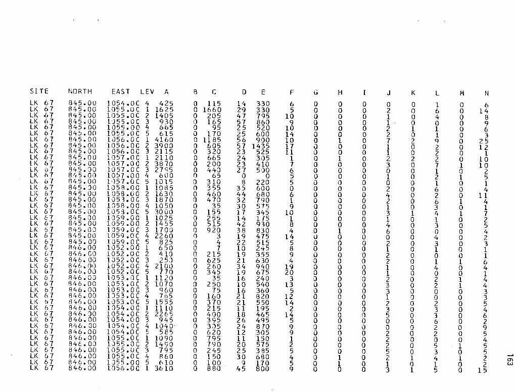
SITE NORTH EAST LEV A B c D E F G H I J K L M N
LK 67 845.00 1054.0C 4 425 0 115 14 330 6 0 0 0 0 0 1 0 6 Li\ 67 845.00 1055.0C 1 1625 0 1660 29 330 5 0 0 0 2 0 6 0 14 LK 67 845.00 1055.0C 2 1405 0 205 47 795 10 0 0 0 1 0 4 0 8 LK 67 845.00 l:J55.0C 3 930 0 165 57 860 9 a 0 0 1 0 0 0 g LK 67 845.00 1055.00 4 605 0 95 25 520 10 0 0 0 2 l 1 0 6 LK f.>7 845.00 1055.0C 5 615 0 170 25 600 14 0 0 0 2 0 1 0 3 LK 67 845.00 1056.0C 1 4160 0 1185 56 900 10 a l 0 7 2 q 0 25 LK 6 7 845.00 1056.0C 2 3900 0 605 57 1435 17 0 0 0 l 0 2 0 12 LK 67 8Li5.00 1056.0C 3 2115 0 320 23 525 11 0 0 0 l 0 2 0 1 LK 67 845.00 1057.0C 1 2110 0 665 24 305 1 0 1 0 2 2 2 0 10 LK 67 845.00 1057.0G 2 3870 0 200 23 410 7 0 0 0 3 0 7 1 10 LK 07 845.00 1057.0C 3 z7q5 0 440 27 500 6 0 0 0 0 0 l 0 2 LK 67 845.00 1057.00 4 600 0 65 0 0 5 0 0 0 l 0 2 1 5 LK 67 845.00 ltl57.0C 5 1015 0 310 8 220 5 i) 0 0 0 0 l 0 l LK 67 845. '.)Q 1058.0C 1 1085 0 3 55 35 600 0 0 0 0 2 0 6 0 4 LI<. 67 845.00 1058.UG 2 1630 0 460 44 680 6 0 0 0 4 0 2 0 11 LK 67 845.00 1051.0C 3 1870 0 470 32 790 l 0 0 0 2 0 6 1 4 lK 67 845.00 1058.00 4 1050 0 35 30 575 9 0 0 0 1 0 3 0 1 LK 67 845.00 1058.0C 5 3000 0 155 17 345 10 0 0 0 3 l 4 1 7 LK 67 8 1+5.00 iosq.oo l 1025 0 255 14 175 1 0 0 0 l 0 l 0 2 LK 67 8t+5.00 1059.00 2 1455 0 515 42 930 8 0 0 0 4 0 3 0 5 LK 67 81t5.0J 1059.0C 3 1700 0 920 38 830 4 0 1 0 6 0 0 0 4 LK 67 845.00 1059 .oc 4 2260 () 3 19 475 14 0 0 0 0 0 4 0 2 LK 6 7 845.00 liJ59.0C 5 825 0 4 22 515 5 0 0 0 2 0 3 0 3 LK f..7 846.00 1052.00 1 650 0 7 10 245 8 0 0 0 1 0 1 0 1 lK 67 846.00 1052.0C 2 4 10 0 215 19 355 9 0 0 0 2 0 0 0 1 LK 6 7 846.00 1052.0C 3 2 50 0 625 21 630 4 0 0 0 2 0 l l 6 lK 67 846.00 1052.0C 4 2100 0 260 34 940 19 0 0 0 1 0 4 0 4 U<. 67 846.00 10 52. 0 c 5 770 0 345 19 675 20 0 0 0 l 0 0 0 1 LK 67 846.00 1053.iJC 1 ll 20 0 35 16 240 3 0 0 0 2 0 2 1 4 LK 6 7 f3lt6.00 1053.0C 2 1070 0 250 10 540 13 0 0 0 3 0 2 l 4 ll\. 6 7 846.00 1053.00 3 960 0 75 16 360 5 0 0 0 3 0 0 0 3 LK 6 7 846.00 l'.)53.0C 4 765 0 160 21 820 12 0 0 0 1 0 0 0 3 LK 6 7 846.00 1053.0C 5 1555 0 370 21 550 14 0 i) 0 2 0 2 0 5 LK 6 7 846.0u 105't.0C l 1110 0 215 11 195 2 0 0 0 3 0 3 0 4 LK 6 7 846.'.)0 1054.0C 2 2265 0 400 18 465 14 0 0 0 5 0 3 0 6 LI<. 6 7 846.00 1054.00 3 945 0 395 26 4q5 5 0 0 0 0 0 6 0 2 LK 67 846.00 1054.0C 4 1040 0 3,)5 24 870 9 0 0 0 0 0 2 0 9 LK 67 846.00 1054.0C 5 585 0 620 12 305 9 0 0 0 2 0 2 0 5 LK 6 7 8~+6.00 1055.0C 1 1090 0 795 11 150 1 0 0 0 2 0 0 0 4 LK 6 7 84t.OO 1J55.00 2 1490 0 790 20 575 2 0 0 0 2 0 5 1 5 LK 6 7 8lt6.00 1055.UC 3 795 0 245 25 385 5 0 0 0 5 0 3 0 5
--' LK 67 846.00 1055.0C 4 860 0 150 30 680 4 0 l 0 ,., 1 4 l 2 L O"I U< 67 846.00 1055.00 5 610 0 100 9 170 5 0 1 0 l 0 l 0 2 w
LK 67 846.00 1056.0C l 3610 0 880 45 800 g 0 0 0 3 1 5 0 15

SITE NORTH EAST LEV A B c D E F
LK 67 846.00 1056.0C 2 2635 0 710 40 770 9 LK 67 846.00 1056.0C 3 675 n 515 17 290 10 LI< 67 846.00 1057.0C 1 177 0 435 20 20 0 LK 67 846.00 lC>57.0C 2 1030 0 520 15 335 2 LK 67 846.00 1057.0C 3 1050 0 140 20 280 5 LK 67 846. 00 liJ57.00 4 2415 o 355 l~ 215 3 LK 67 846.00 1057 .oc 5 360 0 115 0 230 1 LK 67 846.00 1058.0C l 960 0 370 30 390 l LK 67 8't6. 00 1058.0C 2 1595 0 50 26 495 1 LK 67 846.0u 1058.0C 3 2235 0 100 18 260 6 LK. 6 7 846.00 l058eOC 4 1570 . 0 225 12 275 4 LK 6 7 846.00 l058eOC 5 1710 0 135 20 575 11 LK 67 846.00 1059 .oo 1 1260 0 150 17 175 1 LK 67 846.00 1059.00 2 1425 0 940 26 500 3 LK 67 846.00 1059.0C 3 815 0 25 20 685 1 ll< 6 7 846.00 1059.0C 4 860 0 380 14 360 3 LK &7 846.00 10 59. 0 c 5 12 00 0 80 13 250 8 LK 6 7 847.00 1052 .oc 1 640 0 80 13 280 2 LK 67 847.00 l 052 .. oc 2 715 0 520 17 525 10 LK 67 847.00 1052.0C 3 840 0 360 18 610 7 LK 67 847.00 1052.0C 4 340 0 535 16 865 10 LK 67 847.JO 1052.0C 5 500 0 565 12 4~5 13 lK 67 01t 7 e OQ 1053.0C l 1090 0 850 21 390 8 LK 67 847~00 1053. 0 c 2 390 0 l50 16 240 2 LK 67 847.00 1053.0C .3 5E5 0 140 10 355 13 LK 67 847.00 1053.0C 4 660 0 725 13 620 13 LK 6·7 847000 1053.0C 5 960 0 355 18 545 8 LK 67 847.00 1054.0C l 750 0 695 23 240 4 LK 67 A47.00. 1054.0C 2 1010 0 140 17 375 5 LK 6 7 847.00 lu54.0C 3 245 0 480 16 495 8 LK 67 847.00 1054.0C 4 880 0 865 25 460 6 LI< 6 7 847 .. 00 1054.0C 5 1150 0 165 16 435 6 LK 6 7 847.00 1055.00 l 370 0 390 10 120 l lK 67 047.00 1055.00 2 415 0 1390 19 345 8 LK 67 847.00 1055.0C 3 1015 0 300 21 460 9 LK &7 847.00 1055.0C 4 1010 0 735 15 630 8 LK 67 847.00 1055.0C 5 1065 0 1]0 13 120 10 LK 67 847.00 lJ56.0C 1 3580 0 4 75 48 650 9 LK 67 847.00 1056.0C 2 1450 0 1535 39 1000 14 LK 67 847.00 1056.0C 3 2000 0 610 22 640 24 LI< 6 7 847.0l> 1156. 0 c 4 24 3 5 0 940 11 315 8 LK &7 847.00 1056.0C 5 420 0 8 4 120 12 LK 6 7 84J.oo 1057 .oc l 1450 0 250 18 220 3 LK 6 7 84 0 00 1057.0C 2 795 0 355 10 340 .3 LI( 67 84 e OQ 1057 .. 0C 3 870 0 205 10 195 4
G H I J
0 0 0 2 0 0 0 l 0 0 0 0 5 0 0 l 0 l 0 4 0 0 0 2 5 0 0 2 I) 0 0 2 0 0 0 l 0 0 0 2 0 0 0 0 0 0 0 0 0 0 0 0 0 0 0 0 0 0 0 3 0 0 0 2 0 0 0 1 0 0 0 2 0 1 0 l 0 0 0 1 0 0 0 4 0 1 0 2 0 0 0 0 0 0 0 4 0 0 0 2 0 0 0 l 0 0 0 0 0 l 0 4 0 0 0 2 Q 0 0 3 0 1 0 4 0 0 0 0 0 0 0 2 0 l 0 4 0 0 0 1 0 0 0 1 0 0 0 0 0 0 0 2 0 l 0 5 0 0 0 3 0 0 0 1 0 0 0 0 0 l 0 l 0 2 0 1 0 0 0 l
K l
l 3 l 2 0 3 0 l 0 2 0 0 l l 0 0 0 4 0 3 0 2 0 3 0 l 0 2 0 0 J l 0 3 1 l 0 2 0 3 0 4 0 2 0 3 0 0 0 3 0 2 0 4 0 4 0 4 0 l 0 1 0 3 0 0 1 3 0 0 0 0 0 0 0 10 2 7 0 3 0 3 0 l 0 l 0 l 0 l
M
o 1 0 0 l 0 l 0 1 0 0 0 0 0 0 0 0 0 0 0 0 0 l 0 0 0 0 0 0 0 0 0 0 0 0 0 0 0 l 0 0 l 0 0 0
N
6 3 2 4 3 4 3
l l 0 7 4 0 2 3 4 3 2 3 2 4 l 4
12 6 6 3 l 7 6 7 4 0 6 q 3 7 6
10 6 3 .3 2
13 6 8
__, O'I ..i::.

SITE NORTH EAST LEV A B c D E F G H I J K l M N
LK 67 847.00 1057.0C 4 1950 0 480 24 565 5 0 l 0 l 0 2 0 4 LK 6 7 84 7. 00 1057.0C 5 2480 0 65 10 300 8 0 0 0 0 0 2 0 3 LK 67 847.00 1058.0C 1 2040 0 150 23 250 l 0 0 0 2 0 2 0 3 LK 67 847.00 1058.0C 2 400 0 40 l 1 300 4 a 0 0 l 0 5 0 4 LK 67 847.00 1058.0C 3 820 200 45 14 260 3 0 0 0 2 0 4 0 8 LK 67 847.00 1058.0C 4 890 0 220 26 470 5 a 0 0 3 0 2 l 7 LK 67 847.00 1J58.0C 5 6 70 0 360 11 280 9 0 0 0 0 0 2 0 4 LK u 7 847.00 1059.0C l 10 70 0 235 21 ld5 l 0 0 0 3 0 1 0 4 LK 67 847.00 1059.0C 2 1800 0 455 10 150 5 0 0 0 4 0 2 0 6 LK 67 847.00 1')59.0C 3 770 0 625 13 265 5 0 0 0 2 0 1 0 2 LK 67 81t7. 00 1059.0C 4 475 0 5 10 265 5 0 0 0 2 0 0 0 2 LK 6 7 847.00 1C.l59.0C 5 1085 0 10 9 200 6 J 0 0 l 0 l 0 4 LK 67 848.00 1152.0C l 900 0 605 21 365 8 0 0 0 3 0 2 0 3 LK 67 848.00 1052.0C 2 445 0 180 21 685 12 Q 0 0 3 \) 0 0 2 LK 67 848.00 1052.0C 3 340 0 425 16 450 4 0 0 0 2 0 0 0 5 LK o7 848.00 1052.0C 4 860 0 505 17 680 16 () 0 0 3 0 7 0 3 LK 67 8ft8. 00 1052.0C 5 6go 0 130 20 710 20 0 0 0 2 0 l 0 3 LK 67 848.00 1053.0C l 610 0 400 20 280 0 0 0 0 3 0 0 0 7 LK 67 848.00 1053.00 2 5 50 0 670 19 550 4 0 0 0 l 0 6 0 5 LK 67 848.DO 1153.0C 3 710 0 210 16 600 6 0 0 0 2 1 2 0 3 LK 67 848.00 1053.0C 4 500 0 100 17 410 7 0 0 0 5 0 2 0 1 LK 67 848.0J 1J53.0C 5 2180 0 290 28 640 4 0 0 0 3 0 l 1 l LK 67 84B.OO 1·J54. 0 c 1 620 0 CJ5 19 185 1 0 0 0 0 0 4 0 7 LK 67 848.00 1054.0C 2 665 0 150 29 455 3 0 0 0 2 0 4 0 3 LK 67 848.00 1•]54.0C 3 5 45 0 415 19 595 5 0 0 0 3 0 1 0 6 LK 67 848.00 1054.0C 4 1080 0 95 19 390 7 0 0 0 2 0 2 0 3 LK 67 848.00 1054.0C 5 200 0 110 24 635 8 0 0 0 2 0 3 l 6 LK 67 848.00 1055.0C l 1215 0 1010 12 230 7 0 0 0 0 0 l 0 2 LK 67 848.00 1055.0C 2 8 70 0 225 18 280 6 0 0 0 0 0 2 0 6 LK 67 8413.00 lJ55.0C 3 360 I) 440 10 390 4 0 0 0 0 0 3 0 3 lK 67 84B.OO 1055.0C 4 570 0 745 ll 535 0 0 0 0 2 l 0 0 2 LK 67 81~8. 00 1055.0C 5 910 I) 155 14 540 14 0 1 0 2 0 4 0 2 LK 6 7 848.00 1056.0C l 790 0 20 12 140 l 0 0 0 0 0 0 0 1 LK 67 948.00 l\)56.0C 2 330 0 240 20 240 0 0 0 0 1 0 2 0 2 LK 67 848.00 1056.0C 3 640 0 340 20 510 2 0 0 0 2 0 2 ·J 0 lK 67 848.00 1J56.0C 4 1480 0 290 35 950 2 0 0 0 0 0 0 0 2 LK 67 848.00 1056.0C 5 460 0 80 26 760 6 0 0 0 2 1 5 0 4 LK 67 848.00 1J57.0C 1 1115 0 105 15 295 2 0 0 0 4 0 2 0 2 LK 67 848.00 1057.0C 2 650 0 175 13 290 6 0 0 0 0 0 6 0 2 LK 67 848.00 1057.0C 3 4 80 0 10 15 455 2 0 0 0 3 0 5 0 5 LK 6 7 848.00 1;)57.0C 4 830 0 880 24 830 5 0 0 0 1 0 3 0 6 LK 67 848.00 1057.0C 5 1750 () 520 11 380 7 0 0 0 . 1 0 l 0 '+ --' LK 67 848.00 1058.0C l 9 15 0 2 85 12 200 3 Q 0 0 2 0 3 0 1 l O'\
(J1 LI< 6 7 843.00 1058.0C 2 505 0 156 16 235 2 0 0 0 2 0 6 0 4 LK 67 848.00 1058.00 3 452 0 426 18 399 5 0 0 0 0 0 l 0 5

SI TE NORTH EAST LEV A B c D E
LK 67 848.00 1058.0C 4 1262 '.) 42 20 5l8 LK 67 848.00 1058.00 5 950 0 120 19 770 LK 67 848.00 10 59. 0 c 1 470 0 450 12 150 LI< 6 7 848.0Q 1059.0C 2 1000 0 13 20 410 LK 67 848.00 10 59. 0 c 3 590 0 30 29 710 LK 6 7 848.00 1059.CC 4 1280 0 100 34 860
F G H I J
2 0 0 0 2 8 0 0 0 1 0 0 1 0 2 3 0 0 0 2 1 a 0 0 4 6 0 0 0 l
K L
0 3 0 2 0 3 0 4 1 0 0 2
M
0 0 0 0 0 1
N
3 3 5 5 5 l
__. C"I C"I

PROVENIENCE MATERIAL
Feature 5 Carbon
N844 El057 Carbon
Feature 8 Carbon
Feature 25 Carbon
Feature 25 Mussel Shell
TABLE 16. SUMMARY OF RADIOCARBON ASSAYS--41 LK 67
AGE CORRECTIONS TX AGE MASCA* DENDRO.**
NUMBER {UNCORRECTED} B.P. DATE B.C./A.D. DATE B.P. DATE B.C./A.D. DATE
2909 2600 ± 70 2730 780 B.C. 2659-2629 709-679 B.C.
2910 2530 ± 70 2680-2610 730-660 B.C. 2570 620 B.C.
2911 2270 ± 830 2350 400 B.C. 2278-2250 328-300 B.C.
3021 3300 ± 60 3540-3470 1590-1520 B.C. 3527-3495 1577-1545 B.C.
3024 2200 ± 60 2320-2160 370-210 B.C. 2193-2165 243-215 B.C.
*Ralph, Michael, and Han 1973
**Damon, Ferguson, Long, and Wallick 1974
-J
CJ)
'-1

168
TABLE 17. VERTEBRATE FAUNAL IDENTIFICATIONS
Unit Level S12ecies Element Remarks
N846 E1057 2 freshwater drum otolith medium size
N902 El007 l wood rat right distal adult humerus
N904 El008 2 freshwater drum otolith very large
r'J905 El007 6 freshwater drum otolith medium size
N906 E1006 3 freshwater drum otol ith large
N907 E999 4 freshwater drum otol ith sma 11
N907 E1003 6 freshwater drum otolith sma 11
N907 E1007 6 freshwater drum otolith medium size
N908 E997 4 freshwater drum otol ith medium size
N909 E997 2 freshwater drum otolith medium size
N909 E997 5 freshwater drum otolith small
N910 El003 rabbit right proximal adult tibia
N910 El005 6 freshwater drum otol ith large

APP EN DIX II I.
DESCRIPTIONS OF SOAPSTONE PIPE CERAMIC FIGURINE
Two unusual artifacts were found on the surface of 41 LK 67 prior to investigations carried out at the site by the CAR-UTSA crew. A soapstone elbow pipe was recovered from Area D and a fired clay figurine was found in Area E (see Fig. 1 in the main text of this report for general locations of collection areas). Both specimens are in the possession of James Warren, a resident of George West, Texas. Warren provided provenience information on the specimens and graciously permitted analysts to photograph, measure, and examine the objects. He reports that the elbow pipe was found by John Ellisor of Cotulla, Texas.
169
The elbow pipe is made of greenish gray soapstone. Dimensions, configuration, and illustrations are provided in Figure 23. Additional artifactual materials collected from the surface in Area D by the CAR crew suggest that cultural debris in the area was deposited during the Archaic period. Evidence of both Archaic and Late Prehistoric activities, however, are recognized at 31 LK 67. It is thus not possible to confidently affiliate the pipe with a specific period in the local cultural sequence.
The clay figurine from 41 LK 67 is described in the following article by C. K. Chandler that appeared in Volume 49 (1978:341-348) of the Bu.Lte;tln 06 the Texa.6 A!tc.heologica1. Socie;t.y. Chandler's discussion also includes another ceramic figurine found in San Patricio County. The authors extend their sincere thanks to C. K. Chandler and the Texas Archeological Society for permitting a reprint of the following article in this report.

170
TWO CLAY FIGURINES FROM THE CENTRAL
COASTAL REGION OF TEXAS*
C. K. Chandler
ABSTRACT
Descriptive data are provided for two clay figurines from the central coastal area of Texas. One specimen appears to be linked to the Late Prehistoric Rockport Complex, while the cultural attribution of the other is uncertain.
Two fired clay figurines from the central coastal area of Texas are described. One is from San Patricio County and one is from Live Oak County.
The first of these two figurines was discovered in 1969 by the late D. R. Espy on the surface of an open campsite along Chiltipin Creek, San Patricio County, Texas. The site, 41 SP 77, is one of several sites recorded along Chiltipin Creek by the author and D. R. Espy. All of these sites are located immediately adjacent to the existing stream channel and most are subject to occasional flooding. Site 41 SP 77 was discovered and recorded after severe flooding removed approximately 10 inches of topsoil. The clay figurine was found a few weeks later after subsequent flooding.
Most of the sites along Chiltipin Creek had large amounts of lithic debitage and artifacts, but pottery was comparatively scarce. Materials recovered from 41 SP 77 include PeJr..cli..z and Seai.1.o~n arrow points, corner-notched expanding stem dart points, side-notched rectangular stem dart points that most closely resemble the Vcuit type, triangular stemless forms of both straight base and rounded base types, several forms of bifaces, four different styles of drills (bi-pointed, large rounded base, reworked PlcUnvlew dart point, and alternately beveled point on a flake), cores, metate fragments, flake blades, flake scrapers, hammerstones, and 25 small potsherds. Of the 25 sherds, nine are about the same color as the figurine with similar amounts of sand in the paste; but these nine sherds have bone temper. The remaining sherds have a fine sandy appearance with occasional bone temper. One is asphalt-coated on the interior and two are partially asphaltcoated on the exterior. Surface and core colors range from light gray through dark brown to black. The reddish to buff sherds and the figurine have coarser sand grains than the gray to black sherds. This difference in grain size is visible only under magnification.
The figurine is illustrated by both line drawings and photographs in Figs. 2 and 3. It is hand-shaped into a small, anthropomorphic figure with the following characteristics:
*Reprinted from Bulletin of the Texas Archeological Society, Volume 49 (1978: 341-348) with permission from the author and Texas Archeological Society.

Height: 53 mm (estimated maximum height 56 mm).
Width: 21 mm near top (shoulders).
Thick: 18 mm near bottom (hips).
Color: exterior hue 10 YR (all color determinations are based on comparisons with the Munsell color charts). Mostly resembles 11 grayish orange 11 (10 YR 7/4) with some areas tending to 11 dark yellowish orange 11 (10 YR 6/6).
Color: interior paste is generally gray but ranges from 11 pale yellowish brown 11 (10 YR 6/2) to 11 light olive gray 11
(5 y 6/1).
Paste Texture: very fine, compact, homogeneous,_ sandy.
Finish: smoothed but not polished, decorated with fine incised, zigzag, vertical lines.
Temper: none.
Weight: 16.91 grams.
171
The figurine does not appear to have had a head but does have abbreviated legs, one of which is partially missing and also has horizontally cut indentations across the torso near the upper portions of the legs. These appear intended to delineate the limit of the legs. There is also a cut surface from these indentations downward to the lower limits of the legs. These cuts were made by a sharp tool (possibly a flint flake) prior to firing. A navel is formed on the frontal surface of the figurine. There is a slight indentation at the top that tends to define the shoulders. There has been some surface erosion of the figurine, but there are eight closely spaced, vertical zigzag lines on the back and seven on the front. Five of those on the front are on the right side. Some of these lines are barely visible and can best be determined with magnification.
The figurine appears to be locally made. The paste is almost identical to Roekpoftt pottery and surface color is like much of the reported Roekpoftt wares (Suhm and Jelks 1962) The zigzag incised lines are very similar to the squiggly asphalt lines found on Roekpoftt Blaek on G1ta.y wares. It is well-fired.
The specimen is unlike the figurines reported from the lower Pecos area to the west. Those are unfired, and do not have appendages (legs); see Shafer (1975 a,b) and Shafer and Speck (1974).
My original intent was to document only the San Patricio County figurine found by Espy, but in my search for comparative information I discovered that Jim Warren had found a clay figurine in Live Oak County that had not been documented. This fired clay artifact (see Figs. 4-6) was found (on the surface and without other directly associated artifacts) in the general area of site 41 LK 67 overlooking

172
the Frio River near Three Rivers. It appears to be anthropomorphic, but only the torso survives. It shows evidence of having had a head, arms, and legs but these appendages are missing. It is shaped by hand. Following are data obtained by visual and microscopic examination:
Length: 98 mm.
Maximum width: 52 mm at the upper (arm pit) area.
Minimum width: 34 mm at the lower (hip) area.
Thickness: 31 mm at the upper (shoulder) area.
Thickness: 34.5 mm at the lower (hip) area.
Color: exterior, pale reddish brown (5 YR 5/3) to grayish red (5 YR 5/2); interior paste, dark gray (5 YR 4/1).
Paste texture: very coarse and not well compacted ..
Finish: smooth but not polished. Some areas appear to have been rubbed to produce a slightly faceted surface. These areas are visible in Fig. 2.
Weight: 161 .3 grams.
Both the surface and the interior paste have numerous small pitted areas. There are numerous dark brown to black inclusions that appear to be hematite and some gold angular grains that look like iron pyrite. An occasional fragment of mica is also included. Small inclusions of an ashy looking substance that appears to be volcanic ash (tuff) occur throughout the paste. These do not react to hydro.chl oric acid.
Clay figurines are almost unknown in southern Texas. The only previous report reflecting their occurrence was by George C. Martin (1929) who reported specimens from a site on Capano Bay:
11 Two small curious objects of reddish baked clay. These could have been of no particular use and were probably fetishes or ceremonial. The clay composing these were baked to unusual hardness. The objects themselves were of irregular shape, and about two-thirds of the surface of each was coated over with a thick layer of asphalt. A third specimen of exactly similar materials found on the banks of Inferno Creek, Baffin Bay, Kleberg County. The three specimens appear to have been made at one time, all by one person. The clay of all three baked to a peculiar shade never found in pot sherds a 1 ong the coast. 11
These three objects were reportedly donated to the Witte Museum (San Antonio) but could not be located for comparative studies.
Fired clay figurines do occur elsewhere in Texas (e.g., Skinner 1978) but are very scarce. Newell and Krieger (1949) report one torso fragment from the George C.

Davis site. This object is described in detail by Fritz (1975). From this description it appears to be similar in size and surface color to the Live Oak County figurine.
173
Hollow and solid body figurines of Mesoamerican origin have been noted in central and south Texas. I have looked at illustrations of these (cf. Krieger 1953) and none of them resemble the two artifacts described here.
The two figurines documented in this note are an insufficient sample for any far reaching conclusions regarding their cultural implications. However, they do add to our growing knowledge of the cultural inventories of the prehistoric people of this area of Texas.
REFERENCES CITED
Fritz, G .. J.
1975 Analysis of Ceramic Pipes from the George C. Davis Site. Unpub-1 ished M.A. thesis, University of Texas at Austin.
Krieger, A. D.
1953 Recent Developments in the Problem of Relationships Between the Mexican Gulf Coast and Eastern United States. Soc).e.da.d Me.xieana de. An,Vr.opologia. 9(2):497-518.
Martin, G. C.
n. d. PJteLi..mlnaJLy A!tehe.ologJ..eal SU/1.ve.y oi) a PofLt,,{_on oi) :the. Te.xM CoM:t. Made. by Ge.oJtge. C. MaJr..:ti.n and Wendell H. Po:tte.Jt J..n 1927, 1928, 7929. Privately printed.
Newell, H. P. and A. D. Krieger
1949 The George C. Davis Site, Cherokee County, Texas. Soc).e.:ty i)o!t Ame!U.ean A!tehae.ology, Me.moJ..Jt 5.
Shafer, H. J.
l 975a
l 975b
Functional Interpretations of the Lower Pecos Archaic Art. Paper presented at the Programa de Arqueologia, La Prehistoria del Noreste de Mexico y Texas. Reunion sobre aspectos de Arqueologia e Historia del Noreste, Monterrey, N.L., 1975.
Clay Figurines from the Lower Pecos Region, Texas. Ame!U.ean An;t[quJ.;t.g 40(2):148-158.
Shafer, H. J. and F. Speck, Jr.
1974 A Clay Figurine Cache from the Lower Pecos Region, Texas. PlaJ..iu An:th!topolog-Ui:t 19:228-230.

174
Skinner, S. A.
1978 Historic Wichita Figurines from the Edge of the Llano Estacada. GJt..e.a.:t. P .f.LUY!l:i Jo wr..nai. 1 7 : 41 - 48 •
Suhm, D. A. and E. B. Jelks
1962 Handbook of Texas Archaeology: Type Descriptions. Texal.l Altc.he.ologic.ai. Soue;t.y Spe.c.).al. PubUc.a:ti.on l and Te.xM Me.moft..).al. MU6 e.um Bull.eti.n 4 .

FIGURE 1. Map Showing Locations of San Patricio and Live Oak Counties, Texas. a, San Patricio County; b, Live Oak County.
a b
c
FIGURE 2. Figurine from San Patricio County, Texas. Artist's version; front, back and side views are shown.
a
FIGURE 3. Figurine from San Patricio County, Texas. Photographs of front and back of the specimen are shown [see Fig. 2,a,b).
175

a
al
0 5 I I I I I I
cm
~'1·~~'-·1·/ -1> .'' \ -~!i ,, )~ ');/
;·1~~JjA i.,.-d'·
~~
.I'. .. : .;; !;
i r~\· .. ,,l ,. ~--"'\ ·\t'''\ :! . . - c'
I •l "•-
lf)~~-,~f\ .:;c..o---:--~-··--·
b
bl
FIGURE 4. Figurine from Live Oak County, Texas. Artist's version; front, back, and two side views are shown.
a b
0 5 cm
FIGURE 5. Figurine from Live Oak County, Texas. Photographs of front and back of the specimen are shown (see Fig. 4,a,a').
a b
cml 1 11 1211
311
411
51
FIGURE 6. Figurine from Live Oak County, Texas. Photographs of sides are shown (see Fig. 4,b,b').
---.J O'\

burnishing -
chip -
core -
correlation coefficient -
edge break -
edge projection -
edge rounding -
177
GLOSSARY
Ceramic term: the use of a hard tool such as a smooth pebble or a worn sherd to compact and polish a vessel surface, done when a vessel is in a leather-hard state of dryness. A fine clay and water solution is often used; the clay may be the same as that making up the paste, or it may be a different clay, referred to as a burnishing slip.
Part of a flake that, due to breakage, crushing, or shattering, has no striking platform remnant.
Ceramic term: the layer of unoxidized carbon usually visible in the cross section of a freshly broken sherd, also called the carbon streak. The core is usually centered in the cross section but may be offset toward either the interior or exterior. A zoned core is one with distinct color zonation.
Lithic term: a nodule, pebble, cobble, or slab from which a flake has been intentionally removed.
11 A measure of association between two variables; generally assumed to be the product-moment r (or Pearson 1 s r); equivalent to the covariance between two standardized variables .•• 11
(Kim and Mueller 1978:76).
11 Fracture with no apparent point of impact; the fracture sur~ face often meets the upper and lower surface of the tool at approximate right angles, and little to no part of the fracture scar extends onto the upper or lower tool faces 11 (Hayden and Kamminga 1973:7).
The outward-projecting part of a sinuous biface edge located between two reentrants, formed where a flake scar ridge meets the edge. Edge projections represent the boundaries between adjacent points of impact or pressure when flakes are detached from an edge, and consequently may retain traces of grinding for platform preparation. Likewise, because of their exposed position, edge projections tend to accumulate more rapidly than reentrants.
11 Unmodi fi ed and unused flakes normally have angular cross sections at their edges. Tool utilization may reduce this angular profile to a more rounded one through the simple process of blunting and grain detachment from the apex of the angl e11 (Hayden and Kammi nga 1973: 7). Edge rounding may also result from biotic processes, from phys.ical or chemical processes associated with heating, and from intentional plat-form preparation. ·

178
en echelon - As used here, the term refers to a cumulative sequence of flake scars that can be traced backward from the edge of a stone tool. The earliest scars occur farthest from the edge and are truncated by successively later scars as the edge is approached. In this report, the term usually refers to a stairstep-like accumulation of step fractures. This usage of echelon to refer to the profile of an edge probably differs from most archaeological vernacular, which seems to apply the term to an array of scars along an edge.
factors - 11 Hypothesized, unmeasured, and underlying variables which are presumed to be the sources of the observed variables; often divided into unique and common factors 11 (Kim and Mueller 1978: 77). In other words, a factor can be thought of as a composite variable, in which observed variables are combined due to their interrelation.
factor loading - 11A general term referring to a coefficient in a factor pattern or structure matrix" (Kim and Mueller 1978:77). A factor loading shows the direction and degree to which a variable is associated with a factor. High or strong loadings indicate a variable is strongly associated with a certain factor; low or weak loadings that the variable is only partially associated.
factor score - "The estimate for a case on an underlying factor formed from a linear combination of observed variables .•. " (Kim and Mueller 1978:77).
factor score distribution - An areal distribution of factor scores, in this case over
Areas A and Cat 41 LK 67. The factor score distribution shows the nature of horizontal patterning for a given factor.
fire cloud -
flake -
floating -
An unoxidized dark patch on a vessel surface resulting from an inhomogeneous firing atmosphere produced, for ex.ample, by direct contact with fuel.
A fragment detached from a core and retaining at least a partial remnant of the striking platform to which percussion or pressure was applied. Further subdivided into primary, secondary, and tertiary according to the amount of cortex remaining on the external surface.
The use of water or a paste slurry to bring the finer clay particles to the surface of a vessel and align the clay platelets with the surface. A floated surface has a thin layer of fine clay which often masks the temper particles just under the surface. This process is analogous to the final step of finishing concrete. A vessel surface is floated just before it is set aside to dry.

invasive flake scar -
modified flake or chip -
oxidation -
paste -
paste inclusion -
primary flake or chip -
reentrant -
rim -
179
11 A fracture exhibiting a point or restricted area of impact at the artifact edge, which usually widens to a shallow scar and becomes increasingly shallow with distance from the impact point until it reaches the artifact surface. The exact limit of the fracture scar may often be vague due to this progressive thinning" (Hayden and Kamminga 1973:7).
A flake or chip that may have been used as an expedient tool, indicated by edge nicking, battering, or other apparently unintentional edge damage.
To combine with oxygen during firing of a vessel; an oxidized paste has received enough oxygen to burn out any carbon which might be present. If iron minerals such as hematite and goethite are also present in the paste, they will also oxidize, producing light, warm colors such as red, tan, and orange.
The mixture of clay and temper used to form a vessel. A paste may include a variety of constituents such as sand, clay, and silt. A compact paste has few visible pores. A porous paste has many visible pores. A homogeneous paste is one in which the constituents are evenly distributed as opposed to a poorly mixed paste. In a convoluted paste, the constituents are aligned in folded, irregular patterns. A patchy paste is one with distinct patches of untempered clay. The term finegrained paste refers to the texture of the matrix to which the bone temper has been added.
Constituents of the paste other than the clay itself. A nonplastic inclusion is one which retains its structure when~fired (for example, bone or sand). A natural inclusion is one naturally present in the clay. Intentionally added inclusions are called temper.
A flake or chip retaining cortex over its entire dorsal surface, produced by testing or decortifying a core. As defined here, cortex may be absent from the striking platform remnant.
The incurving arc-like portion of a sinuous biface edge located between two adjacent edge projections. Reentrants represent the points of impact or pressure where flakes are detached from an edge. Because of its incurving shape, the reentrant part of a tool edge is substantially protected from wear except by yielding, plastic substances. 11 The margin of the vessel orifice" (Shepard 1976:245). A rim may be direct, tapered, tapered from the exterior, tapered from the interior, thickened, or beveled.

180
secondary flake or chip -
slip -
smoothing -
sooting -
tertiary flake or chip -
trimmed flake or chip -
variable -
varimax rotation -
wet brushing -
A flake or chip retaining from 1 to 99% cortex on the dorsal surface as a result of detachment from a partially decorticate core.
A thin layer of fine clay applied to a vessel surface. Floating produces a self-slipped effect. A true slip is made from clay differing from that comprising the paste. A burnishing ~is a clay layer applied while polishing a surface.
Ceramic term~ the use of fingers or tools to make a vessel surface even.
Lithic term: rounding, or reduction in angularity, of a flake scar ridge or an edge, not necessarily producing polish (increased reflectivity).
Accumulation of a thin layer of carbon on either surface of a vessel, during firing or in cooking over an open fire.
A flake or chip lacking cortex on the dorsal surface, and on the striking platform remnant if present. Same as interior flake or chip.
A flake or chip demonstrating intentional edge preparation through removal of a uniform series of tiny flakes along an edge. Distinguished from modified flakes and chips in that human alteration of the piece is unquestionable (Mallouf 1976: 152-155).
"A quantity that may assume any of a set of variables" (Morris 1976:1417). In this case, variables were counts or weights of selected material classes.
"A method of orthogonal rotation which simplifies the factor structure by maximizing the variance of a column of the pattern matrix" (Kim and Mueller 1978:79).
Use of a brushlike tool, perhaps a bundle of small sticks, to smooth the surface of a wet, freshly made vessel. Frequently applied to interiors of vessels at Choke Canyon, leaving a characteristic surface finish. Brush marks are usually parallel, but can be irregular.


![[Prehistoric America] - ScienceViews.com](https://static.fdokumen.com/doc/165x107/6333b0f7a6138719eb0abae5/prehistoric-america-scienceviewscom.jpg)