EX-CPxL Installer Manual 4.20 - FDP International Group
91
Page 1 of 91 Rev. 4.20 INSTALLER MANUAL EX-CPL FIRE CONTROL PANEL EXCELLENT FIRE SYSTEM FDP International Group S.r.l. - Via Pierobon, 127 - 35010 LIMENA (PD) – ITALY Tel. +39 049 767249 - fax +39 049 767898 E-mail: [email protected] - www.fdpinternational.com - P. IVA 02601740281
-
Upload
khangminh22 -
Category
Documents
-
view
1 -
download
0
Transcript of EX-CPxL Installer Manual 4.20 - FDP International Group

Page 1 of 91Rev. 4.20
INSTALLER MANUAL
EX-CPLFIRE CONTROL PANEL
EXCELLENT FIRE SYSTEM
FDP International Group S.r.l. - Via Pierobon, 127 - 35010 LIMENA (PD) – ITALYTel. +39 049 767249 - fax +39 049 767898
E-mail: [email protected] - www.fdpinternational.com - P. IVA 02601740281
Page 2 of 91Rev. 4.20
INDEX
PART 1 DETAILS ..........................................................................................................................................................................................6
1.1 GENERAL CHARACTERISTICS ...................................................................................................................................................61.2 POINT ADDRESSING AND ACQUISITION .................................................................................................................................8
PART 2 CONTROL PANEL INSTALLATION..........................................................................................................................................9
2.1 SAFETY REQUIREMENTS ............................................................................................................................................................92.2 CONNECTING THE CONTROL PANEL TO THE MAIN POWER LINE 230VCA ......................................................................92.3 FUSES...............................................................................................................................................................................................92.4 FIXING THE CONTAINER...........................................................................................................................................................10
2.4.1 Cable arrangement ...............................................................................................................................................................102.4.2 Observation ..........................................................................................................................................................................102.4.3 Assembly ...............................................................................................................................................................................11
2.5 CONNECTION...............................................................................................................................................................................112.5.1 The circuits of the detection..................................................................................................................................................122.5.2 Fire alarm siren output.........................................................................................................................................................132.5.3 Output for alarm siren fault..................................................................................................................................................142.5.4 Outputs of auxiliary relays no supervised.............................................................................................................................152.5.5 Open Collector outputs.........................................................................................................................................................152.5.6 Auxiliary output 24 Vdc ........................................................................................................................................................152.5.7 Serial ports ...........................................................................................................................................................................152.5.8 Connection to the power supply............................................................................................................................................162.5.9 Battery connections ..............................................................................................................................................................16
2.6 LOOP SECTION.............................................................................................................................................................................162.7 LOCATION OF GROUND SHUNT IN THE CONTROL PANEL.................................................................................................162.8 MAINTENANCE ...........................................................................................................................................................................17
2.8.1 Daily control.........................................................................................................................................................................172.8.2 Weekly control ......................................................................................................................................................................172.8.3 Four-monthly control............................................................................................................................................................172.8.4 Yearly control .......................................................................................................................................................................172.8.5 Cleaning the Smoke Sensor...................................................................................................................................................17
PART 3 PRELIMINARY REMARKS FOR A CORRECT INSTALLATION ......................................................................................18
3.1 LINE CABLE TEST PROCEDURE BEFORE LOOP CONNECTION..........................................................................................183.1.1 Line continuity ......................................................................................................................................................................183.1.2 Shielded ................................................................................................................................................................................183.1.3 Isolation between positive and negative of loop ...................................................................................................................183.1.4 Isolation between SHI / –LOOP and SHI / +LOOP .............................................................................................................183.1.5 Check of SHI short circuits at power supply line..................................................................................................................19
PART 4 ABOUT PROGRAMMING ..........................................................................................................................................................20
4.1 CONTROLS AND INFORMATION..............................................................................................................................................204.1.1 Control panel controls..........................................................................................................................................................204.1.2 Led indicators of the control panel.......................................................................................................................................21
4.2 HOW TO SELECT AN ITEM FROM THE MENU OF THE CONTROL PANEL.........................................................................224.3 PASSWORD MANAGEMENT......................................................................................................................................................234.4 ACCESS LEVELS..........................................................................................................................................................................23
4.4.1 Levels for users and installers ..............................................................................................................................................234.5 OUT OF SERVICE, FAULT, ALARM MESSAGES .....................................................................................................................24
4.5.1 General .................................................................................................................................................................................244.5.2 Silence ..................................................................................................................................................................................244.5.3 View Messages......................................................................................................................................................................244.5.4 Visualizing the event .............................................................................................................................................................264.5.5 Active outputs .......................................................................................................................................................................274.5.6 Alarm Reset ..........................................................................................................................................................................27
4.6 VISUALIZATION OF EVENTS ....................................................................................................................................................274.6.1 Main menu............................................................................................................................................................................274.6.2 Event menu ...........................................................................................................................................................................27
PART 5 FIRST CONFIGURATION OF CONTROL PANEL.................................................................................................................28
PART 6 LOOP PROGRAMMING .............................................................................................................................................................31
6.1 LOOP STARTING..........................................................................................................................................................................316.1.1 Main menu............................................................................................................................................................................316.1.2 Loop menu ............................................................................................................................................................................316.1.3 Loop start/restore (loop selection)........................................................................................................................................316.1.4 Loop start/restore procedure ................................................................................................................................................326.1.5 Information ...........................................................................................................................................................................32
Page 3 of 91Rev. 4.20
6.1.6 Confirmation.........................................................................................................................................................................326.2 LOOP OUT OF SERVICE ..............................................................................................................................................................32
6.2.1 Loop start/restore procedure ................................................................................................................................................32
PART 7 POINT PROGRAMMING............................................................................................................................................................33
7.1 POINT INSERTION .......................................................................................................................................................................337.1.1 Procedure for the acquisition of a point ...............................................................................................................................337.1.2 Main menu............................................................................................................................................................................347.1.3 Point menu............................................................................................................................................................................347.1.4 Address assignation..............................................................................................................................................................347.1.5 Type of point acquisition ......................................................................................................................................................347.1.6 Loop selection.......................................................................................................................................................................357.1.7 Point address selection .........................................................................................................................................................357.1.8 Detectors check values .........................................................................................................................................................357.1.9 Points Acquisition Modes: installer, activation and pre-set address ....................................................................................357.1.10 Points Acquisition in mode: serial number...........................................................................................................................36
7.2 POINT INFORMATION ................................................................................................................................................................377.2.1 Main menu............................................................................................................................................................................377.2.2 Point menu............................................................................................................................................................................377.2.3 Loop selection.......................................................................................................................................................................377.2.4 Point address selection .........................................................................................................................................................387.2.5 Point setting..........................................................................................................................................................................38
7.3 POINTS REMOVAL ......................................................................................................................................................................407.3.1 Main menu............................................................................................................................................................................407.3.2 Point menu............................................................................................................................................................................407.3.3 Points removal (options).......................................................................................................................................................417.3.4 Loop selection.......................................................................................................................................................................417.3.5 Point address selection .........................................................................................................................................................417.3.6 Zone address selection..........................................................................................................................................................41
PART 8 ZONE PROGRAMMING .............................................................................................................................................................42
8.1 DETAILS........................................................................................................................................................................................428.2 ZONE CREATION .........................................................................................................................................................................428.3 ZONE SETTING.............................................................................................................................................................................42
8.3.1 Main menu............................................................................................................................................................................428.3.2 Zone menu ............................................................................................................................................................................428.3.3 Loop selection.......................................................................................................................................................................438.3.4 Zone address selection..........................................................................................................................................................438.3.5 Zone setting ..........................................................................................................................................................................43
PART 9 OUTPUTS PROGRAMMING......................................................................................................................................................45
9.1 DETAILS........................................................................................................................................................................................459.1.1 Main menu............................................................................................................................................................................459.1.2 Output menu .........................................................................................................................................................................459.1.3 Output selection....................................................................................................................................................................459.1.4 Output setting .......................................................................................................................................................................46
9.2 CONTROL PANEL OUTPUT........................................................................................................................................................489.2.1 Output description ................................................................................................................................................................489.2.2 24Vdc output.........................................................................................................................................................................489.2.3 Siren output ..........................................................................................................................................................................489.2.4 Fault output ..........................................................................................................................................................................499.2.5 Relay outputs ........................................................................................................................................................................499.2.6 Open collector outputs..........................................................................................................................................................49
9.3 LOOP OUTPUT..............................................................................................................................................................................509.3.1 Relay output..........................................................................................................................................................................509.3.2 Open collector output ...........................................................................................................................................................50
9.4 LOGICS OF ACTIVATION ...........................................................................................................................................................509.4.1 Logic states...........................................................................................................................................................................519.4.2 Logic of activation ................................................................................................................................................................51
PART 10 SETTING MENU.........................................................................................................................................................................53
10.1 DETAILS...................................................................................................................................................................................5310.2 SUPERVISED / UNSUPERVISED...........................................................................................................................................5310.3 EVACUATION .........................................................................................................................................................................5410.4 FIRE RESTORATION ..............................................................................................................................................................5410.5 DATE / TIME ............................................................................................................................................................................5510.6 PROMPT ...................................................................................................................................................................................5510.7 PASSWORD..............................................................................................................................................................................56
10.7.1 Retrieval of Forgotten Password ..........................................................................................................................................5610.8 LOOP ACTIVATION................................................................................................................................................................5710.9 RESTORING DEFAULT SETTINGS.......................................................................................................................................57

Page 4 of 91Rev. 4.20
PART 11 DIAGNOSTICS MENU...............................................................................................................................................................58
11.1 DETAILS...................................................................................................................................................................................5811.2 SOFTWARE VERSION............................................................................................................................................................5811.3 SMOKE DETECTORS VERIFICATION .................................................................................................................................5811.4 LAMP TEST..............................................................................................................................................................................5911.5 AUTORESET ............................................................................................................................................................................5911.6 CHRONOLOGICAL RESET ....................................................................................................................................................60
PART 12 CONNECTION MENU ...............................................................................................................................................................61
12.1 DETAILS...................................................................................................................................................................................6112.2 EXTERNAL PS2 KEYPAD ......................................................................................................................................................6112.3 AUXILIARY POWER SOURCE ..............................................................................................................................................6212.4 SERIAL OUTPUTS (RS232-RS485-LAN) ...............................................................................................................................62
12.4.1 Local net setting....................................................................................................................................................................6212.4.2 RS232 connection .................................................................................................................................................................6212.4.3 RS485 connection .................................................................................................................................................................6312.4.4 LAN connection ....................................................................................................................................................................63
PART 13 EVACUATION.............................................................................................................................................................................65
13.1 DETAILS...................................................................................................................................................................................6513.2 EVACUATION MENU.............................................................................................................................................................6613.3 EVACUATION START............................................................................................................................................................6613.4 “EVACUATION” AND “EXTINGUISH” OUTPUTS..............................................................................................................67
PART 14 REPEATER PANEL....................................................................................................................................................................68
14.1 DETAILS...................................................................................................................................................................................6814.2 RS232 CONNECTION..............................................................................................................................................................68
PART 15 POINTS DESCRIPTION AND UTILIZATION .......................................................................................................................69
15.1 DETECTORS ............................................................................................................................................................................6915.1.1 Detector addressing..............................................................................................................................................................6915.1.2 Manual zero setting of the address .......................................................................................................................................6915.1.3 Smoke detector......................................................................................................................................................................7015.1.4 Heat detector ........................................................................................................................................................................7115.1.5 Multicriterion detector..........................................................................................................................................................7215.1.6 Electrical schemes ................................................................................................................................................................73
15.2 RESETTABLE BUTTON..........................................................................................................................................................7315.2.1 Input and output description.................................................................................................................................................7315.2.2 Button addressing .................................................................................................................................................................7315.2.3 Manual zero setting of the address .......................................................................................................................................7315.2.4 Point setting..........................................................................................................................................................................7315.2.5 Electrical scheme..................................................................................................................................................................74
15.3 INPUT/OUTPUT MODULE .....................................................................................................................................................7415.3.1 Input and output description.................................................................................................................................................7515.3.2 Module addressing ...............................................................................................................................................................7515.3.3 Manual zero setting of the address .......................................................................................................................................7515.3.4 Point setting..........................................................................................................................................................................7515.3.5 Electrical schemes ................................................................................................................................................................7615.3.6 Connection Lay-Out of smoke and gas linear Detectors ......................................................................................................7615.3.7 Programmed I/O Module for bathroom alarm .....................................................................................................................77
PART 16 GENERIC ELECTRICAL SCHEMES......................................................................................................................................78
16.1 CONNECTION BEETWEN CONTROL PANELS AND PC (RS485)......................................................................................7916.2 CONTROL PANEL CONNECTION ON LAN .........................................................................................................................7916.3 SIREN AND MAGNET CONNECTION WITH CONTROL PANEL ......................................................................................8016.4 SOME CONNECTION POINTS ...............................................................................................................................................81
PART 17 QUICK PROGRAMMING PROCEDURES.............................................................................................................................82
17.1 DETAILS...................................................................................................................................................................................8217.2 FIRS CONTROL PANEL TURN ON........................................................................................................................................8217.3 INSTALLATION LOOP ...........................................................................................................................................................8217.4 POINT ACTIVATION ..............................................................................................................................................................8317.5 INPUT PROGRAMMING.........................................................................................................................................................8417.6 OUTPUT PROGRAMMING.....................................................................................................................................................8417.7 SETTING AN OUTPUT DELAY..............................................................................................................................................8417.8 RESET MODE OF FIRE ALARM..............................................................................................................................................8517.9 RESET OF CONTROL PANEL FOR THE DEFAULT SET UP....................................................................................................86
PART 18 HOW TO SOLVE THE PROBLEMS........................................................................................................................................88
PART 19 TECHNICAL CHARACTERISTICS ........................................................................................................................................90

Page 5 of 91Rev. 4.20
Page 6 of 91Rev. 4.20
1.1 GENERAL CHARACTERISTICS
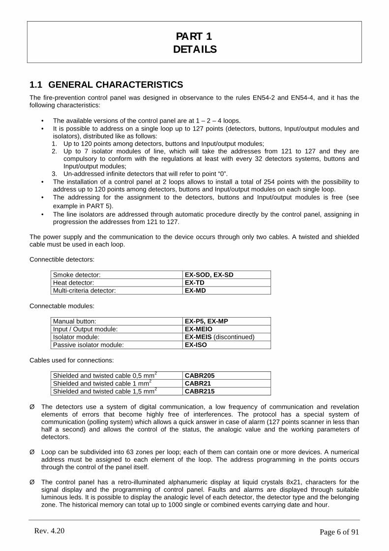
The fire-prevention control panel was designed in observance to the rules EN54-2 and EN54-4, and it has the following characteristics:
• The available versions of the control panel are at 1 – 2 – 4 loops.• It is possible to address on a single loop up to 127 points (detectors, buttons, Input/output modules and
isolators), distributed like as follows:1. Up to 120 points among detectors, buttons and Input/output modules;2. Up to 7 isolator modules of line, which will take the addresses from 121 to 127 and they are
compulsory to conform with the regulations at least with every 32 detectors systems, buttons and Input/output modules;
3. Un-addressed infinite detectors that will refer to point “0”.• The installation of a control panel at 2 loops allows to install a total of 254 points with the possibility to
address up to 120 points among detectors, buttons and Input/output modules on each single loop.• The addressing for the assignment to the detectors, buttons and Input/output modules is free (see
example in PART 5).
• The line isolators are addressed through automatic procedure directly by the control panel, assigning in progression the addresses from 121 to 127.
The power supply and the communication to the device occurs through only two cables. A twisted and shielded cable must be used in each loop.
Connectible detectors:
Smoke detector: EX-SOD, EX-SDHeat detector: EX-TDMulti-criteria detector: EX-MD
Connectable modules:
Manual button: EX-P5, EX-MPInput / Output module: EX-MEIOIsolator module: EX-MEIS (discontinued)Passive isolator module: EX-ISO
Cables used for connections:
Shielded and twisted cable 0,5 mm2 CABR205
Shielded and twisted cable 1 mm2 CABR21
Shielded and twisted cable 1,5 mm2 CABR215
Ø The detectors use a system of digital communication, a low frequency of communication and revelation elements of errors that become highly free of interferences. The protocol has a special system of communication (polling system) which allows a quick answer in case of alarm (127 points scanner in less than half a second) and allows the control of the status, the analogic value and the working parameters of detectors.
Ø Loop can be subdivided into 63 zones per loop; each of them can contain one or more devices. A numerical address must be assigned to each element of the loop. The address programming in the points occurs through the control of the panel itself.
Ø The control panel has a retro-illuminated alphanumeric display at liquid crystals 8x21, characters for the signal display and the programming of control panel. Faults and alarms are displayed through suitable luminous leds. It is possible to display the analogic level of each detector, the detector type and the belonging zone. The historical memory can total up to 1000 single or combined events carrying date and hour.
PART 1DETAILS

Page 7 of 91Rev. 4.20
Ø The control panel has:1. 2 supervised outputs, one of which is preset for the siren;2. 2 no supervised outputs at programmable clean relay NO/NC;3. 4 open collector outputs programmable for typology of alarm and zone.
Ø The control panel is preset for three opto-isolated serial ports, RS-232 and RS-485.1. COM1
• Module RS 232: Mini-net, LAN TCP/IP.• Module RS 485: LAN 485.
2. COM2• Module RS 232 (default): PC, LAN TCP/IP• PS2: keyboard PS2.
3. COM3• Module RS 232: Report of detector check.
Ø The control panel is preset for a further output PS2 to which it is possible to connect a keyboard for a quicker programming of points and zones.
Ø All the programming of the control panel can be made through the panel of the control panel itself, using the keys that have alphanumeric function.
The possible connections through the three gates described previously are given below.
Rs232 SERVICE PC
Ps2 keyboard
RS232 PC Detectors status info
LAN TCP-IP max 64 C.P.
SLAVE CONTROL
SLAVE CONTROL
MASTER PCLAN
1
RS485 Slave control panels net connected to Master PC,(Max 64 control panels).
MOXAMODUL
MOXAMODUL
MOXAMODUL
CONTROL PANEL
2 3
Page 8 of 91Rev. 4.20
1.2 POINT ADDRESSING AND ACQUISITION
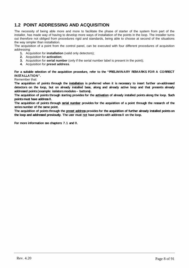
The necessity of being able more and more to facilitate the phase of starter of the system from part of the installer, has made way of having to develop more ways of installation of the points in the loop. The installer turns out therefore not obliged from procedures rigid and standards, being able to choose at second of the situations the way simpler than installation.The acquisition of a point from the control panel, can be executed with four different procedures of acquisition addressing:
1. Acquisition for installation (valid only detectors);2. Acquisition for activation;3. Acquisition for serial number (only if the serial number label is present in the point);4. Acquisition for preset address.
For a suitable selection of the acquisition procedure, refer to the “PRELIMINARY REMARKS FOR A CORRECT INSTALLATION”.Remember that:The acquisition of points through the installation is preferred when it is necessary to insert further un-addressed
detectors on the loop, but on already installed base, along and already active loop and that presents already addressed points (example: isolators modules – buttons).The acquisition of points through starting provides for the activation of already installed points along the loop. Such points must have address 0.
The acquisition of points through serial number provides for the acquisition of a point through the research of the series number of the same point.The acquisition of points through the preset address provides for the acquisition of further already installed points on the loop and addressed previously. The user must not have points with address 0 on the loop.
For more information see chapters: 7.1 and 0.

Page 9 of 91Rev. 4.20
2.1 SAFETY REQUIREMENTS
The installation of the product must be performed by authorized technicians who scrupulously follow all safety norms and procedures – law provision N° 46/90 (Legislative March 5 1990, n° 46). Only such appointed personnel is authorized to open the Control Panel; inside there may be parts run through voltage electricity.The product, is Class I conforming to the EN 60950-1 Normative, must be connected to the mains power line and
maintain the grounding connection and power surge protection (PE) as described on chapter 2.2.
Where to install the product.The product should be installed in a dry area which is not subject to weather agents. Make sure that sufficient space is left around the control panel box so that some ventilation is guaranteed. Do Not install the product on top of or nearby a heat source or dusty areas or wherever there could be corrosive environments.Excessive operating temperature may lead to malfunction and subsequently influence the overall performance and duration of the product itself.In presence of Humidity such as occasional drops of water caused by condensation may damage the product. In the event of condensation, it is advisable to wait until the area is dried. If the product has been stored in a cold environment for a long time, it is advisable to wait a couple of hours before the actual power up to the mains electrical line.
IMPORTANT: only authorized personnel can open the product. Do Not try to open it without proper authorization or else the warrantee will be Void. Remember to disconnect the mains power line and internal batteries before proceeding to the regular maintenance every time.
2.2 CONNECTING THE CONTROL PANEL TO THE MAIN POWER LINE 230VCA
It is expected that the electrical wiring edifice/building in which the Control Panel resides is adequately furnished with a mango-thermic switch as protection for overloads / power surges on line and short circuits.An adequate omni-polarity switch should be in the power line frame and a accessible connector space fitting of atleast 3mm. apart. It is contemplated to adopt a uni-polarity sectioner device for the conductor phaser so that one may identify the neutral.The connector leads for the main power frame and internal cabling must be safely fastened by proper fastening or fixing materials.
Shut-off main power before substituting the battery or performing other “open box” interventions on the product.
Introduce the mains power line of 230Vca in the panel container through the top right-hand corner by keeping it distant from any internal wiring, micro-chip or main board circuitry.
Feed the power to the Control Panel adopting the proper mango-thermic power switch. The main line conductor cable must be of at least 1,5mm² thick with a power work load which can sustain 250Vca.
NOTE: the output relays must be connected only to the circuits type SELV (not harmful power tension) in ref. to the EN 60950-1:2001 Normative.
2.3 FUSES
On the electronic circuit board there are 5 fuses inserted on as many fittings placed vertically and they have their feature functions described: type (F= fast, T= delayed) and nominal current.To better learn all their general characteristics and which fuse is for which function; make reference to thetechnical table reported on PART 19. Please comply to what is indicated and to not change or switch the for any given reason or else you may alter the functioning and may cause serious faults to the Control Panel.
PART 2CONTROL PANEL INSTALLATION

Page 10 of 91Rev. 4.20
- B1+ - B2+ - AUX +
FAULT - + (30Vdc) N L
Battery fuse AUX power supply fuse
AC-DC ADAPTOR
230Vac 30Vdc
Trimmer Vac fuse
Siren out2 fuse 24Vdc out1 fuseFault out3 fuse
+
-
+
-12V 7,2Ah12V 18Ah
12V 7,2Ah12V 18Ah
FAULT + - (30Vdc)
-1B
+1B
SH
I
-1A
+1A
-2B
+2B
SH
I
-2A
+2A
-24
+2
4
SH
I
+S-S- +
FAULT
SH
I
OC
1
OC
2
OC
3
OC
4RL2RL1PS2
N LLINE 230Vac
F1 F2 F3
F4 F5
F6
F1: F315mA L 250VF2: F315mA L 250VF3: F315mA L 250VF4: F1,6A L 250VF5: F1,6A L 250VF6: T400mA L 250V
FUSES LIST
2.4 FIXING THE CONTAINER
The control panel weighs about 10Kg without batteries inside (one battery weighs about maximum 6.5Kg). The control panel must be fixed on a vertical wall or adapted and on equivalent support; it does not have to only come supported without an adequate fixation. For the fixation to the wall, to use first the central holes, then the two holes low. In order to improve the traction on the implantation support, it is possible to use the two holes in the up too, for a total of five points of implantation. For the implantation, to use of the lives of 6mm of greater diameter. For the fixing, use at least 3 screws of 6mm of diameter or more and with an adequate dowel. In case reinforce the surface if necessary.
WARNING: the procedures described in this manual must be only made accessible to qualified personnel.
2.4.1 Cable arrangement
Pay attention to the disposition 230Vac net cables and loops cables.
Watching frontally box the metallic opened, three rectangular openings on the bottom and three holes sluices pre-cut on the top part, can be viewed.Use the holes in the following way:
• rectangular hole or circular hole in top at left:to use for the cables connected to the clips at left (outputs) and at the centrum (data transfer);
• circular hole in top at centrum:to use for the cables connected to the clips at the centrum (data transfer);
• rectangular hole or circular hole in top at right:to use for the cables connected to the clips at right (loop);
• rectangular hole in bottom at centrum:to use for the cables connected to the clips in bottom (auxiliar output at 24Vdc) and that of the transformer (230Vca);
It is advisable to arrange the cable in tidy mode, so as to diminish the eventual and remote interferences between they and the control panel.In particular it is advisable to avoid to make to pass under the card electronic cables of loop and power supply.This operation, yet, is not necessary, in how much it control panel and the protocol of the data has been plans in such mode to be immune at the disturbs and similar interferences.
2.4.2 Observation
In the connection between the control panel and the magneto-thermic power switch, it is reccomended to lock the three-polar cable or the single power supply conductors in way that during the wiring there aren’t any mechanical movements which may effect or weaken the connection itself.The purpose of this pre-caution is to maintain in any case a electrical security condition.
Page 11 of 91Rev. 4.20
For the connection to the power supply clips, the electrical conductors must be terminated between terminal clips, at scope to have in any case a electrical security condition.
2.4.3 Assembly
After having mounted the panel in the most appropriate place, verify proper cabling to adopt and where to run it:• the rectangle holes on the case back;• the round holes are normally closed on the top part of the metal case.
In the case the round pre-fitted holes aren’t utilized; please leave them closed so to prevent any metallic or other pieces to fall into the metal case so that you may prevent damages to the electronic card inside.In case you change the cable access to the metal case; make sure that the holes are closed off so to prevent any possibility of damages to the electronic card.
As for the actual mounting; proceed in the following manner making sure that there is no mains power line or any current connected:
1. open the front cover by unscrewing the four screws on every corner 4x16;2. only if you plan to pass the cables through the top holes; then you punch the pre-cut holes to access the
cabinet;3. fix the metallic case by the three fixing/access points (first the middle one, then the two on the lower part);
one may also use the other two fixing holes on the top part in order to ensure a stronger fixing to the surface;
4. introduce the cables into the metallic case in a most orderly fashion so that they are well sorted and separated (follow the instruction reported on the previous page) so they do not run under the electronic card.
5. proceed in inserting all the electrical connections as described on this manual;6. close the front cover by re-screwing all the screws provided.
In the case the electronic card should be completely removed and /or re-inserted into the metallic case; pay extra attention to the ground wire with cable endings "ring type" secured by soldered steel nuts to host the metal screws 4x20 directly on the metallic case.When the electronic card is re-inserted, re-apply the ground cabling as they were originally: if not executed in this way the electric safety conditions may be jeopardized.
2.5 CONNECTION
The motherboard of the control panel in picture 2. The positions of the clips and fuses are pointed out. Besides the connector PS2 for the keyboard and the grey button of resetting to push at the first starting of the control panel are pointed out.
The left clips concern the control panel outputs (see charter PART 9 page 45), and exactly:
Ø (out5) Clips RL1 (SEL4): relay 1 is a clean relay no supervised that can be programmed NO/NC;Ø (out4) Clips RL2 (SEL3): relay 1 is a clean relay no supervised that can be programmed NO/NC;Ø (out9) Clips OC4: open collector No 4 programmable for typology of alarm and zone;Ø (out8) Clips OC3: open collector No 3 programmable for typology of alarm and zone;Ø (out7) Clips OC2: open collector No 2 programmable for typology of alarm and zone;Ø (out6) Clips OC1: open collector No 1 programmable for typology of alarm and zone;Ø (out3) Clips FAULT (SEL1,2): supervised output of fault;Ø (out2) Clips –S +S: supervised siren;Ø (out1) Clips +24 –24: auxiliary power supply 24Vdc.
WARNING: after the cable connection of the power supply to the GND-N-L clips of AC-DC Adaptor, it is important to immobilize the three electrical cables with a plastic strip. It is necessary to prevent that electrical cables are free to move.
WARNING: the power supply cable must have the ground electrical cable (GND) more long respect the line (L) and neuter (N) cables.

Page 12 of 91Rev. 4.20
- AUX +
FAULT - + (30Vdc) N L
Battery fuse AUX power supply fuse
Ps2 keyboard
LOOP
Optional serial gates
Control panel outputs
Resetting fault system
AC-DC ADAPTOR
230Vac 30Vdc
Trimmer Vac fuse
Siren out2 fuse 24Vdc out1 fuseFault out3 fuse
COM1 COM2 COM3
+
-
+
-12V 7.2Ah12V 18Ah
12V 7.2Ah12V 18Ah
FAULT + - (30Vdc)
-1
B
+1
B
SH
I
-1
A
+1
A
-2B
+2
B
SH
I
-2A
+2
A
-24
+2
4
SH
I
+S-S
- +FAULT
SH
I
OC
1
OC
2
OC
3
OC
4RL2RL1PS2
- B1+ - B2+
Fig.2 - Description of motherboard of the control panel.
2.5.1 The circuits of the detection
The control panel supports exclusively detectors and modules that use a communication system of digital data.A part from a few models, which need auxiliary power supply 24Vdc, the elements are supplied and communicate with the control panel through two cables connected to an input module. The detection circuit must be kept the farthest possible from the other installations and the cables passage, to reduce the risk of external interfaces. Don’t forget, use shielded and twisted cable, to reduce the interferences. The section will depend on the length of loop.
WARNINGInstallations with cable length superior to 2Km are not advised, because the capacity and the induction of cable can start to interfere with data communication from this length onward.
LENGTH (m) SIZE (mm2) CAPACITY (pF/m)
Length up to 500 m min 0,5 max. 150 Length up to 1000 m min 1,0 max. 120Length up to 2000 m min 1,5 max. 100
N.B.: test lines as provided in “LINE CABLE TEST PROCEDURE BEFORE LOOP CONNECTION” before connecting loop to the control panel.
The system is preset for the installation up to four circuits of detection (1, 2, 3 and 4 loops) with a maximum capacity of 508 points (detectors, buttons, Input/output modules or isolator) with the possibility to install up to 120 points (exclude isolator) in a single loop.
As reported in the instructions of the single products, the detectors, buttons and Input/output modules must be addressed.
The descriptions of the different procedures of programming – addressing (single point; self-increment; through
series number) will be dealt with in PART 4 of this manual.
Page 13 of 91Rev. 4.20
MUDULOEX-MEI/O
MUDULOEX-MEI/O
SHORT CIRCUIT
ISOLATORMODULE
ISOLATORMODULE
MUDULOEX-MEI/O
MUDULOEX-MEI/OISOLATORMODULE
ISOLATORMODULE
INTERRUPTEDLINE
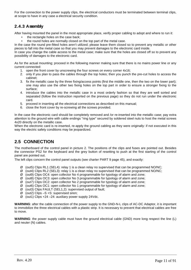
The installation of a detection circuit is made connecting all the control devices so that one closet ring is obtained. As regards the conformity of the system to the rules UNI 9795 and EN 54-2, it is necessary to insert at least a module isolator every 32 detectors or buttons. One can install up to a maximum of seven modules isolators for each loop.
The connection uses the clips A-/ A+ for the installation output and B-/ B+ for the return of the same one.
The cable shielding (shielded) is connected only the part of starting to the clip SHI. The shielded of arrival must not be connected.
• Start from +1A and arrive at +1B, start from –1A and arrive at –1B.• Connect the cable shielding (SHI) of the starting part to the clip SHI. The arrival shielded must not be
connected.• If a loop is not used it is necessary to short circuit it with the jumper (-A with –B and +A with +B).
In case a short circuit on the line is produced, the part of circuit interested by the fault and included between the two modules isolator will be disconnected, with the consequent loss of communication of a maximum of 32 elements (maximum number of elements that the rule UNI 9795 allows to lose in case of line short circuit). In case of single interruption of loop, the control panel will be able to communicate from the two sides (output and return) without losing the communication with the other installed elements.Both the short circuit and the line interruption produce a fault restorable only to executed repair.
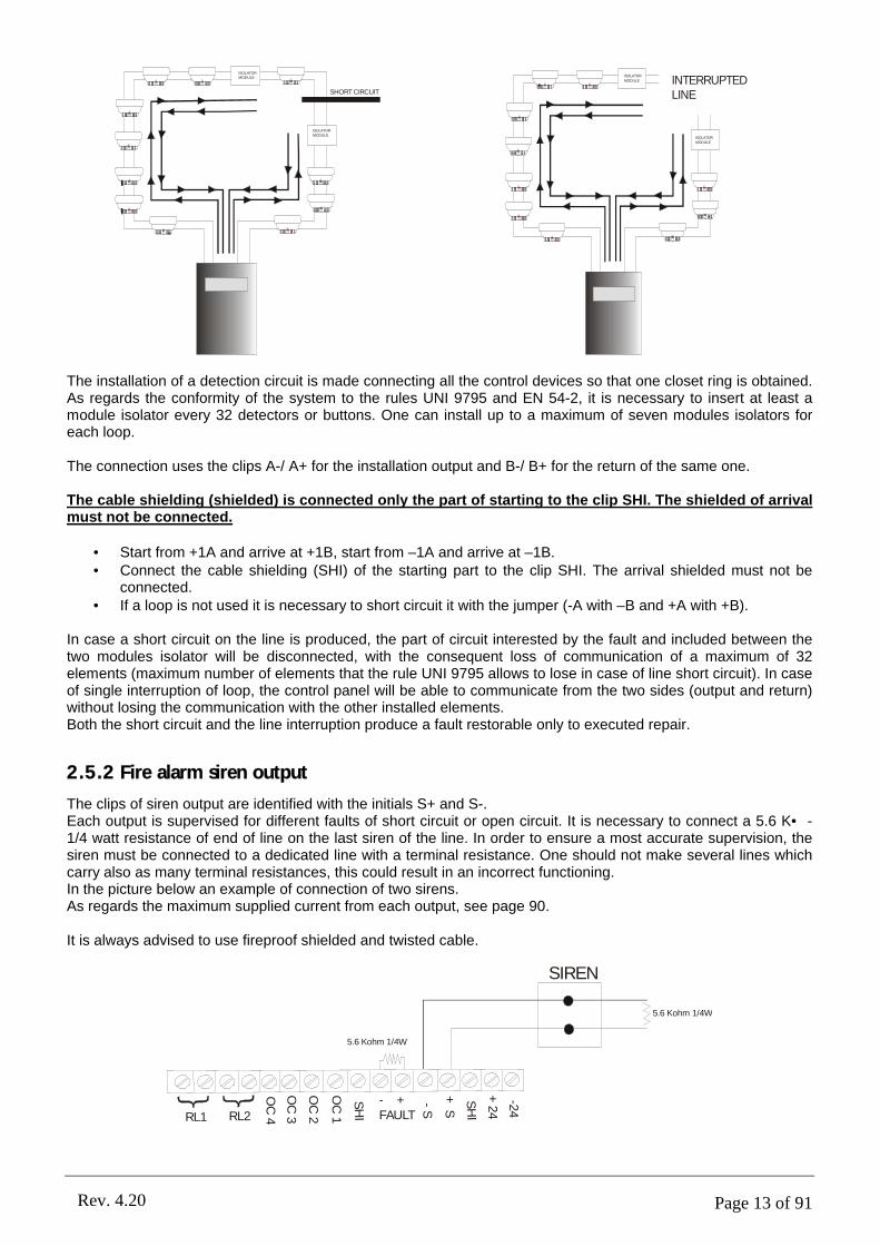
2.5.2 Fire alarm siren output
The clips of siren output are identified with the initials S+ and S-.Each output is supervised for different faults of short circuit or open circuit. It is necessary to connect a 5.6 K• -1/4 watt resistance of end of line on the last siren of the line. In order to ensure a most accurate supervision, the siren must be connected to a dedicated line with a terminal resistance. One should not make several lines which carry also as many terminal resistances, this could result in an incorrect functioning.In the picture below an example of connection of two sirens.As regards the maximum supplied current from each output, see page 90.
It is always advised to use fireproof shielded and twisted cable.
SIREN
5.6 Kohm 1/4W
5.6 Kohm 1/4W
-24
+24
SH
I
+S
-S- +
FAULT
SH
I
OC
1
OC
2
OC
3
OC
4RL2RL1

Page 14 of 91Rev. 4.20
2.5.3 Output for alarm siren fault
The fault output connector terminals are identified and marked as FAULT.The output is normally supervised, but it is possible to change the type of set-up by acting on the software
configuration (see chapter 9.2.4) e hardware (by the Jumpers “SEL1”). In the case of selection of output
supervised, an end of line resistor of 5.6KΩ - 1/4Watt needs to connect on the last siren of the line.For the maximum power allowed on every output, see pg. 90 of this chapter.It is advisable to always use a fire-resistant, double twisted and protected cable for the installation.
Depending on how the “CONFIG.” parameters are set-up (see chapter 9.2.4), it is necessary to modify, while the control Panel is off, and the relative Jumpers to “SEL1”:
SUPERVISED OUTPUTSIREN
5.6 Kohm, 1/4W
5.6 Kohm, 1/4W-2
4
+2
4
SH
I
+S
-S- +
FAULT
SH
I
OC
1
OC
2
OC
3
OC
4RL2RL1
SEL4
SEL3
SEL1
SEL2
Only in this case the output is protected by a fuse (see chapter 2.5).
OUTPUT 24V MISSINGSELF-POWERED
SIREN
5.6 Kohm, 1/4W
-24
+2
4
SH
I
+S
-S- +
FAULT
SH
I
OC
1
OC
2
OC
3
OC
4RL2RL1
SEL4
SEL3
SEL1
SEL2
COMMAND: POSITIVE DISCONNECTED
+
-
OUTPUT RELAY NOT SUPERVISED N/O
SIREN
5.6 Kohm, 1/4W
-24
+2
4
SH
I
+S
-S- +
FAULT
SH
I
OC
1
OC
2
OC
3
OC
4RL2RL1
SEL4
SEL3
SEL1
SEL2
+
-
Page 15 of 91Rev. 4.20
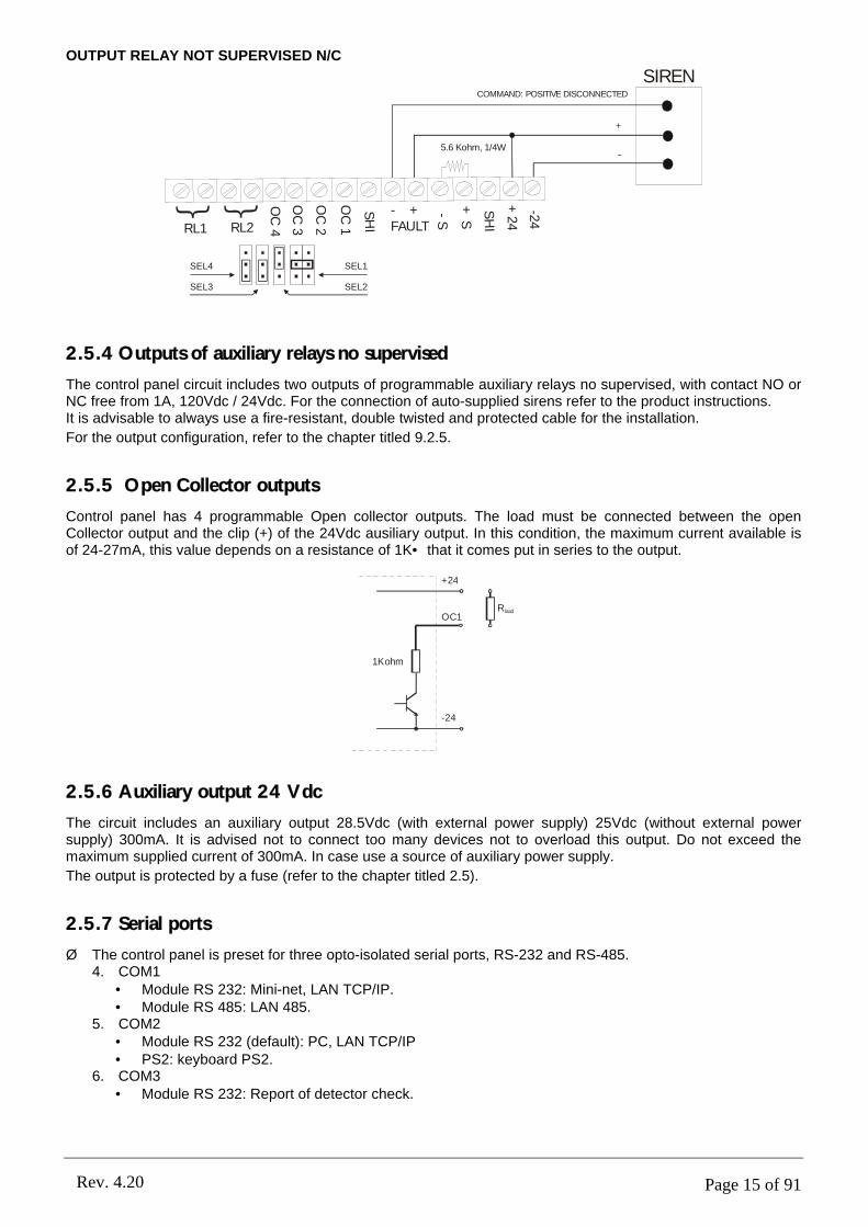
OUTPUT RELAY NOT SUPERVISED N/C
SIREN
5.6 Kohm, 1/4W
-24
+2
4
SH
I
+S
-S- +
FAULT
SH
I
OC
1
OC
2
OC
3
OC
4RL2RL1
SEL4
SEL3
SEL1
SEL2
COMMAND: POSITIVE DISCONNECTED
+
-
2.5.4 Outputs of auxiliary relays no supervised
The control panel circuit includes two outputs of programmable auxiliary relays no supervised, with contact NO or NC free from 1A, 120Vdc / 24Vdc. For the connection of auto-supplied sirens refer to the product instructions.It is advisable to always use a fire-resistant, double twisted and protected cable for the installation.
For the output configuration, refer to the chapter titled 9.2.5.
2.5.5 Open Collector outputs
Control panel has 4 programmable Open collector outputs. The load must be connected between the open Collector output and the clip (+) of the 24Vdc ausiliary output. In this condition, the maximum current available is of 24-27mA, this value depends on a resistance of 1K• that it comes put in series to the output.
+24
-24
OC1
1Kohm
Rload
2.5.6 Auxiliary output 24 Vdc
The circuit includes an auxiliary output 28.5Vdc (with external power supply) 25Vdc (without external power supply) 300mA. It is advised not to connect too many devices not to overload this output. Do not exceed the maximum supplied current of 300mA. In case use a source of auxiliary power supply.
The output is protected by a fuse (refer to the chapter titled 2.5).
2.5.7 Serial ports
Ø The control panel is preset for three opto-isolated serial ports, RS-232 and RS-485.4. COM1
• Module RS 232: Mini-net, LAN TCP/IP.• Module RS 485: LAN 485.
5. COM2• Module RS 232 (default): PC, LAN TCP/IP• PS2: keyboard PS2.
6. COM3• Module RS 232: Report of detector check.

Page 16 of 91Rev. 4.20
2.5.8 Connection to the power supply
Execute the connections with suitable materials and procedures prescribed by the rules in force.Do not execute the electrical connection unless you have verified the actual power cut-off.
PLEASE NOTE• At the moment of installation always connect the mains 230Vac first and then the batteries. In this manner
you prevent dangerous shock sparks.• The power cable for the Control Panel must be connected, for safety reasons and to facilitate
maintenance, to a magneto thermic switch dedicated and with proper electrical specifications. The electrical connection should be direct without any kind of by-pass plug or prongs.
• The minimum required size of cable for power supply must be of 1,5mm² e 250Vca.• The ground wire (yellow/green) and properly connected by the ground fastner screw from the power
supply to the other end of the mains power. Furthermore, it must be properly fixed with the screws provided so to ensure it from mechanical solicitations.
• All cables connected to the Control Panel must be fire proof.• Since the connection to the mains is not off the ground so it does not require any further fastening or
special support to the Control Panel. Shall the case require, please carefully apply any extra cable connection between the Control Panel and the magneto thermic switch so that the cables and the end terminals will not be subject to pulls or jerks in their passage way.
• To apply the connector cable to the power supply. the conductor cable endings should be "pin type", this to ensure and maintain the safety conditions.
2.5.9 Battery connections
On the control panel electronic circuit board there is a fitting to host the power supply from the two auxiliary batteries.In the actual connections, pay careful attention to the polarities and to the color differentiation of the cables and battery terminals. In case of faulty connection, the circuit breaker fuse which is removable will protect the battery and circuit board.
2.6 LOOP SECTION
A section is a loop partition between two isolators. A loop carrying no partition has only one isolator, section (A-B).
In this figure there is a example of loop with 5 sections and 4 EX-MEIS isolators. The clips A are the loop start and B are the loop end. The section partition is not applicable when there’re passive EX-ISO isolator.
2.7 LOCATION OF GROUND SHUNT IN THE CONTROL PANEL
The control panel checks the connection of the installation all the time to point out if some external cables have a round dispersion. In this case an information in the control panel of ground shunt is given through a yellow led.The control panel will work properly with a round shunt in the system. However it is suitable to solve the fault as soon as possible.Most round shunts are located making resistance measures in the cables before collecting them to the control panel.Round shunts can be found in the following external connections:
• Connection of siren circuits.• Connection of detection loop.• Auxiliary output of 24 Vdc.
ISOLATOR121
ISOLATOR122
ISOLATOR123
ISOLATOR124
CONTROL PANEL
A-121 121-122 122-123
123-124124-B

Page 17 of 91Rev. 4.20
2.8 MAINTENANCE
The maintenance measures advised in EN 54-14 must be followed.
2.8.1 Daily control
The user will check that:• The control panel works properly. Otherwise the faults will be reported and registered and the
maintenance staff must be informed.• It is advisable that all or any faults during testing or noted previously, are solved as soon as possible, for
a correct functioning of the control panel.
2.8.2 Weekly control
• It is advisable to check the status of disconnected and connected batteries.• A detector or a button will be started up to test the control panel and the connected fittings of alarm. It is
suitable to check a different zone every month.• Where it is admitted, inform the fire brigade or the control centre.
Any malfunctioning must be noted in the event register. The problems must be solved as soon as possible, in case contacting the installer.
2.8.3 Four-monthly control
The maintenance staff must carry out the following controls:• Look over the notes of the event register.• Examine all the connections of batteries.• Check the alarm functioning, auxiliary fault of the control device and signaller.• Visual inspection of the control devices and signaller, a possible rise in humidity or any other type of
decay.• Check there are not structural changes that can cause the malfunctioning of the detectors, manual
buttons or sirens. In this case carry out a visual inspection, too.Any problem must be noted in the event register, solving the probable problems as soon as possible.
2.8.4 Yearly control
The maintenance staff must have the duty to perform the following controls:• Carry out the control procedures advised daily, monthly and four-monthly.• Test the control panel and check all the detectors work as recommended by the manufacturer (check the
parameters).• Look over visually all the connections to the devices and relative supports are safe, they are not damaged
and are protected properly.• Examine and check all the batteries.
Any fault must be noted in the event register, solving the problems as soon as possible.
2.8.5 Cleaning the Smoke Sensor
For proper functioning of the detector, it is necessary to perform a yearly periodic maintenance check of at least 2 interventions.Detector Test: verify the proper functioning of the detector through a smoke device by paying careful attention in not getting the internal chamber dirty or damage the sensor itself. An alarm simulation can be performed by activating the internal Reed by placing a magnet (note: the Reed test does not qualify as a smoke test).Detector cleaning: the detector must be cleaned by means of compressed air blown through the internal part of the detector. Unscrew the bottom counter-plate screws to take the internal chamber out from the detector head. Clean the chamber, reassemble by making sure that the bottom counter-plate properly matches the fitting (the part where the Reed is placed corresponding to the n°4 of the bottom plate). Close the detector by replacing the screws without screwing too tightly.
Page 18 of 91Rev. 4.20
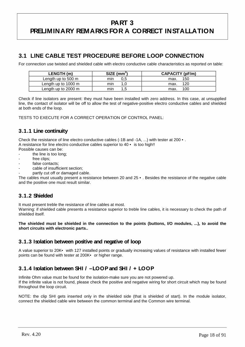
3.1 LINE CABLE TEST PROCEDURE BEFORE LOOP CONNECTION
For connection use twisted and shielded cable with electro conductive cable characteristics as reported on table:
LENGTH (m) SIZE (mm2) CAPACITY (pF/m)
Length up to 500 m min 0,5 max. 150 Length up to 1000 m min 1,0 max. 120Length up to 2000 m min 1,5 max. 100
Check if line isolators are present: they must have been installed with zero address. In this case, at unsupplied line, the contact of isolator will be off to allow the test of negative-positive electro conductive cables and shielded at both ends of the loop.
TESTS TO EXECUTE FOR A CORRECT OPERATION OF CONTROL PANEL:
3.1.1 Line continuity
Check the resistance of line electro conductive cables (-1B and -1A, ...) with tester at 200 •.A resistance for line electro conductive cables superior to 40 • is too high!!Possible causes can be:- the line is too long;- free clips;- false contacts;- cable of insufficient section;- partly cut off or damaged cable.The cables must usually present a resistance between 20 and 25 •. Besides the resistance of the negative cable and the positive one must result similar.
3.1.2 Shielded
It must present treble the resistance of line cables at most.Warning: if shielded cable presents a resistance superior to treble line cables, it is necessary to check the path of shielded itself.
The shielded must be shielded in the connection to the points (buttons, I/O modules, ...), to avoid the short circuits with electronic parts..
3.1.3 Isolation between positive and negative of loop
A value superior to 20K• with 127 installed points or gradually increasing values of resistance with installed fewer points can be found with tester at 200K• or higher range.
3.1.4 Isolation between SHI / –LOOP and SHI / +LOOP
Infinite Ohm value must be found for the isolation-make sure you are not powered up.If the infinite value is not found, please check the positive and negative wiring for short circuit which may be found throughout the loop circuit.
NOTE: the clip SHI gets inserted only in the shielded side (that is shielded of start). In the module isolator, connect the shielded cable wire between the common terminal and the Common wire terminal.
PART 3PRELIMINARY REMARKS FOR A CORRECT INSTALLATION
Page 19 of 91Rev. 4.20
3.1.5 Check of SHI short circuits at power supply line
Connect the positive clip +24; to the loopSet the tester at 50Vdc and measure the voltage between shielded and the negative (of the battery or the clip –24): THERE MUST NOT BE VOLTAGE!!!A possible reading of voltage may occur in the case of short circuit in one ore more detectors or between the shielded clip means that a short circuit, inside a few detectors, between shielded clip and the clip R and the terminal R and common terminal (common clip of base nr. 2 or nr. 3).
FURTHER CHECK FOR SHORT CIRCUITS ON THE LOOP LINE AND POWERED UP SYSTEM:Connect the negative cable of the loop to the clip –24; all leds must flash.Connect a 1KΩ - 5Watt resistance between +loop and +24.The un-flashing leds suggest a problem on the detector.IF THE LEDS ARE STILL NOT FLASHING; CHECK FOR SHORT CIRCUITS ALONG THE LINE.Warning: the presence of isolators along the line cuts off the check verification, so to have final proof for the proper functioning, one may “Jeri Wire” the relay by bridging it to the jumper terminal.

Page 20 of 91Rev. 4.20
PART 4ABOUT PROGRAMMING
4.1 CONTROLS AND INFORMATION
The EN-54 norms supplies two level of access for the control panel user. The access levels of the user are defined as shown previously:
Level 1All the information reads operative, the control panel controls are disabled.The access to the superior level is obtained typing in a numerical code through the numerical keyboard.
Level 2All the information and controls of the control panel are operative. In this level the system configuration cannot be modified. However it is possible to activate or disable zones or sensors to modify time and date. The access to level 3 is obtained typing in a numerical code through the keyboard. After a previously programmed time has passed, the system will go back to level 1 automatically.
4.1.1 Control panel controls
Main control keys:
Silence Silence the internal buzzer.Reset Delete all the alarm conditions and rearm the control panel.Menu Access to auxiliary menu.
Besides there are other keys to enter the different functions.
1,2,3,4,5,6,7,8,9,0 Insertion of the numbers from 0 to 9 and the letters from a to z.Arrow up Advance up wards of the selection.Arrow down Advance down wards of the selection.Left arrow Advance left wards of the selection.Right arrow Advance rightwards of the selection.Menu Main menu input.Sel. Select.Pre. Preceding.Sub. Subsequent.Mod. Modify.Ok To confirm modification.
Scheme of the associations between numerical and alphanumeric push-buttons:
MODALITYKEY “123” “abc” “ABC”
1 1 a b c A B C2 2 d e f D E F3 3 g h i G H I4 4 j k l J K L5 5 m n o M N O6 6 p q r P Q R7 7 s t u S T U8 8 v w x V W X9 9 y z space Y Z SPACE0 0 space . space SPACE . SPACE

Page 21 of 91Rev. 4.20
4.1.2 Led indicators of the control panel
The control panel has indicators led of yellow, green and red colour for a quick identification of its status.
Evacuation Red Active evacuation status.Fire alarm Red Press the control panel has pointed out a alarm condition.Pre-alarm Red The control panel has pointed out a pre-alarm condition.Test Yellow Active function of test.Out of service Yellow It lights up when a part of the system is put out of service.Out of service / siren output
Yellow Delayed siren. For norms the control panel must signal if the siren output is delayed. In this case, in the corner in top at right of the display to appear a siren icon.
Activated output Yellow Lit led at active outputs.Fault Yellow The control panel has pointed out a general fault.System fault Yellow The control panel has pointed out a fault to the system.Battery fault Yellow The control panel has pointed out to the batteries.Aux supply fault Yellow The control panel has pointed out a fault to the auxiliary output.Siren output fault Yellow The control panel has found a fault in the siren output line (S- S+). It is
possible that along this line there is a short circuit or an interruption.Power supply Green This led indicates the presence of the power supply (220Vac). If the power
supply is not present, the led flashes.
Page 22 of 91Rev. 4.20
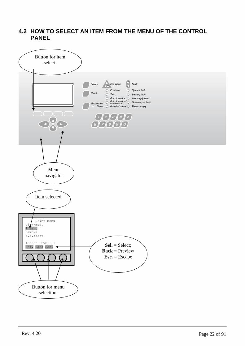
4.2 HOW TO SELECT AN ITEM FROM THE MENU OF THE CONTROL PANEL
Point menuview/mod.insertremoved.b.reset
ACCESS LEVEL: 1Sel. Back Esc. Sel. = Select;
Back = PreviewEsc. = Escape
Button for menu selection.
Item selected
Button for item select.
Menu navigator
Page 23 of 91Rev. 4.20
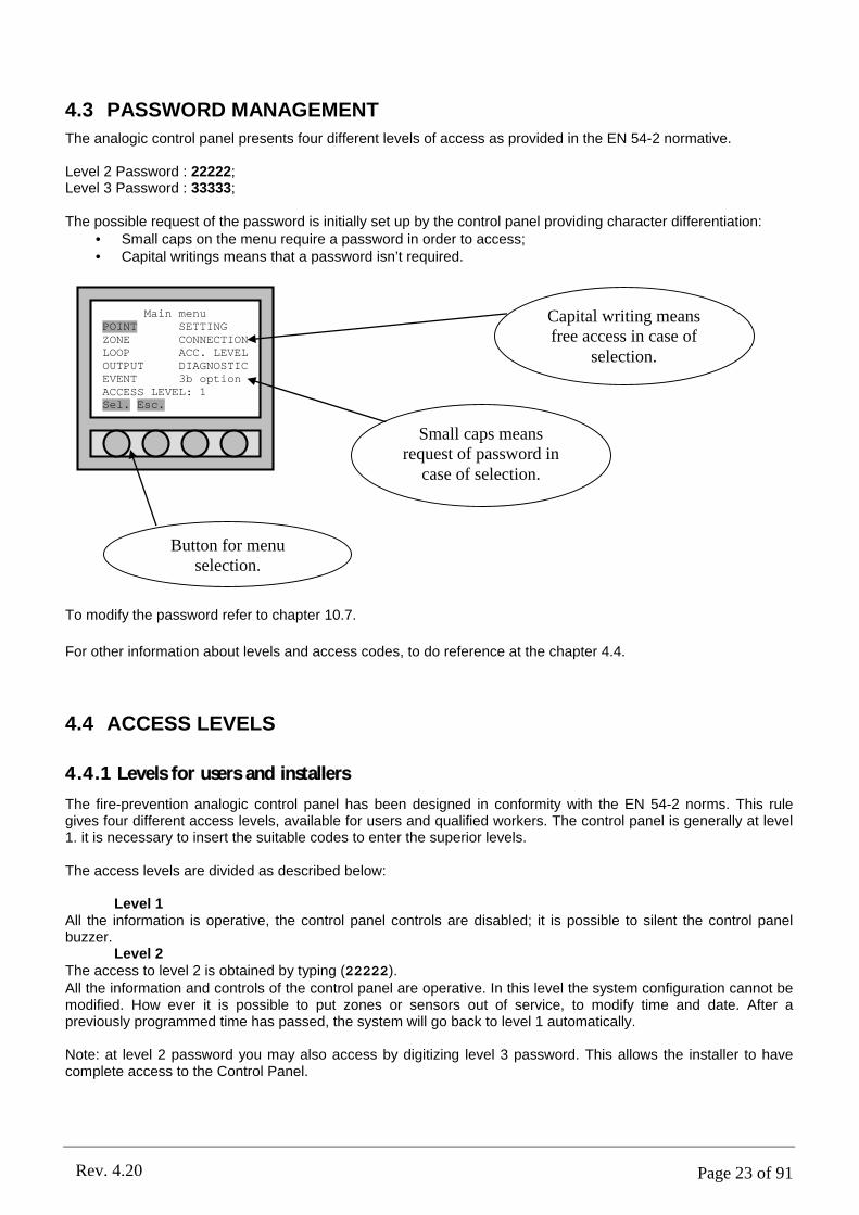
4.3 PASSWORD MANAGEMENT
The analogic control panel presents four different levels of access as provided in the EN 54-2 normative.
Level 2 Password : 22222;Level 3 Password : 33333;
The possible request of the password is initially set up by the control panel providing character differentiation:• Small caps on the menu require a password in order to access;• Capital writings means that a password isn’t required.
To modify the password refer to chapter 10.7.
For other information about levels and access codes, to do reference at the chapter 4.4.
4.4 ACCESS LEVELS
4.4.1 Levels for users and installers
The fire-prevention analogic control panel has been designed in conformity with the EN 54-2 norms. This rule gives four different access levels, available for users and qualified workers. The control panel is generally at level 1. it is necessary to insert the suitable codes to enter the superior levels.
The access levels are divided as described below:
Level 1All the information is operative, the control panel controls are disabled; it is possible to silent the control panel buzzer.
Level 2The access to level 2 is obtained by typing (22222).All the information and controls of the control panel are operative. In this level the system configuration cannot be modified. How ever it is possible to put zones or sensors out of service, to modify time and date. After a previously programmed time has passed, the system will go back to level 1 automatically.
Note: at level 2 password you may also access by digitizing level 3 password. This allows the installer to have complete access to the Control Panel.
Main menuPOINT SETTINGZONE CONNECTIONLOOP ACC. LEVELOUTPUT DIAGNOSTICEVENT 3b optionACCESS LEVEL: 1Sel. Esc.
Button for menu selection.
Capital writing means free access in case of
selection.
Small caps means request of password in
case of selection.

Page 24 of 91Rev. 4.20
Level 3The access to level 3 is obtained typing (33333).All the information of the configuration is accessible in this level and any change that concerns the system configuration proves possible.
Level 4 Access allowed only to the manufacturer.
N.B.: the codes of level 3 and 4 must be used only by the qualified technician to the programming of the control panel.
4.5 OUT OF SERVICE, FAULT, ALARM MESSAGES
4.5.1 General
The Control Panel communicates externally through:ü buzzer (active whenever a new alarm signal has been triggered (alarm or fault);ü led;ü display.
It communicates in the event of:ü fire alarm;ü evacuation;ü fault;ü technological alarm (bath, etc...);ü out of service;ü active outputsü pre-alarm.
4.5.2 Silence
This function is not necessarily linked to fire alarm, fault or out of service alarm.When an element (detector, button or module) is activated, the signal of fire alarm with all the necessary parameters to identify the activated point in the shortest possible time appears on the display. A buzzer inside the control panel is activated and the read led of alarm signal lights up.It is possible to silence at once the buzzer inside the control panel pressing the key silence placed.
GENERAL SIREN SILENCE MODE
If you need to silence the siren/s output and/or all the ones enabled to this command, (see chapter 15.3.4), you must access the “Evacuation menu” and press the related command to the voice “OUTPUTS SILEN.MOD”.It is possible to re-instate the silenced outputs by entering “Evacuation menu” and press the related command button at the voice “OUTPUTS RESTART”.
SILENCE SINGLE SIREN
If you wish to silence one siren at a time and all ones enabled to this function (see chapter 15.3.4), it is necessary to access the “Output setting” menu , related to the output to silence, and press the “Sil.” command. (this
button substitutes the “Mod.” seen in the chapter 9.1.4).
It is possible to re-instate the silenced outputs by entering the “Output setting” menu, related to the output ,
and press the button “Act.” (this button substitutes the “Mod.” as seen on the chapter 9.1.4).
4.5.3 View Messages
Whenever the Control Panel reveals a change coming from the main panel or loop, this shall appear on the display.The simplify the identification of this message display, the Control Panel will subdivide the messages in type groups by showing them according to their priority listing:ü fire alarm (maximum priority);ü evacuation;ü fault;ü technological alarm;

Page 25 of 91Rev. 4.20
ü out of service;ü active outputs;ü pre-alarm (minimum priority).
All and any event which the Control Panel reveals, are automatically saved on the event list (see chapter 4.6).
The exclamation mark (!) or interrogation mark (?) indicate that the origin of the message has not been restored yet and that the reset or restore function through the RESET button, will not have any effect. The difference between the two marks lies in the priority state of verification by the Control Panel; (!) continuous control, but this
symbol (?) stands for periodical control.The absence of (!) or (?) indicates that the origin of the event has been restored and the message can be removed with the RESET button.
When the fire alarm is triggered, the Control Panel visualizes the areas in alarm (not the points or other elements).Menu: access to the Control Panel menu;View: details of selected visualized message;Ala.: allows access to other types of messages (fault, out of service, ...);Poi.: visualize points of the selected area which have gone into alarm.
When the evacuation procedure is enabled, status check and related extinguishing procedure.Menu: access to the control panel menu;View: details of selected visualized message;
Ala.: allows access to other types of messages (fault, out of service, ...).
When the fault is identified, the control panel shows the associated list of events.Menu: access to the control panel menu;
View: details of selected visualized message;
Ala.: allows access to other types of messages (fault, out of service, ...).
When the service alarm is triggered, the control panel shows the associated “armed” points.Menu: access to the control panel menu;
View: details of selected visualized message;
Ala.: allows access to other types of messages (fault, out of service, ...).
FIRE ALARM: 002001 ZONE ALARM 01-1!OFFICE 1002 ZONE ALARM 02-1!OFFICE 2
Menu View Ala. Poi.
EVACUATION: 002001 17/03/05 12:34:58!MANUAL EVACUATION002 17/03/05 12:35:48!EXTINCTION ACTIVATED
Menu View Ala.
FAULT: 002001 17/03/05 12:34:58?OUT.INTERRUPTION 002002 17/03/05 12:35:48!TRADIT.LINE FA 003-1
Menu View Ala.
TECHNOLOG.ALARM: 002001 17/03/05 12:34:58!LOW TECHN. INP 001-2002 17/03/05 12:35:48!BATH TECH. INP 003-1
Menu View Ala.

Page 26 of 91Rev. 4.20
When the “OUT OF SERVICE” command is given to the point/Output/... the control panel shows the associated list.Menu: access to the control panel menu;View: details of selected visualized message;
Ala.: allows access to other types of messages (fault, out of service, ...).
When the outputs are activated, the control panel shows the associated list.Menu: access to the control panel menu;View: details of selected visualized message;
Ala.: allows access to other types of messages (fault, out of service, ...).
4.5.4 Visualizing the event
The control panel, at first, shows the list associated to the events of most important priority.With the “View” button, it is possible to show the selected event in detail.In order to visualize messages which differ from the ones listed on display, press “Ala.” and select the list of events you wish to visualize.
List of types of messages. Only the assigned groups with the given references are shown.
Detailed visualization of a message (in this case we have an event of the alarm area type).Press “Ok” to return to the original list.Event 001/002
•DATE: 20/01/05TIME: 18:30:58EVENT: ZONE ALARMZONE ADDRESS: 01-1Z. NAME: OFFICESTATUS: ENABLEDOk.
OUT OF SERVICE: 002001 17/03/05 12:34:58!O.O.S. POINT 001-2002 17/03/05 12:35:48!O.O.S. LOOP 004
Menu View Ala.
ACTIVE OUTPUTS: 002001 17/03/05 12:34:58!ACTIVATED OUTPUT 002002 17/03/05 12:35:48!ACTIVATED OUTP 004-2
Menu View Ala.
FIRE ALARM: 002001 ZONE ALARM 01-1!OFFICE 1002 ZONE ALARM 02-1!OFFICE 2
Menu View Ala. Poi.
Alarms filter•FIRE ALARMEVACUATIONFAULTTECHNOLOGICAL ALARMOUT OF SERVICEACTIVE OUTPUTSOk. Canc

Page 27 of 91Rev. 4.20
4.5.5 Active outputs
The active or armed outputs menu which allows to verify the status of the outputs and the addressed outputs in activation.
4.5.6 Alarm Reset
To restore the control panel, press the reset button on the front panel keypad. At the command of restore fire
alarm, the control panel will act according to the procedure described on the chapter 10.4.
4.6 VISUALIZATION OF EVENTS
With the intentions of checking over the control panel’s event log, whenever there is a change of status (alarm event, fault, access level, ...) of the system, the control panel will log and list all the relevant conditions.
4.6.1 Main menu
Enter the “Main menu” with the provided arrow keys in display, select “EVENT”. To confirm with the “Sel.” button to shift to “Event menu”.
4.6.2 Event menu
Within the “Event menu” there are 3 commands:
“view”: necessary to visualize all the events.“remove”: necessary to delete the memory of the event log.“alarm view”: necessary to visualize only the events triggered by
the alarm.
Event 001/002•DATE: 20/01/05TIME: 18:30:58EVENT: ARMED OUTPUTOUTPUT ADDRESS: 002TYPE: SIRENSTATUS: ENABLEDOk.
Event menuvisualizzaremoveALARM VIEW
ACCESS LEVEL: 1Sel. Back Esc.
Main menuPOINT SETTINGZONE CONNECTIONLOOP ACC. LEVELOUTPUT DIAGNOSTICEVENT 3b optionACCESS LEVEL: 1Sel. Esc.
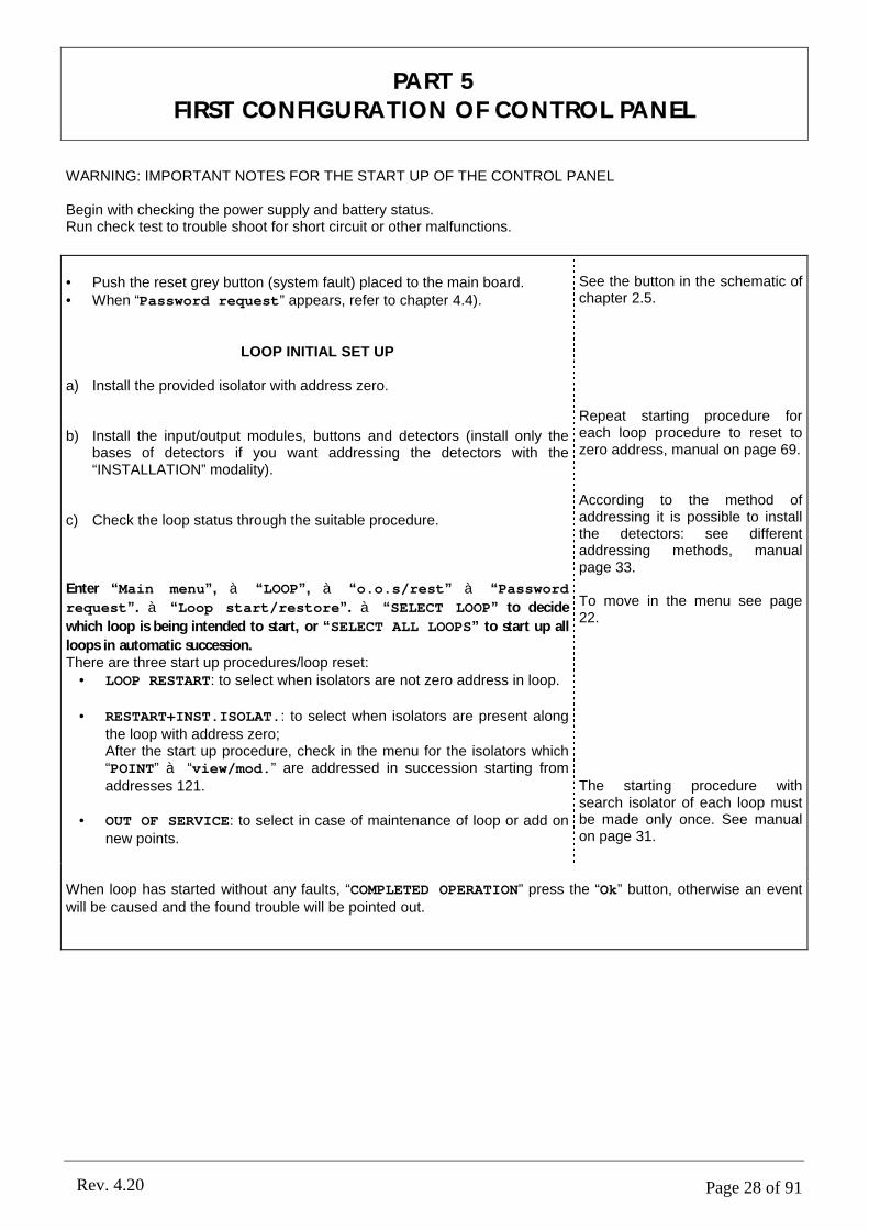
Page 28 of 91Rev. 4.20
WARNING: IMPORTANT NOTES FOR THE START UP OF THE CONTROL PANEL
Begin with checking the power supply and battery status.Run check test to trouble shoot for short circuit or other malfunctions.
• Push the reset grey button (system fault) placed to the main board.• When “Password request” appears, refer to chapter 4.4).
LOOP INITIAL SET UP
a) Install the provided isolator with address zero.
b) Install the input/output modules, buttons and detectors (install only the bases of detectors if you want addressing the detectors with the “INSTALLATION” modality).
c) Check the loop status through the suitable procedure.
Enter “Main menu”, à “LOOP”, à “o.o.s/rest” à “Password
request”. à “Loop start/restore”. à “SELECT LOOP” to decide
which loop is being intended to start, or “SELECT ALL LOOPS” to start up all
loops in automatic succession.There are three start up procedures/loop reset:
• LOOP RESTART: to select when isolators are not zero address in loop.
• RESTART+INST.ISOLAT.: to select when isolators are present along the loop with address zero;After the start up procedure, check in the menu for the isolators which “POINT” à “view/mod.” are addressed in succession starting from addresses 121.
• OUT OF SERVICE: to select in case of maintenance of loop or add on new points.
See the button in the schematic of chapter 2.5.
Repeat starting procedure for each loop procedure to reset to zero address, manual on page 69.
According to the method of addressing it is possible to install the detectors: see different addressing methods, manual page 33.
To move in the menu see page 22.
The starting procedure with search isolator of each loop must be made only once. See manual on page 31.
When loop has started without any faults, “COMPLETED OPERATION” press the “Ok” button, otherwise an event will be caused and the found trouble will be pointed out.
PART 5FIRST CONFIGURATION OF CONTROL PANEL
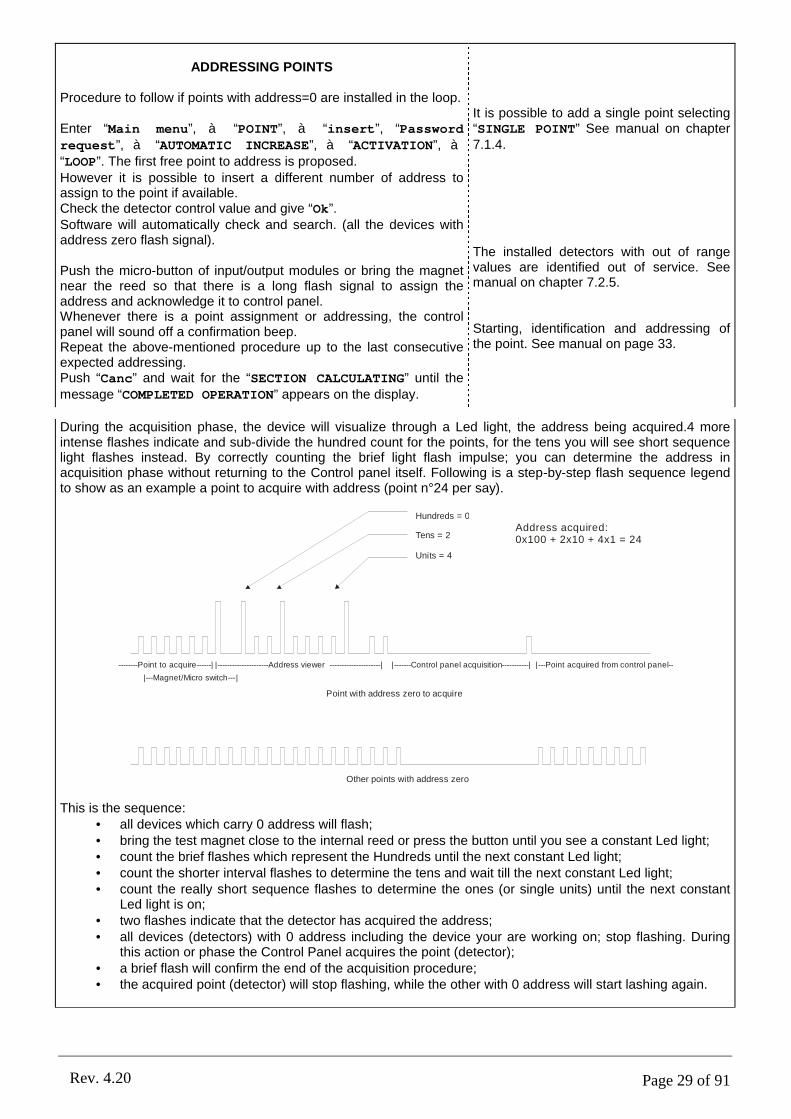
Page 29 of 91Rev. 4.20
ADDRESSING POINTS
Procedure to follow if points with address=0 are installed in the loop.
Enter “Main menu”, à “POINT”, à “insert”, “Password request”, à “AUTOMATIC INCREASE”, à “ACTIVATION”, à“LOOP”. The first free point to address is proposed.However it is possible to insert a different number of address to assign to the point if available.Check the detector control value and give “Ok”.Software will automatically check and search. (all the devices with address zero flash signal).
Push the micro-button of input/output modules or bring the magnet near the reed so that there is a long flash signal to assign the address and acknowledge it to control panel.Whenever there is a point assignment or addressing, the control panel will sound off a confirmation beep.Repeat the above-mentioned procedure up to the last consecutive expected addressing.Push “Canc” and wait for the “SECTION CALCULATING” until the message “COMPLETED OPERATION” appears on the display.
It is possible to add a single point selecting “SINGLE POINT” See manual on chapter 7.1.4.
The installed detectors with out of range values are identified out of service. See manual on chapter 7.2.5.
Starting, identification and addressing of the point. See manual on page 33.
During the acquisition phase, the device will visualize through a Led light, the address being acquired.4 more intense flashes indicate and sub-divide the hundred count for the points, for the tens you will see short sequence light flashes instead. By correctly counting the brief light flash impulse; you can determine the address in acquisition phase without returning to the Control panel itself. Following is a step-by-step flash sequence legend to show as an example a point to acquire with address (point n°24 per say).
Hundreds = 0
Tens = 2
Units = 4
|-------Control panel acquisition-----------||---------------------Address viewer ---------------------|
|---Magnet/Micro switch---|
|---Point acquired from control panel----------Point to acquire------|
Address acquired:0x100 + 2x10 + 4x1 = 24
Other points with address zero
Point with address zero to acquire
This is the sequence:• all devices which carry 0 address will flash;• bring the test magnet close to the internal reed or press the button until you see a constant Led light;• count the brief flashes which represent the Hundreds until the next constant Led light;• count the shorter interval flashes to determine the tens and wait till the next constant Led light;• count the really short sequence flashes to determine the ones (or single units) until the next constant
Led light is on;• two flashes indicate that the detector has acquired the address;• all devices (detectors) with 0 address including the device your are working on; stop flashing. During
this action or phase the Control Panel acquires the point (detector);• a brief flash will confirm the end of the acquisition procedure;• the acquired point (detector) will stop flashing, while the other with 0 address will start lashing again.
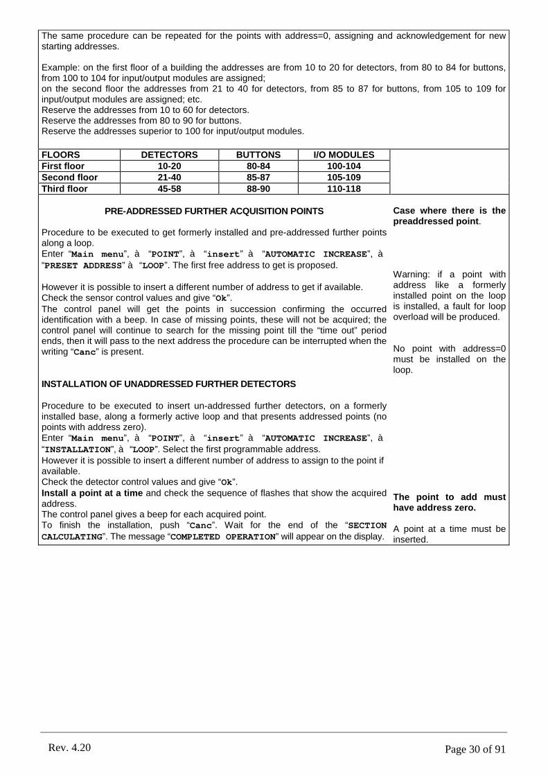
Page 30 of 91Rev. 4.20
The same procedure can be repeated for the points with address=0, assigning and acknowledgement for new starting addresses.
Example: on the first floor of a building the addresses are from 10 to 20 for detectors, from 80 to 84 for buttons, from 100 to 104 for input/output modules are assigned;on the second floor the addresses from 21 to 40 for detectors, from 85 to 87 for buttons, from 105 to 109 for input/output modules are assigned; etc.Reserve the addresses from 10 to 60 for detectors.Reserve the addresses from 80 to 90 for buttons.Reserve the addresses superior to 100 for input/output modules.
FLOORS DETECTORS BUTTONS I/O MODULESFirst floor 10-20 80-84 100-104Second floor 21-40 85-87 105-109Third floor 45-58 88-90 110-118
PRE-ADDRESSED FURTHER ACQUISITION POINTS
Procedure to be executed to get formerly installed and pre-addressed further points along a loop.Enter “Main menu”, à “POINT”, à “insert” à “AUTOMATIC INCREASE”, à“PRESET ADDRESS” à “LOOP”. The first free address to get is proposed.
However it is possible to insert a different number of address to get if available.Check the sensor control values and give “Ok”.The control panel will get the points in succession confirming the occurred identification with a beep. In case of missing points, these will not be acquired; the control panel will continue to search for the missing point till the “time out” period ends, then it will pass to the next address the procedure can be interrupted when the writing “Canc” is present.
INSTALLATION OF UNADDRESSED FURTHER DETECTORS
Procedure to be executed to insert un-addressed further detectors, on a formerly installed base, along a formerly active loop and that presents addressed points (no points with address zero).Enter “Main menu”, à “POINT”, à “insert” à “AUTOMATIC INCREASE”, à“INSTALLATION”, à “LOOP”. Select the first programmable address.However it is possible to insert a different number of address to assign to the point if available.Check the detector control values and give “Ok”.Install a point at a time and check the sequence of flashes that show the acquired address.The control panel gives a beep for each acquired point.To finish the installation, push “Canc”. Wait for the end of the “SECTION CALCULATING”. The message “COMPLETED OPERATION” will appear on the display.
Case where there is the preaddressed point.
Warning: if a point with address like a formerly installed point on the loop is installed, a fault for loop overload will be produced.
No point with address=0 must be installed on the loop.
The point to add must have address zero.
A point at a time must be inserted.

Page 31 of 91Rev. 4.20
PART 6LOOP PROGRAMMING
6.1 LOOP STARTING
6.1.1 Main menu
The starting procedure of each loop must be executed only once.Enter “Main menu” and select “LOOP” using the four arrows placed low on the display.Confirm the made selection to pass to the “Loop menu” with “Sel.”.
6.1.2 Loop menu
Once it has been entered the “Loop menu”, there is only item:
“o.o.s/reset” (out of service/resetting).For the first loop starting and every time that it is necessary the loop restart, “o.o.s/reset” must be selected.
6.1.3 Loop start/restore (loop selection)
When it is necessary to start or reset loop, to enter the menu “Loop start/restore” it is necessary to select “o.k./reset” from the menu. It is now possible to select loop to start or reset, selecting: “SELECT LOOP”, or it is possible to start or reset all the available loops of the control panel selecting “SELECT ALL LOOP”. Confirm the executed selection with “Sel.”. If the user wants to return to the previous menu, select “Canc”.
Main menuPOINT SETTINGZONE CONNECTIONLOOP ACC. LEVELOUTPUT DIAGNOSTICEVENT 3b optionACCESS LEVEL: 1Sel. Esc.
Loop menuo.o.s/reset
ACCESS LEVEL: 1Sel. Back Esc.
Loop start/restore•SELECT LOOPSELECT ALL LOOPS
Sel. Canc

Page 32 of 91Rev. 4.20
6.1.4 Loop start/restore procedure
The menu “Loop start/restore” schedules two procedures of loop starting or resetting and the possibility to place the loop itself out of service (necessary operation in case of maintenance). Starting or resetting procedures of the loop depends on the characteristic of the line:“LOOP RESTART”: to select when isolator along the loop with address 0 are
not present;“RESTART+INST.ISOLAT.”: to select if isolators along the loop with
address 0 are present. In the case they are installed with address beginning from 121. should there be some addressed isolators, they will have to be taken back first to address 0;
“OUT OF SERVICE”: to select in case of maintenance of the loop or the installed points.
6.1.5 Information
Once the loop resetting or starting procedure has been selected and has been confirmed with “Sel.”, the control panel starts the loop control, scanning from point a (control panel starting) to the first possible isolator (point 121-127) and in succession among isolators, as far as point B (control panel arrival). Afterwards it will scan the loop inversely from point B to point A. after the control, loop is activated. After the operation is ended, the control panel passes to the confirmation menu.
6.1.6 Confirmation
After loop resetting or starting operation is completed, the message “COMPLETED OPERATION” is read on the display. Confirm with key “Ok” to complete the loop resetting or starting.
6.2 LOOP OUT OF SERVICE
6.2.1 Loop start/restore procedure
If the user wants to put a loop or all loops in out of service, the user must access to “Loop start/restore” menu and to select “OUT OF
SERVICE”. To access at this menu see chapter 6.1.1t until 6.1.3.The loop in out of service has 0V on the cables.
Loop start/restore•LOOP RESTARTRESTART+INST.ISOLAT.OUT OF SERVICE
Sel. Canc
Information•OPER.: STARTLOOP: 1STEP: LOOP DISCHARG.DIRECTION: A->B
Information
COMPLETED OPERATION
Ok.
Loop start/restoreLOOP RESTARTRESTART+INST.ISOLAT.•OUT OF SERVICE
Sel. Canc
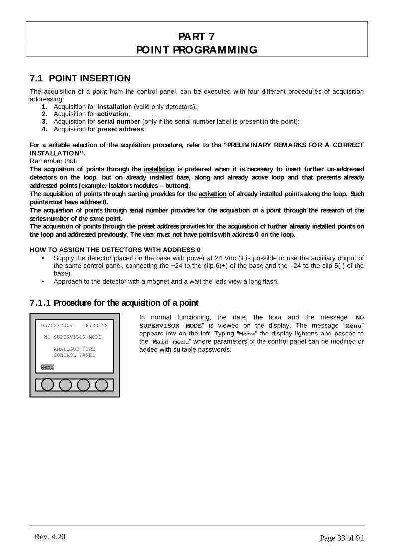
Page 33 of 91Rev. 4.20
PART 7POINT PROGRAMMING
7.1 POINT INSERTION
The acquisition of a point from the control panel, can be executed with four different procedures of acquisition addressing:
1. Acquisition for installation (valid only detectors);2. Acquisition for activation;3. Acquisition for serial number (only if the serial number label is present in the point);4. Acquisition for preset address.
For a suitable selection of the acquisition procedure, refer to the “PRELIMINARY REMARKS FOR A CORRECT INSTALLATION”.Remember that:The acquisition of points through the installation is preferred when it is necessary to insert further un-addressed detectors on the loop, but on already installed base, along and already active loop and that presents already
addressed points (example: isolators modules – buttons).The acquisition of points through starting provides for the activation of already installed points along the loop. Such points must have address 0.The acquisition of points through serial number provides for the acquisition of a point through the research of the
series number of the same point.The acquisition of points through the preset address provides for the acquisition of further already installed points on the loop and addressed previously. The user must not have points with address 0 on the loop.
HOW TO ASSIGN THE DETECTORS WITH ADDRESS 0• Supply the detector placed on the base with power at 24 Vdc (it is possible to use the auxiliary output of
the same control panel, connecting the +24 to the clip 6(+) of the base and the –24 to the clip 5(-) of the base).
• Approach to the detector with a magnet and a wait the leds view a long flash.
7.1.1 Procedure for the acquisition of a point
In normal functioning, the date, the hour and the message “NO SUPERVISOR MODE” is viewed on the display. The message “Menu” appears low on the left. Typing “Menu” the display lightens and passes to the “Main menu” where parameters of the control panel can be modified or added with suitable passwords.
05/02/2007 18:30:58
NO SUPERVISOR MODE
ANALOGUE FIRECONTROL PANEL
Menu

Page 34 of 91Rev. 4.20
7.1.2 Main menu
After the user has entered the “Main menu”, to add some points (detectors,
modules, buttons), it is necessary to select “POINT” using the four arrows
placed low on the display.Confirm the made selection with “Sel.”.
7.1.3 Point menu
After the user has entered the “Point menu”, to add further points (detectors, modules, buttons), it is necessary to select “insert”. Select “Back” to return to the “Main menu”. Select “Esc”, to go out completely.
7.1.4 Address assignation
In the address “Address assignation” the programming procedure is decided:
• Select “SINGLE POINT” to programme one only point;
• Select “AUTOMATIC INCREASE” to programme more points in succession.
Use the four arrows to set oneself on the line that shows the type of address assignment the user wants to select and confirm with “Sel.”. Type in “Del.” to return to the “Point menu”.
7.1.5 Type of point acquisition
After the user has entered the “Point acquisition” menu the acquisition procedure of the point can be decided:
• For “INSTALLATION”;
• For “ACTIVATION”;
• For “SERIAL NUMBER”;
• For “PRESET ADDRESS”.Use the four arrows to set oneself on the line that shows the type of address assignment the user wants to select and confirm with “Sel.”. Type in
“Del.” to return to “Point menu”. Refer to chapter 7.1 for further description of the items.
Main menuPOINT SETTINGZONE CONNECTIONLOOP ACC. LEVELOUTPUT DIAGNOSTICEVENT 3b optionACCESS LEVEL: 1Sel. Esc.
Point menuview/mod.insertremoved.b.reset
ACCESS LEVEL: 1Sel. Back Esc.
Address assignation•SINGLE POINTAUTOMATIC INCREASE
Sel. Del.
Point acquisition•INSTALLATIONACTIVATIONSERIAL NUMBERPRESET ADDRESS
Sel. Del.

Page 35 of 91Rev. 4.20
7.1.6 Loop selection
Select the “Loop” to programme and confirm with “Sel.”, use the four arrows to set oneself on the line that shows the loop the user wants to programme and select and confirm with “Sel.”. Type in “Canc” to return to the “Point menu”.
7.1.7 Point address selection
The control panel supplies the first free address to programme, relative to the selected loop. Through the numerical keyboard it is possible to assign a different number of address. Select “Sel.” to pass to the programming.
7.1.8 Detectors check values
The values assigned to the default detectors correspond to the current norms (EN 54). However, for particular positions of the points, it is possible to modify the levels of smoke and temperature alarm test, that the control panel tests during the acquisition of a detector (it is not possible to modify the levels of the single detectors). The control panel controls for every detector that the value of smoke and temperature measured during the acquisition step is comprised between the levels visualizes on the display. Set yourself on the line and select “Mod.”. The data are modified with the numerical keyboard. At the end of the possible modifications, confirm with “Ok” to pass to the next menu.
7.1.9 Points Acquisition Modes: installer, activation and pre-set address
When the menu of point control values has been confirmed, the control panel passes to the “Information” menu and begins the pre-selected point research. The location procedure of the point depends on the selection of the acquisition way.The acquisition selection for “INSTALLATION” provides to insert the sensor on the base.The acquisition selection for “ACTIVATION” provides to press the micro button of the modules or to get near with the magnet to activate the read of the detectors.The acquisition selection for “PRESET ADDRESS” provides to address the points previously.Press “Canc” to finish the search.
Loop selection•LOOP 1LOOP 2LOOP 3LOOP 4
Sel. Canc
Point addr. select.
ADDRESS: 001
Ok. Canc
Detect. checkvalues•Min.TEMPERAT.°C: 015Max.TEMPERAT.°C: 025Min.SMOKE(0-255):000Max.SMOKE(0-255):020
Ok. Mod. Del.
Information•OPER.: POINT SEARCHPOINT: 001-1
Canc
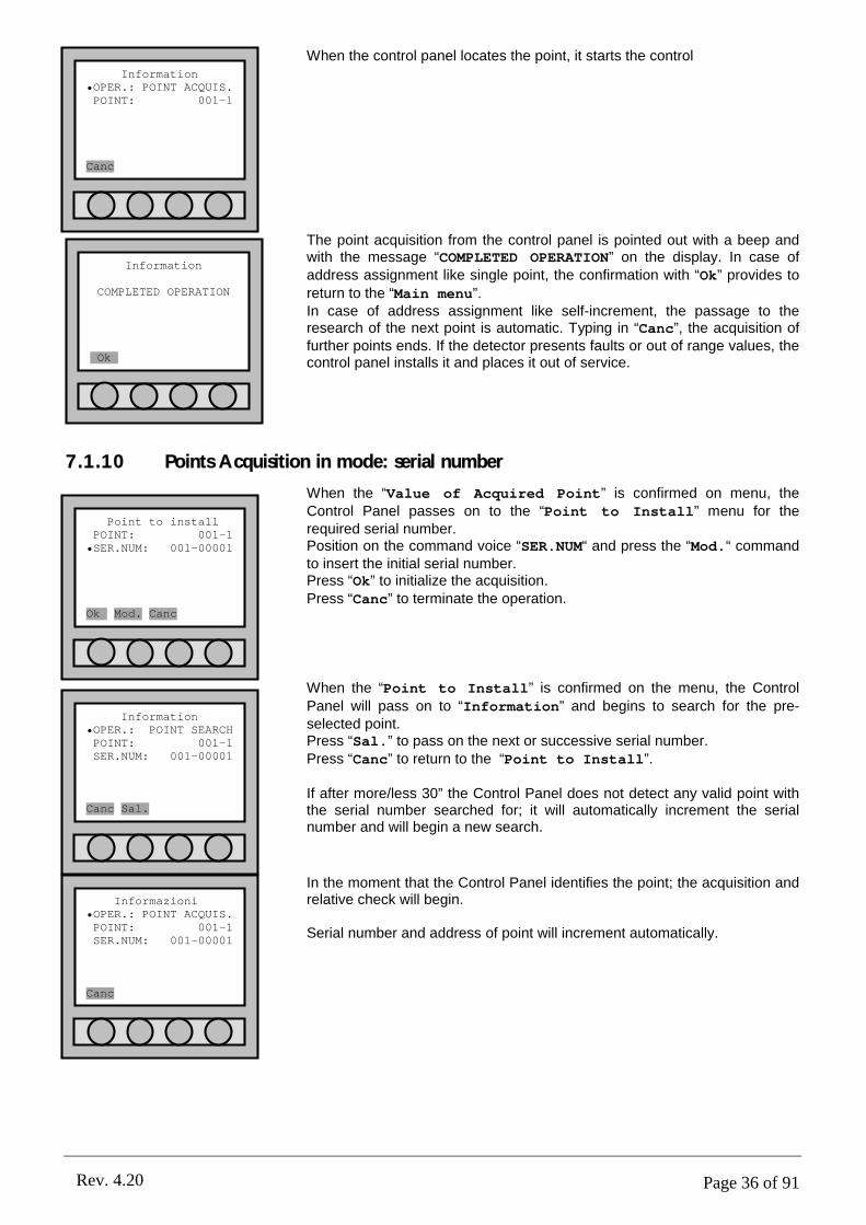
Page 36 of 91Rev. 4.20
When the control panel locates the point, it starts the control
The point acquisition from the control panel is pointed out with a beep and with the message “COMPLETED OPERATION” on the display. In case of address assignment like single point, the confirmation with “Ok” provides to
return to the “Main menu”.In case of address assignment like self-increment, the passage to the research of the next point is automatic. Typing in “Canc”, the acquisition of further points ends. If the detector presents faults or out of range values, the control panel installs it and places it out of service.
7.1.10 Points Acquisition in mode: serial number
When the “Value of Acquired Point” is confirmed on menu, the Control Panel passes on to the “Point to Install” menu for the required serial number. Position on the command voice “SER.NUM“ and press the “Mod.“ command to insert the initial serial number.Press “Ok” to initialize the acquisition.Press “Canc” to terminate the operation.
When the “Point to Install” is confirmed on the menu, the Control
Panel will pass on to “Information” and begins to search for the pre-selected point.Press “Sal.” to pass on the next or successive serial number.Press “Canc” to return to the “Point to Install”.
If after more/less 30” the Control Panel does not detect any valid point with the serial number searched for; it will automatically increment the serial number and will begin a new search.
In the moment that the Control Panel identifies the point; the acquisition and relative check will begin.
Serial number and address of point will increment automatically.
Information
COMPLETED OPERATION
Ok.
Information•OPER.: POINT ACQUIS.POINT: 001-1
Canc
Information•OPER.: POINT SEARCHPOINT: 001-1SER.NUM: 001-00001
Canc Sal.
Informazioni•OPER.: POINT ACQUIS.POINT: 001-1SER.NUM: 001-00001
Canc
Point to installPOINT: 001-1•SER.NUM: 001-00001
Ok. Mod. Canc
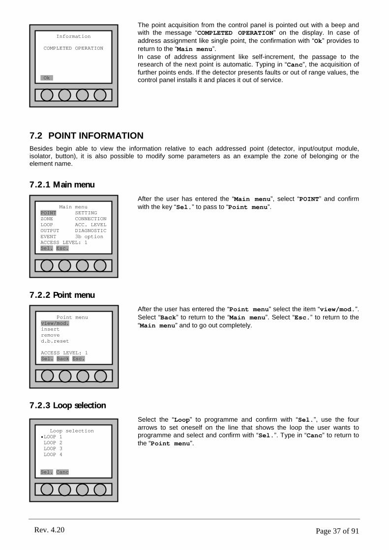
Page 37 of 91Rev. 4.20
The point acquisition from the control panel is pointed out with a beep and with the message “COMPLETED OPERATION” on the display. In case of address assignment like single point, the confirmation with “Ok” provides to return to the “Main menu”.In case of address assignment like self-increment, the passage to the research of the next point is automatic. Typing in “Canc”, the acquisition of further points ends. If the detector presents faults or out of range values, the control panel installs it and places it out of service.
7.2 POINT INFORMATION
Besides begin able to view the information relative to each addressed point (detector, input/output module, isolator, button), it is also possible to modify some parameters as an example the zone of belonging or the element name.
7.2.1 Main menu
After the user has entered the “Main menu”, select “POINT” and confirm with the key “Sel.” to pass to “Point menu”.
7.2.2 Point menu
After the user has entered the “Point menu” select the item “view/mod.”.
Select “Back” to return to the “Main menu”. Select “Esc.” to return to the “Main menu” and to go out completely.
7.2.3 Loop selection
Select the “Loop” to programme and confirm with “Sel.”, use the four arrows to set oneself on the line that shows the loop the user wants to programme and select and confirm with “Sel.”. Type in “Canc” to return to the “Point menu”.
Main menuPOINT SETTINGZONE CONNECTIONLOOP ACC. LEVELOUTPUT DIAGNOSTICEVENT 3b optionACCESS LEVEL: 1Sel. Esc.
Point menuview/mod.insertremoved.b.reset
ACCESS LEVEL: 1Sel. Back Esc.
Loop selection•LOOP 1LOOP 2LOOP 3LOOP 4
Sel. Canc
Information
COMPLETED OPERATION
Ok.
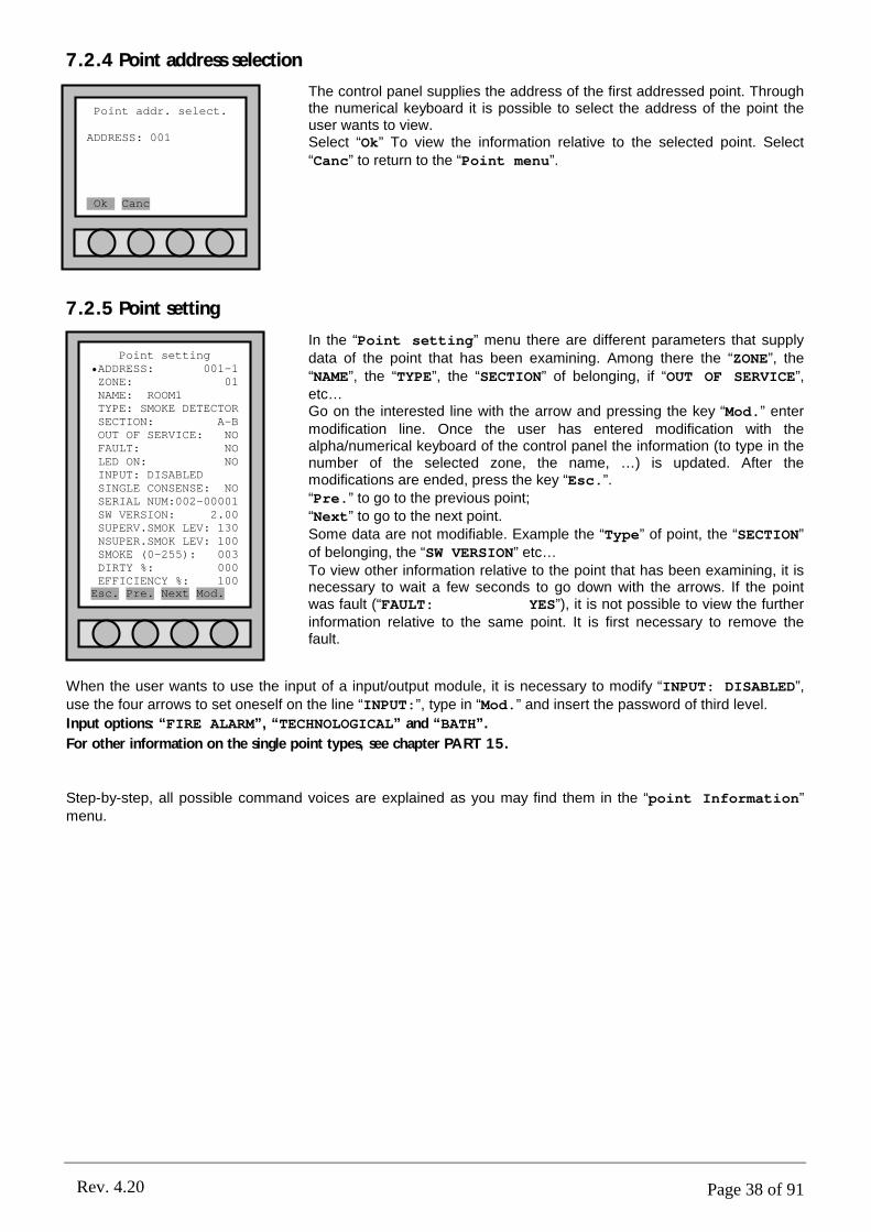
Page 38 of 91Rev. 4.20
7.2.4 Point address selection
The control panel supplies the address of the first addressed point. Through the numerical keyboard it is possible to select the address of the point the user wants to view.Select “Ok” To view the information relative to the selected point. Select “Canc” to return to the “Point menu”.
7.2.5 Point setting
In the “Point setting” menu there are different parameters that supply data of the point that has been examining. Among there the “ZONE”, the “NAME”, the “TYPE”, the “SECTION” of belonging, if “OUT OF SERVICE”, etc…Go on the interested line with the arrow and pressing the key “Mod.” enter modification line. Once the user has entered modification with the alpha/numerical keyboard of the control panel the information (to type in the number of the selected zone, the name, …) is updated. After the modifications are ended, press the key “Esc.”.“Pre.” to go to the previous point;“Next” to go to the next point.Some data are not modifiable. Example the “Type” of point, the “SECTION” of belonging, the “SW VERSION” etc…To view other information relative to the point that has been examining, it is necessary to wait a few seconds to go down with the arrows. If the point was fault (“FAULT: YES”), it is not possible to view the further information relative to the same point. It is first necessary to remove the fault.
When the user wants to use the input of a input/output module, it is necessary to modify “INPUT: DISABLED”,
use the four arrows to set oneself on the line “INPUT:”, type in “Mod.” and insert the password of third level.
Input options: “FIRE ALARM”, “TECHNOLOGICAL” and “BATH”.
For other information on the single point types, see chapter PART 15.
Step-by-step, all possible command voices are explained as you may find them in the “point Information” menu.
Point addr. select.
ADDRESS: 001
Ok. Canc
Point setting•ADDRESS: 001-1ZONE: 01NAME: ROOM1TYPE: SMOKE DETECTORSECTION: A-BOUT OF SERVICE: NOFAULT: NOLED ON: NOINPUT: DISABLEDSINGLE CONSENSE: NOSERIAL NUM:002-00001SW VERSION: 2.00SUPERV.SMOK LEV: 130NSUPER.SMOK LEV: 100SMOKE (0-255): 003DIRTY %: 000EFFICIENCY %: 100Esc. Pre. Next Mod.
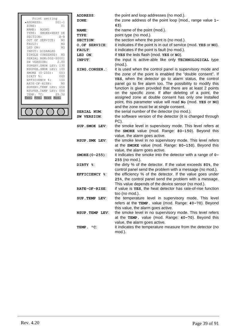
Page 39 of 91Rev. 4.20
ADDRESS: the point and loop addresses (no mod.).ZONE: the zone address of the point loop (mod., range value 1-
63).NAME: the name of the point (mod.).
TYPE: point type (no mod.).SECTION: the section where the point is (no mod.).O.OF SERVICE: it indicates if the point is in out of service (mod. YES or NO).FAULT: it indicates if the point is fault (no mod.).LED ON: if YES the leds flash (mod. YES or NO).
INPUT: the input is active-able like only TECHNOLOGICAL type (mod.).
SING.CONSEN.: it is used when the control panel is supervisory mode and the zone of the point is enabled the "double consent". If YES, when the detector go to alarm status, the control panel go to fire alarm too. The possibility to modify this function is given provided that there are at least 2 points on the specific zone. If after deleting of a point, the assigned zone at double consent has only one installed point, this parameter value will read No (mod. YES or NO) and the zone must be at single consent.
SERIAL NUM: the serial number of the detector (no mod.).SW VERSION: the software version of the detector (it is changed through
PC).SUP.SMOK LEV: the smoke level in supervisory mode. This level refers at
the SMOKE value (mod. Range: 80-150). Beyond this value, the alarm goes active.
NSUP.SMK LEV: the smoke level in no supervisory mode. This level refers at the SMOKE value (mod. Range: 80-150). Beyond this value, the alarm goes active.
SMOKE(0-255): it indicates the smoke into the detector with a range of 0-255 (no mod.).
DIRTY %: the dirty % of the detector. If the value exceeds 80%, the control panel send the problem with a message (no mod.).
EFFICIENCY %: the efficiency % of the detector. If the value goes under 25%, the control panel send the problem with a message. This value depends of the device sensor (no mod.).
RATE-OF-RISE: if value is YES, the heat detector has rate-of-rise function too (no mod.).
SUP.TEMP LEV: the temperature level in supervisory mode. This level
refers at the TEMP. value (mod. Range: 40-70). Beyond this value, the alarm goes active.
NSUP.TEMP LEV: the smoke level in no supervisory mode. This level refers at the TEMP. value (mod. Range: 40-70). Beyond this value, the alarm goes active.
TEMP. °C: it indicates the temperature measure from the detector (no mod.).
Point setting•ADDRESS: 001-1ZONE: 01NAME: ROOM1TYPE: SMOKE+HEAT DESECTION: A-BOUT OF SERVICE: NOFAULT: NOLED ON: NOINPUT: DISABLEDSINGLE CONSENSE: NOSERIAL NUM:002-00001SW VERSION: 2.00SUPERV.SMOK LEV: 130NSUPER.SMOK LEV: 100SMOKE (0-255): 003DIRTY %: 000EFFICIENCY %: 100RATE-OF-RISE: NOSUPERV.TEMP LEV: 058NSUPER.TEMP LEV: 056TEMP. °C: 25.32Esc. Pre. Next Mod.
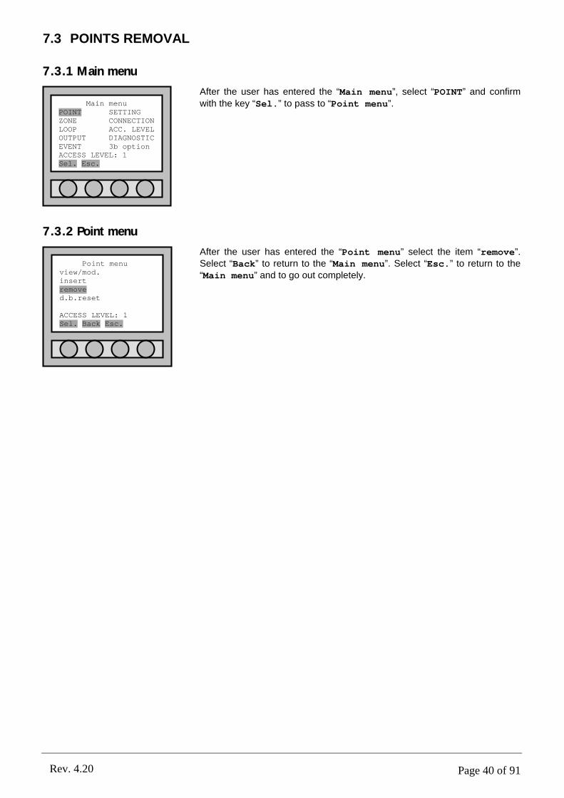
Page 40 of 91Rev. 4.20
7.3 POINTS REMOVAL
7.3.1 Main menu
After the user has entered the “Main menu”, select “POINT” and confirm
with the key “Sel.” to pass to “Point menu”.
7.3.2 Point menu
After the user has entered the “Point menu” select the item “remove”. Select “Back” to return to the “Main menu”. Select “Esc.” to return to the “Main menu” and to go out completely.
Main menuPOINT SETTINGZONE CONNECTIONLOOP ACC. LEVELOUTPUT DIAGNOSTICEVENT 3b optionACCESS LEVEL: 1Sel. Esc.
Point menuview/mod.insertremoved.b.reset
ACCESS LEVEL: 1Sel. Back Esc.
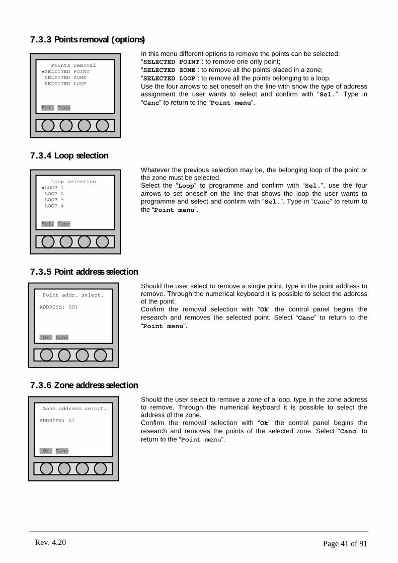
Page 41 of 91Rev. 4.20
7.3.3 Points removal (options)
In this menu different options to remove the points can be selected:“SELECTED POINT”: to remove one only point;“SELECTED ZONE”: to remove all the points placed in a zone;“SELECTED LOOP”: to remove all the points belonging to a loop.Use the four arrows to set oneself on the line with show the type of address assignment the user wants to select and confirm with “Sel.”. Type in
“Canc” to return to the “Point menu”.
7.3.4 Loop selection
Whatever the previous selection may be, the belonging loop of the point or the zone must be selected.Select the “Loop” to programme and confirm with “Sel.”, use the four arrows to set oneself on the line that shows the loop the user wants to programme and select and confirm with “Sel.”. Type in “Canc” to return to the “Point menu”.
7.3.5 Point address selection
Should the user select to remove a single point, type in the point address to remove. Through the numerical keyboard it is possible to select the address of the point.Confirm the removal selection with “Ok” the control panel begins the research and removes the selected point. Select “Canc” to return to the
“Point menu”.
7.3.6 Zone address selection
Should the user select to remove a zone of a loop, type in the zone address to remove. Through the numerical keyboard it is possible to select the address of the zone.Confirm the removal selection with “Ok” the control panel begins the research and removes the points of the selected zone. Select “Canc” to return to the “Point menu”.
Point addr. select.
ADDRESS: 001
Ok. Canc
Points removal•SELECTED POINTSELECTED ZONESELECTED LOOP
Sel. Canc
Loop selection•LOOP 1LOOP 2LOOP 3LOOP 4
Sel. Canc
Zone address select.
ADDRESS: 01
Ok. Canc

Page 42 of 91Rev. 4.20
8.1 DETAILS
It is possible to define 63 zones per loop. Every zone is independent from the zones of the other loops.
8.2 ZONE CREATION
It is not necessary to define a new zone; it is sufficient to assign a point to the new zone that the user wants to create.
To do this, it is necessary to modify the value of the zone in the “Point setting” menu (see the chapter 7.2.5).
8.3 ZONE SETTING
8.3.1 Main menu
After the user has entered the “Main menu”, select “ZONE” and confirm with
the key “Sel.” to pass to “Zone menu”.
8.3.2 Zone menu
After the user has entered the “Zone menu” select the item “view/mod.”. Select “Back” to return to the “Main menu”. Select “Esc.”.
PART 8ZONE PROGRAMMING
Main menuPOINT SETTINGZONE CONNECTIONLOOP ACC. LEVELOUTPUT DIAGNOSTICEVENT 3b optionACCESS LEVEL: 1Sel. Esc.
Zone menuview/mod.
ACCESS LEVEL: 1Sel. Back Esc.
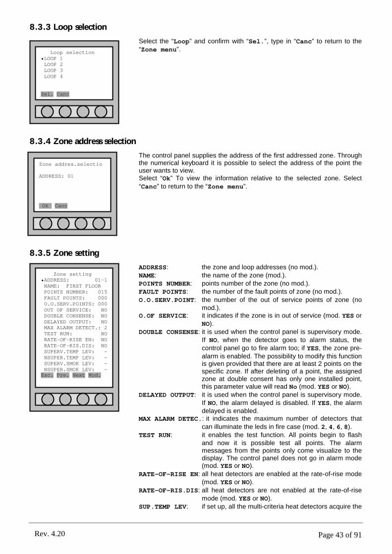
Page 43 of 91Rev. 4.20
8.3.3 Loop selection
Select the “Loop” and confirm with “Sel.”, type in “Canc” to return to the “Zone menu”.
8.3.4 Zone address selection
The control panel supplies the address of the first addressed zone. Through the numerical keyboard it is possible to select the address of the point the user wants to view.Select “Ok” To view the information relative to the selected zone. Select “Canc” to return to the “Zone menu”.
8.3.5 Zone setting
ADDRESS: the zone and loop addresses (no mod.).NAME: the name of the zone (mod.).POINTS NUMBER: points number of the zone (no mod.).FAULT POINTS: the number of the fault points of zone (no mod.).
O.O.SERV.POINT: the number of the out of service points of zone (no mod.).
O.OF SERVICE: it indicates if the zone is in out of service (mod. YES or NO).
DOUBLE CONSENSE: it is used when the control panel is supervisory mode. If NO, when the detector goes to alarm status, the control panel go to fire alarm too; if YES, the zone pre-alarm is enabled. The possibility to modify this function is given provided that there are at least 2 points on the specific zone. If after deleting of a point, the assigned zone at double consent has only one installed point, this parameter value will read No (mod. YES or NO).
DELAYED OUTPUT: it is used when the control panel is supervisory mode. If NO, the alarm delayed is disabled. If YES, the alarm delayed is enabled.
MAX ALARM DETEC.: it indicates the maximum number of detectors that
can illuminate the leds in fire case (mod. 2, 4, 6, 8).TEST RUN: it enables the test function. All points begin to flash
and now it is possible test all points. The alarm messages from the points only come visualize to the display. The control panel does not go in alarm mode (mod. YES or NO).
RATE-OF-RISE EN: all heat detectors are enabled at the rate-of-rise mode (mod. YES or NO).
RATE-OF-RIS.DIS: all heat detectors are not enabled at the rate-of-rise mode (mod. YES or NO).
SUP.TEMP LEV: if set up, all the multi-criteria heat detectors acquire the
Loop selection•LOOP 1LOOP 2LOOP 3LOOP 4
Sel. Canc
Zone addres.selectio
ADDRESS: 01
Ok. Canc
Zone setting•ADDRESS: 01-1NAME: FIRST FLOORPOINTS NUMBER: 015FAULT POINTS: 000O.O.SERV.POINTS: 000OUT OF SERVICE: NODOUBLE CONSENSE: NODELAYED OUTPUT: NOMAX ALARM DETECT.: 2TEST RUN: NORATE-OF-RISE EN: NORATE-OF-RIS.DIS: NOSUPERV.TEMP LEV: -NSUPER.TEMP LEV: -SUPERV.SMOK LEV: -NSUPER.SMOK LEV: -Esc. Pre. Next Mod.

Page 44 of 91Rev. 4.20
temperature level in no supervisory mode on this reported value. Beyond this value, the alarm go active (mod. Range: 40°-70°).
NSUP.TEMP LEV: if set up, all the multi-criteria heat detectors acquire the temperature level in no supervisory mode on this reported value. Beyond this value, the alarm go active (mod. Range: 40°-70°).
SUP.SMOK LEV: if set up, all the multi-criteria smoke detectors acquire the smoke level in supervisory mode on this reported value. This level refers at the SMOKE value (mod. Range: 80-150). Beyond this value, the alarm goes active.
NSUP.SMK LEV: if set up, all the multi-criteria smoke detectors acquire the smoke level in no supervisory mode on this reported value. This level refers at the SMOKE value (mod. Range: 80-150). Beyond this value, the alarm goes active.
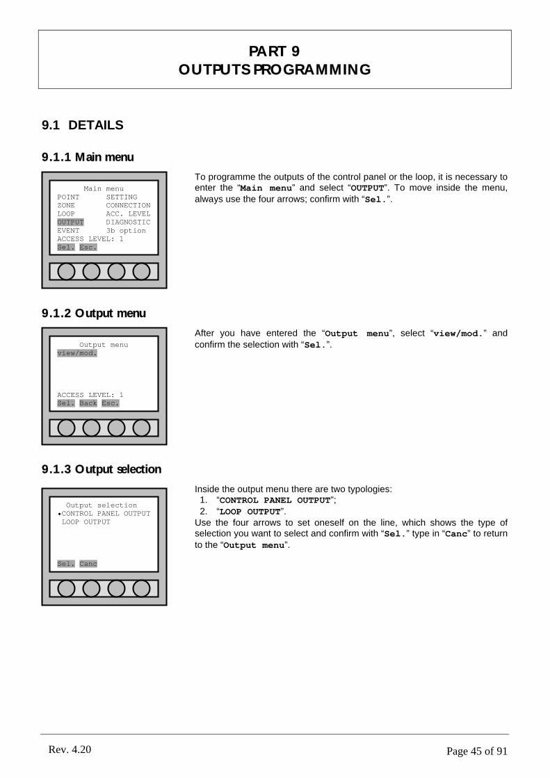
Page 45 of 91Rev. 4.20
9.1 DETAILS
9.1.1 Main menu
To programme the outputs of the control panel or the loop, it is necessary to enter the “Main menu” and select “OUTPUT”. To move inside the menu, always use the four arrows; confirm with “Sel.”.
9.1.2 Output menu
After you have entered the “Output menu”, select “view/mod.” and confirm the selection with “Sel.”.
9.1.3 Output selection
Inside the output menu there are two typologies:1. “CONTROL PANEL OUTPUT”;2. “LOOP OUTPUT”.
Use the four arrows to set oneself on the line, which shows the type of selection you want to select and confirm with “Sel.” type in “Canc” to return to the “Output menu”.
PART 9OUTPUTS PROGRAMMING
Main menuPOINT SETTINGZONE CONNECTIONLOOP ACC. LEVELOUTPUT DIAGNOSTICEVENT 3b optionACCESS LEVEL: 1Sel. Esc.
Output menuview/mod.
ACCESS LEVEL: 1Sel. Back Esc.
Output selection•CONTROL PANEL OUTPUTLOOP OUTPUT
Sel. Canc
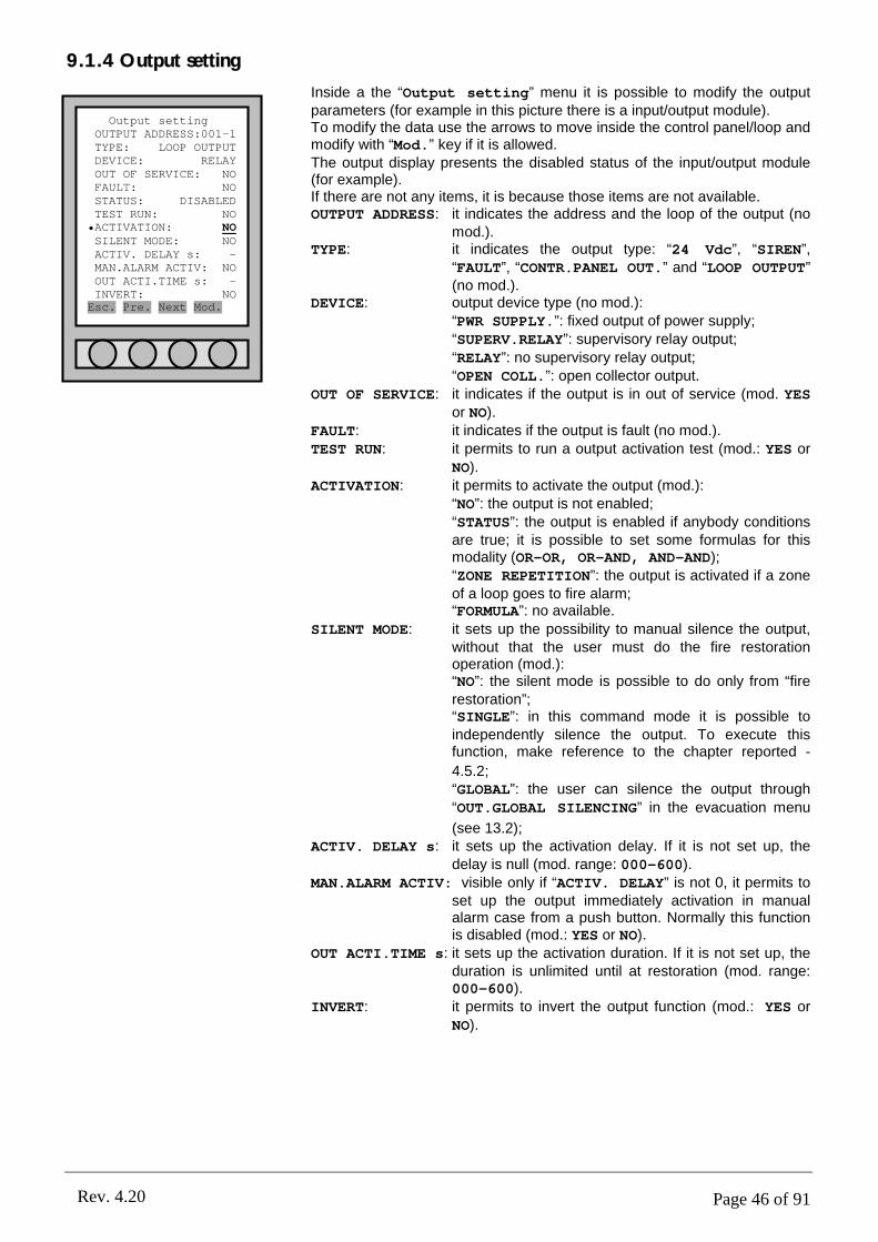
Page 46 of 91Rev. 4.20
9.1.4 Output setting
Inside a the “Output setting” menu it is possible to modify the output parameters (for example in this picture there is a input/output module).To modify the data use the arrows to move inside the control panel/loop and modify with “Mod.” key if it is allowed.The output display presents the disabled status of the input/output module (for example).If there are not any items, it is because those items are not available.OUTPUT ADDRESS: it indicates the address and the loop of the output (no
mod.).TYPE: it indicates the output type: “24 Vdc”, “SIREN”,
“FAULT”, “CONTR.PANEL OUT.” and “LOOP OUTPUT” (no mod.).
DEVICE: output device type (no mod.):“PWR SUPPLY.”: fixed output of power supply;“SUPERV.RELAY”: supervisory relay output;
“RELAY”: no supervisory relay output;“OPEN COLL.”: open collector output.
OUT OF SERVICE: it indicates if the output is in out of service (mod. YESor NO).
FAULT: it indicates if the output is fault (no mod.).TEST RUN: it permits to run a output activation test (mod.: YES or
NO).ACTIVATION: it permits to activate the output (mod.):
“NO”: the output is not enabled;“STATUS”: the output is enabled if anybody conditions are true; it is possible to set some formulas for this modality (OR-OR, OR-AND, AND-AND);“ZONE REPETITION”: the output is activated if a zone of a loop goes to fire alarm;“FORMULA”: no available.
SILENT MODE: it sets up the possibility to manual silence the output, without that the user must do the fire restoration operation (mod.):“NO”: the silent mode is possible to do only from “fire restoration”;“SINGLE”: in this command mode it is possible to independently silence the output. To execute this function, make reference to the chapter reported -
4.5.2;“GLOBAL”: the user can silence the output through
“OUT.GLOBAL SILENCING” in the evacuation menu
(see 13.2);ACTIV. DELAY s: it sets up the activation delay. If it is not set up, the
delay is null (mod. range: 000-600).MAN.ALARM ACTIV: visible only if “ACTIV. DELAY” is not 0, it permits to
set up the output immediately activation in manual alarm case from a push button. Normally this function is disabled (mod.: YES or NO).
OUT ACTI.TIME s: it sets up the activation duration. If it is not set up, the duration is unlimited until at restoration (mod. range: 000-600).
INVERT: it permits to invert the output function (mod.: YES or
NO).
Output settingOUTPUT ADDRESS:001-1TYPE: LOOP OUTPUTDEVICE: RELAYOUT OF SERVICE: NOFAULT: NOSTATUS: DISABLEDTEST RUN: NO•ACTIVATION: NOSILENT MODE: NOACTIV. DELAY s: -MAN.ALARM ACTIV: NOOUT ACTI.TIME s: -INVERT: NOEsc. Pre. Next Mod.
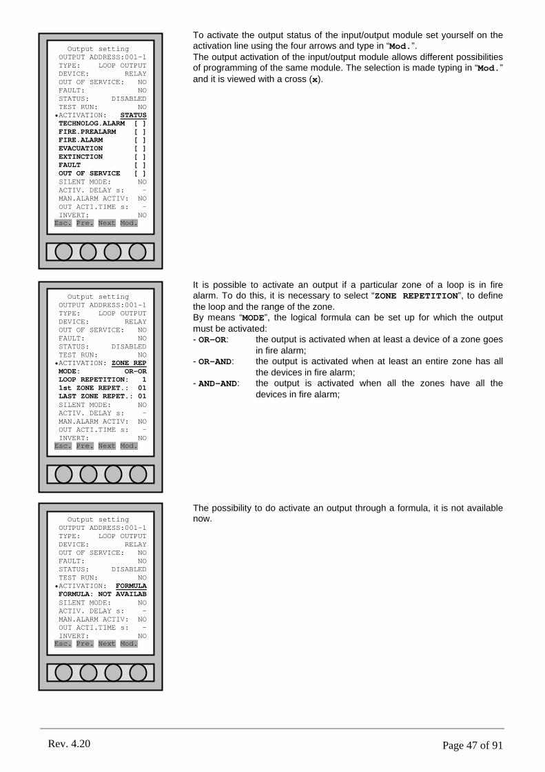
Page 47 of 91Rev. 4.20
To activate the output status of the input/output module set yourself on the activation line using the four arrows and type in “Mod.”.The output activation of the input/output module allows different possibilities of programming of the same module. The selection is made typing in “Mod.” and it is viewed with a cross (x).
It is possible to activate an output if a particular zone of a loop is in fire alarm. To do this, it is necessary to select “ZONE REPETITION”, to define the loop and the range of the zone.By means “MODE”, the logical formula can be set up for which the outputmust be activated:- OR-OR: the output is activated when at least a device of a zone goes
in fire alarm;- OR-AND: the output is activated when at least an entire zone has all
the devices in fire alarm;- AND-AND: the output is activated when all the zones have all the
devices in fire alarm;
The possibility to do activate an output through a formula, it is not available now.Output setting
OUTPUT ADDRESS:001-1TYPE: LOOP OUTPUTDEVICE: RELAYOUT OF SERVICE: NOFAULT: NOSTATUS: DISABLEDTEST RUN: NO•ACTIVATION: FORMULAFORMULA: NOT AVAILABSILENT MODE: NOACTIV. DELAY s: -MAN.ALARM ACTIV: NOOUT ACTI.TIME s: -INVERT: NOEsc. Pre. Next Mod.
Output settingOUTPUT ADDRESS:001-1TYPE: LOOP OUTPUTDEVICE: RELAYOUT OF SERVICE: NOFAULT: NOSTATUS: DISABLEDTEST RUN: NO•ACTIVATION: STATUSTECHNOLOG.ALARM [ ]FIRE.PREALARM [ ]FIRE.ALARM [ ]EVACUATION [ ]EXTINCTION [ ]FAULT [ ] OUT OF SERVICE [ ]SILENT MODE: NOACTIV. DELAY s: -MAN.ALARM ACTIV: NOOUT ACTI.TIME s: -INVERT: NOEsc. Pre. Next Mod.
Output settingOUTPUT ADDRESS:001-1TYPE: LOOP OUTPUTDEVICE: RELAYOUT OF SERVICE: NOFAULT: NOSTATUS: DISABLEDTEST RUN: NO•ACTIVATION: ZONE REPMODE: OR-ORLOOP REPETITION: 11st ZONE REPET.: 01LAST ZONE REPET.: 01SILENT MODE: NOACTIV. DELAY s: -MAN.ALARM ACTIV: NOOUT ACTI.TIME s: -INVERT: NOEsc. Pre. Next Mod.

Page 48 of 91Rev. 4.20
Output setting •OUTPUT ADDRESS: 002TYPE: SIRENDEVICE: SUPERV.RELAYOUT OF SERVICE: NOFAULT: NOSTATUS: DISABLEDTEST RUN: NOACTIV. DELAY s: -MAN.ALARM ACTIV: NOOUT ACTI.TIME s: -INVERT: NOEsc. Pre. Next Mod.
Output setting •OUTPUT ADDRESS: 001TYPE: 24 VdcDEVICE: PWR SUPPLY.OUT OF SERVICE: NOFAULT: NO
Esc. Pre. Next Mod.
9.2 CONTROL PANEL OUTPUT
9.2.1 Output description
Selecting “CONTROL PANEL OUTPUT” the outputs inside the control panel will be able to be programmed as follows:
Ø (out5) Clips RL1 (SEL4): relay 1 is a clean relay no supervised that can be programmed NO/NC;Ø (out4) Clips RL2 (SEL3): relay 1 is a clean relay no supervised that can be programmed NO/NC;Ø (out9) Clips OC4: open collector No 4 programmable for typology of alarm and zone;Ø (out8) Clips OC3: open collector No 3 programmable for typology of alarm and zone;Ø (out7) Clips OC2: open collector No 2 programmable for typology of alarm and zone;Ø (out6) Clips OC1: open collector No 1 programmable for typology of alarm and zone;Ø (out3) Clips FAULT (SEL1,2): supervised output of fault;Ø (out2) Clips –S +S: supervised siren;Ø (out1) Clips +24 –24: auxiliary power supply 24Vdc.
5 4 9 8 7 6 3 2 1
OUTPUTS ADDRESS
-24
+24
SH
I
+S
-S- +FAULT
SH
I
OC
1
OC
2
OC
3
OC
4RL2RL1
SEL4
SEL3
SEL1
SEL2
9.2.2 24Vdc output
It is a power supply output of 24Vdc.
For the information about the menu items, to see the chapter 9.1.4.
9.2.3 Siren output
It is a output of supervisory type siren.
For the information about the menu items, to see the chapter 9.1.4.
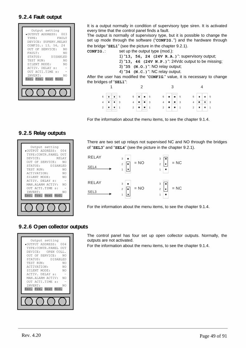
Page 49 of 91Rev. 4.20
Output setting •OUTPUT ADDRESS: 004TYPE:CONTR.PANEL OUTDEVICE: RELAYOUT OF SERVICE: NOSTATUS: DISABLEDTEST RUN: NOACTIVATION: NOSILENT MODE: NOACTIV. DELAY s: -MAN.ALARM ACTIV: NOOUT ACTI.TIME s: -INVERT: NOEsc. Pre. Next Mod.
Output setting •OUTPUT ADDRESS: 003TYPE: FAULTDEVICE: SUPERV.RELAYCONFIG.: 13, 56, 24 OUT OF SERVICE: NOFAULT: NOSTATUS: DISABLEDTEST RUN: NOSILENT MODE: NOACTIV. DELAY s: -OUT ACTI.TIME s: -INVERT: NOEsc. Pre. Next Mod.
Output setting •OUTPUT ADDRESS: 004TYPE:CONTR.PANEL OUTDEVICE: OPEN COLL.OUT OF SERVICE: NOSTATUS: DISABLEDTEST RUN: NOACTIVATION: NOSILENT MODE: NOACTIV. DELAY s: -MAN.ALARM ACTIV: NOOUT ACTI.TIME s: -INVERT: NOEsc. Pre. Next Mod.
9.2.4 Fault output
It is a output normally in condition of supervisory type siren. It is activated every time that the control panel finds a fault.The output is normally of supervisory type, but it is possible to change the set up mode through the software (“CONFIG.”) and the hardware through
the bridge “SEL1” (see the picture in the chapter 9.2.1).CONFIG.: set up the output type (mod.):
1) “13, 56, 24 (24V R.A.)”: supervisory output;
2) "13, 46 (24V N.P.)": 24Vdc output to be missing;3) "35 (N.O.)": NO relay output;4) "34 (N.C.)": NC relay output.
After the user has modified the “CONFIG.” value, it is necessary to change the bridges of “SEL1”:
6
4
2
5
3
1
6
4
2
5
3
1
6
4
2
5
3
1
6
4
2
5
3
1
1 2 3 4
For the information about the menu items, to see the chapter 9.1.4.
9.2.5 Relay outputs
There are two set up relays not supervised NC and NO through the bridges
of “SEL3” and “SEL4” (see the picture in the chapter 9.2.1).
3
2
1
RELAY
SEL4= NO
3
2
1
= NC
3
2
1
= NO3
2
1
= NC
RELAY
SEL3
For the information about the menu items, to see the chapter 9.1.4.
9.2.6 Open collector outputs
The control panel has four set up open collector outputs. Normally, the outputs are not activated.
For the information about the menu items, to see the chapter 9.1.4.

Page 50 of 91Rev. 4.20
Output setting •OUTPUT ADDRESS:001-1TYPE: LOOP OUTPUTDEVICE: OPEN COLL.OUT OF SERVICE: NOSTATUS: DISABLEDTEST RUN: NOACTIVATION: NOSILENT MODE: NOACTIV. DELAY s: -MAN.ALARM ACTIV: NOOUT ACTI.TIME s: -INVERT: NOEsc. Pre. Next Mod.
Output setting •OUTPUT ADDRESS:001-1TYPE: LOOP OUTPUTDEVICE: RELAYOUT OF SERVICE: NOSTATUS: DISABLEDTEST RUN: NOACTIVATION: NOSILENT MODE: NOACTIV. DELAY s: -MAN.ALARM ACTIV: NOOUT ACTI.TIME s: -INVERT: NOEsc. Pre. Next Mod.
9.3 LOOP OUTPUT
Selecting “LOOP OUTPUT” it is possible to programme the address of the point to which the input/output module refers. The output of the input/output module is a contact of exchange to which it is possible to connect a maximum load of 1A and 24Vdc.At the end of a correct circuit, it is necessary to distinguish:
• Always active load and that is to deactivate at the click of the relay (example: electromagnets).• Loads to activate at the click of the relay (example: sirens or optic panels).
For circuit examples see chapter PART 15.
9.3.1 Relay output
Every I/O module has a relay output with C-NO-NC clips.
For the information about the menu items, to see the chapter 9.1.4.
9.3.2 Open collector output
At inside for every detector and button there is a open collector output, but its implementing is depended from a device of low consumption. Currently this device is not available.
For the information about the menu items, to see the chapter 9.1.4.
9.4 LOGICS OF ACTIVATION
The following is a step by step activation procedure by logics of the control panel/loop outputs. These activation steps are subject to various factors such as delays, manual alarms, supervised functions etc.The complexity of this chapter is dictated by the necessity of control which is implemented by the safety normative for the delays and output functions.
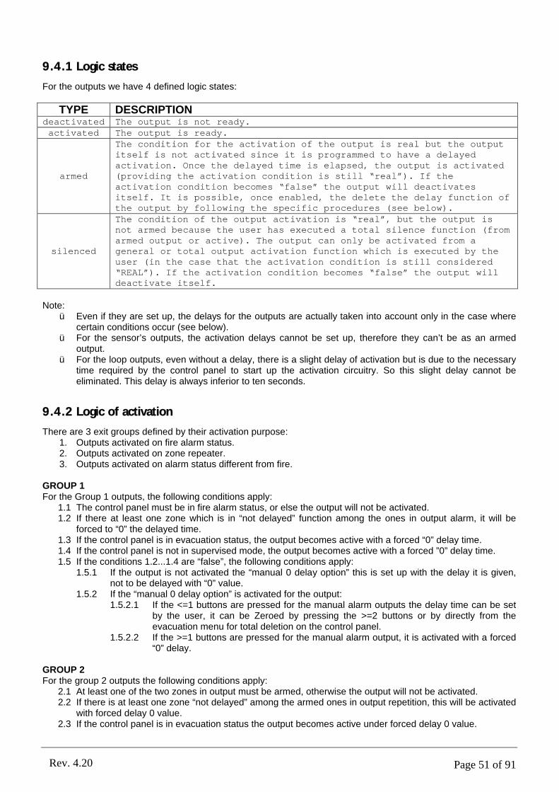
Page 51 of 91Rev. 4.20
9.4.1 Logic states
For the outputs we have 4 defined logic states:
TYPE DESCRIPTIONdeactivated The output is not ready.activated The output is ready.
armed
The condition for the activation of the output is real but the output itself is not activated since it is programmed to have a delayed activation. Once the delayed time is elapsed, the output is activated (providing the activation condition is still “real”). If the activation condition becomes “false” the output will deactivates itself. It is possible, once enabled, the delete the delay function of the output by following the specific procedures (see below).
silenced
The condition of the output activation is “real”, but the output is not armed because the user has executed a total silence function (from armed output or active). The output can only be activated from a general or total output activation function which is executed by the user (in the case that the activation condition is still considered “REAL”). If the activation condition becomes “false” the output will deactivate itself.
Note:ü Even if they are set up, the delays for the outputs are actually taken into account only in the case where
certain conditions occur (see below). ü For the sensor’s outputs, the activation delays cannot be set up, therefore they can’t be as an armed
output. ü For the loop outputs, even without a delay, there is a slight delay of activation but is due to the necessary
time required by the control panel to start up the activation circuitry. So this slight delay cannot be eliminated. This delay is always inferior to ten seconds.
9.4.2 Logic of activation
There are 3 exit groups defined by their activation purpose: 1. Outputs activated on fire alarm status.2. Outputs activated on zone repeater.3. Outputs activated on alarm status different from fire.
GROUP 1For the Group 1 outputs, the following conditions apply:
1.1 The control panel must be in fire alarm status, or else the output will not be activated.1.2 If there at least one zone which is in “not delayed” function among the ones in output alarm, it will be
forced to “0” the delayed time.1.3 If the control panel is in evacuation status, the output becomes active with a forced “0” delay time. 1.4 If the control panel is not in supervised mode, the output becomes active with a forced ”0” delay time.1.5 If the conditions 1.2...1.4 are “false”, the following conditions apply:
1.5.1 If the output is not activated the “manual 0 delay option” this is set up with the delay it is given, not to be delayed with “0” value.
1.5.2 If the “manual 0 delay option” is activated for the output:1.5.2.1 If the <=1 buttons are pressed for the manual alarm outputs the delay time can be set
by the user, it can be Zeroed by pressing the >=2 buttons or by directly from the evacuation menu for total deletion on the control panel.
1.5.2.2 If the >=1 buttons are pressed for the manual alarm output, it is activated with a forced “0” delay.
GROUP 2For the group 2 outputs the following conditions apply:
2.1 At least one of the two zones in output must be armed, otherwise the output will not be activated.2.2 If there is at least one zone “not delayed” among the armed ones in output repetition, this will be activated
with forced delay 0 value.2.3 If the control panel is in evacuation status the output becomes active under forced delay 0 value.
Page 52 of 91Rev. 4.20
2.4 If the control panel is not under supervised mode the output becomes active under forced delay 0 value.2.5 If the conditions 2.2.,.2.4 are not running or “false” the following guidelines apply:If the output is inactive the “manual alarm delay option to zero” is activated with a pre-defined delay which
cannot be “Zeroed”.2.5.2 If for the output there is the active option “manual alarm delay at zero”:
2.5.2.1 If the <=1 manual buttons are pressed for the alarm output the pre-defined delay is activated, which can be “Zeroed” by pressing the >=2 manual button or by the general deleting command of delays on the control panel (from the evacuation menu).
2.5.2.2 If the manual button > =1 is pressed the alarm output is activated with forced “0” delay.
GROUP 3For the group 3 outputs the following conditions apply:
3.1 The control panel must be in the state expected for the functions for it to be activated.3.2 The output occurs with preset delay but it cannot be in any way forced to “0” value.
Note:ü An output can only be activated either on a fire alarm state or on a different status which occurs
simultaneously. ü Hence, depending on the state of the control panel, the output can be considered under the group 1 or
group 3.
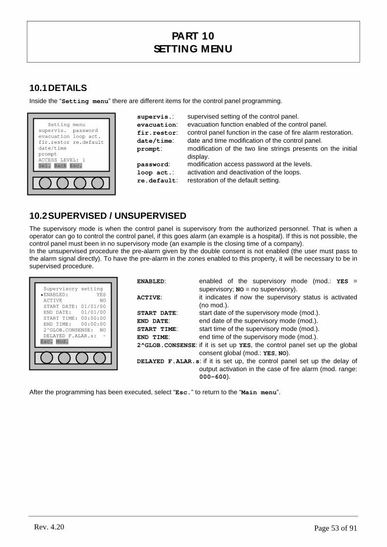
Page 53 of 91Rev. 4.20
10.1DETAILS
Inside the “Setting menu” there are different items for the control panel programming.
supervis.: supervised setting of the control panel.evacuation: evacuation function enabled of the control panel.fir.restor: control panel function in the case of fire alarm restoration.date/time: date and time modification of the control panel.prompt: modification of the two line strings presents on the initial
display.password: modification access password at the levels.
loop act.: activation and deactivation of the loops.re.default: restoration of the default setting.
10.2SUPERVISED / UNSUPERVISED
The supervisory mode is when the control panel is supervisory from the authorized personnel. That is when a operator can go to control the control panel, if this goes alarm (an example is a hospital). If this is not possible, the control panel must been in no supervisory mode (an example is the closing time of a company).In the unsupervised procedure the pre-alarm given by the double consent is not enabled (the user must pass to the alarm signal directly). To have the pre-alarm in the zones enabled to this property, it will be necessary to be in supervised procedure.
ENABLED: enabled of the supervisory mode (mod.: YES =
supervisory; NO = no supervisory).ACTIVE: it indicates if now the supervisory status is activated
(no mod.).START DATE: start date of the supervisory mode (mod.).END DATE: end date of the supervisory mode (mod.).START TIME: start time of the supervisory mode (mod.).END TIME: end time of the supervisory mode (mod.).
2^GLOB.CONSENSE: if it is set up YES, the control panel set up the global consent global (mod.: YES, NO).
DELAYED F.ALAR.s: if it is set up, the control panel set up the delay of output activation in the case of fire alarm (mod. range: 000-600).
After the programming has been executed, select “Esc.” to return to the “Main menu”.
PART 10SETTING MENU
Setting menusupervis. passwordevacuation loop act.fir.restor re.defaultdate/timepromptACCESS LEVEL: 1Sel. Back Esc.
Supervisory setting•ENABLED: YESACTIVE NOSTART DATE: 01/01/00END DATE: 01/01/00START TIME: 00:00:00END TIME: 00:00:002^GLOB.CONSENSE: NODELAYED F.ALAR.s: -Esc. Mod.
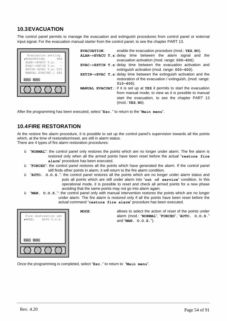
Page 54 of 91Rev. 4.20
10.3EVACUATION
The control panel permits to manage the evacuation and extinguish procedures from control panel or external
input signal. For the evacuation manual starter from the control panel, to see the chapter PART 13.
EVACUATION: enable the evacuation procedure (mod.: YES, NO).ALAR->EVACU T.s: delay time between the alarm signal and the
evacuation activation (mod. range: 000-600).EVAC->EXTIN T.s: delay time between the evacuation activation and
extinguish activation (mod. range: 000-600).EXTIN->EVAC T.s: delay time between the extinguish activation and the
restoration of the evacuation / extinguish, (mod. range: 010-600).
MANUAL EVACUAT.: if it is set up at YES it permits to start the evacuation from manual mode; to view as it is possible to manual
start the evacuation, to see the chapter PART 13(mod.: YES, NO).
After the programming has been executed, select “Esc.” to return to the “Main menu”.
10.4FIRE RESTORATION
At the restore fire alarm procedure, it is possible to set up the control panel’s supervision towards all the points which, at the time of restoration/reset, are still in alarm status.There are 4 types of fire alarm restoration procedures:
ü “NORMAL”: the control panel only restores the points which are no longer under alarm. The fire alarm is
restored only when all the armed points have been reset before the actual “restore fire alarm” procedure has been executed.
ü “FORCED”: the control panel restores all the points which have generated the alarm. If the control panel still finds other points in alarm, it will return to the fire alarm condition.
ü “AUTO. O.O.S.”: the control panel restores all the points which are no longer under alarm status and puts all points which are still under alarm into “out of service” condition. In this operational mode, it is possible to reset and check all armed points for a new phase avoiding that the same points may not go into alarm again.
ü “MAN. O.O.S.”: the control panel only with manual intervention restores the points which are no longer under alarm. The fire alarm is restored only if all the points have been reset before the actual command “restore fire alarm” procedure has been executed.
MODE: allows to select the action of reset of the points under alarm (mod.: “NORMAL”, “FORCED”, “AUTO. O.O.S.” and “MAN. O.O.S.”).
Once the programming is completed, select “Esc.” to return to “Main menu”.
Evacuation setting•EVACUATION: YESALAR->EVACU T.s: -EVAC->EXTIN T.s: -EXTIN->EVAC T.s: 010MANUAL EVACUAT.: YES
Esc. Mod.
Fire restoration set•MODE: AUTO O.O.S.
Esc. Mod.
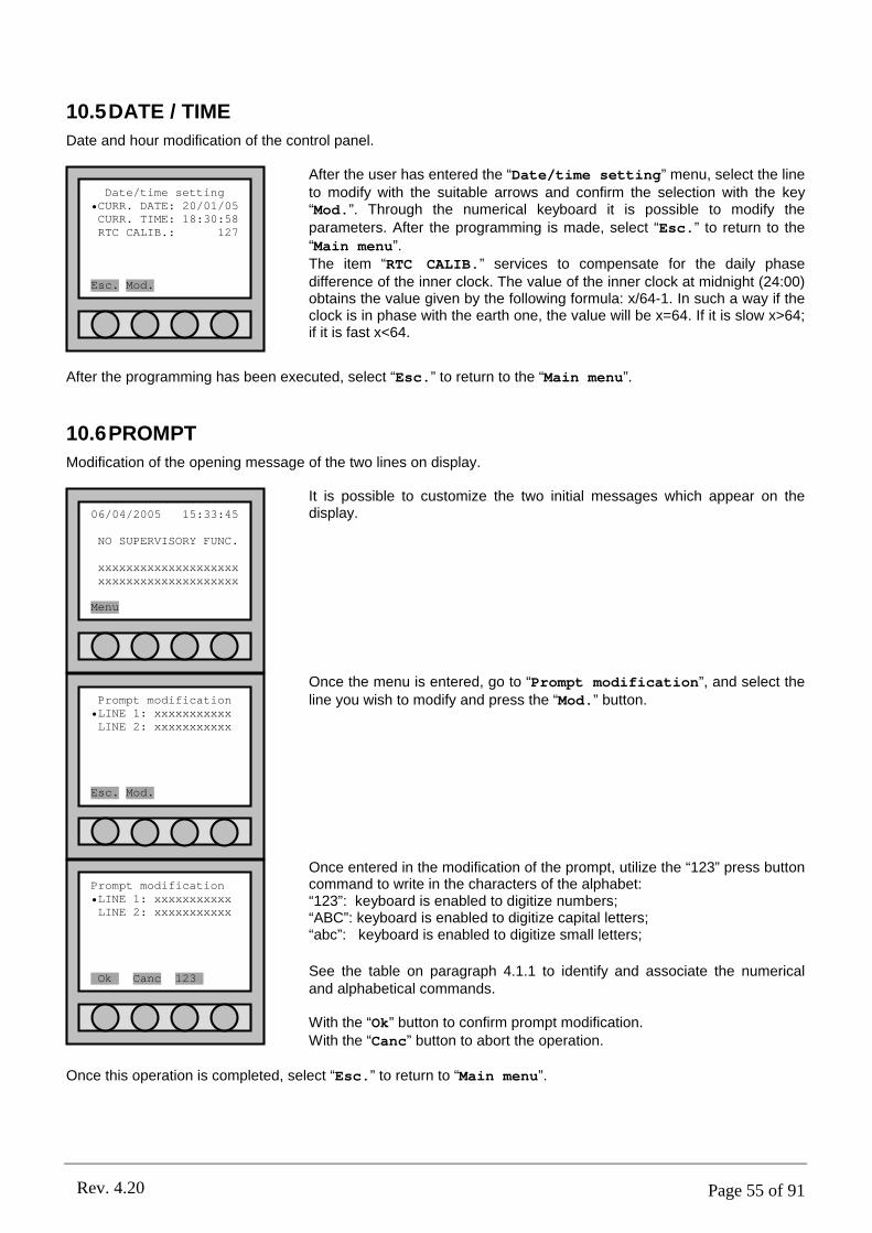
Page 55 of 91Rev. 4.20
10.5DATE / TIME
Date and hour modification of the control panel.
After the user has entered the “Date/time setting” menu, select the line to modify with the suitable arrows and confirm the selection with the key “Mod.”. Through the numerical keyboard it is possible to modify the parameters. After the programming is made, select “Esc.” to return to the “Main menu”.The item “RTC CALIB.” services to compensate for the daily phase difference of the inner clock. The value of the inner clock at midnight (24:00) obtains the value given by the following formula: x/64-1. In such a way if the clock is in phase with the earth one, the value will be x=64. If it is slow x>64; if it is fast x<64.
After the programming has been executed, select “Esc.” to return to the “Main menu”.
10.6PROMPT
Modification of the opening message of the two lines on display.
It is possible to customize the two initial messages which appear on the display.
Once the menu is entered, go to “Prompt modification”, and select the line you wish to modify and press the “Mod.” button.
Once entered in the modification of the prompt, utilize the “123” press button command to write in the characters of the alphabet:“123”: keyboard is enabled to digitize numbers;“ABC”: keyboard is enabled to digitize capital letters;“abc”: keyboard is enabled to digitize small letters;
See the table on paragraph 4.1.1 to identify and associate the numerical and alphabetical commands.
With the “Ok” button to confirm prompt modification. With the “Canc” button to abort the operation.
Once this operation is completed, select “Esc.” to return to “Main menu”.
Date/time setting•CURR. DATE: 20/01/05CURR. TIME: 18:30:58RTC CALIB.: 127
Esc. Mod.
Prompt modification•LINE 1: xxxxxxxxxxxLINE 2: xxxxxxxxxxx
Esc. Mod.
06/04/2005 15:33:45
NO SUPERVISORY FUNC.
xxxxxxxxxxxxxxxxxxxxxxxxxxxxxxxxxxxxxxxx
Menu
Prompt modification•LINE 1: xxxxxxxxxxxLINE 2: xxxxxxxxxxx
Ok Canc 123g

Page 56 of 91Rev. 4.20
10.7PASSWORD
Modification of the access password at various operational levels of the control panel.
Inside the menu, go to “Password setting”, select the line for the entry level required to change its password; then press the “Mod.” button to modify.
Level 2 Password : 22222;Level 3 Password : 33333;
To modify the password, it is mandatory to:1. insert the old password;2. insert the new password;3. confirm the new password;
Press the “Canc” button to delete this operation.
If the modification of the Password was performed correctly, you should visualize “COMPLETED OPERATION” on the display.
Press “Ok” to exit.
Once this operation is completed, select “Esc.” to return to “Main menu”.
10.7.1 Retrieval of Forgotten Password
If by any chance one loses or forgets the password(s), one must interrogate the Control Panel via PC in serial cable connection interface.Procedure:
1. Connect through the RS232/RS485 cable the output of COM1 or COM2 (see chapter 2.5) to a serial port COM of the PC.
2. Launch a common platform program for the running of the serial port (for instance a Hyper Terminal); set-up the COM port with:
Baud rate: 9600.Data bits: 8.Stop bits: 1.Parity: even.Flux control: none.Com: the one used from the time of connection.If using the HyperTerminal: select the command Voices “Add next line on every return to
tabs heading” and “The Echo of characters digitized locally” from the window “Properties” --> “Set-upASCII”.
3. Verify that the Control Panel has the address 99 (see chapter 12.4.1).4. Write the command CEN[enter]; the Control Panel will respond with cen99 (this is to ensure that the
connection is correct and that the address of the Control Panel is actually 99).5. Quick digits (or send through a text file) the command is MOS999F [enter].
Password setting
NEW PASSWORD:
Canc
Password setting•LEVEL 2LEVEL 3LEVEL 3b
Esc. Mod.
Information
COMPLETED OPERATION
Ok.

Page 57 of 91Rev. 4.20
6. The Control Panel responds with mos99222223333346; by excluding the first 5 and last 2 characters,you are able to identify the values of the two passwords which as default carry the value of : level 2: 22222; level 3: 33333.
10.8LOOP ACTIVATION
Loop activation procedure on the control panel. Normally all loop systems available are already active and ready for the system, if a deactivation is required/or cut out a loop, it is obtainable by operating on this menu.
In the “Loop activation” menu, activate/deactivate the loop by pressing the “Mod.” button.Press the “Canc” button to exit the menu without confirming the modifications just executed.Press on “Ok” to exit the menu and then confirm the modifications made. This will re-start the control panel, without the loss of all acquired data (refer
to PART 5).
Once the modification is confirmed, the Control Panel will re-start and will give the “System Fault” reading; thus press the command button “Restore System Fault” located on the electronic circuit board for the restore. If there were Loops in service; they will be automatically restored into their original function – in the “Restore Fault” situation it is not necessary to wait for theLoop re-start.
10.9RESTORING DEFAULT SETTINGS
This procedure allows to reset the control panel’s default settings:
- settings of the superintended function modes;- settings of fire alarm reset;- settings of external power feed;- settings of evacuation;- settings of system’s network address of the control panel;- settings of the control panel’s prompt;- settings of password level 2;- settings of module’s output.
The restored settings are the ones solely related with the control panel. Points, zones and outputs are in any case preserved by the internal memory.
Once entered in “r.default”:Press “Canc” to exit the menu without any other restore command.Press “Ok” to restore the pre-set commando to the ones in default.
Once restoration is confirmed, the Control Panel will re-start and will give the “System Fault” reading; thus press the command button “Restore System Fault” located on the electronic circuit board for the restore. If there were Loops in service; they will be automatically restored into their original function – in the “Restore Fault” situation it is not necessary to wait for the Loop re-start.
Loop activationLOOPS INSTALLED: 004•LOOP 1 YESLOOP 2 YESLOOP 3 YESLOOP 4 YES
Ok Canc Mod.
Confirm operation
REST. DEFAULT SET?
Ok Canc
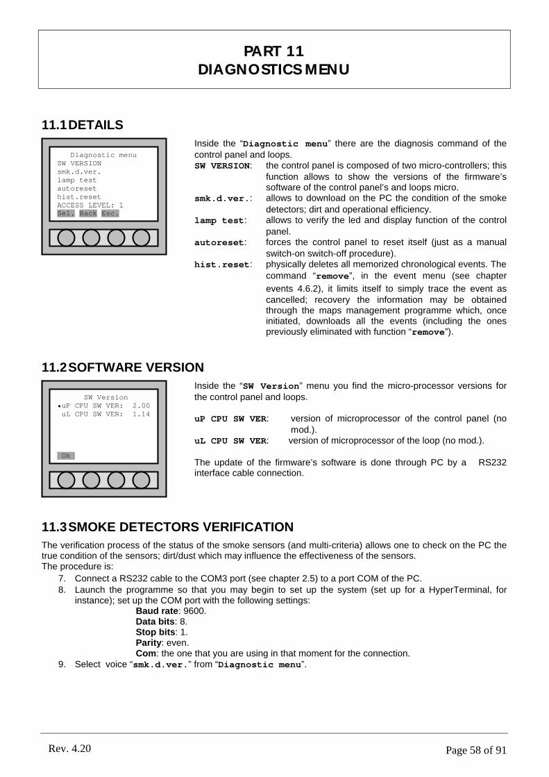
Page 58 of 91Rev. 4.20
11.1DETAILS
Inside the “Diagnostic menu” there are the diagnosis command of the control panel and loops. SW VERSION: the control panel is composed of two micro-controllers; this
function allows to show the versions of the firmware’s software of the control panel’s and loops micro.
smk.d.ver.: allows to download on the PC the condition of the smoke detectors; dirt and operational efficiency.
lamp test: allows to verify the led and display function of the control panel.
autoreset: forces the control panel to reset itself (just as a manual switch-on switch-off procedure).
hist.reset: physically deletes all memorized chronological events. The
command “remove”, in the event menu (see chapter
events 4.6.2), it limits itself to simply trace the event as cancelled; recovery the information may be obtained through the maps management programme which, once initiated, downloads all the events (including the ones previously eliminated with function “remove”).
11.2SOFTWARE VERSION
Inside the “SW Version” menu you find the micro-processor versions for the control panel and loops.
uP CPU SW VER: version of microprocessor of the control panel (no mod.).
uL CPU SW VER: version of microprocessor of the loop (no mod.).
The update of the firmware’s software is done through PC by a RS232 interface cable connection.
11.3SMOKE DETECTORS VERIFICATION
The verification process of the status of the smoke sensors (and multi-criteria) allows one to check on the PC the true condition of the sensors; dirt/dust which may influence the effectiveness of the sensors.The procedure is:
7. Connect a RS232 cable to the COM3 port (see chapter 2.5) to a port COM of the PC.8. Launch the programme so that you may begin to set up the system (set up for a HyperTerminal, for
instance); set up the COM port with the following settings:Baud rate: 9600.Data bits: 8.Stop bits: 1.Parity: even.Com: the one that you are using in that moment for the connection.
9. Select voice “smk.d.ver.” from “Diagnostic menu”.
PART 11DIAGNOSTICS MENU
Diagnostic menuSW VERSIONsmk.d.ver.lamp testautoresethist.resetACCESS LEVEL: 1Sel. Back Esc.
SW Version•uP CPU SW VER: 2.00uL CPU SW VER: 1.14
Okg
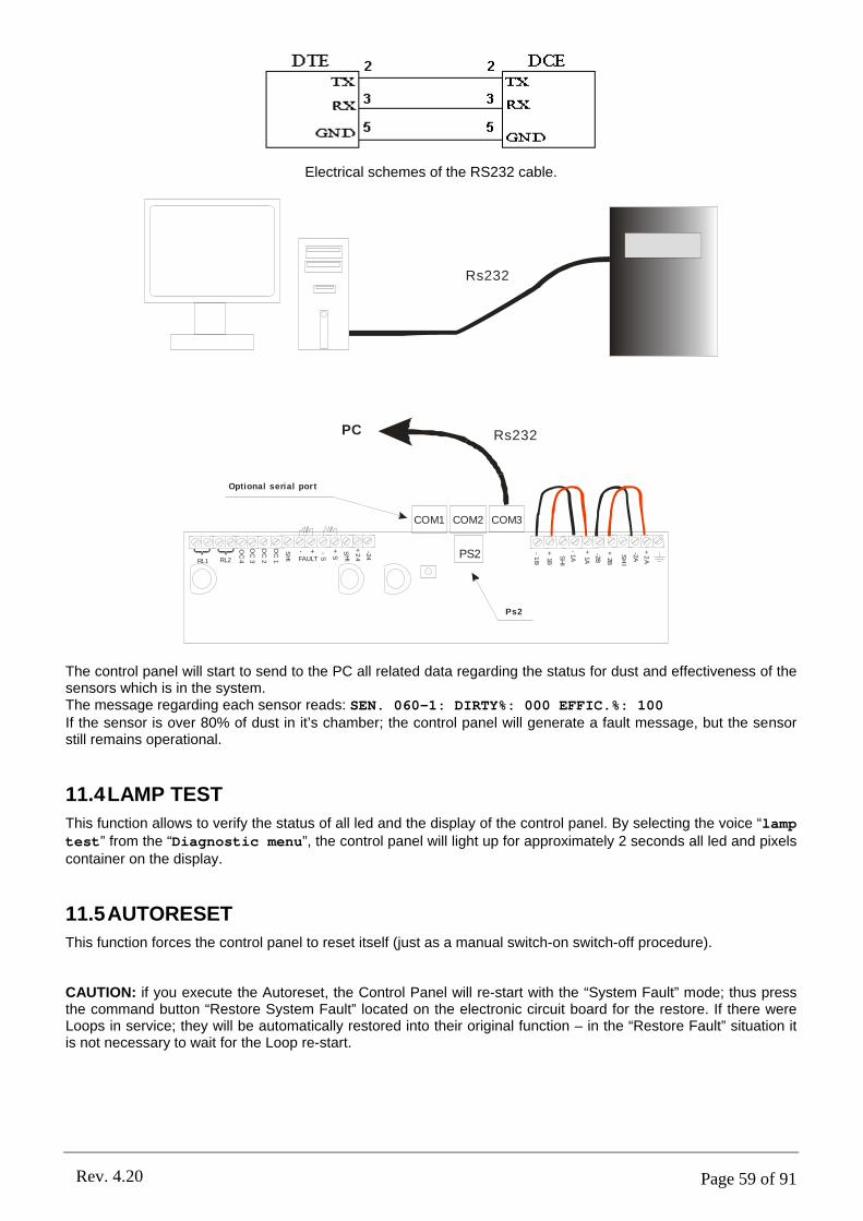
Page 59 of 91Rev. 4.20
Electrical schemes of the RS232 cable.
Rs232
Rs232PC
Ps2
Optional serial port
COM1 COM2 COM3
-1
B
+1B
SH
I
-1A
+1A
-2B
+2B
SH
I
-2A
+2
A
-24
+2
4
SH
I
+S
-S
- +FAULT
SH
I
OC
1
OC
2
OC
3
OC
4RL2RL1PS2
The control panel will start to send to the PC all related data regarding the status for dust and effectiveness of the sensors which is in the system.The message regarding each sensor reads: SEN. 060-1: DIRTY%: 000 EFFIC.%: 100If the sensor is over 80% of dust in it’s chamber; the control panel will generate a fault message, but the sensor still remains operational.
11.4LAMP TEST
This function allows to verify the status of all led and the display of the control panel. By selecting the voice “lamp test” from the “Diagnostic menu”, the control panel will light up for approximately 2 seconds all led and pixels container on the display.
11.5AUTORESET
This function forces the control panel to reset itself (just as a manual switch-on switch-off procedure).
CAUTION: if you execute the Autoreset, the Control Panel will re-start with the “System Fault” mode; thus press the command button “Restore System Fault” located on the electronic circuit board for the restore. If there were Loops in service; they will be automatically restored into their original function – in the “Restore Fault” situation it is not necessary to wait for the Loop re-start.

Page 60 of 91Rev. 4.20
11.6 CHRONOLOGICAL RESET
This function physically deletes all memorized chronological events. The command “remove”, in the event menu
(see chapter events 4.6.2), limits itself to simply trace the event as cancelled; recovery the information may be obtained through the maps management programme which, once initiated, downloads all the events (including the ones previously eliminated with function “remove”).
CAUTION: once the chronological reset is confirmed, the Control Panel will re-start with the “System Fault” mode; thus press the command button “Restore System Fault” located on the electronic circuit board for the restore. If there were Loops in service; they will be automatically restored into their original function – in the “Restore Fault” situation it is not necessary to wait for the Loop re-start.

Page 61 of 91Rev. 4.20
12.1DETAILS
Within the “Connection menu”, all management functions are found for all the devices external to the control panel.
keyboard: allows to enable the use of the external keyboard PS2 instead of the punch keys on the front label of the control panel.
ext.supply: in substitution of the mains 220Vac, it is possible to power the control panel through an external power supply unit(with battery back-up) of 27.6Vdc.
local net: allows to modify the network address of the control panel
(see chapter 0).
12.2EXTERNAL PS2 KEYPAD
Within the “Connection menu”, select the voice “keyboard” to enable the keyboard.Once the correct password is inserted, the control panel will confirm the external enabling function by the message “EXTERN.KEYPAD ENABLED”. Press the “Ok” button to confirm the function modification.
Once the keyboard is active, all the alpha-numerical commands are recognized, the top key symbols, the direction keys, the enter key along with the first four function buttons in relation to the menu keys. The shift key commutes the small caps to capital letters.
PART 12CONNECTION MENU
Connection menukeyboardext.supply.local net
LIVELLO DI ACCESSO: 1Sel. Back Esc.
Information
EXTERN.KEYPAD ENABLED
Ok.
F1 F2 F3 F4
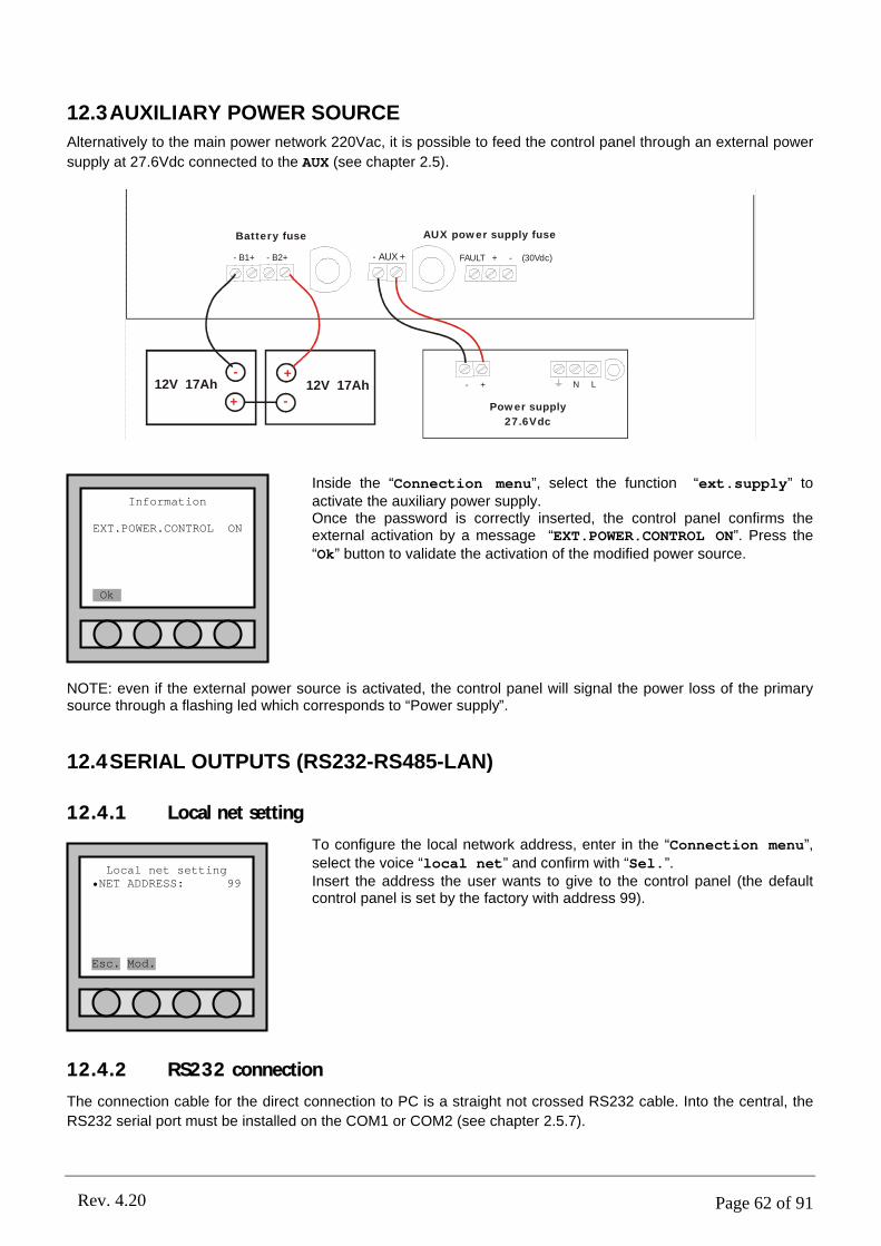
Page 62 of 91Rev. 4.20
12.3AUXILIARY POWER SOURCE
Alternatively to the main power network 220Vac, it is possible to feed the control panel through an external power
supply at 27.6Vdc connected to the AUX (see chapter 2.5).
- B1+ - B2+ - AUX +
- + N L
Battery fuse AUX power supply fuse
Power supply
27.6Vdc
+
-
+
-12V 17Ah 12V 17Ah
FAULT + - (30Vdc)
Inside the “Connection menu”, select the function “ext.supply” to activate the auxiliary power supply.Once the password is correctly inserted, the control panel confirms the external activation by a message “EXT.POWER.CONTROL ON”. Press the “Ok” button to validate the activation of the modified power source.
NOTE: even if the external power source is activated, the control panel will signal the power loss of the primary source through a flashing led which corresponds to “Power supply”.
12.4SERIAL OUTPUTS (RS232-RS485-LAN)
12.4.1 Local net setting
To configure the local network address, enter in the “Connection menu”,
select the voice “local net” and confirm with “Sel.”.Insert the address the user wants to give to the control panel (the default control panel is set by the factory with address 99).
12.4.2 RS232 connection
The connection cable for the direct connection to PC is a straight not crossed RS232 cable. Into the central, the
RS232 serial port must be installed on the COM1 or COM2 (see chapter 2.5.7).
Local net setting•NET ADDRESS: 99
Esc. Mod.
Information
EXT.POWER.CONTROL ON
Ok.
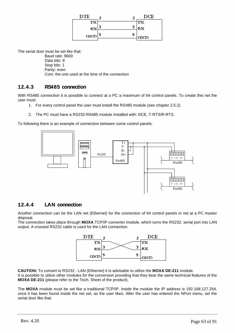
Page 63 of 91Rev. 4.20
The serial door must be set like that:Baud rate: 9600Data bits: 8Stop bits: 1Parity: evenCom: the one used at the time of the connection
12.4.3 RS485 connection
With RS485 connection it is possible to connect at a PC a maximum of 64 control panels. To create this net the user must:
1. For every control panel the user must install the RS485 module (see chapter 2.5.2).
2. The PC must have a RS232-RS485 module installed with: DCE, T-RTS/R-RTS.
To following there is an example of connection between some control panels.
T+T-R-R+
Rs485Rs485
Rs485
Rs232B A dir -5V+
B A dir -5V+
12.4.4 LAN connection
Another connection can be the LAN net (Ethernet) for the connection of 64 control panels in net at a PC master disposal.The connection takes place through MOXA TCP/IP converter module, which turns the RS232, serial port into LAN output. A crossed RS232 cable is used for the LAN connection.
CAUTION: To convert to RS232 - LAN (Ethernet) it is advisable to utilize the MOXA DE-211 module.It is possible to utilize other modules for the conversion providing that they bear the same technical features of the MOXA DE-211 (please refer to the Tech. Sheet of the product).
The MOXA module must be set like a traditional TCP/IP. Inside the module the IP address is 192.168.127.254, once it has been found inside the net set, as the user likes. After the user has entered the NPort menu, set the serial door like that:

Page 64 of 91Rev. 4.20
MOXA DE-211 module:
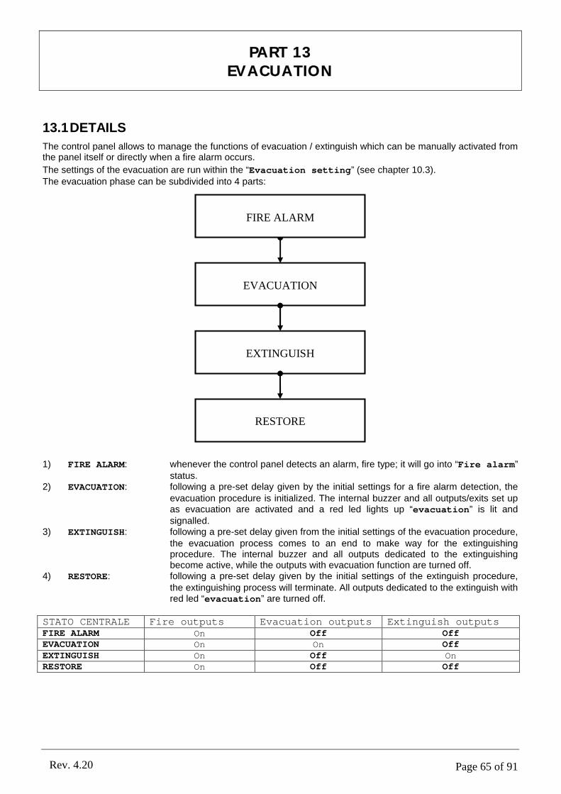
Page 65 of 91Rev. 4.20
13.1DETAILS
The control panel allows to manage the functions of evacuation / extinguish which can be manually activated from the panel itself or directly when a fire alarm occurs.
The settings of the evacuation are run within the “Evacuation setting” (see chapter 10.3).The evacuation phase can be subdivided into 4 parts:
1) FIRE ALARM: whenever the control panel detects an alarm, fire type; it will go into “Fire alarm” status.
2) EVACUATION: following a pre-set delay given by the initial settings for a fire alarm detection, the evacuation procedure is initialized. The internal buzzer and all outputs/exits set up as evacuation are activated and a red led lights up “evacuation” is lit and signalled.
3) EXTINGUISH: following a pre-set delay given from the initial settings of the evacuation procedure, the evacuation process comes to an end to make way for the extinguishing procedure. The internal buzzer and all outputs dedicated to the extinguishing become active, while the outputs with evacuation function are turned off.
4) RESTORE: following a pre-set delay given by the initial settings of the extinguish procedure, the extinguishing process will terminate. All outputs dedicated to the extinguish with red led “evacuation” are turned off.
STATO CENTRALE Fire outputs Evacuation outputs Extinguish outputsFIRE ALARM On Off OffEVACUATION On On OffEXTINGUISH On Off OnRESTORE On Off Off
PART 13EVACUATION
EVACUATION
EXTINGUISH
RESTORE
FIRE ALARM
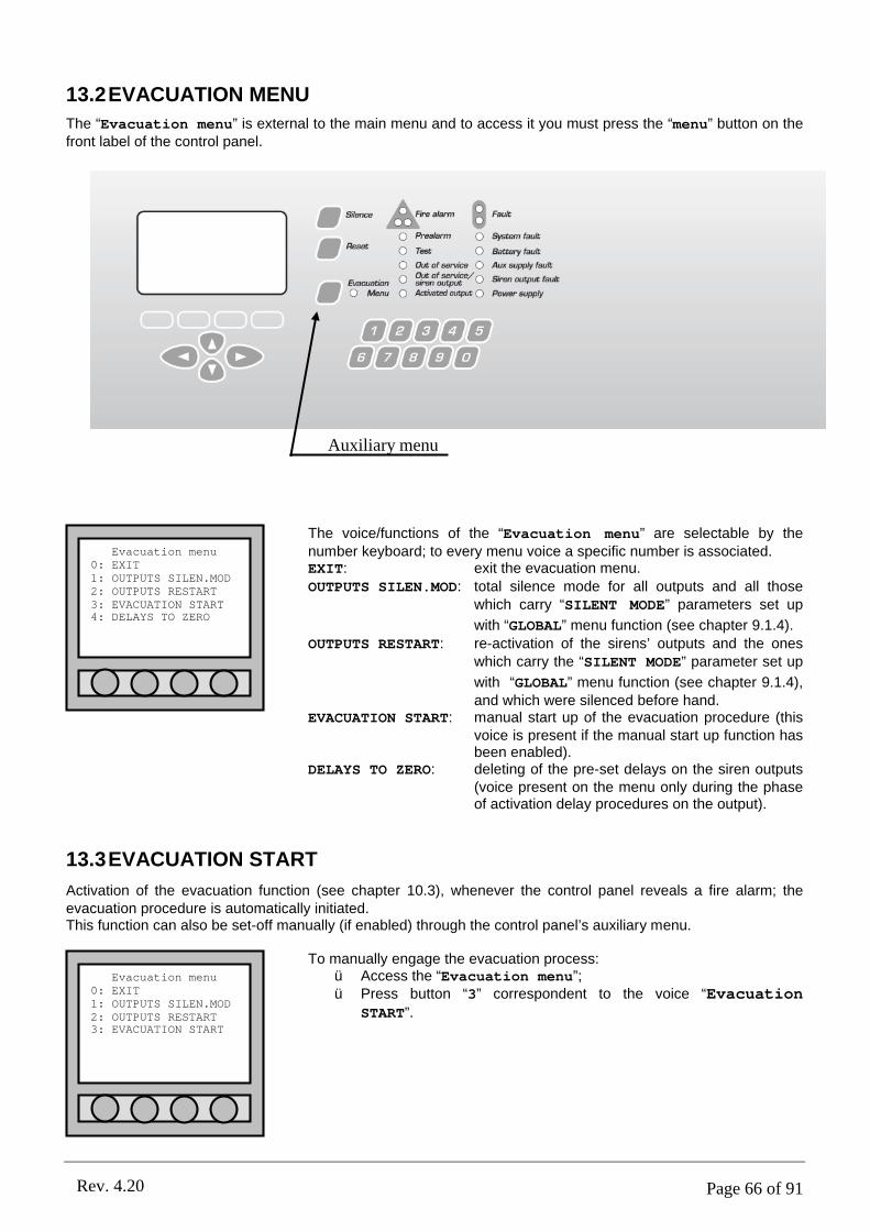
Page 66 of 91Rev. 4.20
13.2EVACUATION MENU
The “Evacuation menu” is external to the main menu and to access it you must press the “menu” button on the front label of the control panel.
The voice/functions of the “Evacuation menu” are selectable by the number keyboard; to every menu voice a specific number is associated.EXIT: exit the evacuation menu.
OUTPUTS SILEN.MOD: total silence mode for all outputs and all those which carry “SILENT MODE” parameters set up
with “GLOBAL” menu function (see chapter 9.1.4).
OUTPUTS RESTART: re-activation of the sirens’ outputs and the ones which carry the “SILENT MODE” parameter set up
with “GLOBAL” menu function (see chapter 9.1.4), and which were silenced before hand.
EVACUATION START: manual start up of the evacuation procedure (this voice is present if the manual start up function has been enabled).
DELAYS TO ZERO: deleting of the pre-set delays on the siren outputs (voice present on the menu only during the phase of activation delay procedures on the output).
13.3EVACUATION START
Activation of the evacuation function (see chapter 10.3), whenever the control panel reveals a fire alarm; the evacuation procedure is automatically initiated.This function can also be set-off manually (if enabled) through the control panel’s auxiliary menu.
To manually engage the evacuation process:ü Access the “Evacuation menu”;ü Press button “3” correspondent to the voice “Evacuation
START”.
Evacuation menu0: EXIT1: OUTPUTS SILEN.MOD2: OUTPUTS RESTART3: EVACUATION START
Auxiliary menu
Evacuation menu0: EXIT1: OUTPUTS SILEN.MOD2: OUTPUTS RESTART3: EVACUATION START4: DELAYS TO ZERO

Page 67 of 91Rev. 4.20
Once the evacuation is initiated, the “Evacuation menu” changes, thus allowing the user to terminate the function (button “3”).
13.4“EVACUATION” AND “EXTINGUISH” OUTPUTS
The control panel’s outputs and loops (I/O modules) can be programmed as “evacuation” or “extinguish” outputs
(see chapter 9.1.4). In this manner it is possible to command a extinguishing control unit or signal the evacuation course or path with the light indicator signs to exit the building.
Evacuation men0: EXIT1: OUTPUTS SILEN.MOD2: OUTPUTS RESTART3: EVACUATION STOP4: DELAYS TO ZERO

Page 68 of 91Rev. 4.20
14.1DETAILS
If the PC is not used as master control for the system, it is possible to create a control centre to coordinate the control panels as a mini network by use of the repeater box.
NOTE: presently it is not possible to unite more repeater boxes to one control panel.
14.2RS232 CONNECTION
By utilizing the repeater box, it is possible to control from one to two inter-connected control panels by RS232 cable. This type of cable limits the distance between the positioning of the two control panels and the repeater box.
Rs232
Rs232
The repeater panel is connected with the control panel through a crossed RS232 cable.
Repeater panel settingFor the repeater setting it is enough to install the RS232 serial port inside the control panel in the first connector on the left. The control panel needs not be set, being already programmed of default. As regards the repeater panel it is better to supply it from an external power supply source to the control panel. Connect the serial port and enter the main menu. At the connection item, follow the table shown below:
CONNECTIONS NETWORK RS232
CONTROL PANELCONNECTIONS
SERIAL 1 SEARCH CONFIRMWITH – OK-
CONTROL PANELDISCONNECTIONS
SERIAL 2
CENTRAL LINKS
Once the user has decided the serial port and the repeater and in search of the control panel, it is enough only to wait and confirm the action. From that moment the panel will view all the control panel’s actions.
To exit the link, keep the “Menu” button pressed.
PART 14REPEATER PANEL
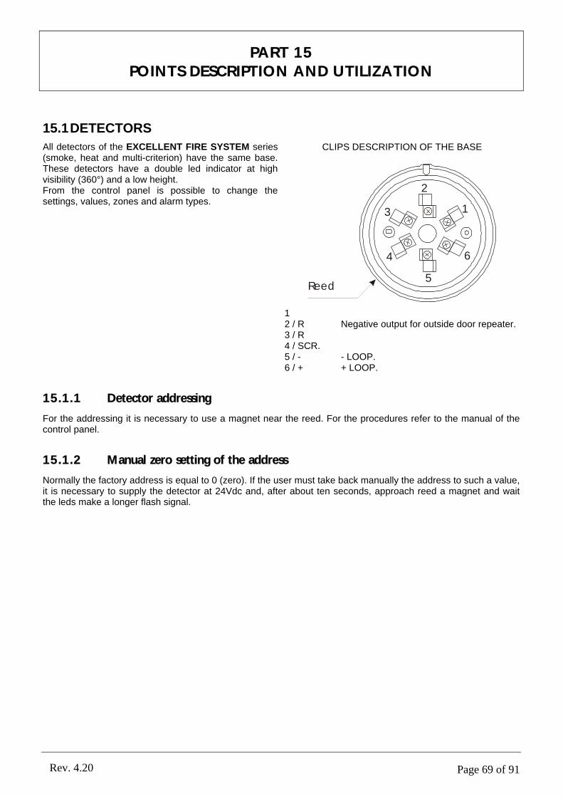
Page 69 of 91Rev. 4.20
15.1DETECTORS
All detectors of the EXCELLENT FIRE SYSTEM series (smoke, heat and multi-criterion) have the same base. These detectors have a double led indicator at high visibility (360°) and a low height.From the control panel is possible to change the settings, values, zones and alarm types.
CLIPS DESCRIPTION OF THE BASE
2
3 1
6
5
4
Reed
12 / R Negative output for outside door repeater.3 / R4 / SCR.5 / - - LOOP.6 / + + LOOP.
15.1.1 Detector addressing
For the addressing it is necessary to use a magnet near the reed. For the procedures refer to the manual of the control panel.
15.1.2 Manual zero setting of the address
Normally the factory address is equal to 0 (zero). If the user must take back manually the address to such a value, it is necessary to supply the detector at 24Vdc and, after about ten seconds, approach reed a magnet and wait the leds make a longer flash signal.
PART 15POINTS DESCRIPTION AND UTILIZATION

Page 70 of 91Rev. 4.20
15.1.3 Smoke detector
The smoke detector reacts to the presence of elements caused by the combustion (visible smoke). The working principle is based on the light dispersion technique (Tyndall effect).
ADDRESS: the point and loop addresses (no mod.).ZONE: the zone address of the point loop (mod., range value
1-63).NAME: the name of the point (mod.).TYPE: point type (no mod.).
SECTION: the section where the point is (no mod.).O.OF SERVICE: it indicates if the point is in out of service (mod. YES or
NO).FAULT: it indicates if the point is fault (no mod.).LED ON: if YES the leds flash (mod. YES or NO).
INPUT: the input is activable like only TECHNOLOGICAL type (mod.).
SING.CONSEN.: it is used when the control panel is supervisory mode and the zone of the point is enabled the "double consent". If YES, when the detector go to alarm status, the control panel go to fire alarm too. The possibility to modify this function is given provided that there are at least 2 points on the specific zone. If after deleting of a point, the assigned zone at single consent has only one installed point, this parameter value will read No(mod. YES or NO).
SERIAL NUM: the serial number of the detector (no mod.).
SW VERSION: the software version of the detector (it is changed through PC).
SUP.SMOK LEV: the smoke level in supervisory mode. This level refers at the SMOKE value (mod. Range: 80-150). Beyond this value, the alarm goes active.
NSUP.SMK LEV: the smoke level in no supervisory mode. This level refers at the SMOKE value (mod. Range: 80-150). Beyond this value, the alarm goes active.
SMOKE(0-255): it indicates the smoke into the detector with a range of 0-255 (no mod.).
DIRTY %: the dirty % of the detector. If the value exceeds 80%, the control panel send the problem with a message (no mod.).
EFFICIENCY %: the efficiency % of the detector. If the value goes
under 25%, the control panel send the problem with a message. This value depends of the device sensor (no mod.).
Point setting•ADDRESS: 001-1ZONE: 01NAME: ROOM1TYPE: SMOKE DETECTOSECTION: A-BOUT OF SERVICE: NOFAULT: NOLED ON: NOINPUT: DISABLEDSINGLE CONSENSE: NOSERIAL NUM:002-00001SW VERSION: 2.00SUPERV.SMOK LEV: 130NSUPER.SMOK LEV: 100SMOKE (0-255): 003DIRTY %: 000EFFICIENCY %: 100Esc. Pre. Next Mod.
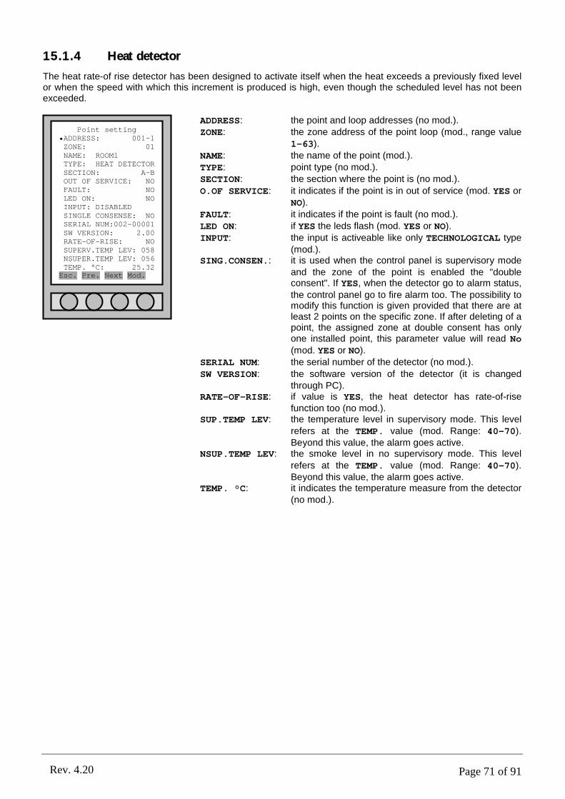
Page 71 of 91Rev. 4.20
15.1.4 Heat detector
The heat rate-of rise detector has been designed to activate itself when the heat exceeds a previously fixed level or when the speed with which this increment is produced is high, even though the scheduled level has not been exceeded.
ADDRESS: the point and loop addresses (no mod.).ZONE: the zone address of the point loop (mod., range value
1-63).NAME: the name of the point (mod.).TYPE: point type (no mod.).SECTION: the section where the point is (no mod.).
O.OF SERVICE: it indicates if the point is in out of service (mod. YES or NO).
FAULT: it indicates if the point is fault (no mod.).LED ON: if YES the leds flash (mod. YES or NO).INPUT: the input is activeable like only TECHNOLOGICAL type
(mod.).SING.CONSEN.: it is used when the control panel is supervisory mode
and the zone of the point is enabled the "double consent". If YES, when the detector go to alarm status, the control panel go to fire alarm too. The possibility to modify this function is given provided that there are at least 2 points on the specific zone. If after deleting of a point, the assigned zone at double consent has only one installed point, this parameter value will read No(mod. YES or NO).
SERIAL NUM: the serial number of the detector (no mod.).
SW VERSION: the software version of the detector (it is changed through PC).
RATE-OF-RISE: if value is YES, the heat detector has rate-of-rise function too (no mod.).
SUP.TEMP LEV: the temperature level in supervisory mode. This level refers at the TEMP. value (mod. Range: 40-70). Beyond this value, the alarm goes active.
NSUP.TEMP LEV: the smoke level in no supervisory mode. This level refers at the TEMP. value (mod. Range: 40-70). Beyond this value, the alarm goes active.
TEMP. °C: it indicates the temperature measure from the detector (no mod.).
Point setting•ADDRESS: 001-1ZONE: 01NAME: ROOM1TYPE: HEAT DETECTORSECTION: A-BOUT OF SERVICE: NOFAULT: NOLED ON: NOINPUT: DISABLEDSINGLE CONSENSE: NOSERIAL NUM:002-00001SW VERSION: 2.00RATE-OF-RISE: NOSUPERV.TEMP LEV: 058NSUPER.TEMP LEV: 056TEMP. °C: 25.32Esc. Pre. Next Mod.
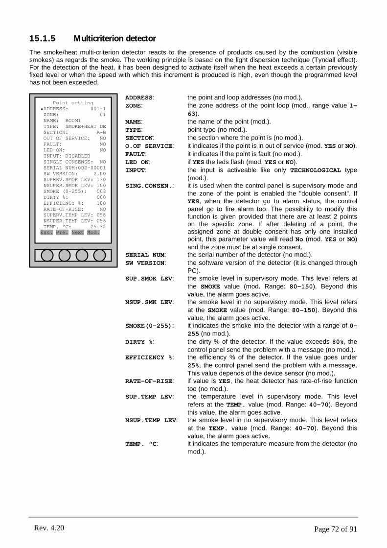
Page 72 of 91Rev. 4.20
15.1.5 Multicriterion detector
The smoke/heat multi-criterion detector reacts to the presence of products caused by the combustion (visible smokes) as regards the smoke. The working principle is based on the light dispersion technique (Tyndall effect). For the detection of the heat, it has been designed to activate itself when the heat exceeds a certain previously fixed level or when the speed with which this increment is produced is high, even though the programmed level has not been exceeded.
ADDRESS: the point and loop addresses (no mod.).ZONE: the zone address of the point loop (mod., range value 1-
63).NAME: the name of the point (mod.).TYPE: point type (no mod.).SECTION: the section where the point is (no mod.).O.OF SERVICE: it indicates if the point is in out of service (mod. YES or NO).
FAULT: it indicates if the point is fault (no mod.).LED ON: if YES the leds flash (mod. YES or NO).INPUT: the input is activeable like only TECHNOLOGICAL type
(mod.).SING.CONSEN.: it is used when the control panel is supervisory mode and
the zone of the point is enabled the "double consent". If YES, when the detector go to alarm status, the control panel go to fire alarm too. The possibility to modify this function is given provided that there are at least 2 points on the specific zone. If after deleting of a point, the assigned zone at double consent has only one installed point, this parameter value will read No (mod. YES or NO) and the zone must be at single consent.
SERIAL NUM: the serial number of the detector (no mod.).
SW VERSION: the software version of the detector (it is changed through PC).
SUP.SMOK LEV: the smoke level in supervisory mode. This level refers at the SMOKE value (mod. Range: 80-150). Beyond this value, the alarm goes active.
NSUP.SMK LEV: the smoke level in no supervisory mode. This level refers at the SMOKE value (mod. Range: 80-150). Beyond this value, the alarm goes active.
SMOKE(0-255): it indicates the smoke into the detector with a range of 0-255 (no mod.).
DIRTY %: the dirty % of the detector. If the value exceeds 80%, the control panel send the problem with a message (no mod.).
EFFICIENCY %: the efficiency % of the detector. If the value goes under
25%, the control panel send the problem with a message. This value depends of the device sensor (no mod.).
RATE-OF-RISE: if value is YES, the heat detector has rate-of-rise function too (no mod.).
SUP.TEMP LEV: the temperature level in supervisory mode. This level refers at the TEMP. value (mod. Range: 40-70). Beyond this value, the alarm goes active.
NSUP.TEMP LEV: the smoke level in no supervisory mode. This level refers at the TEMP. value (mod. Range: 40-70). Beyond this value, the alarm goes active.
TEMP. °C: it indicates the temperature measure from the detector (no mod.).
Point setting•ADDRESS: 001-1ZONE: 01NAME: ROOM1TYPE: SMOKE+HEAT DESECTION: A-BOUT OF SERVICE: NOFAULT: NOLED ON: NOINPUT: DISABLEDSINGLE CONSENSE: NOSERIAL NUM:002-00001SW VERSION: 2.00SUPERV.SMOK LEV: 130NSUPER.SMOK LEV: 100SMOKE (0-255): 003DIRTY %: 000EFFICIENCY %: 100RATE-OF-RISE: NOSUPERV.TEMP LEV: 058NSUPER.TEMP LEV: 056TEMP. °C: 25.32Esc. Pre. Next Mod.

Page 73 of 91Rev. 4.20
15.1.6 Electrical schemes
22
33
11
66
55
44
SHI
Loop +
Loop -
SHI
Loop +
Loop -
CONNECTION TO LOOP: OUTSIDE DOOR REPEATER:
- +
15.2RESETTABLE BUTTON
Manual reset alarm button for control panel.
15.2.1 Input and output description
INPUT: The input is of the type of balanced resistance of the 27K• value. The input signal is given opening the circuit between the two clips and the resistance; but, if it is short circuited, a fault in the input line is indicated. The maximum length of the input line is 8m.OUTPUT: the output is a Open Collector type. It is necessary to use a CMOS interface with a low current supply to control a relay.
The input and output can be programmed with different types of meaning (Example: Alarm fire, technological...).
15.2.2 Button addressing
For the addressing in loop it is necessary to use a magnet near the reed. For the procedures, refer to the manual of the control panel.
15.2.3 Manual zero setting of the address
Normally the factory address is equal to 0 (zero). If you must assign the address to zero, give manually 24V to the detector and, after ten seconds, approach reed a magnet and wait for the led to make a long flash signal.
15.2.4 Point setting
In the “Point setting” menu (submenu of “POINT” item) there are different parameters for this detector. For
the output setting, see chapter PART 9).

Page 74 of 91Rev. 4.20
ADDRESS: the point and loop addresses (no mod.).ZONE: the zone address of the point loop (mod., range value
1-63).NAME: the name of the point (mod.).
TYPE: point type (no mod.).SECTION: the section where the point is (no mod.).O.OF SERVICE: it indicates if the point is in out of service (mod. YES or
NO).FAULT: it indicates if the point is fault (no mod.).
LED ON: if YES the leds flash (mod. YES or NO).INPUT: the input is activeable with the types:
TECHNOLOGICAL, FIRE ALARM and BATH (mod.).SING.CONSEN.: it is used when the control panel is supervisory mode
and the zone of the point is enabled the "double consent". If YES, when the input go to alarm status, the control panel go to fire alarm too. The possibility to modify this function is given provided that there are at least 2 points on the specific zone. If after deleting of a point, the assigned zone at double consent has only one installed point, this parameter value will read No and the zone must be at single consent. The manual the button which gives an alarm signal that is not influenced from these setting. (mod. YES or NO).
SERIAL NUM: the serial number of the button (no mod.).SW VERSION: the software version of the button (it is changed
through PC).
15.2.5 Electrical scheme
- LINE - LINE
+LINE +LINE
L - L +
REED
LOOP CONNECTION
L -
LED
15.3INPUT/OUTPUT MODULE
The input/output module is a device that it has an input module (balanced) and an output module relay (C/NO/NC). It is possible to connect at the input clips a clean contact. (no open collector); at this input is possible
to associate a particular alarm (see chapter 7.2 )
The output module is a two way contact exchange. It is possible to connect it to power loads which can carry a max value absorption of 1A at 24Vcc. For heavier power loads it is advisable to use an external service relay.
For the programming of the output see the chapter PART 9.
Point setting•ADDRESS: 001-1ZONE: 01NAME: ROOM1TYPE: MANUAL ALARMSECTION: A-BOUT OF SERVICE: NOFAULT: NOLED ON: NOINPUT: DISABLEDSINGLE CONSENSE: NOSERIAL NUM:002-00001SW VERSION: 2.00Esc. Pre. Next Mod.
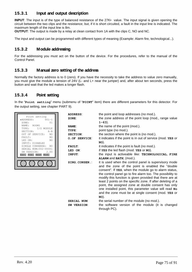
Page 75 of 91Rev. 4.20
15.3.1 Input and output description
INPUT: The input is of the type of balanced resistance of the 27K• value. The input signal is given opening the circuit between the two clips and the resistance; but, if it is short circuited, a fault in the input line is indicated. The maximum length of the input line is 8m.OUTPUT: The output is made by a relay at clean contact from 1A with the clips C, NO and NC.
The input and output can be programmed with different types of meaning (Example: Alarm fire, technological...).
15.3.2 Module addressing
For the addressing you must act on the button of the device. For the procedures, refer to the manual of the Control Panel.
15.3.3 Manual zero setting of the address
Normally the factory address is to 0 (zero). If you have the necessity to take the address to value zero manually, you must give the module a tension of 24V (L- and L+ near the jumper) and, after about ten seconds, press the button and wait that the led makes a longer flash.
15.3.4 Point setting
In the “Point setting” menu (submenu of “POINT” item) there are different parameters for this detector. For
the output setting, see chapter PART 9).
ADDRESS: the point and loop addresses (no mod.).ZONE: the zone address of the point loop (mod., range value
1-63).NAME: the name of the point (mod.).TYPE: point type (no mod.).SECTION: the section where the point is (no mod.).O.OF SERVICE: it indicates if the point is in out of service (mod. YES or
NO).FAULT: it indicates if the point is fault (no mod.).LED ON: if YES the led flash (mod. YES or NO).INPUT: the input is activeable like: TECHNOLOGICAL, FIRE
ALARM and BATH; (mod.).SING.CONSEN.: it is used when the control panel is supervisory mode
and the zone of the point is enabled the "double consent". If YES, when the module go to alarm status, the control panel go to fire alarm too. The possibility to modify this function is given provided that there are at least 2 points on the specific zone. If after deleting of a point, the assigned zone at double consent has only one installed point, this parameter value will read No and the zone must be at single consent (mod. YES or NO).
SERIAL NUM: the serial number of the module (no mod.).SW VERSION: the software version of the module (it is changed
through PC).
Point setting•ADDRESS: 001-1ZONE: 01NAME: ROOM1TYPE: I/O MODULESECTION: A-BOUT OF SERVICE: NOFAULT: NOLED ON: NOINPUT: DISABLEDSINGLE CONSENSE: NOSERIAL NUM:002-00001SW VERSION: 2.00Esc. Pre. Next Mod.
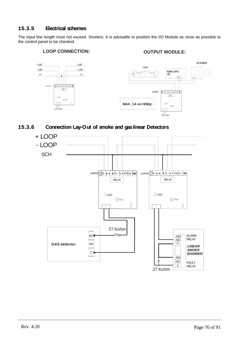
Page 76 of 91Rev. 4.20
15.3.5 Electrical schemes
The input line length must not exceed 5meters. It is advisable to position the I/O Module as close as possible to the control panel to be checked.
- LOOP - LOOP
+ LOOP + LOOP
SCH SCH
L - L + L - L + C NCSL - L + L - L + C NCSL - L + L - L + C NCNOS
RELA Y
LED
JUM PER
27K ohm
LOOP CONNECTION: OUTPUT MODULE:
L - L + L - L + C NCSL - L + L - L + C NCSL - L + L - L + C NCNOS
RELA Y
LE D
JUMPER
27K ohm
POWER SUPPLY24V
+ -
+-
LAMP
+-
ELECTROMAGNET
MAX. 1A on relay.
15.3.6 Connection Lay-Out of smoke and gas linear Detectors
- LOOP
+LOOP
SCH
L - L + L - L + C NCSL - L + L - L + C NCSL - L + L - L + C NCS
RELAY
LED
L - L +L - L + L - L + NCSL - L + L - L + NO NCSL + C
RELAY
LED
NO
LINEARSMOKEBARRIER
GAS detector
ALARMRELAY
FAULTRELAYC
NC
NO
NO
NO
NC
NC
C
C
27 Kohm
27 Kohm
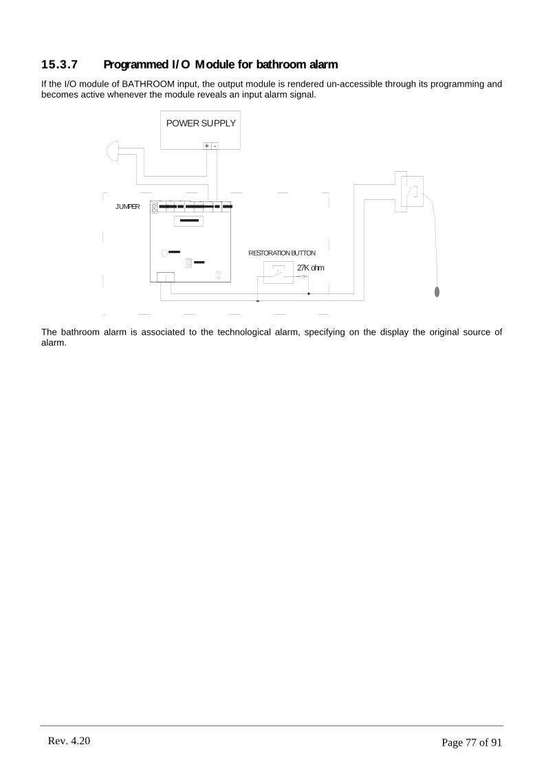
Page 77 of 91Rev. 4.20
15.3.7 Programmed I/O Module for bathroom alarm
If the I/O module of BATHROOM input, the output module is rendered un-accessible through its programming and becomes active whenever the module reveals an input alarm signal.
JUMPER
RESTORATIONBUTTON
27K ohm
POWER SUPPLY
+ -
The bathroom alarm is associated to the technological alarm, specifying on the display the original source of alarm.

Page 78 of 91Rev. 4.20
The following are some examples of connection between some control panels with points.
Connection between two control panels with RS485 serial port; utilization of a supervisor PC through RS245 serial port; magnets, detectors and optical/acoustic lamps along a loop.
- B1+ - B2+ - AUX + FAULT - + (30Vdc)
23
1
65
4
L - L +
23
1
65
4
BUTTON
+-
12-24Vdc Automatic
+-
12-24Vdc
Automatic
POWER SUPPLY24V 2A
+
-
L - L + L - L +NO C NCS
Relè
LED
I/OM
OD
ULE
5.6Kohm
+ -
+-
RS485
RS232RS485
SLAVE
SLAVE
PCMASTER
ELECTROMAGNET50Kg
ELECTROMAGNET50Kg
SIREN
Rs485
-1
B
-1
B
+1
B
+1
B
SH
I
SH
I
-1
A
-1
A
+1
A
+1
A
-2B
-2B
+2
B
+2
B
SH
I
SH
I
-2A
-2A
+2
A
+2
A
-24
-24
+2
4
+2
4
SH
I
SH
I
+S
+S
-S
-S
- +FAULT
-+FAULT
SH
I
SH
I
OC
1
OC
1
OC
2
OC
2
OC
3
OC
3
OC
4
OC
4
RL2
RL2
RL1
RL1
PS2
PS2
L -
PART 16GENERIC ELECTRICAL SCHEMES

Page 79 of 91Rev. 4.20
16.1CONNECTION BEETWEN CONTROL PANELS AND PC (RS485)
J1 J2 J1 J2
J1 J2 J1 J2 J1 J2
PC-Master
J1 da ponticellareJ1 to jumper in clip
With the RS485 serial port it is possible to connect maximum 64 control panels (slave), all of them are controlled from a PC (master). The maximum length with RS485 is 1Km.Into the PC must be installed the X-Advisor software to manage all the control panels.
16.2CONTROL PANEL CONNECTION ON LAN
SWITCHLAN
It is possible to make a control panel net with LAN connection. To connect a control panel with the net, the user must use a MOXA module to interface the RS232 with LAN. Into the PC the user must install the X-Advisorsoftware and to set the software.
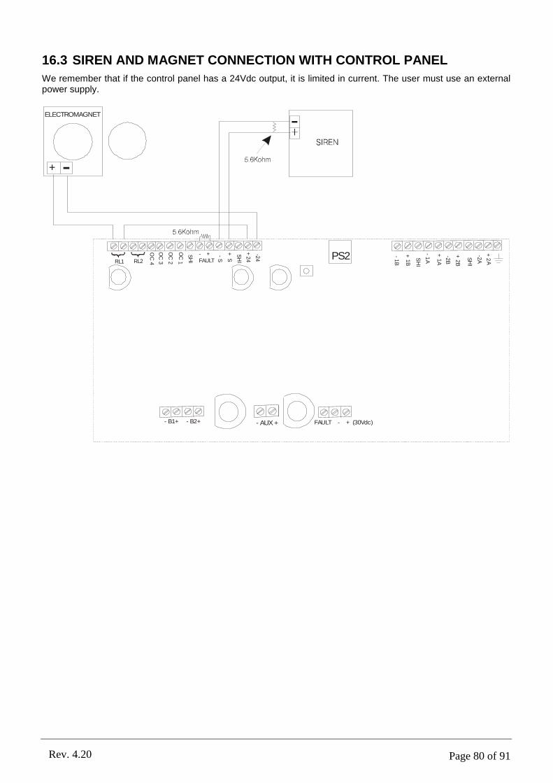
Page 80 of 91Rev. 4.20
16.3 SIREN AND MAGNET CONNECTION WITH CONTROL PANEL
We remember that if the control panel has a 24Vdc output, it is limited in current. The user must use an external power supply.
- B1+ - B2+ - AUX + FAULT - + (30Vdc)
+ -
ELECTROMAGNET
-1
B
+1
B
SH
I
-1
A
+1
A
-2B
+2
B
SH
I
-2A
+2
A
-24
+2
4
SH
I
+S
-S
- +FAULT
SH
I
OC
1
OC
2
OC
3
OC
4RL2RL1PS2

Page 81 of 91Rev. 4.20
16.4SOME CONNECTION POINTS
L -L +S
out
-In
L -L+S
REED
BUTTON
L+
L-
L+
NO
CN
CS
LED
I/O MODULE
24Vdc 2A
Power Supply
+-
12-24V
23
1
65
4
23
1
65
4
23
1
65
4
-1B
+1B
SHI
-1A
+1A
-2B
+2B
SHI
-2A
+2A
-24
+2
4
SHI
+S
-S
- +FAULT
S HI
OC
1
OC
2
OC
3
OC
4RL2RL1PS2
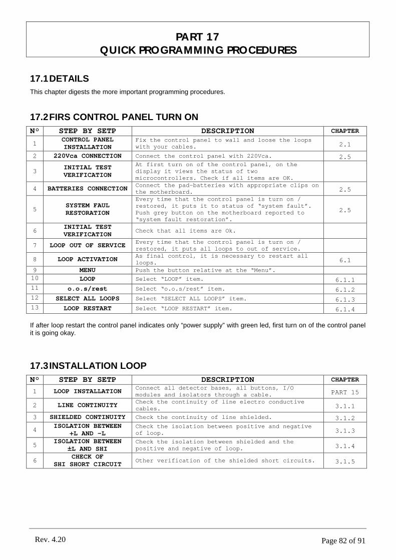
Page 82 of 91Rev. 4.20
PART 17QUICK PROGRAMMING PROCEDURES
17.1DETAILS
This chapter digests the more important programming procedures.
17.2FIRS CONTROL PANEL TURN ON
N° STEP BY SETP DESCRIPTION CHAPTER
1CONTROL PANEL INSTALLATION
Fix the control panel to wall and loose the loopswith your cables. 2.1
2 220Vca CONNECTION Connect the control panel with 220Vca. 2.5
3INITIAL TEST VERIFICATION
At first turn on of the control panel, on the display it views the status of two microcontrollers. Check if all items are OK.
4 BATTERIES CONNECTIONConnect the pad-batteries with appropriate clips on the motherboard. 2.5
5SYSTEM FAUL RESTORATION
Every time that the control panel is turn on / restored, it puts it to status of “system fault”. Push grey button on the motherboard reported to “system fault restoration”.
2.5
6INITIAL TEST VERIFICATION
Check that all items are Ok.
7 LOOP OUT OF SERVICEEvery time that the control panel is turn on / restored, it puts all loops to out of service.
8 LOOP ACTIVATIONAs final control, it is necessary to restart all loops. 6.1
9 MENU Push the button relative at the “Menu”.
10 LOOP Select “LOOP” item. 6.1.111 o.o.s/rest Select “o.o.s/rest” item. 6.1.212 SELECT ALL LOOPS Select “SELECT ALL LOOPS” item. 6.1.313 LOOP RESTART Select “LOOP RESTART” item. 6.1.4
If after loop restart the control panel indicates only “power supply” with green led, first turn on of the control panel it is going okay.
17.3INSTALLATION LOOP
N° STEP BY SETP DESCRIPTION CHAPTER
1 LOOP INSTALLATIONConnect all detector bases, all buttons, I/O modules and isolators through a cable. PART 15
2 LINE CONTINUITYCheck the continuity of line electro conductive cables. 3.1.1
3 SHIELDED CONTINUITY Check the continuity of line shielded. 3.1.2
4ISOLATION BETWEEN
+L AND -LCheck the isolation between positive and negative of loop. 3.1.3
5ISOLATION BETWEEN
±L AND SHICheck the isolation between shielded and the positive and negative of loop. 3.1.4
6CHECK OF
SHI SHORT CIRCUITOther verification of the shielded short circuits. 3.1.5
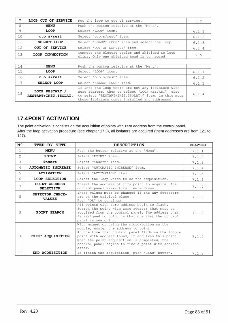
Page 83 of 91Rev. 4.20
7 LOOP OUT OF SERVICE Put the loop to out of service. 6.28 MENU Push the button relative at the “Menu”.
9 LOOP Select “LOOP” item. 6.1.110 o.o.s/rest Select “o.o.s/rest” item. 6.1.211 SELECT LOOP Select “SELECT LOOP” item and select the loop. 6.1.312 OUT OF SERVICE Select “OUT OF SERVICE” item. 6.1.4
13 LOOP CONNECTIONConnect the electro cables and shielded to loop clips. Only one shielded head is connected. 2.5
14 MENU Push the button relative at the “Menu”.
15 LOOP Select “LOOP” item. 6.1.116 o.o.s/rest Select “o.o.s/rest” item. 6.1.217 SELECT LOOP Select “SELECT LOOP” item. 6.1.3
18LOOP RESTART /
RESTART+INST.ISOLAT.
If into the loop there are not any isolators with zero address, then to select “LOOP RESTART”; else to select “RESTART+INST.ISOLAT.” item, in this mode these isolators comes installed and addressed.
6.1.4
17.4POINT ACTIVATION
The point activation is consists on the acquisition of points with zero address from the control panel.
After the loop activation procedure (see chapter 17.3), all isolators are acquired (them addresses are from 121 to 127).
N° STEP BY SETP DESCRIPTION CHAPTER
1 MENU Push the button relative at the “Menu”. 7.1.12 POINT Select “POINT” item. 7.1.23 insert Select “insert” item. 7.1.34 AUTOMATIC INCREASE Select “AUTOMATIC INCREASE” item. 7.1.45 ACTIVATION Select “ACTIVATION” item. 7.1.56 LOOP SELECTION Select the loop which to do the acquisition. 7.1.6
7POINT ADDRESS
SELECTIONInsert the address of firs point to acquire. The control panel views firs free address. 7.1.7
8DETECTOR CHECK-
VALUES
These values must be changed if the any detectors are on the critical place.Push “Ok” to continue.
7.1.8
9 POINT SEARCH
All points with zero address begin to flash.Search the point with zero address that must be acquired from the control panel. The address that is assigned to point is that one that the control panel is searching.
7.1.9
10 POINT ACQUISITION
With magnet or using the micro-button on the module, assign the address to point.At the time that control panel finds on the loop a point with address found, it acquires this point. When the point acquisition is completed, the control panel begins to find a point with address after.
7.1.9
11 END ACQUISITION To finish the acquisition, push “Canc” button. 7.1.9

Page 84 of 91Rev. 4.20
17.5INPUT PROGRAMMING
This procedure permits to programme a I/O module input (for example).
N° STEP BY SETP DESCRIPTION CHAPTER
1 MENU Push the button relative at the “Menu”. 7.22 POINT Select “POINT” item. 7.2.13 view/mod. Select “view/mod.” item. 7.2.24 LOOP SELECTION Select the loop of the I/O module. 7.2.3
5 POINT ADDRESSInsert the point address to begin the points programming of the system. 7.2.4
6 POINT SETTING Into this menu, there are all point parameters. 7.2.5
7 INPUTChange the value of “INPUT” item with “FIRE ALARM” value. 15.3.4
17.6OUTPUT PROGRAMMING
This procedure permits to programme a relay output apiece of a particular status of the control panel (fire alarm, technological alarm, ...).The information about at the loop outputs (for example those of I/O module), they are at inside of the point
information (see chapter 7.2), but they are separated and grouped from “OUTPUT” item (see chapter PART 9).
N° STEP BY SETP DESCRIPTION CHAPTER
1 MENU Push the button relative at the “Menu”.
2 OUTPUT Select “OUTPUT” item. 9.1.13 view/mod. Select “view/mod.” item. 9.1.2
4CONTROL PANEL OUTPUT
LOOP OUTPUTSelect the item, where is the output to programme. 9.1.3
5 OUTPUT SELECTIONSelect the loop (if loop output) and the output address to programme.
6 OUTPUT SETTINGInside at this menu, there are all output parameters. 9.1.4
7 ACTIVATIONChange “ACTIVATION” item and to set up its value at: “STATUS”. 9.1.4
8 ALLARME INCENDIOThought the “Mod.” button, to mark the items for which the output must activate. 9.1.4
17.7SETTING AN OUTPUT DELAY
The possibility to set up a delay to an output is subordinate to the various conditions (see chapter 9.4 for details).1. The control panel must be in supervision Mode.2. The zone in which you want the delay on the output must be set up as “DELAYED OUTPUT” = “YES”.3. Pressing the command the delay is “Zeroed” (in the cases of programmed output for fire alarm).
Settings for supervised Mode:
N° STEP BY SETP DESCRIPTION CHAPTER
1 MENU Push the button relative to the “Menu”.
2 SETTING Select “SETTING” item.
3 supervis. Select “SUPERVIS.” item. 10.14 ENABLE Enable supervised mode. 10.2
5 DATE SETTINGSet up the command field valid from the date in which the control panel must be active under this function.
10.2
6 TIME SETTINGSet up the command field valid for the time in which you want the control panel to operate under this function.
10.2

Page 85 of 91Rev. 4.20
Settings for delayed zone:
N° STEP BY STEP DESCRIPTION CHAPTER
1 MENU Push the button relative at the “Menu”.
2 ZONE Select “ZONE” item. 8.3.13 view/mod. Select “view/mod.” item. 8.3.24 LOOP SELECTION Select loop for the zone. 8.3.3
5 ZONE ADDRESSInsert the address to the zone which you want to assign the delay output. 8.3.4
6 DELAYED OUTPUT = YESSet up the validity field to the “DELAYED OUTPUT” with “YES” value. 8.3.5
Output delay setup:
N° STEP BY SETP DESCRIPTION CHAPTER
1 MENU Push the button relative at the “Menu”.
2 OUTPUT Select “OUTPUT” item. 9.1.13 view/mod. Select “view/mod” item. 9.1.2
4CONTROL PANEL OUTPUT
/LOOP OUTPUT
Select the item, in which there is the output to program. 9.1.3
5 OUTPUT SELECTIONSelect the loop (if it is loop output) and output address to program.
6 OUTPUT SETTINGInside this menu there are all the parameters of the output. 9.1.4
7 ACTIV. DELAYSet up the validity field of command for “ACTIV. DELAY” With the delay value you wish to assign that output.
9.1.4
17.8RESET MODE of FIRE ALARM
The “Reset” button on the keyboard of the Panel allows to reset all events which are no longer pending (the ones who do not have “!” symbol on the second line of description reading).
Once the alarms have been restored, it is possible to set up the reset mode according to the requirements of the user. See charter 10.4 where all the different modes are explained for programming the reset and restore of all fire alarms.
Following this, the reset procedure of fire alarm in case of the set up “F.S. AUTO” is on display (all points automatically out of service during the fire alarm).
Restore Fire Alarm:
N° STEP DESCRIPTION CHAPTER
1 Reset Press button “Reset”. 4.1.12 PASSWORD 2 Insert password level 2.
3 Restore alarms
The Control Panel will restore all alarms and
events which have been reset in automatic (the ones who do not have “!” symbol on the second
line of description reading).
10.1
4All points in fire
alarm out of service
In restoration phase, the Control Panel will find all points in fire alarm which have not been automatically reset and will put all the points still in alarm into out of service.
10.2
5Out of service zone in
fire alarm
If all points of a zone are put into out of service; also the zone will be put out of service.
10.2
In the case that the zones have been put out of service as a result of Alarm reset (event which occurs whenever the points of a zone are put out of service), so one must, before anything, put the zones back into service and then do the same with the points.
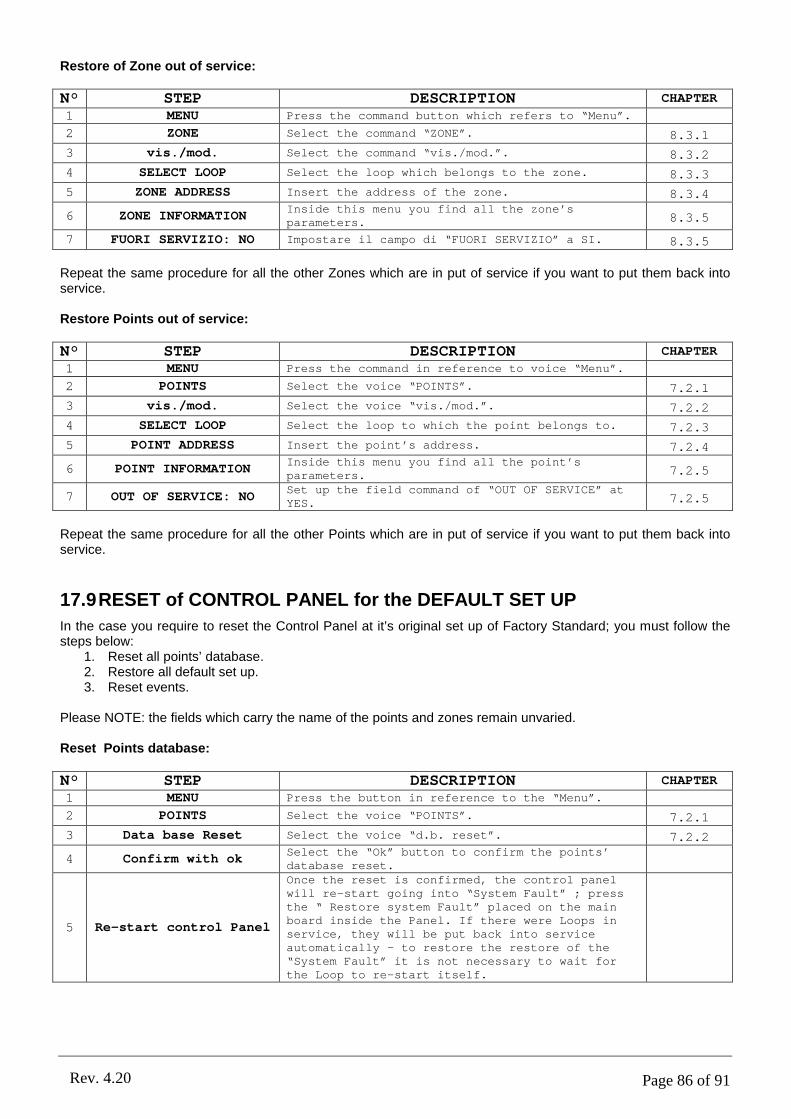
Page 86 of 91Rev. 4.20
Restore of Zone out of service:
N° STEP DESCRIPTION CHAPTER
1 MENU Press the command button which refers to “Menu”.
2 ZONE Select the command “ZONE”. 8.3.13 vis./mod. Select the command “vis./mod.”. 8.3.24 SELECT LOOP Select the loop which belongs to the zone. 8.3.35 ZONE ADDRESS Insert the address of the zone. 8.3.4
6 ZONE INFORMATIONInside this menu you find all the zone’s parameters. 8.3.5
7 FUORI SERVIZIO: NO Impostare il campo di “FUORI SERVIZIO” a SI. 8.3.5
Repeat the same procedure for all the other Zones which are in put of service if you want to put them back into service.
Restore Points out of service:
N° STEP DESCRIPTION CHAPTER
1 MENU Press the command in reference to voice “Menu”.
2 POINTS Select the voice “POINTS”. 7.2.13 vis./mod. Select the voice “vis./mod.”. 7.2.24 SELECT LOOP Select the loop to which the point belongs to. 7.2.35 POINT ADDRESS Insert the point’s address. 7.2.4
6 POINT INFORMATIONInside this menu you find all the point’s parameters. 7.2.5
7 OUT OF SERVICE: NOSet up the field command of “OUT OF SERVICE” at YES. 7.2.5
Repeat the same procedure for all the other Points which are in put of service if you want to put them back into service.
17.9RESET of CONTROL PANEL for the DEFAULT SET UP
In the case you require to reset the Control Panel at it’s original set up of Factory Standard; you must follow the steps below:
1. Reset all points’ database.2. Restore all default set up.3. Reset events.
Please NOTE: the fields which carry the name of the points and zones remain unvaried.
Reset Points database:
N° STEP DESCRIPTION CHAPTER
1 MENU Press the button in reference to the “Menu”.
2 POINTS Select the voice “POINTS”. 7.2.13 Data base Reset Select the voice “d.b. reset”. 7.2.2
4 Confirm with okSelect the “Ok” button to confirm the points’database reset.
5 Re-start control Panel
Once the reset is confirmed, the control panel will re-start going into “System Fault” ; press the “ Restore system Fault” placed on the main board inside the Panel. If there were Loops in service, they will be put back into service automatically – to restore the restore of the “System Fault” it is not necessary to wait for the Loop to re-start itself.
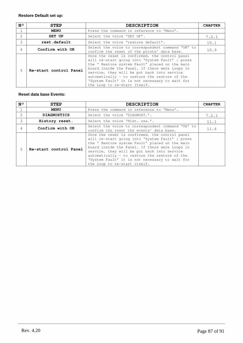
Page 87 of 91Rev. 4.20
Restore Default set up:
N° STEP DESCRIPTION CHAPTER
1 MENU Press the command in reference to “Menu”.
2 SET UP Select the voice “SET UP”. 7.2.13 rest.default Select the voice “restore default”. 10.1
4 Confirm with OKSelect the voice to correspondent command “OK” to confirm the reset of the points’ data base. 10.9
5 Re-start control Panel
Once the reset is confirmed, the control panel will re-start going into “System Fault” ; press the “ Restore system Fault” placed on the main board inside the Panel. If there were Loops inservice, they will be put back into service automatically – to restore the restore of the “System Fault” it is not necessary to wait for the Loop to re-start itself.
Reset data base Events:
N° STEP DESCRIPTION CHAPTER
1 MENU Press the command in reference to “Menu”.
2 DIAGNOSTICS Select the voice “DIAGNOST.”. 7.2.13 History reset. Select the voice “Hist. res.”. 11.1
4 Confirm with OKSelect the voice to correspondent command “Ok” to confirm the reset the events’ data base. 11.6
5 Re-start control Panel
Once the reset is confirmed, the control panel will re-start going into “System Fault” ; press the “ Restore system Fault” placed on the main board inside the Panel. If there were Loops in service, they will be put back into service automatically – to restore the restore of the “System Fault” it is not necessary to wait for the Loop to re-start itself.
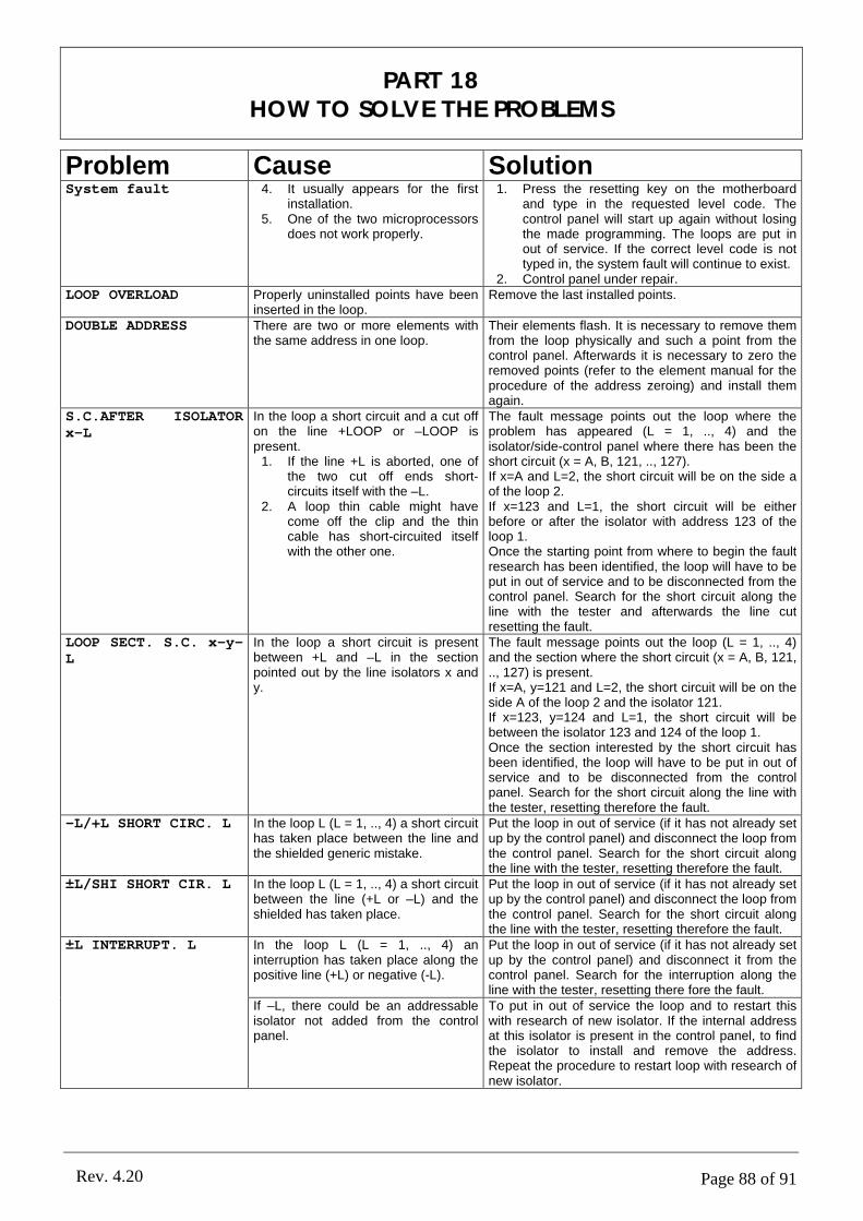
Page 88 of 91Rev. 4.20
Problem Cause SolutionSystem fault 4. It usually appears for the first
installation.5. One of the two microprocessors
does not work properly.
1. Press the resetting key on the motherboard and type in the requested level code. The control panel will start up again without losing the made programming. The loops are put in out of service. If the correct level code is not typed in, the system fault will continue to exist.
2. Control panel under repair.LOOP OVERLOAD Properly uninstalled points have been
inserted in the loop.Remove the last installed points.
DOUBLE ADDRESS There are two or more elements with the same address in one loop.
Their elements flash. It is necessary to remove them from the loop physically and such a point from the control panel. Afterwards it is necessary to zero the removed points (refer to the element manual for the procedure of the address zeroing) and install them again.
S.C.AFTER ISOLATOR x-L
In the loop a short circuit and a cut off on the line +LOOP or –LOOP is present.
1. If the line +L is aborted, one of the two cut off ends short-circuits itself with the –L.
2. A loop thin cable might have come off the clip and the thin cable has short-circuited itself with the other one.
The fault message points out the loop where the problem has appeared (L = 1, .., 4) and the isolator/side-control panel where there has been the short circuit (x = A, B, 121, .., 127).If x=A and L=2, the short circuit will be on the side a of the loop 2.If x=123 and L=1, the short circuit will be either before or after the isolator with address 123 of the loop 1.Once the starting point from where to begin the fault research has been identified, the loop will have to be put in out of service and to be disconnected from the control panel. Search for the short circuit along the line with the tester and afterwards the line cut resetting the fault.
LOOP SECT. S.C. x-y-L
In the loop a short circuit is present between +L and –L in the section pointed out by the line isolators x and y.
The fault message points out the loop (L = 1, .., 4) and the section where the short circuit (x = A, B, 121, .., 127) is present.If x=A, y=121 and L=2, the short circuit will be on the side A of the loop 2 and the isolator 121.If x=123, y=124 and L=1, the short circuit will be between the isolator 123 and 124 of the loop 1.Once the section interested by the short circuit has been identified, the loop will have to be put in out of service and to be disconnected from the control panel. Search for the short circuit along the line with the tester, resetting therefore the fault.
-L/+L SHORT CIRC. L In the loop L (L = 1, .., 4) a short circuit has taken place between the line and the shielded generic mistake.
Put the loop in out of service (if it has not already set up by the control panel) and disconnect the loop from the control panel. Search for the short circuit along the line with the tester, resetting therefore the fault.
±L/SHI SHORT CIR. L In the loop L (L = 1, .., 4) a short circuit between the line (+L or –L) and the shielded has taken place.
Put the loop in out of service (if it has not already set up by the control panel) and disconnect the loop from the control panel. Search for the short circuit along the line with the tester, resetting therefore the fault.
In the loop L (L = 1, .., 4) an interruption has taken place along the positive line (+L) or negative (-L).
Put the loop in out of service (if it has not already set up by the control panel) and disconnect it from the control panel. Search for the interruption along the line with the tester, resetting there fore the fault.
±L INTERRUPT. L
If –L, there could be an addressable isolator not added from the control panel.
To put in out of service the loop and to restart this with research of new isolator. If the internal address at this isolator is present in the control panel, to find the isolator to install and remove the address. Repeat the procedure to restart loop with research of new isolator.
PART 18HOW TO SOLVE THE PROBLEMS
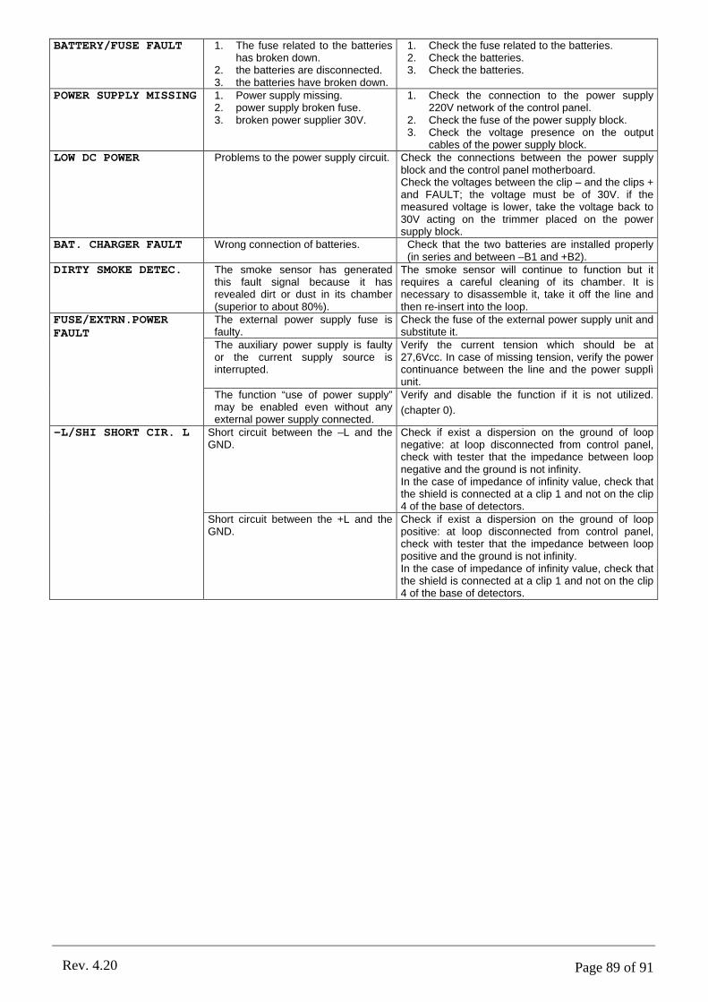
Page 89 of 91Rev. 4.20
BATTERY/FUSE FAULT 1. The fuse related to the batteries has broken down.
2. the batteries are disconnected.3. the batteries have broken down.
1. Check the fuse related to the batteries.2. Check the batteries.3. Check the batteries.
POWER SUPPLY MISSING 1. Power supply missing.2. power supply broken fuse.3. broken power supplier 30V.
1. Check the connection to the power supply 220V network of the control panel.
2. Check the fuse of the power supply block.3. Check the voltage presence on the output
cables of the power supply block.LOW DC POWER Problems to the power supply circuit. Check the connections between the power supply
block and the control panel motherboard.Check the voltages between the clip – and the clips + and FAULT; the voltage must be of 30V. if the measured voltage is lower, take the voltage back to 30V acting on the trimmer placed on the power supply block.
BAT. CHARGER FAULT Wrong connection of batteries. Check that the two batteries are installed properly (in series and between –B1 and +B2).
DIRTY SMOKE DETEC. The smoke sensor has generated this fault signal because it has revealed dirt or dust in its chamber (superior to about 80%).
The smoke sensor will continue to function but it requires a careful cleaning of its chamber. It is necessary to disassemble it, take it off the line and then re-insert into the loop.
The external power supply fuse is faulty.
Check the fuse of the external power supply unit and substitute it.
The auxiliary power supply is faulty or the current supply source is interrupted.
Verify the current tension which should be at 27,6Vcc. In case of missing tension, verify the power continuance between the line and the power supplì unit.
FUSE/EXTRN.POWER FAULT
The function “use of power supply” may be enabled even without any external power supply connected.
Verify and disable the function if it is not utilized.
(chapter 0).
Short circuit between the –L and the GND.
Check if exist a dispersion on the ground of loop negative: at loop disconnected from control panel, check with tester that the impedance between loop negative and the ground is not infinity.In the case of impedance of infinity value, check that the shield is connected at a clip 1 and not on the clip 4 of the base of detectors.
-L/SHI SHORT CIR. L
Short circuit between the +L and the GND.
Check if exist a dispersion on the ground of loop positive: at loop disconnected from control panel, check with tester that the impedance between loop positive and the ground is not infinity.In the case of impedance of infinity value, check that the shield is connected at a clip 1 and not on the clip 4 of the base of detectors.

Page 90 of 91Rev. 4.20
GENERALCase size: 1 loop model: B x H x P 325x440x90mm.
2,4 loop models: B x H x P 410x510x90mm.
Case material: Painted steel.
Fixing: At wall, with installation fixed.
Protection degree: IP40.
Weight: 10Kg (without batteries).
Operating Temperature: - 5 = + 45°C.
Relative humidity: <95% relative humidity, no condensed.
Control panel keypad cleaning It is possible to clean the control panel keypad with a with a humid cloth. Not to use aggressive agents.
LOOPDetection circuit: 1-2-4 loop. Every loop supports the communication with 127 elements
(detectors, buttons, input/output modules and isolators).
Maximum points number for loop:
120 between detectors, buttons and modules;7 addressable isolators;100 passive isolators.
Point types: Into the loop it is possible to install: detectors (smoke, heat e smoke-heat), buttons, I/O modules and isolators.
Definable zone: Up to 63 configurable zones per loop.
LOCAL POWER SUPPLYPower supply voltage: 230Vac + 10% - 15%, 50Hz.
Power supply: < 50VA.
Power supply fuse: T 400mA 250V (delayed).
Power supply output: 30Vdc.
Battery charger output 27.6Vdc nominal at 20°C.
Battery charger fuse: F 1.6A L 250V (fast).
Battery: Loop1: at Pb 2x 12V – 7.2AhLoop2: at Pb 2x 12V – 18AhLoop4: at Pb 2x 12V – 18Ah.
Aux. power supply: 27.6Vdc.
Aux. power supply fuse: F 1.6A L 250V (fast).
PART 19TECHNICAL CHARACTERISTICS
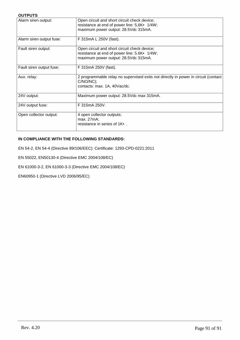
Page 91 of 91Rev. 4.20
OUTPUTSAlarm siren output: Open circuit and short circuit check device;
resistance at end of power line: 5,6K• 1/4W;maximum power output: 28.5Vdc 315mA.
Alarm siren output fuse: F 315mA L 250V (fast).
Fault siren output: Open circuit and short circuit check device;resistance at end of power line: 5.6K• 1/4W;maximum power output: 28.5Vdc 315mA.
Fault siren output fuse: F 315mA 250V (fast).
Aux. relay: 2 programmable relay no supervised exits not directly in power in circuit (contact C/NO/NC);contacts: max. 1A, 40Vac/dc.
24V output: Maximum power output: 28.5Vdc max 315mA.
24V output fuse: F 315mA 250V.
Open collector output: 4 open collector outputs;max. 27mA;resistance in series of 1K•.
IN COMPLIANCE WITH THE FOLLOWING STANDARDS:
EN 54-2, EN 54-4 (Directive 89/106/EEC): Certificate: 1293-CPD-0221:2011
EN 55022, EN50130-4 (Directive EMC 2004/108/EC)
EN 61000-3-2, EN 61000-3-3 (Directive EMC 2004/108/EC)
EN60950-1 (Directive LVD 2006/95/EC)


![21242593[VARIMOT EX.].pdf](https://static.fdokumen.com/doc/165x107/6338b562e57b005bf2016bb4/21242593varimot-expdf.jpg)