Determinants of eating habits among older adults - Mattioli ...
Upload
khangminh22Category
view
0download
0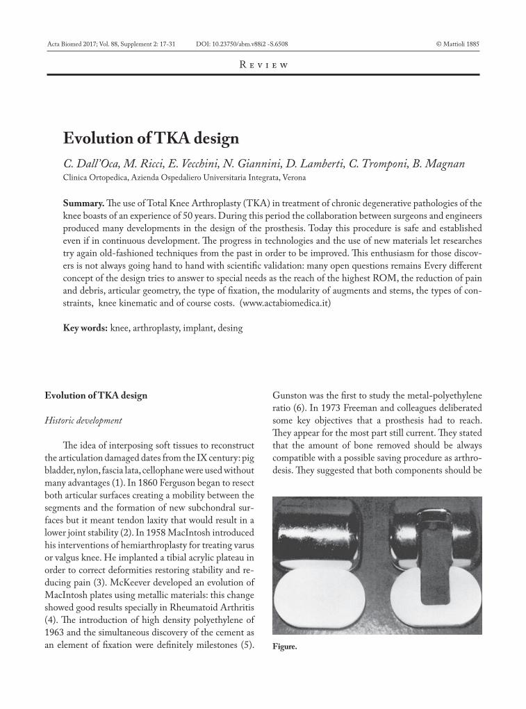
Evolution of TKA designC. Dall’Oca, M. Ricci, E. Vecchini, N. Giannini, D. Lamberti, C. Tromponi, B. MagnanClinica Ortopedica, Azienda Ospedaliero Universitaria Integrata, Verona
Summary. The use of Total Knee Arthroplasty (TKA) in treatment of chronic degenerative pathologies of the knee boasts of an experience of 50 years. During this period the collaboration between surgeons and engineers produced many developments in the design of the prosthesis. Today this procedure is safe and established even if in continuous development. The progress in technologies and the use of new materials let researches try again old-fashioned techniques from the past in order to be improved. This enthusiasm for those discov-ers is not always going hand to hand with scientific validation: many open questions remains Every different concept of the design tries to answer to special needs as the reach of the highest ROM, the reduction of pain and debris, articular geometry, the type of fixation, the modularity of augments and stems, the types of con-straints, knee kinematic and of course costs. (www.actabiomedica.it)
Key words: knee, arthroplasty, implant, desing
Acta Biomed 2017; Vol. 88, Supplement 2: 17-31 DOI: 10.23750/abm.v88i2 -S.6508 © Mattioli 1885
R e v i e w
Evolution of TKA design
Historic development
The idea of interposing soft tissues to reconstruct the articulation damaged dates from the IX century: pig bladder, nylon, fascia lata, cellophane were used without many advantages (1). In 1860 Ferguson began to resect both articular surfaces creating a mobility between the segments and the formation of new subchondral sur-faces but it meant tendon laxity that would result in a lower joint stability (2). In 1958 MacIntosh introduced his interventions of hemiarthroplasty for treating varus or valgus knee. He implanted a tibial acrylic plateau in order to correct deformities restoring stability and re-ducing pain (3). McKeever developed an evolution of MacIntosh plates using metallic materials: this change showed good results specially in Rheumatoid Arthritis (4). The introduction of high density polyethylene of 1963 and the simultaneous discovery of the cement as an element of fixation were definitely milestones (5).
Gunston was the first to study the metal-polyethylene ratio (6). In 1973 Freeman and colleagues deliberated some key objectives that a prosthesis had to reach. They appear for the most part still current. They stated that the amount of bone removed should be always compatible with a possible saving procedure as arthro-desis. They suggested that both components should be
Figure.
06-dall'oca.indd 17 06/06/17 10:23
C. Dall’Oca, M. Ricci, E. Vecchini, et al.18
incompletely constrained so that twisting and varus-valgus stress cannot be transmitted to the bonds be-tween the prosthesis and bone. They established that the friction should be decrease as much as possible and that the hyperextension-limiting mechanism should be progressive rather than abrupt. They settled that the prosthetic component should be fitted to the bone by means that spread the loads over the largest possible area of the bone-prosthesis interface. Among other goals the reduction of wear debris and the infection rate (possible with few dead spaces), the drafting of a standard procedure, the achievement of a sufficient ROM value (from 5 degrees of hyperextension to 90 degrees of flexion), the importance of ligaments (7).
Resurfacing prostheses
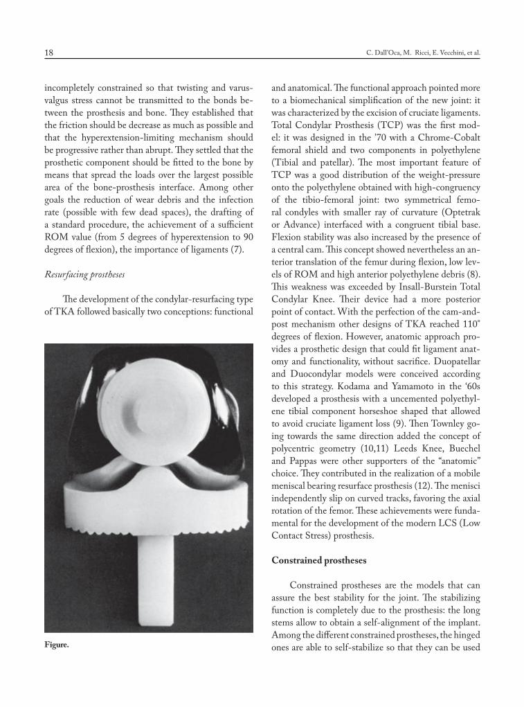
The development of the condylar-resurfacing type of TKA followed basically two conceptions: functional
and anatomical. The functional approach pointed more to a biomechanical simplification of the new joint: it was characterized by the excision of cruciate ligaments. Total Condylar Prosthesis (TCP) was the first mod-el: it was designed in the ’70 with a Chrome-Cobalt femoral shield and two components in polyethylene (Tibial and patellar). The most important feature of TCP was a good distribution of the weight-pressure onto the polyethylene obtained with high-congruency of the tibio-femoral joint: two symmetrical femo-ral condyles with smaller ray of curvature (Optetrak or Advance) interfaced with a congruent tibial base. Flexion stability was also increased by the presence of a central cam. This concept showed nevertheless an an-terior translation of the femur during flexion, low lev-els of ROM and high anterior polyethylene debris (8). This weakness was exceeded by Insall-Burstein Total Condylar Knee. Their device had a more posterior point of contact. With the perfection of the cam-and-post mechanism other designs of TKA reached 110° degrees of flexion. However, anatomic approach pro-vides a prosthetic design that could fit ligament anat-omy and functionality, without sacrifice. Duopatellar and Duocondylar models were conceived according to this strategy. Kodama and Yamamoto in the ‘60s developed a prosthesis with a uncemented polyethyl-ene tibial component horseshoe shaped that allowed to avoid cruciate ligament loss (9). Then Townley go-ing towards the same direction added the concept of polycentric geometry (10,11) Leeds Knee, Buechel and Pappas were other supporters of the “anatomic” choice. They contributed in the realization of a mobile meniscal bearing resurface prosthesis (12). The menisci independently slip on curved tracks, favoring the axial rotation of the femor. These achievements were funda-mental for the development of the modern LCS (Low Contact Stress) prosthesis.
Constrained prostheses
Constrained prostheses are the models that can assure the best stability for the joint. The stabilizing function is completely due to the prosthesis: the long stems allow to obtain a self-alignment of the implant. Among the different constrained prostheses, the hinged ones are able to self-stabilize so that they can be used Figure.
06-dall'oca.indd 18 06/06/17 10:23
Evolution of TKA design 19
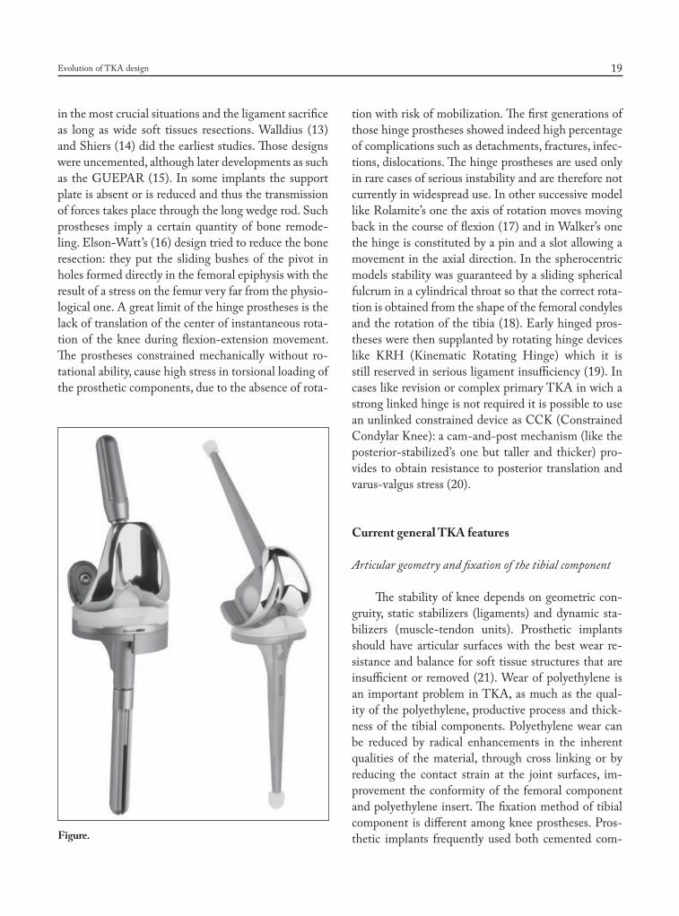
in the most crucial situations and the ligament sacrifice as long as wide soft tissues resections. Walldius (13) and Shiers (14) did the earliest studies. Those designs were uncemented, although later developments as such as the GUEPAR (15). In some implants the support plate is absent or is reduced and thus the transmission of forces takes place through the long wedge rod. Such prostheses imply a certain quantity of bone remode-ling. Elson-Watt’s (16) design tried to reduce the bone resection: they put the sliding bushes of the pivot in holes formed directly in the femoral epiphysis with the result of a stress on the femur very far from the physio-logical one. A great limit of the hinge prostheses is the lack of translation of the center of instantaneous rota-tion of the knee during flexion-extension movement. The prostheses constrained mechanically without ro-tational ability, cause high stress in torsional loading of the prosthetic components, due to the absence of rota-
tion with risk of mobilization. The first generations of those hinge prostheses showed indeed high percentage of complications such as detachments, fractures, infec-tions, dislocations. The hinge prostheses are used only in rare cases of serious instability and are therefore not currently in widespread use. In other successive model like Rolamite’s one the axis of rotation moves moving back in the course of flexion (17) and in Walker’s one the hinge is constituted by a pin and a slot allowing a movement in the axial direction. In the spherocentric models stability was guaranteed by a sliding spherical fulcrum in a cylindrical throat so that the correct rota-tion is obtained from the shape of the femoral condyles and the rotation of the tibia (18). Early hinged pros-theses were then supplanted by rotating hinge devices like KRH (Kinematic Rotating Hinge) which it is still reserved in serious ligament insufficiency (19). In cases like revision or complex primary TKA in wich a strong linked hinge is not required it is possible to use an unlinked constrained device as CCK (Constrained Condylar Knee): a cam-and-post mechanism (like the posterior-stabilized’s one but taller and thicker) pro-vides to obtain resistance to posterior translation and varus-valgus stress (20).
Current general TKA features
Articular geometry and fixation of the tibial component
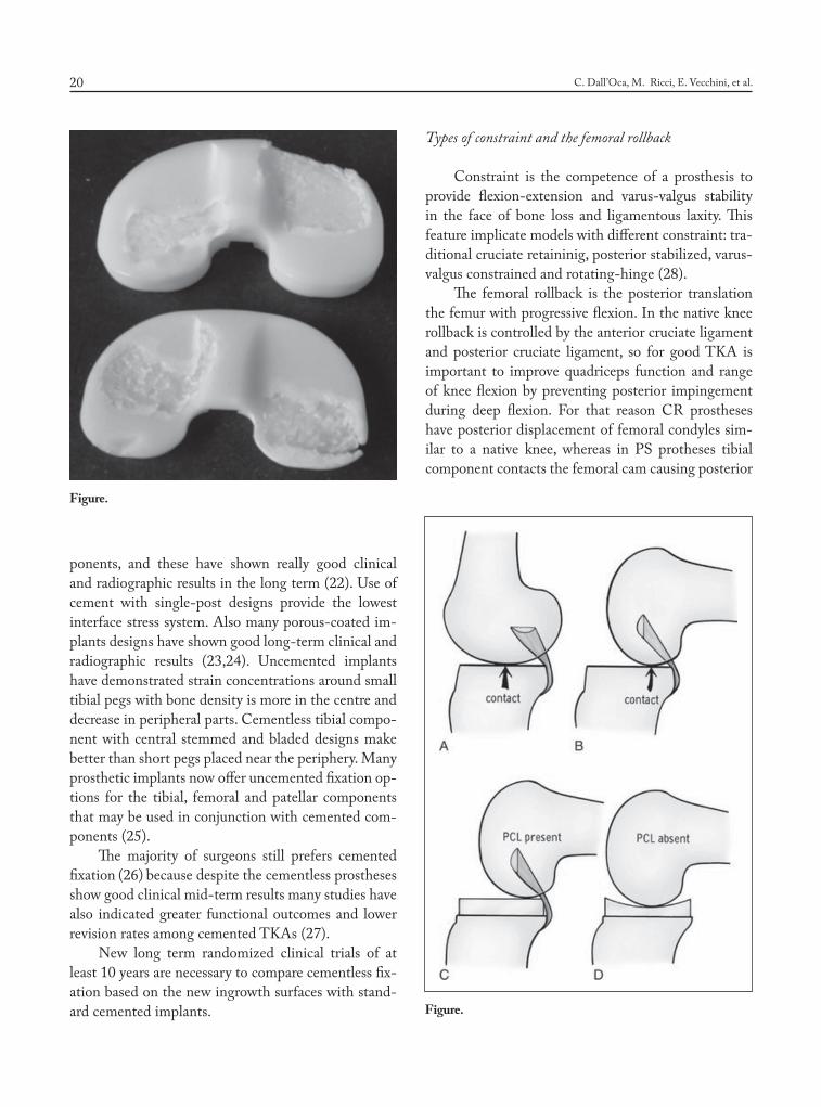
The stability of knee depends on geometric con-gruity, static stabilizers (ligaments) and dynamic sta-bilizers (muscle-tendon units). Prosthetic implants should have articular surfaces with the best wear re-sistance and balance for soft tissue structures that are insufficient or removed (21). Wear of polyethylene is an important problem in TKA, as much as the qual-ity of the polyethylene, productive process and thick-ness of the tibial components. Polyethylene wear can be reduced by radical enhancements in the inherent qualities of the material, through cross linking or by reducing the contact strain at the joint surfaces, im-provement the conformity of the femoral component and polyethylene insert. The fixation method of tibial component is different among knee prostheses. Pros-thetic implants frequently used both cemented com-Figure.
06-dall'oca.indd 19 06/06/17 10:23
C. Dall’Oca, M. Ricci, E. Vecchini, et al.20
ponents, and these have shown really good clinical and radiographic results in the long term (22). Use of cement with single-post designs provide the lowest interface stress system. Also many porous-coated im-plants designs have shown good long-term clinical and radiographic results (23,24). Uncemented implants have demonstrated strain concentrations around small tibial pegs with bone density is more in the centre and decrease in peripheral parts. Cementless tibial compo-nent with central stemmed and bladed designs make better than short pegs placed near the periphery. Many prosthetic implants now offer uncemented fixation op-tions for the tibial, femoral and patellar components that may be used in conjunction with cemented com-ponents (25).
The majority of surgeons still prefers cemented fixation (26) because despite the cementless prostheses show good clinical mid-term results many studies have also indicated greater functional outcomes and lower revision rates among cemented TKAs (27).
New long term randomized clinical trials of at least 10 years are necessary to compare cementless fix-ation based on the new ingrowth surfaces with stand-ard cemented implants.
Types of constraint and the femoral rollback
Constraint is the competence of a prosthesis to provide flexion-extension and varus-valgus stability in the face of bone loss and ligamentous laxity. This feature implicate models with different constraint: tra-ditional cruciate retaininig, posterior stabilized, varus-valgus constrained and rotating-hinge (28).
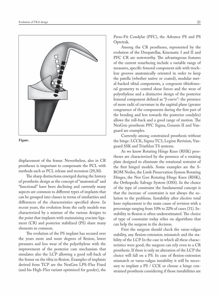
The femoral rollback is the posterior translation the femur with progressive flexion. In the native knee rollback is controlled by the anterior cruciate ligament and posterior cruciate ligament, so for good TKA is important to improve quadriceps function and range of knee flexion by preventing posterior impingement during deep flexion. For that reason CR prostheses have posterior displacement of femoral condyles sim-ilar to a native knee, whereas in PS protheses tibial component contacts the femoral cam causing posterior
Figure.
Figure.
06-dall'oca.indd 20 06/06/17 10:23
Evolution of TKA design 21
displacement of the femur. Nevertheless, also in CR prostheses is important to compensate the PCL with methods such as PCL release and recession (29,30).
The sharp distinctions emerged during the history of prosthetic design as the concept of “anatomical” and “functional” have been declining and currently many aspects are common to different types of implants that can be grouped into classes in terms of similarities and differences of the characteristics specified above. In recent years, the evolution from the early models was characterized by a mixture of the various designs to the point that implants with maintaining cruciate liga-ment (CR) and posterior stabilized (PS) share many elements in common.
The evolution of the PS implant has secured over the years more and more degrees of flexion, lower pressures and less wear of the polyethylene with the improvement of the posterior cam mechanism that simulates also the LCP allowing a good roll-back of the femur on the tibia in flexion. Examples of implants derived from TCP are the NexGen LPS-Flex Fixed (and his High-Flex variant optimized for gender), the
Press-Fit Condylar (PFC), the Advance PS and PS Optetrak.
Among the CR prostheses, represented by the evolution of the Duopatellar, Kinematic I and II and PFC CR are noteworthy. The advantageous features of the current resurfacing include a variable range of measures, specific femoral component side with troch-lear grooves anatomically oriented in order to keep the patella (whether native or coated), modular met-al-backed tibial components, a congruent tibiofemo-ral geometry to control shear forces and the wear of polyethylene and a distinctive design of the posterior femoral component defined as “J-curve”: the presence of more radii of curvature in the sagittal plane (greater congruence of the components during the first part of the bending and less towards the posterior condyles) allows the roll-back and a good range of motion. The NexGen prosthesis PFC Sigma, Genesis II and Van-guard are examples.
Currently among constrained prosthesis without the hinge: LCCK, Sigma TC3, Legion Revision, Van-guard SSK and Triathlon TS systems.
As we know Rotating Hinge Knee (RHK) pros-theses are characterized by the presence of a rotating plate designed to eliminate the rotational restraint of the first hinged models. Some examples are the S-ROM Noiles, the Limb Preservation System Rotating Hinges, the Nex Gen Rotating Hinge Knee (RHK), the Orthopedic Salvage System (OSS). In the choice of the type of constraint the fundamental concept is that the increase of constraint is not always the so-lution to the problems. Instability after elective total knee replacement is the main cause of revision with a percentage ranging from 10% to 22% of cases (31). In-stability in flexion is often underestimated. The choice of type of constraint today relies on algorithms that can help the surgeon in the decision.
First the surgeon should check the varus-valgus stability, any flexion-extension mismatch and the sta-bility of the LCP. In the case in which all these charac-teristics were good, the surgeon can rely even to a CR prosthesis. If there is only an alteration of the LCP the choice will fall on a PS. In case of flexion-extension mismatch or varus-valgus instability it will be neces-sary to implant a PS / CCK or choose a hinge con-strained prosthesis considering if those instabilities are
Figure.
06-dall'oca.indd 21 06/06/17 10:23
C. Dall’Oca, M. Ricci, E. Vecchini, et al.22
correctable with bone/soft tissue reconstruction or not. The CCK is indicated in cases of stability of almost one of the compartments (medial or lateral), deletion of deforming forces and in small losses of substance. In cases of severe laxity, lack / inadequacy of collateral, severe valgus, higher losses of substance and revisions indication is given to RHK. The hinge-fixed prosthe-ses are today reserved for those cases where there is also a serious muscular impairment of quadriceps (32).
Meniscal-Bearing Prostheses
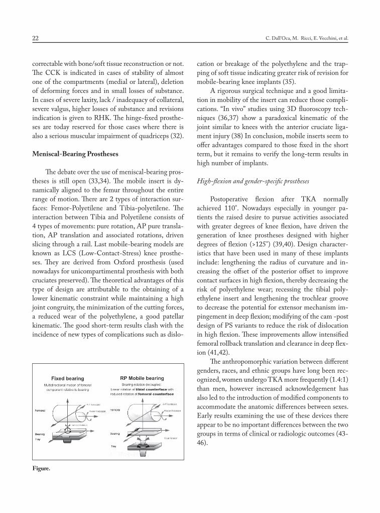
The debate over the use of meniscal-bearing pros-theses is still open (33,34). The mobile insert is dy-namically aligned to the femur throughout the entire range of motion. There are 2 types of interaction sur-faces: Femor-Polyetilene and Tibia-polyetilene. The interaction between Tibia and Polyetilene consists of 4 types of movements: pure rotation, AP pure transla-tion, AP translation and associated rotations, driven slicing through a rail. Last mobile-bearing models are known as LCS (Low-Contact-Stress) knee prosthe-ses. They are derived from Oxford prosthesis (used nowadays for unicompartimental prosthesis with both cruciates preserved). The theoretical advantages of this type of design are attributable to the obtaining of a lower kinematic constraint while maintaining a high joint congruity, the minimization of the cutting forces, a reduced wear of the polyethylene, a good patellar kinematic. The good short-term results clash with the incidence of new types of complications such as dislo-
cation or breakage of the polyethylene and the trap-ping of soft tissue indicating greater risk of revision for mobile-bearing knee implants (35).
A rigorous surgical technique and a good limita-tion in mobility of the insert can reduce those compli-cations. “In vivo” studies using 3D fluoroscopy tech-niques (36,37) show a paradoxical kinematic of the joint similar to knees with the anterior cruciate liga-ment injury (38) In conclusion, mobile inserts seem to offer advantages compared to those fixed in the short term, but it remains to verify the long-term results in high number of implants.
High-flexion and gender-specific prostheses
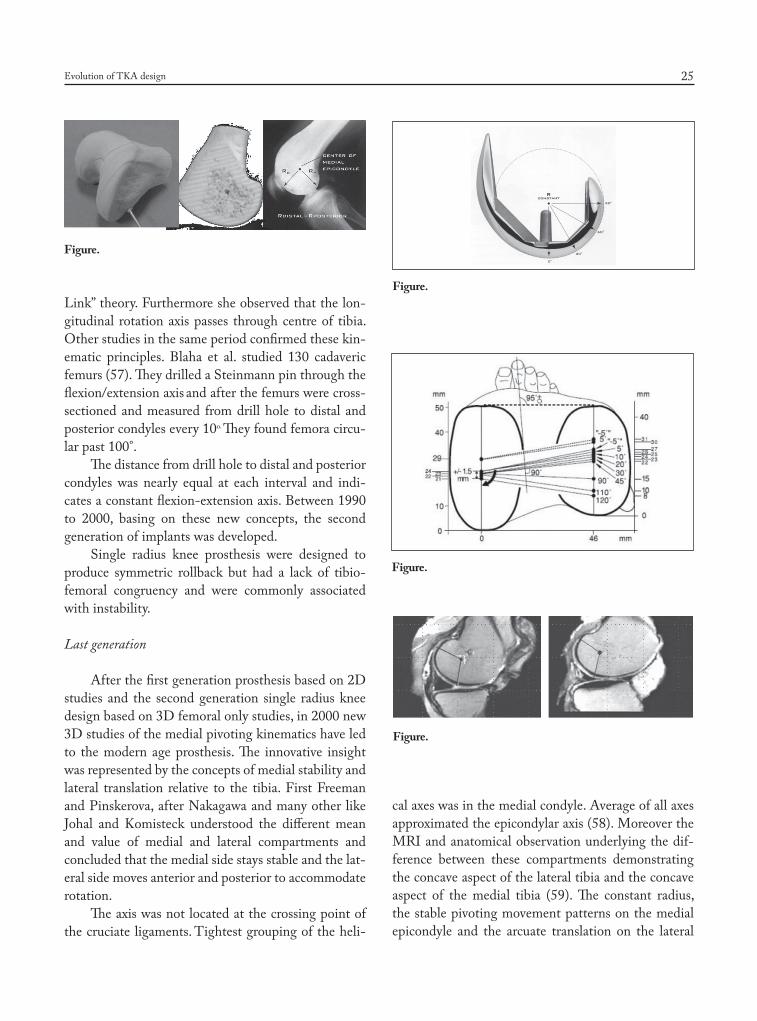
Postoperative flexion after TKA normally achieved 110°. Nowadays especially in younger pa-tients the raised desire to pursue activities associated with greater degrees of knee flexion, have driven the generation of knee prostheses designed with higher degrees of flexion (>125°) (39,40). Design character-istics that have been used in many of these implants include: lengthening the radius of curvature and in-creasing the offset of the posterior offset to improve contact surfaces in high flexion, thereby decreasing the risk of polyethylene wear; recessing the tibial poly-ethylene insert and lengthening the trochlear groove to decrease the potential for extensor mechanism im-pingement in deep flexion; modifying of the cam -post design of PS variants to reduce the risk of dislocation in high flexion. These improvements allow intensified femoral rollback translation and clearance in deep flex-ion (41,42).
The anthropomorphic variation between different genders, races, and ethnic groups have long been rec-ognized, women undergo TKA more frequently (1.4:1) than men, however increased acknowledgement has also led to the introduction of modified components to accommodate the anatomic differences between sexes. Early results examining the use of these devices there appear to be no important differences between the two groups in terms of clinical or radiologic outcomes (43-46).
Figure.
06-dall'oca.indd 22 06/06/17 10:23
Evolution of TKA design 23
Knee kinematic
Introduction
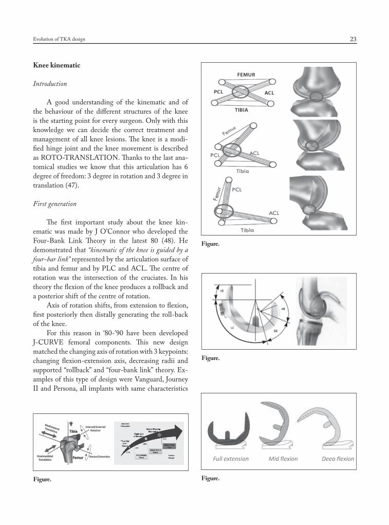
A good understanding of the kinematic and of the behaviour of the different structures of the knee is the starting point for every surgeon. Only with this knowledge we can decide the correct treatment and management of all knee lesions. The knee is a modi-fied hinge joint and the knee movement is described as ROTO-TRANSLATION. Thanks to the last ana-tomical studies we know that this articulation has 6 degree of freedom: 3 degree in rotation and 3 degree in translation (47).
First generation
The first important study about the knee kin-ematic was made by J O’Connor who developed the Four-Bank Link Theory in the latest 80 (48). He demonstrated that “kinematic of the knee is guided by a four-bar link” represented by the articulation surface of tibia and femur and by PLC and ACL. The centre of rotation was the intersection of the cruciates. In his theory the flexion of the knee produces a rollback and a posterior shift of the centre of rotation.
Axis of rotation shifts, from extension to flexion, first posteriorly then distally generating the roll-back of the knee.
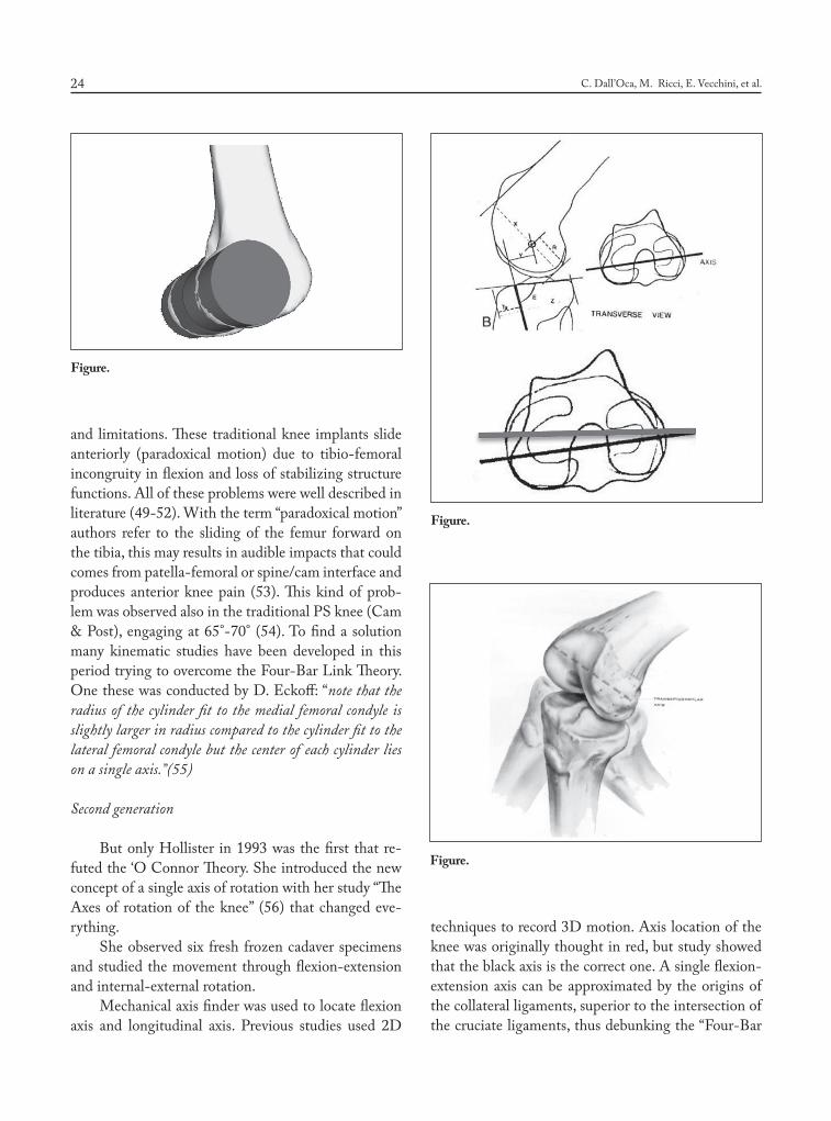
For this reason in ‘80-’90 have been developed J-CURVE femoral components. This new design matched the changing axis of rotation with 3 keypoints: changing flexion-extension axis, decreasing radii and supported “rollback” and “four-bank link” theory. Ex-amples of this type of design were Vanguard, Journey II and Persona, all implants with same characteristics
Figure.
Figure.
Figure.
Figure.
06-dall'oca.indd 23 06/06/17 10:23
C. Dall’Oca, M. Ricci, E. Vecchini, et al.24
and limitations. These traditional knee implants slide anteriorly (paradoxical motion) due to tibio-femoral incongruity in flexion and loss of stabilizing structure functions. All of these problems were well described in literature (49-52). With the term “paradoxical motion” authors refer to the sliding of the femur forward on the tibia, this may results in audible impacts that could comes from patella-femoral or spine/cam interface and produces anterior knee pain (53). This kind of prob-lem was observed also in the traditional PS knee (Cam & Post), engaging at 65°-70° (54). To find a solution many kinematic studies have been developed in this period trying to overcome the Four-Bar Link Theory. One these was conducted by D. Eckoff: “note that the radius of the cylinder fit to the medial femoral condyle is slightly larger in radius compared to the cylinder fit to the lateral femoral condyle but the center of each cylinder lies on a single axis.”(55)
Second generation
But only Hollister in 1993 was the first that re-futed the ‘O Connor Theory. She introduced the new concept of a single axis of rotation with her study “The Axes of rotation of the knee” (56) that changed eve-rything.
She observed six fresh frozen cadaver specimens and studied the movement through flexion-extension and internal-external rotation.
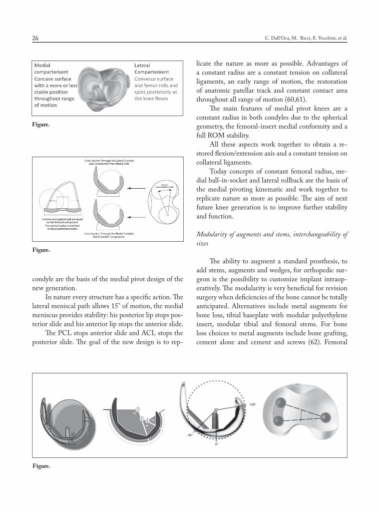
Mechanical axis finder was used to locate flexion axis and longitudinal axis. Previous studies used 2D
techniques to record 3D motion. Axis location of the knee was originally thought in red, but study showed that the black axis is the correct one. A single flexion-extension axis can be approximated by the origins of the collateral ligaments, superior to the intersection of the cruciate ligaments, thus debunking the “Four-Bar
Figure.
Figure.
Figure.
06-dall'oca.indd 24 06/06/17 10:23
Evolution of TKA design 25
Link” theory. Furthermore she observed that the lon-gitudinal rotation axis passes through centre of tibia. Other studies in the same period confirmed these kin-ematic principles. Blaha et al. studied 130 cadaveric femurs (57). They drilled a Steinmann pin through the flexion/extension axis and after the femurs were cross-sectioned and measured from drill hole to distal and posterior condyles every 10o. They found femora circu-lar past 100°.
The distance from drill hole to distal and posterior condyles was nearly equal at each interval and indi-cates a constant flexion-extension axis. Between 1990 to 2000, basing on these new concepts, the second generation of implants was developed.
Single radius knee prosthesis were designed to produce symmetric rollback but had a lack of tibio-femoral congruency and were commonly associated with instability.
Last generation
After the first generation prosthesis based on 2D studies and the second generation single radius knee design based on 3D femoral only studies, in 2000 new 3D studies of the medial pivoting kinematics have led to the modern age prosthesis. The innovative insight was represented by the concepts of medial stability and lateral translation relative to the tibia. First Freeman and Pinskerova, after Nakagawa and many other like Johal and Komisteck understood the different mean and value of medial and lateral compartments and concluded that the medial side stays stable and the lat-eral side moves anterior and posterior to accommodate rotation.
The axis was not located at the crossing point of the cruciate ligaments. Tightest grouping of the heli-
cal axes was in the medial condyle. Average of all axes approximated the epicondylar axis (58). Moreover the MRI and anatomical observation underlying the dif-ference between these compartments demonstrating the concave aspect of the lateral tibia and the concave aspect of the medial tibia (59). The constant radius, the stable pivoting movement patterns on the medial epicondyle and the arcuate translation on the lateral
Figure.
Figure.
Figure.
Figure.
06-dall'oca.indd 25 06/06/17 10:23
C. Dall’Oca, M. Ricci, E. Vecchini, et al.26
condyle are the basis of the medial pivot design of the new generation.
In nature every structure has a specific action. The lateral meniscal path allows 15° of motion, the medial meniscus provides stability: his posterior lip stops pos-terior slide and his anterior lip stops the anterior slide.
The PCL stops anterior slide and ACL stops the posterior slide. The goal of the new design is to rep-
licate the nature as more as possible. Advantages of a constant radius are a constant tension on collateral ligaments, an early range of motion, the restoration of anatomic patellar track and constant contact area throughout all range of motion (60,61).
The main features of medial pivot knees are a constant radius in both condyles due to the spherical geometry, the femoral-insert medial conformity and a full ROM stability.
All these aspects work together to obtain a re-stored flexion/extension axis and a constant tension on collateral ligaments.
Today concepts of constant femoral radius, me-dial ball-in-socket and lateral rollback are the basis of the medial pivoting kinematic and work together to replicate nature as more as possible. The aim of next future knee generation is to improve further stability and function.
Modularity of augments and stems, interchangeability of sizes
The ability to augment a standard prosthesis, to add stems, augments and wedges, for orthopedic sur-geon is the possibility to customize implant intraop-eratively. The modularity is very beneficial for revision surgery when deficiencies of the bone cannot be totally anticipated. Alternatives include metal augments for bone loss, tibial baseplate with modular polyethylene insert, modular tibial and femoral stems. For bone loss choices to metal augments include bone grafting, cement alone and cement and screws (62). Femoral
Figure.
Figure.
Figure.
06-dall'oca.indd 26 06/06/17 10:23
Evolution of TKA design 27
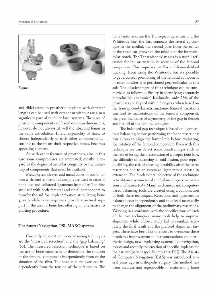
and tibial stems in prosthetic implants with different lengths can be used with cement or without are also a significant part of modular knee systems. The sizes of prosthetic components are based on mean dimensions, however do not always fit well the tibia and femur in the same articulation. Interchangeability of sizes, to choose independently of each other components ac-cording to the fit on their respective bones, becomes appealing element.
As with other features of prostheses, also in this case some compromises are interested, mostly in re-gard to the degree of articular congruity or the inven-tory of components that must be available.
Metaphyseal sleeves and metal cones in combina-tion with semi-constrained designs are used in cases of bone loss and collateral ligaments instability. The first are used with both femoral and tibial components to transfer the aid for implant fixation stimulating bone growth while cone augments provide structural sup-port in the area of bone loss offering an alternative to grafting procedure.
The future: Navigation, PSI, MAKO systems
Currently the most common balancing techniques are the “measured resection” and the “gap balancing” (63). The measured resection technique is based on the use of bone landmarks to determine the rotation of the femoral component independently from of the situation of the tibia. The bone cuts are executed in-dependently from the tension of the soft tissues. The
bone landmarks are the Transepicondylar axis and the Whiteside line: the first connects the lateral epicon-dyle to the medial, the second goes from the center of the trochlear groove to the middle of the intercon-dylar notch. The Tansepicondylar axis is a useful ref-erence for the orientation in rotation of the femoral component. This improves patellar and femoral-tibial tracking. Even using the Whiteside line it’s possible to get a correct positioning of the femoral component in rotation after it is positioned perpendicular to this axis. The disadvantages of this technique can be sum-marized as follows: difficulty in identifying accurately reproducible anatomical landmarks, only 75% of the prostheses are aligned within 3 degrees when based on the transepicondylar axis, anatomic femoral variations can lead to malrotations of the femoral component, the great incidence of asymmetry of the gap in flexion and lift-off of the femoral condyles.
The balanced gap technique is based on ligamen-tous balancing before performing the bone resections: this allows to align the lower limb before evaluating the rotation of the femoral component. Even with this technique we can detect some disadvantages such as the risk of losing the preservation of a proper joint line, the difficulty of balancing in mid flexion, poor repro-ducibility, the risk of creating instability after the latest resections due to an excessive ligamentous release in extension. The fundamental objective of the technique is to obtain a symmetrical and balanced space in exten-sion and flexion (64). Many mechanical and computer-based balancing tools are created using a combination of both these techniques. Resections and ligamentous balance occur independently and thus lead necessarily to change the alignment of the preliminary resections. Working in accordance with the specifications of each of the two techniques, many tools help to improve alignment while unfortunately fail to simulate accu-rately the final result and the prefixed alignment tar-gets. There have been lots of efforts to overcome these problems: improvement in instrumentations and pros-thetic design, new implanting systems like navigation, robots and recently the creation of specific implants for the patient (patient specific implants: PSI). The Assist-ed Computer Navigation (CAS) was introduced sev-eral years ago in orthopedic surgery. The method has been accurate and reproducible in maintaining bone
Figure.
06-dall'oca.indd 27 06/06/17 10:23

C. Dall’Oca, M. Ricci, E. Vecchini, et al.28
resection and ligament balance, in the correct choice of sizes and in the kinematic evaluation of the system. The disadvantages of navigation are related to many factors that lead to the abandonment of this technique such as errors during the registration procedure of the landmarks, mobilization of the fiches and potential fractures due to the insertion of them. The extended surgical time, the increased risk of infection for pro-longed exposure and system costs have meant that this method has not been very successful; the recent lit-erature doesn’t show a clear advantage of navigation compared to the traditional technique (65). The robot assisted technique was introduced in the 90s and then has been abandoned because of the complexity of the preparation (pin positioning in the operating room, successive CT-scan for the study and the return in the operating room for surgery). In recent years this tech-nique has been reclaimed for the reproducible system accuracy and computer-based control of balance. As for the CAS, the Robot Assisted Technique has shown some disadvantages which have limited its diffusion: the intraoperative loss of landmarks and therefore the changing of the procedure, the possible loosening of the pin or pin-related fractures, the higher costs.
PSI System
In recent years specific pre-navigation guides have been introduced for the patient (PSI). The aim is to get a better alignment in comparison to the traditional using CT-3D-scans or MRI and long-standings X-rays of the legs to create custom-made guides through modern rapid prototyping systems (3 D printer).The company that produces the cutting masks acquires the information given by the examinations. In accordance with the surgeon’s preferences (varus-valgus angle, thickness of the cuts etc.) they prepare the draft which is then validated by the user and in about 3-4 weeks PSI guides are ready to be sent for the surgery. The PSI guides are designed to obtain a correct positioning of the prosthetic components mainly researching the alignments on the anatomical axis of the patient, an improvement of Mesaured Technique. A subsequent ligamentous release is required to get the correct bal-ance of the joint space.CT,MRI and X-rays are static and not dynamic examinations so there is no doubt
that the evaluation of the “unbalancing” remains de-tectable only through the clinical evaluation of the op-erator.Prepared PSI-guides allow to perform the distal femoral cuts and the proximal cut of the tibia, then the procedure continues with the traditional masks.. The learning curve is essentially linked to the correct positioning of the masks: if obtained through CT-scan imply the removal of osteophytes and cartilage, while if obtained through RMI only through the removal of
Figure.
Figure.
06-dall'oca.indd 28 06/06/17 10:23
Evolution of TKA design 29
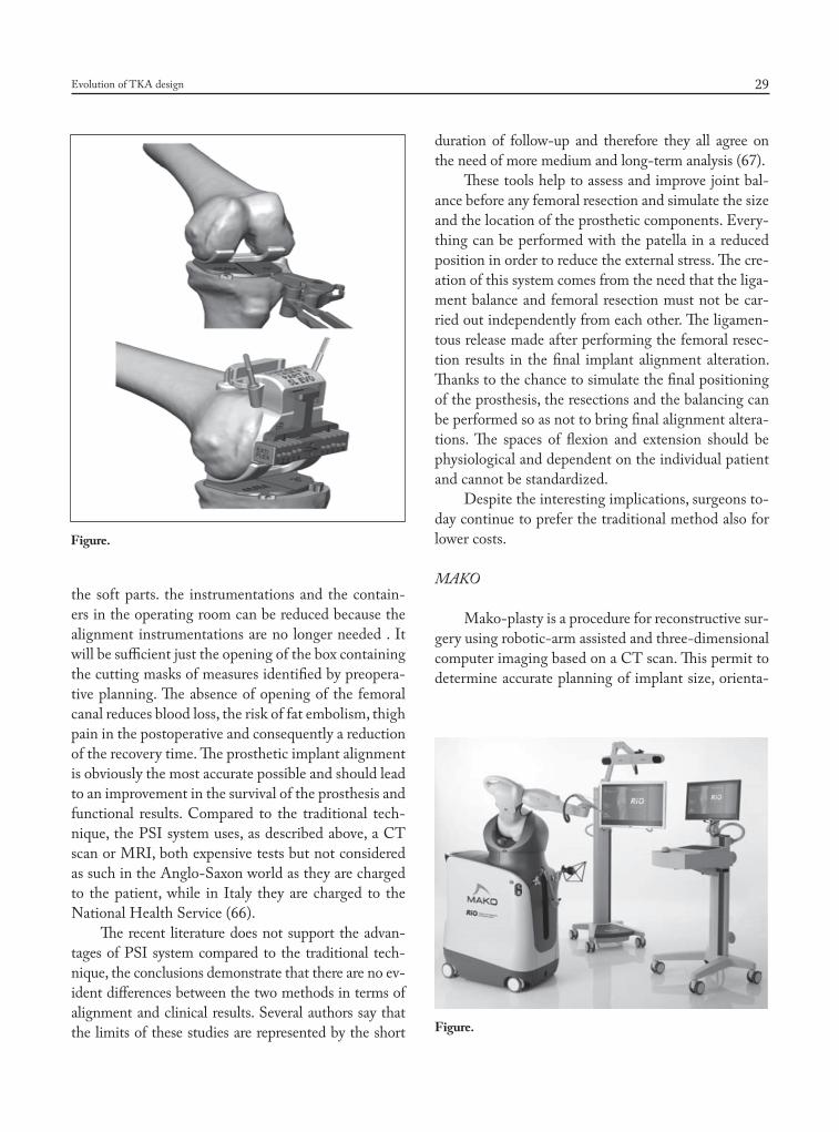
the soft parts. the instrumentations and the contain-ers in the operating room can be reduced because the alignment instrumentations are no longer needed . It will be sufficient just the opening of the box containing the cutting masks of measures identified by preopera-tive planning. The absence of opening of the femoral canal reduces blood loss, the risk of fat embolism, thigh pain in the postoperative and consequently a reduction of the recovery time. The prosthetic implant alignment is obviously the most accurate possible and should lead to an improvement in the survival of the prosthesis and functional results. Compared to the traditional tech-nique, the PSI system uses, as described above, a CT scan or MRI, both expensive tests but not considered as such in the Anglo-Saxon world as they are charged to the patient, while in Italy they are charged to the National Health Service (66).
The recent literature does not support the advan-tages of PSI system compared to the traditional tech-nique, the conclusions demonstrate that there are no ev-ident differences between the two methods in terms of alignment and clinical results. Several authors say that the limits of these studies are represented by the short
duration of follow-up and therefore they all agree on the need of more medium and long-term analysis (67).
These tools help to assess and improve joint bal-ance before any femoral resection and simulate the size and the location of the prosthetic components. Every-thing can be performed with the patella in a reduced position in order to reduce the external stress. The cre-ation of this system comes from the need that the liga-ment balance and femoral resection must not be car-ried out independently from each other. The ligamen-tous release made after performing the femoral resec-tion results in the final implant alignment alteration. Thanks to the chance to simulate the final positioning of the prosthesis, the resections and the balancing can be performed so as not to bring final alignment altera-tions. The spaces of flexion and extension should be physiological and dependent on the individual patient and cannot be standardized.
Despite the interesting implications, surgeons to-day continue to prefer the traditional method also for lower costs.
MAKO
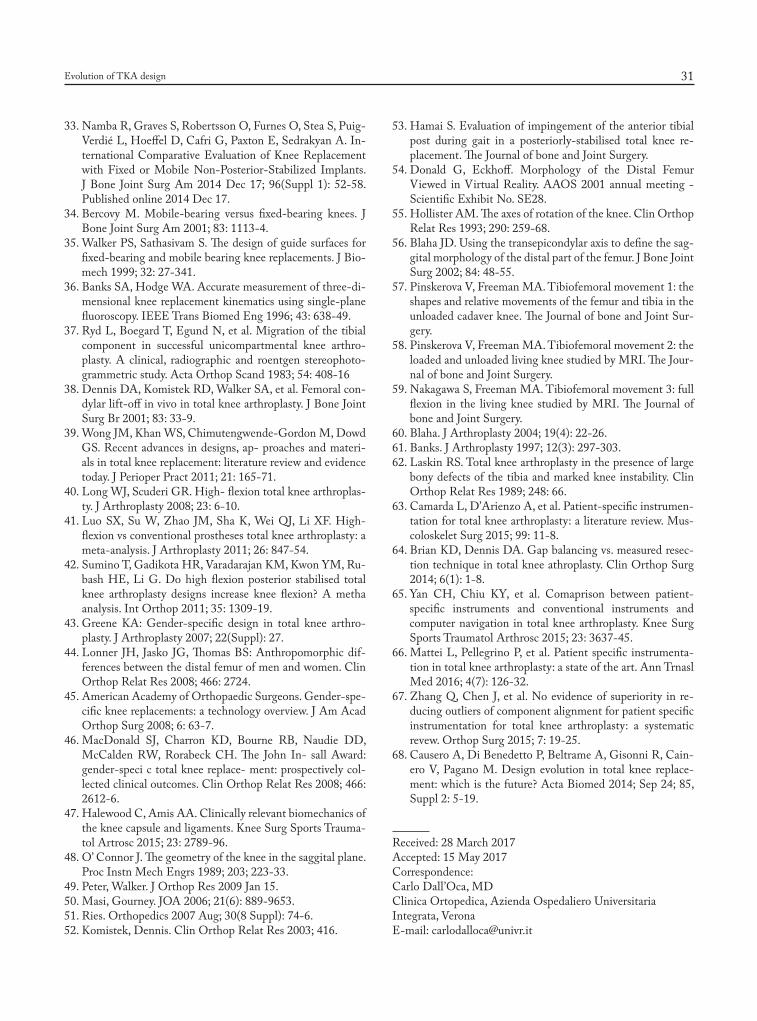
Mako-plasty is a procedure for reconstructive sur-gery using robotic-arm assisted and three-dimensional computer imaging based on a CT scan. This permit to determine accurate planning of implant size, orienta-
Figure.
Figure.
06-dall'oca.indd 29 06/06/17 10:23
C. Dall’Oca, M. Ricci, E. Vecchini, et al.30
tion and alignment preoperatively. During the surgery the adjustments of robotic arms allow for cut away only the bone planned to resected prior to surgery, more correct kinematics and soft-tissue balance.
All these considerations allows us to admit that the ideal design for everyone would be the one that imitates the “own knee design”. The achievement of a good movement is better perceived by the patients than a simple perfect mechanical activity restoration: every patient feels as “abnormal” a knee with a great mechanical activity but unable to reproduce his own knee. The challenge remains to obtain a prosthetic de-sign suitable for every patient (68).
References
1. Verneuil A. De la creation d’une fausse articulation par sec-tion ou resection partielle de l’os maxillaire inferieur, comme moyen de remedier a l’ankylose vraie ou fausse de la ma-choire inferieure. Arch Gen Med 1860; 15 (ser5): 174.
2. Ferguson W. Excision of the knee joint: Recovery with a false joint and a useful limb. Med Times Gaz 1861; 1: 601.
3. Machintosh DL. Hemiarthroplasty of the knee using a space occupying prosthesis for painful varus and valgus de-formities. J Bone Joint Surg Am 1958; 40: 1431.
4. Emerson R, Potter T. The use of the McKeever metallic hemiarthroplasty for unicompartmental arthritis. J Bone Joint Surg Am 1985; 67: 208-212.
5. De Nicola U, Pace N. La protesi di ginocchio di primo im-pianto. Edizione Springer: 29-44.
6. Gunston FH. Polycentric knee arthroplasty: Prosthetic simulation of normal knee movement. J Bone Joint Surg Br 1971; 53: 272.
7. Freeman MA, Swanson SA, Todd RC. Total replacement of the knee using the Freeman-Swanson knee prosthesis.Clin Orthop Relat Res 1973; 94: 153-70.
8. Robinson RP. The early innovators of today’s resurfacing condylar knees. J Arthroplasty. 2005; 20 (1 Suppl 1): 2-26.
9. Yamamoto S. Total knee replacement with Kodama-Yamamoto knee prosthesis. Clin Orthop 1979; 145: 60-7.
10. Townley CO. The anatomic total knee resurfacing arthro-plasty. Clin Orthop 1985; 182: 82-96.
11. Seedhom BB. Designing a total knee prosthesis. Eng Med 1972; 1: 28.
12. Buechel FF, Pappas MJ. New Jersey meniscal bearing knee replacement. US patent 4, 309, 778 1982 Jan 12.
13. Walldius B. Arthroplasty of the knee with an endoprosthe-sis. Acta Chir Scand 1957; 12; 113(6): 445-6.
14. Shiers LG. Arthroplasty of the knee; preliminary report of new method. J Bone Joint Surg Br 1954; 36-B(4): 553-60.
15. Aubriot JH, Deburge A, Genet JP; GUEPAR Group.
GUEPAR hinge knee prosthesis. Orthop Traumatol Surg Res 2014; 100(1): 27-32.
16. Elson R, Watts N. The Sheffield knee prosthesis. J Biomed Mater Res 1974; 8(4 Pt 2): 311-7.
17. Thornton AW, Predecki P. Design considerations in a Ro-lamite knee joint prosthesis. J Biomed Mater Res 1973; 7(3): 419-33.
18. Kaufer H, Matthews LS. Spherocentric knee arthroplasty. Clin Orthop Relat Res 1979; 145: 110-6.
19. Kowalczewski J, Marczak D, Synder M, Sibinski M. Pri-mary rotating-hinge total knee arthroplasty: good outcomes at mid-term follow-up. J Arthroplasty 2014; 29(6): 1202-6.
20. Lachiewicz PF1, Soileau ES. J Arthroplasty. Results of a second-generation constrained condylar prosthesis in pri-mary total knee arthroplasty. 2011 Dec; 26(8): 1228-31
21. Bartel DL, Bicknell VL, Wright TM. The effect of con-formity, thickness, and material on stresses in ultra-high molecular weight components for total joint replacement. J Bone Joint Surg Am 1986; 68(7): 1041-51.
22. Vince KG, Insall JN, Kelly MA. The total condylar prosthe-sis: 10- to 12-year results of a cemented knee replacement. J Bone Joint Surg Br 1989; 71: 793-7.
23. Berger RA, Lyon JH, Jacobs JJ, et al. Problems with ce-mentless total knee arthroplasty at 11 years followup. Clin Orthop Relat Res 2001; 196-207.
24. Goldberg VM, Kraay M. The outcome of the cementless tibial component: a minimum 14-year clinical evaluation. Clin Orthop Relat Res 2004; 214-220.
25. llgen R, Tueting J, Enright T, Schreibman K, Mc- Beath A, Heiner J. Hybrid total knee arthroplasty: a retrospective analysis of clinical and radiographic outcomes at average 10 years follow-up. J Arthroplasty 2004; 19: 95-100.
26. Aprato A, Risitano S, Sabatini L, Giachino M, Agati G, Massè A. Cementless total knee arthroplasty. Ann Transl Med 2016; 4(7): 129. doi: 10.21037/atm.2016.01.34
27. Ranawat CS, Meftah M, Windsor EN, et al. Cementless fixation in total knee arthroplasty: down the boulevard of broken dreams - affirms. J Bone Joint Surg Br 2012; 94: 82-4. 10.1302/0301-620X.94B11.30826
28. Morgan H, Battista V, Leopold SS. Constraint in primary total knee arthroplasty. J Am Acad Orthop Surg 2005; 13: 515-24.
29. Scott RD, Thornhill TS: Posterior cruciate supplementing total knee replacements using conforming inserts and cruci-ate recession: effect of range of motion and radiolucent lines. Clin Ortop Relat Res 1994; 309: 146.
30. Clark CR, Rorabeck CH, MacDonald S, MacDonald D, Swafford J, Cleland D. Posterior-stabilized and cruciate-retaining total knee replacement: a randomized study. Clin Orthop Relat Res 2001; 208-212.
31. Fehring TK1, Odum S, Griffin WL, Mason JB, Nadaud M. Early failures in total knee arthroplasty. Clin Orthop Relat Res 2001; 392: 315-8.
32. McAuley JP1, Engh GA. Constraint in total knee arthro-plasty: when and what? J Arthroplasty 2003; 18(3 Suppl 1): 51-4.
06-dall'oca.indd 30 06/06/17 10:23
Evolution of TKA design 31
33. Namba R, Graves S, Robertsson O, Furnes O, Stea S, Puig-Verdié L, Hoeffel D, Cafri G, Paxton E, Sedrakyan A. In-ternational Comparative Evaluation of Knee Replacement with Fixed or Mobile Non-Posterior-Stabilized Implants. J Bone Joint Surg Am 2014 Dec 17; 96(Suppl 1): 52-58. Published online 2014 Dec 17.
34. Bercovy M. Mobile-bearing versus fixed-bearing knees. J Bone Joint Surg Am 2001; 83: 1113-4.
35. Walker PS, Sathasivam S. The design of guide surfaces for fixed-bearing and mobile bearing knee replacements. J Bio-mech 1999; 32: 27-341.
36. Banks SA, Hodge WA. Accurate measurement of three-di-mensional knee replacement kinematics using single-plane fluoroscopy. IEEE Trans Biomed Eng 1996; 43: 638-49.
37. Ryd L, Boegard T, Egund N, et al. Migration of the tibial component in successful unicompartmental knee arthro-plasty. A clinical, radiographic and roentgen stereophoto-grammetric study. Acta Orthop Scand 1983; 54: 408-16
38. Dennis DA, Komistek RD, Walker SA, et al. Femoral con-dylar lift-off in vivo in total knee arthroplasty. J Bone Joint Surg Br 2001; 83: 33-9.
39. Wong JM, Khan WS, Chimutengwende-Gordon M, Dowd GS. Recent advances in designs, ap- proaches and materi-als in total knee replacement: literature review and evidence today. J Perioper Pract 2011; 21: 165-71.
40. Long WJ, Scuderi GR. High- flexion total knee arthroplas-ty. J Arthroplasty 2008; 23: 6-10.
41. Luo SX, Su W, Zhao JM, Sha K, Wei QJ, Li XF. High- flexion vs conventional prostheses total knee arthroplasty: a meta-analysis. J Arthroplasty 2011; 26: 847-54.
42. Sumino T, Gadikota HR, Varadarajan KM, Kwon YM, Ru-bash HE, Li G. Do high flexion posterior stabilised total knee arthroplasty designs increase knee flexion? A metha analysis. Int Orthop 2011; 35: 1309-19.
43. Greene KA: Gender-specific design in total knee arthro-plasty. J Arthroplasty 2007; 22(Suppl): 27.
44. Lonner JH, Jasko JG, Thomas BS: Anthropomorphic dif-ferences between the distal femur of men and women. Clin Orthop Relat Res 2008; 466: 2724.
45. American Academy of Orthopaedic Surgeons. Gender-spe-cific knee replacements: a technology overview. J Am Acad Orthop Surg 2008; 6: 63-7.
46. MacDonald SJ, Charron KD, Bourne RB, Naudie DD, McCalden RW, Rorabeck CH. The John In- sall Award: gender-speci c total knee replace- ment: prospectively col-lected clinical outcomes. Clin Orthop Relat Res 2008; 466: 2612-6.
47. Halewood C, Amis AA. Clinically relevant biomechanics of the knee capsule and ligaments. Knee Surg Sports Trauma-tol Artrosc 2015; 23: 2789-96.
48. O’ Connor J. The geometry of the knee in the saggital plane. Proc Instn Mech Engrs 1989; 203; 223-33.
49. Peter, Walker. J Orthop Res 2009 Jan 15.50. Masi, Gourney. JOA 2006; 21(6): 889-9653. 51. Ries. Orthopedics 2007 Aug; 30(8 Suppl): 74-6.52. Komistek, Dennis. Clin Orthop Relat Res 2003; 416.
53. Hamai S. Evaluation of impingement of the anterior tibial post during gait in a posteriorly-stabilised total knee re-placement. The Journal of bone and Joint Surgery.
54. Donald G, Eckhoff. Morphology of the Distal Femur Viewed in Virtual Reality. AAOS 2001 annual meeting - Scientific Exhibit No. SE28.
55. Hollister AM. The axes of rotation of the knee. Clin Orthop Relat Res 1993; 290: 259-68.
56. Blaha JD. Using the transepicondylar axis to define the sag-gital morphology of the distal part of the femur. J Bone Joint Surg 2002; 84: 48-55.
57. Pinskerova V, Freeman MA. Tibiofemoral movement 1: the shapes and relative movements of the femur and tibia in the unloaded cadaver knee. The Journal of bone and Joint Sur-gery.
58. Pinskerova V, Freeman MA. Tibiofemoral movement 2: the loaded and unloaded living knee studied by MRI. The Jour-nal of bone and Joint Surgery.
59. Nakagawa S, Freeman MA. Tibiofemoral movement 3: full flexion in the living knee studied by MRI. The Journal of bone and Joint Surgery.
60. Blaha. J Arthroplasty 2004; 19(4): 22-26.61. Banks. J Arthroplasty 1997; 12(3): 297-303.62. Laskin RS. Total knee arthroplasty in the presence of large
bony defects of the tibia and marked knee instability. Clin Orthop Relat Res 1989; 248: 66.
63. Camarda L, D’Arienzo A, et al. Patient-specific instrumen-tation for total knee arthroplasty: a literature review. Mus-coloskelet Surg 2015; 99: 11-8.
64. Brian KD, Dennis DA. Gap balancing vs. measured resec-tion technique in total knee athroplasty. Clin Orthop Surg 2014; 6(1): 1-8.
65. Yan CH, Chiu KY, et al. Comaprison between patient-specific instruments and conventional instruments and computer navigation in total knee arthroplasty. Knee Surg Sports Traumatol Arthrosc 2015; 23: 3637-45.
66. Mattei L, Pellegrino P, et al. Patient specific instrumenta-tion in total knee arthroplasty: a state of the art. Ann Trnasl Med 2016; 4(7): 126-32.
67. Zhang Q, Chen J, et al. No evidence of superiority in re-ducing outliers of component alignment for patient specific instrumentation for total knee arthroplasty: a systematic revew. Orthop Surg 2015; 7: 19-25.
68. Causero A, Di Benedetto P, Beltrame A, Gisonni R, Cain-ero V, Pagano M. Design evolution in total knee replace-ment: which is the future? Acta Biomed 2014; Sep 24; 85, Suppl 2: 5-19.
Received: 28 March 2017Accepted: 15 May 2017Correspondence:Carlo Dall’Oca, MDClinica Ortopedica, Azienda Ospedaliero UniversitariaIntegrata, VeronaE-mail: [email protected]
06-dall'oca.indd 31 06/06/17 10:23
Copyright © 2022 FDOKUMEN