Evaluation of Hydrotreated Biofuels for Use in Naval Diesel ...
119
Graduate Theses, Dissertations, and Problem Reports 2014 Evaluation of Hydrotreated Biofuels for Use in Naval Diesel Evaluation of Hydrotreated Biofuels for Use in Naval Diesel Engines Engines Cory J. Morgan Follow this and additional works at: https://researchrepository.wvu.edu/etd Recommended Citation Recommended Citation Morgan, Cory J., "Evaluation of Hydrotreated Biofuels for Use in Naval Diesel Engines" (2014). Graduate Theses, Dissertations, and Problem Reports. 7333. https://researchrepository.wvu.edu/etd/7333 This Thesis is protected by copyright and/or related rights. It has been brought to you by the The Research Repository @ WVU with permission from the rights-holder(s). You are free to use this Thesis in any way that is permitted by the copyright and related rights legislation that applies to your use. For other uses you must obtain permission from the rights-holder(s) directly, unless additional rights are indicated by a Creative Commons license in the record and/ or on the work itself. This Thesis has been accepted for inclusion in WVU Graduate Theses, Dissertations, and Problem Reports collection by an authorized administrator of The Research Repository @ WVU. For more information, please contact [email protected].
-
Upload
khangminh22 -
Category
Documents
-
view
1 -
download
0
Transcript of Evaluation of Hydrotreated Biofuels for Use in Naval Diesel ...

Graduate Theses, Dissertations, and Problem Reports
2014
Evaluation of Hydrotreated Biofuels for Use in Naval Diesel Evaluation of Hydrotreated Biofuels for Use in Naval Diesel
Engines Engines
Cory J. Morgan
Follow this and additional works at: https://researchrepository.wvu.edu/etd
Recommended Citation Recommended Citation Morgan, Cory J., "Evaluation of Hydrotreated Biofuels for Use in Naval Diesel Engines" (2014). Graduate Theses, Dissertations, and Problem Reports. 7333. https://researchrepository.wvu.edu/etd/7333
This Thesis is protected by copyright and/or related rights. It has been brought to you by the The Research Repository @ WVU with permission from the rights-holder(s). You are free to use this Thesis in any way that is permitted by the copyright and related rights legislation that applies to your use. For other uses you must obtain permission from the rights-holder(s) directly, unless additional rights are indicated by a Creative Commons license in the record and/ or on the work itself. This Thesis has been accepted for inclusion in WVU Graduate Theses, Dissertations, and Problem Reports collection by an authorized administrator of The Research Repository @ WVU. For more information, please contact [email protected].
Evaluation of Hydrotreated Biofuels for Use in
Naval Diesel Engines
Cory J. Morgan
Thesis submitted
to the College of Engineering and Mineral Resource
at West Virginia University
in partial fulfillment of the requirements for the degree of
Master of Science in
Mechanical Engineering
Dr. Gregory Thompson, Chair
Dr. Andrew Nix
Dr. Hailin Li
Department of Mechanical Engineering
Morgantown, West Virginia
2014
Keywords: Diesel Engines, Biofuels, Combustion, Emissions
Copyright 2014 Cory Morgan

All rights reserved
INFORMATION TO ALL USERSThe quality of this reproduction is dependent upon the quality of the copy submitted.
In the unlikely event that the author did not send a complete manuscriptand there are missing pages, these will be noted. Also, if material had to be removed,
a note will indicate the deletion.
Microform Edition © ProQuest LLC.All rights reserved. This work is protected against
unauthorized copying under Title 17, United States Code
ProQuest LLC.789 East Eisenhower Parkway
P.O. Box 1346Ann Arbor, MI 48106 - 1346
UMI 1555320
Published by ProQuest LLC (2014). Copyright in the Dissertation held by the Author.
UMI Number: 1555320

Abstract
Evaluation of Hydrotreated Biofuels for Use in Naval Diesel
Engines
Cory J. Morgan
In recent years the U.S. Navy has developed several energy goals to displace foreign petroleum-
derived fuels. One of these goals involves replacing existing fuels with alternative hydrotreated
biofuels. Hydrotreated biofuels are a second generation renewable diesel fuel and generally have
similar fuel properties and characteristics as petroleum-derived fuels. The U.S Navy is currently
investigating several alternative biofuels including HRJ5, HRD76, DSH76, and HDCD76. To ensure
these fuels perform similarly to or better than petroleum fuels, the U.S. developed a fuel specification
program. Part of this program involves preliminary evaluations of the alternative biofuels in a
laboratory environment to identify negative combustion characteristics and allow a down-select of
fuels before they are evaluated in the field such as on-board Navy vessels. The overall objective of this
study is to identify any negative combustion characteristics of refinery-based hydrotreated renewable
diesel fuels targeted for Navy use. To fulfill this objective, the biofuels were compared in neat and
blended ratios against existing U.S. Navy Fuels JP-5 and F-76. Additionally, the engine performance
and fuel consumption of the biofuels were evaluated as well as the regulated gaseous and particulate
matter exhaust emissions to provide additional assessment information.
To evaluate the performance of these refinery-based hydrotreated biofuels each was tested in the
following ratios: Neat HRJ5, 50/50 JP5/HRJ5, Neat HRD76, 50/50 F76/HRD76, Neat DSH76, 50/50
F76/DSH76, 80/20 F76/DSH76, and 80/20 F76/HDCD76. The fuels were investigated on a 1992 DDC
Series 60 engine equipped with a sensor for in-cylinder pressure measurement and combustion process
analysis. The engine was test on a 15 mode steady state and a transient idle to full power step test (for
JP-5 fuels only). The biofuels, depending on the blend ratios and base fuel, showed reductions in heat
release rate and maximum in-cylinder pressure and temperature. The biofuels also demonstrated
retarded injection timing, shorter ignition delay, shorter premix combustion, and longer diffusion
combustion. The only biofuel that did not follow these trends was 80/20 F76/HDCD76. These result
suggested significant effect of fuel properties, such as cetane number, aromatic content, density, and
heating value, on combustion parameters.
The biofuels also showed favorable emission results. Brake specific emissions of NOx, HC, CO, CO2,
and PM were measured to determine the effect of different fuels, and hence fuel properties, on exhaust
emissions. Significant reductions in NOx, CO2, and PM were achieved, while only slight reductions in
HC and CO were achieved with operation of the biofuels. Reductions in emissions were attributed to
the lower fuel density, lower aromatic content, and higher cetane number of the biofuels. The 80/20
F76/HDCD76 blend higher emissions values due to its higher fuel density, aromatic content, and lower
cetane number compared to the F76.

iii
Acknowledgments
First and foremost, I would like to offer my deepest thanks to everyone involved in my
undergraduate and graduate studies and my research project and thesis.
This thesis would not have been possible without Dr. Gregory Thompson. Dr. Thompson
assisted me in pursuing my Masters degree in many ways ranging from offering me employment and a
research position, to final revisions to my thesis and everything in between. The help and guidance I
received from Dr. Thompson has been invaluable and has helped me to become the engineer I am today.
I would also like to thank my committee members, Dr. Andrew Nix and Dr. Hailin Li, for the insight and
expertise they provided that helped me complete my Masters.
A special acknowledgement goes to Bradley Ralston for educating me about the WVU CAFEE
and engine and emissions testing. Without the time and energy Bradley spent in the test cell during our
test program I would not have been able to acquire the data to complete this thesis. I would like to show
gratitude a specific group of friends and colleagues that had a large role in my success throughout my
studies; Ryan Shields, Kevin Shields, Jr Lucas, Michael Wise, and my brother Derrick.
Finally, I thank my friends and family for their continued support and guidance through all of my
studies and for encouraging me to pursue my Masters degree. I am indebted greatly to my parents and
offer a special thank you for the amount of support and encouragement they have provided in my
schooling and throughout my life. They have offered financial, emotional, and physical support for many
things that helped me earn my degrees and I can never begin to repay them for that.
iv
Table of Contents Abstract ......................................................................................................................................................... ii
Acknowledgments ........................................................................................................................................ iii
Table of Contents ......................................................................................................................................... iv
List of Tables .............................................................................................................................................. viii
List of Figures ................................................................................................................................................ x
Chapter 1: Introduction ................................................................................................................................ 1
1.1 Overview ......................................................................................................................................... 1
1.2 Transesterification Based Refining Methods .................................................................................. 2
1.3 Hydrotreated Biofuels ..................................................................................................................... 2
1.4 Naval Applications of Biofuels......................................................................................................... 3
1.5 Naval Propulsion and Power ........................................................................................................... 4
1.6 Objective ......................................................................................................................................... 5
Chapter 2: Literature Review ........................................................................................................................ 7
2.1 Diesel Engine Combustion .............................................................................................................. 7
2.1.1 In-Cylinder Pressure ................................................................................................................. 8
2.2 Pollutant Formation ........................................................................................................................ 8
2.2.1 NOx ........................................................................................................................................... 9
2.2.2 PM .......................................................................................................................................... 11
2.2.3 CO ........................................................................................................................................... 12
2.2.4 CO2 ......................................................................................................................................... 12
2.2.5 HC ........................................................................................................................................... 12
2.3 Diesel Fuel Properties ................................................................................................................... 14
2.3.1 Density and Specific Gravity ................................................................................................... 14
2.3.2 Cetane Number ...................................................................................................................... 15
2.3.3 Volatility ................................................................................................................................. 16
2.3.4 Sulfur Content ........................................................................................................................ 16
2.3.5 Viscosity ................................................................................................................................. 17
2.3.6 Heating Value ......................................................................................................................... 17
2.3.7 Aromatics ............................................................................................................................... 17
2.4 Application of Hydrotreated Fuels to CI Engines .......................................................................... 18

v
2.4.1 Spray Characteristics .............................................................................................................. 18
2.4.2 Combustion and Emission Characteristics ............................................................................. 20
Chapter 3: Experimental Setup ................................................................................................................... 24
3.1 Introduction .................................................................................................................................. 24
3.2 Test Fuels ...................................................................................................................................... 24
3.2.1 JP-5 ......................................................................................................................................... 25
3.2.2 HRJ5 ........................................................................................................................................ 26
3.2.3 F-76 ........................................................................................................................................ 26
3.2.4 HRD76 .................................................................................................................................... 26
3.2.5 DSH76 ..................................................................................................................................... 26
3.2.6 HDCD76 .................................................................................................................................. 27
3.3 Test Engine .................................................................................................................................... 27
3.4 Engine and Test Cell Parameters .................................................................................................. 28
3.5 Engine Dynamometer ................................................................................................................... 29
3.6 Dilution Tunnel and Sampling System .......................................................................................... 29
3.6.1 Subsonic Venturi .................................................................................................................... 30
3.6.2 Dilution Air ............................................................................................................................. 31
3.6.3 Gaseous Sampling System ..................................................................................................... 31
3.6.4 Particulate Matter Sampling System ..................................................................................... 31
3.7 Exhaust Gas Analyzers ................................................................................................................... 32
3.7.1 Hydrocarbon Analyzer ........................................................................................................... 33
3.7.2 Oxides of Nitrogen Analyzer .................................................................................................. 33
3.7.3 Carbon Monoxide and Carbon Dioxide Analyzers ................................................................. 34
3.8 Intake Air ....................................................................................................................................... 34
3.9 Bag Sampling System .................................................................................................................... 35
3.10 Fuel Measurement ...................................................................................................................... 35
3.11 Data Acquisition .......................................................................................................................... 35
3.12 Testing Procedures and Preparation .......................................................................................... 36
3.12.1 Engine Preparation .............................................................................................................. 36
3.12.2 Exhaust Pipe ......................................................................................................................... 37
3.12.3 Dynamometer Load Cell Calibration .................................................................................... 37
3.12.4 Propane Injections ............................................................................................................... 37

vi
3.12.5 Exhaust Gas Analyzer Calibration ........................................................................................ 37
3.12.6 Hydrocarbon Analyzer Calibration ....................................................................................... 38
3.12.7 Oxides of Nitrogen Analyzer Calibration .............................................................................. 38
3.12.8 Carbon Monoxide and Carbon Dioxide Analyzer Calibration .............................................. 38
3.12.9 Particulate Matter and Filter Weighing ............................................................................... 38
3.13 In-Cylinder Pressure Analysis System ......................................................................................... 39
3.13.1 In-Cylinder Pressure ............................................................................................................. 40
3.13.2 Heat Release ........................................................................................................................ 41
3.13.3 Needle Lift ............................................................................................................................ 41
3.13.4 Start of Combustion ............................................................................................................. 41
3.13.5 Ignition Delay ....................................................................................................................... 41
3.13.6 Estimated End of Combustion ............................................................................................. 42
3.13.7 Mass Fraction Burned .......................................................................................................... 42
3.13.8 Indicated and Brake Mean Effective Pressure ..................................................................... 42
3.13.9 In-Cylinder Gas Temperature ............................................................................................... 42
3.13.10 Air-to-Fuel Ratio ................................................................................................................. 43
3.13.11 Thermal Efficiency .............................................................................................................. 43
Chapter 4: Experimental Configuration ...................................................................................................... 44
4.1 Introduction .................................................................................................................................. 44
4.2 Test Cycles ..................................................................................................................................... 44
4.3 Test Matrix .................................................................................................................................... 45
4.4 Test Preparation and Start-up....................................................................................................... 46
Chapter 5: Results and Discussion .............................................................................................................. 48
5.1 Introduction .................................................................................................................................. 48
5.2 JP-5 Fuels ....................................................................................................................................... 48
5.2.1 In-Cylinder Combustion Parameters ...................................................................................... 49
5.2.1.1 Heat Release and Heat Release Rate .................................................................................. 50
5.2.1.2 In-Cylinder Pressure and Pressure Rise Rate ...................................................................... 53
5.2.1.3 In-Cylinder Temperature ..................................................................................................... 54
5.2.1.4 Start of Fuel Injection and Ignition Delay ........................................................................... 56
5.2.1.5 Premix and Diffusion Fractions ........................................................................................... 57
5.2.2 Emissions ................................................................................................................................ 59

vii
5.2.2.1 HC ........................................................................................................................................ 60
5.2.2.2 NOx...................................................................................................................................... 61
5.2.2.3 CO ........................................................................................................................................ 62
5.2.2.4 CO2 ...................................................................................................................................... 63
5.2.2.5 PM ....................................................................................................................................... 63
5.2.3 Fuel Economy ......................................................................................................................... 64
5.2.4 Transient Tests ....................................................................................................................... 65
5.3 F-76 Fuels ...................................................................................................................................... 66
5.3.1 In-Cylinder Combustion Parameters ...................................................................................... 67
5.3.1.1 Heat Release and Heat Release Rate .................................................................................. 67
5.3.1.2 In-Cylinder Pressure and Pressure Rise Rate ...................................................................... 70
5.3.1.3 In-Cylinder Temperature ..................................................................................................... 72
5.3.1.4 Start of Fuel Injection and Ignition Delay ........................................................................... 74
5.3.1.5 Premix and Diffusion Fraction ............................................................................................. 75
5.3.2 Emissions ................................................................................................................................ 77
5.3.2.1 HC ........................................................................................................................................ 77
5.3.2.2 NOx...................................................................................................................................... 78
5.3.2.3 CO ........................................................................................................................................ 79
5.3.2.4 CO2 ...................................................................................................................................... 80
5.3.2.5 PM ....................................................................................................................................... 81
5.3.3 Fuel Economy ......................................................................................................................... 82
5.4 Uncertainty of Data ....................................................................................................................... 83
Chapter 6: Conclusions and Recommendations ......................................................................................... 84
6.1 Conclusions ................................................................................................................................... 84
6.2 Recommendations ........................................................................................................................ 87
Chapter 7: References ................................................................................................................................. 88
Chapter 8: Appendices ................................................................................................................................ 91
8.1 JP-5 Fuels Data .............................................................................................................................. 91
8.2 F-76 Fuels Data ............................................................................................................................ 101

viii
List of Tables Table 2-1: Typical fuel properties of HVO, EN 590, GTL, and FAME [6] ...................................................... 18
Table 3-1: Naming convention of test fuels ................................................................................................ 24
Table 3-2: Fuel property comparison of JP-5-based fuels per MIL-DTL-5624V .......................................... 25
Table 3-3: Fuel property comparison of F-76-based fuels per MIL-DTL-16884M....................................... 25
Table 3-4: Test engine specifications .......................................................................................................... 28
Table 4-1: Navy Fuels Daily Test Schedule .................................................................................................. 46
Table 5-1: Relationship between BMEP and modal set points for JP-5 steady state test cycle ................. 48
Table 5-2: Relationship between BMEP and modal set points for F-76 test cycle ..................................... 67
Table 8-1: Effects of fuel density, cetane number, and aromatic content on maximum heat release rate
for JP-5 test fuels ........................................................................................................................................ 91
Table 8-2: Effects of fuel density, cetane number, and aromatic content on net heat released for JP-5
test fuels ...................................................................................................................................................... 91
Table 8-3: Effects of fuel density, cetane number, and aromatic content on maximum in-cylinder
pressure for JP-5 test fuels.......................................................................................................................... 92
Table 8-4: Effects of fuel density, cetane number, and aromatic content on maximum pressure rise rate
for JP-5 test fuels ........................................................................................................................................ 92
Table 8-5: Effects of fuel density, cetane number, and aromatic content on maximum in-cylinder
temperature for JP-5 test fuels ................................................................................................................... 93
Table 8-6: Effects of fuel density, cetane number, aromatic content, and viscosity on start of fuel
injection for JP-5 test fuels ......................................................................................................................... 93
Table 8-7: Effects of fuel density, cetane number, and aromatic content on start of combustion for JP-5
test fuels ...................................................................................................................................................... 94
Table 8-8: Effects of fuel density, cetane number, and aromatic content on premix fraction length for JP-
5 test fuels ................................................................................................................................................... 94
Table 8-9: Effects of fuel density, cetane number, and aromatic content on diffusion fraction length for
JP-5 test fuels .............................................................................................................................................. 95
Table 8-10: Effects of fuel density, cetane number, and aromatic content on bsHC emissions for JP-5 test
fuels ............................................................................................................................................................. 96
Table 8-11: Effects of fuel density, cetane number, and aromatic content on bsNOx emissions for JP-5
test fuels ...................................................................................................................................................... 96
Table 8-12: Effects of fuel density, cetane number, and aromatic content on bsCO emissions for JP-5 test
fuels ............................................................................................................................................................. 97
Table 8-13: Effects of fuel density, cetane number, and aromatic content on bsCO2 emissions for JP-5
test fuels ...................................................................................................................................................... 97
Table 8-14: Effects of fuel density, cetane number, and aromatic content on bsPM emissions for JP-5 test
fuels ............................................................................................................................................................. 98
Table 8-15: Effects of fuel density, cetane number, and aromatic content on bsFC for JP-5 test fuels ..... 98
Table 8-16: Transient Combustion Data for JP-5 Test Fuels ....................................................................... 99
Table 8-17: Transient Emissions Data for JP-5 Test Fuels ......................................................................... 100

ix
Table 8-18: Effects of fuel density, cetane number, and aromatic content on maximum heat release rate
for F-76 test fuels ...................................................................................................................................... 101
Table 8-19: Effects of fuel density, cetane number, and aromatic content on net heat released for F-76
test fuels .................................................................................................................................................... 101
Table 8-20: Effects of fuel density, cetane number, and aromatic content on maximum in-cylinder
pressure for F-76 test fuels ....................................................................................................................... 101
Table 8-21: Effects of fuel density, cetane number, and aromatic content on maximum pressure rise rate
for F-76 test fuels ...................................................................................................................................... 102
Table 8-22: Effects of fuel density, cetane number, and aromatic content on maximum in-cylinder
temperature for F-76 test fuels ................................................................................................................ 102
Table 8-23: Effects of fuel density, cetane number, aromatic content, and viscosity on start of fuel
injection for F-76 test fuels ....................................................................................................................... 102
Table 8-24: Effects of fuel density, cetane number, and aromatic content on start of combustion for F-76
test fuels .................................................................................................................................................... 103
Table 8-25: Effects of fuel density, cetane number, and aromatic content on premix fraction length for F-
76 test fuels ............................................................................................................................................... 103
Table 8-26: Effects of fuel density, cetane number, and aromatic content on diffusion fraction length for
F-76 test fuels ............................................................................................................................................ 103
Table 8-27: Effects of fuel density, cetane number, and aromatic content on bsHC emissions for F-76 test
fuels ........................................................................................................................................................... 104
Table 8-28: Effects of fuel density, cetane number, and aromatic content on bsNOx emissions for F-76
test fuels .................................................................................................................................................... 104
Table 8-29: Effects of fuel density, cetane number, and aromatic content on bsCO emissions for F-76 test
fuels ........................................................................................................................................................... 104
Table 8-30: Effects of fuel density, cetane number, and aromatic content on bsCO2 emissions for F-76
test fuels .................................................................................................................................................... 105
Table 8-31: Effects of fuel density, cetane number, and aromatic content on bsPM emissions for F-76
test fuels .................................................................................................................................................... 105
Table 8-32: Effects of fuel density, cetane number, and aromatic content on bsFC for F-76 test fuels .. 105

x
List of Figures Figure 1-1: U.S. Navy Fuels Test Program Protocol [2] ................................................................................. 4
Figure 2-1: Typical Heat Release Curve [18] ................................................................................................. 8
Figure 2-2: Emissions from a Typical Diesel Fuel Spray [17] ......................................................................... 9
Figure 2-3: Schematic of Diesel Spray Pattern Showing Equivalence Ratio [17] ........................................ 13
Figure 2-4: Effect of Cetane Number on Exhaust Emissions [20] ............................................................... 16
Figure 2-5: Schematic of Diesel Fuel Spray [17] .......................................................................................... 19
Figure 3-1: 1992 Rebuilt DDC Series 60 [23] ............................................................................................... 28
Figure 3-2: GE Engine Dynamometer .......................................................................................................... 29
Figure 3-3: Full-Scale Dillution Tunnel at WVU CAFEE Engine Lab ............................................................. 30
Figure 3-4: PM Sampling Box at WVU CAFEE Engine Lab ........................................................................... 32
Figure 3-5: Horiba MEXA 7000 Gas Analyzer Unit ...................................................................................... 33
Figure 3-6: WVU CAFEE Data Acquisition System ....................................................................................... 36
Figure 3-7: Kistler 6125B In-Cylinder Pressure Transducer [18] ................................................................. 40
Figure 4-1: Steady State Test Cycle (JP-5 Fuels) with Mode Order ............................................................. 45
Figure 4-2: Transient Test Cycle (JP-5 Fuels only) ....................................................................................... 45
Figure 5-1: Engine Map and Set Points for JP-5 Test Fuels ......................................................................... 49
Figure 5-2: Heat Release Rate Curve at Mode 5 (25% Engine Load and 1430 rpm) for JP-5 Test Fuels ..... 50
Figure 5-3: Heat Release Rate Curve at Mode 12 (75% Engine Load and 1649 rpm) for JP-5 Test Fuels ... 51
Figure 5-4: Maximum Heat Release Rate at all Test Modes for JP-5 Test Fuels ......................................... 51
Figure 5-5: Effect of Cetane Number of Maximum Heat Release Rate ...................................................... 52
Figure 5-6: Net Heat Released at each Test Mode for JP-5 Test Fuels ....................................................... 52
Figure 5-7: In-Cylinder Pressure Curve at Mode 5 for JP-5 (25% Engine Load and 1430 rpm) Test Fuels . 53
Figure 5-8: In-Cylinder Pressure Curve at Mode 12 (75% Engine Load and 1649 rpm) for JP-5 Test Fuels
.................................................................................................................................................................... 54
Figure 5-9: Maximum Pressure Rise Rate at Each Test Mode for JP-5 Test Fuels ...................................... 54
Figure 5-10: In-Cylinder Temperature Curve at Mode 5 (25% Engine Load and 1430 rpm) for JP-5 Test
Fuels ............................................................................................................................................................ 55
Figure 5-11: In-Cylinder Temperature Curve at Mode 12 (75% Engine Load and 1649 rpm) for JP-5 Test
Fuels ............................................................................................................................................................ 55
Figure 5-12: Heat Release Rate Curve at Mode 5 Indicating Start of Fuel Injection and Start of
Combustion for JP-5 Test Fuels ................................................................................................................... 57
Figure 5-13: Heat Release Rate Curve at Mode 12 Indicating Start of Fuel Injection and Start of
Combustion for JP-5 Test Fuels ................................................................................................................... 57
Figure 5-14: Premix Fraction Length of each Test Mode for JP-5 Test Fuels .............................................. 58
Figure 5-15: Diffusion Fraction Length of each Test Mode for JP-5 Test Fuels .......................................... 59
Figure 5-16: Brake Specific HC Emissions for JP-5 Fuels ............................................................................. 60
Figure 5-17: Effects of Fuel Density on bsHC Emissions ............................................................................. 61
Figure 5-18: Brake Specific NOx Emissions for JP-5 Fuels ........................................................................... 62
Figure 5-19: Brake Specific CO Emissions for JP-5 Fuels ............................................................................. 62
Figure 5-20: Brake Specific CO2 Emissions for JP-5 Fuels ............................................................................ 63

xi
Figure 5-21: Brake Specific PM Emissions for JP-5 Fuels ............................................................................ 64
Figure 5-22: Brake Specific Fuel Consumption for JP-5 Fuels ..................................................................... 65
Figure 5-23: Engine Map and Set Points for F-76 Test Fuels ...................................................................... 67
Figure 5-24: Heat Release Rate Curve at Mode 5 (25% Engine Load and 1416 rpm) for F-76 Test Fuels .. 68
Figure 5-25: Heat Release Rate Curve at Mode 12 (75% Engine Load and 1644 rpm) for F-76 Test Fuels 69
Figure 5-26: Maximum Heat Release Rate at each Test Mode for F-76 Test Fuels .................................... 69
Figure 5-27: Net Heat Released for F-76 Test Fuels .................................................................................... 70
Figure 5-28: In-Cylinder Pressure Curve at Mode 5 (25% Engine Load and 1430 rpm) for F-76 Test Fuels71
Figure 5-29: In-Cylinder Pressure Curve at Mode 12 (75% Engine Load and 1644 rpm) for F-76 Test Fuels
.................................................................................................................................................................... 72
Figure 5-30: Maximum Pressure Rise Rate for F-76 Test Fuels .................................................................. 72
Figure 5-31: In-Cylinder Temperature Curve at Mode 5 (25% Engine Load and 1430 rpm) for F-76 Test
Fuels ............................................................................................................................................................ 73
Figure 5-32: In-Cylinder Temperature Curve at Mode 12 (75% Engine Load and 1644 rpm) for F-76 Test
Fuels ............................................................................................................................................................ 73
Figure 5-33: Heat Release Rate Curve at Mode 5 Indicating Start of Fuel Injection and Start of
Combustion for F-76 Test Fuels .................................................................................................................. 74
Figure 5-34: Heat Release Rate Curve at Mode 12 Indicating Start of Fuel Injection and Start of
Combustion for F-76 Test Fuels .................................................................................................................. 75
Figure 5-35: Length of Premix Fraction for F-76 Test Fuels ........................................................................ 76
Figure 5-36: Length of Diffusion Fraction for F-76 Test Fuels ..................................................................... 77
Figure 5-37: Brake Specific HC Emisions for F-76 Test Fuels ...................................................................... 78
Figure 5-38: Brake Specific NOx Emissions for F-76 Test Fuels ................................................................... 79
Figure 5-39: Brake Specific Emissions of CO for F-76 Test Fuels................................................................. 80
Figure 5-40: Brake Specific Emissions of CO2 for F-76 Test Fuels ............................................................... 81
Figure 5-41: Brake Specific PM Emissions for F-76 Test Fuels .................................................................... 82
Figure 5-42: Brake Specific Fuel Consumption for F-76 Test Fuels ............................................................. 83

1
Chapter 1: Introduction
1.1 Overview
In an effort to reduce dependency on foreign oil, the U.S. Navy is exploring the use of fuels
produced via non-conventional methods, or alternative fuels. In 2009, Secretary of the Navy (SECNAV)
Ray Mabus announced five energy goals to reduce the Department of the Navy’s energy consumption,
decrease its reliance on foreign oil sources, and increase its use of alternative energy [1]. One of the goals
is to deploy a “Great Green Fleet,” a carrier strike group fueled by alternative sources of energy. Prior to
its 2016 deployment, the “Great Green Fleet,” operating on 50 percent biofuels, participated in the Rim of
the Pacific (RIMPAC) maritime exercise in July 2012 [1,2,3]. Following a successful demonstration
during the RIMPAC exercise, outlining the goals of the program, Mabus stated, “It shows that we can
make big strides toward energy security; it shows that we can make big strides toward energy
independence; it shows that we can reduce our vulnerability that we currently have because of our
dependence on foreign sources of oil [3].”
One such fuel that has been examined as an alternative fuel for the U.S. Navy, and commercial,
fleet is biodiesel. Biodiesel is an alternative fuel derived from plant oils, animal fats, or recycled cooking
oils. Biodiesel is renewable, energy efficient, non-toxic, biodegradable, and it can reduce harmful
emissions as well as displace petroleum-derived diesel fuel [4]. In modern diesel engines, blends of up to
20% biodiesel can be used with little or no modifications to the engine or fuel system. Higher blends and
neat biodiesel can also be utilized in diesel engines but may require additional modifications over the
stock diesel configuration.
However, the physical properties of neat biodiesel, B100, that characterize engine-related
performance can be significantly different from that of petroleum diesel. For this reason, biodiesel is
typically blended with conventional diesel to minimize these differences while maintaining some of the
benefits of B100. Blends up to 20% biodiesel and 80% petroleum diesel, or B20, are found in the United
States, and other countries, commercial markets; however, blends as low as 2% biodiesel, B2, are also
utilized. All biodiesel and blends of biodiesel must meet the ASTM D6751 specification in the United
States [5].
Biodiesel can be produced through a process called transesterification in which the raw oils or
fats are reacted with a short-chain alcohol (methanol) in the presence of a catalyst, usually sodium
hydroxide or potassium hydroxide. This process produces new chemical compounds called fatty acid

2
methyl esters (FAME) with glycerin as a bi-product. The transesterification process does not result in a
fuel that meets the ASTM D6751 standard and further downstream refining is typically necessary before
the fuel will meet the ASTM D6751 standard. More recently, hydrotreating of vegetable oils and animal
fats has emerged as an alternative process to esterification for producing biobased diesel fuels [6,7,8].
Fuels produced through hydrotreating are typically referred to as “renewable diesel fuels” opposed to
“biodiesel” which generally refers to FAME.
1.2 Transesterification Based Refining Methods
Refining of the biodiesel downstream of the transesterification process is carried out through
various methods. The first step usually involves the separation of the biodiesel and glycerin through
techniques such as gravitational settling or centrifugation. After separation, the biodiesel is washed with
hot de-ionized water to remove soap, excess alcohol, and residual catalyst. Water washing provides a
means for acid addition to neutralize any remaining catalyst. Once settled, the mixture is heated to
remove residual water. The removal of methanol, via a vacuum flash process, is also desirable
downstream of transesterification. Methanol removal can be performed pre- or post-washing. In addition
to water washing, washing with acids or solid absorbents and ether can be used for purification. Acid
washing neutralizes the catalyst and decomposes the soap formed. Solid absorbents and ether are used to
absorb hydrophilic materials such as glycerol. However, these processes are still followed by water
washing. Reports show that washing with distilled water at 50°C is considered to be the best method to
separate and purify biodiesel [9,10]. The main disadvantage of the washing process is the production of
waste water containing small amounts of methanol, soap, and free glycerol [11].
New developments in membrane based separation technology presents several advantages for
refining of biodiesel over conventional methods. Some of the most effective methods for biodiesel
separation and purification include membrane reactors and seperative ceramic membranes. In these
separation processes, after the removal of methanol, the biodiesel is directly filtered by a microporous
ceramic membrane to remove the residual glycerol, catalyst, and soap to obtain the final product [11].
The advantages of membrane separation methods are the simplification of the biodiesel refining process
and no production of waste water from washing.
1.3 Hydrotreated Biofuels
Hydrotreated biofuels are a second generation renewable diesel fuel made by a refinery-based
process converting bio-based feedstocks to paraffinic hydrocarbon [6]. Since these fuels are liquid
hydrocarbons, they will generally meet ASTM D975 [12] requirements for conventional petroleum-
derived diesel. The “biodiesel” specifications, ASTM D6751, do not apply for “renewable diesel fuel” or

3
“hydrotreated renewable diesel” (HRD). HRD can be produced from various kinds of vegetable oil as
well as non-food oils such as jathropa and algae oil. In the production process, oxygen is removed from
the triglyceride via hydrogenation. Further processing is necessary in order to get a pure hydrocarbon
(primarily C11-C21 normal and isoparaffins) suitable for use as jet fuel or naval distillate. HRD is
practically free of sulfur, oxygen, nitrogen, or aromatics. It also has a high cetane number and a heating
value similar to petroleum diesel [6,7]. Overall, hydrotreated fuels generally have more similar fuel
properties and characteristics of petroleum-derived diesel fuels than that of first generation FAME fuels.
Hydrotreated fuels have received considerable attention for ground, marine, and aviation applications,
especially from the U.S. Navy.
1.4 Naval Applications of Biofuels
In recent years the U.S. Navy has taken steps to increase its use of alternative hydrocarbon fuels.
Beginning in 2001, the use of B20 was implemented to operate non-tactical vehicles and other equipment
at military bases and installations. In late 2003, the U.S. Navy began producing its own biodiesel in a
demonstration project at the Naval Facilities Engineering Services Center. By June 1, 2005, all Navy and
Marine Corps non-tactical diesel vehicles were required to operate on B20 fuel [13]. However, biodiesel
(FAME) is currently banned from use in all deployable, tactical DOD military assets [14]. As a result,
Fischer-Tropsch liquids and hydrotreated renewable oils are being investigated for use in deployable,
tactical DOD assets. In October 2009, SECNAV committed the Navy and Marine Corps to creating a
“Green Strike Group” by 2012 and deploying it by 2016. The “Green Strike Group,” also known as the
“Great Green Fleet,” consisting of five warships and 71 aircraft set sail in July 2012 for the RIMPAC
exercises [3,15]. The ships were powered using a 50-50 blend of hyrdoprocessed renewable diesel
(HRD76) and marine diesel (F-76). Similarly, the aircrafts burned a 50-50 blend of hydroprocessed
renewable jet fuel (HRJ5) and aviation fuel (JP-5) [15]. Hydroprocessed fuels for the U.S. Navy are
designated to be “feedstock neutral,” meaning the fuel can be produced from a variety of feedstocks. The
U.S. Navy requires that these fuels must be derived from either plant or algae oils and produced in the
U.S.A. By 2020, the U.S. Navy’s goal is to generate 50% of its power from alternative sources [2].
The U.S. Navy is currently investigating several biofuels as drop-in replacements for current
marine diesel (F-76) and aviation (JP-5) fuels. Candidate alternative fuels include HRJ5, HRD76,
DSH76, and HDCD76. These fuels must follow existing military specifications for JP-5 (MIL-DTL-
5624V) and F-76 (MIL-DTL-16884M), respectively, until new specifications are developed. To ensure
these fuels perform similarly to or better than petroleum fuels, the U.S. Navy developed a fuel
specification plan [2]. Figure 1-1 shows the fuel qualification process developed by the U.S. Navy.
Included in the program are fit for purpose (FFP) property tests. The FFP tests comprise parameters

4
important to the U.S. Navy that are not included in specifications because they always fall within the
acceptable range with regard to petroleum. Testing includes component, full-scale, platform, and field
testing to ensure compatibility with current U.S. Navy fuels and fuel logistics, material compatibility, fire
safety, and long-term storage requirements. The goal is to ensure that any new drop-in replacement fuel
will not require any modifications to existing infrastructure or propulsion hardware [2].
Figure 1-1: U.S. Navy Fuels Test Program Protocol [2]
1.5 Naval Propulsion and Power
Diesel engines have become an integral part of the U.S. Navy’s propulsion and auxiliary power
systems. Propulsion systems employ many different arrangements of engines, shafts, reducing gears, and
propellers to suit the requirements of the given vessel, vehicle, or aircraft. For example, while it is
possible to use a single large engine (~50,000 bhp) for vessel propulsion, combinations of smaller engines
are typically utilized to increase economy and operational flexibility [16]. Although the exact
arrangement of the propulsion system can vary from ship to ship, most vessels have a twin shaft system
with a single or multiple main propulsion diesel engines (MPDEs) on each shaft depending on the size
and propulsion requirements of the vessels. Rated power for MPDEs can range from ~600 bhp for
smaller vessels to ~17,000 bhp for larger vessels [16]. Auxiliary power is provided from the ship’s
service diesel generators (SSDGs). Vessels usually employ two to four SSDGs, which consist of a diesel
engine coupled with a generator. Depending on the size, capabilities, and operations of the ship the rated

5
power per generator can range from ~150 kW to ~2000 kW [16]. The engines used for propulsion and
auxiliary power can be, and often are, the same or a similar engine.
Diesel engines, in general, are designed to operate on various fuels within a certain range of
properties. However, engines for naval applications operate on NATO F-76, which has more strict
specifications than commercially available fuels. The strict specifications are mainly due to stability and
storage requirements for on-board use and storage of U.S. Navy fuels. These requirements also apply to
JP-5 due to its use in aircrafts aboard Navy vessels. While the proposed fuels have similar properties to
and may even meet current specifications for F-76 and JP-5, subtle differences in fuel properties may
cause unknown operational differences.
Due to the size of the engines used in U.S. Navy vessels, on-board testing becomes expensive
because of the amount of fuel needed. Also, the proposed fuels are currently not mass produced and,
therefore, are more expensive than currently used U.S. Navy fuels. For this reason, among others, small-
scale testing is advantageous. Small-scale testing enables pre-screening of the fuels to determine which
fuels should be investigated further. Other advantages of small-scale testing include: less fuel consumed,
more controlled testing, in-cylinder combustion analysis, accurately quantify emissions, catastrophic
failure is less expensive, and U.S. Navy assets and vessels are not occupied. Among the advantages of
small-scale testing, in-cylinder combustion analysis is particularly important. In-cylinder combustion
analysis makes it possible to determine combustion parameters that may indicate adverse operating
characteristics of a fuel that could lead to engine damage or malfunction. Should these parameters exceed
the operational limits of the engine, piston and cylinder damage is likely and could lead to premature
engine component failure.
1.6 Objective
The global objective of this study is to explore the use of hydrotreated fuels in the U.S. Navy
fleet. Because of the large displacement, and hence large power, engines in the U.S. Navy Fleet targeted
for alternative fuel use, exploratory testing of bio-derived fuels becomes very expensive. Preliminary
evaluation of candidate alternative fuels in a smaller displacement engine, and hence lower fuel
consumption, may identify negative combustion characteristics and allow a down-select of fuels that are
evaluated on-board U.S. Navy vessels. The overall objective of this study is to identify any negative
combustion characteristics of refinery-based hydrotreated renewable diesel fuels targeted for U.S Navy
use. To fulfill this objective, the refinery-based biofuels will be compared in neat and blended ratios
against existing Navy fuels JP-5 and F76. Additionally, the engine performance (torque and power) and

6
fuel consumption of the refinery-based biofuels will be evaluated as well as the regulated gaseous and
particulate matter (PM) exhaust emissions to provide additional assessment information.

7
Chapter 2: Literature Review
The following sections will review topics related to the performance of diesel engines and
hydrotreated fuels. The diesel combustion process will be explained as well as the formation of
pollutants, such as, NOx, HC, CO, CO2, and PM. Diesel fuel properties will be discussed and their
effects on combustion, emissions, and engine performance explained. Previous studies of the application
of hydrotreated fuels in diesel engines will be reviewed to present their general effect on engine
performance.
2.1 Diesel Engine Combustion
The combustion process of a compression-ignition or diesel engine is summarized as follows. A
fresh charge of air is introduced into the combustion chamber through the intake value. The intake valve
closes and the air is compressed. Near the end of the compression stroke when the piston is near top dead
center, fuel is injected into the engine cylinder, just before the desired start of combustion. The liquid
fuel, usually injected at high velocity and pressure, atomizes into small droplets and penetrates into the
combustion chamber. The fuel mixes with the high-temperature and high-pressure air in the cylinder,
absorbs heat and vaporizes. Since the air temperature and pressure are above the fuel’s ignition point,
spontaneous ignition of portions of the already-mixed fuel and air occurs after a delay of a few crank
angle degrees [17]. Injection continues until the desired amount of fuel has entered the cylinder.
Atomization, vaporization, fuel-air mixing, and combustion continue until essentially all the fuel has
passed through each process [17]. Combustion in diesel engines is generally characterized as a two-stage
process, illustrated by Figure 2-1. The premixed combustion stage is the sudden burning, characterized
by high heat release rates, of the premixed air-fuel mixture formed during the ignition delay period.
Premixed combustion could be a high percentage of the total combustion at low load but a relatively
small percentage at high load. Diffusion combustion is controlled by the rate of fuel-air mixing. It is
usually a small percentage of the total combustion at low load but a high percentage of the total
combustion at high load. Heat release rates are usually lower in this phase and decrease as the phase
progresses [17]. During fuel injection, a delay occurs before combustion and is identified in the heat
release rate curve as the negative value illustrated in Figure 2-1. Combustion phasing, heat release rate,
mass fraction burned, and several other combustion properties can be determined through analysis of the
measured in-cylinder pressure.

8
Figure 2-1: Typical Heat Release Curve [18]
2.1.1 In-Cylinder Pressure
Measuring in-cylinder pressure provides the means to analyze the combustion event and
determine combustion characteristics described by start of ignition, ignition delay, combustion duration,
heat release rate, pressure rise rate, and mass fraction burned [18]. In-cylinder pressure can be measured
by a piezoelectric pressure transducer. A piezoelectric pressure transducer enables the measurement of
dynamic pressure at a rate to discern the in-cylinder pressure to less than a crank angle resolution [18].
2.2 Pollutant Formation
Several factors make the diesel engine the desired device for transportation, powering equipment,
and generating electricity more efficiently than any other prime movers in their size range. But the diesel
engine is one of the largest contributors to pollution problems worldwide. Diesel emissions can
contribute to air, water, and soil pollution, reductions in visibility, and global climate change [19].
Exposure to diesel exhaust (DE) can also contribute to the development of several health problems
including cancer and respiratory problems. The current regulated emissions in the US for heavy-duty
diesel engines are carbon monoxide (CO), total hydrocarbons (THC) and/or non-methane hydrocarbons
(NMHC), oxides of nitrogen (NOx), and particulate matter (PM) [20]. Engines used for on-road use are
regulated on a brake-specific mass emissions basis with units of mass per unit of work performed over a
defined set of speed and load set points on an engine dynamometer. Typical units used to report the
9
emissions are g/bhp-hr or g/kW-hr. Permitted levels may vary according to engine size, operation, and
application. The exact composition of DE depends on operational parameters such as engine load, speed,
fuel composition, ambient air temperature, relative humidity, and engine design.
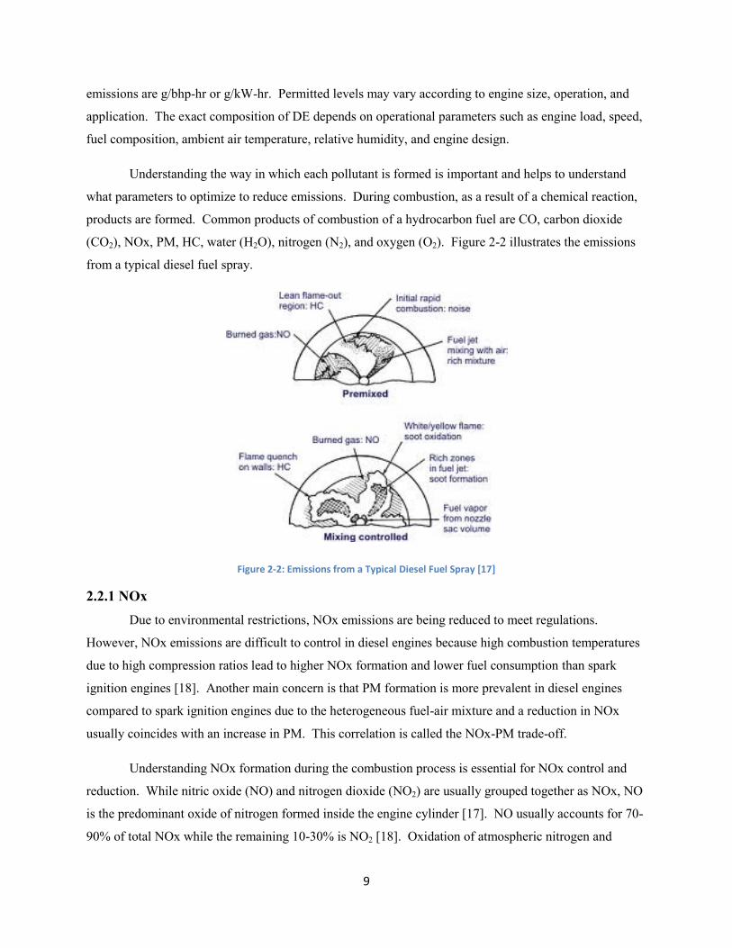
Understanding the way in which each pollutant is formed is important and helps to understand
what parameters to optimize to reduce emissions. During combustion, as a result of a chemical reaction,
products are formed. Common products of combustion of a hydrocarbon fuel are CO, carbon dioxide
(CO2), NOx, PM, HC, water (H2O), nitrogen (N2), and oxygen (O2). Figure 2-2 illustrates the emissions
from a typical diesel fuel spray.
Figure 2-2: Emissions from a Typical Diesel Fuel Spray [17]
2.2.1 NOx
Due to environmental restrictions, NOx emissions are being reduced to meet regulations.
However, NOx emissions are difficult to control in diesel engines because high combustion temperatures
due to high compression ratios lead to higher NOx formation and lower fuel consumption than spark
ignition engines [18]. Another main concern is that PM formation is more prevalent in diesel engines
compared to spark ignition engines due to the heterogeneous fuel-air mixture and a reduction in NOx
usually coincides with an increase in PM. This correlation is called the NOx-PM trade-off.
Understanding NOx formation during the combustion process is essential for NOx control and
reduction. While nitric oxide (NO) and nitrogen dioxide (NO2) are usually grouped together as NOx, NO
is the predominant oxide of nitrogen formed inside the engine cylinder [17]. NO usually accounts for 70-
90% of total NOx while the remaining 10-30% is NO2 [18]. Oxidation of atmospheric nitrogen and

10
oxygen is the principal source of NO. Oxidation of fuel containing nitrogen compounds is an additional
source of NO formation. Four mechanisms are attributed to NOx formation: thermal, N2O-intermediate,
prompt, and fuel. From atmospheric N2, the thermal NOx formation occurs by the well-known extended
Zeldovich mechanism (Equation 2-1, Equation 2-2, Equation 2-3).
Equation 2-1
Equation 2-2
Equation 2-3
The reactions listed above are a simplification of many different elementary reactions. At high
temperatures, dissociation of N2 and O2 can contribute to thermal NOx formation. The reaction rate
constants of these reactions tend to be very slow compared to those for combustion, mainly due to the
relatively high activation energy values. Thus, NO formation through this mechanism has very strong
temperature dependence [17]. The threshold temperature for NO formation is about 1800K. Thermal NO
is generally considered to be formed in the hot bulk mixture such as the combustion products of post
flame gases, where high temperature is available. The N2O-intermediate mechanism consists of
molecular nitrogen and oxygen forming N2O, then reacts with oxygen or hydrogen to form NO. This
mechanism involves mainly the following reactions:
Equation 2-4
Equation 2-5
Equation 2-6
The N2O-intermediat mechanism has previously been a minor contributor to NOx emissions, but has less
dependence on temperature than thermal NOx formation and may have a greater contribution in modern
engines [18]. The prompt NOx mechanism is initiated by the reactions of hydrocarbon fuel radicals and
molecular nitrogen to form atomic nitrogen and species containing nitrogen elements. Through oxidation
these species are converted to NOx. Prompt NOx is usually formed in the initial stage of combustion. Its
contribution to NOx emissions in internal combustion engines is very small. The fourth mechanism, fuel-
borne NOx is formed by nitrogen contained in the fuel, when the nitrogen is oxidized, typically through
the prompt NOx mechanism. Fortunately, current levels of nitrogen in diesel fuels are usually not
significant. Part of the NO formed by these mechanisms is converted to NO2 during and after the
combustion process via:
Equation 2-7
The formation reaction of NO2 is to a large extent due to the availability of the HO2 radical. The NO2
formed can also be destructed and converted back to NO by the following reactions.

11
Equation 2-8
Equation 2-9
It has been demonstrated that the presence of N2 and O2 under considerably high temperature is
the prerequisite for NOx formation. It is also shown that NOx formation has strong temperature
dependence, which can be effected by several design and operation parameters. The most important
engine parameters that affect NOx emissions include: equivalence ratio, burned gas fraction, injection
timing, and compression ratio. Other factors that affect NOx emissions are exhaust gas recirculation
(EGR) rate, engine load, availability of O2, intake humidity level, and intake pressure and temperature.
2.2.2 PM
In the last few decades concerns of what effect PM emissions have on the environment as well as
potential health effects have grown. Diesel PM consists primarily of combustion generated carbonaceous
materials (soot) on which organic compounds have been absorbed [17]. Most PM is the result of
incomplete combustion of the hydrocarbon fuel. PM is seen to consist of collections of elemental and
organic carbon spherules agglomerated into aggregates (or particles). Organic carbon contributes to PM
as the result of unburned fuel, crankcase oil blow-by, and combustion byproducts. Elemental carbon
contributes to PM as the residue of burned fuel. These particles become coated with adsorbed and
condensed organic compounds. The condensed material also includes inorganic species such as sulfates.
PM is typically classified by its size. Any particle from 2.5μm to 10μm in size, known as PM10, is referred
to as an “Inhalable Coarse Particle,” and any particle smaller than 2.5μm, known as PM2.5, is referred to
as a “Fine Particle” [21].
Particulate matter undergoes two main processes in diesel engines: formation and growth. PM
formation takes place at temperatures between about 1000 and 2800 K, and pressures of 50 to 100 atm
[17]. During formation, diesel fuel will undergo pyrolysis, dehydrogenation, and oxidation to form
“carbon-rich” products. These products typically include unsaturated hydrocarbons and polycyclic
aromatic hydrocarbons (PAH). Both are considered the most likely precursors of soot in flames. The
condensation of these products leads to the formation of the first recognizable soot particles, called nuclei
[17]. PM nuclei are very small, often less than 2 nm in diameter. The small nuclei begin to bond together
and grow larger particles through surface growth, coagulation, and aggregation.
The bulk of the solid phase material is generated by surface growth. Surface growth involves the
deposition of the gas-phase species on the nuclei, increasing the size and mass of individual soot particles.
Particle growth also occurs through coagulation, in which the particles collide and coalesce to form larger
particles. After surface growth ceases, these larger particles continue to coalesce to form chainlike

12
structures. This latter coalescence is known as aggregation [17]. Particle growth can continue in the
atmosphere, long after being emitted from the engine, by way of adsorption and condensation. At any
stage in the formation and growth process oxidation can occur where PM is burned with oxidizing species
to form CO, CO2, and HC gases [17].
2.2.3 CO
The formation of CO in diesel engines is attributed to the oxidation of fuel from combustion. The
main contributor to CO formation is insufficient time and oxygen for the oxidation of CO to CO2 [18].
The emissions of CO from internal combustion engines are primarily controlled by the fuel/air
equivalence ratio. For fuel-rich mixtures CO concentrations increase steadily with increasing equivalence
ratio. For fuel-lean mixtures, CO concentrations vary little and are relatively low [17]. Since diesel
engines operate on the lean side of stoichiometric, CO emissions are low and considered to be
insignificant and generally fall far below current regulations [17,18].
2.2.4 CO2
The emissions of CO2 are a direct product from combustion of a hydrocarbon fuel. The
emissions of CO2 form when sufficient time and oxygen is available for oxidation of CO to CO2.
Emissions of CO2 are directly related to fuel consumption in diesel engines. An increase in fuel
consumption increases the emissions of CO2. Global warming and climate change has been attributed to
CO2. For this reason the EPA and the National Highway Traffic Safety Administration (NHTSA)
adopted the first U.S. greenhouse gas (GHG) emission and fuel consumption standards for heavy- and
medium-duty vehicles in 2011 [22]. This regulation covers model years (MY) 2014-2018 engines, with
the NHTSA fuel economy standard being voluntary in MY 2014-2015.
2.2.5 HC
Hydrocarbon emissions are the result of incomplete combustion. The level of unburned HC in
the exhaust gases is generally expressed in terms of total hydrocarbons (THC). THC emissions are a
useful measure of combustion efficiency; however, it is not necessarily a significant index of pollutant
emissions [17]. Hydrocarbons can form and survive in the combustion chamber in many ways such as
flame quenching, absorption into engine oil, misfires, crevices, over-leaning, and under-mixing [17]. HC
emissions contribute not only to gaseous emissions but also the emissions of PM as discussed previously.
Formation and survival of HC starts when diesel fuel is injected into the combustion chamber.
The fuel is sprayed at an optimized angle for which the fuel vaporize, and mix with air, without hitting the
chamber wall. The inner core of the spray pattern is very rich, above the rich combustion limit of the fuel
[17]. The fuel becomes increasingly lean from the center of the spray outwards. At the outermost edge of

13
the spray the fuel becomes too lean, below the lean limit, to support flame propagation [17]. The fuel at
the outside edge will oxidize and become one of the main contributors to HC emitted. Figure 2-3
illustrates the equivalence ration distribution in the fuel spray at the time of ignition.
Figure 2-3: Schematic of Diesel Spray Pattern Showing Equivalence Ratio [17]
Along with the unburned fuel in the outermost region of the fuel spray, the fuel in the over-mixed
(or over-leaned) region has already mixed beyond the lean limit of combustion and will not auto-ignite.
Within this region, unburned fuel, fuel decomposition products, and partial oxidation products (aldehydes
and other oxygenates) will exist [17]. However, not all of these products will completely survive the
combustion process and leave the cylinder. The magnitude of HC in the over-lean region is related to the
amount of fuel injected during the ignition delay period and the mixing rate with air during this period
[17]. Thus, a correlation with unburned HC and length of ignition delay is expected. As the ignition
delay and mixing period increase, the magnitude of HC in this region and the magnitude of HC emissions
will increase [17].
Under-mixing, or over-fueling, will also result in HC emissions due to insufficient mixing with
air. This is usually a result of fuel that leaves the injector at low velocity, late in the combustion process
[17]. The most important source here is excess fuel in the nozzle sac. At the end of the injection process,
some fuel will remain in the tip of the injector after the needle seats. These HC emissions depend upon
the sac volume; therefore, injectors with small or no sac volume will have lower HC emissions [17]. The
fuel in the sac will vaporize as the combustion and expansion process proceed and enter the cylinder at a
low velocity through the nozzle holes. This fuel vapor will mix with air and may escape the cylinder
during the exhaust stroke. Over-fueling may also occur during transient engine operation as the engine
accelerates. Even though the equivalence ratio of the bulk mixture may remain lean, locally rich regions

14
may exist in the cylinder. The rich regions allow for the survival of unburned fuel particles that may
contribute to HC emissions. It is important to note that although many hydrocarbons are not burned
completely during the main combustion process, not all of them escape in the exhaust. Most of them are
still burned off or oxidized in the combustion chamber when mixed with the hot combustion products.
Hydrocarbon emissions have also been found to be sensitive to engine oil and coolant
temperatures. HC emissions are shown to decrease as these temperatures increase [17]. When ignition
delay is held constant, the over-mixing phenomena should also remain approximately constant.
Therefore, wall (or flame) quenching may also be considered a significant source of HC survival. This
will depend upon the amount of spray impingement on the combustion chamber walls [17]. Misfires can
also contribute to a rise in HC emissions; however, complete misfires in a well-designed and adequately
controlled engine are unlikely to occur under normal operating conditions [17].
2.3 Diesel Fuel Properties
Diesel fuels are complex mixtures of hydrocarbon molecules distilled from crude oil. Various
processes exist for refining of fuels to meet the appropriate quality specifications. The standards
specifying requirements placed on diesel fuel properties, such as ASTM D975, have evolved in part to
environmental considerations and emissions legislation [12]. Parameters specified in these standards that
influence emissions as well as combustion include:
Density
Cetane Number
Volatility
Sulfur Content
Viscosity
Heating Value
Aromatics
A summary of the impact these properties have on combustion and emissions are summarized below.
2.3.1 Density and Specific Gravity
Density, an important fuel property, can provide useful information about bulk fuel composition
and performance-related characteristics such as ignition quality, power, fuel economy, and low-
temperature properties [20]. A lower density fuel will generally lead to a lower maximum power and
lower NOx emissions with an increase in PM and CO [23]. Also, fuel injection equipment operates on a
volume metering system, so a change in density will influence engine output properties due to the

15
different mass being injected [20]. Due to this effect higher density fuels lead to a decrease in volumetric
fuel consumption.
Density may sometimes be expressed as specific gravity. Specific gravity is the ratio of the
density of the product being tested to the density of water at a specific temperature. The density can also
be expressed as API gravity, which is an arbitrary scale developed by the American Petroleum Institute
[20]. API gravity is inversely related to specific gravity, therefore a high API gravity means the material
is lower density. Density, specific gravity, and API gravity can all be measured by using either ASTM
D287 or ASTM D1298 methods. API gravity is calculated using the following formula:
Equation 2-10
2.3.2 Cetane Number
Cetane number is a measure of ignition quality of a fuel defined as the readiness for a fuel to
ignite after injected into a diesel engine. Fuels with higher cetane numbers have a higher propensity to
ignite and have a higher ignition quality compared to lower cetane number fuels. The cetane number of a
fuel is determined using ASTM D613 method, along with a Cooperative Fuels Research (CFR) engine, by
comparing its ignition delay of two reference fuels with known cetane numbers under a specified
operating condition [20]. The reference fuels are normal cetane (n-hexadecane or n-C16H34), which has a
cetane number of 100, and heptamethyl nonane (C12H34), which is given a value of 15 [20]. The cetane
number is calculated by the following formula:
Equation 2-11
Cetane number can affect various engine operation parameters as well as emissions. Higher
cetane number fuels have a shorter ignition delay. Lowering the cetane number will lead to a higher
pressure rise rate and reduced brake specific fuel consumption (bsfc). This is partially due to the higher
heating value of lower cetane number fuels [20]. Figure 2-4 shows the effect of cetane number on
emissions of NOx, CO, and HC from three heavy-duty diesel truck engines [20]. This study was
conducted using the Japanese 6-mode test cycle. Emissions of NOx, CO, and HC are all lower when a
fuel with a high cetane number is used. PM emissions also tend to decrease as fuel cetane number
increases [24].

16
Figure 2-4: Effect of Cetane Number on Exhaust Emissions [20]
2.3.3 Volatility
Volatility is a measure of the distillation or boiling range of a fuel. A highly volatile fuel will boil
at a low temperature and evaporate quickly [20]. Volatility is expressed in terms of the temperature at
which successive portions are distilled from a sample fuel under controlled heating in a standardized
apparatus [20]. ASTM D86 is a widely accepted method for distillation. Several factors are recorded
during the distillation process, including: initial boiling point (IBP), final boiling point (FBP), percent of
condensate recovered, percent residue of non-volatile matter [20]. The 10% and 90% or 95% recovery
temperature are often used as more precise indicators of the IBP and FBP, respectively. The distillation
range of a fuel will influence other properties such as flash point, viscosity, autoignition temperature,
density, and cetane number. Although some differences in engine performance are attributable to
variations in volatility, effects are generally modest and far less significant than the influence of
individual engine design [20]. The effect of volatility on gaseous emissions is also generally modest and
again highly dependent on engine design.
2.3.4 Sulfur Content
Sulfur content was the first fuel property to be controlled as a means to limit harmful diesel
exhaust emissions [20]. Sulfur is present in all crude oil and, as a result, is present in all diesel fuels to
some extent. During combustion, most of the sulfur present in the fuel is converted to sulfur dioxide
(SO2) and sulfur trioxide (SO3). These compounds, together with other gases, also form acidic by-
products and solid compounds such as sulfuric acid (H2SO4) and sulfate particulates. The gaseous
emissions will influence the exhaust odor, while the sulfates will contribute to PM emissions [20]. Fuel

17
sulfur content directly influences sulfur oxide emissions. Combustion of fuels with high sulfur content
produce higher sulfur oxide emissions [24]. It is noted that on-road diesel fuels sold in the United Sates
since 2006 have had maximum sulfur content of 15 ppm (termed ULSD) and sulfur-related emissions are
generally not a concern.
2.3.5 Viscosity
The viscosity of a fluid indicates its resistance to flow. The higher the viscosity of a fluid, the
greater the resistance it has to flow. Usually expressed as kinematic viscosity, ASTM D445 is widely
used to determine this property of diesel fuels [20]. Viscosity varies inversely with temperature, therefore
the temperature at which the viscosity was determined must be noted, usually 20°C or 40°C for diesel
fuels [20]. Viscosity plays a major role in the performance of the fuel injection equipment, which must
accurately measure the amount of fuel to be injected. At high temperatures, the viscosity of the fuel is
lower and leaking can occur through seals in the fuel injection system if the viscosity if too low. The
diesel spray pattern and atomization are also influence by fuel viscosity. On-road diesel fuel
specifications impose an upper and lower limit on viscosity to ensure that no problems occur in the fuel
injection system or engine [20,23].
2.3.6 Heating Value
Heating value (or heat of combustion) is an important fuel property. It is defined as the energy
available from a fuel when it is burned, and is the basis for calculating the thermal efficiency of an engine
using that fuel [20]. The heating value of a fuel is determined using a bomb calorimeter described by the
ASTM D240 method. Heating value does not normally appear in specifications for automotive diesel
fuels because it is not controlled during manufacturing [20]. Fuels of varying heating value will produce
different power outputs on the same engine, unless other fuel propertiesor fuel injection systems are
adjusted.
2.3.7 Aromatics
The effects of aromatic content in fuels on engine performance and emissions are highly debated.
While most research shows that aromatics have little or no effect on HC, CO, and PM emissions, some
studies show mixed results. A slight decrease in NOx emissions can result from decreasing aromatic
content [20,23]. This trend can be attributed to the higher combustion temperature of fuels containing
aromatics. There are multiple methods to determine content of aromatics in a hydrocarbon fuel, including
ASTM D5186.

18
2.4 Application of Hydrotreated Fuels to CI Engines Hydrotreated fuels perform similarly to conventional diesel fuel in diesel engines; however, key
property differences lead to different combustion and performance characteristics. Fuel properties of
hydrotreated fuels that may affect combustion include density, cetane number, heating value, oxygen
content, sulfur content, viscosity, and aromatics. Hydrotreated fuels are essentially free of oxygen, sulfur,
and aromatics. These fuels also have a high cetane number and a heating value similar to conventional
diesel [6,7]. Table 2-1 compares fuel properties of hydrotreated vegetable oil (HVO), EN 590 diesel fuel,
gas-to-liquid (GTL) diesel fuel, and FAME. At this point relatively little research exists in literature
about the performance of HVO in diesel engines. However, existing research on the application of HVO
to diesel engines is typically related to spray, combustion, and emission characteristics.
Table 2-1: Typical fuel properties of HVO, EN 590, GTL, and FAME [6]
2.4.1 Spray Characteristics
Few studies have been conducted to compare fuel spray characteristics of HVO and existing
petroleum derived diesel fuels. Though research is limited, spray characteristics of HVO have been
investigated by Hulkkonen et al. and Legg et al. [25,26]. Physical properties of HVO (Table 2-1) such as
density and viscosity will lead to differing spray characteristics of HVO compared to petroleum diesel.
Fundamental fuel spray characteristics are presented in Figure 2-5. Spray velocity is defined as the
velocity of the leading edge of the spray. The spray penetration is defined as the distance from the nozzle
tip to the leading edge of the spray. The length of which the spray disintegrates into droplets is called the
break-up length. The spray angle is the angle formed by the intersection of the spray and the tip of the
injector [25].
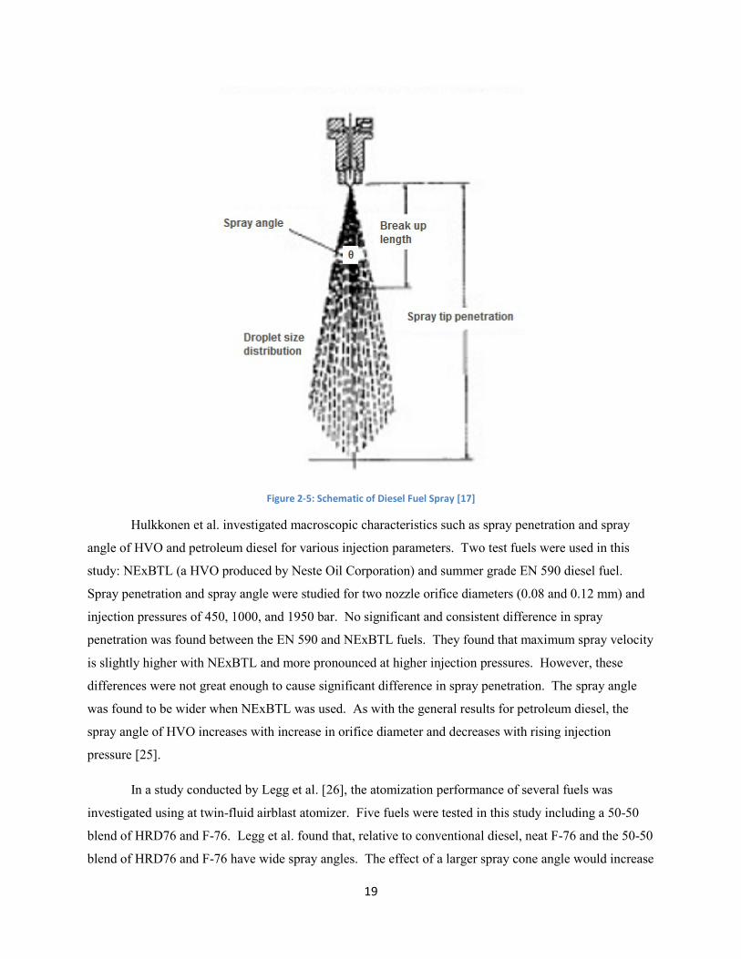
19
Figure 2-5: Schematic of Diesel Fuel Spray [17]
Hulkkonen et al. investigated macroscopic characteristics such as spray penetration and spray
angle of HVO and petroleum diesel for various injection parameters. Two test fuels were used in this
study: NExBTL (a HVO produced by Neste Oil Corporation) and summer grade EN 590 diesel fuel.
Spray penetration and spray angle were studied for two nozzle orifice diameters (0.08 and 0.12 mm) and
injection pressures of 450, 1000, and 1950 bar. No significant and consistent difference in spray
penetration was found between the EN 590 and NExBTL fuels. They found that maximum spray velocity
is slightly higher with NExBTL and more pronounced at higher injection pressures. However, these
differences were not great enough to cause significant difference in spray penetration. The spray angle
was found to be wider when NExBTL was used. As with the general results for petroleum diesel, the
spray angle of HVO increases with increase in orifice diameter and decreases with rising injection
pressure [25].
In a study conducted by Legg et al. [26], the atomization performance of several fuels was
investigated using at twin-fluid airblast atomizer. Five fuels were tested in this study including a 50-50
blend of HRD76 and F-76. Legg et al. found that, relative to conventional diesel, neat F-76 and the 50-50
blend of HRD76 and F-76 have wide spray angles. The effect of a larger spray cone angle would increase

20
the exposure of droplets to the surrounding air, improving secondary atomization as well as mixing and
heat transfer [26]. The spray angle of the neat F-76 and HRD/F-76 blend was also found to be slightly
canted to one side. This study also investigated the Sauter Mean Diameter (SMD) and droplet size
distribution for each test fuel. Fuels with similar physical properties such as F-76, HRD/F-76 blend, and
conventional #2 diesel all produced similar results for SMD and droplet size distribution. Differences
between values for these fuels were within the experimental error [26].
While differences in physical properties of hydrotreated fuels produce slightly different spray
characteristics than conventional diesel, these differences are typically not significant. This suggests that
combustion and emission trends of these fuels is not significantly affected by spray characteristics but
rather by fuel properties such as cetane number, density, heating value, oxygen content, sulfur content,
and viscosity among others.
2.4.2 Combustion and Emission Characteristics
Combustion related properties of HVO are primarily better than petroleum derived diesel fuel.
HVO has higher cetane number, lower boiling point, and lower adiabatic flame temperature than
petroleum diesel. These properties not only allow for more advance combustion strategies but also help
reduce regulated and unregulated exhaust emissions. HVO is adaptable in current engine designs;
however, adjustment to the engines electronic control unit (ECU) may be necessary for optimal
combustion and emission performance. There is a lack of research investigating in-cylinder combustion
characteristics of hydrotreated fuels; most studies focus on overall engine performance and emission
characteristics.
A study by Caton et al. [27] compared angle of peak pressure (AOP), peak pressure (PP),
indicated mean effective pressure (IMEP), and brake mean effective pressure (BMEP) of HRD and
conventional diesel. This study used an indirect injection (IDI) 2007 AM General Engine Products 6.5
liter V8 HMMWV (Humvee) turbocharged diesel engine instrumented to measure in-cylinder pressure.
AOPs for both HRD and diesel were similar but diesel had higher PPs by about 2-6% due to shorter
combustion duration and greater premixed burn. Over most of the engine operating map the IMEP and
BMEP were similar to, or slightly greater, compared to diesel fuel. The slight improvement in IMEP and
BMEP was due to the overall longer burn duration of HRD. This provided for a more favorable
integrated pressure-volume change effect [27]. Maximum power for diesel and HRD were similar due to
similar fuel densities and heating values. Caton et al. also reported results on injection timing, ignition
delay, combustion duration, fuel consumption, and CO2 emissions. HRD fuel operation showed a slightly
retarded start of injection (SOI) of about 0.5 crank angle degrees (CAD). Ignition delay for HRD was
moderately shorter up to 2.5 CAD due to higher cetane number. HRD operation also showed modestly

21
longer combustion duration from 0.5 to 1.5 CAD. This is a result of the shorter ignition delay which
leads to less fuel-air premixing. Brake specific fuel consumption was generally 5-10% lower with HRD
operation and CO2 emissions were consistently lower for HRD, from 5-10%, compared to the petroleum
diesel. This is due to a more favorable H/C fuel ratio of HRD compared to diesel and more efficient
combustion phasing of HRD fuel [27].
Several studies [2,6,7,8,28,29] indicate that reductions in regulated and unregulated emissions as
well as fuel consumption are possible with operation of hydrotreated fuels. Exhaust emissions of three
cars using NExBTL blends were tested and compared with EN 590 and Swedish Environmental Class 1
(EC1) diesel fuels by Rantanen et al. [8]. Fuel blends tested were 5, 15, 20, and 85% by volume of
NExBTL. They found that reductions in CO, HC, and PM were dependent upon the proportion of
NExBTL in the fuel mixture. However, a clear reduction in NOx emissions was not seen in this study. A
fuel blend of 85% NExBTL showed on average 30% less CO emissions, 40% less HC emissions, 17%
less PM, 4-6% less CO2, and <5% NOx emissions compared to EN 590 reference fuel. Changes in fuel
consumption and CO2 emissions were not seen in this study except modest reductions with fuel blend of
85% NExBTL [8].
Emissions of two heavy duty diesel engines and two city buses operated on HVO and sulfur free
EN 590 are presented by Kuronen et al. [6]. One bus was equipped with a urea based SCR (selective
catalyst reduction) and the other with EGR and an oxidation catalyst to reduce NOx emissions. The buses
were tested using the Braunschweigh City Driving Cycle. Emissions results for two other truck engines
are present in this study provided by earlier research. Both European Steady State and Transient test
cycles were used for the engines. Reductions in emissions compared to standard sulfur free EN 590
ranged from 28-46% for PM, 7-14% for NOx, 0-48% for HC, and 5-78% for CO. From this study it is
evident that emission reductions can be significant with HVO. CO2 levels also dropped due to the higher
H/C ratio in HVO compared to diesel. A slight decrease in mass based fuel consumption was also noticed
for HVO; however, volumetric fuel consumption was slightly higher due to the lower density of HVO [6].
Aatola et al. [28] studied the effect of injection timing on emissions and fuel consumption with
HVO fuel. The test engine was a turbocharged 8.4 liter 6-cylinder 4-stroke direct injection diesel engine
with common-rail fuel injection and a charge air cooler. Tested fuels were neat HVO, a blend 30vol-%
HVO and 70vol-% EN 590 diesel fuel. EN 590 was also used as a reference fuel. The engine was run
under steady state conditions as three speeds (1000, 1500, and 2200 rev/min) and two load corresponding
to 50% and 100% load. The main injection timing was varied from six CAD earlier than the default
setting and six CAD later than the default setting with intervals of two CAD. Average reductions of all
emissions were clear with neat HVO. Smoke was reduced about 35% and NOx was reduced about 5%.
With the HVO-EN 590 blend fuel smoke was reduced about 11% but no clear difference in NOx was

22
found. The changes in THC and CO emissions for both fuels were not significant in absolute terms
because of the already low absolute values [28]. Mass based fuel consumption was reduced with neat and
blended HVO fuels but volumetric fuel consumption increased. At all loads and speeds on each measured
injection timings neat HVO lowered both NOx and smoke emissions. These changes were not as
apparent with the blended HVO-EN 590 fuel. Specific fuel consumption (SFC) also decreased with neat
HVO across the load-speed map at each injection timing, again the decrease with the blended fuel is not
that clear. This decrease was attributed to the higher effective heating value of the HVO [28]. A slight
increase in engine efficiency was also observed with both neat HVO and the HVO-EN 590 blend,
possibly due to the higher cetane number and shorter ignition delay. When NOx emission of the engine
was kept equal with all test fuels; the use of neat HVO led to 37% lower smoke and to 6% lower SFC
than the diesel fuel studied. In addition, with constant SFC of the engine for all fuels, the application of
neat HVO led to 16% lower NOx and to 23% lower smoke than the use of diesel fuel. The results of this
study suggest that even more significant reduction in emissions can be achieved with optimized injection
parameters for HVO [28].
The effects of HVO on combustion and emission characteristics were investigated by Sugiyama
et al. [29] using an engine dynamometer and vehicle tests. The test engine was an inline 4-cylinder direct
injection turbocharged diesel engine with common rail fuel injection. The test vehicle was a production
model passenger car with a six-speed manual transmission; the engine had the same specifications as the
engine for dynamometer tests. It was found that the same torque and brake specific energy consumption
(BSEC) could be obtained with HVO as with the diesel. This is partially due to the higher (approximately
3%) injection quantity of HVO. First a test with single fuel injection was performed and then a test with
pilot injections. During the test with single fuel injection, combustion noise, HC, and NOx were all lower
with HVO than diesel fuel. As a result of the shorter ignition delay of HVO, the heat release rate (HRR)
advances. This difference was most prominent at low loads. With pilot injections the reduction in NOx
and combustion noise was not observed; HC and smoke were lower in all load ranges. Also, the
advancement of HRR was decreased with pilot injections. Vehicle tests were conducted with neat HVO,
diesel fuel, and diesel fuel blended with 20% and 40% of HVO. As with the engine dynamometer tests,
vehicle emissions in chassis dynamometer tests produced less HC and CO with neat HVO and the diesel-
HVO blends. NOx levels were similar for each fuel. A decrease in PM was also observed and was more
pronounce with higher proportions of HVO. Optimization of engine performance utilizing the
characteristics of HVO was also investigated in this study. They found that slight advancing the main
injection of HVO fuel, fuel consumption could be decreased by 4-5% without significantly effecting
beneficial emission trends. It was also found that it will be possible to further decrease emissions and fuel
23
consumption by taking advantage of the high cetane number of HVO to optimize combustion by
decreasing the quantity of pilot injection [29].
A study performed by Ghosh and Risley [2] compared engine performance and emission data of a
50/50 blend of ULSD/HRD to ULSD on a 4-stroke marine diesel engine from a Stalwart class vessel.
Emissions were measured at stable operation loads of 100, 75, 50, 25, and 10%. The operation of the
engine on the ULSD/HRD blend resulted in reductions of 10% for NOx, 18% for CO, 5% for CO2, and
25% for PM. Improved fuel economy at intermediate loads was also observed with the 50/50 blend,
while differences in fuel economy at low and high loads were not significant. They concluded that HRD
has the potential to substantially reduce pollutant emissions without engine or vessel infrastructure
modification.
These studies [2,6,7,8,27,28,29,] have shown that HVO generally reduce exhaust emissions and
fuel consumption, though NOx reductions are not always clearly seen. Hydrotreated fuels have the
potential to replace conventional diesel fuel due to fuel properties that lead to similar combustion
characteristics and engine performance. Fuel injection system may require recalibration to further
optimize performance of HVO, but more research is necessary to fully understand the effect of injection
timing on HVO.

24
Chapter 3: Experimental Setup
3.1 Introduction
The experimental equipment and procedures used in this study were conducted at West Virginia
University’s Center for Alternative Fuels, Engines, and Emissions (CAFEE). Where applicable, CAFEE
operates in compliance with CFR 40, Parts 1036 (highway engines), 1042 (marine engines), and 1065
(test procedures). The objective of this investigation was to identify possible positive and negative
attributes of eight proposed alternative fuels on a smaller compression ignition engine than is used for
propulsion engines in the existing Navy fleet. Testing was carried out on a 1992 rebuilt Detroit Diesel
Corporation Series 60 engine coupled to a General Electric DC dynamometer. Emissions data were
characterized with the use of a full scale dilution tunnel system.
3.2 Test Fuels
There were eight proposed alternative fuels being evaluated for the U.S. Navy in this program.
The proposed fuels were compared against their respective reference fuel, either JP-5 or F-76. Each
candidate alternative is a hydrotreated biofuel and was tested as a neat and/or blended fuel. Table 3-1
contains the naming convention of the fuels. Table 3-2 and Table 3-3 contain fuel properties compared to
reference fuel properties of JP-5 and F-76 [27,30,31]. Fuel properties for JP-5 and F-76 are based on
standard military specifications MIL-DTL-5624V [30] and MIL-DTL-16884M [31], respectively.
Detailed property tables and fuel specifications are found in the Appendix. Fuel properties for 80/20
F76/DSH76 were not available because the fuel was mixed on-site and chemical and physical properties
were not determined.
Table 3-1: Naming convention of test fuels
Reference Fuel Candidate Fuel
JP-5 50/50 JP5/HRJ5
Neat HRJ5
F-76
Neat HRD76
50/50 F76/HRD76
Neat DSH76
50/50 F76/DSH76
80/20 F76/DSH76
80/20 F76/HDCD76

25
Table 3-2: Fuel property comparison of JP-5-based fuels per MIL-DTL-5624V
Table 3-3: Fuel property comparison of F-76-based fuels per MIL-DTL-16884M
3.2.1 JP-5
JP-5 is a yellow kerosene-based jet fuel developed in 1952 for use in aircraft stationed aboard
aircraft carriers. JP-5 is a complex mixture of hydrocarbons containing alkanes, naphtenes, and aromatic
hydrocarbons. This fuel requires military-unique additives that are necessary in military weapon systems,
engines, and missions. It is intended for use in aircraft turbine engines, but in some cases, may be burned
in diesel engines. Jet fuel is often used in ground support vehicles at airports instead of diesel. However,
jet fuel tends to have poor lubricating abilities compared to diesel. JP-5 is covered by the military
Property Unit JP-5 HRJ-5
50/50
JP5/HRJ5
Density at 15°C kg/m3 814.8# 766.5# 790.7#
Viscosity at -20°C mm2/s 5.3* 8 5.9
Cetane Number --- 44* 62 51
Freezing Point °C -50* -50 -55
Heating Value (by mass @ 15 C) MJ/kg 42.6 (min) 44 43.5
Heating Value (by volume @ 15 C) MJ/L 33.5 (min) 33.748 34.365
Aromatics vol % 19.2* 0.2 9.8
Flash Point °C 62* 63 64
Hydrogen Content Mass % 13.6* 15 14.2
Sulfur Content Mass % 0.3 (max) report 0.1
Thermal Stability (Pressure Drop) mm Hg 0* 0.0 0.1
#Fuel density measured at WVU CAFEE
*Fuel properties measured by Fuels Division of Naval Air Systems Command [27]
Property Unit F-76 HRD-76
50/50
F76/HRD76 DSH-76
50/50
F76/DSH76 HDCD
80/20
F76/HDCD7
Density at 15°C kg/m3 845.8# 777.9# 812.6# 772.9# 808.5# 928# 862.1#
Viscosity at 40°C mm2/s 3.8* 2.3 2.3 2.4 2.5 5.4 3.3
Cetane Number --- 43* 70 59 58 55 28 44
Cloud Point °C -16* -3 -11 -82 -28 <-81 -14
Heating Value (by mass @ 15 C) MJ/kg 43 (min) 43.9 43.3 44 43.442 42.1 42.8
Heating Value (by volume @ 15 C) MJ/L 34 (min) 34 34.9 34.2 35.4 36 36.6
Aromatics vol % 17.3* 1 11 report 12 20 22
Flash Point °C 62* 64 65 106 81 96 76
Pour Point °C -24* -9 -18 <-75 -48 -48 -18
Hydrogen Content Mass % 12.7* 15 14 14.8 13.9 11.9 12.8
Sulfur Content Mass % 0.34* N/A 0.06 report report NR 0.2
Lubricity μm 460 (max) NR NR 540 460 190 410
Storage Stability mg/100 mL 1* 0.0 0.5 1.0 0.6 0.7 2.3
*Fuel properties measured by Fuels Division of Naval Air Systems Command, Patuxent River, MD and US Naal Academy [27]
#Fuel density measured at WVU CAFEE

26
specification MIL-DTL-5624V [30]. Properties of JP-5 are shown in Table 3-2. In this experiment JP-5
was operated as a reference fuel for neat HRJ5 and 50/50 JP5/HRJ5 proposed alternative fuels.
3.2.2 HRJ5
HRJ5 is a hydroprocessed renewable jet fuel and a possible replacement for JP-5. It is a
paraffinic-type hydrocarbon with no aromatics and a normal jet cut carbon chain length distribution.
Under MIL-DTL-5624V [30] it can be blended up to 50% with JP-5, limited by density and minimum
aromatic content. HRJ5 is not dependent upon feedstock. Relative to JP-5, HRJ5 has lower density,
aromatic content, and volumetric heating value. It also has a higher cetane number and hydrogen content.
In this experiment, HRJ5 was operated as neat HRJ5 and a blend of 50/50 JP5/HRJ5 and compared to JP-
5 reference fuel.
3.2.3 F-76
F-76 is the military specified distillate fuel normally used in shipboard diesel engines, gas
turbines, and boilers for propulsion and auxiliary power. It has stringent specifications and
storage/handling requirements covered in MIL-DTL-16884M [31]. Older naval engineering terminology
referred to F-76 as Diesel Fuel Marine (DFM). Current practice no longer uses “DFM’ as a name for F-
76 and to avoid confusion, F-76 fuel should only be referred to as “F-76.” F-76 is a clear, never dyed fuel.
Table 3-3 shows fuel properties of F-76. In this experiment F-76 was operated as a reference fuel for the
neat alternative HRD76, DSH76, HDCD76, and their respective blends, fuels.
3.2.4 HRD76
HRD76 (Hydroprocessed Renewable Diesel) is another paraffinic-type hydrocarbon fuel with no
aromatics. It has a normal diesel-cut carbon chain length distribution with various degrees of
hydrocarbon branching at all chain lengths. Similar to HRJ5, it is feedstock independent and can be
operated in blends up to 50%, limited by density and minimum aromatic content under MIL-DTL-
16884M [31]. Relative to F-76, it has lower density, aromatic content, volumetric heating value and
higher cetane number and hydrogen content. HRD76 was operated as neat HRD76 and a blend of 50/50
F76/HRD76 in this experiment.
3.2.5 DSH76
DSH76 is a direct sugar to hydrocarbon fuel. First, the sugar is fermented to produce farnesene,
which is then hydroprocessed to produce farnesane. Farnesane is a single-molecule C-15 paraffin.
DSH76 has no distribution of chain length or isomerization. It can used in blends up to 50% before it
meets the limit of density and minimum aromatic content set by MIL-DTL-16884M [31]. Relative to F-
76, DSH76 has a relatively flat boiling point curve, lower density, aromatic content, and volumetric

27
heating value as well as higher cetane number and hydrogen content. DSH76 was operated in three ratios
in this experiment: Neat DSH76, 50/50 F76/DSH76, and 80/20 F76/DSH76.
3.2.6 HDCD76
HDCD76 (or Hydrotreated Depolymerized Cellulosic Diesel) is an aromatic and cycloparaffinic
rich hydrocarbon. Its chemistry is primarily defined by catalytic cracking of cellulosic biomass, which is
followed by downstream hydrotreating. It has a normal distribution of aromatic and cycloparaffinic
molecules. Blending of HDCD76 is limited to 20% because of limits on cetane number, maximum
density, hydrogen content, and viscosity [31]. Unlike the other candidate fuels, HDCD76 has higher
aromatic content, density, viscosity, and volumetric heating value as well as lower cetane number and
hydrogen content compared to F-76. HDCD76 was only operated as an 80/20 F76/HDCD76 blend in this
experiment.
3.3 Test Engine
Evaluation of the test fuels is conducted using a 1992 rebuilt Detroit Diesel Corporation Series 60
engine. In order for this engine to be tested in a laboratory environment some changes were made in
order for the engines to be accommodated. The radiator found in typical on-road vehicles was replaced
with a liquid-to-liquid heat exchanger, and the intercooler replaced with a liquid-to-air intercooler. All
accessories such as the fan and air conditioning unit were either removed or disengaged. Intake air was
conditioned by the CAFEE heating, ventilation, and air conditioning system and the intake filter was
replaced with a laboratory filter. An exhaust back pressure valve on the exhaust pipe took the place of the
exhaust muffler.
The 1992 DDC S60 was rebuilt in 2006 to the original 1992 DDC specifications. It has been
used in previous tests to examine effects of fuel additives on in-cylinder pressure and emission
characteristics reported by Nuszkowski [18] and Tincher [23]. The specifications for this engine can be
found in Table 3-4, and the engine can be seen in Figure 3-1. This engine can be considered a pristine
laboratory engine suitable for emissions testing and in-cylinder pressure analysis. The engine was
previously fitted with two in-cylinder pressure transducers (cylinder No. 3 and No. 5) located in the
engine head by the Detroit Diesel Corporation. The fuel injector in cylinder No. 3 was also fitted with a
needle lift sensor to obtain injection timing data. An encoder attached to the drive shaft of the engine
provided the timing for data acquisition with a low to high voltage at every 0.25 crank angle degree. The
voltage change triggered the DAQ card to acquire a measurement for in-cylinder pressure.

28
Table 3-4: Test engine specifications
Figure 3-1: 1992 Rebuilt DDC Series 60 [23]
3.4 Engine and Test Cell Parameters
During engine testing, several parameters were recorded to ensure proper engine and test cell
operation. Recorded engine parameters included: coolant temperature, oil temperature, exhaust
temperature, exhaust back pressure, manifold air temperature and pressure, and intake depression. Other
parameters were also recorded to ensure the test cell was functioning properly and included: fuel
temperature, intake air temperature, intake air humidity, and inlet and outlet temperatures for each of the
heat exchangers. Along with several other measurements, the parameters listed above were required for
the calculation of in-cylinder pressure and emission data. After each test, all of these parameters were
checked in order to validate the test.
Engine Manufacturer Detroit Diesel Corporation
Engine Model, Year Rebuilt DDC Series 60, 1992
Model Number 6067GU60
Serial Number 06R0105610
Configuration Inline 6 Cylinder
Displacement (L) 12.7
Power Rating (hp) 360 @ 1810 rpm
Torque Rating (ft-lbs) 1450 @ 1200 rpm
Compression Ratio 15:1
Bore X Stroke (mm x mm) 135 X 165
Air Handling Turbocharged, Aftercooled
Exhaust Gas Recirculation N/A

29
3.5 Engine Dynamometer
The dynamometer used for testing during this study was a General Electric direct current model
DYC 243 and can be seen in Figure 3-2. This dynamometer was capable of delivering up to 500hp and
absorbing 550hp. The engine was coupled to the dynamometer using a Vulkan damper and drive shaft
coupling. A load cell mounted on the dynamometer measured the force, used to calculate the engine
torque, and a digital encoder attached to the dynamometer was used to determine engine speed. The
dynamometer was calibrated to be in compliance with CFR 40 Part 1065.310 [32].
Figure 3-2: GE Engine Dynamometer
3.6 Dilution Tunnel and Sampling System
Emission testing at CAFEE was conducted using a full-scale dilution tunnel, shown in Figure 3-3,
in order to measure the effects of exhaust emissions on a simulated real world environment. The system
was designed to meet CFR 40 Part 1065 specifications. The dilution tunnel enables mixing of engine
exhaust and ambient air, which allows a multitude of reactions to occur replicating reactions experienced
once exhaust gas enters the atmosphere. The primary purpose of the dilution tunnel was to allow for
particulate matter formation, but measurement of gaseous emissions was also simplified for transient
tests.
A constant volume sampling system (CVS) was used with the dilution tunnel. In order to satisfy
CFR 40 Part 1065.240, the total volume of exhaust and dilution air must be measure and a continuously
proportioned volume of sample must be collected for analysis [32]. A subsonic venturi (SSV) was used

30
to measure the dilute exhaust mixture. An electric blower, located after all emission probes and the
venturi, was used to pull the air mixture through the CVS system.
Figure 3-3: Full-Scale Dillution Tunnel at WVU CAFEE Engine Lab
3.6.1 Subsonic Venturi
As specified in CFR 40 Part 1065.240 [32], the CVS system consisted of a subsonic venturi
capable of accurately measuring flow being pulled through it. The SSV was used to measure the flow
rate of the exhaust and dilution air mixture and sustain a continuous flow rate through the dilution system.
The venturi flow rate can be determined using Equation 3-1.
Equation 3-1: Venturi Flow Rate
Where, Qv (SCFM) is the standard volumetric flow rate through the venture
Kq is a known constant
ρs is the density at standard conditions
Cd is the coefficient of discharge (or Actual Air Flow/Theoretical Air Flow)
Y is the expansion factor
d is the throat diameter
β is the ratio of the throat diameter to inlet pipe diameter
ρi is the density at inlet conditions
∆P is the differential pressure (or pressure drop) between the throat and inlet

31
3.6.2 Dilution Air
The dilution tunnel is designed to simulate the effects of exhaust gas entering the atmosphere. In
order to reduce variability in the engine performance and the resulting emissions, the intake and dilution
air streams were temperature and humidity controlled. This allowed all tests to be evaluated on the same
basis. Outside ambient air was passed through a HEPA filter to remove PM found in the air. HEPA
filters have an initial collection specification of 99.97%. The air was then conditioned to fall in the 20 to
30°C range with an approximate dew point of 14.5°C as per CFR 40 Part 1065.140 [32].
3.6.3 Gaseous Sampling System
The gaseous sampling system at the WVU CAFEE consisted of heated sampling lines, heated
pumps, heated filters, exhaust gas analyzers, a chiller unit, and an exhaust system. The sampling probes
were located downstream of the dilution air mixing and upstream of the SSV. All sampling probes and
lines were heated to prevent condensation; individual temperatures were dependent upon the emission
species. Samples were taken more than 10 diameters downstream of the exhaust and dilution air mixing.
Samples were taken for the following gases: CO, CO2, NOx, and THC. To satisfy CFR 40 Part 1065.145
[32], sample lines and probes for CO, CO2, and NOx were all maintained at 235±20°F. THC sampling
probes and lines were kept at 375±20°F. CO/CO2 samples were passed through a chiller unit to remove
water from the sample line. The gas samples were then pumped to a MEXA-7000 analyzer consisting of
different exhaust gas analyzers, which are explained in more detail in Section 3.7.
3.6.4 Particulate Matter Sampling System
A gravimetric-based collection method was used to collect particulate matter emissions. A
slipstream was taken from the main dilution tunnel for TPM measurements on the order of 1-2 scfm. The
slipstream passed through a stainless steel sample line connected to the PM sampling box, shown in
Figure 3-4. After entering the PM sampling box, the exhaust gas first passed through a particulate
cyclone with a cut size of 10 μm. The exhaust gas then passed through a 47 mm TX40 filter being held in
a stainless steel filter holder in which PM was collected. A digital mass flow controller measured and
controlled the amount of exhaust gas passing over filter face. The filter face was maintained at a nominal
125°F to prevent the PM from changing due to condensation.
The 47 mm TX40 filters are made of pure borosilicate glass microfibers reinforced with woven
glass clothe and bonded with PTFE (polytetrafluoroethylene). The TX40 filters have a manufacturer
rated efficiency of 99.9%. In accordance with CFR 40 Part 1065.170 [32], the use of one filter is
permissible so long as the minimum initial collection efficiency is at least 99.7% as specified by the

32
manufacturer’s product ratings. All filters were pre-conditioned and weighed prior to and after testing in
a controlled clean room environment following standards set by CFR 40 Part 1065.190 [32].
Figure 3-4: PM Sampling Box at WVU CAFEE Engine Lab
3.7 Exhaust Gas Analyzers
Emissions at WVU CAFEE were measured during testing using a Horiba MEXA-7000 gas
analyzer unit, shown in Figure 3-5. This unit utilizes a chemiluminescent analyzer for oxides of nitrogen,
a heated flame ionization detector (HFID) for total hydrocarbons, and infrared analyzers for carbon
monoxide and carbon dioxide. Each of these analyzers was calibrated using NIST-traceable gases and set
to a range appropriated to the emissions from the engine. Calibrations occurred at the beginning of the
test program.

33
Figure 3-5: Horiba MEXA 7000 Gas Analyzer Unit
3.7.1 Hydrocarbon Analyzer
A HFID analyzer (Horiba Model FIA-721HA) was used to measure the total hydrocarbon
concentration in the gaseous exhaust. An HFID has a heated oven which contains a burner with a heated
pump [23]. A regulated flow of 40% hydrogen/60% helium sustained the flame within the analyzer. As
hydrocarbons passed through the flame positive ions were formed. The positive ions were collected by a
split ring analyzer with polarized electrodes. When the sample is passed through the flame the
electrostatic field generates as small current between electrodes. The measured current is directly
proportional to the concentration of total hydrocarbons in the sample. A secondary hydrocarbon analyzer
(Horiba Model FIA-725A) was used as a quality assurance/quality control (QA/QC) device. Both devices
have linearity within ±1% of full scale and repeatability within ±0.5% of full scale.
3.7.2 Oxides of Nitrogen Analyzer
Oxides of nitrogen were measured with two separate analyzers, both worked on the principle of
chemiluminescence. Chemiluminescence is the chemical reaction that produces light. The primary NOx
analyzer was a Horiba Model CLA-720MA, and a Horiba Model CLA-720A, which acted as a QA/QC
device. First, the sample gas is passed through a NO2 to NO converter to convert all NO2 to NO. The NO

34
is then mixed with ozone (O3) in which the NO is oxidized to NO2, a small portion of the NO2 formed is
in an excited state. In order to reach a stable, non-excited state the excited NO2 released a photon in the
form of light. The released photons were then detected by a photon detector; the number of detected
photons is directly proportional to the number of NO molecules in the exhaust sample. The total level of
NOx in the exhaust gas was detected by the device that responded proportionally to the NO in the sample
and the NO formed from NO2 dissociation [23]. Both analyzers have linearity within ±1% of full scale
and repeatability within ±0.5% of full scale.
3.7.3 Carbon Monoxide and Carbon Dioxide Analyzers
A Horiba AIA-721A and a Horiba AIA-722 were used to measure CO and CO2 emissions,
respectively. Both analyzers used the non-dispersive infrared (NDIR) principle to detect CO and CO2
concentrations. NDIR is based on the ability of certain gases’ to absorb infrared radiation. The absorbed
energy is measured and used to determine the concentration of specific gases in the gaseous sample. Prior
to being sent to the analyzer the sample must be sent through a chiller unit for water to be condensed out
because NDIR is sensitive to water vapor.
3.8 Intake Air
Intake air flow was measure using a laminar flow element (LFE), manufactured by Meriam
Instruments (Model No. 50MC2-6), and conditioned to meet CFR 40 Part 1065.125 specifications [32].
The intake air was taken from outside and passed through an air handling unit where it was cooled to
remove moisture, if necessary. It was then passed through a HEPA filter to remove any particulate matter
from the ambient air. The HEPA filter also helped to ensure test repeatability. The air was then heated
and humidified in a heat exchanger to fall within the 20 to 30°C range.
The differential pressure across the LFE was measured using an Omege differential pressure
transducer. An absolute pressure transducer was used to correct back to standard conditions. Inlet
temperature to the LFE was measured using a resistance temperature device. The actual volumetric flow
rate was calculated using the inlet temperature and the differential pressure. A GE sensor hygrometer,
with a sample line located in the intake pipe after the LFE, was used to measure intake air humidity via
dew point temperature. This sensor was used to reduce laboratory data for the NOx correction factor. A
second hygrometer, an EdgeTech DewPrime II, was used to calibrate the GE hygrometer and as a QA/QC
device to verify intake air temperature and humidity.
35
3.9 Bag Sampling System
For emissions analysis, the concentration of CO, CO2, NOx, and THC in the dilution air needs to
be known. This was completed with the use of the exhaust gas analyzers previously mentioned and two
80-liter Tedlar bags. A background bag sample was taken throughout the test cycle upstream of the
dilution tunnel before exhaust gases were mixed with the dilution air. A second sample, the dilute bag
sample was taken downstream of the exhaust gas and dilution air mixing. Contents of each bag were
analyzed separately and the values recorded. After each test cycle and analysis period each bag was
completely evacuated in preparation for the next test. To account for gas concentrations in the ambient
air the background bag values were subtracted from the continuous sample or dilute bag values.
3.10 Fuel Measurement
Three methods were used at the WVU CAFEE to measure and calculate the amount of fuel
consumed during testing. The first method was a carbon balance method in which the amount of carbon
measured in the diluted exhaust was proportional to the amount of combusted fuel. To determine the
amount of fuel consumed with this method the following parameters needed to be known: specific gravity
of the test fuel, the hydrogen-to-carbon (H/C) ratio and oxygen-to-carbon ratio of the test fuel, and the
mass of HC, CO, and CO2 [23].
The second method used a fuel metering system to measure the fuel flow into the engine. The
fuel metering unit was a Max Machinery Model 710 fuel conditioning system. The measurement system
consisted of a fuel tank, fuel meter, fuel pump, supply and return lines, and a heat exchanger. The heat
exchange allowed the fuel to be maintained at near-constant temperature before it entered the engine. The
output signal from the fuel metering system was recorded as counts, which was used to calculate the mass
flow rate of fuel into the engine.
The last method was a gravimetric method which used a fuel scale that measured the mass of the
test fuel in a 16-gallon fuel barrel. The fuel weight was measured prior to the start and at the end of the
test cycle and continuously throughout the cycle to determine overall and modal fuel consumption.
3.11 Data Acquisition
Laboratory measurements were recorded with a computer-controlled National Instruments SCXI
1001 data acquisition (DAQ) system, shown in Figure 3-6. Output signals, usually voltages, from
measurement devices such as thermocouples or transducers are proportional to some physical
measurement. Some devices transmit a current that was proportional to a physical measurement, since
the DAQ records voltage these signals must be converted to a voltage. The DAQ system takes the
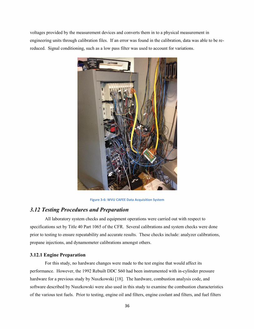
36
voltages provided by the measurement devices and converts them in to a physical measurement in
engineering units through calibration files. If an error was found in the calibration, data was able to be re-
reduced. Signal conditioning, such as a low pass filter was used to account for variations.
Figure 3-6: WVU CAFEE Data Acquisition System
3.12 Testing Procedures and Preparation
All laboratory system checks and equipment operations were carried out with respect to
specifications set by Title 40 Part 1065 of the CFR. Several calibrations and system checks were done
prior to testing to ensure repeatability and accurate results. These checks include: analyzer calibrations,
propane injections, and dynamometer calibrations amongst others.
3.12.1 Engine Preparation
For this study, no hardware changes were made to the test engine that would affect its
performance. However, the 1992 Rebuilt DDC S60 had been instrumented with in-cylinder pressure
hardware for a previous study by Nuszkowski [18]. The hardware, combustion analysis code, and
software described by Nuszkowski were also used in this study to examine the combustion characteristics
of the various test fuels. Prior to testing, engine oil and filters, engine coolant and filters, and fuel filters

37
were replaced to ensure optimal engine performance. Preliminary tests were done with available diesel
fuel to condition the engine oil and to ensure the engine and laboratory systems were operating properly.
Engine oil and coolant temperatures and levels were monitored throughout the test procedure to ensure
proper operating levels were maintained.
3.12.2 Exhaust Pipe
The exhaust system used consisted of a 5 inch diameter steel pipe. Specifications for this system
were in accordance with CFR 40 Part 1065.130 [32]. The steel pipe was insulated with 1 inch layer of
fiber glass insulation to prevent heat loss in the exhaust gas. A butterfly valve was fitted into the pipe to
simulate the appropriate exhaust backpressure on the engine. All connections were either taped with
exhaust tape and clamped or welded in order to prevent leaks.
3.12.3 Dynamometer Load Cell Calibration
Prior to testing the dynamometer load torque cell was calibrate in accordance with CFR 40 Part
1065.310 [32]. This procedure involved hanging a series of calibration weight in 50 lb increments from
the calibration arm. The load cell response was recorded at ten points and a curve fit created to relate the
response to the torque.
3.12.4 Propane Injections
In accordance with CFR 40 Part 1065.341 [32], propane injections were done to ensure the
accuracy of the dilution tunnel and to detect any leaks or losses in the system. Propane was injected into
the dilution tunnel at a known rate via a propane injection kit. Only the injected propane and dilution air
were flowing through the tunnel during propane injections. The propane concentration in the tunnel was
measured by the HC analyzer. The propane recovered during injections had to fall within ±2% of the
amount of propane injected in order for the test to pass. Tests were conducted until three consecutive
tests were within ±0.5% of each other, all of which must have been within the ±2% range of the amount
of propane injected, this criteria is a WVU CAFEE requirement.
3.12.5 Exhaust Gas Analyzer Calibration
Each exhaust gas analyzer was calibrated in accordance with Title 40 Part 1065 of the CFR. Each
calibration gas bottle concentration and pressure was noted. Analyzer calibrations were performed prior
to the start of testing; each calibration consisted of a 10-point non-zero calibration curve. Calibration
gases were chosen based on the specific emissions output of the specific test engine.
38
3.12.6 Hydrocarbon Analyzer Calibration
Hydrocarbon analyzer calibration was conducted in accordance with CFR 40 Part 1065.360 and
Part 1065.365 [32]. The CFR requires that a calibration curve be conducted using a minimum of 6 points.
WVU CAFEE uses 10 points for calibration. Propane was used as the test gas with zero air as the
reference gas. Test points were evaluated starting at 100% propane and decreasing the propane
concentration by 10% in between each calibration point. Prior to each calibration, the zero and span
(100% propane) was checked to ensure its value for calibration. The calibration gas was then varied from
90% to 0% using a Horiba gas divider. The DAQ system recorded the ADC value for each point and
plotted these points against the set point. A line of best-fit was created to evaluate the accuracy of each
point. The best-fit line needed to be within ±2% of the value at each non-zero point and within ±0.3% of
full scale on the zero point [32]. An R2 value of 1±0.0001 or better was required to ensure the response
from the analyzer was linear [32].
3.12.7 Oxides of Nitrogen Analyzer Calibration
The oxides of nitrogen analyzer was calibrated in a similar fashion as the hydrocarbon analyzer
explained above. CFR 40 Part 1065.370 [32] requires a minimum of 9 calibration points; again 10 points
were used at WVU CAFEE. As with the HC analyzer a specific R2 was required to ensure the linearity of
the analyzer. Since the NOx analyzer relied on NO2 to NO conversion for the chemiluminescent detector
to properly measure the amount of NOx in the exhaust sample, a monthly converter efficiency test was
done to verify proper converter operation. In order to verify proper converter operation, the NO2 to NO
converter must allow for measuring at least 95% of the total NO2 at the maximum expected concentration
of NO2 [32].
3.12.8 Carbon Monoxide and Carbon Dioxide Analyzer Calibration
Unlike the NOx and HC analyzers, the CO and CO2 analyzers had a non-linear curve-fit. As with
the HC and NOx analyzer a 10 point calibration curve was used for the CO and CO2 analyzers. However,
in this case the R2 value was used to ensure the higher order polynomial was within the error limits of
each non-zero point. Along with calibration, the CO analyzer had to be checked to ensure no water or
CO2 interference as per CFR 40 Part 1065.355 [32]. Likewise, the CO2 analyzer had to be checked to
verify no water interference with the analyzer as per CFR 40 Part 1065.350 [32]. This ensured the
functionality of the chiller unit and the analyzers.
3.12.9 Particulate Matter and Filter Weighing
Prior to testing, PM filters were pre-conditioned in a clean room as specified in CFR 40 Part
1065.190 [32]. Filters were stored in glass Petri dishes to avoid possible contamination of ambient

39
particles. After the pre-conditioning period and filters were in equilibrium with the clean room
environment, three reference filters were created. These reference filters were used throughout the testing
process to measure the amount of variation in the repeated weighing of these three filters for the entire
test period. Prior to use in an engine test cycle, filters were pre-weighed and associated to the respective
reference filters. After a test cycle, the filters were brought back into the clean room for post-
conditioning. After this conditioning the filters were post-weighed. Filters were pre- and post-weighed
using a Sartorius SE 2-F balance meeting specification of CFR 40 Part 1065.290 [32]. The difference in
mass between pre- and post-weights are a portion of what determines how much PM was created during a
test. The other portion is determined by the amount of PM in the dilution air. This is determined by
taking a background filter during a 20 minute test without the engine running. The background PM
weight could then be subtracted from all test filter weights; however, in this case background PM was not
included in the determination of PM emission for this work. Balance verifications and weighing process
verifications were carried out in accordance with CFR 40 Part 1065.390 [32]. During this study one PM
filter was used for each of the 15 test modes. For the transient step test cycle a single filter was used for
the entire test cycle.
3.13 In-Cylinder Pressure Analysis System
In-cylinder pressure data was recorded using a piezoelectric type pressure transducer. The
pressure transducer measures dynamic pressure within the cylinder. The pressure transducer was
connected to a charge amplifier to amplify the piezoelectric voltage so that the pressure signal can be read
by the DAQ system. The 1992 DDC test engine utilized a Kistler quartz transducer model 6125B, shown
in Figure 3-7. A low-pass filter was applied to the measured in-cylinder pressure to minimize fluctuations
caused by the pressure wave. The low-pass filter had a cut-off frequency of 2500 Hz to reduce high
frequency combustion noise. The low-pass filter is of averaging type, which may cause a reduction in the
premix pressure spike. Since this averaging was applied to all data equally, the relative difference
between fuels should not be significantly impacted [18].

40
Figure 3-7: Kistler 6125B In-Cylinder Pressure Transducer [18]
To acquire the in-cylinder pressure data, DAQ software developed by Nuszkowski [18] was used.
The software allows real-time processing of the acquired pressure data into the heat release and derived
combustion characteristics data. Calculated combustion characteristics can then be determined and
recorded. The combustion analysis system used a stand-alone computer from the rest of the laboratory
system due to computational requirements.
Although the in-cylinder combustion DAQ software provided some real-time measured and
calculated parameters; the acquired pressure data was sent to Dr. Nuszkowski at the University of North
Florida to reanalyze the data. The data was reanalyzed using a Matlab program written by Nuszkowski
[18]. Parameters were directly calculated using the in-cylinder pressure. Engine speed was used to align
the measured and calculated parameters during a test to the laboratory data.
3.13.1 In-Cylinder Pressure
The maximum in-cylinder pressure and its location were calculated from the direct measurement
of the in-cylinder pressure. The maximum pressure provides an indication of engine load. Typically,
higher pressure indicates higher engine loads.
Since the pressure transducer measured dynamics pressure, a reference pressure was needed to
determine an absolute pressure. The method used for this study was a constant polytropic constant [18].
This method was recommended by Brunt et al. [33] for combustion studies because it is more accurate
than measuring the manifold air pressure (MAP). The corrected pressure was averaged from the
calculated pressures over a 60 crank angle degree window during the compression stroke between 120

41
and 60 degrees BTDC [18]. The MAP was obtained from the in-cylinder pressure data at the location of
intake valve closing.
3.13.2 Heat Release
Heat release rate data was processed directly from the measured in-cylinder pressure data in real-
time. Calculated heat release parameters include: maximum heat release rate, location of maximum heat
release rate, net heat released during combustion period, gross heat released during combustion period,
heat released during premix combustion, and heat released during diffusion combustion. The net and
gross heat released is the summation of the heat released during each crank angle resolution from the start
of combustion to the end of combustion.
3.13.3 Needle Lift
The test engine was instrumented with a needle lift sensor inside a single injector. The sensor
was a Hall Effect sensor, which provided a voltage signal proportional to the height of the fuel injection
needle at a response frequency of 25 kHz. Similar to the pressure transducer, the instrumented injector
was installed into cylinder no. 3. The needle lift sensor provided data indicating the start and end of fuel
injection. This was important to examine any injection and resulting ignition differences between the test
fuels.
3.13.4 Start of Combustion
The start of combustion (SOC) is defined as the first measureable quantity of combustion in the
cylinder. Some researchers have used the point at which the pressure deviates from the motoring curve or
the point at which 5% of the total energy has been released. In this study the location of 5% mass fraction
burned was defined as the SOC. When comparing several fuels on the same engine at the same set points,
the start of combustion is an indication of ignition delay.
3.13.5 Ignition Delay
Ignition delay is defined as the crank angle or time period from the start of fuel injection to the
start of combustion. Ignition delay provides an indication of the combustibility of the fuel injected and
the mixing of the air and fuel. A long ignition delay indicates a low cetane fuel or the need for higher
pressures and temperatures within the cylinder for combustion. High cetane fuels have shorted ignition
delay and therefore more fuel is burned during the diffusion burn. A shorter ignition delay can indicate
longer combustion duration and therefore a lower maximum temperature, potentially resulting in lower
NOx emissions.

42
3.13.6 Estimated End of Combustion
Combustion duration is the crank angle or time period from the start of combustion to the end of
combustion (EOC). Combustion duration can be longer when a greater amount of fuel is injected. Long
combustion duration can indicate that too much fuel has been injected, which can cause incomplete
combustion. In this study the EOC was estimated from the location of the maximum heat released over
ten crank angle degrees and adding twenty degrees [18]. The heat released after the EOC should remain
the same for tens of degrees, therefore over estimation of the EOC should be a better assumption than
under estimation [18]. This is especially important when the mass fraction burned is of concern.
3.13.7 Mass Fraction Burned
The mass fraction burned (MFB) is the ratio of the fuel mass burned at a given crank angle,
usually measured as a percentage of the total mass of the injected fuel. Values of interest in this study
were the locations of 5, 10, 50, 90, and 95% MFB, as well as the MFB below 950 K. Calculating the
location of various levels of MFB provides insight to the phasing of the combustion process. The
duration, in crank angle degrees, of SOC to 10% or 50% MFB indicates the strength of the premix
combustion; the duration from 50% to 90% or 95% indicates the intensity of the diffusion burn [18]. In
this study the mass fraction burned was calculated by normalizing the gross heat release at each crank
angle to the total heat released.
Equation 3-2
3.13.8 Indicated and Brake Mean Effective Pressure
Indicated mean effective pressure (IMEP) is the cylinder work normalized by the cylinder
displacement volume. It can also be thought of as the average in-cylinder pressure over the engine cycle.
IMPE is the work delivered to the piston over the compression and expansion stroke, per cycle per unit
displace volume [17]. IMEP is a useful combustion parameter because it allows for the comparison of an
engines ability to do work regardless of engine size. In this study brake mean effective pressure (BMEP)
was also used for comparison purposes.
3.13.9 In-Cylinder Gas Temperature
The mean bulk gas temperature in the cylinder was calculated at each crank angle by making the
ideal gas assumption with a known reference location and temperature [18]. This allowed for the
estimation of the maximum in-cylinder pressure and its location along with the average temperature over
the cycle. The temperature at the start of combustion, the intake gas temperature, and the exhaust gas
temperature were also recorded. The in-cylinder temperature is important because pollutant formation,
43
especially NOx, is strongly temperature dependant. Typically, NOx emissions increase with higher in-
cylinder gas temperatures.
3.13.10 Air-to-Fuel Ratio
The air-to-fuel ratio (AFR) strongly influences combustion conditions and emission
characteristics. The AFR was calculated based on the intake air and the fuel flow. The AFR can be
reported on a mass and/or molar basis, in this study the mass AFR was calculated. AFR varies based on
engine load but typically diesel engines operate on an AFR lower than the stoichiometric AFR. Common
values for the AFR of a diesel engine usually fall within the 18 to 70 range [17].
3.13.11 Thermal Efficiency
Calculating the thermal efficiency indicated how much power was converted from the energy in
the fuel for each combustion event. This provides insight to whether differing properties of the various
test fuels changed the efficiency of combustion. The energy conversion efficiency was calculated based
on the lower heating value of the test fuel and the fuel flow and power from the in-cylinder combustion
parameters.
Equation 3-3
44
Chapter 4: Experimental Configuration
4.1 Introduction
In the following sections the test cycles, test matrix, and test preparations are discussed in detail.
Two test cycles were conducted: a 15 mode steady state test, for all fuels, and a transient idle to full
power step tests for the JP-5-based fuels only. Set points of the test cycles were based on engine maps of
the reference fuels (JP-5 and F-76) and care should be taken when examining the data to ensure the
appropriate reference set point file is used. The test matrix followed a daily schedule throughout the
program. Test preparations included: software start-up, fuel purging, engine warming, in-cylinder
pressure data acquisition encoder verification, and PM filter preparation.
4.2 Test Cycles
Test cycles were computer controlled using engine speed and engine load (torque) as input
values. For each fuel the engine was operated at set points to bring the coolant and oil to operating
conditions. The engine was then mapped at least twice; once as a warm map and again as a hot map. For
all fuels a 15 mode steady state test, illustrated in Figure 4-1,was conducted. It should be noted that
Figure 4-1 shows the set points for the JP-5 fuels only, the engine map for F-76 fuels followed the same
general map but set point values were slightly different due to the differences in fuel properties. The 15
steady state mode points consist of the 13 mode points of the heavy duty supplemental emissions test
(SET) and two additional low speed modes at 900 rpm and 25% and 50% load. The 15 modes were
ordered by ascending power to minimize stabilization time from mode to mode and overall test cycle
time. It is important to note that the SET mode order is not important for this work since emissions are
not a primary concern. The SET modes were used in this work because they provide known operating
conditions in the engine and emissions research community and they provide a wide range of speed-load
points for the effect of fuel properties on combustion to be examined. Each steady state mode had 300, or
more, cycles averaged together; therefore, mode length was adjusted to allow ample time for enough
cycles to occur. Mode length was also affected by the time needed for gaseous exhaust and PM sampling.
A transient step test between idle and rated power was also conducted for fuels being compared to JP-5.
The transient test is shown inFigure 4-2. During the transient test, the engine operated at each mode for
30 seconds and cycled between the idle and full power modes 10 times. This test was selected based on
sponsor input.

45
Figure 4-1: Steady State Test Cycle (JP-5 Fuels) with Mode Order
Figure 4-2: Transient Test Cycle (JP-5 Fuels only)
4.3 Test Matrix
The investigated fuels are shown in Table 3-1. The 1992 DDC engine was evaluated with these
fuels to identify any adverse combustion effects as well as quantify emissions of the alternative Navy
fuels. A seven-day test schedule was utilized; however, additional days were required for troubleshooting
and retests. The daily test schedule, shown in Table 4-1, consisted of multiple steady state tests for each
fuel. During the laboratory startup and preparation the engine was warmed with the reference fuel (JP-5
or F-76), the engine was mapped before testing. If necessary, the fuel system was purged prior to
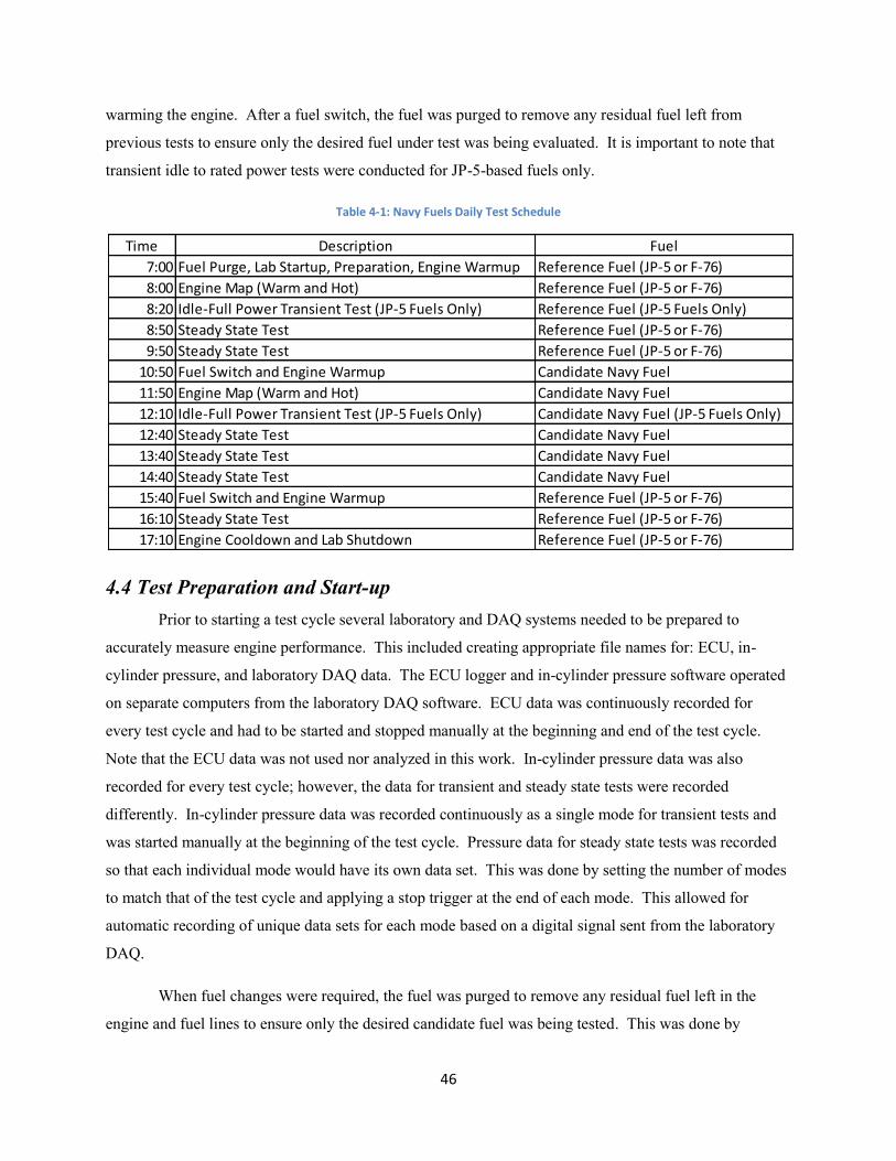
46
warming the engine. After a fuel switch, the fuel was purged to remove any residual fuel left from
previous tests to ensure only the desired fuel under test was being evaluated. It is important to note that
transient idle to rated power tests were conducted for JP-5-based fuels only.
Table 4-1: Navy Fuels Daily Test Schedule
4.4 Test Preparation and Start-up
Prior to starting a test cycle several laboratory and DAQ systems needed to be prepared to
accurately measure engine performance. This included creating appropriate file names for: ECU, in-
cylinder pressure, and laboratory DAQ data. The ECU logger and in-cylinder pressure software operated
on separate computers from the laboratory DAQ software. ECU data was continuously recorded for
every test cycle and had to be started and stopped manually at the beginning and end of the test cycle.
Note that the ECU data was not used nor analyzed in this work. In-cylinder pressure data was also
recorded for every test cycle; however, the data for transient and steady state tests were recorded
differently. In-cylinder pressure data was recorded continuously as a single mode for transient tests and
was started manually at the beginning of the test cycle. Pressure data for steady state tests was recorded
so that each individual mode would have its own data set. This was done by setting the number of modes
to match that of the test cycle and applying a stop trigger at the end of each mode. This allowed for
automatic recording of unique data sets for each mode based on a digital signal sent from the laboratory
DAQ.
When fuel changes were required, the fuel was purged to remove any residual fuel left in the
engine and fuel lines to ensure only the desired candidate fuel was being tested. This was done by
Time Description Fuel
7:00 Fuel Purge, Lab Startup, Preparation, Engine Warmup Reference Fuel (JP-5 or F-76)
8:00 Engine Map (Warm and Hot) Reference Fuel (JP-5 or F-76)
8:20 Idle-Full Power Transient Test (JP-5 Fuels Only) Reference Fuel (JP-5 Fuels Only)
8:50 Steady State Test Reference Fuel (JP-5 or F-76)
9:50 Steady State Test Reference Fuel (JP-5 or F-76)
10:50 Fuel Switch and Engine Warmup Candidate Navy Fuel
11:50 Engine Map (Warm and Hot) Candidate Navy Fuel
12:10 Idle-Full Power Transient Test (JP-5 Fuels Only) Candidate Navy Fuel (JP-5 Fuels Only)
12:40 Steady State Test Candidate Navy Fuel
13:40 Steady State Test Candidate Navy Fuel
14:40 Steady State Test Candidate Navy Fuel
15:40 Fuel Switch and Engine Warmup Reference Fuel (JP-5 or F-76)
16:10 Steady State Test Reference Fuel (JP-5 or F-76)
17:10 Engine Cooldown and Lab Shutdown Reference Fuel (JP-5 or F-76)

47
running the fuel pump with a bypass in the fuel line before the engine and emptying the fuel into a
collection bucket. Also the fuel return line was removed from the fuel barrel drained into a collection
bucket to remove the rest of the fuel. The engine and fuel lines held approximately one gallon of fuel;
two to three gallons of the fuel was purged to ensure complete fuel purge of the previous fuel. Once the
fuel system was purged, the engine was warmed for several minutes with the new fuel to bring the engine
oil and coolant to operation levels. The engine was then mapped at least twice prior to the start of the first
test cycle. This process is outlined in Table 4-1.
Other laboratory start-up and preparations included turning on and warming the MEXA gas
analyzer unit, ensuring all laboratory water and fuel pumps and the dynamometer skid had power, in-
cylinder crank shaft encoder was referenced to top dead center, and preparing PM filters for each test.
During steady state testing PM filters were changed during the stabilization period between each mode
while the transient test only utilized one filter for this test.

48
Chapter 5: Results and Discussion
5.1 Introduction
The following sections will provide test data for all relative tests and fuels. The global objective
of this research was to explore the use of hydrotreated fuels in the U.S. Navy fleet. The overall objective
of this study was to identify any negative combustion characteristics of the alternative candidate biofuels
through in-cylinder pressure analysis. Additionally, the engine performance and fuel consumption as well
as the regulated gaseous and particulate matter emissions were evaluated to provide additional assessment
information. The combustion and emission results consisted of modal steady state tests for all fuels and
transient tests for JP-5 fuels. Using the in-cylinder pressure data, several combustion characteristics were
calculated to aid the understanding of the performance of each fuel. The data presentation has been
divided between the two fuel sets (JP-5 and F-76) and between the combustion and emission data. Modes
5 and 12 have been chosen to be discussed in detail because they provide insight to operational conditions
at both low and high power engine operation. Mode 5 operated at 25% engine load and 1430 rpm, for JP-
5, and 1416 rpm, for F-76, engine speeds and mode 12 operated at 75% engine load and 1649 rpm, for JP-
5, and 1644 rpm, for F-76, engine speeds.
5.2 JP-5 Fuels
Two alternative candidate biofuels (50/50 JP5/HRJ5 and Neat HRJ5) were examined and
compared to the reference fuel (JP-5). The engine was mapped to yield a full power torque curve on the
reference fuel. This baseline torque curve was used throughout the test program for the JP-5 fuels only.
The test program consisted of a 15 mode steady state test and an idle to rated power transient step test.
Figure 5-1 shows the engine map for each fuel along with the set points for each mode. It is noted that
the three full load set points were increased by 100 ft-lb to ensure that full power was reached for each
fuel. Note that there were small run-to-run differences for modes 1 through 12 due to normal run-to-run
and day-to-day variations but there were larger differences in maximum torque values due to differences
in fuel properties. The data is presented below as heat release rate, in-cylinder pressure and temperature
curves for both mode 5 and 12. Data are presented as a function of BMEP, in ascending order, to
illustrate performance differences at other modes. Table 5-1 shows the relationship of BMEP to mode
number and test cycle set points.
Table 5-1: Relationship between BMEP and modal set points for JP-5 steady state test cycle
BMEP (bar) 0.17 2.86 3.68 4.31 4.54 5.73 7.37 8.60 9.09 11.04 12.91 13.64 14.37 16.88 17.81
Mode (-) 1 2 6 5 4 3 9 8 7 12 11 10 15 14 13
Set Speed (rpm) 601 900 1649 1430 1210 900 1649 1430 1210 1649 1430 1210 1649 1430 1210
Set Torque (ft-lb) 0 213 274 321 339 426 549 641 678 823 962 1018 1208 1395 1471

49
Figure 5-1: Engine Map and Set Points for JP-5 Test Fuels
5.2.1 In-Cylinder Combustion Parameters
Several in-cylinder combustion parameters were recorded and calculated through the in-cylinder
pressure analysis. The following sections will present the data for: heat release and heat release rate, in-
cylinder pressure and temperature, fuel injection, ignition delay, and combustion phasing for each JP-5
test fuel. The values for a given parameter were obtained by averaging the values for each mode from
each repeat test for each fuel. The candidate biofuels were compared to the reference fuel (JP-5) using a
percent difference and/or an absolute difference. A percent difference was used for non-crank angle
parameters; a negative percent difference indicated a reduction in a particular parameter and a positive
percent difference showed an increase. Absolute difference was used for values related to crank angle
location, such as injection timing, combustion phasing, locations of maximum values, etc. A positive
difference showed retardation and a negative difference showed advancement in location compared to JP-
5. An absolute difference was used for crank angle-related parameters since many of these values were at
or near zero and may lead to large percent differences that would not be indicative of the relative
differences. The effects of fuel density, cetane number, and aromatic content of the test fuels on the
discussed combustion parameters were also examined, and are reported in the following sections. Each
parameter for each mode were comparedagainst fuel density, cetane number, and aromatic content; a
linear curve fit was applied to determine the m (slope), b (y-intercept), and R2 values. A negative slope
indicates a decrease in a given parameter as the respective fuel property increases and a positive slope
indicates an increase.

50
5.2.1.1 Heat Release and Heat Release Rate
The experimental heat release parameters were calculated and/or measured for each combustion
cycle during steady state and transient testing. An investigation into parameters, such as net heat
released, maximum heat release rate and its location, as well as heat released during premix and diffusion
helped to understand the performance changes between fuels. Figure 5-2 and Figure 5-3 illustrate the
heat release rate (HRR) for mode 5 and 12, respectively. At both modes the maximum HRR was
significantly lower for both candidate biofuels. A shorter ignition delay was also noticed; ignition delay
is indicated by the negative value in the HRR curve. The other test modes show a similar reduction in
maximum HRR as shown in Figure 5-4. The variation bars in Figure 5-4 represent one standard deviation
of the repeat data for each test fuel. Over the entire test cycle the maximum HRR for 50/50 JP5/HRJ5
was ~3 to 25% lower than that of JP-5 and ~3 to 43% lower for Neat HRJ5. At most modes the
maximum HRR occurred during the premix spike; however, as power and engine load increased the
maximum HRR shifted to the diffusion fraction, this can be seen in Figure 5-3 for Neat HRJ5. The
effects of fuel density, cetane number, and aromatic content on maximum heat release rate are presented
in Table 8-1. A graphical example of the regression is illustrated in Figure 5-5, which shows that as
cetane number increases maximum HRR decreases. Table 8-1 indicates that reductions in maximum
HRR can also be attributed to lower fuel density and aromatic content.
Figure 5-2: Heat Release Rate Curve at Mode 5 (25% Engine Load and 1430 rpm) for JP-5 Test Fuels

51
Figure 5-3: Heat Release Rate Curve at Mode 12 (75% Engine Load and 1649 rpm) for JP-5 Test Fuels
Figure 5-4: Maximum Heat Release Rate at all Test Modes for JP-5 Test Fuels

52
Figure 5-5: Effect of Cetane Number of Maximum Heat Release Rate
It was also noticed that the net heat released in Figure 5-6 for the two candidate biofuels (50/50
JP5/HRJ5 and Neat HRJ5) is slightly lower than the reference fuel (JP-5) for most modes. The most
significant difference was seen at the last three modes, where the net heat released for 50/50 JP5/HRJ5 is
~2% to 2.5% lower and ~ 2.75 to 4% lower for Neat HRJ 5 due to lower energy and density of the fuel
injected. The fuel density, cetane number, and aromatic content do not appear to have any significant
effect on net heat released as indicated by the small slope or “m” values in Table 8-2.
Figure 5-6: Net Heat Released at each Test Mode for JP-5 Test Fuels
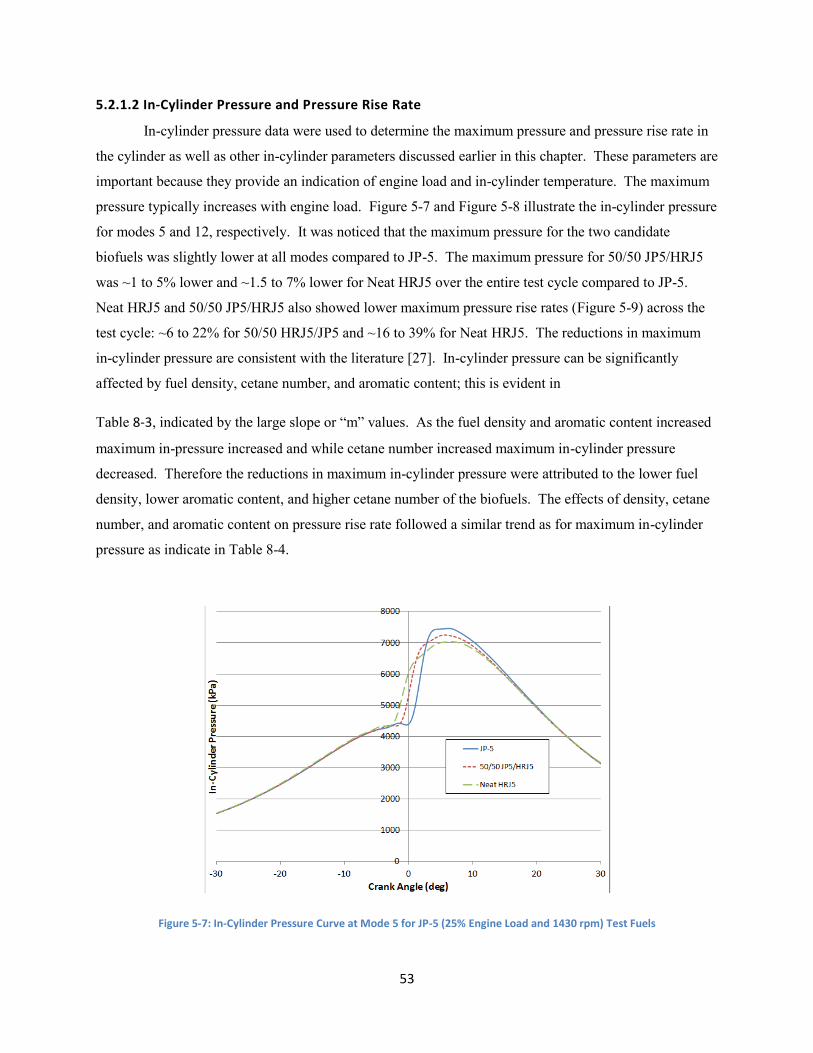
53
5.2.1.2 In-Cylinder Pressure and Pressure Rise Rate
In-cylinder pressure data were used to determine the maximum pressure and pressure rise rate in
the cylinder as well as other in-cylinder parameters discussed earlier in this chapter. These parameters are
important because they provide an indication of engine load and in-cylinder temperature. The maximum
pressure typically increases with engine load. Figure 5-7 and Figure 5-8 illustrate the in-cylinder pressure
for modes 5 and 12, respectively. It was noticed that the maximum pressure for the two candidate
biofuels was slightly lower at all modes compared to JP-5. The maximum pressure for 50/50 JP5/HRJ5
was ~1 to 5% lower and ~1.5 to 7% lower for Neat HRJ5 over the entire test cycle compared to JP-5.
Neat HRJ5 and 50/50 JP5/HRJ5 also showed lower maximum pressure rise rates (Figure 5-9) across the
test cycle: ~6 to 22% for 50/50 HRJ5/JP5 and ~16 to 39% for Neat HRJ5. The reductions in maximum
in-cylinder pressure are consistent with the literature [27]. In-cylinder pressure can be significantly
affected by fuel density, cetane number, and aromatic content; this is evident in
Table 8-3, indicated by the large slope or “m” values. As the fuel density and aromatic content increased
maximum in-pressure increased and while cetane number increased maximum in-cylinder pressure
decreased. Therefore the reductions in maximum in-cylinder pressure were attributed to the lower fuel
density, lower aromatic content, and higher cetane number of the biofuels. The effects of density, cetane
number, and aromatic content on pressure rise rate followed a similar trend as for maximum in-cylinder
pressure as indicate in Table 8-4.
Figure 5-7: In-Cylinder Pressure Curve at Mode 5 for JP-5 (25% Engine Load and 1430 rpm) Test Fuels

54
Figure 5-8: In-Cylinder Pressure Curve at Mode 12 (75% Engine Load and 1649 rpm) for JP-5 Test Fuels
Figure 5-9: Maximum Pressure Rise Rate at Each Test Mode for JP-5 Test Fuels
5.2.1.3 In-Cylinder Temperature
The in-cylinder temperature typically increases as the pressure increases, due to compression and
combustion, and has a similar curve shape. Figure 5-10 shows that the maximum averaged in-cylinder
temperature at mode 5 was slightly lower for both candidate biofuels compared to JP-5. However, as the
power and engine load increased the difference in maximum in-cylinder temperature decreased. This is
evident in Figure 5-11, where the temperature of the biofuels is nearly the same throughout the
compression and combustion period. At any mode the maximum reduction in maximum in-cylinder

55
temperature for either fuel was just under 4.5%; this was relatively insignificant to engine performance
but may have a significant impact on emission formation, especially NOx. Table 8-5illustrates the effects
of density, cetane number, and aromatic content on maximum in-cylinder temperature. A previous study
[18] indicated that as cetane number increases maximum in-cylinder temperature decreases. This study
showed similar results. The lower fuel density and aromatic content may have also helped to reduce the
temperature.
Figure 5-10: In-Cylinder Temperature Curve at Mode 5 (25% Engine Load and 1430 rpm) for JP-5 Test Fuels
Figure 5-11: In-Cylinder Temperature Curve at Mode 12 (75% Engine Load and 1649 rpm) for JP-5 Test Fuels

56
5.2.1.4 Start of Fuel Injection and Ignition Delay
Start of fuel injections was recorded to examine differences in fuel injection patterns between the
fuels. Figure 5-12 and Figure 5-13 show a region of the heat release curve of modes 5 and 12,
respectively, which indicate the start of fuel injection and start of combustion. Start of combustion was
determined based on the location of 5% mass fraction burned. The crank angle period between the start
of fuel injection and start of combustion is the ignition delay. The encoder used to trigger the pressure
DAQ had a resolution of 0.25 degrees so anything less than 0.25 degrees was within the pressure DAQ
resolution and care must be used to infer significance to any changes in crank angle less than 0.25
degrees. At mode 5 (Figure 5-12), fuel injection was slightly retarded by ~0.3 and ~0.15 degrees for Neat
HRJ5 and 50/50 JP5/HRJ5, respectively; and start of combustion was advanced by 2.5 and 1.5 degrees for
Neat HRJ5 and 50/50 JP5/HRJ5, respectively. Therefore, the ignition delay for Neat HRJ5 and 50/50
JP5/HRJ5 was approximately 2.8 degrees shorter and 1.6 degrees shorter, respectively. Mode 12 (Figure
5-13) showed slight (0.25 degree) retardation in start of injection for Neat HRJ5 while start of injection of
50/50 JP5/HRJ5 was too similar to notice a difference; due to the resolution of the pressure DAQ system
it was difficult to draw a conclusion about fuel injection for this fuel at this mode. Start of combustion at
mode 12 was the same for Neat HRJ5 and JP-5 and was advanced by 0.75 degrees for 50/50 JP5/HRJ5.
Despite the similarities in start of fuel injection (JP-5 and 50/50 JP5/HRJ5) and start combustion (JP-5
and Neat HRJ5), the ignition delay of both candidate biofuels is shorter by ~0.3 and 0.7 degrees for Neat
HRJ5 and 50/50 JP5/HRJ5, respectively. Across the entire test cycle start of injection was consistently
retarded by ~0.2 to 0.59 degrees for Neat HRJ5. The 50/50 JP5/HRJ5 blend also showed slightly retarded
injection timing (<0.25 degrees) except for modes 1, 6, and 9. The start of injection for modes 1 and 9
were less than -0.05 degrees different than JP-5 and mode 6 was only advanced by about -0.2 degrees or
less. Differences in fuel injection were attributed to different fuel viscosity and density of the candidate
biofuels. Start of combustion for the biofuels was consistently advanced compared to JP-5 across the
entire test cycle; indicating a shorter ignition delay for both candidate biofuels at all test modes. Shorter
ignition delay with these fuels is consistent with the literature [20,27].
The effects of fuel density, cetane number, and aromatic content on start of injection and start of
combustion are presented in Table 8-6andTable 8-7. The effects of fuel viscosity were also examined for
start of fuel injection. The literature [27] suggests that fuel injection is slightly retarded due to higher
viscosities. This study found similar results indicated by the positive slope or “m” values for viscosity
inTable 8-6. Retarded fuel injection could also be attributed to the lower fuel density and change of
compressibility of the biofuels. The advanced start of combustion is most likely attributed to the higher

57
cetane number of the biofuels. This is indicated by the negative slope or “m” values for cetane number in
Table 8-6.
Figure 5-12: Heat Release Rate Curve at Mode 5 Indicating Start of Fuel Injection and Start of Combustion for JP-5 Test Fuels
Figure 5-13: Heat Release Rate Curve at Mode 12 Indicating Start of Fuel Injection and Start of Combustion for JP-5 Test Fuels
5.2.1.5 Premix and Diffusion Fractions
Premix and diffusion fraction lengths vary with engine load and, typically, premix is a high
percentage of the combustion period at low load and a low percentage at high low load for this era engine
design. Generally, diffusion is a low percentage of the combustion period at low load and a high
percentage at high load. Premix fraction is characterized by sudden and high heat release rates and

58
diffusion is characterized by lower more controlled heat release rates. This is evident in Figure 5-2,
where the combustion period is predominantly premix fraction, and Figure 5-3, where the premix fraction
is only a small portion of the combustion period compared to the diffusion fraction. Figure 5-14 and
Figure 5-15 illustrate the premix and diffusion fraction lengths of all test modes across the test cycle. The
net heat released during both fractions is directly related to its length; a shorter premix fraction indicates
less heat released and a longer diffusion fraction indicates more heat released. The shorter premix
fraction was attributed to the lower fuel density, aromatic content, and cetane number (Table 8-8);
however, these effects were very small. Table 8-9 indicates that the lower density, aromatic content, and
cetane number increased the length of the diffusion fraction. The fuel property effects on diffusion
fraction length were more significant than the effects on premix fraction length.
Figure 5-14: Premix Fraction Length of each Test Mode for JP-5 Test Fuels

59
Figure 5-15: Diffusion Fraction Length of each Test Mode for JP-5 Test Fuels
5.2.2 Emissions
Complex physical and chemical reactions, such as ignition, combustion, vaporization and
atomization, all occur during normal diesel combustion. Each test fuel brought about changes in
operating conditions, and each of these changes determined how exhaust emissions would be effected.
An increase NOx emissions was usually attributed to an increase of in-cylinder temperature. Gaseous HC
in the exhaust was normally attributed to high or low air-to-fuel ratios, and overfueling. Incomplete
combustion would lead to increased CO emissions; known to be a dissociation product of CO2. PM was
composed of organic and inorganic substances found in the fuel and air.
The emission results for the steady state and transient tests are presented in the following
sections. These results include the brake specific mass emissions of HC, NOx, CO, CO2, and PM, as well
as brake specific fuel consumption. The brake specific values were obtained by averaging the data for
each mode of all the tests for a given fuel. The candidate biofuels were compared to the reference fuel by
using a percent difference. A negative percent difference shows a reduction in a particular emission
constituent from the reference fuel and a positive percent difference shows an increase. Note that
variations in small numbers may show up as a large percent difference. Some of this variation in small
values could be attributed to the emissions analyzer ranges. It is important to note that variations also
occurred at mode 1 (idle), so this information must be taken lightly since all the data for the idle mode
were small due to the selected tunnel flow rate and analyzer full-scale range selected to capture the
highest concentrations during testing. Also note that the idle mode, mode 1, data is provided on a mass
rate basis while the other 14 modes are on a brake-specific mass basis. Effects of fuel density, cetane

60
number, and aromatic content of the test fuels on emission constituents were also examined, and are
reported in the following sections. Each brake specific mass emission constituent for each mode was
plotted against fuel density, cetane number, and aromatic content; a linear curve fit was applied to
determine the m (slope), b (y-intercept), and R2 values. A negative slope indicates a decrease in a given
emission constituent as the respective fuel property increases and a positive slope indicates an increase.
5.2.2.1 HC
Brake specific HC emissions for JP-5 test fuels are displayed in Figure 5-16 for each of the 15
modes. Large percent reductions in bsHC emissions were noticed; however, this is partially due to the
relatively low magnitude of HC emissions. Figure 5-17 provides an example on the analysis of fuel
property effects on exhaust emissions; this specific figure illustrates the effects of changing fuel density
on HC emissions. Table 8-10 provides a detailed analysis on effects of fuel density, cetane number, and
aromatic content on bsHC emissions. Figure 5-17 (density impact) and Table 8-10 show that there is no
significant effect of density, cetane number, or aromatic content on bsHC emissions; this is indicated by
the small slope or “m” values in Table 8-10.
Figure 5-16: Brake Specific HC Emissions for JP-5 Fuels

61
Figure 5-17: Effects of Fuel Density on bsHC Emissions
5.2.2.2 NOx
Figure 5-18 illustrates the brake specific NOx emissions for the JP-5 test fuels at each test mode.
It is clearly shown that there is a NOx reduction in all modes for both candidate fuels. The most
significant differences are noticed at 25% engine load and become less significant as engine load and
BMEP increase. At 25% load, reductions up to ~19% are seen for 50/50 JP5/HRJ5 and ~31% for Neat
HRJ5. The percent difference in reduction steadily decreases to ~2.5% for JP5/HRJ5 and ~7% for Neat
HRJ5 as the engine load and BMEP increase. Effects of fuel density, cetane number, and aromatics on
bsNOx emissions are present in Table 8-11. At every mode bsNOx emissions decreased as cetane
number increased due to the shorter premix and longer diffusion fractions caused by higher cetane
numbers. As fuel density and aromatic content increased bsNOx emissions increased. The relation
between NOx emissions and cetane number is consistent with previous studies [18,20]. At high engine
loads the change in bsNOx brought on by a change in fuel properties was less significant than at low
loads.
0.000
0.100
0.200
0.300
0.400
0.500
0.600
0.700
750 800 850 900
bsH
C (
g/b
hp
-hr)
Fuel Density (kg/m3)
Mode 1
Mode 3
Mode 6
Mode 9
Mode 12
Mode 15
Linear (Mode 1)
Linear (Mode 3)
Linear (Mode 6)
Linear (Mode 9)
Linear (Mode 12)
Linear (Mode 15)

62
Figure 5-18: Brake Specific NOx Emissions for JP-5 Fuels
5.2.2.3 CO
Brake specific CO emissions are display in Figure 5-19. Reductions in CO emissions were
noticed at all modes. It is difficult to determine if the reductions were significant due to the relatively low
magnitude CO emissions. Generally, CO emissions fall far below regulated level and are considered
insignificant in diesel engines due to the lean operation [17,18]. There also seemed to be no significant
effects of differences in density, cetane number, or aromatics on bsCO emissions. This was determined
based on the low slope or “m” values in Table 8-12.
Figure 5-19: Brake Specific CO Emissions for JP-5 Fuels

63
5.2.2.4 CO2
As shown in Figure 5-20, reductions in CO2 emissions were noticed for both biofuels. Since CO2
emissions are directly related to fuel consumption it was concluded that reductions in fuel consumption
would also be noticed. Reductions were consistently within 1.5 and 3% for 50/50 JP5/HRJ5 and around 4
to 5% for Neat HRJ5. Although the percent difference is relatively low, these reductions are considered
moderate due to the relative large magnitude of CO2 emissions. This is attributed to a higher H/C ratio of
the biofuels, which leads to more efficient combustion phasing [27]. Cetane number indirectly affected
CO2 emissions by affecting the combustion process; its affect is presented in Table 8-13.
Figure 5-20: Brake Specific CO2 Emissions for JP-5 Fuels
5.2.2.5 PM
Particulate matter emissions were reported as a brake specific constituent in Figure 5-21.
Contrary to the literature [6,7,24,29], multiple low engine load (25%) modes showed a significant
increase in bsPM for 50/50 JP5/HRJ5, while other modes showed slight to moderate reduction. This
trend is interesting because operation of Neat HRJ5 showed significant (~15 to 30%) consistent
reductions in bsPM. Care must be taken when examining the data at the low power modes since data
collection times were not long enough to collect a desired amount of PM on the filter. This is exhibited
by the relatively large run-to-run variation bars in this figure for the low power modes. The mode
duration was a tradeoff between allowing for repeat tests and providing maximum signal output.
Although the gaseous emissions also were subject to relatively low signal output at these low power
modes, the gaseous analyzers were able to capture these signals in a more repeatable manner. It was
known that a priori that PM sample times were not as long as desired but were set to satisfy time and fuel

64
constraints. Table 8-14 indicates that reductions in bsPM are attributed to higher cetane number and an
increase is attributed to an increase in fuel density or aromatic content.
Figure 5-21: Brake Specific PM Emissions for JP-5 Fuels
5.2.3 Fuel Economy
Fuel economy is reported as brake specific fuel consumption (bsFC) and was calculated from the
fuel mass measured by the carbon balance method explained previously. The fuel consumption reported
by the fuel meter and scale are not presented here. Figure 5-22 shows the total bsFC for each test fuel;
modest reductions in bsfc were noticed with operation on both biofuels. The decrease in bsFC was more
evident for Neat HRJ5 and was attributed to the higher cetane number and mass based heating value of
the biofuels [28]. Percent reductions in bsFC of ~1.3 to 2.3% for 50/50 JP5/HRJ5 and ~2.5 to 5% for
Neat HRJ5 were noticed. Data in Table 8-15 supports the claim that as cetane number increases bsFC
decreases slightly.

65
Figure 5-22: Brake Specific Fuel Consumption for JP-5 Fuels
5.2.4 Transient Tests
Idle to full power step tests were conducted to examine the performance of the JP-5 test fuels
under transient operating conditions. Data is reported for two tests of both JP-5 and Neat HRJ5; only one
test was collected, and reported, for 50/50 JP5/HRJ5. Table 8-16 presents the combustion data for each
fuel as minimum, maximum, and average values recorded during the entire test cycle. Maximum values
typically occurred during full power operation or during the transition to or from full power. Average
values were calculated from the entire test cycle. Emission constituents were measured across the entire
test cycle and are reported as brake specific values in Table 8-17. Due to the nature of the test cycle
greater variations in measurements and calculations were noticed throughout the test cycle since multiple
tests were not collected and averaged together. For this reason some of the reported results must be taken
lightly.
During the idle modes the magnitude of most combustion parameters was relatively low
compared to the full power modes. For this reason, parameters that could have adverse affects on
combustion and engine performance are reported as maximum values. This also helps to understand the
performance of each fuel’s maximum performance potential. The maximum heat released for each fuel is
consistent with the heat released during the steady state tests at the same engine load and speed. Slight
reductions were noticed for both 50/50 JP5/HRJ5 and Neat HRJ5. The reductions were more evident
with Neat HRJ5. The maximum HRR for both 50/50 JP5/HRJ5 and Neat HRJ5 was also lower than for
JP-5. It should be noted that the maximum HRR occurred during the transition from idle to full power.
Although the magnitudes are higher the reductions are consistent with the steady state test results. The

66
results for the maximum values of heat released and HRR are supported by the reduction in the average
values for the candidate biofuels in Table 8-16.
The maximum pressure occurred during the transition from full power to idle for each test fuel.
Although the candidate biofuels showed reductions in maximum pressure during transient testing; the
maximum pressure reached during the transient tests was significantly lower (~200kPa) than the pressure
reached during the steady state tests. The maximum pressure rise rate occurred during the transition from
idle to full power; significant reductions were noticed for both biofuels. The maximum PRR during
transient testing was much higher than during steady state testing. It should be noted that the steady state
values were averaged, while the transient values were the maximum achieved. The maximum in-cylinder
temperature achieved during the transient test cycle for Neat HRJ5 was moderately lower (~100 to 150 K)
than for JP-5 and 50/50 JP5/HRJ5 was ~60 to 70 K lower than the JP-f fuel.
As expected, from the literature and steady state results presented here, brake specific emissions
(Table 8-17) were reduced for each constituent for both 50/50 JP5/HRJ5 and Neat HRJ5. Slight
reductions in bsHC emissions were achieved for both biofuels. These reductions are minimal due to the
already low magnitude of bsHC emissions. Brake specific mass emissions for both NOx and CO also
showed minimal reductions for both biofuels. Reductions of ~7 to 10 g/bhp-hr and ~20 g/bhp-hr of
bsCO2 for 50/50 JP5/HRJ5 and for Neat HRJ5, respectively. Brake specific emissions of PM were also
reduced for both fuels: ~5 to 10 mg/bhp-hr for 50/50 JP5/HRJ5 and ~20 to 26 mg/bhp-hr. Along with
reductions in bsCO2 emissions, bsFC was also reduced for both biofuels. The change in emissions was
attributed to the same fuel properties discussed for the steady state tests.
5.3 F-76 Fuels
Six alternative candidate biofuels: Neat HRD76, 50/50 F76/HRD76, Neat DSH76, 50/50
F76/DSH76, 80/20 F76/DSH76, and 80/20 F76/HDCD76 were tested and compared to the reference fuel
(F-76). The engine was mapped to yield a full power torque curve on F-76. This baseline torque curve
was used throughout the test program for the F-76 test fuels only. The test evaluation of the F-76 fuel
consisted of a 15 mode steady state test only. Figure 5-23 shows the engine map for each fuel along with
the set points for each mode. It is noted that the three full load set points for F-76 were increased by 100
ft-lb to ensure that full power is reached for each fuel. Data for modes 5 and 12 is presented as heat
release rate, pressure, and temperature curves to illustrate the performance differences between the fuels.
Some data is also presented as a function of brake mean effective pressure (BMEP) in ascending order;
Table 5-2 shows the relationship between the modal set points and BMEP for the F-76 test cycle.

67
Table 5-2: Relationship between BMEP and modal set points for F-76 test cycle
Figure 5-23: Engine Map and Set Points for F-76 Test Fuels
5.3.1 In-Cylinder Combustion Parameters
Several in-cylinder combustion parameters were recorded and calculated through the in-cylinder
pressure analysis. The following sections will present the data for: heat release and heat release rate, in-
cylinder pressure and temperature, fuel injection timing, ignition delay, and combustion phasing for all F-
76-based test fuels. The values for a given parameter and fuel were obtained by averaging the values for
each mode from each test cycle. The F-76 candidate biofuels were compared to the reference fuel (F-76)
using a percent difference and/or an absolute difference. A percent difference was used for parameters
for non-crank angle location parameters; a negative percent difference indicates a reduction in a particular
parameter and a positive percent difference shows an increase. Absolute difference was used for values
related to crank angle location, such as injection timing, combustion phasing, locations of maximum
values, etc. A positive difference shows retardation and a negative difference shows advancement in
location compared to F-76.
5.3.1.1 Heat Release and Heat Release Rate
Investigation into parameters such as net heat released, maximum heat release rate and its
location, as well as heat released during premix and diffusion provided means to understand performance
differences between each test fuel. Figure 5-24 and Figure 5-25 illustrate the heat release rate curves at
BMEP (bar) 0.15 3.27 6.53 4.75 4.63 4.00 9.50 9.26 7.99 14.24 13.88 11.99 18.85 17.80 15.41
Mode (-) 1 2 3 4 5 6 7 8 9 10 11 12 13 14 15
Set Speed (rpm) 601 900 900 1189 1416 1644 1189 1416 1644 1189 1416 1644 1189 1416 1644
Set Torque (ft-lb) 0 244 488 355 346 299 710 692 597 1064 1037 896 1533 1497 1306
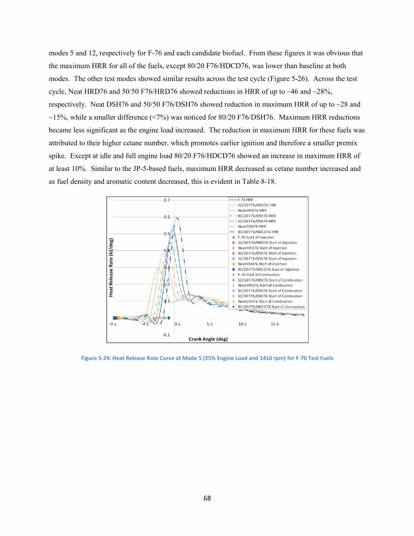
68
modes 5 and 12, respectively for F-76 and each candidate biofuel. From these figures it was obvious that
the maximum HRR for all of the fuels, except 80/20 F76/HDCD76, was lower than baseline at both
modes. The other test modes showed similar results across the test cycle (Figure 5-26). Across the test
cycle, Neat HRD76 and 50/50 F76/HRD76 showed reductions in HRR of up to ~46 and ~28%,
respectively. Neat DSH76 and 50/50 F76/DSH76 showed reduction in maximum HRR of up to ~28 and
~15%, while a smaller difference (<7%) was noticed for 80/20 F76/DSH76. Maximum HRR reductions
became less significant as the engine load increased. The reduction in maximum HRR for these fuels was
attributed to their higher cetane number, which promotes earlier ignition and therefore a smaller premix
spike. Except at idle and full engine load 80/20 F76/HDCD76 showed an increase in maximum HRR of
at least 10%. Similar to the JP-5-based fuels, maximum HRR decreased as cetane number increased and
as fuel density and aromatic content decreased, this is evident in Table 8-18.
Figure 5-24: Heat Release Rate Curve at Mode 5 (25% Engine Load and 1416 rpm) for F-76 Test Fuels

69
Figure 5-25: Heat Release Rate Curve at Mode 12 (75% Engine Load and 1644 rpm) for F-76 Test Fuels
Figure 5-26: Maximum Heat Release Rate at each Test Mode for F-76 Test Fuels
Figure 5-27 shows the net heat released during the combustion period of each mode for all F-76
test fuels. Except at high BMEP (>15.4 bar) it is difficult to notice any significant differences in net heat
released for any fuel. It was noted that data for 80/20 F76/DSH and Neat HRD76 was invalid at mode 1,
due to lack of fuel injection into the cylinder. Mode 2 showed a slight difference in heat released for
80/20 F76/DSH76, Neat HRD76, and Neat DSH76. Except at modes 1 and 2 candidate biofuels showed
less than 2% difference in net heat released at BMEP less than 14.24 bar. At high BMEP (>15.4 bar)
slight reductions (~1.5 to 2.25%) were noticed for 80/20 F76/DSH76. Net heat released decreased as the

70
amount of Neat DSH76 in the fuel increased: ~3.8 to 4.5% for 50/50 F76/DSH76 and ~8.3 to 9% for Neat
DSH76. The 50/50 F76/HRD76 and Neat HRD76 fuels showed slightly lower reductions than the DSH
fuels: ~2.9 to 3.9% and ~6.4 to 7%, respectively. All of the fuels except 80/20 F76/HDCD76 showed
reductions in heat released, which showed an increase of ~1.5 to 2% at BMEP of 15.4 bar and higher. As
with the JP-5-based fuels the fuel density, cetane number, and aromatic content do not appear to have a
significant effect on net released as indicated by the small slope or “m” values in Table 8-19. The
variation in net heat released could be attributed to the different heating values of the biofuels.
Figure 5-27: Net Heat Released for F-76 Test Fuels
5.3.1.2 In-Cylinder Pressure and Pressure Rise Rate
The in-cylinder pressure curves for modes 5 and 12 are shown in Figure 5-28 and Figure 5-29,
respectively. The pressure curve at both modes indicates a reduction in maximum pressure for all of the
candidate biofuels except 80/20 F76/HDCD76. The reduction in maximum pressure was most evident
with Neat HRD76 and Neat DSH76; ~2 to 13% and ~3.5 to 9.4%, respectively. As the amount of Neat
HRD76 and Neat DSH76 in the fuel blends decreased the difference in maximum in-cylinder pressure
decreased. Across the test cycle the reduction in maximum pressure was only ~1 to 5% for 50/50
F76/HRD76, ~2 to 5.2% for 50/50 F76/DSH76, and below 3% for 80/20 F76/DSH76 except for mode 2.
Except for idle, the maximum pressure for 80/20 F76/HDCD76 increased up to ~2%. The most
significant differences were noticed at high (75 to 100%) engine load, where the magnitude of in-cylinder
pressure is greatest. Maximum pressure rise rates can be determined by examining the slope of the

71
pressure curves but it is more practical to plot them as shown in Figure 5-30. The only fuel to achieve an
increase in maximum PRR was 80/20 F76/HDCD76 (~7 to 13%). Neat HRD76 achieved the greatest
reduction (~25 to 42%) in maximum PRR compared to F-76. Both Neat DSH76 and 50/50 F76/HRD76
achieved reductions in maximum PRR of ~16 to 26%. The 50/50 F76/DSH76 and 80/20 F76/DSH76
fuels only achieved reductions up to ~14 and 8%, respectively. Reductions in maximum PRR were
greatest at low engine speed and load, where the magnitude of the PRR was greatest due to larger premix
spikes. The in-cylinder pressure was significantly affected by the fuel density, cetane number, and
aromatic content of the biofuels. This is evident in Table 8-20, indicated by the large slopes or “m”
values the maximum in-cylinder pressure decreased as cetane number increased and as density and
aromatic content decreased. Therefore reductions of in-cylinder pressure were attributed to higher cetane
number, lower density, and lower aromatic content of the biofuels. The opposite can be said for 80/20
F76/HDCD76, which showed an increase in maximum in-cylinder pressure. Table 8-21 shows that
pressure rise rates were affected similarly by changes in fuel density, cetane number, and aromatic
content.
Figure 5-28: In-Cylinder Pressure Curve at Mode 5 (25% Engine Load and 1430 rpm) for F-76 Test Fuels

72
Figure 5-29: In-Cylinder Pressure Curve at Mode 12 (75% Engine Load and 1644 rpm) for F-76 Test Fuels
Figure 5-30: Maximum Pressure Rise Rate for F-76 Test Fuels
5.3.1.3 In-Cylinder Temperature
The maximum in-cylinder temperature was very similar for each test fuel at every mode. Mode
5, shown in Figure 5-31, showed a slight (<2%) drop in maximum temperature for Neat HRD76, 50/50
F76/HRD76, Neat DSH76, 50/50F76/DSH76, and 80/20 F76/DSH76 compared to F-76. The 80/20
F76/HDCD76 blend showed a slight (<1.5%) increase at every mode except idle. The difference of
maximum in-cylinder temperature between the candidate biofuels and F-76 was even less at mode 12
(Figure 5-32). Temperatures were very similar across the test cycle for each fuel. This was attributed to

73
the similar heating values of the candidate biofuels and F-76 and indicates that the different fuel
properties do not significantly affect in-cylinder temperature. The maximum in-cylinder temperature
decreased as cetane number increased and as fuels density and aromatic content decreased. This is
indicated by the negative slope or “m” values for cetane number and positive values for density and
aromatics in Table 8-22.
Figure 5-31: In-Cylinder Temperature Curve at Mode 5 (25% Engine Load and 1430 rpm) for F-76 Test Fuels
Figure 5-32: In-Cylinder Temperature Curve at Mode 12 (75% Engine Load and 1644 rpm) for F-76 Test Fuels

74
5.3.1.4 Start of Fuel Injection and Ignition Delay
Start of fuel injection and start of combustion is indicated in Figure 5-33 and Figure 5-34 for
modes 5 and 12, respectively. The crank angle period between the start of fuel injection and start of
combustion is the ignition delay. Start of combustion was determined based on the location of 5% mass
fraction burned. At mode 5 (Figure 5-33), the fuel injection was slightly retarded for all candidate
biofuels, except 80/20 F76/HDCD76, and start of combustion was advanced compared to F-76. Ignition
delay was shorter by: ~3.1 degrees for Neat HRD76, 1.45 degrees for 50/50 F76/HRD76, 1.25 degrees for
Neat DSH76, 0.8 degrees for 50/50 F76/DSH76, and 0.45 degrees for 80/20 F76/DSH76. Ignition delay
for 80/20 F76/HDCD76 at mode 5 was ~1.4 degrees longer compared to F-76. Similar results are noticed
in Figure 5-34 for mode 12. Across the entire test cycle ignition delay was usually shorter for Neat
HRD76, 50/50 F76/HRD76, Neat DSH76, 80/20 F76/DSH76, and 50/50 F76/DSH76; and longer for
80/20 F76/HDCD76.
The effects of fuel density, cetane number, and aromatic content on start of injection and start of
combustion are presented in Table 8-23and Table 8-24, respectively. The effects of fuel viscosity were
also examined for start of fuel injection. Stated previously, the literature [27] suggests that fuel injection
is slightly retarded due to higher viscosities. Similar results were found in this study except for the 80/20
F76/HDCD76 fuel. The later injection due to higher viscosity is indicated by the negative slope or “m”
values in Table 8-23. Retarded fuel injection could also be attributed to the lower fuel density of the
biofuels. The advanced start of combustion is most likely attributed to the higher cetane number of the
biofuels. This is indicated by the negative slope or “m” values for cetane number in Table 8-24.
Figure 5-33: Heat Release Rate Curve at Mode 5 Indicating Start of Fuel Injection and Start of Combustion for F-76 Test Fuels

75
Figure 5-34: Heat Release Rate Curve at Mode 12 Indicating Start of Fuel Injection and Start of Combustion for F-76 Test Fuels
5.3.1.5 Premix and Diffusion Fraction
Figure 5-24 and Figure 5-25 indicated that at low loads the combustion period is predominantly
premix fraction and diffusion fraction at high load. Premix was indicated by the sudden large spike in
HRR, diffusion was indicated by the slower more controlled change in HRR. Figure 5-35 and Figure
5-36 illustrate the length of the premix and diffusion fractions at each test mode, respectively. The
premix fraction was shorter for all of the candidate biofuels except 80/20 F76/HDCD76 and 80/20
F76/DSH76. Although length of the premix fraction for 80/20 F76/DSH76 was shorter at most modes it
was not consistently shorter and the difference from F-76 was minimal, less than 0.14 degrees. The 80/20
F76/HDCD76 fuel showed a slight increase, up to ~0.27 degrees, in premix fraction length. The change
in premix fraction length for the 80/20 F76/DSH76 and 80/20 F76/HDCD76 fuel blends may not be
significant due to the 0.25 degree resolution of the pressure DAQ system. The rest of the fuels showed a
consistent decrease in premix fraction length. Premix fraction length was only slightly decreased, up to
~0.24 degrees, for 50/50 F76/DSH76 and moderately shorter, up to ~0.39 degrees, for Neat DSH76. The
50/50 F76/HRD76 fuel showed a slightly more pronounce difference than Neat DSH76, up to ~0.52
degrees compared to F-76. The decrease in premix fraction length was most pronounced for Neat
HRD76; up to ~1 degree shorter at full power. The length of the diffusion fraction was generally longer
for the biofuels, except 80/20 F76/HDCD76. Between BMEP of 4 and 13.88 bar the diffusion fraction
length was longer for: Neat HRD76 (2 to 5.2 degrees), 50/50 F76/HRD76 (0.75 to 3.8 degrees), Neat
DSH76 (2.4 to 3.8), 50/50 F76/DSH76 (0.3 to 1.9 degrees), and 80/20 F76/DSH76 (0.1 to 1.2 degrees).
Within this range the difference in diffusion fraction length generally decreased as BMEP increased.
Above this range it was difficult to determine any significant differences because results varied and

76
diffusion length was usually no more than 0.6 degrees different. The diffusion fraction length for 80/20
F76/HDCD76 was consistently shorter by about one degree but showed a maximum and minimum
difference of 0.1 and 2.9 degrees, respectively. Slight effects of density, cetane number, and aromatic
content on the premix and diffusion fraction lengths were noticed based on the small slope values in
Table 8-25 and Table 8-26, respectively. Although effects were small, reductions in premix fraction
length were attributed to lower density, lower aromatic content, and higher cetane number. Increases in
diffusion fraction length were attributed to an increase in cetane number and a decrease in density and
aromatic content.
Figure 5-35: Length of Premix Fraction for F-76 Test Fuels

77
Figure 5-36: Length of Diffusion Fraction for F-76 Test Fuels
5.3.2 Emissions
The emission results for the F-76 test fuels during steady state tests are presented in the following
sections. These results include the brake specific mass emissions of HC, NOx, CO, CO2, and PM, as well
as brake specific fuel consumption. The brake specific values were obtained by averaging the data for
each mode of all the tests for a given fuel. The candidate biofuels were compared to F-76 by using a
percent difference. A negative percent difference shows a reduction in a particular emission constituent
from F-76 and a positive percent difference shows an increase. Any variation in small numbers would
show up as a large percent difference. Some of this variation in small values could be attributed to the
emissions analyzer ranges. It is important to note that variations also occurred at mode 1 (idle), so this
information must be taken lightly since all the data for the idle mode were small values due to the selected
tunnel flow rate and analyzer full-scale range selected to capture the highest concentrations during testing.
Note that the idle mode, mode 1, data is provided on a mass rate basis while the other 14 modes are on a
brake-specific mass basis. The effect of fuel density, cetane number, and aromatic content on exhaust
emissions were examined by applying a linear curve fit to each emission constituent against a given fuel
property. This was explained in more detail in Section 5.2.2 covering emissions of the JP-5 test fuels.
5.3.2.1 HC
Brake specific HC emissions for F-76 test fuels are displayed in Figure 5-37 for all 15 test modes.
Although large percent reductions were noticed for Neat HRD76 (up to 52%), 50/50 F76/HRD76 (up to
49%), and Neat DSH76 and 50/50 F76/DSH76 (up to 25%); the absolute difference is relatively small due
to the low magnitude of bsHC emissions. The 80/20 F76/DSH76 fuel showed reductions less than 10% at

78
most modes but also showed a slight increase at modes 3, 7, 8, and 10. The 80/20 F76/HDCD76 fuel
showed a consistent increase in bsHC emissions up to 16%. The difference in bsHC emissions are most
significant under a BMEP of 4.75 bar, beyond this BMEP the magnitude is low and it is difficult to
determine the significance of the percent difference in bsHC emissions for the biofuels. Based on the
curve fit analysis in Table 8-27, the decrease in bsHC emissions was attributed to the lower fuel density,
lower aromatic content, and higher cetane number of the biofuels. The 80/20 F76/HDCD76 fuel, which
had a higher fuel density, higher aromatic content, and lower cetane number, further supported this claim
as its operation resulted in an increase in bsHC emissions. At high loads the effects of fuel properties is
negligible, indicated by the small slope or “m” values in Table 8-27.
Figure 5-37: Brake Specific HC Emisions for F-76 Test Fuels
5.3.2.2 NOx
Brake specific NOx emissions (Figure 5-38) were lower at every mode for each candidate biofuel
except 80/20 F76/HDCD76. The 80/20 F76/HDCD76 fuel showed an increase in bsNOx up to ~10% at
25% engine load. The increase bsNOx for this fuel became less evident as engine load and BMEP
increased; less than 5% increase from 50% to 100% engine load (BMEP of 7.99 to 18.85 bar). The most
significant reductions in bsNOx were noticed at low loads, where the magnitude of bsNOx emissions was
greatest. The two neat biofuels showed the greatest reduction of bsNOx emissions; ~9 to 26% for Neat
HRD76 and ~11 to 23% for Neat DSH76. NOx emissions were reduced by: ~3 to 15.6% for 50/50
F76/HRD76, ~1.6 to 10.5% for 50/50 F76/DSH76, and ~3.3 to 5.5% for 80/20 F76/DSH76. The
reductions in NOx emissions were attributed to the lower fuel density, lower aromatic content, and higher
cetane number of the biofuels; which led to earlier ignition, shorter premix fraction, longer diffusion

79
fraction, and therefore lower combustion temperatures. This was verified by the analysis in Table 8-28,
where increasing cetane number resulted in decreasing bsNOx, while increasing fuel density and
aromatics resulted in increasing bsNOx.
Figure 5-38: Brake Specific NOx Emissions for F-76 Test Fuels
5.3.2.3 CO
Brake specific CO emissions are displayed in Figure 5-39. Relatively large percent differences in
bsCO emissions were achieved with the biofuels; however, due to the relatively low magnitude of bsCO
emissions, especially at low to medium engine load, it is difficult to determine how significant the
differences are. At high engine load (BMEP>14.24 bar) the difference in bsCO emissions is evident and
significant for some candidate biofuels. The difference in this range is most noticeable for Neat HRD76
and 50/50 F76/HRD76, which showed reduction in bsCO of ~6.2 to 13.7% and ~5.5 to 12.5%,
respectively. Neat DSH76 also showed slight reductions in bsCO of ~1.3 to 7.9%. Except at idle the
50/50 F76/DSH76 fuel showed up to a 16% difference in bsCO emissions, while 80/20 F76/DSH76
showed an increase of ~2.4 to 9.2%. An increase of up to 5.4% in bsCO was noticed for 80/20
F76/HDCD76 in this range. Table 8-29 indicates that there is no significant and/or consistent relationship
between density, cetane number, or aromatic content and bsCO emissions.

80
Figure 5-39: Brake Specific Emissions of CO for F-76 Test Fuels
5.3.2.4 CO2
Consistent reductions in brake specific CO2 were noticed for all candidate biofuels except 80/20
F76/HDCD76, which showed a consistent increase. This is evident in Figure 5-40, which shows the
magnitude of bsCO2 emissions at each test mode. Aside from idle, Neat HRD76 and Neat DSH76
showed very similar reductions in bsCO2 between 3.8 and 6.2%. Brake specific CO2 emissions were
reduced by: ~1.9 to 2.8% for 50/50 F76/DSH76, ~1.6 to 2.2% for 50/50 F76/HRD76, and ~0.5 to 1.8%
for 80/20 F76/DSH76. Operation of 80/20 F76/HDCD76 resulted in an increase of bsCO2 by ~1.1 to
1.5%. It was obvious that as the amount of F-76 in the fuel increased the difference in bsCO2 emissions
decreased. Table 8-30 provides an analysis of fuel property effects on bsCO2. From this analysis it was
concluded that reductions in bsCO2 were achieved due to lower fuel density, lower aromatic content, and
higher cetane number. In the literature CO2 reductions were attributed to a higher H/C ratio hydrotreated
fuels [6].

81
Figure 5-40: Brake Specific Emissions of CO2 for F-76 Test Fuels
5.3.2.5 PM
The biofuels generally showed reductions in brake specific PM (Figure 5-41) across the test
cycle. However, 50/50 F76/DSH76 showed an increase in bsPM at a BMEP of 13.88 and 14.24 bar and
80/20 F76/DSH76 showed an increase above 13.88 bar. The rest of the candidate biofuels showed
consistent reductions in bsPM across the entire test cycle. Reductions in bsPM were most evident for
Neat HRD76 and Neat DSH76 and became less evident as the amount of F-76 in the fuel increased.
Reductions in bsPM ranged from: ~20 to 60% for Neat HRD76, ~8.4 to 50% for 50/50 F76/HRD76, ~4 to
60% for Neat DSH76, and ~2 to 22% for 80/20 F76/HDCD76. Below a BMEP of 13.88 bar, 50/50
F76/DSH76 showed a reduction in bsPM of ~9.8 to 31.5% and ~0.73 to 18% for 80/20 F76/DSH76.
Table 8-31 indicates that as fuel density and aromatic content increase, bsPM emissions increase; and as
cetane number increases, bsPM emissions decrease. Therefore, reductions in bsPM were attributed to
higher cetane number and lower fuel density and aromatic content.

82
Figure 5-41: Brake Specific PM Emissions for F-76 Test Fuels
5.3.3 Fuel Economy
Brake specific fuel consumption for each fuel is presented in Figure 5-42. As expected the bsFC
for all of the candidate biofuels, except 80/20 F76/HDCD76, was slightly reduced. Brake specific FC for
80/20 F76/HDCD76 increased by about 1% at every mode except idle. Differences were magnified at
idle due to the already low bsFC for every fuel. Reductions in bsFC were most evident with Neat HRD76
(~1.8 to 4.2%) and Neat DSH76 (~1.8 to 4%). The 80/20 F76/DSH76 fuel showed relatively lower
reductions of less than 1.5%, 50/50 F76/DSH76 was only slightly better with reductions less than 2.2%.
The 50/50 F76/HRD76 fuel also showed lowered reductions in bsFC, less than 1.4%. Although changes
in fuel consumption were modest, they were attributed to the higher cetane number, lower fuel density,
and lower aromatic content. This claim is supported by the analysis in Table 8-32, which shows that
bsFC decreases as cetane number increases and fuel density and aromatic content decrease.

83
Figure 5-42: Brake Specific Fuel Consumption for F-76 Test Fuels
5.4 Uncertainty of Data
The experimental measurements, and data derived from these measurements, have an uncertainty
associated with each measurement. It is recognized that a propagation of error analysis, or similar
analytical approach, could be performed to quantify the possible error in each measurement. However, a
different approach was taken in this work to provide an indication of the uncertainty. First, historical data
were available for this engine in the laboratory. Preliminary tests, not reported here, were compared to
this historical data and these data showed consistency with the prior data. It is noted that this comparison
does not necessarily mean the data presented herein is accurate or precise but does indicate that the engine
did operate, along with the emissions and in-cylinder pressure data, consistently with prior data.
Secondly, a comparison of the fuel consumed and fuel recovered through a dilute emissions
carbon balance was examined. From this comparison, it was observed that the direct fuel consumption
and carbon balance fuel consumption were within 5%. Based on this comparison, the emissions data are
assumed to be within 5% of the true value.

84
Chapter 6: Conclusions and Recommendations
6.1 Conclusions
Eight different biofuels, from four different base fuels, were investigated on a 1992 Series 60
DDC engine. The biofuels were split into two groups based on their reference fuels (JP-5 and F-76). The
engines were exercised over a 15 mode steady state test, with in-cylinder pressure and needle lift data
collected. The emissions of CO, CO2, HC, NOx, and TPM were also collected. The in-cylinder pressure
and needle lift data was used to determine in-cylinder combustion parameters, fuel injection timing, and
combustion phasing. In addition to the steady state test, a transient idle to full power step test was
conducted for the JP-5 fuel set. Combustion, emission, and engine performance of the candidate biofuels
were compared to the respective reference fuel.
Differences in maximum heat release rate for both fuels sets were most evident at low to medium
load. Both JP-5 candidate biofuels showed reductions up to 25 and 43% for 50/50 JP5/HRJ5 and
Neat HRJ5, respectively. Maximum heat release rate was reduced up to: ~28% for Neat DSH76,
~15% for 50/50 F76/DSH76, ~7% for 80/20 F76/DSH76, ~46% for Neat HRD76, and ~28% for
50/50 F76/HRD76. The reduction in maximum heat release for these fuels was attributed to their
higher cetane number, which promotes earlier ignition and therefore a smaller premix spike.
Again, 80/20 F76/HDCD76 was the only fuel to show an increase (up to ~16%) and was
attributed to its lower cetane number, which led to a larger premix spike.
The maximum in-cylinder pressure for both Neat HRJ5 and 50/50 HRJ5 was slightly lower at all
modes; up to 7% for Neat HRJ5 and 5% for 50/50 JP5/HRJ5. The F-76 fuel set showed similar
results for the HRD and DSH fuels. Neat HRD76 and Neat DSH76 showed a more significant
drop in in-cylinder pressure of up to 13 and 9.4%, respectively. The blended fuels containing
DSH76 and HRD76 showed a less significant reduction in maximum in-cylinder pressure of up to
~5%. The peak pressure increased up to 2% for 80/20 F76/HDCD76 and showed advancement
up to 0.85 degrees in location.
The maximum pressure rise rate was reduced by: ~16 to 39% for Neat HRJ5, ~6 to 22% for 50/50
HRJ5/JP5, ~25 to 42% for Neat HRD76, and ~16 to 26% for Neat DSH76 and 50/50
F76/HRD76. The 50/50 F76/DSH76 and 80/20 F76/DSH76 fuels showed moderate reductions
up 14 and 8%, respectively.
The maximum in-cylinder temperature for both Neat HRJ5 and 50/50 JP5/HRJ5 was reduced up
to 4% compared to the JP-5 fuel. The F-76 fuel set showed similar results with maximum drop in

85
peak temperature of about 2%, excluding the second mode. Also, 80/20 F76/HDCD76 showed a
slight (<1.5%) increase in peak temperature. The reduced in-cylinder peak temperature was
attributed to the lower peak pressure and heat release rate due to the higher cetane number and
lower heating value of the biofuels.
For all of the candidate biofuels, with the exception of 80/20 F76/HDCD76, premix fraction
length was shorter, heat released during premix was lower, diffusion fraction length was longer,
and heat released during diffusion was higher. This was due to the lower rate of pressure rise and
heat release of the biofuels caused by the difference in cetane number and heating value. These
fuel properties, among others, also led to more efficient and overall longer combustion of the
biofuels compared to JP-5 and F-76.
Start of fuel injection was retarded for all biofuels except 80/20 F76/HDCD76; which was only
slightly advanced compared to F-76. The start of injection for the other fuels was retarded by:
~0.2 to 0.59 degrees for Neat HRJ5, less than 0.25 degrees for 50/50 JP5/HRJ5, ~0.55 and 0.95
for Neat DSH76, ~0.15 to 0.85 degrees for 50/50 F76/DSH76, ~0.05 to 0.6 degrees for 80/20
F76/DSH76, and ~0.2 to 1.3 degrees for Neat HRD76 and 50/50 F76/HRD76. Differences in fuel
injection timing were attributed primarily to fuel density and viscosity.
Start of combustion was typically advanced for all of the candidate biofuels, except 80/20
F76/HDCD76. This resulted in a shorter ignition delay for most of the biofuels. The shortest
ignition delays were achieved with the neat fuel blends (Neat HRJ5, Neat HRD76, and Neat
DSH76) and increased as the amount of the reference fuel (JP-5 or F-76) in the fuel blend
increased.
Emission constituents were reported as brake specific values for each mode of the steady state
test. Most of the results were consistent with the literature [2,6,7,8,28,29]. The emissions of HC,
NOx, CO, CO2, and PM showed percent reductions of 6.7 to 49.7%, 4.3 to 31.3%, 2.6 to 72.7%,
4.1 to7.5%, and 4.7 to 62.2%, respectively for Neat HRJ5, and 2.3 to 35.2%, 2.5 to 18.5%, 0.16 to
52.4%, 1.7 to 2.8%, and 0.3 to 9.0%, respectively for 50/50 JP5/HRJ5. The 50/50 JP5/HRJ5 fuel
also showed a percent increase in TPM at modes 2, 4, 5, and 8 of 34.4, 16.5, 5.5, and 2.1%,
respectively. The F-76 candidate biofuels performed similarly except for 80/20 F76/HDCD76;
which showed percent increase in HC, NOx, CO, and CO2 of 1.7 to 15.9%, 1.8 to 9.9%, 0.78 to
32.2%, and 1.1 to 1.5%, respectively, and a 2.0 to 22.5% reduction in PM. The rest of the F-76
biofuels showed varying results between percent increase and decrease of CO emissions; this is
not a major concern due to the already low level of CO emissions.

86
Varying results were noticed for 80/20 F76/DSH76 for HC emissions and percent reductions in
NOx, CO2, and PM of 3.1 to 5.5%, 0.45 to 2.9, and 0.73 to 18.0%, respectively. However, at
high BMEP (≥13.88) PM emissions increased by 2.2 to 10.4%.
Emissions of HC, NOx, CO2, and TPM showed percent reductions of: 3.3 to 52.5%, 8.9 to
26.3%, 4.0 to 13.9%, and 20.4 to 59.7%, respectively for Neat HRD76, 3.0 to 48.5%, 3.3 to
15.6%, 1.6 to 5.7%, and 8.3 to 51.1%, for 50/50 F76/HRD76, 0.38 to 25.4%, 11.6 to 22.7%, 3.8
to 7.9%, and 4.1 to 59.7%, for Neat DSH76, and 1.5 to 25.0%, 1.6 to 10.5%, 1.9 to 5.7%, and
0.17 to 31.5%, for 50/50 F76/DSH76.
Reduction in all emission constituents were also related to the candidate biofuels’ lower density
and aromatic content, as well as their higher cetane number.
The biofuels achieved lower brake specific fuel consumption. Percent reductions of bsFC for
Neat HRJ5, 50/50 JP5/HRJ5, Neat HRD76, 50/50 F76/HRD76, Neat DSH76, 50/50 F76/DSH76,
and 80/20 F76/HRD76 were: 2.8 to 7.4%, 1.3 to 2.6%, 1.8 to 12.4%, 0.69 to 5.0%, 1.8 to 6.1%,
0.8 to 4.9%, and 0.02 to 2.4%, respectively. The 80/20 F76/HDCD76 fuel showed a percent
increase of 0.75 to 1.2% in bsFC. As with the emission constituents, the effects of the biofuels on
bsFC were attributed to their respective values for cetane number, fuel density, and aromatic
content.
Based on the results of this study, it appears that most of the biofuels evaluated have no adverse
combustion effects. In some cases combustion and engine operation may even be improved with the use
of these biofuels. The majority of the fuels showed similar combustion and engine operation attributes as
well as reduced emissions; however, further testing needs to be conducted to determine if the fuels would
be suitable replacement for JP-5 and F-76; however, I would recommend the use of 50/50 JP5/HRJ5 and
50/50 F76/HRD76 because they demonstrate suitable combustion characteristics, reduced emissions, and
displace 50% of the petroleum based fuel.

87
6.2 Recommendations
In order to make additional conclusions about this study and the performance of the tested
hydrotreated biofuels, the following suggestions will be made:
Additional test engines should be used to broaden the evaluation to include newer technology and
larger displacement engines. This would allow more conclusions to be drawn about the
effectiveness of these biofuels.
Additional transient tests should be completed for both fuel sets to further understand the
performance of the fuels under transient operating conditions.
A further regression should be performed to the relate combustion parameters to exhaust
emissions. This would allow for conclusions to be drawn about the mechanisms of pollutant
formation.
Test cycles should be created to simulate engine operation aboard a U.S. Navy vessel and
implemented in the laboratory evaluation of these fuels.
Shipboard testing should be conducted for the F-76 biofuels to evaluate the performance of the
biofuels in the environment that they will be used. This would help to determine how suitable the
fuels are for use in a U.S. Navy vessel.
The JP-5 biofuels should be tested in a turbine jet engine. This would allow further conclusions
to be drawn about whether or not the fuels are suitable for use in a jet engine.

88
Chapter 7: References
[1] Great Green Fleet. 2013. Article. 30 January 2013. <http://greenfleet.dodlive.mil/energy/great-
green-fleet/>
[2] Sujit, G. and T. Risley. Alternative Fuel for Marine Application - Final Report. Technical Report.
U.S. Maritime Administration. Washington, DC, 2012. Document. 30 January 2014.
<http://www.marad.dot.gov/documents/MARAD_ALT_FUEL_FINAL_REPORT_%28R
EVISED_3-22-12%29.pdf>.
[3] Goldstein, E. Military Alternative Fuels Research: The Navy's Great Green Fleet, and Opposition
from Congress. 6 September 2013. Article. 19 September 2013.
<http://www.defensemedianetwork.com/stories/military-alternative-fuels-research-the-
navys-great-green-fleet/>.
[4] Xue, J., Grift, T., and Hansen, A. “Effect of biodiesel on engine performances and emissions,”
Renewable and Sustainable Energy Reviews 15 (2011): 1098-1116 Web
[5] ASTM Standard D6751, 2012, “Standard Specification for Biodiesel Fuel Blend Stock (B100) for
Middle Distillate Fuels,” ASTM International, West Conshohocken, PA, 2012, DOI:
10.1520/D6751-12, www.astm.org.
[6] Kuronen, M., Mikkonen, S., Aakko, P., and Murtonen, T. “Hydrotreated vegetable oil as fuel for
heavy duty diesel engines,” SAE 2007-01-4031, SAE International, Warrendale, PA,
2007
[7] No, S. “Application of hydrotreated vegetable oil from triglyceride based biomass to CI engines –
A review,” Fuel 115 (2014): 88-96
[8] Rantanen, L., Linnaila, R., Aakko, P., and Harju, T. “NExBTL – Biodiesel Fuel of the Second
Generation,” SAE 2005-01-3771, SAE International, Warrendale, PA, 2005
[9] Atadashi, I.M., Aroua, M.K., and Aziz, A.Abdul. “Biodiesel seperation and purification: A
review,” Renewable Energy 36 (2011): 437-443. Web
[10] Yamane, K., Kato, T., and Okutani, H. “Effect of Refining Process in Biodiesel Fuel Production
on Fuel Properties, Diesel Engine Performance and Emissions,” SAE 2003-01-1930,
SAE International, Warrendale, PA, 2003
[11] Wang, Y., Wang, X., Liu, Y., Ou, S., Tan, Y., and Tang, S. “Refining of biodiesel by ceramic
membrane separation,” Fuel Processing Technology 90 (2009): 422-427. Web
[12] ASTM Standard D975, 2013, “Standard Specification for Diesel Fuel Oils,” ASTM International,
West Conshohocken, PA, 2013, DOI: 10.1520/D0975-13, www.astm.org.
[13] O’Rourke, R. “Navy Ship Propulsion Technologies: Options for Reducing Oil Use – Background
for Congress,” 11 December 2006

89
[14] Bartis, J., and Bibber, L. “Alternative Fuels for Military Applications,” RAND National Defense
Research Institute, 2011
[15] Dipasquale, C., and Weiss, D. “‘Great Green Fleet’ Sails Toward Pentagon’s Reduction in Oil
Use,” Think Progress, n.p. 19 Sep. 2013 Web. 10 July 2012.
<http://thinkprogress.org/climate/2012/07/10/513635/great-green-fleet-sails-toward-
pentagons-reduction-in-oil-use/>
[16] Diesel Propulsion Overview. 27 Febuary 1999. Document. 12 October 2013.
<http://www.fas.org/man/dod-101/navy/docs/swos/eng/62n-110.htm>.
[17] Heywood, J., Internal Combustion Engine Fundamentals. New York City: McGraw-Hill, 1988.
[18] Nuszkowski, J., “The Effects of Fuel Additive on Diesel Engine Emissions during Steady State
and Transient Operation,” PhD Dissertation, Department of Mechanical and Aerospace
Engineering, West Virginia University, Morgantown, WV, 2008
[19] Lloyd, A., and Cackette, T. “Diesel Engines: Environmental Impact and Control,” Journal of the
Air & Waste Management Association 51 (2001): 809-847. Web
[20] Owen, K. and Coley, T., Automotive Fuels Reference Book, Second Edition, SAE Publications,
Warrendale, PA, 1995
[21] Particulate Matter (PM). U.S. Environmental Protection Agency, 18 March 2013, EPA, 15
February 2014, < http://www.epa.gov/airquality/particlepollution/>.
[22] Heavy-Duty Vehicles: GHG Emissions & Fuel Economy. DieselNet. September 2011. 15
February 2014. <http://www.dieselnet.com/standards/us/fe_hd.php>.
[23] Tincher, R., “Evaluation of Heavy Duty Diesel Engines Regulated Emissions Based on Variation
of Fuel Properties by Use of Additives,” M.S. Thesis, Department of Mechanical and
Aerospace Engineering, West Virginia University, Morgantown, WV, 2007
[24] Tan, P., Zhao, J., Hu, Z., Lou, D., and Du, A. “Effects of fuel properties on exhaust emissions
from diesel engines,” Journal of Fuel Chemistry and Technology 41(3) (2013): 347-355.
Web
[25] Hulkkonen, T., Hillam, H., Sarjovaara, T., and Larmi, M. “Experimental Study of Spray
Characteristics between Hydrotreated Vegetable Oil (HVO) and Crude Oil Based EN 590
Diesel Fuel,” SAE 2011-24-0042, SAE International, Warrendale, PA, 2011

90
[26] Legg J. M., Narvaez A. A., and McDonell V. G., “Atomization and Combustion Performance of
Renewable Liquid Fuels in a Swirl Stabilized Research Combustor,” ICLASS (2012),
24th Annual Conference on Liquid Atomization and Spray Systems, San Antonio, TX
[27] Caton, P., Williams, S., Kamin, R., Luning-Prak, D., Hamilton, L., and Cowart, J., “Hydrotreated
Algae Renewable Fuel Performance in a Military Diesel Engine,” ICES 2012-81048,
ASME, 2012
[28] Aatola, H., Larmi, M., Sarjovaara, T., and Mikkonen, S. “Hydrotreated Vegetable Oil (HVO) as a
Renewable Diesel Fuel: Trade-off between NOx, Particulate Emission, and Fuel
Consumption of a Heavy Duty Engine,” SAE 2008-01-2500, SAE International,
Warrendale, PA, 2008
[29] Sugiyama, K., Goto, I., Kitano, K., Mogi, K., and Honkanen, M. “Effects of Hydrotreated
Vegetable Oil (HVO) as Renewable Diesel Fuel on Combustion and Exhaust Emissions
in Diesel Engine,” SAE 2011-01-1954, SAE International, Warrendale, PA, 2011
[30] Military Specification MIL-DTL-5624MIL-DTL-5624V, 11 July 2013, “Turbine Fuel, Aviation
Grades JP-4 and JP-5,” Detail Specification.
[31] Military Specification MIL-DTL-16884M, 14 August 2012, “Fuel, Naval Distillate,” Detail
Specification.
[32] Code of Federal Regulations, Title 40 CFR Part 1065, Washington, D.C., Office of Federal
Register National Archive and Records Administration, 2012.
[33] Brunt, M. and Pond, C., “Evaluation of Techniques for Absolute Cylinder Pressure Correction,”
SAE Paper No. 970036, SAE International, Warrendale, PA, 1997

91
Chapter 8: Appendices
8.1 JP-5 Fuels Data
Table 8-1: Effects of fuel density, cetane number, and aromatic content on maximum heat release rate for JP-5 test fuels
Table 8-2: Effects of fuel density, cetane number, and aromatic content on net heat released for JP-5 test fuels
Mode JP-5 Neat HRJ5
50/50
JP5/HRJ5 m b R2 m b R2 m b R2
1 0.749 0.605 0.683 0.0030 -1.6823 0.9981 -0.0079 1.0941 0.9932 0.0076 0.6052 0.9985
2 0.820 0.537 0.673 0.0059 -3.9531 0.9993 -0.0154 -3.9531 0.9993 0.0149 0.5320 0.9990
3 0.828 0.471 0.619 0.0074 -5.2048 0.9897 -0.0193 -5.2048 0.9897 0.0188 0.4566 0.9887
4 0.706 0.413 0.547 0.0061 -4.2418 0.9973 -0.0159 -4.2418 0.9973 0.0154 0.4054 0.9967
5 0.627 0.380 0.495 0.0051 -3.5536 0.9982 -0.0135 -3.5536 0.9982 0.0130 0.3737 0.9978
6 0.523 0.340 0.431 0.0038 -2.5694 0.9999 -0.0100 -2.5694 0.9999 0.0096 0.3375 0.9998
7 0.568 0.326 0.424 0.0050 -3.5297 0.9879 -0.0131 -3.5297 0.9879 0.0128 0.3154 0.9868
8 0.500 0.292 0.378 0.0043 -3.0091 0.9900 -0.0112 -3.0091 0.9900 0.0109 0.2836 0.9890
9 0.470 0.273 0.355 0.0041 -2.8482 0.9906 -0.0106 -2.8482 0.9906 0.0103 0.2654 0.9896
10 0.444 0.281 0.332 0.0034 -2.3106 0.9540 -0.0086 -2.3106 0.9540 0.0086 0.2693 0.9519
11 0.393 0.257 0.295 0.0028 -1.9023 0.9397 -0.0072 -1.9023 0.9397 0.0071 0.2457 0.9373
12 0.363 0.222 0.275 0.0029 -2.0290 0.9812 -0.0076 -2.0290 0.9812 0.0074 0.2142 0.9798
13 0.334 0.308 0.310 0.0005 -0.1040 0.7937 -0.0013 -0.1040 0.7937 0.0014 0.3041 0.7897
14 0.298 0.292 0.291 0.0001 0.1928 0.6415 -0.0003 0.1928 0.6415 0.0003 0.2906 0.6368
15 0.285 0.254 0.256 0.0006 -0.2359 0.7818 -0.0016 -0.2359 0.7818 0.0016 0.2492 0.7777
Max Heat Release Rate (kJ/deg) Density Cetane Number Aromatics
Mode JP-5 Neat HRJ5
50/50
JP5/HRJ5 m b R2 m b R2 m b R2
1 0.926 0.889 0.878 0.0008 0.2906 0.5531 -0.0018 0.9915 0.4270 0.0019 0.8786 0.5482
2 1.728 1.818 1.614 -0.0019 3.2055 0.1970 0.0062 3.2055 0.1970 -0.0048 1.7672 0.2009
3 2.774 2.754 2.770 0.0004 2.4332 0.9073 -0.0012 2.4332 0.9073 0.0011 2.7554 0.9101
4 2.262 2.289 2.267 -0.0006 2.7198 0.8757 0.0016 2.7198 0.8757 -0.0014 2.2866 0.8789
5 2.224 2.221 2.220 0.0001 2.1656 0.5078 -0.0002 2.1656 0.5078 0.0002 2.2198 0.5029
6 2.036 2.036 2.032 0.0000 2.0209 0.0287 0.0000 2.0209 0.0287 0.0000 2.0342 0.0271
7 4.224 4.226 4.199 0.0000 4.2492 0.0042 0.0003 4.2492 0.0042 -0.0001 4.2177 0.0049
8 3.990 3.988 3.980 0.0000 3.9503 0.0445 0.0000 3.9503 0.0445 0.0001 3.9847 0.0425
9 3.532 3.515 3.514 0.0004 3.2437 0.6960 -0.0008 3.2437 0.6960 0.0009 3.5120 0.6915
10 6.256 6.334 6.287 -0.0016 7.5707 0.9852 0.0043 7.5707 0.9852 -0.0041 6.3326 0.9864
11 5.802 5.819 5.797 -0.0003 6.0780 0.5551 0.0010 6.0780 0.5551 -0.0009 5.8145 0.5600
12 4.979 5.037 4.971 -0.0012 5.9473 0.6454 0.0035 5.9473 0.6454 -0.0031 5.0258 0.6501
13 8.346 8.113 8.170 0.0048 4.4038 0.9196 -0.0122 4.4038 0.9196 0.0122 8.0908 0.9169
14 7.803 7.539 7.648 0.0055 3.3319 0.9897 -0.0143 3.3319 0.9897 0.0139 7.5277 0.9887
15 6.656 6.388 6.486 0.0055 2.1234 0.9761 -0.0144 2.1234 0.9761 0.0141 6.3732 0.9746
Net Heat Released (kJ) Density Cetane Number Aromatics

92
Table 8-3: Effects of fuel density, cetane number, and aromatic content on maximum in-cylinder pressure for JP-5 test fuels
Table 8-4: Effects of fuel density, cetane number, and aromatic content on maximum pressure rise rate for JP-5 test fuels
Mode JP-5 Neat HRJ5
50/50
JP5/HRJ5 m b R2 m b R2 m b R2
1 5388.71 5141.60 5265.00 5.116 1219.875 1.000 -13.505 5971.865 0.984 13.005 5138.518 1.000
2 6370.33 5989.00 6053.40 7.891 -101.953 0.872 -19.820 -101.953 0.872 20.023 5942.689 0.868
3 7278.22 6762.60 6993.80 10.675 -1428.535 0.996 -27.966 -1428.535 0.996 27.127 6747.503 0.996
4 7438.22 6994.80 7174.20 9.179 -55.408 0.988 -23.893 -55.408 0.988 23.322 6975.411 0.987
5 7465.89 7033.00 7254.20 8.963 164.580 1.000 -23.698 164.580 1.000 22.785 7029.260 1.000
6 7278.67 6891.40 7070.40 8.018 740.975 0.998 -21.048 740.975 0.998 20.376 6881.826 0.998
7 9199.11 8835.00 8951.80 7.537 3036.320 0.958 -19.372 3036.320 0.958 19.139 8809.018 0.956
8 9211.11 8868.60 8990.80 7.090 3417.744 0.973 -18.323 3417.744 0.973 18.008 8848.225 0.971
9 8904.33 8583.20 8702.20 6.648 3473.934 0.978 -17.215 3473.934 0.978 16.886 8565.556 0.976
10 10862.11 10705.20 10751.40 3.248 8205.015 0.946 -8.315 8205.015 0.946 8.246 10692.640 0.944
11 10903.44 10747.60 10792.60 3.226 8264.136 0.943 -8.251 8264.136 0.943 8.190 10734.833 0.941
12 10444.22 10250.20 10307.80 4.016 7158.843 0.947 -10.285 7158.843 0.947 10.197 10234.826 0.945
13 12678.00 12277.60 12441.00 8.289 5911.862 0.989 -21.586 5911.862 0.989 21.059 12260.556 0.988
14 12810.33 12386.80 12562.40 8.768 5654.136 0.990 -22.856 5654.136 0.990 22.277 12369.681 0.989
15 12034.78 11640.40 11802.60 8.164 5370.797 0.989 -21.272 5370.797 0.989 20.743 11624.027 0.988
Max In-Cylinder Pressure (kPa) Density Cetane Number Aromatics
Mode JP-5 Neat HRJ5
50/50
JP5/HRJ5 m b R2 m b R2 m b R2
1 1552.571 1301.000 1459.333 5.2094 -2681.2963 0.9785 -14.0134 2171.0028 0.9996 13.2521 1308.6475 0.9799
2 1624.778 1126.800 1375.400 10.3101 -6776.1719 1.0000 -27.2143 -6776.1719 1.0000 26.2082 1120.5657 1.0000
3 1650.333 999.200 1286.400 13.4799 -9346.1344 0.9952 -35.2776 -9346.1344 0.9952 34.2547 978.5650 0.9945
4 1461.444 919.800 1175.800 11.2137 -7680.6419 0.9989 -29.4840 -7680.6419 0.9989 28.5011 908.2710 0.9986
5 1280.444 846.800 1057.600 8.9780 -6036.9596 0.9997 -23.6525 -6036.9596 0.9997 22.8203 839.4970 0.9995
6 1059.222 759.400 918.200 6.2077 -3995.9826 0.9989 -16.4590 -3995.9826 0.9989 15.7828 758.6547 0.9992
7 1238.667 767.200 964.400 9.7601 -6726.8965 0.9909 -25.4564 -6726.8965 0.9909 24.7989 748.7131 0.9900
8 1088.889 692.200 862.400 8.2122 -5611.9534 0.9931 -21.4535 -5611.9534 0.9931 20.8672 678.0556 0.9923
9 1008.889 650.600 805.600 7.4173 -5042.9068 0.9938 -19.3871 -5042.9068 0.9938 18.8477 638.2454 0.9930
10 1022.667 643.600 800.200 7.8472 -5382.3788 0.9898 -20.4516 -5382.3788 0.9898 19.9380 628.0926 0.9888
11 911.889 595.200 724.200 6.5559 -4439.7353 0.9884 -17.0713 -4439.7353 0.9884 16.6564 581.6408 0.9874
12 841.889 559.400 679.400 5.8480 -3930.2682 0.9923 -15.2677 -3930.2682 0.9923 14.8594 548.9311 0.9914
13 822.778 550.400 662.600 5.6386 -3779.6588 0.9895 -14.6928 -3779.6588 0.9895 14.3263 539.1501 0.9885
14 756.667 524.000 620.200 4.8165 -3174.6499 0.9899 -12.5536 -3174.6499 0.9899 12.2377 514.5084 0.9889
15 718.667 513.000 602.000 4.2577 -2755.2053 0.9938 -11.1289 -2755.2053 0.9938 10.8191 505.9168 0.9930
Max Pressure Rise Rate (kPa/deg) Density Cetane Number Aromatics

93
Table 8-5: Effects of fuel density, cetane number, and aromatic content on maximum in-cylinder temperature for JP-5 test fuels
Table 8-6: Effects of fuel density, cetane number, aromatic content, and viscosity on start of fuel injection for JP-5 test fuels
Mode JP-5 Neat HRJ5
50/50
JP5/HRJ5 m b R2 m b R2 m b R2
1 1186.86 1142.80 1162.67 0.912 442.946 0.997 -2.390 1289.210 0.966 2.318 1141.547 0.996
2 1400.33 1359.80 1337.60 0.838 703.345 0.405 -1.872 703.345 0.405 2.118 1345.300 0.400
3 1578.78 1514.40 1546.60 1.333 492.735 1.000 -3.519 492.735 1.000 3.388 1513.614 1.000
4 1490.22 1441.20 1460.40 1.015 661.573 0.984 -2.636 661.573 0.984 2.578 1438.848 0.983
5 1476.33 1419.60 1443.20 1.174 517.767 0.990 -3.062 517.767 0.990 2.984 1417.333 0.989
6 1429.56 1376.60 1403.20 1.096 536.239 1.000 -2.895 536.239 1.000 2.787 1375.991 1.000
7 1711.56 1674.40 1682.60 0.769 1081.521 0.905 -1.947 1081.521 0.905 1.952 1670.522 0.902
8 1653.56 1619.80 1629.40 0.699 1081.842 0.941 -1.786 1081.842 0.941 1.774 1616.986 0.939
9 1592.22 1557.40 1571.60 0.721 1003.777 0.989 -1.877 1003.777 0.989 1.831 1555.914 0.987
10 1781.78 1787.00 1778.40 -0.108 1868.015 0.364 0.334 1868.015 0.364 -0.277 1785.089 0.369
11 1704.11 1703.20 1694.40 0.019 1685.865 0.007 0.025 1685.865 0.007 0.045 1700.137 0.006
12 1631.56 1633.60 1621.40 -0.043 1662.572 0.025 0.202 1662.572 0.025 -0.112 1629.939 0.026
13 1835.78 1833.00 1827.80 0.057 1786.870 0.117 -0.098 1786.870 0.117 0.144 1830.793 0.114
14 1749.33 1744.60 1738.00 0.098 1666.696 0.172 -0.186 1666.696 0.172 0.246 1741.585 0.168
15 1681.22 1676.20 1670.40 0.104 1593.915 0.214 -0.207 1593.915 0.214 0.261 1673.398 0.210
Max In-Cylinder Temperature (K) Density Cetane Number Aromatics
Mode JP-5 Neat HRJ5
50/50
JP5/HRJ5 m b R2 m b R2 m b R2 m b R2
1 -2.55 -2.06 -2.58 -0.0101 5.5880 0.7000 0.0289 -3.9104 0.8083 -0.0258 -2.1479 0.7045 0.1982 -3.6669 0.9286
2 -3.75 -3.17 -3.56 -0.0121 6.0584 0.9597 0.0327 6.0584 0.9597 -0.0307 -3.1939 0.9616 0.2089 -4.8297 0.9886
3 -3.50 -3.00 -3.31 -0.0104 4.9155 0.9799 0.0278 4.9155 0.9799 -0.0263 -3.0145 0.9813 0.1757 -4.3952 0.9724
4 -8.00 -7.50 -7.75 -0.0104 0.4349 1.0000 0.0273 0.4349 1.0000 -0.0263 -7.4939 1.0000 0.1679 -8.8246 0.9067
5 -8.71 -8.38 -8.56 -0.0069 -3.0915 0.9950 0.0184 -3.0915 0.9950 -0.0176 -8.3778 0.9957 0.1145 -9.2816 0.9443
6 -9.42 -8.92 -9.63 -0.0104 -1.1241 0.4728 0.0310 -1.1241 0.4728 -0.0265 -9.0617 0.4777 0.2249 -10.7589 0.7673
7 -7.96 -7.50 -7.75 -0.0095 -0.2328 0.9974 0.0252 -0.2328 0.9974 -0.0241 -7.5012 0.9979 0.1565 -8.7378 0.9349
8 -8.71 -8.50 -8.50 -0.0043 -5.1614 0.7490 0.0105 -5.1614 0.7490 -0.0109 -8.4631 0.7447 0.0570 -8.9343 0.4515
9 -9.25 -8.75 -9.44 -0.0104 -0.9510 0.4960 0.0309 -0.9510 0.4960 -0.0265 -8.8881 0.5009 0.2223 -10.5687 0.7866
10 -7.75 -7.50 -7.75 -0.0052 -3.5714 0.7510 0.0147 -3.5714 0.7510 -0.0132 -7.5382 0.7552 0.0995 -8.3035 0.9552
11 -8.58 -8.25 -8.44 -0.0069 -2.9665 0.9950 0.0184 -2.9665 0.9950 -0.0176 -8.2528 0.9957 0.1145 -9.1566 0.9443
12 -9.08 -8.75 -9.13 -0.0069 -3.5248 0.6587 0.0199 -3.5248 0.6587 -0.0176 -8.8146 0.6633 0.1379 -9.8684 0.9042
13 -7.75 -7.44 -7.63 -0.0065 -2.4879 0.9871 0.0173 -2.4879 0.9871 -0.0165 -7.4440 0.9882 0.1088 -8.3007 0.9623
14 -8.63 -8.13 -8.50 -0.0104 -0.2289 0.9237 0.0283 -0.2289 0.9237 -0.0264 -8.1601 0.9263 0.1835 -9.5908 0.9991
15 -9.00 -8.63 -9.00 -0.0078 -2.7321 0.7510 0.0220 -2.7321 0.7510 -0.0198 -8.6822 0.7552 0.1493 -9.8302 0.9552
Start of Fuel Injection (deg) Density Cetane Number Aromatics Viscosity

94
Table 8-7: Effects of fuel density, cetane number, and aromatic content on start of combustion for JP-5 test fuels
Table 8-8: Effects of fuel density, cetane number, and aromatic content on premix fraction length for JP-5 test fuels
Mode JP-5 Neat HRJ5
50/50
JP5/HRJ5 m b R2 m b R2 m b R2
1 2.14 1.00 1.25 0.0237 -17.2369 0.9039 -0.0599 4.5970 0.8173 0.0600 0.8800 0.9010
2 3.08 1.35 2.05 0.0359 -26.2096 0.9876 -0.0934 -26.2096 0.9876 0.0912 1.2738 0.9865
3 2.81 1.25 1.80 0.0322 -23.5073 0.9718 -0.0832 -23.5073 0.9718 0.0818 1.1558 0.9702
4 0.28 -2.00 -1.00 0.0472 -38.1912 0.9949 -0.1234 -38.1912 0.9949 0.1198 -2.0737 0.9942
5 0.50 -2.00 -0.95 0.0518 -41.7369 0.9913 -0.1350 -41.7369 0.9913 0.1315 -2.0966 0.9904
6 0.47 -2.25 -1.05 0.0564 -45.5014 0.9952 -0.1475 -45.5014 0.9952 0.1432 -2.3365 0.9945
7 -1.00 -2.50 -2.00 0.0310 -26.3825 0.9638 -0.0800 -26.3825 0.9638 0.0789 -2.6008 0.9620
8 -1.11 -2.90 -2.25 0.0370 -31.3654 0.9753 -0.0958 -31.3654 0.9753 0.0941 -3.0025 0.9738
9 -1.08 -3.10 -2.25 0.0417 -35.1535 0.9916 -0.1089 -35.1535 0.9916 0.1061 -3.1769 0.9907
10 -2.22 -3.00 -2.75 0.0161 -15.3864 0.9587 -0.0414 -15.3864 0.9587 0.0409 -3.0553 0.9568
11 -2.25 -3.25 -3.00 0.0207 -19.1976 0.9224 -0.0526 -19.1976 0.9224 0.0525 -3.3447 0.9198
12 -2.50 -3.75 -3.25 0.0259 -23.6262 0.9866 -0.0673 -23.6262 0.9866 0.0657 -3.8065 0.9854
13 -2.75 -2.75 -2.85 0.0000 -2.7811 0.0000 0.0008 -2.7811 0.0000 0.0000 -2.7830 0.0000
14 -3.08 -3.30 -3.45 0.0045 -6.8187 0.3442 -0.0098 -6.8187 0.3442 0.0113 -3.3878 0.3396
15 -3.28 -3.95 -3.75 0.0139 -14.6604 0.9476 -0.0356 -14.6604 0.9476 0.0353 -4.0031 0.9454
Start of Combustion (deg) Density Cetane Number Aromatics
Mode JP-5 Neat HRJ5
50/50
JP5/HRJ5 m b R2 m b R2 m b R2
1 6.66 6.53 6.50 0.0027 4.4279 0.6113 -0.0064 6.8987 0.4858 0.0068 6.4967 0.6065
2 7.37 7.06 7.26 0.0064 2.1381 0.9737 -0.0174 2.1381 0.9737 0.0164 7.0689 0.9753
3 7.28 6.70 7.00 0.0121 -2.5873 0.9998 -0.0320 -2.5873 0.9998 0.0308 6.6913 0.9999
4 7.97 7.61 7.75 0.0075 1.8479 0.9843 -0.0195 1.8479 0.9843 0.0191 7.5946 0.9831
5 8.54 8.11 8.38 0.0090 1.1978 0.9819 -0.0243 1.1978 0.9819 0.0230 8.1197 0.9832
6 9.14 8.75 8.89 0.0080 2.5761 0.9744 -0.0208 2.5761 0.9744 0.0204 8.7314 0.9728
7 7.41 6.80 7.15 0.0127 -2.9526 0.9939 -0.0340 -2.9526 0.9939 0.0324 6.8025 0.9946
8 7.87 7.35 7.61 0.0107 -0.8321 0.9999 -0.0282 -0.8321 0.9999 0.0271 7.3470 1.0000
9 8.53 7.82 8.11 0.0147 -3.4856 0.9885 -0.0383 -3.4856 0.9885 0.0374 7.7897 0.9875
10 6.96 6.26 6.56 0.0144 -4.8100 0.9943 -0.0377 -4.8100 0.9943 0.0366 6.2366 0.9935
11 7.29 6.69 6.99 0.0125 -2.9010 1.0000 -0.0330 -2.9010 1.0000 0.0318 6.6806 1.0000
12 7.94 7.30 7.57 0.0133 -2.9079 0.9914 -0.0347 -2.9079 0.9914 0.0338 7.2753 0.9905
13 6.40 5.48 5.91 0.0191 -9.1821 0.9981 -0.0502 -9.1821 0.9981 0.0486 5.4556 0.9977
14 6.79 6.06 6.49 0.0151 -5.4686 0.9887 -0.0403 -5.4686 0.9887 0.0383 6.0735 0.9897
15 7.39 6.85 7.11 0.0111 -1.6910 0.9994 -0.0293 -1.6910 0.9994 0.0283 6.8437 0.9991
Premix Fraction Length (deg) Density Cetane Number Aromatics

95
Table 8-9: Effects of fuel density, cetane number, and aromatic content on diffusion fraction length for JP-5 test fuels
Mode JP-5 Neat HRJ5
50/50
JP5/HRJ5 m b R2 m b R2 m b R2
1 22.66 13.01 11.08 0.1998 -142.3690 0.6041 -0.4732 40.3468 0.4784 0.5058 10.6601 0.5993
2 16.28 23.33 18.73 -0.1460 134.9149 0.9705 0.3941 134.9149 0.9705 -0.3716 23.0630 0.9722
3 20.16 27.79 24.09 -0.1579 148.8942 0.9996 0.4160 148.8942 0.9996 -0.4015 27.9239 0.9994
4 20.89 29.04 24.89 -0.1689 158.4597 0.9999 0.4464 158.4597 0.9999 -0.4293 29.1164 1.0000
5 21.72 29.46 24.78 -0.1604 152.1109 0.9860 0.4298 152.1109 0.9860 -0.4079 29.2906 0.9871
6 23.93 31.34 27.46 -0.1534 148.8846 0.9993 0.4064 148.8846 0.9993 -0.3901 31.3692 0.9996
7 32.39 37.49 35.52 -0.1055 118.5760 0.9824 0.2739 118.5760 0.9824 -0.2681 37.7414 0.9811
8 33.18 38.05 36.37 -0.1008 115.5719 0.9687 0.2601 115.5719 0.9687 -0.2560 38.3560 0.9670
9 33.05 38.10 35.75 -0.1046 118.3363 0.9982 0.2747 118.3363 0.9982 -0.2658 38.2200 0.9977
10 43.23 45.27 47.01 -0.0421 78.4816 0.2900 0.0891 78.4816 0.2900 -0.1063 46.2055 0.2856
11 43.76 45.73 45.07 -0.0408 77.0781 0.9638 0.1050 77.0781 0.9638 -0.1035 45.8624 0.9619
12 42.71 45.23 43.92 -0.0523 85.3097 0.9996 0.1385 85.3097 0.9996 -0.1330 45.2489 0.9997
13 52.05 52.95 52.72 -0.0186 67.2813 0.9270 0.0474 67.2813 0.9270 -0.0472 53.0347 0.9245
14 52.59 53.34 53.27 -0.0156 65.3719 0.8163 0.0386 65.3719 0.8163 -0.0395 53.4528 0.8125
15 50.68 51.48 51.27 -0.0166 64.2518 0.9279 0.0422 64.2518 0.9279 -0.0421 51.5553 0.9254
Diffusion Fraction Length (deg) Density Cetane Number Aromatics

96
Table 8-10: Effects of fuel density, cetane number, and aromatic content on bsHC emissions for JP-5 test fuels
Table 8-11: Effects of fuel density, cetane number, and aromatic content on bsNOx emissions for JP-5 test fuels
Mode JP-5
Neat
HRJ5
50/50
JP5/HRJ5 m b R2 m b R2 m b R2
1* 0.659 0.331 0.427 0.0068 -4.8981 0.9449 -0.0174 1.3822 0.8736 0.0172 0.3046 0.9426
2 0.374 0.204 0.279 0.0035 -2.4926 0.9954 -0.0092 -2.4926 0.9954 0.0089 0.1989 0.9948
3 0.111 0.081 0.100 0.0006 -0.3976 0.9768 -0.0017 -0.3976 0.9768 0.0016 0.0820 0.9782
4 0.201 0.148 0.183 0.0011 -0.7000 0.9674 -0.0030 -0.7000 0.9674 0.0028 0.1499 0.9692
5 0.216 0.166 0.208 0.0010 -0.6279 0.8690 -0.0029 -0.6279 0.8690 0.0027 0.1705 0.8723
6 0.278 0.199 0.227 0.0016 -1.0626 0.9751 -0.0042 -1.0626 0.9751 0.0042 0.1942 0.9736
7 0.082 0.069 0.080 0.0003 -0.1367 0.8580 -0.0008 -0.1367 0.8580 0.0007 0.0706 0.8614
8 0.082 0.063 0.077 0.0004 -0.2364 0.9532 -0.0011 -0.2364 0.9532 0.0010 0.0644 0.9553
9 0.095 0.078 0.090 0.0004 -0.1992 0.9529 -0.0010 -0.1992 0.9529 0.0009 0.0786 0.9549
10 0.047 0.039 0.043 0.0002 -0.0948 1.0000 -0.0005 -0.0948 1.0000 0.0004 0.0386 0.9999
11 0.045 0.038 0.042 0.0002 -0.0865 0.9948 -0.0004 -0.0865 0.9948 0.0004 0.0376 0.9955
12 0.055 0.043 0.047 0.0003 -0.1535 0.9660 -0.0007 -0.1535 0.9660 0.0006 0.0420 0.9642
13 0.030 0.028 0.029 0.0000 -0.0038 0.9996 -0.0001 -0.0038 0.9996 0.0001 0.0284 0.9998
14 0.036 0.029 0.032 0.0001 -0.0813 0.9971 -0.0004 -0.0813 0.9971 0.0004 0.0290 0.9966
15 0.039 0.032 0.035 0.0001 -0.0769 0.9768 -0.0004 -0.0769 0.9768 0.0004 0.0317 0.9753
* Values are reported as a mass rate
bsHC (g/bhp-hr) Density Cetane Number Aromatics
Mode JP-5
Neat
HRJ5
50/50
JP5/HRJ5 m b R2 m b R2 m b R2
1* 6.815 6.519 7.140 0.0062 1.9575 0.2289 -0.0200 7.8736 0.3426 0.0158 6.6710 0.2330
2 12.731 8.752 10.799 0.0824 -54.3851 0.9998 -0.2180 -54.3851 0.9998 0.2095 8.7218 0.9999
3 10.226 7.048 8.334 0.0658 -43.4730 0.9878 -0.1712 -43.4730 0.9878 0.1671 6.9093 0.9867
4 11.820 8.321 9.756 0.0724 -47.3112 0.9891 -0.1887 -47.3112 0.9891 0.1841 8.1743 0.9880
5 11.696 8.153 9.682 0.0734 -48.1532 0.9936 -0.1917 -48.1532 0.9936 0.1864 8.0297 0.9928
6 11.868 8.229 9.957 0.0753 -49.5393 0.9991 -0.1981 -49.5393 0.9991 0.1915 8.1544 0.9988
7 8.170 6.782 7.372 0.0287 -15.2745 0.9924 -0.0750 -15.2745 0.9924 0.0730 6.7305 0.9915
8 8.299 6.832 7.471 0.0304 -16.4680 0.9943 -0.0794 -16.4680 0.9943 0.0771 6.7830 0.9935
9 8.579 6.923 7.620 0.0343 -19.4043 0.9915 -0.0895 -19.4043 0.9915 0.0871 6.8594 0.9906
10 6.222 5.608 5.919 0.0127 -4.1346 1.0000 -0.0336 -4.1346 1.0000 0.0323 5.6015 1.0000
11 6.601 5.936 6.273 0.0138 -4.6115 1.0000 -0.0364 -4.6115 1.0000 0.0350 5.9295 1.0000
12 6.906 6.146 6.536 0.0157 -5.9160 0.9998 -0.0416 -5.9160 0.9998 0.0400 6.1400 0.9999
13 5.591 5.210 5.424 0.0079 -0.8379 0.9952 -0.0210 -0.8379 0.9952 0.0201 5.2126 0.9959
14 5.966 5.545 5.817 0.0087 -1.1102 0.9729 -0.0235 -1.1102 0.9729 0.0222 5.5605 0.9745
15 6.249 5.761 6.053 0.0101 -1.9635 0.9872 -0.0270 -1.9635 0.9872 0.0257 5.7711 0.9882
* Values are reported as a mass rate
bsNOx (g/bhp-hr) Density Cetane Number Aromatics

97
Table 8-12: Effects of fuel density, cetane number, and aromatic content on bsCO emissions for JP-5 test fuels
Table 8-13: Effects of fuel density, cetane number, and aromatic content on bsCO2 emissions for JP-5 test fuels
Mode JP-5
Neat
HRJ5
50/50
JP5/HRJ5 m b R2 m b R2 m b R2
1* 3.980 1.084 1.893 0.0599 -45.0769 0.9385 -0.1531 10.3326 0.8645 0.1522 0.8379 0.9361
2 2.637 0.953 1.480 0.0349 -25.8657 0.9548 -0.0895 -25.8657 0.9548 0.0885 0.8288 0.9528
3 0.369 0.359 0.365 0.0002 0.2073 0.9771 -0.0005 0.2073 0.9771 0.0005 0.3596 0.9785
4 0.810 0.520 0.615 0.0060 -4.0915 0.9614 -0.0154 -4.0915 0.9614 0.0152 0.5003 0.9595
5 0.938 0.583 0.714 0.0073 -5.0591 0.9773 -0.0190 -5.0591 0.9773 0.0186 0.5633 0.9758
6 1.360 0.751 0.903 0.0126 -8.9556 0.9227 -0.0320 -8.9556 0.9227 0.0320 0.6935 0.9201
7 0.884 0.769 0.883 0.0024 -1.0362 0.7601 -0.0067 -1.0362 0.7601 0.0061 0.7862 0.7643
8 0.598 0.512 0.570 0.0018 -0.8484 0.9588 -0.0048 -0.8484 0.9588 0.0045 0.5160 0.9607
9 0.471 0.401 0.444 0.0015 -0.7103 0.9841 -0.0039 -0.7103 0.9841 0.0037 0.4025 0.9853
10 4.097 3.743 4.050 0.0073 -1.8369 0.8472 -0.0204 -1.8369 0.8472 0.0187 3.7814 0.8507
11 1.613 1.495 1.588 0.0024 -0.3525 0.9001 -0.0067 -0.3525 0.9001 0.0062 1.5052 0.9030
12 0.743 0.672 0.706 0.0015 -0.4468 0.9993 -0.0038 -0.4468 0.9993 0.0037 0.6711 0.9991
13 7.686 6.771 7.310 0.0189 -7.7155 0.9897 -0.0506 -7.7155 0.9897 0.0482 6.7869 0.9906
14 2.950 2.688 2.892 0.0054 -1.4354 0.9062 -0.0149 -1.4354 0.9062 0.0138 2.7093 0.9090
15 1.299 1.181 1.255 0.0024 -0.6718 0.9784 -0.0065 -0.6718 0.9784 0.0062 1.1850 0.9798
* Values are reported as a mass rate
bsCO (g/bhp-hr) Density Cetane Number Aromatics
Mode JP-5
Neat
HRJ5
50/50
JP5/HRJ5 m b R2 m b R2 m b R2
1* 316.91 293.01 311.43 0.4950 -84.2537 0.9116 -1.3586 378.2176 0.9695 1.2602 294.8500 0.9143
2 536.51 503.61 521.52 0.6813 -18.1033 0.9975 -1.8102 -18.1033 0.9975 1.7322 503.6862 0.9980
3 472.92 448.18 461.70 0.5123 55.8724 0.9972 -1.3617 55.8724 0.9972 1.3026 448.2542 0.9977
4 487.66 462.94 476.52 0.5117 71.0925 0.9969 -1.3607 71.0925 0.9969 1.3012 463.0410 0.9974
5 500.19 477.02 489.40 0.4799 109.4394 0.9985 -1.2732 109.4394 0.9985 1.2201 476.9935 0.9989
6 532.77 509.70 522.33 0.4777 143.8985 0.9971 -1.2698 143.8985 0.9971 1.2146 509.7735 0.9976
7 454.45 434.59 445.12 0.4112 119.5880 0.9989 -1.0903 119.5880 0.9989 1.0455 434.5427 0.9992
8 454.97 435.18 445.06 0.4098 121.0891 1.0000 -1.0816 121.0891 1.0000 1.0416 434.9322 1.0000
9 466.81 447.34 457.30 0.4032 138.3872 0.9999 -1.0661 138.3872 0.9999 1.0249 447.1707 0.9999
10 452.51 432.95 442.39 0.4050 122.4191 0.9996 -1.0664 122.4191 0.9996 1.0293 432.5956 0.9993
11 445.44 426.79 435.87 0.3862 130.7035 0.9997 -1.0174 130.7035 0.9997 0.9816 426.4786 0.9995
12 451.66 432.93 441.60 0.3877 135.5480 0.9981 -1.0178 135.5480 0.9981 0.9853 432.4749 0.9976
13 451.13 432.46 441.17 0.3865 135.9854 0.9984 -1.0153 135.9854 0.9984 0.9823 432.0277 0.9980
14 444.11 425.67 435.22 0.3818 133.1031 0.9996 -1.0106 133.1031 0.9996 0.9707 425.5526 0.9998
15 448.19 429.50 438.17 0.3869 132.7015 0.9982 -1.0160 132.7015 0.9982 0.9833 429.0454 0.9977
* Values are reported as a mass rate
bsCO2 (g/bhp-hr) Density Cetane Number Aromatics

98
Table 8-14: Effects of fuel density, cetane number, and aromatic content on bsPM emissions for JP-5 test fuels
Table 8-15: Effects of fuel density, cetane number, and aromatic content on bsFC for JP-5 test fuels
Mode JP-5
Neat
HRJ5
50/50
JP5/HRJ5 m b R2 m b R2 m b R2
1* 62.876 23.743 60.740 0.8107 -591.8793 0.7918 -2.2800 168.4390 0.8841 2.0660 29.0104 0.7957
2 113.775 108.425 152.970 0.1120 36.5276 0.0124 -0.6314 36.5276 0.0124 0.2970 122.1650 0.0135
3 52.276 37.237 49.681 0.3115 -199.8910 0.8757 -0.8618 -199.8910 0.8757 0.7933 38.6765 0.8789
4 160.578 148.430 169.440 0.2520 -39.7299 0.3328 -0.7849 -39.7299 0.3328 0.6449 153.2056 0.3374
5 187.454 191.586 218.363 -0.0847 266.1320 0.0149 -0.0077 266.1320 0.0149 -0.2068 201.1476 0.0137
6 282.193 260.639 256.616 0.4458 -86.0239 0.6129 -1.0582 -86.0239 0.6129 1.1289 255.4945 0.6081
7 57.423 52.010 57.231 0.1121 -33.0983 0.7774 -0.3162 -33.0983 0.7774 0.2858 52.7734 0.7815
8 54.515 42.786 55.686 0.2430 -141.1552 0.6769 -0.6980 -141.1552 0.6769 0.6199 44.9624 0.6815
9 66.764 56.740 65.880 0.2077 -101.0561 0.8165 -0.5813 -101.0561 0.8165 0.5291 57.9786 0.8203
10 152.252 116.332 141.110 0.7439 -451.5907 0.9547 -2.0184 -451.5907 0.9547 1.8930 118.1398 0.9567
11 82.115 65.201 78.957 0.3504 -201.5862 0.8851 -0.9674 -201.5862 0.8851 0.8922 66.7404 0.8881
12 65.928 49.117 60.220 0.3481 -216.8415 0.9672 -0.9407 -216.8415 0.9672 0.8858 49.7998 0.9690
13 227.125 175.276 211.145 1.0738 -644.4671 0.9537 -2.9144 -644.4671 0.9537 2.7325 177.9192 0.9558
14 111.706 88.791 105.202 0.4746 -273.3384 0.9419 -1.2926 -273.3384 0.9419 1.2079 90.1431 0.9442
15 78.852 60.027 72.159 0.3898 -237.8819 0.9733 -1.0509 -237.8819 0.9733 0.9918 60.6927 0.9749
* Values are reported as a mass rate
bsPM (mg/bhp-hr) Density Cetane Number Aromatics
Mode JP-5
Neat
HRJ5
50/50
JP5/HRJ5 m b R2 m b R2 m b R2
1* 0.228 0.211 0.223 0.0004 -0.0572 0.9541 -0.0010 0.2709 0.9920 0.0009 0.2122 0.9561
2 0.380 0.361 0.370 0.0004 0.0596 0.9998 -0.0010 0.0596 0.9998 0.0010 0.3608 0.9996
3 0.331 0.319 0.325 0.0002 0.1297 0.9979 -0.0007 0.1297 0.9979 0.0006 0.3189 0.9983
4 0.343 0.331 0.337 0.0002 0.1400 1.0000 -0.0007 0.1400 1.0000 0.0006 0.3312 1.0000
5 0.351 0.340 0.346 0.0002 0.1671 0.9996 -0.0006 0.1671 0.9996 0.0006 0.3403 0.9998
6 0.374 0.364 0.369 0.0002 0.1919 0.9996 -0.0006 0.1919 0.9996 0.0006 0.3635 0.9998
7 0.320 0.311 0.316 0.0002 0.1724 0.9996 -0.0005 0.1724 0.9996 0.0005 0.3112 0.9998
8 0.319 0.311 0.315 0.0002 0.1724 0.9981 -0.0005 0.1724 0.9981 0.0005 0.3103 0.9976
9 0.327 0.319 0.323 0.0002 0.1869 0.9993 -0.0005 0.1869 0.9993 0.0004 0.3188 0.9991
10 0.321 0.312 0.316 0.0002 0.1734 0.9962 -0.0005 0.1734 0.9962 0.0005 0.3121 0.9956
11 0.313 0.305 0.308 0.0002 0.1778 0.9947 -0.0004 0.1778 0.9947 0.0004 0.3046 0.9939
12 0.316 0.308 0.311 0.0002 0.1818 0.9847 -0.0004 0.1818 0.9847 0.0004 0.3079 0.9834
13 0.324 0.316 0.319 0.0002 0.1828 0.9895 -0.0005 0.1828 0.9895 0.0004 0.3152 0.9885
14 0.315 0.305 0.310 0.0002 0.1492 0.9921 -0.0005 0.1492 0.9921 0.0005 0.3051 0.9912
15 0.314 0.307 0.310 0.0002 0.1847 0.9839 -0.0004 0.1847 0.9839 0.0004 0.3062 0.9827
* Values are reported as a mass rate
bsFC (lb/bhp-hr) Density Cetane Number Aromatics

99
Table 8-16: Transient Combustion Data for JP-5 Test Fuels
Fuel JP-5
50/50
JP5/HRJ5 JP-5 Neat HRJ5 Neat HRJ5 JP-5
50/50
JP5/HRJ5 JP-5 Neat HRJ5 Neat HRJ5 JP-5
50/50
JP5/HRJ5 JP-5 Neat HRJ5 Neat HRJ5
Time sec 0.23 0.22 0.21 0.21 0.21 612.51 621.30 626.28 629.20 619.15 309.41 310.07 316.31 318.09 310.42
Engine Speed rpm 306.56 578.64 576.28 575.57 568.65 1880.05 1883.45 1924.45 1899.34 1866.05 1498.75 1497.18 1491.83 1488.66 1495.07
Heat Released kJ 0.00 0.00 0.00 0.00 0.00 7.26 7.19 7.29 7.12 7.13 5.01 4.82 4.97 4.77 4.68
Max Heat Release Rate kJ/deg 0.03 0.18 0.18 -0.64 0.10 1.11 1.03 1.33 0.98 0.68 0.35 0.30 0.36 0.29 0.23
Location of Max Heat Release Rate deg -155.25 -155.25 -155.25 -155.25 -155.25 143.25 144.75 144.75 143.25 144.75 13.14 15.24 14.63 15.11 6.81
Max Pressure kPa 3713.60 3839.81 3988.54 3953.05 3781.51 10071.97 9937.26 10057.00 9773.29 9736.99 8273.43 7991.96 8280.45 7890.00 7709.04
Location of Max Pressure deg -0.50 -1.25 -1.25 -1.25 -1.25 15.25 13.75 16.25 14.75 14.50 7.39 6.65 7.47 6.15 5.40
Max Pressure Rise kPa/deg 109.71 132.66 133.81 139.42 119.65 2091.13 1722.21 2293.61 1512.33 1288.06 553.42 453.03 577.05 461.27 278.04
Location of Max Pressure Rise deg -16.75 -23.00 -23.25 -22.50 -21.50 12.50 10.75 12.50 7.75 8.75 -5.57 -7.93 -4.87 -8.79 -11.71
Max Temperature K 819.56 816.64 817.36 824.02 822.68 2066.15 2002.93 2075.32 1907.54 1949.86 1419.11 1399.14 1419.71 1405.77 1370.61
Location of Max Temperature deg -0.50 -1.50 -1.50 -1.25 -1.50 43.25 43.00 43.25 46.00 43.25 28.98 28.84 28.91 28.73 27.67
Average Temperature K 446.43 442.14 443.08 445.24 446.76 968.54 983.87 979.35 954.13 958.34 754.32 747.94 751.55 750.72 740.92
Pressure at Start of Combustion K 177.85 168.19 171.59 170.57 173.07 493.44 473.94 483.20 466.21 472.81 371.83 363.96 371.26 358.45 360.35
Temperature at Start of Combustion K 343.89 313.32 336.37 330.86 343.86 426.76 421.99 438.25 430.12 417.56 378.15 378.30 377.94 378.15 381.74
Intake Gas Temperature K 304.43 304.76 300.72 305.39 308.84 314.49 314.94 315.47 314.46 325.64 310.36 310.22 309.61 310.42 312.58
Exhaust Gas Temperature K 407.34 372.09 406.91 398.81 355.39 829.52 822.94 826.79 821.57 820.28 733.42 723.88 728.19 724.04 718.58
Start of Injection deg - - - - - - - - - - - - - - -
Stop of Injection deg - - - - - 89.50 89.50 89.50 89.50 89.50 23.67 19.70 19.68 15.99 22.88
Start of Combustion deg - - - - - 29.00 28.50 29.75 29.50 32.50 4.75 1.98 3.59 2.09 -2.79
Location of 5% Mass Fraction Burned deg - - - - - 29.00 28.50 29.75 29.50 32.50 4.75 1.98 3.59 2.09 -2.79
Location of 10% Mass Fraction Burned deg - - - - - 29.00 28.50 29.75 29.50 32.50 6.02 4.06 4.98 4.69 0.04
Location of 50% Mass Fraction Burned deg - - - - - 29.00 28.50 29.75 32.00 32.50 17.57 15.63 16.45 15.93 13.17
Location of 90% Mass Fraction Burned deg - - - - - 49.25 51.25 50.75 127.00 50.75 32.26 30.41 30.55 31.18 28.63
Location of 95% Mass Fraction Burned deg - - - - - 67.25 108.50 115.75 133.50 65.50 39.40 37.99 37.61 38.21 35.40
Estimated End Of Combustion deg - - - - - 144.50 144.75 144.75 144.75 144.75 100.92 99.01 99.02 98.95 90.80
Mass Flow Of Cylinder Charge kg/min 0.35 0.65 0.66 0.66 0.63 5.14 4.99 5.11 4.97 4.95 3.69 3.61 3.68 3.54 3.53
Mass Flow Of Fuel kg/min 0.00 0.00 0.00 0.00 0.00 0.15 0.14 0.14 0.14 0.14 0.10 0.10 0.10 0.09 0.09
Mass AF Ratio - 22.79 23.39 22.52 24.91 24.53 1018284.73 65535.00 65535.00 65535.00 65535.00 907.60 65535.00 65535.00 65535.00 65535.00
Manifold Air Pressure kPa 94.57 91.71 93.61 93.90 94.02 239.84 239.48 246.18 234.58 233.10 191.14 186.83 190.44 184.31 184.72
Gross Indicated Mean Effective Pressure kPa - - - - - - - - - - - - - - -
Brake Torque N-m - - - - - - - - - - - - - - -
Energy Conversion Efficiency % - - - - - - - - - - - - - - -
Length of Premix Fraction deg - - - - - 30.00 29.30 30.00 30.00 30.00 7.44 6.13 7.64 6.56 6.05
Length of Diffustion Fraction deg - - - - - 99.64 62.44 100.00 87.12 62.89 44.01 41.92 43.64 43.80 42.57
Heat Released during Premix kJ - - - - - 2.19 1.77 2.44 1.76 1.49 0.52 0.31 0.54 0.27 0.23
Heat Released during Diffusion kJ - - - - - 6.65 6.41 8.26 6.44 6.47 4.18 4.11 4.15 4.15 4.16
Premix Shape Factor - - - - - - 20.00 17.73 20.00 20.00 18.20 7.57 4.62 7.85 5.96 4.50
Diffusion Shape Factor - - - - - - 43.08 49.97 50.00 50.00 49.99 3.11 2.02 3.35 2.57 2.07
Fresh Air kg/min 0.35 0.65 0.66 0.66 0.63 5.14 4.99 5.11 4.97 4.95 3.69 3.61 3.68 3.54 3.53
Mass Fraction Burned at 950 K - -99.21 -545.34 -855.25 -807.44 -702.41 3.71 340.80 105.91 61.44 860.38 0.16
Minimum Maximum Average
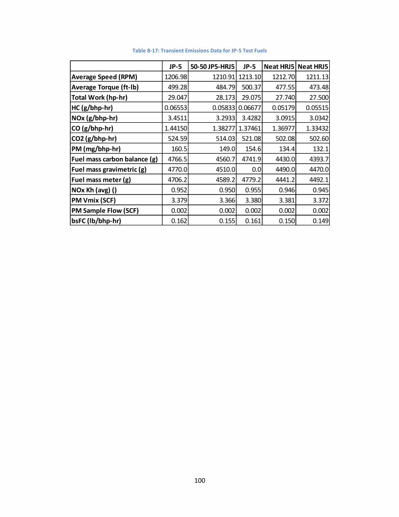
100
Table 8-17: Transient Emissions Data for JP-5 Test Fuels
JP-5 50-50 JP5-HRJ5 JP-5 Neat HRJ5 Neat HRJ5
Average Speed (RPM) 1206.98 1210.91 1213.10 1212.70 1211.13
Average Torque (ft-lb) 499.28 484.79 500.37 477.55 473.48
Total Work (hp-hr) 29.047 28.173 29.075 27.740 27.500
HC (g/bhp-hr) 0.06553 0.05833 0.06677 0.05179 0.05515
NOx (g/bhp-hr) 3.4511 3.2933 3.4282 3.0915 3.0342
CO (g/bhp-hr) 1.44150 1.38277 1.37461 1.36977 1.33432
CO2 (g/bhp-hr) 524.59 514.03 521.08 502.08 502.60
PM (mg/bhp-hr) 160.5 149.0 154.6 134.4 132.1
Fuel mass carbon balance (g) 4766.5 4560.7 4741.9 4430.0 4393.7
Fuel mass gravimetric (g) 4770.0 4510.0 0.0 4490.0 4470.0
Fuel mass meter (g) 4706.2 4589.2 4779.2 4441.2 4492.1
NOx Kh (avg) () 0.952 0.950 0.955 0.946 0.945
PM Vmix (SCF) 3.379 3.366 3.380 3.381 3.372
PM Sample Flow (SCF) 0.002 0.002 0.002 0.002 0.002
bsFC (lb/bhp-hr) 0.162 0.155 0.161 0.150 0.149

101
8.2 F-76 Fuels Data Table 8-18: Effects of fuel density, cetane number, and aromatic content on maximum heat release rate for F-76 test fuels
Table 8-19: Effects of fuel density, cetane number, and aromatic content on net heat released for F-76 test fuels
Table 8-20: Effects of fuel density, cetane number, and aromatic content on maximum in-cylinder pressure for F-76 test fuels
Mode F-76 Neat HRD76
50/50
F76/HRD76 Neat DSH76
50/50
F76/DSH76
80/20
F76/HDCD76 m b R2 m b R2 m b R2
1 0.705 N/A 0.578 0.603 0.650 0.702 0.0013 -0.4261 0.6349 -0.0071 1.0159 0.9225 0.0053 0.5814 0.5902
2 0.676 0.417 0.498 0.527 0.598 0.768 0.0032 -2.0063 0.7924 -0.0120 1.2361 0.9081 0.0129 0.4448 0.7796
3 0.577 0.339 0.428 0.451 0.513 0.665 0.0029 -1.8376 0.7827 -0.0109 1.0912 0.9105 0.0117 0.3725 0.7767
4 0.576 0.311 0.413 0.413 0.489 0.657 0.0032 -2.1462 0.8441 -0.0119 1.1270 0.9270 0.0131 0.3386 0.8323
5 0.527 0.292 0.383 0.379 0.448 0.594 0.0028 -1.8781 0.8550 -0.0104 1.0092 0.9313 0.0115 0.3156 0.8423
6 0.472 0.269 0.349 0.346 0.401 0.524 0.0024 -1.5646 0.8525 -0.0089 0.8807 0.9421 0.0097 0.2907 0.8381
7 0.437 0.248 0.321 0.325 0.378 0.506 0.0024 -1.5442 0.8319 -0.0087 0.8437 0.9130 0.0095 0.2687 0.8202
8 0.394 0.225 0.290 0.286 0.334 0.451 0.0021 -1.3937 0.8596 -0.0077 0.7513 0.9168 0.0086 0.2396 0.8423
9 0.369 0.215 0.275 0.269 0.317 0.423 0.0020 -1.2832 0.8657 -0.0071 0.6984 0.9110 0.0079 0.2275 0.8523
10 0.336 0.291 0.292 0.289 0.294 0.382 0.0009 -0.4532 0.7903 -0.0030 0.4762 0.6316 0.0036 0.2759 0.6942
11 0.298 0.277 0.278 0.274 0.275 0.342 0.0006 -0.2220 0.7027 -0.0019 0.3932 0.5025 0.0024 0.2652 0.6159
12 0.275 0.238 0.241 0.232 0.241 0.312 0.0008 -0.3913 0.8279 -0.0024 0.3898 0.6271 0.0031 0.2240 0.7376
13 0.337 0.316 0.324 0.312 0.322 0.344 0.0003 0.0494 0.9817 -0.0010 0.3817 0.7107 0.0013 0.3118 0.9250
14 0.323 0.304 0.314 0.296 0.310 0.327 0.0003 0.0541 0.9638 -0.0009 0.3610 0.6096 0.0013 0.2989 0.9304
15 0.285 0.266 0.277 0.261 0.273 0.293 0.0003 0.0087 0.9809 -0.0009 0.3271 0.6481 0.0013 0.2618 0.9487
Max Heat Release Rate (kJ/deg) Density Cetane Number Aromatics
Mode F-76 Neat HRD76
50/50
F76/HRD76 Neat DSH76
50/50
F76/DSH76
80/20
F76/HDCD76 m b R2 m b R2 m b R2
1 0.976 N/A 0.873 0.859 0.876 0.932 0.0012 -0.0637 0.6899 -0.0061 1.2171 0.8989 0.0045 0.8468 0.5736
2 2.058 1.415 2.032 1.716 1.967 2.077 0.0060 -2.9823 0.6585 -0.0217 3.0659 0.7029 0.0257 1.6060 0.7337
3 3.154 3.126 3.150 3.108 3.128 3.136 0.0003 2.8673 0.4784 -0.0008 3.1750 0.2064 0.0013 3.1196 0.4677
4 2.366 2.411 2.366 2.380 2.375 2.408 0.0000 2.4084 0.0027 0.0006 2.3541 0.0765 -0.0002 2.3868 0.0107
5 2.379 2.366 2.376 2.360 2.368 2.392 0.0003 2.1287 0.8919 -0.0008 2.4174 0.5095 0.0012 2.3611 0.8334
6 2.264 2.197 2.196 2.178 2.188 2.284 0.0011 1.2963 0.8303 -0.0035 2.4084 0.6354 0.0043 2.1727 0.7048
7 4.422 4.433 4.435 4.416 4.425 4.420 0.0000 4.4567 0.0338 0.0004 4.4017 0.3301 -0.0001 4.4264 0.0226
8 4.244 4.279 4.284 4.266 4.269 4.219 -0.0006 4.7156 0.6487 0.0021 4.1476 0.7093 -0.0021 4.2827 0.5625
9 3.832 3.801 3.761 3.806 3.762 3.836 0.0004 3.4488 0.2214 -0.0017 3.8956 0.2949 0.0013 3.7863 0.1151
10 6.570 6.600 6.606 6.583 6.600 6.542 -0.0005 6.9801 0.5138 0.0018 6.4826 0.5931 -0.0018 6.6022 0.4083
11 6.254 6.291 6.245 6.281 6.243 6.267 -0.0003 6.4792 0.2307 0.0009 6.2141 0.2140 -0.0013 6.2773 0.3448
12 5.456 5.413 5.395 5.446 5.377 5.465 0.0004 5.0710 0.1899 -0.0020 5.5365 0.3321 0.0012 5.4125 0.0919
13 8.986 8.414 8.637 8.233 8.642 9.173 0.0097 0.7764 0.9822 -0.0283 10.2351 0.6778 0.0390 8.2690 0.9522
14 8.316 7.783 8.075 7.621 7.983 8.443 0.0087 0.9994 0.9805 -0.0247 9.3923 0.6491 0.0348 7.6695 0.9547
15 7.187 6.684 6.934 6.532 6.863 7.330 0.0083 0.1335 0.9848 -0.0240 8.2377 0.6605 0.0335 6.5686 0.9516
Net Heat Released (kJ) Density Cetane Number Aromatics
Mode F-76 Neat HRD76
50/50
F76/HRD76 Neat DSH76
50/50
F76/DSH76
80/20
F76/HDCD76 m b R2 m b R2 m b R2
1 5400.38 N/A 5122.67 5170.67 5217.33 5329.00 2.5325 3170.4186 0.5926 -14.4589 5996.9811 0.9525 9.8185 5125.6717 0.5004
2 6424.00 5593.67 6158.00 6003.80 6250.00 6550.25 8.4380 -699.3618 0.7856 -31.9114 7913.0958 0.9115 35.2221 5791.6928 0.8228
3 7380.85 7037.33 7124.33 7080.40 7134.00 7515.00 5.0751 3084.3834 0.8986 -16.9465 8141.2198 0.8128 19.6945 7004.2085 0.8134
4 7355.92 7077.00 7140.33 7106.20 7163.00 7513.50 4.5268 3544.3630 0.8823 -14.8760 8041.6924 0.7729 17.6310 7039.9854 0.8045
5 7528.00 7175.67 7275.67 7226.20 7306.67 7647.50 5.0005 3293.0331 0.9188 -16.8643 8284.6736 0.8477 19.6148 7153.0136 0.8498
6 7406.38 6990.00 7100.67 7076.00 7163.67 7538.25 5.6569 2611.7518 0.8957 -19.6262 8288.6627 0.8746 22.2357 6977.9077 0.8319
7 9345.62 9096.67 9196.33 9021.20 9139.33 9469.75 4.5807 5486.0010 0.9545 -13.2164 9936.1797 0.6446 17.9700 9021.8998 0.8829
8 9579.23 9326.33 9449.33 9225.80 9355.00 9665.25 4.5058 5768.9361 0.9475 -12.5580 10122.0901 0.5971 17.6819 9246.9474 0.8771
9 9315.00 9033.67 9118.00 8948.20 9049.67 9455.25 5.2050 4920.0862 0.9260 -15.1755 9985.4204 0.6385 20.1558 8940.6530 0.8346
10 11375.31 11101.00 11228.33 10978.60 11131.67 11462.25 4.9244 7207.8803 0.9453 -13.6189 11959.6278 0.5865 19.3485 11008.7327 0.8772
11 11726.92 11477.67 11609.67 11310.00 11476.33 11834.00 5.0701 7448.9141 0.9026 -13.1906 12295.7181 0.4956 19.8934 11362.5559 0.8352
12 11234.85 10904.67 11078.67 10771.20 10933.33 11361.50 6.0122 6157.6100 0.9385 -16.6054 11957.8988 0.5807 23.5596 10798.8152 0.8662
13 13588.92 12665.67 13122.67 12392.80 12940.67 13837.25 15.2151 716.9172 0.9816 -43.7645 15491.0831 0.6588 60.6324 12451.6568 0.9369
14 13855.54 12962.00 13461.00 12616.20 13207.67 14118.50 15.4287 821.9689 0.9652 -42.8822 15721.5275 0.6048 61.6089 12720.1767 0.9250
15 13118.08 12214.00 12692.33 11889.40 12435.67 13406.25 15.6431 -96.5463 0.9683 -43.9214 15034.3096 0.6192 62.1665 11970.0976 0.9192
Max In-Cylinder Pressure (kPa) Density Cetane Number Aromatics

102
Table 8-21: Effects of fuel density, cetane number, and aromatic content on maximum pressure rise rate for F-76 test fuels
Table 8-22: Effects of fuel density, cetane number, and aromatic content on maximum in-cylinder temperature for F-76 test fuels
Table 8-23: Effects of fuel density, cetane number, aromatic content, and viscosity on start of fuel injection for F-76 test fuels
Mode F-76 Neat HRD76
50/50
F76/HRD76 Neat DSH76
50/50
F76/DSH76
80/20
F76/HDCD76 m b R2 m b R2 m b R2
1 1512.46 N/A 1266.00 1314.00 1400.67 1476.75 2.3083 -499.7324 0.5904 -12.9153 2062.9892 0.9113 9.3496 1277.4791 0.5440
2 1416.31 891.00 1066.33 1107.20 1255.33 1572.00 6.2553 -3869.3776 0.8056 -23.5372 2508.6516 0.9253 25.3478 950.6098 0.7952
3 1229.62 741.33 932.33 964.40 1097.67 1394.50 5.8123 -3667.1319 0.7968 -21.9340 2262.6915 0.9205 23.6554 810.4104 0.7934
4 1249.31 726.33 935.00 919.00 1077.67 1404.00 6.3736 -4131.8018 0.8567 -23.2926 2329.0956 0.9282 25.8472 779.1967 0.8469
5 1133.85 685.00 867.67 845.40 982.00 1256.25 5.4251 -3450.5732 0.8658 -19.7760 2046.0777 0.9333 21.9966 729.6296 0.8556
6 1015.92 633.00 784.67 770.00 873.00 1111.75 4.5718 -2853.5116 0.8668 -16.7276 1781.9545 0.9414 18.4477 670.1006 0.8483
7 1001.62 614.00 763.67 764.40 878.33 1136.75 4.8307 -3068.9811 0.8419 -17.6872 1829.6438 0.9155 19.5709 653.3214 0.8306
8 906.00 575.00 705.33 689.40 789.33 1017.00 4.1889 -2626.5245 0.8704 -15.0808 1607.2775 0.9152 16.9281 601.7525 0.8544
9 852.62 551.67 667.67 646.60 744.00 956.25 3.8895 -2426.8544 0.8824 -13.8456 1495.6695 0.9070 15.7112 570.7136 0.8654
10 822.69 528.67 642.33 639.00 731.00 917.75 3.6295 -2238.3114 0.8468 -13.2813 1441.8311 0.9199 14.7328 558.1427 0.8387
11 750.46 515.00 606.67 595.80 665.67 839.50 3.0625 -1828.5660 0.8703 -10.9527 1262.7528 0.9029 12.3525 531.8637 0.8510
12 702.69 483.67 574.33 550.80 627.67 777.00 2.8309 -1682.9761 0.8922 -10.0134 1168.4261 0.9056 11.4776 498.2707 0.8816
13 647.15 465.00 537.67 552.20 604.33 703.75 2.1001 -1123.0049 0.7764 -8.0411 1025.9361 0.9233 8.5930 494.3616 0.7812
14 636.08 471.33 532.33 535.00 583.00 694.00 2.0593 -1099.5428 0.8379 -7.5506 989.3150 0.9137 8.3341 487.3663 0.8249
15 616.69 461.33 526.67 515.20 567.00 660.50 1.8970 -984.9271 0.8720 -6.8675 934.4692 0.9271 7.7160 476.4951 0.8672
Max Pressure Rise Rate (kPa/deg) Density Cetane Number Aromatics
Mode F-76 Neat HRD76
50/50
F76/HRD76 Neat DSH76
50/50
F76/DSH76
80/20
F76/HDCD76 m b R2 m b R2 m b R2
1 1187.38 N/A 1148.67 1149.00 1163.33 1171.25 0.3585 869.7876 0.5873 -1.9592 1265.4159 0.8648 1.4408 1145.9747 0.5328
2 1425.15 1247.00 1404.33 1336.00 1409.33 1441.75 1.7031 -7.8790 0.6847 -6.3195 1723.7823 0.7648 7.3390 1299.8349 0.7643
3 1595.69 1572.00 1578.00 1566.00 1583.33 1613.25 0.4675 1204.5214 0.9285 -1.3972 1661.3279 0.6729 1.8734 1564.9479 0.8964
4 1478.54 1468.33 1464.33 1459.80 1474.00 1500.75 0.3520 1188.0155 0.7398 -0.9997 1529.1101 0.4841 1.4064 1459.4552 0.7099
5 1479.31 1451.33 1459.00 1451.20 1470.00 1496.25 0.4745 1081.9265 0.9097 -1.5209 1551.2428 0.7581 1.9269 1447.5202 0.9017
6 1442.00 1402.67 1410.67 1402.00 1423.00 1459.00 0.6226 916.8902 0.9236 -2.0222 1534.1078 0.7905 2.4920 1396.9317 0.8895
7 1719.92 1707.00 1711.33 1697.40 1717.00 1733.00 0.3192 1454.6975 0.8781 -0.8649 1761.7002 0.5230 1.3177 1700.3746 0.8996
8 1665.85 1654.33 1657.00 1644.60 1660.00 1677.00 0.2906 1423.4317 0.8916 -0.7780 1702.4587 0.5184 1.1779 1647.3695 0.8804
9 1603.23 1582.67 1583.33 1574.60 1585.00 1611.00 0.3727 1286.8714 0.9027 -1.1123 1650.9645 0.6524 1.4470 1574.7055 0.8181
10 1819.46 1818.00 1813.67 1803.20 1815.67 1827.25 0.1751 1673.8276 0.6241 -0.3551 1835.6785 0.2083 0.6988 1808.8349 0.5977
11 1743.54 1744.67 1736.33 1729.60 1736.33 1754.00 0.1691 1603.2000 0.5014 -0.3333 1759.0201 0.1580 0.6354 1734.0423 0.4254
12 1661.77 1649.33 1648.67 1644.40 1649.67 1666.00 0.2231 1471.8895 0.8708 -0.6722 1690.1636 0.6415 0.8572 1644.2624 0.7730
13 1871.92 1859.00 1862.67 1846.40 1861.67 1881.25 0.3150 1607.5881 0.8972 -0.8122 1908.3528 0.4837 1.2594 1850.5308 0.8618
14 1786.77 1768.67 1775.00 1755.60 1773.67 1790.00 0.3354 1502.1401 0.9135 -0.8925 1823.8883 0.5246 1.3485 1760.7239 0.8873
15 1712.00 1695.33 1700.33 1679.40 1701.00 1720.25 0.3735 1397.5963 0.8946 -0.9631 1754.1955 0.4825 1.5109 1685.4464 0.8798
Max In-Cylinder Temperature (K) Density Cetane Number Aromatics
Mode F-76 Neat HRD76
50/50
F76/HRD76 Neat DSH76
50/50
F76/DSH76
80/20
F76/HDCD76 m b R2 m b R2 m b R2 m b R2
1 -3.17 N/A -2.50 -2.58 -3.00 -2.50 -0.0015 -1.5294 0.0272 0.0159 -3.5770 0.1539 -0.0073 -2.6602 0.0369 -0.2392 -2.0671 0.2514
2 -4.42 -3.25 -3.92 -3.50 -4.00 -4.50 -0.0134 6.9557 0.9319 0.0461 -6.4589 0.8962 -0.0550 -3.3514 0.9455 -0.6402 -2.1605 0.6694
3 -4.15 -3.50 -3.75 -3.25 -3.50 -4.31 -0.0112 5.3317 0.9252 0.0316 -5.4793 0.6033 -0.0432 -3.2890 0.8320 -0.5438 -2.2399 0.6900
4 -8.46 -8.00 -8.08 -7.65 -8.00 -8.44 -0.0079 -1.6426 0.8577 0.0213 -9.2729 0.4996 -0.0311 -7.7775 0.7885 -0.4012 -6.9954 0.6867
5 -9.19 -7.83 -9.00 -8.65 -8.67 -9.19 -0.0114 0.5281 0.6328 0.0450 -11.2222 0.7977 -0.0466 -8.2628 0.6354 -0.5320 -7.2832 0.4317
6 -10.21 -9.50 -9.83 -9.40 -9.75 -10.56 -0.0122 0.0658 0.9782 0.0365 -11.8803 0.7093 -0.0486 -9.3636 0.9290 -0.5601 -8.3268 0.6449
7 -8.13 -8.00 -7.33 -7.45 -7.67 -8.25 -0.0064 -2.5694 0.3693 0.0172 -8.7512 0.2148 -0.0230 -7.5627 0.2844 -0.4385 -6.5925 0.5381
8 -8.88 -8.00 -8.42 -8.05 -8.50 -9.13 -0.0124 1.6198 0.9839 0.0402 -10.6984 0.8322 -0.0504 -7.9640 0.9722 -0.5859 -6.8749 0.6858
9 -10.21 -9.58 -9.17 -9.30 -9.58 -10.00 -0.0083 -2.9145 0.5411 0.0283 -11.1938 0.5147 -0.0310 -9.3141 0.4559 -0.5868 -8.0173 0.8555
10 -8.13 -7.42 -7.50 -7.35 -7.58 -8.25 -0.0104 0.7309 0.9135 0.0337 -9.5547 0.7830 -0.0403 -7.2807 0.8284 -0.5656 -6.1409 0.8530
11 -8.69 -8.17 -7.83 -7.90 -7.83 -8.94 -0.0106 0.3981 0.6251 0.0327 -10.0229 0.4835 -0.0382 -7.8247 0.4863 -0.6504 -6.4277 0.7385
12 -9.96 -9.42 -9.67 -9.25 -9.58 -10.13 -0.0091 -2.2303 0.9826 0.0264 -11.1135 0.6632 -0.0364 -9.2828 0.9379 -0.4218 -8.5002 0.6567
13 -7.88 -7.58 -6.58 -7.25 -7.42 -8.25 -0.0090 -0.1913 0.3159 0.0309 -9.1890 0.3041 -0.0326 -7.1494 0.2500 -0.6473 -5.7022 0.5157
14 -8.87 -7.92 -8.25 -7.90 -8.58 -8.88 -0.0118 1.1922 0.8988 0.0392 -10.5457 0.8041 -0.0489 -7.8821 0.9305 -0.5841 -6.7825 0.6925
15 -9.73 -9.33 -9.50 -9.10 -9.58 -9.50 -0.0046 -5.7211 0.5645 0.0126 -10.1514 0.3470 -0.0196 -9.2508 0.6196 -0.2211 -8.8463 0.4105
Start of Fuel Injection (deg) Density Cetane Number Aromatics Viscosity

103
Table 8-24: Effects of fuel density, cetane number, and aromatic content on start of combustion for F-76 test fuels
Table 8-25: Effects of fuel density, cetane number, and aromatic content on premix fraction length for F-76 test fuels
Table 8-26: Effects of fuel density, cetane number, and aromatic content on diffusion fraction length for F-76 test fuels
Mode F-76 Neat HRD76
50/50
F76/HRD76 Neat DSH76
50/50
F76/DSH76
80/20
F76/HDCD76 m b R2 m b R2 m b R2
1 0.56 N/A 0.25 0.50 0.33 1.50 0.0097 -7.3527 0.4531 -0.0446 2.9364 0.4688 0.0377 0.1582 0.3827
2 1.08 0.50 0.58 1.20 1.00 1.56 0.0063 -4.1211 0.3190 -0.0305 2.6582 0.6092 0.0247 0.7261 0.2974
3 0.83 0.00 0.25 1.00 1.00 1.00 0.0048 -3.2034 0.1482 -0.0316 2.4095 0.5251 0.0211 0.4570 0.1738
4 -1.40 -3.00 -2.50 -2.00 -1.50 -1.00 0.0160 -14.9109 0.5808 -0.0681 1.8329 0.8536 0.0669 -2.6065 0.6108
5 -1.48 -3.25 -2.75 -2.20 -1.75 -0.88 0.0194 -17.8683 0.6406 -0.0797 2.3165 0.8717 0.0798 -2.8933 0.6490
6 -1.58 -3.50 -2.75 -2.25 -1.75 -1.25 0.0178 -16.6443 0.5759 -0.0772 2.0548 0.8808 0.0745 -2.9658 0.6079
7 -2.50 -3.33 -3.17 -2.55 -2.50 -2.06 0.0084 -9.5204 0.3979 -0.0395 -0.5218 0.7116 0.0346 -3.0503 0.4052
8 -2.75 -4.00 -3.50 -3.00 -3.00 -2.44 0.0112 -12.2548 0.5171 -0.0511 -0.3132 0.8669 0.0458 -3.5973 0.5151
9 -3.00 -4.17 -3.75 -3.25 -3.00 -2.75 0.0101 -11.5370 0.4511 -0.0472 -0.7293 0.7998 0.0427 -3.7703 0.4851
10 -3.23 -3.25 -3.50 -3.05 -3.08 -3.00 0.0006 -3.7137 0.0159 -0.0064 -2.8325 0.1269 0.0027 -3.2137 0.0159
11 -3.75 -4.08 -4.00 -3.65 -3.75 -3.63 0.0022 -5.6083 0.1745 -0.0139 -3.0498 0.5560 0.0090 -3.9051 0.1752
12 -4.12 -4.50 -4.25 -3.85 -4.00 -4.00 0.0013 -5.1527 0.0390 -0.0132 -3.3966 0.3399 0.0060 -4.1829 0.0528
13 -3.25 -2.50 -3.00 -2.75 -3.00 -3.25 -0.0076 3.2088 0.8545 0.0273 -4.4539 0.8967 -0.0314 -2.6275 0.8783
14 -4.00 -3.58 -3.92 -3.50 -3.83 -4.13 -0.0066 1.5441 0.9441 0.0187 -4.8523 0.6148 -0.0273 -3.5386 0.9685
15 -4.50 -4.25 -4.33 -3.95 -4.25 -4.50 -0.0051 -0.1469 0.7924 0.0122 -4.9650 0.3661 -0.0203 -4.0828 0.7554
Start of Combustion (deg) Density Cetane Number Aromatics
Mode F-76 Neat HRD76
50/50
F76/HRD76 Neat DSH76
50/50
F76/DSH76
80/20
F76/HDCD76 m b R2 m b R2 m b R2
1 6.53 N/A 6.41 6.40 6.49 6.59 0.0020 4.8131 0.7847 -0.0095 6.9747 0.8345 0.0086 6.3777 0.7823
2 7.13 6.97 6.92 7.08 7.09 7.21 0.0019 5.5382 0.4042 -0.0083 7.5234 0.6431 0.0074 6.9887 0.3782
3 6.82 6.48 6.67 6.63 6.76 7.01 0.0046 3.0053 0.8309 -0.0163 7.6200 0.8533 0.0188 6.5285 0.8458
4 7.75 7.15 7.50 7.60 7.57 7.86 0.0053 3.2399 0.5966 -0.0231 8.8417 0.9119 0.0215 7.3463 0.5859
5 8.31 7.58 8.06 8.13 8.17 8.40 0.0060 3.2065 0.5628 -0.0265 9.5650 0.8849 0.0250 7.8457 0.5828
6 8.79 8.27 8.58 8.69 8.77 8.87 0.0041 5.3108 0.4680 -0.0191 9.7106 0.8174 0.0176 8.4765 0.5129
7 7.11 6.44 6.77 6.76 6.87 7.16 0.0066 1.5117 0.7942 -0.0257 8.2621 0.9860 0.0267 6.5720 0.7863
8 7.50 6.96 7.11 7.16 7.41 7.70 0.0069 1.7297 0.7747 -0.0255 8.7027 0.8662 0.0282 7.0091 0.7879
9 8.05 7.46 7.76 7.78 7.92 8.21 0.0064 2.6631 0.7643 -0.0249 9.2258 0.9382 0.0263 7.5849 0.7770
10 6.50 5.63 6.22 6.19 6.38 6.56 0.0075 0.1851 0.6176 -0.0313 7.9627 0.8840 0.0315 5.9134 0.6649
11 6.95 6.31 6.52 6.66 6.82 7.12 0.0068 1.1722 0.6858 -0.0277 8.2455 0.9123 0.0280 6.4335 0.6909
12 7.51 6.92 7.05 7.12 7.42 7.64 0.0069 1.6685 0.7360 -0.0263 8.7158 0.8676 0.0286 6.9734 0.7602
13 5.64 4.59 5.13 5.42 5.55 5.79 0.0085 -1.5850 0.4865 -0.0396 7.5264 0.8520 0.0359 4.9739 0.5186
14 6.19 5.40 5.73 5.96 6.08 6.43 0.0078 -0.4035 0.5952 -0.0334 7.7975 0.8814 0.0323 5.6222 0.6106
15 6.94 6.37 6.50 6.80 6.93 6.96 0.0042 3.3024 0.3547 -0.0216 7.9313 0.7457 0.0180 6.5586 0.3848
Premix Fraction Length (deg) Density Cetane Number Aromatics
Mode F-76 Neat HRD76
50/50
F76/HRD76 Neat DSH76
50/50
F76/DSH76
80/20
F76/HDCD76 m b R2 m b R2 m b R2
1 12.91 N/A 13.65 12.62 12.51 12.28 -0.0028 15.0546 0.0331 0.0299 11.2449 0.1919 -0.0119 12.9416 0.0347
2 26.39 24.73 26.02 22.60 24.09 26.44 0.0356 -3.8707 0.6868 -0.0771 29.2734 0.2619 0.1387 23.5827 0.6286
3 29.27 32.15 32.08 30.65 30.77 27.87 -0.0370 60.5886 0.6341 0.1460 22.4583 0.7990 -0.1432 31.9741 0.5699
4 26.62 30.84 29.17 29.64 28.03 25.54 -0.0524 70.8932 0.8936 0.1865 18.0779 0.9197 -0.2130 30.5528 0.8887
5 26.34 31.51 30.13 30.14 28.15 25.53 -0.0610 78.2814 0.8472 0.2240 16.3515 0.9254 -0.2475 31.2458 0.8373
6 29.33 33.91 31.79 31.77 29.63 28.26 -0.0498 71.2781 0.7289 0.1925 20.2289 0.8836 -0.2102 33.0004 0.7806
7 35.55 38.47 37.10 37.83 36.72 34.42 -0.0405 69.6124 0.9409 0.1365 29.1946 0.8681 -0.1635 38.4074 0.9227
8 35.96 38.92 38.05 38.86 37.88 34.41 -0.0486 76.8905 0.9299 0.1554 28.8285 0.7703 -0.1912 39.3655 0.8648
9 36.61 39.46 38.13 39.34 37.89 35.68 -0.0415 71.6381 0.9840 0.1330 30.5591 0.8181 -0.1680 39.6241 0.9674
10 45.45 45.95 44.81 45.58 44.45 42.52 -0.0253 65.3477 0.5282 0.0714 40.8747 0.3424 -0.1085 45.9367 0.5848
11 44.17 46.25 45.33 46.67 45.38 43.20 -0.0360 74.4691 0.9836 0.1067 39.3124 0.7003 -0.1444 46.6893 0.9498
12 44.40 46.81 45.15 46.90 45.22 43.97 -0.0333 72.5227 0.9576 0.1017 39.8302 0.7229 -0.1383 46.8659 0.9900
13 53.36 53.77 53.88 52.83 53.25 52.90 -0.0024 55.3041 0.0398 0.0226 52.0946 0.2796 -0.0092 53.4297 0.0348
14 52.78 53.30 53.30 52.87 52.97 52.65 -0.0046 56.7575 0.3761 0.0228 51.7255 0.7357 -0.0180 53.1667 0.3377
15 51.99 52.66 52.12 52.08 52.03 52.01 -0.0042 55.5369 0.3447 0.0207 51.0144 0.6909 -0.0182 52.3419 0.3968
Diffusion Fraction Length (deg) Density Cetane Number Aromatics

104
Table 8-27: Effects of fuel density, cetane number, and aromatic content on bsHC emissions for F-76 test fuels
Table 8-28: Effects of fuel density, cetane number, and aromatic content on bsNOx emissions for F-76 test fuels
Table 8-29: Effects of fuel density, cetane number, and aromatic content on bsCO emissions for F-76 test fuels
Mode F-76 Neat HRD76
50/50
F76/HRD76 Neat DSH76
50/50
F76/DSH76
80/20
F76/HDCD76 m b R2 m b R2 m b R2
1* 0.334 0.159 0.172 0.314 0.250 0.374 0.0015 -0.9444 0.3593 -0.0075 0.6758 0.7306 0.0056 0.2077 0.3069
2 0.192 0.092 0.133 0.162 0.155 0.221 0.0010 -0.6594 0.6351 -0.0042 0.3915 0.9099 0.0040 0.1173 0.6013
3 0.065 0.042 0.054 0.059 0.055 0.073 0.0002 -0.1328 0.6327 -0.0010 0.1112 0.8740 0.0009 0.0484 0.5847
4 0.160 0.096 0.123 0.128 0.139 0.186 0.0008 -0.4936 0.7923 -0.0029 0.2993 0.9129 0.0031 0.1057 0.7703
5 0.187 0.106 0.146 0.151 0.154 0.213 0.0009 -0.5820 0.7831 -0.0035 0.3512 0.9337 0.0036 0.1212 0.7483
6 0.235 0.122 0.176 0.176 0.188 0.273 0.0013 -0.8946 0.8304 -0.0050 0.4680 0.9293 0.0054 0.1386 0.7971
7 0.070 0.044 0.058 0.059 0.059 0.079 0.0003 -0.1749 0.7612 -0.0011 0.1228 0.9129 0.0012 0.0493 0.7219
8 0.063 0.041 0.055 0.057 0.057 0.071 0.0002 -0.1236 0.6685 -0.0009 0.1068 0.8875 0.0009 0.0479 0.6616
9 0.084 0.053 0.073 0.066 0.073 0.091 0.0004 -0.2151 0.8655 -0.0013 0.1438 0.9209 0.0014 0.0581 0.8640
10 0.035 0.031 0.034 0.035 0.034 0.036 0.0000 0.0065 0.3779 -0.0002 0.0434 0.7331 0.0001 0.0328 0.3608
11 0.032 0.025 0.030 0.030 0.032 0.034 0.0001 -0.0228 0.6177 -0.0003 0.0453 0.8384 0.0003 0.0276 0.6885
12 0.042 0.028 0.038 0.035 0.036 0.044 0.0001 -0.0761 0.8110 -0.0005 0.0659 0.9325 0.0006 0.0313 0.7960
13 0.024 0.023 0.024 0.022 0.025 0.021 0.0000 0.0339 0.0927 0.0000 0.0211 0.0499 0.0000 0.0234 0.0377
14 0.027 0.023 0.026 0.024 0.026 0.024 0.0000 0.0123 0.1455 -0.0001 0.0291 0.2586 0.0001 0.0242 0.2052
15 0.032 0.025 0.030 0.029 0.031 0.032 0.0001 -0.0140 0.6001 -0.0002 0.0423 0.8641 0.0002 0.0274 0.6494
* Values are reported as a mass rate
bsHC (g/bhp-hr) Density Cetane Number Aromatics
Mode F-76 Neat HRD76
50/50
F76/HRD76 Neat DSH76
50/50
F76/DSH76
80/20
F76/HDCD76 m b R2 m b R2 m b R2
1* 7.511 6.156 6.993 6.569 7.390 7.037 0.0101 -1.2405 0.4968 -0.0400 9.1354 0.6365 0.0447 6.4713 0.5890
2 10.558 7.777 8.908 8.448 9.738 11.600 0.0378 -21.2056 0.9037 -0.1305 16.6583 0.8751 0.1542 7.8779 0.9058
3 8.464 7.126 7.758 6.905 7.823 9.140 0.0231 -10.9557 0.9813 -0.0691 11.6605 0.7104 0.0936 6.8813 0.9651
4 10.513 8.429 9.291 8.347 9.463 11.379 0.0330 -17.2620 0.9806 -0.1031 15.2261 0.7774 0.1326 8.1715 0.9521
5 10.490 8.254 9.097 8.270 9.408 11.457 0.0350 -18.9810 0.9668 -0.1115 15.6111 0.7956 0.1407 8.0122 0.9378
6 10.600 8.014 8.995 8.195 9.490 11.484 0.0375 -21.0739 0.9616 -0.1229 16.2033 0.8361 0.1517 7.8630 0.9431
7 8.031 6.944 7.486 6.712 7.384 8.380 0.0177 -6.8960 0.9935 -0.0521 10.3451 0.6987 0.0710 6.7398 0.9634
8 8.360 7.174 7.749 6.873 7.647 8.735 0.0196 -8.1648 0.9908 -0.0572 10.8908 0.6853 0.0787 6.9264 0.9616
9 8.474 7.206 7.854 6.881 7.732 8.922 0.0213 -9.4649 0.9897 -0.0618 11.2351 0.6775 0.0857 6.9410 0.9640
10 6.467 5.771 6.162 5.548 6.044 6.609 0.0112 -2.9959 0.9745 -0.0318 7.8423 0.6380 0.0452 5.6237 0.9550
11 7.116 6.277 6.772 5.972 6.598 7.329 0.0140 -4.7288 0.9684 -0.0392 8.8252 0.6129 0.0566 6.0797 0.9493
12 7.379 6.480 7.038 6.133 6.833 7.622 0.0153 -5.5000 0.9617 -0.0422 9.2278 0.5962 0.0618 6.2623 0.9470
13 5.905 5.375 5.708 5.220 5.593 6.013 0.0084 -1.1982 0.9690 -0.0238 6.9402 0.6302 0.0340 5.2767 0.9552
14 6.628 5.959 6.395 5.710 6.216 6.778 0.0111 -2.7241 0.9547 -0.0306 7.9571 0.5902 0.0448 5.8082 0.9404
15 6.870 6.166 6.635 5.864 6.428 7.055 0.0121 -3.3470 0.9460 -0.0329 8.3047 0.5648 0.0490 5.9858 0.9320
* Values are reported as a mass rate
bsNOx (g/bhp-hr) Density Cetane Number Aromatics
Mode F-76 Neat HRD76
50/50
F76/HRD76 Neat DSH76
50/50
F76/DSH76
80/20
F76/HDCD76 m b R2 m b R2 m b R2
1* 1.569 0.509 0.889 1.086 1.250 2.074 0.0132 -9.4951 0.7434 -0.0504 3.9942 0.8818 0.0530 0.6698 0.7229
2 1.023 0.509 0.669 0.782 0.906 1.216 0.0060 -4.0437 0.7164 -0.0236 2.1449 0.8939 0.0245 0.5925 0.7127
3 0.349 0.333 0.358 0.373 0.375 0.325 -0.0003 0.5719 0.2173 0.0003 0.3378 0.0161 -0.0009 0.3613 0.1382
4 0.579 0.402 0.460 0.484 0.542 0.664 0.0023 -1.3396 0.7619 -0.0086 0.9921 0.8681 0.0093 0.4233 0.7622
5 0.639 0.424 0.515 0.530 0.593 0.720 0.0026 -1.5187 0.7781 -0.0097 1.1037 0.9063 0.0105 0.4590 0.7856
6 0.847 0.514 0.641 0.657 0.765 0.948 0.0039 -2.4634 0.8006 -0.0148 1.5391 0.9211 0.0161 0.5592 0.8050
7 0.888 0.856 0.889 0.954 0.984 0.889 -0.0003 1.1572 0.0499 -0.0005 0.9391 0.0124 -0.0006 0.9164 0.0124
8 0.557 0.531 0.547 0.609 0.607 0.570 -0.0001 0.6693 0.0180 -0.0008 0.6140 0.0630 -0.0002 0.5724 0.0033
9 0.419 0.360 0.381 0.412 0.425 0.449 0.0006 -0.0841 0.4487 -0.0027 0.5573 0.7392 0.0026 0.3809 0.4800
10 4.197 4.286 4.315 4.670 4.754 4.151 -0.0043 7.8855 0.3642 0.0076 3.9768 0.0935 -0.0144 4.5476 0.2471
11 1.598 1.722 1.625 1.949 1.859 1.610 -0.0030 4.1933 0.5433 0.0059 1.4060 0.1644 -0.0114 1.8476 0.4634
12 0.731 0.746 0.697 0.842 0.796 0.760 -0.0006 1.2622 0.1849 0.0003 0.7472 0.0029 -0.0024 0.7871 0.1657
13 8.315 7.599 7.893 7.795 8.406 8.394 0.0079 1.6507 0.6509 -0.0293 9.6761 0.7304 0.0345 7.7029 0.7493
14 3.038 2.848 2.814 2.996 3.134 3.149 0.0021 1.2660 0.2897 -0.0100 3.5425 0.5146 0.0093 2.8981 0.3346
15 1.458 1.258 1.275 1.343 1.429 1.536 0.0025 -0.6413 0.6556 -0.0097 1.9164 0.8122 0.0102 1.2754 0.6617
* Values are reported as a mass rate
bsCO (g/bhp-hr) Density Cetane Number Aromatics

105
Table 8-30: Effects of fuel density, cetane number, and aromatic content on bsCO2 emissions for F-76 test fuels
Table 8-31: Effects of fuel density, cetane number, and aromatic content on bsPM emissions for F-76 test fuels
Table 8-32: Effects of fuel density, cetane number, and aromatic content on bsFC for F-76 test fuels
Mode F-76 Neat HRD76
50/50
F76/HRD76 Neat DSH76
50/50
F76/DSH76
80/20
F76/HDCD76 m b R2 m b R2 m b R2
1* 323.61 278.37 305.30 298.05 305.00 312.32 0.3443 23.7732 0.6552 -1.4063 380.8881 0.8869 1.4080 288.9201 0.6588
2 524.42 491.81 513.31 493.46 509.70 532.34 0.4522 143.0938 0.9846 -1.4122 588.2757 0.7790 1.8410 491.4188 0.9810
3 473.15 448.33 464.16 449.48 462.37 479.10 0.3440 182.9915 0.9862 -1.0780 521.8781 0.7857 1.4029 447.9648 0.9859
4 490.21 463.52 481.13 464.03 477.77 496.51 0.3744 174.3559 0.9862 -1.1575 542.3329 0.7647 1.5234 462.7906 0.9814
5 499.79 474.01 491.37 474.16 488.00 505.73 0.3625 194.0072 0.9837 -1.1142 549.9364 0.7537 1.4779 473.2507 0.9827
6 529.65 505.00 521.18 503.70 516.67 536.15 0.3634 223.1699 0.9892 -1.0952 578.7764 0.7288 1.4705 503.2092 0.9735
7 460.91 439.32 451.97 440.11 451.60 467.04 0.3080 201.3657 0.9907 -0.9681 504.9118 0.7942 1.2536 438.6004 0.9868
8 458.19 437.51 449.74 438.26 448.77 464.45 0.2984 206.8125 0.9920 -0.9350 500.7537 0.7901 1.2109 436.7106 0.9820
9 469.00 447.97 459.14 448.44 458.17 474.87 0.3025 213.5401 0.9958 -0.9526 511.8294 0.8008 1.2182 446.7440 0.9705
10 459.36 439.84 449.96 439.98 450.30 465.96 0.2909 214.3120 0.9923 -0.9122 500.9217 0.7916 1.1773 438.4800 0.9769
11 450.16 431.76 441.19 432.24 441.67 456.56 0.2733 220.0035 0.9898 -0.8622 489.5405 0.7992 1.1053 430.6034 0.9731
12 454.77 435.94 445.13 436.50 445.70 460.76 0.2753 222.5373 0.9903 -0.8742 494.4009 0.8098 1.1107 434.7494 0.9686
13 457.98 439.59 448.30 439.54 449.30 463.20 0.2677 231.9211 0.9925 -0.8461 496.0465 0.8043 1.0826 438.2295 0.9755
14 449.10 430.41 439.12 431.64 440.60 454.71 0.2661 224.5407 0.9831 -0.8596 488.0639 0.8324 1.0751 429.5885 0.9648
15 452.31 433.68 442.32 435.12 443.47 457.59 0.2617 231.2648 0.9832 -0.8492 490.6470 0.8401 1.0546 432.9538 0.9600
* Values are reported as a mass rate
bsCO2 (g/bhp-hr) Density Cetane Number Aromatics
Mode F-76 Neat HRD76
50/50
F76/HRD76 Neat DSH76
50/50
F76/DSH76
80/20
F76/HDCD76 m b R2 m b R2 m b R2
1* 88.11 38.21 43.08 47.64 64.40 69.96 0.4192 -282.3983 0.6162 -1.7090 152.2758 0.8307 1.6802 40.8410 0.5949
2 138.93 74.56 104.71 89.69 107.33 128.31 0.6185 -395.7747 0.8577 -2.2629 231.3360 0.9314 2.4940 80.9411 0.8383
3 70.53 28.44 50.32 28.43 48.30 288.77 2.1999 -1703.4041 0.6061 -6.2620 429.1617 0.3983 8.6603 -5.5678 0.5645
4 179.63 113.36 129.29 121.11 161.90 198.15 0.9035 -584.2494 0.8719 -3.1150 321.3805 0.8408 3.7065 111.4696 0.8820
5 228.72 137.36 181.92 153.20 184.20 166.12 0.5478 -270.2715 0.3818 -2.2317 297.6260 0.5140 2.2723 151.2803 0.3948
6 316.06 155.93 239.89 191.28 269.23 54.62 -0.2790 431.4088 0.0115 -0.6149 238.2203 0.0045 -0.6554 211.4156 0.0038
7 89.50 44.71 70.52 51.87 74.67 75.35 0.3939 -252.5763 0.7190 -1.4117 145.1750 0.7492 1.6585 50.2720 0.7662
8 71.48 33.86 56.12 43.87 59.70 62.75 0.3290 -212.9630 0.7430 -1.2223 121.6533 0.8318 1.3803 40.0678 0.7859
9 84.63 44.93 67.32 50.40 72.13 76.40 0.3875 -249.1572 0.8060 -1.3512 140.0594 0.7951 1.6258 48.8158 0.8529
10 147.22 117.11 134.89 141.12 157.30 66.70 -0.4186 467.8574 0.2090 0.6733 90.4697 0.0439 -1.4706 142.9050 0.1550
11 84.89 58.65 72.71 75.93 86.07 77.16 0.1444 -41.5669 0.2682 -0.7638 117.7805 0.6085 0.6629 68.9074 0.3396
12 72.13 43.02 60.67 53.92 63.83 137.81 0.7908 -571.2962 0.6972 -2.4470 206.0748 0.5415 3.1586 38.5744 0.6685
13 233.14 185.63 207.05 203.18 233.53 86.80 -0.6669 733.9320 0.1897 1.2842 121.1367 0.0571 -2.4035 216.9124 0.1481
14 110.45 83.11 95.53 95.91 110.40 107.32 0.2227 -80.6603 0.5317 -0.9500 152.5444 0.7849 0.9749 90.1685 0.6125
15 88.58 56.56 72.04 68.04 81.23 225.07 1.3663 -1012.5958 0.5982 -4.0779 322.1949 0.4323 5.4191 41.4165 0.5657
* Values are reported as a mass rate
bsPM (mg/bhp-hr) Density Cetane Number Aromatics
Mode F-76 Neat HRD76
50/50
F76/HRD76 Neat DSH76
50/50
F76/DSH76
80/20
F76/HDCD76 m b R2 m b R2 m b R2
1* 0.228 0.217 0.217 0.214 0.217 0.200 -0.0001 0.2599 0.0459 0.0001 0.2115 0.0070 -0.0002 0.2180 0.0494
2 0.367 0.362 0.362 0.352 0.361 0.351 0.0000 0.3561 0.0004 0.0001 0.3553 0.0127 0.0000 0.3588 0.0010
3 0.330 0.328 0.368 0.320 0.326 0.320 0.0000 0.3319 0.0000 0.0004 0.3115 0.0440 0.0001 0.3314 0.0011
4 0.343 0.340 0.346 0.331 0.337 0.331 0.0000 0.3326 0.0015 0.0001 0.3321 0.0322 0.0000 0.3376 0.0024
5 0.348 0.346 0.340 0.337 0.343 0.338 0.0000 0.3362 0.0030 0.0000 0.3411 0.0012 0.0000 0.3417 0.0011
6 0.371 0.368 0.328 0.358 0.363 0.359 0.0000 0.3400 0.0025 -0.0003 0.3732 0.0323 0.0000 0.3578 0.0000
7 0.322 0.320 0.323 0.314 0.319 0.314 0.0000 0.3124 0.0055 0.0000 0.3166 0.0111 0.0000 0.3183 0.0089
8 0.319 0.317 0.317 0.312 0.316 0.312 0.0000 0.3092 0.0075 0.0000 0.3144 0.0024 0.0000 0.3148 0.0086
9 0.326 0.323 0.320 0.318 0.322 0.319 0.0000 0.3088 0.0327 0.0000 0.3238 0.0249 0.0001 0.3207 0.0224
10 0.324 0.321 0.315 0.317 0.321 0.318 0.0000 0.3093 0.0171 -0.0001 0.3231 0.0442 0.0000 0.3188 0.0130
11 0.316 0.313 0.313 0.310 0.313 0.310 0.0000 0.3034 0.0341 0.0000 0.3139 0.0122 0.0000 0.3121 0.0359
12 0.318 0.315 0.321 0.312 0.315 0.312 0.0000 0.3040 0.0196 0.0000 0.3147 0.0013 0.0001 0.3147 0.0264
13 0.328 0.323 0.313 0.321 0.324 0.321 0.0000 0.3036 0.0268 -0.0002 0.3302 0.0989 0.0001 0.3211 0.0182
14 0.316 0.313 0.313 0.309 0.314 0.309 0.0000 0.3058 0.0094 0.0000 0.3130 0.0019 0.0000 0.3119 0.0152
15 0.317 0.313 0.323 0.310 0.314 0.309 0.0000 0.3093 0.0019 0.0001 0.3106 0.0186 0.0000 0.3140 0.0064
* Values are reported as a mass rate
bsFC (lb/bhp-hr) Density Cetane Number Aromatics

106