
Evaluation of a New Wideband Slot Array for MIMO Performance Enhancement in Indoor WLANs
7
1200 IEEE TRANSACTIONS ON ANTENNAS AND PROPAGATION, VOL. 59, NO. 4, APRIL 2011 Evaluation of a New Wideband Slot Array for MIMO Performance Enhancement in Indoor WLANs Jorge R. Costa, Senior Member, IEEE, Eduardo B. Lima, Carla R. Medeiros, and Carlos A. Fernandes, Senior Member, IEEE Abstract—A new wideband compact slot antenna array for in- door WLAN access points (AP) is described, covering several wire- less communication services from 2.4 to 4.8 GHz, that is especially designed to enhance MIMO system capacity. The array topology provides both spatial and polarization diversity. Despite very close packing of the array elements, these exhibit very low mutual cou- pling and low cross-polarization, greatly favoring MIMO diver- sity gain. A detailed MIMO performance comparison is conducted against a common array of patches in indoor environment, based both on simulation and indoor measurements: the new antenna shows a clear improvement in terms of channel capacity. Index Terms—Multiple input multiple output (MIMO) array, printed wideband antenna, spatial and polarization diversity, ta- pered slot antenna, wireless local area network (WLAN). I. INTRODUCTION T HE benefits from using multiple input and multiple output antennas (MIMO) in wireless communications have been widely discussed in the literature. Spatial diversity improves system reliability by decreasing the sensitivity to fading (di- versity gain) without requiring additional bandwidth, unlike the case of frequency or time diversity. Spatial multiplexing can be implemented as an alternative to spatial diversity. In spatial multiplexing each transmitter antenna sends an independent data stream, unlike the case of spatial diversity where each an- tenna sends correlated data (e.g., Alamouti code [1]). With spa- tial multiplexing the spectral efficiency can be increased by a factor [2]. Both for spatial diversity and for spatial multiplexing strate- gies, it is required that the channels between the multiple trans- mitting (Tx) and receiving (Rx) antennas are uncorrelated to maximize data throughput and for successful data stream de- coding. Correlation may result from poor multipath richness of the scenario and from mutual coupling between antenna array elements [3]. Therefore, one important design specification for MIMO antenna arrays is to minimize inter-element coupling. Manuscript received March 19, 2010; revised August 20, 2010; accepted September 02, 2010. Date of publication January 31, 2011; date of current version April 06, 2011. This work was supported in part by the European Union under project FP7 ICT-2007-216715 (NewCom++). J. R. Costa is with the Instituto de Telecomunicações, IST, 1049-001 Lisboa, Portugal and also with the Departamento de Ciências e Tecnologias da Informação, ISCTE—Lisbon University Institute, 1649-026 Lisboa, Portugal (e-mail: [email protected]). E. B. Lima, C. R. Medeiros, and C. A. Fernandes are with Instituto de Tele- comunicações, IST, 1049-001 Lisboa, Portugal. Color versions of one or more of the figures in this paper are available online at http://ieeexplore.ieee.org. Digital Object Identifier 10.1109/TAP.2011.2109685 Polarization diversity was found to be as significant as spatial di- versity at improving diversity gain, and hence MIMO system ca- pacity [4]. Therefore, MIMO array elements should also present pure and frequency stable polarization to obtain full benefit from polarization diversity. The present study aims to present and evaluate a 2 2 printed array antenna intended to enhance MIMO performance in in- door access points (fixed terminal), with the following cumula- tive characteristics: low inter-element coupling, pure linear po- larization from each array element, good front-to-back ratio for wall mounting, high radiation efficiency, and stability of these characteristics over a large bandwidth to accommodate multiple wireless standards such as WiFi, LTE, WiMAX and part of the UWB band. Furthermore, the four array elements are to be ar- ranged in a compact layout with space and polarization diversity. The proposed array elements are based upon the linear po- larized crossed exponentially tapered slot (XETS) antenna de- veloped by the authors for ultrawideband (UWB) systems [5], [6] and modified in [7] to include a back cavity to change the inherently bidirectional radiation pattern into a unidirectional one. This new configuration is referred as cavity back crossed exponentially tapered slot (CXETS) antenna and presents 67% bandwidth. The antenna copes with all the specifications listed above and confirmed MIMO improved performance when com- pared by simulation and measurement to a reference printed patch array with the same element layout and diversity polar- ization scheme. To the authors’ knowledge, no other antenna reported in the literature copes simultaneously with all the above specifications, which makes the CXETS array a novel alternative for MIMO fixed terminal. Many MIMO arrays were proposed in the litera- ture, but in all cases they match only part of the above require- ments [8]–[13], and clearly no solution cumulatively presents comparable characteristics. This paper is organized as follows. The new CXETS array and the array of patches that is used for comparison are both presented in Section II. Section III describes both the MIMO setup for channel transfer matrix measurements and the per- formance evaluation of several MIMO configurations with dif- ferent number of array elements based upon channel capacity estimation. Numerical and experimental results are given and discussed throughout. Conclusions are drawn in Section IV. II. ARRAY DESCRIPTION Both the XETS and rectangular patch arrays were designed using the transient solver of CST Microwave Studio™, based on Finite Integration Method [14]. To ensure fair performance 0018-926X/$26.00 © 2011 IEEE
Transcript of Evaluation of a New Wideband Slot Array for MIMO Performance Enhancement in Indoor WLANs
1200 IEEE TRANSACTIONS ON ANTENNAS AND PROPAGATION, VOL. 59, NO. 4, APRIL 2011
Evaluation of a New Wideband Slot Array for MIMOPerformance Enhancement in Indoor WLANs
Jorge R. Costa, Senior Member, IEEE, Eduardo B. Lima, Carla R. Medeiros, andCarlos A. Fernandes, Senior Member, IEEE
Abstract—A new wideband compact slot antenna array for in-door WLAN access points (AP) is described, covering several wire-less communication services from 2.4 to 4.8 GHz, that is especiallydesigned to enhance MIMO system capacity. The array topologyprovides both spatial and polarization diversity. Despite very closepacking of the array elements, these exhibit very low mutual cou-pling and low cross-polarization, greatly favoring MIMO diver-sity gain. A detailed MIMO performance comparison is conductedagainst a common array of patches in indoor environment, basedboth on simulation and indoor measurements: the new antennashows a clear improvement in terms of channel capacity.
Index Terms—Multiple input multiple output (MIMO) array,printed wideband antenna, spatial and polarization diversity, ta-pered slot antenna, wireless local area network (WLAN).
I. INTRODUCTION
T HE benefits from using multiple input and multiple outputantennas (MIMO) in wireless communications have been
widely discussed in the literature. Spatial diversity improvessystem reliability by decreasing the sensitivity to fading (di-versity gain) without requiring additional bandwidth, unlike thecase of frequency or time diversity. Spatial multiplexing canbe implemented as an alternative to spatial diversity. In spatialmultiplexing each transmitter antenna sends an independentdata stream, unlike the case of spatial diversity where each an-tenna sends correlated data (e.g., Alamouti code [1]). With spa-tial multiplexing the spectral efficiency can be increased by afactor [2].
Both for spatial diversity and for spatial multiplexing strate-gies, it is required that the channels between the multiple trans-mitting (Tx) and receiving (Rx) antennas are uncorrelated tomaximize data throughput and for successful data stream de-coding. Correlation may result from poor multipath richness ofthe scenario and from mutual coupling between antenna arrayelements [3]. Therefore, one important design specification forMIMO antenna arrays is to minimize inter-element coupling.
Manuscript received March 19, 2010; revised August 20, 2010; acceptedSeptember 02, 2010. Date of publication January 31, 2011; date of currentversion April 06, 2011. This work was supported in part by the European Unionunder project FP7 ICT-2007-216715 (NewCom++).
J. R. Costa is with the Instituto de Telecomunicações, IST, 1049-001Lisboa, Portugal and also with the Departamento de Ciências e Tecnologias daInformação, ISCTE—Lisbon University Institute, 1649-026 Lisboa, Portugal(e-mail: [email protected]).
E. B. Lima, C. R. Medeiros, and C. A. Fernandes are with Instituto de Tele-comunicações, IST, 1049-001 Lisboa, Portugal.
Color versions of one or more of the figures in this paper are available onlineat http://ieeexplore.ieee.org.
Digital Object Identifier 10.1109/TAP.2011.2109685
Polarization diversity was found to be as significant as spatial di-versity at improving diversity gain, and hence MIMO system ca-pacity [4]. Therefore, MIMO array elements should also presentpure and frequency stable polarization to obtain full benefit frompolarization diversity.
The present study aims to present and evaluate a 2 2 printedarray antenna intended to enhance MIMO performance in in-door access points (fixed terminal), with the following cumula-tive characteristics: low inter-element coupling, pure linear po-larization from each array element, good front-to-back ratio forwall mounting, high radiation efficiency, and stability of thesecharacteristics over a large bandwidth to accommodate multiplewireless standards such as WiFi, LTE, WiMAX and part of theUWB band. Furthermore, the four array elements are to be ar-ranged in a compact layout with space and polarization diversity.
The proposed array elements are based upon the linear po-larized crossed exponentially tapered slot (XETS) antenna de-veloped by the authors for ultrawideband (UWB) systems [5],[6] and modified in [7] to include a back cavity to change theinherently bidirectional radiation pattern into a unidirectionalone. This new configuration is referred as cavity back crossedexponentially tapered slot (CXETS) antenna and presents 67%bandwidth. The antenna copes with all the specifications listedabove and confirmed MIMO improved performance when com-pared by simulation and measurement to a reference printedpatch array with the same element layout and diversity polar-ization scheme.
To the authors’ knowledge, no other antenna reported in theliterature copes simultaneously with all the above specifications,which makes the CXETS array a novel alternative for MIMOfixed terminal. Many MIMO arrays were proposed in the litera-ture, but in all cases they match only part of the above require-ments [8]–[13], and clearly no solution cumulatively presentscomparable characteristics.
This paper is organized as follows. The new CXETS arrayand the array of patches that is used for comparison are bothpresented in Section II. Section III describes both the MIMOsetup for channel transfer matrix measurements and the per-formance evaluation of several MIMO configurations with dif-ferent number of array elements based upon channel capacityestimation. Numerical and experimental results are given anddiscussed throughout. Conclusions are drawn in Section IV.
II. ARRAY DESCRIPTION
Both the XETS and rectangular patch arrays were designedusing the transient solver of CST Microwave Studio™, basedon Finite Integration Method [14]. To ensure fair performance
0018-926X/$26.00 © 2011 IEEE
COSTA et al.: EVALUATION OF A NEW WIDEBAND SLOT ARRAY FOR MIMO PERFORMANCE ENHANCEMENT 1201
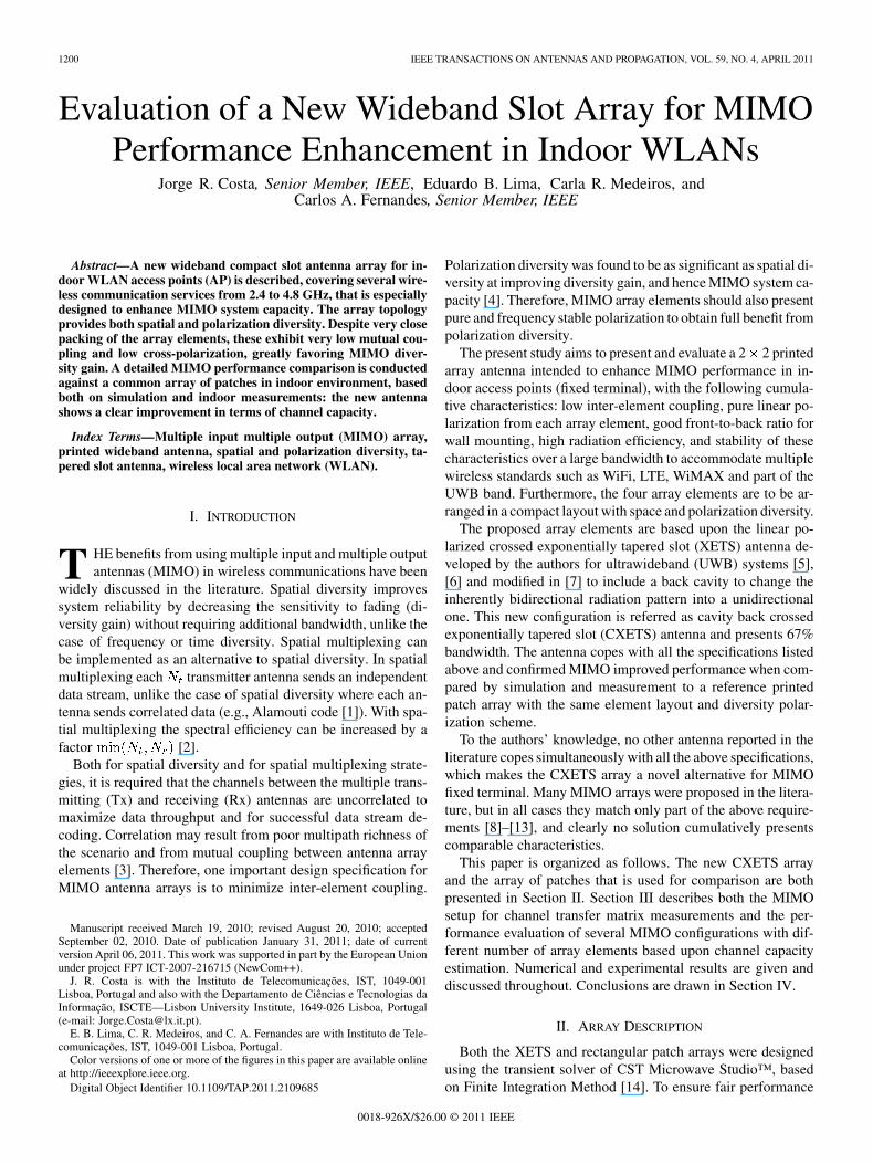
Fig. 1. (a) Photograph of the assembled CXETS array prototype, showing theantenna top face; (b) Disassembled antenna showing the FR4 cavity back andthe feeding coaxial cables soldered on the XETS back petals.
comparison between both arrays, they were designed to havesimilar aperture area.
A. CXETS Array
The crossed exponentially tapered slot (XETS) antenna con-figuration was developed by the authors for UWB systems [5],[6]. It is compact, with stable radiation pattern, low cross-polar-ization and low mutual coupling when packed in a closed arrayconfiguration. However, the radiation pattern is bidirectional. Toproduce a unidirectional radiation pattern, a single antenna wasredesigned to include a grid back cavity [7]. This new configu-ration is onwards referred as the CXETS.
The XETS elements are printed on both sides of DUROID5880 substrate, and thickness
mm. The top face of the four radiatingelements is shown in Fig. 1(a) and the back face, with thefeeding coaxial cables, is shown in Fig. 1(b). These are smalldiameter EZ-47 semi-rigid coaxial cables (1.19 mm diameter),soldered between two replicas of opposing petals from the frontface of each XETS, Fig. 1(b). The RF signal is capacitivelycoupled to the corresponding front petals of each antenna. Thefed petals define the E-plane of each XETS. It was verified thatcommon-mode currents resulting from the unbalanced feedingare low in this assembly and do not perturb significantly theexpected balanced antenna performance. It is seen in Fig. 1(b)that adjacent elements have orthogonal orientation, so, orthog-onal polarization.
The meshed cavity walls are printed on FR4 substrate,and thickness mm. The mesh
is uniform, with 6 mm step. This is a compromise value foundthrough CST simulation that allows retaining a reasonable partof the original antenna bandwidth (now 2.4 to 4.8 GHz) and at
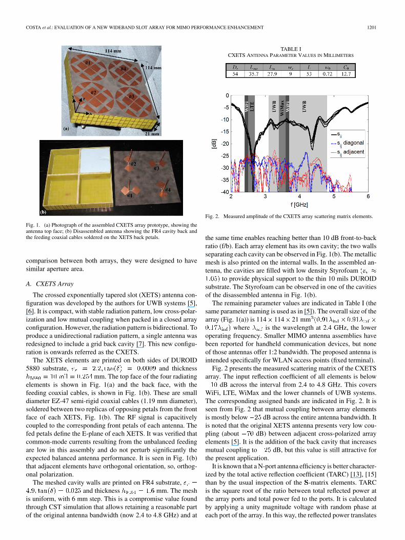
TABLE ICXETS ANTENNA PARAMETER VALUES IN MILLIMETERS
Fig. 2. Measured amplitude of the CXETS array scattering matrix elements.
the same time enables reaching better than 10 dB front-to-backratio (f/b). Each array element has its own cavity; the two wallsseparating each cavity can be observed in Fig. 1(b). The metallicmesh is also printed on the internal walls. In the assembled an-tenna, the cavities are filled with low density Styrofoam
to provide physical support to the thin 10 mils DUROIDsubstrate. The Styrofoam can be observed in one of the cavitiesof the disassembled antenna in Fig. 1(b).
The remaining parameter values are indicated in Table I (thesame parameter naming is used as in [5]). The overall size of thearray (Fig. 1(a)) is 114 114 21 mm
where is the wavelength at 2.4 GHz, the loweroperating frequency. Smaller MIMO antenna assemblies havebeen reported for handheld communication devices, but noneof those antennas offer 1:2 bandwidth. The proposed antenna isintended specifically for WLAN access points (fixed terminal).
Fig. 2 presents the measured scattering matrix of the CXETSarray. The input reflection coefficient of all elements is below
dB across the interval from 2.4 to 4.8 GHz. This coversWiFi, LTE, WiMax and the lower channels of UWB systems.The corresponding assigned bands are indicated in Fig. 2. It isseen from Fig. 2 that mutual coupling between array elementsis mostly below dB across the entire antenna bandwidth. Itis noted that the original XETS antenna presents very low cou-pling (about dB) between adjacent cross-polarized arrayelements [5]. It is the addition of the back cavity that increasesmutual coupling to dB, but this value is still attractive forthe present application.
It is known that a N-port antenna efficiency is better character-ized by the total active reflection coefficient (TARC) [13], [15]than by the usual inspection of the -matrix elements. TARCis the square root of the ratio between total reflected power atthe array ports and total power fed to the ports. It is calculatedby applying a unity magnitude voltage with random phase ateach port of the array. In this way, the reflected power translates
1202 IEEE TRANSACTIONS ON ANTENNAS AND PROPAGATION, VOL. 59, NO. 4, APRIL 2011
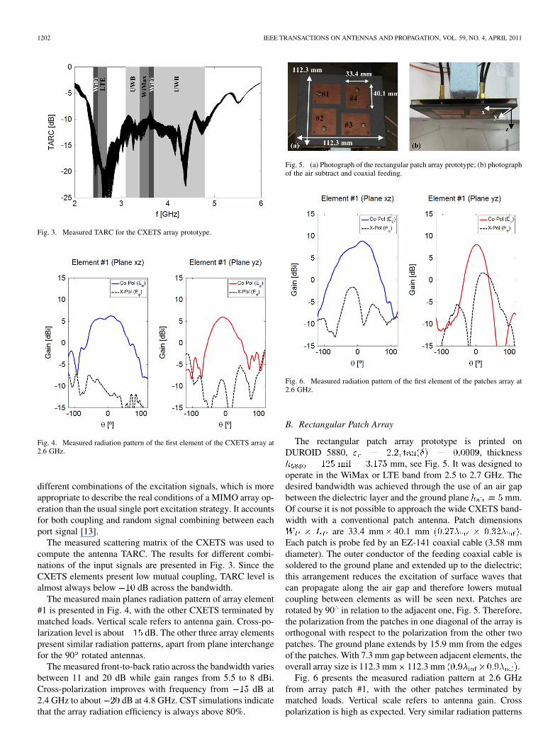
Fig. 3. Measured TARC for the CXETS array prototype.
Fig. 4. Measured radiation pattern of the first element of the CXETS array at2.6 GHz.
different combinations of the excitation signals, which is moreappropriate to describe the real conditions of a MIMO array op-eration than the usual single port excitation strategy. It accountsfor both coupling and random signal combining between eachport signal [13].
The measured scattering matrix of the CXETS was used tocompute the antenna TARC. The results for different combi-nations of the input signals are presented in Fig. 3. Since theCXETS elements present low mutual coupling, TARC level isalmost always below dB across the bandwidth.
The measured main planes radiation pattern of array element#1 is presented in Fig. 4, with the other CXETS terminated bymatched loads. Vertical scale refers to antenna gain. Cross-po-larization level is about dB. The other three array elementspresent similar radiation patterns, apart from plane interchangefor the 90 rotated antennas.
The measured front-to-back ratio across the bandwidth variesbetween 11 and 20 dB while gain ranges from 5.5 to 8 dBi.Cross-polarization improves with frequency from dB at2.4 GHz to about dB at 4.8 GHz. CST simulations indicatethat the array radiation efficiency is always above 80%.
Fig. 5. (a) Photograph of the rectangular patch array prototype; (b) photographof the air subtract and coaxial feeding.
Fig. 6. Measured radiation pattern of the first element of the patches array at2.6 GHz.
B. Rectangular Patch Array
The rectangular patch array prototype is printed onDUROID 5880, , thickness
mm, see Fig. 5. It was designed tooperate in the WiMax or LTE band from 2.5 to 2.7 GHz. Thedesired bandwidth was achieved through the use of an air gapbetween the dielectric layer and the ground plane mm.Of course it is not possible to approach the wide CXETS band-width with a conventional patch antenna. Patch dimensions
are 33.4 mm 40.1 mm .Each patch is probe fed by an EZ-141 coaxial cable (3.58 mmdiameter). The outer conductor of the feeding coaxial cable issoldered to the ground plane and extended up to the dielectric;this arrangement reduces the excitation of surface waves thatcan propagate along the air gap and therefore lowers mutualcoupling between elements as will be seen next. Patches arerotated by 90 in relation to the adjacent one, Fig. 5. Therefore,the polarization from the patches in one diagonal of the array isorthogonal with respect to the polarization from the other twopatches. The ground plane extends by 15.9 mm from the edgesof the patches. With 7.3 mm gap between adjacent elements, theoverall array size is 112.3 mm 112.3 mm .
Fig. 6 presents the measured radiation pattern at 2.6 GHzfrom array patch #1, with the other patches terminated bymatched loads. Vertical scale refers to antenna gain. Crosspolarization is high as expected. Very similar radiation patterns
COSTA et al.: EVALUATION OF A NEW WIDEBAND SLOT ARRAY FOR MIMO PERFORMANCE ENHANCEMENT 1203
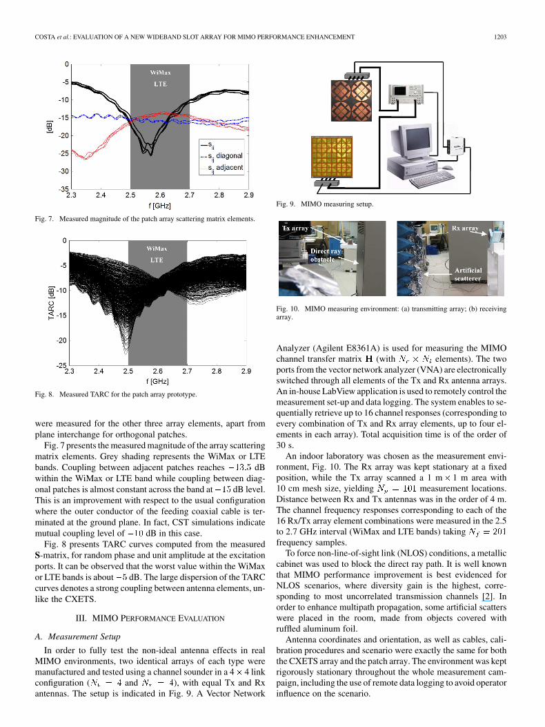
Fig. 7. Measured magnitude of the patch array scattering matrix elements.
Fig. 8. Measured TARC for the patch array prototype.
were measured for the other three array elements, apart fromplane interchange for orthogonal patches.
Fig. 7 presents the measured magnitude of the array scatteringmatrix elements. Grey shading represents the WiMax or LTEbands. Coupling between adjacent patches reaches dBwithin the WiMax or LTE band while coupling between diag-onal patches is almost constant across the band at dB level.This is an improvement with respect to the usual configurationwhere the outer conductor of the feeding coaxial cable is ter-minated at the ground plane. In fact, CST simulations indicatemutual coupling level of dB in this case.
Fig. 8 presents TARC curves computed from the measuredS-matrix, for random phase and unit amplitude at the excitationports. It can be observed that the worst value within the WiMaxor LTE bands is about dB. The large dispersion of the TARCcurves denotes a strong coupling between antenna elements, un-like the CXETS.
III. MIMO PERFORMANCE EVALUATION
A. Measurement Setup
In order to fully test the non-ideal antenna effects in realMIMO environments, two identical arrays of each type weremanufactured and tested using a channel sounder in a 4 4 linkconfiguration ( and ), with equal Tx and Rxantennas. The setup is indicated in Fig. 9. A Vector Network
Fig. 9. MIMO measuring setup.
Fig. 10. MIMO measuring environment: (a) transmitting array; (b) receivingarray.
Analyzer (Agilent E8361A) is used for measuring the MIMOchannel transfer matrix (with elements). The twoports from the vector network analyzer (VNA) are electronicallyswitched through all elements of the Tx and Rx antenna arrays.An in-house LabView application is used to remotely control themeasurement set-up and data logging. The system enables to se-quentially retrieve up to 16 channel responses (corresponding toevery combination of Tx and Rx array elements, up to four el-ements in each array). Total acquisition time is of the order of30 s.
An indoor laboratory was chosen as the measurement envi-ronment, Fig. 10. The Rx array was kept stationary at a fixedposition, while the Tx array scanned a 1 m 1 m area with10 cm mesh size, yielding measurement locations.Distance between Rx and Tx antennas was in the order of 4 m.The channel frequency responses corresponding to each of the16 Rx/Tx array element combinations were measured in the 2.5to 2.7 GHz interval (WiMax and LTE bands) takingfrequency samples.
To force non-line-of-sight link (NLOS) conditions, a metalliccabinet was used to block the direct ray path. It is well knownthat MIMO performance improvement is best evidenced forNLOS scenarios, where diversity gain is the highest, corre-sponding to most uncorrelated transmission channels [2]. Inorder to enhance multipath propagation, some artificial scatterswere placed in the room, made from objects covered withruffled aluminum foil.
Antenna coordinates and orientation, as well as cables, cali-bration procedures and scenario were exactly the same for boththe CXETS array and the patch array. The environment was keptrigorously stationary throughout the whole measurement cam-paign, including the use of remote data logging to avoid operatorinfluence on the scenario.
1204 IEEE TRANSACTIONS ON ANTENNAS AND PROPAGATION, VOL. 59, NO. 4, APRIL 2011
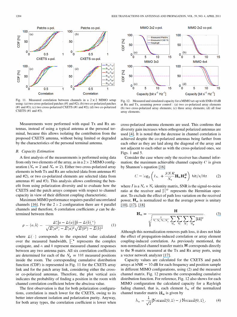
Fig. 11. Measured correlation between channels in a 2� 2 MIMO setupusing: (a) two cross-polarized patches (#1 and #2); (b) two co-polarized patches(#1 and #3); (c) two cross-polarized CXETS (#1 and #2); (d) two co-polarizedCXETS (#1 and #3).
Measurements were performed with equal Tx and Rx an-tennas, instead of using a typical antenna at the personal ter-minal, because this allows isolating the contribution from theproposed CXETS antenna, without being limited or degradedby the characteristics of the personal terminal antenna.
B. Capacity Estimation
A first analysis of the measurements is performed using datafrom only two elements of the array, as in a 2 2 MIMO config-uration ( and ). Either two cross-polarized arrayelements in both Tx and Rx are selected (data from antennas #1and #2), or two co-polarized elements are selected (data fromantennas #1 and #3). This analysis allows confirming the ben-efit from using polarization diversity and to evaluate how theCXETS and the patch arrays compare with respect to channelcapacity in view of their different coupling characteristic.
Maximum MIMO performance requires parallel uncorrelatedchannels [16]. For the 2 2 configuration there are 4 parallelchannels and therefore, 6 correlation coefficients can be de-termined between them
(1)
where corresponds to the expected value calculatedover the measured bandwidth, represents the complexconjugate, and and represent measured channel responsesbetween any two antenna pairs. All six correlation coefficientsare determined for each of the measured positionsinside the room. The corresponding cumulative distributionfunction (CDF) is represented in Fig. 11 for the CXETS arraylink and for the patch array link, considering either the cross-or co-polarized antennas. Therefore, the plot vertical axisindicates the probability of finding a position in the room withchannel correlation coefficient below the abscissa value.
The first observation is that for both polarization configura-tions, correlation is much lower for the CXETS, owing to itsbetter inter-element isolation and polarization purity. Anyway,for both array types, the correlation coefficient is lower when
Fig. 12. Measured and simulated capacity for a MIMO set-up with SNR=10 dBat Rx and Tx, assuming power control : (a) two co-polarized array elements(b) two cross-polarized array elements; (c) three array elements; (d) all fourarray elements.
cross-polarized antenna elements are used. This confirms thatdiversity gain increases when orthogonal polarized antennas areused [4]. It is noted that the decrease in channel correlation isachieved despite the co-polarized antennas being farther fromeach other as they are laid along the diagonal of the array andnot adjacent to each other as with the cross-polarized ones, seeFigs. 1 and 5.
Consider the case where only the receiver has channel infor-mation; the maximum achievable channel capacity is givenby Shannon’s equation [16]
(2)
where is a identity matrix, SNR is the signal-to-noiseratio at the receiver and represents the Hermitian oper-ator. To exclude the effect of path loss variation on the receivedpower, is normalized so that the average power is unitary[10], [17], [18]
(3)
Although this normalization removes path loss, it does not hidethe effect of propagation-induced correlation or array elementcoupling-induced correlation. As previously mentioned, thenon-normalized channel transfer matrix corresponds directlyto the -matrix measured at the Tx and Rx array ports, usinga vector network analyzer [17].
Capacity values are calculated for the CXETS and patcharrays at dB for each frequency and position samplein different MIMO configurations, using (2) and the measuredchannel matrix. Fig. 12 presents the corresponding cumulativedistribution function. For reference, Fig. 12 also shows for eachMIMO configuration the calculated capacity for a Rayleighfading channel, that is, each element of the normalizedchannel transfer matrix is given by
(4)
COSTA et al.: EVALUATION OF A NEW WIDEBAND SLOT ARRAY FOR MIMO PERFORMANCE ENHANCEMENT 1205
TABLE IICAPACITY VALUES FOR 50% PROBABILITY
where is an independent and identically dis-tributed (i.i.d.) value with Gaussian distribution function, zeromean and unit variance . This corresponds to totallyuncorrelated channels.
Capacity improvement from the CXETS array against thearray of patches is more evident for higher order MIMO configu-rations (Fig. 12(c)–(d)). This is clearer when comparing mediancapacity values (dashed horizontal line in Fig. 12). The resultsfor each type of array are indicated in Table II along with theratio between the capacity obtained from measured channel dataand the capacity calculated for completely independent chan-nels (Rayleigh curves).
Table II shows that due to antenna mutual coupling andchannel correlation, capacity does not scale linearly withnumber of channels as would be expected if they were inde-pendent [16]. In fact, the detrimental effect of mutual couplingon capacity increases with the number of array elements [15].However it is clear in all cases the importance of better isolationand polarization purity of the CXETS.
These results assume that the system uses power control tofix SNR at constant 10 dB level. Otherwise, in environmentswith poor multipath richness, configuration #b will tend to re-ceive in average more power than configuration #a. If we wantto alternatively compare capacity for constant Tx power, we canconsider for all cases of Table II the complete measured channeltransfer matrix in the normalization (3) andextract afterwards the sub-matrixes from corresponding toeach configuration [18]. For configuration #a, this leads insteadto 4.57 bit/s/Hz for the patch array and 5.18 bit/s/Hz for theCXETS array, which is not very different from the fixed SNRcase thanks to the richness of the tested scenario. As could beexpected, the other array configurations capacity remains prac-tically unchanged.
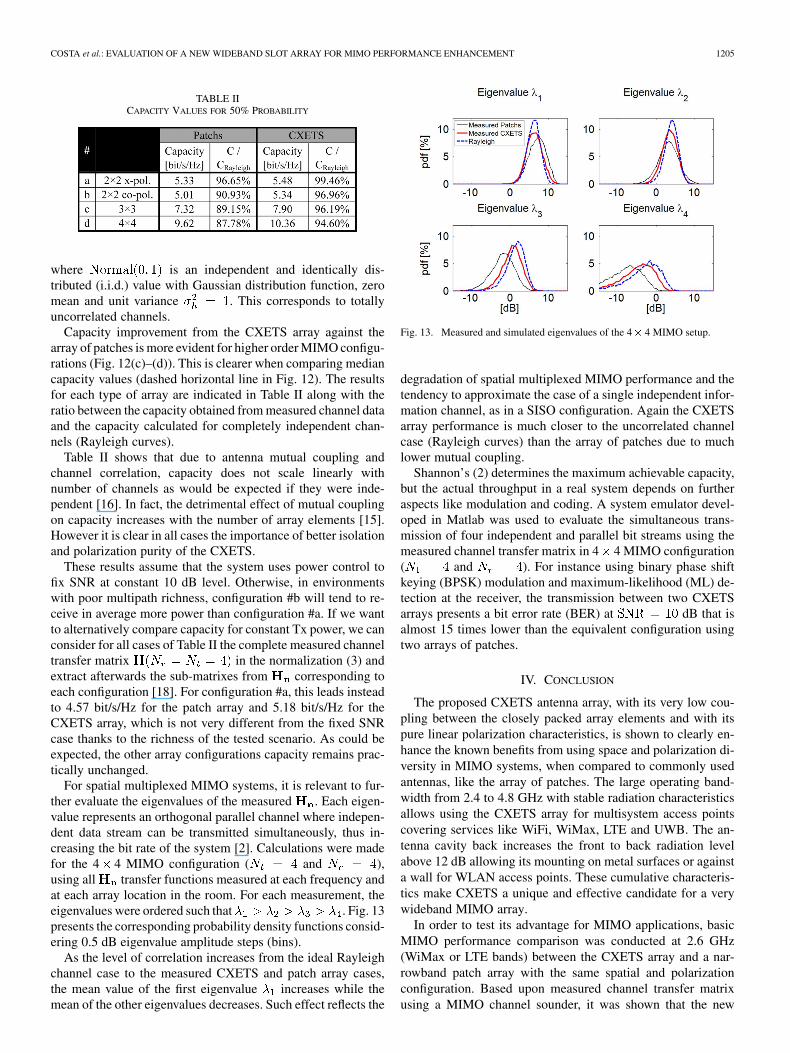
For spatial multiplexed MIMO systems, it is relevant to fur-ther evaluate the eigenvalues of the measured . Each eigen-value represents an orthogonal parallel channel where indepen-dent data stream can be transmitted simultaneously, thus in-creasing the bit rate of the system [2]. Calculations were madefor the 4 4 MIMO configuration ( and ),using all transfer functions measured at each frequency andat each array location in the room. For each measurement, theeigenvalues were ordered such that . Fig. 13presents the corresponding probability density functions consid-ering 0.5 dB eigenvalue amplitude steps (bins).
As the level of correlation increases from the ideal Rayleighchannel case to the measured CXETS and patch array cases,the mean value of the first eigenvalue increases while themean of the other eigenvalues decreases. Such effect reflects the
Fig. 13. Measured and simulated eigenvalues of the 4� 4 MIMO setup.
degradation of spatial multiplexed MIMO performance and thetendency to approximate the case of a single independent infor-mation channel, as in a SISO configuration. Again the CXETSarray performance is much closer to the uncorrelated channelcase (Rayleigh curves) than the array of patches due to muchlower mutual coupling.
Shannon’s (2) determines the maximum achievable capacity,but the actual throughput in a real system depends on furtheraspects like modulation and coding. A system emulator devel-oped in Matlab was used to evaluate the simultaneous trans-mission of four independent and parallel bit streams using themeasured channel transfer matrix in 4 4 MIMO configuration( and ). For instance using binary phase shiftkeying (BPSK) modulation and maximum-likelihood (ML) de-tection at the receiver, the transmission between two CXETSarrays presents a bit error rate (BER) at dB that isalmost 15 times lower than the equivalent configuration usingtwo arrays of patches.
IV. CONCLUSION
The proposed CXETS antenna array, with its very low cou-pling between the closely packed array elements and with itspure linear polarization characteristics, is shown to clearly en-hance the known benefits from using space and polarization di-versity in MIMO systems, when compared to commonly usedantennas, like the array of patches. The large operating band-width from 2.4 to 4.8 GHz with stable radiation characteristicsallows using the CXETS array for multisystem access pointscovering services like WiFi, WiMax, LTE and UWB. The an-tenna cavity back increases the front to back radiation levelabove 12 dB allowing its mounting on metal surfaces or againsta wall for WLAN access points. These cumulative characteris-tics make CXETS a unique and effective candidate for a verywideband MIMO array.
In order to test its advantage for MIMO applications, basicMIMO performance comparison was conducted at 2.6 GHz(WiMax or LTE bands) between the CXETS array and a nar-rowband patch array with the same spatial and polarizationconfiguration. Based upon measured channel transfer matrixusing a MIMO channel sounder, it was shown that the new
1206 IEEE TRANSACTIONS ON ANTENNAS AND PROPAGATION, VOL. 59, NO. 4, APRIL 2011
array increases channel capacity, better approaching the ideallimit for completely uncorrelated channels.
Although all MIMO performance tests were conducted onlyat the lower fraction of the CXETS available bandwidth, it is ex-pected that the overall performance will improve further for therest of the band. In fact, while the antenna radiation characteris-tics remain almost unchanged across the whole band, for higherfrequencies the separation between CXETS array elements be-comes larger in terms of the operating wavelength and, there-fore, the channels between transmit and receive antennas areexpected to become more uncorrelated.
ACKNOWLEDGMENT
The authors acknowledge the collaboration from V. Fred andC. Brito for prototype construction, and A. Almeida for proto-type measurements.
REFERENCES
[1] S. M. Alamouti, “A simple transmit diversity technique for wire-less communications,” IEEE J. Sel. Areas Commun., vol. 16, pp.1451–1458, Oct. 1998.
[2] D. Tse and P. Viswanath, Fundamentals of Wireless Communication.Cambridge, U.K.: Cambridge Univ. Press, 2005.
[3] R. Janaswamy, “Effect of element mutual coupling on the capacity offixed length linear arrays,” IEEE Antennas Wireless Propag. Lett., vol.1, pp. 157–160, 2002.
[4] J. Valenzuela-Valdés, M. García-Fernández, A. Martínez-González,and D. Sánchez-Hernández, “The role of polarization diversity forMIMO systems under Rayleigh-fading environments,” IEEE AntennasWireless Propag. Lett., vol. 5, pp. 534–536, 2006.
[5] J. Costa, C. Medeiros, and C. Fernandes, “Performance of a crossed ex-ponentially tapered slot antenna for UWB systems,” IEEE Trans. An-tennas Propag., vol. 57, pp. 1345–1352, May 2009.
[6] C. Medeiros, J. Costa, and C. Fernandes, “Compact tapered slot UWBantenna with WLAN band rejection,” IEEE Antennas Wireless Propag.Lett., vol. 8, pp. 661–664, 2009.
[7] C. Medeiros, E. Lima, J. Costa, and C. Fernandes, “Wideband slot an-tenna for WLAN access points,” IEEE Antennas Wireless Propag. Lett.,vol. 9, pp. 79–82, 2010.
[8] R. Bhatti, J. Choi, and S. Park, “Quad-band MIMO antenna array forportable wireless communications terminals,” IEEE Antennas WirelessPropag. Lett., vol. 8, pp. 129–132, 2009.
[9] H. Li, J. Xiong, and S. He, “Extremely compact dual-band PIFAs forMIMO application,” Electronics Lett., vol. 45, pp. 869–870, Aug. 2009.
[10] A. Rajagopalan, G. Gupta, A. Konanur, B. Hughes, and G. Lazzi,“Increasing channel capacity of an ultrawideband MIMO systemusing vector antennas,” IEEE Trans. Antennas Propag., vol. 55, pp.2880–2887, Oct. 2007.
[11] S. Zhang, Z. Ying, J. Xiong, and S. He, “Ultrawideband MIMO/diver-sity antennas with a tree-like structure to enhance wideband isolation,”IEEE Antennas Wireless Propag. Lett., vol. 8, pp. 1279–1282, 2009.
[12] S. Zhang, P. Zetterberg, and S. He, “Printed MIMO antenna system offour closely-spaced elements with large bandwidth and high isolation,”Electron. Lett., vol. 46, pp. 1052–1053, Jul. 2010.
[13] M. Manteghi and Y. Rahmat-Samii, “Multiport characteristics of awide-band cavity backed annular patch antenna for multipolarizationoperations,” IEEE Trans. Antennas Propag., vol. 53, pp. 466–474, Jan.2005.
[14] CST [Online]. Available: www.cst.com[15] D. Browne, M. Manteghi, M. Fitz, and Y. Rahmat-Samii, “Experiments
with compact antenna arrays for MIMO radio communications,” IEEETrans. Antennas Propag., vol. 54, pp. 3239–3250, Nov. 2006.
[16] G. Foschini and M. Gans, “On limits of wireless communications in afading environment when using multiple antennas,” Wireless PersonalCommun., vol. 6, pp. 311–335, 1998.
[17] M. Herdin, H. Ozcelik, H. Hofstetter, and E. Bonek, “Variation of mea-sured indoor MlMO capacity with receive direction and position at 5.2GHz,” Electron. Lett., vol. 38, pp. 1283–1285, Oct. 2002.
[18] J. Wallace, M. Jensen, A. Swindlehurst, and B. Jeffs, “Experimentalcharacterization of the MIMO wireless channel: Data acquisition andanalysis,” IEEE Trans. Wireless Commun., vol. 2, pp. 335–343, Mar.2003.
Jorge R. Costa (S’97–M’03–SM’09) was born inLisbon, Portugal, in 1974. He received the Licen-ciado and Ph.D. degrees in electrical and computerengineering from the Instituto Superior Técnico(IST), Technical University of Lisbon, Lisbon,Portugal, in 1997 and 2002, respectively.
He is currently a Researcher at the Instituto deTelecomunicações, Lisbon, Portugal. He is also anAssistant Professor at the Departamento de Ciênciase Tecnologias da Informação, Instituto Superior deCiências do Trabalho e da Empresa. His present
research interests include lenses, reconfigurable antennas, MEMS switches,UWB, MIMO and RFID antennas. He is the coauthor of four patent applicationsand more than 50 contributions to peer reviewed journals and internationalconference proceedings. More than ten of these papers have appeared in IEEEJournals.
Prof. Costa is currently serving as an Associate Editor for the IEEETRANSACTIONS ON ANTENNAS AND PROPAGATION.
Eduardo B. Lima was born in Viseu, Portugal, in1978. He received the Licenciado and M.Sc. degreesin electrical and computer engineering from the In-stituto Superior Técnico (IST), Lisbon, Portugal, in2003 and 2008, respectively.
He is a Researcher and also the software developerfor antenna measurements control at the Instituto deTelecomunicações, Lisbon, Portugal. From 2004 to2007, he was involved on the ESA/ESTEC projectILASH (Integrated Lens Antenna Shaping). He is thecoauthor of one patent application and twelve tech-
nical papers in international journals and conference proceedings in the areaof antennas. His present research interests include dielectric lens antennas andMIMO.
Carla R. Medeiros was born in Ponta Delgada,Açores, Portugal, in 1982. She received the Licen-ciado and M.Sc. degrees in electrical and computerengineering from the Instituto Superior Técnico(IST), Technical University of Lisbon, Lisbon,Portugal, in 2006 and 2007, respectively.
Since 2006, she has been a Researcher at the In-stituto de Telecomunicações (IT), focusing her workon antenna for wireless communications. She col-laborates in national research projects. Her currentresearch interests are in the areas of reconfigurable,
RFID, MIMO and UWB antennas.
Carlos A. Fernandes (S’86–M’89–SM’08) re-ceived the Licenciado, M.Sc., and Ph.D. degrees inelectrical and computer engineering from InstitutoSuperior Técnico (IST), Technical University ofLisbon, Lisbon, Portugal, in 1980, 1985, and 1990,respectively.
He joined the IST in 1980, where he is presentlyFull Professor at the Department of Electrical andComputer Engineering in the areas of microwaves,radio wave propagation and antennas. He is a SeniorResearcher at the Instituto de Telecomunicações and
member of the Board of Directors. He has been the Leader of antenna activitiesin National and European Projects as RACE 2067—MBS (Mobile BroadbandSystem), ACTS AC230—SAMBA (System for Advanced Mobile BroadbandApplications) and ESA/ESTEC—ILASH (Integrated Lens Antenna Shaping).He has coauthored a book, a book chapter, and more than 120 technical papersin peer reviewed international journals and conference proceedings, in the areasof antennas and radiowave propagation modeling. His current research inter-ests include dielectric antennas for millimeter wave applications, antennas andpropagation modeling for personal communication systems, RFID antennas, ar-tificial dielectrics and metamaterials.