Ethylene Flame Dynamics and Inlet Unstart in a Model Scramjet
9
Ethylene Flame Dynamics and Inlet Unstart in a Model Scramjet Qili Liu ∗ University of Notre Dame, Notre Dame, Indiana 46556-5684 Andrea Passaro † Alta, S.p.A., 56121 Pisa, Italy and Damiano Baccarella ∗ and Hyungrok Do ‡ University of Notre Dame, Notre Dame, Indiana 46556 DOI: 10.2514/1.B35214 Ethylene flame dynamics in a model scramjet installed in an open test section of an arc-heated hypersonic wind tunnel are experimentally investigated with freestreams of Mach 4.5–9. An ethylene fuel jet is injected into the model scramjet that is autoignited by high-enthalpy flows compressed and decelerated by a train of shock waves and boundary layers developing in the scramjet isolator/combustor. The ethylene flame behavior is captured by a high- speed movie camera through optical access windows on the model and characterized by surface pressure/temperature traces recorded at five different locations along the flowpath through the model scramjet. Downstream pressure buildup due to combustion heat release, shock-induced compression, and mass loading via the fuel jet triggers the flame propagation toward upstream, stabilizes the flame at a location in the combustor, or pushes the flame further upstream to cause inlet unstart. In particular, flame dynamics while the scramjet undergoes the inlet unstart with Mach 4.5 freestreams are investigated intensively. In addition, stagnation temperature, overall fuel concentration, and oxygen concentration in freestream flows are varied to investigate their influences on the flame dynamics. The flame propagates faster and anchors further upstream with increased total temperature, oxygen enrichment, and overall equivalence ratio slightly above unity. Nomenclature M = Mach number P = static pressure P 0 = stagnation pressure T = surface temperature T 0 = stagnation temperature U l = local flow speed U p = flame propagation speed (absolute speed) ϕ = overall equivalence ratio I. Introduction R ECENTLY developed aircrafts powered by scramjet engines have achieved hypersonic flights using combustion reactions occurring in supersonic flows [1]. Therefore, stabilization of the combustion reactions in scramjets has been one of the most critical issues in developing the next generation of airbreathing propulsion system. For the combustion stabilization, the flame propagation speed U p needs to be balanced with the local flow speed U l in the region adjacent to the flame location, so that the flame anchors at a location in a supersonic combustor. Otherwise, the flame will be blown out (U p < U l ), propagate further upstream toward an inlet, or cause “inlet unstart” (U p >U l ). The inlet unstart, often leading to in- flight engine failure, is caused by thermal choking of supersonic internal flows in scramjets triggered by increased heat release in combustors, which has been most frequently observed during the transition of ramjet-to-scramjet mode in a flight Mach number range of 3–6 [2–6]. Because the inlet unstart has been regarded as one of the most critical potential causes of scramjet malfunctioning, the flame dynamics in the model scramjet are investigated with a focus on the inlet unstart mechanism at Mach 4.5 flight conditions in this study. Numerous studies investigating scramjet flow/flame dynamics and inlet unstart mechanisms have used ground test facilities that are capable of partially reproducing scramjet flight conditions of high Mach number and high-enthalpy flows [7–15]. For example, unsteady shock systems appearing in unstarted flows were inves- tigated in low-enthalpy and high Mach number flows [7–10]. These unsteady shock systems that propagate upstream toward an inlet to cause inlet unstart were observed in choked flows induced by a downstream flow blockage [7,8] or excessive mass loading via jet injections [9,10]. Although it was shown that the unsteady shock system plays an important role in the inlet unstart processes, the behavior of the shock systems could not be directly correlated with that of thermal-choking-induced flow/shock structures appearing in actual scramjets. This is primarily due to the limitation of test facilities that are incapable of sustaining combustion reactions (low enthalpy). Otherwise, shock tunnels [11,12] and expansion tubes [13–15] can provide high-enthalpy flows, although their test times are not sufficient (typically less than a few milliseconds) to reveal the unstart mechanism; propagations of the unsteady shock systems or flames through scramjets take tens of milliseconds [9,10]. Con- tinuous or quasi-continuous arc-heated hypersonic wind tunnels provide high-enthalpy and high Mach number flows for a sufficiently long time period [4]. Nevertheless, a model (e.g., model scramjet) in the test section of the continuous arc tunnels does not allow optical access, primarily due to thermal expansion of the model damaging optical access windows. The reduced test time (approximately 1 s) in a pulsed-arc-heated facility used in this study minimizes the thermal expansion to allow optical accesses through the model scramjet. In this study, we have used a pulsed-arc-heated hypersonic wind tunnel capable of generating Mach 4.5, 6, and 9 flows with up to 4500 K stagnation temperature during a test time of maximum 1 s, which includes only the time duration while freestreams in the test section are in steady state. Typical test times used in this study are between 500 and 800 ms, which is much longer than the characteristic timescale of inlet unstart (tens of milliseconds [9,10]) and the time required to reach steady state with stabilized flames (at most, 200 ms in this study). The pulsed-arc-heated system is newly designed to vary freestream gas composition, minimize NO x production in the Received 16 October 2013; revision received 4 February 2014; accepted for publication 6 February 2014; published online 27 May 2014. Copyright © 2014 by the American Institute of Aeronautics and Astronautics, Inc. All rights reserved. Copies of this paper may be made for personal or internal use, on condition that the copier pay the $10.00 per-copy fee to the Copyright Clearance Center, Inc., 222 Rosewood Drive, Danvers, MA 01923; include the code 1533-3876/14 and $10.00 in correspondence with the CCC. *Ph.D. Student, Department of Aerospace and Mechanical Engineering. † Project Manager, Via A. Gherardesca 5. Member AIAA. ‡ Assistant Professor, Department of Aerospace and Mechanical Engineer- ing. Member AIAA. 1577 JOURNAL OF PROPULSION AND POWER Vol. 30, No. 6, November–December 2014 Downloaded by UNIVERSITY OF NOTRE DAME on November 22, 2014 | http://arc.aiaa.org | DOI: 10.2514/1.B35214
Transcript of Ethylene Flame Dynamics and Inlet Unstart in a Model Scramjet
Ethylene Flame Dynamics and Inlet Unstart in a Model Scramjet
Qili Liu∗
University of Notre Dame, Notre Dame, Indiana 46556-5684
Andrea Passaro†
Alta, S.p.A., 56121 Pisa, Italy
and
Damiano Baccarella∗ and Hyungrok Do‡
University of Notre Dame, Notre Dame, Indiana 46556
DOI: 10.2514/1.B35214
Ethylene flame dynamics in a model scramjet installed in an open test section of an arc-heated hypersonic wind
tunnel are experimentally investigated with freestreams ofMach 4.5–9. An ethylene fuel jet is injected into the model
scramjet that is autoignited by high-enthalpy flows compressed and decelerated by a train of shock waves and
boundary layers developing in the scramjet isolator/combustor. The ethylene flame behavior is captured by a high-
speedmovie camera throughoptical accesswindowson themodel and characterizedby surfacepressure/temperature
traces recorded at five different locations along the flowpath through the model scramjet. Downstream pressure
buildup due to combustion heat release, shock-induced compression, and mass loading via the fuel jet triggers the
flame propagation toward upstream, stabilizes the flame at a location in the combustor, or pushes the flame further
upstream to cause inlet unstart. In particular, flame dynamics while the scramjet undergoes the inlet unstart with
Mach 4.5 freestreams are investigated intensively. In addition, stagnation temperature, overall fuel concentration,
and oxygen concentration in freestream flows are varied to investigate their influences on the flame dynamics. The
flame propagates faster and anchors further upstream with increased total temperature, oxygen enrichment, and
overall equivalence ratio slightly above unity.
Nomenclature
M = Mach numberP = static pressureP0 = stagnation pressureT = surface temperatureT0 = stagnation temperatureUl = local flow speedUp = flame propagation speed (absolute speed)ϕ = overall equivalence ratio
I. Introduction
R ECENTLY developed aircrafts powered by scramjet engineshave achieved hypersonic flights using combustion reactions
occurring in supersonic flows [1]. Therefore, stabilization of thecombustion reactions in scramjets has been one of the most criticalissues in developing the next generation of airbreathing propulsionsystem. For the combustion stabilization, the flame propagationspeed Up needs to be balanced with the local flow speed Ul in theregion adjacent to the flame location, so that the flame anchors at alocation in a supersonic combustor. Otherwise, the flame will beblown out (Up < Ul), propagate further upstream toward an inlet, orcause “inlet unstart” (Up > Ul). The inlet unstart, often leading to in-flight engine failure, is caused by thermal choking of supersonicinternal flows in scramjets triggered by increased heat release incombustors, which has been most frequently observed during thetransition of ramjet-to-scramjet mode in a flight Mach number rangeof 3–6 [2–6]. Because the inlet unstart has been regarded as one of themost critical potential causes of scramjet malfunctioning, the flame
dynamics in the model scramjet are investigated with a focus on theinlet unstart mechanism at Mach 4.5 flight conditions in this study.Numerous studies investigating scramjet flow/flame dynamics and
inlet unstart mechanisms have used ground test facilities that arecapable of partially reproducing scramjet flight conditions of highMach number and high-enthalpy flows [7–15]. For example,unsteady shock systems appearing in unstarted flows were inves-tigated in low-enthalpy and high Mach number flows [7–10]. Theseunsteady shock systems that propagate upstream toward an inlet tocause inlet unstart were observed in choked flows induced by adownstream flow blockage [7,8] or excessive mass loading via jetinjections [9,10]. Although it was shown that the unsteady shocksystem plays an important role in the inlet unstart processes, thebehavior of the shock systems could not be directly correlated withthat of thermal-choking-induced flow/shock structures appearing inactual scramjets. This is primarily due to the limitation of testfacilities that are incapable of sustaining combustion reactions (lowenthalpy). Otherwise, shock tunnels [11,12] and expansion tubes[13–15] can provide high-enthalpy flows, although their test timesare not sufficient (typically less than a fewmilliseconds) to reveal theunstart mechanism; propagations of the unsteady shock systems orflames through scramjets take tens of milliseconds [9,10]. Con-tinuous or quasi-continuous arc-heated hypersonic wind tunnelsprovide high-enthalpy and highMach number flows for a sufficientlylong time period [4]. Nevertheless, a model (e.g., model scramjet) inthe test section of the continuous arc tunnels does not allow opticalaccess, primarily due to thermal expansion of the model damagingoptical access windows. The reduced test time (approximately 1 s) ina pulsed-arc-heated facility used in this study minimizes the thermalexpansion to allow optical accesses through the model scramjet.In this study, we have used a pulsed-arc-heated hypersonic wind
tunnel capable of generating Mach 4.5, 6, and 9 flows with up to4500 K stagnation temperature during a test time of maximum 1 s,which includes only the time duration while freestreams in the testsection are in steady state. Typical test times used in this study arebetween 500 and 800ms,which ismuch longer than the characteristictimescale of inlet unstart (tens of milliseconds [9,10]) and the timerequired to reach steady state with stabilized flames (at most, 200 msin this study). The pulsed-arc-heated system is newly designed tovary freestream gas composition, minimize NOx production in the
Received 16October 2013; revision received4 February 2014; accepted forpublication 6 February 2014; published online 27 May 2014. Copyright ©2014 by the American Institute of Aeronautics and Astronautics, Inc. Allrights reserved. Copies of this paper may be made for personal or internal use,on condition that the copier pay the $10.00 per-copy fee to the CopyrightClearance Center, Inc., 222 Rosewood Drive, Danvers, MA 01923; includethe code 1533-3876/14 and $10.00 in correspondence with the CCC.
*Ph.D. Student, Department of Aerospace and Mechanical Engineering.†Project Manager, Via A. Gherardesca 5. Member AIAA.‡Assistant Professor, Department of Aerospace and Mechanical Engineer-
ing. Member AIAA.
1577
JOURNAL OF PROPULSION AND POWER
Vol. 30, No. 6, November–December 2014
Dow
nloa
ded
by U
NIV
ER
SIT
Y O
F N
OT
RE
DA
ME
on
Nov
embe
r 22
, 201
4 | h
ttp://
arc.
aiaa
.org
| D
OI:
10.
2514
/1.B
3521
4
intensive gas-heating unit, enhance arc stability in pure nitrogen, andprevent electrode oxidation. This new design is ideal for scramjetcombustion experiments requiring high-enthalpy and clean airflowsin a hypersonic regime. A model scramjet with an ethylene fuel jetinjector is installed in the test section (open-type test section) of thehypersonic facility to investigate the flame dynamics. The flamebehavior is investigated under the flow conditions inducing auto-flame-ignition with the shock-compressed high-enthalpy flows inthe model scramjet without any external ignition sources, such as aspark plug. The ethylene jet injected into themodel scramjet is mixedwith incoming flows through the scramjet isolator/combustor andautoignited at a location downstream of the fuel jet. Once an ethyleneflame is autoignited, unsteady/steady flame behaviors (e.g., inletunstart, flame propagation, and stabilization) can be resolved withwall pressure/temperature sensors and a movie camera imagingchemiluminescence of the ethylene flames.
II. Experimental Setup
A. Test Facility and Test Conditions
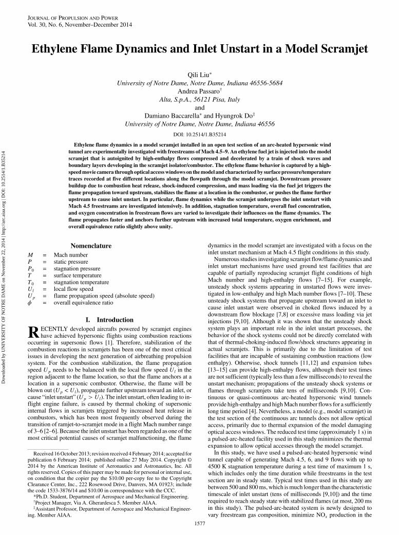
A novel pulsed-arc-heating system (Fig. 1) is designed to providehigh-enthalpy flows that expand through a converging/diverging(C∕D) nozzle into avacuumchamber accommodating the test sectionof the hypersonic facility. Two compressed gas supply tanks con-nected to the arc heater provide constant pressure gas flows throughan arc and into a gas-mixing chamber downstream of the arc,respectively. The compressed nitrogen injected via two gas injectionports located upstream of the arc is heated in the arc region, mixedwith oxygen in the mixing chamber downstream of the arc, andexpands through the C∕D nozzle. Gas composition of the mixtureescaping the arc-heating unit is controlled by gas pressures at theinjection ports (e.g., two nitrogen and two oxygen ports). This newarc-heater configuration is designed mainly to minimize NOxproduction,which affects flame dynamics (e.g.,NOx reduces ignitiondelay [16–18]). The new heater can prevent prompt NOx production
in the arc region while thermal NOx production in the mixingchamber will still be significant. The thermalNOx production can beeffectively minimized by reducing flow residence time in thechamber before the expansion into the vacuum chamber, whichlowers static mixture temperature rapidly. Multiple layers of theturbulent exciters are installed in the mixing chamber to facilitate gasmixing, however, estimated flow residence time (<10 ms) in it issufficiently short for significant reduction of thermalNOx production[19]. Except for the new arc-heating unit built for this combustionstudy, the facility employs the typical hypersonic facility design thathas been used over the past 10 years (e.g., spatial pitot pressuredistribution on the C∕D nozzle exit plane is relatively uniform withrandom variations of maximum 5% of mean value) [20–22]. The archeater is connected to a 260 kWdc power supply delivering current of630 A to produce flows of up to 6 MJ∕kg and 1 MPa (P0) at astagnation condition. A settling chamber upstream of theC∕D nozzlehas a pressure sensor and an optical access window for emissionspectroscopy to monitor the stagnant gas condition. The testcondition is repeatable within 2% variations in stagnation pressureand arc current/voltage.The hypersonic wind-tunnel facility implemented with the new
pulsed-arc-heater (Fig. 1) is used to generate Mach 4.5–9 flows ofvarious freestreamgas composition and total pressure/temperature. Aclean core flow area in the test section of the facility is approximately60–150 mm in diameter depending on C∕D nozzle geometries [20–22], which is large enough to accommodate the model scramjethaving 15 × 40 mm2 cross section. The axisymmetric C∕D nozzlesproduce gas flows at steady state in the test section for a test time of1 s. The stagnation temperature T0 of the freestream flow is variedfrom 1500 to 3500 K, which is a flow enthalpy range for autoignition(>1500K) of partially premixed flames downstream of the fuel jetwithout significant non-premixed flames on fuel jets. Total pressureis mostly fixed at or around 100 kPa with Mach 4.5 freestream flowsfor investigating influences of total temperature, freestream gascomposition, and fuel concentration; the pressure is increased forhigher Mach number flows. Fuel concentration that is controlled byfuel jet injection pressure (flow rate) is varied in awide range in termsof overall equivalence ratio ϕ � 0.2–5.5, in the model scramjet. Theoverall equivalence ratio is derived assuming that the injected fuel isperfectly mixed with the freestream flow captured by the inlet of themodel scramjet.
B. Test Model
Amodel scramjet (Fig. 2) installed in the hypersonicwind tunnel ismade of stainless steel, which is 600 mm in length with an internalflow channel of 15 × 40 mm (height × width) rectangular constantcross section. The inlet of the model consists of sharp leading edges;bottom and side lips are wedged outside and flat on internal surfacesto minimize shock induction into the internal flow channel (scramjetinlet/isolator/combustor). The angle of the inlet upper lip on theinternal surface is 6 or 12 deg (interchangeable) to produce anincident shock wave into the model scramjet; both the inlets (6 or12 deg) have the same flow capture area (entrance height of inlet19.3 mm). An oblique supersonic jet of 1.6 mm in diameter at thethroat expands through a diverging section of 22.5 deg divergentangle and 60 deg inclination toward downstream, which is located100mmdownstream from the inlet lip on the centerline of the bottomwall [the isolator (constant cross-sectional area) length is approxi-mately 80 mm with 12 deg inlet upper lip angle]. The exit of fuel jetnozzle on the scramjet surface is an ellipse, 5.9 × 5.0 mm. Theexpanding supersonic fuel jet is to extend the jet sweep area forfacilitating fuel/oxidizer mixing and, possibly, to avoid non-premixed flame ignition on thewindward side of the jet by increasingthe stretch rate on the jet. As shown in Fig. 2 (bottom left), a solenoidvalve controlling ethylene injection and a fuel reservoir maintainingconstant fuel pressure during the jet injection period are connected tothe fuel jet nozzle. The fuel pressure traces are recorded by a pressuresensor attached on the reservoir. Overall fuel equivalence ratio ϕ inthe combustor is estimated by the ratio of ethylene jet mass flow rateand freestream flow rate through the model scramjet. Awall cavity isFig. 1 Pulsed-arc-heating system a) schematic and b) picture.
1578 LIU ETAL.
Dow
nloa
ded
by U
NIV
ER
SIT
Y O
F N
OT
RE
DA
ME
on
Nov
embe
r 22
, 201
4 | h
ttp://
arc.
aiaa
.org
| D
OI:
10.
2514
/1.B
3521
4

located at 100 mm downstream from the jet nozzle (i.e., 200 mmdownstream from the inlet lip) in the bottom wall of the scramjetmodel, with the dimensions of 3 mm in depth, 12 mm in length alongthe freestream flow direction, and 22.5 deg ramp (back step) angle.Five pressure sensors (Kulite) and five temperature sensors(MEDTHERM coaxial thermocouple, type K) are mounted in thebottomwall (S1–S5 in Fig. 2a) to record surface pressure/temperaturetraces. A high-speed movie camera (Casio, Exilim Pro EX-F1) isused to take time-sequential flame images with 3 ms exposure timethrough quartz windows on both sides of the model scramjet.
III. Results
A. Ethylene Flame Ignition and Stabilization
Three ethylene flame ignition (autoignition) locations in themodelscramjet are identified, which are in 1) a partially premixed regiondownstream of the cavitywhere fuel and air are relativelywell mixed,2) a cavity flameholder machined 100 mm downstream from the fueljet, and 3) on thewindward side of the ethylene fuel jet. The ethyleneflame first appears at one or two of the three ignition locationsdepending on flow conditions such as overall fuel concentration andflow enthalpy. The flame autoignition is observed with Mach 4.5, 6,and 9 flows of high enthalpy above 1800K stagnation temperature. Inthe flame ignition/stabilization study presented in this section,compressed dry air is supplied into the pulsed-arc heater.Flame ignition at a location downstream of the cavity (partially
premixed zone) is observed in most of the flow conditions of highenthalpy sufficient for autoignition (>1800 K stagnation temper-ature). This is because static temperature and pressure of the fuel/airmixture in the model scramjet will increase as the flow travelsthrough the internal flow channel, confining a train of oblique shockwaves. In addition, the shock-induced flow deceleration andboundary-layer developments on the internal surfaces will provideslow flow area in the downstream partially premixed region, helpingflame ignition and stabilization.When a downstream flame is ignited,the combustion heat release and downstream pressure buildup willtrigger flame propagation toward upstream until the flame finds alocation for anchoringwhere flame displacement speed is identical toapproaching flow speed. In general, the approaching flow gets fasteras the flame moves upstream because the approaching flowdecelerates while traveling through the model scramjet or an internalflow channel. When the flame anchors at a location in the partiallypremixed zone, the behavior of the quasi-stable (stable during the rest
of the test time after anchoring) flame reveals characteristics of apremixed flame. For example, the flame anchors at the furthestupstream location when the overall equivalence ratio ϕ is slightlyhigher than unity, which maximizes the fuel burning rate of apremixed flame (as flame images show in Fig. 3; M � 4.5,T0 � 2500 K, and P0 � 100 kPa in the freestreams). Otherwise, anon-premixed flame ignited on thewindward side of the fuel jet, oftenobserved with high fuel jet flow rates (stronger fuel-jet-induced bowshock), diminishes the influence of fuel concentration on the locationof the quasi-stable partially premixed flame (Fig. 3,ϕ > 2.26). In thepresence of the non-premixed flame, the partially premixed flamestabilizes at a location adjacent to the cavity flameholder regardless ofthe overall fuel concentration. We conjecture that the non-premixedflame pilots a partially premixed flame so that the flame is stabilizedbehind the fuel jet near the cavity flameholder. The jet flame (non-premixed flame) piloting a downstream partially premixed flameis illustrated more clearly in the time-sequential flame images ofFig. 4 when freestream Mach number, overall equivalence ratio ϕ,and flow enthalpy are higher, M � 9, ϕ � 3.3, and T0 � 3500 K,respectively. In this case, the upper lip angle of the inlet is increased to12 from 6 deg to induce stronger incident shock waves into theisolator. As shown in the 3–6 ms panel of Fig. 4, a non-premixedflame appears immediately after the fuel jet injection even before the
Fig. 2 Model scramjet installed in the test section of the hypersonic facility a) schematic and b) pictures.
Fig. 3 Quasi-stable ethylene flames with Mach 4.5 freestream
T0 � 2500 K, P0 � 100 kPa, and ϕ � 0.15–3.51 (6 deg upper lipangle). Red dotted lines indicate locations of partially premixed quasi-stable flames.
LIU ETAL. 1579
Dow
nloa
ded
by U
NIV
ER
SIT
Y O
F N
OT
RE
DA
ME
on
Nov
embe
r 22
, 201
4 | h
ttp://
arc.
aiaa
.org
| D
OI:
10.
2514
/1.B
3521
4
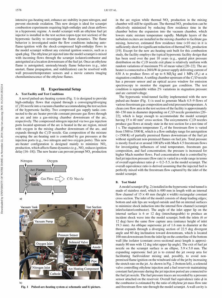
fuel jet is fully developed, and the flame stretches downstream to pilota partially premixed flame (12–27 ms panels of Fig. 4). As shown inFig. 4, under the high-enthalpy and high Mach number conditions,where the ignition and stabilization of non-premixed flames arerelatively easy, the non-premixed flame dominates flame dynamics incases piloting downstream partially premixed flames with suffi-ciently long combustors, such as the one used in this study.In this study, we focus more on the behavior of the partially
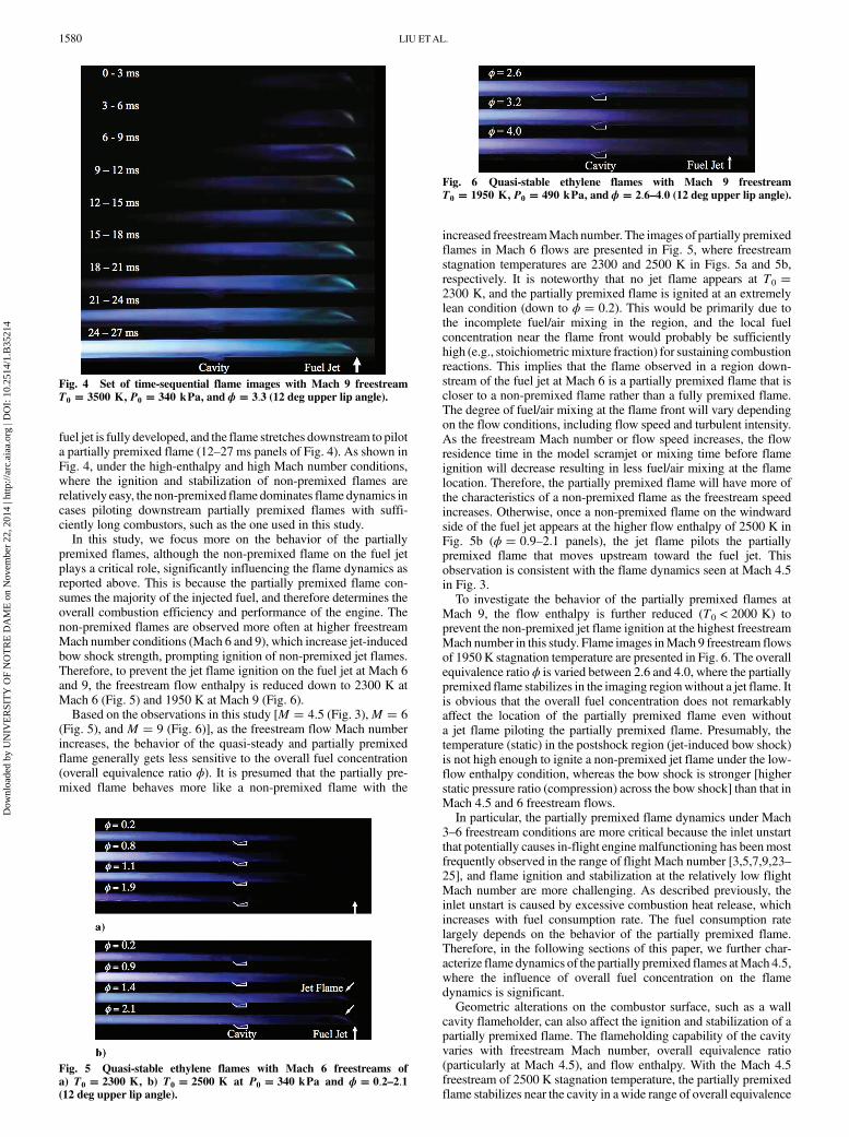
premixed flames, although the non-premixed flame on the fuel jetplays a critical role, significantly influencing the flame dynamics asreported above. This is because the partially premixed flame con-sumes the majority of the injected fuel, and therefore determines theoverall combustion efficiency and performance of the engine. Thenon-premixed flames are observed more often at higher freestreamMach number conditions (Mach 6 and 9), which increase jet-inducedbow shock strength, prompting ignition of non-premixed jet flames.Therefore, to prevent the jet flame ignition on the fuel jet at Mach 6and 9, the freestream flow enthalpy is reduced down to 2300 K atMach 6 (Fig. 5) and 1950 K at Mach 9 (Fig. 6).Based on the observations in this study [M � 4.5 (Fig. 3),M � 6
(Fig. 5), and M � 9 (Fig. 6)], as the freestream flow Mach numberincreases, the behavior of the quasi-steady and partially premixedflame generally gets less sensitive to the overall fuel concentration(overall equivalence ratio ϕ). It is presumed that the partially pre-mixed flame behaves more like a non-premixed flame with the
increased freestreamMach number. The images of partially premixedflames in Mach 6 flows are presented in Fig. 5, where freestreamstagnation temperatures are 2300 and 2500 K in Figs. 5a and 5b,respectively. It is noteworthy that no jet flame appears at T0 �2300 K, and the partially premixed flame is ignited at an extremelylean condition (down to ϕ � 0.2). This would be primarily due tothe incomplete fuel/air mixing in the region, and the local fuelconcentration near the flame front would probably be sufficientlyhigh (e.g., stoichiometricmixture fraction) for sustaining combustionreactions. This implies that the flame observed in a region down-stream of the fuel jet at Mach 6 is a partially premixed flame that iscloser to a non-premixed flame rather than a fully premixed flame.The degree of fuel/air mixing at the flame front will vary dependingon the flow conditions, including flow speed and turbulent intensity.As the freestream Mach number or flow speed increases, the flowresidence time in the model scramjet or mixing time before flameignition will decrease resulting in less fuel/air mixing at the flamelocation. Therefore, the partially premixed flame will have more ofthe characteristics of a non-premixed flame as the freestream speedincreases. Otherwise, once a non-premixed flame on the windwardside of the fuel jet appears at the higher flow enthalpy of 2500 K inFig. 5b (ϕ � 0.9–2.1 panels), the jet flame pilots the partiallypremixed flame that moves upstream toward the fuel jet. Thisobservation is consistent with the flame dynamics seen at Mach 4.5in Fig. 3.To investigate the behavior of the partially premixed flames at
Mach 9, the flow enthalpy is further reduced (T0 < 2000 K) toprevent the non-premixed jet flame ignition at the highest freestreamMach number in this study. Flame images inMach 9 freestream flowsof 1950 K stagnation temperature are presented in Fig. 6. The overallequivalence ratio ϕ is varied between 2.6 and 4.0, where the partiallypremixed flame stabilizes in the imaging regionwithout a jet flame. Itis obvious that the overall fuel concentration does not remarkablyaffect the location of the partially premixed flame even withouta jet flame piloting the partially premixed flame. Presumably, thetemperature (static) in the postshock region (jet-induced bow shock)is not high enough to ignite a non-premixed jet flame under the low-flow enthalpy condition, whereas the bow shock is stronger [higherstatic pressure ratio (compression) across the bow shock] than that inMach 4.5 and 6 freestream flows.In particular, the partially premixed flame dynamics under Mach
3–6 freestream conditions are more critical because the inlet unstartthat potentially causes in-flight engine malfunctioning has beenmostfrequently observed in the range of flight Mach number [3,5,7,9,23–25], and flame ignition and stabilization at the relatively low flightMach number are more challenging. As described previously, theinlet unstart is caused by excessive combustion heat release, whichincreases with fuel consumption rate. The fuel consumption ratelargely depends on the behavior of the partially premixed flame.Therefore, in the following sections of this paper, we further char-acterize flame dynamics of the partially premixed flames atMach 4.5,where the influence of overall fuel concentration on the flamedynamics is significant.Geometric alterations on the combustor surface, such as a wall
cavity flameholder, can also affect the ignition and stabilization of apartially premixed flame. The flameholding capability of the cavityvaries with freestream Mach number, overall equivalence ratio(particularly at Mach 4.5), and flow enthalpy. With the Mach 4.5freestream of 2500 K stagnation temperature, the partially premixedflame stabilizes near the cavity in awide range of overall equivalence
Fig. 4 Set of time-sequential flame images with Mach 9 freestreamT0 � 3500 K, P0 � 340 kPa, and ϕ � 3.3 (12 deg upper lip angle).
Fig. 5 Quasi-stable ethylene flames with Mach 6 freestreams ofa) T0 � 2300 K, b) T0 � 2500 K at P0 � 340 kPa and ϕ � 0.2–2.1(12 deg upper lip angle).
Fig. 6 Quasi-stable ethylene flames with Mach 9 freestreamT0 � 1950 K, P0 � 490 kPa, and ϕ � 2.6–4.0 (12 deg upper lip angle).
1580 LIU ETAL.
Dow
nloa
ded
by U
NIV
ER
SIT
Y O
F N
OT
RE
DA
ME
on
Nov
embe
r 22
, 201
4 | h
ttp://
arc.
aiaa
.org
| D
OI:
10.
2514
/1.B
3521
4
ratio ϕ � 0.93–3.51 as shown in Fig. 3. The wall cavity provides aslow-flow region with relatively high static temperature/pressure,which helps flame ignition and stabilization, serving as a radical poolsupplying radical species to the region adjacent to the flameholder.Furthermore, the cavity can enhance fuel/air mixing by elongatingflow residence time and recirculating the mixture in the cavity.Presumably, the flame stabilization near the cavity observed in Fig. 3is benefited by the radical production/supply from the cavity, as wellas the prolongedmixing time. Thewall cavity can ignite flameswhenthe fuel entrainment into the cavity region is sufficient. The cavityflame ignition at Mach 4.5 is observed under relatively fuel-richconditions, as shown in Figs. 7a (ϕ � 1.34) and 7b (ϕ � 3.51).Interestingly, partially premixed flames are ignited at both locationsdownstream and in the cavity at ϕ � 1.34 (Fig. 7a), then thedownstream partially premixed flame propagates upstream andmerges with the cavity-ignited flame (12–15 ms panel in Fig. 7a).Otherwise, when overall ϕ � 3.51, a partially premixed flame firstappears on the cavity ramp (6–9 ms panel in Fig. 7b) and stretchesdownstream to hold a flame anchoring near the cavity (9–12ms panelin Fig. 7b). The cavity-induced shock on the cavity ramp and theelevated static pressure/temperature in the cavity would directly andindirectly trigger the cavity ignition in the cases presented in Fig. 7.Based on the flame behaviors observed under the various flow
conditions in Figs. 3–7, one can conclude that the cavity flame-holding will be particularly necessary when 1) the flow enthalpy islow (e.g., T0 < 2000 K and M < 6 with the current model scramjetconfiguration), and 2) a non-premixed flame piloting a partiallypremixed flame is not ignited on fuel jets. In practice, the cavityflameholding would be essential in stabilizing a partially premixedflamewhile a scramjet accelerates before reaching hypersonic flightsaboveMach 5.Once the flightMach number exceeds 6, the role of thecavity flameholder would be less critical due to the high Machnumber and high-enthalpy flows capable of igniting and stabilizingthe partially premixed and non-premixed pilot flames.
B. Flame Propagation
Transient ethylene flame propagation through the model scramjetis characterized using a movie camera and five couples of pressure/temperature P∕T sensors (S1–S5 in Fig. 2a) mounted flush with theinternal surface of the model scramjet. Once a partially premixedflame is ignited at a location downstream of the fuel jet, the flamestarts to propagate upstream until it reaches a location appropriate forstable combustion reactions. The flame propagation speedwithMach4.5 freestream flows is estimated for investigating the influence offuel concentration and freestream flow conditions (e.g., temperatureand oxygen concentration) on the unsteady behavior of the partiallypremixed ethylene flame. The partially premixed ethylene flameinteracts with the compressible flow environment to alter the
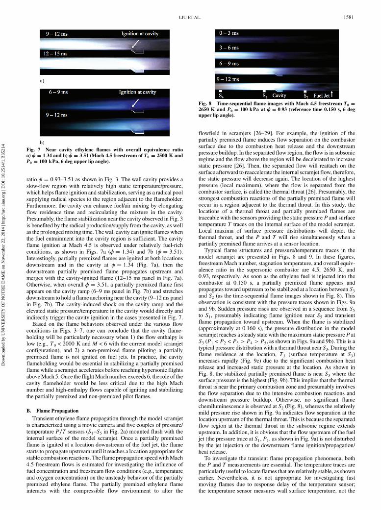
flowfield in scramjets [26–29]. For example, the ignition of thepartially premixed flame induces flow separation on the combustorsurface due to the combustion heat release and the downstreampressure buildup. In the separated flow region, the flow is in subsonicregime and the flow above the region will be decelerated to increasestatic pressure [26]. Then, the separated flow will reattach on thesurface afterward to reaccelerate the internal scramjet flow, therefore,the static pressure will decrease again. The location of the highestpressure (local maximum), where the flow is separated from thecombustor surface, is called the thermal throat [26]. Presumably, thestrongest combustion reactions of the partially premixed flame willoccur in a region adjacent to the thermal throat. In this study, thelocations of a thermal throat and partially premixed flames aretraceable with the sensors providing the static pressure P and surfacetemperature T traces on the internal surface of the model scramjet.Local maxima of surface pressure distributions will depict thethermal throat, and the P and T will rise simultaneously when apartially premixed flame arrives at a sensor location.Typical flame structures and pressure/temperature traces in the
model scramjet are presented in Figs. 8 and 9. In these figures,freestreamMach number, stagnation temperature, and overall equiv-alence ratio in the supersonic combustor are 4.5, 2650 K, and0.93, respectively. As soon as the ethylene fuel is injected into thecombustor at 0.150 s, a partially premixed flame appears andpropagates toward upstream to be stabilized at a location between S3and S2 (as the time-sequential flame images shown in Fig. 8). Thisobservation is consistent with the pressure traces shown in Figs. 9aand 9b. Sudden pressure rises are observed in a sequence from S5to S1, presumably indicating flame ignition near S5 and transientflame propagation toward upstream. When the flame is stabilized(approximately at 0.160 s), the pressure distribution in the modelscramjet reaches a steady state with the maximum static pressureP atS3 (P1 < P2 < P3 > P4 > P5, as shown in Figs. 9a and 9b). This is atypical pressure distribution with a thermal throat near S3. During theflame residence at the location, T3 (surface temperature at S3)increases rapidly (Fig. 9c) due to the significant combustion heatrelease and increased static pressure at the location. As shown inFig. 8, the stabilized partially premixed flame is near S3 where thesurface pressure is the highest (Fig. 9b). This implies that the thermalthroat is near the primary combustion zone and presumably involvesthe flow separation due to the intensive combustion reactions anddownstream pressure buildup. Otherwise, no significant flamechemiluminescence is observed at S2 (Fig. 8), whereas the relativelymild pressure rise shown in Fig. 9a indicates flow separation at thelocation upstream of the thermal throat. This is because the separatedflow region at the thermal throat in the subsonic regime extendsupstream. In addition, it is obvious that the flow upstream of the fueljet (the pressure trace at S1, P1, as shown in Fig. 9a) is not disturbedby the jet injection or the downstream flame ignition/propagation/heat release.To investigate the transient flame propagation phenomena, both
the P and T measurements are essential. The temperature traces areparticularly useful to locate flames that are relatively stable, as shownearlier. Nevertheless, it is not appropriate for investigating fastmoving flames due to response delay of the temperature sensor;the temperature sensor measures wall surface temperature, not the
Fig. 7 Near cavity ethylene flames with overall equivalence ratioa) ϕ � 1.34 and b) ϕ � 3.51 (Mach 4.5 freestream of T0 � 2500 K andP0 � 100 kPa, 6 deg upper lip angle).
Fig. 8 Time-sequential flame images with Mach 4.5 freestream T0 �2650 K and P0 � 100 kPa at ϕ � 0.93 (reference time 0.150 s, 6 degupper lip angle).
LIU ETAL. 1581
Dow
nloa
ded
by U
NIV
ER
SIT
Y O
F N
OT
RE
DA
ME
on
Nov
embe
r 22
, 201
4 | h
ttp://
arc.
aiaa
.org
| D
OI:
10.
2514
/1.B
3521
4
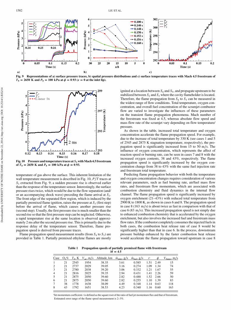
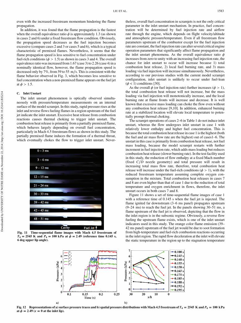
temperature of gas above the surface. This inherent limitation of thewall temperature measurement is described in Fig. 10, P∕T traces atS3 extracted from Fig. 9; a sudden pressure rise is observed earlierthan the response of the temperature sensor. Interestingly, the surfacepressure rises twice, which would be due to the flow separation (and/or an accompanying shock wave) preceding the flame arrival at S3.The front edge of the separated flow region, which is induced by thepartially premixed flame ignition, raises the pressure at S3 (first step)before the arrival of flame, which causes another pressure rise(second step). Usually, the first pressure rise is much smaller than thesecond rise so that the first pressure step can be neglected. Otherwise,a rapid temperature rise at the same location is observed approxi-mately 2ms after the second pressure rise. This is primarily due to theresponse delay of the temperature sensor. Therefore, flame pro-pagation speed is derived from pressure traces.Flame propagation speed measurement results (from S4 to S3) are
provided in Table 1. Partially premixed ethylene flames are mostly
ignited at a location between S4 and S5, and propagate upstream to bestabilized between S2 and S3 where the cavity flameholder is located.Therefore, the flame propagation from S4 to S3 can be measured inthe widest range of flow conditions. Total temperature, oxygen con-centration, and overall fuel concentration of the scramjet combustorflow are varied to investigate the influences of these parameterson the transient flame propagation phenomena. Mach number ofthe freestream was fixed at 4.5, whereas absolute flow speed andmass flow rate of the scramjet vary depending on flow temperature/pressure.As shown in the table, increased total temperature and oxygen
concentration accelerate the flame propagation speed. For example,due to the increase of total temperature by 330 K (see cases 1 and 5of 2545 and 2875 K stagnation temperature, respectively), the pro-pagation speed is significantly increased from 15 to 50 m∕s. Theinfluence of oxygen concentration, which represents the affect ofreaction speed or burning rate, can be seen in cases 7 and 8 with theincreased oxygen contents, 38 and 43%, respectively. The flamepropagation speed is significantly increased by the oxygen con-centration change from 38 to 43% with the same fuel injection rateand freestream total temperature.Predicting flame propagation behavior with both the temperature
and oxygen concentration changes requires consideration of variousrelevant parameters, such as fuel burning rate, air/fuel mass flowrates, and freestream flow momentum, which are associated withcombustion chemistry and fluid dynamics in the internal flowchannel. The flame propagation speed is significantly increased byoxygen enrichment (21–43%) with reduced total temperature from2900 K to 1800 K, as shown in cases 6 and 8. The propagation speedin case 8 (163 m∕s) is about twice as fast in comparison with that ofcase 6 (83 m∕s). This increased propagation speed is not simply dueto enhanced combustion chemistry that is accelerated by the oxygenenrichment, but also involves the increased fuel and freestream massflow rates. If the combustor completely consumes the injected fuels inboth cases, the combustion heat release rate of case 8 would besignificantly higher than that in case 6. In the process, downstreampressure buildup enhanced by the faster combustion heat releasewould accelerate the flame propagation toward upstream in case 8
Fig. 9 Representations of a) surface pressure traces, b) spatial pressure distributions and c) surface temperature traces with Mach 4.5 freestream of
T0 � 2650 K and P0 � 100 kPa at ϕ � 0.93 (x � 0 at the inlet lip).
Fig. 10 Pressure and temperature traces atS3 withMach4.5 freestream
of T0 � 2650 K and P0 � 100 kPa at ϕ � 0.93.
Table 1 Propagation speeds of partially premixed flame with freestreamM � 4.5
Case O2% T0, K V∞, m∕s Altitude, km _minlet, g∕s _mfuel, g∕s ra ϕ Vflame, m∕s1 21 2545 1954 38.35 3.61 0.585 1.51 2.49 152 21 2737 2029 39.05 3.16 0.274 1.09 1.34 743 21 2780 2038 39.20 3.06 0.332 1.21 1.67 554 21 2816 2025 39.35 2.94 0.431 1.41 2.26 595 21 2875 2050 39.60 2.82 0.488 1.52 2.66 506 21 2875 2050 39.60 2.82 0.255 1.10 1.39 837 38 1778 1638 38.09 4.49 0.348 1.14 0.63 1188 43 1792 1651 38.53 4.23 0.340 1.16 0.60 163
aJet momentum coefficient r is defined as the square root of the ratio of fuel jet momentum flux and that of freestream.
Estimated error range of the flame speed measurement is 2–3%.
1582 LIU ETAL.
Dow
nloa
ded
by U
NIV
ER
SIT
Y O
F N
OT
RE
DA
ME
on
Nov
embe
r 22
, 201
4 | h
ttp://
arc.
aiaa
.org
| D
OI:
10.
2514
/1.B
3521
4
even with the increased freestream momentum hindering the flamepropagation.In addition, it was found that the flame propagation is the fastest
when the overall equivalence ratio ϕ is approximately 1.3 (as shownin cases 2 and 6) under a fixed freestream flow condition. Obviously,the propagation speed decreases as the fuel injection becomesexcessive (compare cases 2 and 3 or cases 5 and 6), which is a typicalcharacteristic of premixed flames. Nevertheless, it seems that theflame propagation speed is less sensitive to fuel concentration underfuel-rich conditions (ϕ > 1.5) as shown in cases 3 and 4. The overallequivalence ratiowas increased from1.67 (case 3) to 2.26 (case 4) in anominally identical flow, however, the flame propagation speed isdecreased only by 7%, from 59 to 55 m∕s. This is consistent with theflame behavior observed in Fig. 3, which becomes less sensitive tofuel concentration when a non-premixed flame appears on the fuel jetat ϕ > 1.5.
C. Inlet Unstart
The inlet unstart phenomenon is optically observed simulta-neously with pressure/temperature measurements on an internalsurface of the model scramjet. In this study, rapid pressure rises at theinlet and reverse flows fueling flames in a region upstream of the fueljet indicate the inlet unstart. Excessive heat release from combustionreactions causes thermal choking to trigger inlet unstart. Thecombustion heat release is primarily from a partially premixed flame,which behaves largely depending on overall fuel concentration,particularly in Mach 4.5 freestream flows as shown in this study. Thepartially premixed flame induces the formation of a thermal throat,which eventually chokes the flow to trigger inlet unstart. Never-
theless, overall fuel concentration in scramjets is not the only criticalparameter in the inlet unstart mechanism. In practice, fuel concen-tration will be determined by fuel injection rate and airflowrate through the engine, which depends on flight velocity/altitudeand atmospheric pressure/temperature. Even if all freestream flowparameters upstream of the combustor except for the fuel injectionrate are constant, the fuel injection rate can alter several critical engineoperation parameters that significantly affect flame propagation andthe inlet unstart phenomena. As the overall equivalence ratio ϕincreases from zero to unity with an increasing fuel injection rate, thechance for inlet unstart to occur will increase because 1) totalcombustion heat release, 2) local fuel burning rate, and 3) massloading via fuel injection will increase simultaneously. Nevertheless,according to our previous studies with the current model scramjetconfiguration, inlet unstart is unlikely to occur under fuel-lean(ϕ < 1) conditions [30].As the overall ϕ (or fuel injection rate) further increases (ϕ > 1),
the total combustion heat release will not increase, but the massloading via fuel injection will monotonically increase, and the localburning rate at flame fronts will increase and decrease. It is wellknown that excessive mass loading can choke the flow even withoutany combustion heat release [9,10]. In addition, enhanced burningrate at a stabilized location will elevate local temperature to poten-tially prompt thermal choking.The scramjet operations of cases 2–6 in Table 1 do not induce inlet
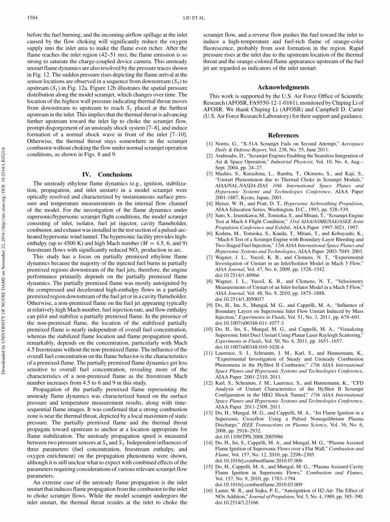
unstart, whereas the flow undergoes inlet unstart in case 1 withrelatively lower enthalpy and higher fuel concentration. This isbecause the total combustion heat release in case 1 is the highest (boththe fuel and air mass flow rate are the highest) out of cases1–6. Theunstart in this case is primarily from combustion heat release, not fuelmass loading, because the model scramjet restarts with furtherincrement in fuel injection rate, which adds mass loading but reducescombustion heat release (slower burning rate). In the test facility usedin this study, the reduction of flow enthalpy at a fixed Mach number(fixed C∕D nozzle geometry) and total pressure will result inincreasing total mass flow rate, therefore, total combustion heatrelease will increase under the fuel-rich conditions (ϕ > 1), with thereduced freestream temperature assuming complete oxygen con-sumption in the mixture. Total combustion heat releases in cases 7and 8 are even higher than that of case 1 due to the reduction of totaltemperature and oxygen enrichment in flows, therefore, the inletunstart occurs in both cases 7 and 8.Figure 11 shows a set of time-sequential flame images of case 1
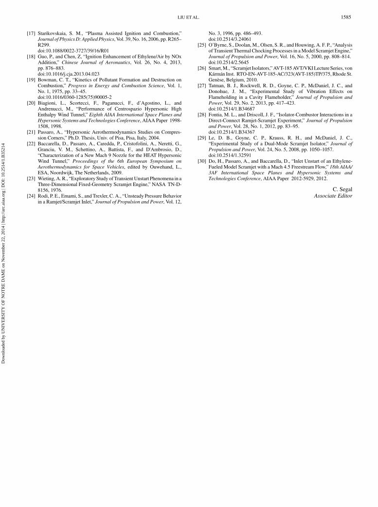
with a reference time of 0.145 s when the fuel jet is injected. Theflame ignited far downstream (3–6 ms panel) propagates upstream(9–24 ms) to reach the fuel jet. In the panels showing 30–51 ms, aflame upstream of the fuel jet is observed, depicting that the flow inthe inlet region is in the subsonic regime. Obviously, a reverse flowfueling the upstream flame exists, which is one of the inlet unstartindicators used in this study. The orange color flame emission (39–42 ms panel) upstream of the fuel jet would be due to soot formationfrom high-temperature and fuel-rich combustion reactions occurringin the inlet region. The rapid flow deceleration at the inlet will elevatethe static temperature in the region up to the stagnation temperature
Fig. 11 Time-sequential flame images with Mach 4.5 freestream ofT0 � 2545 K and P0 � 100 kPa at ϕ � 2.49 (reference time 0.145 s,6 deg upper lip angle).
Fig. 12 Representations of a) surface pressure traces and b) spatial pressure distributions withMach 4.5 freestream ofT0 � 2545 K andP0 � 100 kPaat ϕ � 2.49 (x � 0 at the inlet lip).
LIU ETAL. 1583
Dow
nloa
ded
by U
NIV
ER
SIT
Y O
F N
OT
RE
DA
ME
on
Nov
embe
r 22
, 201
4 | h
ttp://
arc.
aiaa
.org
| D
OI:
10.
2514
/1.B
3521
4
before the fuel burning, and the incoming airflow spillage at the inletcaused by the flow choking will significantly reduce the oxygensupply into the inlet area to make the flame even richer. After theflame reaches the inlet region (42–51 ms), the flame emission is sostrong to saturate the charge-coupled device camera. This unsteadyunstart flame dynamics are also resolved by the pressure traces shownin Fig. 12. The sudden pressure rises depicting the flame arrival at thesensor locations are observed in a sequence from downstream (S5) toupstream (S1) in Fig. 12a. Figure 12b illustrates the spatial pressuredistribution along the model scramjet, which changes over time. Thelocation of the highest wall pressure indicating thermal throat movesfrom downstream to upstream to reach S1 placed at the furthestupstream in the inlet. This implies that the thermal throat is advancingfurther upstream toward the inlet lip to choke the scramjet flow,prompt disgorgement of an unsteady shock system [7–8], and induceformation of a normal shock wave in front of the inlet [7–10].Otherwise, the thermal throat stays somewhere in the scramjetcombustorwithout choking the flowunder normal scramjet operationconditions, as shown in Figs. 8 and 9.
IV. Conclusions
The unsteady ethylene flame dynamics (e.g., ignition, stabiliza-tion, propagation, and inlet unstart) in a model scramjet wereoptically resolved and characterized by instantaneous surface pres-sure and temperature measurements in the internal flow channelof the model. For the investigation of the flame dynamics undersupersonic/hypersonic scramjet flight conditions, the model scramjetconsisting of inlet, isolator, fuel jet injector, cavity flameholder,combustor, and exhaustwas installed in the test section of a pulsed-arc-heated hypersonic wind tunnel. The hypersonic facility provides high-enthalpy (up to 4500 K) and high Mach number (M � 4.5, 6, and 9)freestream flows with significantly reduced NOx production in arc.This study has a focus on partially premixed ethylene flame
dynamics because the majority of the injected fuel burns in partiallypremixed regions downstream of the fuel jets, therefore, the engineperformance primarily depends on the partially premixed flamedynamics. The partially premixed flame was mostly autoignited bythe compressed and decelerated high-enthalpy flows in a partiallypremixed region downstreamof the fuel jet or in a cavity flameholder.Otherwise, a non-premixed flame on the fuel jet appearing typicallyat relatively highMach number, fuel injection rate, and flow enthalpycan pilot and stabilize a partially premixed flame. In the presence ofthe non-premixed flame, the location of the stabilized partiallypremixed flame is nearly independent of overall fuel concentration,whereas the stabilized flame location and flame propagation speed,remarkably, depends on the concentration, particularly with Mach4.5 freestreamswithout the non-premixed flame. The influence of theoverall fuel concentration on the flame behavior is the characteristicsof a premixed flame. The partially premixed flame dynamics get lesssensitive to overall fuel concentration, revealing more of thecharacteristics of a non-premixed flame as the freestream Machnumber increases from 4.5 to 6 and 9 in this study.Propagation of the partially premixed flame representing the
unsteady flame dynamics was characterized based on the surfacepressure and temperature measurement results, along with time-sequential flame images. It was confirmed that a strong combustionzone is near the thermal throat, depicted by a local maximum of staticpressure. The partially premixed flame and the thermal throatpropagate toward upstream to anchor at a location appropriate forflame stabilization. The unsteady propagation speed is measuredbetween two pressure sensors at S4 and S3. Independent influences ofthree parameters (fuel concentration, freestream enthalpy, andoxygen enrichment) on the propagation phenomena were shown,although it is still unclear what to expect with combined effects of theparameters requiring considerations of various relevant scramjet flowparameters.An extreme case of the unsteady flame propagation is the inlet
unstart that induces flame propagation from the combustor to the inletto choke scramjet flows. While the model scramjet undergoes theinlet unstart, the thermal throat resides at the inlet to choke the
scramjet flow, and a reverse flow pushes the fuel toward the inlet toinduce a high-temperature and fuel-rich flame of orange-colorfluorescence, probably from soot formation in the region. Rapidpressure rises at the inlet due to the upstream location of the thermalthroat and the orange-colored flame appearance upstream of the fueljet are regarded as indicators of the inlet unstart.
Acknowledgments
This work is supported by the U.S. Air Force Office of ScientificResearch (AFOSR, FA9550-12-1-0161), monitored byChiping Li ofAFOSR. We thank Chiping Li (AFOSR) and Campbell D. Carter(U.S. Air Force Research Laboratory) for their support and guidance.
References
[1] Norris, G., “X-51A Scramjet Fails on Second Attempt,” Aerospace
Daily & Defense Report, Vol. 238, No. 55, June 2011.[2] Andreadis, D., “Scramjet Engines Enabling the Seamless Integration of
Air & Space Operation,” Industrial Physicist, Vol. 10, No. 4, Aug.–Sept. 2004, pp. 24–27.
[3] Mashio, S., Kurashina, L., Bamba, T., Okimoto, S., and Kaji, S.,“Unstart Phenomenon due to Thermal Choke in Scramjet Module,”AIAA/NAL-NASDA-ISAS 10th International Space Planes and
Hypersonic Systems and Technologies Conference, AIAA Paper2001-1887, Kyoto, Japan, 2001.
[4] Heiser, W. H., and Pratt, D. T., Hypersonic Airbreathing Propulsion,AIAA Education Series, Washington, D.C., 1993, pp. 528–539.
[5] Sato, S., Izumikawa, M., Tomioka, S., andMitani, T., “Scramjet EngineTest at Mach 6 Flight Condition,” 33rd AIAA/ASME/SAE/ASEE Joint
Propulsion Conference and Exhibit, AIAA Paper 1997-3021, 1997.[6] Kodera, M., Tomioka, S., Kanda, T., Mitani, T., and Kobayashi, K.,
“Mach 6 Test of a Scramjet Engine with Boundary-Layer Bleeding andTwo-Staged Fuel Injection,” 12th AIAA International Space Planes and
Hypersonic Systems and Technologies, AIAA Paper 2003-7049, 2003.[7] Wagner, J. L., Yuceil, K. B., and Clemens, N. T., “Experimental
Investigation of Unstart in an Inlet/Isolator Model in Mach 5 Flow,”AIAA Journal, Vol. 47, No. 6, 2009, pp. 1528–1542.doi:10.2514/1.40966
[8] Wagner, J. L., Yuceil, K. B., and Clemens, N. T., “VelocimetryMeasurements of Unstart of an Inlet-Isolator Model in a Mach 5 Flow,”AIAA Journal, Vol. 48, No. 9, 2010, pp. 1875–1888.doi:10.2514/1.J050037
[9] Do, H., Im, S., Mungal, M. G., and Cappelli, M. A., “Influence ofBoundary Layers on Supersonic Inlet Flow Unstart Induced by MassInjection,” Experiments in Fluids, Vol. 51, No. 3, 2011, pp. 679–691.doi:10.1007/s00348-011-1077-3
[10] Do, H., Im, S., Mungal, M. G., and Cappelli, M. A., “VisualizingSupersonic Inlet Duct Unstart Using Planar Laser Rayleigh Scattering,”Experiments in Fluids, Vol. 50, No. 6, 2011, pp. 1651–1657.doi:10.1007/s00348-010-1028-4
[11] Laurence, S. J., Schramm, J. M., Karl, S., and Hannemann, K.,“Experimental Investigation of Steady and Unsteady CombustionPhenomena in the HyShot II Combustor,” 17th AIAA International
Space Planes and Hypersonic Systems and Technologies Conference,AIAA Paper 2001-2310, 2011.
[12] Karl, S., Schramm, J. M., Laurence, S., and Hannemann, K., “CFDAnalysis of Unstart Characteristics of the HyShot II ScramjetConfiguration in the HEG Shock Tunnel,” 17th AIAA International
Space Planes and Hypersonic Systems and Technologies Conference,AIAA Paper 2011-2309, 2011.
[13] Do, H., Mungal, M. G., and Cappelli, M. A., “Jet Flame Ignition in aSupersonic Crossflow Using a Pulsed Nonequilibrium PlasmaDischarge,” IEEE Transactions on Plasma Science, Vol. 36, No. 6,2008, pp. 2918–2932.doi:10.1109/TPS.2008.2005986
[14] Do, H., Im, S., Cappelli, M. A., and Mungal, M. G., “Plasma AssistedFlame Ignition of Supersonic Flows over a Flat Wall,” Combustion andFlame, Vol. 157, No. 12, 2010, pp. 2298–2305.doi:10.1016/j.combustflame.2010.07.006
[15] Do, H., Cappelli, M. A., and Mungal, M. G., “Plasma Assisted CavityFlame Ignition in Supersonic Flows,” Combustion and Flames,Vol. 157, No. 9, 2010, pp. 1783–1794.doi:10.1016/j.combustflame.2010.03.009
[16] Laster, W. R., and Sojka, P. E., “Autoignition of H2-Air: The Effect ofNOxAddition,” Journal of Propulsion, Vol. 5, No. 4, 1989, pp. 385–390.doi:10.2514/3.23166
1584 LIU ETAL.
Dow
nloa
ded
by U
NIV
ER
SIT
Y O
F N
OT
RE
DA
ME
on
Nov
embe
r 22
, 201
4 | h
ttp://
arc.
aiaa
.org
| D
OI:
10.
2514
/1.B
3521
4
[17] Starikovskaia, S. M., “Plasma Assisted Ignition and Combustion,”Journal of PhysicsD: AppliedPhysics, Vol. 39,No. 16, 2006, pp. R265–R299.doi:10.1088/0022-3727/39/16/R01
[18] Guo, P., and Chen, Z, “Ignition Enhancement of Ethylene/Air by NOxAddition,” Chinese Journal of Aeronautics, Vol. 26, No. 4, 2013,pp. 876–883.doi:10.1016/j.cja.2013.04.023
[19] Bowman, C. T., “Kinetics of Pollutant Formation and Destruction onCombustion,” Progress in Energy and Combustion Science, Vol. 1,No. 1, 1975, pp. 33–45.doi:10.1016/0360-1285(75)90005-2
[20] Biagioni, L., Scortecci, F., Paganucci, F., d’Agostino, L., andAndrenucci, M., “Performance of Centrospazio Hypersonic HighEnthalpy Wind Tunnel,” Eighth AIAA International Space Planes and
Hypersonic Systems and Technologies Conference, AIAA Paper 1998-1508, 1998.
[21] Passaro, A., “Hypersonic Aerothermodynamics Studies on Compres-sion Corners,” Ph.D. Thesis, Univ. of Pisa, Pisa, Italy, 2004.
[22] Baccarella, D., Passaro, A., Caredda, P., Cristofolini, A., Neretti, G.,Granciu, V. M., Schettino, A., Battista, F., and D'Ambrosio, D.,“Characterization of a New Mach 9 Nozzle for the HEAT HypersonicWind Tunnel,” Proceedings of the 6th European Symposium on
Aerothermodynamics for Space Vehicles, edited by Ouwehand, L.,ESA, Noordwijk, The Netherlands, 2009.
[23] Wieting,A. R., “Exploratory Study of TransientUnstart Phenomena in aThree-Dimensional Fixed-Geometry Scramjet Engine,” NASA TN-D-8156, 1976.
[24] Rodi, P. E., Emami, S., and Trexler, C. A., “Unsteady Pressure Behaviorin a Ramjet/Scramjet Inlet,” Journal of Propulsion and Power, Vol. 12,
No. 3, 1996, pp. 486–493.doi:10.2514/3.24061
[25] O’Byrne, S., Doolan,M., Olsen, S. R., andHouwing, A. F. P., “Analysisof Transient Thermal Chocking Processes in aModel Scramjet Engine,”Journal of Propulsion and Power, Vol. 16, No. 5, 2000, pp. 808–814.doi:10.2514/2.5645
[26] Smart,M., “Scramjet Isolators,”AVT-185AVT/VKILecture Series, vonKármán Inst. RTO-EN-AVT-185-AC/323(AVT-185)TP/375, Rhode St.Genèse, Belgium, 2010.
[27] Tatman, B. J., Rockwell, R. D., Goyne, C. P., McDaniel, J. C., andDonohue, J. M., “Experimental Study of Vibration Effects onFlameholding in a Cavity Flameholder,” Journal of Propulsion and
Power, Vol. 29, No. 2, 2013, pp. 417–423.doi:10.2514/1.B34687
[28] Fontia, M. L., and Driscoll, J. F., “Isolator-Combustor Interactions in aDirect-Connect Ramjet-Scramjet Experiment,” Journal of Propulsion
and Power, Vol. 28, No. 1, 2012, pp. 83–95.doi:10.2514/1.B34367
[29] Le, D. B., Goyne, C. P., Krauss, R. H., and McDaniel, J. C.,“Experimental Study of a Dual-Mode Scramjet Isolator,” Journal of
Propulsion and Power, Vol. 24, No. 5, 2008, pp. 1050–1057.doi:10.2514/1.32591
[30] Do, H., Passaro, A., and Baccarella, D., “Inlet Unstart of an Ethylene-Fueled Model Scramjet with a Mach 4.5 Freestream Flow,” 18th AIAA/3AF International Space Planes and Hypersonic Systems and
Technologies Conference, AIAA Paper 2012-5929, 2012.
C. SegalAssociate Editor
LIU ETAL. 1585
Dow
nloa
ded
by U
NIV
ER
SIT
Y O
F N
OT
RE
DA
ME
on
Nov
embe
r 22
, 201
4 | h
ttp://
arc.
aiaa
.org
| D
OI:
10.
2514
/1.B
3521
4