
ESP-AT User Guide - Read the Docs for Business
333
ESP-AT User Guide Read the Docs Jun 30, 2022
-
Upload
khangminh22 -
Category
Documents
-
view
0 -
download
0
Transcript of ESP-AT User Guide - Read the Docs for Business

ESP-AT User Guide
Read the Docs
Jun 30, 2022


CONTENTS
1 Get Started 31.1 What is ESP-AT . . . . . . . . . . . . . . . . . . . . . . . . . . . . . . . . . . . . . . . . . . . . . 31.2 Hardware Connection . . . . . . . . . . . . . . . . . . . . . . . . . . . . . . . . . . . . . . . . . . 41.3 Downloading Guide . . . . . . . . . . . . . . . . . . . . . . . . . . . . . . . . . . . . . . . . . . . 12
2 AT Binary Lists 232.1 Released Firmware . . . . . . . . . . . . . . . . . . . . . . . . . . . . . . . . . . . . . . . . . . . . 232.2 Released Firmware . . . . . . . . . . . . . . . . . . . . . . . . . . . . . . . . . . . . . . . . . . . . 242.3 Released Firmware . . . . . . . . . . . . . . . . . . . . . . . . . . . . . . . . . . . . . . . . . . . . 24
3 AT Command Set 273.1 Basic AT Commands . . . . . . . . . . . . . . . . . . . . . . . . . . . . . . . . . . . . . . . . . . . 273.2 Wi-Fi AT Commands . . . . . . . . . . . . . . . . . . . . . . . . . . . . . . . . . . . . . . . . . . . 513.3 TCP/IP AT Commands . . . . . . . . . . . . . . . . . . . . . . . . . . . . . . . . . . . . . . . . . . 813.4 [ESP32 Only] Bluetooth® Low Energy AT Commands . . . . . . . . . . . . . . . . . . . . . . . . . 1183.5 [ESP32 Only] Classic Bluetooth® AT Commands . . . . . . . . . . . . . . . . . . . . . . . . . . . 1623.6 MQTT AT Commands . . . . . . . . . . . . . . . . . . . . . . . . . . . . . . . . . . . . . . . . . . 1823.7 HTTP AT Commands . . . . . . . . . . . . . . . . . . . . . . . . . . . . . . . . . . . . . . . . . . 1933.8 [ESP32 Only] Ethernet AT Commands . . . . . . . . . . . . . . . . . . . . . . . . . . . . . . . . . 1973.9 [ESP8266 Only] Signaling Test AT Commands . . . . . . . . . . . . . . . . . . . . . . . . . . . . . 2003.10 Web server AT Commands . . . . . . . . . . . . . . . . . . . . . . . . . . . . . . . . . . . . . . . . 2013.11 [ESP32 & ESP32-S2 & ESP32-C3] Driver AT Commands . . . . . . . . . . . . . . . . . . . . . . . 2023.12 AT Command Set Comparison . . . . . . . . . . . . . . . . . . . . . . . . . . . . . . . . . . . . . . 2123.13 AT Command Types . . . . . . . . . . . . . . . . . . . . . . . . . . . . . . . . . . . . . . . . . . . 2183.14 AT Commands with Configuration Saved in the Flash . . . . . . . . . . . . . . . . . . . . . . . . . 2193.15 AT Messages . . . . . . . . . . . . . . . . . . . . . . . . . . . . . . . . . . . . . . . . . . . . . . . 219
4 AT Command Examples 2234.1 TCP/IP AT Examples . . . . . . . . . . . . . . . . . . . . . . . . . . . . . . . . . . . . . . . . . . 2234.2 [ESP32 Only] BLE AT Examples . . . . . . . . . . . . . . . . . . . . . . . . . . . . . . . . . . . . 2314.3 MQTT AT Examples . . . . . . . . . . . . . . . . . . . . . . . . . . . . . . . . . . . . . . . . . . . 2424.4 [ESP32 Only] Ethernet AT Examples . . . . . . . . . . . . . . . . . . . . . . . . . . . . . . . . . . 2434.5 Web Server AT Example . . . . . . . . . . . . . . . . . . . . . . . . . . . . . . . . . . . . . . . . . 244
5 How to compile and develop your own AT project 2675.1 Build Your Own ESP-AT Project . . . . . . . . . . . . . . . . . . . . . . . . . . . . . . . . . . . . 2675.2 How to Set AT Port Pins . . . . . . . . . . . . . . . . . . . . . . . . . . . . . . . . . . . . . . . . . 2745.3 How to add user-defined AT commands . . . . . . . . . . . . . . . . . . . . . . . . . . . . . . . . . 2775.4 How To Create Factory Parameter Bin . . . . . . . . . . . . . . . . . . . . . . . . . . . . . . . . . . 2895.5 How To Customize ble services . . . . . . . . . . . . . . . . . . . . . . . . . . . . . . . . . . . . . 293
i

5.6 The Secondary Partitions Table . . . . . . . . . . . . . . . . . . . . . . . . . . . . . . . . . . . . . 2945.7 How to use ESP-AT Classic Bluetooth . . . . . . . . . . . . . . . . . . . . . . . . . . . . . . . . . . 2955.8 How to enable ESP-AT Ethernet . . . . . . . . . . . . . . . . . . . . . . . . . . . . . . . . . . . . . 2975.9 How to Add a New Platform . . . . . . . . . . . . . . . . . . . . . . . . . . . . . . . . . . . . . . . 2985.10 ESP32 SDIO AT Guide . . . . . . . . . . . . . . . . . . . . . . . . . . . . . . . . . . . . . . . . . 2995.11 SPI AT Guide . . . . . . . . . . . . . . . . . . . . . . . . . . . . . . . . . . . . . . . . . . . . . . . 3015.12 How to implement OTA update . . . . . . . . . . . . . . . . . . . . . . . . . . . . . . . . . . . . . 3015.13 How to update the esp-idf version . . . . . . . . . . . . . . . . . . . . . . . . . . . . . . . . . . . . 3075.14 How to understand the differences of each type of module . . . . . . . . . . . . . . . . . . . . . . . 3085.15 AT API Reference . . . . . . . . . . . . . . . . . . . . . . . . . . . . . . . . . . . . . . . . . . . . 309
6 Customized AT Commands and Firmware 3216.1 Tencent Cloud IoT AT Commands and Firmware . . . . . . . . . . . . . . . . . . . . . . . . . . . . 321
7 Index of Abbreviations 323
Index 327
ii

ESP-AT User Guide
[]
This is the documentation for the ESP-AT.
Get Started AT Binary Lists AT Command Set
AT Command Examples Compile and Develop Customized AT Com-mands and Firmware
CONTENTS 1

ESP-AT User Guide
2 CONTENTS

CHAPTER
ONE
GET STARTED
[]
This Get Started guide provides users with detailed information on what is ESP-AT, how to connect hardware, andhow to download and flash AT firmware. It consists of the following parts:
1.1 What is ESP-AT
[]
ESP-AT is a solution developed by Espressif to integrate connectivity into customers’ products, which can be quicklymoved to mass production. It aims to reduce software development costs and quickly form products. With ESP-ATcommands, you can quickly join the wireless network, connect to the cloud platform, realize data transmission andremote control functions, and realize the interconnection of everything through wireless communication easily.
ESP-AT is a project based on ESP-IDF or ESP8266_RTOS_SDK. It makes an ESP board work as a slave, and an MCUas a host. The host MCU sends AT commands to the ESP chip and receives AT responses back. ESP-AT providesa wide range of AT commands with different functions, such as Wi-Fi commands, TCP/IP commands, Bluetooth LEcommands, Bluetooth commands, MQTT commands, HTTP commands, and Ethernet commands.
Fig. 1: ESP-AT Overview
Note: Currently, ESP-AT is based on ESP-IDF or ESP8266_RTOS_SDK, not ESP8266 NonOS SDK.
3

ESP-AT User Guide
AT commands start with “AT”, which stand for “Attention”, and end with a new line (CR LF). Every time you senda command, you will reveive an OK or ERROR, which indicates the final execution status of the current command.Please be noted that all commands are executed serially, which means only one AT command can be executed at atime. Therefore, you should wait for the previous command to be executed before sending out the next one. Otherwise,you will receive busy P.... For more details about AT commands, please refer to AT Command Set.
By default, the host MCU connects to the ESP board via UART, and sends/receives AT commands/responses throughUART. But you can also use other interfaces, such as SDIO, according to your actual use scenario.
You can develop your own AT commands based on our ESP-AT project and implement more features according toyour actual use scenario.
1.2 Hardware Connection
[]
This document introduces what hardware you need to prepare and how to connect them in order to download ATfirmware, send AT commands, and receive AT responses. It covers the following four ESP series of modules:
• ESP32 Series
• ESP32-S2 Series
• ESP32-C3 Series
• ESP8266 Series
For different series of modules, the commands supported by AT firmware are different. Please refer to How to under-stand the differences of each type of module for more details.
1.2.1 What You Need
Table 1: List of Components Required for ESP-AT TestingComponent FunctionESP board Slave MCU.USB cable (ESP borad to PC) Download/Log output connection.PC Act as Host MCU. Download firmware to Slave MCU.USB cable (PC to serial port converter) AT command/response connection.USB to serial port converter Convert between USB signals and TTL signals.Jumper wires (serial port converter to ESP board) AT command/response connection.
Please note that in the above picture, four jump wires are used to connect the ESP board and USB to serial converter.If you don’t use hardware flow control, two wires connecting TX/RX and a simpler converter will be enough.
4 Chapter 1. Get Started

ESP-AT User Guide
Fig. 2: Connection of Components for ESP-AT Testing
1.2.2 ESP32 Series
ESP32 AT uses two UART ports: UART0 is used to download firmware and log output; UART1 is used to send ATcommands and receive AT responses.
All ESP32 modules use GPIO1 and GPIO3 as UART0, but they use different GPIOs as UART1. The following sectionsillustrate which GPIOs you should connect for each ESP32 series of modules.
For more details of ESP32 modules and boards, please refer to ESP32 Modules and Boards.
ESP32-WROOM-32 Series
Table 2: ESP32-WROOM-32 Series Hardware Connection PinoutFunction of Connection ESP Board Pins Other Device PinsDownload/Log output 1
UART0• GPIO3 (RX)• GPIO1 (TX)
PC• TX• RX
AT command/response 2UART1
• GPIO16 (RX)• GPIO17 (TX)• GPIO15 (CTS)• GPIO14 (RTS)
USB to serial converter• TX• RX• RTS• CTS
Note 1: Connection between individual pins of the ESP board and the PC is already established internally on the ESPboard. You only need to provide USB cable between the board and PC.
Note 2: Connection between CTS/RTS is optional, depending on whether you want to use hardware flow control.
1.2. Hardware Connection 5

ESP-AT User Guide
Fig. 3: ESP32-WROOM-32 Series Hardware Connection
If you want to connect your device directly with ESP32-WROOM-32 rather than the ESP board that integrates it,please refer to ESP32-WROOM-32 Datasheet for more details.
ESP32-WROVER Series
Table 3: ESP32-WROVER Series Hardware Connection PinoutFunction of Connection ESP Board Pins Other Device PinsDownload/Log output 1
UART0• GPIO3 (RX)• GPIO1 (TX)
PC• TX• RX
AT command/response 2UART1
• GPIO19 (RX)• GPIO22 (TX)• GPIO15 (CTS)• GPIO14 (RTS)
USB to serial converter• TX• RX• RTS• CTS
Note 1: Connection between individual pins of the ESP board and the PC is already established internally on the ESPboard. You only need to provide USB cable between the board and PC.
Note 2: Connection between CTS/RTS is optional, depending on whether you want to use hardware flow control.
If you want to connect your device directly with ESP32-WROVER rather than the ESP board that integrates it, pleaserefer to ESP32-WROVER Datasheet for more details.
6 Chapter 1. Get Started

ESP-AT User Guide
Fig. 4: ESP32-WROVER Series Hardware Connection
ESP32-PICO Series
Table 4: ESP32-PICO Series Hardware Connection PinoutFunction of Connection ESP Board Pins Other Device PinsDownload/Log output 1
UART0• GPIO3 (RX)• GPIO1 (TX)
PC• TX• RX
AT command/response 2UART1
• GPIO19 (RX)• GPIO22 (TX)• GPIO15 (CTS)• GPIO14 (RTS)
USB to serial converter• TX• RX• RTS• CTS
Note 1: Connection between individual pins of the ESP board and the PC is already established internally on the ESPboard. You only need to provide USB cable between the board and PC.
Note 2: Connection between CTS/RTS is optional, depending on whether you want to use hardware flow control.
If you want to connect your device directly with ESP32-PICO-D4 rather than the ESP board that integrates it, pleaserefer to ESP32-PICO-D4 Datasheet for more details.
1.2. Hardware Connection 7

ESP-AT User Guide
Fig. 5: ESP32-PICO Series Hardware Connection
ESP32-SOLO Series
Table 5: ESP32-SOLO Series Hardware Connection PinoutFunction of Connection ESP Board Pins Other Device PinsDownload/Log output 1
UART0• GPIO3 (RX)• GPIO1 (TX)
PC• TX• RX
AT command/response 2UART1
• GPIO16 (RX)• GPIO17 (TX)• GPIO15 (CTS)• GPIO14 (RTS)
USB to serial converter• TX• RX• RTS• CTS
Note 1: Connection between individual pins of the ESP board and the PC is already established internally on the ESPboard. You only need to provide USB cable between the board and PC.
Note 2: Connection between CTS/RTS is optional, depending on whether you want to use hardware flow control.
If you want to connect your device directly with ESP32-SOLO-1 rather than the ESP board that integrates it, pleaserefer to ESP32-SOLO-1 Datasheet for more details.
1.2.3 ESP32-S2 Series
ESP32-S2 AT uses two UART ports: UART0 is used to download firmware and log output; UART1 is used to sendAT commands and receive AT responses.
8 Chapter 1. Get Started

ESP-AT User Guide
Fig. 6: ESP32-SOLO Series Hardware Connection
Table 6: ESP32-S2 Series Hardware Connection PinoutFunction of Connection ESP Board Pins Other Device PinsDownload/Log output 1
UART0• GPIO44 (RX)• GPIO43 (TX)
PC• TX• RX
AT command/response 2UART1
• GPIO21 (RX)• GPIO17 (TX)• GPIO20 (CTS)• GPIO19 (RTS)
USB to serial converter• TX• RX• RTS• CTS
Note 1: Connection between individual pins of the ESP board and the PC is already established internally on the ESPboard. You only need to provide USB cable between the board and PC.
Note 2: Connection between CTS/RTS is optional, depending on whether you want to use hardware flow control.
If you want to connect your device directly with ESP32-S2-WROOM rather than the ESP board that integrates it,please refer to ESP32-S2-WROOM & ESP32-S2-WROOM-I Datasheet for more details.
1.2. Hardware Connection 9

ESP-AT User Guide
Fig. 7: ESP32-S2 Series Hardware Connection
1.2.4 ESP32-C3 Series
ESP32-C3 AT uses two UART ports: UART0 is used to download firmware and log output; UART1 is used to sendAT commands and receive AT responses.
Table 7: ESP32-C3 Series Hardware Connection PinoutFunction of Connection ESP Board Pins Other Device PinsDownload/Log output 1
UART0• GPIO20 (RX)• GPIO21 (TX)
PC• TX• RX
AT command/response 2UART1
• GPIO6 (RX)• GPIO7 (TX)• GPIO5 (CTS)• GPIO4 (RTS)
USB to serial converter• TX• RX• RTS• CTS
Note 1: Connection between individual pins of the ESP board and the PC is already established internally on the ESPboard. You only need to provide USB cable between the board and PC.
Note 2: Connection between CTS/RTS is optional, depending on whether you want to use hardware flow control.
If you want to connect your device directly with ESP32-C3-MINI-1 rather than the ESP board that integrates it, pleaserefer to ESP32-C3-MINI-1 Datasheet for more details.
10 Chapter 1. Get Started

ESP-AT User Guide
Fig. 8: ESP32-C3 Series Hardware Connection
1.2.5 ESP8266 Series
ESP8266 AT uses two UART ports: UART0 is used to download firmware and send AT commands and receive ATresponses; UART1 is used to log output.
Table 8: ESP8266 Series Hardware Connection PinoutFunction of Connection ESP Board Pins Other Device PinsDownload
UART0• GPIO3 (RX)• GPIO1 (TX)
PC• TX• RX
AT command/response 2UART0
• GPIO13 (RX)• GPIO15 (TX)• GPIO3 (CTS)• GPIO1 (RTS)
USB to serial converter• TX• RX• RTS• CTS
Log outputUART1
• GPIO2 (TX)USB to serial converter
• RX
Note 1: Connection between individual pins of the ESP board and the PC is already established internally on the ESPboard. You only need to provide USB cable between the board and PC.
Note 2: Connection between CTS/RTS is optional, depending on whether you want to use hardware flow control.
Note: The default ESP8266 RTOS AT firmware for ESP-WROOM-02 swaps RX/TX with CTS/RTS. If you want to
1.2. Hardware Connection 11
ESP-AT User Guide
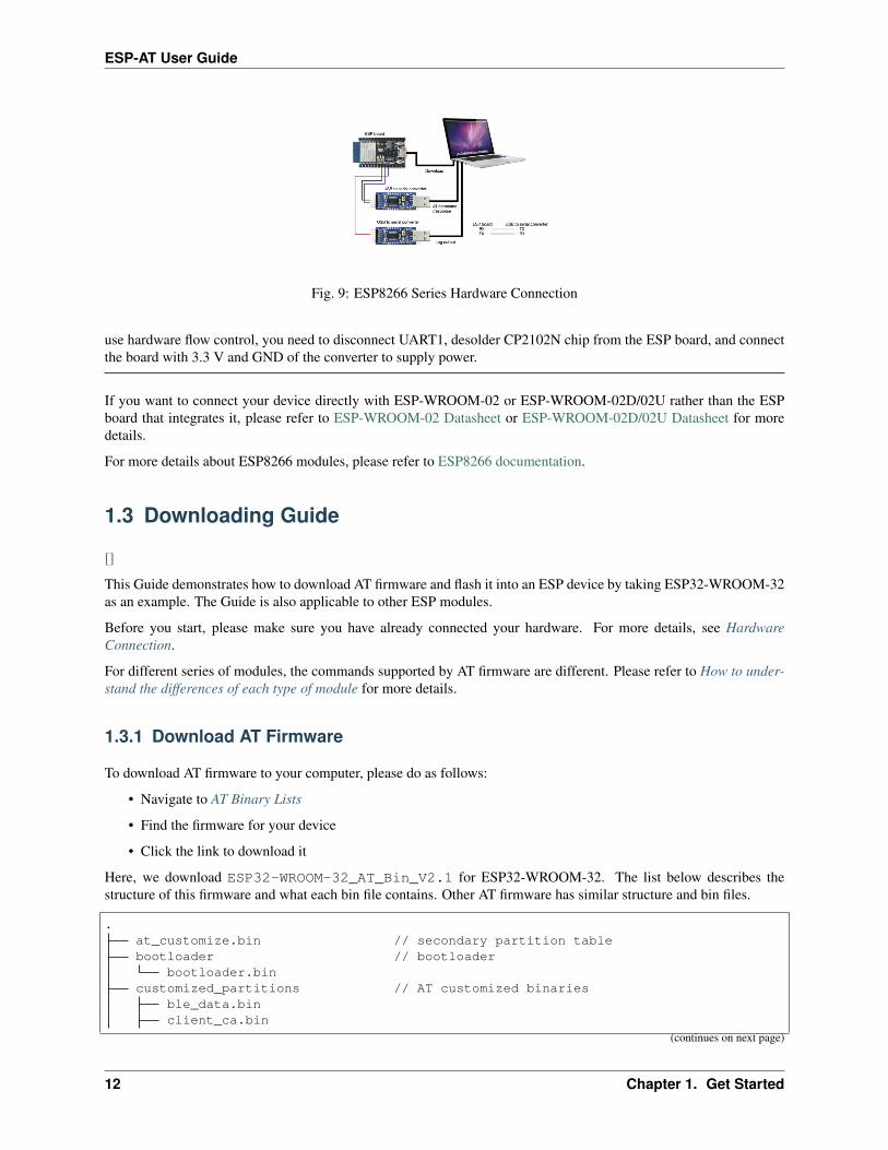
Fig. 9: ESP8266 Series Hardware Connection
use hardware flow control, you need to disconnect UART1, desolder CP2102N chip from the ESP board, and connectthe board with 3.3 V and GND of the converter to supply power.
If you want to connect your device directly with ESP-WROOM-02 or ESP-WROOM-02D/02U rather than the ESPboard that integrates it, please refer to ESP-WROOM-02 Datasheet or ESP-WROOM-02D/02U Datasheet for moredetails.
For more details about ESP8266 modules, please refer to ESP8266 documentation.
1.3 Downloading Guide
[]
This Guide demonstrates how to download AT firmware and flash it into an ESP device by taking ESP32-WROOM-32as an example. The Guide is also applicable to other ESP modules.
Before you start, please make sure you have already connected your hardware. For more details, see HardwareConnection.
For different series of modules, the commands supported by AT firmware are different. Please refer to How to under-stand the differences of each type of module for more details.
1.3.1 Download AT Firmware
To download AT firmware to your computer, please do as follows:
• Navigate to AT Binary Lists
• Find the firmware for your device
• Click the link to download it
Here, we download ESP32-WROOM-32_AT_Bin_V2.1 for ESP32-WROOM-32. The list below describes thestructure of this firmware and what each bin file contains. Other AT firmware has similar structure and bin files.
.at_customize.bin // secondary partition tablebootloader // bootloader
bootloader.bincustomized_partitions // AT customized binaries
ble_data.binclient_ca.bin
(continues on next page)
12 Chapter 1. Get Started

ESP-AT User Guide
(continued from previous page)
client_cert.binclient_key.binfactory_param.binfactory_param_WROOM-32.binmqtt_ca.binmqtt_cert.binmqtt_key.binserver_ca.binserver_cert.binserver_key.bin
download.config // configuration of downloadingesp-at.bin // AT application binaryfactory // A combined bin for factory downloading
factory_WROOM-32.binfactory_parameter.log
flasher_args.json // flasher argumentsota_data_initial.bin // ota data parameterspartition_table // primary partition table
partition-table.binphy_init_data.bin // phy parameters
The file download.config contains the configuration to flash the firmware into multiple addresses:
--flash_mode dio --flash_freq 40m --flash_size 4MB0x8000 partition_table/partition-table.bin0x10000 ota_data_initial.bin0xf000 phy_init_data.bin0x1000 bootloader/bootloader.bin0x100000 esp-at.bin0x20000 at_customize.bin0x24000 customized_partitions/server_cert.bin0x39000 customized_partitions/mqtt_key.bin0x26000 customized_partitions/server_key.bin0x28000 customized_partitions/server_ca.bin0x2e000 customized_partitions/client_ca.bin0x30000 customized_partitions/factory_param.bin0x21000 customized_partitions/ble_data.bin0x3B000 customized_partitions/mqtt_ca.bin0x37000 customized_partitions/mqtt_cert.bin0x2a000 customized_partitions/client_cert.bin0x2c000 customized_partitions/client_key.bin
• --flash_mode dio means the firmware is compiled with flash DIO mode.
• --flash_freq 40m means the firmware’s flash frequency is 40 MHz.
• --flash_size 4MB means the firmware is using flash size 4 MB.
• 0x10000 ota_data_initial.bin means downloading ota_data_initial.bin into the address0x10000.
1.3. Downloading Guide 13

ESP-AT User Guide
1.3.2 Flash AT Firmware into Your Device
Follow the instructions below for your operating system.
Windows
Before starting to flash, you need to download Flash Download Tools for Windows. For more details about the tools,please see readme.pdf or the doc folder in the zip folder.
• Open the ESP Flash Download Tool.
• Select a mode according to your need. (Here, we select Developer Mode.)
Fig. 10: Flash Download Tools Modes
• Select your target chip. For example, choose “ESP8266 DownloadTool” for ESP8266 chip; choose “ESP32-S2DownloadTool” for ESP32-S2 chip. (Here, we select ESP32 DownloadTool.)
• Flash AT firmware into your device. You can select either of the two ways below.
– To download one combined factory bin to address 0, select “DoNotChgBin” to use the default configurationof the factory bin.
– To download multiple bins separately to different addresses, set up the configurations according to the filedownload.config and do NOT select “DoNotChgBin”.
In case of flashing issues, please verify what the COM port number of download interface of the ESP board is andselect it from “COM:” dropdown list. If you don’t know the port number, you can refer to Check port on Windows fordetails.
When you finish flashing, please Check Whether AT Works.
14 Chapter 1. Get Started

ESP-AT User Guide
Fig. 11: Flash Download Tools Target Chip
1.3. Downloading Guide 15

ESP-AT User Guide
Fig. 12: Download to One Address
16 Chapter 1. Get Started

ESP-AT User Guide
Fig. 13: Download to Multiple Addresses
1.3. Downloading Guide 17

ESP-AT User Guide
Linux or macOS
Before you start to flash, you need to install esptool.py.
You can select either of the two ways below to flash AT firmware into your device.
• To download the bins separately into multiple addresses, enter the following command and replace PORTNAMEand download.config:
esptool.py --chip auto --port PORTNAME --baud 115200 --before default_reset --→˓after hard_reset write_flash -z download.config
Replace PORTNAME with your port name. If you don’t know it, you can refer to Check port on Linux andmacOS for details.
Replace download.config with the content inside the file.
Below is the example command for ESP32-WROOM-32.
esptool.py --chip auto --port /dev/tty.usbserial-0001 --baud 115200 --before→˓default_reset --after hard_reset write_flash -z --flash_mode dio --flash_freq→˓40m --flash_size 4MB 0x8000 partition_table/partition-table.bin 0x10000 ota_→˓data_initial.bin 0xf000 phy_init_data.bin 0x1000 bootloader/bootloader.bin→˓0x100000 esp-at.bin 0x20000 at_customize.bin 0x24000 customized_partitions/→˓server_cert.bin 0x39000 customized_partitions/mqtt_key.bin 0x26000 customized_→˓partitions/server_key.bin 0x28000 customized_partitions/server_ca.bin 0x2e000→˓customized_partitions/client_ca.bin 0x30000 customized_partitions/factory_param.→˓bin 0x21000 customized_partitions/ble_data.bin 0x3B000 customized_partitions/→˓mqtt_ca.bin 0x37000 customized_partitions/mqtt_cert.bin 0x2a000 customized_→˓partitions/client_cert.bin 0x2c000 customized_partitions/client_key.bin
• To download the bins together to one address, enter the following command and replace PORTNAME andFILEDIRECTORY:
esptool.py --chip auto --port PORTNAME --baud 115200 --before default_reset --→˓after hard_reset write_flash -z --flash_mode dio --flash_freq 40m --flash_size→˓4MB 0x0 FILEDIRECTORY
Replace PORTNAME with your port name. If you don’t know it, you can refer to Check port on Linux andmacOS for details.
Replace FILEDIRECTORY with the file directory you would flash to the address 0x0. It is normally fac-tory/XXX.bin.
Below is the example command for ESP32-WROOM-32.
esptool.py --chip auto --port /dev/tty.usbserial-0001 --baud 115200 --before→˓default_reset --after hard_reset write_flash -z --flash_mode dio --flash_freq→˓40m --flash_size 4MB 0x0 factory/factory_WROOM-32.bin
When you finish flashing, please Check Whether AT Works.
18 Chapter 1. Get Started

ESP-AT User Guide
1.3.3 Check Whether AT Works
To check whether AT works, do as follows:
• Open a serial port tool, such as SecureCRT;
• Select the Port attached to “AT command/response” line (see Hardware Connection for details);
• Set Baudrate to 115200;
• Set Data Bits to 8;
• Set Parity to None;
• Set Stop Bits to 1;
• Set Flow Type to None;
• Enter the command “AT+GMR” with a new line (CR LF).
If the response is OK as the picture below shows, it means that AT works.
Fig. 14: Response from AT
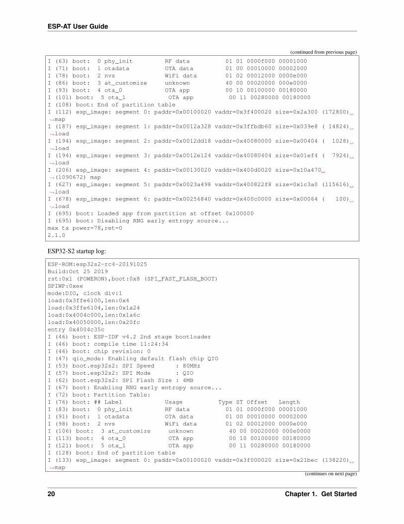
Otherwise, you need to check your ESP startup log, which is visible on PC over “Download/Log output connection”.If it is like the log below, it means that ESP-AT firmware have been initalized correctly.
ESP32 startup log:
ets Jun 8 2016 00:22:57rst:0x1 (POWERON_RESET),boot:0x13 (SPI_FAST_FLASH_BOOT)configsip: 0, SPIWP:0xeeclk_drv:0x00,q_drv:0x00,d_drv:0x00,cs0_drv:0x00,hd_drv:0x00,wp_drv:0x00mode:DIO, clock div:2load:0x3fff0030,len:4load:0x3fff0034,len:7184ho 0 tail 12 room 4load:0x40078000,len:13200load:0x40080400,len:4564entry 0x400806f4I (30) boot: ESP-IDF v4.2 2nd stage bootloaderI (31) boot: compile time 11:23:19I (31) boot: chip revision: 0I (33) boot.esp32: SPI Speed : 40MHzI (38) boot.esp32: SPI Mode : DIOI (42) boot.esp32: SPI Flash Size : 4MBI (47) boot: Enabling RNG early entropy source...I (52) boot: Partition Table:I (56) boot: ## Label Usage Type ST Offset Length
(continues on next page)
1.3. Downloading Guide 19
ESP-AT User Guide
(continued from previous page)
I (63) boot: 0 phy_init RF data 01 01 0000f000 00001000I (71) boot: 1 otadata OTA data 01 00 00010000 00002000I (78) boot: 2 nvs WiFi data 01 02 00012000 0000e000I (86) boot: 3 at_customize unknown 40 00 00020000 000e0000I (93) boot: 4 ota_0 OTA app 00 10 00100000 00180000I (101) boot: 5 ota_1 OTA app 00 11 00280000 00180000I (108) boot: End of partition tableI (112) esp_image: segment 0: paddr=0x00100020 vaddr=0x3f400020 size=0x2a300 (172800)→˓mapI (187) esp_image: segment 1: paddr=0x0012a328 vaddr=0x3ffbdb60 size=0x039e8 ( 14824)→˓loadI (194) esp_image: segment 2: paddr=0x0012dd18 vaddr=0x40080000 size=0x00404 ( 1028)→˓loadI (194) esp_image: segment 3: paddr=0x0012e124 vaddr=0x40080404 size=0x01ef4 ( 7924)→˓loadI (206) esp_image: segment 4: paddr=0x00130020 vaddr=0x400d0020 size=0x10a470→˓(1090672) mapI (627) esp_image: segment 5: paddr=0x0023a498 vaddr=0x400822f8 size=0x1c3a0 (115616)→˓loadI (678) esp_image: segment 6: paddr=0x00256840 vaddr=0x400c0000 size=0x00064 ( 100)→˓loadI (695) boot: Loaded app from partition at offset 0x100000I (695) boot: Disabling RNG early entropy source...max tx power=78,ret=02.1.0
ESP32-S2 startup log:
ESP-ROM:esp32s2-rc4-20191025Build:Oct 25 2019rst:0x1 (POWERON),boot:0x8 (SPI_FAST_FLASH_BOOT)SPIWP:0xeemode:DIO, clock div:1load:0x3ffe6100,len:0x4load:0x3ffe6104,len:0x1a24load:0x4004c000,len:0x1a6cload:0x40050000,len:0x20fcentry 0x4004c35cI (46) boot: ESP-IDF v4.2 2nd stage bootloaderI (46) boot: compile time 11:24:34I (46) boot: chip revision: 0I (47) qio_mode: Enabling default flash chip QIOI (53) boot.esp32s2: SPI Speed : 80MHzI (57) boot.esp32s2: SPI Mode : QIOI (62) boot.esp32s2: SPI Flash Size : 4MBI (67) boot: Enabling RNG early entropy source...I (72) boot: Partition Table:I (76) boot: ## Label Usage Type ST Offset LengthI (83) boot: 0 phy_init RF data 01 01 0000f000 00001000I (91) boot: 1 otadata OTA data 01 00 00010000 00002000I (98) boot: 2 nvs WiFi data 01 02 00012000 0000e000I (106) boot: 3 at_customize unknown 40 00 00020000 000e0000I (113) boot: 4 ota_0 OTA app 00 10 00100000 00180000I (121) boot: 5 ota_1 OTA app 00 11 00280000 00180000I (128) boot: End of partition tableI (133) esp_image: segment 0: paddr=0x00100020 vaddr=0x3f000020 size=0x21bec (138220)→˓map
(continues on next page)
20 Chapter 1. Get Started

ESP-AT User Guide
(continued from previous page)
I (167) esp_image: segment 1: paddr=0x00121c14 vaddr=0x3ffc9330 size=0x02fe0 ( 12256)→˓loadI (169) esp_image: segment 2: paddr=0x00124bfc vaddr=0x40024000 size=0x00404 ( 1028)→˓loadI (173) esp_image: segment 3: paddr=0x00125008 vaddr=0x40024404 size=0x0b010 ( 45072)→˓loadI (193) esp_image: segment 4: paddr=0x00130020 vaddr=0x40080020 size=0xb0784 (722820)→˓mapI (324) esp_image: segment 5: paddr=0x001e07ac vaddr=0x4002f414 size=0x09f18 ( 40728)→˓loadI (334) esp_image: segment 6: paddr=0x001ea6cc vaddr=0x40070000 size=0x0001c ( 28)→˓loadI (346) boot: Loaded app from partition at offset 0x100000I (346) boot: Disabling RNG early entropy source...max tx power=78,ret=02.1.0
ESP32-C3 startup log:
ESP-ROM:esp32c3-20200918Build:Sep 18 2020rst:0x1 (POWERON),boot:0xc (SPI_FAST_FLASH_BOOT)SPIWP:0xeemode:DIO, clock div:2load:0x3fcd6100,len:0x14load:0x3fcd6114,len:0x179cload:0x403ce000,len:0x894load:0x403d0000,len:0x2bf8entry 0x403ce000I (54) boot: ESP-IDF v4.3-beta1 2nd stage bootloaderI (55) boot: compile time 12:09:42I (55) boot: chip revision: 1I (57) boot_comm: chip revision: 1, min. bootloader chip revision: 0I (64) boot.esp32c3: SPI Speed : 40MHzI (68) boot.esp32c3: SPI Mode : DIOI (73) boot.esp32c3: SPI Flash Size : 4MBI (78) boot: Enabling RNG early entropy source...I (83) boot: Partition Table:I (87) boot: ## Label Usage Type ST Offset LengthI (94) boot: 0 phy_init RF data 01 01 0000f000 00001000I (102) boot: 1 otadata OTA data 01 00 00010000 00002000I (109) boot: 2 nvs WiFi data 01 02 00012000 0000e000I (117) boot: 3 at_customize unknown 40 00 00020000 000e0000I (124) boot: 4 ota_0 OTA app 00 10 00100000 00180000I (132) boot: 5 ota_1 OTA app 00 11 00280000 00180000I (139) boot: End of partition tableI (144) boot: No factory image, trying OTA 0I (149) boot_comm: chip revision: 1, min. application chip revision: 0I (156) esp_image: segment 0: paddr=00100020 vaddr=3c140020 size=29cc8h (171208) mapI (201) esp_image: segment 1: paddr=00129cf0 vaddr=3fc8f000 size=03be8h ( 15336) loadI (205) esp_image: segment 2: paddr=0012d8e0 vaddr=40380000 size=02738h ( 10040) loadI (210) esp_image: segment 3: paddr=00130020 vaddr=42000020 size=135bf0h (1268720) mapI (489) esp_image: segment 4: paddr=00265c18 vaddr=40382738 size=0c778h ( 51064) loadI (502) esp_image: segment 5: paddr=00272398 vaddr=50000000 size=00004h ( 4) loadI (508) boot: Loaded app from partition at offset 0x100000I (544) boot: Set actual ota_seq=1 in otadata[0]I (544) boot: Disabling RNG early entropy source...
(continues on next page)
1.3. Downloading Guide 21

ESP-AT User Guide
(continued from previous page)
max tx power=78,ret=02.1.0
ESP8266 startup log:
...boot: ESP-IDF v3.4-rc 2nd stage bootloaderI (54) boot: compile time 11:18:21I (54) boot: SPI Speed : 80MHzI (57) boot: SPI Mode : DIOI (61) boot: SPI Flash Size : 2MBI (65) boot: Partition Table:I (68) boot: ## Label Usage Type ST Offset LengthI (75) boot: 0 otadata OTA data 01 00 00009000 00002000I (83) boot: 1 phy_init RF data 01 01 0000f000 00001000I (90) boot: 2 ota_0 OTA app 00 10 00010000 000e0000I (98) boot: 3 at_customize unknown 40 00 000f0000 00020000I (105) boot: 4 ota_1 OTA app 00 11 00110000 000e0000I (112) boot: 5 nvs WiFi data 01 02 001f0000 00010000I (120) boot: End of partition tableI (124) boot: No factory image, trying OTA 0I (129) esp_image: segment 0: paddr=0x00010010 vaddr=0x40210010 size=0xac0d0 (704720)→˓mapI (138) esp_image: segment 1: paddr=0x000bc0e8 vaddr=0x402bc0e0 size=0x1aba8 (109480)→˓mapI (146) esp_image: segment 2: paddr=0x000d6c98 vaddr=0x3ffe8000 size=0x00788 ( 1928)→˓loadI (155) esp_image: segment 3: paddr=0x000d7428 vaddr=0x40100000 size=0x00080 ( 128)→˓loadI (164) esp_image: segment 4: paddr=0x000d74b0 vaddr=0x40100080 size=0x059c4 ( 22980)→˓loadI (173) boot: Loaded app from partition at offset 0x10000phy_version: 1163.0, 665d56c, Jun 24 2020, 10:00:08, RTOS newmax tx power=78,ret=02.0.0
To learn more about ESP-AT, please read What is ESP-AT .
To get started with ESP-AT, please read Hardware Connection first to learn what hardware to prepare and how toconnect them. Then, you can download and flash AT firmware into your device according to Downloading Guide.
22 Chapter 1. Get Started

CHAPTER
TWO
AT BINARY LISTS
[]
2.1 Released Firmware
It is recommended to use the lastest version of firmware.
2.1.1 ESP32-WROOM-32 Series
• v2.1.0.0 ESP32-WROOM-32_AT_Bin_V2.1.0.0.zip (Recommended)
• v2.0.0.0 ESP32-WROOM-32_AT_Bin_V2.0.0.0.zip
2.1.2 ESP32-WROVER-32 Series
• v2.1.0.0 ESP32-WROVER_AT_Bin_V2.1.0.0.zip (Recommended)
• v2.0.0.0 ESP32-WROVER_AT_Bin_V2.0.0.0.zip
2.1.3 ESP32-PICO Series
• v2.1.0.0 ESP32-PICO-D4_AT_Bin_V2.1.0.0.zip (Recommended)
• v2.0.0.0 ESP32-PICO-D4_AT_Bin_V2.0.0.0.zip
2.1.4 ESP32-SOLO Series
• v2.1.0.0 ESP32-SOLO_AT_Bin_V2.1.0.0.zip (Recommended)
• v2.0.0.0 ESP32-SOLO_AT_Bin_V2.0.0.0.zip
23

ESP-AT User Guide
2.2 Released Firmware
It is recommended to use the lastest version of firmware.
2.2.1 ESP32-S2-WROOM Series
• v2.1.0.0 ESP32-S2-WROOM_AT_Bin_V2.1.0.0.zip (Recommended)
2.2.2 ESP32-S2-WROVER Series
• v2.1.0.0 ESP32-S2-WROVER_AT_Bin_V2.1.0.0.zip (Recommended)
2.2.3 ESP32-S2-SOLO Series
• v2.1.0.0 ESP32-S2-SOLO_AT_Bin_V2.1.0.0.zip (Recommended)
2.2.4 ESP32-S2-MINI Series
• v2.1.0.0 ESP32-S2-MINI_AT_Bin_V2.1.0.0.zip (Recommended)
2.3 Released Firmware
It is recommended to use the lastest version of firmware.
Note:Espressif has not released a separate version for the 1 MB ESP8285/8266 series of chips, but you can referto How to Download the Latest Temporary Version of AT Firmware from GitHub and choose to download the 1MB firmware on the CI (Continuous Integration) of GitHub (Please switch to release/v2.2.0.0_esp8266 branch anddownload esp8285-1MB-at under the Artifacts page).
2.3.1 ESP-WROOM-02 Series
• v2.2.1.0 ESP8266-IDF-AT_V2.2.1.0.zip (Recommended)
• v2.2.0.0 ESP8266-IDF-AT_V2.2.0.0.zip
• v2.1.0.0 ESP8266-IDF-AT_V2.1.0.0.zip
• v2.0.0.0 ESP8266-IDF-AT_V2.0.0.0.zip
Each of the linked above ESP-AT-Bin files contains several binaries for some specific functions, and the fac-tory/factory/xxx.bin is the combination of all binaries. So user can only download the factory/factory_xxx.bin to address 0, or several binaries to different addresses according to ESP-AT-Bin/download.config.
• at_customize.bin is to provide a user partition table, which lists different partitions for the ble_data.bin, SSL certificates, and factory_param_XXX.bin. Furthermore, users can add their own users parti-tions, and read/write the user partitions with the command AT+FS and AT+SYSFLASH.
24 Chapter 2. AT Binary Lists

ESP-AT User Guide
• factory_param_XXX.bin indicates the hardware configurations for different ESP modules (see the ta-ble below). Please make sure the correct bin is used for your specific module. If users design theirown module, they can configure it with reference to the esp-at/docs/en/Compile_and_Develop/How_to_create_factory_parameter_bin.md, and the binaries will be automatically generated af-ter compilation. When users flash the firmware into module according to the download.config, thecustomized_partitions/factory_param.bin should be replaced with the actual module-specificcustomized_partitions/factory_param_XXX.bin. UART CTS and RTS pins are optional.
– ESP32 Series
Modules UART Pins (TX, RX, CTS,RTS)
Factory Parameter Bin
ESP32-WROOM-32 Series (ESP32 De-fault Value)
GPIO17, GPIO16, GPIO15,GPIO14
factory_param_WROOM-32.bin
ESP32-WROVER Series (Supports Clas-sic Bluetooth)
GPIO22, GPIO19, GPIO15,GPIO14
factory_param_WROVER-32.bin
ESP32-PICO Series GPIO22, GPIO19, GPIO15,GPIO14
factory_param_PICO-D4.bin
ESP32-SOLO Series GPIO17, GPIO16, GPIO15,GPIO14
factory_param_SOLO-1.bin
– ESP32S2 Series
Modules UART Pins (TX, RX, CTS, RTS) Factory Parameter BinESP32S2-WROOM Series GPIO17, GPIO21, GPIO20, GPIO19 factory_param_WROOM.binESP32S2-WROVER Series GPIO17, GPIO21, GPIO20, GPIO19 factory_param_WROVER.binESP32S2-SOLO Series GPIO17, GPIO21, GPIO20, GPIO19 factory_param_SOLO.binESP32S2-MINI Series GPIO17, GPIO21, GPIO20, GPIO19 factory_param_MINI.bin
– ESP32-C3 Series
Modules UART Pins (TX, RX, CTS, RTS) Factory Parameter BinESP32-C3-MINI Series GPIO7, GPIO6, GPIO5, GPIO4 factory_param_MINI-1.bin
– ESP8266 Series
Modules UART Pins (TX, RX, CTS,RTS)
Factory Parameter Bin
ESP-WROOM-02 Series (ESP8266 De-fault Value)
GPIO15, GPIO13, GPIO3,GPIO1
factory_param_WROOM-02.bin
• ble_data.bin is to provide BLE services when the ESP32 works as a BLE server;
• server_cert.bin, server_key.bin and server_ca.bin are examples of SSL server‘s certificate;
• client_cert.bin, client_key.bin and client_ca.bin are examples of SSL client‘s certificate.
If some of the functions are not used, then the corresponding binaries need not to be downloaded into flash.
2.3. Released Firmware 25

ESP-AT User Guide
26 Chapter 2. AT Binary Lists

CHAPTER
THREE
AT COMMAND SET
[]
Here is a list of AT commands. Some of them can only work on the ESP32 series, so they are marked as [ESP32Only] at the beginning; those without any mark can work on all ESP series, including ESP32, ESP8266, ESP32-S2,and ESP32-C3.
3.1 Basic AT Commands
[]
• AT: Test AT startup.
• AT+RST: Restart a module.
• AT+GMR: Check version information.
• AT+CMD: List all AT commands and types supported in current firmware.
• AT+GSLP: Enter Deep-sleep mode.
• ATE: Configure AT commands echoing.
• AT+RESTORE: Restore factory default settings of the module.
• AT+UART_CUR: Current UART configuration, not saved in flash.
• AT+UART_DEF: Default UART configuration, saved in flash.
• AT+SLEEP: Set the sleep mode.
• AT+SYSRAM: Query current remaining heap size and minimum heap size.
• AT+SYSMSG: Query/Set System Prompt Information.
• AT+USERRAM: Operate user’s free RAM.
• AT+SYSFLASH: Query/Set User Partitions in Flash.
• [ESP32 Only] AT+FS: Filesystem Operations.
• AT+RFPOWER: Query/Set RF TX Power.
• AT+SYSROLLBACK: Roll back to the previous firmware.
• AT+SYSTIMESTAMP: Query/Set local time stamp.
• AT+SYSLOG: Enable or disable the AT error code prompt.
• AT+SLEEPWKCFG: Query/Set the light-sleep wakeup source and awake GPIO.
27

ESP-AT User Guide
• AT+SYSSTORE: Query/Set parameter store mode.
• AT+SYSREG: Read/write the register.
• [ESP32-S2 Only] AT+SYSTEMP: Read ESP32-S2 internal temperature.
3.1.1 AT: Test AT Startup
Execute Command
Command:
AT
Response:
OK
3.1.2 AT+RST: Restart a Module
Execute Command
Command:
AT+RST
Response:
OK
3.1.3 AT+GMR: Check Version Information
Execute Command
Command:
AT+GMR
Response:
<AT version info><SDK version info><compile time><Bin version>
OK
28 Chapter 3. AT Command Set
ESP-AT User Guide
Parameters
• <AT version info>: information about the esp-at core library version, which is under the directory: esp-at/components/at/lib/. Code is closed source, no plan to open.
• <SDK version info>: information about the esp-at platform sdk version, which is defined in file: esp-at/module_config/module_{platform}_default/IDF_VERSION
• <compile time>: the time to compile the firmware.
• <Bin version>: esp-at firmware version. Version information can be modified in menuconfig.
Note
• If you have any issues on esp-at firmware, please provide AT+GMR version information firstly.
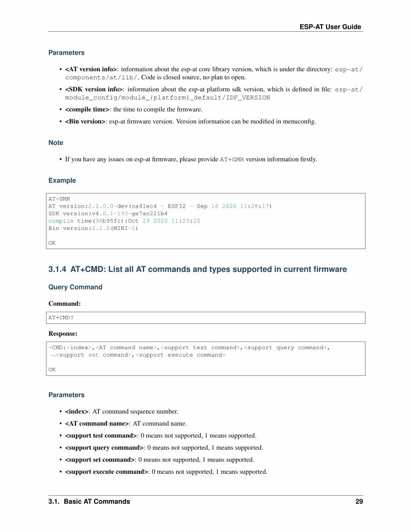
Example
AT+GMRAT version:2.2.0.0-dev(ca41ec4 - ESP32 - Sep 16 2020 11:28:17)SDK version:v4.0.1-193-ge7ac221b4compile time(98b95fc):Oct 29 2020 11:23:25Bin version:2.1.0(MINI-1)
OK
3.1.4 AT+CMD: List all AT commands and types supported in current firmware
Query Command
Command:
AT+CMD?
Response:
+CMD:<index>,<AT command name>,<support test command>,<support query command>,→˓<support set command>,<support execute command>
OK
Parameters
• <index>: AT command sequence number.
• <AT command name>: AT command name.
• <support test command>: 0 means not supported, 1 means supported.
• <support query command>: 0 means not supported, 1 means supported.
• <support set command>: 0 means not supported, 1 means supported.
• <support execute command>: 0 means not supported, 1 means supported.
3.1. Basic AT Commands 29

ESP-AT User Guide
3.1.5 AT+GSLP: Enter Deep-sleep Mode
Set Command
Command:
AT+GSLP=<time>
Response:
<time>
OK
Parameter
• <time>: the duration when the device stays in Deep-sleep. Unit: millisecond. When the time is up, the deviceautomatically wakes up, calls Deep-sleep wake stub, and then proceeds to load the application.
– For ESP32 devices:
* 0 means restarting right now
* the maximum Deep-sleep time is about 28.8 days (2 31-1 milliseconds)
– For ESP32-S2 devices:
* 0 means staying in Deep-sleep mode forever
* the maximum Deep-sleep time is about 28.8 days (2 31-1 milliseconds)
– For ESP8266 devices:
* 0 means staying in Deep-sleep mode forever
* the maximum Deep-sleep time is about 3 hours (due to hardware limitation, more time will lead tosetting failure or internal time overflow)
Notes
• For ESP8266 devices, you must connect GPIO16 to RST pin to wake them up automatically when time is up.
• For all devices, affected by external factors, the theoretical and actual time of Deep-sleep will be different.
• ESP8266 devices can be waken up from Deep-sleep by directly triggering the RST pin low-level pulse.
3.1.6 ATE: Configure AT Commands Echoing
Execute Command
Command:
ATE0
or
30 Chapter 3. AT Command Set

ESP-AT User Guide
ATE1
Response:
OK
Parameters
• ATE0: Switch echo off.
• ATE1: Switch echo on.
3.1.7 AT+RESTORE: Restore Factory Default Settings
Execute Command
Command:
AT+RESTORE
Response:
OK
Notes
• The execution of this command will restore all parameters saved in flash to factory default settings of the module.
• The device will be restarted when this command is executed.
3.1.8 AT+UART_CUR: Current UART Configuration, Not Saved in Flash
Query Command
Command:
AT+UART_CUR?
Response:
+UART_CUR:<baudrate>,<databits>,<stopbits>,<parity>,<flow control>
OK
3.1. Basic AT Commands 31

ESP-AT User Guide
Set Command
Command:
AT+UART_CUR=<baudrate>,<databits>,<stopbits>,<parity>,<flow control>
Response:
OK
Parameters
• <baudrate>: UART baud rate
– For ESP32 and ESP32-S2 devices, the supported range is 80 ~ 5000000.
– For ESP8266 devices, the supported rang is 80 ~ 4500000.
• <databits>: data bits
– 5: 5-bit data
– 6: 6-bit data
– 7: 7-bit data
– 8: 8-bit data
• <stopbits>: stop bits
– 1: 1-bit stop bit
– 2: 1.5-bit stop bit
– 3: 2-bit stop bit
• <parity>: parity bit
– 0: None
– 1: Odd
– 2: Even
• <flow control>: flow control
– 0: flow control is not enabled
– 1: enable RTS
– 2: enable CTS
– 3: enable both RTS and CTS
32 Chapter 3. AT Command Set

ESP-AT User Guide
Notes
• The Query Command will return actual values of UART configuration parameters, which may have minordifferences from the set value because of the clock division.
• The configuration changes will NOT be saved in flash.
• To use hardware flow control, you need to connect CTS/RTS pins of your ESP device. For more de-tails, please refer to Hardware Connection or components/customized_partitions/raw_data/factory_param/factory_param_data.csv.
Example
AT+UART_CUR=115200,8,1,0,3
3.1.9 AT+UART_DEF: Default UART Configuration, Saved in Flash
Query Command
Command:
AT+UART_DEF?
Response:
+UART_DEF:<baudrate>,<databits>,<stopbits>,<parity>,<flow control>
OK
Set Command
Command:
AT+UART_DEF=<baudrate>,<databits>,<stopbits>,<parity>,<flow control>
Response:
OK
Parameters
• <baudrate>: UART baud rate
– For ESP32 and ESP32-S2 devices, the supported range is 80 ~ 5000000.
– For ESP8266 devices, the supported rang is 80 ~ 4500000.
• <databits>: data bits
– 5: 5-bit data
– 6: 6-bit data
– 7: 7-bit data
3.1. Basic AT Commands 33

ESP-AT User Guide
– 8: 8-bit data
• <stopbits>: stop bits
– 1: 1-bit stop bit
– 2: 1.5-bit stop bit
– 3: 2-bit stop bit
• <parity>: parity bit
– 0: None
– 1: Odd
– 2: Even
• <flow control>: flow control
– 0: flow control is not enabled
– 1: enable RTS
– 2: enable CTS
– 3: enable both RTS and CTS
Notes
• The configuration changes will be saved in the NVS area, and will still be valid when the chip is powered onagain.
• To use hardware flow control, you need to connect CTS/RTS pins of your ESP device. For more de-tails, please refer to Hardware Connection or components/customized_partitions/raw_data/factory_param/factory_param_data.csv.
Example
AT+UART_DEF=115200,8,1,0,3
3.1.10 AT+SLEEP: Set the Sleep Mode
Query Command
Command:
AT+SLEEP?
Response:
+SLEEP:<sleep mode>
OK
34 Chapter 3. AT Command Set

ESP-AT User Guide
Set Command
Command:
AT+SLEEP=<sleep mode>
Response:
OK
Parameter
• <sleep mode>:
– 0: Disable the sleep mode.
– 1: Modem-sleep DTIM mode. RF will be periodically closed according to AP DTIM.
– 2: Light-sleep mode. CPU will automatically sleep and RF will be periodically closed according tolisten interval set by AT+CWJAP.
– 3: Modem-sleep listen interval mode. RF will be periodically closed according to listen intervalset by AT+CWJAP.
Note
• Modem-sleep mode and Light-sleep mode can be set only in station mode.
• Before setting the Light-sleep mode, it is recommended to set the wakeup source in advance through the com-mand AT+SLEEPWKCFG, otherwise ESP devices can’t wake up and will always be in sleep mode.
• After setting the Light-sleep mode, if the Light-sleep wakeup condition is not met, ESP devices will automati-cally enter the sleep mode. When the Light-sleep wakeup condition is met, ESP devices will automatically wakeup from sleep mode.
• The query command can return 0, 1, 3, but not 2 (Due to query is not supported by ESP-IDF). That is to say,AT+SLEEP? will return 3 but not 2, if set AT+SLEEP=2.
Example
AT+SLEEP=0
3.1.11 AT+SYSRAM: Query Current Remaining Heap Size and Minimum Heap Size
Query Command
Command:
AT+SYSRAM?
Response:
+SYSRAM:<remaining RAM size>,<minimum heap size>OK
3.1. Basic AT Commands 35

ESP-AT User Guide
Parameters
• <remaining RAM size>: current remaining heap size. Unit: byte.
• <minimum heap size>: minimum heap size that has ever been available. Unit: byte.
Example
AT+SYSRAM?+SYSRAM:148408,84044OK
3.1.12 AT+SYSMSG: Query/Set System Prompt Information
Query Command
Function:
Query the current system prompt information state.
Command:
AT+SYSMSG?
Response:
+SYSMSG:<state>OK
Set Command
Function:
Configure system prompt information.
Command:
AT+SYSMSG=<state>
Response:
OK
Parameter
• <state>:
– Bit0: Prompt information when quitting Wi-Fi Passthrough Mode.
* 0: Print no prompt information when quitting Wi-Fi Passthrough Mode.
* 1: Print +QUITT when quitting Wi-Fi Passthrough Mode.
– Bit1: Connection prompt information type.
36 Chapter 3. AT Command Set
ESP-AT User Guide
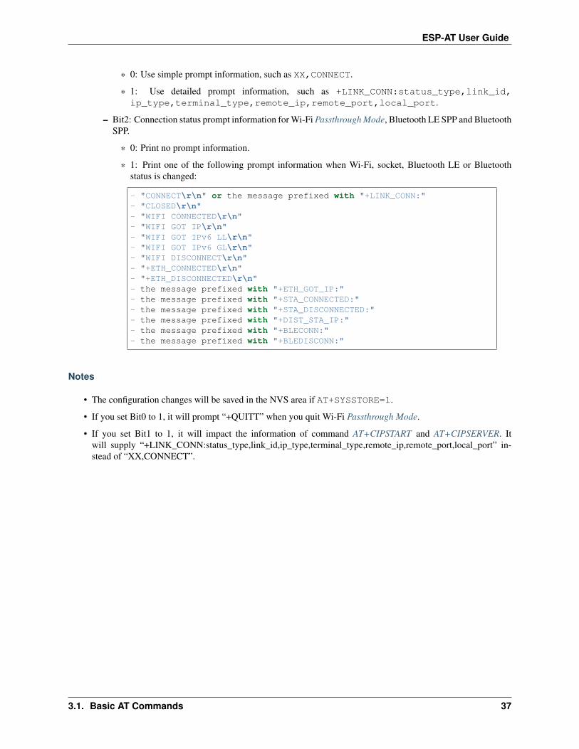
* 0: Use simple prompt information, such as XX,CONNECT.
* 1: Use detailed prompt information, such as +LINK_CONN:status_type,link_id,ip_type,terminal_type,remote_ip,remote_port,local_port.
– Bit2: Connection status prompt information for Wi-Fi Passthrough Mode, Bluetooth LE SPP and BluetoothSPP.
* 0: Print no prompt information.
* 1: Print one of the following prompt information when Wi-Fi, socket, Bluetooth LE or Bluetoothstatus is changed:
- "CONNECT\r\n" or the message prefixed with "+LINK_CONN:"- "CLOSED\r\n"- "WIFI CONNECTED\r\n"- "WIFI GOT IP\r\n"- "WIFI GOT IPv6 LL\r\n"- "WIFI GOT IPv6 GL\r\n"- "WIFI DISCONNECT\r\n"- "+ETH_CONNECTED\r\n"- "+ETH_DISCONNECTED\r\n"- the message prefixed with "+ETH_GOT_IP:"- the message prefixed with "+STA_CONNECTED:"- the message prefixed with "+STA_DISCONNECTED:"- the message prefixed with "+DIST_STA_IP:"- the message prefixed with "+BLECONN:"- the message prefixed with "+BLEDISCONN:"
Notes
• The configuration changes will be saved in the NVS area if AT+SYSSTORE=1.
• If you set Bit0 to 1, it will prompt “+QUITT” when you quit Wi-Fi Passthrough Mode.
• If you set Bit1 to 1, it will impact the information of command AT+CIPSTART and AT+CIPSERVER. Itwill supply “+LINK_CONN:status_type,link_id,ip_type,terminal_type,remote_ip,remote_port,local_port” in-stead of “XX,CONNECT”.
3.1. Basic AT Commands 37

ESP-AT User Guide
Example
// print no promt info when quitting Wi-Fi passthrough mode// print detailed connection prompt info// print no prompt info when the connection status is changedAT+SYSMSG=2
3.1.13 AT+USERRAM: Operate user’s free RAM
Query Command
Function:
Query the current available user’s RAM size.
Command:
AT+USERRAM?
Response:
+USERRAM:<size>OK
Set Command
Function:
Operate user’s free RAM
Command:
AT+USERRAM=<operation>,<size>[,<offset>]
Response:
:: +USERRAM:<length>,<data> // esp-at returns this response only when the operator is read
OK
Parameters
• <operation>:
– 0: release user’s RAM
– 1: malloc user’s RAM
– 2: write user’s RAM
– 3: read user’s RAM
– 4: clear user’s RAM
• <size>: the size to malloc/read/write
• <offset>: the offset to read/write. Default: 0
38 Chapter 3. AT Command Set

ESP-AT User Guide
Notes
• Please malloc the RAM size before you perform any other operations.
• If the operator is write, wrap return > after the write command, then you can send the data that you want towrite. The length should be parameter <length>.
• If the operator is read and the length is bigger than 1024, ESP-AT will reply multiple times in the same format,each reply can carry up to 1024 bytes of data, and eventually end up with \r\nOK\r\n.
Example
// malloc 1 KB user's RAMAT+USERRAM=1,1024
// write 500 bytes to RAM (offset: 0)AT+USERRAM=2,500
// read 64 bytes from RAM offset 100AT+USERRAM=3,64,100
// free the user's RAMAT+USERRAM=0
3.1.14 AT+SYSFLASH: Query/Set User Partitions in Flash
Query Command
Function:
Query user partitions in flash.
Command:
AT+SYSFLASH?
Response:
+SYSFLASH:<partition>,<type>,<subtype>,<addr>,<size>OK
Set Command
Function:
Read/write the user partitions in flash.
Command:
AT+SYSFLASH=<operation>,<partition>,<offset>,<length>
Response:
+SYSFLASH:<length>,<data>OK
3.1. Basic AT Commands 39

ESP-AT User Guide
Parameters
• <operation>:
– 0: erase sector
– 1: write data into the user partition
– 2: read data from the user partition
• <partition>: name of user partition
• <offset>: offset of user partition
• <length>: data length
• <type>: type of user partition
• <subtype>: subtype of user partition
• <addr>: address of user partition
• <size>: size of user partition
Notes
• Please make sure that you have downloaded at_customize.bin before using this command. For more details,please refer to The Secondary Partitions Table.
• When erasing the targeted user partition in its entirety, you can omit the parameters <offset> and <length>.For example, command AT+SYSFLASH=0,"ble_data" can erase the entire “ble_data” user partition. Butif you want to keep the two parameters, they have to be 4KB-aligned.
• The introduction to partitions is in ESP-IDF Partition Tables.
• If the operator is write, wrap return > after the write command, then you can send the data that you want towrite. The length should be parameter <length>.
• If the operator is write, please make sure that you have already erased this partition.
• If the operator is write on a PKI bin, the <length> should be 4 bytes aligned.
Example
// read 100 bytes from the "ble_data" partition offset 0.AT+SYSFLASH=2,"ble_data",0,100
// write 10 bytes to the "ble_data" partition offset 100.AT+SYSFLASH=1,"ble_data",100,10
// erase 8192 bytes from the "ble_data" partition offset 4096.AT+SYSFLASH=0,"ble_data",4096,8192
40 Chapter 3. AT Command Set

ESP-AT User Guide
3.1.15 [ESP32 Only] AT+FS: Filesystem Operations
Set Command
Command:
AT+FS=<type>,<operation>,<filename>,<offset>,<length>
Response:
OK
Parameters
• <type>: only FATFS is currently supported.
– 0: FATFS
• <operation>:
– 0: delete file.
– 1: write file.
– 2: read file.
– 3: query the size of the file.
– 4: list files in a specific directory. Only root directory is currently supported.
• <offset>: apply to writing and reading operations only.
• <length>: data length, applying to writing and reading operations only.
Notes
• Please make sure that you have downloaded at_customize.bin before using this command. For more details,refer to ESP-IDF Partition Tables and The Secondary Partitions Table.
• If the length of the read data is greater than the actual file length, only the actual data length of the file will bereturned.
• If the operator is write, wrap return > after the write command, then you can send the data that you want towrite. The length should be parameter <length>.
Example
// delete a file.AT+FS=0,0,"filename"
// write 10 bytes to offset 100 of a file.AT+FS=0,1,"filename",100,10
// read 100 bytes from offset 0 of a file.AT+FS=0,2,"filename",0,100
// list all files in the root directory.AT+FS=0,4,"."
3.1. Basic AT Commands 41

ESP-AT User Guide
3.1.16 AT+RFPOWER: Query/Set RF TX Power
Query Command
Function:
Query the RF TX Power.
Command:
AT+RFPOWER?
Response:
+RFPOWER:<wifi_power>,<ble_adv_power>,<ble_scan_power>,<ble_conn_power>OK
Set Command
Command:
AT+RFPOWER=<wifi_power>[,<ble_adv_power>,<ble_scan_power>,<ble_conn_power>]
Response:
OK
Parameters
• <wifi_power>: the unit is 0.25 dBm. For example, if you set the value to 78, the actual maximum RF Powervalue is 78 * 0.25 dBm = 19.5 dBm. After you configure it, please confirm the actual value by entering thecommand AT+RFPOWER?.
– For ESP32 and ESP32-S2 devices, the range is [40,78]:
set value actual value actual dBm[34,43] 34 8.5[44,51] 44 11[52,55] 52 13[56,59] 56 14[60,65] 60 15[66,71] 66 16.5[72,77] 72 1878 78 19.5
– For ESP32-C3 devices, the range is [40,84]:
set value actual value actual dBm[40,80] <set value> <set value> * 0.25[81,84] 80 20
42 Chapter 3. AT Command Set

ESP-AT User Guide
– For ESP8266 devices, the range is [40,82]:
set value actual value actual dBm[40,47] 32 8[48,55] 48 12[56,63] 56 14[64,67] 64 16[68,73] 68 17[74,77] 74 18.5[78,81] 78 19.582 82 20.5
• <ble_adv_power>: RF TX Power of Bluetooth LE advertising. Range: [0,7].
– 0: 7 dBm
– 1: 4 dBm
– 2: 1 dBm
– 3: -2 dBm
– 4: -5 dBm
– 5: -8 dBm
– 6: -11 dBm
– 7: -14 dBm
• <ble_scan_power>: RF TX Power of Bluetooth LE scanning. Range: [0,7]: the parameters are the same as<ble_adv_power>.
• <ble_conn_power>: RF TX Power of Bluetooth LE connecting. Range: [0,7]: the same as<ble_adv_power>.
3.1.17 Note
• Since the RF TX Power is actually divided into several levels, and each level has its own value range, thewifi_power value queried by the esp_wifi_get_max_tx_power may differ from the value set byesp_wifi_set_max_tx_power and is no larger than the set value.
3.1.18 AT+SYSROLLBACK: Roll Back to the Previous Firmware
Execute Command
Command:
AT+SYSROLLBACK
Response:
OK
3.1. Basic AT Commands 43

ESP-AT User Guide
Note
• This command will not upgrade via OTA. It only rolls back to the firmware which is in the other OTA partition.
3.1.19 AT+SYSTIMESTAMP: Query/Set Local Time Stamp
Query Command
Function:
Query the time stamp.
Command:
AT+SYSTIMESTAMP?
Response:
+SYSTIMESTAMP:<Unix_timestamp>OK
Set Command
Function:
Set local time stamp. It will be the same as SNTP time when the SNTP time is updated.
Command:
AT+SYSTIMESTAMP=<Unix_timestamp>
Response:
OK
Parameter
• <Unix-timestamp>: Unix timestamp. Unit: second.
Example
AT+SYSTIMESTAMP=1565853509 //2019-08-15 15:18:29
44 Chapter 3. AT Command Set

ESP-AT User Guide
3.1.20 AT+SYSLOG: Enable or Disable the AT Error Code Prompt
Query Command
Function:
Query whether the AT error code prompt is enabled or not.
Command:
AT+SYSLOG?
Response:
+SYSLOG:<status>
OK
Set Command
Function:
Enable or disable the AT error code prompt.
Command:
AT+SYSLOG=<status>
Response:
OK
Parameter
• <status>: enable or disable
– 0: disable
– 1: enable
Example
// enable AT error code promptAT+SYSLOG=1
OKAT+FAKEERR CODE:0x01090000
ERROR
// disable AT error code promptAT+SYSLOG=0
(continues on next page)
3.1. Basic AT Commands 45

ESP-AT User Guide
(continued from previous page)
OKAT+FAKE// No `ERR CODE:0x01090000`
ERROR
The error code is a 32-bit hexadecimal value and defined as follows:
category subcategory extensionbit32 ~ bit24 bit23 ~ bit16 bit15 ~ bit0
• category: stationary value 0x01.
• subcategory: error type.
Table 1: Subcategory of Error CodeError Type Error
CodeDescription
ESP_AT_SUB_OK 0x00 OKESP_AT_SUB_COMMON_ERROR 0x01 reservedESP_AT_SUB_NO_TERMINATOR 0x02 terminator character not found (“rn” ex-
pected)ESP_AT_SUB_NO_AT 0x03 Starting AT not found (or at, At or aT en-
tered)ESP_AT_SUB_PARA_LENGTH_MISMATCH 0x04 parameter length mismatchESP_AT_SUB_PARA_TYPE_MISMATCH 0x05 parameter type mismatchESP_AT_SUB_PARA_NUM_MISMATCH 0x06 parameter number mismatchESP_AT_SUB_PARA_INVALID 0x07 the parameter is invalidESP_AT_SUB_PARA_PARSE_FAIL 0x08 parse parameter failESP_AT_SUB_UNSUPPORT_CMD 0x09 the command is not supportedESP_AT_SUB_CMD_EXEC_FAIL 0x0A the command execution failedESP_AT_SUB_CMD_PROCESSING 0x0B processing of previous command is in
progressESP_AT_SUB_CMD_OP_ERROR 0x0C the command operation type is error
• extension: error extension information. There are different extensions for different subcategory. For moreinformation, please see the components/at/include/esp_at.h.
For example, the error code ERR CODE:0x01090000 means the command is not supported.
3.1.21 AT+SLEEPWKCFG: Set the Light-sleep Wakeup Source and Awake GPIO
Set Command
Command:
AT+SLEEPWKCFG=<wakeup source>,<param1>[,<param2>]
Response:
OK
46 Chapter 3. AT Command Set

ESP-AT User Guide
Parameters
• <wakeup source>:
– 0: wakeup by a timer.
– 1: reserved.
– 2: wakeup by GPIO.
• <param1>:
– If the wakeup source is a timer, it means the time before wakeup. Unit: millisecond.
– If the wakeup source is GPIO, it means the GPIO number.
• <param2>:
– If the wakeup source is GPIO, it means the wakeup level:
– 0: low level.
– 1: high level.
Note
• GPIO16 as the RTC IO can not be set as GPIO wakeup source on ESP8266 platform for light sleep.
Example
// Timer wakeupAT+SLEEPWKCFG=0,1000
// GPIO12 wakeup, low levelAT+SLEEPWKCFG=2,12,0
3.1.22 AT+SYSSTORE: Query/Set Parameter Store Mode
Query Command
Function:
Query the AT parameter store mode.
Command:
AT+SYSSTORE?
Response:
+SYSSTORE:<store_mode>
OK
3.1. Basic AT Commands 47

ESP-AT User Guide
Set Command
Command:
AT+SYSSTORE=<store_mode>
Response:
OK
Parameter
• <store_mode>:
– 0: command configuration is not stored into flash.
– 1: command configuration is stored into flash. (Default)
Note
• This command affects set commands only. Query commands are always fetched from RAM.
• Affected commands:
– AT+SYSMSG
– AT+CWMODE
– AT+CIPV6
– AT+CWJAP
– AT+CWSAP
– AT+CWRECONNCFG
– AT+CIPAP
– AT+CIPSTA
– AT+CIPAPMAC
– AT+CIPSTAMAC
– AT+CIPDNS
– AT+CIPSSLCCONF
– AT+CIPRECONNINTV
– AT+CIPTCPOPT
– AT+CWDHCPS
– AT+CWDHCP
– AT+CWSTAPROTO
– AT+CWAPPROTO
– AT+CWJEAP
– AT+CIPETH
– AT+CIPETHMAC
48 Chapter 3. AT Command Set

ESP-AT User Guide
– AT+BLENAME
– AT+BTNAME
– AT+BLEADVPARAM
– AT+BLEADVDATA
– AT+BLEADVDATAEX
– AT+BLESCANRSPDATA
– AT+BLESCANPARAM
– AT+BTSCANMODE
– AT+BLECONNPARAM
Examples
AT+SYSSTORE=0AT+CWMODE=1 // Not stored into flashAT+CWJAP="test","1234567890" // Not stored into flash
AT+SYSSTORE=1AT+CWMODE=3 // Stored into flashAT+CWJAP="test","1234567890" // Stored into flash
3.1.23 AT+SYSREG: Read/Write the Register
Set Command
Command:
AT+SYSREG=<direct>,<address>[,<write value>]
Response:
+SYSREG:<read value> // Only in read modeOK
Parameters
• <direct>: read or write register.
– 0: read register.
– 1: write register.
• <address>: (uint32) register address. You can refer to Technical Reference Manuals.
• <write value>: (uint32) write value (only in write mode).
3.1. Basic AT Commands 49
ESP-AT User Guide
Note
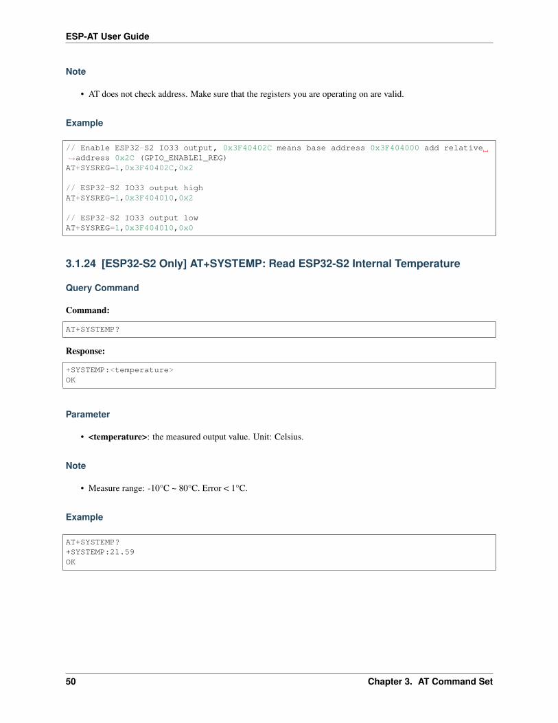
• AT does not check address. Make sure that the registers you are operating on are valid.
Example
// Enable ESP32-S2 IO33 output, 0x3F40402C means base address 0x3F404000 add relative→˓address 0x2C (GPIO_ENABLE1_REG)AT+SYSREG=1,0x3F40402C,0x2
// ESP32-S2 IO33 output highAT+SYSREG=1,0x3F404010,0x2
// ESP32-S2 IO33 output lowAT+SYSREG=1,0x3F404010,0x0
3.1.24 [ESP32-S2 Only] AT+SYSTEMP: Read ESP32-S2 Internal Temperature
Query Command
Command:
AT+SYSTEMP?
Response:
+SYSTEMP:<temperature>OK
Parameter
• <temperature>: the measured output value. Unit: Celsius.
Note
• Measure range: -10°C ~ 80°C. Error < 1°C.
Example
AT+SYSTEMP?+SYSTEMP:21.59OK
50 Chapter 3. AT Command Set

ESP-AT User Guide
3.2 Wi-Fi AT Commands
[]
• AT+CWMODE: Set the Wi-Fi mode (Station/SoftAP/Station+SoftAP).
• AT+CWSTATE: Query the Wi-Fi state and Wi-Fi information.
• AT+CWJAP: Connect to an AP.
• AT+CWRECONNCFG: Query/Set the Wi-Fi reconnecting configuration.
• AT+CWLAPOPT: Set the configuration for the command AT+CWLAP.
• AT+CWLAP: List available APs.
• AT+CWQAP: Disconnect from an AP.
• AT+CWSAP: Query/Set the configuration of an ESP SoftAP.
• AT+CWLIF: Obtain IP address of the station that connects to an ESP SoftAP.
• AT+CWQIF: Disconnect stations from an ESP SoftAP.
• AT+CWDHCP: Enable/disable DHCP.
• AT+CWDHCPS: Query/Set the IP addresses allocated by an ESP SoftAP DHCP server.
• AT+CWAUTOCONN: Connect to an AP automatically when powered on.
• AT+CWAPPROTO: Query/Set the 802.11 b/g/n protocol standard of SoftAP mode.
• AT+CWSTAPROTO: Query/Set the 802.11 b/g/n protocol standard of station mode.
• AT+CIPSTAMAC: Query/Set the MAC address of an ESP station.
• AT+CIPAPMAC: Query/Set the MAC address of an ESP SoftAP.
• AT+CIPSTA: Query/Set the IP address of an ESP station.
• AT+CIPAP: Query/Set the IP address of an ESP SoftAP.
• AT+CWSTARTSMART: Start SmartConfig.
• AT+CWSTOPSMART: Stop SmartConfig.
• AT+WPS: Enable the WPS function.
• AT+MDNS: Configure the mDNS function.
• [ESP32 Only] AT+CWJEAP: Connect to a WPA2 Enterprise AP.
• AT+CWHOSTNAME: Query/Set the host name of an ESP station.
• AT+CWCOUNTRY: Query/Set the Wi-Fi Country Code.
3.2. Wi-Fi AT Commands 51

ESP-AT User Guide
3.2.1 AT+CWMODE: Query/Set the Wi-Fi Mode (Station/SoftAP/Station+SoftAP)
Query Command
Function:
Query the Wi-Fi mode of ESP devices.
Command:
AT+CWMODE?
Response:
+CWMODE:<mode>OK
Set Command
Function:
Set the Wi-Fi mode of ESP devices.
Command:
AT+CWMODE=<mode>[,<auto_connect>]
Response:
OK
Parameters
• <mode>:
– 0: Null mode. Wi-Fi RF will be disabled.
– 1: Station mode.
– 2: SoftAP mode.
– 3: SoftAP+Station mode.
• <auto_connect>: Enable or disable automatic connection to an AP when you change the mode of the ESPdevice from the SoftAP mode or null mode to the station mode or the SoftAP+Station mode. Default: 1. If youomit the parameter, the default value will be used, i.e. automatically connecting to an AP.
– 0: The ESP device will not automatically connect to an AP.
– 1: The ESP device will automatically connect to an AP if the configuration to connect to the AP has alreadybeen saved in flash before.
52 Chapter 3. AT Command Set

ESP-AT User Guide
Note
• The configuration changes will be saved in the NVS area if AT+SYSSTORE=1.
Example
AT+CWMODE=3
3.2.2 AT+CWSTATE: Query the Wi-Fi state and Wi-Fi information
Query Command
Function:
Query the Wi-Fi state and Wi-Fi information of ESP devices.
Command:
AT+CWSTATE?
Response:
+CWSTATE:<state>,<"ssid">
OK
Parameters
• <state>: current Wi-Fi state.
– 0: ESP station has not started any Wi-Fi connection.
– 1: ESP station has connected to an AP, but does not get an IPv4 address yet.
– 2: ESP station has connected to an AP, and got an IPv4 address.
– 3: ESP station is in Wi-Fi connecting or reconnecting state.
– 4: ESP station is in Wi-Fi disconnected state.
• <”ssid”>: the SSID of the target AP.
Note
• When ESP station is not connected to an AP, it is recommended to use this command to query Wi-Fi information;after ESP station is connected to an AP, it is recommended to use AT+CWJAP to query Wi-Fi information.
3.2. Wi-Fi AT Commands 53

ESP-AT User Guide
3.2.3 AT+CWJAP: Connect to an AP
Query Command
Function:
Query the AP to which the ESP Station is already connected.
Command:
AT+CWJAP?
Response:
+CWJAP:<ssid>,<bssid>,<channel>,<rssi>,<pci_en>,<reconn_interval>,<listen_interval>,→˓<scan_mode>,<pmf>OK
Set Command
Function:
Connect an ESP station to a targeted AP.
Command:
AT+CWJAP=[<ssid>],[<pwd>][,<bssid>][,<pci_en>][,<reconn_interval>][,<listen_interval>→˓][,<scan_mode>][,<jap_timeout>][,<pmf>]
Response:
WIFI CONNECTEDWIFI GOT IP
OK[WIFI GOT IPv6 LL][WIFI GOT IPv6 GL]
or
+CWJAP:<error code>ERROR
Execute Command
Function:
Connect an ESP station to a targeted AP with last Wi-Fi configuration.
Command:
AT+CWJAP
Response:
54 Chapter 3. AT Command Set

ESP-AT User Guide
WIFI CONNECTEDWIFI GOT IP
OK[WIFI GOT IPv6 LL][WIFI GOT IPv6 GL]
or
+CWJAP:<error code>ERROR
Parameters
• <ssid>: the SSID of the target AP.
– Escape character syntax is needed if SSID or password contains special characters, such ,, ", or \\.
• <pwd>: password, MAX: 64-byte ASCII.
• <bssid>: the MAC address of the target AP. It cannot be omitted when multiple APs have the same SSID.
• <channel>: channel.
• <rssi>: signal strength.
• <pci_en>: PCI Authentication.
– 0: The ESP station will connect APs with all encryption methods, including OPEN and WEP.
– 1: The ESP station will connect APs with all encryption methods, except OPEN and WEP.
• <reconn_interval>: the interval between Wi-Fi reconnections. Unit: second. Default: 1. Maximum: 7200.
– 0: The ESP station will not reconnect to the AP when disconnected.
– [1,7200]: The ESP station will reconnect to the AP at the specified interval when disconnected.
• <listen_interval>: the interval of listening to the AP’s beacon. Unit: AP beacon intervals. Default: 3. Range:[1,100].
• <scan_mode>:
– 0: fast scan. It will end after finding the targeted AP. The ESP station will connect to the first scanned AP.
– 1: all-channel scan. It will end after all the channels are scanned. The device will connect to the scannedAP with the strongest signal.
• <jap_timeout>: maximum timeout for AT+CWJAP command. Unit: second. Default: 15. Range: [3,600].
• <pmf>: Protected Management Frames. Default: 0.
– 0 means disable PMF.
– bit 0: PMF capable, advertizes support for protected management frame. Device will prefer to connect inPMF mode if other device also advertizes PMF capability.
– bit 1: PMF required, advertizes that protected management frame is required. Device will not associate tonon-PMF capable devices.
• <error code>: (for reference only)
– 1: connection timeout.
3.2. Wi-Fi AT Commands 55

ESP-AT User Guide
– 2: wrong password.
– 3: cannot find the target AP.
– 4: connection failed.
– others: unknown error occurred.
Notes
• The configuration changes will be saved in the NVS area if AT+SYSSTORE=1.
• This command requires Station mode to be enabled.
• The parameter <reconn_interval> of this command is the same as <interval_second> of the com-mand AT+CWRECONNCFG. Therefore, if you omit <reconn_interval> when running this command,the interval between Wi-Fi reconnections will use the default value 1.
• If the <ssid> and <password> parameter are omitted, AT will use the last configuration.
• Execute command has the same maximum timeout to setup command. The default value is 15 seconds, but youcan change it by setting the parameter <jap_timeout>.
• To get an IPv6 address, you need to set AT+CIPV6=1.
• Response OK means that the IPv4 network is ready, but not the IPv6 network. At present, ESP-AT is mainlybased on IPv4 network, supplemented by IPv6 network.
• WIFI GOT IPv6 LL represents that the linklocal IPv6 address has been obtained. This address is calculatedlocally through EUI-64 and does not require the participation of the AP. Because of the parallel timing, this printmay be before or after OK.
• WIFI GOT IPv6 GL represents that the global IPv6 address has been obtained. This address is combined bythe prefix issued by AP and the suffix calculated internally, which requires the participation of the AP. Becauseof the parallel timing, this print may be before or after OK, or it may not be printed because the AP does notsupport IPv6.
Example
// If the target AP's SSID is "abc" and the password is "0123456789", the command→˓should be:AT+CWJAP="abc","0123456789"
// If the target AP's SSID is "ab\,c" and the password is "0123456789"\", the command→˓should be:AT+CWJAP="ab\\\,c","0123456789\"\\"
// If multiple APs all have the SSID of "abc", the target AP can be found by BSSID:AT+CWJAP="abc","0123456789","ca:d7:19:d8:a6:44"
// If esp-at is required that connect to a AP by protected management frame, the→˓command should be:AT+CWJAP="abc","0123456789",,,,,,,3
56 Chapter 3. AT Command Set
ESP-AT User Guide
3.2.4 AT+CWRECONNCFG: Query/Set the Wi-Fi Reconnecting Configuration
Query Command
Function:
Query the configuration of Wi-Fi reconnect.
Command:
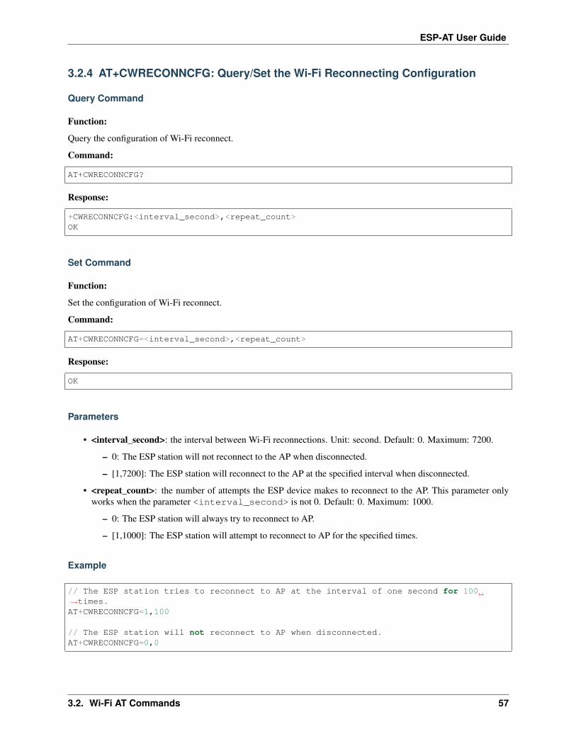
AT+CWRECONNCFG?
Response:
+CWRECONNCFG:<interval_second>,<repeat_count>OK
Set Command
Function:
Set the configuration of Wi-Fi reconnect.
Command:
AT+CWRECONNCFG=<interval_second>,<repeat_count>
Response:
OK
Parameters
• <interval_second>: the interval between Wi-Fi reconnections. Unit: second. Default: 0. Maximum: 7200.
– 0: The ESP station will not reconnect to the AP when disconnected.
– [1,7200]: The ESP station will reconnect to the AP at the specified interval when disconnected.
• <repeat_count>: the number of attempts the ESP device makes to reconnect to the AP. This parameter onlyworks when the parameter <interval_second> is not 0. Default: 0. Maximum: 1000.
– 0: The ESP station will always try to reconnect to AP.
– [1,1000]: The ESP station will attempt to reconnect to AP for the specified times.
Example
// The ESP station tries to reconnect to AP at the interval of one second for 100→˓times.AT+CWRECONNCFG=1,100
// The ESP station will not reconnect to AP when disconnected.AT+CWRECONNCFG=0,0
3.2. Wi-Fi AT Commands 57

ESP-AT User Guide
Notes
• The parameter <interval_second> of this command is the same as the parameter[<reconn_interval>] of the command AT+CWJAP.
• This command works for passive disconnection from APs, Wi-Fi mode switch, and Wi-Fi auto connect afterpower on.
3.2.5 AT+CWLAPOPT: Set the Configuration for the Command AT+CWLAP
Set Command
Command:
AT+CWLAPOPT=<reserved>,<print mask>[,<rssi filter>][,<authmode mask>]
Response:
OK
or
ERROR
Parameters
• <reserved>: reserved item.
• <print mask>: determine whether the following parameters are shown in the result of AT+CWLAP. Default:0x7FF. If you set them to 1, it means showing the corresponding parameters; if you set them as 0, it means NOTshowing the corresponding parameters.
– bit 0: determine whether <ecn> will be shown.
– bit 1: determine whether <ssid> will be shown.
– bit 2: determine whether <rssi> will be shown.
– bit 3: determine whether <mac> will be shown.
– bit 4: determine whether <channel> will be shown.
– bit 5: determine whether <freq_offset> will be shown.
– bit 6: determine whether <freqcal_val> will be shown.
– bit 7: determine whether <pairwise_cipher> will be shown.
– bit 8: determine whether <group_cipher> will be shown.
– bit 9: determine whether <bgn> will be shown.
– bit 10: determine whether <wps> will be shown.
• [<rssi filter>]: determine whether the result of the command AT+CWLAP will be filtered according to rssifilter. In other words, the result of the command will NOT show the APs whose signal strength is belowrssi filter. Unit: dBm. Default: –100. Range: [–100,40].
58 Chapter 3. AT Command Set

ESP-AT User Guide
• [<authmode mask>]: determine whether APs with the following authmodes are shown in the result ofAT+CWLAP. Default: 0xFFFF. If you set bit x to 1, the APs with the corresponding authmode will be shown.If you set bit x to 0, the APs with the corresponding authmode will NOT be shown;
– bit 0: determine whether APs with OPEN authmode will be shown.
– bit 1: determine whether APs with WEP authmode will be shown.
– bit 2: determine whether APs with WPA_PSK authmode will be shown.
– bit 3: determine whether APs with WPA2_PSK authmode will be shown.
– bit 4: determine whether APs with WPA_WPA2_PSK authmode will be shown.
– bit 5: determine whether APs with WPA2_ENTERPRISE authmode will be shown.
– bit 6: determine whether APs with WPA3_PSK authmode will be shown.
– bit 7: determine whether AP with WPA2_WPA3_PSK authmode will be shown.
– [ESP32-C3 Only] bit 8: determine whether AP with WAPI_PSK authmode will be shown.
Example
// The first parameter is 1, meaning that the result of the command AT+CWLAP will be→˓ordered according to RSSI;// The second parameter is 31, namely 0x1F, meaning that the corresponding bits of→˓<print mask> are set to 1. All parameters will be shown in the result of AT+CWLAP.AT+CWLAPOPT=1,31AT+CWLAP
// Just show the AP which authmode is OPENAT+CWLAPOPT=1,31,-100,1AT+CWLAP
3.2.6 AT+CWLAP: List Available APs
Set Command
Function:
Query the APs with specified parameters, such as the SSID, MAC address, or channel.
Command:
AT+CWLAP=[<ssid>,<mac>,<channel>,<scan_type>,<scan_time_min>,<scan_time_max>]
Execute Command
Function:
List all available APs.
Command:
AT+CWLAP
Response:
3.2. Wi-Fi AT Commands 59

ESP-AT User Guide
+CWLAP:<ecn>,<ssid>,<rssi>,<mac>,<channel>,<freq_offset>,<freqcal_val>,<pairwise_→˓cipher>,<group_cipher>,<bgn>,<wps>OK
Parameters
• <ecn>: encryption method.
– 0: OPEN
– 1: WEP
– 2: WPA_PSK
– 3: WPA2_PSK
– 4: WPA_WPA2_PSK
– 5: WPA2_ENTERPRISE
– 6: WPA3_PSK
– 7: WPA2_WPA3_PSK
– [ESP32-C3 Only] 8: WAPI_PSK
• <ssid>: string parameter showing SSID of the AP.
• <rssi>: signal strength.
• <mac>: string parameter showing MAC address of the AP.
• <channel>: channel.
• <scan_type>: Wi-Fi scan type:
– 0: active scan
– 1: passive scan
• <scan_time_min>: the minimum active scan time per channel. Unit: millisecond. Range [0,1500]. If the scantype is passive, this parameter is invalid.
• <scan_time_max>: the maximum active scan time per channel. Unit: millisecond. Range [0,1500]. If thisparameter is 0, the firmware will use the default time: 120 ms for active scan; 360 ms for passive scan.
• <freq_offset>: frequency offset (reserved item).
• <freqcal_val>: frequency calibration value (reserved item).
• <pairwise_cipher>: pairwise cipher type.
– 0: None
– 1: WEP40
– 2: WEP104
– 3: TKIP
– 4: CCMP
– 5: TKIP and CCMP
– 6: AES-CMAC-128
– 7: Unknown
60 Chapter 3. AT Command Set
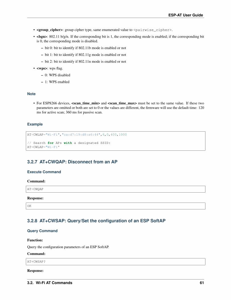
ESP-AT User Guide
• <group_cipher>: group cipher type, same enumerated value to <pairwise_cipher>.
• <bgn>: 802.11 b/g/n. If the corresponding bit is 1, the corresponding mode is enabled; if the corresponding bitis 0, the corresponding mode is disabled.
– bit 0: bit to identify if 802.11b mode is enabled or not
– bit 1: bit to identify if 802.11g mode is enabled or not
– bit 2: bit to identify if 802.11n mode is enabled or not
• <wps>: wps flag.
– 0: WPS disabled
– 1: WPS enabled
Note
• For ESP8266 devices, <scan_time_min> and <scan_time_max> must be set to the same value. If these twoparameters are omitted or both are set to 0 or the values are different, the firmware will use the default time: 120ms for active scan; 360 ms for passive scan.
Example
AT+CWLAP="Wi-Fi","ca:d7:19:d8:a6:44",6,0,400,1000
// Search for APs with a designated SSID:AT+CWLAP="Wi-Fi"
3.2.7 AT+CWQAP: Disconnect from an AP
Execute Command
Command:
AT+CWQAP
Response:
OK
3.2.8 AT+CWSAP: Query/Set the configuration of an ESP SoftAP
Query Command
Function:
Query the configuration parameters of an ESP SoftAP.
Command:
AT+CWSAP?
Response:
3.2. Wi-Fi AT Commands 61

ESP-AT User Guide
+CWSAP:<ssid>,<pwd>,<channel>,<ecn>,<max conn>,<ssid hidden>OK
Set Command
Function:
Set the configuration of an ESP SoftAP.
Command:
AT+CWSAP=<ssid>,<pwd>,<chl>,<ecn>[,<max conn>][,<ssid hidden>]
Response:
OK
Parameters
• <ssid>: string parameter showing SSID of the AP.
• <pwd>: string parameter showing the password. Length: 8 ~ 64 bytes ASCII.
• <channel>: channel ID.
• <ecn>: encryption method; WEP is not supported.
– 0: OPEN
– 2: WPA_PSK
– 3: WPA2_PSK
– 4: WPA_WPA2_PSK
• [<max conn>]: maximum number of stations that ESP SoftAP can connect. Range: [1,10].
• [<ssid hidden>]:
– 0: broadcasting SSID (default).
– 1: not broadcasting SSID.
Notes
• This command works only when AT+CWMODE=2 or AT+CWMODE=3.
• The configuration changes will be saved in the NVS area if AT+SYSSTORE=1.
62 Chapter 3. AT Command Set

ESP-AT User Guide
Example
AT+CWSAP="ESP","1234567890",5,3
3.2.9 AT+CWLIF: Obtain IP Address of the Station That Connects to an ESP SoftAP
Execute Command
Command:
AT+CWLIF
Response:
+CWLIF:<ip addr>,<mac>
OK
Parameters
• <ip addr>: IP address of the station that connects to the ESP SoftAP.
• <mac>: MAC address of the station that connects to the ESP SoftAP.
Note
• This command cannot get a static IP. It works only when DHCP of both the ESP SoftAP and the connectedstation are enabled.
3.2.10 AT+CWQIF: Disconnect Stations from an ESP SoftAP
Execute Command
Function:
Disconnect all stations that are connected to the ESP SoftAP.
Command:
AT+CWQIF
Response:
OK
3.2. Wi-Fi AT Commands 63

ESP-AT User Guide
Set Command
Function:
Disconnect a specific station from the ESP SoftAP.
Command:
AT+CWQIF=<mac>
Response:
OK
Parameter
• <mac>: MAC address of the station to disconnect.
3.2.11 AT+CWDHCP: Enable/Disable DHCP
Query Command
Command:
AT+CWDHCP?
Response:
<state>
Set Command
Function:
Enable/disable DHCP.
Command:
AT+CWDHCP=<operate>,<mode>
Response:
OK
64 Chapter 3. AT Command Set

ESP-AT User Guide
Parameters
• <operate>:
– 0: disable
– 1: enable
• <mode>:
– Bit0: Station DHCP
– Bit1: SoftAP DHCP
• <state>: the status of DHCP
– Bit0:
* 0: Station DHCP is disabled.
* 1: Station DHCP is enabled.
– Bit1:
* 0: SoftAP DHCP is disabled.
* 1: SoftAP DHCP is enabled.
– Bit2 (ESP32 only):
* 0: Ethernet DHCP is disabled.
* 1: Ethernet DHCP is enabled.
Notes
• The configuration changes will be saved in the NVS area if AT+SYSSTORE=1.
• This Set Command correlates with the commands that set static IP, such as AT+CIPSTA and AT+CIPAP:
– If DHCP is enabled, static IP address will be disabled;
– If static IP address is enabled, DHCP will be disabled;
– The last configuration overwrites the previous configuration.
Example
// Enable Station DHCP. If the last DHCP mode is 2, the current DHCP mode will be 3.AT+CWDHCP=1,1
// Disable SoftAP DHCP. If the last DHCP mode is 3, the current DHCP mode will be 1.AT+CWDHCP=0,2
3.2. Wi-Fi AT Commands 65

ESP-AT User Guide
3.2.12 AT+CWDHCPS: Query/Set the IP Addresses Allocated by an ESP SoftAPDHCP Server
Query Command
Command:
AT+CWDHCPS?
Response:
+CWDHCPS=<lease time>,<start IP>,<end IP>OK
Set Command
Function:
Set the IP address range of the ESP SoftAP DHCP server.
Command:
AT+CWDHCPS=<enable>,<lease time>,<start IP>,<end IP>
Response:
OK
Parameters
• <enable>:
– 1: Enable DHCP server settings. The parameters below have to be set.
– 0: Disable DHCP server settings and use the default IP address range.
• <lease time>: lease time. Unit: minute. Range [1,2880].
• <start IP>: start IP address of the IP address range that can be obtained from ESP SoftAP DHCP server.
• <end IP>: end IP address of the IP address range that can be obtained from ESP SoftAP DHCP server.
Notes
• The configuration changes will be saved in the NVS area if AT+SYSSTORE=1.
• This AT command works only when both SoftAP and DHCP server are enabled for ESP devices.
• The IP address should be in the same network segment as the IP address of ESP SoftAP.
66 Chapter 3. AT Command Set
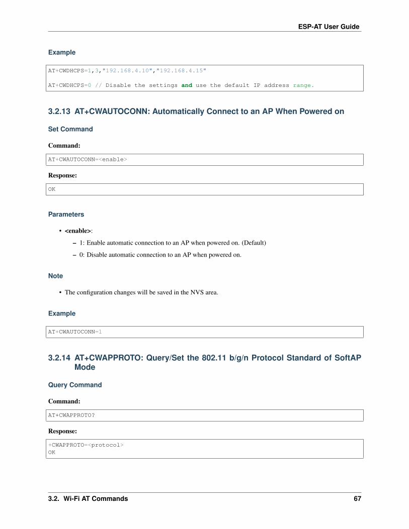
ESP-AT User Guide
Example
AT+CWDHCPS=1,3,"192.168.4.10","192.168.4.15"
AT+CWDHCPS=0 // Disable the settings and use the default IP address range.
3.2.13 AT+CWAUTOCONN: Automatically Connect to an AP When Powered on
Set Command
Command:
AT+CWAUTOCONN=<enable>
Response:
OK
Parameters
• <enable>:
– 1: Enable automatic connection to an AP when powered on. (Default)
– 0: Disable automatic connection to an AP when powered on.
Note
• The configuration changes will be saved in the NVS area.
Example
AT+CWAUTOCONN=1
3.2.14 AT+CWAPPROTO: Query/Set the 802.11 b/g/n Protocol Standard of SoftAPMode
Query Command
Command:
AT+CWAPPROTO?
Response:
+CWAPPROTO=<protocol>OK
3.2. Wi-Fi AT Commands 67

ESP-AT User Guide
Set Command
Command:
AT+CWAPPROTO=<protocol>
Response:
OK
Parameters
• <protocol>:
– bit0: 802.11b protocol standard.
– bit1: 802.11g protocol standard.
– bit2: 802.11n protocol standard.
Note
• Currently ESP devices only support 802.11b or 802.11bg or 802.11bgn mode.
• By default, PHY mode of ESP8266 device is 802.11bg mode, and PHY mode of non ESP8266 device is802.11bgn mode.
3.2.15 AT+CWSTAPROTO: Query/Set the 802.11 b/g/n Protocol Standard of StationMode
Query Command
Command:
AT+CWSTAPROTO?
Response:
+CWSTAPROTO=<protocol>OK
Set Command
Command:
AT+CWSTAPROTO=<protocol>
Response:
OK
68 Chapter 3. AT Command Set

ESP-AT User Guide
Parameters
• <protocol>:
– bit0: 802.11b protocol standard.
– bit1: 802.11g protocol standard.
– bit2: 802.11n protocol standard.
Note
• Currently ESP devices only support 802.11b or 802.11bg or 802.11bgn mode.
• By default, PHY mode of ESP8266 device is 802.11bg mode, and PHY mode of non ESP8266 device is802.11bgn mode.
3.2.16 AT+CIPSTAMAC: Query/Set the MAC Address of an ESP Station
Query Command
Function:
Query the MAC address of the ESP Station.
Command:
AT+CIPSTAMAC?
Response:
+CIPSTAMAC:<mac>OK
Set Command
Function:
Set the MAC address of an ESP station.
Command:
AT+CIPSTAMAC=<mac>
Response:
OK
3.2. Wi-Fi AT Commands 69

ESP-AT User Guide
Parameters
• <mac>: string parameter showing MAC address of an ESP station.
Notes
• The configuration changes will be saved in the NVS area if AT+SYSSTORE=1.
• The MAC address of ESP SoftAP is different from that of the ESP Station. Please make sure that you do not setthe same MAC address for both of them.
• Bit 0 of the ESP MAC address CANNOT be 1. For example, a MAC address can be “1a:. . . ” but not “15:. . . ”.
• FF:FF:FF:FF:FF:FF and 00:00:00:00:00:00 are invalid MAC address and cannot be set.
Example
AT+CIPSTAMAC="1a:fe:35:98:d3:7b"
3.2.17 AT+CIPAPMAC: Query/Set the MAC Address of an ESP SoftAP
Query Command
Function:
Query the MAC address of the ESP SoftAP.
Command:
AT+CIPAPMAC?
Response:
+CIPAPMAC:<mac>OK
Set Command
Function:
Set the MAC address of the ESP SoftAP.
Command:
AT+CIPAPMAC=<mac>
Response:
OK
70 Chapter 3. AT Command Set

ESP-AT User Guide
Parameters
• <mac>: string parameter showing MAC address of the ESP SoftAP.
Notes
• The configuration changes will be saved in the NVS area if AT+SYSSTORE=1.
• The MAC address of ESP SoftAP is different from that of the ESP station. Please make sure that you do not setthe same MAC address for both of them.
• Bit 0 of the ESP MAC address CANNOT be 1. For example, a MAC address can be “18:. . . ” but not “15:. . . ”.
• FF:FF:FF:FF:FF:FF and 00:00:00:00:00:00 are invalid MAC and cannot be set.
Example
AT+CIPAPMAC="18:fe:35:98:d3:7b"
3.2.18 AT+CIPSTA: Query/Set the IP Address of an ESP Station
Query Command
Function:
Query the IP address of the ESP Station.
Command:
AT+CIPSTA?
Response:
+CIPSTA:ip:<"ip">+CIPSTA:gateway:<"gateway">+CIPSTA:netmask:<"netmask">+CIPSTA:ip6ll:<"ipv6 addr">+CIPSTA:ip6gl:<"ipv6 addr">
OK
Set Command
Function:
Set the IPv4 address of the ESP station.
Command:
AT+CIPSTA=<"ip">[,<"gateway">,<"netmask">]
Response:
3.2. Wi-Fi AT Commands 71

ESP-AT User Guide
OK
Parameters
• <”ip”>: string parameter showing the IPv4 address of the ESP station.
• <”gateway”>: gateway.
• <”netmask”>: netmask.
• <”ipv6 addr”>: string parameter showing the IPv6 address of the ESP station.
Notes
• For the query command, only when the ESP station is connected to an AP or the static IP address is configuredcan its IP address be queried.
• The configuration changes will be saved in the NVS area if AT+SYSSTORE=1.
• The Set Command correlates with the commands that set DHCP, such as AT+CWDHCP.
– If static IP address is enabled, DHCP will be disabled;
– If DHCP is enabled, static IP address will be disabled;
– The last configuration overwrites the previous configuration.
Example
AT+CIPSTA="192.168.6.100","192.168.6.1","255.255.255.0"
3.2.19 AT+CIPAP: Query/Set the IP Address of an ESP SoftAP
Query Command
Function:
Query the IP address of the ESP SoftAP.
Command:
AT+CIPAP?
Response:
+CIPAP:ip:<"ip">+CIPAP:gateway:<"gateway">+CIPAP:netmask:<"netmask">+CIPAP:ip6ll:<"ipv6 addr">+CIPAP:ip6gl:<"ipv6 addr">
OK
72 Chapter 3. AT Command Set

ESP-AT User Guide
Set Command
Function:
Set the IPv4 address of the ESP SoftAP.
Command:
AT+CIPAP=<"ip">[,<"gateway">,<"netmask">]
Response:
OK
Parameters
• <”ip”>: string parameter showing the IPv4 address of the ESP SoftAP.
• <”gateway”>: gateway.
• <”netmask”>: netmask.
• <”ipv6 addr”>: string parameter showing the IPv6 address of the ESP SoftAP.
Notes
• The configuration changes will be saved in the NVS area if AT+SYSSTORE=1.
• The set command correlates with the commands that set DHCP, such as AT+CWDHCP.
– If static IP address is enabled, DHCP will be disabled;
– If DHCP is enabled, static IP address will be disabled;
– The last configuration overwrites the previous configuration.
Example
AT+CIPAP="192.168.5.1","192.168.5.1","255.255.255.0"
3.2.20 AT+CWSTARTSMART: Start SmartConfig
Execute Command
Function:
Start SmartConfig of the type ESP-TOUCH+AirKiss.
Command:
AT+CWSTARTSMART
3.2. Wi-Fi AT Commands 73

ESP-AT User Guide
Set Command
Function:
Start SmartConfig of a designated type.
Command:
AT+CWSTARTSMART=<type>[,<auth floor>]
Response:
OK
Parameters
• <type>:
– 1: ESP-TOUCH
– 2: AirKiss
– 3: ESP-TOUCH+AirKiss
• <auth floor>: Wi-Fi authentication mode floor. ESP-AT will not connect to the AP whose authmode is lowerthan this floor.
– 0: OPEN (Default)
– 1: WEP
– 2: WPA_PSK
– 3: WPA2_PSK
– 4: WPA_WPA2_PSK
– 5: WPA2_ENTERPRISE
– 6: WPA3_PSK
– 7: WPA2_WPA3_PSK
Notes
• For more details on SmartConfig, please see ESP-TOUCH User Guide.
• SmartConfig is only available in the ESP station mode.
• The message Smart get Wi-Fi info means that SmartConfig has successfully acquired the AP informa-tion. ESP device will try to connect to the target AP.
• Message Smartconfig connected Wi-Fi is printed if the connection is successful.
• When AT returns Smartconfig connected Wi-Fi, it is recommended to delay more than 6 secondsbefore executing AT+CWSTOPSMART because the ESP device needs to synchronize the SmartConfig resultsto the mobile phone.
• Use command AT+CWSTOPSMART to stop SmartConfig before running other commands. Please make surethat you do not execute other commands during SmartConfig.
74 Chapter 3. AT Command Set

ESP-AT User Guide
Example
AT+CWMODE=1AT+CWSTARTSMART
3.2.21 AT+CWSTOPSMART: Stop SmartConfig
Execute Command
Command:
AT+CWSTOPSMART
Response:
OK
Note
• Irrespective of whether SmartConfig succeeds or not, please always call AT+CWSTOPSMART before executingany other AT commands to release the internal memory taken up by SmartConfig.
Example
AT+CWMODE=1AT+CWSTARTSMARTAT+CWSTOPSMART
3.2.22 AT+WPS: Enable the WPS Function
Set Command
Command:
AT+WPS=<enable>[,<auth floor>]
Response:
OK
3.2. Wi-Fi AT Commands 75

ESP-AT User Guide
Parameters
• <enable>:
– 1: Enable WPS (Wi-Fi Protected Setup) that uses PBC (Push Button Configuration) mode.
– 0: Disable WPS that uses PBC mode.
• <auth floor>: Wi-Fi authentication mode floor. ESP-AT will not connect to the AP whose authmode is lowerthan this floor.
– 0: OPEN (Default)
– 1: WEP
– 2: WPA_PSK
– 3: WPA2_PSK
– 4: WPA_WPA2_PSK
– 5: WPA2_ENTERPRISE
– 6: WPA3_PSK
– 7: WPA2_WPA3_PSK
Notes
• WPS can only be used when the ESP station is enabled.
• WPS does not support WEP (Wired-Equivalent Privacy) encryption.
Example
AT+CWMODE=1AT+WPS=1
3.2.23 AT+MDNS: Configure the mDNS Function
Set Command
Command:
AT+MDNS=<enable>[,<hostname>,<service_name>,<port>]
Response:
OK
76 Chapter 3. AT Command Set

ESP-AT User Guide
Parameters
• <enable>:
– 1: Enable the mDNS function. The following three parameters need to be set.
– 0: Disable the mDNS function. The following three parameters does not need to be set.
• <hostname>: mDNS host name.
• <service_name>: mDNS service name.
• <port>: mDNS port.
Example
AT+MDNS=1,"espressif","_iot",8080AT+MDNS=0
3.2.24 [ESP32 Only] AT+CWJEAP: Connect to a WPA2 Enterprise AP
Query Command
Function:
Query the configuration information of the Enterprise AP to which the ESP station is already connected.
Command:
AT+CWJEAP?
Response:
+CWJEAP:<ssid>,<method>,<identity>,<username>,<password>,<security>OK
Set Command
Function:
Connect to the targeted Enterprise AP.
Command:
AT+CWJEAP=<ssid>,<method>,<identity>,<username>,<password>,<security>[,<jeap_timeout>]
Response:
OK
or
+CWJEAP:TimeoutERROR
3.2. Wi-Fi AT Commands 77

ESP-AT User Guide
Parameters
• <ssid>: the SSID of the Enterprise AP.
– Escape character syntax is needed if SSID or password contains any special characters, such as ,, ", or\\.
• <method>: WPA2 Enterprise authentication method.
– 0: EAP-TLS.
– 1: EAP-PEAP.
– 2: EAP-TTLS.
• <identity>: identity for phase 1. String limited to 1 ~ 32.
• <username>: username for phase 2. Range: 1 ~ 32 bytes. For the EAP-PEAP and EAP-TTLS method, youmust set this parameter. For the EAP-TLS method, you don’t need to.
• <password>: password for phase 2. Range: 1 ~ 32 bytes. For the EAP-PEAP and EAP-TTLS method, youmust set this parameter. For the EAP-TLS method, you don’t need to.
• <security>:
– Bit0: Client certificate.
– Bit1: Server certificate.
• [<jeap_timeout>]: maximum timeout for AT+CWJEAP command. Unit: second. Default: 15. Range: [3,600].
Example
// Connect to EAP-TLS mode Enterprise AP, set identity, verify server certificate and→˓load client certificateAT+CWJEAP="dlink11111",0,"[email protected]",,,3
// Connect to EAP-PEAP mode Enterprise AP, set identity, username and password, not→˓verify server certificate and not load client certificateAT+CWJEAP="dlink11111",1,"[email protected]","espressif","test11",0
Error Code:
The WPA2 Enterprise error code will be prompt as ERR CODE:0x<%08x>.
AT_EAP_MALLOC_FAILED 0x8001AT_EAP_GET_NVS_CONFIG_FAILED 0x8002AT_EAP_CONN_FAILED 0x8003AT_EAP_SET_WIFI_CONFIG_FAILED 0x8004AT_EAP_SET_IDENTITY_FAILED 0x8005AT_EAP_SET_USERNAME_FAILED 0x8006AT_EAP_SET_PASSWORD_FAILED 0x8007AT_EAP_GET_CA_LEN_FAILED 0x8008AT_EAP_READ_CA_FAILED 0x8009AT_EAP_SET_CA_FAILED 0x800AAT_EAP_GET_CERT_LEN_FAILED 0x800BAT_EAP_READ_CERT_FAILED 0x800CAT_EAP_GET_KEY_LEN_FAILED 0x800D
Continued on next page
78 Chapter 3. AT Command Set

ESP-AT User Guide
Table 2 – continued from previous pageAT_EAP_MALLOC_FAILED 0x8001AT_EAP_READ_KEY_FAILED 0x800EAT_EAP_SET_CERT_KEY_FAILED 0x800FAT_EAP_ENABLE_FAILED 0x8010AT_EAP_ALREADY_CONNECTED 0x8011AT_EAP_GET_SSID_FAILED 0x8012AT_EAP_SSID_NULL 0x8013AT_EAP_SSID_LEN_ERROR 0x8014AT_EAP_GET_METHOD_FAILED 0x8015AT_EAP_CONN_TIMEOUT 0x8016AT_EAP_GET_IDENTITY_FAILED 0x8017AT_EAP_IDENTITY_LEN_ERROR 0x8018AT_EAP_GET_USERNAME_FAILED 0x8019AT_EAP_USERNAME_LEN_ERROR 0x801AAT_EAP_GET_PASSWORD_FAILED 0x801BAT_EAP_PASSWORD_LEN_ERROR 0x801CAT_EAP_GET_SECURITY_FAILED 0x801DAT_EAP_SECURITY_ERROR 0x801EAT_EAP_METHOD_SECURITY_UNMATCHED 0x801FAT_EAP_PARAMETER_COUNTS_ERROR 0x8020AT_EAP_GET_WIFI_MODE_ERROR 0x8021AT_EAP_WIFI_MODE_NOT_STA 0x8022AT_EAP_SET_CONFIG_FAILED 0x8023AT_EAP_METHOD_ERROR 0x8024
Note
• The configuration changes will be saved in the NVS area if AT+SYSSTORE=1.
• This command requires Station mode to be active.
• TLS mode will use client certificate. Please make sure it is enabled.
3.2.25 AT+CWHOSTNAME: Query/Set the Host Name of an ESP Station
Query Command
Function:
Query the host name of ESP Station.
Command:
AT+CWHOSTNAME?
Response:
+CWHOSTNAME:<hostname>
OK
3.2. Wi-Fi AT Commands 79

ESP-AT User Guide
Set Command
Function:
Set the host name of ESP Station.
Command:
AT+CWHOSTNAME=<hostname>
Response:
OK
If the Station mode is not enabled, the command will return:
ERROR
Parameters
• <hostname>: the host name of the ESP Station. Maximum length: 32 bytes.
Note
• The configuration changes are not saved in the flash.
Example
AT+CWMODE=3AT+CWHOSTNAME="my_test"
3.2.26 AT+CWCOUNTRY: Query/Set the Wi-Fi Country Code
Query Command
Function:
Query Wi-Fi country code information.
Command:
AT+CWCOUNTRY?
Response:
+CWCOUNTRY:<country_policy>,<country_code>,<start_channel>,<total_channel_count>
OK
80 Chapter 3. AT Command Set
ESP-AT User Guide
Set Command
Function:
Set the Wi-Fi country code information.
Command:
AT+ CWCOUNTRY=<country_policy>,<country_code>,<start_channel>,<total_channel_count>
Response:
OK
Parameters
• <country_policy>:
– 0: will change the county code to be the same as the AP that the ESP device is connected to.
– 1: the country code will not change, always be the one set by command.
• <country_code>: country code. Maximum length: 3 characters.
• <start_channel>: the channel number to start. Range: [1,14].
• <total_channel_count>: total number of channels.
Note
• The configuration changes are not saved in the flash.
Example
AT+CWMODE=3AT+CWCOUNTRY=1,"CN",1,13
3.3 TCP/IP AT Commands
[]
• AT+CIPV6: Enable/disable the network of Internet Protocol Version 6 (IPv6).
• AT+CIPSTATUS: Obtain the TCP/UDP/SSL connection status and information.
• AT+CIPDOMAIN: Resolve a Domain Name.
• AT+CIPSTART: Establish TCP connection, UDP transmission, or SSL connection.
• AT+CIPSTARTEX: Establish TCP connection, UDP transmission, or SSL connection with an automaticallyassigned ID.
• [Passthrough Mode Only] +++: Exit the passthrough mode.
• AT+CIPSEND: Send data in the normal transmission mode or Wi-Fi passthrough mode.
• AT+CIPSENDEX: Send data in the normal transmission mode in expanded ways.
3.3. TCP/IP AT Commands 81
ESP-AT User Guide
• AT+CIPCLOSE: Close TCP/UDP/SSL connection.
• AT+CIFSR: Obtain the local IP address and MAC address.
• AT+CIPMUX: Enable/disable the multiple connections mode.
• AT+CIPSERVER: Delete/create a TCP/SSL server.
• AT+CIPSERVERMAXCONN: Query/Set the maximum connections allowed by a server.
• AT+CIPMODE: Query/Set the transmission mode.
• AT+SAVETRANSLINK: Set whether to enter Wi-Fi passthrough mode on power-up.
• AT+CIPSTO: Query/Set the local TCP Server Timeout.
• AT+CIPSNTPCFG: Query/Set the time zone and SNTP server.
• AT+CIPSNTPTIME: Query the SNTP time.
• AT+CIUPDATE: Upgrade the firmware through Wi-Fi.
• AT+CIPDINFO: Set “+IPD” message mode.
• AT+CIPSSLCCONF: Query/Set SSL clients.
• AT+CIPSSLCCN: Query/Set the Common Name of the SSL client.
• AT+CIPSSLCSNI: Query/Set SSL client Server Name Indication (SNI).
• AT+CIPSSLCALPN: Query/Set SSL client Application Layer Protocol Negotiation (ALPN).
• AT+CIPSSLCPSK: Query/Set SSL client Pre-shared Key (PSK).
• AT+CIPRECONNINTV: Query/Set the TCP/UDP/SSL reconnection interval for the Wi-Fi passthrough mode.
• AT+CIPRECVMODE: Query/Set socket receiving mode.
• AT+CIPRECVDATA: Obtain socket data in passive receiving mode.
• AT+CIPRECVLEN: Obtain socket data length in passive receiving mode.
• AT+PING: Ping the remote host.
• AT+CIPDNS: Query/Set DNS server information.
• AT+CIPTCPOPT: Query/Set the socket options.
3.3.1 AT+CIPV6: Enable/disable the network of Internet Protocol Version 6 (IPv6)
Query Command
Function:
Query whether IPv6 is enabled.
Command:
AT+CIPV6?
Response:
+CIPV6:<enable>
OK
82 Chapter 3. AT Command Set

ESP-AT User Guide
Set Command
Function:
Enable/Disable IPv6 network.
Command:
AT+CIPV6=<enable>
Response:
OK
Parameters
• <enable>: status of IPv6 network. Default: 0.
– 0: disable IPv6 network.
– 1: enable IPv6 network.
Notes
• You should enable IPv6 network before using IPv6 related upper layer AT commands(TCP/UDP/SSL/PING/DNS based on IPv6 network, also known as TCP6/UDP6/SSL6/PING6/DNS6 orTCPv6/UDPv6/SSLv6/PINGv6/DNSv6).
3.3.2 AT+CIPSTATUS: Obtain the TCP/UDP/SSL Connection Status and Information
Execute Command
Command:
AT+CIPSTATUS
Response:
STATUS:<stat>+CIPSTATUS:<link ID>,<"type">,<"remote IP">,<remote port>,<local port>,<tetype>OK
Parameters
• <stat>: status of the ESP station interface.
– 0: The ESP station is not initialized.
– 1: The ESP station is initialized, but not started a Wi-Fi connection yet.
– 2: The ESP station is connected to an AP and its IP address is obtained.
– 3: The ESP station has created a TCP/SSL transmission.
– 4: All of the TCP/UDP/SSL connections of the ESP device station are disconnected.
3.3. TCP/IP AT Commands 83

ESP-AT User Guide
– 5: The ESP station started a Wi-Fi connection, but was not connected to an AP or disconnected from anAP.
• <link ID>: ID of the connection (0~4), used for multiple connections.
• <”type”>: string parameter showing the type of transmission: “TCP”, “TCPv6”, “UDP”, “UDPv6”, “SSL”, or“SSLv6”.
• <”remote IP”>: string parameter showing the remote IPv4 address or IPv6 address.
• <remote port>: the remote port number.
• <local port>: the local port number.
• <tetype>:
– 0: ESP device runs as a client.
– 1: ESP device runs as a server.
3.3.3 AT+CIPDOMAIN: Resolve a Domain Name
Set Command
Command:
AT+CIPDOMAIN=<"domain name">[,<ip network>]
Response:
+CIPDOMAIN:<"IP address">
OK
Parameter
• <”domain name”>: the domain name.
• <ip network>: preferred IP network. Default: 1.
– 1: preferred resolution of IPv4 address
– 2: resolve IPv4 address only
– 3: resolve IPv6 address only
• <”IP address”>: the resolved IPv4 address or IPv6 address.
Example
AT+CWMODE=1 // set the station modeAT+CWJAP="SSID","password" // access to the internetAT+CIPDOMAIN="iot.espressif.cn" // Domain Name Resolution function
// Domain Name Resolution Function for IPv4 address onlyAT+CIPDOMAIN="iot.espressif.cn",2
// Domain Name Resolution Function for IPv6 address only
(continues on next page)
84 Chapter 3. AT Command Set
ESP-AT User Guide
(continued from previous page)
AT+CIPDOMAIN="ipv6.test-ipv6.com",3
// Domain Name Resolution Function for compatible IP addressAT+CIPDOMAIN="ds.test-ipv6.com",1
3.3.4 AT+CIPSTART: Establish TCP Connection, UDP Transmission, or SSL Con-nection
Establish TCP Connection
Set Command
Command:
// Single connection (AT+CIPMUX=0):AT+CIPSTART=<"type">,<"remote host">,<remote port>[,<keep alive>][,<"local IP">]
// Multiple Connections (AT+CIPMUX=1):AT+CIPSTART=<link ID>,<"type">,<"remote host">,<remote port>[,<keep alive>][,<"local→˓IP">]
Response:
CONNECT
OK
Parameters
• <link ID>: ID of network connection (0~4), used for multiple connections.
• <”type”>: string parameter showing the type of transmission: “TCP”, or “TCPv6”. Default: “TCP”.
• <”remote host”>: string parameter showing the IPv4 address or IPv6 address or domain name of remote host.
• <remote port>: the remote port number.
• <keep alive>: TCP keep-alive interval. Default: 0.
– 0: disable TCP keep-alive function.
– 1 ~ 7200: detection interval. Unit: second.
• <”local IP”>: the local IPv4 address or IPv6 address that the connection binds. This parameter is useful whenyou are using multiple network interfaces or multiple IP addresses. By default, it is disabled. If you want to useit, you should specify it first. Null is also valid.
3.3. TCP/IP AT Commands 85

ESP-AT User Guide
Notes
• If you want to establish TCP connection based on IPv6 network, set AT+CIPV6=1 first, and ensure the con-nected AP by AT+CWJAP supports IPv6 and esp-at got the IPv6 address which you can check it by AT+CIPSTA.
• <keep alive> parameter will eventually be configured to the socket option TCP_KEEPIDLE. As for othersocket options of keepalive, TCP_KEEPINTVLwill use 1 by default, and TCP_KEEPCNTwill use 3 by default.
Example
AT+CIPSTART="TCP","iot.espressif.cn",8000AT+CIPSTART="TCP","192.168.101.110",1000AT+CIPSTART="TCP","192.168.101.110",1000,,"192.168.101.100"AT+CIPSTART="TCPv6","test-ipv6.com",80AT+CIPSTART="TCPv6","fe80::860d:8eff:fe9d:cd90",1000,,"fe80::411c:1fdb:22a6:4d24"
// esp-at has obtained an IPv6 global address by AT+CWJAP beforeAT+CIPSTART="TCPv6","2404:6800:4005:80b::2004",80,,→˓"240e:3a1:2070:11c0:32ae:a4ff:fe80:65ac"
Establish UDP Transmission
Set Command
Command:
// Single connection (AT+CIPMUX=0):AT+CIPSTART=<"type">,<"remote host">,<remote port>[,<local port>,<mode>,<"local IP">]
// Multiple connections (AT+CIPMUX=1):AT+CIPSTART=<link ID>,<"type">,<"remote host">,<remote port>[,<local port>,<mode>,<→˓"local IP">]
Response:
CONNECT
OK
Parameters
• <link ID>: ID of network connection (0~4), used for multiple connections.
• <”type”>: string parameter showing the type of transmission: “UDP”, or “UDPv6”. Default: “TCP”.
• <”remote host”>: string parameter showing the IPv4 address or IPv6 address or domain name of remote host.
• <remote port>: remote port number.
• <local port>: UDP port of ESP devices.
• <mode>: In the UDP Wi-Fi passthrough, the value of this parameter has to be 0.
– 0: After UDP data is received, the parameters <"remote host"> and <remote port> will stayunchanged (default).
86 Chapter 3. AT Command Set

ESP-AT User Guide
– 1: Only the first time that UDP data is received from an IP address and port that are different from theinitially set value of parameters <remote host> and <remote port>, will they be changed to theIP address and port of the device that sends the data.
– 2: Each time UDP data is received, the <"remote host"> and <remote port> will be changed tothe IP address and port of the device that sends the data.
• <”local IP”>: the local IPv4 address or IPv6 address that the connection binds. This parameter is useful whenyou are using multiple network interfaces or multiple IP addresses. By default, it is disabled. If you want to useit, you should specify it first. Null is also valid.
Notes
• If the remote host over the UDP is an IPv4 multicast address (224.0.0.0 ~ 239.255.255.255), the ESP device willsend and receive the UDPv4 multicast.
• If the remote host over the UDP is an IPv4 broadcast address (255.255.255.255), the ESP device will send andreceive the UDPv4 broadcast.
• If the remote host over the UDP is an IPv6 multicast address (FF00:0:0:0:0:0:0:0 ~FFFF:FFFF:FFFF:FFFF:FFFF:FFFF:FFFF:FFFF), the ESP device will send and receive the UDP multi-cast based on IPv6 network.
• To use the parameter <mode>, parameter <local port> must be set first.
• If you want to establish UDP connection based on IPv6 network, set AT+CIPV6=1 first, and ensure the con-nected AP by AT+CWJAP supports IPv6 and esp-at got the IPv6 address which you can check it by AT+CIPSTA.
Example
// UDP unicastAT+CIPSTART="UDP","192.168.101.110",1000,1002,2AT+CIPSTART="UDP","192.168.101.110",1000,,,"192.168.101.100"
// UDP unicast based on IPv6 networkAT+CIPSTART="UDPv6","fe80::32ae:a4ff:fe80:65ac",1000,,,"fe80::5512:f37f:bb03:5d9b"
// UDP multicast based on IPv6 networkAT+CIPSTART="UDPv6","FF02::FC",1000,1002,0
Establish SSL Connection
Set Command
Command:
AT+CIPSTART=[<link ID>,]<"type">,<"remote host">,<remote port>[,<keep alive>,<"local→˓IP">]
Response:
OK
3.3. TCP/IP AT Commands 87

ESP-AT User Guide
Parameters
• <link ID>: ID of network connection (0~4), used for multiple connections.
• <”type”>: string parameter showing the type of transmission: “SSL”, or “SSLv6”. Default: “TCP”.
• <”remote host”>: string parameter showing the IPv4 address or IPv6 address or domain name of remote host.
• <remote port>: the remote port number.
• <keep alive>: reserved item for SSL. Default: 0.
• <”local IP”>: the local IPv4 address or IPv6 address that the connection binds. This parameter is useful whenyou are using multiple network interfaces or multiple IP addresses. By default, it is disabled. If you want to useit, you should specify it first. Null is also valid.
Notes
• The number of SSL connections depends on available memory and the maximum number of connections. ForESP8266 devices, only one SSL connection can be established due to limited memory.
• SSL connection needs a large amount of memory. Insufficient memory may cause the system reboot.
• If the AT+CIPSTART is based on an SSL connection and the timeout of each packet is 10 s, the total timeoutwill be much longer depending on the number of handshake packets.
• If you want to establish SSL connection based on IPv6 network, set AT+CIPV6=1 first, and ensure the connectedAP by AT+CWJAP supports IPv6 and esp-at got the IPv6 address which you can check it by AT+CIPSTA.
• <keep alive> parameter will eventually be configured to the socket option TCP_KEEPIDLE. As for othersocket options of keepalive, TCP_KEEPINTVLwill use 1 by default, and TCP_KEEPCNTwill use 3 by default.
Example
AT+CIPSTART="SSL","iot.espressif.cn",8443AT+CIPSTART="SSL","192.168.101.110",1000,,"192.168.101.100"
// esp-at has obtained an IPv6 global address by AT+CWJAP beforeAT+CIPSTART="SSLv6","240e:3a1:2070:11c0:6972:6f96:9147:d66d",1000,,→˓"240e:3a1:2070:11c0:55ce:4e19:9649:b75"
3.3.5 AT+CIPSTARTEX: Establish TCP connection, UDP transmission, or SSL con-nection with an Automatically Assigned ID
This command is similar to AT+CIPSTART except that you don’t need to assign an ID by yourself in multiple connec-tions mode (AT+CIPMUX=1). The system will assign an ID to the new connection automatically.
88 Chapter 3. AT Command Set

ESP-AT User Guide
3.3.6 [Passthrough Mode Only] +++: Exit from Passthrough Mode
Special Execute Command
Function:
Exit from Passthrough Mode and enter the Passthrough Receiving Mode.
Command:
// Only for passthrough mode+++
Notes
• This special execution command consists of three identical + characters (0x2b ASCII), and no CR-LF appendsto the command tail.
• Make sure there is more than 20 ms interval before the first + character, more than 20 ms interval after the third+ character, less than 20 ms interval among the three + characters. Otherwise, the + characters will be sent outas normal passthrough data.
• This command returns no reply.
3.3.7 AT+CIPSEND: Send Data in the Normal Transmission Mode or Wi-FiPassthrough Mode
Set Command
Function:
Set the data length to be send in the Normal Transmission Mode.
Command:
// Single connection: (AT+CIPMUX=0)AT+CIPSEND=<length>
// Multiple connections: (AT+CIPMUX=1)AT+CIPSEND=<link ID>,<length>
// Remote host and port can be set for UDP transmission:AT+CIPSEND=[<link ID>,]<length>[,<"remote host">,<remote port>]
Response:
OK
>
This response indicates that AT is ready for receiving serial data. You should enter the data, and when the data lengthreaches the <length> value, the transmission of data starts.
If the connection cannot be established or is disrupted during data transmission, the system returns:
3.3. TCP/IP AT Commands 89

ESP-AT User Guide
ERROR
If data is transmitted successfully, the system returns:
SEND OK
Execute Command
Function:
Enter the Wi-Fi Passthrough Mode.
Command:
AT+CIPSEND
Response:
OK>
or
ERROR
Enter the Wi-Fi Passthrough Mode. The ESP8266 devices can receive 2048 bytes and send 1460 bytes at most eachtime; the other ESP devices can receive 8192 bytes and send 2920 bytes at most each time. If the length of thecurrently received data is greater than the maximum number of bytes that can be sent, AT will send the received dataimmediately; Otherwise, the received data will be sent out within 20 ms. When a single packet containing +++ isreceived, the ESP device will exit the data sending mode under the Wi-Fi Passthrough Mode. Please wait for at leastone second before sending the next AT command.
This command can only be used for single connection in the Wi-Fi Passthrough Mode. For UDP Wi-Fi passthrough,the <mode> parameter has to be 0 when using AT+CIPSTART .
Parameters
• <link ID>: ID of the connection (0~4), for multiple connections.
• <length>: data length. Maximum: 2048 bytes.
• <”remote host”>: IPv4 address or IPv6 address or domain name of remote host, can be set in UDP transmission.
• <remote port>: the remote port number.
3.3.8 AT+CIPSENDEX: Send Data in the Normal Transmission Mode in ExpandedWays
Set Command
Function:
Set the data length to be send in Normal Transmission Mode, or use \0 (0x5c, 0x30 ASCII) to trigger data transmis-sion.
Command:
90 Chapter 3. AT Command Set

ESP-AT User Guide
// Single connection: (AT+CIPMUX=0)AT+CIPSENDEX=<length>
// Multiple connections: (AT+CIPMUX=1)AT+CIPSENDEX=<link ID>,<length>
// Remote host and port can be set for UDP transmission:AT+CIPSENDEX=[<link ID>,]<length>[,<"remote host">,<remote port>]
Response:
OK
>
This response indicates that AT is ready for receiving data. You should enter the data of designated length. When thedata length reaches the <length> value, or when the string \0 appears in the data, the transmission starts.
If the connection cannot be established or gets disconnected during transmission, the system returns:
ERROR
If the data are successfully transmitted, the system returns:
SEND OK
Parameters
• <link ID>: ID of the connection (0~4), for multiple connections.
• <length>: data length. Maximum: 2048 bytes.
• <”remote host”>: IPv4 address or IPv6 address or domain name of remote host, can be set in UDP transmission.
• <remote port>: remote port can be set in UDP transmission.
Notes
• When the requirement of data length is met, or when the string \0 (0x5c, 0x30 in ASCII) appears, the transmis-sion of data starts. Go back to the normal command mode and wait for the next AT command.
• If the data contains the \<any>, it means that drop backslash symbol and only use <any> character.
• When sending \0, please use a backslash to escape it as \\0.
3.3.9 AT+CIPCLOSE: Close TCP/UDP/SSL Connection
Set Command
Function:
Close TCP/UDP/SSL connection in the multiple connections mode.
Command:
3.3. TCP/IP AT Commands 91

ESP-AT User Guide
AT+CIPCLOSE=<link ID>
Execute Command
Function:
Close TCP/UDP/SSL connection in the single connection mode.
AT+CIPCLOSE
Response:
OK
Parameter
• <link ID>: ID of the connection that you want to close. If you set it to 5, all connections will be closed.
3.3.10 AT+CIFSR: Obtain the Local IP Address and MAC Address
Execute Command
Command:
AT+CIFSR
Response:
+CIFSR:APIP,<"APIP">+CIFSR:APIP6LL,<"APIP6LL">+CIFSR:APIP6GL,<"APIP6GL">+CIFSR:APMAC,<"APMAC">+CIFSR:STAIP,<"STAIP">+CIFSR:STAIP6LL,<"STAIP6LL">+CIFSR:STAIP6GL,<"STAIP6GL">+CIFSR:STAMAC,<"STAMAC">+CIFSR:ETHIP,<"ETHIP">+CIFSR:ETHIP6LL,<"ETHIP6LL">+CIFSR:ETHIP6GL,<"ETHIP6GL">+CIFSR:ETHMAC,<"ETHMAC">
OK
92 Chapter 3. AT Command Set
ESP-AT User Guide
Parameters
• <”APIP”>: IPv4 address of Wi-Fi softAP interface
• <”APIP6LL”>: Linklocal IPv6 address of Wi-Fi softAP interface
• <”APIP6GL”>: Global IPv6 address of Wi-Fi softAP interface
• <”APMAC”>: MAC address of Wi-Fi softAP interface
• <”STAIP”>: IPv4 address of Wi-Fi station interface
• <”STAIP6LL”>: Linklocal IPv6 address of Wi-Fi station interface
• <”STAIP6GL”>: Global IPv6 address of Wi-Fi station interface
• <”STAMAC”>: MAC address of Wi-Fi station interface
• <”ETHIP”>: IPv4 address of ethernet interface
• <”ETHIP6LL”>: Linklocal IPv6 address of ethernet interface
• <”ETHIP6GL”>: Global IPv6 address of ethernet interface
• <”ETHMAC”>: MAC address of ethernet interface
Note
• Only when the ESP device has the valid interface information can you query its IP address and MAC address.
3.3.11 AT+CIPMUX: Enable/disable Multiple Connections
Query Command
Function:
Query the connection type.
Command:
AT+CIPMUX?
Response:
+CIPMUX:<mode>OK
Set Command
Function:
Set the connection type.
Command:
AT+CIPMUX=<mode>
Response:
3.3. TCP/IP AT Commands 93

ESP-AT User Guide
OK
Parameter
• <mode>: connection mode. Default: 0.
– 0: single connection.
– 1: multiple connections.
Notes
• This mode can only be changed after all connections are disconnected.
• If you want to set the multiple connections mode, ESP devices should be in the Normal Transmission Mode(AT+CIPMODE=0).
• If you want to set the single connection mode when the TCP/SSL server is running, you should delete the serverfirst. (AT+CIPSERVER=0).
Example
AT+CIPMUX=1
3.3.12 AT+CIPSERVER: Delete/create a TCP/SSL Server
Query Command
Function:
Query the TCP/SSL server status.
Command:
AT+CIPSERVER?
Response:
+CIPSERVER:<mode>[,<port>,<"type">][,<CA enable>]
OK
Set Command
Command:
AT+CIPSERVER=<mode>[,<param2>][,<"type">][,<CA enable>]
Response:
OK
94 Chapter 3. AT Command Set

ESP-AT User Guide
Parameters
• <mode>:
– 0: delete a server.
– 1: create a server.
• <param2>: It means differently depending on the parameter <mode>:
• If <mode> is 1, <param2> represents the port number. Default: 333.
• If <mode> is 0, <param2> represents whether the server closes all connections. Default: 0.
– 0: shutdown the server and keep existing connections.
– 1: shutdown the server and close all connections.
• <”type”>: server type: “TCP”, “TCPv6”, “SSL”, or “SSLv6”. Default: “TCP”. This parameter is NOTapplicable to ESP8266 platform due to memory limitation.
• <CA enable>: not applicable to ESP8266 devices.
– 0: disable CA.
– 1: enable CA.
Notes
• A TCP/SSL server can only be created when multiple connections are activated (AT+CIPMUX=1).
• A server monitor will be created automatically when the server is created. Only one server can be created atmost.
• When a client is connected to the server, it will take up one connection and be assigned an ID.
• If you want to create a TCP/SSL server based on IPv6 network, set AT+CIPV6=1 first, and obtain an IPv6address.
Example
// To create a TCP serverAT+CIPMUX=1AT+CIPSERVER=1,80
// To create an SSL serverAT+CIPMUX=1AT+CIPSERVER=1,443,"SSL",1
// To create an SSL server based on IPv6 networkAT+CIPMUX=1AT+CIPSERVER=1,443,"SSLv6",0
// To delete an server and close all clientsAT+CIPSERVER=0,1
3.3. TCP/IP AT Commands 95

ESP-AT User Guide
3.3.13 AT+CIPSERVERMAXCONN: Query/Set the Maximum Connections Allowedby a Server
Query Command
Function:
Obtain the maximum number of clients allowed to connect to the TCP/SSL server.
Command:
AT+CIPSERVERMAXCONN?
Response:
+CIPSERVERMAXCONN:<num>OK
Set Command
Function:
Set the maximum number of clients allowed to connect to the TCP/SSL server.
Command:
AT+CIPSERVERMAXCONN=<num>
Response:
OK
Parameter
• <num>: the maximum number of clients allowed to connect to the TCP/SSL server.
Note
• You should call the command AT+CIPSERVERMAXCONN=<num> before creating a server.
Example
AT+CIPMUX=1AT+CIPSERVERMAXCONN=2AT+CIPSERVER=1,80
96 Chapter 3. AT Command Set
ESP-AT User Guide
3.3.14 AT+CIPMODE: Query/Set the Transmission Mode
Query Command
Function:
Query the transmission mode.
Command:
AT+CIPMODE?
Response:
+CIPMODE:<mode>OK
Set Command
Function:
Set the transmission mode.
Command:
AT+CIPMODE=<mode>
Response:
OK
Parameter
• <mode>:
– 0: Normal Transmission Mode.
– 1: Wi-Fi Passthrough Receiving Mode, or called transparent receiving transmission, which can only beenabled in TCP single connection mode, UDP mode when the remote host and port do not change, or SSLsingle connection mode.
Notes
• The configuration changes will NOT be saved in flash.
3.3. TCP/IP AT Commands 97
ESP-AT User Guide
Example
AT+CIPMODE=1
3.3.15 AT+SAVETRANSLINK: Set Whether to Enter Wi-Fi Passthrough Mode onPower-up
For TCP/SSL Single Connection
Set Command
Command:
AT+SAVETRANSLINK=<mode>,<"remote host">,<remote port>[,<"type">,<keep alive>]
Response:
OK
Parameters
• <mode>:
– 0: ESP will NOT enter Wi-Fi Passthrough Mode on power-up.
– 1: ESP will enter Wi-Fi Passthrough Mode on power-up.
• <”remote host”>: string parameter showing the IPv4 address or IPv6 address or domain name of remote host.
• <remote port>: the remote port number.
• <”type”>: string parameter showing the type of transmission: “TCP”, “TCPv6”, “SSL”, or “SSLv6”. Default:“TCP”.
• <keep alive>: TCP keep-alive interval. Default: 0.
– 0: disable the keep-alive function.
– 1 ~ 7200: detection interval. Unit: second.
Notes
• This command will save the Wi-Fi Passthrough Mode configuration in the NVS area. If <mode> is set to 1,ESP device will enter the Wi-Fi Passthrough Mode in any subsequent power cycles. The configuration will takeeffect after ESP reboots.
• As long as the remote host and port are valid, the configuration will be saved in flash.
• If you want to establish TCP/SSL connection based on IPv6 network, set AT+CIPV6=1 first, and ensure the con-nected AP by AT+CWJAP supports IPv6 and esp-at got the IPv6 address which you can check it by AT+CIPSTA.
98 Chapter 3. AT Command Set

ESP-AT User Guide
Example
AT+SAVETRANSLINK=1,"192.168.6.110",1002,"TCP"AT+SAVETRANSLINK=1,"www.baidu.com",443,"SSL"AT+SAVETRANSLINK=1,"240e:3a1:2070:11c0:55ce:4e19:9649:b75",8080,"TCPv6"AT+SAVETRANSLINK=1,"240e:3a1:2070:11c0:55ce:4e19:9649:b75",8080,"SSLv6"
For UDP Transmission
Set Command
Command:
AT+SAVETRANSLINK=<mode>,<"remote host">,<remote port>,[<"type">,<local port>]
Response:
OK
Parameters
• <mode>:
– 0: ESP will NOT enter Wi-Fi Passthrough Mode on power-up.
– 1: ESP will enter Wi-Fi Passthrough Mode on power-up.
• <”remote host”>: string parameter showing the IPv4 address or IPv6 address or domain name of remote host.
• <remote port>: the remote port number.
• <”type”>: string parameter showing the type of transmission: “UDP” or “UDPv6”. Default: “TCP”.
• <local port>: local port when UDP Wi-Fi passthrough is enabled on power-up.
Notes
• This command will save the Wi-Fi Passthrough Mode configuration in the NVS area. If <mode> is set to 1,ESP device will enter the Wi-Fi Passthrough Mode in any subsequent power cycles. The configuration will takeeffect after ESP reboots.
• As long as the remote host and port are valid, the configuration will be saved in flash.
• If you want to establish UDP transmission based on IPv6 network, set AT+CIPV6=1 first, and ensure the con-nected AP by AT+CWJAP supports IPv6 and esp-at got the IPv6 address which you can check it by AT+CIPSTA.
3.3. TCP/IP AT Commands 99

ESP-AT User Guide
Example
AT+SAVETRANSLINK=1,"192.168.6.110",1002,"UDP",1005AT+SAVETRANSLINK=1,"240e:3a1:2070:11c0:55ce:4e19:9649:b75",8081,"UDPv6",1005
3.3.16 AT+CIPSTO: Query/Set the local TCP/SSL Server Timeout
Query Command
Function:
Query the local TCP/SSL server timeout.
Command:
AT+CIPSTO?
Response:
+CIPSTO:<time>OK
Set Command
Function:
Set the local TCP/SSL server timeout.
Command:
AT+CIPSTO=<time>
Response:
OK
Parameter
• <time>: local TCP/SSL server timeout. Unit: second. Range: [0,7200].
Notes
• When a TCP/SSL client does not communicate with the ESP server within the <time> value, the server willterminate this connection.
• If you set <time> to 0, the connection will never timeout. This configuration is not recommended.
• When the client initiates a communication with the server within the set time, the timer will restart. After thetimeout expires, the client is closed. During the set time, if the server initiate a communication with the client,the timer will not restart. After the timeout expires, the client is closed.
100 Chapter 3. AT Command Set
ESP-AT User Guide
Example
AT+CIPMUX=1AT+CIPSERVER=1,1001AT+CIPSTO=10
3.3.17 AT+CIPSNTPCFG: Query/Set the Time Zone and the SNTP Server
Query Command
Command:
AT+CIPSNTPCFG?
Response:
+CIPSNTPCFG:<enable>,<timezone>,<SNTP server1>[,<SNTP server2>,<SNTP server3>]OK
Set Command
Command:
AT+CIPSNTPCFG=<enable>,<timezone>[,<SNTP server1>,<SNTP server2>,<SNTP server3>]
Response:
OK
Parameters
• <enable>: configure the SNTP server:
– 1: the SNTP server is configured.
– 0: the SNTP server is not configured.
• <timezone>: support the following two formats:
– The first format range is [-12,14]. It marks most of the time zones by offset from Coordinated UniversalTime (UTC) in whole hours (UTC12:00 to UTC+14:00).
– The second format is UTC offset. The UTC offset specifies the time value you must add to the UTCtime to get a local time value. It has syntax like [+|-][hh]mm. This is negative if the local time zone ison the west of the Prime Meridian and positive if it is on the east. The hour(hh) must be between -12 and14, and the minute(mm) between 0 and 59. For example, if you want to set the timezone to New Zealand(Chatham Islands) which is in UTC+12:45, you should set the parameter <timezone> to 1245. Pleaserefer to UTC offset wiki for more information.
• [<SNTP server1>]: the first SNTP server.
• [<SNTP server2>]: the second SNTP server.
• [<SNTP server3>]: the third SNTP server.
3.3. TCP/IP AT Commands 101
ESP-AT User Guide
Note
• If the three SNTP servers are not configured, one of the following default servers will be used: “cn.ntp.org.cn”,“ntp.sjtu.edu.cn”, and “us.pool.ntp.org”.
• For the query command, <timezone> parameter in the response may be different from the <timezone>parameter in set command. Because the <timezone> parameter supports the second UTC offset format,for example, set AT+CIPSNTPCFG=1,015, for query command, ESP-AT ignores the leading zero of the<timezone> parameter, and the valid value is 15. It does not belong to the first format, so it is parsedaccording to the second UTC offset format, that is, UTC+00:15, that is, timezone is 0 in the response.
Example
// Enable SNTP server, set timezone to China (UTC+08:00)AT+CIPSNTPCFG=1,8,"cn.ntp.org.cn","ntp.sjtu.edu.cn"orAT+CIPSNTPCFG=1,800,"cn.ntp.org.cn","ntp.sjtu.edu.cn"
// Enable SNTP server, set timezone to New York of the United States (UTC05:00)AT+CIPSNTPCFG=1,-5,"0.pool.ntp.org","time.google.com"orAT+CIPSNTPCFG=1,-500,"0.pool.ntp.org","time.google.com"
// Enable SNTP server, set timezone to New Zealand (Chatham Islands, UTC+12:45)AT+CIPSNTPCFG=1,1245,"0.pool.ntp.org","time.google.com"
3.3.18 AT+CIPSNTPTIME: Query the SNTP Time
Query Command
Command:
AT+CIPSNTPTIME?
Response:
+CIPSNTPTIME:<asctime style time>OK
Note
• The asctime style time is defined at asctime man page.
102 Chapter 3. AT Command Set
ESP-AT User Guide
Example
AT+CIPSNTPCFG=1,8,"cn.ntp.org.cn","ntp.sjtu.edu.cn"
OK
AT+CIPSNTPTIME?+CIPSNTPTIME:Mon Dec 12 02:33:32 2016OK
3.3.19 AT+CIUPDATE: Upgrade Firmware Through Wi-Fi
ESP-AT upgrades firmware at runtime by downloading the new firmware from a specific server through Wi-Fi andthen flash it into some partitions.
Query Command
Function:
Query ESP device upgrade status.
Command:
AT+CIUPDATE?
Response:
+CIPUPDATE:<state>OK
Execute Command
Function:
Upgrade OTA the latest version of firmware via TCP/SSL from the server.
Command:
AT+CIUPDATE
Response:
+CIPUPDATE:<state>OK
or
ERROR
3.3. TCP/IP AT Commands 103

ESP-AT User Guide
Set Command
Function:
Upgrade the specified version of firmware from the server.
Command:
AT+CIUPDATE=<ota mode>[,<version>][,<firmware name>][,<nonblocking>]
Response:
+CIPUPDATE:<state>OK
or
ERROR
Parameters
• <ota mode>:
– 0: OTA via HTTP.
– 1: OTA via HTTPS. If it does not work, please check whether ./build.py menuconfig >Component config > AT > OTA based upon ssl is enabled. For more information, please referto Build Your Own ESP-AT Project.
• <version>: AT version, such as, v1.2.0.0, v1.1.3.0, v1.1.2.0.
• <firmware name>: firmware to upgrade, such as, ota, mqtt_ca, client_ca or other custom partition inat_customize.csv.
• <nonblocking>:
– 0: OTA by blocking mode (In this mode, user can not send AT command until OTA completes successfullyor fails.)
– 1: OTA by non-blocking mode (Users need to manually restart after upgrade done (+CIPUPDATE:4).)
• <state>:
– 0: Idle.
– 1: Server found.
– 2: Connected to the server.
– 3: Got the upgrade version.
– 4: Upgrade done.
– -1: Upgrade failed.
104 Chapter 3. AT Command Set

ESP-AT User Guide
Notes
• The speed of the upgrade depends on the network status.
• If the upgrade fails due to unfavorable network conditions, AT will return ERROR. Please wait for some timebefore retrying.
• If you use Espressif’s AT BIN, AT+CIUPDATE will download a new AT BIN from the Espressif Cloud.
• If you use a user-compiled AT BIN, you need to implement your own AT+CIUPDATE FOTA function. ESP-ATproject provides an example of FOTA.
• After you upgrade the AT firmware, you are suggested to call the command AT+RESTORE to restore the factorydefault settings.
• Upgraded to an older version is not recommended.
Example
AT+CIUPDATEAT+CIUPDATE=1AT+CIUPDATE=1,"v1.2.0.0"AT+CIUPDATE=1,"v2.2.0.0","mqtt_ca"AT+CIUPDATE=1,"V2.2.0.0","ota",1AT+CIUPDATE=1,,,1AT+CIUPDATE=1,,"ota",1AT+CIUPDATE=1,"V2.2.0.0",,1
3.3.20 AT+CIPDINFO: Set “+IPD” Message Mode
Set Command
Command:
AT+CIPDINFO=<mode>
Response:
OK
Parameters
• <mode>:
– 0: does not show the remote host and port in “+IPD” and “+CIPRECVDATA” messages.
– 1: show the remote host and port in “+IPD” and “+CIPRECVDATA” messages.
3.3. TCP/IP AT Commands 105

ESP-AT User Guide
Example
AT+CIPDINFO=1
3.3.21 AT+CIPSSLCCONF: Query/Set SSL Clients
Query Command
Function:
Query the configuration of each connection where the ESP device runs as an SSL client.
Command:
AT+CIPSSLCCONF?
Response:
+CIPSSLCCONF:<link ID>,<auth_mode>,<pki_number>,<ca_number>OK
Set Command
Command:
// Single connection: (AT+CIPMUX=0)AT+CIPSSLCCONF=<auth_mode>[,<pki_number>][,<ca_number>]
// Multiple connections: (AT+CIPMUX=1)AT+CIPSSLCCONF=<link ID>,<auth_mode>[,<pki_number>][,<ca_number>]
Response:
OK
Parameters
• <link ID>: ID of the connection (0 ~ max). For multiple connections, if the value is max, it means all connec-tions. By default, max is 5.
• <auth_mode>:
– 0: no authentication. In this case <pki_number> and <ca_number> are not required.
– 1: the client provides the client certificate for the server to verify.
– 2: the client loads CA certificate to verify the server’s certificate.
– 3: mutual authentication.
• <pki_number>: the index of certificate and private key. If there is only one certificate and private key, the valueshould be 0.
• <ca_number>: the index of CA. If there is only one CA, the value should be 0.
106 Chapter 3. AT Command Set

ESP-AT User Guide
Notes
• If you want this configuration to take effect immediately, run this command before establishing an SSL connec-tion.
• The configuration changes will be saved in the NVS area. If you set the command AT+SAVETRANSLINK toenter SSL Wi-Fi Passthrough Mode on power-up, the ESP device will establish an SSL connection based on thisconfiguration when powered up next time.
3.3.22 AT+CIPSSLCCN: Query/Set the Common Name of the SSL Client
Query Command
Function:
Query the common name of the SSL client of each connection.
Command:
AT+CIPSSLCCN?
Response:
+CIPSSLCCN:<link ID>,<"common name">OK
Set Command
Command:
// Single connection: (AT+CIPMUX=0)AT+CIPSSLCCN=<"common name">
// Multiple connections: (AT+CIPMUX=1)AT+CIPSSLCCN=<link ID>,<"common name">
Response:
OK
Parameters
• <link ID>: ID of the connection (0 ~ max). For the single connection, the link ID is 0. For multiple connections,if the value is max, it means all connections. Max is 5 by default.
• <”common name”>: this parameter is used to verify the Common Name in the certificate sent by the server.The maximum length of common name is 64 bytes.
3.3. TCP/IP AT Commands 107
ESP-AT User Guide
Note
• If you want this configuration to take effect immediately, run this command before establishing the SSL con-nection.
3.3.23 AT+CIPSSLCSNI: Query/Set SSL Client Server Name Indication (SNI)
Query Command
Function:
Query the SNI configuration of each connection.
Command:
AT+CIPSSLCSNI?
Response:
+CIPSSLCSNI:<link ID>,<"sni">OK
Set Command
Command:
Single connection: (AT+CIPMUX=0)AT+CIPSSLCSNI=<"sni">
Multiple connections: (AT+CIPMUX=1)AT+CIPSSLCSNI=<link ID>,<"sni">
Response:
OK
Parameters
• <link ID>: ID of the connection (0 ~ max). For the single connection, the link ID is 0. For multiple connections,if the value is max, it means all connections. Max is 5 by default.
• <”sni”>: the Server Name Indication in ClientHello. The maximum length of sni is 64 bytes.
Notes
• If you want this configuration to take effect immediately, run this command before establishing the SSL con-nection.
108 Chapter 3. AT Command Set

ESP-AT User Guide
3.3.24 AT+CIPSSLCALPN: Query/Set SSL Client Application Layer Protocol Nego-tiation (ALPN)
Query Command
Function:
Query the ALPN configuration of each connection where the ESP device runs as an SSL client.
Command:
AT+CIPSSLCALPN?
Response:
+CIPSSLCALPN:<link ID>[,<"alpn">][,<"alpn">][,<"alpn">]
OK
Set Command
Command:
// Single connection: (AT+CIPMUX=0)AT+CIPSSLCALPN=<counts>[,<"alpn">][,<"alpn">][,<"alpn">]
// Multiple connections: (AT+CIPMUX=1)AT+CIPSSLCALPN=<link ID>,<counts>[,<"alpn">][,<"alpn">][,<"alpn">]
Response:
OK
Parameters
• <link ID>: ID of the connection (0 ~ max). For the single connection, the link ID is 0. For multiple connections,if the value is max, it means all connections. Max is 5 by default.
• <counts>: the number of ALPNs. Range: [0,5].
• 0: clean the ALPN configuration.
• [1,5]: set the ALPN configuration.
• <”alpn”>: a string paramemter showing the ALPN in ClientHello. The maximum length of alpn is limited bythe command length.
3.3. TCP/IP AT Commands 109
ESP-AT User Guide
Note
• If you want this configuration to take effect immediately, run this command before establishing the SSL con-nection.
3.3.25 AT+CIPSSLCPSK: Query/Set SSL Client Pre-shared Key (PSK)
Query Command
Function:
Query the PSK configuration of each connection where the ESP device runs as an SSL client.
Command:
AT+CIPSSLCPSK?
Response:
+CIPSSLCPSK:<link ID>,<"psk">,<"hint">OK
Set Command
Command:
// Single connection: (AT+CIPMUX=0)AT+CIPSSLCPSK=<"psk">,<"hint">
// Multiple connections: (AT+CIPMUX=1)AT+CIPSSLCPSK=<link ID>,<"psk">,<"hint">
Response:
OK
Parameters
• <link ID>: ID of the connection (0 ~ max). For single connection, <link ID> is 0. For multiple connections, ifthe value is max, it means all connections, max is 5 by default.
• <”psk”>: PSK identity. Maximum length: 32.
• <”hint”>: PSK hint. Maximum length: 32.
110 Chapter 3. AT Command Set

ESP-AT User Guide
Notes
• If you want this configuration to take effect immediately, run this command before establishing the SSL con-nection.
3.3.26 AT+CIPRECONNINTV: Query/Set the TCP/UDP/SSL reconnection Interval forthe Wi-Fi Passthrough Mode
Query Command
Function:
Query the automatic connect interval for the Wi-Fi Passthrough Mode.
Command:
AT+CIPRECONNINTV?
Response:
+CIPRECONNINTV:<interval>OK
Set Command
Function:
Set the automatic reconnecting interval when TCP/UDP/SSL transmission breaks in the Wi-Fi Passthrough Mode.
Command:
AT+CIPRECONNINTV=<interval>
Response:
OK
Parameter
• <interval>: the duration between automatic reconnections. Unit: 100 milliseconds. Default: 1. Range:[1,36000].
Note
• The configuration changes will be saved in the NVS area if AT+SYSSTORE=1.
3.3. TCP/IP AT Commands 111
ESP-AT User Guide
Example
AT+CIPRECONNINTV=10
3.3.27 AT+CIPRECVMODE: Query/Set Socket Receiving Mode
Query Command
Function:
Query the socket receiving mode.
Command:
AT+CIPRECVMODE?
Response:
+CIPRECVMODE:<mode>OK
Set Command
Command:
AT+CIPRECVMODE=<mode>
Response:
OK
Parameter
• <mode>: the receive mode of socket data. Default: 0.
– 0: active mode. ESP-AT will send all the received socket data instantly to the host MCU with header“+IPD”.
– 1: passive mode. ESP-AT will keep the received socket data in an internal buffer (socket receive window,5760 bytes by default for ESP8266 devices, 5744 bytes by default for non ESP8266 devices), and waitfor the host MCU to read. If the buffer is full, the socket transmission will be blocked for TCP/SSLconnections, or data will be lost for UDP connections.
112 Chapter 3. AT Command Set

ESP-AT User Guide
Notes
• The configuration can not be used in the Wi-Fi Passthrough Mode. If it is a UDP transmission in passive mode,data will be lost when the buffer is full.
• When ESP-AT receives socket data in passive mode, it will prompt the following messages in different scenarios:
– For multiple connections mode (AT+CIPMUX=1), the message is +IPD,<link ID>,<len>.
– For single connection mode (AT+CIPMUX=0), the message is +IPD,<len>.
• <len> is the total length of socket data in the buffer.
• You should read data by running AT+CIPRECVDATA once there is a +IPD reported. Otherwise, the next +IPDwill not be reported to the host MCU until the previous +IPD has been read.
• In case of disconnection, the buffered socket data will still be there and can be read by the MCU until you sendAT+CIPCLOSE. In other words, if +IPD has been reported, the message CLOSED of this connection will nevercome until you send AT+CIPCLOSE or read all data by command AT+CIPRECVDATA.
Example
AT+CIPRECVMODE=1
3.3.28 AT+CIPRECVDATA: Obtain Socket Data in Passive Receiving Mode
Set Command
Command:
// Single connection: (AT+CIPMUX=0)AT+CIPRECVDATA=<len>
// Multiple connections: (AT+CIPMUX=1)AT+CIPRECVDATA=<link_id>,<len>
Response:
+CIPRECVDATA:<actual_len>,<data>OK
or
+CIPRECVDATA:<actual_len>,<"remote IP">,<remote port>,<data>OK
3.3. TCP/IP AT Commands 113
ESP-AT User Guide
Parameters
• <link_id>: connection ID in multiple connections mode.
• <len>: the max value is 0x7fffffff. If the actual length of the received data is less than len, the actual lengthwill be returned.
• <actual_len>: length of the data you actually obtain.
• <data>: the data you want to obtain.
• <”remote IP”>: string parameter showing the remote IPv4 address or IPv6 address, enabled by the commandAT+CIPDINFO=1.
• <remote port>: the remote port number, enabled by the command AT+CIPDINFO=1.
Example
AT+CIPRECVMODE=1
// For example, if host MCU gets a message of receiving 100-byte data in connection→˓with No.0,// the message will be "+IPD,0,100".// Then you can read those 100-byte data by using the command below.AT+CIPRECVDATA=0,100
3.3.29 AT+CIPRECVLEN: Obtain Socket Data Length in Passive Receiving Mode
Query Command
Function:
Query the length of the entire data buffered for the connection.
Command:
AT+CIPRECVLEN?
Response:
+CIPRECVLEN:<data length of link0>,<data length of link1>,<data length of link2>,→˓<data length of link3>,<data length of link4>OK
Parameters
• <data length of link>: length of the entire data buffered for the connection.
114 Chapter 3. AT Command Set

ESP-AT User Guide
Note
• For SSL connections, ESP-AT will return the length of the encrypted data, so the returned length will be largerthan the real data length.
Example
AT+CIPRECVLEN?+CIPRECVLEN:100,,,,,OK
3.3.30 AT+PING: Ping the Remote Host
Set Command
Function:
Ping the remote host.
Command:
AT+PING=<"host">
Response:
+PING:<time>
OK
or
+PING:TIMEOUT // esp-at returns this response only when the domain name resolution→˓failure or ping timeout
ERROR
Parameters
• <”host”>: string parameter showing the host IPv4 address or IPv6 address or domain name.
• <time>: the response time of ping. Unit: millisecond.
Notes
• If you want to ping a remote host based on IPv6 network, set AT+CIPV6=1 first, and ensure the connected APby AT+CWJAP supports IPv6 and esp-at got the IPv6 address which you can check it by AT+CIPSTA.
• If the remote host is a domain name string, ping will first resolve the domain name (IPv4 address preferred)from DNS (domain name server), and then ping the remote IP address.
3.3. TCP/IP AT Commands 115

ESP-AT User Guide
Example
AT+PING="192.168.1.1"AT+PING="www.baidu.com"
// China Future Internet Engineering CenterAT+PING="240c::6666"
3.3.31 AT+CIPDNS: Query/Set DNS Server Information
Query Command
Function:
Query the current DNS server information.
Command:
AT+CIPDNS?
Response:
+CIPDNS:<enable>[,<"DNS IP1">,<"DNS IP2">,<"DNS IP3">]OK
Set Command
Function:
Set DNS server information.
Command:
AT+CIPDNS=<enable>[,<"DNS IP1">,<"DNS IP2">,<"DNS IP3">]
Response:
OK
or
ERROR
Parameters
• <enable>: configure DNS settings
– 0: Enable automatic DNS settings from DHCP. The DNS will be restored to 208.67.222.222. Onlywhen DHCP is updated will it take effect.
– 1: Enable manual DNS settings. If you do not set a value for <DNS IPx>, it will use 208.67.222.222by default.
116 Chapter 3. AT Command Set
ESP-AT User Guide
• <”DNS IP1”>: the first DNS IP. For the set command, this parameter only works when you set <enable> to 1,i.e. enable manual DNS settings. If you set <enable> to 1 and a value for this parameter, the ESP-AT will returnthis parameter as the current DNS setting when you run the query command.
• <”DNS IP2”>: the second DNS IP. For the set command, this parameter only works when you set <enable> to1, i.e. enable manual DNS settings. If you set <enable> to 1 and a value for this parameter, the ESP-AT willreturn this parameter as the current DNS setting when you run the query command.
• <”DNS IP3”>: the third DNS IP. For the set command, this parameter only works when you set <enable> to 1,i.e. enable manual DNS settings. If you set <enable> to 1 and a value for this parameter, the ESP-AT will returnthis parameter as the current DNS setting when you run the query command.
Notes
• The configuration changes will be saved in the NVS area if AT+SYSSTORE=1.
• The three parameters cannot be set to the same server.
• When <enable> is set to 1, the DNS server may change according to the configuration of the router which theESP device is connected to.
Example
AT+CIPDNS=0AT+CIPDNS=1,"208.67.222.222","114.114.114.114","8.8.8.8"
// first DNS Server based on IPv6: China Future Internet Engineering Center// second DNS Server based on IPv6: google-public-dns-a.google.com// third DNS Server based on IPv6: main DNS Server based on IPv6 in JiangSu Province,→˓ChinaAT+CIPDNS=1,"240c::6666","2001:4860:4860::8888","240e:5a::6666"
3.3.32 AT+CIPTCPOPT: Query/Set the Socket Options
Query Command
Function:
Query current socket options.
Command:
AT+CIPTCPOPT?
Response:
+CIPTCPOPT:<link_id>,<so_linger>,<tcp_nodelay>,<so_sndtimeo>OK
3.3. TCP/IP AT Commands 117

ESP-AT User Guide
Set Command
Command:
// Single TCP connection (AT+CIPMUX=0):AT+CIPTCPOPT=[<so_linger>],[<tcp_nodelay>],[<so_sndtimeo>]
// Multiple TCP Connections (AT+CIPMUX=1):AT+CIPTCPOPT=<link ID>,[<so_linger>],[<tcp_nodelay>],[<so_sndtimeo>]
Response:
OK
or
ERROR
Parameters
• <link_id>: ID of the connection (0 ~ max). For multiple connections, if the value is max, it means all connec-tions. By default, max is 5.
• <so_linger>: configure the SO_LINGER options for the socket. Unit: second. Default: -1.
– = -1: off
– = 0: on, linger time = 0
– > 0: on, linger time = <so_linger>
• <tcp_nodelay>: configure the TCP_NODELAY option for the socket. Default: 0.
– 0: disable TCP_NODELAY
– 1: enable TCP_NODELAY
• <so_sndtimeo>: configure the SO_SNDTIMEO option for socket. Unit: millisecond. Default: 0.
3.4 [ESP32 Only] Bluetooth® Low Energy AT Commands
[]
ESP32 AT firmware supports Bluetooth® Core Specification Version 5.0.
• [ESP32 Only] AT+BLEINIT: Bluetooth LE initialization.
• [ESP32 Only] AT+BLEADDR: Query/Set Bluetooth LE device address.
• [ESP32 Only] AT+BLENAME: Query/Set Bluetooth LE device name.
• [ESP32 Only] AT+BLESCANPARAM: Query/Set parameters of Bluetooth LE scanning.
• [ESP32 Only] AT+BLESCAN: Enable Bluetooth LE scanning.
• [ESP32 Only] AT+BLESCANRSPDATA: Set Bluetooth LE scan response.
• [ESP32 Only] AT+BLEADVPARAM: Query/Set parameters of Bluetooth LE advertising.
• [ESP32 Only] AT+BLEADVDATA: Set Bluetooth LE advertising data.
118 Chapter 3. AT Command Set

ESP-AT User Guide
• [ESP32 Only] AT+BLEADVDATAEX: Automatically set Bluetooth LE advertising data.
• [ESP32 Only] AT+BLEADVSTART: Start Bluetooth LE advertising.
• [ESP32 Only] AT+BLEADVSTOP: Stop Bluetooth LE advertising.
• [ESP32 Only] AT+BLECONN: Establish Bluetooth LE connection.
• [ESP32 Only] AT+BLECONNPARAM: Query/Update parameters of Bluetooth LE connection.
• [ESP32 Only] AT+BLEDISCONN: End Bluetooth LE connection.
• [ESP32 Only] AT+BLEDATALEN: Set Bluetooth LE data packet length.
• [ESP32 Only] AT+BLECFGMTU: Set Bluetooth LE MTU length.
• [ESP32 Only] AT+BLEGATTSSRVCRE: Generic Attributes Server (GATTS) creates services.
• [ESP32 Only] AT+BLEGATTSSRVSTART: GATTS starts services.
• [ESP32 Only] AT+BLEGATTSSRVSTOP: GATTS Stops Services.
• [ESP32 Only] AT+BLEGATTSSRV: GATTS discovers services.
• [ESP32 Only] AT+BLEGATTSCHAR: GATTS discovers characteristics.
• [ESP32 Only] AT+BLEGATTSNTFY: Notify a client of the value of a characteristic value from the server.
• [ESP32 Only] AT+BLEGATTSIND: Indicate the characteristic value from the server to a client.
• [ESP32 Only] AT+BLEGATTSSETATTR: GATTS sets characteristics.
• [ESP32 Only] AT+BLEGATTCPRIMSRV: Generic Attributes Client (GATTC) discovers primary services.
• [ESP32 Only] AT+BLEGATTCINCLSRV: GATTC discovers included services.
• [ESP32 Only] AT+BLEGATTCCHAR: GATTC discovers characteristics.
• [ESP32 Only] AT+BLEGATTCRD: GATTC reads characteristics.
• [ESP32 Only] AT+BLEGATTCWR: GATTC writes characteristics.
• [ESP32 Only] AT+BLESPPCFG: Query/Set Bluetooth LE SPP parameters.
• [ESP32 Only] AT+BLESPP: Enter Bluetooth LE SPP mode.
• [ESP32 Only] AT+BLESECPARAM: Query/Set Bluetooth LE encryption parameters.
• [ESP32 Only] AT+BLEENC: Initiate Bluetooth LE encryption request.
• [ESP32 Only] AT+BLEENCRSP: Respond to the pairing request from the peer device.
• [ESP32 Only] AT+BLEKEYREPLY: Reply the key value to the peer device in the legacy connection stage.
• [ESP32 Only] AT+BLECONFREPLY: Reply the confirm value to the peer device in the legacy connection stage.
• [ESP32 Only] AT+BLEENCDEV: Query bonded Bluetooth LE encryption device list.
• [ESP32 Only] AT+BLEENCCLEAR: Clear Bluetooth LE encryption device list.
• [ESP32 Only] AT+BLESETKEY: Set Bluetooth LE static pair key.
• [ESP32 Only] AT+BLEHIDINIT: Bluetooth LE Human Interface Device (HID) profile initialization.
• [ESP32 Only] AT+BLEHIDKB: Send Bluetooth LE HID keyboard information.
• [ESP32 Only] AT+BLEHIDMUS: Send Bluetooth LE HID mouse information.
• [ESP32 Only] AT+BLEHIDCONSUMER: Send Bluetooth LE HID consumer information.
• [ESP32 Only] AT+BLUFI: Start or Stop BluFi.
3.4. [ESP32 Only] Bluetooth® Low Energy AT Commands 119

ESP-AT User Guide
• [ESP32 Only] AT+BLUFINAME: Query/Set BluFi device name.
3.4.1 [ESP32 Only] AT+BLEINIT: Bluetooth LE Initialization
Query Command
Function:
Check the initialization status of Bluetooth LE.
Command:
AT+BLEINIT?
Response:
If Bluetooth LE is initialized, AT will return:
+BLEINIT:<role>OK
If Bluetooth LE is not initialized, AT will return:
+BLEINIT:0OK
Set Command
Function:
Initialize the role of Bluetooth LE.
Command:
AT+BLEINIT=<init>
Response:
OK
Parameter
• <init>:
– 0: deinit Bluetooth LE
– 1: client role
– 2: server role
120 Chapter 3. AT Command Set
ESP-AT User Guide
Notes
• The file “at_customize.bin” has to be downloaded, so that the relevant commands can be used. Please refer toHow To Customize ble services for more details.
• Before using other Bluetooth LE AT commands, you should run this command first to trigger the initializationprocess.
• After the initialization, the Bluetooth LE role cannot be changed unless you run AT+RST to restart the systemfirst and then re-initialize the Bluetooth LE role.
• If you use an ESP device as a Bluetooth LE server, a service bin should be downloaded into flash.
– To learn how to generate a service bin, please refer to esp-at/tools/readme.md.
– The download address of the service bin is the “ble_data” address in esp-at/module_config/module_${platform}_default/at_customize.csv.
Example
AT+BLEINIT=1
3.4.2 [ESP32 Only] AT+BLEADDR: Query/Set Bluetooth LE Device Address
Query Command
Function:
Query the Bluetooth LE Public Address.
Command:
AT+BLEADDR?
Response:
+BLEADDR:<BLE_public_addr>OK
Set Command
Function:
Set the Bluetooth LE address type.
Command:
AT+BLEADDR=<addr_type>[,<random_addr>]
Response:
OK
3.4. [ESP32 Only] Bluetooth® Low Energy AT Commands 121
ESP-AT User Guide
Parameter
• <addr_type>:
– 0: Public Address
– 1: Random Address
Note
• A Static Address should meet the following requirements:
– The two most significant bits of the address should be equal to 1.
– At least one bit of the random part of the address should be 0.
– At least one bit of the random part of the address should be 1.
Example
AT+BLEADDR=1,"f8:7f:24:87:1c:7b" // Set Random Device Address, Static AddressAT+BLEADDR=1 // Set Random Device Address, Private AddressAT+BLEADDR=0 // Set Public Device Address
3.4.3 [ESP32 Only] AT+BLENAME: Query/Set Bluetooth LE Device Name
Query Command
Function:
Query the Bluetooth LE device name.
Command:
AT+BLENAME?
Response:
+BLENAME:<device_name>OK
Set Command
Function:
Set the Bluetooth LE device name.
Command:
AT+BLENAME=<device_name>
Response:
OK
122 Chapter 3. AT Command Set

ESP-AT User Guide
Parameter
• <device_name>: the Bluetooth LE device name. The maximum length is 32. Default: “BLE_AT”.
Note
• The configuration changes will be saved in the NVS area if AT+SYSSTORE=1.
Example
AT+BLENAME="esp_demo"
3.4.4 [ESP32 Only] AT+BLESCANPARAM: Query/Set Parameters of Bluetooth LEScanning
Query Command
Function:
Query the parameters of Bluetooth LE scanning.
Command:
AT+BLESCANPARAM?
Response:
+BLESCANPARAM:<scan_type>,<own_addr_type>,<filter_policy>,<scan_interval>,<scan_→˓window>OK
Set Command
Function:
Set the parameters of Bluetooth LE scanning.
Command:
AT+BLESCANPARAM=<scan_type>,<own_addr_type>,<filter_policy>,<scan_interval>,<scan_→˓window>
Response:
OK
3.4. [ESP32 Only] Bluetooth® Low Energy AT Commands 123

ESP-AT User Guide
Parameters
• <scan_type>:
– 0: passive scan
– 1: active scan
• <own_addr_type>:
– 0: Public Address
– 1: Random Address
– 2: RPA Public Address
– 3: RPA Random Address
• <filter_policy>:
– 0: BLE_SCAN_FILTER_ALLOW_ALL
– 1: BLE_SCAN_FILTER_ALLOW_ONLY_WLST
– 2: BLE_SCAN_FILTER_ALLOW_UND_RPA_DIR
– 3: BLE_SCAN_FILTER_ALLOW_WLIST_PRA_DIR
• <scan_interval>: scan interval
• <scan_window>: scan window
Note
• The parameter <scan_window> CANNOT be larger than <scan_interval>.
Example
AT+BLEINIT=1 // role: clientAT+BLESCANPARAM=0,0,0,100,50
3.4.5 [ESP32 Only] AT+BLESCAN: Enable Bluetooth LE Scanning
Set Command
Function:
Enable/disable scanning.
Command:
AT+BLESCAN=<enable>[,<interval>][,<filter_type>,<filter_param>]
Response:
+BLESCAN:<addr>,<rssi>,<adv_data>,<scan_rsp_data>,<addr_type>OK
124 Chapter 3. AT Command Set

ESP-AT User Guide
Parameters
• <enable>:
– 1: enable continuous scanning.
– 0: disable continuous scanning.
• [<interval>]: optional parameter. Unit: second.
– If you want to disable the scanning, this parameter should be omitted.
– If you want to enable the scanning, set a value for this parameter:
– When you set it to 0, it means that scanning is continuous.
– When set it to a value other than 0, for example, AT+BLESCAN=1,3, it means that scanning will last for3 seconds and then stop automatically. The scanning results will be returned.
• [<filter_type>]: filtering option.
– 1: “MAC”.
– 2: “NAME”.
• <filter_param>: filtering parameter showing the remote device MAC address or remote device name.
• <addr>: Bluetooth LE address.
• <rssi>: signal strength.
• <adv_data>: advertising data.
• <scan_rsp_data>: scan response data.
• <addr_type>: the address type of broadcasters.
Notes
• The response OK does not necessarily come before the response +BLESCAN:<addr>,<rssi>,<adv_data>,<scan_rsp_data>,<addr_type>. It may be output before +BLESCAN:<addr>,<rssi>,<adv_data>,<scan_rsp_data>,<addr_type> or after it.
Example
AT+BLEINIT=1 // role: clientAT+BLESCAN=1 // start scanningAT+BLESCAN=0 // stop scanningAT+BLESCAN=1,3,1,"24:0A:C4:96:E6:88" // start scanning, filter type is MAC addressAT+BLESCAN=1,3,2,"ESP-AT" // start scanning, filter type is device name
3.4. [ESP32 Only] Bluetooth® Low Energy AT Commands 125

ESP-AT User Guide
3.4.6 [ESP32 Only] AT+BLESCANRSPDATA: Set Bluetooth LE Scan Response
Set Command
Function:
Set scan response.
Command:
AT+BLESCANRSPDATA=<scan_rsp_data>
Response:
OK
Parameter
• <scan_rsp_data>: scan response data is a HEX string. For example, if you want to set the response data to“0x11 0x22 0x33 0x44 0x55”, the command should be AT+BLESCANRSPDATA="1122334455".
Example
AT+BLEINIT=2 // role: serverAT+BLESCANRSPDATA="1122334455"
3.4.7 [ESP32 Only] AT+BLEADVPARAM: Query/Set Parameters of Bluetooth LE Ad-vertising
Query Command
Function:
Query the parameters of advertising.
Command:
AT+BLEADVPARAM?
Response:
+BLEADVPARAM:<adv_int_min>,<adv_int_max>,<adv_type>,<own_addr_type>,<channel_map>,→˓<adv_filter_policy>,<peer_addr_type>,<peer_addr>OK
126 Chapter 3. AT Command Set

ESP-AT User Guide
Set Command
Function:
Set the parameters of advertising.
Command:
AT+BLEADVPARAM=<adv_int_min>,<adv_int_max>, <adv_type>,<own_addr_type>,<channel_map>[,→˓<adv_filter_policy>][,<peer_addr_type>] [,<peer_addr>]
Response:
OK
Parameters
• <adv_int_min>: minimum advertising interval. It should be less than the value of <adv_int_max>. Range:0x0020 ~ 0x4000.
• <adv_int_max>: maximum advertising interval. It should be more than the value of <adv_int_min>.Range: 0x0020 ~ 0x4000.
• <adv_type>:
– 0: ADV_TYPE_IND
– 2: ADV_TYPE_SCAN_IND
– 3: ADV_TYPE_NONCONN_IND
• <own_addr_type>: own Bluetooth LE address type.
– 0: BLE_ADDR_TYPE_PUBLIC
– 1: BLE_ADDR_TYPE_RANDOM
• <channel_map>: channel of advertising.
– 1: ADV_CHNL_37
– 2: ADV_CHNL_38
– 4: ADV_CHNL_39
– 7: ADV_CHNL_ALL
• [<adv_filter_policy>]: filter policy of advertising.
– 0: ADV_FILTER_ALLOW_SCAN_ANY_CON_ANY
– 1: ADV_FILTER_ALLOW_SCAN_WLST_CON_ANY
– 2: ADV_FILTER_ALLOW_SCAN_ANY_CON_WLST
– 3: ADV_FILTER_ALLOW_SCAN_WLST_CON_WLST
• [<peer_addr_type>]: remote Bluetooth LE address type.
– 0: PUBLIC
– 1: RANDOM
• [<peer_addr>]: remote Bluetooth LE address.
3.4. [ESP32 Only] Bluetooth® Low Energy AT Commands 127
ESP-AT User Guide
Example
AT+BLEINIT=2 // role: serverAT+BLEADVPARAM=50,50,0,0,4,0,0,"12:34:45:78:66:88"
3.4.8 [ESP32 Only] AT+BLEADVDATA: Set Bluetooth LE Advertising Data
Set Command
Function:
Set advertising data.
Command:
AT+BLEADVDATA=<adv_data>
Response:
OK
Parameter
• <adv_data>: advertising data in HEX string. For example, to set the advertising data to “0x11 0x22 0x33 0x440x55”, the command should be AT+BLEADVDATA="1122334455".
Note
• If advertising data is preset by command AT+BLEADVDATAEX=<dev_name>,<uuid>,<manufacturer_data>,<include_power>,it will be overwritten by this command.
Example
AT+BLEINIT=2 // role: serverAT+BLEADVDATA="1122334455"
3.4.9 [ESP32 Only] AT+BLEADVDATAEX: Automatically Set Bluetooth LE Advertis-ing Data
Query Command
Function:
Query the parameters of advertising data.
Command:
AT+BLEADVDATAEX?
Response:
128 Chapter 3. AT Command Set

ESP-AT User Guide
+BLEADVDATAEX:<dev_name>,<uuid>,<manufacturer_data>,<include_power>
OK
Set Command
Function:
Set the advertising data and start advertising.
Command:
AT+BLEADVDATAEX=<dev_name>,<uuid>,<manufacturer_data>,<include_power>
Response:
OK
Parameters
• <dev_name>: string parameter showing a device name. For example, if you want to set the de-vice name to “just-test”, the command should be AT+BLEADVSTARTEX="just-test",<uuid>,<manufacturer_data>,<include_power>.
• <uuid>: string parameter. For example, if you want to set the UUID to “0xA002”, the command should beAT+BLEADVSTARTEX=<dev_name>,"A002",<manufacturer_data>,<include_power>.
• <manufacturer_data>: manufacturer data in HEX string. For example, if you set the manufacturer data to“0x11 0x22 0x33 0x44 0x55”, the command should be AT+BLEADVSTARTEX=<dev_name>,<uuid>,"1122334455",<include_power>.
• <include_power>: If you need to include the TX power in the advertising data, you should set the parameter to1. Otherwise, set it to 0.
Note
• If advertising data is preset by command AT+BLEADVDATA=<adv_data>, it will be overwritten by this com-mand.
Example
AT+BLEINIT=2 // role: serverAT+BLEADVDATAEX="ESP-AT","A002","0102030405",1
3.4. [ESP32 Only] Bluetooth® Low Energy AT Commands 129
ESP-AT User Guide
3.4.10 [ESP32 Only] AT+BLEADVSTART: Start Bluetooth LE Advertising
Execute Command
Function:
Start advertising.
Command:
AT+BLEADVSTART
Response:
OK
Notes
• If advertising parameters are NOT set by command AT+BLEADVPARAM=<adv_parameter>, the default pa-rameters will be used.
• If advertising data is NOT set by command AT+BLEADVDATA=<adv_data>, the advertising playload will beempty.
• If advertising data is preset by command AT+BLEADVDATA=<adv_data>, it will be overwritten byAT+BLEADVDATAEX=<dev_name>,<uuid>,<manufacturer_data>,<include_power> and vice versa.
Example
AT+BLEINIT=2 // role: serverAT+BLEADVSTART
3.4.11 [ESP32 Only] AT+BLEADVSTOP: Stop Bluetooth LE Advertising
Execute Command
Function:
Stop advertising.
Command:
AT+BLEADVSTOP
Response:
OK
130 Chapter 3. AT Command Set

ESP-AT User Guide
Note
• After the start of advertising, if the Bluetooth LE connection is established successfully, it will stop advertisingautomatically. In such a case, this command does NOT need to be called.
Example
AT+BLEINIT=2 // role: serverAT+BLEADVSTARTAT+BLEADVSTOP
3.4.12 [ESP32 Only] AT+BLECONN: Establish Bluetooth LE Connection
Query Command
Function:
Query the Bluetooth LE connection.
Command:
AT+BLECONN?
Response:
+BLECONN:<conn_index>,<remote_address>OK
If the connection has not been established, there will be no <conn_index> and <remote_address> in the response.
Set Command
Function:
Establish the Bluetooth LE connection.
Command:
AT+BLECONN=<conn_index>,<remote_address>[,<addr_type>,<timeout>]
Response:
OK
If the connection is established successfully, it will prompt:
+BLECONN:<conn_index>,<remote_address>
Otherwise, it will prompt:
+BLECONN:<conn_index>,-1
3.4. [ESP32 Only] Bluetooth® Low Energy AT Commands 131

ESP-AT User Guide
Parameters
• <conn_index>: index of Bluetooth LE connection. Range: [0,2].
• <remote_address>: remote Bluetooth LE address.
• [<addr_type>]: the address type of broadcasters.
• [<timeout>]: the timeout for the connection command. Unit: second. Range: [3,30].
Notes
• It is recommended to scan devices by running AT+BLESCAN before initiating a new connection to ensure thatthe target device is in the broadcast state.
• The maximum timeout for connection is 30 seconds.
• If the Bluetooth LE server is initialized and the connection is established successfully, you can use this commandto discover the services in the peer device (GATTC). The following GATTC commands can also be used:
– AT+BLEGATTCPRIMSRV
– AT+BLEGATTCINCLSRV
– AT+BLEGATTCCHAR
– AT+BLEGATTCRD
– AT+BLEGATTCWR
– AT+BLEGATTSIND
Example
AT+BLEINIT=1 // role: clientAT+BLECONN=0,"24:0a:c4:09:34:23",0,10
3.4.13 [ESP32 Only] AT+BLECONNPARAM: Query/Update Parameters of BluetoothLE Connection
Query Command
Function:
Query the parameters of Bluetooth LE connection.
Command:
AT+BLECONNPARAM?
Response:
+BLECONNPARAM:<conn_index>,<min_interval>,<max_interval>,<cur_interval>,<latency>,→˓<timeout>OK
132 Chapter 3. AT Command Set

ESP-AT User Guide
Set Command
Function:
Update the parameters of Bluetooth LE connection.
Command:
AT+BLECONNPARAM=<conn_index>,<min_interval>,<max_interval>,<latency>,<timeout>
Response:
OK
If the setting fails, it will prompt the message below:
+BLECONNPARAM: <conn_index>,-1
Parameters
• <conn_index>: index of Bluetooth LE connection. Range: [0,2].
• <min_interval>: minimum connecting interval. Range: 0x0006 ~ 0x0C80.
• <max_interval>: maximum connecting interval. Range: 0x0006 ~ 0x0C80.
• <cur_interval>: current connecting interval.
• <latency>: latency. Range: 0x0000 ~ 0x01F3.
• <timeout>: timeout. Range: 0x000A ~ 0x0C80.
Note
• This command only supports the client role when updating its connection parameters. Of course, the connectionhas to be established first.
Example
AT+BLEINIT=1 // role: clientAT+BLECONN=0,"24:0a:c4:09:34:23"AT+BLECONNPARAM=0,12,14,1,500
3.4.14 [ESP32 Only] AT+BLEDISCONN: End Bluetooth LE Connection
Execute Command
Function:
End the Bluetooth LE connection.
Command:
AT+BLEDISCONN=<conn_index>
3.4. [ESP32 Only] Bluetooth® Low Energy AT Commands 133
ESP-AT User Guide
Response:
OK // The AT+BLEDISCONN command is received.+BLEDISCONN:<conn_index>,<remote_address> // The command is successful.
Parameters
• <conn_index>: index of Bluetooth LE connection. Range: [0,2].
• <remote_address>: remote Bluetooth LE address.
Note
• Only clients can call this command to terminate the connection.
Example
AT+BLEINIT=1 // role: clientAT+BLECONN=0,"24:0a:c4:09:34:23"AT+BLEDISCONN=0
3.4.15 [ESP32 Only] AT+BLEDATALEN: Set Bluetooth LE Data Packet Length
Set Command
Function:
Set the length of Bluetooth LE data packet.
Command:
AT+BLEDATALEN=<conn_index>,<pkt_data_len>
Response:
OK
Parameters
• <conn_index>: index of Bluetooth LE connection. Range: [0,2].
• <pkt_data_len>: data packet’s length. Range: 0x001b ~ 0x00fb.
134 Chapter 3. AT Command Set

ESP-AT User Guide
Note
• The Bluetooth LE connection has to be established first.
Example
AT+BLEINIT=1 // role: clientAT+BLECONN=0,"24:0a:c4:09:34:23"AT+BLEDATALEN=0,30
3.4.16 [ESP32 Only] AT+BLECFGMTU: Set Bluetooth LE MTU Length
Query Command
Function:
Query the length of the maximum transmission unit (MTU).
Command:
AT+BLECFGMTU?
Response:
+BLECFGMTU:<conn_index>,<mtu_size>OK
Set Command
Function:
Set the length of the maximum transmission unit (MTU).
Command:
AT+BLECFGMTU=<conn_index>,<mtu_size>
Response:
OK // The command is received.
Parameters
• <conn_index>: index of Bluetooth LE connection. Range: [0,2].
• <mtu_size>: MTU length.
3.4. [ESP32 Only] Bluetooth® Low Energy AT Commands 135

ESP-AT User Guide
Notes
• Bluetooth LE connection has to be established first.
• Only the client can call this command to set the length of MTU.
• The actual length of MTU needs to be negotiated. The OK response only indicates an attempt to negotiatethe length. The actual length may not be the value you set. Therefore, it is recommended to run commandAT+BLECFGMTU? to query the actual length.
Example
AT+BLEINIT=1 // role: clientAT+BLECONN=0,"24:0a:c4:09:34:23"AT+BLECFGMTU=0,300
3.4.17 [ESP32 Only] AT+BLEGATTSSRVCRE: GATTS Creates Services
Execute Command
Function:
The Generic Attributes Server (GATTS) creates Bluetooth LE services.
Command:
AT+BLEGATTSSRVCRE
Response:
OK
Notes
• If you are using an ESP device as a Bluetooth LE server, a service bin should be downloaded into flash in orderto provide services.
– To learn how to generate a service bin, please refer to esp-at/tools/readme.md.
– The download address of the service bin is the “ble_data” address in esp-at/module_config/module_${platform}_default/at_customize.csv.
• This command should be called immediately to create services, right after the Bluetooth LE server is initialized;If a Bluetooth LE connection is established first, the service creation will fail.
• If the Bluetooth LE client is initialized, you can use this command to create local services. Some GATTScommands can also be used, such as those to start and stop services, set attribute values, and send notifica-tions/indications. See the list below for the specific commands.
– AT+BLEGATTSSRVCRE (It is recommended to execute this command before the connection is estab-lished)
– AT+BLEGATTSSRVSTART (It is recommended to execute this command before the connection is estab-lished)
– AT+BLEGATTSSRV
136 Chapter 3. AT Command Set

ESP-AT User Guide
– AT+BLEGATTSCHAR
– AT+BLEGATTSNTFY
– AT+BLEGATTSIND
– AT+BLEGATTSSETATTR
Example
AT+BLEINIT=2 // role: serverAT+BLEGATTSSRVCRE
3.4.18 [ESP32 Only] AT+BLEGATTSSRVSTART: GATTS Starts Services
Execute Command
Function:
GATTS starts all services.
Command:
AT+BLEGATTSSRVSTART
Set Command
Function:
GATTS starts a specific service.
Command:
AT+BLEGATTSSRVSTART=<srv_index>
Response:
OK
Parameter
• <srv_index>: service’s index starting from 1.
Example
AT+BLEINIT=2 // role: serverAT+BLEGATTSSRVCREAT+BLEGATTSSRVSTART
3.4. [ESP32 Only] Bluetooth® Low Energy AT Commands 137
ESP-AT User Guide
3.4.19 [ESP32 Only] AT+BLEGATTSSRVSTOP: GATTS Stops Services
Execute Command
Function:
GATTS stops all services.
Command:
AT+BLEGATTSSRVSTOP
Set Command
Function:
GATTS stops a specific service.
Command:
AT+BLEGATTSSRVSTOP=<srv_index>
Response:
OK
Parameter
• <srv_index>: service’s index starting from 1.
Example
AT+BLEINIT=2 // role: serverAT+BLEGATTSSRVCREAT+BLEGATTSSRVSTARTAT+BLEGATTSSRVSTOP
3.4.20 [ESP32 Only] AT+BLEGATTSSRV: GATTS Discovers Services
Query Command
Function:
GATTS discovers services.
Command:
AT+BLEGATTSSRV?
Response:
+BLEGATTSSRV:<srv_index>,<start>,<srv_uuid>,<srv_type>OK
138 Chapter 3. AT Command Set
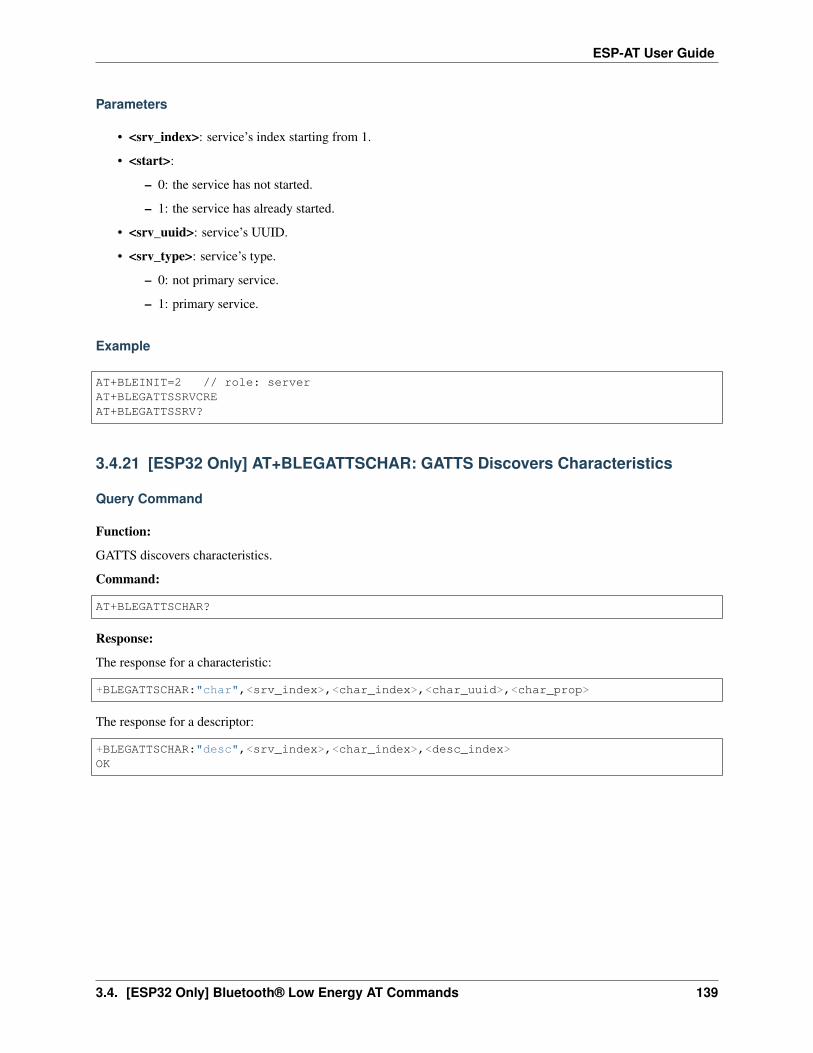
ESP-AT User Guide
Parameters
• <srv_index>: service’s index starting from 1.
• <start>:
– 0: the service has not started.
– 1: the service has already started.
• <srv_uuid>: service’s UUID.
• <srv_type>: service’s type.
– 0: not primary service.
– 1: primary service.
Example
AT+BLEINIT=2 // role: serverAT+BLEGATTSSRVCREAT+BLEGATTSSRV?
3.4.21 [ESP32 Only] AT+BLEGATTSCHAR: GATTS Discovers Characteristics
Query Command
Function:
GATTS discovers characteristics.
Command:
AT+BLEGATTSCHAR?
Response:
The response for a characteristic:
+BLEGATTSCHAR:"char",<srv_index>,<char_index>,<char_uuid>,<char_prop>
The response for a descriptor:
+BLEGATTSCHAR:"desc",<srv_index>,<char_index>,<desc_index>OK
3.4. [ESP32 Only] Bluetooth® Low Energy AT Commands 139

ESP-AT User Guide
Parameters
• <srv_index>: service’s index starting from 1.
• <char_index>: characteristic’s index starting from 1.
• <char_uuid>: characteristic’s UUID.
• <char_prop>: characteristic’s properties.
• <desc_index>: descriptor’s index.
• <desc_uuid>: descriptor’s UUID.
Example
AT+BLEINIT=2 // role: serverAT+BLEGATTSSRVCREAT+BLEGATTSSRVSTARTAT+BLEGATTSCHAR?
3.4.22 [ESP32 Only] AT+BLEGATTSNTFY: Notify a Client of the Value of a Charac-teristic Value from the Server
Set Command
Function:
Notify a client of the value of a characteristic value from the server.
Command:
AT+BLEGATTSNTFY=<conn_index>,<srv_index>,<char_index>,<length>
Response:
>
The symbol > indicates that AT is ready for receiving serial data, and you can enter data now. When the requirementof data length determined by the parameter <length> is met, the notification starts.
If the data transmission is successful, AT returns:
OK
Parameters
• <conn_index>: index of Bluetooth LE connection. Range: [0,2].
• <srv_index>: service’s index. It can be fetched with command AT+BLEGATTSCHAR?.
• <char_index>: characteristic’s index. It can be fetched with command AT+BLEGATTSCHAR?.
• <length>: data length.
140 Chapter 3. AT Command Set

ESP-AT User Guide
Example
AT+BLEINIT=2 // Role: server.AT+BLEGATTSSRVCREAT+BLEGATTSSRVSTARTAT+BLEADVSTART // Start advertising. After the client is connected, it must be→˓configured to receive notifications.AT+BLEGATTSCHAR? // Query the characteristics which the client will be notified of.// For example, to notify of 4-byte data using the 6th characteristic in the 3rd→˓service, use the following command:AT+BLEGATTSNTFY=0,3,6,4// After the symbol ">" shows, enter the 4-byte data, such as "1234". Then the data→˓will be transmitted automatically.
3.4.23 [ESP32 Only] AT+BLEGATTSIND: Indicate the Characteristic Value from theServer to a Client
Set Command
Function:
Indicate the characteristic value from the server to a client.
Command:
AT+BLEGATTSIND=<conn_index>,<srv_index>,<char_index>,<length>
Response:
>
The symbol > indicates that AT is ready for receiving serial data and you can enter data now. When the requirementof data length determined by the parameter <length> is met, the indication starts.
If the data transmission is successful, AT returns:
OK
Parameters
• <conn_index>: index of Bluetooth LE connection. Range: [0,2].
• <srv_index>: service’s index. It can be fetched with command AT+BLEGATTSCHAR?.
• <char_index>: characteristic’s index; it can be fetched with command AT+BLEGATTSCHAR?.
• <length>: data length.
3.4. [ESP32 Only] Bluetooth® Low Energy AT Commands 141
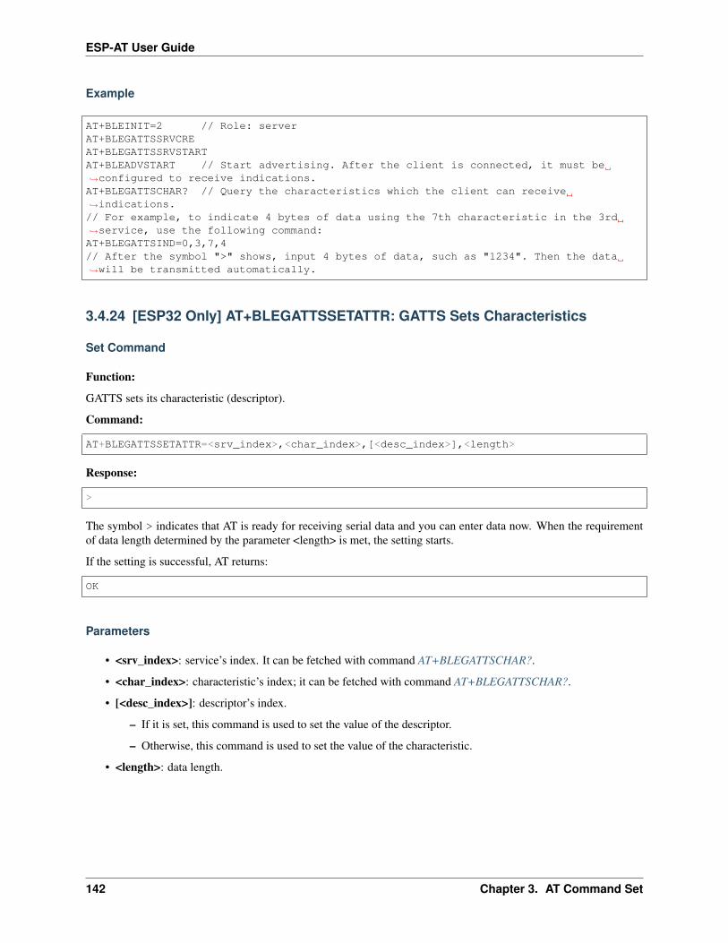
ESP-AT User Guide
Example
AT+BLEINIT=2 // Role: serverAT+BLEGATTSSRVCREAT+BLEGATTSSRVSTARTAT+BLEADVSTART // Start advertising. After the client is connected, it must be→˓configured to receive indications.AT+BLEGATTSCHAR? // Query the characteristics which the client can receive→˓indications.// For example, to indicate 4 bytes of data using the 7th characteristic in the 3rd→˓service, use the following command:AT+BLEGATTSIND=0,3,7,4// After the symbol ">" shows, input 4 bytes of data, such as "1234". Then the data→˓will be transmitted automatically.
3.4.24 [ESP32 Only] AT+BLEGATTSSETATTR: GATTS Sets Characteristics
Set Command
Function:
GATTS sets its characteristic (descriptor).
Command:
AT+BLEGATTSSETATTR=<srv_index>,<char_index>,[<desc_index>],<length>
Response:
>
The symbol > indicates that AT is ready for receiving serial data and you can enter data now. When the requirementof data length determined by the parameter <length> is met, the setting starts.
If the setting is successful, AT returns:
OK
Parameters
• <srv_index>: service’s index. It can be fetched with command AT+BLEGATTSCHAR?.
• <char_index>: characteristic’s index; it can be fetched with command AT+BLEGATTSCHAR?.
• [<desc_index>]: descriptor’s index.
– If it is set, this command is used to set the value of the descriptor.
– Otherwise, this command is used to set the value of the characteristic.
• <length>: data length.
142 Chapter 3. AT Command Set
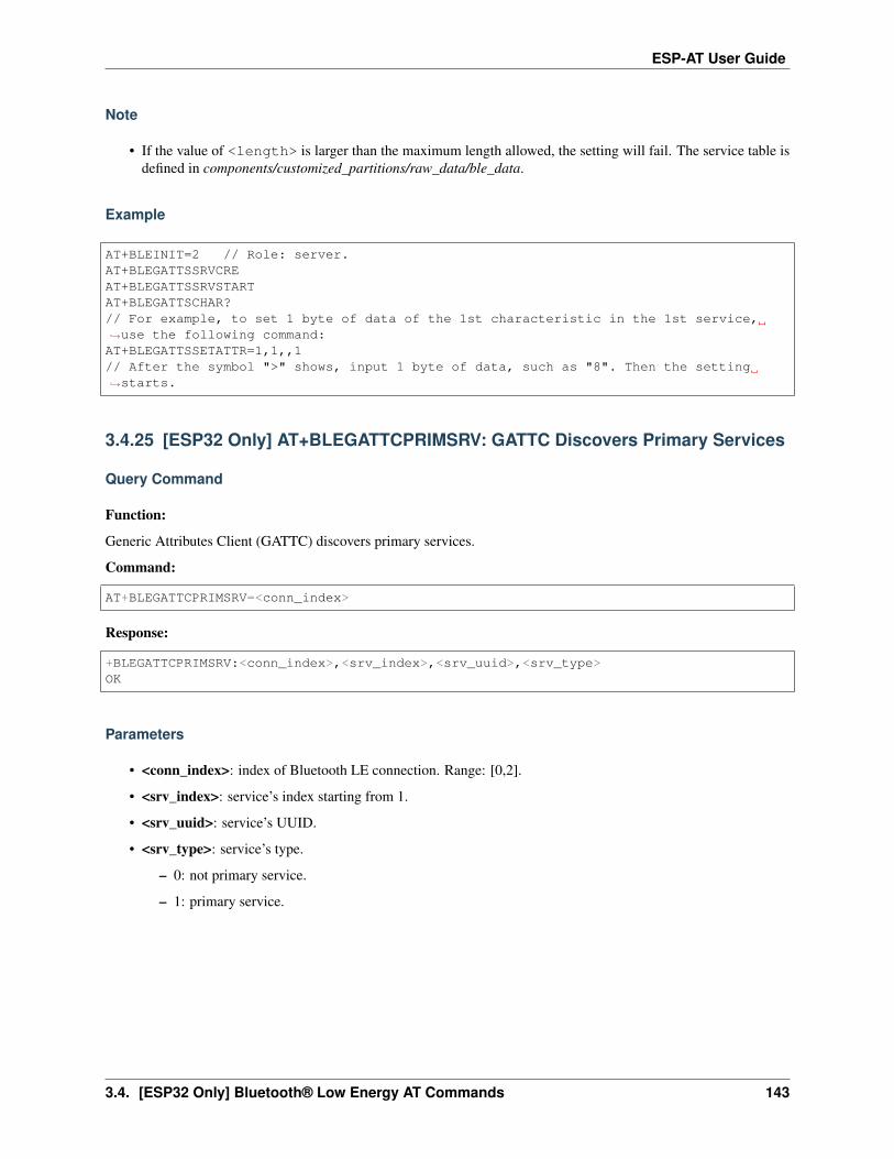
ESP-AT User Guide
Note
• If the value of <length> is larger than the maximum length allowed, the setting will fail. The service table isdefined in components/customized_partitions/raw_data/ble_data.
Example
AT+BLEINIT=2 // Role: server.AT+BLEGATTSSRVCREAT+BLEGATTSSRVSTARTAT+BLEGATTSCHAR?// For example, to set 1 byte of data of the 1st characteristic in the 1st service,→˓use the following command:AT+BLEGATTSSETATTR=1,1,,1// After the symbol ">" shows, input 1 byte of data, such as "8". Then the setting→˓starts.
3.4.25 [ESP32 Only] AT+BLEGATTCPRIMSRV: GATTC Discovers Primary Services
Query Command
Function:
Generic Attributes Client (GATTC) discovers primary services.
Command:
AT+BLEGATTCPRIMSRV=<conn_index>
Response:
+BLEGATTCPRIMSRV:<conn_index>,<srv_index>,<srv_uuid>,<srv_type>OK
Parameters
• <conn_index>: index of Bluetooth LE connection. Range: [0,2].
• <srv_index>: service’s index starting from 1.
• <srv_uuid>: service’s UUID.
• <srv_type>: service’s type.
– 0: not primary service.
– 1: primary service.
3.4. [ESP32 Only] Bluetooth® Low Energy AT Commands 143

ESP-AT User Guide
Note
• The Bluetooth LE connection has to be established first.
Example
AT+BLEINIT=1 // role: clientAT+BLECONN=0,"24:12:5f:9d:91:98"AT+BLEGATTCPRIMSRV=0
3.4.26 [ESP32 Only] AT+BLEGATTCINCLSRV: GATTC Discovers Included Services
Set Command
Function:
GATTC discovers included services.
Command:
AT+BLEGATTCINCLSRV=<conn_index>,<srv_index>
Response:
+BLEGATTCINCLSRV:<conn_index>,<srv_index>,<srv_uuid>,<srv_type>,<included_srv_uuid>,→˓<included_srv_type>OK
Parameters
• <conn_index>: index of Bluetooth LE connection. Range: [0,2].
• <srv_index>: service’s index. It can be fetched with command AT+BLEGATTCPRIMSRV=<conn_index>.
• <srv_uuid>: service’s UUID.
• <srv_type>: service’s type.
– 0: not primary service.
– 1: primary service.
• <included_srv_uuid>: included service’s UUID.
• <included_srv_type>: included service’s type.
– 0: not primary service.
– 1: primary service.
144 Chapter 3. AT Command Set
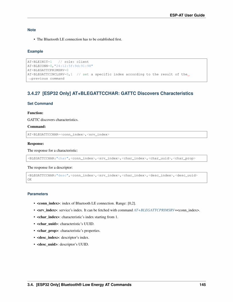
ESP-AT User Guide
Note
• The Bluetooth LE connection has to be established first.
Example
AT+BLEINIT=1 // role: clientAT+BLECONN=0,"24:12:5f:9d:91:98"AT+BLEGATTCPRIMSRV=0AT+BLEGATTCINCLSRV=0,1 // set a specific index according to the result of the→˓previous command
3.4.27 [ESP32 Only] AT+BLEGATTCCHAR: GATTC Discovers Characteristics
Set Command
Function:
GATTC discovers characteristics.
Command:
AT+BLEGATTCCHAR=<conn_index>,<srv_index>
Response:
The response for a characteristic:
+BLEGATTCCHAR:"char",<conn_index>,<srv_index>,<char_index>,<char_uuid>,<char_prop>
The response for a descriptor:
+BLEGATTCCHAR:"desc",<conn_index>,<srv_index>,<char_index>,<desc_index>,<desc_uuid>OK
Parameters
• <conn_index>: index of Bluetooth LE connection. Range: [0,2].
• <srv_index>: service’s index. It can be fetched with command AT+BLEGATTCPRIMSRV=<conn_index>.
• <char_index>: characteristic’s index starting from 1.
• <char_uuid>: characteristic’s UUID.
• <char_prop>: characteristic’s properties.
• <desc_index>: descriptor’s index.
• <desc_uuid>: descriptor’s UUID.
3.4. [ESP32 Only] Bluetooth® Low Energy AT Commands 145
ESP-AT User Guide
Note
• The Bluetooth LE connection has to be established first.
Example
AT+BLEINIT=1 // role: clientAT+BLECONN=0,"24:12:5f:9d:91:98"AT+BLEGATTCPRIMSRV=0AT+BLEGATTCCHAR=0,1 // set a specific index according to the result of the previous→˓command
3.4.28 [ESP32 Only] AT+BLEGATTCRD: GATTC Reads Characteristics
Set Command
Function:
GATTC reads a characteristic or descriptor.
Command:
AT+BLEGATTCRD=<conn_index>,<srv_index>,<char_index>[,<desc_index>]
Response:
+BLEGATTCRD:<conn_index>,<len>,<value>OK
Parameters
• <conn_index>: index of Bluetooth LE connection. Range: [0,2].
• <srv_index>: service’s index. It can be fetched with command AT+BLEGATTCPRIMSRV=<conn_index>.
• <char_index>: characteristic’s index; it can be fetched with commandAT+BLEGATTCCHAR=<conn_index>,<srv_index>.
• [<desc_index>]: descriptor’s index.
– If it is set, the value of the target descriptor will be read.
– if it is not set, the value of the target characteristic will be read.
• <len>: data length.
• <char_value>: characteristic’s value. HEX string is read by commandAT+BLEGATTCRD=<conn_index>,<srv_index>,<char_index>. For example, if the response is+BLEGATTCRD:1,30, it means that the value length is 1, and the content is “0x30”.
• [<desc_value>]: descriptor’s value. HEX string is read by commandAT+BLEGATTCRD=<conn_index>,<srv_index>,<char_index>,<desc_index>. For example, if the re-sponse is +BLEGATTCRD:4,30313233, it means that the value length is 4, and the content is “0x30 0x310x32 0x33”.
146 Chapter 3. AT Command Set

ESP-AT User Guide
Notes
• The Bluetooth LE connection has to be established first.
• If the target characteristic cannot be read, it will return “ERROR”.
Example
AT+BLEINIT=1 // Role: client.AT+BLECONN=0,"24:12:5f:9d:91:98"AT+BLEGATTCPRIMSRV=0AT+BLEGATTCCHAR=0,3 // Set a specific index according to the result of the previous→˓command.// For example, to read 1st descriptor of the 2nd characteristic in the 3rd service,→˓use the following command:AT+BLEGATTCRD=0,3,2,1
3.4.29 [ESP32 Only] AT+BLEGATTCWR: GATTC Writes Characteristics
Set Command
Function:
GATTC writes characteristics or descriptors.
Command:
AT+BLEGATTCWR=<conn_index>,<srv_index>,<char_index>[,<desc_index>],<length>
Response:
>
The symbol > indicates that AT is ready for receiving serial data and you can enter data now. When the requirementof data length determined by the parameter <length> is met, the writing starts.
If the setting is successful, AT returns:
OK
Parameters
• <conn_index>: index of Bluetooth LE connection. Range: [0,2].
• <srv_index>: service’s index. It can be fetched with command AT+BLEGATTCPRIMSRV=<conn_index>.
• <char_index>: characteristic’s index; it can be fetched with commandAT+BLEGATTCCHAR=<conn_index>,<srv_index>.
• [<desc_index>]: descriptor’s index.
– If it is set, the value of the target descriptor will be written.
– If it is not set, the value of the target characteristic will be written.
• <length>: data length.
3.4. [ESP32 Only] Bluetooth® Low Energy AT Commands 147

ESP-AT User Guide
Notes
• The Bluetooth LE connection has to be established first.
• If the target characteristic cannot be written, it will return “ERROR”.
Example
AT+BLEINIT=1 // Role: client.AT+BLECONN=0,"24:12:5f:9d:91:98"AT+BLEGATTCPRIMSRV=0AT+BLEGATTCCHAR=0,3 // Set a specific index according to the result of the previous→˓command.// For example, to write 6 bytes of data to the 4th characteristic in the 3rd service,→˓ use the following command:AT+BLEGATTCWR=0,3,4,,6// After the symbol ">" shows, input 6 bytes of data, such as "123456". Then the→˓writing starts.
3.4.30 [ESP32 Only] AT+BLESPPCFG: Query/Set Bluetooth LE SPP Parameters
Query Command
Function:
Query the parameters of Bluetooth LE Serial Port Profile (SPP).
Command:
AT+BLESPPCFG?
Response:
+BLESPPCFG:<tx_service_index>,<tx_char_index>,<rx_service_index>,<rx_char_index>OK
Set Command
Function:
Set or reset the parameters of Bluetooth LE SPP.
Command:
AT+BLESPPCFG=<cfg_enable>[,<tx_service_index>,<tx_char_index>,<rx_service_index>,<rx_→˓char_index>]
Response:
OK
148 Chapter 3. AT Command Set
ESP-AT User Guide
Parameters
• <cfg_enable>:
– 0: all the SPP parameters will be reset, and the following four parameters don’t need input.
– 1: you should input the following four parameters.
• <tx_service_index>: tx service’s index. It can be fetched with commandAT+BLEGATTCPRIMSRV=<conn_index> and AT+BLEGATTSSRV?.
• <tx_char_index>: tx characteristic’s index. It can be fetched with commandAT+BLEGATTCCHAR=<conn_index>,<srv_index> and AT+BLEGATTSCHAR?.
• <rx_service_index>: rx service’s index. It can be fetched with commandAT+BLEGATTCPRIMSRV=<conn_index> and AT+BLEGATTSSRV?.
• <rx_char_index>: rx characteristic’s index. It can be fetched with commandAT+BLEGATTCCHAR=<conn_index>,<srv_index> and AT+BLEGATTSCHAR?.
Notes
• In Bluetooth LE client, the property of tx characteristic must be write with response or writewithout response, and the property of rx characteristic must be indicate or notify.
• In Bluetooth LE server, the property of tx characteristic must be indicate or notify, and the property of rxcharacteristic must be write with response or write without response.
Example
AT+BLESPPCFG=0 // reset Bluetooth LE SPP parametersAT+BLESPPCFG=1,3,5,3,7 // set Bluetooth LE SPP parametersAT+BLESPPCFG? // query Bluetooth LE SPP parameters
3.4.31 [ESP32 Only] AT+BLESPP: Enter Bluetooth LE SPP Mode
Execute Command
Function:
Enter Bluetooth LE SPP mode.
Command:
AT+BLESPP
Response:
>
3.4. [ESP32 Only] Bluetooth® Low Energy AT Commands 149

ESP-AT User Guide
Notes
• If the Bluetooth LE SPP parameters are illegal, this command will return ERROR.
• During the SPP transmission, AT will not prompt any connection status changes unless bit2 of AT+SYSMSG is1.
Example
AT+BLESPP // enter Bluetooth LE SPP mode
3.4.32 [ESP32 Only] AT+BLESECPARAM: Query/Set Bluetooth LE Encryption Pa-rameters
Query Command
Function:
Query the parameters of Bluetooth LE SMP.
Command:
AT+BLESECPARAM?
Response:
+BLESECPARAM:<auth_req>,<iocap>,<key_size>,<init_key>,<rsp_key>,<auth_option>OK
Set Command
Function:
Set the parameters of Bluetooth LE SMP.
Command:
AT+BLESECPARAM=<auth_req>,<iocap>,<key_size>,<init_key>,<rsp_key>[,<auth_option>]
Response:
OK
Parameters
• <auth_req>: authentication request.
– 0: NO_BOND
– 1: BOND
– 4: MITM
– 8: SC_ONLY
150 Chapter 3. AT Command Set

ESP-AT User Guide
– 9: SC_BOND
– 12: SC_MITM
– 13: SC_MITM_BOND
• <iocap>: input and output capability.
– 0: DisplayOnly
– 1: DisplayYesNo
– 2: KeyboardOnly
– 3: NoInputNoOutput
– 4: Keyboard display
• <key_size>: key length. Range: 7 ~ 16 bytes.
• <init_key>: initial key represented in bit combinations.
• <rsp_key>: response key represented in bit combinations.
• <auth_option>: authentication option of security.
– 0: Select the security level automatically.
– 1: If it cannot follow the preset security level, the connection will disconnect.
Note
• The bit pattern for parameters <init_key> and <rsp_key> is:
– Bit0: Used to exchange the encryption key in the init key & response key.
– Bit1: Used to exchange the IRK key in the init key & response key.
– Bit2: Used to exchange the CSRK key in the init key & response key.
– Bit3: Used to exchange the link key (only used in the Bluetooth LE & BR/EDR coexist mode) in the initkey & response key.
Example
AT+BLESECPARAM=1,4,16,3,3,0
3.4.33 [ESP32 Only] AT+BLEENC: Initiate Bluetooth LE Encryption Request
Set Command
Function:
Start a pairing request
Command:
AT+BLEENC=<conn_index>,<sec_act>
Response:
3.4. [ESP32 Only] Bluetooth® Low Energy AT Commands 151

ESP-AT User Guide
OK
Parameters
• <conn_index>: index of Bluetooth LE connection. Range: [0,2].
• <sec_act>:
– 0: SEC_NONE
– 1: SEC_ENCRYPT
– 2: SEC_ENCRYPT_NO_MITM
– 3: SEC_ENCRYPT_MITM
Note
• Before running this command, please set the security parameters and connection with remote devices.
Example
AT+BLESECPARAM=1,4,16,3,3AT+BLEENC=0,3
3.4.34 [ESP32 Only] AT+BLEENCRSP: Respond to the Pairing Request from thePeer Device
Set Command
Function:
Respond to the pairing request from the peer device.
Command:
AT+BLEENCRSP=<conn_index>,<accept>
Response:
OK
Parameters
• <conn_index>: index of Bluetooth LE connection. Range: [0,2].
• <accept>:
– 0: reject
– 1: accept
152 Chapter 3. AT Command Set
ESP-AT User Guide
Note
• After running this command, AT will output the pairing result at the end of the pairing process.
+BLEAUTHCMPL:<conn_index>,<enc_result>
• <conn_index>: index of Bluetooth LE connection. Range: [0,2].
• <enc_result>:
– 0: encryption succeeded
– 1: encryption failed
Example
AT+BLEENCRSP=0,1
3.4.35 [ESP32 Only] AT+BLEKEYREPLY: Reply the Key Value to the Peer Device inthe Legacy Connection Stage
Set Command
Function:
Reply a pairing key.
Command:
AT+BLEKEYREPLY=<conn_index>,<key>
Response:
OK
Parameters
• <conn_index>: index of Bluetooth LE connection. Range: [0,2].
• <key>: pairing key.
Example
AT+BLEKEYREPLY=0,649784
3.4. [ESP32 Only] Bluetooth® Low Energy AT Commands 153
ESP-AT User Guide
3.4.36 [ESP32 Only] AT+BLECONFREPLY: Reply the Confirm Value to the Peer De-vice in the Legacy Connection Stage
Set Command
Function:
Reply a pairing result.
Command:
AT+BLECONFREPLY=<conn_index>,<confirm>
Response:
OK
Parameters
• <conn_index>: index of Bluetooth LE connection. Range: [0,2].
• <confirm>:
– 0: No
– 1: Yes
Example
AT+BLECONFREPLY=0,1
3.4.37 [ESP32 Only] AT+BLEENCDEV: Query Bonded Bluetooth LE Encryption De-vice List
Query Command
Function:
Query bonded Bluetooth LE encryption device list.
Command:
AT+BLEENCDEV?
Response:
+BLEENCDEV:<enc_dev_index>,<mac_address>OK
154 Chapter 3. AT Command Set

ESP-AT User Guide
Parameters
• <enc_dev_index>: index of the bonded devices.
• <mac_address>: MAC address.
Example
AT+BLEENCDEV?
3.4.38 [ESP32 Only] AT+BLEENCCLEAR: Clear Bluetooth LE Encryption DeviceList
Set Command
Function:
Remove a device from the security database list with a specific index.
Command:
AT+BLEENCCLEAR=<enc_dev_index>
Response:
OK
Execute Command
Function:
Remove all devices from the security database.
Command:
AT+BLEENCCLEAR
Response:
OK
Parameter
• <enc_dev_index>: index of the bonded devices.
3.4. [ESP32 Only] Bluetooth® Low Energy AT Commands 155
ESP-AT User Guide
Example
AT+BLEENCCLEAR
3.4.39 [ESP32 Only] AT+BLESETKEY: Set Bluetooth LE Static Pair Key
Query Command
Function:
Query the Bluetooth LE static pair key. If it is not set, AT will return -1.
Command:
AT+BLESETKEY?
Response:
+BLESETKEY:<static_key>OK
Set Command
Function:
Set a Bluetooth LE static pair key for all Bluetooth LE connections.
Command:
AT+BLESETKEY=<static_key>
Response:
OK
Parameter
• <static_key>: static Bluetooth LE pair key.
Example
AT+BLESETKEY=123456
156 Chapter 3. AT Command Set

ESP-AT User Guide
3.4.40 [ESP32 Only] AT+BLEHIDINIT: Bluetooth LE HID Profile Initialization
Query Command
Function:
Query the initialization status of Bluetooth LE HID profile.
Command:
AT+BLEHIDINIT?
Response:
If Bluetooth LE HID device profile is not initialized, AT will return:
+BLEHIDINIT:0OK
If Bluetooth LE HID device profile is initialized, AT will return:
+BLEHIDINIT:1OK
Set Command
Function:
Initialize the Bluetooth LE HID profile.
Command:
AT+BLEHIDINIT=<init>
Response:
OK
Parameter
• <init>:
– 0: deinit Bluetooth LE HID profile
– 1: init Bluetooth LE HID profile
Note
• The Bluetooth LE HID command cannot be used at the same time with general GATT/GAP commands.
3.4. [ESP32 Only] Bluetooth® Low Energy AT Commands 157

ESP-AT User Guide
Example
AT+BLEHIDINIT=1
3.4.41 [ESP32 Only] AT+BLEHIDKB: Send Bluetooth LE HID Keyboard Information
Set Command
Function:
Send keyboard information.
Command:
AT+BLEHIDKB=<Modifier_keys>,<key_1>,<key_2>,<key_3>,<key_4>,<key_5>,<key_6>
Response:
OK
Parameters
• <Modifier_keys>: modifier keys mask
• <key_1>: key code 1
• <key_2>: key code 2
• <key_3>: key code 3
• <key_4>: key code 4
• <key_5>: key code 5
• <key_6>: key code 6
Note
• For more information about key codes, please refer to the chapter Keyboard/Keypad Page of Universal SerialBus HID Usage Tables.
Example
AT+BLEHIDKB=0,4,0,0,0,0,0 // input the string "a"
158 Chapter 3. AT Command Set
ESP-AT User Guide
3.4.42 [ESP32 Only] AT+BLEHIDMUS: Send Bluetooth LE HID Mouse Information
Set Command
Function:
Send mouse information.
Command:
AT+BLEHIDMUS=<buttons>,<X_displacement>,<Y_displacement>,<wheel>
Response:
OK
Parameters
• <buttons>: mouse button
• <X_displacement>: X displacement
• <Y_displacement>: Y displacement
• <wheel>: wheel
Example
AT+BLEHIDMUS=0,10,10,0
3.4.43 [ESP32 Only] AT+BLEHIDCONSUMER: Send Bluetooth LE HID ConsumerInformation
Set Command
Function:
Send consumer information.
Command:
AT+BLEHIDCONSUMER=<consumer_usage_id>
Response:
OK
3.4. [ESP32 Only] Bluetooth® Low Energy AT Commands 159
ESP-AT User Guide
Parameter
• <consumer_usage_id>: consumer ID, such as power, reset, help, volume and so on. See chapter ConsumerPage (0x0C) of HID Usage Tables for Universal Serial Bus (USB) for more information.
Example
AT+BLEHIDCONSUMER=233 // volume up
3.4.44 [ESP32 Only] AT+BLUFI: Start or Stop BluFi
Query Command
Function:
Query the status of BluFi.
Command:
AT+BLUFI?
Response:
If BluFi is not started, it will return:
+BLUFI:0OK
If BluFi is started, it will return:
+BLUFI:1OK
Set Command
Function:
Start or stop BluFi.
Command:
AT+BLUFI=<option>[,<auth floor>]
Response:
OK
160 Chapter 3. AT Command Set

ESP-AT User Guide
Parameter
• <option>:
– 0: stop BluFi
– 1: start BluFi
• <auth floor>: Wi-Fi authentication mode floor. ESP-AT will not connect to the AP whose authmode is lowerthan this floor.
– 0: OPEN (Default)
– 1: WEP
– 2: WPA_PSK
– 3: WPA2_PSK
– 4: WPA_WPA2_PSK
– 5: WPA2_ENTERPRISE
– 6: WPA3_PSK
– 7: WPA2_WPA3_PSK
Example
AT+BLUFI=1
3.4.45 [ESP32 Only] AT+BLUFINAME: Query/Set BluFi Device Name
Query Command
Function:
Query the BluFi name.
Command:
AT+BLUFINAME?
Response:
+BLUFINAME:<device_name>OK
3.4. [ESP32 Only] Bluetooth® Low Energy AT Commands 161

ESP-AT User Guide
Set Command
Function:
Set the BluFi device name.
Command:
AT+BLUFINAME=<device_name>
Response:
OK
Parameter
• <device_name>: the name of BluFi device.
Notes
• If you need to set BluFi name, please set it before command AT+BLUFI=1. Otherwise, it will use the defaultname BLUFI_DEVICE.
• The maximum length of BluFi name is 29 bytes.
Example
AT+BLUFINAME="BLUFI_DEV"AT+BLUFINAME?
3.5 [ESP32 Only] Classic Bluetooth® AT Commands
[]
ESP32 AT firmware supports Bluetooth® Core Specification Version 5.0.
• [ESP32 Only] AT+BTINIT: Classic Bluetooth initialization.
• [ESP32 Only] AT+BTNAME: Query/Set Classic Bluetooth device name.
• [ESP32 Only] AT+BTSCANMODE: Set Classic Bluetooth scan mode.
• [ESP32 Only] AT+BTSTARTDISC: Start Classic Bluetooth discovery.
• [ESP32 Only] AT+BTSPPINIT: Classic Bluetooth SPP profile initialization.
• [ESP32 Only] AT+BTSPPCONN: Query/Establish SPP connection.
• [ESP32 Only] AT+BTSPPDISCONN: End SPP connection.
• [ESP32 Only] AT+BTSPPSTART: Start Classic Bluetooth SPP profile.
• [ESP32 Only] AT+BTSPPSEND: Send data to remote Classic Bluetooth SPP device.
• [ESP32 Only] AT+BTA2DPINIT: Classic Bluetooth A2DP profile initialization.
• [ESP32 Only] AT+BTA2DPCONN: Establish A2DP connection.
162 Chapter 3. AT Command Set

ESP-AT User Guide
• [ESP32 Only] AT+BTA2DPDISCONN: End A2DP connection.
• [ESP32 Only] AT+BTA2DPSRC: Query/Set the audio file URL.
• [ESP32 Only] AT+BTA2DPCTRL: Control the audio play.
• [ESP32 Only] AT+BTSECPARAM: Query/Set the Classic Bluetooth security parameters.
• [ESP32 Only] AT+BTKEYREPLY: Input the Simple Pair Key.
• [ESP32 Only] AT+BTPINREPLY: Input the Legacy Pair PIN Code.
• [ESP32 Only] AT+BTSECCFM: Reply the confirm value to the peer device in the legacy connection stage.
• [ESP32 Only] AT+BTENCDEV: Query Classic Bluetooth encryption device list.
• [ESP32 Only] AT+BTENCCLEAR: Clear Classic Bluetooth encryption device list.
• [ESP32 Only] AT+BTCOD: Set class of devices.
• [ESP32 Only] AT+BTPOWER: Query/Set power of Classic Bluetooth.
3.5.1 [ESP32 Only] AT+BTINIT: Classic Bluetooth Initialization
Query Command
Function:
Query the initialization status of Classic Bluetooth.
Command:
AT+BTINIT?
Response:
If Classic Bluetooth is initialized, AT will return:
+BTINIT:1OK
If Classic Bluetooth is not initialized, AT will return:
+BTINIT:0OK
Set Command
Function:
Initialize or deinitialize Classic Bluetooth.
Command:
AT+BTINIT=<init>
Response:
OK
3.5. [ESP32 Only] Classic Bluetooth® AT Commands 163
ESP-AT User Guide
Parameter
• <init>:
– 0: deinitialize Classic Bluetooth.
– 1: initialize Classic Bluetooth.
Example
AT+BTINIT=1
3.5.2 [ESP32 Only] AT+BTNAME: Query/Set Classic Bluetooth Device Name
Query Command
Function:
Query the Classic Bluetooth device name.
Command:
AT+BTNAME?
Response:
+BTNAME:<device_name>OK
Set Command
Function:
Set the Classic Bluetooth device name.
Command:
AT+BTNAME=<device_name>
Response:
OK
Parameter
• <device_name>: the Classic Bluetooth device name. The maximum length is 32.
164 Chapter 3. AT Command Set

ESP-AT User Guide
Notes
• The configuration changes will be saved in the NVS area if AT+SYSSTORE=1.
• The default Classic Bluetooth device name is “ESP32_AT”.
Example
AT+BTNAME="esp_demo"
3.5.3 [ESP32 Only] AT+BTSCANMODE: Set Classic Bluetooth Scan Mode
Set Command
Function:
Set the scan mode of Classic Bluetooth.
Command:
AT+BTSCANMODE=<scan_mode>
Response:
OK
Parameter
• <scan_mode>:
– 0: Neither discoverable nor connectable.
– 1: Connectable but not discoverable.
– 2: Both discoverable and connectable.
– 3: Discoverable but not connectable.
Example
AT+BTSCANMODE=2 // both discoverable and connectable
3.5.4 [ESP32 Only] AT+BTSTARTDISC: Start Classic Bluetooth Discovery
Set Command
Function:
Start Classic Bluetooth discovery.
Command:
3.5. [ESP32 Only] Classic Bluetooth® AT Commands 165

ESP-AT User Guide
AT+BTSTARTDISC=<inq_mode>,<inq_len>,<inq_num_rsps>
Response:
+BTSTARTDISC:<bt_addr>,<dev_name>,<major_dev_class>,<minor_dev_class>,<major_srv_→˓class>,<rssi>
OK
Parameters
• <inq_mode>:
– 0: general inquiry mode.
– 1: limited inquiry mode.
• <inq_len>: inquiry duration. Range: 0x01 ~ 0x30.
• <inq_num_rsps>: number of inquiry responses that can be received. If you set it to 0, AT will receive anunlimited number of responses.
• <bt_addr>: Classic Bluetooth address.
• <dev_name>: device name.
• <major_dev_class>:
– 0x0: miscellaneous.
– 0x1: computer.
– 0x2: phone (cellular, cordless, pay phone, modem).
– 0x3: LAN, Network Access Point.
– 0x4: audio/video (headset, speaker, stereo, video display, VCR).
– 0x5: peripheral (mouse, joystick, keyboard).
– 0x6: imaging (printer, scanner, camera, display).
– 0x7: wearable.
– 0x8: toy.
– 0x9: health.
– 0x1F: uncategorized device.
• <minor_dev_class>: please refer to Minor Device Class field.
• <major_srv_class>:
– 0x0: an invalid value.
– 0x1: Limited Discoverable Mode.
– 0x8: positioning (location identification).
– 0x10: networking, such as LAN, Ad hoc.
– 0x20: rendering, such as printing, speakers.
– 0x40: capturing, such as scanner, microphone.
166 Chapter 3. AT Command Set

ESP-AT User Guide
– 0x80: object transfer, such as v-Inbox, v-Folder.
– 0x100: audio, such as speaker, microphone, headerset service.
– 0x200: telephony, such as cordless telephony, modem, headset service.
– 0x400: information, such as WEB-server, WAP-server.
• <rssi>: signal strength.
Example
AT+BTINIT=1AT+BTSCANMODE=2AT+BTSTARTDISC=0,10,10
3.5.5 [ESP32 Only] AT+BTSPPINIT: Classic Bluetooth SPP Profile Initialization
Query Command
Function:
Query the initialization status of Classic Bluetooth SPP profile.
Command:
AT+BTSPPINIT?
Response:
If Classic Bluetooth SPP profile is initialized, it will return:
+BTSPPINIT:1OK
If Classic Bluetooth SPP profile is not initialized, it will return:
+BTSPPINIT:0OK
Set Command
Function:
Initialize or deinitialize Classic Bluetooth SPP profile.
Command:
AT+BTSPPINIT=<init>
Response:
OK
3.5. [ESP32 Only] Classic Bluetooth® AT Commands 167
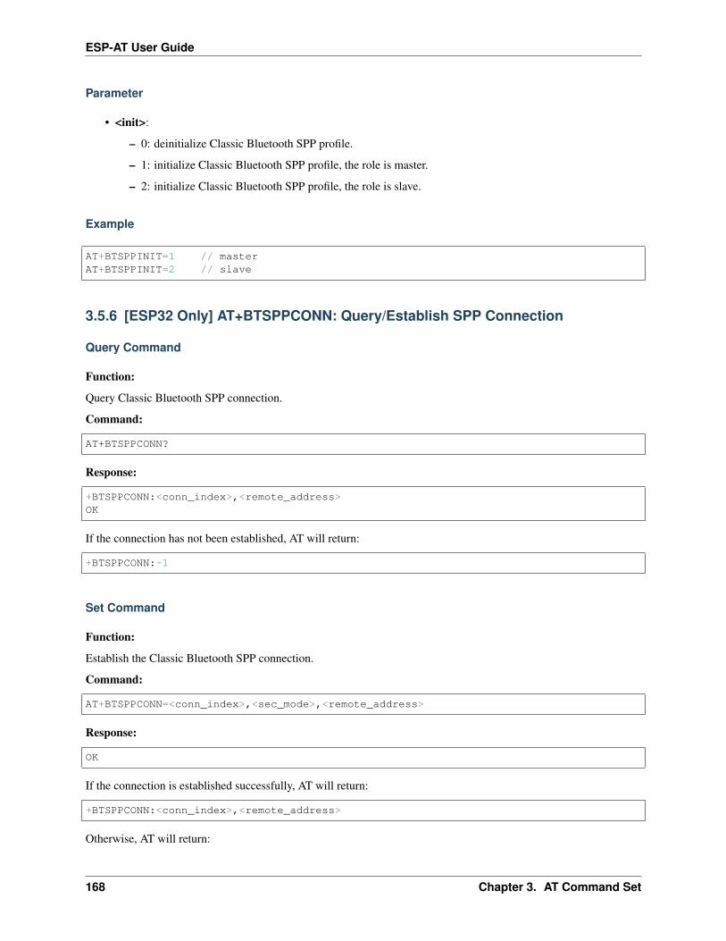
ESP-AT User Guide
Parameter
• <init>:
– 0: deinitialize Classic Bluetooth SPP profile.
– 1: initialize Classic Bluetooth SPP profile, the role is master.
– 2: initialize Classic Bluetooth SPP profile, the role is slave.
Example
AT+BTSPPINIT=1 // masterAT+BTSPPINIT=2 // slave
3.5.6 [ESP32 Only] AT+BTSPPCONN: Query/Establish SPP Connection
Query Command
Function:
Query Classic Bluetooth SPP connection.
Command:
AT+BTSPPCONN?
Response:
+BTSPPCONN:<conn_index>,<remote_address>OK
If the connection has not been established, AT will return:
+BTSPPCONN:-1
Set Command
Function:
Establish the Classic Bluetooth SPP connection.
Command:
AT+BTSPPCONN=<conn_index>,<sec_mode>,<remote_address>
Response:
OK
If the connection is established successfully, AT will return:
+BTSPPCONN:<conn_index>,<remote_address>
Otherwise, AT will return:
168 Chapter 3. AT Command Set
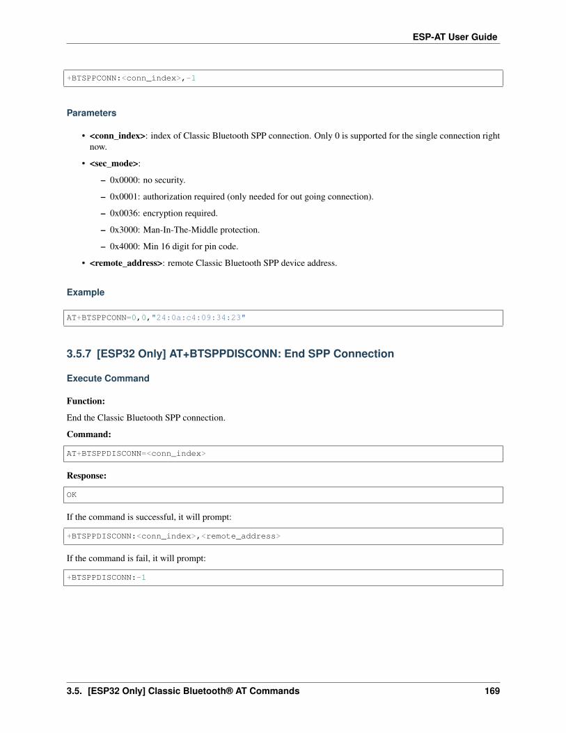
ESP-AT User Guide
+BTSPPCONN:<conn_index>,-1
Parameters
• <conn_index>: index of Classic Bluetooth SPP connection. Only 0 is supported for the single connection rightnow.
• <sec_mode>:
– 0x0000: no security.
– 0x0001: authorization required (only needed for out going connection).
– 0x0036: encryption required.
– 0x3000: Man-In-The-Middle protection.
– 0x4000: Min 16 digit for pin code.
• <remote_address>: remote Classic Bluetooth SPP device address.
Example
AT+BTSPPCONN=0,0,"24:0a:c4:09:34:23"
3.5.7 [ESP32 Only] AT+BTSPPDISCONN: End SPP Connection
Execute Command
Function:
End the Classic Bluetooth SPP connection.
Command:
AT+BTSPPDISCONN=<conn_index>
Response:
OK
If the command is successful, it will prompt:
+BTSPPDISCONN:<conn_index>,<remote_address>
If the command is fail, it will prompt:
+BTSPPDISCONN:-1
3.5. [ESP32 Only] Classic Bluetooth® AT Commands 169

ESP-AT User Guide
Parameters
• <conn_index>: index of Classic Bluetooth SPP connection. Only 0 is supported for the single connection rightnow.
• <remote_address>: remote Classic Bluetooth A2DP device address.
Example
AT+BTSPPDISCONN=0
3.5.8 [ESP32 Only] AT+BTSPPSEND: Send Data to Remote Classic Bluetooth SPPDevice
Execute Command
Function:
Enter Classic Bluetooth SPP mode.
Command:
AT+BTSPPSEND
Response:
>
Set Command
Function:
Send data to the remote Classic Bluetooth SPP device.
Command:
AT+BTSPPSEND=<conn_index>,<data_len>
Response:
OK
Parameters
• <conn_index>: index of Classic Bluetooth SPP connection. Only 0 is supported for the single connection rightnow.
• <data_len>: the length of the data which is ready to be sent.
170 Chapter 3. AT Command Set

ESP-AT User Guide
Notes
• The wrap return is > after this command is executed. Then, the ESP device enters UART Bluetooth passthroughmode. When the packet which only contains +++ is received, the device returns to normal command mode.Please wait for at least one second before sending the next AT command.
Example
AT+BTSPPSEND=0,100AT+BTSPPSEND
3.5.9 [ESP32 Only] AT+BTSPPSTART: Start Classic Bluetooth SPP Profile
Execute Command
Function:
Start Classic Bluetooth SPP profile.
Command:
AT+BTSPPSTART
Response:
OK
Note
• During the SPP transmission, AT will not prompt any connection status changes unless bit2 of AT+SYSMSG is1.
Example
AT+BTSPPSTART
3.5.10 [ESP32 Only] AT+BTA2DPINIT: Classic Bluetooth A2DP Profile Initialization
Query Command
Function:
Query the initialization status of Classic Bluetooth A2DP profile.
Command:
AT+BTA2DPINIT?
Response:
If Classic Bluetooth A2DP profile is initialized, AT will return:
3.5. [ESP32 Only] Classic Bluetooth® AT Commands 171

ESP-AT User Guide
+BTA2DPINIT:1OK
Otherwise, AT will return:
+BTA2DPINIT:0OK
Set Command
Function:
Initialize or deinitialize Classic Bluetooth A2DP profile.
Command:
AT+BTA2DPINIT=<role>,<init_val>
Response:
OK
Parameters
• <role>:
– 0: source.
– 1: sink.
• <init_val>:
– 0: deinitialize Classic Bluetooth A2DP profile.
– 1: initialize Classic Bluetooth A2DP profile.
Example
AT+BTA2DPINIT=0,1
3.5.11 [ESP32 Only] AT+BTA2DPCONN: Query/Establish A2DP Connection
Query Command
Function:
Query Classic Bluetooth A2DP connection.
Command:
AT+BTA2DPCONN?
Response:
172 Chapter 3. AT Command Set

ESP-AT User Guide
+BTA2DPCONN:<conn_index>,<remote_address>OK
If the connection has not been established, AT will NOT return the parameter <conn_index> and <remote_address>.
Set Command
Function:
Establish the Classic Bluetooth A2DP connection.
Command:
AT+BTA2DPCONN=<conn_index>,<remote_address>
Response:
OK
If the connection is established successfully, it will prompt the message below:
+BTA2DPCONN:<conn_index>,<remote_address>
Otherwise, it will return:
+BTA2DPCONN:<conn_index>,-1
Parameters
• <conn_index>: index of Classic Bluetooth A2DP connection. Only 0 is supported for the single connectionright now.
• <remote_address>: remote Classic Bluetooth A2DP device address.
Example
AT+BTA2DPCONN=0,0,0,"24:0a:c4:09:34:23"
3.5.12 [ESP32 Only] AT+BTA2DPDISCONN: End A2DP Connection
Execute Command
Function:
End the Classic Bluetooth A2DP connection.
Command:
AT+BTA2DPDISCONN=<conn_index>
Response:
3.5. [ESP32 Only] Classic Bluetooth® AT Commands 173

ESP-AT User Guide
+BTA2DPDISCONN:<conn_index>,<remote_address>OK
Parameters
• <conn_index>: index of Classic Bluetooth A2DP connection. Only 0 is supported for the single connectionright now.
• <remote_address>: remote Classic Bluetooth A2DP device address.
Example
AT+BTA2DPDISCONN=0
3.5.13 [ESP32 Only] AT+BTA2DPSRC: Query/Set the Audio File URL
Query Command
Function:
Query the audio file URL.
Command:
AT+BTA2DPSRC?
Response:
+BTA2DPSRC:<url>,<type>OK
Execute Command
Function:
Set the audio file URL.
Command:
AT+BTA2DPSRC=<conn_index>,<url>
Response:
OK
174 Chapter 3. AT Command Set

ESP-AT User Guide
Parameters
• <conn_index>: index of Classic Bluetooth A2DP connection. Only 0 is supported for the single connectionright now.
• <url>: the path of the source file. HTTP, HTTPS and FLASH are currently supported.
• <type>: the type of audio file, such as “mp3”.
Note
• Only mp3 format is currently supported.
Example
AT+BTA2DPSRC=0,"https://dl.espressif.com/dl/audio/ff-16b-2c-44100hz.mp3"AT+BTA2DPSRC=0,"flash://spiffs/zhifubao.mp3"
3.5.14 [ESP32 Only] AT+BTA2DPCTRL: Control the Audio Play
Execute Command
Function:
Control the audio play.
Command:
AT+BTA2DPCTRL=<conn_index>,<ctrl>
Response:
OK
Parameters
• <conn_index>: index of Classic Bluetooth A2DP connection. Only 0 is supported for the single connectionright now.
• <ctrl>: types of control.
– 0: A2DP Sink, stop play.
– 1: A2DP Sink, start play.
– 2: A2DP Sink, forward.
– 3: A2DP Sink, backward.
– 4: A2DP Sink, fastward start.
– 5: A2DP Sink, fastward stop.
– 0: A2DP Source, stop play.
– 1: A2DP Source, start play.
3.5. [ESP32 Only] Classic Bluetooth® AT Commands 175

ESP-AT User Guide
– 2: A2DP Source, suspend.
Example
AT+BTA2DPCTRL=0,1 // start play audio
3.5.15 [ESP32 Only] AT+BTSECPARAM: Query/Set the Classic Bluetooth SecurityParameters
Query Command
Function:
Query Classic Bluetooth security parameters.
Command:
AT+BTSECPARAM?
Response:
+BTSECPARAM:<io_cap>,<pin_type>,<pin_code>OK
Set Command
Function:
Set the Classic Bluetooth security parameters.
Command:
AT+BTSECPARAM=<io_cap>,<pin_type>,<pin_code>
Response:
OK
Parameters
• <io_cap>: input and output capability.
– 0: DisplayOnly.
– 1: DisplayYesNo.
– 2: KeyboardOnly.
– 3: NoInputNoOutput.
• <pin_type>: use variable or fixed PIN.
– 0: variable.
– 1: fixed.
176 Chapter 3. AT Command Set

ESP-AT User Guide
• <pin_code>: Legacy Pair PIN Code. Maximum: 16 bytes.
Note
• If you set the parameter <pin_type> to 0, <pin_code> will be ignored.
Example
AT+BTSECPARAM=3,1,"9527"
3.5.16 [ESP32 Only] AT+BTKEYREPLY: Input the Simple Pair Key
Execute Command
Function:
Input the Simple Pair Key.
Command:
AT+BTKEYREPLY=<conn_index>,<Key>
Response:
OK
Parameters
• <conn_index>: index of Classic Bluetooth connection. Currently, only 0 is supported for the single connection.
• <Key>: the Simple Pair Key.
Example
AT+BTKEYREPLY=0,123456
3.5.17 [ESP32 Only] AT+BTPINREPLY: Input the Legacy Pair PIN Code
Execute Command
Function:
Input the Legacy Pair PIN Code.
Command:
AT+BTPINREPLY=<conn_index>,<Pin>
Response:
3.5. [ESP32 Only] Classic Bluetooth® AT Commands 177

ESP-AT User Guide
OK
Parameters
• <conn_index>: index of Classic Bluetooth connection. Currently, only 0 is supported for the single connection.
• <Pin>: the Legacy Pair PIN Code.
Example
AT+BTPINREPLY=0,"6688"
3.5.18 [ESP32 Only] AT+BTSECCFM: Reply the Confirm Value to the Peer Device inthe Legacy Connection Stage
Execute Command
Function:
Reply the confirm value to the peer device in the legacy connection stage.
Command:
AT+BTSECCFM=<conn_index>,<accept>
Response:
OK
Parameters
• <conn_index>: index of Classic Bluetooth connection. Currently, only 0 is supported for the single connection.
• <accept>: reject or accept.
– 0: reject.
– 1: accept.
Example
AT+BTSECCFM=0,1
178 Chapter 3. AT Command Set

ESP-AT User Guide
3.5.19 [ESP32 Only] AT+BTENCDEV: Query Classic Bluetooth Encryption DeviceList
Query Command
Function:
Query the bound devices.
Command:
AT+BTENCDEV?
Response:
+BTENCDEV:<enc_dev_index>,<mac_address>OK
Parameters
• <enc_dev_index>: index of the bound devices.
• <mac_address>: MAC address.
Example
AT+BTENCDEV?
3.5.20 [ESP32 Only] AT+BTENCCLEAR: Clear Classic Bluetooth Encryption DeviceList
Set Command
Function:
Remove a device from the security database list with a specific index.
Command:
AT+BTENCCLEAR=<enc_dev_index>
Response:
OK
3.5. [ESP32 Only] Classic Bluetooth® AT Commands 179

ESP-AT User Guide
Execute Command
Function:
Remove all devices from the security database.
Command:
AT+BLEENCCLEAR
Response:
OK
Parameter
• <enc_dev_index>: index of the bound devices.
Example
AT+BTENCCLEAR
3.5.21 [ESP32 Only] AT+BTCOD: Set Class of Devices
Set Command
Function:
Set the Classic Bluetooth class of devices.
Command:
AT+BTCOD=<major>,<minor>,<service>
Response:
OK
Parameters
• <major>: major class.
• <minor>: minor class.
• <service>: service class.
180 Chapter 3. AT Command Set

ESP-AT User Guide
Example
AT+BTCOD=6,32,32 // the printer
3.5.22 [ESP32 Only] AT+BTPOWER: Query/Set TX power of Classic Bluetooth
Query Command
Function:
Query Classic Bluetooth tx power level.
Command:
AT+BTPOWER?
Response:
+BTPOWER:<min_tx_power>,<max_tx_power>OK
Set Command
Function:
Set the Classic Bluetooth tx power.
Command:
AT+BTPOWER=<min_tx_power>,<max_tx_power>
Response:
OK
Parameters
• <min_tx_power>: The minimum power level. Range: [0,7].
• <max_tx_power>: The maximum power level. Range: [0,7].
Example
AT+BTPOWER=5,6 // set Classic Bluetooth tx power.
3.5. [ESP32 Only] Classic Bluetooth® AT Commands 181
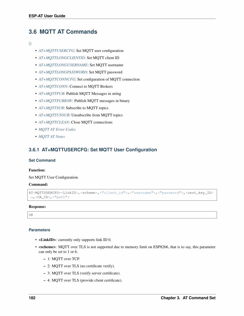
ESP-AT User Guide
3.6 MQTT AT Commands
[]
• AT+MQTTUSERCFG: Set MQTT user configuration
• AT+MQTTLONGCLIENTID: Set MQTT client ID
• AT+MQTTLONGUSERNAME: Set MQTT username
• AT+MQTTLONGPASSWORD: Set MQTT password
• AT+MQTTCONNCFG: Set configuration of MQTT connection
• AT+MQTTCONN: Connect to MQTT Brokers
• AT+MQTTPUB: Publish MQTT Messages in string
• AT+MQTTPUBRAW: Publish MQTT messages in binary
• AT+MQTTSUB: Subscribe to MQTT topics
• AT+MQTTUNSUB: Unsubscribe from MQTT topics
• AT+MQTTCLEAN: Close MQTT connections
• MQTT AT Error Codes
• MQTT AT Notes
3.6.1 AT+MQTTUSERCFG: Set MQTT User Configuration
Set Command
Function:
Set MQTT User Configuration.
Command:
AT+MQTTUSERCFG=<LinkID>,<scheme>,<"client_id">,<"username">,<"password">,<cert_key_ID>→˓,<CA_ID>,<"path">
Response:
OK
Parameters
• <LinkID>: currently only supports link ID 0.
• <scheme>: MQTT over TLS is not supported due to memory limit on ESP8266, that is to say, this parametercan only be set to 1 or 6.
– 1: MQTT over TCP.
– 2: MQTT over TLS (no certificate verify).
– 3: MQTT over TLS (verify server certificate).
– 4: MQTT over TLS (provide client certificate).
182 Chapter 3. AT Command Set
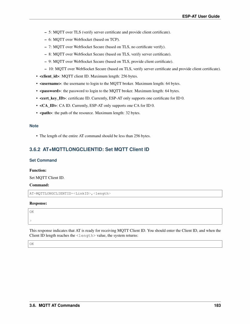
ESP-AT User Guide
– 5: MQTT over TLS (verify server certificate and provide client certificate).
– 6: MQTT over WebSocket (based on TCP).
– 7: MQTT over WebSocket Secure (based on TLS, no certificate verify).
– 8: MQTT over WebSocket Secure (based on TLS, verify server certificate).
– 9: MQTT over WebSocket Secure (based on TLS, provide client certificate).
– 10: MQTT over WebSocket Secure (based on TLS, verify server certificate and provide client certificate).
• <client_id>: MQTT client ID. Maximum length: 256 bytes.
• <username>: the username to login to the MQTT broker. Maximum length: 64 bytes.
• <password>: the password to login to the MQTT broker. Maximum length: 64 bytes.
• <cert_key_ID>: certificate ID. Currently, ESP-AT only supports one certificate for ID 0.
• <CA_ID>: CA ID. Currently, ESP-AT only supports one CA for ID 0.
• <path>: the path of the resource. Maximum length: 32 bytes.
Note
• The length of the entire AT command should be less than 256 bytes.
3.6.2 AT+MQTTLONGCLIENTID: Set MQTT Client ID
Set Command
Function:
Set MQTT Client ID.
Command:
AT+MQTTLONGCLIENTID=<LinkID>,<length>
Response:
OK
>
This response indicates that AT is ready for receiving MQTT Client ID. You should enter the Client ID, and when theClient ID length reaches the <length> value, the system returns:
OK
3.6. MQTT AT Commands 183

ESP-AT User Guide
Parameters
• <LinkID>: currently only supports link ID 0.
• <length>: MQTT client ID length. Range: [1,1024].
Notes
• The command AT+MQTTUSERCFG can also set MQTT client ID. The differences between the two commandsinclude:
– You can use AT+MQTTLONGCLIENTID to set a relatively long client ID since there is a limitation on thelength of the AT+MQTTUSERCFG command.
– You should set AT+MQTTLONGCLIENTID after setting the AT+MQTTUSERCFG command.
3.6.3 AT+MQTTLONGUSERNAME: Set MQTT Username
Set Command
Function:
Set MQTT username.
Command:
AT+MQTTLONGUSERNAME=<LinkID>,<length>
Response:
OK
>
This response indicates that AT is ready for receiving MQTT username. You should enter the MQTT username, andwhen the MQTT username length reaches the <length> value, the system returns:
OK
Parameters
• <LinkID>: only supports link ID 0 currently.
• <length>: MQTT username length. Range: [1,1024].
184 Chapter 3. AT Command Set
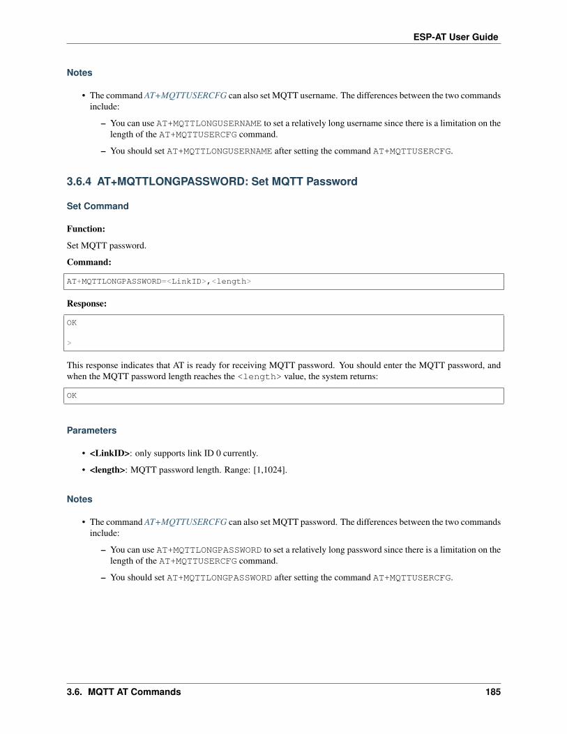
ESP-AT User Guide
Notes
• The command AT+MQTTUSERCFG can also set MQTT username. The differences between the two commandsinclude:
– You can use AT+MQTTLONGUSERNAME to set a relatively long username since there is a limitation on thelength of the AT+MQTTUSERCFG command.
– You should set AT+MQTTLONGUSERNAME after setting the command AT+MQTTUSERCFG.
3.6.4 AT+MQTTLONGPASSWORD: Set MQTT Password
Set Command
Function:
Set MQTT password.
Command:
AT+MQTTLONGPASSWORD=<LinkID>,<length>
Response:
OK
>
This response indicates that AT is ready for receiving MQTT password. You should enter the MQTT password, andwhen the MQTT password length reaches the <length> value, the system returns:
OK
Parameters
• <LinkID>: only supports link ID 0 currently.
• <length>: MQTT password length. Range: [1,1024].
Notes
• The command AT+MQTTUSERCFG can also set MQTT password. The differences between the two commandsinclude:
– You can use AT+MQTTLONGPASSWORD to set a relatively long password since there is a limitation on thelength of the AT+MQTTUSERCFG command.
– You should set AT+MQTTLONGPASSWORD after setting the command AT+MQTTUSERCFG.
3.6. MQTT AT Commands 185

ESP-AT User Guide
3.6.5 AT+MQTTCONNCFG: Set Configuration of MQTT Connection
Set Command
Function:
Set configuration of MQTT Connection.
Command:
AT+MQTTCONNCFG=<LinkID>,<keepalive>,<disable_clean_session>,<"lwt_topic">,<"lwt_msg">,→˓<lwt_qos>,<lwt_retain>
Response:
OK
Parameters
• <LinkID>: only supports link ID 0 currently.
• <keepalive>: timeout of MQTT ping. Unit: second. Range [0,7200]. The default value is 0, which will beforce-changed to 120 s.
• <disable_clean_session>: set MQTT clean session. For more details about this parameter, please refer to thesection Clean Session in MQTT Version 3.1.1.
– 0: enable clean session.
– 1: disable clean session.
• <lwt_topic>: LWT (Last Will and Testament) message topic. Maximum length: 128 bytes.
• <lwt_msg>: LWT message. Maximum length: 64 bytes.
• <lwt_qos>: LWT QoS, which can be set to 0, 1, or 2. Default: 0.
• <lwt_retain>: LWT retain, which can be set to 0 or 1. Default: 0.
3.6.6 AT+MQTTCONN: Connect to MQTT Brokers
Query Command
Function:
Query the MQTT broker that ESP devices are connected to.
Command:
AT+MQTTCONN?
Response:
+MQTTCONN:<LinkID>,<state>,<scheme><"host">,<port>,<"path">,<reconnect>OK
186 Chapter 3. AT Command Set

ESP-AT User Guide
Set Command
Function:
Connect to an MQTT broker.
Command:
AT+MQTTCONN=<LinkID>,<"host">,<port>,<reconnect>
Response:
OK
Parameters
• <LinkID>: only supports link ID 0 currently.
• <host>: MQTT broker domain. Maximum length: 128 bytes.
• <port>: MQTT broker port. Maximum: port 65535.
• <path>: path. Maximum length: 32 bytes.
• <reconnect>:
– 0: MQTT will not reconnect automatically.
– 1: MQTT will reconnect automatically. It takes more resources.
• <state>: MQTT state.
– 0: MQTT uninitialized.
– 1: already set AT+MQTTUSERCFG.
– 2: already set AT+MQTTCONNCFG.
– 3: connection disconnected.
– 4: connection established.
– 5: connected, but did not subscribe to any topic.
– 6: connected, and subscribed to MQTT topics.
• <scheme>:
– 1: MQTT over TCP.
– 2: MQTT over TLS (no certificate verify).
– 3: MQTT over TLS (verify server certificate).
– 4: MQTT over TLS (provide client certificate).
– 5: MQTT over TLS (verify server certificate and provide client certificate).
– 6: MQTT over WebSocket (based on TCP).
– 7: MQTT over WebSocket Secure (based on TLS, verify no certificate).
– 8: MQTT over WebSocket Secure (based on TLS, verify server certificate).
– 9: MQTT over WebSocket Secure (based on TLS, provide client certificate).
– 10: MQTT over WebSocket Secure (based on TLS, verify server certificate and provide client certificate).
3.6. MQTT AT Commands 187

ESP-AT User Guide
3.6.7 AT+MQTTPUB: Publish MQTT Messages in String
Set Command
Function:
Publish MQTT messages in string to a defined topic. If you need to publish messages in binary, please use theAT+MQTTPUBRAW command.
Command:
AT+MQTTPUB=<LinkID>,<"topic">,<"data">,<qos>,<retain>
Response:
OK
Parameters
• <LinkID>: only supports link ID 0 currently.
• <topic>: MQTT topic. Maximum length: 128 bytes.
• <data>: MQTT message in string.
• <qos>: QoS of message, which can be set to 0, 1, or 2. Default: 0.
• <retain>: retain flag.
Notes
• The length of the entire AT command should be less than 256 bytes.
• This command cannot send data \0. If you need to send \0, please use the command AT+MQTTPUBRAWinstead.
3.6.8 AT+MQTTPUBRAW: Publish MQTT Messages in Binary
Set Command
Function:
Publish MQTT messages in binary to a defined topic.
Command:
AT+MQTTPUBRAW=<LinkID>,<"topic">,<length>,<qos>,<retain>
Response:
OK>
The symbol > indicates that AT is ready for receiving serial data, and you can enter the data now. When the requirementof message length determined by the parameter <length> is met, the transmission starts.
If the transmission is successful, AT returns:
188 Chapter 3. AT Command Set

ESP-AT User Guide
+MQTTPUB:OK
Otherwise, it returns:
+MQTTPUB:FAIL
Parameters
• <LinkID>: only supports link ID 0 currently.
• <topic>: MQTT topic. Maximum length: 128 bytes.
• <length>: length of MQTT message. The maximum length varies on different ESP devices.
– For ESP32 devices, the maximum length is limited by available memory.
– For ESP8266 devices, the maximum is limited by available memory and the marcoMQTT_BUFFER_SIZE_BYTE. The default value of the macro is 512. You can change the maxlength limitation by setting it in build.py menuconfig. MQTT_BUFFER_SIZE_BYTE equalsmaximum published data length plus the MQTT header length (depends on topic name length).
• <qos>: QoS of the published message, which can be set to 0, 1, or 2. Default is 0.
• <retain>: retain flag.
3.6.9 AT+MQTTSUB: Subscribe to MQTT Topics
Query Command
Function:
List all MQTT topics that have been already subscribed.
Command:
AT+MQTTSUB?
Response:
+MQTTSUB:<LinkID>,<state>,<"topic1">,<qos>+MQTTSUB:<LinkID>,<state>,<"topic2">,<qos>+MQTTSUB:<LinkID>,<state>,<"topic3">,<qos>...OK
Set Command
Function:
Subscribe to defined MQTT topics with defined QoS. It supports subscribing to multiple topics.
Command:
AT+MQTTSUB=<LinkID>,<"topic">,<qos>
Response:
3.6. MQTT AT Commands 189
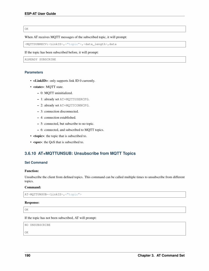
ESP-AT User Guide
OK
When AT receives MQTT messages of the subscribed topic, it will prompt:
+MQTTSUBRECV:<LinkID>,<"topic">,<data_length>,data
If the topic has been subscribed before, it will prompt:
ALREADY SUBSCRIBE
Parameters
• <LinkID>: only supports link ID 0 currently.
• <state>: MQTT state.
– 0: MQTT uninitialized.
– 1: already set AT+MQTTUSERCFG.
– 2: already set AT+MQTTCONNCFG.
– 3: connection disconnected.
– 4: connection established.
– 5: connected, but subscribe to no topic.
– 6: connected, and subscribed to MQTT topics.
• <topic>: the topic that is subscribed to.
• <qos>: the QoS that is subscribed to.
3.6.10 AT+MQTTUNSUB: Unsubscribe from MQTT Topics
Set Command
Function:
Unsubscribe the client from defined topics. This command can be called multiple times to unsubscribe from differenttopics.
Command:
AT+MQTTUNSUB=<LinkID>,<"topic">
Response:
OK
If the topic has not been subscribed, AT will prompt:
NO UNSUBSCRIBE
OK
190 Chapter 3. AT Command Set

ESP-AT User Guide
Parameters
• <LinkID>: only supports link ID 0 currently.
• <topic>: MQTT topic. Maximum length: 128 bytes.
3.6.11 AT+MQTTCLEAN: Close MQTT Connections
Set Command
Function:
Close the MQTT connection and release the resource.
Command:
AT+MQTTCLEAN=<LinkID>
Response:
OK
Parameter
• <LinkID>: only supports link ID 0 currently
3.6.12 MQTT AT Error Codes
The MQTT Error code will be prompted as ERR CODE:0x<%08x>.
Error Type Error CodeAT_MQTT_NO_CONFIGURED 0x6001AT_MQTT_NOT_IN_CONFIGURED_STATE 0x6002AT_MQTT_UNINITIATED_OR_ALREADY_CLEAN 0x6003AT_MQTT_ALREADY_CONNECTED 0x6004AT_MQTT_MALLOC_FAILED 0x6005AT_MQTT_NULL_LINK 0x6006AT_MQTT_NULL_PARAMTER 0x6007AT_MQTT_PARAMETER_COUNTS_IS_WRONG 0x6008AT_MQTT_TLS_CONFIG_ERROR 0x6009AT_MQTT_PARAM_PREPARE_ERROR 0x600AAT_MQTT_CLIENT_START_FAILED 0x600BAT_MQTT_CLIENT_PUBLISH_FAILED 0x600CAT_MQTT_CLIENT_SUBSCRIBE_FAILED 0x600DAT_MQTT_CLIENT_UNSUBSCRIBE_FAILED 0x600EAT_MQTT_CLIENT_DISCONNECT_FAILED 0x600FAT_MQTT_LINK_ID_READ_FAILED 0x6010AT_MQTT_LINK_ID_VALUE_IS_WRONG 0x6011AT_MQTT_SCHEME_READ_FAILED 0x6012AT_MQTT_SCHEME_VALUE_IS_WRONG 0x6013AT_MQTT_CLIENT_ID_READ_FAILED 0x6014
Continued on next page
3.6. MQTT AT Commands 191

ESP-AT User Guide
Table 3 – continued from previous pageError Type Error CodeAT_MQTT_CLIENT_ID_IS_NULL 0x6015AT_MQTT_CLIENT_ID_IS_OVERLENGTH 0x6016AT_MQTT_USERNAME_READ_FAILED 0x6017AT_MQTT_USERNAME_IS_NULL 0x6018AT_MQTT_USERNAME_IS_OVERLENGTH 0x6019AT_MQTT_PASSWORD_READ_FAILED 0x601AAT_MQTT_PASSWORD_IS_NULL 0x601BAT_MQTT_PASSWORD_IS_OVERLENGTH 0x601CAT_MQTT_CERT_KEY_ID_READ_FAILED 0x601DAT_MQTT_CERT_KEY_ID_VALUE_IS_WRONG 0x601EAT_MQTT_CA_ID_READ_FAILED 0x601FAT_MQTT_CA_ID_VALUE_IS_WRONG 0x6020AT_MQTT_CA_LENGTH_ERROR 0x6021AT_MQTT_CA_READ_FAILED 0x6022AT_MQTT_CERT_LENGTH_ERROR 0x6023AT_MQTT_CERT_READ_FAILED 0x6024AT_MQTT_KEY_LENGTH_ERROR 0x6025AT_MQTT_KEY_READ_FAILED 0x6026AT_MQTT_PATH_READ_FAILED 0x6027AT_MQTT_PATH_IS_NULL 0x6028AT_MQTT_PATH_IS_OVERLENGTH 0x6029AT_MQTT_VERSION_READ_FAILED 0x602AAT_MQTT_KEEPALIVE_READ_FAILED 0x602BAT_MQTT_KEEPALIVE_IS_NULL 0x602CAT_MQTT_KEEPALIVE_VALUE_IS_WRONG 0x602DAT_MQTT_DISABLE_CLEAN_SESSION_READ_FAILED 0x602EAT_MQTT_DISABLE_CLEAN_SESSION_VALUE_IS_WRONG 0x602FAT_MQTT_LWT_TOPIC_READ_FAILED 0x6030AT_MQTT_LWT_TOPIC_IS_NULL 0x6031AT_MQTT_LWT_TOPIC_IS_OVERLENGTH 0x6032AT_MQTT_LWT_MSG_READ_FAILED 0x6033AT_MQTT_LWT_MSG_IS_NULL 0x6034AT_MQTT_LWT_MSG_IS_OVERLENGTH 0x6035AT_MQTT_LWT_QOS_READ_FAILED 0x6036AT_MQTT_LWT_QOS_VALUE_IS_WRONG 0x6037AT_MQTT_LWT_RETAIN_READ_FAILED 0x6038AT_MQTT_LWT_RETAIN_VALUE_IS_WRONG 0x6039AT_MQTT_HOST_READ_FAILED 0x603AAT_MQTT_HOST_IS_NULL 0x603BAT_MQTT_HOST_IS_OVERLENGTH 0x603CAT_MQTT_PORT_READ_FAILED 0x603DAT_MQTT_PORT_VALUE_IS_WRONG 0x603EAT_MQTT_RECONNECT_READ_FAILED 0x603FAT_MQTT_RECONNECT_VALUE_IS_WRONG 0x6040AT_MQTT_TOPIC_READ_FAILED 0x6041AT_MQTT_TOPIC_IS_NULL 0x6042AT_MQTT_TOPIC_IS_OVERLENGTH 0x6043AT_MQTT_DATA_READ_FAILED 0x6044AT_MQTT_DATA_IS_NULL 0x6045
Continued on next page
192 Chapter 3. AT Command Set

ESP-AT User Guide
Table 3 – continued from previous pageError Type Error CodeAT_MQTT_DATA_IS_OVERLENGTH 0x6046AT_MQTT_QOS_READ_FAILED 0x6047AT_MQTT_QOS_VALUE_IS_WRONG 0x6048AT_MQTT_RETAIN_READ_FAILED 0x6049AT_MQTT_RETAIN_VALUE_IS_WRONG 0x604AAT_MQTT_PUBLISH_LENGTH_READ_FAILED 0x604BAT_MQTT_PUBLISH_LENGTH_VALUE_IS_WRONG 0x604CAT_MQTT_RECV_LENGTH_IS_WRONG 0x604DAT_MQTT_CREATE_SEMA_FAILED 0x604EAT_MQTT_CREATE_EVENT_GROUP_FAILED 0x604FAT_MQTT_URI_PARSE_FAILED 0x6050AT_MQTT_IN_DISCONNECTED_STATE 0x6051AT_MQTT_HOSTNAME_VERIFY_FAILED 0x6052
3.6.13 MQTT AT Notes
• In general, AT MQTT commands responds within 10 s, except the command AT+MQTTCONN. For example, ifthe router fails to access the Internet, the command AT+MQTTPUB will respond within 10 s. But the commandAT+MQTTCONN may need more time due to packet retransmission in a bad network environment.
• If the AT+MQTTCONN is based on a TLS connection, the timeout of each packet is 10 s, and the total timeoutwill be much longer depending on the handshake packets count.
• When the MQTT connection ends, it will prompt the message +MQTTDISCONNECTED:<LinkID>.
• When the MQTT connection established, it will prompt the message +MQTTCONNECTED:<LinkID>,<scheme>,<"host">,port,<"path">,<reconnect>.
3.7 HTTP AT Commands
[]
• AT+HTTPCLIENT: Send HTTP Client Request
• AT+HTTPGETSIZE: Get HTTP Resource Size
• AT+HTTPCPOST: Post HTTP data of specified length
• HTTP AT Error Codes
3.7.1 AT+HTTPCLIENT: Send HTTP Client Request
Set Command
Command:
AT+HTTPCLIENT=<opt>,<content-type>,<"url">,[<"host">],[<"path">],<transport_type>[,<→˓"data">][,<"http_req_header">][,<"http_req_header">][...]
Response:
3.7. HTTP AT Commands 193

ESP-AT User Guide
+HTTPCLIENT:<size>,<data>
OK
Parameters
• <opt>: method of HTTP client request.
– 1: HEAD
– 2: GET
– 3: POST
– 4: PUT
– 5: DELETE
• <content-type>: data type of HTTP client request.
– 0: application/x-www-form-urlencoded
– 1: application/json
– 2: multipart/form-data
– 3: text/xml
• <”url”>: HTTP URL. The parameter can override the <host> and <path> parameters if they are null.
• <”host”>: domain name or IP address.
• <”path”>: HTTP Path.
• <transport_type>: HTTP Client transport type. Default: 1.
– 1: HTTP_TRANSPORT_OVER_TCP
– 2: HTTP_TRANSPORT_OVER_SSL
• <”data”>: If <opt> is a POST request, this parameter holds the data you send to the HTTP server. If not, thisparameter does not exist, which means there is no need to input a comma to indicate this parameter.
• <http_req_header>: you can send more than one request header to the server.
Notes
• If the url parameter is not null, HTTP client will use it and ignore the host parameter and path parameter;If the url parameter is omited or null string, HTTP client will use host parameter and path parameter.
• In some released firmware, HTTP client commands are not supported (see How to understand the differences ofeach type of module), but you can enable it by ./build.py menuconfig > Component config > AT> AT http command support and build the project (see Build Your Own ESP-AT Project).
• For ESP8266 series of devices, if the URL is HTTPS type or <transport_type> parameter is 2, you needto enlarge at_process_task stack size to more than 4096 by configuring ./build.py menuconfig -> Componentconfig -> AT -> The stack size of the AT process task, otherwise ESP8266 will restart due to insufficient stack.
194 Chapter 3. AT Command Set

ESP-AT User Guide
Example
// HEAD RequestAT+HTTPCLIENT=1,0,"http://httpbin.org/get","httpbin.org","/get",1
// GET RequestAT+HTTPCLIENT=2,0,"http://httpbin.org/get","httpbin.org","/get",1
// POST RequestAT+HTTPCLIENT=3,0,"http://httpbin.org/post","httpbin.org","/post",1,"field1=value1&→˓field2=value2"
3.7.2 AT+HTTPGETSIZE: Get HTTP Resource Size
Set Command
Command:
AT+HTTPGETSIZE=<url>
Response:
+HTTPGETSIZE:<size>
OK
Parameters
• <url>: HTTP URL.
• <size>: HTTP resource size.
Note
• In some released firmware, HTTP client commands are not supported (see How to understand the differences ofeach type of module), but you can enable it by ./build.py menuconfig > Component config > AT> AT http command support and build the project (see Build Your Own ESP-AT Project).
• For ESP8266 series of devices, if the URL is HTTPS type or <transport_type> parameter is 2, you needto enlarge at_process_task stack size to more than 4096 by configuring ./build.py menuconfig -> Componentconfig -> AT -> The stack size of the AT process task, otherwise ESP8266 will restart due to insufficient stack.
Example
AT+HTTPGETSIZE="http://www.baidu.com/img/bdlogo.gif"
3.7. HTTP AT Commands 195

ESP-AT User Guide
3.7.3 AT+HTTPCPOST: Post HTTP data of specified length
Set Command
Command:
AT+HTTPCPOST=<url>,<length>[,<http_req_header_cnt>][,<http_req_header>..<http_req_→˓header>]
Response:
OK>
The symbol > indicates that AT is ready for receiving serial data, and you can enter the data now. When the requirementof message length determined by the parameter <length> is met, the transmission starts.
If the transmission is successful, AT returns:
SEND OK
Otherwise, it returns:
SEND FAIL
Parameters
• <url>: HTTP URL.
• <length>: HTTP data length to POST. The maximum length is equal to the system allocable heap size.
• <http_req_header_cnt>: the number of <http_req_header> parameters.
• [<http_req_header>]: you can send more than one request header to the server.
Note
• For ESP8266 series of devices, if the URL is HTTPS type or <transport_type> parameter is 2, you needto enlarge at_process_task stack size to more than 4096 by configuring ./build.py menuconfig -> Componentconfig -> AT -> The stack size of the AT process task, otherwise ESP8266 will restart due to insufficient stack.
3.7.4 HTTP AT Error Codes
• HTTP Client:
196 Chapter 3. AT Command Set

ESP-AT User Guide
HTTP Client Error Code Description0x7190 Bad Request0x7191 Unauthorized0x7192 Payment Required0x7193 Forbidden0x7194 Not Found0x7195 Method Not Allowed0x7196 Not Acceptable0x7197 Proxy Authentication Required0x7198 Request Timeout0x7199 Conflict0x719a Gone0x719b Length Required0x719c Precondition Failed0x719d Request Entity Too Large0x719e Request-URI Too Long0x719f Unsupported Media Type0x71a0 Requested Range Not Satisfiable0x71a1 Expectation Failed
• HTTP Server:
HTTP Server Error Code Description0x71f4 Internal Server Error0x71f5 Not Implemented0x71f6 Bad Gateway0x71f7 Service Unavailable0x71f8 Gateway Timeout0x71f9 HTTP Version Not Supported
• HTTP AT:
– The error code of command AT+HTTPCLIENT will be 0x7000+Standard HTTP Error Code(For more details about Standard HTTP/1.1 Error Code, see RFC 2616).
– For example, if AT gets the HTTP error 404 when calling command AT+HTTPCLIENT, it will respondwith error code of 0x7194 (hex(0x7000+404)=0x7194).
3.8 [ESP32 Only] Ethernet AT Commands
[]
• Prerequisite
• [ESP32 Only] AT+CIPETHMAC: Query/Set the MAC address of the ESP Ethernet.
• [ESP32 Only] AT+CIPETH: Query/Set the IP address of the ESP Ethernet.
3.8. [ESP32 Only] Ethernet AT Commands 197

ESP-AT User Guide
3.8.1 Prerequisite
Before you run any Ethernet AT Commands, please make the following preparations:
Note: This prerequisite takes ESP32-Ethernet-Kit as an example. If you use other modules or development boards,please refer to corresponding datasheets for RX/TX pins.
• Change AT UART pins (because default AT UART pins are in conflict with the Ethernet function pins):
– Open factory_param_data.csv file.
– In the row of module WROVER-32, change uart_tx_pin from GPIO22 to GPIO2, uart_rx_pinfrom GPIO19 to GPIO4, uart_cts_pin from GPIO15 to GPIO1, and uart_rts_pin from GPIO14to GPIO1 (flow control is optional and is not used here). See How to Set AT Port Pins for more information.
• Enable AT ethernet support. See How to enable ESP-AT Ethernet for more information.
• Compile and flash the project onto ESP32-Ethernet-Kit.
• Connect your hardware:
– Connect Host MCU (PC with USB to serial converter) to GPIO2 (TX) and GPIO4 (RX) of ESP32-Ethernet-Kit when the flow control function is not enabled.
– Connect ESP32-Ethernet-Kit with Ethernet network.
3.8.2 [ESP32 Only] AT+CIPETHMAC: Query/Set the MAC Address of the ESP Ether-net
Query Command
Function:
Query the MAC address of the ESP Ethernet.
Command:
AT+CIPETHMAC?
Response:
+CIPETHMAC:<"mac">OK
Set Command
Function:
Set the MAC address of the ESP Ethernet.
Command:
AT+CIPETHMAC=<"mac">
Response:
198 Chapter 3. AT Command Set

ESP-AT User Guide
OK
Parameter
• <”mac”>: string parameter showing the MAC address of the Ethernet interface.
Notes
• The default firmware does not support Ethernet AT commands (see How to understand the differences of eachtype of module), but you can enable it by ./build.py menuconfig > Component config > AT > ATethernet support and compile the project (see Build Your Own ESP-AT Project).
• The configuration changes will be saved in the NVS area if AT+SYSSTORE=1.
• Please make sure the MAC address of Ethernet interface you set is different from those of other interfaces.
• Bit0 of the ESP MAC address CANNOT be 1. For example, a MAC address can be “1a:. . . ” but not “15:. . . ”.
• FF:FF:FF:FF:FF:FF and 00:00:00:00:00:00 are invalid MAC addresses and cannot be set.
Example
AT+CIPETHMAC="1a:fe:35:98:d4:7b"
3.8.3 [ESP32 Only] AT+CIPETH: Query/Set the IP Address of the the ESP Ethernet
Query Command
Function:
Query the IP address of the ESP Ethernet.
Command:
AT+CIPETH?
Response:
+CIPETH:ip:<ip>+CIPETH:gateway:<gateway>+CIPETH:netmask:<netmask>OK
3.8. [ESP32 Only] Ethernet AT Commands 199

ESP-AT User Guide
Set Command
Function:
Set the IP address of the ESP Ethernet.
Command:
AT+CIPETH=<ip>[,<gateway>,<netmask>]
Response:
OK
Parameters
• <ip>: string parameter showing the IP address of the ESP Ethernet.
• [<gateway>]: gateway.
• [<netmask>]: netmask.
Notes
• The default firmware does not support Ethernet AT commands (see How to understand the differences of eachtype of module), but you can enable it by ./build.py menuconfig > Component config > AT > ATethernet support and compile the project (see Build Your Own ESP-AT Project).
• The configuration changes will be saved in the NVS area if AT+SYSSTORE=1.
• This Set Command correlates with DHCP commands, such as AT+CWDHCP:
– If static IP is enabled, DHCP will be disabled.
– If DHCP is enabled, static IP will be disabled.
– The last configuration overwrites the previous configuration.
Example
AT+CIPETH="192.168.6.100","192.168.6.1","255.255.255.0"
3.9 [ESP8266 Only] Signaling Test AT Commands
[]
• AT+FACTPLCP: Send with long or short PLCP (Physical Layer Convergence Procedure)
200 Chapter 3. AT Command Set

ESP-AT User Guide
3.9.1 [ESP8266 Only] AT+FACTPLCP: Send with Long or Short PLCP
Set Command
Command:
AT+FACTPLCP=<enable>,<tx_with_long>
Response:
OK
Parameters
• <enable>: Enable or disable manual configuration.
– 0: Disable manual configuration. The default value for the parameter <tx_with_long> will be used.
– 1: Enable manual configuration. The type of PLCP that AT sends depends on <tx_with_long>.
• <tx_with_long>: Send with long PLCP or short PLCP.
– 0: Send with short PLCP (default).
– 1: Send with long PLCP.
3.10 Web server AT Commands
• AT+WEBSERVER: Enable/disable Wi-Fi connection configuration via web server.
3.10.1 AT+WEBSERVER: Enable/disable Wi-Fi connection configuration via webserver
Set Command
Command:
AT+WEBSERVER=<enable>,<server_port>,<connection_timeout>
Response:
OK
3.10. Web server AT Commands 201

ESP-AT User Guide
Parameters
• <enable>: Enable or disable web server.
– 0: Disable the web server and release related resources.
– 1: Enable web server, which means that you can use WeChat or a browser to configure Wi-Fi connectioninformation.
• <server_port>: The web server port number.
• <connection_timeout>: The timeout for the every connection. Unit: second. Range:[21,60].
Notes
• There are two ways to provide the HTML files needed by the web server. One is to use fatfs file system (nonESP8266 chips), and you need to enable AT FS command at this time. The other one is to use embedded filesto storge HTML files (default setting).
• Please make sure that the max number of open sockets is not less than 12, you may change the number by ./build.py menuconfig > Component config > LWIP > Max bumber of open sockets andcompile the project (see Build Your Own ESP-AT Project).
• The default firmware does not support web server AT commands (see How to understand the differences of eachtype of module), but you can enable it by ./build.py menuconfig > Component config > AT > ATWEB Server command support and compile the project (see Build Your Own ESP-AT Project).
• For ESP8266 devices, you may need to turn off some unnecessary options to store the necessary html files.
• For more examples, please refer to Web Server AT Example.
Example
// Enable the web server with port 80, and the timeout for the every connection is 50→˓seconds:AT+WEBSERVER=1,80,50
// Disable the web server, the command should be:AT+WEBSERVER=0
3.11 [ESP32 & ESP32-S2 & ESP32-C3] Driver AT Commands
[]
• AT+DRVADC: Read ADC channel value.
• AT+DRVPWMINIT: Initialize PWM driver.
• AT+DRVPWMDUTY: Set PWM duty.
• AT+DRVPWMFADE: Set PWM fade.
• AT+DRVI2CINIT: Initialize I2C master driver.
• AT+DRVI2CRD: Read I2C data.
• AT+DRVI2CWRDATA: Write I2C data.
• AT+DRVI2CWRBYTES: Write no more than 4 bytes I2C data.
202 Chapter 3. AT Command Set

ESP-AT User Guide
• AT+DRVSPICONFGPIO: Configure SPI GPIO.
• AT+DRVSPIINIT: Initialize SPI master driver.
• AT+DRVSPIRD: Read SPI data.
• AT+DRVSPIWR: Write SPI data.
3.11.1 AT+DRVADC: Read ADC Channel Value
Set Command
Command:
AT+DRVADC=<channel>,<atten>
Response:
+DRVADC:<raw data>OK
Parameters
• <channel>: ADC1 channel. Range: 0 ~ 7. See datasheets for corresponding pins.
• <atten>: attenuation.
– 0: 0 dB attenuation gives full-scale voltage 1.1 V.
– 1: 2.5 dB attenuation gives full-scale voltage 1.5 V.
– 2: 6 dB attenuation gives full-scale voltage 2.2 V.
– 3: 11 dB attenuation gives full-scale voltage 3.9 V.
• <raw data>: ADC channel value. The voltage value is raw_data/2 width * atten.
Notes
• ESP-AT only supports ADC1.
• ESP32 and ESP32-C3 support 12-bit width, and ESP32-S2 only supports 13-bit width.
Example
AT+DRVADC=0,0 // ADC1 0 channel, voltage: 0 ~ 1.1 V+DRVADC:2048 // For ESP32 and ESP32-C3, the voltage is 2048 / 4096 * 1.1 = 0.55
// For ESP32-S2, the voltage is 2048 / 8192 * 1.1 = 0.264OK
3.11. [ESP32 & ESP32-S2 & ESP32-C3] Driver AT Commands 203

ESP-AT User Guide
3.11.2 AT+DRVPWMINIT: Initialize PWM Driver
Set Command
Command:
AT+DRVPWMINIT=<freq>,<duty_res>,<ch0_gpio>[,...,<ch3_gpio>]
Response:
OK
Parameters
• <freq>: LEDC timer frequency. Unit: Hz. Range: 1 Hz ~ 8 MHz.
• <duty_res>: LEDC channel duty resolution. Range: 0 ~ 20 bits.
• <chx_gpio>: LEDC output GPIO number of channel x. For example, if you want to use GPIO16 as channel 0,set <ch0_gpio> to 16.
Notes
• AT can support a maximum of 4 channels.
• The number of channels that you initialize using this command will determine how many channels you can setusing other PWM commands, including AT+DRVPWMDUTY and AT+DRVPWMFADE. For example, if youinitialize two channels, you can only change the two channels’ PWM duty using command AT+DRVPWMDUTY.
• The frequency and the duty resolution are interdependent. See Supported Range of Frequency and Duty Reso-lutions for more details.
Example
AT+DRVPWMINIT=5000,13,17,16,18,19 // set 4 channels; frequency: 5 kHz; duty→˓resolution: 13 bitsAT+DRVPWMINIT=10000,10,17 // only use channel 0, frequency: 10 kHz; duty→˓resolution: 10 bits; other PMW commands can only set one channel
3.11.3 AT+DRVPWMDUTY: Set PWM Duty
Set Command
Command:
AT+DRVPWMDUTY=<ch0_duty>[,...,<ch3_duty>]
Response:
OK
204 Chapter 3. AT Command Set

ESP-AT User Guide
Parameter
• <duty>: LEDC channel duty. Range: [0,2 duty_resolution].
Notes
• AT can support a maximum of 4 channels.
• If you do not want to set <duty> for a specific channel, just omit it.
Example
AT+DRVPWMDUTY=255,512 // set channel 0 to duty 255, set channel 1 to duty 512AT+DRVPWMDUTY=,,0 // set channel 2 to duty 0
3.11.4 AT+DRVPWMFADE: Set PWM Fade
Set Command
Command:
AT+DRVPWMFADE=<ch0_target_duty>,<ch0_fade_time>[,...,<ch3_target_duty>,<ch3_fade_time>→˓]
Response:
OK
Parameters
• <target_duty>: target duty of fading. Range: [0, 2 duty_resolution–1].
• <fade_time>: the maximum time of fading. Unit: millisecond.
Notes
• AT can support a maximum of 4 channels.
• If you do not want to set <target_duty> and <fade_time> for a specific channel, just omit them.
Example
AT+DRVPWMFADE=,,0,1000 // use one second to change channel 1 duty to 0AT+DRVPWMFADE=1024,1000,0,2000, // use one second time to change channel 0 duty to→˓1024, two seconds to change channel 1 duty to 0
3.11. [ESP32 & ESP32-S2 & ESP32-C3] Driver AT Commands 205

ESP-AT User Guide
3.11.5 AT+DRVI2CINIT: Initialize I2C Master Driver
Set Command
Command:
AT+DRVI2CINIT=<num>,<scl_io>,<sda_io>,<clock>
Response:
OK
Parameters
• <num>: I2C port number. Range: 0 ~ 1. If the following parameters are not set, AT will deinitialize the I2Cport.
• <scl_io>: GPIO number for I2C SCL signal.
• <sda_io>: GPIO number for I2C SDA signal.
• <clock>: I2C clock frequency for master mode. Unit: Hz. Maximum: 1 MHz.
Note
• This command only supports I2C masters.
Example
AT+DRVI2CINIT=0,25,26,1000 // initialize I2C0; GPIO25 is SCL; GPIO26 is SDA; I2C→˓clock is 1 kHzAT+DRVI2CINIT=0 // deinitialize I2C0
3.11.6 AT+DRVI2CRD: Read I2C Data
Set Command
Command:
AT+DRVI2CRD=<num>,<address>,<length>
Response:
+DRVI2CRD:<read data>OK
206 Chapter 3. AT Command Set

ESP-AT User Guide
Parameters
• <num>: I2C port number. Range: 0 ~ 1.
• <address>: I2C slave device address.
– 7-bit address: 0 ~ 0x7F.
– 10-bit address: The first seven bits of the first byte are the combination 1111 0XX of which the last two bits(XX) are the two Most Significant Bits (MSBs) of the 10-bit address. For example, if the 10-bit address is0x2FF (b’1011111111), the input address should be 0x7AFF (b’111101011111111).
• <length>: I2C data length. Range: 1 ~ 2048.
• <read data>: I2C data.
Note
• I2C transmission timeout is one second.
Example
AT+DRVI2CRD=0,0x34,1 // I2C0 reads one byte data from address 0x34AT+DRVI2CRD=0,0x7AFF,1 // I2C0 reads one byte data from 10-bit address 0x2FF
// I2C0 reads address 0x34, register address 0x27, read 2 bytesAT+DRVI2CWRBYTES=0,0x34,1,0x27 // I2C0 first writes device address 0x34, register→˓address 0x27AT+DRVI2CRD=0,0x34,2 // I2C0 reads 2 bytes
3.11.7 AT+DRVI2CWRDATA: Write I2C Data
Set Command
Command:
AT+DRVI2CWRDATA=<num>,<address>,<length>
Response:
OK>
This response indicates that you should enter the data you want to write. When the requirement of data length is met,the data transmission starts.
If the data is transmitted successfully, AT returns:
OK
If the data transmission fails, AT returns:
ERROR
3.11. [ESP32 & ESP32-S2 & ESP32-C3] Driver AT Commands 207

ESP-AT User Guide
Parameters
• <num>: I2C port number. Range: 0 ~ 1.
• <address>: I2C slave device address.
– 7-bit address: 0 ~ 0x7F.
– 10-bit address: The first seven bits of the first byte are the combination 1111 0XX of which the last two bits(XX) are the two Most Significant Bits (MSBs) of the 10-bit address. For example, if the 10-bit address is0x2FF (b’1011111111), the input address should be 0x7AFF (b’111101011111111).
• <length>: I2C data length. Range: 1 ~ 2048.
Note
• I2C transmission timeout is one second.
Example
AT+DRVI2CWRDATA=0,0x34,10 // I2C0 writes 10 bytes data to address 0x34
3.11.8 AT+DRVI2CWRBYTES: Write No More Than 4 Bytes I2C Data
Set Command
Command:
AT+DRVI2CWRBYTES=<num>,<address>,<length>,<data>
Response:
OK
Parameters
• <num>: I2C port number. Range: 0 ~ 1.
• <address>: I2C slave device address.
– 7-bit address: 0 ~ 0x7F.
– 10-bit address: The first seven bits of the first byte are the combination 1111 0XX of which the last two bits(XX) are the two Most Significant Bits (MSBs) of the 10-bit address. For example, if the 10-bit address is0x2FF (b’1011111111), the input address should be 0x7AFF (b’111101011111111).
• <length>: the length of the I2C data you want to write. Range: 1 ~ 4 bytes.
• <data>: the data of <length> long. Range: 0 ~ 0xFFFFFFFF.
208 Chapter 3. AT Command Set
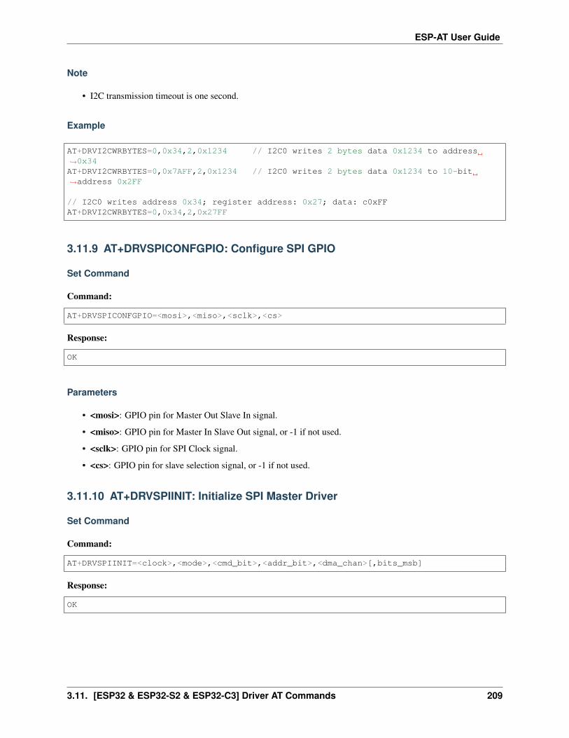
ESP-AT User Guide
Note
• I2C transmission timeout is one second.
Example
AT+DRVI2CWRBYTES=0,0x34,2,0x1234 // I2C0 writes 2 bytes data 0x1234 to address→˓0x34AT+DRVI2CWRBYTES=0,0x7AFF,2,0x1234 // I2C0 writes 2 bytes data 0x1234 to 10-bit→˓address 0x2FF
// I2C0 writes address 0x34; register address: 0x27; data: c0xFFAT+DRVI2CWRBYTES=0,0x34,2,0x27FF
3.11.9 AT+DRVSPICONFGPIO: Configure SPI GPIO
Set Command
Command:
AT+DRVSPICONFGPIO=<mosi>,<miso>,<sclk>,<cs>
Response:
OK
Parameters
• <mosi>: GPIO pin for Master Out Slave In signal.
• <miso>: GPIO pin for Master In Slave Out signal, or -1 if not used.
• <sclk>: GPIO pin for SPI Clock signal.
• <cs>: GPIO pin for slave selection signal, or -1 if not used.
3.11.10 AT+DRVSPIINIT: Initialize SPI Master Driver
Set Command
Command:
AT+DRVSPIINIT=<clock>,<mode>,<cmd_bit>,<addr_bit>,<dma_chan>[,bits_msb]
Response:
OK
3.11. [ESP32 & ESP32-S2 & ESP32-C3] Driver AT Commands 209

ESP-AT User Guide
Parameters
• <clock>: Clock speed, divisors of 80 MHz. Unit: Hz. Maximum: 40 MHz.
• <mode>: SPI mode. Range: 0 ~ 3.
• <cmd_bit>: Default amount of bits in command phase. Range: 0 ~ 16.
• <addr_bit>: Default amount of bits in address phase. Range: 0 ~ 64.
• <dma_chan>: Either channel 1 or 2, or 0 in the case when no DMA is required.
• <bits_msb>: SPI data format:
– Bit0:
* 0: Transmit MSB first (default).
* 1: Transmit LSB first.
– Bit1:
* 0: Receive data MSB first (default).
* 1: Receive data LSB first.
Note
• You should configure SPI GPIO before SPI initialization.
Example
AT+DRVSPIINIT=102400,0,0,0,0,3 // SPI clock: 100 kHz; mode: 0; both command and→˓address bits are 0; not use DMA; transmit and receive LSB firstOKAT+DRVSPIINIT=0 // delete SPI DriverOK
3.11.11 AT+DRVSPIRD: Read SPI Data
Set Command
Command:
AT+DRVSPIRD=<data_len>[,<cmd>,<cmd_len>][,<addr>,<addr_len>]
Response:
+DRVSPIRD:<read data>OK
210 Chapter 3. AT Command Set

ESP-AT User Guide
Parameters
• <data_len>: length of SPI data you want to read. Range: 1 ~ 4092 bytes.
• <cmd>: command data. The length of the data is set in <cmd_len>.
• <cmd_len>: command length in this transaction. Range: 0 ~ 2 bytes.
• <addr>: command address. The length of the address is set in <addr_len>.
• <addr_len>: The address length in this transaction. Range: 0 ~ 4 bytes.
Note
• If you don’t use DMA, the maximum <data_len> you can set is 64 bytes each time.
Example
AT+DRVSPIRD=2 // read 2 bytes data+DRVI2CREAD:ffffOK
AT+DRVSPIRD=2,0x03,1,0x001000,3 // read 2 bytes data; <cmd> is 0x03; <cmd_len> is 1→˓byte; <addr> is 0x1000; <addr_len> is 3 bytes+DRVI2CREAD:ffffOK
3.11.12 AT+DRVSPIWR: Write SPI Data
Set Command
Command:
AT+DRVSPIWR=<data_len>[,<cmd>,<cmd_len>][,<addr>,<addr_len>]
Response:
When <data_len> is larger than 0, AT returns:
OK>
This response indicates that you should enter the data you want to write. When the requirement of data length is met,the data transmission starts.
If the data is transmitted successfully, AT returns:
OK
When <data_len> is equal to 0, which means AT transmits commands and addresses only, and no SPI data, ATreturns:
OK
3.11. [ESP32 & ESP32-S2 & ESP32-C3] Driver AT Commands 211
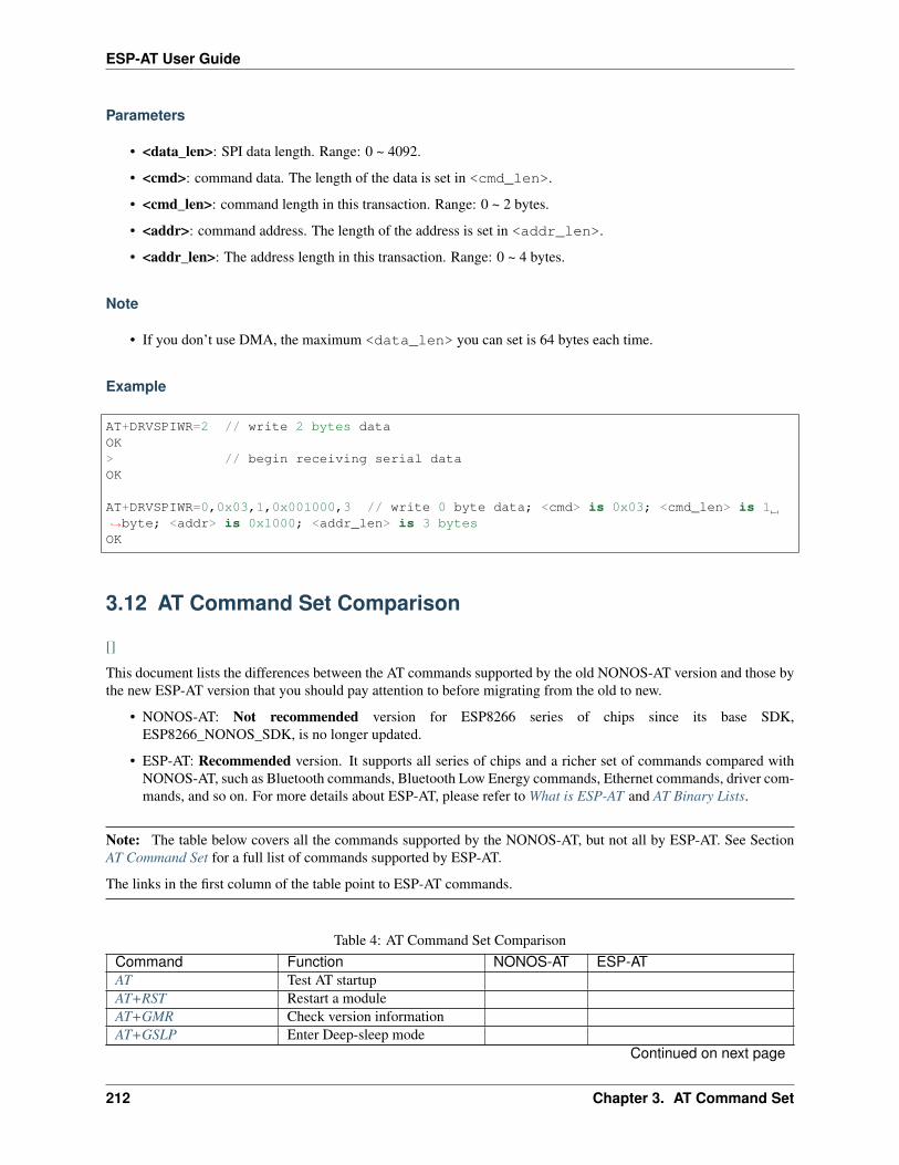
ESP-AT User Guide
Parameters
• <data_len>: SPI data length. Range: 0 ~ 4092.
• <cmd>: command data. The length of the data is set in <cmd_len>.
• <cmd_len>: command length in this transaction. Range: 0 ~ 2 bytes.
• <addr>: command address. The length of the address is set in <addr_len>.
• <addr_len>: The address length in this transaction. Range: 0 ~ 4 bytes.
Note
• If you don’t use DMA, the maximum <data_len> you can set is 64 bytes each time.
Example
AT+DRVSPIWR=2 // write 2 bytes dataOK> // begin receiving serial dataOK
AT+DRVSPIWR=0,0x03,1,0x001000,3 // write 0 byte data; <cmd> is 0x03; <cmd_len> is 1→˓byte; <addr> is 0x1000; <addr_len> is 3 bytesOK
3.12 AT Command Set Comparison
[]
This document lists the differences between the AT commands supported by the old NONOS-AT version and those bythe new ESP-AT version that you should pay attention to before migrating from the old to new.
• NONOS-AT: Not recommended version for ESP8266 series of chips since its base SDK,ESP8266_NONOS_SDK, is no longer updated.
• ESP-AT: Recommended version. It supports all series of chips and a richer set of commands compared withNONOS-AT, such as Bluetooth commands, Bluetooth Low Energy commands, Ethernet commands, driver com-mands, and so on. For more details about ESP-AT, please refer to What is ESP-AT and AT Binary Lists.
Note: The table below covers all the commands supported by the NONOS-AT, but not all by ESP-AT. See SectionAT Command Set for a full list of commands supported by ESP-AT.
The links in the first column of the table point to ESP-AT commands.
Table 4: AT Command Set ComparisonCommand Function NONOS-AT ESP-ATAT Test AT startupAT+RST Restart a moduleAT+GMR Check version informationAT+GSLP Enter Deep-sleep mode
Continued on next page
212 Chapter 3. AT Command Set

ESP-AT User Guide
Table 4 – continued from previous pageCommand Function NONOS-AT ESP-ATATE AT commands echoingAT+RESTORE Restore factory default settingsAT+UART_CUR Current UART configuration,
not saved in flashAT+UART_DEF Default UART configuration,
saved in flashAT+SLEEP Set the sleep mode
1: light sleep2: modemsleep
ESP8266ESP32ESP32-S2 1
AT+WAKEUPGPIO Wakeup from light sleep onGPIO interrupt 3 Similar command:
AT+SLEEPWKCFG
AT+RFPOWER Set RF TX Power
Range: [0,82]Unit: 0.25dBm
2
AT+RFVDD Set RF TX power according toVDD33
AT+SYSRAM Query the remaining space ofRAM
Added the parameter of mini-mum heap size
AT+SYSADC Read ADC valueAT+SYSIOSETCFG Set IO working modeAT+SYSIOGETCFG Query IO working modeAT+SYSGPIODIR Set GPIO directionAT+SYSGPIOWRITE Set GPIO output levelAT+SYSGPIOREAD Read GPIO input levelAT+SYSMSG Set system prompt infoAT+SYSMSG_CUR Set system prompt info, not
saved in flash 3 Similar command:AT+SYSMSG
AT+SYSMSG_DEF Set default system prompt info,saved in flash 3 Similar command:
AT+SYSMSG
AT+CWMODE Set Wi-Fi mode Added automatic connectionafter mode switching
AT+CWMODE_CUR Set current Wi-Fi mode, notsaved in flash 3 Similar command:
AT+CWMODE
Continued on next page
3.12. AT Command Set Comparison 213
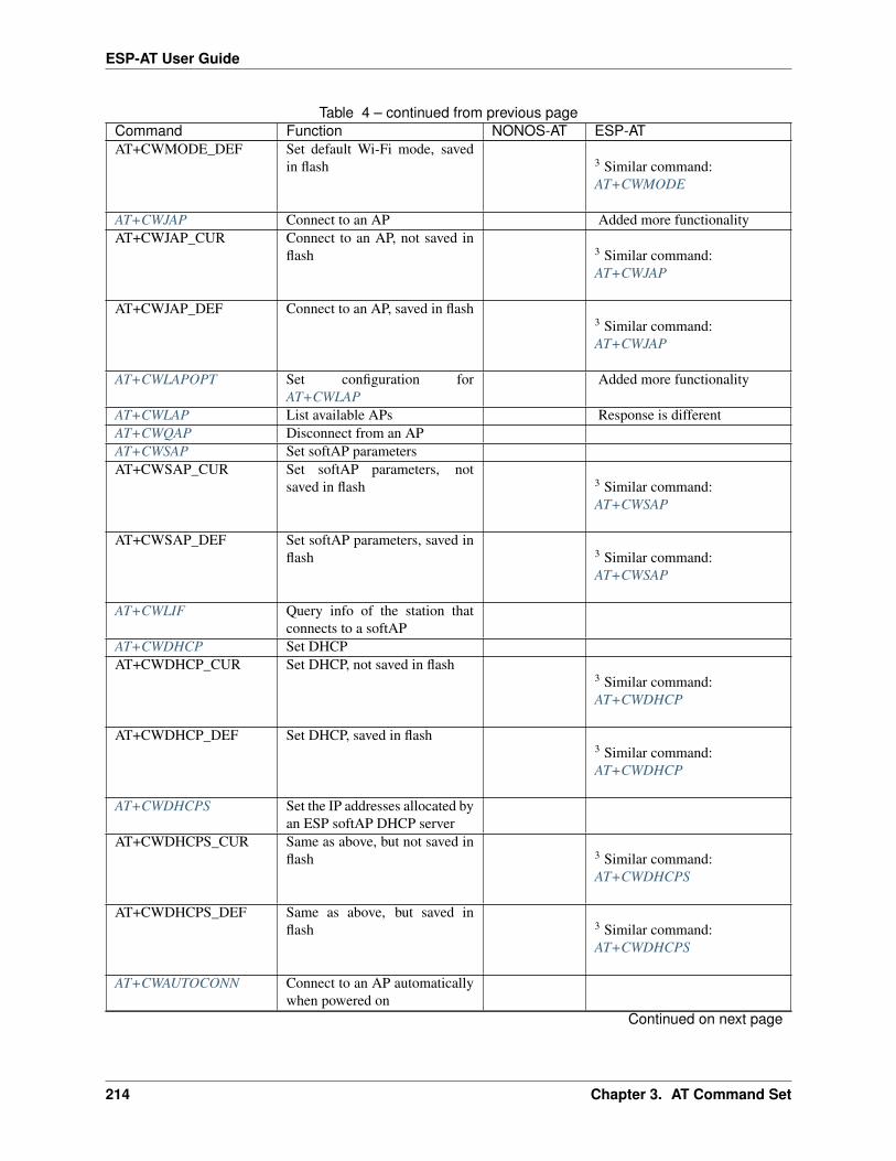
ESP-AT User Guide
Table 4 – continued from previous pageCommand Function NONOS-AT ESP-ATAT+CWMODE_DEF Set default Wi-Fi mode, saved
in flash 3 Similar command:AT+CWMODE
AT+CWJAP Connect to an AP Added more functionalityAT+CWJAP_CUR Connect to an AP, not saved in
flash 3 Similar command:AT+CWJAP
AT+CWJAP_DEF Connect to an AP, saved in flash3 Similar command:AT+CWJAP
AT+CWLAPOPT Set configuration forAT+CWLAP
Added more functionality
AT+CWLAP List available APs Response is differentAT+CWQAP Disconnect from an APAT+CWSAP Set softAP parametersAT+CWSAP_CUR Set softAP parameters, not
saved in flash 3 Similar command:AT+CWSAP
AT+CWSAP_DEF Set softAP parameters, saved inflash 3 Similar command:
AT+CWSAP
AT+CWLIF Query info of the station thatconnects to a softAP
AT+CWDHCP Set DHCPAT+CWDHCP_CUR Set DHCP, not saved in flash
3 Similar command:AT+CWDHCP
AT+CWDHCP_DEF Set DHCP, saved in flash3 Similar command:AT+CWDHCP
AT+CWDHCPS Set the IP addresses allocated byan ESP softAP DHCP server
AT+CWDHCPS_CUR Same as above, but not saved inflash 3 Similar command:
AT+CWDHCPS
AT+CWDHCPS_DEF Same as above, but saved inflash 3 Similar command:
AT+CWDHCPS
AT+CWAUTOCONN Connect to an AP automaticallywhen powered on
Continued on next page
214 Chapter 3. AT Command Set

ESP-AT User Guide
Table 4 – continued from previous pageCommand Function NONOS-AT ESP-ATAT+CIPSTAMAC Set the MAC address of an ESP
stationAT+CIPSTAMAC_CUR Same as above, but not saved in
flash 3 Similar command:AT+CIPSTAMAC
AT+CIPSTAMAC_DEF Same as above, but saved inflash 3 Similar command:
AT+CIPSTAMAC
AT+CIPAPMAC Set the IP address of an ESP sof-tAP
AT+CIPAPMAC_CUR Same as above, but not saved inflash 3 Similar command:
AT+CIPAPMAC
AT+CIPAPMAC_DEF Same as above, but saved inflash 3 Similar command:
AT+CIPAPMAC
AT+CIPSTA Set the IP address of an ESP sta-tion
AT+CIPSTA_CUR Same as above, but not saved inflash 3 Similar command:
AT+CIPSTA
AT+CIPSTA_DEF Same as above, but saved inflash 3 Similar command:
AT+CIPSTA
AT+CIPAP Set the IP address of an ESP sof-tAP
AT+CIPAP_CUR Same as above, but not saved inflash 3 Similar command:
AT+CIPAP
AT+CIPAP_DEF Same as above, but saved inflash 3 Similar command:
AT+CIPAP
AT+CWSTARTSMART Start SmartConfigAT+CWSTOPSMART Stop SmartConfigAT+CWSTARTDISCOVER Enable the mode that an ESP de-
vice can be found by WeChatAT+CWSTOPDISCOVER Disable the mode that an ESP
device can be found by WeChatAT+WPS Enable the WPS functionAT+MDNS Configure the mDNS function
Continued on next page
3.12. AT Command Set Comparison 215

ESP-AT User Guide
Table 4 – continued from previous pageCommand Function NONOS-AT ESP-ATAT+CWJEAP Connect to a WPA2 Enterprise
AP ESP8266ESP32ESP32-S2
AT+CWJEAP_CUR Same as above, but not saved inflash
AT+CWJEAP_DEF Same as above, but saved inflash
AT+CWHOSTNAME Set the host name of an ESP sta-tion
AT+CWCOUNTRY Set the Wi-Fi Country CodeAT+CWCOUNTRY_CUR Same as above, but not saved in
flash 3 Similar command:AT+CWCOUNTRY
AT+CWCOUNTRY_DEF Same as above, but saved inflash 3 Similar command:
AT+CWCOUNTRY
AT+CIPSTATUS Obtain the TCP/UDP/SSL con-nection status and info
AT+CIPDOMAIN Resolve a domain nameAT+CIPSTART Establish a TCP/UDP/SSL con-
nectionAT+CIPSSLSIZE Set SSL buffer sizeAT+CIPSSLCCONF Set SSL clients Parameters are differentAT+CIPSEND Send dataAT+CIPSENDEX Send data of specified length, or
use \0 to trigger data transmis-sion
AT+CIPSENDBUF Write data into the TCP-Send-Buffer
3
AT+CIPBUFRESET Reset the segment ID count 3
AT+CIPBUFSTATUS Query the status of the TCP-Send-Buffer
3
AT+CIPCHECKSEQ Query if a specific segment wassuccessfully sent
3
AT+CIPCLOSEMODE Set the close mode of TCP con-nection
3
AT+CIPCLOSE Close TCP/UDP/SSL connec-tion
AT+CIFSR Obtain the local IP addressAT+CIPMUX Set multiple connectionsAT+CIPSERVER Create a TCP/SSL server SSL server
not supportedSSL server supported for
ESP32 and ESP32-S2, not forESP8266
AT+CIPSERVERMAXCONNSet the maximum connectionsallowed by a server
AT+CIPMODE Set the transmission modeContinued on next page
216 Chapter 3. AT Command Set

ESP-AT User Guide
Table 4 – continued from previous pageCommand Function NONOS-AT ESP-ATAT+SAVETRANSLINK Set whether to enter Wi-Fi
Passthrough Mode on power-upAT+CIPSTO Set the local TCP server timeoutAT+PING Ping the remote hostAT+CIUPDATE Upgrade the firmware through
Wi-FiMore parameters supported
AT+CIPDINFO Show the remote IP and portwith +IPD
AT+CIPRECVMODE Set TCP Receive ModeAT+CIPRECVDATA Get TCP data in passive receive
modeResponse is different
AT+CIPRECVLEN Get TCP data length in passivereceive mode
AT+CIPSNTPCFG Set the time zone and SNTPserver
Added more functionality
AT+CIPSNTPTIME Query SNTP timeAT+CIPDNS Set DNS server informationAT+CIPDNS_CUR Same as above, but not saved in
flash 3 Similar command:AT+CIPDNS
AT+CIPDNS_DEF Same as above, but saved inflash 3 Similar command:
AT+CIPDNS
AT+SYSFLASH Set user partitions in flash
Note 1: AT+SLEEP in ESP-AT:
• ESP8266 and ESP32
– 1: modem sleep by DTIM
– 2: light sleep
– 3: modem sleep by listen interval
• ESP32-S2
Note 2: AT+RFPOWER in ESP-AT:
• ESP8266 . Range: [40,82]. Unit: 0.25 dBm
• ESP32 . Range: [40,78]. Unit: 0.25 dBm. Support Bluetooth LE.
• ESP32-S2 . Range: [40,78]. Unit: 0.25 dBm
Note 3: This command will not be added to the ESP-AT version.
It is strongly recommended to read the following sections for some common information on AT commands before youdive into the details of each command.
• AT Command Types
• AT Commands with Configuration Saved in the Flash
3.12. AT Command Set Comparison 217
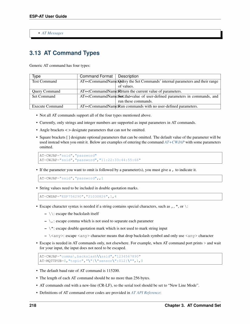
ESP-AT User Guide
• AT Messages
3.13 AT Command Types
Generic AT command has four types:
Type Command Format DescriptionTest Command AT+<CommamdName>=?Query the Set Commands’ internal parameters and their range
of values.Query Command AT+<CommamdName>?Return the current value of parameters.Set Command AT+<CommamdName>=<. . . >Set the value of user-defined parameters in commands, and
run these commands.Execute Command AT+<CommamdName>Run commands with no user-defined parameters.
• Not all AT commands support all of the four types mentioned above.
• Currently, only strings and integer numbers are supported as input parameters in AT commands.
• Angle brackets < > designate parameters that can not be omitted.
• Square brackets [ ] designate optional parameters that can be omitted. The default value of the parameter will beused instead when you omit it. Below are examples of entering the command AT+CWJAP with some parametersomitted.
AT+CWJAP="ssid","password"AT+CWJAP="ssid","password","11:22:33:44:55:66"
• If the parameter you want to omit is followed by a parameter(s), you must give a , to indicate it.
AT+CWJAP="ssid","password",,1
• String values need to be included in double quotation marks.
AT+CWSAP="ESP756290","21030826",1,4
• Escape character syntax is needed if a string contains special characters, such as ,, ", or \:
– \\: escape the backslash itself
– \,: escape comma which is not used to separate each parameter
– \": escape double quotation mark which is not used to mark string input
– \<any>: escape <any> character means that drop backslash symbol and only use <any> character
• Escape is needed in AT commands only, not elsewhere. For example, when AT command port prints > and waitfor your input, the input does not need to be escaped.
AT+CWJAP="comma\,backslash\\ssid","1234567890"AT+MQTTPUB=0,"topic","\"{\"sensor\":012}\"",1,0
• The default baud rate of AT command is 115200.
• The length of each AT command should be no more than 256 bytes.
• AT commands end with a new-line (CR-LF), so the serial tool should be set to “New Line Mode”.
• Definitions of AT command error codes are provided in AT API Reference:
218 Chapter 3. AT Command Set

ESP-AT User Guide
– esp_at_error_code
– esp_at_para_parse_result_type
– esp_at_result_code_string_index
3.14 AT Commands with Configuration Saved in the Flash
Configuration settings entered by the following AT Commands will always be saved in the flash NVS Area, so theycan be automatically restored on reset:
• AT+UART_DEF: AT+UART_DEF=115200,8,1,0,3
• AT+SAVETRANSLINK: AT+SAVETRANSLINK=1,"192.168.6.10",1001
• AT+CWAUTOCONN: AT+CWAUTOCONN=1
Saving of configuration settings by several other commands can be switched on or off with AT+SYSSTORE command,which is mentioned in the Note section of these commands.
3.15 AT Messages
There are two types of ESP-AT messages returned from the ESP-AT command port:
• ESP-AT Response Messages (passive)
Each ESP-AT command input returns response messages to tell the sender the result of the ESP-AT command.
Table 5: ESP-AT Response MessagesAT Response Messages DescriptionOK AT command process done and return OKERROR AT command error or error occurred during the executionSEND OK Data has been sent to the protocol stack (specific to
AT+CIPSEND and AT+CIPSENDEX command). It doesn’tmean that the data has been sent to the opposite end
SEND FAIL Error occurred during sending the data to the protocol stack(specific to AT+CIPSEND and AT+CIPSENDEX command
+<Command Name>:... Response to the sender that describes AT command process re-sults in details
• ESP-AT Message Reports (active)
ESP-AT will report important state changes or messages in the system.
Table 6: ESP-AT Message ReportsESP-AT Message Report Descriptionready The ESP-AT firmware is readybusy p. . . Busy processing. The system is in process of han-
dling the previous command, thus CANNOT acceptthe new input
ERR CODE:<0x%08x> Error code for different commandsWill force to restart!!! Module restart right nowsmartconfig type:<xxx> Smartconfig type
Continued on next page
3.14. AT Commands with Configuration Saved in the Flash 219

ESP-AT User Guide
Table 6 – continued from previous pageESP-AT Message Report DescriptionSmart get wifi info Smartconfig has got the SSID and PASSWORD in-
formationsmartconfig connected wifi Smartconfig done. ESP-AT has connected to the Wi-
FiWIFI CONNECTED Wi-Fi station interface has connected to an APWIFI GOT IP Wi-Fi station interface has got the IPv4 addressWIFI GOT IPv6 LL Wi-Fi station interface has got the IPv6 LinkLocal
addressWIFI GOT IPv6 GL Wi-Fi station interface has got the IPv6 Global ad-
dressWIFI DISCONNECT Wi-Fi station interface has disconnected from an AP+ETH_CONNECTED Ethernet interface has connected+ETH_GOT_IP Ethernet interface has got the IPv4 address+ETH_DISCONNECTED Ethernet interface has disconnected[<conn_id>,]CONNECT A network connection of which ID is <conn_id>
is established (ID=0 by default)[<conn_id>,]CLOSED A network connection of which ID is <conn_id>
ends (ID=0 by default)+LINK_CONN Detailed connection information of TCP/UDP/SSL+STA_CONNECTED: <sta_mac> A station has connected to the Wi-Fi softAP interface
of ESP-AT+DIST_STA_IP: <sta_mac>,<sta_ip> The Wi-Fi softAP interface of ESP-AT distributes an
IP address to the station+STA_DISCONNECTED: <sta_mac> A station disconnected from the Wi-Fi softAP inter-
face of ESP-AT> ESP-AT is waiting for more data to be receivedRecv <xxx> bytes ESP-AT has already received <xxx> bytes from the
ESP-AT command port+IPD ESP-AT received the data from the networkSEND Canceled Cancel to send in Wi-Fi normal sending modeHave <xxx> Connections Has reached the maximum connection counts for
server+QUITT ESP-AT quits from the Wi-Fi Passthrough ModeNO CERT FOUND No valid device certificate found in custom partitionNO PRVT_KEY FOUND No valid private key found in custom partitionNO CA FOUND No valid CA certificate found in custom partition+MQTTCONNECTED MQTT connected to the broker+MQTTDISCONNECTED MQTT disconnected from the broker+MQTTSUBRECV MQTT received the data from the broker+MQTTPUB:FAIL MQTT failed to publish data+MQTTPUB:OK MQTT publish data done+BLECONN A Bluetooth LE connection established+BLEDISCONN A Bluetooth LE connection ends+READ A read operation from Bluetooth LE connection+WRITE A write operation from Bluetooth LE connection+NOTIFY A notification from Bluetooth LE connection+INDICATE An indication from Bluetooth LE connection+BLESECNTFYKEY Bluetooth LE SMP key+BLESECREQ:<conn_index> Received encryption request which index is
<conn_index>Continued on next page
220 Chapter 3. AT Command Set

ESP-AT User Guide
Table 6 – continued from previous pageESP-AT Message Report Description+BLEAUTHCMPL:<conn_index>,<enc_result> Bluetooth LE SMP pairing completed
3.15. AT Messages 221

ESP-AT User Guide
222 Chapter 3. AT Command Set

CHAPTER
FOUR
AT COMMAND EXAMPLES
[]
4.1 TCP/IP AT Examples
• Example 1. ESP as a TCP Client in Single Connection
• Example 2. ESP as a TCP Server in Multiple Connections
• Example 3. UDP Transmission
• Example 4. UART-Wi-Fi Passthrough Transmission
4.1.1 Example 1. ESP as a TCP Client in Single Connection
1. Set the Wi-Fi mode:
Command:AT+CWMODE=3 // SoftAP+Station mode
Response:OK
2. Connect to the router:
AT+CWJAP="SSID","password" // SSID and password of router
Response:OK
3. Query the device’s IP:
AT+CIFSR
Response:192.168.3.106 // device got an IP from router
4. Connect the PC to the same router which ESP is connected to. Use a network tool on the PC to create a TCPserver. For example, the TCP server on PC is 192.168.3.116, port 8080.
5. ESP is connected to the TCP server as a client:
223

ESP-AT User Guide
AT+CIPSTART="TCP","192.168.3.116",8080 // protocolserver IP & port
6. Send data:
AT+CIPSEND=4 // set date length which will be sent, such as 4 bytes>TEST // enter the data, no CR
Response:SEND OK
Note If the number of bytes inputted are more than the length (n) set by AT+CIPSEND, the system will replybusy, and send the first n bytes. And after sending the first n bytes, the system will reply SEND OK.
7. Receive data:
+IPD,n:xxxxxxxxxx // received n bytes, data=xxxxxxxxxxx
4.1.2 Example 2. ESP as a TCP Server in Multiple Connections
When ESP works as a TCP server, multiple connections should be enabled; that is to say, there should be more thanone client connecting to ESP.Below is an example showing how a TCP server is established when ESP works in theSoftAP mode. If ESP works as a Station, set up a server in the same way after connecting ESP to the router.
1. Set the Wi-Fi mode:
Command:AT+CWMODE=3 // SoftAP+Station mode
Response:OK
2. Enable multiple connections.
AT+CIPMUX=1
Response:OK
3. Set up a TCP server.
AT+CIPSERVER=1 // default port = 333
Response:OK
224 Chapter 4. AT Command Examples

ESP-AT User Guide
4. Connect the PC to the ESP SoftAP.
5. Using a network tool on PC to create a TCP client and connect to the TCP server that ESP created.Notice:WhenESP works as a TCP server, there is a timeout mechanism. If the TCP client is connected to the ESP TCP server,while there is no data transmission for a period of time, the server will disconnect from the client. To avoid sucha problem, please set up a data transmission cycle every two seconds.
6. Send data:
// ID number of the first connection is defaulted to be 0AT+CIPSEND=0,4 // send 4 bytes to connection NO.0>TEST // enter the data, no CR
Response:SEND OK
Note If the number of bytes inputted are more than the length (n) set by AT+CIPSEND, the system will replybusy, and send the first n bytes. And after sending the first n bytes, the system will reply SEND OK.
7. Receive data:
+IPD,0,n:xxxxxxxxxx // received n bytes, data=xxxxxxxxxxx
8. Close the TCP connection.
AT+CIPCLOSE=0
Response:0,CLOSEDOK
4.1. TCP/IP AT Examples 225
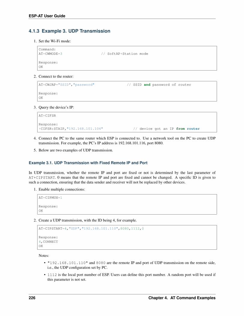
ESP-AT User Guide
4.1.3 Example 3. UDP Transmission
1. Set the Wi-Fi mode:
Command:AT+CWMODE=3 // SoftAP+Station mode
Response:OK
2. Connect to the router:
AT+CWJAP="SSID","password" // SSID and password of router
Response:OK
3. Query the device’s IP:
AT+CIFSR
Response:+CIFSR:STAIP,"192.168.101.104" // device got an IP from router
4. Connect the PC to the same router which ESP is connected to. Use a network tool on the PC to create UDPtransmission. For example, the PC’s IP address is 192.168.101.116, port 8080.
5. Below are two examples of UDP transmission.
Example 3.1. UDP Transmission with Fixed Remote IP and Port
In UDP transmission, whether the remote IP and port are fixed or not is determined by the last parameter ofAT+CIPSTART. 0 means that the remote IP and port are fixed and cannot be changed. A specific ID is given tosuch a connection, ensuring that the data sender and receiver will not be replaced by other devices.
1. Enable multiple connections:
AT+CIPMUX=1
Response:OK
2. Create a UDP transmission, with the ID being 4, for example.
AT+CIPSTART=4,"UDP","192.168.101.110",8080,1112,0
Response:4,CONNECTOK
Notes:
• "192.168.101.110" and 8080 are the remote IP and port of UDP transmission on the remote side,i.e., the UDP configuration set by PC.
• 1112 is the local port number of ESP. Users can define this port number. A random port will be used ifthis parameter is not set.
226 Chapter 4. AT Command Examples

ESP-AT User Guide
• 0 means that the remote IP and port are fixed and cannot be changed. For example, if another PC alsocreates a UDP entity and sends data to ESP port 1112, ESP can receive the data sent from UDP port 1112.But when data are sent using AT command AT+CIPSEND=4,X, it will still be sent to the first PC end. Ifparameter 0 is not used, the data will be sent to the new PC.
3. Send data:
AT+CIPSEND=4,7 // send 7 bytes to transmission NO.4>UDPtest // enter the data, no CR
Response:SEND OK
Note If the number of bytes inputted are more than the length (n) set by AT+CIPSEND, the system will replybusy, and send the first n bytes. And after sending the first n bytes, the system will reply SEND OK.
4. Receive data:
+IPD,4,n:xxxxxxxxxx // received n bytes, data=xxxxxxxxxxx
5. Close UDP transmission No.4
AT+CIPCLOSE=4
Response:4,CLOSEDOK
Example 3.2. UDP Transmission with Changeable Remote IP and Port
1. Create a UDP transmission with the last parameter being 2.
AT+CIPSTART="UDP","192.168.101.110",8080,1112,2
Response:CONNECTOK
Notes:
• "192.168.101.110" and 8080 here refer to the IP and port of the remote UDP transmission terminalwhich is created on a PC in above Example 2.
• 1112 is the local port of ESP. Users can define this port. A random port will be opened if this parameteris not set.
• 2 means the means the opposite terminal of UDP transmission can be changed. The remote IP and portwill be automatically changed to those of the last UDP connection to ESP.
2. Send data:
AT+CIPSEND=7 // send 7 bytes>UDPtest // enter the data, no CR
Response:SEND OK
Note If the number of bytes inputted are more than the length (n) set by AT+CIPSEND, the system will replybusy, and send the first n bytes. And after sending the first n bytes, the system will reply SEND OK.
4.1. TCP/IP AT Examples 227

ESP-AT User Guide
3. If you want to send data to any other UDP terminals, please designate the IP and port of the target terminal inthe command.
AT+CIPSEND=6,"192.168.101.111",1000 // send six bytes>abcdef // enter the data, no CR
Response:SEND OK
4. Receive data:
+IPD,n:xxxxxxxxxx // received n bytes, data=xxxxxxxxxxx
5. Close UDP transmission.
AT+CIPCLOSE
Response:CLOSEDOK
4.1.4 Example 4. UART-Wi-Fi Passthrough Transmission
ESP-AT supports UART-Wi-Fi passthrough transmission only when ESP works as a TCP client in single connectionor UDP transmission.
Example 4.1. ESP as a TCP Client in UART-Wi-Fi Passthrough (Single Connection Mode)
1. Set the Wi-Fi mode:
Command:AT+CWMODE=3 // SoftAP+Station mode
Response:OK
2. Connect to the router:
AT+CWJAP="SSID","password" // SSID and password of router
Response:OK
3. Query the device’s IP:
AT+CIFSR
Response:+CIFSR:STAIP,"192.168.101.105" // device got an IP from router
4. Connect the PC to the same router which ESP is connected to. Use a network tool on the PC to create a TCPserver. For example, the PC’s IP address is 192.168.101.110, port 8080.
5. Connect the ESP device to the TCP server as a TCP client.
228 Chapter 4. AT Command Examples

ESP-AT User Guide
AT+CIPSTART="TCP","192.168.101.110",8080
Response:CONNECTOK
6. Enable the UART-WiFi transmission mode.
AT+CIPMODE=1
Response:OK
7. Send data.
AT+CIPSEND
Response:> // From now on, data received from UART will be transparent→˓transmitted to server
8. Stop sending data.When receiving a packet that contains only +++, the UART-WiFi passthrough transmissionprocess will be stopped. Then please wait at least 1 second before sending next AT command.Please be notedthat if you input +++ directly by typing, the +++, may not be recognised as three consecutive + because ofthe Prolonged time when typing.Notice:The aim of ending the packet with +++ is to exit transparent transmis-sion and to accept normal AT commands, while TCP still remains connected. However, users can also deploycommand AT+CIPSEND to go back into transparent transmission.
9. Exit the UART-WiFi passthrough mode.
AT+CIPMODE=0
Response:OK
10. Close the TCP connection.
AT+CIPCLOSE
Response:CLOSEDOK
Example 4.2. UDP Transmission in UART-Wi-Fi Passthrough Mode
Here is an example of the ESP working as a SoftAP in UDP transparent transmission.
1. Set the Wi-Fi mode:
Command:AT+CWMODE=3 // SoftAP+Station mode
Response:OK
4.1. TCP/IP AT Examples 229

ESP-AT User Guide
2. Connect the PC to the ESP SoftAP.
3. Use a network tool on PC to create a UDP endpoint. For example, the PC’s IP address is 192.168.4.2 andthe port is 1001.
4. Create a UDP transmission between ESP32 and the PC with a fixed remote IP and port.
AT+CIPSTART="UDP","192.168.4.2",1001,2233,0
Response:CONNECTOK
5. Enable the UART-WiFi transmission mode.
AT+CIPMODE=1
Response:OK
6. Send data.
AT+CIPSEND
Response:> // From now on, data received from UART will be transparent→˓transmitted to server
7. Stop sending data.When receiving a packet that contains only +++, the UART-WiFi passthrough transmissionprocess will be stopped. Then please wait at least 1 second before sending next AT command.Please be notedthat if you input +++ directly by typing, the +++, may not be recognised as three consecutive + because ofthe Prolonged time when typing.Notice:The aim of ending the packet with +++ is to exit transparent transmis-sion and to accept normal AT commands, while TCP still remains connected. However, users can also deploycommand AT+CIPSEND to go back into transparent transmission.
8. Exit the UART-WiFi passthrough mode.
AT+CIPMODE=0
(continues on next page)
230 Chapter 4. AT Command Examples

ESP-AT User Guide
(continued from previous page)
Response:OK
9. Close the UDP transmission.
AT+CIPCLOSE
Response:CLOSEDOK
4.2 [ESP32 Only] BLE AT Examples
• Example 1. [ESP32 Only] BLE AT Examples
• Example 2. [ESP32 Only] iBeacon Examples
• Example 3. [ESP32 Only] UART-BLE Passthrough Mode
4.2.1 Example 1. [ESP32 Only] BLE AT Example
Below is an example of using two ESP32 modules, one as a BLE server (hereafter named “ESP32 Server”), the otherone as a BLE client (hereafter named “ESP32 Client”). The example shows how to use BLE functions with ATcommands.Notice:
• The ESP32 Server needs to download a “service bin” into Flash to provide BLE services.
– To learn how to generate a “service bin”, please refer to esp-at/tools/readme.md.
– The download address of the “service bin” is the address of “ble_data” in esp-at/partitions_at.csv.
1. BLE initialization:
ESP32 Server:
Command:AT+BLEINIT=2 // server role
Response:OK
ESP32 Client:
Command:AT+BLEINIT=1 // client role
Response:OK
2. Establish BLE connection:
ESP32 Server:(1) Query the BLE address. For example, its address is “24:0a:c4:03:f4:d6”.
4.2. [ESP32 Only] BLE AT Examples 231
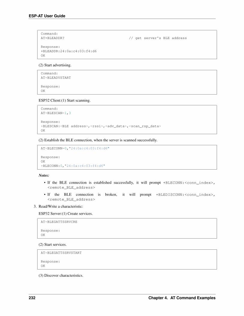
ESP-AT User Guide
Command:AT+BLEADDR? // get server's BLE address
Response:+BLEADDR:24:0a:c4:03:f4:d6OK
(2) Start advertising.
Command:AT+BLEADVSTART
Response:OK
ESP32 Client:(1) Start scanning.
Command:AT+BLESCAN=1,3
Response:+BLESCAN:<BLE address>,<rssi>,<adv_data>,<scan_rsp_data>OK
(2) Establish the BLE connection, when the server is scanned successfully.
AT+BLECONN=0,"24:0a:c4:03:f4:d6"
Response:OK+BLECONN:0,"24:0a:c4:03:f4:d6"
Notes:
• If the BLE connection is established successfully, it will prompt +BLECONN:<conn_index>,<remote_BLE_address>
• If the BLE connection is broken, it will prompt +BLEDISCONN:<conn_index>,<remote_BLE_address>
3. Read/Write a characteristic:
ESP32 Server:(1) Create services.
AT+BLEGATTSSRVCRE
Response:OK
(2) Start services.
AT+BLEGATTSSRVSTART
Response:OK
(3) Discover characteristics.
232 Chapter 4. AT Command Examples

ESP-AT User Guide
AT+BLEGATTSCHAR?
Response:+BLEGATTSCHAR:"char",1,1,0xC300+BLEGATTSCHAR:"desc",1,1,1+BLEGATTSCHAR:"char",1,2,0xC301+BLEGATTSCHAR:"desc",1,2,1+BLEGATTSCHAR:"char",1,3,0xC302+BLEGATTSCHAR:"desc",1,3,1OK
ESP32 Client:(1) Discover services.
AT+BLEGATTCPRIMSRV=0
Response:+BLEGATTCPRIMSRV:0,1,0x1801,1+BLEGATTCPRIMSRV:0,2,0x1800,1+BLEGATTCPRIMSRV:0,3,0xA002,1OK
Notice:
• When discovering services, the ESP32 Client will get two more default services (UUID:0x1800 and0x1801) than what the ESP32 Server will get.
• So, for the same service, the <srv_index> received by the ESP32 Client equals the <srv_index> receivedby ESP32 Server + 2.
• For example, the <srv_index> of the above-mentioned service, 0xA002, is 3 when the ESP32 Clientis in the process of discovering services. But if the ESP32 Server tries to discover it with commandAT+BLEGATTSSRV?, the <srv_index> will be 1.
(2) Discover characteristics.
AT+BLEGATTCCHAR=0,3
Response:+BLEGATTCCHAR:"char",0,3,1,0xC300,2+BLEGATTCCHAR:"desc",0,3,1,1,0x2901+BLEGATTCCHAR:"char",0,3,2,0xC301,2+BLEGATTCCHAR:"desc",0,3,2,1,0x2901+BLEGATTCCHAR:"char",0,3,3,0xC302,8+BLEGATTCCHAR:"desc",0,3,3,1,0x2901+BLEGATTCCHAR:"char",0,3,4,0xC303,4+BLEGATTCCHAR:"desc",0,3,4,1,0x2901+BLEGATTCCHAR:"char",0,3,5,0xC304,8+BLEGATTCCHAR:"char",0,3,6,0xC305,16+BLEGATTCCHAR:"desc",0,3,6,1,0x2902+BLEGATTCCHAR:"char",0,3,7,0xC306,32+BLEGATTCCHAR:"desc",0,3,7,1,0x2902OK
(3) Read a characteristic. Please note that the target characteristic’s property has to support the read operation.
AT+BLEGATTCRD=0,3,1
Response:
(continues on next page)
4.2. [ESP32 Only] BLE AT Examples 233

ESP-AT User Guide
(continued from previous page)
+BLEGATTCRD:0,1,30OK
Note:
• If the ESP32 Client reads the characteristic successfully, message +READ:<conn_index>,<remoteBLE address> will be prompted on the ESP32 Server side.
(4) Write a characteristic. Please note that the target characteristic’s property has to support the write operation.
AT+BLEGATTCWR=0,3,3,,2
Response:> // waiting for dataOK
Note:
• If the ESP32 Client writes the characteristic successfully, message +WRITE:<conn_index>,<srv_index>,<char_index>,[<desc_index>],<len>,<value> will be prompted on theESP32 Server side.
4. Notify of a characteristic:
ESP32 Client:(1) Configure the characteristic’s descriptor. Please note that the target characteristic’s propertyhas to support notifications.
AT+BLEGATTCWR=0,3,6,1,2
Response:> // waiting for dataOK
Note:
• If the ESP32 Client writes the descriptor successfully, message +WRITE:<conn_index>,<srv_index>,<char_index>,<desc_index>,<len>,<value> will be prompted on theESP32 Server side.
ESP32 Server:(1) Notify of a characteristic. Please note that the target characteristic’s property has to supportnotifications.
AT+BLEGATTSNTFY=0,1,6,3
Response:> // waiting for dataOK
Note:
• If the ESP32 Client receives the notification, it will prompt message +NOTIFY:<conn_index>,<srv_index>,<char_index>,<len>,<value>.
• For the same service, the <srv_index> on the ESP32 Client side equals the <srv_index> on the ESP32Server side + 2.
5. Indicate a characteristic:
ESP32 Client:(1) Configure the characteristic’s descriptor. Please note that the target characteristic’s propertyhas to support the indicate operation.
234 Chapter 4. AT Command Examples
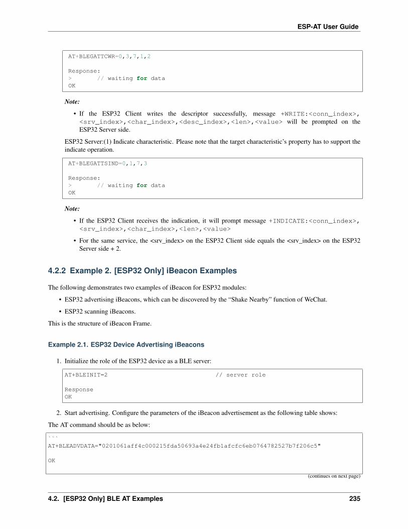
ESP-AT User Guide
AT+BLEGATTCWR=0,3,7,1,2
Response:> // waiting for dataOK
Note:
• If the ESP32 Client writes the descriptor successfully, message +WRITE:<conn_index>,<srv_index>,<char_index>,<desc_index>,<len>,<value> will be prompted on theESP32 Server side.
ESP32 Server:(1) Indicate characteristic. Please note that the target characteristic’s property has to support theindicate operation.
AT+BLEGATTSIND=0,1,7,3
Response:> // waiting for dataOK
Note:
• If the ESP32 Client receives the indication, it will prompt message +INDICATE:<conn_index>,<srv_index>,<char_index>,<len>,<value>
• For the same service, the <srv_index> on the ESP32 Client side equals the <srv_index> on the ESP32Server side + 2.
4.2.2 Example 2. [ESP32 Only] iBeacon Examples
The following demonstrates two examples of iBeacon for ESP32 modules:
• ESP32 advertising iBeacons, which can be discovered by the “Shake Nearby” function of WeChat.
• ESP32 scanning iBeacons.
This is the structure of iBeacon Frame.
Example 2.1. ESP32 Device Advertising iBeacons
1. Initialize the role of the ESP32 device as a BLE server:
AT+BLEINIT=2 // server role
ResponseOK
2. Start advertising. Configure the parameters of the iBeacon advertisement as the following table shows:
The AT command should be as below:
```AT+BLEADVDATA="0201061aff4c000215fda50693a4e24fb1afcfc6eb0764782527b7f206c5"
OK
(continues on next page)
4.2. [ESP32 Only] BLE AT Examples 235

ESP-AT User Guide
(continued from previous page)
AT+BLEADVSTART // Start advertising
OK```
Open WeChat on your mobile phone and then select “Shake Nearby” to discover the ESP32 device that is advertising.
236 Chapter 4. AT Command Examples

ESP-AT User Guide
4.2. [ESP32 Only] BLE AT Examples 237
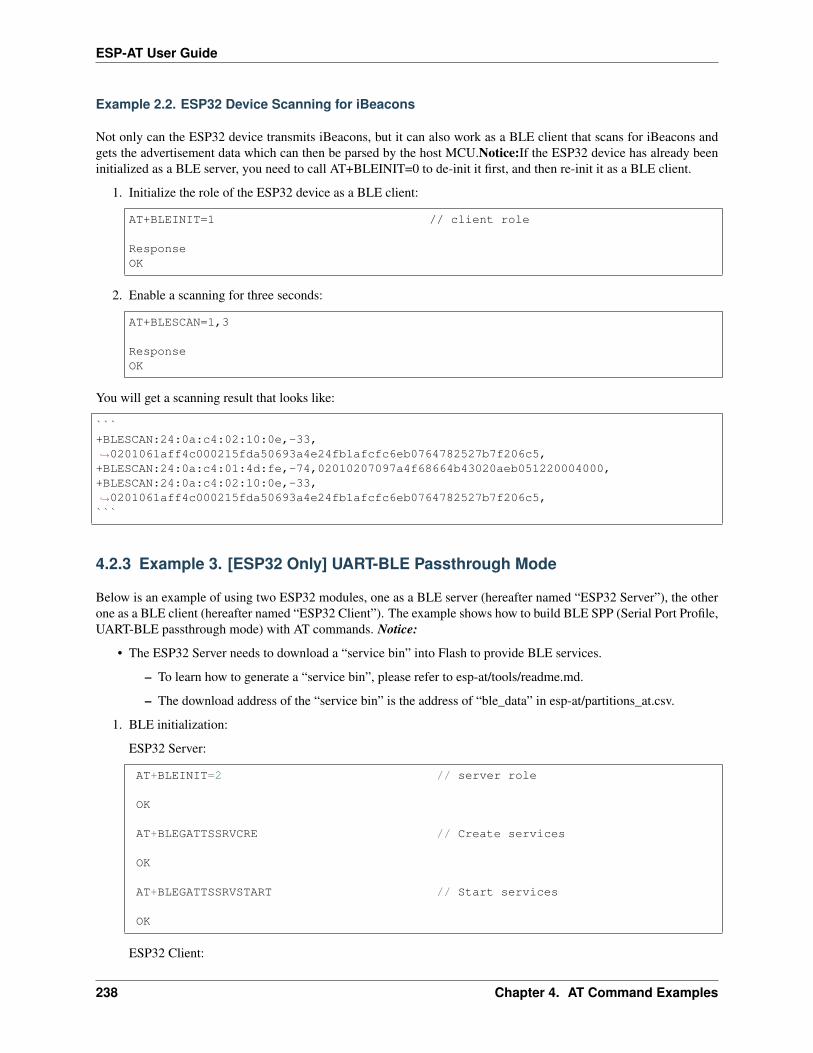
ESP-AT User Guide
Example 2.2. ESP32 Device Scanning for iBeacons
Not only can the ESP32 device transmits iBeacons, but it can also work as a BLE client that scans for iBeacons andgets the advertisement data which can then be parsed by the host MCU.Notice:If the ESP32 device has already beeninitialized as a BLE server, you need to call AT+BLEINIT=0 to de-init it first, and then re-init it as a BLE client.
1. Initialize the role of the ESP32 device as a BLE client:
AT+BLEINIT=1 // client role
ResponseOK
2. Enable a scanning for three seconds:
AT+BLESCAN=1,3
ResponseOK
You will get a scanning result that looks like:
```+BLESCAN:24:0a:c4:02:10:0e,-33,→˓0201061aff4c000215fda50693a4e24fb1afcfc6eb0764782527b7f206c5,+BLESCAN:24:0a:c4:01:4d:fe,-74,02010207097a4f68664b43020aeb051220004000,+BLESCAN:24:0a:c4:02:10:0e,-33,→˓0201061aff4c000215fda50693a4e24fb1afcfc6eb0764782527b7f206c5,```
4.2.3 Example 3. [ESP32 Only] UART-BLE Passthrough Mode
Below is an example of using two ESP32 modules, one as a BLE server (hereafter named “ESP32 Server”), the otherone as a BLE client (hereafter named “ESP32 Client”). The example shows how to build BLE SPP (Serial Port Profile,UART-BLE passthrough mode) with AT commands. Notice:
• The ESP32 Server needs to download a “service bin” into Flash to provide BLE services.
– To learn how to generate a “service bin”, please refer to esp-at/tools/readme.md.
– The download address of the “service bin” is the address of “ble_data” in esp-at/partitions_at.csv.
1. BLE initialization:
ESP32 Server:
AT+BLEINIT=2 // server role
OK
AT+BLEGATTSSRVCRE // Create services
OK
AT+BLEGATTSSRVSTART // Start services
OK
ESP32 Client:
238 Chapter 4. AT Command Examples

ESP-AT User Guide
AT+BLEINIT=1 // client role
OK
2. Establish BLE connection:
ESP32 Server:(1) Query the BLE address. For example, its address is “24:0a:c4:03:f4:d6”.
Command:AT+BLEADDR? // get server's BLE address
Response:+BLEADDR:24:0a:c4:03:f4:d6
OK
(2) Optional Configuration, configure advertisement data. Without the configuration, the payload of the broad-casting packet will be empty.
Command:AT+BLEADVDATA="0201060A09457370726573736966030302A0"
/* The adv data is
* 02 01 06 //<length>,<type>,<data>
* 0A 09 457370726573736966 //<length>,<type>,<data>
* 03 03 02A0 //<length>,<type>,<data>
*/
Response:OK
(3) Start advertising.
Command:AT+BLEADVSTART
Response:OK
ESP32 Client:(1) Start scanning.
Command:AT+BLESCAN=1,3
Response:+BLESCAN:<BLE address>,<rssi>,<adv_data>,<scan_rsp_data>
OK
(2) Establish the BLE connection, when the server is scanned successfully.
AT+BLECONN=0,"24:0a:c4:03:f4:d6"
Response:OK+BLECONN:0,"24:0a:c4:03:f4:d6"
Notes:
4.2. [ESP32 Only] BLE AT Examples 239
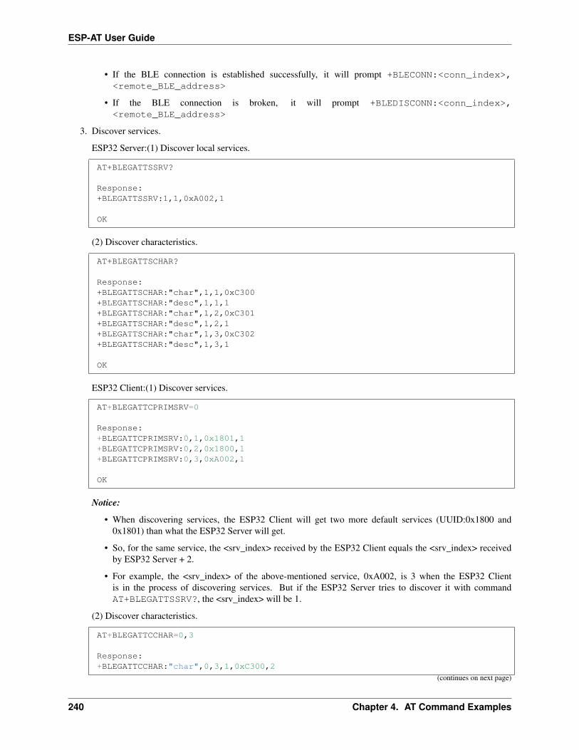
ESP-AT User Guide
• If the BLE connection is established successfully, it will prompt +BLECONN:<conn_index>,<remote_BLE_address>
• If the BLE connection is broken, it will prompt +BLEDISCONN:<conn_index>,<remote_BLE_address>
3. Discover services.
ESP32 Server:(1) Discover local services.
AT+BLEGATTSSRV?
Response:+BLEGATTSSRV:1,1,0xA002,1
OK
(2) Discover characteristics.
AT+BLEGATTSCHAR?
Response:+BLEGATTSCHAR:"char",1,1,0xC300+BLEGATTSCHAR:"desc",1,1,1+BLEGATTSCHAR:"char",1,2,0xC301+BLEGATTSCHAR:"desc",1,2,1+BLEGATTSCHAR:"char",1,3,0xC302+BLEGATTSCHAR:"desc",1,3,1
OK
ESP32 Client:(1) Discover services.
AT+BLEGATTCPRIMSRV=0
Response:+BLEGATTCPRIMSRV:0,1,0x1801,1+BLEGATTCPRIMSRV:0,2,0x1800,1+BLEGATTCPRIMSRV:0,3,0xA002,1
OK
Notice:
• When discovering services, the ESP32 Client will get two more default services (UUID:0x1800 and0x1801) than what the ESP32 Server will get.
• So, for the same service, the <srv_index> received by the ESP32 Client equals the <srv_index> receivedby ESP32 Server + 2.
• For example, the <srv_index> of the above-mentioned service, 0xA002, is 3 when the ESP32 Clientis in the process of discovering services. But if the ESP32 Server tries to discover it with commandAT+BLEGATTSSRV?, the <srv_index> will be 1.
(2) Discover characteristics.
AT+BLEGATTCCHAR=0,3
Response:+BLEGATTCCHAR:"char",0,3,1,0xC300,2
(continues on next page)
240 Chapter 4. AT Command Examples

ESP-AT User Guide
(continued from previous page)
+BLEGATTCCHAR:"desc",0,3,1,1,0x2901+BLEGATTCCHAR:"char",0,3,2,0xC301,2+BLEGATTCCHAR:"desc",0,3,2,1,0x2901+BLEGATTCCHAR:"char",0,3,3,0xC302,8+BLEGATTCCHAR:"desc",0,3,3,1,0x2901+BLEGATTCCHAR:"char",0,3,4,0xC303,4+BLEGATTCCHAR:"desc",0,3,4,1,0x2901+BLEGATTCCHAR:"char",0,3,5,0xC304,8+BLEGATTCCHAR:"char",0,3,6,0xC305,16+BLEGATTCCHAR:"desc",0,3,6,1,0x2902+BLEGATTCCHAR:"char",0,3,7,0xC306,32+BLEGATTCCHAR:"desc",0,3,7,1,0x2902
OK
4. Configure BLE SPP:
ESP32 Client:(1) Set a characteristic that enables writing permission to TX channel for sending data. Set anothercharacteristic that supports notification or indication to RX channel for receiving data.
AT+BLESPPCFG=1,3,5,3,7
Response:OK
(2) Enable BLE SPP:
AT+BLESPP
Response:OK> // waiting for serial data
Note: After ESP32 Client enabling BLE SPP, data received from serial port will be transmitted to the BLE serverdirectly.
ESP32 Server:(1) Set a characteristic that supports notification or indication to TX channel for→˓sending data. Set another characteristic that enables writing permission to RX→˓channel for receiving data.
AT+BLESPPCFG=1,1,7,1,5
Response:OK
(2) Enable BLE SPP:
AT+BLESPP
Response:OK> // waiting for serial data
Notes:
• After ESP32 Server enables BLE SPP, the data received from serial port will be transmitted to the BLE clientdirectly.
4.2. [ESP32 Only] BLE AT Examples 241

ESP-AT User Guide
• If the ESP32 Client does not enable BLE SPP first, or uses other device as BLE client, then the BLE client needsto listen to the notification or indication first. For example, if the ESP32 Client does not enable BLE SPP first,then it should enable listening with command AT+BLEGATTCWR=0,3,7,1,1 first for the ESP32 Server totransmit successfully.
• For the same service, the <srv_index> on the ESP32 Client side equals the <srv_index> on the ESP32Server side plus 2.
4.3 MQTT AT Examples
• Example 1: MQTT over TCP
• Example 2: MQTT over TLS
• Example 3: MQTT over WSS
4.3.1 Example 1: MQTT over TCP (with a Local MQTT Broker)
Create a local MQTT broker. For example, the MQTT broker’s IP address is “192.168.31.113”, port 1883. Then theexample of communicating with the MQTT broker will be as the following steps.
AT+MQTTUSERCFG=0,1,"ESP32","espressif","1234567890",0,0,""AT+MQTTCONN=0,"192.168.31.113",1883,0AT+MQTTSUB=0,"topic",1AT+MQTTPUB=0,"topic","test",1,0AT+MQTTCLEAN=0
4.3.2 Example 2: MQTT over TLS (with a Local MQTT Broker)
Create a local MQTT broker. For example, the MQTT broker’s IP address is “192.168.31.113”, port 1883. Then theexample of communicating with the MQTT broker will be as the following steps.
AT+CIPSNTPCFG=1,8,"ntp1.aliyun.com"AT+CIPSNTPTIME?AT+MQTTUSERCFG=0,3,"ESP32","espressif","1234567890",0,0,""AT+MQTTCONNCFG=0,0,0,"lwtt","lwtm",0,0AT+MQTTCONN=0,"192.168.31.113",1883,0AT+MQTTSUB=0,"topic",1AT+MQTTPUB=0,"topic","test",1,0AT+MQTTCLEAN=0
4.3.3 Example 3: MQTT over WSS
This is an example of communicating with MQTT broker: iot.eclipse.org, of which port is 443.
AT+CIPSNTPCFG=1,8,"ntp1.aliyun.com"AT+CIPSNTPTIME?AT+MQTTUSERCFG=0,7,"ESP32","espressif","1234567890",0,0,"wss"AT+MQTTCONN=0,"iot.eclipse.org",443,0AT+MQTTSUB=0,"topic",1AT+MQTTPUB=0,"topic","test",1,0AT+MQTTCLEAN=0
242 Chapter 4. AT Command Examples

ESP-AT User Guide
4.4 [ESP32 Only] Ethernet AT Examples
Note: Before you run any Ethernet AT commands, please make sure you have followed the Prerequisite.
• Establish a TCP Connection on Ethernet Network
4.4.1 Establish a TCP Connection on Ethernet Network
1. Enable multiple connections.
• Command
AT+CIPMUX=1
• Response
OK
2. Create a TCP server.
• Command
AT+CIPSERVER=1,8081
• Response
OK
3. Obtain the IP address of the server.
• Command
AT+CIPETH?
• Response
+CIPETH:ip:192.168.105.24+CIPETH:gateway:192.168.105.1+CIPETH:netmask:255.255.255.0OK
4. Use a network tool on PC to create a TCP client and connect to the TCP server that ESP created. (IP:192.168.105.24, Port: 8081).
5. Send data in Normal Transmission Mode.
• Command
AT+CIPSEND=0,4 // send 4 bytes to connection ID 0
• Response
OK>
• Enter the data.
4.4. [ESP32 Only] Ethernet AT Examples 243

ESP-AT User Guide
• Response
SEND OK
Note: If the length of the data you entered is more than the value of <length> (n) set by AT+CIPSEND, thesystem will prompt busy, and send the first n bytes. After sending the first n bytes, the system will reply SENDOK.
6. Receive data in Normal Transmission Mode.
When the ESP server receives data, AT will prompt:
+IPD,n:xxxxxxxxxx // received n bytes, data=xxxxxxxxxxx
7. Close TCP Connection.
• Command
AT+CIPCLOSE=0
• Response
OK
8. Delete the TCP server.
• Command
AT+CIPSERVER=0
• Response
OK
4.5 Web Server AT Example
[]
This document mainly introduces the use of AT web server, mainly involving the following applications:
• Wi-Fi Provisioning Using a Browser
• OTA Firmware Upgrade Using a Browser
• Wi-Fi Provisioning Using a WeChat Applet
• OTA Firmware Upgrade Using a WeChat Applet
• [ESP32][ESP32-S Series][ESP32-C Series] Using Capture Portal
Note: The default firmware does not support web server AT commands, please refer to Web server AT Commands toenable the web server.
244 Chapter 4. AT Command Examples
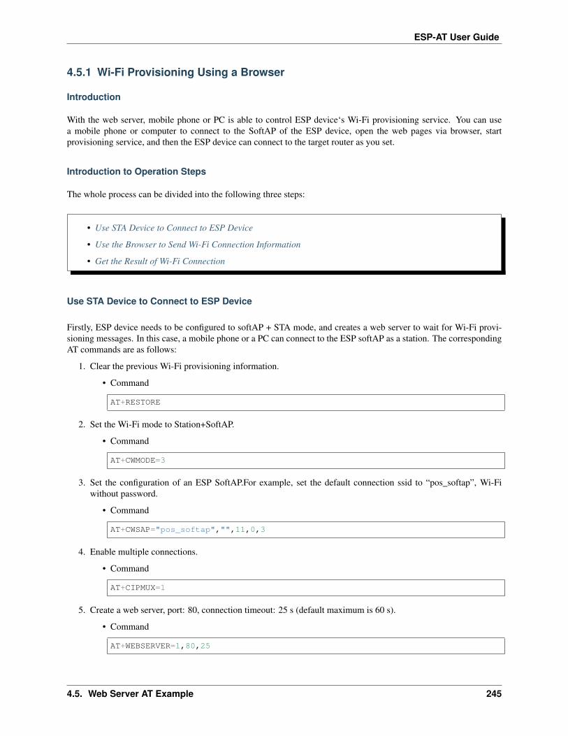
ESP-AT User Guide
4.5.1 Wi-Fi Provisioning Using a Browser
Introduction
With the web server, mobile phone or PC is able to control ESP device‘s Wi-Fi provisioning service. You can usea mobile phone or computer to connect to the SoftAP of the ESP device, open the web pages via browser, startprovisioning service, and then the ESP device can connect to the target router as you set.
Introduction to Operation Steps
The whole process can be divided into the following three steps:
• Use STA Device to Connect to ESP Device
• Use the Browser to Send Wi-Fi Connection Information
• Get the Result of Wi-Fi Connection
Use STA Device to Connect to ESP Device
Firstly, ESP device needs to be configured to softAP + STA mode, and creates a web server to wait for Wi-Fi provi-sioning messages. In this case, a mobile phone or a PC can connect to the ESP softAP as a station. The correspondingAT commands are as follows:
1. Clear the previous Wi-Fi provisioning information.
• Command
AT+RESTORE
2. Set the Wi-Fi mode to Station+SoftAP.
• Command
AT+CWMODE=3
3. Set the configuration of an ESP SoftAP.For example, set the default connection ssid to “pos_softap”, Wi-Fiwithout password.
• Command
AT+CWSAP="pos_softap","",11,0,3
4. Enable multiple connections.
• Command
AT+CIPMUX=1
5. Create a web server, port: 80, connection timeout: 25 s (default maximum is 60 s).
• Command
AT+WEBSERVER=1,80,25
4.5. Web Server AT Example 245

ESP-AT User Guide
After starting the web sever according to the above commands, you can turn on the Wi-Fi connection function on yourSTA device, and connect it to the softAP of the ESP device:
Fig. 1: The browser connects to the ESP AP
Use the Browser to Send Wi-Fi Connection Information
After your STA device connected to the ESP softAP, it can send Wi-Fi connection information to ESP in an HTTPrequest. Please note that if your target AP is the hotspot of the device which opens the web pages, you may not receivethe Wi-Fi connection result. You can enter the default IP address of the web server in the browser (the default IP is192.168.4.1, or you can query the current SoftAP IP address by command AT+CIPAP?), open the Wi-Fi provisioninginterface, and enter the ssid and password of the router to be connected, click “Connect” to let ESP device startconnecting to the router:
Or you can click the drop-down box of SSID to list all APs nearby, select the target AP and enter the password, andthen click “Connect” to let the ESP device start connecting to the router:
Get the Result of Wi-Fi Connection
After the Wi-Fi connection is established successfully, the web page will be displayed as follows:
Note 1: After the Wi-Fi connection is established successfully, the webpage will be closed automatically. If you wantto continue to access the webpage, please re-enter the IP address of the ESP device and reopen the webpage.
At the same time, the following messages will be returned from the ESP-AT command port:
+WEBSERVERRSP:1 // meaning that ESP device has received Wi-Fi connection→˓informationWIFI CONNECTED // meaning that ESP device is connectingWIFI GOT IP // meaning that ESP device connect successfully to the→˓destination rounter+WEBSERVERRSP:2 // meaning that STA device has received Wi-Fi connection result,→˓and web resources can be released
If the ESP device fails to connect to the router, the web page will display:
At the same time, the following messages will be returned from the ESP-AT command port:
+WEBSERVERRSP:1 // meaning that ESP device has received Wi-Fi connection→˓information, but failed to connect to the rounter.
246 Chapter 4. AT Command Examples
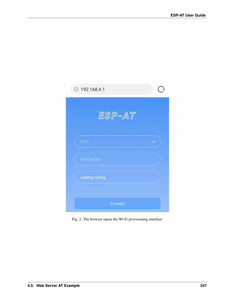
ESP-AT User Guide
Fig. 2: The browser opens the Wi-Fi provisioning interface
4.5. Web Server AT Example 247

ESP-AT User Guide
Fig. 3: Schematic diagram of browser obtaining Wi-Fi AP list
248 Chapter 4. AT Command Examples
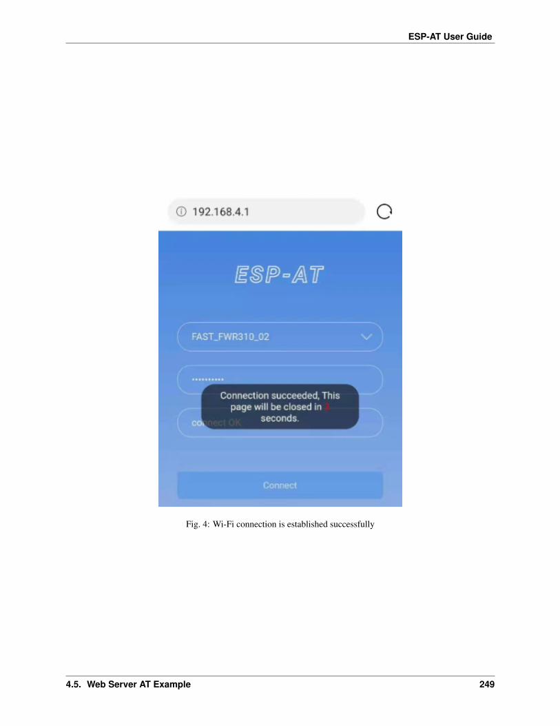
ESP-AT User Guide
Fig. 4: Wi-Fi connection is established successfully
4.5. Web Server AT Example 249

ESP-AT User Guide
Fig. 5: ESP device fails to connect to the router
250 Chapter 4. AT Command Examples

ESP-AT User Guide
Troubleshooting
Note 1: The network configuration page received a prompt “Connection failed”. Please check whether the Wi-Fi APof the ESP module is correctly turned on, and the relevant configuration of the AP, and confirm that the correct ATcommand has been entered to successfully enable the web server.
4.5.2 OTA Firmware Upgrade Using a Browser
Introduction
After the browser opens the web page of the web server, you can choose to enter the OTA upgrade page to upgradethe firmware of the ESP device through the web page.
Introduction to Operation Steps
• Open the OTA Configuration Page
• Select and Send the New Firmware
• Get the Result of OTA
Open the OTA Configuration Page
As shown in the figure, click on the “OTA” option in the lower right corner of the web page, and after opening theOTA configuration page, you can view the current firmware version and AT Core version:
Note 1: The configuration interface can only be opened when the STA device is connected to the AP of the ESP device,or the STA device accessing the OTA configuration page is connected to the ESP device in the same subnet.
Note 2: The “current app version” displayed on the webpage is the version number of the application. You can changethe version number through ./build.py menuconfig –> Component config –> AT –> AT firmwareversion (see Build Your Own ESP-AT Project). In this case, you can manage your application firmware version.
Select and Send the New Firmware
As shown in the figure, click the “Browse” button on the page and select the new firmware to be sent:
Note 1: Before sending the new firmware, the system will check the selected firmware. The suffix of the firmwarename must be .bin, and its size should not exceed 2M.
4.5. Web Server AT Example 251
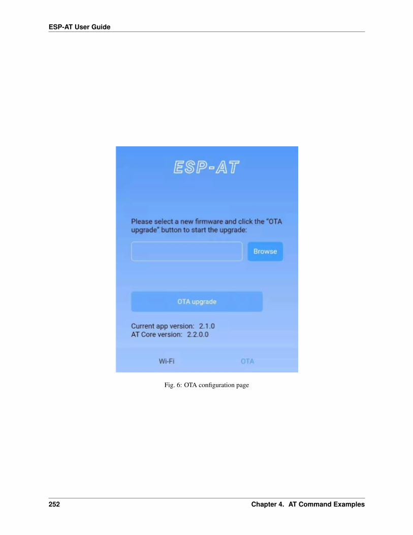
ESP-AT User Guide
Fig. 6: OTA configuration page
252 Chapter 4. AT Command Examples

ESP-AT User Guide
Fig. 7: Select the new version of firmware to be sent
Get the Result of OTA
As shown in the figure, if the ESP device OTA successfully, it will prompt “OTA Succeeded”:
At the same time, the following messages will be returned from the ESP-AT command port:
+WEBSERVERRSP:3 // meaning that ESP device begin to receive ota data+WEBSERVERRSP:4 // meaning that ESP device has received all firmware dataand you→˓can choose to restart the ESP device to apply the new firmware
If the received firmware data verification fails, the following message will be received on the serial port:
+WEBSERVERRSP:3 // meaning that ESP device begin to receive ota data+WEBSERVERRSP:5 // meaning that the received OTA data verification failed. You→˓can choose to reopen the OTA configuration interface and follow the above steps to→˓restart the firmware upgrade
4.5. Web Server AT Example 253
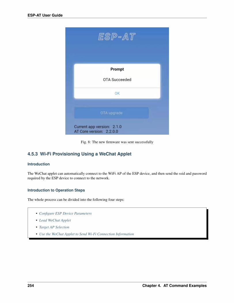
ESP-AT User Guide
Fig. 8: The new firmware was sent successfully
4.5.3 Wi-Fi Provisioning Using a WeChat Applet
Introduction
The WeChat applet can automatically connect to the WiFi AP of the ESP device, and then send the ssid and passwordrequired by the ESP device to connect to the network.
Introduction to Operation Steps
The whole process can be divided into the following four steps:
• Configure ESP Device Parameters
• Load WeChat Applet
• Target AP Selection
• Use the WeChat Applet to Send Wi-Fi Connection Information
254 Chapter 4. AT Command Examples

ESP-AT User Guide
Configure ESP Device Parameters
Firstly, ESP device needs to be configured to softAP + STA mode, and creates a web server to wait for Wi-Fi provi-sioning messages. In this case, a mobile phone or a PC can connect to the ESP softAP as a station. The correspondingAT commands are as follows:
1. Clear the previous Wi-Fi provisioning information.
• Command
AT+RESTORE
2. Set the Wi-Fi mode to Station+SoftAP.
• Command
AT+CWMODE=3
3. Set the configuration of an ESP SoftAP.For example, set the default connection ssid to “pos_softap” , andpassword to “espressif”.
• Command
AT+CWSAP="pos_softap","espressif",11,3,3
Note: By default, the WeChat applet initiates a connection to the SoftAP whose ssid is pos_softap andpassword is espressif. Please make sure to set the parameters of the ESP device according to the aboveconfiguration.
1. Enable multiple connections.
• Command
AT+CIPMUX=1
2. Create a web server, port: 80, connection timeout: 40 s (default maximum is 60 s).
• Command
AT+WEBSERVER=1,80,40
Load WeChat Applet
Open the mobile phone WeChat, scan the following QR code:
Open the WeChat applet and enter the Wi-Fi provisioning interface:
4.5. Web Server AT Example 255

ESP-AT User Guide
Fig. 9: Get the QR code of the applet
Fig. 10: Wi-Fi provisioning interface
256 Chapter 4. AT Command Examples

ESP-AT User Guide
Target AP Selection
After loading the WeChat applet, there are two situations according to different target AP:
Situation 1. If your target AP is the hotspot of the mobile phone which running the WeChat applet, please select the“Local phone hotspot” option box on the WeChat applet page.
Situation 2. If your target AP is just another AP, not as the special situation one as above, then please do not select the“Local phone hotspot” option box.
Use the WeChat Applet to Send Wi-Fi Connection Information
The target AP to be accessed is not the hotspot provided by the mobile phone which loading theWeChat applet.
Here, take connecting to a router as an example, the process of Wi-Fi Connection configuration is introduced:
1.Turn on the mobile Wi-Fi and connect to the router:
Fig. 11: connect to the rounter
2.Open the WeChat applet, you can see that the applet page has automatically displayed the ssid of the current routeras “FAST_FWR310_02”.
Note: If the ssid of the connected router is not displayed on the current page, please click “Re-enter applet” in thefollowing figure to refresh the current page:
3.After entering the password of the router, click “Connect”.
4.After the Wi-Fi connection is established successfully, the web page will be displayed as follows:
At the same time, the following messages will be returned from the ESP-AT command port:
+WEBSERVERRSP:1 // meaning that ESP device has received Wi-Fi connection→˓informationWIFI CONNECTED // meaning that ESP device is connectingWIFI GOT IP // meaning that ESP device connect successfully to the→˓destination rounter+WEBSERVERRSP:2 // meaning that STA device has received Wi-Fi connection result,→˓and web resources can be released
5.If the ESP device fails to connect to the router, the page will display:
At the same time, the following messages will be returned from the ESP-AT command port:
4.5. Web Server AT Example 257

ESP-AT User Guide
Fig. 12: The applet obtains the information of the router to be connected
258 Chapter 4. AT Command Examples

ESP-AT User Guide
Fig. 13: Re-enter the applet
4.5. Web Server AT Example 259

ESP-AT User Guide
Fig. 14: The applet starts the ESP device to connect to the router
260 Chapter 4. AT Command Examples

ESP-AT User Guide
Fig. 15: The applet Wi-Fi provisioning is successful
4.5. Web Server AT Example 261
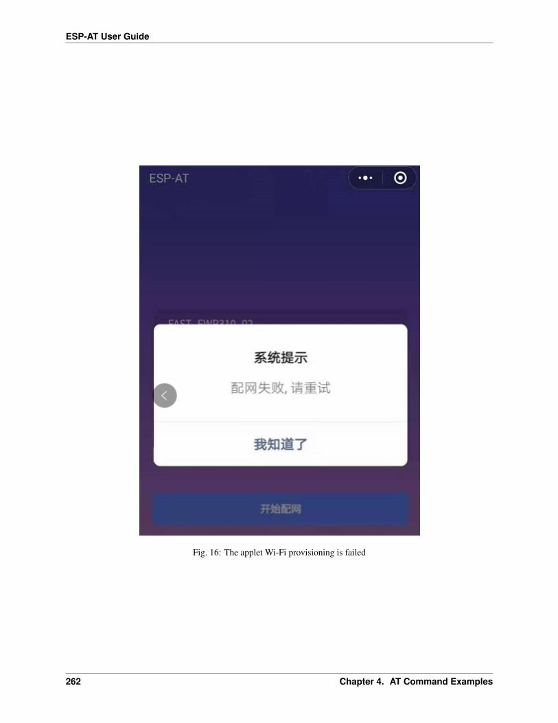
ESP-AT User Guide
Fig. 16: The applet Wi-Fi provisioning is failed
262 Chapter 4. AT Command Examples
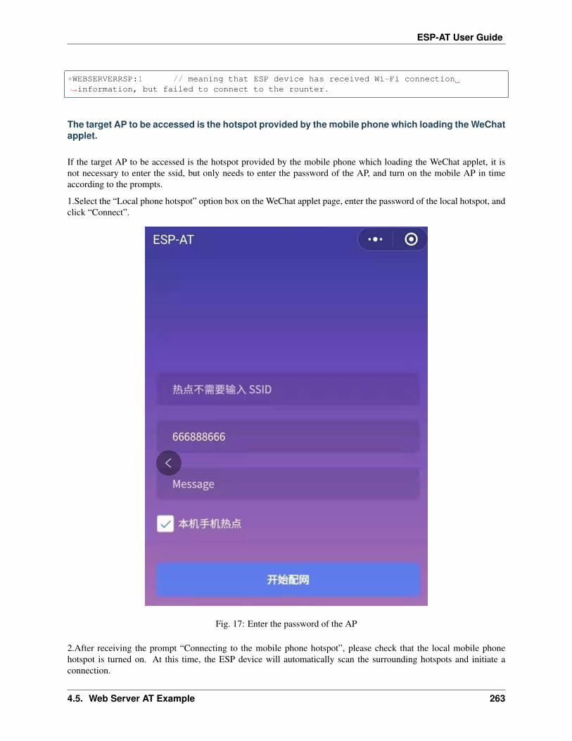
ESP-AT User Guide
+WEBSERVERRSP:1 // meaning that ESP device has received Wi-Fi connection→˓information, but failed to connect to the rounter.
The target AP to be accessed is the hotspot provided by the mobile phone which loading the WeChatapplet.
If the target AP to be accessed is the hotspot provided by the mobile phone which loading the WeChat applet, it isnot necessary to enter the ssid, but only needs to enter the password of the AP, and turn on the mobile AP in timeaccording to the prompts.
1.Select the “Local phone hotspot” option box on the WeChat applet page, enter the password of the local hotspot, andclick “Connect”.
Fig. 17: Enter the password of the AP
2.After receiving the prompt “Connecting to the mobile phone hotspot”, please check that the local mobile phonehotspot is turned on. At this time, the ESP device will automatically scan the surrounding hotspots and initiate aconnection.
4.5. Web Server AT Example 263
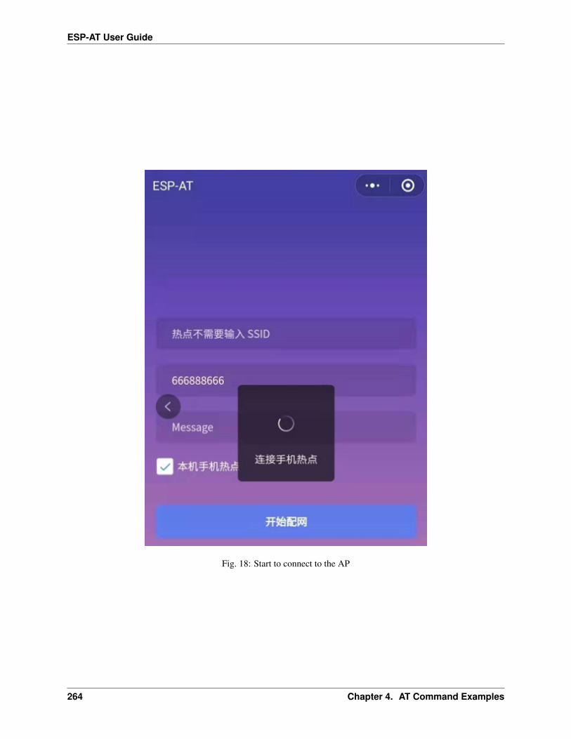
ESP-AT User Guide
Fig. 18: Start to connect to the AP
264 Chapter 4. AT Command Examples
ESP-AT User Guide
3.The display of the WiFi connection results on the applet page and the data output from the serial port are the sameas the above-mentioned “The target AP to be accessed is not the hotspot provided by the mobile phone which loadingthe WeChat applet.”, please refer to the above.
Troubleshooting
Note 1: The Wi-Fi provisioning page received a prompt “Data transmission failed”. Please check whether the Wi-FiAP of the ESP device is correctly turned on, and the relevant configuration of the AP, and confirm that the correct ATcommand has been entered to successfully enable the web server.
Note 2: The Wi-Fi provisioning page receives a prompt “Failed to connect to the AP”. Please check whether the Wi-Fi connection function of the mobile phone is turned on, check whether the Wi-Fi AP of the ESP device is correctlyturned on, and whether the ssid and password of the AP are configured according to the above steps.
Note 3: The Wi-Fi provisioning page receives a prompt “The Wi-Fi provisioning saved by the system expired”. Pleasemanually connect the ESP device AP with a mobile phone, and confirm that the ssid and password of the ESP modulehave been configured according to the above steps.
4.5.4 OTA Firmware Upgrade Using a WeChat Applet
The WeChat applet support online firmware upgrade , please refer to the above-described Configure ESP DeviceParameters specific steps performed ESP device configuration (if the configuration has been completed, do not repeatconfiguration). Once configured, the device performs OTA firmware upgrade processes is similar as OTA FirmwareUpgrade Using a Browser .
4.5.5 [ESP32][ESP32-S Series][ESP32-C Series] Using Capture Portal
Introduction
Captive Portal is commonly used to present a specified page to newly connected devices of a Wi-Fi or wired network.For more information about Captive Portal, please refer to Captive Portal Wiki .
Note: The default firmware does not support web server Captive Portal, you may enable it by ./build.pymenuconfig > Component config > AT > AT WEB Server command support > AT WEB captiveportal support and build the project (see Build Your Own ESP-AT Project). In addition, enabling this featuremay cause page skipping when using wechat applet for Wi-Fi provisioning or OTA firmware upgrade. It is recom-mended that this feature be enabled only when accessing at web using browser.
Introduction to Operation Steps
After Enable Captive Portal support, please refer to Use STA Device to Connect to ESP Device to complete theconfiguration of the ESP device, and then connect to the AP of the ESP device:
As shown in the figure above, after the Station device is connected to the AP of the ESP device with the Captive Portalfunction enabled, it will prompt “requires login/authentication”, and then the browser will automatically open andjump to the main interface of AT Web. If it cannot be redirected automatically, please follow the instructions of theStation device, click “Authentication” or click the name of the “pos_softap” hotspot in the figure above to manuallytrigger the Captive Portal to automatically open the browser and enter the main interface of AT Web.
4.5. Web Server AT Example 265

ESP-AT User Guide
Fig. 19: Connect to the AP with Captive Portal enabled
Troubleshooting
Note 1: Both Station device and AP device support the Captive Portal function to ensure the normal use of this func-tion. Therefore, if the device is connected to the AP of the ESP device, but it does not prompt “Login/Authentication”,it may be that the Station device does not support this function. In this case, please refer to the specific steps of Usethe Browser to Send Wi-Fi Connection Information above to open the main interface of AT Web.
266 Chapter 4. AT Command Examples

CHAPTER
FIVE
HOW TO COMPILE AND DEVELOP YOUR OWN AT PROJECT
[]
5.1 Build Your Own ESP-AT Project
This document details how to build your own ESP-AT project and flash the generated binary files into your ESPdevices, including ESP32, ESP32-S2, ESP32-C3, and ESP8266. It comes in handy when the default AT Binary Listscannot meet your needs, for example, to customize the AT port pins, Bluetooth service, partitions, and so on.
The structure of this document is as follows:
• Overview: Overview of the steps to build an ESP-AT project.
• ESP32, ESP32-S2 and ESP32-C3 Series: Details steps to build a project for ESP32, ESP32-S2, and ESP32-C3series.
• ESP8266 Series: Details steps to build a project for ESP8266.
5.1.1 Overview
Before compiling an ESP-AT project, you need first get started with ESP-IDF and set up the environment for ESP-IDF,because ESP-AT is based on ESP-IDF.
After the environment is ready, install the tools and ESP-AT SDK. Then, connect your ESP device to PC. Use ./build.py menuconfig to set up some configuration for the project. Build the project and flash the generated binfiles onto your ESP device.
Note: Please pay attention to possible conflicts of pins. If choosing AT through HSPI, you can get the informa-tion of the HSPI pin by ./build.py menuconfig –> Component config –> AT –> AT hspi settings.
5.1.2 ESP32, ESP32-S2 and ESP32-C3 Series
This section describes how to compile an ESP-AT project for ESP32, ESP32-S2 and ESP32-C3 series.
267

ESP-AT User Guide
Get Started with ESP-IDF
Get started with ESP-IDF before compiling an ESP-AT project, because ESP-AT is developed based on ESP-IDF, andthe supported version varies from series to series:
Table 1: ESP-IDF Versions for Different SeriesProject IDF Version IDF Documentation VersionESP32 ESP-AT release/v4.2 ESP-IDF Get Started Guide v4.2ESP32-S2 ESP-AT release/v4.2 ESP-IDF Get Started Guide v4.2ESP32-C3 ESP-AT release/v4.3 ESP-IDF Get Started Guide v4.3
First, set up the development environment for ESP-IDF according to Step 1 to 4 of ESP-IDF Get Started Guide (clickthe corresponding link in the table above to navigate to the documentation).
Then, start a simple project of hello_world according to Step 5 to 10 of ESP-IDF Get Started Guide to make sureyour environment works and familiarize yourself with the process of starting a new project based on ESP-IDF. It isnot a must, but you are strongly recommended to do so.
After finishing all the ten steps (if not, at least the first four steps), you can move onto the following steps that areESP-AT specific.
Note: Please do not set IDF_PATH during the process, otherwise, you would encounter some unexpected issueswhen compiling ESP-AT projects later.
Get ESP-AT
To compile an ESP-AT project, you need the software libraries provided by Espressif in the ESP-AT repository.
To get ESP-AT, navigate to your installation directory and clone the repository with git clone, following instructionsbelow specific to your operating system.
• Linux or macOS
cd ~/espgit clone --recursive https://github.com/espressif/esp-at.git
• Windows
cd %userprofile%\espgit clone --recursive https://github.com/espressif/esp-at.git
If you are located in China or have difficulties to access GitHub, you can also use git clone https://gitee.com/EspressifSystems/esp-at.git to get ESP-AT, which may be faster.
ESP-AT will be downloaded into ~/esp/esp-at on Linux or macOS, or %userprofile%\esp\esp-at onWindows.
Note: This guide uses the directory ~/esp on Linux or macOS, or %userprofile%\esp on Windows as aninstallation folder for ESP-AT. You can use any directory, but you will need to adjust paths for the commands respec-tively. Keep in mind that ESP-AT does not support spaces in paths.
268 Chapter 5. How to compile and develop your own AT project

ESP-AT User Guide
Connect Your Device
Connect your device to the PC with a USB cable to download firmware and log output. See Hardware Connection formore information. Note that you do not need to set up the “AT command/response” connection if you do not send ATcommands and receive AT responses during the compiling process. You can change default port pins referring to Howto Set AT Port Pins.
Configure
In this step, you will clone the esp-idf folder into the esp-at folder, set up the development environment in thenewly cloned folder, and configure your project.
1. Navigate to ~/esp/esp-at directory.
2. Run the project configuration utility menuconfig to configure.
./build.py menuconfig
3. Select the following configuration options for your ESP device if it is your first time.
• Select the Platform name for your ESP device. For example, select PLATFORM_ESP32 for ESP32 se-ries of products, PLATFORM_ESP32S2 for ESP32-S2 series of products. Platform name is defined infactory_param_data.csv .
• Select the Module name for your ESP device. For example, select WROOM-32 for the ESP32-WROOM-32Dmodule. Module name is defined in factory_param_data.csv .
• Enable or disable silence mode. If enabled, it will remove some logs and reduce the firmware size. Gener-ally, it should be disabled.
• The above three option items will not appear if the file build/module_info.json exists. So please deleteit if you want to reconfigure the module information.
4. Now, the esp-idf folder is created in esp-at folder. This esp-idf is different from that in Step GetStarted with ESP-IDF.
• If the terminal prompt an error message like the following, please proceed with the next step to set up the developenvironment in the esp-at/esp-idf.
The following Python requirements are not satisfied:...Please follow the instructions found in the "Set up the tools" section of ESP-IDF→˓Get Started Guide.
• If you have compiled an ESP-AT project for an ESP series before and want to switch to another series, you mustrun rm -rf esp-idf to remove the old esp/idf and then proceed with the next step.
• If your esp-idf is upgraded, you are recommended to proceed with the next step.
5. Set up the development environment in the esp-at/esp-idf.
• Set up the tools in the folder if it is the first time you compile the ESP-AT project. See Step 3 of ESP-IDF GetStarted Guide.
• Set up environment variables in the folder every time you compile an ESP-AT project. See Step 4 of ESP-IDFGet Started Guide.
• Install pyyaml and xlrd packages with pip in the folder if you have not done it.
python -m pip install pyyaml xlrd
5.1. Build Your Own ESP-AT Project 269
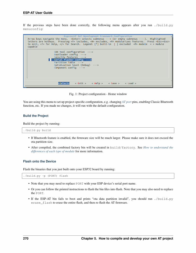
ESP-AT User Guide
If the previous steps have been done correctly, the following menu appears after you run ./build.pymenuconfig:
Fig. 1: Project configuration - Home window
You are using this menu to set up project-specific configuration, e.g. changing AT port pins, enabling Classic Bluetoothfunction, etc. If you made no changes, it will run with the default configuration.
Build the Project
Build the project by running:
./build.py build
• If Bluetooth feature is enabled, the firmware size will be much larger. Please make sure it does not exceed theota partition size.
• After compiled, the combined factory bin will be created in build/factory. See How to understand thedifferences of each type of module for more information.
Flash onto the Device
Flash the binaries that you just built onto your ESP32 board by running:
./build.py -p (PORT) flash
• Note that you may need to replace PORT with your ESP device’s serial port name.
• Or you can follow the printed instructions to flash the bin files into flash. Note that you may also need to replacethe PORT.
• If the ESP-AT bin fails to boot and prints “ota data partition invalid”, you should run ./build.pyerase_flash to erase the entire flash, and then re-flash the AT firmware.
270 Chapter 5. How to compile and develop your own AT project

ESP-AT User Guide
5.1.3 ESP8266 Series
This section describes how to compile an ESP-AT project for ESP8266 series.
Get Started with ESP-IDF
Get started with ESP-IDF before compiling an ESP-AT project, because ESP-AT is developed based on ESP-IDF:
First, set up the development environment according to ESP8266 RTOS SDK Get Started Guide v3.4.
Then, start a simple project of hello_world according to the Guide to make sure your environment works andfamiliarize yourself with the process of starting a new project based on ESP-IDF. It is not a must, but you are stronglyrecommended to do so.
After setting up the development environment and starting a simple project, you can move onto the following stepsthat are ESP-AT specific.
Note: Please do not set IDF_PATH during the process, otherwise, you would encounter some unexpected issueswhen compiling ESP-AT projects later.
Get ESP-AT
To compile an ESP-AT project, you need the software libraries provided by Espressif in the ESP-AT repository.
To get ESP-AT, navigate to your installation directory and clone the repository with git clone, following instructionsbelow specific to your operating system.
• Linux or macOS
cd ~/espgit clone --recursive https://github.com/espressif/esp-at.git
• Windows
cd %userprofile%\espgit clone --recursive https://github.com/espressif/esp-at.git
If you are located in China or have difficulties to access GitHub, you can also use git clone https://gitee.com/EspressifSystems/esp-at.git to get ESP-AT, which may be faster.
ESP-AT will be downloaded into ~/esp/esp-at on Linux or macOS, or %userprofile%\esp\esp-at onWindows.
Note: This guide uses the directory ~/esp on Linux and macOS or %userprofile%\esp on Windows asan installation folder for ESP-AT. You can use any directory, but you will need to adjust paths for the commandsrespectively. Keep in mind that ESP-AT does not support spaces in paths.
5.1. Build Your Own ESP-AT Project 271

ESP-AT User Guide
Checkout to ESP8266 Branch
git checkout release/v2.2.0.0_esp8266
Connect Your Device
Connect your device to the PC with a USB cable to download firmware and log output. See Hardware Connection formore information. Note that you do not need to set up the “AT command/response” connection if you do not send ATcommands and receive AT responses during the compiling process. You can change default port pins referring to Howto Set AT Port Pins.
Configure
In this step, you will clone the esp-idf folder into the esp-at folder, set up the development environment in thenewly cloned folder, and configure your project.
1. Navigate back to your ~/esp/esp-at directory.
2. Run the project configuration utility menuconfig to configure.
./build.py menuconfig
3. Select the following configuration options for your ESP device if it is the first time you build the ESP-AT project.
• Select the Platform name for your ESP device, i.e., select PLATFORM_ESP8266 for your ESP8266 device.Platform name is defined in factory_param_data.csv .
• Select the Module name for your ESP device. For example, select WROOM-02 for the ESP-WROOM-02Dmodule. Module name is defined in factory_param_data.csv .
• Enable or disable silence mode. If enabled, it will remove some logs and reduce the firmware size. Gener-ally, it should be disabled.
• The above three option items will not appear if the file build/module_info.json exists. So please deleteit if you want to reconfigure the module information.
4. Now, the esp-idf folder is created in esp-at folder. This esp-idf is different from that in Step GetStarted with ESP-IDF.
• If the terminal prompt an error message like the following, please proceed with the next step to set up the developenvironment in the esp-at/esp-idf.
The following Python requirements are not satisfied:...Please follow the instructions found in the "Set up the tools" section of ESP-IDF→˓Get Started Guide.
• If you have compiled an ESP-AT project for an ESP series before and want to switch to another series, you mustrun rm -rf esp-idf to remove the old esp/idf and then proceed with the next step.
• If your esp-idf is upgraded, you are recommended to proceed with the next step.
5. Set up the development environment in the esp-at/esp-idf.
• Set up the tools in the folder if it is the first time you compile an ESP-AT project. See ESP8266 RTOS SDK GetStarted Guide v3.4 for more information.
• Set up environment variables in the folder every time you compile an ESP-AT project. See ESP8266 RTOSSDK Get Started Guide v3.4 for more information.
272 Chapter 5. How to compile and develop your own AT project

ESP-AT User Guide
• Install pyyaml and xlrd packages with pip in the folder if you have not done it.
python -m pip install pyyaml xlrd
If the previous steps have been done correctly, the following menu appears after you run ./build.pymenuconfig:
Fig. 2: Project configuration - Home window
You are using this menu to set up project-specific configuration, e.g. changing AT port pins, enabling Classic Bluetoothfunction, etc. If you made no changes, it will run with the default configuration.
Build the Project
Build the project by running:
./build.py build
• After compiled, the combined factory bin will be created in build/factory. By default, the factory bin is 2MB flash size, DIO flash mode and 80 MHz flash speed. See How to understand the differences of each type ofmodule for more information.
Flash onto the Device
Flash the binaries that you just built onto your ESP8266 board by running:
./build.py -p (PORT) flash
• Note that you may need to replace PORT with your ESP device’s serial port name.
• Or you can follow the printed instructions to flash the bin files into flash. Note that you may also need to replacethe PORT.
• If the ESP-AT bin fails to boot and prints “ota data partition invalid”, you should run ./build.pyerase_flash to erase the entire flash, and then re-flash the AT firmware.
5.1. Build Your Own ESP-AT Project 273

ESP-AT User Guide
5.2 How to Set AT Port Pins
This document introduces how to modify AT port pins in the firmware for ESP32, ESP32-S2, ESP32-C3, and ESP8266series of products. By default, ESP-AT uses two UART interfaces as AT ports: one is to output logs (named as logport below) and the other to send AT commands and receive responses (named as command port below).
To modify the AT port pins of your ESP device, you should:
• clone the esp-at project;
• modify the pins either in the menuconfig utility or the factory_param_data.csv table;
• compile the project to generate the new bin in build/customized_partitions/factory_param.bin;
• flash the new bin to your device.
This document focuses on modifying the pins. Click the links above for details of other steps. Below is the documentstructure:
• ESP32 Series
• ESP32-S2 Series
• ESP32-C3 Series
• ESP8266 Series
Note: To use other interfaces as the AT command port, please refer to AT through SDIO , AT through SPI , or ATthrough socket for more details.
5.2.1 ESP32 Series
The log port and command port pins of ESP32 AT firmware can be user-defined to other pins. Refer to ESP32Technical Reference Manual for the pins you can use.
Modify Log Port Pins
By default, the ESP32 AT firmware provided by Espressif uses the following UART0 pins to output log:
• TX: GPIO1
• RX: GPIO3
When compiling your esp-at project, you can modify them to other pins with the menuconfig utitlity:
• ./build.py menuconfig –> Component config –> Common ESP-related –> UART forconsole output
• ./build.py menuconfig –> Component config –> Common ESP-related –> UART TX onGPIO#
• ./build.py menuconfig –> Component config –> Common ESP-related –> UART RX onGPIO#
274 Chapter 5. How to compile and develop your own AT project
ESP-AT User Guide
Modify Command Port Pins
By default, UART1 is used to send AT commands and receive AT responses, and its pins are defined inColumn uart_port, uart_tx_pin, uart_rx_pin, uart_cts_pin, and uart_rts_pin of the fac-tory_param_data.csv .
You can change them directly in your factory_param_data.csv table:
• Open your local factory_param_data.csv file.
• Locate the row of your module.
• Set uart_port as needed.
• Set uart_tx_pin and uart_rx_pin as needed.
• Set uart_cts_pin and uart_rts_pin to be -1 if you do not use the hardware flow control function.
• Save the table.
5.2.2 ESP32-S2 Series
The log port and command port pins of ESP32-S2 AT firmware can be user-defined to other pins. Refer to ESP32-S2Technical Reference Manual for the pins you can use.
Modify Log Port Pins
By default, the ESP32-S2 AT firmware provided by Espressif uses the following UART0 pins to output log:
• TX: GPIO43
• RX: GPIO44
When compiling your esp-at project, you can modify them to other pins with the menuconfig utitlity:
• ./build.py menuconfig –> Component config –> Common ESP-related –> UART forconsole output
• ./build.py menuconfig –> Component config –> Common ESP-related –> UART TX onGPIO#
• ./build.py menuconfig –> Component config –> Common ESP-related –> UART RX onGPIO#
Modify Command Port Pins
By default, UART1 is used to send AT commands and receive AT responses, and its pins are defined inColumn uart_port, uart_tx_pin, uart_rx_pin, uart_cts_pin, and uart_rts_pin of the fac-tory_param_data.csv .
You can change them directly in your factory_param_data.csv table:
• Open your local factory_param_data.csv file.
• Locate the row of your module.
• Set uart_port as needed.
• Set uart_tx_pin and uart_rx_pin as needed.
• Set uart_cts_pin and uart_rts_pin to be -1 if you do not use the hardware flow control function.
5.2. How to Set AT Port Pins 275

ESP-AT User Guide
• Save the table.
5.2.3 ESP32-C3 Series
The log port and command port pins of ESP32-C3 AT firmware can be user-defined to other pins. ESP32-C3 TechnicalReference Manual for the pins you can use.
Modify Log Port Pins
By default, the ESP32-C3 AT firmware provided by Espressif uses the following UART0 pins to output log:
• TX: GPIO21
• RX: GPIO20
When compiling your esp-at project, you can modify them to other pins with the menuconfig utitlity:
• ./build.py menuconfig –> Component config –> Common ESP-related –> UART forconsole output
• ./build.py menuconfig –> Component config –> Common ESP-related –> UART TX onGPIO#
• ./build.py menuconfig –> Component config –> Common ESP-related –> UART RX onGPIO#
Modify Command Port Pins
By default, UART1 is used to send AT commands and receive AT responses, and its pins are defined inColumn uart_port, uart_tx_pin, uart_rx_pin, uart_cts_pin, and uart_rts_pin of the fac-tory_param_data.csv .
You can change them directly in your factory_param_data.csv table:
• Open your local factory_param_data.csv file.
• Locate the row of your module.
• Set uart_port as needed.
• Set uart_tx_pin and uart_rx_pin as needed.
• Set uart_cts_pin and uart_rts_pin to be -1 if you do not use the hardware flow control function.
• Save the table.
5.2.4 ESP8266 Series
The log port and command port pins of the ESP8266 AT firmware can be user-defined to other pins, but with limitedoptions. Please refer to ESP8266 Technical Reference Manual for more details.
276 Chapter 5. How to compile and develop your own AT project

ESP-AT User Guide
Modify Log Port Pins
By default, the ESP8266 AT firmware provided by Espressif uses UART1 to log output. UART1 only supports GPIO2as the TX pin, and the pin should not be modified.
However, you could modify the log port from UART1 to UART0 by:
• ./build.py menuconfig –> Component config –> Common ESP-related –> UART forconsole output
Modify Command Port Pins
By default, ESP8266 AT firmware uses UART0 to send AT commands and receive AT responses. The UART0 pinsare defined in Column uart_port, uart_tx_pin, uart_rx_pin, uart_cts_pin, and uart_rts_pin ofthe factory_param_data.csv .
The UART pins can be changed, but there are only two choices: GPIO15 as TX pin, GPIO13 as RX orGPIO1 as TX, GPIO3 as RX. Below are the detailed steps:
• Open your local factory_param_data.csv file.
• Locate the row of your module.
• Set uart_port as needed.
• Set uart_tx_pin and uart_rx_pin to GPIO15 and GPIO13, or GPIO1 and GPIO3.
• Set uart_cts_pin and uart_rts_pin to be -1 if you do not use the hardware flow control function.
• Save the table.
For example, if you need to set GPIO1 (TX) and GPIO3 (RX) to be both the log port and command port of ESP-WROOM-02, do as follows:
1. Set log port to UART0: ./build.py menuconfig –> Component config –> ESP8266-specific–> UART for console output –> Default: UART0
2. Open your local factory_param_data.csv.
3. Find the row of WROOM-02, set uart_tx_pin to 1, uart_rx_pin to 3, uart_cts_pin to -1,uart_rts_pin to -1, and then save the table.
5.3 How to add user-defined AT commands
This document details how to add a user-defined AT command based on the esp-at project. It uses the AT+TESTcommand as an example to show the sample code for each step.
Customizing a basic and well-functioned command requires at least the two steps below:
• Define AT Commands
• Register AT Commands
This step checks how the newly defined command works out.
• Give it a try
The remaining steps are for relatively complex AT commands and are optional depending on your needs.
• Define Return Values
• Access Command Parameters
5.3. How to add user-defined AT commands 277

ESP-AT User Guide
• Omit Command Parameters
• Block Command Execution
• Access Input Data from AT Command Port
The source code of AT command set is not open-source, and is provided in the form of library file . It is also the basisto parse user-defined AT commands.
5.3.1 Define AT Commands
Before defining any AT command, you should first decide on the name and type of the AT command you want todefine.
Naming rules:
• AT command should start with the + character.
• Alphabetic characters (A~Z, a~z), numeric characters (0~9), and some other characters (!, %, -, ., /, :, _)are supported. See AT Command Types for more information.
Command types:
Each AT command can have up to four types: Test Command, Query Command, Set Command, and Execute Com-mand. See AT Command Types for more information.
Then, define each type of command. Assuming that AT+TEST supports all the four types. Below is the sample codeto define each type.
Test Command:
uint8_t at_test_cmd_test(uint8_t *cmd_name){
uint8_t buffer[64] = {0};
snprintf((char *)buffer, 64, "this cmd is test cmd: %s\r\n", cmd_name);
esp_at_port_write_data(buffer, strlen((char *)buffer));
return ESP_AT_RESULT_CODE_OK;}
Query Command:
uint8_t at_query_cmd_test(uint8_t *cmd_name){
uint8_t buffer[64] = {0};
snprintf((char *)buffer, 64, "this cmd is query cmd: %s\r\n", cmd_name);
esp_at_port_write_data(buffer, strlen((char *)buffer));
return ESP_AT_RESULT_CODE_OK;}
Set Command:
uint8_t at_setup_cmd_test(uint8_t para_num){
int32_t para_int_1 = 0;
(continues on next page)
278 Chapter 5. How to compile and develop your own AT project

ESP-AT User Guide
(continued from previous page)
uint8_t *para_str_2 = NULL;uint8_t num_index = 0;uint8_t buffer[64] = {0};
if (esp_at_get_para_as_digit(num_index++, ¶_int_1) != ESP_AT_PARA_PARSE_→˓RESULT_OK) {
return ESP_AT_RESULT_CODE_ERROR;}
if (esp_at_get_para_as_str(num_index++, ¶_str_2) != ESP_AT_PARA_PARSE_RESULT_→˓OK) {
return ESP_AT_RESULT_CODE_ERROR;}
snprintf((char *)buffer, 64, "this cmd is setup cmd and cmd num is: %u\r\n", para_→˓num);
esp_at_port_write_data(buffer, strlen((char *)buffer));
memset(buffer, 0, 64);snprintf((char *)buffer, 64, "first parameter is: %d\r\n", para_int_1);esp_at_port_write_data(buffer, strlen((char *)buffer));
memset(buffer, 0, 64);snprintf((char *)buffer, 64, "second parameter is: %s\r\n", para_str_2);esp_at_port_write_data(buffer, strlen((char *)buffer));
return ESP_AT_RESULT_CODE_OK;}
Execute Command:
uint8_t at_exe_cmd_test(uint8_t *cmd_name){
uint8_t buffer[64] = {0};
snprintf((char *)buffer, 64, "this cmd is execute cmd: %s\r\n", cmd_name);
esp_at_port_write_data(buffer, strlen((char *)buffer));
return ESP_AT_RESULT_CODE_OK;}
Finally, call esp_at_cmd_struct to define the name and type(s) that your AT command supports. The samplecode below defined the name +TEST (omitting AT) and all the four types.
static esp_at_cmd_struct at_custom_cmd[] = {{"+TEST", at_test_cmd_test, at_query_cmd_test, at_setup_cmd_test, at_exe_cmd_test}
→˓,};
If you do not want to define a particular type, set it to NULL.
5.3. How to add user-defined AT commands 279

ESP-AT User Guide
5.3.2 Register AT Commands
Call API esp_at_custom_cmd_array_regist() to register your AT command. Below is the sample code toregister AT+TEST:
esp_at_custom_cmd_array_regist(at_custom_cmd, sizeof(at_custom_cmd) / sizeof(at_→˓custom_cmd[0]));
Note: esp_at_custom_cmd_array_regist is recommended to be added to the at_custom_init() inapp_main().
5.3.3 Give it a try
If you have finished the above two steps, the command should work after you build the esp-at project and flash thefirmware to your device. Give it a try!
Below is how AT+TEST works out.
Test Command:
AT+TEST=?
Response:
AT+TEST=?this cmd is test cmd: +TEST
OK
Query Command:
AT+TEST?
Response:
AT+TEST?this cmd is query cmd: +TEST
OK
Set Command:
AT+TEST=1,"espressif"
Response:
AT+TEST=1,"espressif"this cmd is setup cmd and cmd num is: 2first parameter is: 1second parameter is: espressif
OK
Execute Command:
280 Chapter 5. How to compile and develop your own AT project

ESP-AT User Guide
AT+TEST
Response:
AT+TESTthis cmd is execute cmd: +TEST
OK
5.3.4 Define Return Values
ESP-AT has defined return values in esp_at_result_code_string_index. See AT Messages for more returnvalues.
In addition to output return values through the return mode, you can also use API esp_at_response_result()to output the execution result of the command. ESP_AT_RESULT_CODE_SEND_OK andESP_AT_RESULT_CODE_SEND_FAIL can be used with the API in code.
For example, when you send data to the server or MCU with the Execute Command of AT+TEST, you can useesp_at_response_result to output the sending result, and the return mode to output the command executionresult. Below is the sample code:
uint8_t at_exe_cmd_test(uint8_t *cmd_name){
uint8_t buffer[64] = {0};
snprintf((char *)buffer, 64, "this cmd is execute cmd: %s\r\n", cmd_name);
esp_at_port_write_data(buffer, strlen((char *)buffer));
// user-defined operation of sending data to server or MCUsend_data_to_server();
// output SEND OKesp_at_response_result(ESP_AT_RESULT_CODE_SEND_OK);
return ESP_AT_RESULT_CODE_OK;}
How it works out:
AT+TESTthis cmd is execute cmd: +TEST
SEND OK
OK
5.3. How to add user-defined AT commands 281

ESP-AT User Guide
5.3.5 Access Command Parameters
ESP-AT provides two APIs to access command parameters:
• esp_at_get_para_as_digit() obtains digital parameters.
• esp_at_get_para_as_str() obtains string parameters.
See Set Command for an example.
5.3.6 Omit Command Parameters
This section describes how to provide optional command parameters:
• Omit the First or Middle Parameter
• Omit the Last Parameter
Omit the First or Middle Parameter
Let’s say you want to make <param_2> and <param_3> of AT+TEST optional. <param_2> is a digital parameter,and <param_3> a string parameter.
AT+TEST=<param_1>[,<param_2>][,<param_3>],<param_4>
Below is the sample code to achieve it:
uint8_t at_setup_cmd_test(uint8_t para_num){
int32_t para_int_1 = 0;int32_t para_int_2 = 0;uint8_t *para_str_3 = NULL;uint8_t *para_str_4 = NULL;uint8_t num_index = 0;uint8_t buffer[64] = {0};esp_at_para_parse_result_type parse_result = ESP_AT_PARA_PARSE_RESULT_OK;
snprintf((char *)buffer, 64, "this cmd is setup cmd and cmd num is: %u\r\n", para_→˓num);
esp_at_port_write_data(buffer, strlen((char *)buffer));
parse_result = esp_at_get_para_as_digit(num_index++, ¶_int_1);if (parse_result != ESP_AT_PARA_PARSE_RESULT_OK) {
return ESP_AT_RESULT_CODE_ERROR;} else {
memset(buffer, 0, 64);snprintf((char *)buffer, 64, "first parameter is: %d\r\n", para_int_1);esp_at_port_write_data(buffer, strlen((char *)buffer));
}
parse_result = esp_at_get_para_as_digit(num_index++, ¶_int_2);if (parse_result != ESP_AT_PARA_PARSE_RESULT_OMITTED) {
if (parse_result != ESP_AT_PARA_PARSE_RESULT_OK) {return ESP_AT_RESULT_CODE_ERROR;
} else {// sample code// user needs to customize the operation
(continues on next page)
282 Chapter 5. How to compile and develop your own AT project

ESP-AT User Guide
(continued from previous page)
memset(buffer, 0, 64);snprintf((char *)buffer, 64, "second parameter is: %d\r\n", para_int_2);esp_at_port_write_data(buffer, strlen((char *)buffer));
}} else {
// sample code// the second parameter is omitted// user needs to customize the operationmemset(buffer, 0, 64);snprintf((char *)buffer, 64, "second parameter is omitted\r\n");esp_at_port_write_data(buffer, strlen((char *)buffer));
}
parse_result = esp_at_get_para_as_str(num_index++, ¶_str_3);if (parse_result != ESP_AT_PARA_PARSE_RESULT_OMITTED) {
if (parse_result != ESP_AT_PARA_PARSE_RESULT_OK) {return ESP_AT_RESULT_CODE_ERROR;
} else {// sample code// user needs to customize the operationmemset(buffer, 0, 64);snprintf((char *)buffer, 64, "third parameter is: %s\r\n", para_str_3);esp_at_port_write_data(buffer, strlen((char *)buffer));
}} else {
// sample code// the third parameter is omitted// user needs to customize the operationmemset(buffer, 0, 64);snprintf((char *)buffer, 64, "third parameter is omitted\r\n");esp_at_port_write_data(buffer, strlen((char *)buffer));
}
parse_result = esp_at_get_para_as_str(num_index++, ¶_str_4);if (parse_result != ESP_AT_PARA_PARSE_RESULT_OK) {
return ESP_AT_RESULT_CODE_ERROR;} else {
memset(buffer, 0, 64);snprintf((char *)buffer, 64, "fourth parameter is: %s\r\n", para_str_4);esp_at_port_write_data(buffer, strlen((char *)buffer));
}
return ESP_AT_RESULT_CODE_OK;}
Note: If the string parameter input is "", it is not omitted.
5.3. How to add user-defined AT commands 283
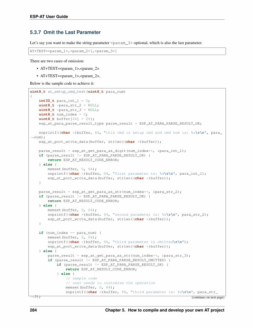
ESP-AT User Guide
5.3.7 Omit the Last Parameter
Let’s say you want to make the string parameter <param_3> optional, which is also the last parameter.
AT+TEST=<param_1>,<param_2>[,<param_3>]
There are two cases of omission:
• AT+TEST=<param_1>,<param_2>
• AT+TEST=<param_1>,<param_2>,
Below is the sample code to achieve it:
uint8_t at_setup_cmd_test(uint8_t para_num){
int32_t para_int_1 = 0;uint8_t *para_str_2 = NULL;uint8_t *para_str_3 = NULL;uint8_t num_index = 0;uint8_t buffer[64] = {0};esp_at_para_parse_result_type parse_result = ESP_AT_PARA_PARSE_RESULT_OK;
snprintf((char *)buffer, 64, "this cmd is setup cmd and cmd num is: %u\r\n", para_→˓num);
esp_at_port_write_data(buffer, strlen((char *)buffer));
parse_result = esp_at_get_para_as_digit(num_index++, ¶_int_1);if (parse_result != ESP_AT_PARA_PARSE_RESULT_OK) {
return ESP_AT_RESULT_CODE_ERROR;} else {
memset(buffer, 0, 64);snprintf((char *)buffer, 64, "first parameter is: %d\r\n", para_int_1);esp_at_port_write_data(buffer, strlen((char *)buffer));
}
parse_result = esp_at_get_para_as_str(num_index++, ¶_str_2);if (parse_result != ESP_AT_PARA_PARSE_RESULT_OK) {
return ESP_AT_RESULT_CODE_ERROR;} else {
memset(buffer, 0, 64);snprintf((char *)buffer, 64, "second parameter is: %s\r\n", para_str_2);esp_at_port_write_data(buffer, strlen((char *)buffer));
}
if (num_index == para_num) {memset(buffer, 0, 64);snprintf((char *)buffer, 64, "third parameter is omitted\r\n");esp_at_port_write_data(buffer, strlen((char *)buffer));
} else {parse_result = esp_at_get_para_as_str(num_index++, ¶_str_3);if (parse_result != ESP_AT_PARA_PARSE_RESULT_OMITTED) {
if (parse_result != ESP_AT_PARA_PARSE_RESULT_OK) {return ESP_AT_RESULT_CODE_ERROR;
} else {// sample code// user needs to customize the operationmemset(buffer, 0, 64);snprintf((char *)buffer, 64, "third parameter is: %s\r\n", para_str_
→˓3); (continues on next page)
284 Chapter 5. How to compile and develop your own AT project

ESP-AT User Guide
(continued from previous page)
esp_at_port_write_data(buffer, strlen((char *)buffer));}
} else {// sample code// the third parameter is omitted// user needs to customize the operationmemset(buffer, 0, 64);snprintf((char *)buffer, 64, "third parameter is omitted\r\n");esp_at_port_write_data(buffer, strlen((char *)buffer));
}}
return ESP_AT_RESULT_CODE_OK;}
Note: If the string parameter input is "", it is not omitted.
5.3.8 Block Command Execution
Sometimes you want to block the execution of one command to wait for another execution result, and the system mayreturn different values according to the result.
Generally, this kind of command needs to synchronize the results of other tasks.
semaphore is recommended to handle synchronization.
The sample code is as follows:
xSemaphoreHandle at_operation_sema = NULL;
uint8_t at_exe_cmd_test(uint8_t *cmd_name){
uint8_t buffer[64] = {0};
snprintf((char *)buffer, 64, "this cmd is execute cmd: %s\r\n", cmd_name);
esp_at_port_write_data(buffer, strlen((char *)buffer));
// sample code// users don't have to create semaphores hereat_operation_sema = xSemaphoreCreateBinary();assert(at_operation_sema != NULL);
// block command execution// wait for another execution result// other tasks can call xSemaphoreGive to release the semaphorexSemaphoreTake(at_operation_sema, portMAX_DELAY);
return ESP_AT_RESULT_CODE_OK;}
5.3. How to add user-defined AT commands 285

ESP-AT User Guide
5.3.9 Access Input Data from AT Command Port
ESP-AT supports accessing input data from AT Command port. It provides two APIs for this purpose.
• esp_at_port_enter_specific() sets the callback function which will be called by AT port after re-ceiving the input data.
• esp_at_port_exit_specific() deletes the callback function set byesp_at_port_enter_specific.
Approaches to access the data vary depending on whether the data length has been specified or not.
5.3.10 Input Data of Specified Length
Assuming that you have specified the data length in <param_1> as follows:
AT+TEST=<param_1>
Below is the sample to access the input data of <param_1> length from AT Command Port:
static xSemaphoreHandle at_sync_sema = NULL;
void wait_data_callback(void){
xSemaphoreGive(at_sync_sema);}
uint8_t at_setup_cmd_test(uint8_t para_num){
int32_t specified_len = 0;int32_t received_len = 0;int32_t remain_len = 0;uint8_t *buf = NULL;uint8_t buffer[64] = {0};
if (esp_at_get_para_as_digit(0, &specified_len) != ESP_AT_PARA_PARSE_RESULT_OK) {return ESP_AT_RESULT_CODE_ERROR;
}
buf = (uint8_t *)malloc(specified_len);if (buf == NULL) {
memset(buffer, 0, 64);snprintf((char *)buffer, 64, "malloc failed\r\n");esp_at_port_write_data(buffer, strlen((char *)buffer));
}
// sample code// users don't have to create semaphores hereif (!at_sync_sema) {
at_sync_sema = xSemaphoreCreateBinary();assert(at_sync_sema != NULL);
}
// output input prompt ">"esp_at_port_write_data((uint8_t *)">", strlen(">"));
// set the callback function which will be called by AT port after receiving the→˓input data
(continues on next page)
286 Chapter 5. How to compile and develop your own AT project

ESP-AT User Guide
(continued from previous page)
esp_at_port_enter_specific(wait_data_callback);
// receie input datawhile(xSemaphoreTake(at_sync_sema, portMAX_DELAY)) {
received_len += esp_at_port_read_data(buf + received_len, specified_len -→˓received_len);
if (specified_len == received_len) {esp_at_port_exit_specific();
// get the length of the remaining input dataremain_len = esp_at_port_get_data_length();if (remain_len > 0) {
// sample code// if the remaining data length > 0, the actual input data length is
→˓greater than the specified received data length// users can customize the operation to process the remaining data// here is just a simple print out of the remaining dataesp_at_port_recv_data_notify(remain_len, portMAX_DELAY);
}
// sample code// output received datamemset(buffer, 0, 64);snprintf((char *)buffer, 64, "\r\nreceived data is: ");esp_at_port_write_data(buffer, strlen((char *)buffer));
esp_at_port_write_data(buf, specified_len);
break;}
}
free(buf);
return ESP_AT_RESULT_CODE_OK;}
So, if you set AT+TEST=5 and the input data is 1234567890, the ESP-AT output is as follows.
AT+TEST=5>67890received data is: 12345OK
5.3.11 Input Data of Unspecified Length
This scenario is similar to the Wi-Fi Passthrough Mode. You do not specify the data length.
AT+TEST
Assuming that ESP-AT ends the execution of the command and returns the execution result, the sample code is asfollows:
5.3. How to add user-defined AT commands 287
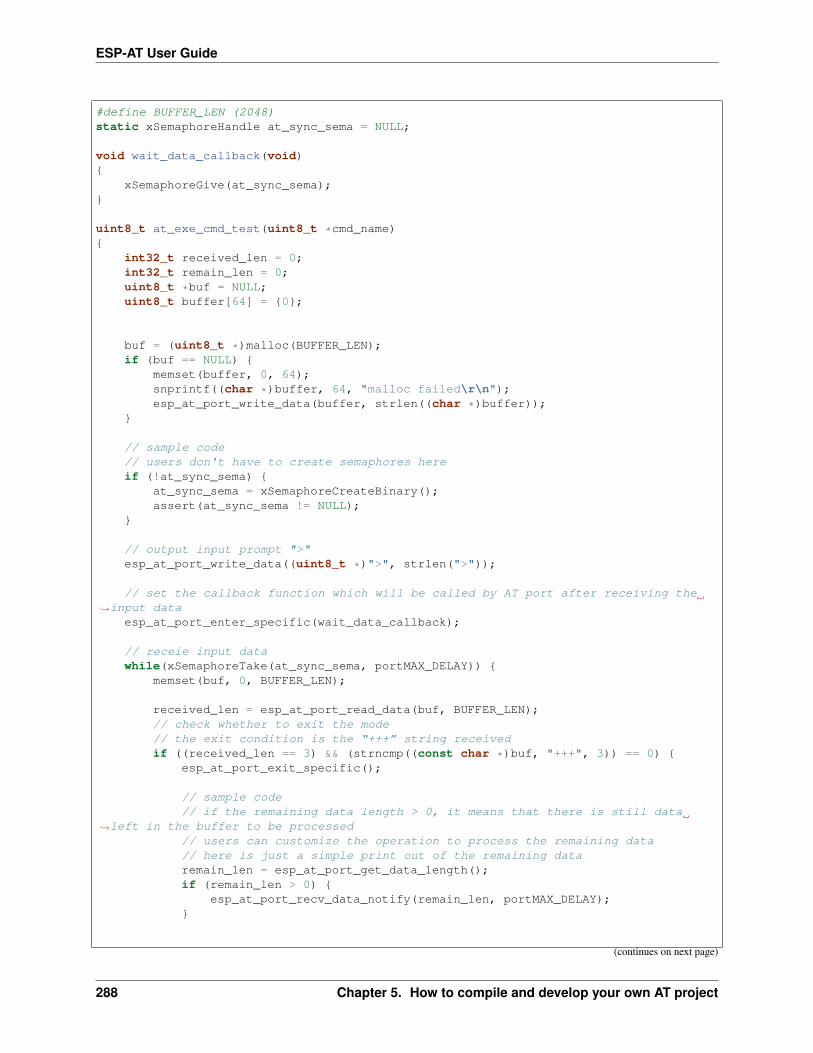
ESP-AT User Guide
#define BUFFER_LEN (2048)static xSemaphoreHandle at_sync_sema = NULL;
void wait_data_callback(void){
xSemaphoreGive(at_sync_sema);}
uint8_t at_exe_cmd_test(uint8_t *cmd_name){
int32_t received_len = 0;int32_t remain_len = 0;uint8_t *buf = NULL;uint8_t buffer[64] = {0};
buf = (uint8_t *)malloc(BUFFER_LEN);if (buf == NULL) {
memset(buffer, 0, 64);snprintf((char *)buffer, 64, "malloc failed\r\n");esp_at_port_write_data(buffer, strlen((char *)buffer));
}
// sample code// users don't have to create semaphores hereif (!at_sync_sema) {
at_sync_sema = xSemaphoreCreateBinary();assert(at_sync_sema != NULL);
}
// output input prompt ">"esp_at_port_write_data((uint8_t *)">", strlen(">"));
// set the callback function which will be called by AT port after receiving the→˓input data
esp_at_port_enter_specific(wait_data_callback);
// receie input datawhile(xSemaphoreTake(at_sync_sema, portMAX_DELAY)) {
memset(buf, 0, BUFFER_LEN);
received_len = esp_at_port_read_data(buf, BUFFER_LEN);// check whether to exit the mode// the exit condition is the “+++” string receivedif ((received_len == 3) && (strncmp((const char *)buf, "+++", 3)) == 0) {
esp_at_port_exit_specific();
// sample code// if the remaining data length > 0, it means that there is still data
→˓left in the buffer to be processed// users can customize the operation to process the remaining data// here is just a simple print out of the remaining dataremain_len = esp_at_port_get_data_length();if (remain_len > 0) {
esp_at_port_recv_data_notify(remain_len, portMAX_DELAY);}
(continues on next page)
288 Chapter 5. How to compile and develop your own AT project
ESP-AT User Guide
(continued from previous page)
break;} else if (received_len > 0) {
// sample code// users can customize the operation to process the received data// here is just a simple print received datamemset(buffer, 0, 64);snprintf((char *)buffer, 64, "\r\nreceived data is: ");esp_at_port_write_data(buffer, strlen((char *)buffer));
esp_at_port_write_data(buf, strlen((char *)buf));}
}
free(buf);
return ESP_AT_RESULT_CODE_OK;}
So, if the first input data is 1234567890, and the second input data is +++, the ESP-AT output is as follows:
AT+TEST>received data is: 1234567890OK
5.4 How To Create Factory Parameter Bin
5.4.1 Overview
In order to adapt the AT firmware to different requirements, for example, different development board, differentcountry code, different RF restriction, we make a table to configure those parameters.
5.4.2 Factory param type
The origin table is components/customized_partitions/raw_data/factory_param/factory_param_type.csv, and the factory parameter type is as the following table:
• description:
– prompt information when build the project
• version:
– the version of factory param mangement
• reserved1
– reserved
• tx_max_power
– Wi-Fi maximum tx power
* For ESP32 Series chip, range[8, 78], more details please refer to ESP32 tx power setting range
5.4. How To Create Factory Parameter Bin 289

ESP-AT User Guide
* For ESP8266 Series chip, range[-128, 127], more details please refer to ESP8266 tx power settingrange
* For ESP32S2 Series chip, range[8, 78], more details please refer to ESP32S2 tx power setting range
* For ESP32-C3 Series chip, range[8, 78], more details please refer to ESP32-C3 tx power setting range
• start_chanel
– Wi-Fi start channel
• channel_num
– the total channel number of Wi-Fi
• country_code
– Country code
• uart_baudrate
– uart baudrate
• uart_tx_pin
– uart tx pin
• uart_rx_pin
– uart rx pin
• uart_cts_pin
– uart cts pin, it can be configured -1, if the pin is not used
• uart_rts_pin
– uart rts pin, it can be configured -1, if the pin is not used
• tx_control_pin
– for some board, tx pin need to be separated from mcu when power on. It can be configured -1, if the pin isnot used
• rx_control_pin
– for some board, rx pin need to be separated from mcu when power on. It can be configured -1, if the pin isnot used
• reserved2
– reserved
• platform
– Which platform the current firmware runs on
• module_name
– Which module the current firmware runs on
290 Chapter 5. How to compile and develop your own AT project

ESP-AT User Guide
5.4.3 Factory param data
The origin table is components/customized_partitions/raw_data/factory_param/factory_param_data.csv, and the information each row contains is about one module. The factoryparameter data is as the following table:
5.4.4 Add customized module
if you want to add a module named as “MY_MODULE”, of which country code is JP, and Wi-Fi channel is from 1 to14, the table should be as the following one:
Then add module information in esp_at_module_info in at_default_config.c, like
static const esp_at_module_info_t esp_at_module_info[] = {#if defined(CONFIG_IDF_TARGET_ESP32)
{"WROOM-32", CONFIG_ESP_AT_OTA_TOKEN_WROOM32, CONFIG_ESP_AT_OTA_SSL_→˓TOKEN_WROOM32 }, // default:ESP32-WROOM-32
{"WROOM-32", CONFIG_ESP_AT_OTA_TOKEN_WROOM32, CONFIG_ESP_AT_OTA_SSL_→˓TOKEN_WROOM32 }, // ESP32-WROOM-32
{"WROVER-32", CONFIG_ESP_AT_OTA_TOKEN_WROVER32, CONFIG_ESP_AT_OTA_SSL_→˓TOKEN_WROVER32 }, // ESP32-WROVER
{"PICO-D4", CONFIG_ESP_AT_OTA_TOKEN_ESP32_PICO_D4, CONFIG_ESP_AT_OTA_SSL_→˓TOKEN_ESP32_PICO_D4}, // ESP32-PICO-D4
{"SOLO-1", CONFIG_ESP_AT_OTA_TOKEN_ESP32_SOLO_1, CONFIG_ESP_AT_OTA_SSL_→˓TOKEN_ESP32_SOLO_1 }, // ESP32-SOLO-1
{"MINI-1", CONFIG_ESP_AT_OTA_TOKEN_ESP32_MINI_1, CONFIG_ESP_AT_OTA_SSL_→˓TOKEN_ESP32_MINI_1 }, // ESP32-MINI-1#endif
#if defined(CONFIG_IDF_TARGET_ESP8266){"WROOM-02", CONFIG_ESP_AT_OTA_TOKEN_WROOM_02, CONFIG_ESP_AT_OTA_SSL_
→˓TOKEN_WROOM_02 },{"WROOM-S2", CONFIG_ESP_AT_OTA_TOKEN_WROOM_S2, CONFIG_ESP_AT_OTA_SSL_
→˓TOKEN_WROOM_S2 },#endif
#if defined(CONFIG_IDF_TARGET_ESP32S2){"WROOM", CONFIG_ESP_AT_OTA_TOKEN_ESP32S2_WROOM, CONFIG_ESP_AT_OTA_
→˓SSL_TOKEN_ESP32S2_WROOM },{"WROVER", CONFIG_ESP_AT_OTA_TOKEN_ESP32S2_WROVER, CONFIG_ESP_AT_OTA_
→˓SSL_TOKEN_ESP32S2_WROVER },{"SOLO", CONFIG_ESP_AT_OTA_TOKEN_ESP32S2_SOLO, CONFIG_ESP_AT_OTA_
→˓SSL_TOKEN_ESP32S2_SOLO },{"MINI", CONFIG_ESP_AT_OTA_TOKEN_ESP32S2_MINI, CONFIG_ESP_AT_OTA_
→˓SSL_TOKEN_ESP32S2_MINI },#endif
#if defined(CONFIG_IDF_TARGET_ESP32C3){"MINI-1", CONFIG_ESP_AT_OTA_TOKEN_ESP32C3_MINI, CONFIG_ESP_AT_OTA_
→˓SSL_TOKEN_ESP32C3_MINI },#endif};
5.4. How To Create Factory Parameter Bin 291

ESP-AT User Guide
5.4.5 Add customized data
If you want to add more parameter, for example, add a string “20181225” as the date, you need to add the type of datein the factory_param_type.csv, as the following table.
Edit factory_param_data.csv with reference to Add customized module, and add the date into the last column,as the following table,
It is important to know that the total size of the AT factory parameter is controlled by theESP_AT_FACTORY_PARAMETER_SIZE in at_default_config.h, and can be adjusted as needed
Notes: It’s recommended that do not change the first 2048 bytes, which may be used by Espressif.
Then, you can add code to parse date in esp_at_factory_parameter_init or other api.
5.4.6 Modify Factory param data
If you simply need to modify factory_param on an existing module, the following three methods are recommended:
• method one
– Premise: you need to have the entire esp-at project.
1. Find the factory_param_data.csv file through the following path: components/customized_partitions/raw_data/factory_param/factory_param_data.csv, andmodify the parameters.
2. Recompile the esp-at project, download the new factory_param.bin into flash.
• method two
– Premise: you need to have the entire esp-at project.
1. Find the factory_param_data.csv file through the following path: components/customized_partitions/raw_data/factory_param/factory_param_data.csv, andmodify the parameters.
2. Open the terminal in the following path: esp-at, execute the following command.
• Commandline: python tools/factory_param_generate.py --platformPLATFORM_ESP32S2 --module WROVER --define_file components/customized_partitions/raw_data/factory_param/factory_param_type.csv--module_file components/customized_partitions/raw_data/factory_param/factory_param_data.csv --bin_name factory_param.bin --log_file ./factory_parameter.log
• The value of the -- platform -- module parameter in the command needs to be changed as thecase may be.
3. It will generate factory_param.bin at esp-at folder, download the new factory_param.bin into flash.
4. If you want to know how to use the commands in step 2, you can study the factory_param_generate.py file inthe ‘esp-at/tools”.
• method three
– Premise: you need to have the factory_param.bin file.
1. Open this file directly with a binary tool, and directly modify the parameters in the corresponding positionaccording to the parameters offset in factory_param_type.csv.
2. Download the new factory_param.bin into flash.
292 Chapter 5. How to compile and develop your own AT project

ESP-AT User Guide
5.5 How To Customize ble services
5.5.1 Where is the BLE Services source file
The path of BLE service source file is esp-at/components/customized_partitions/raw_data/ble_data/example.csv. If user wants to customize the BLE services, You need to:
• Modify the BLE Service file
• use esp-at/tools/BLEService.py to generate ble_data.bin
• Download generated ble_data.bin to address defined in module_config/module_esp32_default/partitions_at.csv(ESP32 modules).
5.5.2 Description of the structure of the BLE service
The BLE Services are defined as a multivariate array of GATT structures, each element of the array always consist ofa service, declarations, characteristics and optional descriptors.
User can define more than one services. For example, if you want to define three services(Server_A, Server_Band Server_C), then these three services need to be arranged in order. Since the definition of each service is similar,here we define one service as example, and then you can define others one by one accordingly.
Each service always consist of a service definition and several characteristics. Each characteristic may be followed bysome descriptions.
the service definition must be in the first line, it always be a primary service (UUID 0x2800) which determines withits value which service is described(for example, a predefined one such as 0x180A or a self generated one).
• For example, the following line defines a primary service with UUID 0xA002.
Definition of characteristics starts from the second line. It contains at least two lines, one is the characteristic declara-tion, another is to define the characteristic. UUID 0x2803 means the characteristic declaration, value of this line setsits permission, for example, 02 means both readable and writable, user can keep this configuration. Then the next linedefines this characteristic, UUID of this line will be the characteristic’s UUID, you can define it as you need, valuewill be the characteristic’s value.
• For example, the following lines define a readable and writable characteristic with UUID 0xC300, whose valueis 0x30.
The attribute can be described further by descriptors. A special one is the descriptor “Client Characteristic Configu-ration” (UUID 0x2902) which should be present if the Notify bit has been activated in the Characteristic Declaration(UUID 0x2803). This descriptor should always be writable and readable.
• For example, the following lines define a readable and writable characteristic with UUID 0xC306, and able tonotify.
5.5. How To Customize ble services 293

ESP-AT User Guide
5.6 The Secondary Partitions Table
5.6.1 Overview
The primary partition table is for system usage, it will generate a “partitions_at.bin” according to the “parti-tions_at.csv” in compilation. And if the primary partition table goes wrong, the system will fail to startup. So generally,we should not change the “partitions_at.csv”.
In this case, we provide a secondary partition table for custom usage, “at_customize.csv”. We have already de-fined some user partitions in it. Custom can add new partitions in the “at_customize.csv”, and generate a new“at_customize.bin” according to it. The partition table can be updated by flashing the new “at_customize.bin” intoflash, or be revised by command “AT+SYSFLASH”.
5.6.2 How to use the secondary partition table
• Enter the project esp32-at, run command python esp-idf/components/partition_table/gen_esp32part.py -q at_customize.csv at_customize.bin to generate a“at_customize.bin”.
• Download the “at_customize.bin” into flash, the default address is 0x20000.
5.6.3 Notes of revising at_customize.csv
• Users should not change the “name” and “type” of the user partitions which we defined in the“at_customize.csv”. But “offset” and “size” can be changed, if necessary.
• If you need to add a new user partition, please check if it has already been defined in the ESP-IDF(esp_partition.h) first.
– If it is defined in the ESP-IDF, you should keep the “type” value to be the same when adding it into theat_customize.csv.
– If it is not defined in the ESP-IDF, please set the “type” to be “0x40” when adding it into theat_customize.csv.
• A user partition’s name should NOT be longer than 16 bytes.
• The default size of the entire “at_customize” partition is 0xE0000, which is defined in the first partition. Pleasedo NOT over the range when adding new user partitions.
5.6.4 When a “at_customize.bin” is needed
To use below AT commands, the “at_customize.bin” should be downloaded into flash.
• AT+SYSFLASH — Set User Partitions in Flash
• AT+FS — Filesystem Operations
• SSL server relevant commands
• BLE server relevant commands
294 Chapter 5. How to compile and develop your own AT project

ESP-AT User Guide
5.7 How to use ESP-AT Classic Bluetooth
5.7.1 Overview
Classic bluetooth is Disabled by default. If you want to use classic bluetooth commands, you need to enable BTcommands in menuconfig.
Component config -> AT -> [*] AT bt command support.
5.7.2 Command Description
initialization
There are two initialization-related commands. Firstly, initializing the bluetooth protocol stack, and then initializingthe profile, such as:
AT+BTINIT=1 // init BT statckAT+BTSPPINIT=2 // init SPP profile, the role is slave
Basic parameters setting
After initialization, there are some basic parameter setting commands that may be need to be invoked.
1. device name
The default device name is esp32, If use command to set the device name, it will be stored in NVS.
AT+BTNAME="EXAMPLE"
2. scan mode
Sets whether it can be discovered and connected.
AT+BTSCANMODE=2 // both discoverable and connectable
3. security parameters
ESP32 supports both Simple pair and Legacy pair by default.
Using this command, you can set the IO capability, PIN type and PIN code of the device.
AT+BTSECPARAM=3,1,"9527" // NO input NO output, fixed PIN code, 9527
If the PIN type is variable, the PIN code will be ignored. If use the Simple pair encryption, the PIn code will beignored.
5.7. How to use ESP-AT Classic Bluetooth 295

ESP-AT User Guide
BT SPP EXAMPLE
1. PC CONNECTS TO ESP32
In this case, generally PC is master and ESP32 is slave. ESP32 needs to do this before the connection is established:
• initialization
AT+BTINIT=1 // init BT stackAT+BTSPPINIT=2 // init spp profile as shaveAT+BTSPPSTART // if role is client, this command is not required
• parameters setting
AT+BTNAME="EXAMPLE" // set device nameAT+BTSCANMODE=2 // discoverable and connectableAT+BTSECPARAM=3,1,"9527" // NoInputNoOutput, fixed PIN code
At this point, the PC should be able to find the bluetooth device with name “EXAMPLE”. If the PC initiates aconnection and the connection succeed, ESP32 will print this log:
+BTSPPCONN:<conn index>,<remote_addr>
ESP32 can also initiate connections, before initiating a connection, please scan the surrounding devices at first:
// General inquiry mode, inquiry duration: 10, inquiry response: 10AT+BTSTARTDISC=0,10,10
The scanning results are as follows:
+BTSTARTDISC:<bt_addr>,<dev_name>,<major_dev_class>,<minor_dev_class>,<major_srv_→˓class>
Initiate the connection using the connection command
// conn_index: 0, sec_mode: 0 -> No security, remote_addressAT+BTSPPCONN=0,0,"24:0a:c4:09:34:23"
After the connection is established, the data can be sent and received
// conn_index: 0, data length: 30AT+BTSPPSEND=0,30
>OK
If you want to enter passthrough mode:
AT+BTSPPSEND
If you want to exit passthrough mode, you can input +++.
296 Chapter 5. How to compile and develop your own AT project

ESP-AT User Guide
ESP32 CONNECTS TO ESP32
If you use two ESP32 boards connected to each otherThe process is basically the same as described above, The onlydifference is the initialization. the client initialization is as follow:
AT+BTINIT=1 // init BT stackAT+BTSPPINIT=1 // init spp profile as master
All other steps are the same as described above.
Encryption-related operation
If the IO capability is not NoInputNoOutput, the encryption process will involve the exchange of key and PIN code.
If need to input the PIN code for Legacy Pair:
// conn_index, PIN codeAT+BTPINREPLY=0,"0000"
If need to input the Simple Pair Key:
// conn_index, KeyAT+BTKEYREPLY=0,123456
If ESP32 has the ability to output, You need to enter this password on the remote device
+BTKEYNTF:0,123456
The ESP32 can also choose to accept or reject the encryption request from the remote device:
// conn_index, accept or rejectAT+BTSECCFM=0,1
There are also two commands to manage bonding devices:
//get the bonded devices listAT+BTENCDEV?//remove a device from the security database list with a specific index.AT+BTENCCLEAR=<enc_dev_index>//remove all devices from the security databaseAT+BLEENCCLEAR
5.8 How to enable ESP-AT Ethernet
5.8.1 Overview
Initialises the Ethernet interface and enables it, then sends DHCP requests and tries to obtain a DHCP lease. Ifsuccessful then you will be able to ping the device.
5.8. How to enable ESP-AT Ethernet 297

ESP-AT User Guide
5.8.2 PHY Configuration
Use ./build.py menuconfig to set the PHY model. These configuration items will vary depending on thehardware configuration you are using.
The default configuration is correct for Espressif’s Ethernet board with TP101 PHY. ESP32 AT supports up to fourEthernet PHY: LAN8720, IP101, DP83848 and RTL8201. TLK110 PHY is no longer supported because TI stopedproduction. If you want to use other phy, follow the document to design.
Compiling
1. ./build.py menuconfig -> Component config -> AT -> AT ethernet support to enable eth-ernet.
2. ./build.py menuconfig -> Component config -> AT -> Ethernet PHY to choose ethernet.
3. Recompile the esp-at project, download AT bin into flash.
5.9 How to Add a New Platform
Since the esp-at project supports different platform, for example, ESP32 UART AT, ESP32 SDIO AT, even supportsESP8266 AT, when compiling the esp-at project, users can set different configurations to generate AT firmware fordifferent ESP modules. The detailed information are in the esp-at/module_config directory. Default config-uration is the “PLATFORM_ESP32” for ESP-WROOM-32.Please note that if you use a different bus (for example,SDIO, SPI or other buses) instead of UART, then you cannot use the default module_espxxxx_default directly,you need to re-configure it in the menuconfig.Herein, we provide an example of the ESP32 SDIO AT to show howto set a new platform for the esp-at project.
5.9.1 1. Create a New Platform
For example, to name the platform as “PLATFORM_ESP32”, the module as “WROOM32-SDIO”, we need to openthe components/customized_partitions/raw_data/factory_param/factory_param_data.csv and add a new row of the new platform at the end.
5.9.2 2. Set Makefile
Open the Makefile and set to the new platform. Please use capital letters.
export ESP_AT_PROJECT_PLATFORM ?= PLATFORM_ESP32export ESP_AT_MODULE_NAME ?= ESP32-SDIO
298 Chapter 5. How to compile and develop your own AT project

ESP-AT User Guide
5.9.3 3. Configure the New Platform
• 3.1. Enter module_config folder, copy the module_esp32_default to make a newmodule_esp32-sdio.
• 3.2. In this example, we need not to change the partition table and the ESP-IDF version, so theat_customize.csv, IDF_VERSION and partitions_at.csv all need not to be changed.
• 3.3. Revise the sdkconfig.defaults
– Configure to use the partition table in the module_esp32-sdio folder, revise the following items
CONFIG_PARTITION_TABLE_CUSTOM_FILENAME="module_config/module_esp32-sdio/→˓partitions_at.csv"
CONFIG_PARTITION_TABLE_FILENAME="module_config/module_esp32-sdio/partitions_at.csv→˓"
CONFIG_AT_CUSTOMIZED_PARTITION_TABLE_FILE="module_config/module_esp32-sdio/at_→˓customize.csv"
– Since the esp-at project already supports the SDIO configuration, we only need to add it into thesdkconfig.defaults.
* Remove the UART AT configuration in the sdkconfig.defaults.
CONFIG_AT_BASE_ON_UART=yCONFIG_AT_UART_PORT=1CONFIG_AT_UART_PORT_RX_PIN=16CONFIG_AT_UART_PORT_TX_PIN=17CONFIG_AT_UART_PORT_RTS_PIN=14CONFIG_AT_UART_PORT_CTS_PIN=15
And add the following configuration.
CONFIG_AT_BASE_ON_SDIO=y
5.9.4 4. Revise the at_core lib
Since the ESP32 SDIO AT and the ESP32 UART AT are based on the same platform, ESP32, they will share the sameat_core.lib. In this case, we need not to add any new at_core lib.If you need to use a new at_core lib, put the lib intothe components/at/lib, rename the lib as libxxxx_at_core.a, xxxx is the platform name. For example,if you set the ESP_AT_PROJECT_PLATFORM ?= PLATFORM_ESP8848 in the Makefile in Step 2, then thelib should be named as libesp8848_at_core.a.
5.10 ESP32 SDIO AT Guide
5.10.1 Overview
SDIO AT is based on ESP32 AT, using SDIO, instead of UART, to communicate with host MCU. The ESP32 SDIOAT runs as an SDIO slave.SDIO communication needs at least 4 pins: CMD, CLK, DAT0, DAT1;
• for one line mode, DAT1 runs as the interrupt pin;
• for four lines mode, two more pins (DAT2 and DAT3) are needed.
5.10. ESP32 SDIO AT Guide 299

ESP-AT User Guide
SDIO SLAVE pins is as below:
• CLK is GPIO14
• CMD is GPIO15
• DAT0 is GPIO2
• DAT1 is GPIO4
• DAT2 is GPIO12 (for four lines mode only)
• DAT3 is GPIO13 (for four lines mode only)
5.10.2 Flashing Firmware
ESP-SDIO-TESTBOARD-V1
1. Turn switch 1, 2, 3, 4, 5 “ON”; and others are “OFF”.
2. Flashing firmware to the master. After the flashing completed, the light on ESP32 slave will turn on, it meansthat the master runs successfully, and power on the slave.
3. Flashing the SDIO AT firmware to the slave.
Note:If you use ESP32-DevKitC or ESP-WROVER-KIT V2 (or earlier versions), please refer to the board-compatibility to set strapping pins, and run the SDIO demo firstly, to make sure the SDIO communication worksproperly. If it is, then you can start your SDIO AT journey.
5.10.3 SDIO Data Transimission
SDIO HOST
1. Power on the SDIO SLAVE (this step is for ESP-SDIO-TESTBOARD-V1 only)
• ESP-SDIO-TESTBOARD-V1 contains one master and three slaves (ESP32, ESP8266 and ESP8089).
• To use ESP32 as SDIO slave, you need to pull down GPIO5, see slave_power_on.
2. Intialize SDIO HOST
• To initialize SDIO, including configure one line or four lines mode, SDIO frequency, initialize SD mode.
3. Negotiate SDIO Communication
• Negotiate SDIO parameters with the slave according to SDIO spec. Please note that SDIO HOST mustwait till the slave startup done, then to start the negotiation. Usually the host needs to delay some time towait.
4. Receive Data
• When the SDIO host detects an interrupt from DAT1, if it is the slave sends new packet to the host, thehost will read those data by CMD53.
5. Send Data
• In SDIO AT demo, the data inputs from serial port, when the SDIO host gets it, the host will send it to theslave through SDIO by CMD53.
• Please note that if the sending time out, there may be something wrong with the slave, then we will re-initiate both SDIO host and slave.
300 Chapter 5. How to compile and develop your own AT project

ESP-AT User Guide
• Also, after AT+RST or AT+RESTORE, both SDIO host and slave should be initiated again.
SDIO SLAVE
When SDIO slave receives data from SDIO host, the slave will inform the AT core and give the data to the AT core tohandle. After the AT core finished the work, the slave will send data to the host as feedback.
1. Initialize SDIO Slave
• Call sdio_slave_initialize to initialize SDIO slave driver
• Call sdio_slave_recv_register_buf to register receiving buffer. To make it receive data faster,you can register multiple buffers.
• Call sdio_slave_recv_load_buf to load the receiving buffer, ready to receive data.
• Call sdio_slave_set_host_intena to set interrupt for host, which mainly used is theSDIO_SLAVE_HOSTINT_SEND_NEW_PACKET, to notify that there is a new packet sent from the host.
• Call sdio_slave_start to start SDIO hardware transmission.
2. Send Data
• Since the SDIO slave data transmission via DMA, you need to copy the data from AT core to the memorywhich DMA can read firstly.
• Call sdio_slave_transmit to send the data.
3. Receive Data
• To speed up the data transmission, after receiving data by sdio_slave_recv, we use a circular linkedlist to transmit the received data to the AT core.
5.11 SPI AT Guide
[]
ESP8266 AT does not support SPI transmission. It is recommended to use ESP32-C3 AT for SPI transmission. Fordetails, please refer to ESP32-C3 SPI AT Guide.
5.12 How to implement OTA update
The following steps guide the users in creating a device on iot.espressif.cn and updating the OTA BIN on it.
1. Open the website http://iot.espressif.cn. If using SSL OTA, it should be https://iot.espressif.cn.
2. Click “Join” in the upper right corner of the webpage, and enter your name, email address, and password.
3. Click on “Device” in the upper right corner of the webpage, and click on “Create” to create a device.
4. A key is generated when the device is successfully created, as the figure below shows.
5. Use the key to compile your own OTA BIN. The process of configuring the AT OTA token key is as follows:
Note: If using SSL OTA, the option “OTA based upon ssl” should be selected.
6. Click on “Product” to enter the webpage, as shown below. Click on the device created. Enter version andcorename under “ROM Deploy”. Rename the BIN compiled in Step 5 as “ota.bin” and save the configuration.
5.11. SPI AT Guide 301

ESP-AT User Guide
Fig. 3: Open iot.espressif.cn website
Fig. 4: Join iot.espressif.cn website
302 Chapter 5. How to compile and develop your own AT project
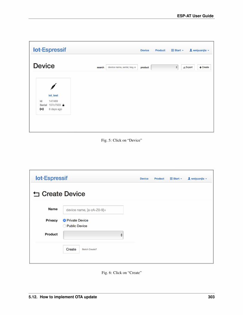
ESP-AT User Guide
Fig. 5: Click on “Device”
Fig. 6: Click on “Create”
5.12. How to implement OTA update 303

ESP-AT User Guide
Fig. 7: A key has been generated
Fig. 8: Configuring the AT OTA token key - Step 1
304 Chapter 5. How to compile and develop your own AT project

ESP-AT User Guide
Fig. 9: Configuring the AT OTA token key - Step 2 and 3
5.12. How to implement OTA update 305

ESP-AT User Guide
Fig. 10: Enter version and corename
306 Chapter 5. How to compile and develop your own AT project

ESP-AT User Guide
7. Click on the ota.bin to save it as the current version.
Fig. 11: Save the current version of ota.bin
8. Run the command AT+CIUPDATE on the ESP device. If the network is connected, OTA update will be done.
5.13 How to update the esp-idf version
The esp-at project supports two platforms by default, ESP32 UART AT and ESP8266 UART AT. Each of the platformhas a set of configurations, you can configure its directory by setting the ESP_AT_MODULE_CONFIG_DIR in theMakefile. The default directory of ESP32 UART AT is module_config/module_esp32_default, andthe ESP8266 UART AT is module_config/module_esp8266_default, version information is in the fileIDF_VERSION. For example, the version info of module_esp32_default is:
branch:mastercommit:7fa98593bc179ea50a1bc8244d5b94bac59c9a10repository:https://github.com/espressif/esp-idf.git
branch: branch of the idfcommit: commit id of the idfrepository: url of the idf
To update the idf/SDK, you need to change the branch, commit and repository to be the ones that you want to updateto.
It is suggested that you can delete the original idf/SDK after updating the file IDF_VERSION. In this case, theesp-at will clone the new idf/SDK according to the file IDF_VERSION firstly in next compilation.
Notice: If you changed the repository url in the file IDF_VERSION, then you have to delete the original idf/SDKin the project. Otherwise, the update may fail.
5.13. How to update the esp-idf version 307

ESP-AT User Guide
5.14 How to understand the differences of each type of module
Since the esp-at project supports different module, for example, WROOM-32, WROVER-32, ESP8266_1MB, evensupports WROOM-5V2L, when compiling the esp-at project, users can set different configurations to generate ATfirmware for different ESP modules. The detailed information are in the esp-at/module_config directory.Inorder to facilitate customers to understand the differences between different modules of the same platform, they willbe summarized in the following list.
5.14.1 1. ESP32 Platform
1. Command differences supported
2. Hardware differences
For factory param, see: components/customized_partitions/raw_data/factory_param/factory_param_data.csv
3. AT pin
See: https://docs.espressif.com/projects/esp-at/en/latest/AT_Binary_Lists/index.html
4. Firmware supported modules
5.14.2 2. ESP8266 Platform
1. Command differences supported
2. Hardware differences
For factory param, see: components/customized_partitions/raw_data/factory_param/factory_param_data.csv
3. AT pin
See: https://docs.espressif.com/projects/esp-at/en/latest/AT_Binary_Lists/index.html
4. Firmware supported modules
5.14.3 3. ESP32S2 Platform
1. Command differences supported
2. Hardware differences
For factory param, see: components/customized_partitions/raw_data/factory_param/factory_param_data.csv
308 Chapter 5. How to compile and develop your own AT project

ESP-AT User Guide
3. AT pin
See: https://docs.espressif.com/projects/esp-at/en/latest/AT_Binary_Lists/index.html
4. Firmware supported modules
5.14.4 4. ESP32-C3 Platform
1. Command differences supported
2. Hardware differences
For factory param, see: components/customized_partitions/raw_data/factory_param/factory_param_data.csv
3. AT pin
See: https://docs.espressif.com/projects/esp-at/en/latest/AT_Binary_Lists/index.html
4. Firmware supported modules
5.15 AT API Reference
5.15.1 Header File
• at/include/esp_at_core.h
5.15.2 Functions
void esp_at_module_init(uint32_t netconn_max, const uint8_t *custom_version)This function should be called only once, before any other AT functions are called.
Parameters
• netconn_max: the maximum number of the link in the at module
• custom_version: version information by custom
esp_at_para_parse_result_type esp_at_get_para_as_digit(int32_t para_index, int32_t *value)Parse digit parameter from command string.
Return
• ESP_AT_PARA_PARSE_RESULT_OK : succeed
• ESP_AT_PARA_PARSE_RESULT_FAIL : fail
• ESP_AT_PARA_PARSE_RESULT_OMITTED : this parameter is OMITTED
Parameters
• para_index: the index of parameter
5.15. AT API Reference 309

ESP-AT User Guide
• value: the value parsed
esp_at_para_parse_result_type esp_at_get_para_as_str(int32_t para_index, uint8_t **result)Parse string parameter from command string.
Return
• ESP_AT_PARA_PARSE_RESULT_OK : succeed
• ESP_AT_PARA_PARSE_RESULT_FAIL : fail
• ESP_AT_PARA_PARSE_RESULT_OMITTED : this parameter is OMITTED
Parameters
• para_index: the index of parameter
• result: the pointer that point to the result.
void esp_at_port_recv_data_notify_from_isr(int32_t len)Calling the esp_at_port_recv_data_notify_from_isr to notify at module that at port received data. When receivedthis notice,at task will get data by calling get_data_length and read_data in esp_at_device_ops. This functionMUST be used in isr.
Parameters
• len: data length
bool esp_at_port_recv_data_notify(int32_t len, uint32_t msec)Calling the esp_at_port_recv_data_notify to notify at module that at port received data. When received thisnotice,at task will get data by calling get_data_length and read_data in esp_at_device_ops. This function MUSTNOT be used in isr.
Return
• true : succeed
• false : fail
Parameters
• len: data length
• msec: timeout time,The unit is millisecond. It waits forever,if msec is portMAX_DELAY.
void esp_at_transmit_terminal_from_isr(void)terminal transparent transmit mode,This function MUST be used in isr.
void esp_at_transmit_terminal(void)terminal transparent transmit mode,This function MUST NOT be used in isr.
bool esp_at_custom_cmd_array_regist(const esp_at_cmd_struct *custom_at_cmd_array,uint32_t cmd_num)
regist at command set, which defined by custom,
Parameters
• custom_at_cmd_array: at command set
• cmd_num: command number
310 Chapter 5. How to compile and develop your own AT project

ESP-AT User Guide
void esp_at_device_ops_regist(esp_at_device_ops_struct *ops)regist device operate functions set,
Parameters
• ops: device operate functions set
bool esp_at_custom_net_ops_regist(int32_t link_id, esp_at_custom_net_ops_struct *ops)
bool esp_at_custom_ble_ops_regist(int32_t conn_index, esp_at_custom_ble_ops_struct *ops)
void esp_at_custom_ops_regist(esp_at_custom_ops_struct *ops)regist custom operate functions set interacting with AT,
Parameters
• ops: custom operate functions set
uint32_t esp_at_get_version(void)get at module version number,
Return at version bit31~bit24: at main version bit23~bit16: at sub version bit15~bit8 : at test version bit7~bit0: at custom version
void esp_at_response_result(uint8_t result_code)response AT process result,
Parameters
• result_code: see esp_at_result_code_string_index
int32_t esp_at_port_write_data(uint8_t *data, int32_t len)write data into device,
Return
• >= 0 : the real length of the data written
• others : fail.
Parameters
• data: data buffer to be written
• len: data length
int32_t esp_at_port_active_write_data(uint8_t *data, int32_t len)call pre_active_write_data_callback() first and then write data into device,
Return
• >= 0 : the real length of the data written
• others : fail.
Parameters
• data: data buffer to be written
• len: data length
5.15. AT API Reference 311

ESP-AT User Guide
int32_t esp_at_port_read_data(uint8_t *data, int32_t len)read data from device,
Return
• >= 0 : the real length of the data read from device
• others : fail
Parameters
• data: data buffer
• len: data length
bool esp_at_port_wait_write_complete(int32_t timeout_msec)wait for transmitting data completely to peer device,
Return
• true : succeed,transmit data completely
• false : fail
Parameters
• timeout_msec: timeout time,The unit is millisecond.
int32_t esp_at_port_get_data_length(void)get the length of the data received,
Return
• >= 0 : the length of the data received
• others : fail
bool esp_at_base_cmd_regist(void)regist at base command set. If not,you can not use AT base command
bool esp_at_user_cmd_regist(void)regist at user command set. If not,you can not use AT user command
bool esp_at_wifi_cmd_regist(void)regist at wifi command set. If not,you can not use AT wifi command
bool esp_at_net_cmd_regist(void)regist at net command set. If not,you can not use AT net command
bool esp_at_mdns_cmd_regist(void)regist at mdns command set. If not,you can not use AT mdns command
bool esp_at_driver_cmd_regist(void)regist at driver command set. If not,you can not use AT driver command
bool esp_at_wps_cmd_regist(void)regist at wps command set. If not,you can not use AT wps command
bool esp_at_smartconfig_cmd_regist(void)regist at smartconfig command set. If not,you can not use AT smartconfig command
bool esp_at_ping_cmd_regist(void)regist at ping command set. If not,you can not use AT ping command
312 Chapter 5. How to compile and develop your own AT project

ESP-AT User Guide
bool esp_at_http_cmd_regist(void)regist at http command set. If not,you can not use AT http command
bool esp_at_mqtt_cmd_regist(void)regist at mqtt command set. If not,you can not use AT mqtt command
bool esp_at_ble_cmd_regist(void)regist at ble command set. If not,you can not use AT ble command
bool esp_at_ble_hid_cmd_regist(void)regist at ble hid command set. If not,you can not use AT ble hid command
bool esp_at_blufi_cmd_regist(void)regist at blufi command set. If not,you can not use AT blufi command
bool esp_at_bt_cmd_regist(void)regist at bt command set. If not,you can not use AT bt command
bool esp_at_bt_spp_cmd_regist(void)regist at bt spp command set. If not,you can not use AT bt spp command
bool esp_at_bt_a2dp_cmd_regist(void)regist at bt a2dp command set. If not,you can not use AT bt a2dp command
bool esp_at_fs_cmd_regist(void)regist at fs command set. If not,you can not use AT fs command
bool esp_at_eap_cmd_regist(void)regist at WPA2 Enterprise AP command set. If not,you can not use AT EAP command
bool esp_at_eth_cmd_regist(void)regist at ethernet command set. If not,you can not use AT ethernet command
bool esp_at_custom_cmd_line_terminator_set(uint8_t *terminator)Set AT command terminator, by default, the terminator is “\r\n” You can change it by calling this function, butit just supports one character now.
Return
• true : succeed,transmit data completely
• false : fail
Parameters
• terminator: the line terminator
uint8_t *esp_at_custom_cmd_line_terminator_get(void)Get AT command line terminator,by default, the return string is “\r\n”.
Return the command line terminator
const esp_partition_t *esp_at_custom_partition_find(esp_partition_type_t type,esp_partition_subtype_t subtype, constchar *label)
Find the partition which is defined in at_customize.csv.
Return pointer to esp_partition_t structure, or NULL if no partition is found. This pointer is valid for thelifetime of the application
Parameters
• type: the type of the partition
5.15. AT API Reference 313

ESP-AT User Guide
• subtype: the subtype of the partition
• label: Partition label
void esp_at_port_enter_specific(esp_at_port_specific_callback_t callback)Set AT core as specific status, it will call callback if receiving data. for example:
static void wait_data_callback (void){
xSemaphoreGive(sync_sema);}
void process_task(void* para){
vSemaphoreCreateBinary(sync_sema);xSemaphoreTake(sync_sema,portMAX_DELAY);esp_at_port_write_data((uint8_t *)">",strlen(">"));esp_at_port_enter_specific(wait_data_callback);while(xSemaphoreTake(sync_sema,portMAX_DELAY)) {
len = esp_at_port_read_data(data, data_len);// TODO:
}}
Parameters
• callback: which will be called when received data from AT port
void esp_at_port_exit_specific(void)Exit AT core as specific status.
const uint8_t *esp_at_get_current_cmd_name(void)Get current AT command name.
esp_err_t esp_at_wifi_event_handler(void *ctx, system_event_t *event)Wi-Fi event handler callback, which used in AT core.
Return
• ESP_OK: succeed
• others: fail
Parameters
• ctx: reserved for user
• event: event type defined in this file
void at_handle_result_code(esp_at_result_code_string_index code, void *pbuf)
314 Chapter 5. How to compile and develop your own AT project

ESP-AT User Guide
5.15.3 Structures
struct esp_at_cmd_structesp_at_cmd_struct used for define at command
Public Members
char *at_cmdNameat command name
uint8_t (*at_testCmd)(uint8_t *cmd_name)Test Command function pointer
uint8_t (*at_queryCmd)(uint8_t *cmd_name)Query Command function pointer
uint8_t (*at_setupCmd)(uint8_t para_num)Setup Command function pointer
uint8_t (*at_exeCmd)(uint8_t *cmd_name)Execute Command function pointer
struct esp_at_device_ops_structesp_at_device_ops_struct device operate functions struct for AT
Public Members
int32_t (*read_data)(uint8_t *data, int32_t len)read data from device
int32_t (*write_data)(uint8_t *data, int32_t len)write data into device
int32_t (*get_data_length)(void)get the length of data received
bool (*wait_write_complete)(int32_t timeout_msec)wait write finish
struct esp_at_custom_net_ops_structesp_at_custom_net_ops_struct custom socket callback for AT
Public Members
int32_t (*recv_data)(uint8_t *data, int32_t len)callback when socket received data
void (*connect_cb)(void)callback when socket connection is built
void (*disconnect_cb)(void)callback when socket connection is disconnected
struct esp_at_custom_ble_ops_structesp_at_custom_ble_ops_struct custom ble callback for AT
5.15. AT API Reference 315

ESP-AT User Guide
Public Members
int32_t (*recv_data)(uint8_t *data, int32_t len)callback when ble received data
void (*connect_cb)(void)callback when ble connection is built
void (*disconnect_cb)(void)callback when ble connection is disconnected
struct esp_at_custom_ops_structesp_at_ops_struct some custom function interacting with AT
Public Members
void (*status_callback)(esp_at_status_type status)callback when AT status changes
void (*pre_sleep_callback)(at_sleep_mode_t mode)callback before enter modem sleep and light sleep
void (*pre_deepsleep_callback)(void)callback before enter deep sleep
void (*pre_restart_callback)(void)callback before restart
void (*pre_active_write_data_callback)(at_write_data_fn_t)callback before write data
5.15.4 Macros
at_min(x, y)
at_max(x, y)
ESP_AT_ERROR_NO(subcategory, extension)
ESP_AT_CMD_ERROR_OKNo Error
ESP_AT_CMD_ERROR_NON_FINISHterminator character not found (“\r\n” expected)
ESP_AT_CMD_ERROR_NOT_FOUND_ATStarting “AT” not found (or at, At or aT entered)
ESP_AT_CMD_ERROR_PARA_LENGTH(which_para)parameter length mismatch
ESP_AT_CMD_ERROR_PARA_TYPE(which_para)parameter type mismatch
ESP_AT_CMD_ERROR_PARA_NUM(need, given)parameter number mismatch
ESP_AT_CMD_ERROR_PARA_INVALID(which_para)the parameter is invalid
316 Chapter 5. How to compile and develop your own AT project

ESP-AT User Guide
ESP_AT_CMD_ERROR_PARA_PARSE_FAIL(which_para)parse parameter fail
ESP_AT_CMD_ERROR_CMD_UNSUPPORTthe command is not supported
ESP_AT_CMD_ERROR_CMD_EXEC_FAIL(result)the command execution failed
ESP_AT_CMD_ERROR_CMD_PROCESSINGprocessing of previous command is in progress
ESP_AT_CMD_ERROR_CMD_OP_ERRORthe command operation type is error
5.15.5 Type Definitions
typedef int32_t (*at_write_data_fn_t)(uint8_t *data, int32_t len)
typedef void (*esp_at_port_specific_callback_t)(void)AT specific callback type.
5.15.6 Enumerations
enum esp_at_status_typeesp_at_status some custom function interacting with AT
Values:
ESP_AT_STATUS_NORMAL = 0x0Normal mode.Now mcu can send AT command
ESP_AT_STATUS_TRANSMITTransparent Transmition mode
enum at_sleep_mode_tValues:
AT_DISABLE_SLEEP = 0
AT_MIN_MODEM_SLEEP
AT_LIGHT_SLEEP
AT_MAX_MODEM_SLEEP
AT_SLEEP_MAX
enum esp_at_modulemodule number,Now just AT module
Values:
ESP_AT_MODULE_NUM = 0x01AT module
enum esp_at_error_codesubcategory number
Values:
5.15. AT API Reference 317

ESP-AT User Guide
ESP_AT_SUB_OK = 0x00OK
ESP_AT_SUB_COMMON_ERROR = 0x01reserved
ESP_AT_SUB_NO_TERMINATOR = 0x02terminator character not found (“\r\n” expected)
ESP_AT_SUB_NO_AT = 0x03Starting “AT” not found (or at, At or aT entered)
ESP_AT_SUB_PARA_LENGTH_MISMATCH = 0x04parameter length mismatch
ESP_AT_SUB_PARA_TYPE_MISMATCH = 0x05parameter type mismatch
ESP_AT_SUB_PARA_NUM_MISMATCH = 0x06parameter number mismatch
ESP_AT_SUB_PARA_INVALID = 0x07the parameter is invalid
ESP_AT_SUB_PARA_PARSE_FAIL = 0x08parse parameter fail
ESP_AT_SUB_UNSUPPORT_CMD = 0x09the command is not supported
ESP_AT_SUB_CMD_EXEC_FAIL = 0x0Athe command execution failed
ESP_AT_SUB_CMD_PROCESSING = 0x0Bprocessing of previous command is in progress
ESP_AT_SUB_CMD_OP_ERROR = 0x0Cthe command operation type is error
enum esp_at_para_parse_result_typethe result of AT parse
Values:
ESP_AT_PARA_PARSE_RESULT_FAIL = -1parse fail,Maybe the type of parameter is mismatched,or out of range
ESP_AT_PARA_PARSE_RESULT_OK = 0Successful
ESP_AT_PARA_PARSE_RESULT_OMITTEDthe parameter is OMITTED.
enum esp_at_result_code_string_indexthe result code of AT command processing
Values:
ESP_AT_RESULT_CODE_OK = 0x00“OK”
ESP_AT_RESULT_CODE_ERROR = 0x01“ERROR”
318 Chapter 5. How to compile and develop your own AT project

ESP-AT User Guide
ESP_AT_RESULT_CODE_FAIL = 0x02“ERROR”
ESP_AT_RESULT_CODE_SEND_OK = 0x03“SEND OK”
ESP_AT_RESULT_CODE_SEND_FAIL = 0x04“SEND FAIL”
ESP_AT_RESULT_CODE_IGNORE = 0x05response nothing, just change internal status
ESP_AT_RESULT_CODE_PROCESS_DONE = 0x06response nothing, just change internal status
ESP_AT_RESULT_CODE_OK_AND_INPUT_PROMPT = 0x07response nothing, just change internal status
ESP_AT_RESULT_CODE_MAX
5.15.7 Header File
• at/include/esp_at.h
5.15.8 Functions
const char *esp_at_get_current_module_name(void)get current module name
const char *esp_at_get_module_name_by_id(uint32_t id)get module name by index
uint32_t esp_at_get_module_id(void)get current module id
void esp_at_board_init(void)init peripheral and default parameters in factory_param.bin
bool esp_at_web_server_cmd_regist(void)regist WiFi config via web command. If not,you can not use web server to config wifi connect
5.15.9 Macros
ESP_AT_PORT_TX_WAIT_MS_MAX
ESP_AT_FACTORY_PARAMETER_SIZE
5.15. AT API Reference 319

ESP-AT User Guide
320 Chapter 5. How to compile and develop your own AT project

CHAPTER
SIX
CUSTOMIZED AT COMMANDS AND FIRMWARE
6.1 Tencent Cloud IoT AT Commands and Firmware
6.1.1 Tencent Cloud IoT AT Command Set
Please refer to [Chinese version]. The English version is not provided since the firmware and commands are applicableto the Chinese market (Tencent).
6.1.2 Tencent Cloud IoT AT Firmware
ESP8266
• ESP8266-WROOM-02 Series
– QCloud_AT_ESP8266_v2.2.0
– QCloud_AT_ESP8266_v2.1.1
321

ESP-AT User Guide
322 Chapter 6. Customized AT Commands and Firmware

CHAPTER
SEVEN
INDEX OF ABBREVIATIONS
A2DP Advanced Audio Distribution Profile
ADC Analog-to-Digital Converter
ALPN Application Layer Protocol Negotiation
AT port AT port is the general name of AT log port (that is used to output log) and AT command port (that is used tosend AT commands and receive responses). Please refer to Hardware Connection for default AT port pins andHow to Set AT Port Pins for how to customize them.
AT AT AT AT Hardware Connection AT How to Set AT Port Pins AT
Bluetooth LE Bluetooth Low Energy
BluFi Wi-Fi network configuration function via Bluetooth channel
BluFi Wi-Fi
DHCP Dynamic Host Configuration Protocol
DNS Domain Name System
DTIM Delivery Traffic Indication Map
GATTC Generic Attributes client
GATT
GATTS Generic Attributes server
GATT
HID Human Interface Device
I2C Inter-Integrated Circuit
ICMP Intemet Control Message Protocol
LWT Last Will and Testament
MAC Media Access Control
MAC
mDNS Multicast Domain Name System
DNS
MSB Most Significant Bit
MTU maximum transmission unit
NVS Non-Volatile Storage
323

ESP-AT User Guide
Normal Transmission Mode Default Transmission Mode
In normal transmission mode, users can send AT commands. For examples, users can send MCU data receivedby AT command port to the opposite end of transmission by AT+CIPSEND; and the data received from theopposite end of transmission will also be returned to MCU through AT command port with additional prompt:+IPD.
During a normal transmission, if the connection breaks, ESP devices will give a prompt and will not attempt toreconnect.
More details are in Transmission Mode Shift Diagram.
AT AT+CIPSEND AT MCU AT MCU +IPD
ESP
Transmission Mode Shift Diagram
Passthrough Mode Also called as “Passthrough Sending & Receiving Mode”.
In passthrough mode, users cannot send AT commands except special +++ command. All MCU data receivedby AT command port will be sent to the opposite end of transmission without any modification; and the datareceived from the opposite end of transmission will also be returned to MCU through AT command port withoutany modification.
During the Wi-Fi passthrough transmission, if the connection breaks, ESP devices will keep trying to reconnectuntil +++ is input to exit the passthrough transmission.
More details are in Transmission Mode Shift Diagram.
“”
AT +++ AT MCU AT MCU
Wi-Fi ESP +++
Transmission Mode Shift Diagram
Transmission Mode Shift Diagram
Fig. 1: Transmission Mode Shift Diagram
More details are in the following introduction.
• Normal Transmission Mode ()
• Passthrough Receiving Mode ()
• Passthrough Mode ()
• AT+CIPMODE
• AT+CIPSEND
• +++
324 Chapter 7. Index of Abbreviations

ESP-AT User Guide
• AT+SAVETRANSLINK
Passthrough Receiving Mode The temporary mode between Normal Transmission Mode and Passthrough Mode.
In passthrough receiving mode, AT cannot send any data to the opposite end of transmission; but the datareceived from the opposite end of transmission can be returned to MCU through AT command port without anymodification. More details are in Transmission Mode Shift Diagram.
AT AT AT MCU Transmission Mode Shift Diagram
PBC Push Button Configuration
PCI Authentication Payment Card Industry Authentication. In ESP-AT project, it refers to all Wi-Fi authenticationmodes except OPEN and WEP.
PCI ESP-AT OPEN WEP Wi-Fi
PLCP Physical Layer Convergence Procedure
PLCP
PMF protected management frame
PSK Pre-shared Key
PWM Pulse-Width Modulation
QoS Quality of Service
RTC Real Time Controller. A group of circuits in SoC that keeps working in any chip mode and at any time.
SoC
SMP Security Manager Protocol
SNI Server Name Indication
SNTP Simple Network Time Protocol
SPI Serial Peripheral Interface
SPP Serial Port Profile
SPP
SSL Secure Sockets Layer
SSL
TLS Transport Layer Security
TLS
URC Unsolicited Result Code
MCU
UTC Coordinated Universal Time
UUID universally unique identifier
WEP Wired-Equivalent Privacy
WEP
WPA Wi-Fi Protected Access
Wi-Fi
325

ESP-AT User Guide
WPA2 Wi-Fi Protected Access II
Wi-Fi II
WPS Wi-Fi Protected Setup
Wi-Fi
• genindex
326 Chapter 7. Index of Abbreviations

INDEX
AA2DP, 323ADC, 323ALPN, 323AT port, 323AT_DISABLE_SLEEP (C++ enumerator), 317at_handle_result_code (C++ function), 314AT_LIGHT_SLEEP (C++ enumerator), 317at_max (C macro), 316AT_MAX_MODEM_SLEEP (C++ enumerator), 317at_min (C macro), 316AT_MIN_MODEM_SLEEP (C++ enumerator), 317AT_SLEEP_MAX (C++ enumerator), 317at_sleep_mode_t (C++ enum), 317at_write_data_fn_t (C++ type), 317
BBluetooth LE, 323BluFi, 323
DDHCP, 323DNS, 323DTIM, 323
Eesp_at_base_cmd_regist (C++ function), 312esp_at_ble_cmd_regist (C++ function), 313esp_at_ble_hid_cmd_regist (C++ function),
313esp_at_blufi_cmd_regist (C++ function), 313esp_at_board_init (C++ function), 319esp_at_bt_a2dp_cmd_regist (C++ function),
313esp_at_bt_cmd_regist (C++ function), 313esp_at_bt_spp_cmd_regist (C++ function), 313ESP_AT_CMD_ERROR_CMD_EXEC_FAIL (C macro),
317ESP_AT_CMD_ERROR_CMD_OP_ERROR (C macro),
317ESP_AT_CMD_ERROR_CMD_PROCESSING (C
macro), 317
ESP_AT_CMD_ERROR_CMD_UNSUPPORT (C macro),317
ESP_AT_CMD_ERROR_NON_FINISH (C macro), 316ESP_AT_CMD_ERROR_NOT_FOUND_AT (C macro),
316ESP_AT_CMD_ERROR_OK (C macro), 316ESP_AT_CMD_ERROR_PARA_INVALID (C macro),
316ESP_AT_CMD_ERROR_PARA_LENGTH (C macro), 316ESP_AT_CMD_ERROR_PARA_NUM (C macro), 316ESP_AT_CMD_ERROR_PARA_PARSE_FAIL (C
macro), 316ESP_AT_CMD_ERROR_PARA_TYPE (C macro), 316esp_at_cmd_struct (C++ class), 315esp_at_cmd_struct::at_cmdName (C++ mem-
ber), 315esp_at_cmd_struct::at_exeCmd (C++ mem-
ber), 315esp_at_cmd_struct::at_queryCmd (C++ mem-
ber), 315esp_at_cmd_struct::at_setupCmd (C++ mem-
ber), 315esp_at_cmd_struct::at_testCmd (C++ mem-
ber), 315esp_at_custom_ble_ops_regist (C++ func-
tion), 311esp_at_custom_ble_ops_struct (C++ class),
315esp_at_custom_ble_ops_struct::connect_cb
(C++ member), 316esp_at_custom_ble_ops_struct::disconnect_cb
(C++ member), 316esp_at_custom_ble_ops_struct::recv_data
(C++ member), 316esp_at_custom_cmd_array_regist (C++ func-
tion), 310esp_at_custom_cmd_line_terminator_get
(C++ function), 313esp_at_custom_cmd_line_terminator_set
(C++ function), 313esp_at_custom_net_ops_regist (C++ func-
tion), 311
327

ESP-AT User Guide
esp_at_custom_net_ops_struct (C++ class),315
esp_at_custom_net_ops_struct::connect_cb(C++ member), 315
esp_at_custom_net_ops_struct::disconnect_cb(C++ member), 315
esp_at_custom_net_ops_struct::recv_data(C++ member), 315
esp_at_custom_ops_regist (C++ function), 311esp_at_custom_ops_struct (C++ class), 316esp_at_custom_ops_struct::pre_active_write_data_callback
(C++ member), 316esp_at_custom_ops_struct::pre_deepsleep_callback
(C++ member), 316esp_at_custom_ops_struct::pre_restart_callback
(C++ member), 316esp_at_custom_ops_struct::pre_sleep_callback
(C++ member), 316esp_at_custom_ops_struct::status_callback
(C++ member), 316esp_at_custom_partition_find (C++ func-
tion), 313esp_at_device_ops_regist (C++ function), 310esp_at_device_ops_struct (C++ class), 315esp_at_device_ops_struct::get_data_length
(C++ member), 315esp_at_device_ops_struct::read_data
(C++ member), 315esp_at_device_ops_struct::wait_write_complete
(C++ member), 315esp_at_device_ops_struct::write_data
(C++ member), 315esp_at_driver_cmd_regist (C++ function), 312esp_at_eap_cmd_regist (C++ function), 313esp_at_error_code (C++ enum), 317ESP_AT_ERROR_NO (C macro), 316esp_at_eth_cmd_regist (C++ function), 313ESP_AT_FACTORY_PARAMETER_SIZE (C macro),
319esp_at_fs_cmd_regist (C++ function), 313esp_at_get_current_cmd_name (C++ function),
314esp_at_get_current_module_name (C++ func-
tion), 319esp_at_get_module_id (C++ function), 319esp_at_get_module_name_by_id (C++ func-
tion), 319esp_at_get_para_as_digit (C++ function), 309esp_at_get_para_as_str (C++ function), 310esp_at_get_version (C++ function), 311esp_at_http_cmd_regist (C++ function), 312esp_at_mdns_cmd_regist (C++ function), 312esp_at_module (C++ enum), 317esp_at_module_init (C++ function), 309
ESP_AT_MODULE_NUM (C++ enumerator), 317esp_at_mqtt_cmd_regist (C++ function), 313esp_at_net_cmd_regist (C++ function), 312ESP_AT_PARA_PARSE_RESULT_FAIL (C++ enu-
merator), 318ESP_AT_PARA_PARSE_RESULT_OK (C++ enumera-
tor), 318ESP_AT_PARA_PARSE_RESULT_OMITTED (C++
enumerator), 318esp_at_para_parse_result_type (C++ enum),
318esp_at_ping_cmd_regist (C++ function), 312esp_at_port_active_write_data (C++ func-
tion), 311esp_at_port_enter_specific (C++ function),
314esp_at_port_exit_specific (C++ function),
314esp_at_port_get_data_length (C++ function),
312esp_at_port_read_data (C++ function), 311esp_at_port_recv_data_notify (C++ func-
tion), 310esp_at_port_recv_data_notify_from_isr
(C++ function), 310esp_at_port_specific_callback_t (C++
type), 317ESP_AT_PORT_TX_WAIT_MS_MAX (C macro), 319esp_at_port_wait_write_complete (C++
function), 312esp_at_port_write_data (C++ function), 311esp_at_response_result (C++ function), 311ESP_AT_RESULT_CODE_ERROR (C++ enumerator),
318ESP_AT_RESULT_CODE_FAIL (C++ enumerator),
318ESP_AT_RESULT_CODE_IGNORE (C++ enumerator),
319ESP_AT_RESULT_CODE_MAX (C++ enumerator), 319ESP_AT_RESULT_CODE_OK (C++ enumerator), 318ESP_AT_RESULT_CODE_OK_AND_INPUT_PROMPT
(C++ enumerator), 319ESP_AT_RESULT_CODE_PROCESS_DONE (C++
enumerator), 319ESP_AT_RESULT_CODE_SEND_FAIL (C++ enumer-
ator), 319ESP_AT_RESULT_CODE_SEND_OK (C++ enumera-
tor), 319esp_at_result_code_string_index (C++
enum), 318esp_at_smartconfig_cmd_regist (C++ func-
tion), 312ESP_AT_STATUS_NORMAL (C++ enumerator), 317ESP_AT_STATUS_TRANSMIT (C++ enumerator), 317
328 Index

ESP-AT User Guide
esp_at_status_type (C++ enum), 317ESP_AT_SUB_CMD_EXEC_FAIL (C++ enumerator),
318ESP_AT_SUB_CMD_OP_ERROR (C++ enumerator),
318ESP_AT_SUB_CMD_PROCESSING (C++ enumerator),
318ESP_AT_SUB_COMMON_ERROR (C++ enumerator),
318ESP_AT_SUB_NO_AT (C++ enumerator), 318ESP_AT_SUB_NO_TERMINATOR (C++ enumerator),
318ESP_AT_SUB_OK (C++ enumerator), 317ESP_AT_SUB_PARA_INVALID (C++ enumerator),
318ESP_AT_SUB_PARA_LENGTH_MISMATCH (C++
enumerator), 318ESP_AT_SUB_PARA_NUM_MISMATCH (C++ enumer-
ator), 318ESP_AT_SUB_PARA_PARSE_FAIL (C++ enumera-
tor), 318ESP_AT_SUB_PARA_TYPE_MISMATCH (C++ enu-
merator), 318ESP_AT_SUB_UNSUPPORT_CMD (C++ enumerator),
318esp_at_transmit_terminal (C++ function), 310esp_at_transmit_terminal_from_isr (C++
function), 310esp_at_user_cmd_regist (C++ function), 312esp_at_web_server_cmd_regist (C++ func-
tion), 319esp_at_wifi_cmd_regist (C++ function), 312esp_at_wifi_event_handler (C++ function),
314esp_at_wps_cmd_regist (C++ function), 312
GGATTC, 323GATTS, 323
HHID, 323
II2C, 323ICMP, 323
LLWT, 323
MMAC, 323mDNS, 323MSB, 323
MTU, 323
NNormal Transmission Mode, 324NVS, 323
PPassthrough Mode, 324Passthrough Receiving Mode, 325PBC, 325PCI Authentication, 325PLCP, 325PMF, 325PSK, 325PWM, 325
QQoS, 325
RRTC, 325
SSMP, 325SNI, 325SNTP, 325SPI, 325SPP, 325SSL, 325
TTLS, 325Transmission Mode Shift Diagram, 324
UURC, 325UTC, 325UUID, 325
WWEP, 325WPA, 325WPA2, 326WPS, 326
Index 329