ES4000™ - Advance-us.com
179
ES4000™ 06/11 Revised 11/13 Form No. 56043152 Service Manual Advance Model 56344200 English
-
Upload
khangminh22 -
Category
Documents
-
view
1 -
download
0
Transcript of ES4000™ - Advance-us.com

ES4000™
06/11 Revised 11/13 Form No. 56043152
Service ManualAdvance Model 56344200
English

Contents iiService Manual – ES4000
Contents
General Information . . . . . . . . . . . . . . . . . . . . . . . . . . . . . . . . . . . . . 6General Machine Description 6Document Revision History 6Nameplate 7
Transporting the Machine 7Towing 8Other Manuals Available 8Cautions and Warnings Symbols 8General Safety Instructions 9
Functional Description for Battery Condition Displays 10Functional Description of Additional Status Displays 10
Know Your Machine 12Control Panel 13Component Descriptions 14
Functional Description of Control Switches 16Maintenance 18
Maintenance Schedule 18Vacuum Shoe Maintenance 19Spray Nozzle Maintenance 19Lubricating the Machine 19Cleaning the Vacuum Motor Filters 19Scrub Brush Maintenance 19
Specifications 23General 23Battery Compartment Dimensions 24Minimum Aisle Turn Around Radius (turning left) 24Minimum Door Pass-Thru Width 24
Chassis System . . . . . . . . . . . . . . . . . . . . . . . . . . . . . . . . . . . . . . . 25Functional Description—Main Components 25
Control System . . . . . . . . . . . . . . . . . . . . . . . . . . . . . . . . . . . . . . . 27Functional Description 27
Control System Circuit Descriptions 28Functional Description of Main Controller 30Component Locations 31Maintenance and Adjustments 34
Hidden Menus 34Program Option Settings 34Service Test Mode 39Extra Info on LCD 43
Troubleshooting 47Fault Codes 47
Removal and Installation 53Replace the Main Control Board 53
Specifications 55Shop Measurements – Main Controller 55

Contents iiiService Manual – ES4000
Electrical System . . . . . . . . . . . . . . . . . . . . . . . . . . . . . . . . . . . . . . 58Functional Description 58
Battery Specifications 62Battery Charger (on-board and portable) 62
Removal and Installation 62Install Batteries 63When Servicing Batteries: 63Battery Low Voltage Cutout Feature - Description 66Battery Condition Indicator - Description 66Battery LOCK Value 67
Maintenance and Adjustments 69Battery Maintenance 69Charging the Batteries 69
To Charge the Batteries 69Battery Testing 70Machine and Chassis Wiring 71Machine and Chassis Wiring 72
Specifications 73INPUT/OUTPUT TABLES 73Shop Measurements – Main Controller 78
Wiring (Ladder) Diagram 56344090 Rev C (1 of 2) 81Wiring (Ladder) Diagram 56344090 Rev C (2 of 2) 82
Wiring Harness Diagram 56344091 Rev C (1 of 2) 83Wiring Harness Diagram 56344091 Rev C (2 of 2) 84
Options and Accessories . . . . . . . . . . . . . . . . . . . . . . . . . . . . . . . . . . 85Options 85Accessories 87
Recovery System . . . . . . . . . . . . . . . . . . . . . . . . . . . . . . . . . . . . . . 90Functional Description 90
Recovery System—Vacuum General 90Recovery System Circuit Description 91Component Locations 92
Maintenance and Adjustments 94Recovery System Service Maintenance Checklist 94Vacuum Filter and Float Cage Maintenance 94
Troubleshooting 96Removal and Installation 97
Vacuum Motor(s) Removal 97Recovery Tank Removal 98Vacuum Shoes Removal 100Recovery System Wet and Dry Pickups—Accessory Port 102
Pickup Connectors 102Wet Connection 103Dry Connection 103Accessory Port—Using Attachments 105
Recovery Shoe Lift Actuator Removal and Adjustment 106Actuator Drive Screw Tube Adjustment 108
General Instructions for All Actuator Motors 108Lift Actuator Drive Screw Tube Adjustment 109
Specifications 110Special Tools 111
Actuator Power Cord Adaptor (part # 56407502) 111

Contents ivService Manual – ES4000
Solution System . . . . . . . . . . . . . . . . . . . . . . . . . . . . . . . . . . . . . . 112Functional Description 112
Solution System Circuit Description 113Component Locations 114Troubleshooting 121
Mechanical / Electrical / Plumbing 121Maintenance and Adjustments 121
Purge Chemical Pump Weekly: 122To Reset the Detergent Counter 122Detergent Ratio 122Nozzle Maintenance 125Chemical Pump Removal 126Solution Solenoid Valve Removal 127Solenoid Valve Disassembly and Cleaning 128
Specifications 129
Scrub System . . . . . . . . . . . . . . . . . . . . . . . . . . . . . . . . . . . . . . . . 130Functional Description 130
Scrub System Circuit Description 131Component Locations 132Maintenance and Adjustments 133
Scrub System Brush Maintenance 133Troubleshooting 134Removal and Installation 135
Scrub Deck Removal 135Scrub Deck Actuator Removal 140Actuator Drive Nut Adjustment 144
General Instructions for All Actuator Motors 144Scrub Deck Lift Actuator Drive Nut Adjustment 145Brush Motor Removal 147Scrub Brush Belt Replacement 149Scrub Brush Removal and Installation 150
Specifications 151Scrub System 151
Special Tools 152Actuator Power Cord Adaptor—Part # 56407502 152
Steering System . . . . . . . . . . . . . . . . . . . . . . . . . . . . . . . . . . . . . . . 153Functional Description 153Maintenance and Adjustments 154Removal and Installation 155
Steering Column shroud removal 155
Wheel System, Non-Traction . . . . . . . . . . . . . . . . . . . . . . . . . . . . . . . 157Functional Description 157Component Locations 157Removal and Installation 158
Replacing the Rear Wheels 158

Contents vService Manual – ES4000
Wheel System, Traction . . . . . . . . . . . . . . . . . . . . . . . . . . . . . . . . . . 159Functional Description 159
Wheel System, Traction Circuit Description 160Component Locations 164Maintenance and Adjustments 165
Curtis Speed Controller Installation Checkout Procedure 165Troubleshooting 166
General Troubleshooting 166Speed Controller Diagnostics 168Speed Controller Status Light /Display Functions 168Wheel Drive Circuit Error Codes / Speed controller Error Flash Codes 169
Removal and Installation 171Drive Pedal Replacement 171Potentiometer Testing 172Testing the Potentiometer 172Replacing the Drive Wheel Assembly 173Replacing the Drive Tire 176Inspecting/Replacing the Drive Wheel Assembly Carbon Brushes 177
Specifications 179Special Tools 179

6Service Manual – ES4000
General Information
General Machine DescriptionThe ES4000 is a commercial rider extractor. The ES4000 has two solution flow options and on board chemical to allow for varying extraction needs. The ES4000 also has the ability to be a sweeper by vacuumizing the deck and recovering soil in the recovery tank.
Service Manual Purpose and Application
This Service Manual is a technical resource designed to aid service personnel in maintaining and repairing the ES4000 Sweeper/Extractor to ensure optimum performance and long service life. Please read it thoroughly before servicing your machine.
Note: Bold numbers and letters in parentheses and underlined indicate an item illustrated on pages 12-14 i.e. (B).
Document Revision History• 05/12
– Expanded Table of Contents
– Turned some pages to landscape orientation for easier viewing on a computer screen
– Added engineering identification information to wiring (ladder)diagrams and wiring harness diagrams.
General Information 7Service Manual – ES4000
• 11/13
– General Information: Added missing vibration specification values
– Electrical System: Corrected minimum voltage reset value following low voltage cut out from 24.6v to 25.08v
Nameplate
The Model Number and Serial Number of your machine are shown on the Nameplate on the machine. The nameplate is mounted on the steering column facing the driver. This information is needed when ordering repair parts for the machine. Use the space below to note the Model Number and Serial Number of your machine for future reference.
Nameplate
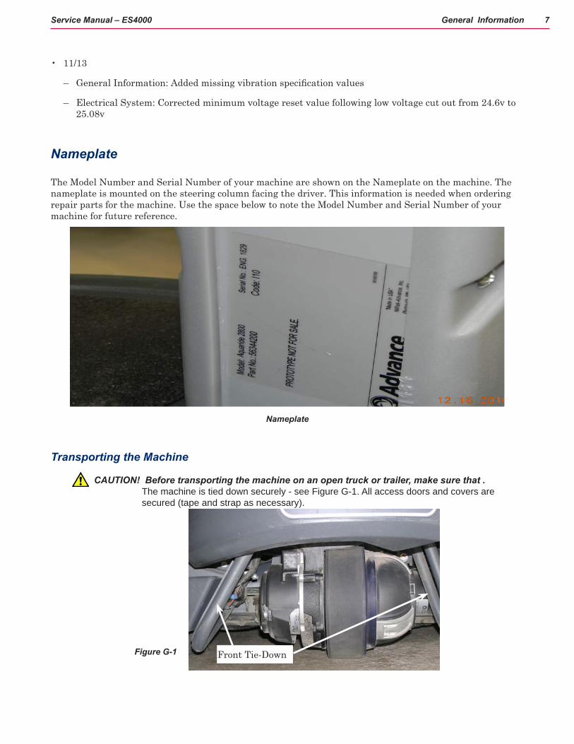
Transporting the Machine
CAUTION! Before transporting the machine on an open truck or trailer, make sure that . The machine is tied down securely - see Figure G-1. All access doors and covers are secured (tape and strap as necessary).
Figure G-1 Front Tie-Down

General Information 8Service Manual – ES4000
Towing
CAUTION! If the machine must be towed or pushed, make sure the Key Switch (Main Power) (J) is in the OFF position and do not move the machine faster than a normal walking pace (2-3 mph, 3-5 kph) and for short distances only. Disengage the electromagnetic brake by wedging an angle bar or flat head screwdriver between the brake lever and motor as shown in the photo below.
Other Manuals Available
The following manuals are available from the Advance Literature Service Department, for your Rider Extractor:
Parts List - Form Number 56042573
Operation Manual - Form Number 56091013
Cautions and Warnings Symbols
Advance uses the symbols below to signal potentially dangerous conditions. Always read this information carefully and take the necessary steps to protect personnel and property. (Triangle Symbol may or may not be used).
DANGER! Is used to warn of immediate hazards that will cause severe personal injury or death.
WARNING! Is used to call attention to a situation that could cause severe personal injury.
CAUTION! Is used to call attention to a situation that could cause minor personal injury or damage to the machine or other property.
Brake disengaged

General Information 9Service Manual – ES4000
General Safety Instructions
Specific Cautions and Warnings are included to warn you of potential danger of machine damage or bodily harm.
WARNING! This machine shall be used only by properly trained and authorized persons.
Other Warnings:
• While on ramps or inclines, avoid sudden stops when loaded. Avoid abrupt sharp turns. Use low speed down hills. Clean only while ascending (driving up) the ramp.
• Keep sparks, flame and smoking materials away from batteries. Explosive gases are vented during normal operation.
• Charging the batteries produces highly explosive hydrogen gas. Charge batteries only in well-ventilated areas, away from open flame. Do not smoke while charging the batteries.
• Remove all jewelry when working near electrical components.
• Turn the key switch off (O) and disconnect the batteries before servicing electrical components.
• Never work under a machine without safety blocks or stands to support the machine.
• Do not dispense flammable cleaning agents, operate the machine on or near these agents, or operate in areas where flammable liquids exist.
• Do not clean this machine with a pressure washer.
CAUTION! This machine is not approved for use on public paths or roads.
Other Cautions:
• This machine is not suitable for picking up hazardous dust.
• When operating this machine, ensure that third parties, particularly children, are not endangered.
• Before performing any service function carefully read all instructions pertaining to that function.
• Do not leave the machine unattended without first turning the key switch off (O), removing the key and applying the parking brake.
• Turn the key switch off (O) before changing the brushes, and before opening any access panels.
• Take precautions to prevent hair, jewelry, or loose clothing from becoming caught in moving parts.
• Use caution when moving this machine in below freezing temperature conditions. Any water in the solution or recovery tanks or in the hose lines could freeze, causing damage to valves and fittings. Flush with windshield washer fluid.
• The batteries must be removed from the machine before the machine is scrapped. The disposal of the batteries should be safely done in accordance with your local environmental regulations.

General Information 10Service Manual – ES4000
Functional Description for Battery Condition Displays
The battery condition indicator (K) consists of three lights; a green (K3), a yellow (K2) and a red (K1). A fully charged battery pack will measure above 24 volts with no load applied. The ES4000 is equipped with a low voltage cutout feature that will turn the scrub system off when the batteries are discharged to their minimum level. There are two different cutout levels to accommodate different battery types. See the Electrical System “Main Control Board Special Program Options” for details. The voltage levels for the various indications are as follows (the voltages shown represent the voltage under load):
Standard AlternateGreen 22.00+ 22.50+Green & Yellow 21.00-21.99 22.00-22.49Yellow 20.00-20.99 21.50-21.99Yellow & Red 19.50-19.99 21.00-21.49Red 19.00-19.49 21.50-21.99Flashing Red/Cutoff <19.00 <21.50
NOTE: When the low voltage cutout level has been reached (flashing red indicator) the batteries must be FULLY recharged (25.08V) to reset the battery condition indicator. The scrub system will not function until the indicator has been reset.
Functional Description of Additional Status Displays The character display on the control panel is used as a display for all functional codes. This display is also used to display the following information depending upon which mode the control is in:
• Error codes*
• Display of control system default parameters*
• Recovery tank FULL indicator*
• If any of the systems on the machine are on or if the throttle is not in neutral, the display will be blank.
* NOTE: Reference (in the Electrical System manual section) the Main Control Board Troubleshooting Guide and the Control Board Special Program Options sections. These sections will explain the machine error code descriptions and cleaning system controller default parameter changes.

General Information 11Service Manual – ES4000

General Information 12Service Manual – ES4000
38
Know Your Machine21. Steering Wheel Tilt Adjust Knob 22. Control Panel 23. Solution Tank Fill Cover 24. Recovery Tank Cover 25. Vacuum Motor Filter Housing 26. Strainer Basket 27. Recovery Tank Shutoff Float 28. Recovery Tank Drain Hose 29. Recovery Hose 30. Dry Mode Port 31. Accessory Port 32. Seat Prop Rod 33. Rear Brush End Cap
34. Machine Battery Connector 35. Solution Filter 36. Solution Shutoff Valve 37. Steering Wheel 38. Wet Mode Port

General Information 13Service Manual – ES4000
Control Panel
A. Key Switch / Main Power B. Solution ON/OFF Switch C. Detergent ON/OFF Switch D. Dry Mode Switch E. LCD Display E1. Hour Meter E2. Fault Codes E3. Solution Tank Level Indicator E4. Transport Mode Indicator E5. Detergent Indicator E6. Detergent Ratio Indicator E7. Battery Indicator E8. Prespray mode Indicator E9. Maintenance Mode Indicator E10. Restore Mode indicator
E11. Sweep Mode Indicator
E12. Recovery Tank Full Indicator
E13. Low Voltage Cutout Indicator
F. Wet Mode Switch G. Interim Mode Switch H. Restorative Mode Switch I. PreTreat Mode Switch J. Horn Switch K. Vacuum ON/OFF Switch
General Information 14Service Manual – ES4000
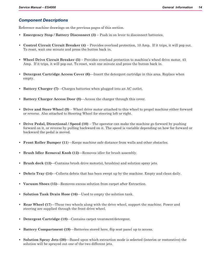
Component Descriptions
Reference machine drawings on the previous pages of this section.
• Emergency Stop / Battery Disconnect (3) – Push in on lever to disconnect batteries.
• Control Circuit Circuit Breaker (4) – Provides overload protection, 10 Amp. If it trips, it will pop out. To reset, wait one minute and press the button back in.
• Wheel Drive Circuit Breaker (5) – Provides overload protection to machine’s wheel drive motor, 45 Amp. If it trips, it will pop out. To reset, wait one minute and press the button back in.
• Detergent Cartridge Access Cover (6)—Insert the detergent cartridge in this area. Replace when empty.
• Battery Charger (7)—Charges batteries when plugged into an AC outlet.
• Battery Charger Access Door (8)—Access the charger through this cover.
• Drive and Steer Wheel (9) – Wheel drive motor attached to this wheel to propel machine either forward or reverse. Also attached to Steering Wheel for steering left or right.
• Drive Pedal, Directional / Speed (10) – The operator can make the machine go forward by pushing forward on it, or reverse by pulling backward on it. The speed is variable depending on how far forward or backward the pedal is moved.
• Front Roller Bumper (11)—Keeps machine safe distance from walls and other obstacles.
• Brush Idler Removal Knob (12)—Removes idler for brush assembly.
• Brush deck (13)—Contains brush drive motor(s), brush(es) and solution spray jets.
• Debris Tray (14)—Collects debris that has been swept up by the machine. Empty and clean daily.
• Vacuum Shoes (15)—Removes excess solution from carpet after Extraction.
• Solution Tank Drain Hose (16)—Used to empty the solution tank.
• Rear Wheel (17)—These two wheels along with the drive wheel, support the machine. Power and steering are supplied through the front drive wheel.
• Detergent Cartridge (18)—Contains carpet treatment/detergent.
• Battery Compartment (19)—Batteries stored here, flip seat panel up to access.
• Solution Spray Jets (20)—Based upon which extraction mode is selected (interim or restorative) the solution will be sprayed out one of the two different jets.

General Information 15Service Manual – ES4000
• Steering Wheel Tilt Adjust Knob (21)—Push down on this knob to adjust the Steering Wheel up or down.
• Control Panel (22)—Operator Controls found here, see “FUNCTIONAL DESCRIPTION OF CONTROL SWITCHES”.
• Solution Tank Fill Cover (23)—Open to fill the solution tank. Total capacity is 40 gallons (151 Liters).
• Recovery Tank Cover (24) – Open to access Recovery Tank for cleaning.
• Vacuum Motors’ Filter Housing (25) – Location of Vacuum Motors air intake filters.
• Strainer Basket (26)—Catches large to mid-size debris in Recovery Tank.
• Recovery Tank Shutoff Float (27)—Shuts off fluid flow from Recovery System when tank is full.
• Recovery Tank Drain Hose (28)—Used to empty the recovery tank.
• Recovery Hose (29)—Hose used to recover solution from carpet and deposit into Recovery Tank.
• Dry Mode Port (30)—Attach Recovery Hose (29) when using the Dry Sweep Mode.
• Accessory Port (31)—Solution attachment for additional accessories.
• Seat Prop Rod (32)—Props the seat upright for access to batteries and battery connector.
• Rear Brush End Cap (33)—Access to rear brush.
• Machine Battery Connector (34)—Batteries plug into this connector, disconnect to charge batteries.
• Solution Filter (35)—Filters solution prior to entering pump and being sprayed on the floor.
• Solution Shutoff Valve (36)—This valve should be fully open whenever operating ES4000. Only close this valve before removing the solution filter to prevent loss of solution.
• Steering Wheel (37)—Steers the machine just like an automobile. Directs the Wheel Drive System.
• Wet Mode Port (38)—Attach Recovery Hose (29) when using any wet mode.

General Information 16Service Manual – ES4000
Functional Description of Control SwitchesThe controls on the ES4000™ were designed with one touch operation in mind. For single pass extracting the user can simply depress one switch and all systems on the machine will be ready to go. For most single-pass extracting operations, the operator should only need to use one of the switches on the control panel. Two of these are the Interim Mode and Restorative Mode switches. In the Interim Mode the solution spray is directed at the scrub brush and the flow rate is reduced. The travel speed is limited to a medium speed. In the Restorative Mode the solution spray is directed at the carpet ahead of the scrub brush and the flow is at maximum. The travel speed is limited to a slow speed.
See drawing on previous pages in this section.
Dry Mode Switch (D)—Pressing this switch when the deck system is active will cause the following to occur:
• The brush(es) will turn off and the deck will raise to the up position
• The solution flow will be stopped
• The vacuum will shut off after a 10 second delay
• The travel speed limit will return to the transport speed setting
Interim Mode Switch (G)—If the scrub system is off, pressing this switch will cause the following to occur:
• The system will be enabled with the system configured for Interim Mode and the deck will be lowered
• The vacuum system will be enabled
• The solution system will be enabled for Interim Mode
• The travel speed will be limited to the Interim Mode speed setting
• As soon as the throttle is moved from the neutral position the scrub brush(es) will start turning and the vacuum will turn on. If the direction is forward the solution flow will start. If the direction is reverse the solution flow will be stopped. It is possible to program the control to automatically raise the scrub deck in reverse. Refer to the Electrical System “Main Control Board Special Program Options” for details.
Note: If the Restorative Mode is selected, pressing this switch will select the Interim Mode. If the Interim Mode is already selected, pressing this switch will have no effect.
General Information 17Service Manual – ES4000
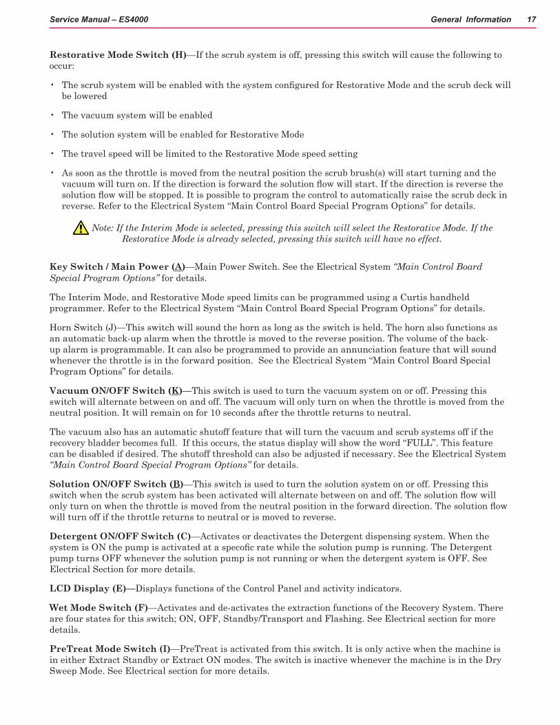
Restorative Mode Switch (H)—If the scrub system is off, pressing this switch will cause the following to occur:
• The scrub system will be enabled with the system configured for Restorative Mode and the scrub deck will be lowered
• The vacuum system will be enabled
• The solution system will be enabled for Restorative Mode
• The travel speed will be limited to the Restorative Mode speed setting
• As soon as the throttle is moved from the neutral position the scrub brush(s) will start turning and the vacuum will turn on. If the direction is forward the solution flow will start. If the direction is reverse the solution flow will be stopped. It is possible to program the control to automatically raise the scrub deck in reverse. Refer to the Electrical System “Main Control Board Special Program Options” for details.
Note: If the Interim Mode is selected, pressing this switch will select the Restorative Mode. If the Restorative Mode is already selected, pressing this switch will have no effect.
Key Switch / Main Power (A)—Main Power Switch. See the Electrical System “Main Control Board Special Program Options” for details.
The Interim Mode, and Restorative Mode speed limits can be programmed using a Curtis handheld programmer. Refer to the Electrical System “Main Control Board Special Program Options” for details.
Horn Switch (J)—This switch will sound the horn as long as the switch is held. The horn also functions as an automatic back-up alarm when the throttle is moved to the reverse position. The volume of the back-up alarm is programmable. It can also be programmed to provide an annunciation feature that will sound whenever the throttle is in the forward position. See the Electrical System “Main Control Board Special Program Options” for details.
Vacuum ON/OFF Switch (K)—This switch is used to turn the vacuum system on or off. Pressing this switch will alternate between on and off. The vacuum will only turn on when the throttle is moved from the neutral position. It will remain on for 10 seconds after the throttle returns to neutral.
The vacuum also has an automatic shutoff feature that will turn the vacuum and scrub systems off if the recovery bladder becomes full. If this occurs, the status display will show the word “FULL”. This feature can be disabled if desired. The shutoff threshold can also be adjusted if necessary. See the Electrical System “Main Control Board Special Program Options” for details.
Solution ON/OFF Switch (B)—This switch is used to turn the solution system on or off. Pressing this switch when the scrub system has been activated will alternate between on and off. The solution flow will only turn on when the throttle is moved from the neutral position in the forward direction. The solution flow will turn off if the throttle returns to neutral or is moved to reverse.
Detergent ON/OFF Switch (C)—Activates or deactivates the Detergent dispensing system. When the system is ON the pump is activated at a specofic rate while the solution pump is running. The Detergent pump turns OFF whenever the solution pump is not running or when the detergent system is OFF. See Electrical Section for more details.
LCD Display (E)—Displays functions of the Control Panel and activity indicators.
Wet Mode Switch (F)—Activates and de-activates the extraction functions of the Recovery System. There are four states for this switch; ON, OFF, Standby/Transport and Flashing. See Electrical section for more details.
PreTreat Mode Switch (I)—PreTreat is activated from this switch. It is only active when the machine is in either Extract Standby or Extract ON modes. The switch is inactive whenever the machine is in the Dry Sweep Mode. See Electrical section for more details.
General Information 18Service Manual – ES4000
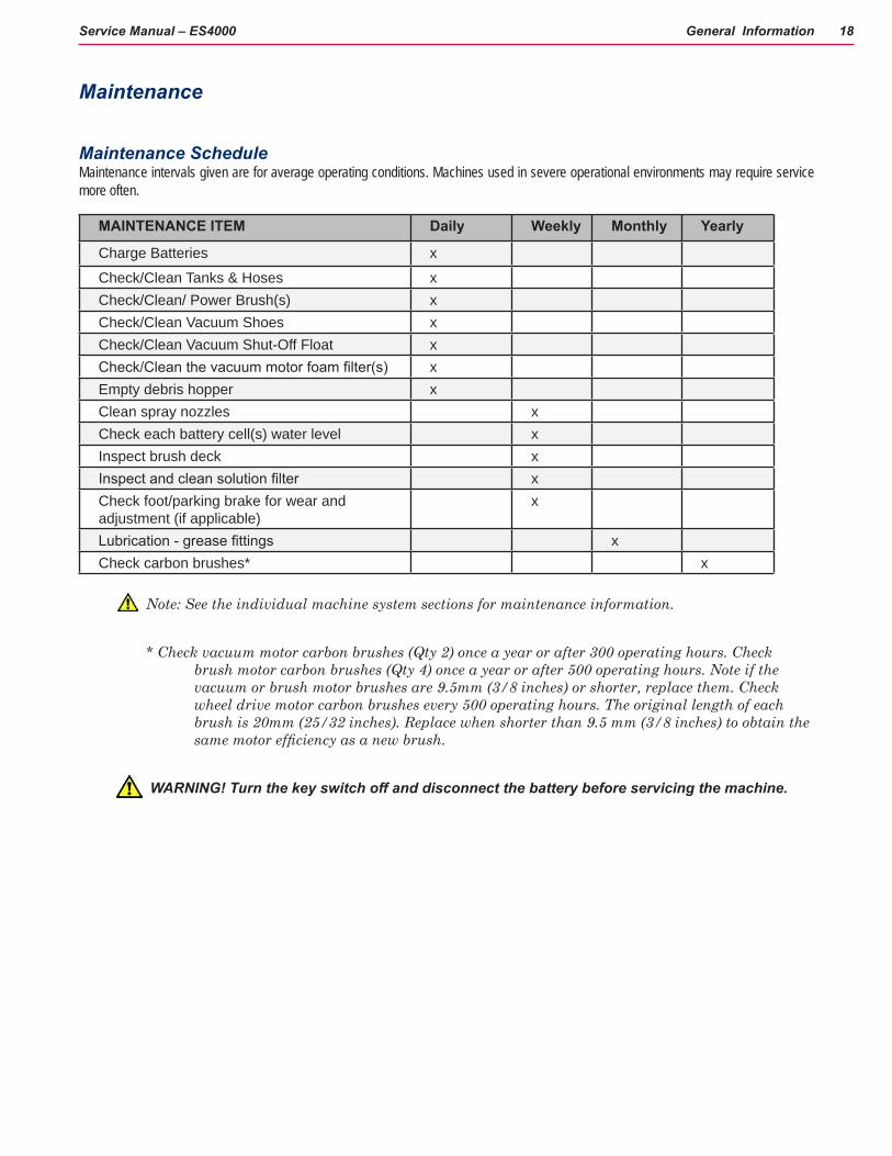
Maintenance
Maintenance Schedule Maintenance intervals given are for average operating conditions. Machines used in severe operational environments may require service more often.
MAINTENANCE ITEM Daily Weekly Monthly Yearly
Charge Batteries x
Check/Clean Tanks & Hoses xCheck/Clean/ Power Brush(s) xCheck/Clean Vacuum Shoes xCheck/Clean Vacuum Shut-Off Float xCheck/Clean the vacuum motor foam filter(s) xEmpty debris hopper xClean spray nozzles xCheck each battery cell(s) water level xInspect brush deck xInspect and clean solution filter xCheck foot/parking brake for wear and adjustment (if applicable)
x
Lubrication - grease fittings xCheck carbon brushes* x
Note: See the individual machine system sections for maintenance information.
* Check vacuum motor carbon brushes (Qty 2) once a year or after 300 operating hours. Check brush motor carbon brushes (Qty 4) once a year or after 500 operating hours. Note if the vacuum or brush motor brushes are 9.5mm (3/8 inches) or shorter, replace them. Check wheel drive motor carbon brushes every 500 operating hours. The original length of each brush is 20mm (25/32 inches). Replace when shorter than 9.5 mm (3/8 inches) to obtain the same motor efficiency as a new brush.
WARNING! Turn the key switch off and disconnect the battery before servicing the machine.

General Information 19Service Manual – ES4000
Vacuum Shoe Maintenance
Check the vacuum shoes daily, they can be removed to aid in cleaning, see “Removing the Vacuum Shoes” in the operators manual. Remove any built-up string, hair or carpet fibers. See the RECOVERY SYSTEM section of this manual for additional information.
Spray Nozzle Maintenance
Remove the spray nozzles once a week. Soak the nozzles overnight in a vinegar solution to remove chemical deposits. See SOLUTION SYSTEM section of this manual for additional information.
Lubricating the Machine
Once a month, pump a small amount of grease into each grease fitting on the machine until grease seeps out around the bearings.
Grease fitting locations are:
• Steering Wheel Shaft Universal joint
Once a month, apply light machine oil to lubricate the:
• Steering Chain
• General Pivot Points For the Brush Deck Linkage
• Cleaning Deck Adjustment Knobs (4)
Cleaning the Vacuum Motor Filters
Clean the vacuum motor filters daily with compressed air. For extremely dirty filters, wash with warm, soapy water and rinse thoroughly with clean water. Allow the filters to dry completely before re-installing in the machine. MAINTENANCE NOTE: Keep a second set of filters on hand to use while first set is drying.
Scrub Brush Maintenance
Check the brush(s) daily. Remove any built-up string, hair or carpet fibers.
General Information 20Service Manual – ES4000
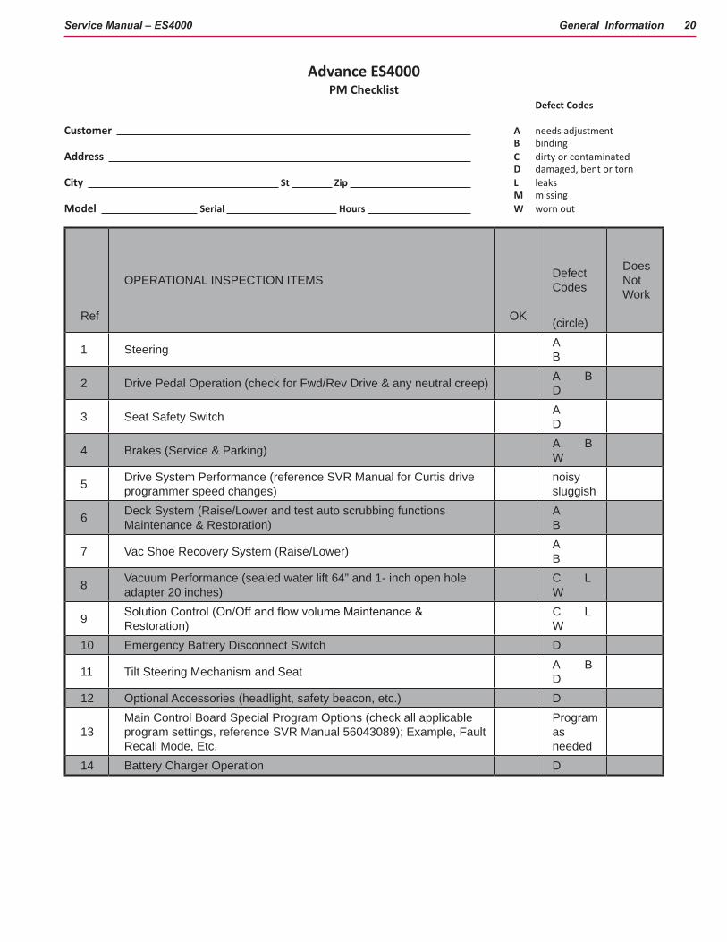
Advance ES4000PM Checklist
Defect Codes
Customer A needs adjustment B bindingAddress C dirty or contaminated D damaged, bent or tornCity St Zip L leaks M missingModel Serial Hours W worn out
Ref
OPERATIONAL INSPECTION ITEMS
OK
Defect Codes
(circle)
Does Not Work
1 Steering A B
2 Drive Pedal Operation (check for Fwd/Rev Drive & any neutral creep) A B D
3 Seat Safety Switch A D
4 Brakes (Service & Parking) A B W
5 Drive System Performance (reference SVR Manual for Curtis drive programmer speed changes)
noisy sluggish
6 Deck System (Raise/Lower and test auto scrubbing functions Maintenance & Restoration)
A B
7 Vac Shoe Recovery System (Raise/Lower) A B
8 Vacuum Performance (sealed water lift 64” and 1- inch open hole adapter 20 inches)
C L W
9 Solution Control (On/Off and flow volume Maintenance & Restoration)
C L W
10 Emergency Battery Disconnect Switch D
11 Tilt Steering Mechanism and Seat A B D
12 Optional Accessories (headlight, safety beacon, etc.) D
13Main Control Board Special Program Options (check all applicable program settings, reference SVR Manual 56043089); Example, Fault Recall Mode, Etc.
Program as needed
14 Battery Charger Operation D

General Information 21Service Manual – ES4000
Ref VISUAL INSPECTION ITEMS Comments OK Defect Codes
(circle)
Does Not Work
15 Scrub Brushes, check for wear and rotate CylindricalA B D W
16 Scrub Brush Motors Carbon Brushes B L W
17 Scrub Brush Drive Belt, wear and tension D W
18 Scrub Brush Deck Actuator MotorA B D W
19 Brush Deck Idler Assembly Bearings D M
20 Scrub Deck Rear Deflector A B W
21 Solution Solenoid Valves (Maintenance & Restoration)
C L
22 Solution Flow Control ValveA B D W
23 Solution Tank, Delivery Hoses & Filter Clean Filter Screen
C L
24 Vacuum Motor Carbon Brushes Wear Limit 3/8” W
25 Vacuum Motor Gaskets and Filters L W
26 Vacuum Float Ball & Cage Assembly Clean Float C M
27 Recovery Tank Cover Gasket C D L
28 Recovery Tank Drain Hose & Cap Flush C L
29 Vacuum Pick-Up Tool & Hoses Back flush C L

General Information 22Service Manual – ES4000
Ref VISUAL INSPECTION ITEMS (continued) Comments OK Defect Codes
(circle)
Does Not Work
30 Battery Pack Condition (clean & water) Load Test C W
31 Front Drive Wheel Motor Carbon Brushes C W
32 Front Drive Tire (rim fastener torque) Tread Wear W
33 Drive Pedal Linkage (neutral return) A B
34 Steering Chain (lubricate & tension) 1/4” Deflection A B C
35 Steering Column (knob & plunger spring) also Universal Joint Grease A
D36 Rear Wheels W37 Sweep Debris Tray C
NOTE: For additional information see operator manual form number 56091013.
Defect Codes
A needs adjustment C dirty or contaminated M missing
B binding D damaged, bent or torn W worn out
L leaks
WORK COMPLETED BY: ACKNOWLEDGED BY:
Service Technician Signature Date Customer Signature Date

General Information 23Service Manual – ES4000
Specifications
General
Machine Voltage 24 VDC
Dimensions (without Squeegee and Scrub Deck)
Length: 61 in (155 cm)
Width (body): 27.5 in (70 cm)
Height (Recovery tank:
Without Overhead Guard 51.7 in (131.3 cm)
With Overhead Guard NA in (NA cm)
Tank CapacitiesSolution Tank: 28.8 gal (109 L)
Recovery Tank: dynamic: 24.7 gal ( 93 L); static: 28.6 gal ( 108 L)
Gross Weight (standard machine w/o options; w/full solution tank, empty recovery tank and heaviest batteries installed) 1447 lbs ( 656 kg)
Net Weight (standard machine w/o options, batteries or removable brushes; w/empty solution and recovery tanks) 587 lbs ( 266 kg)
Static Wheel Loading Front: 587 lbs ( 266 kg) R Rear: 463 lbs (210 kg) L Rear: 401 lbs. (182 kg)
Static Wheel Pressure Front: 178.64 psi ( 12.56 kg/cm2) R Rear: 150.81 psi (10.6 kg/cm2) L Rear: 130.61 psi (9.18 kg/ cm2)
Ingress Protection Code IPX3
Sound Pressure Level (IEC 60704-1) (AXP) 65 dB(A) (3.0 dB(A) uncertainty) Sound and Vibration Report
Vibrations at the Hand Controls (ISO 5349-1) .22m/s2 (.044 m/s2 uncertainty)
Vibrations at the Seat (EN 1032) .02m/s2 (.004 m/s2 uncertainty)
GradeabilityTransport: 16 percent 9 degrees
Cleaning: 9 percent 5 degrees

General Information 24Service Manual – ES4000
Battery Compartment Dimensions
Maximum Battery Compartment
with box: 25” L X 15.5” W X 21” H
without the box: 26.25” X 16” X 21”
Minimum Aisle Turn Around Radius (turning left)28” deck 62.5 inches (1.59 m)
Minimum Door Pass-Thru Width28” deck (AXP & ST) 31.5 inches (.80 m) ENG 1825

25Service Manual – ES4000
Chassis System
Functional Description—Main ComponentsThe chassis system consists of :
• Main machine frame
• Deck Lift Actuator assembly (See Scrub System)
• Shoe Lift Actuator assembly (See Recovery Ssytem)
• Drive Wheel assembly and Rear Wheel assembly (See Wheel System, Traction and Non-Traction)
• Lower WET/DRY/ACCESSORY attachment (See Recovery System)
• Vacuum Shoes (See Recovery System)
Deck Lift Actuator settings
Shoe Lift Actuator Settings
Main Frame (Chassis)
Vacuum Shoes
Drive Wheel
Rear Wheel assembly

Chassis System 26Service Manual – ES4000
Lift actuator assemblies
Lift actuator assembly
Lower Attachment unit for Recovery System
Underside of Chassis System
Reference these sections of this manual for more details about the various parts of the Chassis System:
• Electrical Section—all other electrical functions for entire machine.
• Recovery System for lower attachment unit, Vacuum Shoe functions, and Shoe Lift Actuator
• Wheel System, Traction and Non-Traction for Drive Wheel assembly and Rear Wheel assembly functions and maintenance
• Scrub System for Deck Lift Actuator functions and maintenance

27Service Manual – ES4000
Control System
Functional DescriptionThe Control System consists of the Main Controller, Speed Controller and Operator’s Control Panel.
The Main Controller operates the floor cleaning functions of the machine based on inputs from the operator and other programmed inputs.
The Speed controller controls the speed of the machine as the operator presses the drive pedal.
The Operator’s Control Panel is where the driver controls all the machine cleaning functions.
Control Panel
Main Controller (located inside Control Panel
Speed Controller
Control System 28Service Manual – ES4000
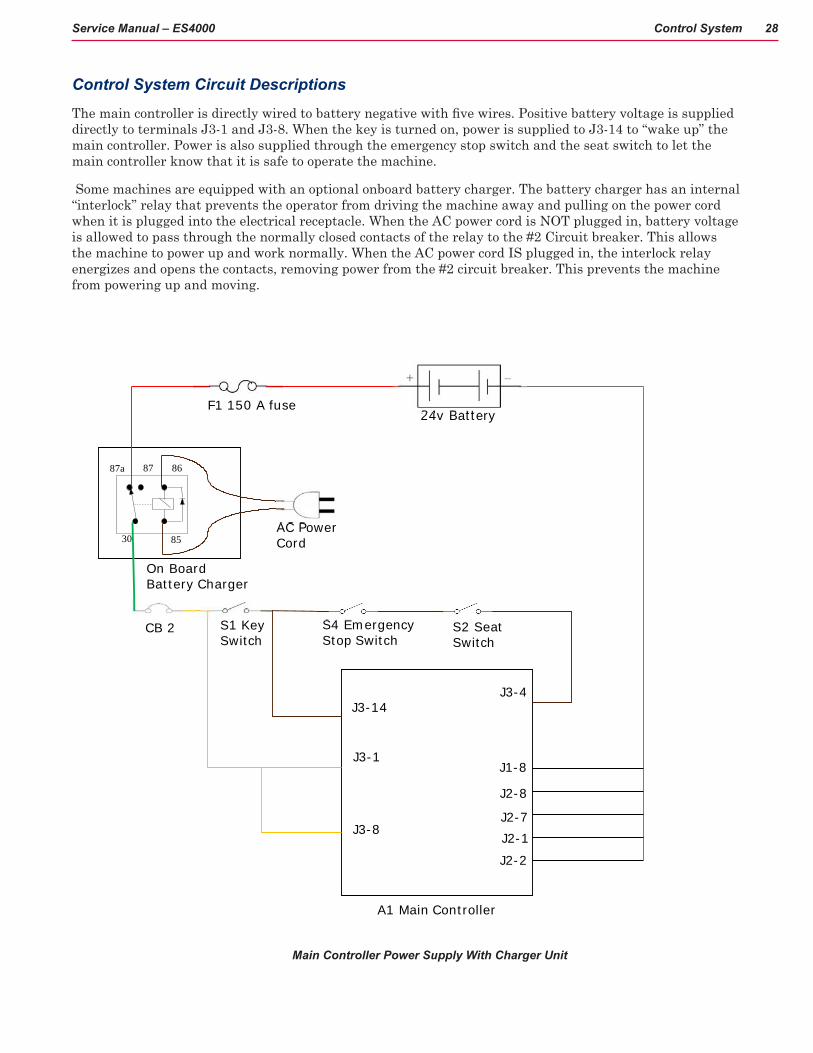
Control System Circuit Descriptions
The main controller is directly wired to battery negative with five wires. Positive battery voltage is supplied directly to terminals J3-1 and J3-8. When the key is turned on, power is supplied to J3-14 to “wake up” the main controller. Power is also supplied through the emergency stop switch and the seat switch to let the main controller know that it is safe to operate the machine.
Some machines are equipped with an optional onboard battery charger. The battery charger has an internal “interlock” relay that prevents the operator from driving the machine away and pulling on the power cord when it is plugged into the electrical receptacle. When the AC power cord is NOT plugged in, battery voltage is allowed to pass through the normally closed contacts of the relay to the #2 Circuit breaker. This allows the machine to power up and work normally. When the AC power cord IS plugged in, the interlock relay energizes and opens the contacts, removing power from the #2 circuit breaker. This prevents the machine from powering up and moving.
A1 Main Controller
S1 KeySwitch
24v BatteryF1 150 A fuse
87a 86
85
87
30
CB 2
AC PowerCord
On BoardBattery Charger
S4 EmergencyStop Switch
S2 SeatSwitch
J3-4
J3-1
J3-8
J3-14
J1-8
J2-8
J2-7J2-1
J2-2
Main Controller Power Supply With Charger Unit

Control System 29Service Manual – ES4000
A1 Main Controller
S1 KeySwitch
24v BatteryF1 150 A fuse
CB 2 S4 EmergencyStop Switch
S2 SeatSwitch
J3-4
J3-1
J3-8
J3-14
J1-8
J2-8
J2-7J2-1
J2-2
Main Controller Power Supply Without Charger Unit

Control System 30Service Manual – ES4000
Functional Description of Main ControllerThere are two controllers on the machine, a Main Controller and a Speed Controller (see WHEEL SYSTEM, TRACTION).
The Main Controller operates the floor cleaning functions of scrub, solution and vacuum based on operator requests and other inputs. It is located directly underneath the operator control panel. It is capable of storing and displaying many fault codes. In addition to fault codes, it supports special modes of operation called “Hidden Menus” that includes “Service Test Mode”. The service test mode is a powerful and convenient diagnostic feature that allows a technician to request specific outputs to operate regardless of current inputs. Most of the other Hidden Menus contain information that tells the controller how the machine is equipped so it can operate accordingly. To access any of the Hidden Menus, refer to the section “To Change Program Option Settings” found later in this chapter.
The Drive Motor Controller (Speed Controller) operates the drive motor that propels the machine based on operator requests. (See the section “Wheel System, Traction” for more information)

Control System 31Service Manual – ES4000
Operator’s seat
Battery Charger compartment-lid closed
Electrical Compartment houses SPEED CONTROLLER
Operator’s Control Panel -location Main Control Board inside
Component Locations• Operator’s Control Panel
• Main Control Board
• Speed Controller (See WHEEL SYSTEM, TRACTION)
• Battery Charger
Batteries located under drivers (operator’s) seat.

Control System 32Service Manual – ES4000
Main Controller
Battery Charger with AC power charging cord
Control System 33Service Manual – ES4000
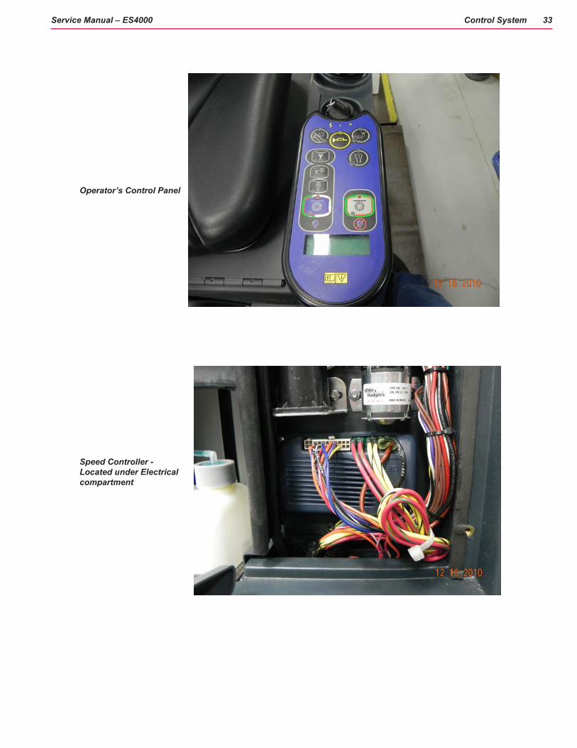
Operator’s Control Panel
Speed Controller - Located under Electrical compartment
Control System 34Service Manual – ES4000
Maintenance and Adjustments
Hidden Menus
Program Option Settings
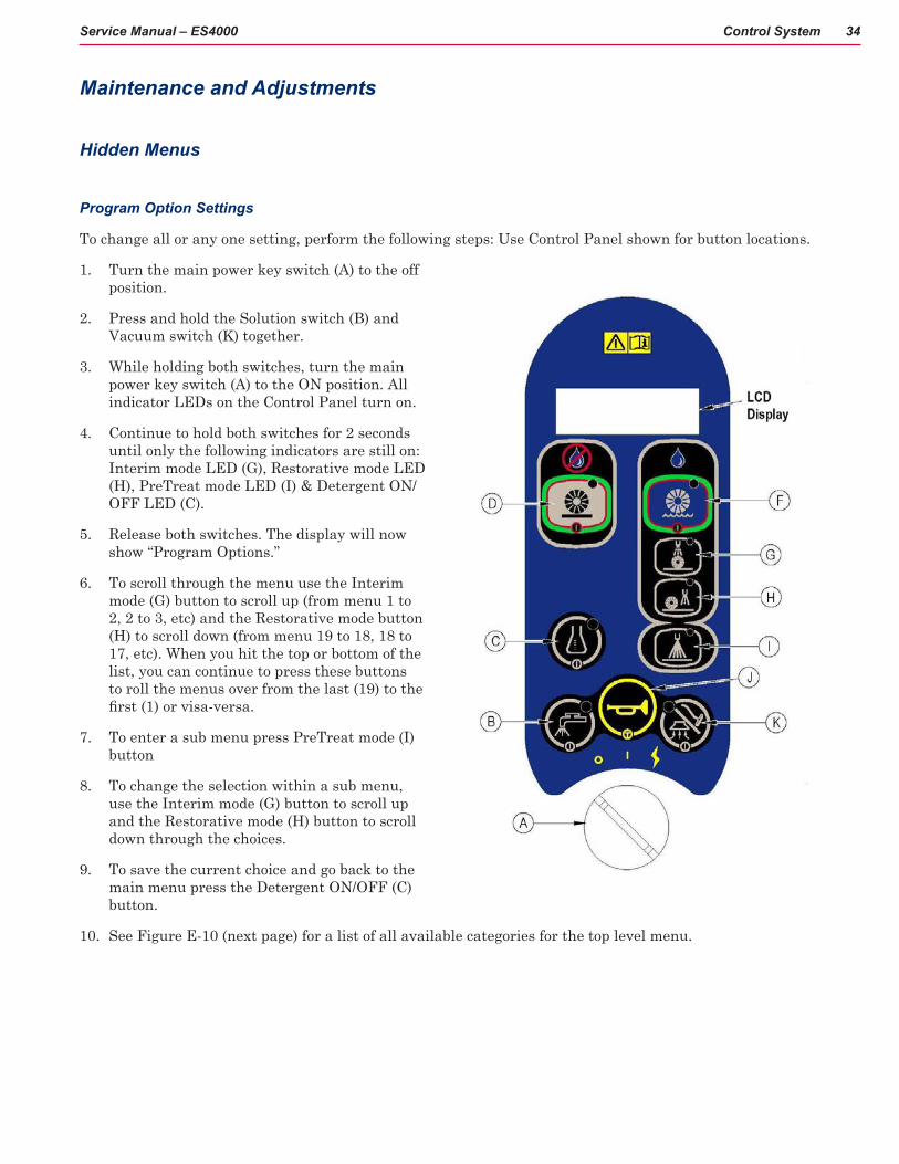
To change all or any one setting, perform the following steps: Use Control Panel shown for button locations.
1. Turn the main power key switch (A) to the off position.
2. Press and hold the Solution switch (B) and Vacuum switch (K) together.
3. While holding both switches, turn the main power key switch (A) to the ON position. All indicator LEDs on the Control Panel turn on.
4. Continue to hold both switches for 2 seconds until only the following indicators are still on: Interim mode LED (G), Restorative mode LED (H), PreTreat mode LED (I) & Detergent ON/OFF LED (C).
5. Release both switches. The display will now show “Program Options.”
6. To scroll through the menu use the Interim mode (G) button to scroll up (from menu 1 to 2, 2 to 3, etc) and the Restorative mode button (H) to scroll down (from menu 19 to 18, 18 to 17, etc). When you hit the top or bottom of the list, you can continue to press these buttons to roll the menus over from the last (19) to the first (1) or visa-versa.
7. To enter a sub menu press PreTreat mode (I) button
8. To change the selection within a sub menu, use the Interim mode (G) button to scroll up and the Restorative mode (H) button to scroll down through the choices.
9. To save the current choice and go back to the main menu press the Detergent ON/OFF (C) button.
10. See Figure E-10 (next page) for a list of all available categories for the top level menu.

Control System 35Service Manual – ES4000
1. LOW VOLTAGE CUTOUT2. MAX MAINT SPEED3. MAX RESTORE SPEED4. MAX PRESPRAY SPD5. MAX SWEEP SPEED6. RECOVERY TANK FULL7. CHEMICAL RATE BIAS8. DECK DOWN TIME9. RESTORE DEFAULTS10. DISPLAY REV LEVEL11. FAULT RECALL12. FAULT DETECTION13. SERVICE TEST MODE14. BACKUP ALARM VOL15. FWD ALARM VOL16. HORN VOL17. EXTRA INFO ON LCD18. FROZEN PARAMETERS19. PANEL TEST
Figure E-10 Top Level Main Options
Low Voltage Cutout
The Low Voltage Cutout Selection is a MANDATORY setting when the Main Control Board is replaced and the machine uses AGM or GEL Batteries. Default is WET BATTERY 80%.
The purpose of the special low battery voltage cutout function is to help prolong battery life. The cleaning deck will be raised and the brush motors and all solution solenoid valves and pumps will turn OFF automatically and cease to function when the batteries discharge to the selected cutout level. The cutout level is adjustable between two settings. The standard setting (wet cell/lead acid) is 20.55 volts and alternate setting (gel/maintenance free) is 21.75 volts. Figure E-11 shows the display.
LOW VOLT CUTOUT WET BATTERY 80%
LOW VOLT CUTOUT MAIN FREE BATTERY 70%
Figure E-11 Low voltage Cutout Selection Submenu Options
See 13. Service Test Mode instructions. All applicable options are identified specifically as part of the Service Test Mode.

Control System 36Service Manual – ES4000
Maximum Maintenance Speed
Program to limit the maximum speed while in maintenance extraction mode to a value less than that allowed for driving when not extracting (0-99% of transport speed in increments of 1%). Default is 22% OF TRANSPORT, see Figure E-12.
Max MAINT Speed 95% OF TRANSPORT
Figure E-12: Maximum Maintenance Speed Submenu Options (example value shown)
Maximum Restore Speed
Program to limit the maximum speed while in restore extraction mode to a value less than that allowed for driving when not extracting (0-99% of transport speed in increments of 1%). Default is 1% OF TRANSPORT, see Figure E-13.
Max RESTORE Speed 95% OF TRANSPORT
Figure E-13: Maximum Restore Speed Submenu Options (example value shown)
Maximum Prespray Speed
Program to limit the maximum speed while in prespray extraction mode to a value less than that allowed for driving when not extracting (0-99% of transport speed in increments of 1%). Default is 58% OF TRANSPORT, see Figure E-14.
Max PRESPRAY Spd 95% OF TRANSPORT
Figure E-14: Maximum Prespray Speed Submenu Options (example value shown)
Maximum Sweep Speed
Program to limit the maximum speed while in dry sweep mode to a value less than that allowed for driving when not sweeping (0-100% of transport speed in increments of 1%). Default 65% OF TRANSPORT, see Figure E-15.
MAX SWEEP SPEED 100% OF TRANSPORT
Figure E-15: Maximum Sweep Speed Submenu Options (example value shown)
Recovery Tank Full Enable/Disable
Enable or disable Recovery Tank Full automatic shutoff feature. Enable means that the automatic shutoff feature is turned on; disable means that the automatic shutoff feature is turned off. Default is 1.ENABLED, see Figure E-16.
RECOVERY TANK FULL 1. ENABLED
Control System 37Service Manual – ES4000
RECOVERY TANK FULL 2.DISABLED
Figure E-16: Recovery Tank Full Enable/Disable Submenu Options
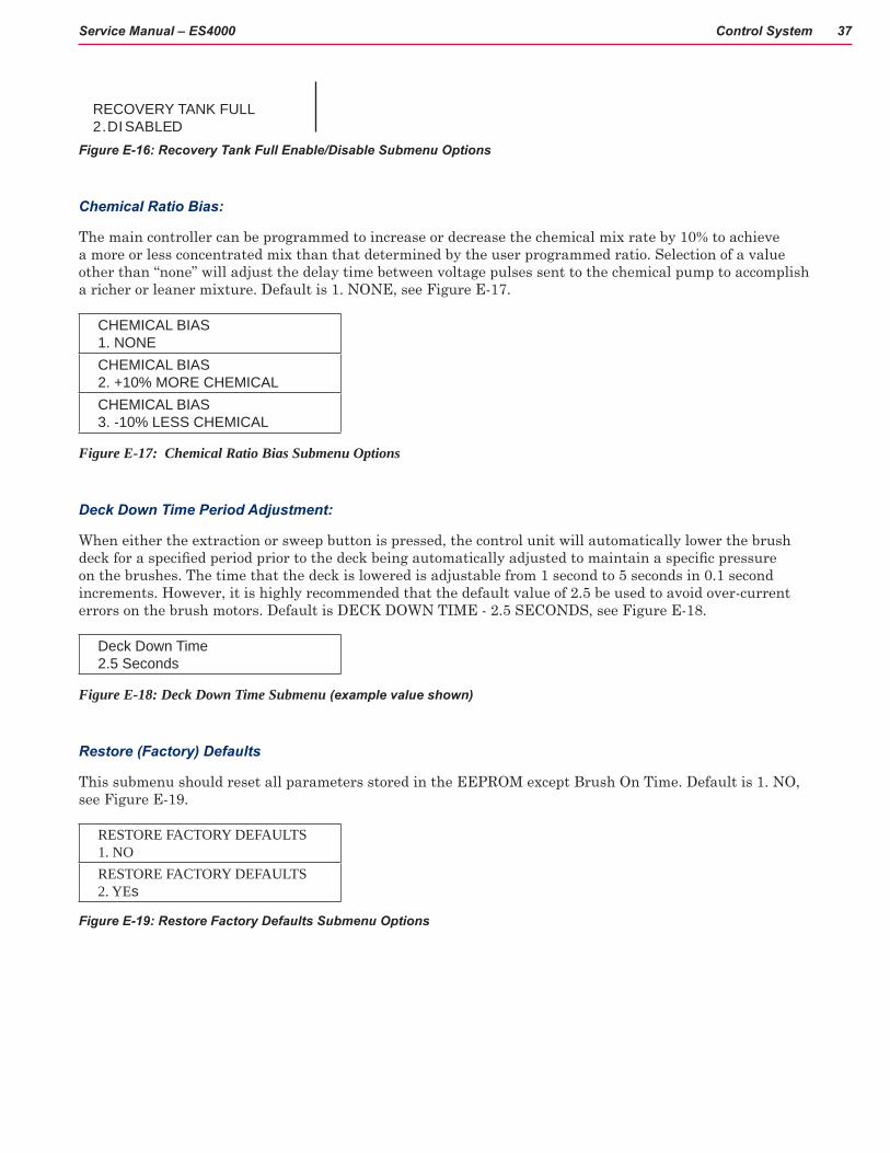
Chemical Ratio Bias:
The main controller can be programmed to increase or decrease the chemical mix rate by 10% to achieve a more or less concentrated mix than that determined by the user programmed ratio. Selection of a value other than “none” will adjust the delay time between voltage pulses sent to the chemical pump to accomplish a richer or leaner mixture. Default is 1. NONE, see Figure E-17.
CHEMICAL BIAS 1. NONECHEMICAL BIAS 2. +10% MORE CHEMICALCHEMICAL BIAS 3. -10% LESS CHEMICAL
Figure E-17: Chemical Ratio Bias Submenu Options
Deck Down Time Period Adjustment:
When either the extraction or sweep button is pressed, the control unit will automatically lower the brush deck for a specified period prior to the deck being automatically adjusted to maintain a specific pressure on the brushes. The time that the deck is lowered is adjustable from 1 second to 5 seconds in 0.1 second increments. However, it is highly recommended that the default value of 2.5 be used to avoid over-current errors on the brush motors. Default is DECK DOWN TIME - 2.5 SECONDS, see Figure E-18.
Deck Down Time 2.5 Seconds
Figure E-18: Deck Down Time Submenu (example value shown)
Restore (Factory) Defaults
This submenu should reset all parameters stored in the EEPROM except Brush On Time. Default is 1. NO, see Figure E-19.
RESTORE FACTORY DEFAULTS 1. NORESTORE FACTORY DEFAULTS 2. YEs
Figure E-19: Restore Factory Defaults Submenu Options
Control System 38Service Manual – ES4000
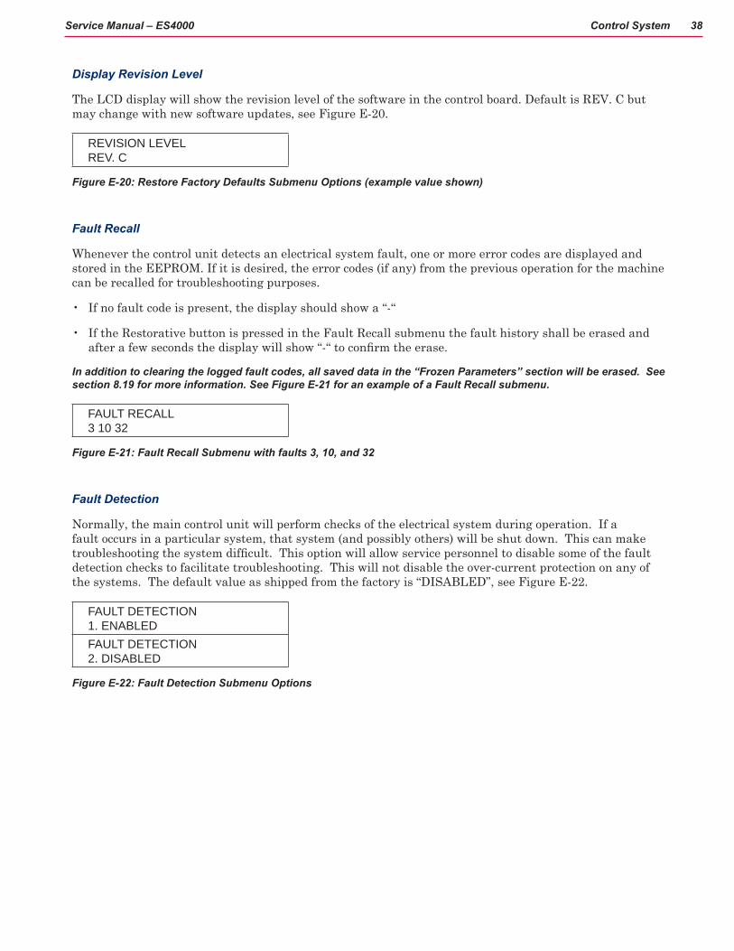
Display Revision Level
The LCD display will show the revision level of the software in the control board. Default is REV. C but may change with new software updates, see Figure E-20.
REVISION LEVEL REV. C
Figure E-20: Restore Factory Defaults Submenu Options (example value shown)
Fault Recall
Whenever the control unit detects an electrical system fault, one or more error codes are displayed and stored in the EEPROM. If it is desired, the error codes (if any) from the previous operation for the machine can be recalled for troubleshooting purposes.
• If no fault code is present, the display should show a “-“
• If the Restorative button is pressed in the Fault Recall submenu the fault history shall be erased and after a few seconds the display will show “-“ to confirm the erase.
In addition to clearing the logged fault codes, all saved data in the “Frozen Parameters” section will be erased. See section 8.19 for more information. See Figure E-21 for an example of a Fault Recall submenu.
FAULT RECALL 3 10 32
Figure E-21: Fault Recall Submenu with faults 3, 10, and 32
Fault Detection
Normally, the main control unit will perform checks of the electrical system during operation. If a fault occurs in a particular system, that system (and possibly others) will be shut down. This can make troubleshooting the system difficult. This option will allow service personnel to disable some of the fault detection checks to facilitate troubleshooting. This will not disable the over-current protection on any of the systems. The default value as shipped from the factory is “DISABLED”, see Figure E-22.
FAULT DETECTION 1. ENABLEDFAULT DETECTION 2. DISABLED
Figure E-22: Fault Detection Submenu Options
Control System 39Service Manual – ES4000
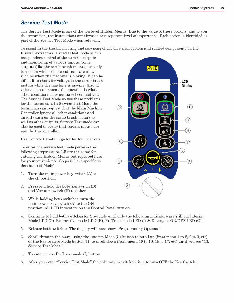
Service Test ModeThe Service Test Mode is one of the top level Hidden Menus. Due to the value of these options, and to you the technician, the instructions are elevated to a separate level of importance. Each option is identified as part of the Service Test Mode when relevent.
To assist in the troubleshooting and servicing of the electrical system and related components on the ES4000 extractors, a special test mode allows independent control of the various outputs and monitoring of various inputs. Some outputs (like the scrub brush motors) are only turned on when other conditions are met, such as when the machine is moving. It can be difficult to check for voltage to the scrub brush motors while the machine is moving. Also, if voltage is not present, the question is what other conditions may not have been met yet. The Service Test Mode solves these problems for the technician. In Service Test Mode the technician can request that the Main Machine Controller ignore all other conditions and directly turn on the scrub brush motors as well as other outputs. Service Test mode can also be used to verify that certain inputs are seen by the controller.
Use Control Panel image for button locations.
To enter the service test mode perform the following steps: (steps 1-5 are the same for entering the Hidden Menus but repeated here for your convenience. Steps 6-8 are specific to Service Test Mode).
1. Turn the main power key switch (A) to the off position.
2. Press and hold the Solution switch (B) and Vacuum switch (K) together.
3. While holding both switches, turn the main power key switch (A) to the ON position. All LED indicators on the Control Panel turn on.
4. Continue to hold both switches for 2 seconds until only the following indicators are still on: Interim Mode LED (G), Restorative mode LED (H), PreTreat mode LED (I) & Detergent ON/OFF LED (C).
5. Release both switches. The display will now show “Programming Options ”
6. Scroll through the menu using the Interim Mode (G) button to scroll up (from menu 1 to 2, 2 to 3, etc) or the Restorative Mode button (H) to scroll down (from menu 19 to 18, 18 to 17, etc) until you see “13. Service Test Mode.”
7. To enter, press PreTreat mode (I) button
8. After you enter “Service Test Mode” the only way to exit from it is to turn OFF the Key Switch.

Control System 40Service Manual – ES4000
How to Read the Battery Voltage—Using the Battery Display
The status display will show the battery voltage in the upper left corner of the panel display. This display is accurate to within +/- 0.15 volts. Therefore, the voltage displayed may not correlate precisely to a high-accuracy, calibrated voltmeter.
25.16 37 BAC: SPD: N MSL: X SAC: BRU: X RSL: SP: VAC: MST: CP: X
If over-current faults are present, the status display will indicate the error codes in the upper center of the display. If more than one error is present, the display will cycle through them every second.
Control Panel Switch Functions
See Control Panel image for button locations. The control panel switches are used in the Service Test Mode to control various output functions of the main control unit. Below is a list of each switch and the function it controls. Pressing a button more than once will toggle through the available states. A detailed description of each function follows.
• Wet Mode switch (F): Controls shoe lift actuator (toggle between OFF, Down and Up).
• Interim mode switch (G): Controls maintenance solenoid (ON/OFF).
• Restorative mode switch (H): Controls the restore solenoid (ON/OFF).
• Vacuum ON/OFF switch (K): Controls vacuum motor contactor (ON/OFF).
• Solution ON/OFF switch (B): Controls solution pump (ON/OFF).
• Horn switch (J): Controls brush motors contactor (ON/OFF).
• Detergent ON/OFF switch (C): Controls the chemical detergent pump (ON/OFF).
• PreTreat mode ON/OFF switch (I): Controls misting solenoid (ON/OFF).
• Dry Mode (D) switch: Controls brush deck lift actuator (toggle between Down and Up)

Control System 41Service Manual – ES4000
Control Panel LCD Information in Service Test Mode
The Control Panel LCD shows various information. Each item has an Acronym or display code to describe the state of the Service Test Mode. See Figure E-23 and E-23a for position of data on LCD.
• 25.31: Display actual battery voltage
• SPD (Speed Controller): N (Neutral), F (Forward), R (Reverse)
• BRU (Brush Contactor): blank (OFF) or X (ON)
• VAC (Vacuum Contactor): blank (OFF) or X (ON)
• 37: Error code or “00” if there are no faults (37 is an example for demonstration)
• MSL (Maintenance solenoid): blank (OFF) or X (ON)
• RSL (Restore solenoid): blank (OFF) or X (ON)
• MST (Mist solenoid): blank (OFF) or X (ON)
• BAC (Brush Actuator): blank (OFF), U (Up), or D (Down)
• SAC (Shoe Actuator): blank (OFF), U (Up), or D (Down)
• SP (Solution Pump): blank (OFF) or “X” (ON)
• CP (Chemical Pump): blank (OFF) or “X” (ON)
Note: In Figure E-23a below, an example screen shows the speed control in Neutral, Brush Contactor on, Maintenance Solenoid on, and Chemical Pump on. One error code is also present, CODE 37.
25.31 37 BAC: SPD: N MSL: X SAC: BRU: X RSL: SP: VAC: MST: CP: X
SERVICE TEST MODE instructions end here.
Figure E-23
Figure E-23a

Control System 42Service Manual – ES4000
Backup Alarm Volume
The backup alarm is variable. Set the back up alarm volume in the hidden menu to: Off, Low, Medium and High. Figure E-24.
BACKUP ALARM VOL 1. OFFBACKUP ALARM VOL 2. LOWBACKUP ALARM VOL 3. MEDIUMBACKUP ALARM VOL 4. HIGH
Figure E-24: Backup Alarm Volume Display
Forward Alarm Volume
The forward annunciation volume is variable using the hidden menu. Set the volume to one of the available levels: Off, Low, Medium and High. Figure E-25.
FWD ALARM VOL 1. OFFFWD ALARM VOL 2. LOWFWD ALARM VOL 3. MEDIUMFWD ALARM VOL 4. HIGH
Figure E-25: Forward Alarm Volume Display
Horn Volume
The horn is adjustable to various levels using the hidden menu. Set the Horn volume to one of the available levels: Off, Low, Medium and High. Figure E-26.
HORN VOLUME 1. OFFHORN VOLUME 2. LOWHORN VOLUME 3. MEDIUMHORN VOLUME 4. HIGH
Figure E-26: Horn Volume Display

Control System 43Service Manual – ES4000
Extra Info on LCD
This screen selects the extra information that can be displayed real-time on the LCD. This aids in troubleshooting the machine in normal operation. The default is to display no extra info. If extra information is selected for display, a 2-letter or 3-letter code is displayed to identify the information, while underneath the code is a number. The number indicates a value in amps, volts, or is without a unit designation depending upon what is selected. Only one piece of extra information can be displayed at any time, but the selected information can be changed at will via the hidden menu. Press DETERGENT button to back out of the menu and save the selection. Cycle the Key Switch to return to normal operations mode. A summary of the identification codes shown on the LCD display is as follows:
• BV = Battery Voltage
• LOK = Battery Lock Level
• FBR, RBR = Front/Rear Brush Motor Current (Instantaneous or Average)
• VAC = Vacuum Motor Current (the sum of two vac motors)
• MSO, RSO = Maintenance Solenoid Current & Restore Solenoid Current
• MST = Misting Solenoid Current
• BCO, VCO = Brush Contactor Current, Vacuum Contactor Current
• BAC, SAC = Brush Actuator Current & Shoe Actuator Current
• CP, SP = Chemical Pump Current & Solution Pump Current
• HRS = Brush On-Time Hourmeter
See Figure E-27 for a list of all available info that can be selected for display.
EXTRA INFO ON LCD 1. NONEEXTRA INFO ON LCD 2. BATT VOLTSEXTRA INFO ON LCD 3. BATT LOCK VALUEEXTRA INFO ON LCD 4. FR AVG BRUSH CURREXTRA INFO ON LCD 5. RR AVG BRUSH CURREXTRA INFO ON LCD 6. VAC MOTOR CURREXTRA INFO ON LCD 7. MAINT SOL CURREXTRA INFO ON LCD 8. REST SOL CURREXTRA INFO ON LCD 9. MIST SOL CURREXTRA INFO ON LCD 10. BRUSH CONT CURREXTRA INFO ON LCD 11. VAC CONT CURR
2. Battery Voltage (volts)
3. Battery Lock Value (no units)
4. Front average brush current (amps)
5. Rear average brush current (amps)
6. Vacuum motor current (total of both motors) (amps)7 Maintenance solenoid current (amps)
8. Restore solenoid current (amps)
9. Misting solenoid current (amps)
10. Brush contactor current (amps)
11. Vacuum contactor current (amps)

Control System 44Service Manual – ES4000
EXTRA INFO ON LCD 12. BRUSH ACT CURREXTRA INFO ON LCD 13. SHOE ACT CURREXTRA INFO ON LCD 14. CHEM PUMP CURREXTRA INFO ON LCD 15. SOLN PUMP CURREXTRA INFO ON LCD 16. ALT AVG BR CURREXTRA INFO ON LCD 17. ALT INST BR CURREXTRA INFO ON LCD 18. FR INST BR CURREXTRA INFO ON LCD 19. RR INST BR CURREXTRA INFO ON LCD 20. BRUSH HOURS
Figure E-27: Diagnostic Mode Selection Display
Frozen Parameters
This screen is used to view all of the internal parameters that were saved or “frozen” when the 1st error code was detected. Nine different parameters are logged, and all but two are saved at 100 msec intervals for 6.4 seconds leading up to the error code. The first viewable parameter is the error code that actually initiated the freezing of parameter values. The second viewable parameter is the hour meter value at the time of the frozen error code. If no error code occurred, then the stored data will all be blank (all zeroes). Examples of the main menu and sub-menus are shown in figures E-29 and E-30. In the Sub-menus, data point #1 is the newest value and #64 is the oldest value (that occurred 6.3 seconds earlier).
There are 2 levels of sub-menus for this top-level menu. In the first sub-menu you select the category of parameter to view by choosing 1 of the 9 categories listed in Figure E-28. For most categories there is a second sub-menu in which you select the specific value in history to view (data point 1 through 64). See figures E-29 and E-30 for examples of submenus. Keypad navigation is the same for each level, so the following set of 3 rules applies to each level:
1. To scroll through the menu use the Interim mode button (G) to scroll up and the Restorative mode (H) button to scroll down. See Control Panel Image for button locations.
2. To enter a sub-menu press the PreTreat button (I). If no
12. Brush actuator current (amps)
13. Shoe actuator current (amps)
14. Chemical pump current (amps)
15. Solution pump current (amps)
16. Alternate every 5 seconds between front and rear average brush current (amps)17. Alternate every 5 seconds between front and rear instantaneous brush current (amps)18. Front instantaneous brush current (amps)
19. Rear instantaneous brush current (amps)
20. Brush hour meter (hours)
The instantaneous views are preferred over the alternating views since they show what the brushes are doing in real time.

Control System 45Service Manual – ES4000
further sub-menus exist then this button has no effect.
3. To go back one level in the menus press the Detergent button (C).
There is one additional feature that is available only when you enter into the 2nd level of menus. This feature automatically turns on and off when you enter or leave a 2nd-level menu:
Upon entering any 1st-level menu, the LED on the Vacuum ON/OFF (K) button will turn on to indicate that this button can be used. Pressing this button in any 1st-level function has no effect, but after entering the 2nd level menu a press of this button will toggle between fast and slow increment modes when you are scrolling through the 64 available data points for each logged parameter.
In slow mode the increment/decrement value is 1, so that pressing the Interim mode (G) button will cycle you from data record 1 to 2, 2 to 3, etc, and pressing the Restorative button will cycle you from data record 64 to 63, 63 to 62, etc.
In fast mode the increment/decrement value is 10, so that pressing the Interim button will cycle you from data record 10 to 20, 20 to 30, etc, and pressing the Restorative button will cycle you from data record 60 to 50, 50 to 40, etc. The purpose of this feature is to reduce the number of button presses required to cycle through all 64 data records should you choose to do so. Use of this feature will automatically end when you press the Detergent button (C) to leave a 2nd-level menu, and the Vacuum button LED will turn off when you press the Detergent button (C) again to leave the 1st-level menu.
Note: Error codes will remain even after an error occurance has been corrected. Clear error codes using the Fault Recall menu.
FROZEN PARAMETERS 1.ERROR CODEFROZEN PARAMETERS 2.HOUR METERFROZEN PARAMETERS 3.BATT VOLTAGEFROZEN PARAMETERS 4.F BRUSH CURRFROZEN PARAMETERS 5.VAC MTR CURRFROZEN PARAMETERS 6.R BRUSH CURRFROZEN PARAMETERS 7.SHOE ACT CURRFROZEN PARAMETERS 8.BRUSH ACT CURR
1. Error code
2. Hour meter
3. Battery Voltage
4. Front brush current
5.Vacuum motor current
6. Rear brush current
7. Shoe actuator current
8.Brush actuator current
9.Machine mode of operation (Transport, Extract, Sweep)
Figure E-28: Frozen Parameters Display
Control System 46Service Manual – ES4000
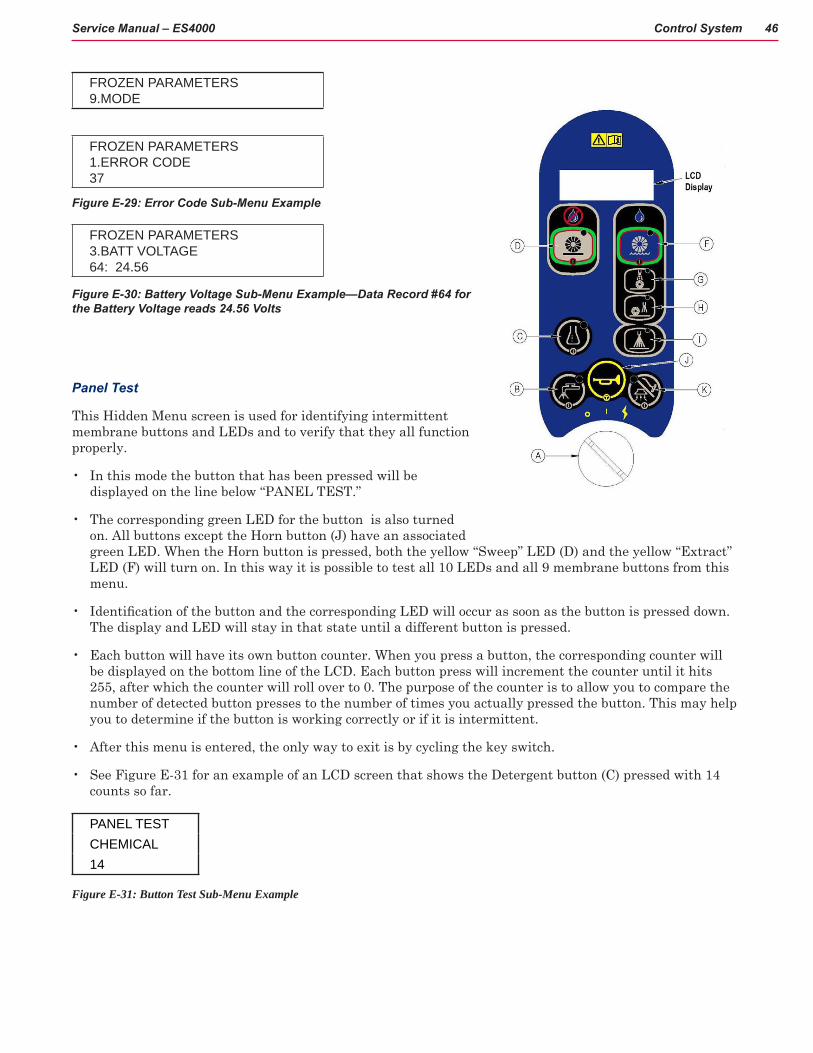
FROZEN PARAMETERS 9.MODE
FROZEN PARAMETERS 1.ERROR CODE 37
Figure E-29: Error Code Sub-Menu Example
FROZEN PARAMETERS 3.BATT VOLTAGE 64: 24.56
Figure E-30: Battery Voltage Sub-Menu Example—Data Record #64 for the Battery Voltage reads 24.56 Volts
Panel Test
This Hidden Menu screen is used for identifying intermittent membrane buttons and LEDs and to verify that they all function properly.
• In this mode the button that has been pressed will be displayed on the line below “PANEL TEST.”
• The corresponding green LED for the button is also turned on. All buttons except the Horn button (J) have an associated green LED. When the Horn button is pressed, both the yellow “Sweep” LED (D) and the yellow “Extract” LED (F) will turn on. In this way it is possible to test all 10 LEDs and all 9 membrane buttons from this menu.
• Identification of the button and the corresponding LED will occur as soon as the button is pressed down. The display and LED will stay in that state until a different button is pressed.
• Each button will have its own button counter. When you press a button, the corresponding counter will be displayed on the bottom line of the LCD. Each button press will increment the counter until it hits 255, after which the counter will roll over to 0. The purpose of the counter is to allow you to compare the number of detected button presses to the number of times you actually pressed the button. This may help you to determine if the button is working correctly or if it is intermittent.
• After this menu is entered, the only way to exit is by cycling the key switch.
• See Figure E-31 for an example of an LCD screen that shows the Detergent button (C) pressed with 14 counts so far.
PANEL TESTCHEMICAL14
Figure E-31: Button Test Sub-Menu Example
Control System 47Service Manual – ES4000
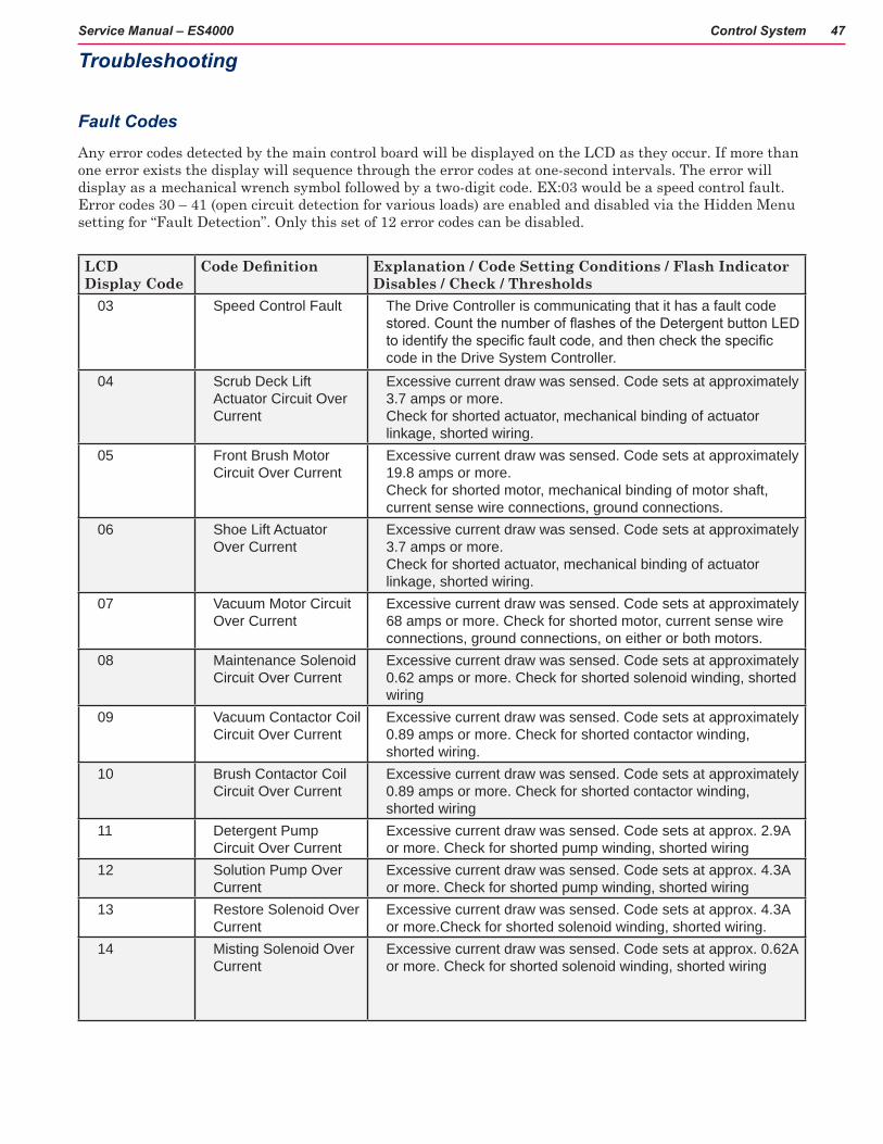
LCD Display Code
CodeDefinition Explanation / Code Setting Conditions / Flash Indicator Disables / Check / Thresholds
03 Speed Control Fault The Drive Controller is communicating that it has a fault code stored. Count the number of flashes of the Detergent button LED to identify the specific fault code, and then check the specific code in the Drive System Controller.
04 Scrub Deck Lift Actuator Circuit Over Current
Excessive current draw was sensed. Code sets at approximately 3.7 amps or more. Check for shorted actuator, mechanical binding of actuator linkage, shorted wiring.
05 Front Brush Motor Circuit Over Current
Excessive current draw was sensed. Code sets at approximately 19.8 amps or more. Check for shorted motor, mechanical binding of motor shaft, current sense wire connections, ground connections.
06 Shoe Lift Actuator Over Current
Excessive current draw was sensed. Code sets at approximately 3.7 amps or more. Check for shorted actuator, mechanical binding of actuator linkage, shorted wiring.
07 Vacuum Motor Circuit Over Current
Excessive current draw was sensed. Code sets at approximately 68 amps or more. Check for shorted motor, current sense wire connections, ground connections, on either or both motors.
08 Maintenance Solenoid Circuit Over Current
Excessive current draw was sensed. Code sets at approximately 0.62 amps or more. Check for shorted solenoid winding, shorted wiring
09 Vacuum Contactor Coil Circuit Over Current
Excessive current draw was sensed. Code sets at approximately 0.89 amps or more. Check for shorted contactor winding, shorted wiring.
10 Brush Contactor Coil Circuit Over Current
Excessive current draw was sensed. Code sets at approximately 0.89 amps or more. Check for shorted contactor winding, shorted wiring
11 Detergent Pump Circuit Over Current
Excessive current draw was sensed. Code sets at approx. 2.9A or more. Check for shorted pump winding, shorted wiring
12 Solution Pump Over Current
Excessive current draw was sensed. Code sets at approx. 4.3A or more. Check for shorted pump winding, shorted wiring
13 Restore Solenoid Over Current
Excessive current draw was sensed. Code sets at approx. 4.3A or more.Check for shorted solenoid winding, shorted wiring.
14 Misting Solenoid Over Current
Excessive current draw was sensed. Code sets at approx. 0.62A or more. Check for shorted solenoid winding, shorted wiring
Troubleshooting
Fault Codes
Any error codes detected by the main control board will be displayed on the LCD as they occur. If more than one error exists the display will sequence through the error codes at one-second intervals. The error will display as a mechanical wrench symbol followed by a two-digit code. EX:03 would be a speed control fault. Error codes 30 – 41 (open circuit detection for various loads) are enabled and disabled via the Hidden Menu setting for “Fault Detection”. Only this set of 12 error codes can be disabled.

Control System 48Service Manual – ES4000
LCD Display Code
CodeDefinition Explanation / Code Setting Conditions / Flash Indicator Disables / Check / Thresholds
15 Rear Brush Motor Over Current
Excessive current draw was sensed. Code sets at approx. 19.8A or more. Check for shorted motor, current sense wire connections, ground connections.
30 Maintenance Solenoid Circuit Open
The Main Machine Controller has turned the solution solenoid circuit on but it is not sensing any current flow. (Senses <= 20mAmps for 10 seconds). Check for open solenoid winding, open wiring.
31 Front Brush Motor Circuit Open
The Main Machine Controller has energized the Brush Contactor but it is not sensing any current flow through the brush motor ground circuit for at least 5 seconds. (Senses <= 2 Amps for 10 seconds) Check Motor, Contactor contacts, Wiring.
32 Scrub Deck Lift Actuator Circuit Open
The Main Machine Controller is trying to move the actuator but it is not sensing any current flow. (Senses <= 67 m Amps for 10 seconds) Check Actuator, wiring.
33 Vacuum Motor Circuit Open
The Main Machine Controller has energized the Vacuum Contactor but it is not sensing any current flow through the vacuum motor ground circuit for at least 5 seconds. (Senses<= 2 Amps for 5 seconds) Check motor, wiring, contactor
34 Shoe Lift Actuator open
The Main Machine Controller is trying to move the actuator but it is not sensing any current flow. (Senses <=67mA for 10 seconds) Check Actuator, wiring
35 Brush Contactor Coil Circuit Open
The Main Machine Controller has attempted to energize the Brush Contactor but it is not seeing any current flow. (Senses <= 40 m Amps for 10 seconds). Check for open Contactor winding, wiring
36 Vacuum Contactor Coil Circuit Open
The Main Machine Controller has attempted to energize the Vacuum Contactor but it is not seeing any current flow. if (Senses <= 40 m Amps for 5 seconds) Check for open Contactor winding, wiring.
37 Detergent Pump Circuit Open
The Main Machine Controller has energized the detergent pump but it is not sensing any current flow. (Senses <= 100 m Amps for 5 seconds). Check for open pump winding, wiring.
38 Rear Brush motor Circuit Open
The Main Machine Controller has energized the Brush Contactor but it is not sensing any current flow through the brush motor ground circuit for at least 5 seconds. (Senses <= 2 Amps for 10 seconds) Check Motor, Contactor contacts, Wiring.
39 Solution Pump Open The Main Machine Controller has energized the solution pump but it is not sensing any current flow. (Senses<= 150 mA for 10 seconds) Check for open pump winding, wiring.

Control System 49Service Manual – ES4000
LCD Display Code
CodeDefinition Explanation / Code Setting Conditions / Flash Indicator Disables / Check / Thresholds
40 Restore Solenoid Open
The Main Machine Controller has turned the solution solenoid circuit on but it is not sensing any current flow (<=20mA for 10 seconds) Check for open solenoid winding, open wiring.
41 Misting Solenoid Open The Main Machine Controller has turned the solution solenoid circuit on but it is not sensing any current flow (<=20 mA for 10 seconds) Check for open solenoid winding, open wiring.
60 Front Brush Motor Stuck Closed
The Main Machine Controller is sensing current flow through the Front Brush Motor ground circuit when it has not energized the Brush Motor Contactor (Senses >= 2 Amps for 10 seconds) Check for a short in the harness wiring to the motor.
61 Vacuum Motor Stuck Closed
The Main Machine Controller is sensing current flow through the Vacuum Motor ground circuit when it has not energized the Vacuum Motor Contactor (Senses >= 2 Amps for 5 seconds) Check for a short in the wiring harness to the motor
62 Maintenance Solenoid Circuit Stuck On (closed)
The Main Machine controller is sensing current flow through its internal switch for the maintenance solenoid circuit when it has not requested that the switch be turned on. (Senses >= 20 m Amps for 10 seconds).
63 Brush Contactor Coil Circuit Stuck On (closed)
The Main Machine controller is sensing current flow through its internal switch for the Brush Contactor Coil circuit when it has not requested that the switch be turned on. (Senses >= 40 m Amps for 10 seconds).
64 Vacuum Contactor Coil Circuit Stuck On (closed)
The Main Machine controller is sensing current flow through its internal switch for the Vacuum Contactor Coil circuit when it has not requested that the switch be turned on. (Senses >= 40 m Amps for 5 seconds).
65 Restore Solenoid Stuck Closed
The Main Machine controller is sensing current flow through its internal switch for the restore solenoid circuit when it has not requested that the switch be turned on. (Senses >= 20 m Amps for 10 seconds).
66 Misting Solenoid Stuck Closed
The Main Machine controller is sensing current flow through its internal switch for the misting solenoid circuit when it has not requested that the switch be turned on. (Senses >= 20 m Amps for 10 seconds).
67 Rear Brush Motor Stuck closed
The Main Machine Controller is sensing current flow through the Rear Brush Motor ground circuit when it has not energized the Brush Motor Contactor (Senses >= 2A for 10 seconds). Check for a short in the harness wiring to the motor.
Figure E-32: Fault Code Descriptions

Control System 50Service Manual – ES4000
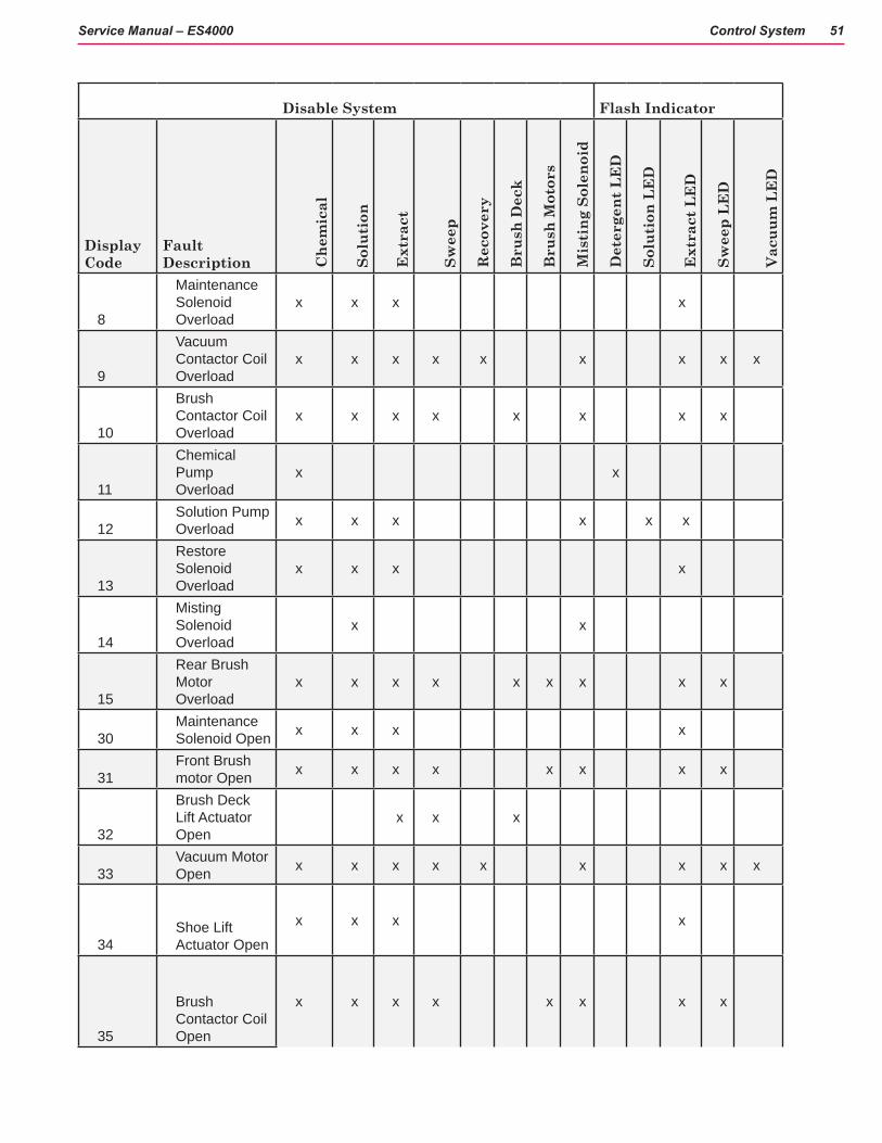
Specific actions will happen for each electrical system fault detected. See figure E-33 for systems to be disabled for each fault code. Once any system is disabled it cannot be turned on again until key switch is cycled. Details of how each system are disabled is as follows:
1. Chemical System: Detergent LED (C) turns off (unless it is flashing due to a chem. pump fault) and chemical off icon is displayed on LCD. Chemical pump turns off.
2. Solution System: Solution LED turns off (unless it is flashing due to a solution pump fault). Solution pump turns off.
3. Extract System: Extract LED, Restore LED, Maintenance LED, and Prespray LED turn off (extract LED will flash if the fault is due to a maintenance or restore solenoid fault). Maintenance and Restore solenoids turn off. Shoe deck returns to raised position. Extract button is locked out. Hose change screens appear on LCD until user acknowledges and switches to Sweep Mode.
4. Sweep System: Sweep LED turns off. Sweep button is locked out. Hose change screens appear on LCD until user acknowledges and switches to Extract Mode.
5. Recovery System: Vacuum/Wand LED turns off (unless it is flashing due to a vacuum fault). Vacuum turns off.
6. Brush Deck: Machine should remain in its current mode (sweep or extract). Brush deck actuator turns off.
7. Brush Motors: Brushes turn off.
8. Misting Solenoid: Solenoid turns off.
NOTE: If both the extract and sweep systems are simultaneously disabled (see chart below) then both the Extract & Sweep LEDs will flash and the LCD will revert to the normal sweep mode screen.
Disable System Flash Indicator
Display Code
Fault Description C
hem
ical
Solu
tion
Ext
ract
Swee
p
Rec
over
y
Bru
sh D
eck
Bru
sh M
otor
s
Mis
ting
Sol
enoi
d
Det
erge
nt L
ED
Solu
tion
LE
D
Ext
ract
LE
D
Swee
p LE
D
Vac
uum
LE
D
3Speed Control Fault x x x x x x
4
Brush Deck Lift Actuator Overload
x x x
5
Front Brush Motor Overload
x x x x x x x x x
6
Shoe Lift Actuator Overload
x x x x
7Vacuum Motor Overload x x x x x x x x x
Control System 51Service Manual – ES4000
Disable System Flash Indicator
Display Code
Fault Description C
hem
ical
Solu
tion
Ext
ract
Swee
p
Rec
over
y
Bru
sh D
eck
Bru
sh M
otor
s
Mis
ting
Sol
enoi
d
Det
erge
nt L
ED
Solu
tion
LE
D
Ext
ract
LE
D
Swee
p LE
D
Vac
uum
LE
D
8
Maintenance Solenoid Overload
x x x x
9
Vacuum Contactor Coil Overload
x x x x x x x x x
10
Brush Contactor Coil Overload
x x x x x x x x
11
Chemical Pump Overload
x x
12Solution Pump Overload x x x x x x
13
Restore Solenoid Overload
x x x x
14
Misting Solenoid Overload
x x
15
Rear Brush Motor Overload
x x x x x x x x x
30Maintenance Solenoid Open x x x x
31Front Brush motor Open x x x x x x x x
32
Brush Deck Lift Actuator Open
x x x
33Vacuum Motor Open x x x x x x x x x
34Shoe Lift Actuator Open
x x x x
35
Brush Contactor Coil Open
x x x x x x x x

Control System 52Service Manual – ES4000
Disable System Flash Indicator
Display Code
Fault Description C
hem
ical
Solu
tion
Ext
ract
Swee
p
Rec
over
y
Bru
sh D
eck
Bru
sh M
otor
s
Mis
ting
Sol
enoi
d
Det
erge
nt L
ED
Solu
tion
LE
D
Ext
ract
LE
D
Swee
p LE
D
Vac
uum
LE
D
36
Vacuum Contactor Coil Open
x x x x x x x x x
37Chemical Pump Open x x
38Rear Brush Motor Open x x x x x x x x
39Solution Pump Open x x x x x x
40Restore Solenoid Open x x x x
41Misting Solenoid Open x x
60
Front Brush motor Stuck Closed
61Vacuum Motor Stuck Closed
62
Maintenance Solenoid Stuck Closed
x x
63
Brush Contactor Coil Stuck Closed
64
Vacuum Contactor Coil Stuck Closed
65
Restore Solenoid Stuck Closed
x x
66
Misting Solenoid Stuck Closed
x
67
Rear Brush motor Stuck Closed
Figure E-33: Disabled Systems for each fault code (Note: Flash indicator at 1 hz rate)

Control System 53Service Manual – ES4000
Removal and Installation
Replace the Main Control Board
Caution! You must disconnect the batteries from the machine at the battery connector before accessing the control board.
Flip the operator’s seat upward and prop it in place.
Remove the 4 screws from the Control Panel assembly.
Lift and tilt the Control Panel Assembly to access the board underneath.
Caution! To prevent damage to the control panel assembly due to static electricity (ESD), wear a properly grounded static control wrist strap before removing the new assembly from its protective static shielding bag. Wear the strap throughout the entire installation process until the four screws attaching the control panel to the machine have been fastened.
Note all wiring and hose connections. Disconnect the wiring and hose connections.
Caution! The ribbon cable(s) and membrane switch grounding film are fragile. Do not scratch or crease during disassembly or re-assembly or damage may occur.
Caution! DO NOT pull the clear tube off the control board or it WILL break the control board! Instead, use a raor knife and carefully cut the tube off the control board.

Control System 54Service Manual – ES4000
Remove the key switch from the control board panel assembly.
Remove the 5 screws from the board assembly. Save the screws and key switch. Discard the old board and replace it with the new one.
Install the new board assembly in the reverse order. Be extra careful when plugging in the connectors on the board.
Key switch assy
1 of 5 screws
Note: After replacing the Main Controller, no special programming of operational values is required if the machine is equipped with WET BATTERIES . However, if the ES4000 machine is equipped with AGM or GEL batteries, it is MANDATORY to set the LOW VOLTAGE CUTOUT function in the Hidden Menus. By default, the initial setting is “Wet Battery 80%” but will need to be changed to “Main Free Battery 70%” if the machine has AGM or GEL batteries. Failure to do so may cause premature battery failure.

Control System 55Service Manual – ES4000
Specifications
Shop Measurements – Main ControllerThe following tables contain some “real world” shop voltage measurements to help you recognize what “normal” looks like. All voltage values were measured with the key switch on and the black (Negative) voltmeter lead con-nected to the main battery negative terminal unless otherwise specified.
Pin ID
Wire Color
Description Measured Value
Comments
J1-1 red/yel Chemical Pump “+” output
2v to 20v Voltage should jump around when pump is operated
J1-2 vio/org Solution Pump output
0.15v When solution flows
J1-3 blu/gra Chemical Pump “-“ output
2v to 20v Voltage should jump around when pump is operated
J1-4 org/blk Brush Deck Actuator motor “+” output
23.9v up
0.26v down
Measured when actuator was moving in both directions
J1-5 blu Brush Deck Actuator motor “-“ output
23.7v up
0.15v down
Measured when actuator was moving in both directions
J1-6 vio/red Rear Brush Motor Current Sense input
0.02v Brushes running without touching the floor
J1-7 blk/wht Restore solenoid output
0.18v When energized
J1-8 blk/wht Battery “-“ input 0.05v While operating in extract mode with vacuum motors on
J1-9 blk/yel Shoe Actuator motor “-” output
24.4v up
0.13v down
Measured when actuator was moving in both directions
J1-10 wht/grn Shoe Actuator motor “+” output
24.6v down
0.12v up
Measured when actuator was moving in both directions
J2-1 blk Battery “-“ input 0.02v With vacuum motors runningJ2-2 Not usedJ2-3 Not usedJ2-4 blk/wht Speed limit output
(Signal from main controller to speed controller)
0.53v 1.29v 2.5v 4.5v
Restore mode Maintenance mode Prespray mode Transport and Sweep modes
J2-5 vio Speed limit pot low ref
0.38v
J2-6 yel Speed limit pot high ref
4.58v

Control System 56Service Manual – ES4000
Pin ID
Wire Color
Description Measured Value
Comments
J2-7 blk Battery “-“ input 0.02v With vacuum motors runningJ2-8 blk Battery “-“ input 0.02v With vacuum motors runningJ2-9 brn/red Vacuum Motor
Current Sense input
0.192v
0.150v
Vacuum on with open hose
Vacuum on with hose blockedJ2-10 yel/vio Front Brush Motor
Current Sense input
0.028v
0.111v
Brush running with deck up
Brush running with deck all the way downJ2-11 Not usedJ2-12 Not usedJ3-1 brn/yel Battery “+“ lead 24.2v With vacuum motors runningJ3-2 blk Battery “-“ input 0.02v With vacuum motors runningJ3-3 blu/org Maintenance
solenoid output0,18v When energized
J3-4 gra/blk Seat Switch input 25.0v
0.00v
Switch closed
Switch openJ3-5 blu/blk Reverse Direction
input from Speed Controller (input = GND when moving in reverse)
1.55v
24.1v
Reverse
Neutral or Forward
J3-6 red/wht Fwd/Reverse input from Speed Controller (input = GND when moving in forward or reverse)
0.24v
24.1v
Reverse or Neutral
Neutral
J3-7 org/blu Speed Controller Status input (input pulses between B+ and GND to indicate error status from Speed Controller)
1.19v
24v
With no speed control faults
With speed control faults (The voltage jumps lower as the code signal is communicated)
J3-8 brn/yel Battery “+“ lead 24.5v With vacuum motors runningJ3-9 grn/blk Horn “-” output 13.3v off
0.01v on
Connects to battery negative to sound horn
J3-10 org/red Horn “+” output 15.0v Constant power supplyJ3-11 vio/blk Misting solenoid
output0.19v When energized
J3-12 gra/blk Vacuum Contactor output
0.26v
4.8v
When first energized (To pull in contactor)
After energized for a few seconds (To hold contactor)

Control System 57Service Manual – ES4000
Pin ID
Wire Color
Description Measured Value
Comments
J3-13 wht/red Brush Motor Contactor output
0.28v
4.8v
When first energized (To pull in contactor)
After energized for a few seconds (To hold contactor)
J3-14 brn Key Switch input (input = B+ voltage when key is turned on)
24.1v With vacuum motors running

58Service Manual – ES4000
Electrical System
Functional DescriptionThe Electrical System is integrated throughout the machine functions. The main functional interface is the Operator’s Interface Panel Assembly (See CONTROL SYSTEM, Control Panel). All operator’s functions are initiated and controlled from this panel. The machine is Battery-powered and rechargeable. The drive system is variable speed controlled via the foot pedal and selection of various operational functions at the Control Panel.
An optional on-board Battery Charger is available for this machine. This manual shows the ES4000 with the Optional Battery Charger installed.
Components Locations• Batteries and connections
• Fuses, E-Stop button
• Battery charger
• Main operator’s interface panel (see CONTROL SYSTEM)
• Speed controller (see WHEEL SYSTEM, TRACTION)
Speed Controller
Operator’s Control Unit
Battery Connect/Disconnect
Emergency Stop
70 amp circuit breaker
10 Amp Circuit Breaker
24 VDC Contactor
24 V, 100 AMP Contactor
150 Amp fuse

Electrical System 59Service Manual – ES4000
Batteries in battery tray with Recovery Tank removed and Operator’s Seat up.
Battery connector (shown disconnected)
Fuses and E-stop locations

Electrical System 60Service Manual – ES4000
On-board Battery Charger
Operator’s main interface panel (CONTROL PANEL)
Speed Controller

Electrical System 61Service Manual – ES4000
Main Electrical Panel
Electrical components in electrical panel
K1 Vacuum Contactor 24VDC K2 Brush Contactor 24V, 100 AMP
Speed Controller
Contactors
Detergent bottle
Detergent pump

Electrical System 62Service Manual – ES4000
Battery Specifications
Advance recommended battery pack capacity is a 310 or 420 AH @ 20 Hour Rate deep cycle battery system (four6V-batteries).Note:ThebatterypackmustfitthebatterycompartmentsizelistedinSpecifications.
Battery Charger (on-board and portable)
– Use a 24V DC output charger matching the DC battery pack voltage and the input AC line voltage supply being used.
– Always when selecting a battery charger follow the recommendation of the battery supplier to match the proper charger DC output amperage to the amp/hour rating batteries being installed. This will prevent the battery pack from being over or under charged.
◦ The recommended 310 AH battery should be matched to a 24V, 25 Amp charger. The recommended 420 AH battery should be matched to a 24V, 36 Amp charger.
Removal and Installation
On-Board Battery Charger and power cord

Electrical System 63Service Manual – ES4000
Install Batteries
WARNING! Use extreme caution when working with batteries. Sulfuric acid in batteries can cause severe injury if allowed to contact the skin or eyes. Explosive hydrogen gas is vented from inside the batteries through openings in the battery caps. This gas can be ignited by any electrical arc, spark or flame.
When Servicing Batteries:
• Remove all jewelry.
• Do not smoke.
• Wear chemical goggles, rubber gloves and a protective apron.
• Work in a well-ventilated area.
• Do not allow tools to touch more than one battery terminal at a time.
CAUTION! Electrical components in this machine can be severely damaged if the batteries are not installed and connected properly.

Electrical System 64Service Manual – ES4000
Figure E-1
Batteries with connectors and main cable disconnected
Remove the batteries from their shipping crate and carefully inspect them for cracks or other damage. If damage is evident, contact the carrier that delivered them or the battery manufacturer to fileadamageclaim.
Your machine comes from the factory with enough battery cables to install four (6 volt), 420 Amp hour batteries. Using two people and an appropriate lifting strap, carefully lift the batteries into the compartment tray exactly as shown on machine decal (Figure E-2).
Battery Connector
Seat Prop
Operator’s Control Panel
Figure E-2
Turn the Master Key Switch OFF and remove the key from the Operator’s Control Panel.
To access the battery compartment tip the operator’s seat forward and set the prop rod. Remove the battery cables from inside the battery compartment. (Figure E-1).

Electrical System 65Service Manual – ES4000
The terminals on the battery cables are marked “+” for positive and “-“ for negative. Install the battery cables as shown, with the terminals marked “+” on the positive battery terminals and the terminals marked “-“ on the negative terminals. Position the cables so the battery caps can be easily removed for battery service.
Carefully tighten the nut in each battery terminal until the terminal will not turn on the battery post. Then tighten the nut half an additional turn. Do not over-tighten the terminals, ortheywillbeverydifficultto remove for future service.
Coat the terminals and posts with spray-on battery terminal coating (available at most auto parts stores).
Put one of the black rubber boots over each of the terminals and retain with supplied tie straps.
Connect the battery pack connector to the Machine Battery Connector and close the operator’s seat platform.

Electrical System 66Service Manual – ES4000
Battery Low Voltage Cutout Feature - Description
The ES4000 is equipped with a low voltage cutout feature to prevent over-discharging of the batteries. When amachine’sbatterypackvoltagefallsbelowspecificallydefinedthresholds(voltagesettings)thecleaningsystem is automatically shut down. The cutout level is adjustable. The standard lead acid battery (wet cell) setting is 1.72V per cell and alternate maintenance free battery (gel cell) setting is 1.81V per cell. The standardsettingisfactoryselectedandshouldbeusedunlessthebatterymanufacturerspecifiesthehighercutout voltage. The Low Voltage Cutout is indicated by the Voltage Low indication shown on the display and everything is disabled except the Horn.
Special Service Note: On all machines (24V) a minimum recharge voltage of 25.08 volts (2.09 volts per cell) must be reached to allow the brush and solution system to (reset) function again following a low voltage cutout.
Battery Condition Indicator - Description
The Battery Condition Indicator will give an indication of the state of charge of the batteries. The battery condition indicator will retain the state-of-charge even if the key has been turned off. The state-of-charge indication is reset to full charge when the batteries have been recharged. It is also possible to choose between two different low voltage thresholds depending on whether maintenance free or standard batteries are being used.
The indicator is shown as an icon on the operator control panel’s display. This icon is present 10 seconds after the Key Switch is turned ON. The icon is a battery with up to 5 vertical bars inside. The number of bars inside the icon represents the charge state of the battery as follows:
1. Battery full = 5 bars
2. Battery at 80% = 4 bars
3. Battery at 60% = 3 bars
4. Battery at 40% = 2 bars
5. Bsttery at 20% = 1 bar
6. Battery depleted = no bars
*Important Note: See the Main Control Board Special Program Options manual section and follow the instructions for changing the low voltage cutout threshold.
BATTERY CONDITION

Electrical System 67Service Manual – ES4000
Battery LOCK Value
TheBatteryLOCKValueisatermusedbyNilfisk-Advancetoreferencetherepresentationofthemachinebattery voltage after it is converted to a digital number and ran through the battery voltage monitoring algorithm. The LOCK value is used to determine the correct battery gauge level to be displayed on the LCD. The LOCK value is also used to trigger a LVI (Low Voltage Inhibit) warning. The LOCK value is nonvolatile and can only be reset as explained above for BATT_RESET.
Low voltage inhibit process
1. When Gel battery reaches LVI Lock value 17, turn off the brushes, pumps and solenoids and raise the brush deck. Still active are the shoe actuator, vacuum and horn.
2. When Gel battery reaches LVI Lock value 18, disable and turn off everything except horn.
3. When Wet battery reaches LVI Lock value 25, turn off the brushes, pumps and solenoids and raise the brush deck. Still active are the shoe actuator, vacuum and horn.
4. When Wet battery reaches LVI Lock value 26, disable and turn off everything except the horn
LOCK Battery Voltage Threshold
LCD DisplayWet Battery Gel Battery
0 24.30 Batt Gauge = 5 Bar
Batt Gauge = 5 Bar
1 24.15 Batt Gauge = 5 Bar
Batt Gauge = 5 Bar
2 24.0 Batt Gauge = 5 Bar
Batt Gauge = 5 Bar
3 23.85 Batt Gauge = 4 Bar
Batt Gauge = 4 Bar
4 23.7 Batt Gauge = 4 Bar
Batt Gauge = 4 Bar
5 23.55 Batt Gauge = 3 Bar
Batt Gauge = 3 Bar
6 23.4 Batt Gauge = 3 Bar
Batt Gauge = 3 Bar
7 23.25 Batt Gauge = 3 Bar
Batt Gauge = 2 Bar
8 23.1 Batt Gauge = 2 Bar
Batt Gauge = 2 Bar
9 22.95 Batt Gauge = 2 Bar
Batt Gauge = 2 Bar
10 22.8 Batt Gauge = 2 Bar
Batt Gauge = 1 Bar
11 22.65 Batt Gauge = 2 Bar
Batt Gauge = 1 Bar
12 22.5 Batt Gauge = 2 Bar
Batt Gauge = 1 Bar
13 22.35 Batt Gauge = 1 Bar
Batt Gauge = 0 Bar
14 22.2 Batt Gauge = 1 Bar
Batt Gauge = 0 Bar
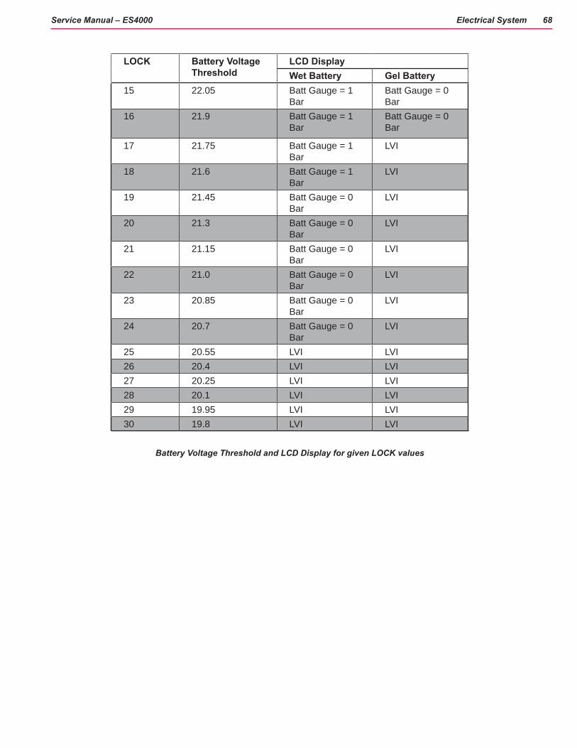
Electrical System 68Service Manual – ES4000
LOCK Battery Voltage Threshold
LCD DisplayWet Battery Gel Battery
15 22.05 Batt Gauge = 1 Bar
Batt Gauge = 0 Bar
16 21.9 Batt Gauge = 1 Bar
Batt Gauge = 0 Bar
17 21.75 Batt Gauge = 1 Bar
LVI
18 21.6 Batt Gauge = 1 Bar
LVI
19 21.45 Batt Gauge = 0 Bar
LVI
20 21.3 Batt Gauge = 0 Bar
LVI
21 21.15 Batt Gauge = 0 Bar
LVI
22 21.0 Batt Gauge = 0 Bar
LVI
23 20.85 Batt Gauge = 0 Bar
LVI
24 20.7 Batt Gauge = 0 Bar
LVI
25 20.55 LVI LVI26 20.4 LVI LVI27 20.25 LVI LVI28 20.1 LVI LVI29 19.95 LVI LVI30 19.8 LVI LVI
Battery Voltage Threshold and LCD Display for given LOCK values

Electrical System 69Service Manual – ES4000
Maintenance and Adjustments
Battery Maintenance
Proper maintenance of electric vehicle batteries can greatly extend their life. Well-maintained batteries may last up to 3 years, but failure after 1 year is common if maintenance has been poor. There are 3 simple rules for good battery maintenance:
• Maintain Proper Electrolyte Level (Weekly) - Use distilled water in batteries whenever possible. If batteries are discharged, add just enough water to cover the plates in each cell. If batteries are fully charged,filleachcelltothebottomofthefillertube.Donotover-fillthebatteries!Donotaddacidtobatteries!
• Keep the Batteries Charged (Weekly) - Batteries should be charged each time that a machine is used for more than 1 hour. Machine operators should open the battery compartment cover for charging, to avoid a concentrated build-up of hydrogen gas. Operators should follow the instructions provided with their specificbatterycharger,todeterminehowlongthebatteriesshouldbecharged.Evenwhenamachineisstored, the batteries should be charged once a month to prevent the batteries from “sulfating”. Almost all battery caps are vented, so there’s no need to loosen or remove them for charging.
• Keep the Batteries Clean (Monthly) - Use a damp cloth to wipe dirt from the top of the batteries. Battery terminals must be clean and tight. If the tops of the batteries are wet after charging, the batteries have probablybeenover-filledorover-charged.Note:Ifthereisacidonthebatteries,washthetopsofthebatteries with a solution of baking soda and water (2) tablespoons of baking soda to 1 quart of water.
Charging the Batteries
Charge the machine’s battery pack each time the machine is used, or when the Battery Condition Indicator show no vertical bars in the battery icon.
Note: The machine also uses a special low voltage cutout that inhibits the cleaning system see in this manual section the Description of the Battery Low Voltage Cutout Feature.
To Charge the Batteries.
1. Disconnect the Battery Connector.
2. Lift the seat and prop it open with the prop rod to provide proper ventilation.
3. Push the connector from the charger into the Battery Connector.
4. Follow the instructions on the battery charger.
5. Checkthefluidlevelinallbatterycellsafterchargingthebatteries.Adddistilledwater,ifnecessary,tobringthefluidleveluptothebottomofthefillertubes.
WARNING! Do not fill the batteries before charging. Only charge batteries in a well-ventilated area. Do not smoke while servicing the batteries.

Electrical System 70Service Manual – ES4000
Battery Testing
Abatteryproblemisusuallyrecognizedbythemachineoperatorasadecreaseinthemachine’srunningtime. This condition is usually caused by one or more “dead cells” in the battery system (one or more cells that is producing less voltage than the other cells).
Note: Always charge batteries before testing. There are 2 ways to find a dead cell:
• Useahydrometertocheckthespecificgravity(or“stateofcharge”)ofthefluidineachcell.Adeadcellisone that reads 50 points (or more) lower than the other cells.
• Use a volt meter to check the voltage of each battery with the cleaning and drive motors running. The battery with the dead cell will read 1 or 2 volts lower than the other batteries in the system.
• If the batteries in the machine are more than 1 year old, it’s usually best to replace the whole set, rather than replacing just one battery. As batteries age, their maintenance requirements change. As they age theyusuallyrequirelongerchargingtimesandahigherfinishrate.Anewerbatteymixedinwitholdbatteries will end up being overcharged and cause it to fail prematurely.
Thetablebelowshowstheapproximate“percentcharged”ofanelectricvehiclebatteryatvariousspecificgravity values, corrected to 80°F (26.7°C).
APPROXIMATE STATE OF CHARGE Charged 1.265 Initial Full Charge
100% 1.26575% 1.22550% 1.19025% 1.155
Discharged 1.120

Electrical System 71Service Manual – ES4000
Machine and Chassis Wiring

Electrical System 72Service Manual – ES4000
Machine and Chassis Wiring
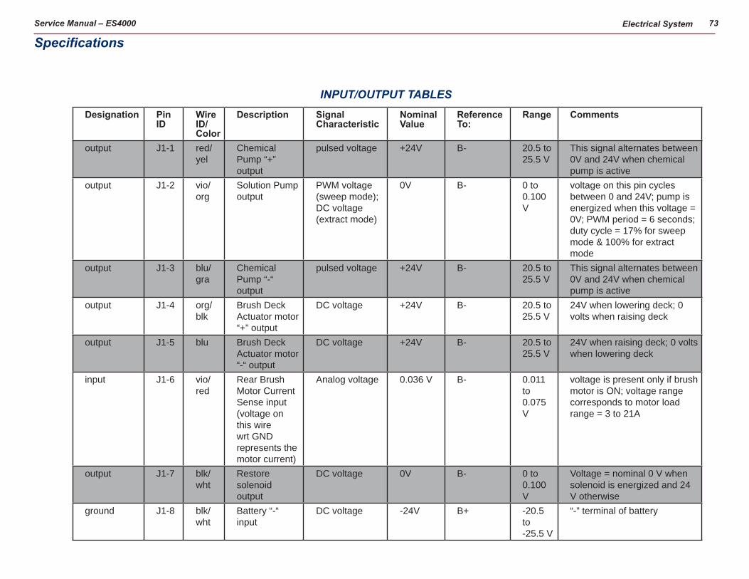
Service Manual – ES4000 Electrical System 73
Designation Pin ID
Wire ID/Color
Description Signal Characteristic
Nominal Value
Reference To:
Range Comments
output J1-1 red/yel
Chemical Pump “+” output
pulsed voltage +24V B- 20.5 to 25.5 V
This signal alternates between 0V and 24V when chemical pump is active
output J1-2 vio/org
Solution Pump output
PWM voltage (sweep mode); DC voltage (extract mode)
0V B- 0 to 0.100 V
voltage on this pin cycles between 0 and 24V; pump is energized when this voltage = 0V; PWM period = 6 seconds; duty cycle = 17% for sweep mode & 100% for extract mode
output J1-3 blu/gra
Chemical Pump “-“ output
pulsed voltage +24V B- 20.5 to 25.5 V
This signal alternates between 0V and 24V when chemical pump is active
output J1-4 org/blk
Brush Deck Actuator motor “+” output
DC voltage +24V B- 20.5 to 25.5 V
24V when lowering deck; 0 volts when raising deck
output J1-5 blu Brush Deck Actuator motor “-“ output
DC voltage +24V B- 20.5 to 25.5 V
24V when raising deck; 0 volts when lowering deck
input J1-6 vio/red
Rear Brush Motor Current Sense input (voltage on this wire wrt GND represents the motor current)
Analog voltage 0.036 V B- 0.011 to 0.075 V
voltage is present only if brush motor is ON; voltage range corresponds to motor load range = 3 to 21A
output J1-7 blk/wht
Restore solenoid output
DC voltage 0V B- 0 to 0.100 V
Voltage = nominal 0 V when solenoid is energized and 24 V otherwise
ground J1-8 blk/wht
Battery “-“ input
DC voltage -24V B+ -20.5 to -25.5 V
“-” terminal of battery
INPUT/OUTPUT TABLES
Specifications

Service Manual – ES4000 Electrical System 74
Designation Pin ID
Wire ID/Color
Description Signal Characteristic
Nominal Value
Reference To:
Range Comments
output J1-9 blk/yel
Shoe Actuator motor “-” output
DC voltage +24V B- 20.5 to 25.5 V
24V when raising deck; 0 volts when lowering deck
output J1-10
wht/grn
Shoe Actuator motor “+” output
DC voltage +24V B- 20.5 to 25.5 V
24V when lowering deck; 0 volts when raising deck
ground J2-1 blk Battery “-“ input
DC voltage -24V B+ -20.5 to -25.5 V
“-” terminal of battery
ground J2-2no connection
J2-3
output J2-4 blk/wht
speed limit pot wiper output
Analog voltage +5V B- 0.0 to 5.0 V
0V corresponds to machine stopped, 5V corrersponds to max allowed speed
input J2-5 vio speed limit pot low ref
DC voltage 0V B- 0 to 0.100 V
0V supply provided by the speed controller for the speed limit pots
input J2-6 yel speed limit pot high ref
DC voltage +5V B- 4.90 to 5.10 V
power supply voltage provided by the speed controller for the speed limit pots
ground J2-7 blk Battery “-“ input
DC voltage -24V B+ -20.5 to -25.5 V
“-” terminal of battery
ground J2-8 blk Battery “-“ input
DC voltage -24V B+ -20.5 to -25.5 V
“-” terminal of battery
input J2-9 brn/red
Vacuum Motor Current Sense input (voltage on this wire wrt GND represents the motor current)
Analog voltage 0.130 V B- 0.103 to 0.154 V
voltage is present only if vacuum is ON; voltage range corresponds to current range = 30 to 45A

Service Manual – ES4000 Electrical System 75
Designation Pin ID
Wire ID/Color
Description Signal Characteristic
Nominal Value
Reference To:
Range Comments
input J2-10
yel/vio
Front Brush Motor Current Sense input (voltage on this wire wrt GND represents the motor current)
Analog voltage 0.050 B- 0.011 to 0.075 V
voltage is present only if brush motor is ON; voltage range corresponds to motor load range = 3 to 21A
no connection
J2-11
no connection
J2-12
Designation Pin ID
Wire ID/Color
Description Signal Characteristic
Nominal Value
Reference To:
Range Comments
power J3-1 brn/yel
Battery “+” lead
DC voltage ‘+ 24 V B- 20.5- 25.5 V
“+” terminal of battery
ground J3-2 blk Battery “-“ input
DC voltage -24V B+ -20.5 to -25.5 V
“-” terminal of battery
output J3-3 blu/org
Maintenance solenoid output
DC voltage 0V B- 0 to 0.100 V
Voltage = nominal 0 V when solenoid is energized and 24 V otherwise
input J3-4 gra/blk
Seat Switch input
DC voltage +24V B- 20.5 to 25.5 V
This signal is 24V when the seat switch is closed (someone is sitting on the seat) and 0V when seat switch is open.
input J3-5 blu/blk
Reverse Direction input from Speed Controller (input = GND when moving in reverse)
DC voltage 0V B- 0 to 0.100 V
Voltage = nominal 0V when drive motor is operating in reverse; voltage = nominal 24V all other times

Service Manual – ES4000 Electrical System 76
Designation Pin ID
Wire ID/Color
Description Signal Characteristic
Nominal Value
Reference To:
Range Comments
input J3-6 red/wht
Fwd/Reverse input from Speed Controller (input = GND when moving in forward or reverse)
DC voltage 0V B- 0 to 0.100 V
Voltage = nominal 0V when drive motor is moving; voltage = nominal 24V when in neutral
input J3-7 org/blu
Speed Controller Status input (input pulses between B+ and GND to indicate error status from Speed Controller)
DC voltage 0V B- 0 to 0.200 V
voltage = nominal 0V when there is no speed controller fault; voltage pulses between 0V and 24V when there is a fault with the speed controller. PULSED SIGNAL EQUAL TO THE FAULT CODE FLASHED BY THE SPEED CONTROL BUILT-IN STATUS LED
power J3-8 brn/yel
Battery “+“ lead
DC voltage +24V B- 20.5 to 25.5 V
“+” terminal of battery
output J3-9 grn/blk
horn “-” output PWM voltage 0V B- 0 to 0.200 V
when horn button is pressed, this signal = 0V. When moving in reverse or when switching machine modes this signal pulses between 0 and 24V using a 50% duty cycle with the on time further modulated at 1 KHz.
output J3-10
org/red
horn “+” output DC voltage +15V B- 14.7 to 15.3 V
constant 15V as supplied by PCB
output J3-11 vio/blk
Misting solenoid output
DC voltage 0V B- 0 to 0.100 V
Voltage = nominal 0 V when solenoid is energized and 24 V otherwise

Service Manual – ES4000 Electrical System 77
Designation Pin ID
Wire ID/Color
Description Signal Characteristic
Nominal Value
Reference To:
Range Comments
output J3-12
gra/blk
Vacuum Contactor output
PWM voltage 0V B- 0 to 0.100 V
voltage on this pin cycles between 0 and 24V; contactor is energized when this voltage = 0V; PWM frequency = 5KHz; duty cycle = 100% for startup and 80% steady state when vacuum is ON
output J3-13
wht/red
Brush Motor Contactor output
PWM voltage 0V B- 0 to 0.100 V
voltage on this pin cycles between 0 and 24V; contactor is energized when this voltage = 0V PWM frequency = 5KHz; duty cycle = 100% for startup and 80% steady state when brush motor is ON
input J3-14
brn Key Switch input (input = B+ voltage - key is on)
DC voltage +24V B- 20.5 to 25.5 V
voltage is = battery voltage when the key switch is ON

Electrical System 78Service Manual – ES4000
Shop Measurements – Main ControllerThe following tables contain some “real world” shop voltage measurements to help you recognize what “normal” looks like. All voltage values were measured with the key switch on and the black (Negative) voltmeter lead con-nected to the main battery negative terminal unless otherwise specified.
Pin ID
Wire Color
Description Measured Value
Comments
J1-1 red/yel Chemical Pump “+” output
2v to 20v Voltage should jump around when pump is operated
J1-2 vio/org Solution Pump output
0.15v When solution flows
J1-3 blu/gra Chemical Pump “-“ output
2v to 20v Voltage should jump around when pump is operated
J1-4 org/blk Brush Deck Actuator motor “+” output
23.9v up
0.26v down
Measured when actuator was moving in both directions
J1-5 blu Brush Deck Actuator motor “-“ output
23.7v up
0.15v down
Measured when actuator was moving in both directions
J1-6 vio/red Rear Brush Motor Current Sense input
0.02v Brushes running without touching the floor
J1-7 blk/wht Restore solenoid output
0.18v When energized
J1-8 blk/wht Battery “-“ input 0.05v While operating in extract mode with vacuum motors on
J1-9 blk/yel Shoe Actuator motor “-” output
24.4v up
0.13v down
Measured when actuator was moving in both directions
J1-10 wht/grn Shoe Actuator motor “+” output
24.6v down
0.12v up
Measured when actuator was moving in both directions
J2-1 blk Battery “-“ input 0.02v With vacuum motors runningJ2-2 Not usedJ2-3 Not usedJ2-4 blk/wht Speed limit output
(Signal from main controller to speed controller)
0.53v 1.29v 2.5v 4.5v
Restore mode Interim mode Pretreat mode Transport and Sweep modes
J2-5 vio Speed limit pot low ref
0.38v
J2-6 yel Speed limit pot high ref
4.58v
J2-7 blk Battery “-“ input 0.02v With vacuum motors runningJ2-8 blk Battery “-“ input 0.02v With vacuum motors running

Electrical System 79Service Manual – ES4000
Pin ID
Wire Color
Description Measured Value
Comments
J2-9 brn/red Vacuum Motor Current Sense input
0.192v
0.150v
Vacuum on with open hose
Vacuum on with hose blockedJ2-10 yel/vio Front Brush Motor
Current Sense input
0.028v
0.111v
Brush running with deck up
Brush running with deck all the way downJ2-11 Not usedJ2-12 Not usedJ3-1 brn/yel Battery “+“ lead 24.2v With vacuum motors runningJ3-2 blk Battery “-“ input 0.02v With vacuum motors runningJ3-3 blu/org Maintenance
solenoid output0,18v When energized
J3-4 gra/blk Seat Switch input 25.0v
0.00v
Switch closed
Switch openJ3-5 blu/blk Reverse Direction
input from Speed Controller (input = GND when moving in reverse)
1.55v
24.1v
Reverse
Neutral or Forward
J3-6 red/wht Fwd/Reverse input from Speed Controller (input = GND when moving in forward or reverse)
0.24v
24.1v
Reverse or Neutral
Neutral
J3-7 org/blu Speed Controller Status input (input pulses between B+ and GND to indicate error status from Speed Controller)
1.19v
24v
With no speed control faults
With speed control faults (The voltage jumps lower as the code signal is communicated)
J3-8 brn/yel Battery “+“ lead 24.5v With vacuum motors runningJ3-9 grn/blk Horn “-” output 13.3v off
0.01v on
Connects to battery negative to sound horn
J3-10 org/red Horn “+” output 15.0v Constant power supplyJ3-11 vio/blk Misting solenoid
output0.19v When energized
J3-12 gra/blk Vacuum Contactor output
0.26v
4.8v
When first energized (To pull in contactor)
After energized for a few seconds (To hold contactor)
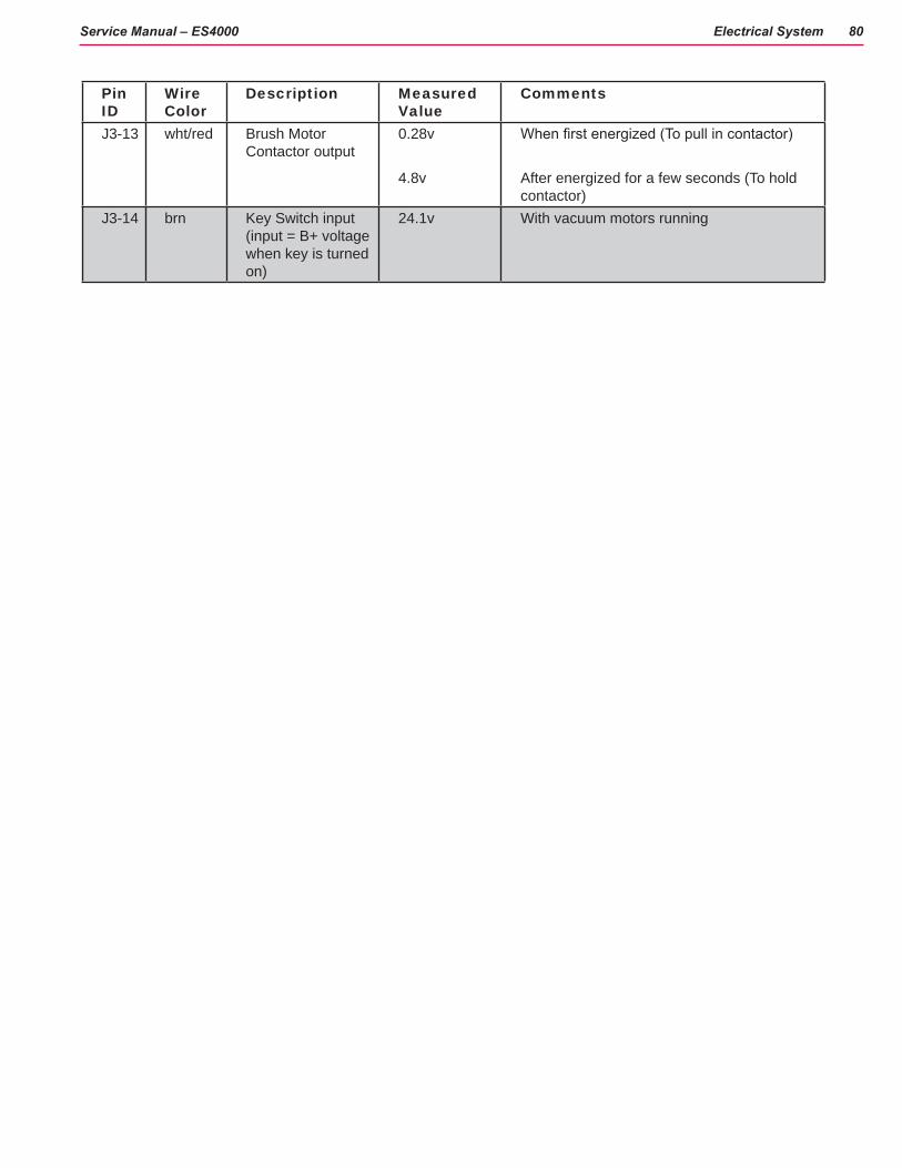
Electrical System 80Service Manual – ES4000
Pin ID
Wire Color
Description Measured Value
Comments
J3-13 wht/red Brush Motor Contactor output
0.28v
4.8v
When first energized (To pull in contactor)
After energized for a few seconds (To hold contactor)
J3-14 brn Key Switch input (input = B+ voltage when key is turned on)
24.1v With vacuum motors running

Service Manual – ES4000 Electrical System 81
A1CONTROL BOARD
ON BOARDBATTERY CHARGER (OPTIONAL)B+ B-
INTERLOCK1
PIN 6 - BRAKE -
PIN 9 - STATUS
PIN 16 - REV. ALARM
PIN 18 - SPEED LIMIT
PIN 13 - POT. LOW
PIN 4 - POT. WIPER
PIN 3 -POT HIGH
PIN
14
- B
RA
KE
+
PIN
5 -
KS
I
B+
B-
M1
M2
A2CURTIS 1228 SPEED CONTROLLER
J3-1 B+J3-8 B+
J3-14 KEY SWITCH
J3-12 VACUUM CONTACTOR
J3-13 BRUSH CONNACTOR
J3-11 MISTINGSOLUTION SOLENOID
J3-10 HORN +
J3-9 HORN -
J1-1 CHEMICAL PUMP(+)
J1-3 CHEMICAL PUMP(-)
SEAT SWITCH J3-4
FORWARD/REVERSE J3-6
STATUS J3-7
REVERSE J3-5
SPEED LIMIT J2-4
POT. HIGH J2-6
POT. LOW J2-5
B- J1-8
B- J2-8
B- J2-7
B- J2-1
B- J2-2
OPTIONAL
OPTIONAL
J1-7 RESTORESOLUTION SOLENOID
J3-3 MAINTENANCESOLUTION SOLENOID
NOTE: SWITCH IS PART OFPUMP ASSEMBLY
J1-2 SOLUTION PUMP
C
C
C
GRA/BLK
GRA/BLK
BLK
BLK
BRN/YEL WHT/BRN
RED
RED
RED
BRN/YEL
RED
BRN
BRN
BRN GRA/BLK
WHT/RED
VIO/BLK
BRN
BRN
ORN/RED
GRN/BLK
RE
D
RED/YEL
BLK
BLK
BLU/GRA
BLK
BLK
WHT/BRN
GRA
VIO
YEL
YEL
BLK/WHT
RED/GRN
BLK
BLU/BLK
ORN/BLU
RE
D/W
HT
RED/WHT
ORN
VIO YEL/BLK
BLK
BRN/BLK
BLK
BLK/WHT
BLU/ORNBRN
VIO/ORNBRN
B+
B-
L2
VALVE, SOLENOID
L2
VALVE, SOLENOID
1 2
EMERGENCY, STOP
S4
EMERGENCY, STOP
S4
L3
VALVE, SOLENOID
L3
VALVE, SOLENOID
1 2
M
M9
SOLUTION PUMP
M
M9
SOLUTION PUMP
+-
S2
SWITCH, SEAT
S2
SWITCH, SEAT
21
CB1
CIRCUIT BREAKER, 70A.
CB1
CIRCUIT BREAKER, 70A.
12
Y1BRAKEY1BRAKE
12
R1
POT 5.0K OHM
R1
POT 5.0K OHM
C
B
A
L1
VALVE, SOLENOID
L1
VALVE, SOLENOID
1 2
MM1
MO
TO
R, W
HE
EL
DR
IVE
MM1
MO
TO
R, W
HE
EL
DR
IVE
2
1
CB2
CIRCUIT BREAKER, 10 AMP
CB2
CIRCUIT BREAKER, 10 AMP
12
LP1
LAMP, FLASHING
LP1
LAMP, FLASHING
1 2
BT1
BATTERY, 24 Vdc
BT1
BATTERY, 24 Vdc
+ -
M
M2
CHEMICAL PUMP
M
M2
CHEMICAL PUMP
+-
F1
FUSE, 150A.
F1
FUSE, 150A.
1 2
K1
CONTACTOR, VACUUM
K1
CONTACTOR, VACUUM
S5S51 2
K2
CONTACTOR, BRUSH
K2
CONTACTOR, BRUSH
S1
SW, SPST KEY
S1
SW, SPST KEY
1 2
H1
HORN
H1
HORN
- +
Wiring (Ladder) Diagram 56344090 Rev. C (1 of 2)
NOTES:
1. DISCONNECT RED WIRE ON CB2 AND REPLACE WITH GREEN WIRE FROM CHARGER WHEN ON BOARD CHARGER IS USED

Service Manual – ES4000 Electrical System 82
SHOE ACT(-) J1-9
SHOE ACT(+) J1-10
BRUSH ACT(+) J1-4
BRUSH ACT(-) J1-5
FRONT BRUSH MOTOR SENSE J2-10
VACUUM MOTOR SENSE J2-9
REAR BRUSH MOTOR SENSE J1-6
A1CONTROL BOARD
C
C
WHT
WHT
REDRED
RED
RED
RED BLK
WHT/GRN
BLK/YEL
BLU
ORN/BLK
BLK
BLK
YEL/VIO
BLK
BRN/RED
VOI/RED
B+ B-
M
M6
MOTOR, VAC
M
M6
MOTOR, VAC
1 2
M
M4
MOTOR, BRUSH LIFT ACTUACTOR
M
M4
MOTOR, BRUSH LIFT ACTUACTOR
-+
M
M7
MOTOR, BRUSH FRONT
M
M7
MOTOR, BRUSH FRONT
+-K2
CONTACTOR, BRUSH
K2
CONTACTOR, BRUSH
4 3
M
M8
MOTOR, BRUSH REAR
M
M8
MOTOR, BRUSH REAR
+-
M
M5
MOTOR, VAC
M
M5
MOTOR, VAC
1 2
K1
CONTACTOR, VACUUM
K1
CONTACTOR, VACUUM
4 3
M
M3
MOTOR,SHOE LIFT ACTUACTOR
M
M3
MOTOR,SHOE LIFT ACTUACTOR
-+
Wiring (Ladder) Diagram 56344090 Rev. C (2 of 2)

Electrical System 83Service Manual – ES4000
Wiring Harness Diagram 56344091 Rev. C (1 of 2)

Electrical System 84Service Manual – ES4000
Wiring Harness Diagram 56344091 Rev. C (2 of 2)

85Service Manual – ES4000
Options and Accessories
Options1. Battery
6V 312 AH AGM, 6v420 AH WET
2. Shelf Charger (Portable) 24V auto 20 AMP 120 VAC/60HZ 24V auto 25 AMP 120 VAC/60HZ 24V auto 36 AMP 120 VAC/60HZ

Options and Accessories 86Service Manual – ES4000
3. On-Board Charger Assembly
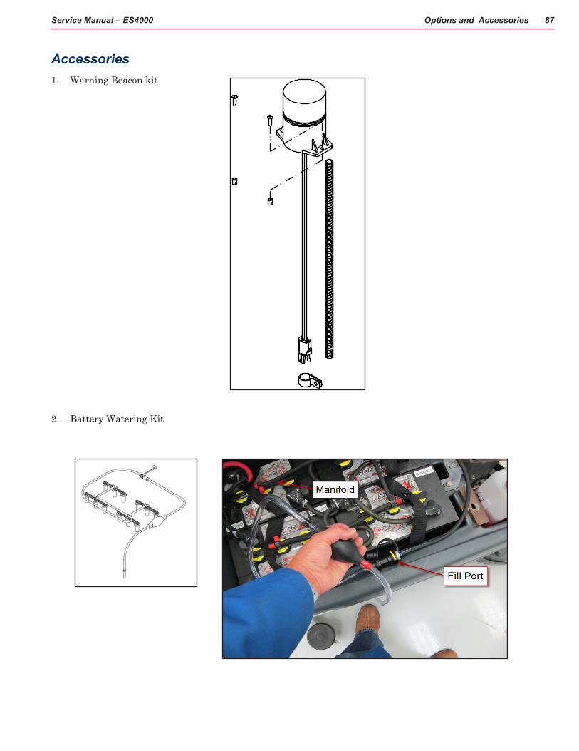
Options and Accessories 87Service Manual – ES4000
Accessories1. Warning Beacon kit
2. Battery Watering Kit

Options and Accessories 88Service Manual – ES4000
3. Chemical Bottle Assembly
4. Battery Fill indicator
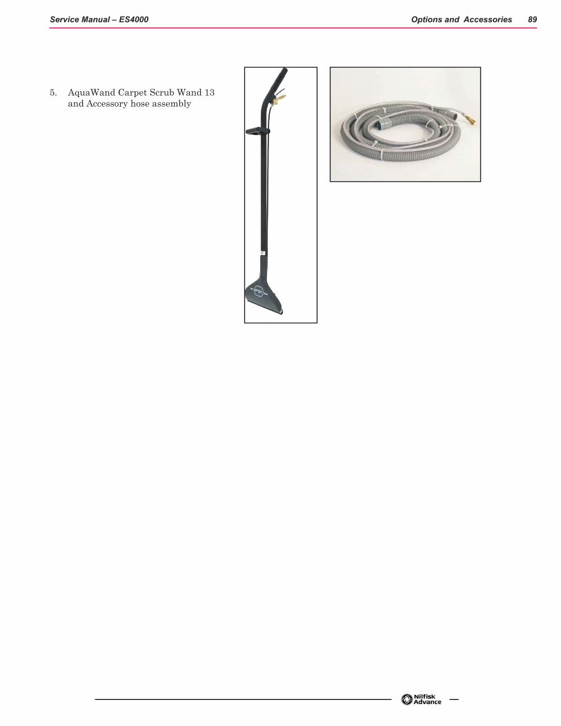
Options and Accessories 89Service Manual – ES4000
5. AquaWand Carpet Scrub Wand 13 and Accessory hose assembly

90Service Manual – ES4000
Recovery System
Functional Description
Recovery System—Vacuum General
During extraction, dirty water is lifted out of the carpet pile by airflow created by two 3 stage 24V vacuum motors. See Figure R-1. The dirty water and air enter at the two vacuum pick-up tools through their small narrow shoe openings that contact the carpet surface. A hose is connected to each shoe to direct water to the Recovery Tank hose that is connected to the Recovery Tank. Once inside the Recovery Tank, the heavier water falls to the bottom of the tank while the air continues through the shutoff float, vacuum motors and is exhausted out of the exhaust tube at the bottom of the vacuum motor housing.
The vacuum system uses a shutoff float that prevents the tank from being overfilled and also stops any water from being sucked into the vacuum motors. This shut-off function works when the float ball reaches its tank full level and the ball becomes seated in the float housing. The added restriction to the vacuum airflow causes a large electrical current load change (lower Amps) to the vacuum motors. Sensing the lowering of the vacuum circuit current load, the main controller A1 automatically shuts off the vacuum and cleaning systems and displays “FULL” on the hourmeter/status display.

Recovery System 91Service Manual – ES4000
Recovery System Circuit Description
The main controller turns on the vacuum motors by energizing the vacuum contactor. The vacuum contactor is provided battery positive voltage on one side of the coil through the key switch. To energize the contactor, the main controller completes a path to ground (battery negative) on the other side of the coil through an internal switch. When the vacuum contactor is energized, the contacts close and supply battery positive voltage to each of the vacuum motors. The vacuum motors are hard-wired to battery negative using a specially calibrated ground wire that has a specific resistance along its length. The purpose of this special calibrated ground wire is to allow the main controller to calculate the current flowing through the wire by measuring the voltage difference between the two ends of the wire. Inside the main controller there is an “internal voltmeter” which is connected across the ends of these wire. As the current increases, the voltage measured increases. The main controller also drives the vacuum shoe lift actuator. It acts as a double throw, double pole switch to provide battery positive and battery negative voltage across the actuator wires in order to drive the actuator. It reverses the polarity to drive the motor in both directions.
A1 Main ControllerS1 Key Switch
24v Battery
InternalVoltmeter
K1 Vacuum Contactor
M5 Vacuum Motor
M6 Vacuum Motor
CalibratedGroundWire
J3-12
J2-9
M3 Vacuum ShoeLift Actuator
B+ B- B- B+

Recovery System 92Service Manual – ES4000
Component Locations
• Recovery Tank and lid
• Recovery hose and dump hose
• Vacuum motor filter
• Strainer basket
• Tank Float shutoff
• Vacuum motor
• Wet Port
• Dry Port
• Vacuum Shoes
• Vacuum shoe lift actuator
• K1 vacuum contactor
See Figure R-1. Recovery Tank recovery hose and and dump hose
Vacuum motor filter
Strainer Basket
Tank Float ShutoffVacuum shoe
K1 vacuum contactorDry Port Wet Port
Vacuum shoe lift actuator

Recovery System 93Service Manual – ES4000
Figure R-1
Strainer Basket
Vacuum Motors
Vacuum Motor Filter
Recovery Tank Float shutoff
Recovery Tank and Lid
Recovery Hose
Dump hose

Recovery System 94Service Manual – ES4000
Maintenance and Adjustments
Recovery System Service Maintenance Checklist
Whenever there is a vacuum problem, check over the entire system. Use the checklist below as a guide to thoroughly check the vacuum system.
− Clean built-up dirt from the inside of both vacuum pick-up (shoes) tools. − Inspect the vacuum motors duct (plenum housing) cover gaskets, clean foam air inlet filters and
screens. − Inspect the hose between the pick-up tools and the recovery tank, rinse any built-up dirt from
the hoses. Replace the hose(s) if it is kinked or damaged. − Inspect and make sure the gaskets on the recovery tank covers are sealing and not damaged. − Inspect and clean the vacuum motor float cage, float ball and shut-off seat. − Make sure that the recovery tank drain hose cap seals airtight.
Recovery System Tank Float
Vacuum Filter and Float Cage Maintenance
To inspect and clean the vacuum motor foam filter just lift open the tethered Vac Duct Cover. Remove the filter by pulling it out from the housing opening. Clean the filter by vacuum or washing it out in warm water.
Note: The filter must be completely dry before reinstalling.
To inspect the vacuum shut off float just open the recovery tank cover to access the float cage assembly (back center in recovery tank). The cage openings must be kept free of any debris that can restrict maximum airflow. To keep it clean, wipe off with a rag regularly or remove and flush with water. The cage is a two piece design and can be snapped apart to separate.
Vacuum System Filter

Recovery System 95Service Manual – ES4000
The Recovery Tank Strainer Basket requires frequent cleaning to avoid clogging the system. Remove the strainer by lifting it upward off the mounting tab.
Completely rinse the basket with clean water and remove any debris that may still cling to the inside or outside.
Recovery Tank Strainer Basket Installation
Re-install the Basket by pushing the mounting tab into position and snapping it into place.
Recovery Tank Strainer Basket

Recovery System 96Service Manual – ES4000
TroubleshootingWhen extracting and experiencing little or no (below normal) waste recovery water entering the recovery tank, the vacuum system is not working properly. When the vacuum system performs poorly, it is usually because of one of the following problems:
Vacuum Leak(s) – Air flowing into the vacuum system past a bad gasket or leaky hose, damaged tank, or a leaky drain hose cap. A vacuum leak below the water line will create turbulence in the recovery tank, causing water to enter the vacuum motor.
Restriction(s) – Anything that blocks the flow of air through the system. Restrictions may also be caused by built-up debris in the pick-up tools, vacuum hoses, float cage or wherever the airflow is forced to make a sharp turn. Both leaks and restrictions decrease the quantity of air flowing through the pick-up tools. This results in less pick-up power.
Vacuum Electrical Components – The vacuum motors and vacuum solenoid are monitored by the main controller to detect any system function failures (error codes). Detected error codes are displayed on the hour meter LED display as they occur.
Note: Reference the Main Control Board Troubleshooting Guide in the Electrical System of this manual for specific fault descriptions and service repair actions.

Recovery System 97Service Manual – ES4000
Removal and Installation
Vacuum Motor(s) Removal
1. See Figure R-5. Remove the vacuum motor Cover (A) that is secured to the recovery tank by six (6) Screws (B).
2. Separate the wiring harness from the motor and lift motor out from it’s mounting cavity.
3. Inspect all the vacuum/recovery system Gaskets, (C, D) also clean the vacuum motor(s) Foam Filter (E), Strainer basket (F) and Hoses.
4. Inspect the carbon motor brushes, if less than 3/8” (10mm) in length replace.
Service Note: The hinged Tank Cover can easily be separated from the vacuum Duct Cover by removing the slotted Pin (use a flat blade screwdriver).
Figure R-5
Vacuum Motor Cover-AScrews-B
Gaskets - C
Gaskets - D
Foam Filter - EStrainer basket - F
Vacuum Motors

Recovery System 98Service Manual – ES4000
Recovery Tank Removal
Drain the recovery tank by using the drain hose.
See Figure R-6.
Figure R-6
Recovery Tank with hoses and connections
Drain Hose Vacuum Hose
Cover
Lift here with both hands

Recovery System 99Service Manual – ES4000
Remove the Recovery hose from the bottom connector bracket.
Swing open the operator seat platform (set the prop rod) and pull apart the vacuum motors’ harness connector (located left rear of battery compartment).
Open the hinged recovery tank Cover and grip the top inside edge of the tank and pull straight up to complete the tank’s separation from the machine’s solution tank/chassis assembly. Next guide the tank off the rear of the machine while taking care to prevent crushing of the vacuum hose, then lay the Tank down onto the floor.
Note: There is some weight to the tank assembly. Be careful when lifting it off. Ask for an extra helper to assist.
Lift here to remove the tank assembly

Recovery System 100Service Manual – ES4000
Vacuum Shoes Removal
1. With the Master Key Switch off, the vacuum shoes should be checked and cleaned daily.
2. See Figure R-7, Disconnect the vacuum recovery hose (AA) from the vacuum shoe (BB). Then pull up on the gold chain (CC). and slide the shoe (BB) away from the Shoe Support Weldment (DD).
Note: The procedure is the same for both shoes, however, the RIGHT shoe must be removed before removing the LEFT shoe.
3. Rinse the shoe housings with warm water to remove any build up of string, hair or carpet fibers. Then reinstall shoes in reverse order of removal.
Figure R-7

Recovery System 101Service Manual – ES4000
Extraction Shoe
Shoe Removal Chain
Lift the chain to remove the Shoe from the shoe support weldment.

Recovery System 102Service Manual – ES4000
Recovery System Wet and Dry Pickups—Accessory Port
Pickup Connectors
The pickup connectors are located on the lower rear part of the machine. This area is best accessed by removing the Recovery Tank but is also accessible by lowering the connector bracket as shown in the photo. Both Wet and Dry connectors are part of the connector bracket.
Lower Recovery System Connectors - Recovery tank removed
Wet connection to Recovery Hose
Wet ConnectionDry ConnectionAccessory Port

Recovery System 103Service Manual – ES4000
Wet Connection
When extracting connect the Recovery hose to the WET connection. When the Extraction shoes pull moisture from the carpet the liquid is transported through the hose to the Recovery Tank through the WET Connection. See photo on previous page. SEE OPERATOR’S MANUAL section OPERATING MACHINE–EXTRACT MODE.
Dry Connection
When operating in the Dry Sweep mode, connect the Recovery hose to the DRY connection. In Dry Sweep mode the vacuum system pulls dust from the hopper area and lightly sprays a water mist into the airstream to dampen dust as it sends it through the DRY Connection and hose to the Recovery Tank. SEE OPERATOR’S MANUAL section “OPERATING THE MACHINE–SWEEP MODE.
Large debris is either thrown into the hopper on the back of the deck, or captured in the strainer basket as it enters the Recovery Tank.
Hose Connected to DRY Connector

Recovery System 104Service Manual – ES4000
1. A misting nozzle is installed into the side of the Misting chamber adaptor. The nozzle assembly can be removed to access the misting nozzle itself.
Misting nozzle for DRY sweeping
2. Turn and pull the misting nozzle assembly from the misting chamber adaptor.
Misting nozzle assembly removed from Misting
chamber adaptor
3. Again, turn and pull the nozzle from the misting nozzle assembly. Clean or replace the nozzle and re-install into the assembly.
Install the misting nozzle assembly into the Misting chamber adaptor.
Nozzle

Recovery System 105Service Manual – ES4000
Accessory Port—Using Attachments
Optional attachments are available for detail or upholstery cleaning with an accessory hose.
1. Disconnect the recovery hose and connect the accessory hose to the Recovery Hose.
2. Attach the SOLUTION connection from the accessory hose to the accessory port located next to the DRY pick-up connection.
3. While not seated in the operator’s seat Turn ON the master key switch and press the VACUUM ON/OFF Switch. The Vacuum motor will run continuously until the switch is pressed again to turn it OFF.
Accessory Port on Recovery System lower panel – bottom rear of machine
Accessory Port

Recovery System 106Service Manual – ES4000
Recovery Shoe Lift Actuator Removal and Adjustment
1. Remove Batteries and Battery tray leaving the open chassis.
2. Access the actuator opening (s) in the chassis.
Access to Shoe Lift Actuator Pin
3. Working from the rear of the machine, Connect the actuator power cord adaptor (part # 56407502) to the harness connector for the Shoe Lift Actuator.
Attach the Positive and Negative leads to the corresponding terminals on a Battery.
Run the Actuator to place the Recovery Shoes to their lowest (on the floor) level.

Recovery System 107Service Manual – ES4000
4. Remove the Retaining Clips from both ends of the lift pin that connects the actuator to the shoe lift cable.
Remove the connecting pin from the Actuator and frame.
Release the cable holding clip.
5. Remove the motor mounting bracket bolts.
6. Remove the Actuator from the frame.
7. Reverse the process to reinstall. See Note!
Note: When re-installing the actuator be very careful not to turn the actuator nut. If the nut has remained in it’s original position the actuator can be reinserted and fastened into place without any other adjustments.

Recovery System 108Service Manual – ES4000
Actuator Drive Screw Tube Adjustment
The following instructions cover the procedure to adjust the drive nut (housing assembly) setting for the machine’s vacuum shoe lift actuator motor. Reference the chart below.
Actuator Motor Drive Drive Screw Tube IN
Drive Drive Screw Tube OUT
Shoe Lift 0.56 inches (14 mm) 2.81 inches (71 mm)
The “Drive Screw Tube IN/OUT Position” dimensions must be measured and adjusted before installing the actuator assembly on the machine.
General Instructions for All Actuator Motors
1. This shows the special actuator power cord adaptor (part # 56407502) that is needed to connect a battery pack and actuator motor for setting the drive nut limit settings.
2. If the batteries are installed, open the machine battery compartment and disconnect the battery connector. The battery pack is needed to power the lift actuator motor to properly set the IN & OUT limit switches.
3. Connect the actuator motor to be tested to the power cord adapter end. Then connect the alligator clips from the cord adapter (red clip to the positive and black to negative) to battery connector or battery posts. The rocker switch is used to change the motor rotation in setting the correct drive nut dimension.
Drive Screw Tube
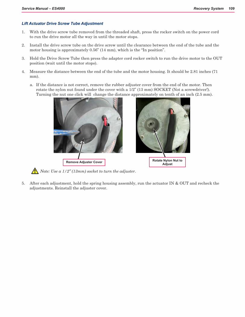
Recovery System 109Service Manual – ES4000
Lift Actuator Drive Screw Tube Adjustment
1. With the drive screw tube removed from the threaded shaft, press the rocker switch on the power cord to run the drive motor all the way in until the motor stops.
2. Install the drive screw tube on the drive screw until the clearance between the end of the tube and the motor housing is approximately 0.56” (14 mm), which is the “In position”.
3. Hold the Drive Screw Tube then press the adapter cord rocker switch to run the drive motor to the OUT position (wait until the motor stops).
4. Measure the distance between the end of the tube and the motor housing. It should be 2.81 inches (71 mm).
a. If the distance is not correct, remove the rubber adjuster cover from the end of the motor. Then rotate the nylon nut found under the cover with a 1/2” (13 mm) SOCKET (Not a screwdriver!). Turning the nut one click will change the distance approximately on tenth of an inch (2.5 mm).
Note: Use a 1/2” (13mm) socket to turn the adjuster.
5. After each adjustment, hold the spring housing assembly, run the actuator IN & OUT and recheck the adjustments. Reinstall the adjuster cover.
Remove Adjuster Cover Rotate Nylon Nut to Adjust

Recovery System 110Service Manual – ES4000
Specifications
Vacuum Motor(s) 2 of .75 HP (560-watt) three-stage
Vacuum performance Two Motors
Sealed: 66.92 in of Water ( kPa)
1” Open-hole Aperture: 23.09 in of Water ( kPa) Max Airflow: 90.1 CFM / 42.52 L/s

Recovery System 111Service Manual – ES4000
Special Tools
Actuator Power Cord Adaptor (part # 56407502)
Power Cord Adaptor in use

112Service Manual –ES4000
Solution System
Functional Description See Figure S-1. A molded plastic (polyethylene) tank stores the machine’s extraction solution. Total machine solution capacity is 29 gallons (109 L). Plumbed into the solution shut off Valve outlet is a serviceable spin off Filter Housing Assembly that keeps debris from entering the Solution Pump and solenoid valves (L1, L2 and L3). Also fitted is a short flexible Drain Hose to drain the tank for system maintenance. The electrical circuit that energizes the solenoid coils is activated through the operator panel buttons and main controller assembly A1.
Note: See the Know Your Machine section in this manual for a detailed explanation of the complete solution operation modes.
The three electrical solenoid valves L3 maintenance, L2 restoration and L1 misting control flow to the nozzles. The Maintenance nozzle directs the solution spray pattern onto the cleaning brush when in the maintenance extraction mode. The Restoration nozzle directs the solution in front of the cleaning brush when in the restoration mode (maximum flow). The misting nozzle directs solution to the misting chamber adaptor during dry sweeping, helping to improve dust filtration during dry pickup.
Chemical Pump
The Chemical Pump is provided for automatically mixing detergent with water from the Solution Tank. When prespray mode is selected at the control panel, the deck is lowered and the shoes are retracted upward, if they are down. When the throttle is engaged forward, the solution pump, the brush motors, and the restore valve will be activated, while the Chemical Pump is activated at a specific rate. The Solution pump, brush motors, Chemical Pump, and the restore valve will turn OFF when the throttle is in reverse or neutral.

Solution System 113Service Manual –ES4000
Solution System Circuit Description
To get solution flowing, the main controller turns on the solution pump and energizes one of three solenoids valves. The solution pump is supplied battery positive power on one side from the key switch. To turn the pump on, the main controller closes a switch to battery negative to complete the circuit. There are three solenoids that control the solution flow. Each of the solenoids is supplied battery positive power to the key switch. To energize one of the solenoids and allow the solution to spray, the main machine controller completes the path to battery negative through an internal switch.
The Main Controller also operates the detergent (Chemical) pump. The two wires for the pump are wired directly to the Main Machine Controller. The Main Machine Controller supplies battery positive on one wire and battery negative on the other for a short period of time to stroke the piston in one direction. It then immediately reverses polarity and does it again to stroke the piston back in the other direction.
Main Controller
L1 Misting Solenoid
L2 Restore Solenoid
L3 Maintenance Solenoid
Solution Pump
Key Switch
24v Battery
M2 Detergent (Chemical) Pump
B+ B- B- B+
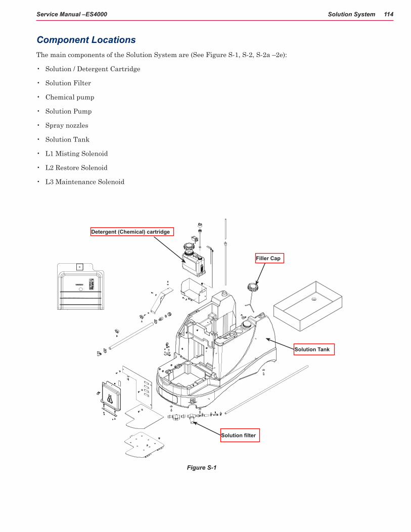
Solution System 114Service Manual –ES4000
Component LocationsThe main components of the Solution System are (See Figure S-1, S-2, S-2a –2e):
• Solution / Detergent Cartridge
• Solution Filter
• Chemical pump
• Solution Pump
• Spray nozzles
• Solution Tank
• L1 Misting Solenoid
• L2 Restore Solenoid
• L3 Maintenance Solenoid
Detergent (Chemical) cartridge
Filler Cap
Solution filter
Figure S-1
Solution Tank

Solution System 115Service Manual –ES4000
Solution Filter and shut-off
Detergent (Chemical) Pump

Solution System 116Service Manual –ES4000
Figure S-2
Figure S-2a
Detergent Cartridge Access Cover
Detergent Cartridge location
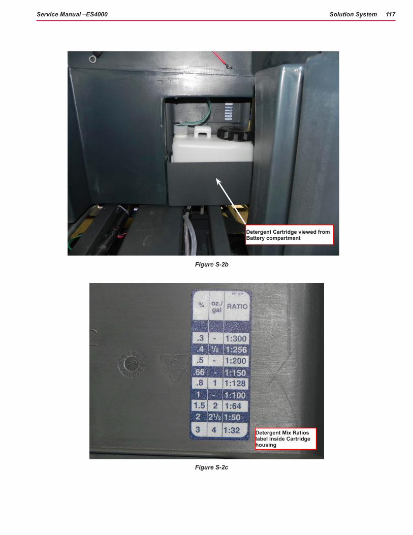
Solution System 117Service Manual –ES4000
Figure S-2b
Figure S-2c
Detergent Cartridge viewed from Battery compartment
Detergent Mix Ratios label inside Cartridge housing

Solution System 118Service Manual –ES4000
Solution Tank with Detergent cartridge access panel
Solution Solenoid Valves L2 and L3 L2
L3
Misting Solenoid L1
Solution Pump
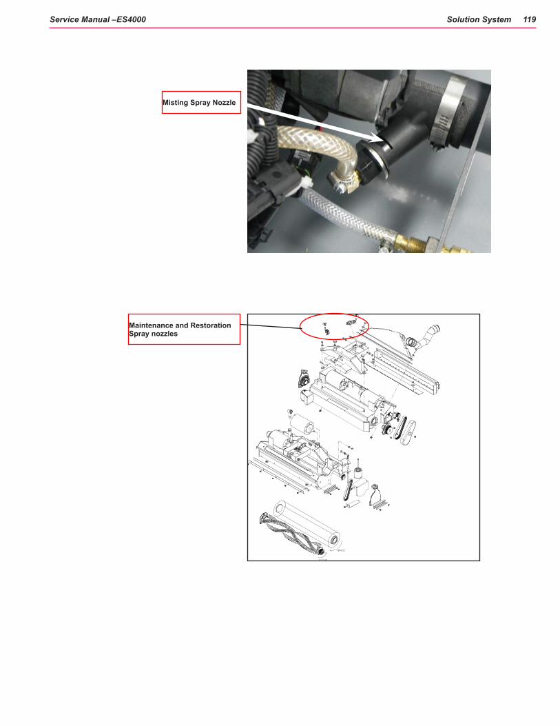
Solution System 119Service Manual –ES4000
Maintenance and Restoration Spray nozzles
Misting Spray Nozzle

Solution System 120Service Manual –ES4000
Figure S-2d
Figure S-2e
Solution Filter location
Solution hose (for drainage)

Solution System 121Service Manual –ES4000
Troubleshooting
Mechanical / Electrical / Plumbing
Problem Possible CauseInadequate or no solution flow No solution in the tank
Main solution flow shut off valve arm is in the closed positionClogged solution filter, hoses and solenoid valvesDefective solution solenoid coils (L1, L2 or L3)Solution system fault in the main controller A1*
*On all models the solution system’s electrical solution solenoids L1, L2 & L3 (misting, restoration & maintenance modes) are monitored by the main controller A1 to detect any system function failures (error codes). Detected error codes from the main controller are displayed on the operator panel display as they occur.
Note: Reference the Main Control Board Troubleshooting Guide in the electrical system of this manual for specific fault descriptions and service repair actions.
Maintenance and Adjustments • SolutionTank: Weekly, empty the solution tank; remove the solution Drain Hose from its storage area
(located underneath the left side of chassis). See figure S-2e. Direct the hose to a designated “Disposal Site” and flush the tank with clean water.
• SolutionFilter:Remove and clean the inline Solution Filter. See Figure S-2d. To access the filter housing for removal, work underneath the middle front of the solution tank see molded “FILTER ” callout. No tools are needed to remove the filter (hand tighten only).
Service Tip: The manual solution shut off valve (located next to the solution filter) must be placed in the full CLOSED position. This prevents loss of solution when servicing the filter strainer while there is solution in the tank.

Solution System 122Service Manual –ES4000
Purge Chemical Pump Weekly:
1. Disconnect and remove the detergent cartridge. Install and connect a Cartridge filled with clean water.
2. Turn the Key Switch (A)ON. Press and hold the Detergent ON / OFF Switch (C)and the Solution ON / OFF Switch (B)for more than 2 seconds while the controller is in any mode except standby to initiate a purge cycle.
Note: Once activated the purge process takes 10 seconds. See illustration on page 135 for Detergent System indicators. Normally one purge cycle is adequate to purge the system.
To Reset the Detergent Counter
As the detergent cartridge is used a counter counts down to keep track of the amount of detergent remaining. When the counter reaches it’s lowest level, the control panel indicates that the cartridge is empty. When refilling or replacing the cartridge, the counter needs to be reset.
To reset the counter, turn the Key Switch (A) ON. Press and hold the Maintenance Mode Switch (G) and the Restoration Mode Switch (H) for more than 2 seconds while the solution and detergent are ON. The Detergent Reset Icon will display for 5 seconds. See illustration on page 135 for Detergent System indicators.
Detergent Ratio
The pre-programmed ratio of detergent to water can be adjusted. There is a decal on the inside of the detergent cartridge access cover (see figures S-2 and S-2c) that will help to determine what ratio should be used for a specific detergent.To set the ratio, with the detergent system OFF, press andhold the Detergent ON/OFF Switch (C)for 2 seconds. The detergent indicator will fl ashand each press of the switch will cycle through the available ratios (1:64, 1:75, 1:100,1:125, 1:150, 1:175, 1:200, 1:250). Once the desired ratio is displayed on the screen, stop and ratio setting will lock in after 5 seconds.

Solution System 123Service Manual –ES4000
DETERGENT SYSTEM PREPARATION AND USE
D
C
B
A
F
G
H
I
E
DETERGENT ENABLED
DETERGENT DISABLED
FULL (RESET)
Press and hold (G) & (H) for more than 2 seconds to Reset.
LOW DETERGENT
PURGE
Press and hold (B) & (C) for more than 2 seconds to Purge.
Detergent system is ON when indicator is ON.
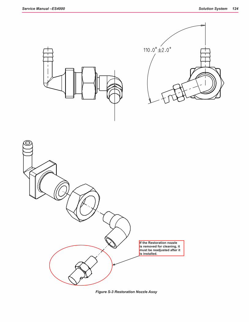
Solution System 124Service Manual –ES4000
Figure S-3 Restoration Nozzle Assy
If the Restoration nozzle is removed for cleaning, it must be readjusted after it is installed.

Solution System 125Service Manual –ES4000
Nozzle Maintenance
The nozzles are mounted on the Scrub Deck and shown in the Scrub System and the Chassis System. See Figure S-3a.
To inspect and clean both nozzles.
1. To remove the Restore nozzle, remove the fastener nut that secures the nozzle and pull it from the brush housing slot with the hose still connected.
Note: The entire Restore Nozzle assembly must be cleaned or the nozzle removed from the fittings and readjusted after the nozzle has been re-installed. See figure S-3.
2. To remove the Maintenance nozzle tip, twist the nozzle a 1/4 turn to separate it from the nozzle body.
Note: Nozzles should be inspected and cleaned once per week.
3. Clean the nozzles by soaking overnight in a solution of full vinegar solution or properly diluted and handled muriatic acid solution to remove build up of chemical deposits.
Note: Do not increase the size of the orifice by cleaning with a drill bit. This will adversely affect the nozzle pressure and spray pattern.
Figure S-3a - Nozzles are shown attached to the Scrub Deck
Nozzles
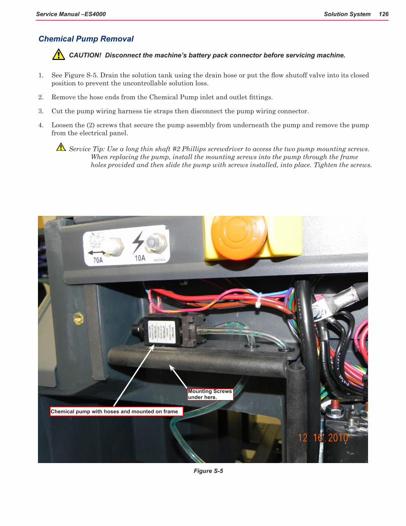
Solution System 126Service Manual –ES4000
Chemical Pump Removal
CAUTION! Disconnect the machine’s battery pack connector before servicing machine.
1. See Figure S-5. Drain the solution tank using the drain hose or put the flow shutoff valve into its closed position to prevent the uncontrollable solution loss.
2. Remove the hose ends from the Chemical Pump inlet and outlet fittings.
3. Cut the pump wiring harness tie straps then disconnect the pump wiring connector.
4. Loosen the (2) screws that secure the pump assembly from underneath the pump and remove the pump from the electrical panel.
Service Tip: Use a long thin shaft #2 Phillips screwdriver to access the two pump mounting screws. When replacing the pump, install the mounting screws into the pump through the frame holes provided and then slide the pump with screws installed, into place. Tighten the screws.
Figure S-5
Chemical pump with hoses and mounted on frame
Mounting Screws under here.

Solution System 127Service Manual –ES4000
Solution Solenoid Valve Removal
1. See Figure S-6. Put the solution flow shutoff Valve (C) into its closed position and the scrub deck in the down position then disconnect the battery pack.
2. Block rear wheels to prevent machine from rolling then jack up the front of the machine 3-4 inches.
CAUTION! Support machine with proper blocking for safety.
3. Cut the necessary wiring harness tie straps used on the Solenoid Valve Assembly then unplug each valve from the machine’s wiring harness.
4. Loosen the two screws that secure the solenoid mount bracket to the chassis, and slide the valve assembly off of the mounting screws.
5. Loosen the necessary hose clamps from the solenoid valve that needs service then pry the hoses off their fittings.
6. Remove the two screws that fasten the valve body to the mount bracket to complete removal.
Figure S-6
Solution Valves
L2
L3
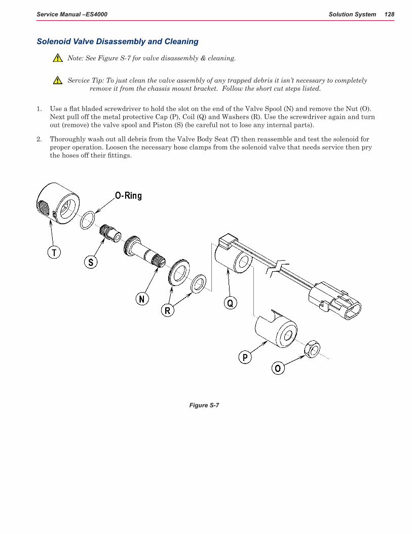
Solution System 128Service Manual –ES4000
Solenoid Valve Disassembly and Cleaning
Note: See Figure S-7 for valve disassembly & cleaning.
Service Tip: To just clean the valve assembly of any trapped debris it isn’t necessary to completely remove it from the chassis mount bracket. Follow the short cut steps listed.
1. Use a flat bladed screwdriver to hold the slot on the end of the Valve Spool (N) and remove the Nut (O). Next pull off the metal protective Cap (P), Coil (Q) and Washers (R). Use the screwdriver again and turn out (remove) the valve spool and Piston (S) (be careful not to lose any internal parts).
2. Thoroughly wash out all debris from the Valve Body Seat (T) then reassemble and test the solenoid for proper operation. Loosen the necessary hose clamps from the solenoid valve that needs service then pry the hoses off their fittings.
Figure S-7

Solution System 129Service Manual –ES4000
Nozzle and Pump DataComponents Flow Rate GPM/Working PressureNozzle “Maintenance” Spec. 033” orifice diameter Brass Nozzle tip I.D.1/8 K1
.29 GPM
Nozzle “Restoration” SPec. .091” orifice diameter - Brass Nozzle tip I.D.1/8 K 7.5
GPM
Pump Specifications Pressure relief switch opens at 100 PSI Max. flow rate 1.6 GPM Max. current 3.5A (average current 3.2A)
Specifications
Solution Control 1 Pump
Solution Flow Rates (1) Maintenance mode .29 gal/min TR 10155(2) Restore Mode .8 gal/min TR 10155
Detergent Ratios Available Using Ecoflex™
400:1 = .25% 200:1 = .5% 100:1 = 1% 32:1 = 3% 300:1 = .3% 150:1 = .66% 64:1 = 1.5% 256:1 = .4% 128:1 = .8% 50:1 = 2%
Recycle System Available
No

130Service Manual –ES4000
Scrub System
Functional Description Cylindrical Brush System Overview
The ES4000 uses two cylindrical brushes that counter rotate to sweep up light debris and scrub at the same time. Each scrub brush is powered by 1/2 HP permanent magnet motors and driven by separate poly-V belt/pulley drives. Debris is swept into the hopper on the back of the scrub deck.
The scrub deck platform is raised & lowered automatically by an electric lift actuator motor (M4). The operation of the machine’s scrub functions are activated when the operator selects (presses) either the Extract or Sweep panel buttons. The scrub brush pressure is electronically controlled to optimize scrub performance on a wide range of carpeted surfaces.
The vacuum motors and brushes run during all system cleaning modes. In DRY SWEEP mode, debris is swept into the hopper on the back of the scrub deck while dust and air are drawn toward the recovery tank.As the dirty air makes it’s way to the recovery tank it passes thru the misting chamber adaptor where the misting nozzle applies a mist that helps to contain the dust.

Scrub System 131Service Manual –ES4000
Scrub System Circuit Description
The main controller turns on the brush motors by energizing the brush contactor. The brush contactor winding is provided battery positive voltage on one side of the coil through the key switch. The main controller completes a path to ground on the other side, through an internal switch, in order to energize the contactor. When the brush contactor is energized, the contacts close and supply battery positive voltage to the brush motors which, are connected in parallel. The motors are hard-wired to battery negative using specially calibrated ground wires that have a specific resistance along their length. The purpose of these special calibrated ground wires is to allow the main controller to calculate the current flowing through the wire by measuring the voltage difference between the two ends of the wire. Inside the main controller there are “internal voltmeters” which are connected across the ends of these wires. As the current increases, the voltage measured increases. The main controller also drives the brush lift actuator. It acts as a double throw, double pole switch to provide battery positive and battery negative voltage across the actuator wires in order to drive the actuator. It reverses the polarity to drive the motor in both directions.
A1 Main ControllerS1 Key Switch
24v Battery
InternalVoltmeters
K2 Brush Contactor
M7 Brush Motor
M8 Brush MotorCalibratedGroundWires
J3-13
J2-10
J1 - 6
M4 Brush Lift Actuator
B+ B+B- B-

Scrub System 132Service Manual –ES4000
Component LocationsThe Scrub System main components are (Figure D-1):
• Scrub brushes (A)
• Brush motors (B) and drive belts (C)
• Debris hopper (tray) (D)
• Restoration Nozzle (E)
• Maintenance Nozzle (F)
• Scrub deck lift actuator (G)
A
B
C
D
E
F
Figure D-1
G

Scrub System 133Service Manual –ES4000
Maintenance and Adjustments
Scrub System Brush Maintenance
The scrub system must be serviced at regular intervals to maintain good scrub performance. Follow the maintenance steps listed below.
1. Rinse clean, built up debris from the debris hopper drain holes (daily).
2. Remove any string wrapped around the scrub brush, drive hub and idler hub (daily).
3. Clean spray nozzles attached to the front and top of the scrub deck (weekly) (See Solution section of this manual).
4. Clean built up dirt from the inside of the scrub brush housing (weekly).
5. Remove both the scrub brushes and rotate, turn the front brush end for end (weekly). See Scrub Brush Removal and Installation section.
6. Inspect the scrub brush bristles for wear monthly. The brushes should be replaced when the bristle length of the front brush is 1 inch (26 mm) or less and when the bristle length of the rear brush is 3/4 of an inch (19 mm) or less.

Scrub System 134Service Manual –ES4000
TroubleshootingThe ES4000 deck brush system’s major electrical components are monitored by the main controller (A1) to detect any system function failures (error codes). The system components covered are the brush motor(s) (M7 & M8), brush solenoid (K1) and brush lift actuator motor (M1). Detected error codes from the main controller are displayed on the hour meter LED display (E) as they occur. See Functional Description section wiring diagram.
Note: Reference the Main Control Board Troubleshooting Guide in the Electrical System of this manual for specific fault descriptions and service repair actions.

Scrub System 135Service Manual –ES4000
Removal and Installation
Scrub Deck Removal
1. See RECOVERY SYSTEM section of this manual to remove the vacuum hoses and shoes prior to deck removal. Also refer to Figures D1 & D1a through D-10.
2. To REMOVE the Scrub Deck assembly use the instructions on the following pages.
3. To INSTALL the Scrub Deck assembly follow the removal steps in reverse order.
Scrub Deck
Vacuum Hose
Vacuum Shoe
Debris Hopper
Brush access coverBrush
Drive belt guard

Scrub System 136Service Manual –ES4000
Figure D-1a
Vacuum hose
Scrub Deck mounting hitch pin
Scrub Deck mounting hitch pin
Debris Hopper
FWD
FWD

Scrub System 137Service Manual –ES4000
Deck lowered
Lift chain to remove the vac shoes
Figure D-2
Figure D-3
Figure D-4
Pull Vacuum shoe from deck mounting
2. Pull off the vacuum hose from the intake connector (Figure D1a). Remove both vacuum pickup shoes by lifting the removal chains then lift up and pull out to separate them from the shoe support weldment. (Figure D-3).
1. Lower the scrub deck with the brush(es) installed (Figure D-2). Attention: Don’t turn the key switch off until after disconnecting the battery pack with the Battery Disconnect (34). This will prevent the scrub deck from automatically raising when the key is turned off.
3. Remove the sweep debris Hopper (Figure D4) from the scrub deck.
Debris Hopper

Scrub System 138Service Manual –ES4000
Remove deck wiring harness
Figure D-5
Figure D-6
4. Unplug the brush motor wiring harness (Figure D-5).
5. Remove the ground wire on the deck.
Remove cotter key from actuator link pin, then remove the link pin.
6. Remove the Hitch Pin that secures the brush deck lift actuator to the scrub deck. (Figure D-6).

Scrub System 139Service Manual –ES4000
Remove solution hose from nozzle(s)
Deck removed
Figure D-7
Figure D-8
Figure D-9
7. Remove the tubing for the solution nozzles (Figure D-7).
Deck mounting pin removed
8. Remove the two Hitch Pins (Figure D1a & D-8) that attach the scrub deck to the machine chassis linkage arm weldment.
9. Carefully maneuver the deck from under the machine to complete its removal (Figure D-9).
Service Note: It is important that the disconnected deck actuator motor is not run. This precaution will prevent the actuator drive nut from being moved from its set specification.

Scrub System 140Service Manual –ES4000
Scrub Deck Actuator Removal
1. To remove the Scrub Deck Actuator begin by removing the Recovery Tank. This will expose the battery compartment and the lower accessory, Wet and Dry hose connections.
2. Remove the battery post connectors and disconnect the cable connectors at the rear of the compartment. Use a hoist to lift all of the batteries together or individually remove them from the battery tray.
3. Remove the battery tray. This will expose the access holes for the Actuators.
Access opening for Scrub Deck Actuator.

Scrub System 141Service Manual –ES4000
4 Working from the rear of the machine, locate the actuator position and the electrical harness for that particular actuator. Disconnect the harness to the actuator. The connection is usually near the end of the actuator (see circle in photo). Remove the 2 bracket screws over the Brush Lift Actuator motor.
6. Attach the actuator power cord adaptor to the harness connector for the Deck Lift Actuator. Attach the Positive and Negative leads from the adaptor to a battery on the corresponding Positive and Negative terminals. See section on Actuator Drive Nut Adjustment.
5. Place a wooden block under both sides of the deck. Tension will be released on the actuator allowing it to be loosened and the lift cable removed.
Remove bracket
Remove two bracket screws

Scrub System 142Service Manual –ES4000
7. Make note of the actuator position in case it rotates out of adjustment.
Run the actuator with the power adaptor until the tension on the lift cable is released.
Indicator runs inside this groove. Move the indicator back just far enough to
release tension.
Lift Actuator mounted under chassis near solution solenoids
Cotter key and mounting pin through end of Actuator Housing
8. Remove the cotter keys at both ends of the mounting pin that passes through the end of the Actuator housing. Remove the washers and slide the brass bushings off the pin.

Scrub System 143Service Manual –ES4000
Remove the Pin
Remove the remaining fastener bolt in the frame.
10. Remove the remaining fastener bolt in the frame. Be careful when the Actuator becomes loose. Be ready to grasp it with your hand.
11. Remove the Actuator Assembly from the frame.
12. To install the Actuator assembly after adjustments or replacement, reverse the removal process. Be careful to not spin the Spring Housing out of adjustment.
9. Remove mounting pin from the housing.

Scrub System 144Service Manual –ES4000
Actuator Drive Nut Adjustment
The following instructions cover the procedure to adjust the drive nut (housing assembly) setting for the machine’s scrub deck actuator motor. Reference the chart below that shows the IN & OUT dimensional specification for the actuator motor that is used on the ES4000.
Actuator Motor Drive Nut Housing Assy IN
• Drive Nut Housing Assy OUT
Brush Lift (ALL) See Adjustment Procedure
3.5 inches (89 mm)
The “Drive Nut Housing Assy IN/OUT Position” dimensions are measured when completely assembled and off the machine. Reference points are the edge of the plastic Spring Housing Assembly.
General Instructions for All Actuator Motors
1. This shows the special actuator power cord adapter that is needed to connect a battery pack and actuator motor for setting the drive nut limit settings.
2. If the batteries are installed, open the machine battery compartment and disconnect the battery connector. The battery pack is needed to power the lift actuator motor to properly set the IN & OUT limit switches.
3. Connect the actuator motor to be tested to the power cord adapter end. Then connect the alligator clips from the cord adapter (red clip to the positive and black to negative) to battery connector or battery posts. The rocker switch is used to change the motor rotation in setting the correct drive nut dimension.

Scrub System 145Service Manual –ES4000
Scrub Deck Lift Actuator Drive Nut Adjustment
1. Assemble spring housing
a. Install the 3 springs and drive nut into one half of the spring housing as shown. Then snap the two spring housing halves together, retaining the springs and nuts inside the housing.
2. Screw the spring housing assembly onto the threaded drive screw a few turns.
3. Press the rocker switch on the power cord to run the drive motor all the way in until the motor stops.
4. Screw the spring housing onto the threaded drive screw until the end of the drive screw shaft just contacts the end of the spring housing.
5. Rotate the housing, either direction (whichever is shortest) until the “flat” surface of the housing will be“up” when the actuator assembly is installed on the machine.
6. Hold the spring housing assembly then press the adapter cord rocker switch to run the drive motor to the OUT position (wait until the motor stops).
Flat Surface Up
3 Springs
Drive Nut
Spring Housing Half

Scrub System 146Service Manual –ES4000
7. Measure the distance between the end of the spring housing and the motor housing. It should be 3.5 inches (89 mm)
a. If the distance is not correct, remove the rubber adjuster cover from the end of the motor. Then rotate the nylon nut found under the cover with a 1/2” (13 mm) SOCKET (Not a screwdriver!). Turning the nut one click will change the distance approximately on tenth of an inch (2.5 mm). After changing the adjustment, run the motor in and out and recheck the “Out” position distance.
Note: Use a 1/2” (13mm) socket to turn the adjuster.
8. After each adjustment, hold the spring housing assembly, run the actuator IN & OUT and recheck the adjustments. Reinstall the adjuster cover.
Remove Adjuster Cover Rotate Nylon Nut to Adjust

Scrub System 147Service Manual –ES4000
Figure D-12
Belt guard
Figure D-13
Belt Guard removed
Figure D-14
Belt installation/removal tool and method
It is recommended that you remove the Deck assembly from the machine to remove the brush motors.
See Figures D-12 through D-15. Remove the Belt Guards (1 screw per side). With an operator in the driver’s seat with the key switch ON and the maintenance mode scrub function selected press the drive pedal to start the scrub brushes and observe which brush motor needs to be removed.
WARNING! Disconnect the battery pack by activating the emergency stop switch and using the battery disconnect before servicing.
Remove the scrub brush drive belt using a belt installation/removal tool (Figure D-14).
Note: The installation/removal tool shown may be replaced by a flat blade screwdriver. The photo shows installation of the belt but removal uses a similar method.
Brush Motor Removal

Scrub System 148Service Manual –ES4000
Figure D-15
Wire connections on motor
Remove the wiring at both the Pos. & Neg. brush motor terminal studs and note the correct wiring connections (for reinstallation) (Figure D-15). Then remove the (3) Screws (Y) and lift the motor out from the scrub deck.
Reassemble in reverse order.
Note: Install motors with wires pointing to the rear towards the plastic motor wiring standoffs.
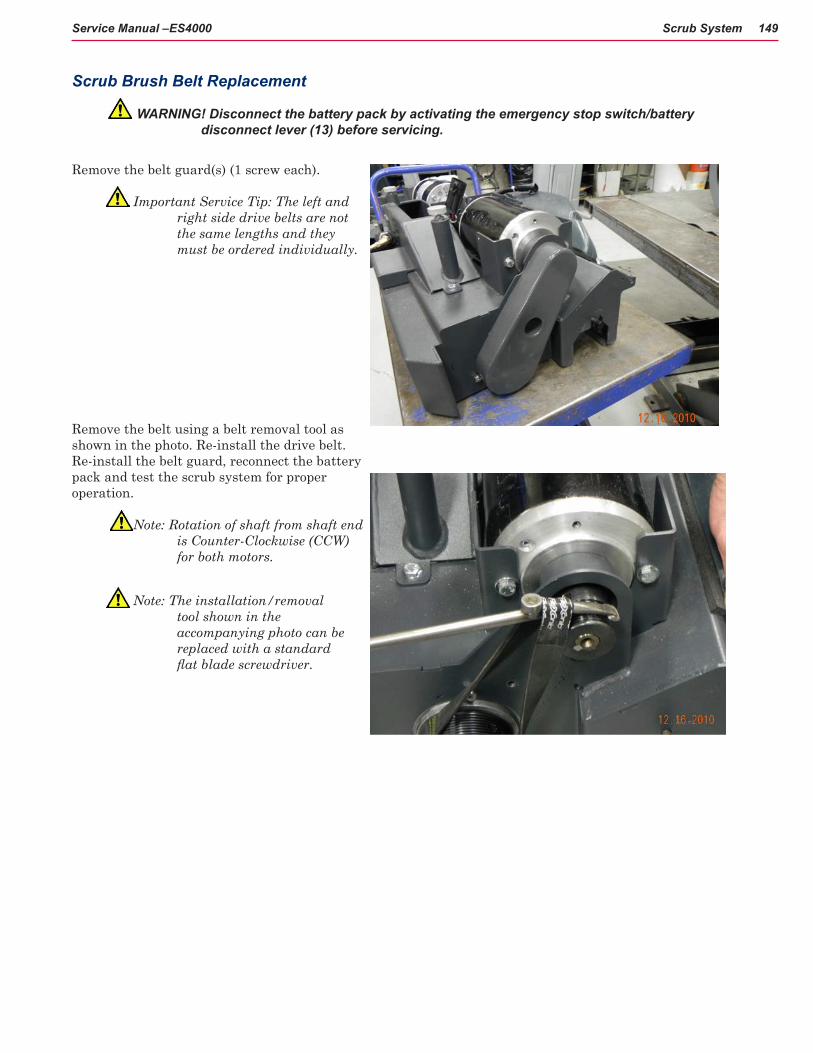
Scrub System 149Service Manual –ES4000
Scrub Brush Belt Replacement
WARNING! Disconnect the battery pack by activating the emergency stop switch/battery disconnect lever (13) before servicing.
Remove the belt guard(s) (1 screw each).
Important Service Tip: The left and right side drive belts are not the same lengths and they must be ordered individually.
Remove the belt using a belt removal tool as shown in the photo. Re-install the drive belt. Re-install the belt guard, reconnect the battery pack and test the scrub system for proper operation.
Note: Rotation of shaft from shaft end is Counter-Clockwise (CCW) for both motors.
Note: The installation/removal tool shown in the accompanying photo can be replaced with a standard flat blade screwdriver.

Scrub System 150Service Manual –ES4000
Scrub Brush Removal and Installation
Figure D-16
Fastener knob Access cover Brush
Figure D-17
Make sure the key switch is off and disconnect the battery pack before servicing.
See Figure D-16. Loosen the black fastener knobs (one on each side) that secure the removable access covers. Pull the covers down and out to remove. Grip the scrub brush and slide it out from the housing end.
To install the brush slide it into the housing, lift slightly, push and turn until it seats into the drive end assembly slots.
Re-install the access cover and tighten the fastener knobs.
See Figure D-17 for shaft rotation and orientation.

Scrub System 151Service Manual –ES4000
Cleaning Deck Type(s) Cylindrical
Cleaning Brush Size(s)and Type(s) (2) 27 in (68.6 cm) Type: Cyl
Scrub path: 28 in. (71.1 cm)
Scrub Motor(s)
Right-hand Motor: .5 HP 373 watts/15.54 Amps
Left-hand Motor: .5 HP 373 watts/15.54 Amps
Scrub Head Speed(s) Right-hand Motor: 1800 RPM
Left-hand Motor: 1800 RPM
Specifications
Scrub System

Scrub System 152Service Manual –ES4000
Special Tools
Actuator Power Cord Adaptor—Part # 56407502

Steering System 153Service Manual – ES4000
Steering System
Functional DescriptionThe Steering System is all mechanical consisting of the steering wheel, shaft, gears and the chain gear drive on the Drive Wheel.
Component LocationsThe Steering System main components are:
• Steering Wheel
• Lower Column Shroud
• Lower Steering Column
• Steering Column Spindle
• Steering boot
• Steering knuckle
• Steering shaft, gears, chain gear on Drive Wheel
Steering Wheel
Steering Column Spindle
Steering Boot
Lower Column Shroud
Lower Steering Column
Steering Knuckle
Chain and drive sprocket
Drive gear and chain

Steering System 154Service Manual – ES4000
Maintenance and AdjustmentsThe Steering System requires minimal maintannce and no adjustment. The most important maintenance item is the Steering Knuckle (Steering Wheel Shaft Universal Joint) where the Spindle attaches to the Column. This is a critical part of the steering mechanism and requires lubrication at least once per month. Anoilfittingislocatedwheretheknucklepivots.Uselightmachineoilinthisfitting.
Steering Wheel Shaft Universal Joint

Steering System 155Service Manual – ES4000
Removal and Installation
Steering Column shroud removal
1. Remove the 4 screws fastening the Lower Column Shroud to the Lower Column Weldment. Figure ST-1.
2. Usingaflatbladedscrewdriver,pryoffthesteeringwheel plastic center cap.
3. Using a 3/4” socket, remove the hex nut from the steering wheel center.
4. Pound the steering wheel off from behind using a mallet, observing the Woodruff key as it may fall out in the process.
Steering Wheel removed
Screws 2 of 4
Figure ST-1

Steering System 156Service Manual – ES4000
5. Pull accordian Steering Boot from the upper steering column.
6. Lift the battery charger cover.
7. Pry the plastic Lower Column Shroud off the weldment by starting on the left side (away from knob) so shroud can clear the weldment linkage bump on the right side.
Reassemble in reverse order, applying a light coat of Silicone spray or water to the inside of the Steering Boot. This will permit free travel over the shaft and ease assembly.
Steering Boot
Battery charger cover open
Shroud lifted from battery charger compartment
Shroud lifted up and off the Steering Column

157Service Manual – ES4000
Wheel System, Non-Traction
Functional Description
The rear wheels are undriven and individually fastened to the machine via spindles and mounting bolts.
Component LocationsThe Wheel System Non-Traction consists of the two rear (Left and Right) wheels, tires, mounting washers and bolts and a wheel bearing. They are mounted to the rear spindles on the lower frame of the main chassis.
SpindleTire and wheel assy
Mounting washer and bolt
Wheel bearing

Wheel System, Non-Traction 158Service Manual – ES4000
Removal and Installation
Replacing the Rear Wheels
1. Block the front Drive Wheel
2. Raise the Rear Wheel (17) to be replaced using a bottle jack on a secure frame member of the machine.
3. To prevent injury, if the rear wheel bearing has frozen, replace the bottle jack with blocks or a jack stand.
4. See Figure WNT-1. Use a 17 mm socket to remove bolt (A), washer (B) and wheel (C).
5. If the bearing has seized, pound off the wheel and use a bearing puller to remove the inner race from the axle.
6. Apply anti-sieze to the inner bearing surface of the new wheel. Install wheel on axle.
7. Apply anti-sieze to the bolt threads before tightening the bolt, washer and wheel.
Figure WNT-1

159Service Manual – ES4000
Wheel System, Traction
Functional DescriptionThe drive wheel assembly is directly connected to the speed controller, which not only provides an output signal of 24V to the drive wheel for forward and reverse movement, but also monitors current and temperature, and controls the electromagnetic brake. The speed controller is programmable through, and can be monitored via, the Curtis Handheld Programmer(part # 56409441) and Curtis Adapter Cable with Quad Plug (part # 56409823), listed in the Special Tools section of this chapter. For information on how to use the Curtis programmer, please refer to the Curtis Programmer Manual (doc. # 56043101).
The throttle potentiometer in the foot pedal controls drive speed and forward/reverse movement. The throttle pot input to the main control board also determines whether or not the vacuum system will engage and is therefore critical to machine performance When the vacuum system is enabled, the brushes are energized and cleaning begins. If the control board senses a Neutral position of the foot pedal, it will not engage these systems unless placed in Service Test Mode or one of the vacuuming modes.
The Electromagnetic Brake is engaged whenever the foot pedal is in Neutral. When the Brake is released, Forward/Reverse is enabled and the drive wheel is energized.

Wheel System, Traction 160Service Manual – ES4000
Wheel System, Traction Circuit Description
The A2 speed controller has heavy current battery positive and battery negative wires that supply the current it needs to drive the wheel motor. The controller wakes up when it receives power through the key switch, emergency stop switch and the seat switch.
S1 KeySwitch
24v BatteryF1 150 A fuse
CB 2 S4 EmergencyStop Switch
S2 SeatSwitch
CB 1
A2 SpeedController
B+
B-
The controller switches power on to the drive wheel motor by providing a connection to battery positive on one wire and to battery negative on the other wire. To reverse direction the controller reverses polarity. Of course this is a slightly simplified explanation, as the motor is not merely switched full on or off. The controller regulates the amount of voltage supplied to the motor to control the motor speed.
B+ B+B- B-
A2 SpeedController
Drive Wheel Motor

Wheel System, Traction 161Service Manual – ES4000
The main input for the speed controller is the drive pedal potentiometer. The controller sends out a regulated five volt supply to one side of the potentiometer. The other side of the potentiometer is connected to battery negative through the POT Low circuit inside the speed controller. This provides a clean filtered ground. A third wire runs from the speed controller to the center terminal of the potentiometer. This is called the “signal” or “wiper” circuit. Inside the potentiometer, a “wiper” moves along a resistive strip. When the drive pedal is in the center or “neutral position”, the wiper is exactly in the middle of the resistive strip and the voltage output is 2.5v to the speed controller. As the drive pedal is moved forward, the wiper moves toward the 5v supply so the voltage increases up to nearly 5v when the pedal is all the way forward. When the drive pedal is moved backwards from the center position the wiper moves towards the ground supply so the voltage drops from 2.5 V down to nearly 0v in full reverse. These voltage changes are “understood” by the controller and are used to request forward and reverse direction as well as speed.
There is a second input, called “Speed Limit” that is used to regulate top speed. The POT high and POT low circuits are also provided to the A1 main controller from the A2 speed controller. This is a 5 V supply source which the main controller modifies and sends back on the speed limit circuit to the drive controller. To request a high top speed, the main controller sends a higher voltage. To request a lower top speed, the main controller reduces the voltage. The speed limit request is dependant on the machine operating mode.
The drive wheel has an electronic brake which is spring-loaded in the locked position. To release the brake, an electric solenoid must be energized. The speed controller supplies battery positive to one side of the brake solenoid winding and switches the other side to battery negative to release the brake. The brake is released whenever the drive pedal is moved from the center “neutral” position in either the forward or reverse direction.
Forward
Reverse
Neutral5v supply
B-Wiper (Input)
A2 Speed ControllerDrive Pedal Potentiometer
A1 Main Controller
5v (POT High)
A2 SpeedController
B- POT Low
0-5vSpeed Limit
5v
B-
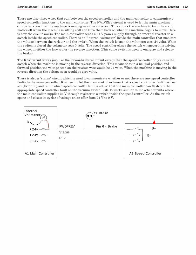
Wheel System, Traction 162Service Manual – ES4000
There are also three wires that run between the speed controller and the main controller to communicate speed controller functions to the main controller. The FWD/REV circuit is used to let the main machine controller know that the machine is moving in either direction. This allows the machine to turn the scrub motors off when the machine is sitting still and turn them back on when the machine begins to move. Here is how the circuit works. The main controller sends a 24 V power supply through an internal resistor to a switch inside the speed controller. There is an “internal voltmeter” inside the main controller that monitors the voltage between the resistor and the switch. When the switch is open the voltmeter sees 24 volts. When the switch is closed the voltmeter sees 0 volts. The speed controller closes the switch whenever it is driving the wheel in either the forward or the reverse direction. (This same switch is used to energize and release the brake).
The REV circuit works just like the forward/reverse circuit except that the speed controller only closes the switch when the machine is moving in the reverse direction. This means that in a neutral position and forward position the voltage seen on the reverse wire would be 24 volts. When the machine is moving in the reverse direction the voltage seen would be zero volts.
There is also a “status” circuit which is used to communicate whether or not there are any speed controller faults to the main controller. It is used to let the main controller know that a speed controller fault has been set (Error 03) and tell it which speed controller fault is set, so that the main controller can flash out the appropriate speed controller fault on the vacuum switch LED. It works similar to the other circuits where the main controller supplies 24 V through resistor to a switch inside the speed controller. As the switch opens and closes its cycles of voltage on an offer from 24 V to 0 V.
A1 Main Controller
Pin 6 - Brake
Y1 Brake
B+
B-
+24v
+24v
+24v
FWD/REV
Status
B-
InternalVoltmeter
REV
A2 Speed Controller

Wheel System, Traction 163Service Manual – ES4000
A1 Main Controller
S1 KeySwitch
24v BatteryF1 150 A fuse
CB 2 S4 EmergencyStop Switch
S2 SeatSwitch
J3-4
CB 1
5v (POT High)
Signal
A2 SpeedController
B- POT Low
InternalVoltmeter
Pin 6 - Brake
Y1 Brake
0-5v
B+
B-
+24v
+24v
+24v
FWD/REV
Status
B-
InternalVoltmeter
B+
B-
B+ B+B- B-
Speed Limit
REV
Drive Wheel Motor
Speed Control System Functional Electrical Schematic

Wheel System, Traction 164Service Manual – ES4000
Component Locations• Lower Chassis
• Drive Spindle
• Drive Wheel assembly with Electromagnetic Brake
• Drive Pedal (forward/reverse) and Potentiometer (Also shown in CONTROL SYSTEM)
• Curtis Speed Controller
Spindle Hex nut
Chassis
Drive wheel assemblySpindle
Wheel Drive System
Drive pedal
Potentometer
Speed controller

Wheel System, Traction 165Service Manual – ES4000
Maintenance and AdjustmentsThe Speed Controller is programmable. Programming is covered in the manufacturer’s literature. When the Speed Controller is replaced (installed) a specific checkout procedure is required.
Curtis Speed Controller Installation Checkout Procedure
After installing a controller and before operating the vehicle, carefully complete the following checkout procedure. If you find a problem during checkout, refer to the Curtis programmer manual for more information.
The installation checkout can be conducted with or without the handheld programmer. The checkout procedure is easier with a programmer otherwise observe the Status LED for codes (located on operator panel wand indicator light).
WARNING! Put the vehicle up on blocks to get the drive wheel off the ground before beginning these tests.Turn the key switch off and make sure that the seat switch is open, and the throttle (pedal) is in neutral. Do not stand, or allow anyone else to stand, directly in front of or behind the vehicle during the tests.
Remove the electrical cover panel to access the controller.
1. Observe the error status fault indicator (DETERGENT LED) on the operator control panel. If a programmer is available, connect it to the programmer plug-in port
2. Sit on the seat and turn the key switch on. The programmer should “power up” with an initial display. If neither happens, check for continuity in the key switch circuit and controller ground.
3. If you are using a programmer, put it into diagnostic mode by pressing the DIAGNOSTICS key.
◦ If there is no error detected, the display should indicate “No Faults Found”. Note: Before pressing the diagnostics key, wait until model # screen appears, if the throttle is activated prior to this screen appearing the controller will shut down.
◦ If there is a problem, the control panel will flash a diagnostic code and the programmer will display a diagnostic message. If you are conducting the checkout without a programmer, refer to the Status LED Fault Codes table in “Speed controller Error Flash Codes” to diagnose the cause.
4. When the problem has been corrected, it may be necessary to cycle the key or seat switch to clear the fault code.
5. While sitting on the seat, operate the throttle. The motor should begin to turn in the selected direction. If it does not, verify the wiring to the controller, and the motor. The motor should run proportionally faster with increasing throttle. If not, refer to the Curtis manual.
6. Put the programmer into test mode by pressing the TEST key. Scroll down to observe the status of the forward, reverse and brake switch. Cycle each switch in turn, observing the programmer. Each input should show the correct state on the programmer.
7. Take the vehicle off the blocks and drive it in an open area. It should have smooth acceleration and good top speed.

Wheel System, Traction 166Service Manual – ES4000
Troubleshooting
General Troubleshooting
When troubleshooting various problems related to the WHEEL SYSTEM it is best to approach the issues with some fundamental steps:
1. If the machine isn’t responding to the drive pedal inputs, forward or reverse, visually inspect that all connections are intact, such as the potentiometer connection.
2. Check and test the batteries for proper charge.
3. Check for any Fault codes. If codes are present, repair malfunction if possible.
4. Be sure the key switch is correctly inserted and/or reset the machine by turning the key off and then ON again.
If these basic checks do not reveal the nature of the problem then see simplified wiring diagram in electrical section of this manual.
Problem Possible CauseMachine will still not move forward or reverse 1. Wheel drive motor circuit breaker (CB1) tripped
(reset 70A circuit breaker). 2. Control board circuit breaker (CB2) tripped (reset circuit breaker). 3. Emergency stop knob tripped (pull out and twist). 4. Safety switch (S2) in seat not closed (check seat switch). 5. Defective wheel drive motor (replace motor). 6. Defective throttle potentiometer (replace).
The wheel drive motor will run only in forward or run only in reverse.
1. Test the Potentiometer wiring outputs pins 3, 4, & 13) at the speed controller for an open. Repair wiring or replace the Drive Pedal Assembly. 2. Controller can’t change electrical polarity to wheel motor - replace the (A2) speed controller.
Pin Function Wire Color3 5.02k Ohm Pot High YEL4 5.02k Ohm pot Wiper GRA5 Seat switch GRA/BLK6 Brake - (minus) RED/WHT8 Mode BLK/WHT9 Error status ORN/BLU13 5.02k Ohm Pot Low VIO14 Brake + (plus) ORN16 Reverse alarm BLU/BLK18 Speed limit BLK/WHT
A2 Pin assignments

Wheel System, Traction 167Service Manual – ES4000
A2 (J10) pin outs
Wheel Drive Motor Typical Current (AMPS) Transport, Full Throttle
Wire colors
M1 15-20 Red/Green and Yellow/Black

Wheel System, Traction 168Service Manual – ES4000
Speed Controller Diagnostics
The Speed Controller diagnostics uses the machine’s control panel LCD display and DETERGENT switch indicator. Another available method is to use the optional hand held Curtis programmer model 1311.
Speed Controller Status Light /Display Functions
If a speed controller fault occurs, the LCD display will indicate “E03”. Additionally the DETERGENT button LED flashes out a specific speed control error code until the fault is corrected. Speed control codes consist of two digits. Count the flash sequence of the DETERGENT LED to obtain the code. Example: (OOO O )3 flashes and a short pause followed by 1 flash and a long pause = 3,1 . See ERROR CODES table for a description of the fault indications.
Speed Controller
Error code displayed
Count Detergent LED flashes for Speed Control Fault Codes
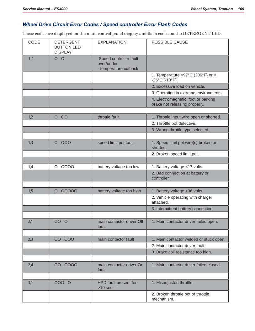
Wheel System, Traction 169Service Manual – ES4000
Wheel Drive Circuit Error Codes / Speed controller Error Flash Codes
These codes are displayed on the main control panel display and flash codes on the DETERGENT LED.
CODE DETERGENT BUTTON LED DISPLAY
EXPLANATION POSSIBLE CAUSE
1,1 O O Speed controller fault-over/under - temperature cutback
1. Temperature >97°C (206°F) or < -25°C (-13°F).
2. Excessive load on vehicle. 3. Operation in extreme environments. 4. Electromagnetic, foot or parking
brake not releasing properly.
1,2 O OO throttle fault 1. Throttle input wire open or shorted.2. Throttle pot defective.3. Wrong throttle type selected.
1,3 O OOO speed limit pot fault 1. Speed limit pot wire(s) broken or shorted.2. Broken speed limit pot.
1,4 O OOOO battery voltage too low 1. Battery voltage <17 volts.2. Bad connection at battery or controller.
1,5 O OOOOO battery voltage too high 1. Battery voltage >36 volts.2. Vehicle operating with charger attached.3. Intermittent battery connection.
2,1 OO O main contactor driver Off fault
1. Main contactor driver failed open.
2,3 OO OOO main contactor fault 1. Main contactor welded or stuck open.2. Main contactor driver fault.3. Brake coil resistance too high.
2,4 OO OOOO main contactor driver On fault
1. Main contactor driver failed closed.
3,1 OOO O HPD fault present for >10 sec.
1. Misadjusted throttle.
2. Broken throttle pot or throttle mechanism.

Wheel System, Traction 170Service Manual – ES4000
CODE DETERGENT BUTTON LED DISPLAY
EXPLANATION POSSIBLE CAUSE
3,2 OOO OO brake On fault 1. Electromagnetic brake driver shorted.2. Electromagnetic brake coil open.
3,3 OOO OOO precharge fault 1. Low battery voltage.2. KS1 and Throttle turned ON at the same time
3,4 OOO OOOO brake Off fault 1. Electromagnetic brake driver open.2. Electromagnetic brake coil shorted.
3,5 OOO OOOOO HPD (High Pedal Disable) fault
1. Improper sequence of throttle and KSI*, push, or inhibit inputs2. Misadjusted throttle pot
4,1 OOOO O current sense fault 1. Short in motor or in motor wiring.2. Controller failure.
4,2 OOOO OO motor voltage fault (hardware failsafe)
1. Motor voltage does not correspond to throttle request.2. Short in motor or in motor wiring3. Controller failure.
4,3 OOOO OOO EEPROM fault 1. EEPROM failure or fault.
4,4 OOOO OOOO power section fault 1. EEPROM failure or fault.2. Short in motor or in motor wiring.3. Controller failure.
*NOTE: A KSI (key switch input) system problem is a specific HPD (high pedal disable) type operational fault, caused by the operator activating the Fwd/Rev drive pedal before turning on the main key switch or activating the throttle before sitting on the seat. This can be cleared by returning the operator’s drive pedal to neutral and cycling the key switch.

Wheel System, Traction 171Service Manual – ES4000
Removal and Installation
Drive Pedal Replacement
WARNING! Disconnect the machine’s battery pack connector (13) before servicing.
1. See Figure B. Remove the 5 Screws (BB) securing the Drive Pedal (CC) to the floor.
2. Disconnect the Potentiometer electrical connector and remove the Drive Pedal (CC) from the machine.
3. Install new pedal in reverse order.
NOTE: The Potentiometer does not require adjustment.
Figure B
Drawing depicts typical assembly but may not match your machine precisely.
See Photo
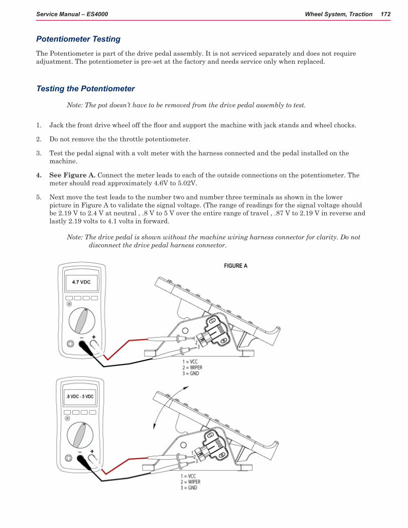
Wheel System, Traction 172Service Manual – ES4000
Potentiometer Testing
The Potentiometer is part of the drive pedal assembly. It is not serviced separately and does not require adjustment. The potentiometer is pre-set at the factory and needs service only when replaced.
Testing the Potentiometer
Note: The pot doesn’t have to be removed from the drive pedal assembly to test.
1. Jack the front drive wheel off the floor and support the machine with jack stands and wheel chocks.
2. Do not remove the the throttle potentiometer.
3. Test the pedal signal with a volt meter with the harness connected and the pedal installed on the machine.
4. See Figure A. Connect the meter leads to each of the outside connections on the potentiometer. The meter should read approximately 4.6V to 5.02V.
5. Next move the test leads to the number two and number three terminals as shown in the lower picture in Figure A to validate the signal voltage. (The range of readings for the signal voltage should be 2.19 V to 2.4 V at neutral , .8 V to 5 V over the entire range of travel , .87 V to 2.19 V in reverse and lastly 2.19 volts to 4.1 volts in forward.
Note: The drive pedal is shown without the machine wiring harness connector for clarity. Do not disconnect the drive pedal harness connector.
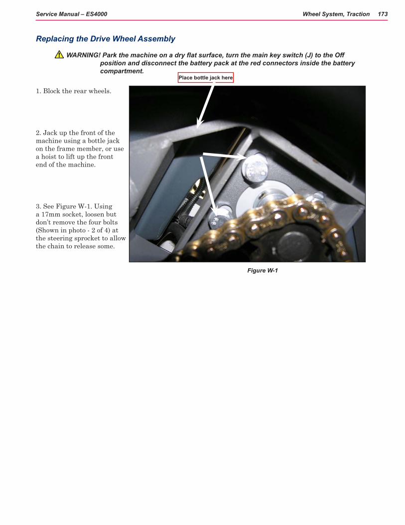
Wheel System, Traction 173Service Manual – ES4000
Replacing the Drive Wheel Assembly
WARNING! Park the machine on a dry flat surface, turn the main key switch (J) to the Off position and disconnect the battery pack at the red connectors inside the battery compartment.
1. Block the rear wheels.
2. Jack up the front of the machine using a bottle jack on the frame member, or use a hoist to lift up the front end of the machine.
3. See Figure W-1. Using a 17mm socket, loosen but don’t remove the four bolts (Shown in photo - 2 of 4) at the steering sprocket to allow the chain to release some.
Figure W-1
Place bottle jack here

Wheel System, Traction 174Service Manual – ES4000
Hex Nut
Figure W-3
Figure W-4
4. Using a 3/8” magnetic socket, remove the four bolts holding the charger in place, and remove the charger and bottom plate. (Figure W-2).
5. See Figure W-3. Using a 1 7/16” socket, remove the hex nut at the top of the Spindle Weldment.
6. See Figure W-4. Turn the Drive Wheel to the right and remove the motor wiring cover (C).
7. Using a 13mm and a 7mm socket, remove the nuts and wires from the drive motor.
8. Turn the motor towards the left. Using a 7/16” socket and wrench, remove the P-clamp.
9. Jack up the front end of the machine enough to allow the wheel to slip free from the machine.
10. See Figure W-1. Using a 17mm socket, remove the four bolts (A) at the top to free the motor from the Steering Plate.
Charger bottom plate covering spindle nut
Figure W-2
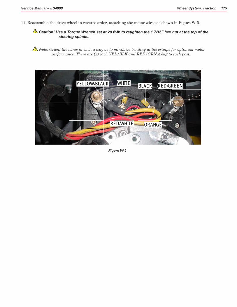
Wheel System, Traction 175Service Manual – ES4000
11. Reassemble the drive wheel in reverse order, attaching the motor wires as shown in Figure W-5.
Caution! Use a Torque Wrench set at 20 ft-lb to retighten the 1 7/16” hex nut at the top of the steering spindle.
Note: Orient the wires in such a way as to minimize bending at the crimps for optimum motor performance. There are (2) each YEL/BLK and RED/GRN going to each post.
WHITE BLACK
ORANGERED/WHITE
RED/GREENYELLOW/BLACK
Figure W-5

Wheel System, Traction 176Service Manual – ES4000
Replacing the Drive Tire
The Drive Tire is assembled as shown in Figure W-6:
1. To replace the tire, follow steps 1-3 of “Replacing the Drive Wheel Assembly.” Then follow Figure W-6 and step through assembly from A through E as shown.
2. Remove the six metric socket head screws.
3. Use Tire Puller Kit (part # 56422174) to replace the tire.
Reassemble in reverse order.
In addition to carbon brushes, parts available for replacement are:
See figure W-6.
• tire with hub (A)
• tire (B)
• motor (C)
• parking brake (D)
• motor cover (E).
Figure W-6

Wheel System, Traction 177Service Manual – ES4000
Inspecting/Replacing the Drive Wheel Assembly Carbon Brushes
Important! To remove/replace/inspect the Carbon Brushes, observe the following: 1. The motor must come off of the machine. 2. The motor assembly must be kept vertical while being disassembled to prevent loss of gear oil.
WARNING! Park the machine on a dry flat surface, turn the main key switch to the Off position and disconnect the battery pack at the red Anderson connectors inside the battery compartment.
1. Follow the instructions in “Replacing the Drive Wheel Assembly”.
2. Place the motor assembly upright, motor side up, as shown.
Caution! To prevent gear oil from draining from the gearbox, disassemble the motor with the Drive Wheel assembly in a vertical position. If some oil is lost, drain completely and refill the oil as indicated at the bottom of the page.
3. See Figure W-7 and photos. Remove the four metric socket head cap screws (A) securing the electric motor to the casting.
4. Use a hard piece of wood or a brass drift punch to tap the motor mounting flange (3 notched locations (B)) to loosen.
5. Grip the motor/brake end bell and pull the motor (C) up and out of its housing.
6. Inspect the 4 carbon brushes and springs. A new carbon brush measures 3/4”. If less than 1/4”, replace.
7. Clean the foam filters, and blow out the motor.
8. If gear oil has been lost, drain and replace with 4.5856 oz (130 g) of Mobilgear 600 XP 150 or AGIP BLASIA 150 gear oil.
9. When placing the motor back into the housing, the brushes can be spring-flexed aside for easy insertion. Release the spring tension on the brushes after the motor is in place.
Changing the Motor brushes - 4 total
Figure W-7See photos next page

Wheel System, Traction 178Service Manual – ES4000
1. Turn motor assembly over and expose the brushes.
2. Locate brushes and retainer springs (clips).
3. Using a screwdriver or other similar tool, release the tension on the springs to allow the brushes to be removed.
4. Remove, inspect the brushes, then clean or replace the brushes.
1 2
3
3
4

Wheel System, Traction 179Service Manual – ES4000
Specifications
Drive WheelDiameter: 9.84 in (25 cm) Width: 3.15 in (80 cm)Type/Material: Blue Urethane
Drive Motor 1.05 HP (780 watts)
Max. Transport SpeedFwd: 3.91 mph (6.30 kph)Rev: 2.61 mph (4.20 kph)
Special Tools1. Curtis Programmer unit 1311
The part number of the handheld programmer is 56409441.
NOTE: If you have a programmer with a serial number before 2100 you will need to update your programmer. A free upgrade kit is available, order part number 56409822. Also a different quad 4 pin programmer cable (PN 56409823) is needed to link the programmer to the controller plug-in port.
2. Tire Puller Kit (part # 56422174)
Curtis programmer
Curtis programmer cable and plug unit