Advance Restricted Report 3D16
63
FIt_E COpy NO. 2-W NATIONAL ADVISORY COMMITTEE FOR AERONAUTICS ORIGINALLY ISSUED April 1943 as Advance Restricted Report 3D16 AN INVESTIGATION OF AIRCRAFT HEATERS XI - MEASURED AND PREDICTED PERFORMANCE OF A SL OTTED -F IN EXHAUST GAS AND AIR HEAT EXCHANGER By L. M. K. Boelter, M. A. Miller, W. H. Sharp, and E. H. Morrin FI University of California NACA WASHINGTON NACA WARTIME REPORTS are reprints of papers originally issued to provide rapid distribution of advance r e sear ch results to an authorized group requiring them for the war effort. They were pre- viously held under a se c urity status but are now unclassiiied. Some of these reports were not tech- nically edite d. All have been repr oduced without change in order to expedite general distribution. y
-
Upload
khangminh22 -
Category
Documents
-
view
1 -
download
0
Transcript of Advance Restricted Report 3D16

FIt_E COpy NO. 2-W
NATIONAL ADVISORY COMMITTEE FOR AERONAUTICS
ORIGINALLY ISSUED
April 1943 as Advance Restricted Report 3D16
AN INVESTIGATION OF AIRCRAFT HEATERS
XI - MEASURED AND PREDICTED PERFORMANCE OF A SLOTTED -FIN
EXHAUST GAS AND AIR HEAT EXCHANGER
By L. M. K. Boelter, M. A. Miller, W. H. Sharp, and E . H. Morrin FI
University of California
NACA WASHINGTON
NACA WARTIME REPORTS are reprints of papers originally issued to provide rapid distribution of advance r esearch results to an authorized group requiring them for the war effort. They were previously held under a security status but are now unclassiiied. Some of these reports were not technically edited. All have been reproduced without change in order to expedite general distribution.
y


•
NATIONAL ADVISORY COMMllTEE FOR AERO L U1ICS
ADVANCE RESTRICT~D REPORT
AN INVESTIGATION OF AIRCRAFT HEATERS
XI - I;iEASURED :AHD' PR.ED I CTE"D FER:;'ORMANCE OF A S LO TTED~F IN
EXHAUST GAS AND AI? HEAl EXCHA~GER
By L, ·hi . K. Boelter, j', A. iv1i ll or , . J. ' H . Sha~p, an~ E. H. Morr in
Thermal and pressuro drop performance data of a slottod-fin Ste17art-i'farnor exhaust sas and ventilating air h6at exchanger are prosented . ~easurements ne~e ' made . using up to 7000 pounds per ~our of · exhaust gas and up to 5000 pounds per hour of ventilating air. Tho inlet exhaust gas tomperature ~as maintainod at about 14000 F; whereas that of the ventilating air was about 95 0 F.
Three different crossfio. air shrouds woro used in tLlese tests. T.hq ·offect of installing a "c entral core" in the E:ixhaust gas si10 ·of the heater \7as determined . Isother~al and nOD -is othermal static pressure drop measure ments were maie on both tne exhaust ~as and vcntilating air sides of the beate~. Isoth e rmal pressure drops across th e inlet and outlet ducts of the air shrouds were moas ured . lemperaturcs of the heater surfaccs at sevoral po i nts were also recorde~.
~easured and predicted heat transfer rates and prcs suro drops arc compared . Tho ~axiruum measured rate of hoat transfer ~as 216 , 000 Btu per hour , The w~ximum measured non -i sotherma l pressure drop on the v 0 ntilati~~ air sido, using a scmi - or dia~onal-crossflo7 air shroud was 16.5 inches of water ; ~hcroas that using a full cross fl07 shroud was 5 . 3 inches o~ ~ator~ The 'maxiD~~ measured pressuro drop on the exhaust gas side of the heater ~as 9 . 8 inches of ~atcr before the central coro las installod and 1 0 • gin c h 0 S 0 f ~ D. t c: r aft 0 r the c c n t r E', 1 cor 0 W,c. sin p l ace . The maximum heater -surface tompornturc was 1120 0 F •

2
T~c StGwa~t-Wa~n6r heater was tested on t~e l~reo
tes~ _ stand.in the hcchanical Engineoring Laboratories of the U~ivcrsity of Cali(~r~ia. '(Soo fig . 1 , and descriutio= of t est stand in r efe renco 1.)
Tho s c he P.. t e r ~ .:1 r c 1.1 sed i n. t 4 0 0 :dw. u s t g a: sst rca I S
of aircraft on~in6s fOJ ~ab ~n, win~, 'a~~ tail - surfaco hoating systems.
The follorin~ data w~re obtained:
1 . ioight rates of c~~au~t Zns e ld ventilating ~ir tl~rou -:.;h tho t ·w.o si.ieG of .. the ·heC1. t c:~c:r....c.,n~;or
2 . ':l'ompe r t:Ltu ros 01 u::~l€'.ust g"'..s and of vent'il"'l.t ·ing air at Ol1t ra j,co an3, exit of h08.t o:;~chnr:gor
3, Tcmpcr~t~ro~ of the hoater surfaces
4 . ' Stetic pressure drop ~casurCLcnts on the exhaust .::;as c..;:lq. v r' 1 til.:'..ting air Gides of the heattn a~d d~cts, uuder both isothor~nl a~d tiotiisot4ormal flow conditioDQ
5~ Isother ma l static ~rcssure drop DcaRurcmonts .' flcrose thO inlet and outl et air - shroud ducts
alone
Tho"'l':Ic'asuromonts ':Vore ma do wi,th thre e. diffe rent ven tilating c,ir shroud .. ar.d also with and ·7ithout."1 "eo r.t ral corell Llstallod in the exhn.u·st ca s Sit1_Cl 'of t llo hc.'0.t"er.
SY'vi30LS
A' area of hcat transfc~, ft~
cross - soction'1.l ~ . rQr. of on e fin· Or) tl c ventil." .. til1[?; air' ' si~c oi thch~Btor, ft 8
'. . . ~
.-crods-scctio~~l area of o~ c fin o~ th0 c~h~ust { '1.S
side of th ~ hc~tur, ft~
cross-soctio~~l ar~a of spot welds , ft2 (Soo
appendix , )

3
unfinned base a r ea on th e ventilating air side of th e heater, ft2
uufinncd bns8 area on the .oxhaus t .gns ~ide of t~c heater, ft2
hoat capacity of air at constRnt pressure, itu/lb OF
hoat ' capacity of e~haust gas at constant pressure, Btu/ lb OF
D hYdrn.nlic,.: .d .iamot.er, ft
Da hyd r aul ic diameter on ventilating air Side, ft . ...
Dg hydra ulic diamet~r on ' exhaust ' gn~ side, ft
fc g
g
G
GO' b
k
ks
L
1 g
. .' . unit thermal co nvective conducitancc (~verage ~lth
length), Btu/h~ ft 8 OF
nit -thermal convecti-jo' conductance· for the vontilatin~ ai r ( ave~n~~ with l ength) , Btu/hr ft? OF
unit th~~mal conv ~ctive co nductance for the exhaust . ga·s .: (avo r 0.ge ':7~th It; ngth) , Btu/hr ft 8 'oF
gravitationa l forco per unit of 'mass, Ib/Ob s'ec8/ft)
rycight rate pe r unit of area ,' lbjhr ft2
weight rate ~pr unit of area for ventilating air. Ib/hr ft 8
~Gight rate per . unit of area for c~ haust gas , 1 b /n f t 2
thermal condu~tivity of fin mato ri a l, Btu/hr ft 2 (OF/ft)
ther~al conductivity of Incono l hoater sholl, 3tu/hr ft2 (OF/ft) ' ,
distance "betwoen stati6~pr06~ur ~ censuring stations and length of hoat transfer surfaca, ft
len g th of fins on , ventilating air side of heater moasured ~erpendicular ly to tho heater sholl, ft
length of fi n s on exhnust gas side of hoator rn~asurod perpendicularly to the hoater 'shell, ft

4
L8 , thickl ' OSS of hoater shell , ft
na numbor of. tins on vcntilating air side
n e: :J UlJ b 0 r 0 f f i 1 S 0!1 0 xha u 8 t ge. s s i d'c .
f hC&1.t --tra:ls"fo r pcr iinct o r 0: ono fin ·.o n eithor side or
e,
hoa~or, ft
.::ensurcd rate of Btu/llr
cnthCl.lpy cl1.o3.nl.';.c of vontilp.ting 2.ir ,
monsurod rateof ·enthalpy chan ~e of c~ha~st ~~S, ,Btu/hr '
totnl therDal rcsista nce including th~t thro~eh
hc~tor sheil , OF hr/Btu
arith~c~ic nvcr[1.~o of tOffiper~turcs ~onsurcd by tTIO thor~ocouplos locat ed on hcatcrshcll n~a r ventilnt il~g o.ir j.n.1Q.'!' (0:10 tilcr~:Jocou:pl ::: at oxh[1.ust f,:-t.f:)
in~ ct , tllO otl cr [1.t e;-h,luS-t gas outlet" o:g'
nrith~otic avoragG of to~p~rat~ros ncnstircd by two ,· .. :theTiJocbu.p l cs. lo.ce.ted on hco.tcr sholl ncar vo.ntilat
in ,!; nil' Q.£~)ei (01:.C thcr!.Joco'..1pl.c 0.t cxha~lst g<',s i 11 lot, t 11 cot h 0 rat c: x h~ u s t r: Cl. sou t lot ) , 0 -.l
., . ~ ,
arithmctic avc:r;r.f,8 of t(j,~1:?or9.t'-1rCS :.;cnsured by t'.70 thcr,~lOco 1plos 10c.J. tod on nop.tor shell. cqu. ·idistn __ t frOE1 ond.s- (o ·n o thcrr.iocoliple Oi: to!) , the ot!lCr on t h 'c ' bot tor" ), 03'
Tn arithcotic nvora~c w i ~od - ~o~n absoluto towpcraturri of
-r 1 + '-r~ either fluill = -_._-;._-, in oquc:.tiol1 (11) on1";
'" o t 11 0 r,.., i s car i t h::) c tic n vcr". f, C 1:: i xc (1.- f.} C~ : . 8. b sol u t 0
to~pernturo of air =
T". arith:Jot'ic (tver:ago :_li:x:o.d - i.i,c<,.n .:;>.ogo lut c to.Jp (. r'l.tu.ro ~,
T .0" +' T {' .., f . t . 1 . c· 0 0 o 0:;\:-10.US· g:<.s = -.--- ---- + 4 .0 ,. .3.
. 2
T 1 r:J i xod - :,j 0:,:, absolute t cf:Jpcr.:'. tur 'o of fluiJ L'. t c!1tro.TIce soctio:1 (point 1) , OR
Tf) r.1 i xqd- T':1.C"'.i1 a b sol Ii t·o t ocp cu'o.t ur f) 'of fluid at exit section ( p oil,t· '2 ) , OR

5
mixed -m ean absolute temperature of fluid for isotherma l pressu r e drop test s , oR
Dean vo l ocity of ' fl~id, ft/soQ
2 ovor - al l unit thoronl conducto.n60, B~u/hr ft OF
GA ovor-BII ther~a l conductarico, Bt~/~r bF .
(UA)totn. l over - al l thor:,n l conductanc e' including hoc-. tor sho ll conducta~c a , Btu/hr OF .
W woi~ht r ate of fluid, l~/hr
\If n ':1 0 i C;h t r 9. too f a ir, . 1 b / _ r c..
w~ 7oi~h t rate of exho.ust g~s , I b/hr !.,
'Y 1 ~ci~~t density of fluid nt entrenco to ~onting section (point 1) , lb/ft~ '
6.p non -isot :lerlJ£1 1 proGsuro dr .op n l on{" hen.ter, lb/ft~
6F ' n
6p~, ' .)
6pt", [,
p ress u re drop n.lon~ heater on ventilatin~ air side, 1 b /f t 8
p ress u re dro:p a Ion::; heat~r a !1 ventilatin e; air side , inches H r- 0
pressure drop nlo!)g he.3.ter o.n e;.:h.3.us t e;.3. S side, 1 b /f t 2
pressu r e drop o.lon heD,tor on exhA.\l. s t gas side, inches H8 0
isoth c r~al pressuro drop .3.long inlot and outlo t ducts of the ~ir s~roud , Ib/ft 2
isothcronl p r essuro drop a lo ng hoator on ly, Ib/ft 2
6F l\so isotho rwal 'p r essure drop a l ong heate r and ducts n t
teupero.ture ' T isD ' lb/ft ~
t iso isothcr ~n lfriction fo.ctor defined by t:..P
'Y L Ur.l
i s 0 D 2g 6t tc~ po r~tur o difference , OF
6tLD 10 Go. rit~~ ic Dean te~pora turG d if forence , OF

6
,-' '; .
di ff erence botw0en mixod -me~n t e~p e r 6 t ur ~s of venti .. 101ting ' a ir ·at · s · ~ct io ns defi11ad by points 1 n:lcl G :::
T - T of .' a 2 ~. l'
6, T (f' d iff e re nce between mixed~mean t emporatur es of exhnust gas a t sections defined by p oints 1 and 2 -::>
0'.":1 ·· T . . - T~." .J b 1 02
]..1 vi s cos i t y o f flu. i d· , 1 b sec / f t Z
T 'a l'
T cr .. '=> 2
~Ju
Pr
R e
mixDl - rnean. t emp o r n t u r ~ of ~e~ti l ~t i n~ a ir ~t ent r an ce sac t io n ( p"O i n t 1) " ·0 F
mixed- mG~n tomper~tute of ventilatin g ofr at ex it s e ctio!"! (po·:i.nt 2), 0], .
!:1 i x 0 d - n e ''.!"! socti In
t G .;1 pe r .'i t U reo f ( P J i f, t 1) " J F
Gxhr.us t Ol"lt r ...... n c e
[,1 i x Cfd - LTC.' 11 t e 1"1)! 0 r ., t u reo f (') X il ". us t ~ o. S ; '; 'li ex its e c -tLm (p 1 int 8 ), JF
.L' ;)
IJUS S clOt nurnb0r = ~ k
Pr :? !"!d tl number 3500 I..l. c p g = k
ROY:10 ld s number = G D 3600 I..l. is
Reynolds number = G P 3600 I..l. is
DEscn IPTIO~T Oi!" STE"iART -~iARJE:::{ SLOTTED-FIB HEATE:l
A(J TESTI~G PROCEDURE
Tho . stevart - Warner slott~d-fin , oXhnus t gas Rnd ven til [l. tin g c. i r he a t e): c han g e r is. a . c r 0 s s flo :·r - t y po h e :t t cr . Tho slo tt ed fins o~ t he i nner or exh nust .g~s si~ e arc pl aced long itud inally ; where:ts those on th o outer or v en til n ticg 2i r si~e ~r o plnced circumferent i n ll y on th e he:tte r shell . The r e nre 52 rows of fins on the a ir s ide of the hoate r ~nd 80 rows on the exh~ust gas .side . E~ch r owan the ~i r sid e i s cut ~t 1/4-inch i n t ervals so th~t thore p r e 69 fins per ro w. On t he exh~ust gas s id e each r ow i s s lott ed ~ t 3 / 4 - inch intGrv~1s, yia1ding 19 fins p0r ro w. The fin s ~re co ns truct ed of O. 045 - i n c h copper

a nd ' :i r ;o s-p ot- we l 'dod. to a ' s t a inl e ss cin b o t h 5 id e~ of th ~ h e ~ t e r ' a ~ e 3/4
- ' ur e:dP'.o_rp e nd'ic:~l n.rly to t 'he sh e ll.
7
ste e l shall. Th e fins inch in l e n ~th men s-
' Th~ f~r~t 'aii -shroud tested ~ith the stewart-Warner hea'ter w'a s a di ag oncfl - 'o-r semi-crossflo'w-type sh'roud oot'a i 'n ed' f :rom the Ames A'e ron autic a l Laboratory, Moff e tt F 'iE3 'i'd, ' Oa rif. · The inl e t d uc t con t a'ined v a n e's \.,,11i eh teride~ to direct th~ ~it o~er the he at e ~ at ri ght 'an g les. (S ee fi gs . 2 and '4;') 'Anot h'er a ir shroUd, Chere a ft e r 'd e si gn a te d a s DC-a) wa s construct ed with dimen s ions equiv a lent to tho s'e ' o f" th e' Anie s 'shroud, but w-i'th 'furl ,crossflbw cha ra c't e'r' f s- t'ic s ~ . (See figs, 2 a nd 5.) A third alr shroud
" ( ie r ea ft e~ " d e si~nate~ a s DC-1) wa s co~i tructed with frill cro ss flo w ch a racteristics, but with a sm ~ ller cle a rance be t ~~~n ~ th e h ea t e r s he ll an d t he shroud.
I n or de r to force t he exh aust g a s b e t wee n th e lon g it u di na l s l ott e d fi ns , a c en tr a l cor e wa s in s t Rll e d on th e ga s side of the hea t er . (S ee fig s . 2 a nd 6,)
The 'w6 i g ht ,rat es of exhaust ga s an d ~en tilati ng a ir w~r e obt a i ne d by means of 6a libr a t ed s~ua r e -ed g e orifices.
The ' exhau st ~a s t em p e r ~ tur es w er~ meaiured a t th ~
i n l et and th e outl e t of t h~ hea t e r by ~eans of shi e lded tr a v e r sing t h er moc oupl ei .
A miii ng d e vic e was u se d at , th e exit of t he n a t u r a l gas f ur nace to g i ve n a n a ppro x im a t e ly uniform t e mp e r a ture d istr ibuti on a t i h~ e n tr a nc e to th e h ea t e r. (The me a sured t empe r a t u r e d istribution i n d egr ee s Fah r enhe it wa s wii h in ± 3 ' pe rc en t ' o f co mp l e t e u n ifor mit y a t th e inl e t end of the h Cla t e r. )
No ~ixi~ g d e v i c e 0~ s us e d aown~tr e~m from th e h e~ t e r on t ~o cxhou s t gas sid e . ~he mens u~ e d t e mp e r a tur ~ distributi on i n deg r ees Fah r e nh e it wa s thus withi n +3 pe rce n t of co mpl e t e unif ormity, whic h wa s r e duc e d to ±li pe rc e nt wh e n t he c on tr a l cor e was i ns t a ll ed b e caus e of t hegr oa t e r mi x i ng en coun t e r e d wh c n th o g ~ s expand e d i n t o th e outl e t
' exhaus t gBS d u ct. (S ec i e f e r en c e 1 f o r a d es cription of t he t es t st ah d an d it s i n strume nt a ti on .)
Fo r n Il shr ouds; t he exhau s t g~s t emp e r ~ tur e tr a v e rs e s we r e me de a t poi n t s 1 5 inc h~s upstr eam an d 24 inch e s d own str ea~ fr om th e e n d s of t he h ea t e r .

8
Tli pC! r p.t ur e s o f t he v on ttl n,t ing It. i r bef 0 I"e an·d 'af t or p a ss nge t h r o u gh th e h ea t e r wer e det e r mi ne d fro m tr Rv0r s cs m,8.d e ~~ it b. uns hi e ld ed. t h ermocoupl,e s. Runs ·2 2 to 51 "1i3r e made-·,yr i tho'u t. :'fl. 'mi x i ng, ,d_evic e in ,th e v e n;til a ti ng 'air out l e t d.uct. , Fo r t hese r u n s . t he t 0mpa r ~ tur o ' ~i ' s tributio
w n s . ~~t h i ~ , '+ 9 pe rc en t o f co mpl e te un if 9 r ~ ~t y . Fpr r~n s 52 t o. 122" ,:1, 3.-i n c h di ame,t e r o,;rific,c ' was i n st il-11,c d. in t he
uS -i.neii d i.9.1:l'e t G ~ . outl a. t ' ~ ir duct to ' ~ aus e better ' mixi ng of t 21C· 'fluid, t h rough, its sudde n e x'pan sion ,d ol/rns'tr o,"l.r:1: fro m t Ile o ri { ic'~ . p ,' , ,~ l:.e , t el!!pc '!.' FI, t u r e ;li,s tri .butio,l'J. th'J.s obt -a i!l cd 'r.:l S wi t ._l'i n ±'2 p erc e nt , 0 '.0 ~o rnpl :.3 t<J 1,l n i :[ 'o r B1 itY .
FP .r ,t he ' Amo s a ir sh roud, t e r.lp a,r n tur ,e tr E\. y orses o f t h\3 ; e!l'til o ti ng ' fo ir w <3r '.\~ · mE\.d c 2_t' point s 2 6' inc he s upstr o:1r1 and 50 i n c hes do~ n ; t~ e~~ fr om t he c en t ~ r lino of t ~e hG~ t e r. ,
~ ~ Q . he£ t le s ses t o t he s ur r o~ n d i ngs wer e r e duc ed · t o a l1ug li g ibl e C'.!,'lount. 'b Y' ')H c,pp i ng t he d u ct s vl it ll n sb cs t ()s s hoo t s . '
,Te:.! pi:)l~ur es of t he , hen t t;r su r f,\ce s V10 r c t lco.. sur ed. ['.. t si x ~o i nt 3 by ~ ~ nns o f t he r mo c o u p l es . On~ pa ir o f t hc r no coup l es ~~s l o c a ~ e d on t he he At er s hol l ~ c~ r the v ant il n ti n~ e..ir · 2:E.~ 8 t siel.:;: ( q ne" t ilG r ;,~o 'd)\ip l e l1i):;. r ·t hc' e Xll.:lUs t 'g,~ s i nle t, L le o t he r t he !' B1() c o 'U})le . near: t ~ o. e:.::h;:;.u s t gf.'.s ' ou t le t). Tl1a nr it hme tic [wa r aga o f t :l.:J3C t w') te ::JIHH".t u res i s des i g -n a ~ 0 d (). S ;; 2., • A so c ~) no. , p a ir ') f t he r 1'1 q C 0 U ::! 1 \;1 ~ . \'1 e. -". 1 ') C L>" t ed n ea r t ,l-: 03 "l en til a. ti n b c, i r ~ 1 G t s i d e ( .::J :r.. 0 , t ~l ,:i r :'1 0 C· 0 u :p 1 C) n a 8. r t ho ex ,~u s t ga.s ,i n 1 0 t ,: ' t he ,;, t ha r 118'),r t h,; exhpvus t ·' g ''..s outl e t) . T:i. c n.rit hn <;ti c :"v ,'!r a b e o f t hes~ t -r o t I0Inp.3 r ['~ tur es is d e ~ i g~~t~d as t b ' ·Tio t hi r d p~ ir o f t hc r mo c ou p 1 0S VI P. S l oc"..t c d on t :1 0 '1o[1, t e r sLe ll o qui d i s t p,n -t fr or.1 ',t he en ds ( ono::: t:.1e r !~,0 C O up l e on t 'J P, th8 o the r o n t ::i e b ') tto n ). The ari thl'lc.ti c . n Y8 r ri. E; e. . o f t !lG S Q t ',:,) t ef.1:Pll r ..... t u r e s : is d G si ~nn. tcd
<:: tI s ., ~ ' r' l' C'" ')) e. ~ c . \ ", c ~ , ~ . . <OJ •
, St n. tic 'p r o,s s uro ,d r 'J p r~ee..su r O !:1e,n t s· "' 0 r e' ;;nd.8' rt cr (1SS t he v cn ti l& t .i ng ~ ir and· oxh~u&t g~s s ides '~ f t h0 ho ~tc r.
T,n t 8.pS , 1 80:: apo.. rt, \'Io r e i ns t r<.. lled C'. t 'enc h: p'r c ss:ur c -Dc~surin g s t q ti on . F ~ r ~ ll s ~ r a u frs , t~~ p r essur e t aps on t he .E:zho.us t ~~ido v! ,e r o ,p l nc8ct O~· t h.; ho,-:!. t '0 r s hedl i-'.b ) ut 2i i nches fr J~ th e ends )f t he ha~ t 0 r. Fa r t he ~mes sh r o u d , t ha ~H e ssu r. e t.n.p,s '):::1 t h~ ve nti ln.,ti,n~ <', l ;r s i A.C2. \'re r .e p ln. c e d a b ' u t ,1 2 i n c he s ups t~e 1 m nn d d~~no tr Gnn fr oD t ho' c on t o r li ne o f t he hC:1. t e r; \'l!le r c:'1.s , f o r t he UC - l [\.:l d 'UC-2 S;1.T ;) u cls I
t h o p r essur e t q p S ~; t he ~8n til r<.. ti ng '~ ir s id es we r e p l ~ c o d in ['. b -i n c h duct 3 0 i n c h~ s ups tr eBD nn d d own str cprn fr JM t he C0:::1tu r li ne o f th o hec t e r.

Q
I s~the rrn a l pressure ~rops along, the inlet and outlet a ir-'sh roud ducts ';"ereoeAsured by deta,chi'rig these ducts, fro m the shroud and placing the D together to obt~in the to ta l pressu r e drop across the two ducts. Th e air sh roud s U¢-l c:'..n d UC-2 utilized th-e S,?l!le' inlet and outlet ducts. Wheil the i n let and out~et ducts used on the Aoes senicro ssflow shroud were pl~ced to ge ther, a very sharpl y curve d path , r6T th e ~i r fas for ped , and the Densure~ pressur e , d 1'0 P - for the due t s pi 2.. C ed ' in t his L'l n. nne r was as I a r g e as the Deas ~re~ isothe~m a l v fi lue acrOSB both t he ducts and th~ hea ter ~hen ~B~d in t he norm~ l Q rr~nge~ent. A, true r v a lue of the pressure drops through the ducts a lone was 0 b t a i ne d by P I a c in g a II sp a c ern , e CU.l. i vaI e n t tot h e width of ' the : a ir shroud b e t we~n ~he , inlet and outlet ducts so that t~e ducts w~re in th e s ame r e l a tive positio n for these tests and for th os e ' tests using beth the a ir shro ud an d the hoater. The pressure drop in ,t his IIs pncer ll 'was negl i g ibl e "(2 percen't ') cODp a r ed 1dth th:l.t across t he ' co n ver g i ng an d diverg i ng , outl e t and inlet ai r ducts.
Hen. t T,r a nsf e r '
The ther oa l output of th e,heater ' was d e t e r mi ned by the en tha lpy changes of t hcl ven til a tin g Air:
( 1)
i n w":.ic11' c W,"IS eve,lu '1.. t e d.:1.t th-e n.rithn e tic ave r :tge Pn
ventilu tin g a ir te ~perntute As a g60d npproxi~Rtion. A ~lot of qn aga i nst wa n. t co n stant va lu es of ' ' exhau st gas r n te Wg , nnd inlet t eD p e r a ture Tgl is SJ own in
fi gur e s 7 to 1 2 .
where
On th e exh[\ust ga i side o f th e hea t e r:
CJ.g =W g Cp(T g -T) g 1 g2
is evn. lua ted for a ir a t th e t eo per n ture n t
th e a rit hne tic nver ag e exhnust ga s t cmpe r ~ t u r e .
(2 )

10
T~e over-all therual · condu~t~~ce UA was ev~lun t ed f ro'tJ. the. expr e s s i ()n ,:
(3)
The v,,'lu,e of L\t;,n for cross f10\"1 i ,s _chaser: [-'.s tlw,t f ·or counterflow ~nd then tlultiplied by a correction f~ctor. (see r efe r eaoe 2.) ~nasmuch ~s t~is corr0ction ' f ~ c . tor w~s " ~lwuys withih 1 percent of uriity , the L\tl~' used i n these culc~lntion~ was taken to be ' that for counterfl.ow of the fIui.ds .
A p l ot of ul as a function o f th e 'vantilnt i ng rate Wa a t oonstant veluGs 6f t he exhaust gas r ~t e
is Gho~n'in figuies 13 to ~8 .
(1. ir, ..
The ther D:).l outp,ut ~ f · t).-,,,, I-,:"':t"' r · ':"lay be predicted when' 'u s ed f'.. t o.t l1 e r iT a 1 u e s 0 f ' /::, t ~ :1 t han tho s e use din t l1 e s e t ests bydetertlining r ates fro~ figur0s 13 e qua t ion (3) "i t h the
UJ at the corresponding fluid weight to 18 and ~sing th ese ragnitudes in new v '). lues of , /::,t'ln .
Predictions of the tJ.agnit~de6 of the over - all ther ra l co nducta~ce a~ were a tte np t ed . The expr0ssion (r ~fo re ~ ce 3 , equat i on (28))
JJ .. :l. = 1 ( 4)
+
where ,/ 1 \ ; -- 1
\fc 1>')e2., and nre the e ffective
r ~s ist ~n c es on the a ir and exhaust gas side~ of th o heate r, r espectively , ~as used.
The ef fec~ive thernal conduct~nces,
( f c. ) e _ ' 8. reo b t a i n G d fro ,:1 e que.. t ion s (s e ere fer e n c e 3 b
for tho derivntion of equations (5') t(~ . (8))
;:: nn") f c e\. P k L
and
.1.\ .... ,. tanh fc Au' a a (5)

, _ I,
= ng JfcrJ' P k Ag t a nh L , E>
vThe r e
cross-sectional are~ of one flll
f c ~'u g g
11
k' thernnl conduct ivi,t;'f of fi n na teri a l evaluated at Rn ave r age tenpe r n ture
P he~ t tr ~n sf e r perimeter of one fin
L l eng th of one fin . ~easured perpendieulirly to he a ter shell
to,t nl nun ber of .co ' on air side of heC'..ter n ' .1. 1118 a
ng t ot 8; 1 nunbe r of fi ns On' exh<.:.ust gas s i d-')
. ~e un~t t her8a l ' c on 1ud t an e e 'along fins C'..nd n lon g u~fi nne d _ a re a Au - 6f heC'..ier
- ior the exhaus t gas side equation
where
fc ::: 5 ,56 , x 10 g
f c g i s
Tg 0.2 96
eva lua t e d
Gg O. 8
D 0 .2 "'. <:>
PrJ' ~ rit hre tic ave r ~ge abso lut e tenpcrnture t'1
fron t he
(7)
Gg exl1r-tust g.ns w'e i gh t r n t 'e per unit cro ss -s e ctiona l aren
Dg hydrau lic dia~eter of spRee (chann e l) be t geen rows of fins, on ' ClJ<::h.:lust g"..s side
Because t he sl ots on the exh~ust gas side we re na r r ow , their e ff e ct on t he fluid flow an d unit thernal conductance was neglocted an d fc was calculnted by Deans of equation
(7), 'ldIi ch is o Rsed ' u~on :fl o'l' in ,pip e s dud c hnnne is -wh e re t he charncterlstic di pens ion i s ih e hydr a ulic di RDe t e r .
On th Q a ir side, t he circum f ~ r en tial fins were slotted a t 1/4-inch int e rv a ls. The i oyno lds n~nb o r usin g th e peri De t e r P of th e fin as th e significant di ~ens ion
Rop = G P v a ri es fro r: 10 , 000 to 25 ,000, so that the 3600 I-L g

12
bouhdc;ry lr'.yor :ovor e",ch f i n muy bt:) 1ilr.linar* fo r a can .,.. sidernb1t; l ength n lcJll g th e fln. The fc!"> for th e .1 an in[l.r
r.
regioe is then evnlua ted from equation (6) of referance 5 :
o. 5( 11 y)o. 5 f c .,- 0 . 112 T ~
~ L (8 )
but since 3£ 00 un Y = G
(9)
F J r t '1 is h Q n t e r , " Li s 1 ./ 4 i il c h 0 n t;l <1 '~,r e n til t=I. tin g r->. i r side . The ffi~gn itud e of t he unit th a r ~n l c onduc t nnce fc ~
rtl ori t; the unfin led be.se :1 r e[~s bct\'JeentL18 r :)'iS of fins ~ i s probably not ,tha 'sncc as ,t:at a lon ~ t he fins.
I f t ja fc ~lon~ , t he unfinned bnsc ar 8~s is c t=l.lcu-11 _
l a t ed on t he basis ~f the hydraulic diun~ t 0 r of the chun-nel between the r a~~ of fi ns , it s value i s f ound to b o flb8ut one - half th~', t of " f ,c.., c \lculntod for I nm il: o. r fl o't[ over the fitis . The he~t t~~nsfer n l ~ng this rinfinned n ren is thus n b but 10 pe rce n t of the t o t ~ l when th e fc . a b nsed n hyd r aul ic diaD8ter is used and is a b ou t 17 per -cent.- oi- t he 'tot'o..l ',;!llCE the fc based on l'1;-:,in a r flo '''' ove r
'. :?.
the fins i s us ed . The hea~ transfe r fr or.! the un f inn ed a r ea theref o re need not be uccurntely k no wn . The nctual VD.luc q f fc ~ is prob~bly betwoen t he tw o ~en ti o ned .
c .
Mt::[~s ur c:: r.; en t s
[1. i r and. exhf'.us t th e r J7i[l l LlP T .
, ], s ~
Pressu:re Dr'Jp
~f t~o st~tic pressure d r ops ~c ros s t ho G~s sides Jf t ~e hea t ~e r e D~da for i so
and non -i sothermal c ond iti ons LlP . ~lso ,
~ressure d r ops w e r ~ ' ~oter~ i ned for t he air inl e t ~nd out l e t ducts a lon£: under is o th ", r l7![1. 1 'c ond iti ons . Tho J:1easured pressure dro~s On the exh~us t g~s side ~~d no t include t~ e lusses in ' the ductin ~ ; so 6F T- = ~?~TR whe r e LlP qTR , ' ], so - , -_. is t he pressure drbp n l ong t he heat,aT a l one .
------------------... The r e s u 1 t s 0 f ~. H • ~i 0 r r i s an u W. A • S ? j f l' 0 r d. (r e f er e ne e 4 ) indic ~ t o th0 t t he boundriry , l aye r ova r ~ r ups o f fl a t P 1 a t e S .:t!1 d c Y lin d ric, r.. l fin sis : 1 "U'1 i nn r f 'J r R C) ";J < 2 0 , 0 0 0 .
Equ<_ti ons ( 8 ) c.n d ( 9 ) a r '3 equ i v2.. 1 ont ' t :->.equ{, ti ;n (1) of r efc r en o. e 4 . '

F e r the eXhaust ga s side the expression
'Y
L tis 0 D
um 2
2g
was us e d t~ determine the diDensionless modulus ,
o r
t hus
2g u :3
ill
L' ( '\
Ls ') D) = 2 g y 6P nTR
/' G :3 ! _'JL '
3(00)
For the ventilating air s'ide, ',:
2 g 'Y 6P H.TR
( Ga \3 \36'00)
13
(10)
(103. )
Th e pressur ~ dr:ps thr ) u ~h ~he duc,ts a n t~e 3ir aide
for the t hree air shrouds 2nd the n~dulu s t· - ' f ) r ' ( L\ ,,' l ,SO D)
the exh '\ust gas and .::.ir s i 'd0S of the, heatt3rare tab'.lle,ted in tables VII n nd' VIII.
Th o n o n -i s J ther~al pressure drop ~f either fluid thr ou g: h th e n03.t exc'han ~ger 'was 'pr e dicted fro::1 is othernal ceasura me nts by ceans of e a u~tion (6) of r efe r en c e 1.
, ' ( T 2. , " 1' . 1 3 6Pm . -- '
lis o T . / . IGv
6P = '\
1 \ I
I •• , M . ... _ • • .. _, • • ~, ... ........ . . .
" \,,h8 ro , . . '.
Ap .t 'ot a l nea,":l.l.r'ee. U T. . '" IS0 friction at
ipotherm~ l pressur e drop due to t e :-J per C', ture m.
" 1 s o
(11)

14
Tl ~ nd Ta ~ ix e d- nenn absolute t enpe r ~ tures of fluid ,'.. t in~.et~ .~n d.· exi t 'q- f h'e.ate r" T'e sp~c-tivo:l~r'
Tn a rith~et ic ave r age of and Ta ,
G flu 1.:1 fl o 1" pe r Uil i t c r o s s - se c t io n a 1 0, rca
un it. y! c.1 g h t ~") f te!:1pcrature
flui~ at i~let· to ~~h t ~ ~ · c Tl
~ cODp-ri son of '~e~5 urad ~nd,prodic~ed non - isoth ~ r n~l pressure cl r op3 thr/u6,h b::5"th [dd.es')f t!lC he'~ t o r is p r e sented in t ~bles I X and X and is shown g r~ph ic ~ lly i n .fi g ur es 1 9 to 23 .
Scat transf e r and p ~essure drop data for the stewo..rt Warner han t e r a r e p~cse;tod' in t nblas I .~ nd II fo r the t ests usin g the "\.1:1.3 S a i -r shr)ucl , in t ab l es III f'.nd I V f, r thJSE usin g t he UC - I a ir sh r ~ud , and i n t ab l es V and VI for th 0sa using t ha UC-2 ~irshr o ud . . •.
DISCUSS IO N OF RESULTS ON TH3 STEV~RT-WAR~ER 3E~~3~ * ~ . .
The en t halpy ch ange of th0 v~nt i lating ~ir W ~G uS8d t :) d. c t e T'"1 i ne t he t 11 J ~!:1 ''', 1 0 u t put 0 f t he. he ate r I f: r t he s e i:leasu r er:e~ t s Vlor o f.n r c accu r rt te th ;;>..n th ')S 8 on the cxh.:::.nst g~s side J f t he he~ t c r. Th0 3rith~otic ~vor ago len t b~l-Rnco r ~ ti~ q /q )f ill thil tests w~s 0 . 78 . It c ~n be g [1.
sh Jwn .that ~ I-percen t e rr r r in the deter~in~ti on Jf e it he r exhaust gas t 0~:pEHr, t HO T ,.,' e! 1400 ' F n~,~~r c:~use .'"1
, ~.. ~.
20-:pe rc e:1 t e: rr :H i n th", · t '~;1per:'. ture ch ,~rrbc 'I f the: CX:l,iUs' t g .'1 S • T h <3 l ow 11 0. '1" t b Q 1 '1 n C <3 r ,1, t i ':' S . :; b t ~, i n· e din t he s c; t cst s r:F1,y'bc due t Cl this 'e rr e r in. ne.'lsur,I3"T:}0:1 tj .th8~;.·:1. 1£') nl,,·y.b"e due to in c o=p 1 8 t e c, ~ busti c~ of th e Gxh~ u s t [n ses .
Th r ee a ir shrJuds ~o r 0 ~s~d in t hese te s ts.
1. Sami- or di~g6nal -cro ss fl ow shroud (designated as Ames a ir shroud). C l e~rance between hente r shell A.nd ,Edr shrou,d is l~ in~·hes .
*Sae also r epo rt by R. A .. Kepne r cud A. R . Collin s (r eLnence 6) on r esult s of t ests p rfor~od on s i mil n r heate rs i nth e He I.e t e r L::t b 0 r r~ t o r y 0 f ·t h e. S t j w C'. r t - iVet r n e r Co . I Ch i c a [; 0 •

15
2. Full cro~~flow shroud (designated as . UC-2 air shr6ud) . Clearance b e tween heater shcill and
, air shroud is 1 ' 15
6 inches (s ame as Ames :1ir shro':ld).
3 . lull c'r 'ossfl 'ow shroud (de~ignated as U.C-l nil' s~roud). Cle3~ance bet~een h~~tcr shell and
. air .shroud is:). inch.
Thus a comparison of the ' results obt a ined when usihg the Ames som~-crossflow and the UC-2 full Crossflow a ir shroud's \..,...ill r o ~ '~al th.c a f ·fect ., ' on 'the lle a t transfer rate and iha pressure 'drop , of the dlrection or manncr in which the v en tilating ai r ds c6nducted across tha heater, since a ll . physic~l: dim Grisions .. we~e identical fo~ th ese two air shrouds. A co~parison of the r esults' obtained' when ~sing the air shrouds. UC -l 'and UC-3 will reyeal the cffe ct, on the pr~ssure . drop and tho r a te of heat tr ans fer, of de cr aan in g t he cross':'sect ional 'area .on th e ventilatin:5 ai .1' side of the heat or. ' " .
During ~h e proli~inary t es ts · o f th e hoater , it w~s discover o~ that tha rat e of heat transf e r was . inappr e - . c~ably affoctG~ by an increase of the exh~ust gas rat e Wg ' from 6000 to 7500 pounds per hour. (S eo' fiGur .e. 7 .) This was an i~d~cation that the eXhau s t gas Gs we re pa~~ing Jhro·u gh the ce.n·ter of the hoater ana not t h1'o u sh th e . ch ,? nnels between the rOJS of tin s . In order t o amo lior Rt e t .h i s e f fcc t, ace n t r a 1 cor e VI n. sin s tall 0 din t h ~ c X h a u s t gas side of the hea ter which forced th e ~USGS to flo\r ' through t_1G chnnn.els b e tw een the rO'.ifS of fin~. · l'he ' me:D..s ur ed r ates of hea t transfer we ra thus incre asod and var~ ed app;rociably .when th e exh.(Xus t . ',,, ':-.8 wei gh t :i.'ate . IV g . was . -;i.ncroQs od from 6100 to 7100 pounds por hour. (S ee. 'fig. 8 .)
. A co mparison of fi gures 13, 15, and 17 rev ea ls t ha t, f o r tho hoator w·ithout th o centr ~ l c ore in tho exhnus t ' gas side, th e over-all th erma l conduct nn c o UA at N~ = 4000 pounds per. hour and" il =. 6900 pOunds per' hour \'!~ s nbout 137 Btu/hr ' oJ usin G t~a Ames air s h roud, 142 Btu/hr of us ill g the UC-l ' air' shroud" a nd 128 Btu/ hr 0 F us in g the UC ~ 2 cdr shr oud .
S ·in .c~ the ' cross - sectionnl , ro a s' e.nd othor dimensions we ro t ho s ome for the A~es somi - crossflow sh roud and tho UC - 2 full-crossflo\·/ shroud , the L1crease -o f 9 Btu/hr of when usin g th o Ame~ shroud must :ave been due to th o ' greater air turbulence, s inc~ t he n ir probably flowcd

16
diesonal1y across the rows of slotted fins and not directly between the fins as with the UC-2 shroud.
The increase of 14 Btu/hr of when using th e UC-l shroud ,over the result obtained when using ih6 tiG~2 .-. . shroud w~~ ,.due to the dacreased cross-sectional area of tho former (I-in. c~earanqe between heater shell and shroud as 'against l'''6-in. clearance) ~ since all other dimensions and physlcal characteristics were identical for the hr-O UC air, shrouds. '
The g raa t er 07e r-a 1,1 the rmal c ondue t a'nc e 0 b t a in ad in the runs using the UC~l air shroud as compared to the run,~ us i ng ,the Am'es, air s hr oud was d U'3 ,t 0 the decreased ' cross-sect~onal area of the f6rmer~ a factor' whi~h out~cighed the turbuLence-forming characteristics of th,e ,diagona,l- or' G,e mi-crossflow Ames shroud. This greator ~eat transfer rate when using th~ ,s~all~r, but full-brossflow, UC-l shroud was obtained ~ith a'much sma~ler static pressure drop.
The measured isothermal pressure drop along th~ uir sido of the heater (inlet , and outlet a ir- duct losses shb tracted) at ' an air r u t e of 3000 pounds por hour was 12 . 4 pounds per square f~ot (2.40 in. of wa te~ using the Ames semi-crossflow shroud, 5 . 45 pounds por square foot (1.05 in. of water) for t~o UC-2 stroud, and 8 .4 5 ~ounds per square foot (1.63 in . of water) for t~D UO-1 air shrou~.
T_us more tha~ double th e pressure drop i s encountered when the ventilnting ai_ is not caus ~ d to flow directly along the space betwoen tho fins , but is allowed to flow someWhat dia~onalli 3cr0sa the rows of firts (cf . pressure drops using Ames and UC-2 ~ir shrouds (figs . 19 and 21) .
T~e pressure dr op was ~ocreascJ to about 70 percent of the me~surad VaiUB for t~o A~as shroud by usiL~ the UC-l· s_:roud, VI: ich 'Jas fully cr;)ssfl.:J1:! but .ad an even smaller cross-sectional area . (S ee figs . 19 and 20.)
It can be said', therofore, that th<J incr oase of the ther 'mal conductance due to th0. groator turbuloncc :lIang the slotte~ fins when usin g the diagona l crossflow shroud is mo r e th a n countarbal nn cod when using the full crossfl;)'I' shroud by decr0C'sin{; t~1,J ['. ir side clo2.rance fr::JJ'1 iTs inches t o 1 inch. The isothermal nnd non-isoth~rmal pr3S sure drops for tho IBtter clearance ore ::Jnly nbout 70 per cant of the v ? lue for tho di~gonal crossflJw shroud.

17
Th~ large incre~sed pressure drop f J r tho semi -c r J S S f 1 ) W s h r ;) ", ci vJJ u 1 d n J t be f :' un d '" hen t his s h r 0 u dis us~d on other typos of h3ntcrs , such os pin-fin hanters ; ~lth;)TIg~ it w0uld bJ experienced when it is usod on nll he ate x c ~'l D. r. g e r s wit: e ire U8 fer 0 n t i [1.1., con t i 11 1.1 I) U. S J r s 0 m i cJntinu::llls (slJttci) fias. Because thd <",- ir is doflectei to fl ow J v~r the henter , the pressure dr)p in th 0 inlet and ou tlat ducts is Gbout 40 percent Jf th0 total pres sure dr0p with the hocter i~st3l1od . T~iD 'pressure drop thr ough the ducts Jf the A~es shroud w~a ns Dueh as the tJt~l prossuro drlp nl ong t~c ducts an d across the lcater when the UC - 2 shroud was used. The pressure d r ~p through the inlet and outlot ductc wns,with the hootor installed , about 20 percent of the total drop usin~ the UC-2 shroud and about 14 po r cent ts i ng the UC - l shroud .
1 ( ' 3 ,) 1 . Wh~n the centra core d12D . 2~ 1~. ~as p ~ced 1D the exh~ust 'g~s side of the henter , the nat cross-sectionnl ~r3G W2S docrunsad by 15 percent . Thus the o7cr-all ther Gal conductance , 1it h the contral cora instelled (sae figs . 14 , 16, al'.d 18) , f'Jr "via;' 4000 p')unds per hour o.nd Vig = 6900 pounds po r hour was about 153 Btu/hr OF for tha runs ifith the se~i - cr'Jssflow shr oud . 157 Htu/hr OF using the UC - l shroud , and 140 Btu/hr OF us i ng the UC - 2 slroud . These r esults Rre nbout 9 to 12 percent higher than those ~ btai nGd without tho c en tr~l c)re inst ~ llod , ~wing to the
incrc~sed value o f G = '(T in thc sp~ce b ~ tween t he fins
o n t 21.J 0 x!~ P. us t l': n s sid e ) f Ll e h G n. t c . T his r t) E U 1 t l[~ s brou -h t ab 0ut b~th by decreasing tho not cr )s s-soctiJnv l a r 0 .'1 0 f f 1 ') 1:1 ,~n d b ~. f ') r c i n g the G c st 0 f 1 ~ \,1 t lu 0 'U g h t 11 c s paces between the fi ns ruther t ~~n thr~ ugh the ope~ centr3.1 spn.cc .
T. e il!creE~sc i:1 UA due ?nly t:) the d.e cronse in tho net cr 0ss -s e cti ~nnl aroo. (incrcB Red G) was c~lcul.'1to~ to b 0 5 t J 6 percent ; thus t~e ron ~ inder of the 9 to 12 perc e~ t incro~sc in UA reported above Du~t hava boen due to forcin G the exhaust gases to flow through the sp~ces
between the fi~s .
The i n cro ~s e i~ UA by use of the eentr~l c ore w')uld hnvc been ~uch groater at higher exh~uBt ~as rates ( say 7500 Ib/hr) than the increase r epJrted above for Wg = 6900 pounds per h?ur . An inspectiJn )f fi gure 13 r eveal s t hat \,111 e n t .'.1 c c e ~l t r ale :) r e Iva s 11 0 t use d U A cl i d nJt chen ge appreciubly when W~ was increased frJD 6000
b

18
tj 7500 pounds per hour , but the use of the c an tral co~e partially remedied this co~d iti on . (Se e fi Q' 14.*)
~he use of the central c~re dJublod the static pras sur,) drop on the e~hRust gas side ~f the hea t o r . At an exhaust gas rate: o:f: 6000 pcunds per h~ur , tile isothermal prossur e d r op increas0d from ab')ut 10 pounds p-i:r- -s Cluar:;foot (1 . 92 in. of water) to about 20 poun s ?ar square f oo t (3.84 in. of ~ate r) . Th8 incre ase in tie i sothermal prassu~ e drop duo merely to tja decraasad net crOS5 -sectiona l a r en (inJr0asad G) would have bean only about 40 percen t o r 4 pounds per square foot' (0 . 77 in . of water) . Thus the r emainde r of the 10 pounds per square foot pros sure drop incroase resulting fr am use ~f the central core was due to the increased flow i n the ch annels or 3paCG3
b e twoen tje rcws of slotted fins . Tho measured and pre dicted non - is0_t ler;;i~t..:!:_ pressura drops '.ve ro 1'.lso abo t t '-r ice e s 1 2. r .; e v: hen t hac e n t r a 1 c 0 r e "/ a s u ::.; e 1 . ( C f . fig s . 2 "'! :i n ct. 23 . )
The arithmetic aV0 r ~g8 . ~ nIl the slope' of th e 6F agair.st ',,1 curv"s (figs . 1 9 tl 23) is 1 . 79 . Thi3 v~~lue of thu aXp 0nent is to be 8Xp0cted , for th~ isothernal friction.?l prossu.re d1"0p is pro]J8rti::>nal to ~isc '!l5- anll
becanse biso' tional t ~ W- O • 2
the i8ot~ermal friction facto r , is propor
(ti~0 m 20- 0 . 2 ) for the t~rbulent rogi~~, thus ths sta tic prossur·,:; c. r "Jp LP is proport i ona l to i-f · o- o • 2
o r i l • PO ~JwevGr , the pr0~sure drop on th e nir sid0 If the heater usiny th~ semi - cr~ssf10~ shroud is du.o not ~q tiroly tJ frictisn but p~rtl; to eddy ani wake-formation l osses .
An i nspection of the p _ essure drop pl~ts reveals that , for th e air side )f tho henter , tho slopo of the n::>n - isothermal pressur 0 drop curve is l ass th~n that of the isothermal cur7U . It c;n be shown that , f::>r the ventilatin~- uir s i lo the slope ~f the nJn - is)tner~~l curve must bo less than tnt) iso t herm-·.l ona , bocause the fJrmcr is a higher volue (th a tcnp.;rn.tu:ca of t he reir is hi~ncr) and must c ) incid8 wit h the isotnG~mal vplu0 Rt
*~he offset due to the USa of the cdntr~l c~re i s n~t sh)wn as cle~rly by the results frJm tests usi~g t nd UO - l ani UC-2 air s~roud3 ; s i nce the highost va lu es o~ exhaust g~G r~ta, whor0 t10 3ffect would i~vG baen m~st noticeable wore not attainRb10 , ~winG t~ the q(d iti onn l r es istance c ~u50d by t~e presGnco ~f the core .

19
an infinite air r ate, for ~hich condition the temperature rise of the air would. 11e zero (T iso = Tal = Ta2 , i . e ., isothermal) . (See figs . 1 0 , 20 , and 21.)
For the exhaust eRS side . the non- i~othermRl curve should tave a g~~~~~!_§!2E! ttan the isothermal 6 rve because the exhaust gRS is cooled . The last term in equation (11) is npgative for the ca1e of a fluid einp cooled and i~ les~ negative at high fluid rates , for tte change in fluid temperature is then less . Also the firct term on the ri~ht sj~e of equation (11) is slightly hjgher for high fluid rates , since the Ta is greater (fluid does not cool RS much ~t h~~h fluid rates for he S C1 me he a t t ran s fer rat e a sat I 0 ,. , flu i d rat e s ) . T hUG t b e combination of a term ~Lich incrQas~. ~ith fluid rRte and anoth5r term ~hich beco,e. las~ n~rRtive at high flu i dr, t e::; y i e Ids a sum W:-1 i chi nc r e a s e ~ ,., i t b he flu i d rqte , 2nd th 8 refore the slo e of the non- isotbermal nres sure drcD curve would be greAter than that of the i 0 -
the r mal curve . (See figs . 22 Rnd 23 . )
Th~ calculat8d values of (ti~O ~~ ~o not indicate qny \ .~ D J
specific corr Elation of the results o£t~ined vith the dif ferent air shrouds and on both sides of th~ heater . (S6P tables VII and VIII . )
On the exhau. t gas side , the value of t iso could be predicted within ~ to 30 ercent b _T mears of thp fric ion factor again~t R e ~nolds numbEr ralation for om~ ercial pipes, evaluating Re ~'or tJ-Li- ch~nnel or 8'OaCE" bet"'een the fins . (Se :; r e. f"'r e nc e 3 , fir . 7.)
It is very difficult to pr ~ dict tte m~gnitude of t· for thp flow along th a narro~ fin3 on the ventilat -1S0 ing air ~ide of the heater .
'i'he agr,,",ament bet\ · ep.D the m e R uren and predi.ct e 'l noni"'othermal pre.:} ere d ops along he exbau t {!'es side of the heater is very good . The corres~ondin~ agrRemfDt f or the air side i~ not so good sinc a tha nre . ure drop over the n·l. r r ow f j n . 0 r. the air sid e i s due , t 0 a f'r ea · ext p nt , to cauGE' other tha.n friction ( 1. P ., eddY'1.nd \"ako - formFltion 10 ses) especially for the Arne sPffii - crossflow shroud . T~e value of 6Pm Ihich is to be substitutod i~ equa-
~iso
tion (11) to obtain tb p pr Q dict~~ fEi_~~2~31 non - isothprmal prc . sure drop should b s that du o 0 friction alone .

20
The nve r '1.~a heater surface te Dper~tur c on th e si de o f t~e ~c~ter whera the ve~til11.ting ~ir en t e r ed WRS ~b)ut 7 50 J F ; \,T ~1 e r e a s t hat n ea r the v on til (,' tin ,~ ,:'t i r ::> u '4 1 G t \" It S
about l OOO~ F. ~he tc~per~ture o f th8 ho~ t e r - sho ll su r f f:'..cC [' t a po i n t int e r E,od i '\to bct\-reen the on tr ".llctl and exit ~i r opon i n~s was l ower in most runs than t h~ t nt t ho a ir o~t r ~nce Jr ex it, This result i s qUQstiou'1.blc , £0r th d lowBst teoperature sh)u ld '00 found ne~ r th e po i nt whore t ho cool air iDpin;es on the hoatar (i . e ., ne~r t he v enti l c, ti ng air inl Qt) . Tl-e thor-:Jc;') uple l oa1i - in vJire s wa r e conducted thr)u;l t he vcntilatin; a ir stra rm '1.~d
although th ey were t~erDally i nsu l a ted SODe error in the te mpe r ~ tur e nBRsurODcnt WUR t o be expe ct ed bec'\use of th e "c0 01in 6 cffec t 1r o f the ni r n the l e'1.d - i n wires .
The p r edic t ed ~~;ni tudes of UA word n b out 80 pe r cent nbOv8 those derived from luboratory uc~sur c~ent3 .
T his dis c r ep a n C y W '\ S prJ '0 ~ '0 1 Y ..l 11. C t ot h e f Co 11 J '.-! i 1 0> t 1J 'J
r 03. s Cl "' s :
1. T~1e v'tlue of t ~1e \'!2i:~1t r ate per unit ".rc:r G o f e it her flu i de '-1.1 C 11 1;.1 t 0 d :: r 0 r:! t i:l0 t) t :.'\. 1 '!V G i .;h t r .. t e !l..'1 d. tho :1 etc r 0 s S - soc t i on a 1 . are apr J l' a b 1 y did. ::. ,J t j -b t , i 11 i n t 11 ere s t ri c t e cl c han n a 1 s '0 e t '-v c e nth c r () itT S ) f f i I U1. T ~ 1 E:
~ctu~l fluid ve l ocities ~ l ong the fins 0r ch~nnels wer~ smaller than th)~e in the cen t or of tho fluid passages .
2 . Tho cxtern!., l i~~:d ii·:tclrn:1.1 fins \II'o r " i n i n tin: .'1. t e c ') II t n. c t "j i t 11 t 11 0 hop, tor s h 0 11 • o f a '0 (l U ton c', - _1 a 1 l' t 11 G t ') t ').1 c r 0 s :: -- soc t i 0 J1 (l, 1
no t 1) 1 r~ c c Ci Onl;;r "n ron :1 r ea ') f t 11 c
11 ns wns wolded to thG heater shell b y ~o~ns of sLn ll s p 'J t w e 1 d S • T :1 e s p~j t itT e 1 d S ',.' hie h w e r e i n d ir e c t c 0 ~ t :', c t with the bnsa ~ot!l. l ro r o pla ad on the ave r ~gG ~t ~pp~0X
i ua toly 3/4 - inc h i nterva ls nlon~ the baso of the fi~s . Th e a r ea wh ich dRS n~t 8~)t - wolded c)uld havo bGo~ i ~Bn
l at3d f r o~ the base by n sn~ll ~~s f i lD or scn l e . ( seo :ll) ;,Jencl i x . )
This c ond itLJn ::10~r c ::usc f 'd lur D ·~':f j T'.,>; tv O_~{~f~.S"~."'::;
l oca l t eDpe r~tur cs on thJ g~s si10 when used in nn actua l n ircr ~f t i nstnlln ti ~n .
If t ho heater wo r e c J~s tructed without fin3 but ope r ated so t hu t tho saDe v~ lu es 0f fc wa r e ab t ~ in ed as were found nlong ~ho fins , the; !-- ;H"nituc.e rf UA ., t vi C'. = 5000 pound s p or }~ )U i' ().nd t r _ = 4490 p,)und S pe r h Ju r ! J uld
5 be 47 Btu/hr ~F . The nensu re d UA f~r the fi nned heBtc r ( usin~ UO-l s~rJud and contral e lra) was 144 Bt~/br 1 F ;

21 .
\·rhereo.s the predicted value . 'las ,262 Btuj:u. 9F . :a;e~cc tb.e mCl.~llitude o~ UA '. w~s inc~eased - 97 Bt~/hr oj bj ·the addi ti.Qn Qf .the fins ". 'but an incrcA.se of about 215 Btu/!:lr oF" c ci u f d. b e o~b t n: i ned 'b Y .. a n1 0 I' e 'p C I' f e c t f u s i il G 0 f the fin s t 0
tho h~8ter shcl~. . .
T.he .. correction' to th·c· oquations for evaluating the u~it thermal condubtance fc due to the variatio~ of fc near the in1~t to a'pipe , channel , o r space bet~een adjac en t , f' ins {~ c ere fer en. c e 7,) , i s neg 1 i ii; i b 1 e i nth e c 0 i'n put a tioD.of th e· fc foi this heiter . On the exhaust ga s si d e the retia of the hydraulic di ama ta r of the channel or space betw~en the . slotted fins t6 the le~~ th of the chaD nel (i. e .• , . D/L) i8 0 . 023 ; and, since th e.,co rrection to ' equation (7) for this liD / I" e.ffec t " is the · multipli.~r i' + 1 . 1 D / L , the ,c"O T r e c t ed .. f cwo u 1 d b (3 0 n l:'l abo u t 3 perc en t g reater than that computed by means of equation (7) as written' Bbove . .
On the yent;ilating air side the fins are so narrow (1/4. in . ) t -hat. tb e boundar,,' lay ers along these fin·s are p r obably laminar '; and ·equation (9 ) appli es without the 'c orr e c t ion f act 0 r . man t ion e d •
1. Ti e ~a~ e of heat transf a r of th e stewart-Varner s lot ted - fin h eat e r ut i 1 i z in,:; t ~1r e .J_ d iff e r 0 :1 t a. i :t'
shrouds was nearly the sam e for each (about a 10 percent difference betw oen t he se mi- and t~ e full - crossflow. air shr oud s) •
2. Th e static p r essure drops through the air side of th e heater were greatly affected by use of th o three air shrouds. The semi - crossflow s!:lroud caused twic o the pr essure drop measured along th o si~ilar but fullcros~f~01:1 shroud ; 'The press.ure ,dr9P vI·as greater. for the semi - crossflow ,shroud because of the pressu.re losse s in th e angular inlet an~ o~tlet ducts and also be~atise the air was not completely defl ect ed so that it flo ~ed ovor the heater at ri gh t angles (i. e ., betw.een th'e 'rows of fins ) but was ·a llow o d to flo,,[ som ewha t · diagonally ·3.cro;ss ·,tho r~ws of fins .
3 . The ' thermal effectiveness of th o copp e r-slott ed f ins used on this hea~er'was conside r ably r educ ed by tfO

22
fact or s . F irst, th e fluids did not flow in t he spaces b e two en t h,o fins ' but, 'for th e mos t part, flo1;{ <3d' 'thr ough t he ope n p a rts of " the eXhaust gas and ventil~ting air p assages . Secondly, t he th e r ma l ' r esis t ance t o heat tr a~sfe r was g r ea tly incr eased, ow ing to ~he limited cont act' a.rea bet \'l.een t he sl ot ted fins and the he a ter shell o '
It would b e advantageoUs to USG a smal18r ' numb e r of more perfectly a ttac hed fins , and thus obtairi equivalent heat tr ansfe r r a t ea but ~ ith c~nsider~bly less pressur e dr op' a s well a s ~~fect a g re at savin~ in tbe weight' o. f t he fin ned heater. , Th e r o also wou l d be l ess d~ngo r cif ove rhe a titi g so a,meta l surface s, such as t~ e tips of ,t he fi~s on th e exhaust gas side" for the r a t e of he2l, t t'r ansfe r thrOugh a well-attn6hed fin w6uld'be g r oat3 r a~d its t afr perature would be c ~ rr espcnding ly lowGr . '
4 . An a tt emp t was made to force t he exhaus t g~s t o fl ow i ~ t he sp~ce between the fins instead Jf through the open c ontral p:.1Ssag0 by inst r1. lling n, " c'3!ltrc..l corell in this sid e of the heater. Without the use of this cen tr al core a consi de rBbl~ varia ti on o f high rnang~tud8s Of exhaus t gas weigh~ rat es did not cause a n app r ociab l e, c hange in th e r ate of heat t ransfer. The u sa of tho c e~ ~ tr al coro , however, forced t~ e exh~ust gas to flow along t he slot t ed fins and , together wi th the increase i n exhaust gas r ata per unit of cross-sectional area, caused
" th e hea t t r ansfer r n.te to increase. The stc>,tic pressure drop, howo v e r, was incre ased at a ~ r eater r ata .
University of California', Berkeley, Cal if.
'II he, folIo,,, i n g m..; t 1:. <J d was u :,: .:: ct. t 0 ,f.! r e die t tho ail, d i _ tionRl thorm~l rGsist~ nce through th d hea t er , owing to t ho imparfoct contact betweon the slot t ad fins and thp he a t e r S:1 01 1 •
This ndcli'tional' ther ma l r e sistance co .. sisted of thr ee l)!?r t s :
1 . The r mal r dsist~n0a from base of copper fin s on Gxh~us t g~s ~ide,tJ poiut of sp ot wo l d

"
23
2 . Tho r mal r es i s t alcc through I ncono l hentc r sho ll ' at point of spot weld
3 ~ Therma l r esistance from sp6t weld to base of coppe r f i ns on ventilating a i r side of hoe t e r
By means of a thermal flux plot ( refe r ence 8 ) the magnitudes of the first and third above - mentionea ris i s t an c e s we r e est i mat e d. t 0 b eO . 3 8 x 1 0- 3 0 F h r / Btu .
Th0 seco~d 'thermal r esistaqce (through the spot weld in the Inconel shell) was evaluated f r om the ox~ression
q
lit = ks. Aspot - weld
Ls
1 =
resistance
The tot~l area. Aspot-weld' which was spot - welded (nssum
ing ono spot wdld of 3/16 - in . diam . per 3/4 in . meaiured alon g the fin base ) was 0 . . 153 square f on t , the therma l condudtivi~y ks of I nconel was taken t o bo 15 Btu/h r f t 2 ( OF/f t), and the thic.kness Ls of I nconel shell vias 0 . 047 inch . Thus
Resistance = = 0.047/12
15 x 0 . 153
-3 Of h r = 1.70 X 10
Btu
The sum ' of the three therm a l resistance 1as then . , 3
( 1 . 70 + O . 3~} 10- = 2 . 0 8 X 10⁻³ OF hr/Btu = Rtotal ' The
over - all th e rma l conductacce UA was then obtained f r om
but
- I (1 "
\UA)tota l
+ (_1_ fcA)~
/ 1 \f AJ + Rtotal
c e g
das the reciprocal of tho over -
g
al l conductance UA previously compnted , wh i ch neglocted t~o additional r esistances through the base of the f i ns and the heate r shell . As ment i oned under Discussion , t he magnitude of UA at w; = 5~OO poundi per hour and W, = 4490 pouads 'pet ·ho'..l.r was' calcula t ed to be '262 :atu/r:r OF . Thus.
= 1
UA =
1
262
- 3 ~ 3 . 82 x 10 OF h r /Btu

24
Theref or e ..
( 1 '\
\ UA/tota 1.· = ( 3 . 82 + 2. 08 ) 10-3 = 5. 90 x :). 0 -3
c r
The f'l Bfnitude of UA for t..is reater deriv e d. irom 1 abo rat 0 r ~T mea sur (:) m cn·l t 5 'II as· 144 " Btu / h r of :
At a lowo~ a i r rate Sa = 2000 Ib/~r ( UA ) tota l wa~ 14 8 Btu/hr of by th e method value deriv ed f r om laboratory d~ia was 1~6
the pred.icted 'l.b 0 V e , ald. t l: G
Etu/'tJr OF.
Although the method i nd ic ated reveals that t he resist an ce of th 8 shell a t t he spot we ld is on e of th o deta rminati v e resistances, it cannot be used ~or predictio n of the c ha racteristics of this henter . This is due to t he f a ct t ha t the ass~mptions wfth re spe ct to t h e dimensions an d the listribUtlo~ of·the sj~t welds w~ r 8 obtained by . 'ex'xm i na tion of t v' o or three rO"/s of ,f in.:> on th 'J ins i de arei outside of th e'llfib. t e r. Al so , it llfa. S t;l.ss um ell 'thC\t tlTe heater shell and fins were i n .ontac t only at t he spot welds .
1'hese fl.s3umptiol1s ca:lnot be ge:1e r al ized, and he.nce the meth~d is of ~i nit~d utility for pr~dict i o~ of th e t ~e rmal c ha ract erist ics o~· U·is h&rte r or othe ri of a similar type . EX 3.. ct knol:llE..dge of the:- (lir;CllsiOllS an e: the lHlmbor of t, e spot wp lds is ll ecesau~y for ac c urDte p r ed ic t ion . blt that can 00 oot e.fnod only -oJ d.8stro ;:ri )'~. J~h() hea t e r .
Even if it wore possi~l ~ to obt~ i n the necessary dat B for prediction of t h0 r es ist anc e of th e spot - welded sh e 11 , cal c \! 1 a. t ion .5 0 f t :1 0- t Ii d r rro <'. 1 9 u t P. u two u 1 d . till 0 (3
impeded. b~r. cl L ich:: of kno·:"led~3 of t~l:'; tru e .re·i,;ht r !.1 t e p e r unit of Cl'O Ss -s cction[l,l '1r>3:)' G oft11 0 v Bl.til at i nc pir or dX~pust cas along th~ spaces (or channels) between t h~ row s of fins .
Tho . au·thors' ,,,lSD to c,xpr.:::ss D.p}) reciation to th::: fol lowin g persons who hol)a~ obt?in 0~p~r im ollta l . data or prepa re this report : : ICo ss r s . S. L . 'S~ord01us , D. tt . · FerOguson , Iv: . E.' ~frC1111.1~hlil!. , Cj . T. RO\~/C , .. 'l. . G. G1lib<)rt , and H. G. Denn i s on .

25
REFERE NCE S
1. Eo e 1 t e r , L • v. . Y.: ., ~f. i 11 e r , M. A ., S II a r n , i'T . E. , }.Ii 0 r r in, E . P. ., I v e r se n, 1.'{ . \\T ., and 1-! a 0 n, K . E .: A n I n v e s -tiration of Ai rc r<l.ft ~~ eaters. IX - ,'easured an1 Pre -d icte d Perfor man ce of Two ~xtaust Ga~-Air Heat Ex change r s and an Anparatus fo r Evaluatinp Ex~aust Gas-Air Bea t Exchangers. NACA A3.R, .1a rch 19h 3.
2 . McA dams , W. E .: Heat Tr a nsmi3 s ion . r:' c G r a .' - P- i ~. ~ Boo k Co., Inc . , 2d ed ., 19LL 3 , -p . 147.
3 . Ma r tine l li , R. C., ' einberg, E . B ., Mo rr in , E. H., a nd Boe l te r, L. M. K. : An Inve3t igation of Ai rcr aft Be aters. IV - v.easured and Predicted P e rfor mance o f Longitudinal l y Finned Tubes. NACA ARR , Oct . 194 2.
4. No rr is , R . E ., and Sp fford , W. A .: High- Pe r fo r m~ nc e Fins for Hea t Tr a nsf er . Tr ans ., A.S . f.l .E., vol. 64 no . 5, July 194 2, pp . 489 - 496 .
5 . Ma r ti nel li , Boe l te r, Heate r s . lation of NA CA ARR,
R. C., Gui be rt, A . G., Mo rrin, E . H., and L. M. K. : An Inves tigati o n of A i rcr aft
VIII - A S i mp lified Me th od for the Calcuthe Unit The r mRl Co nductanc e ove r Wing s . Mar ch 1943 .
6 . Kep n e r, t e ri Heat Ill.
R. A., and Co llins, A . R.: P ~ rf o r ma nc e Ctaractic3 of Exp o ri me n tal Cros s - Flo' E xha.ust - Gas Exchange r s . Stel'art -~va rn er Co r p ., Chicaro,
Auf' . 25 , 194 2 .
7. Boelte r, L . ~f . r ., Den n i son , P . G., Guibert , A. G., and I" orrin, E . H.: An Tnv 9st ipation of AircrAft E r ate r X - Me~.ur ed and Pr p dic ted P e rf o r ma nce of a Flut 8 c1. - Type Exh p. u t Ga s and Air Hl'at Excha nge r , NACA ARR , Yarch 1 94 ~ .
13 . 13 0 e 1 t e r, L . ~.~ . K ., C her r y , V . ~ .. and J 0 h n s " n, H . A .; Supplementary Eeat Tr a nsfer Notes . niv . o f Ca lif . Pr ess , Berkeley , Ca. lif., ~ c, ed ., 1942 , p.I'T - ')O .

Tf\BL E 1.- S TE WART - WAR NER tt l S LO T TE D- F IN T YPE HE ATER
AMES A I R - SHROUD CENTRA L COR E NOT IN GAS SIDE N 0)
OVERALL AIR SIDE EXHAUST - GAS SIDE - HEATER TEMPS. PERFORMANCE
Ta. , LlP~ 19, Tgz .1 T9 Wg .1P~ ~9 ta. tb tc Ll~ (UA) Ru.n Ta 2 .1Ta.. WQ ~a ~9 -ega.
Ibs Inches KBtlA of Of of Ibs I nches K6tu. of of OF of Btu.. No. of of Of
hr H2O hr hr H2 O hr IiroF
22 102 303 201 2560 4.08 125 /4IS /325 90 4230 3.10 lOS 0.84 TEMPERATURES 1170 107 . NOT
2.3 100 263 163 35/0 6 .97 138 1437 132S /12 4280 ..3./5' 132 0.96 MEASURED 1200 //5
24 ..9.5 23.9 144 41.90 .9.60 146 1420 /3/2 108 4280 .3./S 121 QBl 1200 122
2.5" 97 22S 128 4900 12.6 IS2 1437 ·1303 134- 4280 .lIS IS8 /.04- 120S 126
26 5)'>- 2/2 III 56,s0 IS!) 160 1424 1308 //6 4280 ..3./0 137 086 1210 132
27 96 228 1.32 56S0 16.0 "/80 /4/9 1338 81 -f965 620 /.33 0. 74 /220 147
28 97 248 151 4~20 /3.1 180 1455 J3S6 .99 55)65 6.25 /63 f). 90 1230 146
29 97 2SS 158 . 4180 10./ 160 1446 13S6 90 5!)65 62.S 148 0.92 1225 /31
30 97 282 18S 35/0 6.57 IS1 1464- /373 ..91 5915 6.30 148 . 0.94 . 122S 128
JI 97 J22 225 2600 449 141- 1428 /377 SI S9/S 6.40 830 0.59 119S 1/8
..32 110 Jdd 22..3 2620 48S /41 141.j- /368 4- 7 7010 8.80 90.S 064- 1170 120
JJ //..3 2.98 185 J490 705 /S6 /433 /38/ S2 7020 880 100 064 /200 1.30
",]4- 104 272 /68 4230 10.6 172 14// 134.3 68 7010 865 131 076 1190 /44- z >-
..35 108 2-54 146 41)00 1.3.2- 17.3 1407 /343 64- 7020 870 124 072 II'!)S /45 \)
» ..36 108 245 /37 6700 16..5 18.9 /411 /343 68 6950 8.60 /30 0.69 1200 /S8
<:- \ -M

W - t 5a
(CONTINUED)
TABLE 1.- STEWART - WARNER #1 SLOTTED - FI N TYPE HEATER
AMES AIR - SHROUD -- CENTRAL CORE NOT IN GAS SIDE
AIR SIDE -- EXHA UST - GAS SI DE - HEATER TEMPS.
Tal ,
613 flPs' ~5 Run Ta, Ll To. Wa. llPa. 1a T9 , 19. W9 Cj9 ja ta t" tc Ibs Inches KBtu. Ibr Inches ~ No. of of of hr H2O hr of of OF
hr HaD hr of OF of
37 104 242 /.38 5600 IS{3 187 1398 129~ .99 7.530 .9.30 20S 110 TEMPERATURES
38 104 2S4 ISO 4980 13.2 /8/ /403 129/ //2 7S30 935 232 1.28 NOT
39 104 266 162 410 MEASURED
9.75 /6/ /390 /295 .95 7S.30 .9.50 /97 122 40 104- 282 / 78 3460 7.40 149 /3.94 1308 86 75.90 .9.S0 17.9 120
41 lOS 33S 2.30 2480 4 .,3/ /38 1.3.94 13/6 78 7S.90 .9.70 /63 118
44- .92 2// 119 5650 ISJ /62 1433 /304 129 4330 3.40 IS4 09S
45 !)O 228 1.38 55S0 16. 4- 18S 1428 /360 68 6060 6.70 114 062
46 .90 223 133 5580 158 /7..9 1403 132/ 8/ 6.970 880 ISS 087
47 8.9 225 136 5640 15. 7 185 1420 /338 82 7580 .9.80 17/ 092
z » n »
OVERALL PERFORMANCE
L\~ (UA) Btu of hrOF
1/7S IS.9
1170 /SS
1160 /3.9
IIS5 12.9
/130 /22
1210 /34
/230 ISO
120S /48
1220 /52
N -.l

TABLE II: .... STEWART - WARNER #1 SLOTTED .... FIN TYPE HEATER N (»
AMES AIR - SHROUD -- CENTRAL CORE IN GAS SIDE
OVERALL
AIR SIDE - EXHAUST - GAS SIDE - HEATER TEMPS. PERFORMANCE , , :& Run /0., 1a'1. L1Ta. Wa, LlPa ~a '91 'Sa tI T9 Wg 11F§ ~9 cgll- ta. tb tc l\ t.£",.. (UA)
ill Inches KBtu. los Inches KBtLi. 8tu, No. OF OF of
hr H2 O hr of OF of hr HaD hr
of of OF of hroF
480 .98 2..52 /54 5800 /54 216 /431 /.330. /0.7 6880. 160. 20.3 094 TEMPERATURES /2/S /18
490 98 2St3 /60. 49S0 /3.0 /92 /442 /37..3 6.9 68(30. /6.1 /30. 0.66 NOT
MEASURED 12...30. /56
SOD .98 289 /9/ 4220. 10.2 /95 /428 /373 55 6tJ8o. /6/ /0.4 0.53 /205 /62
SID .98 320 222 3020 5.88 /62 /428 /38/ 47 6920 /6.3 8~.4 0.56 /200 /3.5
S2D 89 265 /76 4600 S9S /96 /424 /364 60 7//0 /68 //7 0.60 /2/0 /62
S3D 88 2.9.3 2o.S 3770 4.70 /87 /4..34 /390. 43 7/20 16..9 84.0 0.4.5 /220 IS..3
S4D 81 321 240. 2830. 3./4 /64- /424 /368 S6 6870 17.1 /0.6 0.65 1240 /32
550 83 249 /66 460.0. 5.85 18S /424 /.334 90 6160. 13.8 /S...3 0.83 /2/..5 152
56D 83 211 /94 37.90 4.57 /78 /428 1341 8/ 60.90 13.8 /..36 0.16 /205 /48
S7D 88 322 234 27CJo. 2.9..3 /51 1424 /.368 .56 60.90. 138 93.8 0.60. /1.90 /32
580 .93 248 ISS 4480 6 .27 /68 1437 /2-0~ /38 4S20. 769 /7/ 102 /200 /40.
S.9D 94 266 172 ..3930. S. 24 164 /424 1308 //6 4490 7.64 /43 0.87 //80 /39 z l>
600 .95 28S /90. 3260. 4 .07 /So. /4/..5 /299 //6 450.0 760. /44 a96 /165 129 n J>
6/D /00 .326 226 2430 2.75 /3..3 /420 /330 Qo. 4380 726 /09 0.82 //60 //S
'il .",

w.\~
TABLE m.- STEWART -WARNER #1 SLOTTED-FIN TYPE HEATER
UC 41 AIR-SHROUD -- CENTRAL CORE NOT IN GAS SIDE
OVERALL
z » (J
»
---- AIR SIDE ------ EXHAUST- GAS SIDE - - HEATER TEMPS. PERFORMANCE
Run Ta.., Ta.~ l:lTo.
No. OF OF OF
Wo.
lb hr
6P~ ~a. Inches I< 8tu. H2 0 hr
IS, 192 of OF
LlTg
OF
Wg
Ib hr
l:lP; 1;9 Inches K 8t~ H~O 1i"r
~9 CfJo,
ta. tb tc Llt.1-J (UA)
OF OF OF of st", hrOF
99 90 2.58 168 4320 5..29 176 1426 1375 SI 6860 9.76 96./ o.S'; 684 922 S.98 1220 144
100 90
10/ 94
/02 .92
/03 89
/04 .90
lOS ..91
106 ,g2
292
.323
363
202 .3450 3.70
229 2730 2.52
21/ 2170 16S
167 1434 /391 43
148 /4/0 /364 46
140 1405 1371 34
246 IS7 4320 5.21 164 1403 133.9 64
285 1.96 .3430 3 .60 162 1420 1374 46
316 22S 2690 244 147 1424 /380 44
35'.9 267 2150 /65 /.39 1427 1394 3..3
6880 9,82 81.4 0.49 744 981 6.50 121S 137
6870 9.63 870 05.9 783 1003 684- 1170 126
6900 9.72 645 0.46 825 /0&.3 7..35 1160 12/
5890 7..30 104 063 7S0 884- 56.3 /205 136
5.920 735 74.8 0.46 727 .956 624 1205 134
5910 731 71.S 0.49 778 101/ 672 119S 123
5920 7.35 536' 0.39 825 /057 727 117S I/B
107 .98 32.9 231 2140 /S7 120 1390 1329 61 4490 4.13 7S4 0613 723 lOIS- 650 1145 lOS
108 .94 292 /98 2740 2.35 131 1408 1328 80 4500 415 99.0 0.76 680 ..960 5.94 1175 III
10.9 94 258 /64- 3470 3.54 138 1401 1296 lOS 4500 412 1.30 0.94 628 ,gOS 545 1/70 118
I/O .94 230 /36 4-400 514 14S 1400 /295 lOS 4500 413 130 0.90 576 855 502 1180 123 l\J to

AIR
Run lQ, Ta~
No. of of
820 97 282
830 97 3/3
84D /00 346
8SD /00 380
86D .99 31/
87D 96 333
880 9,5 299
890 94 268
900 94 255
9/D SJ6 289
920 99 324
930 101 36tt
TABLE ISL- STEWART -WARNER #1 SLOTTED-FIN TYPE HEATER
UC • I AIR - SHROUD -- CENTRAL CORE IN GAS SIDE
SIDE -- EXHAUST - GAS SIDE - HEATER TEMPS.
6~ WQ. 6P~ ~a. 19, 19z 619 Wg t1~ 9;9 ~9 til. tb tc ~Q
16 Inches Btu. Ib r~s Btu. of fir of of of 11r
of of of HaO hr hr H~O
/(35 42S0 520 190,000 1420 6800 1655 702 958 776
2/6 34-50 3.18 18QOOO /420 1373 47 6800 16.66 88,000 &-90 748 1007 77S
246 2740 2.61 /63,000 /424 1377 47 6770 1665 8~.500 .S37 796 1046 860
280 21.50 I. 77 14.iOOO /424 1390 -34 6710 16.82 63,400 .4.3 7 896 1085 ..902
272 2170 17.5" 143,000 14-1,5 1360 55 5800 13.40 88,000 .61.3 754- 1064 757
237 27.50 264 158,000 /424 1368 56 5800 13.46 8~SOO .56.5 772 1028 684
204 34.50 3. 71 /70,000 1407 1338 69 5810 /3.45 110,000 .646 714 974- 663
174- 42.50 5.2.3 179,000 1404 133/ 7.3 5840 /3.50 117,000 .6.5.5 667 926 622
16/ 4320 SI6 /68,000 /4-15 1299 1/6 4490 8.08 /43,000.852 622 897 574
/9.3 3400 3.5.9 159,000 1424 1321 10.3 4490 8 .0S 127,000 .800 676 955 624
225 2740 2.45 /4QOOO 1424- 1343 8/ 4480 797 /00,000 .610 723 /006 672
26.3 2/30 /603 /36,000 1424 1351 7.3 4470 8.0/ 8Q700 .660 780 10155 727
~/-M
OVERALL
VJ o
PERFORMANCE
~t.t.... (UA)
of Btu.. hrOF
/220 /,56
119.5 lSI
117,5 1,39
1200 121
/140 125
//80 134-
1175 145
/180 /S2
1180 /42
/17S 135
/170 127 z J> ()
/1.50 //8 »

\"'1-/..5
z ):>
TABLE Y:- STEWART -WARNER #1 SLOTTED-FIN TYPE HEATER ()
» UC #2 AIR - SHROUD CENTRAL CORE NOT IN GAS SIDE
OVERALL AIR SIDE EXHAUST- GAS SIDE~ HEATER TEMPS. PERFORMANCE
Run TQ, 1ilz Ll Til. Wa flP~ ~o 19, T9 ;z. 6.19 Wg flP~ ~9 ~9 ttl tb tc. L1~ (UA) -No. OF of of Ib :L,ches KBtu OF of of Ib Inches ~ CJG OF of of of Btu
hr H.o hr hr H1 0 hr hroF
//1 90 242 /SZ 4280 3.06 158 /41/ /360 SI 6920 983 .96.9 061 688 962 663 /220 12.9
112 .9/ 271 180 3~O 2./4 149 /405 1369 36 6900 g8l 68.2. 0.46 763 /020 7/4 /200 IZ4
1/3 8.9 298 209 2670 1.40 I.jS 1409 /372 37 6920 975 70.4 0.52 790/063 763 /195 //3
//4 92 329 237 2/40 096 /23 1402 /364 38 6900 .9.80 72.0 o.S.9 842 //06 82.3 /180 104
1/5 93 3/9 226 2/20 100 /16 /398 /36/ 37 5850 702 59S OS/ 808 /074- 788 //80 98 //6 93 288 /95 2740 1.4.0 /29 /392 /352. 40 585"0 70Z 6.3.2 0.49 759 1028 733 /2.00 /07
117 .92 259 /67 3470 2/5 140 /393 /340 53 5850 702- 85:2. 0.6/ 70/ 977 672 /190 il8
//8 90 226 136 459032S 15/ /384 1330 54 5850 7.00 86.8 0.58 643 920 609 /200 126
1/9 9/ 22/ /30 4600 328 145 14/6 /344 72 4500 43/ 87./ 060 6/1 901 5(31 1220 //9
/20 90 248 158 3590 2.20 /37 /422 1358 64 45/0 437 7~.4 058 665 970 6.3.9 /2/ S 113
12/ 93 280 187 2780 1.45 126 1430 /374 56 4500 431 68.5 0.54 721 1020 70/ 1215 /04-
122 95 3/4 21.9 2/50 0.90 114 /419 /381 4(3 43.90 4.32 579 05/ 778 /078 766 /200 95 ~

UJ N
TABLE 3[[.- STEWART - WAR NER -I SLOTTED-FIN TYPE HEATER
UC -2 AIR - SHROUD - - CENTRAL CORE IN GAS SIDE
OVERALL AIR SIDE --EXHAUST- GAS SIDE HEATER TEMPS. PERFORMANCE
Run Ta. Ta. ~ia W4 ~~ ~(1 19, 79. .119 W.9 LlF1 ~s j9 t4 tb teo Ll~ (UA)
No. OF Ibs Inches KBtu. OF of of Ibs Inches ~ tgll
of of of ·F Btll OF OF hr HaO hr hr HaD hr h,. OF
70D .93 261 /68 4190 3.8S /70 /413 /374 39 6820 /70 73./ 043 765 /017 724 /210 14<J
71D 92 270 178 .3900 .3.50 16t3 /412 /372 40 6840 175 7s.a 0.45 782 1024 736 12/0 139
72D 94 292. /98 3250 2.S8 156 1420 1368 52 61320 174 91S Q6Z 822 /062 782 1200 /30
7JD 95 334 239 2420 /.58 /40 1420 1390 .30 68/0 /75 S6.2 0.40 (:]9/ //22 852 1/90 //8
7~O 83 2S/ 168 4230 .3.80 /72 /424 /343 81 58/0 /3/ /29 O.7S 7/8 986 699 /220 14/
7.50 9/ 2.62 17/ ..3940 .3.45 /63 /435 135/ 84- 5810 /3./ /34 082 736 1001 708 1220 /34
76D 95 285 /90 3200 2.4S /47 1420 1356 64- 5800 /3/ /02 0.69 786 1044 740 //95 123
770 .93 323 230 24-50 160 /36 /428 /360 60 5830 /31 962 0.7/ 848 /094 822 //80 I/S
780 93 238 /45 4330 3t30 /52 1415 /316 89 4430 795 /08 071 690 !)5S 674 1205 /26
790 .95 246 /S/ 3980 3.36 146 /4/2 /3/.9 .93 4280 7.2s) //0 07S 699 9SS 690 /200 /22
800 93 27/ /78 3300 2.46 /42 /459 /335 124 4290 7.33 /46 /.03 735 978 729 1210 117 z »
8/0 .96 304 208 2520 1.66 /27 /420 /3.50 70 43/0 73/ 83.0 D.6S 75/ //22 BO{3 //85 /07 () }>
W - !5

1.
2.
3·
W- IS
TABLE VII
STEWART-WARNER SLOTT ED-FIN HEATER
I sothe rma l Pre s sure Drop Data (a) Ventilating-Ai r Side
~
Wa G 6 P DUCT 6 PHTR
li P a Tiso Ib/hr Ib/ft2hr Ib/ ft 2 Ib/ft2 Ib/rt2
Usin~ Ames Air Shroud
2000 7.380 2 .60 6·GO 9 · 10 3000 11 . 100 6 .40 12 . 18 .8 4000 14.800 10 . 2 21 ·3 31.5 5000 18 . 400 19·8 27·'2 47 . fJ
Us i ng UC - l Air Shroud
2000 9 . 860 0·73 4 . 02 4 . 75 3000 14,800 1.55 8 . 4 10. 0 4000 19 . 700 2 .70 14.8 17·5 5000 24.600 4 . 15 22 .6 26 .8
Using UC-2 Air Shroud
2000 7.380 0 · 73 2 ·52 3 . 25 3000 11 . 100 1. 55 5 · 45 7~00 4000 14. 800 2 .70 9 · 5 12 . 2 5000 18 .400 4.15 14. 6 18 .8
(a )Pre ssure d rops obtained from plots of Ll P ver sus Wa
(Lso ' ~)
7 · 03 5·84 5 ·78 4 . 71
2 .45 2)28 2 . 27 2.20
2 .73 2 . 63 2.§t 2 .
.L\PDUCT '" Pressure drop in air shroud ducts (entrance and exit sections). Ib/rt2
A PHTR = Pressure drop in heater. Ib/ rt2
/::J. PT = Overall pressure drop t Ll P T + 4 P • Ib/rt2 iso DUC HTR
(1, '~): 2 ' 0/ " ' '> 0 0.,.. a
LIP HTR
(-,:6 of ( lOa)
Wg
lb/hr
1. Without Central Core
4000 6000
10000
2 . With Centra l Core
4000 6000
10000
TABLE VIII
STEWART-WARNER SLOTTED- FI N HEATER
Isothermal Pressure Drop Data(b) Exhaust- Gas S1de
Gg <1 PTiso
; A PHTR
lb/ rt2 hr Ib/ ft2
19. 700 4.60 29.500 9 · 70 49.200 25·0
23 . 200 9 .40 34. 800 19·9 58. 100 5 1·3
(b )Pre ssure drops obta1ned from plots of ~P versus Wg
~ PT ~ Overall pressure drop. Ib/rt2 1ao
lJ. " ~ Pressure drop across heat er only. Ib/ft2 HTR
(1' .1..) =: 2 , ~ ' t IW 0,
ll PHTR
(: :or
z » (i
l>
( S iso .~)
0 ·699 0.658 0 .6 10
1.03 0 .956 0·889
(10)
UJ w

Run Wa Go. No .
Ib /hr Ib/hr ft2
1. Ames Air Shroud
31 2600 10,700 40 3460 14, 200 24 4190 17 , 200 38 4980 20 , 500 46 5580 22 , 900
2. UC-2 Air Shroud
77D 2450 8,800 76D 3200 11,600
i~ 3940 14, 300 4230 15 , 300
3 · UC- l Air Shroud
~ 21~0 10, 300 27 0 13,100
83D 3450 16,500 82D 4250 20 ,300
TABLE IX
STEWART-WARNER SLOTTED-FIN HEATER
Non-Isothermal Pressure Drop Data Venti lating-Air Side
Measur ed Predicted Measur ea isothe rmal non- nbn-pr essure isothermal isothermal drop(c) pr essure pressur e I:! T ' drop drop
Ib / ftJ' I:!P I:!P Ib/ ft2 Ib /rt2
Tiso 558°R
14 .0 18 .8 23'.3 23 · 5 29 ·9 37 .4 33 · 5 40 .7 50 .5 45 · 5 56 . 0 74·5 56 .0 67 .9 82 .0
T, 5520 R 1S0
4.80 7 · 00 8 .3 0
7 ·90 11. 2 12 ·7 11.8 15 ·9 17·9 13 · 7 18 · 5 19 ·7
Tiso 55 lOR
5 ·45 8 . 73 8 ·90 8 .60 13·3 13 ·4
13 ·3 19·7 19 ·5 19·7 27 ·9 27 ·3
(0 )Obtllined from plot of ,6PT. 1S0
ver sus Wa
Tl T2
OR OR
557 782 564 742 555 699 564 714 550 683
553 783 555 745 551 722 553 711
560 B40 560 806 557 773 557 742
.6P = ~PT ' , ~ ~
Tt )','3 .... I ~ + G!,. _ I , _ I ( T,~ o (3600) t, ' ;r ( I, )
QJ-M
T a
OR
669 653 627 639 616
668 650 636 632
700 683 670 650
( 11 )
Run VI G g g No .
Ibs/ hr Ibs/hrft2
1. Wi thout Central Cor e
24 4280 20, 500 28 5970 27 , 500 35 7020 33 , 600 39 7530 36, 000
2 . Wi th Centr lll Core
61D 4380 24, 600 60D 4500 25 , 300 55D 6160 34, 600 48D 6880 38, 700
TABLE X
STEWART-WARNER SLOTTED-FIN HEATER
Non- Isothermal Pre ssur e Drop Data Exhaust-Ga s Side
Measured PreaiC10ed Measured isotherma l non- nan-pr essure isothermal isothermo.l Tl drol d ) pressure pressure ~ T ;~ drop drop OR
Ibs/ft2 h P DP Ibs / rt2 Ibs/rt2
Tiso 5610 R
5. 20 17 ·2 16 ·3 1880 9 .60 33 · 0 32 .4 1915
13 ·0 44 .6 , 45. 1 1867 14. 7 47 ·1 49·3 1850
Tiso 5510R
11 .0 39 ·3 37 ·7 1880 11. 7 40 ·3 39 ·4 1875 21. 0 75 ·4 71.6 1884 25 ·1 89 ·6 83 ·1 1897
T2
OR
1772 1816 1803 1755
1790 1759 1794 1790
(d) Obtnined from plot of t, PT
ver sus W . iso g
6P -r I,';'
P ('0. ) (6)" I (- ) _ /j. _ t - - 11. I
- T,so I;So 3,"0 0 Ol ' ~ ::r;- -
T Il
OR
1826 1865 1835 1802
1835 1817 1839 1843
UJ ~
(ll)
2 l> (') l>

NACA Fig. 1


vv-/ .-
E X H. GAS
--50 ..!.. "
2
---
---I
15 2 " 4
UC -I and UC 112 a i r shrouds
vent . f.' a i r~ .....
-(I \ ' " , -'--'- ~-'--'-
I ~ oas
6..l "
~8
Ames air shr ou d
w I. - 6 . 0 I b s
Fi O. 2. - S c hematic Diaoram
C e ntra l Co re a nd Ames
A
I · . 25"---~
-- x' f 62." ___ -=_=_~ ~~it 1
8
_ M .::9il ! -1...
1 15 ·r ------l A r II
Th e r m oco up l e loc at ion s (6)
3" (, 4' 4 'xDi
5 2 r ows of f i ns (0 .045 " copperl
// !
( 6 9 f i ns per row )
Cen tra l c ore
8 0 ro ws of f i ns (0 .045" copper) ( 19 fins per row)
Se c tion - A-A
Stewart - Warner w i t h
slotted - f i n c entro I cor e
heater
wI. - 32.5 Ibs ( wi t hou t co re )
Air sid e Gas
U C· I UC·2 Ames w i thout core
side
wi t h c o re
Cross - sect . area, ftZ
0.203 0.27 1 0.271 0 .2 03 0.1 72
To ta l wetted per i m. , ft 18 . 6 18. 7 18 . 7 I I. 7 12 . 3
Hydraul i c diameter,ft 0 .0436 0 .0580 0 .0580 0 .069 4 0.0559
of S t ewart- Worner S lotted-Fin Heater WI it h
and U C Ai r S hroud s.
z » o »
IJ ...0
N


W-/5
Figure 3.- Photograph of stewart-Warner slotted-fin heater.
z ~ ~
'xj ..,0
oq
VJ


W-/5
- -----. -'"
\
J
'-~~
\
\~ ~
z f) lJ>
'xj ....,
IJq
Figure 4.- Photograph of stewart-Warner heater using semi-crass-flow (Ames) air shroud. .po
(Taken before installation of traversing, shielded thermocouple at exhaust-gas outl et.)


NACA Figs. 5,6
Figure 5 . - Photograpb of Stewart-Warner beater using UC-l or UC-2 air sbroud.
Figure 6 . - Photograph showing central core installed in eXhaust-gas side of Stewart-Warner heater.


W - 15
Exper. Pts.
190000 Wo 'g 7530 Ib/hr 0
1# 7000 )(
5950 +
4280 0 .j. Vx
1":: ~ 1420 of 0,
(j 'I.';;;' 100 of /; y a, 0
f / /0
j I 0 / qa
Btu / hr I /
/ /
180000
170000
160000
150000
140000
130000
120000
110000
. 100000
o 1000 2000 3000 4000 5000 6000
F i 9. 7. -
Wa ' Ib/hr
Thermal output of Stew.art - Worner heater without
central core , usinO Ames air shroud, as a function
of yen til a tin 9 - a I r rot e.
210000
200000
190 000
180 000
170000
160000
150000
140000
130000
120000
(I block 10 divi sion 5 on 1/20 E ngr: scole.)
Exper. Pis . D
/ Wo "G' 6900- Ib/hr c / 7100
6100 x I 4500 0 / ' , ,/
"- "G' 1420 of g,
! / 'l::: ';;' 95 of a,
/1 /"
Cia I I; / Btu / / hr /
/
/
I
z » o >
o 1000 2000 3000 4000 5000 6000
Wa , Ib/hr
FlO. 8 . - Thermal out put of Stewart - Warner heater
central core, using Ames a i r shroud, as
a f ve n til a tin 0 - a I r rat e.
'T] JS' m
with '-..l a functlo,,"CO

•

VV-/5
Exper. Pis . 190000
Wg ~ 6880 Ib/hr a
180000 5900 x /'
4500 0 l/o' 170000
160000
/ 'T: "" ° V gl = 1420 F
1/ T: ~ 95 OF 0 1
150000
140000
~ V '10 / /'
/ 0--~ i! / 0 hr
130000
120000
01
/ 0 /
110000 - -
100000 _ o 1000 2000 3000 4000 5000 6000
Wa Ib/hr
F i g. 9 .- Thermal ou t p ut of Stewart - Worner heater without
central core, us in g UC • I air shroud, as a
fun c t ion 0 f v en til a tin 9 - air r a , e.
(I block 10/20")
Exper. Pts.
190000 Wg ~ 6800 Ib/hr a /
. n.
180000
170000
160 000
150 000
140 000
5810 X / 4480 0 ---0
't.: ':;' 1420 OF 1// 1/ gl
'T. ~ 97 OF
7 0 1 [7' I
VO
? / /
PI I/O
qa iI/ Btu rt hr
It 130000 ..L
120000
110000
100 000 o 1000 2000 3000 4000 5000 6000
Wa , I b/hr
Fig. IO .- Thermal output of Stewart - Warner heater with
core, using UC,.., I air shroud, as a function
ventilating - air rate.
of
§; o »
Il J)'
central0
CD
o


VV - / 5
E.per. Pts .
190000 Wo "!e 6910 Ib/ hr a
5850 x
180000 4500 0
170000 10, "£ 1410 of
160000
'T" 'Q 92 of a, -Vo/
150000
140 000
130000
120000
110000
/ y../" v
V"/ V 10 V°./" 8tu
hr / 1/°/ /1 Ij I
Ifj' I plj i
~ !j 0
II
100000 o 1000 2000 3000 4000 5000 6000
Wa ' Ib/hr
Fig. 11.- Thermal output of Stewart - Worner heater without
central core, using UC" 2 air shroud, as a
fun c t I a n a f v e n til a tin 9 - air rat e.
190000
180000
170000
160000
150000
140000
130000
120000
110000
100000 o
(I block -;: 10/20")
Ex per. Pts .
Wg ~ 6820 Ib/hr 0
5810 x
4300 ° I. ';;2 1420 of /! 0; v-'t ";;2 93 of ;; a,
I i ~a v"L /
LO Btu
/1 V·%
hr
III V
V / I-I
1000 2000 3000 4000 5000 6000
Wa • I b / h r
FiO.12 . - Thermal output of Stewart - Worner heater
centra I core, using UC"2 air shroud, as
function of ventilating - air rate.
wi t h
a
z » o »
11 is' (f)
N


(UA)
Btu hr of
F i9. 13.-
180
170
160
150
140
130
120
110
100
90 o
Overall
heater
a s a
W-/5
Exper. P t s .
Wo ~ 7530 I b/hr " 7000 x
5950 +
4280
1000 2000 3000 4000 5000 6000
thermal
without
function
Wa Ib / hr
conductance of Stewart - Worner
central core, using Ames air shroud,
of ventilating - air rate .
180
170
160
150
140
(UA)
Btu hrof 130
Fi Q. 14.-
120
110
100
90 o
Overall
heater
as a
(I block = /O/ZO")
E x per. Pts . II
W ~ 6900- Ib/hr 0 o 7100 /
6100 x 0/ 4500 0
1/ 0/
Ii // A VI If V / -/
1000 2000 3000 4000 5000 6000
Wa Ib /hr
thermal conductanc e of Stewart - Warner
z ):>-
~
.,., -.0 (f)
<..N w i th central core, uSing
function of ventilating _ ai r
Ames
rat e.
air shroud, ~


(UA)
Btu hroF
180
170
160
150
140
130
120
110
100
90
80 o
'W-15
1 Exper. Pts.
Wg ~ 6880 Ib/hr 0 5900 II
4500 0
1 ./ /0
V V~ ~
/: V ./0---c / "
j V' 0/ I
0/
X/ l
---- ---
1000 2000 3000 4000 5000 6000
Wa ' Ib/hr
Flg.15.- Overal,1 conductance of Stewart - Worner heater
without central core, using UC -I air shroud, as
a function of ventilating - air rate.
(UA)
Btu hr OF
Fi 0.16. -
180
170
160
150
140
130
120
110
100
90
80 o
(I block 10/20")
E xpe r. P is.
Wg ~ 6800 Ib /hr 0
5800 x
4480 0
c/ ~
)( / ./
/x/ / / / o./"'"
Il 0/ /
I I / / /:/'
II} 0
/
1000 2000 3000 4000 5000 6000
Wa , Ib/hr
Ov erall con du ct ance of Stewart - Worner heater
wi th cent ra l c ore , us ing UC -'1 air shroud, as
a fun c t i an 0 f v e n til a tin 9 - air rat e.
~ ~
II -..a
V> (Jl ~
m


Vv'-/..5 ' i. .I
Exper. Pts .
170 Wg '!2 6910 Ib/hr a
5850 x
160 4500 0
150
140
(UA) 130 / Va
Btu hr of
F i g. 17.-
120
110
100
90 ~
80 a
;( Vx~
~ 0
1/
/1> V
i '/ / ~/ I II I
1000 20003000400050006000
Wa • Ib/hr
Overall th ermal conductance of Stewart-Warner heater
UC.2 air shroud, as a wi t hout central core, using
function of vent i lating - air rate.
(UA)
8 t u
hr of
Fig. 18.-
..
(I block = 10/ 20 ")
Exper. P t s .
170 W ~ g 6820 Ib/hr c
160
150
140
130
120
110
100
90
80 o
Overall
heater
5810 x
4300 0
l-t. ~ V
/ ./
;: J/, V 0/
/1/ 0/
/-
/ 0/
/
1000 2000 3000 4000 5000 6000
Wa Ibl hr
thermal conductance
with central core,
of Stewart - Warn er
using UC.2 air
shroud, as a function of ventilating - air rate.
Z » 52
:Q -.0 (j)
'-J ~
CD

(

200
150
100
80
60
40
30
20
15
10
8
6
5
4
3
2
~ ""'*/5
Measured non-Isothermal
pressure drop • Predicted non-Isothermal
pressure drop x
Measured isothermal drop 0 " / Ii- ~ /
V ~/ / I
/ V
I 0
4 Po / Ib
0
ft1 V"t /
01
i
/P
1 Siopeiso = 1.80
Siopenon-iso = 1.61
) /
Wa , I b/ hr I I
500 1000 2000 4000 6000 10000
F I Q. 19.- Pre s sur e d r 0 p 0 n air 5 ide 0 f S t e war t - War n e r he ate r
with
rate
Ames air shroud, as a function of vent.ilating - air
50
40
30
20
15
10
8
6
5
3
2
Fig.20.-
•
/
APa / ~I
IT)' Ib Tfl 7 V Siope iso = 1.89
III Slope non-iso= 1.63
/ 1 I
/ Measured non- isother mol pressure drop • Predi cted non- isothermal pressure drop x
Measured Isothermal drop 0
1000 2000 4000 6000 10000
Wa ' Ib/hr
Pressure drop on air side of Stewart - Warner
Z » §;
11 ...n
V>
heater with UC #1 air shroud, as a function of(O
v e n til 0 tin 9 - air rot e. I\) o

•

50
40
30
20
15
10
8
6
5
4
3
2
I
ll. Pa
Ib ft2
1000
\;1(1-/5
/ ;, IP.
)
j(; II
I I Siopeiso = 1.90
1/- / Slopenon_lso= 1.61
I I I
/ II
! Measured non- isoth erma I
drop • pressur e
Predi cted non-isothermal pressure dro p x
Measu red Isothermal drop 0
I I I I I I I 2000 4000 6000 10000 20000
Wa ' Ib/hr
Fig. 2 I. - Pre, Ii u r e drop on air side of Stewart - Warner
heater, with UC
ventilatino - air
*2 air
rat e.
shroud, as a funct ion of
80
60
50
40
30
20
15
10
8
6
5
4
:3
2
I
•
.dPI!
Ib fiZ
1000 2000
II J
t ~v rI
/ V l
I V
I II-<I Siope
iso = 1.85 V
/ Siopenon-iso = 2.00
I I I I
/ 7
Measured non- isotherm al pressure drop • Predicted non-isothermal pressure drop x
Measured isothermal drop 0
I I I I I I I 4000 6000 10000
WI! ,Ib/hr
Fig. 22 .- Pressure d ro p on exhaust - gas si de of
Worner heater, without central core, as
function of exh'oust-gas rate.
:
I
Stewart-
a
Z » S;
-n -.0 o N * N N

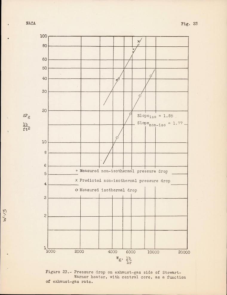
NACA
6Pg
lb ft2
If)
> )
100
80
60
50
40
30
20
10
8
6
5
4
3
2
1 1000
Fig. 23
f 1
/
II
V I V
/
/ II S1opeiso = 1. 85 / Slopenon_iso = 1. 77 _
I 1/
/
/ o Measured non-isothermal
X Predicted non-isothermal
o Mea.sured isothermal drop
2000 4000 6000
Wg • Ib 11r
pressure drop
pressure drop
10000 20000
Figure 23.- Pressure drop on exhaust-gas side of StewartWarner heater, with central core, as a function
of exhaust-gas rate.