
Equator-Series 5 Inground manual - Propools.com
51
INGROUND POOL INSTALLATION INSTRUCTIONS
-
Upload
khangminh22 -
Category
Documents
-
view
4 -
download
0
Transcript of Equator-Series 5 Inground manual - Propools.com

INGROUND POOLINSTALLATION INSTRUCTIONS

STEEL PANELS IN-GROUND POOL INSTALLATION
INDEX ……………………………………….. 1
INTRODUCTION ……………………………………….. 2
PRELIMINARIES ……………………………………….. 2
TOOLS REQUIRED ……………………………………….. 2
LIST OF MATERIALS REQUIRED ……………………………………….. 3
PARTS IDENTIFICATION ……………………………………….. 4
POOL LAYOUT ……………………………………….. 5
EXCAVATION ……………………………………….. 8
POOL WALL ERECTION ……………………………………….. 10
IN-WALL STEP INSTALLATION ……………………………………….. 16
SKIMMER INSTALLATION ……………………………………….. 19
RETURN FITTING INSTALLATION ……………………………………….. 20
MAIN DRAIN INSTALLATION ……………………………………….. 21
CEMENTING THE WALLS ……………………………………….. 23
GROUNDING ……………………………………….. 24
PIPE & FITTINGS INSTALLATION ……………………………………….. 24
BACKFILLING THE POOL ……………………………………….. 27
POOL BOTTOM PREPARATION ……………………………………….. 28
COPING INSTALLATION ……………………………………….. 30
LINER INSTALLATION ……………………………………….. 34
COMPLETING THE JOB ……………………………………….. 45
WARRANTY ……………………………………….. 46
WINTERIZING ……………………………………….. 46
SAFETY STANDARDS ……………………………………….. 47
EXCAVATION DRAWINGS ……………………………………….. 47
NOTICE: The manufacturer makes only those representations which are stated in its Liner warranty.Any other representations, statements, or contracts made by the dealer and/or the contractor to the customer regarding anymaterials produced by the manufacturer are attributable to the dealer and/or the contractor only. The dealer or contractor whosells or installs your pool is an independent contractor and not an agent or employee of the manufacturer.The specifications and design subject to change without notice. The manufacturer maintains a policy of continuousimprovement and therefore reserves the right to change specifications without notice.Not all features shown and/or described are standard. Be sure features and equipment required are listed in Dealer's contract.
PAGE 1

SERIES 5 INGROUND POOL INSTALLATION
INTRODUCTION
Please read right through the instructions in order to get an overall picture of what is required, whichwill avoid the possibility of mistakes, particularly on the excavation, at the early stages. Check toensure that existing services, e.g. electricity and water are adequate. Also check with the hydro &telephone companies for underground cables before excavating. Check with local city or township office to see what size and shape of fencing will be required. A building permit is required before starting, which can be obtained from the local city or township office.
PRELIMINARIES
In selecting the site for the pool, choose an open sunny area with no underground pipes or wiresand away from septic tanks, etc. The pool should be located so that the surface water tends todrain away from the pool deck. Another factor to consider when locating the pool, is that pipes runningto and from the filter should be kept as short as possible.
TOOLS REQUIRED(AVAILABLE AT RENT-ALL OUTLETS)
Utility or sight Level Rod Shovelor Transit Pick4' level 9/64" Drill BitSmall level 9/16" Drill BitWheelbarrow Screw Drivers: Slot 6",Phillips #2&3Rake Hammers: 1 Light (1 6 oz), 1 Heavy (2 Lb.)3/8" Drill (variable speed) 50'Tape MeasureMagnetic Bit Propane Torch9/16" Open End Wrench Cement Trowels (2) 12" to 14"9/16" Socket and ratchet 1 Hand Wood Sawhandle Broom1/2"Open End Socket and Wrench Hose with Spray Nozzle 50' - 75' Extension Cord String - LineIndustrial Shop Vacuum SquareHacksaw Miter Box1 Plumb Bob Small Rubber MalletCement Mixer (if you are Knifemixing your own cement) Lime or Spray PaintFile Pliers15 Foot Extension Ladder Stakes
PAGE 2

MATERIALS REQUIRED
CONCRETE FOR A-FRAMES AND POOL WALLS
Type - 3/4 stone - no air 3,000 PSI
Quantity - It is recommended that a concrete collar is poured around the perimeter of thepool wall approximately 8" deep and 24" wide.
Each A-Frame should be covered to a depth of 12"A 16X32 Bahama requires approximately 3 1/2 cubic yards.Method to calculate cement - .038 x linear footage of pool = cubic yards of cement required.
Example - 16X32 = 96 linear feet x .038 = 3.6 yards.
HARD BOTTOM MIX
Method to calculate quantity of hard bottom mix required -.014 x surface square footageof pool = cubic yards required.
Example - 16X32 = 512 square feet x .014 = 7.2 cubic yards
Type - It is recommended that a hard bottom mix be used for the bottom of the pool.There are different methods and materials which can be used for the hard bottom.
a) One method is to pour a concrete shell and after theconcrete is set, a finished coat is applied.
b) Another method is to pour a hard mix, provided by your local readymix company which can be finished to a smooth surface.
One mix to ask for is as follows: 4 mason / 1 portland cement / 6% air / 3000 P.S.I.
Your local ready mix company may have other recommendations
BACK FILLING
Quantity .25 x linear footage of pool = cubic yards required.
Example - 16X32 = 96 linear feet x 25 = 24 cubic yards
3/8" crushed stone or clear sand16 X 32 requires approximately 24 cubic yards
PAGE 3

PARTS IDENTIFICATION
STEEL WALL ADJUSTABLE "A" FRAME DECK SUPPORT SYSTEM
Both straight and curved wall Our engineers have designed The single and double "A" decksteel panels have a unique heavy duty adjustable support systems were engineeredstrategically located holes (pre- "A" frame that ensures perfect to support the deck around the pool.drilled) at both ends. alignment. This system also adds additionalAdjoining panels are then rigidity to the pool walls.securely fastened togetherusing corrosion resistanthardware supplied, ensuringpositive and accurate alignment.
PAGE 4

POOL LAYOUT
Wall Depth Only:
To provide space for the "A" Frames and for working around the pool later on, the initial excavationto wall depth only is made 2' greater all around, e.g. a 12' X 24' pool will have an initial excavationto wall depth only of 16' X 28'. If you are installing an in-wall step, be sure to stake out an over digto accommodate step.
Refer to the chart diagram #1. Drive two stakes into the ground the appropriate distance apart.(Line No. 1)
Lay out line no.2 and diagonal A and drive a stake into the ground where they meet.
Lay out line no.3 and diagonal B, and drive a stake where they meet.
Check line no.4 for length which should be equal to line no.2
Recheck all other lines in accordance with diagram. Diagonal lines A & B must be equal or poolwill not be rectangular in shape.
PHOTO 1
Diagram 1
PAGE 5

FULL POOL DEPTH See diagram #2
To mark the actual pool size start with stake A, 2 feet inside the initial excavation lines.
From stake A mark off the distance of one side of pool to Stake B (Line no.1).
Lay out line no.2 and no.6 and drive a stake in the ground where they meet (stake C).
Lay out line no.3 and no.5 and drive a stake in the ground where they meet (stake D).
Check line no.4 for length which should be equal to line no.2
Recheck all other lines in accordance with diagram #2. Lines no.6 and no.5 must be equal.
After the pool is staked out, put in an additional 8 stakes in line with stakes A,B,C, & D, 6' to 10' away from the pool (see diagram 2 stakes E). If the original stakes are removed during excavation string lines can be run from stakes E to relocate the pool's position. The string lines can also beused to position the pool wall panels as described in Section 7. Under no circumstances must walls be erected on recently excavated material. The depth of excavation and other dimensionsare shown in the Digging Specification Manual, all of which are finished dimensions, so that an extra 3" - 4" of excavation should be allowed for the hard bottom.
Run a string line between stakes and use chalk or spray paint to mark out lines.
The shaded area is to be excavated to a maximum depth of 42" (See Diagram 2 on Level Stake).
The same method is used to stake out shaped pools. Refer to excavation drawings for detailson squaring shaped pools. Note that all excavation drawings show finished dimensions.
PHOTO 2
PAGE 6

Diagram 2
Sample Pool Sizes:Line no.1Line no.2Line no.3Line no.4Line no.5Line no.6
LEVEL STAKE
Drive a stake in the ground approximately 4 feet away from the pool. The height of this stakeshould be set at the height the top of the steel walls are to be at.
The depth of the initial excavation will depend on how deep the pool walls are to be in the ground.
PAGE 7
16'
28'20'x40'18'x36'16'x32'14'x28'
20'18'
14'28'
12'x24'40'20'40'
32'16'32'
36'18'36'
14'
24'12'24'12'
44'9"44'9"
40'3"40'3"
26'10"26'10"
35'9"35'9"
31'3"31'3"

EXCAVATION
Before starting to excavate, be sure to have a dump site lined up to dump the excavated material.
Get the excavator operator to study the drawing of your particular size pool and stress theimportance of the fairly close tolerances for the walls and inside finish. In particular, ensure thatthe width and length of the deep part of the excavation is not too great, since it is better to havea little extra hand trimming after the walls are firmly in position, than to find that you are trying toinstall the walls on thin air.
The depth of the initial excavation will depend on how deep you intend the pool walls to be in theground. The best way to tackle a sloping site is illustrated below.
While the hole is being dug, a man with a shovel should work in the hole, grading and makingperiodic checks on all measurements to ensure accuracy and avoid unnecessary hand digging later.
All installation drawings show finished dimensions as show in the following drawings.
The hole can now be shaped to a bowl in the deep end, if so desired.
PAGE 8

PHOTO 3
PHOTO 4
PAGE 9

POOL WALL ERECTION
A level foundation of undisturbed earth should be provided where the wall sections will be installed.A level area where the "A" frames will be placed should also be provided at this time.
As final hand trimmings of the excavation is being made, the wall panels should be lowered ontothe working border and leaned against the side of the excavation. Photo #5. Make a final check to seethat the skimmer panel, both return panels are in their desired positions. If the panels have beencorrectly placed, the next step is to bolt them together.
2'-O" RADIUSCORNER PANEL
WALL ASSEMBLYSTEEL WALLPANEL
A-FRAME
STAKE ROD
PHOTO 5Bolt panels and A-frames together. One A-frame is required at each panel joint.*
*Except on 2' and 4' Radius cornersPAGE 10

PHOTO 6
DECK SUPPORTS
If deck supports are to be used, they should be installed at the same time as the A-frames.
Deck supports can be installed at each panel joint and corner and on every wall brace.
Deck support consists of 2 A-frame uprights and 2 horizontal braces.
NOTE: Deck supports are designed to help support decks less than 3' wide.Larger decks requiring extra support
PAGE 11

PHOTO 7
PHOTO 8
PAGE 12
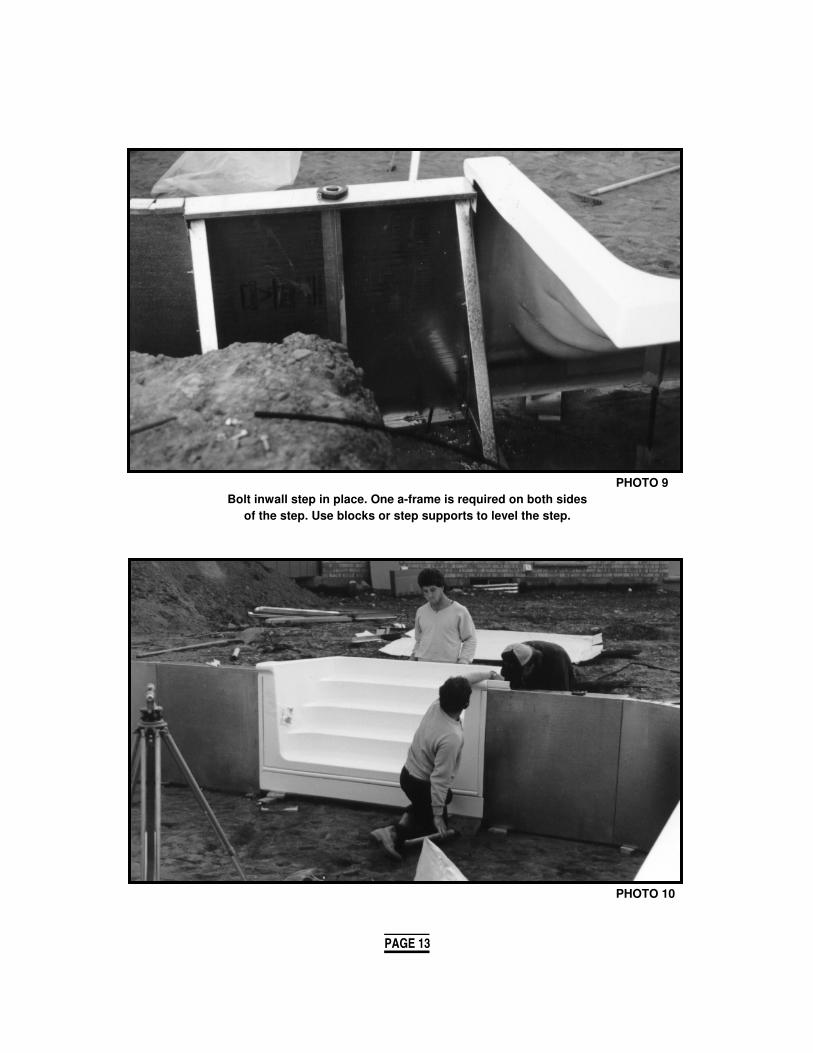
PHOTO 9Bolt inwall step in place. One a-frame is required on both sides
of the step. Use blocks or step supports to level the step.
PHOTO 10
PAGE 13

PHOTO 11
Square the pool making all measurements match pool layout diagram.
PHOTO 12Level panels using a 4' level or sight level. Check level of panels at panel joints.
Shim panel to level. Note: Check the level of curved panels at the center of the panel. After panels are leveled, double check the pool
to be sure it is still square.
PAGE 14

PHOTO 13Secure panels in place with stake rod and or anchor pin & plate. If the ground is soft,
also drive wooden stakes down in front of the panels to hold them in place.
PHOTO 14A string line can be used to align panels. Once aligned
tighten all nuts and bolts on panels and A-frames.
PAGE 15

IN-WALL STEP INSTALLATION
There are a variety of walk in step packages available. The pool can be ordered to accommodatea 4'/6'/8' straight or curved wall step depending on the shape and size. The step can be installed in different positions as shown in the step position chart. If the pool is ordered with a step position the panel mix will be changed to suit the step position.
Review the step manufacturers instructions for proper installation. Instructions will vary fromdifferent manufacturers. Cantelever steps will require special mounting.
Here are some basic guide lines to follow:
Bolt the step in between two steel wall panels making sure the top of the step will be leveled with the top of the coping (not the top of the steel wall)
The back of the step must be supported, and these supports can be used to level the step. Adjustable metal step supports can be ordered with the pool kit. If you do nothave adjustable step supports, concrete blocks can be used.
The step should be leveled to the same slope as the deck which will slope away fromthe pool.
When pouring concrete around the pool, be sure to pour concrete behind the step.
The step should be backfilled in the same manner the rest of the pool is backfilled.(crushed stone or clear sand)
NOTE: See special instructions on step liner installation found on page 34. Step positions are found on pages 17 & 18.
PHOTO 15
PAGE 16

SHAPES, SIZES AND STEP POSITIONSQUALITY IN-GROUND SWIMMING POOLS
SIZES, NAMES, AND SHAPES MAY VARY. PLEASE ASK FOR YOUR EXACT DRAWING BEFORE DIGGING!Shapes available in Left or Right
2' Radius Corners
Sizes: Sizes:14'x28' 14'x28'16'x32' 16'x32'16'x34' 16'x34' Sizes:16'x36' 16'x36' 20'x34'18'x36' 18'x36' 22'x36'20'x40' 20'x40' 24'x40'
6" Radius Corners 2' Radius Corners 2'10" 45 Deg. Corners 4' Radius Corners
Sizes: Sizes: Sizes:14'x28' 14'x28' 14'x28'16'x32' 16'x32' 16'x32'16'x34' 16'x34' 16'x34'16'x36' 16'x36' 16'x36'18'x36' 18'x36' 18'x36'20'x40' 20'x40' 20'x40'
2' Radius Corners 4' Radius Corners
Sizes:16'x28'
Sizes: 16'x30'14'x28' 16'x32'16'x28' 18'x31'16'x32' 18'x33' Sizes:16'x34' 20'x35' 14'x31'18'x34' 20'x37' 16'x38'18'x36' 22'x39' 18'x40'20'x40' 22'x41' 20'x41'
2' Radius Corners 2'10" 45 Deg. Corners 1' Radius Corners 6" Radius Corners
Sizes: Sizes:14'x28' 14'x28'16'x32' 16'x32'16'x34' 16'x34' Sizes:16'x36' 16'x36' 14'x28'16'x38' 16'x38' 16'x32'18'x36' 18'x36' 16'x34'18'x38' 18'x38' 16'x36'20'x40' 20'x40' 18'x36'20'x42' 20'x42' 20'x40'
OVAL
RECTANGLE
KIDNEY
BAHAMA FULL-L ROMAN I ROMAN VI

4' ~ 6' ~ 8' ~ WALK-IN STAIRCASES AVAILABLE FOR MOST POOLS

SHAPES, SIZES AND STEP POSITIONSQUALITY IN-GROUND SWIMMING POOLS
SIZES, NAMES, AND SHAPES MAY VARY. PLEASE ASK FOR YOUR EXACT DRAWING BEFORE DIGGING!Shapes available in Left or Right
Sizes:20'x34'22'x36'24'x40'
4' Radius Corners
Sizes:14'x28'16'x32'16'x34'16'x36'18'x36'20'x40'
4' Radius Corners
Sizes:14'x30'16'x37'18'x39'20'x40'
6" Radius Corners
Sizes:14'x28'16'x32'16'x34'16'x36'18'x36'20'x40'
ROMAN VI


SHAPES, SIZES AND STEP POSITIONSQUALITY IN-GROUND SWIMMING POOLS
SIZES, NAMES, AND SHAPES MAY VARY. PLEASE ASK FOR YOUR EXACT DRAWING BEFORE DIGGING!Shapes available in Left or Right
Sizes:14'x28'16'x30' Sizes:16'x32' Sizes: 18'16'x34' 26'x36' 20'18'x36' 28'x40' 22'20'x40' 30'x44' 24'
2' Radius Corners 2'10" 45 Deg. Corners 2' Radius Corners 4' Radius Corners
Sizes: Sizes: Sizes: Sizes:14'x28' 14'x28' 14'x28' 14'x28'16'x32' 16'x32' 16'x32' 16'x32'16'x34' 16'x34' 16'x34' 16'x34'16'x36' 16'x36' 16'x36' 16'x36'18'x36' 18'x36' 18'x36' 18'x36'20'x40' 20'x40' 20'x40' 20'x40'
Sizes: Sizes: Sizes:14'6"x28'6" 14'x28' 14'x28'
Sizes: 17'x31' 16'x32' 16'x32'15' 17'x34' 16'x34' 16'x34'17' 18'x37' 18'x36' 18'x36'19' 18'x40' 20'x38' 20'x38'22' 18'6"x40'6" 20'x40' 20'x40'24' 20'x40' 22'x43' 22'x43'
2' Radius Corners 2'10" 45 Deg. Corners 4' Radius Corners
Sizes:14'x28' Sizes: Sizes: Sizes:16'x32' 14'x31' 14'x30' 14'x30'18'x34' 16'x38' 16'x38' 16'x37'21'x36' 18'x40' 18'x39' 18'x39'21'x40' 20'x41' 20'x40' 20'x40'
DIAMOND II ROUND
Sizes:24'x24'
OCTAGON GRECIAN
4' ~ 6' ~ 8' ~ WALK-IN STAIRCASES AVAILABLE FOR MOST POOLS
BAHAMA LAZY-L IV FLORIDA LAZY-L II

SKIMMER INSTALLATION
FULLY AUTOMATIC SURFACE SKIMMER
Patented Through the Wall MountNo Water Contact with Pool Wall
The Equator water lock-design features a through the wall mount eliminating any watercontact with the steel panel.
Multiple skimmer types and styles from different manufacturers are available. SEE MANUFACTURERS INSTRUCTIONS FOR CORRECT INSTALLATION.
A) Locate the skimmer in the pool so that the prevailing winds and water recirculation promotes driftof surface debris towards the skimmer.
B) The Skimmer Face Flange mounts through the pool wall opening. A gasket must be installedbetween the Skimmer mounting flange and the pool wall. Align the Skimmer with the sixmounting holes in the pool panel and fasten in place with the (6) 1 " Phillips screws into brassskimmer inserts. See Diagram #3
C) Tape the exposed heads of mounting screws and bolts with duct tape.
D) Support the Skimmer by bracing it behind the pool wall with a skimmer support which is includedin the skimmer pack.
E) When the vinyl liner is installed and the water level has reached the Skimmer, proceed withinstallation of the face flange.
F) Gaskets are required on both sides of the liner, one on the Skimmer Throat and one on the FaceFlange. Installation of the face flange - begin by placing the Face Flange and the Gasket inposition and pierce holes through the Face Flange holes, one at a time, prior to inserting each ofthe 16 - 1 " flat head screws. See Diagram #3. Tighten the screws to make a water tightassembly.
G) Cut out the liner material along the inside edges of the Face Flange.
NOTE: When connecting plumbing, use Teflon tape or peratex 2 - do not use pipe caulking of anykind as this will attack the ABS material that the skimmer is made of causing cracking.
WINTERIZING - See operations manual supplied with the skimmerSKIMMER OPERATION - See operations manual supplied with skimmer.
PAGE 19

RETURN FITTING INSTALLATION
Multiple Return types and styles from different manufacturers are available. SEE MANUFACTURERS INSTRUCTIONS FOR CORRECT INSTALLATION.
A minimum of 2 returns are provided for all pools with some models designed with 3 returns.Inlet panels are pre punched and should be placed as per the installation drawing or in such a wayas to take full advantage of the prevailing winds. (See skimmer installation directions)
IMPORTANT - a gasket must be between the face flange and the liner. The gasket is factory cementedto the face flange). Place face flange in position and pierce holes in the liner for the 4 screws (1" long). Install the screws using a #3 Phillips screw driver. Tighten screws evenly to make a water tight assembly.
INSTALLATIOND) Cut out the liner along the inside edge of the
A) Insert the body of the fitting through the face flange.precut hole in the panel from the inside ofthe pool. (Part #1013). E) Insert spring retainer, (beveled edge facing
eyeball), spring, and eyeball into the return B) Screw the draw nut (Part # 1023) on the fitting and thread ball lock ring (Part #1014)
back of the fitting. The draw nut can be put in place.on smooth flange first. (Do not over tight)
F) Adjust eyeballs in the desired direction.C) When the pool liner is installed and after the
water level has reached the return fittings, WINTERIZING - See operations manualinstall the face flange (Part # 1012). supplied with the skimmer package.
PAGE 20

MAIN DRAIN INSTALLATION
The Main Drain is molded out of high technology thermoplastic materials. It is designed to be used for liner pool installations. It features a 1-1/2" side port for residential installations.
Multiple Main Drain types and styles from different manufacturers are available. SEE MANUFACTURERS INSTRUCTIONS FOR CORRECT INSTALLATION.
ANTI-VORTEX COVER #1020This cover is standard equipmenton the Main Drain. It snaps into place and for added safety, it canbe fastened with the 2 screws supplied (1 " long).
INSTALLATION
A) Dig a hole in the center of the deep end of your pool, approximately 18" X 18" square by 18" deep. Dig a trench to the side of the pool to accommodate the pipe to the skimmer. (Main drain can also be connected directly to the pump and filter)
B) Install the Collection Tube in the bottom port of the Main Drain and solvent cement it in place withABS cement.
C) Install the Hydro Relief Valve Flapper Valve (#1003) in the bottom of the Main Drain Body over the bottom port where the Collection Tube is installed (Gasket side down). This valve is installed bysnapping it into the two U brackets.
D) Install a 1-1/2" threaded adaptor in the side port of the Main Drain, using Teflon tape on the threads.Do not over tighten.
E) Connect the pipe going to the skimmer.
F) Install the Main Drain Body in the 18" x 18" x 18" hole, packing 3/4" of crushed stone around thedrain and Collection Tube.
G) Pour a concrete pad around the Main Drain. Bring the concrete even with the top of the Main Drain.NOTE: You must put tape over the screw holes and so that cement does not plug the screw holes. (This operation can be done when you pour the hard bottom). NOTE: Remove the tape used to protectthe screw holes before installing the liner.
H) Install the liner in the pool, ensuring there is a gasket between the Main Drain Body and the liner.
I) Once the vinyl liner is installed and vacuumed into proper position, install the face flange (#1019).Important: A gasket must be installed between the Face Flange and the liner. This gasket is factorycemented to the Face Flange. Line the Face Flange screw holes up with the Main Drain Body screw holes. Pierce in the liner for the 8 flat head screws (1" long). Insert and tighten the screws usinga #3 Phillips screw driver to make a water tight assembly.
J) Cut out the liner along the edge of the Face Flange.
K) Install the Anti-Vortex Cover, fasten with two screws supplied with the Drain (1" long) for added safety
PAGE 21

Tape screw holes to protect from cement.
PHOTO 16
Glue hydro relief tube inplace with ABS cement
PHOTO 17
DIAGRAM 19
Install gasket on main drain before installing liner.
Check for proper depth. PHOTO 18PHOTO 19
PAGE 22
MAIN DRAININSTALLATION

CEMENTING THE POOL WALLS AND A-FRAMES IN PLACE
Pour concrete around the totalperimeter of the pool forming aconcrete beam
PHOTO 20Before pouring concrete, be sure the pool walls are level and square. The main drain line is
connected to the skimmer, A-frames, deck supports, skimmer support and ladder supports are allinstalled and level.
Pour concrete behind the panels around the total perimeter of the pool including the area behindany walk in stair cases. The concrete should be 8" deep by 24" wide which should fill the width ofthe excavation, this will form your concrete beam. Extra concrete should be poured at each A-frameto a depth of 12" to 14".
PHOTO 21 PHOTO 22PAGE 23
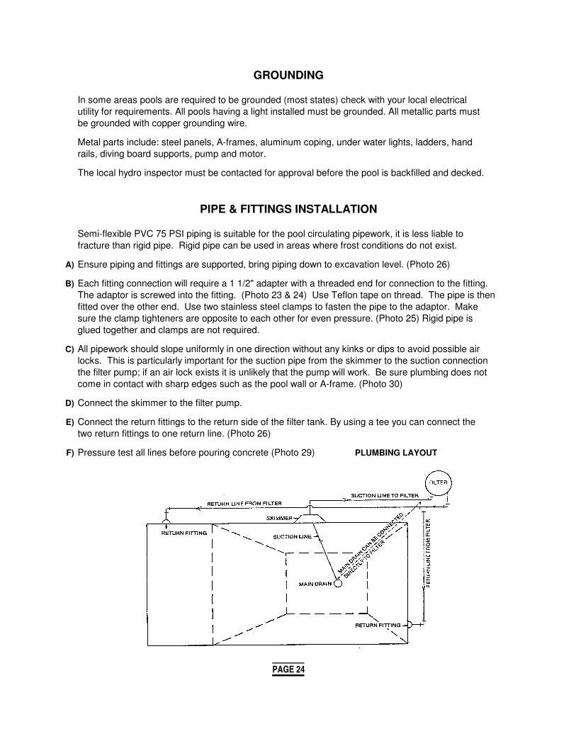
GROUNDING
In some areas pools are required to be grounded (most states) check with your local electricalutility for requirements. All pools having a light installed must be grounded. All metallic parts mustbe grounded with copper grounding wire.
Metal parts include: steel panels, A-frames, aluminum coping, under water lights, ladders, handrails, diving board supports, pump and motor.
The local hydro inspector must be contacted for approval before the pool is backfilled and decked.
PIPE & FITTINGS INSTALLATION
Semi-flexible PVC 75 PSI piping is suitable for the pool circulating pipework, it is less liable tofracture than rigid pipe. Rigid pipe can be used in areas where frost conditions do not exist.
A) Ensure piping and fittings are supported, bring piping down to excavation level. (Photo 26)
B) Each fitting connection will require a 1 1/2" adapter with a threaded end for connection to the fitting.The adaptor is screwed into the fitting. (Photo 23 & 24) Use Teflon tape on thread. The pipe is thenfitted over the other end. Use two stainless steel clamps to fasten the pipe to the adaptor. Makesure the clamp tighteners are opposite to each other for even pressure. (Photo 25) Rigid pipe isglued together and clamps are not required.
C) All pipework should slope uniformly in one direction without any kinks or dips to avoid possible airlocks. This is particularly important for the suction pipe from the skimmer to the suction connectionthe filter pump; if an air lock exists it is unlikely that the pump will work. Be sure plumbing does notcome in contact with sharp edges such as the pool wall or A-frame. (Photo 30)
D) Connect the skimmer to the filter pump.
E) Connect the return fittings to the return side of the filter tank. By using a tee you can connect thetwo return fittings to one return line. (Photo 26)
F) Pressure test all lines before pouring concrete (Photo 29) PLUMBING LAYOUT
PAGE 24

PHOTO 23
Thread the pipe adapters PHOTO 24 Double Clamp all Fittings. PHOTO 25into the fittings.
Run piping to bottom of excavation for support. PHOTO 26
PAGE 25

PHOTO 27 PHOTO 28
Pressure test all lines PHOTO 29 Run piping to bottom of PHOTO 30before backfilling. excavation for support.
PAGE 26

BACKFILLING
PHOTO 31Sono tubes can be used in place of deck supports to support the deck.
A) If using sono tubes in place of deck supports they must be in place before backfilling. (See Photo 31)
B) When using deck supports you will require sono tubes at the corners of 2' and 4' radius corner pools and around walk in stair cases. (See Photo #33)
C) In areas where ground water is apt to run to the pool area, it is recommended that drainage tile be in-stalled in excavated area before backfilling.
D) Test all plumbing before backfilling NOTE: Do not allow any heavy equipment nearthe pool to back fill.
E) Back fill with 3/8" crushed stone or clear sand. Example -(trucks, backhoe, bulldozer etc)
Sono tubes installed to support the deck.
PHOTO 32 PHOTO 33
PAGE 27

POOL BOTTOM PREPARATION
A) Check the depth in various sections of the pool bottom in relation to the top of the walls. If theexcavation has been done carefully, only a small amount of hand trimming will be necessary. Depths may be 2" or 3" deeper than the dimensions shown for your particular pool depending onthe thickness you plan to make the hard bottom, but may not be less, since the liner would notfit smoothly in the pool bottom. In the bottom of the shallow end put 2" of hard bottom mix sothe finished depth is 40".
B) Remove all loose dirt before installing finished bottom.
C) If the excavated hole is a dry hole, i.e. does not need to be continuously pumped out to keep thewater out, then the hard bottom mix can be applied directly on the firm earth approximately 2" to 3"thick; if the hole is a wet hole, the bottom of the deep end should be dug out a further 6". This 6"extra depth should be filled with 3/4" stone. A concrete shell 3" thick should now be laid over the entire bottom and rough trowelled. When this has set, a 1/2" thick layer of hard bottom mix should be spread over the concrete to give you a smooth finish on which the liner will rest. It should be noted that the above is a guide and judgement on the condition of the hole plays an important part indeciding just how wet or dry a given hole is. A concrete shell can also be used if the hole is dry.
D) Materials Required - See Page 3
E) Pre mix hard bottom mixes can be used such as vermiculite - cement pool base which can be mixed on site or pre mixed bases are available from most ready mix concrete supply companies whichdelivers to the job site pre mixed.
SEE PHOTOS 34, 35, 36
PHOTO 34
PAGE 28

1/2" Smooth hard bottom mix. PHOTO 35
Finished bottom PHOTO 36
PAGE 29

COPING INSTALLATION
There are various types of coping available both in PVC & aluminum. The following are instructions for installing 1 style of S/L PVC & aluminum concrete receptor type copings.
ALUMINUM / PVC CONCRETE RECEPTOR COPING
A) On rectangle pools place the 6"/2'/4' radius snap-lock coping corners on all four corners andfasten with self drilling/self taping by means of a magnetic bit (Photo 37)
B) The aluminum coping is then fitted and fastened with self drilling/ self tapping screws every 9".Be sure the coping alignment lip is flush against the front of the steel wall panel. (Photo 38)
C) On Snap-Lock coping, couplings are placed on the backside of the coping at the joints. This aligns each subsequent coping section. Self drilling / self tapping screw secures the coupling.
D) Couplings should then be placed a minimum of one (1) foot apart ensuring the coping will be straightup and down. Self drilling / self tapping screw secures the coupling. (Photo 40)
E) On PVC coping, couplings are referred to as retainers.
Install all four corners. PHOTO 37
PAGE 30

Install retainer clips every 8"1/2" and on either side of coping joint. PHOTO 38
When installing Snap-Lock coping on curve shaped pools, carefully cut slots on the base of thecoping when bending the coping around an inside curve and cut "V" notches in the base of the copingwhen bending around a convex (reverse) curve. The sharper the curve the move "V" notches or slotse.g. 2' radius corner slot every 2" -normal curves approximately every 4" - 5" -reverse curves "V" notchevery 2". (Photo #6, 7, & 8)
Aluminum coping comes in pre radius lengths or can be bent on site as outlined above.
NOTE: After liner is installed the snap-lock clip is the last piece of the coping to be installedlocking the liner in place.
Only if necessary, use a fine file to make the joints of each coping section match.(FLUSH).
Miter box may be used to make nice coping joints.
PHOTO 39
PAGE 31

V notch coping for reverse curves. PHOTO 40
Coping installed on reverse curved panel. PHOTO 41
PAGE 32

ALUMINUM COPING
On rectangle 6", 2' and 4' radius pools fit the preformed radius corners and fasten by means ofself drilling / self tapping screws using a magnetic bit. Ensure alignment lip of the coping is flushagainst the steel panel.
The aluminum coping is then fitted and fastened with self drilling / self tapping screwsevery 12". Ensure alignment is tight against the face of the steel panel.
An aluminum coupling may be installed at every coping joint. Ensure the base lip of the coupling fitstightly against the base of the coping. Secure with a self drilling / self tapping screw.
For shaped (curved) pools, preformed aluminum coping is available for inside or convex (reverse)curved panels, or you can form on site using the same methods used for PVC. When installingaluminum coping on a Kidney pool, start by installing the reverse section of the coping first.
MAKE SURE WHEN PUTTING THE COPING JOINTS TOGETHER, YOU HAVE A CLEAN, TIDYJOINT! A small file might be helpful (or miter box). The preformed aluminum coping has all 9'radius pieces 1O' long. To adjust for different radius, slotting of "V" notching might be necessary.
On Snap Lock coping, after liner is installed the snap-lock clip is installed locking in the liner.
Front mount track is used when a wooden deck or flag stone is being installed to the front edgeof the pool. Front mount track is also used to repair older pools with decks.
For rectangle 6", 2' and 4' radius corners, fasten the preformed radius snap-lock front mountcorners to the inside of the pool wall by means of heavy duty self drilling / self tapping screws.
A small channel is provided where the self drilling / self tapping screws are fastened into the faceof the steel panel every 4".
With Kidney Pools, start in center of reverse panel and let the self drilling / self tapping screwsform the bending.
PAGE 33

INSTALLING THE LINER
Vinyl liners are best installed in warm weather. The liner can be handled better and the packagingwrinkles will disappear more readily. If the liner is to be installed in cool weather, store in a heatedroom for a day or two prior to installation.
A) Before installing the liner, double check the bottom to be sure there are no stones or sharp objectsthat might damage the liner. Also make sure any cement splashed on the steel walls is removed.The steel walls should be dry before installing the liner. Tape panel joints and corners and copingbefore installing the liner.
B) At this point the main drain gasket must be put in place (see main drain installation)
Each liner has a home owner package included which consist of the following:
Be sure to give this to the pool owner
1) Warranty Registration Card2) Safety Book 3) Liner Material Manufacturers Care Guide4) No Diving Safety Stickers
PAGE 34

CONTAINER LINER REMOVAL INSTRUCTIONS
1) Remove metal tabs 2) 5) Place liner in shallow end and unfold taking top of the linerfrom drum. (deep end) towards deep end as indicated
Place drum in shallow end of pool and remove liner by turning drum upside down.
3) Unroll Liner. 4)
Deep end on top.Shallow end on bottom.
C) Unroll liner crossways at shallow end of pool. Make sure edges and corners of liner are accessible. Place two people at each end of the unrolled liner. One person at each end should take hold of theliner corner that will be positioned at the deep end of the pool, the other two people should hold theliner corners for the shallow end. The two people holding the deep end corners then walk down theirrespective sides of the pool, unfolding the liner like an accordion. The liner will then be suspendedover the excavation with all sections in the relative positions. SEE ABOVE
D) Take the top edge of the liner, and starting from the corners, insert the liner bead into the coping trackat several spots to temporarily hold the liner in place. Now finish inserting the liner bead around therest of the pool. SEE BELOW
Insert liner bead into track
E) When you are satisfied that the liner is in its proper position, remove 6" of the liner bead from the extrusion near the drop off to the deep end. In this opening, insert a vacuum cleaner hose to about30" below the top of the wall. It is best to use an industrial type vacuum rated for continuous use.Where the hose is inserted between the liner and wall, seal with duct tape. Also seal off the pipesfrom the skimmer and inlets. A wet/dry type vac should be used.
NOTE: You may choose to run the vacuum hose through the skimmer, but make sure the opening issealed to insure good suction. If the deck is not yet in place, put duct tape along the back edgeof the coping. This will help the vacuum work better.
F) When used, the opening for walk-in steps needs to be sealed to prevent suction loss. You may tapethe backside of the liner to the step, or lay a sheet of plywood across the top of the steps, taping theliner bead to the plywood. Good suction is important for proper liner installation.
PAGE 35

NOTE: Refer to step manufacturers instructions for proper installation of gaskets and flanges.
G) Start the vacuum cleaner. In about 15/20 minutes, the liner will be drawn against the pool excavationand side walls and you will see if the liner bottom is seated correctly in the excavation or if it needsrepositioning. Make adjustments where necessary (if possible with vacuum still running) by pullingliner into place.
NOTE: Do not cut any fittings or add water if the liner does not fit properly. Water will not removewrinkles.Be careful with tools and wear stocking feet, not boots or shoes to avoid damaging the liner.
H) Once the vinyl liner is installed and vacuumed into proper position, install the face flange. A gasketmust be installed between the Face Flange and the liner. This gasket is factory cemented to the FaceFlange. Line the Face Flange screw holes up with the Main Drain Body screw holes. Pierce in theliner for the Main Drain Body screw holes. Pierce in the liner for the 8 flat head screws (1 " long).Insert and tighten the screws (using a #3 Phillips screw driver) to make a water tight assembly.
I) Cut out the liner along the inside edge of the Face Flange.
J) Install the Anti-Vortex Cover and for added safety, fasten with the two screws supplied with theDrain (1 " long).
K) If a walk in step has been installed, use water bags to hold the liner against the shallow end wall.
L) You can now start filling the pool with water while the vacuum is still running.
PHOTO 42
PHOTO 43PAGE 36

PHOTO 44
PHOTO 45
PAGE 37

PHOTO 46
PHOTO 47
PAGE 38
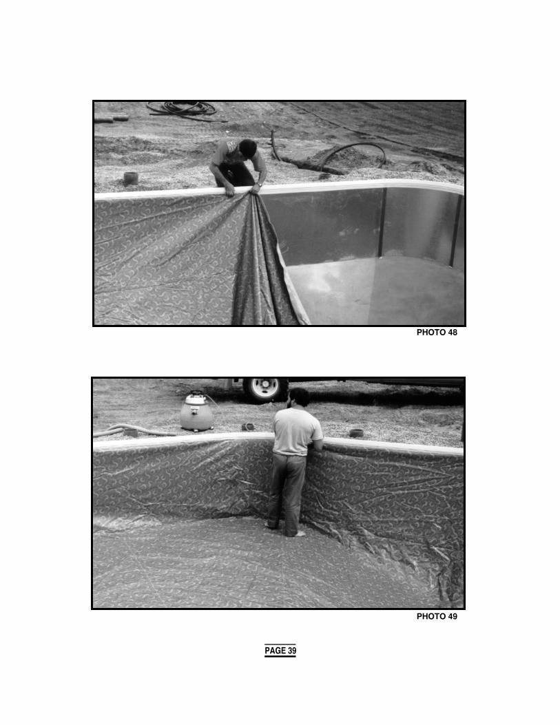
PHOTO 48
PHOTO 49
PAGE 39

PHOTO 50
PHOTO 51
PAGE 40

PHOTO 52 PHOTO 53
PHOTO 54 PHOTO 55
PAGE 41

N) WALK IN STEPS
Normal installation of walk in steps would be as follows but it is recommended you refer to stepmanufacturers installation.
1) Install face flanges on the step when the water reaches the shallow end.
2) Install the 2 side flanges fastening the top 3 screws only.
3) Cut the liner in the center of the step in the shape of a smile. This will allow the tension to betaken off the liner under the bottom step.
4) Install the bottom flange and finish putting the screws inside flange. Be sure there is a gasketbetween the step and the liner and the face flange and the liner.
O) When installing Kidney liners, start at the shallow end and make sure it fits properly. The shallowend line seam and the panel joints should line up. Then distribute the rest of the liner evenlyaround the rest of the perimeter.
P) When installing Roman end pools - 2 vacuums must be used. Sandbags or waterbags are recomm-ended to avoid the liner shifting and causing wrinkles. WATER WILL NOT REMOVE THESE WRINKLES!
NOTE: With most shaped pools again sandbag or waterbag the shallow end.
Q) When there is 6" of water in the shallow end, shut off the vacuum cleaner and remove the vacuumhose. Walk in steps may be cut at this time.
If for any reason larger size screws are used on step flanges, make sure to redrill face flange sothat the larger screws slides through face flange and screws only into step, and does not threadon the face flange or leaks will develop.
PHOTO 56 PHOTO 57
PAGE 42

PHOTO 58
INSTALLING THE RETURN FACE PLATES
PHOTO 59 PHOTO 60
When the water level reaches the return After the face plate is fastened in place, cutfitting, install the face plate as shown in out the liner material in the center, using aPhoto 1. (See manufacturer's instructions small blade. for more details)
PAGE 43

PHOTO 61
PHOTO 62
PHOTO 63PAGE 44

COMPLETING THE JOB
CONCRETE DECK
Before pouring a concrete deck, laying interlocking stones or installing a wooden deck, be sure all deck supports and sauna tubes are in place.
If a deck is to be poured against a solid wall such as a house or retaining wall, be sure a space isleft for expansion. It is also a good idea to use drain tile to avoid ponding against the wall.
All concrete decks should have expansion joints to limit cracking caused by deck expansion or frost.
LIGHTS
If a electrical light is being installed, the pool must be grounded and Hydro inspected before back-filling the pool. In some areas all pools must be grounded even if there is no light.
SERVICES
All electrical/gas services should be inspected before using.
FENCE
All pools should be fenced for safety reasons. Most areas require a fence to be installed aroundthe pool or around the yard. Different rules apply regarding height and construction. Check the localBy Laws.
The Kafko Decorative Metal Fence Systems conform to most By Laws when installed with a selfclosing/locking gate.
Kafko Decorative Metal Fence is available in 2 styles. Picket and Loop-Top.
PICKET AND LOOP-TOPDECORATIVE METAL FENCING
PAGE 45

WARRANTY
Included in home owners package:
The pool kit warranty registration card is packed in the liner drum/box.
The warranty registration should be filled out and mailed to ensure warranty coverage. Warrantiesfor equipment such as filters, pumps, lights, heaters, pool cleaner, steps, etc.. are supplied by themanufacturer of these products, separate from the pool kit warranty.
WINTERIZING
Refer to manufacturers winterizing manual for proper winterizing of the pool and pool equipment.
Instructions for winterizing the pool will vary depending on frost conditions.
Equipment - Refer to equipment manufacturers instructions for winterizing.
WINTERIZING KIT
The Winterizing Kit isdesigned to protect theskimmer from ice damage.All skimmers that areinstalled in pools wherewinter freezing occursshould have this kitinstalled when the poolis winterized.
*NO WARRANTY CLAIMSWILL BE ACCEPTED UNLESSA WINTERIZING KITHAS BEEN INSTALLED.
PROTECT YOUR SKIMMER
PAGE 46

SAFETY BEGINS WITH YOU!
Always refer to diving boards manufacturer's specs before installing any size diving board.
When it comes to safety it is up to the installer of the pool to ensure all possible efforts are made toconstruct the pool to safe standards and to ensure equipment such as diving boards/slides/steps/etc.. are only installed on pools designed for this equipment. If in doubt do not install the equipment. Thecompany provides non diving stickers with all pools. These stickers are packed in the liner drum inthe home owners package.
These stickers must be installed in the shallow end or in the case of shallow depth pools, they areto be installed at both ends and sides of the pool.
Questions on safety can be directed to the company, the equipment manufacturer, orThe Association of Pool and Spa Professionals.
PAGE 47