Energy Dissipation and Transport in Nanoscale Devices - arXiv

This article appeared in a journal published by Elsevier. The attachedcopy is furnished to the author for internal non-commercial researchand education use, including for instruction at the authors institution
and sharing with colleagues.
Other uses, including reproduction and distribution, or selling orlicensing copies, or posting to personal, institutional or third party
websites are prohibited.
In most cases authors are permitted to post their version of thearticle (e.g. in Word or Tex form) to their personal website orinstitutional repository. Authors requiring further information
regarding Elsevier’s archiving and manuscript policies areencouraged to visit:
http://www.elsevier.com/authorsrights
Author's personal copy
Equal energy dissipation in wireless image sensor network: Asolution to energy-hole problem q
Ashraf Hossain a,⇑, S. Chakrabarti b, P.K. Biswas c
a Department of Electronics & Communication Engineering, Aliah University, Maulana Abul Kalam Azad Bhawan, DD-45, Sector-I, Salt Lake City,Kolkata, 700 064 West Bengal, Indiab G.S. Sanyal School of Telecommunications, Indian Institute of Technology Kharagpur, West Bengal 721 302, Indiac Department of Electronics & Electrical Communication Engineering, Indian Institute of Technology Kharagpur, West Bengal 721 302, India
a r t i c l e i n f o
Article history:Available online 15 February 2013
a b s t r a c t
In wireless image sensor networks (WISNs), the nodes closer to the sink are likely to getover-burdened and run out of their battery energy at the early stage of network deploy-ment. This has been reported in the literature as the energy-hole problem. In this paper,we propose to establish equal energy dissipation condition over the network to mitigateenergy-hole problem. We consider a data gathering linear array of wireless camera sensornodes. Each camera sensor node generates one raw image per data gathering cycle. The rawimage captured by each camera sensor node is processed locally and sent to the sink nodeusing intermediate nodes. Exact placement of nodes is derived to ensure equal energy dis-sipation over the network. The raw image is locally processed using discrete wavelet trans-form (DWT). Network lifetime and peak signal-to-noise-ratio (PSNR) of the reconstructedimage are calculated at the sink node for several test images.
Crown Copyright � 2013 Published by Elsevier Ltd. All rights reserved.
1. Introduction
A wireless image sensor network (WISN) consists of a large number of energy constrained wireless camera sensor nodes.The nodes are deployed for a wide range of applications including surveillance, target tracking and habitat monitoring [1].The feasibility of WISN is possible due to the progress of technology in image sensors and wireless communication [2,3]. Thecamera nodes are capable of transmitting and receiving packets over a wireless link. Nodes are powered by battery that maynot be replenished. Each node is also capable of processing its data locally. The performance of WISN is limited by huge dataloads. The camera sensor nodes are sometimes deployed in adverse conditions with limited energy. Once battery energy getsdepleted, the network becomes non-functional. Thus, it is important to process raw image captured by each camera sensornode before transmission. The lifetime of such network plays an important role.
In WISN, the information gathered by the camera nodes has to be sent to the sink node to make the conclusion about theactivity of the area of interest. The communication range of the camera nodes is not large enough to reach the sink node. As aresult, the mode of communication in this network is multi-hop. In a multi-hop wireless network, the nodes closer to thesink may have higher loads of relaying packets as compared to the distant nodes. Hence the nodes closer to the sink are likelyto get over-burdened and run out of their battery energy at the early stage of network deployment. This has been reported inthe literature as ‘‘the energy-hole problem’’ [4].
0045-7906/$ - see front matter Crown Copyright � 2013 Published by Elsevier Ltd. All rights reserved.http://dx.doi.org/10.1016/j.compeleceng.2013.01.012
q Reviews processed and recommended for publication to Editor-in-Chief by Guest Editor Dr. Catalin Lacatus.⇑ Corresponding author. Tel.: +91 9143061335.
E-mail addresses: [email protected], [email protected] (A. Hossain), [email protected] (S. Chakrabarti), [email protected] (P.K. Biswas).
Computers and Electrical Engineering 39 (2013) 1789–1799
Contents lists available at SciVerse ScienceDirect
Computers and Electrical Engineering
journal homepage: www.elsevier .com/ locate/compeleceng
Author's personal copy
Several authors have studied the performance of WISN. Lecuire et al. [5] have studied wavelet-based image transmissionin a linear array of camera nodes. They have proposed a semi-reliable image transmission strategy. Raw image isdecomposed into a number of packets with different priority using wavelet. This study is based on the transmission of imagefrom a source node to a sink node using intermediate nodes in a linear array. The intermediate relay nodes take the decisionof forwarding or discarding a packet depending on their state of battery energy. Thus, there is a chance of a packet beingdiscarding by an intermediate node. If a packet is discarded by an intermediate node near the sink then a significant amountof network energy will be wasted. The whole analysis of the tradeoff between image quality and lifetime is done on the basisof number of hops. However, the authors have not considered the scenario where more than one source nodes are present.
Wu and Abouzeid [6] have studied distributed image compression and transmission in wireless network. Distributed im-age compression is proposed to reduce the computation burden of individual nodes. The authors have considered amulti-hop wireless network where some of the nodes are equipped with camera. Camera sensor node generates raw image.The camera sensor node acts as the source node. The authors have assumed cluster-based routing. Once the camerasensor node captures an image it notifies its cluster head (CH) node. CH selects a group of nodes in its cluster to performdistributed 2D-discrete wavelet transform (2D-DWT) operation. At the end of the operation the processed data is sent tothe neighbor cluster head node towards the base station. The distributed 2D-DWT operation will be repeated until the datareaches to the base station. The number of DWT operation is dependent on quality of reconstructed image at the base station.Tiling-based DWT has also been employed. The lifetime of such a network with distributed compression is compared withcentralized compression method. However, no importance has been given to the idle state energy dissipation of the radio ofthe node.
In [7], the authors have studied image transmission in a wireless sensor network in the event of wireless channel impair-ments and node failure. A wireless channel has been assumed to have two states viz. good and bad. Energy consumption inthe transmission of images from source to destination nodes has been analyzed keeping in mind the quality of the recon-structed image at the destination. Forward error correction code such as RS code has been used.
Wu and Chen [8] have studied collaborative image coding for wireless sensor network. The authors have proposed a col-laborative image coding and transmission scheme to minimize energy for data transmission. Spatial correlation among theneighbor sensor nodes is exploited to calculate overlapping among them. Temporal correlation between two successiveimages has also been analyzed in the case of energy-efficient transmission of image.
Dagher et al. [9] have presented an algorithm for the transmission of image data from the camera sensor node to the sinknode. The main focus of this algorithm is to maximize network lifetime. Camera sensor node captures an image. The authorshave formulated the problem of region allocation such that each part of region is optimally allocated to different cameranodes. Further, they have shown that using image compression the lifetime of the network can be enhanced.
Several authors [10–15] have studied node distribution strategy to avoid energy-hole in the wireless sensor network(WSN). However, no importance has been given on energy-hole in WISN. In this paper, we consider a data gathering lineararray of wireless camera sensor nodes. Each camera sensor node generates one raw image per data gathering cycle. The rawimage captured by each camera sensor node is processed locally and sent to the sink node using intermediate nodes. Weimpose equal energy dissipation condition such that each node dissipates equal energy per data gathering cycle. Exact place-ment of nodes is derived to ensure equal energy dissipation over the network. The raw image is locally processed using dis-crete wavelet transform (DWT). Important image components are identified by local image processing technique. Theselection of image components is done on the basis of reconstructed image quality at the sink node. The lifetime of the net-work has been derived for two schemes of node placement. Peak signal-to-noise ratio (PSNR) of the reconstructed image atthe sink node has also been calculated for several test images.
In our work, the energy dissipation model for radio communication is similar to the model proposed in [16]. The authorsin [16] have considered energy dissipation for transmission, reception and idle state energy of radio. In our work in additionto the above energy dissipation components, we have also considered energy dissipation for image processing. In [6], twotypes of nodes are deployed: sensor nodes with camera and sensor nodes without camera. In our work, we have consideredonly sensor nodes with camera. In [6], no importance has been given to the idle state energy dissipation of the radio of thenode. In our work, we have incorporated the idle state energy of the radio of a node. We have imposed equal energy dissi-pation throughout the network to prolong the network lifetime.
In general, the strategy of node deployment is valid for camera based sensor networks. In the present work, a linear arrayof wireless camera sensor nodes is considered. This type of camera network has applications in surveillance such as borderline surveillance and traffic monitoring in an important road. This study can be extended to a large-scale network (2-D) bythe combination of linear arrays. For example, a circular area of radius 500 m can be covered by the combination of 10 lineararrays of wireless camera sensor nodes. The linear array of nodes is placed in radial direction over the area of interest. Thesink is placed at the center of the area of interest. The lifetime of such a network is equal to that of the linear array of cameranodes.
The rest of the paper is organized as follows. Section 2 presents the system description. Energy consumption modelfor image processing and radio communication is presented in Section 3. In Section 4, we present the basic principle ofimage compression using discrete wavelet transform. Node placement analysis for uniform energy dissipation is pre-sented in Section 5. In Section 6, we present results and discussions for image transmission. Finally, Section 7 concludesthe paper.
1790 A. Hossain et al. / Computers and Electrical Engineering 39 (2013) 1789–1799
Author's personal copy
2. System description
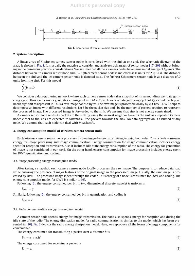
A linear array of K wireless camera sensor nodes is considered with the sink at one end. The schematic diagram of thearray is shown in Fig. 1. It is usually the practice to consider and analyze such arrays of sensor nodes [17–20] without bring-ing in the numerous practical considerations. We assume that all the K camera nodes have same initial energy of E0 units. Thedistance between ith camera sensor node and (i � 1)th camera sensor node is indicated as hi units for 2 6 i 6 K. The distancebetween the sink and the 1st camera sensor node is denoted as h1. The farthest Kth camera sensor node is at a distance of Dunits from the sink. For this modelXK
i¼1
hi ¼ D ð1Þ
We consider a data-gathering network where each camera sensor node takes snapshot of its surroundings per data gath-ering cycle. Thus each camera generates an image of size M � N pixels over a data gathering cycle of Td second. Each pixelneeds eight bit to represent it. Thus a raw image has MN bytes. The raw image is processed locally by 2D-DWT. DWT helps todecompose an image with different resolutions. Let B be the packet size and l be the number of packets required to representthe processed image. The processed image is forwarded to the sink. We assume that sink is not energy constrained.
A camera sensor node sends its packets to the sink by using the nearest neighbor towards the sink as a repeater. Cameranodes closer to the sink are expected to forward all the packets towards the sink. No data aggregation is assumed at anynode. We assume that each node can deal with P packets/s.
3. Energy consumption model of wireless camera sensor node
Each wireless camera sensor node processes its own image before transmitting to neighbor nodes. Thus a node consumesenergy for image processing and image communication. Energy consumption for image communication includes energyspent for reception and transmission. Also it includes idle state energy consumption of the radio. The energy for generationof image is not considered in our work. On the other hand, energy consumption for image processing includes energy spentfor DWT, quantization and coding.
3.1. Image processing energy consumption model
After taking a snapshot, each camera sensor node locally processes the raw image. The purpose is to reduce data loadwhile ensuring the presence of major features of the original image in the processed image. Usually, the raw image is pro-cessed by DWT. The processed image is sent through the coder. Thus energy of a node is consumed for DWT and coding. Theenergy consumption model for DWT is similar to [6].
Following [6], the energy consumed per bit in two dimensional discrete wavelet transform is
EDWT ¼ c ð2Þ
Similarly, following [6], the energy consumed per bit in quantization and coding is
EENT ¼ d ð3Þ
3.2. Radio communication energy consumption model
A camera sensor node spends energy for image transmission. The node also spends energy for reception and during theidle state of the radio. The energy dissipation model for radio communication is similar to the model which has been pre-sented in [16]. Fig. 2 depicts the radio energy dissipation model. Here, we reproduce all the forms of energy components forconvenience.
The energy consumed for transmitting a packet over a distance h is
ETx ¼ et þ edhn ð4Þ
The energy consumed for receiving a packet is
ERx ¼ er ð5Þ
Sink 1 2 3 (i–1) i
ith Camera sensor node K
D
h1 h2 hKhih3
(i+1) K–1
Fig. 1. Linear array of wireless camera sensor nodes.
A. Hossain et al. / Computers and Electrical Engineering 39 (2013) 1789–1799 1791
Author's personal copy
The energy spent by the radio during idle time is
Eidle ¼ eidTidP ð6Þ
where et is the energy spent per packet in the transmitter electronics circuitry, er is the energy spent per packet in the re-ceiver electronics circuitry, edhn is the energy required in amplifier to overcome the path loss over distance h, eid is the energyspent during idle period, Tid is the idle time, P is the packet dealing rate of the radio and n is the path loss exponent.
In the next section we describe the image compression principle.
4. Image compression using 2D-DWT
In this section, we describe the basic principles of image compression using 2D-DWT. DWT has been chosen because it ismore robust under transmission and decoding errors [6].
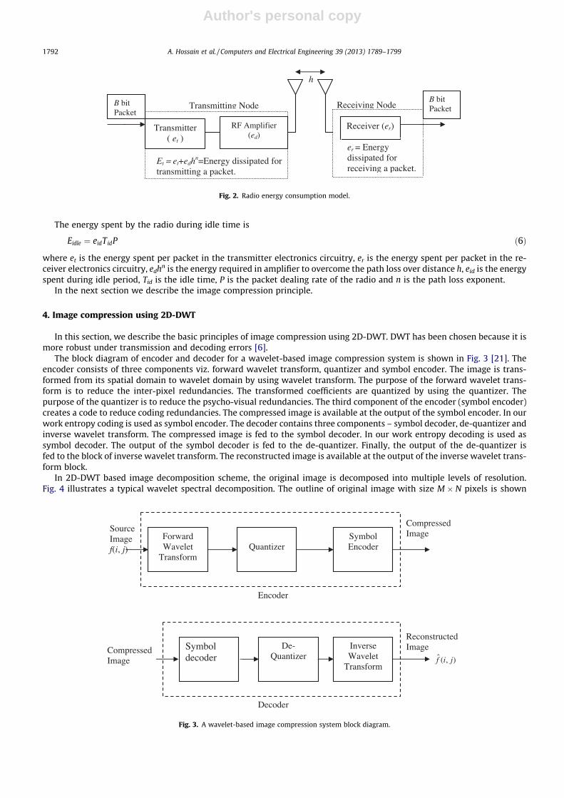
The block diagram of encoder and decoder for a wavelet-based image compression system is shown in Fig. 3 [21]. Theencoder consists of three components viz. forward wavelet transform, quantizer and symbol encoder. The image is trans-formed from its spatial domain to wavelet domain by using wavelet transform. The purpose of the forward wavelet trans-form is to reduce the inter-pixel redundancies. The transformed coefficients are quantized by using the quantizer. Thepurpose of the quantizer is to reduce the psycho-visual redundancies. The third component of the encoder (symbol encoder)creates a code to reduce coding redundancies. The compressed image is available at the output of the symbol encoder. In ourwork entropy coding is used as symbol encoder. The decoder contains three components – symbol decoder, de-quantizer andinverse wavelet transform. The compressed image is fed to the symbol decoder. In our work entropy decoding is used assymbol decoder. The output of the symbol decoder is fed to the de-quantizer. Finally, the output of the de-quantizer isfed to the block of inverse wavelet transform. The reconstructed image is available at the output of the inverse wavelet trans-form block.
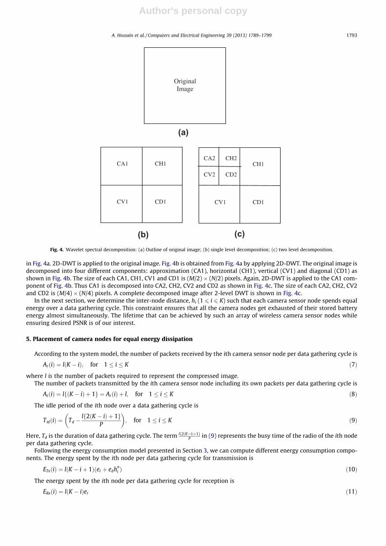
In 2D-DWT based image decomposition scheme, the original image is decomposed into multiple levels of resolution.Fig. 4 illustrates a typical wavelet spectral decomposition. The outline of original image with size M � N pixels is shown
Transmitter ( et )
Receiver (er)
h
B bit Packet
B bit Packet
Transmitting Node Receiving Node
Et = et+edhn=Energy dissipated for
transmitting a packet.
er = Energy dissipated for receiving a packet.
RF Amplifier (ed)
Fig. 2. Radio energy consumption model.
Symbol decoder
De-Quantizer
Inverse Wavelet
Transform
Decoder
Forward Wavelet
Transform Quantizer
Symbol Encoder
Source Image f(i, j)
Encoder
Compressed Image
Reconstructed Image
ˆ ( , )f i jCompressed Image
Fig. 3. A wavelet-based image compression system block diagram.
1792 A. Hossain et al. / Computers and Electrical Engineering 39 (2013) 1789–1799
Author's personal copy
in Fig. 4a. 2D-DWT is applied to the original image. Fig. 4b is obtained from Fig. 4a by applying 2D-DWT. The original image isdecomposed into four different components: approximation (CA1), horizontal (CH1), vertical (CV1) and diagonal (CD1) asshown in Fig. 4b. The size of each CA1, CH1, CV1 and CD1 is (M/2) � (N/2) pixels. Again, 2D-DWT is applied to the CA1 com-ponent of Fig. 4b. Thus CA1 is decomposed into CA2, CH2, CV2 and CD2 as shown in Fig. 4c. The size of each CA2, CH2, CV2and CD2 is (M/4) � (N/4) pixels. A complete decomposed image after 2-level DWT is shown in Fig. 4c.
In the next section, we determine the inter-node distance, hi (1 6 i 6 K) such that each camera sensor node spends equalenergy over a data gathering cycle. This constraint ensures that all the camera nodes get exhausted of their stored batteryenergy almost simultaneously. The lifetime that can be achieved by such an array of wireless camera sensor nodes whileensuring desired PSNR is of our interest.
5. Placement of camera nodes for equal energy dissipation
According to the system model, the number of packets received by the ith camera sensor node per data gathering cycle is
ArðiÞ ¼ lðK � iÞ; for 1 � i � K ð7Þ
where l is the number of packets required to represent the compressed image.The number of packets transmitted by the ith camera sensor node including its own packets per data gathering cycle is
AtðiÞ ¼ lfðK � iÞ þ 1g ¼ ArðiÞ þ l; for 1 � i � K ð8Þ
The idle period of the ith node over a data gathering cycle is
TidðiÞ ¼ Td �lf2ðK � iÞ þ 1g
P
� �; for 1 � i � K ð9Þ
Here, Td is the duration of data gathering cycle. The term lf2ðK�iÞþ1gP in (9) represents the busy time of the radio of the ith node
per data gathering cycle.Following the energy consumption model presented in Section 3, we can compute different energy consumption compo-
nents. The energy spent by the ith node per data gathering cycle for transmission is
ETxðiÞ ¼ lðK � iþ 1Þðet þ edhni Þ ð10Þ
The energy spent by the ith node per data gathering cycle for reception is
ERxðiÞ ¼ lðK � iÞer ð11Þ
Original Image
CA1 CH1
CV1 CD1
CH1
CV1 CD1
CA2 CH2
CV2 CD2
(a)
(c)(b)Fig. 4. Wavelet spectral decomposition: (a) Outline of original image; (b) single level decomposition; (c) two level decomposition.
A. Hossain et al. / Computers and Electrical Engineering 39 (2013) 1789–1799 1793
Author's personal copy
The energy spent by the ith node per data gathering cycle during the idle state is
EidleðiÞ ¼ eid Td �lf2ðK � iÞ þ 1g
P
� �P ð12Þ
where P is the packet processing rate of the radio.Now, combining (10)–(12) together we get the total energy consumed by the ith node per data gathering cycle for image
communication. The total energy consumed by the ith node per data gathering cycle for image communication is
Eimage comðiÞ ¼ lðK � iþ 1Þðet þ edhni Þ þ lðK � iÞer þ eid Td �
lf2ðK � iÞ þ 1gP
� �P ð13Þ
Each camera sensor node also consumes energy for image processing. The energy consumed by the ith node per datagathering cycle for image processing using 2D-DWT is
EDWTðiÞ ¼ MNbcXWj¼1
1
4j�1 ð14Þ
where M � N is the original image size, b is the number of bits per pixel and W is the number of 2D-DWT operation appliedon the raw image.
The energy consumed by the ith node per data gathering cycle for quantization and coding is
EENTðiÞ ¼ qMNbd ð15Þ
where q is the coefficient of the important 2D-DWT components (0 < q < 1).Now, combining (14) and (15) together we get the total energy consumed by the ith node per data gathering cycle for
image processing. The total energy consumed by the ith node per data gathering cycle for image processing is
Eimage procðiÞ ¼ MNbcXWj¼1
1
4j�1 þ qMNbd ð16Þ
The energy consumed by a node for image processing, Eimage_proc(i) is independent of its position.Combining (13) and (16) together, we get the total energy consumed by the ith node per data gathering cycle for image
communication and image processing. The total energy consumed by the ith camera sensor node per data gathering cycle is
EðiÞ ¼ lðK � iþ 1Þðet þ edhni Þ þ lðK � iÞer þ eid Td �
lf2ðK � iÞ þ 1gP
� �P þMNbc
XWj¼1
1
4j�1 þ qMNbd; for 1 6 i 6 K
ð17Þ
Now, imposing the condition that all the nodes dissipate same energy E per data gathering cycle i.e., E(i) = E, for 1 6 i 6 K, theinter-node distance hi can be expressed as
hi ¼E�MNbc
PWj¼1
14j�1 � qMNbd� lðK � iÞðet þ er � 2eidÞ � let þ eidðl� PTdÞ
lðK � iþ 1Þed
" #1n
for 1 6 i 6 K ð18Þ
It is interesting to note that each node dissipates a minimum energy Emin based on the values of system parameters asobtained from (18)
Emin ¼ MNbcXWj¼1
1
4j�1 þ qMNbdþ etlðK � 2Þ þ erlðK � 1Þ þ eidð3l� PTd � 2lKÞ ð19Þ
The feasible solutions of hi is always possible when E > Emin for known values of radio parameters. In the next section, wepresent the results and discussions.
6. Results and discussions for image transmission
In this section we present numerical examples to study the effect of equal energy dissipation in WISN. The issue of nodeplacement and its effects on network lifetime is presented. The quality of the reconstructed image at the sink node is alsocalculated. Specifically, the following issues are considered:
i. Study of equal energy dissipation in wavelet-based image transmission. Comparison of network lifetime achieved bydifferent node placement schemes.
ii. Image quality at the sink node.iii. Effect of DWT.
1794 A. Hossain et al. / Computers and Electrical Engineering 39 (2013) 1789–1799
Author's personal copy
Let Eth be the threshold of residual energy below which a camera sensor node becomes non-functional. Also, let Emax bethe maximum energy consumed by a camera sensor node over a data gathering cycle in a sensor network. Since the durationof each data gathering cycle is Td units, the network lifetime (Tlife) is
Tlife ¼ TdE0 � Eth
Emax
� �ð20Þ
where E0 is the initial energy of a node.Image quality is expressed by peak signal-to-noise ratio (PSNR). PSNR is defined in decibel (dB) as
PSNR ¼ 10log10ð2b � 1Þ2
MSE
" #ð21Þ
where b is the number of bits per pixel and mean-squared error (MSE) for M � N image is defined as
MSE ¼ 1MN
Xi
Xj
½f ði; jÞ � f̂ ði; jÞ�2 ð22Þ
where f(i, j) and f̂ ði; jÞ are the pixel values of the original and reconstructed images respectively.We consider a typical set of parameters as shown in Table 1. Following two schemes have been used for performance
comparison:
� Scheme a – All nodes have equal inter-node spacing i.e., hi = D/K.� Scheme b – This is our proposed scheme. Here, the nodes are placed so that each node dissipates equal amount of energy
per data gathering cycle.
First we consider free space communication (i.e. path loss exponent, n = 2.0) for ease of explanation. Typical values ofother relevant parameters in Table 1 have been chosen following [6] and [16] closely. The radio parameters are expressedper packet basis. On the other hand, the image processing parameters are expressed per bit basis.
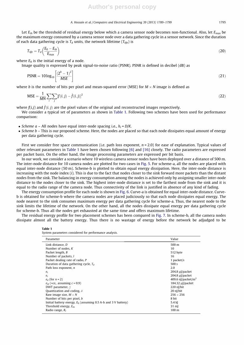
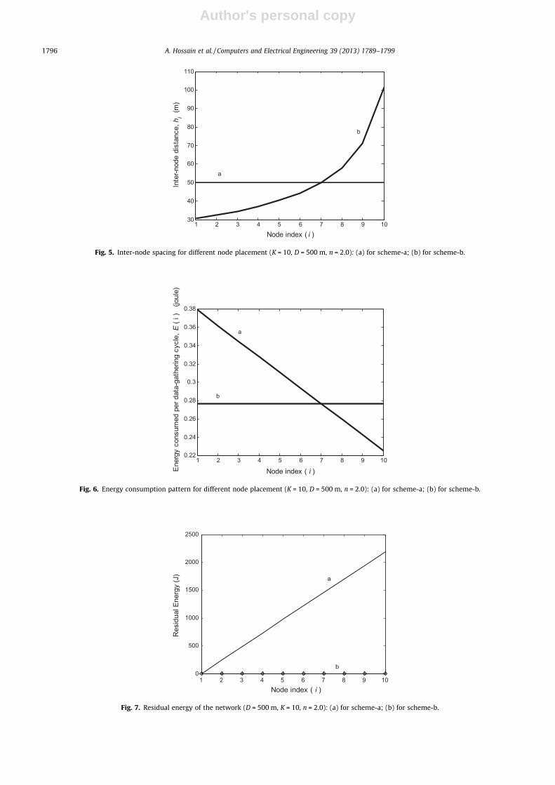
In our work, we consider a scenario where 10 wireless camera sensor nodes have been deployed over a distance of 500 m.The inter-node distance for 10 camera nodes are plotted for two cases in Fig. 5. For scheme-a, all the nodes are placed withequal inter-node distance (50 m). Scheme-b is plotted to obtain equal energy dissipation. Here, the inter-node distance isincreasing with the node index (i). This is due to the fact that nodes closer to the sink forward more packets than the distantnodes from the sink. The balancing in energy consumption among the nodes is achieved only by assigning smaller inter-nodedistance to the nodes closer to the sink. The highest inter-node distance is set to the farthest node from the sink and it isequal to the radio range of the camera node. Thus connectivity of the link is justified in absence of any kind of fading.
The energy consumption profile for each node is shown in Fig. 6. Curve-a is obtained for equal inter-node distance. Curve-b is obtained for scheme-b where the camera nodes are placed judiciously so that each node dissipates equal energy. Thenode nearest to the sink consumes maximum energy per data gathering cycle for scheme-a. Thus, the nearest node to thesink limits the lifetime of the network. On the other hand, all the nodes dissipate equal energy per data gathering cyclefor scheme-b. Thus all the nodes get exhausted at the same time and offers maximum lifetime.
The residual energy profile for two placement schemes has been compared in Fig. 7. In scheme-b, all the camera nodesdissipate almost all the battery energy. Thus there is no wastage of energy before the network be adjudged to be
Table 1System parameters considered for performance analysis.
Parameter Value
Link distance, D 500 mNumber of nodes, K 10Packet length, B 512 byteNumber of packets, l 16Packet dealing rate of radio, P 1 packet/sDuration of data gathering cycle, Td 500 sPath loss exponent, n 2.0et 204.8 lJ/packeter 204.8 lJ/packeted (for n = 2) 409.6 nJ/packet/m2
eid (=cer, assuming c = 0.9) 184.32 lJ/packetDWT parameter, c 220 nJ/bitQuantization and coding, d 20 nJ/bitRaw image size, M � N 256 � 256Number of bits per pixel, b 8 bitInitial battery energy, E0 (assuming 0.5 A-h and 3 V battery) 5.4 kJThreshold energy, Eth 31 mJRadio range, Rr 100 m
A. Hossain et al. / Computers and Electrical Engineering 39 (2013) 1789–1799 1795
Author's personal copy
1 2 3 4 5 6 7 8 9 1030
40
50
60
70
80
90
100
110
Node index ( i )
Inte
r-nod
e di
stan
ce, h
i (m
)a
b
Fig. 5. Inter-node spacing for different node placement (K = 10, D = 500 m, n = 2.0): (a) for scheme-a; (b) for scheme-b.
1 2 3 4 5 6 7 8 9 100.22
0.24
0.26
0.28
0.3
0.32
0.34
0.36
0.38
Node index ( i ) Ene
rgy
cons
umed
per
dat
a-ga
ther
ing
cycl
e, E
( i )
(jo
ule)
b
a
Fig. 6. Energy consumption pattern for different node placement (K = 10, D = 500 m, n = 2.0): (a) for scheme-a; (b) for scheme-b.
1 2 3 4 5 6 7 8 9 100
500
1000
1500
2000
2500
Node index ( i )
Res
idua
l Ene
rgy
(J)
a
b
Fig. 7. Residual energy of the network (D = 500 m, K = 10, n = 2.0): (a) for scheme-a; (b) for scheme-b.
1796 A. Hossain et al. / Computers and Electrical Engineering 39 (2013) 1789–1799
Author's personal copy
non-functional. In scheme-a, the farthest node from the sink has the maximum residual energy which has been wasted asthe network be considered as non-functional when nodes closest to the sink has no left over battery energy.
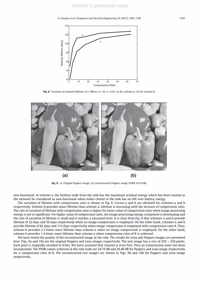
The variation of lifetime with compression ratio is shown in Fig. 8. Curves-a and b are obtained for schemes-a and brespectively. Scheme-b provides more lifetime than scheme-a. Lifetime is increasing with the increase of compression ratio.The rate of variation of lifetime with compression ratio is higher for lower value of compression ratio when image processingenergy is not so significant. For higher value of compression ratio, the image processing energy component is dominating andthe rate of variation of lifetime is small and it reaches a saturated level. It is clear from Fig. 8 that schemes-a and b providelifetime of 22 days and 50 days respectively when no image compression is employed. On the other hand, schemes-a and bprovide lifetime of 82 days and 112 days respectively when image compression is employed with compression ratio 8. Thus,scheme-b provides 2.3 times more lifetime than scheme-a when no image compression is employed. On the other hand,scheme-b provides 1.4 times more lifetime than scheme-a when compression ratio of 8 is achieved.
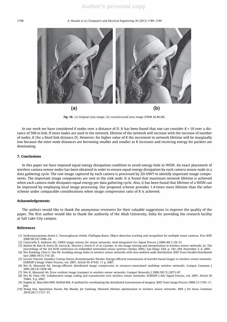
We have tested the quality of the reconstructed image at the sink. The results for Lena and Peppers images are presentedhere. Figs. 9a and 10a are the original Peppers and Lena images respectively. The test image has a size of 256 � 256 pixels.Each pixel is originally encoded to 8 bits. We have assumed that channel is error free. Thus no transmission noise has beenincorporated. The PSNR values achieved at the sink node are 24.79 dB and 26.48 dB for Peppers and Lena image respectivelyfor a compression ratio of 8. The reconstructed test images are shown in Figs. 9b and 10b for Peppers and Lena imagerespectively.
0 10 20 30 40 50 60 7020
40
60
80
100
120
140
Compression Ratio
Net
wor
k lif
etim
e (d
ays) a
b
Fig. 8. Variation of network lifetime (D = 500 m, K = 10, n = 2.0): (a) for scheme-a; (b) for scheme-b.
(a) (b)Fig. 9. (a) Original Peppers image; (b) reconstructed Peppers image (PSNR 24.79 dB).
A. Hossain et al. / Computers and Electrical Engineering 39 (2013) 1789–1799 1797
Author's personal copy
In our work we have considered K nodes over a distance of D. It has been found that one can consider K = 10 over a dis-tance of 500 m link. If more nodes are used in the network, lifetime of the network will increase with the increase of numberof nodes, K (for a fixed link distance D). However, for higher value of K the increment in network lifetime will be marginallylow because the inter-node distances are becoming smaller and smaller as K increases and receiving energy for packets aredominating.
7. Conclusions
In this paper we have imposed equal energy dissipation condition to avoid energy-hole in WISN. An exact placement ofwireless camera sensor nodes has been obtained in order to ensure equal energy dissipation by each camera sensor node in adata gathering cycle. The raw image captured by each camera is processed by 2D-DWT to identify important image compo-nents. The important image components are sent to the sink node. It is found that maximum network lifetime is achievedwhen each camera node dissipates equal energy per data gathering cycle. Also, it has been found that lifetime of a WISN canbe improved by employing local image processing. Our proposed scheme provides 1.4 times more lifetime than the otherscheme under comparable considerations when image compression ratio of 8 is achieved.
Acknowledgements
The authors would like to thank the anonymous reviewers for their valuable suggestions to improve the quality of thepaper. The first author would like to thank the authority of the Aliah University, India for providing the research facilityat Salt Lake City campus.
References
[1] Sankaranarayanan Aswin C, Veeraraghavan Ashok, Chellappa Rama. Object detection tracking and recognition for multiple smart cameras. Proc IEEE2008;96(10):1606–24.
[2] Culurciello E, Andreou AG. CMOS image sensors for sensor networks. Anal Integrated Circ Signal Process J 2006;49(1):39–51.[3] Rahimi M, Baer R, Iroezi OI, Garcia JC, Warrior J, Estrin D, et al. Cyclops: in situ image sensing and interpretation in wireless sensor networks. In: The
proceedings of the 3rd ACM conference on embedded networked sensor systems (SenSys 2005), San Diego, USA, p. 192–204, November 2–4, 2005.[4] Wu Xiaobing, Chen G, Das SK. Avoiding energy holes in wireless sensor networks with non-uniform node distribution. IEEE Trans Parallel Distributed
Syst 2008;19(5):710–20.[5] Lecuire Vincent, Faundez Cristian Duran, Krommenacker Nicolas. Energy-efficient transmission of wavelet-based images in wireless sensor networks.
EURASIP J Image Video Process, vol. 2007, Article ID 47345, 11 p, 2007.[6] Wu H, Abouzeid AA. Energy-efficient distributed image compression in resource-constrained multihop wireless networks. Comput Commun J
2005;28(14):1658–68.[7] Wu H, Abouzeid AA. Error resilient image transport in wireless sensor networks. Comput Networks J 2006;50(15):2873–87.[8] Wu M, Chen CW. Collaborative image coding and transmission over wireless sensor networks. EURASIP J Adv Signal Process, vol. 2007, Article ID
70481, 9 p, 2007.[9] Dagher JC, Marcellin MW, Neifeld MA. A method for coordinating the distributed transmission of imagery. IEEE Trans Image Process 2006;15:1705–17.
July.[10] Wang Hui, Agoulmine Nazim, Ma Maode, Jin Yanliang. Network lifetime optimization in wireless sensor networks. IEEE J Sel Areas Commun
2010;28(7):1127–37.
(a) (b)Fig. 10. (a) Original Lena image; (b) reconstructed Lena image (PSNR 26.48 dB).
1798 A. Hossain et al. / Computers and Electrical Engineering 39 (2013) 1789–1799

Author's personal copy
[11] Yang Yinying, Fonoage Mirela I, Cardei Mihaela. Improving network lifetime with mobile wireless sensor networks. Comput Commun J2010;33(4):409–19.
[12] Marta M, Cardei M. Improved sensor network lifetime with multiple mobile sinks. J Pervasive Mobile Comput 2009;5(5):542–55.[13] Lu K, Liu G, Mao R, Feng Y. Relay node placement based on balancing power consumption in wireless sensor networks. IET Wireless Sens Syst
2011;1(1):1–6.[14] Dali Wei, Yichao Jin, Serdar Vural, Klaus Moessner, Rahim Tafazolli. An energy-efficient clustering solution for wireless sensor networks. IEEE Trans
Wireless Commun 2011;10(11).[15] Azad AKM, Kamruzzaman Joarder. Energy-balanced transmission policies for wireless sensor networks. IEEE Trans Mobile Comput 2011;10(7).[16] Gao Q, Blow KJ, Holding DJ, Marshall IW, Peng XH. Radio range adjustment for energy efficient wireless sensor networks. Ad Hoc Networks J
2006;4(1):75–82.[17] Bicakci Kemal, Gultekin Hakan, Tavli Bulent. The impact of one-time energy costs on network lifetime in wireless sensor networks. IEEE Commun Lett
2009;13(12):905–7.[18] Ergen Sinem Coleri, Varaiya Pravin. On multi-hop routing for energy efficiency. IEEE Commun Lett 2005;9(10):880–1.[19] Haenggi Martin. Energy-balancing strategies for wireless sensor networks. In: The Proceedings of the international symposium on circuits and systems
(ISCAS 2003), Bangkok, Thailand, vol. 4, p. 828–31, May 25–28, 2003.[20] Shelby Zach, Pomalaza-Ráez Carlos, Karvonen Heikki, Haapola Jussi. Energy optimization in multihop wireless embedded and sensor networks. Int J
Wireless Inform Networks (IJWIN) 2005;12(1):11–21.[21] Gonzalez Rafael C, Woods Richard E, Eddins Steven L. Digital image processing using MATLAB. Low price edition, Pearson Education, New Delhi
110001, India; 2006.
Ashraf Hossain earned the B.Tech. and M.Tech. degrees in Radio Physics & Electronics from University of Calcutta, India in 2002 and 2004, respectively. Hereceived the Ph.D. degree in E&ECE from IIT Kharagpur, India in 2011. Currently he is working as an Assistant Professor in the Dept. of Electronics &Communication Engg., Aliah University, Kolkata, India. His research interests include wireless sensor network, communication theory and systems.
S. Chakrabarti received the B.Engg. in Electronics & Telecommunication Engg. from Jadavpur University, Kolkata, India in 1984. He obtained the M.Tech.and Ph.D. degrees from the Dept. of Electronics & Electrical Communication Engg. (E&ECE), IIT Kharagpur, India in 1985 and 1992, respectively. Currently heis working as the Professor at the G.S. Sanyal School of Telecommunications, IIT Kharagpur. His main research areas include wireless communications andnetworking, mobile communications, error control coding and baseband signal processing.
P.K. Biswas received the B.Tech. (Honors), M.Tech and Ph.D. degrees from the Dept. of Electronics and Electrical Communication Engg. (E&ECE), IITKharagpur, India in 1985, 1989, and 1991, respectively. Currently he is working as the Professor in the Department of E&ECE, IIT Kharagpur. His areas ofinterest are image processing, pattern recognition, computer vision, video compression, parallel and distributed processing, and computer networks.
A. Hossain et al. / Computers and Electrical Engineering 39 (2013) 1789–1799 1799
Copyright © 2022 FDOKUMEN