E:\PM65 & DOC\P4\Intel\8irxp\20 - Gigabyte
98
T a b l e o f C o n t e n t BIOS Setup ..................................................................................... 2 T he Main Menu (For example: BIOS Ver. :F2) ................................................. 3 Standard CMOS Features .................................................................................... 5 Advanced BIOS Features ..................................................................................... 8 Advanced Chipset Features ............................................................................... 11 Integrated Peripherals ........................................................................................ 14 Power Management Setup ................................................................................. 23 PnP/PCI Configurations ...................................................................................... 28 PC Health Status .................................................................................................. 30 Frequency/Voltage Control ................................................................................. 32 SelectLanguage .................................................................................................. 34 Load Fail-Safe Defaults ....................................................................................... 35 Load Optimized Defaults .................................................................................... 36 Set Supervisor/User Password .......................................................................... 37 Save & Exit Setup ................................................................................................ 38 Exit Without Saving ............................................................................................. 39 Block Diagram ................................................................................ 40 Dual BIOS / Q-Flash Introduction ..................................................... 41 Four Speaker & SPDIF Introduction ................................................. 49 @ BIOS Introduction ....................................................................... 53 Easy TuneIII TM Introduction .............................................................. 54 RAID Introduction ........................................................................... 55 Driver Installing .............................................................................. 73
-
Upload
khangminh22 -
Category
Documents
-
view
4 -
download
0
Transcript of E:\PM65 & DOC\P4\Intel\8irxp\20 - Gigabyte

Table of Content
BIOS Setup ..................................................................................... 2T he Main Menu (For example: BIOS Ver. :F2) ................................................. 3Standard CMOS Features .................................................................................... 5Advanced BIOS Features ..................................................................................... 8Advanced Chipset Features ............................................................................... 11Integrated Peripherals ........................................................................................14Power Management Setup .................................................................................23PnP/PCI Configurations ......................................................................................28PC Health Status ..................................................................................................30Frequency/Voltage Control .................................................................................32Select Language ..................................................................................................34Load Fail-Safe Defaults .......................................................................................35Load Optimized Defaults ....................................................................................36Set Supervisor/User Password ..........................................................................37Save & Exit Setup ................................................................................................38Exit Without Saving.............................................................................................39
Block Diagram ................................................................................40Dual BIOS / Q-Flash Introduction .....................................................41Four Speaker & SPDIF Introduction .................................................49@ BIOS Introduction .......................................................................53Easy TuneIIITM Introduction ..............................................................54RAID Introduction ...........................................................................55Driver Installing ..............................................................................73

GA-8IRXP Motherboard
2
<?> Move to previous item
<?> Move to next item
<?> Mov e to the item in the left hand
<?> Mov e to the item in the r ight hand
<Esc> Main M enu - Quit and not save changes into CMOS Status Page Setup Menu andOption Page Setup M enu - Exit current page and return to Main Menu
<+/PgUp> Increase the numeric value or make changes
<-/PgDn> Decrease the numeric value or make changes
<F1> General help, only for Status Page Setup Menu and Option Page Setup Menu
<F2> Reserved
<F3> Reserved
<F4> Reserved
<F5> Restore the previous CMOS value from CMOS, only for Option Page Setup Menu
<F6> Load the default C MOS value from BIOS default table, only for Option Page SetupMenu
<F7> Load the Setup Defaults
<F8> Reserved
<F9> Reserved
<F10> Save all the CMOS changes, only for Main Menu
BIOS Setup is an overview of the BIOS Setup Program. The program that allows users to modifythe basic system configuration. This type of information is stored in battery-backed CMOS RAM sothat it retains the Setup information when the pow er is turned off.
ENTERING SETUP
Power ON the computer and press <Del> immediately w ill allow you to enter Setup.
CONTROL KEYS
BIOS Setup

Technical Reference
3
? Standard CMOS Features
This setup page includes all the items in standard compatible BI OS.
? Advanced BIOS Features
This setup page includes all the items of Award special enhanced features.
? Advanced Chipset Features
This setup page includes all the items of chipset special features.
GETTING HELP
Main Menu
The on- line description of the highlighted setup function is displayed at the bottom of the screen.
Status Page Setup Menu / Option Page Setup Menu
Press F1 to pop up a small help w indow that descr ibes the appropriate keys to use and the possibleselections for the highlighted item. To exit the H elp Window press <Esc>.
The Main Menu (For example: BIOS Ver. :F2)Once you enter Award BI OS C MOS Setup U tili ty, the Main Menu (Figure 1) w ill appear on thescreen. The Main Menu allows you to select from eight setup functions and tw o exit choices. Usearrow keys to select among the items and press <Enter> to accept or enter the sub-menu.
Figure 1: Main Menu
CMOS Setup Utility -Copy right (C) 1984-2001 Aw ard Softw are
?Standard CMOS Features Select Language
?Advanced BIOS Features Load Fail-Safe Defaults
?Advanced Chipset Features Load Optimized Defaults
?Integrated Peripherals Set Superv isor Password
?Pow er Management Setup Set User Password
?PnP/PCI Configurations Save & Ex it Setup
?PC Health Status Ex it Without Sav ing
?Frequency/Voltage Control
ESC:Quit F3:Change Language
F8:Dual BIOS /Q-Flash F10:Save & Ex it Setup
T ime, Date, Hard Disk Type...

GA-8IRXP Motherboard
4
? Integrated Peripherals
This setup page includes all onboard peripherals.
? Power Management Setup
This setup page includes all the items of Green function features.
? PnP/PCI Configurations
This setup page includes all the configurations of PC I & PnP I SA resources.
? PC Health Status
This setup page is the System auto detect Temperature, voltage, fan, speed.
? Frequency/Voltage Control
This setup page is control CPU’s clock and frequency ratio.
? Select Language
This setup page is select multi language.
? Load Fail-Safe Defaults
Fail-Safe Defaults indicates the v alue of the system parameters which the sy stem w ould
be in safe configuration.
? Load Optimized Defaults
Optimized Defaults indicates the value of the system parameters which the system w ould
be in best performance configuration.
? Set Supervisor password
Change, set, or disable password. It allows you to limit access to the sy stem and Setup,
or just to Setup.
? Set User password
Change, set, or disable password. It allows you to limit access to the system.
? Save & Exit Setup
Save CMOS value settings to CMOS and exit setup.
? Exit Without Saving
Abandon all CMOS value changes and exit setup.

Technical Reference
5
Standard CMOS FeaturesCMOS Setup Utility -Copy right (C) 1984-2001 Aw ard Softw are
Standard CMOS Features
Date (mm:dd:yy ) Mon, Feb 21 2000 Item Help
T ime (hh:mm:ss) 22:31:24 Menu Level
?IDE Primary Master [Press Enter None]
?IDE Primary Slave [Press Enter None]
?IDE Secondary Master [Press Enter None]
?IDE Secondary Slave [Press Enter None]
Drive A [1.44M, 3.5” ]
Drive B [None]
Floppy 3 Mode Support [Disabled]
Halt On [All, But Keyboard]
Base Memory 640K
Extended Memory 130048K
Total Memory 131072K
????: Move Enter:Select +/-/PU/PD:Value F10:Save ESC:Ex it F1:General Help
F3:Language F5:Prev ious Values F6:Fail-Safe Defaults F7:Optimized DefaultsFigure 2: Standard CMOS Features
?Date
The date format is <week>, <month>, <day>, <year>.?Week The w eek, from Sun to Sat, determined by the BIOS and is display only?Month The month, Jan. Through Dec.?Day The day , from 1 to 31 (or the max imum allow ed in the month)
?Year The year, from 1994 through 2079
?Time
The times format in <hour> <minute> <second>. The time is calculated base on the 24-hour military -time clock. For example, 1 p.m. is 13:00:00.

GA-8IRXP Motherboard
6
? IDE Primary Master, Slave / Secondary Master, Slave
The category identifies the types of hard disk from drive C to F that has been installed in thecomputer. There are tw o types: auto type, and manual type. Manual type is user-definable; Autotype w hich w ill automatically detect HDD type.
Note that the specifications of your drive must match w ith the drive table. The hard disk w ill not w orkproperly if you enter improper information for this category .
If you select User Type, related information w ill be asked to enter to the follow ing items. Enter theinformation directly from the keyboard and press <Enter>. Such information should be prov ided inthe documentation form your hard disk vendor or the system manufacturer.
?Capcity: The hard disk size. The unit is Mega By tes.?Access Mode: The options are: Auto / Large / LBA / Normal.
?Cylinder: The cy linder number of hard disk.?Head The read / Write head number of hard disk.
?Precomp The cy liner number at w hich the disk driver changes the w rite current.?Landing Zone The cy linder number that the disk driver heads(read/w rite) are seated w hen the
disk drive is parked.?SECTORS The sector number of each track define on the hard disk.
I f a hard disk has not been installed select NONE and press <Enter>.
?Drive A / Drive B
The category identifies the ty pes of floppy disk drive A or dr ive B that has been installed in thecomputer.
?None No floppy drive installed?360K, 5.25 in. 5.25 inch PC-type standard drive; 360K byte capacity .
?1.2M, 5.25 in. 5.25 inch AT-type high-density drive; 1.2M by te capacity(3.5 inch w hen 3 Mode is Enabled).
?720K, 3.5 in. 3.5 inch double-sided drive; 720K by te capacity?1.44M, 3.5 in. 3.5 inch double-sided drive; 1.44M by te capacity .?2.88M, 3.5 in. 3.5 inch double-sided drive; 2.88M by te capacity .
? Floppy 3 Mode Support (for Japan Area)
?Disabled Normal Floppy Drive. (Default value)
?Drive A Enabled 3 mode function of Drive A.
?Drive B Enabled 3 mode function of Drive B.
?Both Drive A & B are 3 mode Floppy Drives.

Technical Reference
7
?Halt on
The category determines whether the computer w ill stop if an error is detected during power up.
?NO Errors The system boot w ill not stop for any error that may be detectedand you will be prompted.
?All Errors Whenever the BIOS detects a non-fatal error the system w ill be stopped.
?All, But Keyboar The system boot w ill not stop for a keyboard error; it w ill stop for
all other errors. (Default value)
?All, But Diskette The system boot will not stop for a disk error; it w ill stop for all
other errors.
?All, But Disk/Key The system boot w ill not stop for a keyboard or disk error; it will
stop for all other errors.
Memory
The category is display-only which is determined by POST (Power On Self Test) of the BIOS.
Base Memory
The POST of the BIOS w ill determine the amount of base (or conventional) memoryinstalled in the system.
The value of the base memory is typically 512 K for sy stems w ith 512 K memoryinstalled on the motherboard, or 640 K for systems w ith 640 K or more memoryinstalled on the motherboard.
Extended Memory
The BIOS determines how much extended memory is present during the POST.
This is the amount of memory located above 1 MB in the CPU’s memoryaddress map.

GA-8IRXP Motherboard
8
Advanced BIOS FeaturesCMOS Setup Utility -Copy right (C) 1984-2001 Aw ard Softw are
Advanced BIOS Features
BIOS Flash Protection [Auto]
First Boot Dev ice [Floppy] Item Help
Second Boot Dev ice [HDD-0] Menu Level
Third Boot Dev ice [CDROM]
Boot Up Floppy Seek [Disabled]
Boot Up Num-Lock [On]
Password Check [Setup]
Interrupt Mode [APIC]
MPS Version Control For OS [1.4]
HDD S.M.A.R.T . Capability [Disabled]
????: Move Enter:Select +/-/PU/PD:Value F10:Save ESC:Ex it F1:General Help
F3:Language F5:Prev ious Values F6:Fail-Safe Defaults F7:Optimized Defaults
Figure 3: Advanced BIOS Features
?BIOS Flash Protection
This feature allows you determine the states that flash BI OS.
?Enabled During POST, DMI/ESCD w ould not be updated. But flash tools can updateBIOS alw ays
?Auto BIOS enables flash w rite access automatically w hen updating BIOS data/DMI/ESCD. (Default Value)
?First / Second / Third Boot device
This feature allows you to select the boot device prior ity.
?Floppy Select your boot dev ice priority by Floppy .
?LS120 Select your boot dev ice priority by LS120.
?HDD-0~3 Select your boot dev ice priority by HDD-0~3.
?SCSI Select your boot dev ice priority by SCSI.
?CDROM Select your boot dev ice priority by CDROM.

Technical Reference
9
?LAN Select your boot dev ice priority by LAN.
?USB-CDROM Select your boot dev ice priority by USB-CDROM.
?USB-Z IP Select your boot dev ice priority by USB-ZIP.
?USB-FDD Select your boot dev ice priority by USB-FDD.
?USB-HDD Select your boot dev ice priority by USB-HDD.
?Z IP Select your boot dev ice priority by ZIP.
?Disabled Disabled this function.
?Boot Up Floppy Seek
During POST, BIOS w ill determine the floppy disk drive installed is 40 or 80 tracks. 360 K type is 40tracks 720 K, 1.2 M and 1.44 M are all 80 tracks.
?Enabled BIOS searches for floppy disk drive to determine it is 40 or 80 tracks. Note
that BIOS can not tell from 720 K, 1.2 M or 1.44 M drive type as they are
all 80tracks.
?Disabled BIOS w ill not search for the type of floppy disk drive by track number. Note
that there w ill not be any w arning message if the drive installed is 360 K.
(Default value)
?Boot Up NumLock
When set On, allows the BIOS to automatically enable the Num Lock Function when the systemboots up.
?On Keypad is number keys. (Default value)
?Off Keypad is arrow keys.
?Password Check
This feature allows you to limit access to the system and Setup, or just to Setup.
?System The user must enter correct passw ord in order to access the system and/or BIOSsetup.
?Setup The user must enter correct passw ord in order to access BIOS setup utility .
(Default value)

GA-8IRXP Motherboard
10
?Interrupt Mode
?APIC Through IOAPIC generate more IRQ for system use.(Default value)
?PIC Use AT stantard IRQ controlles to generate IRQ.
When you already have I OAPI C enable system and want to upgrade the system please note,since running an IOAPIC enabled OS (like Windows NT,Windows 2000, Windows XP...) systemwith none IOAPIC HW support w ill cause the system to hang. Follow ing are some situations usersmight run into:
1.An IOAPI C enabled OS and change the BIOS setting from IOAPIC to PIC , this w ill cause yoursystem to hang.
?MPS Version Control For OS
When tw o CPUs onboard (not this board) this feature allows you to select MPS(Multi Proces-sor Specification) version control for OS when logo test excutes.
(Support Multi Processor Specification rev ision 1.4)
Note: Some old MPS OS support 1.1 version only
?1.4 Support MPS Version 1.4 . (Default Value)
?1.1 Support MPS Version 1.1.
?HDD S.M.A.R.T. Capability
S.M.A.R.T. stands for Self-Monitoring and Analysis Reporting Technology which allows yourhard disk driv e to report any read/write errors and issue a warning w ith LDCM installed.
?Enabled Enabled HDD S.M.A.R.T . Capability .
?Disabled Disabled HDD S.M.A.R.T. Capability . (Default value)

Technical Reference
11
Advanced Chipset Features
Figure 4: Advanced Chipset Features
CMOS Setup Utility -Copy right (C) 1984-2001 Aw ard Softw are
Advanced Chipset Features
Configure DRAM T iming [SPD] Item Help
?CAS Latency Time 2 Menu Level
?Active to Precharge Delay 5
?DRAM RAS# to CAS# Delay 2
?DRAM RAS# Precharge 2
?Refresh Mode Select [15.6 usec]
DRAM Data Integrity Mode Non-ECC
DRAM Read Thermal Mgmt [Disable]
Delay T ransaction [Enable]
AGP Aperture Size(MB) [64]
Delay Prior to Thermal [16Min]
????: Move Enter:Select +/-/PU/PD:Value F10:Save ESC:Ex it F1:General Help
F3:Language F5:Prev ious Values F6:Fail-Safe Defaults F7:Optimized Defaults
?Configure DRAM Timing
Warning: Wrong DRAM T iming may make system can’t boot .Clear CMOS to overcome w rong T imingissue)
?SPD Set Configure DRAM T iming Control by SPD. (Default value)
?Manual Set Configure DRAM T iming Control by Manual.
?CAS latency Time
This feature allows you to select the CAS latency Time, When any DDR DIMM installed.
?2.5 Set CAS latency T ime is 2.5.
?2 Set CAS latency T ime is 2. (Default Value)
?1.5 Set CAS latency T ime is 1.5.

GA-8IRXP Motherboard
12
?Active to Precharge Delay
This feature allows you to set AC tive to Precharge Delay, When any DDR DIMM installed.
?5 Set active to Precharge delay timing is 5 clk. (Default value)
?6 Set active to Precharge delay timing is 6 clk.
?7 Set active to Precharge delay timing is 7 clk.
?DRAM RAS# to CAS# delay
This feature allows you to set the delay time that from the DRAM RAS# active to CAS#.
?3 Set DDR RAM RAS# to CAS# delay 3 SCLKs.
?2 Set DDR RAM RAS# to CAS# delay 2 SCLKs.(Default value)
?DRAM RAS# Precharge
This feature allows you to set the DRAM RAS# Precharge Time.
?3 Set DDR RAM RAS# Precharge T ime to 3.
?2 Set DDR RAM RAS# Precharge T ime to 2. (Default value)
?Refresh Mode Select
?7.8 usec Set active to Refresh mode timing is 7.8 usec.
?15.6 usec Set active to Refresh mode timing is 15.6 usec. (Default value)?64 usec Set active to Refresh mode timing is 64 usec.
?DRAM Data Integrity Mode
This feature allow s you to set the DRAM data Integrity Mode
?Non-ECC Set the DRAM data Integrity Mode is Non-ECC (Default)
?ECC Set the DRAM data Integrity Mode is ECC.

Technical Reference
13
?DRAM Read Thermal Mgmt
This feature allows you to set the DRAM Read Thermal Management register which in thechip of Intel 845 for the trade-off between sy stem temperature and performance.
?Disabled Disabled this function.(Default)
?Enabled Enabled can reduce DRAM heat issue.
Note:DRAM heat thermal mangement is alw ays enabled in w rite cycle.
?Delay Transaction
?Disabled Normal operation.
?Enabled Setting at Enabled w ill abort the current PCI master cycle and to accept the new PCImaster request, it reaccepts the original PCI master and returns the PCI data phase
to the original PCI master. it w ill enhance the system performance.
?AGP Graphics Aperture Size
(This feature allows you to select the main memory frame size for AGP use)
?4 AGP Graphics Aperture Size is 4MB.
?8 AGP Graphics Aperture Size is 8MB.
?16 AGP Graphics Aperture Size is 16MB
?32 AGP Graphics Aperture Size is 32MB.
?64 AGP Graphics Aperture Size is 64MB.(Default Value)
?128 AGP Graphics Aperture Size is 128MB.
?256 AGP Graphics Aperture Size is 256MB.
?Delay Prior to Thermal
This feature allows you to select the Delay Prior to thermal.
?4Min Set active CPU Thermal function after booting 4 Min.
?8Min Set active CPU Thermal function after booting 8 Min.
?16Min Set active CPU Thermal function after booting 16 Min. (Default Value)
?32Min Set active CPU Thermal function after booting 32 Min.

GA-8IRXP Motherboard
14
CMOS Setup Utility -Copy right (C) 1984-2001 Aw ard Softw are
Integrated Peripherals
On-Chip Primary PCI IDE [Enabled] Item Help
On-Chip Secondary PCI IDE [Enabled]
IDE Primary Master PIO [Auto] Menu Level
IDE Primary Slave PIO [Auto]
IDE Secondary Master PIO [Auto]
IDE Secondary Slave PIO [Auto]
IDE Primary Master UDMA [Auto]
IDE Primary Slave UDMA [Auto]
IDE Secondary Master UDMA [Auto]
IDE Secondary Slave UDMA [Auto]
IDE1 Conductor Cable [Auto]
IDE2 Conductor Cable [Auto]
USB Controller [Enabled]
USB Keyboard Support [Disabled]
USB Mouse Support [Disabled]
Init Display First [AGP]
AC97 Audio [Auto]
AC97 Modem [Auto]
Onboard USB 2.0 Dev ice [Enabled]
Onboard Sound [Enabled]
Onboard ATA/RAID Dev ice [Enabled]
Pow er On by Mouse [Disabled]
Power On by Keyboard [Disabled]
?KB Power ON Passw ord Enter
Onboard FDC Controller [Enabled]
Onboard Serial Port 1 [3F8/IRQ4]
Onboard Serial Port 2 [2F8/IRQ3]
UART Mode Select [Normal]
?UR2 Duplex Mode Ha lf
Integrated Peripherals

Technical Reference
15
Onboard Parallel Port [378/IRQ7]
Parallel Port Mode [SPP]
?ECP Mode Use DMA 3
AC BACK Function [Soft-Off]
CIR Port Address [Disabled]
?CIR Port IRQ 11
SMART Card Interface Enabled
MS/SDI Interface Memory Stick
????: Move Enter:Select +/-/PU/PD:Value F10:Save ESC:Ex it F1:General Help
F3:Language F5:Prev ious Values F6:Fail-Safe Defaults F7:Optimized DefaultsFigure 5: Integrated Peripherals
?On-Chip Primary PCI IDE
When enabled, allows you to use the onboard primary PC I IDE. If a hard disk controller card isused, set at D isabled.
?Enabled Enable onboard 1st channel IDE port. (Default value)
?Disabled Disable onboard 1st channel IDE port.
?On-Chip Secondary PCI IDE
When enabled, allows y ou to use the onboard secondary PC I IDE. If a hard disk controller card isused, set at D isabled.
?Enabled Enable onboard 2nd channel IDE port. (Default value)
?Disabled Disable onboard 2nd channel IDE port.
? IDE Primary Master PIO (for onboard IDE 1st channel)
?Auto BIOS w ill automatically detect the IDE HDD Accessing mode.
(Default value)
?Mode0~4 Manually set the IDE Accessing mode.
? IDE Primary Slave PIO (for onboard IDE 1st channel)
?Auto BIOS w ill automatically detect the IDE HDD Accessing mode.
(Default value)
?Mode0~4 Manually set the IDE Accessing mode.

GA-8IRXP Motherboard
16
.
? IDE Secondary Master PIO (for onboard IDE 2nd channel)
?Auto BIOS w ill automatically detect the IDE HDD Accessing mode.
(Default value)
?Mode0~4 Manually set the IDE Accessing mode.
? IDE Secondary Slave PIO (for onboard IDE 2nd channel)
?Auto BIOS w ill automatically detect the IDE HDD Accessing mode.
(Default value)
?Mode0~4 Manually set the IDE Accessing mode.
? IDE Primary Master UDMA
?Auto BIOS w ill automatically detect the IDE HDD Accessing mode.
(Default value)
?Disabled Disable UDMA function.
? IDE Primary Slave UDMA
?Auto BIOS w ill automatically detect the IDE HDD Accessing mode.
(Default value)
?Disabled Disable UDMA function.
? IDE Secondary Master UDMA
?Auto BIOS w ill automatically detect the IDE HDD Accessing mode. (Default value)
?Disabled Disable UDMA function.
? IDE Secondary Slave UDMA
?Auto BIOS w ill automatically detect the IDE HDD Accessing mode. (Default value)
?Disabled Disable UDMA function.

Technical Reference
17
? IDE1 Conductor Cable
?Auto Will be automatically detected by BIOS (Default Value)
?ATA66/100 Set IDE1 Conductor Cable to ATA66/100 (Please make sure your IDE device and cableis compatible w ith ATA66/100)
?ATA33 Set IDE1 Conductor Cable to ATA33 (Please make sure your IDE dev ice and cable iscompatible w ith ATA33)
? IDE2 Conductor Cable
?Auto Will be automatically detected by BIOS (Default Value)
?ATA66/100 Set IDE2 Conductor Cable to ATA66/100 (Please make sure your IDE device and cableis compatible w ith ATA66/100)
?ATA33 Set IDE2 Conductor Cable to ATA33 (Please make sure your IDE dev ice and cable iscompatible w ith ATA33).
?USB Controller
Disable this option if you are not using the onboard USB feature.
?Enabled Enabled USB Controller. (Default value)
?Disabled Disabled USB Controller.
?USB Keyboard Support
When a USB keyboard is installed, please set at Enabled.
?Enabled Enabled USB Keyboard Support.
?Disabled Disabled USB Keyboard Support. (Default value)
?USB Mouse Support
?Enabled Enabled USB Mouse Support.
?Disabled Disabled USB Mouse Support. (Default value)

GA-8IRXP Motherboard
18
?Init Display First
This feature allows you to select the first initation of the monitor display from which card, whenyou install an AGP VGA card and a PC I VGA card on board.
?PCI Set Init Display First to PCI Slot.
?AGP Set Init Display First to AGP. (Default value)
?AC97 Audio
This feature allows you to enable or disable the AC97 audio function.
?Auto BIOS w ill automatically detect onboard AC97 Audio or Creative CT5880
audio. (Default value)
?Disabled Disabled AC97 Audio.
?AC97 Modem
?Auto BIOS w ill search MC97 Codec (AMR Modem Card). If found, MC97 function
w ill be enabled. If no MC97 Codec found, MC97 function w ill be disabled.
(Default Value)
?Disabled Disable this function.
?Onboard USB 2.0 Device
?Enable Enable onboard USB 2.0 Device.(Default value)
?Disable Disable onboard USB 2.0 Device.
?Onboard Sound
?Enable Enable onboard sound function.(Default value)
?Disable Disable onboard sound function.
? Onboard ATA/RAID Device
?Enable Enable onboard ATA/RAID Dev ice.(Default value)
?Disable Disable onboard ATA/RAID Device.

Technical Reference
19
?Mouse Power On
?Disabled Disabled this function. (Default value)
?Double Right Set mouse pow er on by double click mouse right bottom.
?Double Left Set mouse pow er on by double click mouse left bottom.
? Keyboard Power On
This feature allows you to set the method for pow ering-on the system.
The option “ Password“ allows you to set up to 5 alphanumeric characters to power-on the system.
The option “Any Key” allows you to touch the keyboard to power on the system.
The option “ Keyboard 98” allows you to use the standard keyboard 98 to power on the sy stem.
?Password Enter from 1 to 5 characters to set the Keyboard Pow er On Password.
?Disabled Disabled this function. (Default value)
?Keyboard 98 If your keyboard have “POWER Key ” button, you can press the key topow er on your system.
?Any Key Set Keyboard pow er on by any key
?KB Power ON Password
?Enter Input passw ord (from 1 to 5 characters) and press Enter to set the Keyboard Pow er On Passw ord..
? Onboard FDC Controller
When enabled, the fioppy diskette driv e (FDD) controller is activated.
?Enabled Enable onboard FDC port. (Default value)
?Disabled Disable onboard FDC port.
?Onboard Serial Port 1
?Auto BIOS w ill automatically setup the port 1 address.
?3F8/IRQ4 Enable onboard Serial port 1 and address is 3F8. (Default value)
?2F8/IRQ3 Enable onboard Serial port 1 and address is 2F8.
?3E8/IRQ4 Enable onboard Serial port 1 and address is 3E8.

GA-8IRXP Motherboard
20
?2E8/IRQ3 Enable onboard Serial port 1 and address is 2E8.
?Disabled Disable onboard Serial port 1.
?Onboard Serial Port 2
?Auto BIOS w ill automatically setup the port 2 address.
?3F8/IRQ4 Enable onboard Serial port 2 and address is 3F8.
?2F8/IRQ3 Enable onboard Serial port 2 and address is 2F8. (Default Value)
?3E8/IRQ4 Enable onboard Serial port 2 and address is 3E8.
?2E8/IRQ3 Enable onboard Serial port 2 and address is 2E8.
?Disabled Disable onboard Serial port 2.
?UART Mode Select
(This feature allow s you to determine which Infra Red(IR) function of Onboard I/O chip)
?ASKIR Set onboard I/O chip UART to ASKIR Mode.
?IrDA Set onboard I/O chip UART to IrDA Mode.
?Normal Set onboard I/O chip UART to Normal Mode. (Default Value)
?RxD, TxD Active
This feature is available only if the item, UART 2 Mode, is set at ASKIR or IrDA. The featureallows you to select the active signals of the recception end and the transmission end.
?Hi, Hi Set RxD,TxD Active to Hi, Hi.
?Hi, Lo Set RxD,TxD Active to Hi, Lo. (Default Value)
?Lo, Hi Set RxD,TxD Active to Lo, Hi.
?Lo, Lo Set RxD,TxD Active to Lo, Lo.
?IR Transmission Delay
?Enabled Enabled IR T ransmission delay. (Default Value)
?Disabled Enabled IR T ransmission delay.

Technical Reference
21
?UR2 Duplex Mode
This feature allows you to select the I R modes.
?Half IR Function Duplex Half. (Default Value)
?Full IR Function Duplex Full.
?OnBoard Parallel port
This feature allows you to select from a given set of parameters if the parallel port uses theonboard I /O controller.
?378/IRQ7 Enable On Board LPT port and address is 378.(Default Value)
?278/IRQ5 Enable On Board LPT port and address is 278.
?3BC/IRQ7 Enable On Board LPT port and address is 3BC.
?Parallel Port Mode
This feature allows y ou to connect w ith an advanced print via the port mode it suppor ts.
?SPP Using Parallel port as Standard Parallel Port. (Default Value)
?EPP Using Parallel port as Enhanced Parallel Port.
?ECP Using Parallel port as Ex tended Capabilities Port.
?ECP+EPP Using Parallel port as ECP & EPP mode.
? ECP Mode Use DMA
This feature allows you to select Direct Memory Access(DM A) channel if the EC P modeselected.
?1 Set ECP mode use DMA 1.
?3 Set ECP mode use DMA 3. (Default value)
?AC Back Function
?Memory System pow er on depends on the status before AC lost.
?Soft -Off Alw ays in Off state w hen AC back. (Default value)
?Full-On Alw ays pow er on the system w hen AC back.

GA-8IRXP Motherboard
22
?CIR Port Address
This feature allows you to select CIR port address or disable it.
?Disabled Disabled this function. (Default Value)
?310 Set CIR Port Address to 310.
?320 Set CIR Port Address to 320.
?CIR Port IRQ
This feature allows you to select C IR IRQ , if C IR is enabled.
?5 Set 5 for CIR Port IRQ.
?11 Set 11 for CIR Port IRQ. (Default Value)
?Smart Card Interface
?Enabled Enabled Smart Card Interface.(Default value)
?Disabled Disabled Smart Card Interface.
?MS/SDI Interface
?Memory Stick Set MS/SDI Interface to Memory Stick.(Default value)
?Secure Digital Set MS/SDI Interface to Secure Digital.
?Disabled Disabled MS/SDI Interface.

Technical Reference
23
Pow er Management SetupCMOS Setup Utility -Copy right (C) 1984-2001 Aw ard Softw are
Pow er Management Setup
ACPI Suspend Type [S1(POS)] Item Help
?USB Dev ice Wake-Up From S3 Disabled Menu Level
Pow er Management [User Define]
Video Off Method [DPMS]
Video Off In Suspend [Yes]
Suspend Type [Stop Grant]
MODEM Use IRQ [3]
Suspend Mode [Disabled]
HDD Power Dow n [Disabled]
Soft-Off by PWR-BTTN [Instant-off]
PME Event Wake Up [Enabled]
ModemRingOn/WakeOnLan [Enabled]
Resume by Alarm [Disabled]
? Date(of Month) Alarm [Everyday]
? Time(hh:mm:ss) Alarm [0 0 0]
** Reload Global T imer Events **
Primary IDE 0 [Disabled]
Primary IDE 1 [Disabled]
Secondary IDE 0 [Disabled]
Secondary IDE 1 [Disabled]
FDD,COM,LPT Port [Disabled]
PCI PIRQ[A-H]# [Disabled]
????: Move Enter:Select +/-/PU/PD:Value F10:Save ESC:Ex it F1:General Help
F3:Language F5:Prev ious Values F6:Fail-Safe Defaults F7:Optimized Defaults
Figure 6: Pow er Management Setup

GA-8IRXP Motherboard
24
?ACPI Suspend Type
?S1/POS Set ACPI Suspend Type to S1/POS (Pow er On Suspend). (Default value)
?S3/STR Set ACPI Suspend Type to S3/STR (Suspend To RAM).
?USB Device Wake-up From S3
When set at Enabled, it allows USB Device to activate the system from ACPI S3 pow er savingmode.
?Enabled Enable USB Dev ice Wakeup From S3.
?Disabled Disable USB Dev ice Wakeup From S3. (Default value)
?Power Management
This feature allow s you to adjust the power management item.
?User Define For configuring our ow n pow er management features (Default Value)
?Min Saving Disabled Green & softw are APM function.
?Max Sav ing Enabled Green & softw are APM function.
?Video off Method
?V/H SYNC+Blank BIOS w ill turn off V/H-SYNC w hen gets into Green mode for Green monitorpow er sav ing.
?Blank Screen BIOS w ill only black monitor w hen gets into Green mode.
?DPMS BIOS w ill use DPMS Standard to control VGA card. (The Green type VGAcard w ill turn off V/H-SYNC automatically.)(Default value)
?Video Off In Suspend
This feature allows you to select VGA status when system goes to suspend mode.
?Yes Set Suspend type is stop grant. (Default value)
?No Set Suspend type is Pow er on Suspend.
?Suspend Type
?Stop Grant Set Suspend type is stop grant. (Default value)
?Pw rOn Suspend Set Suspend type is Pow er on Suspend.

Technical Reference
25
?MODEM Use IRQ
This feature allows you to select the IRQ# to meet your modem’s IRQ#.
?N/A Set MODEM Use IRQ to NA.
?3 Set MODEM Use IRQ to 3.(Default value)
?4 Set MODEM Use IRQ to 4.
?5 Set MODEM Use IRQ to 5.
?7 Set MODEM Use IRQ to 7.
?9 Set MODEM Use IRQ to 9.
?10 Set MODEM Use IRQ to 10.
?11 Set MODEM Use IRQ to 11.
?Suspend Mode
When disabled, the system w ill not enter suspend mode. The specified time option defines theidle time the system takes before it enters suspend mode.
?Disabled Disabled Suspend Mode. (Default value)
?1 min - 1 Hour Setup the timer to enter Suspend Mode.
? HDD Power Down
The option lets the BIOS turn the HDD motor off w hen system is in suspend mode. Selecting 1Min..15Min allow s you define the HDD idle time before the HDD enters the Pow er saving Mode.The options 1Min..15Min w ill not work concurrently. When HDD is in the Power Saving Mode,any access to the HDD w ill wake the HDD up.
?Disabled Disabled HDD Pow er Dow n mode function. (Default value)
?1-15 mins. Enabled HDD Pow er Dow n mode betw een 1 to 15 mins.
?Soft-off by PWR-BTTN
?Instan t-off Press pow er button then Pow er off instantly. (Default value)
?Delay 4 Sec. Press pow er button 4 sec to Pow er off. Enter suspend if button is pressed less
than 4 sec.

GA-8IRXP Motherboard
26
? PME Event Wake up
When set at Enabled, any PC I-PM event awarkes the system from a PC I-PM controlled state.
?Disabled Disabled PME Event Wake up function.
?Enabled Enabled PME Event Wake up function. (Default Value)
?Modem Ring On/ WakeOnLAN
An incoming call v ia modem awakes the system from its soft-off mode./When set at Enabled, aninput signal comes from the other client/server on the LAN awarks the system from a soft offstate if connected over LAN.
?Disabled Disabled Modem Ring On / Wake On LAN function.
?Enabled Enabled Modem Ring On / Wake On LAN function. (Default Value)
?Resume by Alarm
You can set "Resume by Alarm" item to enabled and key in Data/time to pow er on system.
?Disabled Disable this function. (Default Value)
?Enabled Enable alarm function to POWER ON system.
If RTC Alarm Lead To Pow er On is Enabled.
Date ( of Month) Alarm : Everyday , 1~31
T ime ( hh: mm: ss) Alarm : (0~23) : (0~59) : (0~59)
?Primary IDE 0/1
When the primary master/slave HDD isworking, the sy stem timer w ill be reloaded and the systemwill not be into the system w ill not be into suspend mode.
?Disabled Disabled this function. (Default value)
?Enabled Enabled monitor Primary IDE 0/1 for Green event.

Technical Reference
27
?Secondary IDE 0/1
When the secondary master/slave HDD isworking, the system timer w ill be reloaded and thesystem w ill not be into the system w ill not be into suspend mode.
?Disabled Disabled this function. (Default value)
?Enabled Enabled monitor Secondary IDE 0/1 for Green event.
?FDD,COM,LPT Port
When FDD, COM, or LPT is working, the system timer w ill be reloaded and the system w ill not beinto the system w ill not be into suspend mode.
?Disabled Disabled this function. (Default value)
?Enabled Enabled monitor FDC,COM,LPT for Green event.
?PCI PIRQ[A-H] #
When the PC I PIRQ [ A-H]# has been alerted, the system timer w ill be reloaded and the systemwill not be into the system w ill not be into suspend mode.
?Enabled Monitor PCI PIRQ[A-H]# IRQ Active.
?Disabled Ignore PCI PIRQ[A-H]# IRQ Active. (Default value)

GA-8IRXP Motherboard
28
Figure 7: PnP/PCI Configurations
CMOS Setup Utility -Copy right (C) 1984-2001 Aw ard Softw are
PnP/PCI Configurations
Resources Controlled By [Auto ] Item Help
?IRQ Resources Press Enter Menu Level
PCI1/PCI5 IRQ Assignment [Auto]
PCI2 /PCI6 IRQ Assignment [Auto]
PCI3 IRQ Assignment [Auto]
PCI4 IRQ Assignment [Auto]
????: Move Enter:Select +/-/PU/PD:Value F10:Save ESC:Ex it F1:General Help
F3:Language F5:Prev ious Values F6:Fail-Safe Defaults F7:Optimized Defaults
PnP/PCI Configurations
?Resources Controlled by
?Manual User can set the PnP resource (I/O Address, IRQ & DMA channels) usedby legacy ISA DEVICE.
?Auto BIOS automatically use these PnP rescuers. (Default value)
?IRQ Resources ( 3,4,5,7,9,10,11,12,14,15 )
?PCI Dev ice The resource is used by PCI dev ice.
?Reserved Set the resource to reserved.
?PCI1/PCI5 IRQ Assignment
?Auto Auto assign IRQ to PCI 1/ PCI 5. (Default value)
?3,4,5,7,9.,10,11,12,14,15 Set 3,4,5,7,9,10,11,12,14,15 to PCI1/ PCI5.
?PCI2/PCI6 IRQ Assignment
?Auto Auto assign IRQ to PCI 2/ PCI 6. (Default value)
?3,4,5,7,9.,10,11,12,14,15 Set 3,4,5,7,9,10,11,12,14,15 to PCI2/ PCI6.

Technical Reference
29
?PCI3 IRQ Assignment
?Auto Auto assign IRQ to PCI 3. (Default value)
?3,4,5,7,9.,10,11,12,15 Set 3,4,5,7,9,10,11,12,14,15 to PCI3.
?PCI4 IRQ Assignment
?Auto Auto assign IRQ to PCI 4. (Default value)
?3,4,5,7,9.,10,11,12,15 Set 3,4,5,7,9,10,11,12,14,15 to PCI4.
GA-8IRXP Motherboard
30
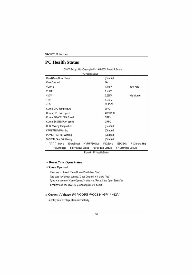
PC Health Status
Figure8: PC Health Status
CMOS Setup Utility -Copy right (C) 1984-2001 Aw ard Softw are
PC Health Status
Reset Case Open Status [Disabled]
Case Opened No
VCORE 1.746V Item Help
VCC18 1.792V
+3.3V 3.296V Menu Level
+ 5V 5.080 V
+12V 11.904V
Current CPU Temperature 39°C
Current CPU FAN Speed 4821 RPM
Current POWER FAN Speed 0 RPM
Current SYSTEM FAN speed 0 RPM
CPU Warning Temperature [Disabled]
CPU FAN Fail Warning [Disabled]
POWER FAN Fail Warning [Disabled]
SYSTEM FAN Fail Warning [Disabled]
????: Move Enter:Select +/-/PU/PD:Value F10:Save ESC:Ex it F1:General Help
F3:Language F5:Prev ious Values F6:Fail-Safe Defaults F7:Optimized Defaults
?Reset Case Open Status
?Case Opened
If the case is closed, "Case Opened" w ill show "No".
If the case have been opened, "Case Opened" w ill show "Yes".If you w ant to reset "Case Opened" value, set "Reset Case Open Status" to
"Enabled" and save CMOS, your computer w ill restart.
?Current Voltage (V) VCORE /VCC18/ +5V / +12V
Detect system’s voltage status automatically.

Technical Reference
31
?Current CPU Temperature (°C)
Detect CPU Temp. automatically.
?Current CPU FAN / POWER / SYSTEM FAN Speed (RPM)
Detect Fan speed status automatically .
?CPU Warning Temperature
?60°C / 140°F Monitor CPU Temp. at 60°C / 140°F.
?70°C / 158°F Monitor CPU Temp. at 70°C / 158°F.
?80°C / 176°F Monitor CPU Temp. at 80°C / 176°F.
?90°C / 194°F Monitor CPU Temp. at 90°C / 194°F.
?Disabled Disabled this function.(Default value)
?Fan Fail Warning ( CPU / POWER / SYSTEM)
?Disabled Fan Fail Alarm Function Disabled. (Default value)
?Enabled Fan Fail Alarm Function Enabled.

GA-8IRXP Motherboard
32
Frequency/Voltage Control
Figure 9: Frequency /Voltage Control
CMOS Setup Utility -Copy right (C) 1984-2001 Aw ard Softw are
Frequency/Voltage Control
CPU Clock Ratio [x 14] Item Help
CPU Host Clock Control [Disable] Menu Level
CPU Host Frequency (MHz) [100]
Host/DRAM Clock ratio [Auto]
Memory Frequency (MHz) [266]
PCI/AGP Frequency (MHz) [33/66]
DIMM OverVoltage Control [Normal]
APG OverVoltage Control [Normal]
CPU OverVoltage Control [Normal]
Normal CPU V core 1.750V
????: Move Enter:Select +/-/PU/PD:Value F10:Save ESC:Ex it F1:General Help
F3:Language F5:Prev ious Values F6:Fail-Safe Defaults F7:Optimized Defaults
?CPU Clock Ratio
Set CPU Ratio if CPU Ratio is unlocked.
?X8~X 23 It’s depends on CPU Clock Ratio.
?CPU Host Clock Control
Note: If system hangs up before enter CMOS setup utility , w ait for 10 sec for times out reboot . Whentime out occur, system w ill reset and run at CPU default Host clock at nex t boot.
?Disable Disable CPU Host Clock Control.(Default value)
?Enable Enable CPU Host Clock Control.
?CPU Host Frequency
?100MHz ~ 200MHzSet CPU Host Clock from 100MHz to 200MHz.

Technical Reference
33
? PCI/AGP Frequency(Mhz)
?The values depend on CPU Host Frequency (Mhz) .
? Memory Frequency(Mhz)
?The values depend on CPU Host Frequency (Mhz) .
?Host/DRAM Clock Ratio
(Warning: w rong frequency may make system can’t boot, clear CMOS to overcome w rong frequencyissue)
?2.0 Memory Frequency = Host clock X 2.0.
?2.66 Memory Frequency = Host clock X 2.66.
?Auto Set Memory frequency by DRAM SPD data. (Default value)
?DIMM OverVoltage Control?Normal The default DIMM voltage. (Default value)
?2.6V~2.8V Set DIMM voltage from 2.6V~2.8V.
?AGP OverVoltage Control?Normal Auto detect AGP voltage. (Default value)?1.6V~1.8V Set CPU voltage from 1.6V~1.8V.
?CPU OverVoltage Control?Normal Auto detect CPU voltage. (Default value)
?1.100V~1.850V Set CPU voltage from 1.100V~1.850V.

GA-8IRXP Motherboard
34
Select Language
Select Language
Multi Language is supports 7 languages. There are English, Japanese, French, Spanish,
Germany, S implif ied Chinese, Traditional Chinese.
Figure 10:Select Language
CMOS Setup Utility -Copy right (C) 1984-2001 Aw ard Softw are
?Standard CMOS Features Select Language
?Advanced BIOS Features Load Fail-Safe Defaults
?Advanced Chipset Features Load Optimized Defaults
?Integrated Peripherals Set Superv isor Password
?Pow er Management Setup Set User Password
?PnP/PCI Configurations Save & Ex it Setup
?PC Health Status Ex it Without Sav ing
?Frequency/Voltage Control
ESC:Quit F3:Change Language
F8:Dual BIOS /Q-Flash F10:Save & Ex it Setup
Load Fail-Safe Defaults
u

Technical Reference
35
Load Fail-Safe Defaults
Figure 11: Load Fail-Safe Defaults
CMOS Setup Utility -Copy right (C) 1984-2001 Aw ard Softw are
?Standard CMOS Features Select Language
?Advanced BIOS Features Load Fail-Safe Defaults
?Advanced Chipset Features Load Optimized Defaults
?Integrated Peripherals Set Superv isor Password
?Pow er Management Setup Set User Password
?PnP/PCI Configurations Save & Ex it Setup
?PC Health Status Ex it Without Sav ing
?Frequency/Voltage Control
ESC:Quit F3:Change Language
F8:Dual BIOS /Q-Flash F10:Save & Ex it Setup
Load Fail-Safe Defaults
?Load Fail-Safe Defaults
Fail-Safe defaults contain the most appropriate values of the system parameters that allowminimum sy stem performance.
Load Fail-Safe Defaults? (Y/N )?Y
GA-8IRXP Motherboard
36
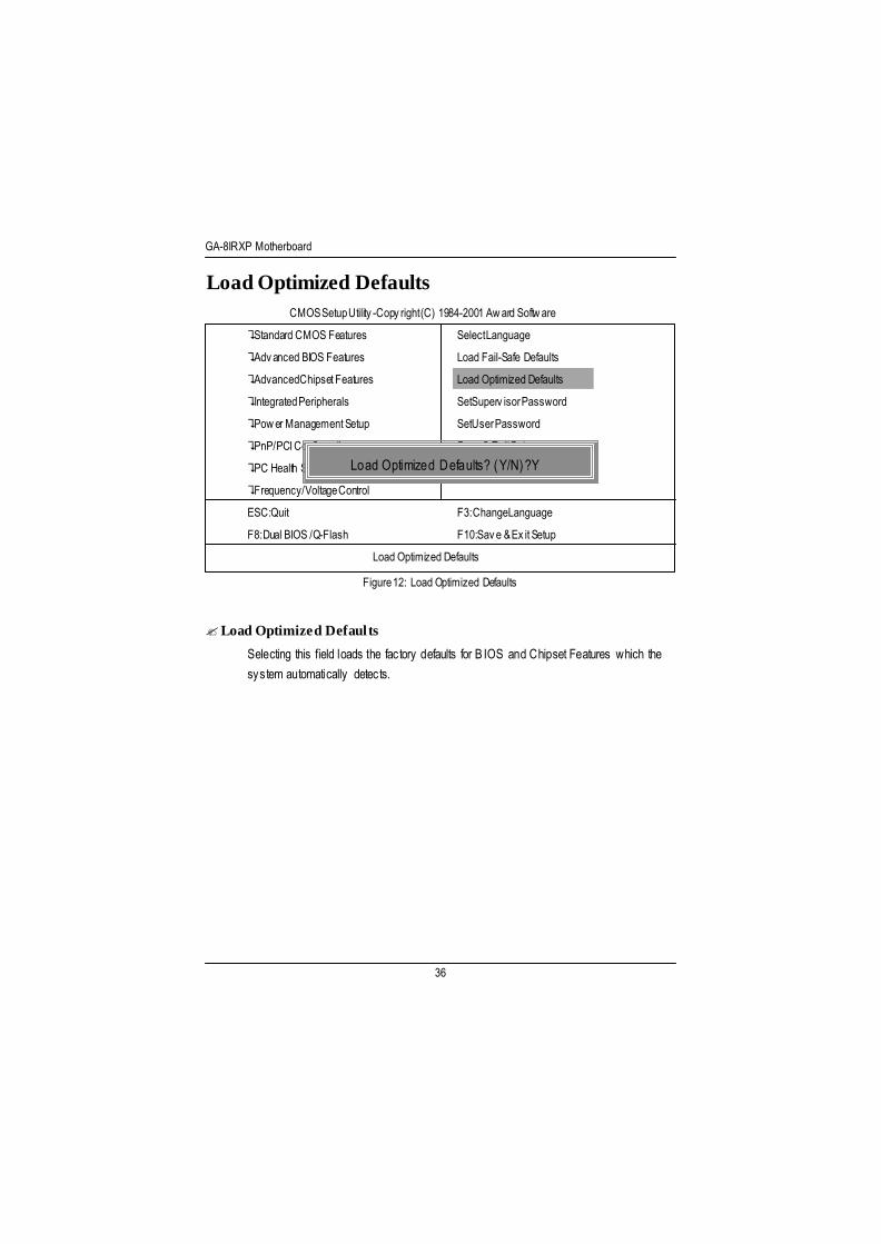
Load Optimized Defaults
Figure 12: Load Optimized Defaults
CMOS Setup Utility -Copy right (C) 1984-2001 Aw ard Softw are
?Standard CMOS Features Select Language
?Advanced BIOS Features Load Fail-Safe Defaults
?Advanced Chipset Features Load Optimized Defaults
?Integrated Peripherals Set Superv isor Password
?Pow er Management Setup Set User Password
?PnP/PCI Configurations Save & Ex it Setup
?PC Health Status Ex it Without Sav ing
?Frequency/Voltage Control
ESC:Quit F3:Change Language
F8:Dual BIOS /Q-Flash F10:Save & Ex it Setup
Load Optimized Defaults
?Load Optimized Defaults
Selecting this field loads the factory defaults for B IOS and Chipset Features which thesystem automatically detects.
Load Optimized D efaults? ( Y/N) ?Y

Technical Reference
37
Set Supervisor/User Passw ord
When you select this function, the follow ing message w ill appear at the center of the screen toassist you in creating a password.
Type the password, up to eight characters, and press <Enter>. You w ill be asked to confirm thepassword. Type the password again and press <Enter>. You may also press <Esc> to abort theselection and not enter a password.
To disable password, just press <Enter> when you are prompted to enter password. A message“PASSWORD DISABLED” will appear to confirm the password being disabled. Once the passwordis disabled, the system w ill boot and you can enter Setup freely.
The BIOS Setup program allows you to specify two separate passwords: a SUPERVISOR PASS-WORD and a USER PASSWORD. When disabled, anyone may access all BIOS Setup programfunction. When enabled, the Supervisor passw ord is required for entering the BIOS Setup programand having full configuration fields, the User password is required to access only basic items.
If you select “ System” at “ Security Option” in Advance BIOS Features Menu, you w ill be promptedfor the password every time the system is rebooted or any time you try to enter Setup Menu.
If you select “Setup” at “Security Option” in Advance BIOS Features Menu, you w ill be promptedonly w hen you try to enter Setup.
Figure 13: Passw ord Setting
CMOS Setup Utility -Copy right (C) 1984-2001 Aw ard Softw are
?Standard CMOS Features Select Language
?Advanced BIOS Features Load Fail-Safe Defaults
?Advanced Chipset Features Load Optimized Defaults
?Integrated Peripherals Set Superv isor Password
?Pow er Management Setup Set User Password
?PnP/PCI Configurations Save & Ex it Setup
?PC Health Status Ex it Without Sav ing
?Frequency/Voltage Control
ESC:Quit F3:Change Language
F8:Dual BIOS /Q-Flash F10:Save & Ex it Setup
Change/Set/Disable Passw ord
Enter Password:

GA-8IRXP Motherboard
38
Save & Exit Setup
Type “Y” w ill quit the Setup U tility and save the user setup value to RTC CMOS.
Type “N ” w ill return to Setup U tility.
Figure 14: Save & Ex it Setup
CMOS Setup Utility -Copy right (C) 1984-2001 Aw ard Softw are
?Standard CMOS Features Select Language
?Advanced BIOS Features Load Fail-Safe Defaults
?Advanced Chipset Features Load Optimized Defaults
?Integrated Peripherals Set Superv isor Password
?Pow er Management Setup Set User Password
?PnP/PCI Configurations Save & Ex it Setup
?PC Health Status Ex it Without Sav ing
?Frequency/Voltage Control
ESC:Quit F3:Change Language
F8:Dual BIOS /Q-Flash F10:Save & Ex it Setup
Save Data to CMOS
Save to CMOS and EXIT (Y/N)? Y

Technical Reference
39
E xit Without Saving
Type “Y” w ill quit the Setup U tility w ithout sav ing to RTC CMOS.
Type “N ” w ill return to Setup U tility.
Figure 15: Ex it Without Sav ing
CMOS Setup Utility -Copy right (C) 1984-2001 Aw ard Softw are
?Standard CMOS Features Select Language
?Advanced BIOS Features Load Fail-Safe Defaults
?Advanced Chipset Features Load Optimized Defaults
?Integrated Peripherals Set Superv isor Password
?Pow er Management Setup Set User Password
?PnP/PCI Configurations Save & Ex it Setup
?PC Health Status Ex it Without Sav ing
?Frequency/Voltage Control
ESC:Quit F3:Change Language
F8:Dual BIOS /Q-Flash F10:Save & Ex it Setup
Abandon all Data
Quit Without Saving (Y/N)? N
GA-8IRXP Motherboard
40
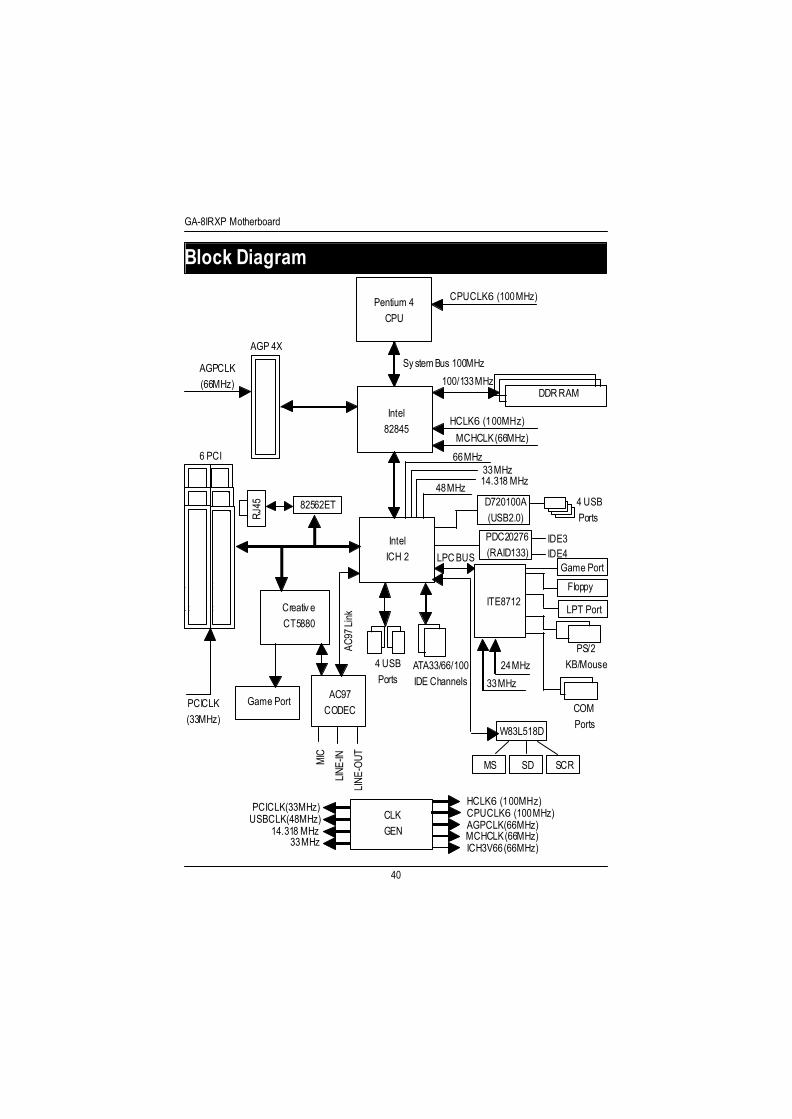
Pentium 4CPU
Intel82845
CreativeCT5880
Game PortAC97
CODEC
IntelICH 2
CPUCLK6 (100MHz)
System Bus 100MHz
DDR RAM100/133 MHz
HCLK6 (100MHz)
MCHCLK (66MHz)
66 MHz33 MHz14.318 MHz
48 MHz
LPC BUS
AGP 4X
AGPCLK(66MHz)
6 PCI
PCICLK(33MHz)
RJ45
AC97
Lin
k
MIC
LINE
-IN
LINE
-OUT
4 USBPorts
ATA33/66/100IDE Channels
CLKGEN
HCLK6 (100MHz)CPUCLK6 (100MHz)AGPCLK (66MHz)MCHCLK (66MHz)ICH3V66 (66MHz)
PCICLK (33MHz)USBCLK (48MHz)
14.318 MHz33 MHz
Block Diagram
82562ET
MS SD SCR
W83L518D
ITE8712
24 MHz
33 MHz
Game Port
Floppy
LPT Port
PS/2 KB/Mouse
COM Ports
PDC20276(RAID133)
IDE3IDE4
D720100A(USB2.0)
4 USBPorts

Technical Reference
41
CMOS Setup Utility -Copy right (C) 1984-2001 Aw ard Softw are
?Standard CMOS Features Select Language
?Advanced BIOS Features Load Fail-Safe Defaults
?Advanced Chipset Features Load Optimized Defaults
?Integrated Peripherals Set Superv isor Password
?Pow er Management Setup Set User Password
?PnP/PCI Configurations Save & Ex it Setup
?PC Health Status Ex it Without Sav ing
?Frequency/Voltage Control
ESC:Quit F3:Change Language
F8:Dual BIOS /Q-Flash F10:Save & Ex it Setup
A. What is Dual BIOS Technology?Dual B IOS means that there are two system BIOS (ROM) on the motherboard, one is the
Main BI OS and the other is Backup BIOS. Under the normal circumstances, the system w orks onthe Main BIOS. If the M ain BIOS is corrupted or damaged, the Backup B IOS can take ov er whilethe system is powered on. This means that your PC w ill still be able to run stably as if nothinghas happened in your BIOS.
B. How to use Dual BIOS and Q-Flash Utility?a. A fter power on the computer, pressing <Del> immediately during POST (Power On Self Test) itw ill allow you to enter Aw ard BIOS CMOS SETUP, then press <F8> to enter Flash utility.
Dual BIOS / Q-Flash Introduction
Enter Dual BIOS / Q-Flash Utility (Y/N) ? Y

GA-8IRXP Motherboard
42
Dual BIOS / Q-Flash U tility V845.4MF3(C) 2001, GIGA-BYTE Technology Co., LTD.
Wide Range Protection :DisabledHalt On BI OS Defects :DisabledAuto Recovery :EnabledBoot From :Main BIOSBIOS Recovery :Main to Backup
F3: Load Default F5:Start BIOS RecoveryF7: Save And Restart F9:Exit Without SavingF8: Update BI OS from disk F10:Recovery from Disk
Use <Space> key to toggle setup
b. Dual BIOS / Q-Flash U tility
c. Dual BI OS Item explanation:
Wide Range Protection: Disabled(Default), EnabledStatus 1:If any failure (ex. U pdate ESCD failure, checksum error or reset… ) occurs in the Main BIOS , justbefore the Operating System is loaded and after the power is on, and that the Wide RangeProtection is set to “Enable”, the PC w ill boot from Backup BIOS automatically.Status 2: If the ROM BIOS on peripherals cards(ex. SCSI Cards, LAN Cards,..) emits signals to requestrestart of the sy stem after the user make any alteration on it, the boot up BIOS w ill not bechanged to the Backup BIOS.

Technical Reference
43
Halt On BIOS Defects : Disabled(Default), EnabledI f the BIOS occurs a checksum error or the Main BIOS occurs a WIDE RANGE PROTECTIONerror and Halt On BIOS Defects set to Enable, the PC w ill show messages on the boot screen,and the system w ill pause and wait for the user’s instruction. I f Auto Recovery :Disabled, it w ill show <or the other key to continue.>
I f Auto Recovery :Enabled, it w ill show <or the other key to Auto Recover.>
Auto Recovery : Enabled(Default), Disabled When one of the Main BIOS or Backup BIOS occurs checksum failure, the working BIOS w illautomatically recover the BIOS of checksum failure.(In the Power Management Setup of the BIOS Setting, if ACPI Suspend Type is set to Suspendto RAM , the Auto Recovery w ill be set to Enable automatically.)(I f y ou want to enter the BIOS setting, please press “ Del” key when the boot screen appears.)
Boot From : Main BIOS(Default), Backup BIOSStatus 1:
The user can set to boot from main BIOS or Backup BIOS.Status 2:
If one of the main BIOS or the Backup BIOS fails, this item “Boot From : Main BIOS(Default)” w ill become gray and w ill not be changed by user.
BIOS Recovery : Main to BackupAuto recovery message:
BIOS Recovery: Main to BackupThe means that the Main BIOS w orks normally and could automatically recov er the BackupBIOS.
BIOS Recovery: Backup to MainThe means that the Backup BIOS works normally and could automatically recover the MainBIOS.(This auto recovery utility is set by sy stem automatically and can’t be changed by user.)

GA-8IRXP Motherboard
44
D. How to use Q-Flash Flash?
C. What is Q-Flash Utility?Q-Flash utility is a pre-O.S. BIOS flash utility enables users to update its BIOS w ithin BIOS
mode, no more fooling around any OS.
F3: Load Default F5: Start BIOS RecoveryLoad current BIOS default value. Press F5 to recovery new BIOS version.
F7: Save and Restart F9: Exit Without SavingSave revised setting and restart the Exit w ithout changing.computer.
F8: Update BIOS from Disk F10: Recovery from Disk
Update boot-up BIOS. Update another BIOS (different from boot-up
BIOS)

Technical Reference
45
DualBIOSTM Technology FAQ
GIGABYTE Technology is pleased to introduce DualBIOS technology, a hot spare for your
system BIOS. This newest “Value-added” feature, in a long series of innovations from
GIGABYTE, is available on this motherboard. Future GIGABYTE motherboards will also
incorporate this innovation.
What’s DualBIOSTM?
On GIGABYTE motherboards with DualBIOS there are physically two BIOS chips. For
simplicity we’ll call one your “Main BIOS” and the other we’ll call your “Backup” BIOS (your “hot
spare”). If your Main BIOS fails, the Backup BIOS almost automatically takes over on your next
system boot. Almost automatically and with virtually zero down time! Whether the problem is a
failure in flashing your BIOS or a virus or a catastrophic failure of the Main BIOS chip, the result
is the same - the Backup BIOS backs you up, almost automatically.

GA-8IRXP Motherboard
46
I I . Q: Why does anyone need a motherboard with DualBIOSTM technology?
Answer:In today’s systems there are more and more BIOS failures. The most common reasons are
virus attacks, BIOS upgrade failures, and/or deterioration of the BIOS (ROM) chip itself.1. New computer v iruses are being found that attack and destroy the system BIOS. They
may corrupt your BI OS code, causing your PC to be unstable or even not boot normally.2. BIOS data w ill be corrupted if a power loss/surge occurs, or if a user resets the sy stem,
or if the power button is pressed dur ing the process of performing a system BIOSupgrade.
3. If a user mistakenly updates their mainboard w ith the incorrect BIOS file, then thesystem may not be able to boot correctly. This may cause the PC system hang inoperation or during boot.
4. A flash ROM’s li fe cycle is limited according to electronic characteristics. The modernPC utilizes the P lug and Play BIOS, and is updated regularly. I f a user changesperipherals often, there is a slight chance of damage to the flash ROM.With Giga-By te Technology’s patented DualB IOST M technology you can reduce thepossibility of hangs during system boot up, and/or loss BIOS data due to above reasons.This new technology w ill eliminate valuable system down time and costly repair billscause by BIOS failures.
I . Q: What is DualBIOSTM technology?
Answer:DualBIOS technology is a patented technology from Giga-Byte Technology. The concept of
this technology is based on the redundancy and fault tolerance theory. DualB IOST M technologysimply means there are two system BI OSes (ROM) integrated onto the motherboard. One is amain BIOS, and the other is a backup BIOS. The mainboard w ill operate normally w ith the mainBIOS, however, if the main BIOS is corrupt or damaged for various reasons, the backup BIOSwill be automatically used when the system powered-On. Your PC w ill operate as before the mainBIOS was damaged, and is completely transparent to the user.

Technical Reference
47
IV. Q: Who Needs DualBIOSTM technology?
Answer:1. Every user should have DualB IOST M technology due to the advancement of computer
viruses.Everyday, there are new BIOS-type viruses discovered that w ill destroy your systemBIOS. Most commercial products on the market do not have solutions to guard againstthis type of virus intrusion. The DualBIOST M technology w ill provide a state-of-the-artsolution to protect your PC:Case I.) V icious computer viruses may w ipe out your entire system BI OS. With aconventional single system BIOS PC , the PC w ill not be functional until it is sent forrepairs.Case II.) I f the “Auto Recovery” option is enabled in the DualBIOST M utili ty, and if a viruscorrupts your system BIOS, the backup BIOS w ill automatically reboot the system andcorrect the main BIOS.Case II I.) A user may override booting from the main system BIOS. The DualBIOST M
I I I . Q: How does DualBIOSTM technology work?
Answer:1. DualB IOST M technology provides a w ide range of protection dur ing the boot up
procedure. It protects your B IOS during system POST, ESCD update, and even all theway to PNP detection/assignment.
2. DualBIOST M provides automatic recovery for the BIOS. When the first BIOS used duringboot up does not complete or if a BIOS checksum error occurs, boot-up is stil l possible.In the DualBIOST M uti lity, the “Auto Recovery” option w ill guarantee that if either the mainBIOS or backup BIOS is corrupted, the DualBIOST M technology w ill use the good BIOSand correct the wrong BIOS automatically.
3. DualBIOST M provides manual recovery for the BIOS. DualBIOST M technology contains abuilt-in flash utility, w hich can flash your system BI OS from backup to main and/or visaversa. There is no need for an OS-dependent flash utility program.
4. DualBIOST M contains a one-way flash utility. The built- in one-w ay flash utility w ill ensurethat the corrupt BI OS is not mistaken as the good BIOS during recovery and that thecorrect BIOS (main vs. backup) w ill be flashed. This w ill prevent the good BIOS frombeing flashed.

GA-8IRXP Motherboard
48
utility may be entered to manually change the boot sequence to boot from the backupBIOS.
2. During or after a BIOS upgrade, if DualBIOST M detects that the main BIOS is corrupt, thebackup BIOS w ill take over the boot-up process automatically. Moreover, i t w ill verify themain and backup B IOS checksums when booting-up. DualBIOST M technology examinesthe checksum of the main and backup BIOS w hile the system is powered on toguarantee your BIOS operates properly.
3. Power Users w ill have the advantage of hav ing two BIOS versions on their mainboard.The benefit is being able to select either version BIOS to suit the per formance systemneeds.
4. Flexibility for high-end desktop PCs and workstation/servers. In the DualBIOST M util ity,the option can be set, “ Halt On When BIOS Defects,” to be enabled to halt your systemwith awarning message that the main BIOS has been corrupted. Most w orkstation/servers require constant operation to guarantee services have not been interrupted. Inthis situation, the “H alt On When BIOS Defects” message may be disabled to avoidsystem pauses during normal booting. Another adv antage you gain from Giga-Byte’sDualBIOST M technology is the ability to upgrade from dual 2 Mbit B IOS to dual 4Mbit B IOS in the future if extra BIOS storage is need.
Technical Reference
49
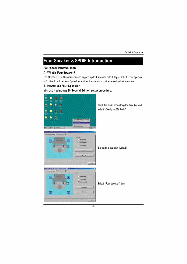
Four Speaker Introduction
A. What is Four Speaker?The Creative CT5880 audio chip can support up to 4 speaker output. I f you select “Four speakerout” , Line In w ill be reconfigured as another line out to support a second pair of speakers.
B. How to use Four Speaker?
Microsoft Windows 98 Second Edition setup procedure:
Click the audio icon along the task bar andselect “Configure 3D Audio”
Select tw o speaker (Default)
Select “Four speaker” item.
Four Speaker & SPDIF Introduction

GA-8IRXP Motherboard
50
Microsoft Windows Me setup procedure:
Go to “Control Panel” and double click“Sounds and Multimedia”.
Select “Audio” Page, and click “Advanced”button.
Select “Quadraphonic Speakers” andclick ok.
C. Four Speaker Application
The four speaker function w ill only be supported in application softw ares that use M icrosoftDirectX and Creative EAX, for example, the game titles, software DVD player and MP3 player.

Technical Reference
51
SPDIF Introduction
A. What is SPDIF?The SPDIF output is capable of providing digital signal to AC 3 decoder w hich can support upto5.1 speakers.
B. How to use SPDIF?
Click your mouse right button in “ My Computer”and select the “P roperties” item.
C lick “Device Manager” item.
C lick “Sound, vidio and game controllers” itemand select the “C reative Sound BlasterPC I128” item.

GA-8IRXP Motherboard
52
Click “Settings” item and select the “Output Mode” item.
C lick “Digital” item, Line Out w ill bereconfigureto SPDIF Out.
Recommend y ou to select “Autosense”, I t w ill automatically detect the type (mono or stereo) ofthe audio connector that you plug into Line Out audio jack, then configure Line Out to eitherSPDIF or Speaker accordingly.

Technical Reference
53
@ BIOS IntroductionGigabyte announces @ BIOSWindows BIOS live update utility
Have you ever updated BI OS by yourself? Or likemany other people, you just know w hat BIOS is,but always hesitate to update it? Because youthink updating newest BIOS is unnecessary andactually you don’t know how to update it.
Maybe not like others, you are very experienced in BI OS updating and spend quite a lot oftime to do it. But of course you don’t like to do it too much. First, dow nload different BIOS fromwebsite and then sw itch the operating system to DOS mode. Secondly, use different flash utilityto update BIOS. The above process is not a interesting job. Besides, always be carefully to storethe BIOS source code correctly in your disks as if y ou update the w rong BIOS, it w ill be anightmare.
Certainly, y ou wonder why motherboard vendors could not just do something r ight to saveyour time and effor t and save y ou from the lousy BIOS updating work? Here it comes! NowGigabyte announces @BIOS— the first Windows BI OS live update utility. This is a smart BIOSupdate software. It could help you to download the BIOS from internetand update it. Not like theother BIOS update software, it’s a Windows utility. With the help of “@BI OS’, BIOS updating is nomore than a click.
Besides, no matter which mainboard you are using, if it’s a Gigabyte’s product*, @BIOS helpyou to maintain the BIOS. This util ity could detect your correct mainboard model and help you tochoose the B IOS accordingly. It then downloads the BIOS from the nearest Gigabyte ftp siteautomatically. There are several different choices; you could use “ I nternet Update” to downloadand update your BIOS directly. Or you may want to keep a backup for your current BI OS, justchoose “Save Current BIOS” to save it first. You make a w ise choice to use Gigabyte, and@BIOS update your BIOS smartly. You are now worry free from updating wrong BIOS, andcapable to maintain and manage your B IOS easily. Again, G igabyte’s innovative product erects amilestone in mainboard industries.
For such a wonderful software, how much it costs? I mpossible! I t’s free! Now, if you buy aGigabyte’s motherboard, you could find this amazing software in the attached driv er CD. Butplease remember, connected to internet at first, then you could have a internet BI OS update fromyour Gigabyte @BIOS.

GA-8IRXP Motherboard
54
Gigabyte announces EasyTuneIIIWindows overdrive utility
“Overdrive” might be one of the mostcommon issues in computer field. But have manyusers ever tried it? The answ er is probably “no”.Because “overdrive” is thought to be very difficultand includes a lot of technical know-how, some-
times “overdriv e” is even considered as special skills found only in some enthusiasts.But as to the experts in “overdr ive”, what’s the truth? They may spend quite a lot of time and
money to study, try and use many different hardware and softw are tools to do “overdrive”. And evenw ith these technologies, they stil l learn that it’s quite a risk because the safety and stability of an“overdrive“ system is unknown.
Now every thing is different because of a Windows overdrive utility EasyTuneIII— announcedby Gigabyte. This utility has totally changed the gaming rule of “overdrive”. This is the first overdriveutility suitable for both normal and power users. Users can choose either “Easy Mode” or “AdvancedMode” to run “overdrive” at their convenience. For users who choose “Easy Mode”, they just need toclick “Auto Optimize” to have auto and immediate CPU overclocking. This software w ill then over-drive CPU speed automatically w ith the result being shown in the control panel. I f someone prefersto “overdrive” by oneself, there is also another choice. C lick “Advanced Mode” to enjoy “sport drive”class ov erclocking. In “ Advanced Mode”, one can change the sy stem bus speed in small incre-ments to get ultimate system performance. And no matter which mainboard is used, if it’s a Gigabyte’sproduct*, EasyTuneIII helps to perform the best of system.
Besides, different from other traditional ov er-clocking methods, Easy TuneIII doesn’t requireusers to change neither BIOS nor hardware sw itch/ jumper setting; on the other hand, they can do“overdrive” at only one click. Therefore, this is a safer way for “overdrive” as nothing is changed onsoftware or hardware. If user runs Easy TuneIII over sy stem’s limitation, the biggest lost is only torestar t the computer again and the side effect is then well controlled. Moreov er, if one well-per-formed system speed been tested in EasyTuneIII, user can “Save” this bus speed and “Load” it innext time. Obviously, Gigabyte EasyTuneIII has already turned the “overdrive” technology towardto a newer generation.
This wonderful software is now free bundled in Gigaby te motherboard attached dr iver C D.Users may make a test driv e of “Easy TuneIII” to find out more amazing features by themselves.
Easy TuneIIITM Introduction

Technical Reference
55
What is RAID?This motherboard implements tw o different ty pes of RAID levels as follows:
RAID 0 (stripe)For capacity -- The motherboard array w ill be as big as the smallest H DD in the array timeshowever many HDDs are in the array. Any larger HDDs w ill simply be truncated. The truncatedspace on the bigger HDDs w ill then be unusable.For sustained data transfers -- A RAI D 0 array consisting of two HDDs w ill transfer at about tw icethe speed of the slowest HDD in the array. A RAID 0 array consisting of four HDDs w ill transfer atabout three times the speed of the slowest HDD in the array.
RAID 1 (mirror)For capacity - This Motherboard array w ill be as big as the smallest HDD in the array. The largerHDD w ill simply be truncated. The truncated space on the bigger HDD w ill then be unusable.For sustained data transfers - - This motherboard array w ill w r ite data at the rate of the slow estHDD in the array. This motherboard array w ill read data at tw ice the rate of the slowest HDD inthe array.
RAID Introduction

GA-8IRXP Motherboard
56
About RAID Levels
Striping (RAID 0)Reads and w rites sectors of data inter leaved between multiple driv es. When any disk memberfails, it affects the entire array. Performance is better than a single drive since the workload isbalanced between the array members. This array type is for high performance systems. Identicaldrives are recommended for performance as well as data storage efficiency. The disk array datacapacity is equal to the number of dr ive members times the smallest member capacity. Forexample, one 1GB and 1 drives w ill form a 2GB (2 x 1GB) disk array.Stripe Size - a value can be set from 1KB to 1024KB sector size. The size can directly affectperformance. In the FastBuild BIOS, the "Desktop" default is 8KB w hile "Server" and "A/VEditing" are 64KB.

Technical Reference
57
Mirroring (RAID 1)Writes duplicate data on to a pair of dr ives w hile reads are per formed in parallel. ATA RAID 1 isfault tolerant because each dr ive of a mirrored pair is installed on separate I DE channels. If oneof the mirrored drives suffers a mechanical failure (e.g. spindle failure) or does not respond, theremaining drive w ill continue to function. This is called Fault Tolerance. If one dr ive has aphysical sector error, the mirrored drive w ill continue to function.
RAID 1 (Mirroring)
On the next reboot, the FastBuildT M uti lity w ill display an error in the array and recommend toreplace the failed drive. Users may choose to continue using their PC, however Promiserecommends replacing the failed driv e as soon as possible. See C hapter 4 for a functionaldescription.
Due to redundancy, the drive capacity of the array is half the total drive capacity. For example,two 1GB drives that have a combined capacity of 2GB would have 1GB of usable storage. Withdriv es of different capacities, there may be unused capacity on the larger dr ive.

GA-8IRXP Motherboard
58
Creating Your Disk ArrayYou w ill now use the FastBuild BIOS util ity to create your array using the attached drives. Thereare two different scenarios in creating this array. You can create an array for performance, youcan create a Security array using new hard drives (recommended).
WARNING: If creating a Security array using an existing hard drive, backup anynecessary data. Failure to follow this accepted PC practice could result in dataloss.
1. Boot your system. If this is the first time you have booted w ith RAID, the FastBuild BI OS w illdisplay the follow ing screen.
FastTrak100 (tm) "Lite" BIOS Version 1.xx (Build xxxx)(c) 1995-2001 Promise Technology, Inc. All Rights Reserved.
No array defined . . .Press <C trl-F> to enter FastBuild (tm) U tilityOr press <ESC> key to continue booting the system.
2. Press <C trl-F> keys to display the FastBuild (tm) U tility Main Menu3. Press "1" to display the Auto Setup Menu below. This is the fastest and easiest method to
creating your first array.
FastBuild (tm) U tility 1.32 (c) 1995-2001 Promise Technology, Inc.[Auto Setup Options M enu]
Optimize Array for: PerformanceTypical Application usage: DESK TOP
[ Auto Setup C onfiguration ]Mode........................................................StripeSpare Driver...............................................0Drives used in Array....................................2Array Disk Capacity (Size in MB)..................160107
[ Keys Available ][?] Up [?] Down [? ,? , Space] Change Option [ESC] Exit [C trl-Y] Save

Technical Reference
59
Creating an Array for PerformanceNOTE: This motherboard allows users to create striped arrays w ith 1, 2 dr ives.To create an array for best performance, follow these steps:1. Using the Spacebar, choose "Performance" under the Optimize Array for section.2. Select how y ou w ill use your PC most under the Typical Application usage section The
choices are A/V Editing, Server, and Desktop (the default).3. Press <C trl-Y> keys to Save and create the array.4. Reboot your sy stem.5. Once the array has been created, you w ill need to FDISK and format the array as if it w ere a
new single hard drive.6. Proceed to Installing D rivers section of the manual (see RA ID Manual of the I UCD).
Creating a Security Array With New DrivesNOTE: This motherborad permit only two drives to be used for a single Mir rored array in AutoSetup.To create an array for data protection using new hard drives, follow these steps:1. Using the Spacebar, choose "Security" under the Optimize Array for section.2. Press <C trl-Y> keys to Save your selection.3. The w indow below w ill appear.
Do y ou want the disk image to be duplicated to another? (Yes/No)Y - C reate and DuplicateN - C reate Only
4. Press "N" for the Create Only option.5. A w indow w ill appear almost immediately confirming that your Security array has been
created.Press any key to reboot the system
Array has been created.<Press Any Key to Reboot>
6. Proceed w ith normal FDISK and format procedures as if you had just installed a new harddrive.
7. Once the arrayed driv es hav e been formatted, proceed to the Installing Driv er chapter (seeRAID M anual of the IUCD) to install your operating system.

GA-8IRXP Motherboard
60
Creating a Security Array With An Existing Data DriveNOTE: This motherboard permits only two drives to be used for a single Mirrored array in Auto
Setup.You would use this method if you w ish to use a drive that already contains data and/or is thebootable sy stem drive in y our system. You w ill need another drive of identical or larger storage
capacity.WARNIN G: Backup any necessary data before proceeding. Failure to followthis accepted PC practice could result in data loss.
WARNING : If you w ish to include your current bootable drive using theWindows NT 4.x or Windows 2000 operating system as part of a bootableMirrored (RAID 1) array on your system, do NOT connect the hard drive to the
motherboard controller y et. You MUST install the Windows NT4 or 2000 driver software first(see RAID Manual of the IU CD) to this drive while it is still attached to your existing harddriv e controller. For all other Operating Systems, proceed here.
Follow these steps:1. Using the Spacebar, choose "Security" under the Optimize Array for section.2. Press <C trl-Y> keys to Save your selection. The w indow below w ill appear.
Do y ou want the disk image to be duplicated to another? (Yes/No)Y - C reate and DuplicateN - C reate Only
3. Press "Y" for the Create and Duplicate option. The w indow below w ill appear asking you toselect the Source drive to use. FastBuild w ill copy all data from the Source dr ive to the Targetdrive.
Source DiskChannel:ID Drive Model Capacity (MB)
Target D iskChannel:ID Drive Model Capacity (MB)
[Please Select A Source Disk]Channel:ID Drive Model Capacity (MB)1 :Master QUANTUMCR8.4A 80632 :Master QUANTUMCR8.4A 8063
[?] Up [?]DOWN [ESC] Exit [Enter] Select

Technical Reference
61
4. Use the arrow keys to choose which dr ive contains the existing data to be copied.5. Press [Enter] keys to selection and start duplication. The follow ing progress screen w ill
appear.
Start to duplicate the image . . . Do you want to continue? (Yes/No)Y - ContinueN - Abort
6. Select "Y" to continue. If you choose "N" , you w ill be returned to step 1.7. Once complete, the follow ing screen w ill appear confirming that your Security array has been
created. Press any key to reboot the system
Array has been created.<Press Any Key to Reboot>
8. Proceed to the Installing Driver chapter (see RAID Manual of the IUCD) to install the RAIDdriv er and/or operating system.

GA-8IRXP Motherboard
62
Using FastBuildTM Configuration UtilityThe FastBuildT M Configuration U tility offers several menu choices to create and manage the dr ivearray on the motherboard. For purposes of this manual, i t is assumed y ou hav e already createdan array in the previous chapter and now w ish to make a change to the array or view otheroptions.
Viewing BIOS ScreenWhen y ou boot your system w ith the RA ID function and driv es installed, the FastBuild BIOS w illdetect the driv es attached and show the follow ing screen.
FastTrak100 ( tm)"Lite" BIOS Version 1.xx (Build xx)(c) 1995-2001 Promise Technology, Inc. All Rights Reserved.
Scanning IDE drives . . . . .
I f an array exists already, the BIOS w ill display the follow ing screen show ing the board RAIDBIOS version and status of the array.
FastTrak100 (tm) "Lite"BIOS Version 1.xx (Build xxxx)(c) 1995-2001 Promise Technology, Inc. All Rights Reserved.
ID MODE SIZE TRACK-MAPPING STATUS1 * 1*2 M irror 16126M 611/128/32 FunctionalPress <C trl-F> to enter FastBuild (tm) U til ity....
The array status consists of three possible conditions: Functional, C rit ical, Offline.Functional - The array is operational.C rit ical - A mirrored array contains a driv e that has failed or disconnected. The remaining drivemember in the array is functional. However, the array has temporarily lost its ability to providefault tolerance. The user should identify the failed dr ive through the FastBuildO Setup util ity, andthen replace the problem drive.Offline - A str iped array has 1 drive that has failed or been disconnected. When the arraycondition is "offline," the user must replace the failed drive(s), then restore data from a backupsource.

Technical Reference
63
Navigating the FastBuildTM Setup MenuWhen using the menus, these are some of the basic navigation tips: Arrow keys highlightsthrough choices; [Space] bar key allows to cy cle through options;[Enter] key selects an option; [ESC] key is used to abort or exit the current menu.
Using the Main MenuThis is the first option screen when entering the FastBuildT M Setup.
FastBuild (tm) U tility 1.xx (c) 1995-2000 Promise Technology, Inc.[ Main Menu ]
Auto Setup..........................................[ 1 ]View Drive Assignments......................[ 2 ]View Array.........................................[ 3 ]Delete Array........................................[ 4 ]Rebuild Array......................................[ 5 ]Controller Configuration.........................[ 6 ]
[ Keys Available ]Press 1...6 to Select Option [ESC] Exit
To create a new array automatically, follow the steps under "C reating Arrays Automatically " onpage 64. Promise recommends this option for most users.To view drives assigned to arrays, see "View ing Drive Assignments" on page 66.To delete an array (but not delete the data contained on the array), select "Deleting An Array" onpage 68.To rebuild a mirrored array, see "Rebuilding an A rray" on page 70.To v iew controller settings, see "View ing C ontroller Configuration" on page 72.
NOTE: After configur ing an array using FastBuild, you should FDISK and formatthe arrayed drive(s) if you are using new, blank drives. Depending on the typeof array you are using.

GA-8IRXP Motherboard
64
Creating Arrays AutomaticallyThe Auto Setup <1> selection from the Main M enu can intuitively help create your disk array . Itw ill assign all available drives appropriate for the disk array you are creating. After making allselections, use C trl-Y to Save selections. FastBuild w ill automatically build the array.
FastBuild (tm) U tility 1.xx (c) 1995-2000 Promise Technology, Inc.[Auto Setup Options M enu]
Optimize Array for: PerformanceTypical Application usage: A/V Editing
[ Auto Setup C onfiguration ]Mode.................................................StripeSpare Drive Count...............................0Drives used in Array............................2Array Disk Capacity............................16126
[ Keys Available ][?] Up [?] Down [? ,? , Space] Change Option [ESC] Exit [C trl-Y] Save
Optimize Array ForSelect whether you want Performance (RAID 0), Security (RAID 1) under the "Optimize Arrayfor"setting.
Performance (RAID 0 Striping)Supports the maximum performance. The storage capacity equals the number of drives timesthe capacity of the smallest drive in the disk array.
NOTE: This motherboard permits striped arrays using 1, 2 drive attached in Auto Setupmode.Security (RAID 1 Mir roring)Creates a mirrored (or fault tolerant) array for data security.
NOTE: Under the Security setting, This motherboard permits tw o drives to be used for asingle Mirrored array only.

Technical Reference
65
Defining Typical Application UsageAllows the user to choose the type of PC usage that w ill be performed in order to optimize howThis motherboard handles data blocks to enhance performance. Your choice w ill determine the block size used. You may choose from: A/V Editing (for audio/video applications, or any similarapplication that requires large file transfers), Server ( for numerous small f ile transfers), orDesktop (a combination of large and small file sizes).
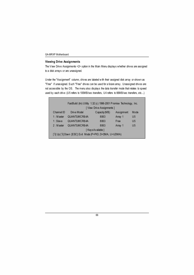
GA-8IRXP Motherboard
66
Viewing Drive AssignmentsThe V iew Drive Assignments <2> option in the Main Menu displays whether drives are assignedto a disk arrays or are unassigned.
Under the "Assignment" column, drives are labeled w ith their assigned disk array or shown as"Free" if unassigned. Such "Free" drives can be used for a future array. Unassigned drives arenot accessible by the OS. The menu also displays the data transfer mode that relates to speedused by each drive (U5 refers to 100MB/sec transfers, U4 refers to 66MB/sec transfers, etc...)
FastBuild (tm) U tility 1.32 (c) 1996-2001 Promise Technology, Inc.[ View Drive Assignments ]
Channel:ID Drive Model Capacity(MB) Assignment Mode1 : M aster QUANTUMCR8.4A 8063 Array 1 U51 : Slave QUANTUMCR8.4A 8063 Free U52 : M aster QUANTUMCR8.4A 8063 Array 1 U5
[ Keys Available ][?] Up [?] Down [ESC] Exit Mode (P=PIO, D=DMA, U=UDMA)

Technical Reference
67
How Orders ArraysDuring startup, the disk arrays on the motherboard are recognized in this order: 1) The array setto bootable in the FastBuildTM Setup, and 2) the Array number (i.e. Array 0, Array 1¡K). Thiswould be involved in determining which drive letters w ill be assigned to each disk array.
How Saves Array InformationAll disk array data is saved into the reserved sector on each array member. We suggests thatusers record their disk array information for future reference.
Another feature of the motherboard disk array sy stem is to recognize drive members even ifdriv es are moved between different motherboard connectors(IDE3&I DE4). S ince each drive'sarray data identifies itself to the array, it is possible to mov e or sw ap driv es w ithout modifying thearray setup. This is valuable when adding drives, or during a rebuild.

GA-8IRXP Motherboard
68
Deleting An ArrayThe Delete Array <4> M enu option allows for deletion of disk array assignments. This is not thesame as deleting data from the driv es themselves. If y ou delete an array by accident (and beforeit has been used again), the array can normally be recov ered by defining the array identically asthe deleted array.
WARNING : Deleting an existing disk array could result in its data loss. Makesure to record all array information including the array type, the disk members,and stripe block size in case you w ish to undo a deletion.
FastBuild (tm) U tility 1.32 (c) 1996-2001 Promise Technology, Inc.[ Delete Array Menu ]
Array No RAID Mode Total D rv Capacity(MB) StatusArray 1 Mirror 2 8063 FunctionalArray 2 Stripe 1 8063 FunctionalArray 3 Stripe 1 8063 FunctionalArray 4 --- -- --- -- --- -- --- --
[ Keys Available ][?] Up [?] Down [ESC] Exit [Del] Delete
1. To delete an array, highlight the Array you w ish to delete and press the [Del] key.2. The V iew Array Definition menu w ill appear (see below) show ing which drives are assigned to
this array.
FastBuild (tm) U tility 1.32 (c) 1996-2001 Promise Technology, Inc.[ Define Array Menu ]
Array No RAID Mode Total D rv Capacity(MB) StatusArray 1 Mirror 2 8063 FunctionalStripe Block: 64 KB
[ Drive Assignments ]Channel:ID Drive Model Capacity (MB) Assignment1 : M aster QUANTUMCR8.4A 8063 Y2 : M aster QUANTUMCR8.4A 8063 Y

Technical Reference
69
3. Confirm yes to the follow ing warning message w ith the <C trl-Y> key to continue arraydeletion:
Are y ou sure you want to delete this array?Press C trl-Y to Delete, others to Abort
4. After deleting the array, y ou should create a new array using Auto Setup or the Define Arraymenu from the FastBuild Main M enu.

GA-8IRXP Motherboard
70
Rebuilding A Mirrored ArrayThe Rebuild A rray <5> Menu option is necessary to recover from an error in a mirrored diskarray. You w ill receive an error message when booting your system from the BIOS.
NOTE: Drives MUST be replaced if they contain any physical errors.
Follow these steps BEFORE using the Rebuild Array menu option:1. On bootup, the system Star tup BIOS w ill display an error message identifying which drive has
failed.2. Press <C trl-F> keys to enter FastBuild Main Menu.3. Select submenu Define Array <3>.4. Select the failed array and identify the Channel and I D of the failed dr ive.5. Power off and physically remove the failed drive.6. Replace the drive w ith an identical model.7. Reboot the system and enter the FastBuild M ain Menu.8. Select the <5> Rebuild Array option. The follow ing screen w ill appear.
FastBuild (tm) U tility 1.32 (c) 1996-2001 Promise Technology, Inc.[ Rebuild A rray Menu ]
Array No RAID Mode Total D rv Capacity(MB) StatusArray 1 Mirror 2 16126 CriticalArray 2 Stripe 1 8063 FunctionalArray 3 Stripe 1 8063 FunctionalArray 4 --- -- --- -- --- --- ---- ---
[ Keys Available ][?] Up [?] Down [ESC] Exit [Enter] Select
9. H ighlight the array whose Status is "C rit ical".10. Press [Enter]. The follow ing screen w ill then appear (see next page).

Technical Reference
71
FastBuild (tm) U tility 1.32 (c) 1996-2001 Promise Technology, Inc.[ Rebuild A rray Menu ]
The Previous recovery is not complete!
<Press Any Key to Restart The Recovery>
11. Press anykey and confirm that the data w ill be copied on to the selected drive. All data on thereplacement drive w ill be wr itten ov er w ith mirrored information from the array driv e. Aprogress bar w ill appear as below.
Please Wait While Duplicating The Image
10% Complete
12. Once the rebuild process is complete, the user w ill be asked to reboot the system.

GA-8IRXP Motherboard
72
Viewing Controller SettingsThe Controller C onfiguration <6> menu selection allow s you to enable or disable the BIOS fromhalting (the default) if it detects an error on boot up. You may also view the system resources(Interrupt and I/O por t address) of data channels
FastBuild (tm) U tility 1.32 (c) 1996-2001 Promise Technology, Inc.[ Adapter Configuration - Options ]Halt On Error: Enable[ System Resources Configuration ]
Channel 1 (I DE1) Interrupt : A I/O Port : 9800Channel 2 (I DE2) Interrupt : A I /O Port : A000
[ Keys Available ][? ,? Space] Change Option [ESC] Exit
Halting BIOS On Bootup ErrorsThe [Adapter Configuration - Options] section allow s you to enable or disable The system to H altoperation at the BI OS startup screen should an error be detected. This is the only option that canbe changed on this screen.
Viewing System ResourcesThe [System Resources Configuration] section of this submenu displays the PC I slot interruptand port address used by the system. The resources used are determined by the M ainboard PC IPnP BIOS for the PC I slot in which the system resides.In the rare case that there is a resource conflict, refer to the Mainboard B IOS documentation onchanges on resources allocated to the system PCI slot.
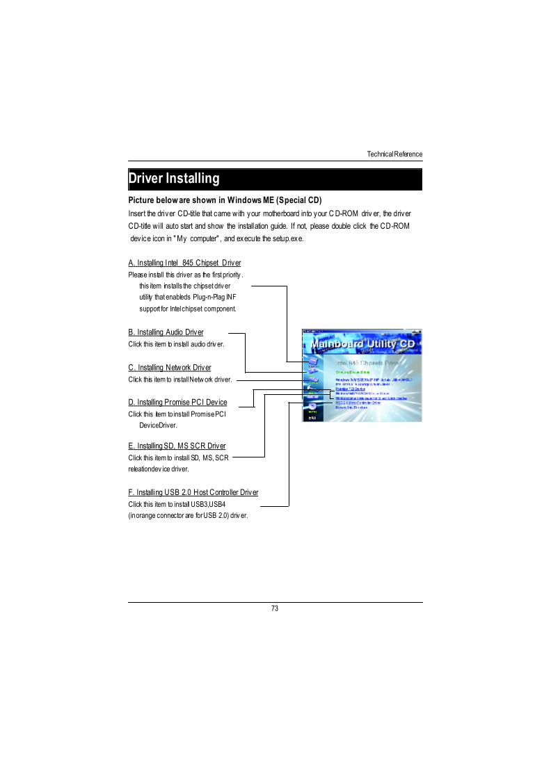
Technical Reference
73
Revision HistoryDriver InstallingPicture below are shown in Windows ME (Special CD)Inser t the driver CD-tit le that came w ith your motherboard into your C D-ROM driv er, the driverCD-title w ill auto start and show the installation guide. If not, please double click the CD-ROM device icon in "My computer" , and execute the setup.exe.
A. Installing I ntel 845 Chipset D riverPlease install this driver as the first priority .
this item installs the chipset driverutility that enableds Plug-n-Plag INF
support for Intel chipset component.
B. Installing Audio DriverClick this item to install audio driver.
C. Installing Network DriverClick this item to install Netw ork driver.
E. Installing SD, MS SCR DriverClick this item to install SD, MS, SCRreleation dev ice driver.
F. Installing USB 2.0 Host Controller DriverClick this item to install USB3,USB4(in orange connector are for USB 2.0) driver.
D. Installing Promise PC I DeviceClick this item to install Promise PCI
Device Driver.

GA-8IRXP Motherboard
74
1. Windows 9x/ME/2000/XP INF UpdateU tility C lick "Windows 9x/ME/2000/XP INFUpdate U tility"item.
(1)
(2) (3)
(4) (5)
2.C lick "Next". 3.C lick "Yes".
4.C lick "Next". 5.C lick "Finish" to restar t computer.
Picture below are shown in Windows ME (Special CD)
Appendix A: Intel 845 Chipset Driver Installation
A. Windows 9x/ME/2000/XP INF Update Utility:Inser t the driver CD-tit le that came w ith your motherboard into your C D-ROM driv er, the driverCD-title w ill auto start and show the installation guide. If not, please double click the CD-ROMdevice icon in "M y computer" , and execute the setup.exe.

Technical Reference
75
Inser t the driver CD-tit le that came w ith your motherboard into your C D-ROM driv er, the driverCD-title w ill auto start and show the installation guide. If not, please double click the CD-ROMdevice icon in "M y computer" , and execute the setup.exe.
B. Intel Ultra ATA Storage Driver:
(1) (2)
(3) (4)
(5)
1. I ntel U ltra ATA Storage Dr iverC lick "Intel U ltra ATA Storage Driver" item.
2.C lick "Next".
3.C lick "Yes". 4.C lick "Next".
5.C lick "Next". 6.C lick "Finish" to restar t computer.

GA-8IRXP Motherboard
76
C: Sound Driver Installation
Revision History
Press "Audio" icon.
C lick "C reative CT5880 Sound Driver" item.
(1)
(2) (3)
2.C lick "Next". 3.C lick "Finish".
D: Network Driver Installation
Press "Network" icon.
C lick "Driver Information".

Technical Reference
77
E: Promise RAID Driver Installation
Click “D river Information” Item
F: Fast Trak Utilies Installation
(1) (2)
(3) (4)
2.C lick "Next".
1.C lick “ Driver Information” Item
4.C lick "Next".3.C lick "Yes".

GA-8IRXP Motherboard
78
(5) (6)
(7) (8)
(9) (10)
5.C lick "Next". 6.C lick "Next".
7.C lick "Next". 8.C lick "Next".
9.C lick "Next". 10.C lick "Next".

Technical Reference
79
G: USB 2.0 Host Controller Driver
(1) (2)
C lick “USB2.0 Host Controller Driver” I tem

GA-8IRXP Motherboard
80
Revision HistoryAppendix B: EasyTuneI I I Utilities Installation
Inser t the driver CD-tit le that came w ith your motherboard into your C D-ROM driv er, the driverCD-title w ill auto start and show the installation guide. If not, please double click the CD-ROMdevice icon in "M y computer" , and execute the setup.exe.
(1) (2)
(3)
(4)
4. P lease enter your name andcompany name, then click "Next".
Press "Tools" icon.
1.C lick "Gigaby te U tilities".
2.C lick "Easy Tune II I Setup".
3.C lick "Next".

Technical Reference
81
(5) (6)
(7) (8)
5.C lick "Next". 6.C lick "Next".
7.C lick "Finish" to restar t computer.

GA-8IRXP Motherboard
82
Appendix C: Face-Wizard Utilities Installation
What is Face-WizardTM ?Face-WizardT M is a w indows based utili ty w ith user-friendly inter face that allows users tochange the boot-up logo w ith picture from Gigaby te Logo Gallery on web site or othercompatible picture you have.
How does it work?Face-WizardT M allow s user to select BIOS on board or file in hard drive, floppy disk , zip, MOor other storage devices and combine the compatible picture you prefer into BIOS. And notonly this, Face-WizardT M also helps user to update BIOS in w indows mode.
What’s benefit for using Face-WizardTM ?I t can personalize boot-up logo to show your unique style from others, and never againlooking at the black and w hite boot up screen.
(1) (2)
(3) (4)
(5)
1.C lick "Face-Wizard" item.
3.C lick "Next".
2.C lick "Next".
4.C lick "Face-Wizard".

Technical Reference
83
BIOS Flash ProcedureBIOS update procedure:If your OS is Win9X, we recommend that you used Gigabyte @BIOST M Program to flash BIOS.
(1) (2)
(3)
Press "Tools" icon.2.C lick "@BIOS Writer U tilityv1.08k".
1.C lick "Gigaby te U tilities".
C lick "?".C lick here.
Methods and steps: I. Update BIOS through Internet
a. C lick "Internet Update" iconb. C lick "Update New BIOS" iconc. Select @BIOST M sever ("Gigabyte @BIOSTM sev er 1 in Taiwan" and "Gigabyte
@BIOST M sever 2 in Taiwan" are available for now, the others w ill be completedsoon)d. Select the ex act model name on your motherboarde. System w ill automatically download and update the BIOS.

GA-8IRXP Motherboard
84
I I. Update BIOS NOT through Internet:a. Do not click "Internet U pdate" iconb. C lick "Update New BIOS"c. Please select "All Files" in dialog box w hile opening the old file.d. Please search for BIOS unzip file, downloading from internet or any other methods (such
as: 8IRXP.F1).e. Complete update process follow ing the instruction.
II I. Save BIOSIn the v ery beginning, there is "Save Current BIOS" icon shown in dialog box. It means tosave the current BIOS version.
IV . Check out supported motherboard and Flash ROM:In the very beginning, there is "About this program" icon shown in dialog box. It can help youcheck out which kind of motherboard and which brand of Flash ROM are supported.
Note:a. In method I, if i t show s two or more motherboard's model names to be selected, please
make sure your motherboard's model name again. Selecting wrong model name w illcause the system unbooted.
b. In method II, be sure that motherboard's model name in B IOS unzip file are the same asyour motherboard's. Otherw ise, your sy stem won't boot.
c. In method I, if the BIOS file you need cannot be found in @BIOST M server, please go ontoGigabyte's web site for downloading and updating it according to method II.
d. Please note that any interruption during updating w ill cause sy stem unbooted

Technical Reference
85
We use GA-7VTX motherboard and Flash841 BIOS flash utility as example.Please flash the BI OS according to the follow ing procedures if you are now under the DOS
mode.Flash BIOS Procedure:STEP 1:(1) Please make sure you have set "Auto" for BIOS Feature Setup (BIOS Flash Protection). For
more detail please refer to page 8.(2) Please make sure your system has installed the extraction utili ty such as w inzip or pkunzip.
Firstly you have to install the extraction utility such as w inzip or pkunzip for unzip the fi les.Both of these utilities are av ailable on many shareware download pages like http://w ww.shareware.cnet.com
STEP 2: Make a DOS boot diskette. (See example: Windows 98 O.S.)Beware: Windows ME/2000 are not allowed to make a DOS boot diskette.(1) With an available floppy disk in the floppy drive. P lease leav e the diskette "UN-write
protected" ty pe. Double click the "My Computer" icon from Desktop, then click "3.5 diskette(A)" and right click to select "Format (M)"

GA-8IRXP Motherboard
86
(2) Select the "Quick (erase)" for Format Ty pe, and pick both "Display summary when finished"and "Copy system files", after that press "Start". That w ill format the floppy and transfer theneeded system files to it.Beware: This procedure w ill erase all the prior data on that floppy, so please proceedaccordingly.
(3) After the floppy has been formatted completely, please press "C lose".

Technical Reference
87
STEP 3: Download BIOS and BIOS util ity program.(1) Please go to Gigabyte w ebsite http://www.gigabyte.com.tw /index.html, and click "Support".
(2) From Support zone, click the "Motherboards BIOS & Drivers".

GA-8IRXP Motherboard
88
(3) We use GA-7VTX motherboard as example. P lease select GA-7VTX by Model or Chipsetoptional menu to obtain BI OS flash files.
(4) Select an appropriate BI OS version (For ex ample: F4), and click to dow nload the file. I t w illpop up a file download screen, then select the "Open this file from its current location" andpress "OK".

Technical Reference
89
(5) At this time the screen shows the follow ing picture, please click "Extract" button to unzip thefiles.
(6) Please extract the dow nload files into the clean bootable floppy disk A mentioned in STEP 2,and press "Extract".

GA-8IRXP Motherboard
90
STEP 4: Make sure the system w ill boot from the floppy disk.(1) Insert the floppy disk (contains bootable program and unzip file) into the floppy drive A. Then,
restar t the system. The system w ill boot from the floppy disk. Please press <DEL> key toenter BIOS setup main menu when system is boot up.
(2) Once you enter the B IOS setup utility, the main menu w ill appear on the screen. Use thearrows to highlight the item "BIOS FEATURES SETUP".
AMIBIOS SIMPLE SETUP UT ILITY - VERSION 1.24b
(C) 1999 American Megatrends, Inc. All Rights Reserved
STANDARD CMOS SETUP INTEGRATED PERIPHERALS
BIOS FEATURES SETUP HARDWARE MONITOR & MISC SETUP
CHIPSET FEATURES SETUP SUPERVISOR PASSWORD
POWER MANAGEMENT SETUP USER PASSWORD
PNP / PCI CONFIGURATION IDE HDD AUTO DETECT ION
LOAD BIOS DEFAULTS SAVE & EXIT SETUP
LOAD SETUP DEFAULTS EXIT WITHOUT SAVING
ESC: Quit ?????: Select Item (Shift)F2 : Change Color F5: Old Values
F6: Load BIOS Defaults F7: Load Setup Defaults F10:Save & Ex it
T ime, Date , Hard Disk Type…

Technical Reference
91
(3) Press "Enter" to enter "BIOS FEATURES SETUP" menu. Use the arrows to highlight the item"1st Boot Device", and then use the "Page Up" or "Page Down" keys to select "Floppy".
AMIBIOS SETUP - BIOS FEATURES SETUP
( C ) 2001 American Megatrends, Inc. All Rights Reserved
1st Boot Dev ice : Floppy
2nd Boot Dev ice : IDE-0
3rd Boot Dev ice : CDROM
S.M.A.R.T . for Hard Disks : Disabled
BootUp Num-Lock : On ESC: Quit ????: Select Item
Floppy Drive Seek : Disabled F1 : Help PU/PD/+/- : Modify
Password Check : Setup F5 : Old Values (Shift)F2: Color
F6 : Load BIOS Defaults
F7 : Load Setup Defaults
(4) Press "ESC" to go back to previous screen. Use the arrows to highlight the item "SAVE &EXIT SETUP" then press "Enter". System w ill ask "SAVE to CMOS and EXIT (Y/N)?" Press"Y" and "Enter" keys to confirm. Now the system w ill reboot automatically, the new BIOSsetting w ill be taken effect next boot-up.
AMIBIOS SIMPLE SETUP UT ILITY - VERSION 1.24b
(C) 2001 American Megatrends, Inc. All Rights Reserved
STANDARD CMOS SETUP INTEGRATED PERIPHERALS
BIOS FEATURES SETUP HARDWARE MONITOR & MISC SETUP
CHIPSET FEATURES SETUP SUPERVISOR PASSWORD
POWER MANAGEMENT SETUP USER PASSWORD
PNP / PCI CONFIGURATION IDE HDD AUTO DETECT ION
LOAD BIOS DEFAULTS SAVE & EXIT SETUP
LOAD SETUP DEFAULTS EXIT WITHOUT SAVING
ESC: Quit ?????: Select Item (Shift)F2 : Change Color F5: Old Values
F6: Load BIOS Defaults F7: Load Setup Defaults F10:Save & Ex it
Save Data to CMOS & Ex it SETUP
Save to CMOS and EXIT (Y/N)? Y

GA-8IRXP Motherboard
92
STEP 5: BIOS flashing.(1) After the system boot from floppy disk, type "A:\> dir/w" and press "Enter" to check the entire
files in floppy A. Then type the "BIOS flash util ity" and "BIOS file" after A:\>. In this case youhave to type "A:\> Flash841 7VTX.F4" and then press "Enter".
Star ting Windows 98…
Microsoft(R) Window s98 © Copyright Microsoft Corp 1981-1999
A:\> dir/w Volume in drive A has no labelVolume Serial Number is 16EB-353DDirectory of A:\COMMAND.COM 7VTX.F4 FLASH841.EXE 3 file(s) 838,954 bytes 0 dir(s) 324,608 bytes free
A:\> Flash841 7VTX.F4
(2) Now screen appears the follow ing Flash U tili ty main menu. Press "Enter", the highlighteditem w ill locate on the model name of the right-upper screen. Right after that, press "Enter" tostart BIOS Flash U tility.

Technical Reference
93
(3) It w ill pop up a screen and asks "Are you sure to flash the BIOS?" Press [Enter] to continuetheprocedure, or press [ESC] to quit.Beware: Please do not turn off the system while you are upgrading BIOS. It w ill render yourBIOS corrupted and system totally inoperative.
(4) The BIOS flash completed. Please press [ESC] to exit Flash U tility.
Are you sure to flash the BIOS?[Enter] to continue Or [Esc] to cancel?
EXIT?[Enter] to continue Or [Esc] to cancel?

GA-8IRXP Motherboard
94
STEP 6: Load BIOS defaults.Normally the system redetects all devices after BIOS has been upgraded. Therefore, wehighly recommend reloading the BIOS defaults after B IOS has been upgraded. Thisimportant step resets everything after the flash.
(1) Take out the floppy diskette from floppy drive, and then restart the system. The boot upscreen w ill indicate your motherboard model and current B IOS version.
(2) Don't forget to press <DEL> key to enter BIOS setup again when system is boot up. Use thearrows to highlight the item "LOAD SETUP DEFAULTS" then press "Enter". System w ill ask"Load Setup Defaults (Y/N)?" Press "Y" and "Enter" keys to confirm.
AMIBIOS SIMPLE SETUP UT ILITY - VERSION 1.24b
(C) 2001 American Megatrends, Inc. All Rights Reserved
STANDARD CMOS SETUP INTEGRATED PERIPHERALS
BIOS FEATURES SETUP HARDWARE MONITOR & MISC SETUP
CHIPSET FEATURES SETUP SUPERVISOR PASSWORD
POWER MANAGEMENT SETUP USER PASSWORD
PNP / PCI CONFIGURATION IDE HDD AUTO DETECT ION
LOAD BIOS DEFAULTS SAVE & EXIT SETUP
LOAD SETUP DEFAULTS EXIT WITHOUT SAVING
ESC: Quit ?????: Select Item (Shift)F2 : Change Color F5: Old Values
F6: Load BIOS Defaults F7: Load Setup Defaults F10:Save & Ex it
Load Setup Defaults
Load Setup Defaults? (Y/N )?N

Technical Reference
95
(3) Use the arrows to highlight the item "SAVE & EXIT SETUP" and press "Enter". System w illask "SAVE to CMOS and EXIT (Y/N)?" Press "Y" and "Enter" keys to confirm. Now thesystem w ill reboot automatically, the new BIOS setting w ill be taken effect next boot-up.
AMIBIOS SIMPLE SETUP UT ILITY - VERSION 1.24b
(C) 2001 American Megatrends, Inc. All Rights Reserved
STANDARD CMOS SETUP INTEGRATED PERIPHERALS
BIOS FEATURES SETUP HARDWARE MONITOR & MISC SETUP
CHIPSET FEATURES SETUP SUPERVISOR PASSWORD
POWER MANAGEMENT SETUP USER PASSWORD
PNP / PCI CONFIGURATION IDE HDD AUTO DETECT ION
LOAD BIOS DEFAULTS SAVE & EXIT SETUP
LOAD SETUP DEFAULTS EXIT WITHOUT SAVING
ESC: Quit ?????: Select Item (Shift)F2 : Change Color F5: Old Values
F6: Load BIOS Defaults F7: Load Setup Defaults F10:Save & Ex it
Save Data to CMOS & Ex it SETUP
Save to CMOS and EXIT (Y/N)? Y
(4) Congratulate you have accomplished the BIOS flash procedure.

GA-8IRXP Motherboard
96
Acronyms MeaningACPI Adv anced Configuration and Power I nterfaceAPM Advanced Power ManagementAGP Accelerated Graphics PortAMR Audio Modem R iserACR Advanced Communications R iserBIOS Basic I nput / Output SystemCPU Central Processing UnitCMOS Complementary Metal Oxide SemiconductorCRIMM Continuity RIMMCNR Communication and Networking R iserDMA Direct Memory AccessDMI Desktop Management InterfaceDIMM Dual Inline Memory ModuleDRM Dual Retention MechanismDRAM Dynamic Random Access MemoryDDR Double Data RateECP Extended C apabilities PortESCD Extended System Configuration DataECC Error Checking and CorrectingEMC Electromagnetic C ompatibilityEPP Enhanced Parallel PortESD Electrostatic DischargeFDD Floppy Disk DeviceFSB Front Side BusHDD Hard Disk DeviceIDE Integrated Dual Channel EnhancedIRQ Interrupt Request
to be continued......
Acronyms

Technical Reference
97
Acronyms MeaningIOAPIC Input Output Advanced Programmable Input ControllerISAIndustry Standard ArchitectureLAN Local Area NetworkI/O Input / OutputLBA Logical Block AddressingLED Light Emitting DiodeMHz Megaher tzMIDI Musical Instrument D igital InterfaceMTH Memory Translator HubMPT Memory Protocol TranslatorNIC Netw ork Interface CardOS Operating SystemOEM Original Equipment M anufacturerPAC PCI A.G.P. ControllerPOST Power-On Self TestPC I Per ipheral Component InterconnectRIMM Rambus in-line Memory M oduleSCI Special C ircumstance InstructionsSECC Single Edge Contact CartridgeSRAM Static Random Access Memory
GA-8IRXP Motherboard
98
Technical Support/RMA SheetCustomer/Country: Company: Phone No.:Contact Person: E-mail Add. :
Model name/Lot Number: PCB revision:BIOS version: O.S./A.S.:
Hardware Mfs. Model name Size: Driver/U tility:ConfigurationCPUMemoryBrandVideo CardAudio CardHDDCD-ROM /DVD-ROMModemNetworkAMR / CNRKeyboardMousePower supplyOther Device
Problem Description:
??